Embed Size (px)
Citation preview
The University of AkronIdeaExchange@UAkron
Honors Research Projects The Dr. Gary B. and Pamela S. Williams HonorsCollege
Spring 2017
Instruction Pamphlet Insertion MachineJim [email protected]
Scott Miller
Michael Kubala
Please take a moment to share how this work helps you through this survey. Your feedback will beimportant as we plan further development of our repository.Follow this and additional works at: http://ideaexchange.uakron.edu/honors_research_projects
Part of the Manufacturing Commons
This Honors Research Project is brought to you for free and open access by The Dr. Gary B. and Pamela S. WilliamsHonors College at IdeaExchange@UAkron, the institutional repository of The University of Akron in Akron, Ohio,USA. It has been accepted for inclusion in Honors Research Projects by an authorized administrator ofIdeaExchange@UAkron. For more information, please contact [email protected], [email protected].
Recommended CitationGriggs, Jim; Miller, Scott; and Kubala, Michael, "Instruction Pamphlet Insertion Machine" (2017). Honors ResearchProjects. 483.http://ideaexchange.uakron.edu/honors_research_projects/483
0
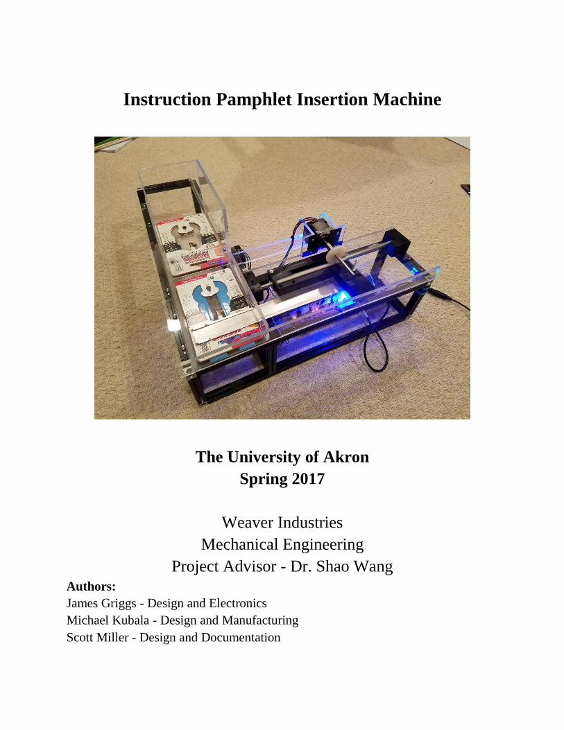
Instruction Pamphlet Insertion Machine
The University of Akron
Spring 2017
Weaver Industries
Mechanical Engineering
Project Advisor - Dr. Shao Wang
Authors:
James Griggs - Design and Electronics
Michael Kubala - Design and Manufacturing
Scott Miller - Design and Documentation
1
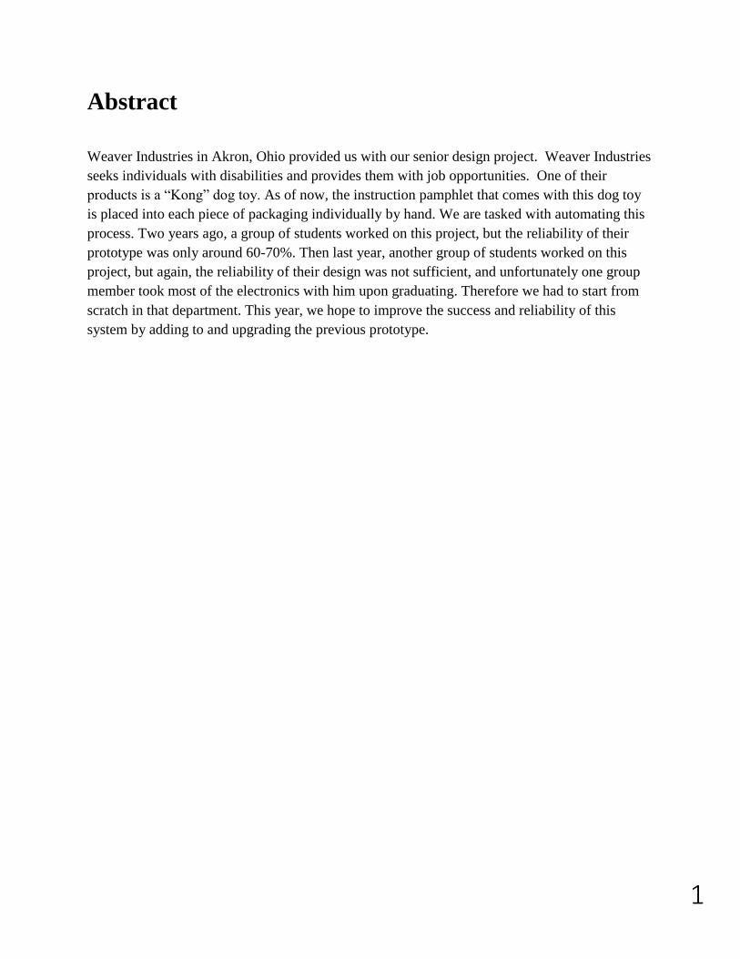
Abstract
Weaver Industries in Akron, Ohio provided us with our senior design project. Weaver Industries
seeks individuals with disabilities and provides them with job opportunities. One of their
products is a “Kong” dog toy. As of now, the instruction pamphlet that comes with this dog toy
is placed into each piece of packaging individually by hand. We are tasked with automating this
process. Two years ago, a group of students worked on this project, but the reliability of their
prototype was only around 60-70%. Then last year, another group of students worked on this
project, but again, the reliability of their design was not sufficient, and unfortunately one group
member took most of the electronics with him upon graduating. Therefore we had to start from
scratch in that department. This year, we hope to improve the success and reliability of this
system by adding to and upgrading the previous prototype.

2
Acknowledgements
We would first like to thank Weaver Industries for providing the University of Akron with this
unique project opportunity. It’s certainly been a learning experience.
We would also like to thank Dr. Shao Wang for being our project advisor. With his help we
were able to stay on track throughout our senior year. He also provided us and our senior class
with highly valuable Concepts of Design information, which made the completion of our project
and report possible.
3
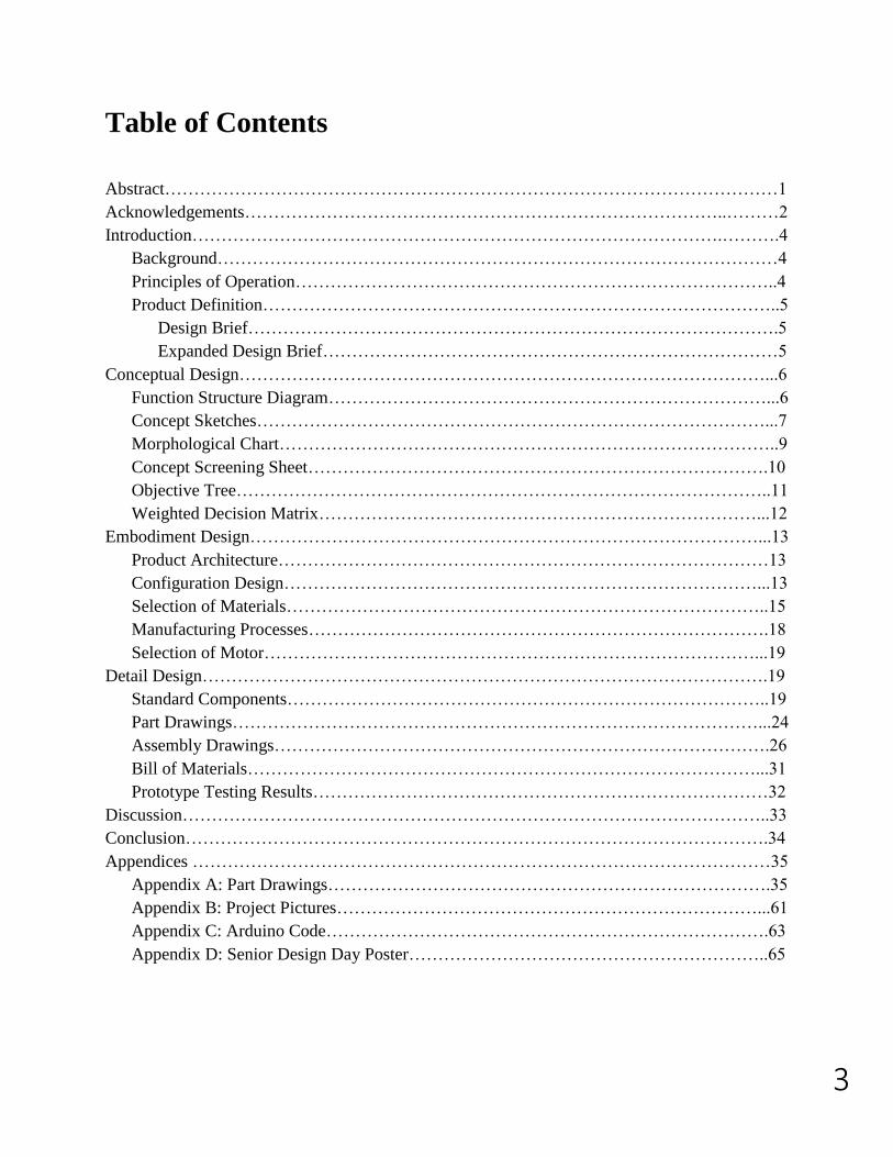
Table of Contents
Abstract……………………………………………………………………………………………1
Acknowledgements………………………………………………………………………..………2
Introduction……………………………………………………………………………….……….4
Background……………………………………………………………………………………4
Principles of Operation………………………………………………………………………..4
Product Definition……………………………………………………………………………..5
Design Brief……………………………………………………………………………….5
Expanded Design Brief……………………………………………………………………5
Conceptual Design………………………………………………………………………………...6
Function Structure Diagram…………………………………………………………………...6
Concept Sketches……………………………………………………………………………...7
Morphological Chart…………………………………………………………………………..9
Concept Screening Sheet…………………………………………………………………….10
Objective Tree………………………………………………………………………………..11
Weighted Decision Matrix…………………………………………………………………...12
Embodiment Design……………………………………………………………………………...13
Product Architecture…………………………………………………………………………13
Configuration Design………………………………………………………………………...13
Selection of Materials………………………………………………………………………..15
Manufacturing Processes…………………………………………………………………….18
Selection of Motor…………………………………………………………………………...19
Detail Design…………………………………………………………………………………….19
Standard Components………………………………………………………………………..19
Part Drawings………………………………………………………………………………...24
Assembly Drawings………………………………………………………………………….26
Bill of Materials……………………………………………………………………………...31
Prototype Testing Results……………………………………………………………………32
Discussion………………………………………………………………………………………..33
Conclusion……………………………………………………………………………………….34
Appendices ………………………………………………………………………………………35
Appendix A: Part Drawings………………………………………………………………….35
Appendix B: Project Pictures………………………………………………………………...61
Appendix C: Arduino Code………………………………………………………………….63
Appendix D: Senior Design Day Poster……………………………………………………..65
4
Introduction:
Background
Weaver Industries has asked that we automate their process of inserting a small instruction
pamphlet into a tight slot on their cardboard dog toy packaging. As of now, the process is
monotonously done by hand. Weaver employs workers with disabilities which can sometimes
limit what can be done by hand, especially in this tight tolerance process. A group of students in
2015 first took this project in hopes of automating the process. However, the success rate of
their design was not sufficient to be put into use. Last year in 2016, a second group of students
redesigned the system and made improvements. Unfortunately the improvements were not
enough to complete the project. After testing last year’s prototype, we made some changes we
believe to be improvements and have developed a new prototype.
Principles of Operation
The key to this project being a success is automation. Automation is the use of control systems
to set-up machinery or other processes to happen automatically. Automation is widely used today
in all fields of manufacturing and production systems. It is also used in steering and stabilization
systems in cars, ships and aircraft. When designed correctly, automation can have many benefits.
The most profound is the manual labor it replaces. Other benefits include savings on materials
and energy. Automation also takes out the element of human error, which in turn tends to be
more efficient and improves the end quality and accuracy of a product. Weaver would like this
process automated not to eliminate jobs, but to open up opportunities for new jobs and to take on
new products.
5
Product Definition:
Design Brief We plan to make a fully automated pamphlet insertion system. The previous prototype needs to
be improved and have additions made to it in order to increase success, reliability and efficiency.
This machine will be put in place at Weaver Industries in order to free up time and labor for their
company.
Expanded Design Brief We plan to make a fully automated pamphlet insertion system. The previous prototype needs to
be improved and have additions made to it in order to increase success, reliability and efficiency.
Each piece of cardboard packaging needs to have one instruction pamphlet inserted completely
into its slot. After the pamphlet is inserted, the end product should be ejected in order for the next
piece of packaging to be loaded. This machine will be put in place in at Weaver Industries. The
addition of an automated system would make the manual labor employees who currently do this
obsolete. Weaver plans to use this excess labor, time and energy to create new jobs and take on
new products. In order for this system to be implemented, it must have a 100% success rate and
be able to run without supervision. Our system is designed to work with the smaller of the two
sizes of their dog toy packaging. Once shown that it is sufficient to do the job, a second system
can be scaled up and built off of this design to run the larger size of packaging
6
Conceptual Design
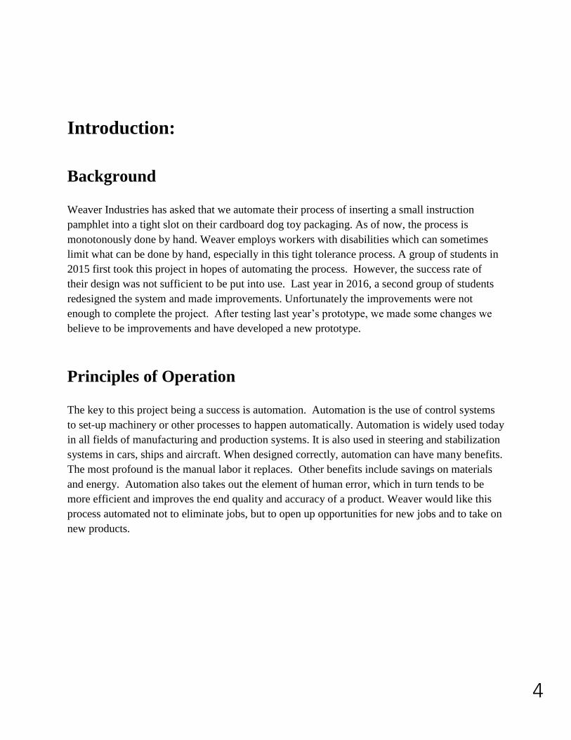
Product Specifications Instruction Manual Dimensions
- 3.5 x 0.89 x 0.04 inches
Cardboard Package Dimensions
- 4 x 6.5 x 0.08 inches (small
size)
- 6 x 9.5 x 0.08 inches (large size)
Pocket Size
- 1.5 inches long Figure [1]: Instruction Pamphlet and Package
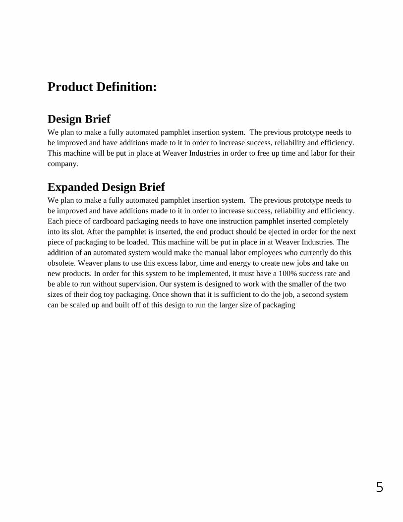
Function Structure Diagram A function structure diagram is a block diagram depicting flows of energy, material and signal as
labeled arrows taking paths between function blocks.
Overall Function Structure Diagram
Figure [2]: Overall Function Structure Diagram
7
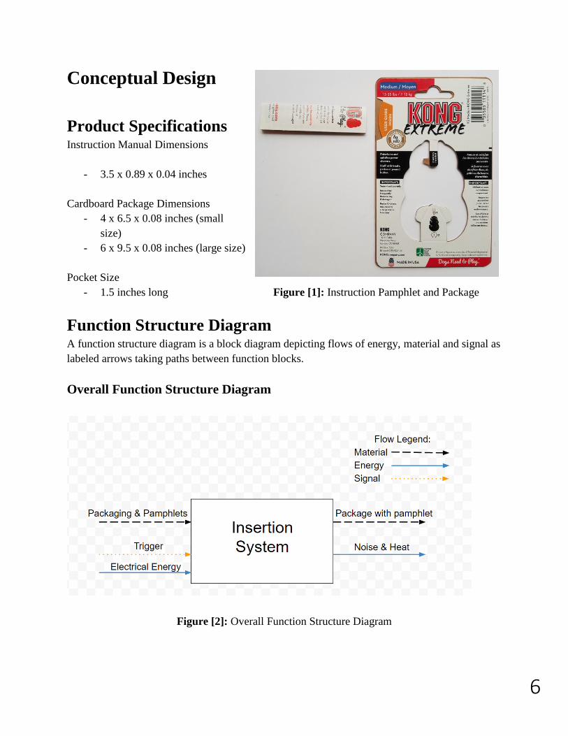
Detailed Function Structure Diagram
Figure [3]: Detailed Function Structure Diagram
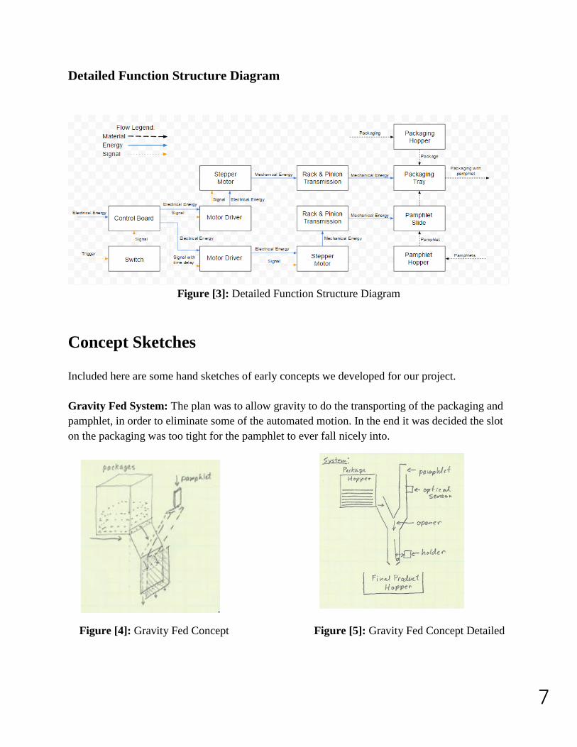
Concept Sketches
Included here are some hand sketches of early concepts we developed for our project.
Gravity Fed System: The plan was to allow gravity to do the transporting of the packaging and
pamphlet, in order to eliminate some of the automated motion. In the end it was decided the slot
on the packaging was too tight for the pamphlet to ever fall nicely into.
Figure [4]: Gravity Fed Concept Figure [5]: Gravity Fed Concept Detailed
8
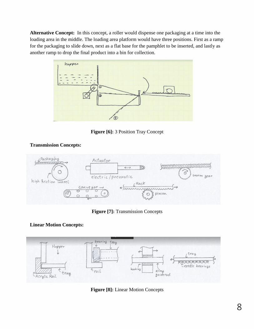
Alternative Concept: In this concept, a roller would dispense one packaging at a time into the
loading area in the middle. The loading area platform would have three positions. First as a ramp
for the packaging to slide down, next as a flat base for the pamphlet to be inserted, and lastly as
another ramp to drop the final product into a bin for collection.
Figure [6]: 3 Position Tray Concept
Transmission Concepts:
Figure [7]: Transmission Concepts
Linear Motion Concepts:
Figure [8]: Linear Motion Concepts
9
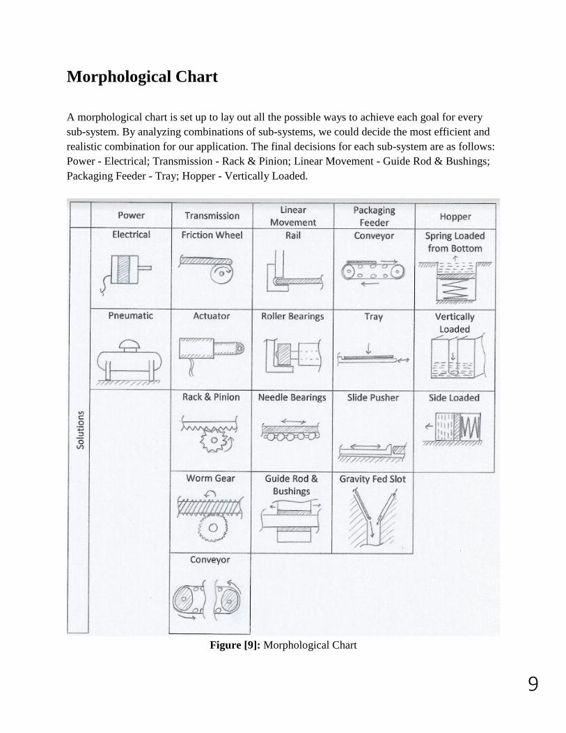
Morphological Chart
A morphological chart is set up to lay out all the possible ways to achieve each goal for every
sub-system. By analyzing combinations of sub-systems, we could decide the most efficient and
realistic combination for our application. The final decisions for each sub-system are as follows:
Power - Electrical; Transmission - Rack & Pinion; Linear Movement - Guide Rod & Bushings;
Packaging Feeder - Tray; Hopper - Vertically Loaded.
Figure [9]: Morphological Chart
10
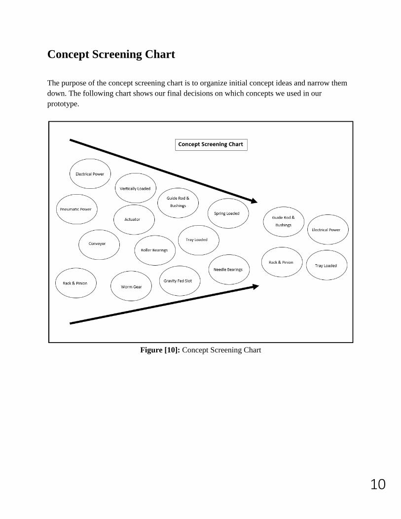
Concept Screening Chart
The purpose of the concept screening chart is to organize initial concept ideas and narrow them
down. The following chart shows our final decisions on which concepts we used in our
prototype.
Figure [10]: Concept Screening Chart
11
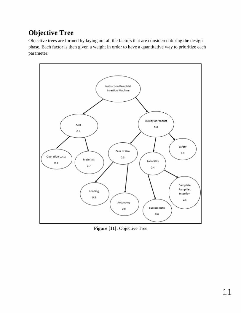
Objective Tree Objective trees are formed by laying out all the factors that are considered during the design
phase. Each factor is then given a weight in order to have a quantitative way to prioritize each
parameter.
Figure [11]: Objective Tree
12
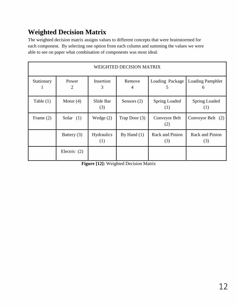
Weighted Decision Matrix The weighted decision matrix assigns values to different concepts that were brainstormed for
each component. By selecting one option from each column and summing the values we were
able to see on paper what combination of components was most ideal.
WEIGHTED DECISION MATRIX
Stationary
1
Power
2
Insertion
3
Remove
4
Loading Package
5
Loading Pamphlet
6
Table (1) Motor (4) Slide Bar
(3)
Sensors (2) Spring Loaded
(1)
Spring Loaded
(1)
Frame (2) Solar (1) Wedge (2) Trap Door (3) Conveyor Belt
(2)
Conveyor Belt (2)
Battery (3) Hydraulics
(1)
By Hand (1) Rack and Pinion
(3)
Rack and Pinion
(3)
Electric (2)
Figure [12]: Weighted Decision Matrix
13
Embodiment Design
Product Architecture
Schematic Diagram
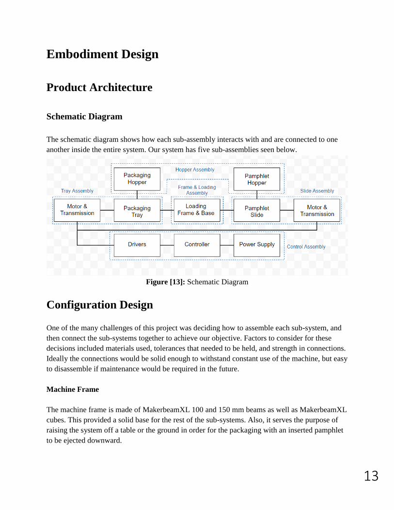
The schematic diagram shows how each sub-assembly interacts with and are connected to one
another inside the entire system. Our system has five sub-assemblies seen below.
Figure [13]: Schematic Diagram
Configuration Design
One of the many challenges of this project was deciding how to assemble each sub-system, and
then connect the sub-systems together to achieve our objective. Factors to consider for these
decisions included materials used, tolerances that needed to be held, and strength in connections.
Ideally the connections would be solid enough to withstand constant use of the machine, but easy
to disassemble if maintenance would be required in the future.
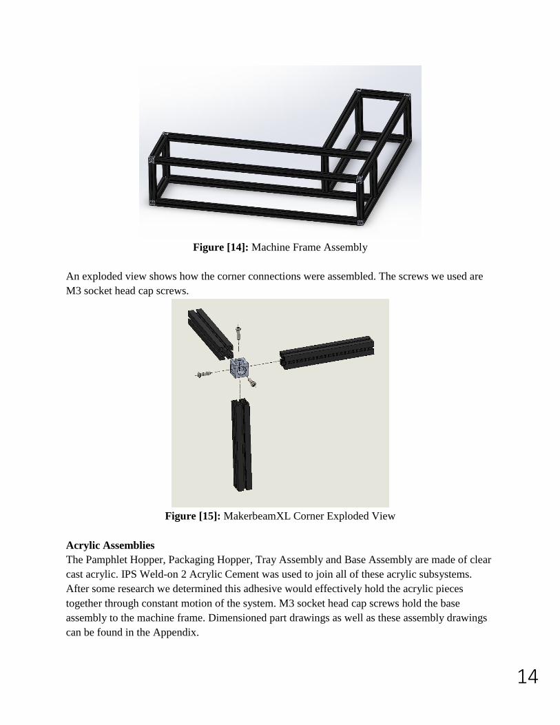
Machine Frame
The machine frame is made of MakerbeamXL 100 and 150 mm beams as well as MakerbeamXL
cubes. This provided a solid base for the rest of the sub-systems. Also, it serves the purpose of
raising the system off a table or the ground in order for the packaging with an inserted pamphlet
to be ejected downward.
14
Figure [14]: Machine Frame Assembly
An exploded view shows how the corner connections were assembled. The screws we used are
M3 socket head cap screws.
Figure [15]: MakerbeamXL Corner Exploded View
Acrylic Assemblies
The Pamphlet Hopper, Packaging Hopper, Tray Assembly and Base Assembly are made of clear
cast acrylic. IPS Weld-on 2 Acrylic Cement was used to join all of these acrylic subsystems.
After some research we determined this adhesive would effectively hold the acrylic pieces
together through constant motion of the system. M3 socket head cap screws hold the base
assembly to the machine frame. Dimensioned part drawings as well as these assembly drawings
can be found in the Appendix.
15
Selection of Materials After finishing the design of the entire system, we needed to decide what materials to construct it
with. Fortunately, last year’s group who worked on this project had left behind most of their
materials. Because we built off of their prototype, almost all the materials are the same. I have
included some of their thought process on the material selection in this section.
Packaging Hopper, Slide Track and Frame:
The prototype we received to work with was made of acrylic. The other options that were
considered were polycarbonate and sheet metal. For ease of use and testing we wanted our
system to be transparent as well as easy to machine. The packaging hopper, slide track and other
framework are all made of acrylic. Pros and cons of some materials are shown below.
Figure [16]: Material Selection Packaging Hopper, Slide Track and Frame
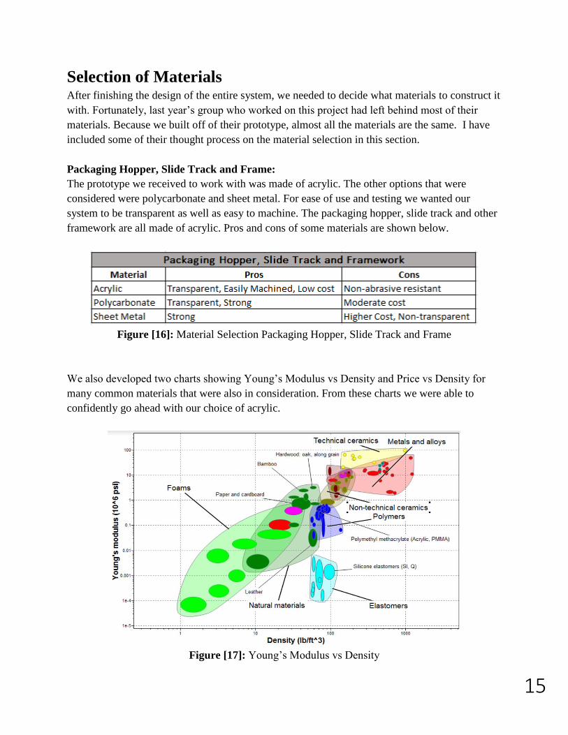
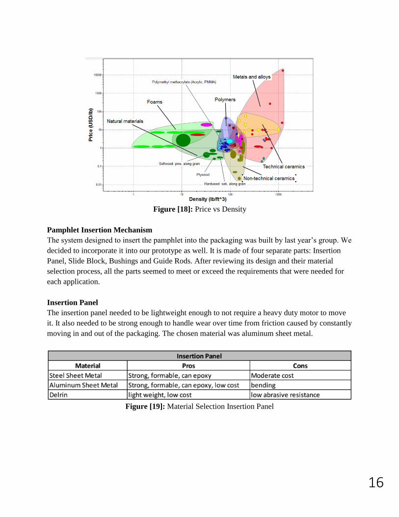
We also developed two charts showing Young’s Modulus vs Density and Price vs Density for
many common materials that were also in consideration. From these charts we were able to
confidently go ahead with our choice of acrylic.
Figure [17]: Young’s Modulus vs Density
16
Figure [18]: Price vs Density
Pamphlet Insertion Mechanism
The system designed to insert the pamphlet into the packaging was built by last year’s group. We
decided to incorporate it into our prototype as well. It is made of four separate parts: Insertion
Panel, Slide Block, Bushings and Guide Rods. After reviewing its design and their material
selection process, all the parts seemed to meet or exceed the requirements that were needed for
each application.
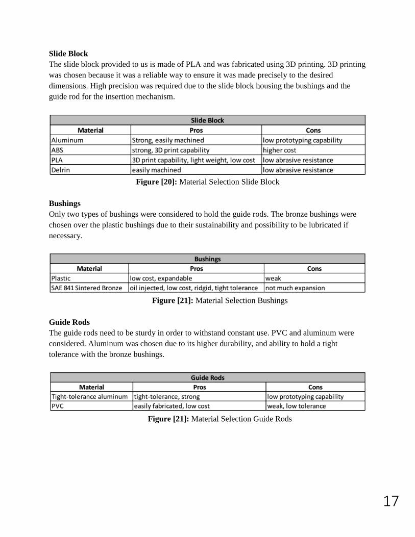
Insertion Panel
The insertion panel needed to be lightweight enough to not require a heavy duty motor to move
it. It also needed to be strong enough to handle wear over time from friction caused by constantly
moving in and out of the packaging. The chosen material was aluminum sheet metal.
Figure [19]: Material Selection Insertion Panel
17
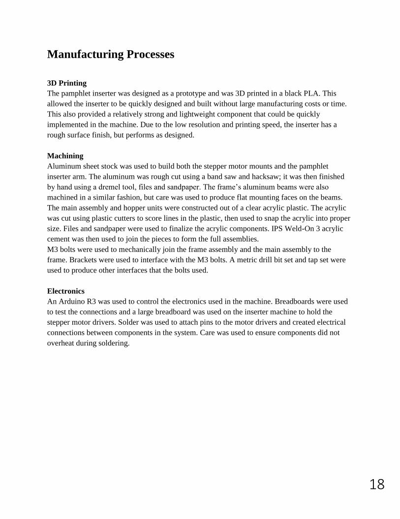
Slide Block
The slide block provided to us is made of PLA and was fabricated using 3D printing. 3D printing
was chosen because it was a reliable way to ensure it was made precisely to the desired
dimensions. High precision was required due to the slide block housing the bushings and the
guide rod for the insertion mechanism.
Figure [20]: Material Selection Slide Block
Bushings
Only two types of bushings were considered to hold the guide rods. The bronze bushings were
chosen over the plastic bushings due to their sustainability and possibility to be lubricated if
necessary.
Figure [21]: Material Selection Bushings
Guide Rods
The guide rods need to be sturdy in order to withstand constant use. PVC and aluminum were
considered. Aluminum was chosen due to its higher durability, and ability to hold a tight
tolerance with the bronze bushings.
Figure [21]: Material Selection Guide Rods
18
Manufacturing Processes
3D Printing
The pamphlet inserter was designed as a prototype and was 3D printed in a black PLA. This
allowed the inserter to be quickly designed and built without large manufacturing costs or time.
This also provided a relatively strong and lightweight component that could be quickly
implemented in the machine. Due to the low resolution and printing speed, the inserter has a
rough surface finish, but performs as designed.
Machining
Aluminum sheet stock was used to build both the stepper motor mounts and the pamphlet
inserter arm. The aluminum was rough cut using a band saw and hacksaw; it was then finished
by hand using a dremel tool, files and sandpaper. The frame’s aluminum beams were also
machined in a similar fashion, but care was used to produce flat mounting faces on the beams.
The main assembly and hopper units were constructed out of a clear acrylic plastic. The acrylic
was cut using plastic cutters to score lines in the plastic, then used to snap the acrylic into proper
size. Files and sandpaper were used to finalize the acrylic components. IPS Weld-On 3 acrylic
cement was then used to join the pieces to form the full assemblies.
M3 bolts were used to mechanically join the frame assembly and the main assembly to the
frame. Brackets were used to interface with the M3 bolts. A metric drill bit set and tap set were
used to produce other interfaces that the bolts used.
Electronics
An Arduino R3 was used to control the electronics used in the machine. Breadboards were used
to test the connections and a large breadboard was used on the inserter machine to hold the
stepper motor drivers. Solder was used to attach pins to the motor drivers and created electrical
connections between components in the system. Care was used to ensure components did not
overheat during soldering.
19
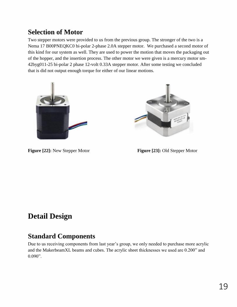
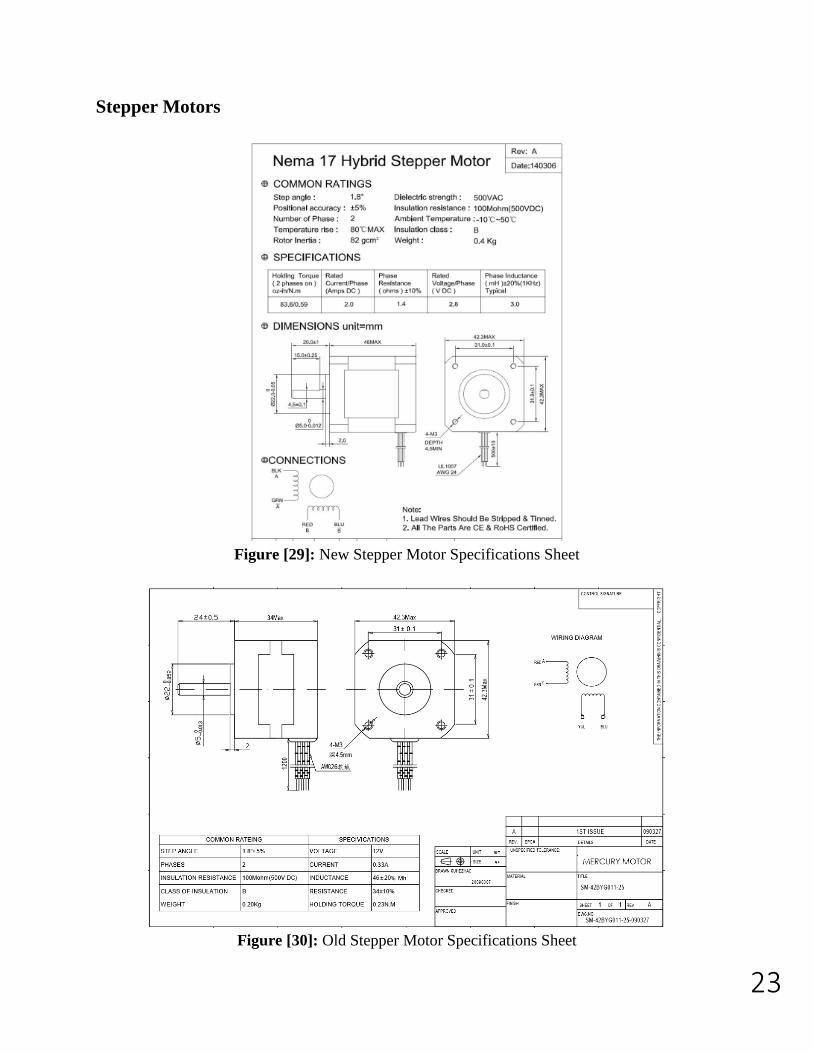
Selection of Motor Two stepper motors were provided to us from the previous group. The stronger of the two is a
Nema 17 B00PNEQKC0 bi-polar 2-phase 2.0A stepper motor. We purchased a second motor of
this kind for our system as well. They are used to power the motion that moves the packaging out
of the hopper, and the insertion process. The other motor we were given is a mercury motor sm-
42byg011-25 bi-polar 2 phase 12-volt 0.33A stepper motor. After some testing we concluded
that is did not output enough torque for either of our linear motions.
Figure [22]: New Stepper Motor Figure [23]: Old Stepper Motor
Detail Design
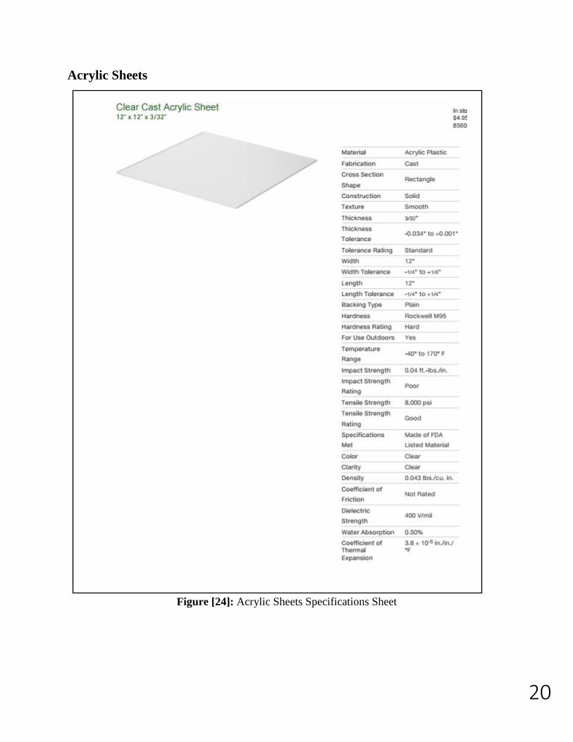
Standard Components Due to us receiving components from last year’s group, we only needed to purchase more acrylic
and the MakerbeamXL beams and cubes. The acrylic sheet thicknesses we used are 0.200” and
0.090”.
20
Acrylic Sheets
Figure [24]: Acrylic Sheets Specifications Sheet
21
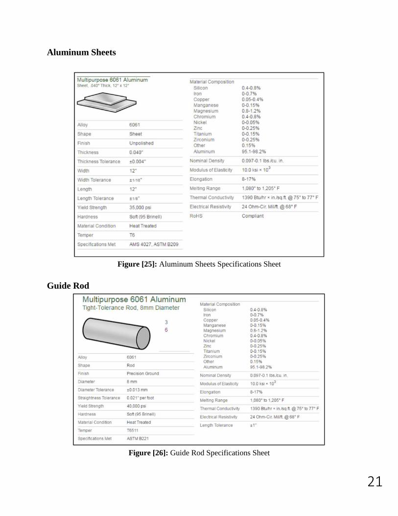
Aluminum Sheets
Figure [25]: Aluminum Sheets Specifications Sheet
Guide Rod
Figure [26]: Guide Rod Specifications Sheet
22
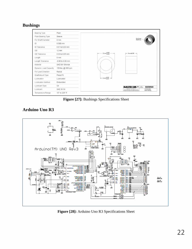
Bushings
Figure [27]: Bushings Specifications Sheet
Arduino Uno R3
Figure [28]: Arduino Uno R3 Specifications Sheet
23
Stepper Motors
Figure [29]: New Stepper Motor Specifications Sheet
Figure [30]: Old Stepper Motor Specifications Sheet
24
Part Drawings
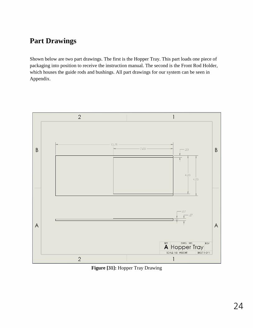
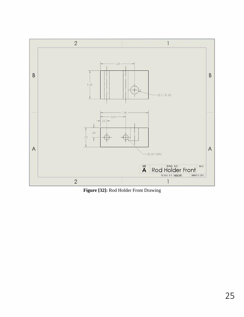
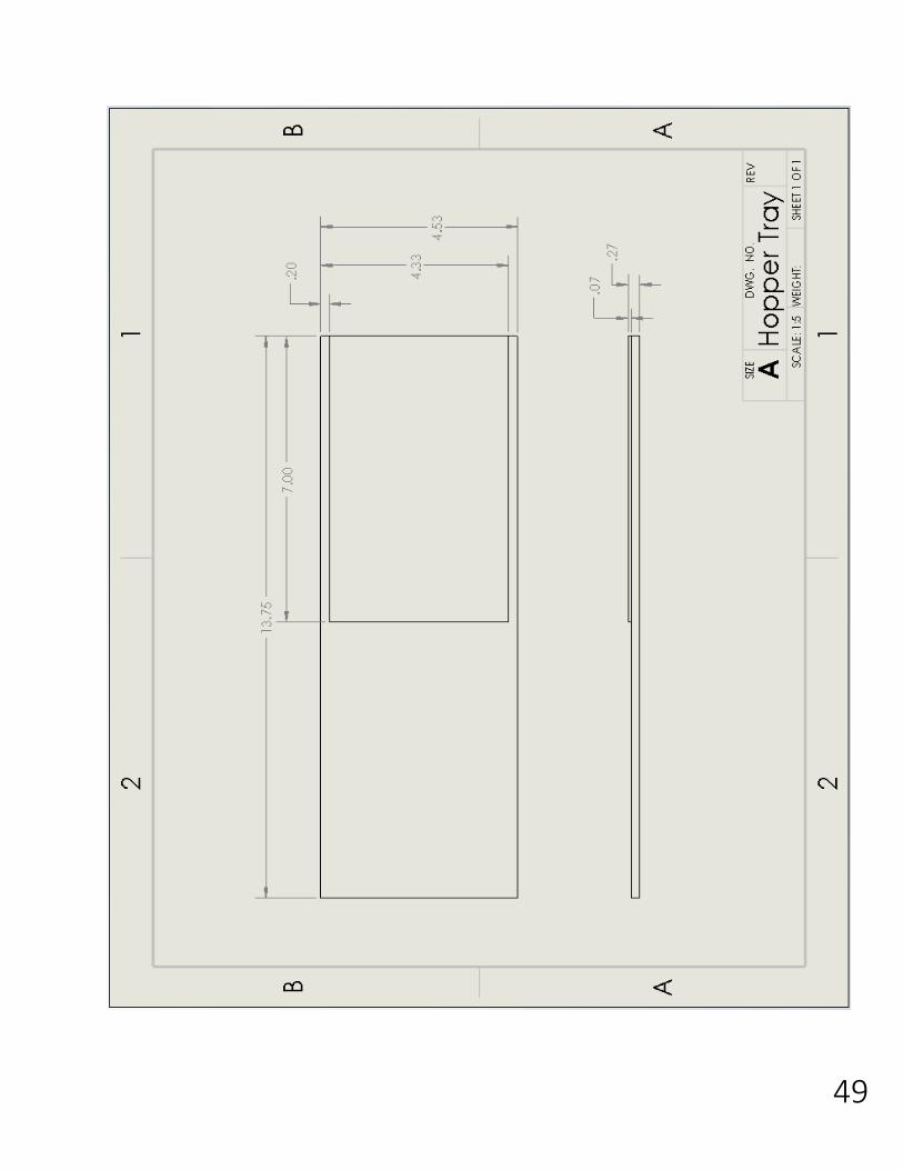
Shown below are two part drawings. The first is the Hopper Tray. This part loads one piece of
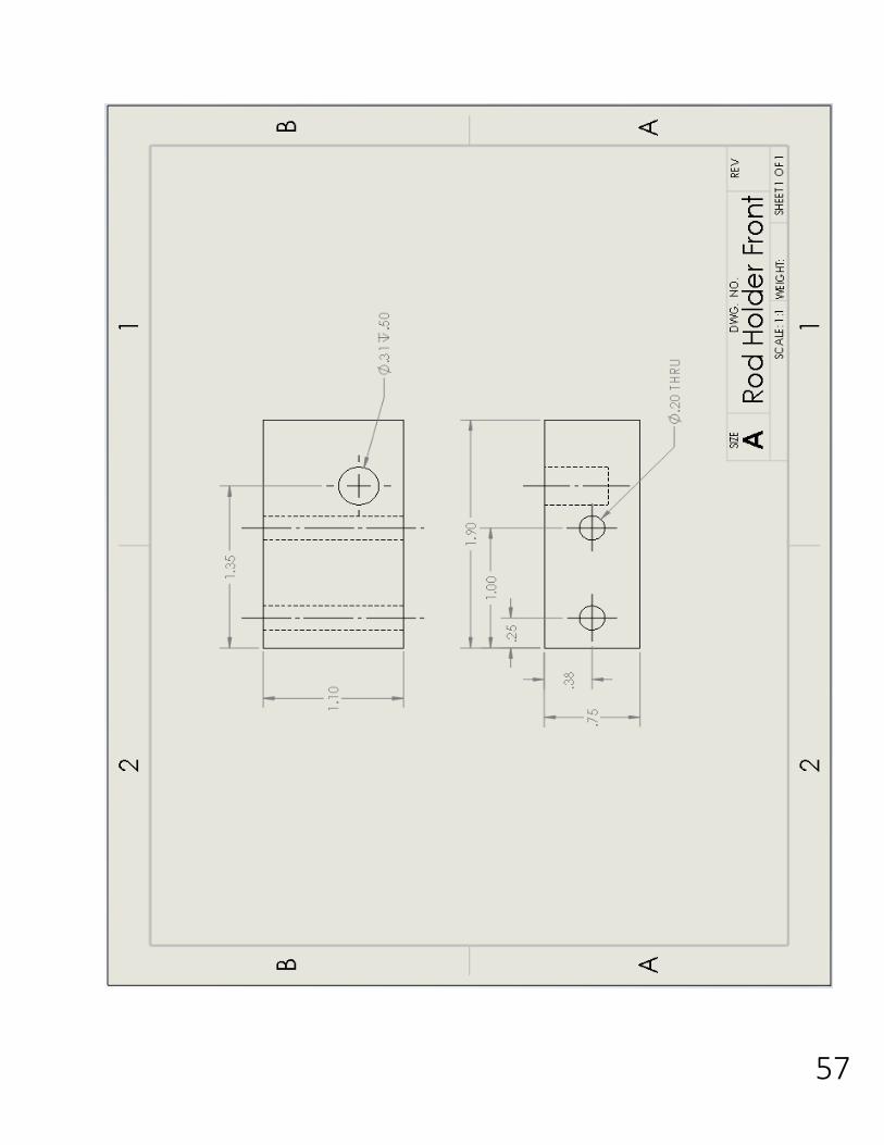
packaging into position to receive the instruction manual. The second is the Front Rod Holder,
which houses the guide rods and bushings. All part drawings for our system can be seen in
Appendix.
Figure [31]: Hopper Tray Drawing
25
Figure [32]: Rod Holder Front Drawing
26
Assembly Drawings
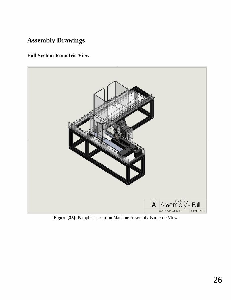
Full System Isometric View
Figure [33]: Pamphlet Insertion Machine Assembly Isometric View
27
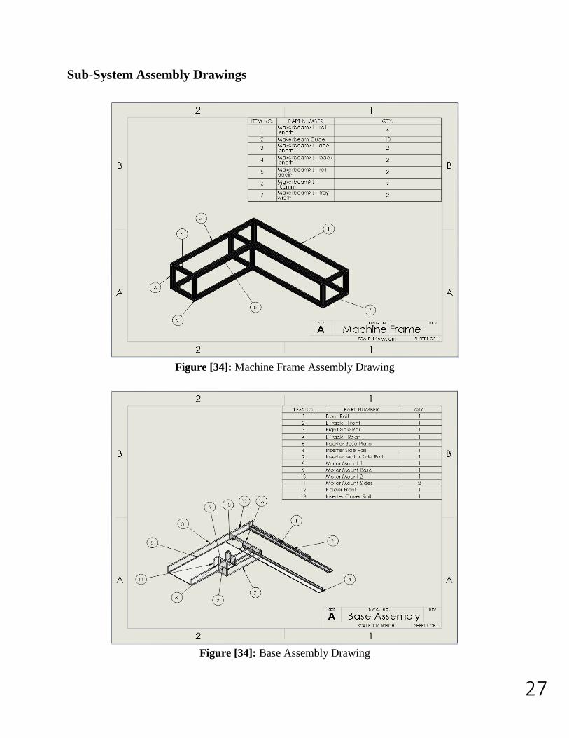
Sub-System Assembly Drawings
Figure [34]: Machine Frame Assembly Drawing
Figure [34]: Base Assembly Drawing
28
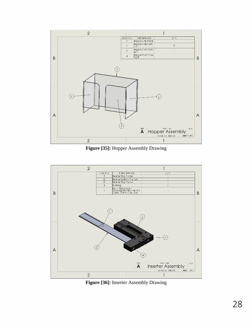
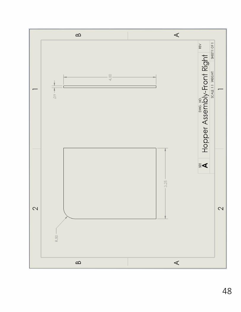
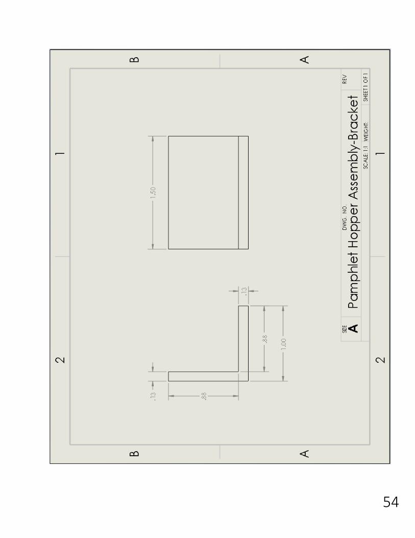
Figure [35]: Hopper Assembly Drawing
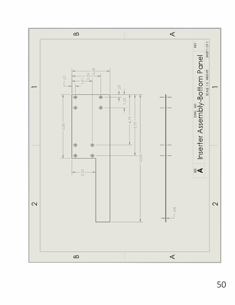
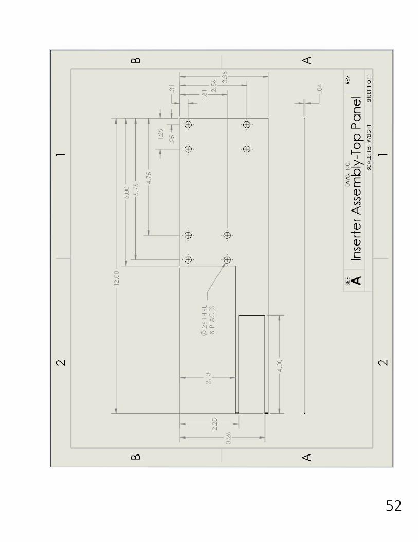
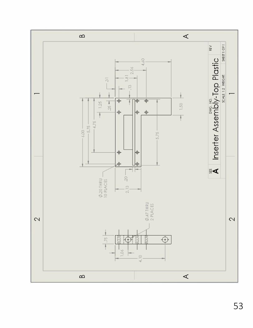
Figure [36]: Inserter Assembly Drawing
29
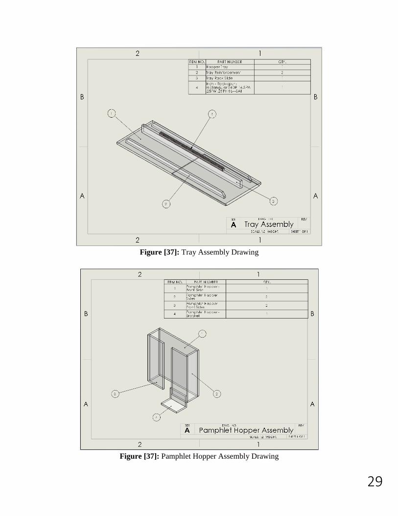
Figure [37]: Tray Assembly Drawing
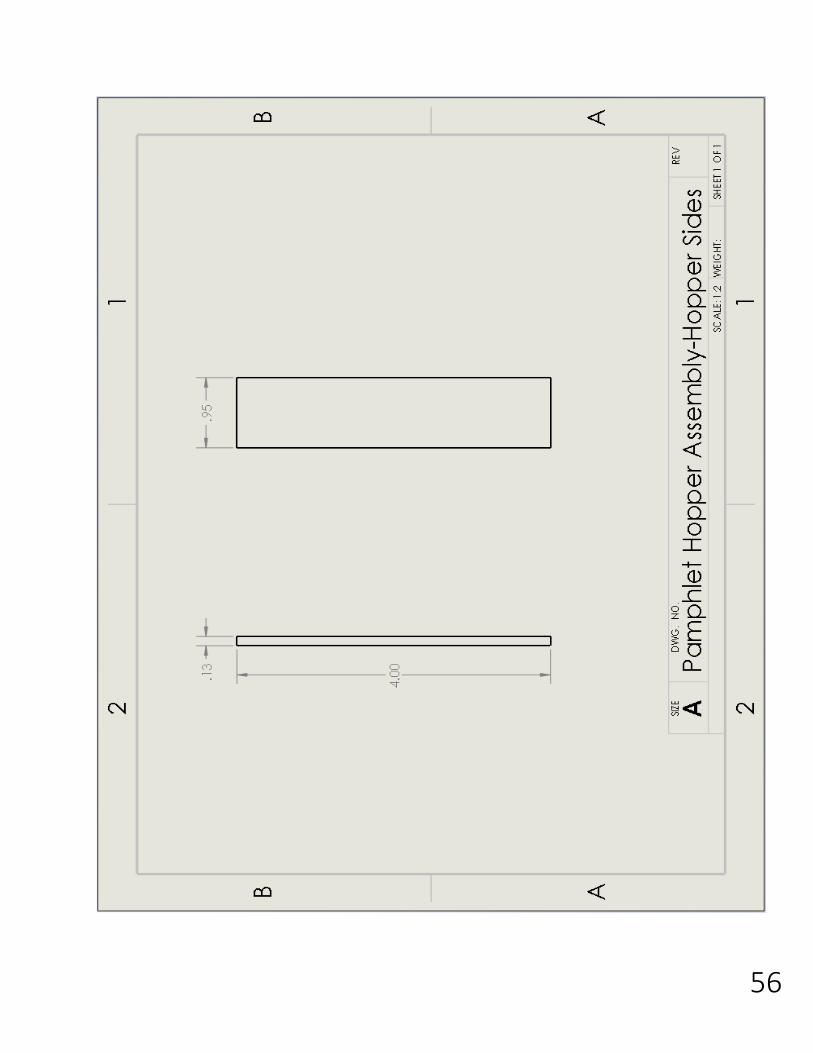
Figure [37]: Pamphlet Hopper Assembly Drawing
30
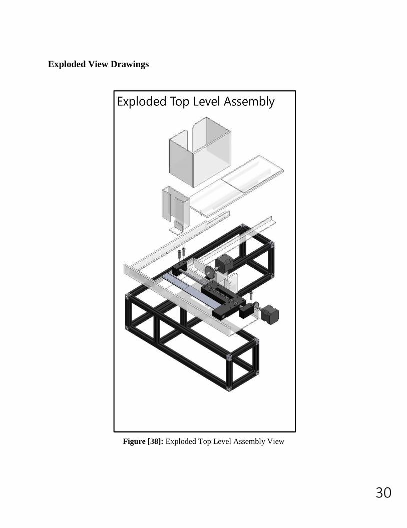
Exploded View Drawings
Figure [38]: Exploded Top Level Assembly View
31
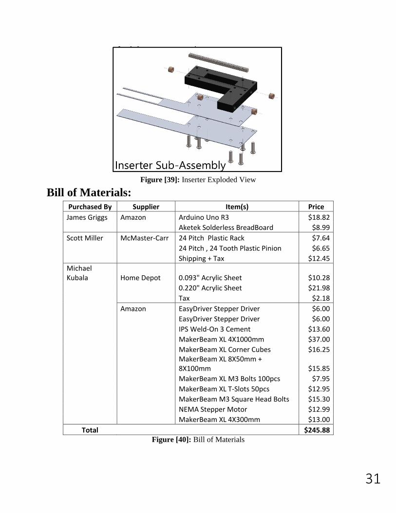
Figure [39]: Inserter Exploded View
Bill of Materials:
Purchased By Supplier Item(s) Price
James Griggs Amazon Arduino Uno R3 $18.82
Aketek Solderless BreadBoard $8.99
Scott Miller McMaster-Carr 24 Pitch Plastic Rack $7.64
24 Pitch , 24 Tooth Plastic Pinion $6.65
Shipping + Tax $12.45
Michael Kubala Home Depot 0.093" Acrylic Sheet $10.28
0.220" Acrylic Sheet $21.98
Tax $2.18
Amazon EasyDriver Stepper Driver $6.00
EasyDriver Stepper Driver $6.00
IPS Weld-On 3 Cement $13.60
MakerBeam XL 4X1000mm $37.00
MakerBeam XL Corner Cubes $16.25
MakerBeam XL 8X50mm + 8X100mm $15.85
MakerBeam XL M3 Bolts 100pcs $7.95
MakerBeam XL T-Slots 50pcs $12.95
MakerBeam M3 Square Head Bolts $15.30
NEMA Stepper Motor $12.99
MakerBeam XL 4X300mm $13.00
Total $245.88 Figure [40]: Bill of Materials
32
Prototype Testing Results
After connecting the subassemblies together and onto the machine frame we began working on
the Arduino code to run the stepper motors. We built multiple circuits and tried many different
Arduino codes, but we could not get the motors to move. After further testing we found that our
driver board was faulty and we ordered two new ones. We also discovered that our power source
was not supplying enough current to run the motors, so we found a new one that could provide
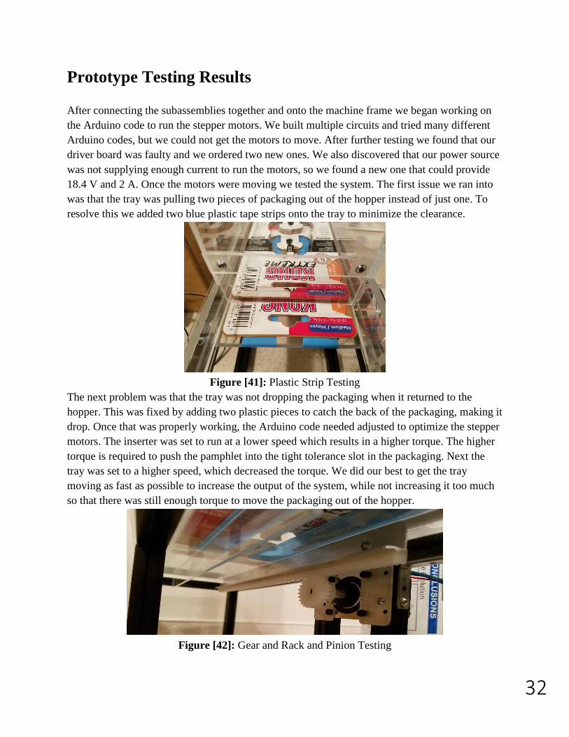
18.4 V and 2 A. Once the motors were moving we tested the system. The first issue we ran into
was that the tray was pulling two pieces of packaging out of the hopper instead of just one. To
resolve this we added two blue plastic tape strips onto the tray to minimize the clearance.
Figure [41]: Plastic Strip Testing
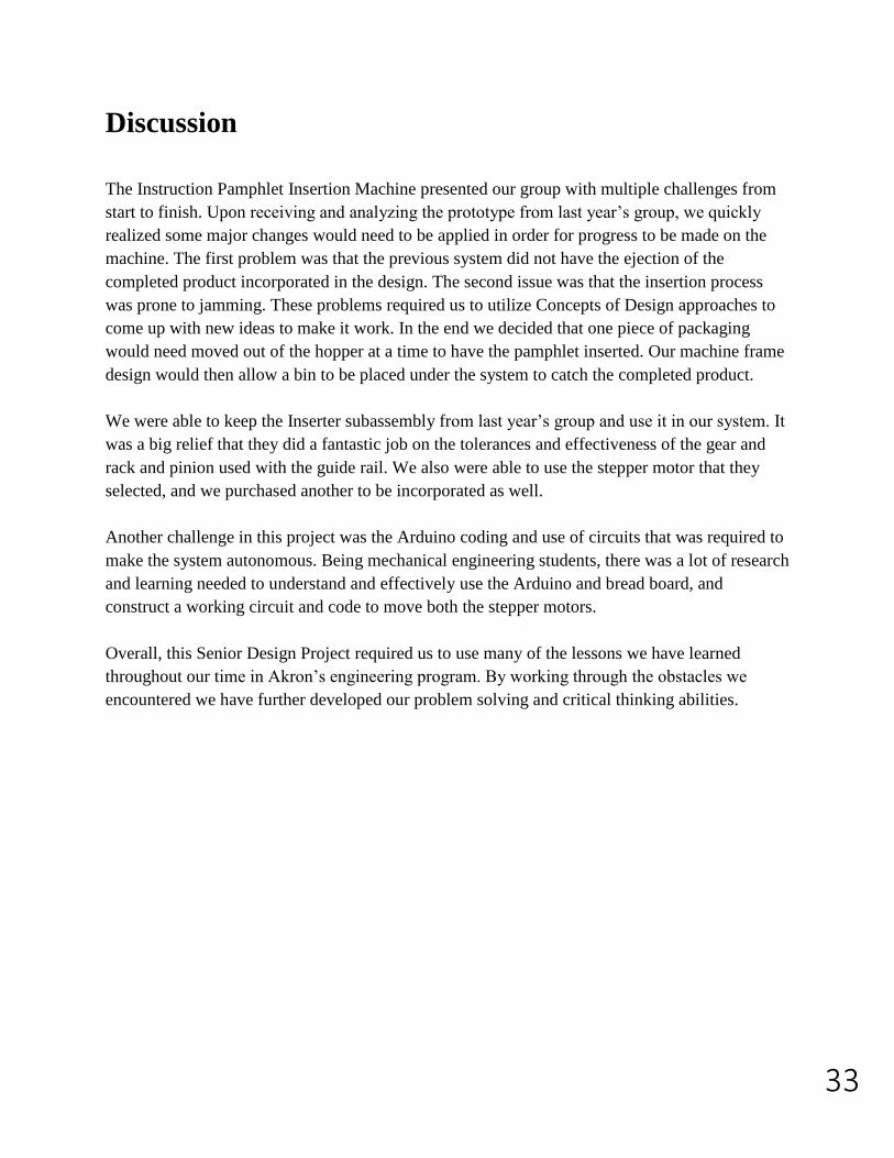
The next problem was that the tray was not dropping the packaging when it returned to the
hopper. This was fixed by adding two plastic pieces to catch the back of the packaging, making it
drop. Once that was properly working, the Arduino code needed adjusted to optimize the stepper
motors. The inserter was set to run at a lower speed which results in a higher torque. The higher
torque is required to push the pamphlet into the tight tolerance slot in the packaging. Next the
tray was set to a higher speed, which decreased the torque. We did our best to get the tray
moving as fast as possible to increase the output of the system, while not increasing it too much
so that there was still enough torque to move the packaging out of the hopper.
Figure [42]: Gear and Rack and Pinion Testing
33
Discussion
The Instruction Pamphlet Insertion Machine presented our group with multiple challenges from
start to finish. Upon receiving and analyzing the prototype from last year’s group, we quickly
realized some major changes would need to be applied in order for progress to be made on the
machine. The first problem was that the previous system did not have the ejection of the
completed product incorporated in the design. The second issue was that the insertion process
was prone to jamming. These problems required us to utilize Concepts of Design approaches to
come up with new ideas to make it work. In the end we decided that one piece of packaging
would need moved out of the hopper at a time to have the pamphlet inserted. Our machine frame
design would then allow a bin to be placed under the system to catch the completed product.
We were able to keep the Inserter subassembly from last year’s group and use it in our system. It
was a big relief that they did a fantastic job on the tolerances and effectiveness of the gear and
rack and pinion used with the guide rail. We also were able to use the stepper motor that they
selected, and we purchased another to be incorporated as well.
Another challenge in this project was the Arduino coding and use of circuits that was required to
make the system autonomous. Being mechanical engineering students, there was a lot of research
and learning needed to understand and effectively use the Arduino and bread board, and
construct a working circuit and code to move both the stepper motors.
Overall, this Senior Design Project required us to use many of the lessons we have learned
throughout our time in Akron’s engineering program. By working through the obstacles we
encountered we have further developed our problem solving and critical thinking abilities.
34
Conclusion
In conclusion, we have manufactured the third generation of the Instruction Pamphlet Insertion
Machine that was provided to us by Weaver Industries. We were given the second-generation
prototype, which we decided to only keep the inserter sub-assembly. We ended up redesigning
and rebuilding all the other sub-assemblies that were used in the second generations prototype.
We successfully designed a way to load a package one at a time continuously into the designated
“loading zone”, where the pamphlet will be inserted, and once inserted the package will be
removed. The mechanism we added to do this task was a packaging tray that will be moved by a
gear and rack powered by a stepper motor. The second-generation prototype also did not have an
electronic system. That was the next issue at hand we had to rework. We added a whole new
electronic package that included our automated pamphlet machine to be run off two stepper
motors that were being controlled by Arduino and two drivers. Going forward for next year’s
group of seniors, a fourth-generation prototype will be required. Some areas to be considered are
to refine the inserter sub-assembly to increase reliability. Redesigning a pamphlet hopper feeder,
so that it will one at a time insert itself into the package on the package tray we developed.
Another idea is to modify our Arduino code to simplify the whole operation of the machine, so
that it can be easily operated by handicapped workers in the Weaver facility.
35
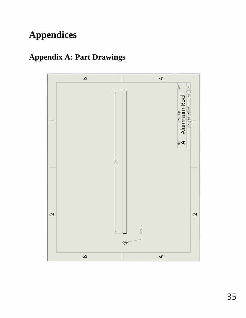
Appendices
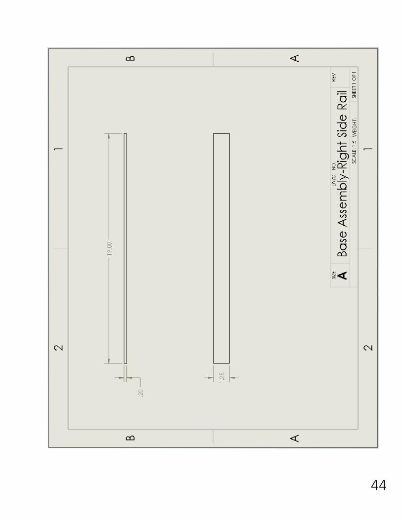
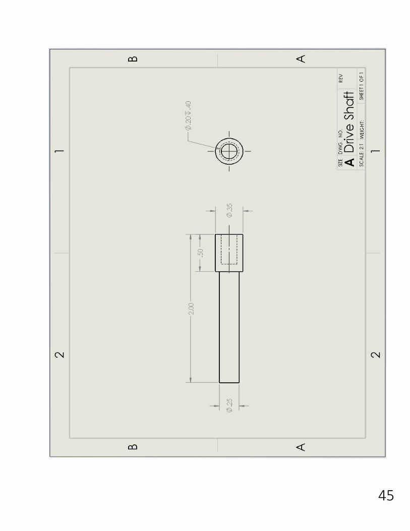
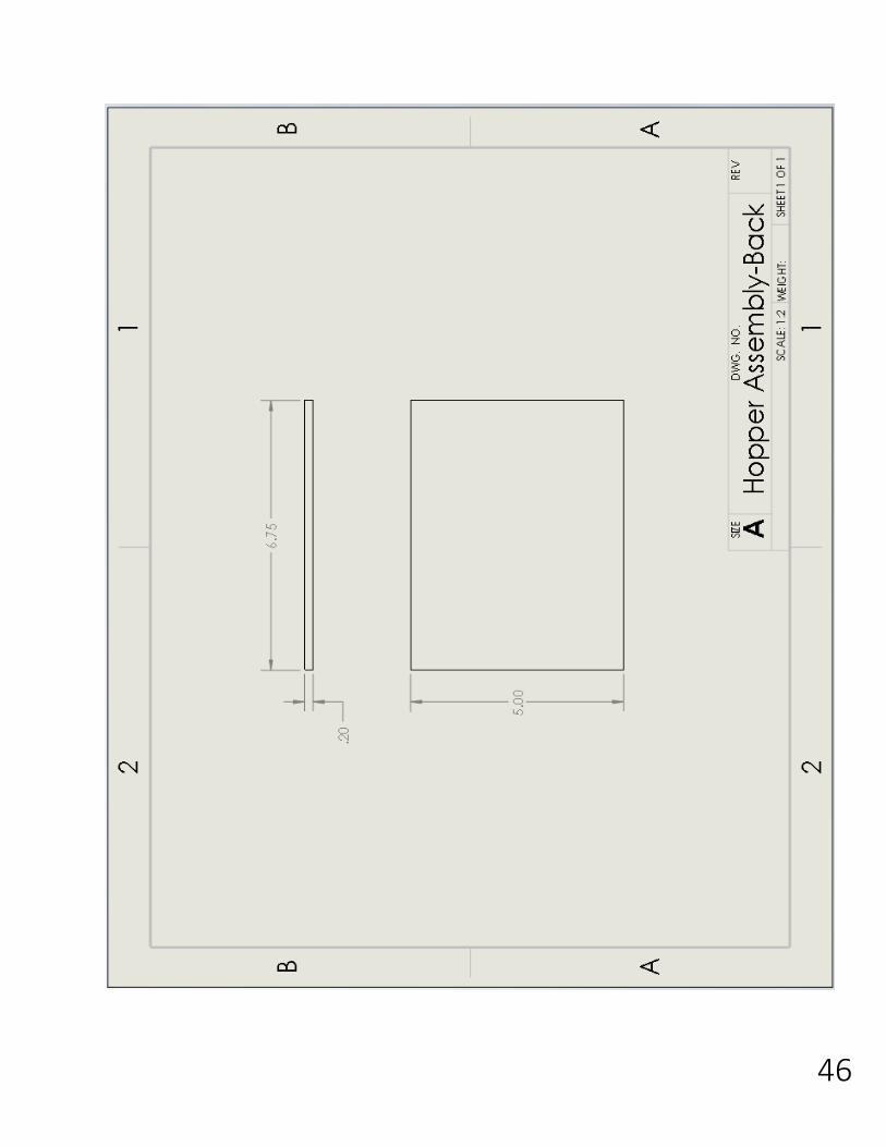
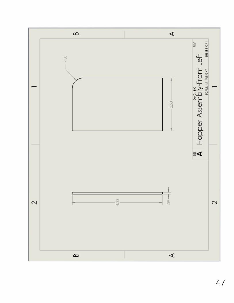
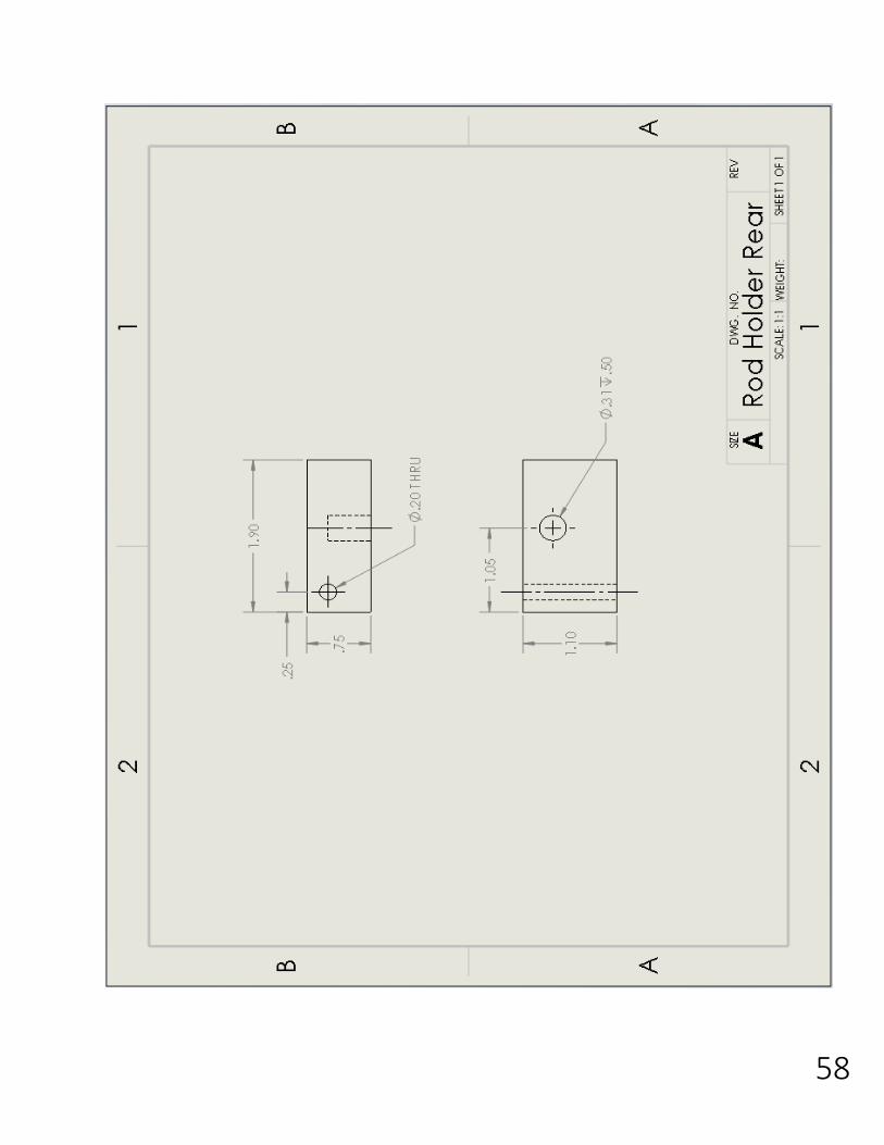
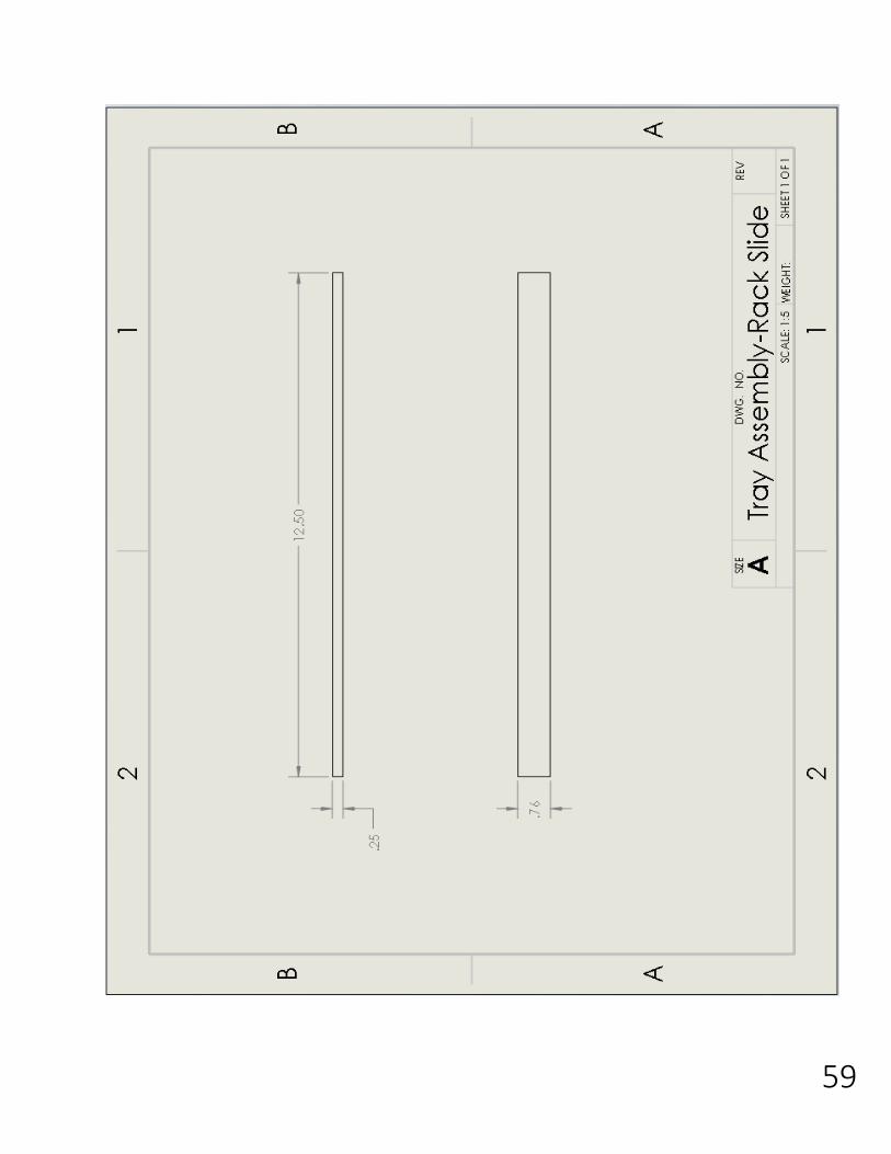
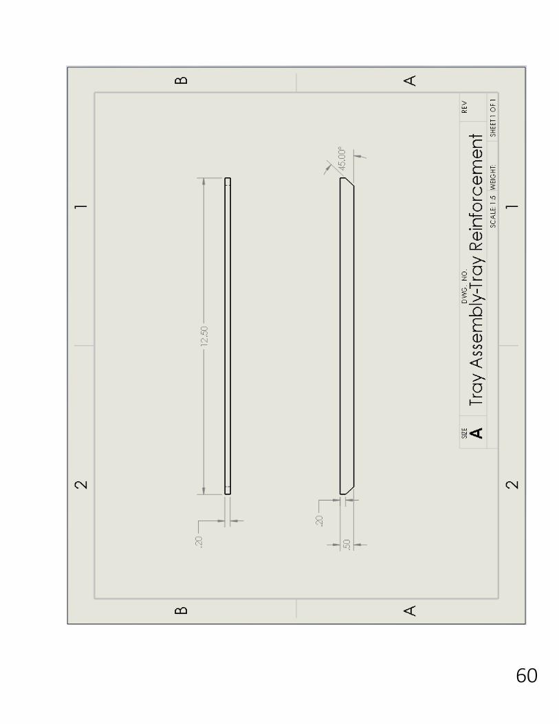
Appendix A: Part Drawings
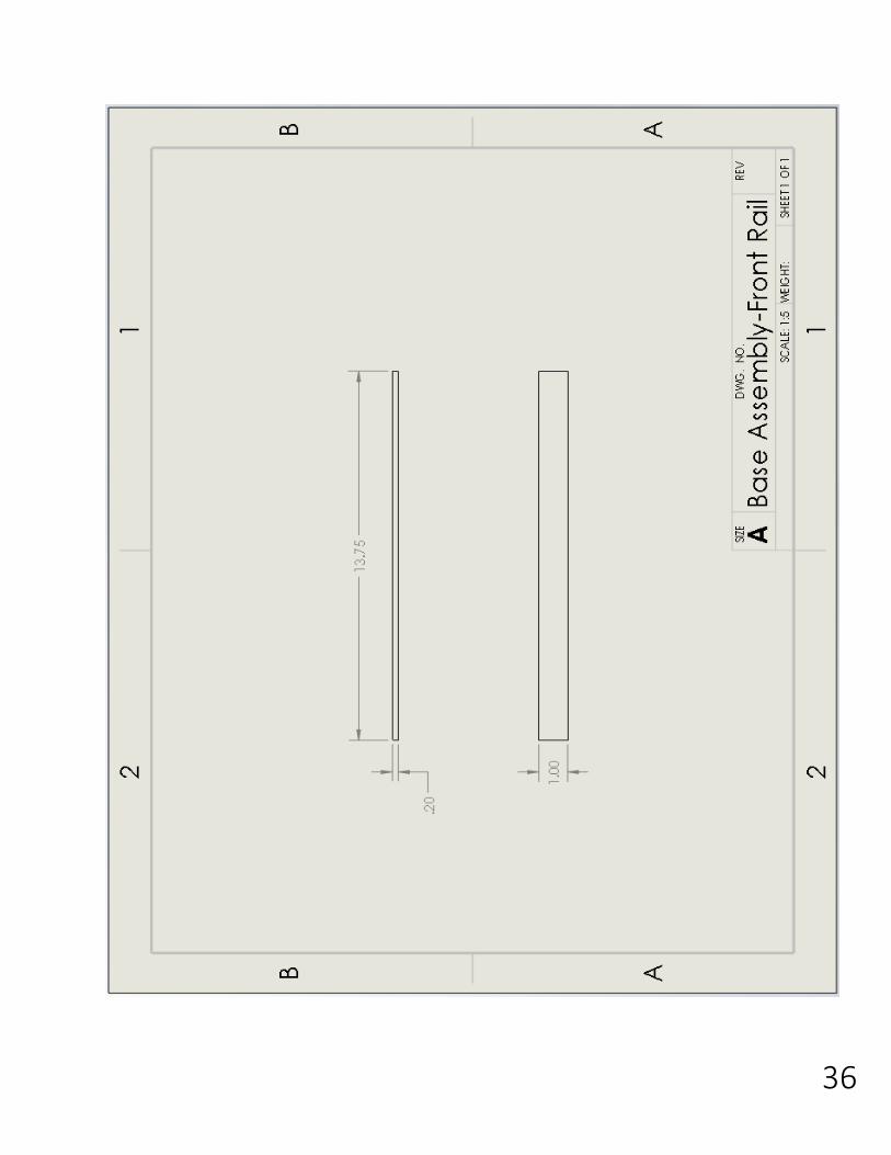
36
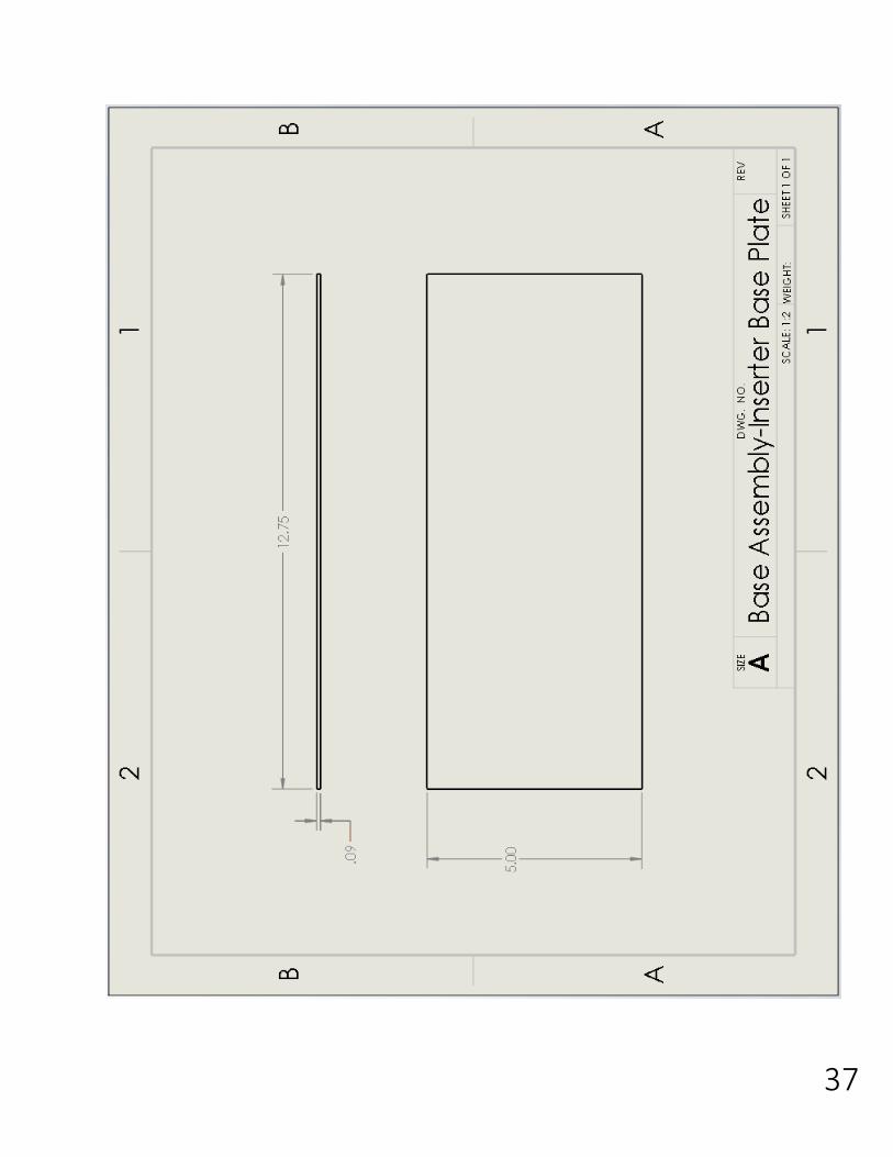
37
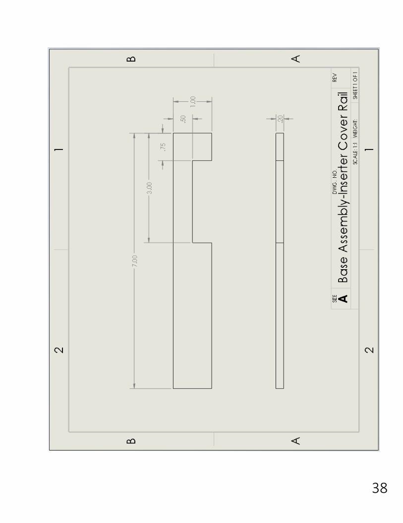
38
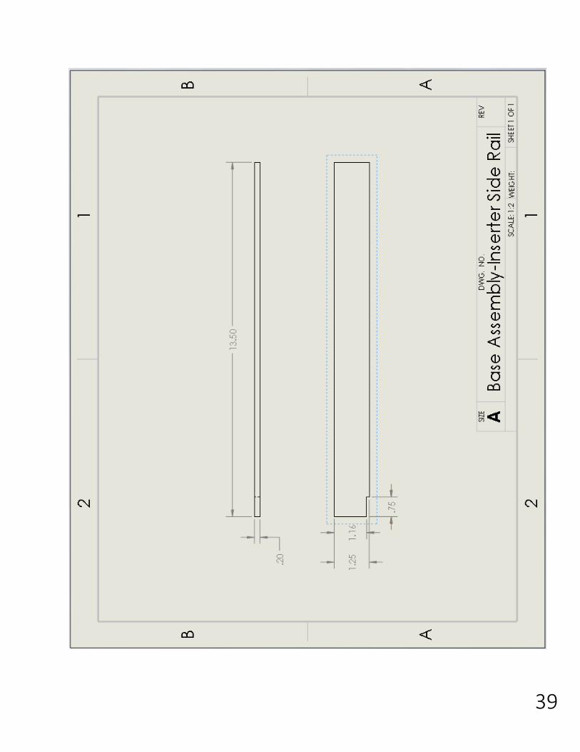
39
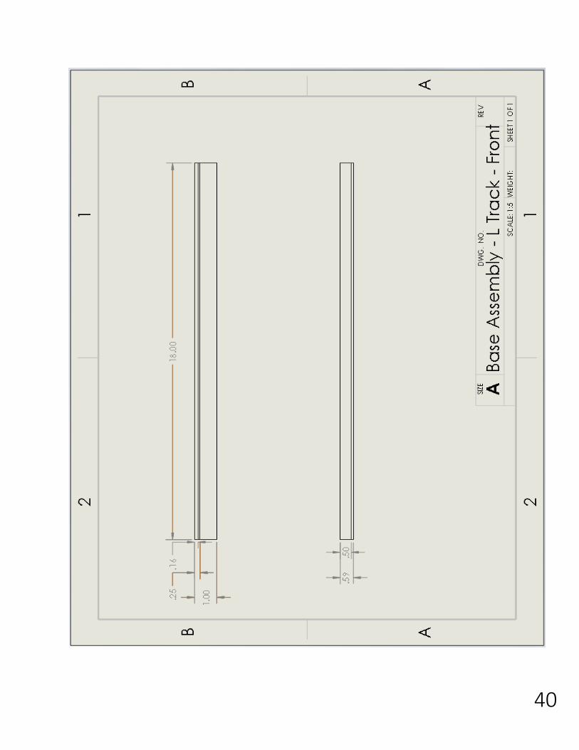
40
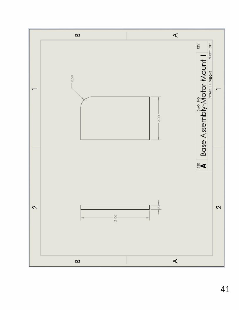
41
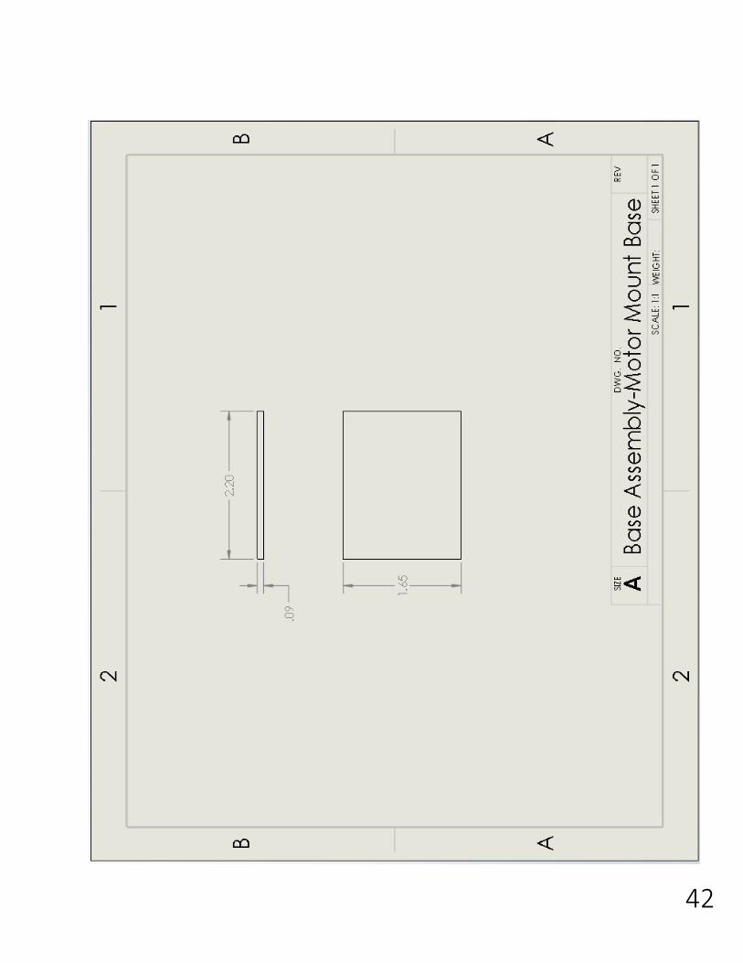
42
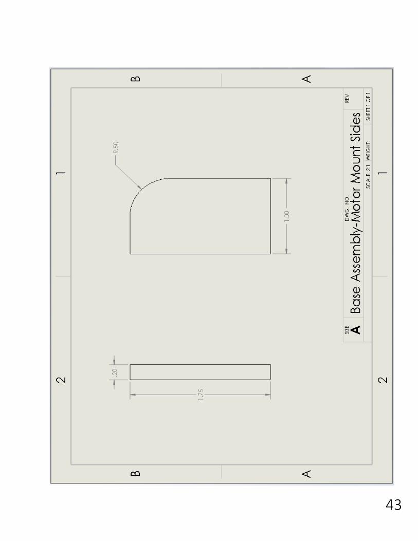
43
44
45
46
47
48
49
50

51
52
53
54

55
56
57
58
59
60
61
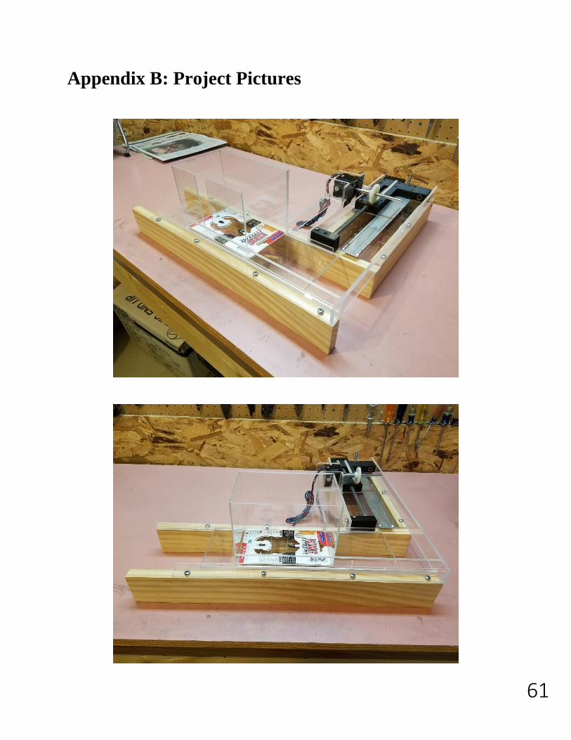
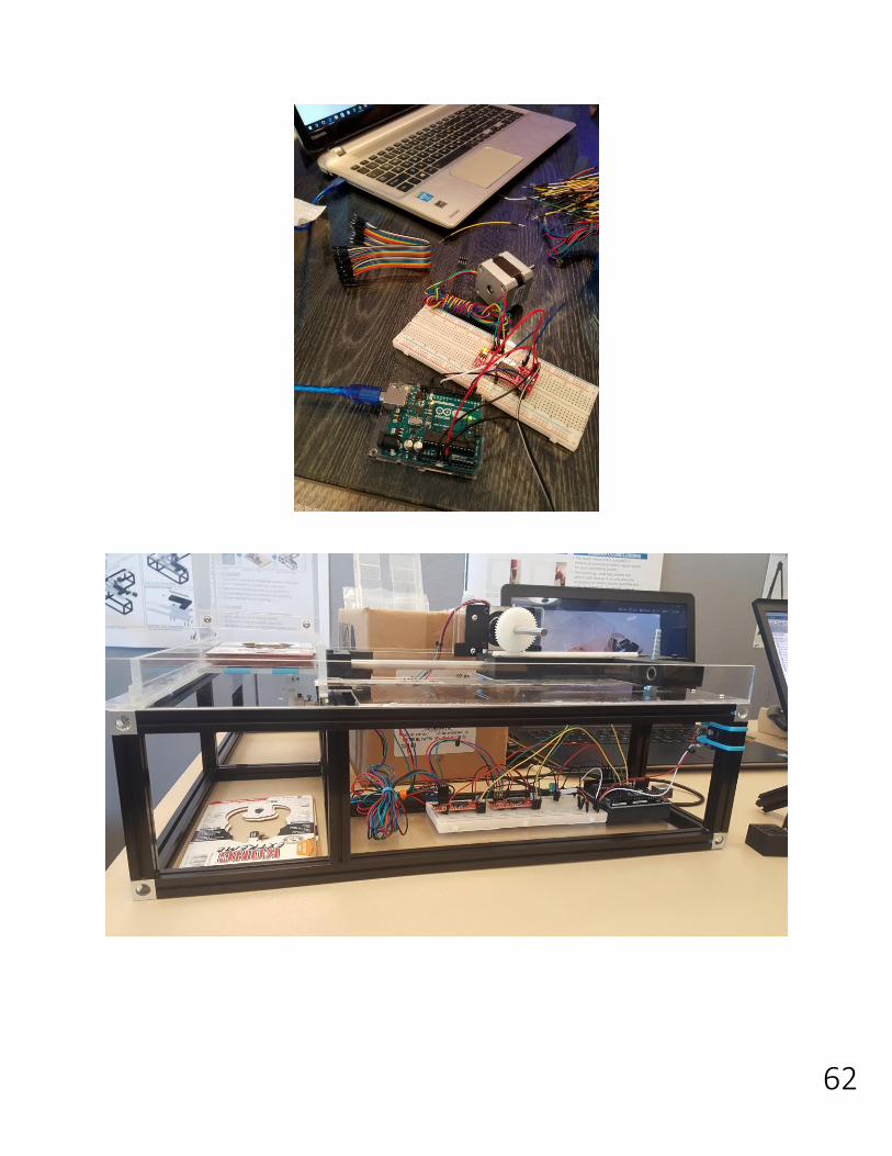
Appendix B: Project Pictures
62

63
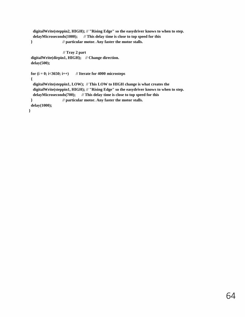
Appendix C: Arduino Code
int dirpin1 = 2;
int steppin1 = 3;
int dirpin2 = 4;
int steppin2 = 5;
void setup()
{
pinMode(dirpin1, OUTPUT);
pinMode(steppin1, OUTPUT);
pinMode(dirpin2, OUTPUT);
pinMode(steppin2, OUTPUT);
}
void loop()
{
int i;
// Tray 1 step
digitalWrite(dirpin1, LOW); // Set the direction.
delay(500);
for (i = 0; i<3650; i++) // Iterate for 4000 microsteps.
{
digitalWrite(steppin1, LOW); // This LOW to HIGH change is what creates the
digitalWrite(steppin1, HIGH); // "Rising Edge" so the easydriver knows to when to step.
delayMicroseconds(700); // This delay time is close to top speed for this
} // particular motor. Any faster the motor stalls.
// Inserter 1 step
digitalWrite(dirpin2, LOW); // Set the direction.
delay(500);
for (i = 0; i<1500; i++) // Iterate for 4000 microsteps.
{
digitalWrite(steppin2, LOW); // This LOW to HIGH change is what creates the
digitalWrite(steppin2, HIGH); // "Rising Edge" so the easydriver knows to when to step.
delayMicroseconds(1000); // This delay time is close to top speed for this
} // particular motor. Any faster the motor stalls.
digitalWrite(dirpin2, HIGH); // Change direction.
delay(100);
for (i = 0; i<1500; i++) // Iterate for 4000 microsteps
{
digitalWrite(steppin2, LOW); // This LOW to HIGH change is what creates the
64
digitalWrite(steppin2, HIGH); // "Rising Edge" so the easydriver knows to when to step.
delayMicroseconds(1000); // This delay time is close to top speed for this
} // particular motor. Any faster the motor stalls.
// Tray 2 part
digitalWrite(dirpin1, HIGH); // Change direction.
delay(500);
for (i = 0; i<3650; i++) // Iterate for 4000 microsteps
{
digitalWrite(steppin1, LOW); // This LOW to HIGH change is what creates the
digitalWrite(steppin1, HIGH); // "Rising Edge" so the easydriver knows to when to step.
delayMicroseconds(700); // This delay time is close to top speed for this
} // particular motor. Any faster the motor stalls.
delay(1000);
}

65
Appendix D: Senior Design Day Poster


