Embed Size (px)
Citation preview
www.elsevier.com/locate/enconman
Energy Conversion and Management 48 (2007) 2680–2693
Integrated gasification gas combined cycle plant withmembrane reactors: Technological and economical analysis
Mario Amelio a, Pietropaolo Morrone a, Fausto Gallucci b, Angelo Basile b,*
a Department of Mechanical Engineering, University of Calabria, Via P. Bucci, Cubo 44/C, 87030 Rende (CS), Italyb Institute on Membrane Technology, ITM-CNR c/o University of Calabria, Via P. Bucci, Cubo 17/C, 87030 Rende (CS), Italy
Received 5 September 2006; accepted 29 April 2007Available online 20 June 2007
Abstract
In the present work, the capture and storage of carbon dioxide from the fossil fuel power plant have been considered. The main objec-tive was to analyze the thermodynamic performances and the technological aspects of two integrated gasification gas combined cycleplants (IGCC), as well as to give a forecast of the investment costs for the plants and the resulting energy consumptions.
The first plant considered is an IGCC* plant (integrated gasification gas combined cycle plant with traditional shift reactors) charac-terized by the traditional water gas shift reactors and a CO2 physical adsorption system followed by the power section. The second one isan IGCCM plant (integrated gasification gas combined cycle plant with membrane reactor) where the coal thermal input is the same asthe first one, but the traditional shift reactors and the physical adsorption unit are replaced by catalytic palladium membrane reactors(CMR).
In the present work, a mono-dimensional computational model of the membrane reactor was proposed to simulate and evaluate thecapability of the IGCCM plant to capture carbon dioxide.
The energetic performances, efficiency and net power of the IGCC* and IGCCM plants were, thus, compared, assuming as standard atraditional IGCC plant without carbon dioxide capture. The economical aspects of the three plants were compared through an econom-ical analysis. Since the IGCC* and IGCCM plants have additional costs related to the capture and disposal of the carbon dioxide, a Car-
bon Tax (adopted in some countries like Sweden) proportional to the number of kilograms of carbon dioxide released in the environmentwas assumed. According to the economical analysis, the IGCCM plant proved to be more convenient than the IGCC* one.� 2007 Elsevier Ltd. All rights reserved.
Keywords: CO2 removal; CO2 capture; IGCC; Membrane reactor
1. Introduction
The world population growth and the consequent rise inpollution and greenhouse gases emissions are the mostimportant problems that the scientific community has tosolve in the near future.
The energy production from fossil sources representsmore than 65% of the global human activity greenhousegases emissions (carbon dioxide CO2, methane CH4 andnitrogen oxide N2O) [1]. Carbon dioxide is the major atmo-
0196-8904/$ - see front matter � 2007 Elsevier Ltd. All rights reserved.
doi:10.1016/j.enconman.2007.04.023
* Corresponding author. Tel.: +39 0984 492013; fax: +39 0984 402103.E-mail address: [email protected] (A. Basile).
spheric contaminant leading to a temperature increasecaused by the greenhouse effect. The scientific communityconsiders the anthropogenic CO2 emission reduction neces-sary to the maintenance of the existing world climate con-dition, so radical changes in energetic technologies,nowadays based on fossil fuels combustion, are necessary.
However, the energetic system shows high rigiditytowards any changes: billions of euros have been spentfor the extraction, transport, conversion and distributioninfrastructures. The valuations indicate fifty years as theminimum time for a complete transformation of the infra-structures cost before new technologies will be commer-cially available. These times are not compatible with thenecessity of lowering the carbon dioxide emissions.
M. Amelio et al. / Energy Conversion and Management 48 (2007) 2680–2693 2681
In these conditions, the capture (separation and storage)of carbon dioxide emitted by the big fossil fuels combus-tion plants is considered as one of the few possible avail-able operations able to stabilize the greenhouse gasesconcentrations in the troposphere, at least until the ener-getic system will be converted to new energetic sources.
There are many available technologies to capture carbondioxide in IGCC power plants, such as physical and chem-ical adsorption, membrane and solid oxide fuel cell(SOFC). However, no commercial IGCC plant with CO2
capture has yet been built [2]. Chemical and physicalabsorption have been extensively examined in terms ofoverall process energy efficiency and cost [2–6]. Most ofthe published works concern chemical and physical absorp-tion systems of CO2 that are more mature technologies thatrealize CO2 separation at relatively low temperatures orwith exhaust gas with both low CO2 concentration andlow partial pressure. For these reasons, in these plants, lar-ger scale equipments for CO2 removal are needed withrespect to pre-combustion fuel decarbonisation systems.
Co-production of electricity and hydrogen with physicalabsorption (Selexol) was also recently studied [7,8]. More-over, Dijkstra and Jansen [9] consider membranes and fuelcells the key technologies in the future. We can observe thatwith chemical absorption, the environmental impact ofadditional pollutant wastes produced by the process shouldalso be considered, in comparison with the clean operationof membrane technology, and further treatment and dis-posal are required. In the last years, great progress has beenmade in improving membrane technology that, however, isstill at an early stage. Membranes offer several advantages:small size, simplicity of operation and maintenance, com-patibility and diversity. Various studies on the technoeco-nomic impact of high temperature membranes to separateCO2 from H2, eventually integrated with water gas shiftreactors, indicate that the IGCC conversion efficiency canbe increased and investment costs reduced in comparisonto physical absorption [5,10].
There are different kind of membranes: polymeric, cera-mic and metallic. Polymeric membranes were studied forthe recovery of CO2 in power plants since 1992, by VanDer Sluijs et al. [11] and Feron et al. [12]. In a more recentstudy [13], two alternative separation options were studied,low temperature separation using polymeric membranesand high temperature separation by ceramic membranes,in an IGCC plant that captures CO2 by using a shift reac-tor and membrane separator. Because of the insufficientCO2 purity in a single stage membrane separation, stagingof membranes was examined. The analysis showed thatCO2 removal in IGCC plants is technically feasible butwith an energy penalty of 8–14%, depending on pressureand staging, and with an increased capital cost, especiallyfor ceramic membranes. However, reductions of CO2 emis-sions exceeding 50% can be obtained compared to that of aconventional IGCC. This work does not include evaluationof the total cost of electricity that was considered in thepresent work. On the other hand, Bredesen et al. [14]
showed that polymeric membranes have, today, some lim-its: insufficient performances in terms of selectivity andflux, and secondly, they cannot be integrated very well intothe power generation process due to a lack of high temper-ature stability.
As far as metallic membranes are considered, a techno-economic study performed by Kreutz et al. [15] regardinghydrogen production with 60/40 Pd–Cu membranes andmicroporous membrane versus Selexol and PSA (pressureswing adsorption) indicates that the cost advantages ofmembrane separators/reactors are moderate. Parametricinvestigation of membrane systems showed that the H2 costvia Pd–Cu membrane is comparable to that via conven-tional technology and that high permeant microporousmembranes offer modest cost reductions (�0.6 $/GJ) butwith reduced H2 purity. In a more recent work [16], thethermodynamic performance of metallic Pd–Cu membranebased plants are compared with similar IGCCs that cap-ture CO2 using conventional (i.e. solvent absorption) tech-nology. This work shows that when 85 vol% of theH2 + CO in the original syngas is extracted as H2 by themembrane reactor, the membrane based IGCC systemsare more efficient by nearly 1.7% than the reference IGCCwith CO2 capture based on commercially ready technology,but it lacks economic aspects in the investigation. To thebest of our knowledge, the Pd–Cu membranes under study[15–22] are supported on ceramic or other supports.Despite the possibility to have a deposition of a very thinlayer (1–2 lm) of Pd–Cu alloy, their main disadvantagesare the high cost of the support compared with the costof the metallic film (at least 50 times higher [21]). In manycases, H2S in the process stream deactivates the metalmembrane and reduces H2 permeation and selectivity[19]. The selectivity H2/N2 is still lower than that of thedense Pd–Ag membranes (the best H2/N2 selectivity isabove 70,000 at 723 K [17] versus infinite for dense Pd–Ag membranes).
In the present work, an energetic and economic analysisof IGCC plants with CO2 capture obtained by Pd–Agmembrane that acts also as a shift reactor was performed.Similar analyses are present in the literature but concernthe capture of CO2 by absorption [2,3], by polymeric[3,13] and ceramic membranes [3,10,13]. Differently thanour work, most of the literature realizes the capture ofCO2 and the gas shift reaction in separate units (to theauthor’s knowledge, the work of Bracht [10] is the onlyone in which these two important phases are realised inone unit).
In the next paragraphs, the discussion was focused espe-cially on the membrane reactor present in the IGCCM
plants. A mono-dimensional computational model of themembrane reactor was developed to evaluate the capabilityof the IGCCM plant to capture carbon dioxide.
An economical and an energetic analysis were per-formed to compare the economical cost of the electricityproduced and the performances (efficiency and net power)of the three plants: the IGCC plant without carbon dioxide
2682 M. Amelio et al. / Energy Conversion and Management 48 (2007) 2680–2693
capture, the IGCC* with traditional water gas shift reactorsand a CO2 physical adsorption system and the IGCCM
with membrane reactors.Because of the high prices of palladium, the effect of the
thickness of the membrane on the performances and costwas investigated. Moreover, the effect of the injection modeof the sweep gas (counter-flow or co-current flow) on theperformances of the MR (membrane reactor) was alsostudied. No papers dealing with an analysis of the effectof membrane thickness and injection mode, to the authors’knowledge, can be found in the literature, and the presentwork constitutes the first attempt in this direction also con-sidering that, as already noted, the literature lacks energeticand economic analyses of IGCCs with CO2 capture with aPd–Ag membrane reactor because they are still in an earlytechnological stage.
Fig. 1. Scheme of the tra
2. IGCC plants description
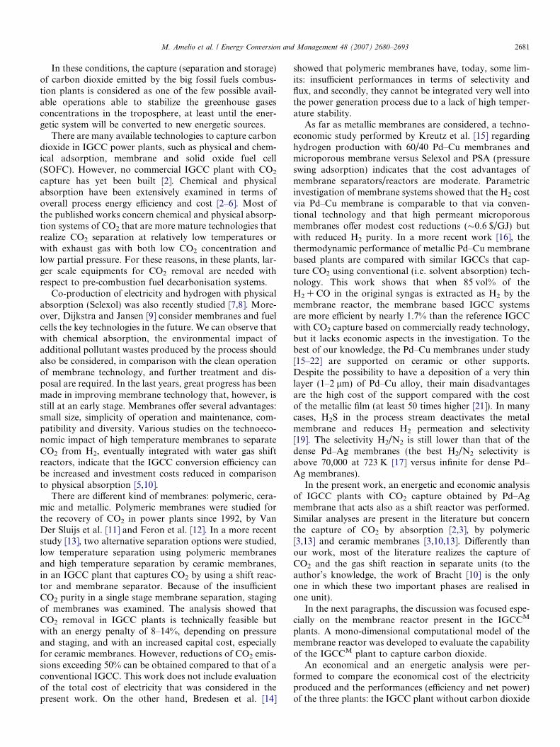
Fig. 1 shows a sketch of an IGCC* plant characterizedby traditional water gas shift reactors and a CO2 physicaladsorption system followed by the power section [23].
The syngas is produced at high temperature in a dragflow gasificator that is fed with oxygen and a water/carbonslurry (Texaco technology). This syngas is subjected to athermal recovery process, and high pressure steam isproduced.
The oxygen used in the gasificator feed is obtained in anair separation unit (ASU). The syngas, mainly composed ofcarbon oxide, hydrogen and water, after the thermal recov-ery, is mixed with a specific amount of steam and fed to thecatalytic reactors where CO is converted into CO2, produc-ing more hydrogen. The carbon dioxide is then separated
ditional IGCC plant.
M. Amelio et al. / Energy Conversion and Management 48 (2007) 2680–2693 2683
from the other gases by physical adsorption. At the end ofthis process, the syngas mainly contains hydrogen, and it isused as fuel in the turbogas plant. In this case, the turbinecan be operated as a natural gas machine instead of a syn-thetic gas machine.
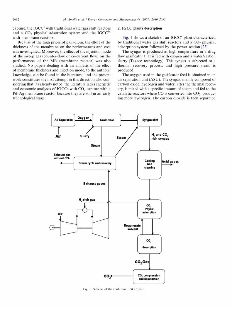
Fig. 2 shows a scheme of an IGCCM plant where thecoal thermal input is the same as above, but the tradi-tional shift reactors and the physical adsorption unitare replaced by catalytic palladium membrane reactors(CMR). It should be observed that the second scheme(with MR) is simplified with respect to the first one (withtraditional reactors). In fact, in the second plant, theCO2 physical adsorption unit as well as the solventrecovery by CO2 flash desorption unit are not necessary.This simplification corresponds to both economical and
Fig. 2. Scheme of the IGCC pla
technological advantages of the IGCCM plant withrespect to the traditional one. Moreover, the reactor sys-tem is much more compact and efficient using a MRinstead of the traditional reactor (TR) for carrying outthe WGS reaction.
The only two disadvantages of the IGCCM plant thatcan be highlighted are: (a) the compression unit has to bebigger than the one used in the traditional system becausea higher amount of CO2 has to be compressed and lique-fied; (b) the thermal recovery in the IGCCM plant needsheat exchangers. In fact, in order to reach the reaction tem-perature in the MR feed stream, additional heat exchangershave to be used in the IGCCM. However, part of the heatshould be recovered by means of an optimisation in theheat exchangers design.
nt with membrane reactor.
2684 M. Amelio et al. / Energy Conversion and Management 48 (2007) 2680–2693
It should be stressed that the second disadvantage ismainly due to the fact that the MR has been inserted ina scheme already optimised to be used with a TR. Startingfrom the positive results obtained in this work, the nextstep should be optimisation (energetic and exergetic) ofthe whole system when a MR is used.
3. Process characteristics of IGCC plants
One of the most important reactions that occur in IGCCplants is the water shift reaction:
H2Oþ CO ¼ CO2 þH2 DH ¼ �40:6 kJ=mol ð1ÞIn the IGCC* plant, the reaction was performed in two
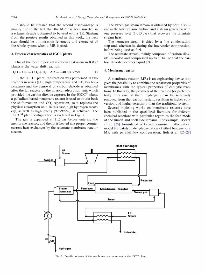
reactors in series (HT, high temperature and LT, low tem-perature) and the removal of carbon dioxide is obtainedafter the LT reactor by the physical adsorption unit, whichprovided the carbon dioxide capture. In the IGCCM plant,a palladium based membrane reactor is used to obtain boththe shift reaction and CO2 separation, so it replaces thephysical adsorption unit. In this case, high hydrogen recov-ery, as well as high purity (99.9999%), is achieved. TheIGCCM plant configuration is sketched in Fig. 3.
The gas is expanded at 11.5 bar before entering themembrane reactor, and then it is heated in a proper countercurrent heat exchanger by the retentate membrane reactorstream.
Fig. 3. Detailed scheme of the membran
The sweep gas steam stream is obtained by both a spill-age in the low pressure turbine and a steam generator withone pressure level (1.013 bar) that recovers the retentatestream heat.
The permeate stream is dried by a first condensationstep and, afterwards, during the intercooler compression,before being used as fuel.
The retentate stream, mainly composed of carbon diox-ide, is cooled and compressed up to 80 bar so that the car-bon dioxide becomes liquid [24].
4. Membrane reactor
A membrane reactor (MR) is an engineering device thatgives the possibility to combine the separation properties ofmembranes with the typical properties of catalytic reac-tions. In this way, the products of the reaction (or preferen-tially only one of them: hydrogen) can be selectivelyremoved from the reaction system, resulting in higher con-version and higher selectivity than the traditional system.
Several modeling works on membrane reactors havebeen published in the specialized literature for differentchemical reactions with particular regard to the feed modeof the lumen and shell side streams. For example, Beckeret al. [25] formulated a two-dimensional mathematicalmodel for catalytic dehydrogenation of ethyl benzene in aMR with parallel flow configuration. Itoh et al. [26–28]
e reactor system in the IGCC plant.
Retentate OUT Feed
Sweep gas Permeate OUT
Retentate OUT Feed
Sweep gas Permeate OUT
Fig. 4. Scheme of the membrane reactor MR: (a) co-current mode; (b) counter current mode.
M. Amelio et al. / Energy Conversion and Management 48 (2007) 2680–2693 2685
simulated the dehydrogenation of cyclohexane in a Pd-MRfor both parallel flow and counter flow reactor configura-tions. Mohan and Govind [29] studied the dehydrogena-tion of cyclohexane in a co-current flow arrangement.Casanave et al. [30] studied the dehydrogenation of isobu-tane in a packed bed zeolite MR in both counter currentand co-current modes. Gallucci et al. simulated methanolsteam reforming [31] and methane steam reforming [32]in a tubular membrane reactor.
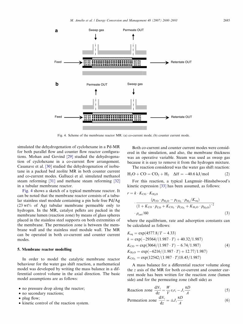
Fig. 4 shows a sketch of a typical membrane reactor. Itcan be noted that the membrane reactor consists of a tubu-lar stainless steel module containing a pin hole free Pd/Ag(23 wt% of Ag) tubular membrane permeable only tohydrogen. In the MR, catalyst pellets are packed in themembrane lumen (reaction zone) by means of glass spheresplaced in the stainless steel supports on both extremities ofthe membrane. The permeation zone is between the mem-brane wall and the stainless steel module wall. The MRcan be operated in both co-current and counter currentmodes.
5. Membrane reactor modelling
In order to model the catalytic membrane reactorbehaviour for the water gas shift reaction, a mathematicalmodel was developed by writing the mass balance in a dif-ferential control volume in the axial direction. The basicmodel assumptions are as follows:
• no pressure drop along the reactor;• no secondary reactions;• plug flow;• kinetic control of the reaction system.
Both co-current and counter current modes were consid-ered in the simulation, and also, the membrane thicknesswas an operative variable. Steam was used as sweep gasbecause it is easy to remove it from the hydrogen mixture.
The reaction considered was the water gas shift reaction:
H2Oþ CO ¼ CO2 þH2 DH ¼ �40:6 kJ=mol ð2ÞFor this reaction, a typical Langmuir–Hinshelwood’s
kinetic expression [33] has been assumed, as follows:
r ¼ k � KCO � KH2O
�ðpCO � pH2O � pCO2
� pH2=KeqÞ
ð1þ KCO � pCO þ KCO2� pCO2
þ KH2O � pH2OÞ�2
� qcat=60 ð3Þ
where the equilibrium, rate and adsorption constants canbe calculated as follows:
Keq ¼ expð4577:8=T � 4:33Þk ¼ expð�29364=ð1:987 � T Þ þ 40:32=1:987ÞKCO ¼ expð3064=ð1:987 � T Þ � 6:74=1:987Þ ð4ÞKH2O ¼ expð�6216=ð1:987 � T Þ þ 12:77=1:987ÞKCO2
¼ expð12542=ð1:987 � T Þ18:45=1:987Þ
A mass balance for a differential reactor volume alongthe z axis of the MR for both co-current and counter cur-rent mode has been written for the reaction zone (lumenside) and for the permeating zone (shell side) as
Reaction zonedN i
dz¼ W
Vviri � J i
pDA
ð5Þ
Permeation zonedNi
dz¼ �J i
pDA
ð6Þ
Start
Get the boundaries conditions.(Inlet flow rates)
Solve the Co-current mode
Guess the permeate hydrogen flow rate
Solve the Counter-current mode
Inlet hydrogen flow rate in the shell < 10-8 mol/s
Store Results
Store Results
YES
NO
Fig. 5. Flow chart of the solution procedure.
2686 M. Amelio et al. / Energy Conversion and Management 48 (2007) 2680–2693
where, in the second member: ‘‘+’’ is used for the co-cur-rent mode and ‘‘�’’ is used for the counter current mode.
For a dense palladium based membrane, the fluxthrough the membrane is only the hydrogen flux due tothe infinite perm-selectivity of H2/(other gases). In particu-lar, the hydrogen flux through the membrane follows theRichardson equation:
J H2¼ A0e
�EaRT
ffiffiffiffiffiffiffiffiffiffiffiplumen
H2
q�
ffiffiffiffiffiffiffiffiffipshell
H2
q� �ð7Þ
where Ea = 29.16 kJ/mol and A0 = 7.06 · 10�4 mol/(m2 s Pa0.5).
Thus, the hydrogen flux increases with temperature andwith increasing difference in the hydrogen partial pressuresquare roots in the lumen side and in the shell side.
The problem can be solved by assuming the boundaryconditions (z = 0).
5.1. Reaction zone (lumen side)
N 01 CO flow rate at the inlet side of the lumen
N02 ¼ mN 0
1 H2O flow rate at the inlet side of the lumen (*)
N03 CO2 flow rate at the inlet side of the lumen
N04 H2 flow rate at the inlet side of the lumen
N05 Ar flow rate at the inlet side of the lumen
N06 CH4 flow rate at the inlet side of the lumen
N07 N2 flow rate at the inlet side of the lumen
where m is the H2O/CO molar feed flow rate ratio.
5.2. Permeation zone (shell side)
N 08 ¼ N 0
Sweep gas Sweep gas flow rate at the inlet side of theshell
N09 H2 flow rate at the inlet side of the shell in co-cur-
rent modeN0
9 for the counter current mode is determined withthe shooting method.
The mass balance equation in the permeate side changesdepending on the sweep mode (co-current or counter cur-rent) adopted.
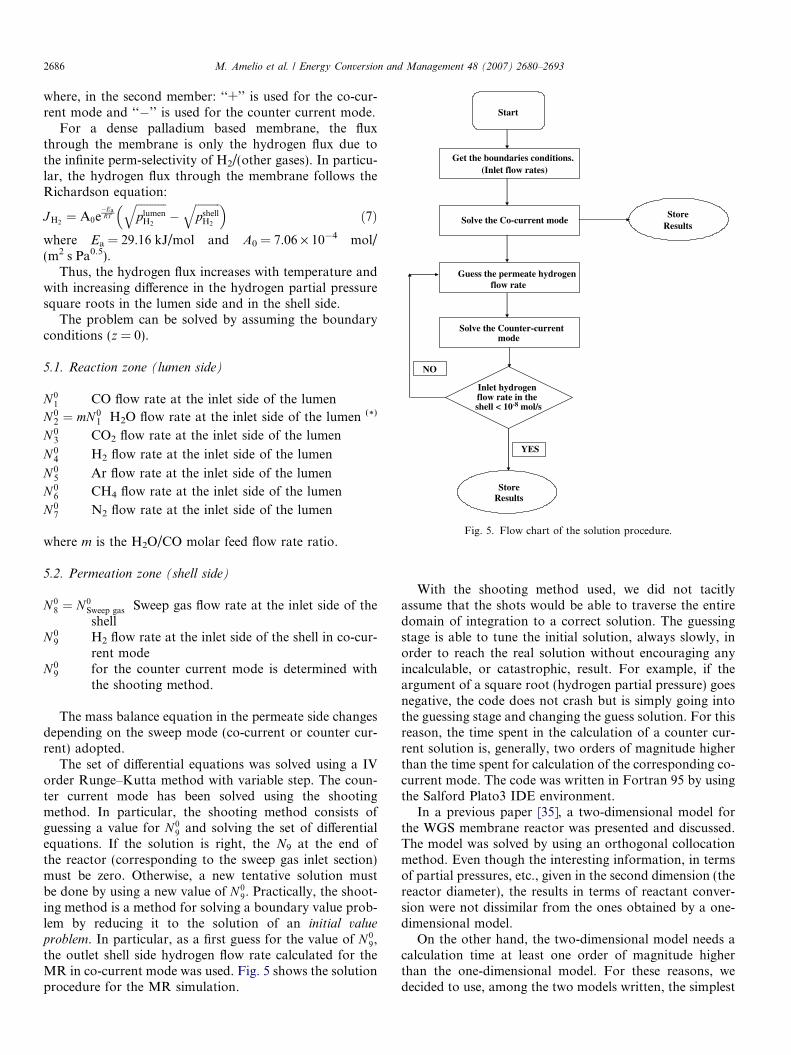
The set of differential equations was solved using a IVorder Runge–Kutta method with variable step. The coun-ter current mode has been solved using the shootingmethod. In particular, the shooting method consists ofguessing a value for N 0
9 and solving the set of differentialequations. If the solution is right, the N9 at the end ofthe reactor (corresponding to the sweep gas inlet section)must be zero. Otherwise, a new tentative solution mustbe done by using a new value of N 0
9. Practically, the shoot-ing method is a method for solving a boundary value prob-lem by reducing it to the solution of an initial value
problem. In particular, as a first guess for the value of N 09,
the outlet shell side hydrogen flow rate calculated for theMR in co-current mode was used. Fig. 5 shows the solutionprocedure for the MR simulation.
With the shooting method used, we did not tacitlyassume that the shots would be able to traverse the entiredomain of integration to a correct solution. The guessingstage is able to tune the initial solution, always slowly, inorder to reach the real solution without encouraging anyincalculable, or catastrophic, result. For example, if theargument of a square root (hydrogen partial pressure) goesnegative, the code does not crash but is simply going intothe guessing stage and changing the guess solution. For thisreason, the time spent in the calculation of a counter cur-rent solution is, generally, two orders of magnitude higherthan the time spent for calculation of the corresponding co-current mode. The code was written in Fortran 95 by usingthe Salford Plato3 IDE environment.
In a previous paper [35], a two-dimensional model forthe WGS membrane reactor was presented and discussed.The model was solved by using an orthogonal collocationmethod. Even though the interesting information, in termsof partial pressures, etc., given in the second dimension (thereactor diameter), the results in terms of reactant conver-sion were not dissimilar from the ones obtained by a one-dimensional model.
On the other hand, the two-dimensional model needs acalculation time at least one order of magnitude higherthan the one-dimensional model. For these reasons, wedecided to use, among the two models written, the simplest
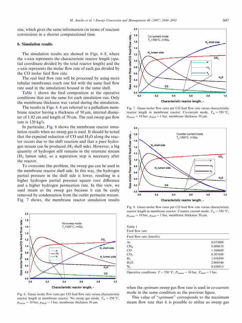
Fig. 7. Gases molar flow rates per CO feed flow rate versus characteristicreactor length in membrane reactor. Co-current mode, Tin = 350 �C,plumen = 10 bar, pshell = 1 bar, membrane thickness 50 lm.
M. Amelio et al. / Energy Conversion and Management 48 (2007) 2680–2693 2687
one, which gives the same information (in terms of reactantconversion) in a shorter computational time.
6. Simulation results
The simulation results are showed in Figs. 6–8, wherethe x-axis represents the characteristic reactor length (spa-tial coordinate divided by the total reactor length) and they-axis represents the molar flow rate of each gas divided bythe CO molar feed flow rate.
The real feed flow rate will be processed by using moretubular membranes (each one fed with the same feed flowrate used in the simulation) housed in the same shell.
Table 1 shows the feed composition at the operativeconditions that are the same for each simulation run. Onlythe membrane thickness was varied during the simulation.
The results in Figs. 6–8 are referred to a palladium mem-brane reactor having a thickness of 50 lm, internal diame-ter of 1.02 cm and length of 70 cm. The real sweep gas flowrate is 120 kg/s.
In particular, Fig. 6 shows the membrane reactor simu-lation results when no sweep gas is used. It should be notedthat the expected reduction of CO and H2O along the reac-tor occurs due to the shift reaction and that a pure hydro-gen stream can be produced (H2 shell side). However, a bigquantity of hydrogen still remains in the retentate stream(H2 lumen side), so a separation step is necessary afterthe reactor.
To overcome this problem, the sweep gas can be used inthe membrane reactor shell side. In this way, the hydrogenpartial pressure in the shell side is lower, resulting in ahigher hydrogen partial pressure square root differenceand a higher hydrogen permeation rate. In this view, weused steam as the sweep gas because it can be easilyremoved by condensation from the outlet permeate stream.Fig. 7 shows, the membrane reactor simulation results
Fig. 6. Gases molar flow rates per CO feed flow rate versus characteristicreactor length in membrane reactor. No sweep gas mode, Tin = 350 �C,plumen = 10 bar, pshell = 1 bar, membrane thickness 50 lm.
Fig. 8. Gases molar flow rates per CO feed flow rate versus characteristicreactor length in membrane reactor. Counter current mode, Tin = 350 �C,plumen = 10 bar, pshell = 1 bar, membrane thickness 50 lm.
Table 1Feed flow rate
Feed flow rate (kmol/s)
Ar 0.033000CH4 0.000670CO 1.560600CO2 0.307698H2 1.058509H2O 2.064344N2 0.026815
Operative conditions: T = 350 �C; Plumen = 10 bar, Pshell = 1 bar.
when the optimum sweep gas flow rate is used in co-currentmode in the same condition as the previous figure.
This value of ‘‘optimum’’ corresponds to the maximumsteam flow rate that it is possible to utilize as sweep gas
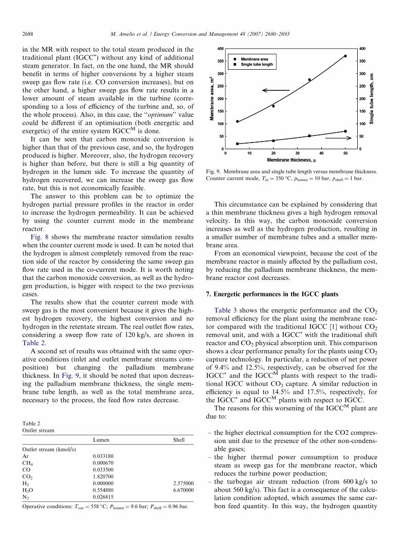
Fig. 9. Membrane area and single tube length versus membrane thickness.Counter current mode, Tin = 350 �C, plumen = 10 bar, pshell = 1 bar.
2688 M. Amelio et al. / Energy Conversion and Management 48 (2007) 2680–2693
in the MR with respect to the total steam produced in thetraditional plant (IGCC*) without any kind of additionalsteam generator. In fact, on the one hand, the MR shouldbenefit in terms of higher conversions by a higher steamsweep gas flow rate (i.e. CO conversion increases), but onthe other hand, a higher sweep gas flow rate results in alower amount of steam available in the turbine (corre-sponding to a loss of efficiency of the turbine and, so, ofthe whole process). Also, in this case, the ‘‘optimum’’ valuecould be different if an optimisation (both energetic andexergetic) of the entire system IGCCM is done.
It can be seen that carbon monoxide conversion ishigher than that of the previous case, and so, the hydrogenproduced is higher. Moreover, also, the hydrogen recoveryis higher than before, but there is still a big quantity ofhydrogen in the lumen side. To increase the quantity ofhydrogen recovered, we can increase the sweep gas flowrate, but this is not economically feasible.
The answer to this problem can be to optimize thehydrogen partial pressure profiles in the reactor in orderto increase the hydrogen permeability. It can be achievedby using the counter current mode in the membranereactor.
Fig. 8 shows the membrane reactor simulation resultswhen the counter current mode is used. It can be noted thatthe hydrogen is almost completely removed from the reac-tion side of the reactor by considering the same sweep gasflow rate used in the co-current mode. It is worth notingthat the carbon monoxide conversion, as well as the hydro-gen production, is bigger with respect to the two previouscases.
The results show that the counter current mode withsweep gas is the most convenient because it gives the high-est hydrogen recovery, the highest conversion and nohydrogen in the retentate stream. The real outlet flow rates,considering a sweep flow rate of 120 kg/s, are shown inTable 2.
A second set of results was obtained with the same oper-ative conditions (inlet and outlet membrane streams com-position) but changing the palladium membranethickness. In Fig. 9, it should be noted that upon decreas-ing the palladium membrane thickness, the single mem-brane tube length, as well as the total membrane area,necessary to the process, the feed flow rates decrease.
Table 2Outlet stream
Lumen Shell
Outlet stream (kmol/s)Ar 0.033180CH4 0.000670CO 0.033500CO2 1.820700H2 0.000000 2.575000H2O 0.554880 6.670000N2 0.026815
Operative conditions: Tout = 558 �C; Plumen = 9.6 bar; Pshell = 0.96 bar.
This circumstance can be explained by considering thata thin membrane thickness gives a high hydrogen removalvelocity. In this way, the carbon monoxide conversionincreases as well as the hydrogen production, resulting ina smaller number of membrane tubes and a smaller mem-brane area.
From an economical viewpoint, because the cost of themembrane reactor is mainly affected by the palladium cost,by reducing the palladium membrane thickness, the mem-brane reactor cost decreases.
7. Energetic performances in the IGCC plants
Table 3 shows the energetic performance and the CO2
removal efficiency for the plant using the membrane reac-tor compared with the traditional IGCC [1] without CO2
removal unit, and with a IGCC* with the traditional shiftreactor and CO2 physical absorption unit. This comparisonshows a clear performance penalty for the plants using CO2
capture technology. In particular, a reduction of net powerof 9.4% and 12.5%, respectively, can be observed for theIGCC* and the IGCCM plants with respect to the tradi-tional IGCC without CO2 capture. A similar reduction inefficiency is equal to 14.5% and 17.5%, respectively, forthe IGCC* and IGCCM plants with respect to IGCC.
The reasons for this worsening of the IGCCM plant aredue to:
– the higher electrical consumption for the CO2 compres-sion unit due to the presence of the other non-condens-able gases;
– the higher thermal power consumption to producesteam as sweep gas for the membrane reactor, whichreduces the turbine power production;
– the turbogas air stream reduction (from 600 kg/s toabout 560 kg/s). This fact is a consequence of the calcu-lation condition adopted, which assumes the same car-bon feed quantity. In this way, the hydrogen quantity
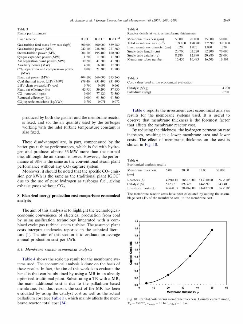
Table 3Plants performances
Plant scheme IGCC IGCC* IGCCM
Gas-turbine feed mass flow rate (kg/s) 600.000 600.000 559.780Gas-turbine power (MW) 242.100 238.300 271.860Steam-turbine power (MW) 204.700 195.400 160.600Syngas expander power (MW) 11.200 11.200 11.500Air separation plant power (MW) 39.200 41.500 41.500Auxiliary power (MW) 14.700 16.100 17.500CO2 separation and compression power
(MW)0.000 21.300 31.700
Plant net power (MW) 404.100 366.000 353.260Coal thermal input, LHV (MW) 879.40 931.400 931.400LHV clean syngas/LHV coal 0.760 0.693 0.663Plant net efficiency (%) 45.950 39.290 37.930CO2 removed (kg/s) 0.000 77.120 73.300Removal efficiency (%) 0.000 91.500 91.500CO2 specific emissions (kg/kWh) 0.709 0.071 0.072
Table 4Reactor details at various membrane thicknesses
Membrane thickness (lm) 5.000 20.000 35.000 50.000Total membrane area (m2) 109.100 170.200 275.910 370.000Inner membrane diameter (cm) 1.020 1.020 1.020 1.020Single tube length (cm) 20.700 32.220 52.200 70.000Single tube catalyst (g) 8.280 12.890 20.880 28.000Membrane tubes number 16,456 16,493 16,503 16,503
Table 5Cost values used in the economical evaluation
Catalyst ($/kg) 4.200Palladium ($/kg) 6700
Table 6Economical analysis results
Membrane thickness(lm)
5.00 20.00 35.00 50.000
Reactors ($) 45918.10 286170.00 813030.00 1.56 · 106
Catalyst ($) 572.27 892.69 1446.92 1943.40Investment costs ($) 46490.37 287062.00 814477.00 1.56 · 106
The membrane reactor costs have been calculated by adding the assem-blage cost (4% of the membrane cost) to the membrane cost.
Fig. 10. Capital costs versus membrane thickness. Counter current mode,Tin = 350 �C, plumen = 10 bar, pshell = 1 bar.
M. Amelio et al. / Energy Conversion and Management 48 (2007) 2680–2693 2689
produced by both the gasifier and the membrane reactoris fixed, and so, the air quantity used by the turbogasworking with the inlet turbine temperature constant isalso fixed.
These disadvantages are, in part, compensated by thebetter gas turbine performances, which is fed with hydro-gen and produces almost 33 MW more than the normalone, although the air stream is lower. However, the perfor-mance of 38% is the same as the conventional steam plantperformance without any CO2 capture system.
Moreover, it should be noted that the specific CO2 emis-sion per kWh is the same as the traditional plant IGCC*
due to the use of pure hydrogen as turbogas fuel, givingexhaust gases without CO2.
8. Electrical energy production cost comparison: economical
analysis
The aim of this analysis is to highlight the technological-economic convenience of electrical production from coalby using gasification technology integrated with a com-bined cycle: gas turbine, steam turbine. The assumed plantcosts interpret tendencies reported in the technical litera-ture [1]. The aim of this section is to evaluate an averageannual production cost per kWh.
8.1. Membrane reactor economical analysis
Table 4 shows the scale up result for the membrane sys-tems used. The economical analysis is done on the basis ofthese results. In fact, the aim of this work is to evaluate thebenefits that can be obtained by using a MR in an alreadyoptimised traditional plant. Substituting a TR with a MR,the main additional cost is due to the palladium basedmembrane. For this reason, the cost of the MR has beenevaluated by using the catalyst cost as well as the actualpalladium cost (see Table 5), which mainly affects the mem-brane reactor total cost [34].
Table 6 reports the investment cost economical analysisresults for the membrane systems used. It is useful toobserve that membrane thickness is the foremost factorthat affects the membrane reactor cost.
By reducing the thickness, the hydrogen permeation rateincreases, resulting in a lower membrane area and lowercosts. The effect of membrane thickness on the cost isshown in Fig. 10.
Table 7Investment costs for the main components
Component IGCC IGCC* IGCCMðAÞ IGCCM
ðBÞ IGCCMðCÞ IGCCM
ðDÞ
Gas-turbine (M$) 53.30 53.30 59.10 59.10 59.10 59.10Steam cycle (M$) 75.10 72.90 63.90 63.90 63.90 63.90Electrical dev. and balance-of-plant power section (M$) 44.80 43.90 43.80 43.80 43.80 43.80Air separation plant (M$) 39.60 41.20 41.20 41.20 41.20 41.20Coal treatment (M$) 19.30 20.10 20.10 20.10 20.10 20.10Gasification and syngas cooling (M$) 162.70 169.00 169.00 169.00 169.00 169.00Syngas cleaning unit (M$) 17.60 18.30 18.30 18.30 18.30 18.30Shift reactors and exchangers (M$) 19.10CO2 removal unit (Selexol) (M$) 19.80Membrane reactors (M$) 0.046 0.29 0.81 1.56CO2 compression (M$) 8.50 15.62 15.62 15.62 15.62Total plant components (M$) 412.50 466.00 431.00 431.30 431.08 432.60Auxiliary components (M$) 12% of components costsEngineering cost (M$) 18% of components costsEventualities (M$) 20% of components costsTotal investment costs (M$) 618.70 699.00 646.50 646.95 647.07 648.90Specific investment costs ($/kW) 1531.00 1910.00 1830.03 1831.34 1833.46 1836.86
IGCC, traditional integrated gasification gas combined cycle plant; IGCC*, integrated gasification gas combined cycle plant with traditional shift reactors;IGCCM(A), integrated gasification gas combined cycle plant with membrane reactor (membrane thickness 5 lm); IGCCM(B), integrated gasification gascombined cycle plant with membrane reactor (membrane thickness 20 lm); IGCCM(C), integrated gasification gas combined cycle plant with membranereactor (membrane thickness 35 lm); IGCCM(D), integrated gasification gas combined cycle plant with membrane reactor (membrane thickness 50 lm).
2690 M. Amelio et al. / Energy Conversion and Management 48 (2007) 2680–2693
8.2. Investment cost evaluation for the whole plant
Table 7 reports the assumptions made and the prelimin-ary economical analysis results to compare the membranebased plant with the traditional ones (IGCC and IGCC*).Moreover, it is useful to evaluate the incidence of the mem-brane reactor on the kWh cost.
As already stated above, the aim of this work is to eval-uate the incidence of the use of a MR in the previouslyoptimized traditional plant. For this reason, the economi-cal analysis considers the additional cost of the MR andthe changes in the cost of the auxiliary units, which arechanging due to the variations in the flow rates considered.The main costs changing are the costs of the gas turbineand the steam cycle, as well as the cost of the CO2 separa-tion and compression.
If a traditional gasification plant without CO2 captureunit is used as like standard, the economical analysis showsthe superiority of the IGCCM plants with respect to theIGCC* one. This is due to the lower cost of the membranereactor with respect to the cost of the traditional shift reac-tor and to the absence of the CO2 physical adsorption cap-ture unit in the IGCCM plant. Another advantageousaspect of IGCCM technology is the high compatibility withthe already existent gas turbine.
Therefore, the prevision of the investment cost for theIGCC plant is 699 M$ for the plant with traditional shiftreactors and 648.9 M$ for the membrane reactor one(membrane thickness 50 lm). This means a unit cost of1910 and 1836.86 (average value) $/kW, respectively.
Kaldis et al. [13] made an energetic and economic anal-ysis of an IGCC of the same size with respect to our plant(440.3 MW) but with capture of CO2 obtained by poly-meric and ceramic membranes. The plant analysed showed
a power increment of 20.6% for the polymeric membraneand 20.2% for the ceramic membrane. The correspondingdecrements in efficiency are 23.3% and 24.6% for the poly-meric and ceramic membranes, respectively. Our plantexhibits less increment of power (12.5%) and less decrementin efficiency (17.7%). Also, investment costs results arelower with the Pd–Ag membrane reactor. One reason isthat in the work of Kaldis et al. [13], the shift reactionand CO2 separation are realised in two different units.Moreover, this work lacks the evaluation of the total costof electricity.
A further comparison with a recent work of Ordorica-Garcia et al. [2] can be done. The authors presented anenergetic and economic analysis of an IGCC plant withtraditional absorption systems for the capture of CO2.The power penalization is 16%, but we have to observethat this plant reaches 80% CO2 capture, while our plantobtains a 91.5% CO2 capture. Moreover, investment costsare higher with respect to our plant, also due to the factthat the water shift reaction is realised in another unit.However, IGCC plants with CO2 and H2S co-capturehave substantial technoeconomic advantages over IGCCplants that capture CO2 and H2S separately (its poweroutput is only 4% lower than the IGCC without capture,while the other plant has a penalization of 37%). Thepresent work includes evaluation of the cost of the elec-tricity produced, which will be discussed in the nextsection.
8.3. Cost of the electricity production
The cost of electricity production (COE) ($/MWh) ismainly affected by fuel costs and capital costs and was cal-culated with the following equation:
Carbon Tax, mill$/kgCO2
0 10 20 30 40
Ele
ctri
city
co
st,
$/M
Wh
40
50
60
70
80
43 4464.20
64.25
64.30
64.35
64.40
64.45
64.50
IGCCMD
IGCCMB
IGCCMA
IGCCMC
IGCC*
IGCC
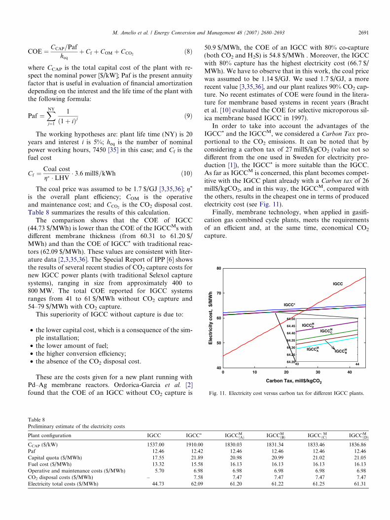
Fig. 11. Electricity cost versus carbon tax for different IGCC plants.
M. Amelio et al. / Energy Conversion and Management 48 (2007) 2680–2693 2691
COE ¼ CCAP=Paf
heq
þ Cf þ COM þ CCO2ð8Þ
where CCAP is the total capital cost of the plant with re-spect the nominal power [$/kW]; Paf is the present annuityfactor that is useful in evaluation of financial amortizationdepending on the interest and the life time of the plant withthe following formula:
Paf ¼XNY
j¼1
1
ð1þ iÞjð9Þ
The working hypotheses are: plant life time (NY) is 20years and interest i is 5%; heq is the number of nominalpower working hours, 7450 [35] in this case; and Cf is thefuel cost
Cf ¼Coal cost
g� � LHV� 3:6 mill$=kWh ð10Þ
The coal price was assumed to be 1.7 $/GJ [3,35,36]; g*
is the overall plant efficiency; COM is the operativeand maintenance cost; and CCO2
is the CO2 disposal cost.Table 8 summarizes the results of this calculation.
The comparison shows that the COE of IGCC(44.73 $/MWh) is lower than the COE of the IGCCMs withdifferent membrane thickness (from 60.31 to 61.20 $/MWh) and than the COE of IGCC* with traditional reac-tors (62.09 $/MWh). These values are consistent with liter-ature data [2,3,35,36]. The Special Report of IPP [6] showsthe results of several recent studies of CO2 capture costs fornew IGCC power plants (with traditional Selexol capturesystems), ranging in size from approximately 400 to800 MW. The total COE reported for IGCC systemsranges from 41 to 61 $/MWh without CO2 capture and54–79 $/MWh with CO2 capture.
This superiority of IGCC without capture is due to:
• the lower capital cost, which is a consequence of the sim-ple installation;
• the lower amount of fuel;• the higher conversion efficiency;• the absence of the CO2 disposal cost.
These are the costs given for a new plant running withPd–Ag membrane reactors. Ordorica-Garcia et al. [2]found that the COE of an IGCC without CO2 capture is
Table 8Preliminary estimate of the electricity costs
Plant configuration IGCC IGCC*
CCAP ($/kW) 1537.00 1910.00Paf 12.46 12.42Capital quota ($/MWh) 17.55 21.89Fuel cost ($/MWh) 13.32 15.58Operative and maintenance costs ($/MWh) 5.70 6.98CO2 disposal costs ($/MWh) – 7.58Electricity total costs ($/MWh) 44.73 62.09
50.9 $/MWh, the COE of an IGCC with 80% co-capture(both CO2 and H2S) is 54.8 $/MWh . Moreover, the IGCCwith 80% capture has the highest electricity cost (66.7 $/MWh). We have to observe that in this work, the coal pricewas assumed to be 1.14 $/GJ. We used 1.7 $/GJ, a morerecent value [3,35,36], and our plant realizes 90% CO2 cap-ture. No recent estimates of COE were found in the litera-ture for membrane based systems in recent years (Brachtet al. [10] evaluated the COE for selective microporous sil-ica membrane based IGCC in 1997).
In order to take into account the advantages of theIGCC* and the IGCCM, we considered a Carbon Tax pro-portional to the CO2 emissions. It can be noted that byconsidering a carbon tax of 27 mill$/kgCO2 (value not sodifferent from the one used in Sweden for electricity pro-duction [1]), the IGCC* is more suitable than the IGCC.As far as IGCCM is concerned, this plant becomes compet-itive with the IGCC plant already with a Carbon tax of 26mill$/kgCO2, and in this way, the IGCCM, compared withthe others, results in the cheapest one in terms of producedelectricity cost (see Fig. 11).
Finally, membrane technology, when applied in gasifi-cation gas combined cycle plants, meets the requirementsof an efficient and, at the same time, economical CO2
capture.
IGCCMðAÞ IGCCM
ðBÞ IGCC MðCÞ IGCCM
ðDÞ
1830.03 1831.34 1833.46 1836.8612.46 12.46 12.46 12.4620.98 20.99 21.02 21.0516.13 16.13 16.13 16.136.98 6.98 6.98 6.987.47 7.47 7.47 7.47
61.20 61.22 61.25 61.31
2692 M. Amelio et al. / Energy Conversion and Management 48 (2007) 2680–2693
9. Conclusions
The present paper is concerned with the capture andstorage of CO2 with membrane technology in gasificationgas combined cycle plants that use fossil fuel (IGCCM)compared to the traditional process and separation meth-ods that use traditional water shift reactors and adsorptionsystems (IGCC*). After an analysis of the energetic perfor-mances of these plants, the results show a rather moderateperformance penalty of an IGCCM plant with respect toIGCC* (3.46% penalty in efficiency and 3.48% penalty innet power), fundamentally due to the higher electricalpower consumption for the CO2 compression and for theproduction of the steam used as the sweep gas for the mem-brane reactor. On the contrary, from an economical pointof view, the prevision of the investment and the cost of theelectricity production (COE) of the IGCCM plant is morecompetitive with respect to the IGCC* plant in the middleterm (investment cost and COE of IGCCM are, respec-tively, 4% and 1.4% lower) due to the low costs of mem-brane reactors and to the absence of the CO2 absorptionunit. The COE reported in the literature for IGCC systemswith CO2capture (traditional systems) ranges from 54 to79 $/MWh, while our value of COE is 61.20 $/MWh.Moreover, the membrane technology is evolving rapidly,and the results of this analysis would be far more appealingwith improving membrane performances. Therefore, thedecision to adopt such a system in IGCC plants shouldbe viewed from a middle to long term perspective, consid-ering also that membrane systems are simple, rugged anddo not require chemical reagents that can cause other pol-luting emissions, typical of the chemical adsorption unit.
Finally, all the calculations about the membrane reac-tors were performed simply by replacing the traditionalreactors and the sorption unit with the membrane reactors.This means that the optimal operative conditions for thetraditional reactors were used also for the membrane reac-tors. A new optimisation of the whole process will be stud-ied in a future work to better understand the effect of themembrane reactor on this system.
Acknowledgements
The authors thank Mrs. America Oliva for her help inimproving the English usage through the paper.
References
[1] Cumo M, Santi F, Simboletti G. Energia, cambiamenti climatici esequestro dell’anidride carbonica. La Termotecnica 2003:33–43.
[2] Ordorica-Garcia G, Douglas P, Croiset E, Zheng L. Technoeconomicevaluation of IGCC power plants for CO2 avoidance. Energ ConversManage 2006;47:2250–9.
[3] Damen K, Van Troost M, Faaij A, Turkenburg W. A comparison ofelectricity and hydrogen production systems with CO2 capture andstorage. part a: review and selection of promising conversion andcapture technologies. Prog Energ Combust Sci 2006;32:215–46.
[4] Pruschek R, Oeljeklaus G, Brand V, Haupt G, Zimmerman G,Ribberink JS. Combined cycle power plant with integrated coalgasification, CO shift and CO2 washing. Energ Convers Manage1995;36:797–800.
[5] Waku H, Tamura I, Inoue M, Akai M. Life cycle analysis of fossilpower plant with CO2 recovery and sequestring system. EnergConvers Manage 1995;36:877–80.
[6] Intergovernamental Panel on Climate Changes, Carbon capture andstorage, IPP special Report; 2005.
[7] Chiesa P, Consonni S, Kreutz T, Williams R. Co-production ofhydrogen, electricity and CO2 from coal with commercially readytechnology. Part a: performance and emissions. Int J Hydrogen Energ2005;30:747–67.
[8] Chiesa P, Consonni S, Kreutz T, Williams R. Co-production ofhydrogen, electricity and CO2 from coal with commercially readytechnology. Part b: economic analysis. Energ Convers Manage2006;47:2250–9.
[9] Djikstra JW, Jansen D. Novel concepts for CO2 capture. Energy2004;29:1249–57.
[10] Bracht M. Water gas shift membrane reactor for CO2 control inIGCC systems: techno-economic feasibility study. Energ ConversManage 1997;38:159–62.
[11] Van Der Sluijs J, Hendriks C, Blok K. Feasibility of polymermembranes for carbon dioxide recovery from flue gases. EnergConvers Manage 1992;33:429–36.
[12] Feron P, Jansen A, Klaassen R. Membrane technology in carbondioxide removal. Energ Convers Manage 1992;33:421.
[13] Kaldis SP, Skodras G, Sakellaropoulos GP. Energy and capital costanalysis of CO2 capture in coal IGCC processes via gas separationmembranes. Fuel Process Technol 2004;85:337–46.
[14] Bredesen R, Jordal K, Bolland O. High-temperature membranes inpower generation with CO2 capture. Chem Eng Process 2004;43:1129–58.
[15] Kreutz TG, Williams RH, Socolow RH, Chiesa P, Lozza G.Production of hydrogen and electricity from coal with CO2 capture.In: Gale J, Kaya Y, editors. Sixth international conference ongreenhouse gas control technologies, Kyoto, Japan. Amster-dam: Pergamon; 2003. p. 141–7.
[16] Chiesa P, Kreutz TG, Lozza GG. CO2 Sequestration from IGCCpower plants by means of metallic membranes. J Eng Gas TurbPower 2006;128:1.
[17] Nam SE, Lee KH. Hydrogen separation by Pd alloy compositemembranes: introduction of diffusion barrier. J Membrane Sci2001;192:177–85.
[18] Hoang HT, Tong HD, Gielens FC, Jansen HV, Elwenspoek MC.Fabrication and characterization of dual sputtered Pd–Cu alloy filmsfor hydrogen separation membranes. Mater Lett 2004;58:525–8.
[19] Kulprathipanja A, Alptekin GO, Falconer JL, Way JD. Pd and Pd–Cu membranes: inhibition of H2 permeation by H2S. J Membrane Sci2005;254:49–62.
[20] Howard BH, Killmeyer RP, Rothenberger KS, Cugini AV, MorrealeBD, Enick RM, et al. Hydrogen permeance of palladium–copperalloy membranes over a wide range of temperatures and pressures.J Membrane Sci 2004;241:207–18.
[21] Roa F, Way JD, McCormick RL, Paglieri SN. Preparation andcharacterization of Pd–Cu composite membranes for hydrogenseparation. Chem Eng J 2003;93:11–22.
[22] Roa F, Way JD. The effect of air exposure on palladium–coppercomposite membranes. Appl Surf Sci 2005;240:85–104.
[23] Chiesa P, Consonni S, Lozza G. Confronto tra i diversi metodi diriduzione delle emissioni di CO2 negli impianti IGCC. La termotec-nica; 1999.
[24] Chiesa P, Lozza G. CO2 Emission abatement in IGCC power plantsby semi-closed cycles. Part a: with air-blown combustion and physicalabsorption. ASME paper 98-GT-385.
[25] Becker YL, Dixon AJ, Moser WR, Ma YH. Modeling of ethylbenzene dehydrogenation in a catalytic membrane reactor. J Mem-brane Sci 1993;77:233–44.

M. Amelio et al. / Energy Conversion and Management 48 (2007) 2680–2693 2693
[26] Itoh N. A membrane reactor using palladium. AIChE J 1987;33(9):1576–8.
[27] Itoh N, Shindo Y, Haraya K. Ideal flow models for palladiummembrane reactors. J Chem Eng Jpn 1990;23(4):420–6.
[28] Itoh N, Xu WC, Haraya K. Basic experimental study on palladiummembrane reactors. J Membrane Sci 1992;66(2-3):149–55.
[29] Mohan K, Govind R. Analysis of a co-current membrane reactor.AIChE J 1986;32(12):2083–6.
[30] Casanave D, Ciavarella P, Fiaty K, Dalmon JA. Zeolite membranereactor for isobutene dehydrogenation: experimental results andtheoretical modelling. Chem Eng Sci 1999;54:2807–15.
[31] Gallucci F, Paturzo L, Basile A. Hydrogen recovery from methanolsteam reforming in a dense membrane reactor: simulation study. IndEng Chem Res 2004;43:2420–32.
[32] Gallucci F, Paturzo L, Basile A. A simulation study of the steamreforming of methane in a dense tubular membrane reactor. Int JHydrogen Energ 2004;29:611–7.
[33] Podolski WF, Kim YG. Modeling water gas shift reaction. Ind EngChem Proc Des Dev 1974;13(4):414–21.
[34] Basile A, Paturzo L, Gallucci F. Co-current and counter current modesfor water gas shift membrane reactor. Catal Today 2003;82:275–81.
[35] Criscuoli A, Basile A, Drioli E, Loiacono O. An economic feasibilitystudy for water gas shift membrane reactor. J Membrane Sci2001;181:21–7.
[36] Domenichini RM, Mancuso L, Ripani S. Produzione di energiaelettrica ed effetto serra: alternative a confronto per la cattura dellaCO2 in impianti a carbone e a gas naturale. ANIMP-ATI, Energia daCarbone Pulito nella prospettiva del dopo Kyoto; 12 July 2006.


