Embed Size (px)
Citation preview
Copyright © 2018 ComAp s.r.o. Written by Zdeněk Liberda Prague, Czech Republic
ComAp, spol. s r.o. U Uranie 1612/14a, 180 00 Praha 7, Czech Republic Tel: +420 246 012 111, Fax: +420 246 316 647 E-mail: [email protected], www.comap-control.com
Operator Guide
Compact Controller for Stand-by and Parallel Operating Gen-sets
Inteli New Technology
Mains Supervision Controller
IM-NT-BTB, MCB, MGCB Operator Guide
IM-NT
January 2018
IM-NT-2.3 Operator Guide ©ComAp – January 2018 2 IM-NT-2.3 Operator Guide.pdf
Table of Contents
Controller System Description............................................................................................................. 3 Available Documentation ......................................................................................................................... 4
IM-NT General Manuals ...................................................................................................................... 4 IM-NT Application Manuals ................................................................................................................. 4 Inteli Troubleshooting Manuals ........................................................................................................... 4 Inteli NT PC Tools Manuals ................................................................................................................ 4 Inteli Communication Manuals ............................................................................................................ 5 Dangerous Voltage ............................................................................................................................. 6 Adjust Set Points ................................................................................................................................. 6 Adjust set points .................................................................................................................................. 6
BTB Operator Interface ........................................................................................................................... 8 BTB Pushbuttons and LEDs ............................................................................................................... 8 BTB Measurement Screens Description ........................................................................................... 13 BTB Mode and Function Description ................................................................................................ 15
MGCB Operator Interface ...................................................................................................................... 18 MGCB Pushbuttons and LEDs .......................................................................................................... 18 MGCB Measurement Screens Description ....................................................................................... 23
MCB Operator Interface ........................................................................................................................ 28 MCB Pushbuttons and LEDs ............................................................................................................ 28 MCB Measurement Screens Description .......................................................................................... 33 MCB/MGCB Mode and Function Description ................................................................................... 36
List of Abbreviations .............................................................................................................................. 40
IM-NT-2.3 Operator Guide ©ComAp – January 2018 3 IM-NT-2.3 Operator Guide.pdf
General Guidelines
This manual provides general information on how to operate the InteliMains NT controllers and it is intended for everybody who is concerned with operation and maintenance of the controller.
Controller System Description
IM-NT controller is comprehensive mains supervision controller for multiple generating sets operating in parallel to the Mains. The controller automatically connects the group of gen-sets to the Mains. A modular construction allow upgrades to different levels of complexity in order to provide the best solution for various customer applications. The key feature of the controller is its easy-to-use operation and installation. Predefined configurations for typical applications are available as well as user-defined configurations for special applications.
Default Applications For the IM-NT controller there are three default applications: BTB, MCB, MGCB.
BTB Bus-Tie Breaker application
MCB Mains Circuit Breaker and application
MGCB Master Generator Circuit Breaker application
BTB application - Controller is between two groups of gen-sets (buses) - Controls only Bust-tie Breaker (BTB) - Enables reverse synchronization of one group to another MCB application - Controller is between bus (group of gen-sets) and the Mains - Controls only one Mains Circuit Breaker (MCB) - Enables reverse synchronization of the gen-sets to the Mains MGCB application - Controller is between bus (group of gen-sets) and the Mains - Controls Mains Circuit Breaker (MCB) and MGCB (Master Generator Circuit Breaker) - Enables reverse synchronization of the gen-sets to the Mains (over MCB) - Enables forward synchronization of the gen-sets (over MGCB)
IM-NT-2.3 Operator Guide ©ComAp – January 2018 4 IM-NT-2.3 Operator Guide.pdf
Available Documentation
IM-NT General Manuals
IG/IS-NT Installation Guide.pdf
IG/IS-NT Application Guide.pdf
IM-NT Application Manuals
For each application the appropriate manual is available:
IM-NT-BTB Reference Guide.pdf
IM-NT-MCB-MGCB Reference Guide.pdf These manuals include these chapters:
• Functions
• Protections and Alarm management
• Controller operation states
• Inputs and Outputs
• Setpoints
• Controller configuration and monitoring
Inteli Troubleshooting Manuals
IGS-NT Troubleshooting Guide.pdf Includes description of possible troubles during configuration, adjustment and operation of the controller. Consists of two parts:
• List of troubles and their solution
• “How to” section with recommended procedures in some typical situations
Inteli NT PC Tools Manuals
InteliMonitor.pdf This manual describes InteliMonitor monitoring PC tool in the following chapters:
• Connection to the controller (Direct, Modem, Internet)
• InteliDDE Server
• Menus description
• Password and access code
GenConfig.pdf This manual describes GenConfig configuration PC tool in the following chapters:
• Connection to the controller (Direct, Modem, Internet)
• InteliDDE Server
• Menus description
• Controller Configuration Steps (Modules, I/O, Setpoints, Protections, History, User Sensors, Language Translator, PLC Functions, LBI, LAI, Power Formats)
IM-NT-2.3 Operator Guide ©ComAp – January 2018 5 IM-NT-2.3 Operator Guide.pdf
Inteli Communication Manuals
InteliCommunicationGuide.pdf This manual covers communication topics regarding all types of our controllers. It applies to communication between the controller and superior service or monitoring system but not to communication among the controllers or between the controller and it’s peripherals (extension modules, ECU). It is divided into the following chapters:
• Local connection
• Remote connection
• Modem connection
• Internet connection
• Active call, active SMS, active email
• Modbus connection
• I-LB, IG-IB communication units
• Modem recommendations
• Recommended converters
IM-NT-2.3 Operator Guide ©ComAp – January 2018 6 IM-NT-2.3 Operator Guide.pdf
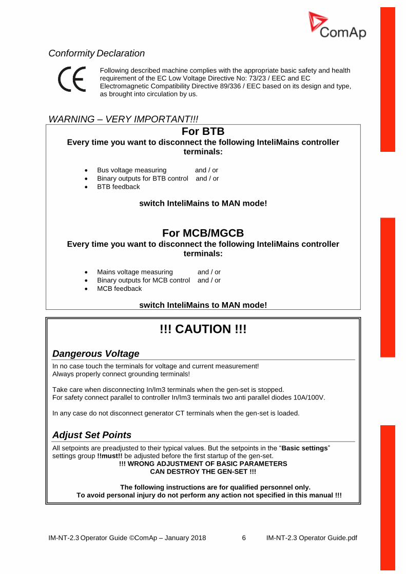
Conformity Declaration
Following described machine complies with the appropriate basic safety and health requirement of the EC Low Voltage Directive No: 73/23 / EEC and EC Electromagnetic Compatibility Directive 89/336 / EEC based on its design and type, as brought into circulation by us.
WARNING – VERY IMPORTANT!!!
For BTB Every time you want to disconnect the following InteliMains controller
terminals:
• Bus voltage measuring and / or
• Binary outputs for BTB control and / or
• BTB feedback
switch InteliMains to MAN mode!
For MCB/MGCB Every time you want to disconnect the following InteliMains controller
terminals:
• Mains voltage measuring and / or
• Binary outputs for MCB control and / or
• MCB feedback
switch InteliMains to MAN mode!
!!! CAUTION !!!
Dangerous Voltage
In no case touch the terminals for voltage and current measurement! Always properly connect grounding terminals! Take care when disconnecting In/Im3 terminals when the gen-set is stopped. For safety connect parallel to controller In/Im3 terminals two anti parallel diodes 10A/100V. In any case do not disconnect generator CT terminals when the gen-set is loaded.
Adjust Set Points
All setpoints are preadjusted to their typical values. But the setpoints in the “Basic settings” settings group !!must!! be adjusted before the first startup of the gen-set.
!!! WRONG ADJUSTMENT OF BASIC PARAMETERS CAN DESTROY THE GEN-SET !!!
The following instructions are for qualified personnel only.
To avoid personal injury do not perform any action not specified in this manual !!!
Adjust set points
All parameters are preadjusted to their typical values. But the set points in the “Basic settings” settings group !!must!! be adjusted before the first startup of the gen-set.
!!! WRONG ADJUSTMENT OF BASIC PARAMETERS CAN DESTROY THE GEN-SET !!!
The following instructions are for qualified personnel only.
IM-NT-2.3 Operator Guide ©ComAp – January 2018 7 IM-NT-2.3 Operator Guide.pdf
Note: ComAp believes that all information provided herein is correct and reliable and reserves the right to update at any time. ComAp does not assume any responsibility for its use unless otherwise expressly undertaken.
IM-NT-2.3 Operator Guide ©ComAp – January 2018 8 IM-NT-2.3 Operator Guide.pdf
BTB Operator Interface
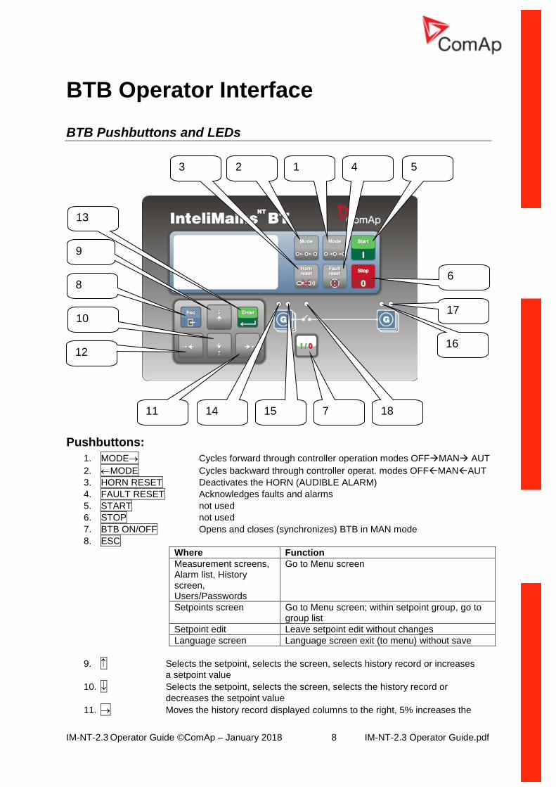
BTB Pushbuttons and LEDs
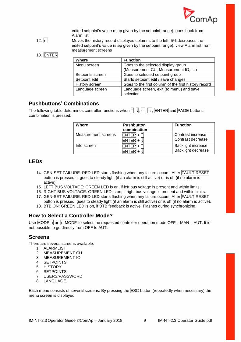
Pushbuttons:
1. MODE Cycles forward through controller operation modes OFFMAN AUT
2. MODE Cycles backward through controller operat. modes OFFMANAUT
3. HORN RESET Deactivates the HORN (AUDIBLE ALARM)
4. FAULT RESET Acknowledges faults and alarms
5. START not used
6. STOP not used
7. BTB ON/OFF Opens and closes (synchronizes) BTB in MAN mode
8. ESC
Where Function
Measurement screens, Alarm list, History screen, Users/Passwords
Go to Menu screen
Setpoints screen Go to Menu screen; within setpoint group, go to group list
Setpoint edit Leave setpoint edit without changes
Language screen Language screen exit (to menu) without save
9. Selects the setpoint, selects the screen, selects history record or increases
a setpoint value
10. Selects the setpoint, selects the screen, selects the history record or
decreases the setpoint value
11. Moves the history record displayed columns to the right, 5% increases the
9
10
8
12
11 14 7 15 18
13
16
3
6
5
17
1 4 2
IM-NT-2.3 Operator Guide ©ComAp – January 2018 9 IM-NT-2.3 Operator Guide.pdf
edited setpoint’s value (step given by the setpoint range), goes back from Alarm list
12. Moves the history record displayed columns to the left, 5% decreases the
edited setpoint’s value (step given by the setpoint range), view Alarm list from measurement screens
13. ENTER
Where Function
Menu screen Goes to the selected display group (Measurement CU, Measurement IO, …)
Setpoints screen Goes to selected setpoint group
Setpoint edit Starts setpoint edit / save changes
History screen Goes to the first column of the first history record
Language screen Language screen, exit (to menu) and save selection
Pushbuttons’ Combinations
The following table determines controller functions when , , , , ENTER and PAGE buttons’
combination is pressed:
Where Pushbutton combination
Function
Measurement screens ENTER +
ENTER +
Contrast increase Contrast decrease
Info screen ENTER +
ENTER +
Backlight increase Backlight decrease
LEDs
14. GEN-SET FAILURE: RED LED starts flashing when any failure occurs. After FAULT RESET
button is pressed, it goes to steady light (if an alarm is still active) or is off (if no alarm is active).
15. LEFT BUS VOLTAGE: GREEN LED is on, if left bus voltage is present and within limits. 16. RIGHT BUS VOLTAGE: GREEN LED is on, if right bus voltage is present and within limits.
17. GEN-SET FAILURE: RED LED starts flashing when any failure occurs. After FAULT RESET
button is pressed, goes to steady light (if an alarm is still active) or is off (if no alarm is active). 18. BTB ON: GREEN LED is on, if BTB feedback is active. Flashes during synchronizing.
How to Select a Controller Mode?
Use MODE or MODE to select the requested controller operation mode OFF – MAN – AUT. It is
not possible to go directly from OFF to AUT.
Screens There are several screens available:
1. ALARMLIST 2. MEASUREMENT CU 3. MEASUREMENT IO 4. SETPOINTS 5. HISTORY 6. SETPOINTS 7. USERS/PASSWORD 8. LANGUAGE.
Each menu consists of several screens. By pressing the ESC button (repeatedly when necessary) the
menu screen is displayed.
IM-NT-2.3 Operator Guide ©ComAp – January 2018 10 IM-NT-2.3 Operator Guide.pdf
How to View the Alarm List? 1. Select the ALARMLIST menu item.
2. Press ENTER or press in measurements’ screens to go directly to the Alarm list.
How to View Measured Data?
1. Select the MEASUREMENT CU menu item and press ENTER.
2. Use and to select the screen with requested data.
How to View IO Values?
1. Select the MEASUREMENT IO menu item and press ENTER.
2. Use and to select the screen with requested data.
How to View the History Menu?
1. Select HISTORY menu item and press ENTER.
2. Use or to select a requested record.
3. Use or to cycle forward/backward through columns of the record.
How to View and Edit Setpoints?
1. Select SETPOINTS menu item and press ENTER.
2. Use or to select requested setpoints group.
3. Press ENTER to confirm.
4. Use or to select requested setpoint.
5. Setpoints marked are password protected.
6. Press ENTER to edit.
7. Use or to modify the setpoint. When or is pressed for 2 sec, auto repeat function and
speedup is activated. Use or to change the setpoint value by 5% of it’s range.
8. Press ENTER to confirm or ESC to leave without change.
9. Press ESC to leave selected setpoints group.
How to Change the Password?
1. Select USERS/PASSWORD menu item and press ENTER.
2. Use or to select User.
3. Press ENTER to confirm.
4. Select ChangePassword and press ENTER.
5. Use or or or to set new password.
6. Press ENTER to confirm password.
How to Set the Language?
1. Select the LANGUAGE menu item (if not already selected) and press ENTER.
2. Use or to select a requested Language.
3. Press ENTER to confirm.
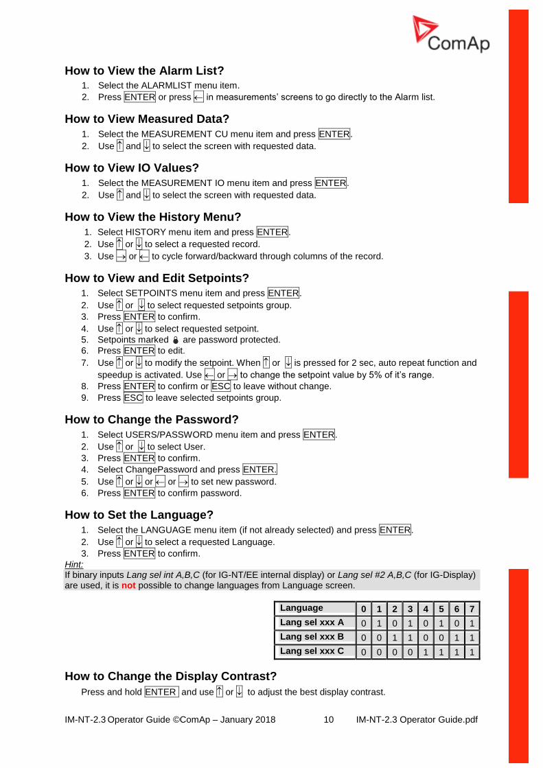
Hint: If binary inputs Lang sel int A,B,C (for IG-NT/EE internal display) or Lang sel #2 A,B,C (for IG-Display) are used, it is not possible to change languages from Language screen.
Language 0 1 2 3 4 5 6 7
Lang sel xxx A 0 1 0 1 0 1 0 1
Lang sel xxx B 0 0 1 1 0 0 1 1
Lang sel xxx C 0 0 0 0 1 1 1 1
How to Change the Display Contrast?
Press and hold ENTER and use or to adjust the best display contrast.
IM-NT-2.3 Operator Guide ©ComAp – January 2018 11 IM-NT-2.3 Operator Guide.pdf
Hint: Available from the MEASUREMENT screens only.
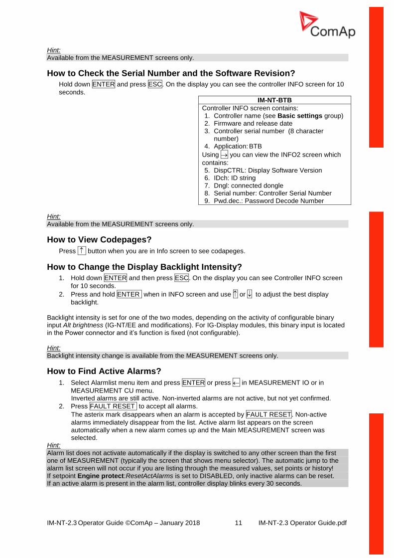
How to Check the Serial Number and the Software Revision?
Hold down ENTER and press ESC. On the display you can see the controller INFO screen for 10
seconds.
IM-NT-BTB
Controller INFO screen contains: 1. Controller name (see Basic settings group) 2. Firmware and release date 3. Controller serial number (8 character
number) 4. Application: BTB
Using you can view the INFO2 screen which
contains: 5. DispCTRL: Display Software Version 6. IDch: ID string 7. Dngl: connected dongle 8. Serial number: Controller Serial Number 9. Pwd.dec.: Password Decode Number
Hint: Available from the MEASUREMENT screens only.
How to View Codepages?
Press button when you are in Info screen to see codapeges.
How to Change the Display Backlight Intensity?
1. Hold down ENTER and then press ESC. On the display you can see Controller INFO screen
for 10 seconds.
2. Press and hold ENTER when in INFO screen and use or to adjust the best display
backlight.
Backlight intensity is set for one of the two modes, depending on the activity of configurable binary input Alt brightness (IG-NT/EE and modifications). For IG-Display modules, this binary input is located in the Power connector and it’s function is fixed (not configurable). Hint: Backlight intensity change is available from the MEASUREMENT screens only.
How to Find Active Alarms?
1. Select Alarmlist menu item and press ENTER or press in MEASUREMENT IO or in
MEASUREMENT CU menu. Inverted alarms are still active. Non-inverted alarms are not active, but not yet confirmed.
2. Press FAULT RESET to accept all alarms.
The asterix mark disappears when an alarm is accepted by FAULT RESET. Non-active
alarms immediately disappear from the list. Active alarm list appears on the screen automatically when a new alarm comes up and the Main MEASUREMENT screen was selected.
Hint: Alarm list does not activate automatically if the display is switched to any other screen than the first one of MEASUREMENT (typically the screen that shows menu selector). The automatic jump to the alarm list screen will not occur if you are listing through the measured values, set points or history! If setpoint Engine protect:ResetActAlarms is set to DISABLED, only inactive alarms can be reset. If an active alarm is present in the alarm list, controller display blinks every 30 seconds.
IM-NT-2.3 Operator Guide ©ComAp – January 2018 12 IM-NT-2.3 Operator Guide.pdf
When to Use BTB ON/OFF Button?
The button is disabled in AUT mode. In MAN mode it is enabled, but before closing the circuit breaker, bus voltage and frequency must be within limits. The controller has internal protection to avoid the breaker closure without synchronizing. The controller recognizes automatically:
• if there is bus voltage and the gen-set(s) shall be synchronized before closing the BTB
• or if there is no voltage on the bus and the BTB can be closed without synchronizing. Use this button in MAN mode to close or open the BTB. Be careful while doing this, because you can disconnect the load from the Mains/gen-set(s)!!!
IM-NT-2.3 Operator Guide ©ComAp – January 2018 13 IM-NT-2.3 Operator Guide.pdf
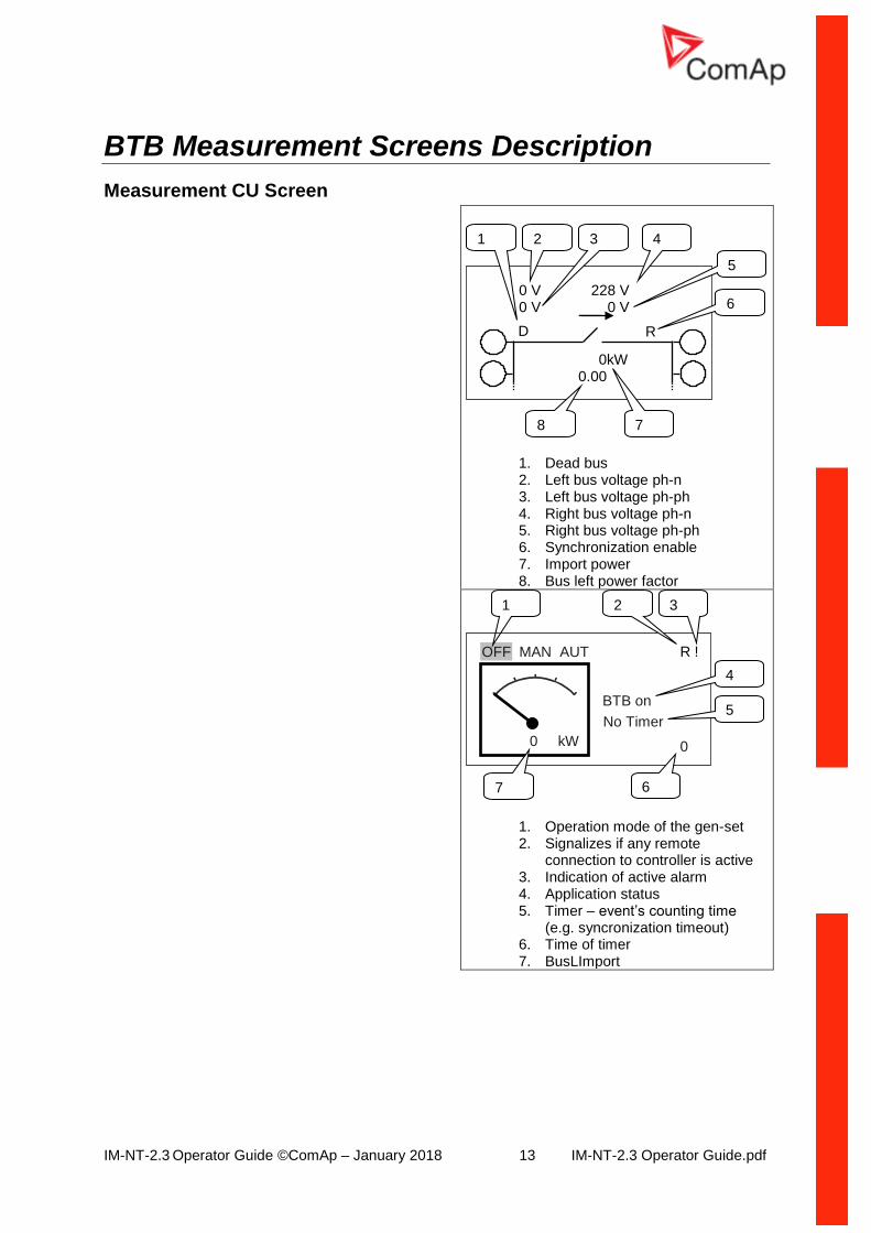
BTB Measurement Screens Description
Measurement CU Screen
1. Dead bus 2. Left bus voltage ph-n 3. Left bus voltage ph-ph 4. Right bus voltage ph-n 5. Right bus voltage ph-ph 6. Synchronization enable 7. Import power 8. Bus left power factor
1. Operation mode of the gen-set 2. Signalizes if any remote
connection to controller is active 3. Indication of active alarm 4. Application status 5. Timer – event’s counting time
(e.g. syncronization timeout) 6. Time of timer 7. BusLImport
OFF MAN AUT
BTB on
R !
0 kW
No Timer
0
1 2 3
4
5
6 7
0 V 228 V 0 V 0 V
0kW 0.00
D R
1 2 3 4 5
6
8 7
IM-NT-2.3 Operator Guide ©ComAp – January 2018 14 IM-NT-2.3 Operator Guide.pdf
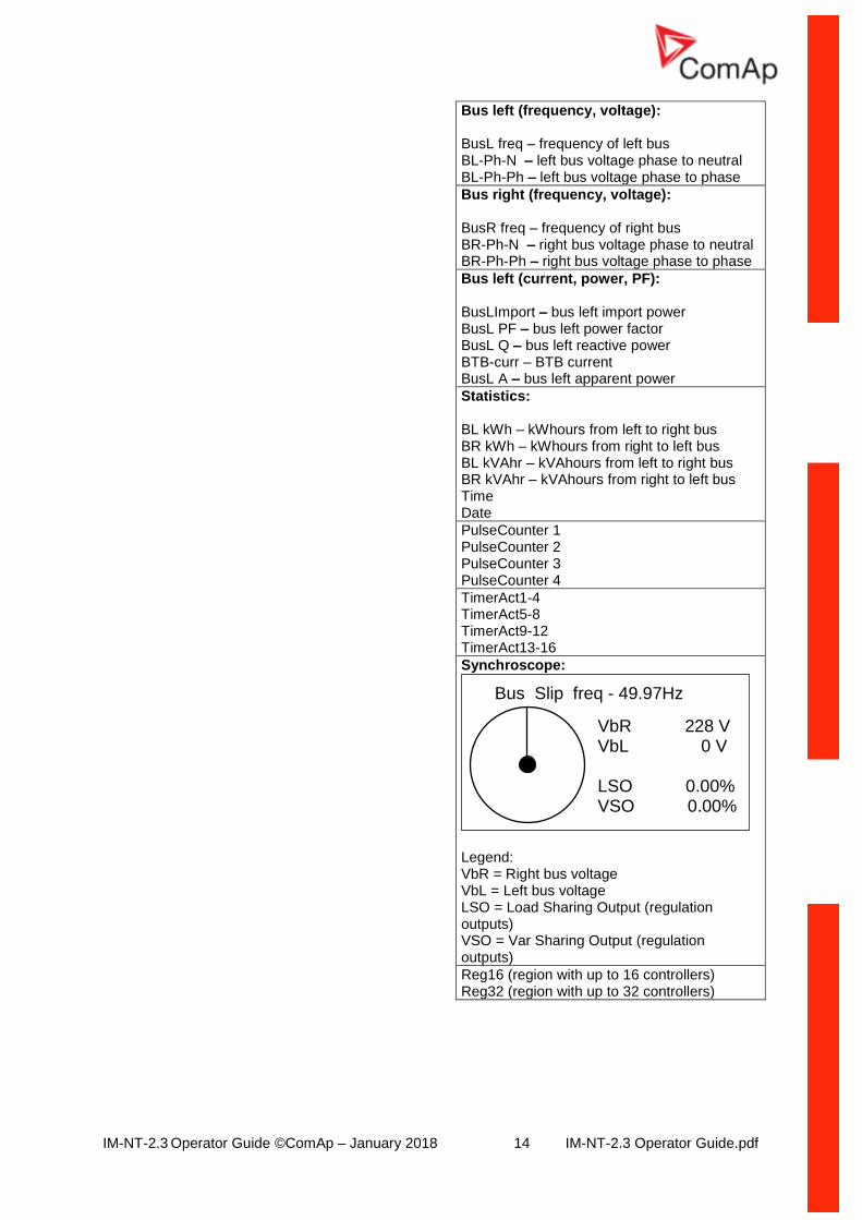
Bus left (frequency, voltage): BusL freq – frequency of left bus BL-Ph-N – left bus voltage phase to neutral BL-Ph-Ph – left bus voltage phase to phase
Bus right (frequency, voltage): BusR freq – frequency of right bus BR-Ph-N – right bus voltage phase to neutral BR-Ph-Ph – right bus voltage phase to phase
Bus left (current, power, PF): BusLImport – bus left import power BusL PF – bus left power factor BusL Q – bus left reactive power BTB-curr – BTB current BusL A – bus left apparent power
Statistics: BL kWh – kWhours from left to right bus BR kWh – kWhours from right to left bus BL kVAhr – kVAhours from left to right bus BR kVAhr – kVAhours from right to left bus Time Date
PulseCounter 1 PulseCounter 2 PulseCounter 3 PulseCounter 4
TimerAct1-4 TimerAct5-8 TimerAct9-12 TimerAct13-16
Synchroscope:
Legend: VbR = Right bus voltage VbL = Left bus voltage LSO = Load Sharing Output (regulation outputs) VSO = Var Sharing Output (regulation outputs)
Reg16 (region with up to 16 controllers) Reg32 (region with up to 32 controllers)
VbR 228 V VbL 0 V LSO 0.00% VSO 0.00%
Bus Slip freq - 49.97Hz
IM-NT-2.3 Operator Guide ©ComAp – January 2018 15 IM-NT-2.3 Operator Guide.pdf
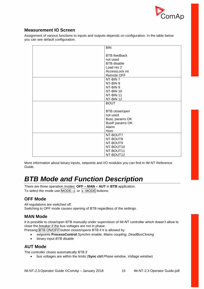
Measurement IO Screen Assignment of various functions to inputs and outputs depends on configuration. In the table below you can see default configuration.
BIN BTB feedback not used BTB disable Load res 2 AccessLock int Remote OFF
NT-BIN 7 NT-BIN 8 NT-BIN 9 NT-BIN 10 NT-BIN 11 NT-BIN 12
BOUT BTB close/open not used BusL params OK BusR params OK Alarm Horn
NT-BOUT7 NT-BOUT8 NT-BOUT9 NT-BOUT10 NT-BOUT11 NT-BOUT12
More information about binary inputs, setpoints and I/O modules you can find in IM-NT Reference Guide.
BTB Mode and Function Description There are three operation modes: OFF – MAN – AUT in BTB application.
To select the mode use MODE or MODE buttons.
OFF Mode All regulations are switched off. Switching to OFF mode causes opening of BTB regardless of the settings.
MAN Mode It is possible to close/open BTB manually under supervision of IM-NT controller which doesn’t allow to close the breaker if the bus voltages are not in phase.
Pressing BTB ON/OFF button closes/opens BTB if it is allowed by
• setpoints ProcessControl:Synchro enable, Mains coupling, DeadBusClosing
• binary input BTB disable
AUT Mode The controller closes automatically BTB if
• bus voltages are within the limits (Sync ctrl:Phase window, Voltage window)
IM-NT-2.3 Operator Guide ©ComAp – January 2018 16 IM-NT-2.3 Operator Guide.pdf
• there is voltage on one of the buses and closing to dead bus is enabled by ProcessControl:DeadBusClosing
• binary input BTB disable is not closed
• it is enabled by setting of ProcessControl:Synchro enable, Mains coupling setpoints Hint: It is not possible to close BTB in MAN and AUT mode if there is no voltage on both buses. If voltage on both left and right bus disappears, the BTB is automatically opened. After the BTB is closed, IM-NT-BTB deactivates all regulation loops that are taken over by the IM-NT-M(G)CB.

IM-NT-2.3 Operator Guide ©ComAp – January 2018 17 IM-NT-2.3 Operator Guide.pdf
IM-NT-2.3 Operator Guide ©ComAp – January 2018 18 IM-NT-2.3 Operator Guide.pdf
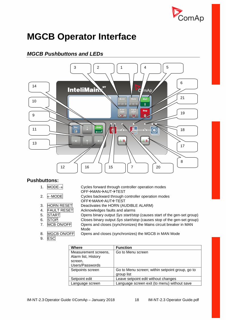
MGCB Operator Interface
MGCB Pushbuttons and LEDs
Pushbuttons:
1. MODE Cycles forward through controller operation modes
OFFMANAUTTEST
2. MODE Cycles backward through controller operation modes
OFFMANAUTTEST
3. HORN RESET Deactivates the HORN (AUDIBLE ALARM)
4. FAULT RESET Acknowledges faults and alarms
5. START Opens binary output Sys start/stop (causes start of the gen-set group)
6. STOP Closes binary output Sys start/stop (causes stop of the gen-set group)
7. MCB ON/OFF Opens and closes (synchronizes) the Mains circuit breaker in MAN
Mode
8. MGCB ON/OFF Opens and closes (synchronizes) the MGCB in MAN Mode
9. ESC
Where Function
Measurement screens, Alarm list, History screen, Users/Passwords
Go to Menu screen
Setpoints screen Go to Menu screen; within setpoint group, go to group list
Setpoint edit Leave setpoint edit without changes
Language screen Language screen exit (to menu) without save
11
9
13
12 16 15 20
14
18
3
21
2 1 4
7
17
5
6
10
8
19
IM-NT-2.3 Operator Guide ©ComAp – January 2018 19 IM-NT-2.3 Operator Guide.pdf
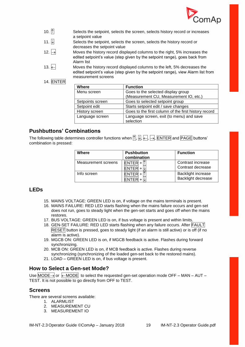
10. Selects the setpoint, selects the screen, selects history record or increases
a setpoint value
11. Selects the setpoint, selects the screen, selects the history record or
decreases the setpoint value
12. Moves the history record displayed columns to the right, 5% increases the
edited setpoint’s value (step given by the setpoint range), goes back from Alarm list
13. Moves the history record displayed columns to the left, 5% decreases the
edited setpoint’s value (step given by the setpoint range), view Alarm list from measurement screens
14. ENTER
Where Function
Menu screen Goes to the selected display group (Measurement CU, Measurement IO, etc.)
Setpoints screen Goes to selected setpoint group
Setpoint edit Starts setpoint edit / save changes
History screen Goes to the first column of the first history record
Language screen Language screen, exit (to menu) and save selection
Pushbuttons’ Combinations
The following table determines controller functions when , , , , ENTER and PAGE buttons’
combination is pressed:
Where Pushbutton combination
Function
Measurement screens ENTER +
ENTER +
Contrast increase Contrast decrease
Info screen ENTER +
ENTER +
Backlight increase Backlight decrease
LEDs
15. MAINS VOLTAGE: GREEN LED is on, if voltage on the mains terminals is present. 16. MAINS FAILURE: RED LED starts flashing when the mains failure occurs and gen-set
does not run, goes to steady light when the gen-set starts and goes off when the mains restores.
17. BUS VOLTAGE: GREEN LED is on, if bus voltage is present and within limits.
18. GEN-SET FAILURE: RED LED starts flashing when any failure occurs. After FAULT
RESET button is pressed, goes to steady light (if an alarm is still active) or is off (if no
alarm is active). 19. MGCB ON: GREEN LED is on, if MGCB feedback is active. Flashes during forward
synchronizing. 20. MCB ON: GREEN LED is on, if MCB feedback is active. Flashes during reverse
synchronizing (synchronizing of the loaded gen-set back to the restored mains). 21. LOAD – GREEN LED is on, if bus voltage is present.
How to Select a Gen-set Mode?
Use MODE or MODE to select the requested gen-set operation mode OFF – MAN – AUT –
TEST. It is not possible to go directly from OFF to TEST.
Screens There are several screens available:
1. ALARMLIST 2. MEASUREMENT CU 3. MEASUREMENT IO
IM-NT-2.3 Operator Guide ©ComAp – January 2018 20 IM-NT-2.3 Operator Guide.pdf
4. HISTORY 5. SETPOINTS 6. USERS/PASSWORD 7. LANGUAGES
Each menu consists of several screens. By pressing the ESC button (repeatedly when necessary) the
menu screen is displayed.
How to View the Alarm List? 1. Select the ALARMLIST menu item.
2. Press ENTER or press in measurements’ screens to go directly to the Alarm list.
How to View Measured Data?
1. Select the MEASUREMENT CU menu item and press ENTER.
2. Use and to select the screen with requested data.
How to View IO Values?
1. Select the MEASUREMENT IO menu item and press ENTER.
2. Use and to select the screen with requested data.
How to View the History Menu?
1. Select HISTORY menu item and press ENTER.
2. Use or to select a requested record.
3. Use or to cycle forward/backward through columns of the record.
How to View and Edit Setpoints?
1. Select SETPOINTS menu item and press ENTER.
2. Use or to select requested setpoints group.
3. Press ENTER to confirm.
4. Use or to select requested setpoint.
5. Setpoints marked are password protected.
6. Press ENTER to edit.
7. Use or to modify the setpoint. When or is pressed for 2 sec, auto repeat function and
speedup is activated. Use or to change the setpoint value by 5% of it’s range.
8. Press ENTER to confirm or ESC to leave without change.
9. Press ESC to leave selected setpoints group.
How to Change the Password?
1. Select USERS/PASSWORD menu item and press ENTER.
2. Use or to select User.
3. Press ENTER to confirm.
4. Select ChangePassword and press ENTER.
5. Use or or or to set new password.
6. Press ENTER to confirm password.
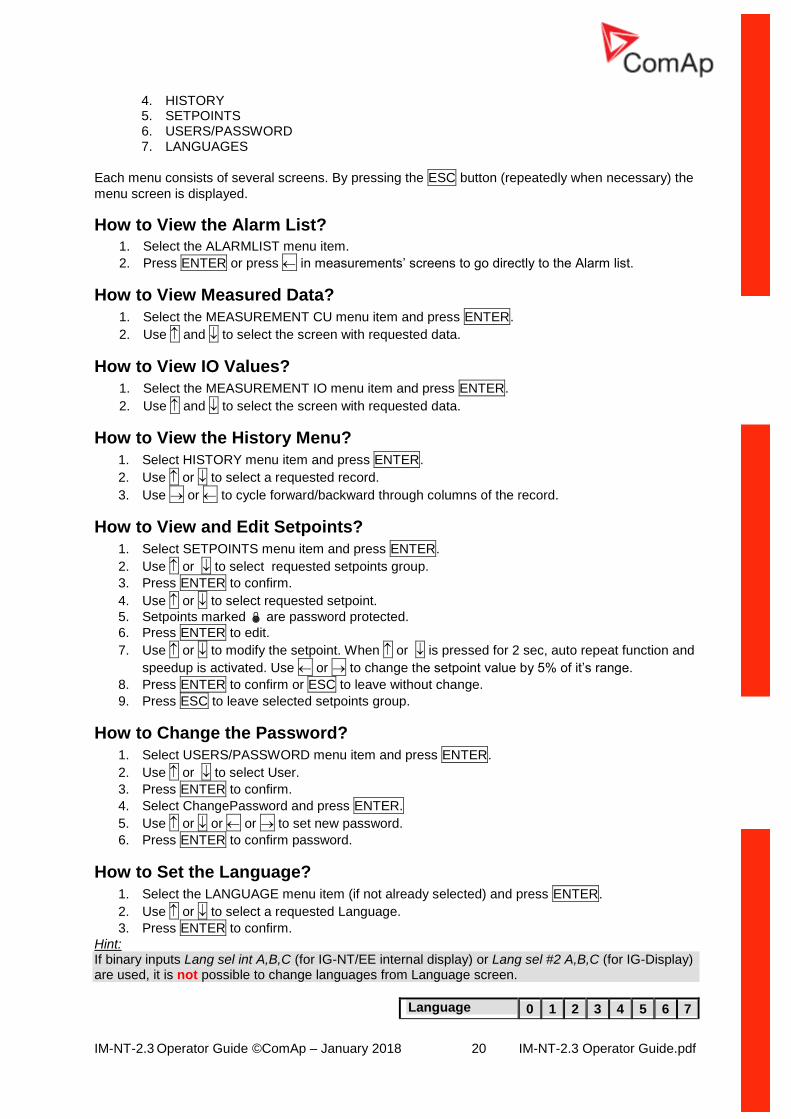
How to Set the Language?
1. Select the LANGUAGE menu item (if not already selected) and press ENTER.
2. Use or to select a requested Language.
3. Press ENTER to confirm.
Hint: If binary inputs Lang sel int A,B,C (for IG-NT/EE internal display) or Lang sel #2 A,B,C (for IG-Display) are used, it is not possible to change languages from Language screen.
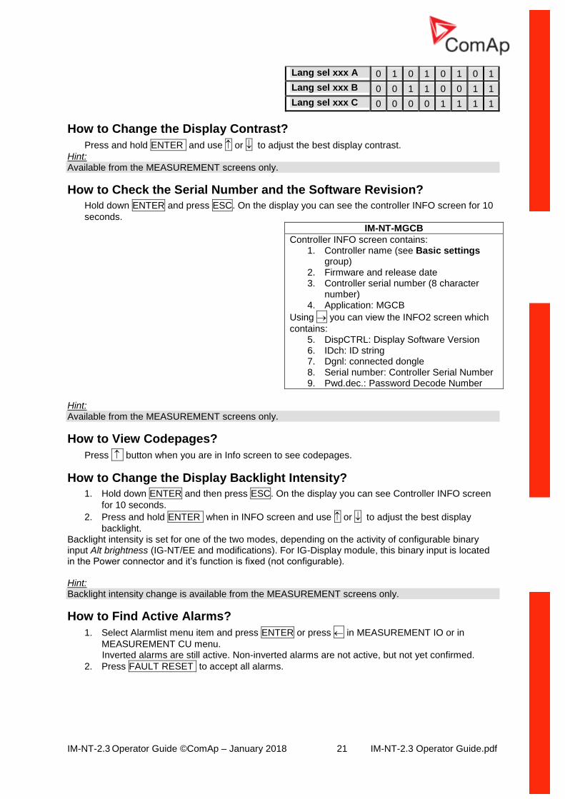
Language 0 1 2 3 4 5 6 7
IM-NT-2.3 Operator Guide ©ComAp – January 2018 21 IM-NT-2.3 Operator Guide.pdf
Lang sel xxx A 0 1 0 1 0 1 0 1
Lang sel xxx B 0 0 1 1 0 0 1 1
Lang sel xxx C 0 0 0 0 1 1 1 1
How to Change the Display Contrast?
Press and hold ENTER and use or to adjust the best display contrast.
Hint: Available from the MEASUREMENT screens only.
How to Check the Serial Number and the Software Revision?
Hold down ENTER and press ESC. On the display you can see the controller INFO screen for 10
seconds.
IM-NT-MGCB
Controller INFO screen contains: 1. Controller name (see Basic settings
group) 2. Firmware and release date 3. Controller serial number (8 character
number) 4. Application: MGCB
Using you can view the INFO2 screen which
contains: 5. DispCTRL: Display Software Version 6. IDch: ID string 7. Dgnl: connected dongle 8. Serial number: Controller Serial Number 9. Pwd.dec.: Password Decode Number
Hint: Available from the MEASUREMENT screens only.
How to View Codepages?
Press button when you are in Info screen to see codepages.
How to Change the Display Backlight Intensity?
1. Hold down ENTER and then press ESC. On the display you can see Controller INFO screen
for 10 seconds.
2. Press and hold ENTER when in INFO screen and use or to adjust the best display
backlight. Backlight intensity is set for one of the two modes, depending on the activity of configurable binary input Alt brightness (IG-NT/EE and modifications). For IG-Display module, this binary input is located in the Power connector and it’s function is fixed (not configurable). Hint: Backlight intensity change is available from the MEASUREMENT screens only.
How to Find Active Alarms?
1. Select Alarmlist menu item and press ENTER or press in MEASUREMENT IO or in
MEASUREMENT CU menu. Inverted alarms are still active. Non-inverted alarms are not active, but not yet confirmed.
2. Press FAULT RESET to accept all alarms.
IM-NT-2.3 Operator Guide ©ComAp – January 2018 22 IM-NT-2.3 Operator Guide.pdf
The asterix mark disappears when an alarm is accepted by FAULT RESET. Non-active
alarms immediately disappear from the list. Active alarm list appears on the screen automatically when a new alarm comes up and the Main MEASUREMENT screen was selected.
Hint: Alarm list does not activate automatically if the display is switched to any other screen than the first one of MEASUREMENT (typically the screen that shows menu selector on the upper). The automatic jump to the alarm list screen will not occur if you are listing through the measured values, set points or history! If setpoint Engine protect:ResetActAlarms is set to DISABLED, only inactive alarms can be reset. If an active alarm is present in the alarm list, controller display blinks every 30 seconds.
When to Use MCB ON/OFF Button?
The button is disabled in AUT mode. In MAN and TEST modes it is enabled, but before closing of the circuit beaker, bus voltage and frequency must be within limits. The controller has internal protection to avoid the breaker closure without synchronizing. Use the MCB button in MAN or TEST mode to close or open the MCB. Be careful while doing this, because you can disconnect the load from gen-sets!!! The controller recognizes automatically:
• if there is mains / bus voltage and the gen-set(s) shall be synchronized before closing the GCB
• or if there is no voltage on the bus and the MCB can be closed without synchronizing
When to Use MGCB ON/OFF Button?
The button is disabled in AUT mode. The controller has internal protection to avoid the breaker closure without synchronizing. Use this button in MAN or TEST mode to close or open the MGCB. Be careful while doing this, because you can disconnect the load from the mains!!! The controller recognizes automatically:
• if there is mains / bus voltage and the gen-set(s) shall be synchronized before closing the MGCB
• or if there is no voltage on the bus and the MGCB can be closed without synchronizing

IM-NT-2.3 Operator Guide ©ComAp – January 2018 23 IM-NT-2.3 Operator Guide.pdf
MGCB Measurement Screens Description
Measurement CU Screen
1. Mains: actual value of active power and power factor
2. Actual power factor control mode and required value
3. Actual power control mode and required value
4. Load: actual value of active power and power factor
5. “R” is signalizing if any remote connection to controller is active. If “!” is shown, it indicates an active alarm.
6. Gen-set(s): actual value of active power and power factor
1. Operation mode of the gen-set 2. Application status 3. Load Shedding status 4. Timer – event’s counting time
(e.g. syncronization timeout) 5. Time of timer 6. Active power
Mains (power, PF) MainsImport – active power imported from Mains Mains PF – Mains power factor Mains Q – Mains reactive power
OFF MAN AUT TEST
No LoadSh
6
3
4
0 kW No Timer
0
1
5
MainsFlt
2
5
None 0 None 0.00
0kW 0.00
R
0kW 0.00
0kW 0.00
2
3 4 4
1 6 1 6
2
3
IM-NT-2.3 Operator Guide ©ComAp – January 2018 24 IM-NT-2.3 Operator Guide.pdf
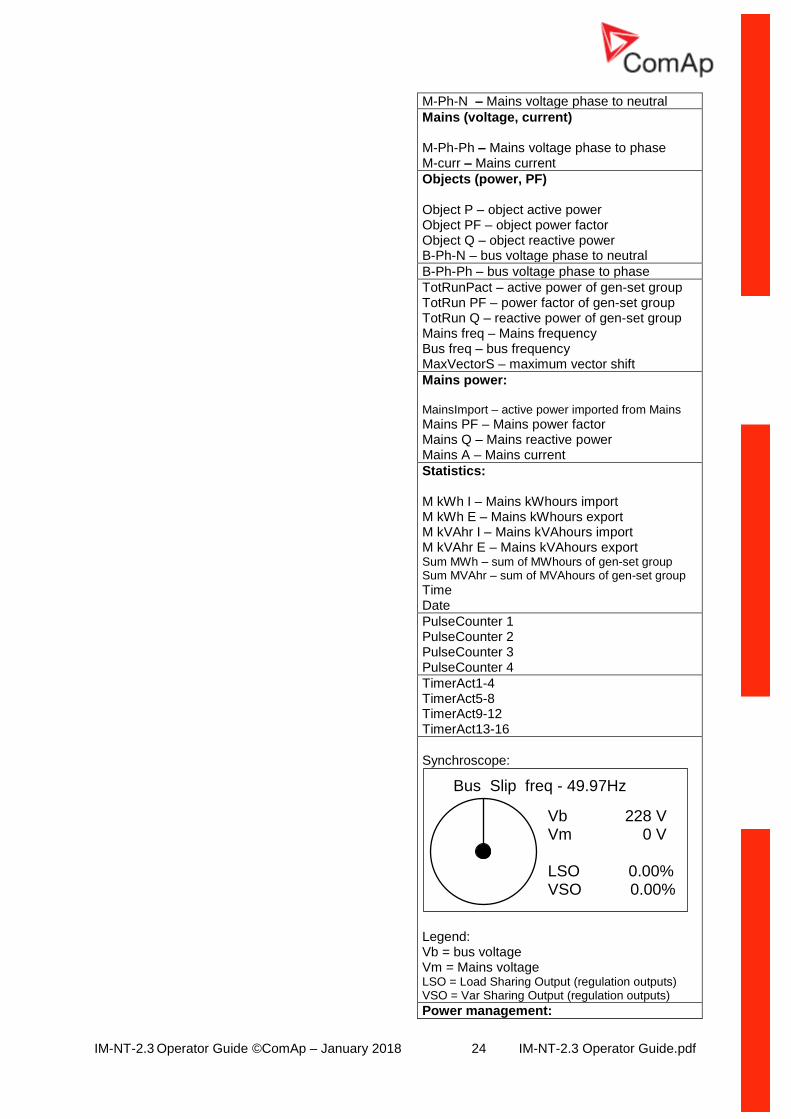
M-Ph-N – Mains voltage phase to neutral
Mains (voltage, current) M-Ph-Ph – Mains voltage phase to phase M-curr – Mains current
Objects (power, PF) Object P – object active power Object PF – object power factor Object Q – object reactive power B-Ph-N – bus voltage phase to neutral
B-Ph-Ph – bus voltage phase to phase
TotRunPact – active power of gen-set group TotRun PF – power factor of gen-set group TotRun Q – reactive power of gen-set group Mains freq – Mains frequency Bus freq – bus frequency MaxVectorS – maximum vector shift
Mains power: MainsImport – active power imported from Mains
Mains PF – Mains power factor Mains Q – Mains reactive power Mains A – Mains current
Statistics: M kWh I – Mains kWhours import M kWh E – Mains kWhours export M kVAhr I – Mains kVAhours import M kVAhr E – Mains kVAhours export Sum MWh – sum of MWhours of gen-set group Sum MVAhr – sum of MVAhours of gen-set group
Time Date
PulseCounter 1 PulseCounter 2 PulseCounter 3 PulseCounter 4
TimerAct1-4 TimerAct5-8 TimerAct9-12 TimerAct13-16
Synchroscope:
Legend: Vb = bus voltage Vm = Mains voltage LSO = Load Sharing Output (regulation outputs) VSO = Var Sharing Output (regulation outputs)
Power management:
Vb 228 V Vm 0 V LSO 0.00% VSO 0.00%
Bus Slip freq - 49.97Hz
IM-NT-2.3 Operator Guide ©ComAp – January 2018 25 IM-NT-2.3 Operator Guide.pdf
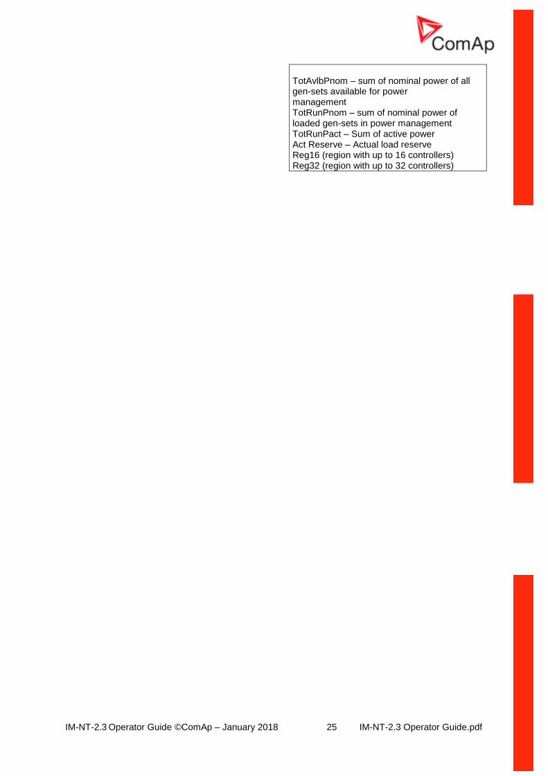
TotAvlbPnom – sum of nominal power of all gen-sets available for power management TotRunPnom – sum of nominal power of loaded gen-sets in power management TotRunPact – Sum of active power Act Reserve – Actual load reserve Reg16 (region with up to 16 controllers) Reg32 (region with up to 32 controllers)
IM-NT-2.3 Operator Guide ©ComAp – January 2018 26 IM-NT-2.3 Operator Guide.pdf
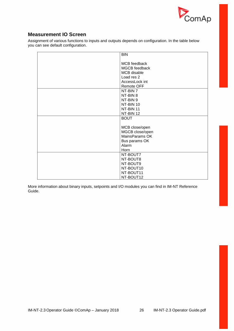
Measurement IO Screen Assignment of various functions to inputs and outputs depends on configuration. In the table below you can see default configuration.
BIN MCB feedback MGCB feedback MCB disable Load res 2 AccessLock int Remote OFF
NT-BIN 7 NT-BIN 8 NT-BIN 9 NT-BIN 10 NT-BIN 11 NT-BIN 12
BOUT MCB close/open MGCB close/open MainsParams OK Bus params OK Alarm Horn
NT-BOUT7 NT-BOUT8 NT-BOUT9 NT-BOUT10 NT-BOUT11 NT-BOUT12
More information about binary inputs, setpoints and I/O modules you can find in IM-NT Reference Guide.

IM-NT-2.3 Operator Guide ©ComAp – January 2018 27 IM-NT-2.3 Operator Guide.pdf
IM-NT-2.3 Operator Guide ©ComAp – January 2018 28 IM-NT-2.3 Operator Guide.pdf
MCB Operator Interface
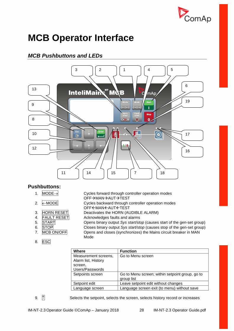
MCB Pushbuttons and LEDs
Pushbuttons:
1. MODE Cycles forward through controller operation modes
OFFMANAUTTEST
2. MODE Cycles backward through controller operation modes
OFFMANAUTTEST
3. HORN RESET Deactivates the HORN (AUDIBLE ALARM)
4. FAULT RESET Acknowledges faults and alarms
5. START Opens binary output Sys start/stop (causes start of the gen-set group)
6. STOP Closes binary output Sys start/stop (causes stop of the gen-set group)
7. MCB ON/OFF Opens and closes (synchronizes) the Mains circuit breaker in MAN
Mode
8. ESC
Where Function
Measurement screens, Alarm list, History screen, Users/Passwords
Go to Menu screen
Setpoints screen Go to Menu screen; within setpoint group, go to group list
Setpoint edit Leave setpoint edit without changes
Language screen Language screen exit (to menu) without save
9. Selects the setpoint, selects the screen, selects history record or increases
10
8
12
11 14 15 18
13
17
3
19
2 1 4
7
16
5
6
9
IM-NT-2.3 Operator Guide ©ComAp – January 2018 29 IM-NT-2.3 Operator Guide.pdf
a setpoint value
10. Selects the setpoint, selects the screen, selects the history record or
decreases the setpoint value
11. Moves the history record displayed columns to the right, 5% increases the
edited setpoint’s value (step given by the setpoint range), goes back from Alarm list
12. Moves the history record displayed columns to the left, 5% decreases the
edited setpoint’s value (step given by the setpoint range), view Alarm list from measurement screens
13. ENTER
Where Function
Menu screen Goes to the selected display group (Measurement CU, Measurement IO, etc.)
Setpoints screen Goes to selected setpoint group
Setpoint edit Starts setpoint edit / save changes
History screen Goes to the first column of the first history record
Language screen Language screen, exit (to menu) and save selection
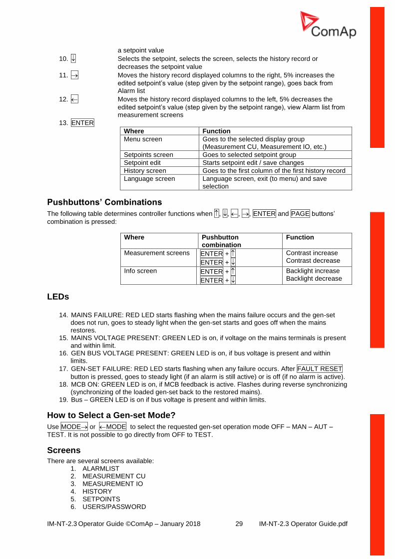
Pushbuttons’ Combinations
The following table determines controller functions when , , , , ENTER and PAGE buttons’
combination is pressed:
Where Pushbutton combination
Function
Measurement screens ENTER +
ENTER +
Contrast increase Contrast decrease
Info screen ENTER +
ENTER +
Backlight increase Backlight decrease
LEDs
14. MAINS FAILURE: RED LED starts flashing when the mains failure occurs and the gen-set does not run, goes to steady light when the gen-set starts and goes off when the mains restores.
15. MAINS VOLTAGE PRESENT: GREEN LED is on, if voltage on the mains terminals is present and within limit.
16. GEN BUS VOLTAGE PRESENT: GREEN LED is on, if bus voltage is present and within limits.
17. GEN-SET FAILURE: RED LED starts flashing when any failure occurs. After FAULT RESET
button is pressed, goes to steady light (if an alarm is still active) or is off (if no alarm is active). 18. MCB ON: GREEN LED is on, if MCB feedback is active. Flashes during reverse synchronizing
(synchronizing of the loaded gen-set back to the restored mains). 19. Bus – GREEN LED is on if bus voltage is present and within limits.
How to Select a Gen-set Mode?
Use MODE or MODE to select the requested gen-set operation mode OFF – MAN – AUT –
TEST. It is not possible to go directly from OFF to TEST.
Screens There are several screens available:
1. ALARMLIST 2. MEASUREMENT CU 3. MEASUREMENT IO 4. HISTORY 5. SETPOINTS 6. USERS/PASSWORD
IM-NT-2.3 Operator Guide ©ComAp – January 2018 30 IM-NT-2.3 Operator Guide.pdf
7. LANGUAGES
Each menu consists of several screens. By pressing the ESC button (repeatedly when necessary) the
menu screen is displayed.
How to View the Alarm List? 1. Select the ALARMLIST menu item.
2. Press ENTER or press in measurements’ screens to go directly to the Alarm list.
How to View Measured Data?
1. Select the MEASUREMENT CU menu item and press ENTER.
2. Use and to select the screen with requested data.
How to View IO Values?
1. Select the MEASUREMENT IO menu item and press ENTER.
2. Use and to select the screen with requested data.
How to View the History Menu?
1. Select HISTORY menu item and press ENTER.
2. Use or to select a requested record.
3. Use or to cycle forward/backward through columns of the record.
How to View and Edit Setpoints?
1. Select SETPOINTS menu item and press ENTER.
2. Use or to select requested setpoints group.
3. Press ENTER to confirm.
4. Use or to select requested setpoint.
5. Setpoints marked are password protected.
6. Press ENTER to edit.
7. Use or to modify the setpoint. When or is pressed for 2 sec, auto repeat function and
speedup is activated. Use or to change the setpoint value by 5% of it’s range.
8. Press ENTER to confirm or ESC to leave without change.
9. Press ESC to leave selected setpoints group.
How to Change the Password?
1. Select USERS/PASSWORD menu item and press ENTER.
2. Use or to select User.
3. Press ENTER to confirm.
4. Select ChangePassword and press ENTER.
5. Use or or or to set new password.
6. Press ENTER to confirm password.
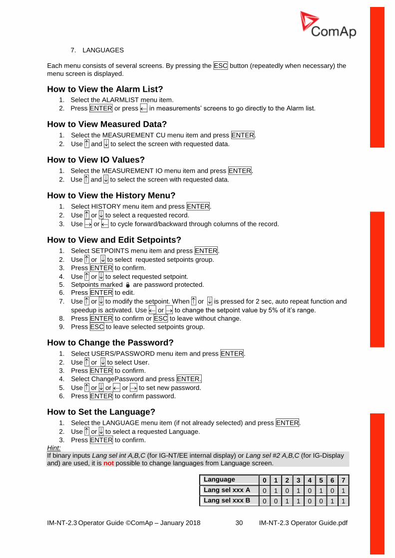
How to Set the Language?
1. Select the LANGUAGE menu item (if not already selected) and press ENTER.
2. Use or to select a requested Language.
3. Press ENTER to confirm.
Hint: If binary inputs Lang sel int A,B,C (for IG-NT/EE internal display) or Lang sel #2 A,B,C (for IG-Display and) are used, it is not possible to change languages from Language screen.
Language 0 1 2 3 4 5 6 7
Lang sel xxx A 0 1 0 1 0 1 0 1
Lang sel xxx B 0 0 1 1 0 0 1 1
IM-NT-2.3 Operator Guide ©ComAp – January 2018 31 IM-NT-2.3 Operator Guide.pdf
Lang sel xxx C 0 0 0 0 1 1 1 1
How to Change the Display Contrast?
Press and hold ENTER and use or to adjust the best display contrast.
Hint: Available from the MEASUREMENT screens only.
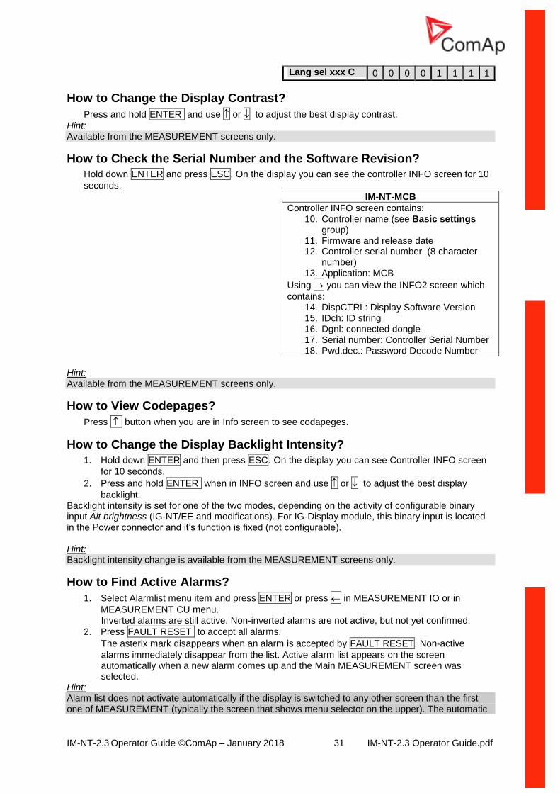
How to Check the Serial Number and the Software Revision?
Hold down ENTER and press ESC. On the display you can see the controller INFO screen for 10
seconds.
IM-NT-MCB
Controller INFO screen contains: 10. Controller name (see Basic settings
group) 11. Firmware and release date 12. Controller serial number (8 character
number) 13. Application: MCB
Using you can view the INFO2 screen which
contains: 14. DispCTRL: Display Software Version 15. IDch: ID string 16. Dgnl: connected dongle 17. Serial number: Controller Serial Number 18. Pwd.dec.: Password Decode Number
Hint: Available from the MEASUREMENT screens only.
How to View Codepages?
Press button when you are in Info screen to see codapeges.
How to Change the Display Backlight Intensity?
1. Hold down ENTER and then press ESC. On the display you can see Controller INFO screen
for 10 seconds.
2. Press and hold ENTER when in INFO screen and use or to adjust the best display
backlight. Backlight intensity is set for one of the two modes, depending on the activity of configurable binary input Alt brightness (IG-NT/EE and modifications). For IG-Display module, this binary input is located in the Power connector and it’s function is fixed (not configurable). Hint: Backlight intensity change is available from the MEASUREMENT screens only.
How to Find Active Alarms?
1. Select Alarmlist menu item and press ENTER or press in MEASUREMENT IO or in
MEASUREMENT CU menu. Inverted alarms are still active. Non-inverted alarms are not active, but not yet confirmed.
2. Press FAULT RESET to accept all alarms.
The asterix mark disappears when an alarm is accepted by FAULT RESET. Non-active
alarms immediately disappear from the list. Active alarm list appears on the screen automatically when a new alarm comes up and the Main MEASUREMENT screen was selected.
Hint: Alarm list does not activate automatically if the display is switched to any other screen than the first one of MEASUREMENT (typically the screen that shows menu selector on the upper). The automatic
IM-NT-2.3 Operator Guide ©ComAp – January 2018 32 IM-NT-2.3 Operator Guide.pdf
jump to the alarm list screen will not occur if you are listing through the measured values, set points or history! If setpoint Engine protect:ResetActAlarms is set to DISABLED, only inactive alarms can be reset. If an active alarm is present in the alarm list, controller display blinks every 30 seconds.
When to Use MCB ON/OFF Button?
The button is disabled in AUT mode. In MAN and TEST modes it is enabled, but before closing of the circuit beaker, generator voltage and frequency must be within limits. The controller has internal protection to avoid the breaker closure without synchronizing. The controller recognizes automatically:
• if there is mains / bus voltage and the gen-set shall be synchronized before closing the MCB
• or if there is no voltage on the bus and the MCB can be closed without synchronizing.
IM-NT-2.3 Operator Guide ©ComAp – January 2018 33 IM-NT-2.3 Operator Guide.pdf
MCB Measurement Screens Description
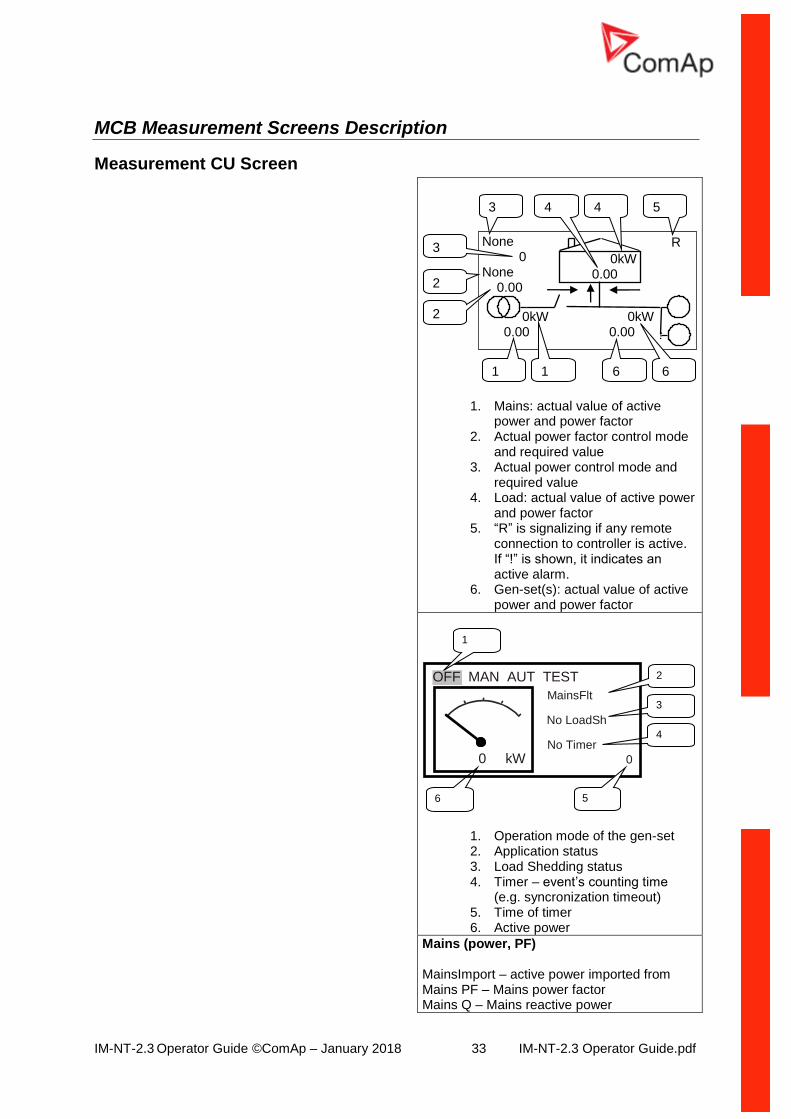
Measurement CU Screen
1. Mains: actual value of active power and power factor
2. Actual power factor control mode and required value
3. Actual power control mode and required value
4. Load: actual value of active power and power factor
5. “R” is signalizing if any remote connection to controller is active. If “!” is shown, it indicates an active alarm.
6. Gen-set(s): actual value of active power and power factor
1. Operation mode of the gen-set 2. Application status 3. Load Shedding status 4. Timer – event’s counting time
(e.g. syncronization timeout) 5. Time of timer 6. Active power
Mains (power, PF) MainsImport – active power imported from Mains PF – Mains power factor Mains Q – Mains reactive power
OFF MAN AUT TEST
No LoadSh
6
3
4
0 kW No Timer
0
1
5
MainsFlt
2
5
None 0 None 0.00
0kW 0.00
R
0kW 0.00
0kW 0.00
2
3 4 4
1 6 1 6
2
3
IM-NT-2.3 Operator Guide ©ComAp – January 2018 34 IM-NT-2.3 Operator Guide.pdf
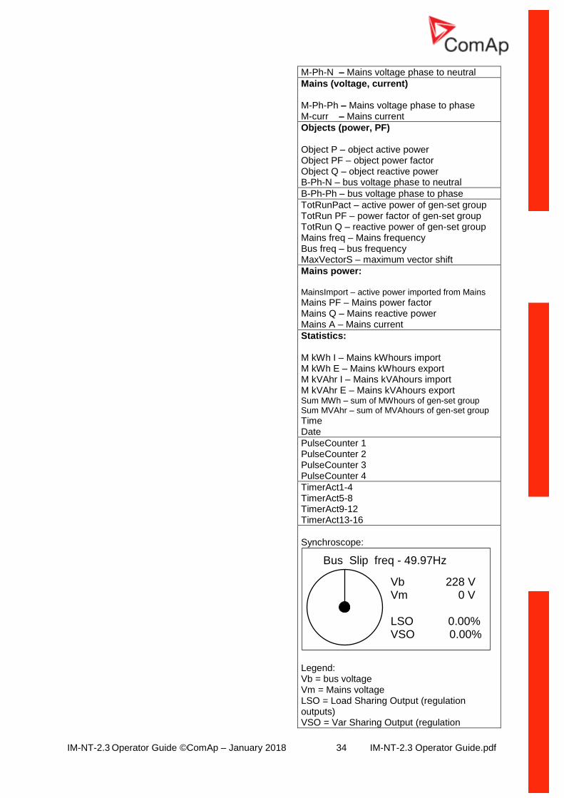
M-Ph-N – Mains voltage phase to neutral
Mains (voltage, current) M-Ph-Ph – Mains voltage phase to phase M-curr – Mains current
Objects (power, PF) Object P – object active power Object PF – object power factor Object Q – object reactive power B-Ph-N – bus voltage phase to neutral
B-Ph-Ph – bus voltage phase to phase
TotRunPact – active power of gen-set group TotRun PF – power factor of gen-set group TotRun Q – reactive power of gen-set group Mains freq – Mains frequency Bus freq – bus frequency MaxVectorS – maximum vector shift
Mains power: MainsImport – active power imported from Mains
Mains PF – Mains power factor Mains Q – Mains reactive power Mains A – Mains current
Statistics: M kWh I – Mains kWhours import M kWh E – Mains kWhours export M kVAhr I – Mains kVAhours import M kVAhr E – Mains kVAhours export Sum MWh – sum of MWhours of gen-set group Sum MVAhr – sum of MVAhours of gen-set group
Time Date
PulseCounter 1 PulseCounter 2 PulseCounter 3 PulseCounter 4
TimerAct1-4 TimerAct5-8 TimerAct9-12 TimerAct13-16
Synchroscope:
Legend: Vb = bus voltage Vm = Mains voltage LSO = Load Sharing Output (regulation outputs) VSO = Var Sharing Output (regulation
Vb 228 V Vm 0 V LSO 0.00% VSO 0.00%
Bus Slip freq - 49.97Hz
IM-NT-2.3 Operator Guide ©ComAp – January 2018 35 IM-NT-2.3 Operator Guide.pdf
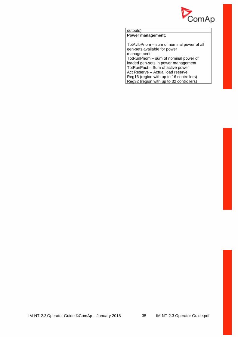
outputs)
Power management: TotAvlbPnom – sum of nominal power of all gen-sets available for power management TotRunPnom – sum of nominal power of loaded gen-sets in power management TotRunPact – Sum of active power Act Reserve – Actual load reserve Reg16 (region with up to 16 controllers) Reg32 (region with up to 32 controllers)
IM-NT-2.3 Operator Guide ©ComAp – January 2018 36 IM-NT-2.3 Operator Guide.pdf
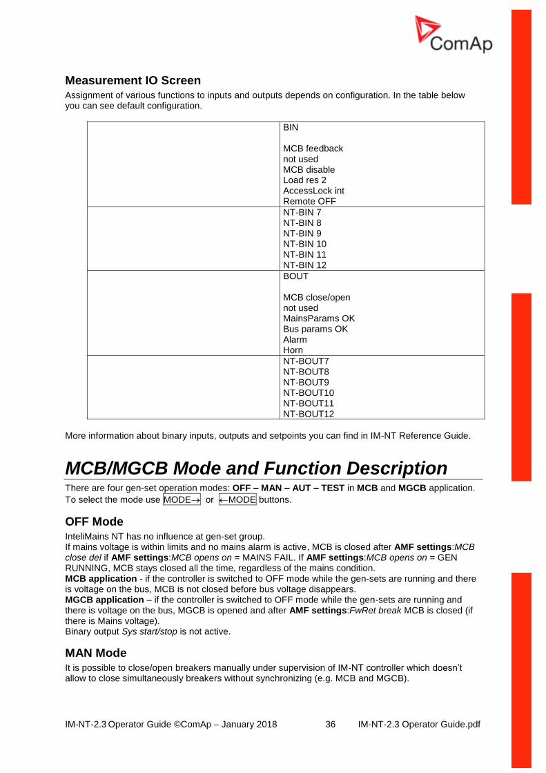
Measurement IO Screen Assignment of various functions to inputs and outputs depends on configuration. In the table below you can see default configuration.
BIN MCB feedback not used MCB disable Load res 2 AccessLock int Remote OFF
NT-BIN 7 NT-BIN 8 NT-BIN 9 NT-BIN 10 NT-BIN 11 NT-BIN 12
BOUT MCB close/open not used MainsParams OK Bus params OK Alarm Horn
NT-BOUT7 NT-BOUT8 NT-BOUT9 NT-BOUT10 NT-BOUT11 NT-BOUT12
More information about binary inputs, outputs and setpoints you can find in IM-NT Reference Guide.
MCB/MGCB Mode and Function Description There are four gen-set operation modes: OFF – MAN – AUT – TEST in MCB and MGCB application.
To select the mode use MODE or MODE buttons.
OFF Mode InteliMains NT has no influence at gen-set group. If mains voltage is within limits and no mains alarm is active, MCB is closed after AMF settings:MCB close del if AMF settings:MCB opens on = MAINS FAIL. If AMF settings:MCB opens on = GEN RUNNING, MCB stays closed all the time, regardless of the mains condition. MCB application - if the controller is switched to OFF mode while the gen-sets are running and there is voltage on the bus, MCB is not closed before bus voltage disappears. MGCB application – if the controller is switched to OFF mode while the gen-sets are running and there is voltage on the bus, MGCB is opened and after AMF settings:FwRet break MCB is closed (if there is Mains voltage). Binary output Sys start/stop is not active.
MAN Mode It is possible to close/open breakers manually under supervision of IM-NT controller which doesn’t allow to close simultaneously breakers without synchronizing (e.g. MCB and MGCB).
IM-NT-2.3 Operator Guide ©ComAp – January 2018 37 IM-NT-2.3 Operator Guide.pdf
If the Mains fails, controller opens MCB if AMF settings:MCB opens on = MAINS FAIL. After the
Mains returns, MCB stays opened. Otherwise MCB is controlled manually by pressing MCB ON/OFF
button or closing MCBButton binary input. MGCB application – if the Mains fails, group of gen-sets is started and there is voltage on the bus,
MGCB can be closed anytime by pressing MGCB ON/OFF button.
Pressing of Start/Stop buttons closes/opens binary output Sys start/stop, i.e. cause start/stop of the
gen-set group.
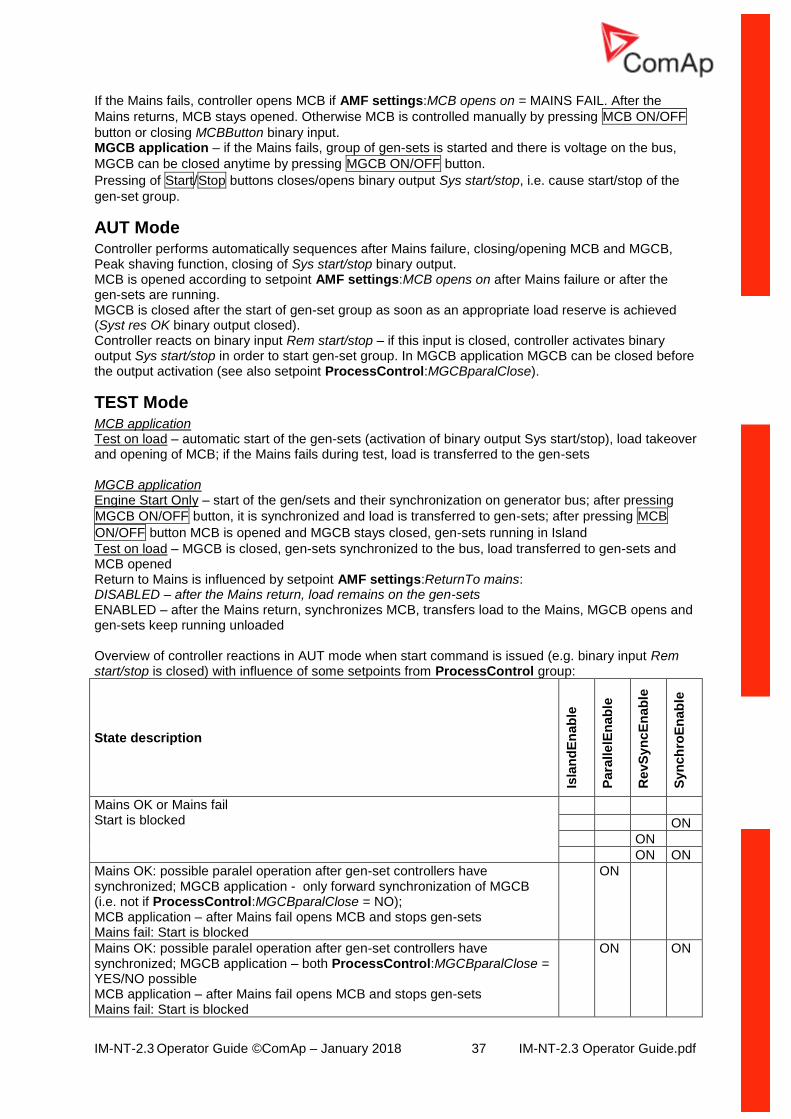
AUT Mode Controller performs automatically sequences after Mains failure, closing/opening MCB and MGCB, Peak shaving function, closing of Sys start/stop binary output. MCB is opened according to setpoint AMF settings:MCB opens on after Mains failure or after the gen-sets are running. MGCB is closed after the start of gen-set group as soon as an appropriate load reserve is achieved (Syst res OK binary output closed). Controller reacts on binary input Rem start/stop – if this input is closed, controller activates binary output Sys start/stop in order to start gen-set group. In MGCB application MGCB can be closed before the output activation (see also setpoint ProcessControl:MGCBparalClose).
TEST Mode MCB application Test on load – automatic start of the gen-sets (activation of binary output Sys start/stop), load takeover and opening of MCB; if the Mains fails during test, load is transferred to the gen-sets MGCB application Engine Start Only – start of the gen/sets and their synchronization on generator bus; after pressing
MGCB ON/OFF button, it is synchronized and load is transferred to gen-sets; after pressing MCB
ON/OFF button MCB is opened and MGCB stays closed, gen-sets running in Island
Test on load – MGCB is closed, gen-sets synchronized to the bus, load transferred to gen-sets and MCB opened Return to Mains is influenced by setpoint AMF settings:ReturnTo mains: DISABLED – after the Mains return, load remains on the gen-sets ENABLED – after the Mains return, synchronizes MCB, transfers load to the Mains, MGCB opens and gen-sets keep running unloaded Overview of controller reactions in AUT mode when start command is issued (e.g. binary input Rem start/stop is closed) with influence of some setpoints from ProcessControl group:
State description
Isla
nd
En
ab
le
Para
lle
lEn
ab
le
RevS
yn
cE
nab
le
Syn
ch
roE
nab
le
Mains OK or Mains fail Start is blocked
ON
ON
ON ON
Mains OK: possible paralel operation after gen-set controllers have synchronized; MGCB application - only forward synchronization of MGCB (i.e. not if ProcessControl:MGCBparalClose = NO); MCB application – after Mains fail opens MCB and stops gen-sets Mains fail: Start is blocked
ON
Mains OK: possible paralel operation after gen-set controllers have synchronized; MGCB application – both ProcessControl:MGCBparalClose = YES/NO possible MCB application – after Mains fail opens MCB and stops gen-sets Mains fail: Start is blocked
ON ON
IM-NT-2.3 Operator Guide ©ComAp – January 2018 38 IM-NT-2.3 Operator Guide.pdf
State description
Isla
nd
En
ab
le
Para
lle
lEn
ab
le
RevS
yn
cE
nab
le
Syn
ch
roE
nab
le
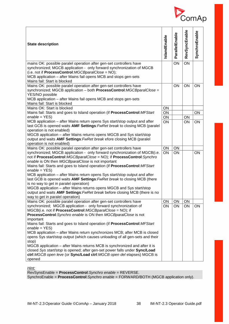
mains OK: possible paralel operation after gen-set controllers have synchronized; MGCB application - only forward synchronization of MGCB (i.e. not if ProcessControl:MGCBparalClose = NO); MCB application – after Mains fail opens MCB and stops gen-sets Mains fail: Start is blocked
ON ON
Mains OK: possible paralel operation after gen-set controllers have synchronized; MGCB application – both ProcessControl:MGCBparalClose = YES/NO possible MCB application – after Mains fail opens MCB and stops gen-sets Mains fail: Start is blocked
ON ON ON
Mains OK: Start is blocked Mains fail: Starts and goes to Island operation (if ProcessControl:MFStart enable = YES) MCB application – after Mains return opens Sys start/stop output and after last GCB is opened waits AMF Settings:FwRet break to closing MCB (paralel operation is not enabled) MGCB application – after Mains returns opens MGCB and Sys start/stop output and waits AMF Settings:FwRet break efore closing MCB (paralel operation is not enabled)
ON
ON ON
ON ON
ON ON ON
Mains OK: possible paralel operation after gen-set controllers have synchronized; MGCB application - only forward synchronization of MGCB(i.e. not if ProcessControl:MGCBparalClose = NO); if ProcessControl:Synchro enable is ON then MGCBparalClose is not important Mains fail: Starts and goes to Island operation (if ProcessControl:MFStart enable = YES) MCB application – after Mains return opens Sys start/stop output and after last GCB is opened waits AMF Settings:FwRet break to closing MCB (there is no way to get in paralel operation) MGCB application – after Mains returns opens MGCB and Sys start/stop output and waits AMF Settings:FwRet break before closing MCB (there is no way to get in paralel operation)
ON ON
ON ON ON
Mains OK: possible paralel operation after gen-set controllers have synchronized; MGCB application - only forward synchronization of MGCB(i.e. not if ProcessControl:MGCBparalClose = NO); if ProcessControl:Synchro enable is ON then MGCBparalClose is not important Mains fail: Starts and goes to Island operation (if ProcessControl:MFStart enable = YES) MCB application – after Mains return synchronizes MCB; after MCB is closed opens Sys start/stop output (which causes unloading of all gen-sets and their stop) MGCB application – after Mains returns MCB is synchronized and after it is closed Sys start/stop is opened; after gen-set power falls under Sync/Load ctrl:MGCB open leve (or Sync/Load ctrl:MGCB open del elapses) MGCB is opened
ON ON ON
ON ON ON ON
Hint: RevSynsEnable = ProcessControl:Synchro enable = REVERSE. SynchroEnable = ProcessControl:Synchro enable = FORWARD/BOTH (MGCB application only).

IM-NT-2.3 Operator Guide ©ComAp – January 2018 39 IM-NT-2.3 Operator Guide.pdf
IM-NT-2.3 Operator Guide ©ComAp – January 2018 40 IM-NT-2.3 Operator Guide.pdf
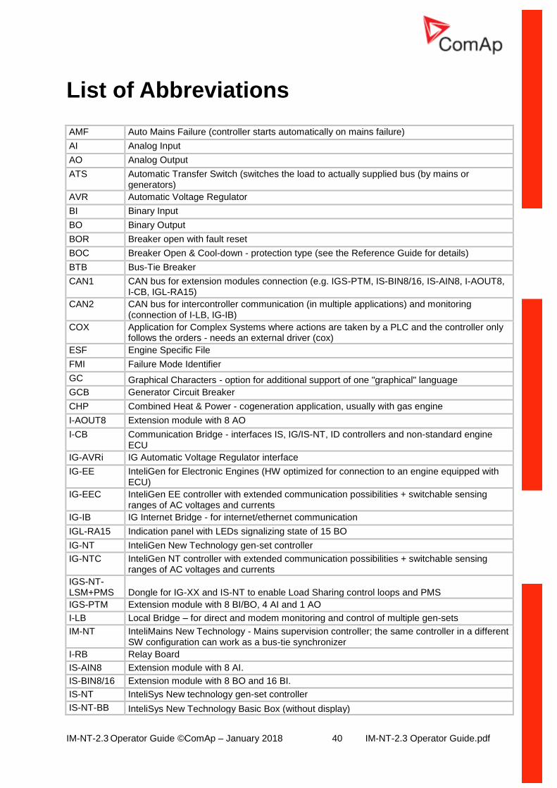
List of Abbreviations
AMF Auto Mains Failure (controller starts automatically on mains failure)
AI Analog Input
AO Analog Output
ATS Automatic Transfer Switch (switches the load to actually supplied bus (by mains or generators)
AVR Automatic Voltage Regulator
BI Binary Input
BO Binary Output
BOR Breaker open with fault reset
BOC Breaker Open & Cool-down - protection type (see the Reference Guide for details)
BTB Bus-Tie Breaker
CAN1 CAN bus for extension modules connection (e.g. IGS-PTM, IS-BIN8/16, IS-AIN8, I-AOUT8, I-CB, IGL-RA15)
CAN2 CAN bus for intercontroller communication (in multiple applications) and monitoring (connection of I-LB, IG-IB)
COX Application for Complex Systems where actions are taken by a PLC and the controller only follows the orders - needs an external driver (cox)
ESF Engine Specific File
FMI Failure Mode Identifier
GC Graphical Characters - option for additional support of one "graphical" language
GCB Generator Circuit Breaker
CHP Combined Heat & Power - cogeneration application, usually with gas engine
I-AOUT8 Extension module with 8 AO
I-CB Communication Bridge - interfaces IS, IG/IS-NT, ID controllers and non-standard engine ECU
IG-AVRi IG Automatic Voltage Regulator interface
IG-EE InteliGen for Electronic Engines (HW optimized for connection to an engine equipped with ECU)
IG-EEC InteliGen EE controller with extended communication possibilities + switchable sensing ranges of AC voltages and currents
IG-IB IG Internet Bridge - for internet/ethernet communication
IGL-RA15 Indication panel with LEDs signalizing state of 15 BO
IG-NT InteliGen New Technology gen-set controller
IG-NTC InteliGen NT controller with extended communication possibilities + switchable sensing ranges of AC voltages and currents
IGS-NT-LSM+PMS Dongle for IG-XX and IS-NT to enable Load Sharing control loops and PMS
IGS-PTM Extension module with 8 BI/BO, 4 AI and 1 AO
I-LB Local Bridge – for direct and modem monitoring and control of multiple gen-sets
IM-NT InteliMains New Technology - Mains supervision controller; the same controller in a different SW configuration can work as a bus-tie synchronizer
I-RB Relay Board
IS-AIN8 Extension module with 8 AI.
IS-BIN8/16 Extension module with 8 BO and 16 BI.
IS-NT InteliSys New technology gen-set controller
IS-NT-BB InteliSys New Technology Basic Box (without display)
IM-NT-2.3 Operator Guide ©ComAp – January 2018 41 IM-NT-2.3 Operator Guide.pdf
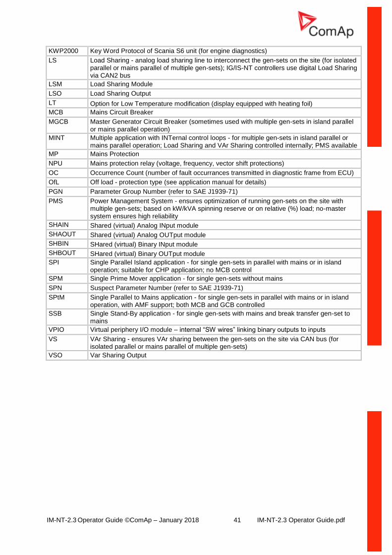
KWP2000 Key Word Protocol of Scania S6 unit (for engine diagnostics)
LS Load Sharing - analog load sharing line to interconnect the gen-sets on the site (for isolated parallel or mains parallel of multiple gen-sets); IG/IS-NT controllers use digital Load Sharing via CAN2 bus
LSM Load Sharing Module
LSO Load Sharing Output
LT Option for Low Temperature modification (display equipped with heating foil)
MCB Mains Circuit Breaker
MGCB Master Generator Circuit Breaker (sometimes used with multiple gen-sets in island parallel or mains parallel operation)
MINT Multiple application with INTernal control loops - for multiple gen-sets in island parallel or mains parallel operation; Load Sharing and VAr Sharing controlled internally; PMS available
MP Mains Protection
NPU Mains protection relay (voltage, frequency, vector shift protections)
OC Occurrence Count (number of fault occurrances transmitted in diagnostic frame from ECU)
OfL Off load - protection type (see application manual for details)
PGN Parameter Group Number (refer to SAE J1939-71)
PMS Power Management System - ensures optimization of running gen-sets on the site with multiple gen-sets; based on kW/kVA spinning reserve or on relative (%) load; no-master system ensures high reliability
SHAIN Shared (virtual) Analog INput module
SHAOUT Shared (virtual) Analog OUTput module
SHBIN SHared (virtual) Binary INput module
SHBOUT SHared (virtual) Binary OUTput module
SPI Single Parallel Island application - for single gen-sets in parallel with mains or in island operation; suitable for CHP application; no MCB control
SPM Single Prime Mover application - for single gen-sets without mains
SPN Suspect Parameter Number (refer to SAE J1939-71)
SPtM Single Parallel to Mains application - for single gen-sets in parallel with mains or in island operation, with AMF support; both MCB and GCB controlled
SSB Single Stand-By application - for single gen-sets with mains and break transfer gen-set to mains
VPIO Virtual periphery I/O module – internal “SW wires” linking binary outputs to inputs
VS VAr Sharing - ensures VAr sharing between the gen-sets on the site via CAN bus (for isolated parallel or mains parallel of multiple gen-sets)
VSO Var Sharing Output