Embed Size (px)
Citation preview
Ingeniería y CienciaISSN:1794-9165ISSN-e: 2256-4314ing. cienc., vol 8, no16, pp. 11–36, julio-diciembre. 2012.http://www.eafit.edu.co/ingcienciaThis a open-access article distributed under the terms of the Creative Commons Attribution License.
Inverse-FEM Characterization of a BrainTissue Phantom to Simulate Compression
and IndentationElizabeth Mesa–Múnera1, Juan F. Ramírez–Salazar2, Pierre Boulanger3 and
John W. Branch4
Received:18-abr-2012, Acepted: 17-oct-2012Available online: 30-nov-2012
MSC: 74S05
AbstractThe realistic simulation of tool-tissue interactions is necessary for the develop-ment of surgical simulators and one of the key element for it realism is accuratebio-mechanical tissue models. In this paper, we determined the mechanicalproperties of soft tissue by minimizing the difference between experimentalmeasurements and the analytical or simulated solution of the deformation.Then, we selected the best model parameters that fit the experimental data tosimulate a bonded compression and a needle indentation with a flat-tip. Weshow that the inverse FEM allows accurate material property estimation. Wealso validated our results using multiple tool-tissue interactions over the samespecimen.
1 Mechanical Engineer, M.Sc in Systems Engineering, [email protected], researcherNational University of Colombia, Medellin–Colombia.2 Mechanical Engineer, M.Sc in Systems Engineering, [email protected], researcher,National University of Colombia, Medellin–Colombia.3 Ph.D in Electrical Engineering, [email protected], professor, University of Alberta,Edmonton–Canada.4 Ph.D in Systems Engineering, [email protected], professor, National University ofColombia, Medellín–Colombia.
Universidad EAFIT 11|
Inverse-FEM Characterization of a Brain Tissue Phantom to Simulate Compression andIndentation
Key words: Inverse FEM, Compression Test, Indentation, TissueCalibration, Surgical Simulators.
Caracterización de tejido cerebral artificial utilizandoInverse-FEM para simular indentación y comprensiónResumenUna simulación realista de la interacción tejido-herramienta es necesaria pa-ra desarrollar simuldores quirúrgicos, y la presición en modelos biomecánicosde tejidos es determinante para cumplir tal fin. Los trabajos previos han ca-racterizado las propiedades de tejidos blandos; sin embargo, ha faltado unavalidación apropiada de los resultados. En este trabajo se determinaron laspropiedades mecánicas de un tejido blando minimizando la diferencia entrelas mediciones experimentales y la solución analítica o simulada del problema.Luego, fueron seleccionados los parámetros que mejor se ajustaron a los da-tos experimentales para simular una compresión con fricción y la indentaciónde una aguja con punta plana. Se concluye que el inverse-FEM permite laprecisa estimación de las propiedades del material. Además, estos resultadosfueron validados con varias interacciones tejido-herramienta sobre el mismoespécimen.
Palabras claves: inverse-FEM, Ensayo a Compresión, Indentación,Calibración de tejidos, Simuladores Quirúrgicos.
1 Introduction
The realistic simulation of surgical procedures has been considered to be an ef-fective and safe method for the development of surgical training and planningby emphasizing on real-time interaction with medical instruments and realis-tic virtual models of patients. Surgical simulators have been developed for awide range of procedures and they can be classified into three main categories:needle-based, open, and minimally invasive surgery (MIS). Neurosurgical nee-dle insertion (NI) is a type of MIS that is performed with a restricted fieldof view, displaced 2D visual feedback, and distorted haptic feedback. To sim-ulate realistic surgical interventions for NI into the brain, it is necessary toimplement algorithms that are accurate and computationally efficient [1]. Fur-thermore, the accuracy of planning in medical interventions and the credibility
|12 Ingeniería y Ciencia
Elizabeth Mesa–Múnera, Juan F. Ramírez–Salazar, Pierre Boulanger and John W. Branch
of surgical simulation depend on soft-tissue constitutive laws, representationsof the surgical tools, organ geometry, and boundary conditions imposed bythe connective tissues surrounding the organ [2]. Much research and develop-ment have been devoted to training surgeons in MIS using visual and hapticfeedback, but the accurate characterization of soft tissue models is critical forhaptic simulation and remains an open research area [3].
Techniques to acquire soft tissue properties are difficult. Some researchershave evaluated soft tissue properties in-vivo, ex-vivo, or in phantom tissues, us-ing stretch tests [4], aspiration experiments [5], compression tests, and needleinsertion, for linear [6] and non-linear bio-mechanical models [7]. In all thesecases, researchers showed that their material models fit correctly with the ex-perimental data acquired during a material calibration procedure. However,they did not evaluate the estimated material properties in different experi-mental setups that resemble real-world procedures. In this paper, a materialmodel of a silicone rubber with properties close to brain tissues was estimatedusing different experimental setups (standard compression, bonded compres-sion, and flat-tip needle indentation). Initially, the material parameters areestimated by performing a standard compression test and by comparing ananalytical deformation solution to the experimental data. Following this ini-tial estimation, the simulated deformations are compared and validated withthe ones resulting from bounded compression and needle indentation usinginverse Finite Element Methods (FEM). This paper is organized as follow-ing. We first, review the related work on tissue characterization in Section 2.We also review the theoretical foundations of hyperelastic models in Section3. Sections 4, 5, and 6 describe the methods, experiments, and results tocalibrate a material model using a standard compression test, bonded com-pression test, and an indentation experiment, respectively. We then concludeand discuss future work.
2 Related Work
To produce a realistic approximation of soft tissue in surgical virtual environ-ments, it is necessary to develop accurate mathematical models that predictits behavior. Tissue characterization consists of estimating material propertiesusing measurements of tool-tissue interaction forces and deformations. Someresearchers use indentation [6],[7], others consider stretching [4], aspiration [5],
ing.cienc., vol 8, n◦16, julio-diciembre. 2012. 13|
Inverse-FEM Characterization of a Brain Tissue Phantom to Simulate Compression andIndentation
compression [8], and vibration [9]. Results have been reported for different or-gans of animals and humans, such as the liver [10], the brain [11],[12], and thekidney [7]. Some researchers have used ex-vivo experiments and phantom tis-sues, as they allow precise control of the sample and experimental conditionsfor modeling [6],[13].
Some materials can be successfully defined by very simple approximationsbased on Hooke’s Law, as shown by DiMaio and Salcudean in [6]. However,more complex materials, such as liver, kidney, and brain, require the use ofviscoelastic and hyperelastic models. Kim et al. [7] determined the hyper-viscoelastic properties of intra-abdominal organs in-vivo using an indentationdevice. As mentioned earlier, previous work on tissue calibration did notevaluate and validate model performance in different conditions. For instance,Miller et al. [11] demonstrated that swine brain tissue is considerably softerin extension than in compression.
3 Theoretical Foundations
Biomechanics seeks to understand the mechanics of living systems. We focusedour study on the deformation and displacement of a continuous material whensubjected to the action of different stresses and forces. The definitions in thissection come from the continuum mechanics theory presented by Fung in hisbooks [15],[14] and the notation is according to the book by Bower [16]. Thissection presents the hyperelastic constitutive laws to approximate brain tissuebehavior. An extensive overview of continuum mechanics is beyond the scopeof this section, but [16],[15] and [14] provide a good introduction to this subjectand its applications to living tissues.
3.1 Hyperelasticity
Different constitutive laws are used to model the mechanical response of amaterial according to its behavior [16]. These models are obtained by fi-tting experimental measurements to a set of equations that relate stresses andstrains. Hyperelastic models are required when the material is subjected tofinite displacements, whereas elastic theory is restricted to infinitesimal dis-placements. Hyperelasticity constitutes the basis for more complex material
|14 Ingeniería y Ciencia
Elizabeth Mesa–Múnera, Juan F. Ramírez–Salazar, Pierre Boulanger and John W. Branch
models such as viscoelasticity and tissue damage [17]. The constitutive equa-tion for a hyperelastic material is derived from an analytic function of thestrain energy density (W ) with respect to the deformation gradient tensor(Fij). The strain energy can be defined in terms of the invariants (I1, I2, I3)of the left Cauchy Green deformation tensor (Bij), the alternative invariants(I1, I2, J) of Bij , or in terms of the principal stretches (λ1, λ2, λ3), as shownby: W (F) = U(I1, I2, I3) = U(I1, I2, J) = U(λ1, λ2, λ3). Later, W is relatedwith the Cauchy Stress Tensor (σij) to model the behavior of a hyperelasticmaterial and is defined by:
σij =1
JFik
∂W
∂Fkj, (1)
where F and J denote the deformation gradient tensor and its Jacobian, res-pectively. Depending on the complexity of the function W , different featuressuch as nonlinearity and anisotropy can be added into the model [17]. Some ofthe most representative forms of the strain energy density, which are usuallyincluded in commercial FEM software and are: Polynomial Strain Energy,Reduced Polynomial Strain Energy Potential, Ogden Form, Neo-Hookean Solidand Mooney-Rivlin Solid.
Soft biological tissues can be approximated as nearly incompressible ma-terials because of their high water content. To model fully incompressiblematerials using any of the previous models, one simply needs to set the Jaco-bian equal to 1.
4 Material calibration using the analytical solution of a simplecompression test
Tissue characterization consists of the determination of material properties byminimizing the differences between experimental measurements and the solu-tion of the constitutive equation. This equation can be solved analytically ornumerically. The first step consist of solving an analytical solution of a sim-ple uniaxial compression test of multiple hyperelastic materials to determinedirectly the model parameters based on a least-squares fit.
ing.cienc., vol 8, n◦16, julio-diciembre. 2012. 15|
Inverse-FEM Characterization of a Brain Tissue Phantom to Simulate Compression andIndentation
4.1 Analytical Solution of an Uniaxial Compression Test
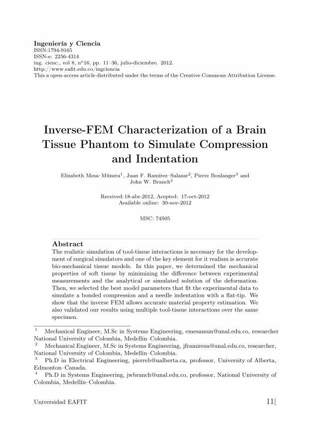
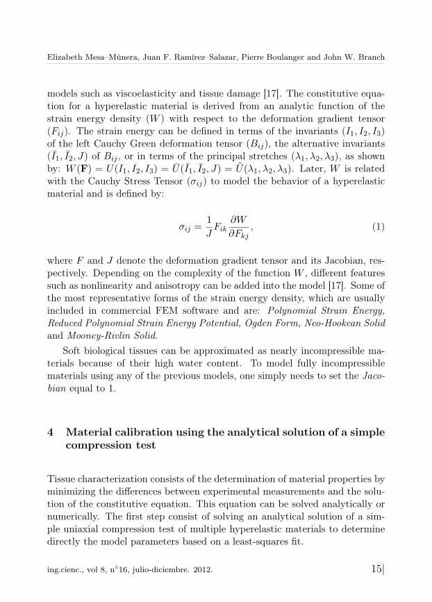
In a simple uniaxial compression test, the material is submitted to a stressescreated by holding the material between two lubricated plates to avoid lateralstresses (see Fig. 1). Let’s assume that the material is incompressible, homo-geneous, and isotropic material. Therefore the transverse strains ε22 and ε33
‡
are considered to be the same.
Figure 1: Standard compression test on a silicon rubber cylinder
Using the Poisson’s ratio (ν), one can relate the transverse strains withthe axial strain ε11 as following: (1 + ε22) = (1 + ε33) = (1 + ε11)
−ν , wherethe principal stretches are defined in terms of the principal nominal strainsby: λi = 1 + εii. Additionally, the deformation gradient tensor (F ) can bealso expressed in terms of λi as shown by Eq. 2. To satisfy the assumption ofan incompressible material, the Jacobian (J) should be equal to 1. Therefore,J = det(F ) = λ1λ2λ3 = 1, where
F =
λ1 0 00 λ2 00 0 λ3
. (2)
Considering that this procedure will be the same for the rest of the materialmodels, an analytical solution for a Neo-Hookean material can be easily deter-mined. From Eq.1 the stress-strain relationship from the strain energy densitycan be deduced [16]:
σij =C10
J5/3(Bij −
1
3Bkkδij) +K1(J − 1)δij . (3)
‡ε33 is perpendicular to the applied load and ε11 is in the same direction of the load.
|16 Ingeniería y Ciencia
Elizabeth Mesa–Múnera, Juan F. Ramírez–Salazar, Pierre Boulanger and John W. Branch
Now, defining the left Cauchy-Green deformation tensor as Bij = FikFjk andusing Eq. 2, the normal stress for an incompressible Neo-Hookean material isgiven by σ11 = 2C10(λ
21 − 1
3(λ21 + λ2
2 + λ23)), where λ2 = λ3 = λ
−1/21 .
Using the relationship between strains and stresses during a uniaxial compres-sion test, the normal components of the Cauchy Stress can be defined in termsof the principal stretch in direction of the load application:σ11 =
43C10(λ
21 − λ−1
1 ); σ22 = σ33 =23C10(λ
−11 − λ2
1).Knowing that the relationship of the Cauchy stress with the nominal stress
is given by Sij = JF−1ik σkj , we can define the following nominal stresses (Sij):
S11 =43C10(λ1 − λ−2
1 ), S22 = S33 =23C10(λ
−21 − λ1).
We rather use nominal stress instead of the Cauchy stress, because Sij
corresponds to the internal force per unit of undeformed area acting withina solid, which is easier to determine during an experimental procedure. Theconstitutive equations for the Neo-Hookean, Reduced Polynomial, MooneyRivlin, and Ogden models are respectively:
Neo-Hookean: S11 = 2C10(λ1 − λ−21 ), (4)
2nd Order Reduced Pol.: S11 = 2(λ1 − λ−21 )(C10 + 2C20(I1 − 3)), (5)
Mooney-Rivlin Solid: S11 = 2(1− λ−31 )(C10λ1 + C01), (6)
Ogden Form: S11 = 2µ1
α1(λα1−1
1 − λ−0.5α1−11 ). (7)
4.2 Experimental Setup: Uniaxial Compression Test
As shown by Francheschini et al. [18], human brain tissue is similar to filledelastomers, and can be modeled by a nonlinear solid with small volumetriccompressibility. Girnary [19] also highlights that silicone brain phantoms area good approximation to simulate brain behavior. Other additional studiesuse silicone rubber phantoms (such as Ecoflex ) to successfully simulate thebehavior of human tissue [20],[21],[22],[23].
The parameters for four different hyperelastic models were estimated tosimulate the mechanical behavior of a platinum-cure silicone rubber submittedto a compression test.The silicone rubber is called Ecoflex 00-10 (from Smooth-On, Inc.) where aproportion (20%) of a softener called "Slacker" (also from Smooth-On, Inc.)
ing.cienc., vol 8, n◦16, julio-diciembre. 2012. 17|
Inverse-FEM Characterization of a Brain Tissue Phantom to Simulate Compression andIndentation
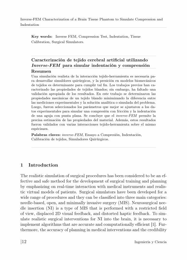
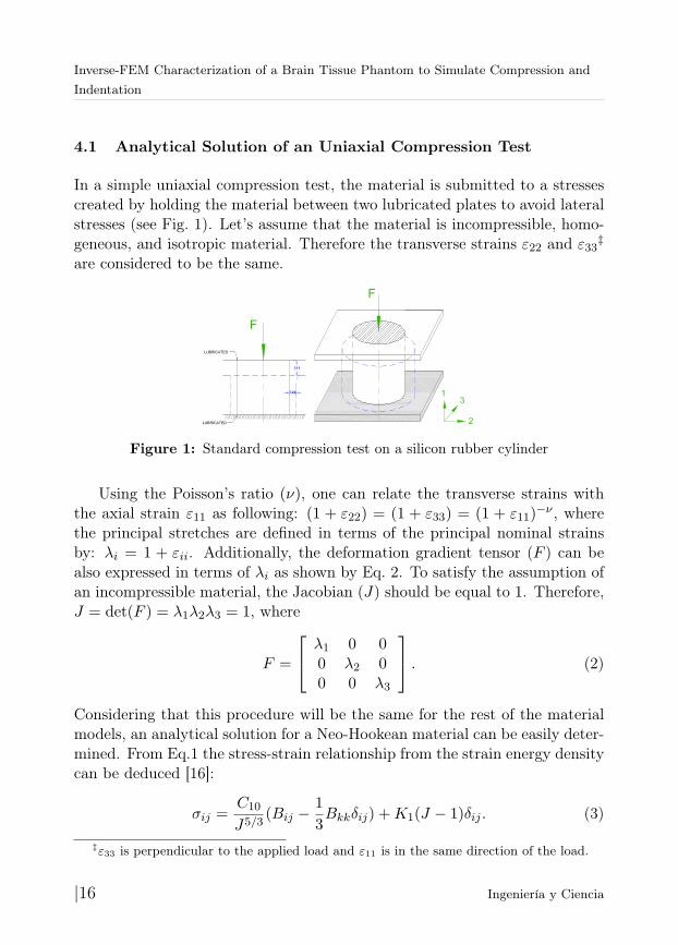
was used to simulate brain tissue. Each component of the rubber solution wasevenly mixed according to the recommendations of the manufacturer and thenformed into a cylindrical mold of 80 mm diameter and 70 mm height.
Figure 2: Experimental setup for the compression test of a silicon rubber (Ecoflex-0010) cylinder. The surfaces were lubricated and the specimen was compressed to astrain of 0.14
A force/torque sensing sensor was installed on a laparoscopic grasping tooland was calibrated by the manufacturer (ATI, Industrial Automation). Themaximum error in the Z axis (the needle axis) is 0.75% of its full-scale load.This calibration was done at a constant 22◦C. The force/torque sensor (ATIMini40 SI-40-2) had a resolution of 0.02 N and was attached to a laparoscopicgrasping tool, which was fixed to a rigid plate (see Fig. 2). The contact areaswere lubricated with talcum powder in order to minimize lateral friction. Theplate was displaced using a Phidget bipolar stepper motor to compress thetissue at a constant velocity of 0.248 mm/s (based on [24],[25],[26],[18],[12]),until the plate was displaced by 10 mm.
4.3 Methodology
A C++ program was developed to integrate the measurements of forces (givenby the f/t sensor) with displacements (given by the motor) using the time (in
|18 Ingeniería y Ciencia
Elizabeth Mesa–Múnera, Juan F. Ramírez–Salazar, Pierre Boulanger and John W. Branch
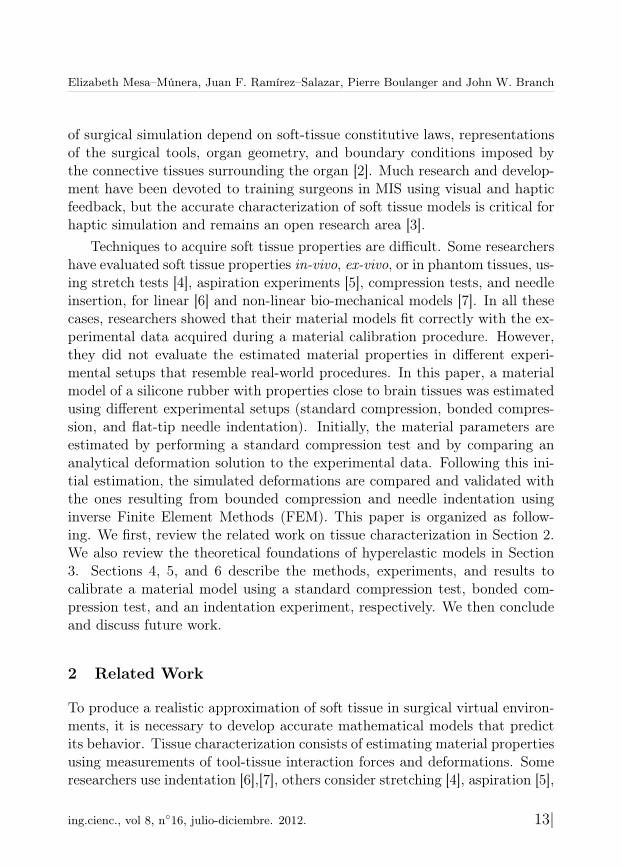
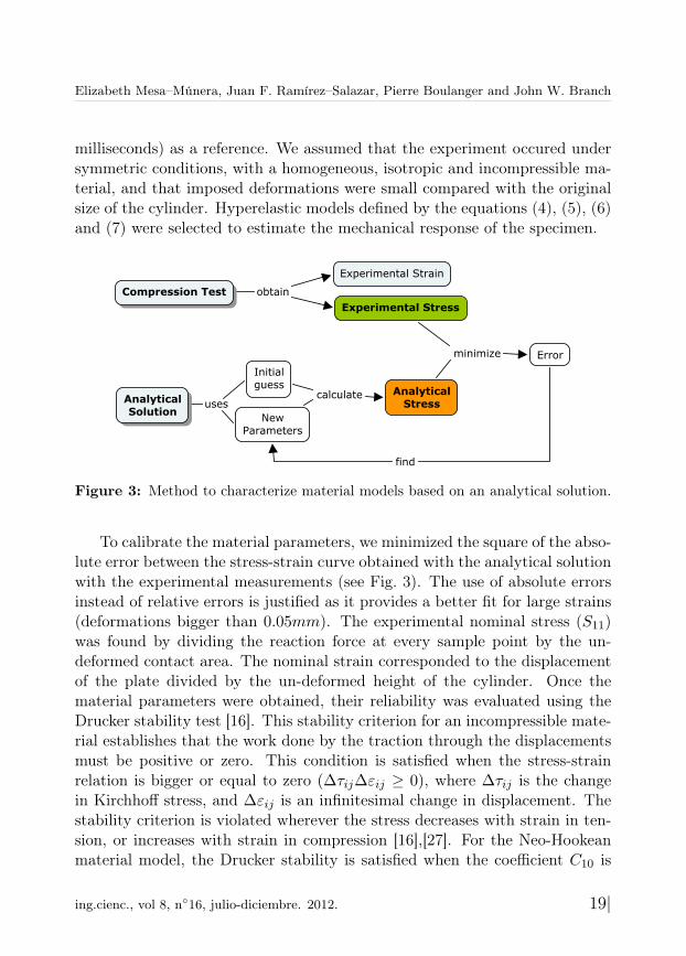
milliseconds) as a reference. We assumed that the experiment occured undersymmetric conditions, with a homogeneous, isotropic and incompressible ma-terial, and that imposed deformations were small compared with the originalsize of the cylinder. Hyperelastic models defined by the equations (4), (5), (6)and (7) were selected to estimate the mechanical response of the specimen.
Figure 3: Method to characterize material models based on an analytical solution.
To calibrate the material parameters, we minimized the square of the abso-lute error between the stress-strain curve obtained with the analytical solutionwith the experimental measurements (see Fig. 3). The use of absolute errorsinstead of relative errors is justified as it provides a better fit for large strains(deformations bigger than 0.05mm). The experimental nominal stress (S11)was found by dividing the reaction force at every sample point by the un-deformed contact area. The nominal strain corresponded to the displacementof the plate divided by the un-deformed height of the cylinder. Once thematerial parameters were obtained, their reliability was evaluated using theDrucker stability test [16]. This stability criterion for an incompressible mate-rial establishes that the work done by the traction through the displacementsmust be positive or zero. This condition is satisfied when the stress-strainrelation is bigger or equal to zero (∆τij∆εij ≥ 0), where ∆τij is the changein Kirchhoff stress, and ∆εij is an infinitesimal change in displacement. Thestability criterion is violated wherever the stress decreases with strain in ten-sion, or increases with strain in compression [16],[27]. For the Neo-Hookeanmaterial model, the Drucker stability is satisfied when the coefficient C10 is
ing.cienc., vol 8, n◦16, julio-diciembre. 2012. 19|
Inverse-FEM Characterization of a Brain Tissue Phantom to Simulate Compression andIndentation
positive.
4.4 Results
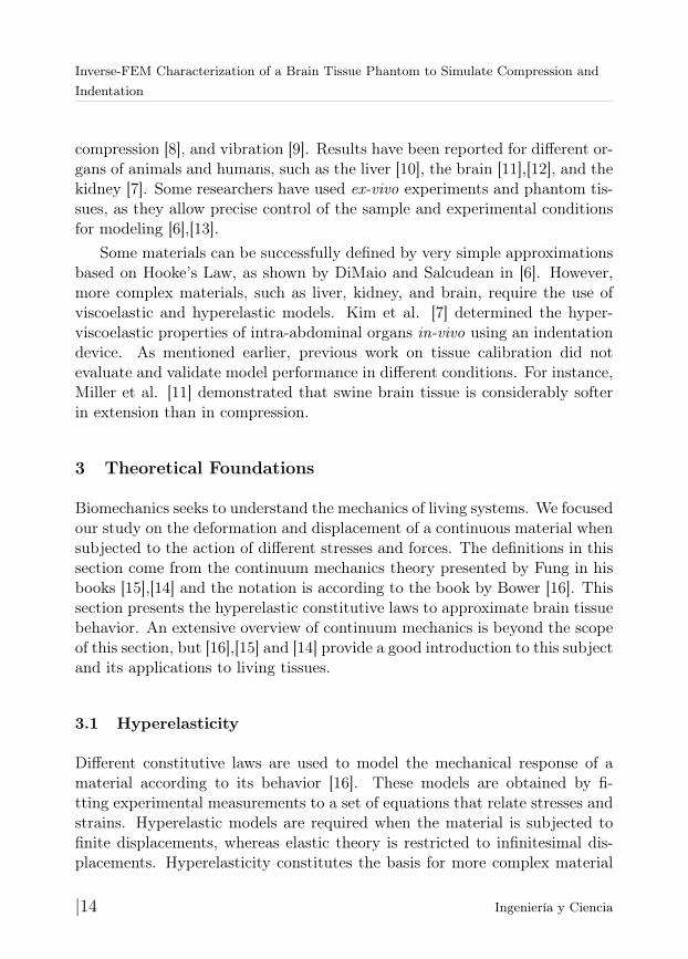
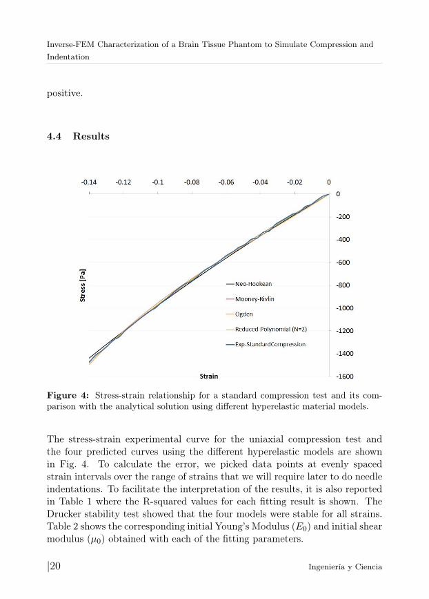
Figure 4: Stress-strain relationship for a standard compression test and its com-parison with the analytical solution using different hyperelastic material models.
The stress-strain experimental curve for the uniaxial compression test andthe four predicted curves using the different hyperelastic models are shownin Fig. 4. To calculate the error, we picked data points at evenly spacedstrain intervals over the range of strains that we will require later to do needleindentations. To facilitate the interpretation of the results, it is also reportedin Table 1 where the R-squared values for each fitting result is shown. TheDrucker stability test showed that the four models were stable for all strains.Table 2 shows the corresponding initial Young’s Modulus (E0) and initial shearmodulus (µ0) obtained with each of the fitting parameters.
|20 Ingeniería y Ciencia
Elizabeth Mesa–Múnera, Juan F. Ramírez–Salazar, Pierre Boulanger and John W. Branch
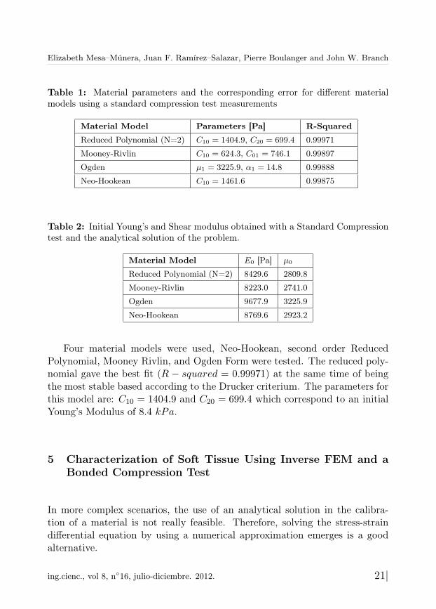
Table 1: Material parameters and the corresponding error for different materialmodels using a standard compression test measurements
Material Model Parameters [Pa] R-Squared
Reduced Polynomial (N=2) C10 = 1404.9, C20 = 699.4 0.99971
Mooney-Rivlin C10 = 624.3, C01 = 746.1 0.99897
Ogden µ1 = 3225.9, α1 = 14.8 0.99888
Neo-Hookean C10 = 1461.6 0.99875
Table 2: Initial Young’s and Shear modulus obtained with a Standard Compressiontest and the analytical solution of the problem.
Material Model E0 [Pa] µ0
Reduced Polynomial (N=2) 8429.6 2809.8
Mooney-Rivlin 8223.0 2741.0
Ogden 9677.9 3225.9
Neo-Hookean 8769.6 2923.2
Four material models were used, Neo-Hookean, second order ReducedPolynomial, Mooney Rivlin, and Ogden Form were tested. The reduced poly-nomial gave the best fit (R − squared = 0.99971) at the same time of beingthe most stable based according to the Drucker criterium. The parameters forthis model are: C10 = 1404.9 and C20 = 699.4 which correspond to an initialYoung’s Modulus of 8.4 kPa.
5 Characterization of Soft Tissue Using Inverse FEM and aBonded Compression Test
In more complex scenarios, the use of an analytical solution in the calibra-tion of a material is not really feasible. Therefore, solving the stress-straindifferential equation by using a numerical approximation emerges is a goodalternative.
ing.cienc., vol 8, n◦16, julio-diciembre. 2012. 21|
Inverse-FEM Characterization of a Brain Tissue Phantom to Simulate Compression andIndentation
5.1 Inverse Finite Element Method
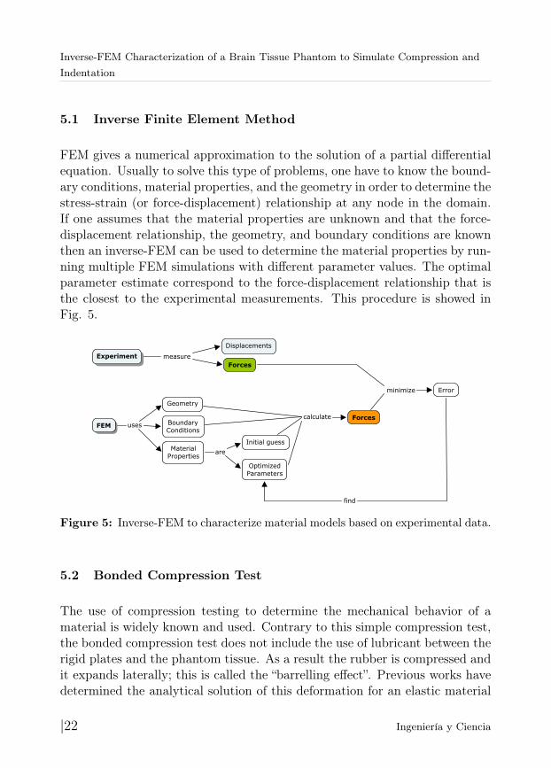
FEM gives a numerical approximation to the solution of a partial differentialequation. Usually to solve this type of problems, one have to know the bound-ary conditions, material properties, and the geometry in order to determine thestress-strain (or force-displacement) relationship at any node in the domain.If one assumes that the material properties are unknown and that the force-displacement relationship, the geometry, and boundary conditions are knownthen an inverse-FEM can be used to determine the material properties by run-ning multiple FEM simulations with different parameter values. The optimalparameter estimate correspond to the force-displacement relationship that isthe closest to the experimental measurements. This procedure is showed inFig. 5.
Figure 5: Inverse-FEM to characterize material models based on experimental data.
5.2 Bonded Compression Test
The use of compression testing to determine the mechanical behavior of amaterial is widely known and used. Contrary to this simple compression test,the bonded compression test does not include the use of lubricant between therigid plates and the phantom tissue. As a result the rubber is compressed andit expands laterally; this is called the “barrelling effect”. Previous works havedetermined the analytical solution of this deformation for an elastic material
|22 Ingeniería y Ciencia
Elizabeth Mesa–Múnera, Juan F. Ramírez–Salazar, Pierre Boulanger and John W. Branch
[8],[28],[29]. However, the solution for more complicated material models (suchas viscoelastic and hyperelastic) is not trivial.
5.2.1 Experimental Setup Using the same material specimen as before,we applied compressive forces without the use of lubricant and executed theexperiment three times in order to validate the measurements. The forcesensor, motor, temperature, displacement of the plate, and the velocity ofmovement, were the same.
5.3 Methodology
Based on the experimental measurements, the material properties were deter-mined using the method described in Fig. 5. Multiple FEM simulations werecomputed keeping the same geometries and boundary conditions except forthe friction between the plates and the tissue. Additionally, we optimized thematerial properties to minimize the error between experimental measurementsand the FEM results.
Because a cylindrical sample was used, one could also analyze this 3–D problem as an axis-symmetric formulation reducing the problem to a 2Dscheme. Based on [31],[30],[32] the friction coefficient between silicone rubberand steel ranges between 0.6 to 0.9. We ran multiple simulations using thesevarious friction coefficients and did not find any significant differences eitherin the prediction of the reaction forces nor in the geometrical changes. Inconsequence, we used a friction coefficient of 0.7 in all our simulations. Wesimulated bounded compression in ABAQUS 6.10 EF2 as the contact betweena rigid plate and silicone rubber specimen. The discrete rigid bodies weretwo lines composed by 10 linear line elements of type RAX2 and 11 nodes.Each rigid body had a reference point where we applied boundary conditions.The axis-symmetric deformable model corresponded to a square of 40 mm by70 mm, with 500 linear quadrilateral hybrid elements of type C4X4RH and 546nodes. The mesh size was graded to be more refined close to the areas wherewe expected higher deformations and coarse near to the axis of revolution.In all simulations, we allowed nonlinearities, for the material model and forlarge geometric deformation. We delimited position constraints for the threeparts that were provided for our simulation. The edges of the rigid parts
ing.cienc., vol 8, n◦16, julio-diciembre. 2012. 23|
Inverse-FEM Characterization of a Brain Tissue Phantom to Simulate Compression andIndentation
were coincident with the upper and lower surface of the deformable body.At the contact, we defined a penalty method, where the tangential behaviorhad the friction coefficient equal to 0.7. This boundary condition completelyrestricted the displacement and rotation of the RP-B. The RP-A was displaced10 mm in y-direction during 40.32 s (which ensured a compression velocity of0.248 mm/s), its displacement in X and rotation around Z was fixed to be zero.Finally, we also applied a symmetric boundary condition in the X direction.
Because this study required a nonlinear optimization, the solution wasfound by specifying the loading as a function of time, which allowed us toobtain the nonlinear response. Therefore, for each time increment ABAQUSsolved the system of equations using the Newton optimization method. Theintegration time steps was defined between 1.25 × 10⁻⁵ and 0.25. Once thesolution for a specific set of material properties was found, an optimization al-gorithm determined a new set of parameters to redo the FEM simulation (thissteps were done in PYTHON). With the initial guess we used a Levenberg-Marquardt optimization algorithm to find the material coefficients that fitsbetter the experimental measurements. We used a Python program to ma-nage the inputs and outputs directly from ABAQUS, to estimate the error,process the output, modify the material properties, and re-submit a new si-mulation until the convergence is achieved. Finally, we validated the stabilityof the material using the Drucker stability test.
5.4 Results
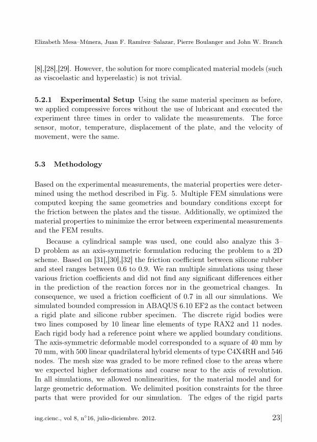
The figure 6 shows the geometrical changes of a Silicon Rubber cylinder sub-mitted under compressive forces without lubricant.
Figure 6: Deformation of the tissue under a compression test without lubricantbetween the rigid surfaces and the silicone rubber.
|24 Ingeniería y Ciencia
Elizabeth Mesa–Múnera, Juan F. Ramírez–Salazar, Pierre Boulanger and John W. Branch
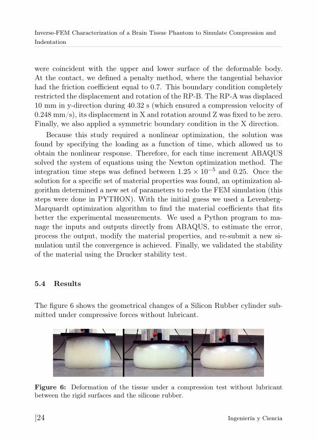
To visualize the behavior of the force/displacement (f/d) curve for thematerial at higher deformations, we also submitted the tissue to a bondedcompression test that displaced the plate up to 30 mm (see Fig. 7). In thatcase, it was obvious the curvature of the f/d relationship. But, because we areinterested in brain needle insertion applications, we do not require indentationsthat produce strains bigger than 0.14 (bigger than 10mm using this specimen).Therefore, we will focus in the definition of a material model that accuratelyfit the region of strains lower than 0.14.
Figure 7: Experimental Force/Displacement plot for a bonded compression test(compressed by 30 mm).
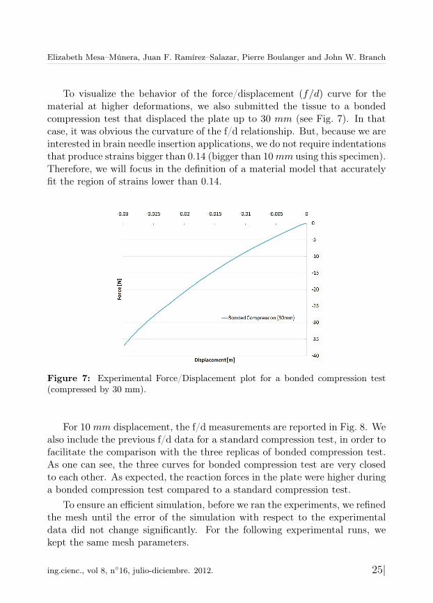
For 10 mm displacement, the f/d measurements are reported in Fig. 8. Wealso include the previous f/d data for a standard compression test, in order tofacilitate the comparison with the three replicas of bonded compression test.As one can see, the three curves for bonded compression test are very closedto each other. As expected, the reaction forces in the plate were higher duringa bonded compression test compared to a standard compression test.
To ensure an efficient simulation, before we ran the experiments, we refinedthe mesh until the error of the simulation with respect to the experimentaldata did not change significantly. For the following experimental runs, wekept the same mesh parameters.
ing.cienc., vol 8, n◦16, julio-diciembre. 2012. 25|
Inverse-FEM Characterization of a Brain Tissue Phantom to Simulate Compression andIndentation
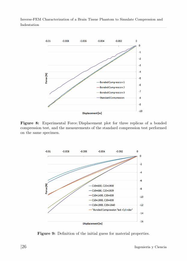
Figure 8: Experimental Force/Displacement plot for three replicas of a bondedcompression test, and the measurements of the standard compression test performedon the same specimen.
Figure 9: Definition of the initial guess for material properties.
|26 Ingeniería y Ciencia
Elizabeth Mesa–Múnera, Juan F. Ramírez–Salazar, Pierre Boulanger and John W. Branch
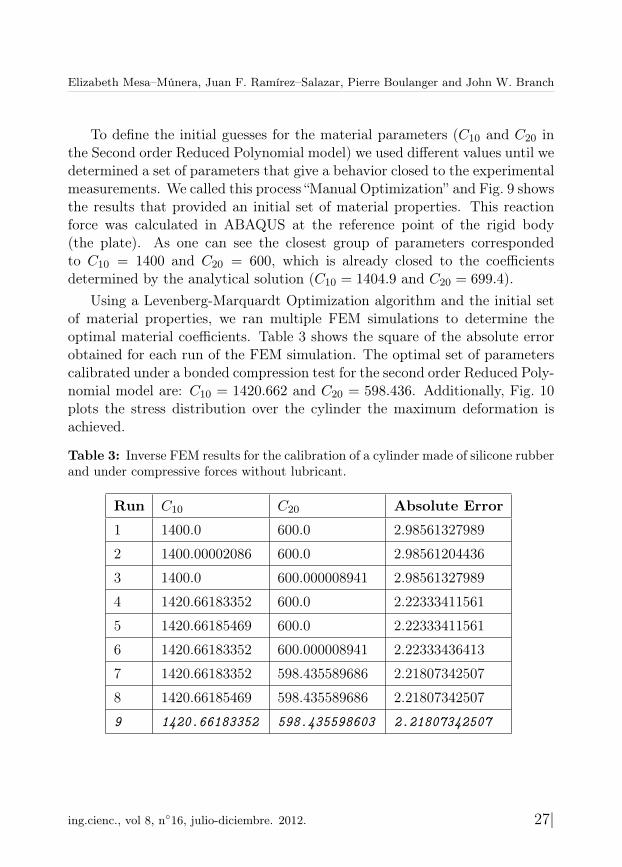
To define the initial guesses for the material parameters (C10 and C20 inthe Second order Reduced Polynomial model) we used different values until wedetermined a set of parameters that give a behavior closed to the experimentalmeasurements. We called this process “Manual Optimization” and Fig. 9 showsthe results that provided an initial set of material properties. This reactionforce was calculated in ABAQUS at the reference point of the rigid body(the plate). As one can see the closest group of parameters correspondedto C10 = 1400 and C20 = 600, which is already closed to the coefficientsdetermined by the analytical solution (C10 = 1404.9 and C20 = 699.4).
Using a Levenberg-Marquardt Optimization algorithm and the initial setof material properties, we ran multiple FEM simulations to determine theoptimal material coefficients. Table 3 shows the square of the absolute errorobtained for each run of the FEM simulation. The optimal set of parameterscalibrated under a bonded compression test for the second order Reduced Poly-nomial model are: C10 = 1420.662 and C20 = 598.436. Additionally, Fig. 10plots the stress distribution over the cylinder the maximum deformation isachieved.
Table 3: Inverse FEM results for the calibration of a cylinder made of silicone rubberand under compressive forces without lubricant.
Run C10 C20 Absolute Error
1 1400.0 600.0 2.98561327989
2 1400.00002086 600.0 2.98561204436
3 1400.0 600.000008941 2.98561327989
4 1420.66183352 600.0 2.22333411561
5 1420.66185469 600.0 2.22333411561
6 1420.66183352 600.000008941 2.22333436413
7 1420.66183352 598.435589686 2.21807342507
8 1420.66185469 598.435589686 2.21807342507
9 1420.66183352 598.435598603 2.21807342507
ing.cienc., vol 8, n◦16, julio-diciembre. 2012. 27|
Inverse-FEM Characterization of a Brain Tissue Phantom to Simulate Compression andIndentation
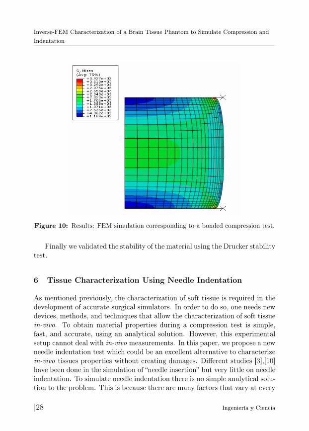
Figure 10: Results: FEM simulation corresponding to a bonded compression test.
Finally we validated the stability of the material using the Drucker stabilitytest.
6 Tissue Characterization Using Needle Indentation
As mentioned previously, the characterization of soft tissue is required in thedevelopment of accurate surgical simulators. In order to do so, one needs newdevices, methods, and techniques that allow the characterization of soft tissuein-vivo. To obtain material properties during a compression test is simple,fast, and accurate, using an analytical solution. However, this experimentalsetup cannot deal with in-vivo measurements. In this paper, we propose a newneedle indentation test which could be an excellent alternative to characterizein-vivo tissues properties without creating damages. Different studies [3],[10]have been done in the simulation of “needle insertion” but very little on needleindentation. To simulate needle indentation there is no simple analytical solu-tion to the problem. This is because there are many factors that vary at every
|28 Ingeniería y Ciencia
Elizabeth Mesa–Múnera, Juan F. Ramírez–Salazar, Pierre Boulanger and John W. Branch
step right after a needle touches the soft tissue. Depending on the shape of theneedle, the reaction force direction will be different. Additionally, the contactarea changes depending on the needle shape and the distance of penetration.To solve the problem, we use an inverse FEM method which assumes that theneedles are rigid and that the problem can be reduced to an axis-symmetriccondition.
6.1 Methodology
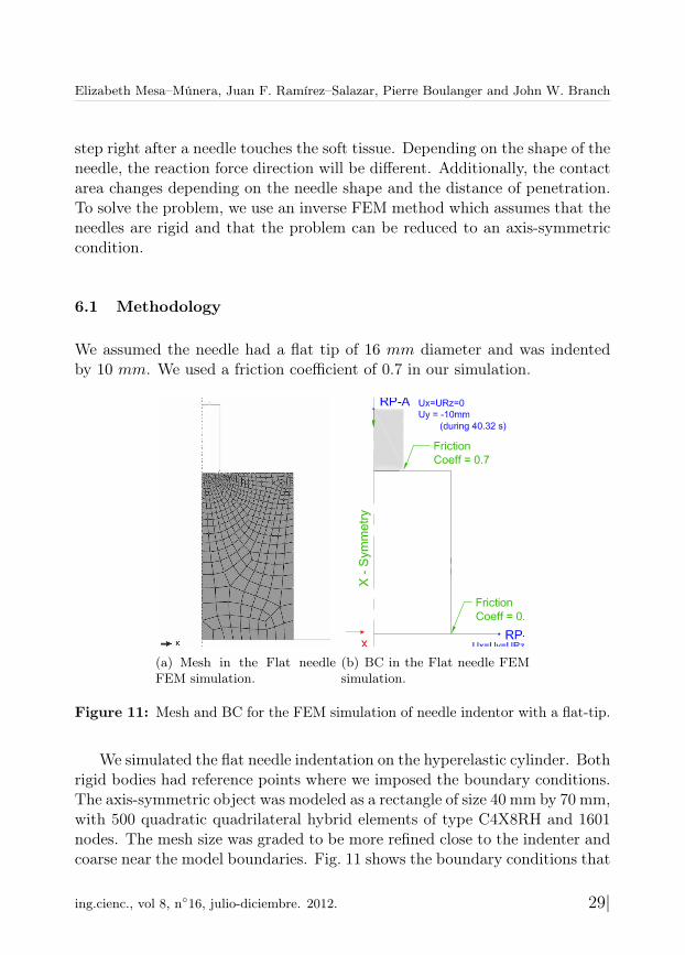
We assumed the needle had a flat tip of 16 mm diameter and was indentedby 10 mm. We used a friction coefficient of 0.7 in our simulation.
(a) Mesh in the Flat needleFEM simulation.
(b) BC in the Flat needle FEMsimulation.
Figure 11: Mesh and BC for the FEM simulation of needle indentor with a flat-tip.
We simulated the flat needle indentation on the hyperelastic cylinder. Bothrigid bodies had reference points where we imposed the boundary conditions.The axis-symmetric object was modeled as a rectangle of size 40 mm by 70 mm,with 500 quadratic quadrilateral hybrid elements of type C4X8RH and 1601nodes. The mesh size was graded to be more refined close to the indenter andcoarse near the model boundaries. Fig. 11 shows the boundary conditions that
ing.cienc., vol 8, n◦16, julio-diciembre. 2012. 29|
Inverse-FEM Characterization of a Brain Tissue Phantom to Simulate Compression andIndentation
were to the rigid bodies and to the soft tissue. As for the time integration it isdefined 1.209×10⁻⁴ was the minimum increment size and 2 was the maximumincrement. Because this simulation is more computationally expensive, theprogram ran in parallel on 4 processors. As the initial guess we used the resultsof the previous characterization (C10 = 1420.0 and C20 = 598.0). Again, weimplemented a Levenberg-Marquardt Optimization algorithm to obtain theoptimal material properties. Finally, and once we obtained the optimal set ofparameters, we validated their stability using the Drucker test.
6.2 Experimental Setup
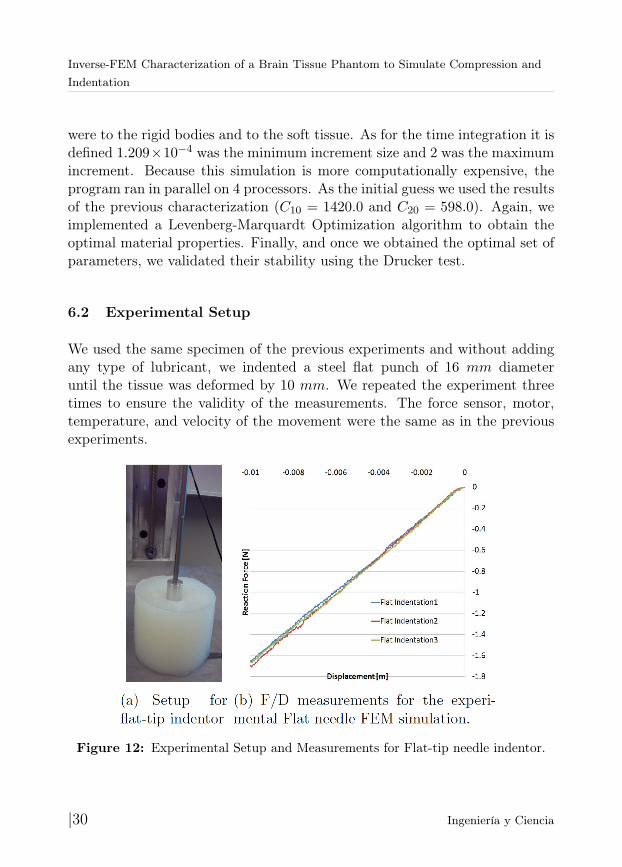
We used the same specimen of the previous experiments and without addingany type of lubricant, we indented a steel flat punch of 16 mm diameteruntil the tissue was deformed by 10 mm. We repeated the experiment threetimes to ensure the validity of the measurements. The force sensor, motor,temperature, and velocity of the movement were the same as in the previousexperiments.
Figure 12: Experimental Setup and Measurements for Flat-tip needle indentor.
|30 Ingeniería y Ciencia
Elizabeth Mesa–Múnera, Juan F. Ramírez–Salazar, Pierre Boulanger and John W. Branch
6.3 Results
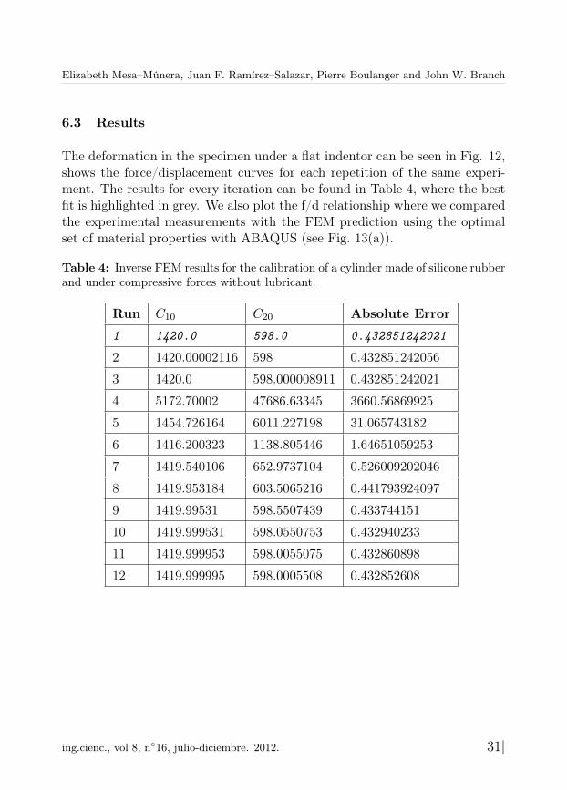
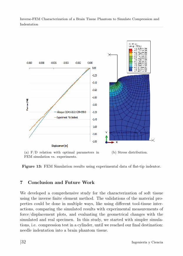
The deformation in the specimen under a flat indentor can be seen in Fig. 12,shows the force/displacement curves for each repetition of the same experi-ment. The results for every iteration can be found in Table 4, where the bestfit is highlighted in grey. We also plot the f/d relationship where we comparedthe experimental measurements with the FEM prediction using the optimalset of material properties with ABAQUS (see Fig. 13(a)).
Table 4: Inverse FEM results for the calibration of a cylinder made of silicone rubberand under compressive forces without lubricant.
Run C10 C20 Absolute Error
1 1420.0 598.0 0.432851242021
2 1420.00002116 598 0.432851242056
3 1420.0 598.000008911 0.432851242021
4 5172.70002 47686.63345 3660.56869925
5 1454.726164 6011.227198 31.065743182
6 1416.200323 1138.805446 1.64651059253
7 1419.540106 652.9737104 0.526009202046
8 1419.953184 603.5065216 0.441793924097
9 1419.99531 598.5507439 0.433744151
10 1419.999531 598.0550753 0.432940233
11 1419.999953 598.0055075 0.432860898
12 1419.999995 598.0005508 0.432852608
ing.cienc., vol 8, n◦16, julio-diciembre. 2012. 31|
Inverse-FEM Characterization of a Brain Tissue Phantom to Simulate Compression andIndentation
(a) F/D relation with optimal parameters inFEM simulation vs. experiments.
(b) Stress distribution.
Figure 13: FEM Simulation results using experimental data of flat-tip indentor.
7 Conclusion and Future Work
We developed a comprehensive study for the characterization of soft tissueusing the inverse finite element method. The validations of the material pro-perties could be done in multiple ways, like using different tool-tissue inter-actions, comparing the simulated results with experimental measurements offorce/displacement plots, and evaluating the geometrical changes with thesimulated and real specimen. In this study, we started with simpler simula-tions, i.e. compression test in a cylinder, until we reached our final destination:needle indentation into a brain phantom tissue.
|32 Ingeniería y Ciencia
Elizabeth Mesa–Múnera, Juan F. Ramírez–Salazar, Pierre Boulanger and John W. Branch
In our study, we submitted the cylinder to compressive forces with lubri-cant, and we calibrated the material using an analytical solution. We ob-tained the parameters for the Neo-Hookean, Reduced Polynomial, Mooney-Rivlin, and Ogden material models, and we determined if they were stablefor all strains using the Drucker stability criterium. We concluded that thesecond order reduced polynomial model is the best approximation to the ex-perimental data. To validate the results, we re-calibrated the same cylinderusing a bounded compression test using an axis-symmetric FEM simulationin ABAQUS, and a second order reduced polynomial model. We observed theestimated material properties were very close to the standard method.
The final step was to study indentations of a flat-tip indenter with soft-tissues. As mentioned earlier, the final aim of this study was to contribute inthe development of surgical simulators, which requires fast and accurate mod-els. Therefore, it was important to analyze how much the simulation could besimplified. Therefore we probed that using an axis-symmetric FEM simulationwith hyperelastic materials, we successfully at calibrating the sample. Again,the parameters were very similar to the ones obtained with compression tests.
Future work will explore FEM simulations with higher complexity, i.e. fora conical-shaped needle, using an viscoelastic material models, 3D simulations,different geometries and in-vivo measurements.
References
[1] A. Maciel, T. Halic, Z. Lu, L. P. Nedel, y S. De, “Using the PhysX engine forphysics-based virtual surgery with force feedback”, The International Journalof Medical Robotics and Computer Assisted Surgery, vol. 5, n.o 3, pp. 341-353,2009. Referenced in 12
[2] S. Misra, K. J. Macura, K. T. Ramesh, A. M. Okamura, “The Importance ofOrgan Geometry and Boundary Constraints for Planning of Medical Interven-tions”, Med Eng Phys, vol. 31, n.o 2, pp. 195-206, mar. 2009.Referenced in 13
[3] N. Abolhassani, R. Patel, M. Moallem, “Needle insertion into soft tissue: Asurvey”, Medical Engineering & Physics, vol. 29, n.o 4, pp. 413-431, may 2007.Referenced in 13, 28
[4] I. Brouwer, J. Ustin, L. Bentley, A. Sherman, N. Dhruv, F. Tendick, “MeasuringIn Vivo Animal Soft Tissue Properties for Haptic Modeling in Surgical Simula-
ing.cienc., vol 8, n◦16, julio-diciembre. 2012. 33|
Inverse-FEM Characterization of a Brain Tissue Phantom to Simulate Compression andIndentation
tion”, in Stud Health Technol Inform, 2001, pp. 69-74.Referenced in 13
[5] M. Kauer, V. Vuskovic, J. Dual, G. Szekely, y M. Bajka, “Inverse finite elementcharacterization of soft tissues”, Medical Image Analysis, vol. 6, n.o 3, pp. 275-287, sep. 2002. Referenced in 13
[6] S. P. DiMaio y S. E. Salcudean, “Needle insertion modelling and simulation”,in Robotics and Automation, 2002. Proceedings. ICRA ’02. IEEE InternationalConference on, 2002, vol. 2, pp. 2098 - 2105 vol.2. Referenced in 13, 14
[7] J. Kim y M. Srinivasan, “Characterization of Viscoelastic Soft Tissue Propertiesfrom In Vivo Animal Experiments and Inverse FE Parameter Estimation”, inMedical Image Computing and Computer-Assisted Intervention - MICCAI 2005,vol. 3750, J. Duncan y G. Gerig, Eds. Springer Berlin / Heidelberg, 2005, pp.599-606. Referenced in 13, 14
[8] C. Dechwayukul y W. Thongruang, “Compressive modulus of adhesive bondedrubber block”, Songklanakarin Journal of Science and Technology, vol. 30, n.o2, pp. 221-225, 2008. Referenced in 14, 23
[9] M. Kaneko, C. Toya, y M. Okajima, “Active Strobe Imager for Visualizing Dy-namic Behavior of Tumors”, in Robotics and Automation, 2007 IEEE Interna-tional Conference on, 2007, pp. 3009 -3014. Referenced in 14
[10] A. M. Okamura, C. Simone, y M. D. O’Leary, “Force modeling for needle inser-tion into soft tissue”, Biomedical Engineering, IEEE Transactions on, vol. 51,n.o 10, pp. 1707 -1716, oct. 2004. Referenced in 14, 28
[11] K. Miller, A. Wittek, G. Joldes, A. Horton, T. Dutta-Roy, J. Berger, y L.Morriss, “Modelling brain deformations for computer-integrated neurosurgery”,International Journal for Numerical Methods in Biomedical Engineering, vol.26, n.o 1, pp. 117-138, 2010. Referenced in 14
[12] M. Kohandel, S. Sivaloganathan, G. Tenti, y J. M. Drake, “The constitutiveproperties of the brain parenchyma: Part 1. Strain energy approach”, MedicalEngineering & Physics, vol. 28, n.o 5, pp. 449-454, jun. 2006.Referenced in 14, 18
[13] K. Sangpradit, H. Liu, L. D. Seneviratne, y K. Althoefer, “Tissue identificationusing inverse Finite Element analysis of rolling indentation”, in Robotics andAutomation, 2009. ICRA ’09. IEEE International Conference on, 2009, pp. 1250-1255. Referenced in 14
[14] Y. C. Fung, Biomechanics: Mechanical Properties of Living Tissues, SecondEdition, 2nd ed. Springer, 1993. Referenced in 14
|34 Ingeniería y Ciencia
Elizabeth Mesa–Múnera, Juan F. Ramírez–Salazar, Pierre Boulanger and John W. Branch
[15] Y. C. Fung, Foundations of Solid Mechanics, 2nd Printing. Prentice Hall, 1965.Referenced in 14
[16] A. F. Bower, Applied Mechanics of Solids, 1.a ed. CRC Press, 2009.Referenced in 14, 16, 19
[17] N. Famaey y J. V. Sloten, “Soft tissue modelling for applications in virtualsurgery and surgical robotics”, Computer Methods in Biomechanics and Biomed-ical Engineering, vol. 11, n.o 4, pp. 351-366, 2008. Referenced in 15
[18] G. Franceschini, D. Bigoni, P. Regitnig, y G. A. Holzapfel, “Brain tissue de-forms similarly to filled elastomers and follows consolidation theory”, Journal ofthe Mechanics and Physics of Solids, vol. 54, n.o 12, pp. 2592-2620, dic. 2006.Referenced in 17, 18
[19] H. Girnary, “BRAIN PHANTOM PROJECT”, dic. 2007. Referenced in 17
[20] H. O. Altamar, R. E. Ong, C. L. Glisson, D. P. Viprakasit, M. I. Miga, S.D. Herrell, y R. L. Galloway, “Kidney Deformation and Intraprocedural Regis-tration: A Study of Elements of Image-Guided Kidney Surgery”, Journal ofEndourology, vol. 25, n.o 3, pp. 511-517, mar. 2011. Referenced in 17
[21] A. Deram, V. Luboz, E. Promayon, y Y. Payan, “Using a 3D biomechanicalmodel to improve a light aspiration device for in vivo soft tissue characterisation”,Computer Methods in Biomechanics and Biomedical Engineering, vol. 15, n.osup1, pp. 41-43, 2012. Referenced in 17
[22] E. Promayon, V. Luboz, G. Chagnon, T. Alonso, D. Favier, C. Barthod, yY. Payan, “Comparison of LASTIC (Light Aspiration device for in vivo SoftTIssue Characterization) with classic Tensile Tests.”, in Proceedings of the EU-ROMECH534 Colloquium., France, 2012, pp. 75-76. Referenced in 17
[23] D. Hendrickson y F. Bellezo, “Surgical Simulator, Simulated Organs and Methodof Making Same”, . Referenced in 17
[24] K. Miller y K. Chinzei, “Constitutive modelling of brain tissue: Experiment andtheory”, Journal of Biomechanics, vol. 30, n.o 11-12, pp. 1115-1121, nov. 1997.Referenced in 18
[25] K. Miller, “Constitutive model of brain tissue suitable for finite element analysisof surgical procedures”, Journal of Biomechanics, vol. 32, n.o 5, pp. 531-537,may 1999. Referenced in 18
[26] K. Miller, K. Chinzei, G. Orssengo, y P. Bednarz, “Mechanical properties of braintissue in-vivo: experiment and computer simulation”, Journal of Biomechanics,vol. 33, n.o 11, pp. 1369-1376, nov. 2000. Referenced in 18
ing.cienc., vol 8, n◦16, julio-diciembre. 2012. 35|
Inverse-FEM Characterization of a Brain Tissue Phantom to Simulate Compression andIndentation
[27] K. I. Romanov, “The drucker stability of a material”, Journal of Applied Mathe-matics and Mechanics, vol. 65, n.o 1, pp. 155-162, feb. 2001.Referenced in 19
[28] A. N. Gent y E. A. Meinecke, “Compression, bending, and shear of bondedrubber blocks”, Polymer Engineering & Science, vol. 10, n.o 1, pp. 48-53, 1970.Referenced in 23
[29] J. G. Williams y C. Gamonpilas, “Using the simple compression test to deter-mine Young’s modulus, Poisson’s ratio and the Coulomb friction coefficient”,International Journal of Solids and Structures, vol. 45, n.o 16, pp. 4448-4459,ago. 2008. Referenced in 23
[30] “Friction - DiracDelta Science & Engineering Encyclopedia”. [Online]. Available:www.diracdelta.co.uk/science/source/f/r/ . [Accessed: 06-nov-2012].Referenced in 23
[31] “Coefficients of Friction for Steel”. [Online]. Available:hypertextbook.com/facts/2005/steel.shtml [Accessed: mar-2011].Referenced in 23
[32] “Coefficient of Friction”. [Online]. Available:http://buildingcriteria2.tpub.com/ufc_4_152_01/ufc_4_152_010141.htm[Accessed: mar-2011]. Referenced in 23
|36 Ingeniería y Ciencia


