Embed Size (px)
Citation preview
Investigation on Crosstalk in Multi-core Optical Fibers
A Master's Thesis
Submitted to the Faculty of the
Escola Tècnica d'Enginyeria de Telecomunicació de
Barcelona
Universitat Politècnica de Catalunya
by
Ludwig Adolfo Tapia Martinez
In partial fulfilment
of the requirements for the degree of
MASTER IN TELECOMMUNICATIONS ENGINEERING
Advisor: Joan Manuel Gene Bernaus
Barcelona, September 2015


1
Title of the thesis: Investigation on Crosstalk in Multi-core Optical Fibers
Author: Ludwig Adolfo Tapia Martinez
Advisor: Joan Manuel Gene Bernaus
Abstract
We start by describing what SDM is, the problem at hand for it’s been considered and the
different solutions it can provide. We focus on Multi-Core Fibers (MCF) as the favorite
solution regarding SDM and proceed to study the main parameter that dictates the
performance and limitations of said fiber, the crosstalk. We explain the different methods
for accurately estimate the crosstalk under different situations depending on the nature of
the cores and if they are using trench or not. We demonstrate the different approaches with
our own simulations as well as the bend insensitiveness of heterogeneous MCF.
We finish this work by establishing different strategies to obtain the lowest possible
crosstalk and proceed to propose a design of our own, a 19 core Heterogeneous Trench
Assisted MCF that is made by 3 types of cores and then proceed to show the results of the
simulations carried to this design.

2
Dedication
This dissertation is lovingly dedicated to:
My parents: Anselmo Tapia and Beatriz Martinez. You’ve always stood by my side
no matter what I was struggling with and taught me many of the things that today,
I can proudly say are the foundation of the man I’ve become and marked the
guidelines to improve myself at every step of this journey that we call life. Thank you
for your unconditional love, unwavering support and showing me with example on
how to raise a family based on happiness, trust, love and dedication. I always want
to do justice to every time you believed in me, and I know I’m all grown up now;
but my dad will always be my hero and my mom will always be my inspiration. Love
you with all my life and soul.
My Brothers and Family: Anselmo I. and Laura, thank you for growing up with me,
never felt lonely as I always knew I had you by my side; for giving me the purpose
of always trying my best to serve as example and take care of you whenever I
could. Aunt Mary and Ivana, you know you’ve always been my second mom and
second sister; thank you for giving me the privilege and joy of being able to call
you that way, because of how much I love you and how much you love me I know
I can. I want to thank my whole family for all your love and support through this new
experience that has made me grown in so many ways I can’t describe.
My girlfriend: Haneidy Veras, I want to thank you with all my heart for all your
patience and efforts through this journey, and for the dedication and love you’ve
constantly give me at every minute of my life. You’re the person who comes along
and naturally makes all things better and life happier. Thank you for all we’ve been
together. Love you today, love you forever.
My friends and roommates: you all have been with me through this journey in one
way or the other, being good laughs or unforgettable moments, being here beside
me or on the other side of the earth. Thank you for your true friendship and constant
support.
I sincerely love all of you and hope to always keep having each of you by my side.
Thank you,
Ludwig Tapia M.

3
Acknowledgements
It has been a great pleasure and opportunity to spend the last two years in the Technical
School of telecommunication engineering of Barcelona at the Polytechnic University of
Cataluña (UPC) and having completed my master’s degree in an environment of constant
professional development and perfectionism.
First of all, I want to express my most heart-felt and sincere gratitude to my thesis’s director,
Professor Joan Manuel Gene Bernaus, of the department of signal and communications
theory at the Polytechnic University of Cataluña (UPC). Couldn’t have asked for a better
guide throughout this daunting process and making it a truly enjoyable experience through
his constant support and patience.
Secondly, I want to express my deepest gratitude to the president of my country, The
Dominican Republic, Lic. Danilo Medina and to the head of the education ministry, Lic.
Ligia Amado Melo; thanks for choosing me as part of the scholarship program of our
country and allowing me to further expand my education as my experience by sending me
abroad.
Also I want to express my appreciation to fellow student Junting Pan, whose parallel
research also con Multi-Core Fibers also helped as guidelines and further proof to the
crosstalk estimation methods being tested.
I’m also grateful to all the UPC staff who inadvertedly helped me on the journey that led to
the culmination of this work as to my constant learning process through this whole
experience living abroad.
I would like to thank to all my colleagues that contributed to my growth and gave me their
kind support with their useful suggestions as their advice.
Last but not least, I’d like to thank the lively and prosperous city of Barcelona, for giving me
the warmth of its people and the unforgettable experiences that brought me to call this city
my second home.

4
Revision history and approval record
Revision Date Purpose
0 15/07/2015 Document creation
1 30/07/2015 Document revision
2 31/08/2015 Document revision
3 03/09/2015 Document revision
Written by: Reviewed and approved by:
Date 02/09/2015 Date 03/09/2015
Name Ludwig A. Tapia M. Name Joan M. Gene Bernaus
Position Project Author Position Project Supervisor

5
Table of contents
Abstract ................................................................................................................................. 1
Acknowledgements .............................................................................................................. 3
Revision history and approval record................................................................................... 4
Table of contents .................................................................................................................. 5
List of Figures ....................................................................................................................... 6
List of Tables ........................................................................................................................ 7
1. Introduction .................................................................................................................... 8
2. Space-Division Multiplexing (SDM) .............................................................................. 9
2.1. Multi-Mode Fibers (MMF) .................................................................................... 11
2.2. Multi-Core Fibers (MCF) ...................................................................................... 13
3. Crosstalk Estimation in MCF ...................................................................................... 15
3.1. Coupled-Mode Theory (CMT) ............................................................................. 15
3.2. Coupled-Power Theory (CPT) ............................................................................. 18
3.3. Homogeneous MCF Crosstalk Estimation .......................................................... 23
3.4. Heterogeneous MCF Crosstalk Estimation ......................................................... 26
3.4.1. Demonstration of Heterogeneous-MCF bending radius insensitiveness .... 33
4. Layout Design Strategies for Low Crosstalk on MCFs. ............................................. 35
4.1. 19 core Hetero-TA-MCF Proposal....................................................................... 37
5. Conclusions and future development ......................................................................... 40
Bibliography ........................................................................................................................ 42

6
List of Figures
Fig. 1. Physical dimensions for multiplexing and modulating electromagnetic waves. [9] 10
Fig. 2. Supported LP-Modes for given values of the normalized frequency and normalized
propagation constant. [9] .................................................................................................... 12
Fig. 3. Schematic of a 7-core MCF.[13] ............................................................................. 13
Fig. 4. 7-Core Holey MCF [14] ........................................................................................... 14
Fig. 5. Schematic of a bent MCF. [20] ............................................................................... 16
Fig. 6. Random phase offsets applied at every segment. [18] .......................................... 18
Fig. 7. Three types of autocorrelation functions; d: correlation length [20] ....................... 19
Fig. 8 Refractive index profile and cross=sectional dimensions for (a) Step-Index structure
and (b) a trench assisted structure. [21] ............................................................................ 23
Fig. 9. Homogeneous MCF XT Results ............................................................................. 25
Fig. 10. (a) Example of Heterogeneous MCF and, (b) Refractive index difference vs Critical
Bending Radius vs Core Pitch. [22] ................................................................................... 26
Fig. 11 Refractive index distribution with trench of (a) Core p (b) Core q and (c) outside the
cores. [23] ........................................................................................................................... 27
Fig. 12 Geometries for calculating the coupling coefficients [23]...................................... 29
Fig. 13. Core effective index and effective area of the fundamental mode at 1550-nm
wavelength as function of core radius r1 and core refractive index difference. [22] ......... 31
Fig. 14. Homogeneous Step-Index and Trench-assisted vs Heterogeneous TA-MCF .... 32
Fig. 15. 14-Core TA-Heterogeneous MCF ........................................................................ 33
Fig. 16Correlation length simulation results (Bending Radius in mm) .............................. 34
Fig. 17 Partial View of Hetero-TA-MCF [23] ...................................................................... 36
Fig. 18. 19 core Hetero-TA-MCF with 3 types of cores ..................................................... 37

7
List of Tables
Table 1. Electromagnetic waves Physical Dimensions ....................................................... 9
Table 2. Structural Parameters for XT Calculations .......................................................... 24
Table 3. Parameters Hetero-TA-MCF ............................................................................... 31
Table 4. Structural Parameters for Calculation MCF-14cores .......................................... 34
Table 5 Parameters 19 Cores Hetero-TA-MCF ................................................................ 38
Table 6. 19 Core Hetero-TA-MCF Crosstalk Simulation Results...................................... 39

8
1. Introduction
Since its conception and implementation; optical fiber communication has become the
backbone for the telecommunications infrastructure that supports the internet and various
other high-volume data applications; nearly every call we make, every text message we
send, every movie we download and every internet based application is then converted
into a ray of photons that travels through the billions of kilometres of optical fiber that’s been
deployed around the globe.
In recent decades network traffic demand has exponentially grown unceasingly, this is a
direct consequence of the emergence of new technologies and applications that have
modified in certain ways our social interactions and our rate at which we consume data;
also the recent rising of machine-to-machine data centric applications and the advent of
the phenomenon called “internet of things” have caused this demand to skyrocket to new
heights ever imagined by network engineers. This traffic demand has been showing growth
rates in the 20% to 60% range per year [1] on the last decade and all forecast point that it
won’t slow its pace in the years to come.
Optical networks have been growing as well in the recent decades, with new technologies
being implemented to cope with the increasing demand and also to reduce the costs that
these networks imply. The introduction of wavelength-division multiplexing (WDM) [2] and
dense wavelength-division multiplexing (DWDM) [3] which has been the main approach to
meet the increasing demand across the different optical networks on the recent decade.
Coherent detection [4] has also gained much traction as it significantly increases systems
capacity by maximizing the Signal to noise ratio (SNR) of an optical channel in comparison
to direct detection; thus enabling the use of high spectral efficiency quadrature amplitude
modulation (QAM) that transmits the optical signal in both its amplitude and phase
components. Nowadays Digital Coherent Optical Transmission systems [5] are
commercially available opening the path for 100Gbps speeds and beyond.
Although all these new technologies allowed for a multiplicative increase on the capacity
of current optical systems, they are not enough to cope with the exponential growth that
traffic demand is experimenting nowadays; furthermore the current systems are quickly
approaching to the maximum amount of information that can be transmitted on a given
channel, also known as the nonlinear Shannon fundamental information limit [6], leaving
us in a path towards an state where all the capacity of current optical systems is used, also

9
called capacity crunch [7]. This leads to the search of new methods that allow us to
dramatically increase the capacity, an even higher increment of the SNR can only be
achieved by increasing the signal power, but that comes with several limits as how much
power can be amplified and ultimately fiber nonlinearities impose an upper limit on how
much power can allocated to a certain fiber.
Today’s optical systems have already implemented solutions on all the available degrees
of freedom (namely: frequency, polarization amplitude and phase) but one, which is space.
This leaves us with an answer that’s being implemented on other systems but comes as a
first in the world of fiber optics as Space-Divison Multiplexing (SDM); which is considered
as the next evolution on optical network systems.
2. Space-Division Multiplexing (SDM)
All segments of today’s telecommunication networks employ electromagnetic waves to
travel across the medium in which they’re used; said waves are ruled by Maxwell’s
equations in a classical context. The electromagnetic field of these waves can be altered
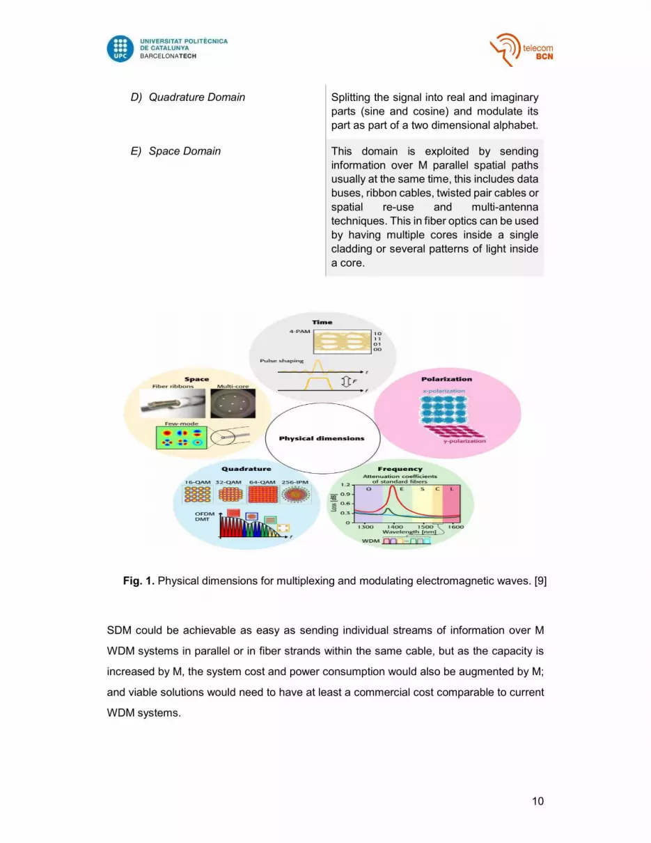
across five physical dimensions (see Table 1) where they can be employed as techniques
to multiplex or modulate the signal [8], as shown on Fig. 1 [9]
Table 1. Electromagnetic waves Physical Dimensions
A) Time Domain Creating time slots and vary a single scalar
magnitude of an electromagnetic wave
within the time slot in a predefined way to
form symbols, then transmit said symbols
at a symbol rate R.
B) Frequency Domain Transmitting multiple communication
signals in parallel on K sufficiently
separated carrier frequencies over the
same transmission medium.
C) Polarization Domain Taking advantage of the vector nature of
electromagnetic waves, especially in
coherent detection, we can transmit
simultaneously on a set of two orthogonal
polarizations by introducing correlations between the symbols of both polarizations,
thus doubling the transmission capacity.
10
SDM could be achievable as easy as sending individual streams of information over M
WDM systems in parallel or in fiber strands within the same cable, but as the capacity is
increased by M, the system cost and power consumption would also be augmented by M;
and viable solutions would need to have at least a commercial cost comparable to current
WDM systems.
D) Quadrature Domain Splitting the signal into real and imaginary
parts (sine and cosine) and modulate its
part as part of a two dimensional alphabet.
E) Space Domain This domain is exploited by sending
information over M parallel spatial paths usually at the same time, this includes data
buses, ribbon cables, twisted pair cables or
spatial re-use and multi-antenna
techniques. This in fiber optics can be used
by having multiple cores inside a single
cladding or several patterns of light inside
a core.
Fig. 1. Physical dimensions for multiplexing and modulating electromagnetic waves. [9]

11
Also another limiting factor about re-utilizing current DWDM systems is that by having
exhausted solutions in the other four physical dimensions we’ve gone from a state where
laser and filter capabilities, processing power and other technological factors where the
limiting aspects to the present state where the nonlinear Shannon information limit which
is a fundamental capacity boundary in single-mode fibers has become the frontier that we
must overcome to meet the demands of generations to come.
This leaves the investigation on new fibers as the most promising solution to exploit the
space dimension which hasn’t been tried to any extent, making the problematic as not if
SDM is a solution but when it’s going to become commercially adopted.
Nowadays there are several proposals as which would be the best solution to adopt
regarding SDM, the most favourable solutions being Multi-core Fibers (MCF) and Multi-
Mode Fibers (MMF).
2.1. Multi-Mode Fibers (MMF)
Single mode fibers are the leading transmission medium for fiber-optic communications
systems employed all over the world, as all fibers, they guide light using a high-index core
and low-index cladding by a phenomenon called total internal reflection at the core-cladding
boundary.
In step-index fibers, the refractive index is uniformly distributed across the core length
which is then enclosed by a cladding with a given refractive index enough to have the
relative refractive index different less than 10-2; thus fiber modes being weakly guided.
Under this behaviour, the vectorial modes of the fiber can be simplified utilizing linear
polarization (LP) modes[16].
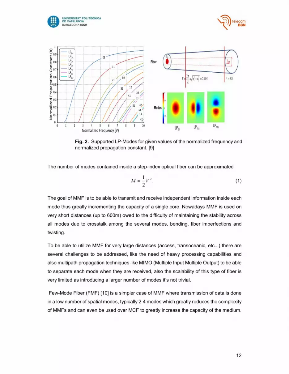
Multi-mode fibers are a type of fiber that allows several modes to be transmitted through
this medium, to be able to send more modes than the fundamental LP01 its core needs to
be quite larger than its SMF counterpart, with sizes typically between 50-100 micrometers.
This larger core allows us to have a large numerical aperture thus enables the fiber to have
more light to be contained inside its core. Fig. 2 shows the supported modes given the
normalized frequency and the normalized propagation constant.
12
The number of modes contained inside a step-index optical fiber can be approximated
.2
1 2VM (1)
The goal of MMF is to be able to transmit and receive independent information inside each
mode thus greatly incrementing the capacity of a single core. Nowadays MMF is used on
very short distances (up to 600m) owed to the difficulty of maintaining the stability across
all modes due to crosstalk among the several modes, bending, fiber imperfections and
twisting.
To be able to utilize MMF for very large distances (access, transoceanic, etc...) there are
several challenges to be addressed, like the need of heavy processing capabilities and
also multipath propagation techniques like MIMO (Multiple Input Multiple Output) to be able
to separate each mode when they are received, also the scalability of this type of fiber is
very limited as introducing a larger number of modes it’s not trivial.
Few-Mode Fiber (FMF) [10] is a simpler case of MMF where transmission of data is done
in a low number of spatial modes, typically 2-4 modes which greatly reduces the complexity
of MMFs and can even be used over MCF to greatly increase the capacity of the medium.
Fig. 2. Supported LP-Modes for given values of the normalized frequency and
normalized propagation constant. [9]

13
2.2. Multi-Core Fibers (MCF)
Multi-Core Fibers (MCF) are a type of fibers that consist on having multiple cores enclosed
in a single cladding. They were first discovered by Furakawa Electric in 1979 [24], later
investigations were done by France Telecom in the 1990’s [24] but they never became the
centre of attention due to diverse constrains at the time. Nowadays they are a hot topic
mainly due to being an answer to the capacity crunch we are facing at the end of the decade.
MCF’s were proposed as viable solution due to the limit that systems based on SSMF have
reached, peaking at 100 Tb/s bit rates [12] .The number of cores varies inside the cladding
depending on the design parameters taking into consideration. A seven core MCF has
been chosen to represent the main parameters taken into consideration on a MCF, the
layout of this particular MCF is a core at its center and six outer cores equally separated
from the center. Fig. 3 shows the schematic of a 7-core MCF [13].
As shown in Fig. 3, each core has its own diameter d, although in some situations it’s
desired that the cores differ in some sense, hence the δd. Λ is the distance that separates
two neighbouring cores, it’s called core pitch and also it’s considered the fundamental
parameter that defines crosstalk between two cores; by changing the core pitch the
crosstalk can be controlled accordingly. In this particular scenario each core its enclosed
inside a trench [13] that further confines light into the centre of the core.
Fig. 3. Schematic of a 7-core MCF.[13]

14
MCF, depending in its fabrication method, can be solid or holey. Holey MCF are
characterized by having a hexagonal array of holes that runs through the whole span of
the fiber, where a hole is omitted a core it’s formed. They are made from Photonic Crystal
Fiber (PCF). Fig. 4 further illustrates a holey MCF [14] .
Furthermore MCF can be categorized depending on the selection of its cores into
Homogeneous or Heterogeneous MCF. MCF are homogeneous when all of their cores
have the same size and refractive index, also the core-to-core distance rules the core
density inside the fiber thus assuring acceptable stable crosstalk along the propagation
length. On the contrary, in heterogeneous MCF all cores are not identical based on the
knowledge that the maximum power transferred between cores drops abruptly if there’s a
noticeable difference on their core radius; thus the arrangements and selection of cores
make a fundamental process on designing said fibers with the advantage of a more
efficiently packaged fiber and lower crosstalk [15].
Crosstalk characterization and estimation it’s the most important parameter when
comparing MCF and MMF. As modes are deeply coupled in MMF this greatly reduces the
distance that can be covered by said fiber and also uncoupling techniques require a higher
degree of processing power as whereas the crosstalk in MCF can be managed and kept
very low for thousands of kilometres and complex uncoupling techniques can be fully
avoided.
Fig. 4. 7-Core Holey MCF [14]

15
3. Crosstalk Estimation in MCF
Crosstalk by definition (2) is a disturbance caused by the electric or magnetic fields of one
telecommunication signal that affects the signal of adjacent circuits; this phenomenon that
causes this is called electromagnetic interference (EMI). In MCF crosstalk becomes a
crucial factor to have in consideration because having multiple cores so tightly packaged
inside a single cladding will inevitably cause that the signals being transmitted inside them
will be severely limited due to the degradation caused by the crosstalk. Crosstalk can be
defined with (2) where P’(Z) is the power at the output of the reference core and P(Z) is
the power at the ouput of the interference core(s).
].[)(
)(log10)( 10 dB
ZP
ZPZXT
(2)
Crosstalk mitigation is a daunting task and will be the main limitation to the capacity in
terms of signal quality and quantity of cores that we will be able to manage inside a MCF.
To be able to mitigate such a treat to our systems we first need to have a secure approach
to measure it, but building experimental samples to the various designs that can be used
can be a time and expense consuming task, thus having an accurate method to estimate
crosstalk in MCF is a must.
There are two methods that have been developed to estimate crosstalk in MCF; the
Coupled-Mode Theory (CMT) and the Coupled-Power Theory (CPT) [18].
3.1. Coupled-Mode Theory (CMT)
Coupled mode theory (CMT) is a perturbational approach for analysing the coupling
of vibrational systems (mechanical, optical, electrical, etc.) in space or in time. In an axially
uniform optical waveguide a set of propagation modes exist, these are specific to each
waveguide and satisfy the orthogonality condition [16]. If two waveguides are sufficiently
close then the optical modes of each waveguide either interfere or couple with each other,
also if the electromagnetic field distributions after mode coupling are not so different than
before the coupling, then the propagation characteristics of the coupled waveguides can
be analysed utilizing CMT.
The conventional coupled-mode equations (CME) without higher-order terms for bent MCF
shown in Fig. 5 are expressed as [17]

16
mnmnnmn
m zfzjzjdz
d)()exp()( . (3)
Where Am is the mode amplitude in core m, z is the propagation direction, mn is the mode-
coupling coefficient (MCC) from core n to core m, mn = m - n = - nm is the
propagation constant difference with m and n being the propagation constant of modes
in core m and core n and f is the phase function describing the bending and twisting
effects along the fiber. The phase function is formed by two parts; one is deterministic,
)](exp[ nmj and the other is the random part,
�
).()](exp[)( zfjzf nm (4)
With m being the phase present in core m caused by bend and/or twist. For regular MCF
with one core at its center surrounded by the other cores in a ring formation, 01 and 2
to m are expressed as
z
m
b
mm zdz
zR0)(cos
)(
. (5)
Where Ʌ is the core pitch, Rb is the bending radius, and m ,
03)2()(
mzzm . (6)
With ɣ and 0 being the twist pitch and the twist offset. When doing these calculations for
loss-less MCFs, MCCs should be symmetric, meaning that mn = nm . Nonetheless, for
non-identical cores the MCCs are not symmetric and hence, when using conventional
CMEs, total power is not preserved. By utilizing the cross-power term, nmmn CC the
relation of the MCCs can be expressed as
nm = mn - mnmnC (7)
Fig. 5. Schematic of a bent MCF. [20]

17
Thus the maximum power-conversion efficiency from core n to core m can also be expressed as
2
2
)2/(
)2/(
mnnmmn
mnmnmnmn
CF
. (8)
Taking into account that for identical cores ( mn = nm , mnC =0), the maximum power-
conversion efficiency is reduced to
22
2
)2/(
mn
mnmnF . (9)
Thus allowing us to redefine the MCC as
2mn
mnmnmn C
. (10)
And
22mn
mnnmnm
nmnmnm CC
. (11)
Considering the amendments we’ve applied to the relationship of the MCCs, we can write
them as average of usual MCCs,
nmnmmn
mn
2
. (12)
This leaves is with redefined MCCs that are symmetric and hence, we can use the
conventional CMEs and the law of power conservation is fulfilled.
In order to consider the random part of the phase function
�
��
�
, the whole medium is
separated into finite segments of equal length, generated by using uniform random
numbers)(exp rndj , are applied to all cores at every segment. The length of the segment
used in CMT is thought to be a stochastic parameter corresponding to the correlation length
used in CPT, as shown in Fig. 6 [18]

18
CMT allows us to accurately estimate the MCC needed to calculate the power coupling
between the modes of the cores inside the MCF, taking into account the twisting and
bending effects along the fiber; although this method is very accurate a large number of
simulations are needed to estimate the value of crosstalk.
3.2. Coupled-Power Theory (CPT)
Coupled-Power Theory (CPT) is based on the principle of measuring the amount of power
that the signal being transmitted in one core is transferring to its neighbouring core. In
contrast to CMT, CPT is able to realize fast and accurate estimation of intercore crosstalk
on MCFs, this is done by averaging the bending and twisting effects long the fiber using a
predetermined correlation length dc [18].
The coupled-power equations (CPE) are written as [19]
mn
mnmnm zPzPzhdz
dP)].()()[( (13)
Where mP is the average power in core m and mnh is the power-coupling coefficient (PCC).
As it was established with MCCs, PCCs should be also symmetric, thus making use of the
derivations used with MCCs, we can define the local PCCs as following by considering Eq.
(5) and defining the local propagation constant difference at z=z’, mn
)].(cos)(cos[)(
zzzR
nnmm
b
mnmn
(14)
And the redefined CMEs are written as follow
.)()exp()(
mnmnnmn
m zfzjzjdz
d (15)
The remaining random part of phase function, δf, is assumed to be stationary; thus its
ensemble average is equal to zero, 0)(zf . Doing this substitution in Eq. (15) and
Fig. 6. Random phase offsets applied at every segment. [18]

19
calculating the average power at point z sufficiently close to z=0, 2)()( zAzP mm , is
given
dffjPzP mn
zz
nmnm )()()([exp)0()( *
00
2 . (16)
Doing the following change of variable, , we obtain
z
mn
z
nmnm dffjPzP0
*
0
2 )()()exp()0()( . (17)
The random part of the phase function, δf, is a stationary random process and
consequently, it has an autocorrelation function, )()()( * ffR , plus the
variance is equal to one, R(0)=1. With this the equation can be rewritten as
dRjzPzP mn
mnnm )()exp(
2)0()(
2
. (18)
Lastly, we attain the resulting local PCC with the power spectral density, )( mnS , which
is the Fourier transform of the autocorrelation function:
)(2)0(
)( 2
mnmn
n
mmn S
zP
zPh
. (19)
At this moment we should consider which type of autocorrelation function to use, among
them we can highlight 3 types that gives the better results on par with real measures, as
shown on Fig. 7 [20]
.
Fig. 7. Three types of autocorrelation functions; d: correlation length [20]

20
The Gaussian autocorrelation function (GAF),
2
exp)(cd
R
. (20)
The triangular autocorrelation function (TAF),
c
c
c
d
ddR
,0
,1)( . (21)
And the exponential autocorrelation function (EAF)
cdR
exp)( . (22)
Where dc is the correlation length. Taking into consideration the pros and cons of each
autocorrelation function, we’ve adopted the EAF as in the nonphase-matching region with
bending radius larger than the critical bending radius Rpk the crosstalk behaviour is not
well simulated using GAF and the PCC based on TAF becomes zero at specific values of
mn d( mn
d/2=Iπ with I being an integer excluding zero), thus being this behaviour
physically unacceptable. The PCC based on an exponential autocorrelation function is
given by
2
2
)(1
2)(
d
dzh
mn
mnmn
. (23)
This is a lorenzian function that is the Fourier transform of an exponential function. In order
to avoid numerical solutions of CPEs, the PCC is averaged over a twist pitch as
/2
0
)(2
dzzhh mnmn . (24)
If we make the substitution of (23) into (24), the average PCC
ℎ
���
can be analytically
evaluated as
.
112 2
acbcacbadh mnmn (25)

21
With
2
1
b
mnmn
R
dBda . (26)
2
2)(1
b
mnmn
R
dBdb . (27)
2
1
b
mnmn
R
dBdc . (28)
Where 2mn is the mode coupling coefficient between cores (see section 3.3) and
22 )()( nnmmnnmmmn yyxxB . By employing the average PCC that is
independent of the twist rate ɣ, the crosstalk XT between two cores with a fiber length L can be estimated as
).tanh( LhXT mn (29)
Besides, if the crosstalk is very small, it can be approximated as
.LhXT mn (30)
The critical bending radius Rpk, as it can be seen from (25) to (28), is given by
mn
mnpk
BR
. (31)
And the equivalent average PCC is written as
2
2
2
21
2112
d
ddh
mn
mn
mnmn
. (32)
When the correlation length is large (d>>1/|2 nm |) and small (d<<1/|2 nm |), (32) is
condensed to
mn
mnmnd
h
2 . (33)
dh mnmn22 . (34)

22
Besides the average PCC analytical expression varies depending the relationship
between Rb,Rpk,d and nm .
Case 1. When the bending radius is large (Rb>>Rpk) , the average PCC given by (25)
is reduced to
2
2
)(1
2)(
d
dzh
mn
mnmn
. (35)
Additionally if the correlation length is large (d>>1/| nm |), the average PCC given
in (35) is reduced to
2
2
)(
2)(
dzh
mn
mnmn
. (36)
This case is pretty important as it states that the average PCC is inversely
proportional to the correlation length and to the square of the propagation constant
difference nm , signifying that the crosstalk could be suppressed in heterogeneous
MCFs with nonidentical cores.
Case 2. When the bending radius is small (Rb<<Rpk), the average PCC is
.
/1
22
2
bmn
mnmn
RdB
dh
(37)
Furthermore, when the correlation length is large (d>>Rb/Bmn), the average PCC
given by
.2 2
mn
bmnmn
B
Rh
(38)
Case 3. For homogeneous MCFs(0 mmmn
), with small bending
radius(Rb<<Bmnd) the average PCC is expressed as
.2 2
mnm
bmnmn
Rh
(39)

23
3.3. Homogeneous MCF Crosstalk Estimation
Homogeneous MCF can be considered the simplest type of MCF due to being only the
encasement of several cores of fiber inside the same cladding just taking into account the
separation of the cores as the main design parameter. To fully understand crosstalk and
how to achieve improvements on this matter we should start by first stating the equations
that estimate crosstalk on its simplest form, and then start making changes on the nature
of the cores and thus analyzing the obtained results.
These are the refractive index profiles for a normal step-index structure and a trench-
assisted one, as its shown on Fig. 8, the refractive indices for the core, cladding and trench
are expressed as n1,n0 and n2. The relative refractive index differences, between core and
cladding and trench and cladding are Δ1 and Δ2. The core radius,
the distance from the outer edge of the 1st cladding to the core center, the distance from
the outer edge of trench to the core center and trench width are a1 , a2, a3 and wtr,
correspondingly.
To correctly estimate the crosstalk of a step-index structure, first of all we have to calculate
the mode coupling coefficient, which is given as [21]
.
)(
**
*220
dxdyu
dxdyNN
ppppz
qpq
pq
(40)
Where ω stands for the angular frequency of the electromagnetic field, ε0 is the permitiviyty
of vacuum, N2(x,y) represents the refractive index distribution in the entire coupled region,
N2q embodies the refractive index distribution of waveguide q. This equation can be further
shortened to
Fig. 8 Refractive index profile and cross=sectional dimensions for (a) Step-Index
structure and (b) a trench assisted structure. [21]

24
.exp( 1
1
1
1
)121
31
21
1
1
a
W
W
a
WKV
U
apq
(41)
Where )( 221
221
21 nkaU and
)( 20
2221
21 nkaW
, in which β is the propagation
constant. 2/1
1111 )2( nkaV is the V number which determines the modes propagating in
a fiber, also k represents the wavenumber and λ is the wavelength of light in the vacuum.
K1(W1) is the modified Bessel function of the 2nd kind with 1st order and Ʌ is the core-to-
core distance.
In the other hand trench-assisted MCF can also be estimated in a similar manner. As the
sizes of the 1st cladding and the trench are not infinitely large, the solutions in these two
regions also contain the modified Bessel functions of the first kind. The mode coupling
coefficient can be estimated by the following analytical approach [22]
1
121
1
1
)121
31
21
1
1 )(2exp
( a
wtrWWW
W
a
WV
U
apq
(42)
Where 2/12
1222 )( WVW ,
2/122
2012 )( nnkaV
and
/)( 121
1
wtrWWW
W
.
Now that we have a method to estimate the MCC between two cores we can proceed to
make some crosstalk calculations, which after having the MCC can be calculated as
)tanh( LhXT where .2 2
bpqRh , hence we have the resulting equation as
LR
XTbpq
22 (43)
To verify the accuracy of the stated equations we proceeded to run simulations with the following parameters
Table 2. Structural Parameters for XT Calculations
Parameters units Step-index Trench-assisted
a1 μm 4.5 4.5
a2/a1 -- --- 2
a3/a1 -- --- 3

25
Wtr/a1 -- --- 1
N0 -- 1.45 1.45
Δ1 % 0.35 0.35
Δ2 % --- -0.35,-0.70
Rb mm 140 140
L km 100 100
As it’s been shown in Fig. 9, the results of the simulations are in line with what’s been
indicated by the equations above, furthermore it can be seen the direct dependency that
core-to-core distance exerts over crosstalk, for each μm that the Ʌ increases, the crosstalk
also increases at a 3db rate. Also as part of the behaviour of crosstalk we can notices is
how much the crosstalk drops as a trench was introduced to better confine the light inside
the core thus decreasing the amount of signal that couples in the other cores; also to note
is that the relative refractive index of the trench dictates the intensity at which the light is
confined inside the core. Crosstalk reductions of 20 to 35 dB are obtained with respect the
step-index case.
Fig. 9. Homogeneous MCF XT Results

26
3.4. Heterogeneous MCF Crosstalk Estimation
Heterogeneous MCFs ( are developed as an improvement over homogeneous MCFs as
homogeneous MCFs offer reliable stable crosstalk all along the fiber span, heterogeneous
MCFs offer greatly reduced crosstalk by introducing another set of parameters that are to
be taken into consideration at the time to design a fiber. Heterogeneous MCFs are
characterized by having a subtle difference of core radius and/or refractive index enough
that there’s a phase mismatch between the cores thus differentiating the electromagnetic
fields such that the coupling of signals is greatly diminished. By numerous simulations the
minimum effective refractive index difference that two cores need to have in order to have
a phase mismatch is of Δneff>0.001[23].
Another feature of Heterogeneous MCFs besides that they allow us to have lower crosstalk
along the fiber is that they are bend insensitive as it was stated and proved in Case 1 of
section 3.2, thus allowing us to have a more reliable medium in long haul transmissions.
The first step on designing a heterogeneous MCF is the selection of the layout and how
many cores the fiber will ultimalety account, then the next step is selecting the types of
cores that we’re going use; although theoretically you could use several different types of
cores, practically this is not feasible as the fabrication complexity would severely increase
also increasing the cost thus making the fiber not economically feasible.
(a) (b)
Fig. 10. (a) Example of Heterogeneous MCF and, (b) Refractive index difference vs Critical
Bending Radius vs Core Pitch. [22]

27
To estimate the crosstalk between the different types of cores, a mode coupling coefficient
needs to be calculated taking into account the diversity of cores and trench that we’re going
to have.
The method for calculating the general mode-coupling coefficient was given in eq.(40) as
[23]
.
)(
**
*220
dxdyu
dxdyNN
ppppz
qpq
pq
Were Ep and Eq represent the amplitude of the electric field distribution of core p and core
q respectively, furthermore the refractive-index distribution in the entire coupled region is
written as
(44)
Where N1(r, θ) and N2(r, θ) represent the refractive-index distribution of each core with
trench structure, and n(r, θ) means the refractive-index distribution outside the cores, as
shown in Fig. 11
),(),(),(),( 222
21
2 rnrNrNrN
Fig. 11 Refractive index distribution with trench of (a) Core p (b) Core q
and (c) outside the cores. [23]

28
We can start by substituting the electric fields inside of optical fibers into Maxwell’s equation as
.0,11 222
2
2
2
2
2
2
z
zzz rnkrrrr
(45)
From here we can define the wave number in the core m (m=1,2), cladding and trench
along the fiber as
222mmm kn
(46)
222 knclmm
(47)
222 kntrmm
(48)
Where β is the propagation constant and k is the wavenumber in a vacuum. The normalized
frequency (V1-m, V2-m), the normalized transverse wave number in core m (U1-m), that
in cladding (W1-m) and that in trench (W2-m) can be expressed as follows
2211 clmmm nnkaV
(49)
2212 trclmm nnkaV
(50)
996.01428.1 111 mmmm VaW
(51)
21
2111 mmmmm WVaU
(52)
21
2212 mmmmm WVaW
(53)
In the core regions, the solutions for Eq. (45) of TM modes are the 0th order Bessel function
and the 0th order Neumann function, however the Neumann function diverges infinetly at
r=0, thus the Bessel functions give us the proper solution for the field in the core. In the

29
cladding region the solution are given by the modified Bessel functions of the first and
second kind.
In Fig. 12 [22] we can see a profile of cores m and p, where D is the core-to-core distance
and R1, R2 and R3 are the distances from the core center to the outer trench, inner trench
and inner cladding accordingly. Associating this profile to the z-components of the electric
field we can state the continuity relationship as this boundary conditions
)()(
)()(
)()(
)()(
)()(
1
25
1
24
1
14
1
13
1
33
1
32
1
22
1
21
11
m
mnm
m
mnm
m
mnm
m
mnm
m
mmnm
m
mmnm
m
mmnm
m
mmnm
mnmmnm
a
RWKF
a
RWKE
a
RWKE
a
RWKD
a
aWKD
a
aWKC
a
aWKC
a
aWKB
WKBUJA
(54)
Fig. 12 Geometries for calculating the coupling coefficients [23]

30
Expressing Ep*.Eq inside Eq. (45) gives us
)cos()cos()()(
)()(.
1
11
1
11
1
10
1
10
11
11*
q
q
p
pqpq
q
q
p
p
qp
qp
qpqpqqp
a
RWK
a
rUJAAQ
a
RWK
a
rUJ
WU
aaAAQ
(55)
And by using the integral formulas of the Bessel functions the coupling coefficients are
expressed as
pa
q
q
p
p
qpqpqpqp
q
aq
q
q
q
q
ppclp
pq
rdrra
WI
a
rUJ
UJUJVVaann
a
aaWW
a
DW
DW
aUWnnk
1
0 1
1
0
1
10
11111111
1
23
21
1
1
1
1
1122
)()(
)()(
])(2exp[2
)(
(56)
With the coupling coefficient already developed we can now move forward and choose the
type of cores required. For our simulation we choose a ring layout with two types of cores
as shown in Fig. 15, this is a pretty general core arrangement that would give us very much
insight into the crosstalk behaviour. To select the parameters of both types of cores we
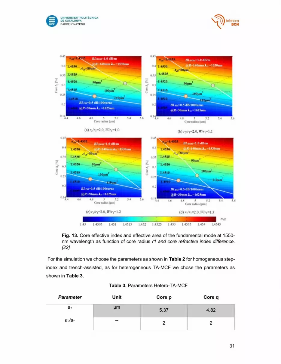
fixed the Aeff and chose the core radius and Δ1 as shown in Fig. 13 [22].
Given this we chose core radius and refractive indices differences as to maximize the neff
between the cores by following the black-dotted lines corresponding to an Aeff of 100 μm2,
this was chosen with the intention of minimizing the nonlinear effects inside the fiber. Given
this we chose the points corresponding to the higher and lower boundaries that crosses
through the bending loses allowed limits.
31
For the simulation we choose the parameters as shown in Table 2 for homogeneous step-
index and trench-assisted, as for heterogeneous TA-MCF we chose the parameters as
shown in Table 3.
Table 3. Parameters Hetero-TA-MCF
Parameter Unit Core p Core q
a1 μm 5.37 4.82
a2/a1 -- 2 2
Fig. 13. Core effective index and effective area of the fundamental mode at 1550-nm wavelength as function of core radius r1 and core refractive index difference.
[22]

32
a3/a1 -- 3 3
Wtr/a1 -- 1 1
N0 -- 1.45 1.45
Δ1 % 0.31 0.247
Δ2 % -0.7 -0.7
Rb mm 140 140
L km 100 100
As it can be seen from the results in Fig. 14 the advantages of heterogeneous MCF are
not so evident when there’s a low number of cores as the core-to-core distance is very
large and the effects of the coupling between the cores can be barely measured, on the
Fig. 14. Homogeneous Step-Index and Trench-assisted vs Heterogeneous TA-
MCF

33
contrary the advantages are clearly as the number of cores grows, shrinking the Ʌ and the
effects of coupling are stronger; hetero-TA-MCF show a much lower crosstalk (40db for 14
cores) than the homogeneous counterparts thus making the limit not the crosstalk
interference between the cores anymore, but the physical fiber limit in which the cores set
on a certain layout can’t be further brought together.
There are disadvantages as well as having different types of cores can account for greater
coupling losses and amplification issues if the cores are mismatch one to another, although
they don’t overweight the fact that Hetero-TA-MCF are the defacto solution instead of
Homogeneous MCF to maximize the use of space inside the fiber.
3.4.1. Demonstration of Heterogeneous-MCF bending radius insensitiveness
For this simulation we wanted to verify some of the statements made above, more precisely
the impact of changing the correlation length and bending radius to have a better
understanding of the effects that these parameters play on the design of a MCF. For our
simulations we chose a 14-core TA-heterogeneous MCF with a ring layout, as shown in
Fig. 15, it allows us to control the impact of the difference of propagation constant among
the fiber.
Fig. 15. 14-Core TA-Heterogeneous MCF

34
The parameters employed for this simulation are shown in Table 4.
Table 4. Structural Parameters for Calculation MCF-14cores
Parameter Unit Core Type A Core Type B
r1 [um] 4.8 4.3
r2/r1 - 2 2
r3/r1 - 3 3
Wtr/r1 - 1 1
Δ1 % 0.41 0.36
Δ2 % -0.7 -0.7
Ncl - 1.45 1.45
Ʌ [um] 36.7 36.7
XT
@100km
Fig. 16Correlation length simulation results (Bending Radius in mm)

35
The peak bending radius is given by the difference of propagation constant between the
different types of cores.
Among the different types of cores there’s a phase matching region and a mismatch region,
as can be seen in the peak in Fig. 16 on the phase matching region the crosstalk is
impervious to the change on the correlation length thus becoming really sensitive to the
changes on the bending radius; in the other hand after crossing the peak bending radius it
enters on an phase-mismatch region where the crosstalk is insensitive to the bending
radius and becomes dependent on the correlation length chosen to estimate the crosstalk.
The correlation length becomes relevant because it dictates on how the twisting effects on
the fiber are averaged, thus by increasing the correlation length the twisting effects are
averaged on a major proportion of the fiber and contrasting the results to the coupled power
theory we can see that this effects becomes smaller when averaged on the phase
mismatch region thus explaining why increasing the correlation length the crosstalk tends
to decrease.
4. Layout Design Strategies for Low Crosstalk on MCFs.
After having discussed the different types of MCFs and the methods to calculate the
crosstalk among its cores, we can use the aforementioned knowledge to establish certain
strategies to design a MCF. One of the first steps on said design process is to set a goal
which in our case is to maximize the capacity of said fiber, but even that has several ways
to be done; we’re going to tackle that challenge by the most important parameter and the
focus of this thesis: the crosstalk.
For our design analysis we’re going to set a crosstalk threshold and from there set the
different parameters that conform a MCF. Our target crosstalk is fixed at 30dB/1000km;
this value is completely arbitrary. We pick 1000 Km as a good reference for transnational
networks and pick the 30 dB because it allows you to use up to 64-QAM with negligible
penalty [8]. Having established said crosstalk threshold we continue to choose the nature
of the MCF (homogeneous or heterogeneous) and after the core parameters such as core
radius, refractive indices, trench width if is having one; and last but not least after having
the different core parameters we finalize the design process by setting a layout that fulfils
our intended target by the cores placement.

36
To design a MCF we need to take into consideration some physical constrains that are
common to all optical fibers. First of all we should set the cladding diameter (CD), although
a bigger cladding means that more cores can fit inside there’s a physical limitations as
where the mechanical reliability of the fiber cannot be ensured anymore; therefore we set
our CD to the maximum allowed size that is 225 um.
Another parameter that has a physical limitation is the outer cladding thickness (OCT) that
is the distance the center of the cores need to be from the edge of the cladding, to minimize
the microbending loss the required minimum OCT is of 30 um, therefore we set the OCT
to said quantity. The core pitch (Ʌ) is to be established while optimizing the quantity of
cores but the minimum distance between trench edges (d) is of 3 um to ensure that even
if the fiber bends the trenches will never touch each other. In Fig. 17 [23] we can appreciate
the enlarged partial view of a Hetero-TA-MCF where all said parameters can be
appreciated.
Having set all the aforementioned parameters it’s time to decide on a layout strategy that
can fulfil our crosstalk and capacity requirements. There are several layout proposals like
ring layout, hexagonal layout [24] or just without any geometrical form at all; of course the
core allocation will depend on the core quantity and nature. One approach to establish the
core quantity was the circle packing theory [25], based on obtaining the maximum quantity
of circles of a given radius inside of a determined circle, usually being a unitary circle but
can be extrapolated to any circle of any size, this can be taken into consideration to find a
method to swiftly calculate core pitch, but we need to also take into consideration that the
resulting layout must also be commercially viable.
Fig. 17 Partial View of Hetero-TA-MCF [23]

37
The logical step to lower the crosstalk between cores would be maximizing the distance
between them to reduce the intensity of the power that it receives from other cores, but
having a limited space other strategies are needed like increasing the trench width, or even
introducing holes or gaps between the cores.
4.1. 19 core Hetero-TA-MCF Proposal
Having studied the crosstalk estimation methods and analysed the different parameters to
take into consideration at the moment of designing a MCF, we’re ready to propose a layout
that at our understanding covers all the aforementioned criteria, successfully designing an
arrangement of 19 cores while maintaining the crosstalk low and well below the said
crosstalk threshold.
The thought process behind this design is the same as the original goal, to minimize
crosstalk while retaining a huge capacity gain without compromising mechanical reliability
or hindering the performance of the cores. We’ve chosen a ring layout as is the type of
layout that is the most efficient using the circular available space and also because of its
manufacturing simplicity compared to other layouts.
Fig. 18. 19 core Hetero-TA-MCF with 3 types of cores

38
It’s composed of an outer and an inner ring as well as a center core. In Fig. 18 we can
notice the size of the outer cladding as well as an inner circle that passes between the
centers of all outer cores serving as a guide of the required OCT.
Also we’ve chosen a heterogeneous MCF against a homogeneous MCF because of its low
crosstalk properties and as well as its bend insensitiveness as was demonstrated before.
Making use of the core selection process depicted earlier we’ve chosen 3 types of cores
instead of the usual 2 that we’ve seen in different proposals; we didn’t make use of more
types as the difference between them would too small thus increasing the coupling effect
between the cores. All have been chosen with an Aeff of 100 um2 to minimize the impact
of nonlinearities inside the fiber.
As it’s shown in Table 5 we can see the parameters used for each type of core, each
thought in a way to minimize the crosstalk as much as possible. On the outer and inner
rings we’ve used cores of the type A & B exclusively and positioning them on an
intercalated manner, thus maximizing the core pitch between the cores of the same type
thus decreasing the crosstalk between them; the explanation of how the parameters were
established are explained in Section 3.3.
The third type of core we chose was exclusively selected as a center core and its
parameters were chosen by taking the midpoint in the black-dotted where core types A &
B were chosen. By having a third core type as a center core we greatly reduce the crosstalk
caused by the inner ring cores; another added benefit of having a different center core is
that because of the lower crosstalk we can pack inner cores closer thus increasing the
distance between the inner ring cores and the outer ring cores and as a result of that the
crosstalk on the outer ring is further reduced. We decided not to change the trench width
or its refractive index as increasing them would imply greater bending losses and to which
extent it is increased is out of our reach as it’d take extensive numerical simulations using
FEM (Finite Element Method).
Table 5 Parameters 19 Cores Hetero-TA-MCF
Parameter Unit Core Type A Core Type B Core Type C
r1 [um] 5.37 4.82 5.12
r2/r1 - 2 2 2
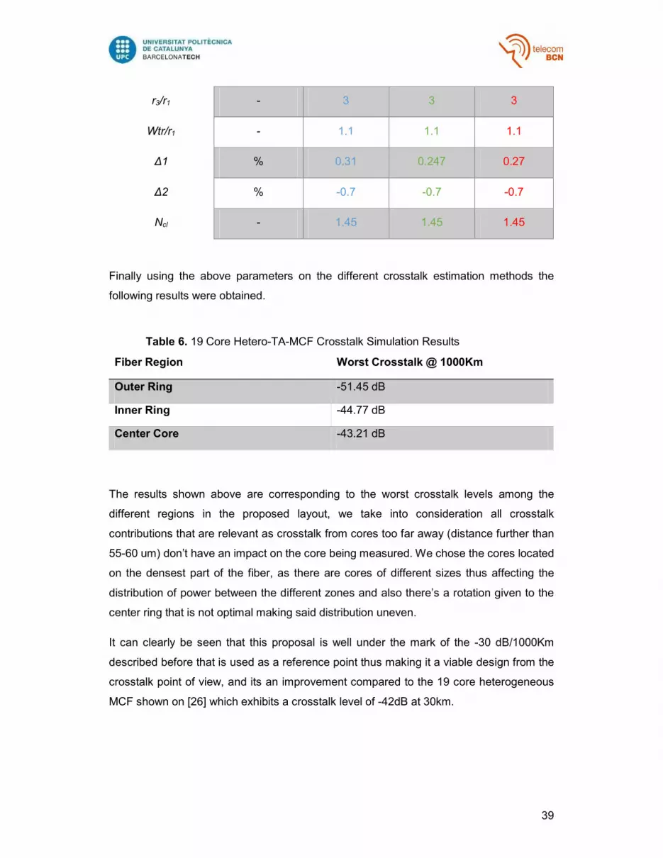
39
r3/r1 - 3 3 3
Wtr/r1 - 1.1 1.1 1.1
Δ1 % 0.31 0.247 0.27
Δ2 % -0.7 -0.7 -0.7
Ncl - 1.45 1.45 1.45
Finally using the above parameters on the different crosstalk estimation methods the
following results were obtained.
Table 6. 19 Core Hetero-TA-MCF Crosstalk Simulation Results
Fiber Region Worst Crosstalk @ 1000Km
Outer Ring -51.45 dB
Inner Ring -44.77 dB
Center Core -43.21 dB
The results shown above are corresponding to the worst crosstalk levels among the
different regions in the proposed layout, we take into consideration all crosstalk
contributions that are relevant as crosstalk from cores too far away (distance further than
55-60 um) don’t have an impact on the core being measured. We chose the cores located
on the densest part of the fiber, as there are cores of different sizes thus affecting the
distribution of power between the different zones and also there’s a rotation given to the
center ring that is not optimal making said distribution uneven.
It can clearly be seen that this proposal is well under the mark of the -30 dB/1000Km
described before that is used as a reference point thus making it a viable design from the
crosstalk point of view, and its an improvement compared to the 19 core heterogeneous
MCF shown on [26] which exhibits a crosstalk level of -42dB at 30km.

40
5. Conclusions and future development
In this work we’ve explored the different SDM solutions to the unavoidable capacity crunch
that is in the advent as current deployed optical technologies are quickly approaching their
capacity limits; making emphasis on Multi-core Fibers (MCF) as the favorite choice to be
deployed because of its simplicity and economic feasibility compared to Multi-Mode Fibers
(MMF).
As our main objective we’ve studied the most important parameter that establishes the
performance of said fiber in distance and capacity; the crosstalk. As in MCF there are many
cores tightly packaged together is inevitable that signals start causing undesired effects
from one core to another; besides the physical space available for cores, the maximum
tolerated crosstalk dictates the maximum quantity of cores we can use.
We’ve studied several approaches to estimate crosstalk under different scenarios
depending on the nature of the cores, separation between them and the use of tools like
trenches to characterize its behavior and thus be able to establish a strategy to minimize
the crosstalk impact as much as possible without sacrificing too much on reliability or
economic feasibility.
To test the different theories and approximations we’ve carried our own simulations to
obtain results of our own and compare them with the results obtained by the crosstalk
estimation methods presented by the different authors; where we’ve found ours to be in
good agreement with the aforementioned outcomes. This has led to a deeper
understanding of the crosstalk behavior and the different parameters that affect the
interaction that happens between cores; thus allowing us to be able to determine certain
strategies to design a MCF of our own.
We’ve designed a 19-core Heterogeneous trench assisted MCF with the intention of having
a very low crosstalk through its different regions. We’ve set the different parameters in
accordance to the crosstalk estimation methods that we’ve studied and the results obtained
from the simulations are indeed in accordance with the expected behavior and obtained
crosstalk level far under the -30 dB threshold at 1,000 Km distance. Our design is not
optimal but it’s indeed a step in the right direction, further simulations utilizing the finite
element method (FEM) and the elaboration of lab prototypes would aim to a more realistic
solution.

41
To further extend the capacity of MCFs, the combination of MCF and MMF seems to be a
must. The utilization of MMF in the form of Few-Mode Fibers (FMF) along with MCFs is a
promising improvement over the current MCF solutions where mostly single-mode fibers
are being used [24]. This would allow to greatly increase the resulting capacity and
furthermore open the doors to the development of more resource intensive applications
that make use of the new attained capabilities.
In summary, SDM is still a totally new challenge to the different professionals compounding
the current optical fiber communication research. There is still very much left to explore as
it’s a new paradigm that promises to guide the evolution of optical communications on the
years to come, the knowledge obtained through SDM research as also the crosstalk
characterization on MCF will also contribute in other fields where the use of spatial
techniques as signal coupling are needed.

42
Bibliography
[1] “Cisco Visual Networking Index: Forecast and Methodology”, 2014–2019; [online]
available at: http://www.cisco.com/c/en/us/solutions/collateral/service-provider/ip-
ngn-ip-next-generation-network/white_paper_c11-481360.pdf
[2] T. Li, “The impact of optical amplifiers on long-distance lightwave
telecommunications,” Proc. IEEE 81, 1568–1579 (1993).
[3] “Introduction to DWDM Technology” , 2001; [online] available at:
https://www.cisco.com/application/pdf/en/us/guest/products/ps2011/c2001/ccmigr
ation_09186a00802342cf.pdf
[4] G. Li, “Recent advances in coherent optical communication,” Adv. Opt.
Photon. 1, 279–307 (2009).
[5] J. Rasmussen, “Digital Coherent Receiver Technology for 100-Gb/s Optical
Transport Systems”, FUJITSU Sci. Tech. J., Vol. 46, No. 1 (January 2010).
[6] Essiambre, R.; Kramer, G.; Winzer, P.J.; Foschini, G.J.; Goebel, B., "Capacity
Limits of Optical Fiber Networks," Lightwave Technology, Journal of , vol.28, no.4,
pp.662,701, Feb.15, 2010.
[7] Chralyvy, Andrew, "Plenary paper: The coming capacity crunch," Optical
Communication, 2009. ECOC '09. 35th European Conference on , vol., no., pp.1,1,
20-24 Sept. 2009.
[8] Peter J. Winzer, “Spatial Multiplexing: The Next Frontier in Network Capacity
Scaling”, ECOC 2013, London.
[9] Peter J. Winzer, “Spatial Multiplexing In Fiber Optics: The 10x Scaling Of
Metro/Core Capacities", Bell Labs Technical Journal, 2014.
[10] Fontaine, N.K.; Ryf, R.; Haoshuo Chen; Velazquez Benitez, A.; Antonio
Lopez, J.E.; Amezcua Correa, R.; Binbin Guan; Ercan, B.; Scott, R.P.; Ben Yoo,
S.J.; Gruner-Nielsen, L.; Yi Sun; Lingle, R.J., "30×30 MIMO transmission over 15
spatial modes," in Optical Fiber Communications Conference and Exhibition (OFC),
2015 , vol., no., pp.1-3, 22-26 March 2015”G. Li, “Space-division multiplexing: the
next frontier in optical communication”; Advances in Optics and Photonics 6, 413–
487 (2014).
[11] S. Matsuo, K. Takenaga, Y. Arakawa, Y. Sasaki, S. Tanigawa, K. Saitoh,
and M. Koshiba, “Crosstalk behaviour of cores in multi-core fiber under bent
condition,” IEICE Electron. Express 8(6), 385–390 (2011).
[12] K. Imamura and R. Sugizaki, “Recent Advances in Multi-Core Transmission
Fibers” Proceedings of Opto-Electronics Communications Conference
(OECC2012), Busan, Korea, July 2012, pp. 559-560.
[13] K. Takenga, Y. Arakawa, S. Tanigawa, N. Guan, S. Matsuo, K. Saitoh and
M. Koshiba, “Reduction of Crosstalk by Trench-Assisted MultiCore Fiber”
Proceedings of Optical Fiber Communication/National Fiber Optic Engineers
Conference, Los Angeles, United States, March 2011.
[14] K. Mukasa, K. Imamura, Y. Tsuchida and R. Sugizaki, “Multi-Core Fibers for
Large Capacity SDM” Proceedings of Optical Fiber Communication/National Fiber
Optic Engineers Conference, Los Angeles, United States, March 2011.

43
[15] M. Koshiba, K. Saitoh and Y. Kokubun, “Heterogeneous Multi-Core Fibers:
Proposals and Design Principles” IEICE Electronics Express, Vol. 6, No. 2, pp. 98-
103.
[16] K. Okamoto, Fundamentals of Optical Waveguides, 2nd ed. (Academic
Press, 2006).
[17] J. M. Fini, B. Zhu, T. F. Taunay, and M. F. Yan, “Statistics of crosstalk in
bent multicore fibers,” Opt. Express 18(14), 15122–15129 (2010).
[18] Koshiba M1, Saitoh K, “Multi-core fiber design and analysis: coupled-mode
theory and coupled-power theory”, Opt Express. 2011 Dec 12; 19(26):B102-11.
[19] D. Marcuse, “Derivation of coupled power equations,” Bell Syst. Tech. J. 51,
229–237 (1972).
[20] M. Koshiba, K. Saitoh, “Analytical Expression of Average Power-Coupling
Coefficients for Estimating Intercore Crosstalk in Multicore Fibers”, IEEE Photonics
Journal, Vol. 4 Oct. 2012.
[21] F. Ye, J. Tu, “Simple analytical expression for crosstalk estimation in
homogeneous trench-assisted multi-core fibers”, Optic Express Sept. 2014.
[22] J. Tu, K. Saitoh, M. Koshiba, K. Takenaga, and S. Matsuo, “Design and
analysis of large-effective-area heterogeneous trench-assisted multi-core fiber,”
Opt. Express 20, 15157–15170 (2012).
[23] J. Tu, K. Saitoh, M. Koshiba, “Optimized Design Method for Bend-Insensitive
Heterogeneous Trench-Assisted Multi-Core Fiber With Ultra-Low Crosstalk and
High Core Density”, Journal Of Lightwave Technology, Vol. 31, No. 15, August 1,
2013.
[24] Karamdeep Singh, Gurmeet Kaur, “Multi-Core Fibers: An Overview”,
International Conference on Emerging Technologies in Electronics & Communication (ICETEC-13).
[25] Circle Packing Theory, http://www.packomania.com/.
[26] Jun Sakaguchi, Werner Klaus, Benjamin J. Puttnam, José Manuel Delgado
Mendinueta, Yoshinari Awaji, Naoya Wada, Yukihiro Tsuchida, Koichi Maeda,
Masateru Tadakuma, Katsunori Imamura, Ryuichi Sugizaki, Tetsuya Kobayashi,
Yusaku Tottori, Masayuki Watanabe, and R. V. Jensen, "19-core MCF transmission
system using EDFA with shared core pumping coupled via free-space optics," Opt.
Express 22, 90-95 (2014).

44


![Stimulated Brillouin scattering slow light in optical fibers [Invited]](https://img.pdfslide.net/doc/110x75/634dc52e024fe175900b1734/stimulated-brillouin-scattering-slow-light-in-optical-fibers-invited.jpg)


