Embed Size (px)
Citation preview
JOURNAL OF LIGHTWAVE TECHNOLOGY, VOL. 17, NO. 8, AUGUST 1999 1273
Crosstalk Analysis of MultiwavelengthOptical Cross Connects
Tim Gyselings,Student Member, IEEE,Geert Morthier,Member, IEEE, Member, OSA,and Roel Baets,Senior Member, IEEE, Member, OSA
Abstract—This paper presents the results of a crosstalk anal-ysis of four optical wavelength division multiplexed (WDM)cross-connect (OXC) topologies. An optimal set of parametersis determined to reduce the total crosstalk. The scalability of thetopologies is presented in terms of wavelengths and input fibers.The total crosstalk in function of the number of cascaded OXC’sis compared for the four topologies.
Index Terms—Optical communication, optical crosstalk, op-tical cross connect (OXC), optical switches, optical wavelengthconversion, wavelength division multiplexing (WDM).
I. INTRODUCTION
OPTICAL wavelength division multiplexing (WDM) net-works are very promising due to their large bandwidth,
their large flexibility and the possibility to upgrade the existingoptical fiber networks to WDM networks [1]–[8]. WDM hasalready been introduced in commercial systems. All-opticalcross connects (OXC), however, have not yet been usedfor the routing of the signals in any of these commercialsystems. Several OXC topologies have been presented in theliterature, but their use has so far been limited to field trials,usually with a small number of input–output fibers and/orwavelength channels [9]–[20], [27]–[36]. The fact, that inpractical systems many signals and wavelength channels couldinfluence each other and cause significant crosstalk in theoptical cross connect, has probably prevented the use of OXC’sin commercial systems [21]–[23], [26], [31], [41], [42].
The crosstalk levels in OXC configurations presented so farare generally so high that they give rise to a significant signaldegradation and to an increased bit error probability. Becauseof the complexity of an OXC, different sources of crosstalkexist, which makes it difficult to optimize the componentparameters for minimum total crosstalk. In this paper, thecrosstalk of four different OXC topologies is calculated andcompared with each other, and the influence of the componentcrosstalk on the total crosstalk is identified.
We present an analytical approximation for the totalcrosstalk level of four different OXC topologies, which makesthe component parameter optimization considerably easier.
Manuscript received May 15, 1998; revised March 22, 1999. This workwas supported in part by the European ACTS Project OPEN (AC066) and theEuropean ACTS Project PHOTON (AC0084). The work of T. Gyselings wassupported by the Flemish Institute for Science and Technology (IWT).
The authors are with the Department of Information Technology, Universityof Gent, IMEC, Sint-Pietersnieuwstraat 41, B-9000 Gent, Belgium (e-mail:[email protected]).
Publisher Item Identifier S 0733-8724(99)06342-2.
The crosstalk sources are related to the different individualcomponents of the OXC’s.
This paper is divided into four main parts. In the first partthe different OXC topologies are presented and explained.The different crosstalk sources in the OXC are identifiedand quantified in the second part. Afterwards the analyticalequations for the topologies are derived. The results arepresented in part four. The analytical approach is validatedby comparing the results obtained by the analytical equationwith results obtained by numerical simulations. Afterwardsthe influence of the component parameters on the crosstalkis studied. In the next paragraph the scalability in terms ofnumber of wavelengths and number of input/output fibers, isinvestigated. Finally the crosstalk levels of the four topologiesare compared in function of the number of cascaded OXC’s.
II. OXC TOPOLOGY
Several topologies exist for all optical WDM cross connects.The most suitable topology for an application depends ingeneral on the required functionality and on the cost, capacityand flexibility constraints. In this paper, we evaluate theinfluence of two switching matrices and the use of wavelengthconverters on the crosstalk properties of an OXC. The impacton the crosstalk when swapping the order between switchingand selecting (of the wavelength channel) has been studied.That is why different OXC topologies have been definedand the crosstalk of each of these has been evaluated. Bycomparing the results of the different topologies one canderive the influence of the switching matrix, of the wavelengthconverters and of the order between switching and selecting.The topologies defined in this paper are not the only possible,but are generic topologies that make it possible to evaluatethe crosstalk properties.
The first switching matrix that was studied is based on anarray of gates. The first OXC topology includes this switchingmatrix to route the different wavelength channels. Splitters andcombiners are placed in front of and behind the switch matrixand filters are used to select the wavelength channels. Thebroadcast and select optical cross connect topology is shownin Fig. 1 [10], [11], [14], [15].
Another switching matrix studied in this paper is basedon a mechano-optical space switch. This switching matrixis embedded in an OXC topology (Fig. 2) that makes useof demuliplexers and multiplexers to select the wavelengthchannels.
0733–8724/99$10.00 1999 IEEE
1274 JOURNAL OF LIGHTWAVE TECHNOLOGY, VOL. 17, NO. 8, AUGUST 1999
Fig. 1. Topology 1: OXC switch based on gates.
Fig. 2. Topology 2: OXC switch based on space switch.
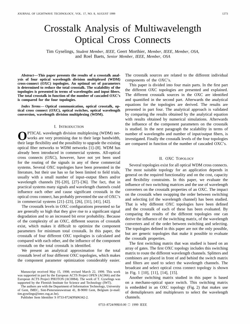
To analyze the impact when swapping the order betweenswitching and selecting of the wavelength channels, a thirdOXC topology has been defined (Fig. 3). This topology isthe mirror image of the first one. The switching matrix oftopology 1 is used but the wavelength channels are selectedby the filters, before being routed to the desired output fiber.
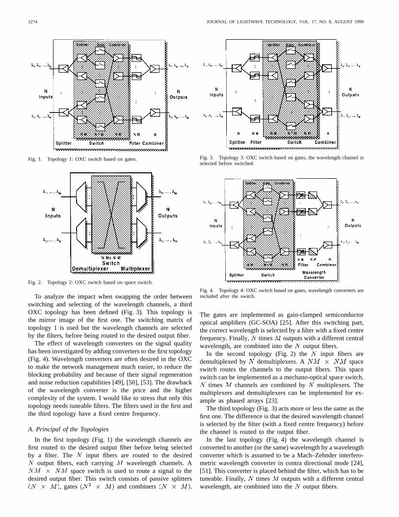
The effect of wavelength converters on the signal qualityhas been investigated by adding converters to the first topology(Fig. 4). Wavelength converters are often desired in the OXCto make the network management much easier, to reduce theblocking probability and because of their signal regenerationand noise reduction capabilities [49], [50], [53]. The drawbackof the wavelength converter is the price and the highercomplexity of the system. I would like to stress that only thistopology needs tuneable filters. The filters used in the first andthe third topology have a fixed centre frequency.
A. Principal of the Topologies
In the first topology (Fig. 1) the wavelength channels arefirst routed to the desired output fiber before being selectedby a filter. The input fibers are routed to the desired
output fibers, each carrying wavelength channels. Aspace switch is used to route a signal to the
desired output fiber. This switch consists of passive splitters, gates and combiners .
Fig. 3. Topology 3: OXC switch based on gates, the wavelength channel isselected before switched.
Fig. 4. Topology 4: OXC switch based on gates, wavelength converters areincluded after the switch.
The gates are implemented as gain-clamped semiconductoroptical amplifiers (GC-SOA) [25]. After this switching part,the correct wavelength is selected by a filter with a fixed centrefrequency. Finally, times outputs with a different centralwavelength, are combined into the output fibers.
In the second topology (Fig. 2) the input fibers aredemultiplexed by demultiplexers. A spaceswitch routes the channels to the output fibers. This spaceswitch can be implemented as a mechano-optical space switch.
times channels are combined by multiplexers. Themultiplexers and demultiplexers can be implemented for ex-ample as phased arrays [23].
The third topology (Fig. 3) acts more or less the same as thefirst one. The difference is that the desired wavelength channelis selected by the filter (with a fixed centre frequency) beforethe channel is routed to the output fiber.
In the last topology (Fig. 4) the wavelength channel isconverted to another (or the same) wavelength by a wavelengthconverter which is assumed to be a Mach–Zehnder interfero-metric wavelength converter in contra directional mode [24],[51]. This converter is placed behind the filter, which has to betuneable. Finally, times outputs with a different centralwavelength, are combined into the output fibers.
GYSELINGS et al.: CROSSTALK ANALYSIS OF MULTIWAVELENGTH OXC’S 1275
Fig. 5. Interband and intraband crosstalk.
III. CROSSTALK SOURCES
Crosstalk will be one of the major limitations for theintroduction of OXC in all optical networks. In this paper theinfluence of the components on the total OXC crosstalk is in-vestigated. The different classes of crosstalk are first clarified.
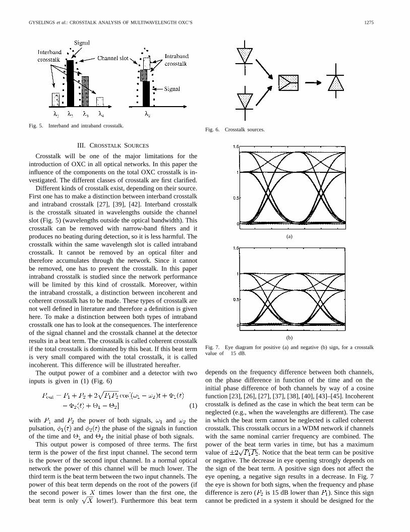
Different kinds of crosstalk exist, depending on their source.First one has to make a distinction between interband crosstalkand intraband crosstalk [27], [39], [42]. Interband crosstalkis the crosstalk situated in wavelengths outside the channelslot (Fig. 5) (wavelengths outside the optical bandwidth). Thiscrosstalk can be removed with narrow-band filters and itproduces no beating during detection, so it is less harmful. Thecrosstalk within the same wavelength slot is called intrabandcrosstalk. It cannot be removed by an optical filter andtherefore accumulates through the network. Since it cannotbe removed, one has to prevent the crosstalk. In this paperintraband crosstalk is studied since the network performancewill be limited by this kind of crosstalk. Moreover, withinthe intraband crosstalk, a distinction between incoherent andcoherent crosstalk has to be made. These types of crosstalk arenot well defined in literature and therefore a definition is givenhere. To make a distinction between both types of intrabandcrosstalk one has to look at the consequences. The interferenceof the signal channel and the crosstalk channel at the detectorresults in a beat term. The crosstalk is called coherent crosstalkif the total crosstalk is dominated by this beat. If this beat termis very small compared with the total crosstalk, it is calledincoherent. This difference will be illustrated hereafter.
The output power of a combiner and a detector with twoinputs is given in (1) (Fig. 6)
(1)
with and the power of both signals, and thepulsation, and the phase of the signals in functionof the time and and the initial phase of both signals.
This output power is composed of three terms. The firstterm is the power of the first input channel. The second termis the power of the second input channel. In a normal opticalnetwork the power of this channel will be much lower. Thethird term is the beat term between the two input channels. Thepower of this beat term depends on the root of the powers (ifthe second power is times lower than the first one, thebeat term is only lower!). Furthermore this beat term
Fig. 6. Crosstalk sources.
(a)
(b)
Fig. 7. Eye diagram for positive (a) and negative (b) sign, for a crosstalkvalue of�15 dB.
depends on the frequency difference between both channels,on the phase difference in function of the time and on theinitial phase difference of both channels by way of a cosinefunction [23], [26], [27], [37], [38], [40], [43]–[45]. Incoherentcrosstalk is defined as the case in which the beat term can beneglected (e.g., when the wavelengths are different). The casein which the beat term cannot be neglected is called coherentcrosstalk. This crosstalk occurs in a WDM network if channelswith the same nominal carrier frequency are combined. Thepower of the beat term varies in time, but has a maximumvalue of . Notice that the beat term can be positiveor negative. The decrease in eye opening strongly depends onthe sign of the beat term. A positive sign does not affect theeye opening, a negative sign results in a decrease. In Fig. 7the eye is shown for both signs, when the frequency and phasedifference is zero ( is 15 dB lower than ). Since this signcannot be predicted in a system it should be designed for the
1276 JOURNAL OF LIGHTWAVE TECHNOLOGY, VOL. 17, NO. 8, AUGUST 1999
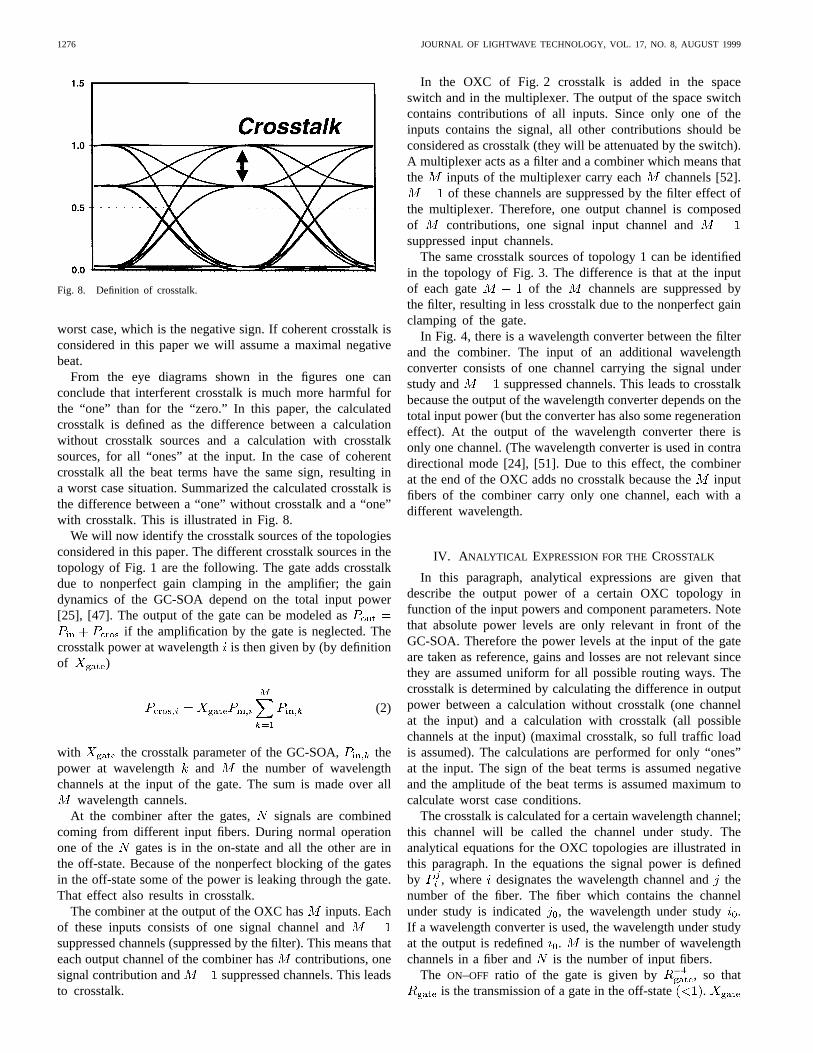
Fig. 8. Definition of crosstalk.
worst case, which is the negative sign. If coherent crosstalk isconsidered in this paper we will assume a maximal negativebeat.
From the eye diagrams shown in the figures one canconclude that interferent crosstalk is much more harmful forthe “one” than for the “zero.” In this paper, the calculatedcrosstalk is defined as the difference between a calculationwithout crosstalk sources and a calculation with crosstalksources, for all “ones” at the input. In the case of coherentcrosstalk all the beat terms have the same sign, resulting ina worst case situation. Summarized the calculated crosstalk isthe difference between a “one” without crosstalk and a “one”with crosstalk. This is illustrated in Fig. 8.
We will now identify the crosstalk sources of the topologiesconsidered in this paper. The different crosstalk sources in thetopology of Fig. 1 are the following. The gate adds crosstalkdue to nonperfect gain clamping in the amplifier; the gaindynamics of the GC-SOA depend on the total input power[25], [47]. The output of the gate can be modeled as
if the amplification by the gate is neglected. Thecrosstalk power at wavelengthis then given by (by definitionof )
(2)
with the crosstalk parameter of the GC-SOA, thepower at wavelength and the number of wavelengthchannels at the input of the gate. The sum is made over all
wavelength cannels.At the combiner after the gates, signals are combined
coming from different input fibers. During normal operationone of the gates is in the on-state and all the other are inthe off-state. Because of the nonperfect blocking of the gatesin the off-state some of the power is leaking through the gate.That effect also results in crosstalk.
The combiner at the output of the OXC has inputs. Eachof these inputs consists of one signal channel andsuppressed channels (suppressed by the filter). This means thateach output channel of the combiner hascontributions, onesignal contribution and suppressed channels. This leadsto crosstalk.
In the OXC of Fig. 2 crosstalk is added in the spaceswitch and in the multiplexer. The output of the space switchcontains contributions of all inputs. Since only one of theinputs contains the signal, all other contributions should beconsidered as crosstalk (they will be attenuated by the switch).A multiplexer acts as a filter and a combiner which means thatthe inputs of the multiplexer carry each channels [52].
of these channels are suppressed by the filter effect ofthe multiplexer. Therefore, one output channel is composedof contributions, one signal input channel andsuppressed input channels.
The same crosstalk sources of topology 1 can be identifiedin the topology of Fig. 3. The difference is that at the inputof each gate of the channels are suppressed bythe filter, resulting in less crosstalk due to the nonperfect gainclamping of the gate.
In Fig. 4, there is a wavelength converter between the filterand the combiner. The input of an additional wavelengthconverter consists of one channel carrying the signal understudy and suppressed channels. This leads to crosstalkbecause the output of the wavelength converter depends on thetotal input power (but the converter has also some regenerationeffect). At the output of the wavelength converter there isonly one channel. (The wavelength converter is used in contradirectional mode [24], [51]. Due to this effect, the combinerat the end of the OXC adds no crosstalk because theinputfibers of the combiner carry only one channel, each with adifferent wavelength.
IV. A NALYTICAL EXPRESSION FOR THECROSSTALK
In this paragraph, analytical expressions are given thatdescribe the output power of a certain OXC topology infunction of the input powers and component parameters. Notethat absolute power levels are only relevant in front of theGC-SOA. Therefore the power levels at the input of the gateare taken as reference, gains and losses are not relevant sincethey are assumed uniform for all possible routing ways. Thecrosstalk is determined by calculating the difference in outputpower between a calculation without crosstalk (one channelat the input) and a calculation with crosstalk (all possiblechannels at the input) (maximal crosstalk, so full traffic loadis assumed). The calculations are performed for only “ones”at the input. The sign of the beat terms is assumed negativeand the amplitude of the beat terms is assumed maximum tocalculate worst case conditions.
The crosstalk is calculated for a certain wavelength channel;this channel will be called the channel under study. Theanalytical equations for the OXC topologies are illustrated inthis paragraph. In the equations the signal power is definedby , where designates the wavelength channel andthenumber of the fiber. The fiber which contains the channelunder study is indicated , the wavelength under study.If a wavelength converter is used, the wavelength under studyat the output is redefined . is the number of wavelengthchannels in a fiber and is the number of input fibers.
The ON–OFF ratio of the gate is given by , so thatis the transmission of a gate in the off-state .
GYSELINGS et al.: CROSSTALK ANALYSIS OF MULTIWAVELENGTH OXC’S 1277
is the crosstalk parameter of the gate, defined in (2). Thesuppression of a wavelength channel by a filter is given by
. This means that is the transmission of the filter seenby that channel ( 1). The crosstalk of the switch matrix isgiven by and is defined as the fraction of the input powerrouted to other outputs. The crosstalk of the demultiplexer andthe multiplexer are given by and and are alsodefined as transmission factors (1).
Equation (3), shown at the bottom of the page, is givenfor the first topology in case of coherent crosstalk. The firstthree terms are the noninterfering contributions, the last threeterms are the contributions due to the interference of differentchannels (beat terms).
The first term contains the input power. The output powerwould be equal to the input power if no interaction with theother channels existed. The second term contains the crosstalkof the gate due to nonperfect gain clamping. The third termcontains contributions due to input channels with the samewavelength at other input fibers. These are the direct crosstalkcontributions, resulting in an increase of the output power.The interference between the channels results in the last threeterms, with the negative sign. First there is the interferencebetween the signal channel and the crosstalk channels. Noticethat these contributions only scale with the root ofand resulting in severe signal degradation. The secondinterference term contains the beat terms of the differentcrosstalk channels. Since each of these crosstalk channels iscomposed of different contributions (e.g., times thecontribution ), beat terms between these contributionshave to be taken into account (last term).
The equation for the second topology differs from the previ-ous one because other components are used (space switch andmuliplexers–demultiplexers). A simplified version of the equa-tion is given below with only the most dominant contributionsshown in (4) at the bottom of the page. The results shown inthis paper are based on a full equation. Five contributions can
be distinguished. The first term is the input signal. The secondterm contains the direct crosstalk contributions. The beat termsare given in the next three terms. First, we have the interfer-ence between the crosstalk contributions. Afterwards,the beat between signal and crosstalk channels is given. Thelast term is the beat between different crosstalk contributions.
The equation for the third topology, shown in (5) at thebottom of the next page, is rather equal to the equation for thefirst topology. The same six contributions can be distinguished.The only difference between both equations (and OXC) is thatthe crosstalk due to the not-perfect gain clamping of the gateis less important in this topology because the other wavelengthchannels are filtered before the gate. The other contributionsare the same.
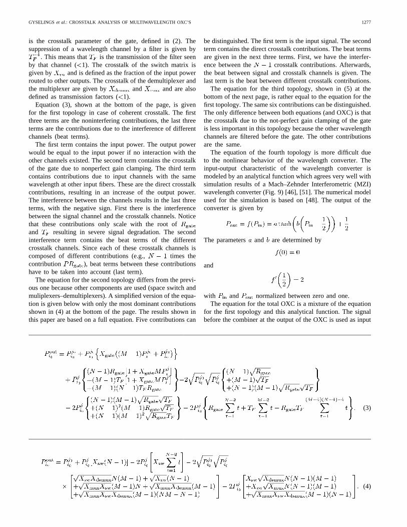
The equation of the fourth topology is more difficult dueto the nonlinear behavior of the wavelength converter. Theinput-output characteristic of the wavelength converter ismodeled by an analytical function which agrees very well withsimulation results of a Mach–Zehnder Interferometric (MZI)wavelength converter (Fig. 9) [46], [51]. The numerical modelused for the simulation is based on [48]. The output of theconverter is given by
The parameters and are determined by
and
with and normalized between zero and one.The equation for the total OXC is a mixture of the equation
for the first topology and this analytical function. The signalbefore the combiner at the output of the OXC is used as input
(3)
(4)
1278 JOURNAL OF LIGHTWAVE TECHNOLOGY, VOL. 17, NO. 8, AUGUST 1999
Fig. 9. Analytical function compared with a numerically simulated wave-length converter input–output function.
for the analytical function and the outputs of this function arecombined to form the output of the OXC.
V. NUMERICAL RESULTS
The parameter values used for the calculations are given inTable I, except when stated otherwise. The calculated crosstalkis defined as
Crosstalk (6)
with the output power of a calculation with allchannels at the input and the output power of acalculation with only the channel under study at the input ofthe OXC.
The input power is chosen to be very low. As mentionedbefore, power levels at the input of the gate are taken asreference. A power value of 20 dBm is a normal input valuefor a gate.
A. Validation of the Analytical Approach
The analytical approach has been validated by calculatingthe crosstalk for the first OXC topology as a function of theinput power and comparing this result with the results of anumerical simulation of the same topology.
The numerical simulations are performed in the time do-main. The concept of the simulation tool is that each compo-
TABLE IPARAMETER VALUES USED FOR THECALCULATIONS
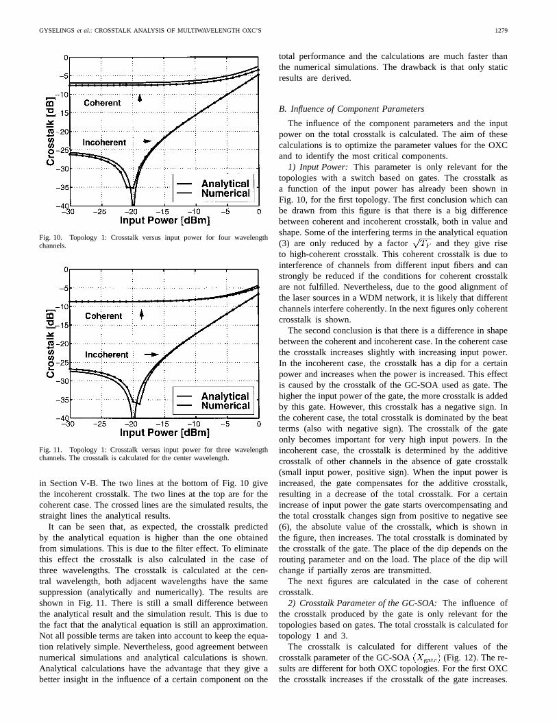
nent is represented by a function which calculates the opticalfields at the output of the component based on the optical fieldsat the input and on the component parameters. The systemmodel of the gate used in these simulations is controlledby comparing with results obtained by a detailed numericalsimulation described in [47]. The filter is implemented as aFabry–Perot filter, with a free spectral range of 70 nm (largerthan twice the used bandwidth). The channel spacing is 3.2nm and four channels are used. The parameter givenin Table I is defined as the transmission factor seen by theneighboring channel. Wavelengths further from the centralwavelength of the filter are suppressed more. Therefore weexpect higher analytical crosstalk than numerical crosstalkbecause in the numerical simulations the suppression of non-adjacent channels is higher. In the case presented in this paperthere was one nonadjacent channel (four wavelengths wereused and the crosstalk was calculated at one of the centrewavelengths).
The results of the analytical calculation and the numericalsimulation are shown in Fig. 10. In this paragraph, the dif-ference between the analytical calculations and the numericalsimulations is discussed. The shape of the figure is discussed
(5)
GYSELINGS et al.: CROSSTALK ANALYSIS OF MULTIWAVELENGTH OXC’S 1279
Fig. 10. Topology 1: Crosstalk versus input power for four wavelengthchannels.
Fig. 11. Topology 1: Crosstalk versus input power for three wavelengthchannels. The crosstalk is calculated for the center wavelength.
in Section V-B. The two lines at the bottom of Fig. 10 givethe incoherent crosstalk. The two lines at the top are for thecoherent case. The crossed lines are the simulated results, thestraight lines the analytical results.
It can be seen that, as expected, the crosstalk predictedby the analytical equation is higher than the one obtainedfrom simulations. This is due to the filter effect. To eliminatethis effect the crosstalk is also calculated in the case ofthree wavelengths. The crosstalk is calculated at the cen-tral wavelength, both adjacent wavelengths have the samesuppression (analytically and numerically). The results areshown in Fig. 11. There is still a small difference betweenthe analytical result and the simulation result. This is due tothe fact that the analytical equation is still an approximation.Not all possible terms are taken into account to keep the equa-tion relatively simple. Nevertheless, good agreement betweennumerical simulations and analytical calculations is shown.Analytical calculations have the advantage that they give abetter insight in the influence of a certain component on the
total performance and the calculations are much faster thanthe numerical simulations. The drawback is that only staticresults are derived.
B. Influence of Component Parameters
The influence of the component parameters and the inputpower on the total crosstalk is calculated. The aim of thesecalculations is to optimize the parameter values for the OXCand to identify the most critical components.
1) Input Power: This parameter is only relevant for thetopologies with a switch based on gates. The crosstalk asa function of the input power has already been shown inFig. 10, for the first topology. The first conclusion which canbe drawn from this figure is that there is a big differencebetween coherent and incoherent crosstalk, both in value andshape. Some of the interfering terms in the analytical equation(3) are only reduced by a factor and they give riseto high-coherent crosstalk. This coherent crosstalk is due tointerference of channels from different input fibers and canstrongly be reduced if the conditions for coherent crosstalkare not fulfilled. Nevertheless, due to the good alignment ofthe laser sources in a WDM network, it is likely that differentchannels interfere coherently. In the next figures only coherentcrosstalk is shown.
The second conclusion is that there is a difference in shapebetween the coherent and incoherent case. In the coherent casethe crosstalk increases slightly with increasing input power.In the incoherent case, the crosstalk has a dip for a certainpower and increases when the power is increased. This effectis caused by the crosstalk of the GC-SOA used as gate. Thehigher the input power of the gate, the more crosstalk is addedby this gate. However, this crosstalk has a negative sign. Inthe coherent case, the total crosstalk is dominated by the beatterms (also with negative sign). The crosstalk of the gateonly becomes important for very high input powers. In theincoherent case, the crosstalk is determined by the additivecrosstalk of other channels in the absence of gate crosstalk(small input power, positive sign). When the input power isincreased, the gate compensates for the additive crosstalk,resulting in a decrease of the total crosstalk. For a certainincrease of input power the gate starts overcompensating andthe total crosstalk changes sign from positive to negative see(6), the absolute value of the crosstalk, which is shown inthe figure, then increases. The total crosstalk is dominated bythe crosstalk of the gate. The place of the dip depends on therouting parameter and on the load. The place of the dip willchange if partially zeros are transmitted.
The next figures are calculated in the case of coherentcrosstalk.
2) Crosstalk Parameter of the GC-SOA:The influence ofthe crosstalk produced by the gate is only relevant for thetopologies based on gates. The total crosstalk is calculated fortopology 1 and 3.
The crosstalk is calculated for different values of thecrosstalk parameter of the GC-SOA (Fig. 12). The re-sults are different for both OXC topologies. For the first OXCthe crosstalk increases if the crosstalk of the gate increases.
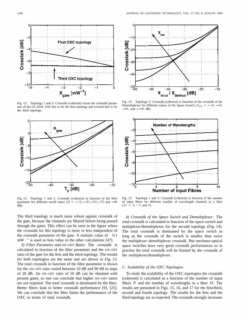
1280 JOURNAL OF LIGHTWAVE TECHNOLOGY, VOL. 17, NO. 8, AUGUST 1999
Fig. 12. Topology 1 and 3: Crosstalk (coherent) versus the crosstalk param-eter of the GC-SOA. Full line is for the first topology and crossed line is forthe third topology.
Fig. 13. Topology 1 and 3: Crosstalk (coherent) in function of the filterparameter for different on/off ratios (R = �10;�30;�50;�70 and�90dB).
The third topology is much more robust against crosstalk ofthe gate, because the channels are filtered before being passedthrough the gates. This effect can be seen in the figure wherethe crosstalk for this topology is more or less independent ofthe crosstalk parameter of the gate. A realistic value of0.1mW 1 is used as bias value in the other calculations [47].
3) Filter Parameter andON–OFF Ratio: The crosstalk iscalculated in function of the filter parameter and theON–OFF
ratio of the gate for the first and the third topology. The resultsfor both topologies are the same and are shown in Fig. 13.The total crosstalk in function of the filter parameter is shownfor the ON–OFF ratio varied between 10 dB and 90 dB in stepsof 20 dB. An ON–OFF ratio of 50 dB can be obtained withpresent gates, so one can conclude that higherON–OFF ratiosare not required. The total crosstalk is dominated by the filter.Better filters lead to better crosstalk performance [9], [25].We can conclude that the filter limits the performance of theOXC in terms of total crosstalk.
Fig. 14. Topology 2: Crosstalk (coherent) in function of the crosstalk of theDemultiplexer for different values of the Space Switch (Xsw = �40, �60,�80, and�100 dB).
Fig. 15. Topology 1 and 3: Crosstalk (coherent) in function of the numberof input fibers for different number of wavelength channels in a fiber(M = 2; 4; 6 and 8).
4) Crosstalk of the Space Switch and Demultiplexer:Thetotal crosstalk is calculated in function of the space switch andmultiplexer/demultiplexer for the second topology (Fig. 14).The total crosstalk is dominated by the space switch aslong as the crosstalk of the switch is smaller than twicethe multiplexer–demultiplexer crosstalk. But mechano-opticalspace switches have very good crosstalk performances so inpractise the total crosstalk will be limited by the crosstalk ofthe multiplexer/demultiplexer.
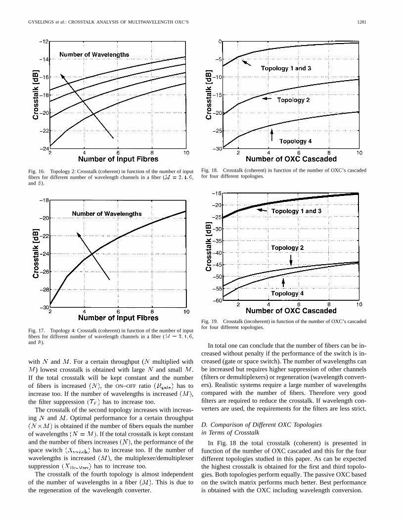
C. Scalability of the OXC Topologies
To study the scalability of the OXC topologies the crosstalk(coherent) is calculated as a function of the number of inputfibers and the number of wavelengths in a fiber. Theresults are presented in Figs. 15, 16, and 17 for the first/third,second and fourth topology. The results for the first and thethird topology are as expected. The crosstalk strongly increases
GYSELINGS et al.: CROSSTALK ANALYSIS OF MULTIWAVELENGTH OXC’S 1281
Fig. 16. Topology 2: Crosstalk (coherent) in function of the number of inputfibers for different number of wavelength channels in a fiber (M = 2; 4; 6,and 8).
Fig. 17. Topology 4: Crosstalk (coherent) in function of the number of inputfibers for different number of wavelength channels in a fiber (M = 2; 4; 6,and 8).
with and . For a certain throughput ( multiplied with) lowest crosstalk is obtained with large and small .
If the total crosstalk will be kept constant and the numberof fibers is increased , the ON–OFF ratio has toincrease too. If the number of wavelengths is increased,the filter suppression has to increase too.
The crosstalk of the second topology increases with increas-ing and . Optimal performance for a certain throughput
is obtained if the number of fibers equals the numberof wavelengths . If the total crosstalk is kept constantand the number of fibers increases , the performance of thespace switch has to increase too. If the number ofwavelengths is increased , the multiplexer/demultiplexersuppression - has to increase too.
The crosstalk of the fourth topology is almost independentof the number of wavelengths in a fiber . This is due tothe regeneration of the wavelength converter.
Fig. 18. Crosstalk (coherent) in function of the number of OXC’s cascadedfor four different topologies.
Fig. 19. Crosstalk (incoherent) in function of the number of OXC’s cascadedfor four different topologies.
In total one can conclude that the number of fibers can be in-creased without penalty if the performance of the switch is in-creased (gate or space switch). The number of wavelengths canbe increased but requires higher suppression of other channels(filters or demultiplexers) or regeneration (wavelength convert-ers). Realistic systems require a large number of wavelengthscompared with the number of fibers. Therefore very goodfilters are required to reduce the crosstalk. If wavelength con-verters are used, the requirements for the filters are less strict.
D. Comparison of Different OXC Topologiesin Terms of Crosstalk
In Fig. 18 the total crosstalk (coherent) is presented infunction of the number of OXC cascaded and this for the fourdifferent topologies studied in this paper. As can be expectedthe highest crosstalk is obtained for the first and third topolo-gies. Both topologies perform equally. The passive OXC basedon the switch matrix performs much better. Best performanceis obtained with the OXC including wavelength conversion.
1282 JOURNAL OF LIGHTWAVE TECHNOLOGY, VOL. 17, NO. 8, AUGUST 1999
The better performance of the passive topology comparedto the first two topologies can be expected due to the lowcrosstalk values of the space switch, and because filteringoccurs before and after the space switch.
The very good performance of the OXC with wavelengthconverters is due to the regeneration capabilities of the con-verter [49], [50] and due to the absence of interference crosstalkat the last combiner. If the crosstalk before the converter issmall, it has little impact on the total crosstalk. The crosstalkbefore the converter can be reduced by optimising the crosstalkof the first topology. For that reason, the extensive study of thefirst topology is important. Optimal parameter settings for thistopology will give optimal performance for the topology withwavelength converters. If the crosstalk before the wavelengthconverter is kept low, many converters can be cascaded.
From the comparison of the first and third topology, weconclude that they perform equally, independent of the placeof the filter. The only difference is that the topology withselection before the switching, is not sensitive to variations inthe crosstalk parameter of the gate, while the first topologywith the selection after the switch matrix is very sensitive.
By comparing the first two topologies, we see that thefirst one has considerable higher crosstalk. But this topologycontains only one filter and the second topology contains twofilters, one in front of and one behind the switch. From thecalculations in function of the component parameters we seethat both topologies are limited by the filter. We can concludethat the mechano-optical space switch performs better than theswitch based on gates (even better performance is mentionedin literature [9], but in both cases the total crosstalk is limitedby other components.
The wavelength converter improves the performance ofan OXC topology drastically (comparison between the firstand the last OXC). The drawback is that converters are veryexpensive and that they add jitter.
Optimal crosstalk performance will be obtained if filteringbefore and after the switch matrix is accomplished and wave-length conversion is used. Both switch matrixes perform good.The crosstalk of the switch is not dominant as long as it isbetter than twice the filter suppression. If gates are used in theswitch matrix, the total input power should be sufficiently lowso that the gain of the gate is clamped. This can be obtainedby filtering in front of the switch.
The incoherent crosstalk in function of the number of OXCcascaded is shown in Fig. 19 (The crosstalk of topology 1is calculated with an input power of 30 dBm to avoiddominant gate crosstalk). While the coherent crosstalk gives anupper limit, the incoherent crosstalk gives a lower limit whichcan be obtained with a certain set of component parameters.The margin between upper and lower limit indicates theimprovement which can be obtained by suppressing the beatterm. This can be obtained for example by phase scrambling.If a crosstalk value of 20 dB can be tolerated, only the OXCwith wavelength converters satisfies the demand if a numberof cross connects is cascaded. By suppressing the beat termthe same tolerance can be fulfilled with the second topology.
One can conclude that a calculation in the case of coherentcrosstalk gives an upper boundary. When this upper boundary
does not meet the requirements there is room for improvementby suppressing the beat. An incoherent calculation results ina lower boundary. If this lower boundary is not good enough,better component parameters are required.
VI. CONCLUSION
In this paper, four different OXC topologies have beenstudied. Their crosstalk sources have been identified and theirtotal crosstalk is calculated based on analytical equations.Good qualitative agreement with the numerical simulationshave been demonstrated.
From the comparison between the different OXC’s we canconclude that the performance is limited by the filters. Bothswitch matrixes fulfill the demand. Wavelength convertersimprove the system and make the filter requirements less strict.That is why they could be necessary in future optical crossconnects. A high input power of the gates will result in anextra penalty. Optimal results are obtained if filters are usedin front of and behind the switch and if wavelength convertersare applied.
A big difference between coherent crosstalk and noncoher-ent crosstalk has been observed as was expected. To reducethe coherent crosstalk, phase scramblers could be used. A cal-culation in case of coherent crosstalk gives an upper boundaryon the expected crosstalk, a calculation of the incoherent caseresults in a lower boundary. If the lower boundary does notmeet the requirements better components are necessary.
REFERENCES
[1] C. A. Brackett, “Is there an emerging consensus on WDM networking,”J. Lightwave Technol., vol. 14, pp. 936–941, June 1996.
[2] D. J. Blumenthal, M. Shell, and M. D. Vaughn, “Physical limitationsto scalability of WDM all-optical networks,”Opt. Photon. News, Feb.1997.
[3] V. Mizrahi et al., “The future of WDM systems,” inProc. ECOC 1997,1997, pp. 137–141.
[4] M. Artiglia, “Upgrading installed systems to multigigabit bit-rates bymeans of dispersion compensating,” inProc. ECOC 1996, MoB4, pp.1.75–1.82, 1996.
[5] M. J. O’Mahony, “Results from the COST 239 project: Ultra-highcapacity optical transmission networks,” inProc. ECOC 1996, TuB1.2,pp. 2.11–2.18, 1996.
[6] H. Kogelnik, “WDM networks: A U.S. perspective,” inProc. ECOC1996, MoA 2.2, pp. 5.81–5.86, 1996.
[7] M. J. O’Mahony, D. Simeonidou, A. Yu, J. Zhou, “The design of aeuropean optical network,”J. Lightwave Technol., vol. 13, pp. 817–828,May 1995.
[8] G. R. Hill et al., “A transport network layer based on optical networkelements,”J. Lightwave Technol., vol. 11, pp. 667–679, May/June 1993.
[9] M. Erman, “What technology is required for the pan-european network,what is available and what is not,” inProc. ECOC 1996, TuB 2.2, pp.5.87–5.94, 1996.
[10] A. Jourdan, F. Masetti, M. Garnot, G. Soulage, and M. Sotom, “Designsand implementation of a fully reconfigurable all-optical crossconnectfor high capacity multiwavelength transport networks,”J. LightwaveTechnol., vol. 14, pp. 1198–1206, June 1996.
[11] A. Jourdanet al., “Fully reconfigurable WDM optical crossconnect:Feasibility validation and preparation of prototype crossconnect forACTS “OPEN” field trials,” in Proc. ECOC 1997, pp. 55–58, 1997.
[12] M. W. Chbatet al., “The OPEN ACTS project: Early achievements andperspectives,” inProc. ECOC 1996, WeP 1.1, pp. 3.253–3.256.
[13] A. Jourdanet al., “WDM networking experiment including all-opticalcrossconnect cascade and transmission over 320 km G.652 fiber to 10Gbit/s,” in Proc. ECOC 1996, ThD 1.6, pp. 4.123–4.126.
[14] D. Chiaroni et al., “Feasibility issues of a high-speed photonic packetswitching fabric based on WDM subnanosecond optical gates,” inProc.ECOC 1996, ThD. 1.7, pp. 4.127–4.130.
GYSELINGS et al.: CROSSTALK ANALYSIS OF MULTIWAVELENGTH OXC’S 1283
[15] C. A. Brackett, “Dense wavelength division multiplexing networks:Principle and applications,”J. Select. Areas Commun., vol. 8, pp.948–964, Aug. 1990.
[16] B. Mikkelsen, K. Wunsel, P. Doussiereet al., “Demonstration of a robustWDM cross-connect cascade based on all-optical wavelength convertersfor routing and wavelength slot interchange,” inProc. ECOC 1997, pp.245–248.
[17] R. E. Wagneret al., “Realising the vision of multiwavelength opticalnetworking,” in Proc. ECOC 1997, pp. 143–147.
[18] P. B. Hansen, M. Shilling, P. Doussiereet al., “20 Gbit/s experimentaldemonstration of all-optical WDM packet switch,” inProc. ECOC 1997,pp. 13–16.
[19] M. Teshimaet al., “Demonstration of virtual wavelength path cross-connect,” inProc. ECOC 1997, pp. 59–62.
[20] M. Rasztovits-Wiechet al., “PHOTON—A progressive step towardoptical transport networks in europe,” inProc. NOC’96, vol. 1, pp.174–181.
[21] O. Ishida, N. Takachio, and K. Sato, “Modular cross-connect system forWDM optical-path networks,” inProc. ECOC 1997, pp. 63–66.
[22] C. Casper, H. M. Foisel, E. Patzak, B. Strebel, and K. Weich, “Improve-ment of crosstalk tolerance in optical cross connects by regenerativefrequency converters,” inProc. ECOC 1996, ThD 1.5, pp. 4.119–4.122.
[23] H. Takahashiet al., “Impact of crosstalk in an arrayed-waveguidemultiplexer onN �N optical interconnection,”J. Lightwave Technol.,vol. 14, pp. 1097–1105, June 1996.
[24] G. Eilenbergeret al., “Cascadability of transparent WDM routing nodesusing regenerating wavelength conversion components,” inProc. ECOC1996, MoA 4.4, pp. 1.35–1.38.
[25] G. Soulageet al., “4 � 4 space-switch based on clamped-gain semi-conductor optical amplifiers in a16� 10 Gbit/s WDM experiment,” inProc. ECOC 1996, ThD 2.1, pp. 4.145–4.148.
[26] C. Li and F. Tong, “Crosstalk and interference penalty in all-opticalnetworks using static wavelength routers,”J. Lightwave Technol., vol.14, pp. 1120–1126, June 1996.
[27] J. Zhou et al., “Crosstalk in multiwavelength optical cross connectnetworks,”J. Lightwave Technol., vol. 14, pp. 1423–1435, June 1996.
[28] H. Sano, Y. Sawadaet al., “Novel optical cross-connect architecturefor restoration in backbone networks,” inProc. ECIO 1997, PThA5, pp.84–87.
[29] R. T. Hofmeisteret al., “Project Learn—Light exchanegable, add/dropring network,” in Proc. OFC 1997, PD25, 1997.
[30] R. S. Vodhanelet al., “National-scale WDM networking demonstrationby the MONET consortium,” inProc. OFC 1997, PD27.
[31] H. Obara and T. Kawai, “Virtually crosstalk-free wavelength routingnetwork architecture,”Electron. Lett., vol. 32, no. 6, pp. 1123–1125,June 1996.
[32] M. F. Stephens, M. J. O’Mahony, M. J. Robertsonet al., “Demon-stration of a flexible all-optical wavelength converting/routing switcharchitecture,” inProc. ECOC 1996, ThD 1.9, pp. 4.135–4.138.
[33] M. Koga et al., “Optical path cross-connect demonstrator designed toachieve 320 Gbit/s,” inProc. ECOC 1996, ThC 3.1, pp. 5.29–5.32.
[34] M. Koga et al., “Design and performance of an optical path cross-connect system based on wavelength path concept,”J. LightwaveTechnol., vol. 14, pp. 1106–1119, June 1996.
[35] Y. Jin and M. Kavehrad, “An optical cross-connect system as a high-speed switching core and its performance analysis,”J. Lightwave Tech.,vol. 14, pp. 1183–1197, June 1996.
[36] R. E. Wagneret al., “MONET: Multiwavelength optical networking,”J. Lightwave Technol., vol. 14, pp. 1349–1355, 1996.
[37] A. M. Hill and D. B. Payne, “Linear crosstalk in wavelength-division-multiplexed optical fiber transmission systems,”J. Lightwave Technol.,vol. LT-3, pp. 643–650, June 1985.
[38] C. P. Larsen, L. Gillner and M. Gustavsson, “Linear crosstalk propertiesof large WDM cross-connects,” inProc. ECIO 1997, PWA4, pp. 27–30.
[39] D. J. Blumenthal, “Coherent crosstalk in photonic switched networks,”in Proc. ECIO 1997, PWA1, pp. 1–6.
[40] L. Gillner, C. P. Larsen, and M. Gustavson, “Influence of crosstalkon the scalability of optical multi-wavelength switching networks,” inProc. LEOS Summer Topical Meeting,Montreal, P.Q., Canada, Aug.1997, TuC2, pp. 32–33.
[41] G. A. Castanon, O. K. Tonguz, and A. Bononi, “Impact of crosstalk onthe performance of multi-wavelength optical cross-connected networksusing deflection routing,” inProc. LEOS 1996, ThG4, pp. 318–319.
[42] Y. K. Park et al., “Crosstalk and prefiltering in a two-channel ASKheterodyne detection system without the effect of laser phase noise,”J.Lightwave Technol., vol. 6, pp. 1312–1319, Aug. 1988.
[43] D. J. Blumenthal, P. Grandestrand, and L. Thylen, “BER floors dueto heterodyne coherent crosstalk in space photonic switches for WDMnetworks,”IEEE Photon. Technol. Lett., vol. 8, pp. 284–286, Feb. 1996.
[44] O. Lindunger and E. Almstrom, “Time dependence of interferometriccrosstalk in all-optical networks,” inProc. ECIO 1997, PWA3, pp.23–26.
[45] P. B. Hansen and L. Eskildsen, “Multi-path interference in opticallypre-amplified lightwave systems,” inProc. ECOC 1997, pp. 271–274.
[46] P. Ohlen and E. Berglind, “Noise accumulation and BER estimates inconcatenated nonlinear optoelectronic repeaters,”IEEE Photon. Technol.Lett., vol. 9, pp. 1011–1013, July 1997.
[47] J. Sun, G. Morthier, and R. Baets, “Numerical and theoretical study ofthe crosstalk in gain clamped semiconductor optical amplifiers,”IEEEJ. Select. Topics Quantum Electron., vol. 3, pp. 1162–1167, Oct. 1997.
[48] T. Durhuuset al., “Detailed dynamic model for semiconductor opti-cal amplifiers and their crosstalk and intermodulation distortion,”J.Lightwave Technol., vol. 10, pp. 1056–1065, Aug. 1992.
[49] B. Mikkelsen et al., “All-optical noise reduction capability of inter-ferometric wavelength converters,”Electron. Lett., vol. 32, no. 6, pp.566–567, 1996.
[50] T. Gyselings, G. Morthier and R. Baets, “Strong improvement in opticalsignal regeneration and noise reduction through asymmetric biasingof mach-zehnder interferometric all-optical wavelength converters,” inProc. ECOC 1997, pp. 188–191.
[51] T. Durhuuset al., “All-optical wavelength conversion by semiconductoroptical amplifiers,”J. Lightwave Technol., vol. 14, pp. 942–954, June1996.
[52] K. Vreeburg, “InP-based photonic integrated circuits for wavelengthrouting and switching,” Ph.D. dissertation, Univ. Delft, The Netherlands,Dec. 1997, ch. 5.
[53] W. V. Parys, B. Van Caenegem, and B. Vandenberghe, “Meshedwavelength-division multiplexed networks partially equipped withwavelength converters,” inProc. OFC 1998, ThU1, pp. 359–360.
[54] K. Okamoto, “Integrated optical WDM devices,” inProc. ECIO 1997,EWC1, pp. 62–67.
Tim Gyselings (S’98) was born in Deurne, Belgium, on February 19, 1972.He received the degree in electrical engineering from the University of Gent,Belgium, in 1995.
Since 1995, he has been with the Department of Information Technology(INTEC) of the University of Gent. He holds a research fellowship at theFlemish Institute for Science and Technology (IWT). His main interests arethe modeling of WDM networks.
Mr. Gyselings is a student member of IEEE Laser and Opto-ElectronicsSociety (LEOS), IEEE Communications Society (COMSOC), and the FlemishEngineer Association.
Geert Morthier (M’88) was born in Gent, Belgium, on March 20, 1964. Hereceived the degree in electrical engineering and the Ph.D. degree from theUniversity of Gent in 1987 and 1991, respectively.
Since 1991, he has been a member of the permanent staff of the IMEC at theUniversity of Gent. His main interests are in the modeling and characterizationof optoelectronic components. He has authored or coauthored over 70 papersin the field. He is also one of two authors of theHandbook of DistributedFeedback Laser(Norwood, MA: Artech House, 1997) and coeditor of thebook How to Model and Measure Photonic Components: Experience From aEuropean Project(New york: Springer-Verlag, 1998).
Dr. Morthier is a member of the Optical Society of America (OSA).
Roel Baets(M’88–SM’96) received the degree in electrical engineering fromthe University of Gent, Gent, Belgium, in 1980. He received the M.Sc. degreein electrical engineering from Stanford University, Stanford, CA, in 1981 andthe Ph.D. degree from the University of Gent in 1984.
Since 1981, he has been with the Department of Information Technology(INTEC) of the University of Gent. Since 1989, he has been a Professor inthe Engineering Faculty of the University of Gent. From 1990 to 1994, he hasalso been a part-time Professor at the Technical University of Delft, Delft, TheNetherlands. He has worked in the field of III–V devices for optoelectronicsystems. With over 100 publications and conference papers, he has madecontributions to the modeling of semiconductor laser diodes, passive guided-wave devices, and to the design and fabrication of OEIC’s. His main interestsnow are the modeling, design and testing of optoelectronic devices, circuitsand systems for optical communication, and optical interconnect.
Dr. Baets is a member of the IEEE Laser and Opto-Electronics Society,SPIE, Optical Society of the America (OSA), and the Flemish EngineerAssociation. He has been member of the program committees of OFC, ECOC,IEEE Semiconductor Laser Conference, ESSDERC, CLEO-Europe and theEuropean Conference on Integrated Optics.