Embed Size (px)
Citation preview
Tangram Technology Ltd.
33 Gaping Lane, Hitchin, Herts., SG5 2DF
Phone: 01462 437 686
E-mail: [email protected]
Web Pages: www.tangram.co.uk
© Tangram Technology Ltd.
Plastics Topics – Joining plastics
Plastics Topics – Joining plastics
1
Contents:
Introduction 2
Part 1: Welding 3
1. Heat staking ....................................................................................................................... 3
2. Ultrasonic welding ............................................................................................................. 3
3. Hot plate welding ............................................................................................................... 5
4. Friction welding ................................................................................................................. 6
5. Induction welding .............................................................................................................. 7
6. Laser welding ..................................................................................................................... 7
7. Summary ............................................................................................................................ 7
Part 2: Mechanical fastening 8
1. Press fits ............................................................................................................................. 8
2. Snap fits .............................................................................................................................. 8
3. Screws ................................................................................................................................ 9
4. Staples and nails ............................................................................................................. 10
5. Rivets ................................................................................................................................ 10
6. Summary .......................................................................................................................... 10
Part 3: Adhesives and solvents 11
1. Solvent cements .............................................................................................................. 11
2. Adhesives ......................................................................................................................... 11
3. Adhesion theories ........................................................................................................... 11
4. Wetting .............................................................................................................................. 11
5. Pre-treatment ................................................................................................................... 13
6. Types of adhesives ......................................................................................................... 14
7. Designing adhesive joints .............................................................................................. 14
8. Summary .......................................................................................................................... 16
Plastics Topics – Joining plastics
2
Introduction
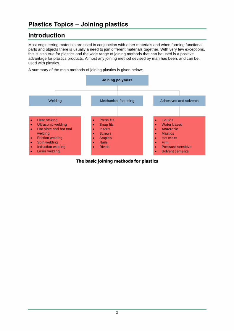
Most engineering materials are used in conjunction with other materials and when forming functional parts and objects there is usually a need to join different materials together. With very few exceptions, this is also true for plastics and the wide range of joining methods that can be used is a positive advantage for plastics products. Almost any joining method devised by man has been, and can be, used with plastics.
A summary of the main methods of joining plastics is given below:
The basic joining methods for plastics
Joining polymers
Welding
• Heat staking
• Ultrasonic welding
• Hot plate and hot tool
welding
• Friction welding
• Spin welding
• Induction welding
• Laser welding
Adhesives and solvents
• Liquids
• Water based
• Anaerobic
• Mastics
• Hot melts
• Film
• Pressure sensitive
• Solvent cements
Mechanical fastening
• Press fits
• Snap fits
• Inserts
• Screws
• Staples
• Nails
• Rivets
Plastics Topics – Joining plastics
3
Part 1: Welding
Many plastics products that are designed not to be disassembled are welded together and one of the
most common welded plastic products is the vinyl window – where simple hot plate welding is used to form the corners. The thermoplastic nature of plastics means that welding can be used to melt the plastic and to form a joint that is as strong as the parent material. This is not the only type of welding and many techniques exist to weld plastics.
1. Heat staking
Heat staking is the plastics equivalent of a permanent rivet and involves thermally softening a stake that is an integral part of a moulding and then forming a rivet-like retaining head under pressure from a cold tool. The most common heat source is hot air and the method is often called ‘hot air staking’.
The stake is a low-cost integral part of the moulding and there is no need for any separate fastener – a benefit in terms of recycling as there are no foreign materials to remove or sort.
Hot air staking is a two-step process. The stake is heated by a continuous current of hot air at 150°C to 400°C and when the stake has reached the softening point, the heat source is withdrawn. The rivet head is formed by a cold forming tool that shapes the stake to consolidate and join the parts. The tool is removed when the rivet head has cooled enough to hold the joint.
For good load holding, it is better to have more small stakes than a few very thick ones because these can heat up more and can be formed more easily. Where thick stakes are unavoidable, the heat distribution can be improved by adding a V-shaped dimple to increase the heat transfer. For easier assembly, the clearance hole in the component to be riveted should be 10% greater than the stake diameter. In all cases, the forming height of the stake should be enough to completely form the rivet head but should not be so great that there is distortion during heating.
The shape of the forming tool determines the shape of the fully formed rivet head and the volume of the forming tool cavity should be slightly less than that of the section of stake that is to be formed. This creates a compacting pressure to ensure a fully formed head.
Heat staking can be used to join simple sheets, to support printed circuit board and rollover staking can be used to secure springs, bearings, bushes and inserts.
2. Ultrasonic welding
In some ways, ultrasonic welding is similar to heat staking except that ultrasonic energy is used as the heat source. Ultrasound is also suitable for techniques such as spot welding, staking, inserting and swaging. Ultrasonic welding uses vibration at frequencies from 15kHz to 40kHz applied to the interface between two parts to be joined to generate heat that locally melts the plastic and forms a fusion weld.
The key part of an ultrasonic welder is a piezoelectric transducer (a PZT converter) that vibrates when a high frequency alternating current is applied. The vibrations produced by the PZT converter are small (0.01mm to 0.02mm) and are initially boosted by a tuned resonator to effectively double the amplitude of the vibrations. The vibrations must also be concentrated in the area where the weld is to be created and this requires a ‘sonotrode’ or ‘horn’ to focus the vibrations in the correct area. The horn is actually in contact with the parts to be welded and not only concentrates the ultrasonic vibrations but also again amplifies these (to the region of 0.05mm to 0.12mm) and provides the contact pressure necessary for a good weld. Horn design is very application specific and required specialist knowledge of the parts and the process. One important aspect of horn design is the distinction between near and far-field welds: A near-field weld is where the joint is within about 6mm of a horn tip contact point; anything else is a far-field weld. Far-field welding is much less effective because of energy losses within the material.
Not all materials are well suited to ultrasonic welding because not all materials transmit high frequency vibrations equally. As general rules:
• Rigid materials are better than flexible materials.
• Amorphous materials are better than semi-crystalline materials.
Plastics Topics – Joining plastics
4
• Far-field welding in semi-crystalline materials generally gives poor results.
• The process can be used to join dissimilar plastics but the difference in melt temperature between the materials should not be greater than 20°C and the materials should be chemically compatible.
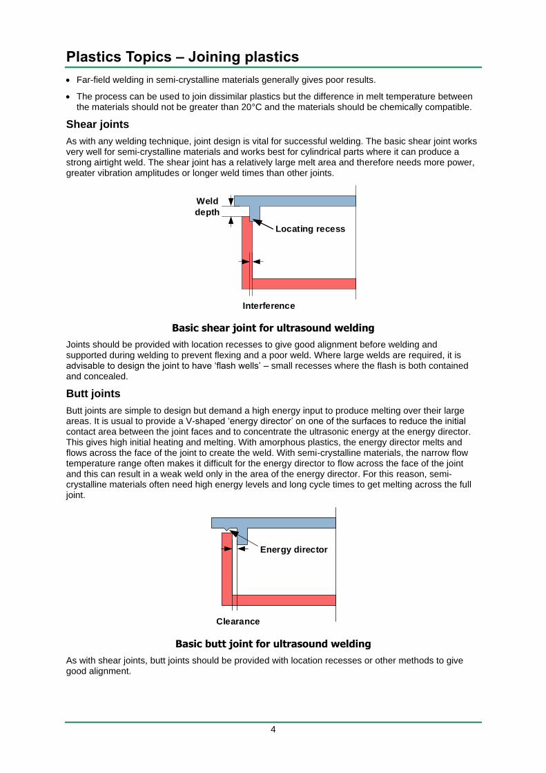
Shear joints
As with any welding technique, joint design is vital for successful welding. The basic shear joint works very well for semi-crystalline materials and works best for cylindrical parts where it can produce a strong airtight weld. The shear joint has a relatively large melt area and therefore needs more power, greater vibration amplitudes or longer weld times than other joints.
Basic shear joint for ultrasound welding
Joints should be provided with location recesses to give good alignment before welding and supported during welding to prevent flexing and a poor weld. Where large welds are required, it is advisable to design the joint to have ‘flash wells’ – small recesses where the flash is both contained and concealed.
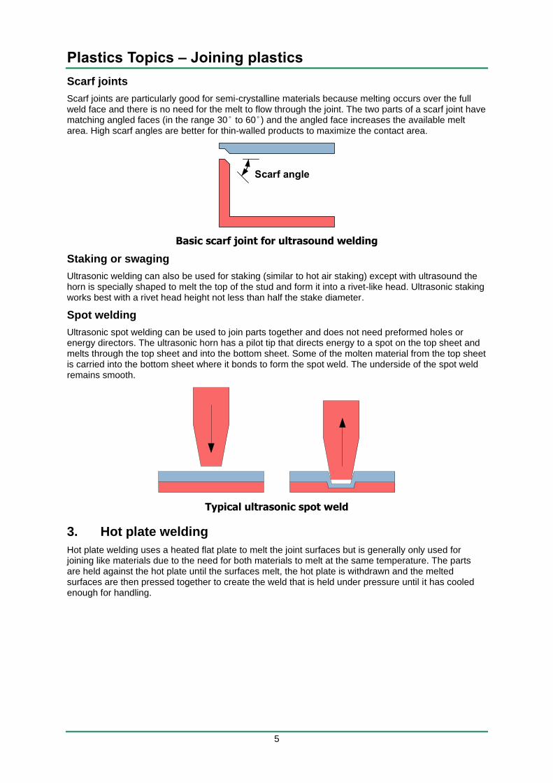
Butt joints
Butt joints are simple to design but demand a high energy input to produce melting over their large areas. It is usual to provide a V-shaped ‘energy director’ on one of the surfaces to reduce the initial contact area between the joint faces and to concentrate the ultrasonic energy at the energy director. This gives high initial heating and melting. With amorphous plastics, the energy director melts and flows across the face of the joint to create the weld. With semi-crystalline materials, the narrow flow temperature range often makes it difficult for the energy director to flow across the face of the joint and this can result in a weak weld only in the area of the energy director. For this reason, semi-crystalline materials often need high energy levels and long cycle times to get melting across the full joint.
Basic butt joint for ultrasound welding
As with shear joints, butt joints should be provided with location recesses or other methods to give good alignment.
Locating recess
Interference
Weld
depth
Clearance
Energy director
Plastics Topics – Joining plastics
5
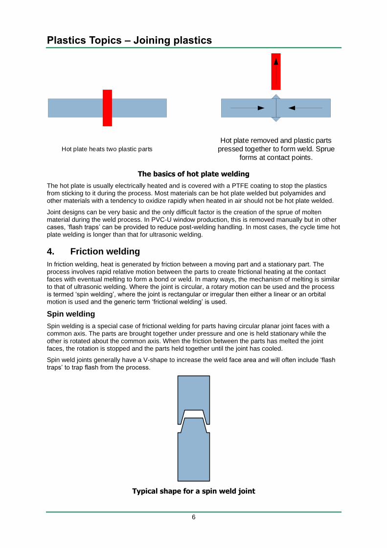
Scarf joints
Scarf joints are particularly good for semi-crystalline materials because melting occurs over the full weld face and there is no need for the melt to flow through the joint. The two parts of a scarf joint have matching angled faces (in the range 30° to 60°) and the angled face increases the available melt area. High scarf angles are better for thin-walled products to maximize the contact area.
Basic scarf joint for ultrasound welding
Staking or swaging
Ultrasonic welding can also be used for staking (similar to hot air staking) except with ultrasound the horn is specially shaped to melt the top of the stud and form it into a rivet-like head. Ultrasonic staking works best with a rivet head height not less than half the stake diameter.
Spot welding
Ultrasonic spot welding can be used to join parts together and does not need preformed holes or energy directors. The ultrasonic horn has a pilot tip that directs energy to a spot on the top sheet and melts through the top sheet and into the bottom sheet. Some of the molten material from the top sheet is carried into the bottom sheet where it bonds to form the spot weld. The underside of the spot weld remains smooth.
Typical ultrasonic spot weld
3. Hot plate welding
Hot plate welding uses a heated flat plate to melt the joint surfaces but is generally only used for joining like materials due to the need for both materials to melt at the same temperature. The parts are held against the hot plate until the surfaces melt, the hot plate is withdrawn and the melted surfaces are then pressed together to create the weld that is held under pressure until it has cooled enough for handling.
Plastics Topics – Joining plastics
6
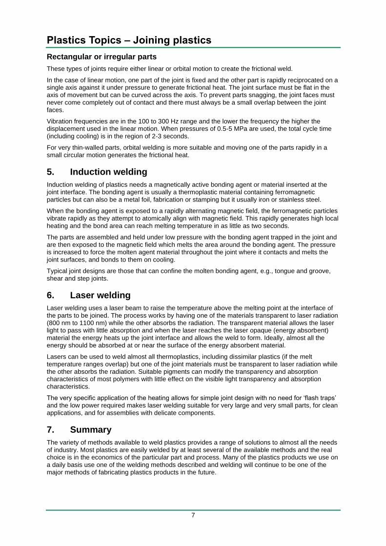
The basics of hot plate welding
The hot plate is usually electrically heated and is covered with a PTFE coating to stop the plastics from sticking to it during the process. Most materials can be hot plate welded but polyamides and other materials with a tendency to oxidize rapidly when heated in air should not be hot plate welded.
Joint designs can be very basic and the only difficult factor is the creation of the sprue of molten material during the weld process. In PVC-U window production, this is removed manually but in other cases, ‘flash traps’ can be provided to reduce post-welding handling. In most cases, the cycle time hot plate welding is longer than that for ultrasonic welding.
4. Friction welding
In friction welding, heat is generated by friction between a moving part and a stationary part. The process involves rapid relative motion between the parts to create frictional heating at the contact faces with eventual melting to form a bond or weld. In many ways, the mechanism of melting is similar to that of ultrasonic welding. Where the joint is circular, a rotary motion can be used and the process is termed ‘spin welding’, where the joint is rectangular or irregular then either a linear or an orbital motion is used and the generic term ‘frictional welding’ is used.
Spin welding
Spin welding is a special case of frictional welding for parts having circular planar joint faces with a common axis. The parts are brought together under pressure and one is held stationary while the other is rotated about the common axis. When the friction between the parts has melted the joint faces, the rotation is stopped and the parts held together until the joint has cooled.
Spin weld joints generally have a V-shape to increase the weld face area and will often include ‘flash traps’ to trap flash from the process.
Typical shape for a spin weld joint
Hot plate heats two plastic parts
Hot plate removed and plastic parts
pressed together to form weld. Sprue
forms at contact points.
Plastics Topics – Joining plastics
7
Rectangular or irregular parts
These types of joints require either linear or orbital motion to create the frictional weld.
In the case of linear motion, one part of the joint is fixed and the other part is rapidly reciprocated on a single axis against it under pressure to generate frictional heat. The joint surface must be flat in the axis of movement but can be curved across the axis. To prevent parts snagging, the joint faces must never come completely out of contact and there must always be a small overlap between the joint faces.
Vibration frequencies are in the 100 to 300 Hz range and the lower the frequency the higher the displacement used in the linear motion. When pressures of 0.5-5 MPa are used, the total cycle time (including cooling) is in the region of 2-3 seconds.
For very thin-walled parts, orbital welding is more suitable and moving one of the parts rapidly in a small circular motion generates the frictional heat.
5. Induction welding
Induction welding of plastics needs a magnetically active bonding agent or material inserted at the joint interface. The bonding agent is usually a thermoplastic material containing ferromagnetic particles but can also be a metal foil, fabrication or stamping but it usually iron or stainless steel.
When the bonding agent is exposed to a rapidly alternating magnetic field, the ferromagnetic particles vibrate rapidly as they attempt to atomically align with magnetic field. This rapidly generates high local heating and the bond area can reach melting temperature in as little as two seconds.
The parts are assembled and held under low pressure with the bonding agent trapped in the joint and are then exposed to the magnetic field which melts the area around the bonding agent. The pressure is increased to force the molten agent material throughout the joint where it contacts and melts the joint surfaces, and bonds to them on cooling.
Typical joint designs are those that can confine the molten bonding agent, e.g., tongue and groove, shear and step joints.
6. Laser welding
Laser welding uses a laser beam to raise the temperature above the melting point at the interface of the parts to be joined. The process works by having one of the materials transparent to laser radiation (800 nm to 1100 nm) while the other absorbs the radiation. The transparent material allows the laser light to pass with little absorption and when the laser reaches the laser opaque (energy absorbent) material the energy heats up the joint interface and allows the weld to form. Ideally, almost all the energy should be absorbed at or near the surface of the energy absorbent material.
Lasers can be used to weld almost all thermoplastics, including dissimilar plastics (if the melt temperature ranges overlap) but one of the joint materials must be transparent to laser radiation while the other absorbs the radiation. Suitable pigments can modify the transparency and absorption characteristics of most polymers with little effect on the visible light transparency and absorption characteristics.
The very specific application of the heating allows for simple joint design with no need for ‘flash traps’ and the low power required makes laser welding suitable for very large and very small parts, for clean applications, and for assemblies with delicate components.
7. Summary
The variety of methods available to weld plastics provides a range of solutions to almost all the needs of industry. Most plastics are easily welded by at least several of the available methods and the real choice is in the economics of the particular part and process. Many of the plastics products we use on a daily basis use one of the welding methods described and welding will continue to be one of the major methods of fabricating plastics products in the future.
Plastics Topics – Joining plastics
8
Part 2: Mechanical fastening
1. Press fits
Press fits are used in many applications in the metals industry to fasten items together by forcing an object onto a shaft that is slightly too big for the hole or pushing a bearing into a hole that is slightly too small for the bearing. Similar methods can be used for joining plastics items together and press fits are often used for joining plastics to metal shafts (e.g., forcing a gear onto a metal shaft) or for fitting plastics bearings into holes. Press fits are a simple and inexpensive method of joining products and the critical factor is the degree of interference between the two parts.
If the interference is too great then the parts will be difficult to assemble and if it is too small then the press fit will be ineffective. Manufacturing tolerances are particularly important for press fits and it is essential to ensure that the press fit still works at the extremes of the manufacturing tolerances. Press fits are permanently stressed and creep of the plastic over time, particularly at higher temperatures, can lead to relaxation and failure of the press fit. One method of overcoming this is to knurl or profile the metal piece so that the plastic material cold flows into the serrations and creates a mechanical interference between the two materials.
2. Snap fits
Snap fits are one of the most common methods of assembling plastics consumer parts and involve pushing a projection on one part past an obstruction, into a hole or over a projection on the mating part. Snap fits work by using the elasticity of plastics and can be either permanent or releasable depending on the detailed design of the part.
Snap fits are assembled by applying a force to bring the parts together, this is resisted by an interference between the parts but when the applied force is sufficient, one of the parts deflects to allow the parts to come together and then releases after the interference points have passed one another and the parts have fully mated.
Snap fits can be easily designed into mouldings or extrusions and do not significantly increase cycle times or part costs. The final assembly is also simple and requires no tooling or consumables that increase costs and make recycling difficult. The snap fit is therefore one of the most cost-effective methods of joining plastics parts.
Cantilever snap fits
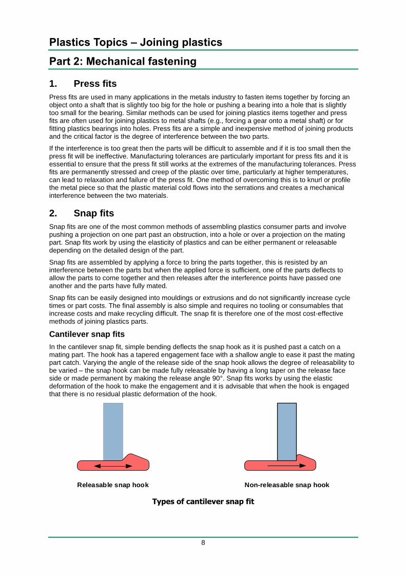
In the cantilever snap fit, simple bending deflects the snap hook as it is pushed past a catch on a mating part. The hook has a tapered engagement face with a shallow angle to ease it past the mating part catch. Varying the angle of the release side of the snap hook allows the degree of releasability to be varied – the snap hook can be made fully releasable by having a long taper on the release face side or made permanent by making the release angle 90°. Snap fits works by using the elastic deformation of the hook to make the engagement and it is advisable that when the hook is engaged that there is no residual plastic deformation of the hook.
Types of cantilever snap fit
Releasable snap hook Non-releasable snap hook
Plastics Topics – Joining plastics
9
As the cantilever hook is pushed past the catch, it deflects and the amount of deflection should not exceed the allowable strain for the cantilever material otherwise permanent deflection may occur and the operation of the snap hook will be compromised.
Cylindrical and spherical snap fits
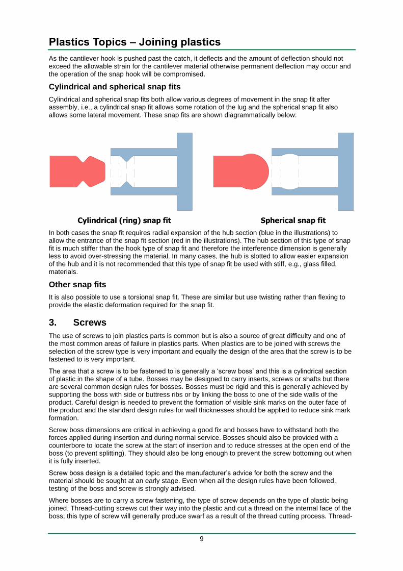
Cylindrical and spherical snap fits both allow various degrees of movement in the snap fit after assembly, i.e., a cylindrical snap fit allows some rotation of the lug and the spherical snap fit also allows some lateral movement. These snap fits are shown diagrammatically below:
Cylindrical (ring) snap fit Spherical snap fit
In both cases the snap fit requires radial expansion of the hub section (blue in the illustrations) to allow the entrance of the snap fit section (red in the illustrations). The hub section of this type of snap fit is much stiffer than the hook type of snap fit and therefore the interference dimension is generally less to avoid over-stressing the material. In many cases, the hub is slotted to allow easier expansion of the hub and it is not recommended that this type of snap fit be used with stiff, e.g., glass filled, materials.
Other snap fits
It is also possible to use a torsional snap fit. These are similar but use twisting rather than flexing to provide the elastic deformation required for the snap fit.
3. Screws
The use of screws to join plastics parts is common but is also a source of great difficulty and one of the most common areas of failure in plastics parts. When plastics are to be joined with screws the selection of the screw type is very important and equally the design of the area that the screw is to be fastened to is very important.
The area that a screw is to be fastened to is generally a ‘screw boss’ and this is a cylindrical section of plastic in the shape of a tube. Bosses may be designed to carry inserts, screws or shafts but there are several common design rules for bosses. Bosses must be rigid and this is generally achieved by supporting the boss with side or buttress ribs or by linking the boss to one of the side walls of the product. Careful design is needed to prevent the formation of visible sink marks on the outer face of the product and the standard design rules for wall thicknesses should be applied to reduce sink mark formation.
Screw boss dimensions are critical in achieving a good fix and bosses have to withstand both the forces applied during insertion and during normal service. Bosses should also be provided with a counterbore to locate the screw at the start of insertion and to reduce stresses at the open end of the boss (to prevent splitting). They should also be long enough to prevent the screw bottoming out when it is fully inserted.
Screw boss design is a detailed topic and the manufacturer’s advice for both the screw and the material should be sought at an early stage. Even when all the design rules have been followed, testing of the boss and screw is strongly advised.
Where bosses are to carry a screw fastening, the type of screw depends on the type of plastic being joined. Thread-cutting screws cut their way into the plastic and cut a thread on the internal face of the boss; this type of screw will generally produce swarf as a result of the thread cutting process. Thread-
Plastics Topics – Joining plastics
10
cutting screws are used for soft thermoplastics. The alternative is a thread-forming screw where the screw produces a thread not by cutting the plastic but by the process of cold flow of the plastic as the thread enters the boss. Thread-forming screws are used for hard thermoplastics and thermosetting materials but only thread forming screws specifically designed for plastics should be used.
4. Staples and nails
Staples and nails are not often used to join plastics parts but can be used to fasten plastics parts to other materials such as wood. The smooth sides of staples and nails means that they have a low effective pull out force when used with smooth and low friction materials such as most plastics and should not be used to join two plastics parts. When staples and nails are used, they should have substantial thickness (in the case of staples) or large heads (in the case of nails) to prevent the staple of nail being pulled through the plastic under even moderate loads.
As a rule, staples and nails should be regarded as a last resort when joining plastics products.
5. Rivets
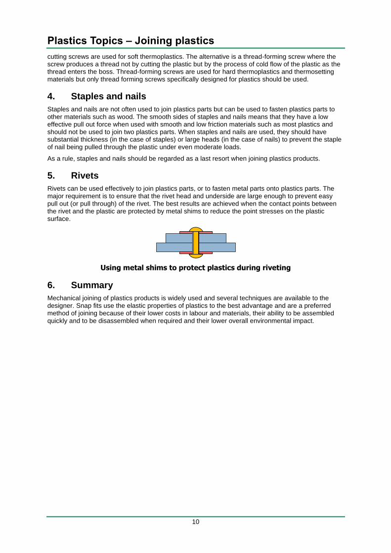
Rivets can be used effectively to join plastics parts, or to fasten metal parts onto plastics parts. The major requirement is to ensure that the rivet head and underside are large enough to prevent easy pull out (or pull through) of the rivet. The best results are achieved when the contact points between the rivet and the plastic are protected by metal shims to reduce the point stresses on the plastic surface.
Using metal shims to protect plastics during riveting
6. Summary
Mechanical joining of plastics products is widely used and several techniques are available to the designer. Snap fits use the elastic properties of plastics to the best advantage and are a preferred method of joining because of their lower costs in labour and materials, their ability to be assembled quickly and to be disassembled when required and their lower overall environmental impact.
Plastics Topics – Joining plastics
11
Part 3: Adhesives and solvents
1. Solvent cements
Solvent bonding is used for joining similar plastics together and uses a solvent that softens the polymer. When the surfaces to be bonded are held under pressure the polymer chains are attracted to one another and become tangled together. After the solvent has evaporated the surfaces again become hard and the bond is created. Solvent bonding is more restricted than adhesive bonding because it is normally used only for bonding together plastics of the same type and cannot be used for bonding plastics to other materials.
Solvent bonding can be used for many plastics such as ABS, PS, PA, PMMA and PVC. Typical of the solvents used are methylene chloride, ethylene dichloride, trichloroethylene, methyl ethyl ketone, tetrahydrofuran and methylene chloride. The solvent used may be in the simple liquid form or it may have a polymer dissolved in it to act as a gap-filler during the solvent bonding process.
Any solvent has health and safety concerns (the vapours can be toxic) and many are flammable. This has led to restrictions in the industrial use of solvents and they have largely fallen out of favour and been replaced by more conventional adhesives. As a general rule, solvent bonding is only to be considered if adhesive bonding cannot be used.
2. Adhesives
Adhesives are one of the most common methods of joining plastics Adhesives are a common method of joining plastics but it is an area that demands careful attention. Adhesives, as anyone who has tried to glue a PE part back together again will tell you, is a subject that is very difficult to get right. When used correctly adhesives are one of the basics in the product designer’s toolkit and can be both economical and effective.
3. Adhesion theories
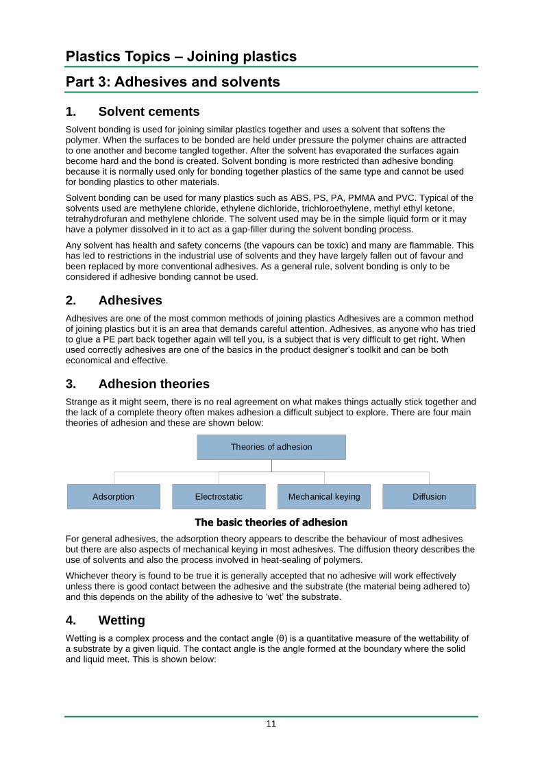
Strange as it might seem, there is no real agreement on what makes things actually stick together and the lack of a complete theory often makes adhesion a difficult subject to explore. There are four main theories of adhesion and these are shown below:
The basic theories of adhesion
For general adhesives, the adsorption theory appears to describe the behaviour of most adhesives but there are also aspects of mechanical keying in most adhesives. The diffusion theory describes the use of solvents and also the process involved in heat-sealing of polymers.
Whichever theory is found to be true it is generally accepted that no adhesive will work effectively unless there is good contact between the adhesive and the substrate (the material being adhered to) and this depends on the ability of the adhesive to ‘wet’ the substrate.
4. Wetting
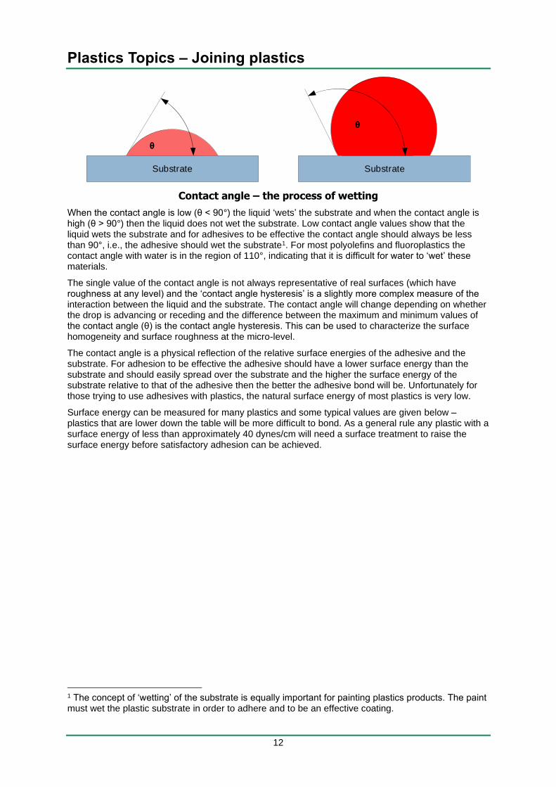
Wetting is a complex process and the contact angle (θ) is a quantitative measure of the wettability of a substrate by a given liquid. The contact angle is the angle formed at the boundary where the solid and liquid meet. This is shown below:
Theories of adhesion
Adsorption Mechanical keyingElectrostatic Diffusion
Plastics Topics – Joining plastics
12
Contact angle – the process of wetting
When the contact angle is low (θ < 90°) the liquid ‘wets’ the substrate and when the contact angle is high (θ > 90°) then the liquid does not wet the substrate. Low contact angle values show that the liquid wets the substrate and for adhesives to be effective the contact angle should always be less than 90°, i.e., the adhesive should wet the substrate1. For most polyolefins and fluoroplastics the contact angle with water is in the region of 110°, indicating that it is difficult for water to ‘wet’ these materials.
The single value of the contact angle is not always representative of real surfaces (which have roughness at any level) and the ‘contact angle hysteresis’ is a slightly more complex measure of the interaction between the liquid and the substrate. The contact angle will change depending on whether the drop is advancing or receding and the difference between the maximum and minimum values of the contact angle (θ) is the contact angle hysteresis. This can be used to characterize the surface homogeneity and surface roughness at the micro-level.
The contact angle is a physical reflection of the relative surface energies of the adhesive and the substrate. For adhesion to be effective the adhesive should have a lower surface energy than the substrate and should easily spread over the substrate and the higher the surface energy of the substrate relative to that of the adhesive then the better the adhesive bond will be. Unfortunately for those trying to use adhesives with plastics, the natural surface energy of most plastics is very low.
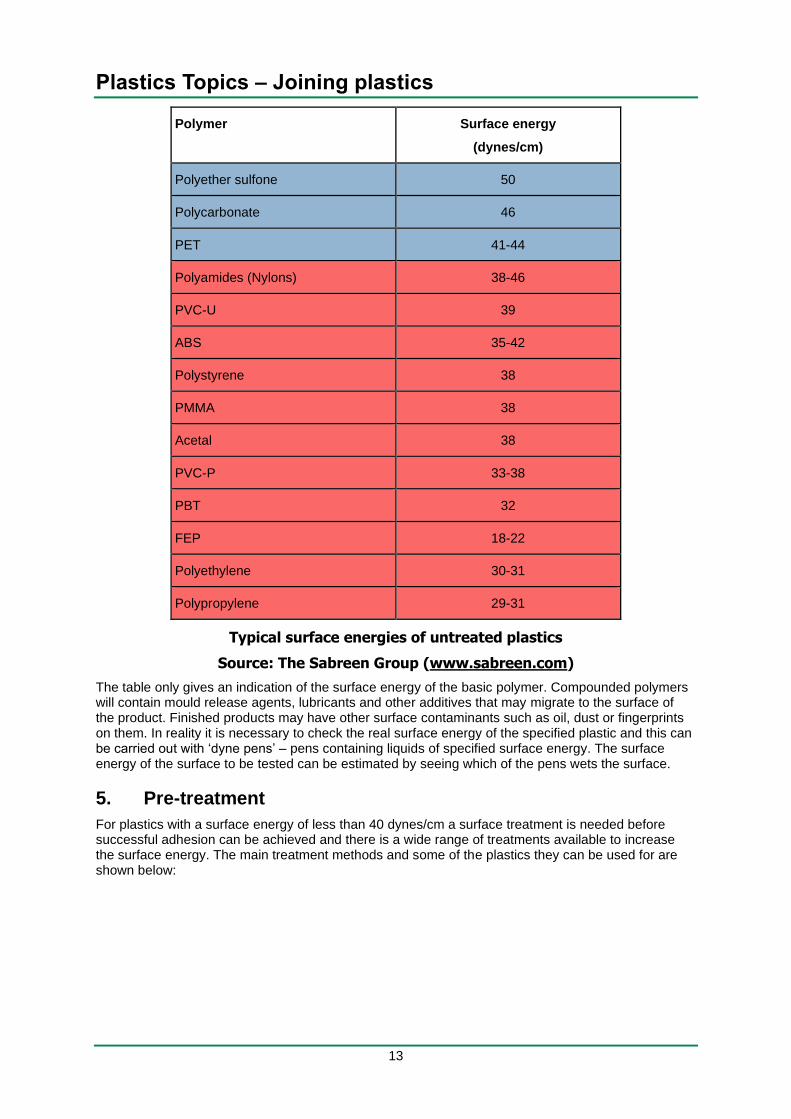
Surface energy can be measured for many plastics and some typical values are given below – plastics that are lower down the table will be more difficult to bond. As a general rule any plastic with a surface energy of less than approximately 40 dynes/cm will need a surface treatment to raise the surface energy before satisfactory adhesion can be achieved.
1 The concept of ‘wetting’ of the substrate is equally important for painting plastics products. The paint must wet the plastic substrate in order to adhere and to be an effective coating.
SubstrateSubstrate
θ
θ
Plastics Topics – Joining plastics
13
Polymer Surface energy
(dynes/cm)
Polyether sulfone 50
Polycarbonate 46
PET 41-44
Polyamides (Nylons) 38-46
PVC-U 39
ABS 35-42
Polystyrene 38
PMMA 38
Acetal 38
PVC-P 33-38
PBT 32
FEP 18-22
Polyethylene 30-31
Polypropylene 29-31
Typical surface energies of untreated plastics
Source: The Sabreen Group (www.sabreen.com)
The table only gives an indication of the surface energy of the basic polymer. Compounded polymers will contain mould release agents, lubricants and other additives that may migrate to the surface of the product. Finished products may have other surface contaminants such as oil, dust or fingerprints on them. In reality it is necessary to check the real surface energy of the specified plastic and this can be carried out with ‘dyne pens’ – pens containing liquids of specified surface energy. The surface energy of the surface to be tested can be estimated by seeing which of the pens wets the surface.
5. Pre-treatment
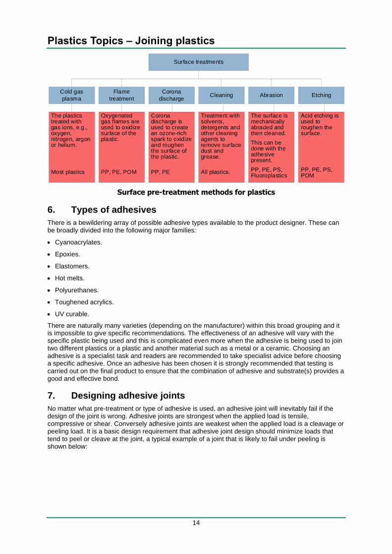
For plastics with a surface energy of less than 40 dynes/cm a surface treatment is needed before successful adhesion can be achieved and there is a wide range of treatments available to increase the surface energy. The main treatment methods and some of the plastics they can be used for are shown below:
Plastics Topics – Joining plastics
14
Surface pre-treatment methods for plastics
6. Types of adhesives
There is a bewildering array of possible adhesive types available to the product designer. These can be broadly divided into the following major families:
• Cyanoacrylates.
• Epoxies.
• Elastomers.
• Hot melts.
• Polyurethanes.
• Toughened acrylics.
• UV curable.
There are naturally many varieties (depending on the manufacturer) within this broad grouping and it is impossible to give specific recommendations. The effectiveness of an adhesive will vary with the specific plastic being used and this is complicated even more when the adhesive is being used to join two different plastics or a plastic and another material such as a metal or a ceramic. Choosing an adhesive is a specialist task and readers are recommended to take specialist advice before choosing a specific adhesive. Once an adhesive has been chosen it is strongly recommended that testing is carried out on the final product to ensure that the combination of adhesive and substrate(s) provides a good and effective bond.
7. Designing adhesive joints
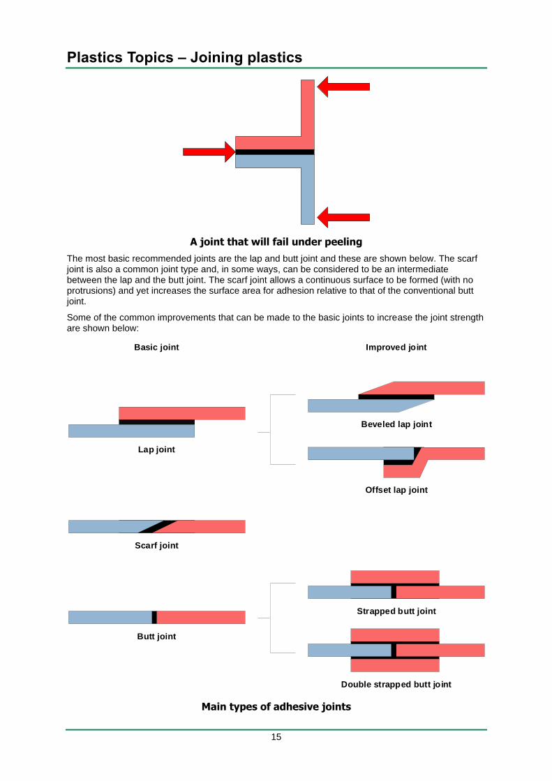
No matter what pre-treatment or type of adhesive is used, an adhesive joint will inevitably fail if the design of the joint is wrong. Adhesive joints are strongest when the applied load is tensile, compressive or shear. Conversely adhesive joints are weakest when the applied load is a cleavage or peeling load. It is a basic design requirement that adhesive joint design should minimize loads that tend to peel or cleave at the joint, a typical example of a joint that is likely to fail under peeling is shown below:
Surface treatments
Cold gas
plasma
Corona
discharge
Flame
treatmentCleaning EtchingAbrasion
The plastics treated with gas ions, e.g., oxygen, nitrogen, argon or helium.
Most plastics
Oxygenated gas flames are used to oxidize surface of the plastic.
PP, PE, POM
Corona discharge is used to create an ozone-rich spark to oxidize and roughen the surface of the plastic.
PP, PE
Treatment with solvents, detergents and other cleaning agents to remove surface dust and grease.
All plastics.
The surface is mechanically abraded and then cleaned.
This can be done with the adhesive present.
PP, PE, PS, Fluoroplastics
Acid etching is used to roughen the surface.
PP, PE, PS, POM
Plastics Topics – Joining plastics
15
A joint that will fail under peeling
The most basic recommended joints are the lap and butt joint and these are shown below. The scarf joint is also a common joint type and, in some ways, can be considered to be an intermediate between the lap and the butt joint. The scarf joint allows a continuous surface to be formed (with no protrusions) and yet increases the surface area for adhesion relative to that of the conventional butt joint.
Some of the common improvements that can be made to the basic joints to increase the joint strength are shown below:
Main types of adhesive joints
Butt joint
Strapped butt joint
Double strapped butt joint
Beveled lap joint
Offset lap joint
Scarf joint
Lap joint
Basic joint Improved joint
Plastics Topics – Joining plastics
16
Designing a successful joint is not simply about the type of joint used; the joint strength will also be affected by the relative dimensions of the joint and the thickness of the adhesive and in both cases the rules are not what you would expect them to be:
• Joint thickness: When using adhesives, the basic rule is to use as little as possible and this is not simply for reasons of economy. Joint strength is generally maximized when the adhesive used is just enough to provide a complete covering of adhesive and to completely fill any gaps in between the substrates due to surface roughness. Thicker adhesive coatings will generally result in lower adhesive joint strengths.
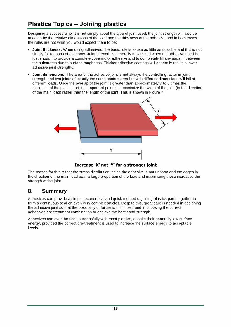
• Joint dimensions: The area of the adhesive joint is not always the controlling factor in joint strength and two joints of exactly the same contact area but with different dimensions will fail at different loads. Once the overlap of the joint is greater than approximately 3 to 5 times the thickness of the plastic part, the important point is to maximize the width of the joint (in the direction of the main load) rather than the length of the joint. This is shown in Figure 7.
Increase ‘X’ not ‘Y’ for a stronger joint
The reason for this is that the stress distribution inside the adhesive is not uniform and the edges in the direction of the main load bear a large proportion of the load and maximizing these increases the strength of the joint.
8. Summary
Adhesives can provide a simple, economical and quick method of joining plastics parts together to form a continuous seal on even very complex articles. Despite this, great care is needed in designing the adhesive joint so that the possibility of failure is minimized and in choosing the correct adhesives/pre-treatment combination to achieve the best bond strength.
Adhesives can even be used successfully with most plastics, despite their generally low surface energy, provided the correct pre-treatment is used to increase the surface energy to acceptable levels.


