Embed Size (px)
Citation preview

SIGNAL PROCESSING. MANUSCRIPT SIGPRO-4285 1
Joint Use of DFT Filter Banks and ModulatedTransmultiplexers for Multicarrier Communications
Fernando Cruz–Roldan and Manuel Blanco–Velasco
Abstract—In this paper, new procedures for performing mul-ticarrier modulation (MCM) are presented, based on usingIFFT/FFT embedded in a filter bank-based transmultiplexersystem. The IFFT/FFT blocks, along with the use of cyclicprefix or zero-padding strategies, enable easy equalization ofthe transmission channel. Additionally, the transmultiplexersystem provides improved spectral discrimination, which canincreases the transceiver robustness against mainly narrow-band interferences. Moreover, one of the proposed procedurespresents an IDFT as the final stage of the MCM transmitter,and a DFT as the first stage of the receiver. This front-end issimilar to standardized systems, enabling its compatibility. Asit is illustrated by means of several examples, given a signalto noise ratio and comparing the new procedures to DFT-basedMCM adopted in several digital communications standards, thefollowing attractive features can be found: a) greater spectralseparation in the information transmitted over each subcarrierand b) the robustness of the systems in noisy environments,mainly when narrow-band interferences appear, can be increased,allowing a reduction in the bit error probability.
Index Terms—Transmultiplexer (TMUX), modulated filterbank, cosine multitone, discrete wavelet multitone, multitonetransceiver, multicarrier transceiver, multicarrier mod ulator,OFDM, DMT, polyphase filter, prototype filter.
I. I NTRODUCTION
M ULTICARRIER modulation (MCM) is based on split-ting the communication channel bandwidthB into
subchannels with a bandwidthBN smaller than the coherencebandwidth BC [1]. This modulation has been adopted inseveral digital wireline and also wireless communicationsstandards (for example, [2]–[5]), and it is a potential candidatefor the physical layer of cognitive radio systems [6]–[9].
Figure 1 shows a block diagram that implements MCM.At the transmitter, data are processed by anM -point InverseDiscrete Fourier Transform (IDFT) -beingM the number ofsubchannels or subcarriers- by its fast algorithm of implemen-tation (Inverse Fast Fourier Transform - IFFT). At the receiver,a Discrete Fourier Transform (DFT), also by its fast algorithm(Fast Fourier Transform - FFT), is performed. Discrete Multi-tone Modulation (DMT) and Orthogonal Frequency-DivisionMultiplexing (OFDM) are particular cases of MCM, and thusthey can be described by the above block diagram.
The DFT can be interpreted from the theory of multiratesystems as an exponentially modulated filter bank, where the
This work was partially supported by the Spanish Ministry ofScience andInnovation through project TEC2009-08133, and by Comunidad Autonoma deMadrid and Universidad de Alcala through project CCG08-UAH/TIC-3941.
F. Cruz-Roldan and M. Blanco–Velasco are with the Department ofTeorıa de la Senal y Comunicaciones, Escuela Politecnica Superior de laUniversidad de Alcala, 28871 Alcala de Henares (Madrid),SPAIN (phone:+ 34 91885 66 93; fax: : + 34 91 885 66 99; e-mail:[email protected],[email protected]).
prototype filter is anM -length rectangular window [10], whereM is the length of the DFT (the number of subchannelsin MCM systems). Since each filter in the DFT bank isobtained from a rectangular window, the minimum subchanneldiscrimination is on the order of 13.5 dB. Considering that thedispersive channel destroys orthogonality between subcarriers,when IFFT/FFT are used for data transmission, the systemsuffers from intercarrier interferences (ICI) and intersymbolinterferences (ISI). In addition, radio frequency interferences(RFI) emerging from amateur and AM radio signals or otherkinds of narrow-band interferences, sometimes lead to majorperformance degradation, affecting a large number of subcar-riers [11]–[13]. As a result, the performance of DFT-basedMCM systems in noisy environments, mainly with narrow-band noise, is far from being robust and reliable.
In order to solve some of these problems, researchershave been investigating the use of alternative filter bankswith a transmultiplexer (TMUX) configuration [14]–[24]. Fig.2(a) shows an example of anM -channel filter bank-basedtransmultiplexer, where the blockz−δ represents a delay. Thevalue ofδ depends on the length of the filters, and although thisparameter is not considered in the remainder of this work, itisworth noting that it should be included at the transmitter oratthe receiver stage in order to obtain proper system operation.
A. Aim of this work
In this paper, two procedures are presented for data trans-mission and reception. Both procedures are based on usingfilter bank-based transmultiplexers and DFT-based multicarriermodulators with cyclic prefix (CP) or zero-padded (ZP) trans-mission. On the one hand, the filter bank-based transmulti-plexers provide better spectral discrimination, which increasesthe transceiver capability to combat the deteriorating effect ofnarrow-band interferences. On the other hand, the IFFT/FFTblocks, along with the use of cyclic prefix or zero-paddingstrategies, enable easy equalization of the transmission chan-nel. In addition, as the IFFT/FFT is the solution adopted inmost standards systems, the compatibility of one of theseprocedures with a large number of DFT-based MCM devicescan be achieved with relative ease.
The proposed procedures offer the following two attractivefeatures: a) a larger spectral separation on the informationtransmitted over each subcarrier (procedure 1); b) betternarrow-band interferences rejection (procedure 2). Moreover,secret and private communication systems can also be sup-ported in both systems, since the transmitted signal can onlybe recovered if the prototype filter is known to the receiver.Finally, the proposed systems also allow the reconfiguration of

SIGNAL PROCESSING. MANUSCRIPT SIGPRO-4285 2
Fig. 1. Block diagram of a cyclic-prefixed DFT-based multicarrier system over a channel with additive noise.
(a)
(b)
Fig. 2. (a)M -channel filter bank-based transmultiplexer. (b) Block diagram of the transmitting and the receiving filter banks implemented with fast algorithms(for R = M andR = M/2).
the transmitter and the receiver, taking the channel conditionsinto account1. This last characteristic is common for any filterbank-based transmuliplexer system.
The remainder of this paper is organized as follows. In Sec-tion II, preliminary concepts are briefly recalled. The proposedprocedures for designing the entire communication systemsarepresented in Section III. Section IV describes the characteris-tics of some matrices that appear in the proposed procedures,and since these matrices depend on the kind of modulationchosen to design the corresponding transmultiplexer, somemodulations widely used for this purpose are also shown. InSection V, three examples are included to illustrate the benefitsof the proposed design schemes. These examples are basedon two different modulations, cosine and exponential, andshow the performance of the proposed systems under additive
1Channel knowledge is required for both the transmitter and the receiver.
white Gaussian noise (AWGN) and narrow-band interferences.Finally, Section VI contains some concluding remarks.
Notation: A−1 represents the inverse ofA. Matrix I = IM
denotes anM × M identity matrix, andJ = JM denotes theM × M reversal matrix:
J = JM =
0 · · · 0 10 · · · 1 0...
......
1 · · · 0 0
.
When referring to filters or discrete-time sequences, the low-ercase letters will refer to the time domain, e.g.,h[n], whereasthe uppercase letter will be used to thez-transform of the samesequence, i.e.,H(z).

SIGNAL PROCESSING. MANUSCRIPT SIGPRO-4285 3
Fig. 3. Block diagram of a zero-padded transmission channelwith additivenoise.
II. PRELIMINARIES
A. CP and ZP transmission
In order to correct the effects of frequency-selective finiteimpulse response channels and to facilitate the receiver’sequalization task, several techniques have been proposed,suchas the insertion of a cyclic prefix or by appending zeroes [31].Fig. 1 shows the block diagram for a cyclic-prefixed DFT-based multicarrier system over a channel with additive noise.In this figure, each block represents the following: a) the CPblock inserts the cyclic prefix at the transmitter; b)c representsthe transmission channel; c) TEQ is a time-domain equalizerthat shortens the effective channelh to an appropriate length[32]; d) the R-CP block removes the cyclic prefix; e) theFEQ block is a frequency-domain equalizer, which basicallyconsists of a1/λi bank of scalars, which efficiently equalizesthe frequency-selective channel in the frequency domain2. Inorder to obtain the block diagram for the zero-padding DFT-based multicarrier system, the blockH in Fig. 1 must bereplaced with the one shown in Fig. 3 (for more details on ZPor CP, see [31]). The inserted CP or ZP allows the effectivematrix channelH to be modeled as a right-circulant matrix,which can be expressed as
H = W−1 ·Λ ·W, (1)
where Λ is a diagonal matrix, in which the dia-gonal elementsλi, 0 ≤ i ≤ (M − 1), are ob-tained as theM -point DFT of the effective channelh,i.e., Λ = diag
{
λ0, λ1, · · · λM−1
}
with λi =M−1∑
n=0h [n] · e−j 2π
Mi·n, 0 ≤ i ≤ (M − 1).
B. Filter bank-based transmultiplexers and fast algorithms ofimplementation
It is well-known that several maximally decimated filterbanks can be efficiently implemented, reducing the total com-putational cost. Examples can be found in [10], [20], [21],
2Using this definition, the equalizer is designed with the zero-forcingcriterion, which perfectly reverses the effect of the transmission channel. Ifnoise cannot be ignored, the Minimum Mean-Square Error (MMSE) criterionmakes an optimum trade between channel inversion and noise enhancement,taking into account the signal-to-noise ratio.
[24]–[30]. For example, an analysis (receiving) filter bankimplemented with butterfly structures with a Type-IV DiscreteCosine Transform (DCT) is shown in [25].
Therefore, using some of the aforementioned fast algo-rithms, a significant group of filter bank-based TMUX can bedescribed as in Figure 2(b), containing general block diagramsfor the transmitter and the receiver, obtained from the synthesisand the analysis filter banks, respectively3. This figure showsthat the order of fast implementation algorithms is usuallyasfollows. At the transmitter, there are: (a) Matrix and transformoperations; (b) polyphase filters, or lattice or butterfly struc-tures; and (c) parallel/serial (P/S) converter. At the receiver,there are: (a) Serial/parallel converter; (b) polyphase filters,or lattice or butterfly structures; (c) matrix and transformationoperations. For the proposed systems, the key point is that thelast and the first stage of the transmitter and the receiver are,respectively, a P/S and an S/P converter.
C. P/S and S/P converters
Parallel/Serial and Serial/Parallel converters that usuallyappear in the standardized DFT-based MCM and also in somesystems obtained by means of a trigonometric modulationpresent the same upsampling and downsampling rates asthe subcarrier number. Equivalent implementations for theseconverters can be found in [33]. In this case, it is easyto demonstrate that when CP or ZP are used, the channeltransmission matrixH (Fig. 4 for R = M ) is right-circulant[1]. However, for certain kinds of exponentially modulated-based systems, the upsampling and downsampling rates areusually half the subcarrier number.
Let us consider the system in Figure 4 forR = M/2. With-out including either CP or ZP, the input-output relationship isgiven by
yM−1
yM−2
...y0
=
h0 h1 · · · hL 0 · · · 00 h0 · · · hL−1 hL · · · 0...
.... . .
. . .. . .
. . ....
0 · · · 0 h0 · · · hL−1 hL
×
xM−1 + x3M/2−1
...xM/2 + xM
xM/2−1 + x−1
...x0 + x−M/2
x−M−1 + x−1−M/2
...x−M−L + x−L−M/2
+
eM−1
eM−2
...e0
.
(2)If a CP is included, it holds true that
x−M−1 + x−1−M/2
...x−M−L + x−L−M/2
=
xM−1 + x3M/2−1
...xM−1−L + x3M/2−L
,
3Transform operations, which can also be seen as matrix operations, involveoperations directly related with a direct or its inverse transformation: DCT,DFT, etc.

SIGNAL PROCESSING. MANUSCRIPT SIGPRO-4285 4
x0
xM-1
Paralell/Serial Serial/Paralell
1xFIR
-orderL
R-CPRy0
y1
yM-1z
z
z
z-1
-1
H(z)
Noise
e
+^
CP
R
R
R
R
R
^
^
Fig. 4. Matrix channelH in modulated-based system (R = M or R =M/2).
which means (2) is equivalent to
yM−1
yM−2
...y0
=
h0 h1 · · · hL 0 · · · 00 h0 · · · hL−1 hL · · · 0...
.... . .
. . .. . .
. .....
0 · · · 0 h0 · · · hL−1 hL
......
. . .. . .
. . .. . .
...h2 h3 · · · hL−2 · · · h0 h1
h1 h2 · · · hL−1 · · · 0 h0
×
xM−1 + x3M/2−1
...xM/2 + xM
xM/2−1 + x−1
...x0 + x−M/2
+
eM−1
eM−2
e0
,
which expressed in matrix form is
y = H · x + e.
In other words,H is also a right-circulant matrix, and can alsobe diagonalized using DFT matrices such as the one given in(1). The same result can also be obtained using ZP.
III. D ESCRIPTION OFTRANSMISSION SYSTEMS
The proposed systems are open to multiple implementations,depending on the fast algorithm that implements the trans-multiplexer system. However, they could be represented ingeneral terms by means of two procedures with block diagramsshown below. In this section and for the rest of this work, itis considered that the TEQ is not needed.
A. Procedure 1
The first procedure is shown in Fig. 5. In this case, the trans-mitter is the synthesis bank implemented by fast algorithms,and the input-output relationship is given by
y = Ptx · Ctx · X, (3)
where
• X =[
X0 X1 · · · XM−1
]Tis the input data.
• Ctx represents theM × M matrix and transform opera-tions.
• Ptx is theM ×M matrix of polyphase filters, or latticeor butterfly structures.
• y is the output data.
Its corresponding receiver is also shown in Fig. 5, in whichthe input-output relationship can be expressed as
X = Crx ·Prx · W−1 · Λ−1 · W · y + N1, (4)
where
• y is the receiving data.• W is theM ×M DFT matrix implemented by means of
fast algorithms (FFT).• Λ−1 is the M × M diagonal matrix characterizing
the FEQ, whose values are given byΛ−1 =diag
{
1/λ0 , 1/λ1, · · · 1/λM−1
}
.• W−1 is the M × M inverse DFT matrix implemented
by fast algorithms (IFFT).• Prx is an M × M matrix that represents the stage of
polyphase filters, or lattice or butterfly structures at thereceiver.
• Crx is anM×M matrix obtained from a transform alongwith additional matrices.
• N1 =[
n1,0 n1,1 · · · n1,M−1
]Tis a term that
depends on the noisy channel.• X =
[
X0 X1 · · · XM−1
]Tis the output data.
B. Procedure 2: Embedded Multicarrier Modulation
The IDFT block at the receiver in procedure 1 could beperformed on the transmitter, providing a different schemeofimplementation shown in Figure 6. This procedure is denotedas embedded multicarrier modulation (em-MCM)4. In thiscase, the transmitter is the synthesis bank implemented byfast algorithm, which includes polyphase filters, or lattice orbutterfly structures, together with a block of matrix and trans-form operations. In this case, the input-output relationships inboth the transmitter and the receiver are given by
y = W−1 ·Ptx · Ctx · X, (5)
X = Crx · Prx ·Λ−1 ·W · y + N2. (6)
C. Input-Output Relationship
In both Figures 5 and 6, the input-output relationship canbe expressed as
X = Crx ·Prx ·W−1 ·Λ−1 · W · H ·Ptx · Ctx ·X + N1,
and
X = Crx ·Prx ·Λ−1 · W · H ·W−1 ·Ptx · Ctx ·X + N2,
respectively. If each element of the diagonal matrixΛ−1
(FEQ) is chosen as1/λi, 0 ≤ i ≤ (M − 1), with λi being
4Although this term was firstly used in [34] to denote a different ideaof MCM extended to multiple layers, this term is used here because it bestdescribes the idea of an MCM inserted into a transmultiplexer system.

SIGNAL PROCESSING. MANUSCRIPT SIGPRO-4285 5
Fig. 5. Transmission system scheme using procedure 1 and CP.
Fig. 6. Transmission system scheme using procedure 2 and CP.
the M -point DFT of the impulse response effective channelh, the expressions above can be reduced to
X = Crx ·Prx · Ptx · Ctx · X + Ni. (7)
In the absence of noise (Ni = 0), if the transmultiplexersystem satisfies the perfect reconstruction property, we obtainX = z−n0 ·X, wheren0 is an integer number, and in the eventof a nearly perfect reconstruction (NPR) transmultiplexer, wehaveX ≈ z−n0 ·X.
IV. CHARACTERISTICS OFMATRICES Ctx, Ptx, Crx, AND
Prx
A well-known procedure for obtaining the transmitting andthe receiving subchannel filters consists in applying a trigono-metric (usually cosine or sine) or exponential modulation toone or two prototype filters. There are several modulationschemes, and the expressions governing these modulationsultimately determine the characteristics of the transmission andreception matricesCtx, Ptx, Crx, andPrx.
A. Trigonometric modulation
Although only three different examples are given below,other modulations or different algorithms of implementationthat could be used in the proposed procedures can be found,for example, in [10], [20], [21], [24]–[30].
(a) Cosine modulation. Each filter in the transmultiplexersystem is obtained as
fi [n] = k1p1 [n] cos
(
(2i + 1)π
2M
(
n − N − 1
2
)
− θi
)
,
(8a)
gi [n] = k2p2 [n] cos
(
(2i + 1)π
2M
(
n − N − 1
2
)
+ θi
)
,
(8b)
where 0 ≤ i ≤ (M − 1), fi [n] are the transmitting fil-ters, gi [n] are the receiving filters,p1 [n] and p2 [n] are theprototype filters,k1 and k2 are constants, andθi are phaseparameters with influence on amplitude distortion and aliasingerror [10].
(b) Sine modulation. In this case, the equations are givenby
fi [n] = k1p1 [n] sin
(
(2i + 1)π
2M
(
n − N − 1
2
)
− θi
)
,
gi [n] = k2p2 [n] sin
(
(2i + 1)π
2M
(
n − N − 1
2
)
+ θi
)
.
(c) Mixed modulation for2M -subcarrier systems. In [28],a mixed modulation, which provides linear-phase filters, isgiven:
gi [n] = k1p1 [n] cos( π
Min
)
, i = 0, i = M,
gi [n] = k2p1 [n] cos( π
Min
)
, 1 ≤ i ≤ (M − 1) ,
gri [n] = k2p1 [n − M ] sin
(
πM
i (n − M))
,1 ≤ i ≤ (M − 1) ,
fi [n] = gi [N + M − n] , 0 ≤ i ≤ M,
f ri [n] = gr
i [N + M − n] , 1 ≤ i ≤ (M − 1) ,
wherefi [n] andf ri [n] are the synthesis or transmitting filters,
gi [n] andgri [n] are the analysis or receiving filters,p1 [n] is
the prototype filter, andk1 andk2 are constants.Some techniques for designing prototype filters for modu-
lated filter banks can be found in [35] or in the referencesincluded in this work. The design of the prototype filter isa key point in order to get a TMUX with either perfect ornearly perfect reconstruction (PR or NPR) property. The PRsystem does not introduce distortion (amplitude and phase)

SIGNAL PROCESSING. MANUSCRIPT SIGPRO-4285 6
and aliasing, but the discrimination and selectivity of eachfilter in the bank is not as high as for NPR systems for thesame filter length. In the NPR case, the prototype filter canbe designed allowing a controlled distortion or aliasing errorto increase both the selectivity and the discrimination of theprototype filter. These characteristics remain in each filter inthe TMUX, since the transmitting and the receiving filtersare obtained after applying the trigonometric or exponentialmodulation. In addition, as explained above, the prototypefilter length determines the fast algorithm of implementation,and therefore the matrix and transform blocks (Ctx andCrx).As an example, given a cosine modulation such as eq. (8), thefast algorithm of implementation differs depending on whetherthe prototype filter length isN = 2KM or N = (2K +1)M ,with K being an integer andM the number of channels, andit also differs depending on whetherK is an even or an oddnumber (for more detail, see [10], [26], [30]).
The polyphase filtering blocks (Ptx and Prx) can consistof a set of parallel filters, the coefficients of which areobtained from the prototype filter by different expressions[10], [27], [29], [36]. In turn, each of these filters can beimplemented using a direct or a transpose form, by meansof lattice structures, singly or in pairs, as mentioned above.As an example, letP (z) be the transfer function of a givenprototype filterp [n]; the type-1 polyphase decomposition canbe obtained as
P (z) =M−1∑
ℓ=0
z−ℓ · Qℓ
(
zM)
, (9)
Qℓ (z) =∞∑
n=−∞
qℓ[n] · z−n, q
ℓ[n] = p [n · M + ℓ] ,
0 ≤ ℓ ≤ M − 1.(10)
B. Exponential modulation
As an alternative to designing filter banks or transmulti-plexers, several kinds of exponential modulations have beenproposed in [7], [10], [18], [23]–[25], [27]–[29], [37]–[39].In general terms, many of these systems can be obtained bymeans of Generalized DFT Filter Banks (GDFT-FB), in whichthe transmitting (fk [n]) and the receiving (gk [n]) filters aregiven by the following expressions:
fk [n] = c1 · p1 [n] · W−(k+k1)(n+n1)2M , (11a)
gk [n] = c2 · p2 [n] · W−(k+k2)(n+n2)2M , (11b)
where ci, ki and ni, 1 ≤ i ≤ 2, are constants,WM =e−j2π/M , andp1 [n] andp2 [n] are the prototype filters.
Different architectures for Type 1 and Type 2 ModifiedDiscrete Fourier Transform (MDFT) filter banks are shown in[38], [40], with these systems differing both in their structureand also in the way the transmitting and the receiving filtersare obtained. Starting with two prototype filters,Pi (z) =∑Lp−1
n=0 pi [n] · z−n, 1 ≤ i ≤ 2, of equal lengthLp, theFk (z)andGk (z) filters can be obtained as
Fk (z) = M · P2
(
zW kM
)
· W k(α·D−βM/2)/2M , (12a)
Gk (z) = P1
(
zW kM
)
· W k(α·D+βM/2)/2M , (12b)
where M is the subcarrier number,D is a constant relatedwith Lp, andα andβ are parameters depending on the type ofMDFT system. Frequently,P1 (z) = P2 (z) = P (z). Differentimplementations for the Type 1 MDFT filter bank are given,for example, in [37], where two DFT are used, and these can bereduced to only one, depending on the prototype filter length.In addition, the way to obtain alternative efficient structures isexplained in [41].
A particular case of a GDFT filter bank is ModulatedComplex Lapped Transform (MCLT), of which there are fastalgorithms of implementation obtained from cosine and sinemodulated filter banks, based on discrete cosine and sinetransforms, and also based on the FFT. If the prototype filteris a sine function with a specific length, fast algorithms ofimplementation can also be obtained [39].
V. EXAMPLE DESIGN
Example 1 (trigonometric modulation).-Specific examplesof transmitters and receivers using both procedures 1 and 2 areshown in Fig. 7. The TMUX which was the basis of the designis derived from a 64-channel maximally decimated NPR cosinemodulated filter bank, where the receiving filters (gk [n]) andthe transmitting filters (fk [n]), 0 ≤ k ≤ 63, are obtained froma prototypep [n], using the following expressions:
gk [n] = 2p [n] cos
(
(2k + 1)π
2M
(
n − N − 1
2
)
+ (−1)k π
4
)
,
(13a)
fk [n] = M · gk [N − 1 − n] . (13b)
The 768-length prototype filterp [n] was designed using thetechnique proposed in [35]. For this length, sinceN = 2KMis satisfied, withK being an even number, the matrix andtransform block at the receiver is given by [10]
Crx =√
M · Γc · C ·[
(I− J) − (I + J)]
,
whereC is a Type-IV discrete cosine transform, implementedby means of fast algorithms, andΓc is an M × M diagonalmatrix with diagonal elements[Γc]kk = cos (6π (k + 0.5)) =−1. A set of parallel polyphase filters is also used for thisNPR system, the matrix of which is given by
Prx =
Q0
(
−z2)
0 · · · 00 Q1
(
−z2)
· · · 0...
.... . . · · ·
0 · · · · · · Q2M−1
(
−z2)
,
where the relations betweenQℓ(z) andP (z) are shown in (9)and (10). The transmitting filters are time-reversed versions ofthe reception filters (gk [n] = (1/M) · fk [N − 1 − n]), andusing (13b), matrixCtx can be obtained from
[
Ctx
]
k,n
= 2 · cos(
(
k + 12
)
πM
(
n − N−12
)
− (−1)k · π4
)
,

SIGNAL PROCESSING. MANUSCRIPT SIGPRO-4285 7
(a)
(b)
Fig. 7. Examples of transmitter and receiver obtained with anearly perfect reconstruction (NPR) cosine modulated filter bank. (a) Procedure 1. (b) Procedure2 (em-MCM).
so that the efficient algorithm is expressed as a Type-IVdiscrete cosine transform, an additionalM × M diagonalmatrix, matricesI and J, and the corresponding polyphasecomponents diagonal matrix. The final transmitters are plottedin Fig. 7.
As mentioned above, TMUX-based systems provide a bigspectral separation for the data information sent through eachsubcarrier. The magnitude response obtained for a rectangularwindow (OFDM) is shown in Fig. 8, in which secondarylobes of -13.5 dB per subchannel can be seen. Conversely,each transmitting and receiving subchannel filter in the TMUXsystem has a minimum stopband discrimination of around 90dB (Fig. 8).
Let us now consider the additional implementation cost–compared to DFT-based MCM systems– needed to carryout the new procedure, taking the number of multiplicationsand additions into consideration. Only the computationalcost in the receiver is considered, since the cost of thecorresponding transmitter is similar. The blockCrx requires:(a) (M/2) log2 M + M multiplications and(3M/2) log2 Madditions to compute theM -point Type-IV DCT [25], [42];(b) 2M additions to implement both the−(I − J) and(I + J)matrices; (c)M additions for the rest of the operations. Theoperations which involve a change of sign are not consideredmultiplications. The matrixPrx also requiresN/M multi-
0 0.01 0.02 0.03 0.04 0.05 0.06 0.07−120
−100
−80
−60
−40
−20
0
Normalized Frequency
Ma
gn
itud
e (
dB
)
Subchannel 0(TMUX)
Subchannel 1(TMUX)
Subchannel 0(DFT)
Subchannel 1(DFT)
Fig. 8. Subchannel filter magnitude responses for the TMUX and the OFDM-based (DFT) system.
plications and(N − 1)/M additions per input sample [10].Table I shows the total increase of the implementation cost.In the example considered here, the required additional cost

SIGNAL PROCESSING. MANUSCRIPT SIGPRO-4285 8
TABLE IINCREASE OF COMPUTATIONAL COMPLEXITY FOR EVERYM SAMPLES TO IMPLEMENT THE RECEIVER OF THE EXAMPLES DESIGN.
Block Example 1 Example 3Multiplications Additions Multiplications Additions
Crx (M/2) log2 M + M (3M/2) log2 M + 3M (M/2) log2 (M) − 3M/2 + 2 M log2 MPrx N (N − 1) N (N − 1)
−10 −5 0 5 10 15 20 2510
−7
10−6
10−5
10−4
10−3
10−2
10−1
100
Eb/No (dB)
BE
R
OFDM
Proc−1
Proc−2
OFDM (S.I.<20 dB
)
Proc−1 (S.I.<20 dB
)
Proc−2 (S.I.<20 dB
)
OFDM (S.I.<45 dB
)
Proc−1 (S.I.<45 dB
)
Proc−2 (S.I.<45 dB
)
Fig. 9. Example 1. Performance of the proposed systems and DFT-basedMCM in the presence of AWGN with and without deterministic narrow-band interferences. The difference in power between the transmitted and theinterference signals is 20 dB (S.I.<20dB ) and 45 dB (S.I.<45dB ).
to implement the receiver is 1024 multiplications and 1535additions for every 64 input samples.
In this example design, more than three million binary datawere generated and converted into parallel data to be trans-mitted over fifty-two subcarriers. Before proceeding with themulticarrier modulation, the data at each subcarrier are mappedby QPSK modulation. After mapping them, the parallel datawere fed into the proposed procedures 1 and 2-based systems,and also into a standardized OFDM system to compare theirperformances.
The first set of experiments shows the performance of theproposed systems and the DFT-based MCM (OFDM) in thefollowing communication scenarios:
i) A discrete-time memoryless Gaussian channel.ii) A discrete-time memoryless Gaussian channel in the pre-
sence of a deterministic sinusoidal narrow-band interfe-rence (considering two different powers). The amplitudeof the sinusoid is selected to satisfy the requirement thatthe power of the interfering signal is 20 and 45 dB lowerthan the power of the transmitting signal.
The results are plotted in Fig. 9, and clearly show that the BERperformance of OFDM and both procedures 1 and 2 are quitesimilar over the Gaussian channel, without any narrow-bandinterference. With the first sinusoidal interference of power20 dB lower than the transmitting signal (S.I.<20dB in Fig. 9),procedure 2 shows BER values below10−5 for Eb/No higherthan 22 dB. However, the BER has significantly increased
−10 −5 0 5 10 15 20 2510
−7
10−6
10−5
10−4
10−3
10−2
10−1
100
AWGN + Narrow−Band Interference (Sinusoidal or AR) + Channel (Ref. [44])
Eb/No
BE
R
OFDM (S.I.<40 dB
)
Procedure 1 (S.I.<40 dB
)
Procedure 2 (S.I.<40 dB
)
OFDM (AR1)
Procedure 1 (AR 1
)
Procedure 2 (AR 1
)
OFDM (AR2)
Procedure 1 (AR 2
)
Procedure 2 (AR 2
)
Fig. 10. Example 1. Performance of the proposed systems and OFDM inthe presence of different narrow-band interferences.
in procedure 1 and OFDM in the presence of this narrow-band interference, suffering both systems from an extremedegradation. In the other case, the BER of procedure 2 isslightly modified in the presence of AWGN and the sinusoidalinterference of lower power (S.I.<45dB in Fig. 9), whereas theperformance of procedure 1 and the DFT-based system suffersfrom a degradation. Comparing procedure 2 to procedure 1 andOFDM, there are about 11.5 dB and 2.5 dB of gain at10−5
BER, respectively.In the second set of experiments, the effects of another
sinusoidal interference and two AR narrow-band interferencesof different bandwidths are studied. AWGN and the followingtransmission channel [44]
c = δ [n] + 1.36δ [n − 1] + 0.3948δ [n − 2] − 0.631δ [n − 3]− 0.7495δ [n − 4] − 0.3055δ [n − 5] + 0.0419δ [n − 6] ,
are also considered. The length of the cyclic prefix for this caseis equal to the order of the transmission channel, i.e.,ν = 5,and for all the receivers, the FEQ is designed under the ZFcriterion. Both AR interferences were modeled as a 2nd-orderGaussian autoregressive process, i.e., a model of the form
ik =
p∑
n=1
ϕn · ik−n + ek
is assumed, wherep = 2, {ek} is a white Gaussian process,and where the AR parametersϕ1 and ϕ2 are assumed to beconstant. In order to obtain two AR interferences with differentbandwidth affecting intermediate subchannels, white Gaussian

SIGNAL PROCESSING. MANUSCRIPT SIGPRO-4285 9
−65−60−55−50−45−40−3510
−6
10−5
10−4
10−3
10−2
10−1
100
Noise Power (dB)
BE
RGaussian Channel (Eb/No=25 dB)
Procedure 1Procedure 2
Fig. 11. Example 1. Performance of procedures 1 and 2 adding zero-meanGaussian noise to the receiving filter (Eb/No = 25 dB).
noise is passed through two different second-order IIR filterswith poles at:
i) 0.9999e±jπ/3, i.e., ϕ1 = 0.9999 and ϕ2 = −0.9998(AR1 in Fig. 10).
ii) 0.92e±jπ/3, i.e., ϕ1 = 0.92 andϕ2 = −0.8464 (AR2 inFig. 10).
As can be seen in Fig 10, procedure 2 always outperformsboth OFDM and procedure 1, with a gain of at least 2 dBconsidering AR1 or 9 dB for the sinusoidal interference case.Finally, procedure 2 is the only one that offers BER valuesbelow 10−5 (for Eb/No = 12.7 dB) in the presence of theAR2 narrowband interference.
An important advantage of TMUX-based multicarrier sys-tems is that secret and private communications can be per-formed, since the transmitted signal can only be recoveredwhen the prototype filter is perfectly known by the receiver.The third set of experiments illustrates this property for theproposed systems. The simulation consists in adding zero-mean Gaussian noise of different powers to the coefficients ofthe prototype filter from which the receiving filters are derived,before measuring the final BER. Fig. 11 shows the effectsunder the above conditions for both procedures 1 and 2. In thisexperimental simulation, a discrete-time memoryless Gaussianchannel with a signal power to additive white Gaussian noisepower (Eb/No) equal to 25 dB, is considered. Under theseconditions, if the receiver has a perfect knowledge of thetransmitter, the BER is below10−5 (see the square-markedlines in Fig. 9). It should be noted in Fig. 11 that the aboveBER is obtained when the noise power added to the receivingfilters is lower than -62 dB.
Example 2. In this example, we illustrate the design ofa procedure 1-based system, using ZP5 and the same trans-
5For each block ofM samples to be transmitted,ν zeros are padded. Inaddition, the lastν samples are added to theν first ones of the received block[31].
0 5 10 15 20 25 30 3510
−7
10−6
10−5
10−4
10−3
10−2
10−1
100
Eb/No (dB)
BE
R
Procedure 1 (AWGN)OFDM (AWGN)Procedure 1 (AWGN+Channel C
f)
OFDM (AWGN+Channel Cf)
Procedure 1 (AWGN+Channel D)OFDM (AWGN+Channel D)
Fig. 12. Example 2. Performance of Procedure 1 and DFT-based MCM indifferent channels.
multiplexer that is given in theExample 1, Fig. 7(a). Theparameters used for the simulations are similar to thoseconsidered inExample 1: More than three million binarydata were generated and converted into parallel data to betransmitted over fifty-two subcarriers. Before proceedingwiththe multicarrier modulation, the data at each subcarrier aremapped by QPSK modulation. After mapping them, the paral-lel data were fed into the proposed procedure 1-based system,and also into a standardized OFDM system to compare theirperformances. As transmission channels, an ideal channel,afrequency-selective channel following a stochastic modelwithan exponential delay power density spectrum (channel D in[43, p. 97]), and also a frequency-selective fading channelmodel (Cf channel in [43, p. 111]) are considered. For allthe above cases, zero-mean Gaussian noise is added. In orderto avoid the performance differences due to the severity ofsome fading channel’s frequency response, the experimentsconsist of averaging the outcome of fifty transmissions throughdifferent fading channels. At the receiver, to perform thefrequency-domain equalization, the zero forcing equalizer isused for the channel D; i.e., each coefficientλi is obtainedfrom the 64-point DFT of the channel impulse response ashas been previously explained. However, a minimum mean-squared error (MMSE) equalizer is employed for theCf
channel. For this last equalizer, each coefficient is obtainedas
Ci =λ∗
i(
|λi|2 + σ2e
/
σ2s
) ,
where σ2e is the variance of additive noise, andσ2
s is thevariance of the transmitted data symbols. As is well-known,MMSE solution reduces to the ZF solution forσ2
e = 0. Thesimulations results (Fig. 12) show that the proposed procedure1 outperforms the standardized DFT-based system.
Example 3 (exponential modulation).-The block diagramof the Type-2 MDFT-based transmitter and receiver systems
SIGNAL PROCESSING. MANUSCRIPT SIGPRO-4285 10
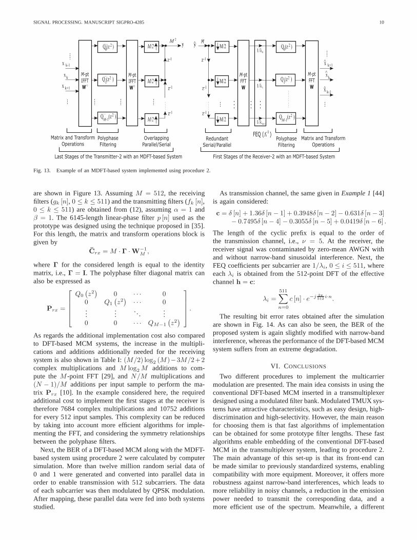
Fig. 13. Example of an MDFT-based system implemented using procedure 2.
are shown in Figure 13. AssumingM = 512, the receivingfilters (gk [n], 0 ≤ k ≤ 511) and the transmitting filters (fk [n],0 ≤ k ≤ 511) are obtained from (12), assumingα = 1 andβ = 1. The 6145-length linear-phase filterp [n] used as theprototype was designed using the technique proposed in [35].For this length, the matrix and transform operations block isgiven by
Crx = M · Γ ·W−1M ,
where Γ for the considered length is equal to the identitymatrix, i.e.,Γ = I. The polyphase filter diagonal matrix canalso be expressed as
Prx =
Q0
(
z2)
0 · · · 00 Q1
(
z2)
· · · 0...
.... . .
...0 0 · · · QM−1
(
z2)
.
As regards the additional implementation cost also comparedto DFT-based MCM systems, the increase in the multipli-cations and additions additionally needed for the receivingsystem is also shown in Table I:(M/2) log2 (M)−3M/2+2complex multiplications andM log2 M additions to com-pute theM -point FFT [29], andN/M multiplications and(N − 1)/M additions per input sample to perform the ma-trix Prx [10]. In the example considered here, the requiredadditional cost to implement the first stages at the receiveristherefore 7684 complex multiplications and 10752 additionsfor every 512 input samples. This complexity can be reducedby taking into account more efficient algorithms for imple-menting the FFT, and considering the symmetry relationshipsbetween the polyphase filters.
Next, the BER of a DFT-based MCM along with the MDFT-based system using procedure 2 were calculated by computersimulation. More than twelve million random serial data of0 and 1 were generated and converted into parallel data inorder to enable transmission with 512 subcarriers. The dataof each subcarrier was then modulated by QPSK modulation.After mapping, these parallel data were fed into both systemsstudied.
As transmission channel, the same given inExample 1[44]is again considered:
c = δ [n] + 1.36δ [n − 1] + 0.3948δ [n − 2] − 0.631δ [n − 3]− 0.7495δ [n − 4] − 0.3055δ [n − 5] + 0.0419δ [n − 6] .
The length of the cyclic prefix is equal to the order ofthe transmission channel, i.e.,ν = 5. At the receiver, thereceiver signal was contaminated by zero-mean AWGN withand without narrow-band sinusoidal interference. Next, theFEQ coefficients per subcarrier are1/λi, 0 ≤ i ≤ 511, whereeachλi is obtained from the 512-point DFT of the effectivechannelh = c:
λi =511∑
n=0
c [n] · e−j 2π512
i·n.
The resulting bit error rates obtained after the simulationare shown in Fig. 14. As can also be seen, the BER of theproposed system is again slightly modified with narrow-bandinterference, whereas the performance of the DFT-based MCMsystem suffers from an extreme degradation.
VI. CONCLUSIONS
Two different procedures to implement the multicarriermodulation are presented. The main idea consists in using theconventional DFT-based MCM inserted in a transmultiplexerdesigned using a modulated filter bank. Modulated TMUX sys-tems have attractive characteristics, such as easy design,high-discrimination and high-selectivity. However, the main reasonfor choosing them is that fast algorithms of implementationcan be obtained for some prototype filter lengths. These fastalgorithms enable embedding of the conventional DFT-basedMCM in the transmultiplexer system, leading to procedure 2.The main advantage of this set-up is that its front-end canbe made similar to previously standardized systems, enablingcompatibility with more equipment. Moreover, it offers morerobustness against narrow-band interferences, which leads tomore reliability in noisy channels, a reduction in the emissionpower needed to transmit the corresponding data, and amore efficient use of the spectrum. Meanwhile, a different

SIGNAL PROCESSING. MANUSCRIPT SIGPRO-4285 11
−15 −10 −5 0 5 10 15 20 2510
−7
10−6
10−5
10−4
10−3
10−2
10−1
100
Eb/No(dB)
BE
R
AWGN Theory
DFT (AWGN)
DFT (Channel+AWGN)
DFT (Channel+AWGN+Interf.)
Proc. 2 (AWGN)
Proc. 2 (Channel+AWGN)
Proc. 2 (Channel+AWGN+Interf.)
Fig. 14. Example 3. Results obtained for a DFT-based MCM (OFDM) andan MDFT-based system using procedure 2 in presence of AWGN with andwithout narrow-band interference. The number of subcarriers is 512, and thedifference in power between the transmitted signal and the interference signalis 20 dB.
modulator, called procedure 1, can be obtained simply bychanging the position of the IFFT from the transmitter to thereceiver after the FEQ. The price paid when both proceduresare used is basically an increase in computational complexity,whereas the advantages are numerous.
ACKNOWLEDGEMENT
The authors would like to thank the Handling Editor and theanonymous Reviewers for their insightful recommendations,which have significantly contributed to the improvement ofthis paper.
REFERENCES
[1] A. Goldsmith, Wireless Communications.Cambridge University Press,2006.
[2] European Telecommunications Standards Institute, ETSI EN 300 744,V1.4.1, Digital Video Broadcasting (DVB); Framing structure, channelcoding and modulation for digital terrestrial television,2001.
[3] IEEE 802.11g-2003, Further Higher-Speed Physical Layer Extension inthe 2.4 GHz Band, 2003.
[4] ITU-T Recommendation G.992.5, Asymmetric digital subscriber line(ADSL) transceivers - Extended bandwidth ADSL2 (ADSL2plus), 2005.
[5] ITU-T Recommendation G.993.2, Very high speed digital subscriber line2 (VDSL2), 2006.
[6] B. Fette, Cognitive Radio Technology.Burlington, Elsevier, 2006.[7] J. Mitola III, Cognitive Radio Architecture. New Jersey, Wiley-
Interscience, 2006.[8] B. Farhang-Boroujeny and R. Kempter, “Multicarrier Communication
Techniques for Spectrum Sensing and Communication in CognitiveRadios,” IEEE Communications Magazine, vol. 46, no. 4, pp. 80-85,Apr. 2008.
[9] K.-H. Chen and T. D. Chiueh, “A Cognitive radio system using discretewavelet multitone modulation,” IEEE Transactions on Circuits andSystems -I: Regular Papers, vol. 55, no. 10, pp. 3246-3258, Nov. 2008.
[10] P. P. Vaidyanathan,Multirate Systems and Filter Banks.Prentice–Hall,Englewood Cliffs NJ, 1993
[11] D. Toumpakaris, J. M. Cioffi, F. Gauthier, and A. Zeddam,“Digitalinterference cancellation for DSL using information from the RS de-coder,” European Transactions on Telecommunications, vol.19, no. 1,pp.53-60, Jan./Feb. 2008.
[12] G. H. Jajamovich and C. G. Galarza, “Multicarrier demodulationfor frequency selective channels subject to narrow band interferences,”Digital Signal Processing, vol. 18, no. 4, pp. 598-611, Jul. 2008.
[13] B. Borna and T. N. Davidson, “Biwindowed discrete multitonetransceiver,” IEEE Transactions on Signal Processing, vol. 55, no. 8,pp. 4217-4226, Aug. 2007.
[14] S. D. Sandberg and M. A. Tzannes, “Overlapped discrete multitonemodulation for high speed copper wire communications,”IEEE Journalon Selected Areas in Communications, vol. 13, no. 9, pp. 1571-1585, Dec.1995.
[15] K. W. Martin, “Small side-lobe filter design for multitone data-communication applications,” IEEE Transactions on Circuits andSystems-II: Analog and Digital Signal Processing, vol. 45, no. 8, pp.1155-1161, Aug. 1998.
[16] S. Govardhanagiri, T. Karp, P. Heller, and T. Nguyen, “Performanceanalysis of multicarrier modulation systems using cosine modulated filterbanks,” in Proc. of IEEE Int. Conf. on Acoustics, Speech, and SignalProcessing, Mar. 1999,vol. 3, pp. 1405-1408.
[17] G. Cherubini, E. Eleftheriou, and S. Olcer, “Filtered multitone mod-ulation for very high-speed digital subscriber lines,”IEEE Journal onSelected Areas in Communications, vol. 20, no. 5, pp. 1016-1028, Jun.2002.
[18] P. Siohan, C. Siclet, and N. Lacaille, “Analysis and design ofOFDM/OQAM systems based on filterbank theory,”IEEE Transactionson Signal Processing,, vol. 50, no. 5, pp. 1170-1183, May 2002.
[19] S. Mirabbasi and K. Martin, “Overlapped complex-modulated trans-multiplexer filter with simplified design and superior stopband,” IEEETransactions on Circuits and Systems-II: Analog and Digital SignalProcessing, vol. 50, no. 8, pp. 456-465, Aug. 2003.
[20] B. Farhang-Boroujeny, “Multicarrier modulation withblind detectioncapability using cosine-modulated filter banks,”IEEE Transactions onCommunications,, vol. 51, no. 12, pp. 2057-2070, Dec. 2003.
[21] B. Farhang-Boroujeny and L. Lin, “Analysis of post-combiner equalizersin cosine-modulated filterbank-based transmultiplexer system,” IEEETransactions on Signal Processing,, vol. 51, no. 12, pp. 3249-3262, Dec.2003.
[22] P. S. R. Diniz, L. C. R. de Barcellos, and S. L. Netto, “Design ofhigh-resolution cosine-modulated transmultiplexers with sharp transitionband,” IEEE Transactions on Signal Processing,, vol. 52, no. 5, pp. 1278-1288, May 2004.
[23] M. R. Wilbur, T. N. Davidson, and J. P. Reilly, “Efficientdesign ofoversampled NPR GDFT filterbanks,”IEEE Transactions on SignalProcessing, vol. 52, no. 7, pp. 1947-1963, Jul. 2004.
[24] L. Lin and B. Farhang-Boroujeny, “Cosine-Modulated Multitone forVery-High-Speed Digital Subscriber Lines,”EURASIP Journal on Ap-plied Signal Processing, Article ID 19329, 16 pages, 2006.
[25] H. Malvar, Signal Processing with Lapped Transforms.Artech House,1992
[26] R. D. Koilpillai and P. P. Vaidyanathan, “Cosine-Modulated FIR FilterBanks Satisfying Perfect Reconstruction,”IEEE Transactions on SignalProcessing, vol. 40, no. 4, pp. 770-783, Apr. 1992.
[27] N. J. Fliege,Multirate Digital Signal Processing.Chicester: John Wileyand Sons, 1994.
[28] Y.-P. Lin and P. P. Vaidyanathan, ”Linear phase cosine modulatedmaximally decimated filter banks with perfect reconstruction,” IEEETransactions on Signal Processing, vol. 43, no. 11, pp. 2525-2539, Nov.1995.
[29] P. S. R. Diniz, E. A. B. da Silva, and S. L. Netto,Digital SignalProcessing. System Analysis and Design.Cambridge University Press,2002.
[30] F. Cruz-Roldan and M. Monteagudo, “Efficient implementation ofnearly-perfect reconstruction cosine-modulated filterbanks,” IEEE Trans-actions on Signal Processing, vol. 52, no. 9, pp. 2661-2664, Sep. 2004.
[31] B. Muquet, Z. Wang, G. B. Giannakis, M. de Courville, andP.Duhamel, “Cyclic prefixing or Zero padding for wireless multicarriertransmissions?,”IEEE Transactions on Communications, vol. 50, no. 12,pp. 2136-2148, Dec. 2002.
[32] R. K. Martin, K. Vanbleu, M. Ding, G. Ysebaert, M. Milosevic, B. L.Evans, M. Moonen, C. R. Johnson Jr., “Implementation Complexity andCommunication Performance Tradeoffs in Discrete Multitone ModulationEqualizers,”IEEE Transactions on Signal Processing, vol. 54, no. 8, pp.3216-3230, Aug. 2006.
[33] A. N. Akansu and M. J. Medley (Ed.),Wavelet, Subband and BlockTransforms in Communications and Multimedia. Norwell, Massachussets,Kluwer Academic Publishers, 1999

SIGNAL PROCESSING. MANUSCRIPT SIGPRO-4285 12
[34] S. S. Pradhan and K. Ramchandran, “Efficient layered data transportover multicarrier systems using optimized embedded modulation,” IEEETransactions on Communications, vol. 50, no. 6, pp. 877-881, Jun 2002.
[35] F. Cruz-Roldan, P. Martın, J. Saez-Landete, M. Blanco-Velasco, and T.Saramaki, “A fast windowing-based technique exploiting spline functionsfor designing modulated filter banks,”IEEE Transactions on Circuits andSystems -I: Regular Papers, vol. 56, no. 1, pp. 168-178, Jan. 2009.
[36] R. E. Crochiere and L. R. Rabiner,Multirate Digital Signal Processing.New Jersey, Prentice-Hall, 1983
[37] N. J. Fliege, “Computational efficiency of modified DFT-polyphase filterbanks,” in Proceeding of ”7th Asilomar Conf. Signals, Systems, andComputers, Nov. 1993, pp. 1296-1300.
[38] T. Karp and N. J. Fliege, “Modified DFT filter banks with perfectreconstruction,”IEEE Transactions Circuits and Systems-II: Analog andDigital Signal Processing, vol. 46, no. 11, pp. 1404-1414, Nov. 1999.
[39] H. Malvar, “Fast algorithm for the Modulated Complex Lapped
Transform,” IEEE Signal Processing Letters, vol. 10, no. 1, pp. 8-10,Jan. 2003.
[40] P. N. Heller,T. Karp, and T. Q. Nguyen, “A general formulation ofmodulated filter banks,”IEEE Transactions on Signal Processing, vol.47, no. 4, pp. 986-1002, Apr. 1999.
[41] T. Karp and N. J. Fliege, “Computational efficient realization ofMDFT filter banks,” inProc. of European Signal Processing Conference(EUSIPCO-1996), Trieste (Italy), Sep. 1996, pp. 1183-1186.
[42] K. R. Rao and P. Yip.Discrete Cosine Transform: Algorithms, Advan-tages, Applications. Academic Press, New York, 1990
[43] S. C. Thompson, “Constant envelope OFDM phase modulation,” Ph.D.dissertation, University of California, San Diego, 2005.
[44] Y. Xiao, Y.-Y. Cao, and Z. Lin, “Robust filtering for discrete-timesystems with saturation and its application to transmultiplexers,” IEEETransactions on Signal Processing, vol. 52, no. 5, pp. 1266-1277, May2004.


