Embed Size (px)
Citation preview

1278 IEEE TRANSACTIONS ON SIGNAL PROCESSING, VOL. 52, NO. 5, MAY 2004
Design of High-Resolution Cosine-ModulatedTransmultiplexers with Sharp Transition Band
Paulo S. R. Diniz, Fellow, IEEE, Luiz C. R. de Barcellos, and Sergio L. Netto, Member, IEEE
Abstract—Due to the growing importance of multichannel mod-ulation, there has been great interest in the design of high-perfor-mance transmultiplex systems. In this paper, a new cosine-modu-lated transmultiplex structure is proposed based on a prototypefilter designed with the frequency-response masking (FRM) ap-proach. This new structure leads to substantial reduction in thecomputational complexity (number of multiplications per outputsample) of the prototype filters having sharp transition band andequivalently small roll-off values. The relation between the inter-polation factor used in the FRM prototype filter and the decima-tion factor in the subbands leads to distinct structures. Examplesincluded indicate that the reduction in computational complexitycan be higher than 50% of the current state-of-art designs, whereasthe reduction on the number of distinct coefficients of the proto-type filter can be reduced even further (over 75%). As a result, theproposed approach allows the design of very selective subfilters fortransmultiplexes with a very large number of subchannels.
Index Terms—Cosine-modulated filterbanks, cosine-modulatedtransmultiplexers, extended lapped transforms, filterbanks,frequency response masking, high-resolution spectral analysis,multirate systems, sharp transition band filters, transmultiplexers.
I. INTRODUCTION
MULTICHANNEL modulation methods play a key rolein modern data transmission channels with severe and
moderate intersymbol interference (ISI). The key idea behindthe success of this technique is the partition of a physicalchannel in nonoverlapping narrowband subchannels througha transmultiplexer. If the subchannels are narrow enough, theassociated channel response in each subchannel frequencyrange appears to be flat, avoiding the use of equalizers. Inaddition, the subchannel division allows, whenever possible,the exploitation of signal-to-noise ratio (SNR) in the differentsubbands in order to manage the dataload in each subchannel.Typically, subchannels with high SNR utilize high-order mod-ulation, whereas subchannels with moderate SNR lower ordermodulation should be used. On the other hand, subchannelswith severe interference are not used for data transmission.Such schemes are employed in a number of high-speed digitalsubscriber line (xDSL) systems.
Manuscript received October 9, 2002; revised June 12, 2003. The associateeditor coordinating the review of this manuscript and approving it for publica-tion was Prof. Trac D. Tran.
P. S. R. Diniz and S. L. Netto are with the Programa de EngenhariaElétrica-COPPE/EE/UFRJ, Rio de Janeiro, RJ, 21945-970, Brazil (e-mail:[email protected]; [email protected]).
L. C. R. de Barcellos was with the Programa de Engenharia Elétrica-COPPE/EE/UFRJ, Rio de Janeiro, RJ, 21945-970, Brazil. He is now withPetrobras, Rua Gerneral Canabarro 500, 11o andar, Rio de Janeiro, RJ, Brazil.
Digital Object Identifier 10.1109/TSP.2004.826157
A critical component of the multichannel systems is thefilterbank-based transmultiplex (TMUX). The ideal situationrequires the design of highly selective filterbanks to avoidcrosstalk between subchannels and that the subfilter frequencyresponses are narrow enough such that channel response in eachsubband appears to be flat. The latter condition is achieved byfilterbanks with a very large number of subbands, whose designwith the currently available techniques leads to an optimizationproblem with a prohibitive number of parameters.
The cosine-modulated transmultiplex (CMT) is very popularin applications requiring a large number of subbands due to theireasy design and efficient implementation, in terms of computa-tional complexity [1]–[5]. However, with the current state of theart, one is not able to design CMTs meeting the demanding re-quirements of multichannel systems, including large number ofchannels (above 1000, for instance) with low levels of ISI andintercarrier interference (ICI).
A possible strategy is to employ the frequency-responsemasking (FRM) approach to design the prototype filter ofthe CMT. The FRM is an efficient method for designinglinear-phase finite impulse response (FIR) digital filters withgeneral passbands and sharp transition bands. With such amethod, by allowing a small increase in the filter group delay,it is possible to reduce the overall filter complexity (numberof arithmetic operations required per output sample) whencompared with standard design methods. In fact, it has beenverified that the FRM approach can achieve a reduction toabout 30% of the number of coefficients required by a min-imax FIR filter design realized in direct form [6], [7]. Recentresults show that the FRM framework can be generalized toaccommodate different structures and approximation methods[8]–[10]. Unfortunately, the application of FRM to designcomputationally efficient CMT is not straightforward andrequires careful investigation.
In this paper, a solution to design CMTs with a reducednumber of distinct parameters to be optimized is presented.The approach is feasible due to a judicious use of the FRMapproach, as opposed to standard design methods, to design theCMT prototype filter. As an illustration, it is verified that withthe FRM prototype filter, the parameters of interest of a TMUXsystem (namely, the attenuation, the overall delay, and theISI and ICI levels) are comparable with those in the standarddesign, whereas the number of coefficients can be reducedsubstantially (down to about 50% of the original number).Therefore, it is possible to achieve complexity reduction in aCMT structure without sacrificing other design requirements.
The relation between the interpolation factor used in the CMTprototype filter and the FRM decimation factor in the subbands
1053-587X/04$20.00 © 2004 IEEE

DINIZ et al.: DESIGN OF HIGH-RESOLUTION COSINE-MODULATED TRANSMULTIPLEXERS 1279
Fig. 1. Basic realization of an FIR filter using the FRM approach, depictingthe positive (upper) and the negative (lower) branches of the FRM filter.
leads to different structures that all have a small number of dis-tinct coefficients when compared with the standard structure.The reduction in the number of coefficients (to about 25% ofthe original number of distinct parameters) opens new venuesfor the possible design of filterbanks with sharp transition bandand with a large number of subbands, as demonstrated in thedesign examples.
The organization of this paper is as follows: In Sections IIand III, we briefly describe the main ideas behind the FRM ap-proach and the CMT systems, respectively. In Section IV, wepropose an efficient structure of CMT systems, and in Section V,design examples are included, illustrating the advantages of theproposed method. Through these examples, we illustrate howthe proposed method is capable of designing multichannel com-munications systems with a very large number of channels, re-quiring a quite reduced number of distinct coefficients. Such areduced number of distinct parameters allows a faster optimiza-tion procedure when figures of merit, such as ISI and ICI, areconsidered in the design process.
II. FREQUENCY-RESPONSE MASKING APPROACH
The basic block diagram for the FRM approach can be seenin Fig. 1. In this scheme, if we use an interpolation factor of ,the so-called interpolated base filter presents a repeti-tive frequency spectrum whose output signal is processed by thepositive masking filter , of order , in the upper branchof this realization. Similarly, a complementary version of thisrepetitive frequency response is in cascade with thenegative masking filter , of order , in the lower branchof the realization. In this procedure, both masking filters keepsome of the spectrum repetitions within the desired passband,which are added together to compose the desired frequency re-sponse. These operations are depicted in Fig. 2, where one canclearly see the sharp transition band in the resulting response.
If the base filter has linear-phase and an even order , itsdirect and complementary transfer functions, interpolated by afactor of , are given by
(1)
(2)
respectively, where is the impulse response of the basefilter.
The design specifications of each FRM subfilter can be foundin the original paper [6]. The value of that minimizes theoverall number of multiplications can be obtained by estimating
Fig. 2. Combination of the frequency responses in the upper and lowerbranches generating the FRM filter with very narrow transition band. (a) Basefilter. (b) Positive masking operation. (c) Negative masking operation. (d)Resulting response.
Fig. 3. Block diagram for anM -channel TMUX.
the lengths of all subfilters for various and either finding thebest case scenario heuristically or using the strategy detailed in[7]. Then, it is possible to optimize the responses of the subfil-ters by using a variety of algorithms [8]–[10]. If the transitionband is not too sharp when compared with the passband, then itis possible to discard the lower branch of the FRM filter, furtherreducing the number of coefficients in the overall filter. In addi-tion, the specifications of the subfilters can be relaxed, using theconcept of “don’t care bands” since there is no overlap betweenthe frequency responses of the FRM upper and lower branchesas described in [6].
III. TMUX CONFIGURATION
The TMUX is an application of filterbanks in which thesignals coming from various sources are interpolated, filteredby a synthesis bank, and added together to compose a singlesignal for transmission over a given channel C [1], [5]. At thereceiver, the analysis filters split the transmitted signal backinto channels, where each output corresponds to one originalinput source. If the TMUX has perfect reconstruction (PR),then the output signals are equal to the source signals when thechannel model is a pure delay, whereas if the estimated signalsreceive small interference from the other sources, we have thenearly perfect reconstruction (NPR) case. Fig. 3 depicts theblock diagram for such system.
The main advantage of using a CMT is the fact that only oneprototype filter design is required [1], [11]–[13] since the syn-thesis and analysis filters are obtained by modulating this filterwith a proper cosine function. For the prototype filter, the 3-dB

1280 IEEE TRANSACTIONS ON SIGNAL PROCESSING, VOL. 52, NO. 5, MAY 2004
attenuation point and the stopband edge of the magnitude re-sponse are located at
dB (3)
respectively, where is the so-called roll-off factor.If the prototype filter of order has a transfer function
(4)
then the impulse responses of the analysis and the synthesis fil-ters are given, respectively, by
(5)
(6)
for , and .If the prototype filter has coefficients, then it is pos-
sible to decompose it into polyphase components
(7)
where the polyphase components are given by
(8)
Therefore, the analysis filter can be written as1
(9)
where
(10)
such that
(11)
1The same procedure can be applied to the synthesis filters.
Fig. 4. Efficient CMT structure.
From (9), we can define a vector containing the transfer func-tions of the analysis filters as follows:
......
(12)The two matrix and are related to the DCT-IV matrix asfollows:
(13)
(14)
where , with representing the largestinteger less than or equal to , is the identity matrix, andis the reverse (flipped) identity matrix, and each element of theDCT-IV matrix is given by
(15)
The efficient structure for the CMT related to (12) is depictedin Fig. 4. From this figure, one infers that the CMT realizationrequires only multiplications for the polyphase compo-nents, one multiplication by , the premodulating matrices con-sisting of , , and the DCT-IV. Theoverall number of multiplications per output sample (not takinginto consideration any symmetry of coefficients) is then
(16)
where is associated with the multiplication by the constantand the modulating matrices, which can be implemented usingfast algorithms [14]. The polyphase decomposition turns thevalue of small, independent of the number of channels ,demonstrating the efficiency of the structure.
If the prototype filter has symmetric impulse response, thenit is possible to use the butterfly-based structures proposed byMalvar [2], [11], depicted in Fig. 5. The resulting filterbank hasperfect reconstruction. If it is desired to design an NPR filter-bank, a modified structure can be used instead [3], [5]. In the

DINIZ et al.: DESIGN OF HIGH-RESOLUTION COSINE-MODULATED TRANSMULTIPLEXERS 1281
Fig. 5. Improved CMT structure using butterflies for the PR case.
case of Fig. 5, the stages of butterflies can be viewed as ma-trices with nonzero elements only at the main diagonals, thus re-ducing the computational complexity to about 25% of the valueobtained with the polyphase decomposition.
The transfer matrix, which includes all transfer functionsfrom input to output , for the TMUX case has the followingelements:
(17)
The ISI and ICI can be estimated with the following expres-sions [5]:
ISI (18)
ICI (19)
where is the ideal impulse, is the impulse responsefor the th channel output, and the term is thecrosstalk between the th and th channels, which can bedetermined from (17).
IV. FRM DESIGN FOR THE PROTOTYPE FILTER
Let us first consider only the upper branch of the FRM struc-ture in Fig. 1 as the prototype filter for the CMT. Then, thetransfer functions for the analysis filters become
(20)
where the term denotes the convolution betweenthe interpolated base filter and the positive masking filter re-sponses, and is the overall order of the FRM filter. The keypoint is to find an efficient structure to calculate the convolu-tion in (20), which takes into consideration the special propertyof the cosine functions for each sample. Assuming thatand have orders and , respectively, and using thedefinition of convolution, (20) can be rewritten as
(21)
Fig. 6. For L = 2K M , the passbands of the interpolated base filter arecentered on (2k�)=(L), which include (�)=(2M), where the ! dB frequencyfor the CMT prototype filter should be.
The key problem is to find the proper values for such that thisconvolution allows us to exploit the relationship of (11).
A. Solution for Multiple of
We start by noting that if the interpolated filter has interpo-lation factor of , with being an integer greaterthan zero, then (21) becomes
(22)and using the cosine relationship in (11), we have
(23)
Therefore, it is possible to resolve the convolution problem byusing a cascade of two filters. The masking filter can be decom-posed by using polyphase decomposition. Unfortunately, for thecases in which , it is not possible to compose a pro-totype filter using the FRM approach since the desirable tran-sition band of the prototype filter is not realizable. This occursbecause the center frequency of one of the bands of the inter-polated filter (or its complementary version) traverses the fre-quency dB of the transition band of the CMT prototype filter,as depicted in Fig. 6. Therefore, it is not possible to satisfy thecondition of (3).
B. Solution for Multiple of
Nevertheless, it is possible to find an efficient implementationfor (21) in the cases where , with being an in-teger greater than zero, since in those cases, the transition bandis realizable. In this case, (21) becomes
(24)
The idea is now to decompose not only the masking filter but thebase filter as well, in order to solve (24). By decomposing firstthe interpolated base filter into polyphase components

1282 IEEE TRANSACTIONS ON SIGNAL PROCESSING, VOL. 52, NO. 5, MAY 2004
Fig. 7. Multiple-signal filtering structure.
and assuming that the base filter has coefficients, whereis a positive integer, we can write
(25)
Then, by using the cosine relationship of (11), we obtain
(26)
By decomposing the masking filter and assuming that, with analogous to the value of in the stan-
dard CMT design, we can write
(27)
where the polyphase decomposition of the base filter is given by
(28)
for , and the masking filter polyphasedecomposition is given by
(29)
for . Equation (27) indicates that theCMT can be implemented by using structures of Fig. 4, wherein each one, a filter is placed at the input of the
system, and then, the DCT-IV outputs with appropriate line per-mutation added to generate the responses . Since themodulating matrices and the masking filters are the same, ex-cept for line permutations, the multiple-signal filtering structureof Fig. 7 can be used in order to simplify the overall structure.
In Fig. 7, the various input–output relationships are given by
(30)
as desired. By rearranging the outputs after these components,it is possible to add the signals just before the premodulatingmatrices by dropping out some of the decimators. This leads usto the structure depicted in Fig. 8. At this point, it is worth notingthat the value of for calculating the modulating matrices andthe constant is identical to the standard CMT approach sincethe modulating stage remains the same. Thus, the FRM-CMTfilter can be viewed as a standard CMT with prototype filter ofoverall order , where for the FRM-CMT case,we have
(31)
as seen in Fig. 8.If both branches in the FRM design are required, this entire
procedure can be applied to the lower branch, and by forcingboth masking filters to have the same order ,the responses of the two branches can be added together justbefore the modulating stage. In such cases, the total number ofdistinct coefficients, not assuming symmetry or antisymmetryof any impulse response, is given by
(32)
and the total number of multiplications per output sample,without taking into consideration any symmetry in the subfiltercoefficients, is given by
(33)
We also note that the value of may differ for each polyphasecomponent of the base filter. This occurs because adding morecoefficients to the base filter does not misarrange the cosinemodulation, as opposed to changing the masking filter lengthto a value other than .
C. Generalized Solution for
For a more general solution, we use the results from the pre-vious sections to derive a structure for the case where the inter-polation factor is written as [4]
(34)
where is a non-negative integer and a positive integer. Inthis case, (21) can be written as
(35)

DINIZ et al.: DESIGN OF HIGH-RESOLUTION COSINE-MODULATED TRANSMULTIPLEXERS 1283
Fig. 8. CMT structure using FRM for the case when L = M=K .
and then, by using , , and ,as before, we have
(36)
By using the relation of (11), we have
(37)
and, as is even, one can exploit the polyphase decompositionof , such that (37) becomes
(38)
By defining the modified polyphase components of the interpo-lated base filter as
(39)
with , (38) can be rewritten as
(40)
and we derive the structure depicted in Fig. 9, with , as givenin (31). The corresponding synthesis bank is implemented bythe transposed structure of the analysis filterbank with the givenbase filter included.
The main difference between the structures in Figs. 8 and9 is that in the latter, the interpolation factor of the polyphasecomponents of the base filter is instead of . If both FRMbranches are present such that , the numberof distinct coefficients of the structure depicted in Fig. 9 is givenby (32), whereas its computational complexity is given by (33),as before.
The values of and can be chosen such that the overallFRM-CMT filter has the same order as the standard CMT designto allow a more direct comparison between the two structures.In the examples presented in the next section, we explore thisdesign scenario. A summary of all variables of interest is givenin Table I.
D. General Case with the Butterfly Structure
It can be verified that using the multiple-signal filtering struc-ture of Figs. 7–9 is equivalent to using masking filters in par-allel and adding their responses just before the DCT-IV opera-tion. Thus, it is also possible to use a butterfly structure for thegeneral case of , as depicted in Fig. 10. In the case of ,since the butterfly-based structure requires only decimation by
, the resulting structure will not require the multiple-signalfiltering stage. This particular but very important case is de-picted in Fig. 11.
For the general case of , the compu-tational complexity is reduced due to the butterfly structure that

1284 IEEE TRANSACTIONS ON SIGNAL PROCESSING, VOL. 52, NO. 5, MAY 2004
Fig. 9. CMT structure using FRM for the general case of L = 2K M +M=K .
Fig. 10. Improved FRM-CMT general structure using butterflies.
TABLE ISUMMARY OF VARIABLES OF INTEREST IN
PROPOSED FRM-CMT STRUCTURE
has fast implementation, as well as due to the fact that the inter-polating factor is half of the value for the polyphase
structure case. Now, however, the modified polyphase compo-nents of the base filter are given by
(41)
It is worth noting that in the butterfly-based structures givenin Figs. 10 and 11, the overall PR property will depend on thebase filter characteristics since the masking filter will inherentlyyield PR. In most practical cases, as the ones seen in the exam-ples below, the FRM-CMT is NPR in general. There are, how-ever, some cases where the base filter presents trivial transferfunctions that result in a PR property for the entire FRM-CMTstructure.
E. Multistage FRM-CMT Structure
It is possible to derive a multistage FRM-CMT structure,by using several levels of FRM design for the CMT prototypefilter, to further reduce the overall computational complexity.Assuming that the lower branch is absent in the initial FRMdesign, the main idea is, for instance, to redesign the FRMmasking filter, if the order of this filter is still too high, withother levels of the FRM approach. In this case, the originalFRM-CMT -interpolated base filter will be in cascade with

DINIZ et al.: DESIGN OF HIGH-RESOLUTION COSINE-MODULATED TRANSMULTIPLEXERS 1285
Fig. 11. Improved FRM-CMT structure using butterflies with L = M .
Fig. 12. FRM-CMT prototype filter using a two-stage masking-filterdecomposition.
TABLE IICOMPARISON BETWEEN THE CMT DESIGNS USING OPTIMIZED DIRECT-FORM
AND FRM PROTOTYPE FILTERS IN EXAMPLE 1
the second level FRM-CMT -interpolated base filter andcorresponding masking filter, as seen in Fig. 12. For instance,if is a multiple of , it is then necessary to decomposethe second-stage base filter by a factor of .This procedure can then be generalized to design multistageFRM-CMT systems, as seen in Example 3 below.
The corresponding computational complexity for the multi-stage FRM-CMT structure is given by
(42)
where , , and are the second-stage counterparts of ,, and , respectively, and so on.
V. NUMERICAL EXAMPLES
A. Example 1
We design a CMT with channels using and. In this case, should be sufficient to perform
the design. Calculating the bandedge frequencies for the designof the CMT prototype filter, we obtain and
, leading to dB . Using an opti-mized direct-form FIR design for the prototype filter with order
, we obtain the results presented in thefirst line of Table II [1]. By using an FRM design, we achieve theminimum number of distinct coefficients with , leadingto and , corresponding to an overall filter order
, as given in Table III.
TABLE IIIBEST REDUCTION SCENARIO FOR THE FRM FILTER IN EXAMPLE 1
As we can see from Table II, in this case, using the FRMapproach leads to substantial reduction in the number of dis-tinct coefficients, whereas the number of multiplications peroutput sample increased. Thus, although the filterbank imple-mented with the structure of Fig. 8 does not present computa-tional complexity reduction, its design is much simpler since thenumber of variables (coefficients) to optimize is smaller whencompared with the standard CMT design. In addition, the struc-ture of Fig. 8 can be mapped back onto the standard structureof Figs. 4 or 5, resulting in a reduced number of operations peroutput sample. The FRM approach has increased the value ofthe minimum stopband attenuation , consequently slightly in-creasing the value of the ICI. If we wish to reduce these values,it is possible to increase the order of the FRM filter where thenumber of coefficients needed may still be significantly smallerthan for the direct-form implementation. Figs. 13 and 14 depictthe magnitude responses of the prototype filter and the bank fil-ters, respectively.
B. Example 2
For this second example, we designed a CMT withchannels, using and . Calculating thebandedge frequencies for the design of the prototype filter, weobtained and , leading to dB
. By using the FRM approach, the best design has, corresponding to and , and is described
in Table IV.Table V compares the optimized direct-form and the FRM ap-
proaches for designing the CMT prototype filter. In this case, weachieved significant reductions in the number of distinct coeffi-cients and in the overall computational complexity of the CMTsystem. Figs. 15 and 16 depict the magnitude responses of theprototype filter and the subfilters of the bank, respectively, inthis example.
C. Example 3
In this example, a CMT with channels is designed,using , dB, and dB. The standardminimax design would require a filter of order ,which constitutes a nonpractical option. By using a single-stage

1286 IEEE TRANSACTIONS ON SIGNAL PROCESSING, VOL. 52, NO. 5, MAY 2004
Fig. 13. Magnitude response for the FRM prototype filter in Example 1.
Fig. 14. Magnitude response for the CMT in Example 1.
TABLE IVBEST REDUCTION SCENARIO FOR THE FRM FILTER IN EXAMPLE 2
TABLE VCOMPARISON BETWEEN THE CMT DESIGNS USING OPTIMIZED DIRECT-FORM
AND FRM PROTOTYPE FILTERS IN EXAMPLE 2
FRM-CMT, selecting and (thus and), we obtain, for the prototype filter, the results shown in
the first line of Table VI. From this table, by keepingand replacing the masking filter with second and third FRMstages, some computational complexity can be further reduced.However, if we change the original interpolation factor to
, the best reduction scenario is achieved with a three-stageFRM-CMT design, as indicated in the fourth line of Table VI.
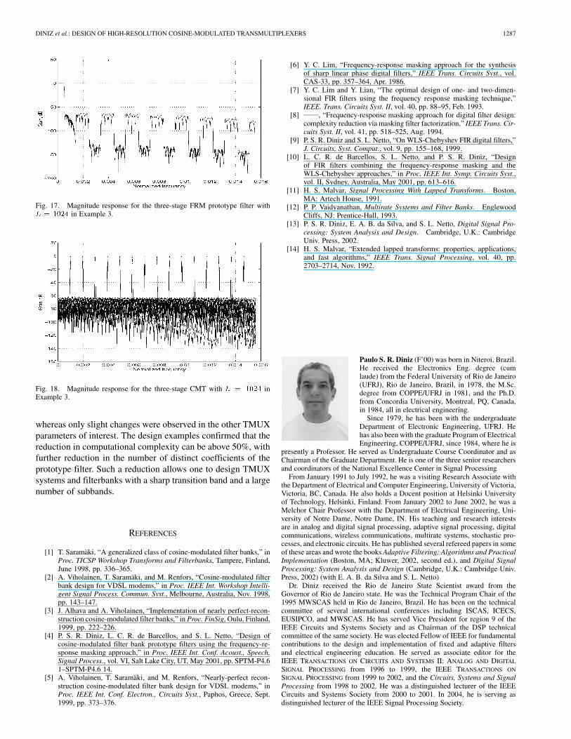
Table VII presents the passband ripple and stopband atten-uation level achieved by each multistage design described inTable VI. The prototype and filterbank responses for the first16 channels of the three-level FRM-CMT with areshown in Fig. 17 and Fig. 18, respectively.
Fig. 15. Magnitude response for the FRM prototype filter in Example 2.
Fig. 16. Magnitude response for the CMT in Example 2.
TABLE VICOMPARISON OF SUBFILTER CHARACTERISTICS BETWEEN MULTISTAGE
FRM-CMT FILTERS IN EXAMPLE 3
TABLE VIICOMPARISON OF MAGNITUDE CHARACTERISTICS BETWEEN MULTISTAGE
FRM-CMT FILTERS IN EXAMPLE 3
VI. CONCLUSION
In this paper, it was shown how it is feasible to design veryselective transmultiplexers based on cosine modulation. Byviewing the frequency-response masking (FRM) filter as amultirate system, it was possible to derive efficient filterbankrealizations for a very general relationship between the numberof channels and the FRM interpolation factor . The timedelay of the resulting transmultiplex (TMUX) is not increased,
DINIZ et al.: DESIGN OF HIGH-RESOLUTION COSINE-MODULATED TRANSMULTIPLEXERS 1287
Fig. 17. Magnitude response for the three-stage FRM prototype filter withL = 1024 in Example 3.
Fig. 18. Magnitude response for the three-stage CMT with L = 1024 inExample 3.
whereas only slight changes were observed in the other TMUXparameters of interest. The design examples confirmed that thereduction in computational complexity can be above 50%, withfurther reduction in the number of distinct coefficients of theprototype filter. Such a reduction allows one to design TMUXsystems and filterbanks with a sharp transition band and a largenumber of subbands.
REFERENCES
[1] T. Saramäki, “A generalized class of cosine-modulated filter banks,” inProc. TICSP Workshop Transforms and Filterbanks, Tampere, Finland,June 1998, pp. 336–365.
[2] A. Viholainen, T. Saramäki, and M. Renfors, “Cosine-modulated filterbank design for VDSL modems,” in Proc. IEEE Int. Workshop Intelli-gent Signal Process. Commun. Syst., Melbourne, Australia, Nov. 1998,pp. 143–147.
[3] J. Alhava and A. Viholainen, “Implementation of nearly perfect-recon-struction cosine-modulated filter banks,” in Proc. FinSig, Oulu, Finland,1999, pp. 222–226.
[4] P. S. R. Diniz, L. C. R. de Barcellos, and S. L. Netto, “Design ofcosine-modulated filter bank prototype filters using the frequency-re-sponse masking approach,” in Proc. IEEE Int. Conf. Acoust., Speech,Signal Process., vol. VI, Salt Lake City, UT, May 2001, pp. SPTM-P4.61–SPTM-P4.6 14.
[5] A. Viholainen, T. Saramäki, and M. Renfors, “Nearly-perfect recon-struction cosine-modulated filter bank design for VDSL modems,” inProc. IEEE Int. Conf. Electron., Circuits Syst., Paphos, Greece, Sept.1999, pp. 373–376.
[6] Y. C. Lim, “Frequency-response masking approach for the synthesisof sharp linear phase digital filters,” IEEE Trans. Circuits Syst., vol.CAS-33, pp. 357–364, Apr. 1986.
[7] Y. C. Lim and Y. Lian, “The optimal design of one- and two-dimen-sional FIR filters using the frequency response masking technique,”IEEE. Trans. Circuits Syst. II, vol. 40, pp. 88–95, Feb. 1993.
[8] , “Frequency-response masking approach for digital filter design:complexity reduction via masking filter factorization,” IEEE Trans. Cir-cuits Syst. II, vol. 41, pp. 518–525, Aug. 1994.
[9] P. S. R. Diniz and S. L. Netto, “On WLS-Chebyshev FIR digital filters,”J. Circuits, Syst. Comput., vol. 9, pp. 155–168, 1999.
[10] L. C. R. de Barcellos, S. L. Netto, and P. S. R. Diniz, “Designof FIR filters combining the frequency-response masking and theWLS-Chebyshev approaches,” in Proc. IEEE Int. Symp. Circuits Syst.,vol. II, Sydney, Australia, May 2001, pp. 613–616.
[11] H. S. Malvar, Signal Processing With Lapped Transforms. Boston,MA: Artech House, 1991.
[12] P. P. Vaidyanathan, Multirate Systems and Filter Banks. EnglewoodCliffs, NJ: Prentice-Hall, 1993.
[13] P. S. R. Diniz, E. A. B. da Silva, and S. L. Netto, Digital Signal Pro-cessing: System Analysis and Design. Cambridge, U.K.: CambridgeUniv. Press, 2002.
[14] H. S. Malvar, “Extended lapped transforms: properties, applications,and fast algorithms,” IEEE Trans. Signal Processing, vol. 40, pp.2703–2714, Nov. 1992.
Paulo S. R. Diniz (F’00) was born in Niteroi, Brazil.He received the Electronics Eng. degree (cumlaude) from the Federal University of Rio de Janeiro(UFRJ), Rio de Janeiro, Brazil, in 1978, the M.Sc.degree from COPPE/UFRJ in 1981, and the Ph.D.from Concordia University, Montreal, PQ, Canada,in 1984, all in electrical engineering.
Since 1979, he has been with the undergraduateDepartment of Electronic Engineering, UFRJ. Hehas also been with the graduate Program of ElectricalEngineering, COPPE/UFRJ, since 1984, where he is
presently a Professor. He served as Undergraduate Course Coordinator and asChairman of the Graduate Department. He is one of the three senior researchersand coordinators of the National Excellence Center in Signal Processing
From January 1991 to July 1992, he was a visiting Research Associate withthe Department of Electrical and Computer Engineering, University of Victoria,Victoria, BC, Canada. He also holds a Docent position at Helsinki Universityof Technology, Helsinki, Finland. From January 2002 to June 2002, he was aMelchor Chair Professor with the Department of Electrical Engineering, Uni-versity of Notre Dame, Notre Dame, IN. His teaching and research interestsare in analog and digital signal processing, adaptive signal processing, digitalcommunications, wireless communications, multirate systems, stochastic pro-cesses, and electronic circuits. He has published several refereed papers in someof these areas and wrote the books Adaptive Filtering: Algorithms and PracticalImplementation (Boston, MA; Kluwer, 2002, second ed.), and Digital SignalProcessing: System Analysis and Design (Cambridge, U.K.: Cambridge Univ.Press, 2002) (with E. A. B. da Silva and S. L. Netto)
Dr. Diniz received the Rio de Janeiro State Scientist award from theGovernor of Rio de Janeiro state. He was the Technical Program Chair of the1995 MWSCAS held in Rio de Janeiro, Brazil. He has been on the technicalcommittee of several international conferences including ISCAS, ICECS,EUSIPCO, and MWSCAS. He has served Vice President for region 9 of theIEEE Circuits and Systems Society and as Chairman of the DSP technicalcommittee of the same society. He was elected Fellow of IEEE for fundamentalcontributions to the design and implementation of fixed and adaptive filtersand electrical engineering education. He served as associate editor for theIEEE TRANSACTIONS ON CIRCUITS AND SYSTEMS II: ANALOG AND DIGITAL
SIGNAL PROCESSING from 1996 to 1999, the IEEE TRANSACTIONS ON
SIGNAL PROCESSING from 1999 to 2002, and the Circuits, Systems and SignalProcessing from 1998 to 2002. He was a distinguished lecturer of the IEEECircuits and Systems Society from 2000 to 2001. In 2004, he is serving asdistinguished lecturer of the IEEE Signal Processing Society.

1288 IEEE TRANSACTIONS ON SIGNAL PROCESSING, VOL. 52, NO. 5, MAY 2004
Luiz C. R. de Barcellos was born in Guaratinguetá,SP, Brazil. He received the B.Sc. degree from theFederal University of Rio de Janeiro (UFRJ), Riode Janeiro, Brazil, in 1999 and the M.Sc. degreefrom COPPE/UFRJ in 2001, both in electricalengineering. He is currently pursuing the Ph.D.degree at COPPE/UFRJ.
Since 2002, he has been with Petrobras (BrazilianPetroleum Holding), Rio de Janeiro. His research in-terests are in the areas of digital signal processing,control, and communications systems.
Sergio L. Netto (M’99) was born in Rio de Janeiro,RJ, Brazil. He received the B.Sc. degree (cum laude)from the Federal University of Rio de Janeiro (UFRJ)in 1991, the M.Sc. degree from COPPE/UFRJ in1992, and the Ph.D. degree from the Universityof Victoria, Victoria, BC, Canada, in 1996, all inelectrical engineering.
Since 1997, he has been an associate professorwith the Department of Electronics and ComputerEngineering, UFRJ and, since 1998, with theProgram of Electrical Engineering, COPPE/UFRJ.
He is the co-author (with P. S. R. Diniz and E. A. B. da Silva) of DigitalSignal Processing: System Analysis and Design (Cambridge, U.K., CambridgeUniv. Press, 2002). He is an associate editor for the journal Circuits, Systemsand Signal Processing. His research interests are in the areas of digital signalprocessing and adaptive signal processing.
Dr. Netto is currently serving as the Vice President for Region 9 of the IEEECircuits and Systems Society.


