Embed Size (px)
Citation preview
83
21, rue d’Artois, F-75008 PARIS 0906 ZAGREB 2007http : //www.cigre.org
Electromagnetic compatibility in various kinds of substationsin Croatian transmission networks and mitigation measures
S. BOJIĆ*, A. SEKSO TELENTO, I. DOLIĆ
Energy Institute Ltd., Zagreb CROATIA
SUMMARY
In the last two decades have been studied the conditions of electromagnetic compatibility (EMC) in different kind of substations in transmission networks of Croatia. Investigations have been done by measuring method using special measuring technique and also by computing simulations. In this paper will be shown conditions of EMC which have been studied by measuring method during normal or fault switching operations of disconnectors and circuit breakers. Conditions of EMC with particular stress on transient voltages in secondary circuits within various kind of transmission network objects have been carefully studied (AIS, GIS, old and new substation design type, rated voltages from 110 kV to 400 kV).
In the paper will be given the review of some main data from those investigations made in the long period of time. Then main findings will be given and the differences in EMC conditions will be shown taking into account various parameters such as: design details of substations (distances, cable types, protective measures etc.). Also, it will be given a review of measuring methods and tools (oscilloscopes with low and deep acquisition memory, statistical tools for data processing, etc.). Generally, it was shown that overvoltatges in secondary equipment follows normal or Gaussian statistical distribution from which some typical data have been taken, such as 98% - probability values etc.
Consequently, different kind of the mitigation measures have been proposed in cases of high overvoltages in secondary circuits. Typically, changes in earthing systems, in cable sheets connections etc. have been proposed to utilities. All proposed measures have been tested by measuring methods too and the effects have been very satisfactory in ensuring EMC conditions within substations. Some most interesting ways in reducing high level of TEVR in GIS substations will be shown in pictures.
Given results and effects of mitigation measures in Croatian transmission network substations clearly show that the best method is experimental investigation which usually was followed by some necessary mitigation measures which ensure the conditions of EMC within substations according to international standards and recommendations.
. KEYWORDS Electromagnetic compatibility, High voltage, Substation, Transmission network, Mitigation measure, Disconnector, Switching operation, Measurements, Statistical analysis
S. Bojić, A. Sekso Telento, I. Dolić, Electromagnetic compatibility in various kinds of substations in Croatian transmission networks and mitigation measures, Journal of Energy, vol. 59 Number 1–4 (2010) Special Issue, p. 83–89
Journal of Energy
journal homepage: http://journalofenergy.com/
VOLUME 59 Number 1–4 | 2010 Special Issue

84
1. INTRODUCTION
In the last 25 years the discipline “Electromagnetic compatibility” (Abb.: EMC) become one important part of design and testing within power substations and power plants [1]. In Croatian electric power system the study of EMC questions passed the way from the first methodology studies [2] and first measurements in high voltage (HV) substations [5, 6] to the mature discipline. The first serious study started practically along with introducing 400 kV voltage in power transmission network.
As have been known, the main problem with EM incompatibility of some electrical equipment in power substations are transient overvoltages in primary or secondary circuits due to lightning strokes, switching operations and different kinds of faults. Overvoltages due to earth faults and lightning strokes are relatively infrequent and in primary circuits they are in majority cases successful suppressed by using of MO arresters and switching control measures.
The most important thing for the occurrence of transients, special in secondary circuits, is automatic or intentional switching of HV disconnectors and circuits breakers, (Fig. 1).
Fig. 1 Arc between contacts of disconnector in AIS 400 kV substation Tumbri, near Zagreb
Travelling current and voltage waves due to disconnector switching influence on sensitive
measuring, protective and control circuits. The main part of influence is coming through the measuring transformers because of specific kind of conjugation between primary and secondary circuits (inductive and capacitive). In some cases conductive and radiated components are significant, too.
Fig. 2 View on one of the GIS 110 kV substation Dobri in which EMC conditions have been investigated
2
S. Bojić, A. Sekso Telento, I. Dolić, Electromagnetic compatibility in various kinds of substations in Croatian transmission networks and mitigation measures, Journal of Energy, vol. 59 Number 1–4 (2010) Special Issue, p. 83–89

85
It is important to point out the great significance of transient overvoltages in GIS substations, although all AIS substations are not immune on them. But in GIS and in apparatus with compressed SF6 enclosed by metal cylinders, very high frequency overvoltages are spread in the form of complicated travelling waves, which after few reflections are transferring into very high frequency (up to 50 MHz) and low damped oscillations. The main characteristics of those very fast transients (VFTO) are very steep wave fronts (typical rise time 3 to 5 ns). Such waves may cause significant transient overvoltages in secondary circuits, very high transient voltage rise of metal enclosure (TEVR) and significant transient ground potential rise (TGPR) on different parts of grounding system.
In the beginning of research the EMC problems in Croatian transmission networks it was decided after introducing the first important theoretical studies [4] that the very useful method for determining the level, wave shape, kind and main causes of transient overvoltages are direct measurements within high voltage substations. One of those main reasons for this conclusion is complex structure of substations usually inconvenient for computation, special in secondary circuits.
2. EXPERIMENTAL INVESTIGATIONS OF TRANSIENT OVERVOLTAGES
IN SECONDARY CIRCUITS OF “AIS & GIS” SUBSTATIONS IN CROATIA
2.1 Description of measurements
For experimental study of transient overvoltages it was chosen a typical test configurations of substations which are showed on next two figures (one of 400 kV AIS substations on Fig. 3 and one of 110 kV GIS substations, Fig. 4). In each configuration measuring of transients have been done during disconnectors switching “On” and “Off” on different parts of substations.
Fig. 3 400 kV AIS substation Žerjavinec with locations of disconnectors which have been switched on and off
Fig. 4 GIS substation 110 kV Dobri with location of disconnectors during EMC investigation
3
S. Bojić, A. Sekso Telento, I. Dolić, Electromagnetic compatibility in various kinds of substations in Croatian transmission networks and mitigation measures, Journal of Energy, vol. 59 Number 1–4 (2010) Special Issue, p. 83–89

86
In AIS substation as a most dangerous was chosen switching of unloaded auxiliary bus-bars (Fig. 3), but in GIS the section of enclosed busbars with sectional disconnector (Fig. 4). For each type of measurement the choice of measuring-acquisition equipment was based of expected amplitude and frequency spectrum of studied transients. Because of that are chosen modern digital-storage oscilloscopes with frequency bandwidth of 500 MHz, sample rate from 0.5 to 1 Gs/sec. Also it was necessary to take the instruments with very deep acquisition memory and high voltage measuring probe with 250 MHz frequency bandwidth. Measurements have been done on measuring points in secondary equipment cubicles (Fig. 5a and 5b), but in GIS substations on different points of metal enclosure, additionally.
Fig. 5a Detail of measuring equipment Fig. 5b Measurements points in relay cubicle
Furthermore, because of stochastic nature of transients measurements have been repeated several times in the same configuration due to statistical processing of collected samples. In intention to find maximum values of transients in each switching cycles it was used sequential memory mode of oscilloscope.
2.2 Review of results The first results of measurements and studies conducted in AIS type of 400 kV substations
showed desirable level of overvoltages in secondary circuits in 400 kV substations which was less than 2 kVpeak [5, 6]. In some specific cases the level of overvoltages exceeded 3 kVpeak and it was to required to make additional EMC measurements [4, 5]. In majority of new 400 kV substations because of application new EMC measures already through the building process it was found lower level of overvoltages in secondary circuits [3, 10, 12]. On Fig. 6a is shown typical oscillogram of overvoltages in secondary circuits in one of new 400 kV AIS substation. For comparison Fig. 6b shows measured overvoltage in secondary circuits investigated within 110 kV GIS type of substation.
0 5 10 15 20 25 30-800
-600
-400
-200
0
200
400
600
800
UPS
L2 [V
]
t [us]
-800
-600
-400
-200
0
200
400
600
800
0 0,5 1 1,5 2 2,5 µs
V
3
Fig. 6a Transient in AIS 400 kV Žerjavinec Fig. 6b Overvoltage in 110 kV GIS Dobri
4
S. Bojić, A. Sekso Telento, I. Dolić, Electromagnetic compatibility in various kinds of substations in Croatian transmission networks and mitigation measures, Journal of Energy, vol. 59 Number 1–4 (2010) Special Issue, p. 83–89
87
In GIS substations besides of amplitude level more care have to be taken on frequency range of transient overvoltages (usually 5-20 times higher than for AIS) due to some specific properties of GIS (very steep overvoltages, small design distances, superposition of TEVR etc.) In that sense more experimental studies have been performed in Croatian GIS substations in past several years with statistical evaluation of measuring results special because of higher risk of undesirable disturbances in secondary circuits.
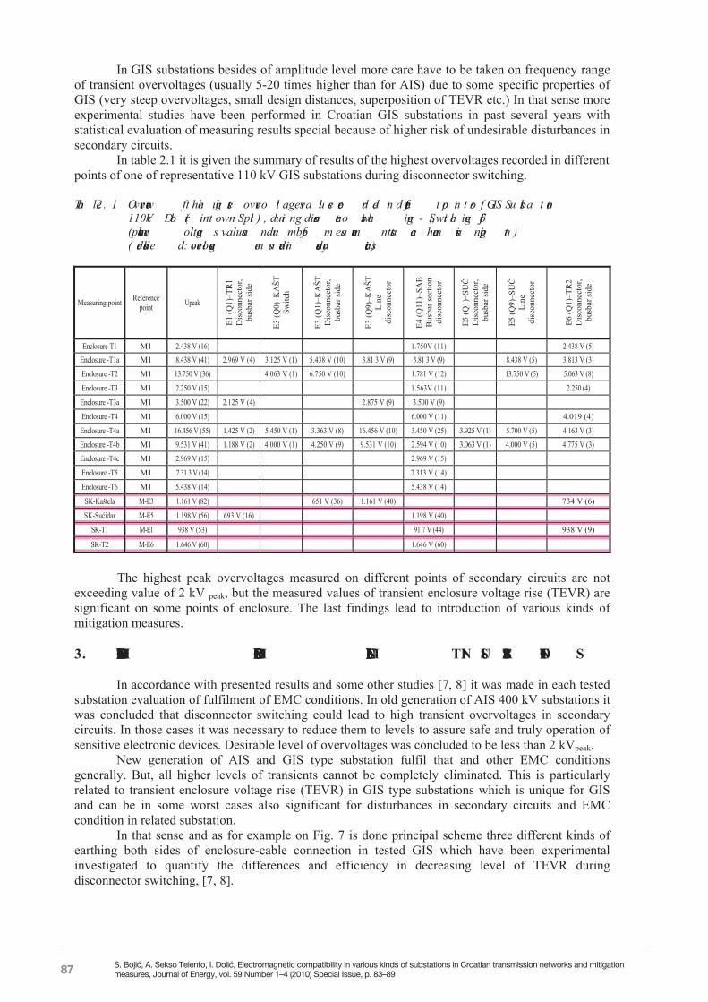
In table 2.1 it is given the summary of results of the highest overvoltages recorded in different points of one of representative 110 kV GIS substations during disconnector switching.
Table 2.1 Overview of the highest overvoltages values recorded in different points of GIS Substation
110 kV Dobri (in town Split), during disconnectors switching-„Switching off”(peak overvoltages values and number of measurements at each measuring point)(red sheded: overvoltages measured in secondary circuits)
Measuring point Reference point Upeak
E1 (Q
1)–T
R1
Dis
conn
ecto
r, bu
sbar
side
E3 (Q
0)–K
AŠT
Sw
itch
E3 (Q
1)–K
AŠT
D
isco
nnec
tor,
busb
ar si
de
E3 (Q
9)–K
AŠT
Li
ne
disc
onne
ctor
E4 (Q
11)–
SAB
B
usba
r sec
tion
disc
onne
ctor
E5 (Q
1)–S
UČ
D
isco
nnec
tor,
busb
ar si
de
E5 (Q
9)–S
UČ
Li
ne
disc
onne
ctor
E6 (Q
1)–T
R2
Dis
conn
ecto
r, bu
sbar
side
Enclosure-T1 M1 2.438 V (16) 1.750V (11) 2.438 V (5) Enclosure -T1a M1 8.438 V (41) 2.969 V (4) 3.125 V (1) 5.438 V (10) 3.81 3 V (9) 3.81 3 V (9) 8.438 V (5) 3.813 V (3)
Enclosure -T2 M1 13.750 V (36) 4.063 V (1) 6.750 V (10) 1.781 V (12) 13.750 V (5) 5.063 V (8)
Enclosure -T3 M1 2.250 V (15) 1.563V (11) 2.250 (4)
Enclosure -T3a M1 3.500 V (22) 2.125 V (4) 2.875 V (9) 3.500 V (9)
Enclosure -T4 M1 6.000 V (15) 6.000 V (11) 4.019 (4)
Enclosure -T4a M1 16.456 V (55) 1.425 V (2) 5.450 V (1) 3.363 V (8) 16.456 V (10) 3.450 V (25) 3.925 V (1) 5.700 V (5) 4.163 V (3)
Enclosure -T4b M1 9.531 V (41) 1.188 V (2) 4.000 V (1) 4.250 V (9) 9.531 V (10) 2.594 V (10) 3.063 V (1) 4.000 V (5) 4.775 V (3)
Enclosure -T4c M1 2.969 V (15) 2.969 V (15)
Enclosure -T5 M1 7.31 3 V (14) 7.313 V (14)
Enclosure -T6 M1 5.438 V (14) 5.438 V (14)
SK-Kaštela M-E3 1.161 V (82) 651 V (36) 1.161 V (40) 734 V (6)
SK-Sućidar M-E5 1.198 V (56) 693 V (16) 1.198 V (40)
SK-T1 M-E1 938 V (53) 91 7 V (44) 938 V (9)
SK-T2 M-E6 1.646 V (60) 1.646 V (60)
The highest peak overvoltages measured on different points of secondary circuits are not
exceeding value of 2 kV peak, but the measured values of transient enclosure voltage rise (TEVR) are significant on some points of enclosure. The last findings lead to introduction of various kinds of mitigation measures.
3. MITIGATION MEASURES FOR EMC FULFILMENT IN SUBSTATIONS
In accordance with presented results and some other studies [7, 8] it was made in each tested
substation evaluation of fulfilment of EMC conditions. In old generation of AIS 400 kV substations it was concluded that disconnector switching could lead to high transient overvoltages in secondary circuits. In those cases it was necessary to reduce them to levels to assure safe and truly operation of sensitive electronic devices. Desirable level of overvoltages was concluded to be less than 2 kVpeak.
New generation of AIS and GIS type substation fulfil that and other EMC conditions generally. But, all higher levels of transients cannot be completely eliminated. This is particularly related to transient enclosure voltage rise (TEVR) in GIS type substations which is unique for GIS and can be in some worst cases also significant for disturbances in secondary circuits and EMC condition in related substation.
In that sense and as for example on Fig. 7 is done principal scheme three different kinds of earthing both sides of enclosure-cable connection in tested GIS which have been experimental investigated to quantify the differences and efficiency in decreasing level of TEVR during disconnector switching, [7, 8].
5
S. Bojić, A. Sekso Telento, I. Dolić, Electromagnetic compatibility in various kinds of substations in Croatian transmission networks and mitigation measures, Journal of Energy, vol. 59 Number 1–4 (2010) Special Issue, p. 83–89

88
Rope
K2
B
A
Tape
Earthing box
K3
Tape
B
A
E
Rope
Earthing
box
MOV
Rope
K4
A
B
Tape
Earthingbox
A B E measuring points
Fig. 7. Test configurations to determine efficiency of different kinds of earthing interconnected GIS enclosure and cable terminals on TEVR level
Measurements have been repeated several times in the same configurations to get representative samples for farther statistical evaluation. Summary of statistical evaluated results is described as bar diagrams Fig. 8 (left part of figure). From the diagrams is evident the influence of low inductance earthing on both sides of enclosure-cable interconnection in significant mitigation TEVR in tested GIS.
0
10
20
30
40
50
60
K2C
able - metallic
screen (A)
K2 S
hield (B)
K2 Grounding
busbar(C
)
K2 Supporting
pylon(D
)
K3C
able - metallic
screen (A)
K3 Shield
(B)
K4C
able - metallic
screen (A)
K4 Shield
(B)
EL-TO ZG
- Cable
terminations*
EL-TO ZG
- GIS
metal
enclosure*
EL-TO - Earthing of a
bushing*
EL-TO ZG
secondary circuits*
TS Zadar - Centar
secondary circuits
TS D
obrisecondary circuits *
Configuration, Measuring point
Volta
ge [k
V]
0,0
0,1
0,2
0,3
0,4
0,5
0,6
Volta
ge [p
.u.]
k98max
Interval of maximum theoretical expected value (sampling method)
Interval of maximum measured values (samples)
Average value of samples
Interval of other lower values measured during disconnectorswitchingValues according to model
* Values from individual measurements
Fig. 7. Summary of results of tested configurations to determine efficiency of different kinds of earthing interconnected GIS enclosure and cable terminals on TEVR level; Transient overvoltages in secondary circuits measured in three different GIS substations (in red frame)
6
S. Bojić, A. Sekso Telento, I. Dolić, Electromagnetic compatibility in various kinds of substations in Croatian transmission networks and mitigation measures, Journal of Energy, vol. 59 Number 1–4 (2010) Special Issue, p. 83–89
89
But sometimes it is difficult and expensive to carry out enough effective measures. Because of that the most effective way is to predict ways for reducing of overvoltages already in the phase of design of new substations. In that sense experiences with measurements in existing substations are essential.
4. MAIN CONCLUSIONS AND LESSONS LEARNED Some main conclusions from measuring investigations of transient overvoltages in secondary circuits in different kind of Croatian 110 kV and 400 kV substations may be briefly stated as follows. 1. Overvoltages within old types of AIS substations are generally higher and often need reductions 2. GIS substations showed lower level of peak values of transient overvoltages in comparison to AIS substations, but generally have higher frequency range and some specific problems (TEVR) 3. Various mitigation measures undertaken after first measurements showed good suppressive effects 4. It was decided to carry out measuring investigations in all type of substations periodically and according to IEC and other regulations 5. Computing methods of investigations of EMC conditions is considered as useful in design phase for new substations and may be validated only through measuring investigations with special and sophisticated equipment. BIBLIOGRAPHY [1] CIGRE: Monograph on GIS Very Fast Transients, Presented by Working Group 33/13.09, Paris
July 1989 [2] CIGRE: Earthing of GIS: An application guide, Technical Brochure Ref. 044, Paris 1993 [3] CIGRE: Guide on EMC in power plants and substations, Technical Brochure Ref. 126, Paris
1997 [4] A. Sekso: Limitations of overvoltages in secondary circuits of HV substations and EMC
problems (Study in Croatian), Institute for Electric Power Industry, Zagreb 1983 [5] R. Naumov, P. Vukelja, N. Jokanović, A. Sekso: Induced voltages in secondary circuits of 400
kV substation Ernestinovo (Study in Serbian), Institute Nikola Tesla, Belgrade 1985 [6] R. Naumov, P. Vukelja: Experimental investigations of transient overvoltages in secondary
circuits of 400 kV and 220 kV HV substations, CIGRE Symposium “Power system EMC”, Paper No. 500-05, Laussane 1993
[7] S. Bojić, I. Uglešić: Research of the efficiency of measures for decreasing of TEVR in GIS, Proceedings IPST, Paper 090, pp. 25-30 , Rio de Janeiro 2001
[8 S. Bojić: Enclosure voltage rise in HV switchgears due to disconnector switching, M. Sc. Thesis (Croatian), University of Zagreb, Zagreb 2002
[9] A. Sekso Telento, S. Bojić: Measurements of overvoltages in secondary circuits for EMC evaluation in transmission network substations, Paper No.P.05.50 on XIIIth Symposium on High Voltage Engineering, Delft, Netherlands, 2003
[10] Ž. Štih, S. Berberović, Z. Haznadar, S. Banić: Analysis of EMC in 400 kV substation Ernestinovo, Paper No. C4-12 (in Croatian), Proceedings of 6th Session of Croatian NC CIGRE, pp 115-124, Cavtat 2003
[11] J. Šimić, S. Gross: Electromagnetic environment and immunity of equipment to EM disturbances in power system objects, Ibid. Paper No. C4-11, pp. 105 - 114
[12] S. Banić, B. Pinčić, B. Glavan, M. Rončević, V. Ilijanić. Analysis of HV substation parameters which influence to EMC, Paper No. C4-07 (in Croatian) on 7th Session of Croatian NC CIGRE, Cavtat 2005
7
S. Bojić, A. Sekso Telento, I. Dolić, Electromagnetic compatibility in various kinds of substations in Croatian transmission networks and mitigation measures, Journal of Energy, vol. 59 Number 1–4 (2010) Special Issue, p. 83–89


