Embed Size (px)
Citation preview
/542
www.ietdl.org
Published in IET Generation, Transmission & DistributionReceived on 25th June 2007Revised on 26th September 2007doi: 10.1049/iet-gtd:20070281
ISSN 1751-8687
Kalman filter based synchronisation methodsR. Cardoso1 R.F. de Camargo2 H. Pinheiro2 H.A. Grundling21Federal University of Technology – Parana – UTFPR, Industrial Automation Research Group – GPAI, Campus Pato Branco,Via do Conhecimento, Km1, Pato Branco, PR, CEP 85503-390, Brazil2Federal University of Santa Maria – UFSM, Center of Technology – CT, Power Electronics and Control ResearchGroup – GEPOC, Av. Roraima S/N, Campus Camobi, Santa Maria, RS, CEP 97105-900, BrazilE-mail: [email protected]
Abstract: Single- and three-phase synchronisation methods based on optimum filtering theory are proposed.These methods are based mainly on the Kalman filter and are therefore termed Kalman filter-phase lockedloop. They explicitly include in the problem formulation the presence of harmonics, voltage unbalance,measurement noise, transients and frequency deviation. Such perturbations degrade the performance ofmany synchronisation structures presented in literature. The formulation presented here makes thesynchronisation signals less sensitive to these perturbations. It is also shown that the proposed methods canbe helpful by also providing the amplitude, instantaneous phase and frequency of grid voltages that can beuseful for the analysis of power quality. Furthermore, the Kalman filter provides a way of obtaining the bestcompromise between transient response and measurement noise rejection for the synchronisation signals.The paper sets out the development of the proposed methods together with the choice of tuningparameters and their physical meaning. Simulations and experimental results using a DSP TMS320F2812 arepresented to show the effectiveness of the proposed schemes.
1 IntroductionDetermining the phase angle of grid voltages isimportant for many power conditioning devices suchas active power filters, reactive power compensators,uninterruptible power supplies, among others, thatmust be appropriately synchronised with grid voltages.Another application where synchronisation plays animportant role is on distributed power generationsystems [1]. Because of the dynamic nature of thepower system, the synchronisation method chosenmust be capable of rejecting many perturbationsinherent to the system, such as harmonics, voltagesags and swells, imbalance, frequency deviations,measurement noise and phase angle jump [2, 3].
A traditional approach for the extraction of the phaseangle is the use of closed-loop techniques, such asthe phase-locked loops (PLLs) [4]. For three-phaseapplications, the phase angle is usually obtainedby means of the well-known synchronous referenceframe PLL. Implementation of these methods is
IET Gener. Transm. Distrib., 2008, Vol. 2, No. 4, pp. 542–555doi: 10.1049/iet-gtd:20070281
straightforward but they suffer from the presence ofharmonics and voltage imbalance as described in [5].Further analysis of the behaviour of the synchronousreference frame PLL under distorted and unbalancedutility conditions can be found in [6], where sometuning recommendations are also made to minimise theimpact of the harmonics and voltage unbalance in thephase angle tracking. In [7], an improved PLL, based ona repetitive controller, is proposed. This PLL has simplestructure and is capable to reject the negative sequence.
Another closed-loop approach recently proposed isthe enhanced phase-locked loop (EPLL) [3]. Thisstructure is based on use of the gradient method andthree gains are used to tune the algorithm. Like thePLL, the choice of its gains will influence its trackingcapability. Since there is no rule to guide the choice ofthe gains, tuning them by trial and error can betedious. The concept of the EPLL is furtherelaborated in [8] and a new dual EPLL (DEPLL) isdiscussed. According to the authors, the DEPLL canlead to detection errors under certain grid conditions.
& The Institution of Engineering and Technology 2008
& T
www.ietdl.org
The dual second order generalized integrator-frequencylocked loop was later proposed to overcome thedrawbacks of the DEPLL.
Open-loop techniques have also been described in theliterature. Reference [9] proposes an approach based onweighted least-squares that is capable of rejecting theeffects of the negative-sequence and of accommodatingfrequency variations. However it is sensitive to thepresence of noise and harmonics in the voltages andpresents long transients in detecting frequency variations.Another simple method is the PLL based on low-passfilters (LPF-PLL) [2]. This method is simple but hasshortcomings. The filtering process introduces phaseshift that must be compensated by a rotation matrix. Thephase shift is a function of the frequency and, since thismethod does not consider frequency variations, fullcompensation of the phase shift is not possible. Voltageimbalance is also not considered and there must be atrade-off between harmonics rejection and convergencespeed, defined by the cut-off frequency of the LPFs.Because of oscillatory behaviour its use is notrecommended for systems subjected to phase jumps [2].
A recently proposed synchronisation method, thenormalized positive synchronous frame (NPSF), is alsobased on LPFs and considers voltage imbalance andfrequency deviations [10]. In this method, the cut-offfrequency of the LPFs tracks the grid frequency basedon an adaptation algorithm. This main drawback isthat the only tuning parameter is the convergence rateof the frequency identifier. Neither the convergencespeed nor harmonic rejection can be modifiedsince the cut-off frequencies of the LPFs must be thesame as the grid frequency.
A possible alternative to extract the phase angle of asignal is the use of the Kalman filter [11]. This filter iswell known due its ability to deal with linear systemscorrupted by uncertainties in the states of the plant aswell as measurement noise. The spectrum of this typeof noise is usually distributed over a wide range offrequencies which can be modelled as white noise [12].The elimination of this perturbation by traditionalfiltering methods is not straightforward because of thesignificant phase changes that the signal can suffer. Sincethe Kalman filter is an optimal algorithm that considersthis type of perturbation in its formulation, it becomesa promising alternative for extracting the phaseinformation of a noisy signal of interest.
Some authors have already studied the relationsbetween the Kalman filter and the PLL [13–17]. Thesynchronisation methods based on the Kalman filterare used, basically, in telecommunication systems anddo not consider the presence of disturbances in thesignal of interest such as harmonics and voltages sagsand swells as occur in the power system; nor are they
he Institution of Engineering and Technology 2008 IE
appropriate for three-phase systems. Another approachis the use of the extended Kalman filter [2]. However,the extended Kalman filter uses linearisations aroundthe estimates provided by the filter. Since thelinearisations are applied using the last availableestimate, the propagation equations are only valid ifthe estimate is not very distant from the actual state[18]. Moreover an arbitrary choice of the filtercovariance matrices together with initial filter statesnot sufficiently close to the actual states may lead to afilter that fails to converge [19].
This paper proposes single- and three-phasesynchronisation methods based on the Kalman filter.They are termed the Kalman filter-phase locked loop(KF-PLL). As will be shown, the Kalman gain can beevaluated off-line, so that the filter can be implementedusing fixed gains, simplifying its implementation.The proposal is capable of generating thesynchronization signals even with input signals thatcontain harmonics and measurement noise. To achievethis, a mathematical model is used that considers theexistence of harmonics in the signal, and which alsoallows for the possible occurrence of transient voltages.As this model involves the grid frequency, theperformance of the filter may be reduced if the gridfrequency deviates from the value considered in thefilter. Therefore, the fundamental grid frequency is alsoidentified and is used to update the mathematicalmodel used in the filter. The identification procedure isbased on the internal model principle [20] in a waysimilar to that presented in [21]. However, the presentidentification method uses a modified input signal and,in contrast to [21], the algorithm is entirely derived indiscrete form. The first discrete implementation ofsuch algorithm appeared in [22] but their derivation isnot clear. In this paper, the discrete derivation isentirely presented for a better understanding of itsdiscrete implementation. For the three-phase case, thepossibility of voltage imbalance is also considered, andsince the Kalman filter is an optimum algorithm, theresults represent a good compromise between transientresponse and disturbance rejection. If the stochasticmodel of the process to be filtered is completelyknown, the obtained results are optimum according toseveral optimisation criteria [23].
The performance of the proposed synchronisationstructures is assessed based on comparisons with othermethods presented in literature. Preliminary resultscan be found in [24]. In this paper, differently of [24],the classical synchronous reference frame PLL isincluded in the comparative analysis and performanceunder voltage sag, sinusoidal and non-sinusoidal gridvoltages are also addressed. For the three-phase case,results are compared with those from the EPLL [3],from the NPSF [10] and from the synchronousreference frame PLL [5]. For the single-phase case,
T Gener. Transm. Distrib., 2008, Vol. 2, No. 4, pp. 542–555/doi: 10.1049/iet-gtd:20070281
543
544
www.ietdl.org
results are compared with those from the EPLL andfrom the transport delay based PLL [25].
This paper is organised as follows: Section 2 presentsthe Kalman filter equations. Section 3 introduces themathematical modelling of a signal with harmonics.The grid frequency identification is described inSection 4. The proposed synchronisation methods aredeveloped in Section 5. Section 6 shows resultsobtained from comparisons of performance. Resultsof digital implementation in a fixed point DSPTMS320F2812 are shown in Section 7. Finally, theresults of real time experiments are given in Section 8.
2 Kalman filter algorithmConsider a discrete linear dynamic stochastic systemmodelled by
xkþ1 ¼ Fkxk þ Gkgk (1)
yk ¼ Fkxk þ yk (2)
dim xk ¼ n� 1, dim yk ¼ r � 1,
dim gk ¼ p� 1 (3)
where gk and y k are independent Gaussian white noisewith means and covariances given by
E{gi} ¼ 0, E{gigTj } ¼ Q idij (4)
E{yi} ¼ 0, E{yiyTj } ¼ Ridij (5)
E{giyTj } ¼ 0, E{gix
Tj } ¼ 0,
E{yixTj } ¼ 0, 8i, j (6)
where Ef.g denotes the expectation mathematicaloperator and dij denotes the Kronecker Delta function.The matricesfk,Gk and Fk have appropriate dimensions.
Denoting by xkþ1jk the estimate of xkþ1 based on allthe measurements up to k, the filtering equation as givenin [26] is
xkþ1jk ¼ Fkxkjk�1 þ Kk( yk � Fkxkjk�1) (7)
where
Kk ¼ FkPkjk�1FTk (FkPkjk�1F
Tk þ Rk)
�1 (8)
is the Kalman gain and
Pkþ1jk ¼ FkPkjk�1FTk � KkFkPkjk�1F
Tk
þ GkQ kGTk (9)
/IET Gener. Transm. Distrib., 2008, Vol. 2, No. 4, pp. 542–555doi: 10.1049/iet-gtd:20070281
is the covariance matrix of the estimation error of thevector xkþ1 evaluated at time tk
Pkþ1jk W E{(xkþ1 � xkþ1jk)(xkþ1 � xkþ1jk)T} (10)
The initial conditions are given by x0j�1 and P0j21.Further details can be found in [26].
3 Mathematical modelling ofa signal with harmonicsTo use the Kalman filter described in Section 2 amathematical model is needed that describes the processto be filtered. This section describes how to obtain amathematical model that adequately represents the gridvoltages dynamics. Initially a signal is considered whichcontains only the fundamental component; harmoniccomponents are introduced subsequently.
Consider a signal with amplitude Ak, angularfrequency vk and phase uk
Sk ¼ Ak sin(vktk þ uk) (11)
Let
x1k ¼ Ak sin(vktk þ uk) (12)
and
x2k ¼ Ak cos(vktk þ uk) (13)
Initially, consider Akþ1 ’ Ak, vkþ1 ’ vk and ukþ1 ’ uk.At the time tkþ1 ¼ tkþ Ts the signal Skþ1 can be expressedas
Skþ1 ¼ Akþ1 sin(vktk þ vkTs þ ukþ1) ¼ x1kþ1
¼ x1k cos(vkTs)þ x2k sin(vkTs) (14)
where Ts is the sampling period.
Additionally
x2kþ1¼ Akþ1 cos(vktk þ vkTs þ ukþ1)
¼ �x1k sin(vkTs)þ x2k cos(vkTs) (15)
To model amplitude or phase variations in the signal, aperturbation vector [g1 g2]k
T in the system states isconsidered. The state space representation of the
& The Institution of Engineering and Technology 2008
& T
www.ietdl.org
signal then becomes
x1x2
� �kþ1
¼cos(vkTs) sin(vkTs)
� sin(vkTs) cos(vkTs)
� �x1x2
� �k
þg1
g2
� �k
(16)
yk ¼ 1 0� � x1
x2
� �k
þ yk (17)
where y k represents the measurement noise.
If there are n frequencies in the signal Sk, that is
Sk ¼Xni¼1
Aik sin(ivktk þ uik) (18)
the state space representation of the signal becomes
x1x2
..
.
x2n�1
x2n
266666664
377777775
kþ1
¼
M1 � � � 0
..
. . .. ..
.
0 � � � Mn
264
375
k
�
x1x2
..
.
x2n�1
x2n
266666664
377777775
k
þ
g1
g2
..
.
g2n�1
g2n
266666664
377777775
k
(19)
yk ¼ 1 0 � � � 1 0� �
x1x2
..
.
x2n�1
x2n
2666664
3777775
k
þ yk (20)
where
Mi ¼cos(ivkTs) sin(ivkTs)� sin(ivkTs) cos(ivkTs)
� �(21)
The perturbation vector [g1 g2... g2n21 g2n]k
T modelsamplitude or phase variations of each harmoniccomponent of the signal and its covariance is given by
he Institution of Engineering and Technology 2008 IE
matrix Q , defined by (4). The covariance of themeasurement noise y k is given by R as defined in (5).
The mathematical model (19)–(21) has the sameform as the mathematical model (1), (2) used in theKalman filter. Note that this model needs the value ofthe angular grid frequency that can be subject todeviations from its nominal value. Usually, in stiffgrids this is not a concern since it must be regulatedbetween +1 Hz in accordance to IEC 61000-2-2 [27].However even in stiff grids some disturbances can leadto frequency deviations outside these limits [28]. Inweak grids, such as autonomous systems, largerfrequency variations can occur. If the frequencyconsidered in the mathematical model differs from thereal value, the estimates provided by the filter willnot be accurate. It is therefore necessary to identifythe grid frequency in real time to update the modelused in the Kalman filter. This is accomplished by themethod given in next section.
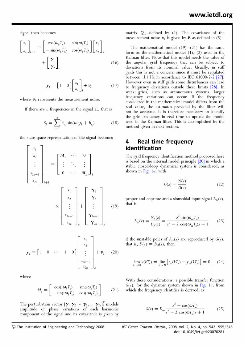
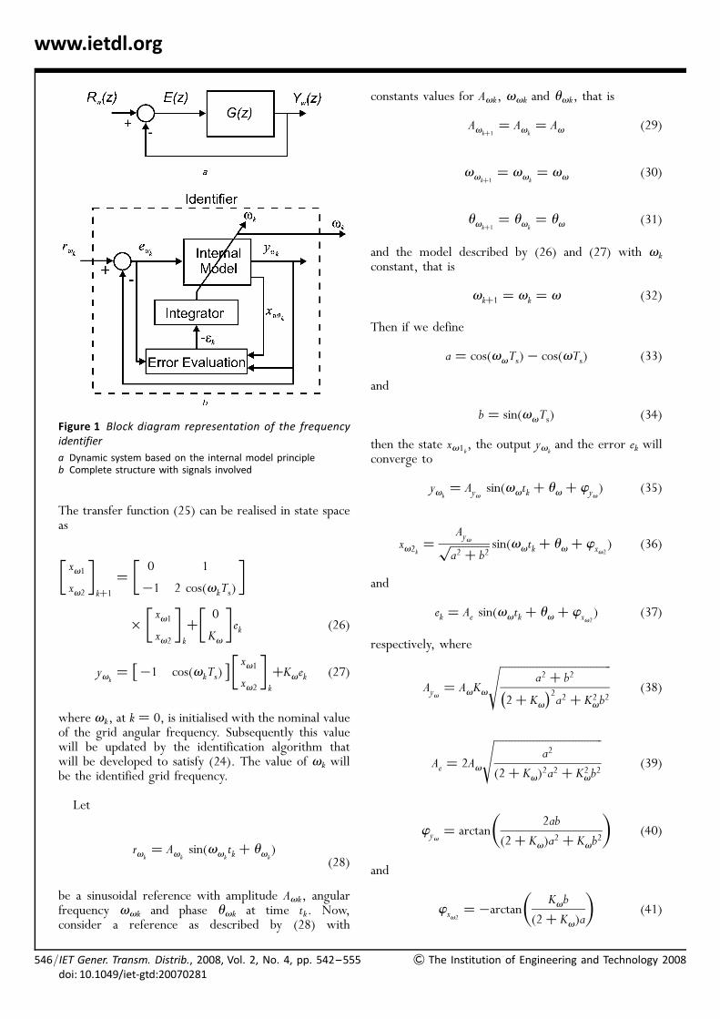
4 Real time frequencyidentificationThe grid frequency identification method proposed hereis based on the internal model principle [20] in which astable closed-loop dynamical system is considered, asshown in Fig. 1a, with
G(z) ¼N(z)
D(z)(22)
proper and coprime and a sinusoidal input signal Rv(z),that is
Rv(z) ¼NR(z)
DR(z)¼
z2 sin(vvTs)
z2 � 2 cos(vvTs)zþ 1(23)
if the unstable poles of Rv(z) are reproduced by G(z),that is, D(z) ¼ DR(z), then
limk!1
e(kTs) ¼ limk!1
rv(kTs)� yv(kTs)� �
¼ 0 (24)
With these considerations, a possible transfer functionG(z), for the dynamic system shown in Fig. 1a, fromwhich the frequency identifier is derived, is
G(z) ¼ Kvz2 � cos(vTs)
z2 � 2 cos(vTs)zþ 1(25)
T Gener. Transm. Distrib., 2008, Vol. 2, No. 4, pp. 542–555/doi: 10.1049/iet-gtd:20070281
545
/546
www.ietdl.org
The transfer function (25) can be realised in state spaceas
xv1xv2
� �kþ1
¼0 1
�1 2 cos(vkTs)
� �
�xv1xv2
� �k
þ0
Kv
� �ek (26)
yvk¼ �1 cos(vkTs)� � xv1
xv2
� �k
þKvek (27)
where vk, at k ¼ 0, is initialised with the nominal valueof the grid angular frequency. Subsequently this valuewill be updated by the identification algorithm thatwill be developed to satisfy (24). The value of vk willbe the identified grid frequency.
Let
rvk¼ Avk
sin(vvktk þ uvk
)(28)
be a sinusoidal reference with amplitude Avk, angularfrequency vvk and phase uvk at time tk. Now,consider a reference as described by (28) with
Figure 1 Block diagram representation of the frequencyidentifier
a Dynamic system based on the internal model principleb Complete structure with signals involved
IET Gener. Transm. Distrib., 2008, Vol. 2, No. 4, pp. 542–555doi: 10.1049/iet-gtd:20070281
constants values for Avk, vvk and uvk, that is
Avkþ1¼ Avk
¼ Av (29)
vvkþ1¼ vvk
¼ vv (30)
uvkþ1¼ uvk
¼ uv (31)
and the model described by (26) and (27) with vkconstant, that is
vkþ1 ¼ vk ¼ v (32)
Then if we define
a ¼ cos(vvTs)� cos(vTs) (33)
and
b ¼ sin(vvTs) (34)
then the state xv1k, the output yvkand the error ek will
converge to
yvk¼ Ayv sin(vvtk þ uv þ wyv
) (35)
xv2k ¼Ayvffiffiffiffiffiffiffiffiffiffiffiffiffia2 þ b2
p sin(vvtk þ uv þ wxv2) (36)
and
ek ¼ Ae sin(vvtk þ uv þ wxv2) (37)
respectively, where
Ayv ¼ AvKv
ffiffiffiffiffiffiffiffiffiffiffiffiffiffiffiffiffiffiffiffiffiffiffiffiffiffiffiffiffiffiffiffiffiffiffiffiffia2 þ b2
2þ Kv� �2
a2 þ K2vb2
s(38)
Ae ¼ 2Av
ffiffiffiffiffiffiffiffiffiffiffiffiffiffiffiffiffiffiffiffiffiffiffiffiffiffiffiffiffiffiffiffiffiffiffiffia2
(2þ Kv)2a2 þ K2vb
2
s(39)
wyv¼ arctan
2ab
(2þ Kv)a2 þ Kvb2
� (40)
and
wxv2¼ �arctan
Kvb
(2þ Kv)a
� (41)
& The Institution of Engineering and Technology 2008
&
www.ietdl.org
When the angular frequency of the driving signal isthe same as the frequency considered in the statespace representation of G(z), that is, when vv ¼ v,yvk
will track the input signal rvkby virtue of (35).
Hence, from (37), in steady-state, ek ¼ 0. Thereforethe error ek provides useful information for theidentification of the angular frequency vv of thedriving signal.
For the proposed discrete model (26) and (27),considering vv ’ v, in steady-state, two orthogonalsignals are obtained
yvk’ Av sin(vvtk þ uv) (42)
and
xv2k ��Av
sin(vv)cos(vvtk þ uv) (43)
Defining fk as
fk ¼ vvtk þ uv (44)
then, the frequency vv can be obtained by
vv ¼fkþ1 � fk
Ts(45)
Using (42) and (43) leads to
tan(fk) ¼sin(vvtk þ uv)
cos(vvtk þ uv)¼
yvk
�sin(vvTs)xv2k(46)
which gives
fk ¼ arctan( tan(fk)) (47)
To obtain tan(fk) in (46), we need to know the angularfrequency vv of the driving signal, which is unknown.By putting vv ’ v, vv is replaced by v. Hence
tan(fk) �yvk
�sin(vTs)xv2k(48)
and
fk � arctanyvk
�sin (vTs)xv2k
!(49)
Instead of using (45) to obtain the derivative of fk, (47)is used together with the definition of the continuousderivative of arctan. Then, the continuous values arereplaced by the discrete ones available at time tk, with
The Institution of Engineering and Technology 2008 IE
continuous derivatives approximated by
d
dt(�) ’ (�)kþ1 � (�)k
Ts(50)
The derivative of arctan is given by
d
dtarctan[ tan(f(t))] ¼
1
1þ tan(f(t))2d
dttan(f(t))
(51)which, by replacing tan(f(t)) by its value at time tk asgiven by (48), using (26) and (27) and re-introducingthe subscript of time k, gives an estimate of thefrequency vv of the driving signal denoted by vvk
vvk’ vk �
1
Ts
Kv sin(vkTs)xv2k ek[sin(vkTs)xv2k ]
2 þ [ yvk]2
(52)
giving the error vvk� vk
vvk� vk ’ �
1
Ts
Kv sin(vkTs)xv2k ek[sin(vkTs)xv2k ]
2 þ [ yvk]2
¼ �1
Ts1k (53)
where
1k ¼Kv sin(vkTs)xv2k ek
[sin(vkTs)xv2k ]2 þ [ yvk
]2(54)
Therefore vk can be updated by
vkþ1 � vk
Ts¼ �Ku
1
Ts1k (55)
giving
vkþ1 ¼ vk � Ku1k (56)
where Ku is again a scalar.
Based on (56) the model (26) and (27) is updated. Thestructure of the identifier is shown in Fig. 1b, where theinternal model is given by (26) and (27), the error 1k isgiven by (54) and the integrator is given by (56).
Since the voltage measurements may be corrupted bymeasurement noise, harmonics and suffer from voltagesags and swells, the use of these measurementsdirectly as rvk
may result in undesirable behaviour ofthe frequency identifier. To avoid it, the synchronisationsignal is used which is generated by the structures
T Gener. Transm. Distrib., 2008, Vol. 2, No. 4, pp. 542–555/doi: 10.1049/iet-gtd:20070281
547
548
www.ietdl.org
proposed in next section. As will be shown, these signalsare already filtered and normalised.
5 Synchronisation methodsThis section develops single- and three-phasesynchronisation methods based on the Kalman filter.The methods are presented based on the estimatesavailable at time tk, that is, xjkk�1. If desired, theproposed methods could be arranged in predictiveform where the synchronisation signals are obtainedusing the predicted estimate xkþ1kj. This can be usefulfor the use of predictive control laws.
5.1 Single-phase synchronisation
For single-phase synchronisation it is necessary togenerate a signal in phase with the fundamentalcomponent of the grid voltage. From (19), it is clearthat
x1k ¼ Ak sin(vktk þ u1k) (57)
and
x2k ¼ Ak cos(vktk þ u1k) (58)
are the orthogonal components of the fundamentalvoltage phasor of the grid voltage. Its instantaneousphase is
fV1k¼ vktk þ u1k (59)
/IET Gener. Transm. Distrib., 2008, Vol. 2, No. 4, pp. 542–555doi: 10.1049/iet-gtd:20070281
From the Kalman filter described in Section 2, withmathematical model of the signal Sk given by (19)–(21), the estimates of the components of thefundamental voltage phasor x1kjk�1 and x2kjk�1 areobtained. Based on these estimates, and assumingAk = 0, the sine and cosine functions are given by
sin(fV1k) ¼
x1kjk�1
Ak¼ rvk
(60)
and
cos(fV1k) ¼
x2kjk�1
Ak(61)
where
Ak ¼ffiffiffiffiffiffiffiffiffiffiffiffiffiffiffiffiffiffiffiffiffiffiffiffix21kjk�1
þ x22kjk�1
q(62)
The angular frequency vk needed in the mathematicalmodel used by the Kalman filter is updated by thealgorithm described in Section 4. The reference signalrvk
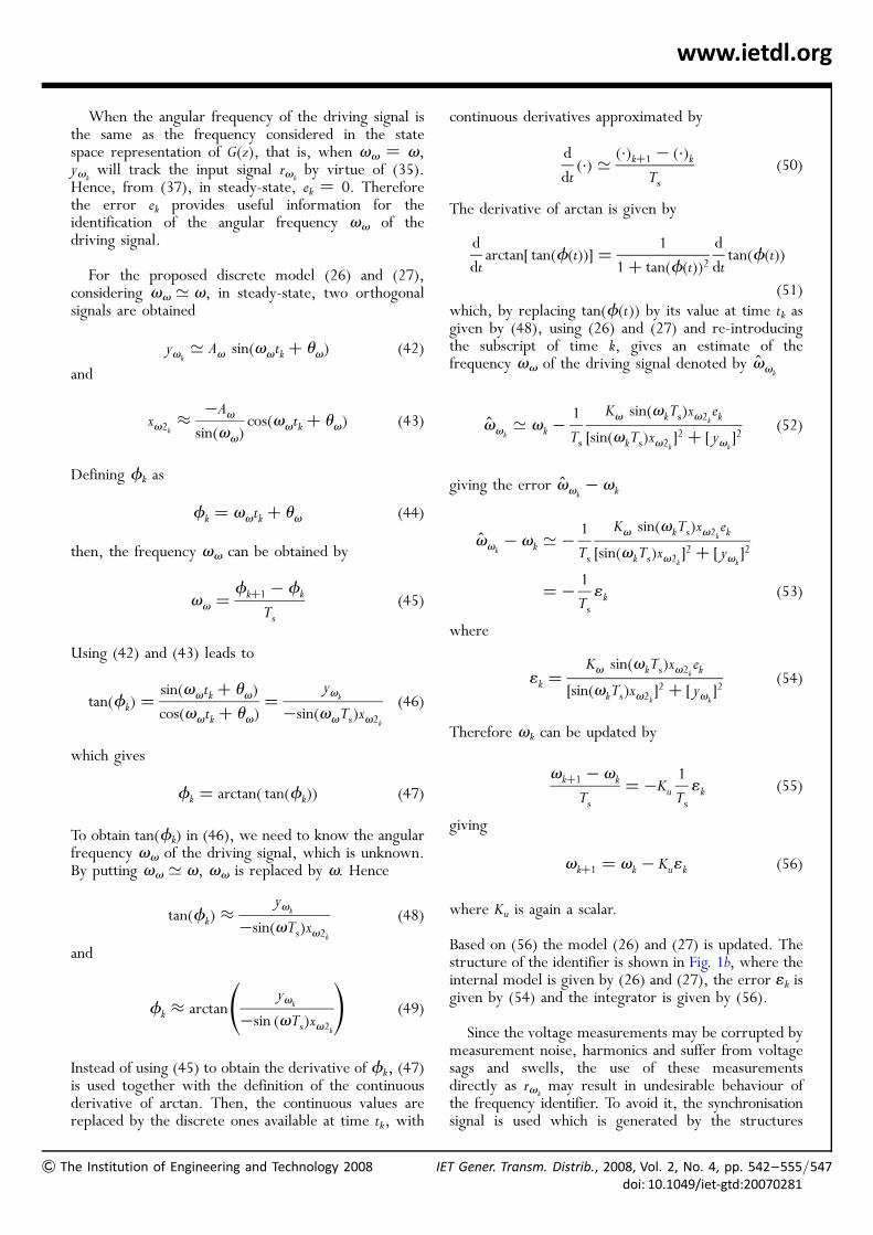
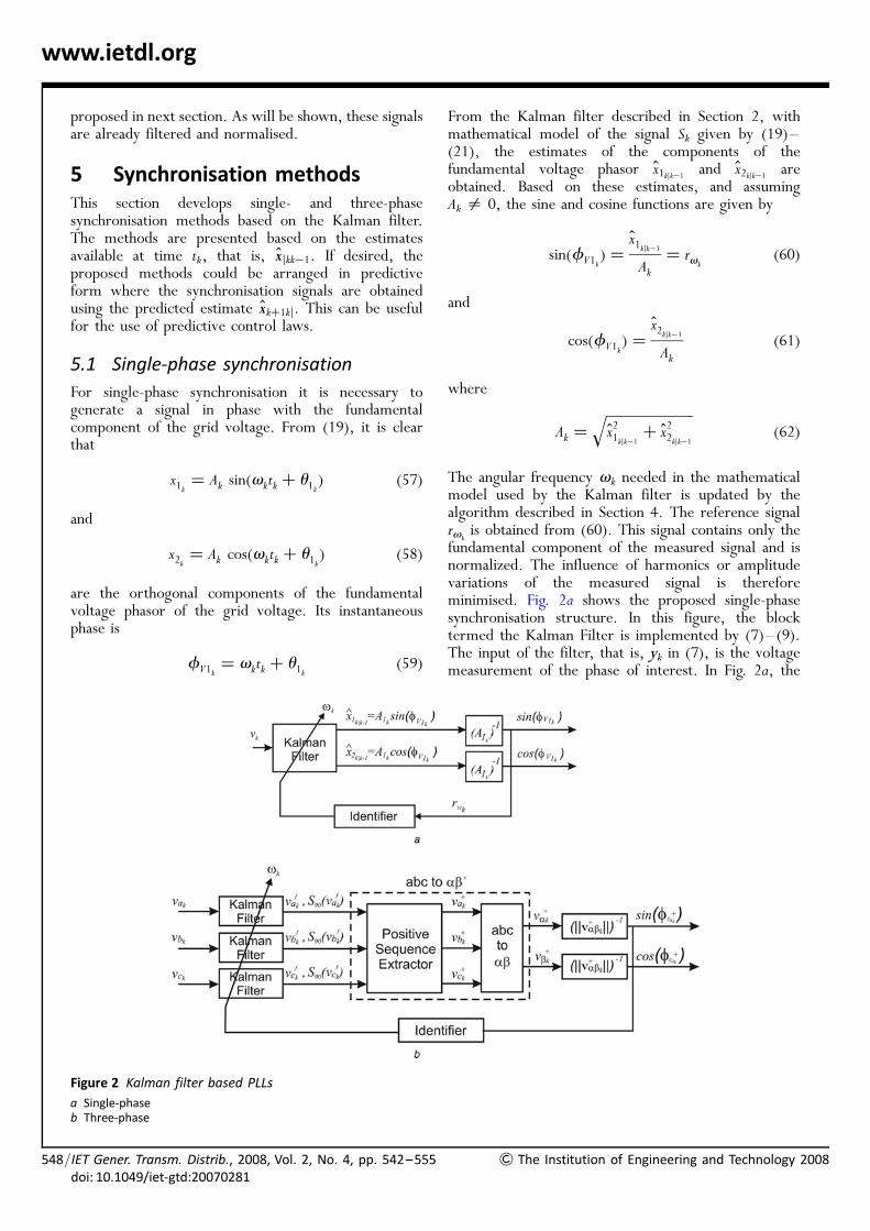
is obtained from (60). This signal contains only thefundamental component of the measured signal and isnormalized. The influence of harmonics or amplitudevariations of the measured signal is thereforeminimised. Fig. 2a shows the proposed single-phasesynchronisation structure. In this figure, the blocktermed the Kalman Filter is implemented by (7)–(9).The input of the filter, that is, yk in (7), is the voltagemeasurement of the phase of interest. In Fig. 2a, the
Figure 2 Kalman filter based PLLs
a Single-phaseb Three-phase
& The Institution of Engineering and Technology 2008
&
www.ietdl.org
input of the filter is represented by vk. The Kalman filterwill provide the estimates of the harmonics included inthe mathematical model (19)–(21) used to describe thesignal. Since the interest is on the fundamentalcomponent, only the first two estimated states x1kjk�1
and x2kjk�1 are used. These estimates are the twoorthogonal signals used to obtain the synchronisationsignals as depicted in Fig. 2a.
The proposed synchronisation method can also beuseful to analyse the grid voltage. From (62) theamplitude of the fundamental component of the gridvoltage can be obtained. From (60) and (61) theinstantaneous phase of the fundamental grid voltagecomponent is found to be
fV1k¼ arctan
x1kjk�1
x2kjk�1
!(63)
5.2 Three-phase synchronisation
Depending on the application, the difficulty in three-phase synchronisation can be greater. The voltagewaveforms may be unbalanced and may containharmonics and measurement noise. In someapplications, such as power conditioning equipment [9,29], distributed generation [3], PWM rectifiers [10]among others, it is desirable that the synchronisationmethod be able to accommodate these perturbationsand provide synchronism signals in phase with thepositive sequence of the fundamental component ofthe grid voltages.
Given the fundamental phase voltages vakf, vbk
f and vckf,
the positive sequence components can be obtainedthrough [30]
vþavþbvþc
24
35
k
¼1
3
1 a a2
a2 1 a
a a2 1
24
35 v f
a
vfb
v fc
24
35
k
(64)
where a ¼ e j1208. Considering e+j1208¼ �(1=2)+ffiffiffi
3p
=2� �
e j908 and defining S90 as the 908 phase shiftoperator, that is, S90 ¼ e j908, (64) can be rewritten as
vþak ¼1
3v fak�1
6(v fbkþ v f
ck)þ
ffiffiffi3
p
6S90(v
fbk� v f
ck)
vþbk ¼ �vþak � vþck
vþck ¼1
3v fck�1
6(v fakþ v
fbk)þ
ffiffiffi3
p
6S90(v
fak� v
fbk)
(65)
The values of v fak, v fbk, v f
ck and its in quadraturecomponents S90(v
fak), S90(v
fbk) and S90(v
fck) are obtained
The Institution of Engineering and Technology 2008 IE
directly from the Kalman filter because of (57) and(58). That is, v f
ak¼ xa1kjk�1
, vfbk ¼ xb1kjk�1
, v fck¼ xc1kjk�1
and S90(v fak) ¼ xa2kjk�1
, S90(vfbk ) ¼ xb2kjk�1
, S90(v fck) ¼
xc2kjk�1, where the superscripts a, b and c indicate the
filter associated to each phase. This avoids the needfor additional filters to provide the phase shiftrequired in the fundamental component to obtain thein quadrature components of the voltages.
To obtain the synchronism signals the positivesequence components are represented in the stationaryreference frame ab
vþavþb
� �k
¼2
31 �1=2 �1=20 �
ffiffiffi3
p=2
ffiffiffi3
p=2
� � vþavþbvþc
24
35
k
(66)
To simplify the transforms (65) and (66), they can becombined as
vþab ¼ T1vfabck
þ T2S90vfabck
(67)
where
vþabk¼
vþavþb
� �k
, vfabck ¼v favfb
v fc
24
35
k
(68)
T1 ¼2
31=2 �1=4 �1=40 �
ffiffiffi3
p=4
ffiffiffi3
p=4
� �(69)
and
T2 ¼2
30
ffiffiffi3
p=4 �
ffiffiffi3
p=4
1=2 �1=4 �1=4
� �(70)
Therefore considering kvþabkk = 0 the synchronism
signals are given by
sin(fþVak) ¼
vþak
kvþabkk¼ rvk
(71)
and
cos(fþVak) ¼
vþbk
kvþabkk
(72)
where
kvþabkk ¼
ffiffiffiffiffiffiffiffiffiffiffiffiffiffiffiffiffiffiffiffiffiffiffiffiffiffi(vþak
)2 þ (vþbk)2
q(73)
T Gener. Transm. Distrib., 2008, Vol. 2, No. 4, pp. 542–555/doi: 10.1049/iet-gtd:20070281
549
/550
www.ietdl.org
The angular frequency in the mathematical model usedby the Kalman filter is updated again by the algorithmset out in Section 4. The reference signal rvk
isobtained from (71). Fig. 2b shows the proposed three-phase synchronisation method. Similarly to the single-phase case, the signals vak, vbk and vck, in Fig. 2b, arethe inputs of three Kalman filters used to decomposethe grid voltages of each phase in the harmoniccomponents considered in the signal model. Fromeach filter, the first two orthogonal estimated statesare used by the positive sequence extractor block, thatis, vak
f, vbkf, vck
f and its in quadrature componentsS90(vak
f), S90(vbkf) and S90(vck
f). Note that to reduce theprocessing time, the positive sequence extractor andabc to ab blocks are combined as show by (67).
As in the single-phase case, the three-phase method canprovide useful information about the positive sequenceof the grid voltages. The instantaneous phase can beobtained from (71) and (72)
fþVak
¼ arctanvþak
vþbk
!(74)
while the amplitude of the positive sequence component is
Aþk ¼ kvþabkk (75)
6 Performance comparisonThe performance of the proposed synchronisationmethods was analysed by means of simulation. Thethree-phase method was compared with threesynchronisation methods. Two of them were asrecently proposed: namely the EPLL [3] and the NPSF[10]. The third is the PLL based on the synchronousreference frame [5]. The proposed single-phasemethod is compared with the EPLL and the transport-delay PLL [25].
To specify the comparison scenario,recommendations of international standards wereconsidered with simulations calculated using Matlab.The compatibility level for the total harmonicdistortion, in accordance with IEC 61000-2-2 [27] isTHD ¼ 8% for long-term effects and THD ¼ 11%for short-term effects. The IEEE Std 519-1992[31] is stricter, recommending THD ¼ 5% or less,depending on the bus voltage. Voltages were thereforesuch that THD ¼ 11.5%. The harmonic componentswere set as follows: 0.1 pu of fifth, 0.05 pu of seventhand 0.03 pu of 11th. The measurement noise had zeromean and covariance R ¼ 200 V2. The nominalfrequency of the fundamental voltage components wasf ¼ 60 Hz and ignoring voltage imbalance, the
IET Gener. Transm. Distrib., 2008, Vol. 2, No. 4, pp. 542–555doi: 10.1049/iet-gtd:20070281
fundamental phase voltages are
v fa ¼
ffiffiffi2
p� 127/08V,
vfb ¼
ffiffiffi2
p� 127/� 1208V
v fc ¼
ffiffiffi2
p� 127/þ 1208V
(76)
The compatibility level for imbalance is a negativesequence component of 2% of the positive sequencecomponent, in accordance to IEC 61000-2-2. The IEC60034 [32] requires generators to deliver continuously-rated output at the rated power factor over the rangesof +5% in voltage. In simulations, an imbalance of20.2 pu in phase c was accepted. Unless otherwiseindicated, these waveforms were used in the tests thatfollow.
Temporary power frequency variation is allowedwithin the range of +1 Hz of the nominal frequency inaccordance to IEC 61000-2-2. Frequency deviation isalso addressed by IEEE Std C37.106-2003 [33] whichlimits the operation of synchronous generators outsidethe nominal operation frequency. The limits range from57–63 Hz depending on the type of turbine. Thestandard IEC 60034 allows a frequency variation of+2% and outside these limits recommends that theoperation be limited in extent, duration and frequencyof occurrence. This information is useful for simplifyingthe digital implementation of the synchronisationmethods proposed in this paper, as will be shown inSection 7.
To compare different synchronisation methods, ascenario was used in which all algorithms presentedthe same transient behaviour. Since the NPSF is basedon LPFs there is no flexibility in the tuning ofthe transient response. Hence, its response is used asreference for tuning of the other synchronisationstructures. The sampling frequency is 10.5 kHz.
The mathematical model used in the Kalman filter ofthe proposed method incorporates the fundamental, 3rd,5th, 7th and 11th harmonics. The covariance of themeasurement noise is set to R ¼ 200 V2 and arisesfrom the covariance used in the generation of themeasurement noise in the simulations. The covarianceof the process noise is set to Q ¼ 0.05 � I10�10V
2 andis defined to produce a similar transient response of theother methods analysed. In fact in practice, bothmatrices Q and R can be identified by using whiteningtechniques as presented in [34, 35].
To design the transfer function gain Kv, see (25), thenatural frequency is set equal to the nominal angularfrequency of the grid, that is, vn ¼ v ¼ 377 rad/sand a damping coefficient j ¼ 0.707 is used to obtain
& The Institution of Engineering and Technology 2008
&
www.ietdl.org
a transient behaviour that is sufficiently fast but with asmall overshoot. Therefore from the well-knownrelationships [36]
jzj ¼ e�Tsjvn (77)and
/z ¼ Tsvn
ffiffiffiffiffiffiffiffiffiffiffiffi1� j2
p(rad) (78)
replacing the values of vn and j by those defined forthem gives the roots of the closed loop characteristicequation, that is
z ¼ 0:975+ j0:025 (79)
From (79) and the closed-loop characteristic equation,solving for Kv we have Kv ¼ 0.052.
The gain Ku is responsible for the speed ofconvergence of the frequency identifier. DefiningKu ¼ 1/Ti and assuming a constant input applied tothe integrator, Ti represents the time that theintegrator needs for its output to reach the inputvalue, with zero initial conditions. For fastconvergence Ti must have a small value. However, ahigh value for Ku may lead to instability. In thefollowing tests Ti ¼ 0.05 s giving Ku ¼ 20. This gainprovides a satisfactory performance for the integrator.
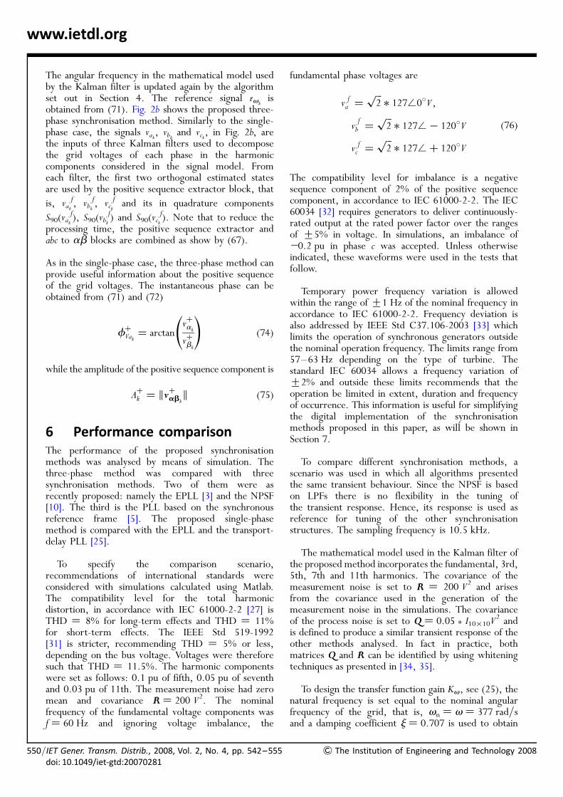
Fig. 3 shows the steady-state RMS error in detection ofthe phase angle when the measurement noise is present.
Figure 3 Performance comparison in presence ofmeasurement noise
a Single-phaseb Three-phase
The Institution of Engineering and Technology 2008 IE
For a signal highly corrupted by noise (S/N ¼ 0 dB), theerror given by methods proposed in this paper is abouthalf that given by the other methods. Reducing thenoise, the performance of the proposed methodsincreases and, above S/N ¼ 25 dB, the RMS error issmaller than 0.58 for the single phase method andsmaller than 0.28 for the three-phase method.
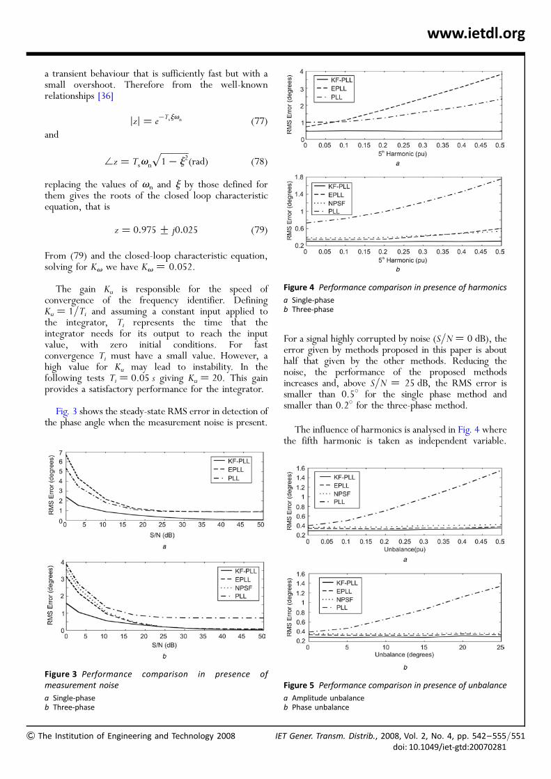
The influence of harmonics is analysed in Fig. 4 wherethe fifth harmonic is taken as independent variable.
Figure 4 Performance comparison in presence of harmonics
a Single-phaseb Three-phase
Figure 5 Performance comparison in presence of unbalance
a Amplitude unbalanceb Phase unbalance
T Gener. Transm. Distrib., 2008, Vol. 2, No. 4, pp. 542–555/doi: 10.1049/iet-gtd:20070281
551
552
www.ietdl.org
The proposed methods are practically insensitive to thepresence of the fifth harmonic as it is varied from zero to0.5 pu. The error is approximately 0.58 for the single-phase method and 0.38 for the three-phase method.
The effect of voltage imbalance is shown in Fig. 5.The amplitude imbalance is generated reducing theamplitude of the voltage of phase c up to 0.5 pu. Thephase imbalance is generated by shifting the voltage ofphase c up to 258. All the algorithms that extract thepositive sequence are insensitive to these perturbationswhile, as expected, the PLL shows an error that is afunction of the voltage imbalance. Again, the KF-PLLperforms better than the other synchronisationmethods.
7 Digital implementationThis section describes the digital implementation of theproposed synchronisation methods in a 32 bits fixed-point DSP (TI-TMS320F2812). In this type of device,
/IET Gener. Transm. Distrib., 2008, Vol. 2, No. 4, pp. 542–555doi: 10.1049/iet-gtd:20070281
special attention must be given to ensure the desiredperformance of the algorithm due the finite wordlength and precision of the device. Therefore to copewith these issues and to improve the performance ofthe algorithms the IQ math library [37] was used.To determine the sampling frequency, two factorsmust be considered: calculation time and the samplingfrequency usually used in power electronic apparatus.If neither the calculation time nor the equipmentsampling frequency impose restrictions, higher samplingfrequencies will provide better results. The samplingfrequency used is 10.5 kHz. Functions developed in Ccode were used to implement the algorithms.
When implementing the Kalman filter it is necessaryto evaluate the Kalman gain Kk, given by (8), for whichthe covariance matrix (9) must be computed at everysampling time k. Since the standards IEC 61000-2-2,IEC 60034 and IEEE Std C37.106-2003 limit the rangeof frequency deviation in the grid, a fixed Kalman gaincan be used evaluated at the nominal grid frequency.
Figure 6 Bode diagrams for different conditions of operation of the Kalman filter
a Frequency response of the Kalman filter considering f ¼ 60 Hzb Error introduced by using fixed Kalman gains but considering f ¼ 57 Hz in the mathematical model of the Kalman filterc Error introduced by using fixed Kalman gains but considering f ¼ 63 Hz in the mathematical model of the Kalman filter
& The Institution of Engineering and Technology 2008
& T
www.ietdl.org
Considering f ¼ 60 Hz and based on the valuesQ ¼ 0.05 � I10�10V
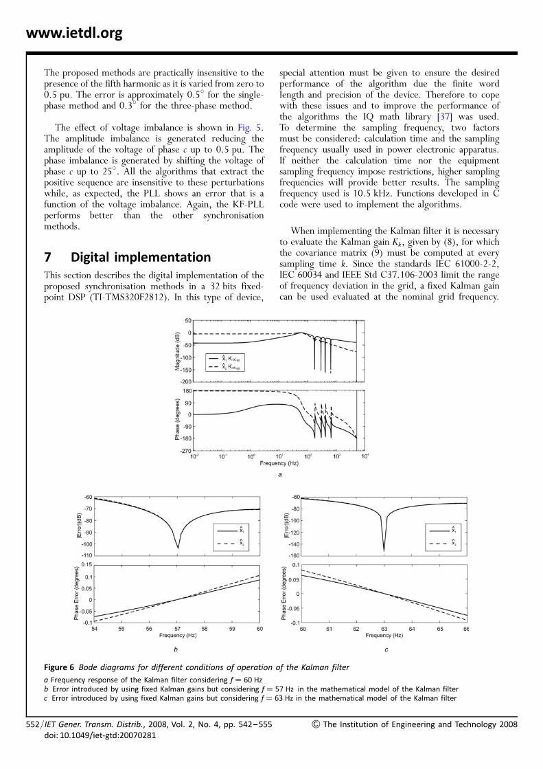
2 and R ¼ 200 V2, defined inSection 6, the following steady-state Kalman filter gainis obtained
K160¼ 21:1726 �0:0848 21:1721��0:1728 21:1727 � � �
� � � 0:0693 21:1161 1:5481
� � � 21:0486 �2:2893�T�10�3 (80)
Based on this gain, Fig. 6a shows the frequency responseof the Kalman filter states x1 and x2. The proposedsynchronisation schemes strongly reject the harmonicsat the frequencies used in the mathematical model. Atthe fundamental frequency the gains equal unity andthe difference in phase is 08 and 2908 for the states x1and x2, respectively. Figs. 6b and 6c present the errorsin magnitude, in dB, and in phase, in degrees, thatarise when fixed gains are used. When fixed gains areevaluated for the nominal grid frequency, that is,f ¼ 60 Hz, both errors, in magnitude and phase, arenegligible if the actual grid frequency is updated in themathematical model of the filter.
In some applications, such as those described in therecommendations of of E.ON Netz GmbH [38], thesynchronisation must be kept even under a voltage dropof 0.85 pu. The results of the digital implementation ofthe proposed methods under a three-phase voltage drop
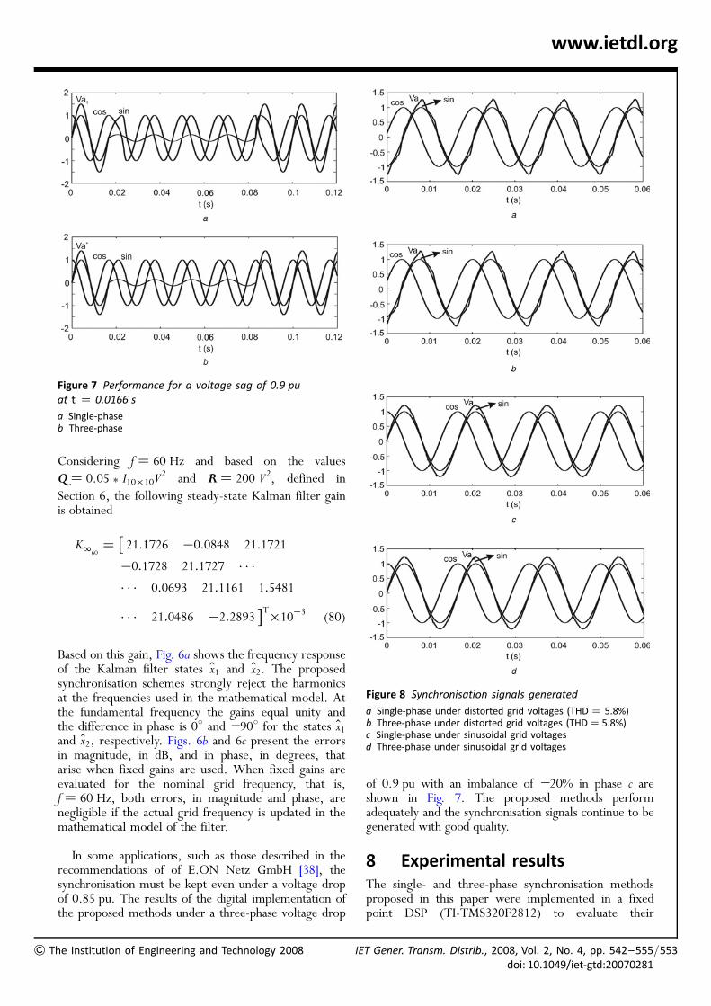
Figure 7 Performance for a voltage sag of 0.9 puat t ¼ 0.0166 s
a Single-phaseb Three-phase
he Institution of Engineering and Technology 2008 IE
of 0.9 pu with an imbalance of 220% in phase c areshown in Fig. 7. The proposed methods performadequately and the synchronisation signals continue to begenerated with good quality.
8 Experimental resultsThe single- and three-phase synchronisation methodsproposed in this paper were implemented in a fixedpoint DSP (TI-TMS320F2812) to evaluate their
Figure 8 Synchronisation signals generated
a Single-phase under distorted grid voltages (THD ¼ 5.8%)b Three-phase under distorted grid voltages (THD ¼ 5.8%)c Single-phase under sinusoidal grid voltagesd Three-phase under sinusoidal grid voltages
T Gener. Transm. Distrib., 2008, Vol. 2, No. 4, pp. 542–555/doi: 10.1049/iet-gtd:20070281
553
554
www.ietdl.org
performance in real time. The Kalman gain usedand sampling frequency are the same described inSection 7. The calculation time for the single-phasesynchronisation method is 13.8 ms and for the three-phase synchronisation method is 23.2 ms. Figs. 8aand 8b depict the synchronisation signals obtained withthe proposed single- and the three-phase KF-PLLs superimposed with the distorted grid voltage(THD ¼ 5.8%). Figs. 8c and 8d show thesynchronisation signals for a sinusoidal grid voltage.The good behaviour of both proposed structurescan be noted, even when voltage waveforms aredistorted.
9 ConclusionsThis paper presented a new approach, termed KF-PLL,for obtaining the synchronisation signals with the gridvoltages. The proposed methods are based on optimumfiltering theory and are capable of dealing with signalscorrupted by harmonics and measurement noise. Forthree-phase systems the proposed method also considersvoltage imbalance. The synchronisation methods can alsoprovide information about the grid voltages such asamplitude, instantaneous phase and frequency useful forthe analysis of power quality. The methods can also beimplemented in predictive form, which is very useful forspecification of predictive control laws.
To deal with voltage frequency variations,fundamental grid frequency identification in real timeis proposed for updating the Kalman filter model. Itwas shown that for frequency deviations within thelimits allowed by several standards fixed Kalman gainscan be used, which simplifies digital implementation.The formulation of the proposed synchronisationschemes deals explicitly with the following phenomenathat can occur in a real system: presence ofharmonics, voltage transients, measurement noise,voltage imbalance and frequency deviation. Table 1summarises the hypothesis considered in the
Table 1 Hypothesis used in the formulation of differentsynchronisation structures
Hypothesis Structure
PLL EPLL NPSF KF-PLL
measurement noise no no no yes
voltage transients no no no yes
harmonics no no yes yes
frequency identification no yes yes yes
unbalance no yes yes yes
optimisation no no no yes
/IET Gener. Transm. Distrib., 2008, Vol. 2, No. 4, pp. 542–555doi: 10.1049/iet-gtd:20070281
formulation of the proposed synchronisation methodsand those analysed in this paper.
The paper explains the development of the proposedmethods and also provides tuning guidance. Simulations,digital implementation and experimental results show theeffectiveness of the proposed methods and the resultsachieved surpass those from other methods considered inthis paper. The experimental results show that theproposed synchronisation methods can be implementedwithout great difficulty in a fixed-point DSP. Theimplementation based on fixed Kalman gains simplifiesthe DSP implementation, and the paper shows that theeffect on performance of the fixed gains is small.
10 References
[1] BLAABJERG F., TEODORESCU R., LISERRE M., TIMBUS A.V.:‘Overview of control and grid synchronization fordistributed power generation systems’, IEEE Trans. Ind.Electron., 2006, 53, (5), pp. 1398–1409
[2] SVENSSON J.: ‘Synchronization methods for grid-connected voltage source converters’, IEE Proc., Gener.Transm. Distrib., 2001, 148, (3), pp. 229–235
[3] KARIMI-GHARTEMANI M., IRAVANI M.R.: ‘A method forsynchronization of power electronic converters in pollutedand variable-frequency environments’, IEEE Trans. PowerSyst., 2004, 19, (3), pp. 1263–1270
[4] HSIEH G.-C., HUNG J.C.: ‘Phase-locked loop techniques-asurvey’, IEEE Trans. Ind. Electron., 1996, 43, (6), pp. 609–615
[5] CHUNG S.-K.: ‘A phase tracking system for three phaseutility interface inverters’, IEEE Trans. Power Electron.,2000, 15, (3), pp. 431–438
[6] KAURA V., BLASKO V.: ‘Operation of a phase locked loopsystem under distorted utility conditions’, IEEE Trans. Ind.Appl., 1997, 33, (1), pp. 58–63
[7] TIMBUSA.V., BLAABJERG F., TEODORESCUR., LISERREM., RODRIGUEZ P.:‘PLL algorithm for power generation systems robust to gridvoltage faults’. Proc. 37th IEEE Power Electronics SpecialistsConf., Jeju, South Korea, 2006
[8] RODRIGUEZ P., LUNAA., CIOBOTARUM., TEODORESCUR., BLAABJERG F.:‘Advanced grid synchronization system for power convertersunder unbalanced and distorted operating conditions’. Proc.Annual Conf. IEEE Industrial Electronics Society, Paris, France,November 2006, pp. 5173–5178
[9] SONG H.-S., NAM K.: ‘Instantaneous phase-angleestimation algorithm under unbalanced voltage-sagconditions’, IEE Proc., Gener. Transm. Distrib., 2000, 147,(6), pp. 409–415
& The Institution of Engineering and Technology 2008
&
www.ietdl.org
[10] DE CAMARGO R.F., PINHEIRO H.: ‘Synchronization method forthree-phase PWM converters under unbalance anddistorted grid’, IEE Proc. Electr. Power Appl., 2006, 153,(5), pp. 763–772
[11] KALMAN R.E.: ‘A new approach to linear filtering andprediction problems’, J. Basic Eng., 1960, 82D, pp. 35–45
[12] GELB A., KASPER J.F., NASH R.A., PRICE C.F., SUTHERLAND A.A.:‘Applied optimal estimation’ (M.I.T. Press, 1996, 1st edn.)
[13] CHRISTIANSEN G.S.: ‘Modelling of a PRML timing loop as aKalman filter’. Proc. IEEE Global Telecommunications Conf.,San Francisco, 1994, pp. 1157–1161
[14] DRIESSEN P.F.: ‘DPLL bit synchronizer with rapidacquisition using adaptive Kalman filtering techniques’,IEEE Trans. Commun., 1994, 42, (9), pp. 2673–2675
[15] PATAPOUNIAN A.: ‘On phase-locked loops and Kalmanfilters’, IEEE Trans. Commun., 1999, 47, (5), pp. 670–672
[16] IZADI M.H., LEUNG B.: ‘PLL-based frequency discriminatorusing the loop filter as an estimator’, IEEE Trans. CircuitSyst.-II Analog Digit. signal Process., 2002, 49, (11),pp. 721–727
[17] GUPTA S.C.: ‘Phase-locked loops’. Proc. IEEE, 1975, 63,pp. 291–306
[18] BOUTAYEB M., RAFARALAHY H., DAROUACH M.: ‘Convergenceanalysis of the extended Kalman filter used as anobserver for nonlinear deterministic discrete-timesystems’, IEEE Trans. Autom. Control, 1997, 42, (4),pp. 581–586
[19] BOUTAYEB M., AUBRY D.: ‘A strong tracking extendedKalman observer for nonlinear discrete-time systems’, IEEETrans. Autom. Control, 1999, 44, (8), pp. 1550–1556
[20] FRANCIS B.A., WONHAM W.M.: ‘The internal model principleof control theory’, Automatica, 1976, 12, (5), pp. 457–465
[21] BROWN L.J., ZHANG Q.: ‘Periodic disturbance cancellationwith uncertain frequency’, Automatica, 2004, 40, pp. 631–637
[22] ZHAO Z., BROWN L.: ‘Fast estimation of power systemfrequency using adaptive internal-model controltechnique’. Proc. 43rd IEEE Conf. Decision and Control,Paradise Island, Bahamas, December 2004, pp. 845–850
[23] MAYBECK P.S.: ‘Stochastic models, estimation andcontrol-vol. 1’ (Academic Press, New York, 1979, 1st edn.)
[24] CARDOSO R., DE CAMARGO R.F., PINHEIRO H., GRUNDLING H.A.:‘Kalman filter based synchronization methods’. Proc. 37thIEEE Power Electronics Specialists Conf., Jeju, South Korea, 2006
The Institution of Engineering and Technology 2008 I
[25] SILVA S.M., LOPES B.M., FILHO B.J.C. , CAMPANA R.P., BOAVENTURAW.C.: ‘Performance evaluation of PLL algorithms for single-phase grid-connected systems’. Proc. 39th IndustryApplications Society Annual Meeting, Seattle, 2004
[26] BROWN R.G.: ‘Introduction to random signals and appliedKalman filtering’ (John Wiley & Sons, New York, 1992, 2ndedn.)
[27] IEC 61000-2-2: Electromagnetic compatibility (EMC) part2-2: Environment-compatibility levels for low frequencyconducted disturbances and signaling in public low-voltage power supply systems, 2001
[28] DECKER I.C., DOTTA D., AGOSTINI M.N., ZIMATH S.L., SILVA A.S.:‘Performance of a synchronized phasor measurementsystem in the Brazilian power system’. Proc. IEEEPower Engineering Society GeneralMeeting, Montreal, 2006
[29] CAMPOS A., JOOS G., ZIOGAS P.D., LINDSAY J.F.: ‘Analysis anddesign of a series voltage unbalance compensator basedon a three-phase VSI operating with unbalance switchingfunctions’, IEEE Trans. Power Electron., 1994, 9, (3),pp. 269–274
[30] FORTESCUE C.L.: ‘Method of symmetrical coordinatesapplied to the solution of polyphase networks’, Trans.AIEE, 1918, 37, pp. 1027–1140
[31] IEEE STD 519-1992: ‘IEEE recommended practices andrequirements for harmonic control in electrical powersystems’, 1993
[32] IEC 60034: ‘Rotating electrical machines part 3: Specificrequirements for turbine-type synchronous machines’,1996
[33] IEEE STD C37.106-2003: ‘IEEE guide for abnormalfrequency protection for power generating plants’, 2003
[34] MEHRA R.K.: ‘On the identification of variances andadaptive Kalman filtering’, IEEE Trans. Autom. Control,1970, AC-15, (3), pp. 175–184
[35] CARDOSO R., CAMARA H.T., GRUNDLING H.A.: ‘Sensorlessinduction motor control using low cost electrical sensors’.Proc. 36th IEEE Power Electronics Specialists Conf., Recife,Brazil, 2005
[36] OGATA K.: ‘Discrete-time control systems’ (Prentice-Hall,Upper Saddle River, 1994, 2nd edn.)
[37] TEXAS INSTRUMENTS: ‘IQ math library-module user’sguide-C28x foundation software’, 2002
[38] E.ON NETZ GMBH: ‘Grid code for high and extra highvoltage’, 2003
ET Gener. Transm. Distrib., 2008, Vol. 2, No. 4, pp. 542–555/doi: 10.1049/iet-gtd:20070281
555