Embed Size (px)
Citation preview
1
LABORATORY MANUAL
Digital Electronics & Microprocessor Lab
(5th Semester)
Prepared By: Deepika Sarkar
Department of Electronics Engineering
Govt. Polytechnic Nabarangpur
Department of Electrical Engineering Govt. Polytechnic Nabarangpur- 764059

2
TABLE OF CONTENTS
Sl. No Name of theExperiment Pages
1 To verify all the logic gates. 5-7
2 Universal properties of NAND & NOR gates.
8-12
3 Implementation of half adder and Full adder using logic gates. 13-15
4 Implementation of half & full subtracter using logic gates.
16-19
5 Implementation of a 4-bit Binary to Gray code converter. 20-24
6 Implementation of a Single bit digital comparator 24-26
7 To study Multiplexer and demultiplexer. 27-28
8 Study of flipflops 29-30
9 Realize 4 bit asynchronous counter 30-31
10 Realize 4 bit synchronous counter
11 Implement mod-10 asynchronous counter
12 Study of shift register 32-33

3
13 1s complement & 2s complement.
14 Addition and subtraction of 2 8 bit numbers.
15 Decimal addition & subtraction of of 8 bit numbers.
16 Comparision between 2 numbers and find the largest in an array.
17 Block transfer.
18 Traffic light control using 8255.
19 Generation of square wave using 8255.
4
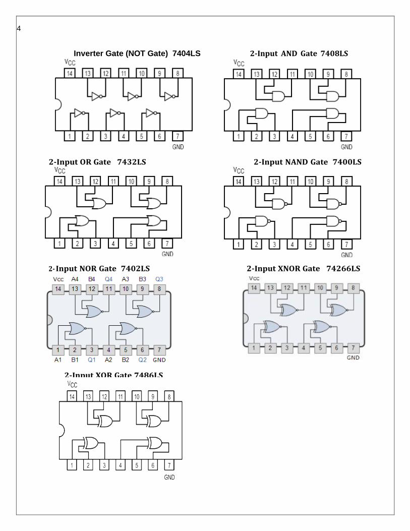
Inverter Gate (NOT Gate) 7404LS 2-Input AND Gate 7408LS
2-Input OR Gate 7432LS 2-Input NAND Gate 7400LS
2- Input NOR Gate 7402LS 2-Input XNOR Gate 74266LS
2-Input XOR Gate 7486LS

5
A O/P
0 1
1 0
Experiment No:1 Date: / /
Aim: - To Verify truth tables of AND, OR, NOT, NOR, NAND, XOR, XNOR gates.
Apparatus Required: -
1. All the basic gates mention in the fig. 2. IC Trainer Kit
Procedure: -
1. Place the IC on IC Trainer Kit.
2. Connect VCC and ground to respective pins of IC Trainer Kit.
3. Connect the inputs to the input switches provided in the IC Trainer
Kit.
4. Connect the outputs to the switches of O/P LEDs,
5. Apply various combinations of inputs according to the truth table and
observe condition of LEDs.
6. Disconnect output from the LEDs and note down the corresponding
multimeter voltage readings for various combinations of inputs.
Inverter Gate (NOT Gate) 7404LS
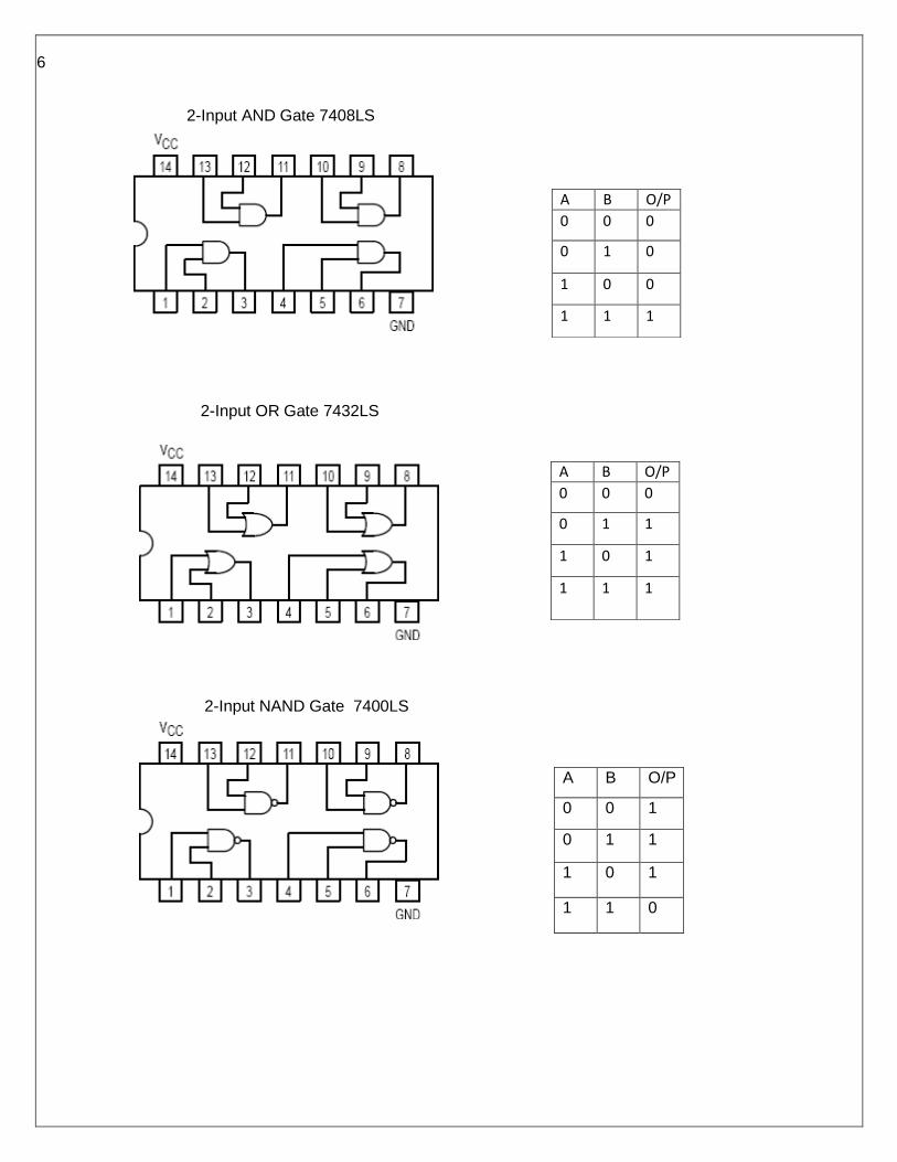
6
A B O/P
0 0 0
0 1 0
1 0 0
1 1 1
A B O/P
0 0 0
0 1 1
1 0 1
1 1 1
A B O/P
0 0 1
0 1 1
1 0 1
1 1 0
2-Input AND Gate 7408LS
2-Input OR Gate 7432LS
2-Input NAND Gate 7400LS
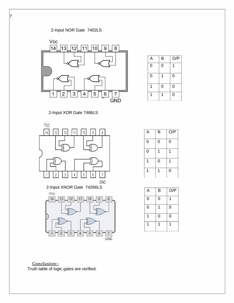
7
A B O/P
0 0 1
0 1 0
1 0 0
1 1 0
A B O/P
0 0 0
0 1 1
1 0 1
1 1 0
2-Input NOR Gate 7402LS
2-Input XOR Gate 7486LS
2-Input XNOR Gate 74266LS
Conclusion:- Truth table of logic gates are verified.
A B O/P
0 0 1
0 1 0
1 0 0
1 1 1
8
Experiment No:2 Date: / /
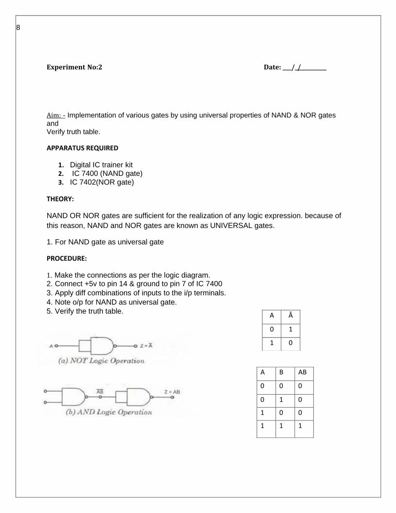
Aim: - Implementation of various gates by using universal properties of NAND & NOR gates and Verify truth table.
APPARATUS REQUIRED
1. Digital IC trainer kit 2. IC 7400 (NAND gate) 3. IC 7402(NOR gate)
THEORY:
NAND OR NOR gates are sufficient for the realization of any logic expression. because of
this reason, NAND and NOR gates are known as UNIVERSAL gates.
1. For NAND gate as universal gate
PROCEDURE:
1. Make the connections as per the logic diagram. 2. Connect +5v to pin 14 & ground to pin 7 of IC 7400
3. Apply diff combinations of inputs to the i/p terminals.
4. Note o/p for NAND as universal gate.
5. Verify the truth table.
A Ā
0 1
1 0
A B AB
0 0 0
0 1 0
1 0 0
1 1 1
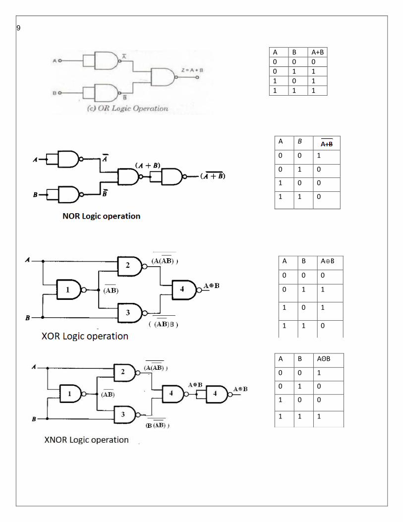
9
A B
0 0 1
0 1 0
1 0 0
1 1 0
A B A⊕B
0 0 0
0 1 1
1 0 1
1 1 0
A B AʘB
0 0 1
0 1 0
1 0 0
1 1 1
A B A+B
0 0 0
0 1 1
1 0 1
1 1 1
10
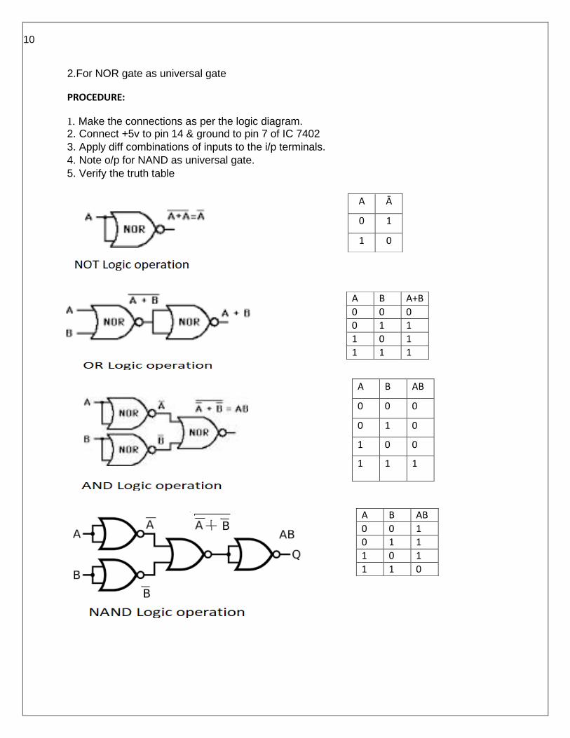
A Ā
0 1
1 0
A B A+B
0 0 0 0 1 1
1 0 1
1 1 1
A B AB
0 0 1
0 1 1
1 0 1
1 1 0
2.For NOR gate as universal gate
PROCEDURE:
1. Make the connections as per the logic diagram. 2. Connect +5v to pin 14 & ground to pin 7 of IC 7402
3. Apply diff combinations of inputs to the i/p terminals.
4. Note o/p for NAND as universal gate.
5. Verify the truth table
A B AB
0 0 0
0 1 0
1 0 0
1 1 1
11
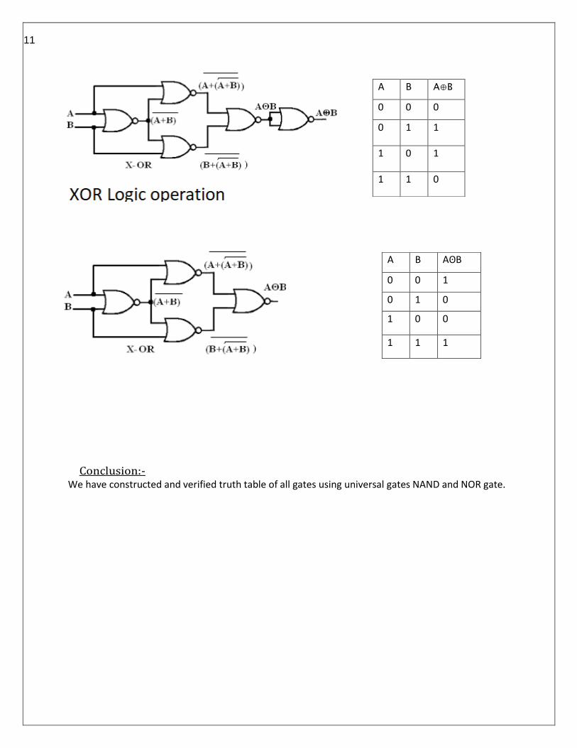
A B AʘB
0 0 1
0 1 0
1 0 0
1 1 1
Conclusion:- We have constructed and verified truth table of all gates using universal gates NAND and NOR gate.
A B A⊕B
0 0 0
0 1 1
1 0 1
1 1 0

12
Experiment No:3 Date: / /
Aim: - Implementation of half adder and Full adder using logic gates.
APPARATUS REQUIRED
1.IC 7486, IC 7432, IC 7408, IC 7400.
2. Digital trainer kit.
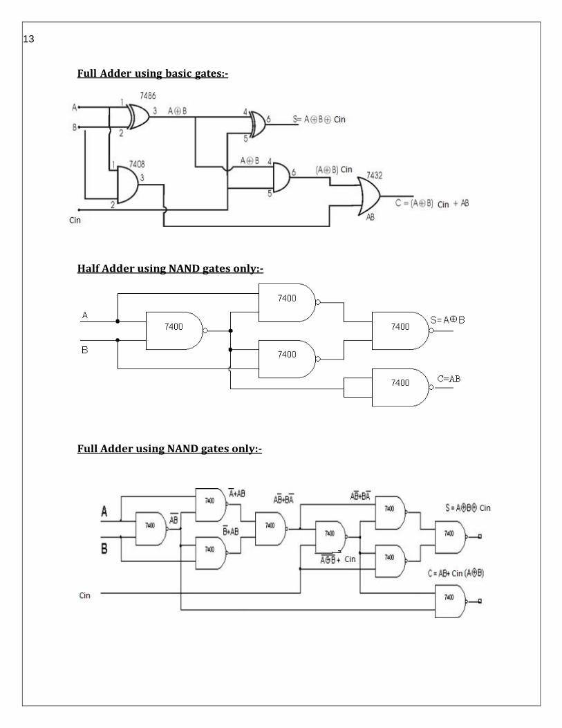
THEORY: Half-Adder: A combinational logic circuit that performs the addition of two data bits, A and B, is called a half-adder. Addition will result in two output bits; one of which is the sum bit, S, and the other is the carry bit, C. The Boolean functions describing the half-adder are:
S =A ⊕ B C = A B
Full-Adder: The half-adder does not take the carry bit from its previous stage into account. This
carry bit from its previous stage is called carry-in bit. A combinational logic circuit that adds two
data bits, A and B, and a carry-in bit, Cin, is called a full-adder. The Boolean functions describing
the full-adder are:
S = (x ⊕ y) ⊕ Cin C = xy + Cin (x ⊕ y)
Procedure: - 1. Verify the gates. 2. Make the connections as per the circuit diagram.
3. Switch on VCC and apply various combinations of input according to the truth table.
4. Note down the output readings for half and full adder sum and the carry bit for different combinations of inputs.
Half Adder using basic gates:-
13
Full Adder using basic gates:-
Half Adder using NAND gates only:-
Full Adder using NAND gates only:-
14
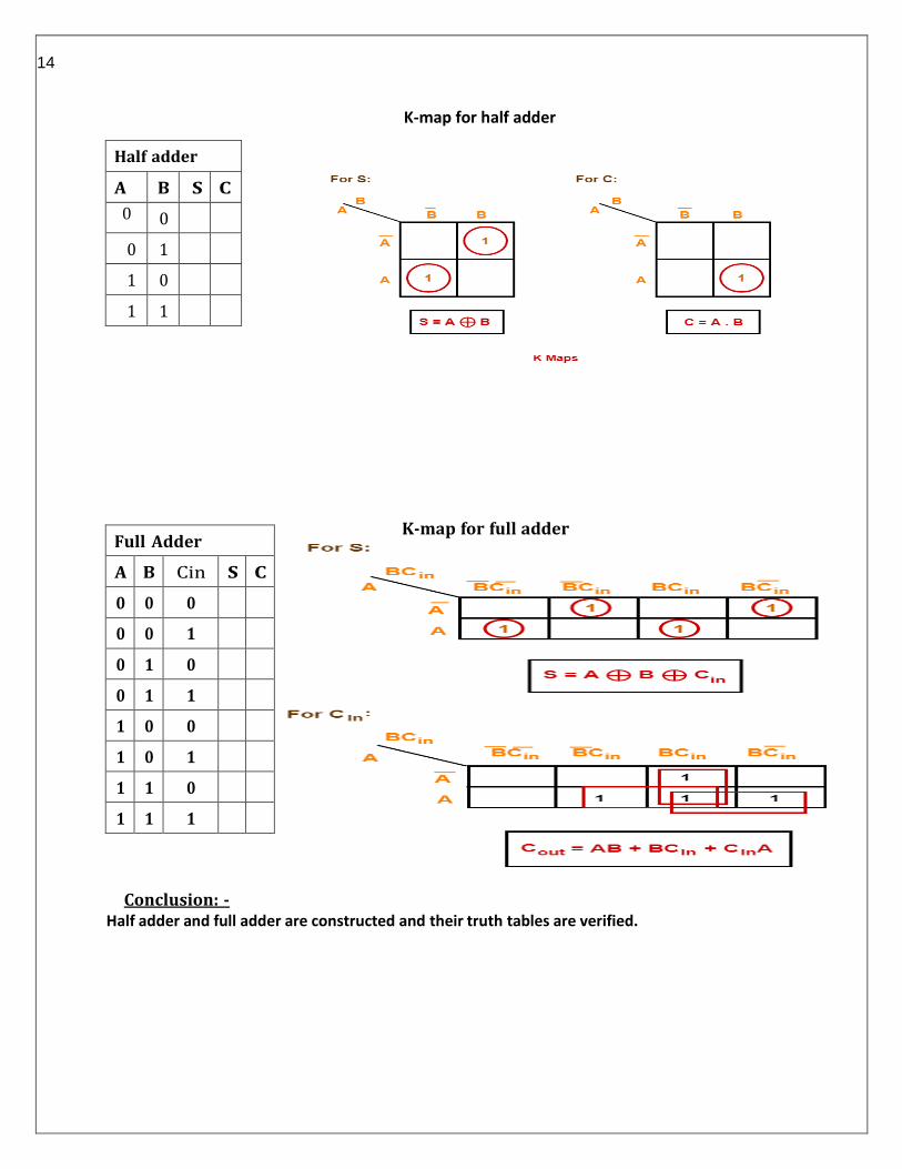
Half adder
A B S C
0 0
0 1
1 0
1 1
K-map for half adder
K-map for full adder
Conclusion: -
Half adder and full adder are constructed and their truth tables are verified.
Full Adder
A B Cin S C
0 0 0
0 0 1
0 1 0
0 1 1
1 0 0
1 0 1
1 1 0
1 1 1

15
Experiment No:4 Date: / /
Aim: - Implementation of half subtractor and Full subtractor using logic gates.
APPARATUS REQUIRED
1.IC 7486, IC 7432, IC 7408,IC7404, IC7400.
2. Digital trainer kit.
THEORY:
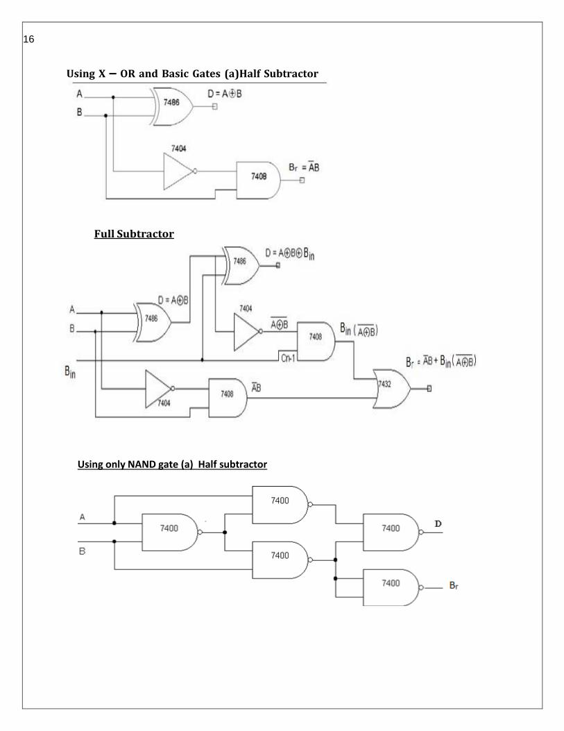
Half Subtractor: Subtracting a single-bit binary value B from another A (i.e. A -B) produces a
difference bit D and a borrow out bit B-out. This operation is called half subtraction and the circuit
to realize it is called a half subtractor. The Boolean functions describing the halfSubtractor are:
D =A ⊕ B Br = Α B
Full Subtractor: Subtracting two single-bit binary values, B, Cin from a single-bit value A produces a
difference bit D and a borrow out Br bit. This is called full subtraction. The Boolean functions
describing the full-subtracter are:
D = (x ⊕ y) ⊕ Bin Br = ΑB + Α (Bin) + B (Bin)
Procedure: -
1. Verify the gates. 2. Make the connections as per the circuit diagram.
3. Switch on VCC and apply various combinations of input according to the truth table.
4. Note down the output readings for half and full subtractor difference and borrow bit for different combinations of inputs.
16
Using X – OR and Basic Gates (a)Half Subtractor
Full Subtractor
Using only NAND gate (a) Half subtractor
17
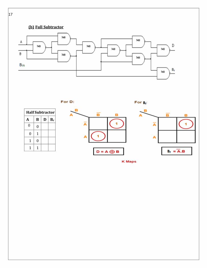
Half Subtractor
A B D Br
0 0
0 1
1 0
1 1
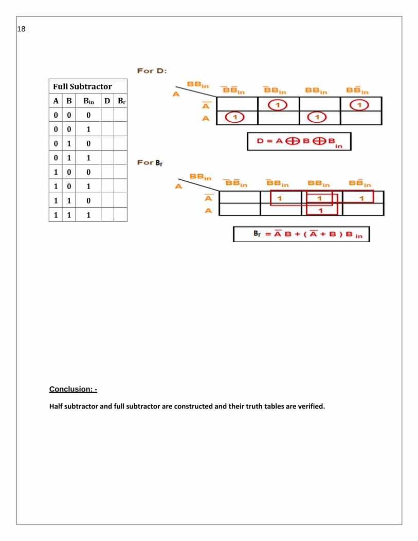
(b) Full Subtractor
18
Conclusion: -
Half subtractor and full subtractor are constructed and their truth tables are verified.
Full Subtractor
A B Bin D Br
0 0 0
0 0 1
0 1 0
0 1 1
1 0 0
1 0 1
1 1 0
1 1 1

19
Experiment No:5 Date: / /
Aim: - Implementation of a 4-bit Binary to Gray code converter.
APPARATUS REQUIRED
1. IC 7486
2. Digital trainer kit
THEORY:
Gray Code is one of the most important codes. It is a non-weighted code which belongs to a
class of codes called minimum change codes.
In this codes while traversing from one step to another step, only one bit in the code group
changes.
The input variable are designated as B3, B2, B1, B0 and the output variables are designated as
G3, G2, G1, G0.
Procedure: - 1. The circuit connections are made as shown in fig.
2. Pin (14) is connected to +Vcc and Pin (7) to ground.
3. In the case of binary to gray conversion, the inputs B0, B1, B2 and B3 are given at respective pins and outputs G0, G1, G2, G3 are taken for all the 16 combinations of the input.
4. The values of the outputs are tabulated.
TRUTH TABLE:
Binary Input Gray code output
B3 B2 B1 B0 G3 G2 G1 G0
0 0 0 0 0 0 0 0
0 0 0 1 0 0 0 1

20
0 0 1 0 0 0 1 1
0 0 1 1 0 0 1 0
0 1 0 0 0 1 1 0
0 1 0 1 0 1 1 1
0 1 1 0 0 1 0 1
0 1 1 1 0 1 0 0
1 0 0 0 1 1 0 0
1 0 0 1 1 1 0 1
1 0 1 0 1 1 1 1
1 0 1 1 1 1 1 0
1 1 0 0 1 0 1 0
1 1 0 1 1 0 1 1
1 1 1 0 1 0 0 1
1 1 1 1 1 0 0 0
21
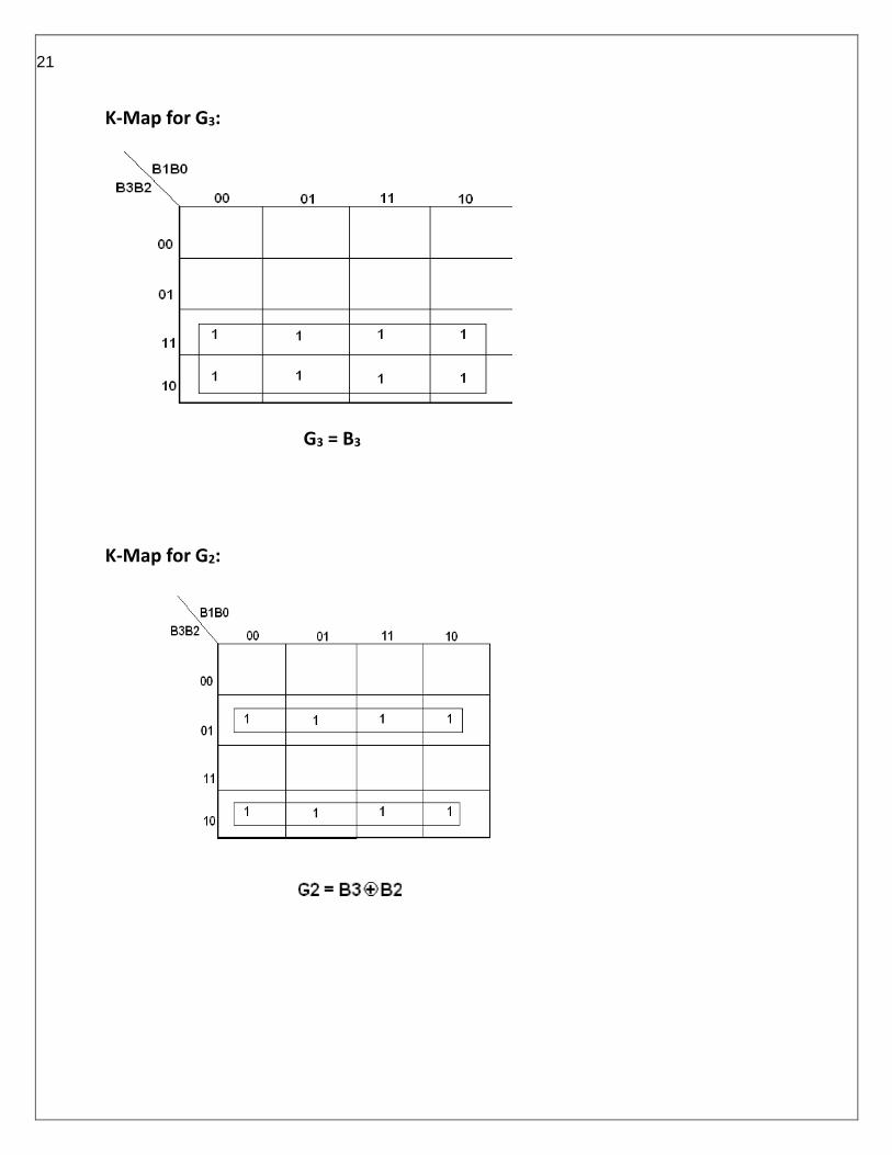
K-Map for G3:
G3 = B3
K-Map for G2:
22
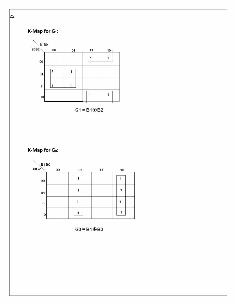
K-Map for G1:
K-Map for G0:
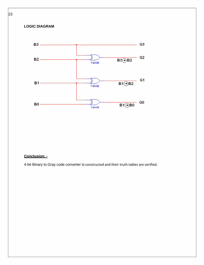
23
LOGIC DIAGRAM
Conclusion: -
4-bit Binary to Gray code converter is constructed and their truth tables are verified.

24
INPUTS OUTPUTS
A B A > B A = B A < B
0 0 0 1 0
0 1 0 0 1
1 0 1 0 0
1 1 0 1 0
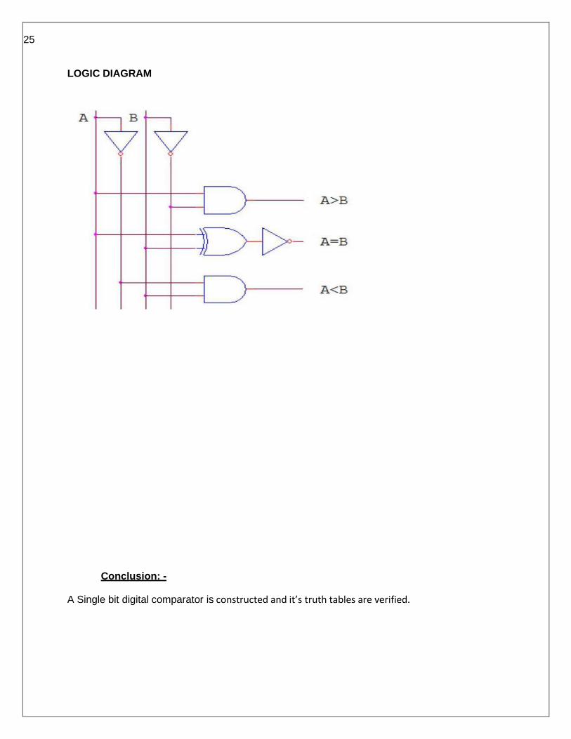
Experiment No:6 Date: / /
Aim: - Implementation of a Single bit digital comparator.
APPARATUS REQUIRED
1. IC 7404,IC 7408,IC 74266
2. Digital trainer kit
THEORY:
Magnitude Comparator is a logical circuit, which compares two signals A and B and generates
three logical outputs, whether A > B, A = B, or A < B.
Procedure: - 1. The circuit connections are made as shown in fig.
2. Pin (14) is connected to +Vcc and Pin (7) to ground.
3. The inputs A,B are given at respective pins and outputs A > B, A = B, or A < B are connected to the output LED.
4. The values of the outputs are tabulated.
TRUTH TABLE
25
LOGIC DIAGRAM
Conclusion: -
A Single bit digital comparator is constructed and it’s truth tables are verified.
26
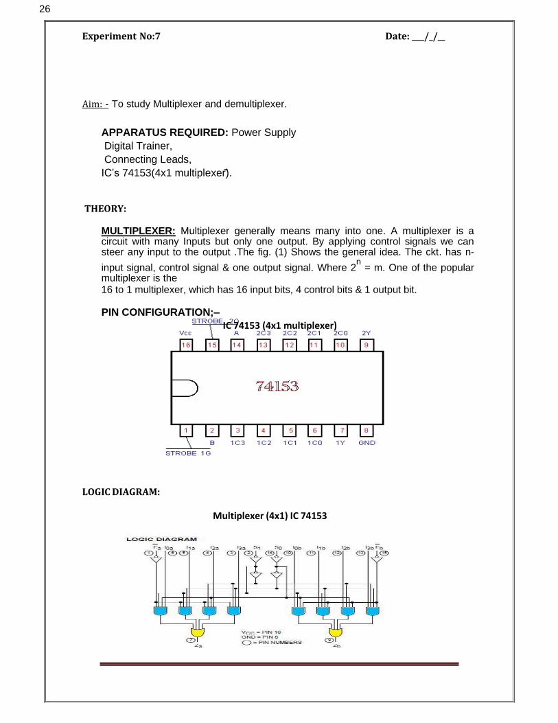
Experiment No:7 Date: / /
Aim: - To study Multiplexer and demultiplexer.
APPARATUS REQUIRED: Power Supply
Digital Trainer,
Connecting Leads,
IC’s 74153(4x1 multiplexer).
THEORY:
MULTIPLEXER: Multiplexer generally means many into one. A multiplexer is a circuit with many Inputs but only one output. By applying control signals we can steer any input to the output .The fig. (1) Shows the general idea. The ckt. has n-
input signal, control signal & one output signal. Where 2n
= m. One of the popular multiplexer is the 16 to 1 multiplexer, which has 16 input bits, 4 control bits & 1 output bit.
PIN CONFIGURATION;–
IC 74153 (4x1 multiplexer)
LOGIC DIAGRAM:
Multiplexer (4x1) IC 74153

27
PROCEDURE: 1. Fix the IC's on the bread board &give the input supply.
2. Make connection according to the circuit. 3. Give select signal and strobe signal at respective pins. 4. Connect +5 v Vcc supply at pin no 24 &
GND at pin no 12. 5. Verify the truth table for various inputs.
OBSERVATION TABLE:
Truth Table of multiplexer (4x1) IC 74153
Conclusion: Verify the truth table of multiplexer for various inputs.
28
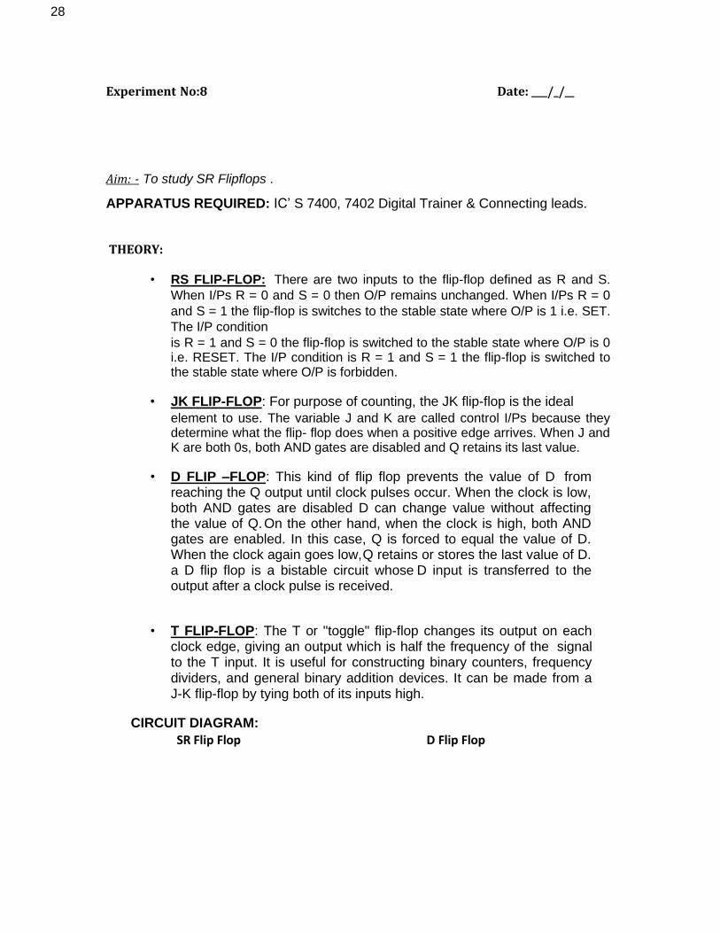
Experiment No:8 Date: / /
Aim: - To study SR Flipflops .
APPARATUS REQUIRED: IC’ S 7400, 7402 Digital Trainer & Connecting leads.
THEORY:
• RS FLIP-FLOP: There are two inputs to the flip-flop defined as R and S.
When I/Ps R = 0 and S = 0 then O/P remains unchanged. When I/Ps R = 0
and S = 1 the flip-flop is switches to the stable state where O/P is 1 i.e. SET.
The I/P condition
is R = 1 and S = 0 the flip-flop is switched to the stable state where O/P is 0 i.e. RESET. The I/P condition is R = 1 and S = 1 the flip-flop is switched to the stable state where O/P is forbidden.
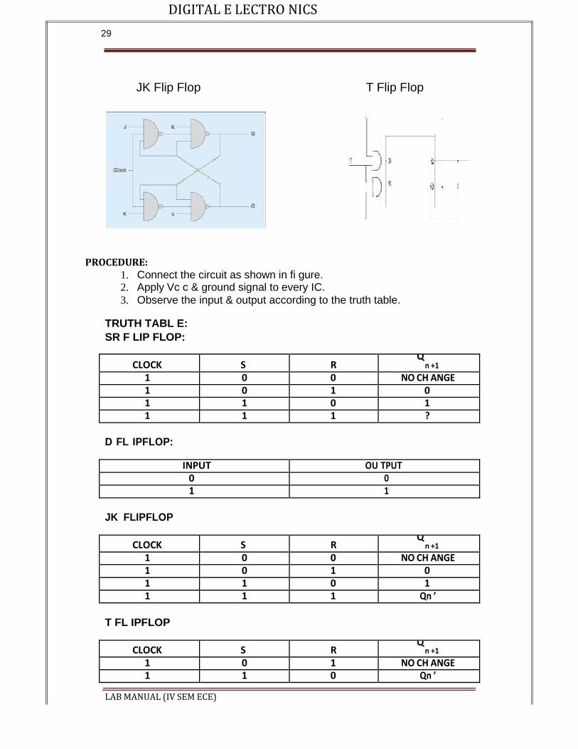
• JK FLIP-FLOP: For purpose of counting, the JK flip-flop is the ideal
element to use. The variable J and K are called control I/Ps because they determine what the flip- flop does when a positive edge arrives. When J and K are both 0s, both AND gates are disabled and Q retains its last value.
• D FLIP –FLOP: This kind of flip flop prevents the value of D from reaching the Q output until clock pulses occur. When the clock is low, both AND gates are disabled D can change value without affecting the value of Q. On the other hand, when the clock is high, both AND gates are enabled. In this case, Q is forced to equal the value of D. When the clock again goes low, Q retains or stores the last value of D. a D flip flop is a bistable circuit whose D input is transferred to the output after a clock pulse is received.
• T FLIP-FLOP: The T or "toggle" flip-flop changes its output on each clock edge, giving an output which is half the frequency of the signal to the T input. It is useful for constructing binary counters, frequency dividers, and general binary addition devices. It can be made from a J-K flip-flop by tying both of its inputs high.
CIRCUIT DIAGRAM:
SR Flip Flop D Flip Flop
DIGITAL E LECTRO NICS
LAB MANUAL (IV SEM ECE)
29
JK Flip Flop T Flip Flop
PROCEDURE:
1. Connect the circuit as shown in fi gure. 2. Apply Vc c & ground signal to every IC.
3. Observe the input & output according to the truth table.
TRUTH TABL E:
SR F LIP FLOP:
CLOCK S R Q
n +1
1 0 0 NO CH ANGE 1 0 1 0 1 1 0 1 1 1 1 ?
D FL IPFLOP:
INPUT OU TPUT 0 0 1 1
JK FLIPFLOP
CLOCK S R Q
n +1
1 0 0 NO CH ANGE 1 0 1 0 1 1 0 1 1 1 1 Qn ’
T FL IPFLOP
CLOCK S R Q
n +1
1 0 1 NO CH ANGE 1 1 0 Qn ’
DIGITAL E LECTRO NICS
LAB MANUAL (IV SEM ECE)
30
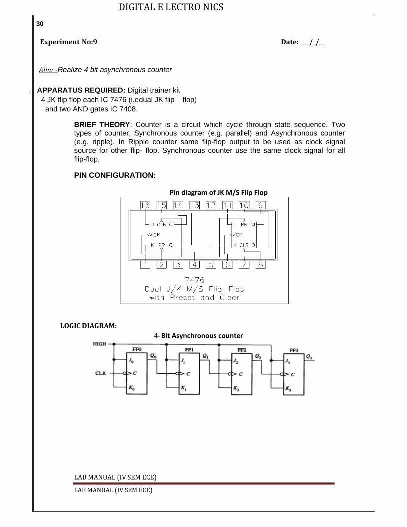
Experiment No:9 Date: / /
Aim: -Realize 4 bit asynchronous counter
. APPARATUS REQUIRED: Digital trainer kit
4 JK flip flop each IC 7476 (i.e dual JK flip flop)
and two AND gates IC 7408.
BRIEF THEORY: Counter is a circuit which cycle through state sequence. Two types of counter, Synchronous counter (e.g. parallel) and Asynchronous counter
(e.g. ripple). In Ripple counter same flip-flop output to be used as clock signal
source for other flip- flop. Synchronous counter use the same clock signal for all
flip-flop.
PIN CONFIGURATION:
Pin diagram of JK M/S Flip Flop
LOGIC DIAGRAM: 4- Bit Asynchronous counter
LAB MANUAL (IV SEM ECE)

DIGITAL E LECTRO NICS
LAB MANUAL (IV SEM ECE)
31
Pin Number Description
1 Clock 1 Input
2 Preset 1 Input
3 Clear 1 Input
4 J1 Input
5 Vcc
6 Clock 2 Input
7 Preset 2 Input
8 Clear 2 Input
9 J2 Input
10 Complement Q2 Output
11 Q2 Output
12 K2 Input
13 Ground
14 Complement Q1 Output
15 Q1 Output
16 K1 Input
PROCEDURE: a) Make the connections as per the logic diagram. b) Connect +5v and ground according to pin configuration. c) Apply diff combinations of inputs to the i/p terminals. d) Note o/p for summation. e) Verify the truth table.
RESULT: 4-bit asynchronous counter studied and verified.
.
DIGITAL E LECTRO NICS
LAB MANUAL (IV SEM ECE)
32
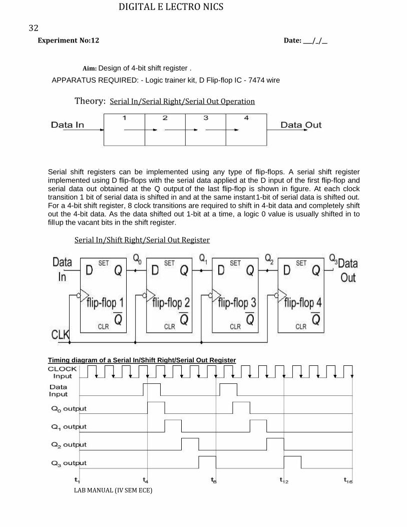
Experiment No:12 Date: / /
Aim: Design of 4-bit shift register .
APPARATUS REQUIRED: - Logic trainer kit, D Flip-flop IC - 7474 wire
Theory: Serial In/Serial Right/Serial Out Operation
Serial shift registers can be implemented using any type of flip-flops. A serial shift register implemented using D flip-flops with the serial data applied at the D input of the first flip-flop and serial data out obtained at the Q output of the last flip-flop is shown in figure. At each clock transition 1 bit of serial data is shifted in and at the same instant 1-bit of serial data is shifted out. For a 4-bit shift register, 8 clock transitions are required to shift in 4-bit data and completely shift out the 4-bit data. As the data shifted out 1-bit at a time, a logic 0 value is usually shifted in to fill up the vacant bits in the shift register.
Serial In/Shift Right/Serial Out Register
Timing diagram of a Serial In/Shift Right/Serial Out Register

DIGITAL E LECTRO NICS
LAB MANUAL (IV SEM ECE)
33
PROCEDURE:
(i) Connections are given as per circuit diagram.
(ii) Logical inputs are given as per circuit diagram.
(iii) Observe the output and verify the truth table.
RESULT:
Thus the Shift register was designed and their truth table is verified
--------------------------------------------------------------- ------------------------------------------
.

DIGITAL E LECTRO NICS
LAB MANUAL (IV SEM ECE)

LABORATORY MANUAL
of
Electrical Machine Lab-II
(5th Semester)
Prepared by- SRI CHANDRAMANI MAHAPATRA,
Lecturer
Department of Electrical Engineering
Govt. Polytechnic, Nabarangapur, At/PO- Agnipur,
Dist.- Nabarangapur, PIN- 764059, Odisha
2
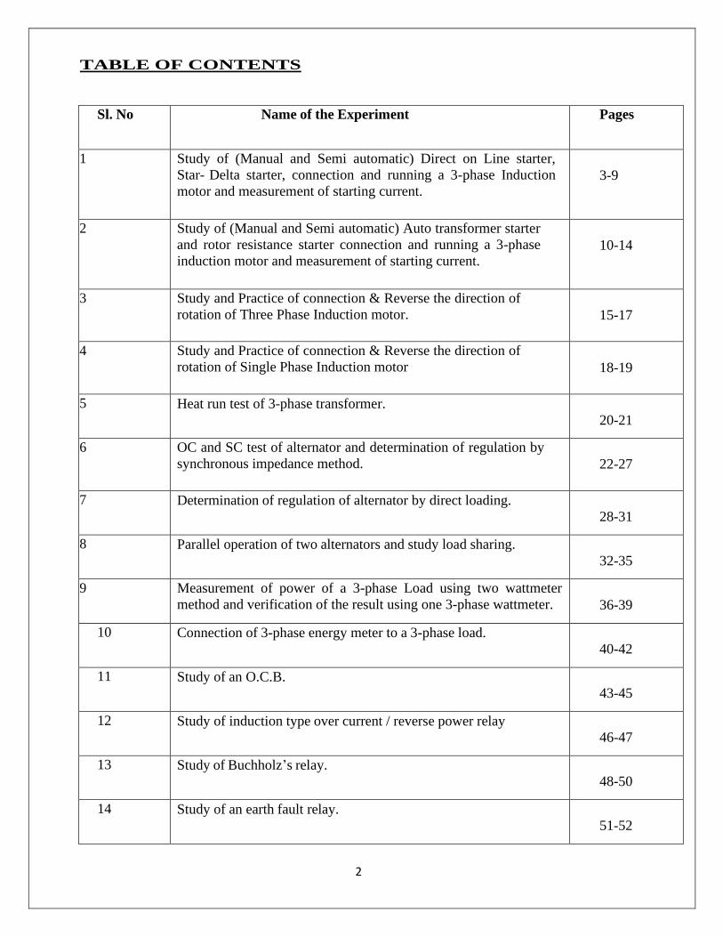
TABLE OF CONTENTS
Sl. No Name of the Experiment Pages
1 Study of (Manual and Semi automatic) Direct on Line starter,
Star- Delta starter, connection and running a 3-phase Induction
motor and measurement of starting current.
3-9
2 Study of (Manual and Semi automatic) Auto transformer starter
and rotor resistance starter connection and running a 3-phase
induction motor and measurement of starting current.
10-14
3 Study and Practice of connection & Reverse the direction of
rotation of Three Phase Induction motor.
15-17
4 Study and Practice of connection & Reverse the direction of
rotation of Single Phase Induction motor
18-19
5 Heat run test of 3-phase transformer.
20-21
6 OC and SC test of alternator and determination of regulation by
synchronous impedance method.
22-27
7 Determination of regulation of alternator by direct loading.
28-31
8 Parallel operation of two alternators and study load sharing.
32-35
9 Measurement of power of a 3-phase Load using two wattmeter
method and verification of the result using one 3-phase wattmeter.
36-39
10 Connection of 3-phase energy meter to a 3-phase load.
40-42
11 Study of an O.C.B.
43-45
12 Study of induction type over current / reverse power relay
46-47
13 Study of Buchholz’s relay.
48-50
14 Study of an earth fault relay.
51-52

3
Experiment - 01
Aim- Study of (manual and Semi automatic) Direct on line starter, Star- Delta Starter,
connection and running a 3-phase induction motor and measurement of starting current.
APPARATUS REQUIRED :-
Sl. No Name of the Equipment Specification Quantity
1 3-ɸ Induction Motor 415v, 1440 RPM, 2HP,
50 Hz
1no
2 Insulated Combination Pliers 150mm 1no
3 Screw driver 200mm 1no
4 Line Tester 1100v, 6‟‟ 1no
5 3-ɸ DOL Starter 400 V, 9-14 A, 7.5 HP 1no
6 Star-Delta Starter 415 V, 10-16A, 50 Hz 1no
7 Multimeter - 1 no
8 Wires 2.5 sq mm As per requirement
Theory:-
3-ɸ Induction Motor:-
The three-phase AC induction motor is a rotating electric machine that is designed to operate on
a three-phase supply. This 3 phase motor is also called as an asynchronous motor. These AC
motors are of two types: squirrel and slip-ring type induction motors.
It works on the same principle as a DC motor, that is, the current-carrying conductors kept in a
magnetic field will tend to create a force.
Direct on line (DOL) starter:-
DOL Starter (Direct Online Starter) is also known as “across the line starter”. DOL starter is a
device consists of main contactor, protective devices and overload relay which is used for motor
starting operations. It is used for low rating usually below 5HP motors.
In direct online starter method of motor starting, the motor stator windings is directly connected
to the main supply where the DOL protect the motor circuit from high inrush current which may
damage the overall circuit as the initial current is much more higher than the full rated current.

4
Construction of DOL Starter:-
A DOL or Direct Online starter has simply two buttons; Green and Red, where the green button
is used for starting and the red is used for stopping the motor. The green button connects the
terminals and closes the circuit while the red button disconnects the terminals and breaks the
circuit.
The DOL starter is made of a circuit breaker or MCCB or fuse, an overload relay and contactor
or coil. The circuit breaker is used for protection against short circuits while the overload relay
protects the motor from overloading. The contactor is used for starting and stopping the motor
where the green and red buttons are connected.
DOL Starter Working Principle:-
The working principle of a DOL starter begins with the connection to the 3-phase main with the
motor. The control circuit is connected to any two phases and energized from them only. When
we press the start button, the current flows through contactor coil (magnetizing coil) and control
circuit also. The current energizes the contactor coil and leads to close the contacts, and hence
3-phase supply becomes available to the motor.
If we press the stop button, the current through the contact becomes discontinued, hence supply
to the motor will not be available, and the similar thing will happen when the overload relay
operates. Since the supply of motor breaks, the machine will come to rest. The contactor coil
(Magnetizing Coil) gets supply even though we release start button because when we release
start button, it will get supply from the primary contacts as illustrated in the diagram of the
Direct Online Starter.
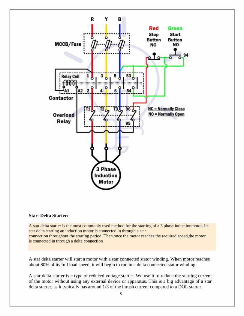
5
A star delta starter is the most commonly used method for the starting of a 3 phase induction motor. In
star delta starting an induction motor is connected in through a star
connection throughout the starting period. Then once the motor reaches the required speed, the motor
is connected in through a delta connection
Star- Delta Starter:-
A star delta starter will start a motor with a star connected stator winding. When motor reaches
about 80% of its full load speed, it will begin to run in a delta connected stator winding.
A star delta starter is a type of reduced voltage starter. We use it to reduce the starting current
of the motor without using any external device or apparatus. This is a big advantage of a star
delta starter, as it typically has around 1/3 of the inrush current compared to a DOL starter.
6
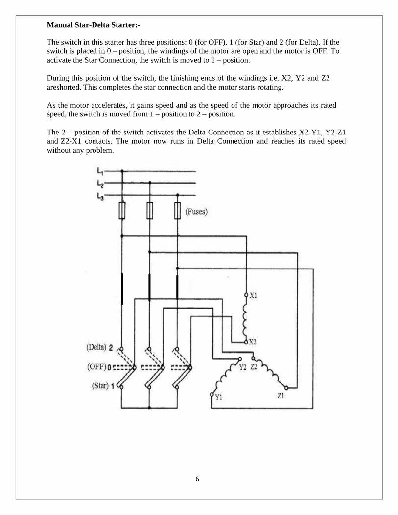
Manual Star-Delta Starter:-
The switch in this starter has three positions: 0 (for OFF), 1 (for Star) and 2 (for Delta). If the
switch is placed in 0 – position, the windings of the motor are open and the motor is OFF. To
activate the Star Connection, the switch is moved to 1 – position.
During this position of the switch, the finishing ends of the windings i.e. X2, Y2 and Z2
are shorted. This completes the star connection and the motor starts rotating.
As the motor accelerates, it gains speed and as the speed of the motor approaches its rated
speed, the switch is moved from 1 – position to 2 – position.
The 2 – position of the switch activates the Delta Connection as it establishes X2-Y1, Y2-Z1
and Z2-X1 contacts. The motor now runs in Delta Connection and reaches its rated speed
without any problem.
7
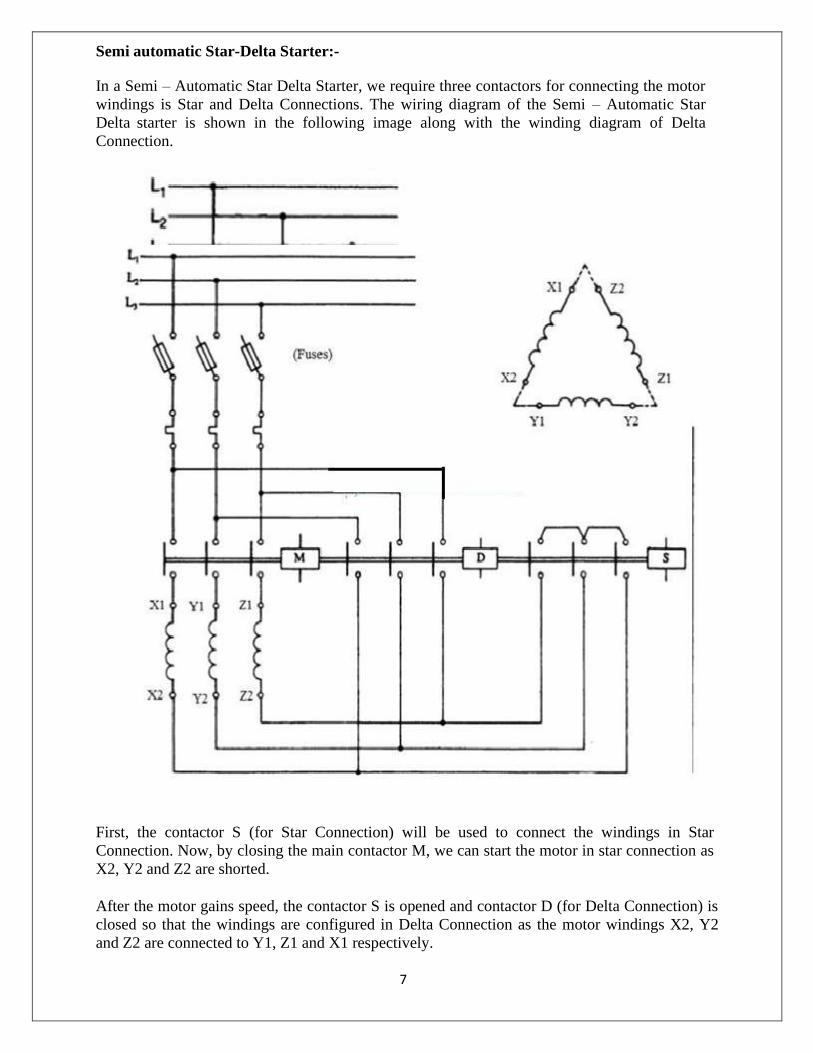
Semi automatic Star-Delta Starter:-
In a Semi – Automatic Star Delta Starter, we require three contactors for connecting the motor
windings is Star and Delta Connections. The wiring diagram of the Semi – Automatic Star
Delta starter is shown in the following image along with the winding diagram of Delta
Connection.
First, the contactor S (for Star Connection) will be used to connect the windings in Star
Connection. Now, by closing the main contactor M, we can start the motor in star connection as
X2, Y2 and Z2 are shorted.
After the motor gains speed, the contactor S is opened and contactor D (for Delta Connection) is
closed so that the windings are configured in Delta Connection as the motor windings X2, Y2
and Z2 are connected to Y1, Z1 and X1 respectively.
8
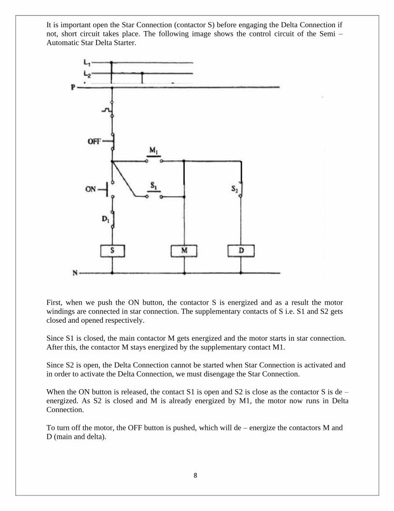
It is important open the Star Connection (contactor S) before engaging the Delta Connection if
not, short circuit takes place. The following image shows the control circuit of the Semi –
Automatic Star Delta Starter.
First, when we push the ON button, the contactor S is energized and as a result the motor
windings are connected in star connection. The supplementary contacts of S i.e. S1 and S2 gets
closed and opened respectively.
Since S1 is closed, the main contactor M gets energized and the motor starts in star connection.
After this, the contactor M stays energized by the supplementary contact M1.
Since S2 is open, the Delta Connection cannot be started when Star Connection is activated and
in order to activate the Delta Connection, we must disengage the Star Connection.
When the ON button is released, the contact S1 is open and S2 is close as the contactor S is de –
energized. As S2 is closed and M is already energized by M1, the motor now runs in Delta
Connection.
To turn off the motor, the OFF button is pushed, which will de – energize the contactors M and
D (main and delta).

9
Procedure:-
1. Make the connections as shown in the circuit diagram.
2. Set the timer at the marked position (10 secs).
3. Check the three phase supply at the voltmeter.
4. check the sequence of the operations of the contactors after switching the start button.
5. Connect the power supply terminals R Y B to the M C and delta power terminals RYB on the
board.
6. Record the no-load current at starting with the help of ammeter.
Tabulation:-
Sl.
No.
Name of Starters Starting Current in Amp
1
2
3
Conclusion:-
From the above experiment, we learnt about the, manual and Semi automatic Direct on line
starter, Star- Delta Starter, connection and running a 3-phase induction motor and its starting
current.

10
Experiment - 02
Aim- Study of (manual and Semi automatic) Auto transformer starter, Rotor resistance Starter,
connection and running a 3-phase induction motor and measurement of starting current.
APPARATUS REQUIRED:-
Sl. No Name of the Equipment Specification Quantity
1 3-ɸ Induction Motor 415 V, 1440 RPM, 2 HP 1no
2 3-ɸ Slip-ring Induction Motor 415 V, 1480 RPM, 5 HP 1no
3 Insulated Combination Pliers 150mm 1no
4 Screw driver 200mm 1no
5 Line Tester 1100v, 6‟‟ 1no
6 Wire Stripper 150mm 1 no
7 3-ɸ Auto Transformer Starter 415 V, 14 A, 10 KVA 1no
8 Rotor Resistance Starter 415 V, 50 Hz, 3 Phase 1no
9 Multimeter - 1no
10 Wires 2.5 sq mm As per required
Theory:-
3-ɸ Induction Motor:-
The three-phase AC induction motor is a rotating electric machine that is designed to operate on
a three-phase supply. This 3 phase motor is also called as an asynchronous motor. These AC
motors are of two types: squirrel and slip-ring type induction motors.
It works on the same principle as a DC motor, that is, the current-carrying conductors kept in a
magnetic field will tend to create a force.
Auto Transformer Starter:-
Squirrel cage induction motor started on full line voltage using D O L starter as a starting
method draw very large starting current which can damage motor winding and also create a
current surge on the power system. Hence another starting method is used to start three phase
induction motor called an autotransformer starter. Auto transformer Starter can be used for

11
both star/delta connected induction motors.
The starting current 6 to 8 times the rated current and this can cause voltage dip in supply and
also motor and motor-driven equipment experience large torque surge which can damage the
motor as well as connected equipment. Three phase autotransformer is used to reduce high
inrush starting current.
Many reduce voltage starting methods are used to start induction motor. one of them is
autotransformer starter, autotransformer starter is also reduced
voltage starter particularly used for higher rating motors greater than 10HP.
Auto-transformer starter (Variable Autotransformer) can be used with any squirrel cage
induction motor, motor supplied through taps of three-phase auto transformer starter. In Auto-
transformer Starter, Motor is directly connected on secondary of autotransformer.
The taps provided on auto-transformer limit the starting voltage and supply motor in steps of
50% 65% or 80% of nominal voltage. Using auto transformer for starting purpose the line
current is always less than motor nominal current during start, because of motor connected to
the secondary side of auto-transformer starter during acceleration.
If motor connected to 50% tap of auto transformer, the motor current would be reduced up to
50% of nominal starting current. But the line current will be only 25% of nominal starting
current. The difference between line current and motor current due to auto transformer is in the
circuit.
Due to the lower line, current auto transformer starter is a very popular type of reduce voltage
starter. Since the motor starting current is greater than the line current with autotransformer
starter, the starter produced more torque per ampere of line current than any other type of
reduce voltage starter
12
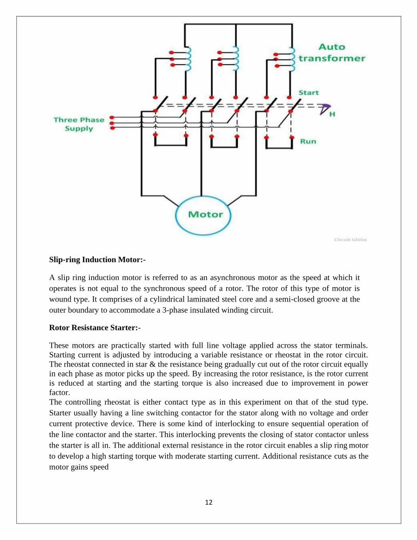
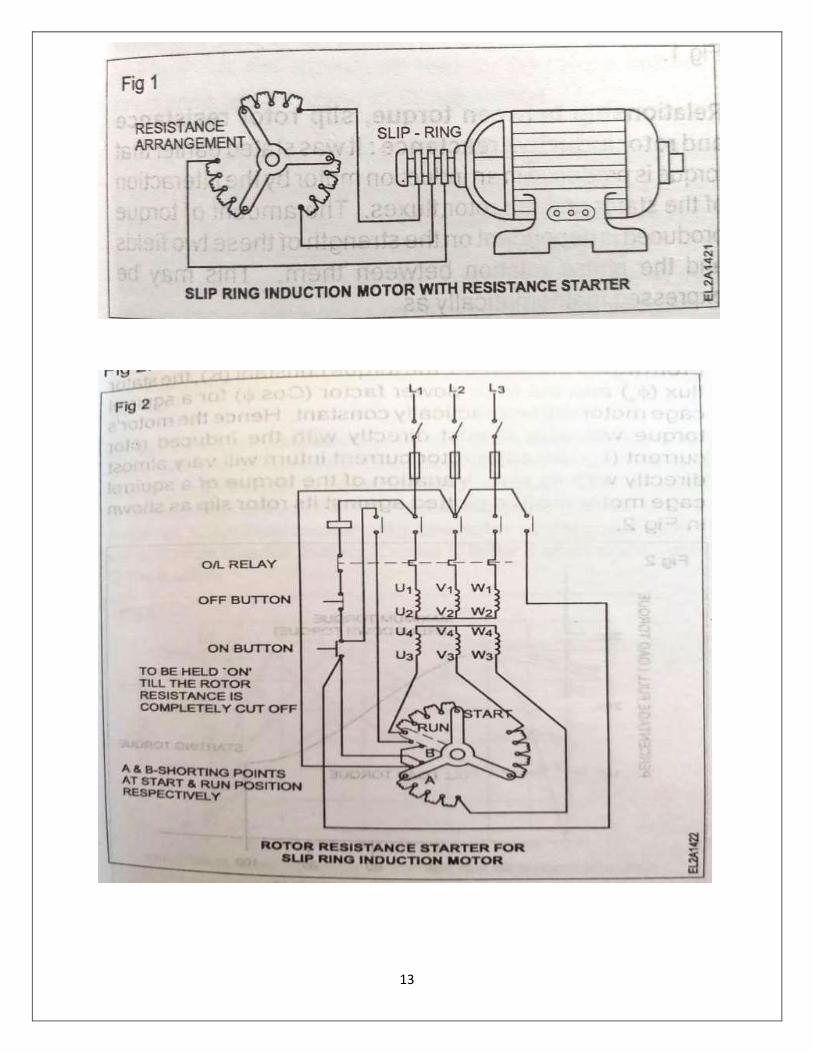
Slip-ring Induction Motor:-
A slip ring induction motor is referred to as an asynchronous motor as the speed at which it
operates is not equal to the synchronous speed of a rotor. The rotor of this type of motor is
wound type. It comprises of a cylindrical laminated steel core and a semi-closed groove at the
outer boundary to accommodate a 3-phase insulated winding circuit.
Rotor Resistance Starter:-
These motors are practically started with full line voltage applied across the stator terminals.
Starting current is adjusted by introducing a variable resistance or rheostat in the rotor circuit.
The rheostat connected in star & the resistance being gradually cut out of the rotor circuit equally
in each phase as motor picks up the speed. By increasing the rotor resistance, is the rotor current
is reduced at starting and the starting torque is also increased due to improvement in power
factor.
The controlling rheostat is either contact type as in this experiment on that of the stud type.
Starter usually having a line switching contactor for the stator along with no voltage and order
current protective device. There is some kind of interlocking to ensure sequential operation of
the line contactor and the starter. This interlocking prevents the closing of stator contactor unless
the starter is all in. The additional external resistance in the rotor circuit enables a slip ring motor
to develop a high starting torque with moderate starting current. Additional resistance cuts as the
motor gains speed
13

14
Procedure:-
1. Make the connections as shown in the circuit diagram.
2. Set the timer at the marked position (10 secs).
3. Check the three phase supply at the voltmeter.
4. check the sequence of the operations of the contactors after switching the start button.
5. Connect the power supply terminals R Y B to the M C and delta power terminals RYB on the
board.
6. Record the no-load current at starting with the help of ammeter.
Tabulation:-
Sl.No Name of Starters Starting Current in Amp
1
2
3
Conclusion:- From the above experiment, we learnt about the, Auto Transformer Starter, Rotor
resistance Starter, connection and running a 3-phase induction motor and its starting current.

15
Experiment - 03
Aim- Study and Practice of connection & Reverse the direction of rotation of Three Phase Induction motor.
APPARATUS REQUIRED:-
Sl. No Name of the Equipment Specification Quantity
1 3-ɸInduction Motor 415 V, 1440 RPM, 2 HP 1no
2 Insulated Combination Pliers 150mm 1no
3 Screw driver 200mm 1no
4 Line Tester 1100v, 6‟‟ 1no
5 Wire Stripper 150mm 1 no
6 D O L Starter 400 V, 9-14 A, 7.5 HP 1no
7 Wires 2.5 sq mm As per required
Theory:-
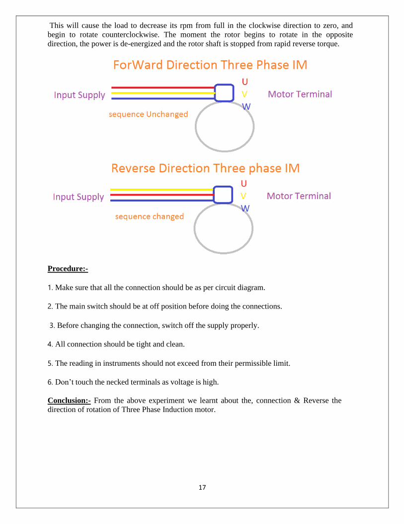
The direction of rotation of an electric motor can be changed anytime and easily at the motor
terminals. In three-phase motors, the windings configuration can easily be changed from a star
or Y connection to a delta or mesh connection at the motor terminal box.
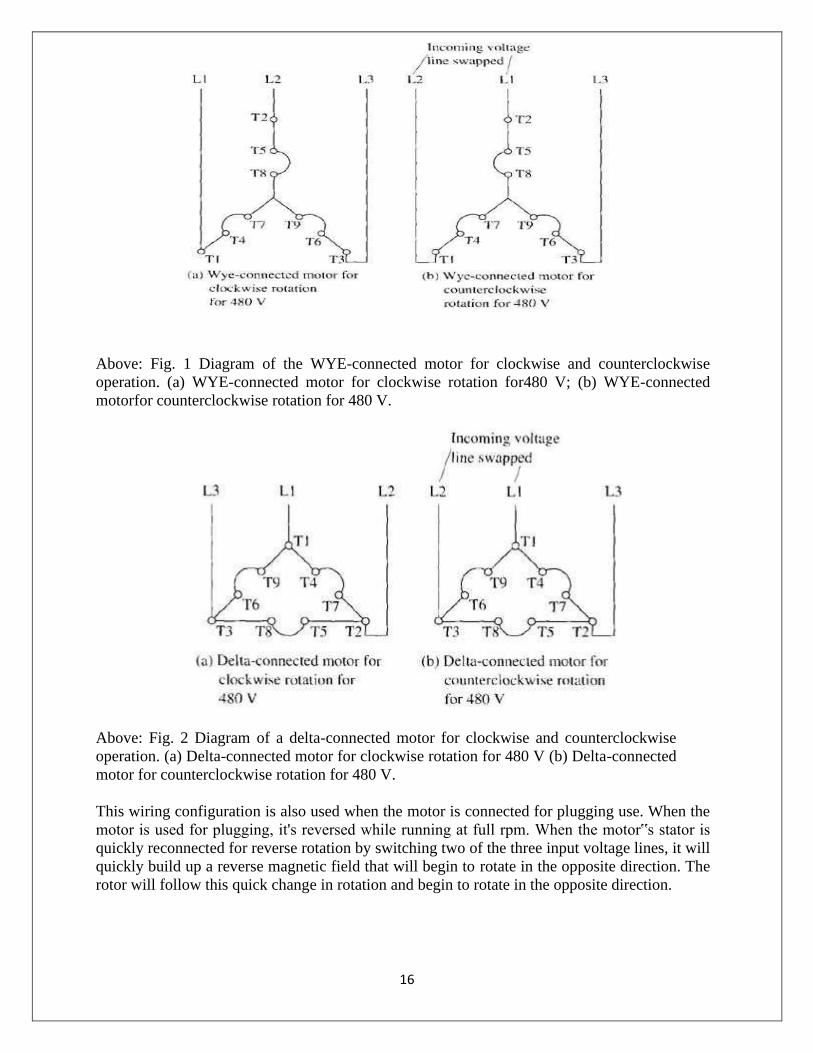
The rotation of a WYE- or delta-connected motor can be changed by exchanging any two of the
three phases of the incoming voltage. Fig. 1 shows diagrams for a WYE-connected motor and
Fig. 2 shows the diagrams for a delta-connected motor for clockwise (forward) and
counterclockwise (reverse) rotation. From these diagrams notice that T1 and T2 supply voltage
terminals have been exchanged in the diagram for motor reversal. In industrial applications,
terminals Ti and T2 are generally switched by the contacts of the reversing motor starter. These
diagrams will be useful for installation connections and troubleshooting.
16
Above: Fig. 1 Diagram of the WYE-connected motor for clockwise and counterclockwise
operation. (a) WYE-connected motor for clockwise rotation for480 V; (b) WYE-connected
motor for counterclockwise rotation for 480 V.
Above: Fig. 2 Diagram of a delta-connected motor for clockwise and counterclockwise
operation. (a) Delta-connected motor for clockwise rotation for 480 V (b) Delta-connected
motor for counterclockwise rotation for 480 V.
This wiring configuration is also used when the motor is connected for plugging use. When the
motor is used for plugging, it's reversed while running at full rpm. When the motor‟s stator is
quickly reconnected for reverse rotation by switching two of the three input voltage lines, it will
quickly build up a reverse magnetic field that will begin to rotate in the opposite direction. The
rotor will follow this quick change in rotation and begin to rotate in the opposite direction.
17
This will cause the load to decrease its rpm from full in the clockwise direction to zero, and
begin to rotate counterclockwise. The moment the rotor begins to rotate in the opposite
direction, the power is de-energized and the rotor shaft is stopped from rapid reverse torque.
Procedure:-
1. Make sure that all the connection should be as per circuit diagram.
2. The main switch should be at off position before doing the connections.
3. Before changing the connection, switch off the supply properly.
4. All connection should be tight and clean.
5. The reading in instruments should not exceed from their permissible limit.
6. Don’t touch the necked terminals as voltage is high.
Conclusion:- From the above experiment we learnt about the, connection & Reverse the
direction of rotation of Three Phase Induction motor.
18
Experiment - 04
Aim- Study and Practice of connection & Reverse the direction of rotation of Single Phase Induction motor.
APPARATUS REQUIRED:-
Sl. No Name of the Equipment Specification Quantity
1 1-ɸ Induction Motor 230 V, 1440 RPM, 7.5
A
1no
2 Insulated Combination Pliers 150mm 1no
3 Screw driver 200mm 1no
4 Line Tester 1100v, 6‟‟ 1no
5 Wire Stripper 150mm 1 no
6 Wires 2.5 sq mm As per required
Theory:-
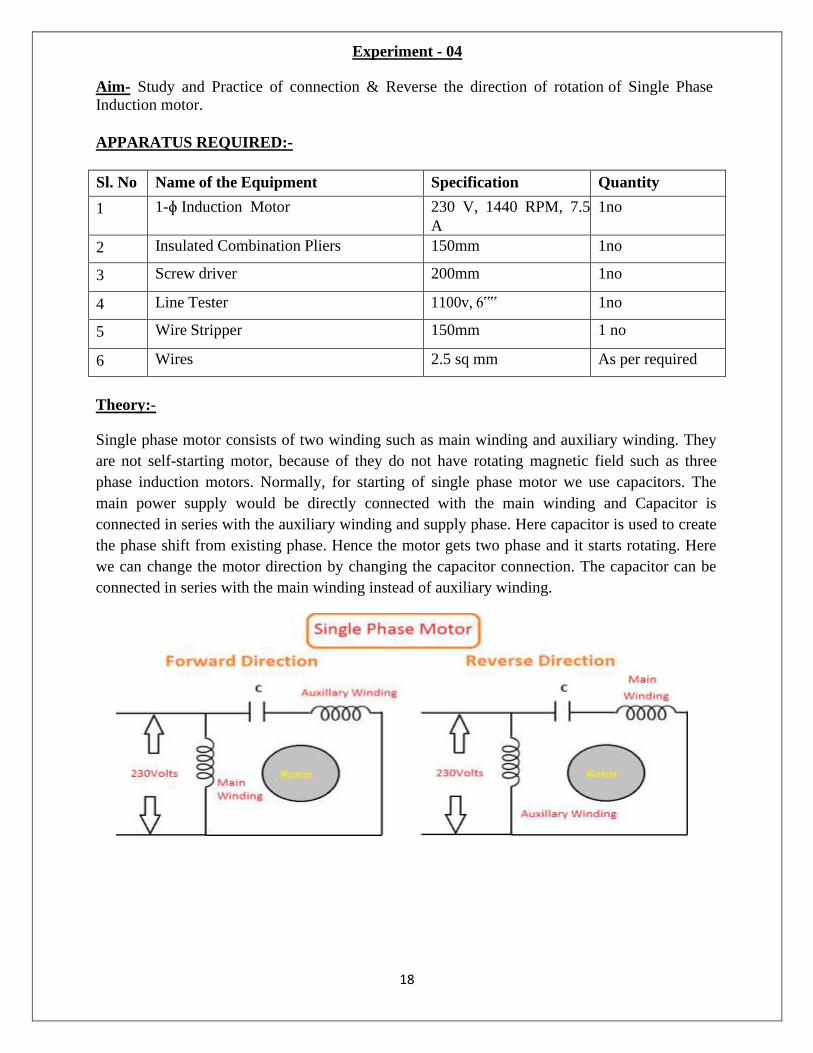
Single phase motor consists of two winding such as main winding and auxiliary winding. They
are not self-starting motor, because of they do not have rotating magnetic field such as three
phase induction motors. Normally, for starting of single phase motor we use capacitors. The
main power supply would be directly connected with the main winding and Capacitor is
connected in series with the auxiliary winding and supply phase. Here capacitor is used to create
the phase shift from existing phase. Hence the motor gets two phase and it starts rotating. Here
we can change the motor direction by changing the capacitor connection. The capacitor can be
connected in series with the main winding instead of auxiliary winding.

19
Procedure:-
1. Make sure that all the connection should be as per circuit diagram.
2. The main switch should be at off position before doing the connections.
3. Before changing the connection, switch off the supply properly.
4. All connection should be tight and clean.
5. The reading in instruments should not exceed from their permissible limit.
6. Don‟t touch the necked terminals as voltage is high.
Conclusion:- From the above experiment we learnt about the, connection & Reverse the
direction of rotation of Single Phase Induction motor.
20
Experiment - 05
Aim- Heat run test of 3-phase transformer.
APPARATUS REQUIRED:-
Sl. No Name of the Equipment Specification Quantity
1 3-ɸ Transformer 440 V/ 230V, 20 KVA,
INS. CL- B, 3 Phase
1no
2 Line Tester 1100v, 6‟‟ 1no
3 Wire Stripper 150mm 1 no
4 Voltmeter 500v 1no
5 Ammeter 15A 1no
6 Three Phase Variac 415 V,17 A, 12 KVA,
50 Hz
1no
7 Temperature Indicator - 1no
8 Wires 2.5 sq mm As per required
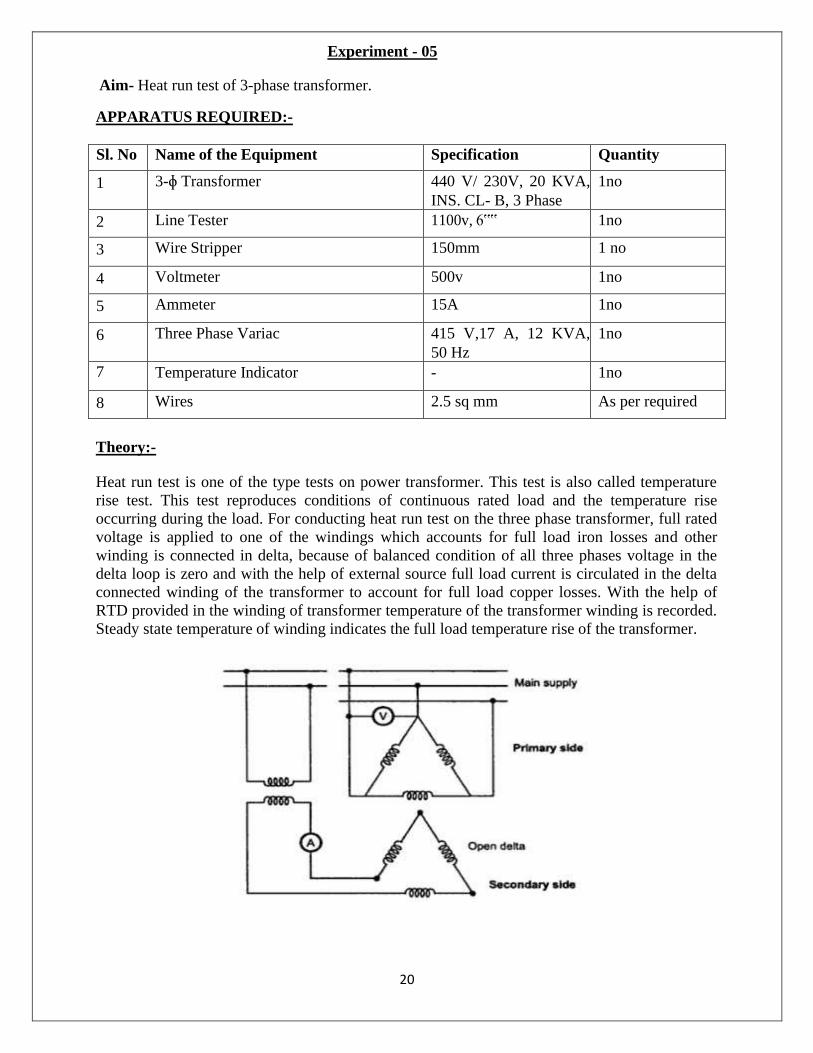
Theory:-
Heat run test is one of the type tests on power transformer. This test is also called temperature
rise test. This test reproduces conditions of continuous rated load and the temperature rise
occurring during the load. For conducting heat run test on the three phase transformer, full rated
voltage is applied to one of the windings which accounts for full load iron losses and other
winding is connected in delta, because of balanced condition of all three phases voltage in the
delta loop is zero and with the help of external source full load current is circulated in the delta
connected winding of the transformer to account for full load copper losses. With the help of
RTD provided in the winding of transformer temperature of the transformer winding is recorded.
Steady state temperature of winding indicates the full load temperature rise of the transformer.

21
Procedure:-
1. Make the connections as per the circuit diagram given in fig. attached.
2. Increase the voltage in the primary winding with the help of
3 phase variac to rated voltage.
3. Adjust the current in the closed delta secondary winding to the rated current of the secondary
winding.
4. Record the temperature of the winding after every 15 minutes till temperature of winding
reaches to a steady state condition i.e. temperature does not rise any more.
5. Time taken to reach the final temperature give idea about the thermal time constant of the
transformer and final temperature gives the full load temperature rise of the transformer.
Conclusion:- From the above experiment, we learnt about the heat run test of three phase
transformer.

22
Experiment - 06
Aim- OC and SC test of alternator and determination of regulation by synchronous impedance method.
APPARATUS REQUIRED: -
Sl. No Name of the Equipment Specification Quantity
1
DC Motor Coupled to Alternator
Motor- 230 V, 5 KVA, 5.5 HP,
1500 RPM, If = 1.2 A, Ia= 22 A
Alternator- 415 V, 5 KVA, 0.8
PF, 1500 RPM, If = 1.5 A, Ia=
6.6 A, 3 Phase
1no
2 Line Tester 1100v, 6‟‟ 1no
3 Wire Stripper 150mm 1 no
4 Voltmeter 600 V AC 1no
5 Ammeter 10 A AC 1no
5 Ammeter 2.5 A AC 1 no
6 Rheostat 500 ohm, 1 A 1no
7 Multimeter - 1 no
7 Tachometer 0-9999 RPM, Digital 1no
8 Wires 2.5 sq mm As per required
Theory:-
Open Circuit Test and Short Circuit Test are performed on a Synchronous Machine to find out
the Synchronous impedance For Large Machine to determine-the voltage-regulation.
Open Circuit Test:-
The alternator is run at rated synchronous speed and the load terminals are kept open. That is,
all the loads are disconnected. The field current is set to zero, this condition is called open circuit
test condition.
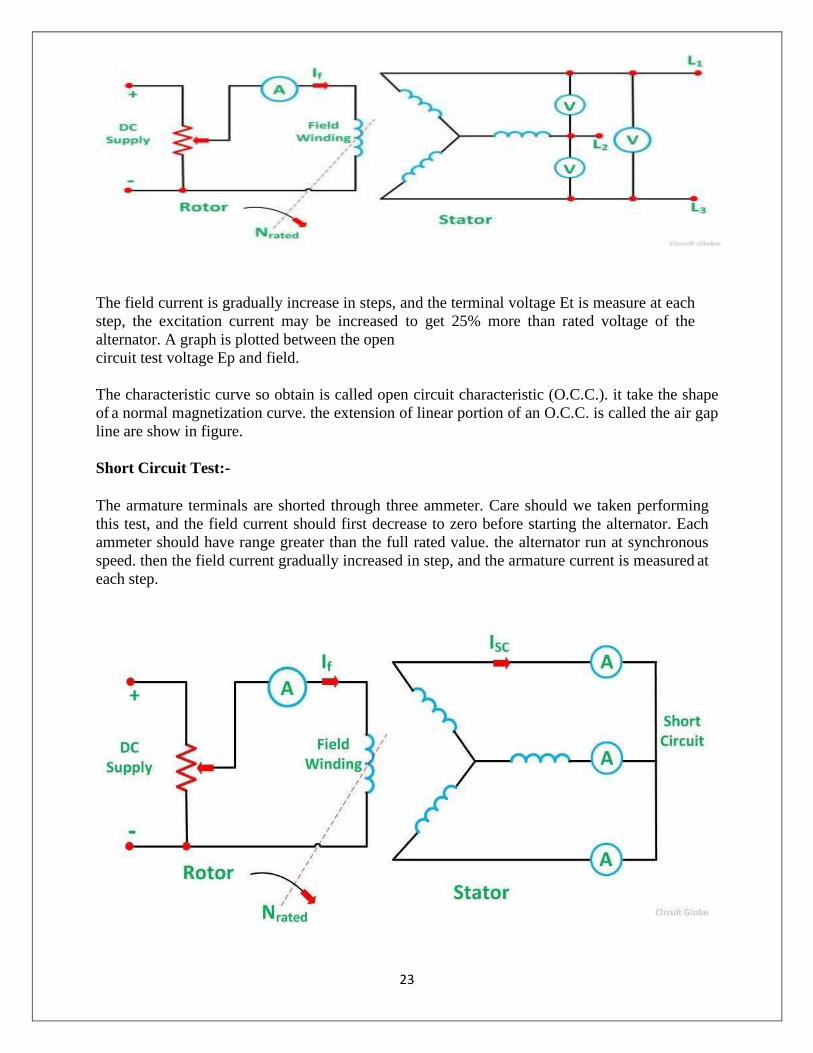
23
The field current is gradually increase in steps, and the terminal voltage Et is measure at each
step, the excitation current may be increased to get 25% more than rated voltage of the
alternator. A graph is plotted between the open
circuit test voltage Ep and field.
The characteristic curve so obtain is called open circuit characteristic (O.C.C.). it take the shape
of a normal magnetization curve. the extension of linear portion of an O.C.C. is called the air gap
line are show in figure.
Short Circuit Test:-
The armature terminals are shorted through three ammeter. Care should we taken performing
this test, and the field current should first decrease to zero before starting the alternator. Each
ammeter should have range greater than the full rated value. the alternator run at synchronous
speed. then the field current gradually increased in step, and the armature current is measured at
each step.
24
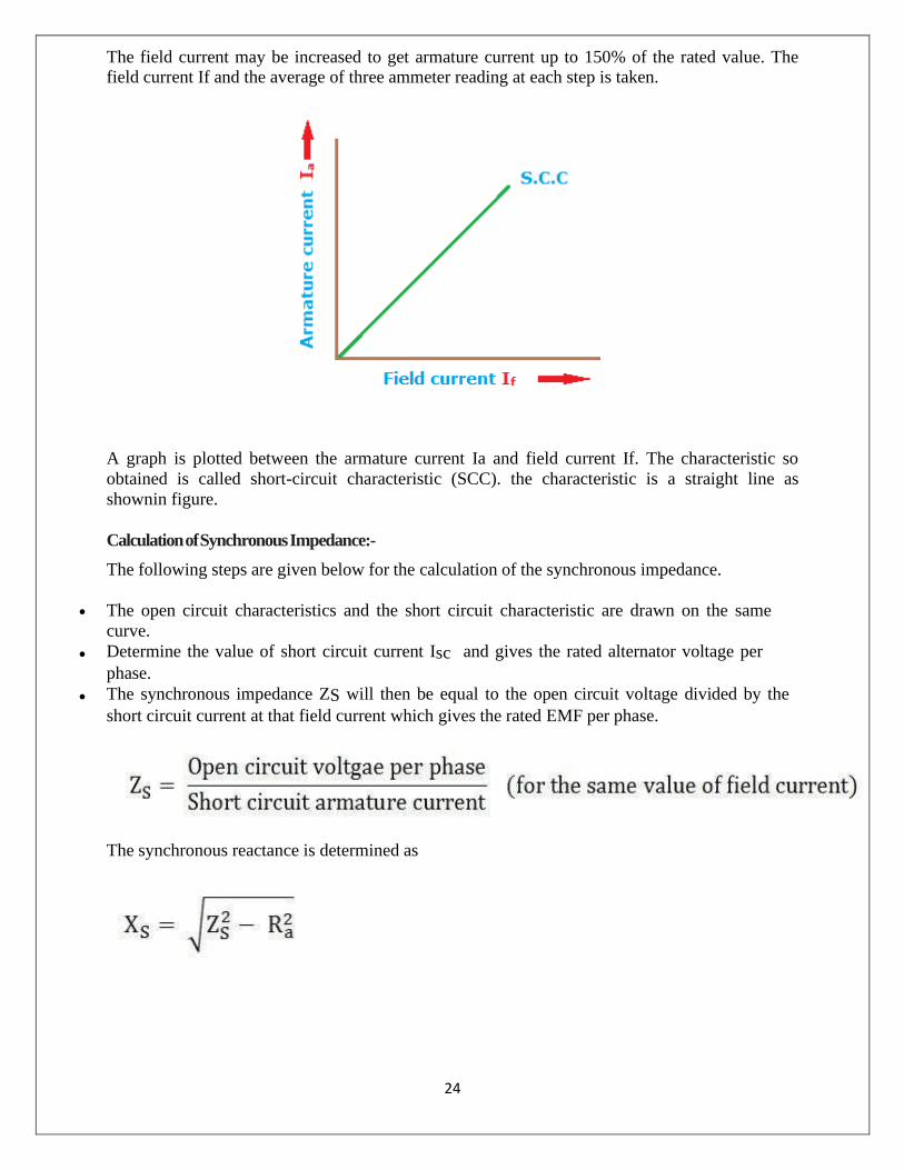
The field current may be increased to get armature current up to 150% of the rated value. The field current If and the average of three ammeter reading at each step is taken.
A graph is plotted between the armature current Ia and field current If. The characteristic so
obtained is called short-circuit characteristic (SCC). the characteristic is a straight line as
shown in figure.
Calculation of Synchronous Impedance:-
The following steps are given below for the calculation of the synchronous impedance.
• The open circuit characteristics and the short circuit characteristic are drawn on the same
curve.
• Determine the value of short circuit current Isc and gives the rated alternator voltage per
phase.
• The synchronous impedance ZS will then be equal to the open circuit voltage divided by the
short circuit current at that field current which gives the rated EMF per phase.
The synchronous reactance is determined as
25
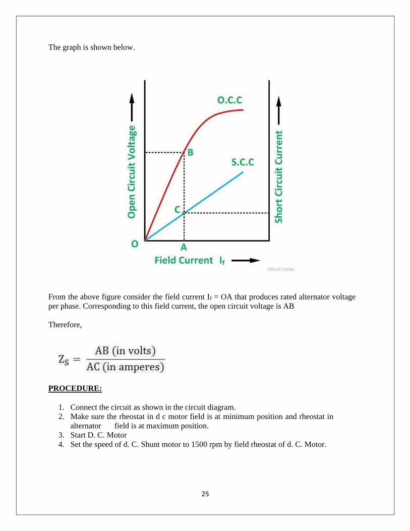
The graph is shown below.
From the above figure consider the field current If = OA that produces rated alternator voltage
per phase. Corresponding to this field current, the open circuit voltage is AB
Therefore,
PROCEDURE:
1. Connect the circuit as shown in the circuit diagram.
2. Make sure the rheostat in d c motor field is at minimum position and rheostat in
alternator field is at maximum position.
3. Start D. C. Motor
4. Set the speed of d. C. Shunt motor to 1500 rpm by field rheostat of d. C. Motor.

26
For O.C. test:-
1. Note down the voltmeter reading when switch in field of alternator is open. This is
voltage due to residual magnetism when field current is zero.
2. Close the switch in field circuit (single pole), take down readings of D. C. Ammeter (If)
and Voltmeter (Voc) by gradually reducing resistance in the field circuit of alternator.
3. Take down readings up to Voc = 440 V. Field current of alternator should not exceed its
rating.
4. Increase resistance gradually, then directly switch off D.C. Supply.
For S. C. Test:-
1. Connect Ammeter in R and Y terminal of alternator, Short Y and B terminals Make
sure rheostat positions of both machine fields Motor field rheostat - minimum,
Alternator field rheostat – maximum position.
2. Switch on DC supply, start DC Motor by 3-point starter.
3. Adjust speed of DC motor at 1500 rpm by field rheostat.
4. Close the single pole switch, DC ammeter will be at minimum reading.
5. Take down DC. Ammeter reading (If) and AC. ammeter (ISC)reading by gradually
reducing Field resistance of alternator.
6. Short circuit current of alternator must be below 4.2A that is rated current of
alternator.
7. Increase resistance to max of alternator field and switch off DC supply.
8. Remove connections.
OBSERVATION TABLE:-
Open Circuit Test:-
Sl. No IF amps VOC Volts
1
2
3
4
5

27
Short Circuit Test:-
Sl. No IF amps VSC Volts
1
2
3
4
5
Conclusion:- From the above experiment, we learnt about the, OC and SC test of alternator and determination of regulation by synchronous impedance method.
28
Experiment - 07
Aim- Determine of regulation of alternator by direct loading.
APPARATUS REQUIRED:-
Sl. No Name of the Equipment Specification Quantity
1
DC Motor Coupled to Alternator
Motor- 230 V, 5 KVA, 5.5
HP, 1500 RPM, If = 1.2 A, Ia=
22 A
Alternator- 415 V, 5 KVA,
0.8 PF, 1500 RPM, If = 1.5
A, Ia= 6.6 A, 3 Phase
1no
2 Line Tester 1100v, 6‟‟ 1no
3 Wire Stripper 150mm 1 no
4 Voltmeter 600 V AC 1no
5 Ammeter 10 A AC 4 nos
6 Rheostat 500 Ohm, 1 A 1no
7 Multimeter - 1 no
7 Tachometer 0-9999 RPM, Digital 1no
8 Frequency Meter Digital Type 1 no
9 Three Phase Resistor Load 440V, 1KΩ 1no
10 Wires 2.5 sq mm As per
required
Theory:-
The Voltage Regulation of a Alternator is the rise in voltage at the terminals when the load is
reduced from full load rated value to zero, speed and field current remaining constant. It
depends upon the power factor of the load. For unity and lagging power factors, there is always a
voltage drop with the increase of load, but for a certain leading power, the full load voltage
regulation is zero.
The voltage regulation is given by the equation shown below.
29
Where,
• |Ea| is the magnitude of a generated voltage per phase
• |V| is the magnitude of rated terminal voltage per phase
In this case, the terminal voltage is the same for both full load and no load conditions. At lower
leading power factors, the voltage rises with the increase of load, and the regulation is negative.
Determination of Voltage Regulation:-
There are mainly two methods which are used to determine the regulation of voltage of a
smooth cylindrical rotor type alternators. They are named as direct load test method
and indirect methods of voltage regulation. The indirect method is further classified
as Synchronous Impedance Method, Ampere-turn Method and Zero Power Factor Method.
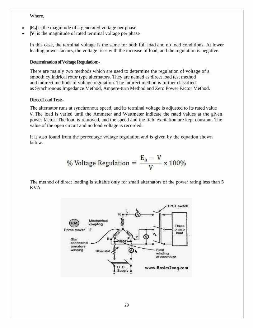
Direct Load Test:-
The alternator runs at synchronous speed, and its terminal voltage is adjusted to its rated value
V. The load is varied until the Ammeter and Wattmeter indicate the rated values at the given
power factor. The load is removed, and the speed and the field excitation are kept constant. The
value of the open circuit and no load voltage is recorded.
It is also found from the percentage voltage regulation and is given by the equation shown
below.
The method of direct loading is suitable only for small alternators of the power rating less than 5
KVA.

30
Procedure:-
1. Connect the circuit as per the circuit diagram.
2. Keep the field rheostat of d.c. motor at minimum position and field rheostat of alternator
at maximum position.
3. Switch on d.c. supply and start d.c. shunt motor.
4. Adjust the speed of d.c. motor to 1500 r.p.m. Adjust rheostat in field circuit of alternator
such that it gives rated voltage i.e. 400V. Take down voltmeter reading. This is no load
voltage of alternator.
5. Switch ON load such that ammeter of each phase indicate same reading.
6. Check speed of motor, if it is reduced, adjust the speed to 1500 r.p.m. at this loading
condition.
7. Take down readings of ammeter and voltmeter by gradually increasing load. At each
loading condition, speed should be adjusted to 1500 rpm.
8. Switch off load bank.
9. Adjust rheostat of alternator field to maximum position and switch off d.c. supply.
10. Plot the graph.
Observation Table:-
Sl. No Ia amps VL (volts) N rpm
1
2
3
4
5
31
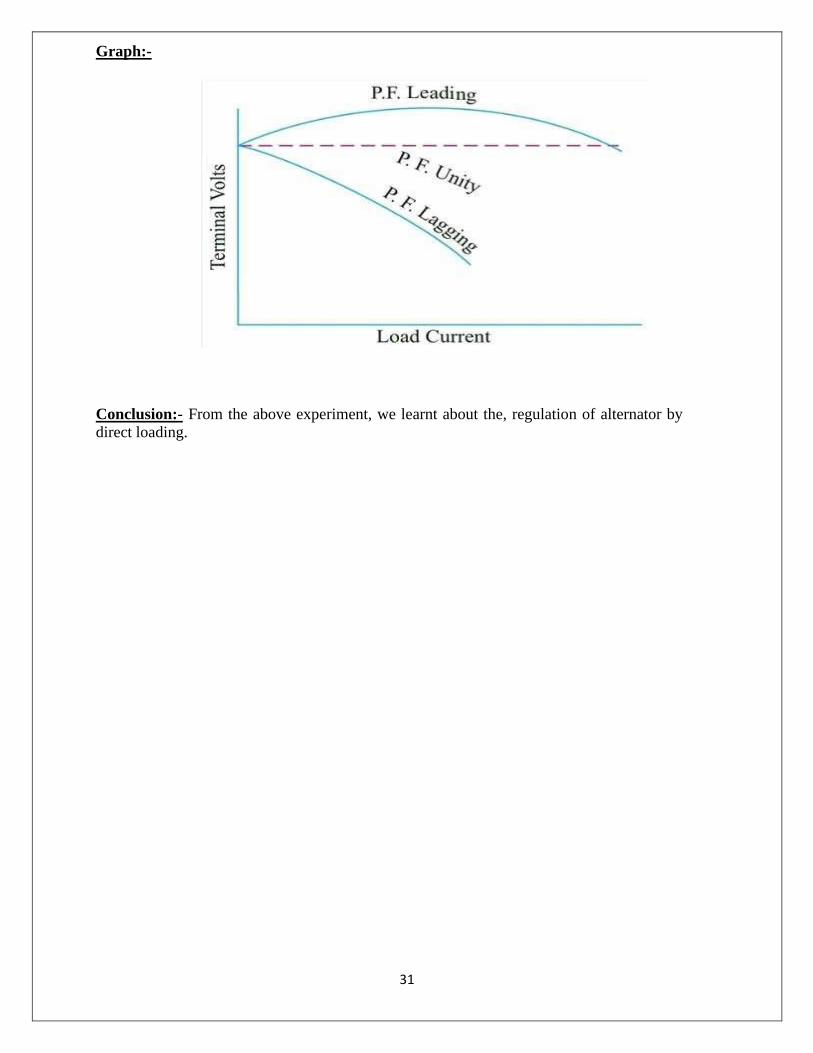
Graph:-
Conclusion:- From the above experiment, we learnt about the, regulation of alternator by direct loading.

32
Experiment - 08
Aim- Parallel operation of two alternators and study load sharing.
APPARATUS REQUIRED:-
Sl. No Name of the Equipment Specification Quantity
1
DC Motor Coupled to Alternator
Motor- 220V DC, 4 KW,
1500RPM, IA= 22 A, IF=1.1
A
Alternator- 415 V AC, 5
KVA,50 Hz, 5.5 A, 3 Phase
2nos
2 Line Tester 1100v, 6‟‟ 1no
3 Wire Stripper 150mm 1 no
4 Voltmeter 600 V AC 2nos
5 Ammeter 10 A AC 2 nos
6 Rheostat 500ohm, 1A 4 nos
7 Multimeter - 1 no
7 Tachometer Digital Type 1 nos
8 Synchroscope - 1 no
9 Lamps 100W 6nos
10 Wires 2.5 sq mm As per required
Theory:-
Alternator is really an AC generator. In alternator, an EMF is induced in the stator (stationary
wire) with the influence of rotating magnetic field (rotor) due to Faraday’s law of induction. Due
to the synchronous speed of rotation of field poles, it is also known as synchronous generator.
Here, we can discuss about parallel operation of alternator. When the AC power systems are
interconnected for efficiency, the alternators should also have to be connected in parallel. There
will be more than two alternators connected in parallel in generating stations.
Condition for Parallel Operation of Alternator:-
There are some conditions to be satisfied for parallel operation of the alternator. Before entering
into that, we should understand some terms which are as follows.
1. The process of connecting two alternators or an alternator and an infinite bus bar
system in parallel is known as synchronizing.
2. Running machine is the machine which carries the load.
33
3. Incoming machine is the alternator or machine which has to be connected in parallel with the system.
The conditions to be satisfied are:-
1. The phase sequence of the incoming machine voltage and the bus bar voltage should be
identical.
2. The RMS line voltage (terminal voltage) of the bus bar or already running machine
and the incoming machine should be the same.
3. The phase angle of the two systems should be equal.
4. The frequency of the two terminal voltages (incoming machine and the bus bar) should
be nearly the same. Large power transients will occur when frequencies are not nearly
equal.
Departure from the above conditions will result in the formation of power surges and current. It
also results in unwanted electro-mechanical oscillation of rotor which leads to the damage of
equipment.
Methods:-
There are two synchronizing methods -
a. Using incandescent lamp
b. Using synchroscope.
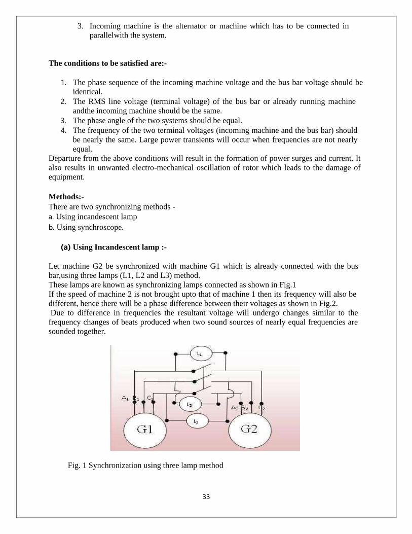
(a) Using Incandescent lamp :-
Let machine G2 be synchronized with machine G1 which is already connected with the bus
bar, using three lamps (L1, L2 and L3) method.
These lamps are known as synchronizing lamps connected as shown in Fig.1
If the speed of machine 2 is not brought upto that of machine 1 then its frequency will also be
different, hence there will be a phase difference between their voltages as shown in Fig.2.
Due to difference in frequencies the resultant voltage will undergo changes similar to the
frequency changes of beats produced when two sound sources of nearly equal frequencies are
sounded together.
Fig. 1 Synchronization using three lamp method

34
The resultant voltage is sometimes maximum and sometimes minimum.
Hence, the lamps will flicker, sometimes dark and sometimes bright.
Synchronization is done at the middle of the dark period. This method of synchronizing is
known as dark lamp method.
Lamp L1 is connected between A1 and A2, L2 between B1 and C2 and L3 between C1 and B2.
These three lamps slowly brighten and darken in cyclic successor in a direction depending upon
whether incoming machine 2 is fast or slow.
The synchronizing switch will be closed at the moment when lamp L1 will be completely dark.
This method has following drawbacks:
1. The lamps become dark at about one third of the rated voltage. Hence, faulty synchronizing
may be done in dark period.
2. Using this method it is not possible to find out that how much the machine is slow or fast.
3. This method is not applicable for high voltage alternators, because lamp ratings are normally
low. For such situations we need an extra transformer to step down the voltage.
(b) SYNCHRONIZING BY SYNCHROSCOPE:
Synchroscope is a device that shows the correct instant of closing the synchronizing switch with
the help of a pointer which will rotate on the dial.
The rotation of pointer also indicates whether the incoming machine is running too slow or too
fast.
If incoming machine is slow then pointer rotates in anticlockwise direction and if machine is
fast then pointer rotates in clockwise direction.
PROCEDURE:
Fig. 3 Synchronizing by Synchroscope
1. Make the connection diagram as shown in figure 1.1
2. Run one of the alternators and adjust its voltage at rated value and close switch to bus bar.
3. Start the second set (alternator 2), bring it upto proper speed equal to that of the running
alternator (or bus bar voltage).
4. Synchronize the incoming alternator by any one method described in theory.

35
Observations :-
1. Measure and adjust voltage of incoming machine (Vg) and bus bar (Vs) till Vg=Vs.
2. Measure and adjust the speed of incoming machine, till synchroscope needle creeps.
3. Close synchronizing switch
Conclusion:- From the above experiment, we learnt about the, Parallel operation of two alternators and study load sharing.
36
Experiment - 09
Aim- Measurement of power of a 3-phase Load using two wattmeter method and
verification of the result using one 3- phase wattmeter.
APPARATUS REQUIRED:-
Sl. No Name of the Equipment Specification Quantity
1 Wattmeter 250V, 4A, 1000 W 2nos
2 Three Phase Wattmeter 440V, 10A, 10 KW 1no
3 Line Tester 1100v, 6‟‟ 1no
4 Wire Stripper 150mm 1 no
5 Voltmeter (0-300) V 2nos
6 Ammeter (0-5) A 2nos
7 Three Phase Resistive Load 440V, 3 Phase, 3 KW 1no
9 Wires 2.5 sq mm As per required
Theory:-
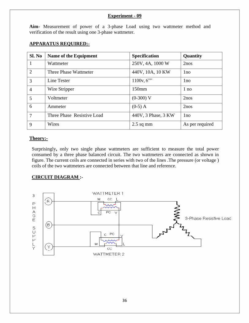
Surprisingly, only two single phase wattmeters are sufficient to measure the total power
consumed by a three phase balanced circuit. The two wattmeters are connected as shown in
figure. The current coils are connected in series with two of the lines .The pressure (or voltage )
coils of the two wattmeters are connected between that line and reference.
CIRCUIT DIAGRAM :-

37
PROCEDURE :-
1. Connect the circuit as shown in figure.
2. Keep the three phase variac at its zero position.
3. Switch on the main supply.
4. Increase the voltage supplied to the circuit by changing the positions of variac so that all the
meters give readable deflection.
5. Note down readings of all the meters
Tabulation:-
Sl. No Load Voltage
in Volt
Load Current
In Ampere
Wattmeter
(W1)Reading
In Kwh
Wattmeter
(W2)Reading
In Kwh
P= W1 +
W2
1
2
3
4
5
PRECAUTIONS :
1. Connections should be tight.
2. Take the readings carefully.
3. Switch off the circuit when not in use.
Verification Of Result Using One 3-Phase Wattmeter
THEORY:
Three phase reactive power can be measured by two wattmeter method which is universally
adopted Method. The difference between higher reading wattmeter and lower wattmeter
reading yields VLILsinØ. so, the total 3 reactive power is √3 V L I L sinØ
Reactive power in a balance 3-Ø load can also be calculated by using single wattmeter. In this
method, the current coil of the wattmeter is connected in any on line and the pressure coils across
the other two lines. Let us assume that the Current coil is connected in R phase and pressure coil
is connected across „Y‟ and „B‟ phases. Assuming phases. Assuming phase sequence RYB and an
inductive load of an angle „Ø‟ the phasor diagram for the circuits is as follows.

38
Here current through current coil = IR Voltage across pressure coil = VYB
The phase angle between VYB and IR from the phasor diagram is 90°-Ø Wattmeter reading
is VYB IR Cos (90°-Ø)
W = VYB IR Sin (90°-Ø)
In terms of line current and voltage
W = VYB IR Cos (90°-Ø)
Items of line current and voltage
W = VL IL Sin Ø
The total 3-Ø reactive power is √3 VL IL Sin Ø
CIRCUIT DIAGRAM
PROCEDURE:
1. Connect the circuit as shown in fig.
2. Switch „ON‟ the supply.
3. Note down the corresponding there reading and calculate 3-phase reactive power.
4. Now increase the load of three phase Inductive load steps and note down the corresponding
meter readings.
5. Remove the load and ‘switch off’ the supply.

39
TABULAR COLUMN:
Sl. No 3 Phase Load Wattmeter Reading 3 Phase Reactive Power
1 1 A
2 2 A
3 3 A
4 4 A
5 5 A
Conclusion:- From the above experiment, we learnt about the, Measurement of power of a 3-
phase Load using two wattmeter method and verification of the result using one 3-phase
wattmeter.

40
Experiment - 10
Aim- Connection of 3-phase energy meter to a 3-phase load.
APPARATUS REQUIRED:-
Sl. No Name of the Equipment Specification Quantity
1 3 Phase, 4 WIRE AC static watthour
meter
440 V, 10-60 A, 50 Hz,
CL-1
1no
2 Three Phase Resistive Load 415 V, 3 KW, 3 Phase 1no
3 Insulated Combination Pliers 150mm 1no
4 Line Tester 1100v, 6‟‟ 1no
5 Wire Stripper 150mm 1 no
6 Wires 2.5 sq mm As per required
Theory:-
Three Phase Energy Meter:-
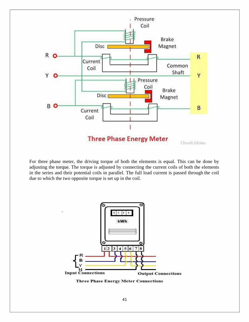
The meter which is used for measuring the power of three phase supply is known as the three
phase energy meter. The three phase meter is constructed by connecting the two single phase
meter through the shaft. The total energy is the sum of the reading of both the elements.
Working Principle of Three Phase Energy Meter:-
The torque of both the elements is added mechanically, and the total rotation of the shaft is
proportional to the three phase energy consumption.
Construction of Three Phase Energy Meter:-
The three phase energy meter has two discs mounted on the common shaft. Both the disc has
its braking magnet, copper ring, shading band and the compensator for getting the correct
reading. The two elements are used for measuring the three phase power. The construction of
the three phase meter is shown in the figure below.
41
For three phase meter, the driving torque of both the elements is equal. This can be done by
adjusting the torque. The torque is adjusted by connecting the current coils of both the elements
in the series and their potential coils in parallel. The full load current is passed through the coil
due to which the two opposite torque is set up in the coil.

42
The strength of both the torques is equal, and hence they do not allow the disc to rotate. If the
torque becomes unequal and the disc rotates then the magnetic shunt is adjusted. The balance
torque is obtained before testing the meter. The position of the compensator and the braking
magnet are separately adjusted to each of the element for obtaining the balance torque.
Procedure:-
1. We should take all the tools and material.
2. Make the connection as per circuit diagram.
3. All the connection should be tight.
4. Switch on the supply.
5. Observe the output.
Conclusion:-
From the above experiment, we learnt about the, connection of 3-phase energy meter to a 3-phase load.
43
Experiment - 11
Aim- Study of an O.C.B.
APPARATUS REQUIRED:-
Sl. No Name of the Equipment Specification Quantity
1 Oil Circuit Breaker 415 V,100 A, 3 Ph, 50
Hz
1no
2 Insulated Combination Pliers 150mm 1no
3 Screw driver 200mm 1no
Theory:-
Oil circuit breaker is such type of circuit breaker which used oil as a dielectric or insulating
medium for arc extinction. In oil circuit breaker the contacts of the breaker are made to separate
within an insulating oil. When the fault occurs in the system the contacts of the circuit breaker
are open under the insulating oil, and an arc is developed between them and the heat of the arc is
evaporated in the surrounding oil.
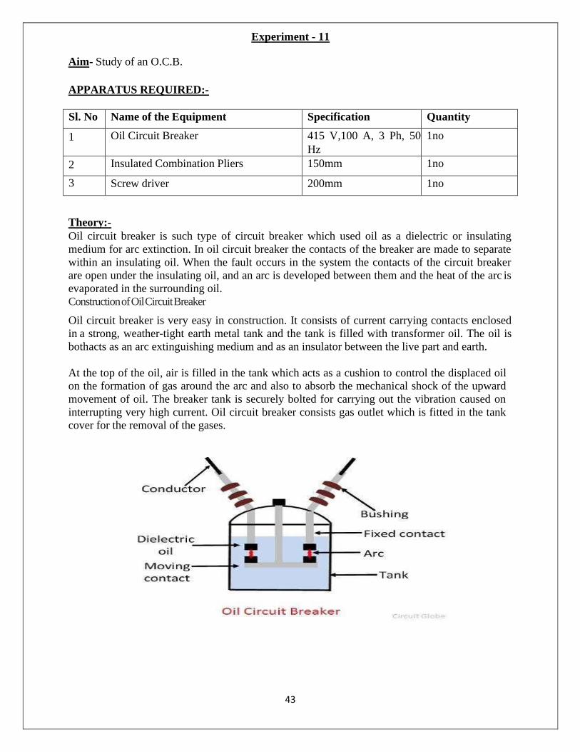
Construction of Oil Circuit Breaker
Oil circuit breaker is very easy in construction. It consists of current carrying contacts enclosed
in a strong, weather-tight earth metal tank and the tank is filled with transformer oil. The oil is
both acts as an arc extinguishing medium and as an insulator between the live part and earth.
At the top of the oil, air is filled in the tank which acts as a cushion to control the displaced oil
on the formation of gas around the arc and also to absorb the mechanical shock of the upward
movement of oil. The breaker tank is securely bolted for carrying out the vibration caused on
interrupting very high current. Oil circuit breaker consists gas outlet which is fitted in the tank
cover for the removal of the gases.
44
Working Principle of Oil Circuit Breaker:-
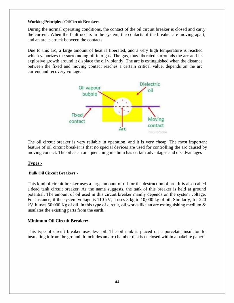
During the normal operating conditions, the contact of the oil circuit breaker is closed and carry
the current. When the fault occurs in the system, the contacts of the breaker are moving apart,
and an arc is struck between the contacts.
Due to this arc, a large amount of heat is liberated, and a very high temperature is reached
which vaporizes the surrounding oil into gas. The gas, thus liberated surrounds the arc and its
explosive growth around it displace the oil violently. The arc is extinguished when the distance
between the fixed and moving contact reaches a certain critical value, depends on the arc
current and recovery voltage.
The oil circuit breaker is very reliable in operation, and it is very cheap. The most important
feature of oil circuit breaker is that no special devices are used for controlling the arc caused by
moving contact. The oil as an arc quenching medium has certain advantages and disadvantages
Types:-
.Bulk Oil Circuit Breakers:-
This kind of circuit breaker uses a large amount of oil for the destruction of arc. It is also called
a dead tank circuit breaker. As the name suggests, the tank of this breaker is held at ground
potential. The amount of oil used in this circuit breaker mainly depends on the system voltage.
For instance, if the system voltage is 110 kV, it uses 8 kg to 10,000 kg of oil. Similarly, for 220
kV, it uses 50,000 Kg of oil. In this type of circuit, oil works like an arc extinguishing medium &
insulates the existing parts from the earth.
Minimum Oil Circuit Breaker:-
This type of circuit breaker uses less oil. The oil tank is placed on a porcelain insulator for insulating it from the ground. It includes an arc chamber that is enclosed within a bakelite paper.

45
This circuit breaker includes two portions; the upper portion is porcelain that is enclosed with contacts whereas the lower portion is supported through the porcelain
It uses less space as compared with bulk oil type. It is not used where the repeated operation is
necessary. The main benefits of this circuit breaker are, it uses less oil, less space, less weight,
tank size is small, less maintenance, etc.
Maintenance of Oil Circuit Breaker:-
For every type of circuit breaker, maintenance is required. Similarly in oil type also, it is essential
to verify and change the oil as well as contacts. Once the short circuit occurs, then a circuit
breaker is interrupted. Sometimes, the contacts may get damaged because of arcing. So, the
dielectric oil may get carbonized within the region of the contacts then its dielectric strength can
be reduced and breaking capacity can be decreased. As a result, the maintenance of the breaker is
necessary for verifying, replacing the oil & contacts.
The following points must be check before inspecting the circuit breaker
a. Observe the internal parts & arcing contacts. Once it gets a short circuit then the
contacts must be changed.
b. Observe the coil’s dielectric strength
c. The surface of the breaker must be cleaned & eliminate carbon deposits through a dry
fabric & strong.
d. Verify the level of oil.
e. Tripping as well as closing mechanism must be checked.
Conclusion: - From the above experiment, we learnt about the, oil circuit breaker of
transformer.
46
Experiment - 12
Aim- Study of an induction type over current/ reverse power relay.
APPARATUS REQUIRED:-
Sl. No Name of the Equipment Specification Quantity
1 Induction Type Over Current Relay 440V, 2-10 A, 50 Hz
C.T. Sec= 5 Amp
1no
2 Insulated Combination Pliers 150mm 1no
3 Line Tester 1100v, 6‟‟ 1no
4 Wire Stripper 150mm 1 no
5 Wires 2.5 sq mm As per required
6 Over current relay test kit - 1 no
Theory:-
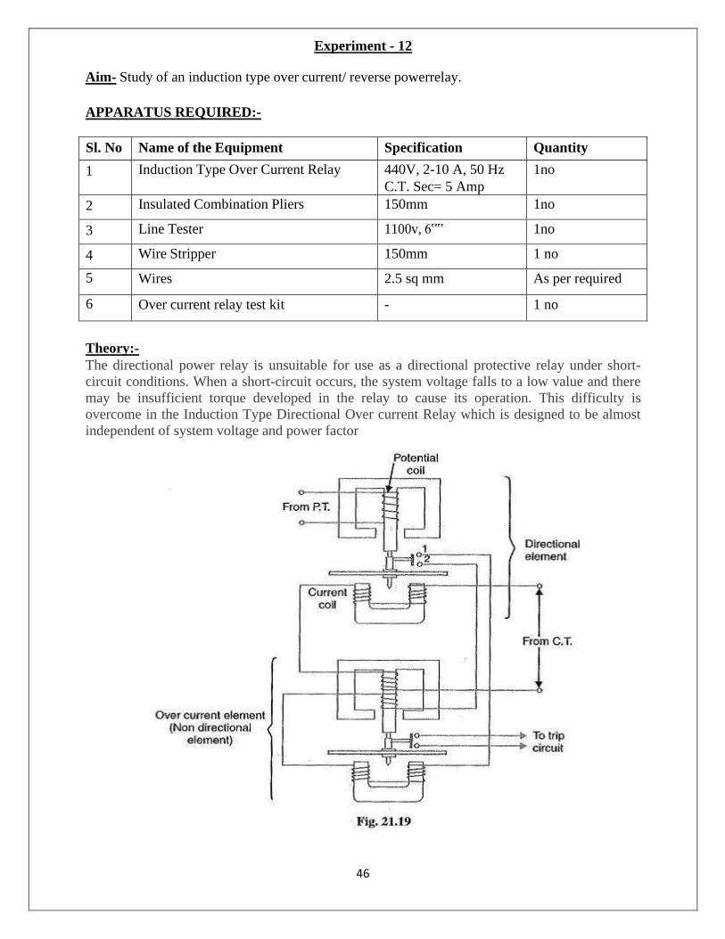
The directional power relay is unsuitable for use as a directional protective relay under short-
circuit conditions. When a short-circuit occurs, the system voltage falls to a low value and there
may be insufficient torque developed in the relay to cause its operation. This difficulty is
overcome in the Induction Type Directional Over current Relay which is designed to be almost
independent of system voltage and power factor

47
Constructional details: Fig. 21.19 shows the constructional details of a typical Induction
Type Directional Over current Relay. It consists of two relay elements mounted on a common
case viz.
1. Directional element and
2. Non-directional element.
1. Directional element:
It is essentially a directional power relay which operates when power flows in a specific
direction. The potential coil of this element is connected through a potential transformer (P.T.) to
the system voltage. The current coil of the element is energized through a C.T. by the circuit
current. This winding is carried over the upper magnet of the non-directional element. The trip
contacts (1 and 2) of the directional element are connected in series with the secondary
circuit of the over current element. Therefore, the latter element cannot start to operate until its
secondary circuit is completed. In other words, the directional element must operate first (i.e.
contacts I and 2 should close) in order to operate the over current element.
3. Non-directional element:-
It is an over current element similar in all respects to a non-directional over current relay
described in Art. 21.11. The spindle of the disc of this element carries a moving contact which
closes the fixed contacts (trip circuit contacts) after the operation of directional element.
It may be noted that plug-setting bridge is also provided in the relay for current setting but has
been omitted in the figure for clarity and simplicity. The tappings are provided on the upper
magnet of over current element and are connected to the bridge.
Operation:
Under normal operating conditions, power flows in the normal direction in the circuit protected
by the relay. Therefore, Induction Type Directional Over current Relay (upper element) does not
operate, thereby keeping the over current element (lower element) unexercised. However, when a
short-circuit occurs, there is a tendency for the current or power to flow in the reverse direction.
Should this happen, the disc of the upper element rotates to bridge the fixed contacts 1 and 2.
This completes the circuit for over current element.
The disc of this element rotates and the moving contact attached to it closes the trip circuit. This
operates the circuit breaker which isolates the faulty section. The two relay elements are so
arranged that final tripping of the current controlled by them is not made till the following
conditions are satisfied:
1. Current flows in a direction such as to operate the directional element.
2. Current in the reverse direction exceeds the pre-set value.
3. Excessive current persists for a period corresponding to the time setting of over current
element.
Conclusion:- From the above experiment, we learnt about the, induction type over current
relay.
48
Experiment - 13
Aim- Study of Buchholz’s Relay.
APPARATUS REQUIRED:-
Sl. No Name of the Equipment Specification Quantity
1 Buchholz’s Relay Testing Kit - 1no
2 Insulated Combination Pliers 150mm 1no
3 Line Tester 1100v, 6‟‟ 1no
4 Wire Stripper 150mm 1 no
5 Wires 2.5 sq mm As per required
Theory:-
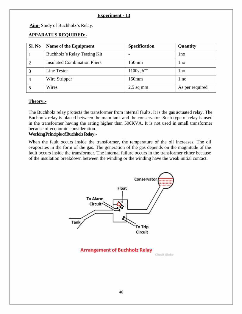
The Buchholz relay protects the transformer from internal faults. It is the gas actuated relay. The
Buchholz relay is placed between the main tank and the conservator. Such type of relay is used
in the transformer having the rating higher than 500KVA. It is not used in small transformer
because of economic consideration.
Working Principle of Buchholz Relay:-
When the fault occurs inside the transformer, the temperature of the oil increases. The oil
evaporates in the form of the gas. The generation of the gas depends on the magnitude of the
fault occurs inside the transformer. The internal failure occurs in the transformer either because
of the insulation breakdown between the winding or the winding have the weak initial contact.
49
The fault induces the arc which increases the temperature of the gas. The oil becomes
evaporated and moves upwards. The Buchholz relay detects the failure and gives the alarm to
the personnel. The transformer is disconnected from the main supply for maintenance.
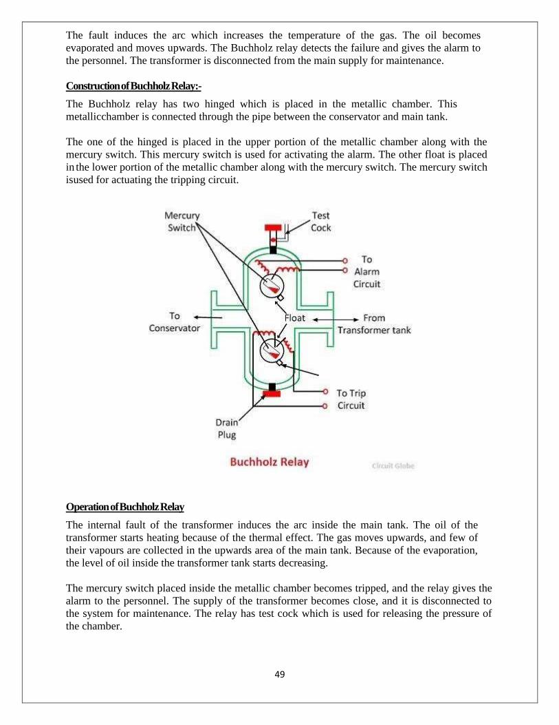
Construction of Buchholz Relay:-
The Buchholz relay has two hinged which is placed in the metallic chamber. This
metallic chamber is connected through the pipe between the conservator and main tank.
The one of the hinged is placed in the upper portion of the metallic chamber along with the
mercury switch. This mercury switch is used for activating the alarm. The other float is placed
in the lower portion of the metallic chamber along with the mercury switch. The mercury switch
is used for actuating the tripping circuit.
Operation of Buchholz Relay
The internal fault of the transformer induces the arc inside the main tank. The oil of the
transformer starts heating because of the thermal effect. The gas moves upwards, and few of
their vapours are collected in the upwards area of the main tank. Because of the evaporation,
the level of oil inside the transformer tank starts decreasing.
The mercury switch placed inside the metallic chamber becomes tripped, and the relay gives the
alarm to the personnel. The supply of the transformer becomes close, and it is disconnected to
the system for maintenance. The relay has test cock which is used for releasing the pressure of
the chamber.

50
When the severe fault occurs inside the transformer, the lower mercury switch placed inside the
metallic chamber becomes slightly tilted because of which the tripping circuit becomes closed.
Thus, the transformer is disconnected from the main circuit.
Limitations of Buchholz Relay:-
The following are the disadvantages of Buchholz relay.
1. The relay is used only in oil immersed transformer.
2. It can only detect the fault below oil level.
3. This relay does not protect the connecting cables. Hence separate protection is
used for the cables.
4. The response time of the relay is high.
5. The minimum operating time of the relay is 0.1 seconds.
Procedure:-
i Close all the balls.
ii Press the air compressor in order to increase the pressure.
iii Immediately open the valve number 1.
iv Oil from the tank rushes into the Buchholz relay & fill it completely.
v Open the output valve of Buchholz relay.
vi Oil will rush out from the Buchholz relay into tank.
vii When the oil reaches at the half level, the buzzers starts ringing to show that the low
recipient fault has occurred.
Conclusion: - From the above experiment, we learnt about the, Buchholz’s relay.
51
Experiment - 14
Aim- Study of an Earth Fault Relay.
APPARATUS REQUIRED:-
Sl. No Name of the Equipment Specification Quantity
1 Earth Fault Relay Testing Kit - 1no
2 Insulated Combination Pliers 150mm 1no
3 Line Tester 1100v, 6‟‟ 1no
4 Wire Stripper 150mm 1 no
5 Wires 2.5 sq mm As per required
Theory:-
The function of a relay is to detect abnormal conditions in the system and to initiate through
appropriate circuit breakers the disconnection of faulty circuits so that Interference with the
general supply is minimized.
Earth fault protection can be provided with normal over current relays, if the minimum earth
fault current is sufficient in magnitude. The design of a comprehensive protection scheme in a
power system requires the detailed study of time-current characteristics of the various relays used
in the scheme. Thus it is necessary to obtain the time current characteristics of these relays. The
over current relay works on the induction principle. The moving system consists of an aluminum
disc fixed on a vertical shaft and rotating on two jeweled bearings between the poles of an
electromagnet and a damping magnet. The winding of the electromagnet is provided with seven
taps (generally0, which are brought on the front panel, and the required tap is selected by a push-
in -type plug. The pick-up current setting can thus be varied by the use of such plug multiplier
setting. The pick-up current values of earth fault relays are normally quite low.
Operation:
With supply on load are continuously monitored Electronic comparator checks this value with
set value (N) of phase & earth fault trip, which can be adjusted on front plate. Pick up response
is (1.1 N) IDMT timing is applicable to over current above 2N as per chosen curve. Time setting
multiplier for actual tripping time delay. TMS is adjusted by 11-position switch & with variable
preset pot. These pots adjusted time for intermediate values indicated on TMS switch. Tripping
cause is indicated by LED lamp (OC/EF). When over current trips the circuit relay „ NO‟ contact
changes to „NC‟ when relay trips indicating LED to „NC‟ when relay trip indicating LED to
„NC‟ when relay trips indicating LED to „NC‟ when relay trip indicating LED flag will remain
ON till manually reset.

52
Circuit Diagram:-
Procedure: -
1. Make the connection as shown in fig.
2. Set current and time setting of relays as per requirement
3. Set phase trip to 50% and set phase time at X1 with phase TMS at maximum position.
4. Switch on variac and check power ON indication provided on relay front panel.
5. Very dimmer state with fault current of 1A, relay will trip after certain time delay.
6. Switch OFF dimmer state without disrobing its position and change the position of DPT
switch. Also reset time.
7. Switch ON dimmer state changes the position of switch and measure the relay time from
timer.
8. Reap eat same procedure for varying a different fault current.
9. Repeat this procedure consider different set phase time (TMS)
Observation Table:-
Current setting =……Phase TMS
Sr. No. Fault
Current (A)
PSM Timer time
for TSM=
Timer time
for TSM=
Timer time
for TSM=
Conclusion: - From the above experiment, we learnt about the, Earth Fault relay.

GOVT.POLYTECHNIC, Nabarangpur
DEPARTMENT OF
ELECTRICAL ENGINEERING
POWER ELECTRONICS AND PLC LABORATORY MANUAL
5th SEM. ELECTRICAL

2
DOS
It is COMPULSORY to wear covered shoes when entering the lab. You must keep your bags at the designated area. Bags should NOT
be placed on or under the workbench. Chairs and stools should be kept under the workbenches when not
in use. Sit upright on chairs or stools, keeping feet on the floor. Follow the instructions of your lab demonstrator while conducting
the experiments. In an emergency, all power in this lab can be switched off by
pressing the button on the main breaker panel. It is to be used for emergencies ONLY.
DON’TS
Do NOT transfer equipment to other workbench or other labs without permission.
Do NOT touch any equipment until you are told to do so. Wearing a ring or watch can be hazardous in an electrical lab
since such items make good electrodes for the human body NO food and drinks are allowed in this lab. NEVER touch any equipment’s or components with wet or damp
hands.

3
Pr.2 POWER ELECTRONICS & PLC LAB
Name of the Course: Diploma in Electrical Engineering Course code: Pr.2 Semester 5th
Total Period: 45 Examination 3hrs Lab. periods: 3 P / week Term Work 25 Maximum marks: 75 End Semester
Examination: 50
LIST OF EXPERIMENTS
(I) Power Electronics
1. Study of switching characteristics of a power transistor.
2. Study of V-I characteristics of SCR.
3. Study of V-I characteristics of TRIAC.
4. Study of V-I characteristics of DIAC.
5. Study of drive circuit for SCR & TRIAC using DIAC.
6. Study of drive circuit for SCR & TRIAC using UJT.
7. To study phase controlled bridge rectifier using resistive load.
8. To study series Inverter.
9. Study of voltage source Inverter.
10. To perform the speed control of DC motor using Chopper.
11. To study single-phase Cyclo-converter.
(II) PLC Programming
1. Introduction/Familiarization PLC Trainer & its Installation with PC
(a) Learn the basics and hardware components of PLC.
(b) Understand configuration of PLC system.

4
(c) Study various building blocks of PLC.
(d) Determine the No. of digital I/O & Analog I/O.
2. Execute the different Ladder Diagrams
(a) Demonstrate PLC and Ladder diagram-Preparation downloading and running.
(b) Execute Ladder diagrams for different Logical Gates.
(c) Execute Ladder diagrams using timers & counters.
3. Execute the Ladder Diagrams with model applications.
(i) DOL starter (ii) Star- Delta starter.
4. Execute Ladder diagrams with model applications (i) Stair case lighting(ii)
Traffic light controller.

5
TABLE OF CONTENTS
SI.No Name of the Experiments Pages Power Electronics
1 Study of switching characteristics of a power transistor 6-7
2 Study of V-I characteristics of SCR 8-11
3 Study of V-I characteristics of TRIAC 12-16
4 Study of V-I characteristics of DIAC 17-19
5 Study of drive circuit for SCR & TRIAC using DIAC 20-21
6 Study of drive circuit for SCR & TRIAC using UJT 22-23
7 To study phase controlled bridge rectifier using resistive load 24-29
8 To study series Inverter 30-32
9 Study of voltage source Inverter 33-34
10 To perform the speed control of DC motor using Chopper 35-37
11 To study single-phase Cyclo-converter 38-41
PLC Programming 42-76
1 Introduction/Familiarization PLC Trainer & its Installation with PC
(a) Learn the basics and hardware components of PLC (b) Understand configuration of PLC system (c) Study various building blocks of PLC (d) Determine the No. of digital I/O & Analog I/O 2 Execute the different Ladder Diagrams
(a) Demonstrate PLC and Ladder diagram-Preparation downloading and running
(b) Execute Ladder diagrams for different Logical Gates (c) Execute Ladder diagrams using timers & counters 3 Execute the Ladder Diagrams with model applications
(i) DOL starter (ii) Star- Delta starter
4 Execute Ladder diagrams with model applications (i) Stair case lighting (ii) Traffic light controller
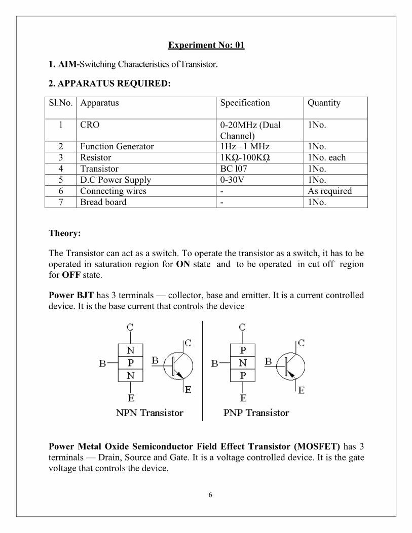
6
Experiment No: 01
1. AIM-Switching Characteristics of Transistor.
2. APPARATUS REQUIRED:
Sl.No. Apparatus Specification Quantity
1 CRO 0-20MHz (Dual Channel)
1No.
2 Function Generator 1Hz– 1 MHz 1No. 3 Resistor 1Kῼ-100Kῼ 1No. each 4 Transistor BC l07 1No. 5 D.C Power Supply 0-30V 1No. 6 Connecting wires - As required 7 Bread board - 1No.
Theory:
The Transistor can act as a switch. To operate the transistor as a switch, it has to be operated in saturation region for ON state and to be operated in cut off region for OFF state.
Power BJT has 3 terminals — collector, base and emitter. It is a current controlled device. It is the base current that controls the device
Power Metal Oxide Semiconductor Field Effect Transistor (MOSFET) has 3 terminals — Drain, Source and Gate. It is a voltage controlled device. It is the gate voltage that controls the device.
7
Insulated Gate Bipolar Transistor (IGBT) has 3 terminals — Collector, Emitter and Gate. It is also a voltage controlled device. It is the gate voltage that controls the device.
Procedure:
1. Connect the circuit as shown in the above figure. 2. Apply the Square wave of 4 Vp-p at frequency of l KHz. 3. Observe the waveforms at Collector and Base of the transistor and plot it.
CONCLUSION:
Hence, we verified the above experiment.
8
Experiment No: 02
1. AIM: Study of V-I characteristics of SCR
2. APPARATUS REQUIRED:
SI.No Apparatus Specification Quantity 1 SCR Kit 1 2 Voltmeter 0- 50V DC 1 3 Ammeter 0-500 mA DC 1 4 Ammeter 0-25mA DC 1 5 Resister 100omh 1 6 Patch cards - As per required
3. THEORY:
An elementary circuit diagram for obtaining static V-I characteristics of a thyristor is shown in Fig. (a). The anode and cathode are connected to main source through the load. The gate and cathode are fed from a source Es which provides positive gate current from gate to cathode.
9
Fig. (b) Shows static V-I characteristics of a thyristor. Here Va is the anode voltage across thyristor terminals A, K and Ia is the anode current. Typical SCR V-I characteristicshown in Fig. (b) reveals that a thyristor has three basic modes of operation; namely, reverse blocking mode, forward blocking (off-state) mode and forward conduction (on-state) mode. These three modes of operation are now discussed below:
Reverse Blocking Mode: When cathode is made positive with respect to anode with switch S open, Fig. (a), thyristor is reverse biased. Junctions J1 J3 are seen to be reverse biased whereas junction J2 is forward biased. The device behaves as if two diodes are connected in series with reverse voltage applied across them. A small leakage current of the order of a few mill amperes (or a few microamperes depending upon the SCR rating) flows. This is reverse blocking mode, called the off-state, of the thyristor. If the reverse voltage is increased, then at a critical breakdown level, called reverse break-down voltage VBR, an avalanche occurs at J1 and J3 and the reverse current increases rap-idly. A large current associated with VBR gives rise to more losses in the SCR. This may lead to thyristor damage as the junction temperature may exceed its permissible temperature rise. It should, therefore, be ensured that maximum working reverse voltage across a thyristor does not exceed VBR. When reverse voltage applied across a thyristor is less than VBR, the device offers high impedance in the reverse direction. The SCR in the reverse blocking mode may therefore be treated as an open switch.
Note that V-I characteristic after avalanche breakdown during reverse blocking mode is applicable only when load resistance is zero, Fig.(b). In case load resistance is present, a large anode current associated with avalanche breakdown at VBR would cause substantial voltage drop across load and as a result, V-I characteristic in third quadrant would bend to the right of vertical line drawn at VBR.
Forward Blocking Mode: When anode is positive with respect to the cathode, with gate circuit open, thyristor is said to be forward biased. It is seen from this figure that junctions J1, J3 are forward biased but junction J2 is reverse biased. In this mode, a small current, called forward leakage current, flows. In case the forward voltage is increased, then the reverse biased junction J2 will have an avalanche breakdown at a voltage called forward break over voltage VB0. When forward voltage is less than VBO, SCR offers high impedance. Therefore, a thyristor can be treated as an open switch even in the forward blocking mode.
10
4. CIRCUIT DIAGRAM:
5. PROCEDURE:
Connections are made as shown in the circuit diagram. The value of gate current IG, is set to convenient value by adjusting VGG. By varying the anode cathode voltage VAA gradually in step by step, note
down the cor-responding values of VAK and IA. Note down VAK and IA at the instant of firing of SCRand after firing (by reducing the voltmeter ranges and ammeter ranges) then increase the supply voltage VAA. Note down corresponding values of VAK and IA.
The point at which SCR fires, gives the value of break over voltage VBO. A graph of VAK V/S IA is to be plotted. The on state resistance can be calculated from the graph by using a formula. The gate supply voltage VGG is to be switched off. Observe the ammeter reading by reducing the anode cathode supply voltage
VAA .The point at which ammeter reading suddenly goes to zero gives the value of holding current IH
Steps no.2, 3, 4, 5, 6, 7, 8 are repeated for another value of gate current IG.

11
6. OBSERVATION:
For forward bias
SI.No Voltage (V) Current (mA)
For reverse bias
SI.No Voltage (V) Current (μA)
7. CONCLUSION:
The V-I characteristics of silicon controlled rectifier is plotted on the graph which is true according to theory.
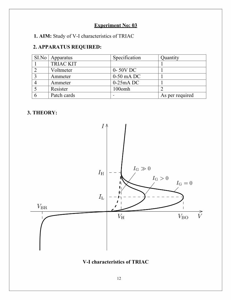
12
Experiment No: 03
1. AIM: Study of V-I characteristics of TRIAC
2. APPARATUS REQUIRED:
SI.No Apparatus Specification Quantity 1 TRIAC KIT 1 2 Voltmeter 0- 50V DC 1 3 Ammeter 0-50 mA DC 1 4 Ammeter 0-25mA DC 1 5 Resister 100omh 2 6 Patch cards - As per required
3. THEORY:
V-I characteristics of TRIAC

13
Typical V-I characteristics of a triacare shown in figure. The triac has on and off state characteristics similar to SCR but now the characteristic is applicable to both positive and negative voltages. This is expected because triac consists of two SCRs connected in parallel but opposite in directions.
MT2 is positive with respect to MTX in the first quadrant and it is negative in the third quad rant. As already said in previous blog posts, the gate triggering may occur in any of the following four modes.
Quadrant I operation: VMT2, positive; VG1 positive Quadrant II operation: VMT21 positive; VGl negative Quadrant III operation: VMT21 negative; VGl negative Quadrant IV operation: VMT21 negative; VG1 positive
Where VMT21 and VGl are the voltages of terminal MT2 and gate with respect to terminal MT1.
The device, when starts conduction permits a very heavy amount of current to flow through it. This large inrush of current must be restricted by employing external resistance; otherwise the device may get damaged.
The gate is the control terminal of the device. By applying proper signal to the gate, the firing angle of the device can be controlled. The circuits used in the gate for triggering the device are called the gate-triggering circuits. The gate-triggering circuits for the triac are almost same like those used for SCRs. These triggering circuits usually generate trigger pulses for firing the device. The trigger pulse should be of sufficient magnitude and duration so that firing of the device is assured. Usually, duration of 35 us is sufficient for sustaining the firing of the device.
A typical triac has the following voltage/current values:
Instantaneous on-state voltage – 1.5 Volts
On-state current – 25 Amperes
Holding current, IH - 75 Milli Amperes
Average triggering current, IG – 5 Milli Amperes
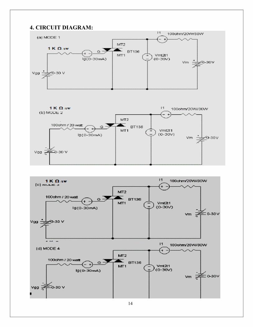
14
4. CIRCUIT DIAGRAM:

15
5. PROCEDURE:
1. Connections are made as per the circuit diagram. 2. Adjust the value of Ig to zero or some minimum value. 3. By varying the voltage (Vmt1mt2) from 0- 10v, note down the corresponding
values of current ( I1). 4. Now apply the gate voltage gradually, until SCR fires, then note down the
values of Ig and also the values of Vmt1mt2 and I1. 5. Increase Vm to some value and note down Vmt1mt2 and I1. 6. Reduce the gate voltage to zero; observe ammeter reading by reducing Vm
which gives the values of IH (Holding current) at the point at which, current suddenly drops to zero.
7. Repeat the above process 2,3,4,5,6 for different values of break over voltages.
8. Plot the graph of Vmt1mt2 Vs I1
6. OBSERVATION:
For forward bias
SI.No Voltage (V) Current (mA)

16
For reverse bias
SI.No Voltage (V) Current (μA)
7. CONCLUSION:
The V-I characteristics of TRIAC is plotted on the graph which is true according to theory.
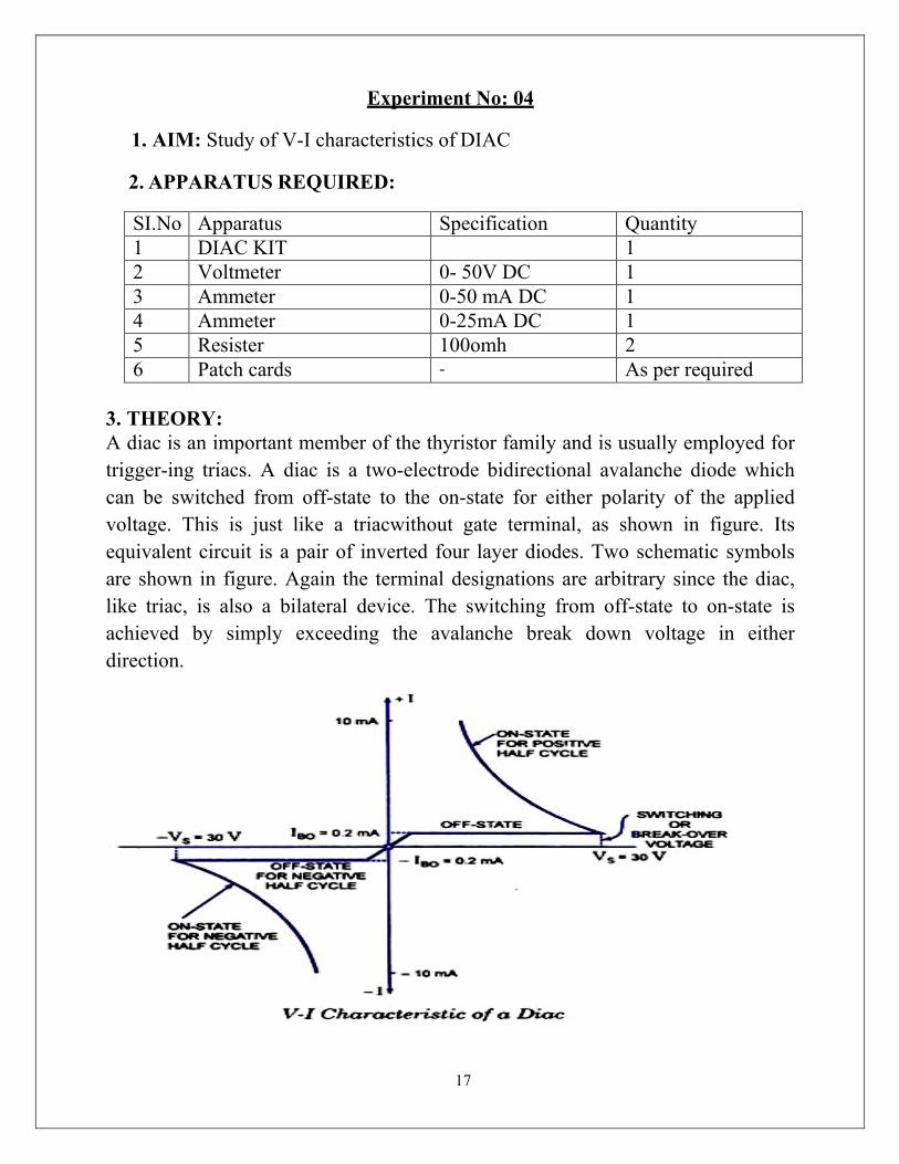
17
Experiment No: 04
1. AIM: Study of V-I characteristics of DIAC
2. APPARATUS REQUIRED:
SI.No Apparatus Specification Quantity 1 DIAC KIT 1 2 Voltmeter 0- 50V DC 1 3 Ammeter 0-50 mA DC 1 4 Ammeter 0-25mA DC 1 5 Resister 100omh 2 6 Patch cards - As per required
3. THEORY: A diac is an important member of the thyristor family and is usually employed for trigger-ing triacs. A diac is a two-electrode bidirectional avalanche diode which can be switched from off-state to the on-state for either polarity of the applied voltage. This is just like a triacwithout gate terminal, as shown in figure. Its equivalent circuit is a pair of inverted four layer diodes. Two schematic symbols are shown in figure. Again the terminal designations are arbitrary since the diac, like triac, is also a bilateral device. The switching from off-state to on-state is achieved by simply exceeding the avalanche break down voltage in either direction.
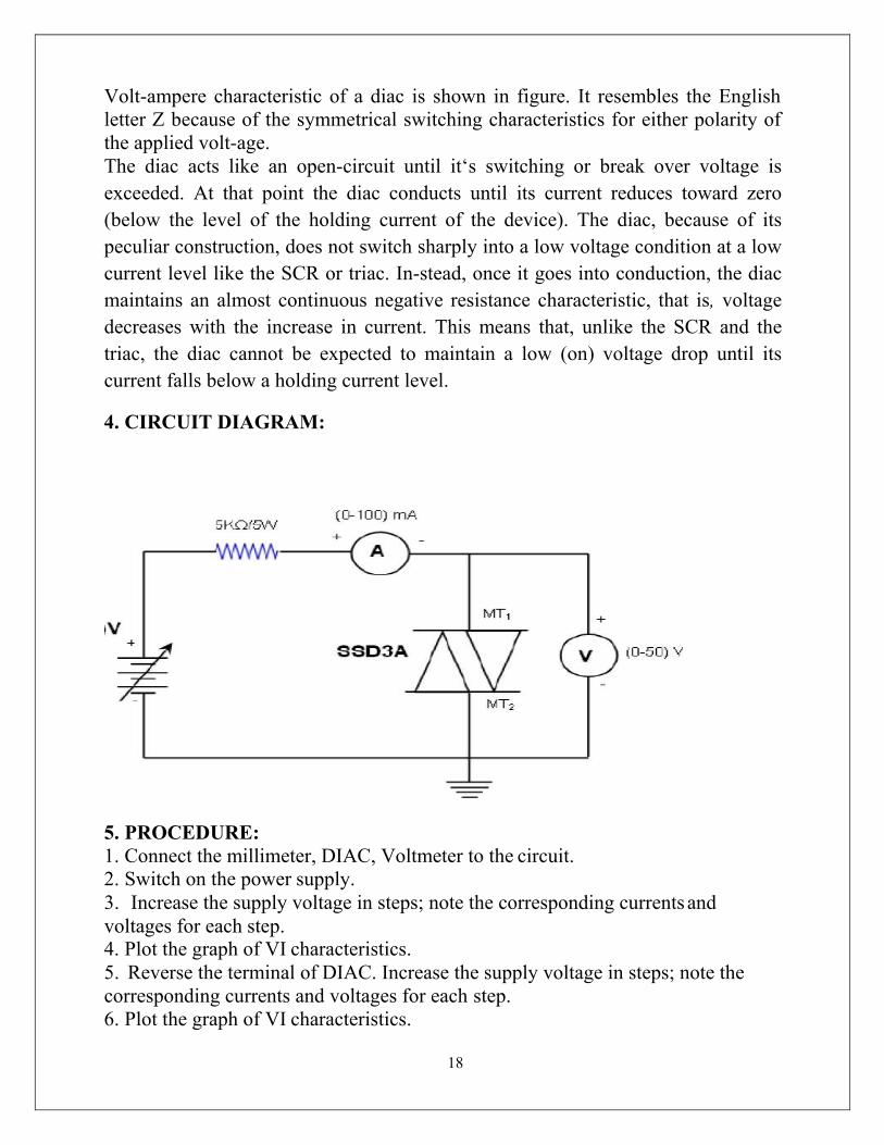
18
Volt-ampere characteristic of a diac is shown in figure. It resembles the English letter Z because of the symmetrical switching characteristics for either polarity of the applied volt-age. The diac acts like an open-circuit until it‘s switching or break over voltage is exceeded. At that point the diac conducts until its current reduces toward zero (below the level of the holding current of the device). The diac, because of its peculiar construction, does not switch sharply into a low voltage condition at a low current level like the SCR or triac. In-stead, once it goes into conduction, the diac maintains an almost continuous negative resistance characteristic, that is, voltage decreases with the increase in current. This means that, unlike the SCR and the triac, the diac cannot be expected to maintain a low (on) voltage drop until its current falls below a holding current level.
4. CIRCUIT DIAGRAM:
5. PROCEDURE: 1. Connect the millimeter, DIAC, Voltmeter to the circuit. 2. Switch on the power supply. 3. Increase the supply voltage in steps; note the corresponding currents and voltages for each step. 4. Plot the graph of VI characteristics. 5. Reverse the terminal of DIAC. Increase the supply voltage in steps; note the corresponding currents and voltages for each step. 6. Plot the graph of VI characteristics.

19
6. OBSERVATION:
For forward bias
SI.No Voltage (V) Current (mA)
For reverse bias
SI.No Voltage (V) Current (μA)
7. CONCLUSION:
The V-I characteristics of DIAC is plotted on the graph which is true according to theory.
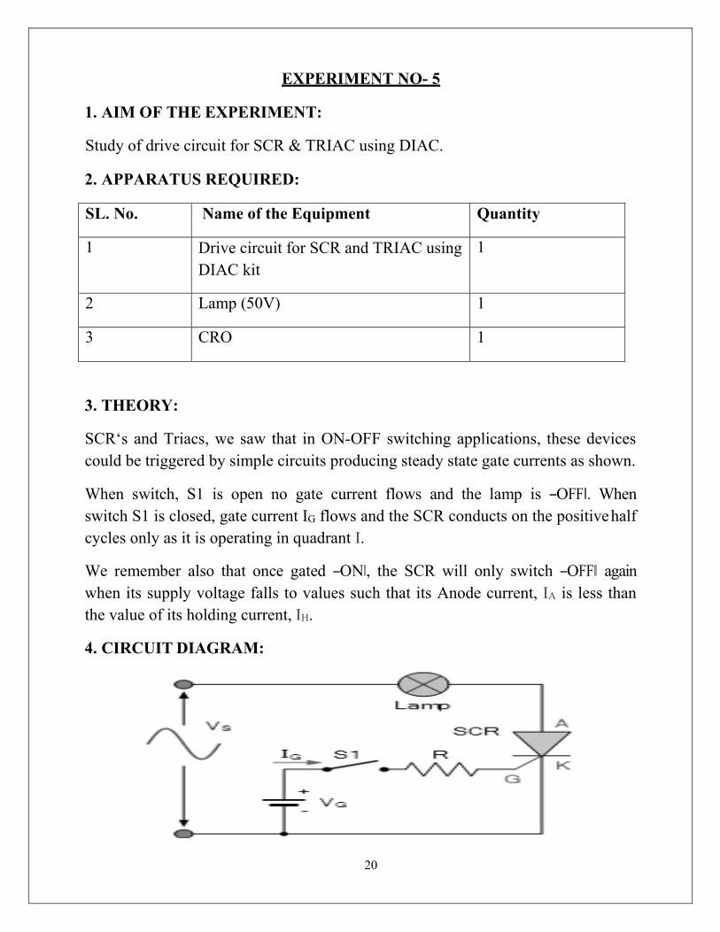
20
EXPERIMENT NO- 5
1. AIM OF THE EXPERIMENT:
Study of drive circuit for SCR & TRIAC using DIAC.
2. APPARATUS REQUIRED:
SL. No. Name of the Equipment Quantity
1 Drive circuit for SCR and TRIAC using DIAC kit
1
2 Lamp (50V) 1
3 CRO 1
3. THEORY:
SCR‘s and Triacs, we saw that in ON-OFF switching applications, these devices could be triggered by simple circuits producing steady state gate currents as shown.
When switch, S1 is open no gate current flows and the lamp is ―OFF‖. When switch S1 is closed, gate current IG flows and the SCR conducts on the positive half cycles only as it is operating in quadrant Ι.
We remember also that once gated ―ON‖, the SCR will only switch ―OFF‖ again when its supply voltage falls to values such that its Anode current, IA is less than the value of its holding current, IH.
4. CIRCUIT DIAGRAM:

21
5. PROCEDURE:
1. Make the connection as per the circuit diagram. 2. Connect the lamp at load terminal. 3. Switch ON the mains supply, vary the firing angle potentiometer and
Observe the variation in lamp brightness and also note down the voltage(AC volts) variation across the lamp using multimeter.
4. Write down these readings in table.
5. Observe the wave form.
6. OBSERVATION:
SL. NO.
Input Voltage AC in volts
Firing angle in degrees
Output voltage DC in Volts
7. CONCLUSION:
Drive circuit for SCR and TRIAC using DIAC is studied.
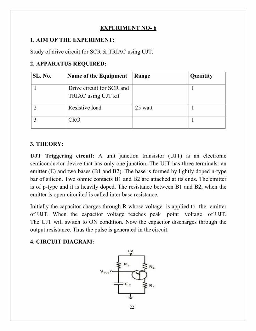
22
EXPERIMENT NO- 6
1. AIM OF THE EXPERIMENT:
Study of drive circuit for SCR & TRIAC using UJT.
2. APPARATUS REQUIRED:
SL. No. Name of the Equipment Range Quantity
1 Drive circuit for SCR and TRIAC using UJT kit
1
2 Resistive load 25 watt 1
3 CRO 1
3. THEORY:
UJT Triggering circuit: A unit junction transistor (UJT) is an electronic semiconductor device that has only one junction. The UJT has three terminals: an emitter (E) and two bases (B1 and B2). The base is formed by lightly doped n-type bar of silicon. Two ohmic contacts B1 and B2 are attached at its ends. The emitter is of p-type and it is heavily doped. The resistance between B1 and B2, when the emitter is open-circuited is called inter base resistance.
Initially the capacitor charges through R whose voltage is applied to the emitter of UJT. When the capacitor voltage reaches peak point voltage of UJT. The UJT will switch to ON condition. Now the capacitor discharges through the output resistance. Thus the pulse is generated in the circuit.
4. CIRCUIT DIAGRAM:

23
5. PROCEDURE:
1. The connections are made as per the circuit diagram given above. 2. The R Load must be 60W bulb. 3. When the load is Rheostat, then it must be in maximum position. 4. Turn on the SW2 and observe the waveform across between G1&K1 5. Turn ON SW1 and observe the waveform across the R load. 6. Measure the X-axis time interval of ON time of Load Voltage and OFF
Time of Load Voltage. 7. Adjust the value of Firing angle and note down the load voltage. 8. Repeat the step 6. 9. Repeat the experiment for different values of α and note down Vo.
6. OBSERVATION:
Sl. NO. Firing Angle Load Voltage
7. CONCLUSION:
UJT triggering circuit using SCR and TRIAC is constructed and found the load voltage for various firing angles.
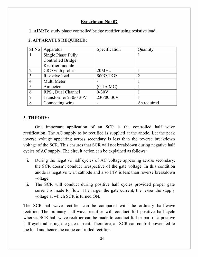
24
Experiment No: 07
1. AIM:To study phase controlled bridge rectifier using resistive load.
2. APPARATUS REQUIRED:
SI.No Apparatus Specification Quantity 1 Single Phase Fully
Controlled Bridge Rectifier module
1
2 CRO with probes 20MHz 1 3 Resistive load 500ῼ,1Kῼ 2 4 Multi Meter - 1 5 Ammeter (0-1A,MC) 1 6 RPS , Dual Channel 0-30V 1 7 Transformer 230/0-30V 230/00-30V 1 8 Connecting wire - As required
3. THEORY:
One important application of an SCR is the controlled half wave rectification. The AC supply to be rectified is supplied at the anode. Let the peak inverse voltage appearing across secondary is less than the reverse breakdown voltage of the SCR. This ensures that SCR will not breakdown during negative half cycles of AC supply. The circuit action can be explained as follows:.
i. During the negative half cycles of AC voltage appearing across secondary, the SCR doesn‘t conduct irrespective of the gate voltage. In this condition anode is negative w.r.t cathode and also PIV is less than reverse breakdown voltage.
ii. The SCR will conduct during positive half cycles provided proper gate current is made to flow. The larger the gate current, the lesser the supply voltage at which SCR is turned ON.
The SCR half-wave rectifier can be compared with the ordinary half-wave rectifier. The ordinary half-wave rectifier will conduct full positive half-cycle whereas SCR half-wave rectifier can be made to conduct full or part of a positive half-cycle adjusting the gate current. Therefore, an SCR can control power fed to the load and hence the name controlled rectifier.
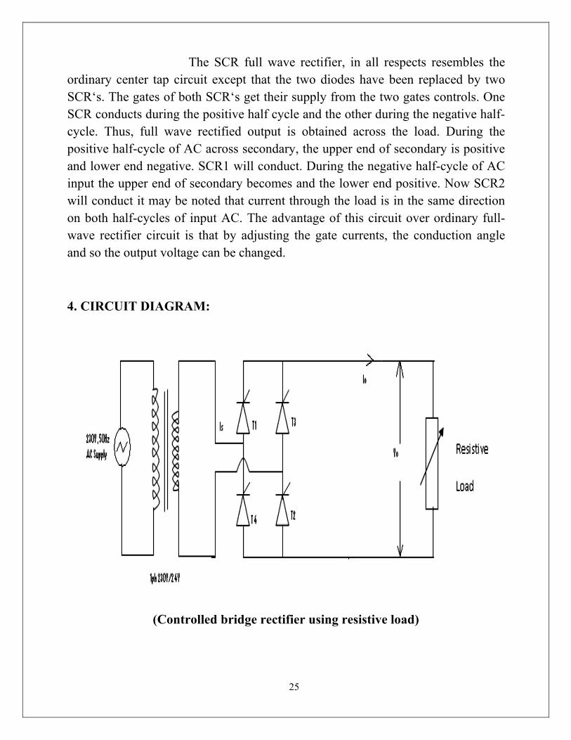
25
The SCR full wave rectifier, in all respects resembles the ordinary center tap circuit except that the two diodes have been replaced by two SCR‘s. The gates of both SCR‘s get their supply from the two gates controls. One SCR conducts during the positive half cycle and the other during the negative half- cycle. Thus, full wave rectified output is obtained across the load. During the positive half-cycle of AC across secondary, the upper end of secondary is positive and lower end negative. SCR1 will conduct. During the negative half-cycle of AC input the upper end of secondary becomes and the lower end positive. Now SCR2 will conduct it may be noted that current through the load is in the same direction on both half-cycles of input AC. The advantage of this circuit over ordinary full- wave rectifier circuit is that by adjusting the gate currents, the conduction angle and so the output voltage can be changed.
4. CIRCUIT DIAGRAM:
(Controlled bridge rectifier using resistive load)
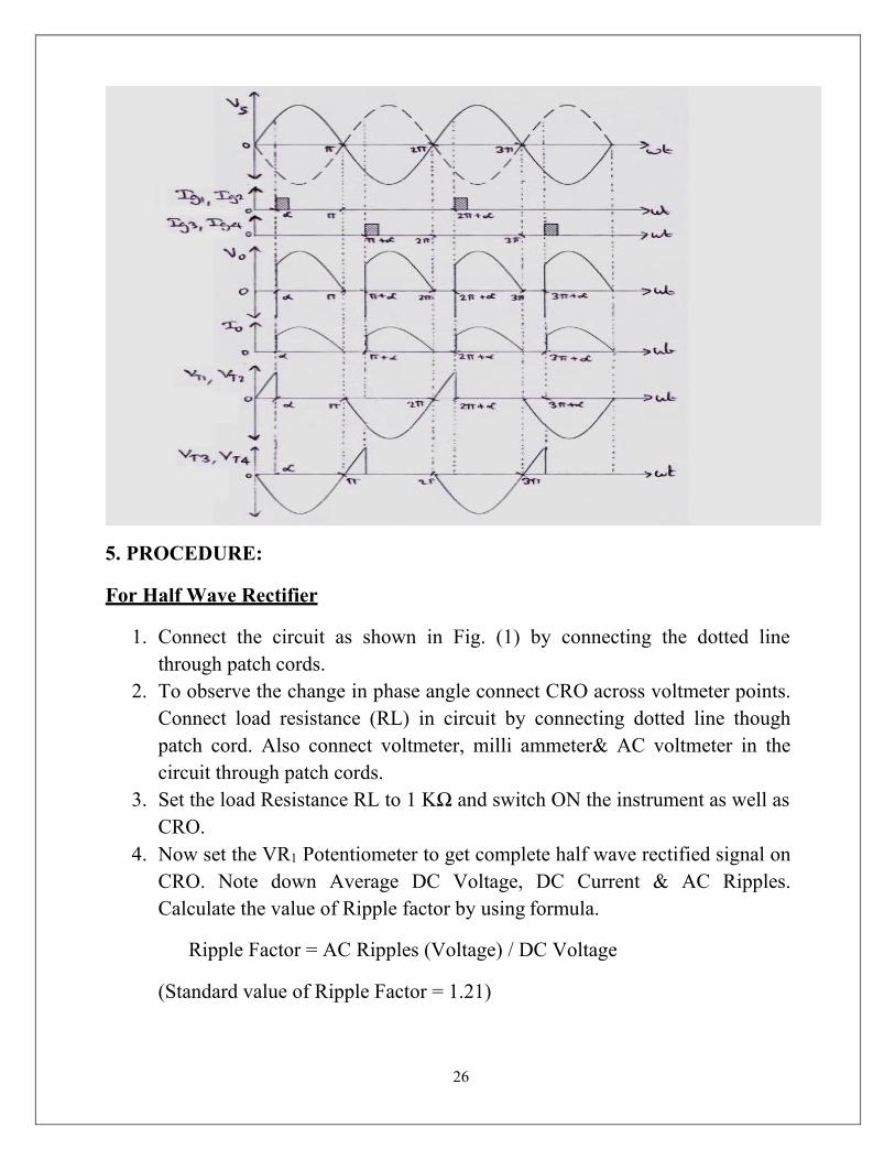
26
5. PROCEDURE:
For Half Wave Rectifier
1. Connect the circuit as shown in Fig. (1) by connecting the dotted line through patch cords.
2. To observe the change in phase angle connect CRO across voltmeter points. Connect load resistance (RL) in circuit by connecting dotted line though patch cord. Also connect voltmeter, milli ammeter& AC voltmeter in the circuit through patch cords.
3. Set the load Resistance RL to 1 KΩ and switch ON the instrument as well as CRO.
4. Now set the VR1 Potentiometer to get complete half wave rectified signal on CRO. Note down Average DC Voltage, DC Current & AC Ripples. Calculate the value of Ripple factor by using formula.
Ripple Factor = AC Ripples (Voltage) / DC Voltage
(Standard value of Ripple Factor = 1.21)

27
5. Now change the firing angle of SCR by varying potentiometer VR1 and every time note down the observations of Average DC voltage, Current & AC Ripples. Also note down Firing Angle from CRO.
6. Also note down the observations of Voltage, Current & AC Ripples by varying the Load Resistances (RL).
For Full Wave Rectifier
1. Connect the circuit as shown in Fig.(2) by connecting the dotted lines through patch cords.
2. To observe the change in phase angle connect CRO across voltmeter points. Connect load resistance (RL) in the circuit by connecting dotted line through patch cord. Also connect voltmeter, milli ammeter& AC voltmeter in the circuit through patch cords.
3. Set the load Resistance RL to 1 KΩ and switch ON the instrument as well as CRO.
4. Now set VR1& VR2 Potentiometer to get complete full wave rectified signal on CRO. Note down average DC voltage, DC current & AC ripples. Calculate the value of Ripple factor by using formula :
Ripple Factor = AC Ripples (Voltage) / DC Voltage (Standard value of Ripple Factor = 0.48)
5. Now change the firing angle of SCR by varying potentiometer VR1& VR2 and every time note down the observations of Average DC voltage, Current & AC Ripples. Also note down firing angle from CRO.
6. Also note down the observations of Voltage, Current & AC supplies by varying the load resistance (RL).
For Fully Controlled Bridge Rectifier
1. Connect the circuit as shown in Fig. (3) by connecting the dotted line through patch cords.
2. To observe the change in phase angle connect CRO across voltmeter points. Connect load Resistance (RL) in the circuit by connecting dotted line through patch cord. Also connect Voltmeter, millimeter& AC Voltmeter in the circuit through patch cords.
3. Set the Load Resistance (RL) to 1KΩ and switch ON the instrument as well as CRO.

28
4. Now set the VR1, VR2, VR3, VR4 Potentiometers to get complete full wave rectified (Through Bridge circuit) signal on CRO. Note down average DC voltage, DC current & AC ripples. Calculate the value of Ripple factor using formula:
Ripple Factor = AC Ripples (Voltage) / DC Voltage (Standard value of ripple factor = 0.48)
5. Now change the firing angle of SCR by varying potentiometer VR1, VR2, VR3 & VR4 every time note down the observations of Average DC voltage, Current & AC Ripples. Also note down Firing Angle from CRO.
6. Also note down the observations of Voltage, Current & AC Ripples by varying the Load Resistances (RL).
6. OBSERVATION:
For Half Wave Rectifier
Firing Angle
DC voltage DC current
Load Resistance
Ripple (AC voltage)
Ripple Factor= AC volts/DC volts
For Full wave Rectifier
Firing Angle
DC voltage DC current
Load Resistance
Ripple (AC
voltage)
Ripple Factor=
AC volts/DC
volts

29
For Bridge Rectifier
Firing Angle
DC voltage DC current
Load Resistance
Ripple (AC
voltage)
Ripple Factor=
AC volts/DC
volts
7. CONCLUSION:
From the above experiment we studied the phase controlled bridge rectifier using resistive load.
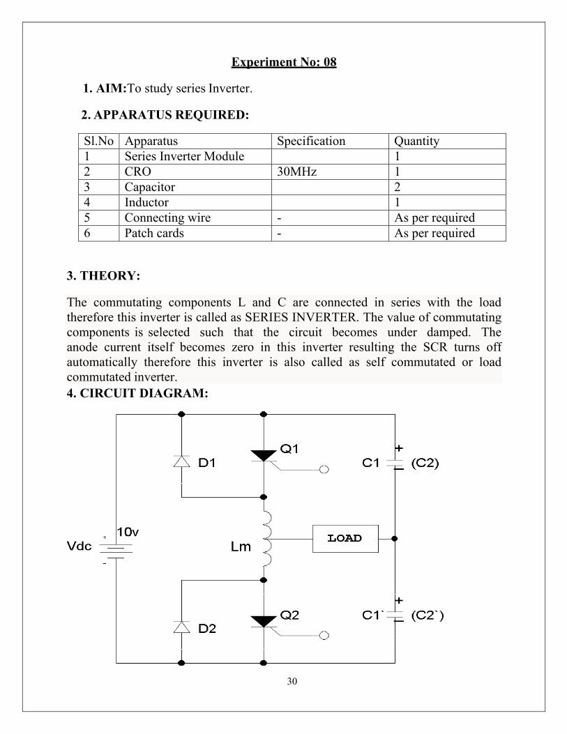
30
The commutating components L and C are connected in series with the load therefore this inverter is called as SERIES INVERTER. The value of commutating components is selected such that the circuit becomes under damped. The anode current itself becomes zero in this inverter resulting the SCR turns off automatically therefore this inverter is also called as self commutated or load commutated inverter.
Experiment No: 08
1. AIM:To study series Inverter.
2. APPARATUS REQUIRED:
Sl.No Apparatus Specification Quantity 1 Series Inverter Module 1 2 CRO 30MHz 1 3 Capacitor 2 4 Inductor 1 5 Connecting wire - As per required 6 Patch cards - As per required
3. THEORY:
4. CIRCUIT DIAGRAM:
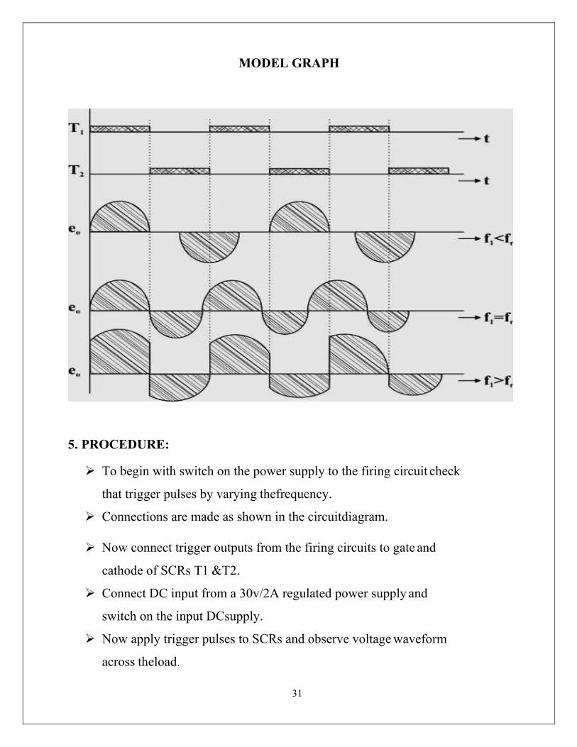
31
MODEL GRAPH
5. PROCEDURE:
To begin with switch on the power supply to the firing circuit check
that trigger pulses by varying thefrequency.
Connections are made as shown in the circuitdiagram.
Now connect trigger outputs from the firing circuits to gate and
cathode of SCRs T1 &T2.
Connect DC input from a 30v/2A regulated power supply and
switch on the input DCsupply.
Now apply trigger pulses to SCRs and observe voltage waveform
across theload.

32
Measure Vorms& frequency of o/p voltagewaveform.
6. OBSERVATION:
Sl.No Amplitude in Volt TON (ms) TOFF (ms)
7. CONCLUSION:
Thus the operation of a series inverter is studied.
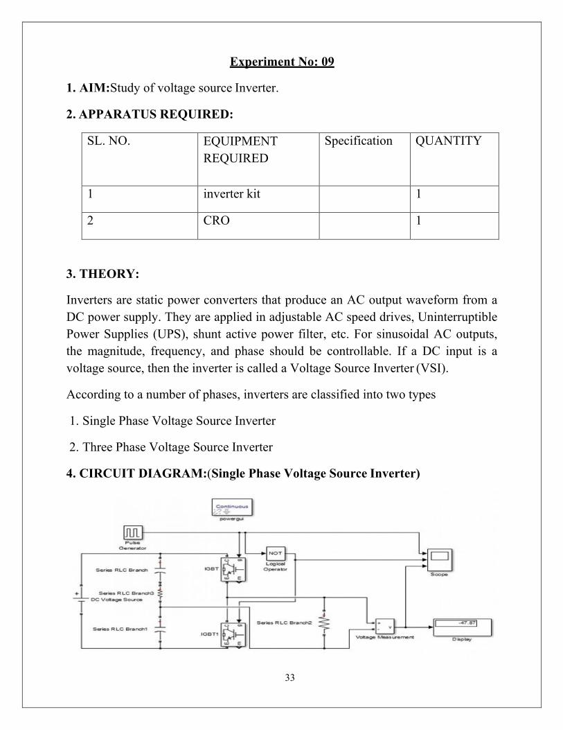
33
Experiment No: 09
1. AIM:Study of voltage source Inverter.
2. APPARATUS REQUIRED:
SL. NO. EQUIPMENT REQUIRED
Specification QUANTITY
1 inverter kit 1
2 CRO 1
3. THEORY:
Inverters are static power converters that produce an AC output waveform from a DC power supply. They are applied in adjustable AC speed drives, Uninterruptible Power Supplies (UPS), shunt active power filter, etc. For sinusoidal AC outputs, the magnitude, frequency, and phase should be controllable. If a DC input is a voltage source, then the inverter is called a Voltage Source Inverter (VSI).
According to a number of phases, inverters are classified into two types
1. Single Phase Voltage Source Inverter
2. Three Phase Voltage Source Inverter
4. CIRCUIT DIAGRAM:(Single Phase Voltage Source Inverter)
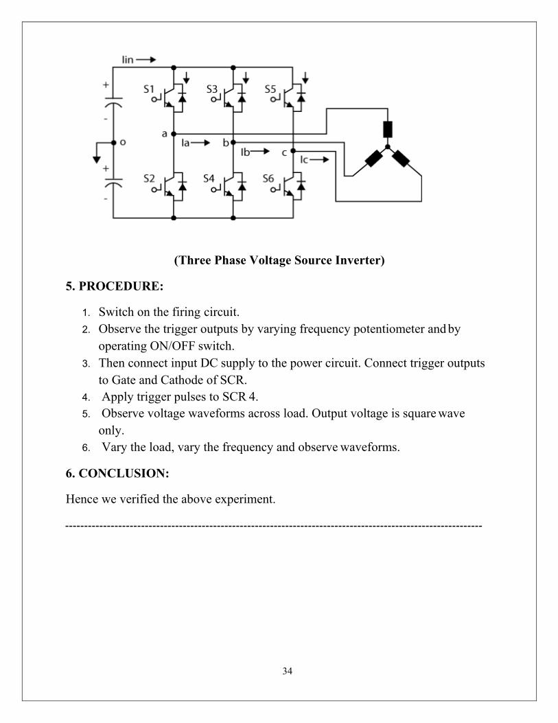
34
(Three Phase Voltage Source Inverter)
5. PROCEDURE:
1. Switch on the firing circuit. 2. Observe the trigger outputs by varying frequency potentiometer and by
operating ON/OFF switch. 3. Then connect input DC supply to the power circuit. Connect trigger outputs
to Gate and Cathode of SCR. 4. Apply trigger pulses to SCR 4. 5. Observe voltage waveforms across load. Output voltage is square wave
only. 6. Vary the load, vary the frequency and observe waveforms.
6. CONCLUSION:
Hence we verified the above experiment.
35
Experiment No: 10
1. AIM:To perform the speed control ofDC motor using Chopper.
2. APPARATUS REQUIRED:
SL.No Apparatus Specification Quantity 1 Power electronic kit 1 2 Servo motor 1 3 DSO 1 4 Connecting lead As per required
3. THEORY:
Circuit diagram is shown in fig. (1) and it consist of RC network which control the speed of motor. There are two method of Triggering to SCR using RC network. They are explained below and we are using RC half wave circuit to control the speed of motor .SCR is here acting as an half wave rectifier and allows only half cycle of ac signal to the armature. This is an method of voltage control of armature by using SCR whose firing angle is varied and accordingly voltage of armature is varied.
RC FIRING CIRCUITS:
The limited range of firing angle control by resistance firing circuit can be overcome by RC firing circuit .There are several variations of RC trigger circuits. Here only two of them are presented.
(i) RC Half wave Trigger Circuit
By varying the value of R ,firing angle can be controlled from 0-180.In negative half cycle ,capacitor c charges through resistance with lower plate positive to the peak supply voltage Vm at wt = -900.after wt= -900 ,sources voltage VS decreases from –Vm to zero. During this period capacitor voltage VC may fall from –Vm at wt=-900 to some lower value at wt=00. Now, as the SCR anode voltage passes through zero and becomes positive, C begins to charge through variable resistance R from the initial voltage. When capacitor charges to positive voltage equal to gate trigger voltage Vgt SCR is fired and after this capacitor holds
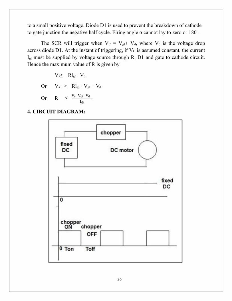
36
to a small positive voltage. Diode D1 is used to prevent the breakdown of cathode to gate junction the negative half cycle. Firing angle α cannot lay to zero or 1800.
The SCR will trigger when VC = Vgt+ Vd, where Vd is the voltage drop across diode D1. At the instant of triggering, if VC is assumed constant, the current Igt must be supplied by voltage source through R, D1 and gate to cathode circuit. Hence the maximum value of R is given by
Vs≥ Rlgt+ Vc
Or Vs ≥ Rlgt+ Vgt + Vd
Or R ≤ Vs−Vdt−Vd
Idt
4. CIRCUIT DIAGRAM:
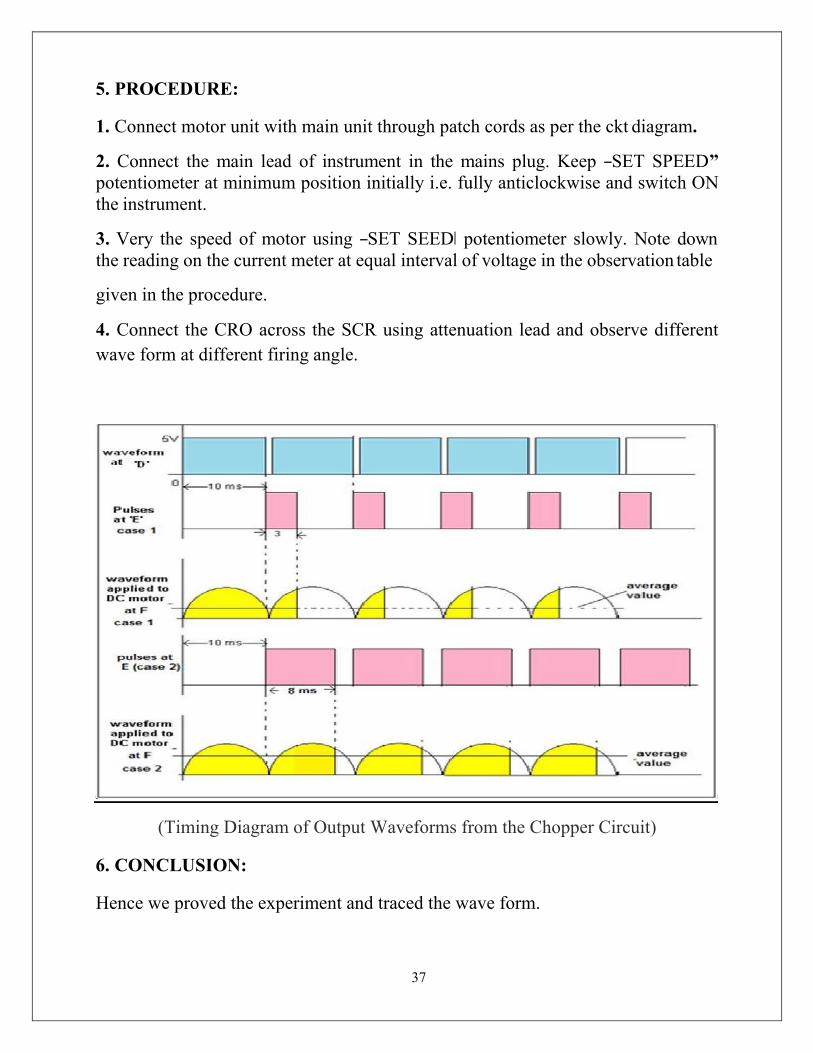
37
5. PROCEDURE:
1. Connect motor unit with main unit through patch cords as per the ckt diagram.
2. Connect the main lead of instrument in the mains plug. Keep ―SET SPEED” potentiometer at minimum position initially i.e. fully anticlockwise and switch ON the instrument.
3. Very the speed of motor using ―SET SEED‖ potentiometer slowly. Note down the reading on the current meter at equal interval of voltage in the observation table
given in the procedure.
4. Connect the CRO across the SCR using attenuation lead and observe different wave form at different firing angle.
(Timing Diagram of Output Waveforms from the Chopper Circuit)
6. CONCLUSION:
Hence we proved the experiment and traced the wave form.
38
Experiment No: 11
1. AIM:To study single-phase Cyclo-converter.
2. APPARATUS REQUIRED:
SL.No Apparatus Specification Quantity 1 Cycloconverter power
ckt.with firing ckt. 1
2 Transformer 230V(150V-15V) 1 3 Rheostat 100ῼ/2A 1 4 Multimeter 1 5 CRO 30MHz 1 5 Connecting wire - As per required 6 Patch cards - As per required
3. THEORY:
A cycloconverter converts input power at one frequency to output power at a different frequency with one stage conversion. Cycloconverter is used in speed Control of high power AC drives, induction heating etc.
The circuit shown is for obtaining single phase frequency divided output from a single phase AC input. One group of SCR‘s produces positive polarity load voltage and other group produces negative half cycle of the output. SCR‘s T1 andT3 of the positive group are gated together depending on the polarity of the input, only one of them will conduct, when upper AC terminal is positive with respect too, SCR T1will conduct and when upper AC terminal is negative, SCR T3willconduct thus in both half cycles of input, the load voltage polarity will be positive by changing firing angle, the duration of conducting of each SCR (and there by the magnitude of the output voltage) can be varied.
For the sake of simplicity it is assumed that the load is positive. Then each SCR will have a conduction angle of (π –α) and turn off by natural commutation at the end of every half cycle of the input. At the end of each half period of the output, the firing pulses to the SCR‘sof the positive group will be stopped and SCR‘s T2 and T4 of the negative group will be fired.
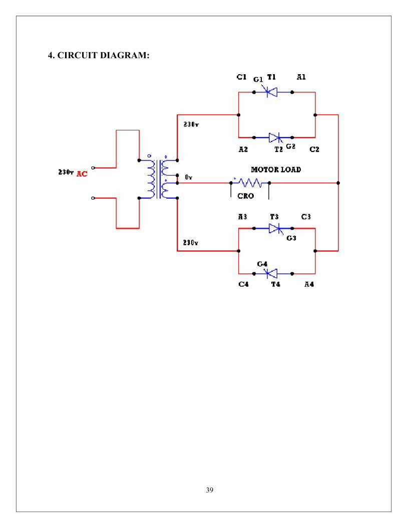
39
4. CIRCUIT DIAGRAM:
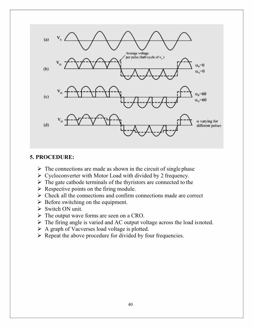
40
5. PROCEDURE:
The connections are made as shown in the circuit of single phase Cycloconverter with Motor Load with divided by 2 frequency. The gate cathode terminals of the thyristors are connected to the Respective points on the firing module. Check all the connections and confirm connections made are correct Before switching on the equipment. Switch ON unit. The output wave forms are seen on a CRO. The firing angle is varied and AC output voltage across the load is noted. A graph of Vacverses load voltage is plotted. Repeat the above procedure for divided by four frequencies.

6. OBSERVATION:
Frequency divided by 2
SI.No Firing angle α (degrees) Load voltage in volts using AC voltmeter in volts
RPM
1 1800
2 1500
3 1200
4 900
5 600
6 300
7 00
7. CONCLUSION:
Thus the operation of a single-phase Cyclo-converter is studied.

PLC LAB
Learn the basics and hardware components of PLC
The basic elements of a PLC include input modules or points, a Central Processing Unit (CPU), output modules or points, and a programming device. The type of input modules or points used by a PLC depends upon the types of input devices used. Some input modules or points respond to digital inputs, also called discrete inputs, which are either on or off. Other modules or inputs respond to analog signals.
PLC Hardware components Alright, now that we‘ve got that out of the way, let‘s look at what we mean by the
term PLC Hardware. The Hardware components of a PLC include the following:
Processor, Power Supply, Input/output Modules, and a Programming Device. Let‘s look at each piece of hardware, or module one at a time. 1) Power Supply The Power Supply is connected to AC mains for the supply voltage.
The output of the Power supply is a DC voltage used to power all of the other modules associated with the PLC.
The Power supply DOES NOT provide power for field devices.
2) Input/output modules

The input/output modules are connected to digital or analog field devices.

Input field devices include switches, encoders, and transmitters for example. Typical output field devices are relays, lamps, and proportional valves.
3) Processor The Processor consists of the CPU (central processing unit) and memory.
The processor section makes decisions needed to observe and operate the field devices
connected to the Input/output modules.

The decisions are based upon a user-created program saved in the memory. The memory also stores data representing the condition of all input field devices and contains the data telling the output field devices what to do.
4) Programming Device The Programming Device in today‘s industrial applications is usually a laptop or a
desktop computer that facilitates the creation of decision-making programs destined for
the PLC.
(b) Understand configuration of PLC system
Configuration is used to group all resources of the PLC system together. It also provides means for data exchange between them. A resource is the processing facility, able to execute IEC programs. It is defined in order to assign task to the physical resources of a PLC system.
(C) Study various building blocks of PLC

Power Supply Module This module is used to provide the required power to the whole PLC system. It converts the available AC power to DC power which is required by the CPU and I/O module. PLC generally works on a 24V DC supply. Few PLC uses an isolated power supply.
CPU Module and Memory CPU module has a central processor, ROM & RAM memory. ROM memory includes an operating system, drivers, and application programs. RAM memory is used to store programs and data. CPU is the brain of PLC with an octal or hexagonal microprocessor. Being a microprocessor-based CPU, it replaces timers, relays, and counters. Two types of processors as a single bit or word processor can be incorporated with a PLC. One bit processor is used to perform logic functions. Whereas word processors are used for processing text, numerical data, controlling, and recording data.
CPU reads the input data from sensors, processes it, and finally sends the command to controlling devices. DC power source, as mentioned in the previous discussion is required voltage signals. CPU also contains other electrical parts to connect cables used by other units.
Input and Output Module
Input devices can be either start and stop pushbuttons, switches, etc and output devices can be an electric heater, valves, relays, etc. I/O module helps to interface input and output devices with a microprocessor. The input module of PLC is explained in the below figure.
The output module of PLC works similarly to the input module but in the reverse process. It interfaces the output load and processor. So here the first section would be logic session and the power section comes next. The working of the output module is shown in the below figure
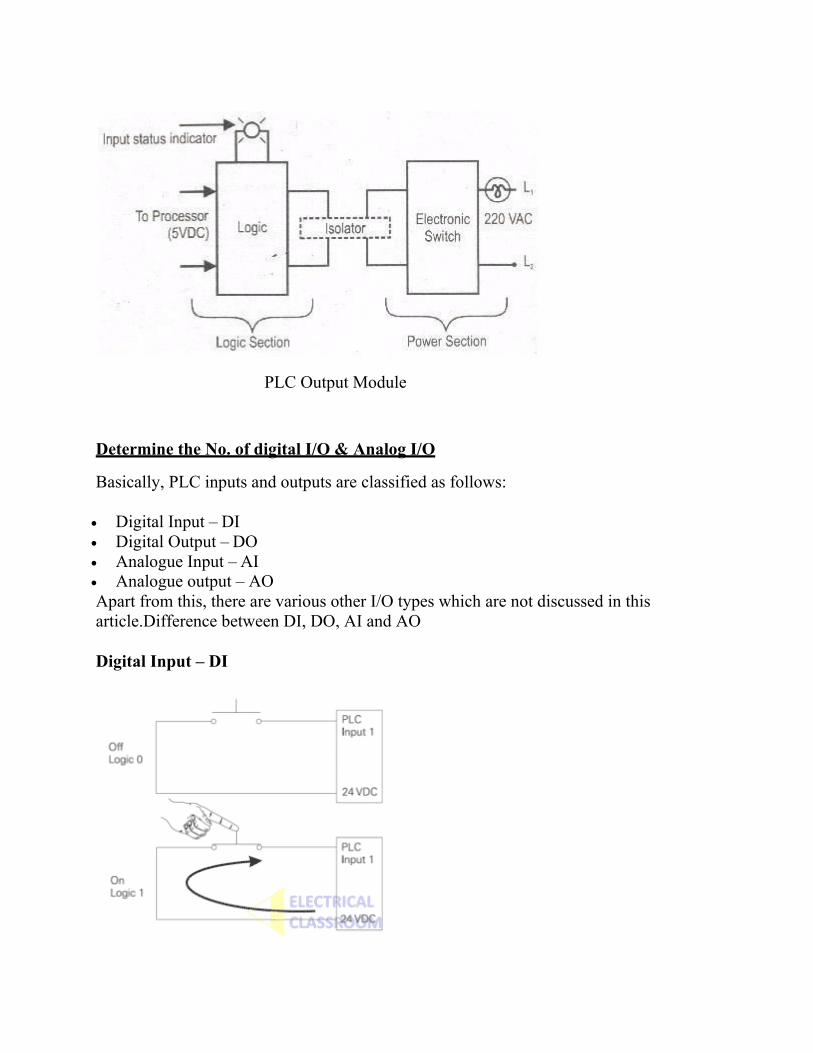
PLC Output Module
Determine the No. of digital I/O & Analog I/O
Basically, PLC inputs and outputs are classified as follows:
• Digital Input – DI • Digital Output – DO • Analogue Input – AI • Analogue output – AO Apart from this, there are various other I/O types which are not discussed in this article.Difference between DI, DO, AI and AO
Digital Input – DI
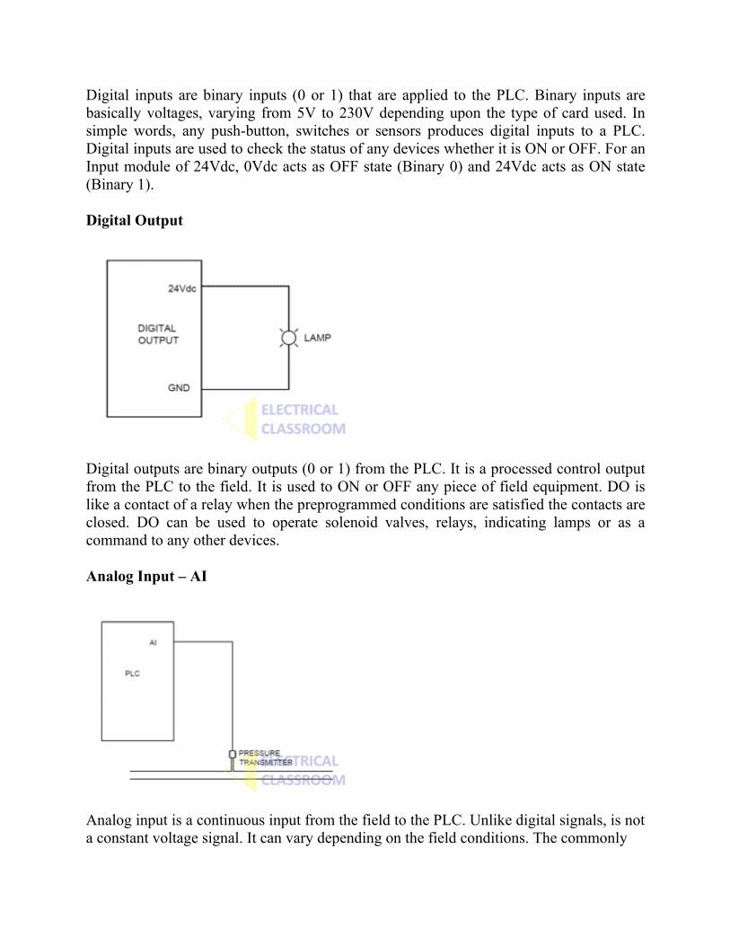
Digital inputs are binary inputs (0 or 1) that are applied to the PLC. Binary inputs are basically voltages, varying from 5V to 230V depending upon the type of card used. In simple words, any push-button, switches or sensors produces digital inputs to a PLC. Digital inputs are used to check the status of any devices whether it is ON or OFF. For an Input module of 24Vdc, 0Vdc acts as OFF state (Binary 0) and 24Vdc acts as ON state (Binary 1).
Digital Output
Digital outputs are binary outputs (0 or 1) from the PLC. It is a processed control output from the PLC to the field. It is used to ON or OFF any piece of field equipment. DO is like a contact of a relay when the preprogrammed conditions are satisfied the contacts are closed. DO can be used to operate solenoid valves, relays, indicating lamps or as a command to any other devices.
Analog Input – AI
Analog input is a continuous input from the field to the PLC. Unlike digital signals, is not a constant voltage signal. It can vary depending on the field conditions. The commonly

used analogue signals are 4-20mA signal and 0-10Vdc Signal. Depending on the field conditions the input signal can vary between 4-20mA or 0-10Vdc. For Example, if you are monitoring a pressure of water flowing through a pipe using a pressure transmitter of range 0-10 Bar, the transmitter will give a signal between 0 and 10V proportional to the pressure in the pipe.
Analog Output
Analogue output is a continuous output from PLC to the field devices. For example, if you have a variable frequency drive and you want to give a speed reference signal to it you can use analogue output. Otherwise, if you are measuring the pressure using analogue input as explained above and you would like to display it on an analogue meter you can use an analogue output of PLC.

Execute the different Ladder Diagrams

Execute Ladder diagrams for different Logical Gates
Aim: Study of various logic Execution in ladder diagram.
Equipment
1) Computer with SIMATIC software. 2) Siemens S7-1200 PLC. 3) LEDs. 4) Switches. 5) Connecting wires.
Theory: The majority of PLC manufacturers use the ladder logic diagram programming language to program their programmable logic controllers (PLCs). Some manufacturers prefer using logic gate circuits or Boolean expressions to program their PLCs. Therefore, it is beneficial to know how to convert one type of PLC programming language to the other. In this practical, you will learn how to create logic gate circuits from ladder logic diagrams and vice versa. You will review the functions associated with the combinational logic gates. These gates are the NOT, AND, OR, NAND, NOR, XOR, and XNOR gates. You will learn how to create PLC ladder logic diagrams that emulate the functions of these gates.
1. NOT GATE In electronics, NOT GATE is also called an ‗Inverter‘ or ‗Buffer‘. Working: NOT gate works as inversion. It takes one input and gives one output. When the input is high then the output is low and vice-versa.
Logic Gate Truth Table for NOT Gate:
Input (I1)
Output (Q1)
0 1
1 0

NOT Gate in PLC programming:
In the case of PLC ladder, there will be a push button to provide input. When (I1) is pressed then the coil (Q1) is on. And when Input (I1) is released then coil( Q1 is off. Symbolic Representation.
2. AND GATE
Working: In AND Gate, when both inputs (I1 and I2) are high then the output (Q1) will be high. For all other inputs, output (Q1) will be the low.
Logic Gate Truth Table for AND Gate:
Input (I1)
Input (I2)
Output (Q1)
0 0 0
0 1 0
1 0 0
1 1 1
AND Gate in PLC programming: Using Ladder diagram programming, we are connecting two switches (I1 and I2) as input and coil/lamp (Q1) as output.
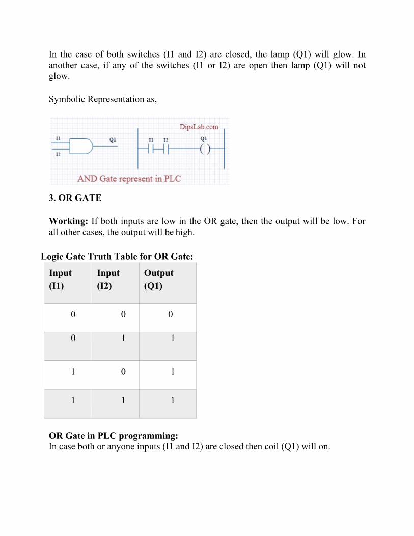
In the case of both switches (I1 and I2) are closed, the lamp (Q1) will glow. In another case, if any of the switches (I1 or I2) are open then lamp (Q1) will not glow.
Symbolic Representation as,
3. OR GATE
Working: If both inputs are low in the OR gate, then the output will be low. For all other cases, the output will be high.
Logic Gate Truth Table for OR Gate:
Input (I1)
Input (I2)
Output (Q1)
0 0 0
0 1 1
1 0 1
1 1 1
OR Gate in PLC programming: In case both or anyone inputs (I1 and I2) are closed then coil (Q1) will on.

Symbolic Representation as,
In the above circuit diagram, switch (I1) is pressed then the coil (Q1) will be energized. After releasing switch (I1), the energizing coil (Q1) is providing supply to switch (I2). Then switch (I2) will become automatically activated.
4. NAND GATE NAND gate is operated as an AND gate and followed by the inverter.
Working: In NAND Gate, the output will be low when both inputs are high. For all other cases, the output will be high.
Logic Gate Truth Table for NAND Gate:
Input (I1)
Input (I2)
Output (Q1)
0 0 1
0 1 1
1 0 1
1 1 0
NAND Gate in PLC programming: If both switches (I1 and I2) or anyone switch (I1 or I2) are closed, the lamp will be glow. In the case, both switches are open then the lamp will not be glow.

13
Symbolic Representation as,
5. NOR GATE NOR Gate is operated OR Gate followed by the NOT Gate.
When both inputs are low then the output will be high. Otherwise, the low output will occur if both inputs are high.
Logic Gate Truth Table for NOR Gate:
Input (I1)
Input (I2)
Output (Q1)
0 0 1
0 1 0
1 0 0
1 1 0
NOR Gate in PLC programming: The Coil (Q1) will be activated if both inputs are closed. Coil (Q1) will be deactivated if anyone or Bothe the inputs are open.

14
Symbolic Representation as,
6. EX-OR GATE
Working: If both inputs are high or low, the output will become low. For any other input condition, the output will be high.
Logic Gate Truth Table for EX-OR Gate:
Input (I1)
Input (I2)
Output (Q1)
0 0 0
0 1 1
1 0 1
1 1 0
EX-OR Gate in PLC programming: In the function of EX-OR Gate, the lamp will be on if one switch is closed and another switch is opened.

15
Symbolic Representation as,
7. EX-NOR GATE
Working: When both inputs (I1 and I2) are high or low then the output will high. If anyone input is high or low then the output will become low.
Logic Gate Truth Table for EX-NOR Gate:
Input (I1)
Input (I2)
Output (Q1)
0 0 1
0 1 0
1 0 0
1 1 1
EX_NOR gate in PLC programming: The function of EX-NOR Gate, the lamp (Q1) will be on if both switches (I1 and I2) are open or closed. The lamp (Q1) will not be on if anyone switches (I1) is activated and another switch (I2) is deactivated.

16
Symbolic Representation as,
Procedure:
• Connect two switches to the digital input module.
• Connect one LED to the digital output module.
• Write down the ladder diagram to implement AND-logic function using SIMATIC Manager software.
• Download the program to the PLC. • Repeat steps 1 through 4 to implement OR-logic function. • Repeat steps 1 through 4 to implement Parallel NOT-logic function.
Conclusion:
This is all about different logic gates using PLC ladder programming. As well as PLC programming rules and programming instructions are also important for writing the program.
Execute Ladder diagrams using timers & counters
AIM: To differentiate the usage of the timer and counter in Ladder Diagram.
Equipment
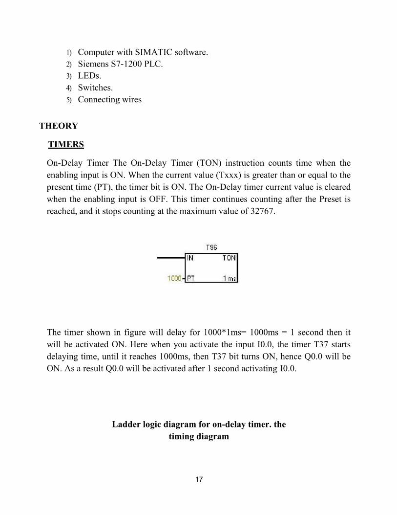
17
1) Computer with SIMATIC software. 2) Siemens S7-1200 PLC. 3) LEDs. 4) Switches. 5) Connecting wires
THEORY
TIMERS
On-Delay Timer The On-Delay Timer (TON) instruction counts time when the enabling input is ON. When the current value (Txxx) is greater than or equal to the present time (PT), the timer bit is ON. The On-Delay timer current value is cleared when the enabling input is OFF. This timer continues counting after the Preset is reached, and it stops counting at the maximum value of 32767.
The timer shown in figure will delay for 1000*1ms= 1000ms = 1 second then it will be activated ON. Here when you activate the input I0.0, the timer T37 starts delaying time, until it reaches 1000ms, then T37 bit turns ON, hence Q0.0 will be ON. As a result Q0.0 will be activated after 1 second activating I0.0.
Ladder logic diagram for on-delay timer. the timing diagram
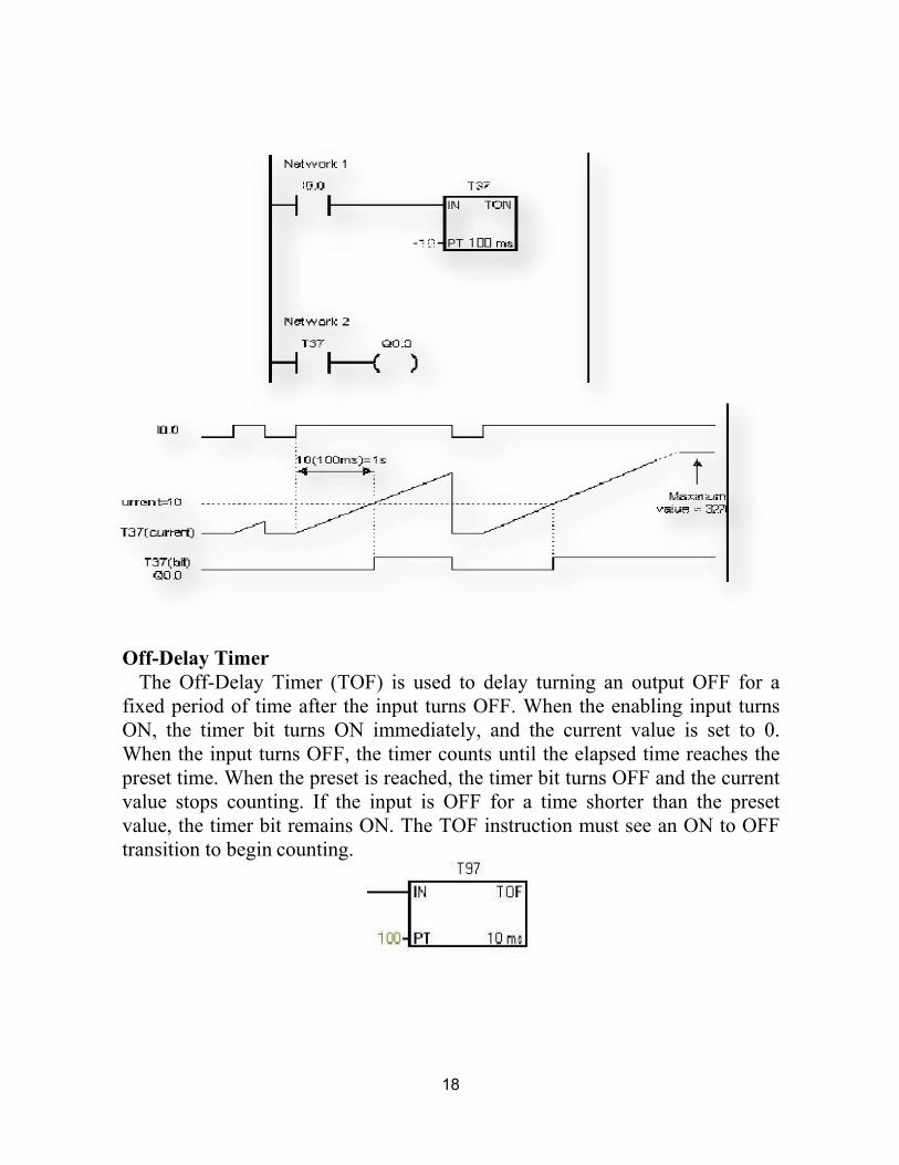
18
Off-Delay Timer The Off-Delay Timer (TOF) is used to delay turning an output OFF for a
fixed period of time after the input turns OFF. When the enabling input turns ON, the timer bit turns ON immediately, and the current value is set to 0. When the input turns OFF, the timer counts until the elapsed time reaches the preset time. When the preset is reached, the timer bit turns OFF and the current value stops counting. If the input is OFF for a time shorter than the preset value, the timer bit remains ON. The TOF instruction must see an ON to OFF transition to begin counting.
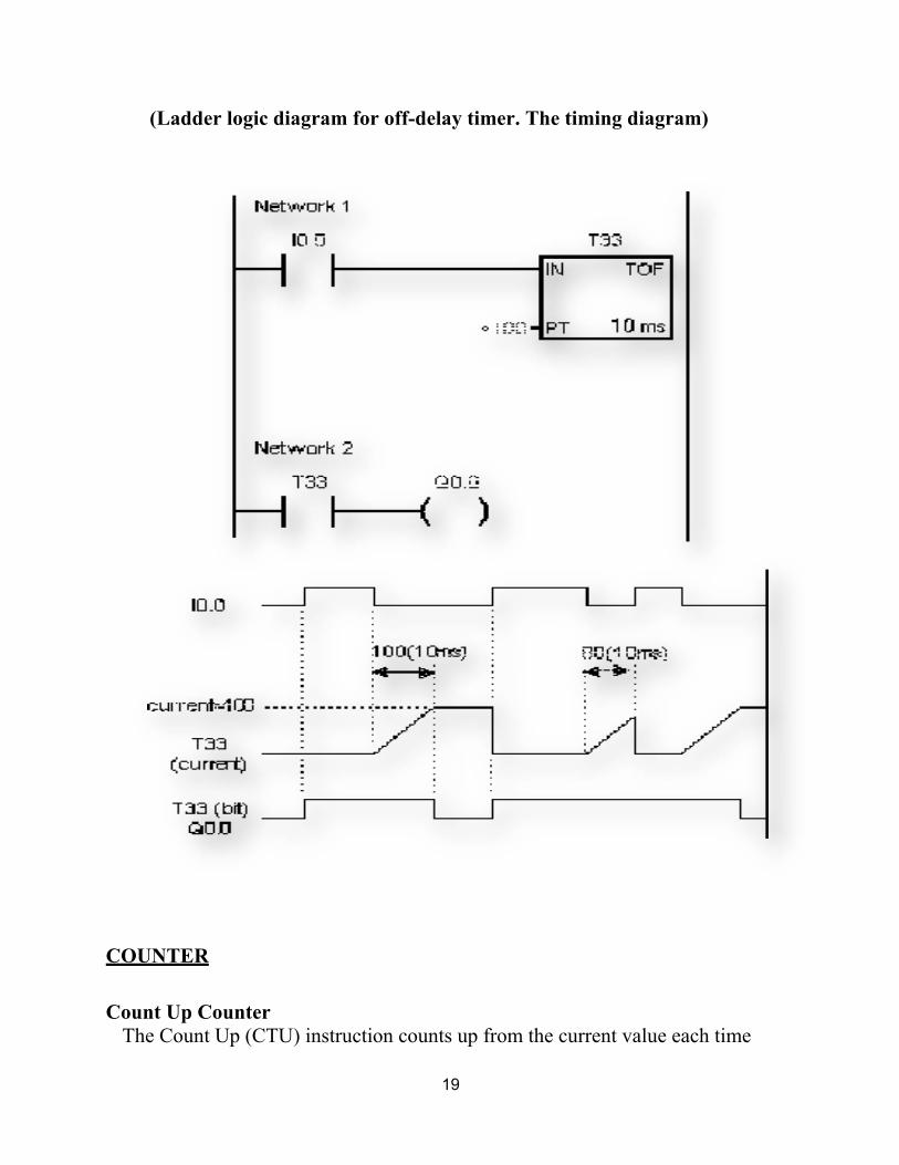
19
(Ladder logic diagram for off-delay timer. The timing diagram)
COUNTER
Count Up Counter The Count Up (CTU) instruction counts up from the current value each time
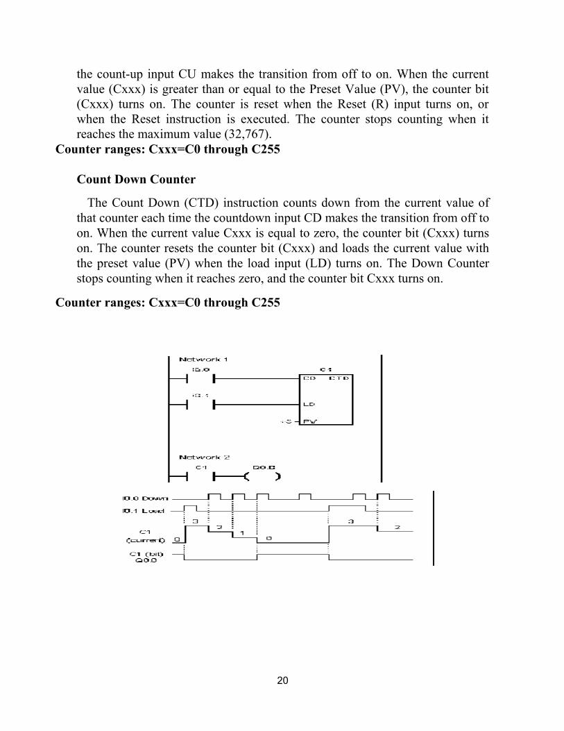
20
the count-up input CU makes the transition from off to on. When the current value (Cxxx) is greater than or equal to the Preset Value (PV), the counter bit (Cxxx) turns on. The counter is reset when the Reset (R) input turns on, or when the Reset instruction is executed. The counter stops counting when it reaches the maximum value (32,767).
Counter ranges: Cxxx=C0 through C255
Count Down Counter
The Count Down (CTD) instruction counts down from the current value of that counter each time the countdown input CD makes the transition from off to on. When the current value Cxxx is equal to zero, the counter bit (Cxxx) turns on. The counter resets the counter bit (Cxxx) and loads the current value with the preset value (PV) when the load input (LD) turns on. The Down Counter stops counting when it reaches zero, and the counter bit Cxxx turns on.
Counter ranges: Cxxx=C0 through C255

21
PROCEDURE: 1. Turn the PC ON. 2. Turn the PLC ON. 3. Start V4.0 STEP 7 Micro WIN SP5. 4. Select View>>Ladder. 5. Form Bit Logic double, click the normally open contact. 6. Click on the red question marks, and rename the normally open contactor with
a physical input name, I0.0- I0.7 or I1.0-I1.5, let us say I0.0. 7. Now from the Bit Logic, double click the output, and name it with a physical
output name, Q0.0-Q0.7 or Q1.0-Q1.1, let us say Q0.0, the result rung will be as shown in the next figure.
8. Select PLC>>Compile All; make sure that the "Total Errors" is zero. 9. Select PLC>>STOP to place the PLC in the stop mode. 10. To download the ladder diagram to the PLC, click download (shown to the
right), the window for downloading appears then click to download. 11. Now place the PLC in the run mode, by selecting PLC>>RUN. 12. Now the PLC is ready for use performing the function of the ladder diagram
that you have drawn.
Conclusion:
This is all about different timer and counter using PLC ladder programming. As well as PLC programming rules and programming instructions are also important for writing the program.
…………………………………………………………………………………
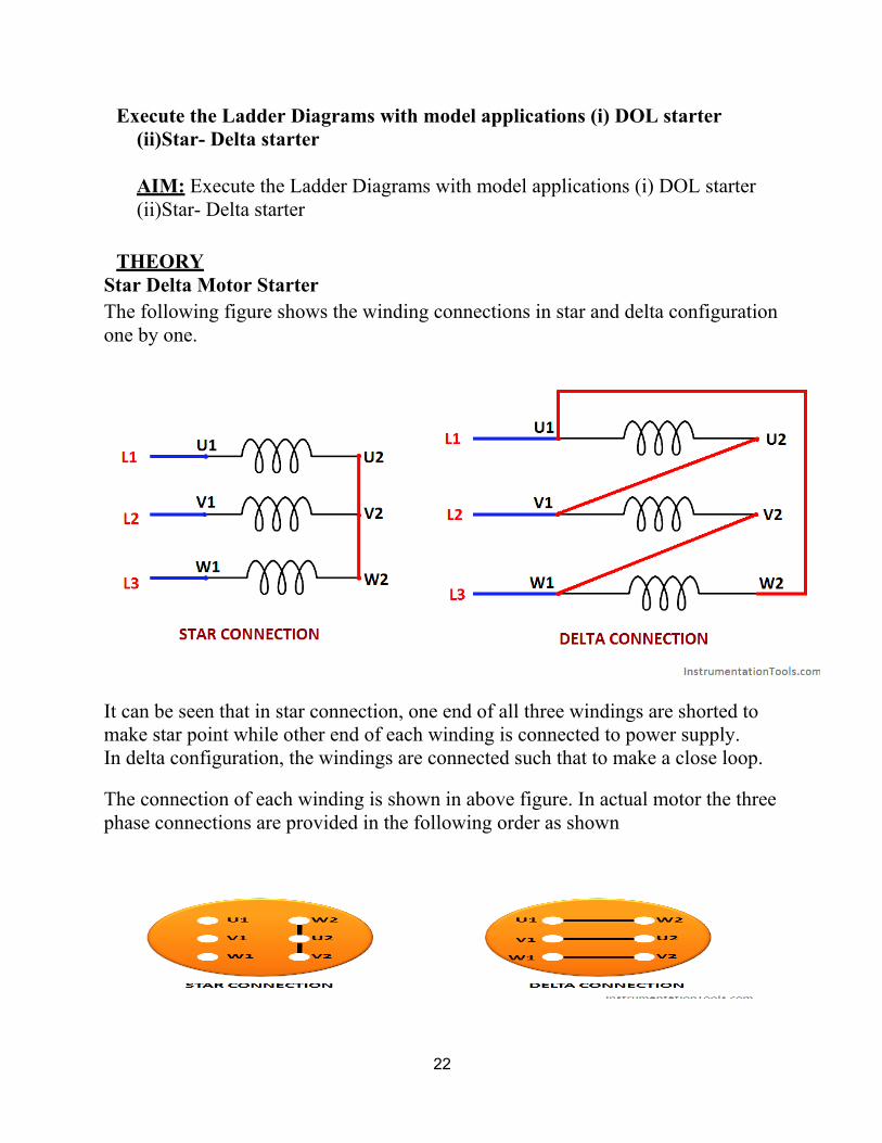
22
Execute the Ladder Diagrams with model applications (i) DOL starter (ii)Star- Delta starter
AIM: Execute the Ladder Diagrams with model applications (i) DOL starter (ii)Star- Delta starter
THEORY
Star Delta Motor Starter The following figure shows the winding connections in star and delta configuration one by one.
It can be seen that in star connection, one end of all three windings are shorted to make star point while other end of each winding is connected to power supply. In delta configuration, the windings are connected such that to make a close loop.
The connection of each winding is shown in above figure. In actual motor the three phase connections are provided in the following order as shown

23
So in order to make winding connection in star and delta style in practical motor, the connection is shown above.
Main contractor is used to supply power to the windings. It must be turned on all the time. Initially the star contactor is closed while delta contactor is open It makes the motor windings in star configuration.
The contactors are controlled by using PLC. The following section of PLC tutorial will explain the ladder programming for star delta motor starter.
PROCEDURE
PLC program for star delta motor starter:
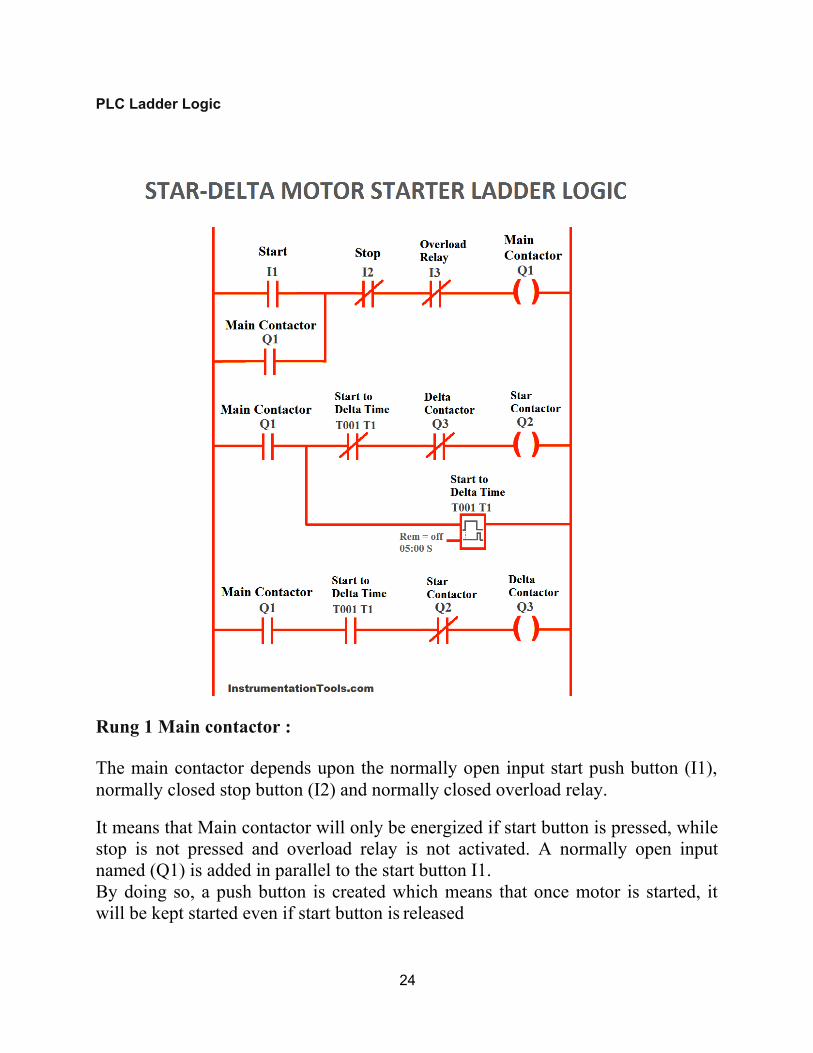
24
PLC Ladder Logic
Rung 1 Main contactor :
The main contactor depends upon the normally open input start push button (I1), normally closed stop button (I2) and normally closed overload relay.
It means that Main contactor will only be energized if start button is pressed, while stop is not pressed and overload relay is not activated. A normally open input named (Q1) is added in parallel to the start button I1. By doing so, a push button is created which means that once motor is started, it will be kept started even if start button is released

25
Rung 2 Star contactor:
Star contactor depends upon main contactor, normally close contacts of timer (T1), and normally close contacts of output delta contactor (Q3). So star contactor will only be energized if main contactor is ON, time output is not activated and delta contactor is not energized.
Timer T1:
Timer T1 measures the time after which the winding connection of star delta starter is to be changed. It will start counting time after main contractor is energized.
Rung 3 Delta contactor:
Delta contactor will be energized when main contactor (Q1) is energized, timer T1 is activated and star contactor (Q3) is de-energized.
Also see Programming of push button and other requirements for simple motor starter is explained in PLC Tutorial: Motor starter
DOL Starter Ladder Diagram The ladder diagram of the dol starter.dol (Direct-On-Line) starter is used to start the motor by applying full line voltage to the motor. Dol starter is used for the motors having rating up to the 05HP. Figure shows the control diagram of the dol starter.

26
PROCEDURE START push button for starting of the starter STOP push button to stop the circuit CONTACTOR for holding
When START push button is pressed contactor will be ON and it starts until the STOP push button is not pressed. When we have pressed the start push button the contactor NO behind the start push button holds the circuit. STOP push button is pressed the CONTACTOR will be OFF untill START button is not pressed again.
We can also made this program using latching here is the ladder diagram of dol starter using latching.
CONCLUSION: This is all about the Ladder Diagrams with model applications (i) DOL starter (ii)Star- Delta starter.
……………………………………………………………………………………….

27
Execute Ladder diagrams with model applications (i) Stair case lighting (ii) Traffic light controller
AIM: Execute Ladder diagrams with model applications Stair case lighting.
Equipment: I0.0 & I0.1: Input toggle switches. Q0.0: Output signaling device.
THEORY;
This ladder logic of stair-case wiring works on the X-OR logic i.e.Y is (A.B^) + (A^. B) Suppose initially only I0.0 is pressed and I0.1 remains open physically as shown then the upper branch of rung 1 goes TRUE and Q0.0 gets energized.
Now, if I0.0 is also pressed then it will make its interlock N-C contact I0.1 to go open and as a result Q0.0 de-energizes . Again, if switch I0.0 is pressed it will also make its interlock contact I0.0 in parallel branch to go again N-C, which in turn makes the parallel branch logic true and Q0.0 again energizes but if the I0.1 input is also pressed again the logic goes FALSE and Q0.0 again de-energizes. This is the basic concept of an X-OR logic gate.
.
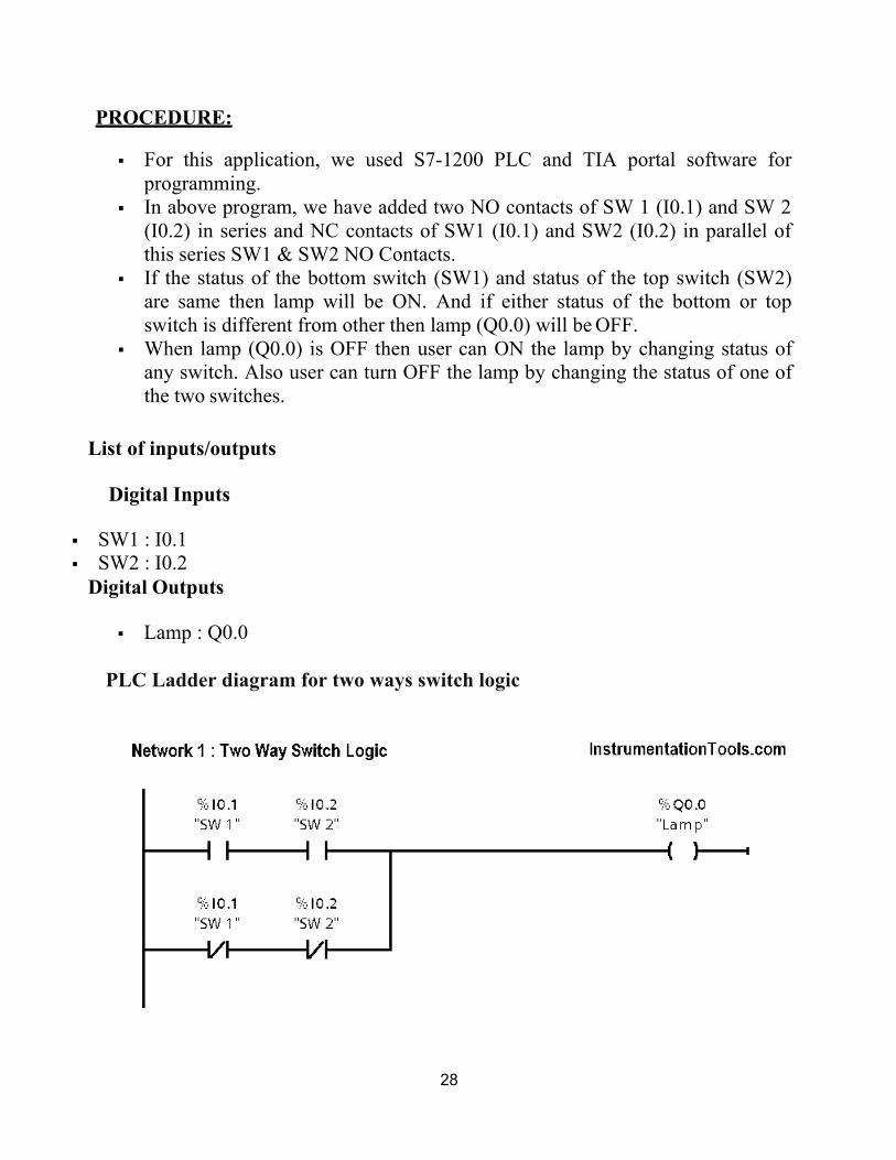
28
PROCEDURE:
For this application, we used S7-1200 PLC and TIA portal software for programming.
In above program, we have added two NO contacts of SW 1 (I0.1) and SW 2 (I0.2) in series and NC contacts of SW1 (I0.1) and SW2 (I0.2) in parallel of this series SW1 & SW2 NO Contacts.
If the status of the bottom switch (SW1) and status of the top switch (SW2) are same then lamp will be ON. And if either status of the bottom or top switch is different from other then lamp (Q0.0) will be OFF.
When lamp (Q0.0) is OFF then user can ON the lamp by changing status of any switch. Also user can turn OFF the lamp by changing the status of one of the two switches.
List of inputs/outputs
Digital Inputs
SW1 : I0.1 SW2 : I0.2
Digital Outputs
Lamp : Q0.0
PLC Ladder diagram for two ways switch logic

29
Runtime Test Cases
CONCLUSION:
The above PLC Logic provided for basic idea about application of PLC for Stair case lighting Two Way Switch Logic.
……………………………………………………………………………………….
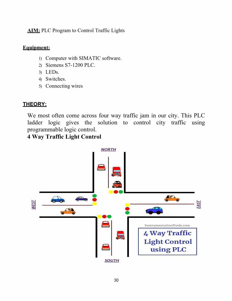
30
AIM: PLC Program to Control Traffic Lights
Equipment:
1) Computer with SIMATIC software. 2) Siemens S7-1200 PLC. 3) LEDs. 4) Switches. 5) Connecting wires
THEORY:
We most often come across four way traffic jam in our city. This PLC ladder logic gives the solution to control city traffic using programmable logic control. 4 Way Traffic Light Control

31
List of Inputs and Outputs
S.no Address Name Input/Output
1 I:0/0 Start Input
2 I:0/1 Stop Input
3 B3.0 Memory Memory
4 O:0/0 East Green Output
5 O:0/1 North Red Output
6 O:0/2 West Red Output
7 O:0/3 South Yellow Output
8 O:0/4 East Yellow Output
9 O:0/5 North Yellow Output
10 O:0/6 North Green Output
11 O:0/7 East Red Output
12 O:0/8 West Yellow Output

32
13 O:0/9 West Green Output
14 O:0/10 South Yellow Output
15 O:0/11 South Green Output
Sequence of Operation
Below tabular column gives the Steps or sequence of outputs to turn ON the traffic system lamps (RED, GREEN, YELLOW)
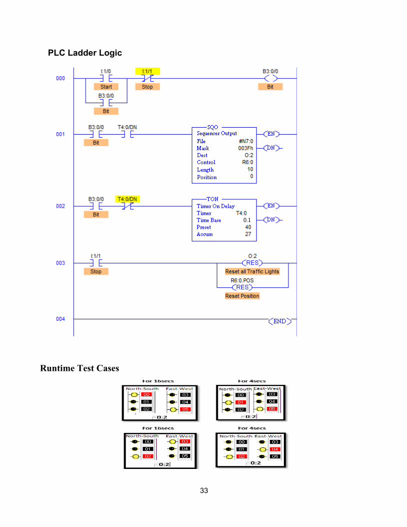
33
PLC Ladder Logic
Runtime Test Cases

34
PROCEDURE • RUNG000 again here is for Master Start and Stop the process. • File; #N7:0 and File length is 10, hence output sequence is varied
from N7:0 to N7:10 with each input. • Destination is set to O:2 hence with each transition, N7:0 to N7:10
are moved to O:2 with masking. • O:2/0 to O:2/5 are used as the output address to Traffic Lights and
hence Mask has value 003Fh which means data flow of N7:0/0…N7:10/0 to N7:0/5…N7:10/5 is passed and the remaining N7:0/6…N7:10/6 to N7:0/15…N7:10/15 are blocked.
• Control parameters are assigned to register R6:0. • Sequence of traffic lights to be operated are stored in the registers
from N7:0 to N7:10 as following • Time base is set to 4secs, hence after every 4secs, output sequence
is changed to its next register pattern outputs which is then transferred to O:2 and O:2/0 to O:2/5 are energized accordingly.
• As we can see, from N7:1 to N7:4 have the same bit pattern. So, these bits are set to 1 for 4 cycles that is 16secs. These bits are used for South-North Green light and East-West Red light.
• Similarly the entire sequence is followed. • When Stop I:1/1 is pressed, Position is reset to 0 and all the
outputs are de- energized.
Conclusion:
The above explained 4 ways traffic light control using PLC is for example only. It may vary from real time. We can use this example program to understand the working of timers and Interlocking function in PLC.


