Embed Size (px)
Citation preview

NASA Contractor Report 1774l 3
Large Deployable Reflector (LDR) System
Concept and Technology Def=n=t=on StudyVolume II Technology Assessment andTechnology Development Plan
Donald L. AgnewPeter A. Jones
(NASA-CR-1T7_I3-Vo|-2) LARGE
OEPLUYA_LE REFLECTOR (LDR) SYSTEM
CONCEPT AND TECHNOLOGY DEFINITION
STUOY. VOLUME 2: TECHNOLOGY
ASSESSMFNT ANO TECHNOLOGY
0EVELOPNENT PLAN Final TechnicalReport (Eastman Kodak Co.)
N93-12593
Unclas
G3/74 0t30690
CONTRACT NAS2-11861
April 1989
I IASANational Aeronautics and
Space Administration


NASA Contractor Report 177413
Large Deployable Reflector (LDR) SystemConcept and Technology Definition StudyVolume II- Technology Assessment andTechnology Development PlanDonald L. AgnewPeter A. Jones
Eastman Kodak Company, Rochester, New York
Prepared forAmes Research CenterCONTRACT NAS2-11861
April 1989
fUASANational Aeronautics and
Space Administration
Ames Research CenterMoffett Field, California 94035


Section
TABLE OF CONTENTS
VOLUME II
Title Page
1.01.1
1.2
1.2.1
1.2.2
2.0
2.1
2.2
2.3
3.0
3.13.1.1
3.1.23.1.3
3.1.4
3.1.5
3.1.6
3.2
3.2.1
3.2.2
3.2.3
3.2.4
3.2.5
3,2.6
3.2.7
3.2.8
3.2.9
3.2.10
3.2.11
3.2.12
3.3
3.3.1
3.3.2
3.4
3.4.1
List of FiguresList of TablesForeword
OVERVIEW
Objective and Background
System Concept and Technology Definition Study
LDR Requirements and Implications
Study Rationale and Tasks
SYSTEM CONCEPTS
Concept I: Multiple Shuttle Assembly
Concept 2: Space Station Assembly
Concept 3: Single Shuttle/ACC Assembly
TECHNOLOGY ASSESSMENT
Sensing, Controls, and Control Electronics (OAST Category A)
Primary Mirror Segment Sensing and Control ApproachFold Mirror Chopping
Secondary Mirror Chopping
Fine Guidance Sensing and Control
Secondary Mirror Sensing and Control Approach
Noise Reduction in Control Moment Gyros (FSC)
Materia]s, Structures, Thermal and Dynamics (OAST Category B)
Dynamic Structural Control
Dynamic Dimensional Stability (MDAC)
Dynamic Response Prediction Precision (MDAC)Structural Nonlinearity (MDAC)
Low Jitter and Rapid Setting (MDAC)
Verification/Acceptance Ground Testing (MDAC)
Mechanical Stability - Damage Tolerance (MDAC)
Step Sunshield
Secondary Mirror Temperature Control
Primary Mirror Temperature Control
Collapsible Sunshield
Spacecraft Buildup on Orbit (FSC)
Propulsion and Power (OAST Category C)
Structural Dynamics: Advanced Power System (FSC)
Monopropellant Refueling (FSC)
Human Factors (OAST Category D)
Human Factors (MDAC)
v
vii
viii
1
1
5
5
I0
18
18
20
2O
25
25
25
26
29
32
35
40
42
4245
47
4849
50
51
53
54
58
60
62
63
63
65
66
66
iii
p_CEDING PAGwIIBLANK i_OT FILMED


Title PageSection
3.5
3.5.1
3.5.2
3.5.3
3.6
3.7
3.7.1
3.7.2
3.7.3
3.7.43.7.5
3.83.8.1
3.8.2
4.04.1
4.2
4.3
Cryogenics and Sensors (OAST Category E)
Hybrid Cryogenic System for Science InstrumentsCryogenic Systems for Detector Temperatures Less Than O.3°K
Robotic On-Orbit Cryogenic ReplenishmentCommunications and Data Handling (OAST Category F)
Optics Materials and Fabrication (OAST Category G)
Active Primary Mirror
Primary Mirror Contamination ProtectionGlass Material for the Primary Mirror
Composite Material for the Primary MirrorOff-Axis Mirror Segment Processing
Other (OAST Category H)ACC Contamination Protection/Remote Maneuvering Arm
Shuttle Bay Contamination Protection
SUMMARY
Technology Tasks in Priority OrderTask Milestones
Budget Milestones
74
74
76
79
81
81
81
83
85
89
93
96
97
97
97
98
99
99
iv

Figure
1.1-I
1.1-2
1.2-1
1.2.2-I
1.2.2-2
1.2.2-3
1.2.2-4
1.2.2-5
1.2.2-61.2.2-7
1.2.2-8
2.1-I
2.1-2
2.2-1
2.2-2
2.3-I
2.3-2
3.1.1-1
3.1.2-1
3.1.3-2
3.1.3-3
3.1.3-4
3.1.3-5
3.1.4-1
3.1.5-I
3.1.5-4
3.1.6-1
3.2.1-1
3.2.2-I
LIST OF FIGURES
Title
Summary LDR Technology Development Schedule
Technology Development Projected Funding Profile
Selected LDR System Parameters and Performance Requirements
Large Deployable Reflector (LDR) System Concept and Technology
Definition Study
Technology Definition Phase of Study
Task 1 Technology Specification/Categorization
Task 2 Technology Assessment
Technology Assessment Summary Format
Task 3 Technology Development
Technology Development Prioritization Criteria
Task 3 Integrated Technology Development Plan
Multiple Shuttle Assembly
LDR Observatory
Concept 2: Space Station Assembly
LDR Observatory
Concept 3: Single Shuttle/ACC AssemblyLDR Observatory
Category B: Materials, Structures, Thermal, and
Dynamics Step Sunshield
Category A: Sensing, Controls, and Control Electronics
Fold Mirror ChoppingFold Mirror Chopping Concepts
Category A: Sensing, Controls, and Control Electronics
Secondary Mirror Chopping
Operational Performance Prediction
Maximum Allowable Chopping Field of View
Secondary Mirror Chopping
SM Chopping Mechanism Concepts
Category A: Sensing, Controls and Control Electronics
Fine Guidance Sensing and Control
Category A: Sensing, Controls, and Control Electronics
Secondary Mirror Sensing and Control Approach
LDR Optical Subsystem Operational Performance Prediction
LDR Optical Subsystem Operational Performance Prediction
(Reallocated to Increase Secondary Mirror Misalignment Allowable
Error)
A11owable Despace Error
Technology Assessment Noise Reduction In CMG's
Category B: Materials, Structures, Thermal and Dynamics
Dynamic Structural Control
Category B: Materials, Structures and Dynamics Dynamic
Dimensional Stability
Page
4
4
6
11
12121314151517
18
19
21
2123
23
25
27
28
29
30
30
31
32
33
35
36
36
37
41
42
46
v

3.2.4-1
3.2.5-1
3.2.6-1
3.2.7-1
3.2.8-1
3.2.9-I
3.2.10-1
3.2.11-1
3.2.11-2
3.2.12-1
3.3.1-1
3.3.2-1
3.4.1-1
3.4.1-2
3.4.1-3
3.4.1-4
3.4.1-5
3.4.1-6
3.4.1-7
3.4.1-8
3.5.1-1
3.5.2-I
3.5.3-1
3.7.1-1
3.7.1-2
3.7.1-3
3.7.2-1
3.7.3-1
3.7.3-2
3.7.3-3
3.7.4-1
3.7.4-2
3.7.4-3
3.7.5-1
3.7.5-2
Title Page
Category B: Materials, Structures and Dynamics Dynamic Response 47Prediction Precision
Category B: Materials, Structures and Dynamics Structural 48
Non-LinearityCategory B: Materials, Structures and Dynamics Low Jitter 49
and Rapid Settling
Category B: Materials, Structures and Dynamic Verification/ 51
Acceptance Ground Testing
Category B: Materials, Structures and Dynamics Mechanical 52
Stability - Damage Tolerance
Category B: Materials, Structures, Thermal, and Dynamics Step 55Sunshield
Category B: Materials, Structures, Thermal and Dynamics 57Secondary Mirror Temperature Control
Category B: Materials, Structures, Thermal, and Dynamics Primary 59
Mirror Temperature Control
Category B: Materials, Structures, Thermal, and Dynamics 60
Collapsible SunshieldCleanliness Requirements 61
Technology Assessment Spacecraft Buildup on Orbit 63
Technolgoy Assessment Structural Dynamics: Advanced Power Systems 65
Monopropellant Refueling 66
Category D: Human Factors 67
LDR Mirror Set Back-up Structure Assembly 67
Primary Mirror Assembly Phases 68
Human Factors Technology Advancement Needs For LDR 69LDR Construction Overview 69
LDR Backup Truss Construction Approach Tradeoff: EVA Vs? 70
LDR Mirror Backup Truss Tests (In MDAC Underwater Test Facility) 71
ORU* Exchange Logistics Module (OMV-Based) 73
Category E: Cryogenics and Sensors Hybrid Cryogenic System For 75
Science Instruments
Category E: Cryogenics and Sensors Cryogenic Systems For Detector 78
Temperatures Less Than 0.3°K
Category E: Cryogenics and Sensors Robotic On-Orbit Cryogenic 80
Replenishment
Category G: Optics Materials and Fabrication Active Primary Mirror 82
Coherently Phased Mirrors 82
Active Segmented Mirror 84
Category G: Optics Materials and Fabrication Primary Mirror 84Contamination Protection
Category G: Optics Materials and Fabrication Glass Material 87
for the Primary Mirror
Thermal Expansion of Corning Fused Silica Glass 88
Predicted Areal Density (Frit-Bonded) 88
Category G: Optics Materials and Fabrication Composite Material 90
For The Primary Mirror
Thermal-Expansion Coefficients 91
Selection of Primary Mirror Substrate Material 92
Category G: Optics Materials and Fabrication Off-Axis Mirror 94
Segment Processing
LDR Primary Mirror Segment Manufacture Alternatives 95
v±

LIST OF TABLES
Table
1.1-I1.2.2-I1.2.2-2
2.1-I2.1-22.2-i2.2-22.3-12.3-2
3.1.2-13.1.5-13.2.1-I
3.7.3-13.7.4-13.7.5-1
4.3-1
Title
Individual Technology Augmentation Projects Cross Reference
Candidate Technology Issues by OAST Category
Prioritized Technology Augmentation Programs
Concept I:
Concept 2:Concept 2:
Concept 2:
Concept 3:
Concept 3:
Summary
System Highlights
Summary
System Highlights
SummarySystem Highlights
Rotating Versus Push/Pull Tertiary ChoppersDespace Error Allocation
Dynamic Structural Control Needs for TechnologyImprovement for LDR
Reflector Material Trade Material PropertiesReflector Material Trade Material Properties
LDR Derived Performance Requirements
LDR Integrated Technology Development Plan
page
2
13
16
19
20
22
22
24
24
28
38
43
87
9195
100
vii

FOREWORD
This volume is the second of two that comprise the Final Technical Report. It
includes technology assessments and plans prepared by Kodak and its two study
team members, McDonnell Douglas Astronautics Company-Huntington Beach (MDAC) and
Fairchild Space Company (FSC). Portions of the document primarily prepared by
these team members are identified by their company initials (MDAC or FSC)
following a section or paragraph heading.
Volume I contains the executive summary for the total study and a report of the
systems analysis phase. Topics covered are: study approach and methodology;
reports of thirteen system analysis and trade tasks; and descriptions of three
selected LDR system concepts. Supporting information is contained in appendicesto Volume I.
This Technology Assessment and Technology Development Plan is submitted in
response to Article If, Section C, Paragraph i, Item g of Contract NAS2-11861,
Large Deployable Reflector System Concept and Technology Definition Study. The
plan format corresponds to the draft outline provided by the NASA TechnicalMonitor.
Engineers and scientists who contributed to the study are identified below by companyaffiliation and technical or functional role:
Eastman Kodak Compan_
Study Manager Donald L. Agnew
Optical Systems Analysis Peter A. Jones
Thermal/Cryogeni cs Ana lys is John J. Meyers and
Robert D. Grigg
Reflector Materials and
Mechanical Analysis
David A. Crowe and
Robert R. Brearey
Pointing and Control Michael J. Clayton,Richard A. Kent and
Rodney E. Wetterskog
Chopping Dr. Dennis A. Thompson
Optical Analysis Randy C. VanVranken and
Joseph J. Charles
Structural Analysis Dr. Vincent J. Piarulli and
Dr. Victor L. Genberg
Cost Modeling Victor F. Vinkey
viii

McDonnell Dou)las Astronautics Compan@-Huntin)ton Beach
Study Manager
Structural Analysis
Payload Integration
Science Instruments Considerations
Thermal Analysis
Assembly Techniques
Logistics
Fritz C. Runge
Lester L. Westenberger
Fred W. Shepphird
Dr. Chandler Kennedy
William Nelson
George King
Randy Farner
Fairchild Space Company
Study Manager
System Analysis
Science Instruments Considerations
Orbit/Rendezvous Analysis
Propellant Requirements
Control, Power, andMicrometeroid Environment
Radiation Environment
Contamination Control
Donald R. Burrowbridge
Bernard Raab
Dr. Paul Adam Blanchard
William M. Grounds
Maryel len Maxson
Mark Frieder
P.R,K. Chetty
Bernard Bloom
ix

1.0 OVERVIEW
1.1 OBJECTIVE AND BACKGROUND
This Technology Assessment and Technology Development Plan defines a plan aimed at
achieving requisite levels of technological capability prior to start of Phase C
development of the Large Deployable Reflector (LDR) in the early 1990's. Prepared by
EastmanKodak Company and its subcontractors, McDonnell Douglas Astronautics Company-
Huntington Beach and Fairchild Space Company, the plan comprises 22 individual tech-
nology development projects, whose sponsorship as technology initiatives by NASA is
recommended during the time period 1986-1991.
This plan was developed as part of the LDR System Concept and Technology Definition
Study under NASA-Ames Research Center Contract NAS2-11861. It addresses technology
concerns derived from review of three system concepts of the LDR observatory syn-
thesized by the Kodak team that are described in Section 2.0. Envisioned as a 20-
meter diameter aperture astronomical telescope facility, primarily for observations
in the range of 30 micrometers to I millimeter, LDR presents technology challenges in
many areas. Implementation of the technology augmentation plans recommended herein
can beneficially support an LDR schedule requiring technology readiness by year-end1991.
The 22 proposed augmentation projects selected from more than 30 candidates are de-
signed to accelerate the progress of technology growth essential to LDR, where the
rate of growth over the next six years is projected to fall short of LDR needs, based
on assessments by the Kodak team. A description of the assessment and plan develop-
ment is presented in Paragraph 1.2 below.
The five LDR technology areas most in need of supplementary support, (rated "high"
based on a high, medium, low, or not-rated prioritization of the candidates) are:
• Cryogenic cooling - demonstration of a hybrid (stored cryogens and closed
cycle mechanical cooler) system for the LDR science instruments.
e Human factors - demonstration of astronaut capability to assemble the optical
precision LDR in space and to perform other roles.
• Active primary mirror - demonstration of an LDR unique, segmented, mirror
design having tilt, piston, and figure control for each panel.
e Dynamic structural control - development of a dynamic simulation model of the
LDR that links dispersed structural design and analysis techniques.
• Primary mirror contamination protection - development of means (such as
strippable coatings) to protect the reflector on-orbit during deployment
assembly, servicing revisits.
Seventeen other technology areas are adjudged to be of medium concern and augmenta-
tion support is also recommended. Assessments of these areas and descriptions of
proposed development plans are presented in Section 3.0. Table 1.1-I lists the 22
high and medium areas by title and provides a cross-reference to their location in
Section 3.0, where they are arranged by Office of Aeronautics and Space Technology
(OAST) categories.

TABLE 1.1-I
INDIVIDUAL TECHNOLOGY AUGMENTATION PROJECTS CROSS REFERENCE
OAST._TEGORY. TECHNOLOGYPROJECTTITLE
KODAKPROGP,AM
GROUP
PARAGRAPHLOCATION
SECTION 3.0
HIGH PRIORITY (S PROJECTS)
B DYNAMICSTRUCTUI_L CONTROL
D HUMANFACTORS
E HYBRID CRY_ENIC SYSTEHFOR SCIENCE INSTRUMENTS
6 ACTIVE PRIMARYMIRROR
G PRIMARY NIRROR CONTAMINATION PROTECTION
MEDIUM PRIORITY (17 PROJECTS)
A PRIMARYMIRROR SEGMENTSENSING AND CONTROLAPPROACH
A FOLD MIRRORCHOPPING
A SECONDARYMIRROR CHOPPING
A FINE GUIDANCESENSING AND CONTROL
B DYNAMICDIHENSION STABILITY
B DYNAMIC RESPONSE PREDICTION PRECISION
B STRUCTURALNONLINEARITY
B LOWJITTER AND RAPID SETTLING
B VERIFICATION/ACCEPTANCEGROUNDTESTING
B MECHANICALSTABILITY - DAMAGETOLERANCE
B STEP SUNSHIELD
B SECONDARYMIRRORTEMPERATUP,E CONTROL
B PRIMARYMIP,ROR TEMPERATURECONTROL
CRYOGENICSYSTEHS FOR DETECTORTEMPERATURELESS THAN 0.3 DEGREESKELVIN
POINTING'& STABILITY 3.2.1
POINTING & STABILITY 3.4.1
DETECTABILITY 3.5.I
REFLECTORQUALITY 3.7.1
DETECTABILITY 3.7.2
REFLECTORQUALITY 3.1.1
DETECTABILITY 3.1.2
DETECTABILITY 3.1.3
POINTING & STABILITY 3.1.4
POINTING & STABILITY 3.2.2
POINTING & STABILITY 3.2.3
"POINTING & STABILITY 3.2.4
POINTING & STABILITY 3.2.5
POINTING & STABILITY 3.2.6
POINTING & STABILITY
DETECTABItITY
DETECTABILITY
DETECTABILITY
DETECTABILITY
3.2.7
3.2.8
3.2.9
3.2.10
3.5.2
E ROBOTIC ON-ORBIT CRYOGENIC REPLENISHMENT DETECTABILITY 3.5.3
G GLASSMATERIAL FOR PRIMARYMIRROR REFLECTORQUALITY 3.7.3I
G COMPOSiTEMATERIAL FORTHE PRIMARYM-IRROR REFLECTORQUALITY 3.7.4
2

Kodak has synthesized three broad, time-phased, five-year programs from the 22 indi-
vidual technology projects. This was done to better understand the interrelation-
ships of the projects, so as to identify intermediate decision points where alterna-
tives existed, and to consider the overall funding implications. The three programsare:
• Reflector Quality Program
• Pointing and Stability Program
• Detectability Program
The Reflector Quality Program comprises four interrelated projects concerned with
primary mirror (reflector) materials development, selection of a mirror design, and
mirror demonstration to meet LDR requirements.
The Pointing and Stability Program combines nine projects. Six are interrelated
structural materials, structural design, and test developments. The Dynamic Struc-
tural Control simulation modeling is also in this group, as are the Human Factors and
Fine Guidance projects.
The Detectability Program also comprises nine projects. It deals with technologies
that principally determine the ability of LDR to achieve its background-limited NEP
sensitivity goals. Three projects are concerned with cryogenics, three with thermal
control, two with chopping, and one is the Primary Mirror Contamination Protection
Project, mentioned above.
A summary schedule of the Kodak-MDAC-FSC technology development plan is presented in
Figure 1.1-I along with milestones of the NASA LDR master schedule. Separate, more
detailed time-phased plans for each of the three programs are included in Section4.0.
The recommended funding for the technology development projects totals $70.425
million (rough order of magnitude based on 1985 dollars not forward priced). The
three component program funding levels are:
Detectability Program
Pointing and Stability Program
Reflector Quality Program
$40.750M21.275M
8.400M
Time-phased funding details by project and program are contained in Section 4.0. The
cumulative funding profile is shown in Figure 1.1-2.

PROGRAM DIPLDCENTATION SCHEDULE
(MS[I) ON NAY 1984 KICKOFF NE['TING,kND _BSE_ENT CUSTOMER DIS-CUSSIONS)
I_AK-NOAC-FSC TECHNOLOGYOEVELO_ENT PLAN
• REFLECTOR QI_LITY PROGRAM(4 PNDJ[¢TS)
• POINTING AND STABILITY PRO6RA_
(9 PROJECTS)
• s)_'r[c_As:_.tT'r_OGANq(g PROJ[CT$)
SUMMARY
q
L
i0_ 86
E T_CHNDL_Y |NITIATIYE$
L_", I
sl/gx
_ERZ_ O[V/ m,_R Ksl_w mmm o_o
TER|AL OEV ISTRUCT DEV AND T[S1 ($)HUMAN FACTORS (1)
I I ")CR'tOG[llCSYSTmS(3)
| _[_mAL com_mL(3)CHOPPING (2) | '
LDR TECHNOLOGY DEVELOPMENT SCHEDULE
Figure 1.1-1
zt-
u
I-
TOTAL TECHNOLOCY
PROGR_ $70. Z,25_1
POINTING AND STABILITY
PROGR_ $21.275H
I0 o REFLECTOR QUALITY$8._00M
TECHNOLOGY
86
DEVELOPI',IENT
CAL ENOAR YEAR
PROJECTED FUNDING PROFILE
Figure I.I-2
4
(REVISED 25 FEBRUARY 1985)

1.2 SYSTEM CONCEPT AND TECHNOLOGY DEFINITION STUDY
This technology assessment and technology development plan is the principal output of
an approximately one-year duration study effort, conducted for NASA-Ames ResearchCenter.
This section briefly summarizes the baseline LDR requirements established for the
study and their major implications, and describes the study rationale and tasks.
1.2.1 LDR Requirements and Implications
Requirements imposed for the study are reproduced in Figure 1.2-1. Implications with
respect to design and technology concerns are highlighted in the following
paragraphs, for the more significant requirements.
DIAMETER
The 20-meter aperture, eight times that of the Hubble Space Telescope, immediately
infers that the LDR observatory must be mechanically designed to permit its assemblyon orbit (automated or manually-assisted). Neither the payload bay of the Shuttle
Orbiter nor the proposed Aft Cargo Compartment (on the aft end of the External Tank)
can accommodate the packaging of LDR for transportation to orbit without complex
folding, modularization, reliable deployment techniques, or astronaut-assisted con-
struction. The 20-meter desired aperture, however, represents a "break-point" in
potential LDR science return. The primary mirror, of necessity, is segmented, and
requires means for initial establishment and maintenance of its ideal optical figure.
Consequently, subsystems must be provided for measuring figure (wave front) and
correcting segment tilt and piston errors, matching radius of curvature of the diff-
erent segments, and, possibly for correcting the figure of the individual segments.
(These are obviously driven by zero-g, themal, and dynamic factors).
The shear size of LDR forces lightweighting considerations in all designs. The pri-
mary mirror, support structure, and sunshield are significant contributors to the
weight budget.
F/RATIO
The combination of the system and primary mirror f/ratios constitute a 20-fold magni-
fication. This sets a very tight tolerance on secondary mirror alignment. Precision
metering (perhaps by placing glass-matrix rods inside the secondary mirror support
struts) of the secondary is required. A secondary mirror sensing and control system
will be needed that can sense secondary mirror despace, tilt, and decenter errors and
correct them, most likely by utilizing high-precision tilt and piston actuators be-
hind the secondary mirror.
SHORTEST WAVELENGTH OF DIFFRACTION-LIMITED PERFORMANCE
This requirement establishes fundamental requirements on the total system wave front
error and the budget allocated to each contributor. As written, the "diffraction-
limited" modifier implies that approximately 84% of the energy collected from a point
source be contained in the innermost bright spot of the Airy disk formed at the image
plane, for the shortest wave length of best attainable performance. This criterion
is a standard used in design of optical and infrared telescopes and instruments. The

Parameters
Diameter
Field o! view
F/Ra t tob
SI,Jrte_t wdvelength of diffraction-limi ted p,:rfomance
Light b.cket blur circle a
Optics temperature
Emissivity (system)
Ah_olute pointing
Jitter
Slew
Scan
Track
Chnppt mjb
Sldelohes
Other
Sky exclusion
Cryo system
Ltfetim
Requirements
20 m primary, 1 In secondary
>_.3 arcmln
System FII0, prlmry F/0.S
31)-S0 m (aperture efficiency > 30S 0t 30/4m)
2._, arcsec (at I-i ID)
Prpm,-y ( 2001( (-_1 K uniformity),secondary" <..12S K (_1 K untfomtty)
0.05
0.05 arcsec
0.02 arcsec - within | gin after slt_
20 -" SO°/mtn
I" x I" - linear scan at l'/mtn
O.2°/hr (for comets _> 2S" from Sun)
Yes, 2 Hz, ! arcmtn (reacttonless)
Low near stdelobes
Ltmtted cross polarization
60°-90 ° from Sun. _ 45" from (arth
Various ter.q)eratures in the ran!le 0.1 K to50K, 1.5 kW total power required
> 10 yr. approximately 3 yr revisit
e 1he tolL,_'a,ces (e.g., rms surface accura,'y) needed to achieve a value of 2 arcsec for the 119hib.cket ,.,de are more severe than the '.c)lcrances associated with a diffraction limit of 50 pro.Tlnis requireaent will be studied further.
b Approximate.
SELECTED LDR SYSTEM PARAMETERS AND PERFORMANCE REQUIREMENTS
Figure 1.2-1

bracketed requirement (that aperture efficiency exceed 30% at 3Oil. m) is based on
antenna gain definitions and is equivalent to a much less stringent requirement than
the Airy disk criterion.
The literal interpretation of this requirement places tighter tolerance on RMS sur-
face quality and budgeted optical alignment than does the interpretation that aper-
ture efficiency of 30% is to be substituted for "diffraction-limited performance".
Figuring of optical surfaces to the more stringent Airy criterion is routinely per-formed successfully at much shorter wavelengths. Relaxation to the aperture
efficiency criterion does suggest that the mirror processing time could be reduced
(since the allowable surface error could be relaxed). The benefit, in terms of large
tool processing applied to primary mirror glass substrates, does not appear signi-ficant, however.
This requirement, from a telescope design point-of-view, has major impact on the
design of the LDR optical support structures. The array of segmented mirrors and
optical system components must all be kept within budgeted alignment tolerances, in
order to maintain the diffraction-limited performance goal. Maintenance of the
stability of the primary mirror support structure for an observatory as large as LDR
implies consideration of detailed modeling of the dynamics involved, thermal in-
fluences on design, interrelationship of the spacecraft control system and the mirror
segment control system (including the degree of figure control and rigid body control
required), properties of materials, and others.
OPTICS TEMPERATURE
The mirror temperature requirements are of profound importance to the design of LDR.
The need for uniformity of temperature on both these mirrors derives from the basic
LDR concept that the local background noise sources be removed by chopping the re-
ceived signal. (The relatively warm telescope mirrors emit energy in the same wave
length regions as the sources being observed). The effective elimination of back-
ground imposes the requirement for the +I°K uniformity across the mirrors at a giveninstant, and suggests that the time-varying bulk mirror temperatures can be allowed
to change only very slowly during a typical (30 minutes) observation (since the
chopping rate is 2 hertz).
The bulk mirror temperature requirements force the utilization of a sunshield orshade and an overall telescope thermal design approach that considers the energy
incident from the back of the primary mirror and support structure, the exclusion
angles about the sun and earth, and the selected orbit, among many factors.
Since the secondary mirror bulk temperature (125°K) requirement is lower than the
primary, thermal design of the secondary will probably require an active cooling
concept. Maintenance of LDR image quality is strongly dependent on thermal designs
that reduce temperature variability. The use of low coefficient-of-thermal-expansion
materials is important in the reflector segments and its structural support. The
thermal uniformity requirement on the mirrors implies that high conductivity paths
may be required on mirror substrates to assure fast equilibration of varying heat
loads. Isotropic CTE of mirror substrates is also essential.

ABSOLUTE POINTING, JITTER, SLEW, SCAN, AND TRACK
This set of requirements places severe requirements on the LDR structural design andpointing and control system, when considered in light of the size of LDR and itsassembly mode on orbit.
The absolute pointing requirement implies the need for an optical fine guidance
sensing system using a visible star catalog. Direct use of the primary mirror and
secondary mirror are thus not acceptable since they are not finished to the quality
necessary. A separate sensing system using an optical quality telescope will need tobe carefully boresighted to the LDR telescope line of sight.
The jitter, slew, scan, and track requirements all influence the structural design,particularly the primary mirror support structure. The integrated structure of LDR
must consider dynamic dimensional stability needs; structural nonlinearities; incor-
poration of passive techniques to limit jitter and promote rapid decay of dynamic
deflections from both vibratory and attitude maneuver responses; one-g to zero-geffects; and the influence of astronaut assembly on the structure.
The control system for pointing the LDR must be adequate to achieve the ranges andaccuracies imposed by these requirements (within the duty cycle set by the observa-
tion sequence). Its interaction with the fine guidance sensor must be fully defined.
The secondary mirror chopping design must provide for essentially reactionless re-
sponse to satisfy jitter requirements.
CHOPPING
The chopping requirement calls for a very effective means for eliminating the back-ground (telescope) noise from the signal.
Achievement by oscillating the secondary mirror impacts the secondary mirror support
structure and assembly greatly. Combined with the need to cool the secondary, pro-vide for tilt, decenter, and despace adjustments, reactionless chopping adds addi-
tional complexity to an already difficult design problem.
Fold mirror chopping (within the S/I compartment) is inherently less effective, adds
complexity to the fold mirror assembly which is enclosed in a cryogenically cooled
chamber, and has little heritage in ground-based telescope designs. Chopping demands
extremely high reliability because it is absolutely critical to the performance ofLDR, as it is currently conceived.
SIDELOBES
The requirement for low sidelobes influences the selection of the basic opticaldesigns for LDR. Unfilled apertures, such as a "ring" interferometer, and slot
configurations can not satisfy this requirement without special design or operational
considerations. The Cassegrain optical configuration easily satisfies this require-
ment when the mirror segments are aligned and shaped to meet the optical figuretolerances.

SKY EXCLUSION
These requirements have great influence on the thermal control and sunshield design,
and place operational restrictions on observations and pointing.
Cylindrical sunshield designs must consider the energy striking the interior when the
line of sight is less than 90 degrees from the sun or earth's limb. Thus, a flare
(cone or scoop) at the top of the cylinder or equivalent means, such as a step sun-shield, must be utilized to meet the 60-degree sun exclusion and 45-degree earth ex-
clusion angles.
CRYO SYSTEM
These extremely low temperature requirements for the science instruments imply very
advanced cryogenic cooling systems must be developed for LDR.
Achievement of LDR detection goals is absolutely dependent upon providing adequately
sized, reliable cooling. Initial cool down, parasitic losses, space/weight budgetsand revisit intervals are factors that indicate a hybrid - - stored cryogens plus a
mechanical refrigerator - - system is needed for the generic cooling of the S/I's.
To achieve O.I°K, adiabatic demagnetization and/or the helium dilution technique will
be needed to be developed.
A shutter (plug) may be necessary to isolate the S/I compartment for thermal control.
Contaminants, which have a proclivity to settle at the coldest portion of a system,
must be considered in all areas of the cryogenically cooled S/I compartment,
including the fold mirror that directs the telescope beam to the individual S/I's.
LIFETIME
Ten year life places basic design goals on all LDR elements, but many items may
potentially be designed to be serviced, replaced, repaired, upgraded, or refurbishedon-orbit.
The replenishment of cryogens and propellants on a regular basis throughout the LDRlife is considered absolutely essential. Robotic means (using an orbit maneuvering
vehicle with smart front end servicer, for example) should be developed.
The lifetime and revisit interval establish basic orbit altitude requirements for LDR
and consequent propellant needs for achieving operating altitude and returning torendevous with the shuttle or space station. The orbit environment will influence
LDR design. Potential impact with space debris and micrometeroids may call for
damage tolerant materials or structurally redundant concepts.
Particulate contamination over the operational life of LDR could degrade primary
mirror performance. Attention must be given to use of materials/designs that will
minimize outgassing or release of particles.

1.2.2 Study Rationale and Tasks
In developing the design for an advanced space system, such as LDR, it is essential
to carefully consider the level of technology readiness of each of the key elements
of the proposed system. The probability of successful implementation of the system
concept increases the more closely the levels of technology readiness of each of the
key elements match the needed operational capability. This principle of program
development is the basis for the LDR System Concept and Technology Definition
Studies, contracted by NASA-Ames Research Center to two separate industry teams
(headed by Eastman Kodak Company and Lockheed Palo Alto Research Laboratories).
Each contractor team was tasked to perform LDR system analyses and trades, synthesize
two or more concepts, assess the key technology issues, and lay out technology
development plans to bring technology levels to the level considered necessary for an
LDR development, assuming a technology cutoff date at year end 1991.
This plan was presented at the LDR Technology Planning Workshop, held March 17-22,1985 at the Asilomar Conference Center in California. It is NASA's goal to
subsequently establish a technology development initiatives program for LDR.
Figure 1.2.2-1 presents the overall Kodak study plan. It comprises six major tasks.
Approximately 70% of the effort, as established by the contract statement of work
(SOW), was performed in the study of systems analysis issues and development of
system concepts (blocks above SOW Task 3.1 and 3.2 in Figure 1.2.2-1). During the
system analysis task, some 13 issues were analyzed, a review of baseline requirements
was performed, and science instrument considerations were surveyed. Based on these
analyses, three LDR systems concepts were formulated and reported at Technical
Progress Review No. 2 (see Section 2.0).
The final four tasks (SOW 3.3 thru 3.6) concern the Technology definition phase of
the study. The activities involved in this phase are summarized in Figure 1.2.2-2.
Conduct of these tasks proceeded as follows: In Step I (Figure 1.2.2-3) the three
system concepts output from the early phase of the study were reviewed by the
contractor team members with respect to their functional areas of concern assigned in
the system analysis phase. The performance levels of technology issues wereestablished and an initial candidate list of technology issues generated. This was
reviewed by the teamm and a consolidated final list prepared. Each technology issue
was then assigned to one of eight categories provided by NASA.
The 31 consolidated technology issues are listed in Table 1.2.2-1 below by the Office
of Aeronautics and Space (OAST) categories.
In Step 2 (Figure 1.2.2-4), issues from the categorized technology list were
investigated by the assigned contractor, and a technology assessment developed. This
assessment included an evaluation of today's level of technology, a forecast of what
it may be by the end of 1991 (without any LDR technology development support), and a
goal for the level of readiness for LDR by 1991. This approach enabled technologyshortfalls to be identified.
A schematic of the standardized assessment format is presented in Figure 1.2.2-5.
JO

|.
k
k,,,)
o
l--(y..)
zo
r_ i.--
-JZv_
I,
L_>--UJC._...JOI.._ -.JL._Or_ z
-t-
r_ I..-
>_ ?-._OZ.._1 c_
C__Z
.,:_ <J
h-
>.-Or)
N
0.)
O_
LI_
11

TECHNOLOGY
ECIFICATION
• AND
TEGORIZATION
TECH"OLOGYASSESSMENT
v I PLAN
TECHNOLOGY
WORKSHnP
• REVIEW SYSTEM CONCEPTS
• GENERATE CONSOLIDATEDLIST OF TECHNOLOGYISSUES BY OAST CATEGORY(SUPPLIED IN CONTRACTSOW)
FOR EACH ISSUE: e CREATE INOIVIDUALAUGMENTATION PLANS
• USE SEVEN LEVELASSESSMENTSCALE • PRIORITIZE BY:
- HIGHe ASSESS TOOAY'S - MEDIUM
AND ]99] LEVELS - LOW
e ESTABLISH GOALS - NOT RATED
FOR LDR ,ke SYNTHESIZE
• IDENTIFY INTEGRATED PLANSHORTFALLS (HIGHS, MEDIUMS,
ONLY)
- REFLECTOR QUALITY- POINTING & STABILITY- DETECTABILITY
• PRESENT INPUT/PARTICIPATE ATASILOMAR
]7-22 MARCH
• DRAFT FINAL REPORT
TECHNOLOGY DEFINITION PHASE OF STUDY
Figure 1.2.2-2
SYSTEM CONCEPTSDESCRIPTION
°/®®
FSC
i NDAC- gB
I K,OOAK
• Review SystemConcept
•Spectfy Perform-ance Levels ofTechnolog.y
J
Methodolocjy
1. Identify tntttal candidate technolog:|ssues
2. Review by contractor team3. Consensus ltst of technolocJy tssues4. Asstgn each technology issue OAST
category
• Each contractor reviewed fumcttonalareas wtthtn assigned responsibility
TASK Q TECHNOLOGY SPECIFICATION/CATEGORIZATION
Figure 1.2.2-3
12

TABLE 1.2.2-I
CANDIDATE TECHNOLOGY ISSUES BY OAST CATEGORY
ORSTCATEGORY/TITLE
A, SENSING, CONTROLS,AND CONTROLEUECTRONICS
e PRIIqARYRIRROR SEGIqENT_NSING AND C_IIOL" APPRQkCNI FOlD NIRRORCHOPPING
e _E¢ONDARYHIANOR CHOPPING
• FINE GUIDANCESENSING AND CONTROL
II SECONDARYNIRROR SENSING AND CONTROl.AI_RORCH
• NOISE REDUCTIONiN CONTROLIqOI_NT GYROS
II. RATERIALS, STRUCTURES,THgRI_I., AND DYNANICS
o DYI_qIC STRUCTURALCONTROL
• DYI_JqlC DIRENSIOI_L STABILITYo DYRAJqlCRESPONSEPREDICTION PI_-_CISION
• STRUCTURALNONLII_ARITY
e LOWJITTER AND RAPIO SETTLINGe VERIFICATION/ACCEPTANCEGROUNDTESTING
e RECHANICALSTABILITY - DAAASETOLERANCE
o STEP SUNSHiELD
• SECONDARYfllRROR TIDqPO_TURECONTROL
• PRIIMJtY RIRROR T-Og_RATORJECONTROL
• COUAi_IBLE SI/II_IELJD
• SPACECRAFTBUILDUP ON OIBIT
C. I_IOPULSloN/UD POUER
e STRUCTURALDYIWIICS: ADVANCEDPORERSYSTEJqO _LLAIIT REFUELING
II, _ FACTORS
e NUlM/I FACTORS
I. CRYOGENICSAND SENSORS
• NYDRID CRYOG[NICSYSTFJqFOR SCIENCE INSTROIqENTS
• CRYOGENICSYSTERSFOR _TECTOR TEJqI_RATURESLESS THAN 0.3°Ko ROBOTICON-OIUIIT CRYOGENICREPLENISNIENT
F. COI_UIIICATIONS _ I_TA IMJ®LIN6egOUE
6, OPTICS IMllFJIIAUi MID FAB4qlCATION
• ACTIVE PRIRABY RIRROR
e PRIPAqY IqlqRORCONTAIqlNATIONPROTECTION
• 6LASS IMTERIAL FOR THE PRIIqA.qYNIRROR
• coIqPOSITERATERIAL FOR THE PRIPARY NIRRCAt
e OFF-AXIS NIU_)R SEglE_ PROCESSING
N. OTHER
e ACC COiITNqlRATIONPROTECTION/REROTERMIEDVIERINGARMe SHU_LE gAY CONTANIRATIONPROTECTION
CATEGORIZEq TECHNOLOGYISSUES LIST FROM TASK
CONSIDER:
• Government/NASA Programs,Industry IR&D
• Generic Growth
MDAC
FSC
KODAK
FOR EACH ISSUE (WITHINCONTRACTORSASSIGNED AREA):
1. Assess present level of
technology
Z. Forecast unaccelerated
(i.e., no LDR) trendthrough 1991
3. Establish LDR goal forlevel of readinessneeded by 1991
I. Identify "shortfalls"
_. Provide supporting
rationale, key milestonedata
e 7-LEVEL ASSESSMENT SCALE
EACH TECHNOLOGY
• fill' ---" ilHI• lull• _ --..,-,,.--,.illml• full• illP"
TASK_2_TECHNOLOGY ASSESSMENT
Figure 1.2.2-4
13

Technolo_ Readiness Level
7 - ENGINEERING MODEL TESTED INSPACE
6 - PROTOTYPE ENGINEERING MODEL TESTEDIN RELEVANT ENVIRONMENT
5 - COMPONENT/BRASSBOARD TESTED INRELEVANT ENVIRONMENT
4 - CRITICAL FUNCTION/CHARACTERISTICDEMONSTRATION
3 - CONCEPTUAL DESIGN TESTEDANALYTICALLY OR EXPERIMENTALLY
2 - CONCEPTUAL DESIGN FORMULATED
I - BASIC PRINCIPLES OBSERVED/REPORTED
/,,____ELECTED LEVEL
BY LDR _
GOAL: LEVEL 5 BY 1991 (EXAMPLE)
85 86 B7 88 89 90 9]
CALENDARYEAR
TECHNOLOGY ASSESSMENT SUMMARY FORMAT
Figure 1.2.2-5
Note that the assessment uses the seven-level technology readiness scale of the NASA
System Technology Model.
In Step 3 (Figure 1.2.2-6), individual technology development plans were generated
where shortfalls had been identified in the assessments prepared in Step 2. These
were formatted into "quadrant" charts, standardized by the LDR contract TechnicalMonitor.
Prioritization of the plans was accomplished in an iterative process that rated each
plan as to its impact on relative risk to LDR implementation.
Ratings of high, medium, low, or not-rated were assigned using the criteria listed in
Figure 1.2.2-7.
The final rankings tallied to 5 highs, 17 mediums, 4 lows, and 5 not-rated. These
plans are listed in Table 1.2.2-2 by rank and OAST category.
14

IND IV IDUALTECHNOLOGYASSESS)IENTS
TECHNOLOGYASSESSMENT
p _
I.
:2.
KODAK
For each technologynequt rtng Incrementalgrowth or acceleration.create an augmntatlonp]an to reach LOR r_adl-mess goal :
e Ttme phased• Intermediate milestonese Esttmate of effort/cost
Prtortttze (based on t_e-pact on nelattve rtskto LDR I_lplementatto_)
PRIORITIZATION
Each contractor forhis ar_asRevtew by KodakConsensus list
INOIVIDUAL TECHNOLOGYSUPOIARIES*W
TECHNOLOGY RATI ONALEISSUE
ALTERNATIVES
OBJECTIVE RISK
I ASSESSMgNT AUGMENTATION
PLAN
eeIOGITIZEOILIST -. J
MEDION_g
I -co-oNFOI tATLO. I ( RANTC RTS)NOT RATED _ I
TASK@TECHNOLOGY DEVELOPMENTFigure 1.2.2-6
RANK CRITERIA
HIGH • LDR UNIQUE AND RE(_JIRES MAJOR AOVANCE IN STATE*OF-THE-ARTe NO REASONABLEALTERNATIVES IF NEED UNSATISFIEDe CRITICAL TO PERFOI_ANCE OF LORe HIGH PAYOFF POTENTIAL IF SUCCESSFUL• LONG DEVELOPMENTEFFORT FORESEEN
MEDIUM e LDR UNIQUE AND SOME IMPROVEMENT EXCEEDING PROJECTED STATE-OF-THE-ART IS REQIJIRED
e ALTERNATIVE APPROACHIDENTIFIEDe MINOR PERFORMANCEIMPACT IF UNSUCCESSFUL IN SATISFYING NEED
LOW e SIMILAR ACTIVITIES IN PROGRESS IN NASA, DO0, OR INDUSTRY IR&DWITH HIGH CONFIDENCE OF SUCCESS
e SMALL IMFI_OVEHENT IN STATE-OF-THE-ART REQUIRED• SEVERAL ALTERNATIVES ARE POSSIBLE
NOT RANKED a INTERRELATED WITH EXTERNAL FACTORS• CONSTRAINED BY STUDY SCOPE/TIME
TECHNOLOGY DEVELOPMENT PRIORITIZATION CRITERIA
Figure 1.2.2-7
15

A
A
A
A
B
B
B
B
B
B
B
B
B
£
E
G
G
A
B
II
G
A
C
C
it
FI
TABLE 1.2.2-2
PRIORITIZED TECHNOLOGY AUGMENTATION PROGRA_IS
mlCI'I- 5
MI=I)IUM- X7
T_I.wOGY
PR.IMARY Iqllq_ SEGKDcr SI=_,'SINGAND OOWI'ROL
FOLD MIRRDR CHOPPING
5_Y Pillq_O_CI_II4G
leII_ GUII:_I_Z S_SING A_ OCNTROL
DIC DII'_BqSICNkL _ILITY
DYi_F, IC RESR3NSE PREDICTION PRECISION
NONLINEARITY
IX_ JITr_ AI_ RAPID SETTLING
V_.IFICATION/'AECEP'IP_,rZ GRR._D TESTING
_CRANICAL S'I_BILITY - _ TOL_tmd_CE
STEP S_SHIELD
SEC'ONI%_RY MI_ TEMP_A_RE CONTROL
PRIMARY MIRROR T_ERAT_ (_L
C_C SYS'II_S _ D£T_ TD_)_RATUPZ_ Lff=SSTHAN 0.3*g
B_]I_FIC _IT (:_.YOGII'w'ICREP__
G;_._S MATERIAL _ THE PRIMARY MIRRCt'_
COMIOSIT_ _TI_.IAL _ _ PRI_ M11q_O_
I.(_I- 4
S_Y MII_(_ SENSING _ _
COLLAPSIBLE SUN_HIELD
SPACLeO_AFT B_/£_ ON ORBIT
OFF-AXIS MIRR_ SEG_2_r PROCESSING
so'r l_A'r_ - 5
16

Kodak then proceeded to synthesize an integrated technology development plan bygrouping individual augmentation plans rated high or medium under one of three
fundamental issues as shown in Figure 1.2.2-8.
IIIDIVlOImL I'LMS
CHA,ITS C 1 Group the IndlvlduJl
technology augmentationplans by fundamentalissues:
PR|ORITIZEI_ _ I Reflector qualtty
J LZST J _ . Potnt,ng .nd st.b,11ty• Detectabi I Ity TINE-PHASED INTER-
l__ 2 Synthesize integrated RELATF_ TECHNOLOGYPLANplan _
R_ Fi.Jscs_IL. 41,_tl.n'V
,_ _.,_l- --"
I
TASK_INTEGRATED TECHNOLOGY DEVELOPMENT PLAN
Figure 1.2.2-8
"Quadrant charts" for all of the high/medium rated technologies are included in the
technology assessments of Section 3.0.
17

2.0 SYSTEM CONCEPTS
The Kodak team has synthesized three LDR system concepts. These concepts served as
aids in defining technology development needs for LDR. Conclusions of the trades
performed in the system analysis phase have been incorporated. Different subsystem
approaches have been included to insure alternative choices are given visibility.
Therefore, the system concepts presented are non-optimized (but representative) and
arbitrarily configured to encompass technology candidates. It must be emphasized
that the orbital deployment mode has a major system impact.
2.1 CONCEPT 1: MULTIPLE SHUTTLE ASSEMBLY
Concept 1 incorporates an assembly concept utilizing the Shuttle orbiter only (Figure
2.1-I). The goal is to get the LDR up in three Shuttle loads. However, as many as
three additional Shuttles for astronaut assembly may be required. In this concept,
EVA time must be minimized. This could be accomplished by: (1) maximizing
manufacturing and testing on the ground, (2) complete LDR observatory checkout on the
ground (i.e., disassembly and reassemble in-orbit), (3) transporting to orbit
finished assemblies where possible, (4) utilizing RMS device(s) with EVA assist and
(5) utilizing "simple" latching mechanisms. The LDR observatory concept (Figure
2.1-2) is a "true" Cassegrain telescope with trapezoidal primary mirror segments.
Chopping would be performed with the secondary mirror. A summary of Concept I
features is given in Table 2.1-1. The system highlights are shown in Table 2.1-2.
r_
CONCEPT 1: MULTIPLE SHUTTLE ASSEMBLY
Figure 2.1-I
18

• CASSEGRAIN
• 8 S/I's INONE NODULE
• TRAPEZOIDSEGMENTS
• SN CHOPPING
• 20 METERS
LDR OBSERVATORY
Figure 2.1-2
TABLE 2.1-1
CONCEPT 1: SUMMARY
OPTICAL CONFIGURATION
• "TRUE" CASSEGRAIN• PARABOLtC PRIMARY MIRRORo 1.3 M HYPERBOLIC SECONDARYMIRROR• PN ANG SM BAFFLE MAY BE REQUIRED
APERTURE SIZE
• 20-METER FILLED APERTURE• <3 SHUTTLE LOADS
REFLECTOR MATERIAL
• GLASS (SELECTED FOR EXCELLENT CTE ANG CTEVARIABILITY)
SEGMENTED MIRROR CONCEPT
• TRAPEZOIDAL SEGMENTS• RIGID BODY MOTION CONTROl. ONLY (TILT AND PISTON)
OPTICAL SUBSYSTEM CONCEPTS
• GLASS SECONDARYMIRROR• TRIPLE BIPOO GRAPHITE/EPOXY METERING• RIGID BODY MOTION CONTROL (TILT, DECENTER, DESPACE)
THEIqMALCONSIDERATIONS
• PASSIVE Iqq WITH TRIM HEATERS
• THERMAL SHROUD ('STEP SHIELD")• CRYO-FLU|D STOI_E AND ACTIVE REFRIGERATION SYSTEM
FOR SCIENTIFIC INSTRUMENTS AND SECONDARYMIRROR
POINTING AND CONTROL
• BOO¥ POINTING ABOUT SYSTEM CENTER OF MASS• FINE GUIDANCE SENSING WITH SEPARATE VISIBLE TELESCOPE• CHOPPING WITH SECOMDARYMIRROR
TRANSPORTATION TO ORBIT
• 3 SHUTTLE LOAOS• RNS DEVICE(S) WITH EVA ASSIST• "SIMPLE" LATCHING MECHANISMS
STRUCTURES
• GRAPHITE/EPOXY TRIPLE BIPOO SECONDARYMIRROR SUPPORT• GRAPHITE/EPOXY TETRAHEDRAL TRUSS PM REACTION STRUCTURE• REFERENCE PLATFORMUNDER CENTER I_1 CORE• THERMALSHROUD ('STEP SHIELD')
CONTAMINATION CONTROL
• PRIMARY MIRROR PROTECTION (STRIPPABLE COATING)• POSSIBLE COLLAPSABLE THEN4AL SHROUD FOR SHUTTLE
REVISIT
SPACECRAFT FUNCTIONS
• PROVIDE SPACE PLATFORM CAPABILITY THROUGHLOROOSERVATORYASSEMBLY
• ORBITAL PANgqETERS (t • 28.5°; h _ _)
19
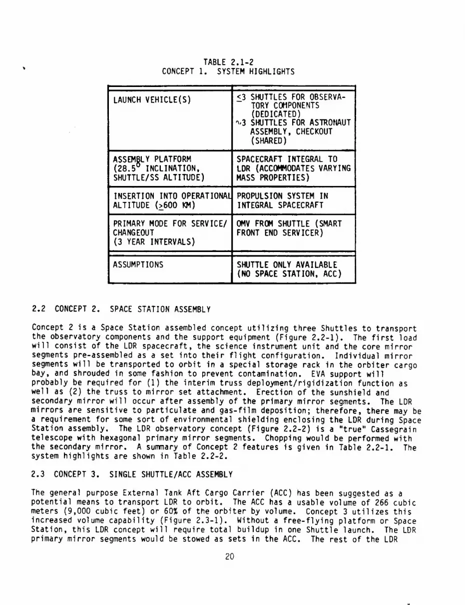
TABLE 2.1-2
CONCEPT I. SYSTEM HIGHLIGHTS
i ii
LAUNCH VEHICLE(S)
ASS_I_LY PLATFORM(28.5v INCLINATION,
SHUTTLE/SS ALTITUDE)
INSERTION INTO OPERATIONAL
ALTITUDE (_600 KM)
PRIMARY MODE FOR SERVICE/CHANGEOUT
(3 YEAR INTERVALS)
ASSUMPTIONS
<3 SHUTTLES FOR OBSERVA-TORY COMPONENTS
(DEDICATED)4,3 SHUTTLES FOR ASIRONAUT
ASSEMBLY, CHECKOUT
(SHARED)ml
SPACECRAFT INTEGRAL TO
LDR (ACCOMMODATES VARYING
MASS PROPERTIES)
PROPULSION SYSTEM IN
INTEGRAL SPACECRAFT
OMV FROM SHUTTLE (SMART
FRONT END SERVICER)
SHUTTLE ONLY AVAILABLE
(NO SPACE STATION, ACC)
2.2 CONCEPT 2. SPACE STATION ASSEMBLY
Concept 2 is a Space Station assembled concept utilizing three Shuttles to transport
the observatory components and the support equipment (Figure 2.2-I). The first loadwill consist of the LDR spacecraft, the science instrument unit and the core mirror
segments pre-assembled as a set into their flight configuration. Individual mirror
segments will be transported to orbit in a special storage rack in the orbiter cargo
bay, and shrouded in some fashion to prevent contamination. EVA support will
probably be required for (I) the interim truss deployment/rigidization function aswell as (2) the truss to mirror set attachment. Erection of the sunshield and
secondary mirror will occur after assembly of the primary mirror segments. The LDR
mirrors are sensitive to particulate and gas-film deposition; therefore, there may be
a requirement for some sort of environmental shielding enclosing the LDR during Space
Station assembly. The LDR observatory concept (Figure 2.2-2) is a "true" Cassegrain
telescope with hexagonal primary mirror segments. Chopping would be performed with
the secondary mirror. A summary of Concept 2 features is given in Table 2.2-I. Thesystem highlights are shown in Table 2.2-2.
2.3 CONCEPT 3. SINGLE SHUTTLE/ACC ASSEMBLY
The general purpose External Tank Aft Cargo Carrier (ACC) has been suggested as a
potential means to transport LDR to orbit. The ACC has a usable volume of 266 cubic
meters (9,000 cubic feet) or 60% of the orbiter by volume. Concept 3 utilizes this
increased volume capability (Figure 2.3-1). Without a free-flying platform or Space
Station, this LDR concept will require total buildup in one Shuttle launch. The LDR
primary mirror segments would be stowed as sets in the ACC. The rest of the LDR
20

CONCEPT 2: SPACE STATION ASSERBLY
Figure 2.2-1
• CASSEGRAIN
• 8 S/I's IN
4 MODULES
• HEXAGONALSEGMENTS
• SM CHOPPING
• 20 METERS
LDR OBSERVATORY
Figure 2.2-2
21

TABLE 2.2-I
CONCEPT 2: SUleqARY
OPTICAL CONFIGURATION
• 2-MIRROR TELESCOPE
• PARABOLIC PRIMARY MIRROR
• 1.3-NETER HYPERBOLIC SECONDARY MIRROR
• Pie ANO SM BAFFLE HAY BE REQUIRED
APERTURE S[ZE
• ZO-METER FILLED APERTURE
REFLECTOR MATERIAL
• GLASS (SELECTED FOR EXCELLENT CTE ANDCTE VARIABILITY)
SEGMENTED MIRROR CONCEPT
l, HE)LAGONALSEGHENTS• RIGID BODY MOTION CONTROL(PISTON AND TILT)
OPTICAL SUBSYSTEM CONCEPTS
• GLASS SECONDARY MIRROR
• TRIPLE BIPOD GRAPHITE/EPOXY METERING OFSECONDARY MIRROR
• RIGID BOOY NOTION CONTROL (TILT, DECENTER,
OESPACE)
THEIU_kL CONSIDERATIONS
I PASSIVE PM WITH TRIM HEATERS
e THERMAL SHROUD ("STEP SHIELD")• CRYO-FLUID STORAGEAND ACTIVE REFRIGERATION
SYSTEM FOR SCIENTIFIC INSTRUMENTS AND SECONDARYMIRROR
POINTING AND CONTROL
• BODY POINTING ABOUT SYSTEM CENTER OF Ka.SS• FINE GUIDANCE SENSING WITH SEPARATE VISIBLE
TELESCOPE• CHOPPING WITH SECONDARYMIRROR
TRANSPORTATION TO ORBIT
• THREE SHUTTLE LOADS
STRUCTURES
• GRAPHITE/EPOXY TRIPLE BIPOD SECONDARYMIRROR SUPPORT• GRAPHITE/EPOXY TETRAHEDRAL TRUSS Pf4 REACTION
STRUCTURE• REFERENCE PLATFORM UNDER PH CORE• THEI_4AL SHROUD ("STEP SHIELD")
CONTAMINATION CONTROL
• PRIMARY MIRROR PROTECTION (STRIPPABLE COATING)• CONTAMINATION SHROUD ON SPACE STATION POSSIBLY NEEDED
SPACECRAFT FUNCTIONS
• ORBITAL P_TERS (t • 28.5o; h
TABLE 2.2-2
CONCEPT 2: SYSTEM HIGHLIGHTS
_500_
LAUNCH VEHICLE(S)
ASSEMBLY PLATFORM
(28.5 v INCLINATION,SHUTTLE/SS ALTITUDE)
INSERTION INTO OPERATIONAL
ALTITUDE (_500 _)
PRIMARY MODE FOR SERVICE/
CHANGEOUT
(3 YEAR INTERVALS)
ASSUMPTIONS
<3 SHUTTLES FOR OBSERVA-
TORY COMPONENTS, ASSY/
CHECKOUT SUPPORT
EQUIPMENT
I
SPACE STATION AND SPACE-
CRAFT INTEGRAL TO LDR
PROPULSION SYSTEM IN
INTEGRAL SPACECRAFT
OMV FROM SPACE STATION
(SMART FRONT END SERVICER
MANNED SPACE STATION
AVAILABLE (NO ACC)
22

observatory (spacecraft, scientific instruments, secondary mirror assembly, shroud,
etc.) and support equipment would be stowed in the Orbiter Bay. Packing density will
limit the size of LDR below the 20 meter requirement. The LDR observatory concept
(Figure 2.3-2) is a "true" Cassegrain telescope with hexagonal segments. Chopping
would be performed by a fold mirror. A summary of Concept 3 features is given in
Table 2.3-I. The system highlights are shown in Table 2.3-2.
f
CONCEPT 3: SINGLE SHUTTLE/ACC ASSEMBLY
Figure 2.3-1
J
• CASSEGRAIN
• 4 S/l's IN ONEMODULE
• HEXAGONAL
SEGMENTS
• FOLD MIRROR
CHOPPING
• 13 METERS
LDR OBSERVATORY
Figure Z.3-2
23

TABLE 2.3-1
CONCEPT 3: SUNI@LRY
OPTICAL CONFIGURATION
• "TRUE" CASSEGRAIN• PARABOLIC PRIMARY MIRROR
• O.B5-METER HYPERBOLIC SECONDARY MIRROR
APERTURE SIZE
• 13-METER FILLED APERTURE• | SHUTTLE WITH ACC
REFLECTOR MATERIAL
• 6LASS (SELECTED FOR EXCELLENT CTE AND CTEVARIABILITY)
$E_JMENTEDMIRROR CONCEPT
• HEXAGONALSEGMENTS IN 7 SEGMENT SETS• RIGID BODY MOTION CONTROL ONLY (TILT AND PISTON)
OPTICAL SUOSYSTEMCONCEPTS
• GLASS SECONDARYMIRROR
• TRIPPLE BIPOD GRAPHITE/EPOXY METERING DFSECONDARY
• RIGID BODY MOTION CONTROL (TILT, OECENTER,DESPACE)
THERPIAL CONSIDERATIONS
• PASSIVE PM WITH TRIM HEATERS• THERMAL SHROUD ("STEP SHIELD")• CRYO-FLUID STORAGE AND ACTIVE REFRIGERATION SYSTEM
FOR SCIENTIFIC INSTRUMENTS AND SECONDARYMIRROR
POINTING AND CONTROL
• BODY POINTING ABOUT SYSTEM CENTER OF MASS• FINE GDIDANCE SENSING WITH SEPARATE VISIBLE
TELESCOPE• CHOPPING WITH PLANO FOLD MIRROR
TRANSPORTATION TO ORBIT
• PM SEGMENTNODULES IN ACC• REST OF LDR OBSERVATORYSTORED IN ORBITER BAY• RMS DEVICE(S) WITH EVA ASSIST• "SIMPLE" LATCHING MECHANISMS
STRUCTURES
• GRAPHITE/EPOXY TRIPLE BIPOD SECONDARY MIRROR SUPPORTe GRAPHITE/EPOXY TETRAHEDRAL TRUSS PM REACTION STRUCTURE
• THERMAL SHROUD ("STEP SHIELD")• REFERENCE PLATFORM UNDER CENTER PM CORE
CONTANINATION CONTROL
• PRIMARY MIRROR PROTECTION (STRIPPABLE COATING)
SPACECRAFT FUNCTIONS
• PROVIDE SPACE PLATFORMCAPABILITY THROUGHLDROBSERVATORYASSEMBLY
• ORBITAL PARAMETERS (t = 28.5% h:,600 KM)
TABLE 2.3-2
CONCEPT 3: SYSTEM HIGHLIGHTSt | i t ,n
LAUNCH VEHICLE(S) I SHUTTLE/ACC
ASSEMBLY PLATFORM(28.5 v INCLINATION,
SHUTTLE/SS ALTITUDE)
INSERTION INTO OPERATIONAL
ALTITUDE (_600 KM)
PRIMARY MODE FOR SERVICE/CHANGEOUT
(3 YEAR INTERVALS)
ASSUMPTIONS
SPACECRAFT INTEGRAL TO LDR
(SUPPORTED FROM SHUTTLE
PAYLOAD BAY)
PROPULSION SYSTEM IN
INTEGRAL SPACECRAFT
OMV FROM SHUTTLE/ACC
(SMART FRONT END SERVICER)
SHUTTLE/ACC AVAILABLE (NO
SPACE STATION)
24
3.0 TECHNOLOGY ASSESSMENT
3.1 SENSING, CONTROLS, AND CONTROL ELECTRONICS (OAST CATEGORY A)
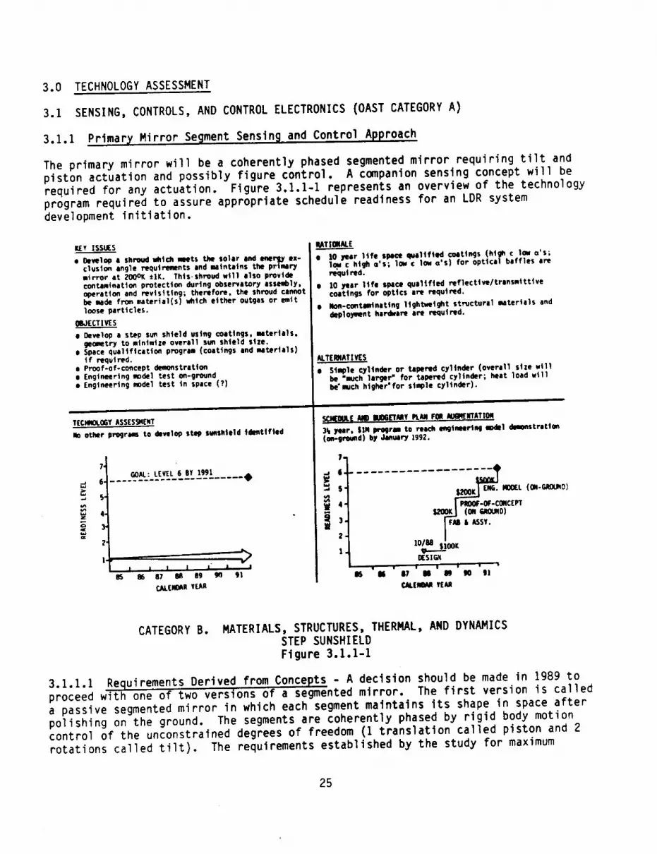
3.1.1 Primary Mirror Segment Sensing and Control Approach
The primary mirror will be a coherently phased segmented mirror requiring tilt and
piston actuation and possibly figure control. A companion sensing concept will be
required for any actuation. Figure 3.1.1-1 represents an overview of the technology
program required to assure appropriate schedule readiness for an LDR systemdevelopment initiation.
KIV ISSUES
• Oeye1op a shroud which meets the solar and Imergy ex-clusion angle requirements and maintains the primarymirror at 2000K *IK. Thts-shreud wtll also providecontamtnat|on protection during observatory assembly,operation and revisiting; thertfore, the shroud cannotbe made from material(s) which either outgas or emttloose particles.
OBJECTIVES
e 9evelop a step su_ shield using coatings, materials,geometry to minimize overall sun shield size.
e Space qualification program (coatings and materials)t f requI red.
• P_f-of-concept demonstrationa Engineering w,ode| test on-ground• Engineering model Lest in space (?)
i
T(CHNOLOGYASSESSNENT
No other program to develop step sunshleld Identified
6'
S-
4.
Y
2"
I.
_._._.,}..}}_}_Ea_t_jjx.....•
J J l I " J •87 lk_ B9 go 91
_LENOM fLeA
RATICRAI,E
• 10 year life space qualified coatings (htghc Io_ o's;low ¢ high o'S; 1oN c low o'S) for optical baffles arer_utred.
• ]O year )tie space qu|ltfted reflecttve/transmtttivecoattngs for Optics are required.
• Non-contaminating lightweight structural materials anddeploymnt hardware are required.
ALTERNATIVES
• Sia_le cylinder or tapered cylinder (overall size willbe "much larger" for tapered cylinder; heat load willbe'much higher'for simple cylinder).
iii
SClqOUL( _ I_os_Mv PUre F_./IU_mATI.ON
)k yur, SIN program to reach un9ineertn9 model dm_nstretion(ee-greund) by January 1992.
$" ,_..,,, E_. mOCL (ON-C,eO_O)ea_
,_ 4. I p_moe-o_-coNctvr
)" FM i ASSY.
1. lO_...-_ O°KIISI_
' • • _ I • •
aS 8i ill M Im go gl
CALEII_JI YEAR
CATEGORY B. MATERIALS, STRUCTURES, THERMAL, AND DYNAMICSSTEP SUNSHIELD
Figure 3.1.1-1
3.1.1.1 Requirements Derived from Concepts - A decision should be made in 1989 toproceed with one of two versions of a segmented mirror. The first version is called
a passive segmented mirror in which each segment maintains its shape in space after
polishing on the ground. The segments are coherently phased by rigid body motion
control of the unconstrained degrees of freedom (I translation called piston and 2
rotations called tilt). The requirements established by the study for maximum
25

allowable tilt error is 0.6 microradian and for maximumallowable piston error is 1.3micrometers. The second version is called an active segmentedmirror in which eachsegmentmaintains its shape in space after polishing on the ground by active figurecontrol using actuators. The segmentsurface quality, as set by the study, whichmust be maintained for either an active segment of a passive segment, is 0.5micrometer ms. In addition to these requirements, a radius matching requirement isimposedon a segmentedmirror. This study established a radius mismatch requirementof 50 parts per million.
3.1.1.2 Required Technolo_ Maturit_ Level - There are currently related DoDsegmented mirror activities with "similar" requirements. However, the operational
wavelength range and the operating level are unique to LDR. For this reason an LDR
segment phasing test (demonstration of cophasing between two outer segments) has been
proposed. A set of actuators and sensors is needed for this test. Consequently, the
LDR technology program has been configured at OAST Level 5 (component tested) andtime phased with the mirror demonstration program.
3.1 1.3 On-going Technology Developments and Estimation of Where the Technolo_ WillBe in 1991 - The actuator and sensor technology is a straight forward extension of
current techniques demonstrated in DARPA and industry IR&D programs. Actuators and
sensors with similar requirements have been demonstrated for use with future large
ground-based telescope programs (Keck Telescope and National New TechnologyTelescope).
3.1.1.4 TechnoloB_ Shortfall and Augmentation Plan - A set of actuators and sensors
is needed for the segment phasing demonstration. The technology plan activities are:
• 1989 Design of actuators and sensors ($200K)
• 1989 - Fabrication and assembly of actuators and sensors ($2.8M)
• 1990 - Component testing of actuators and sensors ($650K)
3.1.2 Fold Mirror Chopping
The key issue is the development of a fold mirror control subsystem incorporating"chopping" capability and incremental positioning capability. The former is used to
subtract the background level from the star signal. The latter is used to fold the
beam to a single scientific instrument (Note: As many as eight scientific
instruments are planned). Figure 3.1.2-I represents an overview of the technology
program required to assure appropriate schedule readiness for LDR system developmentinitiation.
3.1.2.1 Requirements Derived from Concepts - The fold mirror must have the
capability to rotate in 45 degree increments. The accuracy of mirror location is
determined by the location of the detector surface. An accuracy of +1 arcsecond was
used in the study. In order to have a throw of 1 arcminute for chop-ping and
utilizing a push/pull chopper, the push/pull step will be approximately +6millimeters. In addition to these requirements, the chopping mechanism should
provide a two (2) hertz square wave (reactionless).
The Science Working Group would like a selectable chopping axis for use with extended
sources. It should be emphasized that any control concept must be compatible with
maintaining the fold mirror temperature (Note: probably lower than 125 degrees K for
background noise considerations).
26

Isy ISSUE
• bvel_P a plino mirror control subsystem incorporating"chopping" cspabtllty and Increment•! postttontnqcapability (Note: As many as etght scteettftc ln-Str_ents are planned)
OBJ(CTIVE
• Design. Fabricate. assemble, and test proof-of-concept fold mirror assembly (mirror vtth contrel$)
TECHNOLOGYASS(SSM(NT
No other programs utilizing chopping vtth a planofold mirror tdeetlfted
S" GOAL: L(VEL 6 BY 1991 ._
5-
4
i }
95 " 86 ' 87 ' R_ ' P'}' 9r) ' 91 'CAL[NDAN Y(AE
RATIONAL(
• hckground Subtr|ctton (chopplMJ) tecImtqucs havebeen Incorporated Into several ground based |Rtelescopes. Two alternative concepts (push/pu))and roWtIng) have been suggested
ALTERNATIV ( S
• Secondary mirror chopping
mSKe inadequate infoemtton for c_ppfng technique selection
e Cos,t. I_,rfomance
SCHEOULEAND OUOGETANYPLAN FOIl _(NTATION
Two year, 1900K prollrm to reach 9oal by October |99O1019O
5S........... SF___O ''-'''4_4 $_OOK
I FAB, ASSY OFI ACTUATORSMID
10188 •
_DE_s),OO1K DECl S] Or,IGN TOCONTINL_E
' 87 I 88 I B9 '90 ' _1! *
CAL£_ ¥(AR
8S '86
CATEGORY A: SENSING, CONTROLS, AND CONTROL ELECTRONICSFOLD MIRROR CHOPPING
Figure 3.1.2-I
3.1.2.2 Required TechnoloQy Maturity Level - In 1989 a decision should be made toproceed with one of two chopping concepts (fold mirror chopping or secondary mirror
chopping). No other programs have been identified utilizing chopping with a plano
fold mirror. Consequently, the LDR technology program has been configured for a
proof-of-concept fold mirror assembly (mirror with controls), i.e., OAST Level 6
(engineering model tested on the ground) by 1990.
3.1.2.3 On-9oin 9 Technology Development and Estimation of Where the Technology WillBe in 1991 - Shown in Figure 3.1.2-2 are two alternate approaches to fold mirror
chopping (rotating and push/pull). The concepts have been "tried" on ground based
telescopes. Very little quantitative data exists on the results.
A comparison of the two concepts is shown in Table 3.1.2-1. Since no other programs
have been identified utilizing fold mirror chopping, the technology will probably
remain at OAST Level I (basic principles observed/reported) without LDR sponsorship.
3.1.2.4 Technolo)_ Shortfall and Augmentation Plan - Development of a plano mirrorcontrol system incorporating both incremental positioning capability and "chopping"
capability is needed. The objective of the LDR technology program is a fold mirror
assembly (mirror with controls) demonstration. The technology plan involves the
following activities:
27
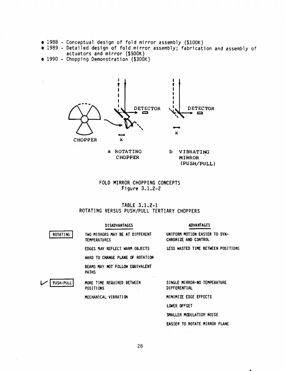
• 1988 - Conceptual design of fold mirror assembly ($100K)
e 1989 - Detailed design of fold mirror assembly; fabrication and assembly of
actuators and mirror ($500K)
• 1990 - Chopping Demonstration ($300K)
I
T!
I
@ '! D
CHOPPER x
a ROTATING b
CHOPPER
I!IIII
,4.:
x
DETECTORc:3
VIBRATING
MIRROR
(PU SH/PULL)
FOLD MIRROR CHOPPING CONCEPTS
Figure 3.1.2-2
TABLE 3.1.2-1
ROTATING VERSUS PUSH/PULL TERTIARY CHOPPERS
I ROTATING I
L,/I PUSH-PULLi
DISADVANTAGES
TWO MIRRORS MAY BE AT DIFFERENT
TEMPERATURES
EDGES HAY REFLECT WARM OBJECTS
HARD TO CHANGE PLANE OF ROTATION
BEAMS MAY NOT FOLLOW EQUIVALENT
PATHS
MORE TIME REQUIRED BETWEEN
POSITIONS
MECHANICAL VIBRATION
ADVANTAGES
UNIFORM MOTION EASIER TO SYN-
CHRONIZE AND CONTROL
LESS WASTED TIME BETWEEN POSITIONS
SINGLE MIRROR-NO TEMPERATURE
DIFFERENTIAL
MINIMIZE EDGE EFFECTS
LOWEROFFSET
SMALLER MODULATIOM NOISE
EASIER TO ROTATE MIRROR PLANE
28
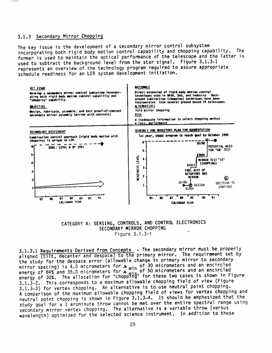
3.1.3 Secondary, Mirror Choppin_
The key issue is the development of a secondary mirror control subsystem
incorporating both rigid body motion control capability and chopping capability. The
former is used to maintain the optical performance of the telescope and the latter is
used to subtract the background level from the star signal. Figure 3.1.3-I
represents an overview of the technology program required to assure appropriateschedule readiness for an LDR system development initiation.
_' ISSUE
bye, lop a secemaQry mirror coettrel subsystem incorpor-ating both rigid body motion control capability and"chopp|n 9" ¢lpibl|lty.
OBJECTIVE
Besign, fabricate, assemble, and test proof-of-conceptsecondary IIrror assembly (mirror with controls)
TECHNOLOGYASS[SSn(NT
Combtnetlofl coatrol approach (rigid body motton withchopptn9) Is unique to LDR.
S,
5-
4.
3-
2-
I-
GOAL: LEVEL 6 BY 1991
.....
65 86 87 88 8q 9(1 91CALENCAR YEAR
UTIOI_L(
Oit_.ct extension of rtgtd body motion controltechniques used tn NASA, OoO. end industry. Back-ground subtraction (chopping) techniques have beenincorporated into several g_nd based IR telescopes.ALTERJNATIYES
Fold mirror chopptng
rls__._Ke Inadequate _nformtto_ to select chol)ptng methode Cost a merformance
.SCH(OULE AND NDDG£TAR¥ PLAN FOR AUG_NTATION
4.
3.
Two year, $900K program to reach 9o41 by October 1990
IPOT(NII_ WEED5. |FOR "OG" TEST
|
.i MIRROn1[ST ]G"
$soo_ (C.OPeI.olFABI, ASSY OFACTUATORSAND
M I RROR
] • IO/_I_KDESIGN
• I I • I • Iis m s7 _ m 9o glCALENOAR YEAR
®DECIS]OP_ TO
CONT[NUE
CATEGORY A: SENSING, CONTROLS, AND CONTROL ELECTRONICSSECONDARY MIRROR CHOPPING
Figure 3.1.3-I
3.1.3.1 Requirements Derived from Concepts - The secondary mirror must be properlyaligned (tilt, decenter and despace) to the primary mirror. The requirement set by
the study for the despace error (allowable change in primary mirror to secondary
mirror spacing) is 4.0 micrometers for _ . of 30 micrometers and an encircledenergy of 84% and 35.0 micrometers for _ _]_ of 50 micrometers and an encircled
energy of 30%. The allocation for "chopp_" for these two cases is shown in Figure
3.1.3-2. This corresponds to a maximum allowable chopping field of view (Figure
3.1.3-3) for vertex chopping. An alternative is to use neutral point chopping.A comparison of the maximum allowable chopping field of views for vertex chopping and
neutral point chopping is shown in Figure 3.1.3-4. It should be emphasized that the
study goal for a 1 arcminute throw cannot be met over the entire spectral range using
secondary mirror vertex chopping. The alternative is a variable throw (versus
wavelength) optimized for the selected science instrument. In addition to these
29

requirements the chopping mechanismshould provide a 2 hertz square wave(reactionless). The Science Working Group would like a selectable chopping axis foruse with extended sources. It should be emphasizedthat any control concept must becompatible with maintaining the secondary mirror at 125 degrees + I degree K.
I
SECONDARY MIRROR I
CHOPPING
O.q_'RMS
JSIATIC2.OwRMsWAVEFRONT ERROR] [STATIC3.ql,R_WAVEFRONT ERROR1
!
I
I
I
i _CONDARY IqlRRORMISAL IGN_NI ERROR
O,6J' RRS
1I
_CONOARY .qlRRON IRIGID BODYMOTION
o.q_ R_
I
III
I _CONDARY PIIRROR
MISALIGNIqENTERROR
3.0,,R_
II
I .r_CONDARYMIRROR.|CmmeING I
2,1 t, RIqS I
II SECOXDARY MIRROR ]
RIGID BODY MOTIONI
2.I_R_ j
I ,
OPERATIONAL PERFORMANCE PREDICTION
Figure 3.1.3-2
100
_' 10
II.0
.J
_ 1"
Z
Z
U 01 | I
O,1 I I0 i00
RM$ WAVE FRONT ERROR (MICROMETERS)
(i) AMIN - 30pM. E " 84%(2) A MIN m 30_w M, E - 30%
(3) A MAX - 1000_M, E " 8q%
(q) AMAX" 1000uM. E" 30%
MAXIMUM ALLOWABLE CHOPPING FIELD OF VIEW
Figure 3.1.3-3
30

NEUTRAL""VERTEXo POINT
OPERATIONAL ENCIRCLED AIRY DI_K CHOPPI_NG CHOPPINGWAVELENGTH(_M) ENERGY(%) DIA,(_C) FOV (_C) FOV(SEC)
30 8q 1 ÷ 0.5 + 2
30 30 I + 2,8 + 12
;000 8q 33 + 16 + GH
I(H)O 30 33 + I00 + 400a
• THEZ 30 SE'_CHOPPINGREQUIREMENTS_ANNOTBEMETOVERTHEENTIRESPECTRALRANGE.BASEDONEITHER8q1 OR30%ENCIRCLEDENERGYALLOCATION.
e RELIEFTO 30%ENCIRCLEDENERGYALLOCATIONWILL ALLOWVERTEXCHOPPINGFOVOF3 AIRY DISKDIAMETERS.
e HOWSMALLA CHOPPINGFIELDOF VIEWIS ACCEPTABLE(I. E., HOW@IANYAIRY DISK DIAMETERS)ANDSTILL 1}(3NECESSARYBACKGROUNDSUBTRACTION?
• ALLOWABLETHROWLIMITEDBY COMA• " ALLOWABLETHROWLIMITEDBY ASTIG/_ATISR(APPROXI@IATECALCULATION)
SECONDARY MIRROR CHOPPING
Figure 3.1.3-4
3.1.3.2 Required Technolog_ Maturity Level - In 1989 a decision should be made toproceed with one of two chopping concepts (fold mirror chopping or secondary mirror
chopping). If the secondary mirror concept is chosen the resultant control approach
(rigid body motion with chopping) is unique to LDR. Consequently, the LDR technology
program has been configured for a proof-of-concept secondary mirror assembly (mirror
with controls), i.e., OAST Level 6 (engineering model tested on the ground) by 1990.
However, the precision requirements and the need to prove space compatibility may
mandate a later space demonstration, i.e., OAST Level 7.
3.1.3.3 On-going Technolog_ Developments and Estimation of Where the Technolog_ WillBe in 1991 - The concept of realigning the secondary mirror to the primary mirror
using rigid body actuators is a straight forward extension of current techniques
demonstrated in DARPA and industry IR&D programs. The NASA Space Telescope utilizes
this concept.
Background subtraction techniques using the secondary mirror have been incorporated
into several ground-based IR telescopes. Shown in Figure 3.1.3-5 are two secondary
mirror chopping concepts investigated in this study. The first involves choppingabout the vertex of the secondary mirror. The allowable throw is limited by coma.
The second involves chopping about the coma neutral point. The allowable throw is
limited by astigmatism. Difficult engineering mechanisms will be required for either
secondary mirror vertex or neutral point chopping.
31

(FIXEOAXIS)I NEUTRALPCINTI
TOP VIEw
,ACTUATOR
SM CHOPPING MECHANISM CONCEPTS
Figure 3.1.3-5
The only space program identified with secondary mirror chopping is SIRTF. However,
the combination control approach (rigid body motion with chopping) is unique to LDR.
Therefore the technology will probably remain at OAST Level 1 (basic principles
observed/reported) or improve only "slightly" without LDR sponsorship.
3.1.3.4 Technology, Shortfall and Augmentation Plan - Development of a secondary
mirror control subsystem incorporating both rigid body motion control capability and
"chopping" capability is needed. The objective of the LDR technology program is a
secondary mirror assembly (mirror with controls) demonstration. The technology planinvolves the following activities:
• 1988 - Conceptual design of secondary mirror assembly ($100K)• 1989 - Detailed design of secondary mirror assembly, fabrication and
assembly of actuators and mirror ($500K)
• 1990 - Chopping demonstratiop ($300K)
3.1.4 Fine Guidance Sensin_ and Control
The use of a separate visible telescope for fine guidance sensing was selected in
this study. This telescope must be co-boresighted to LDR and provide the control
system (spacecraft and telescope) the information necessary to meet the pointing
stability requirement. Figure 3.1.4-1 presents an overview of the technology programrequired to assure appropriate schedule readiness for an LDR system developmentinitiation.
32

I_(T ISSUT
|nterra14ttonshtp of telescope control system andspacecraft control system ustn9 a separate vtstbleoptical system foe" Fire Guidance Sensor System.
OBJECTIVES
• ConcePtual des|qn of Fine Guidance Sensor.
• Conceptua| des|gn of co-borestqhttnq approach.• Critical functton dmonstratton.
II
TECHNOLOGYASSESSMENT
Closely related OoD and NASA Star Tracker andFine Gu|dance Sans|rig Technology.
7-
i IS.
S"
4"
3-
2-
].
I • J ! " w i •
05 M 82 M M tO If!
£4L(;IDM V(M
RATi 0NAL£
• The use of a sef_lrate vts4ble telescope for Fine
Guidance S_nstn9 yes selected tn th4s study.• This telescope must be co-borestghted to the m_n
telescolN lind prOvide the control system (splice-craft and telescolpe) the lnfonlmtlon necessary tomeet the potntl_l stability requtreetmt.Estalbltshtng the prtmry itrror r•lictton Structureas the stable pllitfom for refereflce of theFine Guidance sensor ts of Col_ert_.
I I
SCHEOUL( AND IIUOGETAR¥ PLAN FOR NIGICEKTATION
2_-yHr, $700K program to nlach goal by January 1991.
71
-J S'
4"
Z
1
.... -so-_--.O,
]O/M I
I • • II • u
IS OS 117 88 Og t0 gl
r,JL(g0M V(M
CATEGORY A: SENSING, CONTROLS AND CONTROL ELECTRONICS
FINE GUIDANCE SENSING AND CONTROL
Figure 3.1.4-I
3.1.4.1 Requirements Derived from Concepts - The function of the LDR fine guidancesensor is to measure misalignment of the LDR line of sight vector by measuring the
position of auxiliary guide images (Note: Space telescope utilizes a visual star
catalog with visual star magnitude as low as 14.5). The measurement is transferred
to the "pointing control system" to correct the line of sight error. Line of sighterrors as small as a few percent of a star image diameter must be measured and
corrected to prevent the resulting image motion from significantly degrading image
quality (Note: In this study 0.02 arcsecond was used as the maximum allowable
pointing stability error). One option would be to utilize the LDR telescope for fine
guidance sensing (i.e., the Space Telescope approach). However, visible fine
guidance sensing is not compatible with the LDR operational wavelength region fromthe far I/R to the submillimeter region. Two alternate approaches were evaluated in
this study. The first approach utilizes a section(s) of the LDR optical subsystem
for fine guidance sensing. The visible quality section(s) could be an inner annulus,
an outer annulus, or patches. The concept has the advantages of (1) utilizing the
same line of sight and (2) the focal length of the fine guidance sensor is the same
as the focal length of LDR allowing relatively small pointing errors to be sensed.
It has the disadvantages of requiring (1) fabrication and maintenance of visible
quality sections on a large segmented mirror and (2) maintaining visible quality on
section(s) of the secondary mirror.33

The selected concept was to utilize a separate visible telescope for fine guidance
sensing. The optical subsystem would be a set of CCD solid state sensors filling the
field of view to meet the threshold magnitude requirements. The line of sight of the
fine guidance sensor would be co-boresighted to the LDR line of sight (Note: In this
study the maximum allowable co-boresighting error was set at the absolute pointing
error, 0.05 arcsecond).
3.1.4.2 Required TechnoloB_ Maturity Level - There is an interrelationship of thetelescope control system and spacecraft control system using a separate visible
optical system for fine guidance sensing. This telescope must be co-boresighted to
the main telescope and provide the control system (spacecraft and telescope) the
information necessary to meet the pointing stability requirement. Establishing theprimary mirror reaction structure as the stable platform for reference of the fine
guidance sensor is of concern. With respect to the fine guidance telescope itself
the catadioptric telescope is state-of-the-art technology. Solid state sensors
(CCD's, CID's, PDA's) have become increasingly attractive for astronomical imaging.
This is due to low readout noise, high quantum efficiency, high dynamic range,
linearity, and stability. The predominance of red stars near the galactic pole
(poorest star density region) when combined with a solid state sensor leads to more
available stars for a given threshold magnitude than either the eye or a
photomultiplier tube as a detector. Technical improvements and availability (yield)
make solid state sensors ready for serious consideration in a 1980's fine guidance
sensor. The co-boresighting approach is the technology shortfall. Consequently, the
LDR technology program is configured at OAST Level 4 (critical function
demonstrated). Completion is 1991 to coincide with activities on-going in thestructural control area establishing the interrelationship between the LDR structural
control philosophy and fine guidance sensing.
3.1.4.3 On-going Technology Developments and Estimation of Where the Technology Will
Be in 1991 - The Space Telescope must be able to track an object within a pointing
stability error of 0.007 arcseconds with a time constant of much less than 1 second.
The only way to reach this level is to use images formed by the Space Telescope it-
self (2.4 meter aperture). The fine guidance sensor investigated in this study would
utilize a similar approach with a 1 meter aperture and an integration time of 500
milliseconds. The Space Telescope fine guidance sensor is based on a concept of star
tracking using wave front interferometry. The collimated beam is fed to Koester's
prisms which provide a set of interferometric fringes to pairs of detecting photo-
multipliers. These detectors do not scan the fringes but interrogate the total
intensity of signal which varies as the star moves.
Kodak recently completed a one year study for NASA/MSFC. The purpose of that study
was to investigate new approaches to fine guidance sensing and furnish a conceptual
design for an advanced fine guidance sensor with no moving parts. The resulting
concepts utilize solid state sensors. Technical improvements and availability
(yield) make these solid state sensors (CCD's and CID's) ready for a 1980's fine
guidance sensor. In the area of co-boresighting there are closely related DoD
programs in communications and directed energy.
3.1.4.4 Technology Shortfall and Augmentation Plan - The technology shortfall is inthe area of co-boresighting relative to the dynamlc LDR. The technology plan in-
volves the following activities:
• 1988 - Conceptual design of fine guidance sensor and co-boresighting
approach ($200K)• 1989 - Critical function demonstration of co-boresighting ($500K)
34

3.1.5 Secondary Mirror Sensing and Control Approach
Because of the high asphericity of the LDR primary mirror (f/O.5), the misalignments
of the secondary mirror must be controlled to accuracy levels consistent with the
allocated tolerances using rigid body actuators with a "true" metering structure.
Figure 3.1.5-1, presents an overview of the technology program required to assure
appropriate schedule readiness for an LDR system development initiation.
3.1.5.1 Requirements Derived From Concepts - The alignment of the secondary mirroroptical axis to the primary mirror optical axis must be maintained within allocated
tolerances.
There are five secondary mirror vertex motions of concern (2 tilts, 2 decenters, and
1 despace). Shown in Figure 3.1.5-2 is a preliminary LDR operational performance
prediction. Highlighted is the total RSS of the secondary mirror misalignment error.
Shown in Figure 3.1.5-3 is a second performance prediction which loosens the minimum
operational wavelength and encircled energy requirements.
OBJ(CTI lr[$
aLmmtTIWS
¢enT_ ntmnnlsm
• Limr KtWteeS for rigid bedy milan c_trol (tilt,dmxmter. 4•space)
S(ltsInG
• Intee_l: tilt, dlc_t_, _ dlSpiH:e 14•Sees (dtrectmMvrm_t of _sali_t)
• (ztePIWIl: stir se_t_l (ml_fm_t) (l_lm_t msu_-mt of i_s•ltgmmt)
SUPPORT $ImRlWI
s 0e_lop a tutti1 I_mslch (Ktllltllm IIWIse_lm))
• COmlw)Nmt _rlfic•tl(m Ile_rm (idl'_r,Sensim), imd co_t_l, s1_)rt stro¢tw¢)
• Pr_f-of*¢m_ept limMtrlttms
TEOClIOLOGT JGS[SSI_NT
/_eers to be stroIgbt fon_lrd exte_lan of cm'_ttl_lmlqt_s 41eeo_strate_ In DA_A and tndustr7 IRSO
• The study defined the need fir • "trim" rot•Tin0• texture. A triple b4Pml I_w•eds ms selected _reither • shell or truss NHw_. The seccmdlry mirror
wmild be ree|i_pned be_ o_ertetSons using thesK_mlory mirror rt_lld I_ ratio• ectuetmrs.
• The •lte_atlw It • am_nsetloe su_ort stro¢tur_--the sec_ndee7 mtr_or vovld be realigned irimJ_bservltlens uslq the set.dory _rror rigid bed7tutti• •ctM4tors
SCI_IR.[ N_ |UOG(TAflY PL_ FOR /I/GI_NIMI011
P_rml-gr_ i 9oils7_Jl&bylimm_rmOct_ert° 19'J_,_•ch 1_91Mlrlq m_tl
pruritus. Closely r_14t4d technology reed on NASASt_ce TeleScope,
GOIL: L[_L I li1 1991
4'
|,,
I,
e
¢Js[InM WM
19
S'
4.
1.
|.
I
/
I01_I
.... ----*FULL*SC_L! I_l[I. li'--I"m_iiP_• mlmm
(TIIR[ |llq_) _ .... "_'
I SUP"_T SIIUCTm[
I0/I? SI_ IXN0*
lllr[IM1'[l NI_ _[SIGI_
CATEGORY A: SENSING, CONTROLS, AND CONTROL ELECTRONICS
SECONDARY MIRROR SENSING AND CONTROL APPROACH
Figure 3.1.5-1
35

ImIBIMY MllltOIt ASSI_IILy
KAIIIR:RClrUII ED
_VEFRGN'T ERROR
!.5 uH lUtS (0.0.5 _)
!i SlATIC IMVEFROHT ERROR
(TEST ENV IR_
1.8 uM _ (0.06)-)
I
STATIC IkkVEFROMT DROll 1
(04'E_AT[ONAL F.mf ImENTI_
2.0 uH RI,IS (0.067 _)
i..
I 'mmmLJs'mucTU_l.II VARIATIONS I
Io, .. ,_ (0.03_j
i ,,,
UvEFRONT ERROR1.7 t,H IU4S
(0.057 X)
II
,i,
o.6 _ RXS(0.02 Xl
SEL'Ole_R¥ NIIIItOR
ASPIII_R IC N 19MllCH
0.1 uH RHS
(0.O03 _)
LDR OPTICAL SUBSYSTEM
OPERATIONAL PERFORNANCE PREDICTION
(_min = 30#.m; E = 84%; D = 20 m)
Figure 3.1.5-2
IF11g4/gtt NIRIOR AS_|LY
MANUFACllJRED
IIAVEFRONT ERROR
!.5 uM RMS (O.05 _)'
i Sl"ILTIC IAVEFRONT ERROR(OPEIATIONkL e_VlROM_EN_I
5.6 uH ILl,IS (0.11 ._) J
JI
SI_TIC IIAVEFRONY ERROR
(TEST ENV IRON_ENT)
VARIATIONS J
2.5 UH R,qS (0.05 ;I)J5.0 uM lOiS (O, lO ).)
I
I NANUF_TtmB) Nf
] IIkVEFIIglIT EIUtQR
i _o.o3__) 114s .. _s (o096 _qlj '
J II SECONDARY MIRROR ASSBI411LY
NANIIFAC11.1R ED SECONIIAR Y MIRROR
IMV£FRONT ERROR ASPIIIiRIC NI_IiATCH
O.S iRI lUlS (0.027 _,) O.t uH EHS(0.0O3 _)
LDR OPTICAL SUBSYSTEN
OPERATIONAL PERFORHANCE PREDICTION (REALLOCATED TO INCREASE
SECONDARY MIRROR NISALIGNRENT ALLOMABLE ERROR)
(_min -- 50_m; E = 30][; D = 20 m)
Figure 3.1.5-3
36

The secondary mirror to primary mirror spacing imposes the tightest requirement.
This is due to the fast aspheric secondary mirror which magnifies the primary mirror
focal ratio of 0.5 into a Cassegrain system focal ratio of 10. Shown in Figure
3.1.5-4 is the allowable despace error for varying operational conditions. The
requirements for despace error set by the study are summarized in Table 3.1.5-I.
1000
LUF--,,, 100:E0m_
n,,on,,r_
t_¢.1
(1.
" 10
// f
//
.... i'_Xm_n- 30 UM
I
IE - s41!
;!III
Jf
ff
fp# " 2.0
fpl " 1.0
...... J_ ............... .;._, _ _/" o._
o = 30%!
I!
II
I
I
I!
I!
!!
!
I
!
!
I
!!
t
1.0 2.0 3.0 4.0 5.0 6.0
RMS WAVE FRONT ERROR (MICROMETERS]
1 J
ALLOWABLE DESPACE ERROR
Figure 3.1.5-4
37

TABLE 3.1.5-I
DESPACE ERROR ALLOCATION
I CASE I
II • Minimum operational wavelength
I • _ncircJed energy
i • Maximum atlowabJe aespace error
t
30 Micrometers
4 M1 crometers
CASE II
m Minimum operational wavelength
e Encircled energy
• Maximum allowable despace error
50 Micrometers
30%
35 Micrometers
3.1.5.2 Required Technolog_ Maturity Level - The technology appears to be a straightforward extension ot current techniques demonstrated in DARPA and industry IR&D
programs. There is a closely related approach used on the NASA Space lelescope.
The LDR technology program has been configured for a demonstration of rigid body
control to the LDR requirements (i.e., OAST Level 6 - engineering model tested).
3.1.5.3 On-Going Technolo_y Developments and Estimation of Where The Technology WillBe in 1991 - The study defined the need for a "true" metering structure. A triple
bipod approach was selected over either a shell or truss approach. The secondary
mirror would be realigned between observations using the secondary mirror rigid body
motion actuators. Metering requirements for LDR are similar to those for the NASA
Space Telescope, for which a graphite-epoxy truss was selected.
Eastman Kodak Company as a subcontractor to LMSC defined a test program to measure
metering structure performance in the Composite Optical Subsystem Structure (COSS)
program. This development program was for a next generation optical support in
space. The support is composed of both graphite epoxy and graphite aluminum
composites. Kodak is investigating structural materials for high precision optical
support structures in space applications. Kodak with Corning Glass Works is
investigating the use of glass matrix materials. When coupled with glass optics the
potential for extremely high metering performance is suggested. In addition, Kodak
is developing a composite material for metering applications under IR&D. It
potentially has very attractive metering properties and addresses the outgassing
problem currently experienced in graphite ploymer composites. An attractive
alternative approach to metering was used in the astrometric telescope of the U.S.
Naval Observatory. Glass metering rods were used to maintain metering. External tothese rods were aluminum tubes to maintain structural functions.
There are currently two approaches to secondary mirror alignment sensing. The first
uses an external source approach: the wave front of a star is sensed.
Mathematically this information is transformed into rigid body motion information.
The Hubble Space Telescope utilizes such an approach. An alternate approach is todirectly monitor the rigid body motions of the secondary mirror via internal sensors.
Using this approach it can be demonstrated via on-ground measurement verification
techniques that on-orbit alignment of the secondary mirror axis to the primary mirror
axis can be accomplished. Kodak has demonstrated this concept of measuring
misalignments directly. A tilt sensor optical beam reflects from a reference flat at
or near the secondary mirror vertex. The decenter sensor optical beam reflects from
38

the mirror surface. The source concept is a small, illuminated, pinhole apertureimaged through a projection lens. Projection lenses of a solid Cassegrain
construction to maintain high internal thermal structural stability have been
breadboarded. The pinhole aperture, secondary mirror, and primary mirror are all
located on a single cylinder.
3.1.5.4 Technology Shortfall and Augmentation Plan - The LDR development programwould demonstrate a secondary mirror control approach (actuation and sensing). It
involves the following activities:
• 1987 Integrated mirror design (mirror, sensing, control and support
structure) ($75K)
• 1988 Component testing ($400K)
• 1989 Proof-of-concept demonstration ($250K)
39

3.1.6 Noise Reduction in Control Moment G_ros (FSC 1
3.1.6.1 Requirements Derived from Concepts - An evaluation of LDR technology issuesreaatlng to the spacecraft portlon ot the system, reveals that in the realm of
spacecraft aynam_c stability two ot the subsystems may requlre aavancea technology:
the flexible-body dynamics related to the large extended solar arrays of the electric
power subsystem may be most effectively obviated by the use of radioisotope power
systems;and the control-moment-gyros required for spacecraft attitude control mayneed to be improved by reducing system inherent noise.
The quantitative validation of the requirements in each of these subsystems must
await a dynamic modeling of system transient response to disturbance inputs.
The structural dynamics - advanced power system trade potential is disucssed
in Paragrah 3.3.1.
GMG wheel bearings are selected to meet simultaneous requirements on load bearing
capability, speed, life, friction, and smoothness. In addition to wheel generated
noise, CMGs produce noise at their gimbal torquers. Such noise results from
imperfect gearing (when present), non-uniform torque output over a gimbal motorrevolution, and friction effects.
The particular requirements of LDR torquing -- large torques required intermittentlyfor slew, and small torques ordinarily required for control -- permit consideration
of alternate CMG designs and torquer set configurations. Possibilities include use
of hybrid CMG/reaction wheel configurations, wherein the CMGs are used for slew and
coarse control and the wheels are used for fine control. Shock mounting the CMGs,which is reasonable because they run at constant speed, would minimize wheel noise
transmission to LDR. Even the requirements for LDR wheel bearing design and
manufacturing improvements will be eased by such an approach.
Technology advances for LDR torquers may be summarized as:
I. Improve bearing life consistent with load, speed, friction, and smoothness.
2. Improve torquer designs and components to reduce cogging, increase gear
smoothness (with negligible backlash), and reduce friction.
3. Decrease noise torque transmission to LDR by improved bearings, wheel balancing,and vibration isolation of the full CMG.
4. Consider value of hybrid torquing systems which include CMGs and reaction wheels.
3.1.6.2 Required Technology Maturit_ Level - As stated above, a quantitative goalfor LDR first requires a system modeling for transient dynamic response.
4O

3.1.6.3 On-going Technology Developments and Estimation of Where the Technolo_ WillBe in Iggl - The largest control moment gyros known to have been flown were the 2300
ft-lb-sec units used for Skylab control. These units are probably inadequate for LDR
use primarily due to their limited life expectance of 3-4 years. An estimation of
the significance of their torque noise output depends upon predictions of total LDR
dynamics. Reaction wheels for Space Telescope have required the special development
of low noise bearings and wheel testing techniques. LDR's requirements may force an
equivalent development for their CMGs. Current technology has been assigned a level 5rating.
3.1.6.4 Technolo(_y Shortfall and Augmentation Plan - A program to raise thetechnology readiness from level 5 to leve 7 might require an investment of $I
million. Such a program is indicated in Figure 3.1.6-1, which summarizes the goals
and rationale of the augmentation plan.
I NCIIEAIE LIFE
IIEARBIG • _ IMPI_OVEMENT
:L REOt3CE TOA(_JE
NEOUCIE _ TO#IOUE NO6E
REDUCE GIKIAL TOI_DUiER FRICTION
IMfflOVlE WHEEL IN.ANCING
DEVELOP VIIII_ATION I$OI.ATION TECHNIQUES
I. DEVELOP HYIIRID TORQUING APPROACHES USING CMGs ANO
REACTION WHEELS
OUANTCrA rlVE GOALS REOUIRE SYSTEM MOOELING
FOR TRANSIENT DYNAMIC RESPONSES
TECHNOLOGY ASSESSMENT
LEVEL 7
LEVEL O
LEVEL S
LEVEL 4
LEVEL3
LEVEL 2
LEVEL1
N d17 N m W II
mJ1. PIIM[SENT 3 YR. LiFE BASED ON LOAD, BPIEEO. POWER,
8MOQTHNEll8 TIE4DEIL IItE'VEW, PARTICUi.A.qLY
CONSIDERING mEaNT CAPNNL/TY.
2. REQEIWON TOROUEnS AS REQUIRL_. OOIaTANT II_ED
¢_UUq_rE_TCS OF _ WU(F.8 VlmATION
180LATION FF.ASIBLE.
3. REDUCE CMG i_RFORMANCE REQUIREMENT8 BY
_JPPLF.J_NTING WITH LOW IIPEED _ _ REACTION
WHEELS,
i
BC;HEDUI. I: W IIUDGETR.qV RAN FOR AUOMq_NTATION
(APPflOXIJATE; 0[PEI4)IIO ON RESULTE OF SYSTEM MO(OLiNG)
LEVEL 7"
0,1
_u
/ / w,L- _,/ /
a o , i I i I
m 117 M Io go _1
TECHNOLOGY ASSESSMENT NOISE REDUCTION IN CMG'S
Figure 3.1.6-I
41

3.2 MATERIALS, STRUCTURES, THERMAL, AND DYNAMICS (OAST CATEGORY B)
3.2.1 Dynamic Structural Control
Dynamic structural control of LDR is a fundamental requirement that directly followsfrom the desired optical performance of the telescope. Clearly, there is a
quantifiable need to maintain: pointing stability of the telescope as a whole,
angular stability of the fine guidance sensor with respect to some principal frame of
reference in the main telescope, relative position of the primary mirror segments
with respect to that frame of reference, as well as position of the secondary mirror,
fold mirror and focal plane with respect to that frame of reference. Figure 3.2.1-1
presents an overview of the technology program required to assure appropriate
schedule readiness for an LDR system development initiation.
IU[Y ISSUES
, Determination of the Interrelationship between the$pacecreft control system and the telescope controlsysUm (figure control and rigid body control).
I Can the primary mirror be establ|shod as thefined reference for the telescope?
• Degree of (_yl|c structural control required?
OBJECTIVES
e Improve structural control software
O Co_cept_ll LDR structural designo LDR structural contro| model
TECHNOLOGYASSESS_NT
Parallel DeO and industry IR&O programs forstructural control (harclware and software),
7-
W 4
W2-
!
GOAL: LEVEL 4 BY 1991
! • I I ! i
IS U I1 , M M gO Ii
CALEt YEkq
RATIONALE
O New software is required to determine interrelation-shtp between structural d_'nemtcs and controlsys t ms.
• "Smart" destgn concepts arle A4eded to otn|mtzehardware complexity.
o Advancements are needed tn structurel materialsand structural Joints.
SCHEI_LE AND BUDGETARYPLA.q FOR AUC_IENTATIO_I
Three-year program to advance dymmtc structuralcontrol modeling.
7m
•-J 6.
W 4"
W2
w
1191
--•URE
CONTI_OLNOI_LI STRUCTURAL
D(SIGN- llfROYE SOFTWARE
I I I • •
17 M m 10 II
/VE_
CATEGORY B: MATERIALS, STRUCTURES, THERMAL AND DYNAMICSDYNAMIC STRUCTURAL CONTROL
Figure 3.2.1-1
42

3.2.1.1 Requirements Derived from Concepts - It is clear that even though theoptical performance requirements are not as stringent as in many visible light
telescopes, the large aperture size and low overall weight will result inevitably in
a relatively flexible structure that has the potential to be much more dynamic than a
smaller space telescope. While conventional telescopes are often designed with theassumption that the primary mirror is absolutely rigid and can be used as a fixed
reference for assuring stability of the rest of the telescope, the LDR is likely to
be a very live structure with the dynamics of the central structure, primary optics,
secondary optics, sunshade, and control system fully coupled.
The key issues which must be addressed are: (1) What is the interrelationship
between the spacecraft control system and the telescope control system (figure
control and rigid body control)? (2) Can the primary mirror be established as the
fixed reference for the telescope? (3) What is the degree of dynamic structural
control required for LDR?
3.2.1.2 Required Technology Maturit_ Level - In order to support an LDR programinitiation in 1992, the overall dynamic control needs for LDR must be defined and
well established. These needs are listed in Table 3.2.1-1. In summary, it specifies
the need for materials and combinations of materials and lists the need for better
analytical and modeling tools for a variety of special challenges presented by LDR.
There are also some specialized design concepts that can have a major impact on the
ability to achieve structural and optical control.
TABLE 3.2.1-1
DYNAMIC STRUCTURAL CONTROL
NEEDS FOR TECHNOLOGY IMPROVEMENT FOR LDR
MATERI ALS
e LOWCTEMATERIALSNEEDEDFORSTRUCTURE• LIGHTWEIGHT,HIGH STIFFNESS,LOWCREEP,HIGHDAMPING• COMPOSITESTRUCTURES--OPTIMALCOMBINATIONOF_IATERIALS
ANALYSISTOOLS
• BETTERMEANSOF SYNTHESIZINGAND OPTIMIZINGCOMPLEXSTRUCTURES
• MORE ACCURATE,CAPABLE,FINITEELEMENTDYNAMICMODELINGe MATHMODELSOF JOINTS, NEWCOMPOSITES,SENSORS,ACTUATORSe BETTERMODELINGFORCOMPLEXCONTROLSYSTEMS--POSSIBLYNON-LINEAR• BETTERNON-LINEARMODELINGOF FRICTION,DAMPING,LARGEDEFLECTIONS• TOOLSFORMODELINGEOUATIONSWITHTIME DEPENDENTCOEFFICIENTS
DESIGNAPPROACH
• RECOGNIZEINTERACTIVENATUREOFSYSTEM--POINTING,MODALRESPONSE,FIGURECONTROL• CONSIDERACCURACY,RANGE,RESPONSEOF SEPSqRSAND ACTUATORS
e MAKEUSE OF LONGRANGEDISTANCEMEASURINGTECHNOLOGYTO SYMTHFSIZESTIFFNESSe TIEREDAPPROACHTO DISTRIBUTECONTROLFUNCTIONS• UNDERSTANDDISTURBANCES(OPERATIONAL,TRANSITORY)--ATTENUATE
e EXACTCONSTRAINTPHILOSOPHYe MODALDESIGN,PASSIVEAND ACTIVEDAMPINGOF STRUCTURE,ISOLATION
e BETTERJOINTDESIGN
43
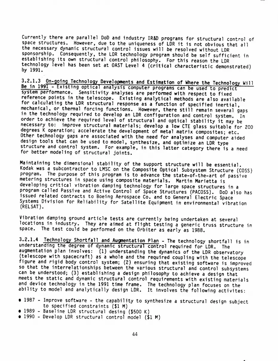
Currently there are parallel DoDand industry IR&Dprograms for structural control ofspace structures. However, due to the uniqueness of LDRit is not obvious that allthe necessary dynamic structural control issues will be resolved without LDRsponsorship. Consequently, the LDRtechnology program should be self sufficient inestablishing its own structural control philosophy. For this reason the LDRtechnology level has been set at OASTLevel 4 (critical characteristic demonstrated)by 1991.
3.2.1.3 On-_oin_ Technolo_ Developments and Estimation of Where the Technology WillBe in 1991 - Existing optical analysis computer programs can be used to predict
system performance. Sensitivity analyses are performed with respect to fixed
reference points in the telescope. Existing analytical methods are also available
for calculating the LDR structural response as a function of specified inertial,
mechanical, or thermal forcing functions. However, there still remain several gaps
in the technology required to develop an LDR configuration and control system. In
order to achieve the required level of structural and optical stability it may be
necessary to: improve structural materials; develop a low CTE glass suitable for 200
degrees K operation; accelerate the development of metal matrix composites; etc.
Other technology gaps are associated with the need for analyses and computer aided
design tools that can be used to model, synthesize, and optimize an LDR typestructure and control system. For example, in this latter category there is a need
for better modeling of structural joints.
Maintaining the dimensional stability of the support structure will be essential.
Kodak was a subcontractor to LMSC on the Composite Optical Subsystem Structure (COSS)program. The purpose of this program is to advance the state-of-the-art of passive
metering structures in space using composite materials. Martin Marietta is
developing critical vibration damping technology for large space structures in aprogram called Passive and Active Control of Space Structures (PACOSS). DoD also has
issued related contracts to Boeing Aerospace Co. and to General Electric Space
Systems Division for Reliability for Satellite Equipment in environmental vibration
(RELSAT).
Vibration damping ground article tests are currently being undertaken at several
locations in industry. They are aimed at flight testing a generic truss structure in
space. The test could be performed on the Orbiter as early as 1988.
3.2.1.4 Technolo_ Shortfall and Augmentation Plan - The technology shortfall is inunderstanding the degree of dynamic structural control required for LDR. The
augmentation plan involves: (1) understanding the dynamics of the LDR observatory
(telescope with spacecraft) as a whole and the required coupling with the telescope
figure and rigid body control system; (2) ensuring that existing software is improvedso that the interrelationships between the various structural and control subsystems
can be understood; (3) establishing a design philosophy to achieve a design that
meets the static and dynamic structural control requirements with existing materials
and device technology in the 1991 time frame. The technology plan focuses on the
ability to model and analytically design LDR. It involves the following activites:
• 1987 - Improve software - the capability to synthesize a structural design subject
to specified constraints ($1 M)
• 1989 - Baseline LDR structural desing ($500 K)
• 1990 - Develop LDR structural control model ($1 M)
44

3.2.2 D_namic Dimensional Stabilitx (MDAC)
The key issues are vibration and thermal transient responses. Vibration isolation
techniques are reasonably well understood but specific solutions are strongly
dependent upon the operational design.
The thermal transient issue involves a direct trade between the performance of the
step sunshield and the required thermal response stability of the structure. Since
the requirements for the sunshield are undefined, LDR needs to pursue a near zero CTEmaterial approach.
Figure 3.2.2-1 presents an overview of the technology program required to assure
appropriate schedule readiness for an LDR system development initiation.
3.2.2.1 Requirements Derived from Concepts - The long term dimensional stability isdetermined by the c_anges in material properties. Set dimension is influenced by
outgassing losses (i.e., water in resin composites), UV or other high energy
degradation, erosion by atomic or molecular oxygen, life cycle microcracking or
creep, and the accumulated effects of very small micrometeoroids. To a large extent
these can be controlled by designed protection, shields and coatings.
Performance degradation produced by mechanical and thermal loading environments can
be minimized by the use of structural materials which possess high specific
stiffness, strength and self-damping characteristics. Dimensional stability of the
LDR structure will also be significantly enhanced by the use of materials with near
zero coefficient of thermal expansion (CTE) and which possess high thermal
conductivity in order to minimize thermal gradients and stresses.
3.2.2.2 Required Technology Maturit_ Level - The alternative to a passive "metering"structure philosophy using near zero CTE materials is a system with complex active
damping. The LDR technology program is based on demonstrating performance of passive
control techniques at OAST Level 6 (engineering model tested).
3.2.2.3 On-_oin_ Technolo_, Development and Estimation of Where the Technolog_ WillBe in 1991 - Vibrations from on-board equipment may translate into distortions in the
mirror support structure. These vibrations could be controlled by isolating the
disturbance sources or by application of viscoelastic damping treatments. The task
of isolating disturbances is aggravated by the fact that LDR will probably have a
high modal density which makes it difficult to identify the offending modes. If an
effective isolation system cannot be devised, viscoelastic materials (VEM) offer
promise for achieving good vibration control. Unfortunately, in addition to being
highly temperature and frequency dependent the structural characteristics of VEM's
are not well defined and like composite members may be subject to material
degradation in the space environment. Realistic VEM hardware suitable for LDR
applications are just now being developed under programs like MDAC's "Passively
Damped Joint Concepts" contract with the AFOSR and potential benefits of viscoelastic
damping have been studied on programs like SASP (Science and Applications Space
Platform) and ACCOS (Active Control of Space Structures).
Some design methods for integrating VEM concepts is state-or-the-art, but these are
relatively heavy for an LDR class structure. Lightweight concepts are being
experimentally developed under the AFOSR study. Progress to date is at essentially
OAST Level I and a qualified concept is not yet achieved. Outlook is claimed to be
optimistic with anticipated continuing efforts.45

Key issue
• Limit Structural Dynamic Response Deflectionsto Micron Level During Observation Periods
• Thermal Transients and Vibration Sources ArePrincipal Disturbances
Objectives
• Develop a Material lor Truss Members Having aNear Zero CTE end s Low ACTE and EstablishFabrication Process, Property Data,Repeatability Expectations
Technology Assessment
• Composite Property Tailoring Is Well Advancedand Supported by Numerous Programs --
• Development Tailoring for Spocllic Application IsDesirable
86 iS 87 88 89 90 81
Calender Year
Rationale
• Graphite/Epoxy Has a High Maturity Level end aRelatively Broad Properties Tailoring end NearZero CTEMatedel Design is Essentially State of theArt Low Rejection Rate Feb Is Part Dependent
• Vibration Attenuation Deferred to Phase B andIs Contingent on the Signatures of SpecificSelected Vibratory Equipment
Alternative
• CTE Value Goal May Be Tradable With thePerformance Level of the Encompassing ThermalControl System
Rlsk Reduction
• Develop Metal Matdx Data and Processes• Develop Structural Forms for Graphite/Glass
Schedule and BudgelaryPlan for Augmentation
• Three Year $1200K Will Provide Database for LDRSpecific Composite Construction and Processes
_IOWprogrPanlclNi,inom
i Feb end Test Samples "
:Design. _ _.0
$400K_ I Feb lind Test Repreaeniallwl
¢,].v_'-l_lli_i_ Truss Member Forms
m Develop C<mstructlonandFob Concepls
I I I i I I J8S 841 87 88 89 90 01
Calender Year
CATEGORY B: MATERIALS, STRUCTURES AND DYNAMICSDYNAMIC DIMENSIONAL STABILITY
Figure 3.2.2-1
3.2.2.4 Technology Shortfall and Augmentation Plan - The AFOSR efforts should be
monitored. Contingent upon its progress it is recommended the LDR initiate parallel
development efforts with VEM concepts directly related to LDR candidate structural
member concepts. Part of the effort should be to develop high fidelity model
capability for VEM concepts and support the general predictive analysis efforts. The
technology project should culminate in performance demonstration with a STEP flight
test experiment.
46

3.2.3 D_namic Response Prediction Precision (MDACl
The key issue is in predicting the structural responses to micron levels. Figure
3.2.3-1 presents an overview of the technology program required to assure appropriateschedule readiness for an LDR system development initiation.
3.2.3.1 Requirements Derived from Concepts - The key issue is in predicting thestructural responses to micron levels. This requires accurate knowledge of materials
properties and forcing functions. Also required are improved linear and non-linearstructural design/analysis computer programs.
3.2.3.2 Required Technolo_ Maturit_ Level - The alternative to a very highconfidence in the ability to predict structural response to micron levels is large
scale prototype testing in the space environment. The analytical process should be
verified at least to OAST Level 5 for LDR go ahead.
3.2.3.3 On-going Technology Developments and Estimation of Where the Technolo_ WillBe in 1991 - The basic analytical processes are adequate, however, analyses meeting
LDR precision requirements and model complexity have not been demonstrated.
Key Issue
m Predicting Micron Level Dynamic Oefloction Limits
Requires Ultra High Fidelity: Modelling, AnalyticalProcesses, Material Properties end LoadsEnvironments
Objectives
• Develop and Demonstrate That An AnalyticalProcess Will Be Available Which Can Predict LOR
Quality Structures for Micron Level Responses WillBe a Reasonable Degree of Confidence
Technology Assessment
Rationale
• Design I.oast Complex Structure• Fewest Nodes and Members
• Highest Port Commonality• Minimum Non-Llnearity
• Measured Material Properties of Qualified Paris
Alternative
m Design to Eliminate or Minimize Non Linearlty inFeatures
Risk Reduction
• Small Scale Component/Subassembly Prototype
Space Testing
Schedule end Budgetary Plan for Auamentation
• No Current Visible Program Has Been IdentifiedWhich May Be Developing LDR Quality PredictionCapability
7
S - •4
3 _" .,_ _ / Possible Space Station
-- 2__ kltliatlveIi I_I I i I I ]
85 88 8? 88 89 90 91
Calendar Year
• Year $350K Will Provide LDR Go Ahead ConfidenceIn the Predictive Accuracy of LDR Super Precision
Requirements/
(MM) P_rtl_lpate *n7 if- Step Progr•m _ _
i II I Olmonllrlted Predictive
__$ _ f:_dorm AmllyslslTnt4 $SOK I Vllidltion
-- 3 S100K _ Perlorm Simple ArmlylleS/Sensltlvlties2 m Assess Analytical ProcesslOev Improvements1
I I I I i i ]85 86 IT 88 8g 90 g1
CMendor Veer
CATEGORY B: MATERIALS, STRUCTURES AND DYNAMICSDYNAMIC RESPONSE PREDICTION PRECISION
Figure 3.2.3-1
47

3.2.3.4 Technolo_y Shortfall and AuQmentation Plan - No current program has beenidentified to develop prediction capabilities to LDR levels. Consequently this LDRtechnology program has been configured to meet this goal by 1991.
3.2.4 Structural Nonlinearit_ (MDAC)
LDR inherently has a large number of structural joints. Further development in the
area of nonlinear dynamic modeling will be required. Figure 3.2.4-1 presents an
overview of the technology program required to assure appropriate schedule readiness
for an LDR system development initiation.
3.2.4.1 Requirements Derived from Concepts - A major critical issue which can beidentified with the use of composite structures in a metering application is the
joint between subsections. The isotropic properties can affect the demensional
properties and therefore affect metering. The potential trouble areas inlcude:
built-in stresses, assembly variations, stress redistribution during repeat actuation
and the material response to the operational environment.
Kay Issues• Interface Fittings and Their Attachment to Truss
Members Typical Reflect Non Linear Qualities• Joint Non Linear Models Are Not Well Defined• Non Linear Dynamic Analysis Is Very Computer
Intensive and Relatively Expensive
Objectives
• Develop High Fidelity Non Linear ModelingTechniques
• Develop Understanding of How to EffectivelyReduce Joint Non Lineerity
• Perlorm Correlation Testing
Technology Assessment
i No Vtsibie Oeveiopment for LDR Fidelity Reqs
Retl_rtelem Design to Eliminate or Minimize Non Llnearltles• Passive Damping Devices Contribute to Issue• Nt)n Linearitles are Unavoidable• High Fidelity Modeling is Required for LDR
Precision Goal
Alternatives• Large Scale Prototype Space Testing
Risk Reduction• Develop LDR Structural Configurations and
Analyze for Sensitive Elements as Early asPossible
• Test Non Linear Parts to Verily Modeling asEarly as Possible
Schedule end Budgetary Plan for Augmentation
• Two and One Half Year $700K Program to HaveDemonstrated High Fidelity Non Linear Modeling• Low Level AFOSR Development
• Space Station initiate May Contribute
T
S4
321
tPossible Sp4cs Slat|on initiative
5_'/
-' .... 3 "_'' -- Cwrent Trend
7 I I I i w"" I
85 86 87 88 89 S0 91
Calendar Year
Capability
(MM) Parl_tpsle in
6 _ Modeled/Test Demonstrated4
2 I Non Unoer MOdel Research
1I | I I i u J
85 e6 I17 88 89 90 91
Calende¢ Year
CATEGORY B: MATERIALS, STRUCTURES, AND DYNAMICSSTRUCTURAL NON-LINEARITY
Figure 3.2.4-I
48

3.2.4.2 Required Technolos_ Maturit_ Level - Dynamic response prediction precisionis directly related to the quality of nonlinear modeling and the amount of nonlinear
elements in the whole mode. LDR has a very large number of joints where nonlinearity
is common. Nonlinear modeling capabilities should be demonstrated to OAST Level 6
prior to investing substantially in system level analyses.
3.2.4.3 On-9oin_ Technolo_ Developments and Estimation of Where the Tehcnology WillBe in 1991 - Nonlinear modeling is generally understood; however, few if any efforts
have required the techniques to be developed and demonstrated for LDR required
precision.
3.2.4.4 Technology Shortfall and Ausmentation Plan - An effort is recommended todevelop the techniques for nonlinear modeling of truss joint members. This includes
modeling and experimental correlation testing. This project should also develop the
design criteria to aid in minimizing nonlinear qualities of joints. This project
should also support and culminate in demonstration of capability in the STEP flight
test experiment.
3.2.5 Low Jitter and Rapid Settlln_ (MDAC)
LDR inherently has a large number of joints. Because the stiffness characteristics
of these joints are not well defined, they introduce an unwanted and unknown degree
of flexibility into the mirror supporting structure. This unknown flexibility is a
modal error that results in degradation of the optical system's performance. Figure
3.2.5-I presents an overview of the technology program required to assure appropriate
schedule readiness for an LDR system develo_ent initiation.
Key Issuesm Limil Jitter and Promote Rapid Decay el
Dynamic Oefleclions From Bolh Vibratory andAltitude Maneuver Responses With Passive
Techniques
Obiectives
• Develop ViscoElastic Material (VEM) Conceptsfor Use as Integral Structure Members
• Fabricate lind Test LDR Specilic Concepts• Validate VEM Suitability by Mid 1988 tor Critical
Decision on Alternate Approach
Technology Assessment
• AFOSR Development -- Success andDevelopment Continualion Uncertain
l F LOR Goal; Level II by 19916_ ......... .-r---_
•" f3 I- _ Poss,ble Space' $tat,or_
2_ j Irl*hatlve
IL _ *F,OSR : _ , i iIS 06 07 08 89 SO Sl
Calender Year
CATEGORY B: MATERIALS,LOW JITTER AND
Figu re
Rationale
m System Simplicity of VEM Devices Is ExtremelyAttractive -- Currently In Development byAFOSR
• Applicable 1o Both High and Low Frequency
Damping• No Qualified Concepts to Oils But Optimistic
OutlookAllernatlve
• Active Damping Control System
Risk Reduction
• Develop Both Aclive and Passive Damping
Concepts In Parallele Perform High Fidelity Dynamic Analysis to Verity
an Optimislic VEM Will Meet LDR Reqs
Schedule and Budgetary Plan Ior Augmentation
• Building on or Continuing AFOSR Eflorl - ThreeYears $6.700K Program to Reach Goat by Early 1990
Ready for Delllgfl Criteria Usa ..\ S6M Sty.Feb and Test \ - .
?r LOiRCc_cepts__ _F:::::_ _i,_t ,¢_t
Ill" I I Fab lind ?ha.'nallVac
_J. _ Ta,t*,ototyp,pa_,31-_ --'_ooKs,-_'\ -" *..,.,t,O,c,s,o.-Ac,,,o,_p,og'_ I _ "_..,,h,,dam,*.,,-vE.S_,,ab,,,,,I _" Moliltor AFO$111 Progress
I I _ I i I I ] JIS X l? II 19 SO 91
Calar_dar Year
STRUCTURES, AND DYNAMICS
RAPID SETTLING
3.2.5-1
49

3.2.5.1 Requirements Derived from Concepts - Passive control is a candidatetechnique. Control of both high frequency vibration and low frequency maneuver
responses is considered feasible with visco-elastic materials (VEM) integrally
contained in the structure.
3.2.5.2 Required Technolo_ Maturit_ Level - Since the alternative is a complexactively damped system, LDR should be based on demonstrated performance of a passive
control technique at OAST Level 6 (engineering model tested).
3.2.5.3 On-going Technology Development and Estimation of Where the Technology WillBe in 1991 - The development of visco-elastic materials is currently being sponso, ed
by AFOSR. These are applicable to low and high frequency damping. There are no
space qualified concepts to date.
3.2.5.4 Technolo_,Y Shortfall and Augmentation Plan - The LDR technology program hasthe following activities:
e Develop visco-elastic materials• Fabricate and test LDR specific concepts
• Validate VEM suitability by 1988
3.2.6 Veriflcation/Acceptance Ground Testin 9 (MDAC)
Space testing is relatively expensive and is faced with limited schedules. It is
important to be able to accomplish most structural development, verification, and
acceptance testing on the ground. Figure 3.2.6-1 presents an overview of the tech-
nology program required to assure appropriate schedule readiness for an LDR systemdevelopment initiation.
3.2.6.1 Requirements Derived from Concepts - In manufacturing LDR, with its large
segmented mirror, on-ground testing will be required at all levels of buildup. The
on-ground assembly issue involves initializing and checkout in "Ig" (i.e., "Og" simu-lation) and recapturing and maintaining in "Og" an aggregate segmented mirror in
which coherent phasing between segments is required.
3.2.6.2 Required Technolog_ Maturit_ Level - The cost and schedule importance of
ground testing indicates a need to demonstrate a basic capability of OAST Level 5development prior to start of an LDR Phase B effort.
3.2.6.3 On-going Technology Developments and Estimation of Where the Technolog_ Willbe in 1991- No programs to date have the need to ground test LDR class structures to
required LDR precision levels. It appears that whole new techniques must be develop-ed to test the large flexible structures to micro stress/strain levels and for accu-
rate determination of such structural vibration modes and frequencies in the ground
environment. Our judgement is that such a technology lies between OAST Level 1 and 2.
3.2.6.4 Technolo_ Shortfall and Augmentation Plan - A project to develop the testingmethodology and test data reduction process is recommended. It includes a phase to
develop the concepts for a test plan, a phase for experimental testing to verify theprocess, and a phase to test sample structure as a proof-of-concept demonstration.
This effort should support and participate in the STEP flight test experiment for afinal correlation demonstration.
50

Key issues
• Testing Ior Slruciural Response Characteristicsfor Micro Level DesignConditions Against theOne G BiasinglPreloadlng Conditions of GroundEnvironment
Objeclives
• Develop end Demonstrate Test, Procedure and DataReduction in One G Environment el LDR ClassStructures to LDR Required Micro Level CondiUonsand Response Limits
m Sp_.e Test Sample Structure for Correlabon
Technology Assessment
Retlomlle
• Reciprocal Loading Tests, Scale Model Zero GDrop Testing In Vacuum Chamb4r Are theAvailable Modes of Ground Testing tot MicroStrain, Praised Free Conditions
• Supplement ProDable Space Station Inlth:Uve toInclude I.DR Micro Precision Goals
Alternative
• Largo Scale Prototype ,Specs TealJn0
Risk Reduction
• Moderate Size Generic Truss Ground Tested and
Comparison Space Teated
Schedule and Budgetary Pain for Augmentation
• Ground Environmenl Raducllon and Micron
Level Matrology Ior Large Flexible Structures IsStill Uncertain
7
4
_. 2I" "J_ t t po..,_._ s,.,_
I l_. _ : i i i I ISo 01
-¢
iS M S7 M U
• 2-1/2 Year S600K Project Will Define Ground TestCapabilities end Lavet of Zero Space Testing
nOl_ TIPin
I i | i 1 I Ia8 M 67 M M I_ 01
CaC_du _
CATEGORY B: MATERIALS, STRUCTURES, AND DYNAMIC
VERIFICATION/ACCEPTANCE GROUND TESTING
Figure 3.2.6-1
3.2.7 Mechanical Stabilit7 - Dama?e Tolerance (MDAC 1
One element of long term stability for a 10 year life spacecraft is the damage
tolerance of the structure from the micrometeoroid and space debris environments.Figure 3.2.7-I represents an overview of the technology program required to assure
appropriate schedule readiness for an LDR system development initiation.
3.2.7.1 Requirements Derived from Concepts - Current data indicates that there is ahigh probability of impact by particles as large as one centimeter. Two aspects of
damage from micrometeoroid and man-made debris must be considered. The first
involves the damage tolerance requirements needed in the structural materials. The
second involves the redundance required in the structural elements.
3.2.7.2 Required Technolo_7 Maturity Level - High velocity particle impact phenomenahas been demonstrated on the ground; however, the results are dependent upon
structural material and structural shape. Consequently, the LDR technology plan hasbeen established at OAST Level 6 to firmly establish the failure modes on
representative LDR materials and structural elements.
3.2.7.3 On-_oin_ Technology Developments and Estimation of Where the Technolo97 WillBe in 1991 - Basic impact technology is well advanced; however, technology should be
applied to representative LDR structural arrangements.
51

Key Issuesa Micrometeoroid and Man Made Debris Criteria
Show That Large Elements of LDR Have a 99%Probability of impact by Particles > 1 cm endMirror Support Structure by > 50 mm Particles
• The Debris Model May Be More Severe in theLDR Time Frame
Objectivesa Develop and Test Candidate Structural Member
Concepts to Define DamigeiFellure Modes andDesign Criteria
Technology Assessment
• Particle Impact Phenomena Is Reasonably Well
Rationale
a Use Materiel With High Damage Tolerance• Graphite/Epoxy
• Use Structurally Redundant Concepts
Alternative• Plan Ior On-Demand Repair VisitsRisk Reduction• Implement a Thermal Shroud Which Will Provide
Substantial Particle Shield Capability
Schedule and Budgetary Plan for Augmentation• 15 Month $12S K Project Would Provide LDR
Understood But Damage Characterization IsSomewhat Design Dependent
is u s7 84 89 90 01
Calendar Year
Specific Design Criteria
PMticie Impecl, Ready for
7[- SIruciurel Teals \ Design Crllerie Use
! :4 F T,,' Speclmens__ F=_ sTsK'r'--L-'<:....._F _'Mon.or Spece Stet_ Cmerie' r Developmenl
I i i I i i I |
86 IXI 117 88 il9 IJO ol
CalenmJrVel.
CATEGORY B: MATERIALS, STRUCTURES, AND DYNAMICSMECHANICAL STABILITY - DAMAGE TOLERANCE
Figure 3.2.7-I
3.2.7.4 Technolo_ Shortfall and Augmentationproject is recommended to firmly establish the
structural redundancy requirements,
Plan - A relatively small impactstructural failure modes and define
52

3.2.8 Step Sunshield
3.2.8.1 Requirements Derived From Concepts - The LDR Primary Mirror must bemaintained at a temperature level of T _200°K and be protected from contamination
and meteorite damage. For the specified optical telescope pointing requirements
(< 60°-90 ° to sun, and _45 ° to the earth) it becomes necessary to employ a mirrorshield for reducing the thermal loading into the mirror; otherwise the heat gains
would be enormous for a 20 meter diameter mirror. The thermal shielding technique
also enables a passive thermal control approach to be employed which offers thenecessary high reliability. Futhermore, active cooling systems, even in conjunction
with shields, would be very large, create vibrations, require momentum compensation,
consume large amounts of power (which in turn requires thermal cooling), are costly,
difficult to test, and offer minimal flexibility to design and system operational
parameter changes.
The present design approach is to employ a 20 meter inside diameter x 20 meter high
cylindrical step-geometry shield around the primary mirror. The thermal control
finishes applied to the step surfaces will be specular with low solar absorption and
high emittance on the top side and diffuse with high solar absorption and low emit-tance on the bottom side. This surface finish combination together with the step-
geometry configuration of the shield directly reflects a majority of the in-coming
solar and albedo energy from the shield cavity and both scavenges all internally
bounced solar wavelength energy and reduces the direct IR wavelength energy radiatedto the mirror from the underside shield surfaces which view the mirror. In addition
to the shield thermal finishes the surfaces of all optics (primary and secondary
mirror) will be highly specular with low solar absorption and low emittance coatings
(polished silver).
The thermal shield must be configured and constructed to enable packaging within the
space shuttle cargo bay and then be either deployed on-orbit or assembled from a
space station. The materials of construction must not only meet structural and ther-
mal requirements but must be non-contaminating to the optical surfaces. In fact, it
is possible that the shield will serve as an on-orbit workshop to protect the mirror
segments against contamination from the space station and cargo shuttles during
mirror assembly and check-out.
It should be mentioned that a straight wall cylindrical shield would result in much
higher thermal loads to the mirror and that a tapered shield while offering a some-what reduced thermal load would become very large. The step-geometry configuration
results in little increase in outside diameter (about 2.829 meters) and limits the
heat gain to that of a large tapered shield. The steps are also more attractive in
managing and reducing internal specular reflections.
3.2.8.2 Required Technolo_ Maturit_ Level - Precise temperature control of thetelescope primary mirror is essentia to LDR. This can be accomplished with a
reliable, passive thermal control approach which in part uses a step-geometry thermalshield. The shield is a vital component in the overall LDR telescope thermal control
hardware and it must reach at least an engineering model technology maturity status
(Level 6) by 1991. There are no major requirements needed in developing entirely new
technology but a strong emphasis is needed on innovative engineering concepts and
designs. The concepts must consider transport, human factors, deployment techniques,
and safety. Effort is also needed in development of structural materials with
non-contaminating and low out-gassing characteristics.
53

3.2.8.3 On-going Technology Developments and Estimation of Where Technology Will Be
in 1991 - No current direct work is underway in the development of technology needed
for the step-configuration mirror shield. The overall technology maturity status isno higher than Level 1; however, features of the shield, such as thermal finishes,
deserve a higher ranking. Thermal finishes of the generic type needed have been
space tested to Level 7; nevertheless, when considering the 10 year life requirements
demanded by LDR it is believed more stable finishes are needed and their maturitylevel is likely no higher than Level 4.
Much work is underway in development of strong, lightweight structures employing both
polymer and metal matrix composites but the non-contamination requirements for LDRwill necessitate the development of improved materials.
3.2.8.4 Technolo_ Shortfalls and Au_mentatlon Plan - The use of composite materials
is indicated for achieving a weight economical rigidized structural design for the
step-geometry shield. The thermal properties and low CTE composites are also
attractive features. Unfortunately, the out-gassing levels (water vapor andorganics) from current polymer matrix composites is excessive for meeting the needed
contamination level control of LDR. While metal matrix composites show lesscontamination they are exceedingly expensive and their thermal characteristics are
not as attractive in terms of the thermal properties desired in the LDR shield
design.
Thermal finishes with the features specified in 3.2.8.1 are available; however, there
is considerable question as to their long term (10 year life) stability for LDR. The
coatings must not be degraded by intensive long term solar (UV) exposure and by
meteorite impact; this implies high chemical stability and mechanical hardness.
Novel engineering design concepts are needed to integrate the shield configuration
into a package suitable for launch in the Space Shuttle followed either by on-orbitdeployment or assembly from a space station. The assembly must further serve as an
efficient protective workshop during assembly of the telescope mirror segments; againnovel engineering is implied.
A 3.5 year, $IM program is recommended beginning in 1988 with a funding level of
$0. IM for the first year followed by about $0.9M spread about evenly over the next
2.5 years as outlined and broken down in the schedule plot of £igure 3.2.8-1.
3.2.9 Secondar_ Mirror Temperature Control
3.2.9.1 Requirements Derived From Concepts - To reduce the telescope noisebackground to a tolerable level a desired goal is to operate the secondary mirror ata temperature no higher than 125°K based upon the specified primary mirror maximum
temperature of 200°K. Analysis shows that this can not be accomplished with acompletely passive design (as in the 200°K primary mirror case) and that some
cryogenic cooling will be needed. To meet the tight optical-path stability
requirements all of the optical elements must be completely isolated from mechanical
vibrations; this implies that no active refrigeration system (e.g., mechanical pumps)
can be coupled to the optical elements. Accordingly, a more passive cooling approach
is indicated such as provided by stored cryogens.
The cooling approach that is implemented must avoid contaminating the optical
surfaces. Further, thermal expansion must be managed in a manner as not to impact
mechanical forces onto the optical elements and supporting metering structure.
54

,'EY ISSUES
• Develop a shroud which meets the solar end energy ex-clusion angle requirements end maintains the primarymirror at 200OK zlK. ThiS shroud _tll also providecontamination protection during observatory assembly.operation and revisiting; therefore, the shroud cannotbe made from material(s) whtch either outgas or amttloose particles.
OBJECTIVES
• Develop a step sun shield using coatings, mater|als,geometry to minimize overall sun shield size.
• Space qualification program (coatings and materiels)if requt red.
• Proof-of-concept Uemonstretton• Engineering medel test on-ground• Engineering made1 test tn space (7)
TECN_Y ASSES_NT
other program to develop step s_sMeld Identified
.J
7"
6,
S'
4,
3-
2"
I-
B5
GOAL: LEVEL6 BY |991
l l L I I * •86 87 88 89 90 91
CALENDAR'fEAR
RATIONALE
e 10 year 11fe space qualified coettngs (high c low _'s;low chtgh o's; low c low o's) for opttcal baffles arerequt red.
• 10 year 11fe space qualified reflectlve/transmitttvecoatings for optics ire required.
• Non-contaminating Itght_etght structure1 materials anddeplo_mmnt her(Mere ere required.
ALTERNATIVES
• Simple cylinder or tarred cyltnder (overall size willbe "much larger" for tapered cylinder; heat load wtllbe'much higher'for stmple cylinder).
SCHEDULEANOIIUOGETAJtVPLAIt FOIl AUGflENTATI.ON
)k year, $1N program to reach NtIrlq rode1 Istretton(on*ground) by January 1992.
79
I'q
,_ 64- ........' S'I ,_ I ENG. N(X)(L (ON-CdtOUND)
W 4-1 I PROOF-OF-CONCEPT
s2oo_j 1o. wuNo)3 4 I FAB & ASSY.
I2-1
DESIC_9 I | B I s w
aS IJ 87 88 89 90 91
CATEGORY B: NATERIALS, .STRUCTURES, THERIIAL, AND DYNANICS STEP SUNSHIELD
Figure 3.2.8-1
55
Two approaches appear promising: a stored LN_ cryogen system packaged directly onto
the backside of the secondary mirror and a remotely located LN_ cryogen system withthe cryogens piped to the mirror via the mirror support structure. A 10-year life
reliability goal for the system is needed; however, the design can be based upon
cryogen replenishment and general overall servicing at 3 year intervals. Size of the
system is important since it must fit into a space which will not obscure the optical
path.
With or without a mirror cooling system it will be necessary to actively realign the
optical position (in tilt, decenter, and despace). Chopping of the secondary may
also be utilized. This added system capability will not fully compensate for thebenefits gained by cooling the secondary mirror to 125°K.
3.2.9.2 Required Technology Maturity Level - The optical system background noiserequirements for LDR require that the temperature of the secondary mirror becontrolled at about 125°K + I°K. A demonstration of the critical functions and
characteristics (technolog_ maturity Level 4), in terms of optical performance,
should be available by 1991. It is believed that the actual space operational
experience from other NASA and DoD programs for similar cryogenic system hardwarewill enable this Level 4 technology, specific to LDR, to be upgraded to an equivalent
technology maturity at Level 6.
Important aspects of the LDR directed effort must address the issues of contamination
control, complete optical isolation for structural mounting size in terms of not
obscuring the optical path, remote robotic serviceability, damage protection such as
from meteorites, and high reliability.
3.2.9.3 On-_oin_ Technology Developments and Estimation of Where Technology Will BeIn 1991 - Effort is currently underway in the development of space oriented stored
cryogenic systems and periodic refurbishment of these systems (e.g., SIRTF).
Considerable technology, specific to cryogen storage and management, will beavailable from this work by 1991; however, in terms of integrating stored cryogens to
a precision optical mirror, the technology maturity is currently only at Level 1 and
will likely be no higher by 1991 without further specifically related work.
3.2.9.4 Technology Shortfalls and Augmentation Plan - Direct adaptation of a stored
cryogen system for cooling the secondary mirror in a precision optical telescope
assembly must be implemented with a design which avoids any motion or mechanical
displacement of the mirror. This implies nearly complete isolation from structurallyinduced loads and mechanical vibration. Dimensional changes and stresses produced by
the large cool-down temperature change (125°K) must also be isolated from the optical
system. Considering first the need for this isolation and then the need for goodthermal contact, in terms of cooling the mirror to 125 ° + I°K, a difficult problem in
engineering is created. Further, the system must be impTemented to provide a 3 year
life cooling capacity without obscuring the optical path. The flow of cryofluid and
evolved gas must be managed to avoid or greatly suppress vibrations. The system must
be further integrated to enable serviceability at 3 year intervals without
introducing physical damage or contamination to the adjacent optical elements. The
design must be compatible with thermal shielding surrounding the secondary and
primary mirrors and must consider protection from meteorite damage. All design must
have a reliability goal of 10 year life in space which is much more demanding than
required by current programs.
56

A 2-1/4 year, $0.7M program is recommended beginning in 1988 with a funding level of
$0.2M for the first year followed by $0.5M spread over the next 1.5 years as outlined
and broken down in the schedule plot of Figure 3.2.9-1.
_Y ISSU[
Secondary mirror temerature kho_ld be lover than primarymirror temperature (goal: |50 K) due to te)escof)e backgroundnoise considerations. This wtll require active secondarymirror cooling. Naintaining alignment of secondary mirror
alignment Is of concern.
OB,)( CTIV._._..._E
Secondary mirror development program estabIishteg theapproach for temperature Control and altgraent control.
TECHNOLOGYASSESSMENT
Related NASA and DoD programs.regu]rqmentS unique to LDR.
7-
t.
S,
4,
3,
2'
I
Js
GOAL: LEV(L 4 |V 199L
Holeever, combination of
4
I ! I i • •e7 m m _ s|
{.aL[nO_VEkJ
Tvo alternate temoerature control approaches have beensuQgested: (l) self-contained cryogen package beh|ndsecondary mirror, (2) cryogen ts transferred through the"legs" of the secondary mirror metering structure. In etth,case the conling approach wtll tmpect the philosophy ofsecondary mirror altgment (I.e., Is active or passiveallgnmant onlntotnance required?)
ALTERNATIVES
(1) Secondary mirror Is maintained at space onblent tempera-
ture throughout orbit. The secondary mirror viii opera&emortar than the goal (probably about 200 J(). (2) C_pen-satlql secondary mirror support structure.
ul
SCHEDULE AND BUDGETARYPLAN FOR AUGM(NTATION
2_, year, $500K program to roach goal by Jan_rw 1992.
7-
y:
_.2-
Io
119t
• • I e • • •m M II; II m N M tl gZ
ViM
CATEGORY B: MATERIALS, STRUCTURES, THERMAL AND DYNAMICSSECONDARY MIRROR TEMPERATURE CONTROL
Figure 3.2.9-1
57

3.2.10 Primar_ Mirror Temperature Control
3.2.10.1 Requirements Derived From Concepts - The specified temperature control
uniformity for _he LDR primary mirror is +I.0°K and the base control temperature isspecified as T _ 200°K. A semi-passive t_ermal control concept has been preliminar-
ily analyzed which will meet these specified requirements. The primary mirror will
be enclosed within a cylindrical step-geometry shield (discussed in the step sun-
shield technology assessment). The mirror will be temperature control modulated by
means of a thermal control plate, with trim heaters, that face the rear surface of
the mirror. This temperature control plate, in turn, views a thermal control cavity
on the backside that is equipped with "space-viewing louvers". The louvers are
opened to dump heat at times when excess thermal energy falls onto the mirror.
The system is described as semi-passive because it employs active but highly reliable
electrical trim heaters for temperature control. The reliability will be further
enhanced by using separate heaters and controls on each mirror segment. The moving
louvers will use bi-metal control elements with over-riding electrical motor drives.
It is believed this system can be designed and constructed to meet the 10 year lifespecified for LDR.
3.2.10.2 Required Technology Maturity Level - Precise temperature control of thetelescope primary mirror is essential to LDR. This can be accomplished with a
reliable semi-passive thermal control approach as described above. Excluding the
shield, which was discussed in the step-sunshield technology assessment, the
remaining elements in the suggested overall thermal control concept must reach atechnology maturity Level 4 by 1991.
There are no major requirements needed in developing entirely new technology but a
strong emphasis is needed on detailed thermal modeling and analysis, in innovativeengineering design, and in system breadboard testing. Emphasis must be placed on
component reliability and on simple backup (over-ride) features which add littlecomplexity, weight, and power demands on the system. The entire design must consider
assembly on a space station or direct deployment from the space shuttle.
3.2.10.3 On-Going Technolog_ Developments and Estimation of Where Technolo_ WillBe In 1991 - No current direct work is underway for the engineering requirements
needed to fully analyze and implement the stated thermal control concept; thus, it
would accordingly be rated at a maturity Level I. This may appear misleading since
the basic fundamentals are understood; however, they are not being focused into the
necessary integrated design which must consider 10 year life reliability and on-orbitassembly and check-out.
3.2.10.4 Technology Shortfalls and Augmentation Plan - The basic fundamentals to thestated thermal control concepts are understood; however, they must be focused into an
integrated design which considers 10 year life reliability and on-orbit assembly andcheck-out. Work is also needed to assess backup control features and how to best
provide them. All designs and hardware must consider contamination of the optical
surfaces; this will require careful selection of materials and may exclude lubricants
on moving surfaces (e.g. louver pivots).
58

A detailed thermal model and analysis will be needed which will predict the thermalcontrol performance under the full range of operational telescope pointing parameters
and under "worst hot case" and "worst cold case" conditions of orbit parameters,
thermal finishes, and system geometry.
A 2.5 year, $0.7M program is recommended beginning in 1988 with a funding level of
$0.2M for the first year and $0.5M over the next 1.5 years as outlined and brokendown
in the schedule plot of Figure 3.2.10-1.
KEY ISSUE
Telescope backgrounO subtraction techniquesrequire maintaining primary mirror at a uniformt_rature (Goal: _ I°K)
OBJECTIVES
e Detailed design of primary mirror
temperature control concepte Critical function c_monstration
TECHNOLOOY ASSESSMENT
No other programs identified with this
RATIONALE
Alternate technical approaches to maintaining the primarymirror at 200°K zl°K appear to exist. One approach prelim-
inarily analyzed in this stay involved the use of a stepsunshield end trim l_eat_rs on i plate located .hind the primary
mirror which facms a cevtty tlwt is ther_lly controlled using"louvers" to view space.
SCHEDULE AND BUDGETARY PLAN FOR AUGMENTATION
2_ year, $700K progrsm to reach goQ1 by January 1992.
operating _erature or t_eratureuniformity requlremants.
7-
4"
3.
2
GOAL: LEVEL 4 BY 1991......................... "_
I w I_ I I
8S B6 87 88 89
_ TEM
7m •
90 91
7-
._ 4"
2-
! m
85 86
1191
OARD
10188 _ _N)
DESIGNI | I l
87 88 89 90 91
GALENDAil VEM
CATEGORY B: MATERIALS, STRUCTURES, THERMAL, AND DYNAMICSPRIMARY MIRROR TEMPERATURE CONTROL
Figure 3.2.10-I
59

3.2.11 Collapsible Sunshield
Contamination control must be considered in all phases of the LDR buildup and end
use. A concept to protect the primary mirror and secondary mirror from particulate
contamination during Shuttle revisits and during servicing with space station is
required. Figure 3.2.11-1 presents an overview of the technology program requiredto assure appropriate schedule readiness for an LDR system development initiation.
3.2.11.1 Requirements Derived From Concepts - A major concern in the boost,deployment, operation, and revisit/maintenance phases is contamination due to
propulsion effluents. Throughput loss and/or optical quality degradation could
occur with no protection. Particulate contamination increases the high spatial
frequency content on the mirror surface. Figure 3.2.11-2 shows the effect on
performance (light bucket mode and imaging mode) of particulate contamination.
Ill ISS_
o Develop a concept to protect primarymirror and secondary mtrror from par-ttculate contamination after LBR
observatory buildup ---
Dur|ng shuttle revlst and servicingwith space station
MJECT! _S
• Define enviroment
e [va]uate a]ternate protection conceptse Select concept as part of Phase B
Stud7
5TCJmOLOGT ASSESSI_.NT
he other programs to develop thesetypes of contamination protectionidentified. Close relationship to
design of thermal shroud(See Step Sunshleld)
(BY END OFPHASE B)
MTlimN.I
• Techniques for contomtnatton controlduring on-ground I_lldup via cleanroom environment end cleon packagingire Nll established
• Recommend strtppoble coatings onprimary mirror and secondary mtrror
durtng LDR observatory butldup
ALIERN_TIIfl[
• No LDR protection during shuttle re-
visttlng end servicing---possiblyresulting tn throughput loss and/oroptical quality degradation
RISKS
• Seriously degraded system performance• Difficult to recover perfomance
SCHEDULE AND BUDG£TAJtT PLAN FOR_NTAT|OII
Selection of concept should be
part of Phase B Study
CALANDAR YEAR
CATEGORY B: MATERIALS, STRUCTURES, THERMAL, AND DYNAMICSCOLLAPSIBLE SUNSHIELD
Figure 3.2.11-1
60

(1) • LIGHT BUCKET MOOE ()kmnin-l_,m)
(2) • IMAGING MODE ( kmln-)Oj, m)
SURFACE ROUGHNESS
W l THOUT
PARTICULATE CONTAMINATION
250 _
7500 _ RJ'IS
SURFACE PARTICLES
SURFACE ROUGHNESS
friTH
PARTICULATE CONTAMINATION
O
> 250 A R_
o
> 750O A RIMS
io'l,
IO !
e:ei
no'
!
nO'
\"___, IMAGING MODE
1
LIGHT BUCKET MODE "__.
. , . __ -,,- "__,,i_ \'
IO W lie _ lOI lira@MII(,ILI $111 lllimcll
• PILL. SII,
CLEANLINESS REQUIREMENTS
Figure 3.2.11-2
3.2.11.2 Required Technolog_ Maturity Level - No other programs to develop thesetypes of contamination protection have been identified. A potential protective coverfor LDR is a sunshield shroud combination which could be closed between telescope
operations and during revisiting. The step sunshield development program is there-
fore closely coupled to the collapsible sunshield development program. Consequently,
this development program is configured at OAST Level 6 (engineering model tested).
3.2.11.3 On-going Technology Developments and Estimation of Where The Technology,
Will Be In 1991 - No other programs to develop these types of contamination protec-tion have been identified. MDAC has experience in containment shrouds for Shuttle
orbit borne spacecraft. The first type is a soft shroud performing a thermal
function only, which is integrated into the carrier pallet for Shuttle PAM D
payloads. The second type is a metal shroud which is more representative of acontamination shroud which is deployed from the orbiter and jettisoned from the
spacecraft away from the orbiter environment.
3.2.11.4 TechnoloQ_ Shortfall and Augmentation Plan - Currently there are no other
programs identified that require this type of contamination protection. Alternate
protection concepts should be evaluated with respect to an LDR "point" design.
Therefore, selection of a contamination protection concept should be part of the LDR
Phase B Study.
61
3.2.12 Spacecraft Buildup on Orbit (FSC)
Inasmuch as spacecraft and spacecraft subsystems are common elements in various space
programs, many of the LDR spacecraft technology requirements are planned for
development under other programs. Chief among these is the NASA Space Station
program, in which numerous technology development efforts are being initiated.
The challenge to LDR will be to achieve careful evaluations of its specific needs in
order to determine the relevance of Space Station and other development efforts, and
to pinpoint capabilities which may fall short of LDR requirements, if any.
Most spacecraft requirements will grow out of overall system-level studies, at a
phase A or phase B level of detail. At a pre-phase A level, trends and directions
are revealed, which enable a qualitative estimation of the critical technology areasin the supporting spacecraft functions. It is useful to evaluate the spacecraft
subsystems from this standpoint as a guide to the trend of requirements and possibleshortcomings of contemplated developments.
3.2.12.1 Requirements Derived from Concepts - Concept 1 requires on-orbit assemblyof system elements, and may require similar incremental buildup of spacecraftelements as well.
3.2.12.2 Required Technology Maturit_ Level - A readiness level of 7 by 1991 hasbeen set as the LDR goal in this area.
3.2.12.3 On-_oin 9 Technolo_ Developments and Estimation of Where the Technolo_Will be in 1991 - The incremental buildup concept is a well-accepted Space Station
requirement, although the subsystem level to be developed for assembly may be too
large and not appropriate to the LDR spacecraft requirement. More directlyapplicable may be the Fairchild Leasecraft development, in which subsystem elements
of the proper size (i.e., spacecraft subassemblies) will be exchanged and installed
on orbit. For instance, a unit known as the Control Augmentation Module, which
consists of a set of four Hubble Space Telescope reaction wheels, will be installed
on the Leasecraft Platform on orbit when required by large payloads. The anticipated
buildup of this capability as a result of the Leasecraft activity is shown in Figure
3.2.12-I. Based on the demonstrated on-orbit changeout of a spacecraft subsystem
module on the Solar Maximum Repair Mission, this technology is currently Level 6.
62

CONCEPT t IIQUIIqEI ON.Oegn AOMMI.Y OF SYSTEM
ELEMENTS. ANO MAY IqiEQUgqE 81MLNq INCREMENTAL IKJt.DUP
OF SPACECIIqAF_ ELEMENTS A8 WELL, THIS CONCEPT iS A
WELL-AGCEPTED 8PACE STATION REOUIREMENT, ALTHOUGH
THE IIUIMIYITEM LEVEL TO lil[ DEVELOPED FOR ASSEMllLY MAY
lie 1"OO LAAGE ANO NOT APPIqOPNATE 1"0 THE LDR SPACE.
CFIAIrT IqEQqJIREMENT. MOIqE DIRECTLY API_r..AIN.E MAY I_
THE FAIIqCHI..O LEASECIqAFT OEVELOPMEWr, IN WHICH SUil*
IYSTEM k'U[I_ENT$ Of THE PIqOi_R _ (LE., M'MCECRAF"T
IUSAMIEMOUES) WILL M EXCHANGED AND INST/_LLEO ON
OflBIT. liASEO ON THE DEMONSTRATED ON.OIqlIIT CHANGEOqJT
OF A SPACECRAFT $UaSYSTEM _E 0N THE tK)LAFi
MAXIMUM Iq_PAIl_ MISSION. _ TI_OGY st CUIIIPJENTLY
UEVIEL IL
TECHNOLOGY/dmEmENT
TECHNQt.OGY LEVEL
- ;.::.:=.¢
I I I I I i IM 17 m N W 01
YlSNq
DE IlCPlP'TII_. IqATIONALE
- 8MPlM DEMONSTRATION V_ EVA
- LEAliECRAFT PLATII_IqM TO OEM(_qWTlqATE
REMOTE AISEMIK.Y ANO DliAIN_kU_Y Oil:
SUtSYSTEMS. PAYLOAOS ANO _ AM)
iqI[MOTELY*ACTUAT1ED MIECHANiSMS.
II_EIXJU[ _ _ l_glli_rATlOU MAY lie NF.¢ES.U_V
KEY
ImOGAAM
MLESTONES
swsml M
eI_IBIT _ MTIU.MIIQq
A
I ias n
I I I I I
IT N U W I_1-49_..4 1-1_
TECHNOLOGY ASSESSMENT SPACECRAFT BUILDUP ON ORBIT
Figure 3.2.12-I
3.2.12.4 TechnoloQ_ Shortfall and Augmentation Plannecessary.
No augmentation may be
3.3 PROPULSION AND POWER (OAST CATEGORY C)
3.3.1 Structural D#,namics: Advanced Power S_,stem (FSC)
The spacecraft electrical power and attitude control subsystems fall into the same
category: well-developed and state-of-the-art for most applications, possibly in-cluding LDR. However, in considerations of overall system dynamics, i.e., pointing
control and stability, one or both of these subsystems may very well exhibit sig-
nificant deficiencies. This cannot be ascertained with certainty without a dynamic
modeling of the entire system and a study of the responses to transient inputs.
Nevertheless, in the realm of flexible-spacecraft dynamics, LDR is likely to be a
system of prime interest.
63

The electric-power system is of someconcern in this connection because it is likelyto contribute a major element of system flexibility: large solar arrays on longbooms. If the solar exclusion angle for observations is less than 90 degrees, thenthese boomsmayneed to extend beyond the shadowof the primary reflector, as greatas 5 to 10 meters on each side. The arrays themselves will then extend an additional10 to 20 meters beyond the end of the boomson each side.
Furthermore, this problem is not likely to occur in the sameform on the Space Sta-tion. The station is expected to maintain a fixed orientation in space (with refer-ence to Earth) and fine-pointing requirements are expected to be satisfied by indi-vidual, isolated, pointing control systems. By contrast, LDRwill be re-orientingits pointing direction frequently, mainly to avoid observational exclusion zones, andwill require rapid settling at its newly established pointing direction. Flexibleextensions, most notably the large solar arrays, or noise i_troduced by the activeelements of the attitude control subsystem, i.e., the control-moment-gyros, will beinimical to achieving this result.
3.3.1.1 Requirements Derived from Concepts - Most commonly, approaches to resolving
the structural dynamic effects of extended solar arrays or other appendages involve
structural stiffening, or alternatively, structural isolation. Neither approach has
proven wholly satisfactory, and ultimately system workarounds and compromises areaccepted.
Another alternative would be the complete replacement of solar arrays by a power
system which is compact and not sun-dependent, e.g., nuclear power. In the power
range of LDR interest radioisotope-dynamic-generators are most satisfactory.
3.3.1.2 Required Technolo_ Maturit_ Level - A goal of achieving Level 7 by 1991 is
recommended, if the advanced power system approach were adopted.
3.3.1.3 On-going Technolo_y Developments and Estimation of Where the Technolog,v WillBe In 1991 - A Department of Energy program conducted from 1975 to 1980 succeeded in
bringing a radioisotope dynamic generator (DIPS) to a state of Level 5-6 readiness.
This system is capable of satisfying the 2 to 10 kilowatt power range most satisfac-
torily. However, no mission requirement was evident and the program was discontinuedin 1980.
Nuclear power systems currently under active development are either too low-power or
too high-power for LDR. Radioisotope thermoelectric generators (RTG's) have been
developed to Level 7 for power up to 300 watts per unit. Reactor power systems
currently in development (Level 2) are designed for 100 kilowatts and higher (SP-
100). Therefore, restoration of the DIPS system and completion of its development
would be preferred for LDR. Application of DIPS to the LDR mission would essentially
obviate the structural-dynamic effects of the major flexible appendage of this
system.
3.3.1.4 Technology Shortfall and Augmentation Plan - A technology road map for
restoring and completing the development of the dynamic generators is shown in Figure3.3.1-I. The radioisotope heat source developed is already at Level 6. The necessi-
ty for reviewing, restoring, revalidating, and retesting the dynamic generator
system(s) return this element to Level 4.
64

_M, REQtJIRENENT, COAL
REB_I_ESENTS A QUANT_ LEVEL INCREASE IN SPACE SYSTEM
SIZE, AND IN THE IMPORTANCE OF" STRUCTUPJU,.-,DYNAMIC
NOCEL INGo UNL I KE SPACE STAT I ONp _ WILL UNDERGO
F'REOUENT REORIENTATION AND WILL RE_UIRE A HIGH LEVEL
OF STRUCTURAL STABILITY, THE SOLAR ARRAYS ARE LIKELY
TO CONTRIBUTE A MAJOR ELEMENT OF' SYSTEM FLEXIBILITY TO
AVOID SHADOWING BY THE PRIMARY REFLECTOR. THE ARRAYS
WILL BE MOUNTED ON 5-TO-10 METER BO(OIS, AND WILL
EXTEND 10-TO-20 METERS BEYOND THE BO(W_So
NOST COI4U£)NLY, APPROACHES TO RESOt.VING THE DYNAJ41C
EFFEC_rS OF EXTENDED SOLAR ARRAYS OR OTHER APPENDAGES
INVOLVE STRUCTURAL STIFFEN I NG, OR ALTERNAT I VELY
STRUCTURAL ISOLATION. NEITHER APPROACH HAS BI_OVED
WI.R)LLY SATISFACTORY, AND ULTIMATELY SYSTEM WORK-
AROUNDS AND COPaPRONISES N_E ACCEFFED. ANOTHER
ALTERNATIVE WOULD BE _ COMPLETE RE_t.ACEMENT OF
SOLAR ARRAYS BY A POWER SYSTEM WHICH IS COMPACT AND
NOT SUN-DEPENDCNT, E.G. NUCLEAR POWER IN THE POWER
RANGE OF _ INTEREST R,JJ_IOISOTOPE-DYNAMIC-C._=p_ER.,O, TONS
MOST SATISFACTORY.
PERSP_CT I VE, PLAN
FUTURE LD_ STUDIES SNOULD INCLUDE A DETAILEC
SYSTEM DYNAJ_IC MODELING AND STUDY OF TRANSIEKT
RESPONSES AND SYSTEM SETTLING TINES. DYNAHIS
ISOTOPE POWER SYSTEM SWK)ULD BE INCLUDED IN THE
NODELtNG AS WELL AS SOt.AR ARRAYS. A DEPAR'r)4(NT
OF ENERGY Pt_OGRAM CONI_JCTED FR(_ 1975 TO 1980
SUCCEEDED IN BRINGI_ A DYNAMIC ISOTOPE POWE_
SYSTEM (DIPS) TO A STATE OF LEVELS-6 READINESS.
THIS SYSTEM 15 CAPABLE OF" SATISFYING THE 2-TO-
10 KILOWATT t:_)WER RA_E NOST SATISFACTORY.
HOWEVER, NO MISSION REQUIREMENT WAS EVIDENT
AND THE PROC,RA_4 WAS DISCONTINUED IN 1980,
LEADING TO A DECLINE IN TECHNOLOGY LEVEL. A
PRO(;RJ_ TO RESTORE, REVALIDATE AND COt4PLETE
DEVELC_qlENT OF THE SYSTEM 15 SHOWN BELOW.
SPACE-QUALIFIED RADIOISOTOF_Z HEAT SOURCES ARE
ALREADY AT LEVEL 6 AND WILL NOVE TC LEVZL 7
IN 1986.
TIECNWC_Y A_II_NT
lrlECN.
LEVEL
7
I'
$.
4
TECH
LEVEL
7 m
S "
fig
4 a
3 "
m...........-, ---,I " I "'
ml,-_ _ll, v
_) _ m In .m ,n m m.! ama6"I'mm#i_
m-, |m _m
I I I t Iam J 07 N N lid It N 07 J m 10
TECHNOLOGY ASSESSMENT
STRUCTURAL DYNAMICS: ADVANCED POWER SYSTEMS
Figure 3.3.1-1 •
I
01
l-tST- _ I-I_
3.3.2 Monopropellant Refuelin_ (FSC)
3.3.2.1 Requirement Derived from Concepts - The requirementof the LDR spacecraft propulsion subsystem presents itself asissue.
for on-orbit refueling
a true new-technology
3.3.2.2 Required Technolo_v Maturit_ Level - A goal of reaching Level 7 by 1991 isrecommended, as indicated in Figure 3.3.2-1.
3.3.2.3 On-going Technolog3 Developments and Estimation of Where the Technology Will
Be In 1991 o On-orbit refueling has been identified as a key satellite service
requirement of the Space Station, so that the availability of the requisite tech-nology is highly probable. The estimate of the time-phased development level of this
technology is shown in Figure 3.3.2-1. Based on the refueling demonstration experi-
ence of STS Flight 41G, this technology is currently Level 5.
3.3.2.4 Technolo_ Shortfall and Augmentation Plan - No augmentation should be
necessary.
65

• PmM_y
• RIPUENI_ HYDRAZI#E ON 04qlllT
I_CONON_Y
._L.LANTT_S
TIECHNOLOGY ASJHESSMENT
7
. f| -
LIEVEL4 _
$ --
I a
I |
m M
II I I II I
17 I I gO III
'VlEAA
• PAOP£LLANT TlUd_I_rEIq EXP£iqlM£NT ON lrLIOHT 41G
ALL TECHNOLQGI8 _8JuuqY FOR PIK)PEI._U_TIItANSFER
• VENTING OF IIQIITIVE EXPUI.IION PROIqELL.ANT T_II(S
_EGUI_S NO ADOm0NAL TECHNOLOGY
• PA881VE FUEL IdANAGIEMEWr TANK8 IItEQUAE
TECHNOLOGY 0LrVILOPIdlNT Faq Zl/tO.G LJQUID GAS
EPARATION DURI_ VF.KrlIG
• I_iESIURANT RIlIUPPLY TICHNr..A_Y _AIqO
INO _JOMENTATION
SHOULD M I#_f_Wd_
3.4
MONOPROPELLANT REFUELING
Figure 3.3.2-1
HUMAN FACTORS (OAST Category D)
3.4.1 Human Factors (MDAC 1
The key issue for Human Factors on LDR is the extent to which space crews will be
able to contribute to the challenging construction of such a large, complex,
high-accuracy structure, as opposed to remotely controlled or robotic systems.
Some LDR-applicable technology advancements in this area will be developed on Space
Station. However, by comparison, the Space Station structure is simpler and far less
performance demanding than that of LDR. Consequently, since no other predecessor
system has the unique type of structural challenges of LDR, certain LDR-dedicated
Human Factors technology advancements are required to support a hardware go-ahead
decision. Figure 3.4.1-1 presents an overview of the Human Factors technology
program required to assure appropriate schedule readiness for an LDR systemdevelopment initiation.
3.4.1.1 Requirements Derived from Concepts - LDR might be constructed on the SpaceStation as shown in Figure 3.4.1-2. Compaction and packaging of these large
deployable/assemblable structural elements for shuttle transport to orbit present a
major challenge not only for the LDR design but also for on-orbit construction
operations. An extensive array of EVA functions will be involved.
66
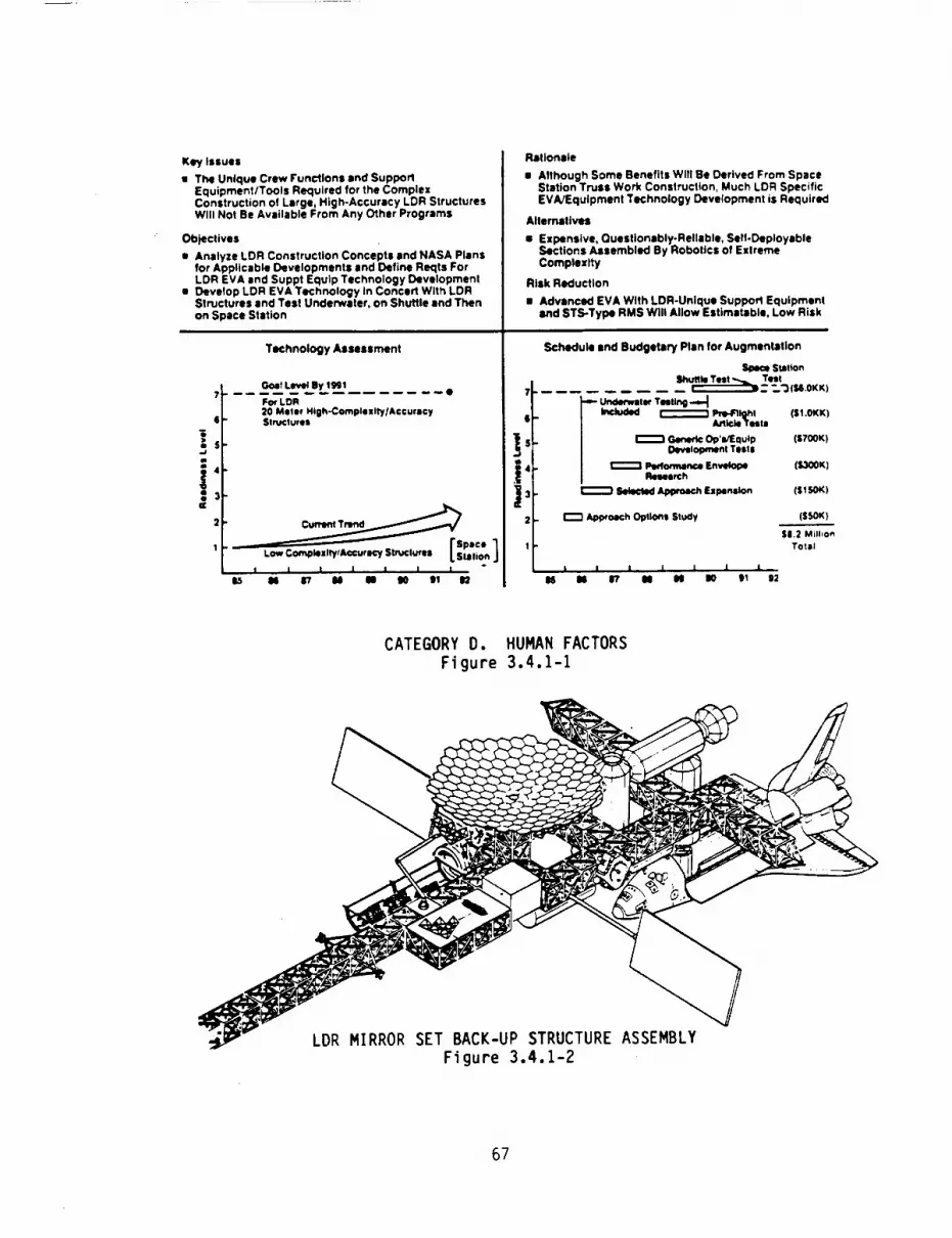
Key Issues
• The Unique Crew Functions and SupportEquipment/Tools Required for the ComplexConstruction of Large High-Accuracy LDR StructuresWill Not Be Available From Any Other Programs
Objectives
• Analyze LDR Construction Concepts and NASA Plansfor Applicable Developments and Define Reqts ForLDR EVA end Suppt Equip Technology Development
• Develop LDR EVA Technology In Concert With LDRStructures and Test Underwater, on Shuffle and Thenon Space Station
Technology Assessment
Rationale
a Although Some Benefits Will Be Derived From SpaceStation Truss Work Construction, Much LDR SpecificEVA/Equipment Technology Development is Required
Alternatives
• Expensive, Questionably-Reliable, Self-DeployableSections Assembled By Robotics of ExtremeComplexity
Risk Reduction
• Advanced EVA With LDR-Unique Suppod Equipmentand STS-Type RMS Will Allow Estimateble, Low Risk
Schedule and Budgetary Plan for Augmentation
Spe4_ StiltonGet ....... Shuffle Test % Test
LI_H. By .l_J'Jl • 7 -- • m_--_..'=ItN 0KK)For LDR 4- Undefwatl¢ Testing -_20 Meter Hlgh-ComphlRity/Accufacy . Inc_ded _ PNPIrIIohl ($1 0KK)Structures _ Aallcle'frestl
"_ _ s r_t _ Op UEQ ,,p (S700K)._ r_ _iop,_nt Test.
'1"- L.'.',,ooJ' ,o,./ ! I i [ I I I ° I I I 1 I J I
. ,_ ,7 J, m ,0 o, n ,s m .7 m m ,o ,, .
CATEGORY D. HUMAN FACTORS
Figure 3.4.1-1
LDR MIRROR SET BACK-UP STRUCTURE ASSEMBLYFigure 3.4.1-2
67

The huge size of LDR forces the elemental fractionation for delivery of the system,such as the trusswork shown in Figure 3.4.1-3. The role of the crew in the verynumerous assembly and deployment functions is critical, since automation thereofrequires extensive remotely controlled fixtures, major and mini-manipulations andalignment, plus specific redundant automatic latches which are expensive andquestionable as to linearity and capacity of structural loading. It is apparent thatmany crew/machine combinations are required to satisfy the spectrum of functionsconceived. The objective of this technology plan is to determine the role-split mosteffective of humans and machines in LDR construction.
There are many unique human roles in prospect for LDR construction and a combinationof supporting resources that are both uniquely LDR and presumed to be available forcommon use from the Space Station. Figure 3.4.1-4 presents an overview listing ofthe technology advancement needs envisioned for LDR by human role and supportingresource categories.
Mirror.Set to Mlrror-Se!
Truss to Mirror Back
PRIMARY MIRROR ASSEMBLY PHASESFigure 3.4,1-3
68

Unique Human Roles in Space For LDR I
• EVA Construction/Alignment
• EVA Maintenance/Modification
• Integrated EVA/Robotics Operations
• Integrated EVA/IVA/Ground Specialist Operations
I Support for Unique Human Roles in Space For LDR ]
• Special Tools and Aids (Unfold, Couple, Rigidize, Align and Latch)
• Real-Time Instruction/Reference Information System
• Logistics, Packaging and Slowage
• Space Station Accommodations
• Development Simulations
• Ground (One-g and Underwater)• Shuttle-Based
• Space Station-Based
• Space Suits
• Robotics and Manipulators and Crew Interaction
• Crew-Involvement Structures and Mechanisms
HUMAN FACTORS TECHNOLOGY ADVANCEMENT NEEDS FOR LDR
Figure 3.4.1-4
The major LDR elements and resources required for construction are listed in Figure
3.4.1-5, giving an overview of the extensive scope of construction required by LDR.
Elements J
• Spacecraft• Science Instrument Module + Core Primary Mirrors• _50 Primary Mirrors + Individual Delta Frame Assemblies• _50 Primary Mirror Support Trusses (Bundled)• Secondary Mirror and Support Equipment Module
• Secondary Mirror Hexapod + Metering Rods= _6 Sunshield Frame• _6 Sunshield Panels• --2 Sunshield Attached Radiators
[ Resources J
• Space Shuttle (Transport)
• Space Station (Construction, Checkout, Launch and Servicing)• Space Station Core Crew Support• LDR Special Crew• EVA Aids and Tools
= Interior Control and Monitoring Consoles• Exterior Stowage, Holding Fixtures, Hangar and Work Stations
LDR CONSTRUCTION OVERVIEW
Figure 3.4.1-5
69

For example, the role of the crew in construction of one of 50 of the LDR primary
mirror support structure sectors, will involve the following functions:
m Monitor bundle destowage from delivery pallet by movable RMS• Guide bundle to work fixture and secure
• Release bundle securing device with aids
e Manipulate bundle into deployed state
• Override hangups with portable aids• Rigidize numerous joints with aids
• Cooperate with remotely controlled manipulation of truss to vicinity of mirrorassembly back-face
• Detach from manipulator and align for final latching with aids
• Attach and pre-load latches with aids
• Lock up latches with aids (may be repeated on completed assembly for finalalignment)
• Connect instrumentation and utility lines with aids
• Cooperate with manipulator in affixing aft thermal shields with aids.
Similar EVA/machine functions and operational aids and tools will be required forassembly of the secondary mirror hexapod, despacing metering columns and the huge
sunshield/radiator assemblage. Figure 3.4.1-6 illustrates the types of considera-
tions in prospect for trading off EVA versus optional approaches to basic construc-tion functions.
,o,cj+..o,c++ ] Ico°.°..oo,iTHURIS Mechanical Interface • PerformanceSTUDY Cumulative Cost VersusNo. of Times - Humans
- Tools/AidsActivity Is Performed • COSt
'00i , .._ _ (Mullti.Program Use?)IROe_4 dQmt I _ _ +
" __ .._ " j /o ....... _ • Technolog,calL.-,_- ........ : I ....... / _ ..... ." _ Read hess
f.,o. ...... _...... _p..._.._--->...._,..,._.,or I • .ack,,pOp,or,si,0_'-'_-;:-+,.,,--:0---;oo,o,--_"-- _ _._.., .. ,mpac,onReso.,ce=__ _ I UnlqueLDRDevelopmemt I
o ,=i .........,.oo0._, c....,......,,.....,°,• - L.x(--| ! J _J_fw_'_M.... ,_.,' ....... [ Training
._£._ _ _ _,_,_ j..... ,,,0°o .a ........... "I' .......... t "r^^.+,^',.,+__IP r-" t l i....... Augmel'_leO .......... ,,I, .......... f "v_'°+_l_°
t • ....... / l | I........ Teteol_r ,tea ......... ,_, .......... +_
J ,,/_--+2_.-_-_ , ; I..... 1:-'-::'- °".'::_ ........../ Rooot'cs+:i a..... - - ............-........"Te,e re.n,e
10 100 1000
NumOII OI Tlmtl Act61_ll¥ II OIl'lormld
-'7 l'----Potential Number of Field Joints
In LDR Mirror Backup Truss
[Technical Complexities I
• Joints are Widely Dispersed; Imbedded in Truss Work (Figure of Revolution)
• Joints Must Be Highly-Loaded and Predictable (for Performance Predictibility)
• System Reliability Goes Down as Number of Aulomated Joints Goes Up
LDR BACKUP TRUSS CONSTRUCTION APPROACH TRADEOFF" EVA VS?
Figure 3.4.1-6
70

3.4.1.2 Required Technology Maturit_ Level - In order to support an LDR programinitiation in 1992, it is vital that the Human Factors technology capabilities
required by LDR construction be established earlier (1990-91) to support effective
concept development. Since the zero-g environment is such a dominating source of
design criteria in this technology, it is important that some flight test demonstra-
tion of proof-of-concept be performed to validate concept development assumptions for
LDR-unique EVA/tools/aid capabilities. Since there will be only Human Factor
technology developments for low-complexity/low-accuracy structures in the 1986-91
period (such as Space Station trusswork), LDR interests must develop certain unique
Human Factor capabilities for their own needs. Consequently, the LDR technology
program should be configured to build up progressively from analytical efforts and
elemental underwater tests in 1986 to a shuttle flight test with the NASA Langley
STEP pallet or the NASA Marshall MPESS pallet or both by 1991, i.e., OAST Level 7
(engineering model tests in space). These efforts should, of course, be coordinated
with the structural/mechanical technology advancements for LDR. McDonnell Douglas
Astronautics has current company-sponsored efforts in underwater EVA simulations of
an LDR primary mirror support structure (see Figure 3.4.1-7). It is important to
note that numerous important LDR structural/mechanical design decisions, including
the cost aspects of various options, require inputs on human and human-aid capabili-
ties that will not be developed by any other system or generic technology program.
LDR MIRROR BACKUP TRUSS TESTS
(In MDAC Underwater Test Facility)
Figure 3.4.1-7
71

3.4.1.3 On-going Technolog,v Developments and Estimation of Where the Technology WillBe in 1991 - At the present time, there is technology development on-going for gen-
eric large beam-like truss structures for systems such as Space Station and
platforms. The near-term EASE and ACCESS EVA construction experiments are aimed at
such systems and address essentially large span, relatively low-complexity,
low-accuracy (stability) box-like or planar structures. LDR is very different from
such structures. Its structure will be a deep cross-section, parabolic, or spherical
dish; it will be very high in complexity and its stability performance will require a
stretch in the state-of-the-art of structures . . . far beyond Space Station.
Consequently, so will the Human Factors technology required to assemble LDR. It is
estimated that under current Human Factor technology development for space
construction that the readiness level for LDR-type capabilities is now at Level i.
Further, it is estimated that without dedicated LDR activity , the state-of-artreadiness level for LDR in 1991 would be between Levels 2 and 3. The challenge,
therefore, for LDR interests is to fund and accomplish LDR-peculiar technologyadvancement to Level 7 by 1991 for the rationale described earlier.
3.4.1.4 Technology Shortfall and Augmentation Plan - Even if NASA's currently
planned generic Human Factor Technology program is augmented substantially for SpaceStation, there will still be a significant shortfall in the capability of EVA and
crew aids for construction of the high-complexity/high-accuracy/dished LDR structurein 1991.
The shortfall will primarily be in the areas of special crew techniques and aids for(I) unfolding, aligning, attaching, rigidizing, calibrating and adjusting a unique
figure-of-revolution truss which requires numerous three-dimensional, nested-section
joining, (2) assembling high-accuracy primary mirror segments, (3) integrating
primary and secondary mirror assemblies with interconnecting multipods, and (4)
erecting a combination of large area hard and soft goods panels for a sun shield and
soft goods blankets over the entire aft side of the mirror support structure. The
challenging operations are unique to LDR and are not required for any prior orparallel program. Moreover the degree to which humans with aids can perform such
functions must be known as early as possible to influence the degree to which the
concept for LDR construction must resort to expensive, questionably-reliable,
automated construction and rigidization techniques.
The LDR augmentation recommended for NASA's generic Human Factors Technology program
involves the following progressive activities:
e 1986 -
e 1987 -
• 1988 -
• 1989 -
e 1990 -
Study of approach options and human/aids/automation tradeoffs (assume
contractor IRAD) ($50K)
Expansion of selected approach definitions and low-cost start of longterm escalatory underwater test program of structural/mechanical
elements, techniques and equipments ($150K)
Conduct Performance Envelope Research of various factors/aids and
approach to quantify and calibrate capabilities potential (including
underwater tests) ($300K)
LDR-generic Operations/Equipment Development Tests (advanced fidelity,
maturing design items) (inc]uding underwater tests) ($700K)
Pre-flight article tests (ground testing of all elements of subsequent
72

• 1991 -
shuttle "STEP" flight test, i.e., pre-test of flightworthy items)
(including underwater tests) ($1.0M)
Shuttle-based test of 1990 developed/1991 converted test equipment to
certify capabilities, problem-potential and contingency management
approaches. (including STEP pallet rental) ($6.0M)
Subsequent testing of equipment on Space Station is anticipated where extended
duration flight will make more extensive testing, evaluation and concept-validation
possible.
3.4.1.5 Related Multi-Program Technology, Consideration - Since LDR will operate as a
free-flyer after construction on the Space Station, it will be remotely serviced viasome OMV-mounted module as shown in Figure 3.4.1-8. Consequently, the LDR program
will place requirements on NASA's generic Remote Servicing Technology which includes
human involvement for overall monitoring and selective basic and contingency control
operations. The Human Factor-related technology involved in remote servicing will be
developed to support many different free-flying spacecraft, therefore, it is not
discussed or costed in detail here. However, LDR will levy certain unique require-
ments on such emerging crew/machine reservicing capabilities, and of course, help tojustify its development by at least the mid-1990's.
REDUNDANTSTOWABLEMAN IPI
MANEUVERVEHICLE(OMV)
TELESCOPEPRIMARY
-ORU EXCHANGELOG IST IC5 MODULE
LOR SPACECRAFTAND MULTIPLEINSTRUMENT
CHAMOER ,,
• ORBIT REPLACEABLE UNIT
ORU* EXCHANGE LOGISTICS
MODULE (OMV-BASED)
Figure 3.4.1-8
73

3.5 CRYOGENICSANDSENSORS(OASTCATEGORYE)
3.5.1 H_brid Cr_,oBenic S_stem For Science Instruments
3.5.1.1 Requirements Derived from Concepts - The LDR scientific instruments will
require operational cyrogenic cooling loads of about 8 watts at 77°K, 4 watts at20°K, and 1 watt at 2°K. When considering initial cooldown requirements and the
additional parasitic heat loads the total cryogen refrigeration capacity, over a 3
year life interval, makes the size of a stored cryogenic system exceptionally large
and impractical. Further, the required capacity that would be needed is eventually
impractical for active closed-cycle mechanical or chemical absorption cryogenic re-
frigeration machines designed for spacecraft operation.
It will be possible to meet these refrigeration requirements with a reasonably sized,
practical and reliable "hybrid" cryogenic system consisting of a stored cryogen in
conjunction with a closed-cycle active refrigeration machine. The stored cryogen
will provide most of the initial cooldown refrigeration. The operational capacity
requirement will be possible using active refrigeration machines sized for about 10watts at 77°K, 1.5 watts at 20°K and 0.75 watts at 2°K. These are considered
reasonable capacities. The stored cryogen can be packaged in concentric spheres with
a maximum outer diameter of roughly 2.5 meters.
3.5.1.2 Required Technology Maturit_ Level - The cryogenic cooling system isabsolutely essential to operation of the scientific instruments and accordingly it is
necessary that a system be available which has demonstrated both satisfactory
performance and reliability. The importance of this system justifies a technology
maturity to space testing (Level 7) by 1991. The "hybrid" cryogenic system
reliability goal should be aimed at a 10 year life in terms of all active mechanical
pump components and controls. Innovative engineering and materials development isneeded to improve the efficiency and performance of stored cryogen vessels in terms
of improving insulation and structural mounts to reduce parasitic heat gains to the
stored cryogen and plumbing. In addition, the efficiency of active refrigeration
systems must be increased and more effective thermal radiators are needed to reject
the large mechanical pump heat loads. An improvement is needed in the implementation
of cryogen cooled thermal insulation shields, using spent cryogen, and to then
recycle (i.e. recover) this cryogen. The simultaneous and continuous management of
cryogen liquid and vapor within a common storage tank, in a zero-g environment,
presents many engineering challenges.
The hybrid system must be configured to enable on-orbit serviceability and/or com-
ponent replacement. Although the 10 year life goal objective will not be compromised
the design must be capable of easily accommodating replacement of the various active
mechanical system components. Attention will also be given to multi-compartment-
alized stored cryogen vessels to guard against cryogen loss such as caused by
meteorite impact.
3.5.1.3 On-_oin 9 Technology Developments and Estimation of Where The Technolo_ WillBe in 1991 - Considerable effort is currently being expended by both DoD and NASA on
the development of active closed cycle cryo-refrigeration machines; for example, the
NASA Goddard/Philips 5W Sterling cycle machine and JPL Lanthanum Pentanickel hybrid
absorption cycle. These efforts are well below the level needed to meet the much
74

more demandingcapacity, temperature level, and reliability requirements needed byLDR. The current trend at best would accomplish a componentLevel 6 technology by1991 with a more likely Level of 5. In terms of an integrated "hybrid" system the1991 level would be even lower at possibly Level 4. A muchmore intensive effort isneeded to increase the capacity of active machines and to achieve lower temperaturelevels of 2-4°K with highly reliable hardware. Cryogen fluid and gas managementin a"hybrid" system is mandatory and involves technology and design issues not associatedwith separated stored cryogen and active mechanical equipment.
3.5.1.4 Technolo_ Shortfalls and Augmentation Plan - A major shortfall in currenttechnology is development of active closed cycle cryo-refrigeration machines with the
LDR capacity requirements at 2-4°K. Machines designed for higher efficiency and much
improved reliability (10 year life) are also indicated. Packaging and hardening of
associated electronics will require considerable effort; current status resembles
brassboard lashups with little attention to space hardware miniturization and
packaging. Considerably more engineering thought and innovation is necessary for
stored cryogen vessels, insulation, and structural mounting.
A $12M total program is recommended beginning in 1986 with a funding level of about
$2M spread over three years followed by $10M spread over the next three years as out-
lined and broken-down in the schedule plot of Figure 3.5.1-1.
_Y ISSUE
lettle| c_16_m _et lo_s _d the le_ _retl_alcryogenic heat load$ require that a hybrid refrigerationsystm (comprising both stored cryogens and active, c)onedcycle refr|geratIon michtne) be employed. This Is partt-culirly cTltIcal since e high MrcLmtage of abe _perituqrequirements ere betxeen ltquld helium end _ydro_mtomperat ures,
ORJECT|V[$
• Develop e reliable, IO-Yeer life UeChHtC81 pimp toachieve liquid helI_l tlmberatureS for LDR at the neededrefrigeration capac!ty (_S watts) _ _ reasondd_le(_,_ vests) power input.
• Develop ¢nmpenion cryogenic storage tonkige for use vltbact|ve refrtgerettofl componeBts to bendle super c_f|uld$ In space (zero-g)
• Develop super Insulation techniques end mchontcsl mount-Ings vtth near-zero heat leeklge.
• Develop efficient heat rejection sdmms for the mc_nl_
ca1 _frl_ratton |0ads
Iio effictlmt hybrid system exists today Imd, tn particu-lar, ichenlcsl SyStm fall ue|l below the needed cope-
7 - -_,_- _el. 7 RY1,,|
C' i l i I I i l85 86 87 88 89 9(3 91
CAL[NDAR YEAR
CATEGORY E"
HYBRID CRYOGENIC
A c_ltng systiu ceapeised enly of stored crypts Iscmq}letoly _precttcel for the L_ beseltne requtItS.The p_ablllty of developing i IChanf_l IMchtne Ulatelm_ could h_mdle co¢ldevn _ul_nts Is also beyondroasonsble projection,
ALTERNATIVES
Alternative techniques for the Closed cycle mchenIcel systemtnclude I c_mtcal _so_tton refrigerator (such asLonthjnun pent•nickel hydride), or casci_Jd _oule-_Nmq_sons_tN, _PL_hes istra_ e laboratory LINI, SysLemvlth 20 to 40"K c_ibl|tty.
RtS[__SIf the _J_ttv_s con not he It, t_n the L_ _mperetum,refrigeration load, aN life roquIrom_ts would have to bescaled beck, perhaps radically0 ulth co_$equent Impact onmeeting the science toils of LDR.
SCHEDULE _ BUDGETARY PLAN F_ AUGMENTATION
SIX YEAR, $12 _ _ TO R_H GOAL IY 1_I
city lind rolfel_llft¥ for L_. The pmJecfAed rate ofprogress In govenwmtt develoFemnt program tS not expecto,to satisfy LDR needs.
7.
i "" _K ISPACE TEST/
...... I DES, FA,B, GROUHD
_Lt 5' d '_du_lu_j_'j TEST ENG HOoEL10/86 - I--.--'_. DES, IrAB,
,. _ +|,oooK! P'u,<P\ +._'i":_O.ENTS__ 500K I T,_IY,.ACE
2soKItNSU_TZON/"O_WTX,GS_I ; _ 250K i .EAT KF.,JECTtON
i i i i i I =' l
85 86 87 88 89 90 91
_[N_R YEAR
CRYOGENICS AND SENSORS
SYSTEM FOR SCIENCE INSTRUMENTS
Figure 3,5.1-I
75

3.5.2 Cryogenic Systems for Detector Temperatures Less Than 0.3°K
3.5.2.1 Requirements Derived From The Concepts - Certain scientific instruments
(e.g., 200-1000j_m submillimeter camera) for LDR require NEP's of I x 10"16 w/hz -I/2.
To achieve these NEP levels cooling will be needed to about O.I°K. Temperatures to
O.3°K can be obtained with evaporation of He3 which, in itself, requires a special
refrigeration system (e.g., absorption pump and condenser pot) if the He 3 is to be
recovered. To achieve the much lower level of O.I°K will require systems such as
Adiabatic Demagnetization Refrigeration (ADR) or He3-H 4 dilution refrigeration.
Any selected refrigeration system must be extremely reliable and capable of operation
at zero-g. It must also be characterized by low weight, small size, and low
operational power requirements for compatibility with spacecraft. Further, for LDR,
this refrigeration system must be a logical selection in terms of how it integratesinto the major cryogenic systems servicing the bulk cooling requirements of thescience instruments.
3.5.2.2 Required Technology Maturity Level - To cool special science instruments to
O.I°K will require extensive development in active cryogenic cooling technology.
The long life expectancy and reliability demanded by LDR necessitates system hardwaredevelopment and testing through Level 7 by 1991.
A logical plan is to initially pursue at least two candidate approaches; the most
likely are ADR and He3-He 4 dilution. In the case of He3-He 4 dilution, major tech-
nology barriers exist since this technique involves interface phase separations which
will not occur in a zero-g environment. Accordingly, techniques such as semi-permeable membrane separation must be studied. In the case of ADR substantial tech-
nology and engineering improvements are needed in efficiency, size, magnetic
superconductivity, thermal switches, insulation, thermal isolation, and generalconfiguration packaging for integration into the total LDR cryogenic systems and forserviceability.
3.5.2.3 On-Going Technolo_ Developments and Estimation of Where The Technolo_ Will
Be in 1991 - Numerous laboratory ADR and He3-He 4 dilution cryorefrigeration systems
have been built, to date, and operated. In addition, NASA Goddard has designed an ADR
system with features for operation in space. Several current DoD and NASA spaceprograms are considering ADR hardware (e.g., AXAF and SIRTF).
While this past experience and current technology development effort provides a sound
starting base for employing an ADR system in LDR it will be necessary to make further
ADR technological advances in reliability, magnetic superconductivity control, and
techniques to enable long periods of continuous cooling capacity. However, in the case
of He3-He 4 dilution refrigeration very little, if any, effort is being directed to a
system compatible to space, zero-g operation.
76

At current rates of development an ADRsystem may conceivably reach Level 7 by 1991;however, as indicated it will most likely not meet the needed requirements for LDRand
accordingly should be ranked no higher than Level 6. In the case of He3-He4 dilutionrefrigeration, the current rate of technology development will undoubtedly not exceedLevel 3 by 1991.
3.5.2.4 Technology Shortfalls and Augmentation Plan - In the case of He3-He 4 dilution
refrigeration the major shortfall is in developing a system that can be operated in a
zero-g environment. Novel concepts, such as semi-permeable membrane phase separation,are needed. This system is currently ranked no higher than about Level i and
considerable effort is needed, early-on, to determine if it can realistically be
considered as an LDR candidate cooling system. Nevertheless, the present technical
judgement is that a He3-He 4 dilution refrigeration system, capable of zero-g operation,
is possible.
The major shortfall seen for an ADR system, in LDR, is in development of technology for
much higher reliability and likely increased refrigeration capacity.
A $13M total program is recommended, beginning in 1986, with a funding level of $6M for
ADR and $7M for He3-He 4 dilution refrigeration. Of course, if obvious impractical
technical barriers are encountered with the He3-He 4 dilution refrigeration system this
effort would be terminated; a decision point is indicated following the second year of
effort. The funding level for ADR is about $5M spread over the firstRfou_ years,followed by $IM over one year. The success path funding level for HeV-He - dilution
refrigeration is about $2M spread over the first two years followed by $4M spread over
the next three years, and ending with $IM over one year. These fundings are outlined
and broken-down in the schedule plot of Figure 3.5.2-1.
77

Some propesiN LDR Sclwce lnstrmwnts {e.g., ?OG-IO00 im
subatlltsit_r camera) _y requtre cOOltng of/the detectorstO aS Iota IS O.|°K (for lt(P'$ of 10"1" UHZ"° I). Adiabatickadlgnetilltlon Ilefr|gerators {_) and aHe'_H4 dtluttonc4olers am tim r.Jmdldito apgreuches. Homver, these iystaonvtll require extensive toc_olcqLy develocmnt to becomeiN.ictt¢il lid relloble. The Heltum dllutloR tochntq_ wuldlot o_lrlk4 IR zero- 9 as presently tnlll_t_ I_d vial rmivtrenw techniques, such as semt-pemoble mlbranes. AOlt's ire|lmfflctlmt end require Innovetlem to enable continuous refrig-eration for long duration observation periods ('- 30 al_uto$ perorbit issued for LOR).
OSJ(CTlY[S
• 9evelc_ a SNce*qvaltfted relloble |O-yetr refrigeration sysUmfor achlevtng 0.1°1( Umparatures and necessary continuous refrig-eration capacity. At least two Iupr_cltes should be Investigated.based on AOlt or Hellas dilution principles.
TECHNOLOGY ASSESSN[NT
Seth ADII*$ _ _llum Dilution tAch_lque$ haw _ used Inlaboratories for years. A fllg_t-tjq_e _ has be_ built andtested at GSF£. An ADA for an AXAF Sgoctroscogy Instr_lnthas beam proposed.
GOAL: L(V(L 7 IY 199|O
SpArj. kOIMkTIC9(RAGfl(T IZAT ION E_
..a _ogS.
W 4-
w2-
1.
' i • J I w •
I_ li 17 II N I0 ' 91
CALEJIOM ViM
The preposH tachntm to be imtwed ire bued m axe-slam of _ physical tham_tynMIIc _logy. Gr_md-based systems have been built and conslderetton ts beinggtwm to SpaCoborne sysUms. A n_ber of hat,are 4evelop-mona program are curnmtll vndervay, Iwth at IIASA aad OoD.
ALTERNATIVES
llO otJwr IW_cttCl| !mySlc|l thsraedyv_lc al_re_hes weretdonttfle_ that vovld setlsf_ the umperature requlrN_tsbelow O.Y'K.
If these tachnlqnes are not fully developed, then Instrunentdetector talpereture objectives baler 0.3"g (liquid :He Itett)lily not be 4tfJltned or Ule useful Itfe _y be comr_dsed,Accidental quenching of the superconductivity of the signettn lit G |s • IlOtlfltll| fil|ufe _ of coi_ern.
S_H(OULE NlO IIJOG(I'AII¥ PLAN FOR AUGMENTATION
Cmpettn9 pr_jrm to reach 9eel b7 1rod of 1991eAOIt path total 16,0001(e:lte*_ d11utlon path total * $7,0001(
I TOTAL 10114 -$13,000K _a_ADIADATIC
Om_.(TIZATXO_ stooo_JI•EF_X_EUTS .rs_( I
S' _-$;F'i, il;A_E" _l_i ( [ SPACE TEST"_ 4' C{)I4PA11$LE _r --
= &SPACE TI:ST(_TO_p_T_L[SF_4 _ TEST
10/86 t2OOOK ]_9(ClSlO_ TO PROC[(O2- 3HE.aN ( _. - _Ol$, NMLY2[, FAB,
OILUTIO_ & TEST MEN)8OA_; PROVEI-
8S 86 87 68 89 90 91
CALENBNI Y[AR
CRYOGENIC
CATEGORY E: CRYOGENICS AND SENSORS ,
SYSTEMS FOR DETECTOR TEMPERATURES LESS THAN 0.3°K
Figure 3.5.2-1
78

3.5.3 Robotic On-Orbit Cr},ogenic Replenishment
3.5.3.1 Requirements Derived From Concepts - The total life requirements for LDR areat least 10 years with a goal of 15 years. The large demand for cryogenic cooling over
this long period, becomes unmanageable in terms of stored cryogens, and the reliability
demands on active closed-cycle mechanical cryogenic refrigeration equipment would be
totally unrealistic. Studies show that a "hybrid" system composed of stored cryogenand active closed-cycle mechanical or chemical absorption refrigeration systems are
possible and practical over a three year life period. Accordingly, it will be nec-
essary to reservice the cryogenic cooling systems from three to four times over thelifetime of LDR. Two approaches are possible: return LDR to the Space Station or con-
duct a robotic controlled service operation at the operational orbit position of LDR.
The best technical judgement indicates servicing the cryogenic systems at the on-orbitlocation of LDR is feasible and that this approach will be the most economical and cost
effective. Also, protection of the LDR Optical Telescope system from contamination at
all times is mandatory, and this can be more realistically accomplished by OMV
cryogenic system servicing.
3.5.3.2 Required Technolo_ Maturity, Level - The cryogenic cooling system for scienceinstruments is absolutely essential for the successful operation of LDR. Thus, it
becomes mandatory that a highly reliable technique be developed to service refrigera-
tion equipment and replenish cryogens on-orbit (OMV) at intervals of about three years.
The importance of this robotic system justifies a technology maturity to complete space
testing (Level 7) by 1991. The testing need not involve a full-size system; however,it must entail all essential functions including features to suppress and control
contamination of the systems being serviced.
The on-orbit robotic servicing system must be implemented to allow both the replen-
ishment of cryogens and the general maintenance of, or complete module replacement of,
equipment such as the active closed-cycle mechanical refrigeration pumps, plumbing
hardware (valves, etc.), and controls. The LDR system hardware must be designed withthis in mind. Major advances are needed in the techology of remote control of fluid
handling and gas venting systems, and in the development of compatible plumbing hard-
ware (particularly valves and connectors).
3.5.3.3 On-Going Technology Developments and Estimation of Where The Technolo_ WillBe In 1991 - The technology maturity of robotic on-orbit cryogenic fluid replenishment
and/or servlclng of mechanical equipment is very low at an e_timated Level 1. Some
study is in progress for the SIRTF program to resupply cryogen at the Space Station but
the technology required for the robotic system needs of LDR are much more demanding.At best, the current rate of technology development will reach a maturity level of
about 5 by 1991; however, it is questionable that it will include all the features
(e.g., 100% robotic operation, very high reliability, and contamination control) needed
for the LDR system. The total technology status, in terms of LDR, will fall far short
of a needed technology maturity at Level 7.
3.5.3.4 Technology, Shortfalls and Augmentation Plan - The major shortfall in thecurrent technology efforts (e.g., SIRTF program) assoclated with on-orbit replenishment
and servicing of stored cryogenic refrigeration systems is that it is directed mainly
to Space Station application. In this situation, astronaut assistance is available and
79

total 100%robotic operation is not essential. In addition, the requirements ofnon-contamination are not nearly as stringent as will be demandedby the LDRopticaltelescope and science instrument hardware plus the associated thermal/optical shields.Not only are the reliability requirements muchhigher for the LDRsystem but manyaddedfunctions in terms of sensing, guidance, and manuverability are essential. In addi-tion, the LDRrobotic on-orbit cryogenic refrigeration servicing system must accomplishdual functions of cryogenic fluid replenishment, general maintenance servicing ofequipment and plumbing hardware, and capabilities for complete equipment modulereplacement. A substantially intensified technology development effort is justified•
A five year $11.25Mprogram is recommendedbegining in 1986 with a funding level of$0.75M for the first year, and doubling each year thereafter as outlined and brokendownin the schedule plot of Figure 3.5.3-1. This is considered to be a minimal program andcould exceed this estimate by a factor of 2x depending on the rate of technology gains
expected from other similar on-going programs (e.g., SIRTF).
KEY ISSUE
Periodic replenishment of cryogens aboard LDR iScritical to successful achievement of |O-year ltfe.Robotic servicing from the shuttle or space station atregular intervals has been proposed but requires major
developrent.
_JECTIVES
1. Study, analyze concepts to efficiently resupplyltqutd helium at LDR operational altitude usingO_fi//Smart Front End.
2. De_nstrate selected technique, mthod.
RATIONALE
• DMV servicing at mission accessible orbit altitudeshas been conceived for instrument change out,exbeodtbles resupply, and other functions.
• Accesslbt|tty. contamination, reliability, safety,commnality Mad to be studied.
ALTERNATIVES
• Return LDR to shuttle/space station altitude forresupply.
RXS___K• Without robotic, remote capability, replenish_nt
costs and do, time are high.
TECHNOLOGYASSJESSMENT SCHEDULE AND BUDGETARY PLAN FOR AUGMENTATION
Study in progress for S|RTF Program to resupply atspace station. Space station based OMV with "S_rt"Front-End Servicers has been conceptualized. Military
space initiatives may evolve.LDR GOAL: LEVEL 7 BY 1992
7 .... I,-IOC IN EARLY 1990'S TII4EF_
!
| I | | e • ""L
iS g_ II1 11g gO _ 111
Five-year. $11.25M program to reach shuttle testreadiness.
71
-J 6-
4"I
Z-
1-
SHUTTLE TE_
W_O.WATERTESTS,_$6 .OMI
4/9o_. fan$3.0X J FESi-I;_'-FLIGHT
10/88 IDESIGM• FAg, ARTI CLE
,o/.,.s_K _sT '''
10/" _ FAg CRITICAL [TEI4S. TESTDESIG/I CONCEPTSSTUDY
I m • | e • "
M 16 O; N m _ 91
I VIM
CATEGORY E: CRYOGENICS AND SENSORS
ROBOTIC ON-ORBIT CRYOGENIC REPLENISHMENT
Figure 3.5.3-1
80
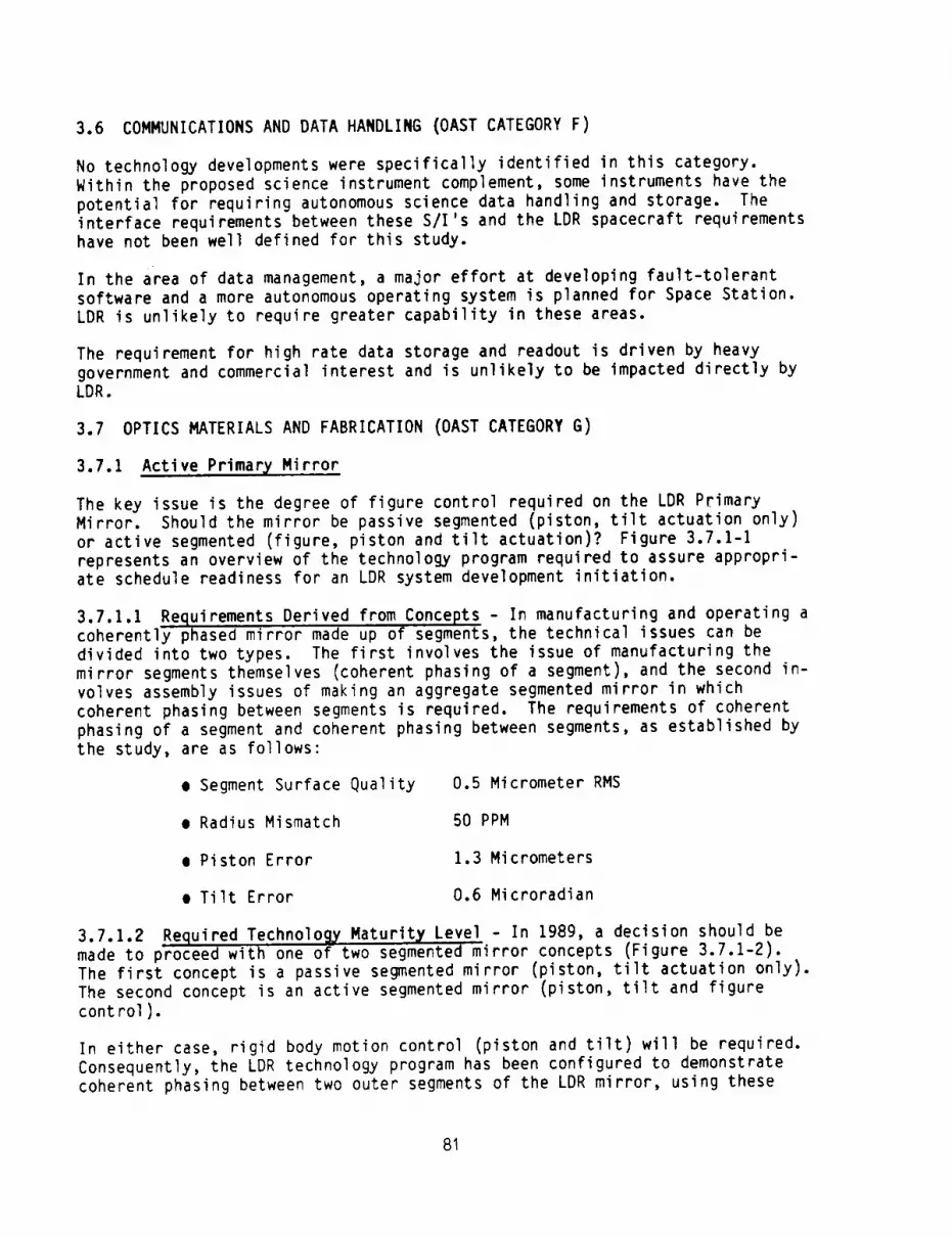
3.6 COMMUNICATIONSANDDATAHANDLING(OASTCATEGORYF)
No technology developments were specifically identified in this category.Within the proposed science instrument complement, someinstruments have thepotential for requiring autonomousscience data handling and storage. Theinterface requirements between these S/I's and the LDRspacecraft requirementshave not been well defined for this study.
In the area of data management,a major effort at developing fault-tolerantsoftware and a more autonomousoperating system is planned for Space Station.LDRis unlikely to require greater capability in these areas.
The requirement for high rate data storage and readout is driven by heavygovernment and commercial interest and is unlikely to be impacted directly byLDR.
3.7 OPTICSMATERIALSANDFABRICATION(OASTCATEGORYG)
3.7.1 Active Primary Mirror
The key issue is the degree of figure control required on the LDR PrimaryMirror. Should the mirror be passive segmented (piston, tilt actuation only)
or active segmented (figure, piston and tilt actuation)? Figure 3.7.1-I
represents an overview of the technology program required to assure appropri-ate schedule readiness for an LDR system development initiation.
3.7.1.1 Requirements Derived from Concepts - In manufacturing and operating acoherently phased mirror made up of segments, the technical issues can be
divided into two types. The first involves the issue of manufacturing the
mirror segments themselves (coherent phasing of a segment), and the second in-
volves assembly issues of making an aggregate segmented mirror in which
coherent phasing between segments is required. The requirements of coherent
phasing of a segment and coherent phasing between segments, as established by
the study, are as follows:
• Segment Surface Quality 0.5 Micrometer RMS
• Radius Mismatch 50 PPM
• Piston Error 1.3 Micrometers
• Tilt Error 0.6 Microradian
3.7.1.2 Required Technology, Maturity Level - In 1989, a decision should bemade to proceed with one of two segmented mirror concepts (Figure 3.7.1-2).The first concept is a passive segmented mirror (piston, tilt actuation only).The second concept is an active segmented mirror (piston, tilt and figurecontrol).
In either case, rigid body motion control (piston and tilt) will be required.Consequently, the LDR technology program has been configured to demonstratecoherent phasing between two outer segments of the LDR mirror, using these
81

KEY ISSUES
• Should the LDR primary mirror be passive sege_,nted
(piston, ttlt acuatton only) or active segmented(figure. ptston and ttlt actuation)?
OBJECTIVES
• Parallel passive segmented and acttve segmented
l| rror designs• Selection of one concept at prel|minary design
revte_ (PDR)• Engineering demnstratton (on-ground) of
selected concept--coherent phastn9 of" two outersegments.
TECHNOLOGY ASSESSMENT
Related OoD activities wtth "similar" requtreRents.However, operational wavelength range and 200"Koperating level untque to LDR
7-
6- GOAL: LEVEL 6 BY 1992 .......
_ 4
2
1,
I | ! | I w w
85 !16 87 88 89 90 9!
CALENI_ tEAR
t
RATIONALE
• Passive and active segmented mirror technology required
for LDR ts simtlar to current techniques demonstratedtn DARPA and tndustry IR&D programs.
RE(_UIRENENTS (ESTABLISHED BY STUDY)
• Segment surface qualtty O.S micrmters ms• Radius mismatch 50 PPM
•Ptston error 1.3 micrometers•Ttlt error 0.6 microradians
SCHEDULE ANO BUDGETARY PLAN FOR AUGMENTATION
5_ year, $3.5#4 program to reach goal by January 1992
7,
6...>..a S'
W 4"
2°
1.
L,
I I
85 86
¢. _. I SEGMENT PHASING"_'Jml TEST
FAB & ASSY.
I OF TWO SEGMENTS
DETAILED DESIGN
TWODESIGNSit | II • m
87 88 89 90 91CN..ENDAR YEAR
®SELECTION
OF 1CONCEPT
CATEGORY G: OPTICS MATERIALS AND FABRICATION
ACTIVE PRIMARY MIRROR
Figure 3.7.1-1
FIVE TIER
PASSIVE SEGMENTED
FACEPLATE i_ I
IIIIIIIBACKPLATE I I I
\\ //\SUPPORT P,l _ j
STRUCTURE \
RIGID BODY MOTION ACTUATORS
_FIGURE ACTUATORS
ACTIVE SEGMENTED
STRUCTURE 3\ M\\ _
//\\\\ I\,ACTUATORS
SUPPORT STRUCTURE
COHERENTLY PHASED MIRRORS
Figure 3.7.1-2
82

actuators. The selection of a passive or active mirror will determine the
degree of figure control required and the approach for coherent phasing of a
segment and radius matching between segments. The demonstration has been
configured at OAST Level 6 (engineering model tested) to be completed by 1992.
3.7.1.3 On-Goin_ Technology Developments and Estimation of Where the
Technolo_y Will Be in 1991 - Passive and active segmented mirror technologyrequired for LDR is similar to current techniques demonstrated in DARPA and
industry IR&D programs. A schematic of an active segmented mirror is shown in
Figure 3.7.1-3. An engineering model demonstration of this type of mirror is
currently being undertaken by DoD. However, the LDR operational wavelength
range (30 micrometers to 1000 micrometers) and the LDR operational temperature
(200°K) are unique to LDR. The segmented mirror technology to meet these
requirements might not be ready by 1991 without LDR acceleration.
3.7.1.4 Technolo!_y Shortfall and Augmentation Plan - There are related DoDactivities with "similar" requirements. However, the operational wavelength
range and the operational temperature are unique to LDR. A primary mirror
concept should be defined and demonstrated for the LDR program. The LDR
augmentation recommended is: (1) parallel passive segmented and active
segmented mirror design and (2) engineering demonstration (on-ground) of the
selected concept. This demonstration would involve coherent phasing of two
outer segments. The technology plan involves the following activities:
• 1988 - Parallel conceptual passive segmented and active segmentedmirror designs ($300K)
e 1989 - Detailed design of selected concept ($200K)
e 1990 - Fabrication and assembly of two outer segments ($2.3m)
• 1991 - Segment phasing test ($700K)
3.7.2 Primary Mirror Contamination Protection
Contamination control must be considered in all phases of the LDR buildup and
end use; in the design by selection of materials and coatings; in manufacture,
assembly, and testing by defining facility and hardware cleanliness require-
ments, and in subsequent transportation, integration, pre-launch testing,
deployment, and telescope operation. Figure 3.7.2-I presents an overview of
the technology program required to assure appropriate schedule readiness for
an LDR system development initiation.
3.7.2.1 Requirements Derived from Concepts - The requirements for control ofprimary mirror contamination can best be stated in terms of performance. When
chopping a source, it is important to obtain a uniform background signal. The
presence of particulate contamination on the primary mirror will produce
scattered radiation, contributing to a reduction in ability to remove bac_-
ground radiation.
83

FACEPLATE
FIGURE ACTUATOR
REACTIONSTRUCTURE
RIGID BODY
PiOTIONACTUATORS
ACTIVE SEGMENTED MIRROR
Figure 3.7.KEY ISSUE
Develop a concept to protect the primary andsecondarymirror from particulatecontaminationduring LDR observatory buildup.
OBJECTIVES
• Define environment• Evaluate alternate protection concepts
("baggies",strippable coatings, etc.)m Select and develop concept• Fabricate, assemble, and test proof-of-concept on 2 mirror segments from segmentedmirror demonstration
TECHNOLOGYASSESSMENT
llo other program to develop these r_pes of cnnta-inattonprotect ion identified.
7_
6-
4-
I 3"
2 =
_ __5_:_CEVECjB_,_199_I-- _
m
85' 86 i 67 ' 88 189 1 90 191'
CALENDARYEAR , •
.-3
RATIONALE
• Techniques for contamination control duringon-ground buildup via clean room environmentand clean packaging are well established.
• Strippable coatings have been "successfully"Implemented on small optics
ALTERNATIVE
m No primary mirror protection---possibly result-ing in throughput loss and/or optical quality_gradation.
RISKS
• Seriously degraded system performance• Difficult to recover performance
.SCHEDULE_ BUDGETHt,V PLANFORAUGHENTATION
2is_lrear, $SOOKprogram to reach 9o41 by January 1991
)
06
1191
$2_,.._ - -0
I PROOF-OF-CONCEPT
$2_r_.KJ ON 2 MIRRORSEGMENTS
I DEVELOP_NT
10/88_,._$.,$lookSELECTIOIt1 | | • •
87 ks IB 90 91
CALENDAit YEAIL
CATEGORYG" OPTICS MATERIALS AND FABRICATIONPRIMARY MIRROR CONTAMINATIONPROTECTION
Figure 3.7.2-I84

If molecular monolayers are deposited on the primary mirror, these may produce
unwanted spectral absorption which will produce unknown effects on the radio-
metric performance of the instrument. In addition to these effects, the over-
all throughput of the instrument will be reduced because of reduced mirror
reflectance. The presence of contamination may also alter the thermal
performance of the optics by changing the emissivity and absorptance.
3.7.2.2 Required Technological Maturit_ Level - In order to achieve therequisite performance for LDR, techniques must be developed for contamination
protection of the LDR primary mirror during launch, orbital assembly, deploy-
ment and subsequent refurbishment. These methods must be developed to atleast OAST Level 5 (component tested) by 1991. The environment within which
the LDR observatory will operate must be determined from a contamination point
of view. Once the environment has been defined, the effects of the
environment in producing mirror contamination must be estimated. This, in
turn, will produce performance effects that must be estimated. The severity
and nature of these effects will determine the technology required to protect
against the contamination. It is anticipated that Level 5 maturity will be
adequate to prepare for full scale LDR implementation.
3.7.2.3 On-Going Technology Developments and Estimation of Where theTechnology Will Be in 1991 - Currently, no efforts are underway to develop
contamination protection technology for space mirrors of the LDR size cate-
gory. Eastman Kodak Company has had extensive experience in providing contam-
ination protection for large optics during manufacture, and in placing
strippable coatings on small optics. The required protection may range all
the way from such strippable coatings for primary mirror segments to "clean"
enclosures for orbital assembly operations.
Kodak currently has 12 glass samples on the Long Duration Exposure Facility
(LDEF). It is expected that this facility may be returned to ground in 1987.
These samples will be evaluated at Kodak for particulate contamination due to
space exposure during LDEF's orbital life and also due to the Shuttle itself.These experiments are the first step (i.e., defining the contamination
environment) in developing contamination protection for space optics.
3.7.2.4 Technolo_).vShortfall and Implementation Plan - It is planned to
develop packaging methods for primary mirror segment modules that will allowtransportation from the clean factory environment to the orbital assembly
location. The effort will be based on existing strippable coating technology
for small optics. The environment will be defined, and its effects assessed.The overall program will cost approximately $500K, and will take 2.5 to 3
years to complete. The final stage of this effort will involve a proof of
concept demonstration on two primary mirror segments. Start is planned for
10/1/88, with completion on 1/1/91. Advantage will be taken of the LDEF data
expected to be obtained in 1987. This will help to define the expectedeffects.
3.7.3 Glass Material for the Primary/ Mirror
The large primary mirror surface area justifies consideration of a new glass
material for operation at 200°K. This may enable a passive (piston, tilt
85

actuation only) segmentedmirror concept, thus, reducing dependencyon complexfigure control. Figure 3.7.3-1 represents an overview of the technologyprogram required to assure appropriate schedule readiness for an LDR systemdevelopment initiation. °
3.7.3.1 Requirements Derived from Concepts - The selection of the mirror
material requires careful consideration of the mirror design in "1-g" manufac-
ture and"O-g" operation, as well as the mirror interface with the mountingarrangement, the control actuation, and the backup reaction structure. The
material properties of Young's Modulus, density, thermal expansion, conductiv-
ity, and heat capacity must also be carefully weighed (See Table 3.7.3-I).The ability of a material to athermalize can be described by a figure of merit
called thermal diffusivity: (conductivity)/(density x heat capacity). Amaterial with a high diffusivity value will althermalize quickly. Most
materials with low CTE, such as glass, have low conductivity and low specificheat. These materials athermalize (reach equilibrium) very slowly. This
means that mirrors made of glass or glass cermaic materials (operating above
IO0°K) are more stable under thermal transients or gradients; however, they
will take a very long time to reach thermal equilibrium. There is no "ideal"
material for optical components that will perform over a temperature rangebecause the CTE of all materials, changes with temperature (Figure 3.7.3-2).
The low expansion glass materials (ULE', Zerodur, and Cervit) have negligiblethermal expansion near room temperature (300°K). Fused silica has a zero co-
efficient at about 140°K. The coefficient of expansion also varies with the
amount of titanium dioxide doping. Corning's ULE" material is fused silica
doped with 7.5 percent titanium dioxide. From the figure, it can be seen that
this biases the point where the instantaneous CTE is zero at approximately
300°K (room temperature). In a similar manner, a new ultra low expansion
glass could be envisioned for the primary mirror at 200°K by using fusedsilica with 3 percent doping.
Glass and glassy ceramic materials have reached a level of maturity for space
optical mirrors. The ability to lightweight, polish to excellent optical
quality and retain this figure has been demonstrated on programs such as SpaceTelescope. Alternate state-of-the-art lightweighting concepts exist
(machining; fusion welding; frit bonding). Shown in Figure 3.7.3-3 is the
predicted areal density for a frit bonded mirror. The top curve shows a
design optimized for visible light applications with an aspect ratio of 7 to 1
and a rigidity of a few waves. The lower curve was calculated for an aspectratio of 20 to I, reducing the weight at the expense of the inherent struc-tural rigidity. The basic assumption is that larger deflections can be
tolerated at far infrared and submillimeter operational wavelengths.
3.7.3.2 Required Technolo_LY Maturity Level - In 1989, a decision should be
made to proceed with one of two segmented mirror concepts. The first conceptis a passive segmented mirror (piston, tilt actuation only). The second
concept is an active segmented mirror (piston, tilt and figure control). A
glass material is a major candidate for implementation of a passive segmentedmirror. Consequently, the LDR technology program has been configured to
establish the technology to OAST Level 5 (component/breadboard tested) by1989.
86

KrY Issu(s
• The large pr(--ry_llrror surface area Justifies cmlsidora-tton of a new ULE'" for oNrett_ et 200uK. This mayenable • Nsslve (pistem, tilt actuation only) segmentedmirror coecWt thus r•ductng dWendenc¥ on complex ftgurecontrol
IIJ(CTZV(S
• Develop fused stllca glass doped vlth approxtmtely 35titanium dtoxtdo and.cOmlSittble frlt that meets CTE goalof 0 _*O.03xlOTM per VK and 1oR CT[ veriabtltty.
• Fabricate and test fr|t-IIndod proof-of*coN:lpt mirrorseOmmt
TECHNOLOGYASS(SSMENT
ilo other prngrams to dovelop N4r zeJ_oCTE iterlalproperties at 200"K |d_tlfled. 200"1( operating level
ILATIOlkkL£
• Tatlor(ng fused $11tca doping and frtt llterlals tomeet LN requtrelnts appears to be strelght forvardexLenston of ¢urrenL.technlques de_mstreted on SpaceTelescope using UL( m aml tn IMIIPA and I•dustry |R&DprngraI.
ALTERNATIV(S
• Develop • clpostt4 tutorial s4ttsfylng the si CTFJ_;TE properties.
• laplemntatlon of flgurt cmtrol vlth exlsttng glassor ¢oNx)stUI idrror malMlrtils.
RISK R(OUCTION
• P•r•llel primary Mrror tadmoingy 4evelolmmt projectsvould reduul risk.
SCHF_IJL(AND IJUOGETA,RYPt,,AllFOIl AUGIq(JCrATION
2-I/2 year, $700K program to reach goal by April 1989
Is vnlque to LINt
7
6d
.J
t_
GOAL: LEV[L S BY 1991
4-
3-
2-
1CURk(NTTREND
85 86 A1 68 89CAL(NOARVF.AR
7
.j &4/89
V
O/ O(SIGN, FAB, TESTPItOOF*OF-CONC_PT$2O #i_ SI[G.
I FAB, TEST SAMPLES
i0/86_-- FORMULATE SAMPLES OF MATERIAL, FRIT
, $2(IOK.....
IB 86 87 M 09 gO 91 _DECISION TOVF_ CONTINUE
JGLASS/CERAMICSJ
FUSED SILICA
(3% liO2)
ZEROOUR
PYREX
HEXALOY (•SIC)
CATEGORY G: OPTICS MATERIALS AND FABRICATION
GLASS MATERIAL FOR THE PRIMARY MIRROR
Figure 3.7.3-I
TABLE 3.7.3-I
REFLECTOR MATERIAL TRADE MATERIAL PROPERTIES
FIGURES OF MERIT
_G
a @ 2_O°K uM/M°K E o _ o Cp E/p 0 • C/pcwH/M'K PART/PART GP_.a.a GM/CM3 WATT/M K J/KG°K SPEC. STIFF DIFFUSIVITY
0 *0.03 76. 2.2 1.4 740
0.16 *0.05 94. 2.5 Y.6 821
2.9 65. 2.2 1.1 753
3.9 (RT) *0.3 410. 3.1 125 1420
34.5 8.6x10 "4
37.6 7.8x10 "4
29.5 6.6x10 "4
132 0.028
alpTHERMAL
DISTORTION
35
256.
4395.
I_. (RT)
87

o..t 3#7940 %
t FUSED SILl/#
i 02 --
j#,__ - TiO 2
o.oL--/--_ .... .--.,-.,,_-'_---'""""// / / ,L'LC/ !
-o.,1/ ," _ =
I/ • /; z-o.4-f / I !
i -o.6-1 / :LOR ! __,SP_CZ
-I / I _'_ A TEL[SCOeEI / T z P"
-o.sV , II I.,.o[ 1
-zoo -sGo 6 iGoTEMPERATUREI oc
7'3 vh zh 3)3TEI4PERATUI|E. OK
THERMAL EXPANSION OF CORNING FUSED SILICA GLASS
Figure 3.7.3-2
150
A100
- 50
! ! I I
l.O 2.0 3.0 4.0 5.0
SEGMENT LENGTH (METERS)
The top curve showso design optimized for visible light applications with on aspectratio of 7 to 1 and o rigidity of o few waves, The lower curve was calculated for onaspect ratio of 20 to 1, reducing the weight at the expenseof the Inherent structuralrigidity, The basic assumptionis that larger deflections can be tolerated at forInfrared and subml]ltmeter ooerotionoI wavelengths,
PREDICTED AREAL DENSITY (FRIT-BONDED)
Figure 3.7.3-3
88

3.7.3.3 On-Goin_ Technolo_,y Developments and Estimation of Where the Technol-ogy Will Be in 1991 - For several years, Kodak has been engaged in developing
passive fused silica mirrors which meet stringent weight budgets and optical
figure quality requirements from room temperature to cryogenic temperature.
This capability has been successfully demonstrated with ultra lightweight
fused silica frit bonded mirrors with and without broad band multilayer high
reflectance coating up to diameters of 0.5 meter. Technical issues addressed
and resolved include the design and manufacture of ultra lightweight frit
mirrors, CTE match, bond strength, CTE homogeneity, polishing to diffraction
limited quality, optical stability, optical performance at cryogenic tempera-ture and coating performance. Current work involves demonstration of the
optical performance of these new generation ultra lightweight mirrors kine-
matically mounted and subjected to cryogenic environment. Key issues demon-
strated are: (I) mirror optical performance from room temperature to IOO°K,
(2) strain-free mirror mount attachment (glass metal), and (3) flexuredkenematic mount design.
Tailoring fused silica doping and frit materials to meet LDR requirements
appears to be straight forward extension of current techniques demonstrated on
Space Telescope using ULE" and in DARPA and industry IR&D programs. However,
no other programs to develop near zero CTE material properties at 200°K have
been indentified. The 200°K operating level is unique to LDR.
3.7.3.4 Technolo_ Shortfall and Augmentation Plan - The mirror designapproach must not only be rugged, low risk, and reliable, but also capable of
surviving a launch environment and enduring in space for many years. A design
approach which meets performance requirements at 200°K employing passive
mirrors (without figure control actuators, sensors, and electronics) made of
glass, offers significant advantages in weight, performance, and reliability.
The LDR augmentation recommended is: (1) develop fused silica glass doped
with approximately 3% titanium dioxide and compatible frit that meets CTE goal
of 0 + 0.03 X 10⁻⁶ per °K and low CTE variability and (2) fabricate and test a
frit bonded subscale proof-of-concept mirror.
The technology plan involves the following activities:
• 1986 - Formulate samples of the glass material and frit material ($200K)
I 1987 - Fabricate and test sample elements ($200K)
• 1988 - Design, fabricate and test proof-of-concept subscale mirror
segment ($300K)
3.7.4 Composite Material for the Primary Mirror
Development of a composite material with high dimensional stability for oper-
ation at 200°K may allow either molding or replication to be used in manufac-
turing the mirror segments. Also, composites may enable a passive (piston,
tilt actuation only) segmented mirror concept, thus, reducing dependency on
complex figure control. Figure 3.7.4-I presents an overview of the technology
program required to assure appropriate schedule readiness for an LDR system
development initiation.
89

Oevelol_mnt of a cmq)oslte matRr|al with high dimonstonalstability for olxmratiml at ZQO'K. This My enable J passive(piston, tilt.actuattem only) segmented Ilrror concept thusreducing dependency on cml)lex figure cmtrol.
O&JECTIrES
e _velop a camposl_e euterlal that rots CT( 9o41 of0 tO.O3x|O TM per K and low CT£ vartablltt, y.
e Fabricate and test proof*of*concept _s|te mirror seg-Rnt.
T(CHNOLOGYASSESSN(NT
llo other programs to develop ccmpeslte Ilterlals vith theseproperties ldentl fled
6.
-_ 4
3 TM
|--
J l85 86
GGAL: LEVEL S BY 1991
87 88 89 90
C.ALEqOAR YEAR
4,
i I
91
IMTIOI_.E
Anisotro_tc CTE ts currently a pr_lm _lth compositeilterlals for mirrors. Can a new composite mlterta! bedeveloped to Ilintetn the surface figure qualtty passively(preliminary sat it 0.75 itcrometers)?
ALTERNATIVES
e Develop • glass IIterts| satisfying _ same CTE/_rT(properties.
• lmplementat|on of ftguro control vtth ex|st|ng glass orcomposite mirror itertals
RISK REnUCTION
e Parallel prllry mdrror teclwmlO_LY clevtlopmnt projectswould reduce rtsk.
SOHEDUL( AND LmOG(TARY PLAN FOR #NUGIaIENTATIOR
2-1/2 year, $750 program to reach goal by April 1989
T
6 4189
4 ESIII. Fro. TEST
i _ PIN_-oIr-COIICEPT] $2oo_ mamas_G.I FAB, TEST SAMPLES2i
] , I0/I_-- IMTERIAL O£1RLOPI(IIT
IB m 87 88 III gO gl (_DECISION TO
fJ_Jl]mM Vl_l CONTINUE
/
CATEGORY G: OPTICS MATERIALS AND FABRICATION
COMPOSITE MATERIAL FOR THE PRIMARY MIRROR
Figure 3.7.4-1
3.7.4.1 Requirements Derived from Concepts - Shown in Figure 3.7.4-2 are the
average coefficients of expansion of several materials. Due to the high
quality needed from the primary mirror, materials that can provide
coefficients of expansion (CTE) that are close to zero are desirable. Shown
in Table 3.7.4-I, is a comparison of some candidate composite materials.
Graphite fiber composites with polymer resins or metal matrix can be designed
to provide this zero CTE characteristic. However, due to the layup approach,an anisotropic CTE and a relatively large CTE variability exists.
90
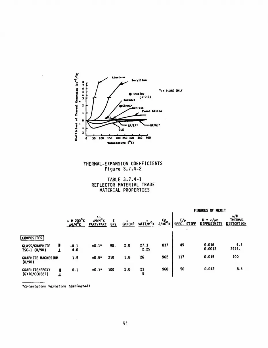
J.' F r,, ,,,-,.,̀'=<''r# I/,O,o=-.,,,
. i _md $111r.a
i.ll,,lll _)
THERMAL-EXPANSION COEFFICIENTS
Figure 3.7.4-2
TABLE 3.7.4-I
REFLECTOR MATERIAL TRADE
MATERIAL PROPERTIES
A o
a @2j_O°K _/M°K E p Ki_._'K PART/PART GPa GMICM3 _TT/M°K
|COMPOSITES|
GLASS/GRAPHITE | -0.1TSC-! (0/90) 1 4.0
GRAPHITE NAGNESILIM 1.5(o/9o)
GRAPtlITE/EPOXY II 0.1(GY70/CODE87) ..L
*0.1* 90. 2.0
±O.S* 210 1.8
±O.l* lO0 2.0
"O_in_at'_on Va_i.ation (Eee{..,_id)
27.32.25
26
238
Cp
837
962
960
FIGURESOF MERIT
a/OE/p D - _Ipc THERMAL
SPEC. STIFF DIFFUSIVITY DISTORTIONI
45 0.015 6.20.0013 2976.
117 0.015 lOO
50 0.012 8.4
9'I

An additional issue is imposed on a coherently phased segmented mirror. A
mismatch between radii of the segments and the design radius of the overall
mirror (4R/R), will also result in a wave front error. The system (4R/R)requirement establishes the maximum allowable CTE variability. For coherent
phasing at wavelengths longer than 30 micrometers, the radii of the segments
must be matched to 50 PPM (Note: established by wave front budgeting alloca-
tion in the study). Shown in Figure 3.7.4-3 is the allowable CTE variabilityas a function of wavelength.
From this graph, three choices are possible using grahite epoxy: (I) lower
the CTE variability of the material, (2) utilize smaller panels, or (3)operate at longer wavelengths. The intent in this technology program is tolower the CTE variability of the material.
O.IB 0.1.
0.018
o
0.0018
mBEST" GRAPHITE EPOXY
"BEST" FUSED QUARTZ
ALLOWABLE FROM BUDGET
0.00018 O. 0001
20 40 60 80 100 120 140 160 180
XMi N (Iq I CROIqETERS)
200 220
SELECTION OF PRIMARY MIRROR SUBSTRATE MATERIAL
(300°K-_--,-200°K)Figure 3.7.4-3
3.7.4.2 Required Technology Maturity Level - In 1989, a decision should bemade to proceed with one of two segmented mirror concepts. The first concept
is a passive segmented mirror (piston, tilt actuation only). The second
concept is an active segmented mirror (piston, tilt and figure control). A
composite material is a major candidate for implementation of a passive seg-mented mirror. Consequently, the LDR technology program has been configured
to establish the technology to OAST Level 5 (component/breadboard tested) by
1989.
92

3.7.4.3 On-goin9 Technolog#, Developments and Estimation of Where the Technology'Will Be in 1991 - Graphite fiber composites with polymer resins or metal matrix can
be designed to provide the zero CTE characteristic. The graphite compositematerials consist of continuous graphite fibers embedded in a thermosetting polymer
matrix, such as 934 epoxy resin. The composite is made in laminated form by the
successive layup of preimpregnated unidirectional tape. Near zero thermal expansion
behavior is obtained by proper balance of the negative expansion of the fibers and
the positive expansion resin. The use of metal matrix materials for orbiting
optical structures that require very stringent dimensional tolerances is within the
practical reach of technology. Thin layer unidirectional graphite/aluminum and
graphite/magnesium laminates, as well as unidirectional pultruded structural membershave been used in several space applications. The ultimate goal in this category is
to obtain thin multilayer laminates with desired layup angles similar to the
practice used for the graphite epoxy structures.
Due to the layup approach an anisotropic CTE and a relatively large CTE variabilityexists. It is the intent in this LDR technology program to address these two
material properties. No other programs to develop
composite materials with these requirements have been identified.
3.7.4.4 Technolo_y Shortfall and Augmentation Plan - The mirror designmust not only be rugged, low risk, and reliable, but also capable of surviving a
launch environment and enduring in space for many years. A design approach which
meets performance requirements at 200°K employing passive mirrors (without figurecontrol actuators, sensors and electronics) made from a composite material offers
significant advantage in weight, performance, and reliability. Composites offer a
high payoff in producibility. If a composite material could be found that issufficiently homogenous, molding or replication of the off-axis mirror segmentsbecome attractive alternatives to conventional processing (polishing).
The LDR augmentation recommended is: (1) develop a composite material that meets
CTE goal of O +0.03 x 10⁻⁶ per °K and low CTE variability and (2) fabricate and test
a composite su_scale proof-of-concept mirror.
The technology plan involves the following activities:
e 1986 - Material development ($250K)
• 1987 - Fabricate and test sample elements ($200K)
• 1988 - Design, fabricate and test proof of conceptsubscale mirror segment ($300K)
3.7.5 Off-Axis Mirror Segment Processing
Many mirror segments must be produced for the LDR primary mirror. For the 20 meterdiameter case there are approximately fifty 2.8 meter segments. In addition, these
segments are off-axis sections of a parabolic asphere with an extremely large
asphericity (departure from best fit sphere). Figure 3.7.5-1 represents an overview
of the technology program required to assure appropriate schedule readiness for an
LDR system development initiation.
93

KEY ISSUE
the primary mirror segments (off*axis parabolic segments)
have an extremely large asphertctty (departure from bestfit sphere)
OBJECTIVES
e Develop LOR primary mirror processing approach.
• Emphasize appro4ches that mtnimtze polishing step andmaximize grinding step. (for Imaging mode)
• Investigate alternative processing approaches to meetspecu]arity requirement (for light bucket mode)
-J
crL,J
Q_
TECHNOLOGY ASSESSMENT
NO other program tdent$fied wtth the same performance
r_qutrements (surface quality, specularlty, and wave-length range). Current techniques demonstrated in DARPA
and tn industry IR&D programs emphasize polishing step---schedule and cost implications. These latter approachesshould be available by 1991.
GOAL: LEVEL S BY 199]
4.
3
2-
1"
• 1 | A i | l !
R5 86 q7 P_q Rq 9_ 91
RATIONALE
The technology of contour generation has improved in thelast few years. This reduces the amount of fomal
polishing required and in some cases this later stepcould be eliminated completely. (i.e., only a "shine-to-remove" the gray would be required after contour
generation to meet the specularity requirement)
SCHEDULE ANO BUDGETARY PLAN FOR AUGMENTATION
Two year $600K program to reach goal by October 1990
t_J-J
_J
6
5
4
3
2-
]-
R5 P_
10/90
s2_r-_ _ _COALI .leeoR
TEST
I _OCESSlNCI OEIq)NSTRAT I ON
IO_ESSI NG PLAN
1 I I i J
87 88 89 90 91
CALENDAR YEAR
CATEGORY G: OPTICS MATERIALS AND FABRICATION
OFF-AXIS MIRROR SEGMENT PROCESSING
Figure 3.7.5-1
3.7.5.1 Requirements Derived from Concepts - The inability to manufacture an
optical surface to perfectly match the designed surface results in degradation of
performance (wave front error and scatter) of an imaging system. These surface
deviations result in low spatial frequency figure error (global), medium spatial
frequency error of surface ripple or quilting (core print-through) and high spatial
frequency error surface roughness. An additional issue is imposed on a coherently
phased segmented mirror. A mismatch between radii of the segments and the designradius of the overall mirror will also result in a wavefront error. The
requirements as established by the study are summarized in Table 3.7.5-i.
94

TABLE 3.7.5-1
LDR DERIVED PERFORMANCE REQUIREMENTS
(To Iqeet Diffraction Ltmlted anO Light Bucket Requirements Simultaneously)
LOW MID HIGH
SPATIAL FREq. SPATIAL FREq. SPATIAL FREq. RADIUS MISMATCH
(RRS Surface Error, _) (Autocorrelation Length/Pupll Oia.) (RMS Surface Roughness, _) (PPN)
0.5 0.125 _50 SO
3.7.5.2 Required Technolo_y Maturit_ Level - Shown in Figure 3.7.5-2 are two
alternatives to processing the LDR primary mirror segments. The first approach isthe traditional Kodak method for manufacturing an aspheric mirror. This is a three
step process: shaping, contour generation and figuring. The second approach
eliminates the need for formal polishing. In this concept the contour generation
step is extended past the traditional hand-off point of one micrometer to as close
to the final desired asphere as possible. This maximizes the major material removal
step (contour generation) and minimizes the polishing step. A demonstration has
been configured at OAST Level 5 (component/breadboard tested) to be completed by1990.
H F--0GENERATION ;" THE GRAY" WITH FLEXIBLE
t LAPS
CONTACT
SPHERO_TRY I i CONTACTPROFI LOMETRY i
CONTOUR
GENERAT ION I
I CONTACT CONTACTPROF ILO_IETRY I
HENE VISIBLEI NTERFEROMETRY
_ "SHINE-TO-REMOVETHE GRAY"
ACCEPTNICE TEST IHENE VISIBLE
INTERFEROIVtETRY
ACCEPTANCE TEST 1HENE VISIBLE
INTERFEROfI_TRY
LDR PRIMARY MIRROR SEGMENT MANUFACTURE ALTERNATIVES
Figure 3.7.5-2
95

3.7 5.3 On-Going Technoloi_v Developments and Estimation of Where the Technolo_yWili Be in 1991 - The current manufacture of an aspheric mirror is performed in a
three-step process: shaping, contour generation, and figuring. In the shaping stepa nominal sphere is generated onto the surface with a rough grinder. The goal is to
leave the minimum of material to be removed in the following two steps. Loose
abrasive grinding on a "tub grinder" in step two brings the contour to the desired
aspheric shape and radius. A "shine-to-remove the gray" is performed to reduce the
surface roughness and maximize fringe contrast. In the third step, the figure
errors a_e divided into symmetrical and asymmetrical components. Full aperturetools are made to correct each component. These large tools minimize the mid to
high spatial frequency error (ripple). The large aperture tooling approachdeveloped by Kodak minimizes the mirror processing time (amount of time the tool is
actually on the mirror). This allows parallel processing of mirror segments, thusreducing the need for a large number of mirrors. The technology of contour
generation has improved in the last few years. This reduces the amount of formal
polishing required and, in some cases this later step could be eliminated
completely. (i.e., only a "shine-to-remove the gray" would be required after
contour generation to meet the secularity requirement).
Current techniques demonstrated in DARPA and in industry IR&D programs emphasize thepolishing step. Use of this traditional approach has schedule and cost implications
for LDR. The newer precision contour generation approach is available now and
should be directly applicable to the LDR segments. However, no other programs have
been identified with the same performance requirements (surface quality,
specularity, and wavelength range).
3.7.5.4 Technolo_ Shortfall and Augmentation Plan If the contour generation step(grinding) could reach the desired asphere, no forma_ polishing step would be
required. The segment would require only a "shine to remove the gray" to meet the
specularity requirement. Kodak has investigated and built a "proof-of-concept"
contour generator under IR&D. It has been used to successfully generate large
optics to tolerances similar to those of LDR. The LDR augmentation plan is to
investigate precision contour generation for the LDR segments. The plan involves
the following activities:
• 1988 - Establish mirror processing plan ($50K)
• 1989 - Processing demonstration ($350K)
• 1990 - Mirror segment test ($200K)
3.8 OTHER (OAST CATEGORY H)
The two items in this category identify potential technology developments in
transportation systems based on perceived LDR requirements. Assessments are notincluded.
96

3.8.1 ACC Contamination Protection/Remote Maneuvering Arm
Concept 3 assumes the use of the proposed Shuttle Orbiter/Aft Cargo Carriertransportation-to-orbit capability. Should this mode be developed, its application
for carrying LDR to orbit and serving as a platform for assembly must be reviewed
with respect to LDR contamination concerns and deployment concepts, in particular,
and compatibility with LDR in general. Because of the location of Shuttle Reaction
Control System nozzles with respect to the ACC, there may be a need to provide
special contamination control packaging of the primary segments that are stored inand later removed from the ACC on orbit. In addition, to handle the primary mirror
segments, a new remote maneuvering system, longer than the current arm on the
Shuttle, would be required to reach to the ACC.
3.8.2 Shuttle Ba_ Contamination Protection
The sensitivity of LDR performance to contamination requires attention to protectivemeasures throughout all phases of ground activities, launch, assembly on-orbit, and
revisits.
The launch environment within the Shuttle bay may require the utilization of special
protective control methods for LDR optical elements during ascent venting.
4.0 SUMMARY
The Kodak MDAC-FSC study team has identified 22 technology augmentation needs for
LDR. These needs are judged to be beneficial to support an LDR schedule requiring
technology readiness by year-end 1991.
Of these needs, five are considered of primary importance based on unique LDR
requirements, lack of viable alternatives, high potential payoff, or anticipated
long term developments. The 17 other needs rated medium are considered important
and their implementation is recommended.
A plan that integrates the 22 individual technology augmentation needs into three
fundamental issue groups has been created. The groups are:
• Reflector Quality Program
• Pointing and Stability Program
• Detectability Program
These program plans are enclosed as foldouts at the end of this volume.
97

4.1 TECHNOLOGY TASKS IN PRIORITY ORDER
OAST CATEGORY
B
D
E
G
G
A
A
A
A
B
B
B
B
B
B
B
B
B
E
E
G
G
A
C
C
H
H
TECHNOLOGY
HIGH - 5
DYNAMIC STRUCTURAL CONTROL
HUMAN FACTORS
HYBRID CRYOGENIC SYSTEM FOR SCIENCE INSTRUMENTS
ACTIVE PRIMARY MIRROR
PRIMARY MIRROR CONTAMINATION PROTECTION
MEDIUM - 17
PRIMARY MIRROR SEGMENT SENSING AND CONTROL APPROACH
FOLD MIRROR CHOPPING
SECONDARY MIRROR CHOPPING
FINE GUIDANCE SENSING AND CONTROL
DYNAMIC DIMENSIONAL STABILITY
DYNAMIC RESPONSE PREDICTION PRECISION
STRUCTURAL NONLINEARITY
LOW JILTER AND RAPID SETTLING
VERIFICATION/ACCEPTANCE GROUND TESTING
MECHANICAL STABILITY - DAMAGE TOLERANCE
STEP SUNSHIELD
SECONDARY MIRROR TEMPERATURE CONTROL
PRIMARY MIRROR TEMPERATURE CONTROL
CRYOGENIC SYSTEMS FOR DETECTOR TEMPERATURES LESS THAN 0.3°K
ROBOTIC ON-ORBIT CRYOGENIC REPLENISHMENT
GLASS MATERIAL FOR THE PRIMARY MIRROR
COMPOSITE MATERIAL FOR THE PRIMARY MIRROR
LOW - 4
SECONDARY MIRROR SENSING AND CONTROL APPROACH
COLLAPSIBLE SUNSHIELD
SPACECRAFT BUILDUP ON ORBIT
OFF-AXIS MIRROR SEGMENT PROCESSING
NOT RATED - 5
NOISE REDUCTION IN CONTROL MOMENT GYROS
STRUCTURAL DYNAMICS: ADVANCED POWER SYSTEM
MONOPROPELLANT REFUELING
ACC CONTAMINATION PROTECTION/REMOTE MANEUVERING ARM
SHUTTLE BAY CONTAMINATION PROTECTION
98

4.2 TASK MILESTONES
Milestones of tasks are included in each of the individual development planschedules in Section 3.0.
Some milestones are also indicated on the foldouts of the three integrated plans atthe end of this volume.
4.3 BUDGET MILESTONES
Budget milestones are indicated on each of the individual development plan schedulesin Section 3.0
A time-phased budget summary of the three Kodak technology programs and their
constituent projects is shown in Table 4.3-1.
99
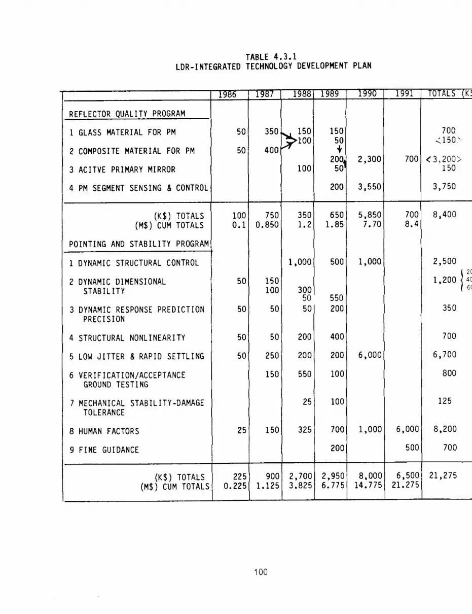
TABLE 4.3.1
LDR-INTEGRATED TECHNOLOGY DEVELOPMENT PLAN
1986
REFLECTOR QUALITY PROGRAM
1 GLASS MATERIAL FOR PM
2 COMPOSITE MATERIAL FOR PM
3 ACITVE PRIMARY MIRROR
4 PM SEGMENT SENSING & CONTROL
(KS) TOTALS
5O
5O
I00
1987 1988
350
400
750
150!
100
100
350
1989
150
50
i,200
50
200
65O
1990
2,300
3,550
5,850
1991
7OO
7OO
TOTALS (K
700
<150".
<3,200>150
3,750
8,400
(MS) CUM TOTALS
POINTING AND STABILITY PROGRAM
1 DYNAMIC STRUCTURAL CONTROL
2 DYNAMIC DIMENSIONAL
STABILITY
3 DYNAMIC RESPONSE PREDICTION
PRECISION
4 STRUCTURAL NONLINEARITY
5 LOW JITTER & RAPID SETTLING
6 VERIFICATION/ACCEPTANCEGROUND TESTING
7 MECHANICAL STABILITY-DAMAGE
TOLERANCE
8 HUMAN FACTORS
9 FINE GUIDANCE
(KS) TOTALS
(MS) CUM TOTALS
0.1
50
50
5O
5O
25
O.850
150
IO0
50
5O
25O
150
150
1.2
1,000
3OO5O
5O
20O
200
55O
25
325
1.851
5OO
55O
200
400
200
I00
100
700
200
7.70
1,000
6,000
1,000
8.4
6,000
500
225
0.225900 2,700
1.125 3.8252,9506.775
8,000 _14.775
2,500
1,200 4c6<
350
700
6,700
8OO
125
8,200
700
6,5001 21,27521.275
100

TABLE 4.3.1
LDR-INTEGRATED TECHNOLOGY DEVELOPMENT PLAN
(CONTINUED)
DETECTABILITY PROGRAM
1 HYBRID CRYOGENIC SYSTEM
FOR SCIENCE INSTRUMENTS
2 CRYOGENIC SYSTEM FORDETECTORS LESS THAN O.3°K
HELIUM DILUTION
ADIABATIC DEMAG.
3 STEP SUNSHIELD
4 PM TEMPERATURE CONTROL
5 SM TEMPERATURE CONTROL
6 SM CHOPPING
7 FOLD MIRROR CHOPPING
8 PM CONTAMINATION PROTECTION
9 ROBOTIC ON-ORBIT CRYOGENIC
REPLENISHMENT
(KS) TOTALS
(MS) CUM TOTALS
(KS) GRAND TOTAL _
(MS) CUM TOTAL
1986
100
100
i00
150
450
0.450
775
0.775
1987
9OO
1,000
900
600
3,4003.850
5,0505.825
1988 1989
1,000
500 3,000
900
500 2,000
1,500 1,500
100
200
200
50 50
100
50 50
200
1,200 3,300
5,700 10,7009.550 20.250
8,750 14,30014.575 28.875
1990
1,500
1,000
1,500
1,000500
200
500
500
8OO
400
4,500!
12,400
32.650
26,25055.125
1991
4,000
1,000
500
700
400
1,500
I
8,10040.750
TOTALS (KS)
12,0001
2C'SC
500C
5000
20007,000 5o0c
6,000{ ,_oo:2000
I,000
700
700
ioo{900 _1oe
100
1,000
11,250
15,300
70.4251
40,750
70,425
101

FOLDOUT FRAME /"REFLECTOR OUi
($8,4G..-
CALENDAR
86TURN-ON
]0/86
87 88INTERIM
OES IGNREVIEW
OAST CATEGORY G
MATERIAL DEVELOPMENT PROGRAM
IGLASS MATERIAL FOR THE PRIMARY MIRROR I
FORMULATE SAMPLES HFAB& TEST I _,OF MATERIAL & FRIT SAMPLES$200K $200K
SELECT
OAST CATEGORY G
ICOMPOSITE MATERIAL FOR THE PRIMARY MIRROR I
IFORMULATE SAMPLES L...IFAB & TEST !OF MATERIAL & FRITI ISAMPLES I
8250K $200K
OAST CATEGORY G
IACTIVE PRIMARY MIRROR I
OAST CATEGORY A
PRIMARY MIRROR SEGMENT SENSING & CONTROL I
i
MIRROR DES
DESIGN AND T__FABRICATION
$I00K $_
CONCEPTUAL DESIGN Ol
A PASSIVE SEGMENTED
MIRROR (TILT AND
PISTON ONLY)$15_
SEL
CONCEPTUAL DESIGN O,
A ACTIVE SEGMENTED
MIRROR (TILT, PISTON&FIGURE)
$150'

_LI TY PROGRAM
-',000)
FOLDOUT FRAME
YEAR
89PRELIMINARY
DESIGN
REVIEW
CRITICAL
DESIGN
REVIEW
90 91
IGN PROGRAM
#.%
ECT
K
SEGMENTED MIRROR DEMONSTRATION
DETAILED DESIGNIIFABRICATION & SSSEMBLYIIOPTICAL TEST OF COHERENT I
OF A SEGMENTED _-_OF TWO OUTER SEGMENTS I-_PHASING BETWEEN IMIRROR I IAND A 'STABLE'TEST ITWO SEGMENTS (ON-GROUND) I
m2OOKISUPPORT STRUCTURE $700K
$2.3M 'CAN MIRROR BE PHASEDON A STABLE PLATFORM?'
DESIGN OF SENSING &L_FABRICATION ASSEMBLY I
CONTROL SUBSYSTEM_J l& TEST OF ACTUATORS I_"OOK IAND SENSORS l
_3.55M
103

_--¢i
-_1
o
J 0 Z C)
m in
o I"I1
m f') -4 O z -[7
r-u
_ m V_
O Z
o ¢'i
m -<
m _c m- T p
_
_m
°
-Z_
n).
,z
E"_
m|
m_
i-q
--.t
crq
u .-<
Z Z_
C)
0 P'I
Z 0 Z r-"
--I
03 r- .-.i
-< J
[-)
0 m
m Z m c 0 Z C)
m tnm Z Z -.
4
r-
m O .,< Z f') ,,..4
f- -.4C r"
O Z ml
='4
rl -i
_z
"4
o
J_ [_1 gl f')
!
_z
_D O
I__
o_
_o_'_
_m_z_
io_'m_'O_
im_
Iz_
m_
_z
_'_
=
_o
._-I
m
0-I
_
tO
./
O z --4
I-,,-
4
z
.,403
O _-,
-4
--<
"13
_0
0 _0

zoI
t_
•.4f'_
|
Ir._
"UI
O_¢')I
m l'rl
-r
Z r-- i
O m O.i'-
m¸
Z m
m
m "11
m
o Z_D
111
Z m _-_
0 r-Z 0 .-j
m -4 Z
i
._m
i
,-re mr,I
m,,-
i _,_
Io
-I
I
_t_,
'-4
1
--T-'
m I--
O f -4--I
m Z "v
m .-i
.-I
r-
T 8 m r-
u_
m -I- -F
_D
O r m.w
m -4 -F
pP0
m -4m
mP "-r-
i--I
ii-
_W_
lnoo
lo-_

.
FOU)OUT FRAME
DETECTABILIT_
($40,750,C
CALENDAR
86 TURN-ON 8_
0/86
88INTERIM
ESIGN
EVIEW
OAST CATEGORY E
I HYBRID CRYOGENIC SYSTEMFOR SCIENCE INSTRUMENTS
DESIGN PUMP.TANKAGE, INSULATION/MOUNTINGS, HEAT REJECTION I-
$2M
OAST CATEGORY E
ICRYO SYSTEM FOR DETECTORS ILESS THAN 0.3"K$2M
13HE__HE DILUT]0NDESIGN,ANALYZE,FAB. AND TEST i____r _BRASSBOARD PROVE ZERO-D DPERATIO 4 -IEI
ADIABATIC DEMAGNETIZATION REFRIGERATDRIDESIGN. FAB.,ASSEMBLE SP,
OAST CATEGORY B
I STEP SUNSHIELD ]
OAST CATEGORY B
I PM TEMPERATURE CONTROL I
OAST CATEGORY B
I SM TEMPERATURE CONTROL I
0AST CATEGORY A
I SM CHOPPING I
0ASI CATEGORY A
IFOLD MIRROR CHOPPING I
OAST CATEGORY G
IPMCONTAMINATION PROTECTIONI
I CON(EPTUAL DESIGN OF A I
SECONDARY MIRROR ZNCORPOR- I
ATING BOTH RIGID BODY |__
MOTION CAPACAPABILITY AND|_ I
CHOPPING CAPABIL]IY I_ I
$]OOK_I ....
I CONCEPTU'L DESIGN Dr A FOLD l_lI _IRROR II_ORPOR,TING BOTH L_
IINCREMENTAL POSITIONING CAPABIL- /
I ITY & CHOPPING CAPABILITY /
$IOOK
OAST CATEGORY E
ROBOTIC ON-ORBITCRYOGENIC REPLENISHMENT
CONCEPTS STUDY
$750K
FAB CRITICAL
ITEMS. TEST I IBRA.'$1SOOK
/oG,

PROGRAM
00)
FOLDOUT FRAME
89RELIMINARY
DESICNREVIEW
9O
A
t 0ES'0N'"SS''LE' TESTE"O''EER'N0H$5M
$4M3N, F]LE,& ASSEMBLE COMPATIBLE [;INEERINO MODEL & SPACE TEST I
ICE COMPATIBLE ENGINEERING
DETAILED DESIGN OF
STEP SUNSHIELO
$100K
TAILED DESIGN OF PM
EMP CONTROL CONCEPT
$200K
:TAILED DESIGN OF S_
EMP CONTROL CONCEPT
$200K
DETAILED DESIGN OF
MIRROR ASSEMBLY
(MIRROR W/ CONTROLS)
$100_
EVALUATE ALTERNATIVE
PROTECTION CONCEPTS
$200_
91
ENGINEERING MODEL TEST
(IN-SPACE)
$1M
t SPACE TEST J__
MODEL & SPACE TEST H SPACE TEST I
$5M $1M
_ENGI_ERI_ MOOELYES,IFAB & ASSEMBLE
$200K
PM TEMP CONTROL DEMONSTRAT]ON _ IP'HUOI- OF CONL:_P] DEMO OF j
MAINTA]NANCE OF 200" t I'K L ....{POSSIBLY UTILIZE SUBSCALE MIRROR l
SEGMENT FROM MIRROR DESIGN PROGRAM|$500K
I
SM TEMP CONTROL DEMO $500K J
BRASS BOARD DEMO OF I ..............
L
MAINTAIN_NCE OF TEMPAND AL] GNIdENT
$SOOK'IS PASSIVE OR ACTIVE ALIGNMENT
MAINTA ] NANCE REOU] RED?m
_poF'P 1NO DEMONSTRATION
| BRASS BOARD DEMO OF CHOPPING _ ........
..... ._ WITH RIGID BODY MOTION CONTROL FOR |
|ALIGNMENT OR INCREMENTAL POSIIIONING |
$800K
--t
PM PROTECTION DEMO
J PROOF OF CONCEPT TEST|DEVELOP A'N^'PT " IUTIL1ZING 2 SEGMENTS OR.... P-1 /i,ll AMP SEGMENTED MIRROR DEMOON S LL S LES
$4OOK STUDY CONCEPT#/ STRIPPABLE COAT]NO/
$400K
• CAN ]HE MIRROR SEC4AENYbREMAIN COHERENTLYPH_._IED
AFYER REMOVALOF 1HE COATING?"
UNDERWATER TEST PROGRAM
AB._ TEST I.... ] DESIGN, FAR. L TEST t_BOARD _ PRE-FLIGHT ARTICLE
$3.0M $6.0M107

1 Report No. 2, Government AccRsion No.
NASA CR- 1774134, T_tle and Subtitle
Large Deployable Reflector (LDR) System Concept
and Technology Definition Study volume zz -Technoloqy Assessment and Development Plan
7. Author(sl
D. L. Agnew and P. A. Jones
9, _f_ming Orpni_tiom Name and Addrm
Eastman Kodak CompanyGovernment Systems DivisionResearch and EngineerinqRochester_ New York 14650
_12 Spo_ing _lencv Name and Address
National Aeronautics and Space AdministrationWashington, DC 20546
3. Recipient's Catalog No.
5. Regort Date
April 1989
6. Performing Orpnizati_ Code
=
8. Performing Orpnizlltion Re!l:X)rt No.
10. Work U.it No,
506-62-21
11. Co.trlct or Grant No.
NAS2-1186113. Type of Reporl and Pro'tad Covered
Contractor Report
14. Spont, qrir'_ Agency Cod, e
15. _D_e_mtary Notes
Point of Contact: Technical Monitor, Kenji Nishioka, Code SSS, MS 244-8Ames Research Center; Moffett Field, CA 94035(415) 694-6540 or FTS 464-6540
16 Abstract
A study was conducted to define reasonable and representative LDR systemconcepts for the purpose of defining a technology development program aimedat providing the requisite technological capability necessary to start LDRdevelopment by the end of 1991. This Volume II presents thirteen technologyassessments and technology development plans, as well as an overview andsummary of the LDR concepts. Twenty-two proposed augmentation projects aredescribed (selected from more than 30 candidates). The five LDR technologyareas most in need of supplementary support are: cryogenic cooling;astronaut assembly of the optically precise LDR in space; active segmentedprimary mirror; dynamic structural control; and primary mirror contaminationcontrol. Three broad, time-phased, five-year programs were synthesized fromthe 22 projects, scheduled, and funding requirements estimated. Volume I(separate) contains the executive summary for the total study and a reportof the systems analyses/trade studies.
17. Key Wor_ (Suggest_ by Author(s))
Large Deployable Reflector (LDR),Observatory, Spaceborne Telescope,Infrared Astronomy, SubmillimeterAstronomy
18. Oilltribution Statement
Unclassified - Unlimited
Subject Category: 12
19 S¢'curitv C_assif (of this report)
Unclassified
20. Security Clasaif, (of this I:mge)
Unclassified
21. No. of P_ies 22 Price"
119 A06
"For sale by the National Technical Information Service, SDringfield, Virginia 22161
PRECEt')'NG P_G;; Rt _:.!k" i'_JO7 _'t' ',_:--",",


