Embed Size (px)
Citation preview
Innovative Methodology
Multichannel Micromanipulator and Chamber System for RecordingMultineuronal Activity in Alert, Non-Human Primates
Charles M. Gray, Baldwin Goodell, and Alex LearCenter for Computational Biology, Department of Cell Biology and Neuroscience, Montana State University, Bozeman, Montana
Submitted 7 March 2007; accepted in final form 5 May 2007
Gray CM, Goodell B, Lear A. Multichannel micromanipulator andchamber system for recording multineuronal activity in alert, non-humanprimates. J Neurophysiol 98: 527–536, 2007. First published May 9, 2007doi:10.1152/jn.00259.2007. We describe the design and performance ofan electromechanical system for conducting multineuron recording ex-periments in alert non-human primates. The system is based on a simpledesign, consisting of a microdrive, control electronics, software, and aunique type of recording chamber. The microdrive consists of an alumi-num frame, a set of eight linear actuators driven by computer-controlledminiature stepping motors, and two printed circuit boards (PCBs) thatprovide connectivity to the electrodes and the control electronics. Thecontrol circuitry is structured around an Atmel RISC-based microcon-troller, which sends commands to as many as eight motor control cards,each capable of controlling eight motors. The microcontroller is pro-grammed in C and uses serial communication to interface with a hostcomputer. The graphical user interface for sending commands is writtenin C and runs on a conventional personal computer. The recordingchamber is low in profile, mounts within a circular craniotomy, andincorporates a removable internal sleeve. A replaceable Sylastic mem-brane can be stretched across the bottom opening of the sleeve to providea watertight seal between the cranial cavity and the external environment.This greatly reduces the susceptibility to infection, nearly eliminates theneed for routine cleaning, and permits repeated introduction of electrodesinto the brain at the same sites while maintaining the watertight seal. Thesystem is reliable, easy to use, and has several advantages over othercommercially available systems with similar capabilities.
I N T R O D U C T I O N
A widely used technique for monitoring neuronal activity inawake-behaving monkeys is to implant a recording chamberover a craniotomy in the skull and advance electrodes into thebrain each day using a microdrive that mounts onto the cham-ber. The electrodes are typically advanced through the duralmembrane or, when deep structures are accessed, they areprotected by guide tubes that are advanced into the brain(Asaad et al. 2000; Baker et al. 1999; Cham et al. 2005; Milleret al. 1996; Mountcastle et al. 1991; Prut et al. 1998). Thiscommonly used set of techniques suffers from at least twotypes of problems: one is related to the type of recordingchambers in common usage, and a second is associated withthe manipulation of electrodes.
A fundamental difficulty with commonly used recordingchambers is that they are not hermetically sealed. This leads toa high incidence of infections within the chamber, therebyrisking the health of the animal and increasing the need fordaily cleaning. A second problem is that the dural membrane istough, grows vigorously when exposed, and can dimple sub-stantially when passing multiple microelectrodes. To alleviate
this problem, the dura must be repeatedly “thinned” to avoidelectrode damage (Spinks et al. 2003) and excessive dimpling.This procedure risks further infection, is time consuming, andis stressful to the animal. Finally, daily implantation of one ormore guide tubes through the dura can result in significantdamage, potentially cause the animal pain, or further increasethe possibility of infection.
The principal problems with currently available microma-nipulators are that they are usually limited to one or a fewelectrodes, and they often employ bulky and/or manual mech-anisms for controlling electrode movement, can be difficult toelectrically shield, or are quite expensive, putting them beyondthe resources of many laboratories (Mountcastle et al. 1991;Reitboeck and Werner 1983). These problems are exacerbatedif the experimental questions require monitoring of neuronalactivity from more than one region of the brain.
Here we describe the design and performance of a new typeof recording chamber and micromanipulator system that cansolve or reduce these problems and increase the feasibility formultineuron recording from one or more regions of the brainsimultaneously. The chamber system is small, is low in profile,and provides a semi-chronic window onto the brain through theuse of a watertight, replaceable Sylastic membrane (Arieli et al.2002). The membrane is self-sealing, prevents infection andallows multiple electrodes to be easily and repeatedly intro-duced. The micromanipulator allows the remote control ofeight independently moveable microelectrodes, is wellshielded and easy to setup and use, and is comparably inex-pensive. The control electronics can operate up to eight micro-manipulators at a time, making it feasible to monitor neuronalactivity from multiple regions of the brain simultaneously.
M E T H O D S
All mechanical design work was performed using SolidWorks, acomputer aided design package (SolidWorks). Electrical circuit de-sign and the layout of printed circuit boards were performed using theOrCAD Capture and OrCAD Layout software packages, respectively(Cadence).
Chamber system
The chamber system, shown in Fig. 1, was designed with twoobjectives in mind. First and foremost, we wanted the intracranialspace to be hermetically sealed off from the external environment.This would serve to reduce the chances of infection and help reestab-lish the normal balance of intracranial pressure. The barrier formaintaining the seal had to permit the passage of microelectrodeswithout disrupting the seal or damaging the electrodes and ideally
Address for reprint requests and other correspondence: C. M. Gray, Centerfor Computational Biology, 1 Lewis Hall, Montana State University, Boze-man, MT 59717 (E-mail: [email protected]).
The costs of publication of this article were defrayed in part by the paymentof page charges. The article must therefore be hereby marked “advertisement”in accordance with 18 U.S.C. Section 1734 solely to indicate this fact.
J Neurophysiol 98: 527–536, 2007.First published May 9, 2007; doi:10.1152/jn.00259.2007.
5270022-3077/07 $8.00 Copyright © 2007 The American Physiological Societywww.jn.org
would lie in direct contact with the surface of the dura. To satisfy bothconstraints, we chose to use a thin membrane of Sylastic (Dow-Corning, No. 7–4107) that had been successfully employed in opticalimaging experiments in non-human primates (Arieli et al. 2002).While allowing easy passage of the electrodes, the membrane’s abilityto reseal is limited to a relatively small number of electrode penetra-tions (5–10 at a single site). It therefore became necessary to make themembrane replaceable after its seal becomes compromised. Oursecond objective was to keep the diameter and height of the chambersmall, so that multiple chambers could be implanted in a single animaland so that the dural or cortical surface of the brain could be easilyaccessed during simple surgical procedures.
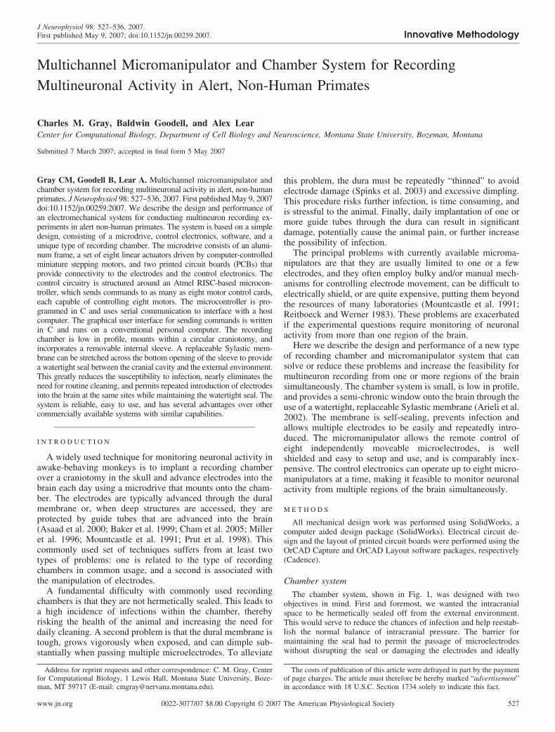
To accomplish these objectives, we designed the system to consistof five components. Design drawings of the system are shown in Fig.1A and a completed system is shown in Fig. 1C. The componentsinclude the chamber, a removable sleeve and retaining ring, a plug, acap, and an O-ring. The chamber, sleeve, and retaining ring areconstructed from Titanium (6AL/4V ELI), and the plug and cap areconstructed from Ultem plastic. The O-ring is made of silicone 70durometer red and is manufactured by Sterling Seals.
To bring the Sylastic membrane in contact with the dural surface,we first designed the chamber to have a lower extension of its wallthat would fit snugly within a circular craniotomy (Fig. 1B). The depthof the lower wall was set to 2 mm so that when implanted its bottomsurface would rest gently on the surface of the dura. Depending on thelocation of the implant, this often required some thinning of thecranial bone to ensure even thickness around the chamber. The sleevewas designed to thread into the chamber, and its vertical dimension
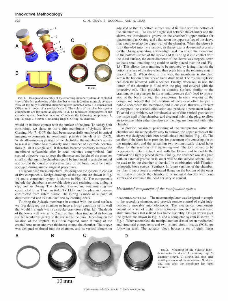
adjusted so that its bottom surface would lie flush with the bottom ofthe chamber wall. To ensure a tight seal between the chamber and thesleeve, we introduced a groove on the chamber’s upper surface forplacement of an O-ring, and a flange on the upper surface of the sleevethat would overlap the upper wall of the chamber. When the sleeve isfully threaded into the chamber, its flange exerts downward pressureon the O-ring generating a water-tight seal. To attach the membraneto the bottom surface of the sleeve and thus bring it into contact withthe dural surface, the outer diameter of the sleeve was stepped downso that a small retaining ring could be easily placed over the end (Fig.1A). This allows the membrane to be mounted by laying it across thebottom surface of the sleeve and then press fitting the retaining ring inplace (Fig. 2). When done in this way, the membrane is stretchedacross the bottom of the sleeve like a drum head. The residual Sylasticcan then be removed with a scalpel. Finally, when not in use, thelumen of the chamber is filled with the plug and covered with theprotective cap. This provides an abutting surface, similar to thecranium, so that changes in intracranial pressure don’t lead to protru-sion of the brain through the craniotomy. In early versions of thedesign, we noticed that the insertion of the sleeve often trapped abubble underneath the membrane, and in one case, this was sufficientto compress the cortical circulation and produce a permanent lesion.To avoid this problem, we introduced a set of four vertical grooves onthe inside wall of the chamber, and a central hole in the plug, to allowair to escape when either the sleeve or the plug are mounted within thechamber.
To provide consistent positioning of the manipulator within thechamber and make the sleeve easy to remove, the upper surface of thesleeve was designed with three small, closed-end holes (Fig. 1C). Thesmaller of the three holes provides for placement of a centering pin onthe manipulator, and the remaining two symmetrically placed holesallow for the insertion of a tightening tool. The tool proved to benecessary to obtain a tight seal with the O-ring and to enable theremoval of a tightly placed sleeve. Finally, the chamber was designedwith an external groove on its outer wall so that acrylic cement couldbe used to fix the chamber to the skull in combination with Titaniumorthopedic bone screws (Synthes). In future versions of the chamber,we plan to incorporate a perforated flange on the bottom of the outerwall that will enable the chamber to be mounted directly with bonescrews and eliminate the need for acrylic cement.
Mechanical components of the manipulator system
ASSEMBLED SYSTEM. The micromanipulator was designed to coupleto the recording chamber, and provide remote control of eight inde-pendently movable microelectrodes. The mechanical componentsconsist of a set of eight linear actuators mounted in a machinedaluminum block that is fixed to a frame assembly. Design drawings ofthe system are shown in Fig. 3, and a completed system is shown inFig. 4. When assembled, the manipulator consists of seven mechanicaland structural components and two printed circuit boards (PCB, seefollowing text). The actuator block houses a set of eight linear
FIG. 1. Design and assembly of the recording chamber system. A: explodedview of the design drawing of the chamber system in 2 orientations. B: cutawayview of the fully assembled chamber system mounted onto a 3-dimensional(3D) cranial model of a monkey’s skull. The colors of the chamber systemcomponents are the same as depicted in A. C: fabricated components of thechamber system. Numbers in A and C indicate the following components: 1,cap; 2, plug; 3, sleeve; 4, retaining ring; 5, O-ring; 6, chamber.
FIG. 2. Mounting of the Sylastic mem-brane onto the sleeve. A: retaining ring. B:chamber sleeve. C: sleeve and ring afterinitial placement of the membrane. D: sleeveand ring after the membrane has beentrimmed.
Innovative Methodology
528 C. M. GRAY, B. GOODELL, AND A. LEAR
J Neurophysiol • VOL 98 • JULY 2007 • www.jn.org
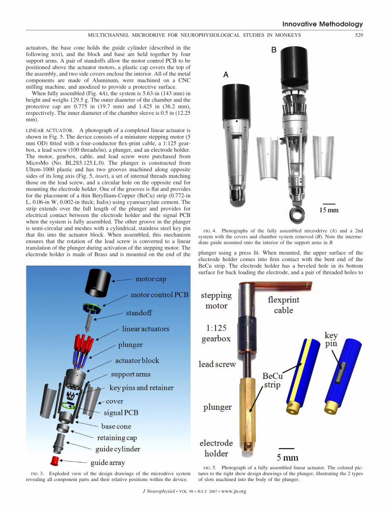
actuators, the base cone holds the guide cylinder (described in thefollowing text), and the block and base are held together by foursupport arms. A pair of standoffs allow the motor control PCB to bepositioned above the actuator motors, a plastic cap covers the top ofthe assembly, and two side covers enclose the interior. All of the metalcomponents are made of Aluminum, were machined on a CNCmilling machine, and anodized to provide a protective surface.
When fully assembled (Fig. 4A), the system is 5.63-in (143 mm) inheight and weighs 129.5 g. The outer diameter of the chamber and theprotective cap are 0.775 in (19.7 mm) and 1.425 in (36.2 mm),respectively. The inner diameter of the chamber sleeve is 0.5 in (12.25mm).
LINEAR ACTUATOR. A photograph of a completed linear actuator isshown in Fig. 5. The device consists of a miniature stepping motor (5mm OD) fitted with a four-conductor flex-print cable, a 1:125 gear-box, a lead screw (100 threads/in), a plunger, and an electrode holder.The motor, gearbox, cable, and lead screw were purchased fromMicroMo (No. BL2S5.125.L.0). The plunger is constructed fromUltem-1000 plastic and has two grooves machined along oppositesides of its long axis (Fig. 5, inset), a set of internal threads matchingthose on the lead screw, and a circular hole on the opposite end formounting the electrode holder. One of the grooves is flat and providesfor the placement of a thin Beryllium-Copper (BeCu) strip (0.772-inL, 0.06-in W, 0.002-in thick; Italix) using cyanoacrylate cement. Thestrip extends over the full length of the plunger and provides forelectrical contact between the electrode holder and the signal PCBwhen the system is fully assembled. The other groove in the plungeris semi-circular and meshes with a cylindrical, stainless steel key pinthat fits into the actuator block. When assembled, this mechanismensures that the rotation of the lead screw is converted to a lineartranslation of the plunger during activation of the stepping motor. Theelectrode holder is made of Brass and is mounted on the end of the plunger using a press fit. When mounted, the upper surface of the
electrode holder comes into firm contact with the bent end of theBeCu strip. The electrode holder has a beveled hole in its bottomsurface for back loading the electrode, and a pair of threaded holes to
FIG. 4. Photographs of the fully assembled microdrive (A) and a 2ndsystem with the covers and chamber system removed (B). Note the interme-diate guide mounted onto the interior of the support arms in B.
FIG. 5. Photograph of a fully assembled linear actuator. The colored pic-tures to the right show design drawings of the plunger, illustrating the 2 typesof slots machined into the body of the plunger.
FIG. 3. Exploded view of the design drawings of the microdrive systemrevealing all component parts and their relative positions within the device.
Innovative Methodology
529MULTICHANNEL MICRODRIVE FOR NEUROPHYSIOLOGICAL STUDIES IN MONKEYS
J Neurophysiol • VOL 98 • JULY 2007 • www.jn.org
mount opposing set screws (1/16 in, 0–80) that enable the electrodeto be held firmly in place. The bottom surface of both set screws areground flat to minimize shearing forces to the end of the electrode.
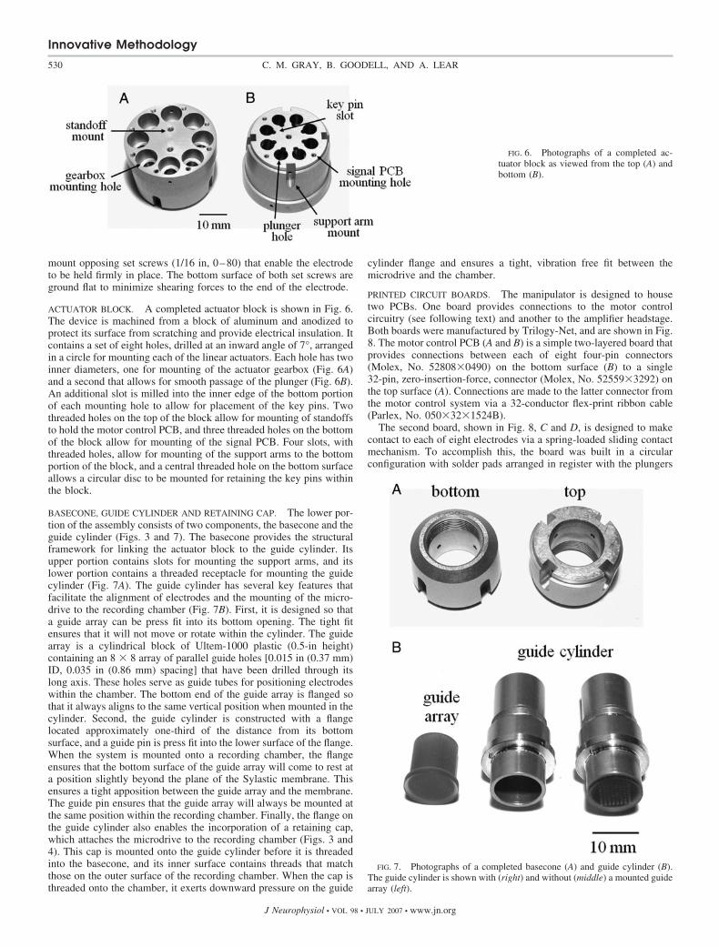
ACTUATOR BLOCK. A completed actuator block is shown in Fig. 6.The device is machined from a block of aluminum and anodized toprotect its surface from scratching and provide electrical insulation. Itcontains a set of eight holes, drilled at an inward angle of 7°, arrangedin a circle for mounting each of the linear actuators. Each hole has twoinner diameters, one for mounting of the actuator gearbox (Fig. 6A)and a second that allows for smooth passage of the plunger (Fig. 6B).An additional slot is milled into the inner edge of the bottom portionof each mounting hole to allow for placement of the key pins. Twothreaded holes on the top of the block allow for mounting of standoffsto hold the motor control PCB, and three threaded holes on the bottomof the block allow for mounting of the signal PCB. Four slots, withthreaded holes, allow for mounting of the support arms to the bottomportion of the block, and a central threaded hole on the bottom surfaceallows a circular disc to be mounted for retaining the key pins withinthe block.
BASECONE, GUIDE CYLINDER AND RETAINING CAP. The lower por-tion of the assembly consists of two components, the basecone and theguide cylinder (Figs. 3 and 7). The basecone provides the structuralframework for linking the actuator block to the guide cylinder. Itsupper portion contains slots for mounting the support arms, and itslower portion contains a threaded receptacle for mounting the guidecylinder (Fig. 7A). The guide cylinder has several key features thatfacilitate the alignment of electrodes and the mounting of the micro-drive to the recording chamber (Fig. 7B). First, it is designed so thata guide array can be press fit into its bottom opening. The tight fitensures that it will not move or rotate within the cylinder. The guidearray is a cylindrical block of Ultem-1000 plastic (0.5-in height)containing an 8 � 8 array of parallel guide holes [0.015 in (0.37 mm)ID, 0.035 in (0.86 mm) spacing] that have been drilled through itslong axis. These holes serve as guide tubes for positioning electrodeswithin the chamber. The bottom end of the guide array is flanged sothat it always aligns to the same vertical position when mounted in thecylinder. Second, the guide cylinder is constructed with a flangelocated approximately one-third of the distance from its bottomsurface, and a guide pin is press fit into the lower surface of the flange.When the system is mounted onto a recording chamber, the flangeensures that the bottom surface of the guide array will come to rest ata position slightly beyond the plane of the Sylastic membrane. Thisensures a tight apposition between the guide array and the membrane.The guide pin ensures that the guide array will always be mounted atthe same position within the recording chamber. Finally, the flange onthe guide cylinder also enables the incorporation of a retaining cap,which attaches the microdrive to the recording chamber (Figs. 3 and4). This cap is mounted onto the guide cylinder before it is threadedinto the basecone, and its inner surface contains threads that matchthose on the outer surface of the recording chamber. When the cap isthreaded onto the chamber, it exerts downward pressure on the guide
cylinder flange and ensures a tight, vibration free fit between themicrodrive and the chamber.
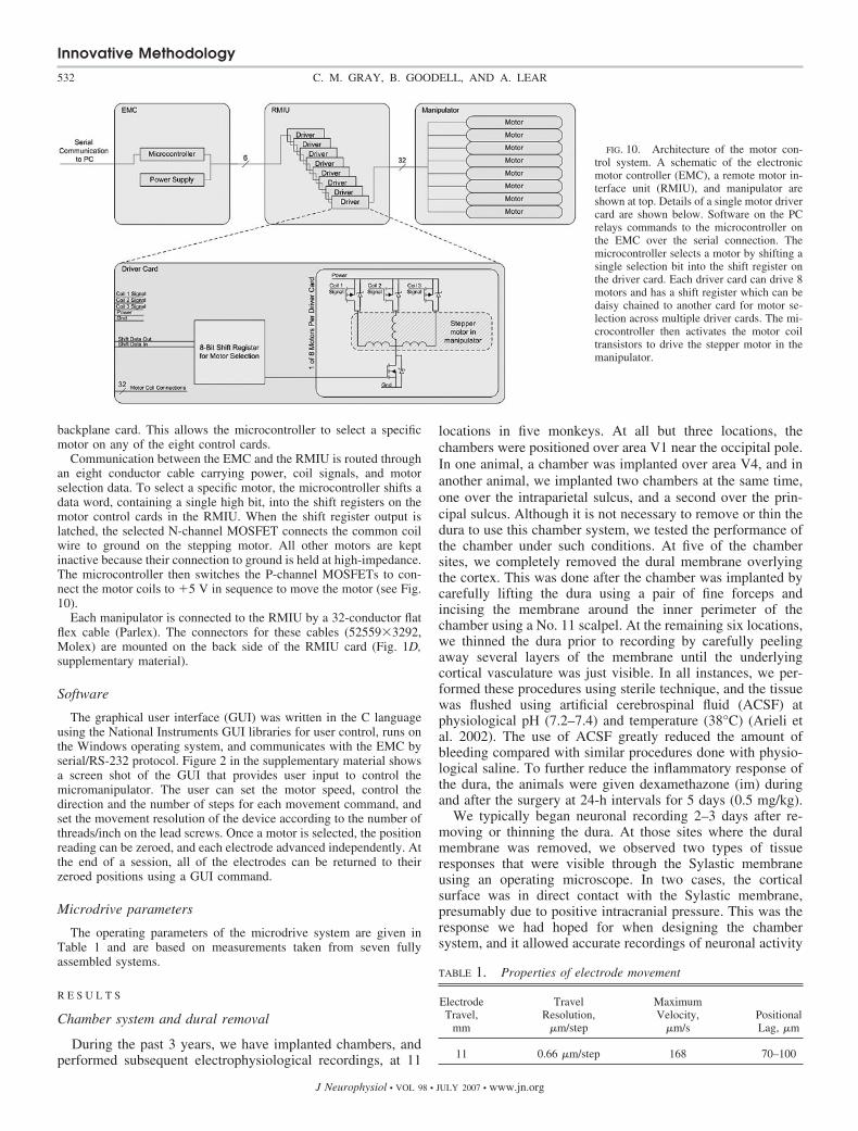
PRINTED CIRCUIT BOARDS. The manipulator is designed to housetwo PCBs. One board provides connections to the motor controlcircuitry (see following text) and another to the amplifier headstage.Both boards were manufactured by Trilogy-Net, and are shown in Fig.8. The motor control PCB (A and B) is a simple two-layered board thatprovides connections between each of eight four-pin connectors(Molex, No. 52808�0490) on the bottom surface (B) to a single32-pin, zero-insertion-force, connector (Molex, No. 52559�3292) onthe top surface (A). Connections are made to the latter connector fromthe motor control system via a 32-conductor flex-print ribbon cable(Parlex, No. 050�32�1524B).
The second board, shown in Fig. 8, C and D, is designed to makecontact to each of eight electrodes via a spring-loaded sliding contactmechanism. To accomplish this, the board was built in a circularconfiguration with solder pads arranged in register with the plungers
FIG. 6. Photographs of a completed ac-tuator block as viewed from the top (A) andbottom (B).
FIG. 7. Photographs of a completed basecone (A) and guide cylinder (B).The guide cylinder is shown with (right) and without (middle) a mounted guidearray (left).
Innovative Methodology
530 C. M. GRAY, B. GOODELL, AND A. LEAR
J Neurophysiol • VOL 98 • JULY 2007 • www.jn.org
of each actuator. Electrical contact is established by soldering a shortberyllium-copper (BeCu) tab (0.120 � 0.040 � 0.002 in) to each padso that it extends 2 mm toward the center of the circuit board (Fig. 8,C and D). This ensures that when the PCB is mounted onto theactuator block, each BeCu tab is gently pressing against the corre-sponding BeCu strip of the plunger thereby making a spring-loadedcontact.
The BeCu tabs and strips were made by Italix (Santa Clara, CA).They were cut, bent, heat treated, and cleaned. The tabs were solderedonto the PCB during the final step in manufacture of the boards(Trilogy-Net). The connector making contact with the amplifier head-stage consisted of nine pins having a pitch of 0.05 in. This connectorwas compatible with MultiChannel Systems headstage (MPA8I);however, the connector can be easily replaced to accommodate othertypes of headstage amplifiers.
Assembly
For assembly, the lead screw on each actuator is fitted with aplunger and electrode holder (Fig. 5) and then mounted into one of theholes in the actuator block (Fig. 6A). The flexiprint cable attached toeach motor is folded upward and inserted into the correspondingconnector on the underside of the motor control PCB (Fig. 8B). ThePCB is then fixed to the standoffs that are mounted on the top surfaceof the actuator block. The key pins are then placed into each hemi-spherical slot on the underside of the actuator block, and the retainingplate is screwed in place. Once this step is completed, the signal PCBis gently placed over the ends of the plungers and fixed in place withcap screws. During this step, it is important to insure that the BeCutabs do not catch on the ends of the plungers or electrode holders,otherwise they will be bent backwards and will have to be repaired orthe PCB replaced. Figure 9 shows a bottom-up view of an assembledmicrodrive before the support arms and basecone are attached. Bshows a magnified view of the sliding contact between the BeCu tabson the signal PCB and the BeCu strips mounted on each plunger. Cshows the relationship between the key pins mounted within theactuator block and the semicircular groove in each plunger. In the finalsteps of the assembly, the support arms are mounted onto the basecone
and the actuator block. The retaining cap is placed over the guidecylinder, which is then threaded into the basecone (see Figs. 3 and 4for details).
Motor control system
The control system that interfaces to the micromanipulator consistsof two main parts, a rack-mounted electronic motor controller (EMC),and a remote motor interface unit (RMIU). A schematic diagram ofthe control system architecture is shown in Fig. 10, and photographsof the printed circuit boards are shown in Fig. 1 of the supplementarymaterials.1 The main component in the EMC is the Atmel AT-mega128 8-bit RISC microcontroller operating at 14.7456 MHz. Thisdevice communicates with a monitoring and control computer via aserial connection, stores the positions of all the motors, and providesthe control signals for the timing of the stepping motors. Software forthe microcontroller was written in C, converted to assembly code anddownloaded using the software package AVR Studio 4 (Atmel). Theserial connection transmission rate is set at 115,200 bit/s for fastcontinuous updates of motor positions. The serial communicationprotocol utilizes ASCII command strings, which are newline characterterminated. Error detection is accomplished using an odd-parity bit.The high level serial (RS-232) signals are level shifted to the I/Ovoltages required by the microcontroller using a MAX232 interfacechip.
The RMIU controls motor selection and delivers current to theselected motor. Each unit houses eight removable motor control cards,each capable of driving eight stepping motors. The cards are mountedin a backplane card, capable of mounting eight control cards toprovide control of �64 motors (Fig. 1, B and D, supplementarymaterial). Each control card has its own shift register (SN74HC595D,Texas Instruments), to enable motor selection, and a single N-channel(IRF7456) and three P-channel MOSFETs (IRF7210, InternationalRectifier) to provide current to each motor. The shift register of eachcontrol card is connected serially to that of the adjacent cards via the
1The online version of this article contains supplemental data.
FIG. 8. Photographs of the motor control printed circuit boards (PCB; A,top view; B, bottom view) and the signal PCB [C, top view; D, magnified toillustrate the beryllium-copper (BeCu) tabs].
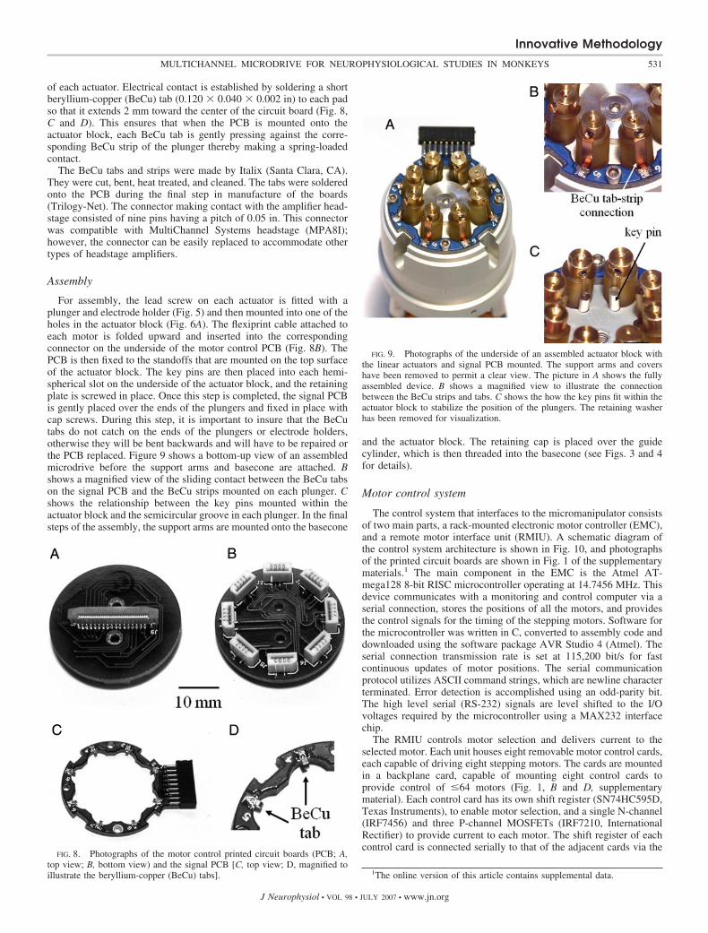
FIG. 9. Photographs of the underside of an assembled actuator block withthe linear actuators and signal PCB mounted. The support arms and covershave been removed to permit a clear view. The picture in A shows the fullyassembled device. B shows a magnified view to illustrate the connectionbetween the BeCu strips and tabs. C shows the how the key pins fit within theactuator block to stabilize the position of the plungers. The retaining washerhas been removed for visualization.
Innovative Methodology
531MULTICHANNEL MICRODRIVE FOR NEUROPHYSIOLOGICAL STUDIES IN MONKEYS
J Neurophysiol • VOL 98 • JULY 2007 • www.jn.org
backplane card. This allows the microcontroller to select a specificmotor on any of the eight control cards.
Communication between the EMC and the RMIU is routed throughan eight conductor cable carrying power, coil signals, and motorselection data. To select a specific motor, the microcontroller shifts adata word, containing a single high bit, into the shift registers on themotor control cards in the RMIU. When the shift register output islatched, the selected N-channel MOSFET connects the common coilwire to ground on the stepping motor. All other motors are keptinactive because their connection to ground is held at high-impedance.The microcontroller then switches the P-channel MOSFETs to con-nect the motor coils to �5 V in sequence to move the motor (see Fig.10).
Each manipulator is connected to the RMIU by a 32-conductor flatflex cable (Parlex). The connectors for these cables (52559�3292,Molex) are mounted on the back side of the RMIU card (Fig. 1D,supplementary material).
Software
The graphical user interface (GUI) was written in the C languageusing the National Instruments GUI libraries for user control, runs onthe Windows operating system, and communicates with the EMC byserial/RS-232 protocol. Figure 2 in the supplementary material showsa screen shot of the GUI that provides user input to control themicromanipulator. The user can set the motor speed, control thedirection and the number of steps for each movement command, andset the movement resolution of the device according to the number ofthreads/inch on the lead screws. Once a motor is selected, the positionreading can be zeroed, and each electrode advanced independently. Atthe end of a session, all of the electrodes can be returned to theirzeroed positions using a GUI command.
Microdrive parameters
The operating parameters of the microdrive system are given inTable 1 and are based on measurements taken from seven fullyassembled systems.
R E S U L T S
Chamber system and dural removal
During the past 3 years, we have implanted chambers, andperformed subsequent electrophysiological recordings, at 11
locations in five monkeys. At all but three locations, thechambers were positioned over area V1 near the occipital pole.In one animal, a chamber was implanted over area V4, and inanother animal, we implanted two chambers at the same time,one over the intraparietal sulcus, and a second over the prin-cipal sulcus. Although it is not necessary to remove or thin thedura to use this chamber system, we tested the performance ofthe chamber under such conditions. At five of the chambersites, we completely removed the dural membrane overlyingthe cortex. This was done after the chamber was implanted bycarefully lifting the dura using a pair of fine forceps andincising the membrane around the inner perimeter of thechamber using a No. 11 scalpel. At the remaining six locations,we thinned the dura prior to recording by carefully peelingaway several layers of the membrane until the underlyingcortical vasculature was just visible. In all instances, we per-formed these procedures using sterile technique, and the tissuewas flushed using artificial cerebrospinal fluid (ACSF) atphysiological pH (7.2–7.4) and temperature (38°C) (Arieli etal. 2002). The use of ACSF greatly reduced the amount ofbleeding compared with similar procedures done with physio-logical saline. To further reduce the inflammatory response ofthe dura, the animals were given dexamethazone (im) duringand after the surgery at 24-h intervals for 5 days (0.5 mg/kg).
We typically began neuronal recording 2–3 days after re-moving or thinning the dura. At those sites where the duralmembrane was removed, we observed two types of tissueresponses that were visible through the Sylastic membraneusing an operating microscope. In two cases, the corticalsurface was in direct contact with the Sylastic membrane,presumably due to positive intracranial pressure. This was theresponse we had hoped for when designing the chambersystem, and it allowed accurate recordings of neuronal activity
TABLE 1. Properties of electrode movement
ElectrodeTravel,
mm
TravelResolution,
�m/step
MaximumVelocity,
�m/sPositionalLag, �m
11 0.66 �m/step 168 70–100
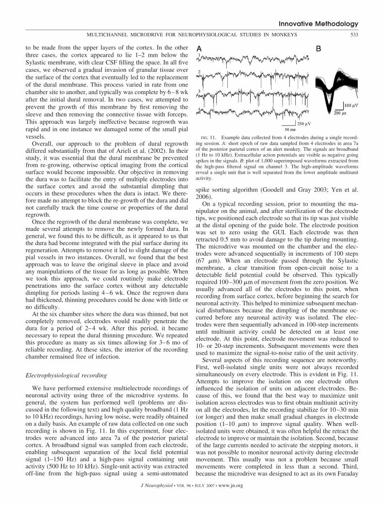
FIG. 10. Architecture of the motor con-trol system. A schematic of the electronicmotor controller (EMC), a remote motor in-terface unit (RMIU), and manipulator areshown at top. Details of a single motor drivercard are shown below. Software on the PCrelays commands to the microcontroller onthe EMC over the serial connection. Themicrocontroller selects a motor by shifting asingle selection bit into the shift register onthe driver card. Each driver card can drive 8motors and has a shift register which can bedaisy chained to another card for motor se-lection across multiple driver cards. The mi-crocontroller then activates the motor coiltransistors to drive the stepper motor in themanipulator.
Innovative Methodology
532 C. M. GRAY, B. GOODELL, AND A. LEAR
J Neurophysiol • VOL 98 • JULY 2007 • www.jn.org
to be made from the upper layers of the cortex. In the otherthree cases, the cortex appeared to lie 1–2 mm below theSylastic membrane, with clear CSF filling the space. In all fivecases, we observed a gradual invasion of granular tissue overthe surface of the cortex that eventually led to the replacementof the dural membrane. This process varied in rate from onechamber site to another, and typically was complete by 6–8 wkafter the initial dural removal. In two cases, we attempted toprevent the growth of this membrane by first removing thesleeve and then removing the connective tissue with forceps.This approach was largely ineffective because regrowth wasrapid and in one instance we damaged some of the small pialvessels.
Overall, our approach to the problem of dural regrowthdiffered substantially from that of Arieli et al. (2002). In theirstudy, it was essential that the dural membrane be preventedfrom re-growing, otherwise optical imaging from the corticalsurface would become impossible. Our objective in removingthe dura was to facilitate the entry of multiple electrodes intothe surface cortex and avoid the substantial dimpling thatoccurs in these procedures when the dura is intact. We there-fore made no attempt to block the re-growth of the dura and didnot carefully track the time course or properties of the duralregrowth.
Once the regrowth of the dural membrane was complete, wemade several attempts to remove the newly formed dura. Ingeneral, we found this to be difficult, as it appeared to us thatthe dura had become integrated with the pial surface during itsregeneration. Attempts to remove it led to slight damage of thepial vessels in two instances. Overall, we found that the bestapproach was to leave the original sleeve in place and avoidany manipulations of the tissue for as long as possible. Whenwe took this approach, we could routinely make electrodepenetrations into the surface cortex without any detectabledimpling for periods lasting 4–6 wk. Once the regrown durahad thickened, thinning procedures could be done with little orno difficulty.
At the six chamber sites where the dura was thinned, but notcompletely removed, electrodes would readily penetrate thedura for a period of 2–4 wk. After this period, it becamenecessary to repeat the dural thinning procedure. We repeatedthis procedure as many as six times allowing for 3–6 mo ofreliable recording. At these sites, the interior of the recordingchamber remained free of infection.
Electrophysiological recording
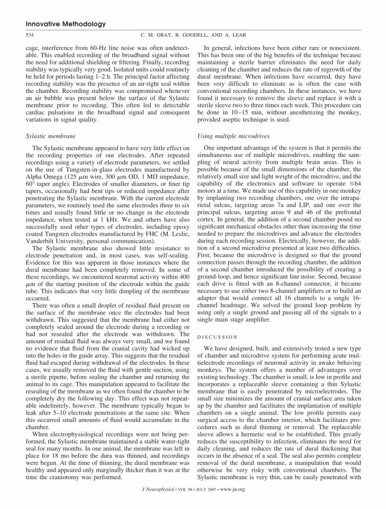
We have performed extensive multielectrode recordings ofneuronal activity using three of the microdrive systems. Ingeneral, the system has performed well (problems are dis-cussed in the following text) and high quality broadband (1 Hzto 10 kHz) recordings, having low noise, were readily obtainedon a daily basis. An example of raw data collected on one suchrecording is shown in Fig. 11. In this experiment, four elec-trodes were advanced into area 7a of the posterior parietalcortex. A broadband signal was sampled from each electrode,enabling subsequent separation of the local field potentialsignal (1–150 Hz) and a high-pass signal containing unitactivity (500 Hz to 10 kHz). Single-unit activity was extractedoff-line from the high-pass signal using a semi-automated
spike sorting algorithm (Goodell and Gray 2003; Yen et al.2006).
On a typical recording session, prior to mounting the ma-nipulator on the animal, and after sterilization of the electrodetips, we positioned each electrode so that its tip was just visibleat the distal opening of the guide hole. The electrode positionwas set to zero using the GUI. Each electrode was thenretracted 0.5 mm to avoid damage to the tip during mounting.The microdrive was mounted on the chamber and the elec-trodes were advanced sequentially in increments of 100 steps(67 �m). When an electrode passed through the Sylasticmembrane, a clear transition from open-circuit noise to adetectable field potential could be observed. This typicallyrequired 100–300 �m of movement from the zero position. Weusually advanced all of the electrodes to this point, whenrecording from surface cortex, before beginning the search forneuronal activity. This helped to minimize subsequent mechan-ical disturbances because the dimpling of the membrane oc-curred before any neuronal activity was isolated. The elec-trodes were then sequentially advanced in 100-step incrementsuntil multiunit activity could be detected on at least oneelectrode. At this point, electrode movement was reduced to10- or 20-step increments. Subsequent movements were thenused to maximize the signal-to-noise ratio of the unit activity.
Several aspects of this recording sequence are noteworthy.First, well-isolated single units were not always recordedsimultaneously on every electrode. This is evident in Fig. 11.Attempts to improve the isolation on one electrode ofteninfluenced the isolation of units on adjacent electrodes. Be-cause of this, we found that the best way to maximize unitisolation across electrodes was to first obtain multiunit activityon all the electrodes, let the recording stabilize for 10–30 min(or longer) and then make small gradual changes in electrodeposition (1–10 �m) to improve signal quality. When well-isolated units were obtained, it was often helpful the retract theelectrode to improve or maintain the isolation. Second, becauseof the large currents needed to activate the stepping motors, itwas not possible to monitor neuronal activity during electrodemovement. This usually was not a problem because smallmovements were completed in less than a second. Third,because the microdrive was designed to act as its own Faraday
FIG. 11. Example data collected from 4 electrodes during a single record-ing session. A: short epoch of raw data sampled from 4 electrodes in area 7aof the posterior parietal cortex of an alert monkey. The signals are broadband(1 Hz to 10 kHz). Extracellular action potentials are visible as negative goingspikes in the signals. B: plot of 1,000 superimposed waveforms extracted fromthe high-pass filtered signal on channel 3. The high-amplitude waveformsreveal a single unit that is well separated from the lower amplitude multiunitactivity.
Innovative Methodology
533MULTICHANNEL MICRODRIVE FOR NEUROPHYSIOLOGICAL STUDIES IN MONKEYS
J Neurophysiol • VOL 98 • JULY 2007 • www.jn.org
cage, interference from 60-Hz line noise was often undetect-able. This enabled recording of the broadband signal withoutthe need for additional shielding or filtering. Finally, recordingstability was typically very good. Isolated units could routinelybe held for periods lasting 1–2 h. The principal factor affectingrecording stability was the presence of an air-tight seal withinthe chamber. Recording stability was compromised wheneveran air bubble was present below the surface of the Sylasticmembrane prior to recording. This often led to detectablecardiac pulsations in the broadband signal and consequentvariations in signal quality.
Sylastic membrane
The Sylastic membrane appeared to have very little effect onthe recording properties of our electrodes. After repeatedrecordings using a variety of electrode parameters, we settledon the use of Tungsten-in-glass electrodes manufactured byAlpha Omega (125 �m wire, 300 �m OD, 1 M� impedance,60° taper angle). Electrodes of smaller diameters, or finer tiptapers, occasionally had bent tips or reduced impedance afterpenetrating the Sylastic membrane. With the current electrodeparameters, we routinely used the same electrodes three to sixtimes and usually found little or no change in the electrodeimpedance, when tested at 1 kHz. We and others have alsosuccessfully used other types of electrodes, including epoxycoated Tungsten electrodes manufactured by FHC (M. Leslie,Vanderbilt University, personal communication).
The Sylastic membrane also showed little resistance toelectrode penetration and, in most cases, was self-sealing.Evidence for this was apparent in those instances where thedural membrane had been completely removed. In some ofthese recordings, we encountered neuronal activity within 400�m of the starting position of the electrode within the guidetube. This indicates that very little dimpling of the membraneoccurred.
There was often a small droplet of residual fluid present onthe surface of the membrane once the electrodes had beenwithdrawn. This suggested that the membrane had either notcompletely sealed around the electrode during a recording orhad not resealed after the electrode was withdrawn. Theamount of residual fluid was always very small, and we foundno evidence that fluid from the cranial cavity had wicked upinto the holes in the guide array. This suggests that the residualfluid had escaped during withdrawal of the electrodes. In thesecases, we usually removed the fluid with gentle suction, usinga sterile pipette, before sealing the chamber and returning theanimal to its cage. This manipulation appeared to facilitate theresealing of the membrane as we often found the chamber to becompletely dry the following day. This effect was not repeat-able indefinitely, however. The membrane typically began toleak after 5–10 electrode penetrations at the same site. Whenthis occurred small amounts of fluid would accumulate in thechamber.
When electrophysiological recordings were not being per-formed, the Sylastic membrane maintained a stable water-tightseal for many months. In one animal, the membrane was left inplace for 18 mo before the dura was thinned, and recordingswere begun. At the time of thinning, the dural membrane washealthy and appeared only marginally thicker than it was at thetime the craniotomy was performed.
In general, infections have been either rare or nonexistent.This has been one of the big benefits of the technique becausemaintaining a sterile barrier eliminates the need for dailycleaning of the chamber and reduces the rate of regrowth of thedural membrane. When infections have occurred, they havebeen very difficult to eliminate as is often the case withconventional recording chambers. In these instances, we havefound it necessary to remove the sleeve and replace it with asterile sleeve two to three times each week. This procedure canbe done in 10–15 min, without anesthetizing the monkey,provided aseptic technique is used.
Using multiple microdrives
One important advantage of the system is that it permits thesimultaneous use of multiple microdrives, enabling the sam-pling of neural activity from multiple brain areas. This ispossible because of the small dimensions of the chamber, therelatively small size and light weight of the microdrive, and thecapability of the electronics and software to operate �64motors at a time. We made use of this capability in one monkeyby implanting two recording chambers, one over the intrapa-rietal sulcus, targeting areas 7a and LIP, and one over theprincipal sulcus, targeting areas 9 and 46 of the prefrontalcortex. In general, the addition of a second chamber posed nosignificant mechanical obstacles other than increasing the timeneeded to prepare the microdrives and advance the electrodesduring each recording session. Electrically, however, the addi-tion of a second microdrive presented at least two difficulties.First, because the microdrive is designed so that the groundconnection passes through the recording chamber, the additionof a second chamber introduced the possibility of creating aground-loop, and hence significant line noise. Second, becauseeach drive is fitted with an 8-channel connector, it becamenecessary to use either two 8-channel amplifiers or to build anadapter that would connect all 16 channels to a single 16-channel headstage. We solved the ground loop problem byusing only a single ground and passing all of the signals to asingle main stage amplifier.
D I S C U S S I O N
We have designed, built, and extensively tested a new typeof chamber and microdrive system for performing acute mul-tielectrode recordings of neuronal activity in awake behavingmonkeys. The system offers a number of advantages overexisting technology. The chamber is small, is low in profile andincorporates a replaceable sleeve containing a thin Sylasticmembrane that is easily penetrated by microelectrodes. Thesmall size minimizes the amount of cranial surface area takenup by the chamber and facilitates the implantation of multiplechambers on a single animal. The low profile permits easysurgical access to the chamber interior, which facilitates pro-cedures such as dural thinning or removal. The replaceablesleeve allows a hermetic seal to be established. This greatlyreduces the susceptibility to infection, eliminates the need fordaily cleaning, and reduces the rate of dural thickening thatoccurs in the absence of a seal. The seal also permits completeremoval of the dural membrane, a manipulation that wouldotherwise be very risky with conventional chambers. TheSylastic membrane is very thin, can be easily penetrated with
Innovative Methodology
534 C. M. GRAY, B. GOODELL, AND A. LEAR
J Neurophysiol • VOL 98 • JULY 2007 • www.jn.org
multiple microelectrodes without changing their recordingcharacteristics, and, when coupled with thinning or removal ofthe dura, greatly reduces dimpling of the tissue thereby per-mitting more accurate tracking of electrode depth in the corti-cal tissue.
The microdrive and electronic control system also offerseveral advantages over existing technologies. The device iseasy to use and relatively small in size and weight, couplesdirectly to the chamber system, requires no special accessorydevices to operate, and acts as its own grounded Faraday cageto eliminate line noise and permit broadband recording. Thecontrol system is operated by a personal computer, via serialport communication, running the Windows operating system,and can control �64 motors with no design change. Togetherthis design increases the versatility for performing multielec-trode recordings in alert monkeys. We expect that futurerefinements in the existing design will further increase theirflexibility and reliability for a wide variety of uses.
Technical problems and future modifications
As with any new technology, a number of minor technicalproblems were encountered, and the need for additional designchanges became apparent, both of which deserve comment.With respect to the chamber system, the current design requiresthat acrylic cement be used to fix the device to the animal’sskull. This has worked well, but the design would be improvedby directly fixing the device to the skull. This would serve toreduce the overall dimensions of the implant and potentiallyreduce the susceptibility to infection. A simple way to imple-ment this capability would be to design the chamber with legsor a mesh radiating parallel to the cranial surface that could befixed directly to the skull with orthopedic bone screws. Thiswould increase the fabrication cost of the chamber but could beeasily implemented with conventional machining techniques.Another limitation of the chamber is that it is designed to beimplanted tangential to the cortical surface. This limits thenumber of locations that can be targeted because the increaseof soft tissue at more lateral locations interferes with the use ofthe chamber. This problem can be solved by redesigning thechamber to mount vertically, but optimizing the design re-quires prior knowledge of the dimensions of the skull at thetarget site so that the lower surface of the chamber can bemachined to fit each animal’s skull at a particular recordinglocation. Although this can be accomplished by reconstructingthe cranial surface from a CT scan (Gray and Goodell 2005), itwill substantially increase the cost for each chamber. More-over, the internal sleeve would have to be redesigned to mountvertically within the chamber, and it would not be possible toincorporate the Sylastic membrane in the current manner.Finally, it would be useful to construct the chamber out ofplastic to make it compatible with magnetic resonance imag-ing. We see no fundamental problems with this other than thepossible need to increase the thickness of the retaining ring formounting the Sylastic membrane onto the sleeve.
With respect to the microdrive and control system, a numberof useful design changes became apparent after extensive useof the system. These included mechanical, electrical, andsoftware changes. Mechanically, we discovered three problemsthat limited the performance of the system. First, the actuatorsconsistently displayed �70–100 �m of positional lag when
reversing movement direction, making accurate electrode po-sitioning difficult whenever a change of direction was required.We were unable to effectively reduce the lag by improving theprecision of the threads on the plunger without also increasingthe friction on the lead screw. The best solution is to compen-sate for the lag in the control software by incorporating aposition offset equal to the magnitude of the lag. A secondmechanical problem became apparent over time as the duralmembrane increased in thickness. At the beginning of record-ing sessions, when the electrodes were being advanced throughthe dura, the electrode shafts would occasionally bend ratherthan penetrate the dura. This was due to the small wirediameter of our electrodes (100 �m, 300 �m with glassinsulation) and the long span between the electrode holder andthe top of the guide array. We solved this problem by incor-porating a set of eight stainless steel guide tubes that could bepress-fit into selected holes in the top of the guide array priorto recording, and held in alignment with each actuator using agrid mounted on the interior of the support arms (the grid isvisible in the middle of the microdrive in Fig. 4A). Finally, wealso found that it was easy to mistakenly retract or advance theactuators beyond their upper and lower positional limits. Whenthis happened, there were times when the resulting frictionwould cause the plunger to stick in place, and these instanceswere not registered by the software and were thus not detectedby the user. Short of incorporating a separate position encoderfor each actuator, which we ruled out due to size, complexityand expense, the best solution is to incorporate end limitswithin the software which can be set at the beginning of eachrecording session.
Electrically, we found very few problems overall. The onlyconsistent difficulty, which showed up after prolonged use ofthe system, was the presence of occasional intermittent signalconnections between the BeCu tabs on the PCB and the BeCustrips on the plungers. We discovered that these problems weredue either to the build up of an oxidation layer on the surfaceof the BeCu contacts or a slight bending of the tabs making theconnection between strips and tabs unreliable. We solved thefirst problem by occasionally cleaning the surfaces of thecontacts. The latter problem was solved by redesigning theBeCu tabs so that they were thicker and longer. This increasedthe force of the spring loaded contact between the tabs and thestrips on the plungers.
Although we have mentioned several changes to the soft-ware that improved the design or eliminated problems, we alsofound that the system could be greatly improved by includingsoftware modifications to permit automated electrode move-ment sequences. This was particularly evident when advancingmultiple electrodes each day, which often required a great dealof time by the user. This capability should be relatively easy toimplement and would enable the user to specify a wide varietyof movement sequences.
A C K N O W L E D G M E N T S
We thank M. Leslie at Vanderbilt University for valuable comments on anearlier version of the manuscript. We also thank R. Himmelspach for excellentcare of the animals.
G R A N T S
This material is based upon work supported by National Science Founda-tion Grant 0138848. This work also was supported by a grant to C. M. Gray
Innovative Methodology
535MULTICHANNEL MICRODRIVE FOR NEUROPHYSIOLOGICAL STUDIES IN MONKEYS
J Neurophysiol • VOL 98 • JULY 2007 • www.jn.org
from the program for Instrument Development for Biological Research at theNational Science Foundation.
R E F E R E N C E S
Asaad WF, Rainer G, Miller EK. Task-specific neural activity in the primateprefrontal cortex. J Neurophysiol 84: 451–459, 2000.
Arieli A, Grinvald A, Slovin H. Dural substitute for long-term imaging ofcortical activity in behaving monkeys and its clinical implications. J Neu-rosci Methods 114: 119–133, 2002.
Baker SN, Philbin N, Spinks R, Pinches EM, Wolpert DM, MacManusDG, Pauluis Q, Lemon RN. Multiple single unit recording in the cortex ofmonkeys using independently moveable microelectrodes. J Neurosci Meth-ods 94: 5–17, 1999.
Cham JG, Branchaud EA, Nenadic Z, Greger B, Andersen RA, BurdickJW. Semi-chronic motorized microdrive and control algorithm for autono-mously isolating and maintaining optimal extracellular action potentials.J Neurophysiol 93: 570–579, 2005.
Goodell AB, Gray CM. Semi-automated solution to the spike overlap problem usingtetrode data obtained from cat visual cortex. Soc Neurosci Abstr 429.9, 2003.
Gray CM, Goodell AB. Targeted semi-chronic recording from multiple sites inmultiple visual cortical areas in alert monkeys. Soc Neurosci Abstr 569.16, 2005.
Miller EK, Erickson CA, Desimone R. Neural mechanisms of visualworking memory in prefrontal cortex of the macaque. J Neurosci 16:5154 –5167, 1996.
Mountcastle VB, Reitboeck HJ, Poggio GF, Steinmetz MA. Adaptation ofthe Reitboeck method of multiple microelectrode recording to the neocortexof the waking monkey. J Neurosci Methods 36: 77–84, 1991.
Prut Y, Vaadia E, Bergman H, Haalman I, Slovin H, Abeles M. Spatio-temporal structure of cortical activity: properties and behavioral relevance.J Neurophysiol 79: 2857–2874, 1998.
Reitboeck HJ, Werner G. Multi-electrode recording system for the study ofspatio-temporal activity patterns of neurons in the central nervous system.Experientia 39: 339–341, 1983.
Spinks RL, Baker SN, Jackson A, Khaw PT, Lemon RN. Problem of duralscarring in recording from awake, behaving monkeys: a solution using5-fluorouracil. J Neurophysiol 90: 1324–1332, 2003.
Yen SC, Baker J, Gray CM. Heterogeneity in the responses of adjacentneurons to natural stimuli in cat striate cortex. J Neurophysiol 97:1326 –1341, 2007.
Innovative Methodology
536 C. M. GRAY, B. GOODELL, AND A. LEAR
J Neurophysiol • VOL 98 • JULY 2007 • www.jn.org


