Embed Size (px)
Citation preview
Laser-welded packaging of a Nd:YAG laser for space applications Cheryl G. Asbury*", Duncan Liu", Jerry L. Mulder", James G. Hawley**b,
Atul Mehta", Serge Dubovitsky" "Jet Propulsion Laboratory, California Institute of Technology;
bAdvanced Technology Center, Lockheed Martin Space Systems Company
ABSTRACT
The success of interferometry in space depends on the development of lasers that can survive launch conditions and the challenging space environment during missions that could last five years or more. This paper describes the fabrication of a rugged, laser-welded package for a 200mW, monolithic diode-pumped solid-state Nd:YAG laser operating at 13 19nm. Environmental testing shows that the laser withstands non-operational thermal cycles over a temperature range from -20°C to 55"C, and 22.3 g-rms of random vibration, with little or no degradation of laser output power or performance. The novel packaging method employs a specially designed housing to which multi-mode or single-mode polarization-maintaining fiber pigtails can be aligned and laser-welded into place. To further enhance reliability, a redundant pumping system called the Multi-Fiber Pump Ferrule (MFPF) was developed and implemented. The MFPF allows multiple laser diode pump modules to be aligned to the laser crystal simultaneously, in order to accommodate either parallel or standby pump redundancy. This compact, lightweight design is well suited for space flight applications and the laser-welded technique can easily be adapted to a number of other fiber optic and electro-optic devices in which critical optical alignments must be maintained in a harsh environment. Keywords: Laser, Packaging, Laser-welded, Space, Fiber-pigtailed
1. INTRODUCTION
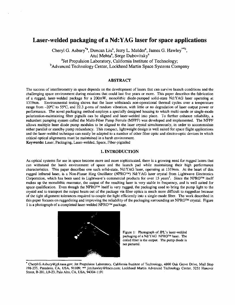
As optical systems for use in space become more and more sophisticated, there is a growing need for rugged lasers that can withstand the harsh environment of space and the launch pad while maintaining their high performance characteristics. This paper describes one such solid-state, Nd:YAG laser, operating at 1319nm. At the heart of this rugged infrared laser, is a Non-Planar Ring Oscillator (NPROTM) Nd:YAG laser crystal from Lightwave Electronics Corporation, which has been used in Lightwave's commercial products for over 15 years'. Since the NPROTM itself makes up the monolithic resonator, the output of the resulting laser is very stable in frequency, and is well suited for space qualification. Even though the NPROTM itself is very rugged, the packaging used to bring the pump light to the crystal and to transport the output beam out of the package via fiber optics is much more difficult to ruggedize because of the tight alignment tolerances required to couple the light efficiently into a single-mode fiber. The work described in this paper focuses on ruggedizing and improving the reliability of the packaging surrounding an NPROTM crystal. Figure 1 is a photograph of a completed laser-welded NPROTM package.
Figure 1: Photograph of JPL's laser-welded packaging of a NdYAG NPROTM laser. The coiled fiber is the output. The pump diode is not pictured.
[email protected]; Jet Propulsion Laboratory, California Institute of Technology, 4800 Oak Grove Drive, Mail Stop 198-235, Pasadena, CA, USA, 91 109; ** [email protected]; Lockheed Martin Advanced Technology Center, 3251 Hanover Street, B-201, L9-23, Palo Alto, CA, USA, 94304-1 191
2. BACKGROUND
The N P R O T M is an optically pumped, monolithic ring laser resonator made of Nd:YAG. The entire optical path of the laser is contained in the Nd:YAG, which is the gain medium, and the four mirrors of the resonator consist of three facets that serve as total internal reflectors, and a coated front surface. The coated surface serves as both the entry point for the pump light and the partial reflector for the output beam. The crystal is pumped, either directly or via fiber, with 808nm light from a laser diode. The application of a magnetic field in the crystal, in a direction perpendicular to the front facet, coupled with the Verdet effect in the Nd:YAG, produces output in only one direction of the resonator ring. Due to the NPROTM's inherent frequency stability, it has become an attractive laser for metrology and spectrometry.
Even though the commercial laser product from Lightwave Electronics Corporation provides all the high-performance characteristics required for space metrology, the commercial laser packaging was not designed to withstand the rigors of space. Therefore, improvements must be made to the ruggedness and reliability of the NPROTM packaging before the laser can be used in space flight.
3. METHOD
3.1 Ruggedized design After reviewing the design of the commercial packaging of the NPROm laser crystal from a space flight perspective, three main areas of concern were identified: 1) the alignment stability between the pump light beam and the NPROTM crystal, 2) the alignment stability between the NPROTM crystal and the output fiber, and 3) the reliability of the pump laser diode. Angular misalignments of as little as 2mrad and certain transverse misalignments of as little as 2 microns between the NPROTM and the output fiber can result in as much as a 50% drop in output power. When the commercial NPROTM laser was subjected to environmental tests that mimic potential launch conditions and extreme temperature cycles (far beyond commercial laser specifications), the optical power out of the fiber dropped between 40% and 50%. The cause of this power drop is believed to be a combination of angular and transverse misalignment in both critical alignment paths, due to epoxy shrinkage and solder creep and flow. The importance of the reliability of the pump laser diode depends on the power required at end of life, the length of the mission, and the desired confidence level. For this work, the goal was to design a laser with relatively high-power optical output (200mW) that suffers no degradation in output power over a 10-year mission. The high-power, 808nm laser diodes currently available on the market do not meet these mission life goals with the level of confidence required by most space missions. Commercial diode laser lifetime data and JPL experience with diode laser lifetime suggest that, given current high-power diode laser technology, redundant devices are needed to meet a mission life goal of 10 years when such high output power is required.
In view of the above areas of concern, the main goal of the re-design of the "ROW packaging was to ensure that the optical components did not move with respect to one another. In order to achieve this goal, several changes were made to the packaging.' First, since both epoxy bonds and solder bonds are susceptible to physical changes with the application of thermal cycles, humidity, and applied forces, all components with critical alignment tolerances were laser- welded into position. Epoxy and solder bonds were eliminated wherever possible. Second, the optical path was shortened from about 8 cm down to 3 cm by eliminating turning mirrors that were unnecessary for the new design, reducing the package size, and simplifying the optical layout. Third, the pump light was delivered to the NPROTM crystal via fiber, so that the laser-welding technique could be used to secure the alignment between the pump and the NPROTM. Lastly, a heater plate was used to control the NPROTM temperature instead of a thermoelectric cooler (TEC). Since a heater-only approach is sufficient for this application, the heater plate design was selected for its higher level of ruggedness and reliability.
The re-designed NPROTM packaging consists of a one-piece NPROTM housing to which input and output optics can be aligned and laser-welded into place. The only epoxy and solder bonds that remain are used to bond the crystal and heater plate to the NPROTM housing, and to bond optical components into laser-weldable housings. These locations are not critical to optical alignment, and allow the epoxies and solders to be applied and cured under controlled conditions. Alignment is achieved with an x-y translation stage that also enables rotation about the z-axis (fiber axis), and a chuck that can move the fiber or other cylindrical element along the z-axis. This alignment station provides sub-micron alignment resolution and 5 0 d i n c h alignment repeatability.
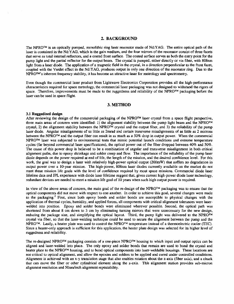
The laser welding was done with a Newport Model 4000 Laser Welder that utilizes a high-power pulsed Nd:YAG laser to make the welds. Three laser beams impinge on the joint to be welded from points that are 120' apart, and this geometry must be taken into account when designing the parts that are to be laser-welded together. All three laser beams must be accessible to the weld joint, and in order to reduce post-weld shifts, the joint must have cylindrical symmetry. If post-weld shifts do occur, force can be applied to the weld joint in empirically determined directions to make small adjustments. This post-weld shift correction technique often results in complete restoration of the output power. Proper selection of both weld materials and weld schedule ensure a strong bond. Figure 2 shows a photograph of the weld joints.
Figure 2: Photograph of laser-welded joints.
F
t' Fbs pigto1
Figure 3: Optical layout of laser-welded NPROTM package.
Simplification of the optical layout was another important consideration in designing the new welded NPROTM housing. Figure 3 diagrams the optical layout of the laser-welded package. Eliminating components enables the shortening of the optical path and leaves fewer components that could move over time. This laser-welded design eliminates all turning mirrors, so that the optical path has been reduced from about 8 cm down to about 3 cm. Shortening the optical path improves reliability by reducing the sensitivity of the output power to angular misalignment.
The optical path was also simplified by delivering the pump light to the NPROTM via optical fiber. The fiber-to- NPROTM alignment is easier to achieve than the alignment of a bulk diode laser to the NPROTM, and is easily accommodated by the laser-welder equipment. Since the mode of the NPROTM resonator is not as well matched to the fiber output as it is to pump light delivered directly from the diode, some optical efficiency is sacrificed for the sake of ease in alignment and reliable bonding. In addition to being a convenient way to align the pump light to the N P R O T M , fiber delivery also allows the diode to be packaged safely and to be placed in a different location than the laser, accommodating thermal and/or configuration requirements.
3.2 Design Verification In order to test the design, three brassboard prototypes (designated 2A. 2B, and 2C) were built using the laser-welded design. The prototypes were built with an identical assembly method, with the exception of the installation of the N P R O T M in laser 2C. The NPROTMs that were purchased from Lightwave were already attached to an alumina carrier with the adhesive used in Lightwave's commercial products. During the build of laser 2C at JPL, the NPROTM was accidentally de-bonded from its alumina carrier, so the commercial adhesive was replaced with an epoxy commonly used at JPL, which has a higher glass transition temperature (T,) than the commercial adhesive, and the crystal was re- bonded to the original carrier.
The laser components were welded into place serially, except for the beamsplitter, which was secured into place with epoxy, and the laser characteristics were monitored and optimized throughout the alignment and laser-welding process. The optical power output of the NPROTM crystal was monitored during the alignment of the pump fiber, and once the
power out of the crystal reached a maximum, the pump fiber was laser-welded into position. Whenever post-weld shifts decreased the output, force was applied to the fiber ferrule in the proper direction to re-optimize the power. The quarter- wave plate was aligned for maximum polarization extinction ratio, and the isolator was aligned for maximum throughput. The output power and polarization were monitored out of the polarization-maintaining output fiber, and when optimum output conditions were achieved, the components were laser-welded into place.
-
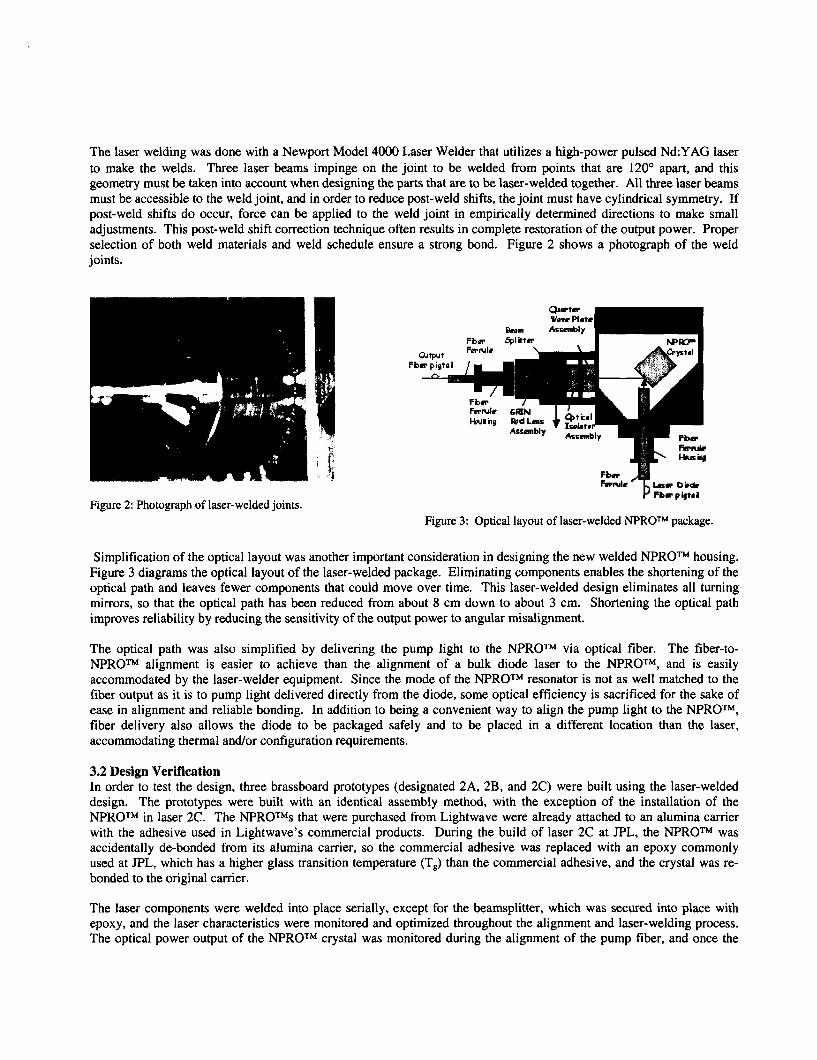
Once all three prototypes were complete, single-mode operation was verified with a spectrum analyzer and the frequency stability was measured before they were put on a yearlong mechanical stability test. For the stability tests, the lasers were run continuously at room temperature, and the ratio of fiber output power to internal power (reflected from the beamsplitter) was measured and recorded every week. This metric was chosen so that the measurement would be independent of laser diode power stability. About halfway through the stability test the lasers were temporarily removed from the test rack and put through a series of environmental tests. Laser 2B underwent a sine survey, sine vibration and random vibration. The other two lasers underwent random vibration only. Figure 4 shows the vibration test levels. The ratio of fiber output power to internal power was measured before and after each shake.
Random Vibration Level (3 axes)
20 Hz.. ............................... . O . W gz/Hz 20-50 Hz., ............................ ...+ 6 dB/oct 50-800 Hz ................................ 0.4 gz/Hz
2000 Hz ................................ 0.064 g2/Hz Overall:. ................................ .22.3 g-rms Duration.. ............................ .I80 secfaxis
800-2000 Hz.. ........................ ...- 6 dB/oct
Sine Survey (x axis)
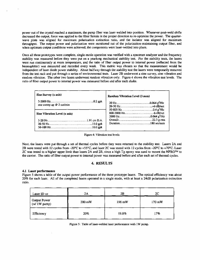
Laser ID 5
Output Power (w/ 1 W pump)
Efficiency
5-2000 HZ ............................................ 0.2 gpk one sweep up @ 2 oct/min
Sine Vibration Level (x axis)
2A 2B 2 c
200 mW 198 mW 170 mW
20% 19.8% 17%
5-20 Hz ...................................... ..1.91 cm D.A. 20-50 Hz ............................................ 15.0 gpk 50-100 Hz .......................................... 10.0 gpk
Figure 4: Vibration test levels
Next, the lasers were put through a set of thermal cycles before they were returned to the stability test. Lasers 2A and 2B were tested with 12 cycles from -20°C to +55"C, and laser 2C was tested with 12 cycles from -20°C to +70°C. Laser 2C was tested to a higher upper limit than lasers 2A and 2B, since a high Tg epoxy was used to mount the NPROTM to the carrier. The ratio of fiber output power to internal power was measured before and after each set of thermal cycles.
4. RESULTS
4.1 Laser performance Figure 5 shows a table of the output power performance of the three prototype lasers. The optical efficiency was about 20% for each laser. All of the completed lasers operated in a single mode, with at least a 24dB polarization extinction ratio.
~ ~ ~ ~
Figure 5 : Table of laser-welded laser performance with 1W pump.
The frequency noise of the laser-welded lasers was not as low as the commercial laser, primarily due to excess feedback into the laser diode. Improved frequency noise performance is expected when all feedback surfaces have been eliminated from the design. Following these original measurements, the flat-polished connectors on the pump diode pigtails were replaced with angle-polished connectors, resulting in significantly reduced frequency noise.
Test Laser 2A
4.2 Vibration tests Laser 2B passed the full battery of vibration tests, including sine survey, sine vibration, and random vibration. No change in the ratio of fiber output power to internal power was detected within measurement error (+ 5%) when it was measured before and after the vibration tests. Lasers 2A and 2C were tested simultaneously with the random vibration profile only, and both lasers passed the test with the ratio of fiber output power to internal power remaining unchanged within measurement error when measured pre- and post-test.
Laser 2C Laser 2B
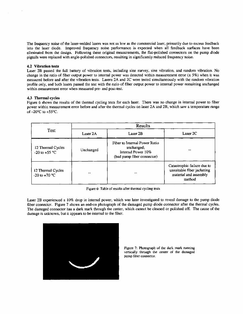
4.3 Thermal cycles Figure 6 shows the results of the thermal cycling tests for each laser. There was no change in internal power to fiber power within measurement error before and after the thermal cycles on laser 2A and 2B, which saw a temperature range of -20°C to + 5 5 T
12 Thermal Cycles -20 to +55 "C
Fiber to Internal Power Ratio unchanged;
Internal Power 10% (bad pump fiber connector)
Unchanged
~~ ~
12 Thermal Cycles -20 to +70 "C
Catastrophic failure due to unsuitable fiber jacketing
material and assembly method
-- --
Laser 2B experienced a 10% drop in internal power, which was later investigated to reveal damage to the pump diode fiber connector. Figure 7 shows an end-on photograph of the damaged pump diode connector after the thermal cycles. The damaged connector has a dark mark through the center, which cannot be cleaned or polished off. The cause of the damage is unknown, but it appears to be internal to the fiber.
Figure 7: Photograph of the dark mark running vertically through the center of the damaged pump fiber connector.
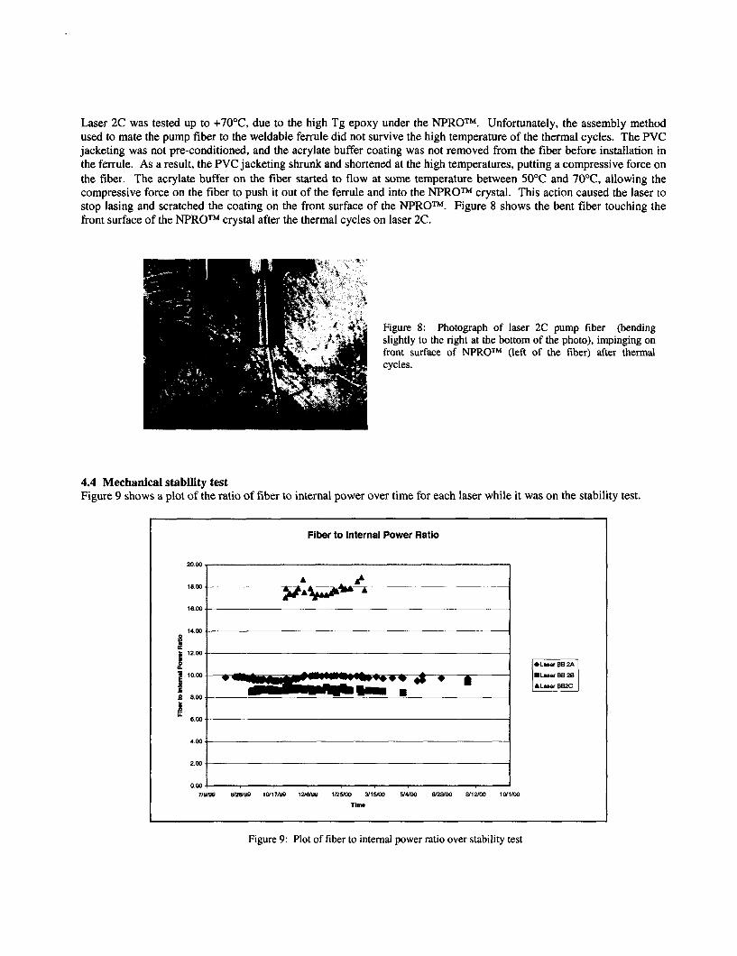
Laser 2C was tested up to +70°C, due to the high Tg epoxy under the NPROTM. Unfortunately, the assembly method used to mate the pump fiber to the weldable ferrule did not survive the high temperature of the thermal cycles. The PVC jacketing was not pre-conditioned, and the acrylate buffer coating was not removed from the fiber before installation in the ferrule. As a result, the PVC jacketing shrunk and shortened at the high temperatures, putting a compressive force on the fiber. The acrylate buffer on the fiber started to flow at some temperature between 50°C and 7OoC, allowing the compressive force on the fiber to push it out of the ferrule and into the NPROTM crystal. This action caused the laser to stop lasing and scratched the coating on the front surface of the NPROTM. Figure 8 shows the bent fiber touching the front surface of the NPROTM crystal after the thermal cycles on laser 2C.
Figure 8: Photograph of laser slightly to the right at the bottom front surface of NPROTM (left cycles.
2C pump fiber (bending of the photo), impinging on of the fiber) after thermal
4.4 Mechanical stability test Figure 9 shows a plot of the ratio of fiber to intemal power over time for each laser while it was on the stability test.
Fiber to Internal Power Ratio
4.00
0.00 J 71- &?WOO 10117ISQ 1 2 I W 1RY00 Y 1 W YUW 8/29/00 WlUW 1(
T i m
Figure 9: Plot of fiber to intemal power ratio over stability test
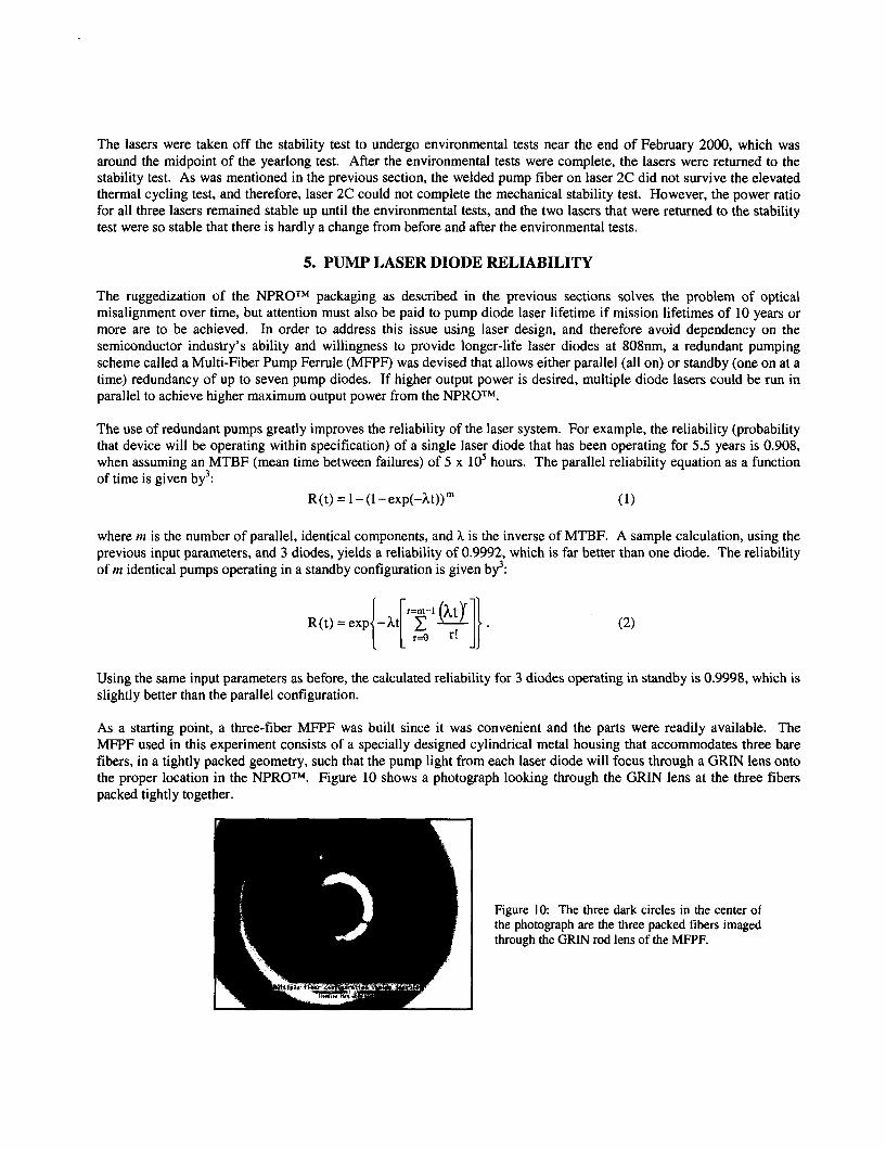
The lasers were taken off the stability test to undergo environmental tests near the end of February 2000, which was around the midpoint of the yearlong test. After the environmental tests were complete, the lasers were returned to the stability test. As was mentioned in the previous section, the welded pump fiber on laser 2C did not survive the elevated thermal cycling test, and therefore, laser 2C could not complete the mechanical stability test. However, the power ratio for all three lasers remained stable up until the environmental tests, and the two lasers that were returned to the stability test were so stable that there is hardly a change from before and after the environmental tests.
5. PUMP LASER DIODE RELIABILITY
The ruggedization of the NF'ROTM packaging as described in the previous sections solves the problem of optical misalignment over time, but attention must also be paid to pump diode laser lifetime if mission lifetimes of 10 years or more are to be achieved. In order to address this issue using laser design, and therefore avoid dependency on the semiconductor industry's ability and willingness to provide longer-life laser diodes at 808nm. a redundant pumping scheme called a Multi-Fiber Pump Ferrule (MFPF) was devised that allows either parallel (all on) or standby (one on at a time) redundancy of up to seven pump diodes. If higher output power is desired, multiple diode lasers could be run in parallel to achieve higher maximum output power from the NPROTM.
The use of redundant pumps greatly improves the reliability of the laser system. For example, the reliability (probability that device will be operating within specification) of a single laser diode that has been operating for 5.5 years is 0.908, when assuming an MTBF (mean time between failures) of 5 x lo' hours. The parallel reliability equation as a function of time is given by3:
R(t) = l-(l-exp(-ht))m (1)
where m is the number of parallel, identical components, and h is the inverse of MTBF. A sample calculation, using the previous input parameters, and 3 diodes, yields a reliability of 0.9992, which is far better than one diode. The reliability of m identical pumps operating in a standby configuration is given by3:
Using the same input parameters as before, the calculated reliability for 3 diodes operating in standby is 0.9998. which is slightly better than the parallel configuration.
As a starting point, a three-fiber MFPF was built since it was convenient and the parts were readily available. The MFPF used in this experiment consists of a specially designed cylindrical metal housing that accommodates three bare fibers, in a tightly packed geometry, such that the pump light from each laser diode will focus through a GRIN lens onto the proper location in the "ROTM. Figure 10 shows a photograph looking through the GRIN lens at the three fibers packed tightly together.
Figure 1 0 The three dark circles in the center of the photograph are the three packed fibers imaged through the GRIN rod lens of the MFPF.
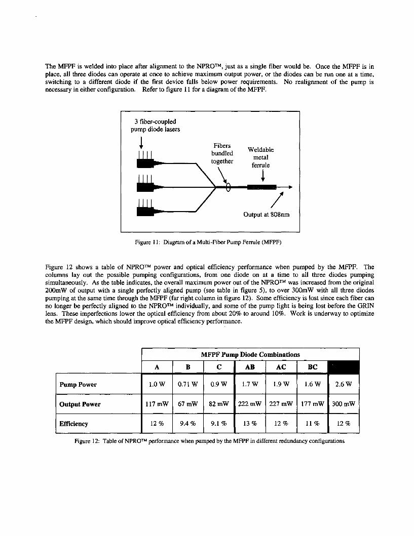
The MFPF is welded into place after alignment to the NPROTM, just as a single fiber would be. Once the MFPF is in place, all three diodes can operate at once to achieve maximum output power, or the diodes can be run one at a time, switching to a different diode if the first device falls below power requirements. No realignment of the pump is necessary in either configuration. Refer to figure 11 for a diagram of the MFPF.
Pump Power
Output Power
Efficiency
3 fiber-coupled pump diode lasers
1.OW 0.71W 0.9W 1.7W 1.9W 1.6W 2.6W
117mW 67mW 82mW 222mW 227mW 177mW 300mW
12 % 9.4 % 9.1 % 13 % 12 % 11 % 12 %
Output at 808nm
Figure 11: Diagram of a Multi-Fiber Pump Ferrule (MFPF)
Figure 12 shows a table of NPROTM power and optical efficiency performance when pumped by the MFPF. The columns lay out the possible pumping configurations, from one diode on at a time to all three diodes pumping simultaneously. As the table indicates, the overall maximum power out of the "ROTM was increased from the original 200mW of output with a single perfectly aligned pump (see table in figure 5), to over 300mW with all three diodes pumping at the same time through the MFPF (far right column in figure 12). Some efficiency is lost since each fiber can no longer be perfectly aligned to the NPROTM individually, and some of the pump light is being lost before the GRIN lens. These imperfections lower the optical efficiency from about 20% to around 10%. Work is underway to optimize the MFPF design, which should improve optical efficiency performance.
Figure 12: Table of NPROTM performance when pumped by the MFPF in different redundancy configurations
6. CONCLUSIONS
This paper described the design, construction, and test of a compact, rugged, and highly frequency-stable CW IR laser with 200-300mW output at 1319nm. The laser was ruggedized by laser-welding input and output optics to a metal housing containing an NPROTM resonator crystal from Lightwave Electronics Corporation. The laser-welded packaging design described in this paper successfully held passive and active optical elements aligned with respect to each other such that no output power degradation due to misalignment was observed. The ratio of fiber output power to internal power remained constant to within measurement error throughout a series of vibration tests and thermal cycles and a 1- year mechanical stability test. Problems were encountered during environmental testing, but they are independent of the laser-welding technique, and must be addressed in other ways. The pump diode fiber connectors must be qualified for extreme environments, or fiber splices must be utilized. The materials used to make the fiber cabling must be qualified for high temperatures, as well as the assembly techniques for mating the fiber cabling to the weldable metal ferrules. Pump diode lifetime limitations were addressed by designing a redundant pumping configuration for the “ROTM that can be used in either parallel or standby mode. The MFPF increased the overall maximum power output of the laser, but decreased the optical efficiency. Optimization of the MFPF design is expected to improve its optical efficiency, and that work is underway.
ACKNOWLEDGEMENTS
The authors gratefully acknowledge Thomas Kane at Lightwave Electronics Corporation for sharing his NPROTM expertise. This research was carried out at the Jet Propulsion Laboratory, California Institute of Technology, under a contract with the National Aeronautics and Space Administration. Reference herein to any specific commercial product, process, or service by trade name, trademark, manufacturer, or otherwise, does not constitute or imply its endorsement by the United States Government or the Jet Propulsion Laboratory, California Institute of Technology.
REFERENCES
1.
2. 3.
T.J. Kane, R. L. Byer, “Monolithic, Unidirectional Single Mode Nd:YAG Ring Laser,” Optics Letters 10,65, 1985. D. Liu, “Laser welded fiber-pigtailed NPROTM Laser,” NASA Tech Briefs, 25, pp. 12a, NP0-20885,2001. W. H. V. Alven, Reliability Engineering: ARINC Research Corp., Prentiss Hall, 1964.


