Embed Size (px)
Citation preview
Lecture 18
November 5, 2018
Statics - TAM 211

Announcements
Upcoming deadlines:
Tuesday (11/6) Prairie Learn HW 7
Friday (11/9) Written Assignment 7
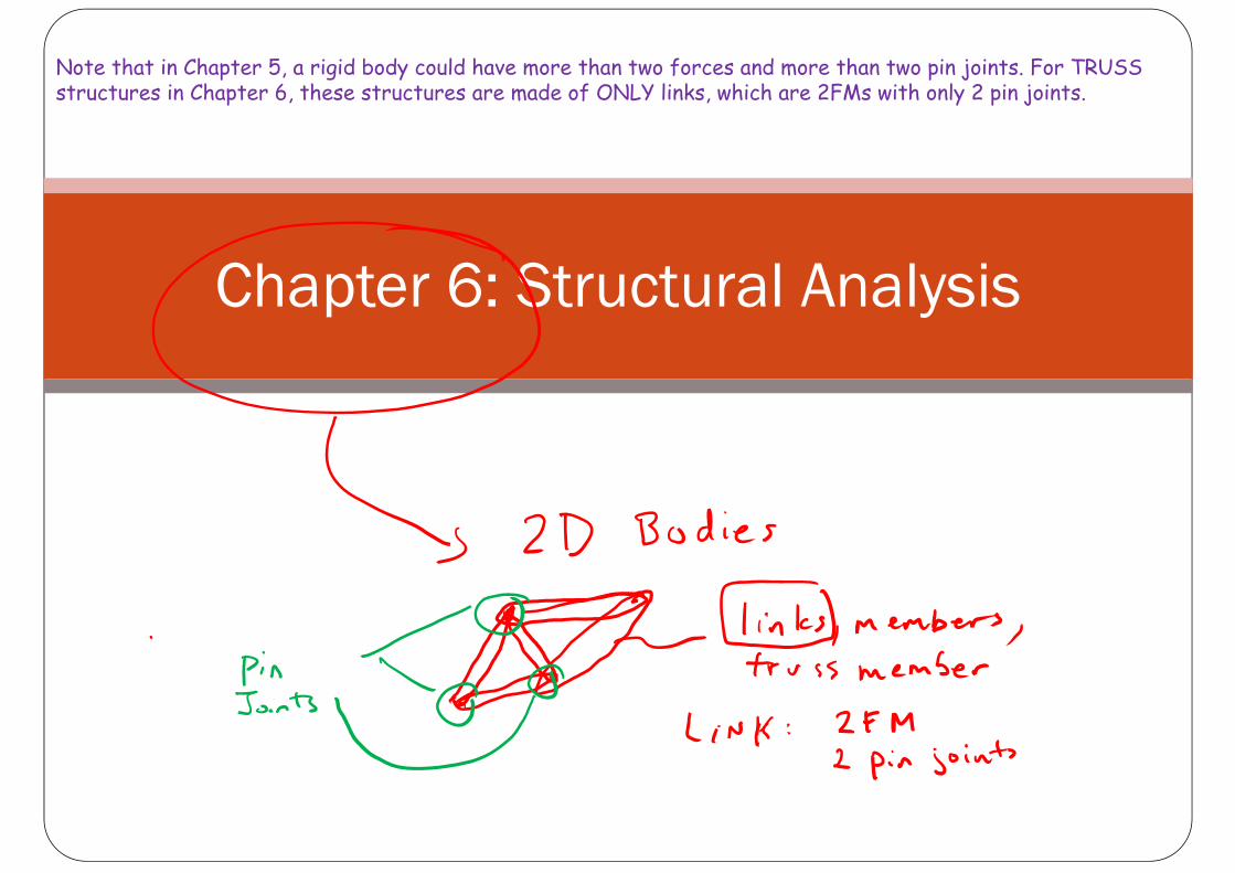
Chapter 6: Structural Analysis
Note that in Chapter 5, a rigid body could have more than two forces and more than two pin joints. For TRUSS structures in Chapter 6, these structures are made of ONLY links, which are 2FMs with only 2 pin joints.
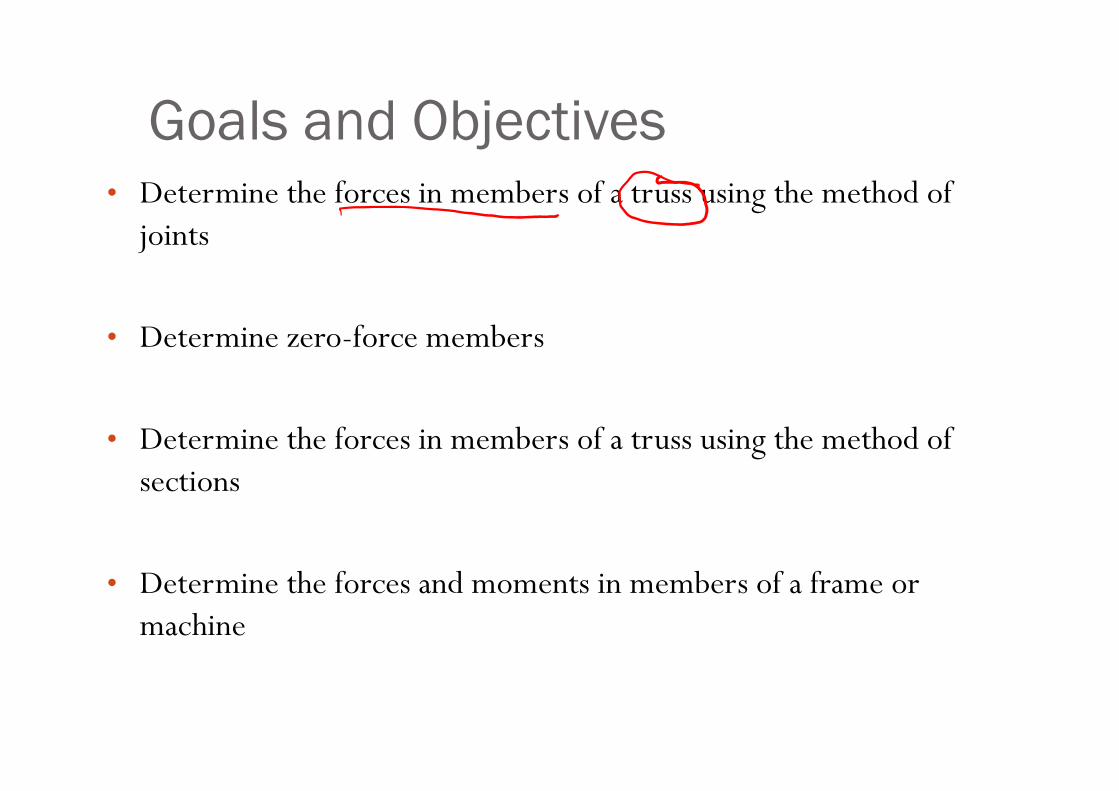
Goals and Objectives• Determine the forces in members of a truss using the method of
joints
• Determine zero-force members
• Determine the forces in members of a truss using the method of sections
• Determine the forces and moments in members of a frame or machine
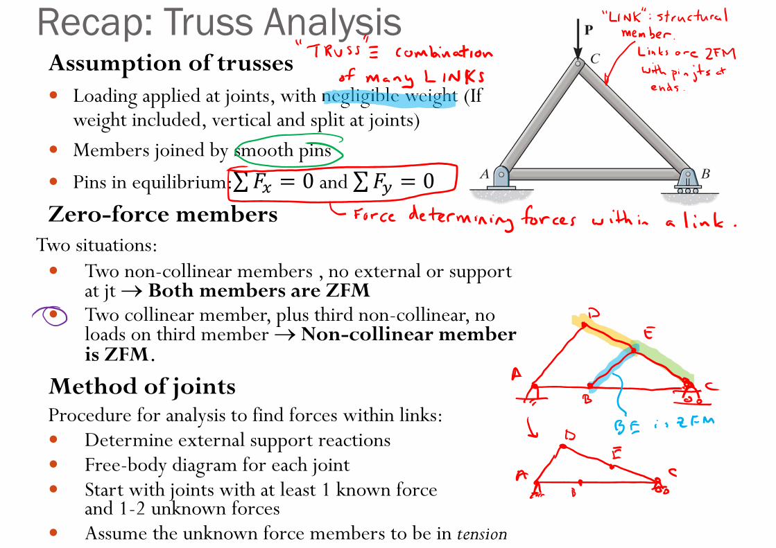
Assumption of trusses Loading applied at joints, with negligible weight (If
weight included, vertical and split at joints) Members joined by smooth pins
Pins in equilibrium:∑ 0and ∑ 0Zero-force members
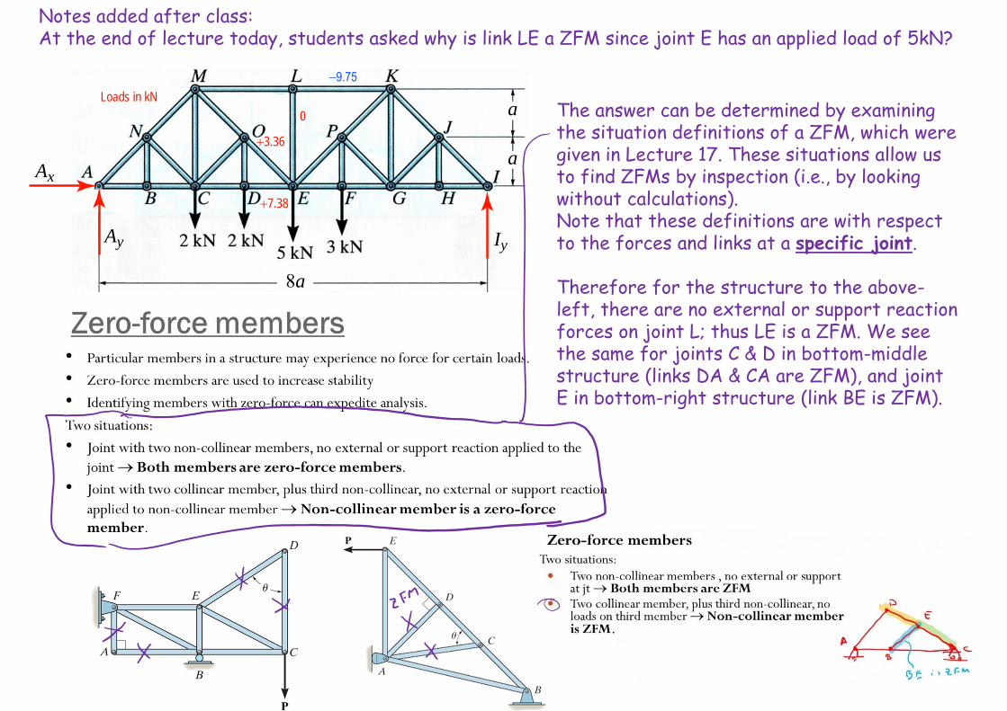
Two situations: Two non-collinear members , no external or support
at jt Both members are ZFM Two collinear member, plus third non-collinear, no
loads on third member Non-collinear member is ZFM.
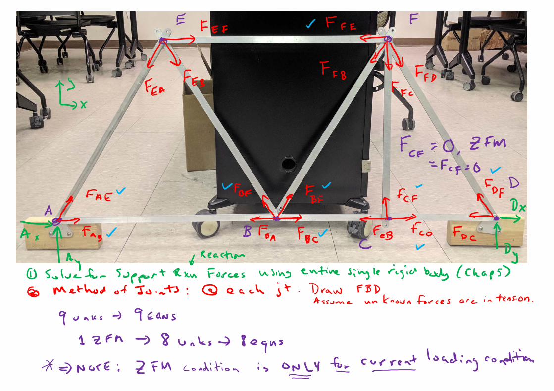
Method of jointsProcedure for analysis to find forces within links: Determine external support reactions Free-body diagram for each joint Start with joints with at least 1 known force
and 1-2 unknown forces Assume the unknown force members to be in tension
Recap: Truss Analysis
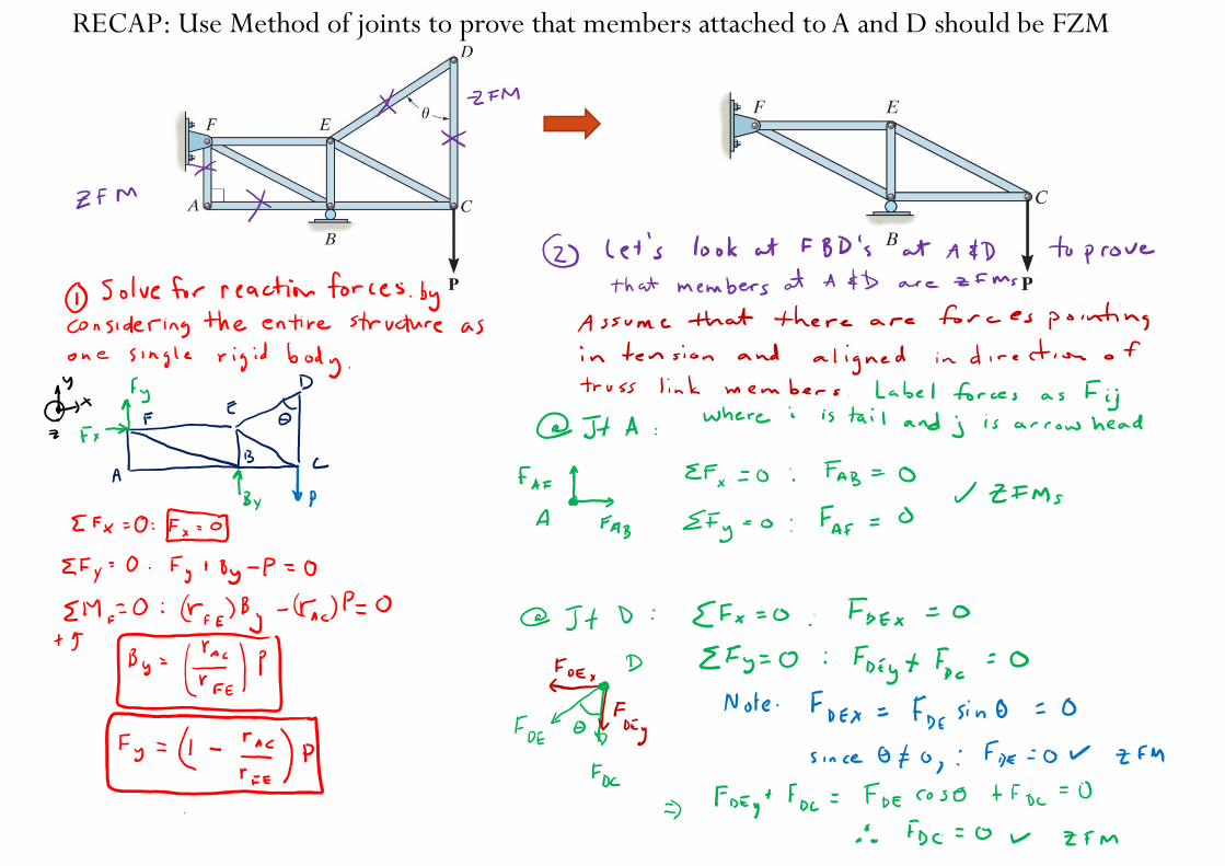
RECAP: Use Method of joints to prove that members attached to A and D should be FZM
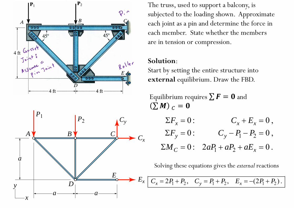
The truss, used to support a balcony, is subjected to the loading shown. Approximate each joint as a pin and determine the force in each member. State whether the members are in tension or compression.
A
P1 P2
Cx
Ex
Cy
B C
DE
a
a
y
xa
Solution:Start by setting the entire structure into external equilibrium. Draw the FBD.
1 2
1 2
0 : 0 ,0 : 0 ,
0 : 2 0 .
x x x
y y
C x
F C EF C P P
M aP aP aE
1 2 1 2 1 22 , , (2 ) .x y xC P P C P P E P P
Solving these equations gives the external reactions
Equilibrium requires ∑ and ∑
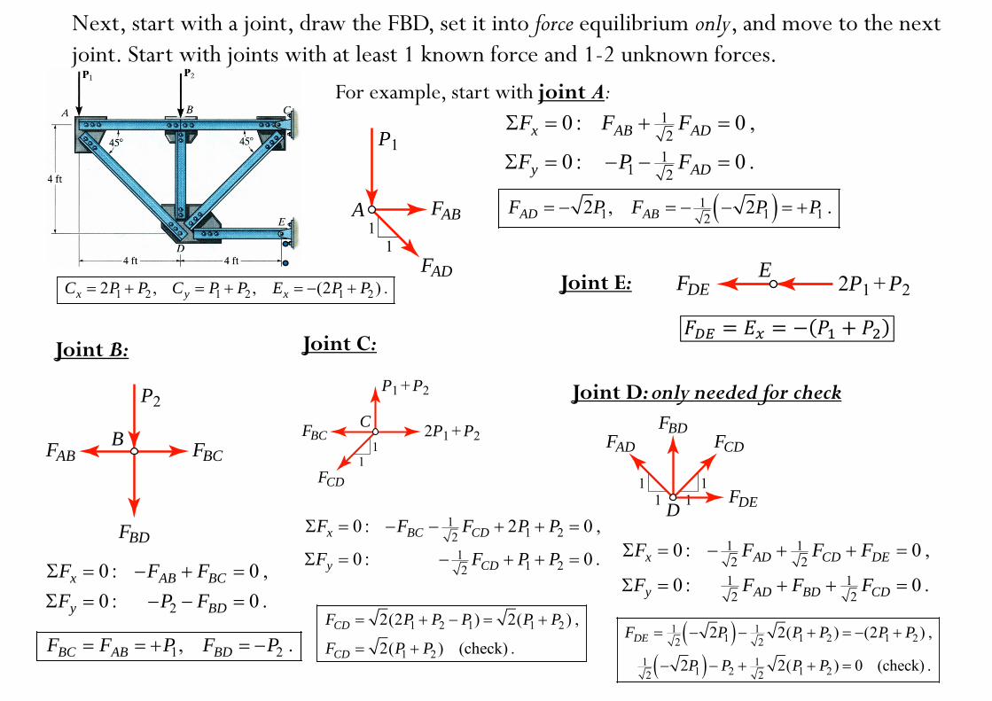
Next, start with a joint, draw the FBD, set it into force equilibrium only, and move to the next joint. Start with joints with at least 1 known force and 1-2 unknown forces.
11
A
P1
FAB
FAD
12
11 2
0 : 0 ,
0 : 0 .x AB AD
y AD
F F F
F P F
11 1 12
2 , 2 .AD ABF P F P P
P2
BFAB FBC
FBD
For example, start with joint A:
Joint B:
2
0 : 0 ,0 : 0 .
x AB BC
y BD
F F FF P F
1 2, .BC AB BDF F P F P
Joint C:
11 22
11 22
0 : 2 0 ,
0 : 0 .x BC CD
y CD
F F F P P
F F P P
C1
1
FBC
FCD
P1 + P2
2P1 + P2
1 2 1 1 2
1 2
2(2 ) 2( ) ,
2( ) (check) .CD
CD
F P P P P P
F P P
11
11 D
FCD
FDE
FADFBD
E 2P1 + P2FDE
Joint D: only needed for check
Joint E:
1 12 2
1 12 2
0 : 0 ,
0 : 0 .x AD CD DE
y AD BD CD
F F F F
F F F F
1 11 1 2 1 22 2
1 11 2 1 22 2
2 2( ) (2 ) ,
2 2( ) 0 (check) .
DEF P P P P P
P P P P
1 2 1 2 1 22 , , (2 ) .x y xC P P C P P E P P
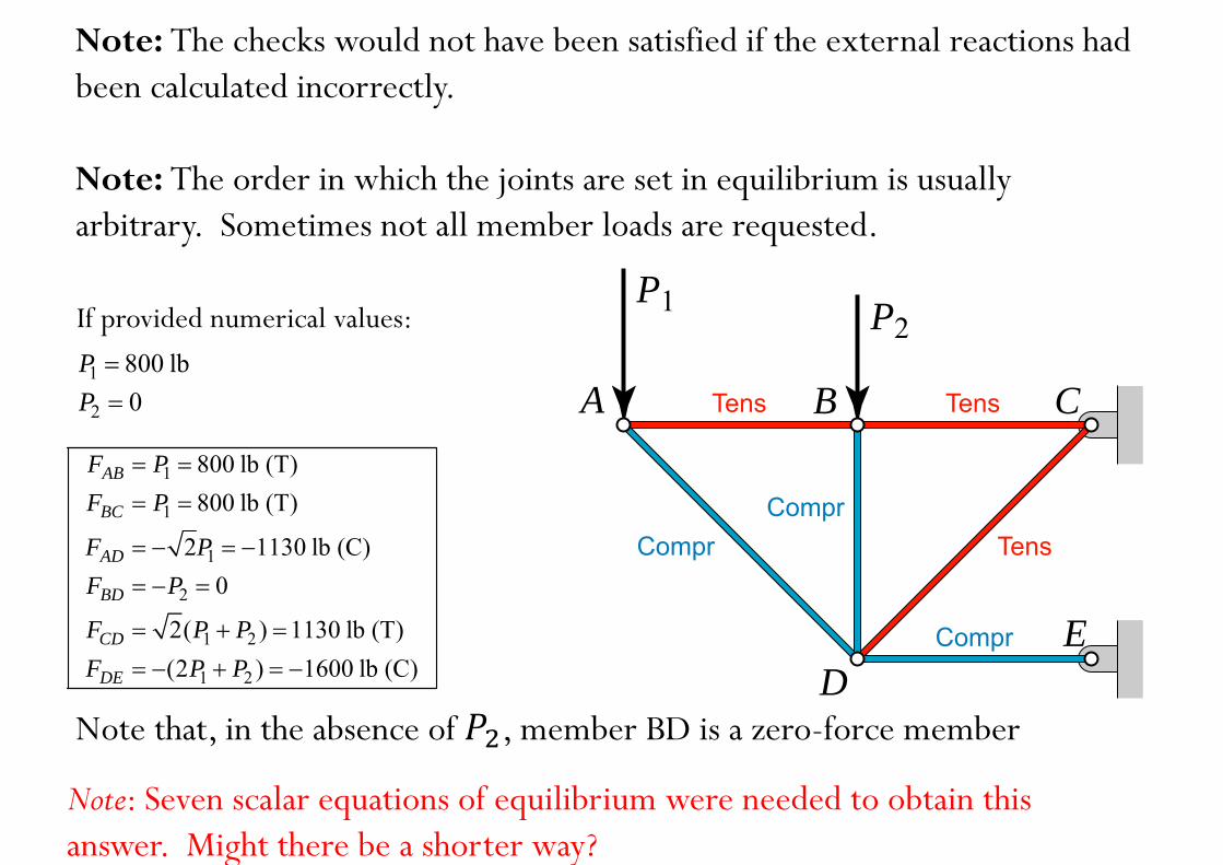
Note: The checks would not have been satisfied if the external reactions had been calculated incorrectly.
Note: The order in which the joints are set in equilibrium is usually arbitrary. Sometimes not all member loads are requested.
1
1
1
2
1 2
1 2
800 lb (T)800 lb (T)
2 1130 lb (C)0
2( ) 1130 lb (T)(2 ) 1600 lb (C)
AB
BC
AD
BD
CD
DE
F PF P
F PF P
F P PF P P
A
P1 P2
B C
DE
Tens
Compr
Compr
Compr
Tens
Tens
Note that, in the absence of , member BD is a zero-force member
1 800 lbP
2 0P
If provided numerical values:
Note: Seven scalar equations of equilibrium were needed to obtain this answer. Might there be a shorter way?
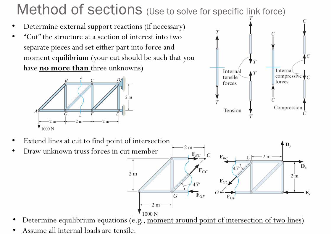
• Determine external support reactions (if necessary)• “Cut” the structure at a section of interest into two
separate pieces and set either part into force and moment equilibrium (your cut should be such that you have no more than three unknowns)
• Extend lines at cut to find point of intersection• Draw unknown truss forces in cut member
• Determine equilibrium equations (e.g., moment around point of intersection of two lines)• Assume all internal loads are tensile.
Method of sections (Use to solve for specific link force)
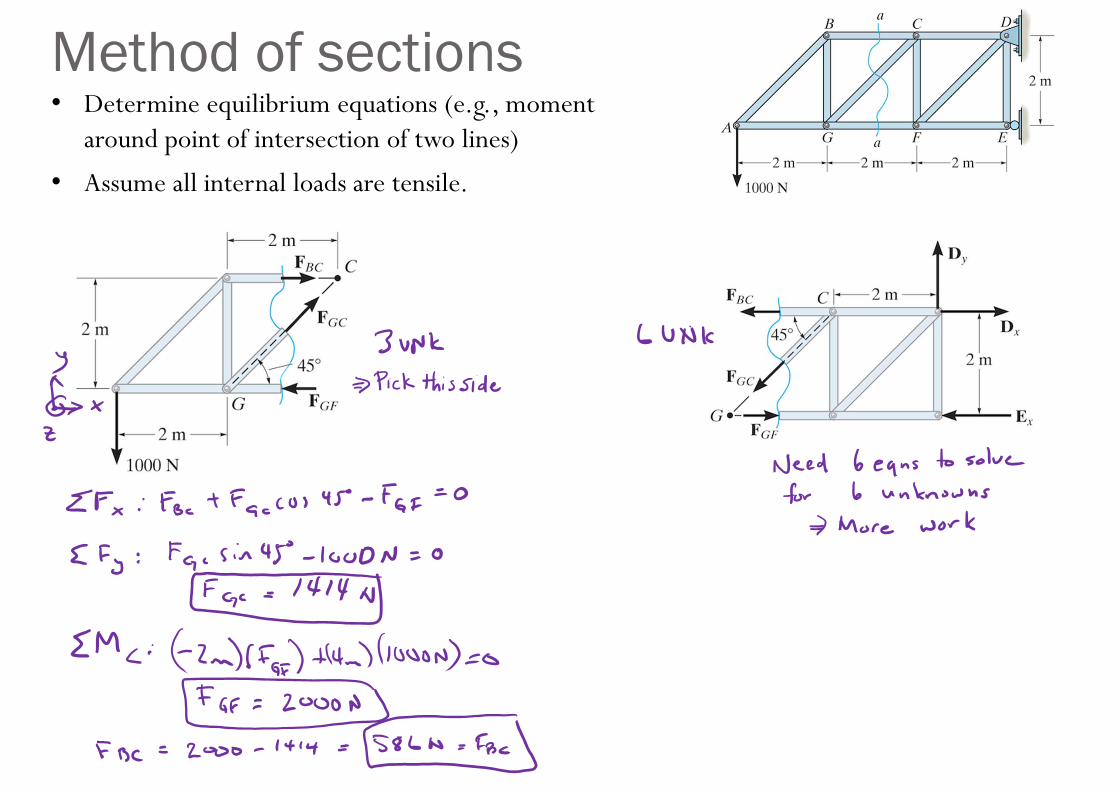
Method of sections• Determine equilibrium equations (e.g., moment
around point of intersection of two lines)
• Assume all internal loads are tensile.
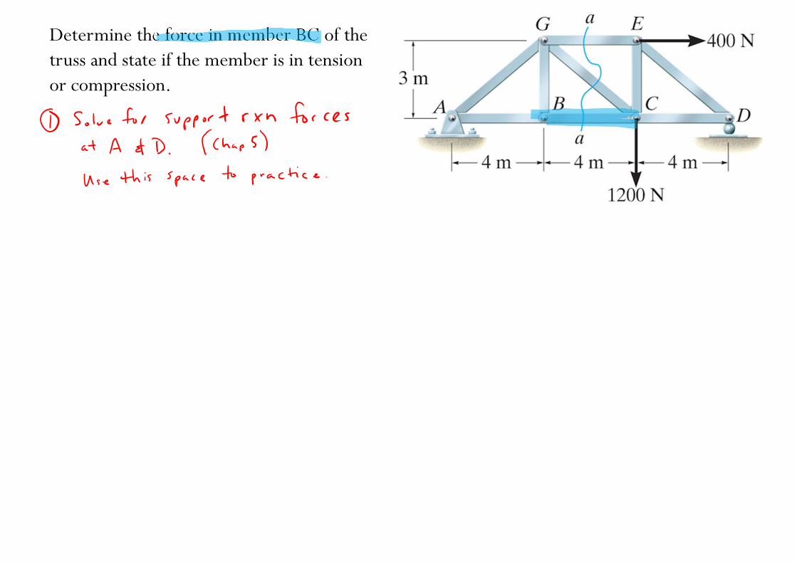
Determine the force in member BC of the truss and state if the member is in tension or compression.
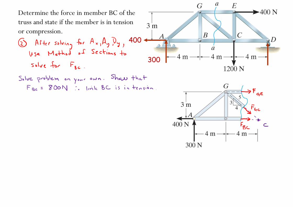
Determine the force in member BC of the truss and state if the member is in tension or compression.
400
300
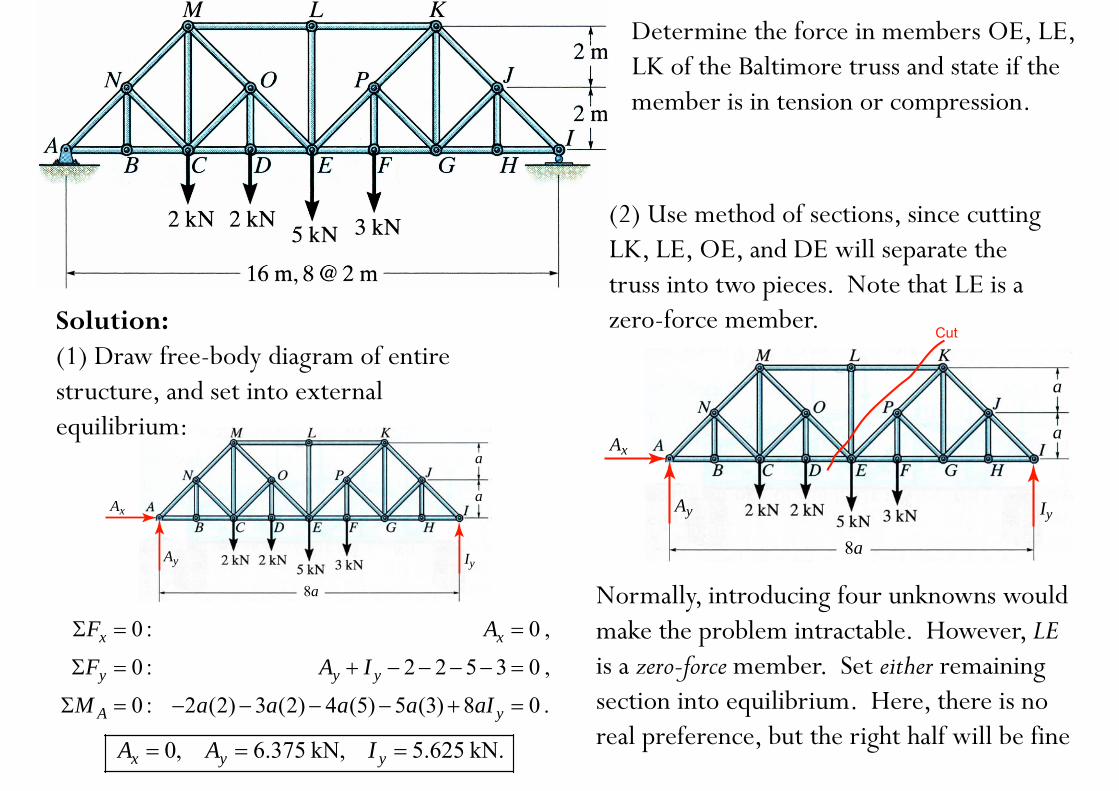
Determine the force in members OE, LE, LK of the Baltimore truss and state if the member is in tension or compression.
Ax
Ay Iy
8a
a
a
0 : 0 ,
0 : 2 2 5 3 0 ,
0 : 2 (2) 3 (2) 4 (5) 5 (3) 8 0 .
x x
y y y
A y
F A
F A I
M a a a a aI
0, 6.375 kN, 5.625 kN.x y yA A I
Ax
Ay Iy
8a
a
a
Cut
Normally, introducing four unknowns would make the problem intractable. However, LEis a zero-force member. Set either remaining section into equilibrium. Here, there is no real preference, but the right half will be fine
(2) Use method of sections, since cutting LK, LE, OE, and DE will separate the truss into two pieces. Note that LE is a zero-force member. Solution:
(1) Draw free-body diagram of entire structure, and set into external equilibrium:
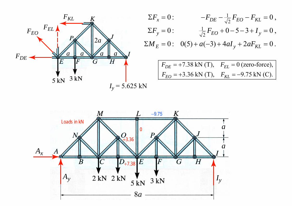
FDE
FEOFEL
FKL
Iy = 5.625 kN
2a
a a a a
12
12
0 : 0 ,
0 : 0 5 3 0 ,
0 : 0(5) ( 3) 4 2 0 .
x DE EO KL
y EO y
E y KL
F F F F
F F I
M a aI aF
Ax
Ay Iy
8a
a
a
+7.38
+3.36
Loads in kN0
7.38 kN (T), 0 (zero-force),3.36 kN (T), 9.75 kN (C).
DE EL
EO KL
F FF F
Ax
Ay Iy
8a
a
a
+7.38
+3.36
Loads in kN0
Notes added after class:At the end of lecture today, students asked why is link LE a ZFM since joint E has an applied load of 5kN?
The answer can be determined by examining the situation definitions of a ZFM, which were given in Lecture 17. These situations allow us to find ZFMs by inspection (i.e., by looking without calculations).Note that these definitions are with respect to the forces and links at a specific joint.
Therefore for the structure to the above-left, there are no external or support reaction forces on joint L; thus LE is a ZFM. We see the same for joints C & D in bottom-middle structure (links DA & CA are ZFM), and joint E in bottom-right structure (link BE is ZFM).


