Embed Size (px)
Citation preview
Lenovo Deployment Pack for Microsoft SystemCenter Configuration ManagerInstallation and User's Guide
Version 6.3

Note
Before using this information and the product it supports, read the information in Appendix G “Notices” onpage 141.
Third Edition (September 2016)
© Copyright Lenovo 2014, 2016.Portions © Copyright IBM Corporation 2014
LIMITED AND RESTRICTED RIGHTS NOTICE: If data or software is delivered pursuant to a General ServicesAdministration “GSA” contract, use, reproduction, or disclosure is subject to restrictions set forth in Contract No.GS-35F-05925
Contents
Figures . . . . . . . . . . . . . . . . iii
Tables . . . . . . . . . . . . . . . . . . v
About this publication . . . . . . . . viiConventions and terminology . . . . . . . . . viiWorld Wide Web resources. . . . . . . . . . vii
Chapter 1. Product introduction . . . . 1License support . . . . . . . . . . . . . . . 1
Chapter 2. Installing and importingthe Lenovo Deployment Pack . . . . . 3Prerequisites . . . . . . . . . . . . . . . . 3Installing the Lenovo Deployment Pack intoSCCM . . . . . . . . . . . . . . . . . . . 3Importing the Lenovo Deployment Pack intoSCCM . . . . . . . . . . . . . . . . . . . 4Upgrading the IBM Deployment Pack from version1.4, 3.0, 3.1, 3.2, 4.0, 4.5, 5.0, or 5.5 to LenovoDeployment Pack v6.3 . . . . . . . . . . . 15Uninstalling the Lenovo Deployment Pack . . . . 16Reusing the task sequence after reinstalling theLenovo Deployment Pack . . . . . . . . . . 16Integrating the Lenovo System Enablement Pack . 19
Lenovo Deployment Pack . . . . . . . . 19How SEP works in Configuration Manager . . 19
Chapter 3. Preparing fordeployment . . . . . . . . . . . . . . 21Preparing for deployment in SCCM 2007 . . . . 21
SCCM OSD initial configuration . . . . . . 21Post-installation configuration . . . . . . . 25Creating a task sequence for Lenovoservers . . . . . . . . . . . . . . . . 28Updating the distribution points for a bootimage . . . . . . . . . . . . . . . . 33Advertising the task sequence to the newservers . . . . . . . . . . . . . . . . 34Capturing operating system images . . . . 35Lenovo Deployment Pack feature reference . 41Preparing the operating system image . . . 41
Preparing for deployment in SCCM 2012 . . . . 51SCCM OSD initial configuration . . . . . . 51Post-installation configuration . . . . . . . 53Preparing the operating system image . . . 59
Chapter 4. End-to-end deploymentscenario . . . . . . . . . . . . . . . . 71
End-to-end deployment scenario in SCCM 2007 . 71Adding a target server to ConfigurationManager . . . . . . . . . . . . . . . 71Preparing a task sequence . . . . . . . . 71Advertising a task sequence . . . . . . . 74Checking the task sequence executionresult . . . . . . . . . . . . . . . . 77
End-to-end deployment scenario in SCCM 2012 . 80Adding a target server to ConfigurationManager . . . . . . . . . . . . . . . 80Preparing a task sequence . . . . . . . . 80Advertising a task sequence . . . . . . . 82Checking the task sequence executionresult . . . . . . . . . . . . . . . . 86
Chapter 5. Lenovo Deployment Packfeatures . . . . . . . . . . . . . . . . 89Configuring RAID through PRAID . . . . . . . 89
Configuring RAID through the policy file . . . 89Configuring RAID through the Array BuilderWizard . . . . . . . . . . . . . . . . 92
Configuring hardware settings through ASU . . . 94Configuring IMM through the ASU . . . . . 94Configuring uEFI through the ASU . . . . . 96
Supported Lenovo hardware-specific configurationlist . . . . . . . . . . . . . . . . . . . 97Operating system deployment . . . . . . . . 98
Chapter 6. Supported hardware andsoftware . . . . . . . . . . . . . . . 101Server support. . . . . . . . . . . . . . . 101RAID controller support . . . . . . . . . . . 103
Appendix A. Hints and tips . . . . . 105PXE issues . . . . . . . . . . . . . . . . 105Tips when rebooting to PXE or USB . . . . . . 107Tips to resolve problems when starting theLenovoDeployment Pack . . . . . . . . . . . . . 107Manual workaround method . . . . . . . . . 109The Reboot to PXE/USB custom action . . . . . 109Preventing a server from looping during multiplereboot processing . . . . . . . . . . . . . 109
Appendix B. Troubleshooting . . . . 111Troubleshooting installation issues . . . . . . . 112Troubleshooting administrator console issues . . 113Troubleshooting device driver issues . . . . . . 113Troubleshooting WinPE and task sequenceissues . . . . . . . . . . . . . . . . . . 115
© Copyright Lenovo 2014, 2016 i
Troubleshooting general issues . . . . . . . . 120
Appendix C. Running Sysprep . . . 121Running Sysprep on Windows Server 2003 . . . 121Running Sysprep on Windows Server 2008 orWindows Server 2012 . . . . . . . . . . . . 126
Appendix D. Getting help andtechnical assistance . . . . . . . . 129Before you call. . . . . . . . . . . . . . . 129Using the documentation . . . . . . . . . . 129Getting help and information from the World WideWeb . . . . . . . . . . . . . . . . . . . 130Hardware service and support . . . . . . . . 130
Appendix E. Capturing and deployingWindows 2008 R2 . . . . . . . . . . 131Changing the OSDTargetSystemRoot property . . 131Deploying the Windows 2008 R2 image . . . . . 132
Appendix F. Accessibility features forthe Lenovo Deployment Pack . . . 139
AppendixG. Notices. . . . . . . . . 141Trademarks . . . . . . . . . . . . . . . . 142Important notes . . . . . . . . . . . . . . 142
ii Lenovo Deployment Pack for Microsoft System Center Configuration Manager Installation and User's Guide

Figures
1. InstallShield Wizard Completed . . . . . . . 42. Lenovo Deployment Pack Import Wizard
Welcome page . . . . . . . . . . . . . 53. Target Systems page . . . . . . . . . . . 64. Boot Image page . . . . . . . . . . . . 75. Additional SEP Packages page . . . . . . . 76. Boot Image page . . . . . . . . . . . . 87. Ready to Begin page . . . . . . . . . . . 88. Progress page . . . . . . . . . . . . . 99. Completed page. . . . . . . . . . . . 1010. Post Import Instruction page . . . . . . . 1111. Items added to the SCCM 2007 console after
installing the Lenovo Deployment Pack . . . 1212. Items added to the SCCM 2012 console after
installing the Lenovo Deployment Pack . . . 1313. New Bare Metal Deployment option added in
SCCM 2007 . . . . . . . . . . . . . 1314. New Bare Metal Deployment option added in
SCCM 2012 . . . . . . . . . . . . . 1415. New action in Task Sequence Editor . . . . 1416. Previous version detection . . . . . . . . 1517. Missing Objects window . . . . . . . . 1718. Selecting the Lenovo Custom Reboot script
5.6 package . . . . . . . . . . . . . 1819. SEP workflow . . . . . . . . . . . . . 1920. Select Client Agents . . . . . . . . . . 2121. Computer Client Agent Properties
window . . . . . . . . . . . . . . . 2222. New Site Role wizard . . . . . . . . . . 2323. PXE service point PropertiesGeneral tab . . 2424. PXE service point PropertiesDatabase
tab . . . . . . . . . . . . . . . . . 2525. Manage Distribution Points Wizard . . . . 2626. Manage Distribution Points Wizard . . . . 2727. Enabling command-line support . . . . . 2828. “Create a Lenovo Server Deployment Task
Sequence” menu . . . . . . . . . . . 2929. The Create Server Deployment Task
Sequence wizard . . . . . . . . . . . 2930. Opening the Task Sequence Editor . . . . 3031. Missing Objects dialog box . . . . . . . 3132. Apply Operating System Image settings . . 3233. Apply Driver Package settings . . . . . . 3334. Update Distribution Points option . . . . . 3435. Import Computer Information Wizard. . . . 3636. Setting the operating system location on the
target server . . . . . . . . . . . . . 3637. New Task Sequence Wizard . . . . . . . 3738. Naming the task sequence in the New Task
Sequence Wizard . . . . . . . . . . . 3739. Editing the OS capture task sequence to
identify the share . . . . . . . . . . . 3840. Advertising the OS capture task
sequence . . . . . . . . . . . . . . 3841. New Advertisement Wizard . . . . . . . 3942. New Advertisement Wizard: Schedule
page . . . . . . . . . . . . . . . . 39
43. New Advertisement Wizard: DistributionPoints page . . . . . . . . . . . . . 40
44. Import Computer Information Wizard. . . . 4245. Adding a single computer . . . . . . . . 4346. Adding the new computer to a collection . . 4447. Setting the location variable . . . . . . . 4548. Capture Operating System Image . . . . . 4649. Advertisement settings, General tab . . . . 4750. Advertisement settings, Schedule tab . . . 4851. Advertisement settings, Distribution Points
tab . . . . . . . . . . . . . . . . . 4952. Adding operating system images . . . . . 5053. Select Software Distribution . . . . . . . 5154. Windows User Account window . . . . . 5255. Enable PXE role . . . . . . . . . . . . 5356. Configuring the data source . . . . . . . 5457. Package share settings . . . . . . . . . 5558. Set Windows PE Scratch Space . . . . . 5659. Distribution Content Wizard . . . . . . . 5760. Update Distribution Points Wizard . . . . . 5861. Enabling command-line support . . . . . 5962. Import Computer Information Wizard. . . . 6163. Adding a single computer . . . . . . . . 6264. Adding the new computer to a collection . . 6365. Setting the location variable . . . . . . . 6466. Capture Operating System Image . . . . . 6567. Deployment properties, Deployment Settings
tab . . . . . . . . . . . . . . . . . 6668. Deployment properties, Scheduling tab. . . 6769. Deployment properties, Distribution Points
tab . . . . . . . . . . . . . . . . . 6870. Adding operating system images . . . . . 6971. Creating a task sequence . . . . . . . . 7272. Applying driver package properties . . . . 7373. Selecting the mass storage driver . . . . . 7474. Selecting the collection containing the target
server . . . . . . . . . . . . . . . . 7575. Scheduling the advertisement . . . . . . 7676. Specifying distribution points options . . . 7777. Restarting the target server from PXE . . . 7878. Starting the download process . . . . . . 7879. Running the Format and Partition Disk
action . . . . . . . . . . . . . . . . 7980. Running the Apply Operating System Image
action . . . . . . . . . . . . . . . . 7981. Creating a task sequence by using the
template . . . . . . . . . . . . . . . 8082. Applying driver package properties . . . . 8183. Selecting the mass storage driver . . . . . 8284. Select the deployment settings . . . . . . 8385. Schedule the deployment . . . . . . . . 8486. Select the user experience. . . . . . . . 8587. Specify distribution points options. . . . . 8688. Restarting the target server from PXE . . . 8789. Starting the download process . . . . . . 8790. Running the Format and Partition Disk
action . . . . . . . . . . . . . . . . 88
© Copyright Lenovo 2014, 2016 iii
91. Running the Apply Operating System Imageaction . . . . . . . . . . . . . . . . 88
92. Editing the task sequence . . . . . . . . 9093. Editing the Set RAID Config (ini file) task . . 9194. RAID configuration task sequence for INI
files . . . . . . . . . . . . . . . . . 9295. Array Builder Wizard . . . . . . . . . . 9396. Dynamic RAID configuration . . . . . . . 9397. Selecting an IMM ini file . . . . . . . . . 9598. Sample settings in an IMM.ini file . . . . . 9699. Selecting a uEFI .ini file . . . . . . . . . 97100. Properties page for a Reboot to PXE / USB
action . . . . . . . . . . . . . . . . 107101. Welcome to Setup Manager . . . . . . . 121102. Setup Manager: Creating a new answer
file . . . . . . . . . . . . . . . . . 122103. Setup Manager: Type of Setup . . . . . . 122104. Setup Manager: Windows product . . . . 123
105. Setup Manager: License Agreement . . . . 123106. Setup Manager: Name and
Organization . . . . . . . . . . . . . 124107. Setup Manager: Display Settings . . . . . 124108. Setup Manager: Product Key. . . . . . . 125109. Setup Manager: Administrator
Password . . . . . . . . . . . . . . 125110. Setup Manager: Path and file name . . . . 126111. System Preparation Tool (Sysprep) . . . . 127112. Two partitions . . . . . . . . . . . . 131113. OSDTargetSystemRoot property . . . . . 132114. Image list . . . . . . . . . . . . . . 133115. Format and partition disk . . . . . . . . 134116. Partition properties . . . . . . . . . . 135117. Partition properties for the second
volume . . . . . . . . . . . . . . . 136118. Task sequence . . . . . . . . . . . . 137119. Deploy Windows 2008 R2 page. . . . . . 138
iv Lenovo Deployment Pack for Microsoft System Center Configuration Manager Installation and User's Guide

Tables
1. Terms, acronyms and abbreviations . . . . vii2. Supported Lenovo systems . . . . . . . 1013. Supported IBM systems. . . . . . . . . 102
4. PXE-required settings foradvertisements . . . . . . . . . . . . 105
5. WinPE boot image-required settings . . . . 105
© Copyright Lenovo 2014, 2016 v

vi Lenovo Deployment Pack for Microsoft System Center Configuration Manager Installation and User's Guide
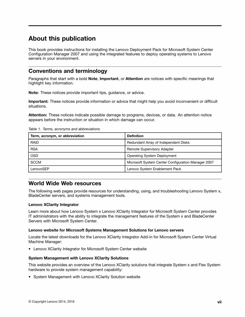
About this publication
This book provides instructions for installing the Lenovo Deployment Pack for Microsoft System CenterConfiguration Manager 2007 and using the integrated features to deploy operating systems to Lenovoservers in your environment.
Conventions and terminologyParagraphs that start with a bold Note, Important, or Attention are notices with specific meanings thathighlight key information.
Note: These notices provide important tips, guidance, or advice.
Important: These notices provide information or advice that might help you avoid inconvenient or difficultsituations.
Attention: These notices indicate possible damage to programs, devices, or data. An attention noticeappears before the instruction or situation in which damage can occur.
Table 1. Terms, acronyms and abbreviations
Term, acronym, or abbreviation Definition
RAID Redundant Array of Independent Disks
RSA Remote Supervisory Adapter
OSD Operating System Deployment
SCCM Microsoft System Center Configuration Manager 2007
LenovoSEP Lenovo System Enablement Pack
World Wide Web resourcesThe following web pages provide resources for understanding, using, and troubleshooting Lenovo System x,BladeCenter servers, and systems management tools.
Lenovo XClarity Integrator
Learn more about how Lenovo System x Lenovo XClarity Integrator for Microsoft System Center providesIT administrators with the ability to integrate the management features of the System x and BladeCenterServers with Microsoft System Center.
Lenovo website for Microsoft Systems Management Solutions for Lenovo servers
Locate the latest downloads for the Lenovo XClarity Integrator Add-in for Microsoft System Center VirtualMachine Manager:
• Lenovo XClarity Integrator for Microsoft System Center website
System Management with Lenovo XClarity Solutions
This website provides an overview of the Lenovo XClarity solutions that integrate System x and Flex Systemhardware to provide system management capability:
• System Management with Lenovo XClarity Solution website
© Copyright Lenovo 2014, 2016 vii
Lenovo technical support portal
This website can assist you in locating support for hardware and software:
• Lenovo Support Portal website
Lenovo ServerProven pages
Obtain information about hardware compatibility with Lenovo System x, BladeCenter, and IBM IntelliStationhardware.
• Lenovo ServerProven: Compatibility for BladeCenter products
• Lenovo ServerProven: Compatability for Flex System Chassis
• Lenovo ServerProven: Compatability for System x hardware, applications, and middleware
Microsoft System Center Configuration Manager
Refer to the following Microsoft sites for information about System Center Configuration Manager andrelated documentation.
• Microsoft System Center Technical Documentation Library website
• Microsoft System Center Configuration Manager 2007 website
• Microsoft System Center Configuration Manager 2007 SP1 Update webpage
• Microsoft System Center Configuration Manager 2007 Documentation Library webpage
• Microsoft System Center Configuration Manager 2012 website
viii Lenovo Deployment Pack for Microsoft System Center Configuration Manager Installation and User's Guide
Chapter 1. Product introduction
The Lenovo Deployment Pack for Microsoft Configuration Manager enables you to tailor and build customhardware deployment solutions for installing the Windows operating system on the following hardware:LenovoSystem x, BladeCenter, and Blade Servers hardware.
When integrated with the Microsoft System Center Configuration Manager 2007 (SCCM) Operating SystemDeployment component (including SCCM 2007 and SCCM 2012), the Lenovo Deployment Pack simplifiesthe steps for creating and customizing jobs to deploy hardware configurations and operating systems.
The Lenovo Deployment Pack, v6.3 supports the following types of deployment:
• Policy-based Redundant Array of Independent Disks (RAID) configuration using PRAID, a built-in toolused to configure RAID
• Configuration of the following system settings by using the ASU– BIOS/uEFI– BMC/IMM (including multiple nodes)– RSA
• Automated deployment of the following operating systems:
– Windows 2003 32bit/X64
– Windows 2003 R2 32bit/X64
– Windows 2008 32bit/X64
– Windows 2008 R2 SP1 (X64)
– Windows 2012 (X64) - SCCM 2012 SP1 or above required
Note: If the version of SCCM is earlier than 2012 SP1, Lenovo Deployment Pack will not import theWindows 2012 drivers and packages into SCCM.
– Windows 2012 R2
The Lenovo Deployment Pack, v6.3 also provides the following components and functionality:
• Custom WinPE boot image with all required drivers, including WinPE x86 boot image and WinPE x64boot image
• Sample configuration files and scripts for Windows 2003, Windows 2008, and Windows 2012
• A command-line tool to import the Lenovo System Enablement PackSEP into the SCCM server
• Transparent upgrade from Lenovo Deployment Pack v1.3
• Support for license controller
• Support for automatically importing the Lenovo System Enablement Pack into the SCCM server
License supportIf no product license is activated when this product is installed, the trial license is automatically activated.
Lenovo Deployment Pack for Microsoft System Center Configuration Manager is a fee-based release thatincludes a trial version. Lenovo Deployment Pack has one premium feature: the ability to automaticallyimport the Lenovo System Enablement Pack (SEP) into the SCCM server. If no product license is activatedwhen this product is installed for the first time, the trial license is automatically activated. Ensure that yoursystem time is correct, to take advantage of the full trial period.
© Copyright Lenovo 2014, 2016 1

After the trial license is activated, it is valid for 90 days. During the trial period, the premium features areavailable. In the last 5 days of the trial period, you will receive a notification about the trial license expiration,which will display every 24 hours. After the trial license expires, the product license should be activated orthe premium features will be disabled.
Information about the product license is located on the Passport Advantage and Passport AdvantageExpress website.
2 Lenovo Deployment Pack for Microsoft System Center Configuration Manager Installation and User's Guide
Chapter 2. Installing and importing the Lenovo DeploymentPack
This section describes the steps to install and import the Lenovo Deployment Pack. It includes informationabout prerequisites, as well as instructions for installing, upgrading, removing, reinstalling, and importing theLenovo Deployment Pack into SCCM.
System enablement packs (SEPs) add support for hardware released after the current release of the LenovoDeployment Pack. This chapter includes information about importing and configuring SEPs.
PrerequisitesBefore installing the Lenovo Deployment Pack, make sure that your system meets these prerequisites.
• The SCCM site server or administrative console is in a normal status
Note: Before installing the Lenovo Deployment Pack, be sure that all SCCM components are up andrunning correctly on the SCCM server. If there are errors listed in the SCCM status, resolve those errorsfirst. For more information about how to check SCCM status and resolve errors, see the Microsoft SystemCenter Technical Documentation Library website.
• An installation account with the corresponding administrative authority, such as system administrator andSCCM administrator authority
• For SCCM 2012 SP1 or later, Windows Assessment and Deployment Kit (Windows ADK) must alreadybe installed. For SCCM 2012 and SCCM 2007, Windows Automated Installation Kit (WAIK) must beinstalled. If Windows ADK and WAIK coexist,Lenovo Deployment Pack selects Windows ADK whencreating the boot image.
• If the SCCM server is running on Windows 2008, ensure that hotfix 979492 is installed on the SCCMserver. For more information, see the Microsoft support – An .inf file cannot be validated when anapplication uses the "SetupVerifyInfFile" function in Windows Vista and in Windows Server 2008 webpage.
The Lenovo Deployment Pack can be installed on the SCCM site server or on the SCCM administrativeconsole. Installation on the administrative console only adds Lenovo custom interface related componentsto the console, rather than adding other components into the SCCM site infrastructure. If you only installLenovo Deployment Pack on the administrative console, the Lenovo Deployment Pack functionality cannotbe used, although Lenovo-related task sequences are shown on the administrative console.
Note: To use the Lenovo Deployment Pack through the administrative console, the same version of theLenovo Deployment Pack has to be installed on both the corresponding SCCM site server and the SCCMadministrative console.
Installing the Lenovo Deployment Pack into SCCMThis topic describes how to install the Lenovo Deployment Pack.
Before you begin
Download the Lenovo Deployment Pack from the Lenovo XClarity Integrator for Microsoft System Centerwebsite
About this task
© Copyright Lenovo 2014, 2016 3
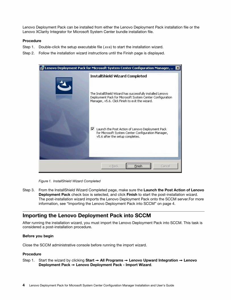
Lenovo Deployment Pack can be installed from either the Lenovo Deployment Pack installation file or theLenovo XClarity Integrator for Microsoft System Center bundle installation file.
Procedure
Step 1. Double-click the setup executable file (.exe) to start the installation wizard.
Step 2. Follow the installation wizard instructions until the Finish page is displayed.
Figure 1. InstallShield Wizard Completed
Step 3. From the InstallShield Wizard Completed page, make sure the Launch the Post Action of LenovoDeployment Pack check box is selected, and click Finish to start the post-installation wizard.The post-installation wizard imports the Lenovo Deployment Pack onto the SCCM server.For moreinformation, see “Importing the Lenovo Deployment Pack into SCCM” on page 4.
Importing the Lenovo Deployment Pack into SCCMAfter running the installation wizard, you must import the Lenovo Deployment Pack into SCCM. This task isconsidered a post-installation procedure.
Before you begin
Close the SCCM administrative console before running the import wizard.
Procedure
Step 1. Start the wizard by clicking Start ➙ All Programs ➙ Lenovo Upward Integration ➙ LenovoDeployment Pack ➙ Lenovo Deployment Pack - Import Wizard.
4 Lenovo Deployment Pack for Microsoft System Center Configuration Manager Installation and User's Guide

Figure 2. Lenovo Deployment Pack Import Wizard Welcome page
Step 2. On the Welcome page, select Import Lenovo Deployment Pack to SCCM, and click Next.The Target Systems page opens.
Chapter 2. Installing and importing the Lenovo Deployment Pack 5
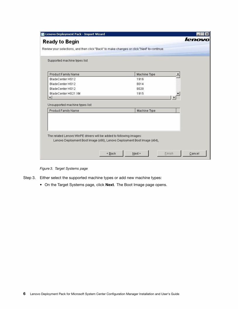
Figure 3. Target Systems page
Step 3. Either select the supported machine types or add new machine types:
• On the Target Systems page, click Next. The Boot Image page opens.
6 Lenovo Deployment Pack for Microsoft System Center Configuration Manager Installation and User's Guide
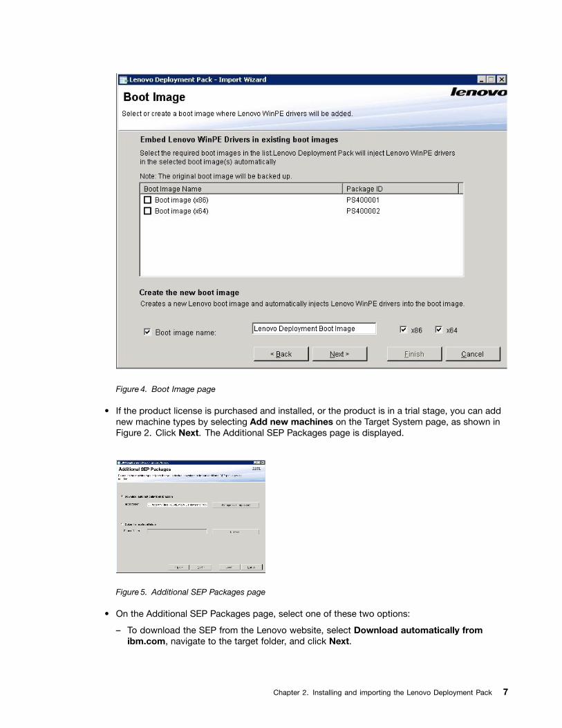
Figure 4. Boot Image page
• If the product license is purchased and installed, or the product is in a trial stage, you can addnew machine types by selecting Add new machines on the Target System page, as shown inFigure 2. Click Next. The Additional SEP Packages page is displayed.
Figure 5. Additional SEP Packages page
• On the Additional SEP Packages page, select one of these two options:
– To download the SEP from the Lenovo website, select Download automatically fromibm.com, navigate to the target folder, and click Next.
Chapter 2. Installing and importing the Lenovo Deployment Pack 7
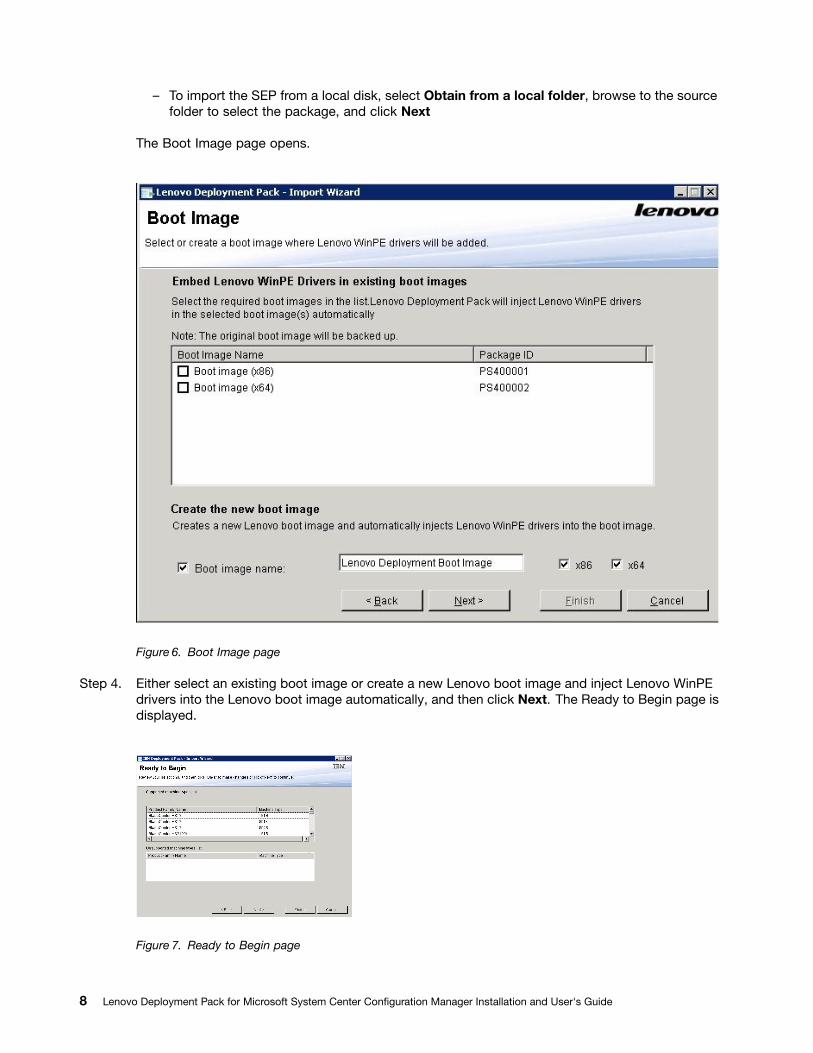
– To import the SEP from a local disk, select Obtain from a local folder, browse to the sourcefolder to select the package, and click Next
The Boot Image page opens.
Figure 6. Boot Image page
Step 4. Either select an existing boot image or create a new Lenovo boot image and inject Lenovo WinPEdrivers into the Lenovo boot image automatically, and then click Next. The Ready to Begin page isdisplayed.
Figure 7. Ready to Begin page
8 Lenovo Deployment Pack for Microsoft System Center Configuration Manager Installation and User's Guide
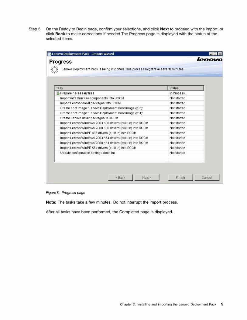
Step 5. On the Ready to Begin page, confirm your selections, and click Next to proceed with the import, orclick Back to make corrections if needed.The Progress page is displayed with the status of theselected items.
Figure 8. Progress page
Note: The tasks take a few minutes. Do not interrupt the import process.
After all tasks have been performed, the Completed page is displayed.
Chapter 2. Installing and importing the Lenovo Deployment Pack 9
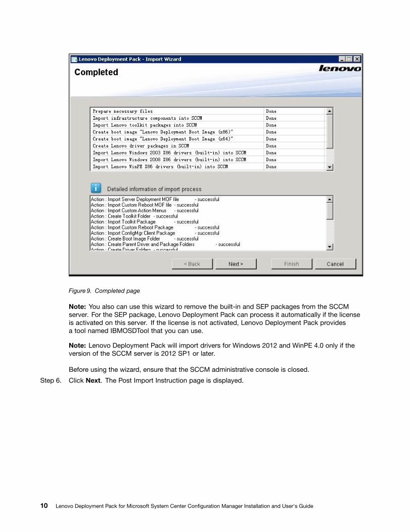
Figure 9. Completed page
Note: You also can use this wizard to remove the built-in and SEP packages from the SCCMserver. For the SEP package, Lenovo Deployment Pack can process it automatically if the licenseis activated on this server. If the license is not activated, Lenovo Deployment Pack providesa tool named IBMOSDTool that you can use.
Note: Lenovo Deployment Pack will import drivers for Windows 2012 and WinPE 4.0 only if theversion of the SCCM server is 2012 SP1 or later.
Before using the wizard, ensure that the SCCM administrative console is closed.
Step 6. Click Next. The Post Import Instruction page is displayed.
10 Lenovo Deployment Pack for Microsoft System Center Configuration Manager Installation and User's Guide
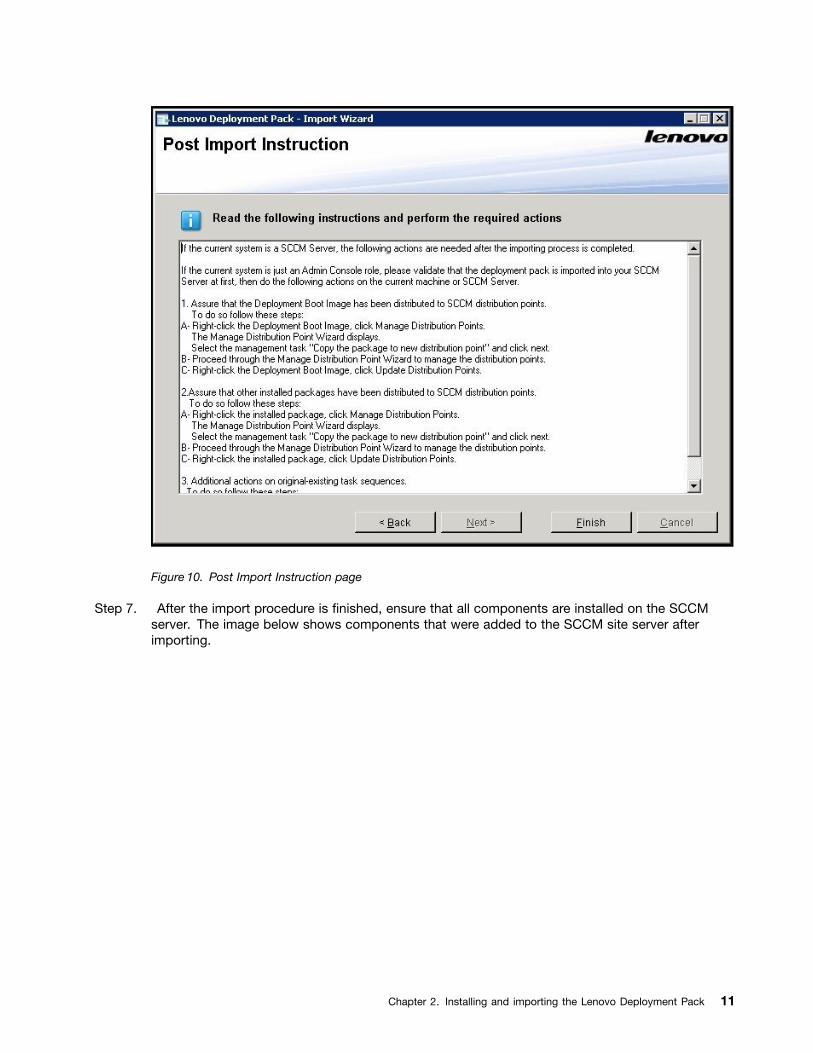
Figure 10. Post Import Instruction page
Step 7. After the import procedure is finished, ensure that all components are installed on the SCCMserver. The image below shows components that were added to the SCCM site server afterimporting.
Chapter 2. Installing and importing the Lenovo Deployment Pack 11
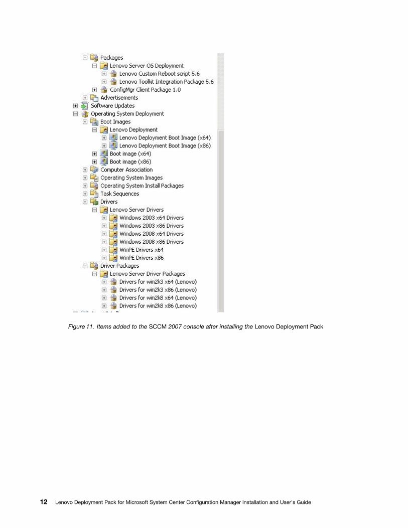
Figure 11. Items added to the SCCM 2007 console after installing the Lenovo Deployment Pack
12 Lenovo Deployment Pack for Microsoft System Center Configuration Manager Installation and User's Guide
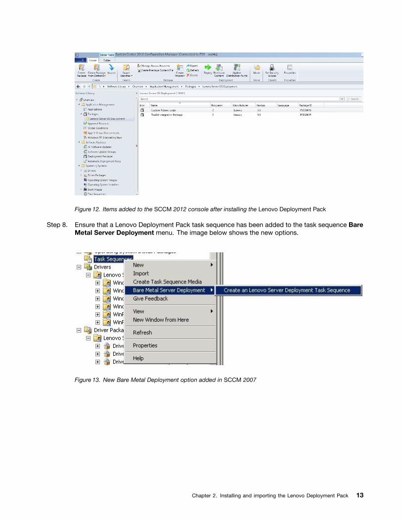
Figure 12. Items added to the SCCM 2012 console after installing the Lenovo Deployment Pack
Step 8. Ensure that a Lenovo Deployment Pack task sequence has been added to the task sequence BareMetal Server Deployment menu. The image below shows the new options.
Figure 13. New Bare Metal Deployment option added in SCCM 2007
Chapter 2. Installing and importing the Lenovo Deployment Pack 13
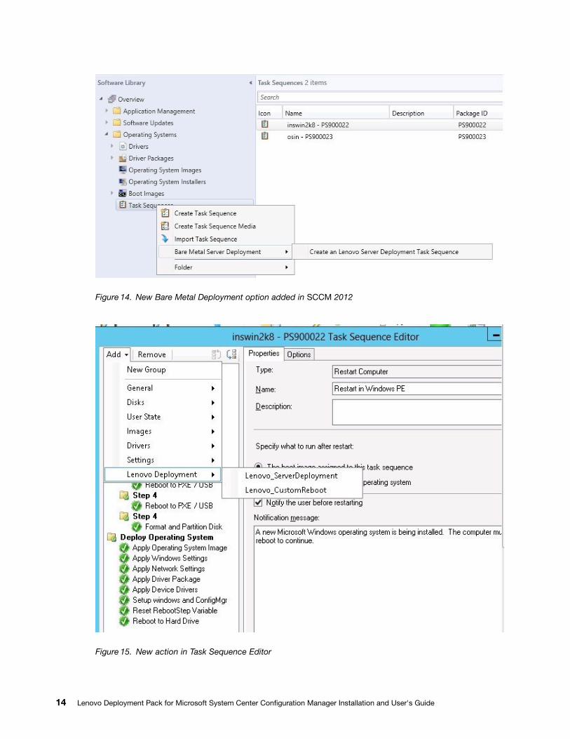
Figure 14. New Bare Metal Deployment option added in SCCM 2012
Figure 15. New action in Task Sequence Editor
14 Lenovo Deployment Pack for Microsoft System Center Configuration Manager Installation and User's Guide
Note: To import the Lenovo Deployment Pack into SCCM on a console-only server, choose ImportLenovo Deployment Pack into SCCM and accept the default configuration on the import wizardto complete the process.
What to do next
To remove the Lenovo Deployment Pack from SCCM, select Remove Lenovo Deployment Pack fromSCCM on the welcome page. Follow the prompts in the wizard to completely remove the files.
Upgrading the IBM Deployment Pack from version 1.4, 3.0, 3.1, 3.2, 4.0,4.5, 5.0, or 5.5 to Lenovo Deployment Pack v6.3If you are currently running version 1.4, 3.0, 3.1, 3.2, 4.0, 4.5, 5.0, or 5.5 and want to upgrade to version v6.3of the Lenovo Deployment Pack, follow the instructions in this section.
Before you begin
Download the Lenovo Deployment Pack from the Lenovo XClarity Integrator for Microsoft System Centerwebsite.
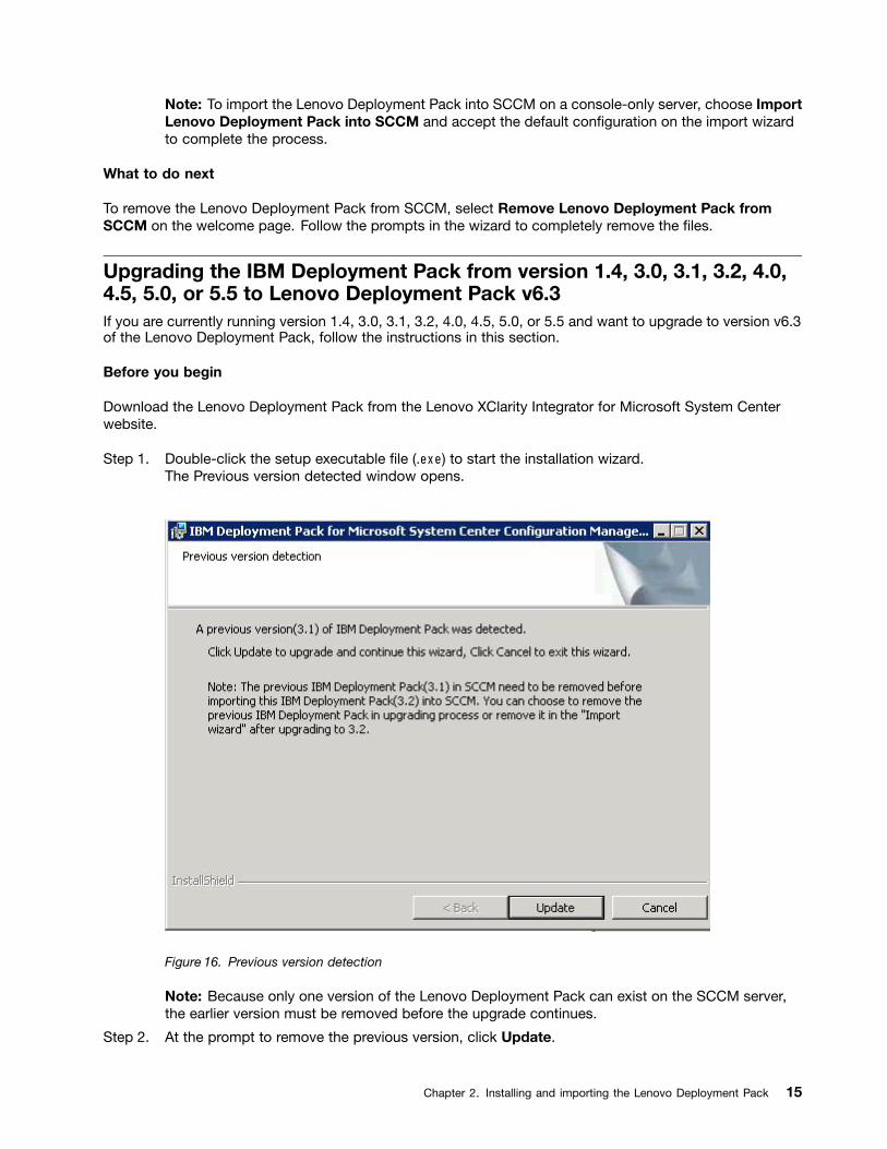
Step 1. Double-click the setup executable file (.exe) to start the installation wizard.The Previous version detected window opens.
Figure 16. Previous version detection
Note: Because only one version of the Lenovo Deployment Pack can exist on the SCCM server,the earlier version must be removed before the upgrade continues.
Step 2. At the prompt to remove the previous version, click Update.
Chapter 2. Installing and importing the Lenovo Deployment Pack 15
IBM Deployment Pack version 1.4, 3.0, 3.1, 3.2, 4.0 or 5.0 is uninstalled and Lenovo DeploymentPack is installed on the SCCM server.
Step 3. On the Finish page, start the post-installation wizard. Using the post-installation wizard, youcan import the Lenovo Deployment Pack built-in packages onto the SCCM server. For moreinformation, see “Installing the Lenovo Deployment Pack into SCCM” on page 3.
Uninstalling the Lenovo Deployment PackThis topic describes how to uninstall the Lenovo Deployment Pack.
About this task
The Lenovo Deployment Pack can be uninstalled by clicking Start ➙ All Programs ➙ Lenovo UpwardIntegration ➙ Lenovo Deployment Pack ➙ Uninstall
Note: You can also uninstall the Lenovo Deployment Pack by either clicking Control Panel ➙ Add orRemove Programs or by running the setup.exe. file
Procedure
Step 1. After clicking the uninstallation shortcut in the system Start menu, a confirmation window opens.Click YES to continue.
Step 2. Indicate if you want to remove or keep the settings from the previous version.
• If you want to keep the settings from the previous version, select Keep previous settings inSCCM. The settings remain without any modification.
• If you want to remove the settings from the previous version. select Remove previous settingsfrom SCCM. All imported SEP packages and built-in packages are uninstalled at the same time;however, the Lenovo-specific boot image (x86 and x64) is retained.
Note: By design, the uninstallation procedure does not remove the Lenovo-specific boot imagesthat were created during installation that are tied to task sequence packages. Removing the bootimage might invalidate some workable task sequences that you are using.
Reusing the task sequence after reinstalling the Lenovo DeploymentPackAfter uninstalling the Lenovo Deployment Pack, you can reinstall it, but you must perform a few extra stepsto reuse your existing task sequence.
About this task
Because of how the operating system deployment feature works with Configuration Manager, tasksequences require some manual steps after you reinstall the deployment pack.
Procedure
Step 1. Right-click the task sequence that you want to reuse, and click Edit.
Step 2. Identify the source package for the Diskpart clean custom action.
If the task sequence used the Diskpart clean custom action, the Missing Objects window opens.
16 Lenovo Deployment Pack for Microsoft System Center Configuration Manager Installation and User's Guide
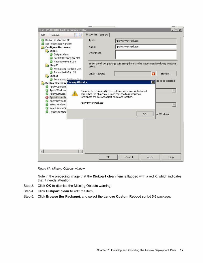
Figure 17. Missing Objects window
Note in the preceding image that the Diskpart clean item is flagged with a red X, which indicatesthat it needs attention.
Step 3. Click OK to dismiss the Missing Objects warning.
Step 4. Click Diskpart clean to edit the item.
Step 5. Click Browse (for Package), and select the Lenovo Custom Reboot script 5.6 package.
Chapter 2. Installing and importing the Lenovo Deployment Pack 17
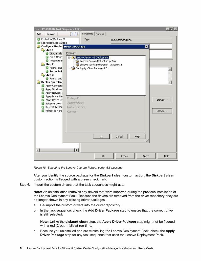
Figure 18. Selecting the Lenovo Custom Reboot script 5.6 package
After you identify the source package for the Diskpart clean custom action, the Diskpart cleancustom action is flagged with a green checkmark.
Step 6. Import the custom drivers that the task sequences might use.
Note: An uninstallation removes any drivers that were imported during the previous installation ofthe Lenovo Deployment Pack. Because the drivers are removed from the driver repository, they areno longer shown in any existing driver packages.
a. Re-import the custom drivers into the driver repository.
b. In the task sequence, check the Add Driver Package step to ensure that the correct driveris still selected.
Note: Unlike the diskpart clean step, the Apply Driver Package step might not be flaggedwith a red X, but it fails at run time.
c. Because you uninstalled and are reinstalling the Lenovo Deployment Pack, check the ApplyDriver Package step for any task sequence that uses the Lenovo Deployment Pack.
18 Lenovo Deployment Pack for Microsoft System Center Configuration Manager Installation and User's Guide
d. Update the distribution points with the updated driver packages.
Integrating the Lenovo System Enablement PackThe topics in this section explain how a Lenovo System Enablement Pack is integrated into ConfigurationManager.
Lenovo Deployment PackThe Lenovo Deployment Pack uses Lenovo ToolsCenter tools to provide specific functionality, such asconfiguring the System BootOrder and RAID.
ToolsCenter tools are changing the means of delivery code. Because Lenovo System Enablement Packuses system-specific codes that are separate from tools, new hardware is supported without requiring anew version of the tools.
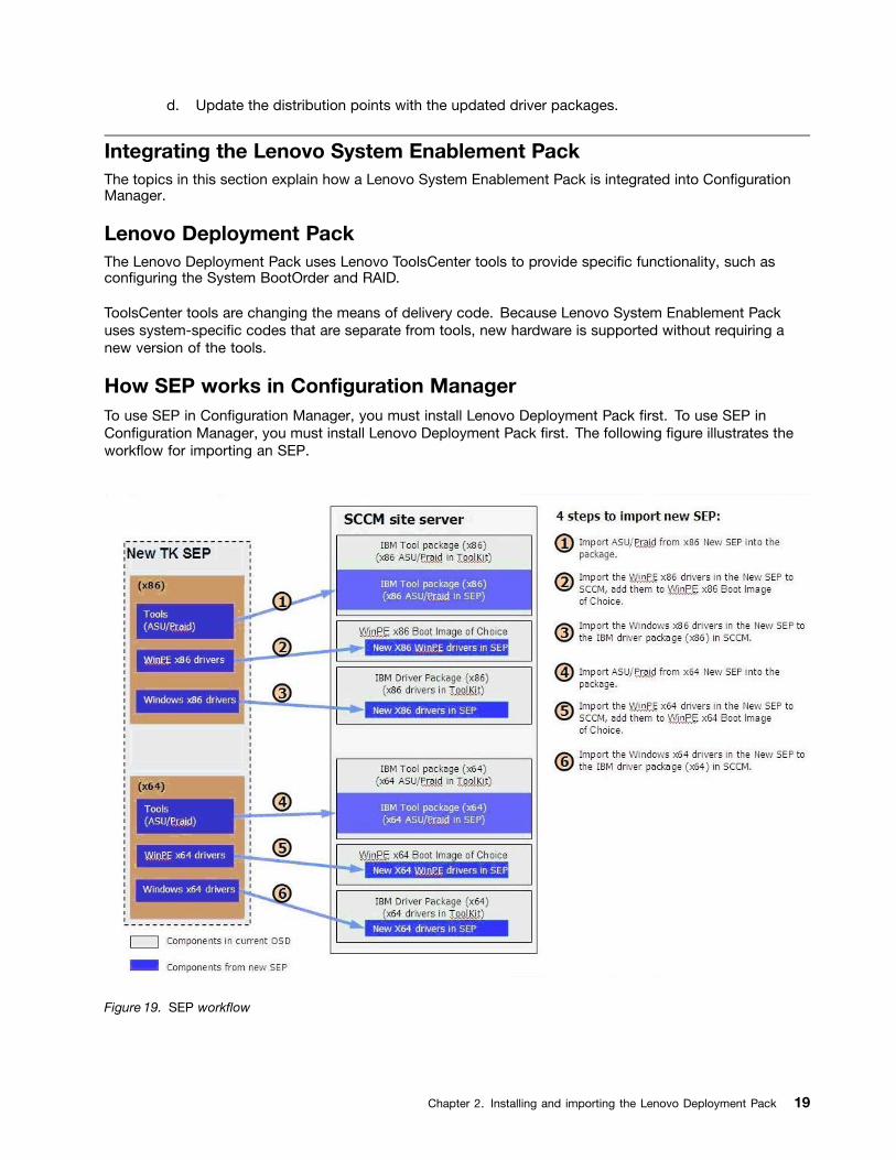
How SEP works in Configuration ManagerTo use SEP in Configuration Manager, you must install Lenovo Deployment Pack first. To use SEP inConfiguration Manager, you must install Lenovo Deployment Pack first. The following figure illustrates theworkflow for importing an SEP.
Figure 19. SEP workflow
Chapter 2. Installing and importing the Lenovo Deployment Pack 19

20 Lenovo Deployment Pack for Microsoft System Center Configuration Manager Installation and User's Guide
Chapter 3. Preparing for deployment
Now that the Lenovo Deployment Pack is installed, you can perform the configuration steps requiredto prepare for a full deployment, including those for SCCM OSD initial configuration, post-installationconfiguration and updating distribution points.
Preparing for deployment in SCCM 2007Before deploying SCCM 2007, you must perform some procedures as a prerequisite, which includeconfiguring OSD, updating distribution points, and selecting the boot image.
The following sections guide you through the process step by step.
SCCM OSD initial configurationThis topic refers you to detailed information about how to configure your operating system deployment(OSD) environment by describing the actions you should take in SCCM.
The following information about configuring OSD is provided as a general reference. For more detailedinformation about setting up OSD in SCCM, see the Microsoft System Center Configuration Manager2007 Documentation Library webpage.
Setting the network access accountTo set the network access account, use the Configuration Manager console. The network access accountshould be set up for use during operating system deployment.
Procedure
Step 1. Start Microsoft System Center Configuration Manager 2007.
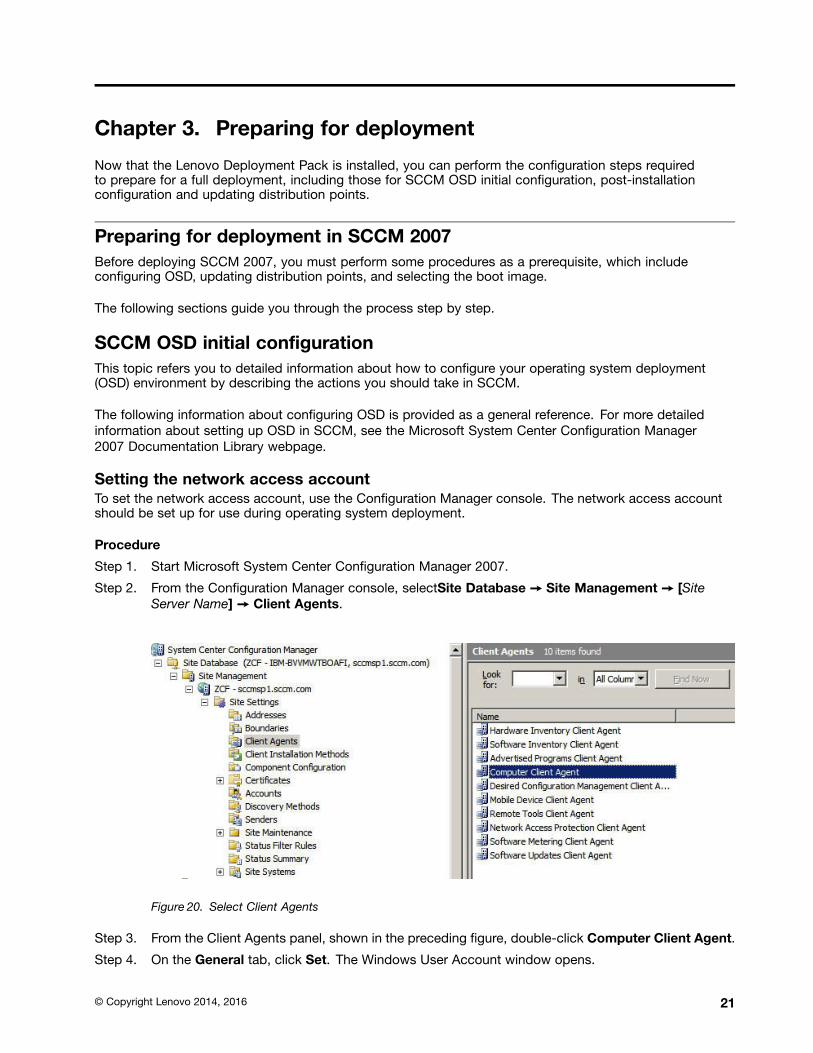
Step 2. From the Configuration Manager console, selectSite Database ➙ Site Management ➙ [SiteServer Name] ➙ Client Agents.
Figure 20. Select Client Agents
Step 3. From the Client Agents panel, shown in the preceding figure, double-click Computer Client Agent.
Step 4. On the General tab, click Set. The Windows User Account window opens.
© Copyright Lenovo 2014, 2016 21
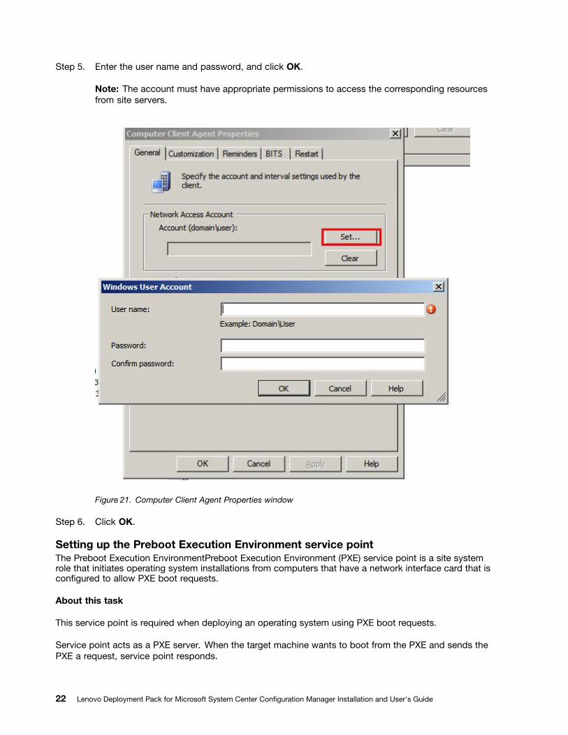
Step 5. Enter the user name and password, and click OK.
Note: The account must have appropriate permissions to access the corresponding resourcesfrom site servers.
Figure 21. Computer Client Agent Properties window
Step 6. Click OK.
Setting up the Preboot Execution Environment service pointThe Preboot Execution EnvironmentPreboot Execution Environment (PXE) service point is a site systemrole that initiates operating system installations from computers that have a network interface card that isconfigured to allow PXE boot requests.
About this task
This service point is required when deploying an operating system using PXE boot requests.
Service point acts as a PXE server. When the target machine wants to boot from the PXE and sends thePXE a request, service point responds.
22 Lenovo Deployment Pack for Microsoft System Center Configuration Manager Installation and User's Guide
Procedure
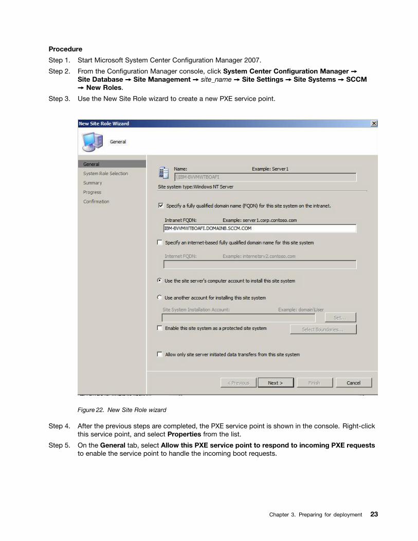
Step 1. Start Microsoft System Center Configuration Manager 2007.
Step 2. From the Configuration Manager console, click System Center Configuration Manager ➙Site Database ➙ Site Management ➙ site_name ➙ Site Settings ➙ Site Systems ➙ SCCM➙ New Roles.
Step 3. Use the New Site Role wizard to create a new PXE service point.
Figure 22. New Site Role wizard
Step 4. After the previous steps are completed, the PXE service point is shown in the console. Right-clickthis service point, and select Properties from the list.
Step 5. On the General tab, select Allow this PXE service point to respond to incoming PXE requeststo enable the service point to handle the incoming boot requests.
Chapter 3. Preparing for deployment 23
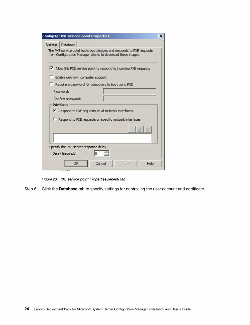
Figure 23. PXE service point PropertiesGeneral tab
Step 6. Click the Database tab to specify settings for controlling the user account and certificate.
24 Lenovo Deployment Pack for Microsoft System Center Configuration Manager Installation and User's Guide
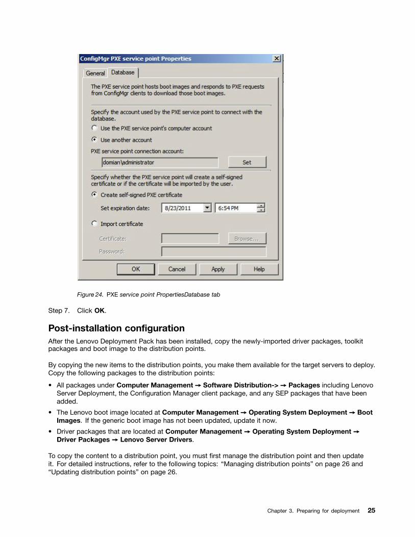
Figure 24. PXE service point PropertiesDatabase tab
Step 7. Click OK.
Post-installation configurationAfter the Lenovo Deployment Pack has been installed, copy the newly-imported driver packages, toolkitpackages and boot image to the distribution points.
By copying the new items to the distribution points, you make them available for the target servers to deploy.Copy the following packages to the distribution points:
• All packages under Computer Management ➙ Software Distribution-> ➙ Packages including LenovoServer Deployment, the Configuration Manager client package, and any SEP packages that have beenadded.
• The Lenovo boot image located at Computer Management ➙ Operating System Deployment ➙ BootImages. If the generic boot image has not been updated, update it now.
• Driver packages that are located at Computer Management ➙ Operating System Deployment ➙Driver Packages ➙ Lenovo Server Drivers.
To copy the content to a distribution point, you must first manage the distribution point and then updateit. For detailed instructions, refer to the following topics: “Managing distribution points” on page 26 and“Updating distribution points” on page 26.
Chapter 3. Preparing for deployment 25
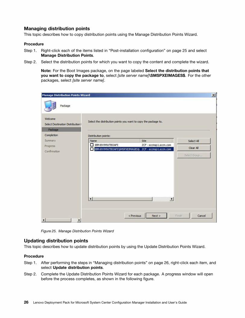
Managing distribution pointsThis topic describes how to copy distribution points using the Manage Distribution Points Wizard.
Procedure
Step 1. Right-click each of the items listed in “Post-installation configuration” on page 25 and selectManage Distribution Points.
Step 2. Select the distribution points for which you want to copy the content and complete the wizard.
Note: For the Boot Images package, on the page labeled Select the distribution points thatyou want to copy the package to, select [site server name]\SMSPXEIMAGES$. For the otherpackages, select [site server name].
Figure 25. Manage Distribution Points Wizard
Updating distribution pointsThis topic describes how to update distribution points by using the Update Distribution Points Wizard.
Procedure
Step 1. After performing the steps in “Managing distribution points” on page 26, right-click each item, andselect Update distribution points.
Step 2. Complete the Update Distribution Points Wizard for each package. A progress window will openbefore the process completes, as shown in the following figure.
26 Lenovo Deployment Pack for Microsoft System Center Configuration Manager Installation and User's Guide
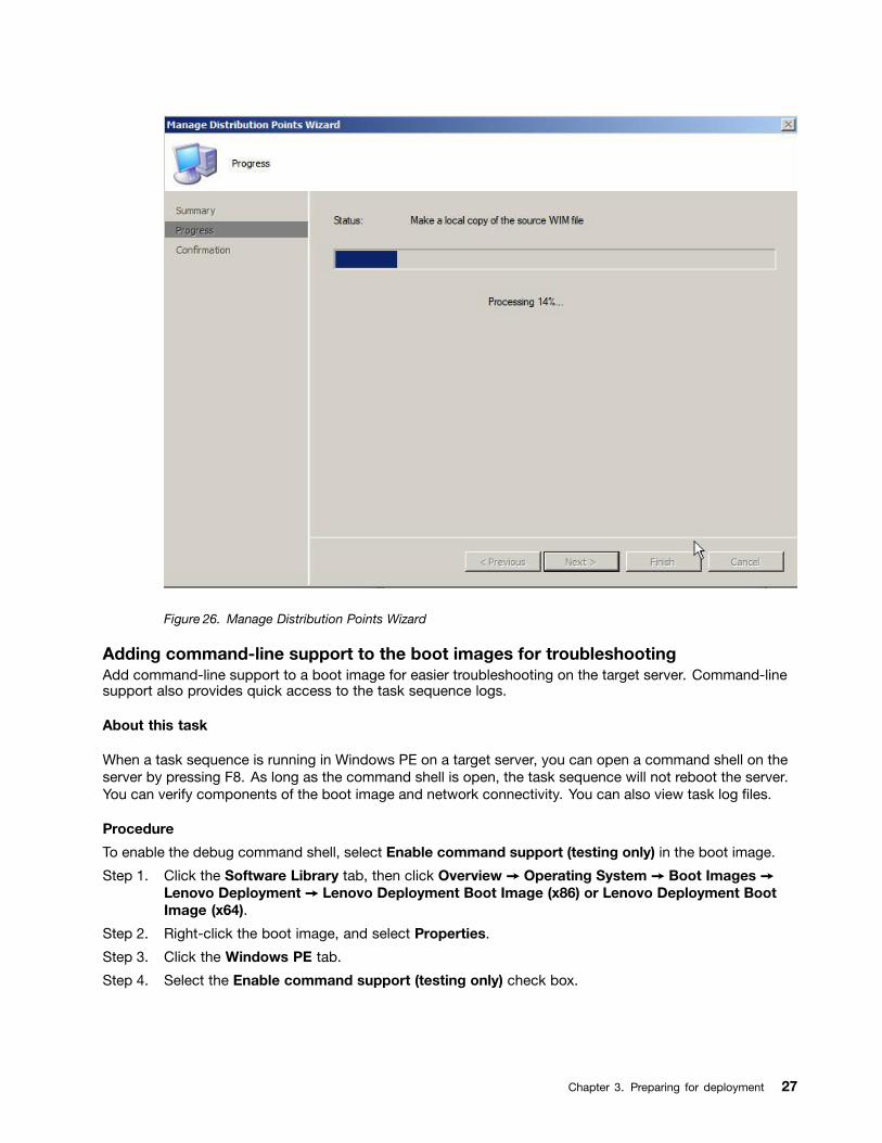
Figure 26. Manage Distribution Points Wizard
Adding command-line support to the boot images for troubleshootingAdd command-line support to a boot image for easier troubleshooting on the target server. Command-linesupport also provides quick access to the task sequence logs.
About this task
When a task sequence is running in Windows PE on a target server, you can open a command shell on theserver by pressing F8. As long as the command shell is open, the task sequence will not reboot the server.You can verify components of the boot image and network connectivity. You can also view task log files.
Procedure
To enable the debug command shell, select Enable command support (testing only) in the boot image.
Step 1. Click the Software Library tab, then click Overview ➙ Operating System ➙ Boot Images ➙Lenovo Deployment ➙ Lenovo Deployment Boot Image (x86) or Lenovo Deployment BootImage (x64).
Step 2. Right-click the boot image, and select Properties.
Step 3. Click the Windows PE tab.
Step 4. Select the Enable command support (testing only) check box.
Chapter 3. Preparing for deployment 27

Figure 27. Enabling command-line support
Step 5. Click OK.
What to do next
After completing this procedure, update the distribution points. See “Updating distribution points” onpage 26.
Creating a task sequence for Lenovo serversThe Lenovo Server Deployment Task Sequence template can help you create a task sequence for theLenovo servers.
Step 1. Open the Configuration Manager Console and navigate to Operating System Deployment➙ Task Sequence.
Step 2. Right-click Task Sequence ➙ Bare Metal Server Deployment ➙ Create a Lenovo ServerDeployment Task Sequence. The Create Server Deployment Task Sequence wizard opens.
28 Lenovo Deployment Pack for Microsoft System Center Configuration Manager Installation and User's Guide
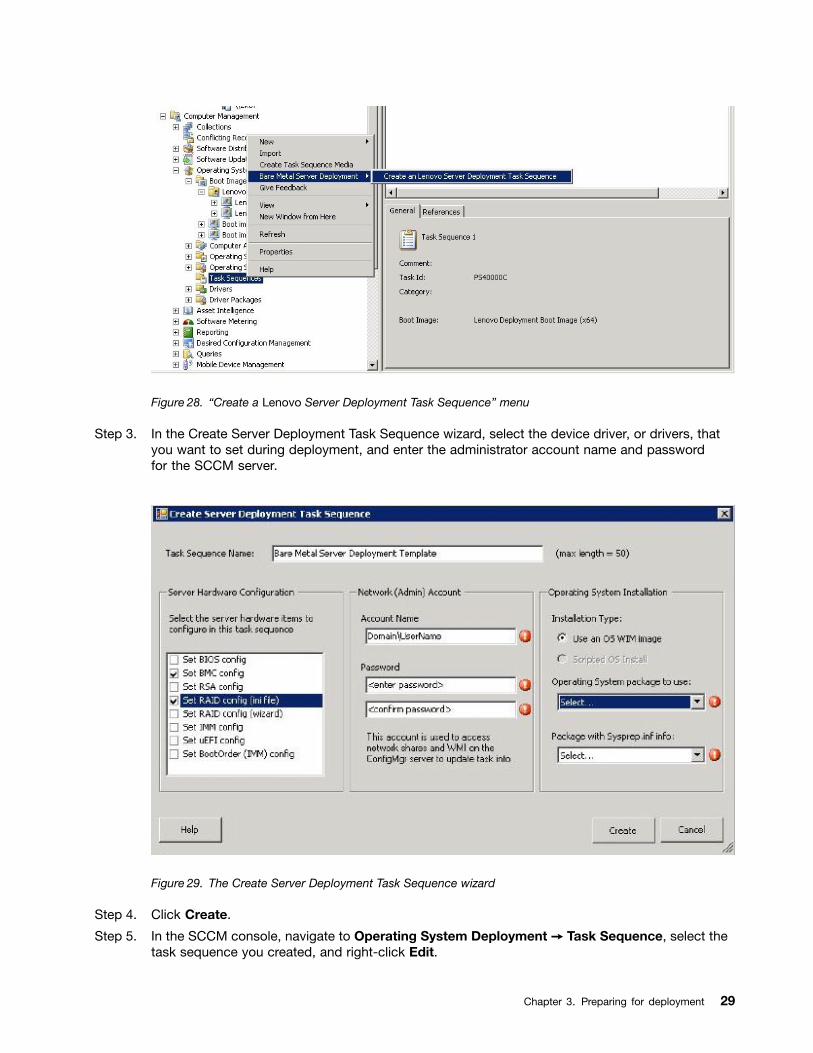
Figure 28. “Create a Lenovo Server Deployment Task Sequence” menu
Step 3. In the Create Server Deployment Task Sequence wizard, select the device driver, or drivers, thatyou want to set during deployment, and enter the administrator account name and passwordfor the SCCM server.
Figure 29. The Create Server Deployment Task Sequence wizard
Step 4. Click Create.
Step 5. In the SCCM console, navigate to Operating System Deployment ➙ Task Sequence, select thetask sequence you created, and right-click Edit.
Chapter 3. Preparing for deployment 29
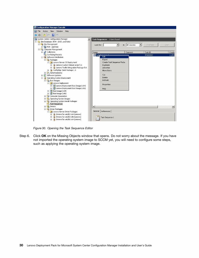
Figure 30. Opening the Task Sequence Editor
Step 6. Click OK on the Missing Objects window that opens. Do not worry about the message. If you havenot imported the operating system image to SCCM yet, you will need to configure some steps,such as applying the operating system image.
30 Lenovo Deployment Pack for Microsoft System Center Configuration Manager Installation and User's Guide
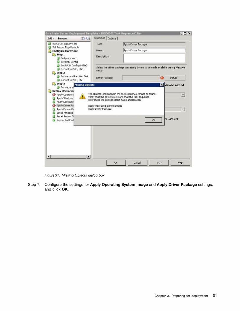
Figure 31. Missing Objects dialog box
Step 7. Configure the settings for Apply Operating System Image and Apply Driver Package settings,and click OK.
Chapter 3. Preparing for deployment 31
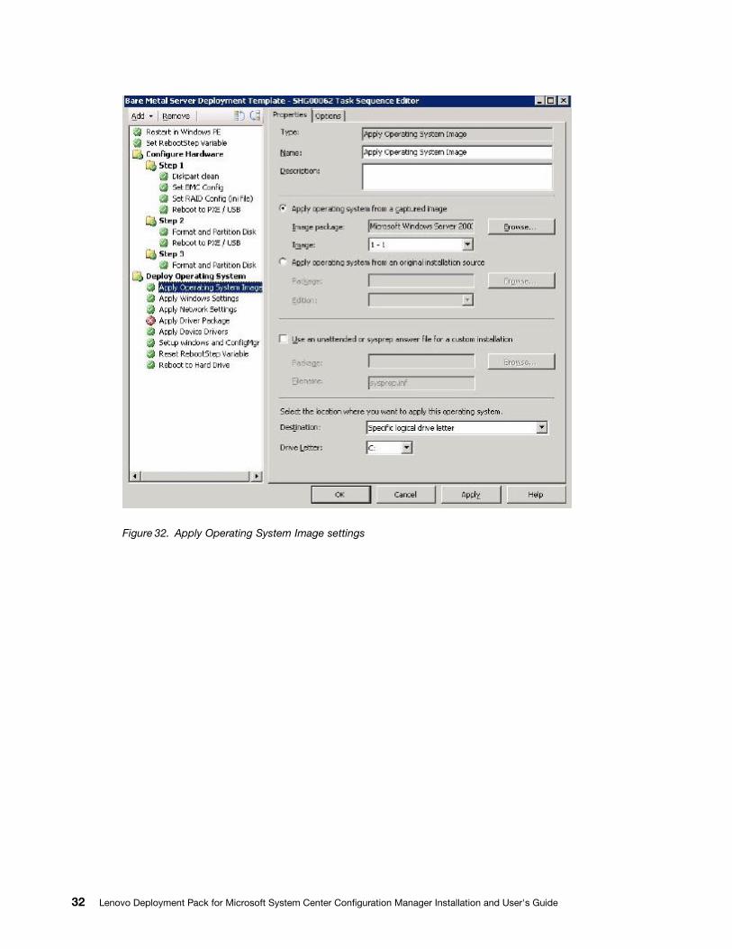
Figure 32. Apply Operating System Image settings
32 Lenovo Deployment Pack for Microsoft System Center Configuration Manager Installation and User's Guide
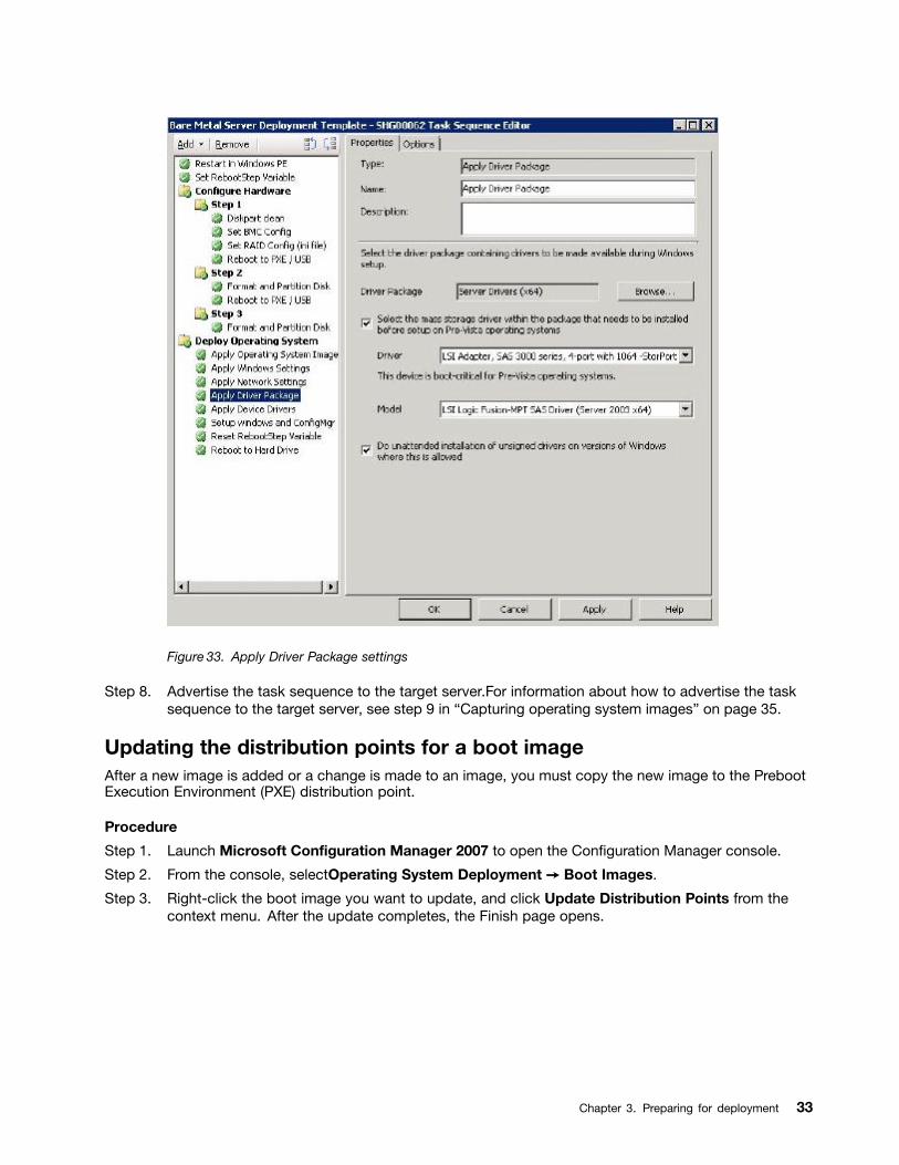
Figure 33. Apply Driver Package settings
Step 8. Advertise the task sequence to the target server.For information about how to advertise the tasksequence to the target server, see step 9 in “Capturing operating system images” on page 35.
Updating the distribution points for a boot imageAfter a new image is added or a change is made to an image, you must copy the new image to the PrebootExecution Environment (PXE) distribution point.
Procedure
Step 1. Launch Microsoft Configuration Manager 2007 to open the Configuration Manager console.
Step 2. From the console, selectOperating System Deployment ➙ Boot Images.
Step 3. Right-click the boot image you want to update, and click Update Distribution Points from thecontext menu. After the update completes, the Finish page opens.
Chapter 3. Preparing for deployment 33
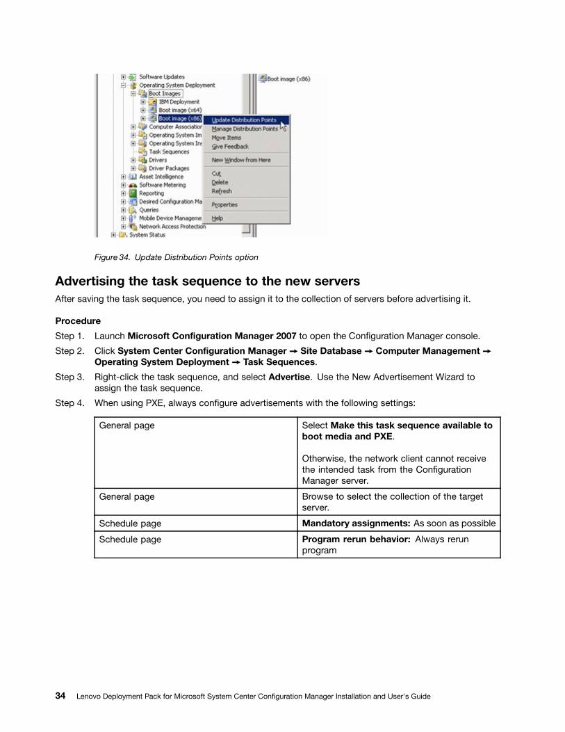
Figure 34. Update Distribution Points option
Advertising the task sequence to the new serversAfter saving the task sequence, you need to assign it to the collection of servers before advertising it.
Procedure
Step 1. Launch Microsoft Configuration Manager 2007 to open the Configuration Manager console.
Step 2. Click System Center Configuration Manager ➙ Site Database ➙ Computer Management ➙Operating System Deployment ➙ Task Sequences.
Step 3. Right-click the task sequence, and select Advertise. Use the New Advertisement Wizard toassign the task sequence.
Step 4. When using PXE, always configure advertisements with the following settings:
General page Select Make this task sequence available toboot media and PXE.
Otherwise, the network client cannot receivethe intended task from the ConfigurationManager server.
General page Browse to select the collection of the targetserver.
Schedule page Mandatory assignments: As soon as possible
Schedule page Program rerun behavior: Always rerunprogram
34 Lenovo Deployment Pack for Microsoft System Center Configuration Manager Installation and User's Guide
Distribution Points page Select Access content directly from adistribution point when needed by therunning task sequence.
In WinPE, the default option "Downloadcontent locally when needed by running tasksequence" does not work. WinPE causes thetask sequence engine to ignore all actions thathave packages set for this option.
Interaction page Select Show task sequence progress.
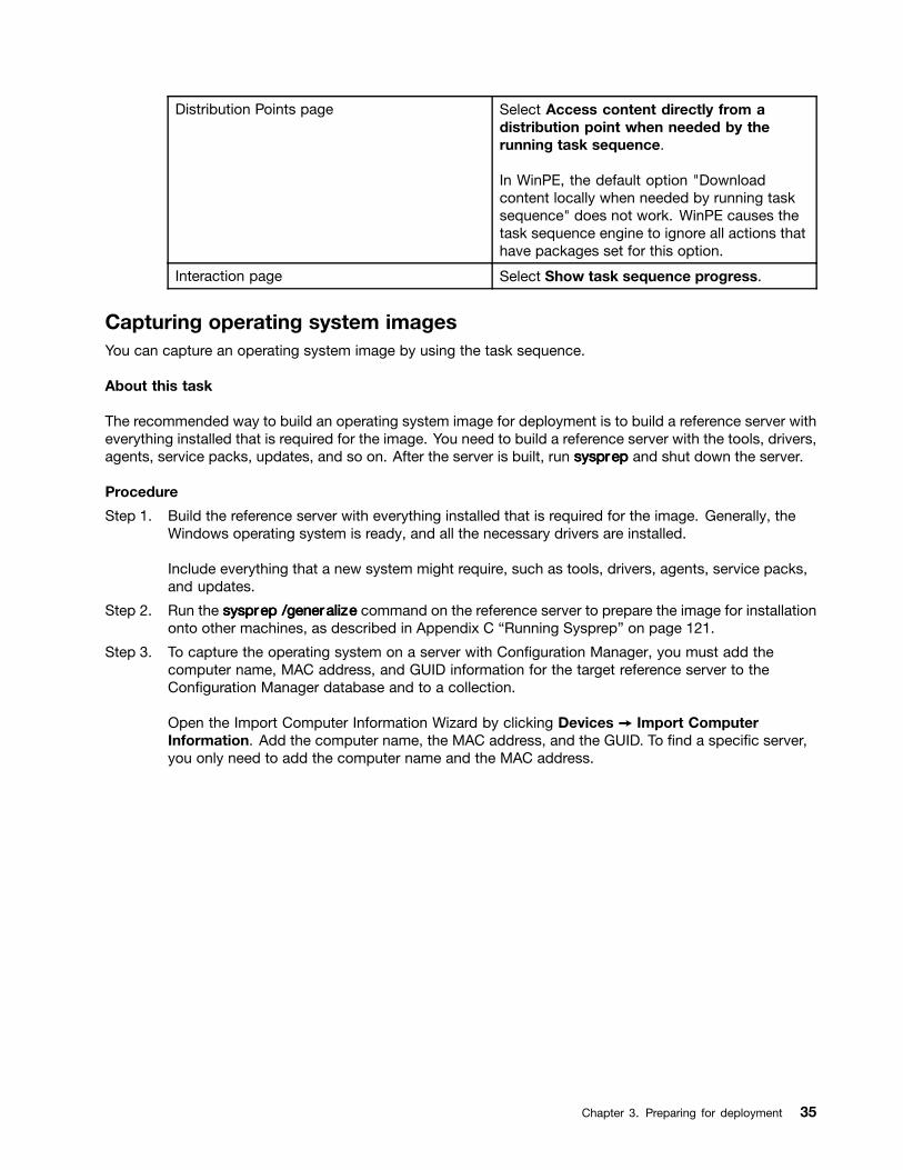
Capturing operating system imagesYou can capture an operating system image by using the task sequence.
About this task
The recommended way to build an operating system image for deployment is to build a reference server witheverything installed that is required for the image. You need to build a reference server with the tools, drivers,agents, service packs, updates, and so on. After the server is built, run sysprsysprsysprepepep and shut down the server.
Procedure
Step 1. Build the reference server with everything installed that is required for the image. Generally, theWindows operating system is ready, and all the necessary drivers are installed.
Include everything that a new system might require, such as tools, drivers, agents, service packs,and updates.
Step 2. Run the sysprsysprsysprepepep /gener/gener/generalizalizalizeee command on the reference server to prepare the image for installationonto other machines, as described in Appendix C “Running Sysprep” on page 121.
Step 3. To capture the operating system on a server with Configuration Manager, you must add thecomputer name, MAC address, and GUID information for the target reference server to theConfiguration Manager database and to a collection.
Open the Import Computer Information Wizard by clicking Devices ➙ Import ComputerInformation. Add the computer name, the MAC address, and the GUID. To find a specific server,you only need to add the computer name and the MAC address.
Chapter 3. Preparing for deployment 35
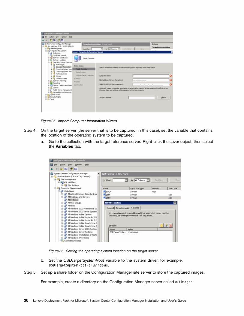
Figure 35. Import Computer Information Wizard
Step 4. On the target server (the server that is to be captured, in this case), set the variable that containsthe location of the operating system to be captured.
a. Go to the collection with the target reference server. Right-click the sever object, then selectthe Variables tab.
Figure 36. Setting the operating system location on the target server
b. Set the OSDTargetSystemRoot variable to the system driver, for example,OSDTargetSystemRoot=c:\windows.
Step 5. Set up a share folder on the Configuration Manager site server to store the captured images.
For example, create a directory on the Configuration Manager server called c:\images.
36 Lenovo Deployment Pack for Microsoft System Center Configuration Manager Installation and User's Guide
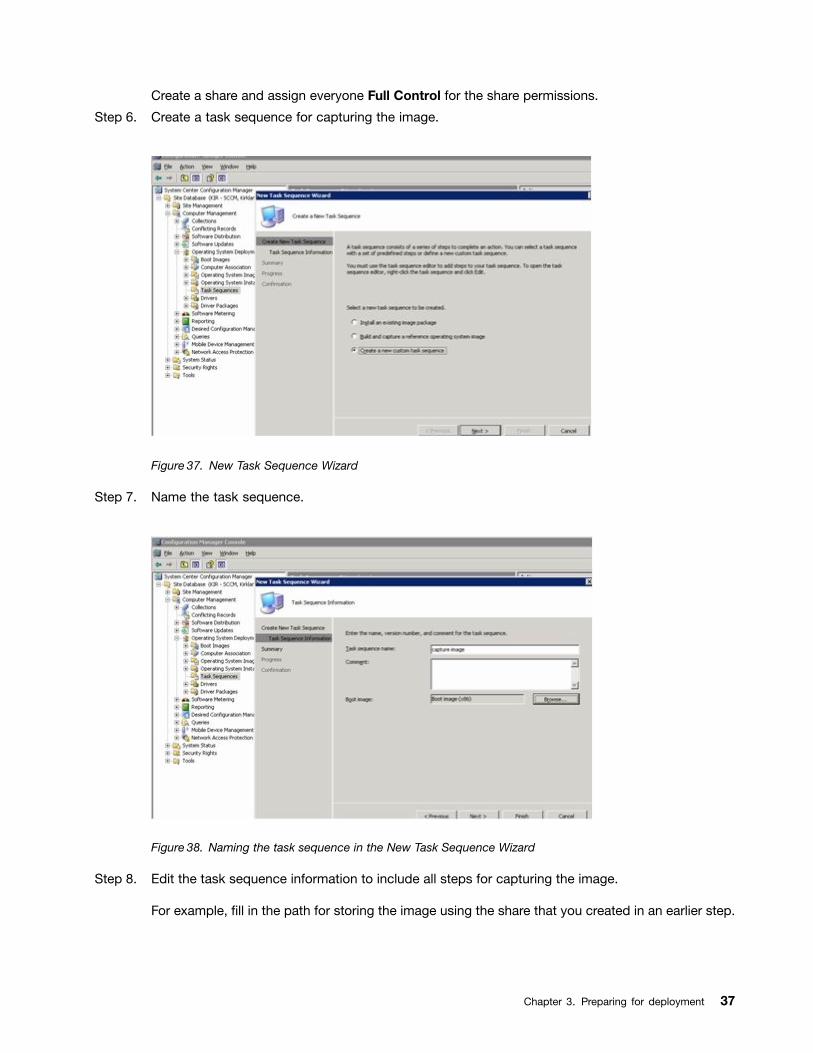
Create a share and assign everyone Full Control for the share permissions.
Step 6. Create a task sequence for capturing the image.
Figure 37. New Task Sequence Wizard
Step 7. Name the task sequence.
Figure 38. Naming the task sequence in the New Task Sequence Wizard
Step 8. Edit the task sequence information to include all steps for capturing the image.
For example, fill in the path for storing the image using the share that you created in an earlier step.
Chapter 3. Preparing for deployment 37
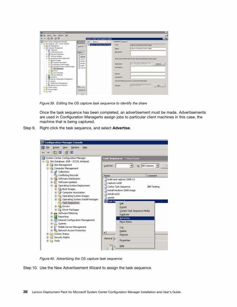
Figure 39. Editing the OS capture task sequence to identify the share
Once the task sequence has been completed, an advertisement must be made. Advertisementsare used in Configuration Managerto assign jobs to particular client machines in this case, themachine that is being captured.
Step 9. Right-click the task sequence, and select Advertise.
Figure 40. Advertising the OS capture task sequence
Step 10. Use the New Advertisement Wizard to assign the task sequence.
38 Lenovo Deployment Pack for Microsoft System Center Configuration Manager Installation and User's Guide
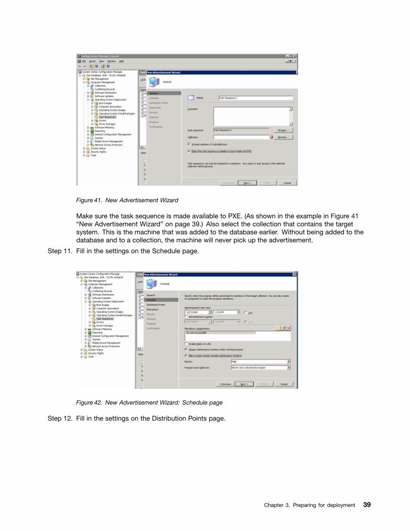
Figure 41. New Advertisement Wizard
Make sure the task sequence is made available to PXE. (As shown in the example in Figure 41“New Advertisement Wizard” on page 39.) Also select the collection that contains the targetsystem. This is the machine that was added to the database earlier. Without being added to thedatabase and to a collection, the machine will never pick up the advertisement.
Step 11. Fill in the settings on the Schedule page.
Figure 42. New Advertisement Wizard: Schedule page
Step 12. Fill in the settings on the Distribution Points page.
Chapter 3. Preparing for deployment 39
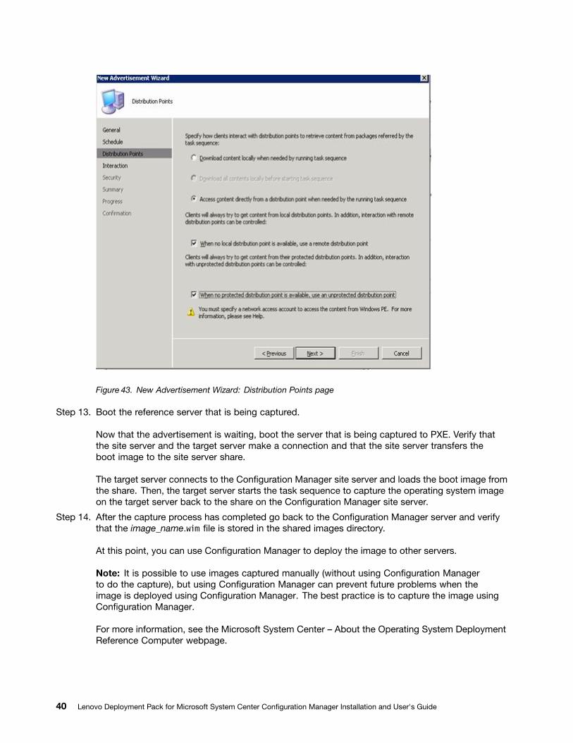
Figure 43. New Advertisement Wizard: Distribution Points page
Step 13. Boot the reference server that is being captured.
Now that the advertisement is waiting, boot the server that is being captured to PXE. Verify thatthe site server and the target server make a connection and that the site server transfers theboot image to the site server share.
The target server connects to the Configuration Manager site server and loads the boot image fromthe share. Then, the target server starts the task sequence to capture the operating system imageon the target server back to the share on the Configuration Manager site server.
Step 14. After the capture process has completed go back to the Configuration Manager server and verifythat the image_name.wim file is stored in the shared images directory.
At this point, you can use Configuration Manager to deploy the image to other servers.
Note: It is possible to use images captured manually (without using Configuration Managerto do the capture), but using Configuration Manager can prevent future problems when theimage is deployed using Configuration Manager. The best practice is to capture the image usingConfiguration Manager.
For more information, see the Microsoft System Center – About the Operating System DeploymentReference Computer webpage.
40 Lenovo Deployment Pack for Microsoft System Center Configuration Manager Installation and User's Guide
Lenovo Deployment Pack feature referenceThis section describes the features and functionality that are available in the Lenovo Deployment Pack.Some functionality or capabilities might differ from other Configuration Manager deployment kits with whichyou might be familiar. Such differences are based on the capabilities of existing tools or additional integrationthat Lenovo has included in this Configuration Manager deployment kit.
Preparing the operating system imageThis section describes how to capture operating system images and prepare reference servers. You can usethe operating system image in the operating system deployment task sequence.
Note: You can use images captured manually (without using Configuration Manager to do the capture).However, using Configuration Manager to capture the image can prevent problems when the image isdeployed using Configuration Manager. The best practice is to capture the image using ConfigurationManager.
Capturing operating system imagesUse Configuration Manager to capture operating system images.
Lenovo Deployment Pack supports the clone method to install operating systems. To use this method, youmust prepare an operating system image.
Preparing the reference serverThis topic directs you to information about building the reference server, which is required when capturingoperating system images.
Procedure
Step 1. Build the reference server with everything installed that is required for the image. Include everythingthat a new system might require, such as tools, drivers, agents, service packs, and updates.
Step 2. On the reference server, run the sysprsysprsysprepepep /gener/gener/generalizalizalizeee command to prepare the image for installationonto other servers. For instructions, see Appendix C “Running Sysprep” on page 121.
Adding a target server to Configuration ManagerThis topic describes how to create a collection and add one or more servers to it.
About this task
To enable SCCM to recognize the target server, use the MAC address of the system's primary networkinterface (the interface used for deployment). To group servers,SCCM uses collections. A number of defaultcollections are already created based on operating system version and other attributes. Use the followingprocedure to create a new collection to use for deployments.
Procedure
Step 1. Right-click Site Database, and then select Computer Management ➙ Operating SystemDeployment ➙ Computer Association ➙ Import Computer Information. The Import ComputerInformation Wizard opens. You can add one or multiple servers to a collection at the same time.Here is an example of how to add a single server.
Chapter 3. Preparing for deployment 41
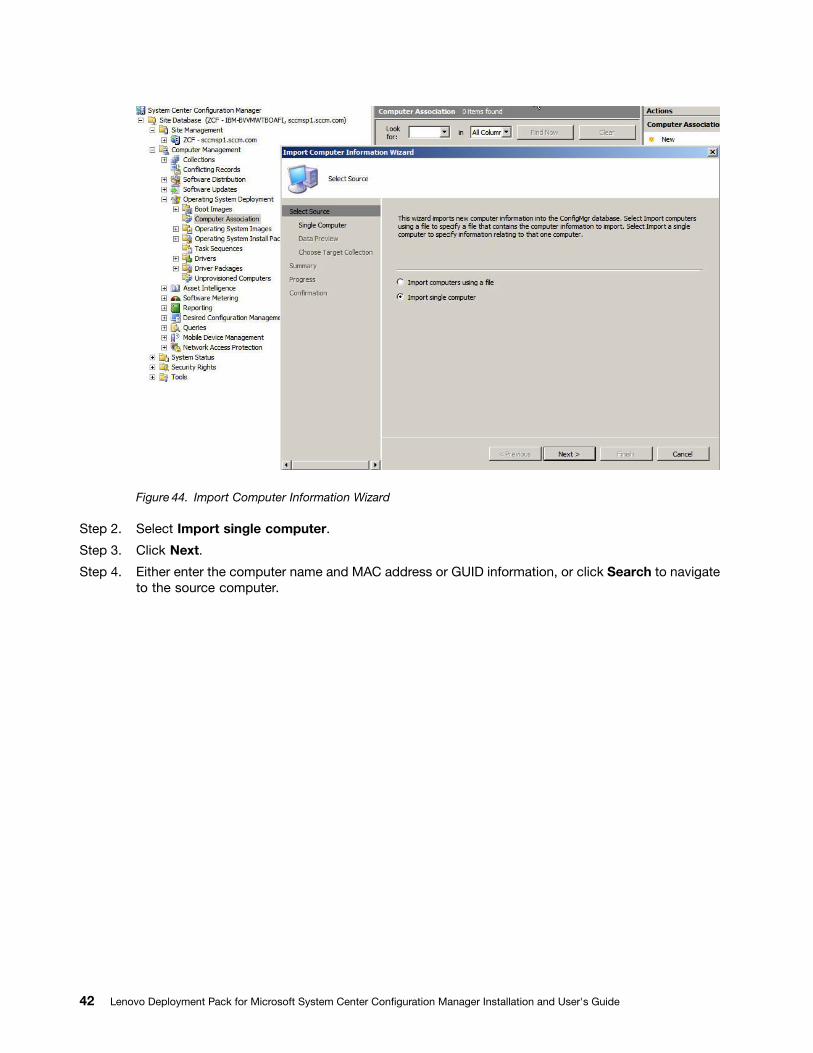
Figure 44. Import Computer Information Wizard
Step 2. Select Import single computer.
Step 3. Click Next.
Step 4. Either enter the computer name and MAC address or GUID information, or click Search to navigateto the source computer.
42 Lenovo Deployment Pack for Microsoft System Center Configuration Manager Installation and User's Guide
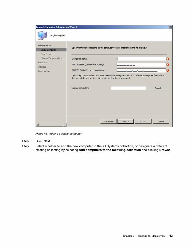
Figure 45. Adding a single computer
Step 5. Click Next.
Step 6. Select whether to add the new computer to the All Systems collection, or designate a differentexisting collecting by selecting Add computers to the following collection and clicking Browse.
Chapter 3. Preparing for deployment 43
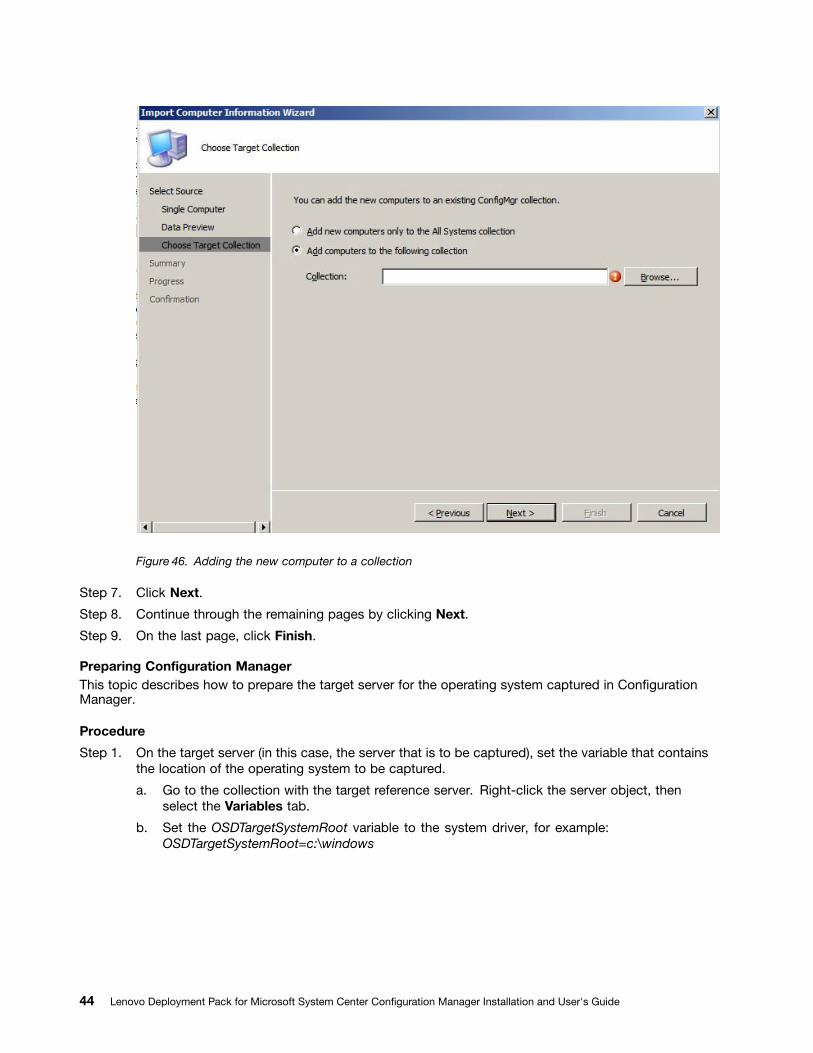
Figure 46. Adding the new computer to a collection
Step 7. Click Next.
Step 8. Continue through the remaining pages by clicking Next.
Step 9. On the last page, click Finish.
Preparing Configuration ManagerThis topic describes how to prepare the target server for the operating system captured in ConfigurationManager.
Procedure
Step 1. On the target server (in this case, the server that is to be captured), set the variable that containsthe location of the operating system to be captured.
a. Go to the collection with the target reference server. Right-click the server object, thenselect the Variables tab.
b. Set the OSDTargetSystemRoot variable to the system driver, for example:OSDTargetSystemRoot=c:\windows
44 Lenovo Deployment Pack for Microsoft System Center Configuration Manager Installation and User's Guide
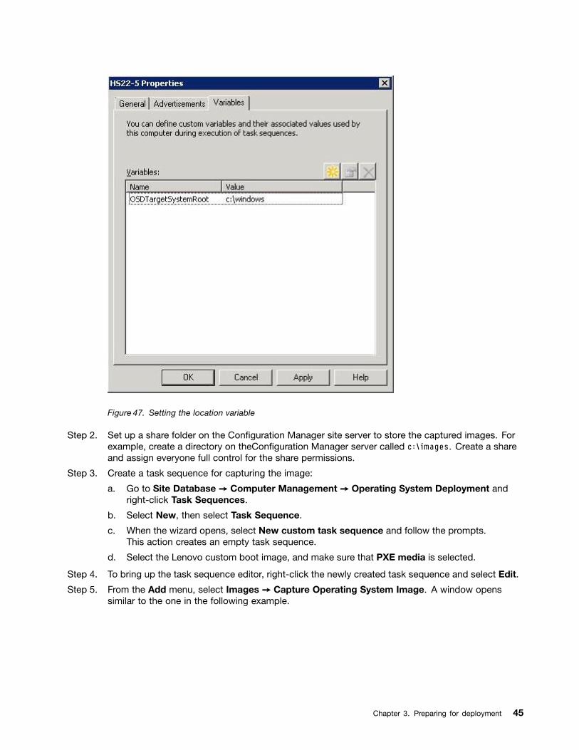
Figure 47. Setting the location variable
Step 2. Set up a share folder on the Configuration Manager site server to store the captured images. Forexample, create a directory on theConfiguration Manager server called c:\images. Create a shareand assign everyone full control for the share permissions.
Step 3. Create a task sequence for capturing the image:
a. Go to Site Database ➙ Computer Management ➙ Operating System Deployment andright-click Task Sequences.
b. Select New, then select Task Sequence.
c. When the wizard opens, select New custom task sequence and follow the prompts.This action creates an empty task sequence.
d. Select the Lenovo custom boot image, and make sure that PXE media is selected.
Step 4. To bring up the task sequence editor, right-click the newly created task sequence and select Edit.
Step 5. From the Add menu, select Images ➙ Capture Operating System Image. A window openssimilar to the one in the following example.
Chapter 3. Preparing for deployment 45
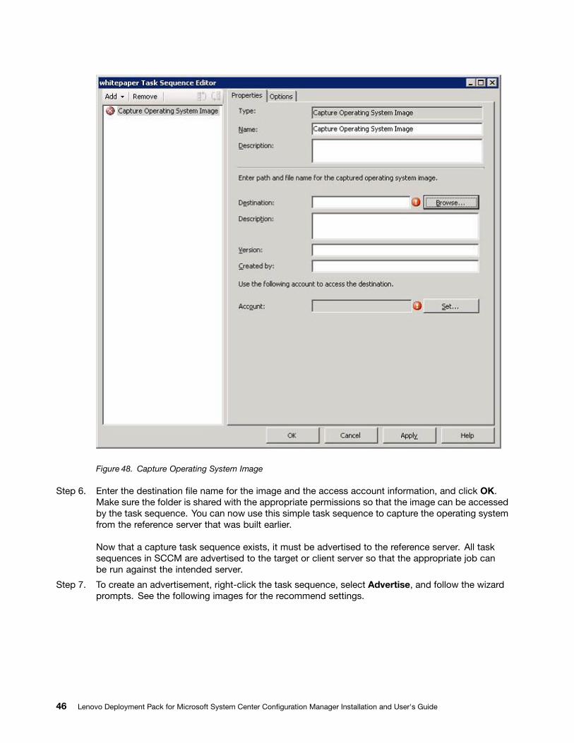
Figure 48. Capture Operating System Image
Step 6. Enter the destination file name for the image and the access account information, and click OK.Make sure the folder is shared with the appropriate permissions so that the image can be accessedby the task sequence. You can now use this simple task sequence to capture the operating systemfrom the reference server that was built earlier.
Now that a capture task sequence exists, it must be advertised to the reference server. All tasksequences in SCCM are advertised to the target or client server so that the appropriate job canbe run against the intended server.
Step 7. To create an advertisement, right-click the task sequence, select Advertise, and follow the wizardprompts. See the following images for the recommend settings.
46 Lenovo Deployment Pack for Microsoft System Center Configuration Manager Installation and User's Guide
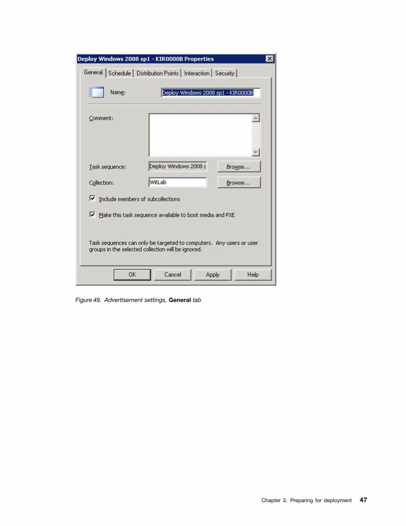
Figure 49. Advertisement settings, General tab
Chapter 3. Preparing for deployment 47
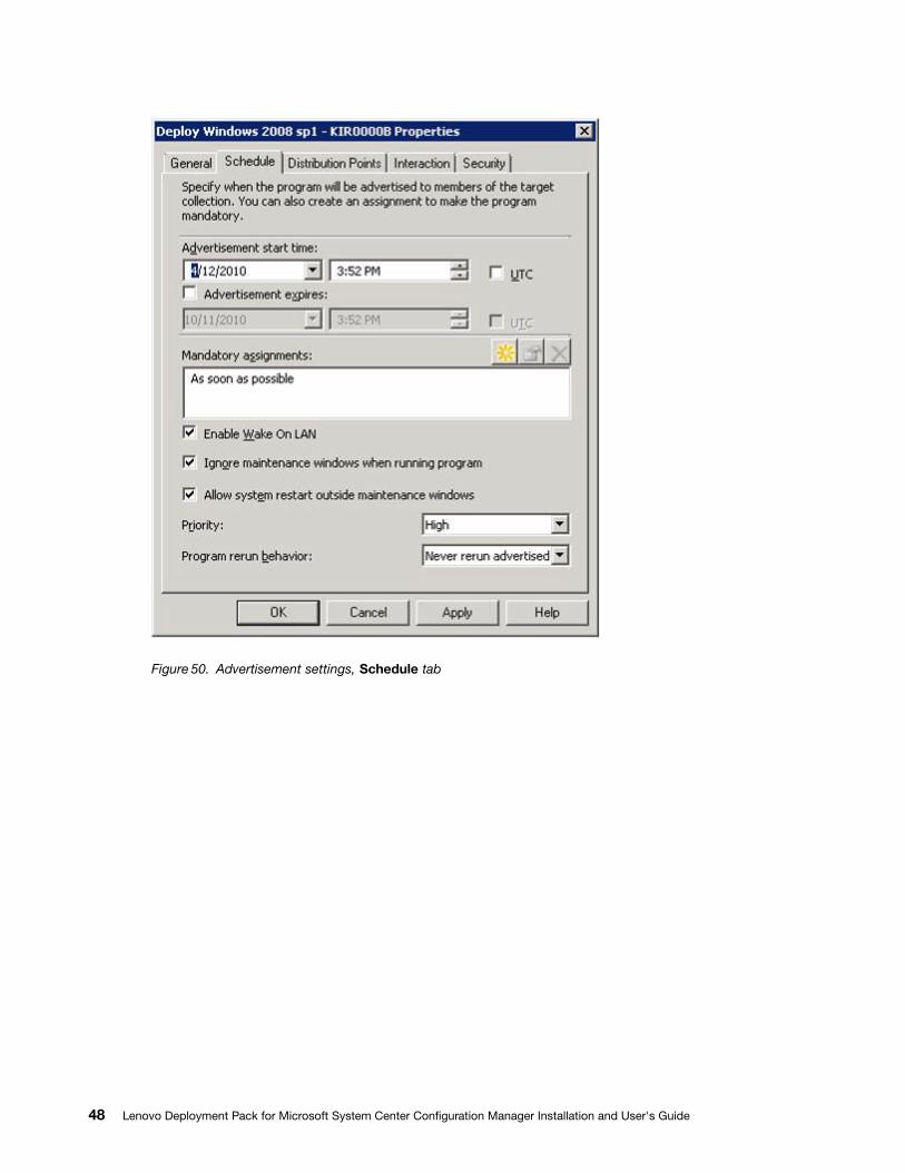
Figure 50. Advertisement settings, Schedule tab
48 Lenovo Deployment Pack for Microsoft System Center Configuration Manager Installation and User's Guide
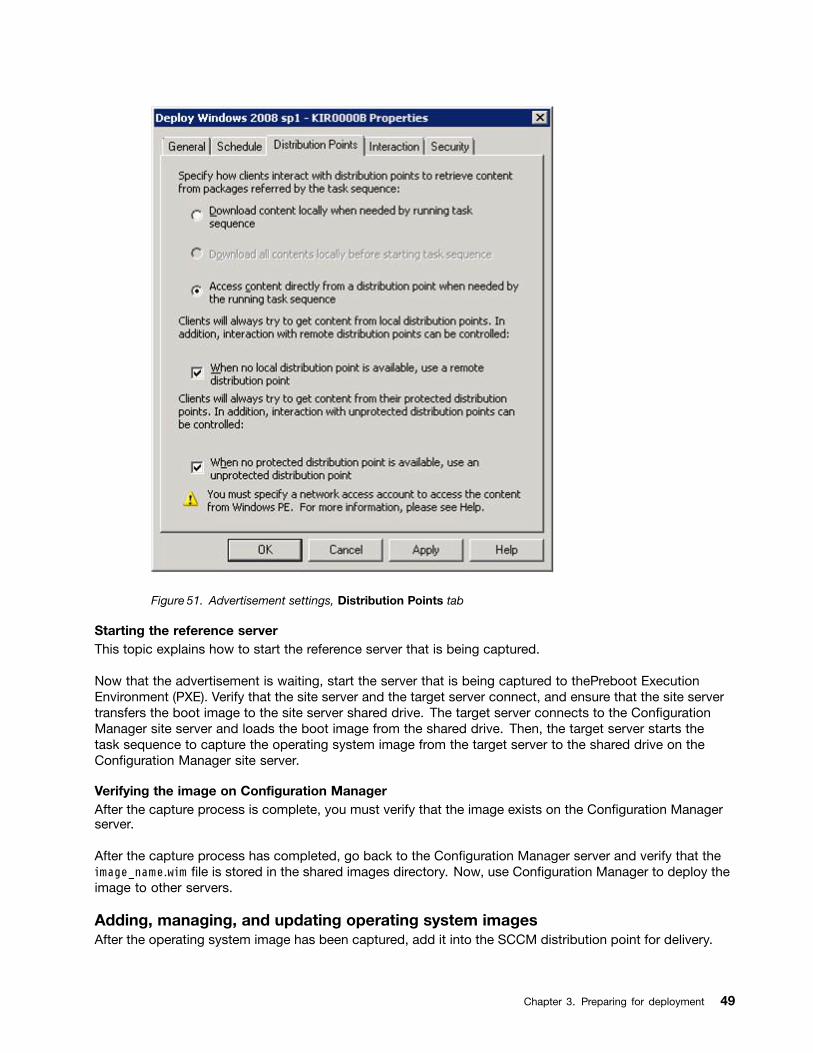
Figure 51. Advertisement settings, Distribution Points tab
Starting the reference serverThis topic explains how to start the reference server that is being captured.
Now that the advertisement is waiting, start the server that is being captured to thePreboot ExecutionEnvironment (PXE). Verify that the site server and the target server connect, and ensure that the site servertransfers the boot image to the site server shared drive. The target server connects to the ConfigurationManager site server and loads the boot image from the shared drive. Then, the target server starts thetask sequence to capture the operating system image from the target server to the shared drive on theConfiguration Manager site server.
Verifying the image on Configuration ManagerAfter the capture process is complete, you must verify that the image exists on the Configuration Managerserver.
After the capture process has completed, go back to the Configuration Manager server and verify that theimage_name.wim file is stored in the shared images directory. Now, use Configuration Manager to deploy theimage to other servers.
Adding, managing, and updating operating system imagesAfter the operating system image has been captured, add it into the SCCM distribution point for delivery.
Chapter 3. Preparing for deployment 49
To add the operating system image to the SCCM distribution point for delivery, you must first add theoperating system image and then manage and update the distribution points.
Adding operating system imagesUse these steps to add the operating system images.
Procedure
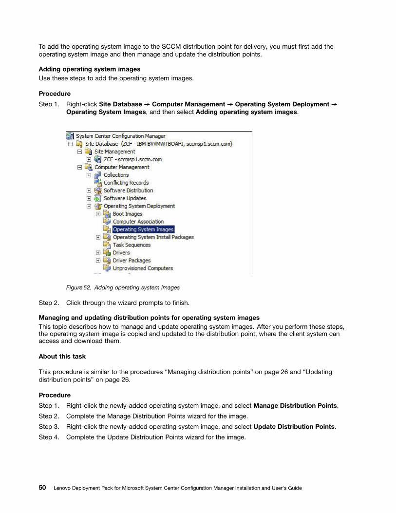
Step 1. Right-click Site Database ➙ Computer Management ➙ Operating System Deployment ➙Operating System Images, and then select Adding operating system images.
Figure 52. Adding operating system images
Step 2. Click through the wizard prompts to finish.
Managing and updating distribution points for operating system imagesThis topic describes how to manage and update operating system images. After you perform these steps,the operating system image is copied and updated to the distribution point, where the client system canaccess and download them.
About this task
This procedure is similar to the procedures “Managing distribution points” on page 26 and “Updatingdistribution points” on page 26.
Procedure
Step 1. Right-click the newly-added operating system image, and select Manage Distribution Points.
Step 2. Complete the Manage Distribution Points wizard for the image.
Step 3. Right-click the newly-added operating system image, and select Update Distribution Points.
Step 4. Complete the Update Distribution Points wizard for the image.
50 Lenovo Deployment Pack for Microsoft System Center Configuration Manager Installation and User's Guide
Preparing for deployment in SCCM 2012Before deploying SCCM 2012, you must perform some procedures as a prerequisite, which includeconfiguring OSD, updating distribution points, and selecting the boot image.
The following sections will guide you through the process step by step.
SCCM OSD initial configurationThis topic refers you to detailed information about how to configure your operating system deployment(OSD) environment by describing the actions you should take in SCCM.
The following information about configuring OSD is provided as a general reference. For more detailedinformation about setting up OSD in SCCM, see the Microsoft System Center Configuration Manager2007 Documentation Library webpage.
Setting the network access accountTo set the network access account, use the Configuration Manager console.
Procedure
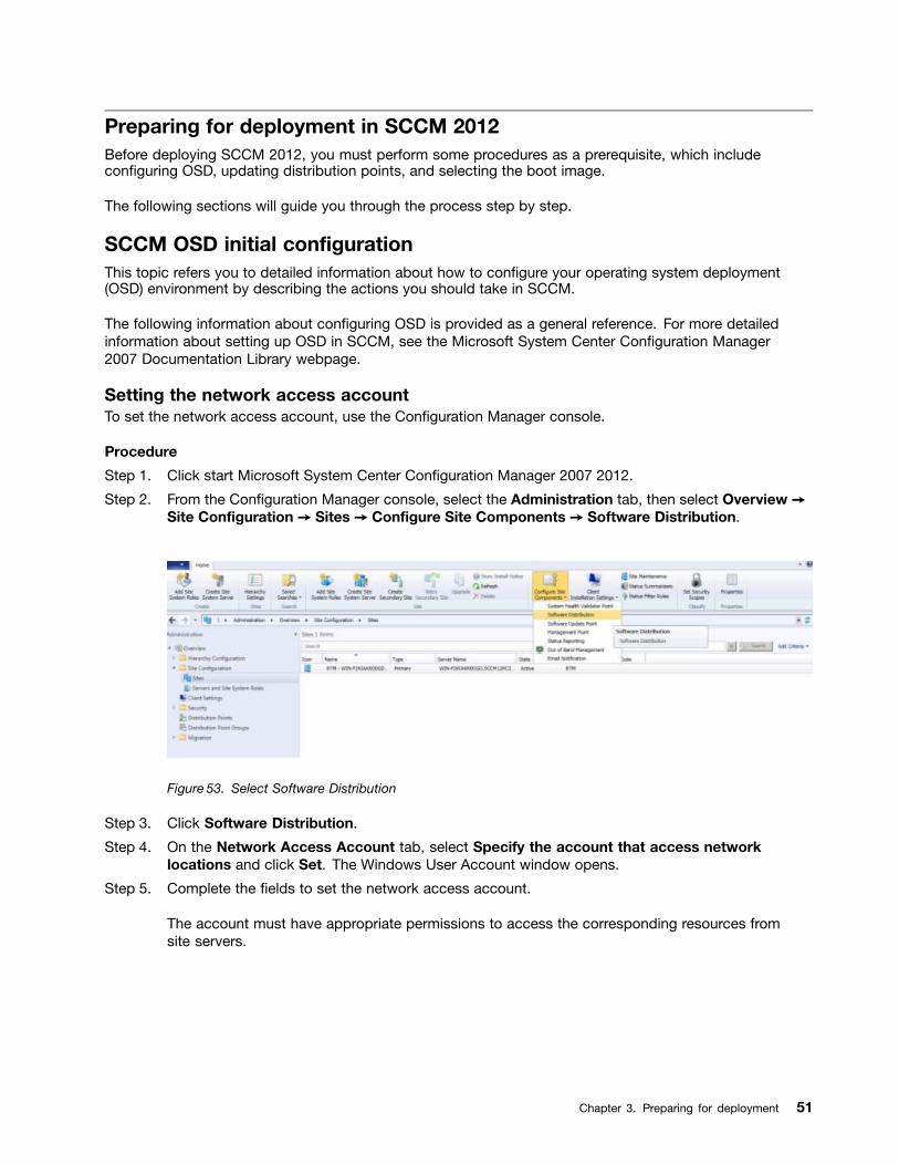
Step 1. Click start Microsoft System Center Configuration Manager 2007 2012.
Step 2. From the Configuration Manager console, select the Administration tab, then select Overview ➙Site Configuration ➙ Sites ➙ Configure Site Components ➙ Software Distribution.
Figure 53. Select Software Distribution
Step 3. Click Software Distribution.
Step 4. On the Network Access Account tab, select Specify the account that access networklocations and click Set. The Windows User Account window opens.
Step 5. Complete the fields to set the network access account.
The account must have appropriate permissions to access the corresponding resources fromsite servers.
Chapter 3. Preparing for deployment 51
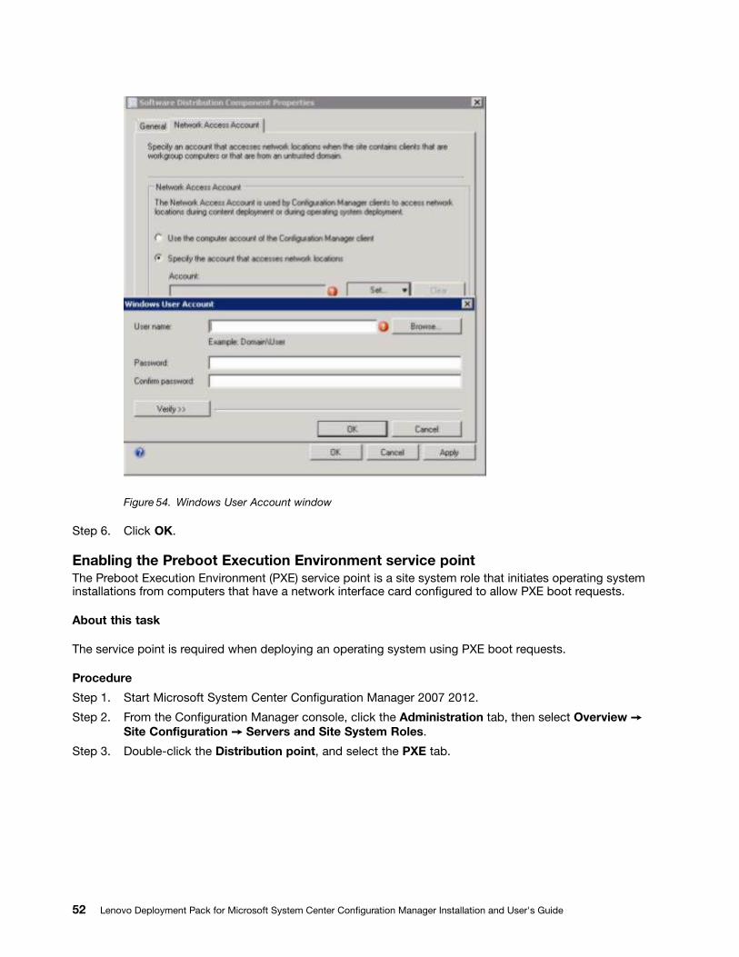
Figure 54. Windows User Account window
Step 6. Click OK.
Enabling the Preboot Execution Environment service pointThe Preboot Execution Environment (PXE) service point is a site system role that initiates operating systeminstallations from computers that have a network interface card configured to allow PXE boot requests.
About this task
The service point is required when deploying an operating system using PXE boot requests.
Procedure
Step 1. Start Microsoft System Center Configuration Manager 2007 2012.
Step 2. From the Configuration Manager console, click the Administration tab, then select Overview ➙Site Configuration ➙ Servers and Site System Roles.
Step 3. Double-click the Distribution point, and select the PXE tab.
52 Lenovo Deployment Pack for Microsoft System Center Configuration Manager Installation and User's Guide
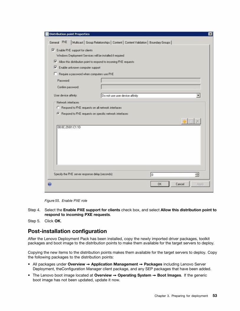
Figure 55. Enable PXE role
Step 4. Select the Enable PXE support for clients check box, and select Allow this distribution point torespond to incoming PXE requests.
Step 5. Click OK.
Post-installation configurationAfter the Lenovo Deployment Pack has been installed, copy the newly imported driver packages, toolkitpackages and boot image to the distribution points to make them available for the target servers to deploy.
Copying the new items to the distribution points makes them available for the target servers to deploy. Copythe following packages to the distribution points:
• All packages under Overview ➙ Application Management ➙ Packages including Lenovo ServerDeployment, theConfiguration Manager client package, and any SEP packages that have been added.
• The Lenovo boot image located at Overview ➙ Operating System ➙ Boot Images. If the genericboot image has not been updated, update it now.
Chapter 3. Preparing for deployment 53
• Driver packages that are located at Overview ➙ Operating System ➙ Driver Packages ➙ LenovoServer Driver Packages.
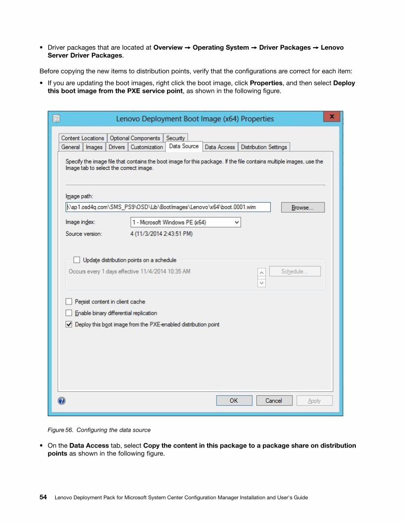
Before copying the new items to distribution points, verify that the configurations are correct for each item:
• If you are updating the boot images, right click the boot image, click Properties, and then select Deploythis boot image from the PXE service point, as shown in the following figure.
Figure 56. Configuring the data source
• On the Data Access tab, select Copy the content in this package to a package share on distributionpoints as shown in the following figure.
54 Lenovo Deployment Pack for Microsoft System Center Configuration Manager Installation and User's Guide
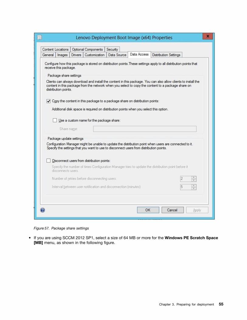
Figure 57. Package share settings
• If you are using SCCM 2012 SP1, select a size of 64 MB or more for the Windows PE Scratch Space[MB] menu, as shown in the following figure.
Chapter 3. Preparing for deployment 55
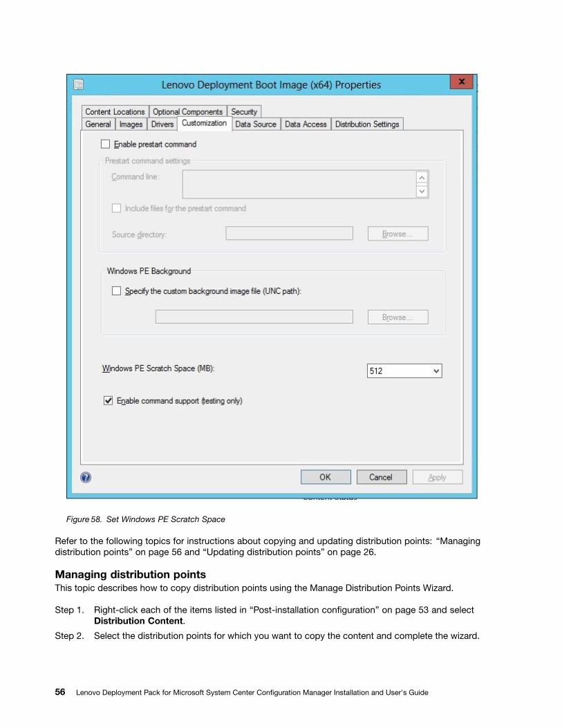
Figure 58. Set Windows PE Scratch Space
Refer to the following topics for instructions about copying and updating distribution points: “Managingdistribution points” on page 56 and “Updating distribution points” on page 26.
Managing distribution pointsThis topic describes how to copy distribution points using the Manage Distribution Points Wizard.
Step 1. Right-click each of the items listed in “Post-installation configuration” on page 53 and selectDistribution Content.
Step 2. Select the distribution points for which you want to copy the content and complete the wizard.
56 Lenovo Deployment Pack for Microsoft System Center Configuration Manager Installation and User's Guide
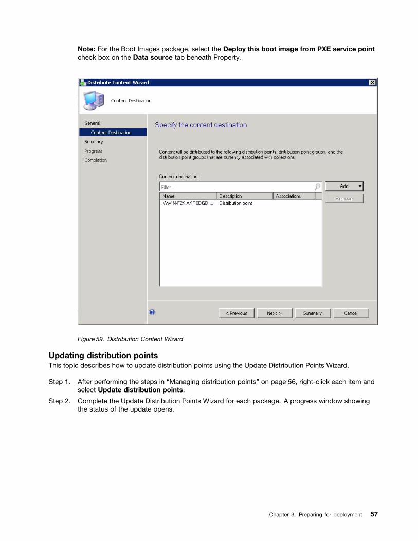
Note: For the Boot Images package, select the Deploy this boot image from PXE service pointcheck box on the Data source tab beneath Property.
Figure 59. Distribution Content Wizard
Updating distribution pointsThis topic describes how to update distribution points using the Update Distribution Points Wizard.
Step 1. After performing the steps in “Managing distribution points” on page 56, right-click each item andselect Update distribution points.
Step 2. Complete the Update Distribution Points Wizard for each package. A progress window showingthe status of the update opens.
Chapter 3. Preparing for deployment 57
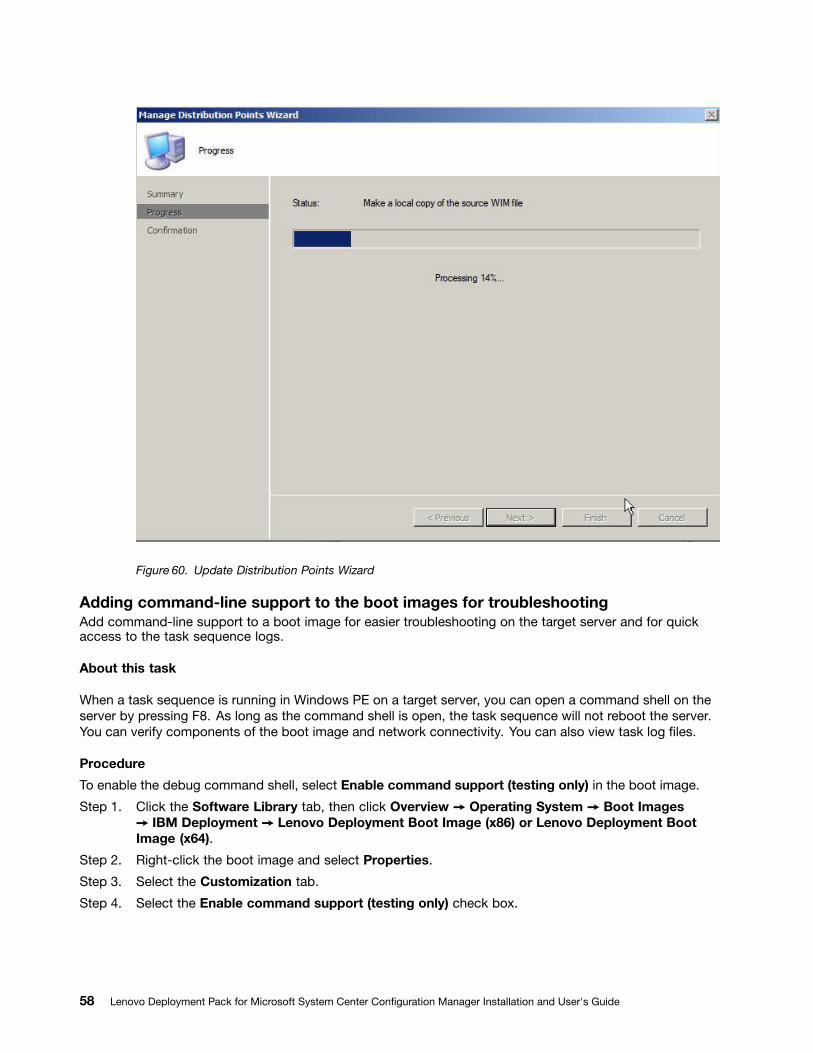
Figure 60. Update Distribution Points Wizard
Adding command-line support to the boot images for troubleshootingAdd command-line support to a boot image for easier troubleshooting on the target server and for quickaccess to the task sequence logs.
About this task
When a task sequence is running in Windows PE on a target server, you can open a command shell on theserver by pressing F8. As long as the command shell is open, the task sequence will not reboot the server.You can verify components of the boot image and network connectivity. You can also view task log files.
Procedure
To enable the debug command shell, select Enable command support (testing only) in the boot image.
Step 1. Click the Software Library tab, then click Overview ➙ Operating System ➙ Boot Images➙ IBM Deployment ➙ Lenovo Deployment Boot Image (x86) or Lenovo Deployment BootImage (x64).
Step 2. Right-click the boot image and select Properties.
Step 3. Select the Customization tab.
Step 4. Select the Enable command support (testing only) check box.
58 Lenovo Deployment Pack for Microsoft System Center Configuration Manager Installation and User's Guide
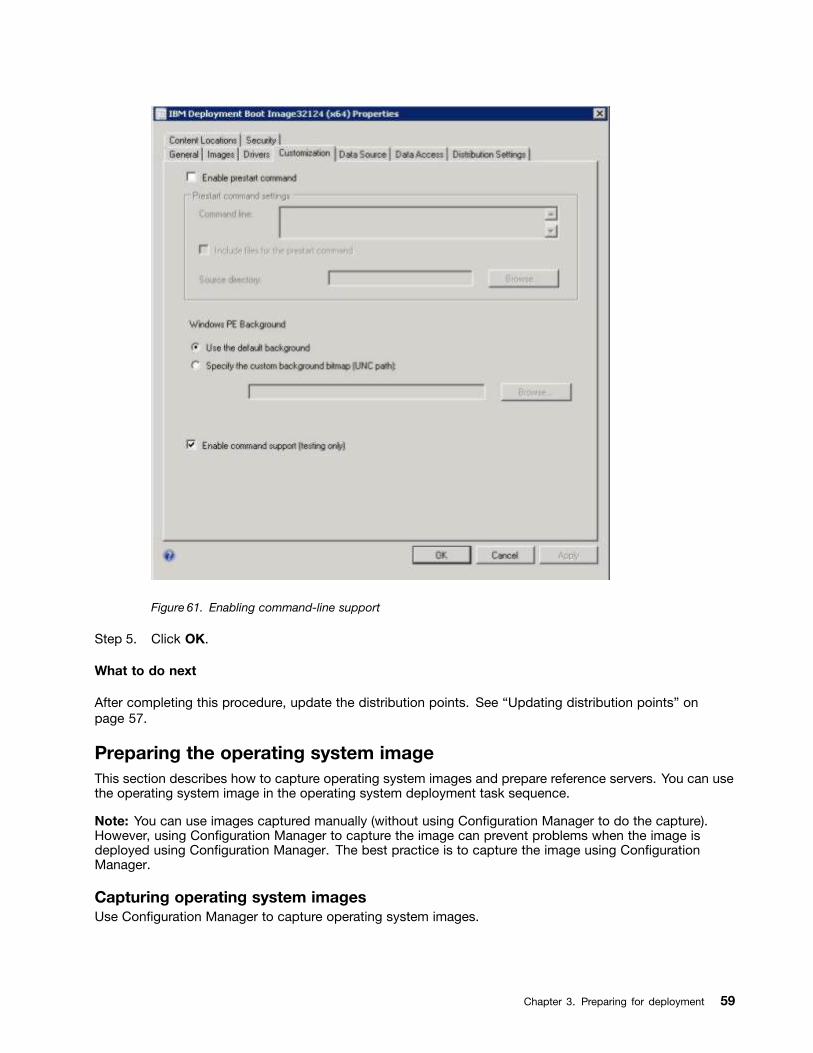
Figure 61. Enabling command-line support
Step 5. Click OK.
What to do next
After completing this procedure, update the distribution points. See “Updating distribution points” onpage 57.
Preparing the operating system imageThis section describes how to capture operating system images and prepare reference servers. You can usethe operating system image in the operating system deployment task sequence.
Note: You can use images captured manually (without using Configuration Manager to do the capture).However, using Configuration Manager to capture the image can prevent problems when the image isdeployed using Configuration Manager. The best practice is to capture the image using ConfigurationManager.
Capturing operating system imagesUse Configuration Manager to capture operating system images.
Chapter 3. Preparing for deployment 59
Lenovo Deployment Pack supports the clone method to install operating systems. To use this method, youmust prepare an operating system image.
Preparing the reference serverThis topic directs you to information about building the reference server, which is required when capturingoperating system images.
Procedure
Step 1. Build the reference server with everything installed that is required for the image. Include everythingthat a new system might require, such as tools, drivers, agents, service packs, and updates.
Step 2. On the reference server, run the sysprsysprsysprepepep /gener/gener/generalizalizalizeee command to prepare the image for installationonto other servers. For instructions, see Appendix C “Running Sysprep” on page 121.
Adding a target server to Configuration ManagerThis topic describes how to create a collection and add one or more servers to it.
About this task
To enable SCCM to recognize the target server, use the MAC address of the system's primary networkinterface (the interface used for deployment). To group servers,SCCM uses collections. A number of defaultcollections are already created based on operating system version and other attributes. Use the followingprocedure to create a new collection to use for deployments.
Procedure
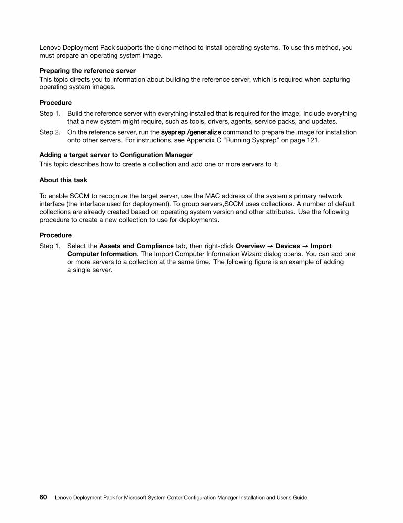
Step 1. Select the Assets and Compliance tab, then right-click Overview ➙ Devices ➙ ImportComputer Information. The Import Computer Information Wizard dialog opens. You can add oneor more servers to a collection at the same time. The following figure is an example of addinga single server.
60 Lenovo Deployment Pack for Microsoft System Center Configuration Manager Installation and User's Guide
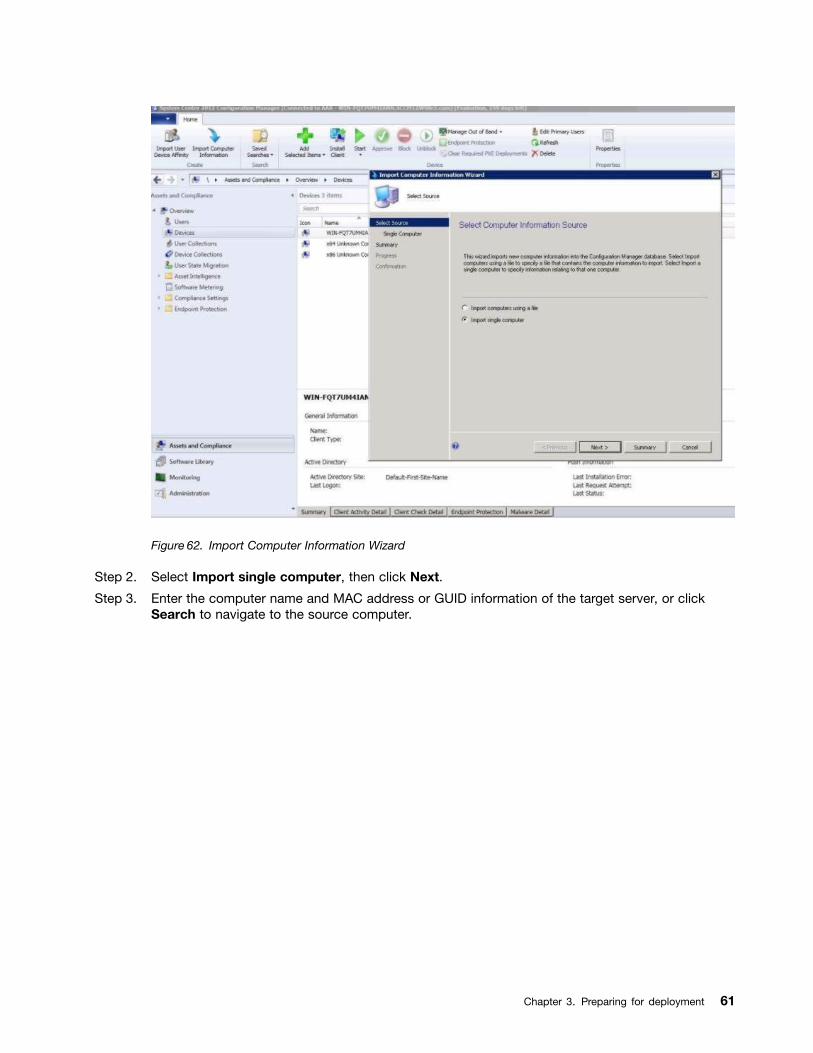
Figure 62. Import Computer Information Wizard
Step 2. Select Import single computer, then click Next.
Step 3. Enter the computer name and MAC address or GUID information of the target server, or clickSearch to navigate to the source computer.
Chapter 3. Preparing for deployment 61
Figure 63. Adding a single computer
Step 4. Click Next.
Step 5. Select whether to add the new computer to the All Systems collection, or click Browse to selectan existing collection to add the computer to.
62 Lenovo Deployment Pack for Microsoft System Center Configuration Manager Installation and User's Guide
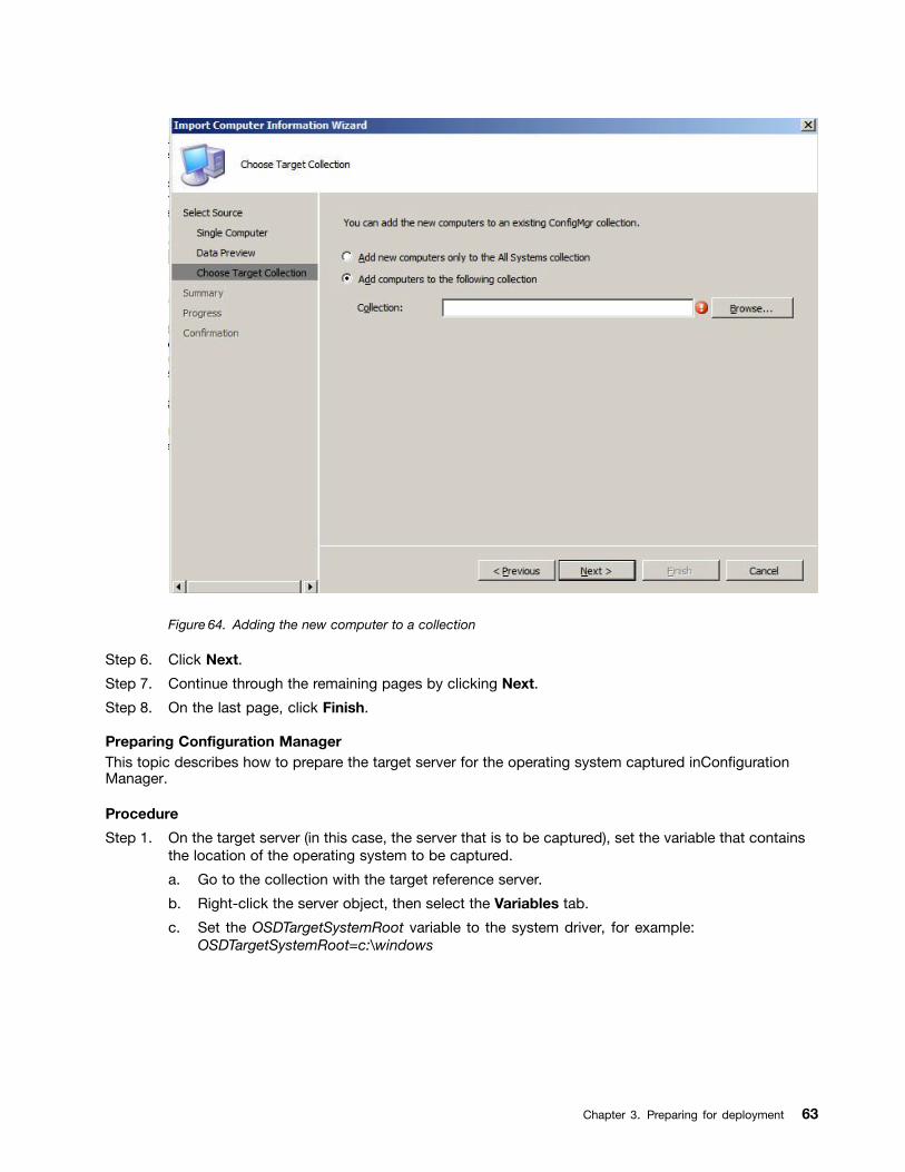
Figure 64. Adding the new computer to a collection
Step 6. Click Next.
Step 7. Continue through the remaining pages by clicking Next.
Step 8. On the last page, click Finish.
Preparing Configuration ManagerThis topic describes how to prepare the target server for the operating system captured inConfigurationManager.
Procedure
Step 1. On the target server (in this case, the server that is to be captured), set the variable that containsthe location of the operating system to be captured.
a. Go to the collection with the target reference server.
b. Right-click the server object, then select the Variables tab.
c. Set the OSDTargetSystemRoot variable to the system driver, for example:OSDTargetSystemRoot=c:\windows
Chapter 3. Preparing for deployment 63
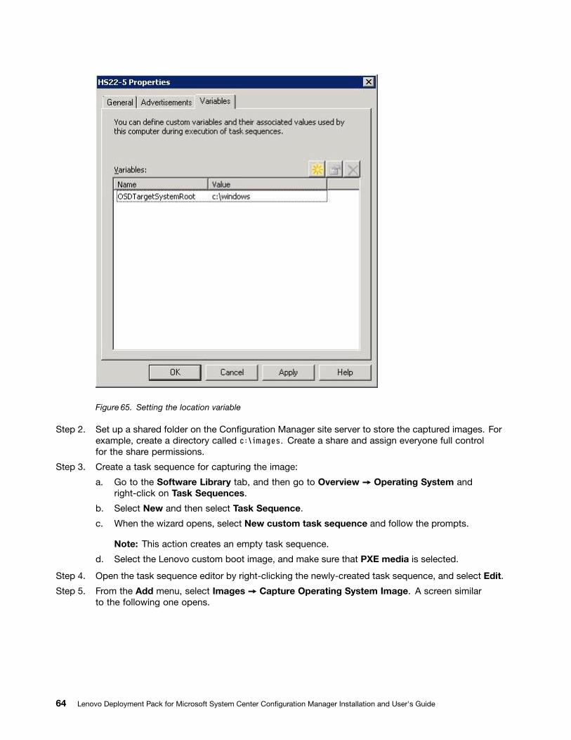
Figure 65. Setting the location variable
Step 2. Set up a shared folder on the Configuration Manager site server to store the captured images. Forexample, create a directory called c:\images. Create a share and assign everyone full controlfor the share permissions.
Step 3. Create a task sequence for capturing the image:
a. Go to the Software Library tab, and then go to Overview ➙ Operating System andright-click on Task Sequences.
b. Select New and then select Task Sequence.
c. When the wizard opens, select New custom task sequence and follow the prompts.
Note: This action creates an empty task sequence.
d. Select the Lenovo custom boot image, and make sure that PXE media is selected.
Step 4. Open the task sequence editor by right-clicking the newly-created task sequence, and select Edit.
Step 5. From the Add menu, select Images ➙ Capture Operating System Image. A screen similarto the following one opens.
64 Lenovo Deployment Pack for Microsoft System Center Configuration Manager Installation and User's Guide
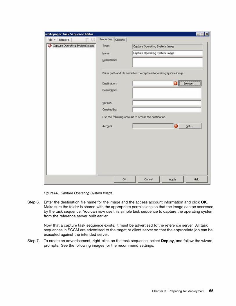
Figure 66. Capture Operating System Image
Step 6. Enter the destination file name for the image and the access account information and click OK.Make sure the folder is shared with the appropriate permissions so that the image can be accessedby the task sequence. You can now use this simple task sequence to capture the operating systemfrom the reference server built earlier.
Now that a capture task sequence exists, it must be advertised to the reference server. All tasksequences in SCCM are advertised to the target or client server so that the appropriate job can beexecuted against the intended server.
Step 7. To create an advertisement, right-click on the task sequence, select Deploy, and follow the wizardprompts. See the following images for the recommend settings.
Chapter 3. Preparing for deployment 65
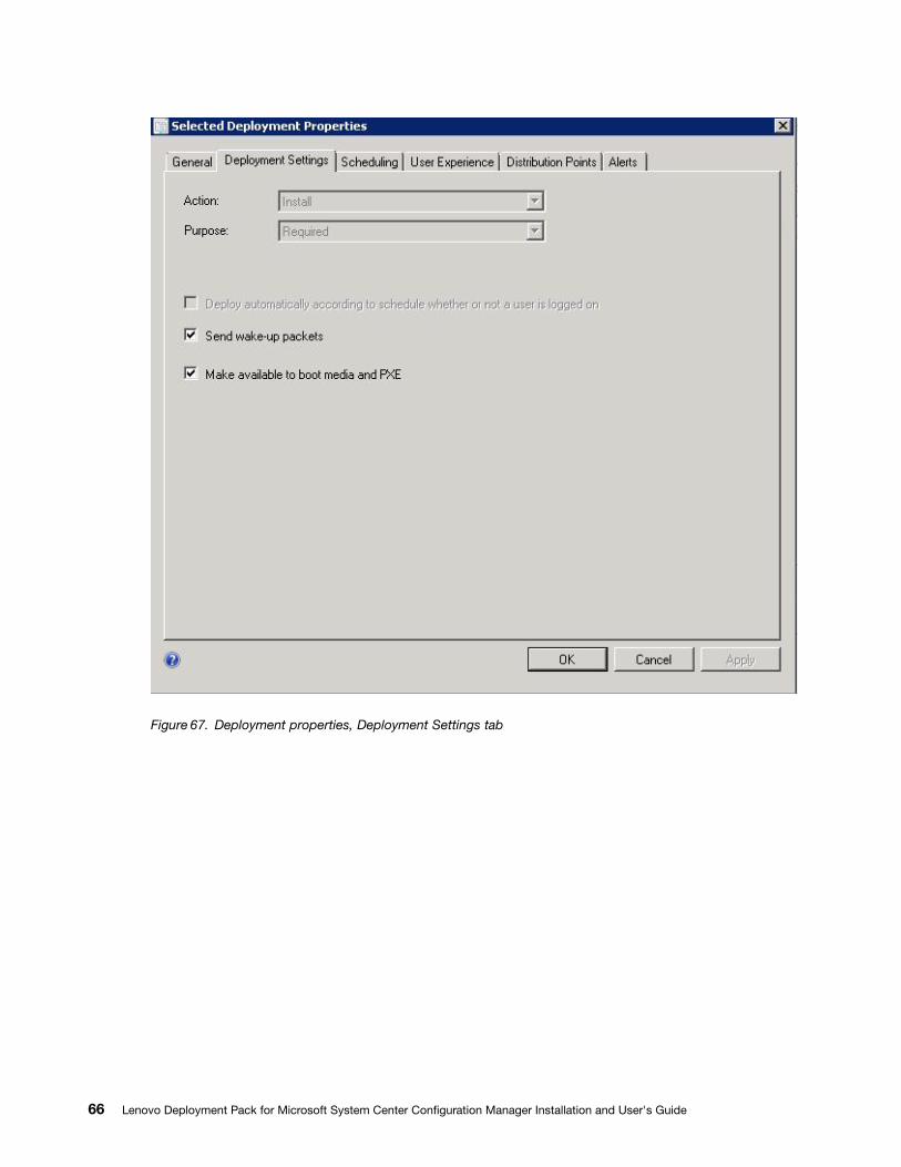
Figure 67. Deployment properties, Deployment Settings tab
66 Lenovo Deployment Pack for Microsoft System Center Configuration Manager Installation and User's Guide
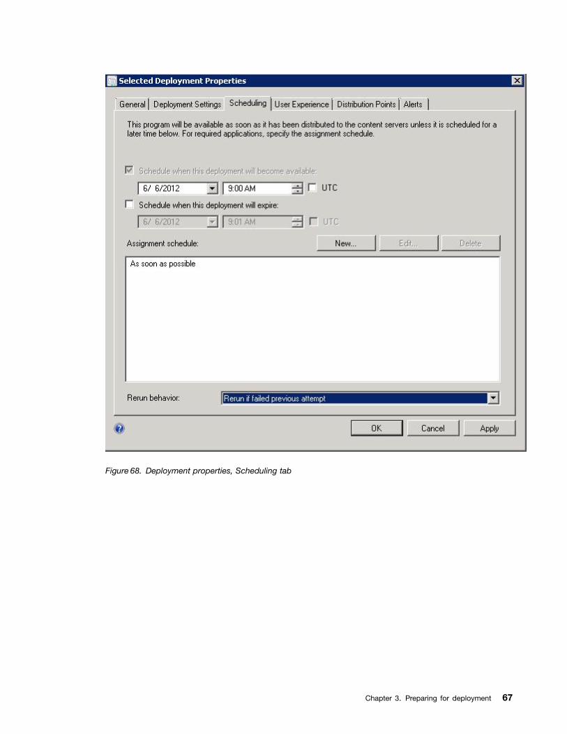
Figure 68. Deployment properties, Scheduling tab
Chapter 3. Preparing for deployment 67
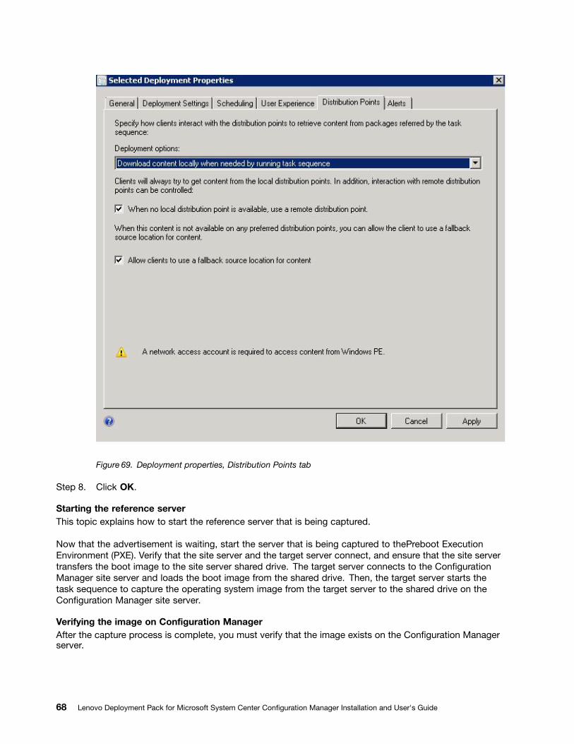
Figure 69. Deployment properties, Distribution Points tab
Step 8. Click OK.
Starting the reference serverThis topic explains how to start the reference server that is being captured.
Now that the advertisement is waiting, start the server that is being captured to thePreboot ExecutionEnvironment (PXE). Verify that the site server and the target server connect, and ensure that the site servertransfers the boot image to the site server shared drive. The target server connects to the ConfigurationManager site server and loads the boot image from the shared drive. Then, the target server starts thetask sequence to capture the operating system image from the target server to the shared drive on theConfiguration Manager site server.
Verifying the image on Configuration ManagerAfter the capture process is complete, you must verify that the image exists on the Configuration Managerserver.
68 Lenovo Deployment Pack for Microsoft System Center Configuration Manager Installation and User's Guide
After the capture process has completed, go back to the Configuration Manager server and verify that theimage_name.wim file is stored in the shared images directory. Now, use Configuration Manager to deploy theimage to other servers.
Adding, managing, and updating operating system imagesAfter the operating system image has been captured, add it into the SCCM distribution point for delivery.
To add the operating system image to the SCCM distribution point for delivery, you must first add theoperating system image and then manage and update the distribution points.
Adding operating system imagesUse these steps to add the operating system images to the distribution point for delivery.
Procedure
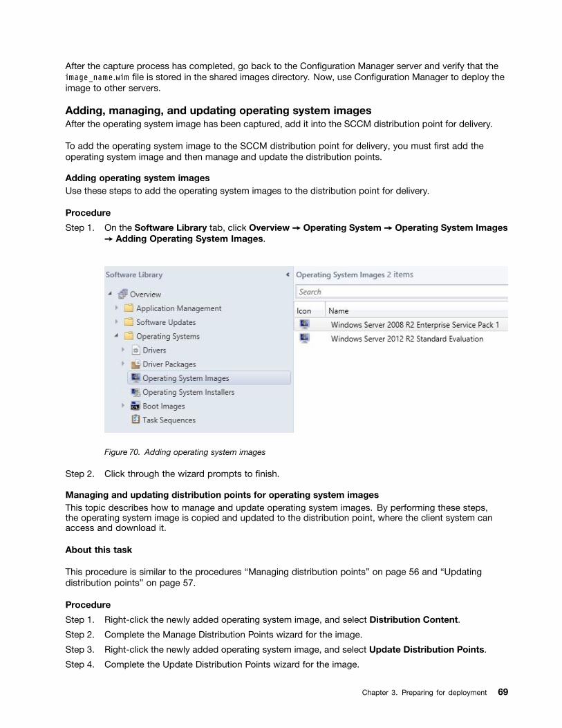
Step 1. On the Software Library tab, click Overview ➙ Operating System ➙ Operating System Images➙ Adding Operating System Images.
Figure 70. Adding operating system images
Step 2. Click through the wizard prompts to finish.
Managing and updating distribution points for operating system imagesThis topic describes how to manage and update operating system images. By performing these steps,the operating system image is copied and updated to the distribution point, where the client system canaccess and download it.
About this task
This procedure is similar to the procedures “Managing distribution points” on page 56 and “Updatingdistribution points” on page 57.
Procedure
Step 1. Right-click the newly added operating system image, and select Distribution Content.
Step 2. Complete the Manage Distribution Points wizard for the image.
Step 3. Right-click the newly added operating system image, and select Update Distribution Points.
Step 4. Complete the Update Distribution Points wizard for the image.
Chapter 3. Preparing for deployment 69

70 Lenovo Deployment Pack for Microsoft System Center Configuration Manager Installation and User's Guide
Chapter 4. End-to-end deployment scenario
Although the Lenovo Deployment Pack provides various hardware configuration and operating systemdeployment functionality, the execution process is similar. This section describes how to deploy the tasksequence and explains the end-to-end deployment scenario. Use this scenario to deploy different scripts tofulfill different Deployment Pack functions.
End-to-end deployment scenario in SCCM 2007This section covers the end-to-end deployment scenario in SCCM 2007.
Adding a target server to Configuration ManagerThe first task in the scenario is to add the target server to Configuration Manager so that ConfigurationManager will recognize the target server as a known server when deploying the task sequence.
About this task
For detailed steps, refer to “Adding a target server to Configuration Manager” on page 41.
Preparing a task sequenceThis topic explains how to create a task sequence by using the template provided in theLenovo DeploymentPack.
About this task
The template provided by Lenovo Deployment Pack makes it quick and easy to create a task sequence. Acompleted task sequence template that includes hardware configuration, operating system deployment,driver feeding and more will be automatically created.
Procedure
Step 1. Open the Configuration Manager console and navigate to Operating System Deployment ➙Task Sequence.
Step 2. Right-click Task Sequence, then select Bare Metal Server Deployment ➙ Create a LenovoServer Deployment Task Sequence. The template shown in the following figure opens.
© Copyright Lenovo 2014, 2016 71
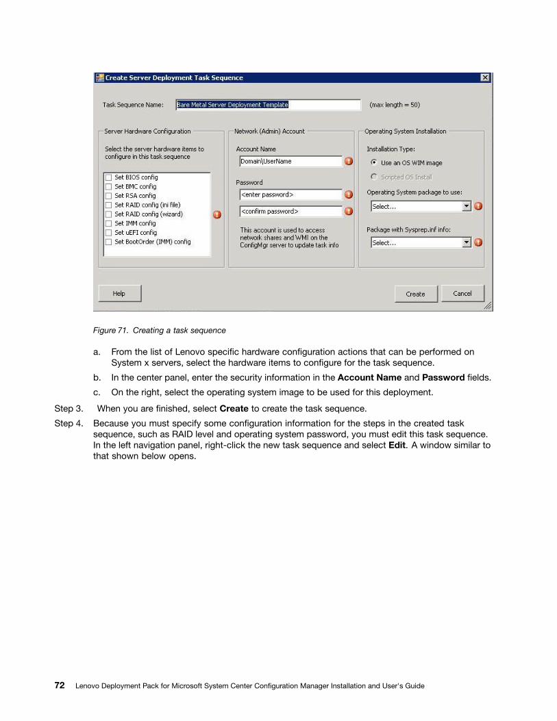
Figure 71. Creating a task sequence
a. From the list of Lenovo specific hardware configuration actions that can be performed onSystem x servers, select the hardware items to configure for the task sequence.
b. In the center panel, enter the security information in the Account Name and Password fields.
c. On the right, select the operating system image to be used for this deployment.
Step 3. When you are finished, select Create to create the task sequence.
Step 4. Because you must specify some configuration information for the steps in the created tasksequence, such as RAID level and operating system password, you must edit this task sequence.In the left navigation panel, right-click the new task sequence and select Edit. A window similar tothat shown below opens.
72 Lenovo Deployment Pack for Microsoft System Center Configuration Manager Installation and User's Guide
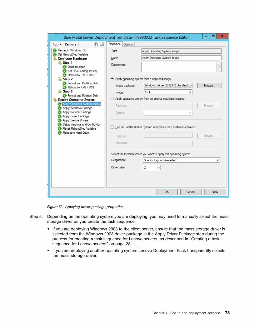
Figure 72. Applying driver package properties
Step 5. Depending on the operating system you are deploying, you may need to manually select the massstorage driver as you create the task sequence:
• If you are deploying Windows 2003 to the client server, ensure that the mass storage driver isselected from the Windows 2003 driver package in the Apply Driver Package step during theprocess for creating a task sequence for Lenovo servers, as described in “Creating a tasksequence for Lenovo servers” on page 28.
• If you are deploying another operating system,Lenovo Deployment Pack transparently selectsthe mass storage driver.
Chapter 4. End-to-end deployment scenario 73

Figure 73. Selecting the mass storage driver
The actions from configuring hardware are provided by theLenovo Deployment Pack pre-operatingsystem load. In these examples, Deploy Operating System is a Windows® installation withtheLenovo driver packages added.
Step 6. Click OK.
Note: For Lenovo specific hardware configuration, refer to Chapter 5 “Lenovo Deployment Packfeatures” on page 89.
Note: Prepare the operating system deployment image file by using the instructions in “Preparingthe operating system image” on page 59.
Advertising a task sequenceAfter creating and saving a task sequence, create an advertisement and deploy it to a collection.
About this task
Advertisements are used in Configuration Manager to assign jobs to client servers, in this case, the serverthat is being deployed, such as running a task sequence to deploy a Windows operating system on aclient server.
Procedure
Step 1. Right-click the task sequence, and select Advertise.
Step 2. Select the collection that contains the target server.
Step 3. Select Make this task sequence available to boot media and PXE.
74 Lenovo Deployment Pack for Microsoft System Center Configuration Manager Installation and User's Guide
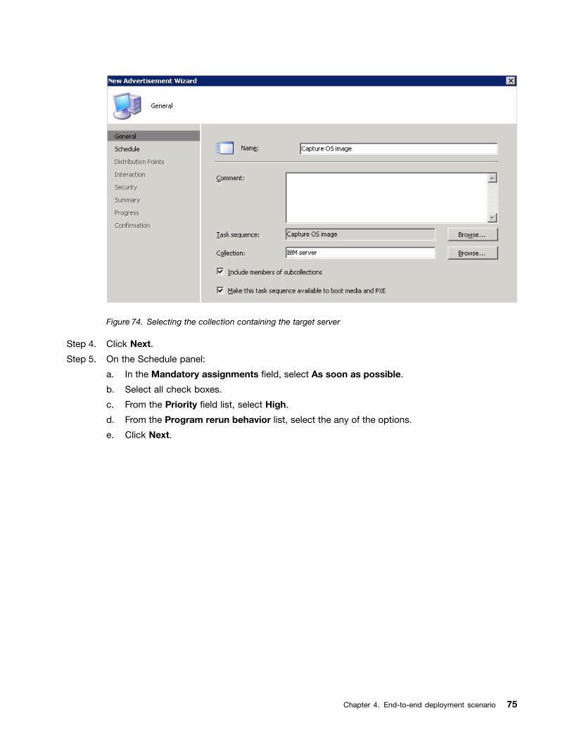
Figure 74. Selecting the collection containing the target server
Step 4. Click Next.
Step 5. On the Schedule panel:
a. In the Mandatory assignments field, select As soon as possible.
b. Select all check boxes.
c. From the Priority field list, select High.
d. From the Program rerun behavior list, select the any of the options.
e. Click Next.
Chapter 4. End-to-end deployment scenario 75
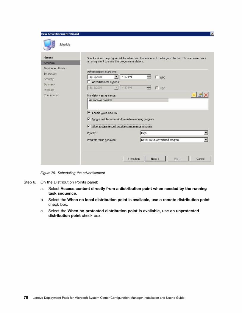
Figure 75. Scheduling the advertisement
Step 6. On the Distribution Points panel:
a. Select Access content directly from a distribution point when needed by the runningtask sequence.
b. Select the When no local distribution point is available, use a remote distribution pointcheck box.
c. Select the When no protected distribution point is available, use an unprotecteddistribution point check box.
76 Lenovo Deployment Pack for Microsoft System Center Configuration Manager Installation and User's Guide
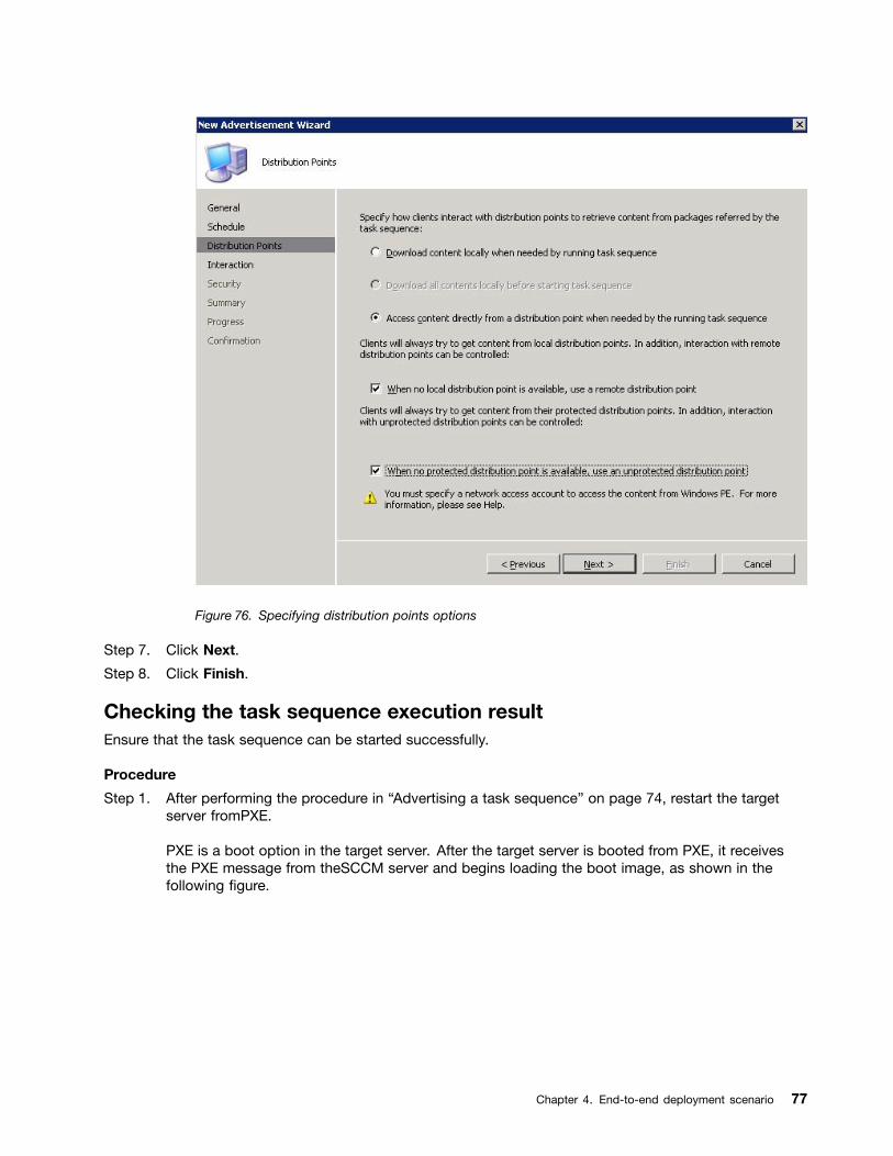
Figure 76. Specifying distribution points options
Step 7. Click Next.
Step 8. Click Finish.
Checking the task sequence execution resultEnsure that the task sequence can be started successfully.
Procedure
Step 1. After performing the procedure in “Advertising a task sequence” on page 74, restart the targetserver fromPXE.
PXE is a boot option in the target server. After the target server is booted from PXE, it receivesthe PXE message from theSCCM server and begins loading the boot image, as shown in thefollowing figure.
Chapter 4. End-to-end deployment scenario 77
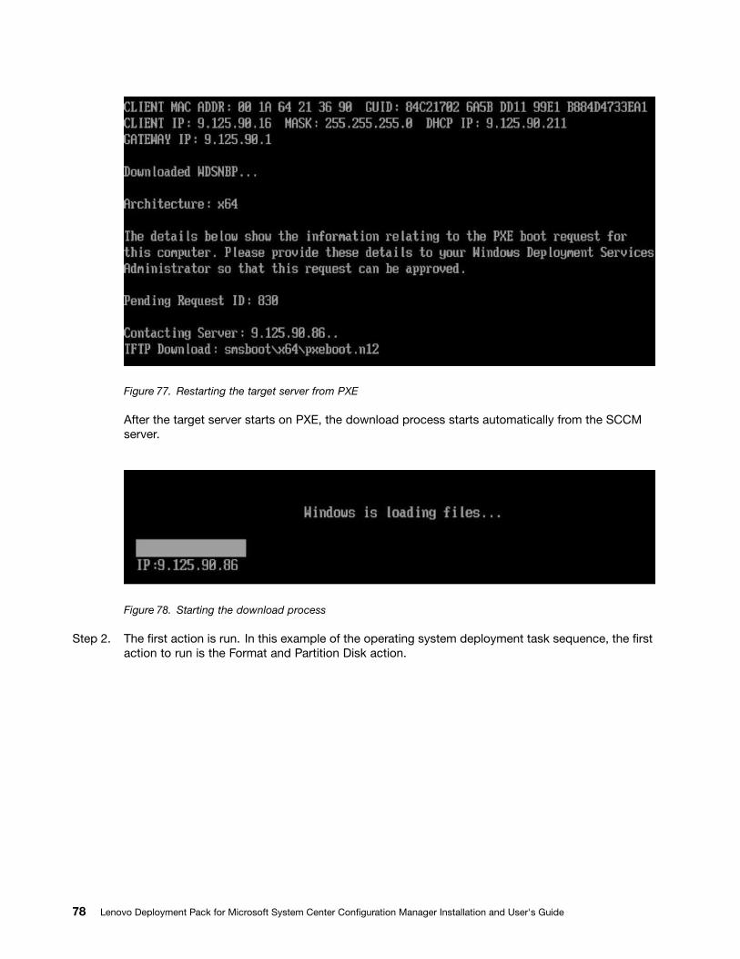
Figure 77. Restarting the target server from PXE
After the target server starts on PXE, the download process starts automatically from the SCCMserver.
Figure 78. Starting the download process
Step 2. The first action is run. In this example of the operating system deployment task sequence, the firstaction to run is the Format and Partition Disk action.
78 Lenovo Deployment Pack for Microsoft System Center Configuration Manager Installation and User's Guide
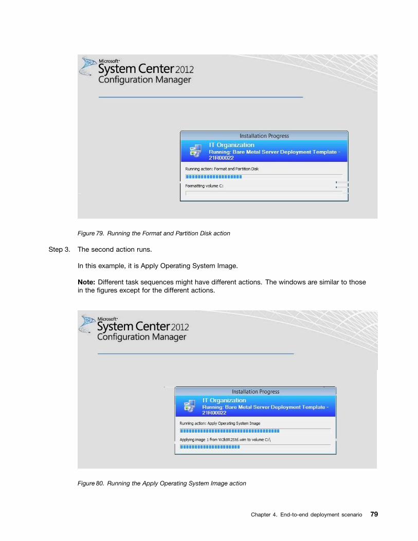
Figure 79. Running the Format and Partition Disk action
Step 3. The second action runs.
In this example, it is Apply Operating System Image.
Note: Different task sequences might have different actions. The windows are similar to thosein the figures except for the different actions.
Figure 80. Running the Apply Operating System Image action
Chapter 4. End-to-end deployment scenario 79
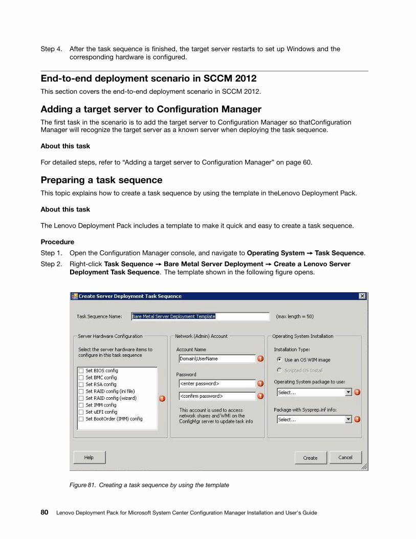
Step 4. After the task sequence is finished, the target server restarts to set up Windows and thecorresponding hardware is configured.
End-to-end deployment scenario in SCCM 2012This section covers the end-to-end deployment scenario in SCCM 2012.
Adding a target server to Configuration ManagerThe first task in the scenario is to add the target server to Configuration Manager so thatConfigurationManager will recognize the target server as a known server when deploying the task sequence.
About this task
For detailed steps, refer to “Adding a target server to Configuration Manager” on page 60.
Preparing a task sequenceThis topic explains how to create a task sequence by using the template in theLenovo Deployment Pack.
About this task
The Lenovo Deployment Pack includes a template to make it quick and easy to create a task sequence.
Procedure
Step 1. Open the Configuration Manager console, and navigate to Operating System ➙ Task Sequence.
Step 2. Right-click Task Sequence ➙ Bare Metal Server Deployment ➙ Create a Lenovo ServerDeployment Task Sequence. The template shown in the following figure opens.
Figure 81. Creating a task sequence by using the template
80 Lenovo Deployment Pack for Microsoft System Center Configuration Manager Installation and User's Guide
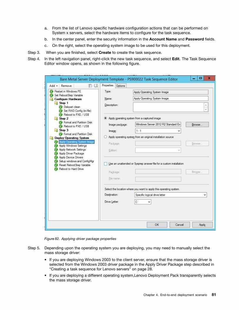
a. From the list of Lenovo specific hardware configuration actions that can be performed onSystem x servers, select the hardware items to configure for the task sequence.
b. In the center panel, enter the security information in the Account Name and Password fields.
c. On the right, select the operating system image to be used for this deployment.
Step 3. When you are finished, select Create to create the task sequence.
Step 4. In the left navigation panel, right-click the new task sequence, and select Edit. The Task SequenceEditor window opens, as shown in the following figure.
Figure 82. Applying driver package properties
Step 5. Depending upon the operating system you are deploying, you may need to manually select themass storage driver:
• If you are deploying Windows 2003 to the client server, ensure that the mass storage driver isselected from the Windows 2003 driver package in the Apply Driver Package step described in“Creating a task sequence for Lenovo servers” on page 28.
• If you are deploying a different operating system,Lenovo Deployment Pack transparently selectsthe mass storage driver.
Chapter 4. End-to-end deployment scenario 81
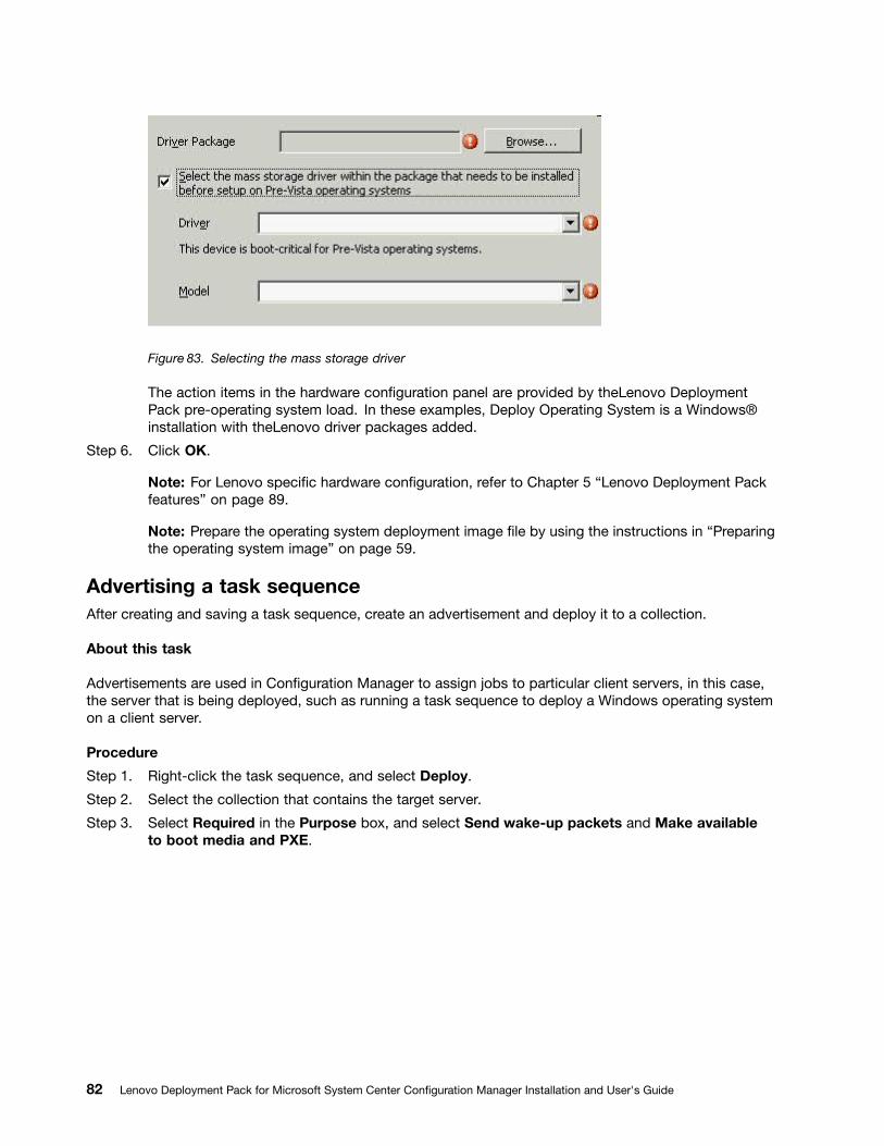
Figure 83. Selecting the mass storage driver
The action items in the hardware configuration panel are provided by theLenovo DeploymentPack pre-operating system load. In these examples, Deploy Operating System is a Windows®installation with theLenovo driver packages added.
Step 6. Click OK.
Note: For Lenovo specific hardware configuration, refer to Chapter 5 “Lenovo Deployment Packfeatures” on page 89.
Note: Prepare the operating system deployment image file by using the instructions in “Preparingthe operating system image” on page 59.
Advertising a task sequenceAfter creating and saving a task sequence, create an advertisement and deploy it to a collection.
About this task
Advertisements are used in Configuration Manager to assign jobs to particular client servers, in this case,the server that is being deployed, such as running a task sequence to deploy a Windows operating systemon a client server.
Procedure
Step 1. Right-click the task sequence, and select Deploy.
Step 2. Select the collection that contains the target server.
Step 3. Select Required in the Purpose box, and select Send wake-up packets and Make availableto boot media and PXE.
82 Lenovo Deployment Pack for Microsoft System Center Configuration Manager Installation and User's Guide
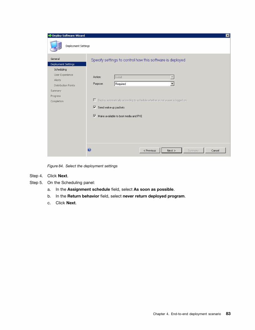
Figure 84. Select the deployment settings
Step 4. Click Next.
Step 5. On the Scheduling panel:
a. In the Assignment schedule field, select As soon as possible.
b. In the Return behavior field, select never return deployed program.
c. Click Next.
Chapter 4. End-to-end deployment scenario 83
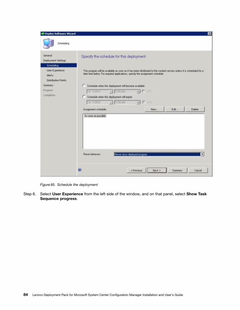
Figure 85. Schedule the deployment
Step 6. Select User Experience from the left side of the window, and on that panel, select Show TaskSequence progress.
84 Lenovo Deployment Pack for Microsoft System Center Configuration Manager Installation and User's Guide
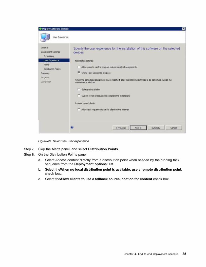
Figure 86. Select the user experience
Step 7. Skip the Alerts panel, and select Distribution Points.
Step 8. On the Distribution Points panel:
a. Select Access content directly from a distribution point when needed by the running tasksequence from the Deployment options: list.
b. Select theWhen no local distribution point is available, use a remote distribution point.check box.
c. Select theAllow clients to use a fallback source location for content check box.
Chapter 4. End-to-end deployment scenario 85
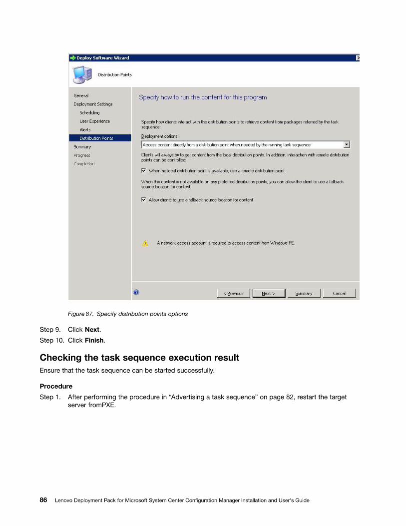
Figure 87. Specify distribution points options
Step 9. Click Next.
Step 10. Click Finish.
Checking the task sequence execution resultEnsure that the task sequence can be started successfully.
Procedure
Step 1. After performing the procedure in “Advertising a task sequence” on page 82, restart the targetserver fromPXE.
86 Lenovo Deployment Pack for Microsoft System Center Configuration Manager Installation and User's Guide
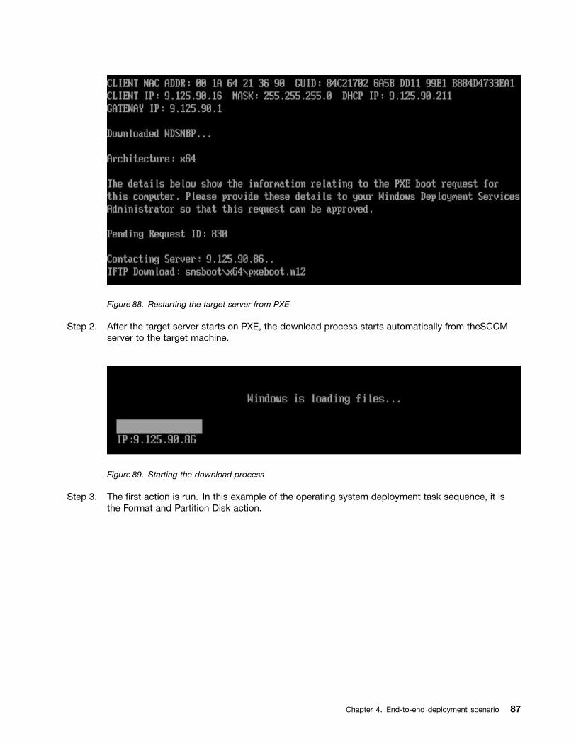
Figure 88. Restarting the target server from PXE
Step 2. After the target server starts on PXE, the download process starts automatically from theSCCMserver to the target machine.
Figure 89. Starting the download process
Step 3. The first action is run. In this example of the operating system deployment task sequence, it isthe Format and Partition Disk action.
Chapter 4. End-to-end deployment scenario 87
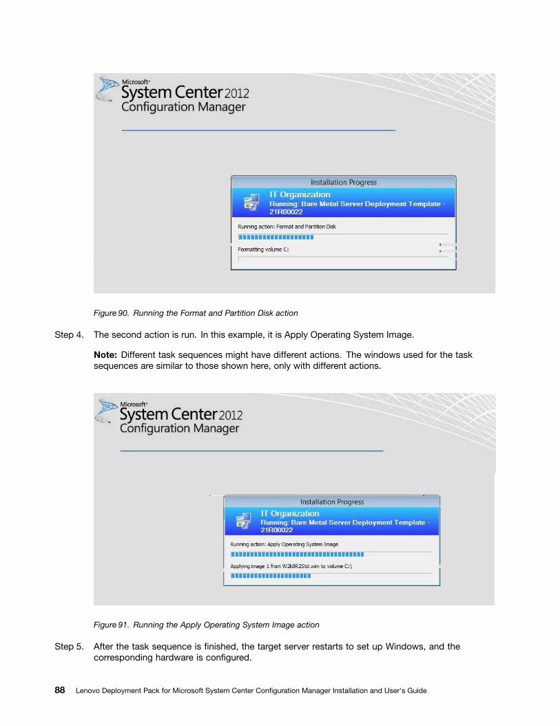
Figure 90. Running the Format and Partition Disk action
Step 4. The second action is run. In this example, it is Apply Operating System Image.
Note: Different task sequences might have different actions. The windows used for the tasksequences are similar to those shown here, only with different actions.
Figure 91. Running the Apply Operating System Image action
Step 5. After the task sequence is finished, the target server restarts to set up Windows, and thecorresponding hardware is configured.
88 Lenovo Deployment Pack for Microsoft System Center Configuration Manager Installation and User's Guide
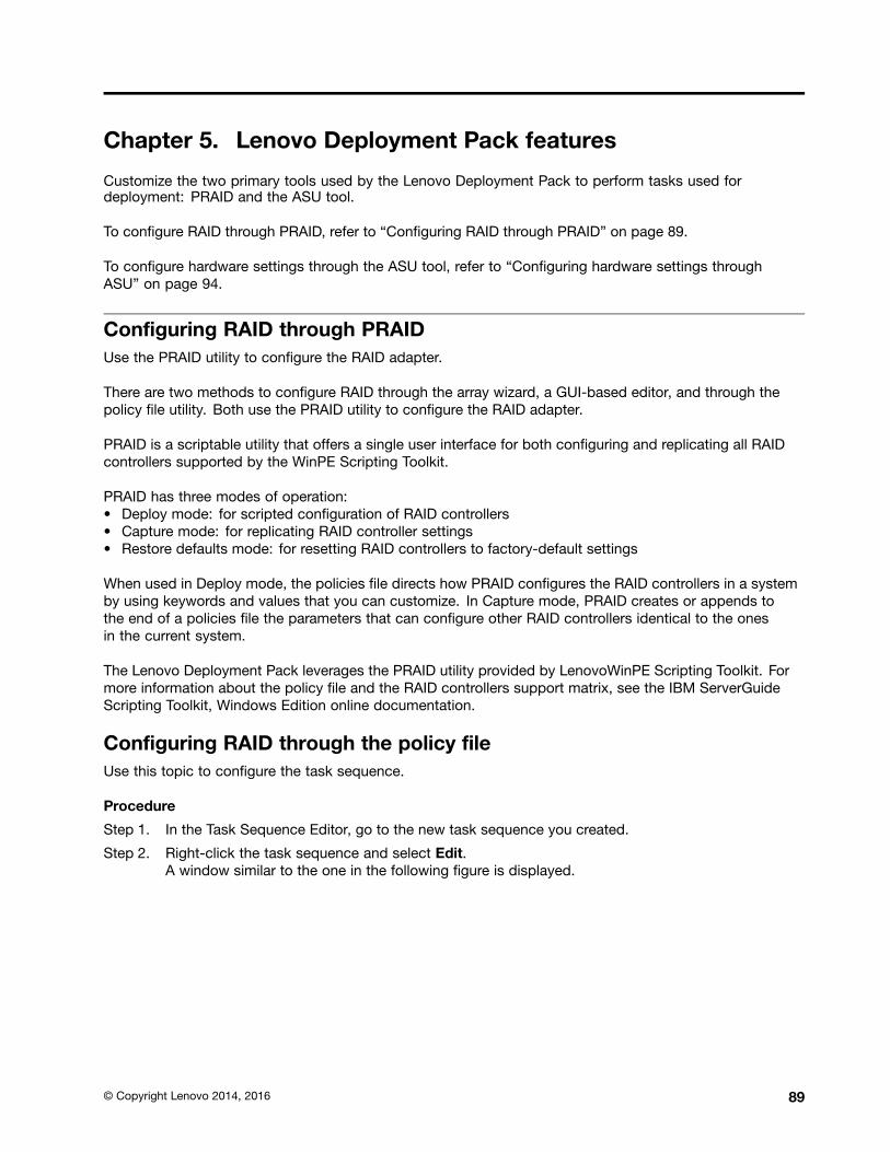
Chapter 5. Lenovo Deployment Pack features
Customize the two primary tools used by the Lenovo Deployment Pack to perform tasks used fordeployment: PRAID and the ASU tool.
To configure RAID through PRAID, refer to “Configuring RAID through PRAID” on page 89.
To configure hardware settings through the ASU tool, refer to “Configuring hardware settings throughASU” on page 94.
Configuring RAID through PRAIDUse the PRAID utility to configure the RAID adapter.
There are two methods to configure RAID through the array wizard, a GUI-based editor, and through thepolicy file utility. Both use the PRAID utility to configure the RAID adapter.
PRAID is a scriptable utility that offers a single user interface for both configuring and replicating all RAIDcontrollers supported by the WinPE Scripting Toolkit.
PRAID has three modes of operation:• Deploy mode: for scripted configuration of RAID controllers• Capture mode: for replicating RAID controller settings• Restore defaults mode: for resetting RAID controllers to factory-default settings
When used in Deploy mode, the policies file directs how PRAID configures the RAID controllers in a systemby using keywords and values that you can customize. In Capture mode, PRAID creates or appends tothe end of a policies file the parameters that can configure other RAID controllers identical to the onesin the current system.
The Lenovo Deployment Pack leverages the PRAID utility provided by LenovoWinPE Scripting Toolkit. Formore information about the policy file and the RAID controllers support matrix, see the IBM ServerGuideScripting Toolkit, Windows Edition online documentation.
Configuring RAID through the policy fileUse this topic to configure the task sequence.
Procedure
Step 1. In the Task Sequence Editor, go to the new task sequence you created.
Step 2. Right-click the task sequence and select Edit.A window similar to the one in the following figure is displayed.
© Copyright Lenovo 2014, 2016 89
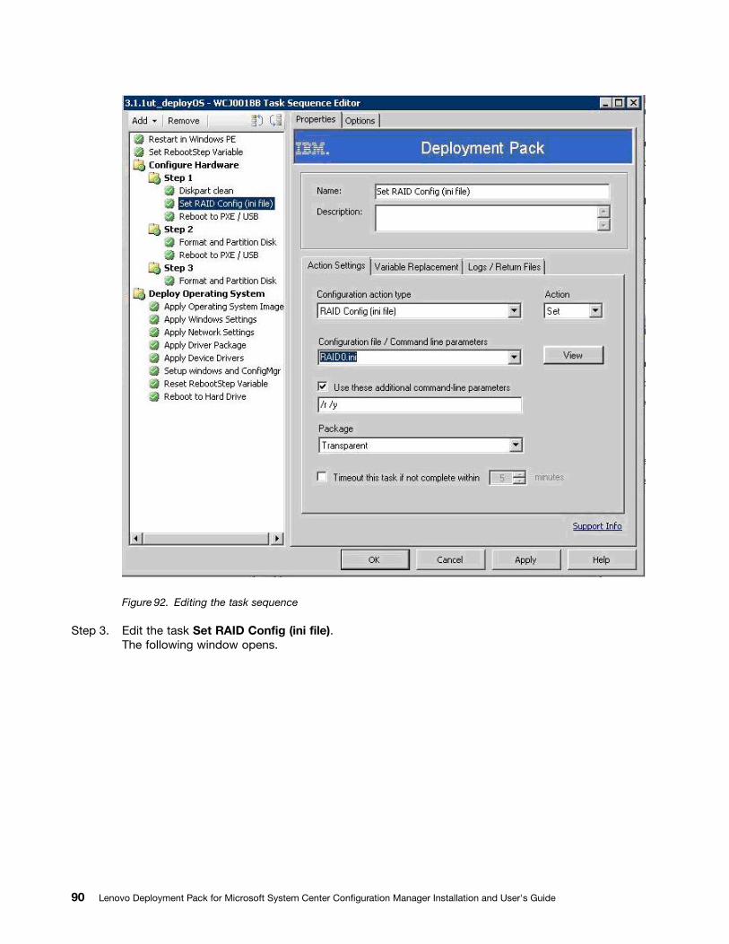
Figure 92. Editing the task sequence
Step 3. Edit the task Set RAID Config (ini file).The following window opens.
90 Lenovo Deployment Pack for Microsoft System Center Configuration Manager Installation and User's Guide
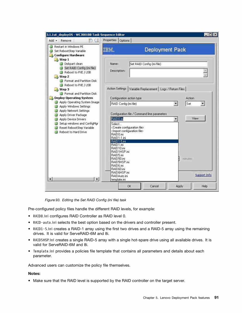
Figure 93. Editing the Set RAID Config (ini file) task
Pre-configured policy files handle the different RAID levels, for example:
• RAID0.ini configures RAID Controller as RAID level 0.
• RAID-auto.ini selects the best option based on the drivers and controller present.
• RAID1-5.ini creates a RAID-1 array using the first two drives and a RAID-5 array using the remainingdrives. It is valid for ServeRAID-6M and 8i.
• RAID5HSP.ini creates a single RAID-5 array with a single hot-spare drive using all available drives. It isvalid for ServeRAID-6M and 8i.
• Template.ini provides a policies file template that contains all parameters and details about eachparameter.
Advanced users can customize the policy file themselves.
Notes:
• Make sure that the RAID level is supported by the RAID controller on the target server.
Chapter 5. Lenovo Deployment Pack features 91
• The Lenovo Deployment Pack software invokes PRAID with the /r switch and the /y switch for all Setoperations using the wizard. These switches tell PRAID to remove the array configuration from allcontrollers attached to the server being deployed before applying the new configuration. These switchesavoid failures due to pre-configured arrays, and they operate similarly on older versions of PRAID. Youcan add these switches manually to RAID configurations using the command line or when using INI files.The following figure illustrates how to add the switches when using an INI file. You can also add otherswitches. For other parameters, refer to WinPE Scripting Toolkit User Guide.
Figure 94. RAID configuration task sequence for INI files
Configuring RAID through the Array Builder WizardAnother way to configure RAID is through the Array Builder Wizard provided by MicrosoftSCCM.
To configure RAID, the Lenovo Deployment Pack creates a policy file according to input from the ArrayBuilder Wizard and deploys the policy file and the PRAID utility to the target server.
92 Lenovo Deployment Pack for Microsoft System Center Configuration Manager Installation and User's Guide
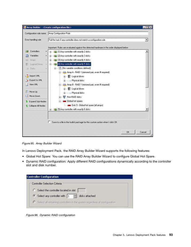
Figure 95. Array Builder Wizard
In Lenovo Deployment Pack. the RAID Array Builder Wizard supports the following features:
• Global Hot Spare: You can use the RAID Array Builder Wizard to configure Global Hot Spare.
• Dynamic RAID configuration: Apply different RAID configurations dynamically according to the controllerslot and disk number.
Figure 96. Dynamic RAID configuration
Chapter 5. Lenovo Deployment Pack features 93
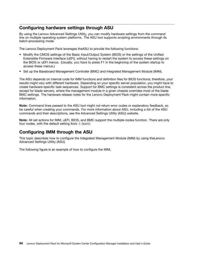
Configuring hardware settings through ASUBy using the Lenovo Advanced Settings Utility, you can modify hardware settings from the commandline on multiple operating system platforms. The ASU tool supports scripting environments through itsbatch-processing mode.
The Lenovo Deployment Pack leverages theASU to provide the following functions:
• Modify the CMOS settings of the Basic Input/Output System (BIOS) or the settings of the UnifiedExtensible Firmware Interface (uEFI), without having to restart the system to access these settings onthe BIOS or uEFI menus. (Usually, you have to press F1 in the beginning of the system startup toaccess these menus.)
• Set up the Baseboard Management Controller (BMC) and Integrated Management Module (IMM).
The ASU depends on internal code for IMM functions and definition files for BIOS functions; therefore, yourresults might vary with different hardware. Depending on your specific server population, you might have tocreate hardware-specific task sequences. Support for BMC settings is consistent across the product line,except for blade servers, where the management module in a given chassis overrides most of the bladeBMC settings. The hardware release notes for the Lenovo Deployment Pack might contain more specificinformation.
Note: Command lines passed to the ASU tool might not return error codes or explanatory feedback, sobe careful when creating your commands. For more information about ASU, including a list of the ASUcommands and their descriptions, see the Advanced Settings Utility (ASU) website.
Note: All set actions for IMM, uEFI, BIOS, and BMC support the multiple-nodes function. There are onlyfour nodes, with the default setting Node-1 (main).
Configuring IMM through the ASUThis topic describes how to configure the Integrated Management Module (IMM) by using theLenovoAdvanced Settings Utility (ASU).
The following figure is an example of how to configure the IMM.
94 Lenovo Deployment Pack for Microsoft System Center Configuration Manager Installation and User's Guide
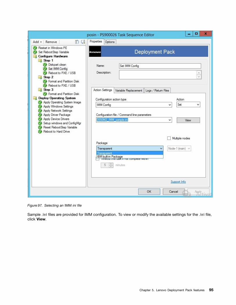
Figure 97. Selecting an IMM ini file
Sample .ini files are provided for IMM configuration. To view or modify the available settings for the .ini file,click View.
Chapter 5. Lenovo Deployment Pack features 95
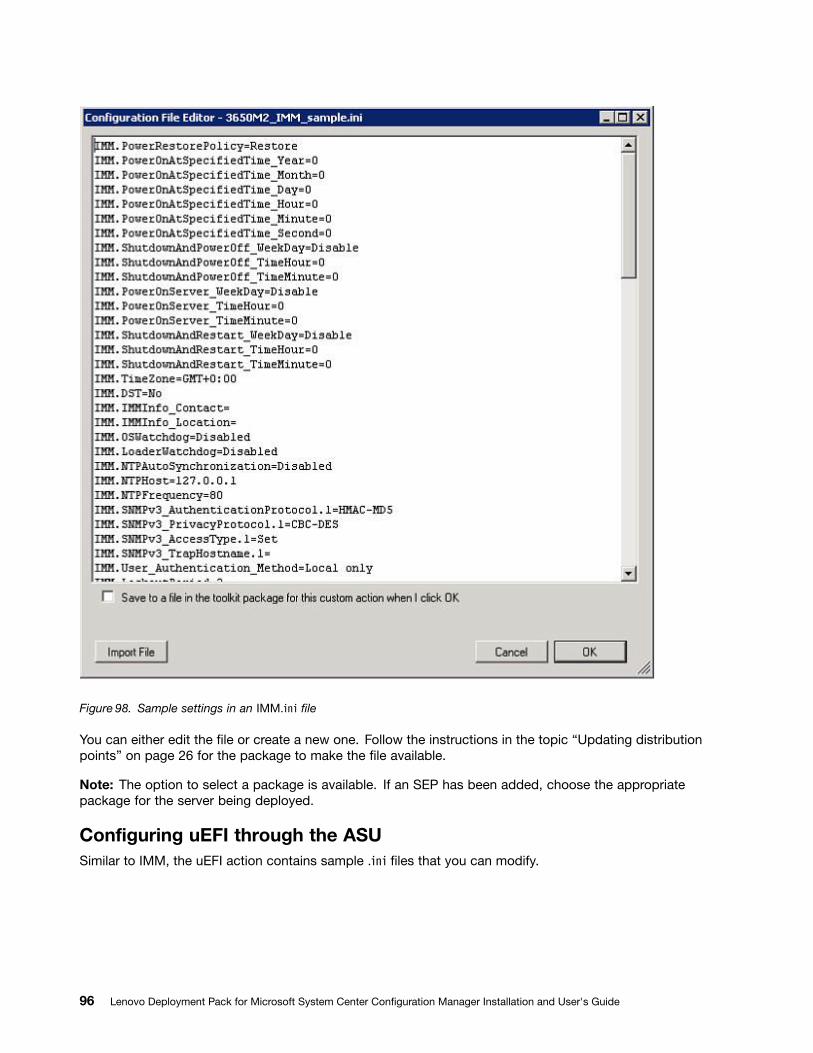
Figure 98. Sample settings in an IMM.ini file
You can either edit the file or create a new one. Follow the instructions in the topic “Updating distributionpoints” on page 26 for the package to make the file available.
Note: The option to select a package is available. If an SEP has been added, choose the appropriatepackage for the server being deployed.
Configuring uEFI through the ASUSimilar to IMM, the uEFI action contains sample .ini files that you can modify.
96 Lenovo Deployment Pack for Microsoft System Center Configuration Manager Installation and User's Guide
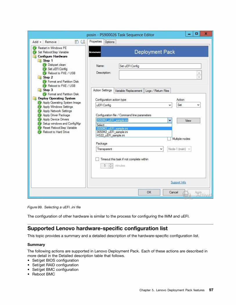
Figure 99. Selecting a uEFI .ini file
The configuration of other hardware is similar to the process for configuring the IMM and uEFI.
Supported Lenovo hardware-specific configuration listThis topic provides a summary and a detailed description of the hardware-specific configuration list.
Summary
The following actions are supported in Lenovo Deployment Pack. Each of these actions are described inmore detail in the Detailed description table that follows.• Set/get BIOS configuration• Set/get RAID configuration• Set/get BMC configuration• Reboot BMC
Chapter 5. Lenovo Deployment Pack features 97
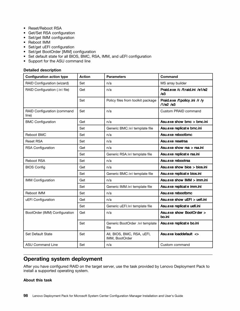
• Reset/Reboot RSA• Get/Set RSA configuration• Set/get IMM configuration• Reboot IMM• Set/get uEFI configuration• Set/get BootOrder [IMM] configuration• Set default state for all BIOS, BMC, RSA, IMM, and uEFI configuration• Support for the ASU command line
Detailed description
Configuration action type Action Parameters Command
RAID Configuration (wizard) Set n/a MS array builder
Get n/a PPPrrraid.eaid.eaid.exxxeee /c/c/c /f:r/f:r/f:raid.iniaid.iniaid.ini /e1/e2/e1/e2/e1/e2/e3/e3/e3
RAID Configuration (.ini file)
Set Policy files from toolkit package PPPrrraid.eaid.eaid.exxxeee /f:policy/f:policy/f:policy .ini.ini.ini /r/r/r /y/y/y/1/e2/1/e2/1/e2 /e3/e3/e3
RAID Configuration (commandline)
Set n/a Custom PRAID command
Get n/a Asu.eAsu.eAsu.exxxeee showshowshow bmcbmcbmc >>> bmc.inibmc.inibmc.iniBMC Configuration
Set Generic BMC.ini template file Asu.eAsu.eAsu.exxxeee rrreplicateplicateplicat eee bmc.inibmc.inibmc.ini
Reboot BMC Set n/a Asu.eAsu.eAsu.exxxeee rrrebootbmcebootbmcebootbmc
Reset RSA Set n/a Asu.eAsu.eAsu.exxxeee rrresetrsaesetrsaesetrsa
Get n/a Asu.eAsu.eAsu.exxxeee showshowshow rsarsarsa >>> rsa.inirsa.inirsa.iniRSA Configuration
Set Generic RSA.ini template file Asu.eAsu.eAsu.exxxeee rrreplicateplicateplicat eee rsa.inirsa.inirsa.ini
Reboot RSA Set n/a Asu.eAsu.eAsu.exxxeee rrrebootrsaebootrsaebootrsa
Get n/a Asu.eAsu.eAsu.exxxeee showshowshow biosbiosbios >>> bios.inibios.inibios.iniBIOS Config
Set Generic BMC.ini template file Asu.eAsu.eAsu.exxxeee rrreplicateplicateplicat eee bios.inibios.inibios.ini
Get n/a Asu.eAsu.eAsu.exxxeee showshowshow IMMIMMIMM >>> imm.iniimm.iniimm.iniIMM Configuration
Set Generic IMM.ini template file Asu.eAsu.eAsu.exxxeee rrreplicateplicateplicat eee imm.iniimm.iniimm.ini
Reboot IMM Set n/a Asu.eAsu.eAsu.exxxeee rrrebootbmcebootbmcebootbmc
Get n/a Asu.eAsu.eAsu.exxxeee showshowshow uEFIuEFIuEFI >>> uefi.iniuefi.iniuefi.iniuEFI Configuration
Set Generic uEFI.ini template file Asu.eAsu.eAsu.exxxeee rrreplicateplicateplicat eee uefi.iniuefi.iniuefi.ini
Get n/a Asu.eAsu.eAsu.exxxeee showshowshow BootOrBootOrBootOrderderder >>>bo.inibo.inibo.ini
BootOrder (IMM) Configuration
Set Generic BootOrder .ini templatefile
Asu.eAsu.eAsu.exxxeee rrreplicateplicateplicat eee bo.inibo.inibo.ini
Set Default State Set All, BIOS, BMC, RSA, uEFI,IMM, BootOrder
Asu.eAsu.eAsu.exxxeee loaddefaultloaddefaultloaddefault <><><>
ASU Command Line Set n/a Custom command
Operating system deploymentAfter you have configured RAID on the target server, use the task provided by Lenovo Deployment Pack toinstall a supported operating system.
About this task
98 Lenovo Deployment Pack for Microsoft System Center Configuration Manager Installation and User's Guide

Lenovo Deployment Pack supports the following operating systems:• Windows 2003 32bit/X64• Windows 2003 R2 32bit/X64• Windows 2008 32bit/X64• Windows 2008 R2 SP1 (X64)• Windows 2012 (X64) - SCCM 2012 SP1 or above is required
Lenovo Deployment Pack supports deploying the captured operating system image to the target server. Theprocess conducts end-to-end deployment scenarios with the operating system selected. Refer to the topic,Chapter 4 “End-to-end deployment scenario” on page 71.
Chapter 5. Lenovo Deployment Pack features 99

100 Lenovo Deployment Pack for Microsoft System Center Configuration Manager Installation and User's Guide
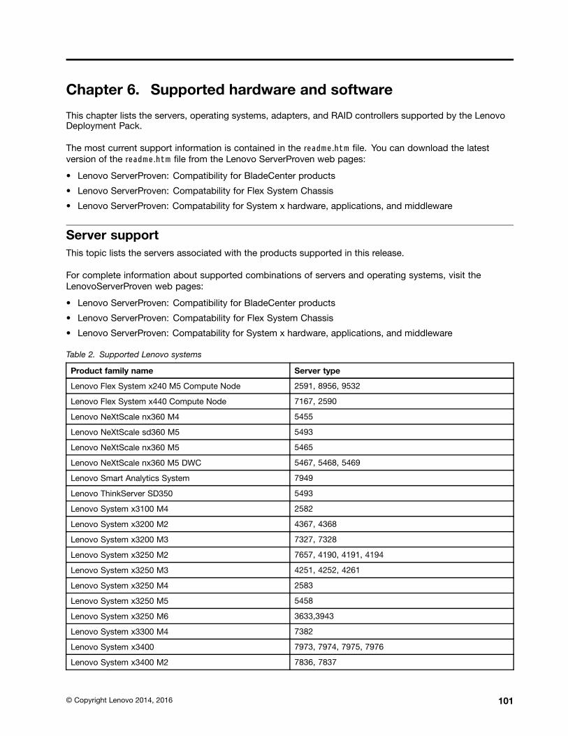
Chapter 6. Supported hardware and software
This chapter lists the servers, operating systems, adapters, and RAID controllers supported by the LenovoDeployment Pack.
The most current support information is contained in the readme.htm file. You can download the latestversion of the readme.htm file from the Lenovo ServerProven web pages:
• Lenovo ServerProven: Compatibility for BladeCenter products
• Lenovo ServerProven: Compatability for Flex System Chassis
• Lenovo ServerProven: Compatability for System x hardware, applications, and middleware
Server supportThis topic lists the servers associated with the products supported in this release.
For complete information about supported combinations of servers and operating systems, visit theLenovoServerProven web pages:
• Lenovo ServerProven: Compatibility for BladeCenter products
• Lenovo ServerProven: Compatability for Flex System Chassis
• Lenovo ServerProven: Compatability for System x hardware, applications, and middleware
Table 2. Supported Lenovo systems
Product family name Server type
Lenovo Flex System x240 M5 Compute Node 2591, 8956, 9532
Lenovo Flex System x440 Compute Node 7167, 2590
Lenovo NeXtScale nx360 M4 5455
Lenovo NeXtScale sd360 M5 5493
Lenovo NeXtScale nx360 M5 5465
Lenovo NeXtScale nx360 M5 DWC 5467, 5468, 5469
Lenovo Smart Analytics System 7949
Lenovo ThinkServer SD350 5493
Lenovo System x3100 M4 2582
Lenovo System x3200 M2 4367, 4368
Lenovo System x3200 M3 7327, 7328
Lenovo System x3250 M2 7657, 4190, 4191, 4194
Lenovo System x3250 M3 4251, 4252, 4261
Lenovo System x3250 M4 2583
Lenovo System x3250 M5 5458
Lenovo System x3250 M6 3633,3943
Lenovo System x3300 M4 7382
Lenovo System x3400 7973, 7974, 7975, 7976
Lenovo System x3400 M2 7836, 7837
© Copyright Lenovo 2014, 2016 101
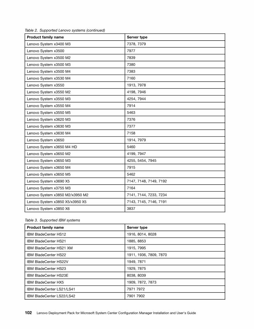
Table 2. Supported Lenovo systems (continued)
Product family name Server type
Lenovo System x3400 M3 7378, 7379
Lenovo System x3500 7977
Lenovo System x3500 M2 7839
Lenovo System x3500 M3 7380
Lenovo System x3500 M4 7383
Lenovo System x3530 M4 7160
Lenovo System x3550 1913, 7978
Lenovo System x3550 M2 4198, 7946
Lenovo System x3550 M3 4254, 7944
Lenovo System x3550 M4 7914
Lenovo System x3550 M5 5463
Lenovo System x3620 M3 7376
Lenovo System x3630 M3 7377
Lenovo System x3630 M4 7158
Lenovo System x3650 1914, 7979
Lenovo System x3650 M4 HD 5460
Lenovo System x3650 M2 4199, 7947
Lenovo System x3650 M3 4255, 5454, 7945
Lenovo System x3650 M4 7915
Lenovo System x3650 M5 5462
Lenovo System x3690 X5 7147, 7148, 7149, 7192
Lenovo System x3755 M3 7164
Lenovo System x3850 M2/x3950 M2 7141, 7144, 7233, 7234
Lenovo System x3850 X5/x3950 X5 7143, 7145, 7146, 7191
Lenovo System x3850 X6 3837
Table 3. Supported IBM systems
Product family name Server type
IBM BladeCenter HS12 1916, 8014, 8028
IBM BladeCenter HS21 1885, 8853
IBM BladeCenter HS21 XM 1915, 7995
IBM BladeCenter HS22 1911, 1936, 7809, 7870
IBM BladeCenter HS22V 1949, 7871
IBM BladeCenter HS23 1929, 7875
IBM BladeCenter HS23E 8038, 8039
IBM BladeCenter HX5 1909, 7872, 7873
IBM BladeCenter LS21/LS41 7971 7972
IBM BladeCenter LS22/LS42 7901 7902
102 Lenovo Deployment Pack for Microsoft System Center Configuration Manager Installation and User's Guide
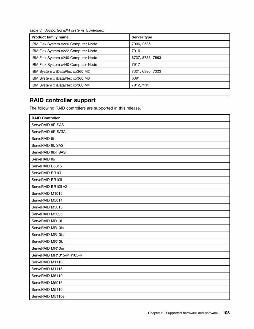
Table 3. Supported IBM systems (continued)
Product family name Server type
IBM Flex System x220 Computer Node 7906, 2585
IBM Flex System x222 Computer Node 7916
IBM Flex System x240 Computer Node 8737, 8738, 7863
IBM Flex System x440 Computer Node 7917
IBM System x iDataPlex dx360 M2 7321, 6380, 7323
IBM System x iDataPlex dx360 M3 6391
IBM System x iDataPlex dx360 M4 7912,7913
RAID controller supportThe following RAID controllers are supported in this release.
RAID Controller
ServeRAID 8E-SAS
ServeRAID 8E-SATA
ServeRAID 8i
ServeRAID 8k SAS
ServeRAID 8k-l SAS
ServeRAID 8s
ServeRAID B5015
ServeRAID BR10i
ServeRAID BR10il
ServeRAID BR10il v2
ServeRAID M1015
ServeRAID M5014
ServeRAID M5015
ServeRAID M5025
ServeRAID MR10i
ServeRAID MR10ie
ServeRAID MR10is
ServeRAID MR10k
ServeRAID MR10m
ServeRAID MR1015/MR105-R
ServeRAID M1110
ServeRAID M1115
ServeRAID M5110
ServeRAID M5016
ServeRAID M5110
ServeRAID M5110e
Chapter 6. Supported hardware and software 103
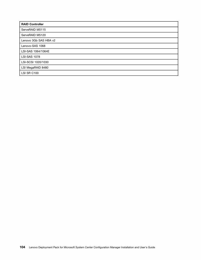
RAID Controller
ServeRAID M5115
ServeRAID M5120
Lenovo 3Gb SAS HBA v2
Lenovo-SAS 1068
LSI-SAS 1064/1064E
LSI-SAS 1078
LSI-SCSI 1020/1030
LSI MegaRAID 8480
LSI SR C100
104 Lenovo Deployment Pack for Microsoft System Center Configuration Manager Installation and User's Guide
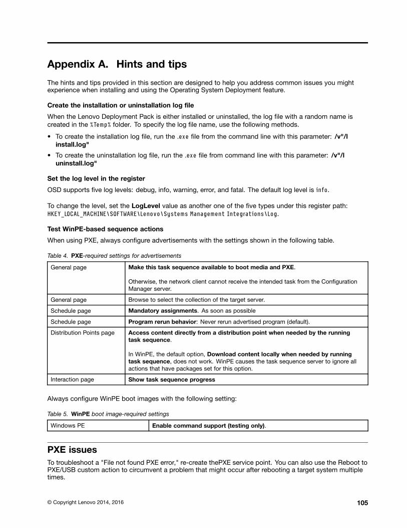
Appendix A. Hints and tips
The hints and tips provided in this section are designed to help you address common issues you mightexperience when installing and using the Operating System Deployment feature.
Create the installation or uninstallation log file
When the Lenovo Deployment Pack is either installed or uninstalled, the log file with a random name iscreated in the %Temp% folder. To specify the log file name, use the following methods.
• To create the installation log file, run the .exe file from the command line with this parameter: /v"/linstall.log"
• To create the uninstallation log file, run the .exe file from command line with this parameter: /v"/luninstall.log"
Set the log level in the register
OSD supports five log levels: debug, info, warning, error, and fatal. The default log level is info.
To change the level, set the LogLevel value as another one of the five types under this register path:HKEY_LOCAL_MACHINE\SOFTWARE\Lenovo\Systems Management Integrations\Log.
Test WinPE-based sequence actions
When using PXE, always configure advertisements with the settings shown in the following table.
Table 4. PXE-required settings for advertisements
General page Make this task sequence available to boot media and PXE.
Otherwise, the network client cannot receive the intended task from the ConfigurationManager server.
General page Browse to select the collection of the target server.
Schedule page Mandatory assignments. As soon as possible
Schedule page Program rerun behavior: Never rerun advertised program (default).
Distribution Points page Access content directly from a distribution point when needed by the runningtask sequence.
In WinPE, the default option, Download content locally when needed by runningtask sequence, does not work. WinPE causes the task sequence server to ignore allactions that have packages set for this option.
Interaction page Show task sequence progress
Always configure WinPE boot images with the following setting:
Table 5. WinPE boot image-required settings
Windows PE Enable command support (testing only).
PXE issuesTo troubleshoot a "File not found PXE error," re-create thePXE service point. You can also use the Reboot toPXE/USB custom action to circumvent a problem that might occur after rebooting a target system multipletimes.
© Copyright Lenovo 2014, 2016 105
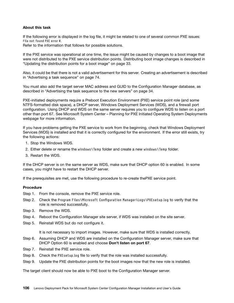
About this task
If the following error is displayed in the log file, it might be related to one of several common PXE issues:File not found PXE error #.Refer to the information that follows for possible solutions.
If the PXE service was operational at one time, the issue might be caused by changes to a boot image thatwere not distributed to the PXE service distribution points. Distributing boot image changes is described in“Updating the distribution points for a boot image” on page 33.
Also, it could be that there is not a valid advertisement for this server. Creating an advertisement is describedin “Advertising a task sequence” on page 74.
You must also add the target server MAC address and GUID to the Configuration Manager database, asdescribed in “Advertising the task sequence to the new servers” on page 34.
PXE-initiated deployments require a Preboot Execution Environment (PXE) service point role (and someNTFS-formatted disk space), a DHCP server, Windows Deployment Services (WDS), and a firewall portconfiguration. Using DHCP and WDS on the same server requires you to configure WDS to listen on a portother than port 67. See Microsoft System Center – Planning for PXE Initiated Operating System Deploymentswebpage for more information.
If you have problems getting the PXE service to work from the beginning, check that Windows DeploymentServices (WDS) is installed and that it is correctly configured for the environment. If the error still exists, trythe following actions:
1. Stop the Windows WDS.
2. Either delete or rename the windows\Temp folder and create a new windows\Temp folder.
3. Restart the WDS.
If the DHCP server is on the same server as WDS, make sure that DHCP option 60 is enabled. In somecases, you might have to restart the DHCP server.
If the prerequisites are met, use the following procedure to re-create thePXE service point.
Procedure
Step 1. From the console, remove the PXE service role.
Step 2. Check the Program Files\Microsoft Configuration Manager\Logs\PXEsetup.log to verify that therole is removed successfully.
Step 3. Remove the WDS.
Step 4. Reboot the Configuration Manager site server, if WDS was installed on the site server.
Step 5. Reinstall WDS but do not configure it.
It is not necessary to import images. However, make sure that WDS is installed correctly.
Step 6. Assuming DHCP and WDS are installed on the Configuration Manager server, make sure thatDHCP Option 60 is enabled and choose Don't listen on port 67.
Step 7. Reinstall the PXE service role.
Step 8. Check the PXEsetup.log file to verify that the role was installed successfully.
Step 9. Update the PXE distribution points for the boot images now that the new role is installed.
The target client should now be able to PXE boot to the Configuration Manager server.
106 Lenovo Deployment Pack for Microsoft System Center Configuration Manager Installation and User's Guide
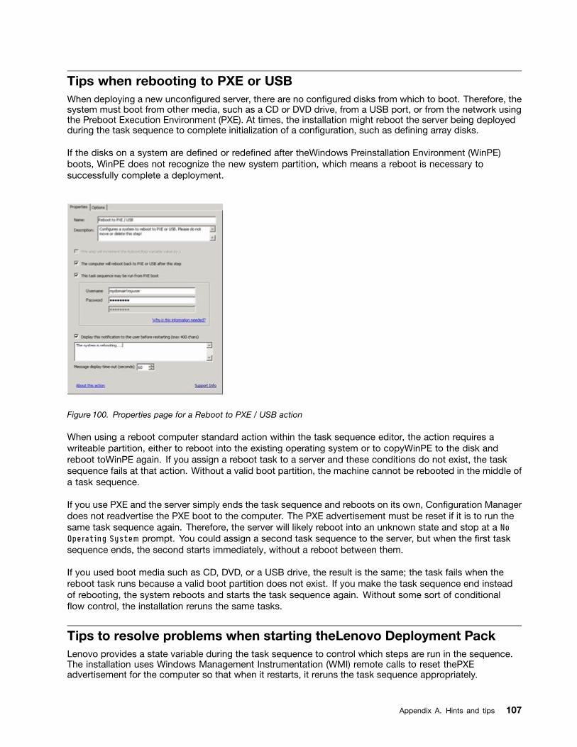
Tips when rebooting to PXE or USBWhen deploying a new unconfigured server, there are no configured disks from which to boot. Therefore, thesystem must boot from other media, such as a CD or DVD drive, from a USB port, or from the network usingthe Preboot Execution Environment (PXE). At times, the installation might reboot the server being deployedduring the task sequence to complete initialization of a configuration, such as defining array disks.
If the disks on a system are defined or redefined after theWindows Preinstallation Environment (WinPE)boots, WinPE does not recognize the new system partition, which means a reboot is necessary tosuccessfully complete a deployment.
Figure 100. Properties page for a Reboot to PXE / USB action
When using a reboot computer standard action within the task sequence editor, the action requires awriteable partition, either to reboot into the existing operating system or to copyWinPE to the disk andreboot toWinPE again. If you assign a reboot task to a server and these conditions do not exist, the tasksequence fails at that action. Without a valid boot partition, the machine cannot be rebooted in the middle ofa task sequence.
If you use PXE and the server simply ends the task sequence and reboots on its own, Configuration Managerdoes not readvertise the PXE boot to the computer. The PXE advertisement must be reset if it is to run thesame task sequence again. Therefore, the server will likely reboot into an unknown state and stop at a NoOperating System prompt. You could assign a second task sequence to the server, but when the first tasksequence ends, the second starts immediately, without a reboot between them.
If you used boot media such as CD, DVD, or a USB drive, the result is the same; the task fails when thereboot task runs because a valid boot partition does not exist. If you make the task sequence end insteadof rebooting, the system reboots and starts the task sequence again. Without some sort of conditionalflow control, the installation reruns the same tasks.
Tips to resolve problems when starting theLenovo Deployment PackLenovo provides a state variable during the task sequence to control which steps are run in the sequence.The installation uses Windows Management Instrumentation (WMI) remote calls to reset thePXEadvertisement for the computer so that when it restarts, it reruns the task sequence appropriately.
Appendix A. Hints and tips 107

To control the flow of the task sequence across restarts, groups are created that have conditions set onthe state variable. This state variable is a task sequence variable set through the Configuration Managerserver or, for a disconnected deployment, by using a file-based method.
The following example shows what a task sequence flow might look like:
First start sequence
1. The computer starts WinPE through PXE. The task sequence variable is not set. (RebootStep = null)
2. The Set RebootStep Variable action sets the variable to 1.
3. The Configure Hardware group runs.
4. The group Step 1 condition is set to true. (RebootStep = 1)
a. Actions inside this group run.
b. The Reboot to PXE/USB action resets the PXE advertisement.
5. The group Step 2 condition is set to false, which skips some steps.
6. The group Step 3 condition is set to false, which skips some steps.
7. The Deploy Operating System group condition is set to false.
8. The task sequence ends and the computer restarts.
Second start sequence
1. The computer starts and uses PXE or USB to load WinPE again. (RebootStep = 1)
2. The Set RebootStep Variable action sets the variable to 2. (RebootStep = 2)
3. The Configure Hardware group runs.
4. The group Step 1 condition is set to false, which skips some steps.
5. The group Step 2 condition is set to true. (RebootStep = 2).
a. Actions inside group 2 run.
b. The Reboot to PXE/USB resets the PXE advertisement.
6. The group Step 3 condition is set to false, which skips some steps.
7. The Deploy Operating System group condition is set to false.
8. The task sequence ends and the computer restarts.
Third start sequence
1. The computer starts and uses PXE or USB to load WinPE again. (RebootStep = 2)
2. The Set RebootStep Variable action sets the variable to 3. (RebootStep = 3)
3. The Configure Hardware group runs.
4. The group Step 1 condition is set to false, which skips some steps.
5. The group Step 2 condition is set to false, which skips some steps.
6. The group Step 3 condition is set to true. (RebootStep = 3)
a. Actions inside group 3 run without restarting at the end.
7. The Deploy Operating System group condition is set to true.
a. Actions inside this group run.
b. The Reset RebootStep Variable action sets the variable to 0. (RebootStep = 0)
8. The task sequence ends and the computer restarts on the final operating system loaded on the disk.
108 Lenovo Deployment Pack for Microsoft System Center Configuration Manager Installation and User's Guide
Manual workaround methodYou can manually work around the PXE reboot issue by creating the task sequence steps and groups andusing the procedure that the Lenovo Deployment Pack uses to solve the problem.
The solution also involves creating a custom script that connects remotely to the Configuration Managerserver (with appropriate credentials), accessing WMI, and resetting the PXE advertisement for the specificcomputer running the task sequence.
However, there is no need to do this work manually because the custom action described in the topic “TheReboot to PXE/USB custom action” on page 109 sets up the task sequence for you.
The Reboot to PXE/USB custom actionInsert the PXE/USB custom action to control multiple reboots when booting toPXE or USB.
After Lenovo Deployment Pack is installed on the Configuration Manager server, this custom action isautomatically installed. You can also insert the custom action into a task sequence by performing thefollowing steps:
1. Right-click the task sequences folder to create a sample task sequence that includes all of the tasksneeded (including reboots) for deploying a server from bare metal.
2. When inserting a new OEM custom action, use the dialog box about reboots to create a new tasksequence with the appropriate actions using the current task sequence actions.
3. Manually insert the Reboot to PXE/USB action into a task sequence from a selection on the tasksequence editor menu to create a new task sequence.
Preventing a server from looping during multiple reboot processingDuring multiple reboot processing, the target server might loop and be unable to run the task sequencecorrectly. The problem is due to an improper setting for the state variable that controls the installation. Theimproper setting can occur when an error occurs that does not stop the installation.
About this task
The sample task sequence templates in the Lenovo Deployment Pack provide for multiple reboots back toUSB or PXE, and they use a computer variable to track the current boot stage in the process.
The computer variable determines which groups or steps are run during each phase of the deployment. If anerror occurs during a task sequence, this variable is not automatically reset, and your task sequence mightnot restart from the beginning or even the current phase of deployment.
To ensure that the computer restarts the sequence from the beginning, remove the computer variable forany computer that has failed the task sequence.
Reset the computer variable by performing the following procedure.
Procedure
Step 1. Start Microsoft Configuration Manager to open the Configuration Manager console.
Step 2. From the console, click Computer Management ➙ Collections.
Step 3. Right-click the computer resource in the appropriate collection.
Step 4. Click Properties ➙ Variables.
Appendix A. Hints and tips 109

Step 5. Select the RebootStep variable.
Step 6. Click Delete.
Step 7. Click Apply.
Step 8. Click OK.
110 Lenovo Deployment Pack for Microsoft System Center Configuration Manager Installation and User's Guide
Appendix B. Troubleshooting
Frequently, the reason for a problem you are experiencing is due to a faulty setting or unintended omissionduring setup. The symptoms of a problem that you have often provide clues to the reason for the problem.In general, troubleshooting begins with making sure that you performed certain tasks.
About this task
To begin troubleshooting, follow these basic steps.
Procedure
Step 1. Read the documentation.
The majority of issues related to the use of this product are covered in the documentation. Checkthe documentation before calling support.
Some sections of the Configuration Manager documentation that you should be familiar withinclude those related to related Microsoft TechNet:
• Microsoft System Center – Troubleshooting Operating System Deployment webpage
• Microsoft System Center – Troubleshooting Operating System Image Deployment Using USBDevices webpage
Step 2. Check your action settings.
The primary cause of task sequence failures is related to the settings you entered in the tasksequence steps.
Check the task sequence steps for:
• Valid environment or task sequence variable references
• Valid file references. Use DOS 8.3 naming whenever possible. Never use file names withembedded spaces.
• Valid directory references. When capturing files from a target computer, ensure that thedestination directory already exists. The process does not automatically create directorystructures.
Step 3. Check the log files and use debug logging.
The custom actions in this deployment kit provide for capturing the SMSTS.LOG file from WinPE andsending it back to the Configuration Manager server.
To help with troubleshooting issues, you can also perform extended logging with the customaction. Enable this logging on the Logs/Return Files tab in the sequence action.
Step 4. When all else fails, contact Lenovo support, as described in Appendix D “Getting help and technicalassistance” on page 129. Before contacting support, however, gather appropriate informationrelated to your problem. When you call Lenovo support, you must have a set of information toprovide them so that they can efficiently work your issue. Before calling, gather the appropriateinformation. Here are suggestions for what to collect.
a. Export the task sequence you were using by right-clicking the task sequence and selectingExport.
b. If the issue is visible in the interface, collect screen captures of the relevant portions.
© Copyright Lenovo 2014, 2016 111
c. If the issue is related to installation of the product or follows closely after installation:
1. Gather a copy of the MSI installation log located in the temporary files directory (identifiedin the %TEMP% environment variable). This file is usually located in a 1 directory and hasa random name formatted as MSIrandom_characters.LOG.
2. Gather a copy of the _Installer.Log file and the _InstalledComponents.Xmlfile, which are located in the following directory: AdminUI InstallDirectory\XmlStorage\Extensions\bin\Deployment\Lenovo\Lenovo DeploymentPack\setup
Note: The location of the log file varies by machine.
d. If the issue occurred while running a task sequence:
1. Gather a copy of the SMSTS.LOG file from WinPE. The log might be in theX:\Windows\Temp\Smstslog directory for a PXE boot. The log might also be inthe \Smstslog directory on the local drive. The format of the log name might beSMSTSLOGtime_based_name>.LOG.
2. Gather a copy of the custom action logs saved using the Retrieve the task sequencelog file from the client when this action runs check box on the custom action Logs/ Return Files tab. You should also select the check box for Enable extended/debuglogging by this action.
3. Gather a copy of the files used as input to the configuration task, such as configurationINI or XML files.
e. A complete, detailed explanation of the issue, including:
1. The exact point of failure, such as the action running when the process failed, adescription or screen captures of error messages, error codes, and other relevant facts.
2. A detailed description of the computers being configured, such as model, hardwareconfiguration, RAID controllers, and other characteristics.
3. A description of circumstances related to the following questions:
• Has this task sequence or action ever worked? When did it stop working?
• If it worked before, what is different now? Is the task sequence is being appliedto different computer types? Is it using different configuration files, different tasksequence variables, or has something else been modified?
Troubleshooting installation issuesSome common installation issues are presented along with information about how to troubleshoot them.
A custom action does not appear on the Configuration Manager console
Configuration Manager uses information stored in Windows Management Instrumentation (WMI) to load thecustom action assemblies from disk. This WMI information is imported into the site system's WMI databaseduring installation through the use of Managed Object Format (.mof) files. If an error occurred duringimportation or for some reason the WMI information is incorrect, the MMC might generate an exceptionwhen trying to load the assembly. The cause might be that the file name or assembly name was not found.
Check WMI under root\SMS_site_code\SMS_TaskSequenceStep\SMS_TaskSequenceAction for the appropriateWMI class for the product installed. For example the product might be Lenovo_DeploymentPack.
If the desired class does not exist, the custom action cannot appear in the menu. Use the installer to tryreinstalling the site server files.
112 Lenovo Deployment Pack for Microsoft System Center Configuration Manager Installation and User's Guide
If you are familiar with the contents of the WMI classes, you can modify the class as appropriate to correctthe error. A good tool for viewing and editing WMI information is WMI CIM Studio, which is part of theWMI Administrative Tools.
The Lenovo Deployment Pack is not completely removed from SCCM
By design, boot images are not removed because they are tied to task sequence packages. Removing theboot image might invalidate other working task sequences that you are using.
If you are no longer using the boot images created by this product, delete them from the console.
How to delete remaining physical folders created by Lenovo Deployment Pack
1. Locate the SCCM installation folder.
2. Find the subfolder AdminUI\XmlStorage\Extensions\bin\Deployment, and delete the folder namedLenovo.
3. Find the subfolder OSD\lib\Drivers, and delete the folder named Lenovo.
4. Find the subfolder OSD\lib\Packages\Deployment, and delete the folder named Lenovo.
Troubleshooting administrator console issuesSome common administrator console issues are presented here along with information about how to resolvethem.
Enabling user interface debug logging
If you customized the configuration XML but the XML is not correct, the actions in the user interface mightnot work properly.
Turn on debug logging on the administrative console part of the custom action. Set the Debug Logging keyto 1, which is the DWORD value in the base registry key for the Lenovo Deployment Pack.
MMC crash, exception, or Property Not Found errors occur when loading custom action
Configuration Manager uses information stored in WMI to load the custom action assemblies from disk.This WMI information is imported into the site system WMI database during installation through the useof MOF files. If an error occurred during importation, or for some reason the WMI information is incorrect,the MMC might generate an exception when trying to load the assembly, likely because the file name orassembly name is not found.
Check WMI under root\SMS_site_code\SMS_TaskSequenceStep\SMS_TaskSequenceAction for the appropriateWMI class for the product installed, such as: Lenovo_DeploymentPack.
If the desired class does not exist, the custom action cannot appear in the menu. Use the installer toreinstall the site server files to correct the problem.
If you are already familiar with the contents of the WMI classes, you can modify the class as appropriateto correct the error. A good tool for viewing and editing WMI information is WMI CIM Studio, which ispart of the WMI Administrative Tools.
Troubleshooting device driver issuesIn many instances, you must import drivers into yourWinPE boot image for the OEM utilities to function. Insome circumstances, the driver packages available from the OEM include an installation program to installthe drivers, but do not include instructions about how to import the driver intoWinPE.
Appendix B. Troubleshooting 113
Configuration Manager imports drivers into WinPE using the standard driver injection process available in theWinPE tool set. This requires a driver INF file (or txtsetup.oem file) along with the driver and other necessaryfiles. The INF file is used in the standard driver installation process to insert the driver into WinPE.
In addition, trying to automatically import the driver into the Configuration Manager Driver Catalog and theninserting the driver into the boot image might fail due to one or more of the following issues.
Renamed files
Some driver files are named differently depending on the operating system to which they apply:driver_w2k.sys, driver_w2k3.sys, and driver_w2k3_64.sys, for example, might apply to Windows 2000,Windows Server 2003, and Windows Server 2003 64-bit.
The installation program might rename the files to base names before installing the driver, such as driver.sys.If the installation program renames files before installing them, the driver cannot be injected into theWinPEimage because the correct file names are not present.
Modified boot image
During the installation of the Lenovo Deployment Pack, the installation program performs severalmodifications to aWinPE boot image to insert drivers and other changes that allow the Lenovo DeploymentPack utilities to function.
By default, the installation program makes a copy of the Configuration Manager default boot image(boot.wim), mounts the file, makes changes, and unmounts the file.
This modified boot.wim file contains the base set of changes needed by theLenovo Deployment Pack. Inaddition, network and storage drivers are added for boot devices, such as array controllers, and networkdrivers to be able to communicate with the network in WinPE.
Drivers should be added through the driver catalog within the Operating System Deployment node ofthe Configuration Manager administrative console.
Configuration Manager stores two boot images for distributing to machines booting to PXE. The boot.wim fileis the base boot image that contains no Configuration Manager specific files.
When you add drivers to a boot image and then update the boot image on a distribution point,Configuration Manager takes the base boot.wim file and adds the drivers from the driver catalog,along with other Configuration Manager files to create a new WIM file named boot.packageID.wim, forexample,boot.SMS00001.wim.
The new WIM file is then distributed to the assignedPXE distribution points for your site.
Failing imported drivers
Often, several drivers are loaded together in a common directory and contain a TXTSETUP.OEM file. However,when you try to update the WinPE boot image after these drivers are injected, it might fail. This issue canalso occur with only one driver in a directory. By default, Configuration Manager chooses the TXTSETUP.OEMfile for its source of import information for the drivers. If this file exists, Configuration Manager does notdisplay any associated INF files.
It is better to load drivers individually by using their respective INF files. To do this, rename any TXTSETUP.OEMfiles in the driver directory so that Configuration Manager prompts you to select the INF files and importthe drivers individually.
114 Lenovo Deployment Pack for Microsoft System Center Configuration Manager Installation and User's Guide

Troubleshooting WinPE and task sequence issuesSome common WinPE and task sequence issues are presented along with information about how totroubleshoot them.
WinPE never starts the task sequence
Check the SMSTS.LOG file at X:\windows\temp\smstslog\smsts.log. If a package never downloaded, it islikely that you do not have the appropriate network drivers installed, which prevents the server fromcommunicating with Configuration Manager.
Check your driver catalog to ensure that you have the right network drivers available and installed in theboot image, and update the boot image to your distribution points.
Additional network or storage drivers might be needed in the boot image to enable the WinPE boot tofunction correctly. Add those through Drivers in the Operating System Deployment node.
The right drivers have been added to the boot image, but are not loading
The original boot.wim file (WinPE boot image) created whenConfiguration Manager was installed is copiedand modified with Lenovo specific drivers and other files. Your task sequences that use the LenovoDeployment Pack must use this boot image, or the tools might not work properly.
Check to make sure the image into which you loaded the drivers is the same image being used by the tasksequence.
This error is common for administrators who maintain multiple boot images.
Servers will not boot using PXE
PXE is an extension of DHCP, which uses a broadcast type of communication. Broadcast communicationuses standard timeout values that are not readily changeable. As a result, a computer waits for a defaulttimeframe to receive a DHCP or PXE response before timing out and causing a failure condition.
Each time a server is rebooted, it must renegotiate the connection to the switch. Some network switchesarrive configured with default settings that might incur connectivity delays. That is, the settings on the switchmight cause a DHCP orPXE timeout because they fail to negotiate a connection in time.
One of the features that can be affected by this issue is Spanning Tree Protocol (STP). STP is a protocol thatprevents loops and provides redundancy within a network. A networking device using this algorithm mightexperience some latency as it collects information about other network devices. During this period, serversmight boot to PXE and time out while waiting for a response from Windows Deployment Services. Disablethe STP or enable PortFast on end-node ports for the target server to prevent such occurrences. Refer to themanufacturer's user guide for further information.
Another feature that can be affected by this issue is the EtherChannel or Port Aggregation Protocol (PAgP).EtherChannel allows multiple links between devices to act as one fast link that shares the load between thelinks. Running the EtherChannel Protocol in automatic mode can cause a connectivity delay of up to 15seconds. To eliminate the delay, either switch to a manual mode or turn off this feature.
Speed and duplex negotiation can also play a role in negotiation time outs. If auto-negotiation on theswitch is set to off, and the server is not configured to that speed and duplex setting, the switch will notnegotiate with that server.
For more information, see the Cisco website and the following Cisco documents:
• Cisco: Using PortFast and Other Commands to Fix Workstation Startup Connectivity Delays webpage
Appendix B. Troubleshooting 115

• Cisco: Configuring and Troubleshooting Ethernet 10/100/1000Mb Half/Full Duplex Auto-Negotiationwebpage
Default boot order does not allowPXE to boot when a valid drive exists
When an active partition is created on a hard drive, it automatically becomes a bootable device if a validoperating system has been installed. If your PXE NIC comes after the hard drive in the boot order, thehard drive tries to boot before PXE and boots to Windows, or causes an Invalid System Partition error ifWindows is not installed.
To resolve this issue, be sure that PXE is placed before the hard drive in the boot order. Keep in mind thateven ifPXE is first in the boot order, the computer does not actually boot to PXE unless ConfigurationManager has a task sequence for it to run.
When using a Reboot action after initializing an array controller, the task sequence fails
Configuration Manager 2007 does not allow a task sequence to reboot back to PXE. It can reboot backto WinPE or to an installed operating system, both of which require a disk partition and the appropriateinstalled software.
Without a disk partition, Configuration Managerfails when attempting to reboot during a task sequencebecause it expects to copyWinPE to the disk. Additionally, the management point tracks when a machinehas booted toPXE to run a task sequence, and after a server has booted to PXE for a task sequence, itcannot use PXE as a boot method again for that task sequence unless the advertisement is reset.
To perform a reboot to PXE if you need to within a task sequence, use the custom action called Reboot ToPXE." This custom action, written using C# and VBScript, connects to the Configuration Manager 2007 SDK,and contains custom code to drive actions in the admin console as well as the machine being deployed.This custom action performs all the steps necessary to perform the reboot to PXE and allow for properprogram flow when it occurs.
The only other way to accomplish a reboot to PXE is to use more than one task sequence, let the computerfall off the end of the first task sequence and manually reset the PXE advertisement for the computer.
Task sequence fails with Failed to Download Policy and code 0x80093102 or 0x80004005
This error code typically refers to a certificate validation issue.
The SMSTS.LOG file will show an entry with the following text:CryptDecryptMessage ( &DecryptParams, pbEncrypted,nEncryptedSize, 0, &nPlainSize, 0 ), HRESULT=80093102
orno cert available for policy decoding
Possible causes are:
• Misconfiguration of your domain or a site server, such as DNS not pointing to the site server, or the siteserver not specifying a valid FQDN (which is referred to by the DNS listing). If your site server does notspecify a FQDN (and only specifies the NETBIOS name), and your DNS server refers to the FQDN, afaulty lookup might cause this error.
• The certificate being used for PXE and boot media. Check the certificates under the Site Settings nodeand see if any certificates are blocked or missing. Open the certificates and ensure that they are actuallyinstalled into the certificate store. If not, install them.
If these actions do not work, remove the package from the distribution point (through Manage DistributionPoints) and add the package again to regenerate the package hash.
116 Lenovo Deployment Pack for Microsoft System Center Configuration Manager Installation and User's Guide
Task sequence fails with Failed to Download Policy and code 0x80004005
This error code typically refers to a certificate validation issue.
TheSMSTS.LOGfile will show an entry with the following text:failed to download policy
Check the certificates under the Site Settings node to if any certificates are blocked or missing. Open thecertificates to ensure that the certificates are installed into the certificate store. If not, install the certificates.
Task sequence fails because the package is not downloading
In WinPE, the default option Download content locally when needed by running task sequence does notwork. When inWinPE, the task sequence engine ignores (and fail) all actions that have packages set forthis option.
Set all packages needed for use in WinPEto Access content directly from a distribution point whenneeded by the running task sequence.
Task sequence does not run again even after clearing thePXE advertisement
You must set the advertisement to Always rerun so that any time you reset the PXE advertisement, theadvertisement is applied to the computer regardless of whether it ran the task sequence before.
Task sequences fail or act incorrectly after an upgrade
When upgrading from a previous version of this product, existing task sequences using custom actionsare not automatically updated.
To function correctly, open each task sequence action that uses a custom action in an editor. Add a . to thedescription and remove it to enable the Apply button. Click Apply to refresh the properties of the customaction and save any new automatic data or formatting that is required to function with the new version.
Files and logs are not returned from the client
A number of issues can prevent the task sequence from returning files or logs from the client.
Among the possible issues that might prevent the task sequence from returning files or logs from theclient are:
• Failure of the client-side script prior to the file copy, which is usually evident in the log file. Repeat thetask and press F8 during the task to get to a command prompt, if you selected the check box for Enablecommand support on the boot image properties ➙ Windows PE page.
Then open the SMSTS.LOG file. The location varies. InWinPE viaPXE, the location is atX:\Windows\Temp\Smstslog\smsts.log.
• Malformed XML in the Lenovo Deployment Pack configuration file. Correct the XML file accordingto the original format.
• The command being run has an error but exits with code 0. This can occur when a severe error isencountered in the script while the script is set to ignore errors and use programmatic error handling.The error handling did not catch the same error.
Report such issues to the Lenovo support site, as described in Appendix D “Getting help and technicalassistance” on page 129.
• The task sequence cannot access the share or mapped drive that is the target drive for copying the filesor logs. Ensure that the network is connected and that the user ID and Password that are required toaccess the share are correct.
Appendix B. Troubleshooting 117
Logs are returned but not output files
A number of issues can prevent the task sequence from returning output files while allowing the tasksequence to return log files.
Among the possible causes for the task sequence not returning output files from the client are:• No return file parameters are specified in the configuration XML.• Return file parameters in the configuration XML are incorrect.• An error is occurring with the operation of the utility that generates the output file.• A null variable is causing an error in the file name of the file to be returned.
Task steps do not automatically change after a change is made to the configuration XML file
If you change the configuration XML file, previously existing task steps do not automatically changeunless you edit them.
To fix the existing task steps, open the task sequence editor and make a minor edit to each custom actionstep in the sequence. For example, you can add a period to the description and then delete it to enablethe Apply button. Click Apply. The task sequence steps are now saved with the automatically updatedinformation from the new XML file.
Task sequence fails at Apply Operating System with Failed to make volume X:\ bootable
This issue is indicated by log content similar to the following text:MakeVolumeBootable( pszVolume ),HRESULT=80004005(e:\nts_sms_fre\sms\client\osdeployment\applyos\installcommon.cpp,759)
Failed to make volume E:\ bootable.Please ensure that you have set an active partition on the bootdisk before installing the operating system.
Unspecified error (Error: 80004005; Source: Windows)
ConfigureBootVolume(targetVolume),HRESULT=80004005(e:\nts_sms_fre\sms\client\osdeployment\applyos\applyos.cpp,326)
Process completed with exit code 2147500037
Several problems can cause this error.
This issue can be related to two different scenarios:
• If you are using a Format & Partition action in your task sequence to partition the hard drives, make surethat you select the check box for Make this the boot partition on one of the partitions. If you do notmake a drive bootable and the computer has only the single drive, the task sequence engine automaticallymakes one of the partitions the boot partition. But if there are multiple drives, the task sequence enginecannot determine which drive should be bootable, and you see this error.
• If you upgraded from the Configuration Manager RTM to SP1, you might have a problem if both harddrives are completely raw. If you have never partitioned the drives, a known bug in Windows PE preventsWindows PE from determining the drive where it was booted, and you see this error. This situation is likelyon a server with a RAID controller where you have just formed two or more RAID sets. The new RAIDsets are completely raw because they have never existed before.
The only workaround to the problem of multiple raw drives is to manually boot into Windows PE and rundiskpart to partition at least one of the drives. Then run the task sequence again. The task sequenceshould work.
118 Lenovo Deployment Pack for Microsoft System Center Configuration Manager Installation and User's Guide
The known problem with Windows PE is fixed in Windows Vista SP1 and hence in the Windows PEthat is derived from Vista SP1.
Install Configuration Manager 2007 SP1Configuration Manager 2007 SP1 includes the SP1 version of the Windows Automated Installation Kit.Download and install Configuration Manager SP1 to get the new version.
Upgrading to Configuration Manager 2007 SP1 automatically updates your default boot images, butdoes not automatically upgrade the Lenovo boot images.
Upgrade the Lenovo boot images by re-running the Lenovo Deployment Pack installer and selectingModify on the window that opens. You must also update your distribution points so that the new imagesare used and update the distribution points for the default boot images as well.
The product installer detects the version of WinPE that is currently in use by the default boot images. Ifthe default boot images are not Vista SP1, the product cannot install.
How to tell if your boot images are upgraded to Vista SP1Boot image properties contain an identifier for OS Version.
Perform the following procedure to see the version ofWinPE in your boot images:
1. Click Computer Management ➙ Operating System Deployment ➙ Boot Images ➙ IBMDeployment.
2. Right-click the boot image and select Properties.
3. Click Images.
4. Check the OS Version property for a value of 6.0.6001.18000 or greater.
What to do if your boot images are not upgraded to Vista SP1You can manually re-create your boot images using the Windows AIK and following the steps listedinMicrosoft System Center – How to Add a Boot Image to Configuration Manager.
If your Configuration Manager processes permit, you might find it easier to remove the old boot imagepackages using the Admin Console, delete the files in theOSD\bootdirectories, and rerun the SP1 upgrade installation.
How to tell if WAIK was upgraded to Vista SP1
1. Click Start ➙ Run; then run the RegeditRegeditRegedit command.
2. Navigate to HKEY_LOCAL_MACHINE\SOFTWARE\Microsoft\ComponentStudio.
3. There should be a single key under this key, which is named with the number of the WindowsAIK version.
Note: Only one version of Windows AIK can be installed. However, an uninstall operation mighthave failed to remove the registry key. In such a case, the registry key with the highest versionnumber should be the correct version number.
What to do if Windows AIK was not upgraded to Vista SP1Configuration Manager is supposed to automatically upgrade the Windows AIK version during anupgrade to Configuration Manager SP1. If that did not occur, try manually uninstalling Windows AIK andrerunning the Configuration Manager SP1 upgrade.
To download Windows AIK, see the Microsoft System Center – Automated Installation Kit (AIK) forWindows Vista SP1 and Windows Server 2008 page.
Appendix B. Troubleshooting 119
System environment variables are not carried over to the next action in the task sequence
When a task sequence runs, commands run in a command shell. When the task ends, so does the commandshell environment, which causes the loss of any system variables that are defined in the task.
To pass variables between tasks, set the variables as Task Sequence variables, Collection variables,or Machine variables.
Troubleshooting general issuesSome general installation issues are presented along with information for addressing them.
When viewing logs with the Trace32 utility, the logs appear to be cut off
Trace32 does not always display the entire log file. The log might appear to have lost large periods of time,when in fact the entries are in the log. Try viewing the logs using WordPad, because Notepad does notshow tab characters correctly.
Restarting a failed PXE-based task sequence
To troubleshoot a failed PXE-based task sequence, follow these steps.
1. Right-click on the computer you are testing, and select Clear last PXE advertisement. Select theadvertisement, and click OK.
2. If you updated anything in the package used by the client, find the package under SoftwareDistribution, right-click the package, then select Update Distribution Points.
3. If you updated any DLL associated with task sequences, go back through the task sequences andedit each step that uses that DLL. Task steps do not change automatically, but require that you editthem to pick up the updated DLL. All that is required is a keystroke in the Description box so thatyou can click Apply.
4. If you updated anything in the WinPE Boot Image, find the boot image by clicking Operating SystemDeployment ➙ Boot Images, right-clicking the image, and selecting Update Distribution Points.
120 Lenovo Deployment Pack for Microsoft System Center Configuration Manager Installation and User's Guide
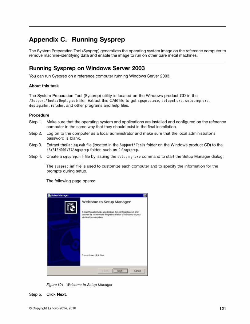
Appendix C. Running Sysprep
The System Preparation Tool (Sysprep) generalizes the operating system image on the reference computer toremove machine-identifying data and enable the image to run on other bare metal machines.
Running Sysprep on Windows Server 2003You can run Sysprep on a reference computer running Windows Server 2003.
About this task
The System Preparation Tool (Sysprep) utility is located on the Windows product CD in the/Support/Tools/Deploy.cab file. Extract this CAB file to get sysprep.exe, setupcl.exe, setupmgr.exe,deploy.chm, ref.chm, and other programs and help files.
Procedure
Step 1. Make sure that the operating system and applications are installed and configured on the referencecomputer in the same way that they should exist in the final installation.
Step 2. Log on to the computer as a local administrator and make sure that the local administrator'spassword is blank.
Step 3. Extract theDeploy.cab file (located in the Support\Tools folder on the Windows product CD) to the%SYSTEMDRIVE%\sysprep folder, such as C:\sysprep.
Step 4. Create a sysprep.inf file by issuing the setupmgr.exe command to start the Setup Manager dialog.
The sysprep.inf file is used to customize each computer and to specify the information for theprompts during setup.
The following page opens:
Figure 101. Welcome to Setup Manager
Step 5. Click Next.
© Copyright Lenovo 2014, 2016 121
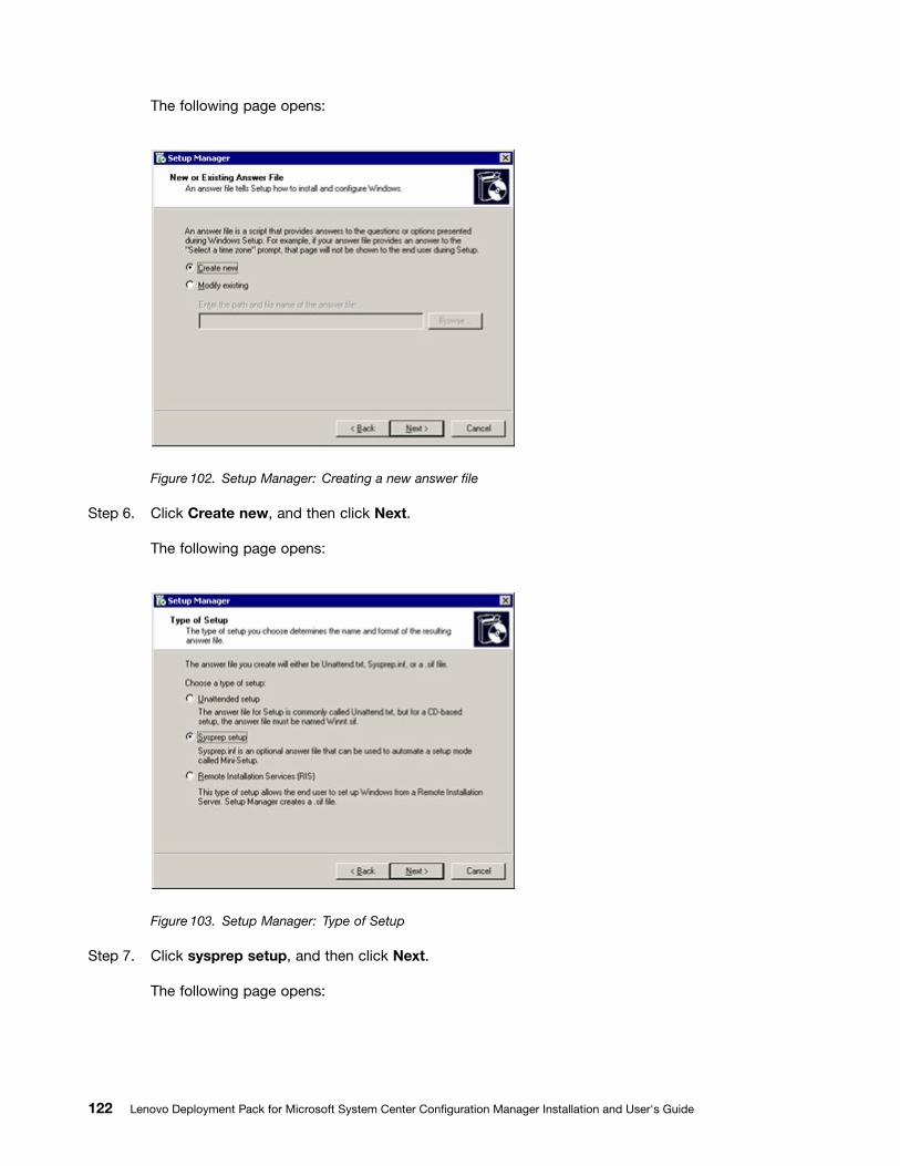
The following page opens:
Figure 102. Setup Manager: Creating a new answer file
Step 6. Click Create new, and then click Next.
The following page opens:
Figure 103. Setup Manager: Type of Setup
Step 7. Click sysprep setup, and then click Next.
The following page opens:
122 Lenovo Deployment Pack for Microsoft System Center Configuration Manager Installation and User's Guide
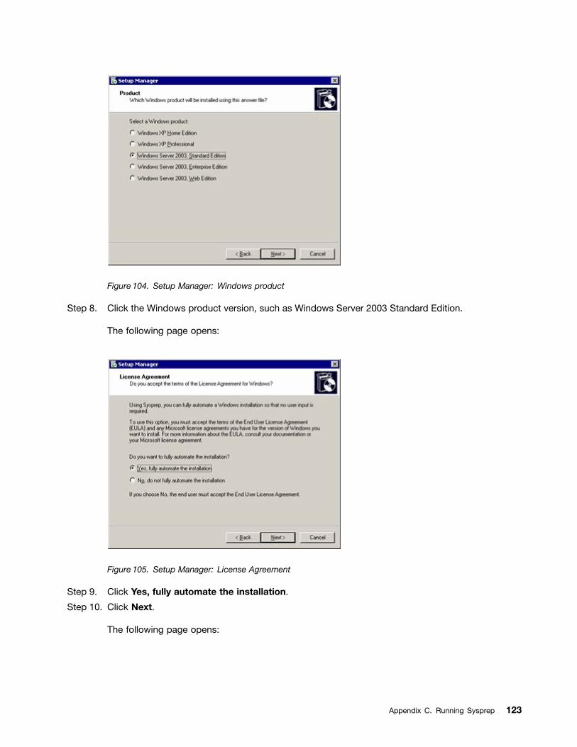
Figure 104. Setup Manager: Windows product
Step 8. Click the Windows product version, such as Windows Server 2003 Standard Edition.
The following page opens:
Figure 105. Setup Manager: License Agreement
Step 9. Click Yes, fully automate the installation.
Step 10. Click Next.
The following page opens:
Appendix C. Running Sysprep 123
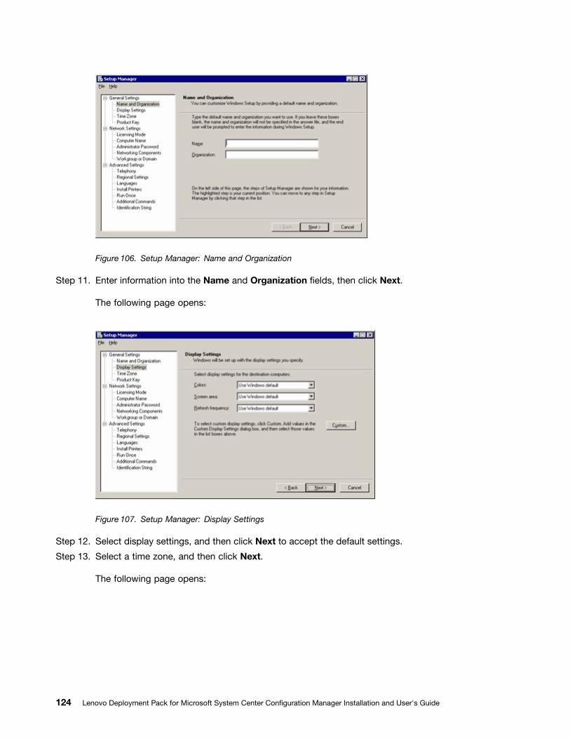
Figure 106. Setup Manager: Name and Organization
Step 11. Enter information into the Name and Organization fields, then click Next.
The following page opens:
Figure 107. Setup Manager: Display Settings
Step 12. Select display settings, and then click Next to accept the default settings.
Step 13. Select a time zone, and then click Next.
The following page opens:
124 Lenovo Deployment Pack for Microsoft System Center Configuration Manager Installation and User's Guide
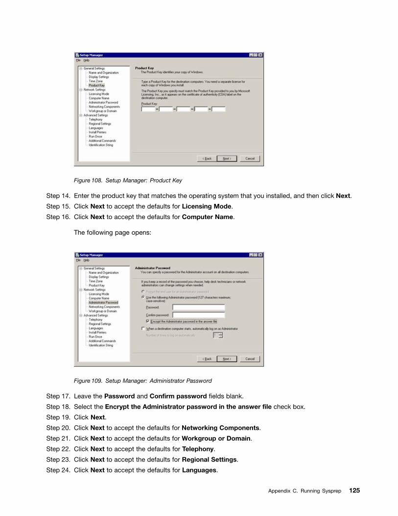
Figure 108. Setup Manager: Product Key
Step 14. Enter the product key that matches the operating system that you installed, and then click Next.
Step 15. Click Next to accept the defaults for Licensing Mode.
Step 16. Click Next to accept the defaults for Computer Name.
The following page opens:
Figure 109. Setup Manager: Administrator Password
Step 17. Leave the Password and Confirm password fields blank.
Step 18. Select the Encrypt the Administrator password in the answer file check box.
Step 19. Click Next.
Step 20. Click Next to accept the defaults for Networking Components.
Step 21. Click Next to accept the defaults for Workgroup or Domain.
Step 22. Click Next to accept the defaults for Telephony.
Step 23. Click Next to accept the defaults for Regional Settings.
Step 24. Click Next to accept the defaults for Languages.
Appendix C. Running Sysprep 125
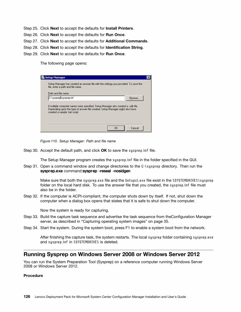
Step 25. Click Next to accept the defaults for Install Printers.
Step 26. Click Next to accept the defaults for Run Once.
Step 27. Click Next to accept the defaults for Additional Commands.
Step 28. Click Next to accept the defaults for Identification String.
Step 29. Click Next to accept the defaults for Run Once.
The following page opens:
Figure 110. Setup Manager: Path and file name
Step 30. Accept the default path, and click OK to save the sysprep.inf file.
The Setup Manager program creates the sysprep.inf file in the folder specified in the GUI.
Step 31. Open a command window and change directories to the C:\sysprep directory. Then run thesysprsysprsysprep.eep.eep.exxxeee command:sysprsysprsysprepepep -r-r-resealesealeseal -nosidgen-nosidgen-nosidgen
Make sure that both the sysprep.exe file and the Setupcl.exe file exist in the %SYSTEMDRIVE%\sysprepfolder on the local hard disk. To use the answer file that you created, the sysprep.inf file mustalso be in the folder.
Step 32. If the computer is ACPI-compliant, the computer shuts down by itself. If not, shut down thecomputer when a dialog box opens that states that it is safe to shut down the computer.
Now the system is ready for capturing.
Step 33. Build the capture task sequence and advertise the task sequence from theConfiguration Managerserver, as described in “Capturing operating system images” on page 35.
Step 34. Start the system. During the system boot, press F1 to enable a system boot from the network.
After finishing the capture task, the system restarts. The local sysprep folder containing sysprep.exeand sysprep.inf in %SYSTEMDRIVE% is deleted.
Running Sysprep on Windows Server 2008 or Windows Server 2012You can run the System Preparation Tool (Sysprep) on a reference computer running Windows Server2008 or Windows Server 2012.
Procedure
126 Lenovo Deployment Pack for Microsoft System Center Configuration Manager Installation and User's Guide
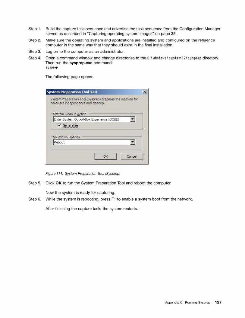
Step 1. Build the capture task sequence and advertise the task sequence from the Configuration Managerserver, as described in “Capturing operating system images” on page 35.
Step 2. Make sure the operating system and applications are installed and configured on the referencecomputer in the same way that they should exist in the final installation.
Step 3. Log on to the computer as an administrator.
Step 4. Open a command window and change directories to the C:\windows\system32\sysprep directory.Then run the sysprep.exe command:sysprep
The following page opens:
Figure 111. System Preparation Tool (Sysprep)
Step 5. Click OK to run the System Preparation Tool and reboot the computer.
Now the system is ready for capturing.
Step 6. While the system is rebooting, press F1 to enable a system boot from the network.
After finishing the capture task, the system restarts.
Appendix C. Running Sysprep 127

128 Lenovo Deployment Pack for Microsoft System Center Configuration Manager Installation and User's Guide
Appendix D. Getting help and technical assistance
If you need help, service, or technical assistance or just want more information aboutLenovo products, youcan find a wide variety of sources available from Lenovo to assist you.
About this task
This information describes where to go for additional information aboutLenovo and Lenovo products, whatto do if you experience a problem with your system, and who to call for service, if it is necessary.
Before you callBefore you call, make sure that you tried to solve the problem yourself.
About this task
Make sure that you have taken these steps to try to solve the problem:
• Check all cables to make sure that they are connected.
• Check the power switches to make sure that the system and any optional devices are turned on.
• Use the troubleshooting information in your system documentation, and use the diagnostic tools thatcome with your system. Information about diagnostic tools is in the Problem Determination and ServiceGuide on the Lenovo Documentation CD that comes with your system.
• Go to Lenovo Deployment Pack for Microsoft System Center Configuration Manager website to check fortechnical information, hints, tips, and new device drivers or to submit a request for information.
You can solve many problems without outside assistance by following the troubleshooting procedures thatLenovo provides in the online help or in the documentation that is provided with your Lenovo product. Thedocumentation that comes with Lenovo systems also describes the diagnostic tests that you can perform.Most systems, operating systems, and programs come with documentation that contains troubleshootingprocedures and explanations of error messages and error codes. If you suspect a software problem, see thedocumentation for the operating system or program.
Using the documentationInformation about your Lenovo system and preinstalled software, if any, or optional device is available in thedocumentation that comes with the product. That documentation can include printed documents, onlinedocuments, readme files, and help files.
About this task
See the troubleshooting information in your system documentation for instructions for using the diagnosticprograms. The troubleshooting information or the diagnostic programs might tell you that you needadditional or updated device drivers or other software.Lenovo maintains pages on the World Wide Webwhere you can get the latest technical information and download device drivers and updates.
To access these pages, go to Lenovo Deployment Pack for Microsoft System Center Configuration Managerwebsite and follow the instructions.
© Copyright Lenovo 2014, 2016 129
Getting help and information from the World Wide WebThe Lenovo web site has up-to-date information about Lenovo systems, optional devices, services, andsupport, including http://www.ibm.com/systems/x/, http://www.ibm.com/systems/bladecenter/, andhttp://www.ibm.com/intellistation/.
About this task
You can find service information for Lenovo systems and optional devices at Lenovo Deployment Pack forMicrosoft System Center Configuration Manager website.
Hardware service and supportYou can receive hardware service through your Lenovo reseller or Lenovo Services.
About this task
To locate a reseller authorized by Lenovo to provide warranty service, go to the IBM PartnerWorld websiteand click Find a Business Partner on the right side of the page. For Lenovo support telephone numbers,see IBM Directory of worldwide contacts webpage.
In the U.S. and Canada, call 1-800-IBM-SERV (1-800-426-7378). In the U.S. and Canada, hardware serviceand support is available 24 hours a day, 7 days a week.
In the U.K., these services are available Monday through Friday, from 9 a.m. to 6 p.m.
130 Lenovo Deployment Pack for Microsoft System Center Configuration Manager Installation and User's Guide
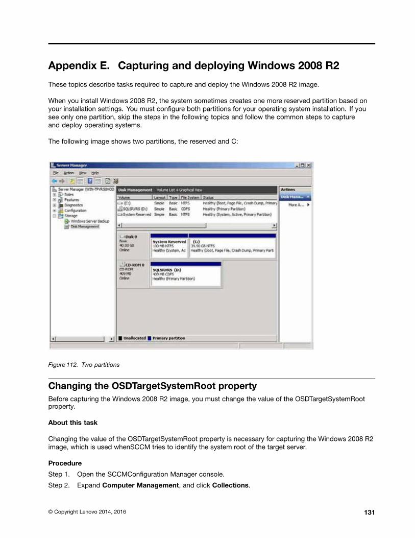
Appendix E. Capturing and deploying Windows 2008 R2
These topics describe tasks required to capture and deploy the Windows 2008 R2 image.
When you install Windows 2008 R2, the system sometimes creates one more reserved partition based onyour installation settings. You must configure both partitions for your operating system installation. If yousee only one partition, skip the steps in the following topics and follow the common steps to captureand deploy operating systems.
The following image shows two partitions, the reserved and C:
Figure 112. Two partitions
Changing the OSDTargetSystemRoot propertyBefore capturing the Windows 2008 R2 image, you must change the value of the OSDTargetSystemRootproperty.
About this task
Changing the value of the OSDTargetSystemRoot property is necessary for capturing the Windows 2008 R2image, which is used whenSCCM tries to identify the system root of the target server.
Procedure
Step 1. Open the SCCMConfiguration Manager console.
Step 2. Expand Computer Management, and click Collections.
© Copyright Lenovo 2014, 2016 131
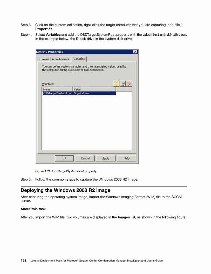
Step 3. Click on the custom collection, right-click the target computer that you are capturing, and clickProperties.
Step 4. Select Variables and add the OSDTargetSystemRoot property with the value [SystemDisk]:\Windows.In the example below, the D disk drive is the system disk drive.
Figure 113. OSDTargetSystemRoot property
Step 5. Follow the common steps to capture the Windows 2008 R2 image.
Deploying the Windows 2008 R2 imageAfter capturing the operating system image, import the Windows Imaging Format (WIM) file to the SCCMserver.
About this task
After you import the WIM file, two volumes are displayed in the Images list, as shown in the following figure.
132 Lenovo Deployment Pack for Microsoft System Center Configuration Manager Installation and User's Guide
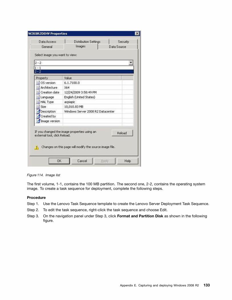
Figure 114. Image list
The first volume, 1-1, contains the 100 MB partition. The second one, 2-2, contains the operating systemimage. To create a task sequence for deployment, complete the following steps.
Procedure
Step 1. Use the Lenovo Task Sequence template to create the Lenovo Server Deployment Task Sequence.
Step 2. To edit the task sequence, right-click the task sequence and choose Edit.
Step 3. On the navigation panel under Step 3, click Format and Partition Disk as shown in the followingfigure.
Appendix E. Capturing and deploying Windows 2008 R2 133
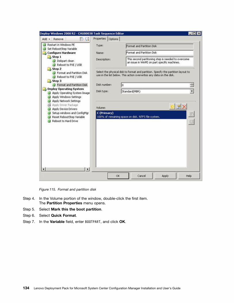
Figure 115. Format and partition disk
Step 4. In the Volume portion of the window, double-click the first item.The Partition Properties menu opens.
Step 5. Select Mark this the boot partition.
Step 6. Select Quick Format.
Step 7. In the Variable field, enter BOOTPART, and click OK.
134 Lenovo Deployment Pack for Microsoft System Center Configuration Manager Installation and User's Guide
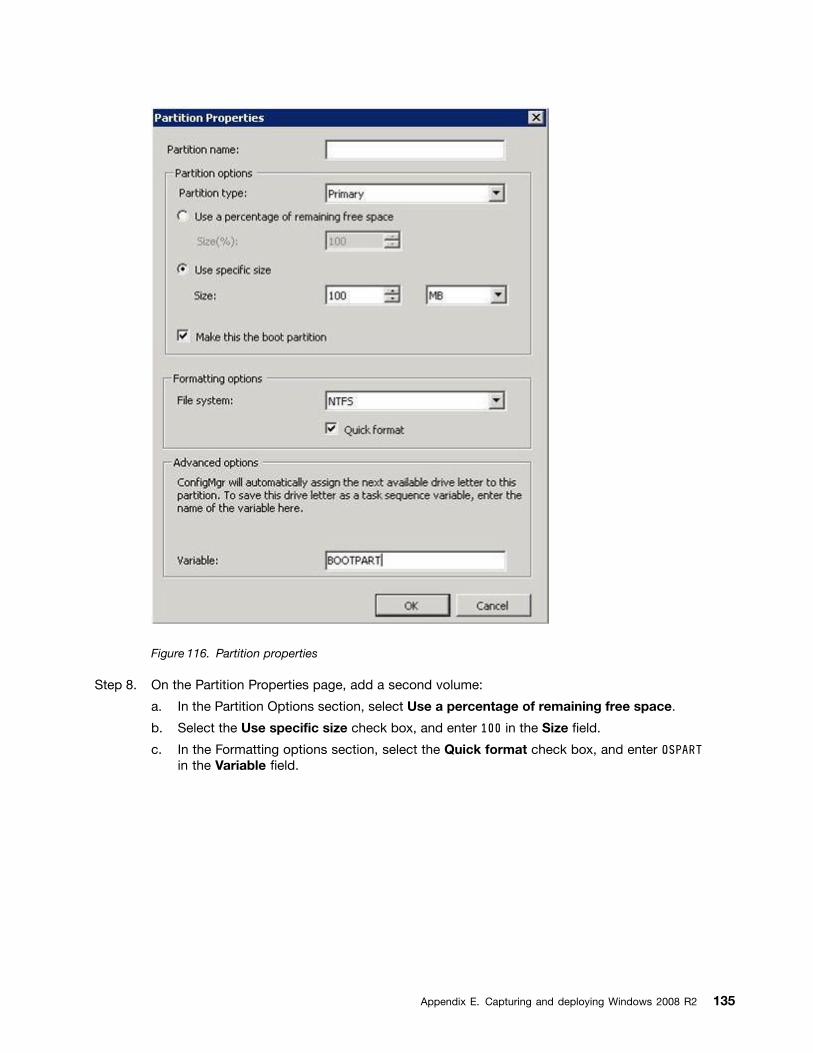
Figure 116. Partition properties
Step 8. On the Partition Properties page, add a second volume:
a. In the Partition Options section, select Use a percentage of remaining free space.
b. Select the Use specific size check box, and enter 100 in the Size field.
c. In the Formatting options section, select the Quick format check box, and enter OSPARTin the Variable field.
Appendix E. Capturing and deploying Windows 2008 R2 135
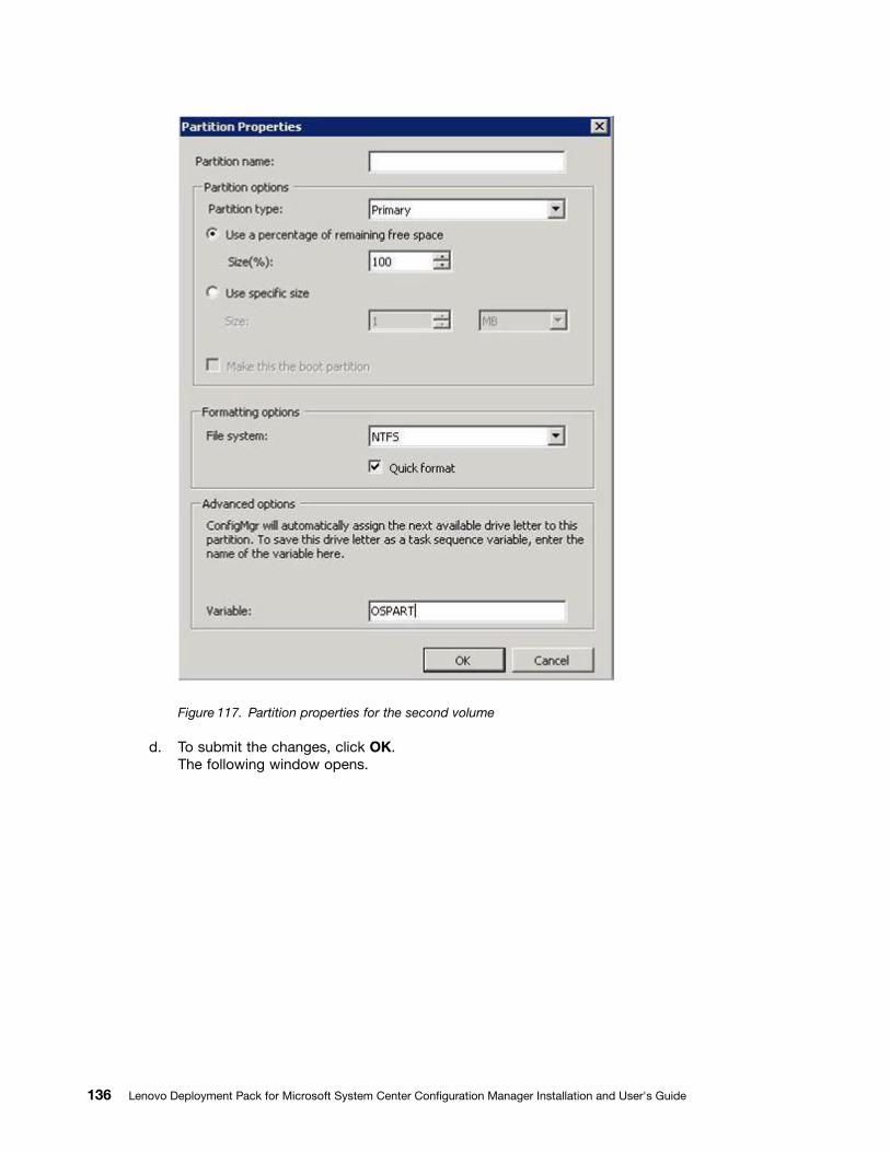
Figure 117. Partition properties for the second volume
d. To submit the changes, click OK.The following window opens.
136 Lenovo Deployment Pack for Microsoft System Center Configuration Manager Installation and User's Guide
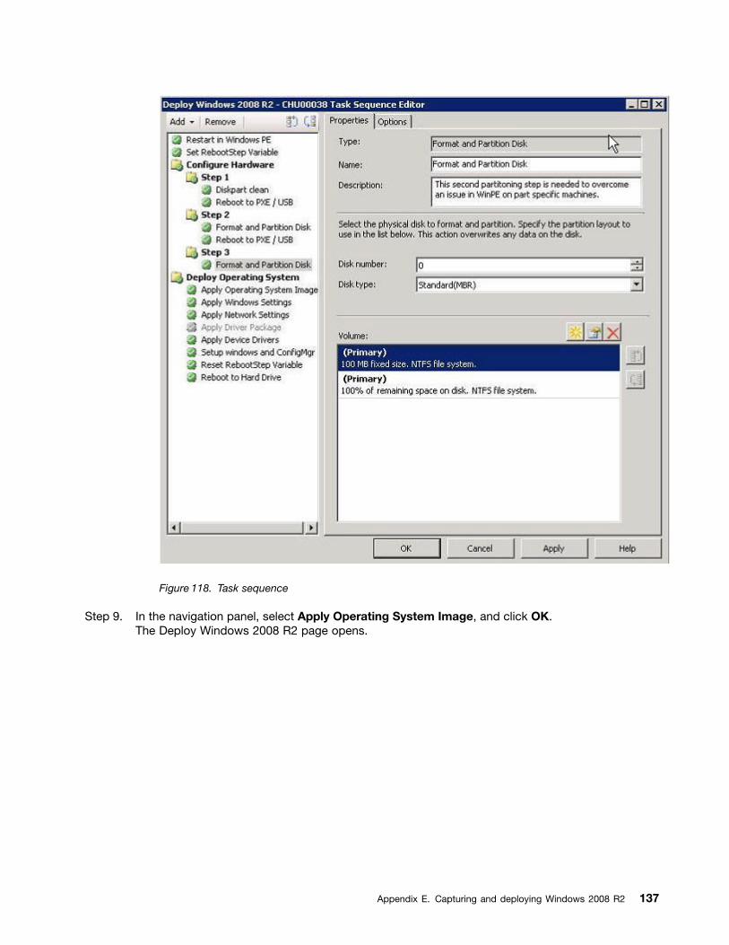
Figure 118. Task sequence
Step 9. In the navigation panel, select Apply Operating System Image, and click OK.The Deploy Windows 2008 R2 page opens.
Appendix E. Capturing and deploying Windows 2008 R2 137
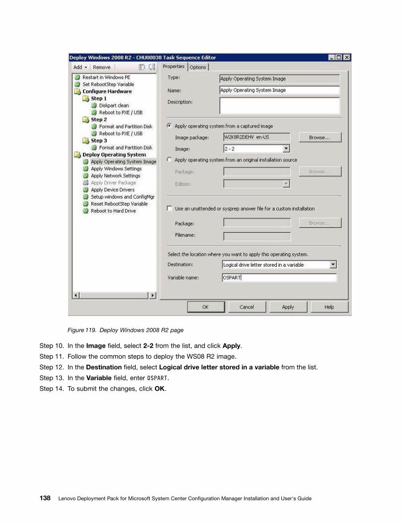
Figure 119. Deploy Windows 2008 R2 page
Step 10. In the Image field, select 2-2 from the list, and click Apply.
Step 11. Follow the common steps to deploy the WS08 R2 image.
Step 12. In the Destination field, select Logical drive letter stored in a variable from the list.
Step 13. In the Variable field, enter OSPART.
Step 14. To submit the changes, click OK.
138 Lenovo Deployment Pack for Microsoft System Center Configuration Manager Installation and User's Guide
Appendix F. Accessibility features for the Lenovo DeploymentPack
Accessibility features help users who have a disability, such as restricted mobility or limited vision, touse information technology products successfully.
Accessibility features
The following list includes the major accessibility features in the Lenovo Deployment Pack:• Can be operated using only the keyboard• Communicates all information independent of color• Inherit system settings for font, size, and color• Supports interfaces commonly used by screen readers and screen magnifiers
Keyboard navigation
This product uses standard Microsoft® Windows navigation keys.
Lenovo and accessibility
See theLenovo Accessibility website for more information about the commitment that Lenovo has toaccessibility.
© Copyright Lenovo 2014, 2016 139

140 Lenovo Deployment Pack for Microsoft System Center Configuration Manager Installation and User's Guide
Appendix G. Notices
Lenovo may not offer the products, services, or features discussed in this document in all countries. Consultyour local Lenovo representative for information on the products and services currently available in your area.
Any reference to a Lenovo product, program, or service is not intended to state or imply that only thatLenovo product, program, or service may be used. Any functionally equivalent product, program, or servicethat does not infringe any Lenovo intellectual property right may be used instead. However, it is the user'sresponsibility to evaluate and verify the operation of any other product, program, or service.
Lenovo may have patents or pending patent applications covering subject matter described in thisdocument. The furnishing of this document does not give you any license to these patents. You can sendlicense inquiries, in writing, to:
Lenovo (United States), Inc.1009 Think Place - Building OneMorrisville, NC 27560U.S.A.Attention: Lenovo Director of Licensing
LENOVO PROVIDES THIS PUBLICATION “AS IS” WITHOUT WARRANTY OF ANY KIND, EITHER EXPRESSOR IMPLIED, INCLUDING, BUT NOT LIMITED TO, THE IMPLIED WARRANTIES OF NON-INFRINGEMENT,MERCHANTABILITY OR FITNESS FOR A PARTICULAR PURPOSE. Some jurisdictions do not allowdisclaimer of express or implied warranties in certain transactions, therefore, this statement may not applyto you.
This information could include technical inaccuracies or typographical errors. Changes are periodicallymade to the information herein; these changes will be incorporated in new editions of the publication.Lenovo may make improvements and/or changes in the product(s) and/or the program(s) described in thispublication at any time without notice.
The products described in this document are not intended for use in implantation or other life supportapplications where malfunction may result in injury or death to persons. The information contained in thisdocument does not affect or change Lenovo product specifications or warranties. Nothing in this documentshall operate as an express or implied license or indemnity under the intellectual property rights of Lenovoor third parties. All information contained in this document was obtained in specific environments and ispresented as an illustration. The result obtained in other operating environments may vary.
Lenovo may use or distribute any of the information you supply in any way it believes appropriate withoutincurring any obligation to you.
Any references in this publication to non-Lenovo Web sites are provided for convenience only and do not inany manner serve as an endorsement of those Web sites. The materials at those Web sites are not part ofthe materials for this Lenovo product, and use of those Web sites is at your own risk.
Any performance data contained herein was determined in a controlled environment. Therefore, the resultobtained in other operating environments may vary significantly. Some measurements may have beenmade on development-level systems and there is no guarantee that these measurements will be the sameon generally available systems. Furthermore, some measurements may have been estimated throughextrapolation. Actual results may vary. Users of this document should verify the applicable data for theirspecific environment.
© Copyright Lenovo 2014, 2016 141

TrademarksLenovo, the Lenovo logo, Flex System, System x, and NeXtScale System are trademarks of Lenovo in theUnited States, other countries, or both.
Intel and Intel Xeon are trademarks of Intel Corporation in the United States, other countries, or both.
Internet Explorer, Microsoft, and Windows are trademarks of the Microsoft group of companies.
Linux is a registered trademark of Linus Torvalds.
Other company, product, or service names may be trademarks or service marks of others.
Important notesProcessor speed indicates the internal clock speed of the microprocessor; other factors also affectapplication performance.
When referring to processor storage, real and virtual storage, or channel volume, KB stands for 1 024 bytes,MB stands for 1 048 576 bytes, and GB stands for 1 073 741 824 bytes.
When referring to hard disk drive capacity or communications volume, MB stands for 1 000 000 bytes,and GB stands for 1 000 000 000 bytes. Total user-accessible capacity can vary depending on operatingenvironments.
Lenovo makes no representations or warranties with respect to non-Lenovo products. Support (if any) forthe non-Lenovo products is provided by the third party, not Lenovo.
Some software might differ from its retail version (if available) and might not include user manuals or allprogram functionality.
142 Lenovo Deployment Pack for Microsoft System Center Configuration Manager Installation and User's Guide