Embed Size (px)
Citation preview

Lexmark MS81x, MS71x printer
Machine Type 4063-2xx, -4x0, -63x, -83x
Service Manual
• Start diagnostics
• Maintenance
• Safety and notices
• Trademarks
• Index
January 08, 2013 www.lexmark.com
P/N 12G3023
Product information
Product name:Lexmark MS71x and MS81x Series
Machine type:4063
Model(s):2xx, 4x0, 63x, 83x
Edition notice
January 08, 2013
The following paragraph does not apply to any country where such provisions are inconsistent with local law: LEXMARK INTERNATIONAL,INC., PROVIDES THIS PUBLICATION “AS IS” WITHOUT WARRANTY OF ANY KIND, EITHER EXPRESS OR IMPLIED, INCLUDING, BUT NOT LIMITEDTO, THE IMPLIED WARRANTIES OF MERCHANTABILITY OR FITNESS FOR A PARTICULAR PURPOSE. Some states do not allow disclaimer ofexpress or implied warranties in certain transactions; therefore, this statement may not apply to you.
This publication could include technical inaccuracies or typographical errors. Changes are periodically made to the information herein; thesechanges will be incorporated in later editions. Improvements or changes in the products or the programs described may be made at anytime.
References in this publication to products, programs, or services do not imply that the manufacturer intends to make these available in allcountries in which it operates. Any reference to a product, program, or service is not intended to state or imply that only that product,program, or service may be used. Any functionally equivalent product, program, or service that does not infringe any existing intellectualproperty right may be used instead. Evaluation and verification of operation in conjunction with other products, programs, or services,except those expressly designated by the manufacturer, are the user’s responsibility.
TrademarksLexmark and Lexmark with diamond design are trademarks of Lexmark International, Inc., registered in the United States and/or othercountries.PrintCryption is a trademark of Lexmark International, Inc.Mac and the Mac logo are trademarks of Apple Inc., registered in the U.S. and other countries.PCL® is a registered trademark of the Hewlett-Packard Company. PCL is Hewlett-Packard Company’s designation of a set of printer commands(language) and functions included in its printer products. This printer is intended to be compatible with the PCL language. This means theprinter recognizes PCL commands used in various application programs, and that the printer emulates the functions corresponding to thecommands.All other trademarks are the property of their respective owners.
© 2012 Lexmark International, Inc.All rights reserved.
P/N 12G3023
4063

Table of contents
Product information.....................................................................................2
Edition notice...............................................................................................2
Notices and safety information..................................................................17Laser notices............................................................................................................................................17
Safety.......................................................................................................................................................20
Preface.......................................................................................................25Service manual conventions....................................................................................................................25
General information...................................................................................27Printer configurations.............................................................................................................................28
Paper guidelines......................................................................................................................................30Paper characteristics.........................................................................................................................................30Selecting paper .................................................................................................................................................31Selecting preprinted forms and letterhead ......................................................................................................31Using recycled paper and other office papers ..................................................................................................31Storing paper ....................................................................................................................................................33
Data security notice.................................................................................................................................33
Tools required for service........................................................................................................................34
Diagnostic information...............................................................................35Troubleshooting overview.......................................................................................................................35
Performing the initial troubleshooting check ...................................................................................................35Error code number key .....................................................................................................................................36
Power‑on Reset (POR) sequence.............................................................................................................36
Using Safe Mode.....................................................................................................................................37
Fixing print quality issues........................................................................................................................37Initial print quality check ..................................................................................................................................38Gray background on prints ...............................................................................................................................39Printer is printing blank pages ..........................................................................................................................40Printer is printing solid black pages ..................................................................................................................41Repeating defects .............................................................................................................................................41Shadow images appear on prints .....................................................................................................................42Skewed print .....................................................................................................................................................43Streaked horizontal lines appear on prints.......................................................................................................44Streaked vertical lines appear on prints ...........................................................................................................46
4063
Table of contents
3

Toner rubs off ...................................................................................................................................................47
Paper jams...............................................................................................................................................47Understanding jam numbers and locations......................................................................................................48200–201 paper jams .........................................................................................................................................50Sensor (input) static jam service check.............................................................................................................54Sensor (input) early arriving jam service check ................................................................................................54Sensor (input) never‑ or late‑arriving jam service check.................................................................................. 56Sensor (input) late-leaving or did-not-clear jam service check.........................................................................57Main drive motor control jam service check ....................................................................................................59Printhead motor control jam service check......................................................................................................59Fuser drive motor control jam service check....................................................................................................60Sensor (input) miscellaneous jam 1 service check............................................................................................60Sensor (input) miscellaneous jam 2 service check............................................................................................61Sensor (input) miscellaneous jam 3 service check............................................................................................61202 paper jams .................................................................................................................................................61Sensor (fuser exit) static jam service check ......................................................................................................64Sensor (fuser exit) late-leaving jam service check ............................................................................................64Sensor (fuser exit) late-arriving jam service check ...........................................................................................65Sensor (narrow media) late arriving jam service check ....................................................................................66Sensor (narrow media) static jam service check...............................................................................................67Sensor (fuser exit) miscellaneous jam service check ........................................................................................68Fuser ID chip control jam service check............................................................................................................68203 paper jams .................................................................................................................................................69Upper redrive motor control jam service check ...............................................................................................69230 paper jams .................................................................................................................................................70Sensor (duplex path) static jam service check ..................................................................................................73Sensor (duplex path) early arriving jam service check......................................................................................74Sensor (duplex path) never‑ or late‑arriving jam service check .......................................................................74Sensor (duplex path) late leaving jam service check ........................................................................................75Duplex control jam service check .....................................................................................................................76Sensor (duplex path) miscellaneous jam service check ....................................................................................77Sensor (input) never-arriving jam (exiting duplex) service check.....................................................................78235–239 paper jams .........................................................................................................................................7824x paper jams..................................................................................................................................................79Media feeder motor control service check.......................................................................................................81Media tray 1, tray pulled jam ...........................................................................................................................82Media feeder motor tray lift error service check .............................................................................................83Sensor (input) never-arriving jam from tray 1 service check............................................................................83250 paper jams .................................................................................................................................................84Sensor (input) never-arriving jam from MPF media tray service check............................................................8641y.xx paper jams .............................................................................................................................................8843y.xx paper jams .............................................................................................................................................89451 paper jams .................................................................................................................................................90455–457 paper jams .........................................................................................................................................91
4063
Table of contents
4

User attendance messages (0-99.99)......................................................................................................94User attendance messages (0‑99.99) ............................................................................................................... 94Toner level sensing error check ........................................................................................................................99Toner cartridge smart chip error service check ................................................................................................99Imaging unit smart chip service check............................................................................................................100Fuser unit smart chip service check................................................................................................................101
Printer hardware errors (100-199.99)...................................................................................................101Printer hardware error messages(100‑199.99) .............................................................................................. 102Printhead ID service check..............................................................................................................................106Printhead service check ..................................................................................................................................106Fuser drive motor service check .....................................................................................................................107Fuser service check .........................................................................................................................................107LVPS service check ..........................................................................................................................................108Toner level sensing service check ...................................................................................................................108Main drive motor service check......................................................................................................................109Media feeder service check ............................................................................................................................109Redrive motor service check...........................................................................................................................110Duplex motor service check............................................................................................................................110Toner add motor service check ......................................................................................................................111Main cooling fan service check .......................................................................................................................111Cartridge cooling fan service check ................................................................................................................112LVPS cooling fan service check .......................................................................................................................112HVPS cooling fan service check.......................................................................................................................113Miscellaneous cooling fan service check ........................................................................................................113
Firmware and/or system electronics errors (900-999.99)....................................................................1139xx error messages .........................................................................................................................................114System software error service check..............................................................................................................117NVRAM mismatch failure service check .........................................................................................................122
Input/output option hardware errors...................................................................................................1233xx error messages (300‑399.99) ................................................................................................................... 123250/550-sheet transport motor failure service check....................................................................................128250/550-sheet media feeder failure service check ........................................................................................130250/550-sheet controller board failure service check....................................................................................132HCIT lift drive motor failure service check......................................................................................................133HCIT lift plate failure service check.................................................................................................................135HCIT transport motor failure service check ....................................................................................................137HCOE failure service check .............................................................................................................................139Mailbox failure service check..........................................................................................................................140Output expander failure service check ...........................................................................................................141
Input/output option paper jam errors..................................................................................................143Input option jam error messages (242‑245.99) .............................................................................................. 143250/550-sheet media tray option jam service check......................................................................................154HCIT jam service check ...................................................................................................................................156HCIT source jam service check........................................................................................................................159
4063
Table of contents
5
4xx error messages (400‑499.99) ................................................................................................................... 161Sensor (mailbox pass through) jam service check ..........................................................................................171Mailbox diverter jam service check ................................................................................................................174HCOE diverter jam service check ....................................................................................................................175Sensor (HCOE pass through) jam service check..............................................................................................177Sensor (finisher pass through) jam service check...........................................................................................179Finisher left tamper jam service check ...........................................................................................................181Finisher right tamper jam service check .........................................................................................................182Finisher ejector jam service check ..................................................................................................................184Finisher diverter jam service check ................................................................................................................185Finisher paddle jam service check ..................................................................................................................186Finisher tray holder jam service check ...........................................................................................................188Stapler carriage jam service check..................................................................................................................189Output expander jam service check ...............................................................................................................191Sensor (media in stapler) jam service check...................................................................................................193
Symptoms..............................................................................................................................................194Base printer symptoms...................................................................................................................................194Network service check....................................................................................................................................194Dead machine service check...........................................................................................................................197Option tray symptoms ....................................................................................................................................198250/550-sheet media type error service check ..............................................................................................199250/550-sheet tray undetected service check ...............................................................................................201HCIT incorrect media error service check .......................................................................................................202HCIT media type error service check ..............................................................................................................204HCIT undetected service check.......................................................................................................................206HCIT media low undetected service check .....................................................................................................207Finisher side door error service check ............................................................................................................209Mailbox incorrect bin exit service check.........................................................................................................211Finisher cartridge error service check ............................................................................................................212Finisher undetected service check..................................................................................................................214Finisher bin error service check .....................................................................................................................215Finisher door undetected service check ........................................................................................................216Stapler carriage failure service check .............................................................................................................218Finisher bin media present error service check..............................................................................................219Output expander error service check .............................................................................................................221
Service menus..........................................................................................223Using the printer control panel.............................................................................................................223
Menus list..............................................................................................................................................224
Diagnostics menu..................................................................................................................................224Entering diagnostics mode .............................................................................................................................225REGISTRATION ................................................................................................................................................225PRINT TESTS ....................................................................................................................................................226
Print Quality Pages (Prt Quality Pgs) ..........................................................................................................226
4063
Table of contents
6

HARDWARE TESTS ..........................................................................................................................................226Panel Test ...................................................................................................................................................226Button Test.................................................................................................................................................227DRAM Test..................................................................................................................................................227Serial Wrap Test .........................................................................................................................................228USB HS Test Mode......................................................................................................................................228
DUPLEX TESTS .................................................................................................................................................229Quick Test...................................................................................................................................................229Top Margin .................................................................................................................................................230Sensor Test .................................................................................................................................................230Motor Test..................................................................................................................................................230Duplex Feed 1.............................................................................................................................................231Duplex Feed 2.............................................................................................................................................231
INPUT TRAY TESTS ..........................................................................................................................................231Feed Tests ..................................................................................................................................................231Sensor Tests ...............................................................................................................................................232
OUTPUT BIN TESTS .........................................................................................................................................232Feed Tests ..................................................................................................................................................232Feed To All Bins ..........................................................................................................................................232Sensor Test .................................................................................................................................................233Diverter Test...............................................................................................................................................233
FINISHER TESTS ...............................................................................................................................................233Staple Test ..................................................................................................................................................233Hole Punch Test..........................................................................................................................................234Feed Test (finisher).....................................................................................................................................234Finisher Sensor Test ...................................................................................................................................234
BASE SENSOR TEST..........................................................................................................................................235DEVICE TESTS ..................................................................................................................................................235
Quick Disk Test ...........................................................................................................................................235Disk Test/Clean...........................................................................................................................................236Flash Test....................................................................................................................................................236
PRINTER SETUP ...............................................................................................................................................236Defaults ......................................................................................................................................................236Printed Page Count.....................................................................................................................................237Permanent Page Count (Perm page count)................................................................................................237Processor ID................................................................................................................................................237Engine Setting [x] .......................................................................................................................................238Edge to Edge...............................................................................................................................................238Parallel Strobe Adjustment (Par 1 Strobe Adj) ...........................................................................................238
EP SETUP.........................................................................................................................................................238EP Defaults .................................................................................................................................................238Fuser Temperature (Fuser Temp)...............................................................................................................238Fuser Page Count .......................................................................................................................................239Warm Up Time ...........................................................................................................................................239Transfer ......................................................................................................................................................239
4063
Table of contents
7
Print Contrast .............................................................................................................................................239Charge Roll .................................................................................................................................................239Gap Adjust ..................................................................................................................................................240Automatic Darkness Adjust (Auto Dark Adj) ..............................................................................................240
REPORTS .........................................................................................................................................................240Menu Settings Page....................................................................................................................................240Installed Licenses........................................................................................................................................241
EVENT LOG......................................................................................................................................................241Display Log .................................................................................................................................................241Print Log .....................................................................................................................................................241Clear Log.....................................................................................................................................................241
Exit Diags.........................................................................................................................................................242
Configuration menu..............................................................................................................................242Entering configuration mode..........................................................................................................................243Roller Kit Counter Value..................................................................................................................................243Reset Roller Kit Counter..................................................................................................................................243Print Quality Pages..........................................................................................................................................244Reports ........................................................................................................................................................... 244
Menu Settings Page....................................................................................................................................244Event Log....................................................................................................................................................244
Size sensing .....................................................................................................................................................244Panel Menus ...................................................................................................................................................245PPDS Emulation ..............................................................................................................................................245Download Emuls .............................................................................................................................................245Safe Mode.......................................................................................................................................................245Factory Defaults..............................................................................................................................................246Energy Conserve .............................................................................................................................................246Paper Prompts ................................................................................................................................................246Envelope Prompts...........................................................................................................................................247Action for Prompts..........................................................................................................................................247Jobs on Disk ....................................................................................................................................................248Disk Encryption ...............................................................................................................................................248Erase All Information on Disk..........................................................................................................................248Wipe All Settings.............................................................................................................................................249Font Sharpening..............................................................................................................................................249Require Standby..............................................................................................................................................249A5 Loading ......................................................................................................................................................249UI Automation ................................................................................................................................................250LES Applications ..............................................................................................................................................250Key Repeat Initial Delay ..................................................................................................................................250Key Repeat Rate..............................................................................................................................................250Wiper Message ...............................................................................................................................................251Clear Supply Usage History .............................................................................................................................251Clear Custom Status........................................................................................................................................251USB Speed.......................................................................................................................................................251
4063
Table of contents
8
Automatically Display Error Screens ...............................................................................................................252USB PnP ..........................................................................................................................................................252
Entering invalid engine mode................................................................................................................252
Entering recovery mode........................................................................................................................252
Accessing the Network SE menu...........................................................................................................253
Service Engineer menu..........................................................................................................................253Accessing the service engineer (SE) menu......................................................................................................253Service engineer (SE) menu ............................................................................................................................253
Repair information...................................................................................255Removal precautions.............................................................................................................................255
Handling ESD‑sensitive parts ..........................................................................................................................255Controller board/control panel replacement .................................................................................................256eSF solutions backup ......................................................................................................................................256Ribbon cable connectors ................................................................................................................................257
Zero Insertion Force (ZIF) connectors ........................................................................................................257Horizontal top contact connector ..............................................................................................................258Horizontal bottom contact connector........................................................................................................261Vertical mount contact connector .............................................................................................................264Horizontal sliding contact connector .........................................................................................................267Low Insertion Force (LIF) connector...........................................................................................................270
Adjustments..........................................................................................................................................271Media aligner roller adjustment .....................................................................................................................272Polygon printhead mechanical registration adjustment ................................................................................274
Removal procedures.............................................................................................................................277
Base printer - cover removals...............................................................................................................277Left cover removal ..........................................................................................................................................277Rear lower cover removal...............................................................................................................................280Top cover removal ..........................................................................................................................................282Right cover removal........................................................................................................................................283Rear door removal ..........................................................................................................................................285
Base printer- front removals.................................................................................................................286Duplex exit diverter removal ..........................................................................................................................286Front door removal.........................................................................................................................................288Inner guide deflector removal ........................................................................................................................289Laser printhead removal.................................................................................................................................291Left inner cover removal.................................................................................................................................295Media aligner roller removal ..........................................................................................................................297Media turn guide removal ..............................................................................................................................299Media vertical guide removal .........................................................................................................................300MPF feeder lift plate removal .........................................................................................................................302MPF pick roller removal..................................................................................................................................305MPF tray removal ...........................................................................................................................................308
4063
Table of contents
9
Right inner cover removal ..............................................................................................................................309Sensor (input) removal ...................................................................................................................................310Sensor (toner density) removal ......................................................................................................................312Transfer roller left arm with cable removal ....................................................................................................313Transfer roller right arm removal ...................................................................................................................314Transfer roller removal ...................................................................................................................................317
Base printer - rear removals..................................................................................................................319Duplex motor removal....................................................................................................................................320Fuser removal .................................................................................................................................................322Fuser access door removal .............................................................................................................................324Left frame pivot removal ................................................................................................................................325Output bin sensor cover removal ...................................................................................................................326Right frame pivot removal ..............................................................................................................................327Sensor (rear door interlock) removal..............................................................................................................328
Base printer - top removals...................................................................................................................328Sensor (standard bin full) removal .................................................................................................................329Standard bin cover removal............................................................................................................................330Upper redrive removal....................................................................................................................................331
Base printer - bottom removals............................................................................................................333Duplex removal...............................................................................................................................................333Duplex front flap removal...............................................................................................................................335Duplex rear flap removal ................................................................................................................................336Left frame extension removal.........................................................................................................................337Media tray removal ........................................................................................................................................339Media size actuator removal ..........................................................................................................................340Pick roller assembly removal ..........................................................................................................................342Right frame extension.....................................................................................................................................343Sensor (duplex path) removal.........................................................................................................................344Sensor (tray 1 media out) removal .................................................................................................................345Separator roller assembly removal.................................................................................................................347
Base printer - left removals...................................................................................................................348Controller board removal ...............................................................................................................................349Controller board access cover removal ..........................................................................................................350Controller board access shield removal..........................................................................................................351Fuser drive motor removal .............................................................................................................................351Main cooling fan removal ...............................................................................................................................353Main drive motor removal..............................................................................................................................354Media feeder removal ....................................................................................................................................356PCBA housing removal....................................................................................................................................357Sensor (control panel interlock) removal .......................................................................................................359Sensor (pick roller position) removal..............................................................................................................360Toner add motor removal...............................................................................................................................361
Base printer - right removals.................................................................................................................362Cartridge cooling fan removal ........................................................................................................................363
4063
Table of contents
10
Duplex cooling fan removal ............................................................................................................................364HVPS removal .................................................................................................................................................365LVPS removal ..................................................................................................................................................366
Control panel removals.........................................................................................................................3694.3‑inch tilting display removal.......................................................................................................................3697‑inch tilting display removal..........................................................................................................................372Control panel removal (2.4‑inch screen) ........................................................................................................ 375Control panel removal (4.3‑inch screen, 7‑inch screen)................................................................................. 381Control panel board (2.4‑inch tilting display) removal ................................................................................... 387Control panel board (4.3‑inch tilting display) removal ................................................................................... 390Control panel board (7‑inch tilting display) removal (MS812de) ................................................................... 393Control panel front cover removal .................................................................................................................396Control panel latch removal ...........................................................................................................................398Control panel left bezel removal ....................................................................................................................399Left control panel hinge removal....................................................................................................................400Right control panel hinge removal..................................................................................................................403
250/550-sheet media tray option removals..........................................................................................406250/550-sheet media tray and drawer assembly removal.............................................................................406Media tray separation roller removal.............................................................................................................407Media tray assembly removal.........................................................................................................................407Media tray front cover removal......................................................................................................................407Drawer pick roller removal ............................................................................................................................408Sensor (pick roll position) removal ................................................................................................................408Drawer assembly rear cover removal .............................................................................................................409Drawer assembly left cover removal ..............................................................................................................410Drawer controller PCBA removal....................................................................................................................411Drawer upper interface cable removal...........................................................................................................412Drawer lower interface cable removal ...........................................................................................................413Drawer media feeder removal .......................................................................................................................414Drawer transport motor removal ...................................................................................................................416Sensor (drawer pass through) removal ..........................................................................................................417Sensor (pick) removal .....................................................................................................................................419
High capacity input tray option removals.............................................................................................422HCIT and drawer assembly removal ...............................................................................................................422HCIT removal ..................................................................................................................................................423HCIT drawer assembly removal ......................................................................................................................423HCIT separator roll assembly removal ............................................................................................................424HCIT media guide removal..............................................................................................................................424HCIT front cover removal................................................................................................................................425HCIT pick arm assembly removal ....................................................................................................................427HCIT drawer assembly rear cover removal.....................................................................................................428HCIT drawer assembly left cover removal ......................................................................................................429HCIT drawer assembly right cover removal ....................................................................................................431HCIT controller PCBA removal ........................................................................................................................433
4063
Table of contents
11
HCIT top cover assembly removal ..................................................................................................................434HCIT lift drive motor removal .........................................................................................................................436HCIT drawer assembly interface cable removal .............................................................................................438Sensor (HCIT media low) with flag removal....................................................................................................439Sensor (pick roll position) removal .................................................................................................................440Sensor (HCIT pick) removal .............................................................................................................................442HCIT media feeder removal ............................................................................................................................443
Output expander option removals........................................................................................................446Output expander assembly removal...............................................................................................................446Output expander top cover removal ..............................................................................................................446Output expander rear door removal ..............................................................................................................447Output expander sensor cover removal .........................................................................................................449Sensor (media bin full) with flag removal .......................................................................................................449Output expander right cover removal ............................................................................................................450Output expander left cover removal ..............................................................................................................452Output expander controller PCBA removal ....................................................................................................454Lower interface cable removal .......................................................................................................................455Upper interface cable removal .......................................................................................................................456Spring with string removal..............................................................................................................................458
High capacity output expander option removals..................................................................................460High capacity output expander assembly removal.........................................................................................460HCOE top cover removal.................................................................................................................................460HCOE rear door removal.................................................................................................................................461HCOE sensor cover removal ...........................................................................................................................462Sensor (HCOE media bin full) with flag removal .............................................................................................463HCOE right outer cover removal.....................................................................................................................463HCOE left cover removal.................................................................................................................................465HCOE controller PCBA removal.......................................................................................................................467HCOE lower interface cable removal ..............................................................................................................469HCOE upper interface cable removal..............................................................................................................470
Staple finisher option removals............................................................................................................471Staple finisher assembly removal ...................................................................................................................471Stapler rear door removal...............................................................................................................................472Stapler right cover removal ............................................................................................................................474Sensor (cartridge door interlock) removal......................................................................................................476Stapler door close limit switch removal..........................................................................................................476Stapler carriage assembly removal .................................................................................................................479Stapler left cover removal ..............................................................................................................................480Stapler cartridge access door removal ...........................................................................................................482Stapler top cover removal ..............................................................................................................................482Stapler spring with string removal..................................................................................................................484Media stack flap (right) removal.....................................................................................................................485Media stack flap (left) removal .......................................................................................................................486Standard output bin LED removal...................................................................................................................489
4063
Table of contents
12
Sensor (finisher bin media present) removal..................................................................................................490Tamper motor (right) removal........................................................................................................................491Tamper motor (left) removal ..........................................................................................................................491Tamper drive belt removal .............................................................................................................................492Paddle drive motor removal ...........................................................................................................................493Stapler lower interface cable removal............................................................................................................494Stapler controller PCBA removal ....................................................................................................................496Sensor (bin full send) removal ........................................................................................................................497Sensor (bin full receive) removal ....................................................................................................................498
Mailbox option removals......................................................................................................................500Mailbox assembly removal .............................................................................................................................500Mailbox top cover removal.............................................................................................................................500Mailbox rear door removal .............................................................................................................................500Mailbox right cover removal...........................................................................................................................502Mailbox spring with string removal ................................................................................................................503Mailbox solenoid removal ..............................................................................................................................504Mailbox left cover removal.............................................................................................................................506Mailbox controller PCBA removal...................................................................................................................507Sensor (mailbox divert motor) removal..........................................................................................................509Mailbox lower interface cable removal ..........................................................................................................510Mailbox upper interface cable removal..........................................................................................................512Mailbox divert motor removal........................................................................................................................512Mailbox media bin full flag removal ...............................................................................................................514Sensor (mailbox bin full receive) removal ......................................................................................................515Mailbox belt removal......................................................................................................................................518Mailbox output bin LED assembly removal ....................................................................................................520
Component locations...............................................................................525Connectors............................................................................................................................................525
Controller board....................................................................................................................................525
Maintenance............................................................................................533Inspection guide....................................................................................................................................533
Scheduled maintenance........................................................................................................................535Fuser maintenance kits...................................................................................................................................535
Replacing fuser maintenance kits...............................................................................................................535Identifying the type of fuser used in the printer ........................................................................................536
Resetting the Roller Kit counter......................................................................................................................537
Preventive maintenance.......................................................................................................................538Device‑specific preventive maintenance........................................................................................................538
Lubrication specification.......................................................................................................................538
Cleaning the printer..............................................................................................................................538
4063
Table of contents
13
Parts catalog............................................................................................540Legend...................................................................................................................................................540
Assembly 1: Covers................................................................................................................................543
Assembly 2: Paper path.........................................................................................................................545
Assembly 3: Fusers................................................................................................................................547
Assembly 4: Electronics.........................................................................................................................549
Assembly 5: Drive motors.....................................................................................................................553
Assembly 6: Duplex...............................................................................................................................555
Assembly 7: Frame................................................................................................................................557
Assembly 8: Control panel.....................................................................................................................559
Assembly 9: Paper tray..........................................................................................................................563
Assembly 10: Input options..................................................................................................... ..............565
Assembly 11: 250-sheet tray option......................................................................................................567
Assembly 12: 550-sheet tray option......................................................................................................569
Assembly 13: High capacity input tray option 1....................................................................................571
Assembly 14: High capacity input tray option 2....................................................................................573
Assembly 15: Output options................................................................................................................575
Assembly 16: Output expander option.................................................................................................577
Assembly 17: High capacity output expander option............................................................................579
Assembly 18: Staple finisher option 1...................................................................................................581
Assembly 19: Staple finisher option 2...................................................................................................583
Assembly 20: Mailbox option 1.............................................................................................................585
Assembly 21: Mailbox option 2.............................................................................................................587
Assembly 22: Miscellaneous.................................................................................................................589
Assembly 23: Power cords....................................................................................................................593
Appendix A: Printer specifications............................................................595Power specifications..............................................................................................................................595
Operating clearances.............................................................................................................................596
Acoustics...............................................................................................................................................596
Environment..........................................................................................................................................597
Processor...............................................................................................................................................597
Appendix B: Options and features............................................................599Available internal options.....................................................................................................................599
Input options supported.......................................................................................................................599
4063
Table of contents
14
Output options supported.....................................................................................................................599
Physical specifications (options)............................................................................................................600
Options configurations..........................................................................................................................600
Appendix C: Theory of operation..............................................................601Models MS81x and MS71x paper path rollers and sensors..................................................................602
Models MS81x and MS71x sensors.......................................................................................................603
Functions of main components - need a new title................................................................................603Media tray assembly.......................................................................................................................................603Rear media guide............................................................................................................................................603Side media guide.............................................................................................................................................603
Media tray.............................................................................................................................................604Media feeder ..................................................................................................................................................604Sensor (media size) .........................................................................................................................................604Sensor (pick roller position) ............................................................................................................................604
Multi-purpose feeder (MPF).................................................................................................................604MPF pick roller................................................................................................................................................605MPF pick solenoid...........................................................................................................................................605
Registration...........................................................................................................................................605Sensor (input) .................................................................................................................................................606
Duplex...................................................................................................................................................606Sensor (duplex path).......................................................................................................................................606
Transfer.................................................................................................................................................606Transfer roller .................................................................................................................................................607
Printhead...............................................................................................................................................608
Fuser components.................................................................................................................................609Heat belt (belt fuser).......................................................................................................................................610Heat belt (hot roll fuser) .................................................................................................................................610Pressure roll ....................................................................................................................................................610Heater lamp (hot roll fuser) ............................................................................................................................611Thermistor ......................................................................................................................................................611Sensor (fuser exit) ...........................................................................................................................................611Sensor (narrow media) (hot roll fuser only) ...................................................................................................611
Exit.........................................................................................................................................................611Sensor (standard bin full)................................................................................................................................612
Drive......................................................................................................................................................612Main drive motor assembly ............................................................................................................................612Fuser drive motor assembly ...........................................................................................................................612Toner add motor assembly.............................................................................................................................613Redrive motor assembly .................................................................................................................................613
Sensors..................................................................................................................................................614
4063
Table of contents
15

Electrical components and controller...................................................................................................614Sensor (control panel door interlock) .............................................................................................................615Sensor (rear door interlock)............................................................................................................................615Main cooling fan .............................................................................................................................................615Cartridge cooling fan.......................................................................................................................................615Duplex cooling fan ............................................................................................................. .............................615Fuser cooling fan (hot roll printer only) ..........................................................................................................615LVPS board assembly ......................................................................................................................................616HVPS board assembly .....................................................................................................................................616Controller board .............................................................................................................................................616
Xerographic and print cartridge components.......................................................................................616
Supported paper sizes, types, and weights...........................................................................................620Paper types and weights supported by the printer ........................................................................................620Paper sizes supported by the printer..............................................................................................................621Paper sizes, types, and weights supported by the optional finishers.............................................................622
Output options theory...........................................................................................................................624Output expander theory .................................................................................................................................624High capacity output expander theory ...........................................................................................................625Mailbox theory................................................................................................................................................626Staple finisher theory......................................................................................................................................627
Appendix D: Acronyms.............................................................................629Acronyms...............................................................................................................................................629
Index........................................................................................................631
Part number index...................................................................................639
Part name index.......................................................................................649
4063
Table of contents
16
Notices and safety information
Laser notices
Laser noticeThe printer is certified in the U.S. to conform to the requirements of DHHS 21 CFR, Chapter I, Subchapter J for Class I(1) laser products, and elsewhere is certified as a Class I laser product conforming to the requirements of IEC 60825-1.
Class I laser products are not considered to be hazardous. The printer contains internally a Class IIIb (3b) laser that isnominally a 10 milliwatt gallium arsenide laser operating in the wavelength of 787-800 nanometers. The laser systemand printer are designed so there is never any human access to laser radiation above a Class I level during normaloperation, user maintenance, or prescribed service condition.
Laser-HinweisDer Drucker wurde in den USA zertifiziert und entspricht den DHHS-Vorschriften 21 CFR, Kapitel I, Unterkapitel J fürLaserprodukte der Klasse I (1); andernorts ist er als Laserprodukt der Klasse I zertifiziert, das den IEC 60825-1-Anforderungen entspricht.
Laserprodukte der Klasse I werden nicht als gefährlich eingestuft. Der Drucker enthält im Inneren einen Laser derKlasse IIIb (3b), und zwar einen 10-Milliwatt-Gallium-Arsenid-Laser, der im Wellenlängenbereich von 787 bis 800Nanometern arbeitet. Das Lasersystem und der Drucker sind so konstruiert, dass unter normalen Betriebsbedingungen,bei der Wartung durch den Benutzer oder bei den vorgeschriebenen Wartungsbedingungen Menschen keinerLaserstrahlung ausgesetzt sind, die die Werte für Klasse I überschreitet.
Avis relatif à l'utilisation du laserL'imprimante est certifiée conforme aux exigences de la réglementation des Etats-Unis relative aux produits laser (DHHS21 CFR, Chapter I, Subchapter J for Class I (1)). Pour les autres pays, elle est certifiée conforme aux exigences des normesIEC 60825-1 relatives aux produits laser de classe I.
Les produits laser de Classe I ne sont pas considérés comme dangereux. L'imprimante contient un laser de classe IIIb(3b), laser arséniure de gallium 10 milliwatts opérant sur une longueur d'onde de l'ordre de 787 à 800 nanomètres. Lesystème laser ainsi que l'imprimante ont été conçus de manière à ce que personne ne soit exposé à des rayonnementslaser dépassant le niveau de classe I dans le cadre d'un fonctionnement normal, de l'entretien par l'utilisateur ou de lamaintenance.
Avvertenze sui prodotti laserLa stampante è certificata negli Stati Uniti come stampante conforme ai requisiti DHHS 21 CFR, Capitolo I, SottocapitoloJ per i prodotti laser di Classe I (1), mentre in altri paesi è certificata come prodotto laser di Classe I conforme ai requisitiIEC 60825-1.
I prodotti laser di Classe I non sono considerati pericolosi. La stampante contiene un laser di Classe IIIb (3b), che ènominalmente un laser ad arseniuro di gallio a 10milliwatt funzionante a una lunghezza d'onda di 787-800 nanometri.Il sistema laser e la stampante sono stati progettati in modo da impedire l'esposizione a radiazioni laser superiori allivello previsto dalla Classe I durante le normali operazioni di stampa, manutenzione o assistenza.
4063
Notices and safety information
17
Aviso de láserEsta impresora se ha certificado en EE. UU. de conformidad con los requisitos de DHHS 21 CFR, capítulo I, subcapítuloJ, para los productos láser de Clase I (1), y en otros países está certificada como un producto láser de Clase I de acuerdocon los requisitos de IEC 60825-1.
Los productos láser de Clase I no se consideran peligrosos. La impresora contiene un láser interno de Clase IIIb (3b) quenominalmente es un láser de arseniuro de galio de 10 milivatios que funciona en una longitud de onda de 787-800nanómetros. El sistema láser y la impresora se han diseñado para que ningún individuo acceda nunca a las radiacionesláser por encima del nivel de Clase I durante su uso normal, ni en tareas de mantenimiento o intervenciones de serviciotécnico prescritas.
Aviso sobre laserA impressora foi certificada nos EUA por estar em conformidade com os requisitos do DHHS 21 CFR, capítulo I,subcapítulo J, para produtos a laser de Classe I (1) e, nos demais países, foi certificada como produto a laser de ClasseI em conformidade com os requisitos da IEC 60825-1.
Os produtos a laser de Classe I não são considerados perigosos. A impressora contém, internamente, um laser de ClasseIIIb (3b) que é um laser de arsenieto de gálio de 10 miliwatts operando no comprimento de onda de 787-800nanômetros. O sistema do laser e a impressora foram projetados para que jamais haja acesso humano à radiação dolaser acima do nível da Classe I durante a operação normal ou a manutenção pelo usuário ou sob as condições demanutenção prescritas.
LaserinformatieDeze printer is in de Verenigde Staten gecertificeerd als een product dat voldoet aan de vereisten van DHHS 21 CFR,hoofdstuk 1, paragraaf J voor laserproducten van klasse I (1). Elders is de printer gecertificeerd als een laserproductvan klasse I dat voldoet aan de vereisten van IEC 60825-1.
Laserproducten van klasse I worden geacht geen gevaar op te leveren. De printer bevat intern een laser van klasse IIIb(3b), een galliumarsenide laser met een nominaal vermogen van 10 milliwatt en een golflengtebereik van 787-800nanometer. Het lasersysteem en de printer zijn zodanig ontworpen dat gebruikers nooit blootstaan aan laserstralingdie hoger is dan het toegestane niveau voor klasse I-apparaten, tijdens normaal gebruik, onderhoudswerkzaamhedendoor de gebruiker of voorgeschreven servicewerkzaamheden.
LasererklæringDenne printer er certificeret i USA i henhold til kravene i DHHS 21 CFR, afsnit I, underafsnit J, for Klasse I-laserprodukter(1) og certificeret andetsteds som et Klasse I-laserprodukt i henhold til kravene i IEC 60825-1.
Klasse I-laserprodukter anses ikke for at være farlige. Printeren indeholder internt en klasse IIIb (3b)-laser, der nominelter en 10 milliwatt galliumarsenid-laser, som fungerer i bølgelængdeområdet 787-800 nanometer. Lasersystemet ogprinteren er udviklet på en sådan måde, at der ikke er en direkte laserstråling, der overskrider Klasse I-niveauet undernormal brug, brugers vedligeholdelse eller de foreskrevne servicebetingelser.
LaserilmoitusTämä tulostin on sertifioitu Yhdysvalloissa DHHS 21 CFR, Chapter I, Subchapter J -standardin mukaiseksi luokan I (1) -lasertuotteeksi ja muualla IEC 60825-1 -standardin mukaiseksi luokan I lasertuotteeksi.
4063
Notices and safety information
18
Luokan I lasertuotteita ei pidetä haitallisina. Tulostimen sisällä on luokan IIIb (3b) laser, joka on nimellisteholtaan 10mW:n galliumarsenidilaser ja toimii 787–800 nanometrin aallonpituuksilla. Laserjärjestelmä ja tulostin ovatrakenteeltaan sellaisia, että käyttäjä ei joudu alttiiksi luokkaa 1 suuremmalle säteilylle normaalin käytön, ylläpidon taihuollon aikana.
LasermeddelandeSkrivaren är certifierad i USA enligt kraven i DHHS 21 CFR, avsnitt I, underavsnitt J för laserprodukter av klass I (1) ochi andra länder är den certifierad som en laserprodukt av klass I som uppfyller kraven i IEC 60825-1.
Laserprodukter av klass I anses inte vara skadliga. Skrivaren innehåller en klass IIIb (3b)-laser, vilket är en 10 mWgalliumarseniklaser som arbetar inom en våglängd på 787–800 nm. Lasersystemet och skrivaren är utformade så attmänniskor aldrig utsätts för laserstrålning över klass I-nivå under normala förhållanden vid användning, underhåll ellerservice.
LasermerknadSkriveren er sertifisert i USA for samsvar med kravene i DHHS 21 CFR, kapittel I, underkapittel J for laserprodukter avklasse I (1), og er andre steder sertifisert som et laserprodukt av klasse I som samsvarer med kravene i IEC 60825-1.
Laserprodukter av klasse I anses ikke som helseskadelige. Skriveren inneholder en intern laser av klasse IIIb (3b) somnominelt er en 10 milliwatt galliumarsenid-laser, og som opererer i bølgelengder på 787-800 nanometer. Lasersystemetog skriveren er utformet slik at mennesker ikke utsettes for laserstråling utover nivået i klasse I under normal drift,vedlikehold eller foreskrevet service.
Avís sobre el làserAls EUA, la impressora està certificada de conformitat amb els requisits del capítol I, apartat J del CFR 21 del Departamentde Salut i Serveis Humans per a productes làser de classe I (1) i a la resta de països està certificada com a producte làserde classe I d'acord amb els requisits de la norma IEC 60825-1.
Els productes làser de classe I no es consideren perillosos. A l'interior de la impressora hi ha un làser de classe IIIb (3b)que nominalment es un arsenur de galió de 10 mil·liwatts que funciona a una longitud d'ona de 787-800 nanòmetres.El sistema làser y la impressora s'han dissenyat amb l'objectiu d'impedir l'accés humà de la radiació làser superior alnivell de classe I durant un funcionament normal, el manteniment per part de l'usuari o les condicions de serveiprescrites.
レーザーに関する通知
本機は、米国においてクラス I(1)レーザー製品に対する DHHS 21 CFR、Chapter I、Subchapter J の要件に準拠し、その他の国では IEC 60825-1 の要件に準拠するクラス I レーザー製品として認可されています。
クラス I レーザー製品は、危険性がないとみなされています。 本機には、クラス IIIb(3b)レーザーが内蔵されています。これは、787 ~ 800 ナノメートルの波長で動作する定格 7 ミリワットのガリウムヒ素レーザーです。 レーザーシステムとプリンタは、通常の操作、ユーザーによるメンテナンス、または所定のサービス条件の下で、ユーザーがクラス I レベルを超えるレーザー放射に絶対にさらされないように設計されています。
레이저 관련 공지이 프린터는 미국에서 DHHS 21 CFR, Chapter I, Subchapter J의 요구 사항을 준수하는 클래스 I(1) 레이저 제품으로 승인되었으며 이외 지역에서 IEC 60825-1의 요구 사항을 준수하는 클래스 I 레이저 제품으로 승인되었습니다.
4063
Notices and safety information
19
Class I 레이저 제품은 위험한 제품으로 간주되지 않습니다. 프린터에는 655-675 나노미터의 파장 영역에서 작동하는 공칭 7밀리와트 갈륨 비소 레이저인 클래스 IIIb(3b) 레이저가 내부에 포함되어 있습니다. 레이저 시스템과 프린터는 정상적인 작동, 사용자 유지 관리 또는 사전 설명된 서비스 조건에는 사람에게 클래스 I 수준 이상의 레이저 방사가 노출되지 않도록 설계되었습니다.
激光注意事项本打印机在美国认证合乎 DHHS 21 CFR Chapter I,Subchapter J 对分类 I(1)激光产品的标准,而在其他地区则被认证是合乎 IEC 60825-1 的分类 I 激光产品。
一般认为分类 I 激光产品不具有危险性。本打印机内部含有分类 IIIb(3b)的激光,在操作过程中会产生额定7 毫瓦的砷化镓激光,其波长范围在 787-800nm 之间。本激光系统及打印机的设计,在一般操作、使用者维护或规定内的维修情况下,不会使人体接触分类 I 以上等级的辐射。
雷射聲明
本印表機係經過美國核可,符合 DHHS 21 CFR,Chapter I,Subchapter J 規定的 I (1) 級雷射產品激光注意事项;在美國以外的地區,為符合 IEC 60825-1 規定的 I 級雷射產品。
根據 I 級雷射產品的規定,這類產品不會對人體造成傷害。本機所採用之 IIIb (3b) 級雷射只會產生 7 百萬分之一瓦特 (milliwatt)、波長 787 至 800 億分之一米 (nanometer) 的鎵砷放射線 (gallium arsenide laser)。使用者只要以正確的方法操作及維護保養,並依照先前所述之維修方式進行修護,此印表機與其雷射系統絕不會產生 I 級以上的放射線,而對人體造成傷害。
Safety
Safety information• The safety of this product is based on testing and approvals of the original design and specific components. The
manufacturer is not responsible for safety in the event of use of unauthorized replacement parts.
• The maintenance information for this product has been prepared for use by a professional service person and isnot intended to be used by others.
• There may be an increased risk of electric shock and personal injury during disassembly and servicing of this product.Professional service personnel should understand this and take necessary precautions.
CAUTION—POTENTIAL INJURY
The lithium battery in this product is not intended to be replaced. There is a danger of explosion if a lithiumbattery is incorrectly replaced. Do not recharge, disassemble, or incinerate a lithium battery. Discard usedlithium batteries according to the manufacturer's instructions and local regulations.
Consignes de sécurité• La sécurité de ce produit repose sur des tests et des agréations portant sur sa conception d'origine et sur des
composants particuliers. Le fabricant n'assume aucune responsabilité concernant la sécurité en cas d'utilisation depièces de rechange non agréées.
• Les consignes d'entretien et de réparation de ce produit s'adressent uniquement à un personnel de maintenancequalifié.
• Le démontage et l'entretien de ce produit pouvant présenter certains risques électriques, le personnel d'entretienqualifié devra prendre toutes les précautions nécessaires.
4063
Notices and safety information
20
AVERTISSEMENT—RISQUE DE BLESSURE
La batterie lithium de ce produit n'est pas destinée à être remplacée. Il existe un risque d'explosion si unebatterie lithium est placée de façon incorrecte. Ne rechargez pas, ne démontez pas et n’incinérez pas unebatterie lithium. Mettez les batteries lithium usagées au rebut selon les instructions du fabricant et lesréglementations locales.
Norme di sicurezza• La sicurezza del prodotto si basa sui test e sull'approvazione del progetto originale e dei componenti specifici. Il
produttore non è responsabile per la sicurezza in caso di sostituzione non autorizzata delle parti.
• Le informazioni riguardanti la manutenzione di questo prodotto sono indirizzate soltanto al personale di assistenzaautorizzato.
• Durante lo smontaggio e la manutenzione di questo prodotto, il rischio di subire scosse elettriche e danni allapersona è più elevato. Il personale di assistenza autorizzato deve, quindi, adottare le precauzioni necessarie.
ATTENZIONE — PERICOLO DI LESIONI
La batteria al litio presente del prodotto non deve essere sostituita. In caso di sostituzione errata dellabatteria al litio, potrebbe verificarsi un'esplosione. Non ricaricare, smontare o bruciare batterie al litio.Smaltire le batterie al litio usate seguendo le istruzioni del produttore e le norme locali.
Sicherheitshinweise• Die Sicherheit dieses Produkts basiert auf Tests und Zulassungen des ursprünglichen Modells und bestimmter
Bauteile. Bei Verwendung nicht genehmigter Ersatzteile wird vom Hersteller keine Verantwortung oder Haftungfür die Sicherheit übernommen.
• Die Wartungsinformationen für dieses Produkt sind ausschließlich für die Verwendung durch einenWartungsfachmann bestimmt.
• Während des Auseinandernehmens und der Wartung des Geräts besteht ein zusätzliches Risiko eines elektrischenSchlags und körperlicher Verletzung. Das zuständige Fachpersonal sollte entsprechende Vorsichtsmaßnahmentreffen.
VORSICHT - VERLETZUNGSGEFAHR
Die Lithiumbatterie in diesem Produkt darf nicht ausgetauscht werden. Wird eine Lithiumbatterie nichtordnungsgemäß ausgetauscht, besteht Explosionsgefahr. Lithiumbatterien dürfen auf keinen Fall wiederaufgeladen, auseinander genommen oder verbrannt werden. Befolgen Sie zum Entsorgen verbrauchterLithiumbatterien die Anweisungen des Herstellers und die örtlichen Bestimmungen.
Pautas de Seguridad• La seguridad de este producto se basa en pruebas y aprobaciones del diseño original y componentes específicos.
El fabricante no es responsable de la seguridad en caso de uso de piezas de repuesto no autorizadas.
• La información sobre el mantenimiento de este producto está dirigida exclusivamente al personal cualificado demantenimiento.
• Existe mayor riesgo de descarga eléctrica y de daños personales durante el desmontaje y la reparación de la máquina.El personal cualificado debe ser consciente de este peligro y tomar las precauciones necesarias.
PRECAUCIÓN: POSIBLES DAÑOS PERSONALES
La batería de litio de este producto no debe reemplazarse. Existe riesgo de explosión si se sustituyeincorrectamente una batería de litio. No recargue, desmonte ni incinere una batería de litio. Deseche lasbaterías de litio según las instrucciones del fabricante y las normativas locales.
4063
Notices and safety information
21
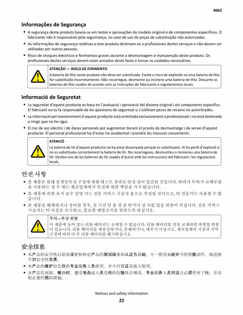
Informações de Segurança• A segurança deste produto baseia-se em testes e aprovações do modelo original e de componentes específicos. O
fabricante não é responsável pela segunrança, no caso de uso de peças de substituição não autorizadas.
• As informações de segurança relativas a este produto destinam-se a profissionais destes serviços e não devem serutilizadas por outras pessoas.
• Risco de choques eléctricos e ferimentos graves durante a desmontagem e manutenção deste produto. Osprofissionais destes serviços devem estar avisados deste facto e tomar os cuidados necessários.
ATENÇÃO — RISCO DE FERIMENTO
A bateria de lítio neste produto não deve ser substituída. Existe o risco de explosão se uma bateria de lítiofor substituída incorretamente. Não recarregue, desmonte ou incinere uma bateria de lítio. Descarte asbaterias de lítio usadas de acordo com as instruções do fabricante e regulamentos locais.
Informació de Seguretat• La seguretat d'aquest producte es basa en l'avaluació i aprovació del disseny original i els components específics.
El fabricant no es fa responsable de les qüestions de seguretat si s'utilitzen peces de recanvi no autoritzades.
• La informació pel manteniment d’aquest producte està orientada exclusivament a professionals i no està destinadaa ningú que no ho sigui.
• El risc de xoc elèctric i de danys personals pot augmentar durant el procés de desmuntatge i de servei d’aquestproducte. El personal professional ha d’estar-ne assabentat i prendre les mesures convenients.
ATENCIÓ
La bateria de liti d'aquest producte no ha estat dissenyada perquè es substitueixi. Hi ha perill d’explosió sino es substitueix correctament la bateria de liti. No recarregueu, desmunteu o incinereu una bateria deliti. Desfeu-vos de les bateries de liti usades d’acord amb les instruccions del fabricant i les regulacionslocals.
안전 사항• 본 제품은 원래 설계및특정 구성에 대한 테스트 결과로 안정 성이 입증된 것입니다. 따라서 무허가 교체부품을 사용하는 경 우 에는 제조업체에서 안전에 대한 책임을 지지 않습니다.
• 본 제품에 관한 유지 보수 설명 서는 전문 서비스 기술자 용으로 작성된 것이므로, 비 전문가는 사용할 수 없습니다.
• 본 제품을 해체하거나 정비할 경우, 전 기전 인 충 경 을 받거나 상 처를 입을 위험이 커집니다. 전문 서비스기술자는 이 사실을 숙지하고, 필요한 예방조치를 취하도록 하십시오.
주의—부상 위험
이 제품에 들어 있는 리튬 배터리는 교체할 수 없습니다. 리튬 배터리를 잘못 교체하면 폭발할 위험이 있습니다. 리튬 배터리를 재충전하거나, 분해하거나, 태우지 마십시오. 제조업체의 지침과 지역규정에 따라 다 쓴 리튬 배터리를 폐기하십시오.
安全信息• 本产品的安全性以原来设计和特定产品的测试结果和认证为基础。万一使用来经许可的替换部件,制造商不对安全性负责。
• 本产品的维护信息仅供专业服务人员使用,并不打算证其他人使用。
• 本产品在拆卸、维修时,遭受电击或人员受伤的危险性会增高,专业服务人员对这点必须有所了触,并采取必要的预防措施。
4063
Notices and safety information
22

当心一可能的伤害:
本产品中的锂电池不可更换。如果不正确更换锂电池,可能会有爆炸危险。不要再 充电、拆解或焚烧锂电池。丢弃旧的锂电池时应按照制造商的指导及当地法规进行处理。
4063
Notices and safety information
23

4063
24
PrefaceThis manual contains maintenance procedures for service personnel.
It is divided into the following chapters:
• General information contains a general description of the printer and the maintenance approach used to repair it.Special tools and test equipment, as well as general environmental and safety instructions, are discussed.
• Diagnostic information contains diagnostic aids you can use to isolate failing field replaceable units. Thesediagnostic aids include error code tables, symptom tables, and service checks.
• Diagnostic aids contains descriptions of the printer interface, the user and service menus, and the basic theory ofprinter operation.
• Repair information provides instructions for making printer adjustments and removing and installing FRUs.
• Connector locations uses illustrations to identify the connector locations.
• Preventive maintenance contains the lubrication specifications and recommendations to prevent problems.
• Parts catalog contains illustrations and part numbers for individual FRUs.
• Appendix A—Contains service tips and detailed information about the product, including the basic theory of printeroperation.
• Appendix B—Contains representative print samples.
Service manual conventionsNote: A note provides additional information.
Warning—Potential Damage: A warning identifies something that might damage the product hardware or software.
This service manual uses several different types of caution statements:
CAUTION—POTENTIAL INJURY: A caution identifies something that might cause the service technician harm.
CAUTION—SHOCK HAZARD: This type of caution indicates a danger from hazardous voltage in the area of theproduct where you are working. Unplug the product before you start working, or use caution if the productmust receive power to perform the task.
CAUTION—HOT SURFACE: This type of caution indicates a hot surface.
CAUTION—TIPPING HAZARD: This type of caution indicates a tipping hazard.
4063
Preface
25

4063
26

General information• “Printer configurations” on page 28
• “Paper guidelines” on page 30
• “Data security notice” on page 33
• “Tools required for service” on page 34
4063
General information
27
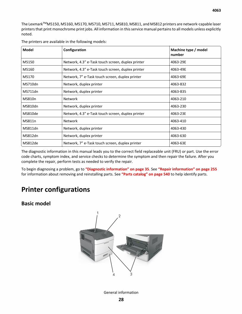
The LexmarkTMM5150, M5160, M5170, MS710, MS711, MS810, MS811, and MS812 printers are network‑capable laserprinters that print monochrome print jobs. All information in this service manual pertains to all models unless explicitlynoted.
The printers are available in the following models:
Model Configuration Machine type / modelnumber
M5150 Network, 4.3” e‑Task touch screen, duplex printer 4063‑29E
M5160 Network, 4.3” e‑Task touch screen, duplex printer 4063‑49E
M5170 Network, 7” e‑Task touch screen, duplex printer 4063‑69E
MS710dn Network, duplex printer 4063‑832
MS711dn Network, duplex printer 4063‑835
MS810n Network 4063-210
MS810dn Network, duplex printer 4063-230
MS810de Network, 4.3” e‑Task touch screen, duplex printer 4063-23E
MS811n Network 4063-410
MS811dn Network, duplex printer 4063-430
MS812dn Network, duplex printer 4063-630
MS812de Network, 7” e‑Task touch screen, duplex printer 4063-63E
The diagnostic information in this manual leads you to the correct field replaceable unit (FRU) or part. Use the errorcode charts, symptom index, and service checks to determine the symptom and then repair the failure. After youcomplete the repair, perform tests as needed to verify the repair.
To begin diagnosing a problem, go to “Diagnostic information” on page 35. See “Repair information” on page 255for information about removing and reinstalling parts. See “Parts catalog” on page 540 to help identify parts.
Printer configurations
Basic model
4063
General information
28
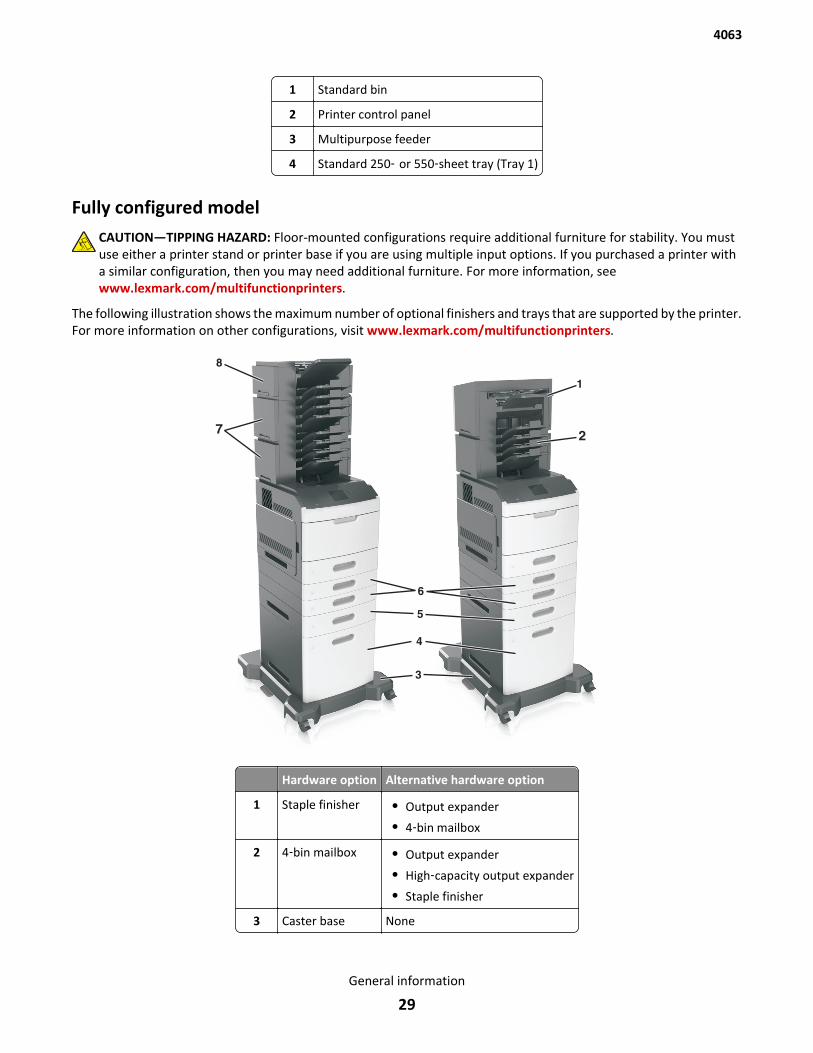
1 Standard bin
2 Printer control panel
3 Multipurpose feeder
4 Standard 250‑ or 550‑sheet tray (Tray 1)
Fully configured modelCAUTION—TIPPING HAZARD: Floor-mounted configurations require additional furniture for stability. You mustuse either a printer stand or printer base if you are using multiple input options. If you purchased a printer witha similar configuration, then you may need additional furniture. For more information, seewww.lexmark.com/multifunctionprinters.
The following illustration shows the maximum number of optional finishers and trays that are supported by the printer.For more information on other configurations, visit www.lexmark.com/multifunctionprinters.
Hardware option Alternative hardware option
1 Staple finisher • Output expander
• 4‑bin mailbox
2 4‑bin mailbox • Output expander
• High‑capacity output expander
• Staple finisher
3 Caster base None
4063
General information
29
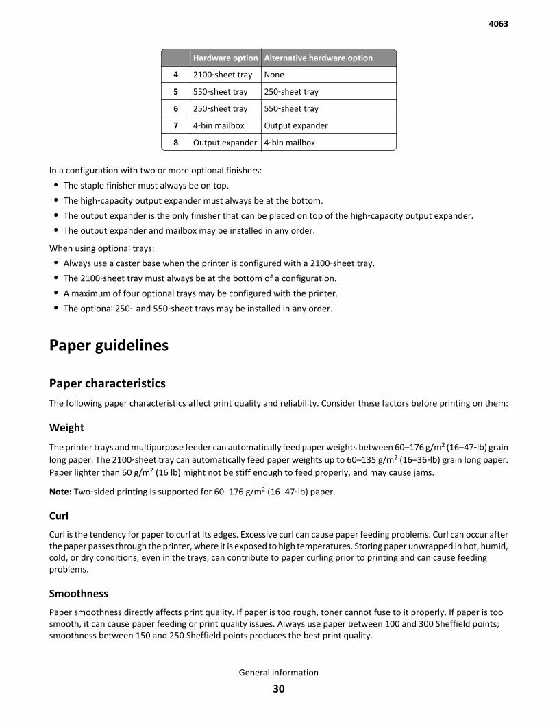
Hardware option Alternative hardware option
4 2100‑sheet tray None
5 550‑sheet tray 250‑sheet tray
6 250‑sheet tray 550‑sheet tray
7 4‑bin mailbox Output expander
8 Output expander 4‑bin mailbox
In a configuration with two or more optional finishers:
• The staple finisher must always be on top.
• The high‑capacity output expander must always be at the bottom.
• The output expander is the only finisher that can be placed on top of the high‑capacity output expander.
• The output expander and mailbox may be installed in any order.
When using optional trays:
• Always use a caster base when the printer is configured with a 2100‑sheet tray.
• The 2100‑sheet tray must always be at the bottom of a configuration.
• A maximum of four optional trays may be configured with the printer.
• The optional 250‑ and 550‑sheet trays may be installed in any order.
Paper guidelines
Paper characteristicsThe following paper characteristics affect print quality and reliability. Consider these factors before printing on them:
Weight
The printer trays and multipurpose feeder can automatically feed paper weights between 60–176 g/m2 (16–47‑lb) grainlong paper. The 2100‑sheet tray can automatically feed paper weights up to 60–135 g/m2 (16–36‑lb) grain long paper.Paper lighter than 60 g/m2 (16 lb) might not be stiff enough to feed properly, and may cause jams.
Note: Two‑sided printing is supported for 60–176 g/m2 (16–47‑lb) paper.
Curl
Curl is the tendency for paper to curl at its edges. Excessive curl can cause paper feeding problems. Curl can occur afterthe paper passes through the printer, where it is exposed to high temperatures. Storing paper unwrapped in hot, humid,cold, or dry conditions, even in the trays, can contribute to paper curling prior to printing and can cause feedingproblems.
Smoothness
Paper smoothness directly affects print quality. If paper is too rough, toner cannot fuse to it properly. If paper is toosmooth, it can cause paper feeding or print quality issues. Always use paper between 100 and 300 Sheffield points;smoothness between 150 and 250 Sheffield points produces the best print quality.
4063
General information
30
Moisture content
The amount of moisture in paper affects both print quality and the ability of the printer to feed the paper correctly.Leave paper in its original wrapper until it is time to use it. This limits the exposure of paper to moisture changes thatcan degrade its performance.
Store paper in its original wrapper in the same environment as the printer for 24 to 48 hours before printing. Extendthe time several days if the storage or transportation environment is very different from the printer environment. Thickpaper may also require a longer conditioning period.
Grain direction
Grain refers to the alignment of the paper fibers in a sheet of paper. Grain is either grain long, running the length ofthe paper, or grain short, running the width of the paper.
For 60–176 g/m2 (16–47‑lb) paper, grain long paper is recommended.
Fiber content
Most high‑quality xerographic paper is made from 100% chemically treated pulped wood. This content provides thepaper with a high degree of stability, resulting in fewer paper feeding problems and better print quality. Paper containingfibers such as cotton can negatively affect paper handling.
Selecting paperUsing the appropriate paper prevents jams and helps ensure trouble‑free printing.
To help avoid paper jams and poor print quality:
• Always use new, undamaged paper.
• Before loading paper, know the recommended printable side of the paper. This information is usually indicated onthe paper package.
• Do not use paper that has been cut or trimmed by hand.
• Do not mix paper sizes, types, or weights in the same tray; mixing results in jams.
• Do not use coated papers unless they are specifically designed for electrophotographic printing.
Selecting preprinted forms and letterhead• Use grain long for 60–90‑g/m2 (16–24‑lb) paper.
• Use only forms and letterhead printed using an offset lithographic or engraved printing process.
• Avoid paper with rough or heavily textured surfaces.
• Use inks that are not affected by the resin in toner. Inks that are oxidation‑set or oil‑based generally meet theserequirements; latex inks might not.
• Print samples on preprinted forms and letterheads considered for use before buying large quantities. Thisdetermines whether or not the ink in the preprinted form or letterhead will affect print quality.
• When in doubt, contact your paper supplier.
Using recycled paper and other office papersAs an environmentally conscientious company, Lexmark supports the use of recycled paper produced specifically foruse in laser (electrophotographic) printers.
4063
General information
31

While no blanket statement can be made that all recycled paper will feed well, Lexmark consistently tests papers thatrepresent recycled cut size copier papers available on the global market. This scientific testing is conducted with rigorand discipline. Many factors are taken into consideration both separately and as a whole, including the following:
• Amount of post-consumer waste (Lexmark tests up to 100% post-consumer waste content.)
• Temperature and humidity conditions (Testing chambers simulate climates from all over the world.)
• Moisture content (Business papers should have low moisture: 4–5%.)
• Bending resistance and proper stiffness means optimum feeding through the printer.
• Thickness (impacts how much can be loaded into a tray)
• Surface roughness (measured in Sheffield units, impacts print clarity and how well toner fuses to the paper)
• Surface friction (determines how easily sheets can be separated)
• Grain and formation (impacts curling, which also influences the mechanics of how the paper behaves as it movesthrough the printer)
• Brightness and texture (look and feel)
Recycled papers are better than ever; however, the amount of recycled content in a paper affects the degree of controlover foreign matter. And while recycled papers are one good path to printing in an environmentally responsible manner,they are not perfect. The energy required to de-ink and deal with additives such as colorants and “glue” often generatesmore carbon emissions than does normal paper production. However, using recycled papers enables better resourcemanagement overall.
Lexmark concerns itself with the responsible use of paper in general based on life cycle assessments of its products. Togain a better understanding of the impact of printers on the environment, the company commissioned a number oflife cycle assessments and found that paper was identified as the primary contributor (up to 80%) of carbon emissionscaused throughout the entire life of a device (from design to end-of-life). This is due to the energy-intensivemanufacturing processes required to make paper.
Thus, Lexmark seeks to educate customers and partners on minimizing the impact of paper. Using recycled paper isone way. Eliminating excessive and unnecessary paper consumption is another. Lexmark is well-equipped to helpcustomers minimize printing and copying waste. In addition, the company encourages purchasing paper from supplierswho demonstrate their commitment to sustainable forestry practices.
Lexmark does not endorse specific suppliers, although a converter’s product list for special applications is maintained.However, the following paper choice guidelines will help alleviate the environmental impact of printing:
1 Minimize paper consumption.
2 Be selective about the origin of wood fiber. Buy from suppliers who carry certifications such as the ForestryStewardship Council (FSC) or The Program for the Endorsement of Forest Certification (PEFC). These certificationsguarantee that the paper manufacturer uses wood pulp from forestry operators that employ environmentally andsocially responsible forest management and restoration practices.
3 Choose the most appropriate paper for printing needs: normal 75 or 80 g/m2 certified paper, lower weight paper,or recycled paper.
Unacceptable paper examples
Test results indicate that the following paper types are at risk for use with laser printers:
• Chemically treated papers used to make copies without carbon paper, also known as carbonless papers
• Preprinted papers with chemicals that may contaminate the printer
• Preprinted papers that can be affected by the temperature in the printer fuser
4063
General information
32

• Preprinted papers that require a registration (the precise location on the page) greater than ± 2.3 mm (± 0.9 in.),such as optical character recognition (OCR) forms. In some cases, registration can be adjusted with a softwareapplication to successfully print on these forms.)
• Coated papers (erasable bond), synthetic papers, thermal papers
• Rough-edged, rough or heavily textured surface papers or curled papers
• Recycled papers that fail EN12281:2002 (European testing)
• Paper weighing less than 60 g/m2 (16 lb)
• Multiple part forms or documents
For more information about Lexmark, visit www.lexmark.com. General sustainability-related information can be foundat the Environmental Sustainability link.
Storing paperUse these paper storage guidelines to help avoid jams and uneven print quality:
• For best results, store paper where the temperature is 21°C (70°F) and the relative humidity is 40 percent. Mostlabel manufacturers recommend printing in a temperature range of 18–24°C (65–75°F) with relative humiditybetween 40 and 60 percent.
• Store paper in cartons, on a pallet or shelf, rather than on the floor.
• Store individual packages on a flat surface.
• Do not store anything on top of individual paper packages.
• Take paper out of the carton or wrapper only when you are ready to load it in the printer. The carton and wrapperhelp keep the paper clean, dry, and flat.
Data security noticeThis printer contains various types of memory that are capable of storing device and network settings, informationfrom embedded solutions, and user data:
• Volatile memory—This device utilizes standard Random Access Memory (RAM) to temporarily buffer user dataduring simple print and copy jobs.
• Non-volatile memory—This device may utilize two forms of non-volatile memory: EEPROM and NAND (flashmemory). Both types are used to store the operating system, device settings, network information, scanner andbookmark settings, and embedded solutions.
• Hard disk memory—Some devices have a hard disk drive installed. The printer hard disk is designed for device-specific functionality and cannot be used for long term storage for data that is not print-related. The hard disk doesnot provide the capability for users to extract information, create folders, create disk or network file shares, or FTPinformation directly from a client device. The hard disk can retain buffered user data from complex scan, print,copy, and fax jobs, as well as form data, and font data.
To erase volatile memory, turn off the printer.
To erase non-volatile memory, see “Erase All Information on Disk” on page 248.
To erase the printer hard disk, see “Wipe All Settings” on page 249.
The printer control panel and RIP/controller board contain NVRAM. The old part must be returned to your next levelsupport.
4063
General information
33
Tools required for serviceFlat-blade screwdrivers, various sizes#1 Phillips screwdriver, magnetic#2 Phillips screwdriver, magnetic#2 Phillips screwdriver, magnetic short-blade7/32 inch (5.5 mm) open-end wrench7.0 mm nut driverNeedlenose pliersDiagonal side cuttersSpring hookFeeler gaugesAnalog or digital multimeterParallel wrap plug 1319128Twinax/serial debug cable 1381963Coax/serial debug cable 1381964Flash light (optional)3 mm hex wrench5.5 mm hex wrench
4063
General information
34
Diagnostic information• “Troubleshooting overview” on page 35
• “Power‑on Reset (POR) sequence” on page 36
• “Using Safe Mode” on page 37
• “Fixing print quality issues” on page 37
• “Paper jams” on page 47
• “User attendance messages (0-99.99)” on page 94
• “Printer hardware errors (100-199.99)” on page 101
• “Firmware and/or system electronics errors (900-999.99)” on page 113
• “Input/output option hardware errors” on page 123
• “Input/output option paper jam errors” on page 143
• “Symptoms” on page 194
CAUTION—SHOCK HAZARD: If you are accessing the controller board or installing optional hardware ormemory devices sometime after setting up the printer, then turn the printer off, and unplug the power cordfrom the electrical outlet before continuing. If you have any other devices attached to the printer, then turnthem off as well, and unplug any cables going into the printer.
CAUTION—POTENTIAL INJURY: The printer weight is greater than 18 kg (40 lb) and requires two or moretrained personnel to lift it safely.
CAUTION—HOT SURFACE: The inside of the printer might be hot. To reduce the risk of injury from a hotcomponent, allow the surface to cool before touching.
Troubleshooting overview• “Performing the initial troubleshooting check” on page 35
• “Error code number key” on page 36
Performing the initial troubleshooting checkBefore you start the troubleshooting procedures, perform the following checks:
• With the power cord unplugged from the wall outlet, check that the cord is free from breakage, short-circuits,disconnected wires, or incorrect connections.
• Make sure the printer is properly grounded. Check the power cord ground terminal.
• Make sure the power supply line voltage is within 10% of the rated line voltage.
• Make sure the machine is securely installed on a level surface in a well-ventilated area.
• Make sure the room temperature is between 16 and 32°C (60 and 90°F) and that the relative humidity is between20 and 80%.
• Avoid sites generating ammonia gas, high temperature, high humidity (near water faucets, kettles, humidifiers),cold spaces, near open flames, and dusty areas.
• Avoid sites exposed to direct sunlight.
4063
Diagnostic information
35
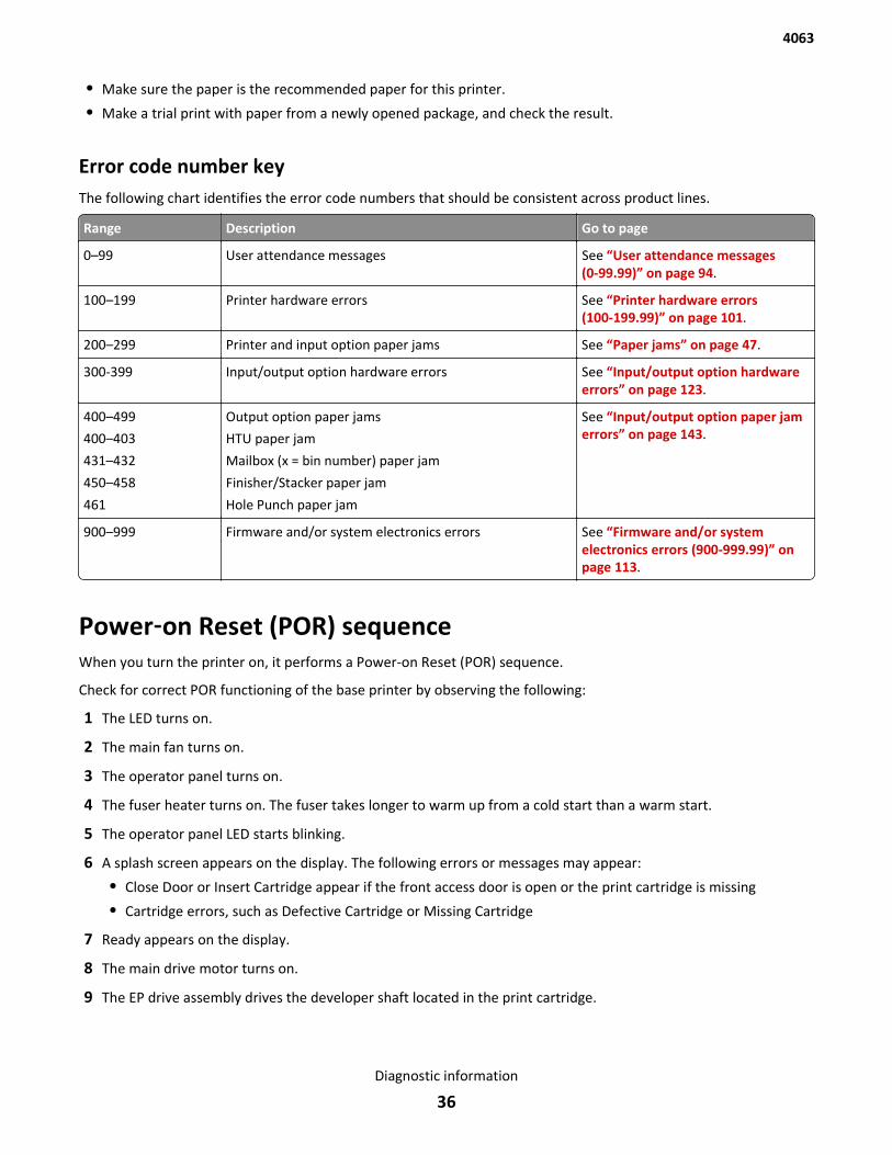
• Make sure the paper is the recommended paper for this printer.
• Make a trial print with paper from a newly opened package, and check the result.
Error code number keyThe following chart identifies the error code numbers that should be consistent across product lines.
Range Description Go to page
0–99 User attendance messages See “User attendance messages(0-99.99)” on page 94.
100–199 Printer hardware errors See “Printer hardware errors(100-199.99)” on page 101.
200–299 Printer and input option paper jams See “Paper jams” on page 47.
300-399 Input/output option hardware errors See “Input/output option hardwareerrors” on page 123.
400–499
400–403
431–432
450–458
461
Output option paper jams
HTU paper jam
Mailbox (x = bin number) paper jam
Finisher/Stacker paper jam
Hole Punch paper jam
See “Input/output option paper jamerrors” on page 143.
900–999 Firmware and/or system electronics errors See “Firmware and/or systemelectronics errors (900-999.99)” onpage 113.
Power‑on Reset (POR) sequenceWhen you turn the printer on, it performs a Power-on Reset (POR) sequence.
Check for correct POR functioning of the base printer by observing the following:
1 The LED turns on.
2 The main fan turns on.
3 The operator panel turns on.
4 The fuser heater turns on. The fuser takes longer to warm up from a cold start than a warm start.
5 The operator panel LED starts blinking.
6 A splash screen appears on the display. The following errors or messages may appear:
• Close Door or Insert Cartridge appear if the front access door is open or the print cartridge is missing
• Cartridge errors, such as Defective Cartridge or Missing Cartridge
7 Ready appears on the display.
8 The main drive motor turns on.
9 The EP drive assembly drives the developer shaft located in the print cartridge.
4063
Diagnostic information
36
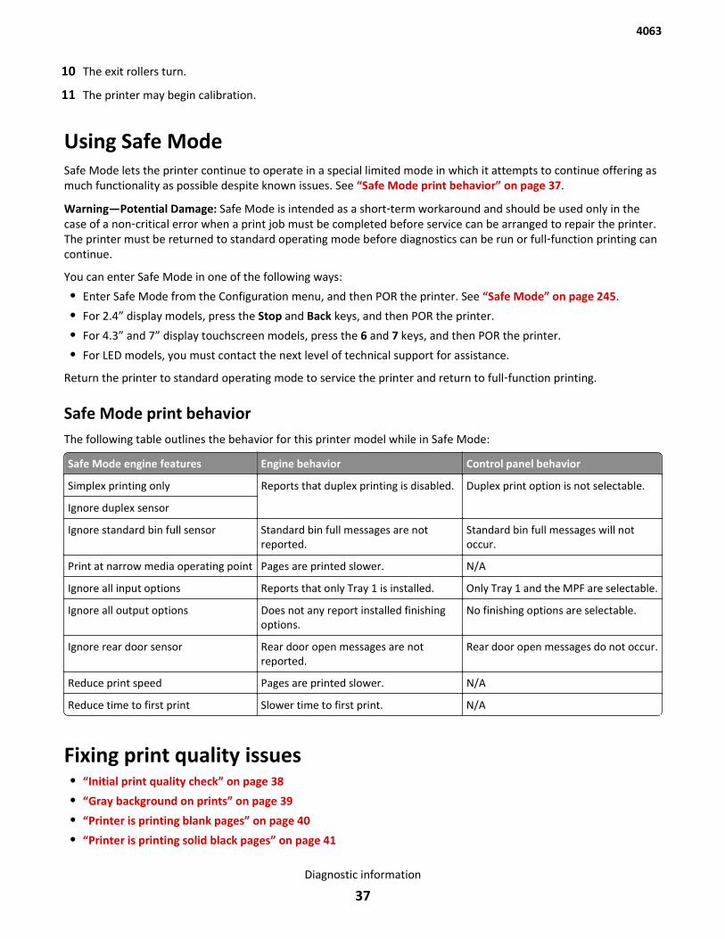
10 The exit rollers turn.
11 The printer may begin calibration.
Using Safe ModeSafe Mode lets the printer continue to operate in a special limited mode in which it attempts to continue offering asmuch functionality as possible despite known issues. See “Safe Mode print behavior” on page 37.
Warning—Potential Damage: Safe Mode is intended as a short‑term workaround and should be used only in thecase of a non‑critical error when a print job must be completed before service can be arranged to repair the printer.The printer must be returned to standard operating mode before diagnostics can be run or full‑function printing cancontinue.
You can enter Safe Mode in one of the following ways:
• Enter Safe Mode from the Configuration menu, and then POR the printer. See “Safe Mode” on page 245.
• For 2.4” display models, press the Stop and Back keys, and then POR the printer.
• For 4.3” and 7” display touchscreen models, press the 6 and 7 keys, and then POR the printer.
• For LED models, you must contact the next level of technical support for assistance.
Return the printer to standard operating mode to service the printer and return to full‑function printing.
Safe Mode print behaviorThe following table outlines the behavior for this printer model while in Safe Mode:
Safe Mode engine features Engine behavior Control panel behavior
Simplex printing only Reports that duplex printing is disabled. Duplex print option is not selectable.
Ignore duplex sensor
Ignore standard bin full sensor Standard bin full messages are notreported.
Standard bin full messages will notoccur.
Print at narrow media operating point Pages are printed slower. N/A
Ignore all input options Reports that only Tray 1 is installed. Only Tray 1 and the MPF are selectable.
Ignore all output options Does not any report installed finishingoptions.
No finishing options are selectable.
Ignore rear door sensor Rear door open messages are notreported.
Rear door open messages do not occur.
Reduce print speed Pages are printed slower. N/A
Reduce time to first print Slower time to first print. N/A
Fixing print quality issues• “Initial print quality check” on page 38
• “Gray background on prints” on page 39
• “Printer is printing blank pages” on page 40
• “Printer is printing solid black pages” on page 41
4063
Diagnostic information
37

• “Repeating defects” on page 41
• “Shadow images appear on prints” on page 42
• “Skewed print” on page 43
• “Streaked horizontal lines appear on prints” on page 44
• “Streaked vertical lines appear on prints” on page 46
• “Toner rubs off” on page 47
The symptoms described in this chapter might require replacement of one or more CRUs (Customer Replaceable Units)designated as supplies or maintenance items, which are the responsibility of the customer. With the customer'spermission, you might need to install a developer (toner) cartridge.
Initial print quality checkBefore troubleshooting specific print problems, complete the following initial print quality check:
1 Print a menu settings page, and then check the life status of all supplies. Any supplies that are low should be replaced.Be sure to keep the original menu page to restore the customer's custom settings if needed.
2 On the menu page, make sure the following settings are at the default level:
• Print Resolution: Set to 600 dpi (print quality problems should be checked at different resolution settings).
• Toner Darkness: Set to 8 (default).
• Check the paper type, texture and weight settings against the paper that is loaded in the printer.
3 Inspect the transfer roller for damage. Replace, if damaged.
4 Inspect the print cartridge and imaging unit for damage. Replace, if damaged.
5 If paper other than 20 lb plain letter/A4 paper is being used, load 20 lb plain letter/A4 and print the Print Qualitypages to see if the problem remains. Use Tray 1 to test print quality problems.
6 Print the Print Quality Pages, and then look for variations in the print from what is expected.
7 Check to ensure the correct printer driver for the installed software is being used. An incorrect printer driver forthe installed software can cause problems. Incorrect characters could print, and the copy may not fit the pagecorrectly.
8 Measure all voltages from the connector to the printer ground.
4063
Diagnostic information
38
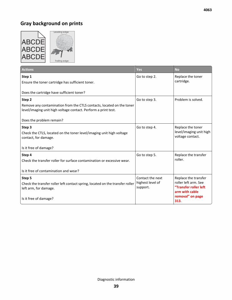
Gray background on prints
ABCDE
ABCDEABCDE
Leading edge
Trailing edge
Actions Yes No
Step 1
Ensure the toner cartridge has sufficient toner.
Does the cartridge have sufficient toner?
Go to step 2. Replace the tonercartridge.
Step 2
Remove any contamination from the CTLS contacts, located on the tonerlevel/imaging unit high voltage contact. Perform a print test.
Does the problem remain?
Go to step 3. Problem is solved.
Step 3
Check the CTLS, located on the toner level/imaging unit high voltagecontact, for damage.
Is it free of damage?
Go to step 4. Replace the tonerlevel/imaging unit highvoltage contact.
Step 4
Check the transfer roller for surface contamination or excessive wear.
Is it free of contamination and wear?
Go to step 5. Replace the transferroller.
Step 5
Check the transfer roller left contact spring, located on the transfer rollerleft arm, for damage.
Is it free of damage?
Contact the nexthighest level ofsupport.
Replace the transferroller left arm. See“Transfer roller leftarm with cableremoval” on page 313.
4063
Diagnostic information
39
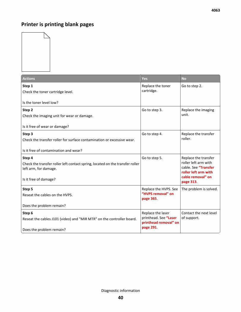
Printer is printing blank pages
Actions Yes No
Step 1
Check the toner cartridge level.
Is the toner level low?
Replace the tonercartridge.
Go to step 2.
Step 2
Check the imaging unit for wear or damage.
Is it free of wear or damage?
Go to step 3. Replace the imagingunit.
Step 3
Check the transfer roller for surface contamination or excessive wear.
Is it free of contamination and wear?
Go to step 4. Replace the transferroller.
Step 4
Check the transfer roller left contact spring, located on the transfer rollerleft arm, for damage.
Is it free of damage?
Go to step 5. Replace the transferroller left arm withcable. See “Transferroller left arm withcable removal” onpage 313.
Step 5
Reseat the cables on the HVPS.
Does the problem remain?
Replace the HVPS. See“HVPS removal” onpage 365.
The problem is solved.
Step 6
Reseat the cables J101 (video) and "MIR MTR" on the controller board.
Does the problem remain?
Replace the laserprinthead. See “Laserprinthead removal” onpage 291.
Contact the next levelof support.
4063
Diagnostic information
40
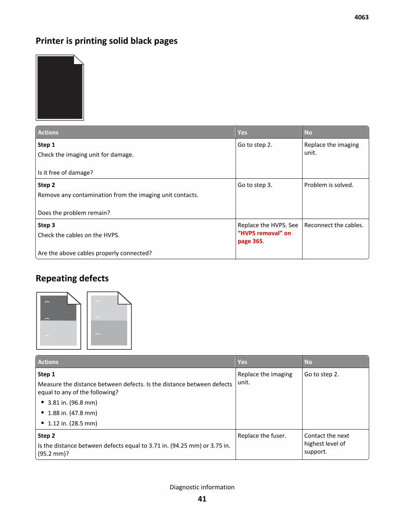
Printer is printing solid black pages
Actions Yes No
Step 1
Check the imaging unit for damage.
Is it free of damage?
Go to step 2. Replace the imagingunit.
Step 2
Remove any contamination from the imaging unit contacts.
Does the problem remain?
Go to step 3. Problem is solved.
Step 3
Check the cables on the HVPS.
Are the above cables properly connected?
Replace the HVPS. See“HVPS removal” onpage 365.
Reconnect the cables.
Repeating defects
Actions Yes No
Step 1
Measure the distance between defects. Is the distance between defectsequal to any of the following?
• 3.81 in. (96.8 mm)
• 1.88 in. (47.8 mm)
• 1.12 in. (28.5 mm)
Replace the imagingunit.
Go to step 2.
Step 2
Is the distance between defects equal to 3.71 in. (94.25 mm) or 3.75 in.(95.2 mm)?
Replace the fuser. Contact the nexthighest level ofsupport.
4063
Diagnostic information
41
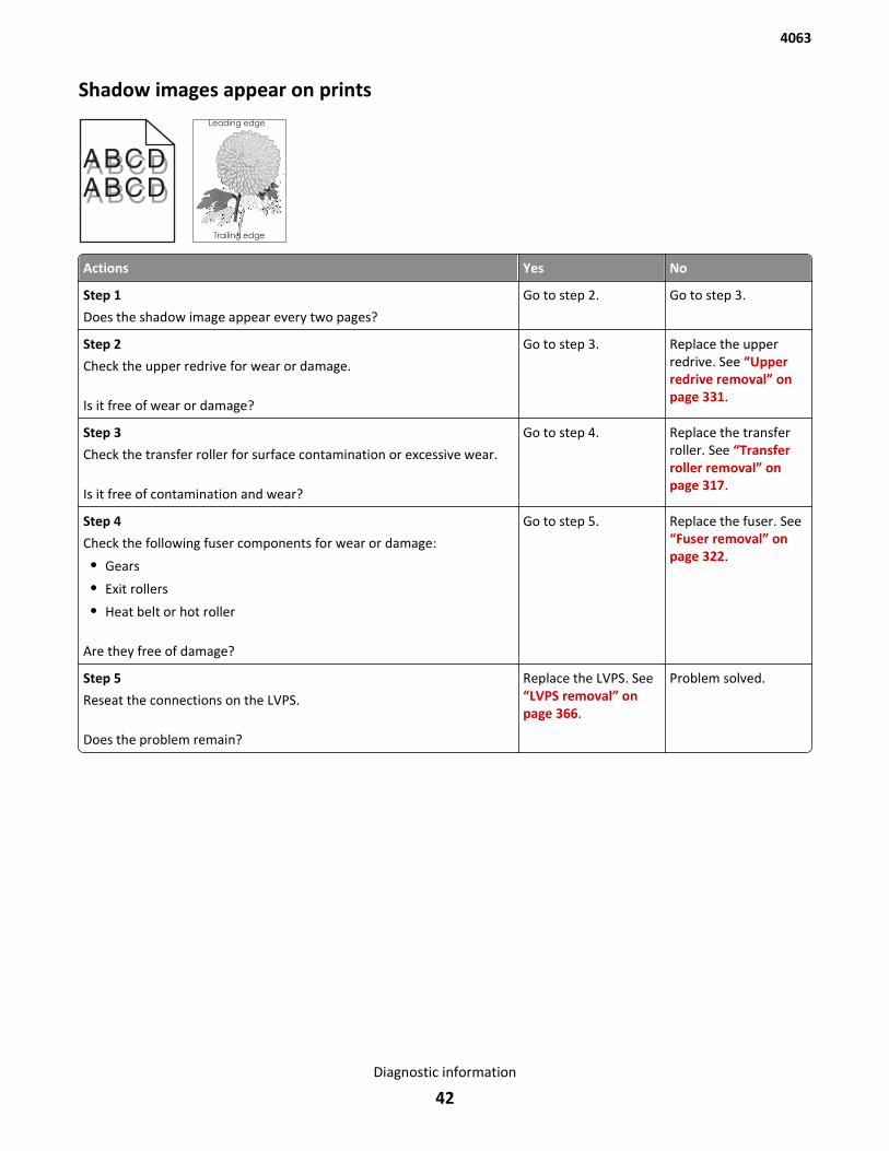
Shadow images appear on prints
ABCDABCDABCDABCD
Leading edge
Trailing edge
Actions Yes No
Step 1
Does the shadow image appear every two pages?
Go to step 2. Go to step 3.
Step 2
Check the upper redrive for wear or damage.
Is it free of wear or damage?
Go to step 3. Replace the upperredrive. See “Upperredrive removal” onpage 331.
Step 3
Check the transfer roller for surface contamination or excessive wear.
Is it free of contamination and wear?
Go to step 4. Replace the transferroller. See “Transferroller removal” onpage 317.
Step 4
Check the following fuser components for wear or damage:
• Gears
• Exit rollers
• Heat belt or hot roller
Are they free of damage?
Go to step 5. Replace the fuser. See“Fuser removal” onpage 322.
Step 5
Reseat the connections on the LVPS.
Does the problem remain?
Replace the LVPS. See“LVPS removal” onpage 366.
Problem solved.
4063
Diagnostic information
42
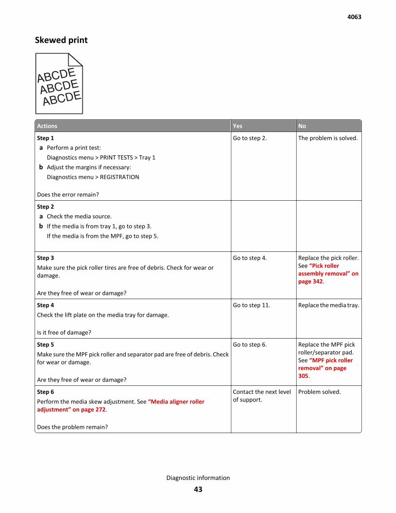
Skewed print
))ABCDE
ABCDEABCDE
Actions Yes No
Step 1
a Perform a print test:
Diagnostics menu > PRINT TESTS > Tray 1
b Adjust the margins if necessary:
Diagnostics menu > REGISTRATION
Does the error remain?
Go to step 2. The problem is solved.
Step 2
a Check the media source.
b If the media is from tray 1, go to step 3.
If the media is from the MPF, go to step 5.
Step 3
Make sure the pick roller tires are free of debris. Check for wear ordamage.
Are they free of wear or damage?
Go to step 4. Replace the pick roller.See “Pick rollerassembly removal” onpage 342.
Step 4
Check the lift plate on the media tray for damage.
Is it free of damage?
Go to step 11. Replace the media tray.
Step 5
Make sure the MPF pick roller and separator pad are free of debris. Checkfor wear or damage.
Are they free of wear or damage?
Go to step 6. Replace the MPF pickroller/separator pad.See “MPF pick rollerremoval” on page 305.
Step 6
Perform the media skew adjustment. See “Media aligner rolleradjustment” on page 272.
Does the problem remain?
Contact the next levelof support.
Problem solved.
4063
Diagnostic information
43
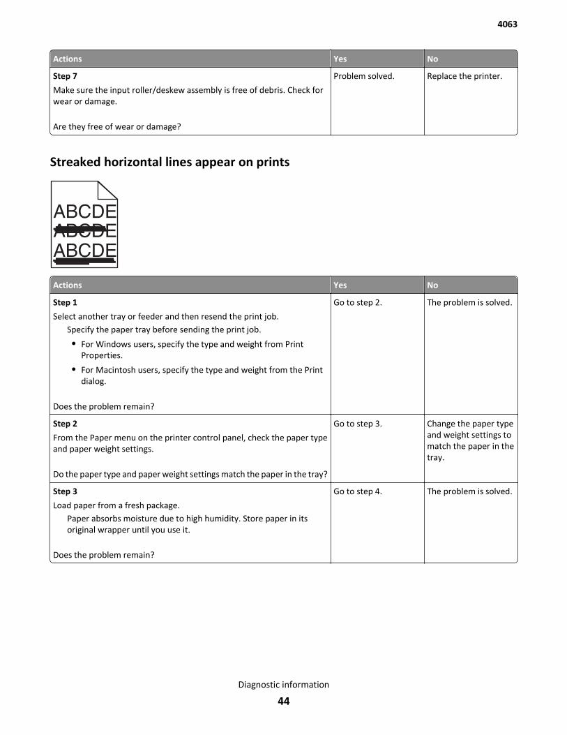
Actions Yes No
Step 7
Make sure the input roller/deskew assembly is free of debris. Check forwear or damage.
Are they free of wear or damage?
Problem solved. Replace the printer.
Streaked horizontal lines appear on prints
ABCDEABCDEABCDE
Actions Yes No
Step 1
Select another tray or feeder and then resend the print job.Specify the paper tray before sending the print job.
• For Windows users, specify the type and weight from PrintProperties.
• For Macintosh users, specify the type and weight from the Printdialog.
Does the problem remain?
Go to step 2. The problem is solved.
Step 2
From the Paper menu on the printer control panel, check the paper typeand paper weight settings.
Do the paper type and paper weight settings match the paper in the tray?
Go to step 3. Change the paper typeand weight settings tomatch the paper in thetray.
Step 3
Load paper from a fresh package.Paper absorbs moisture due to high humidity. Store paper in itsoriginal wrapper until you use it.
Does the problem remain?
Go to step 4. The problem is solved.
4063
Diagnostic information
44
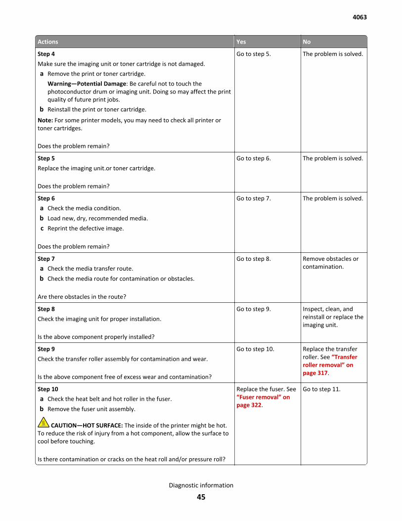
Actions Yes No
Step 4
Make sure the imaging unit or toner cartridge is not damaged.
a Remove the print or toner cartridge.
Warning—Potential Damage: Be careful not to touch thephotoconductor drum or imaging unit. Doing so may affect the printquality of future print jobs.
b Reinstall the print or toner cartridge.
Note: For some printer models, you may need to check all printer ortoner cartridges.
Does the problem remain?
Go to step 5. The problem is solved.
Step 5
Replace the imaging unit.or toner cartridge.
Does the problem remain?
Go to step 6. The problem is solved.
Step 6
a Check the media condition.
b Load new, dry, recommended media.
c Reprint the defective image.
Does the problem remain?
Go to step 7. The problem is solved.
Step 7
a Check the media transfer route.
b Check the media route for contamination or obstacles.
Are there obstacles in the route?
Go to step 8. Remove obstacles orcontamination.
Step 8
Check the imaging unit for proper installation.
Is the above component properly installed?
Go to step 9. Inspect, clean, andreinstall or replace theimaging unit.
Step 9
Check the transfer roller assembly for contamination and wear.
Is the above component free of excess wear and contamination?
Go to step 10. Replace the transferroller. See “Transferroller removal” onpage 317.
Step 10
a Check the heat belt and hot roller in the fuser.
b Remove the fuser unit assembly.
CAUTION—HOT SURFACE: The inside of the printer might be hot.To reduce the risk of injury from a hot component, allow the surface tocool before touching.
Is there contamination or cracks on the heat roll and/or pressure roll?
Replace the fuser. See“Fuser removal” onpage 322.
Go to step 11.
4063
Diagnostic information
45
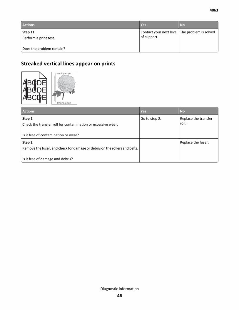
Actions Yes No
Step 11
Perform a print test.
Does the problem remain?
Contact your next levelof support.
The problem is solved.
Streaked vertical lines appear on prints
ABCDEABCDEABCDE
Leading edge
Trailing edge
Actions Yes No
Step 1
Check the transfer roll for contamination or excessive wear.
Is it free of contamination or wear?
Go to step 2. Replace the transferroll.
Step 2
Remove the fuser, and check for damage or debris on the rollers and belts.
Is it free of damage and debris?
Replace the fuser.
4063
Diagnostic information
46
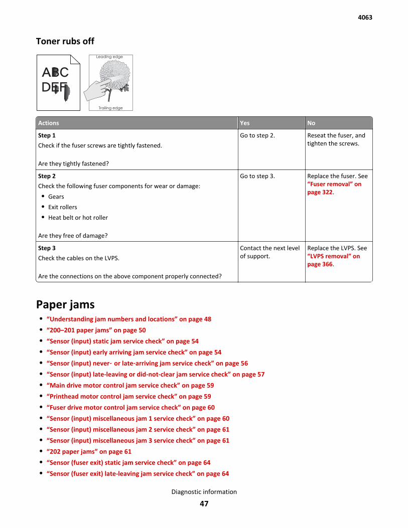
Toner rubs offLeading edge
Trailing edge
ABC
DEF
Actions Yes No
Step 1
Check if the fuser screws are tightly fastened.
Are they tightly fastened?
Go to step 2. Reseat the fuser, andtighten the screws.
Step 2
Check the following fuser components for wear or damage:
• Gears
• Exit rollers
• Heat belt or hot roller
Are they free of damage?
Go to step 3. Replace the fuser. See“Fuser removal” onpage 322.
Step 3
Check the cables on the LVPS.
Are the connections on the above component properly connected?
Contact the next levelof support.
Replace the LVPS. See“LVPS removal” onpage 366.
Paper jams• “Understanding jam numbers and locations” on page 48
• “200–201 paper jams” on page 50
• “Sensor (input) static jam service check” on page 54
• “Sensor (input) early arriving jam service check” on page 54
• “Sensor (input) never‑ or late‑arriving jam service check” on page 56
• “Sensor (input) late-leaving or did-not-clear jam service check” on page 57
• “Main drive motor control jam service check” on page 59
• “Printhead motor control jam service check” on page 59
• “Fuser drive motor control jam service check” on page 60
• “Sensor (input) miscellaneous jam 1 service check” on page 60
• “Sensor (input) miscellaneous jam 2 service check” on page 61
• “Sensor (input) miscellaneous jam 3 service check” on page 61
• “202 paper jams” on page 61
• “Sensor (fuser exit) static jam service check” on page 64
• “Sensor (fuser exit) late-leaving jam service check” on page 64
4063
Diagnostic information
47
• “Sensor (fuser exit) late-arriving jam service check” on page 65
• “Sensor (narrow media) late arriving jam service check” on page 66
• “Sensor (narrow media) static jam service check” on page 67
• “Sensor (fuser exit) miscellaneous jam service check” on page 68
• “Fuser ID chip control jam service check” on page 68
• “203 paper jams” on page 69
• “Upper redrive motor control jam service check” on page 69
• “230 paper jams” on page 70
• “Sensor (duplex path) static jam service check” on page 73
• “Sensor (duplex path) early arriving jam service check” on page 74
• “Sensor (duplex path) never‑ or late‑arriving jam service check” on page 74
• “Sensor (duplex path) late leaving jam service check” on page 75
• “Duplex control jam service check” on page 76
• “Sensor (duplex path) miscellaneous jam service check” on page 77
• “Sensor (input) never-arriving jam (exiting duplex) service check” on page 78
• “235–239 paper jams” on page 78
• “24x paper jams” on page 79
• “Media feeder motor control service check” on page 81
• “Media tray 1, tray pulled jam” on page 82
• “Media feeder motor tray lift error service check” on page 83
• “Sensor (input) never-arriving jam from tray 1 service check” on page 83
• “250 paper jams” on page 84
• “Sensor (input) never-arriving jam from MPF media tray service check” on page 86
• “41y.xx paper jams” on page 88
• “43y.xx paper jams” on page 89
• “451 paper jams” on page 90
• “455–457 paper jams” on page 91
Understanding jam numbers and locationsWhen a jam occurs, a message indicating the jam location appears on the display. Open doors and covers, and removetrays to access jam locations. To resolve any paper jam message, you must clear all jammed paper from the paper path.
4063
Diagnostic information
48
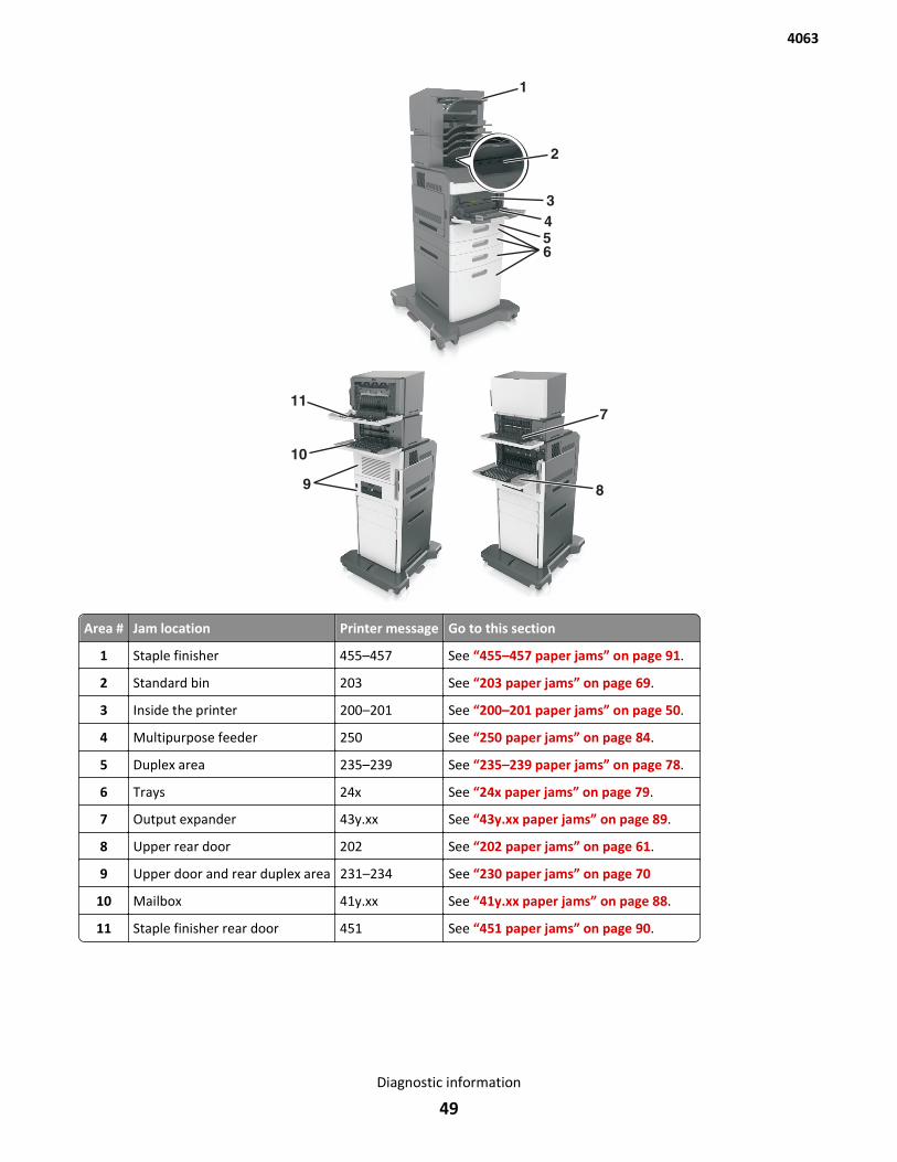
Area # Jam location Printer message Go to this section
1 Staple finisher 455–457 See “455–457 paper jams” on page 91.
2 Standard bin 203 See “203 paper jams” on page 69.
3 Inside the printer 200–201 See “200–201 paper jams” on page 50.
4 Multipurpose feeder 250 See “250 paper jams” on page 84.
5 Duplex area 235–239 See “235–239 paper jams” on page 78.
6 Trays 24x See “24x paper jams” on page 79.
7 Output expander 43y.xx See “43y.xx paper jams” on page 89.
8 Upper rear door 202 See “202 paper jams” on page 61.
9 Upper door and rear duplex area 231–234 See “230 paper jams” on page 70
10 Mailbox 41y.xx See “41y.xx paper jams” on page 88.
11 Staple finisher rear door 451 See “451 paper jams” on page 90.
4063
Diagnostic information
49
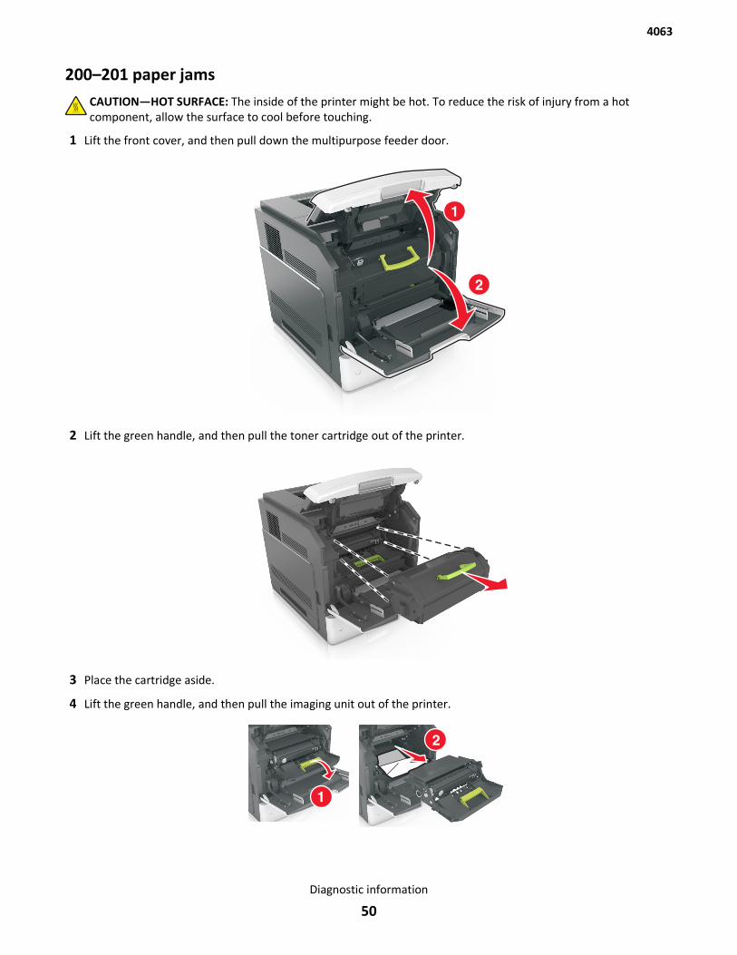
200–201 paper jamsCAUTION—HOT SURFACE: The inside of the printer might be hot. To reduce the risk of injury from a hotcomponent, allow the surface to cool before touching.
1 Lift the front cover, and then pull down the multipurpose feeder door.
2 Lift the green handle, and then pull the toner cartridge out of the printer.
3 Place the cartridge aside.
4 Lift the green handle, and then pull the imaging unit out of the printer.
4063
Diagnostic information
50
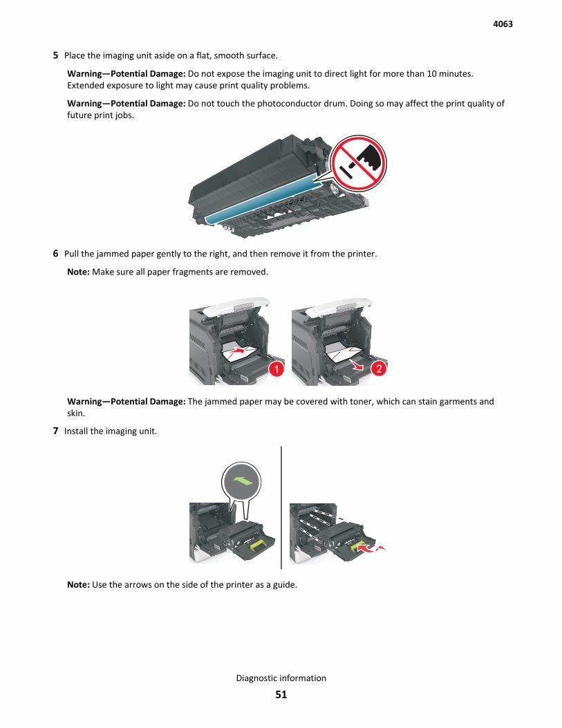
5 Place the imaging unit aside on a flat, smooth surface.
Warning—Potential Damage: Do not expose the imaging unit to direct light for more than 10 minutes.Extended exposure to light may cause print quality problems.
Warning—Potential Damage: Do not touch the photoconductor drum. Doing so may affect the print quality offuture print jobs.
6 Pull the jammed paper gently to the right, and then remove it from the printer.
Note: Make sure all paper fragments are removed.
Warning—Potential Damage: The jammed paper may be covered with toner, which can stain garments andskin.
7 Install the imaging unit.
Note: Use the arrows on the side of the printer as a guide.
4063
Diagnostic information
51
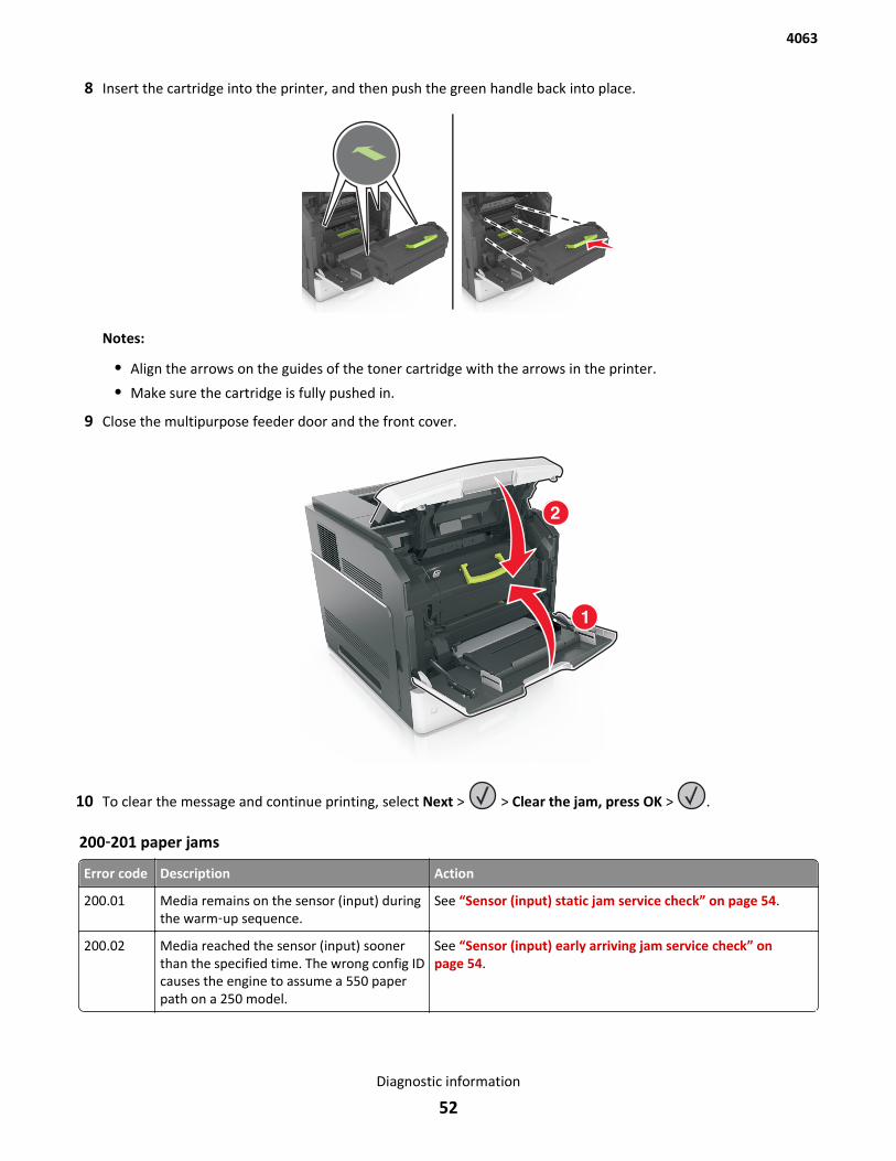
8 Insert the cartridge into the printer, and then push the green handle back into place.
Notes:
• Align the arrows on the guides of the toner cartridge with the arrows in the printer.
• Make sure the cartridge is fully pushed in.
9 Close the multipurpose feeder door and the front cover.
10 To clear the message and continue printing, select Next > > Clear the jam, press OK > .
200‑201 paper jams
Error code Description Action
200.01 Media remains on the sensor (input) duringthe warm‑up sequence.
See “Sensor (input) static jam service check” on page 54.
200.02 Media reached the sensor (input) soonerthan the specified time. The wrong config IDcauses the engine to assume a 550 paperpath on a 250 model.
See “Sensor (input) early arriving jam service check” onpage 54.
4063
Diagnostic information
52
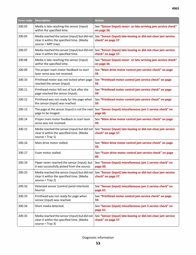
Error code Description Action
200.03 Media is late reaching the sensor (input)within the specified time.
See “Sensor (input) never‑ or late‑arriving jam service check”on page 56.
200.05 Media reached the sensor (input) but did notclear it within the specified time. (Mediasource = MPF tray)
See “Sensor (input) late-leaving or did-not-clear jam servicecheck” on page 57.
200.07 Media reached the sensor (input) but did notclear it within the specified time.
See “Sensor (input) late-leaving or did-not-clear jam servicecheck” on page 57.
200.08 Media is late reaching the sensor (input)within the specified time.
See “Sensor (input) never‑ or late‑arriving jam service check”on page 56.
200.09 The proper main motor feedback to startlaser servo was not received.
See “Main drive motor control jam service check” on page 59.
200.10 Printhead motor was not locked when pagereached the sensor (input).
See “Printhead motor control jam service check” on page 59.
200.11 Printhead motor fell out of lock after thepage reached the sensor (input).
See “Printhead motor control jam service check” on page 59.
200.12 Printhead was not ready for the page whenthe sensor (input) was reached.
See “Printhead motor control jam service check” on page 59.
200.13 The page at the sensor (input) is not the nextpage to be imaged.
See “Sensor (input) miscellaneous jam 1 service check” onpage 60.
200.14 Proper main motor feedback to start laserservo was not received.
See “Main drive motor control jam service check” on page 59.
200.15 Media reached the sensor (input) but did notclear it within the specified time. (Mediasource = Tray 1)
See “Sensor (input) late-leaving or did-not-clear jam servicecheck” on page 57.
200.16 Main drive motor stalled. See “Main drive motor control jam service check” on page 59.
200.17 Fuser motor stalled. See “Fuser drive motor control jam service check” on page 60.
200.19 Paper never reached the sensor (input), butit was successfully picked from the source.
See “Sensor (input) miscellaneous jam 1 service check” onpage 60.
200.25 Media reached the sensor (input) but did notclear it within the specified time. (Mediasource = Tray 2)
See “Sensor (input) late-leaving or did-not-clear jam servicecheck” on page 57.
200.32 Detected sensor (control panel interlock)bounce.
See “Sensor (input) miscellaneous jam 2 service check” onpage 61.
200.33 Printhead was not ready for page whensensor (input) was reached.
See “Printhead motor control jam service check” on page 59.
200.34 Short media detected. See “Sensor (input) miscellaneous jam 3 service check” onpage 61.
200.35 Media reached the sensor (input) but did notclear it within the specified time. (Mediasource = Tray 3)
See “Sensor (input) late-leaving or did-not-clear jam servicecheck” on page 57.
4063
Diagnostic information
53
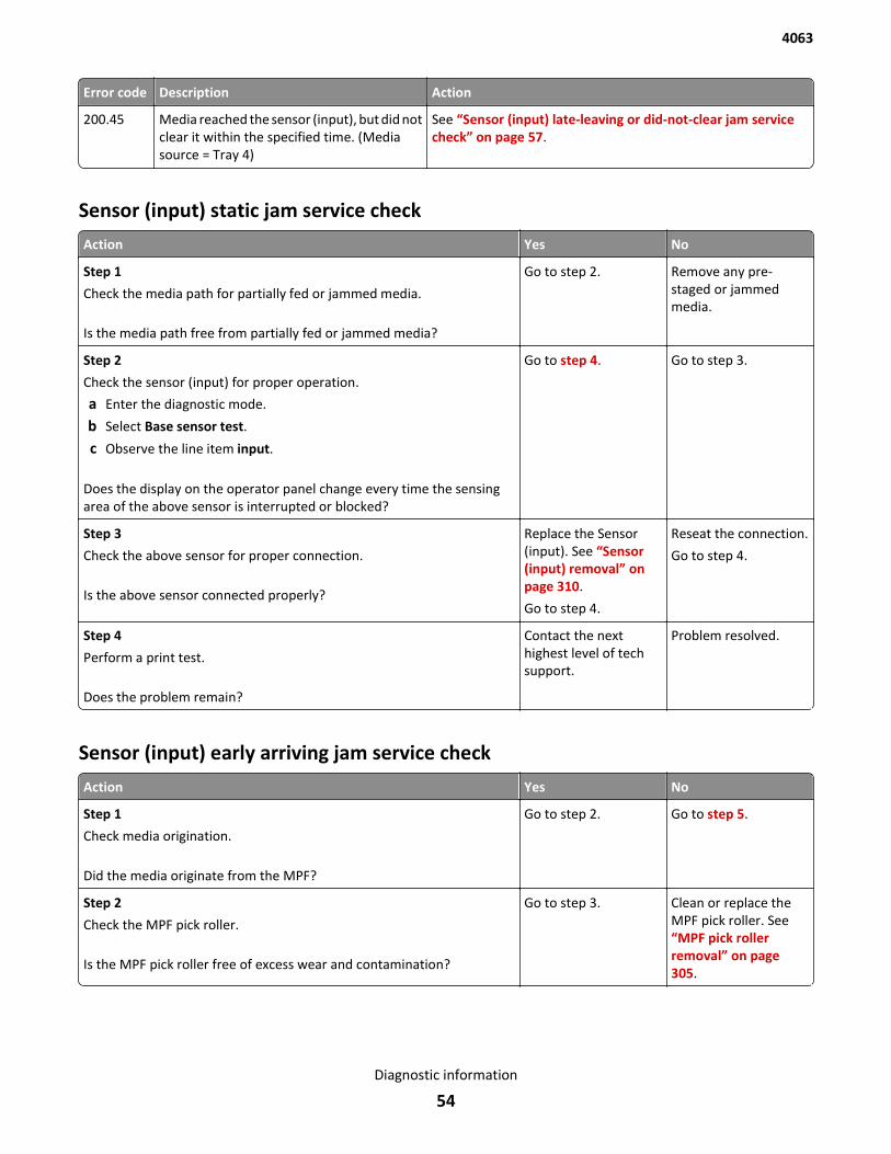
Error code Description Action
200.45 Media reached the sensor (input), but did notclear it within the specified time. (Mediasource = Tray 4)
See “Sensor (input) late-leaving or did-not-clear jam servicecheck” on page 57.
Sensor (input) static jam service check
Action Yes No
Step 1
Check the media path for partially fed or jammed media.
Is the media path free from partially fed or jammed media?
Go to step 2. Remove any pre-staged or jammedmedia.
Step 2
Check the sensor (input) for proper operation.
a Enter the diagnostic mode.
b Select Base sensor test.
c Observe the line item input.
Does the display on the operator panel change every time the sensingarea of the above sensor is interrupted or blocked?
Go to step 4. Go to step 3.
Step 3
Check the above sensor for proper connection.
Is the above sensor connected properly?
Replace the Sensor(input). See “Sensor(input) removal” onpage 310.
Go to step 4.
Reseat the connection.
Go to step 4.
Step 4
Perform a print test.
Does the problem remain?
Contact the nexthighest level of techsupport.
Problem resolved.
Sensor (input) early arriving jam service check
Action Yes No
Step 1
Check media origination.
Did the media originate from the MPF?
Go to step 2. Go to step 5.
Step 2
Check the MPF pick roller.
Is the MPF pick roller free of excess wear and contamination?
Go to step 3. Clean or replace theMPF pick roller. See“MPF pick rollerremoval” on page 305.
4063
Diagnostic information
54
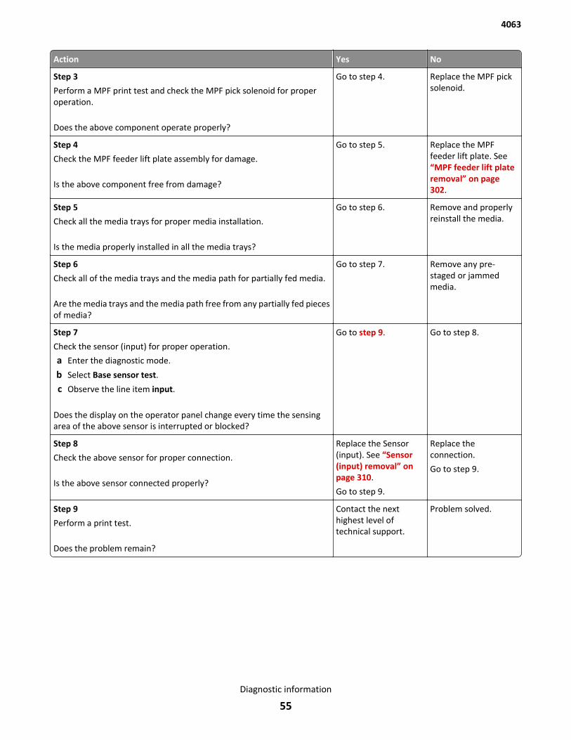
Action Yes No
Step 3
Perform a MPF print test and check the MPF pick solenoid for properoperation.
Does the above component operate properly?
Go to step 4. Replace the MPF picksolenoid.
Step 4
Check the MPF feeder lift plate assembly for damage.
Is the above component free from damage?
Go to step 5. Replace the MPFfeeder lift plate. See“MPF feeder lift plateremoval” on page 302.
Step 5
Check all the media trays for proper media installation.
Is the media properly installed in all the media trays?
Go to step 6. Remove and properlyreinstall the media.
Step 6
Check all of the media trays and the media path for partially fed media.
Are the media trays and the media path free from any partially fed piecesof media?
Go to step 7. Remove any pre-staged or jammedmedia.
Step 7
Check the sensor (input) for proper operation.
a Enter the diagnostic mode.
b Select Base sensor test.
c Observe the line item input.
Does the display on the operator panel change every time the sensingarea of the above sensor is interrupted or blocked?
Go to step 9. Go to step 8.
Step 8
Check the above sensor for proper connection.
Is the above sensor connected properly?
Replace the Sensor(input). See “Sensor(input) removal” onpage 310.
Go to step 9.
Replace theconnection.
Go to step 9.
Step 9
Perform a print test.
Does the problem remain?
Contact the nexthighest level oftechnical support.
Problem solved.
4063
Diagnostic information
55

Sensor (input) never‑ or late‑arriving jam service check
Action Yes No
Step 1
Check the media size setup and tray guides for all media trays.
Does the media size, in use, match the size set for all media trays?
Go to step 2. Replace the media, orchange the media sizesetup.
Step 2
Check the media trays for overfilling.
Are any of the media trays overfilled?
Remove any excessnew media.
Go to step 3.
Step 3
Check the media condition in all media trays.
Is any of the media in any of the media trays crumpled or damaged?
Replace the damagedmedia.
Go to step 4.
Step 4
Check media origination.
Did the media originate from the MPF?
Go to step 5. Go to step 7.
Step 5
Check the MPF pick roll assembly.
Is the above component free of excess wear and contamination?
Go to step 6. Clean or replace theMPF pick roller. See“MPF pick rollerremoval” on page 305.
Step 6
Perform a MPF print test, and check the MPF pick solenoid for properoperation.
Does the above component operate properly?
Go to step 9. Replace the MPF picksolenoid.
Step 7
Check the pick roller assembly in the media tray being picked from.
Is the pick roller assembly free of excess wear and contamination?
Go to step 8. Clean or replace thepick roller assembly.See “Pick rollerassembly removal” onpage 342.
Step 8
Check the pick roller assembly for proper installation. Fully press the pickroller assembly toward the sensor to make sure the mounting latches areproperly engaging the slot in the shaft.
Does the problem remain?
Go to step 9. The problem is solved.
Step 9
Check the aligner assembly for obstructions.
Is the above component free from obstructions?
Go to step 10. Remove obstructions.
4063
Diagnostic information
56
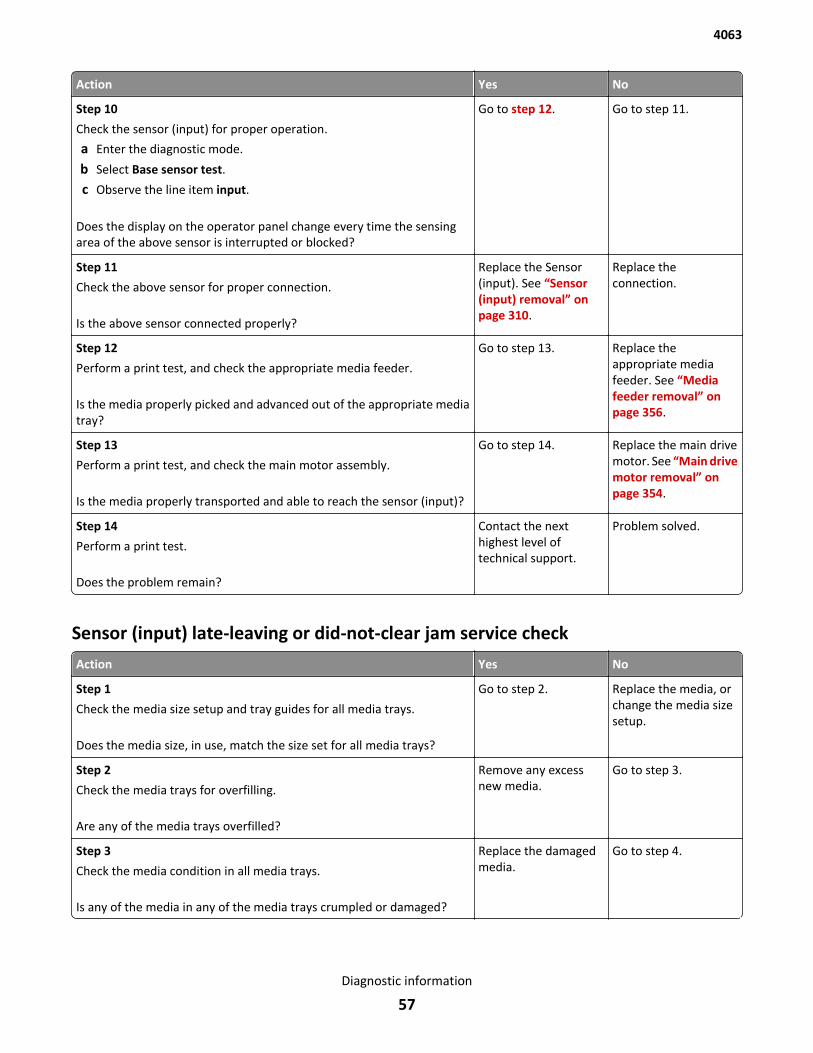
Action Yes No
Step 10
Check the sensor (input) for proper operation.
a Enter the diagnostic mode.
b Select Base sensor test.
c Observe the line item input.
Does the display on the operator panel change every time the sensingarea of the above sensor is interrupted or blocked?
Go to step 12. Go to step 11.
Step 11
Check the above sensor for proper connection.
Is the above sensor connected properly?
Replace the Sensor(input). See “Sensor(input) removal” onpage 310.
Replace theconnection.
Step 12
Perform a print test, and check the appropriate media feeder.
Is the media properly picked and advanced out of the appropriate mediatray?
Go to step 13. Replace theappropriate mediafeeder. See “Mediafeeder removal” onpage 356.
Step 13
Perform a print test, and check the main motor assembly.
Is the media properly transported and able to reach the sensor (input)?
Go to step 14. Replace the main drivemotor. See “Main drivemotor removal” onpage 354.
Step 14
Perform a print test.
Does the problem remain?
Contact the nexthighest level oftechnical support.
Problem solved.
Sensor (input) late-leaving or did-not-clear jam service check
Action Yes No
Step 1
Check the media size setup and tray guides for all media trays.
Does the media size, in use, match the size set for all media trays?
Go to step 2. Replace the media, orchange the media sizesetup.
Step 2
Check the media trays for overfilling.
Are any of the media trays overfilled?
Remove any excessnew media.
Go to step 3.
Step 3
Check the media condition in all media trays.
Is any of the media in any of the media trays crumpled or damaged?
Replace the damagedmedia.
Go to step 4.
4063
Diagnostic information
57
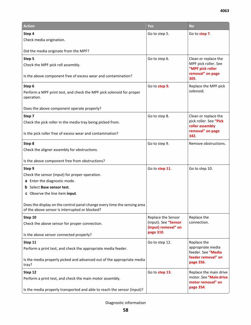
Action Yes No
Step 4
Check media origination.
Did the media originate from the MPF?
Go to step 5. Go to step 7.
Step 5
Check the MPF pick roll assembly.
Is the above component free of excess wear and contamination?
Go to step 6. Clean or replace theMPF pick roller. See“MPF pick rollerremoval” on page 305.
Step 6
Perform a MPF print test, and check the MPF pick solenoid for properoperation.
Does the above component operate properly?
Go to step 9. Replace the MPF picksolenoid.
Step 7
Check the pick roller in the media tray being picked from.
Is the pick roller free of excess wear and contamination?
Go to step 8. Clean or replace thepick roller. See “Pickroller assemblyremoval” on page 342.
Step 8
Check the aligner assembly for obstructions.
Is the above component free from obstructions?
Go to step 9. Remove obstructions.
Step 9
Check the sensor (input) for proper operation.
a Enter the diagnostic mode.
b Select Base sensor test.
c Observe the line item input.
Does the display on the control panel change every time the sensing areaof the above sensor is interrupted or blocked?
Go to step 11. Go to step 10.
Step 10
Check the above sensor for proper connection.
Is the above sensor connected properly?
Replace the Sensor(input). See “Sensor(input) removal” onpage 310.
Replace theconnection.
Step 11
Perform a print test, and check the appropriate media feeder.
Is the media properly picked and advanced out of the appropriate mediatray?
Go to step 12. Replace theappropriate mediafeeder. See “Mediafeeder removal” onpage 356.
Step 12
Perform a print test, and check the main motor assembly.
Is the media properly transported and able to reach the sensor (input)?
Go to step 13. Replace the main drivemotor. See “Main drivemotor removal” onpage 354.
4063
Diagnostic information
58
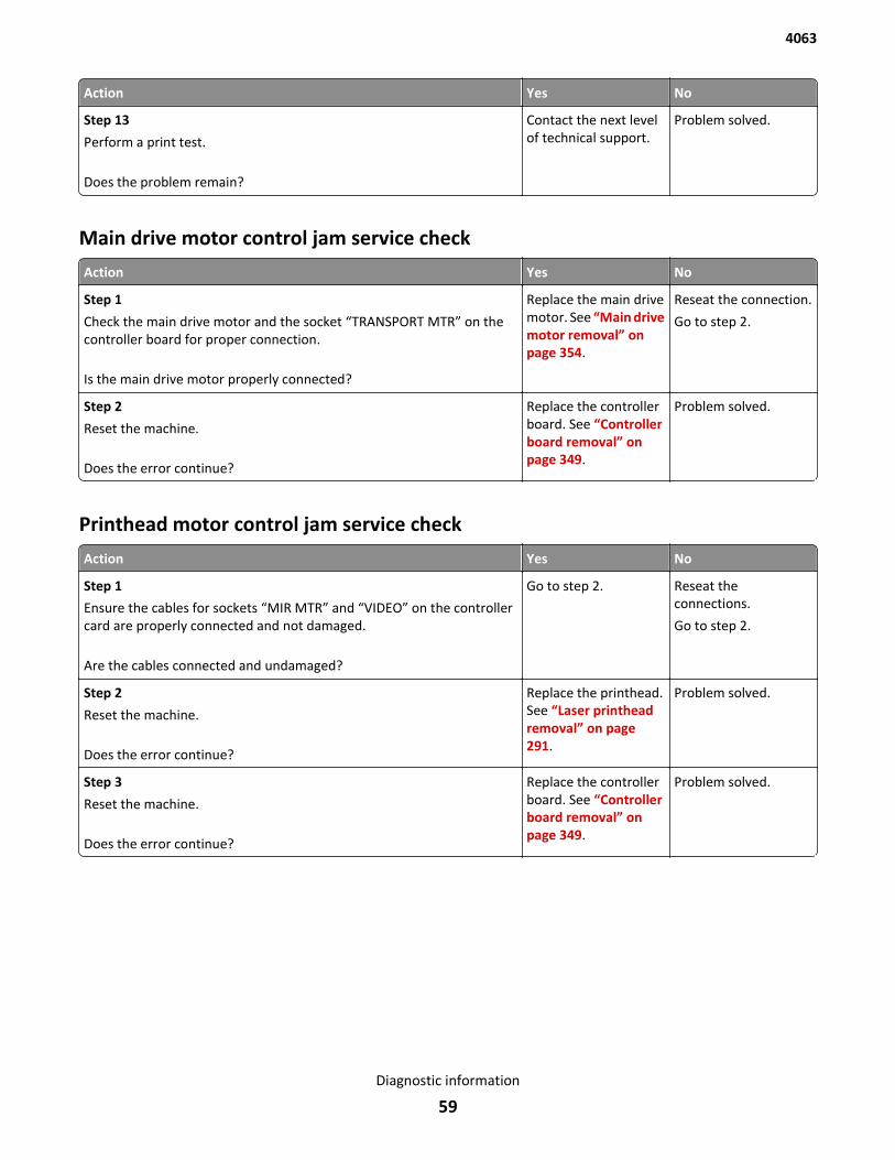
Action Yes No
Step 13
Perform a print test.
Does the problem remain?
Contact the next levelof technical support.
Problem solved.
Main drive motor control jam service check
Action Yes No
Step 1
Check the main drive motor and the socket “TRANSPORT MTR” on thecontroller board for proper connection.
Is the main drive motor properly connected?
Replace the main drivemotor. See “Main drivemotor removal” onpage 354.
Reseat the connection.
Go to step 2.
Step 2
Reset the machine.
Does the error continue?
Replace the controllerboard. See “Controllerboard removal” onpage 349.
Problem solved.
Printhead motor control jam service check
Action Yes No
Step 1
Ensure the cables for sockets “MIR MTR” and “VIDEO” on the controllercard are properly connected and not damaged.
Are the cables connected and undamaged?
Go to step 2. Reseat theconnections.
Go to step 2.
Step 2
Reset the machine.
Does the error continue?
Replace the printhead.See “Laser printheadremoval” on page 291.
Problem solved.
Step 3
Reset the machine.
Does the error continue?
Replace the controllerboard. See “Controllerboard removal” onpage 349.
Problem solved.
4063
Diagnostic information
59
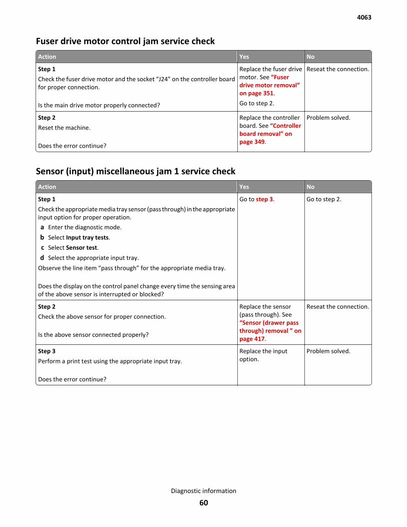
Fuser drive motor control jam service check
Action Yes No
Step 1
Check the fuser drive motor and the socket “J24” on the controller boardfor proper connection.
Is the main drive motor properly connected?
Replace the fuser drivemotor. See “Fuserdrive motor removal”on page 351.
Go to step 2.
Reseat the connection.
Step 2
Reset the machine.
Does the error continue?
Replace the controllerboard. See “Controllerboard removal” onpage 349.
Problem solved.
Sensor (input) miscellaneous jam 1 service check
Action Yes No
Step 1
Check the appropriate media tray sensor (pass through) in the appropriateinput option for proper operation.
a Enter the diagnostic mode.
b Select Input tray tests.
c Select Sensor test.
d Select the appropriate input tray.
Observe the line item “pass through” for the appropriate media tray.
Does the display on the control panel change every time the sensing areaof the above sensor is interrupted or blocked?
Go to step 3. Go to step 2.
Step 2
Check the above sensor for proper connection.
Is the above sensor connected properly?
Replace the sensor(pass through). See“Sensor (drawer passthrough) removal ” onpage 417.
Reseat the connection.
Step 3
Perform a print test using the appropriate input tray.
Does the error continue?
Replace the inputoption.
Problem solved.
4063
Diagnostic information
60
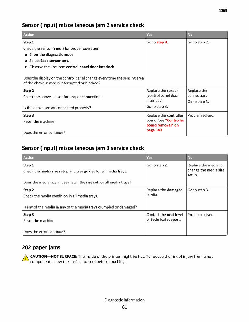
Sensor (input) miscellaneous jam 2 service check
Action Yes No
Step 1
Check the sensor (input) for proper operation.
a Enter the diagnostic mode.
b Select Base sensor test.
c Observe the line item control panel door interlock.
Does the display on the control panel change every time the sensing areaof the above sensor is interrupted or blocked?
Go to step 3. Go to step 2.
Step 2
Check the above sensor for proper connection.
Is the above sensor connected properly?
Replace the sensor(control panel doorinterlock).
Go to step 3.
Replace theconnection.
Go to step 3.
Step 3
Reset the machine.
Does the error continue?
Replace the controllerboard. See “Controllerboard removal” onpage 349.
Problem solved.
Sensor (input) miscellaneous jam 3 service check
Action Yes No
Step 1
Check the media size setup and tray guides for all media trays.
Does the media size in use match the size set for all media trays?
Go to step 2. Replace the media, orchange the media sizesetup.
Step 2
Check the media condition in all media trays.
Is any of the media in any of the media trays crumpled or damaged?
Replace the damagedmedia.
Go to step 3.
Step 3
Reset the machine.
Does the error continue?
Contact the next levelof technical support.
Problem solved.
202 paper jamsCAUTION—HOT SURFACE: The inside of the printer might be hot. To reduce the risk of injury from a hotcomponent, allow the surface to cool before touching.
4063
Diagnostic information
61
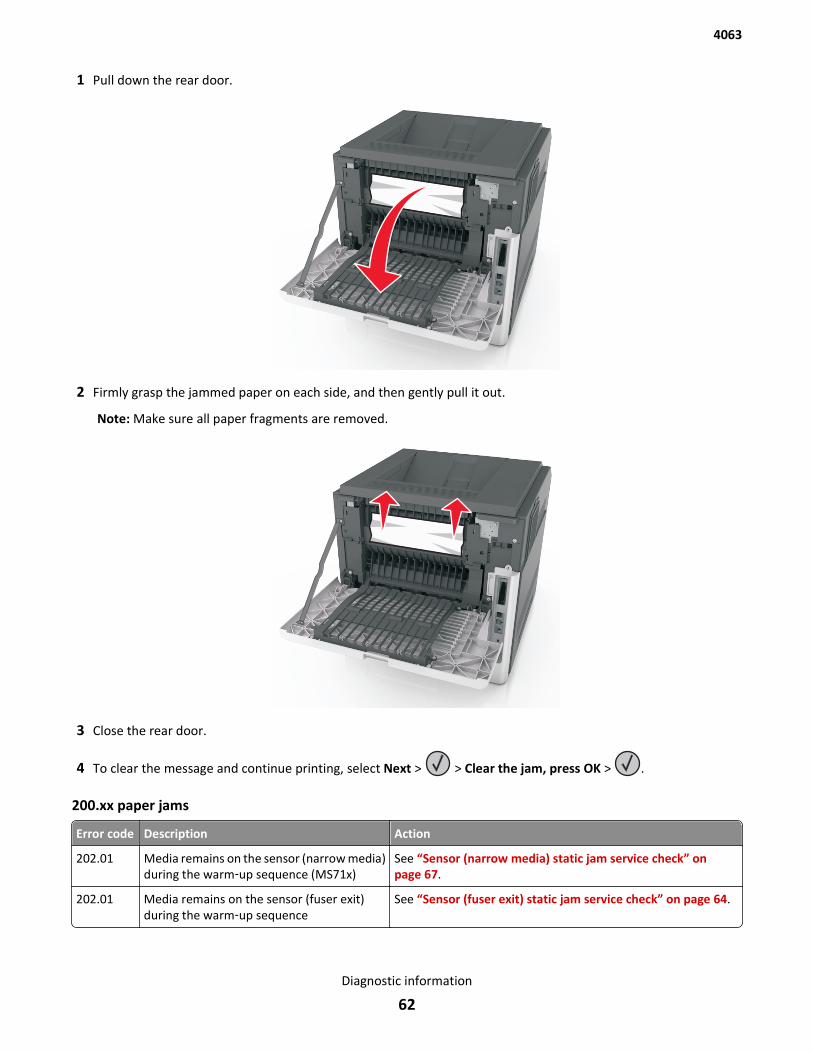
1 Pull down the rear door.
2 Firmly grasp the jammed paper on each side, and then gently pull it out.
Note: Make sure all paper fragments are removed.
3 Close the rear door.
4 To clear the message and continue printing, select Next > > Clear the jam, press OK > .
200.xx paper jams
Error code Description Action
202.01 Media remains on the sensor (narrow media)during the warm‑up sequence (MS71x)
See “Sensor (narrow media) static jam service check” onpage 67.
202.01 Media remains on the sensor (fuser exit)during the warm‑up sequence
See “Sensor (fuser exit) static jam service check” on page 64.
4063
Diagnostic information
62
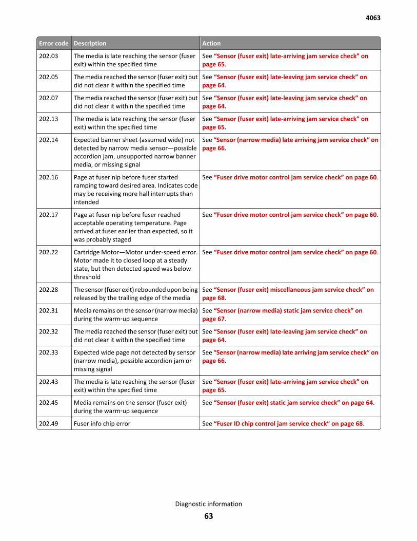
Error code Description Action
202.03 The media is late reaching the sensor (fuserexit) within the specified time
See “Sensor (fuser exit) late-arriving jam service check” onpage 65.
202.05 The media reached the sensor (fuser exit) butdid not clear it within the specified time
See “Sensor (fuser exit) late-leaving jam service check” onpage 64.
202.07 The media reached the sensor (fuser exit) butdid not clear it within the specified time
See “Sensor (fuser exit) late-leaving jam service check” onpage 64.
202.13 The media is late reaching the sensor (fuserexit) within the specified time
See “Sensor (fuser exit) late-arriving jam service check” onpage 65.
202.14 Expected banner sheet (assumed wide) notdetected by narrow media sensor—possibleaccordion jam, unsupported narrow bannermedia, or missing signal
See “Sensor (narrow media) late arriving jam service check” onpage 66.
202.16 Page at fuser nip before fuser startedramping toward desired area. Indicates codemay be receiving more hall interrupts thanintended
See “Fuser drive motor control jam service check” on page 60.
202.17 Page at fuser nip before fuser reachedacceptable operating temperature. Pagearrived at fuser earlier than expected, so itwas probably staged
See “Fuser drive motor control jam service check” on page 60.
202.22 Cartridge Motor—Motor under‑speed error.Motor made it to closed loop at a steadystate, but then detected speed was belowthreshold
See “Fuser drive motor control jam service check” on page 60.
202.28 The sensor (fuser exit) rebounded upon beingreleased by the trailing edge of the media
See “Sensor (fuser exit) miscellaneous jam service check” onpage 68.
202.31 Media remains on the sensor (narrow media)during the warm‑up sequence
See “Sensor (narrow media) static jam service check” onpage 67.
202.32 The media reached the sensor (fuser exit) butdid not clear it within the specified time
See “Sensor (fuser exit) late-leaving jam service check” onpage 64.
202.33 Expected wide page not detected by sensor(narrow media), possible accordion jam ormissing signal
See “Sensor (narrow media) late arriving jam service check” onpage 66.
202.43 The media is late reaching the sensor (fuserexit) within the specified time
See “Sensor (fuser exit) late-arriving jam service check” onpage 65.
202.45 Media remains on the sensor (fuser exit)during the warm‑up sequence
See “Sensor (fuser exit) static jam service check” on page 64.
202.49 Fuser info chip error See “Fuser ID chip control jam service check” on page 68.
4063
Diagnostic information
63

Sensor (fuser exit) static jam service check
Action Yes No
Step 1
Check the media size setup and tray guides for all media trays.
Does the media size, in use, match the size set for all media trays?
Go to step 2. Replace the media, orchange the media sizesetup.
Step 2
Check the media condition in all media trays.
Is any of the media in any of the media trays crumpled or damaged?
Replace the damagedmedia with new media.
Go to step 3.
Step 3
Reset the machine.
Does the error continue?
Contact the nexthighest level oftechnical support.
Problem solved.
Sensor (fuser exit) late-leaving jam service check
Action Yes No
Step 1
Check the rear door.
Is the rear door free of damage and properly closed?
Go to step 2. Close or replace therear door. See “Reardoor removal” onpage 285.
Step 2
Check the fuser unit assembly for damage and life expiration.
Is the above component damaged or has it exceeded life?
Replace the fuser. See“Fuser removal” onpage 322.
Go to step 3.
Step 3
Check the sensor (fuser output) for proper operation.
a Enter the diagnostic mode.
b Select Base sensor tests.
c Observe the line item fuser exit.
Does the display on the control panel change every time the sensing areaof the above sensor is interrupted or blocked?
Go to step 5. Go to step 4.
Step 4
Check the above sensor for proper connection.
Is the above sensor connected properly?
Replace the fuser. See“Fuser removal” onpage 322.
Reseat the connection.
Step 5
Check the upper redrive for damage.
Is the above component free from damage?
Go to step 6. Replace the upperredrive. See “Upperredrive removal” onpage 331.
4063
Diagnostic information
64
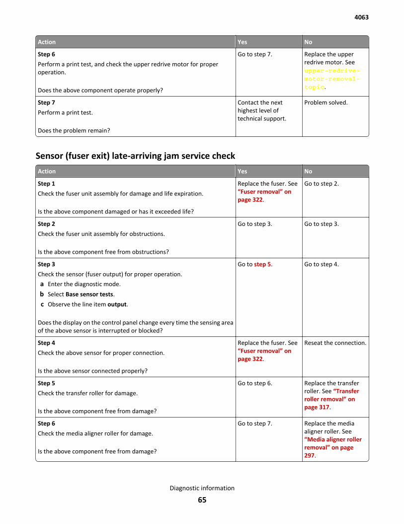
Action Yes No
Step 6
Perform a print test, and check the upper redrive motor for properoperation.
Does the above component operate properly?
Go to step 7. Replace the upperredrive motor. Seeupper-redrive-motor-removal-topic.
Step 7
Perform a print test.
Does the problem remain?
Contact the nexthighest level oftechnical support.
Problem solved.
Sensor (fuser exit) late-arriving jam service check
Action Yes No
Step 1
Check the fuser unit assembly for damage and life expiration.
Is the above component damaged or has it exceeded life?
Replace the fuser. See“Fuser removal” onpage 322.
Go to step 2.
Step 2
Check the fuser unit assembly for obstructions.
Is the above component free from obstructions?
Go to step 3. Go to step 3.
Step 3
Check the sensor (fuser output) for proper operation.
a Enter the diagnostic mode.
b Select Base sensor tests.
c Observe the line item output.
Does the display on the control panel change every time the sensing areaof the above sensor is interrupted or blocked?
Go to step 5. Go to step 4.
Step 4
Check the above sensor for proper connection.
Is the above sensor connected properly?
Replace the fuser. See“Fuser removal” onpage 322.
Reseat the connection.
Step 5
Check the transfer roller for damage.
Is the above component free from damage?
Go to step 6. Replace the transferroller. See “Transferroller removal” onpage 317.
Step 6
Check the media aligner roller for damage.
Is the above component free from damage?
Go to step 7. Replace the mediaaligner roller. See“Media aligner rollerremoval” on page 297.
4063
Diagnostic information
65
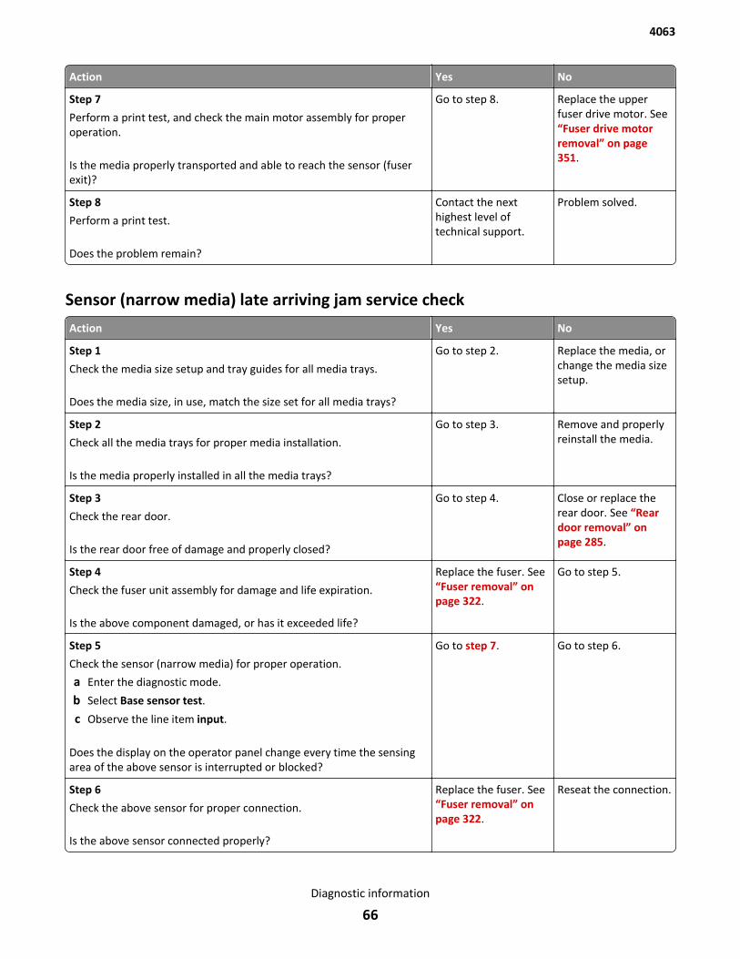
Action Yes No
Step 7
Perform a print test, and check the main motor assembly for properoperation.
Is the media properly transported and able to reach the sensor (fuserexit)?
Go to step 8. Replace the upperfuser drive motor. See“Fuser drive motorremoval” on page 351.
Step 8
Perform a print test.
Does the problem remain?
Contact the nexthighest level oftechnical support.
Problem solved.
Sensor (narrow media) late arriving jam service check
Action Yes No
Step 1
Check the media size setup and tray guides for all media trays.
Does the media size, in use, match the size set for all media trays?
Go to step 2. Replace the media, orchange the media sizesetup.
Step 2
Check all the media trays for proper media installation.
Is the media properly installed in all the media trays?
Go to step 3. Remove and properlyreinstall the media.
Step 3
Check the rear door.
Is the rear door free of damage and properly closed?
Go to step 4. Close or replace therear door. See “Reardoor removal” onpage 285.
Step 4
Check the fuser unit assembly for damage and life expiration.
Is the above component damaged, or has it exceeded life?
Replace the fuser. See“Fuser removal” onpage 322.
Go to step 5.
Step 5
Check the sensor (narrow media) for proper operation.
a Enter the diagnostic mode.
b Select Base sensor test.
c Observe the line item input.
Does the display on the operator panel change every time the sensingarea of the above sensor is interrupted or blocked?
Go to step 7. Go to step 6.
Step 6
Check the above sensor for proper connection.
Is the above sensor connected properly?
Replace the fuser. See“Fuser removal” onpage 322.
Reseat the connection.
4063
Diagnostic information
66
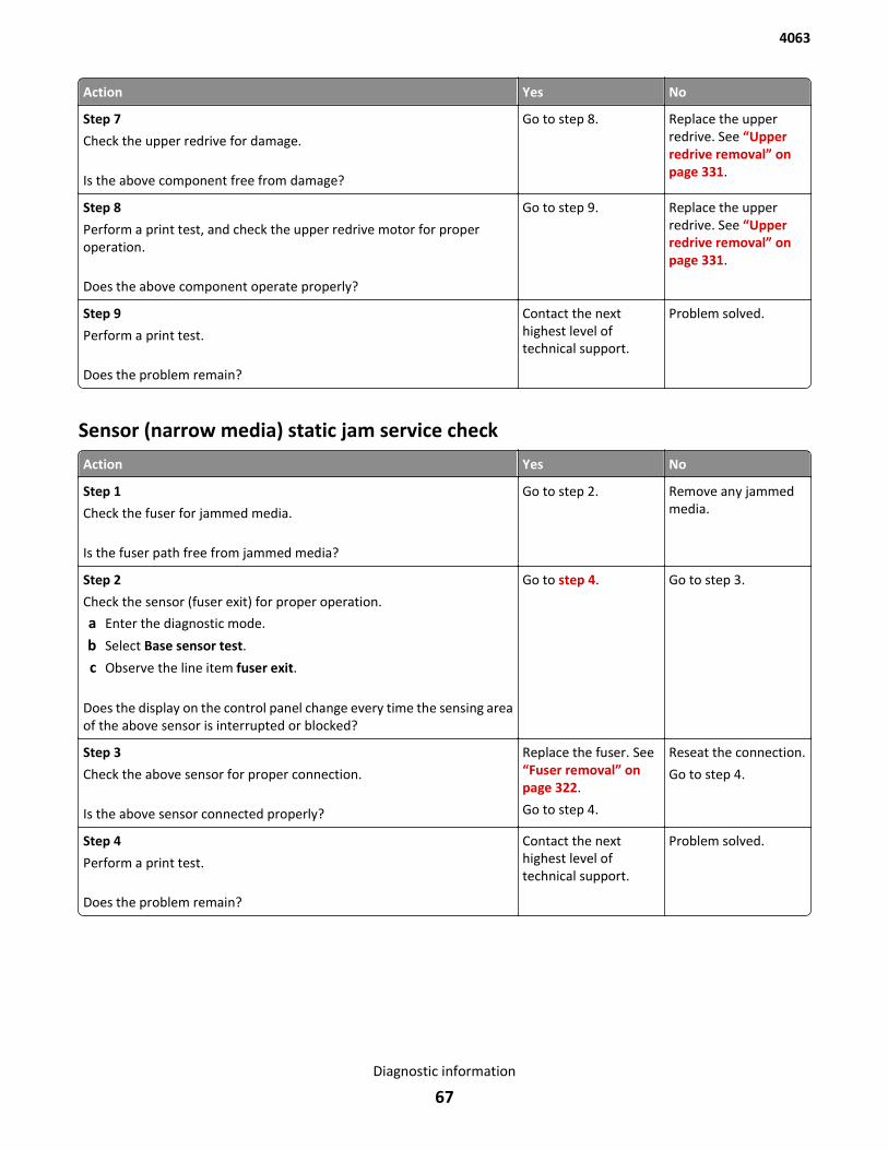
Action Yes No
Step 7
Check the upper redrive for damage.
Is the above component free from damage?
Go to step 8. Replace the upperredrive. See “Upperredrive removal” onpage 331.
Step 8
Perform a print test, and check the upper redrive motor for properoperation.
Does the above component operate properly?
Go to step 9. Replace the upperredrive. See “Upperredrive removal” onpage 331.
Step 9
Perform a print test.
Does the problem remain?
Contact the nexthighest level oftechnical support.
Problem solved.
Sensor (narrow media) static jam service check
Action Yes No
Step 1
Check the fuser for jammed media.
Is the fuser path free from jammed media?
Go to step 2. Remove any jammedmedia.
Step 2
Check the sensor (fuser exit) for proper operation.
a Enter the diagnostic mode.
b Select Base sensor test.
c Observe the line item fuser exit.
Does the display on the control panel change every time the sensing areaof the above sensor is interrupted or blocked?
Go to step 4. Go to step 3.
Step 3
Check the above sensor for proper connection.
Is the above sensor connected properly?
Replace the fuser. See“Fuser removal” onpage 322.
Go to step 4.
Reseat the connection.
Go to step 4.
Step 4
Perform a print test.
Does the problem remain?
Contact the nexthighest level oftechnical support.
Problem solved.
4063
Diagnostic information
67
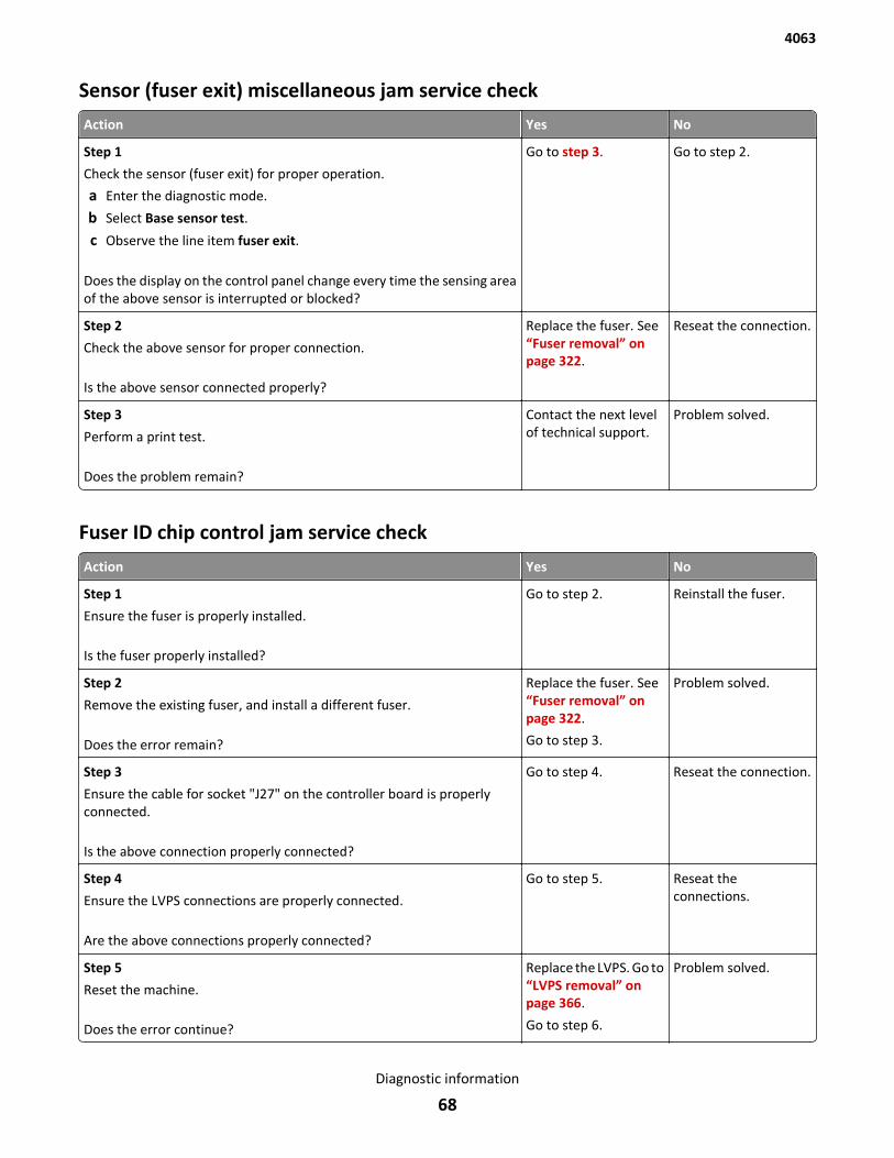
Sensor (fuser exit) miscellaneous jam service check
Action Yes No
Step 1
Check the sensor (fuser exit) for proper operation.
a Enter the diagnostic mode.
b Select Base sensor test.
c Observe the line item fuser exit.
Does the display on the control panel change every time the sensing areaof the above sensor is interrupted or blocked?
Go to step 3. Go to step 2.
Step 2
Check the above sensor for proper connection.
Is the above sensor connected properly?
Replace the fuser. See“Fuser removal” onpage 322.
Reseat the connection.
Step 3
Perform a print test.
Does the problem remain?
Contact the next levelof technical support.
Problem solved.
Fuser ID chip control jam service check
Action Yes No
Step 1
Ensure the fuser is properly installed.
Is the fuser properly installed?
Go to step 2. Reinstall the fuser.
Step 2
Remove the existing fuser, and install a different fuser.
Does the error remain?
Replace the fuser. See“Fuser removal” onpage 322.
Go to step 3.
Problem solved.
Step 3
Ensure the cable for socket "J27" on the controller board is properlyconnected.
Is the above connection properly connected?
Go to step 4. Reseat the connection.
Step 4
Ensure the LVPS connections are properly connected.
Are the above connections properly connected?
Go to step 5. Reseat theconnections.
Step 5
Reset the machine.
Does the error continue?
Replace the LVPS. Go to“LVPS removal” onpage 366.
Go to step 6.
Problem solved.
4063
Diagnostic information
68
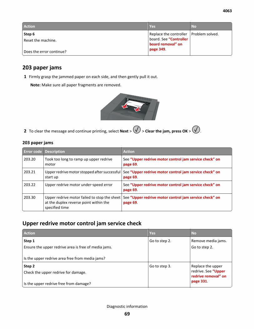
Action Yes No
Step 6
Reset the machine.
Does the error continue?
Replace the controllerboard. See “Controllerboard removal” onpage 349.
Problem solved.
203 paper jams1 Firmly grasp the jammed paper on each side, and then gently pull it out.
Note: Make sure all paper fragments are removed.
2 To clear the message and continue printing, select Next > > Clear the jam, press OK > .
203 paper jams
Error code Description Action
203.20 Took too long to ramp up upper redrivemotor
See “Upper redrive motor control jam service check” onpage 69.
203.21 Upper redrive motor stopped after successfulstart up
See “Upper redrive motor control jam service check” onpage 69.
203.22 Upper redrive motor under‑speed error See “Upper redrive motor control jam service check” onpage 69.
203.30 Upper redrive motor failed to stop the sheetat the duplex reverse point within thespecified time
See “Upper redrive motor control jam service check” onpage 69.
Upper redrive motor control jam service check
Action Yes No
Step 1
Ensure the upper redrive area is free of media jams.
Is the upper redrive area free from media jams?
Go to step 2. Remove media jams.
Go to step 2.
Step 2
Check the upper redrive for damage.
Is the upper redrive free from damage?
Go to step 3. Replace the upperredrive. See “Upperredrive removal” onpage 331.
4063
Diagnostic information
69
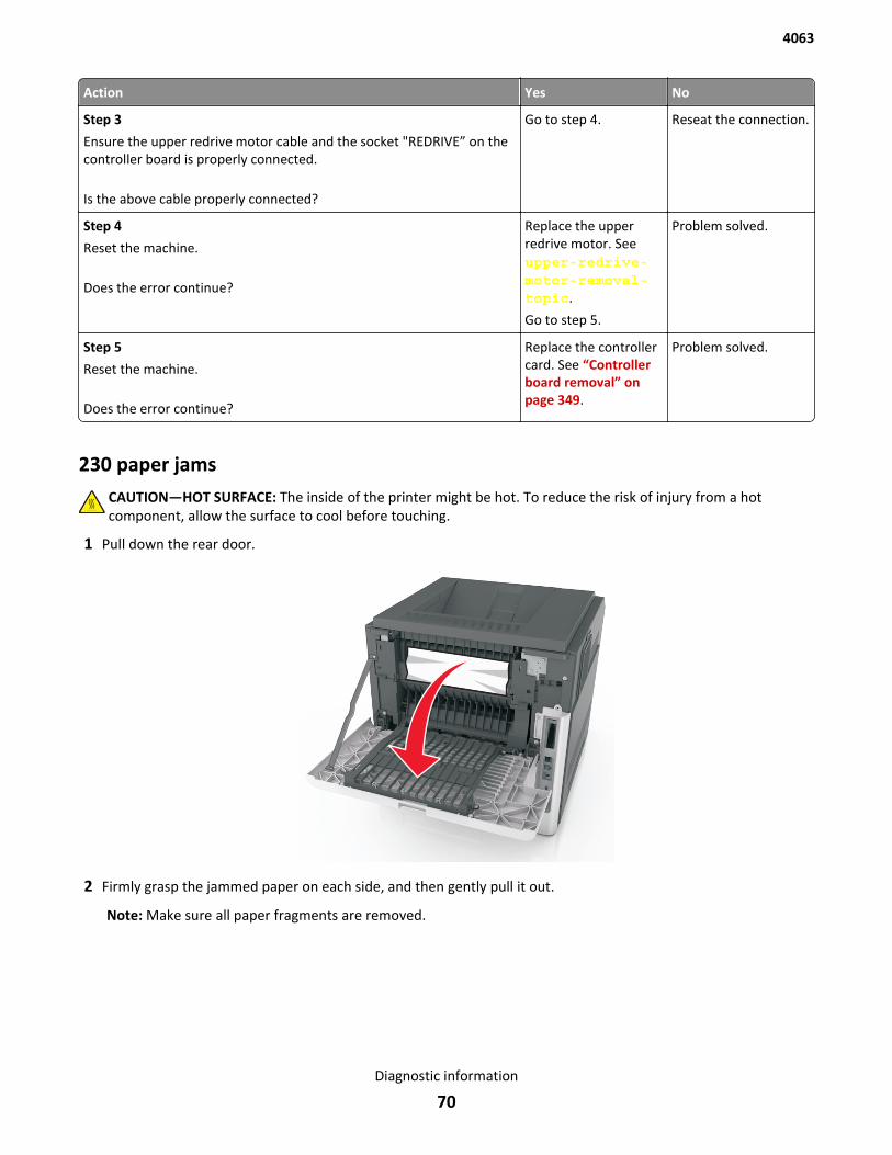
Action Yes No
Step 3
Ensure the upper redrive motor cable and the socket "REDRIVE” on thecontroller board is properly connected.
Is the above cable properly connected?
Go to step 4. Reseat the connection.
Step 4
Reset the machine.
Does the error continue?
Replace the upperredrive motor. Seeupper-redrive-motor-removal-topic.
Go to step 5.
Problem solved.
Step 5
Reset the machine.
Does the error continue?
Replace the controllercard. See “Controllerboard removal” onpage 349.
Problem solved.
230 paper jamsCAUTION—HOT SURFACE: The inside of the printer might be hot. To reduce the risk of injury from a hotcomponent, allow the surface to cool before touching.
1 Pull down the rear door.
2 Firmly grasp the jammed paper on each side, and then gently pull it out.
Note: Make sure all paper fragments are removed.
4063
Diagnostic information
70
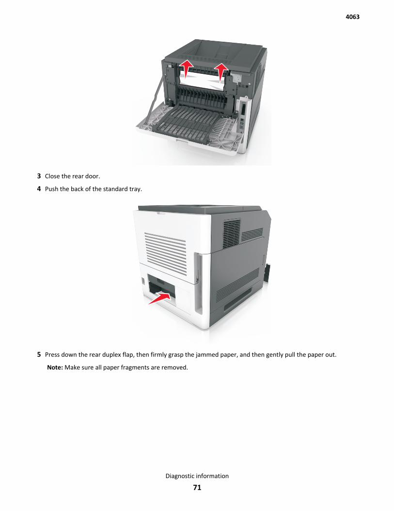
3 Close the rear door.
4 Push the back of the standard tray.
5 Press down the rear duplex flap, then firmly grasp the jammed paper, and then gently pull the paper out.
Note: Make sure all paper fragments are removed.
4063
Diagnostic information
71
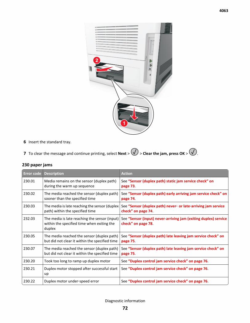
6 Insert the standard tray.
7 To clear the message and continue printing, select Next > > Clear the jam, press OK > .
230 paper jams
Error code Description Action
230.01 Media remains on the sensor (duplex path)during the warm up sequence
See “Sensor (duplex path) static jam service check” onpage 73.
230.02 The media reached the sensor (duplex path)sooner than the specified time
See “Sensor (duplex path) early arriving jam service check” onpage 74.
230.03 The media is late reaching the sensor (duplexpath) within the specified time
See “Sensor (duplex path) never‑ or late‑arriving jam servicecheck” on page 74.
232.03 The media is late reaching the sensor (input)within the specified time when exiting theduplex
See “Sensor (input) never-arriving jam (exiting duplex) servicecheck” on page 78.
230.05 The media reached the sensor (duplex path)but did not clear it within the specified time
See “Sensor (duplex path) late leaving jam service check” onpage 75.
230.07 The media reached the sensor (duplex path)but did not clear it within the specified time
See “Sensor (duplex path) late leaving jam service check” onpage 75.
230.20 Took too long to ramp up duplex motor See “Duplex control jam service check” on page 76.
230.21 Duplex motor stopped after successful startup
See “Duplex control jam service check” on page 76.
230.22 Duplex motor under‑speed error See “Duplex control jam service check” on page 76.
4063
Diagnostic information
72
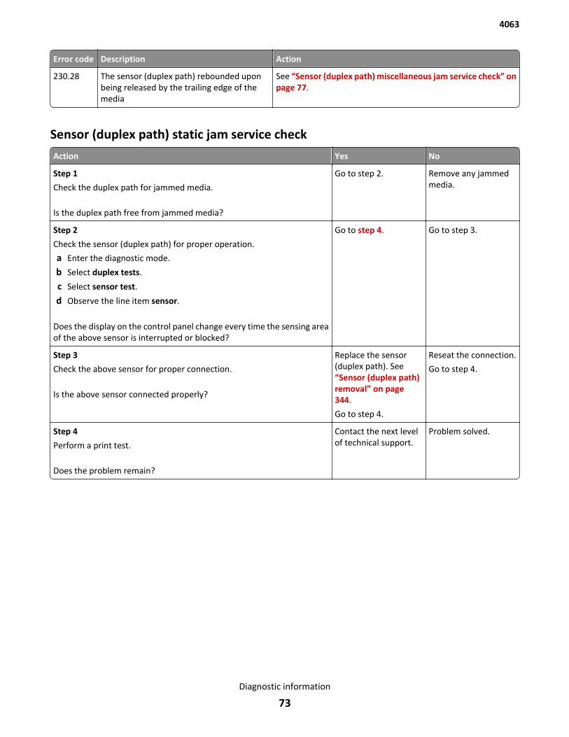
Error code Description Action
230.28 The sensor (duplex path) rebounded uponbeing released by the trailing edge of themedia
See “Sensor (duplex path) miscellaneous jam service check” onpage 77.
Sensor (duplex path) static jam service check
Action Yes No
Step 1
Check the duplex path for jammed media.
Is the duplex path free from jammed media?
Go to step 2. Remove any jammedmedia.
Step 2
Check the sensor (duplex path) for proper operation.
a Enter the diagnostic mode.
b Select duplex tests.
c Select sensor test.
d Observe the line item sensor.
Does the display on the control panel change every time the sensing areaof the above sensor is interrupted or blocked?
Go to step 4. Go to step 3.
Step 3
Check the above sensor for proper connection.
Is the above sensor connected properly?
Replace the sensor(duplex path). See“Sensor (duplex path)removal” on page 344.
Go to step 4.
Reseat the connection.
Go to step 4.
Step 4
Perform a print test.
Does the problem remain?
Contact the next levelof technical support.
Problem solved.
4063
Diagnostic information
73
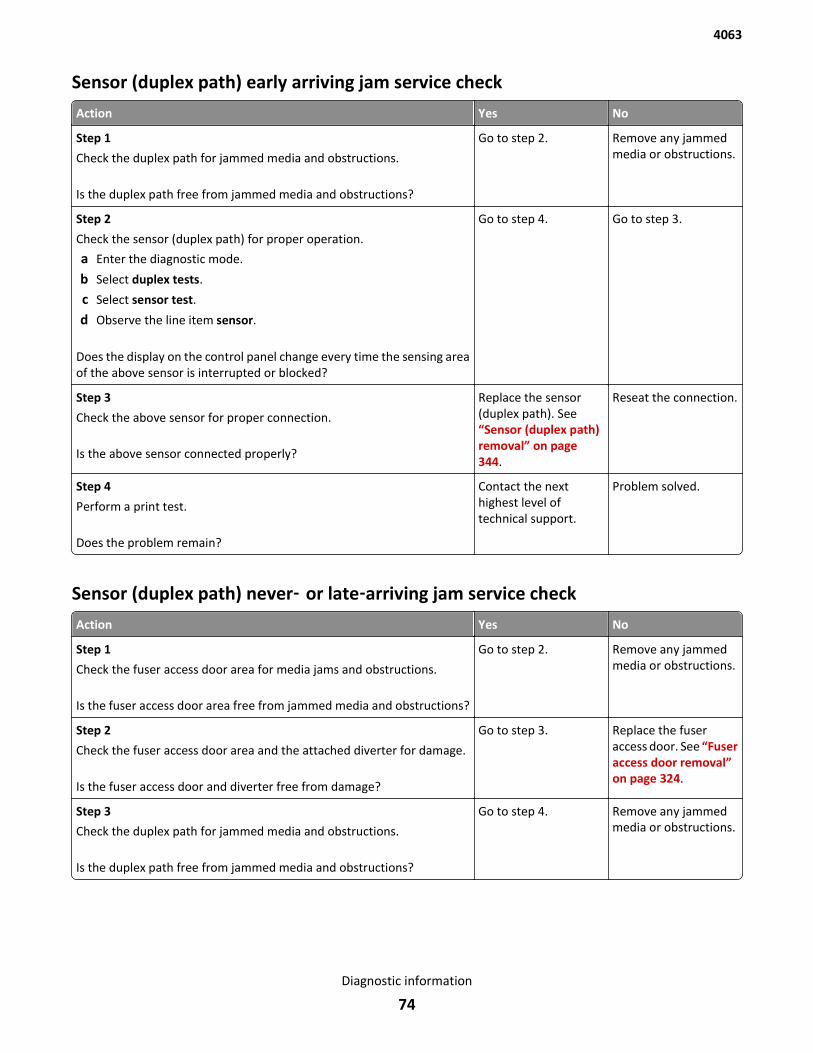
Sensor (duplex path) early arriving jam service check
Action Yes No
Step 1
Check the duplex path for jammed media and obstructions.
Is the duplex path free from jammed media and obstructions?
Go to step 2. Remove any jammedmedia or obstructions.
Step 2
Check the sensor (duplex path) for proper operation.
a Enter the diagnostic mode.
b Select duplex tests.
c Select sensor test.
d Observe the line item sensor.
Does the display on the control panel change every time the sensing areaof the above sensor is interrupted or blocked?
Go to step 4. Go to step 3.
Step 3
Check the above sensor for proper connection.
Is the above sensor connected properly?
Replace the sensor(duplex path). See“Sensor (duplex path)removal” on page 344.
Reseat the connection.
Step 4
Perform a print test.
Does the problem remain?
Contact the nexthighest level oftechnical support.
Problem solved.
Sensor (duplex path) never‑ or late‑arriving jam service check
Action Yes No
Step 1
Check the fuser access door area for media jams and obstructions.
Is the fuser access door area free from jammed media and obstructions?
Go to step 2. Remove any jammedmedia or obstructions.
Step 2
Check the fuser access door area and the attached diverter for damage.
Is the fuser access door and diverter free from damage?
Go to step 3. Replace the fuseraccess door. See “Fuseraccess door removal”on page 324.
Step 3
Check the duplex path for jammed media and obstructions.
Is the duplex path free from jammed media and obstructions?
Go to step 4. Remove any jammedmedia or obstructions.
4063
Diagnostic information
74
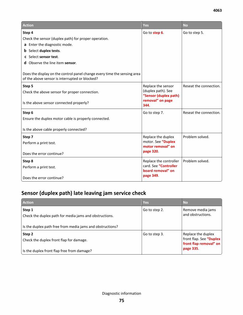
Action Yes No
Step 4
Check the sensor (duplex path) for proper operation.
a Enter the diagnostic mode.
b Select duplex tests.
c Select sensor test.
d Observe the line item sensor.
Does the display on the control panel change every time the sensing areaof the above sensor is interrupted or blocked?
Go to step 6. Go to step 5.
Step 5
Check the above sensor for proper connection.
Is the above sensor connected properly?
Replace the sensor(duplex path). See“Sensor (duplex path)removal” on page 344.
Reseat the connection.
Step 6
Ensure the duplex motor cable is properly connected.
Is the above cable properly connected?
Go to step 7. Reseat the connection.
Step 7
Perform a print test.
Does the error continue?
Replace the duplexmotor. See “Duplexmotor removal” onpage 320.
Problem solved.
Step 8
Perform a print test.
Does the error continue?
Replace the controllercard. See “Controllerboard removal” onpage 349.
Problem solved.
Sensor (duplex path) late leaving jam service check
Action Yes No
Step 1
Check the duplex path for media jams and obstructions.
Is the duplex path free from media jams and obstructions?
Go to step 2. Remove media jamsand obstructions.
Step 2
Check the duplex front flap for damage.
Is the duplex front flap free from damage?
Go to step 3. Replace the duplexfront flap. See “Duplexfront flap removal” onpage 335.
4063
Diagnostic information
75
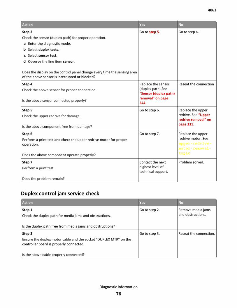
Action Yes No
Step 3
Check the sensor (duplex path) for proper operation.
a Enter the diagnostic mode.
b Select duplex tests.
c Select sensor test.
d Observe the line item sensor.
Does the display on the control panel change every time the sensing areaof the above sensor is interrupted or blocked?
Go to step 5. Go to step 4.
Step 4
Check the above sensor for proper connection.
Is the above sensor connected properly?
Replace the sensor(duplex path) See“Sensor (duplex path)removal” on page 344.
Reseat the connection
Step 5
Check the upper redrive for damage.
Is the above component free from damage?
Go to step 6. Replace the upperredrive. See “Upperredrive removal” onpage 331.
Step 6
Perform a print test and check the upper redrive motor for properoperation.
Does the above component operate properly?
Go to step 7. Replace the upperredrive motor. Seeupper-redrive-motor-removal-topic.
Step 7
Perform a print test.
Does the problem remain?
Contact the nexthighest level oftechnical support.
Problem solved.
Duplex control jam service check
Action Yes No
Step 1
Check the duplex path for media jams and obstructions.
Is the duplex path free from media jams and obstructions?
Go to step 2. Remove media jamsand obstructions.
Step 2
Ensure the duplex motor cable and the socket "DUPLEX MTR” on thecontroller board is properly connected.
Is the above cable properly connected?
Go to step 3. Reseat the connection.
4063
Diagnostic information
76
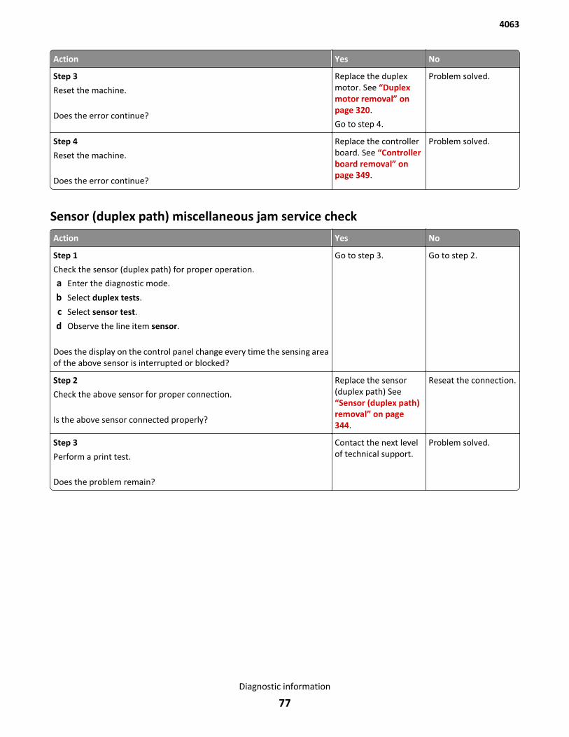
Action Yes No
Step 3
Reset the machine.
Does the error continue?
Replace the duplexmotor. See “Duplexmotor removal” onpage 320.
Go to step 4.
Problem solved.
Step 4
Reset the machine.
Does the error continue?
Replace the controllerboard. See “Controllerboard removal” onpage 349.
Problem solved.
Sensor (duplex path) miscellaneous jam service check
Action Yes No
Step 1
Check the sensor (duplex path) for proper operation.
a Enter the diagnostic mode.
b Select duplex tests.
c Select sensor test.
d Observe the line item sensor.
Does the display on the control panel change every time the sensing areaof the above sensor is interrupted or blocked?
Go to step 3. Go to step 2.
Step 2
Check the above sensor for proper connection.
Is the above sensor connected properly?
Replace the sensor(duplex path) See“Sensor (duplex path)removal” on page 344.
Reseat the connection.
Step 3
Perform a print test.
Does the problem remain?
Contact the next levelof technical support.
Problem solved.
4063
Diagnostic information
77
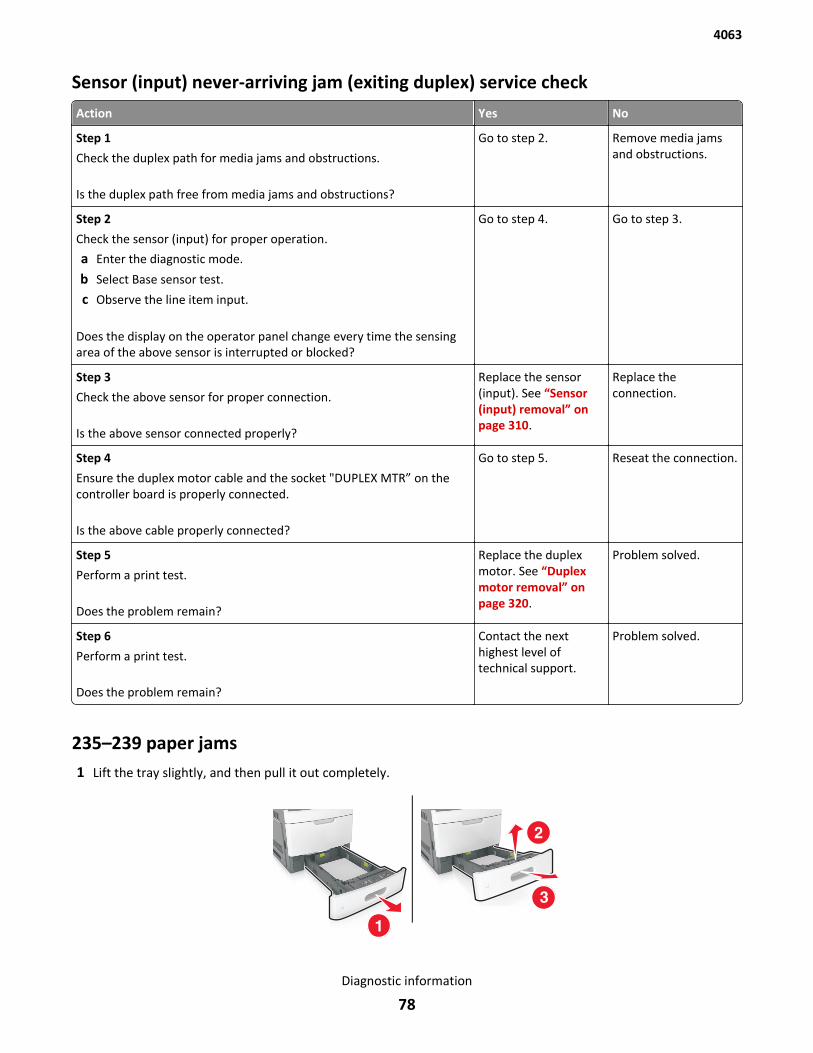
Sensor (input) never-arriving jam (exiting duplex) service check
Action Yes No
Step 1
Check the duplex path for media jams and obstructions.
Is the duplex path free from media jams and obstructions?
Go to step 2. Remove media jamsand obstructions.
Step 2
Check the sensor (input) for proper operation.
a Enter the diagnostic mode.
b Select Base sensor test.
c Observe the line item input.
Does the display on the operator panel change every time the sensingarea of the above sensor is interrupted or blocked?
Go to step 4. Go to step 3.
Step 3
Check the above sensor for proper connection.
Is the above sensor connected properly?
Replace the sensor(input). See “Sensor(input) removal” onpage 310.
Replace theconnection.
Step 4
Ensure the duplex motor cable and the socket "DUPLEX MTR” on thecontroller board is properly connected.
Is the above cable properly connected?
Go to step 5. Reseat the connection.
Step 5
Perform a print test.
Does the problem remain?
Replace the duplexmotor. See “Duplexmotor removal” onpage 320.
Problem solved.
Step 6
Perform a print test.
Does the problem remain?
Contact the nexthighest level oftechnical support.
Problem solved.
235–239 paper jams1 Lift the tray slightly, and then pull it out completely.
4063
Diagnostic information
78
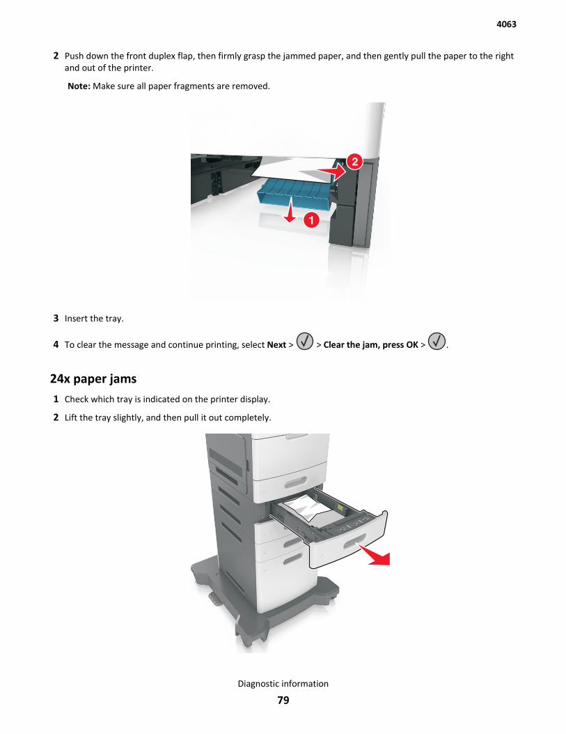
2 Push down the front duplex flap, then firmly grasp the jammed paper, and then gently pull the paper to the rightand out of the printer.
Note: Make sure all paper fragments are removed.
3 Insert the tray.
4 To clear the message and continue printing, select Next > > Clear the jam, press OK > .
24x paper jams1 Check which tray is indicated on the printer display.
2 Lift the tray slightly, and then pull it out completely.
4063
Diagnostic information
79
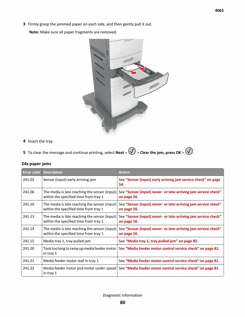
3 Firmly grasp the jammed paper on each side, and then gently pull it out.
Note: Make sure all paper fragments are removed.
4 Insert the tray.
5 To clear the message and continue printing, select Next > > Clear the jam, press OK > .
24x paper jams
Error code Description Action
241.02 Sensor (input) early arriving jam See “Sensor (input) early arriving jam service check” on page 54.
241.06 The media is late reaching the sensor (input)within the specified time from tray 1
See “Sensor (input) never‑ or late‑arriving jam service check”on page 56.
241.10 The media is late reaching the sensor (input)within the specified time from tray 1
See “Sensor (input) never‑ or late‑arriving jam service check”on page 56.
241.13 The media is late reaching the sensor (input)within the specified time from tray 1
See “Sensor (input) never‑ or late‑arriving jam service check”on page 56.
241.14 The media is late reaching the sensor (input)within the specified time from tray 1
See “Sensor (input) never‑ or late‑arriving jam service check”on page 56.
241.15 Media tray 1, tray pulled jam See “Media tray 1, tray pulled jam” on page 82.
241.20 Took too long to ramp up media feeder motorin tray 1
See “Media feeder motor control service check” on page 81.
241.21 Media feeder motor stall in tray 1 See “Media feeder motor control service check” on page 81.
241.22 Media feeder motor pick motor under‑speedin tray 1
See “Media feeder motor control service check” on page 81.
4063
Diagnostic information
80
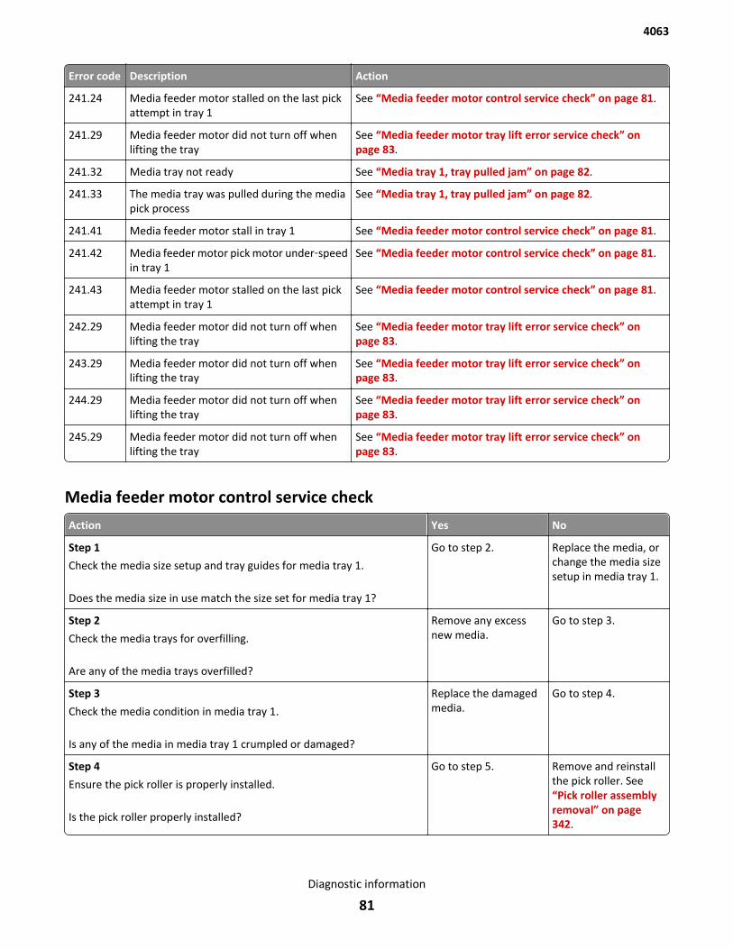
Error code Description Action
241.24 Media feeder motor stalled on the last pickattempt in tray 1
See “Media feeder motor control service check” on page 81.
241.29 Media feeder motor did not turn off whenlifting the tray
See “Media feeder motor tray lift error service check” onpage 83.
241.32 Media tray not ready See “Media tray 1, tray pulled jam” on page 82.
241.33 The media tray was pulled during the mediapick process
See “Media tray 1, tray pulled jam” on page 82.
241.41 Media feeder motor stall in tray 1 See “Media feeder motor control service check” on page 81.
241.42 Media feeder motor pick motor under‑speedin tray 1
See “Media feeder motor control service check” on page 81.
241.43 Media feeder motor stalled on the last pickattempt in tray 1
See “Media feeder motor control service check” on page 81.
242.29 Media feeder motor did not turn off whenlifting the tray
See “Media feeder motor tray lift error service check” onpage 83.
243.29 Media feeder motor did not turn off whenlifting the tray
See “Media feeder motor tray lift error service check” onpage 83.
244.29 Media feeder motor did not turn off whenlifting the tray
See “Media feeder motor tray lift error service check” onpage 83.
245.29 Media feeder motor did not turn off whenlifting the tray
See “Media feeder motor tray lift error service check” onpage 83.
Media feeder motor control service check
Action Yes No
Step 1
Check the media size setup and tray guides for media tray 1.
Does the media size in use match the size set for media tray 1?
Go to step 2. Replace the media, orchange the media sizesetup in media tray 1.
Step 2
Check the media trays for overfilling.
Are any of the media trays overfilled?
Remove any excessnew media.
Go to step 3.
Step 3
Check the media condition in media tray 1.
Is any of the media in media tray 1 crumpled or damaged?
Replace the damagedmedia.
Go to step 4.
Step 4
Ensure the pick roller is properly installed.
Is the pick roller properly installed?
Go to step 5. Remove and reinstallthe pick roller. See“Pick roller assemblyremoval” on page 342.
4063
Diagnostic information
81
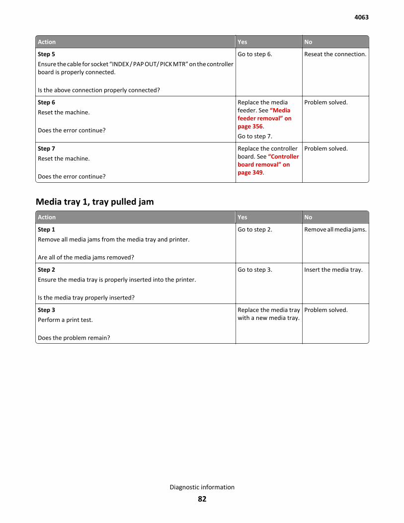
Action Yes No
Step 5
Ensure the cable for socket “INDEX / PAP OUT/ PICK MTR” on the controllerboard is properly connected.
Is the above connection properly connected?
Go to step 6. Reseat the connection.
Step 6
Reset the machine.
Does the error continue?
Replace the mediafeeder. See “Mediafeeder removal” onpage 356.
Go to step 7.
Problem solved.
Step 7
Reset the machine.
Does the error continue?
Replace the controllerboard. See “Controllerboard removal” onpage 349.
Problem solved.
Media tray 1, tray pulled jam
Action Yes No
Step 1
Remove all media jams from the media tray and printer.
Are all of the media jams removed?
Go to step 2. Remove all media jams.
Step 2
Ensure the media tray is properly inserted into the printer.
Is the media tray properly inserted?
Go to step 3. Insert the media tray.
Step 3
Perform a print test.
Does the problem remain?
Replace the media traywith a new media tray.
Problem solved.
4063
Diagnostic information
82
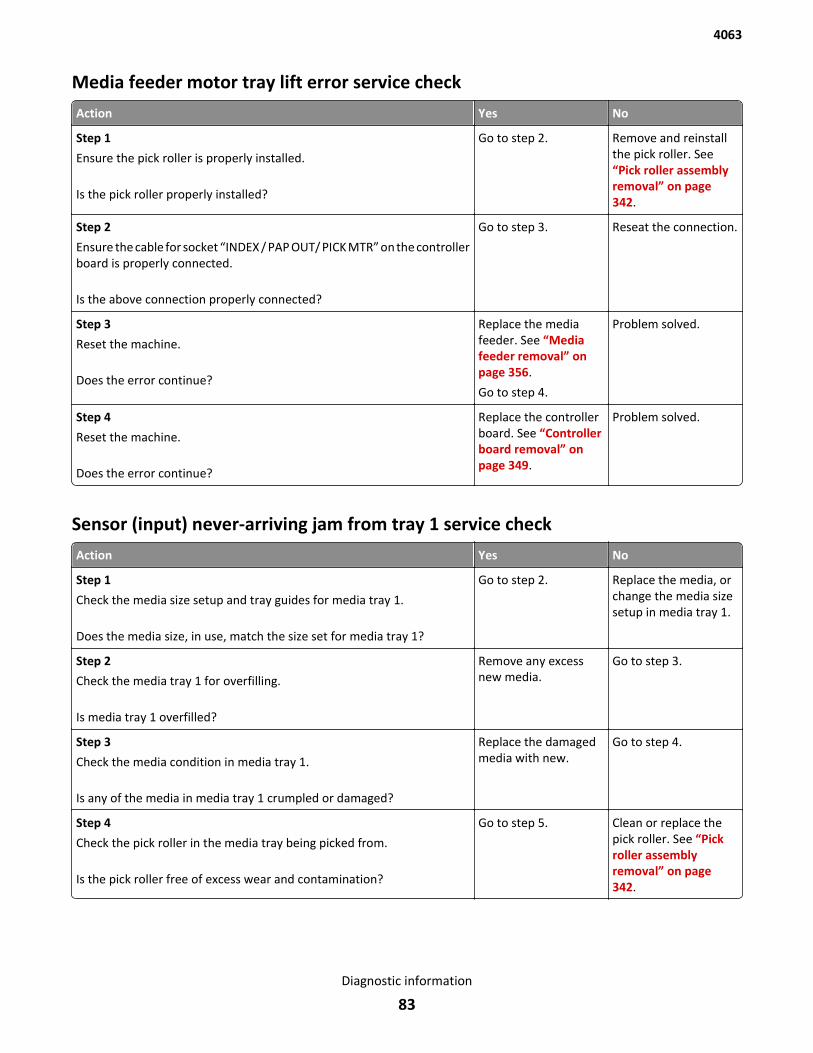
Media feeder motor tray lift error service check
Action Yes No
Step 1
Ensure the pick roller is properly installed.
Is the pick roller properly installed?
Go to step 2. Remove and reinstallthe pick roller. See“Pick roller assemblyremoval” on page 342.
Step 2
Ensure the cable for socket “INDEX / PAP OUT/ PICK MTR” on the controllerboard is properly connected.
Is the above connection properly connected?
Go to step 3. Reseat the connection.
Step 3
Reset the machine.
Does the error continue?
Replace the mediafeeder. See “Mediafeeder removal” onpage 356.
Go to step 4.
Problem solved.
Step 4
Reset the machine.
Does the error continue?
Replace the controllerboard. See “Controllerboard removal” onpage 349.
Problem solved.
Sensor (input) never-arriving jam from tray 1 service check
Action Yes No
Step 1
Check the media size setup and tray guides for media tray 1.
Does the media size, in use, match the size set for media tray 1?
Go to step 2. Replace the media, orchange the media sizesetup in media tray 1.
Step 2
Check the media tray 1 for overfilling.
Is media tray 1 overfilled?
Remove any excessnew media.
Go to step 3.
Step 3
Check the media condition in media tray 1.
Is any of the media in media tray 1 crumpled or damaged?
Replace the damagedmedia with new.
Go to step 4.
Step 4
Check the pick roller in the media tray being picked from.
Is the pick roller free of excess wear and contamination?
Go to step 5. Clean or replace thepick roller. See “Pickroller assemblyremoval” on page 342.
4063
Diagnostic information
83
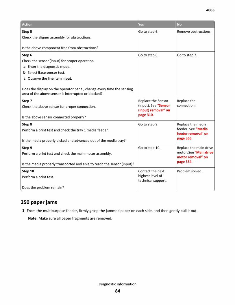
Action Yes No
Step 5
Check the aligner assembly for obstructions.
Is the above component free from obstructions?
Go to step 6. Remove obstructions.
Step 6
Check the sensor (input) for proper operation.
a Enter the diagnostic mode.
b Select Base sensor test.
c Observe the line item input.
Does the display on the operator panel, change every time the sensingarea of the above sensor is interrupted or blocked?
Go to step 8. Go to step 7.
Step 7
Check the above sensor for proper connection.
Is the above sensor connected properly?
Replace the Sensor(input). See “Sensor(input) removal” onpage 310.
Replace theconnection.
Step 8
Perform a print test and check the tray 1 media feeder.
Is the media properly picked and advanced out of the media tray?
Go to step 9. Replace the mediafeeder. See “Mediafeeder removal” onpage 356.
Step 9
Perform a print test and check the main motor assembly.
Is the media properly transported and able to reach the sensor (input)?
Go to step 10. Replace the main drivemotor. See “Main drivemotor removal” onpage 354.
Step 10
Perform a print test.
Does the problem remain?
Contact the nexthighest level oftechnical support.
Problem solved.
250 paper jams1 From the multipurpose feeder, firmly grasp the jammed paper on each side, and then gently pull it out.
Note: Make sure all paper fragments are removed.
4063
Diagnostic information
84
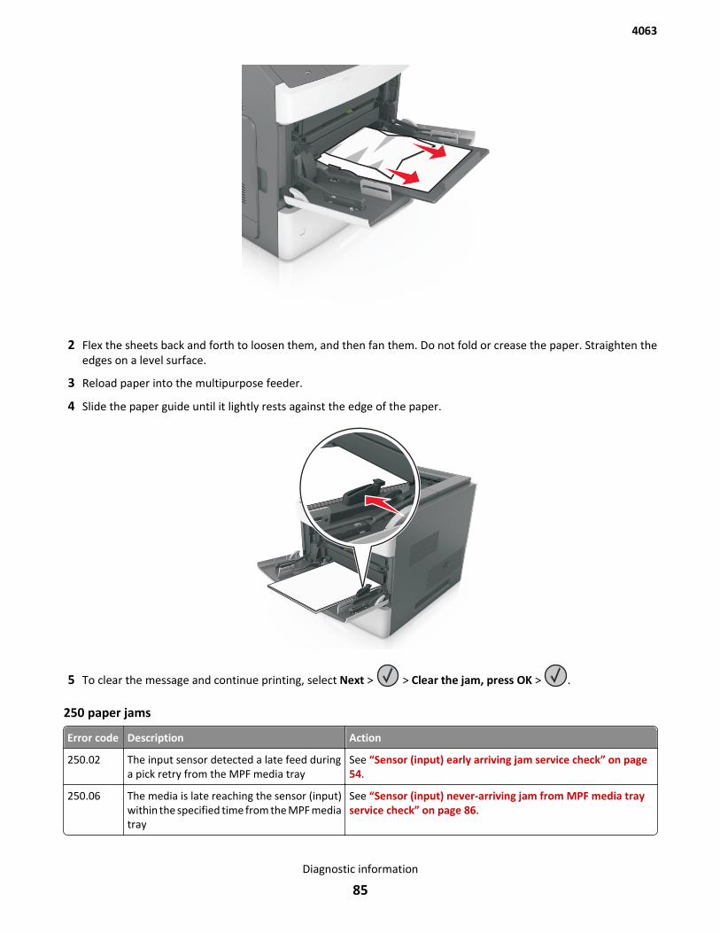
2 Flex the sheets back and forth to loosen them, and then fan them. Do not fold or crease the paper. Straighten theedges on a level surface.
3 Reload paper into the multipurpose feeder.
4 Slide the paper guide until it lightly rests against the edge of the paper.
5 To clear the message and continue printing, select Next > > Clear the jam, press OK > .
250 paper jams
Error code Description Action
250.02 The input sensor detected a late feed duringa pick retry from the MPF media tray
See “Sensor (input) early arriving jam service check” on page 54.
250.06 The media is late reaching the sensor (input)within the specified time from the MPF mediatray
See “Sensor (input) never-arriving jam from MPF media trayservice check” on page 86.
4063
Diagnostic information
85
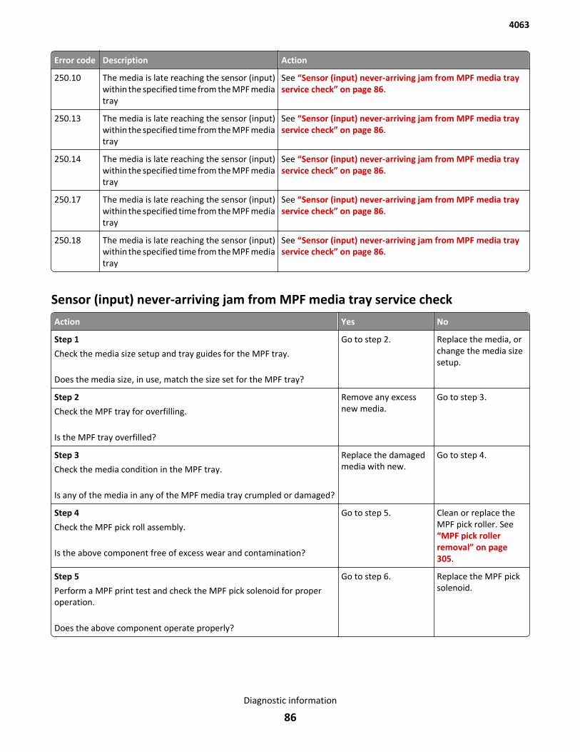
Error code Description Action
250.10 The media is late reaching the sensor (input)within the specified time from the MPF mediatray
See “Sensor (input) never-arriving jam from MPF media trayservice check” on page 86.
250.13 The media is late reaching the sensor (input)within the specified time from the MPF mediatray
See “Sensor (input) never-arriving jam from MPF media trayservice check” on page 86.
250.14 The media is late reaching the sensor (input)within the specified time from the MPF mediatray
See “Sensor (input) never-arriving jam from MPF media trayservice check” on page 86.
250.17 The media is late reaching the sensor (input)within the specified time from the MPF mediatray
See “Sensor (input) never-arriving jam from MPF media trayservice check” on page 86.
250.18 The media is late reaching the sensor (input)within the specified time from the MPF mediatray
See “Sensor (input) never-arriving jam from MPF media trayservice check” on page 86.
Sensor (input) never-arriving jam from MPF media tray service check
Action Yes No
Step 1
Check the media size setup and tray guides for the MPF tray.
Does the media size, in use, match the size set for the MPF tray?
Go to step 2. Replace the media, orchange the media sizesetup.
Step 2
Check the MPF tray for overfilling.
Is the MPF tray overfilled?
Remove any excessnew media.
Go to step 3.
Step 3
Check the media condition in the MPF tray.
Is any of the media in any of the MPF media tray crumpled or damaged?
Replace the damagedmedia with new.
Go to step 4.
Step 4
Check the MPF pick roll assembly.
Is the above component free of excess wear and contamination?
Go to step 5. Clean or replace theMPF pick roller. See“MPF pick rollerremoval” on page 305.
Step 5
Perform a MPF print test and check the MPF pick solenoid for properoperation.
Does the above component operate properly?
Go to step 6. Replace the MPF picksolenoid.
4063
Diagnostic information
86
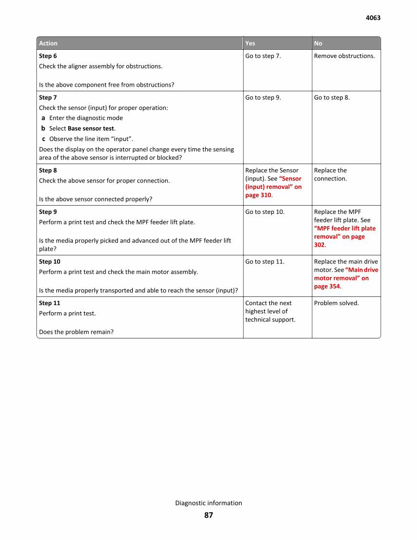
Action Yes No
Step 6
Check the aligner assembly for obstructions.
Is the above component free from obstructions?
Go to step 7. Remove obstructions.
Step 7
Check the sensor (input) for proper operation:
a Enter the diagnostic mode
b Select Base sensor test.
c Observe the line item “input”.
Does the display on the operator panel change every time the sensingarea of the above sensor is interrupted or blocked?
Go to step 9. Go to step 8.
Step 8
Check the above sensor for proper connection.
Is the above sensor connected properly?
Replace the Sensor(input). See “Sensor(input) removal” onpage 310.
Replace theconnection.
Step 9
Perform a print test and check the MPF feeder lift plate.
Is the media properly picked and advanced out of the MPF feeder liftplate?
Go to step 10. Replace the MPFfeeder lift plate. See“MPF feeder lift plateremoval” on page 302.
Step 10
Perform a print test and check the main motor assembly.
Is the media properly transported and able to reach the sensor (input)?
Go to step 11. Replace the main drivemotor. See “Main drivemotor removal” onpage 354.
Step 11
Perform a print test.
Does the problem remain?
Contact the nexthighest level oftechnical support.
Problem solved.
4063
Diagnostic information
87
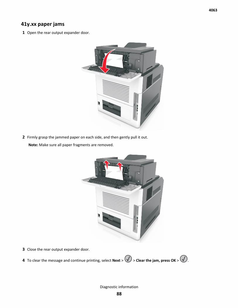
41y.xx paper jams1 Open the rear output expander door.
2 Firmly grasp the jammed paper on each side, and then gently pull it out.
Note: Make sure all paper fragments are removed.
3 Close the rear output expander door.
4 To clear the message and continue printing, select Next > > Clear the jam, press OK > .
4063
Diagnostic information
88
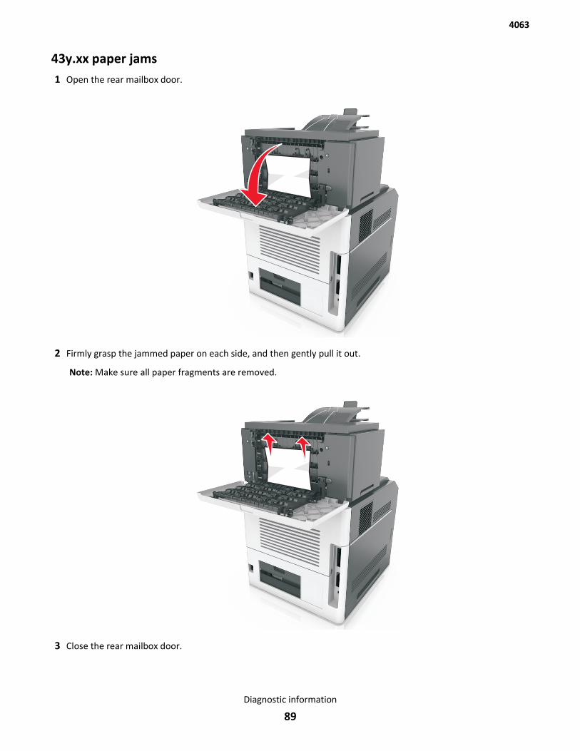
43y.xx paper jams1 Open the rear mailbox door.
2 Firmly grasp the jammed paper on each side, and then gently pull it out.
Note: Make sure all paper fragments are removed.
3 Close the rear mailbox door.
4063
Diagnostic information
89
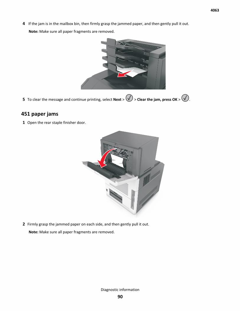
4 If the jam is in the mailbox bin, then firmly grasp the jammed paper, and then gently pull it out.
Note: Make sure all paper fragments are removed.
5 To clear the message and continue printing, select Next > > Clear the jam, press OK > .
451 paper jams1 Open the rear staple finisher door.
2 Firmly grasp the jammed paper on each side, and then gently pull it out.
Note: Make sure all paper fragments are removed.
4063
Diagnostic information
90
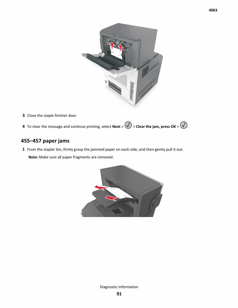
3 Close the staple finisher door.
4 To clear the message and continue printing, select Next > > Clear the jam, press OK > .
455–457 paper jams1 From the stapler bin, firmly grasp the jammed paper on each side, and then gently pull it out.
Note: Make sure all paper fragments are removed.
4063
Diagnostic information
91
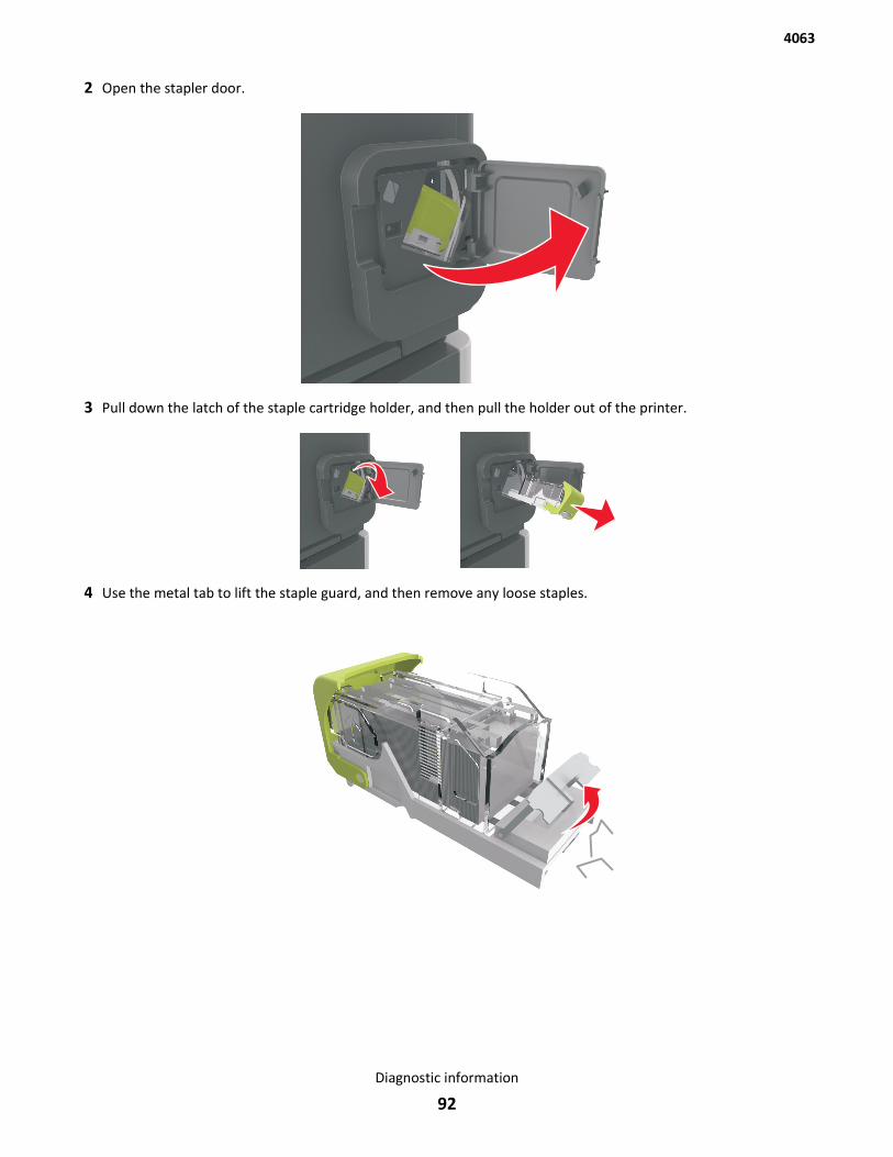
2 Open the stapler door.
3 Pull down the latch of the staple cartridge holder, and then pull the holder out of the printer.
4 Use the metal tab to lift the staple guard, and then remove any loose staples.
4063
Diagnostic information
92
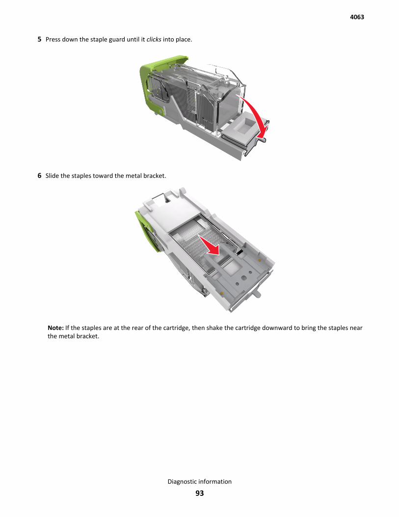
5 Press down the staple guard until it clicks into place.
6 Slide the staples toward the metal bracket.
Note: If the staples are at the rear of the cartridge, then shake the cartridge downward to bring the staples nearthe metal bracket.
4063
Diagnostic information
93
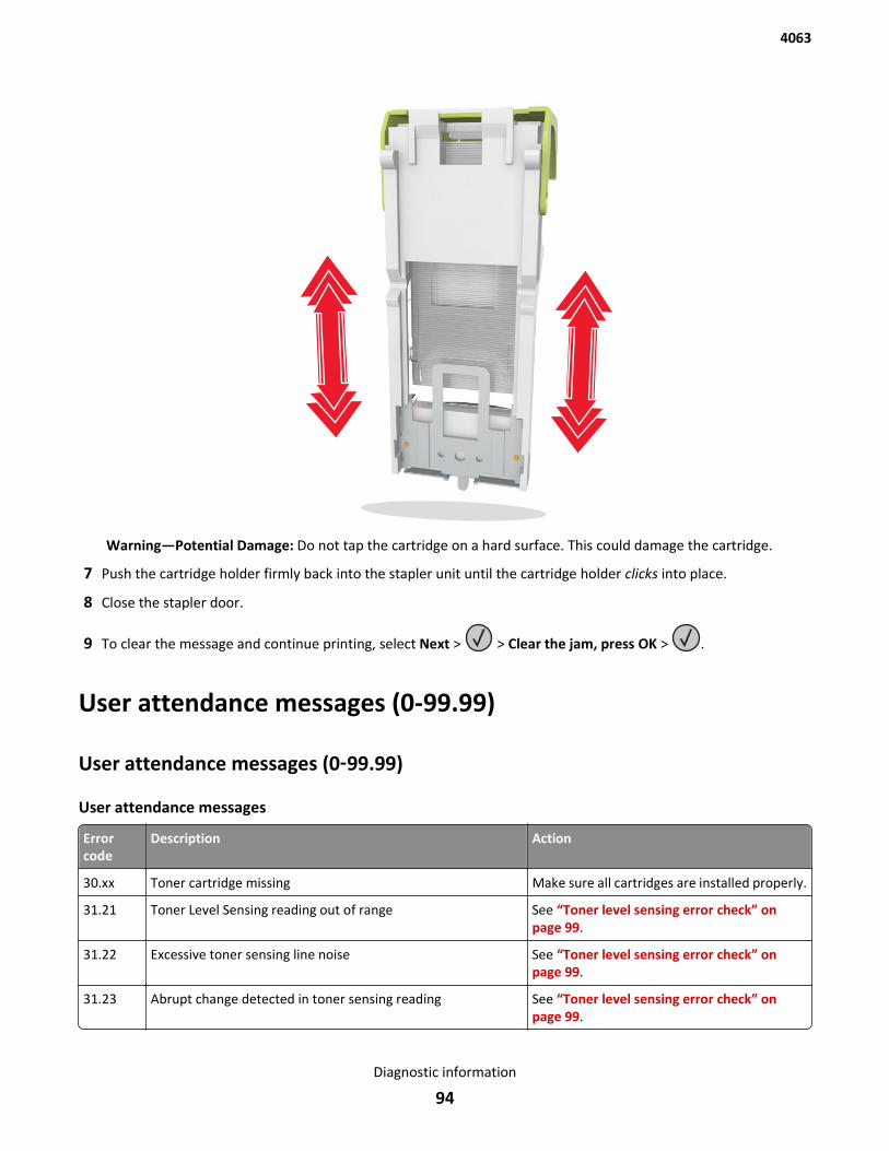
Warning—Potential Damage: Do not tap the cartridge on a hard surface. This could damage the cartridge.
7 Push the cartridge holder firmly back into the stapler unit until the cartridge holder clicks into place.
8 Close the stapler door.
9 To clear the message and continue printing, select Next > > Clear the jam, press OK > .
User attendance messages (0-99.99)
User attendance messages (0‑99.99)
User attendance messages
Errorcode
Description Action
30.xx Toner cartridge missing Make sure all cartridges are installed properly.
31.21 Toner Level Sensing reading out of range See “Toner level sensing error check” onpage 99.
31.22 Excessive toner sensing line noise See “Toner level sensing error check” onpage 99.
31.23 Abrupt change detected in toner sensing reading See “Toner level sensing error check” onpage 99.
4063
Diagnostic information
94
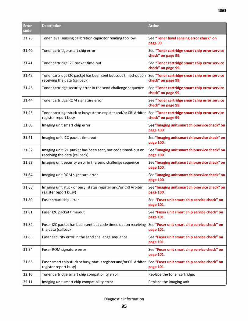
Errorcode
Description Action
31.25 Toner level sensing calibration capacitor reading too low See “Toner level sensing error check” onpage 99.
31.40 Toner cartridge smart chip error See “Toner cartridge smart chip error servicecheck” on page 99.
31.41 Toner cartridge I2C packet time-out See “Toner cartridge smart chip error servicecheck” on page 99.
31.42 Toner cartridge I2C packet has been sent but code timed-out onreceiving the data (callback)
See “Toner cartridge smart chip error servicecheck” on page 99.
31.43 Toner cartridge security error in the send challenge sequence See “Toner cartridge smart chip error servicecheck” on page 99.
31.44 Toner cartridge ROM signature error See “Toner cartridge smart chip error servicecheck” on page 99.
31.45 Toner cartridge stuck or busy; status register and/or CRI Arbiterregister report busy
See “Toner cartridge smart chip error servicecheck” on page 99.
31.60 Imaging unit smart chip error See “Imaging unit smart chip service check” onpage 100.
31.61 Imaging unit I2C packet time-out See “Imaging unit smart chip service check” onpage 100.
31.62 Imaging unit I2C packet has been sent, but code timed-out onreceiving the data (callback)
See “Imaging unit smart chip service check” onpage 100.
31.63 Imaging unit security error in the send challenge sequence See “Imaging unit smart chip service check” onpage 100.
31.64 Imaging unit ROM signature error See “Imaging unit smart chip service check” onpage 100.
31.65 Imaging unit stuck or busy; status register and/or CRI Arbiterregister report busy)
See “Imaging unit smart chip service check” onpage 100.
31.80 Fuser smart chip error See “Fuser unit smart chip service check” onpage 101.
31.81 Fuser I2C packet time-out See “Fuser unit smart chip service check” onpage 101.
31.82 Fuser I2C packet has been sent but code timed out on receivingthe data (callback)
See “Fuser unit smart chip service check” onpage 101.
31.83 Fuser security error in the send challenge sequence See “Fuser unit smart chip service check” onpage 101.
31.84 Fuser ROM signature error See “Fuser unit smart chip service check” onpage 101.
31.85 Fuser smart chip stuck or busy; status register and/or CRI Arbiterregister report busy)
See “Fuser unit smart chip service check” onpage 101.
32.10 Toner cartridge smart chip compatibility error Replace the toner cartridge.
32.11 Imaging unit smart chip compatibility error Replace the imaging unit.
4063
Diagnostic information
95
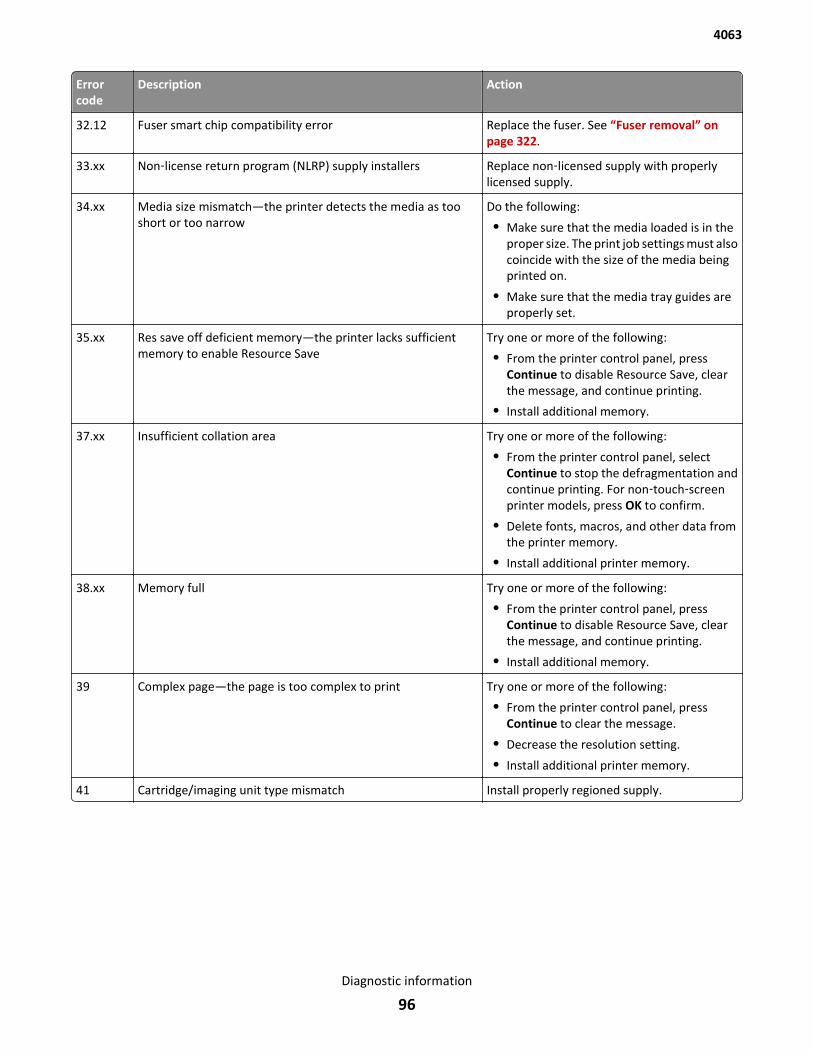
Errorcode
Description Action
32.12 Fuser smart chip compatibility error Replace the fuser. See “Fuser removal” onpage 322.
33.xx Non‑license return program (NLRP) supply installers Replace non‑licensed supply with properlylicensed supply.
34.xx Media size mismatch—the printer detects the media as tooshort or too narrow
Do the following:
• Make sure that the media loaded is in theproper size. The print job settings must alsocoincide with the size of the media beingprinted on.
• Make sure that the media tray guides areproperly set.
35.xx Res save off deficient memory—the printer lacks sufficientmemory to enable Resource Save
Try one or more of the following:
• From the printer control panel, pressContinue to disable Resource Save, clearthe message, and continue printing.
• Install additional memory.
37.xx Insufficient collation area Try one or more of the following:
• From the printer control panel, selectContinue to stop the defragmentation andcontinue printing. For non‑touch‑screenprinter models, press OK to confirm.
• Delete fonts, macros, and other data fromthe printer memory.
• Install additional printer memory.
38.xx Memory full Try one or more of the following:
• From the printer control panel, pressContinue to disable Resource Save, clearthe message, and continue printing.
• Install additional memory.
39 Complex page—the page is too complex to print Try one or more of the following:
• From the printer control panel, pressContinue to clear the message.
• Decrease the resolution setting.
• Install additional printer memory.
41 Cartridge/imaging unit type mismatch Install properly regioned supply.
4063
Diagnostic information
96
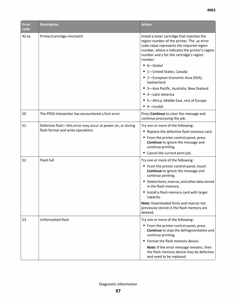
Errorcode
Description Action
42.xy Printer/cartridge mismatch Install a toner cartridge that matches theregion number of the printer. The .xy errorcode value represents the required regionnumber, where x indicates the printer’s regionnumber and y for the cartridge’s regionnumber:
• 0—Global
• 1—United States, Canada
• 2—European Economic Area (EEA),Switzerland
• 3—Asia Pacific, Australia, New Zealand
• 4—Latin America
• 5—Africa, Middle East, rest of Europe
• 9—Invalid
50 The PPDS interpreter has encountered a font error Press Continue to clear the message andcontinue processing the job.
51 Defective flash—this error may occur at power on, or duringflash format and write operations
Try one or more of the following:
• Replace the defective flash memory card.
• From the printer control panel, pressContinue to ignore the message andcontinue printing.
• Cancel the current print job.
52 Flash full Try one or more of the following:
• From the printer control panel, touchContinue to ignore the message andcontinue printing.
• Delete fonts, macros, and other data storedin the flash memory.
• Install a flash memory card with largercapacity.
Note: Downloaded fonts and macros notpreviously stored in the flash memory aredeleted.
53 Unformatted flash Try one or more of the following:
• From the printer control panel, pressContinue to stop the defragmentation andcontinue printing.
• Format the flash memory device.
Note: If the error message remains, thenthe flash memory device may be defectiveand need to be replaced.
4063
Diagnostic information
97
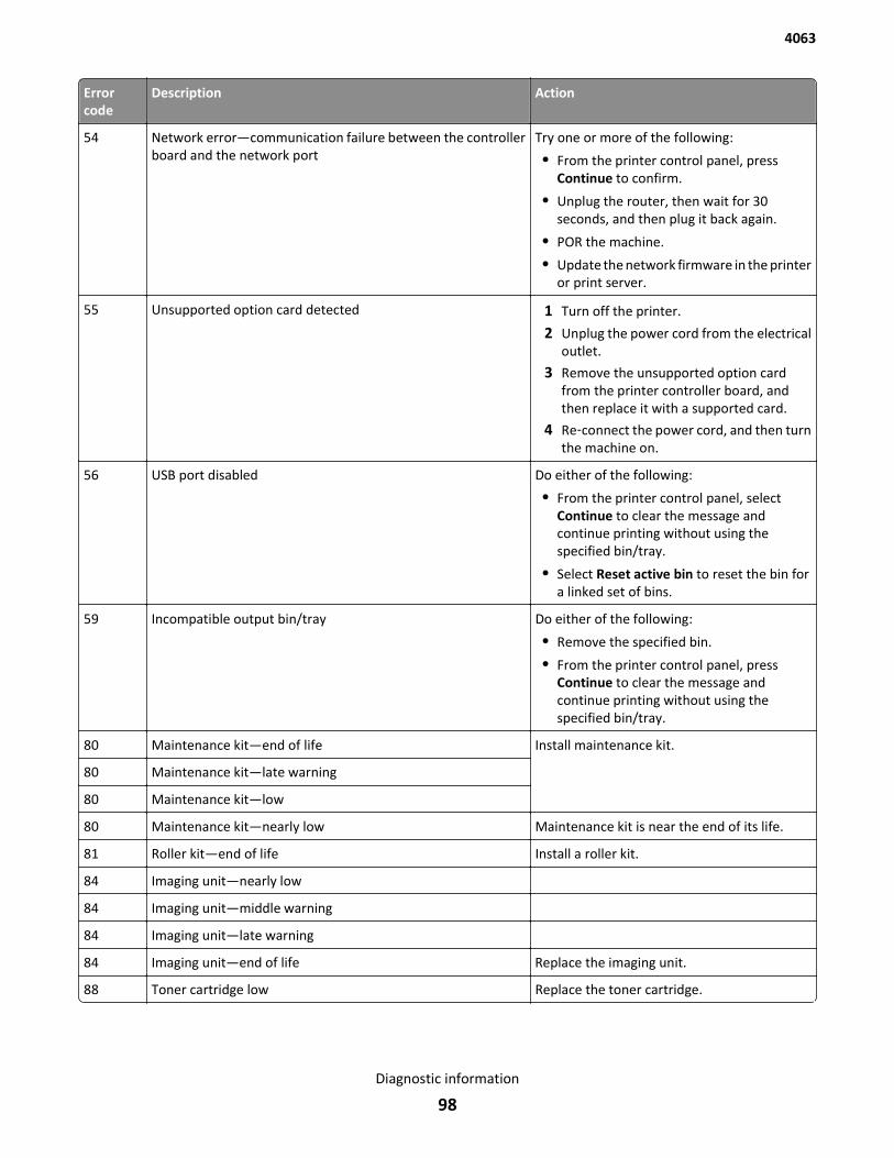
Errorcode
Description Action
54 Network error—communication failure between the controllerboard and the network port
Try one or more of the following:
• From the printer control panel, pressContinue to confirm.
• Unplug the router, then wait for 30seconds, and then plug it back again.
• POR the machine.
• Update the network firmware in the printeror print server.
55 Unsupported option card detected 1 Turn off the printer.
2 Unplug the power cord from the electricaloutlet.
3 Remove the unsupported option cardfrom the printer controller board, andthen replace it with a supported card.
4 Re‑connect the power cord, and then turnthe machine on.
56 USB port disabled Do either of the following:
• From the printer control panel, selectContinue to clear the message andcontinue printing without using thespecified bin/tray.
• Select Reset active bin to reset the bin fora linked set of bins.
59 Incompatible output bin/tray Do either of the following:
• Remove the specified bin.
• From the printer control panel, pressContinue to clear the message andcontinue printing without using thespecified bin/tray.
80 Maintenance kit—end of life Install maintenance kit.
80 Maintenance kit—late warning
80 Maintenance kit—low
80 Maintenance kit—nearly low Maintenance kit is near the end of its life.
81 Roller kit—end of life Install a roller kit.
84 Imaging unit—nearly low
84 Imaging unit—middle warning
84 Imaging unit—late warning
84 Imaging unit—end of life Replace the imaging unit.
88 Toner cartridge low Replace the toner cartridge.
4063
Diagnostic information
98
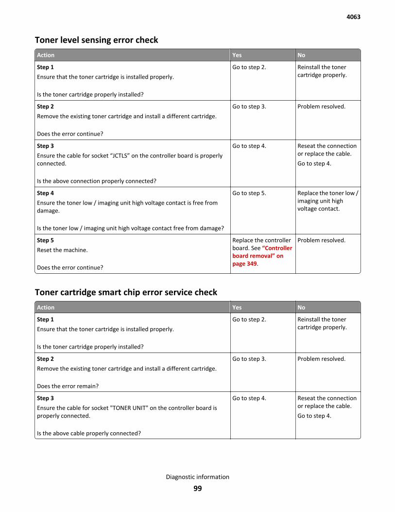
Toner level sensing error check
Action Yes No
Step 1
Ensure that the toner cartridge is installed properly.
Is the toner cartridge properly installed?
Go to step 2. Reinstall the tonercartridge properly.
Step 2
Remove the existing toner cartridge and install a different cartridge.
Does the error continue?
Go to step 3. Problem resolved.
Step 3
Ensure the cable for socket “JCTLS” on the controller board is properlyconnected.
Is the above connection properly connected?
Go to step 4. Reseat the connectionor replace the cable.
Go to step 4.
Step 4
Ensure the toner low / imaging unit high voltage contact is free fromdamage.
Is the toner low / imaging unit high voltage contact free from damage?
Go to step 5. Replace the toner low /imaging unit highvoltage contact.
Step 5
Reset the machine.
Does the error continue?
Replace the controllerboard. See “Controllerboard removal” onpage 349.
Problem resolved.
Toner cartridge smart chip error service check
Action Yes No
Step 1
Ensure that the toner cartridge is installed properly.
Is the toner cartridge properly installed?
Go to step 2. Reinstall the tonercartridge properly.
Step 2
Remove the existing toner cartridge and install a different cartridge.
Does the error remain?
Go to step 3. Problem resolved.
Step 3
Ensure the cable for socket "TONER UNIT" on the controller board isproperly connected.
Is the above cable properly connected?
Go to step 4. Reseat the connectionor replace the cable.
Go to step 4.
4063
Diagnostic information
99
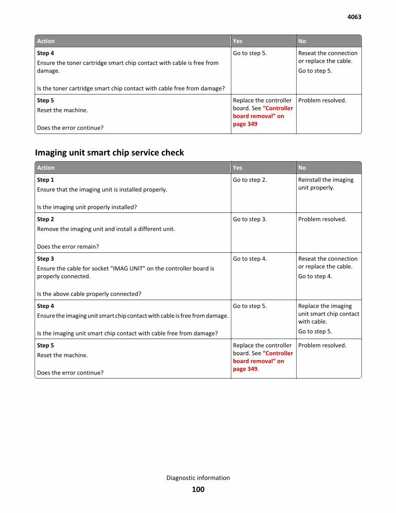
Action Yes No
Step 4
Ensure the toner cartridge smart chip contact with cable is free fromdamage.
Is the toner cartridge smart chip contact with cable free from damage?
Go to step 5. Reseat the connectionor replace the cable.
Go to step 5.
Step 5
Reset the machine.
Does the error continue?
Replace the controllerboard. See “Controllerboard removal” onpage 349
Problem resolved.
Imaging unit smart chip service check
Action Yes No
Step 1
Ensure that the imaging unit is installed properly.
Is the imaging unit properly installed?
Go to step 2. Reinstall the imagingunit properly.
Step 2
Remove the imaging unit and install a different unit.
Does the error remain?
Go to step 3. Problem resolved.
Step 3
Ensure the cable for socket "IMAG UNIT" on the controller board isproperly connected.
Is the above cable properly connected?
Go to step 4. Reseat the connectionor replace the cable.
Go to step 4.
Step 4
Ensure the imaging unit smart chip contact with cable is free from damage.
Is the imaging unit smart chip contact with cable free from damage?
Go to step 5. Replace the imagingunit smart chip contactwith cable.
Go to step 5.
Step 5
Reset the machine.
Does the error continue?
Replace the controllerboard. See “Controllerboard removal” onpage 349.
Problem resolved.
4063
Diagnostic information
100
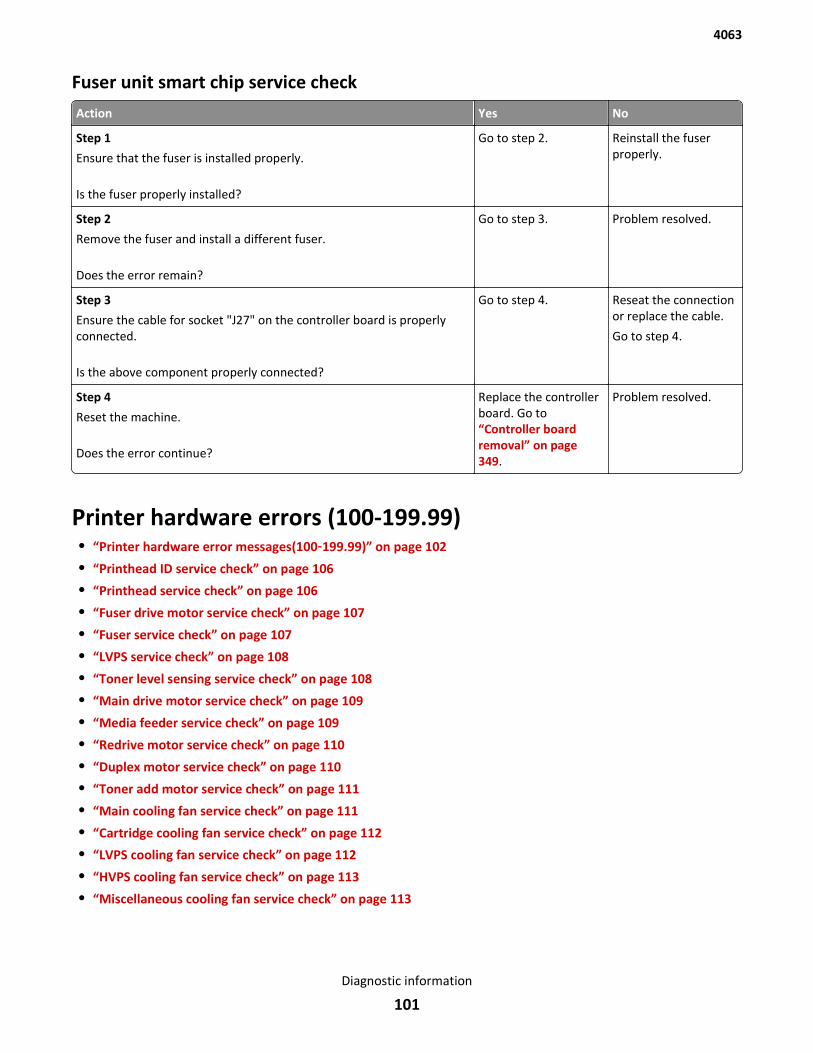
Fuser unit smart chip service check
Action Yes No
Step 1
Ensure that the fuser is installed properly.
Is the fuser properly installed?
Go to step 2. Reinstall the fuserproperly.
Step 2
Remove the fuser and install a different fuser.
Does the error remain?
Go to step 3. Problem resolved.
Step 3
Ensure the cable for socket "J27" on the controller board is properlyconnected.
Is the above component properly connected?
Go to step 4. Reseat the connectionor replace the cable.
Go to step 4.
Step 4
Reset the machine.
Does the error continue?
Replace the controllerboard. Go to“Controller boardremoval” on page 349.
Problem resolved.
Printer hardware errors (100-199.99)• “Printer hardware error messages(100‑199.99)” on page 102
• “Printhead ID service check” on page 106
• “Printhead service check” on page 106
• “Fuser drive motor service check” on page 107
• “Fuser service check” on page 107
• “LVPS service check” on page 108
• “Toner level sensing service check” on page 108
• “Main drive motor service check” on page 109
• “Media feeder service check” on page 109
• “Redrive motor service check” on page 110
• “Duplex motor service check” on page 110
• “Toner add motor service check” on page 111
• “Main cooling fan service check” on page 111
• “Cartridge cooling fan service check” on page 112
• “LVPS cooling fan service check” on page 112
• “HVPS cooling fan service check” on page 113
• “Miscellaneous cooling fan service check” on page 113
4063
Diagnostic information
101
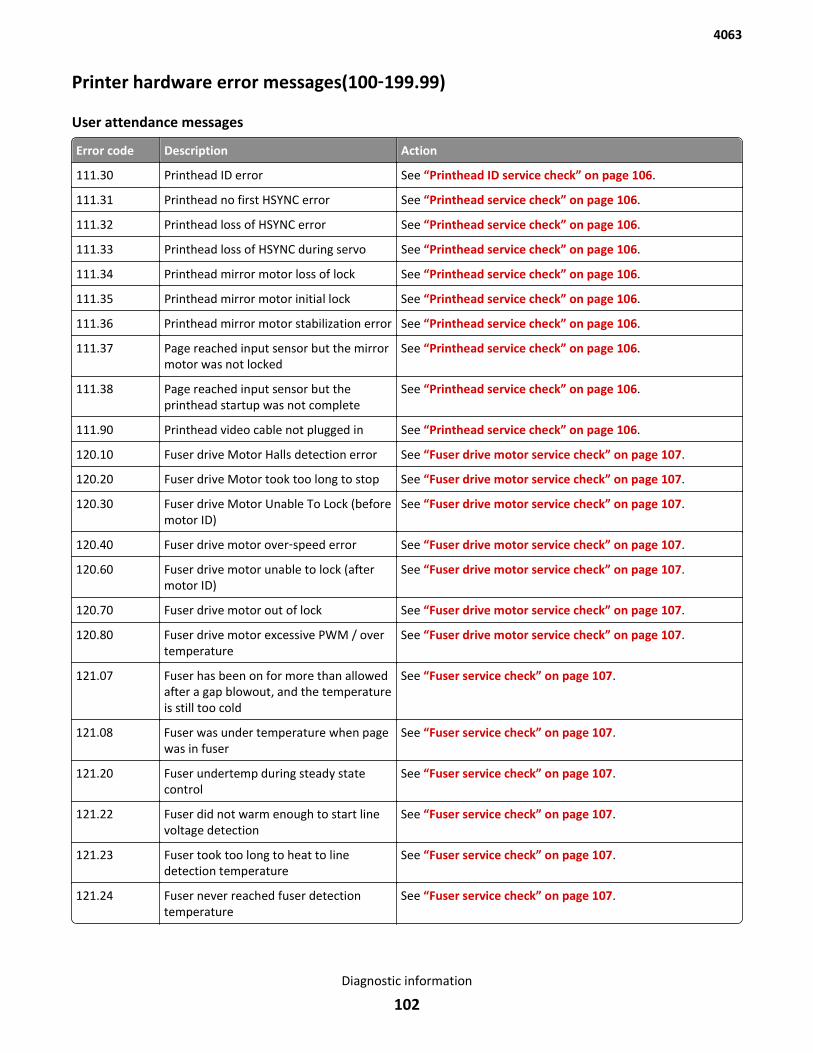
Printer hardware error messages(100‑199.99)
User attendance messages
Error code Description Action
111.30 Printhead ID error See “Printhead ID service check” on page 106.
111.31 Printhead no first HSYNC error See “Printhead service check” on page 106.
111.32 Printhead loss of HSYNC error See “Printhead service check” on page 106.
111.33 Printhead loss of HSYNC during servo See “Printhead service check” on page 106.
111.34 Printhead mirror motor loss of lock See “Printhead service check” on page 106.
111.35 Printhead mirror motor initial lock See “Printhead service check” on page 106.
111.36 Printhead mirror motor stabilization error See “Printhead service check” on page 106.
111.37 Page reached input sensor but the mirrormotor was not locked
See “Printhead service check” on page 106.
111.38 Page reached input sensor but theprinthead startup was not complete
See “Printhead service check” on page 106.
111.90 Printhead video cable not plugged in See “Printhead service check” on page 106.
120.10 Fuser drive Motor Halls detection error See “Fuser drive motor service check” on page 107.
120.20 Fuser drive Motor took too long to stop See “Fuser drive motor service check” on page 107.
120.30 Fuser drive Motor Unable To Lock (beforemotor ID)
See “Fuser drive motor service check” on page 107.
120.40 Fuser drive motor over‑speed error See “Fuser drive motor service check” on page 107.
120.60 Fuser drive motor unable to lock (aftermotor ID)
See “Fuser drive motor service check” on page 107.
120.70 Fuser drive motor out of lock See “Fuser drive motor service check” on page 107.
120.80 Fuser drive motor excessive PWM / overtemperature
See “Fuser drive motor service check” on page 107.
121.07 Fuser has been on for more than allowedafter a gap blowout, and the temperatureis still too cold
See “Fuser service check” on page 107.
121.08 Fuser was under temperature when pagewas in fuser
See “Fuser service check” on page 107.
121.20 Fuser undertemp during steady statecontrol
See “Fuser service check” on page 107.
121.22 Fuser did not warm enough to start linevoltage detection
See “Fuser service check” on page 107.
121.23 Fuser took too long to heat to linedetection temperature
See “Fuser service check” on page 107.
121.24 Fuser never reached fuser detectiontemperature
See “Fuser service check” on page 107.
4063
Diagnostic information
102
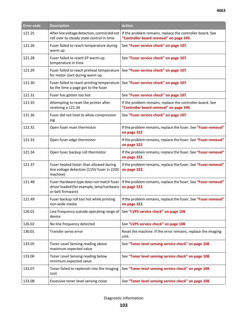
Error code Description Action
121.25 After line voltage detection, control did notroll over to steady state control in time
If the problem remains, replace the controller board. See“Controller board removal” on page 349.
121.26 Fuser failed to reach temperature duringwarm up
See “Fuser service check” on page 107.
121.28 Fuser failed to reach EP warm-uptemperature in time
See “Fuser service check” on page 107.
121.29 Fuser failed to reach preheat temperaturefor motor start during warm up
See “Fuser service check” on page 107.
121.30 Fuser failed to reach printing temperatureby the time a page got to the fuser
See “Fuser service check” on page 107.
121.31 Fuser has gotten too hot See “Fuser service check” on page 107.
121.35 Attempting to reset the printer afterreceiving a 121.34
If the problem remains, replace the controller board. See“Controller board removal” on page 349.
121.36 Fuser did not heat to allow compressionjog
See “Fuser service check” on page 107.
121.32 Open fuser main thermistor If the problem remains, replace the fuser. See “Fuser removal”on page 322
121.33 Open fuser edge thermistor If the problem remains, replace the fuser. See “Fuser removal”on page 322
121.34 Open fuser backup roll thermistor If the problem remains, replace the fuser. See “Fuser removal”on page 322.
121.37 Fuser heated faster than allowed duringline voltage detection (115V fuser in 220Vmachine)
If the problem remains, replace the fuser. See “Fuser removal”on page 322.
121.48 Fuser Hardware type does not match fuserdriver loaded (for example, lamp hardwareor belt firmware)
If the problem remains, replace the fuser. See “Fuser removal”on page 322.
121.49 Fuser backup roll too hot while printingnon-wide media
If the problem remains, replace the fuser. See “Fuser removal”on page 322.
126.01 Line Frequency outside operating range ofdevice
See “LVPS service check” on page 108.
126.02 No line frequency detected See “LVPS service check” on page 108.
130.01 Transfer servo error Reset the machine. If the error remains, replace the imagingunit.
133.05 Toner Level Sensing reading abovemaximum expected value
See “Toner level sensing service check” on page 108.
133.06 Toner Level Sensing reading belowminimum expected value
See “Toner level sensing service check” on page 108.
133.07 Toner failed to replenish into the ImagingUnit
See “Toner level sensing service check” on page 108.
133.08 Excessive toner level sensing noise See “Toner level sensing service check” on page 108.
4063
Diagnostic information
103
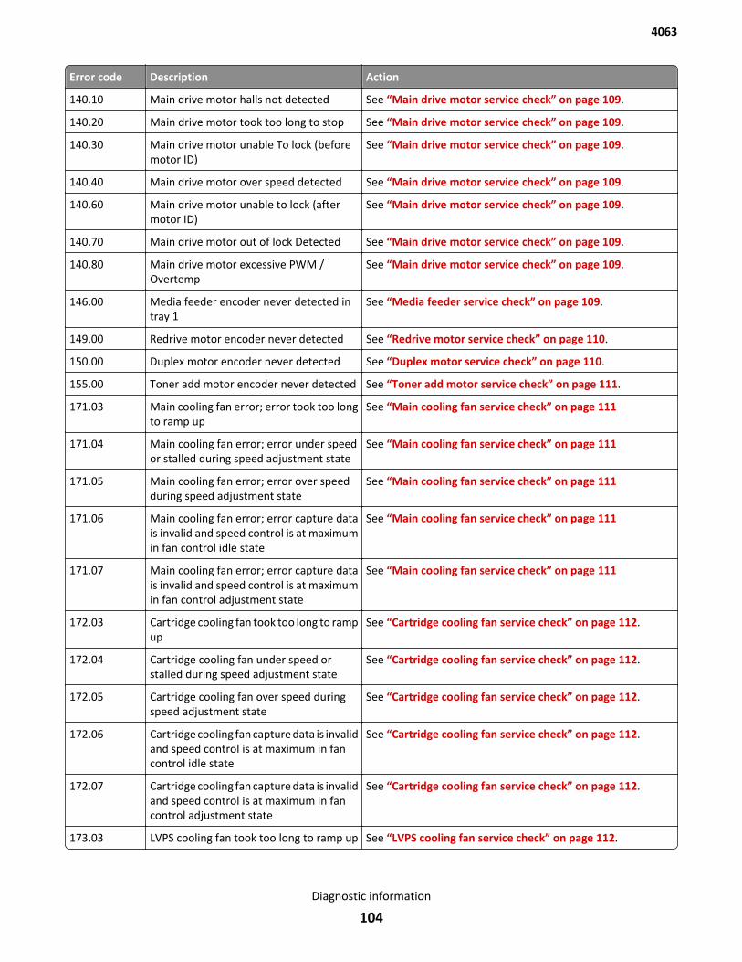
Error code Description Action
140.10 Main drive motor halls not detected See “Main drive motor service check” on page 109.
140.20 Main drive motor took too long to stop See “Main drive motor service check” on page 109.
140.30 Main drive motor unable To lock (beforemotor ID)
See “Main drive motor service check” on page 109.
140.40 Main drive motor over speed detected See “Main drive motor service check” on page 109.
140.60 Main drive motor unable to lock (aftermotor ID)
See “Main drive motor service check” on page 109.
140.70 Main drive motor out of lock Detected See “Main drive motor service check” on page 109.
140.80 Main drive motor excessive PWM /Overtemp
See “Main drive motor service check” on page 109.
146.00 Media feeder encoder never detected intray 1
See “Media feeder service check” on page 109.
149.00 Redrive motor encoder never detected See “Redrive motor service check” on page 110.
150.00 Duplex motor encoder never detected See “Duplex motor service check” on page 110.
155.00 Toner add motor encoder never detected See “Toner add motor service check” on page 111.
171.03 Main cooling fan error; error took too longto ramp up
See “Main cooling fan service check” on page 111
171.04 Main cooling fan error; error under speedor stalled during speed adjustment state
See “Main cooling fan service check” on page 111
171.05 Main cooling fan error; error over speedduring speed adjustment state
See “Main cooling fan service check” on page 111
171.06 Main cooling fan error; error capture datais invalid and speed control is at maximumin fan control idle state
See “Main cooling fan service check” on page 111
171.07 Main cooling fan error; error capture datais invalid and speed control is at maximumin fan control adjustment state
See “Main cooling fan service check” on page 111
172.03 Cartridge cooling fan took too long to rampup
See “Cartridge cooling fan service check” on page 112.
172.04 Cartridge cooling fan under speed orstalled during speed adjustment state
See “Cartridge cooling fan service check” on page 112.
172.05 Cartridge cooling fan over speed duringspeed adjustment state
See “Cartridge cooling fan service check” on page 112.
172.06 Cartridge cooling fan capture data is invalidand speed control is at maximum in fancontrol idle state
See “Cartridge cooling fan service check” on page 112.
172.07 Cartridge cooling fan capture data is invalidand speed control is at maximum in fancontrol adjustment state
See “Cartridge cooling fan service check” on page 112.
173.03 LVPS cooling fan took too long to ramp up See “LVPS cooling fan service check” on page 112.
4063
Diagnostic information
104
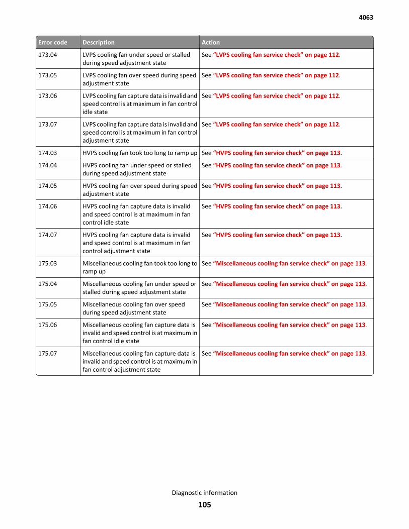
Error code Description Action
173.04 LVPS cooling fan under speed or stalledduring speed adjustment state
See “LVPS cooling fan service check” on page 112.
173.05 LVPS cooling fan over speed during speedadjustment state
See “LVPS cooling fan service check” on page 112.
173.06 LVPS cooling fan capture data is invalid andspeed control is at maximum in fan controlidle state
See “LVPS cooling fan service check” on page 112.
173.07 LVPS cooling fan capture data is invalid andspeed control is at maximum in fan controladjustment state
See “LVPS cooling fan service check” on page 112.
174.03 HVPS cooling fan took too long to ramp up See “HVPS cooling fan service check” on page 113.
174.04 HVPS cooling fan under speed or stalledduring speed adjustment state
See “HVPS cooling fan service check” on page 113.
174.05 HVPS cooling fan over speed during speedadjustment state
See “HVPS cooling fan service check” on page 113.
174.06 HVPS cooling fan capture data is invalidand speed control is at maximum in fancontrol idle state
See “HVPS cooling fan service check” on page 113.
174.07 HVPS cooling fan capture data is invalidand speed control is at maximum in fancontrol adjustment state
See “HVPS cooling fan service check” on page 113.
175.03 Miscellaneous cooling fan took too long toramp up
See “Miscellaneous cooling fan service check” on page 113.
175.04 Miscellaneous cooling fan under speed orstalled during speed adjustment state
See “Miscellaneous cooling fan service check” on page 113.
175.05 Miscellaneous cooling fan over speedduring speed adjustment state
See “Miscellaneous cooling fan service check” on page 113.
175.06 Miscellaneous cooling fan capture data isinvalid and speed control is at maximum infan control idle state
See “Miscellaneous cooling fan service check” on page 113.
175.07 Miscellaneous cooling fan capture data isinvalid and speed control is at maximum infan control adjustment state
See “Miscellaneous cooling fan service check” on page 113.
4063
Diagnostic information
105
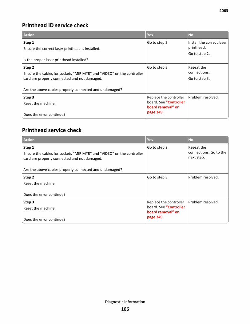
Printhead ID service check
Action Yes No
Step 1
Ensure the correct laser printhead is installed.
Is the proper laser printhead installed?
Go to step 2. Install the correct laserprinthead.
Go to step 2.
Step 2
Ensure the cables for sockets “MIR MTR” and “VIDEO” on the controllercard are properly connected and not damaged.
Are the above cables properly connected and undamaged?
Go to step 3. Reseat theconnections.
Go to step 3.
Step 3
Reset the machine.
Does the error continue?
Replace the controllerboard. See “Controllerboard removal” onpage 349.
Problem resolved.
Printhead service check
Action Yes No
Step 1
Ensure the cables for sockets “MIR MTR” and “VIDEO” on the controllercard are properly connected and not damaged.
Are the above cables properly connected and undamaged?
Go to step 2. Reseat theconnections. Go to thenext step.
Step 2
Reset the machine.
Does the error continue?
Go to step 3. Problem resolved.
Step 3
Reset the machine.
Does the error continue?
Replace the controllerboard. See “Controllerboard removal” onpage 349.
Problem resolved.
4063
Diagnostic information
106
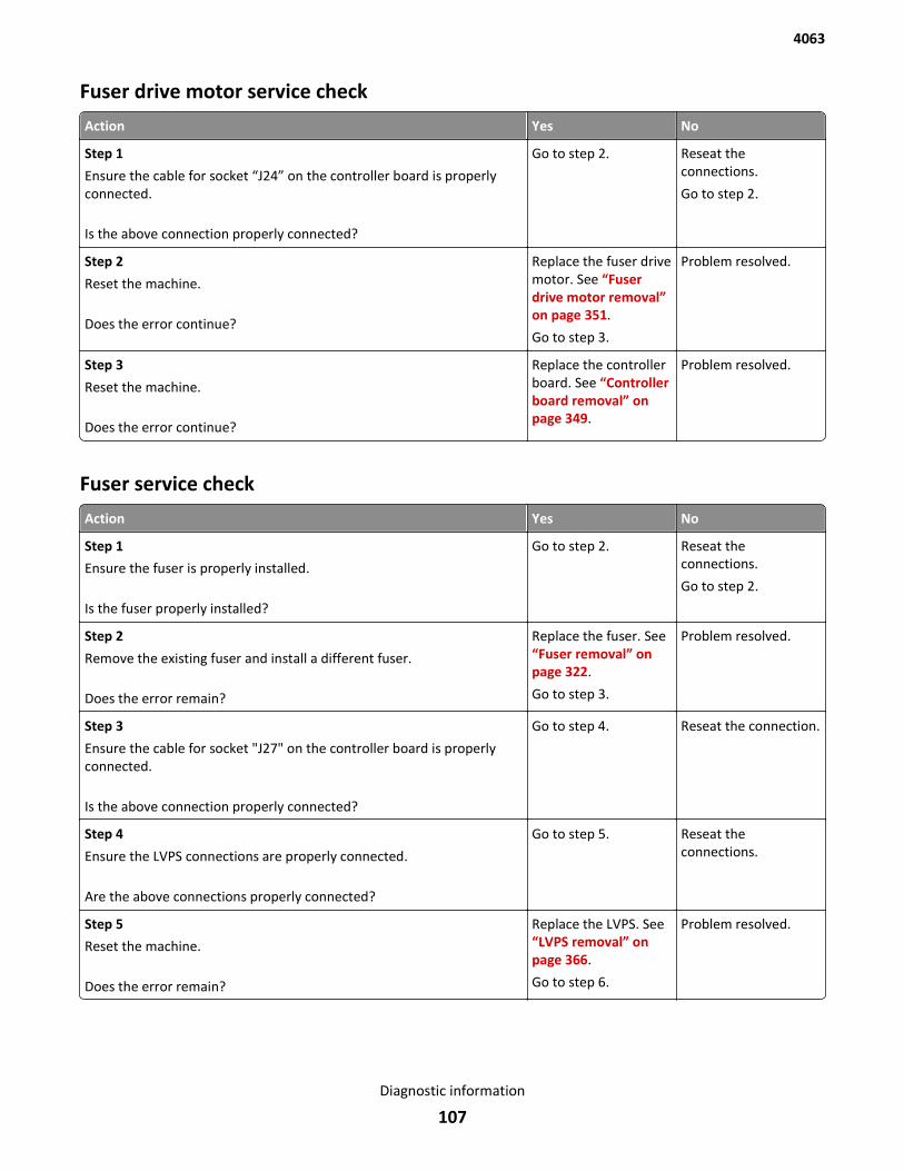
Fuser drive motor service check
Action Yes No
Step 1
Ensure the cable for socket “J24” on the controller board is properlyconnected.
Is the above connection properly connected?
Go to step 2. Reseat theconnections.
Go to step 2.
Step 2
Reset the machine.
Does the error continue?
Replace the fuser drivemotor. See “Fuserdrive motor removal”on page 351.
Go to step 3.
Problem resolved.
Step 3
Reset the machine.
Does the error continue?
Replace the controllerboard. See “Controllerboard removal” onpage 349.
Problem resolved.
Fuser service check
Action Yes No
Step 1
Ensure the fuser is properly installed.
Is the fuser properly installed?
Go to step 2. Reseat theconnections.
Go to step 2.
Step 2
Remove the existing fuser and install a different fuser.
Does the error remain?
Replace the fuser. See“Fuser removal” onpage 322.
Go to step 3.
Problem resolved.
Step 3
Ensure the cable for socket "J27" on the controller board is properlyconnected.
Is the above connection properly connected?
Go to step 4. Reseat the connection.
Step 4
Ensure the LVPS connections are properly connected.
Are the above connections properly connected?
Go to step 5. Reseat theconnections.
Step 5
Reset the machine.
Does the error remain?
Replace the LVPS. See“LVPS removal” onpage 366.
Go to step 6.
Problem resolved.
4063
Diagnostic information
107
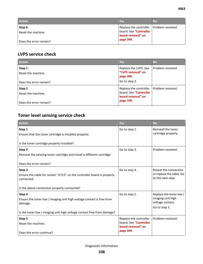
Action Yes No
Step 6
Reset the machine.
Does the error remain?
Replace the controllerboard. See “Controllerboard removal” onpage 349.
Problem resolved.
LVPS service check
Action Yes No
Step 1
Reset the machine.
Does the error remain?
Replace the LVPS. See“LVPS removal” onpage 366.
Go to step 2.
Problem resolved.
Step 2
Reset the machine.
Does the error remain?
Replace the controllerboard. See “Controllerboard removal” onpage 349.
Problem resolved.
Toner level sensing service check
Action Yes No
Step 1
Ensure that the toner cartridge is installed properly.
Is the toner cartridge properly installed?
Go to step 2. Reinstall the tonercartridge properly.
Step 2
Remove the existing toner cartridge and install a different cartridge.
Does the error remain?
Go to step 3. Problem resolved.
Step 3
Ensure the cable for socket “JCTLS” on the controller board is properlyconnected.
Is the above connection properly connected?
Go to step 4. Reseat the connectionor replace the cable. Goto the next step.
Step 4
Ensure the toner low / imaging unit high voltage contact is free fromdamage.
Is the toner low / imaging unit high voltage contact free from damage?
Go to step 5. Replace the toner low /imaging unit highvoltage contact.
Go to step 5.
Step 5
Reset the machine.
Does the error continue?
Replace the controllerboard. See “Controllerboard removal” onpage 349.
Problem resolved.
4063
Diagnostic information
108
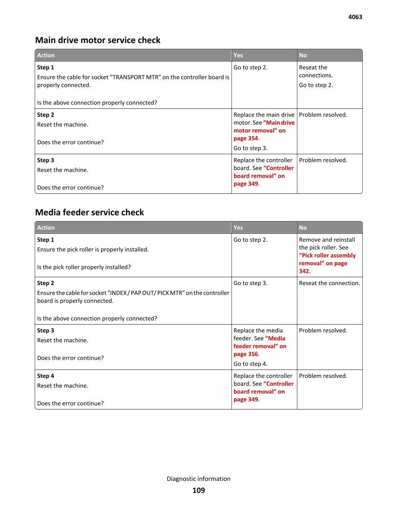
Main drive motor service check
Action Yes No
Step 1
Ensure the cable for socket “TRANSPORT MTR” on the controller board isproperly connected.
Is the above connection properly connected?
Go to step 2. Reseat theconnections.
Go to step 2.
Step 2
Reset the machine.
Does the error continue?
Replace the main drivemotor. See “Main drivemotor removal” onpage 354.
Go to step 3.
Problem resolved.
Step 3
Reset the machine.
Does the error continue?
Replace the controllerboard. See “Controllerboard removal” onpage 349.
Problem resolved.
Media feeder service check
Action Yes No
Step 1
Ensure the pick roller is properly installed.
Is the pick roller properly installed?
Go to step 2. Remove and reinstallthe pick roller. See“Pick roller assemblyremoval” on page 342.
Step 2
Ensure the cable for socket “INDEX / PAP OUT/ PICK MTR” on the controllerboard is properly connected.
Is the above connection properly connected?
Go to step 3. Reseat the connection.
Step 3
Reset the machine.
Does the error continue?
Replace the mediafeeder. See “Mediafeeder removal” onpage 356.
Go to step 4.
Problem resolved.
Step 4
Reset the machine.
Does the error continue?
Replace the controllerboard. See “Controllerboard removal” onpage 349.
Problem resolved.
4063
Diagnostic information
109
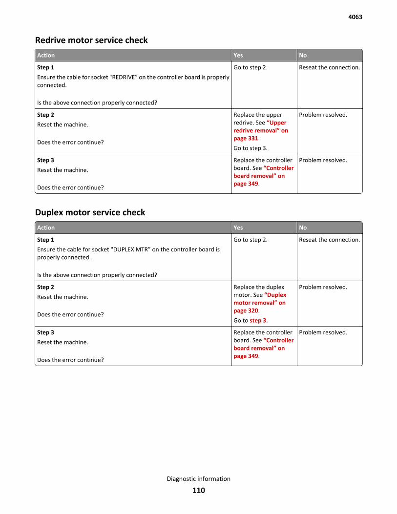
Redrive motor service check
Action Yes No
Step 1
Ensure the cable for socket "REDRIVE” on the controller board is properlyconnected.
Is the above connection properly connected?
Go to step 2. Reseat the connection.
Step 2
Reset the machine.
Does the error continue?
Replace the upperredrive. See “Upperredrive removal” onpage 331.
Go to step 3.
Problem resolved.
Step 3
Reset the machine.
Does the error continue?
Replace the controllerboard. See “Controllerboard removal” onpage 349.
Problem resolved.
Duplex motor service check
Action Yes No
Step 1
Ensure the cable for socket "DUPLEX MTR” on the controller board isproperly connected.
Is the above connection properly connected?
Go to step 2. Reseat the connection.
Step 2
Reset the machine.
Does the error continue?
Replace the duplexmotor. See “Duplexmotor removal” onpage 320.
Go to step 3.
Problem resolved.
Step 3
Reset the machine.
Does the error continue?
Replace the controllerboard. See “Controllerboard removal” onpage 349.
Problem resolved.
4063
Diagnostic information
110
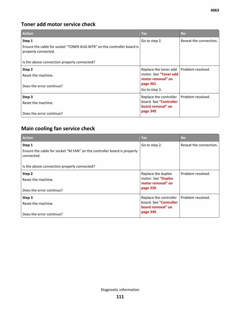
Toner add motor service check
Action Yes No
Step 1
Ensure the cable for socket "TONER AUG MTR” on the controller board isproperly connected.
Is the above connection properly connected?
Go to step 2. Reseat the connection.
Step 2
Reset the machine.
Does the error continue?
Replace the toner addmotor. See “Toner addmotor removal” onpage 361.
Go to step 3.
Problem resolved.
Step 3
Reset the machine.
Does the error continue?
Replace the controllerboard. See “Controllerboard removal” onpage 349.
Problem resolved.
Main cooling fan service check
Action Yes No
Step 1
Ensure the cable for socket "M FAN” on the controller board is properlyconnected.
Is the above connection properly connected?
Go to step 2. Reseat the connection.
Step 2
Reset the machine.
Does the error continue?
Replace the duplexmotor. See “Duplexmotor removal” onpage 320.
Problem resolved.
Step 3
Reset the machine.
Does the error continue?
Replace the controllerboard. See “Controllerboard removal” onpage 349.
Problem resolved.
4063
Diagnostic information
111
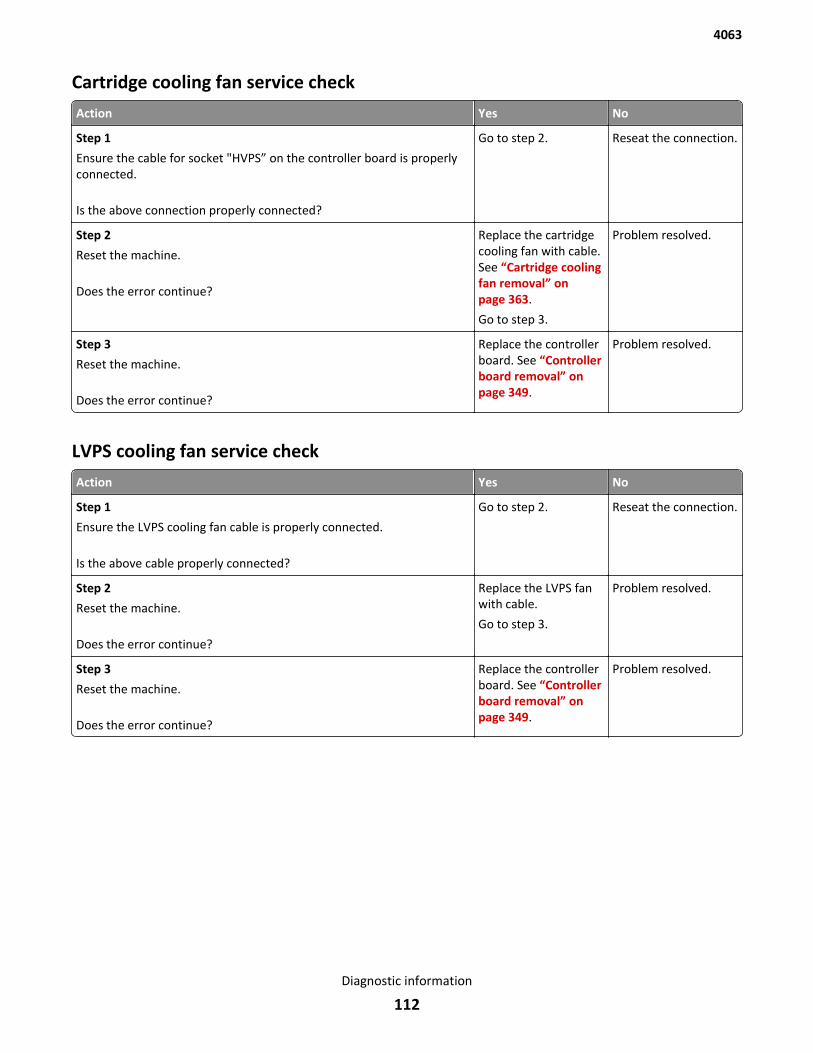
Cartridge cooling fan service check
Action Yes No
Step 1
Ensure the cable for socket "HVPS” on the controller board is properlyconnected.
Is the above connection properly connected?
Go to step 2. Reseat the connection.
Step 2
Reset the machine.
Does the error continue?
Replace the cartridgecooling fan with cable.See “Cartridge coolingfan removal” onpage 363.
Go to step 3.
Problem resolved.
Step 3
Reset the machine.
Does the error continue?
Replace the controllerboard. See “Controllerboard removal” onpage 349.
Problem resolved.
LVPS cooling fan service check
Action Yes No
Step 1
Ensure the LVPS cooling fan cable is properly connected.
Is the above cable properly connected?
Go to step 2. Reseat the connection.
Step 2
Reset the machine.
Does the error continue?
Replace the LVPS fanwith cable.
Go to step 3.
Problem resolved.
Step 3
Reset the machine.
Does the error continue?
Replace the controllerboard. See “Controllerboard removal” onpage 349.
Problem resolved.
4063
Diagnostic information
112
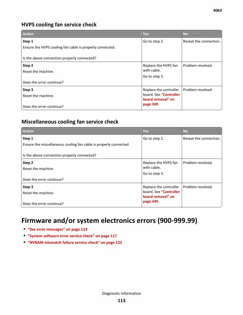
HVPS cooling fan service check
Action Yes No
Step 1
Ensure the HVPS cooling fan cable is properly connected.
Is the above connection properly connected?
Go to step 2. Reseat the connection.
Step 2
Reset the machine.
Does the error continue?
Replace the HVPS fanwith cable.
Go to step 3.
Problem resolved.
Step 3
Reset the machine.
Does the error continue?
Replace the controllerboard. See “Controllerboard removal” onpage 349.
Problem resolved.
Miscellaneous cooling fan service check
Action Yes No
Step 1
Ensure the miscellaneous cooling fan cable is properly connected.
Is the above connection properly connected?
Go to step 2. Reseat the connection.
Step 2
Reset the machine.
Does the error continue?
Replace the HVPS fanwith cable.
Go to step 3.
Problem resolved.
Step 3
Reset the machine.
Does the error continue?
Replace the controllerboard. See “Controllerboard removal” onpage 349.
Problem resolved.
Firmware and/or system electronics errors (900-999.99)• “9xx error messages” on page 114
• “System software error service check” on page 117
• “NVRAM mismatch failure service check” on page 122
4063
Diagnostic information
113
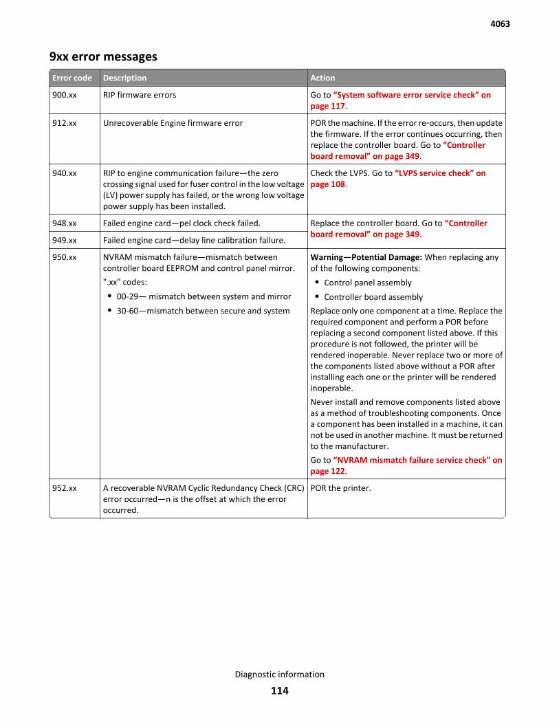
9xx error messages
Error code Description Action
900.xx RIP firmware errors Go to “System software error service check” onpage 117.
912.xx Unrecoverable Engine firmware error POR the machine. If the error re‑occurs, then updatethe firmware. If the error continues occurring, thenreplace the controller board. Go to “Controllerboard removal” on page 349.
940.xx RIP to engine communication failure—the zerocrossing signal used for fuser control in the low voltage(LV) power supply has failed, or the wrong low voltagepower supply has been installed.
Check the LVPS. Go to “LVPS service check” onpage 108.
948.xx Failed engine card—pel clock check failed. Replace the controller board. Go to “Controllerboard removal” on page 349.
949.xx Failed engine card—delay line calibration failure.
950.xx NVRAM mismatch failure—mismatch betweencontroller board EEPROM and control panel mirror.
".xx" codes:
• 00-29— mismatch between system and mirror
• 30-60—mismatch between secure and system
Warning—Potential Damage: When replacing anyof the following components:
• Control panel assembly
• Controller board assembly
Replace only one component at a time. Replace therequired component and perform a POR beforereplacing a second component listed above. If thisprocedure is not followed, the printer will berendered inoperable. Never replace two or more ofthe components listed above without a POR afterinstalling each one or the printer will be renderedinoperable.
Never install and remove components listed aboveas a method of troubleshooting components. Oncea component has been installed in a machine, it cannot be used in another machine. It must be returnedto the manufacturer.
Go to “NVRAM mismatch failure service check” onpage 122.
952.xx A recoverable NVRAM Cyclic Redundancy Check (CRC)error occurred—n is the offset at which the erroroccurred.
POR the printer.
4063
Diagnostic information
114
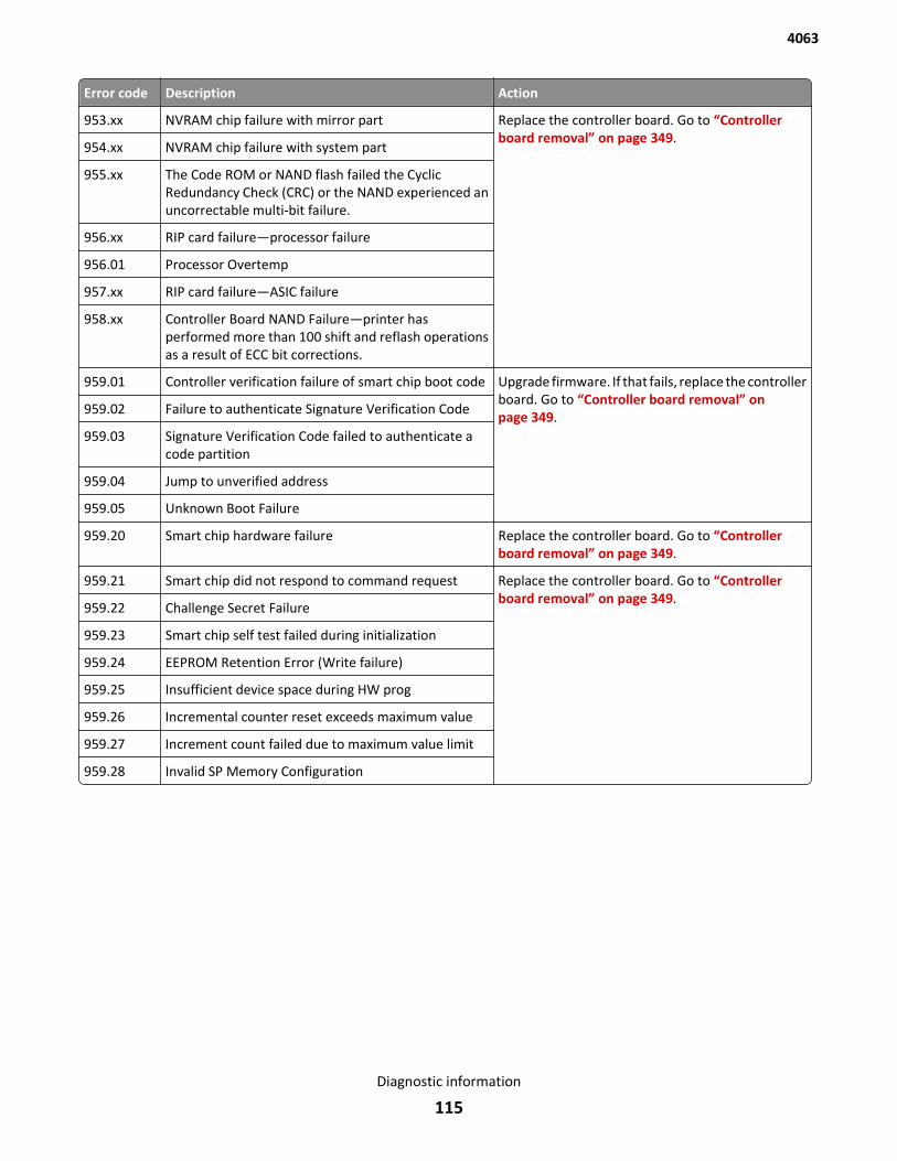
Error code Description Action
953.xx NVRAM chip failure with mirror part Replace the controller board. Go to “Controllerboard removal” on page 349.
954.xx NVRAM chip failure with system part
955.xx The Code ROM or NAND flash failed the CyclicRedundancy Check (CRC) or the NAND experienced anuncorrectable multi-bit failure.
956.xx RIP card failure—processor failure
956.01 Processor Overtemp
957.xx RIP card failure—ASIC failure
958.xx Controller Board NAND Failure—printer hasperformed more than 100 shift and reflash operationsas a result of ECC bit corrections.
959.01 Controller verification failure of smart chip boot code Upgrade firmware. If that fails, replace the controllerboard. Go to “Controller board removal” onpage 349.959.02 Failure to authenticate Signature Verification Code
959.03 Signature Verification Code failed to authenticate acode partition
959.04 Jump to unverified address
959.05 Unknown Boot Failure
959.20 Smart chip hardware failure Replace the controller board. Go to “Controllerboard removal” on page 349.
959.21 Smart chip did not respond to command request Replace the controller board. Go to “Controllerboard removal” on page 349.
959.22 Challenge Secret Failure
959.23 Smart chip self test failed during initialization
959.24 EEPROM Retention Error (Write failure)
959.25 Insufficient device space during HW prog
959.26 Incremental counter reset exceeds maximum value
959.27 Increment count failed due to maximum value limit
959.28 Invalid SP Memory Configuration
4063
Diagnostic information
115
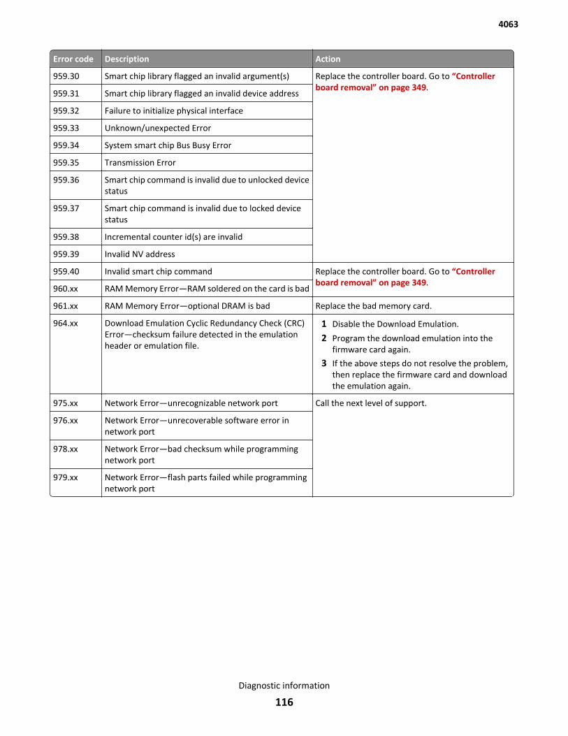
Error code Description Action
959.30 Smart chip library flagged an invalid argument(s) Replace the controller board. Go to “Controllerboard removal” on page 349.
959.31 Smart chip library flagged an invalid device address
959.32 Failure to initialize physical interface
959.33 Unknown/unexpected Error
959.34 System smart chip Bus Busy Error
959.35 Transmission Error
959.36 Smart chip command is invalid due to unlocked devicestatus
959.37 Smart chip command is invalid due to locked devicestatus
959.38 Incremental counter id(s) are invalid
959.39 Invalid NV address
959.40 Invalid smart chip command Replace the controller board. Go to “Controllerboard removal” on page 349.
960.xx RAM Memory Error—RAM soldered on the card is bad
961.xx RAM Memory Error—optional DRAM is bad Replace the bad memory card.
964.xx Download Emulation Cyclic Redundancy Check (CRC)Error—checksum failure detected in the emulationheader or emulation file.
1 Disable the Download Emulation.
2 Program the download emulation into thefirmware card again.
3 If the above steps do not resolve the problem,then replace the firmware card and downloadthe emulation again.
975.xx Network Error—unrecognizable network port Call the next level of support.
976.xx Network Error—unrecoverable software error innetwork port
978.xx Network Error—bad checksum while programmingnetwork port
979.xx Network Error—flash parts failed while programmingnetwork port
4063
Diagnostic information
116
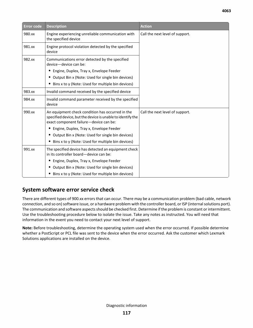
Error code Description Action
980.xx Engine experiencing unreliable communication withthe specified device
Call the next level of support.
981.xx Engine protocol violation detected by the specifieddevice
982.xx Communications error detected by the specifieddevice—device can be:
• Engine, Duplex, Tray x, Envelope Feeder
• Output Bin x (Note: Used for single bin devices)
• Bins x to y (Note: Used for multiple bin devices)
983.xx Invalid command received by the specified device
984.xx Invalid command parameter received by the specifieddevice
990.xx An equipment check condition has occurred in thespecified device, but the device is unable to identify theexact component failure—device can be:
• Engine, Duplex, Tray x, Envelope Feeder
• Output Bin x (Note: Used for single bin devices)
• Bins x to y (Note: Used for multiple bin devices)
Call the next level of support.
991.xx The specified device has detected an equipment checkin its controller board—device can be:
• Engine, Duplex, Tray x, Envelope Feeder
• Output Bin x (Note: Used for single bin devices)
• Bins x to y (Note: Used for multiple bin devices)
System software error service checkThere are different types of 900.xx errors that can occur. There may be a communication problem (bad cable, networkconnection, and so on) software issue, or a hardware problem with the controller board, or ISP (internal solutions port).The communication and software aspects should be checked first. Determine if the problem is constant or intermittent.Use the troubleshooting procedure below to isolate the issue. Take any notes as instructed. You will need thatinformation in the event you need to contact your next level of support.
Note: Before troubleshooting, determine the operating system used when the error occurred. If possible determinewhether a PostScript or PCL file was sent to the device when the error occurred. Ask the customer which LexmarkSolutions applications are installed on the device.
4063
Diagnostic information
117
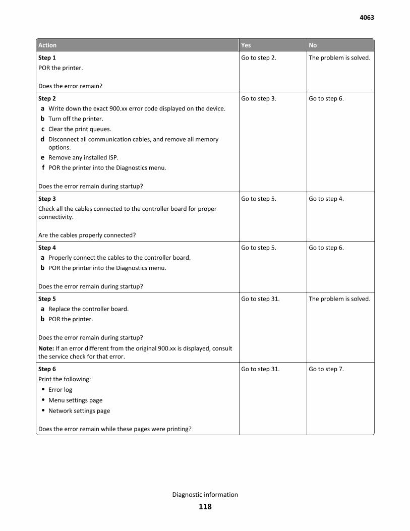
Action Yes No
Step 1
POR the printer.
Does the error remain?
Go to step 2. The problem is solved.
Step 2
a Write down the exact 900.xx error code displayed on the device.
b Turn off the printer.
c Clear the print queues.
d Disconnect all communication cables, and remove all memoryoptions.
e Remove any installed ISP.
f POR the printer into the Diagnostics menu.
Does the error remain during startup?
Go to step 3. Go to step 6.
Step 3
Check all the cables connected to the controller board for properconnectivity.
Are the cables properly connected?
Go to step 5. Go to step 4.
Step 4
a Properly connect the cables to the controller board.
b POR the printer into the Diagnostics menu.
Does the error remain during startup?
Go to step 5. Go to step 6.
Step 5
a Replace the controller board.
b POR the printer.
Does the error remain during startup?
Note: If an error different from the original 900.xx is displayed, consultthe service check for that error.
Go to step 31. The problem is solved.
Step 6
Print the following:
• Error log
• Menu settings page
• Network settings page
Does the error remain while these pages were printing?
Go to step 31. Go to step 7.
4063
Diagnostic information
118
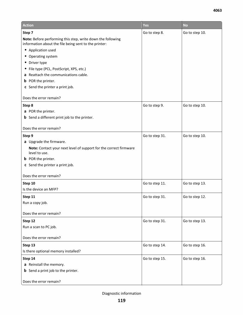
Action Yes No
Step 7
Note: Before performing this step, write down the followinginformation about the file being sent to the printer:
• Application used
• Operating system
• Driver type
• File type (PCL, PostScript, XPS, etc.)
a Reattach the communications cable.
b POR the printer.
c Send the printer a print job.
Does the error remain?
Go to step 8. Go to step 10.
Step 8
a POR the printer.
b Send a different print job to the printer.
Does the error remain?
Go to step 9. Go to step 10.
Step 9
a Upgrade the firmware.
Note: Contact your next level of support for the correct firmwarelevel to use.
b POR the printer.
c Send the printer a print job.
Does the error remain?
Go to step 31. Go to step 10.
Step 10
Is the device an MFP?
Go to step 11. Go to step 13.
Step 11
Run a copy job.
Does the error remain?
Go to step 31. Go to step 12.
Step 12
Run a scan to PC job.
Does the error remain?
Go to step 31. Go to step 13.
Step 13
Is there optional memory installed?
Go to step 14. Go to step 16.
Step 14
a Reinstall the memory.
b Send a print job to the printer.
Does the error remain?
Go to step 15. Go to step 16.
4063
Diagnostic information
119
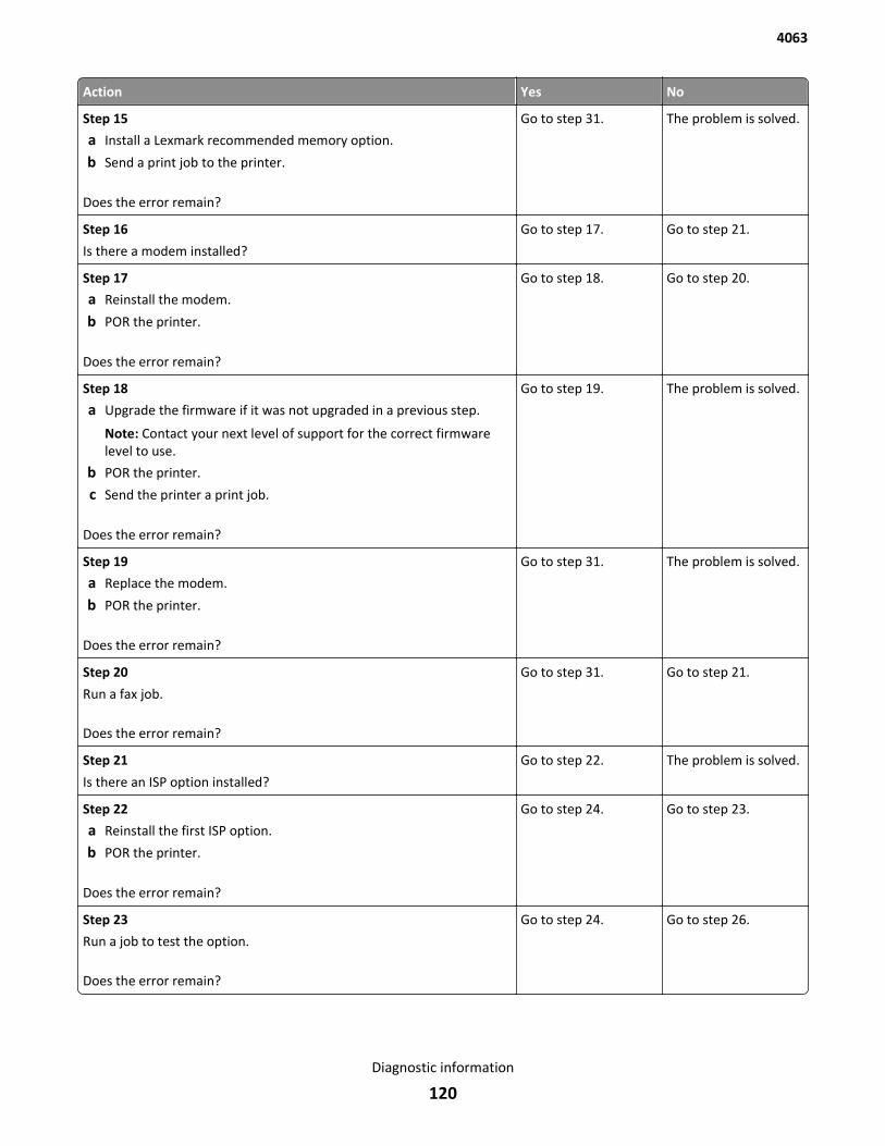
Action Yes No
Step 15
a Install a Lexmark recommended memory option.
b Send a print job to the printer.
Does the error remain?
Go to step 31. The problem is solved.
Step 16
Is there a modem installed?
Go to step 17. Go to step 21.
Step 17
a Reinstall the modem.
b POR the printer.
Does the error remain?
Go to step 18. Go to step 20.
Step 18
a Upgrade the firmware if it was not upgraded in a previous step.
Note: Contact your next level of support for the correct firmwarelevel to use.
b POR the printer.
c Send the printer a print job.
Does the error remain?
Go to step 19. The problem is solved.
Step 19
a Replace the modem.
b POR the printer.
Does the error remain?
Go to step 31. The problem is solved.
Step 20
Run a fax job.
Does the error remain?
Go to step 31. Go to step 21.
Step 21
Is there an ISP option installed?
Go to step 22. The problem is solved.
Step 22
a Reinstall the first ISP option.
b POR the printer.
Does the error remain?
Go to step 24. Go to step 23.
Step 23
Run a job to test the option.
Does the error remain?
Go to step 24. Go to step 26.
4063
Diagnostic information
120
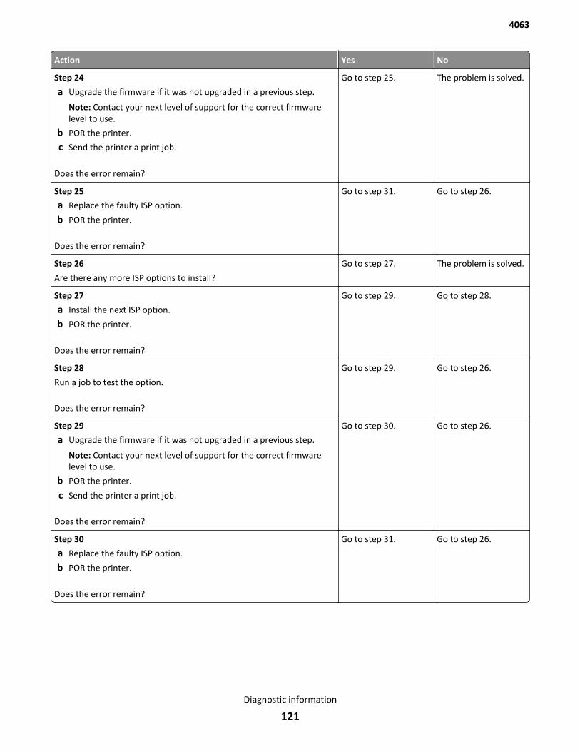
Action Yes No
Step 24
a Upgrade the firmware if it was not upgraded in a previous step.
Note: Contact your next level of support for the correct firmwarelevel to use.
b POR the printer.
c Send the printer a print job.
Does the error remain?
Go to step 25. The problem is solved.
Step 25
a Replace the faulty ISP option.
b POR the printer.
Does the error remain?
Go to step 31. Go to step 26.
Step 26
Are there any more ISP options to install?
Go to step 27. The problem is solved.
Step 27
a Install the next ISP option.
b POR the printer.
Does the error remain?
Go to step 29. Go to step 28.
Step 28
Run a job to test the option.
Does the error remain?
Go to step 29. Go to step 26.
Step 29
a Upgrade the firmware if it was not upgraded in a previous step.
Note: Contact your next level of support for the correct firmwarelevel to use.
b POR the printer.
c Send the printer a print job.
Does the error remain?
Go to step 30. Go to step 26.
Step 30
a Replace the faulty ISP option.
b POR the printer.
Does the error remain?
Go to step 31. Go to step 26.
4063
Diagnostic information
121
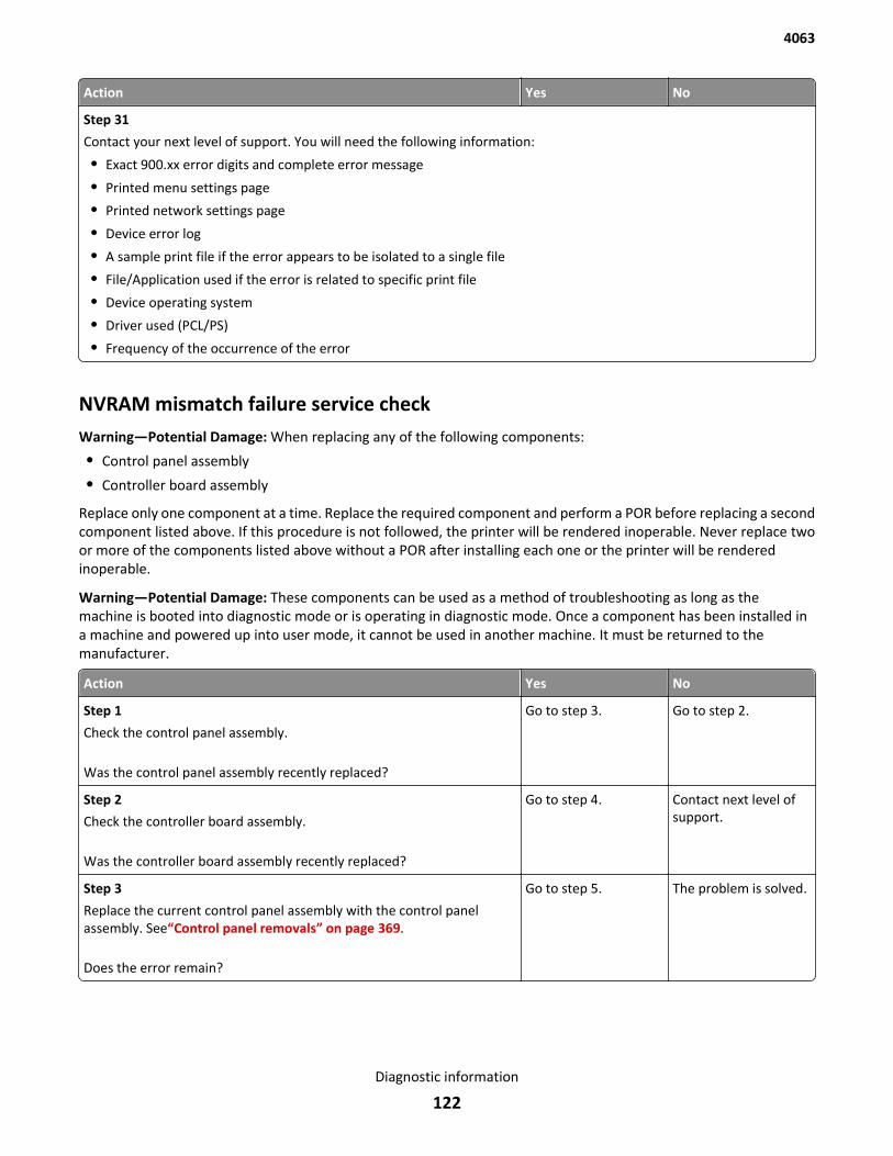
Action Yes No
Step 31
Contact your next level of support. You will need the following information:
• Exact 900.xx error digits and complete error message
• Printed menu settings page
• Printed network settings page
• Device error log
• A sample print file if the error appears to be isolated to a single file
• File/Application used if the error is related to specific print file
• Device operating system
• Driver used (PCL/PS)
• Frequency of the occurrence of the error
NVRAM mismatch failure service checkWarning—Potential Damage: When replacing any of the following components:
• Control panel assembly
• Controller board assembly
Replace only one component at a time. Replace the required component and perform a POR before replacing a secondcomponent listed above. If this procedure is not followed, the printer will be rendered inoperable. Never replace twoor more of the components listed above without a POR after installing each one or the printer will be renderedinoperable.
Warning—Potential Damage: These components can be used as a method of troubleshooting as long as themachine is booted into diagnostic mode or is operating in diagnostic mode. Once a component has been installed ina machine and powered up into user mode, it cannot be used in another machine. It must be returned to themanufacturer.
Action Yes No
Step 1
Check the control panel assembly.
Was the control panel assembly recently replaced?
Go to step 3. Go to step 2.
Step 2
Check the controller board assembly.
Was the controller board assembly recently replaced?
Go to step 4. Contact next level ofsupport.
Step 3
Replace the current control panel assembly with the control panelassembly. See“Control panel removals” on page 369.
Does the error remain?
Go to step 5. The problem is solved.
4063
Diagnostic information
122
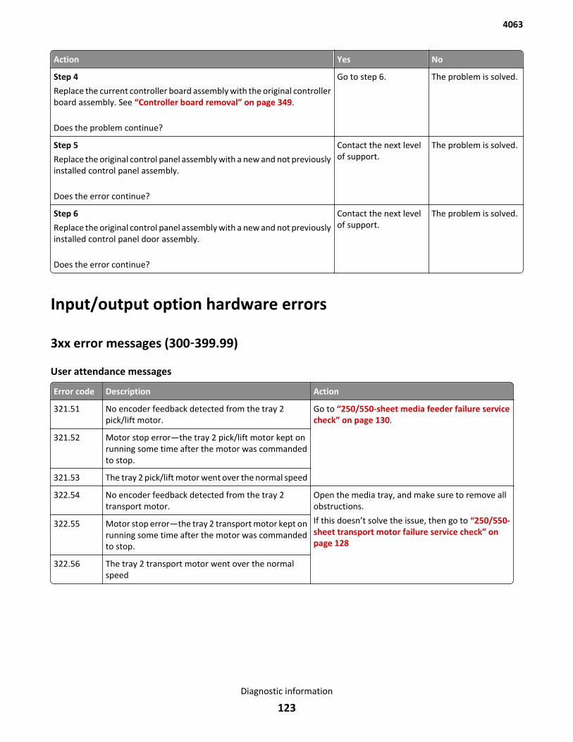
Action Yes No
Step 4
Replace the current controller board assembly with the original controllerboard assembly. See “Controller board removal” on page 349.
Does the problem continue?
Go to step 6. The problem is solved.
Step 5
Replace the original control panel assembly with a new and not previouslyinstalled control panel assembly.
Does the error continue?
Contact the next levelof support.
The problem is solved.
Step 6
Replace the original control panel assembly with a new and not previouslyinstalled control panel door assembly.
Does the error continue?
Contact the next levelof support.
The problem is solved.
Input/output option hardware errors
3xx error messages (300‑399.99)
User attendance messages
Error code Description Action
321.51 No encoder feedback detected from the tray 2pick/lift motor.
Go to “250/550-sheet media feeder failure servicecheck” on page 130.
321.52 Motor stop error—the tray 2 pick/lift motor kept onrunning some time after the motor was commandedto stop.
321.53 The tray 2 pick/lift motor went over the normal speed
322.54 No encoder feedback detected from the tray 2transport motor.
Open the media tray, and make sure to remove allobstructions.
If this doesn’t solve the issue, then go to “250/550-sheet transport motor failure service check” onpage 128
322.55 Motor stop error—the tray 2 transport motor kept onrunning some time after the motor was commandedto stop.
322.56 The tray 2 transport motor went over the normalspeed
4063
Diagnostic information
123
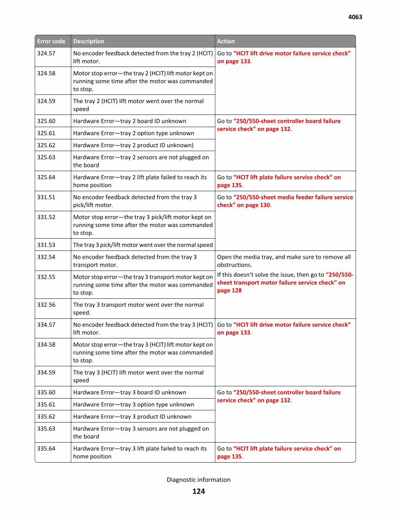
Error code Description Action
324.57 No encoder feedback detected from the tray 2 (HCIT)lift motor.
Go to “HCIT lift drive motor failure service check”on page 133.
324.58 Motor stop error—the tray 2 (HCIT) lift motor kept onrunning some time after the motor was commandedto stop.
324.59 The tray 2 (HCIT) lift motor went over the normalspeed
325.60 Hardware Error—tray 2 board ID unknown Go to “250/550-sheet controller board failureservice check” on page 132.
325.61 Hardware Error—tray 2 option type unknown
325.62 Hardware Error—tray 2 product ID unknown)
325.63 Hardware Error—tray 2 sensors are not plugged onthe board
325.64 Hardware Error—tray 2 lift plate failed to reach itshome position
Go to “HCIT lift plate failure service check” onpage 135.
331.51 No encoder feedback detected from the tray 3pick/lift motor.
Go to “250/550-sheet media feeder failure servicecheck” on page 130.
331.52 Motor stop error—the tray 3 pick/lift motor kept onrunning some time after the motor was commandedto stop.
331.53 The tray 3 pick/lift motor went over the normal speed
332.54 No encoder feedback detected from the tray 3transport motor.
Open the media tray, and make sure to remove allobstructions.
If this doesn’t solve the issue, then go to “250/550-sheet transport motor failure service check” onpage 128
332.55 Motor stop error—the tray 3 transport motor kept onrunning some time after the motor was commandedto stop.
332.56 The tray 3 transport motor went over the normalspeed.
334.57 No encoder feedback detected from the tray 3 (HCIT)lift motor.
Go to “HCIT lift drive motor failure service check”on page 133.
334.58 Motor stop error—the tray 3 (HCIT) lift motor kept onrunning some time after the motor was commandedto stop.
334.59 The tray 3 (HCIT) lift motor went over the normalspeed
335.60 Hardware Error—tray 3 board ID unknown Go to “250/550-sheet controller board failureservice check” on page 132.
335.61 Hardware Error—tray 3 option type unknown
335.62 Hardware Error—tray 3 product ID unknown
335.63 Hardware Error—tray 3 sensors are not plugged onthe board
335.64 Hardware Error—tray 3 lift plate failed to reach itshome position
Go to “HCIT lift plate failure service check” onpage 135.
4063
Diagnostic information
124
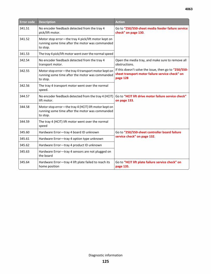
Error code Description Action
341.51 No encoder feedback detected from the tray 4pick/lift motor.
Go to “250/550-sheet media feeder failure servicecheck” on page 130.
341.52 Motor stop error—the tray 4 pick/lift motor kept onrunning some time after the motor was commandedto stop.
341.53 The tray 4 pick/lift motor went over the normal speed
342.54 No encoder feedback detected from the tray 4transport motor.
Open the media tray, and make sure to remove allobstructions.
If this doesn’t solve the issue, then go to “250/550-sheet transport motor failure service check” onpage 128
342.55 Motor stop error—the tray 4 transport motor kept onrunning some time after the motor was commandedto stop.
342.56 The tray 4 transport motor went over the normalspeed.
344.57 No encoder feedback detected from the tray 4 (HCIT)lift motor.
Go to “HCIT lift drive motor failure service check”on page 133.
344.58 Motor stop error—the tray 4 (HCIT) lift motor kept onrunning some time after the motor was commandedto stop.
344.59 The tray 4 (HCIT) lift motor went over the normalspeed
345.60 Hardware Error—tray 4 board ID unknown Go to “250/550-sheet controller board failureservice check” on page 132.
345.61 Hardware Error—tray 4 option type unknown
345.62 Hardware Error—tray 4 product ID unknown
345.63 Hardware Error—tray 4 sensors are not plugged onthe board
345.64 Hardware Error—tray 4 lift plate failed to reach itshome position
Go to “HCIT lift plate failure service check” onpage 135.
4063
Diagnostic information
125
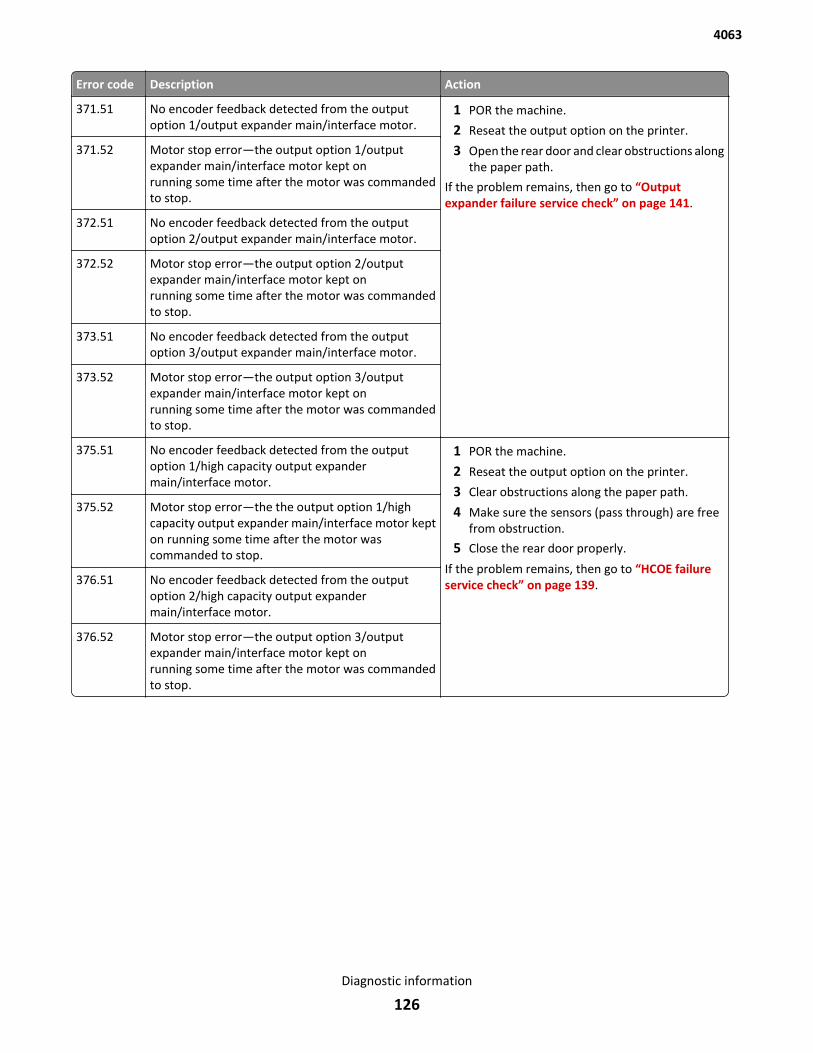
Error code Description Action
371.51 No encoder feedback detected from the outputoption 1/output expander main/interface motor.
1 POR the machine.
2 Reseat the output option on the printer.
3 Open the rear door and clear obstructions alongthe paper path.
If the problem remains, then go to “Outputexpander failure service check” on page 141.
371.52 Motor stop error—the output option 1/outputexpander main/interface motor kept onrunning some time after the motor was commandedto stop.
372.51 No encoder feedback detected from the outputoption 2/output expander main/interface motor.
372.52 Motor stop error—the output option 2/outputexpander main/interface motor kept onrunning some time after the motor was commandedto stop.
373.51 No encoder feedback detected from the outputoption 3/output expander main/interface motor.
373.52 Motor stop error—the output option 3/outputexpander main/interface motor kept onrunning some time after the motor was commandedto stop.
375.51 No encoder feedback detected from the outputoption 1/high capacity output expandermain/interface motor.
1 POR the machine.
2 Reseat the output option on the printer.
3 Clear obstructions along the paper path.
4 Make sure the sensors (pass through) are freefrom obstruction.
5 Close the rear door properly.
If the problem remains, then go to “HCOE failureservice check” on page 139.
375.52 Motor stop error—the the output option 1/highcapacity output expander main/interface motor kepton running some time after the motor wascommanded to stop.
376.51 No encoder feedback detected from the outputoption 2/high capacity output expandermain/interface motor.
376.52 Motor stop error—the output option 3/outputexpander main/interface motor kept onrunning some time after the motor was commandedto stop.
4063
Diagnostic information
126
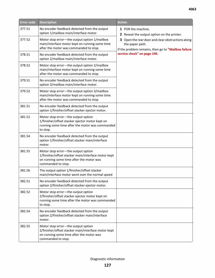
Error code Description Action
377.51 No encoder feedback detected from the outputoption 1/mailbox main/interface motor.
1 POR the machine.
2 Reseat the output option on the printer.
3 Open the rear door and clear obstructions alongthe paper path.
If the problem remains, then go to “Mailbox failureservice check” on page 140.
377.52 Motor stop error—the output option 1/mailboxmain/interface motor kept on running some timeafter the motor was commanded to stop.
378.51 No encoder feedback detected from the outputoption 2/mailbox main/interface motor.
378.52 Motor stop error—the output option 2/mailboxmain/interface motor kept on running some timeafter the motor was commanded to stop.
379.51 No encoder feedback detected from the outputoption 3/mailbox main/interface motor.
379.52 Motor stop error—the output option 3/mailboxmain/interface motor kept on running some timeafter the motor was commanded to stop.
381.51 No encoder feedback detected from the outputoption 1/finisher/offset stacker ejector motor.
381.52 Motor stop error—the output option1/finisher/offset stacker ejector motor kept onrunning some time after the motor was commandedto stop.
381.54 No encoder feedback detected from the outputoption 1/finisher/offset stacker main/interfacemotor.
381.55 Motor stop error—the output option1/finisher/offset stacker main/interface motor kepton running some time after the motor wascommanded to stop.
381.56 The output option 1/finisher/offset stackermain/interface motor went over the normal speed
382.51 No encoder feedback detected from the outputoption 2/finisher/offset stacker ejector motor.
382.52 Motor stop error—the output option2/finisher/offset stacker ejector motor kept onrunning some time after the motor was commandedto stop.
382.54 No encoder feedback detected from the outputoption 2/finisher/offset stacker main/interfacemotor.
382.55 Motor stop error—the output option2/finisher/offset stacker main/interface motor kepton running some time after the motor wascommanded to stop.
4063
Diagnostic information
127
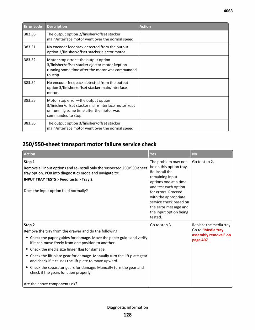
Error code Description Action
382.56 The output option 2/finisher/offset stackermain/interface motor went over the normal speed
383.51 No encoder feedback detected from the outputoption 3/finisher/offset stacker ejector motor.
383.52 Motor stop error—the output option3/finisher/offset stacker ejector motor kept onrunning some time after the motor was commandedto stop.
383.54 No encoder feedback detected from the outputoption 3/finisher/offset stacker main/interfacemotor.
383.55 Motor stop error—the output option3/finisher/offset stacker main/interface motor kepton running some time after the motor wascommanded to stop.
383.56 The output option 3/finisher/offset stackermain/interface motor went over the normal speed
250/550-sheet transport motor failure service check
Action Yes No
Step 1
Remove all input options and re-install only the suspected 250/550-sheettray option. POR into diagnostics mode and navigate to:
INPUT TRAY TESTS > Feed tests > Tray 2
Does the input option feed normally?
The problem may notbe on this option tray.Re-install theremaining inputoptions one at a timeand test each optionfor errors. Proceedwith the appropriateservice check based onthe error message andthe input option beingtested.
Go to step 2.
Step 2
Remove the tray from the drawer and do the following:
• Check the paper guides for damage. Move the paper guide and verifyif it can move freely from one position to another.
• Check the media size finger flag for damage.
• Check the lift plate gear for damage. Manually turn the lift plate gearand check if it causes the lift plate to move upward.
• Check the separator gears for damage. Manually turn the gear andcheck if the gears function properly.
Are the above components ok?
Go to step 3. Replace the media tray.Go to “Media trayassembly removal” onpage 407.
4063
Diagnostic information
128
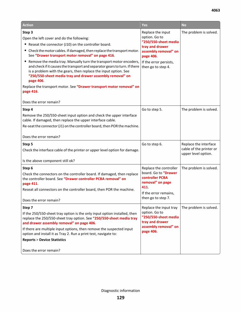
Action Yes No
Step 3
Open the left cover and do the following:
• Reseat the connector (J10) on the controller board.
• Check the motor cables. If damaged, then replace the transport motor.See “Drawer transport motor removal” on page 416.
• Remove the media tray. Manually turn the transport motor encoders,and check if it causes the transport and separator gears to turn. If thereis a problem with the gears, then replace the input option. See“250/550-sheet media tray and drawer assembly removal” onpage 406.
Replace the transport motor. See “Drawer transport motor removal” onpage 416.
Does the error remain?
Replace the inputoption. Go to“250/550-sheet mediatray and drawerassembly removal” onpage 406.
If the error persists,then go to step 4.
The problem is solved.
Step 4
Remove the 250/550-sheet input option and check the upper interfacecable. If damaged, then replace the upper interface cable.
Re-seat the connector (J1) on the controller board, then POR the machine.
Does the error remain?
Go to step 5. The problem is solved.
Step 5
Check the interface cable of the printer or upper level option for damage.
Is the above component still ok?
Go to step 6. Replace the interfacecable of the printer orupper level option.
Step 6
Check the connectors on the controller board. If damaged, then replacethe controller board. See “Drawer controller PCBA removal” onpage 411.
Reseat all connectors on the controller board, then POR the machine.
Does the error remain?
Replace the controllerboard. Go to “Drawercontroller PCBAremoval” on page 411.
If the error remains,then go to step 7.
The problem is solved.
Step 7
If the 250/550-sheet tray option is the only input option installed, thenreplace the 250/550-sheet tray option. See “250/550-sheet media trayand drawer assembly removal” on page 406.
If there are multiple input options, then remove the suspected inputoption and install it as Tray 2. Run a print test, navigate to:
Reports > Device Statistics
Does the error remain?
Replace the input trayoption. Go to“250/550-sheet mediatray and drawerassembly removal” onpage 406.
The problem is solved.
4063
Diagnostic information
129
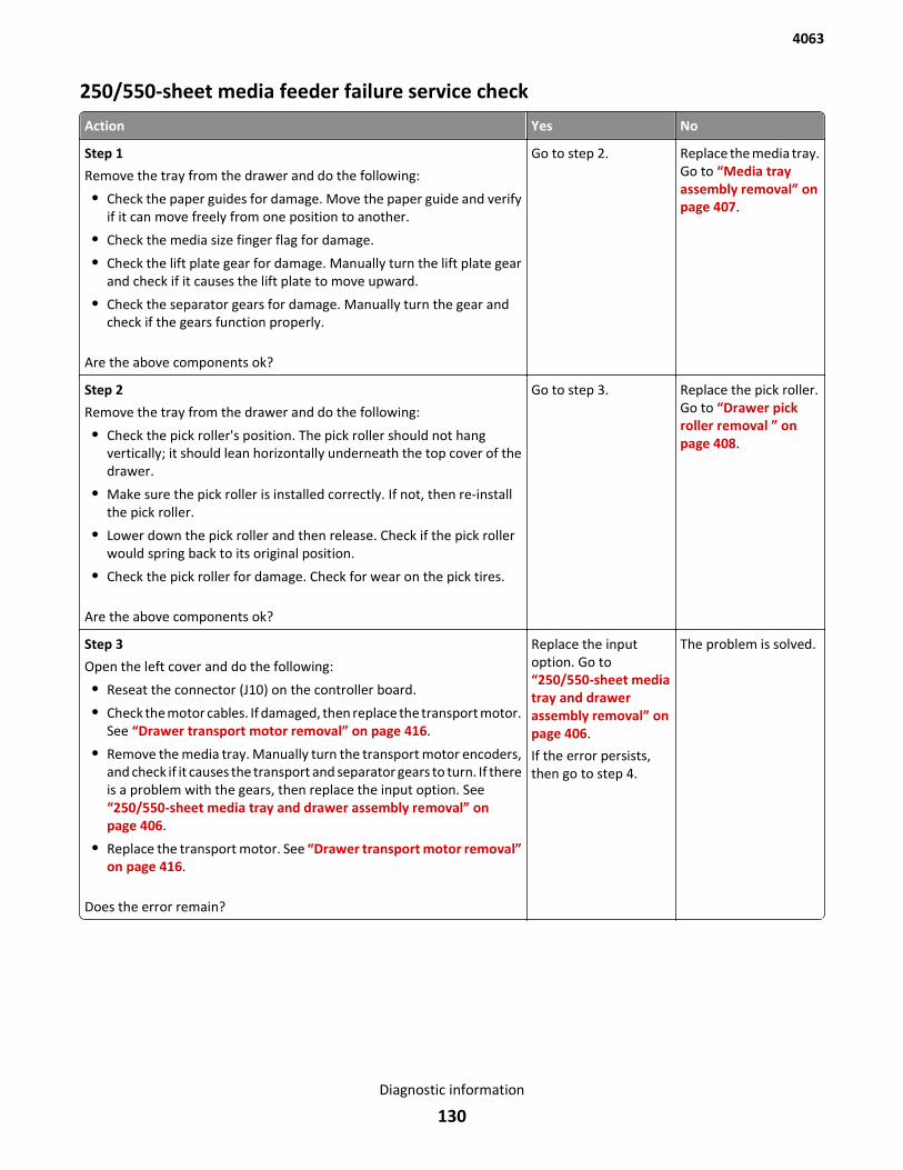
250/550-sheet media feeder failure service check
Action Yes No
Step 1
Remove the tray from the drawer and do the following:
• Check the paper guides for damage. Move the paper guide and verifyif it can move freely from one position to another.
• Check the media size finger flag for damage.
• Check the lift plate gear for damage. Manually turn the lift plate gearand check if it causes the lift plate to move upward.
• Check the separator gears for damage. Manually turn the gear andcheck if the gears function properly.
Are the above components ok?
Go to step 2. Replace the media tray.Go to “Media trayassembly removal” onpage 407.
Step 2
Remove the tray from the drawer and do the following:
• Check the pick roller's position. The pick roller should not hangvertically; it should lean horizontally underneath the top cover of thedrawer.
• Make sure the pick roller is installed correctly. If not, then re-installthe pick roller.
• Lower down the pick roller and then release. Check if the pick rollerwould spring back to its original position.
• Check the pick roller for damage. Check for wear on the pick tires.
Are the above components ok?
Go to step 3. Replace the pick roller.Go to “Drawer pickroller removal ” onpage 408.
Step 3
Open the left cover and do the following:
• Reseat the connector (J10) on the controller board.
• Check the motor cables. If damaged, then replace the transport motor.See “Drawer transport motor removal” on page 416.
• Remove the media tray. Manually turn the transport motor encoders,and check if it causes the transport and separator gears to turn. If thereis a problem with the gears, then replace the input option. See“250/550-sheet media tray and drawer assembly removal” onpage 406.
• Replace the transport motor. See “Drawer transport motor removal”on page 416.
Does the error remain?
Replace the inputoption. Go to“250/550-sheet mediatray and drawerassembly removal” onpage 406.
If the error persists,then go to step 4.
The problem is solved.
4063
Diagnostic information
130
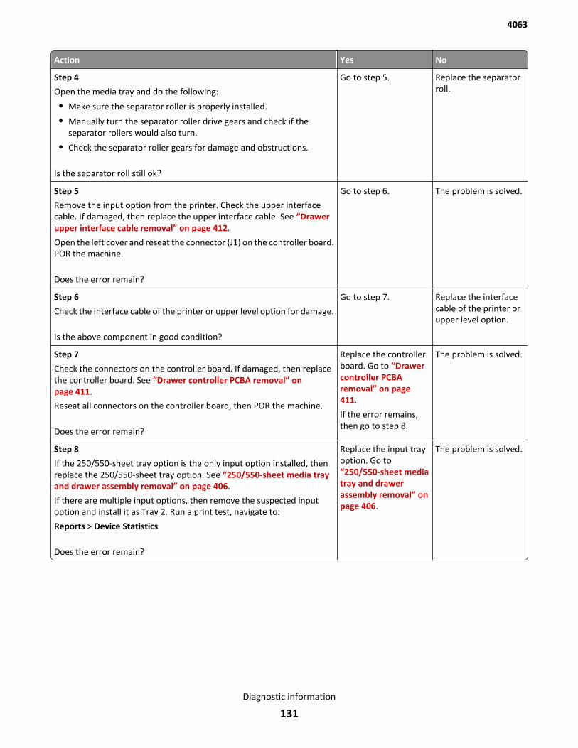
Action Yes No
Step 4
Open the media tray and do the following:
• Make sure the separator roller is properly installed.
• Manually turn the separator roller drive gears and check if theseparator rollers would also turn.
• Check the separator roller gears for damage and obstructions.
Is the separator roll still ok?
Go to step 5. Replace the separatorroll.
Step 5
Remove the input option from the printer. Check the upper interfacecable. If damaged, then replace the upper interface cable. See “Drawerupper interface cable removal” on page 412.
Open the left cover and reseat the connector (J1) on the controller board.POR the machine.
Does the error remain?
Go to step 6. The problem is solved.
Step 6
Check the interface cable of the printer or upper level option for damage.
Is the above component in good condition?
Go to step 7. Replace the interfacecable of the printer orupper level option.
Step 7
Check the connectors on the controller board. If damaged, then replacethe controller board. See “Drawer controller PCBA removal” onpage 411.
Reseat all connectors on the controller board, then POR the machine.
Does the error remain?
Replace the controllerboard. Go to “Drawercontroller PCBAremoval” on page 411.
If the error remains,then go to step 8.
The problem is solved.
Step 8
If the 250/550-sheet tray option is the only input option installed, thenreplace the 250/550-sheet tray option. See “250/550-sheet media trayand drawer assembly removal” on page 406.
If there are multiple input options, then remove the suspected inputoption and install it as Tray 2. Run a print test, navigate to:
Reports > Device Statistics
Does the error remain?
Replace the input trayoption. Go to“250/550-sheet mediatray and drawerassembly removal” onpage 406.
The problem is solved.
4063
Diagnostic information
131
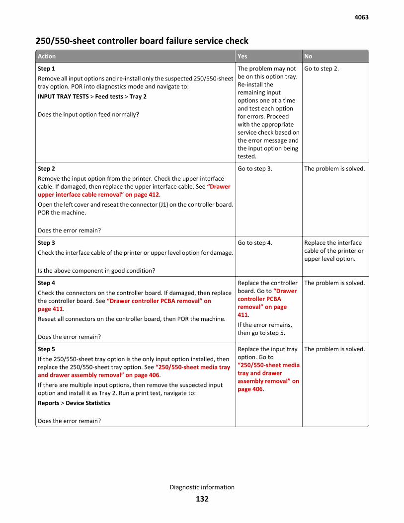
250/550-sheet controller board failure service check
Action Yes No
Step 1
Remove all input options and re-install only the suspected 250/550-sheettray option. POR into diagnostics mode and navigate to:
INPUT TRAY TESTS > Feed tests > Tray 2
Does the input option feed normally?
The problem may notbe on this option tray.Re-install theremaining inputoptions one at a timeand test each optionfor errors. Proceedwith the appropriateservice check based onthe error message andthe input option beingtested.
Go to step 2.
Step 2
Remove the input option from the printer. Check the upper interfacecable. If damaged, then replace the upper interface cable. See “Drawerupper interface cable removal” on page 412.
Open the left cover and reseat the connector (J1) on the controller board.POR the machine.
Does the error remain?
Go to step 3. The problem is solved.
Step 3
Check the interface cable of the printer or upper level option for damage.
Is the above component in good condition?
Go to step 4. Replace the interfacecable of the printer orupper level option.
Step 4
Check the connectors on the controller board. If damaged, then replacethe controller board. See “Drawer controller PCBA removal” onpage 411.
Reseat all connectors on the controller board, then POR the machine.
Does the error remain?
Replace the controllerboard. Go to “Drawercontroller PCBAremoval” on page 411.
If the error remains,then go to step 5.
The problem is solved.
Step 5
If the 250/550-sheet tray option is the only input option installed, thenreplace the 250/550-sheet tray option. See “250/550-sheet media trayand drawer assembly removal” on page 406.
If there are multiple input options, then remove the suspected inputoption and install it as Tray 2. Run a print test, navigate to:
Reports > Device Statistics
Does the error remain?
Replace the input trayoption. Go to“250/550-sheet mediatray and drawerassembly removal” onpage 406.
The problem is solved.
4063
Diagnostic information
132
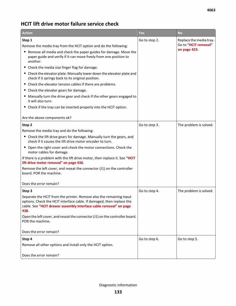
HCIT lift drive motor failure service check
Action Yes No
Step 1
Remove the media tray from the HCIT option and do the following:
• Remove all media and check the paper guides for damage. Move thepaper guide and verify if it can move freely from one position toanother.
• Check the media size finger flag for damage.
• Check the elevator plate. Manually lower down the elevator plate andcheck if it springs back to its original position.
• Check the elevator tension cables if there are problems.
• Check the elevator gears for damage.
• Manually turn the drive gear and check if the other gears engaged toit will also turn.
• Check if the tray can be inserted properly into the HCIT option.
Are the above components ok?
Go to step 2. Replace the media tray.Go to “HCIT removal”on page 423.
Step 2
Remove the media tray and do the following:
• Check the lift drive gears for damage. Manually turn the gears, andcheck if it causes the lift drive motor encoder to turn.
• Open the right cover and check the motor connections. Check themotor cables for damage.
If there is a problem with the lift drive motor, then replace it. See “HCITlift drive motor removal” on page 436.
Remove the left cover, and reseat the connector (J1) on the controllerboard. POR the machine.
Does the error remain?
Go to step 3. The problem is solved.
Step 3
Separate the HCIT from the printer. Remove also the remaining inputoptions. Check the HCIT interface cable. If damaged, then replace thecable. See “HCIT drawer assembly interface cable removal” on page 438.
Open the left cover, and reseat the connector (J1) on the controller board.POR the machine.
Does the error remain?
Go to step 4. The problem is solved.
Step 4
Remove all other options and install only the HCIT option.
Does the error remain?
Go to step 6. Go to step 5.
4063
Diagnostic information
133
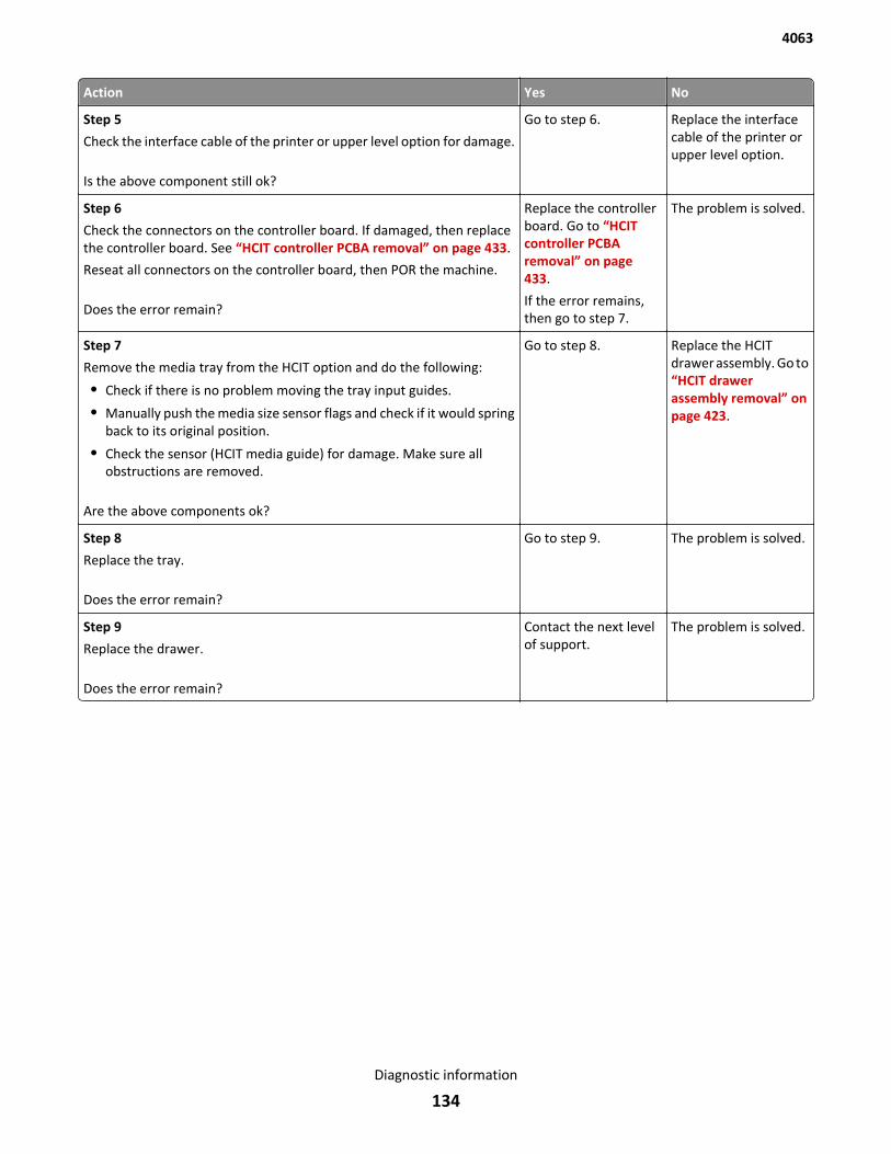
Action Yes No
Step 5
Check the interface cable of the printer or upper level option for damage.
Is the above component still ok?
Go to step 6. Replace the interfacecable of the printer orupper level option.
Step 6
Check the connectors on the controller board. If damaged, then replacethe controller board. See “HCIT controller PCBA removal” on page 433.
Reseat all connectors on the controller board, then POR the machine.
Does the error remain?
Replace the controllerboard. Go to “HCITcontroller PCBAremoval” on page 433.
If the error remains,then go to step 7.
The problem is solved.
Step 7
Remove the media tray from the HCIT option and do the following:
• Check if there is no problem moving the tray input guides.
• Manually push the media size sensor flags and check if it would springback to its original position.
• Check the sensor (HCIT media guide) for damage. Make sure allobstructions are removed.
Are the above components ok?
Go to step 8. Replace the HCITdrawer assembly. Go to“HCIT drawerassembly removal” onpage 423.
Step 8
Replace the tray.
Does the error remain?
Go to step 9. The problem is solved.
Step 9
Replace the drawer.
Does the error remain?
Contact the next levelof support.
The problem is solved.
4063
Diagnostic information
134
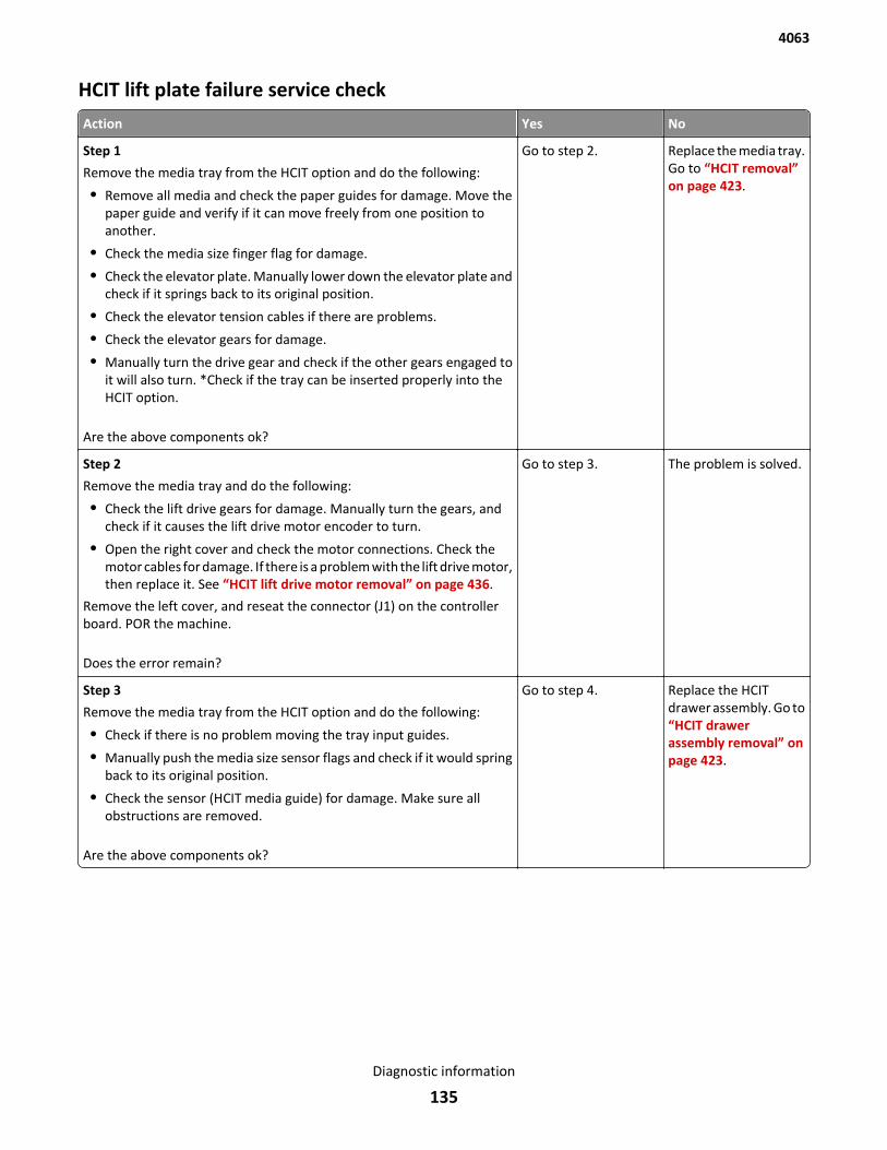
HCIT lift plate failure service check
Action Yes No
Step 1
Remove the media tray from the HCIT option and do the following:
• Remove all media and check the paper guides for damage. Move thepaper guide and verify if it can move freely from one position toanother.
• Check the media size finger flag for damage.
• Check the elevator plate. Manually lower down the elevator plate andcheck if it springs back to its original position.
• Check the elevator tension cables if there are problems.
• Check the elevator gears for damage.
• Manually turn the drive gear and check if the other gears engaged toit will also turn. *Check if the tray can be inserted properly into theHCIT option.
Are the above components ok?
Go to step 2. Replace the media tray.Go to “HCIT removal”on page 423.
Step 2
Remove the media tray and do the following:
• Check the lift drive gears for damage. Manually turn the gears, andcheck if it causes the lift drive motor encoder to turn.
• Open the right cover and check the motor connections. Check themotor cables for damage. If there is a problem with the lift drive motor,then replace it. See “HCIT lift drive motor removal” on page 436.
Remove the left cover, and reseat the connector (J1) on the controllerboard. POR the machine.
Does the error remain?
Go to step 3. The problem is solved.
Step 3
Remove the media tray from the HCIT option and do the following:
• Check if there is no problem moving the tray input guides.
• Manually push the media size sensor flags and check if it would springback to its original position.
• Check the sensor (HCIT media guide) for damage. Make sure allobstructions are removed.
Are the above components ok?
Go to step 4. Replace the HCITdrawer assembly. Go to“HCIT drawerassembly removal” onpage 423.
4063
Diagnostic information
135

Action Yes No
Step 4
Separate the HCIT from the printer. Remove also the remaining inputoptions. Check the HCIT interface cable. If damaged, then replace thecable. See “HCIT drawer assembly interface cable removal” on page 438.
Open the left cover, and reseat the connector (J1) on the controller board.POR the machine.
Does the error remain?
Go to step 5. The problem is solved.
Step 5
Remove all other options and install only the HCIT option.
Does the error remain?
Go to step 7. Go to step 6.
Step 6
Check the interface cable of the printer or upper level option for damage.
Is the above component still ok?
Go to step 7. Replace the interfacecable of the printer orupper level option.
Step 7
Check the connectors on the controller board. If damaged, then replacethe controller board. See “HCIT controller PCBA removal” on page 433.
Reseat all connectors on the controller board, then POR the machine.
Does the error remain?
Replace the controllerboard. Go to “HCITcontroller PCBAremoval” on page 433.
If the error remains,then go to step 8.
The problem is solved.
Step 8
Replace the tray.
Does the error remain?
Go to step 9. The problem is solved.
Step 9
Replace the drawer.
Does the error remain?
Contact the next levelof support.
The problem is solved.
4063
Diagnostic information
136
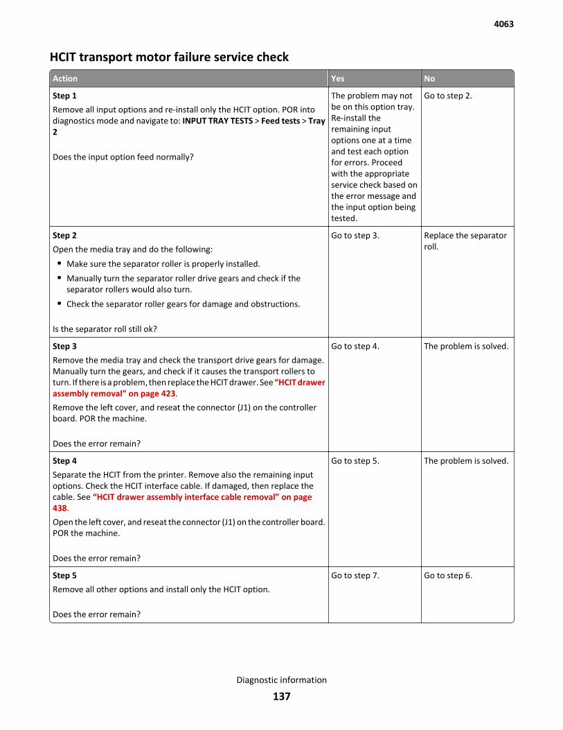
HCIT transport motor failure service check
Action Yes No
Step 1
Remove all input options and re-install only the HCIT option. POR intodiagnostics mode and navigate to: INPUT TRAY TESTS > Feed tests > Tray2
Does the input option feed normally?
The problem may notbe on this option tray.Re-install theremaining inputoptions one at a timeand test each optionfor errors. Proceedwith the appropriateservice check based onthe error message andthe input option beingtested.
Go to step 2.
Step 2
Open the media tray and do the following:
• Make sure the separator roller is properly installed.
• Manually turn the separator roller drive gears and check if theseparator rollers would also turn.
• Check the separator roller gears for damage and obstructions.
Is the separator roll still ok?
Go to step 3. Replace the separatorroll.
Step 3
Remove the media tray and check the transport drive gears for damage.Manually turn the gears, and check if it causes the transport rollers toturn. If there is a problem, then replace the HCIT drawer. See “HCIT drawerassembly removal” on page 423.
Remove the left cover, and reseat the connector (J1) on the controllerboard. POR the machine.
Does the error remain?
Go to step 4. The problem is solved.
Step 4
Separate the HCIT from the printer. Remove also the remaining inputoptions. Check the HCIT interface cable. If damaged, then replace thecable. See “HCIT drawer assembly interface cable removal” on page 438.
Open the left cover, and reseat the connector (J1) on the controller board.POR the machine.
Does the error remain?
Go to step 5. The problem is solved.
Step 5
Remove all other options and install only the HCIT option.
Does the error remain?
Go to step 7. Go to step 6.
4063
Diagnostic information
137

Action Yes No
Step 6
Check the interface cable of the printer or upper level option for damage.
Is the above component still ok?
Go to step 7. Replace the interfacecable of the printer orupper level option.
Step 7
Check the connectors on the controller board. If damaged, then replacethe controller board. See “HCIT controller PCBA removal” on page 433.
Reseat all connectors on the controller board, then POR the machine.
Does the error remain?
Replace the controllerboard. Go to “HCITcontroller PCBAremoval” on page 433.
If the error remains,then go to step 8.
The problem is solved.
Step 8
Remove the media tray from the HCIT option and do the following:
• Check if there is no problem moving the tray input guides.
• Manually push the media size sensor flags and check if it would springback to its original position.
• Check the sensor (HCIT media guide) for damage. Make sure allobstructions are removed.
Are the above components ok?
Go to step 9. Replace the HCITdrawer assembly. Go to“HCIT drawerassembly removal” onpage 423.
Step 9
Replace the tray.
Does the error remain?
Go to step 10. The problem is solved.
Step 10
Replace the drawer.
Does the error remain?
Contact the next levelof support.
The problem is solved.
4063
Diagnostic information
138
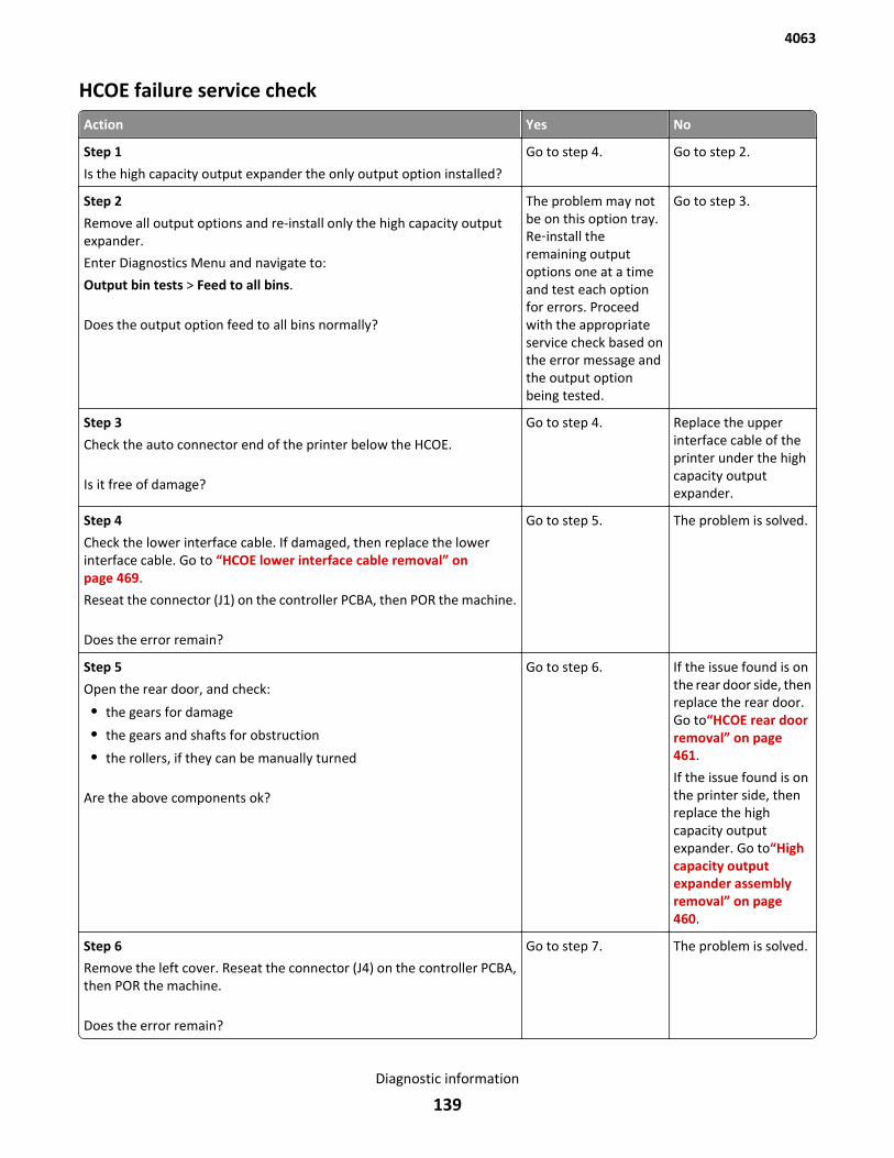
HCOE failure service check
Action Yes No
Step 1
Is the high capacity output expander the only output option installed?
Go to step 4. Go to step 2.
Step 2
Remove all output options and re-install only the high capacity outputexpander.
Enter Diagnostics Menu and navigate to:
Output bin tests > Feed to all bins.
Does the output option feed to all bins normally?
The problem may notbe on this option tray.Re‑install theremaining outputoptions one at a timeand test each optionfor errors. Proceedwith the appropriateservice check based onthe error message andthe output optionbeing tested.
Go to step 3.
Step 3
Check the auto connector end of the printer below the HCOE.
Is it free of damage?
Go to step 4. Replace the upperinterface cable of theprinter under the highcapacity outputexpander.
Step 4
Check the lower interface cable. If damaged, then replace the lowerinterface cable. Go to “HCOE lower interface cable removal” onpage 469.
Reseat the connector (J1) on the controller PCBA, then POR the machine.
Does the error remain?
Go to step 5. The problem is solved.
Step 5
Open the rear door, and check:
• the gears for damage
• the gears and shafts for obstruction
• the rollers, if they can be manually turned
Are the above components ok?
Go to step 6. If the issue found is onthe rear door side, thenreplace the rear door.Go to“HCOE rear doorremoval” on page 461.
If the issue found is onthe printer side, thenreplace the highcapacity outputexpander. Go to“Highcapacity outputexpander assemblyremoval” on page 460.
Step 6
Remove the left cover. Reseat the connector (J4) on the controller PCBA,then POR the machine.
Does the error remain?
Go to step 7. The problem is solved.
4063
Diagnostic information
139
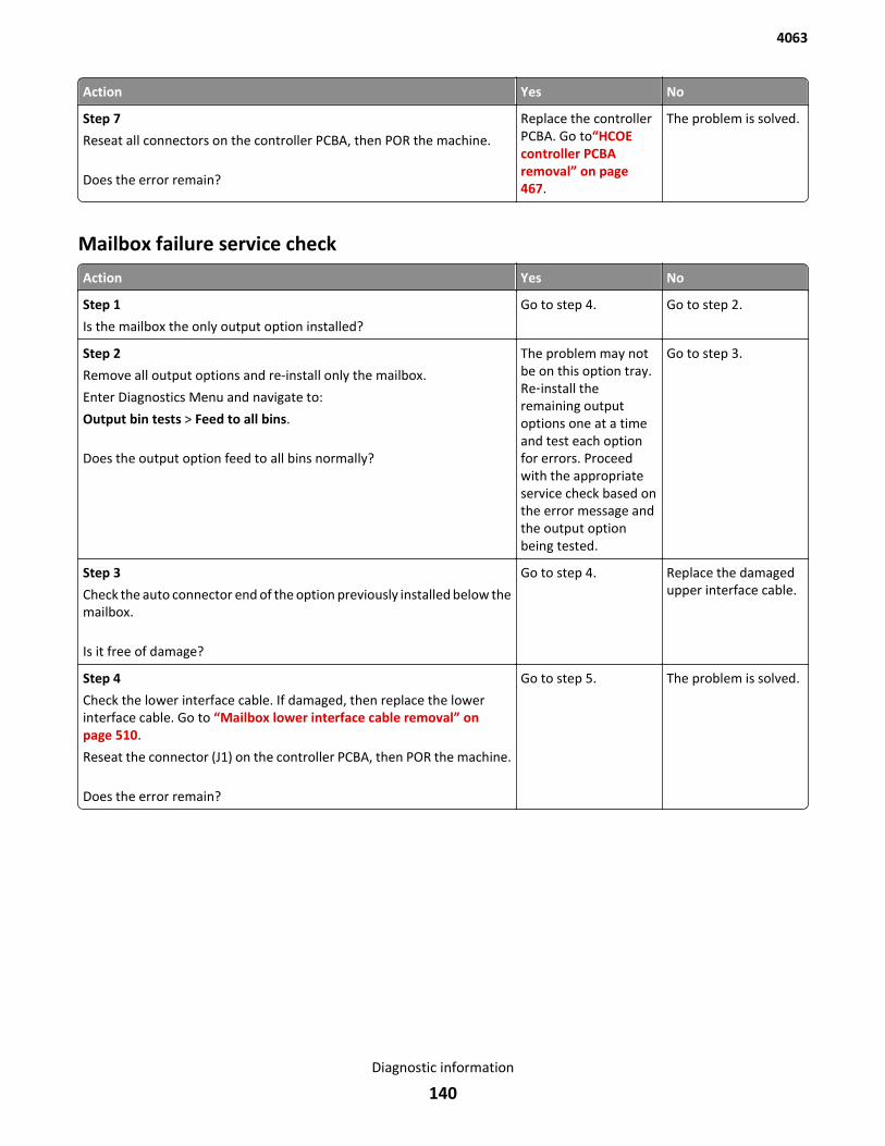
Action Yes No
Step 7
Reseat all connectors on the controller PCBA, then POR the machine.
Does the error remain?
Replace the controllerPCBA. Go to“HCOEcontroller PCBAremoval” on page 467.
The problem is solved.
Mailbox failure service check
Action Yes No
Step 1
Is the mailbox the only output option installed?
Go to step 4. Go to step 2.
Step 2
Remove all output options and re-install only the mailbox.
Enter Diagnostics Menu and navigate to:
Output bin tests > Feed to all bins.
Does the output option feed to all bins normally?
The problem may notbe on this option tray.Re‑install theremaining outputoptions one at a timeand test each optionfor errors. Proceedwith the appropriateservice check based onthe error message andthe output optionbeing tested.
Go to step 3.
Step 3
Check the auto connector end of the option previously installed below themailbox.
Is it free of damage?
Go to step 4. Replace the damagedupper interface cable.
Step 4
Check the lower interface cable. If damaged, then replace the lowerinterface cable. Go to “Mailbox lower interface cable removal” onpage 510.
Reseat the connector (J1) on the controller PCBA, then POR the machine.
Does the error remain?
Go to step 5. The problem is solved.
4063
Diagnostic information
140
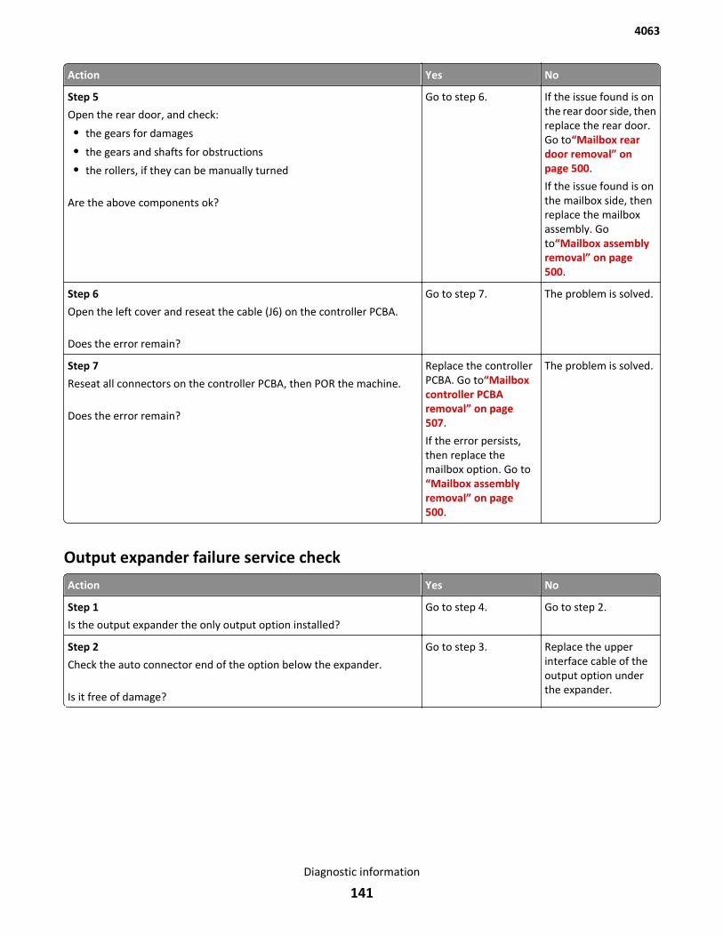
Action Yes No
Step 5
Open the rear door, and check:
• the gears for damages
• the gears and shafts for obstructions
• the rollers, if they can be manually turned
Are the above components ok?
Go to step 6. If the issue found is onthe rear door side, thenreplace the rear door.Go to“Mailbox reardoor removal” onpage 500.
If the issue found is onthe mailbox side, thenreplace the mailboxassembly. Goto“Mailbox assemblyremoval” on page 500.
Step 6
Open the left cover and reseat the cable (J6) on the controller PCBA.
Does the error remain?
Go to step 7. The problem is solved.
Step 7
Reseat all connectors on the controller PCBA, then POR the machine.
Does the error remain?
Replace the controllerPCBA. Go to“Mailboxcontroller PCBAremoval” on page 507.
If the error persists,then replace themailbox option. Go to“Mailbox assemblyremoval” on page 500.
The problem is solved.
Output expander failure service check
Action Yes No
Step 1
Is the output expander the only output option installed?
Go to step 4. Go to step 2.
Step 2
Check the auto connector end of the option below the expander.
Is it free of damage?
Go to step 3. Replace the upperinterface cable of theoutput option underthe expander.
4063
Diagnostic information
141
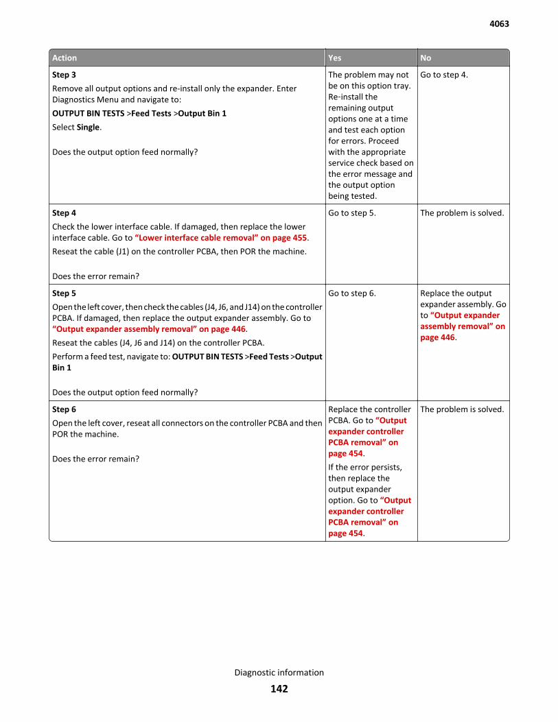
Action Yes No
Step 3
Remove all output options and re-install only the expander. EnterDiagnostics Menu and navigate to:
OUTPUT BIN TESTS >Feed Tests >Output Bin 1
Select Single.
Does the output option feed normally?
The problem may notbe on this option tray.Re‑install theremaining outputoptions one at a timeand test each optionfor errors. Proceedwith the appropriateservice check based onthe error message andthe output optionbeing tested.
Go to step 4.
Step 4
Check the lower interface cable. If damaged, then replace the lowerinterface cable. Go to “Lower interface cable removal” on page 455.
Reseat the cable (J1) on the controller PCBA, then POR the machine.
Does the error remain?
Go to step 5. The problem is solved.
Step 5
Open the left cover, then check the cables (J4, J6, and J14) on the controllerPCBA. If damaged, then replace the output expander assembly. Go to“Output expander assembly removal” on page 446.
Reseat the cables (J4, J6 and J14) on the controller PCBA.
Perform a feed test, navigate to: OUTPUT BIN TESTS >Feed Tests >OutputBin 1
Does the output option feed normally?
Go to step 6. Replace the outputexpander assembly. Goto “Output expanderassembly removal” onpage 446.
Step 6
Open the left cover, reseat all connectors on the controller PCBA and thenPOR the machine.
Does the error remain?
Replace the controllerPCBA. Go to “Outputexpander controllerPCBA removal” onpage 454.
If the error persists,then replace theoutput expanderoption. Go to “Outputexpander controllerPCBA removal” onpage 454.
The problem is solved.
4063
Diagnostic information
142
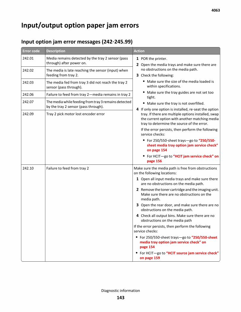
Input/output option paper jam errors
Input option jam error messages (242‑245.99)
Error code Description Action
242.01 Media remains detected by the tray 2 sensor (passthrough) after power on.
1 POR the printer.
2 Open the media trays and make sure there areno obstructions on the media path.
3 Check the following:
• Make sure the size of the media loaded iswithin specifications.
• Make sure the tray guides are not set tootight.
• Make sure the tray is not overfilled.
4 If only one option is installed, re‑seat the optiontray. If there are multiple options installed, swapthe current option with another matching mediatray to determine the source of the error.
If the error persists, then perform the followingservice checks:
• For 250/550‑sheet trays—go to “250/550-sheet media tray option jam service check”on page 154
• For HCIT—go to “HCIT jam service check” onpage 156
242.02 The media is late reaching the sensor (input) whenfeeding from tray 2.
242.03 The media fed from tray 3 did not reach the tray 2sensor (pass through).
242.06 Failure to feed from tray 2—media remains in tray 2
242.07 The media while feeding from tray 3 remains detectedby the tray 2 sensor (pass through).
242.09 Tray 2 pick motor lost encoder error
242.10 Failure to feed from tray 2 Make sure the media path is free from obstructionson the following locations:
1 Open all input media trays and make sure thereare no obstructions on the media path.
2 Remove the toner cartridge and the imaging unit.Make sure there are no obstructions on themedia path.
3 Open the rear door, and make sure there are noobstructions on the media path.
4 Check all output bins. Make sure there are noobstructions on the media path
If the error persists, then perform the followingservice checks:
• For 250/550‑sheet trays—go to “250/550-sheetmedia tray option jam service check” onpage 154
• For HCIT—go to “HCIT source jam service check”on page 159
4063
Diagnostic information
143
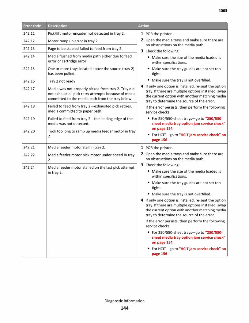
Error code Description Action
242.11 Pick/lift motor encoder not detected in tray 2. 1 POR the printer.
2 Open the media trays and make sure there areno obstructions on the media path.
3 Check the following:
• Make sure the size of the media loaded iswithin specifications.
• Make sure the tray guides are not set tootight.
• Make sure the tray is not overfilled.
4 If only one option is installed, re‑seat the optiontray. If there are multiple options installed, swapthe current option with another matching mediatray to determine the source of the error.
If the error persists, then perform the followingservice checks:
• For 250/550‑sheet trays—go to “250/550-sheet media tray option jam service check”on page 154
• For HCIT—go to “HCIT jam service check” onpage 156
242.12 Motor ramp up error in tray 2.
242.13 Page to be stapled failed to feed from tray 2.
242.14 Media flushed from media path either due to feederror or cartridge error
242.15 One or more trays located above the source (tray 2)has been pulled.
242.16 Tray 2 not ready
242.17 Media was not properly picked from tray 2. Tray didnot exhaust all pick retry attempts because of mediacommitted to the media path from the tray below.
242.18 Failed to feed from tray 2—exhausted pick retries,media committed to paper path.
242.19 Failed to feed from tray 2—the leading edge of themedia was not detected.
242.20 Took too long to ramp up media feeder motor in tray2
242.21 Media feeder motor stall in tray 2. 1 POR the printer.
2 Open the media trays and make sure there areno obstructions on the media path.
3 Check the following:
• Make sure the size of the media loaded iswithin specifications.
• Make sure the tray guides are not set tootight.
• Make sure the tray is not overfilled.
4 If only one option is installed, re‑seat the optiontray. If there are multiple options installed, swapthe current option with another matching mediatray to determine the source of the error.
If the error persists, then perform the followingservice checks:
• For 250/550‑sheet trays—go to “250/550-sheet media tray option jam service check”on page 154
• For HCIT—go to “HCIT jam service check” onpage 156
242.22 Media feeder motor pick motor under‑speed in tray2.
242.24 Media feeder motor stalled on the last pick attemptin tray 2.
4063
Diagnostic information
144
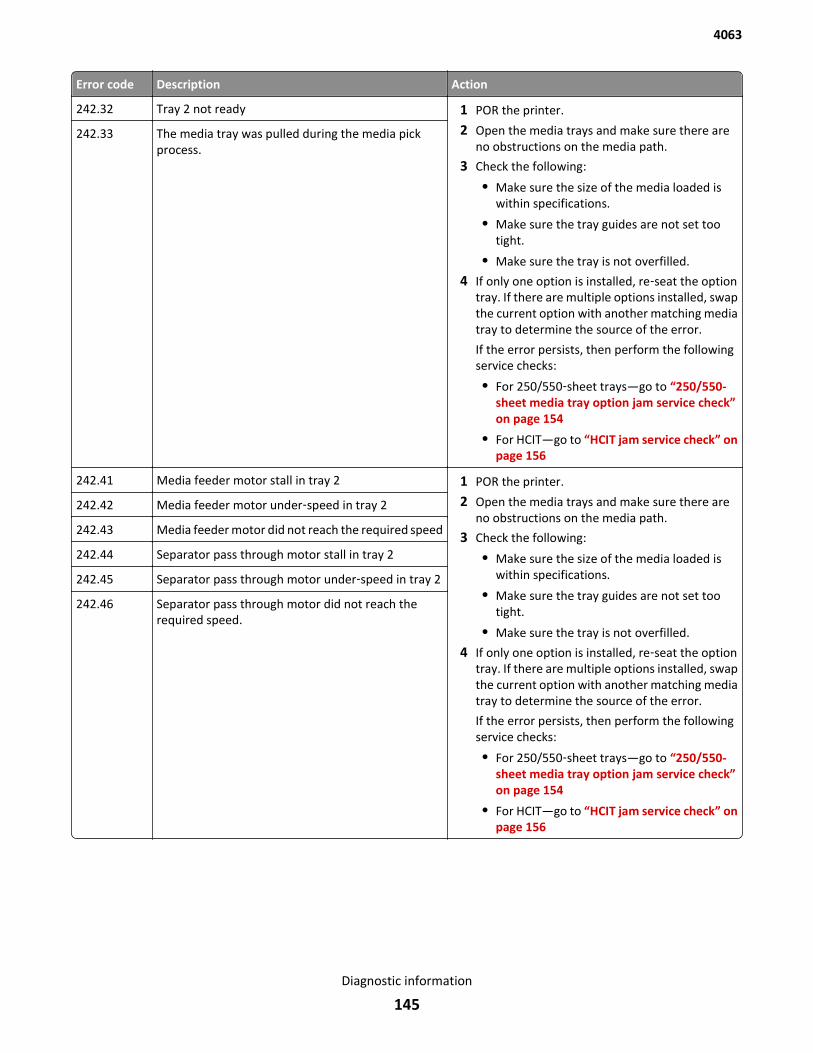
Error code Description Action
242.32 Tray 2 not ready 1 POR the printer.
2 Open the media trays and make sure there areno obstructions on the media path.
3 Check the following:
• Make sure the size of the media loaded iswithin specifications.
• Make sure the tray guides are not set tootight.
• Make sure the tray is not overfilled.
4 If only one option is installed, re‑seat the optiontray. If there are multiple options installed, swapthe current option with another matching mediatray to determine the source of the error.
If the error persists, then perform the followingservice checks:
• For 250/550‑sheet trays—go to “250/550-sheet media tray option jam service check”on page 154
• For HCIT—go to “HCIT jam service check” onpage 156
242.33 The media tray was pulled during the media pickprocess.
242.41 Media feeder motor stall in tray 2 1 POR the printer.
2 Open the media trays and make sure there areno obstructions on the media path.
3 Check the following:
• Make sure the size of the media loaded iswithin specifications.
• Make sure the tray guides are not set tootight.
• Make sure the tray is not overfilled.
4 If only one option is installed, re‑seat the optiontray. If there are multiple options installed, swapthe current option with another matching mediatray to determine the source of the error.
If the error persists, then perform the followingservice checks:
• For 250/550‑sheet trays—go to “250/550-sheet media tray option jam service check”on page 154
• For HCIT—go to “HCIT jam service check” onpage 156
242.42 Media feeder motor under‑speed in tray 2
242.43 Media feeder motor did not reach the required speed
242.44 Separator pass through motor stall in tray 2
242.45 Separator pass through motor under‑speed in tray 2
242.46 Separator pass through motor did not reach therequired speed.
4063
Diagnostic information
145
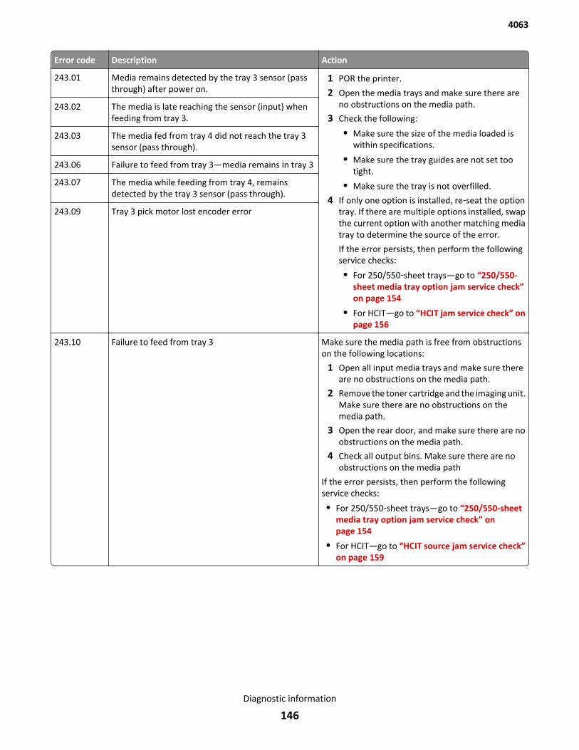
Error code Description Action
243.01 Media remains detected by the tray 3 sensor (passthrough) after power on.
1 POR the printer.
2 Open the media trays and make sure there areno obstructions on the media path.
3 Check the following:
• Make sure the size of the media loaded iswithin specifications.
• Make sure the tray guides are not set tootight.
• Make sure the tray is not overfilled.
4 If only one option is installed, re‑seat the optiontray. If there are multiple options installed, swapthe current option with another matching mediatray to determine the source of the error.
If the error persists, then perform the followingservice checks:
• For 250/550‑sheet trays—go to “250/550-sheet media tray option jam service check”on page 154
• For HCIT—go to “HCIT jam service check” onpage 156
243.02 The media is late reaching the sensor (input) whenfeeding from tray 3.
243.03 The media fed from tray 4 did not reach the tray 3sensor (pass through).
243.06 Failure to feed from tray 3—media remains in tray 3
243.07 The media while feeding from tray 4, remainsdetected by the tray 3 sensor (pass through).
243.09 Tray 3 pick motor lost encoder error
243.10 Failure to feed from tray 3 Make sure the media path is free from obstructionson the following locations:
1 Open all input media trays and make sure thereare no obstructions on the media path.
2 Remove the toner cartridge and the imaging unit.Make sure there are no obstructions on themedia path.
3 Open the rear door, and make sure there are noobstructions on the media path.
4 Check all output bins. Make sure there are noobstructions on the media path
If the error persists, then perform the followingservice checks:
• For 250/550‑sheet trays—go to “250/550-sheetmedia tray option jam service check” onpage 154
• For HCIT—go to “HCIT source jam service check”on page 159
4063
Diagnostic information
146
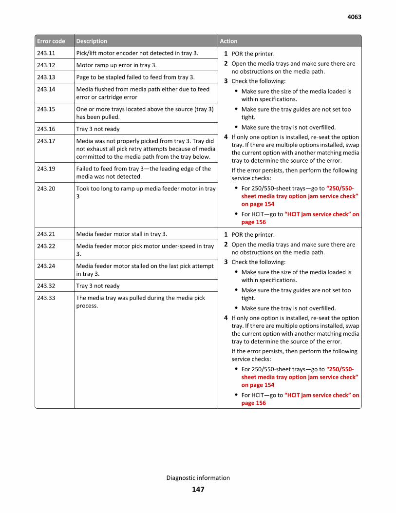
Error code Description Action
243.11 Pick/lift motor encoder not detected in tray 3. 1 POR the printer.
2 Open the media trays and make sure there areno obstructions on the media path.
3 Check the following:
• Make sure the size of the media loaded iswithin specifications.
• Make sure the tray guides are not set tootight.
• Make sure the tray is not overfilled.
4 If only one option is installed, re‑seat the optiontray. If there are multiple options installed, swapthe current option with another matching mediatray to determine the source of the error.
If the error persists, then perform the followingservice checks:
• For 250/550‑sheet trays—go to “250/550-sheet media tray option jam service check”on page 154
• For HCIT—go to “HCIT jam service check” onpage 156
243.12 Motor ramp up error in tray 3.
243.13 Page to be stapled failed to feed from tray 3.
243.14 Media flushed from media path either due to feederror or cartridge error
243.15 One or more trays located above the source (tray 3)has been pulled.
243.16 Tray 3 not ready
243.17 Media was not properly picked from tray 3. Tray didnot exhaust all pick retry attempts because of mediacommitted to the media path from the tray below.
243.19 Failed to feed from tray 3—the leading edge of themedia was not detected.
243.20 Took too long to ramp up media feeder motor in tray3
243.21 Media feeder motor stall in tray 3. 1 POR the printer.
2 Open the media trays and make sure there areno obstructions on the media path.
3 Check the following:
• Make sure the size of the media loaded iswithin specifications.
• Make sure the tray guides are not set tootight.
• Make sure the tray is not overfilled.
4 If only one option is installed, re‑seat the optiontray. If there are multiple options installed, swapthe current option with another matching mediatray to determine the source of the error.
If the error persists, then perform the followingservice checks:
• For 250/550‑sheet trays—go to “250/550-sheet media tray option jam service check”on page 154
• For HCIT—go to “HCIT jam service check” onpage 156
243.22 Media feeder motor pick motor under‑speed in tray3.
243.24 Media feeder motor stalled on the last pick attemptin tray 3.
243.32 Tray 3 not ready
243.33 The media tray was pulled during the media pickprocess.
4063
Diagnostic information
147
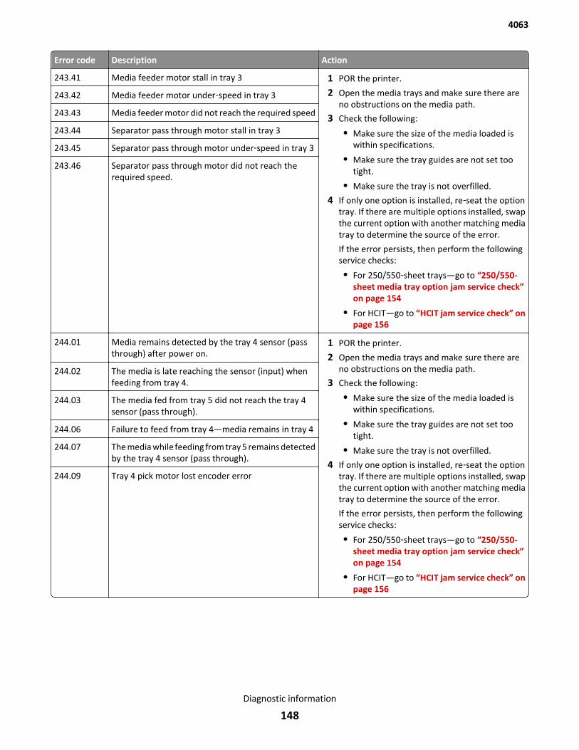
Error code Description Action
243.41 Media feeder motor stall in tray 3 1 POR the printer.
2 Open the media trays and make sure there areno obstructions on the media path.
3 Check the following:
• Make sure the size of the media loaded iswithin specifications.
• Make sure the tray guides are not set tootight.
• Make sure the tray is not overfilled.
4 If only one option is installed, re‑seat the optiontray. If there are multiple options installed, swapthe current option with another matching mediatray to determine the source of the error.
If the error persists, then perform the followingservice checks:
• For 250/550‑sheet trays—go to “250/550-sheet media tray option jam service check”on page 154
• For HCIT—go to “HCIT jam service check” onpage 156
243.42 Media feeder motor under‑speed in tray 3
243.43 Media feeder motor did not reach the required speed
243.44 Separator pass through motor stall in tray 3
243.45 Separator pass through motor under‑speed in tray 3
243.46 Separator pass through motor did not reach therequired speed.
244.01 Media remains detected by the tray 4 sensor (passthrough) after power on.
1 POR the printer.
2 Open the media trays and make sure there areno obstructions on the media path.
3 Check the following:
• Make sure the size of the media loaded iswithin specifications.
• Make sure the tray guides are not set tootight.
• Make sure the tray is not overfilled.
4 If only one option is installed, re‑seat the optiontray. If there are multiple options installed, swapthe current option with another matching mediatray to determine the source of the error.
If the error persists, then perform the followingservice checks:
• For 250/550‑sheet trays—go to “250/550-sheet media tray option jam service check”on page 154
• For HCIT—go to “HCIT jam service check” onpage 156
244.02 The media is late reaching the sensor (input) whenfeeding from tray 4.
244.03 The media fed from tray 5 did not reach the tray 4sensor (pass through).
244.06 Failure to feed from tray 4—media remains in tray 4
244.07 The media while feeding from tray 5 remains detectedby the tray 4 sensor (pass through).
244.09 Tray 4 pick motor lost encoder error
4063
Diagnostic information
148

Error code Description Action
244.10 Failure to feed from tray 4 Make sure the media path is free from obstructionson the following locations:
1 Open all input media trays and make sure thereare no obstructions on the media path.
2 Remove the toner cartridge and the imaging unit.Make sure there are no obstructions on themedia path.
3 Open the rear door, and make sure there are noobstructions on the media path.
4 Check all output bins. Make sure there are noobstructions on the media path
If the error persists, then perform the followingservice checks:
• For 250/550‑sheet trays—go to “250/550-sheetmedia tray option jam service check” onpage 154
• For HCIT—go to “HCIT source jam service check”on page 159
244.11 Pick/lift motor encoder not detected in tray 4. 1 POR the printer.
2 Open the media trays and make sure there areno obstructions on the media path.
3 Check the following:
• Make sure the size of the media loaded iswithin specifications.
• Make sure the tray guides are not set tootight.
• Make sure the tray is not overfilled.
4 If only one option is installed, re‑seat the optiontray. If there are multiple options installed, swapthe current option with another matching mediatray to determine the source of the error.
If the error persists, then perform the followingservice checks:
• For 250/550‑sheet trays—go to “250/550-sheet media tray option jam service check”on page 154
• For HCIT—go to “HCIT jam service check” onpage 156
244.12 Motor ramp up error in tray 4.
244.13 Page to be stapled failed to feed from tray 4.
244.14 Media flushed from media path either due to feederror or cartridge error
244.15 One or more trays located above the source (tray 4)has been pulled.
244.16 Tray 4 not ready
244.17 Media was not properly picked from tray 4. Tray didnot exhaust all pick retry attempts because of mediacommitted to the media path from the tray below.
244.19 Failed to feed from tray 4—the leading edge of themedia was not detected.
244.20 Took too long to ramp up media feeder motor in tray4
4063
Diagnostic information
149
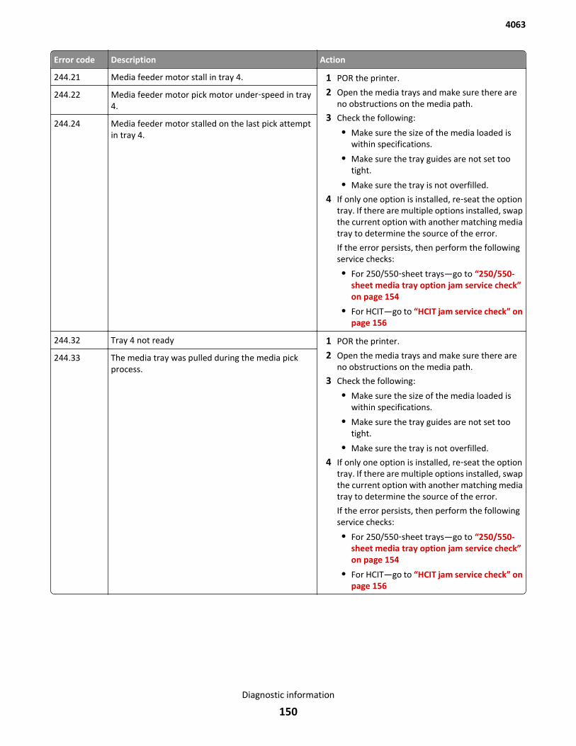
Error code Description Action
244.21 Media feeder motor stall in tray 4. 1 POR the printer.
2 Open the media trays and make sure there areno obstructions on the media path.
3 Check the following:
• Make sure the size of the media loaded iswithin specifications.
• Make sure the tray guides are not set tootight.
• Make sure the tray is not overfilled.
4 If only one option is installed, re‑seat the optiontray. If there are multiple options installed, swapthe current option with another matching mediatray to determine the source of the error.
If the error persists, then perform the followingservice checks:
• For 250/550‑sheet trays—go to “250/550-sheet media tray option jam service check”on page 154
• For HCIT—go to “HCIT jam service check” onpage 156
244.22 Media feeder motor pick motor under‑speed in tray4.
244.24 Media feeder motor stalled on the last pick attemptin tray 4.
244.32 Tray 4 not ready 1 POR the printer.
2 Open the media trays and make sure there areno obstructions on the media path.
3 Check the following:
• Make sure the size of the media loaded iswithin specifications.
• Make sure the tray guides are not set tootight.
• Make sure the tray is not overfilled.
4 If only one option is installed, re‑seat the optiontray. If there are multiple options installed, swapthe current option with another matching mediatray to determine the source of the error.
If the error persists, then perform the followingservice checks:
• For 250/550‑sheet trays—go to “250/550-sheet media tray option jam service check”on page 154
• For HCIT—go to “HCIT jam service check” onpage 156
244.33 The media tray was pulled during the media pickprocess.
4063
Diagnostic information
150

Error code Description Action
244.41 Media feeder motor stall in tray 4 1 POR the printer.
2 Open the media trays and make sure there areno obstructions on the media path.
3 Check the following:
• Make sure the size of the media loaded iswithin specifications.
• Make sure the tray guides are not set tootight.
• Make sure the tray is not overfilled.
4 If only one option is installed, re‑seat the optiontray. If there are multiple options installed, swapthe current option with another matching mediatray to determine the source of the error.
If the error persists, then perform the followingservice checks:
• For 250/550‑sheet trays—go to “250/550-sheet media tray option jam service check”on page 154
• For HCIT—go to “HCIT jam service check” onpage 156
244.42 Media feeder motor under‑speed in tray 4
244.43 Media feeder motor did not reach the required speed
244.44 Separator pass through motor stall in tray 4
244.45 Separator pass through motor under‑speed in tray 4
244.46 Separator pass through motor did not reach therequired speed.
245.01 Media remains detected by the tray 5 sensor (passthrough) after power on.
1 POR the printer.
2 Open the media trays and make sure there areno obstructions on the media path.
3 Check the following:
• Make sure the size of the media loaded iswithin specifications.
• Make sure the tray guides are not set tootight.
• Make sure the tray is not overfilled.
4 If only one option is installed, re‑seat the optiontray. If there are multiple options installed, swapthe current option with another matching mediatray to determine the source of the error.
If the error persists, then perform the followingservice checks:
• For 250/550‑sheet trays—go to “250/550-sheet media tray option jam service check”on page 154
• For HCIT—go to “HCIT jam service check” onpage 156
245.02 The media is late reaching the sensor (input) whenfeeding from tray 6.
245.03 The media fed from tray 6 did not reach the tray 5sensor (pass through).
245.06 Failure to feed from tray 5—media remains in tray 5
245.07 The media while feeding from tray 6 remains detectedby the tray 5 sensor (pass through).
245.09 Tray 5 pick motor lost encoder error
4063
Diagnostic information
151
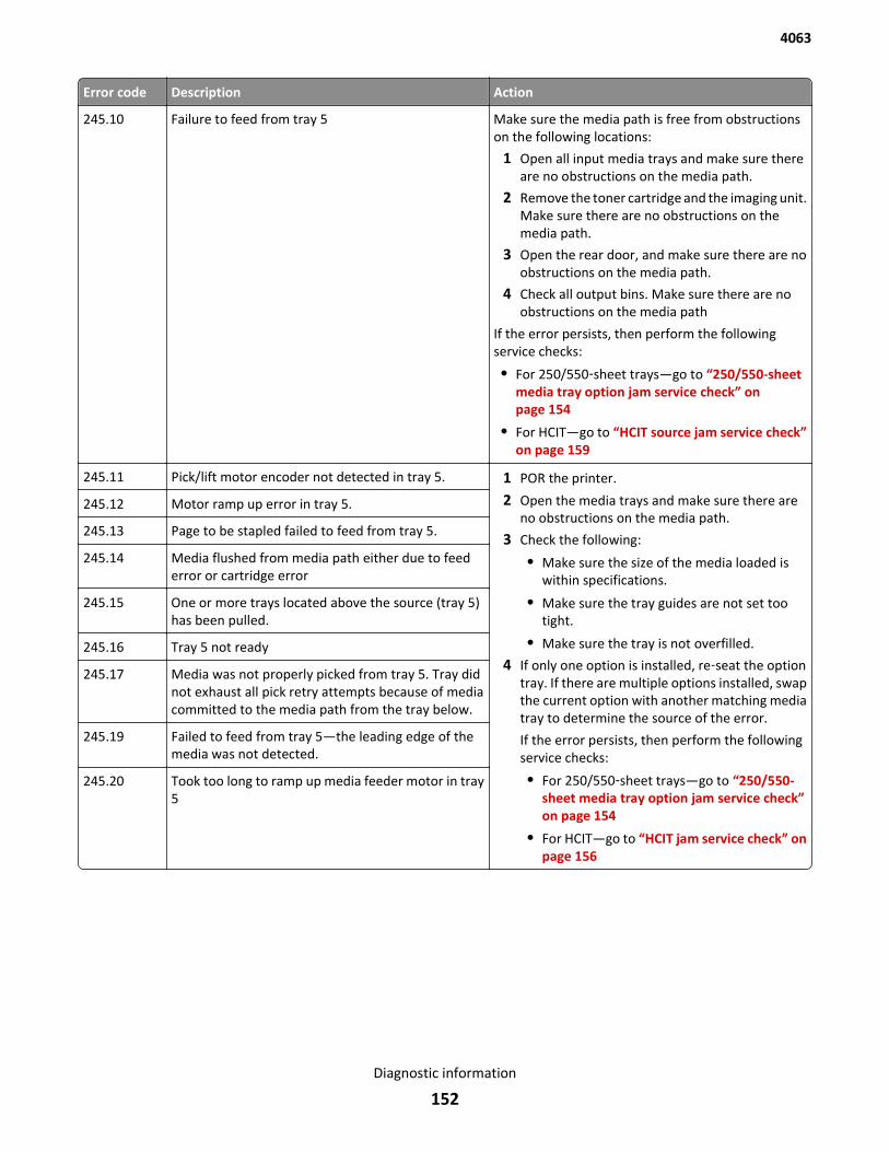
Error code Description Action
245.10 Failure to feed from tray 5 Make sure the media path is free from obstructionson the following locations:
1 Open all input media trays and make sure thereare no obstructions on the media path.
2 Remove the toner cartridge and the imaging unit.Make sure there are no obstructions on themedia path.
3 Open the rear door, and make sure there are noobstructions on the media path.
4 Check all output bins. Make sure there are noobstructions on the media path
If the error persists, then perform the followingservice checks:
• For 250/550‑sheet trays—go to “250/550-sheetmedia tray option jam service check” onpage 154
• For HCIT—go to “HCIT source jam service check”on page 159
245.11 Pick/lift motor encoder not detected in tray 5. 1 POR the printer.
2 Open the media trays and make sure there areno obstructions on the media path.
3 Check the following:
• Make sure the size of the media loaded iswithin specifications.
• Make sure the tray guides are not set tootight.
• Make sure the tray is not overfilled.
4 If only one option is installed, re‑seat the optiontray. If there are multiple options installed, swapthe current option with another matching mediatray to determine the source of the error.
If the error persists, then perform the followingservice checks:
• For 250/550‑sheet trays—go to “250/550-sheet media tray option jam service check”on page 154
• For HCIT—go to “HCIT jam service check” onpage 156
245.12 Motor ramp up error in tray 5.
245.13 Page to be stapled failed to feed from tray 5.
245.14 Media flushed from media path either due to feederror or cartridge error
245.15 One or more trays located above the source (tray 5)has been pulled.
245.16 Tray 5 not ready
245.17 Media was not properly picked from tray 5. Tray didnot exhaust all pick retry attempts because of mediacommitted to the media path from the tray below.
245.19 Failed to feed from tray 5—the leading edge of themedia was not detected.
245.20 Took too long to ramp up media feeder motor in tray5
4063
Diagnostic information
152

Error code Description Action
245.21 Media feeder motor stall in tray 5. 1 POR the printer.
2 Open the media trays and make sure there areno obstructions on the media path.
3 Check the following:
• Make sure the size of the media loaded iswithin specifications.
• Make sure the tray guides are not set tootight.
• Make sure the tray is not overfilled.
4 If only one option is installed, re‑seat the optiontray. If there are multiple options installed, swapthe current option with another matching mediatray to determine the source of the error.
If the error persists, then perform the followingservice checks:
• For 250/550‑sheet trays—go to “250/550-sheet media tray option jam service check”on page 154
• For HCIT—go to “HCIT jam service check” onpage 156
245.22 Media feeder motor pick motor under‑speed in tray5.
245.24 Media feeder motor stalled on the last pick attemptin tray 5.
245.32 Tray 5 not ready 1 POR the printer.
2 Open the media trays and make sure there areno obstructions on the media path.
3 Check the following:
• Make sure the size of the media loaded iswithin specifications.
• Make sure the tray guides are not set tootight.
• Make sure the tray is not overfilled.
4 If only one option is installed, re‑seat the optiontray. If there are multiple options installed, swapthe current option with another matching mediatray to determine the source of the error.
If the error persists, then perform the followingservice checks:
• For 250/550‑sheet trays—go to “250/550-sheet media tray option jam service check”on page 154
• For HCIT—go to “HCIT jam service check” onpage 156
245.33 The media tray was pulled during the media pickprocess.
4063
Diagnostic information
153
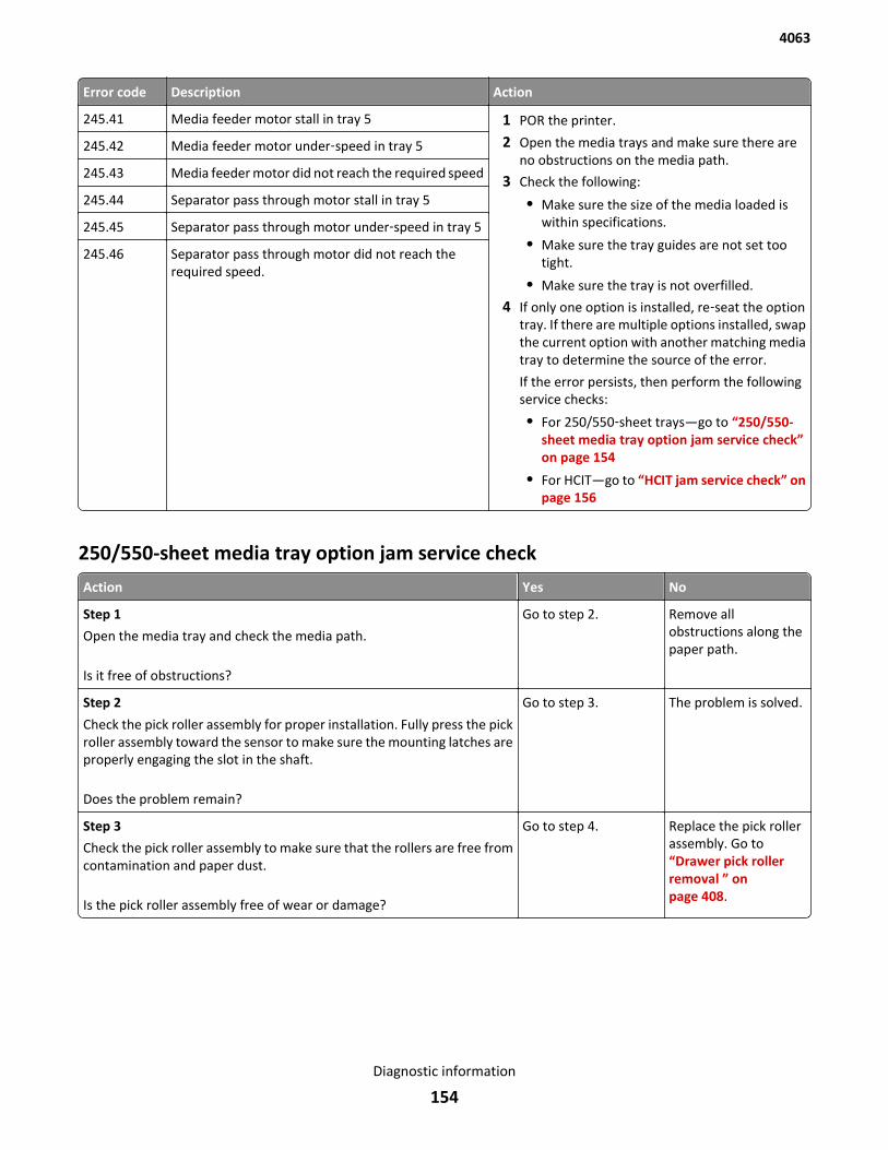
Error code Description Action
245.41 Media feeder motor stall in tray 5 1 POR the printer.
2 Open the media trays and make sure there areno obstructions on the media path.
3 Check the following:
• Make sure the size of the media loaded iswithin specifications.
• Make sure the tray guides are not set tootight.
• Make sure the tray is not overfilled.
4 If only one option is installed, re‑seat the optiontray. If there are multiple options installed, swapthe current option with another matching mediatray to determine the source of the error.
If the error persists, then perform the followingservice checks:
• For 250/550‑sheet trays—go to “250/550-sheet media tray option jam service check”on page 154
• For HCIT—go to “HCIT jam service check” onpage 156
245.42 Media feeder motor under‑speed in tray 5
245.43 Media feeder motor did not reach the required speed
245.44 Separator pass through motor stall in tray 5
245.45 Separator pass through motor under‑speed in tray 5
245.46 Separator pass through motor did not reach therequired speed.
250/550-sheet media tray option jam service check
Action Yes No
Step 1
Open the media tray and check the media path.
Is it free of obstructions?
Go to step 2. Remove allobstructions along thepaper path.
Step 2
Check the pick roller assembly for proper installation. Fully press the pickroller assembly toward the sensor to make sure the mounting latches areproperly engaging the slot in the shaft.
Does the problem remain?
Go to step 3. The problem is solved.
Step 3
Check the pick roller assembly to make sure that the rollers are free fromcontamination and paper dust.
Is the pick roller assembly free of wear or damage?
Go to step 4. Replace the pick rollerassembly. Go to“Drawer pick rollerremoval ” onpage 408.
4063
Diagnostic information
154
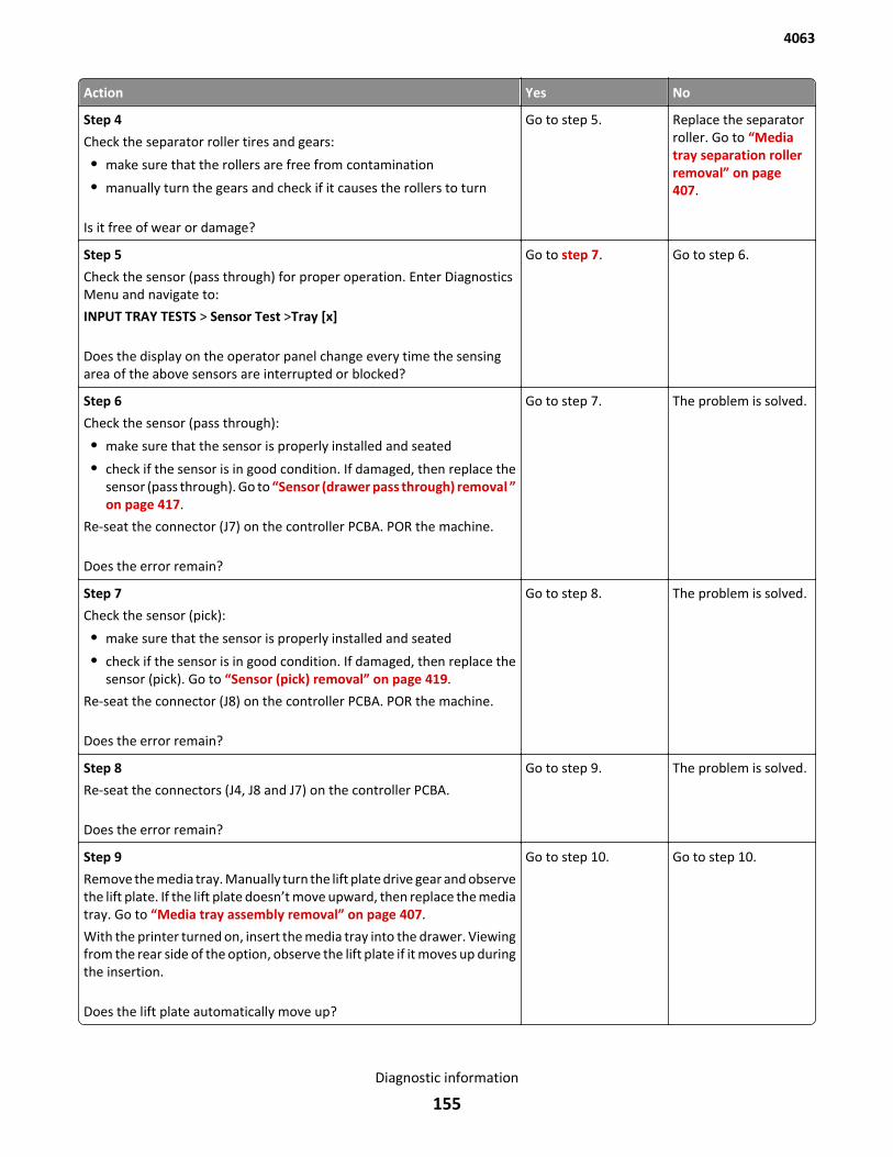
Action Yes No
Step 4
Check the separator roller tires and gears:
• make sure that the rollers are free from contamination
• manually turn the gears and check if it causes the rollers to turn
Is it free of wear or damage?
Go to step 5. Replace the separatorroller. Go to “Mediatray separation rollerremoval” on page 407.
Step 5
Check the sensor (pass through) for proper operation. Enter DiagnosticsMenu and navigate to:
INPUT TRAY TESTS > Sensor Test >Tray [x]
Does the display on the operator panel change every time the sensingarea of the above sensors are interrupted or blocked?
Go to step 7. Go to step 6.
Step 6
Check the sensor (pass through):
• make sure that the sensor is properly installed and seated
• check if the sensor is in good condition. If damaged, then replace thesensor (pass through). Go to “Sensor (drawer pass through) removal ”on page 417.
Re-seat the connector (J7) on the controller PCBA. POR the machine.
Does the error remain?
Go to step 7. The problem is solved.
Step 7
Check the sensor (pick):
• make sure that the sensor is properly installed and seated
• check if the sensor is in good condition. If damaged, then replace thesensor (pick). Go to “Sensor (pick) removal” on page 419.
Re-seat the connector (J8) on the controller PCBA. POR the machine.
Does the error remain?
Go to step 8. The problem is solved.
Step 8
Re-seat the connectors (J4, J8 and J7) on the controller PCBA.
Does the error remain?
Go to step 9. The problem is solved.
Step 9
Remove the media tray. Manually turn the lift plate drive gear and observethe lift plate. If the lift plate doesn’t move upward, then replace the mediatray. Go to “Media tray assembly removal” on page 407.
With the printer turned on, insert the media tray into the drawer. Viewingfrom the rear side of the option, observe the lift plate if it moves up duringthe insertion.
Does the lift plate automatically move up?
Go to step 10. Go to step 10.
4063
Diagnostic information
155
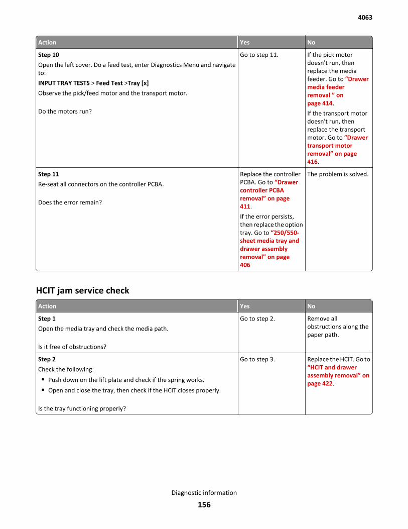
Action Yes No
Step 10
Open the left cover. Do a feed test, enter Diagnostics Menu and navigateto:
INPUT TRAY TESTS > Feed Test >Tray [x]
Observe the pick/feed motor and the transport motor.
Do the motors run?
Go to step 11. If the pick motordoesn't run, thenreplace the mediafeeder. Go to “Drawermedia feederremoval ” onpage 414.
If the transport motordoesn't run, thenreplace the transportmotor. Go to “Drawertransport motorremoval” on page 416.
Step 11
Re-seat all connectors on the controller PCBA.
Does the error remain?
Replace the controllerPCBA. Go to “Drawercontroller PCBAremoval” on page 411.
If the error persists,then replace the optiontray. Go to “250/550-sheet media tray anddrawer assemblyremoval” on page 406
The problem is solved.
HCIT jam service check
Action Yes No
Step 1
Open the media tray and check the media path.
Is it free of obstructions?
Go to step 2. Remove allobstructions along thepaper path.
Step 2
Check the following:
• Push down on the lift plate and check if the spring works.
• Open and close the tray, then check if the HCIT closes properly.
Is the tray functioning properly?
Go to step 3. Replace the HCIT. Go to“HCIT and drawerassembly removal” onpage 422.
4063
Diagnostic information
156
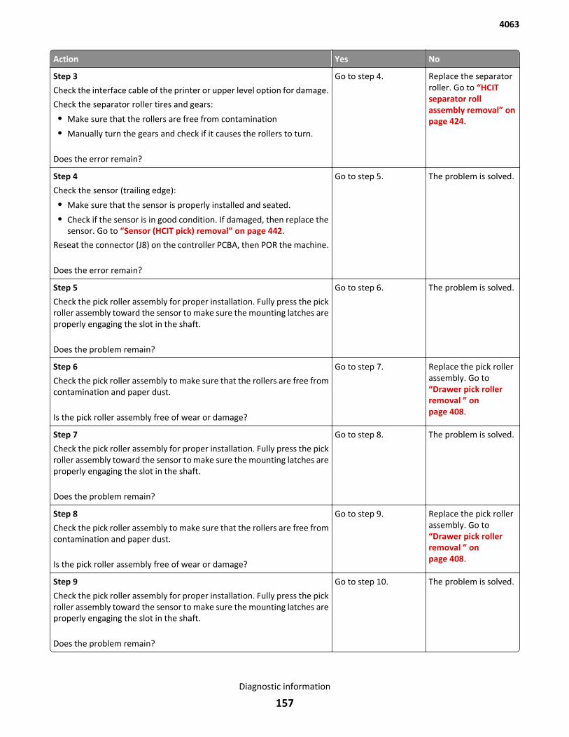
Action Yes No
Step 3
Check the interface cable of the printer or upper level option for damage.
Check the separator roller tires and gears:
• Make sure that the rollers are free from contamination
• Manually turn the gears and check if it causes the rollers to turn.
Does the error remain?
Go to step 4. Replace the separatorroller. Go to “HCITseparator rollassembly removal” onpage 424.
Step 4
Check the sensor (trailing edge):
• Make sure that the sensor is properly installed and seated.
• Check if the sensor is in good condition. If damaged, then replace thesensor. Go to “Sensor (HCIT pick) removal” on page 442.
Reseat the connector (J8) on the controller PCBA, then POR the machine.
Does the error remain?
Go to step 5. The problem is solved.
Step 5
Check the pick roller assembly for proper installation. Fully press the pickroller assembly toward the sensor to make sure the mounting latches areproperly engaging the slot in the shaft.
Does the problem remain?
Go to step 6. The problem is solved.
Step 6
Check the pick roller assembly to make sure that the rollers are free fromcontamination and paper dust.
Is the pick roller assembly free of wear or damage?
Go to step 7. Replace the pick rollerassembly. Go to“Drawer pick rollerremoval ” onpage 408.
Step 7
Check the pick roller assembly for proper installation. Fully press the pickroller assembly toward the sensor to make sure the mounting latches areproperly engaging the slot in the shaft.
Does the problem remain?
Go to step 8. The problem is solved.
Step 8
Check the pick roller assembly to make sure that the rollers are free fromcontamination and paper dust.
Is the pick roller assembly free of wear or damage?
Go to step 9. Replace the pick rollerassembly. Go to“Drawer pick rollerremoval ” onpage 408.
Step 9
Check the pick roller assembly for proper installation. Fully press the pickroller assembly toward the sensor to make sure the mounting latches areproperly engaging the slot in the shaft.
Does the problem remain?
Go to step 10. The problem is solved.
4063
Diagnostic information
157
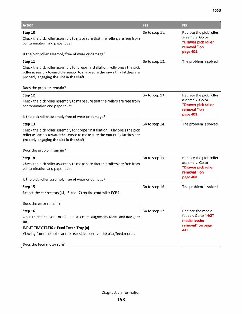
Action Yes No
Step 10
Check the pick roller assembly to make sure that the rollers are free fromcontamination and paper dust.
Is the pick roller assembly free of wear or damage?
Go to step 11. Replace the pick rollerassembly. Go to“Drawer pick rollerremoval ” onpage 408.
Step 11
Check the pick roller assembly for proper installation. Fully press the pickroller assembly toward the sensor to make sure the mounting latches areproperly engaging the slot in the shaft.
Does the problem remain?
Go to step 12. The problem is solved.
Step 12
Check the pick roller assembly to make sure that the rollers are free fromcontamination and paper dust.
Is the pick roller assembly free of wear or damage?
Go to step 13. Replace the pick rollerassembly. Go to“Drawer pick rollerremoval ” onpage 408.
Step 13
Check the pick roller assembly for proper installation. Fully press the pickroller assembly toward the sensor to make sure the mounting latches areproperly engaging the slot in the shaft.
Does the problem remain?
Go to step 14. The problem is solved.
Step 14
Check the pick roller assembly to make sure that the rollers are free fromcontamination and paper dust.
Is the pick roller assembly free of wear or damage?
Go to step 15. Replace the pick rollerassembly. Go to“Drawer pick rollerremoval ” onpage 408.
Step 15
Reseat the connectors (J4, J8 and J7) on the controller PCBA.
Does the error remain?
Go to step 16. The problem is solved.
Step 16
Open the rear cover. Do a feed test, enter Diagnostics Menu and navigateto:
INPUT TRAY TESTS > Feed Test > Tray [x]
Viewing from the holes at the rear side, observe the pick/feed motor.
Does the feed motor run?
Go to step 17. Replace the mediafeeder. Go to “HCITmedia feederremoval” on page 443.
4063
Diagnostic information
158
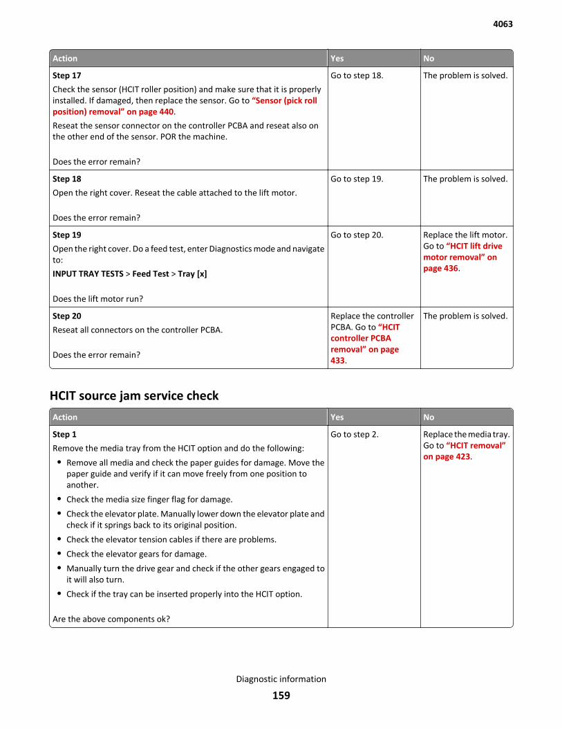
Action Yes No
Step 17
Check the sensor (HCIT roller position) and make sure that it is properlyinstalled. If damaged, then replace the sensor. Go to “Sensor (pick rollposition) removal” on page 440.
Reseat the sensor connector on the controller PCBA and reseat also onthe other end of the sensor. POR the machine.
Does the error remain?
Go to step 18. The problem is solved.
Step 18
Open the right cover. Reseat the cable attached to the lift motor.
Does the error remain?
Go to step 19. The problem is solved.
Step 19
Open the right cover. Do a feed test, enter Diagnostics mode and navigateto:
INPUT TRAY TESTS > Feed Test > Tray [x]
Does the lift motor run?
Go to step 20. Replace the lift motor.Go to “HCIT lift drivemotor removal” onpage 436.
Step 20
Reseat all connectors on the controller PCBA.
Does the error remain?
Replace the controllerPCBA. Go to “HCITcontroller PCBAremoval” on page 433.
The problem is solved.
HCIT source jam service check
Action Yes No
Step 1
Remove the media tray from the HCIT option and do the following:
• Remove all media and check the paper guides for damage. Move thepaper guide and verify if it can move freely from one position toanother.
• Check the media size finger flag for damage.
• Check the elevator plate. Manually lower down the elevator plate andcheck if it springs back to its original position.
• Check the elevator tension cables if there are problems.
• Check the elevator gears for damage.
• Manually turn the drive gear and check if the other gears engaged toit will also turn.
• Check if the tray can be inserted properly into the HCIT option.
Are the above components ok?
Go to step 2. Replace the media tray.Go to “HCIT removal”on page 423.
4063
Diagnostic information
159
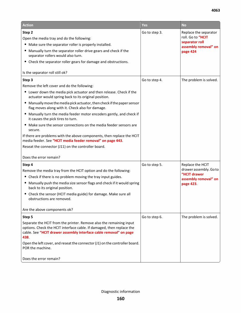
Action Yes No
Step 2
Open the media tray and do the following:
• Make sure the separator roller is properly installed.
• Manually turn the separator roller drive gears and check if theseparator rollers would also turn.
• Check the separator roller gears for damage and obstructions.
Is the separator roll still ok?
Go to step 3. Replace the separatorroll. Go to “HCITseparator rollassembly removal” onpage 424
Step 3
Remove the left cover and do the following:
• Lower down the media pick actuator and then release. Check if theactuator would spring back to its original position.
• Manually move the media pick actuator, then check if the paper sensorflag moves along with it. Check also for damage.
• Manually turn the media feeder motor encoders gently, and check ifit causes the pick tires to turn.
• Make sure the sensor connections on the media feeder sensors aresecure.
If there are problems with the above components, then replace the HCITmedia feeder. See “HCIT media feeder removal” on page 443.
Reseat the connector (J11) on the controller board.
Does the error remain?
Go to step 4. The problem is solved.
Step 4
Remove the media tray from the HCIT option and do the following:
• Check if there is no problem moving the tray input guides.
• Manually push the media size sensor flags and check if it would springback to its original position.
• Check the sensor (HCIT media guide) for damage. Make sure allobstructions are removed.
Are the above components ok?
Go to step 5. Replace the HCITdrawer assembly. Go to“HCIT drawerassembly removal” onpage 423.
Step 5
Separate the HCIT from the printer. Remove also the remaining inputoptions. Check the HCIT interface cable. If damaged, then replace thecable. See “HCIT drawer assembly interface cable removal” on page 438.
Open the left cover, and reseat the connector (J1) on the controller board.POR the machine.
Does the error remain?
Go to step 6. The problem is solved.
4063
Diagnostic information
160
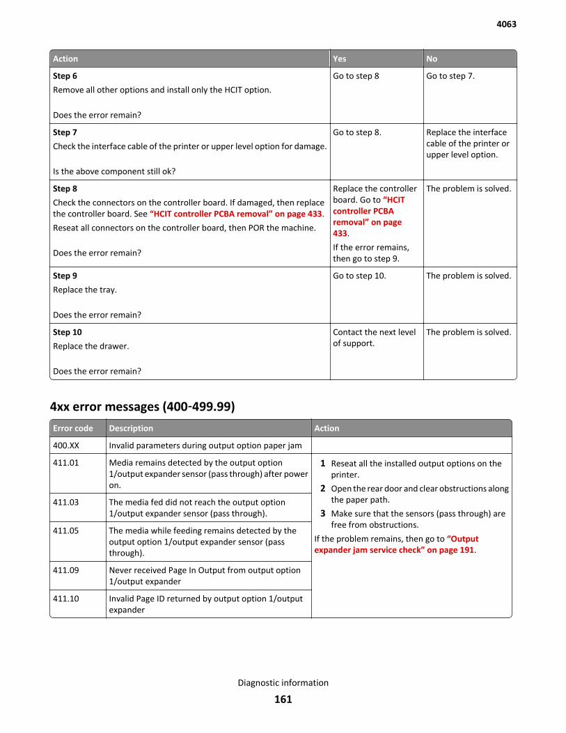
Action Yes No
Step 6
Remove all other options and install only the HCIT option.
Does the error remain?
Go to step 8 Go to step 7.
Step 7
Check the interface cable of the printer or upper level option for damage.
Is the above component still ok?
Go to step 8. Replace the interfacecable of the printer orupper level option.
Step 8
Check the connectors on the controller board. If damaged, then replacethe controller board. See “HCIT controller PCBA removal” on page 433.
Reseat all connectors on the controller board, then POR the machine.
Does the error remain?
Replace the controllerboard. Go to “HCITcontroller PCBAremoval” on page 433.
If the error remains,then go to step 9.
The problem is solved.
Step 9
Replace the tray.
Does the error remain?
Go to step 10. The problem is solved.
Step 10
Replace the drawer.
Does the error remain?
Contact the next levelof support.
The problem is solved.
4xx error messages (400‑499.99)
Error code Description Action
400.XX Invalid parameters during output option paper jam
411.01 Media remains detected by the output option1/output expander sensor (pass through) after poweron.
1 Reseat all the installed output options on theprinter.
2 Open the rear door and clear obstructions alongthe paper path.
3 Make sure that the sensors (pass through) arefree from obstructions.
If the problem remains, then go to “Outputexpander jam service check” on page 191.
411.03 The media fed did not reach the output option1/output expander sensor (pass through).
411.05 The media while feeding remains detected by theoutput option 1/output expander sensor (passthrough).
411.09 Never received Page In Output from output option1/output expander
411.10 Invalid Page ID returned by output option 1/outputexpander
4063
Diagnostic information
161
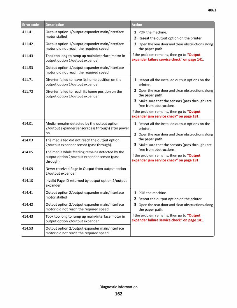
Error code Description Action
411.41 Output option 1/output expander main/interfacemotor stalled
1 POR the machine.
2 Reseat the output option on the printer.
3 Open the rear door and clear obstructions alongthe paper path.
If the problem remains, then go to “Outputexpander failure service check” on page 141.
411.42 Output option 1/output expander main/interfacemotor did not reach the required speed.
411.43 Took too long to ramp up main/interface motor inoutput option 1/output expander
411.53 Output option 1/output expander main/interfacemotor did not reach the required speed.
411.71 Diverter failed to leave its home position on theoutput option 1/output expander
1 Reseat all the installed output options on theprinter.
2 Open the rear door and clear obstructions alongthe paper path.
3 Make sure that the sensors (pass through) arefree from obstructions.
If the problem remains, then go to “Outputexpander jam service check” on page 191.
411.72 Diverter failed to reach its home position on theoutput option 1/output expander
414.01 Media remains detected by the output option2/output expander sensor (pass through) after poweron.
1 Reseat all the installed output options on theprinter.
2 Open the rear door and clear obstructions alongthe paper path.
3 Make sure that the sensors (pass through) arefree from obstructions.
If the problem remains, then go to “Outputexpander jam service check” on page 191.
414.03 The media fed did not reach the output option2/output expander sensor (pass through).
414.05 The media while feeding remains detected by theoutput option 2/output expander sensor (passthrough).
414.09 Never received Page In Output from output option2/output expander
414.10 Invalid Page ID returned by output option 2/outputexpander
414.41 Output option 2/output expander main/interfacemotor stalled
1 POR the machine.
2 Reseat the output option on the printer.
3 Open the rear door and clear obstructions alongthe paper path.
If the problem remains, then go to “Outputexpander failure service check” on page 141.
414.42 Output option 2/output expander main/interfacemotor did not reach the required speed.
414.43 Took too long to ramp up main/interface motor inoutput option 2/output expander
414.53 Output option 2/output expander main/interfacemotor did not reach the required speed.
4063
Diagnostic information
162
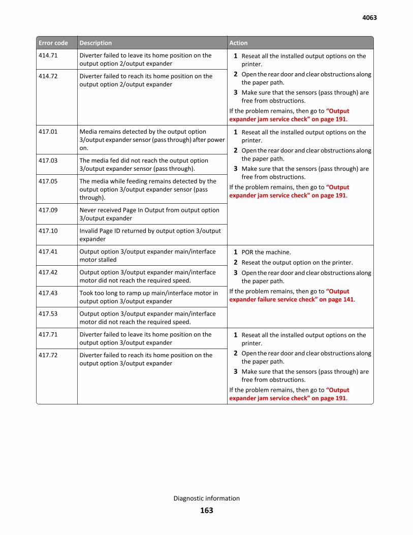
Error code Description Action
414.71 Diverter failed to leave its home position on theoutput option 2/output expander
1 Reseat all the installed output options on theprinter.
2 Open the rear door and clear obstructions alongthe paper path.
3 Make sure that the sensors (pass through) arefree from obstructions.
If the problem remains, then go to “Outputexpander jam service check” on page 191.
414.72 Diverter failed to reach its home position on theoutput option 2/output expander
417.01 Media remains detected by the output option3/output expander sensor (pass through) after poweron.
1 Reseat all the installed output options on theprinter.
2 Open the rear door and clear obstructions alongthe paper path.
3 Make sure that the sensors (pass through) arefree from obstructions.
If the problem remains, then go to “Outputexpander jam service check” on page 191.
417.03 The media fed did not reach the output option3/output expander sensor (pass through).
417.05 The media while feeding remains detected by theoutput option 3/output expander sensor (passthrough).
417.09 Never received Page In Output from output option3/output expander
417.10 Invalid Page ID returned by output option 3/outputexpander
417.41 Output option 3/output expander main/interfacemotor stalled
1 POR the machine.
2 Reseat the output option on the printer.
3 Open the rear door and clear obstructions alongthe paper path.
If the problem remains, then go to “Outputexpander failure service check” on page 141.
417.42 Output option 3/output expander main/interfacemotor did not reach the required speed.
417.43 Took too long to ramp up main/interface motor inoutput option 3/output expander
417.53 Output option 3/output expander main/interfacemotor did not reach the required speed.
417.71 Diverter failed to leave its home position on theoutput option 3/output expander
1 Reseat all the installed output options on theprinter.
2 Open the rear door and clear obstructions alongthe paper path.
3 Make sure that the sensors (pass through) arefree from obstructions.
If the problem remains, then go to “Outputexpander jam service check” on page 191.
417.72 Diverter failed to reach its home position on theoutput option 3/output expander
4063
Diagnostic information
163
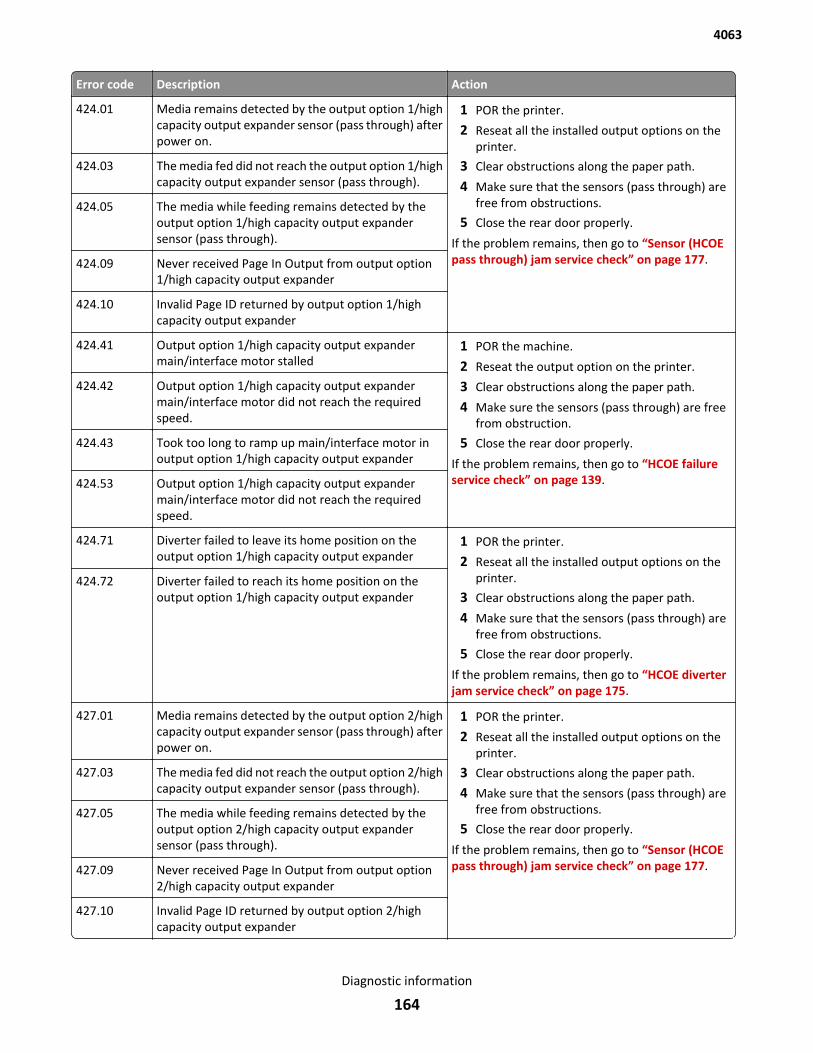
Error code Description Action
424.01 Media remains detected by the output option 1/highcapacity output expander sensor (pass through) afterpower on.
1 POR the printer.
2 Reseat all the installed output options on theprinter.
3 Clear obstructions along the paper path.
4 Make sure that the sensors (pass through) arefree from obstructions.
5 Close the rear door properly.
If the problem remains, then go to “Sensor (HCOEpass through) jam service check” on page 177.
424.03 The media fed did not reach the output option 1/highcapacity output expander sensor (pass through).
424.05 The media while feeding remains detected by theoutput option 1/high capacity output expandersensor (pass through).
424.09 Never received Page In Output from output option1/high capacity output expander
424.10 Invalid Page ID returned by output option 1/highcapacity output expander
424.41 Output option 1/high capacity output expandermain/interface motor stalled
1 POR the machine.
2 Reseat the output option on the printer.
3 Clear obstructions along the paper path.
4 Make sure the sensors (pass through) are freefrom obstruction.
5 Close the rear door properly.
If the problem remains, then go to “HCOE failureservice check” on page 139.
424.42 Output option 1/high capacity output expandermain/interface motor did not reach the requiredspeed.
424.43 Took too long to ramp up main/interface motor inoutput option 1/high capacity output expander
424.53 Output option 1/high capacity output expandermain/interface motor did not reach the requiredspeed.
424.71 Diverter failed to leave its home position on theoutput option 1/high capacity output expander
1 POR the printer.
2 Reseat all the installed output options on theprinter.
3 Clear obstructions along the paper path.
4 Make sure that the sensors (pass through) arefree from obstructions.
5 Close the rear door properly.
If the problem remains, then go to “HCOE diverterjam service check” on page 175.
424.72 Diverter failed to reach its home position on theoutput option 1/high capacity output expander
427.01 Media remains detected by the output option 2/highcapacity output expander sensor (pass through) afterpower on.
1 POR the printer.
2 Reseat all the installed output options on theprinter.
3 Clear obstructions along the paper path.
4 Make sure that the sensors (pass through) arefree from obstructions.
5 Close the rear door properly.
If the problem remains, then go to “Sensor (HCOEpass through) jam service check” on page 177.
427.03 The media fed did not reach the output option 2/highcapacity output expander sensor (pass through).
427.05 The media while feeding remains detected by theoutput option 2/high capacity output expandersensor (pass through).
427.09 Never received Page In Output from output option2/high capacity output expander
427.10 Invalid Page ID returned by output option 2/highcapacity output expander
4063
Diagnostic information
164
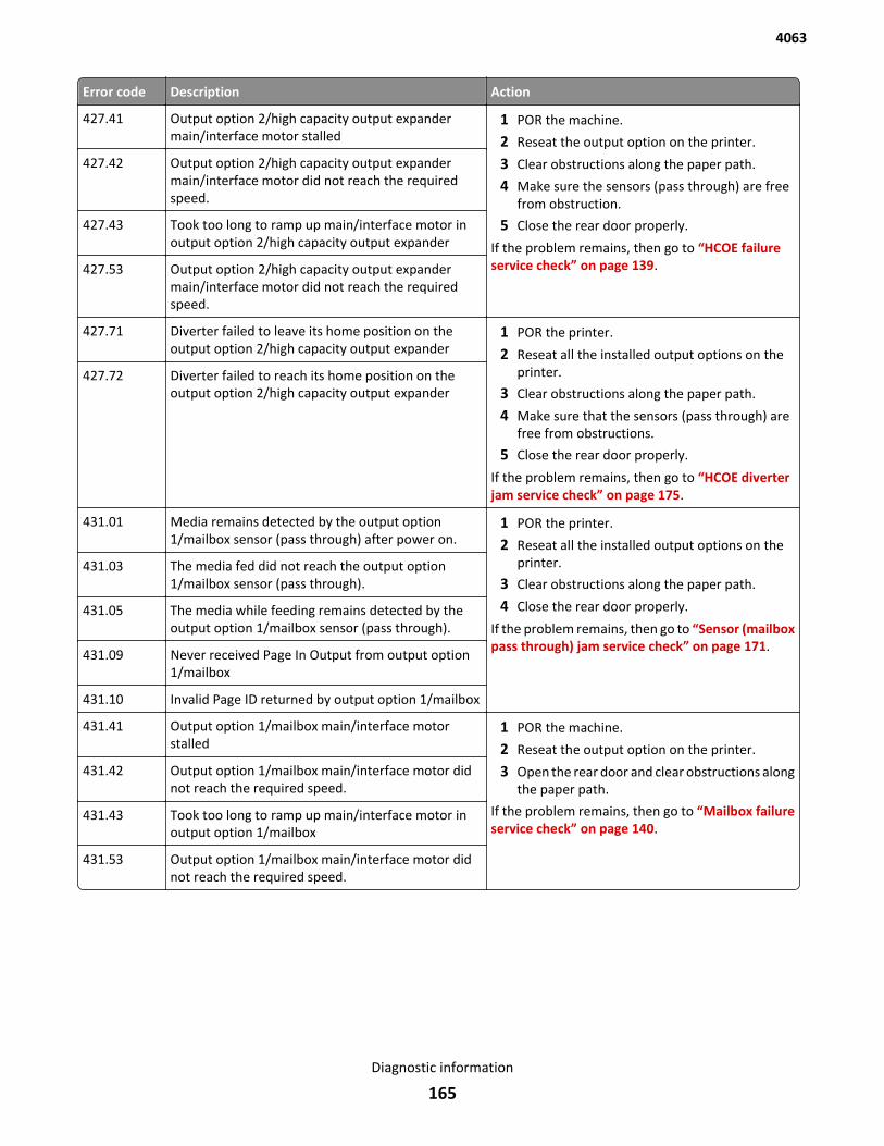
Error code Description Action
427.41 Output option 2/high capacity output expandermain/interface motor stalled
1 POR the machine.
2 Reseat the output option on the printer.
3 Clear obstructions along the paper path.
4 Make sure the sensors (pass through) are freefrom obstruction.
5 Close the rear door properly.
If the problem remains, then go to “HCOE failureservice check” on page 139.
427.42 Output option 2/high capacity output expandermain/interface motor did not reach the requiredspeed.
427.43 Took too long to ramp up main/interface motor inoutput option 2/high capacity output expander
427.53 Output option 2/high capacity output expandermain/interface motor did not reach the requiredspeed.
427.71 Diverter failed to leave its home position on theoutput option 2/high capacity output expander
1 POR the printer.
2 Reseat all the installed output options on theprinter.
3 Clear obstructions along the paper path.
4 Make sure that the sensors (pass through) arefree from obstructions.
5 Close the rear door properly.
If the problem remains, then go to “HCOE diverterjam service check” on page 175.
427.72 Diverter failed to reach its home position on theoutput option 2/high capacity output expander
431.01 Media remains detected by the output option1/mailbox sensor (pass through) after power on.
1 POR the printer.
2 Reseat all the installed output options on theprinter.
3 Clear obstructions along the paper path.
4 Close the rear door properly.
If the problem remains, then go to “Sensor (mailboxpass through) jam service check” on page 171.
431.03 The media fed did not reach the output option1/mailbox sensor (pass through).
431.05 The media while feeding remains detected by theoutput option 1/mailbox sensor (pass through).
431.09 Never received Page In Output from output option1/mailbox
431.10 Invalid Page ID returned by output option 1/mailbox
431.41 Output option 1/mailbox main/interface motorstalled
1 POR the machine.
2 Reseat the output option on the printer.
3 Open the rear door and clear obstructions alongthe paper path.
If the problem remains, then go to “Mailbox failureservice check” on page 140.
431.42 Output option 1/mailbox main/interface motor didnot reach the required speed.
431.43 Took too long to ramp up main/interface motor inoutput option 1/mailbox
431.53 Output option 1/mailbox main/interface motor didnot reach the required speed.
4063
Diagnostic information
165
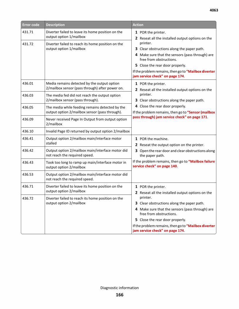
Error code Description Action
431.71 Diverter failed to leave its home position on theoutput option 1/mailbox
1 POR the printer.
2 Reseat all the installed output options on theprinter.
3 Clear obstructions along the paper path.
4 Make sure that the sensors (pass through) arefree from obstructions.
5 Close the rear door properly.
If the problem remains, then go to “Mailbox diverterjam service check” on page 174.
431.72 Diverter failed to reach its home position on theoutput option 1/mailbox
436.01 Media remains detected by the output option2/mailbox sensor (pass through) after power on.
1 POR the printer.
2 Reseat all the installed output options on theprinter.
3 Clear obstructions along the paper path.
4 Close the rear door properly.
If the problem remains, then go to “Sensor (mailboxpass through) jam service check” on page 171.
436.03 The media fed did not reach the output option2/mailbox sensor (pass through).
436.05 The media while feeding remains detected by theoutput option 2/mailbox sensor (pass through).
436.09 Never received Page In Output from output option2/mailbox
436.10 Invalid Page ID returned by output option 2/mailbox
436.41 Output option 2/mailbox main/interface motorstalled
1 POR the machine.
2 Reseat the output option on the printer.
3 Open the rear door and clear obstructions alongthe paper path.
If the problem remains, then go to “Mailbox failureservice check” on page 140.
436.42 Output option 2/mailbox main/interface motor didnot reach the required speed.
436.43 Took too long to ramp up main/interface motor inoutput option 2/mailbox
436.53 Output option 2/mailbox main/interface motor didnot reach the required speed.
436.71 Diverter failed to leave its home position on theoutput option 2/mailbox
1 POR the printer.
2 Reseat all the installed output options on theprinter.
3 Clear obstructions along the paper path.
4 Make sure that the sensors (pass through) arefree from obstructions.
5 Close the rear door properly.
If the problem remains, then go to “Mailbox diverterjam service check” on page 174.
436.72 Diverter failed to reach its home position on theoutput option 2/mailbox
4063
Diagnostic information
166
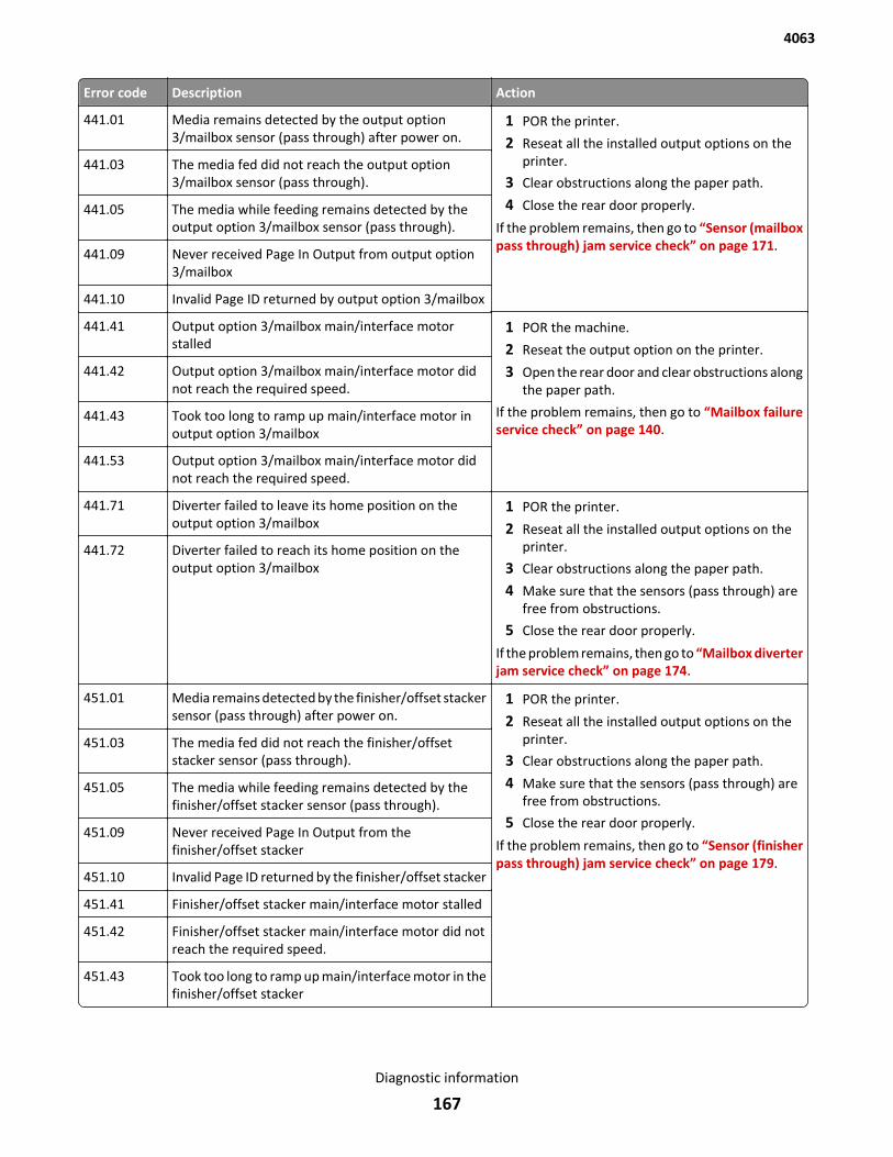
Error code Description Action
441.01 Media remains detected by the output option3/mailbox sensor (pass through) after power on.
1 POR the printer.
2 Reseat all the installed output options on theprinter.
3 Clear obstructions along the paper path.
4 Close the rear door properly.
If the problem remains, then go to “Sensor (mailboxpass through) jam service check” on page 171.
441.03 The media fed did not reach the output option3/mailbox sensor (pass through).
441.05 The media while feeding remains detected by theoutput option 3/mailbox sensor (pass through).
441.09 Never received Page In Output from output option3/mailbox
441.10 Invalid Page ID returned by output option 3/mailbox
441.41 Output option 3/mailbox main/interface motorstalled
1 POR the machine.
2 Reseat the output option on the printer.
3 Open the rear door and clear obstructions alongthe paper path.
If the problem remains, then go to “Mailbox failureservice check” on page 140.
441.42 Output option 3/mailbox main/interface motor didnot reach the required speed.
441.43 Took too long to ramp up main/interface motor inoutput option 3/mailbox
441.53 Output option 3/mailbox main/interface motor didnot reach the required speed.
441.71 Diverter failed to leave its home position on theoutput option 3/mailbox
1 POR the printer.
2 Reseat all the installed output options on theprinter.
3 Clear obstructions along the paper path.
4 Make sure that the sensors (pass through) arefree from obstructions.
5 Close the rear door properly.
If the problem remains, then go to “Mailbox diverterjam service check” on page 174.
441.72 Diverter failed to reach its home position on theoutput option 3/mailbox
451.01 Media remains detected by the finisher/offset stackersensor (pass through) after power on.
1 POR the printer.
2 Reseat all the installed output options on theprinter.
3 Clear obstructions along the paper path.
4 Make sure that the sensors (pass through) arefree from obstructions.
5 Close the rear door properly.
If the problem remains, then go to “Sensor (finisherpass through) jam service check” on page 179.
451.03 The media fed did not reach the finisher/offsetstacker sensor (pass through).
451.05 The media while feeding remains detected by thefinisher/offset stacker sensor (pass through).
451.09 Never received Page In Output from thefinisher/offset stacker
451.10 Invalid Page ID returned by the finisher/offset stacker
451.41 Finisher/offset stacker main/interface motor stalled
451.42 Finisher/offset stacker main/interface motor did notreach the required speed.
451.43 Took too long to ramp up main/interface motor in thefinisher/offset stacker
4063
Diagnostic information
167
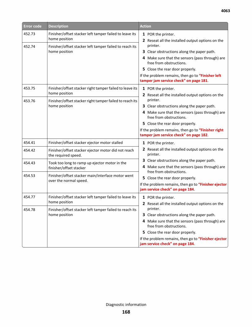
Error code Description Action
452.73 Finisher/offset stacker left tamper failed to leave itshome position
1 POR the printer.
2 Reseat all the installed output options on theprinter.
3 Clear obstructions along the paper path.
4 Make sure that the sensors (pass through) arefree from obstructions.
5 Close the rear door properly.
If the problem remains, then go to “Finisher lefttamper jam service check” on page 181.
452.74 Finisher/offset stacker left tamper failed to reach itshome position
453.75 Finisher/offset stacker right tamper failed to leave itshome position
1 POR the printer.
2 Reseat all the installed output options on theprinter.
3 Clear obstructions along the paper path.
4 Make sure that the sensors (pass through) arefree from obstructions.
5 Close the rear door properly.
If the problem remains, then go to “Finisher righttamper jam service check” on page 182.
453.76 Finisher/offset stacker right tamper failed to reach itshome position
454.41 Finisher/offset stacker ejector motor stalled 1 POR the printer.
2 Reseat all the installed output options on theprinter.
3 Clear obstructions along the paper path.
4 Make sure that the sensors (pass through) arefree from obstructions.
5 Close the rear door properly.
If the problem remains, then go to “Finisher ejectorjam service check” on page 184.
454.42 Finisher/offset stacker ejector motor did not reachthe required speed.
454.43 Took too long to ramp up ejector motor in thefinisher/offset stacker
454.53 Finisher/offset stacker main/interface motor wentover the normal speed.
454.77 Finisher/offset stacker left tamper failed to leave itshome position
1 POR the printer.
2 Reseat all the installed output options on theprinter.
3 Clear obstructions along the paper path.
4 Make sure that the sensors (pass through) arefree from obstructions.
5 Close the rear door properly.
If the problem remains, then go to “Finisher ejectorjam service check” on page 184.
454.78 Finisher/offset stacker left tamper failed to reach itshome position
4063
Diagnostic information
168
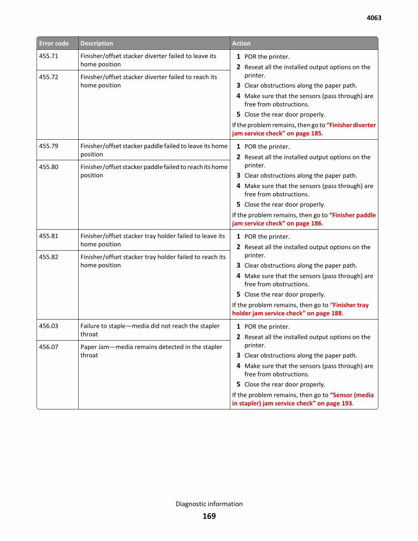
Error code Description Action
455.71 Finisher/offset stacker diverter failed to leave itshome position
1 POR the printer.
2 Reseat all the installed output options on theprinter.
3 Clear obstructions along the paper path.
4 Make sure that the sensors (pass through) arefree from obstructions.
5 Close the rear door properly.
If the problem remains, then go to “Finisher diverterjam service check” on page 185.
455.72 Finisher/offset stacker diverter failed to reach itshome position
455.79 Finisher/offset stacker paddle failed to leave its homeposition
1 POR the printer.
2 Reseat all the installed output options on theprinter.
3 Clear obstructions along the paper path.
4 Make sure that the sensors (pass through) arefree from obstructions.
5 Close the rear door properly.
If the problem remains, then go to “Finisher paddlejam service check” on page 186.
455.80 Finisher/offset stacker paddle failed to reach its homeposition
455.81 Finisher/offset stacker tray holder failed to leave itshome position
1 POR the printer.
2 Reseat all the installed output options on theprinter.
3 Clear obstructions along the paper path.
4 Make sure that the sensors (pass through) arefree from obstructions.
5 Close the rear door properly.
If the problem remains, then go to “Finisher trayholder jam service check” on page 188.
455.82 Finisher/offset stacker tray holder failed to reach itshome position
456.03 Failure to staple—media did not reach the staplerthroat
1 POR the printer.
2 Reseat all the installed output options on theprinter.
3 Clear obstructions along the paper path.
4 Make sure that the sensors (pass through) arefree from obstructions.
5 Close the rear door properly.
If the problem remains, then go to “Sensor (mediain stapler) jam service check” on page 193.
456.07 Paper Jam—media remains detected in the staplerthroat
4063
Diagnostic information
169
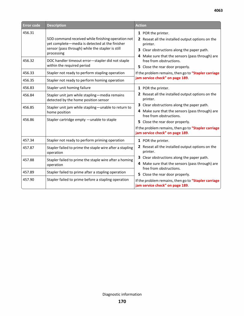
Error code Description Action
456.31
SOD command received while finishing operation notyet complete—media is detected at the finishersensor (pass through) while the stapler is stillprocessing
1 POR the printer.
2 Reseat all the installed output options on theprinter.
3 Clear obstructions along the paper path.
4 Make sure that the sensors (pass through) arefree from obstructions.
5 Close the rear door properly.
If the problem remains, then go to “Stapler carriagejam service check” on page 189.
456.32 DOC handler timeout error—stapler did not staplewithin the required period
456.33 Stapler not ready to perform stapling operation
456.35 Stapler not ready to perform homing operation
456.83 Stapler unit homing failure 1 POR the printer.
2 Reseat all the installed output options on theprinter.
3 Clear obstructions along the paper path.
4 Make sure that the sensors (pass through) arefree from obstructions.
5 Close the rear door properly.
If the problem remains, then go to “Stapler carriagejam service check” on page 189.
456.84 Stapler unit jam while stapling—media remainsdetected by the home position sensor
456.85 Stapler unit jam while stapling—unable to return tohome position
456.86 Stapler cartridge empty —unable to staple
457.34 Stapler not ready to perform priming operation 1 POR the printer.
2 Reseat all the installed output options on theprinter.
3 Clear obstructions along the paper path.
4 Make sure that the sensors (pass through) arefree from obstructions.
5 Close the rear door properly.
If the problem remains, then go to “Stapler carriagejam service check” on page 189.
457.87 Stapler failed to prime the staple wire after a staplingoperation
457.88 Stapler failed to prime the staple wire after a homingoperation
457.89 Stapler failed to prime after a stapling operation
457.90 Stapler failed to prime before a stapling operation
4063
Diagnostic information
170
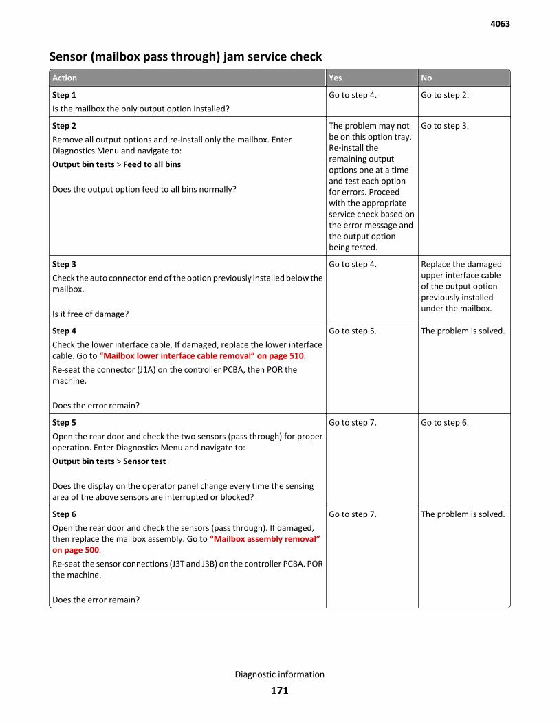
Sensor (mailbox pass through) jam service check
Action Yes No
Step 1
Is the mailbox the only output option installed?
Go to step 4. Go to step 2.
Step 2
Remove all output options and re-install only the mailbox. EnterDiagnostics Menu and navigate to:
Output bin tests > Feed to all bins
Does the output option feed to all bins normally?
The problem may notbe on this option tray.Re‑install theremaining outputoptions one at a timeand test each optionfor errors. Proceedwith the appropriateservice check based onthe error message andthe output optionbeing tested.
Go to step 3.
Step 3
Check the auto connector end of the option previously installed below themailbox.
Is it free of damage?
Go to step 4. Replace the damagedupper interface cableof the output optionpreviously installedunder the mailbox.
Step 4
Check the lower interface cable. If damaged, replace the lower interfacecable. Go to “Mailbox lower interface cable removal” on page 510.
Re-seat the connector (J1A) on the controller PCBA, then POR themachine.
Does the error remain?
Go to step 5. The problem is solved.
Step 5
Open the rear door and check the two sensors (pass through) for properoperation. Enter Diagnostics Menu and navigate to:
Output bin tests > Sensor test
Does the display on the operator panel change every time the sensingarea of the above sensors are interrupted or blocked?
Go to step 7. Go to step 6.
Step 6
Open the rear door and check the sensors (pass through). If damaged,then replace the mailbox assembly. Go to “Mailbox assembly removal”on page 500.
Re-seat the sensor connections (J3T and J3B) on the controller PCBA. PORthe machine.
Does the error remain?
Go to step 7. The problem is solved.
4063
Diagnostic information
171
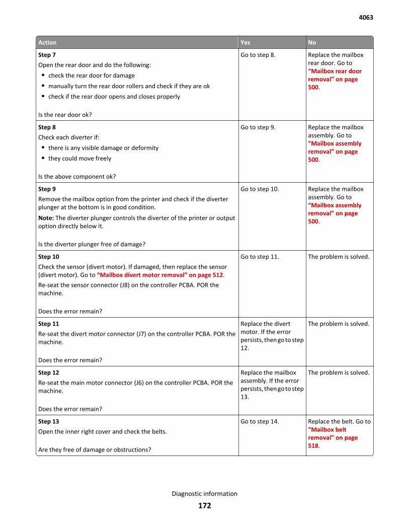
Action Yes No
Step 7
Open the rear door and do the following:
• check the rear door for damage
• manually turn the rear door rollers and check if they are ok
• check if the rear door opens and closes properly
Is the rear door ok?
Go to step 8. Replace the mailboxrear door. Go to“Mailbox rear doorremoval” on page 500.
Step 8
Check each diverter if:
• there is any visible damage or deformity
• they could move freely
Is the above component ok?
Go to step 9. Replace the mailboxassembly. Go to“Mailbox assemblyremoval” on page 500.
Step 9
Remove the mailbox option from the printer and check if the diverterplunger at the bottom is in good condition.
Note: The diverter plunger controls the diverter of the printer or outputoption directly below it.
Is the diverter plunger free of damage?
Go to step 10. Replace the mailboxassembly. Go to“Mailbox assemblyremoval” on page 500.
Step 10
Check the sensor (divert motor). If damaged, then replace the sensor(divert motor). Go to “Mailbox divert motor removal” on page 512.
Re-seat the sensor connector (J8) on the controller PCBA. POR themachine.
Does the error remain?
Go to step 11. The problem is solved.
Step 11
Re-seat the divert motor connector (J7) on the controller PCBA. POR themachine.
Does the error remain?
Replace the divertmotor. If the errorpersists, then go to step12.
The problem is solved.
Step 12
Re-seat the main motor connector (J6) on the controller PCBA. POR themachine.
Does the error remain?
Replace the mailboxassembly. If the errorpersists, then go to step13.
The problem is solved.
Step 13
Open the inner right cover and check the belts.
Are they free of damage or obstructions?
Go to step 14. Replace the belt. Go to“Mailbox beltremoval” on page 518.
4063
Diagnostic information
172
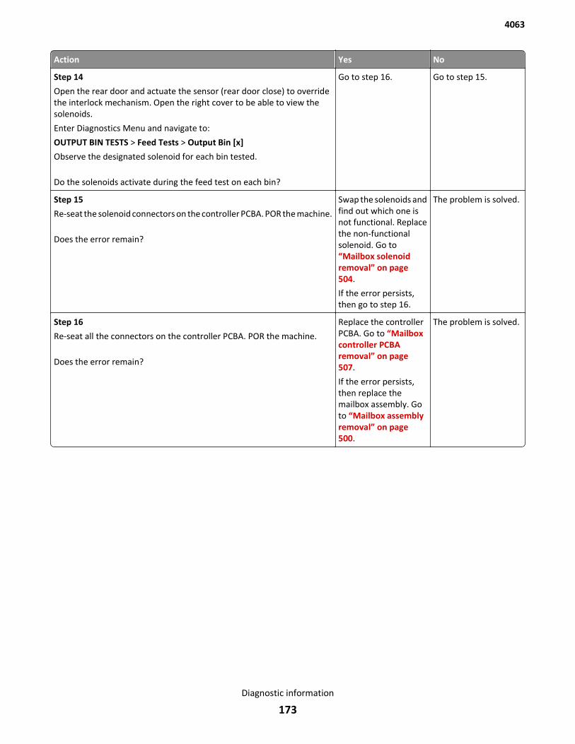
Action Yes No
Step 14
Open the rear door and actuate the sensor (rear door close) to overridethe interlock mechanism. Open the right cover to be able to view thesolenoids.
Enter Diagnostics Menu and navigate to:
OUTPUT BIN TESTS > Feed Tests > Output Bin [x]
Observe the designated solenoid for each bin tested.
Do the solenoids activate during the feed test on each bin?
Go to step 16. Go to step 15.
Step 15
Re-seat the solenoid connectors on the controller PCBA. POR the machine.
Does the error remain?
Swap the solenoids andfind out which one isnot functional. Replacethe non-functionalsolenoid. Go to“Mailbox solenoidremoval” on page 504.
If the error persists,then go to step 16.
The problem is solved.
Step 16
Re-seat all the connectors on the controller PCBA. POR the machine.
Does the error remain?
Replace the controllerPCBA. Go to “Mailboxcontroller PCBAremoval” on page 507.
If the error persists,then replace themailbox assembly. Goto “Mailbox assemblyremoval” on page 500.
The problem is solved.
4063
Diagnostic information
173
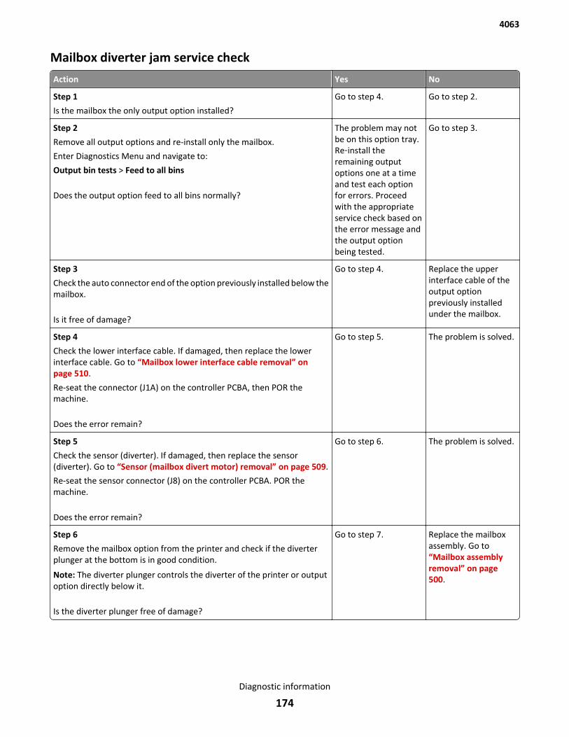
Mailbox diverter jam service check
Action Yes No
Step 1
Is the mailbox the only output option installed?
Go to step 4. Go to step 2.
Step 2
Remove all output options and re-install only the mailbox.
Enter Diagnostics Menu and navigate to:
Output bin tests > Feed to all bins
Does the output option feed to all bins normally?
The problem may notbe on this option tray.Re‑install theremaining outputoptions one at a timeand test each optionfor errors. Proceedwith the appropriateservice check based onthe error message andthe output optionbeing tested.
Go to step 3.
Step 3
Check the auto connector end of the option previously installed below themailbox.
Is it free of damage?
Go to step 4. Replace the upperinterface cable of theoutput optionpreviously installedunder the mailbox.
Step 4
Check the lower interface cable. If damaged, then replace the lowerinterface cable. Go to “Mailbox lower interface cable removal” onpage 510.
Re-seat the connector (J1A) on the controller PCBA, then POR themachine.
Does the error remain?
Go to step 5. The problem is solved.
Step 5
Check the sensor (diverter). If damaged, then replace the sensor(diverter). Go to “Sensor (mailbox divert motor) removal” on page 509.
Re-seat the sensor connector (J8) on the controller PCBA. POR themachine.
Does the error remain?
Go to step 6. The problem is solved.
Step 6
Remove the mailbox option from the printer and check if the diverterplunger at the bottom is in good condition.
Note: The diverter plunger controls the diverter of the printer or outputoption directly below it.
Is the diverter plunger free of damage?
Go to step 7. Replace the mailboxassembly. Go to“Mailbox assemblyremoval” on page 500.
4063
Diagnostic information
174
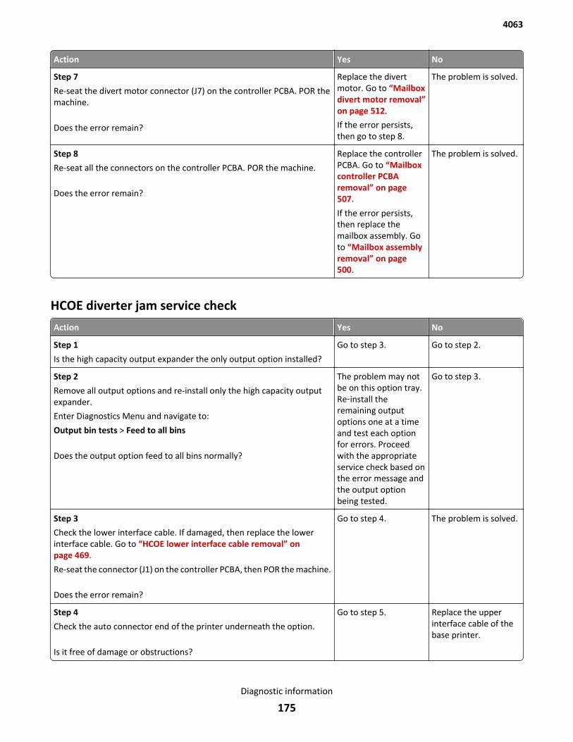
Action Yes No
Step 7
Re-seat the divert motor connector (J7) on the controller PCBA. POR themachine.
Does the error remain?
Replace the divertmotor. Go to “Mailboxdivert motor removal”on page 512.
If the error persists,then go to step 8.
The problem is solved.
Step 8
Re-seat all the connectors on the controller PCBA. POR the machine.
Does the error remain?
Replace the controllerPCBA. Go to “Mailboxcontroller PCBAremoval” on page 507.
If the error persists,then replace themailbox assembly. Goto “Mailbox assemblyremoval” on page 500.
The problem is solved.
HCOE diverter jam service check
Action Yes No
Step 1
Is the high capacity output expander the only output option installed?
Go to step 3. Go to step 2.
Step 2
Remove all output options and re-install only the high capacity outputexpander.
Enter Diagnostics Menu and navigate to:
Output bin tests > Feed to all bins
Does the output option feed to all bins normally?
The problem may notbe on this option tray.Re‑install theremaining outputoptions one at a timeand test each optionfor errors. Proceedwith the appropriateservice check based onthe error message andthe output optionbeing tested.
Go to step 3.
Step 3
Check the lower interface cable. If damaged, then replace the lowerinterface cable. Go to “HCOE lower interface cable removal” onpage 469.
Re-seat the connector (J1) on the controller PCBA, then POR the machine.
Does the error remain?
Go to step 4. The problem is solved.
Step 4
Check the auto connector end of the printer underneath the option.
Is it free of damage or obstructions?
Go to step 5. Replace the upperinterface cable of thebase printer.
4063
Diagnostic information
175
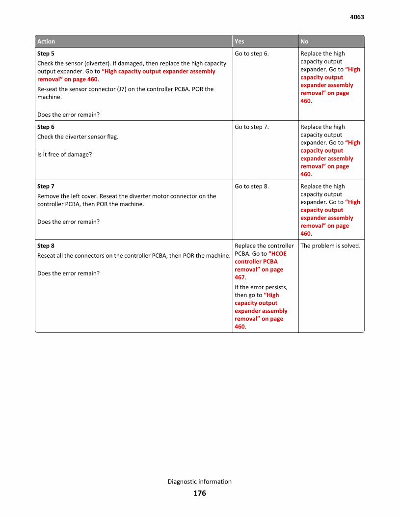
Action Yes No
Step 5
Check the sensor (diverter). If damaged, then replace the high capacityoutput expander. Go to “High capacity output expander assemblyremoval” on page 460.
Re-seat the sensor connector (J7) on the controller PCBA. POR themachine.
Does the error remain?
Go to step 6. Replace the highcapacity outputexpander. Go to “Highcapacity outputexpander assemblyremoval” on page 460.
Step 6
Check the diverter sensor flag.
Is it free of damage?
Go to step 7. Replace the highcapacity outputexpander. Go to “Highcapacity outputexpander assemblyremoval” on page 460.
Step 7
Remove the left cover. Reseat the diverter motor connector on thecontroller PCBA, then POR the machine.
Does the error remain?
Go to step 8. Replace the highcapacity outputexpander. Go to “Highcapacity outputexpander assemblyremoval” on page 460.
Step 8
Reseat all the connectors on the controller PCBA, then POR the machine.
Does the error remain?
Replace the controllerPCBA. Go to “HCOEcontroller PCBAremoval” on page 467.
If the error persists,then go to “Highcapacity outputexpander assemblyremoval” on page 460.
The problem is solved.
4063
Diagnostic information
176
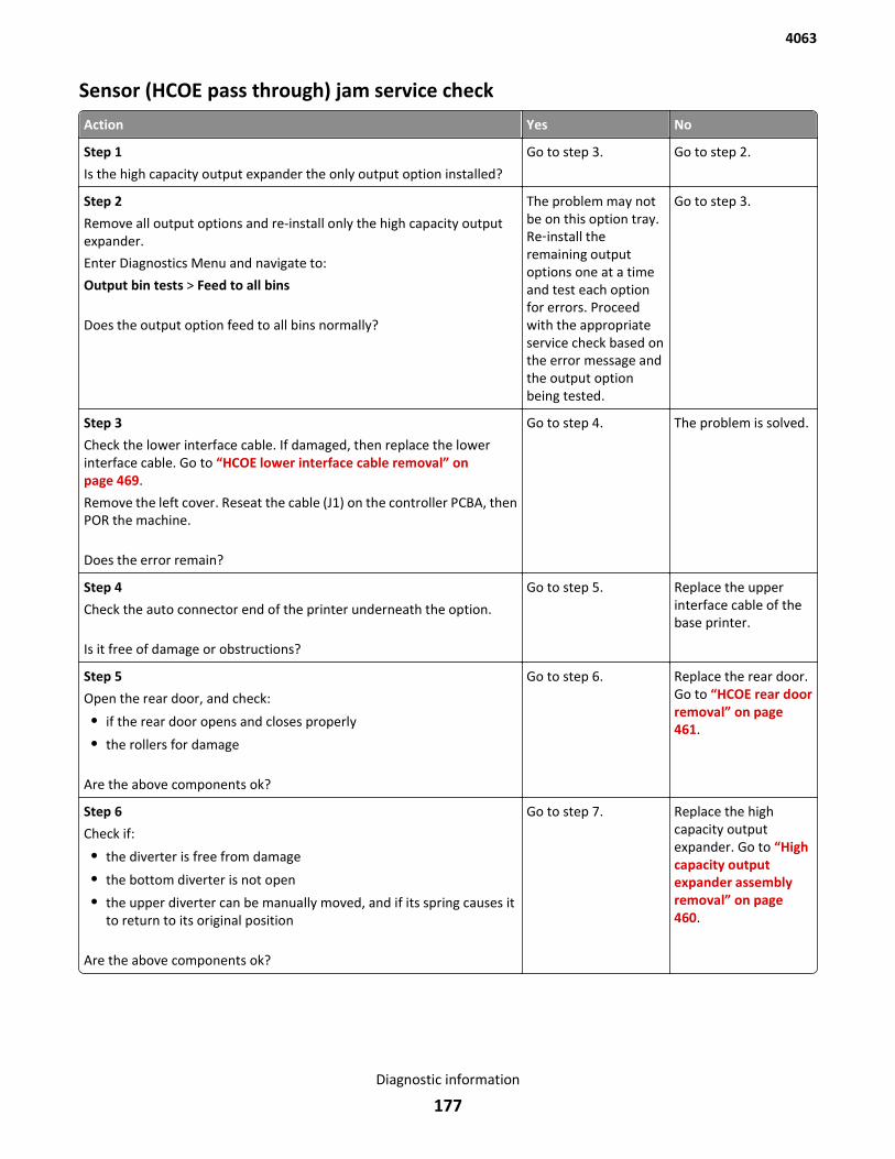
Sensor (HCOE pass through) jam service check
Action Yes No
Step 1
Is the high capacity output expander the only output option installed?
Go to step 3. Go to step 2.
Step 2
Remove all output options and re-install only the high capacity outputexpander.
Enter Diagnostics Menu and navigate to:
Output bin tests > Feed to all bins
Does the output option feed to all bins normally?
The problem may notbe on this option tray.Re‑install theremaining outputoptions one at a timeand test each optionfor errors. Proceedwith the appropriateservice check based onthe error message andthe output optionbeing tested.
Go to step 3.
Step 3
Check the lower interface cable. If damaged, then replace the lowerinterface cable. Go to “HCOE lower interface cable removal” onpage 469.
Remove the left cover. Reseat the cable (J1) on the controller PCBA, thenPOR the machine.
Does the error remain?
Go to step 4. The problem is solved.
Step 4
Check the auto connector end of the printer underneath the option.
Is it free of damage or obstructions?
Go to step 5. Replace the upperinterface cable of thebase printer.
Step 5
Open the rear door, and check:
• if the rear door opens and closes properly
• the rollers for damage
Are the above components ok?
Go to step 6. Replace the rear door.Go to “HCOE rear doorremoval” on page 461.
Step 6
Check if:
• the diverter is free from damage
• the bottom diverter is not open
• the upper diverter can be manually moved, and if its spring causes itto return to its original position
Are the above components ok?
Go to step 7. Replace the highcapacity outputexpander. Go to “Highcapacity outputexpander assemblyremoval” on page 460.
4063
Diagnostic information
177
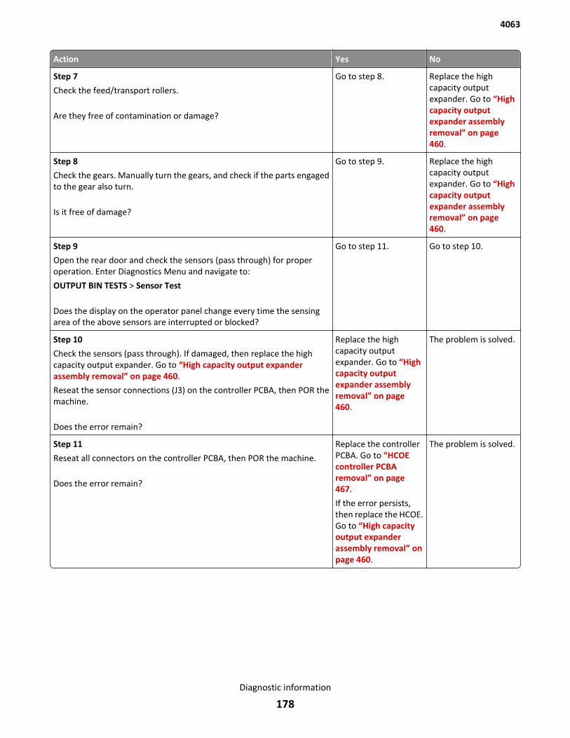
Action Yes No
Step 7
Check the feed/transport rollers.
Are they free of contamination or damage?
Go to step 8. Replace the highcapacity outputexpander. Go to “Highcapacity outputexpander assemblyremoval” on page 460.
Step 8
Check the gears. Manually turn the gears, and check if the parts engagedto the gear also turn.
Is it free of damage?
Go to step 9. Replace the highcapacity outputexpander. Go to “Highcapacity outputexpander assemblyremoval” on page 460.
Step 9
Open the rear door and check the sensors (pass through) for properoperation. Enter Diagnostics Menu and navigate to:
OUTPUT BIN TESTS > Sensor Test
Does the display on the operator panel change every time the sensingarea of the above sensors are interrupted or blocked?
Go to step 11. Go to step 10.
Step 10
Check the sensors (pass through). If damaged, then replace the highcapacity output expander. Go to “High capacity output expanderassembly removal” on page 460.
Reseat the sensor connections (J3) on the controller PCBA, then POR themachine.
Does the error remain?
Replace the highcapacity outputexpander. Go to “Highcapacity outputexpander assemblyremoval” on page 460.
The problem is solved.
Step 11
Reseat all connectors on the controller PCBA, then POR the machine.
Does the error remain?
Replace the controllerPCBA. Go to “HCOEcontroller PCBAremoval” on page 467.
If the error persists,then replace the HCOE.Go to “High capacityoutput expanderassembly removal” onpage 460.
The problem is solved.
4063
Diagnostic information
178
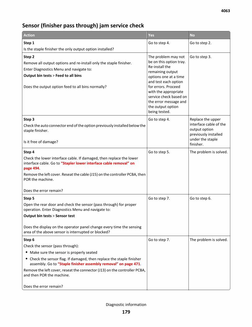
Sensor (finisher pass through) jam service check
Action Yes No
Step 1
Is the staple finisher the only output option installed?
Go to step 4. Go to step 2.
Step 2
Remove all output options and re-install only the staple finisher.
Enter Diagnostics Menu and navigate to:
Output bin tests > Feed to all bins
Does the output option feed to all bins normally?
The problem may notbe on this option tray.Re‑install theremaining outputoptions one at a timeand test each optionfor errors. Proceedwith the appropriateservice check based onthe error message andthe output optionbeing tested.
Go to step 3.
Step 3
Check the auto connector end of the option previously installed below thestaple finisher.
Is it free of damage?
Go to step 4. Replace the upperinterface cable of theoutput optionpreviously installedunder the staplefinisher.
Step 4
Check the lower interface cable. If damaged, then replace the lowerinterface cable. Go to “Stapler lower interface cable removal” onpage 494.
Remove the left cover. Reseat the cable (J15) on the controller PCBA, thenPOR the machine.
Does the error remain?
Go to step 5. The problem is solved.
Step 5
Open the rear door and check the sensor (pass through) for properoperation. Enter Diagnostics Menu and navigate to:
Output bin tests > Sensor test
Does the display on the operator panel change every time the sensingarea of the above sensor is interrupted or blocked?
Go to step 7. Go to step 6.
Step 6
Check the sensor (pass through):
• Make sure the sensor is properly seated
• Check the sensor flag. If damaged, then replace the staple finisherassembly. Go to “Staple finisher assembly removal” on page 471.
Remove the left cover, reseat the connector (J13) on the controller PCBA,and then POR the machine.
Does the error remain?
Go to step 7. The problem is solved.
4063
Diagnostic information
179
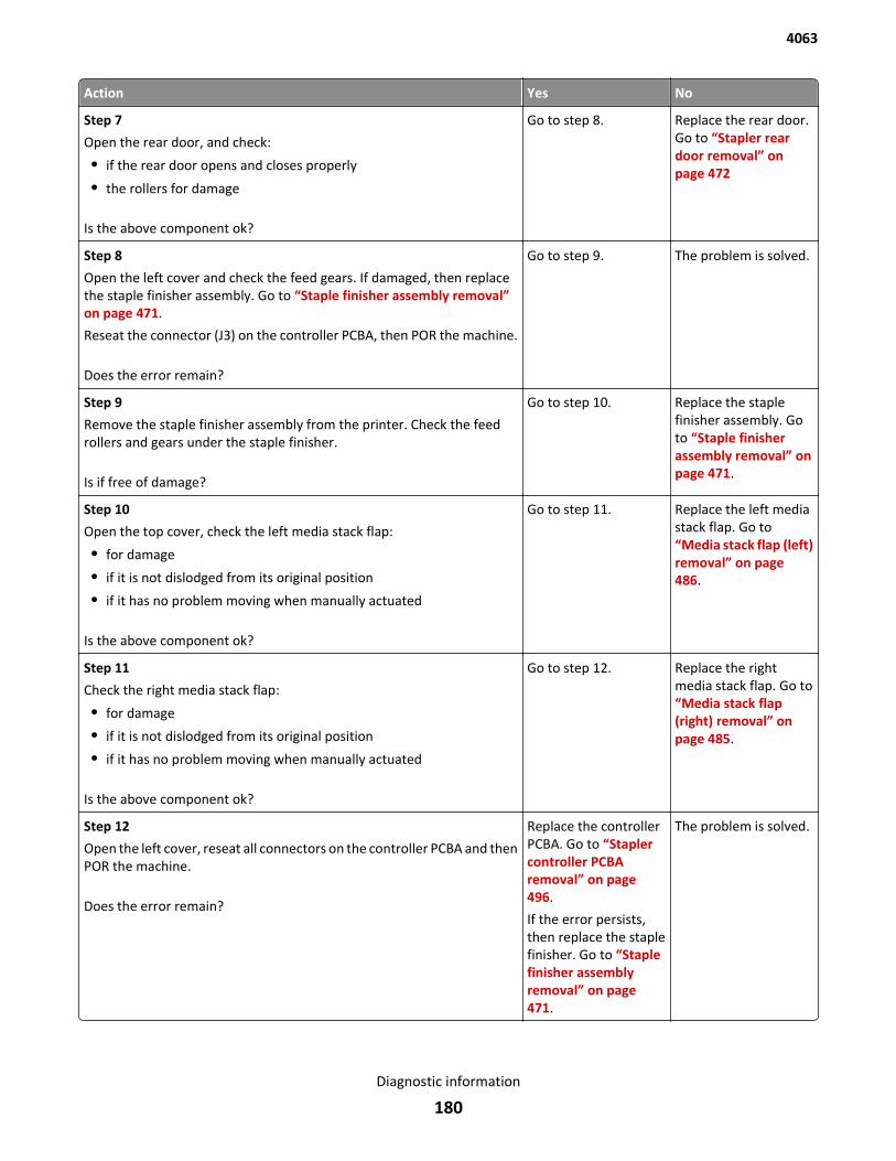
Action Yes No
Step 7
Open the rear door, and check:
• if the rear door opens and closes properly
• the rollers for damage
Is the above component ok?
Go to step 8. Replace the rear door.Go to “Stapler reardoor removal” onpage 472
Step 8
Open the left cover and check the feed gears. If damaged, then replacethe staple finisher assembly. Go to “Staple finisher assembly removal”on page 471.
Reseat the connector (J3) on the controller PCBA, then POR the machine.
Does the error remain?
Go to step 9. The problem is solved.
Step 9
Remove the staple finisher assembly from the printer. Check the feedrollers and gears under the staple finisher.
Is if free of damage?
Go to step 10. Replace the staplefinisher assembly. Goto “Staple finisherassembly removal” onpage 471.
Step 10
Open the top cover, check the left media stack flap:
• for damage
• if it is not dislodged from its original position
• if it has no problem moving when manually actuated
Is the above component ok?
Go to step 11. Replace the left mediastack flap. Go to“Media stack flap (left)removal” on page 486.
Step 11
Check the right media stack flap:
• for damage
• if it is not dislodged from its original position
• if it has no problem moving when manually actuated
Is the above component ok?
Go to step 12. Replace the rightmedia stack flap. Go to“Media stack flap(right) removal” onpage 485.
Step 12
Open the left cover, reseat all connectors on the controller PCBA and thenPOR the machine.
Does the error remain?
Replace the controllerPCBA. Go to “Staplercontroller PCBAremoval” on page 496.
If the error persists,then replace the staplefinisher. Go to “Staplefinisher assemblyremoval” on page 471.
The problem is solved.
4063
Diagnostic information
180
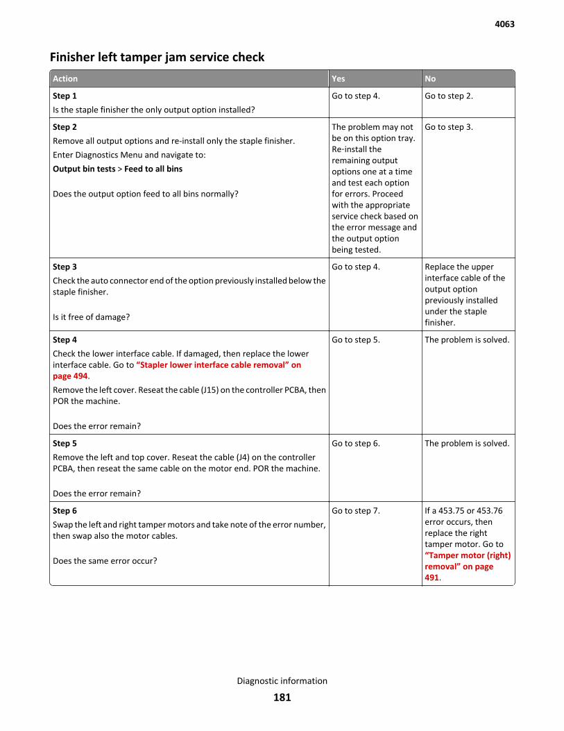
Finisher left tamper jam service check
Action Yes No
Step 1
Is the staple finisher the only output option installed?
Go to step 4. Go to step 2.
Step 2
Remove all output options and re-install only the staple finisher.
Enter Diagnostics Menu and navigate to:
Output bin tests > Feed to all bins
Does the output option feed to all bins normally?
The problem may notbe on this option tray.Re‑install theremaining outputoptions one at a timeand test each optionfor errors. Proceedwith the appropriateservice check based onthe error message andthe output optionbeing tested.
Go to step 3.
Step 3
Check the auto connector end of the option previously installed below thestaple finisher.
Is it free of damage?
Go to step 4. Replace the upperinterface cable of theoutput optionpreviously installedunder the staplefinisher.
Step 4
Check the lower interface cable. If damaged, then replace the lowerinterface cable. Go to “Stapler lower interface cable removal” onpage 494.
Remove the left cover. Reseat the cable (J15) on the controller PCBA, thenPOR the machine.
Does the error remain?
Go to step 5. The problem is solved.
Step 5
Remove the left and top cover. Reseat the cable (J4) on the controllerPCBA, then reseat the same cable on the motor end. POR the machine.
Does the error remain?
Go to step 6. The problem is solved.
Step 6
Swap the left and right tamper motors and take note of the error number,then swap also the motor cables.
Does the same error occur?
Go to step 7. If a 453.75 or 453.76error occurs, thenreplace the righttamper motor. Go to“Tamper motor (right)removal” on page 491.
4063
Diagnostic information
181
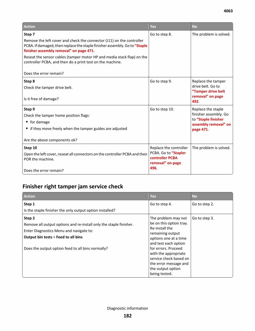
Action Yes No
Step 7
Remove the left cover and check the connector (J11) on the controllerPCBA. If damaged, then replace the staple finisher assembly. Go to “Staplefinisher assembly removal” on page 471.
Reseat the sensor cables (tamper motor HP and media stack flap) on thecontroller PCBA, and then do a print test on the machine.
Does the error remain?
Go to step 8. The problem is solved.
Step 8
Check the tamper drive belt.
Is it free of damage?
Go to step 9. Replace the tamperdrive belt. Go to“Tamper drive beltremoval” on page 492.
Step 9
Check the tamper home position flags:
• for damage
• if they move freely when the tamper guides are adjusted
Are the above components ok?
Go to step 10. Replace the staplefinisher assembly. Goto “Staple finisherassembly removal” onpage 471.
Step 10
Open the left cover, reseat all connectors on the controller PCBA and thenPOR the machine.
Does the error remain?
Replace the controllerPCBA. Go to “Staplercontroller PCBAremoval” on page 496.
The problem is solved.
Finisher right tamper jam service check
Action Yes No
Step 1
Is the staple finisher the only output option installed?
Go to step 4. Go to step 2.
Step 2
Remove all output options and re-install only the staple finisher.
Enter Diagnostics Menu and navigate to:
Output bin tests > Feed to all bins
Does the output option feed to all bins normally?
The problem may notbe on this option tray.Re‑install theremaining outputoptions one at a timeand test each optionfor errors. Proceedwith the appropriateservice check based onthe error message andthe output optionbeing tested.
Go to step 3.
4063
Diagnostic information
182
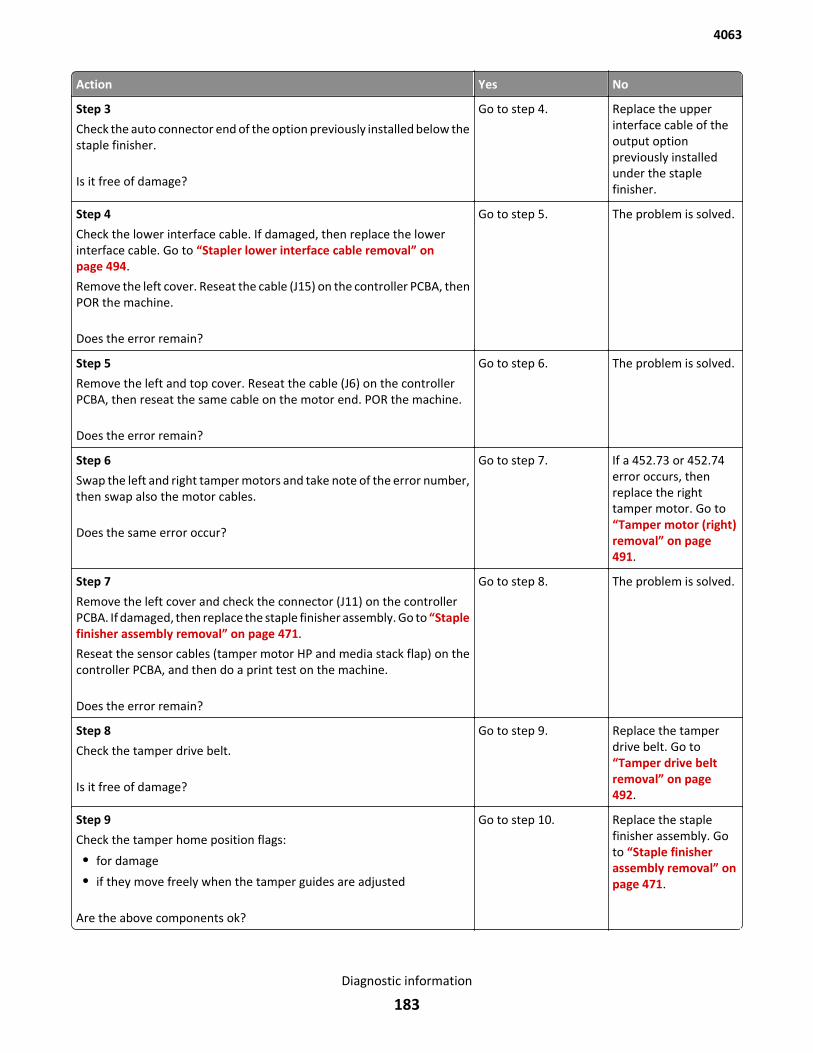
Action Yes No
Step 3
Check the auto connector end of the option previously installed below thestaple finisher.
Is it free of damage?
Go to step 4. Replace the upperinterface cable of theoutput optionpreviously installedunder the staplefinisher.
Step 4
Check the lower interface cable. If damaged, then replace the lowerinterface cable. Go to “Stapler lower interface cable removal” onpage 494.
Remove the left cover. Reseat the cable (J15) on the controller PCBA, thenPOR the machine.
Does the error remain?
Go to step 5. The problem is solved.
Step 5
Remove the left and top cover. Reseat the cable (J6) on the controllerPCBA, then reseat the same cable on the motor end. POR the machine.
Does the error remain?
Go to step 6. The problem is solved.
Step 6
Swap the left and right tamper motors and take note of the error number,then swap also the motor cables.
Does the same error occur?
Go to step 7. If a 452.73 or 452.74error occurs, thenreplace the righttamper motor. Go to“Tamper motor (right)removal” on page 491.
Step 7
Remove the left cover and check the connector (J11) on the controllerPCBA. If damaged, then replace the staple finisher assembly. Go to “Staplefinisher assembly removal” on page 471.
Reseat the sensor cables (tamper motor HP and media stack flap) on thecontroller PCBA, and then do a print test on the machine.
Does the error remain?
Go to step 8. The problem is solved.
Step 8
Check the tamper drive belt.
Is it free of damage?
Go to step 9. Replace the tamperdrive belt. Go to“Tamper drive beltremoval” on page 492.
Step 9
Check the tamper home position flags:
• for damage
• if they move freely when the tamper guides are adjusted
Are the above components ok?
Go to step 10. Replace the staplefinisher assembly. Goto “Staple finisherassembly removal” onpage 471.
4063
Diagnostic information
183
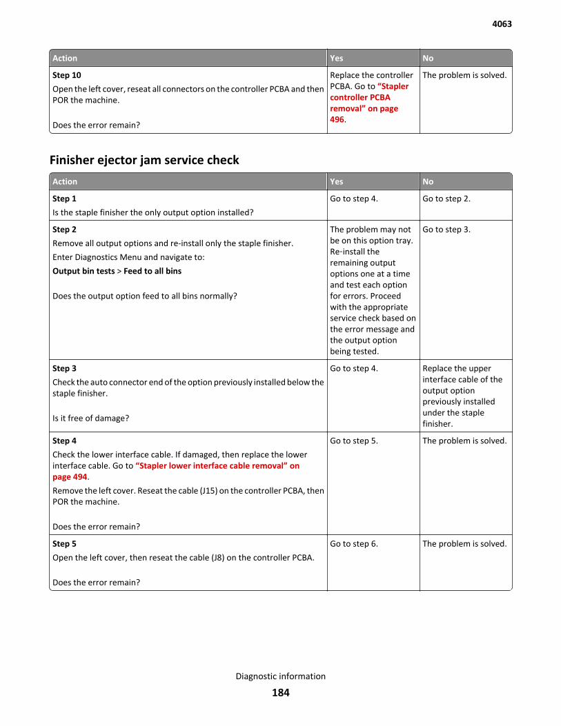
Action Yes No
Step 10
Open the left cover, reseat all connectors on the controller PCBA and thenPOR the machine.
Does the error remain?
Replace the controllerPCBA. Go to “Staplercontroller PCBAremoval” on page 496.
The problem is solved.
Finisher ejector jam service check
Action Yes No
Step 1
Is the staple finisher the only output option installed?
Go to step 4. Go to step 2.
Step 2
Remove all output options and re-install only the staple finisher.
Enter Diagnostics Menu and navigate to:
Output bin tests > Feed to all bins
Does the output option feed to all bins normally?
The problem may notbe on this option tray.Re‑install theremaining outputoptions one at a timeand test each optionfor errors. Proceedwith the appropriateservice check based onthe error message andthe output optionbeing tested.
Go to step 3.
Step 3
Check the auto connector end of the option previously installed below thestaple finisher.
Is it free of damage?
Go to step 4. Replace the upperinterface cable of theoutput optionpreviously installedunder the staplefinisher.
Step 4
Check the lower interface cable. If damaged, then replace the lowerinterface cable. Go to “Stapler lower interface cable removal” onpage 494.
Remove the left cover. Reseat the cable (J15) on the controller PCBA, thenPOR the machine.
Does the error remain?
Go to step 5. The problem is solved.
Step 5
Open the left cover, then reseat the cable (J8) on the controller PCBA.
Does the error remain?
Go to step 6. The problem is solved.
4063
Diagnostic information
184

Action Yes No
Step 6
Check the ejector and do the following:
• clear obstructions
• inspect the ejector
Is the ejector free of damage?
Go to step 7. Replace the staplefinisher assembly. Goto “Staple finisherassembly removal” onpage 471.
Step 7
Open the left cover, reseat all connectors on the controller PCBA and thenPOR the machine.
Does the error remain?
Replace the controllerPCBA. Go to “Staplercontroller PCBAremoval” on page 496.
The problem is solved.
Finisher diverter jam service check
Action Yes No
Step 1
Is the staple finisher the only output option installed?
Go to step 4. Go to step 2.
Step 2
Remove all output options and re-install only the staple finisher.
Enter Diagnostics Menu and navigate to:
Output bin tests > Feed to all bins
Does the output option feed to all bins normally?
The problem may notbe on this option tray.Re‑install theremaining outputoptions one at a timeand test each optionfor errors. Proceedwith the appropriateservice check based onthe error message andthe output optionbeing tested.
Go to step 3.
Step 3
Check the auto connector end of the option previously installed below thestaple finisher.
Is it free of damage?
Go to step 4. Replace the upperinterface cable of theoutput optionpreviously installedunder the staplefinisher.
Step 4
Check the lower interface cable. If damaged, then replace the lowerinterface cable. Go to “Stapler lower interface cable removal” onpage 494.
Remove the left cover. Reseat the cable (J15) on the controller PCBA, thenPOR the machine.
Does the error remain?
Go to step 5. The problem is solved.
4063
Diagnostic information
185
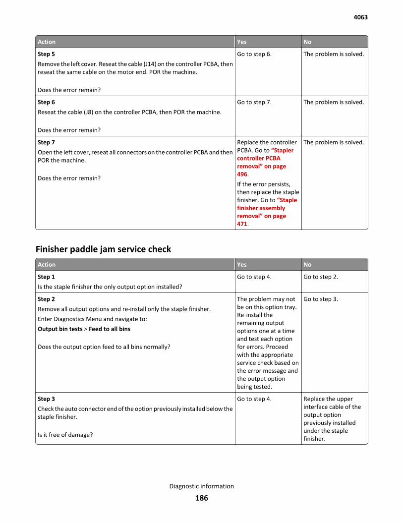
Action Yes No
Step 5
Remove the left cover. Reseat the cable (J14) on the controller PCBA, thenreseat the same cable on the motor end. POR the machine.
Does the error remain?
Go to step 6. The problem is solved.
Step 6
Reseat the cable (J8) on the controller PCBA, then POR the machine.
Does the error remain?
Go to step 7. The problem is solved.
Step 7
Open the left cover, reseat all connectors on the controller PCBA and thenPOR the machine.
Does the error remain?
Replace the controllerPCBA. Go to “Staplercontroller PCBAremoval” on page 496.
If the error persists,then replace the staplefinisher. Go to “Staplefinisher assemblyremoval” on page 471.
The problem is solved.
Finisher paddle jam service check
Action Yes No
Step 1
Is the staple finisher the only output option installed?
Go to step 4. Go to step 2.
Step 2
Remove all output options and re-install only the staple finisher.
Enter Diagnostics Menu and navigate to:
Output bin tests > Feed to all bins
Does the output option feed to all bins normally?
The problem may notbe on this option tray.Re‑install theremaining outputoptions one at a timeand test each optionfor errors. Proceedwith the appropriateservice check based onthe error message andthe output optionbeing tested.
Go to step 3.
Step 3
Check the auto connector end of the option previously installed below thestaple finisher.
Is it free of damage?
Go to step 4. Replace the upperinterface cable of theoutput optionpreviously installedunder the staplefinisher.
4063
Diagnostic information
186
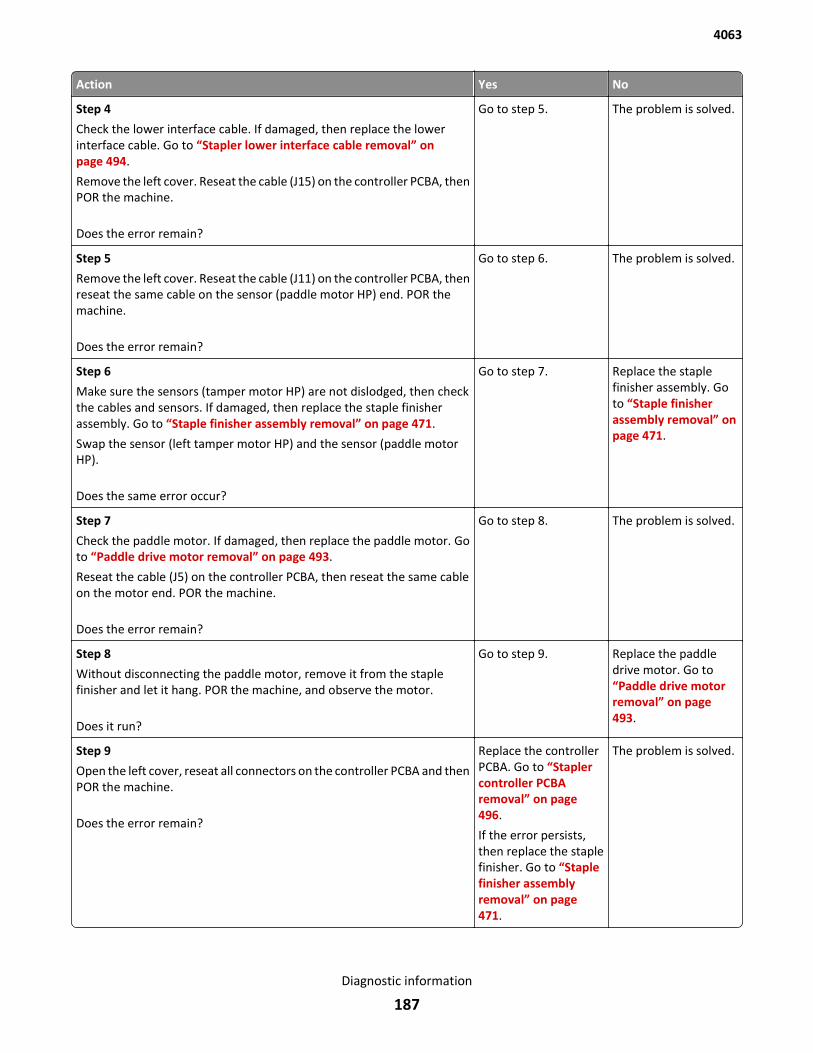
Action Yes No
Step 4
Check the lower interface cable. If damaged, then replace the lowerinterface cable. Go to “Stapler lower interface cable removal” onpage 494.
Remove the left cover. Reseat the cable (J15) on the controller PCBA, thenPOR the machine.
Does the error remain?
Go to step 5. The problem is solved.
Step 5
Remove the left cover. Reseat the cable (J11) on the controller PCBA, thenreseat the same cable on the sensor (paddle motor HP) end. POR themachine.
Does the error remain?
Go to step 6. The problem is solved.
Step 6
Make sure the sensors (tamper motor HP) are not dislodged, then checkthe cables and sensors. If damaged, then replace the staple finisherassembly. Go to “Staple finisher assembly removal” on page 471.
Swap the sensor (left tamper motor HP) and the sensor (paddle motorHP).
Does the same error occur?
Go to step 7. Replace the staplefinisher assembly. Goto “Staple finisherassembly removal” onpage 471.
Step 7
Check the paddle motor. If damaged, then replace the paddle motor. Goto “Paddle drive motor removal” on page 493.
Reseat the cable (J5) on the controller PCBA, then reseat the same cableon the motor end. POR the machine.
Does the error remain?
Go to step 8. The problem is solved.
Step 8
Without disconnecting the paddle motor, remove it from the staplefinisher and let it hang. POR the machine, and observe the motor.
Does it run?
Go to step 9. Replace the paddledrive motor. Go to“Paddle drive motorremoval” on page 493.
Step 9
Open the left cover, reseat all connectors on the controller PCBA and thenPOR the machine.
Does the error remain?
Replace the controllerPCBA. Go to “Staplercontroller PCBAremoval” on page 496.
If the error persists,then replace the staplefinisher. Go to “Staplefinisher assemblyremoval” on page 471.
The problem is solved.
4063
Diagnostic information
187
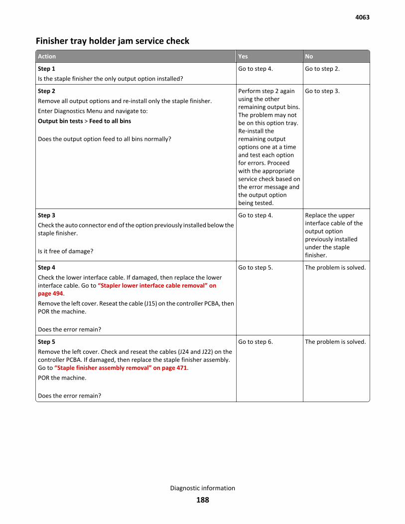
Finisher tray holder jam service check
Action Yes No
Step 1
Is the staple finisher the only output option installed?
Go to step 4. Go to step 2.
Step 2
Remove all output options and re-install only the staple finisher.
Enter Diagnostics Menu and navigate to:
Output bin tests > Feed to all bins
Does the output option feed to all bins normally?
Perform step 2 againusing the otherremaining output bins.The problem may notbe on this option tray.Re‑install theremaining outputoptions one at a timeand test each optionfor errors. Proceedwith the appropriateservice check based onthe error message andthe output optionbeing tested.
Go to step 3.
Step 3
Check the auto connector end of the option previously installed below thestaple finisher.
Is it free of damage?
Go to step 4. Replace the upperinterface cable of theoutput optionpreviously installedunder the staplefinisher.
Step 4
Check the lower interface cable. If damaged, then replace the lowerinterface cable. Go to “Stapler lower interface cable removal” onpage 494.
Remove the left cover. Reseat the cable (J15) on the controller PCBA, thenPOR the machine.
Does the error remain?
Go to step 5. The problem is solved.
Step 5
Remove the left cover. Check and reseat the cables (J24 and J22) on thecontroller PCBA. If damaged, then replace the staple finisher assembly.Go to “Staple finisher assembly removal” on page 471.
POR the machine.
Does the error remain?
Go to step 6. The problem is solved.
4063
Diagnostic information
188

Action Yes No
Step 6
Open the left cover, reseat all connectors on the controller PCBA and thenPOR the machine.
Does the error remain?
Replace the controllerPCBA. Go to “Staplercontroller PCBAremoval” on page 496.
If the error persiststhen replace the staplefinisher. Go to “Staplefinisher assemblyremoval” on page 471.
The problem is solved.
Stapler carriage jam service check
Action Yes No
Step 1
Is the staple finisher the only output option installed?
Go to step 4. Go to step 2.
Step 2
Remove all output options and re-install only the staple finisher.
Enter Diagnostics Menu and navigate to:
Output bin tests > Feed to all bins
Does the output option feed to all bins normally?
The problem may notbe on this option tray.Re‑install theremaining outputoptions one at a timeand test each optionfor errors. Proceedwith the appropriateservice check based onthe error message andthe output optionbeing tested.
Go to step 3.
Step 3
Check the auto connector end of the option previously installed below thestaple finisher.
Is it free of damage?
Go to step 4. Replace the upperinterface cable of theoutput optionpreviously installedunder the staplefinisher.
Step 4
Check the lower interface cable. If damaged, then replace the lowerinterface cable. Go to “Stapler lower interface cable removal” onpage 494.
Remove the left cover. Reseat the cable (J15) on the controller PCBA, thenPOR the machine.
Does the error remain?
Go to step 5. The problem is solved.
4063
Diagnostic information
189
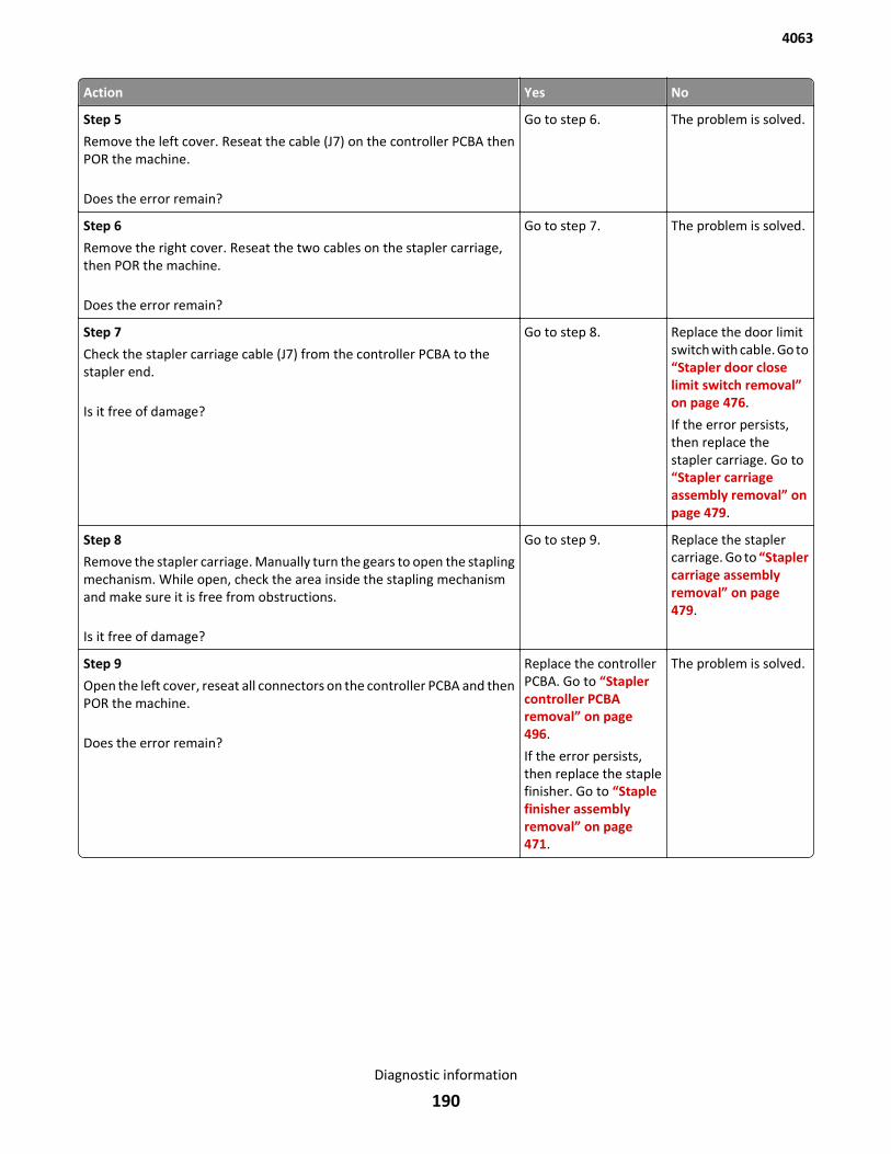
Action Yes No
Step 5
Remove the left cover. Reseat the cable (J7) on the controller PCBA thenPOR the machine.
Does the error remain?
Go to step 6. The problem is solved.
Step 6
Remove the right cover. Reseat the two cables on the stapler carriage,then POR the machine.
Does the error remain?
Go to step 7. The problem is solved.
Step 7
Check the stapler carriage cable (J7) from the controller PCBA to thestapler end.
Is it free of damage?
Go to step 8. Replace the door limitswitch with cable. Go to“Stapler door closelimit switch removal”on page 476.
If the error persists,then replace thestapler carriage. Go to“Stapler carriageassembly removal” onpage 479.
Step 8
Remove the stapler carriage. Manually turn the gears to open the staplingmechanism. While open, check the area inside the stapling mechanismand make sure it is free from obstructions.
Is it free of damage?
Go to step 9. Replace the staplercarriage. Go to “Staplercarriage assemblyremoval” on page 479.
Step 9
Open the left cover, reseat all connectors on the controller PCBA and thenPOR the machine.
Does the error remain?
Replace the controllerPCBA. Go to “Staplercontroller PCBAremoval” on page 496.
If the error persists,then replace the staplefinisher. Go to “Staplefinisher assemblyremoval” on page 471.
The problem is solved.
4063
Diagnostic information
190
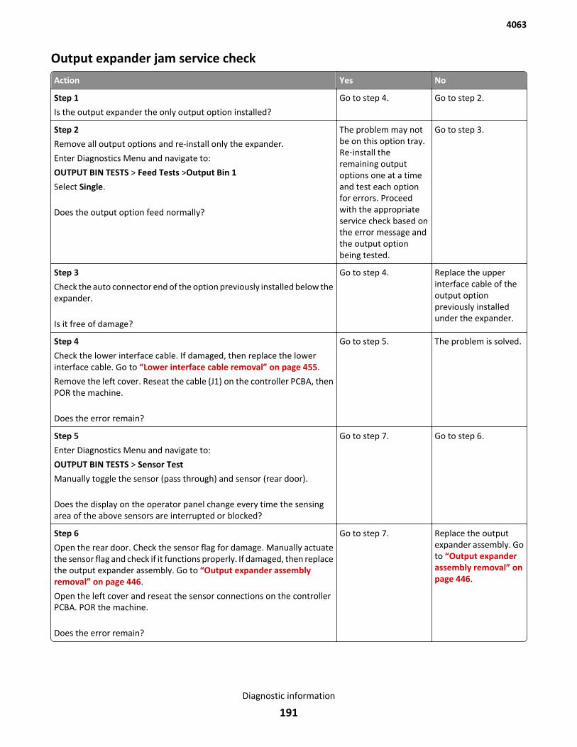
Output expander jam service check
Action Yes No
Step 1
Is the output expander the only output option installed?
Go to step 4. Go to step 2.
Step 2
Remove all output options and re-install only the expander.
Enter Diagnostics Menu and navigate to:
OUTPUT BIN TESTS > Feed Tests >Output Bin 1
Select Single.
Does the output option feed normally?
The problem may notbe on this option tray.Re‑install theremaining outputoptions one at a timeand test each optionfor errors. Proceedwith the appropriateservice check based onthe error message andthe output optionbeing tested.
Go to step 3.
Step 3
Check the auto connector end of the option previously installed below theexpander.
Is it free of damage?
Go to step 4. Replace the upperinterface cable of theoutput optionpreviously installedunder the expander.
Step 4
Check the lower interface cable. If damaged, then replace the lowerinterface cable. Go to “Lower interface cable removal” on page 455.
Remove the left cover. Reseat the cable (J1) on the controller PCBA, thenPOR the machine.
Does the error remain?
Go to step 5. The problem is solved.
Step 5
Enter Diagnostics Menu and navigate to:
OUTPUT BIN TESTS > Sensor Test
Manually toggle the sensor (pass through) and sensor (rear door).
Does the display on the operator panel change every time the sensingarea of the above sensors are interrupted or blocked?
Go to step 7. Go to step 6.
Step 6
Open the rear door. Check the sensor flag for damage. Manually actuatethe sensor flag and check if it functions properly. If damaged, then replacethe output expander assembly. Go to “Output expander assemblyremoval” on page 446.
Open the left cover and reseat the sensor connections on the controllerPCBA. POR the machine.
Does the error remain?
Go to step 7. Replace the outputexpander assembly. Goto “Output expanderassembly removal” onpage 446.
4063
Diagnostic information
191
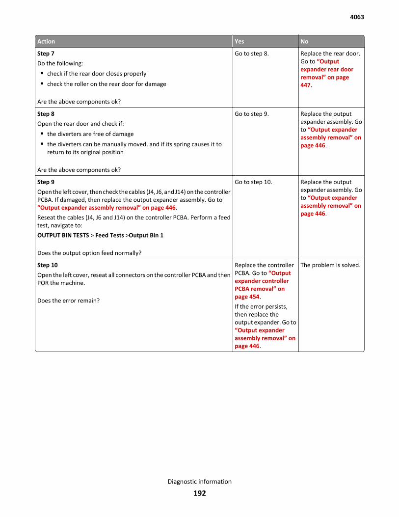
Action Yes No
Step 7
Do the following:
• check if the rear door closes properly
• check the roller on the rear door for damage
Are the above components ok?
Go to step 8. Replace the rear door.Go to “Outputexpander rear doorremoval” on page 447.
Step 8
Open the rear door and check if:
• the diverters are free of damage
• the diverters can be manually moved, and if its spring causes it toreturn to its original position
Are the above components ok?
Go to step 9. Replace the outputexpander assembly. Goto “Output expanderassembly removal” onpage 446.
Step 9
Open the left cover, then check the cables (J4, J6, and J14) on the controllerPCBA. If damaged, then replace the output expander assembly. Go to“Output expander assembly removal” on page 446.
Reseat the cables (J4, J6 and J14) on the controller PCBA. Perform a feedtest, navigate to:
OUTPUT BIN TESTS > Feed Tests >Output Bin 1
Does the output option feed normally?
Go to step 10. Replace the outputexpander assembly. Goto “Output expanderassembly removal” onpage 446.
Step 10
Open the left cover, reseat all connectors on the controller PCBA and thenPOR the machine.
Does the error remain?
Replace the controllerPCBA. Go to “Outputexpander controllerPCBA removal” onpage 454.
If the error persists,then replace theoutput expander. Go to“Output expanderassembly removal” onpage 446.
The problem is solved.
4063
Diagnostic information
192
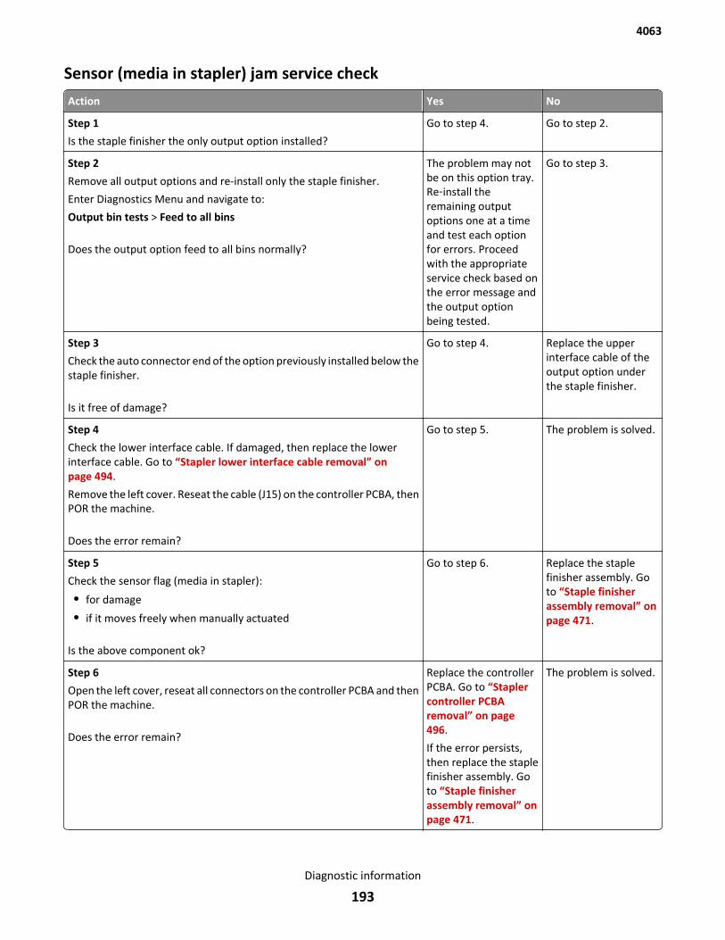
Sensor (media in stapler) jam service check
Action Yes No
Step 1
Is the staple finisher the only output option installed?
Go to step 4. Go to step 2.
Step 2
Remove all output options and re-install only the staple finisher.
Enter Diagnostics Menu and navigate to:
Output bin tests > Feed to all bins
Does the output option feed to all bins normally?
The problem may notbe on this option tray.Re‑install theremaining outputoptions one at a timeand test each optionfor errors. Proceedwith the appropriateservice check based onthe error message andthe output optionbeing tested.
Go to step 3.
Step 3
Check the auto connector end of the option previously installed below thestaple finisher.
Is it free of damage?
Go to step 4. Replace the upperinterface cable of theoutput option underthe staple finisher.
Step 4
Check the lower interface cable. If damaged, then replace the lowerinterface cable. Go to “Stapler lower interface cable removal” onpage 494.
Remove the left cover. Reseat the cable (J15) on the controller PCBA, thenPOR the machine.
Does the error remain?
Go to step 5. The problem is solved.
Step 5
Check the sensor flag (media in stapler):
• for damage
• if it moves freely when manually actuated
Is the above component ok?
Go to step 6. Replace the staplefinisher assembly. Goto “Staple finisherassembly removal” onpage 471.
Step 6
Open the left cover, reseat all connectors on the controller PCBA and thenPOR the machine.
Does the error remain?
Replace the controllerPCBA. Go to “Staplercontroller PCBAremoval” on page 496.
If the error persists,then replace the staplefinisher assembly. Goto “Staple finisherassembly removal” onpage 471.
The problem is solved.
4063
Diagnostic information
193
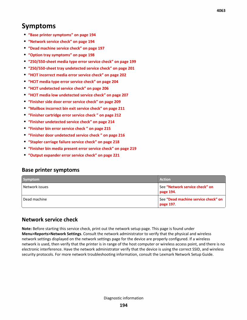
Symptoms• “Base printer symptoms” on page 194
• “Network service check” on page 194
• “Dead machine service check” on page 197
• “Option tray symptoms” on page 198
• “250/550-sheet media type error service check” on page 199
• “250/550-sheet tray undetected service check” on page 201
• “HCIT incorrect media error service check” on page 202
• “HCIT media type error service check” on page 204
• “HCIT undetected service check” on page 206
• “HCIT media low undetected service check” on page 207
• “Finisher side door error service check” on page 209
• “Mailbox incorrect bin exit service check” on page 211
• “Finisher cartridge error service check ” on page 212
• “Finisher undetected service check” on page 214
• “Finisher bin error service check ” on page 215
• “Finisher door undetected service check ” on page 216
• “Stapler carriage failure service check” on page 218
• “Finisher bin media present error service check” on page 219
• “Output expander error service check” on page 221
Base printer symptoms
Symptom Action
Network issues See “Network service check” onpage 194.
Dead machine See “Dead machine service check” onpage 197.
Network service checkNote: Before starting this service check, print out the network setup page. This page is found underMenu>Reports>Network Settings. Consult the network administrator to verify that the physical and wirelessnetwork settings displayed on the network settings page for the device are properly configured. If a wirelessnetwork is used, then verify that the printer is in range of the host computer or wireless access point, and there is noelectronic interference. Have the network administrator verify that the device is using the correct SSID, and wirelesssecurity protocols. For more network troubleshooting information, consult the Lexmark Network Setup Guide.
4063
Diagnostic information
194
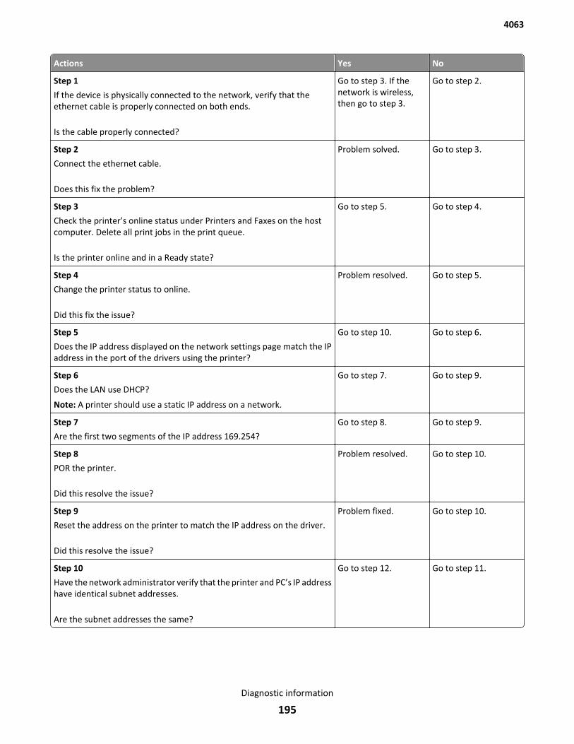
Actions Yes No
Step 1
If the device is physically connected to the network, verify that theethernet cable is properly connected on both ends.
Is the cable properly connected?
Go to step 3. If thenetwork is wireless,then go to step 3.
Go to step 2.
Step 2
Connect the ethernet cable.
Does this fix the problem?
Problem solved. Go to step 3.
Step 3
Check the printer’s online status under Printers and Faxes on the hostcomputer. Delete all print jobs in the print queue.
Is the printer online and in a Ready state?
Go to step 5. Go to step 4.
Step 4
Change the printer status to online.
Did this fix the issue?
Problem resolved. Go to step 5.
Step 5
Does the IP address displayed on the network settings page match the IPaddress in the port of the drivers using the printer?
Go to step 10. Go to step 6.
Step 6
Does the LAN use DHCP?
Note: A printer should use a static IP address on a network.
Go to step 7. Go to step 9.
Step 7
Are the first two segments of the IP address 169.254?
Go to step 8. Go to step 9.
Step 8
POR the printer.
Did this resolve the issue?
Problem resolved. Go to step 10.
Step 9
Reset the address on the printer to match the IP address on the driver.
Did this resolve the issue?
Problem fixed. Go to step 10.
Step 10
Have the network administrator verify that the printer and PC’s IP addresshave identical subnet addresses.
Are the subnet addresses the same?
Go to step 12. Go to step 11.
4063
Diagnostic information
195
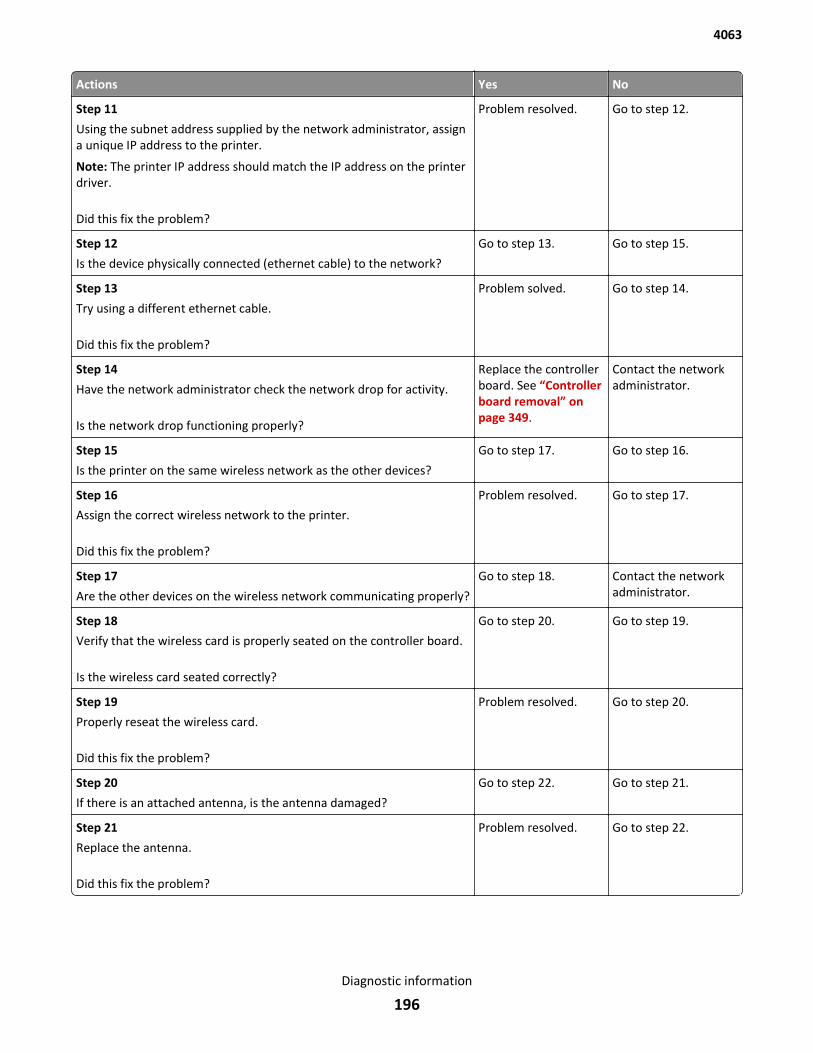
Actions Yes No
Step 11
Using the subnet address supplied by the network administrator, assigna unique IP address to the printer.
Note: The printer IP address should match the IP address on the printerdriver.
Did this fix the problem?
Problem resolved. Go to step 12.
Step 12
Is the device physically connected (ethernet cable) to the network?
Go to step 13. Go to step 15.
Step 13
Try using a different ethernet cable.
Did this fix the problem?
Problem solved. Go to step 14.
Step 14
Have the network administrator check the network drop for activity.
Is the network drop functioning properly?
Replace the controllerboard. See “Controllerboard removal” onpage 349.
Contact the networkadministrator.
Step 15
Is the printer on the same wireless network as the other devices?
Go to step 17. Go to step 16.
Step 16
Assign the correct wireless network to the printer.
Did this fix the problem?
Problem resolved. Go to step 17.
Step 17
Are the other devices on the wireless network communicating properly?
Go to step 18. Contact the networkadministrator.
Step 18
Verify that the wireless card is properly seated on the controller board.
Is the wireless card seated correctly?
Go to step 20. Go to step 19.
Step 19
Properly reseat the wireless card.
Did this fix the problem?
Problem resolved. Go to step 20.
Step 20
If there is an attached antenna, is the antenna damaged?
Go to step 22. Go to step 21.
Step 21
Replace the antenna.
Did this fix the problem?
Problem resolved. Go to step 22.
4063
Diagnostic information
196
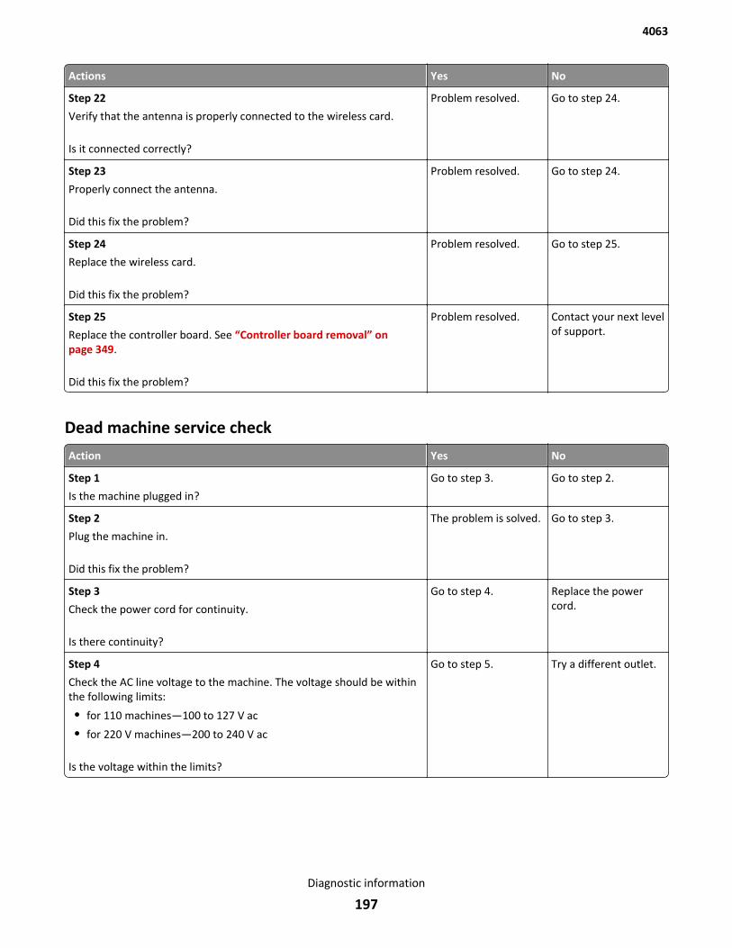
Actions Yes No
Step 22
Verify that the antenna is properly connected to the wireless card.
Is it connected correctly?
Problem resolved. Go to step 24.
Step 23
Properly connect the antenna.
Did this fix the problem?
Problem resolved. Go to step 24.
Step 24
Replace the wireless card.
Did this fix the problem?
Problem resolved. Go to step 25.
Step 25
Replace the controller board. See “Controller board removal” onpage 349.
Did this fix the problem?
Problem resolved. Contact your next levelof support.
Dead machine service check
Action Yes No
Step 1
Is the machine plugged in?
Go to step 3. Go to step 2.
Step 2
Plug the machine in.
Did this fix the problem?
The problem is solved. Go to step 3.
Step 3
Check the power cord for continuity.
Is there continuity?
Go to step 4. Replace the powercord.
Step 4
Check the AC line voltage to the machine. The voltage should be withinthe following limits:
• for 110 machines—100 to 127 V ac
• for 220 V machines—200 to 240 V ac
Is the voltage within the limits?
Go to step 5. Try a different outlet.
4063
Diagnostic information
197
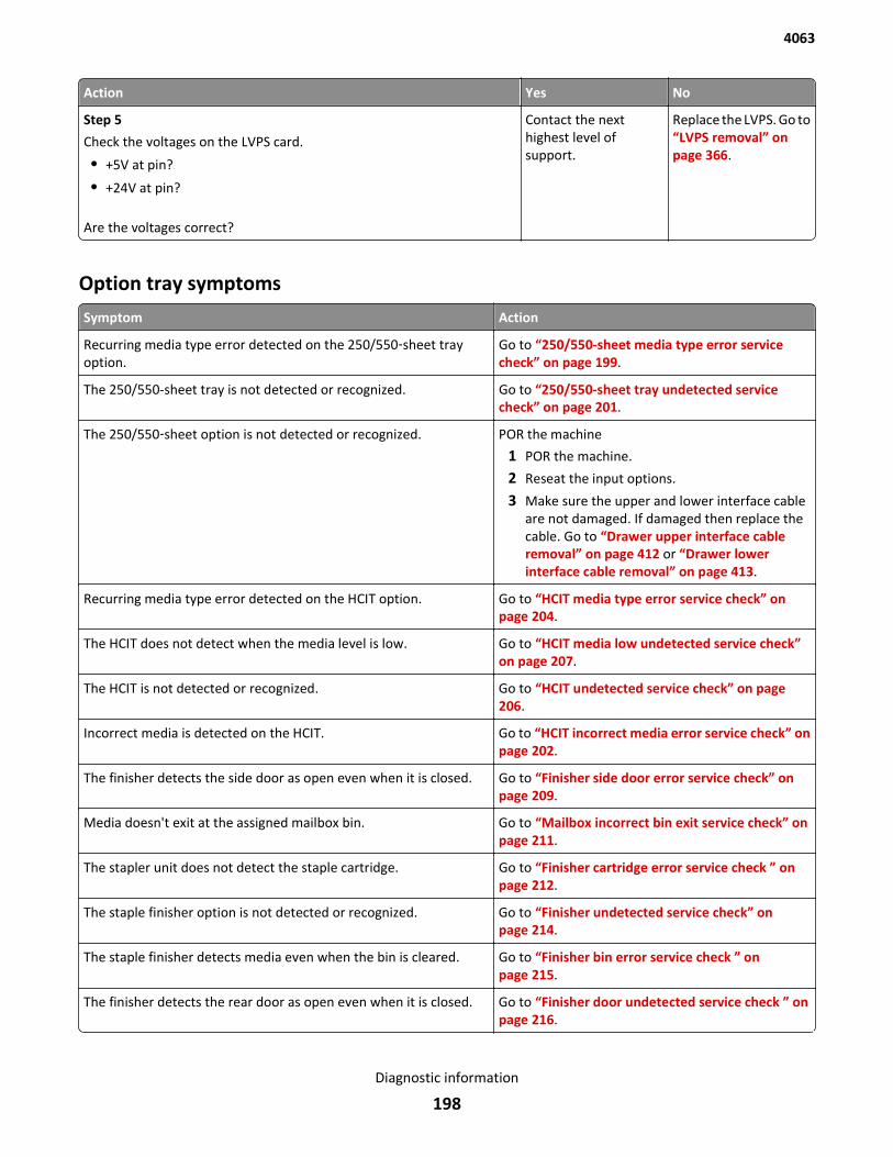
Action Yes No
Step 5
Check the voltages on the LVPS card.
• +5V at pin?
• +24V at pin?
Are the voltages correct?
Contact the nexthighest level ofsupport.
Replace the LVPS. Go to“LVPS removal” onpage 366.
Option tray symptoms
Symptom Action
Recurring media type error detected on the 250/550‑sheet trayoption.
Go to “250/550-sheet media type error servicecheck” on page 199.
The 250/550-sheet tray is not detected or recognized. Go to “250/550-sheet tray undetected servicecheck” on page 201.
The 250/550‑sheet option is not detected or recognized. POR the machine
1 POR the machine.
2 Reseat the input options.
3 Make sure the upper and lower interface cableare not damaged. If damaged then replace thecable. Go to “Drawer upper interface cableremoval” on page 412 or “Drawer lowerinterface cable removal” on page 413.
Recurring media type error detected on the HCIT option. Go to “HCIT media type error service check” onpage 204.
The HCIT does not detect when the media level is low. Go to “HCIT media low undetected service check”on page 207.
The HCIT is not detected or recognized. Go to “HCIT undetected service check” on page 206.
Incorrect media is detected on the HCIT. Go to “HCIT incorrect media error service check” onpage 202.
The finisher detects the side door as open even when it is closed. Go to “Finisher side door error service check” onpage 209.
Media doesn't exit at the assigned mailbox bin. Go to “Mailbox incorrect bin exit service check” onpage 211.
The stapler unit does not detect the staple cartridge. Go to “Finisher cartridge error service check ” onpage 212.
The staple finisher option is not detected or recognized. Go to “Finisher undetected service check” onpage 214.
The staple finisher detects media even when the bin is cleared. Go to “Finisher bin error service check ” onpage 215.
The finisher detects the rear door as open even when it is closed. Go to “Finisher door undetected service check ” onpage 216.
4063
Diagnostic information
198
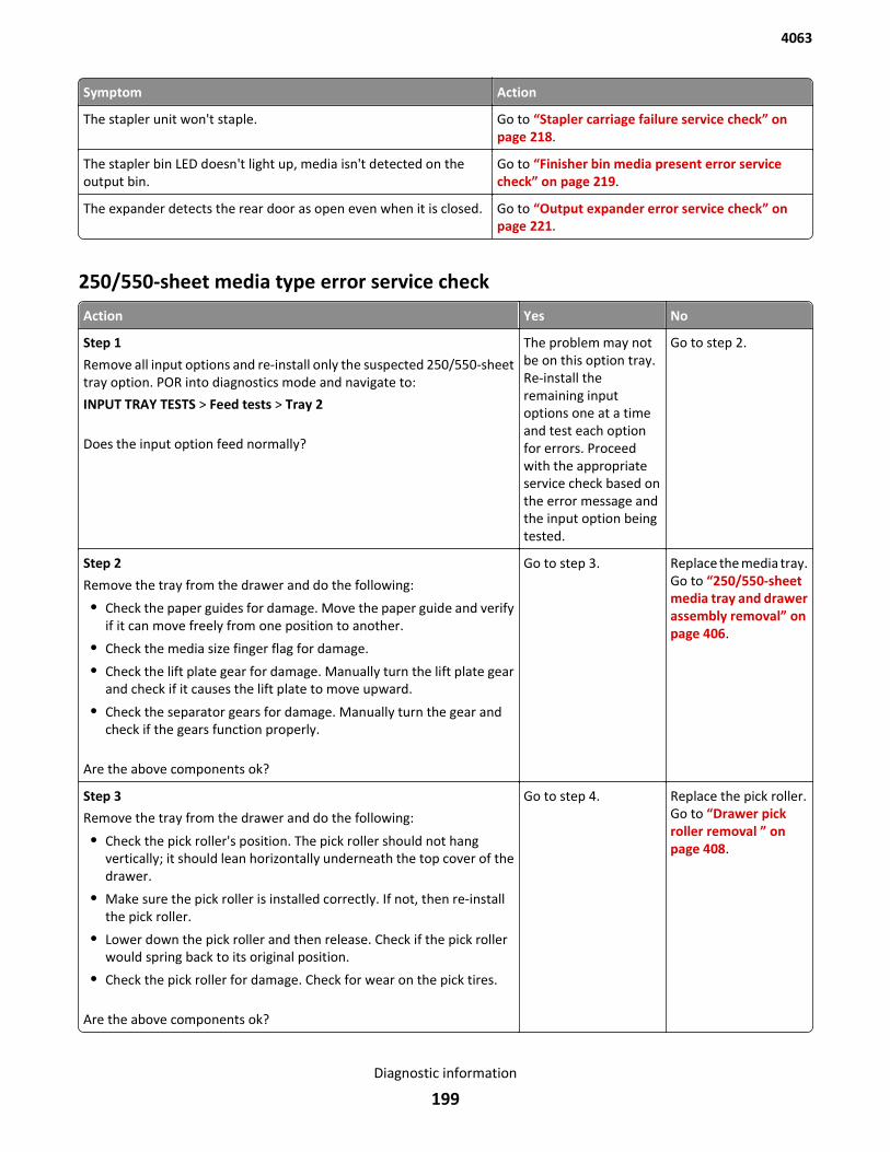
Symptom Action
The stapler unit won't staple. Go to “Stapler carriage failure service check” onpage 218.
The stapler bin LED doesn't light up, media isn't detected on theoutput bin.
Go to “Finisher bin media present error servicecheck” on page 219.
The expander detects the rear door as open even when it is closed. Go to “Output expander error service check” onpage 221.
250/550-sheet media type error service check
Action Yes No
Step 1
Remove all input options and re-install only the suspected 250/550-sheettray option. POR into diagnostics mode and navigate to:
INPUT TRAY TESTS > Feed tests > Tray 2
Does the input option feed normally?
The problem may notbe on this option tray.Re-install theremaining inputoptions one at a timeand test each optionfor errors. Proceedwith the appropriateservice check based onthe error message andthe input option beingtested.
Go to step 2.
Step 2
Remove the tray from the drawer and do the following:
• Check the paper guides for damage. Move the paper guide and verifyif it can move freely from one position to another.
• Check the media size finger flag for damage.
• Check the lift plate gear for damage. Manually turn the lift plate gearand check if it causes the lift plate to move upward.
• Check the separator gears for damage. Manually turn the gear andcheck if the gears function properly.
Are the above components ok?
Go to step 3. Replace the media tray.Go to “250/550-sheetmedia tray and drawerassembly removal” onpage 406.
Step 3
Remove the tray from the drawer and do the following:
• Check the pick roller's position. The pick roller should not hangvertically; it should lean horizontally underneath the top cover of thedrawer.
• Make sure the pick roller is installed correctly. If not, then re-installthe pick roller.
• Lower down the pick roller and then release. Check if the pick rollerwould spring back to its original position.
• Check the pick roller for damage. Check for wear on the pick tires.
Are the above components ok?
Go to step 4. Replace the pick roller.Go to “Drawer pickroller removal ” onpage 408.
4063
Diagnostic information
199
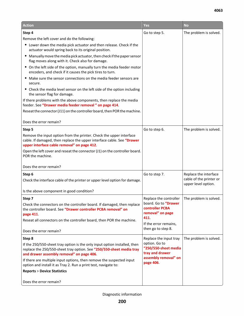
Action Yes No
Step 4
Remove the left cover and do the following:
• Lower down the media pick actuator and then release. Check if theactuator would spring back to its original position.
• Manually move the media pick actuator, then check if the paper sensorflag moves along with it. Check also for damage.
• On the left side of the option, manually turn the media feeder motorencoders, and check if it causes the pick tires to turn.
• Make sure the sensor connections on the media feeder sensors aresecure.
• Check the media level sensor on the left side of the option includingthe sensor flag for damage.
If there problems with the above components, then replace the mediafeeder. See “Drawer media feeder removal ” on page 414.
Reseat the connector (J11) on the controller board, then POR the machine.
Does the error remain?
Go to step 5. The problem is solved.
Step 5
Remove the input option from the printer. Check the upper interfacecable. If damaged, then replace the upper interface cable. See “Drawerupper interface cable removal” on page 412.
Open the left cover and reseat the connector (J1) on the controller board.POR the machine.
Does the error remain?
Go to step 6. The problem is solved.
Step 6
Check the interface cable of the printer or upper level option for damage.
Is the above component in good condition?
Go to step 7. Replace the interfacecable of the printer orupper level option.
Step 7
Check the connectors on the controller board. If damaged, then replacethe controller board. See “Drawer controller PCBA removal” onpage 411.
Reseat all connectors on the controller board, then POR the machine.
Does the error remain?
Replace the controllerboard. Go to “Drawercontroller PCBAremoval” on page 411.
If the error remains,then go to step 8.
The problem is solved.
Step 8
If the 250/550-sheet tray option is the only input option installed, thenreplace the 250/550-sheet tray option. See “250/550-sheet media trayand drawer assembly removal” on page 406.
If there are multiple input options, then remove the suspected inputoption and install it as Tray 2. Run a print test, navigate to:
Reports > Device Statistics
Does the error remain?
Replace the input trayoption. Go to“250/550-sheet mediatray and drawerassembly removal” onpage 406.
The problem is solved.
4063
Diagnostic information
200
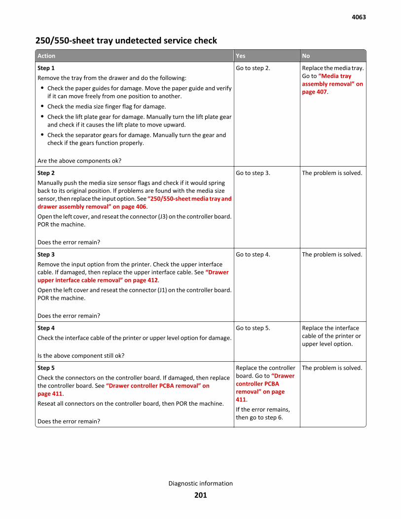
250/550-sheet tray undetected service check
Action Yes No
Step 1
Remove the tray from the drawer and do the following:
• Check the paper guides for damage. Move the paper guide and verifyif it can move freely from one position to another.
• Check the media size finger flag for damage.
• Check the lift plate gear for damage. Manually turn the lift plate gearand check if it causes the lift plate to move upward.
• Check the separator gears for damage. Manually turn the gear andcheck if the gears function properly.
Are the above components ok?
Go to step 2. Replace the media tray.Go to “Media trayassembly removal” onpage 407.
Step 2
Manually push the media size sensor flags and check if it would springback to its original position. If problems are found with the media sizesensor, then replace the input option. See “250/550-sheet media tray anddrawer assembly removal” on page 406.
Open the left cover, and reseat the connector (J3) on the controller board.POR the machine.
Does the error remain?
Go to step 3. The problem is solved.
Step 3
Remove the input option from the printer. Check the upper interfacecable. If damaged, then replace the upper interface cable. See “Drawerupper interface cable removal” on page 412.
Open the left cover and reseat the connector (J1) on the controller board.POR the machine.
Does the error remain?
Go to step 4. The problem is solved.
Step 4
Check the interface cable of the printer or upper level option for damage.
Is the above component still ok?
Go to step 5. Replace the interfacecable of the printer orupper level option.
Step 5
Check the connectors on the controller board. If damaged, then replacethe controller board. See “Drawer controller PCBA removal” onpage 411.
Reseat all connectors on the controller board, then POR the machine.
Does the error remain?
Replace the controllerboard. Go to “Drawercontroller PCBAremoval” on page 411.
If the error remains,then go to step 6.
The problem is solved.
4063
Diagnostic information
201
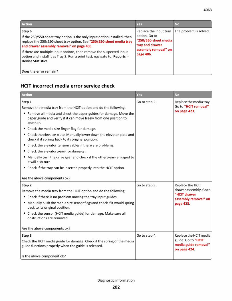
Action Yes No
Step 6
If the 250/550-sheet tray option is the only input option installed, thenreplace the 250/550-sheet tray option. See “250/550-sheet media trayand drawer assembly removal” on page 406.
If there are multiple input options, then remove the suspected inputoption and install it as Tray 2. Run a print test, navigate to: Reports >Device Statistics
Does the error remain?
Replace the input trayoption. Go to“250/550-sheet mediatray and drawerassembly removal” onpage 406.
The problem is solved.
HCIT incorrect media error service check
Action Yes No
Step 1
Remove the media tray from the HCIT option and do the following:
• Remove all media and check the paper guides for damage. Move thepaper guide and verify if it can move freely from one position toanother.
• Check the media size finger flag for damage.
• Check the elevator plate. Manually lower down the elevator plate andcheck if it springs back to its original position.
• Check the elevator tension cables if there are problems.
• Check the elevator gears for damage.
• Manually turn the drive gear and check if the other gears engaged toit will also turn.
• Check if the tray can be inserted properly into the HCIT option.
Are the above components ok?
Go to step 2. Replace the media tray.Go to “HCIT removal”on page 423.
Step 2
Remove the media tray from the HCIT option and do the following:
• Check if there is no problem moving the tray input guides.
• Manually push the media size sensor flags and check if it would springback to its original position.
• Check the sensor (HCIT media guide) for damage. Make sure allobstructions are removed.
Are the above components ok?
Go to step 3. Replace the HCITdrawer assembly. Go to“HCIT drawerassembly removal” onpage 423.
Step 3
Check the HCIT media guide for damage. Check if the spring of the mediaguide functions properly when the guide is released.
Is the above component ok?
Go to step 4. Replace the HCIT mediaguide. Go to “HCITmedia guide removal”on page 424.
4063
Diagnostic information
202
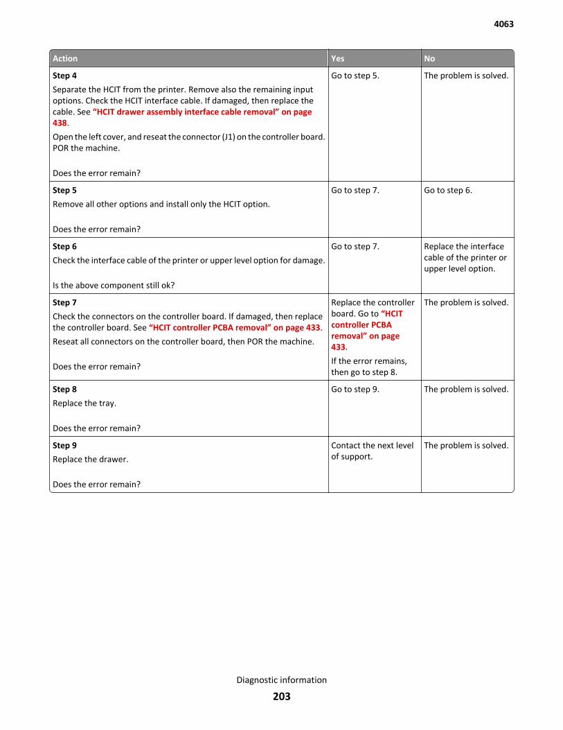
Action Yes No
Step 4
Separate the HCIT from the printer. Remove also the remaining inputoptions. Check the HCIT interface cable. If damaged, then replace thecable. See “HCIT drawer assembly interface cable removal” on page 438.
Open the left cover, and reseat the connector (J1) on the controller board.POR the machine.
Does the error remain?
Go to step 5. The problem is solved.
Step 5
Remove all other options and install only the HCIT option.
Does the error remain?
Go to step 7. Go to step 6.
Step 6
Check the interface cable of the printer or upper level option for damage.
Is the above component still ok?
Go to step 7. Replace the interfacecable of the printer orupper level option.
Step 7
Check the connectors on the controller board. If damaged, then replacethe controller board. See “HCIT controller PCBA removal” on page 433.
Reseat all connectors on the controller board, then POR the machine.
Does the error remain?
Replace the controllerboard. Go to “HCITcontroller PCBAremoval” on page 433.
If the error remains,then go to step 8.
The problem is solved.
Step 8
Replace the tray.
Does the error remain?
Go to step 9. The problem is solved.
Step 9
Replace the drawer.
Does the error remain?
Contact the next levelof support.
The problem is solved.
4063
Diagnostic information
203
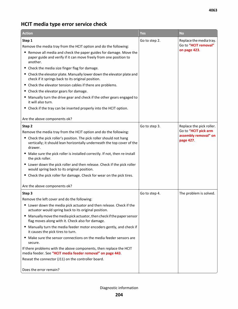
HCIT media type error service check
Action Yes No
Step 1
Remove the media tray from the HCIT option and do the following:
• Remove all media and check the paper guides for damage. Move thepaper guide and verify if it can move freely from one position toanother.
• Check the media size finger flag for damage.
• Check the elevator plate. Manually lower down the elevator plate andcheck if it springs back to its original position.
• Check the elevator tension cables if there are problems.
• Check the elevator gears for damage.
• Manually turn the drive gear and check if the other gears engaged toit will also turn.
• Check if the tray can be inserted properly into the HCIT option.
Are the above components ok?
Go to step 2. Replace the media tray.Go to “HCIT removal”on page 423.
Step 2
Remove the media tray from the HCIT option and do the following:
• Check the pick roller's position. The pick roller should not hangvertically; it should lean horizontally underneath the top cover of thedrawer.
• Make sure the pick roller is installed correctly. If not, then re-installthe pick roller.
• Lower down the pick roller and then release. Check if the pick rollerwould spring back to its original position.
• Check the pick roller for damage. Check for wear on the pick tires.
Are the above components ok?
Go to step 3. Replace the pick roller.Go to “HCIT pick armassembly removal” onpage 427.
Step 3
Remove the left cover and do the following:
• Lower down the media pick actuator and then release. Check if theactuator would spring back to its original position.
• Manually move the media pick actuator, then check if the paper sensorflag moves along with it. Check also for damage.
• Manually turn the media feeder motor encoders gently, and check ifit causes the pick tires to turn.
• Make sure the sensor connections on the media feeder sensors aresecure.
If there problems with the above components, then replace the HCITmedia feeder. See “HCIT media feeder removal” on page 443.
Reseat the connector (J11) on the controller board.
Does the error remain?
Go to step 4. The problem is solved.
4063
Diagnostic information
204
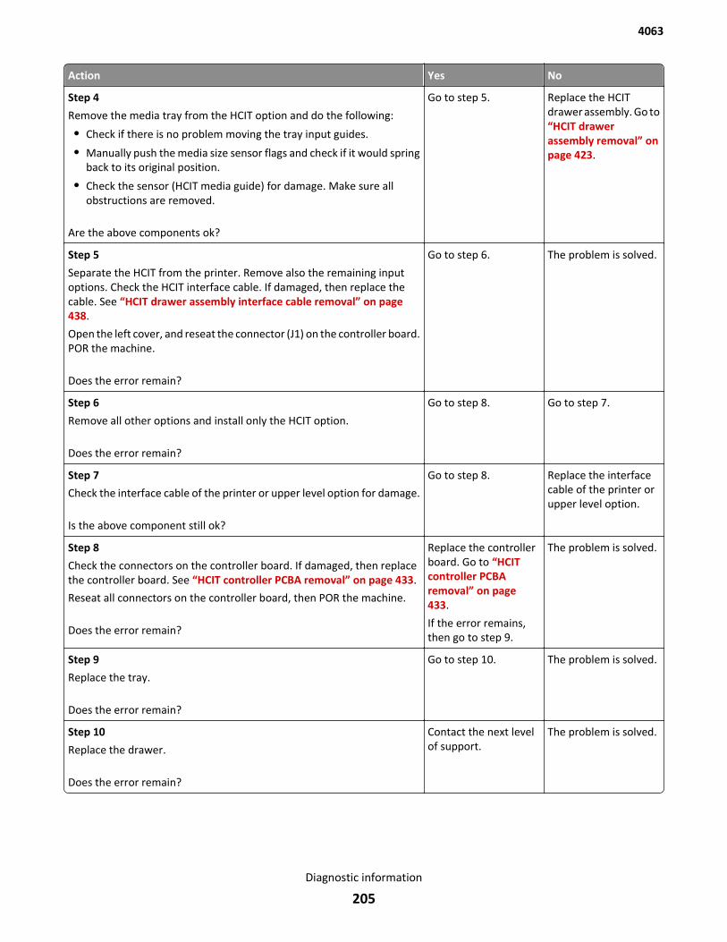
Action Yes No
Step 4
Remove the media tray from the HCIT option and do the following:
• Check if there is no problem moving the tray input guides.
• Manually push the media size sensor flags and check if it would springback to its original position.
• Check the sensor (HCIT media guide) for damage. Make sure allobstructions are removed.
Are the above components ok?
Go to step 5. Replace the HCITdrawer assembly. Go to“HCIT drawerassembly removal” onpage 423.
Step 5
Separate the HCIT from the printer. Remove also the remaining inputoptions. Check the HCIT interface cable. If damaged, then replace thecable. See “HCIT drawer assembly interface cable removal” on page 438.
Open the left cover, and reseat the connector (J1) on the controller board.POR the machine.
Does the error remain?
Go to step 6. The problem is solved.
Step 6
Remove all other options and install only the HCIT option.
Does the error remain?
Go to step 8. Go to step 7.
Step 7
Check the interface cable of the printer or upper level option for damage.
Is the above component still ok?
Go to step 8. Replace the interfacecable of the printer orupper level option.
Step 8
Check the connectors on the controller board. If damaged, then replacethe controller board. See “HCIT controller PCBA removal” on page 433.
Reseat all connectors on the controller board, then POR the machine.
Does the error remain?
Replace the controllerboard. Go to “HCITcontroller PCBAremoval” on page 433.
If the error remains,then go to step 9.
The problem is solved.
Step 9
Replace the tray.
Does the error remain?
Go to step 10. The problem is solved.
Step 10
Replace the drawer.
Does the error remain?
Contact the next levelof support.
The problem is solved.
4063
Diagnostic information
205
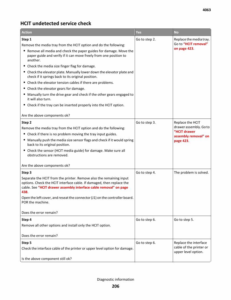
HCIT undetected service check
Action Yes No
Step 1
Remove the media tray from the HCIT option and do the following:
• Remove all media and check the paper guides for damage. Move thepaper guide and verify if it can move freely from one position toanother.
• Check the media size finger flag for damage.
• Check the elevator plate. Manually lower down the elevator plate andcheck if it springs back to its original position.
• Check the elevator tension cables if there are problems.
• Check the elevator gears for damage.
• Manually turn the drive gear and check if the other gears engaged toit will also turn.
• Check if the tray can be inserted properly into the HCIT option.
Are the above components ok?
Go to step 2. Replace the media tray.Go to “HCIT removal”on page 423.
Step 2
Remove the media tray from the HCIT option and do the following:
• Check if there is no problem moving the tray input guides.
• Manually push the media size sensor flags and check if it would springback to its original position.
• Check the sensor (HCIT media guide) for damage. Make sure allobstructions are removed.
Are the above components ok?
Go to step 3. Replace the HCITdrawer assembly. Go to“HCIT drawerassembly removal” onpage 423.
Step 3
Separate the HCIT from the printer. Remove also the remaining inputoptions. Check the HCIT interface cable. If damaged, then replace thecable. See “HCIT drawer assembly interface cable removal” on page 438.
Open the left cover, and reseat the connector (J1) on the controller board.POR the machine.
Does the error remain?
Go to step 4. The problem is solved.
Step 4
Remove all other options and install only the HCIT option.
Does the error remain?
Go to step 6. Go to step 5.
Step 5
Check the interface cable of the printer or upper level option for damage.
Is the above component still ok?
Go to step 6. Replace the interfacecable of the printer orupper level option.
4063
Diagnostic information
206
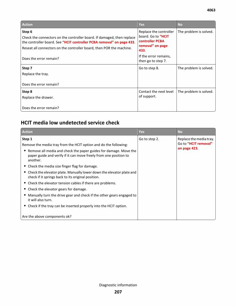
Action Yes No
Step 6
Check the connectors on the controller board. If damaged, then replacethe controller board. See “HCIT controller PCBA removal” on page 433.
Reseat all connectors on the controller board, then POR the machine.
Does the error remain?
Replace the controllerboard. Go to “HCITcontroller PCBAremoval” on page 433.
If the error remains,then go to step 7.
The problem is solved.
Step 7
Replace the tray.
Does the error remain?
Go to step 8. The problem is solved.
Step 8
Replace the drawer.
Does the error remain?
Contact the next levelof support.
The problem is solved.
HCIT media low undetected service check
Action Yes No
Step 1
Remove the media tray from the HCIT option and do the following:
• Remove all media and check the paper guides for damage. Move thepaper guide and verify if it can move freely from one position toanother.
• Check the media size finger flag for damage.
• Check the elevator plate. Manually lower down the elevator plate andcheck if it springs back to its original position.
• Check the elevator tension cables if there are problems.
• Check the elevator gears for damage.
• Manually turn the drive gear and check if the other gears engaged toit will also turn.
• Check if the tray can be inserted properly into the HCIT option.
Are the above components ok?
Go to step 2. Replace the media tray.Go to “HCIT removal”on page 423.
4063
Diagnostic information
207
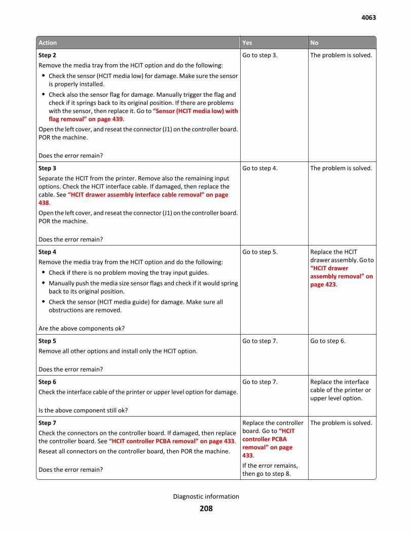
Action Yes No
Step 2
Remove the media tray from the HCIT option and do the following:
• Check the sensor (HCIT media low) for damage. Make sure the sensoris properly installed.
• Check also the sensor flag for damage. Manually trigger the flag andcheck if it springs back to its original position. If there are problemswith the sensor, then replace it. Go to “Sensor (HCIT media low) withflag removal” on page 439.
Open the left cover, and reseat the connector (J1) on the controller board.POR the machine.
Does the error remain?
Go to step 3. The problem is solved.
Step 3
Separate the HCIT from the printer. Remove also the remaining inputoptions. Check the HCIT interface cable. If damaged, then replace thecable. See “HCIT drawer assembly interface cable removal” on page 438.
Open the left cover, and reseat the connector (J1) on the controller board.POR the machine.
Does the error remain?
Go to step 4. The problem is solved.
Step 4
Remove the media tray from the HCIT option and do the following:
• Check if there is no problem moving the tray input guides.
• Manually push the media size sensor flags and check if it would springback to its original position.
• Check the sensor (HCIT media guide) for damage. Make sure allobstructions are removed.
Are the above components ok?
Go to step 5. Replace the HCITdrawer assembly. Go to“HCIT drawerassembly removal” onpage 423.
Step 5
Remove all other options and install only the HCIT option.
Does the error remain?
Go to step 7. Go to step 6.
Step 6
Check the interface cable of the printer or upper level option for damage.
Is the above component still ok?
Go to step 7. Replace the interfacecable of the printer orupper level option.
Step 7
Check the connectors on the controller board. If damaged, then replacethe controller board. See “HCIT controller PCBA removal” on page 433.
Reseat all connectors on the controller board, then POR the machine.
Does the error remain?
Replace the controllerboard. Go to “HCITcontroller PCBAremoval” on page 433.
If the error remains,then go to step 8.
The problem is solved.
4063
Diagnostic information
208
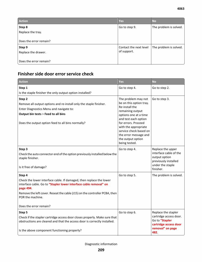
Action Yes No
Step 8
Replace the tray.
Does the error remain?
Go to step 9. The problem is solved.
Step 9
Replace the drawer.
Does the error remain?
Contact the next levelof support.
The problem is solved.
Finisher side door error service check
Action Yes No
Step 1
Is the staple finisher the only output option installed?
Go to step 4. Go to step 2.
Step 2
Remove all output options and re-install only the staple finisher.
Enter Diagnostics Menu and navigate to:
Output bin tests > Feed to all bins
Does the output option feed to all bins normally?
The problem may notbe on this option tray.Re‑install theremaining outputoptions one at a timeand test each optionfor errors. Proceedwith the appropriateservice check based onthe error message andthe output optionbeing tested.
Go to step 3.
Step 3
Check the auto connector end of the option previously installed below thestaple finisher.
Is it free of damage?
Go to step 4. Replace the upperinterface cable of theoutput optionpreviously installedunder the staplefinisher.
Step 4
Check the lower interface cable. If damaged, then replace the lowerinterface cable. Go to “Stapler lower interface cable removal” onpage 494.
Remove the left cover. Reseat the cable (J15) on the controller PCBA, thenPOR the machine.
Does the error remain?
Go to step 5. The problem is solved.
Step 5
Check if the stapler cartridge access door closes properly. Make sure thatobstructions are cleared and that the access door is correctly installed.
Is the above component functioning properly?
Go to step 6. Replace the staplercartridge access door.Go to “Staplercartridge access doorremoval” on page 482.
4063
Diagnostic information
209
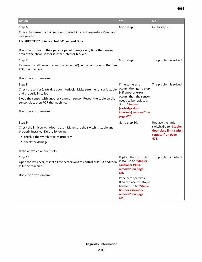
Action Yes No
Step 6
Check the sensor (cartridge door interlock). Enter Diagnostics Menu andnavigate to:
FINISHER TESTS > Sensor Test >Cover and Door
Does the display on the operator panel change every time the sensingarea of the above sensor is interrupted or blocked?
Go to step 8. Go to step 7.
Step 7
Remove the left cover. Reseat the cable (J20) on the controller PCBA thenPOR the machine.
Does the error remain?
Go to step 8. The problem is solved.
Step 8
Check the sensor (cartridge door interlock). Make sure the sensor is stableand properly installed.
Swap the sensor with another common sensor. Reseat the cable on thesensor side, then POR the machine.
Does the error remain?
If the same erroroccurs, then go to step9. If another erroroccurs, then the sensorneeds to be replaced.Go to “Sensor(cartridge doorinterlock) removal” onpage 476.
The problem is solved.
Step 9
Check the limit switch (door close). Make sure the switch is stable andproperly installed. Do the following:
• check if the switch toggles properly
• check for damage
Is the above component ok?
Go to step 10. Replace the limitswitch. Go to “Staplerdoor close limit switchremoval” on page 476.
Step 10
Open the left cover, reseat all connectors on the controller PCBA and thenPOR the machine.
Does the error remain?
Replace the controllerPCBA. Go to “Staplercontroller PCBAremoval” on page 496.
If the error persists,then replace the staplefinisher. Go to “Staplefinisher assemblyremoval” on page 471.
The problem is solved.
4063
Diagnostic information
210
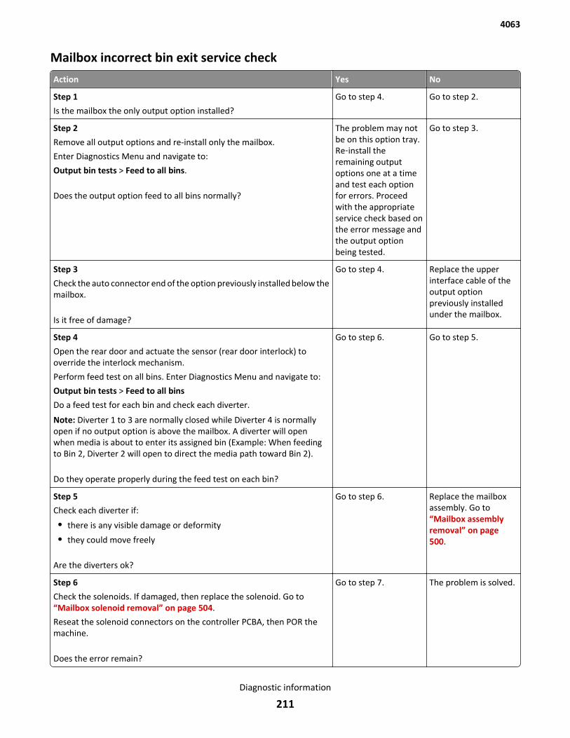
Mailbox incorrect bin exit service check
Action Yes No
Step 1
Is the mailbox the only output option installed?
Go to step 4. Go to step 2.
Step 2
Remove all output options and re-install only the mailbox.
Enter Diagnostics Menu and navigate to:
Output bin tests > Feed to all bins.
Does the output option feed to all bins normally?
The problem may notbe on this option tray.Re‑install theremaining outputoptions one at a timeand test each optionfor errors. Proceedwith the appropriateservice check based onthe error message andthe output optionbeing tested.
Go to step 3.
Step 3
Check the auto connector end of the option previously installed below themailbox.
Is it free of damage?
Go to step 4. Replace the upperinterface cable of theoutput optionpreviously installedunder the mailbox.
Step 4
Open the rear door and actuate the sensor (rear door interlock) tooverride the interlock mechanism.
Perform feed test on all bins. Enter Diagnostics Menu and navigate to:
Output bin tests > Feed to all bins
Do a feed test for each bin and check each diverter.
Note: Diverter 1 to 3 are normally closed while Diverter 4 is normallyopen if no output option is above the mailbox. A diverter will openwhen media is about to enter its assigned bin (Example: When feedingto Bin 2, Diverter 2 will open to direct the media path toward Bin 2).
Do they operate properly during the feed test on each bin?
Go to step 6. Go to step 5.
Step 5
Check each diverter if:
• there is any visible damage or deformity
• they could move freely
Are the diverters ok?
Go to step 6. Replace the mailboxassembly. Go to“Mailbox assemblyremoval” on page 500.
Step 6
Check the solenoids. If damaged, then replace the solenoid. Go to“Mailbox solenoid removal” on page 504.
Reseat the solenoid connectors on the controller PCBA, then POR themachine.
Does the error remain?
Go to step 7. The problem is solved.
4063
Diagnostic information
211
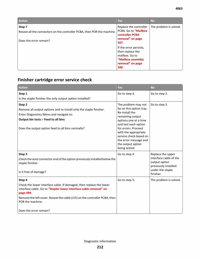
Action Yes No
Step 7
Reseat all the connectors on the controller PCBA, then POR the machine.
Does the error remain?
Replace the controllerPCBA. Go to “Mailboxcontroller PCBAremoval” on page 507.
If the error persists,then replace themailbox. Go to“Mailbox assemblyremoval” on page 500.
The problem is solved.
Finisher cartridge error service check
Action Yes No
Step 1
Is the staple finisher the only output option installed?
Go to step 4. Go to step 2.
Step 2
Remove all output options and re-install only the staple finisher.
Enter Diagnostics Menu and navigate to:
Output bin tests > Feed to all bins
Does the output option feed to all bins normally?
The problem may notbe on this option tray.Re‑install theremaining outputoptions one at a timeand test each optionfor errors. Proceedwith the appropriateservice check based onthe error message andthe output optionbeing tested.
Go to step 3.
Step 3
Check the auto connector end of the option previously installed below thestaple finisher.
Is it free of damage?
Go to step 4. Replace the upperinterface cable of theoutput optionpreviously installedunder the staplefinisher.
Step 4
Check the lower interface cable. If damaged, then replace the lowerinterface cable. Go to “Stapler lower interface cable removal” onpage 494.
Remove the left cover. Reseat the cable (J15) on the controller PCBA, thenPOR the machine.
Does the error remain?
Go to step 5. The problem is solved.
4063
Diagnostic information
212
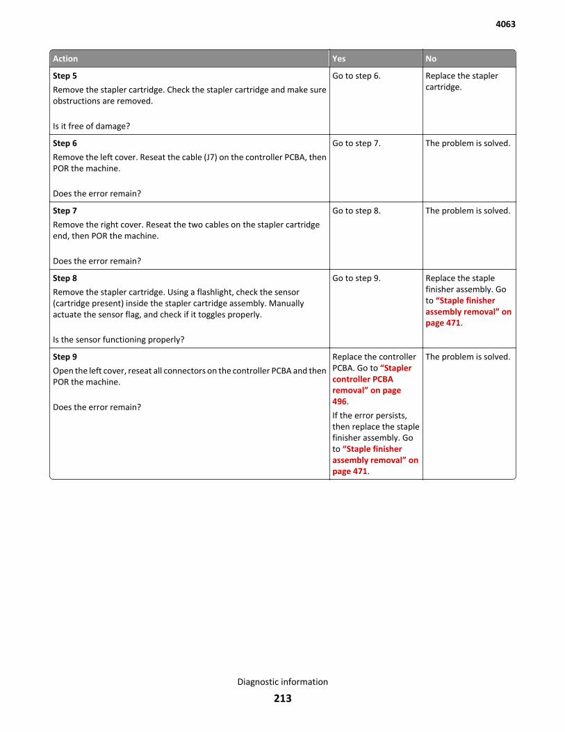
Action Yes No
Step 5
Remove the stapler cartridge. Check the stapler cartridge and make sureobstructions are removed.
Is it free of damage?
Go to step 6. Replace the staplercartridge.
Step 6
Remove the left cover. Reseat the cable (J7) on the controller PCBA, thenPOR the machine.
Does the error remain?
Go to step 7. The problem is solved.
Step 7
Remove the right cover. Reseat the two cables on the stapler cartridgeend, then POR the machine.
Does the error remain?
Go to step 8. The problem is solved.
Step 8
Remove the stapler cartridge. Using a flashlight, check the sensor(cartridge present) inside the stapler cartridge assembly. Manuallyactuate the sensor flag, and check if it toggles properly.
Is the sensor functioning properly?
Go to step 9. Replace the staplefinisher assembly. Goto “Staple finisherassembly removal” onpage 471.
Step 9
Open the left cover, reseat all connectors on the controller PCBA and thenPOR the machine.
Does the error remain?
Replace the controllerPCBA. Go to “Staplercontroller PCBAremoval” on page 496.
If the error persists,then replace the staplefinisher assembly. Goto “Staple finisherassembly removal” onpage 471.
The problem is solved.
4063
Diagnostic information
213
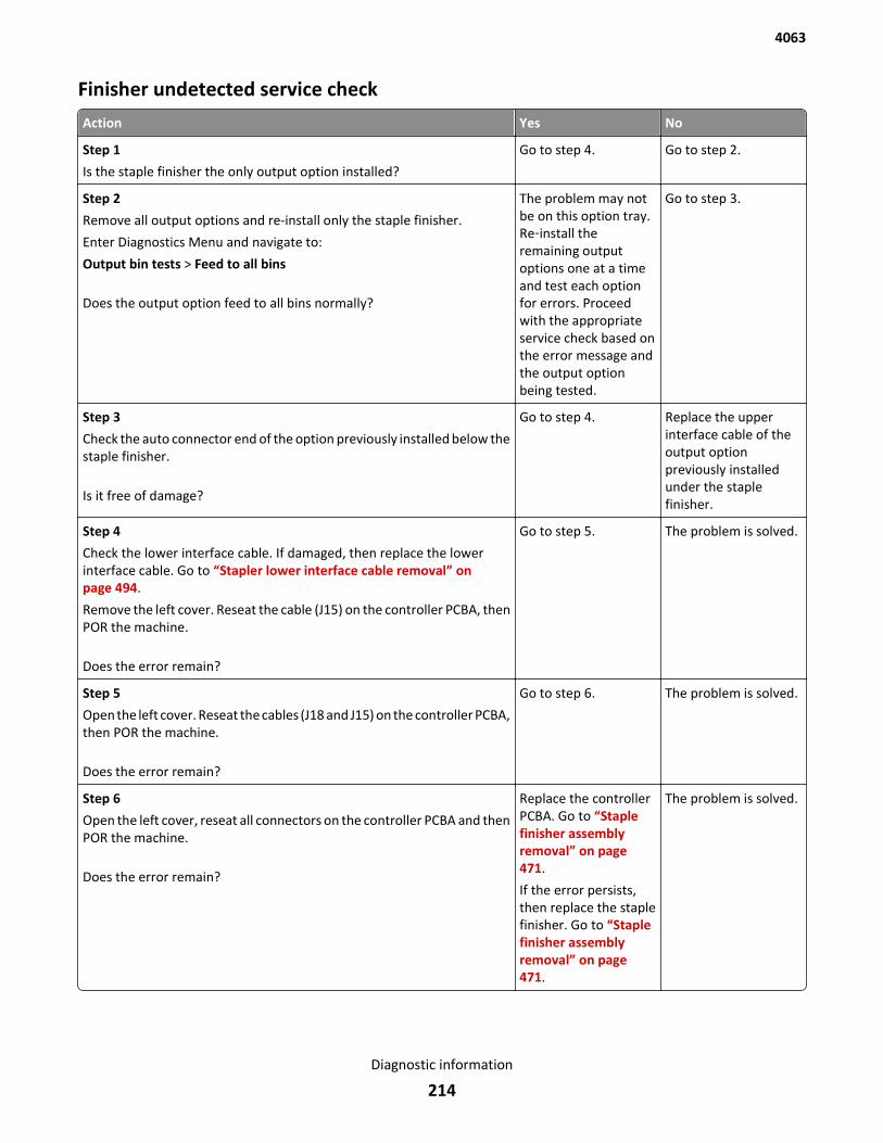
Finisher undetected service check
Action Yes No
Step 1
Is the staple finisher the only output option installed?
Go to step 4. Go to step 2.
Step 2
Remove all output options and re-install only the staple finisher.
Enter Diagnostics Menu and navigate to:
Output bin tests > Feed to all bins
Does the output option feed to all bins normally?
The problem may notbe on this option tray.Re‑install theremaining outputoptions one at a timeand test each optionfor errors. Proceedwith the appropriateservice check based onthe error message andthe output optionbeing tested.
Go to step 3.
Step 3
Check the auto connector end of the option previously installed below thestaple finisher.
Is it free of damage?
Go to step 4. Replace the upperinterface cable of theoutput optionpreviously installedunder the staplefinisher.
Step 4
Check the lower interface cable. If damaged, then replace the lowerinterface cable. Go to “Stapler lower interface cable removal” onpage 494.
Remove the left cover. Reseat the cable (J15) on the controller PCBA, thenPOR the machine.
Does the error remain?
Go to step 5. The problem is solved.
Step 5
Open the left cover. Reseat the cables (J18 and J15) on the controller PCBA,then POR the machine.
Does the error remain?
Go to step 6. The problem is solved.
Step 6
Open the left cover, reseat all connectors on the controller PCBA and thenPOR the machine.
Does the error remain?
Replace the controllerPCBA. Go to “Staplefinisher assemblyremoval” on page 471.
If the error persists,then replace the staplefinisher. Go to “Staplefinisher assemblyremoval” on page 471.
The problem is solved.
4063
Diagnostic information
214
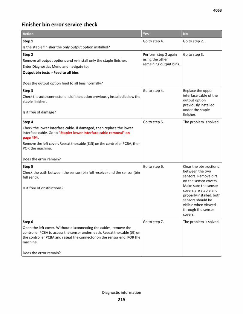
Finisher bin error service check
Action Yes No
Step 1
Is the staple finisher the only output option installed?
Go to step 4. Go to step 2.
Step 2
Remove all output options and re-install only the staple finisher.
Enter Diagnostics Menu and navigate to:
Output bin tests > Feed to all bins
Does the output option feed to all bins normally?
Perform step 2 againusing the otherremaining output bins.
Go to step 3.
Step 3
Check the auto connector end of the option previously installed below thestaple finisher.
Is it free of damage?
Go to step 4. Replace the upperinterface cable of theoutput optionpreviously installedunder the staplefinisher.
Step 4
Check the lower interface cable. If damaged, then replace the lowerinterface cable. Go to “Stapler lower interface cable removal” onpage 494.
Remove the left cover. Reseat the cable (J15) on the controller PCBA, thenPOR the machine.
Does the error remain?
Go to step 5. The problem is solved.
Step 5
Check the path between the sensor (bin full receive) and the sensor (binfull send).
Is it free of obstructions?
Go to step 6. Clear the obstructionsbetween the twosensors. Remove dirton the sensor covers.Make sure the sensorcovers are stable andproperly installed; bothsensors should bevisible when viewedthrough the sensorcovers.
Step 6
Open the left cover. Without disconnecting the cables, remove thecontroller PCBA to access the sensor underneath. Reseat the cable (J9) onthe controller PCBA and reseat the connector on the sensor end. POR themachine.
Does the error remain?
Go to step 7. The problem is solved.
4063
Diagnostic information
215
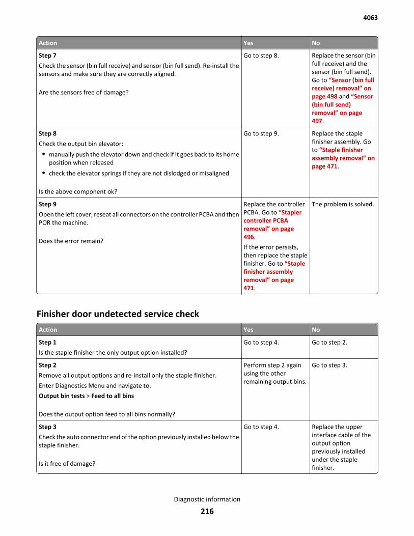
Action Yes No
Step 7
Check the sensor (bin full receive) and sensor (bin full send). Re-install thesensors and make sure they are correctly aligned.
Are the sensors free of damage?
Go to step 8. Replace the sensor (binfull receive) and thesensor (bin full send).Go to “Sensor (bin fullreceive) removal” onpage 498 and “Sensor(bin full send)removal” on page 497.
Step 8
Check the output bin elevator:
• manually push the elevator down and check if it goes back to its homeposition when released
• check the elevator springs if they are not dislodged or misaligned
Is the above component ok?
Go to step 9. Replace the staplefinisher assembly. Goto “Staple finisherassembly removal” onpage 471.
Step 9
Open the left cover, reseat all connectors on the controller PCBA and thenPOR the machine.
Does the error remain?
Replace the controllerPCBA. Go to “Staplercontroller PCBAremoval” on page 496.
If the error persists,then replace the staplefinisher. Go to “Staplefinisher assemblyremoval” on page 471.
The problem is solved.
Finisher door undetected service check
Action Yes No
Step 1
Is the staple finisher the only output option installed?
Go to step 4. Go to step 2.
Step 2
Remove all output options and re-install only the staple finisher.
Enter Diagnostics Menu and navigate to:
Output bin tests > Feed to all bins
Does the output option feed to all bins normally?
Perform step 2 againusing the otherremaining output bins.
Go to step 3.
Step 3
Check the auto connector end of the option previously installed below thestaple finisher.
Is it free of damage?
Go to step 4. Replace the upperinterface cable of theoutput optionpreviously installedunder the staplefinisher.
4063
Diagnostic information
216
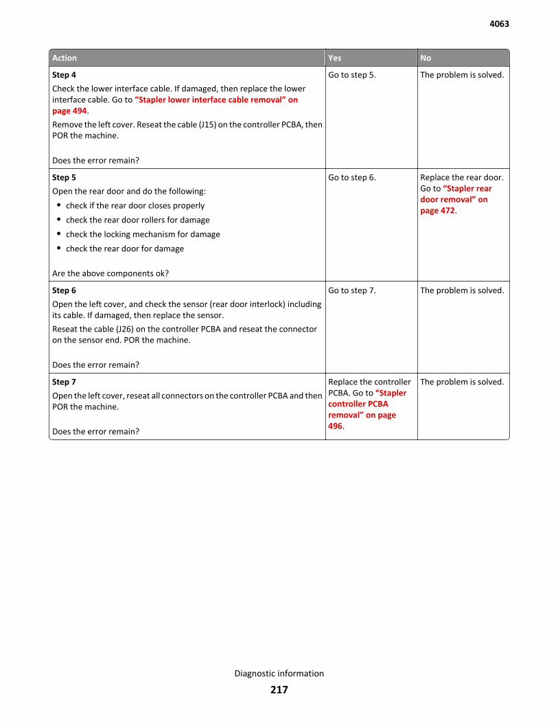
Action Yes No
Step 4
Check the lower interface cable. If damaged, then replace the lowerinterface cable. Go to “Stapler lower interface cable removal” onpage 494.
Remove the left cover. Reseat the cable (J15) on the controller PCBA, thenPOR the machine.
Does the error remain?
Go to step 5. The problem is solved.
Step 5
Open the rear door and do the following:
• check if the rear door closes properly
• check the rear door rollers for damage
• check the locking mechanism for damage
• check the rear door for damage
Are the above components ok?
Go to step 6. Replace the rear door.Go to “Stapler reardoor removal” onpage 472.
Step 6
Open the left cover, and check the sensor (rear door interlock) includingits cable. If damaged, then replace the sensor.
Reseat the cable (J26) on the controller PCBA and reseat the connectoron the sensor end. POR the machine.
Does the error remain?
Go to step 7. The problem is solved.
Step 7
Open the left cover, reseat all connectors on the controller PCBA and thenPOR the machine.
Does the error remain?
Replace the controllerPCBA. Go to “Staplercontroller PCBAremoval” on page 496.
The problem is solved.
4063
Diagnostic information
217
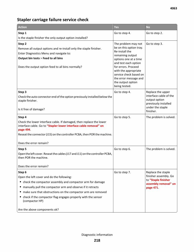
Stapler carriage failure service check
Action Yes No
Step 1
Is the staple finisher the only output option installed?
Go to step 4. Go to step 2.
Step 2
Remove all output options and re-install only the staple finisher.
Enter Diagnostics Menu and navigate to:
Output bin tests > Feed to all bins
Does the output option feed to all bins normally?
The problem may notbe on this option tray.Re‑install theremaining outputoptions one at a timeand test each optionfor errors. Proceedwith the appropriateservice check based onthe error message andthe output optionbeing tested.
Go to step 3.
Step 3
Check the auto connector end of the option previously installed below thestaple finisher.
Is it free of damage?
Go to step 4. Replace the upperinterface cable of theoutput optionpreviously installedunder the staplefinisher.
Step 4
Check the lower interface cable. If damaged, then replace the lowerinterface cable. Go to “Stapler lower interface cable removal” onpage 494.
Reseat the connector (J15) on the controller PCBA, then POR the machine.
Does the error remain?
Go to step 5. The problem is solved.
Step 5
Open the left cover. Reseat the cables (J17 and J11) on the controller PCBA,then POR the machine.
Does the error remain?
Go to step 6. The problem is solved.
Step 6
Open the left cover and do the following:
• check the compactor assembly and compactor arm for damage
• manually pull the compactor arm and observe if it retracts
• make sure that obstructions on the compactor arm are removed
• check if the compactor flag engages properly with the sensor(compactor HP)
Are the above components ok?
Go to step 7. Replace the staplefinisher assembly. Goto “Staple finisherassembly removal” onpage 471.
4063
Diagnostic information
218
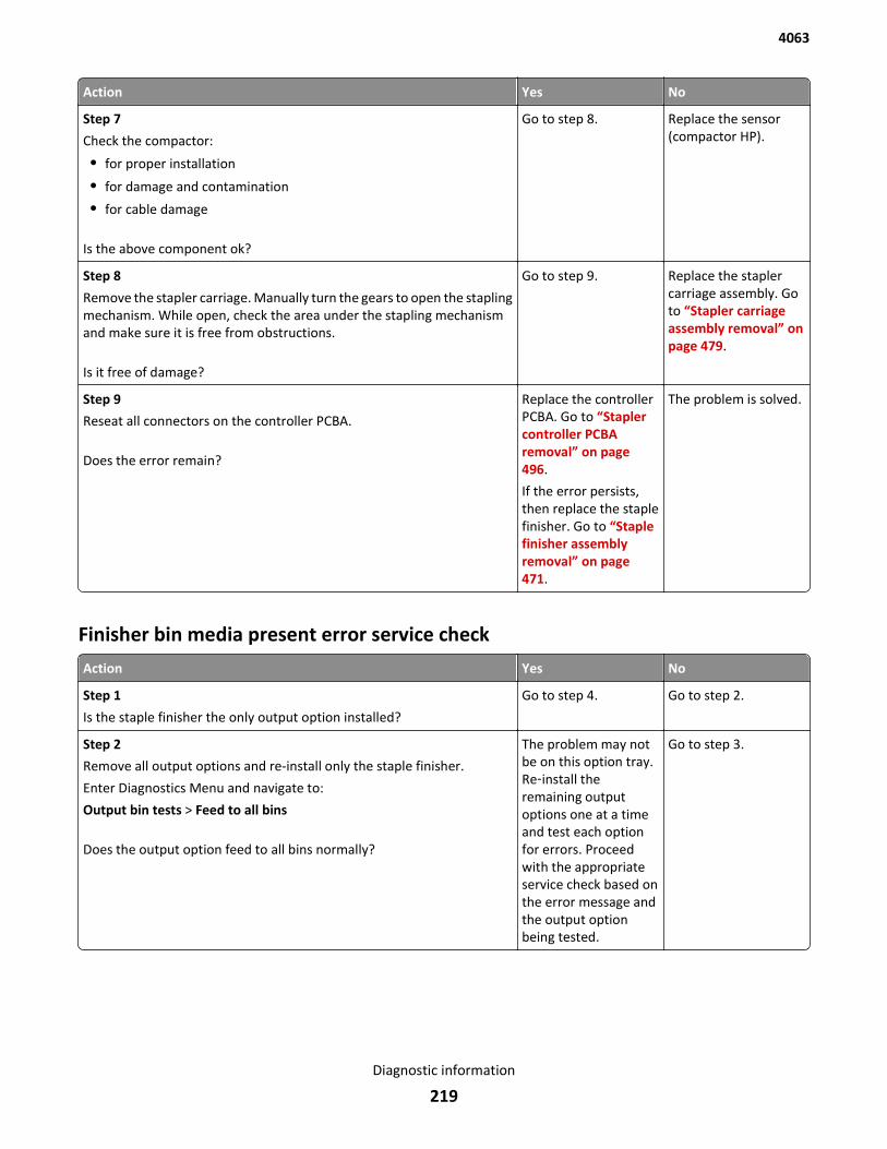
Action Yes No
Step 7
Check the compactor:
• for proper installation
• for damage and contamination
• for cable damage
Is the above component ok?
Go to step 8. Replace the sensor(compactor HP).
Step 8
Remove the stapler carriage. Manually turn the gears to open the staplingmechanism. While open, check the area under the stapling mechanismand make sure it is free from obstructions.
Is it free of damage?
Go to step 9. Replace the staplercarriage assembly. Goto “Stapler carriageassembly removal” onpage 479.
Step 9
Reseat all connectors on the controller PCBA.
Does the error remain?
Replace the controllerPCBA. Go to “Staplercontroller PCBAremoval” on page 496.
If the error persists,then replace the staplefinisher. Go to “Staplefinisher assemblyremoval” on page 471.
The problem is solved.
Finisher bin media present error service check
Action Yes No
Step 1
Is the staple finisher the only output option installed?
Go to step 4. Go to step 2.
Step 2
Remove all output options and re-install only the staple finisher.
Enter Diagnostics Menu and navigate to:
Output bin tests > Feed to all bins
Does the output option feed to all bins normally?
The problem may notbe on this option tray.Re‑install theremaining outputoptions one at a timeand test each optionfor errors. Proceedwith the appropriateservice check based onthe error message andthe output optionbeing tested.
Go to step 3.
4063
Diagnostic information
219
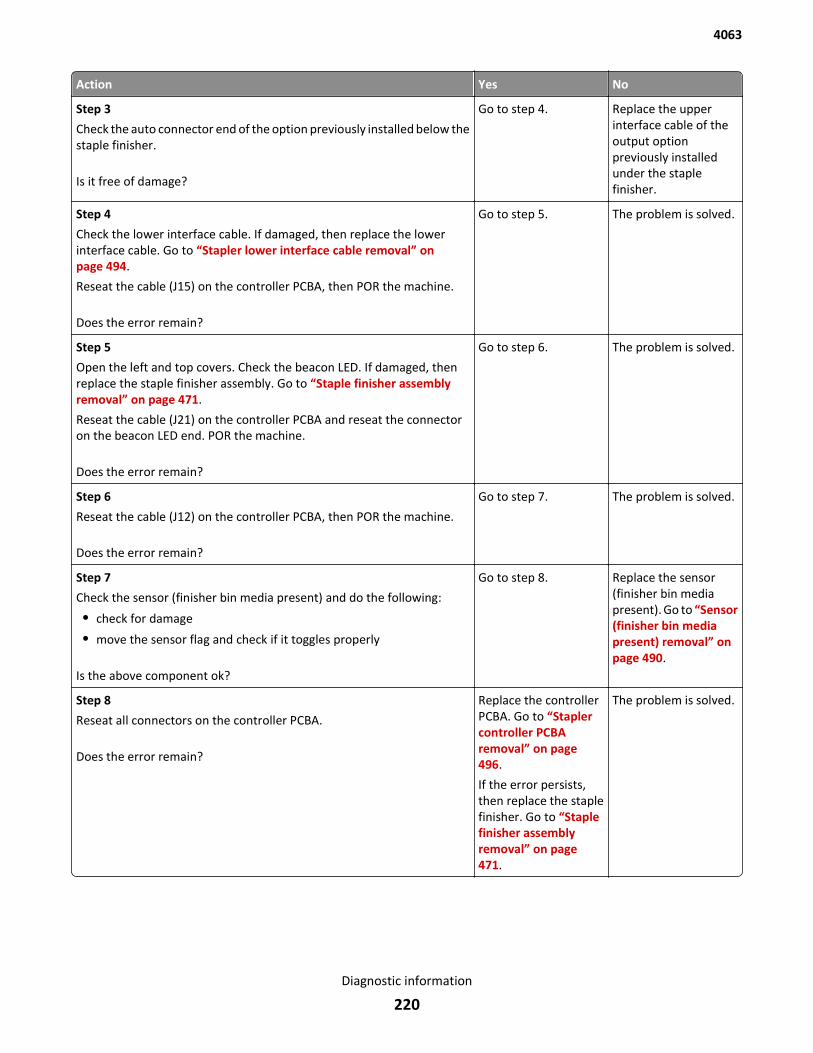
Action Yes No
Step 3
Check the auto connector end of the option previously installed below thestaple finisher.
Is it free of damage?
Go to step 4. Replace the upperinterface cable of theoutput optionpreviously installedunder the staplefinisher.
Step 4
Check the lower interface cable. If damaged, then replace the lowerinterface cable. Go to “Stapler lower interface cable removal” onpage 494.
Reseat the cable (J15) on the controller PCBA, then POR the machine.
Does the error remain?
Go to step 5. The problem is solved.
Step 5
Open the left and top covers. Check the beacon LED. If damaged, thenreplace the staple finisher assembly. Go to “Staple finisher assemblyremoval” on page 471.
Reseat the cable (J21) on the controller PCBA and reseat the connectoron the beacon LED end. POR the machine.
Does the error remain?
Go to step 6. The problem is solved.
Step 6
Reseat the cable (J12) on the controller PCBA, then POR the machine.
Does the error remain?
Go to step 7. The problem is solved.
Step 7
Check the sensor (finisher bin media present) and do the following:
• check for damage
• move the sensor flag and check if it toggles properly
Is the above component ok?
Go to step 8. Replace the sensor(finisher bin mediapresent). Go to “Sensor(finisher bin mediapresent) removal” onpage 490.
Step 8
Reseat all connectors on the controller PCBA.
Does the error remain?
Replace the controllerPCBA. Go to “Staplercontroller PCBAremoval” on page 496.
If the error persists,then replace the staplefinisher. Go to “Staplefinisher assemblyremoval” on page 471.
The problem is solved.
4063
Diagnostic information
220
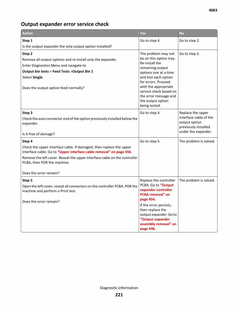
Output expander error service check
Action Yes No
Step 1
Is the output expander the only output option installed?
Go to step 4. Go to step 2.
Step 2
Remove all output options and re-install only the expander.
Enter Diagnostics Menu and navigate to:
Output bin tests > Feed Tests >Output Bin 1
Select Single.
Does the output option feed normally?
The problem may notbe on this option tray.Re‑install theremaining outputoptions one at a timeand test each optionfor errors. Proceedwith the appropriateservice check based onthe error message andthe output optionbeing tested.
Go to step 3.
Step 3
Check the auto connector end of the option previously installed below theexpander.
Is it free of damage?
Go to step 4. Replace the upperinterface cable of theoutput optionpreviously installedunder the expander.
Step 4
Check the upper interface cable. If damaged, then replace the upperinterface cable. Go to “Upper interface cable removal” on page 456.
Remove the left cover. Reseat the upper interface cable on the controllerPCBA, then POR the machine.
Does the error remain?
Go to step 5. The problem is solved.
Step 5
Open the left cover, reseat all connectors on the controller PCBA. POR themachine and perform a Print test.
Does the error remain?
Replace the controllerPCBA. Go to “Outputexpander controllerPCBA removal” onpage 454.
If the error persists,then replace theoutput expander. Go to“Output expanderassembly removal” onpage 446.
The problem is solved.
4063
Diagnostic information
221

4063
222
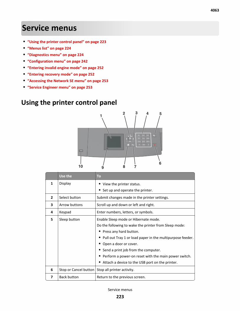
Service menus• “Using the printer control panel” on page 223
• “Menus list” on page 224
• “Diagnostics menu” on page 224
• “Configuration menu” on page 242
• “Entering invalid engine mode” on page 252
• “Entering recovery mode” on page 252
• “Accessing the Network SE menu” on page 253
• “Service Engineer menu” on page 253
Using the printer control panel
Use the To
1 Display • View the printer status.
• Set up and operate the printer.
2 Select button Submit changes made in the printer settings.
3 Arrow buttons Scroll up and down or left and right.
4 Keypad Enter numbers, letters, or symbols.
5 Sleep button Enable Sleep mode or Hibernate mode.
Do the following to wake the printer from Sleep mode:
• Press any hard button.
• Pull out Tray 1 or load paper in the multipurpose feeder.
• Open a door or cover.
• Send a print job from the computer.
• Perform a power‑on reset with the main power switch.
• Attach a device to the USB port on the printer.
6 Stop or Cancel button Stop all printer activity.
7 Back button Return to the previous screen.
4063
Service menus
223
Use the To
8 Home button Go to the home screen.
9 Indicator light Check the status of the printer.
10 USB port Connect a flash drive to the printer.
Note: Only the front USB port supports flash drives.
Menus listPaper Menu Reports Network/Ports
Default Source
Paper Size/Type
Configure MP
Substitute Size
Paper Texture
Paper Weight
Paper Loading
Custom Types
Universal Setup
Bin Setup
Menu Settings Page
Device Statistics
Stapler Test
Network Setup Page 1
Profiles List
Print Fonts
Print Directory
Asset Report
Active NIC
Standard Network 2
Standard USB
Parallel [x]
Serial [x]
SMTP Setup
Security Settings Help
Confidential Print
Disk Wiping
Security Audit Log
Set Date and Time
General Settings
Flash Drive Menu
Print Settings
Print All Guides
Print Quality
Printing Guide
Media Guide
Print Defects Guide
Menu Map
Information Guide
Connection Guide
Moving Guide
Supplies Guide
1 Depending on the printer setup, this menu item appears as Network Setup Page or Network [x] Setup Page.2 Depending on the printer setup, this menu item appears as Standard Network or Network [x].
Diagnostics menu• “Entering diagnostics mode” on page 225
• “REGISTRATION” on page 225
• “PRINT TESTS” on page 226
• “HARDWARE TESTS” on page 226
• “DUPLEX TESTS” on page 229
• “INPUT TRAY TESTS” on page 231
4063
Service menus
224
• “OUTPUT BIN TESTS” on page 232
• “FINISHER TESTS” on page 233
• “BASE SENSOR TEST” on page 235
• “DEVICE TESTS” on page 235
• “PRINTER SETUP” on page 236
• “EP SETUP” on page 238
• “REPORTS” on page 240
• “EVENT LOG” on page 241
• “Exit Diags” on page 242
The Diagnostics menu group contains the settings and operations used while manufacturing and servicing the printer.
Entering diagnostics mode1 Turn off the printer.
2 Press and hold 3 and 6.
3 Turn on the printer.
4 Hold the buttons until the splash screen appears.
5 Select Exit Diags to exit Diagnostics mode and return to the printer home screen.
REGISTRATIONThese settings adjust the margins of the black plane.
To set the Registration:
1 Print a Quick test page.
a From the Diagnostics menu, navigate to:REGISTRATION > Quick Test
b Retain this page to determine the changes you need to make to the margin settings. The alignment diamondsin the margins should touch the margins of the page.
The Quick test page contains the following information:
• Printer registration settings
• Code levels
• Alignment diamonds at the top, bottom, and each side
• Horizontal lines for skew adjustment
• General printer information, including current page count, installed memory, processor speed, serialnumber, engine ID, and controller board ID
2 Change the value of any of the margin settings.
Top Margin -25 to +25 Increasing the value moves the image down the page. Always adjust thetop before the bottom margin.
Bottom Margin -20 to +20 Increasing the value moves the image toward the top of the page.
4063
Service menus
225
Left Margin ‑25 to +25 Increasing the value moves the image toward the right margin. Alwaysadjust the left before the right margin.
Right Margin -15 to +15 Increasing the value moves the image toward the right of the page.
PRINT TESTSThe Print Test determines whether the printer can print on media from any of the paper input sources. Each of theinstalled sources is available within the Print Tests menu.
The content of the test page varies depending on the media in the selected input source:
• If the selected source contains paper, then a page similar to the Quick test page is printed, but without the printregistration diamonds.
• If the selected source contains envelopes, then an envelope print test pattern is printed. This pattern contains onlytext, which consists of continuous prints of each character in the selected symbol set. If Continuous is selected,then the envelope print test pattern is printed on the first envelope; the rest are blank.
The Print Test page always prints single-sided, regardless of the duplex setting or the presence of the duplex option.
To run the Print Test:
1 From the Diagnostics menu, navigate to PRINT TESTS.
2 Select the paper source.
3 Select any of the following:
• Single—Prints a single Print test page (No buttons are active while the Print Test Page is printing.)
• Continuous—Continuously prints the Print test pages until X is pressed
Print Quality Pages (Prt Quality Pgs)
This diagnostic function lets the user run print quality test pages with the toner cartridge lockout function disabled.
The report consists of four pages. The printer always uses media from Tray 1 to print this report. It will not prompt fora change in media regardless of the media type in Tray 1.
Note: This test cannot be canceled after it has begun. If duplex is activated, then the report is printed in duplex.
To print the Print quality pages:
From the Diagnostics menu, navigate to PRINT TESTS > Prt Quality Pgs.
HARDWARE TESTSIf the hardware test fails, replace the failing part.
Panel Test
This test verifies the control panel display function.
To run the Panel test:
1 From the Diagnostics menu, navigate to:
Hardware Tests > Panel Test
2 Press X to exit the test.
4063
Service menus
226
Button Test
This test verifies the control panel button function except for the Sleep button.
To run the test for non‑touchscreen models:
1 From the Diagnostics menu, navigate to:
HARDWARE TESTS > Button Test
2 The panel displays Press and an icon matching one of the control panel buttons. Press the physical button that isrepresented by the icon, and the printer tests the function of that button.
If the test is successful, then the panel displays another icon to test.
If a button fails the test, or if a different button is pressed, then the panel displays Test Failed and returns tothe main section of the HARDWARE TESTS menu. After three seconds of inactivity, the panel automatically returnsto the main section of the HARDWARE TESTS menu.
If all buttons pass the test, then the panel displays PASSED and returns to the main section of the HARDWARETESTS menu.
3 Press X or Back to exit the test.
To run the test for the touchscreen models:
1 From the Diagnostics menu, navigate to:
HARDWARE TESTS > Button Test
2 With no buttons pressed, a pattern matching the control panel buttons is displayed. Press each control panel buttonone at a time, and the panel highlights the represented button in the matching pattern.
3 Release the button, and the highlight disappears.
4 Press X or Back to exit the test.
DRAM Test
This test checks the validity of DRAM, both standard and optional. The test repeatedly writes patterns of data to theDRAM to verify that each bit in the memory can be set and read correctly.
To run the DRAM test:
1 From the Diagnostics menu, navigate to:
Hardware Tests > DRAM Test
2 Testing… appears, followed by Resetting the Printer.
3 After the printer resets, the results of the test appear: DRAM Test [x] P:###### F:######.
• [x]—Represents the size of the installed DRAM.
• P:######—Represents the number of times the memory test has passed and finished successfully, with themaximum pass count being 999,999.
• F:#####—Represents the number of times the memory test has failed and finished with errors, with themaximum fail count being 999,999.
4 After the maximum pass count or fail count is reached, or when all the DRAM has been tested, the test stops andthe final results appear.
4063
Service menus
227

Serial Wrap Test
Use this test to check the operation of the Serial Port Hardware using a wrap plug. Each signal is tested. If the test fails,replace the controller board.
To run the Serial Wrap Test:
1 Disconnect the serial interface cable, and install the wrap plug.
2 From the Diagnostics menu, navigate to HARDWARE TESTS >Serial Wrap Test.
3 Select the appropriate Serial Wrap Test from the list. Values may include Serial Wrap, Serial 1 Wrap, Serial 2Wrap, or Serial 3 Wrap. Each time the test finishes, the screen updates with the result. P and F represent the samenumbers for DRAM. If the test passes, the Pass Count increases by 1. However, if the test fails, one of the followingfailure messages appears for approximately three seconds, and the Fail Count increases by 1:
Receive Status Interrupt Error
Status Error
Receive Data Interrupt Error
Transmit Data Interrupt Error
Transmit Empty Error
Threshold Error
Receive Data Ready Error
Break Interrupt Error
Framing Error
Parity Error
Overrun Error
Data Error
Data 232 Error
Data 422 Error
FIFO Error
DSR Error
DSR PIO Error
DSR Interrupt Error
CTS Error
CTS PIO Error
CTS Interrupt Error
After the maximum count is reached or a failure occurs, the test stops.
4 Press Stop (X) to cancel the test.
USB HS Test Mode
1 From the Diagnostics menu, navigate to:
Hardware Tests > USB HS Test Mode
2 Choose the desired port, and then choose the desired test.
4063
Service menus
228
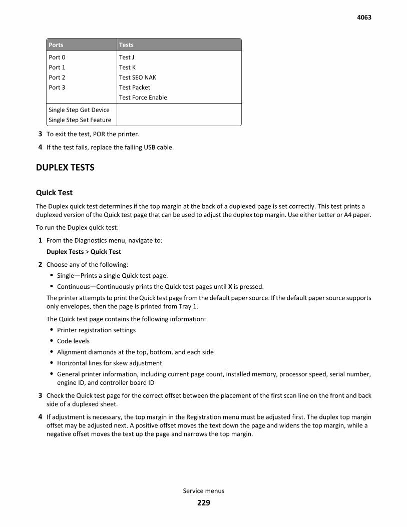
Ports Tests
Port 0
Port 1
Port 2
Port 3
Test J
Test K
Test SEO NAK
Test Packet
Test Force Enable
Single Step Get Device
Single Step Set Feature
3 To exit the test, POR the printer.
4 If the test fails, replace the failing USB cable.
DUPLEX TESTS
Quick Test
The Duplex quick test determines if the top margin at the back of a duplexed page is set correctly. This test prints aduplexed version of the Quick test page that can be used to adjust the duplex top margin. Use either Letter or A4 paper.
To run the Duplex quick test:
1 From the Diagnostics menu, navigate to:
Duplex Tests > Quick Test
2 Choose any of the following:
• Single—Prints a single Quick test page.
• Continuous—Continuously prints the Quick test pages until X is pressed.
The printer attempts to print the Quick test page from the default paper source. If the default paper source supportsonly envelopes, then the page is printed from Tray 1.
The Quick test page contains the following information:
• Printer registration settings
• Code levels
• Alignment diamonds at the top, bottom, and each side
• Horizontal lines for skew adjustment
• General printer information, including current page count, installed memory, processor speed, serial number,engine ID, and controller board ID
3 Check the Quick test page for the correct offset between the placement of the first scan line on the front and backside of a duplexed sheet.
4 If adjustment is necessary, the top margin in the Registration menu must be adjusted first. The duplex top marginoffset may be adjusted next. A positive offset moves the text down the page and widens the top margin, while anegative offset moves the text up the page and narrows the top margin.
4063
Service menus
229

Top Margin
This setting controls the offset between the placement of the first scan line on the front and back side of a duplex sheet.
Note: If adjustment is necessary, the top margin in the Registration menu must be adjusted first. The duplex topmargin may be adjusted next.
To adjust this setting:
1 From the Diagnostics menu, navigate to:
Duplex tests > Top Margin
2 Change the margin values.
Changing the value by 1 unit moves the margin by 1/100 in. A positive value moves the text down the page andwidens the top margin. A negative value moves the text up the page and narrows the top margin.
3 Depending on the printer model, press OK or touch to save the desired margin value.
Sensor Test
Use this test to determine if the duplex sensor and switches are working properly.
To run this test:
1 From the Diagnostics menu, navigate to:
Duplex Tests > Sensor Test
2 Testing… appears while the printer is verifying the state of the sensor.
The control panel displays the current state of the sensor.
3 Manually actuate the sensor to make it toggle between Open and Closed. If the sensor does not toggle, then itis malfunctioning.
4 Press X to exit the test.
Motor Test
Use this test to test the duplex option paper feed drive system and verify that the power and velocity values areacceptable. The duplex runs the DC motor at high speed and low speed, taking an average of the power (PWM) requiredfor each speed and calculating the KE value.
To run this test:
1 From the Diagnostics menu, navigate to:
Duplex Tests > Motor Test
2 When the motor stops and has passed the test, the following message appears:
Motor Test
Test Passed
3 Press X or Back to exit the test.
4063
Service menus
230
Duplex Feed 1
This test feeds a blank sheet of paper from Tray 1 to the duplex paper stop position 1. This test can be run using anyof the supported paper sizes.
To run this test:
1 From the Diagnostics menu, navigate to:
Duplex Tests > Duplex Feed 1
The power indicator blinks while the paper is feeding, and Duplex Feed 1 Feeding… appears. This test cannotbe canceled. The panel displays Duplex Feed 1 Clear Paper when the paper reaches the duplex paperstop position 1.
2 Remove the sheet of paper from the duplex unit, and shut the duplex door.
3 Press X to clear the message.
Duplex Feed 2
This test feeds a blank sheet of paper to the duplex paper stop position 2. This test can be run using any of the supportedpaper sizes.
To run this test:
1 From the Diagnostics menu, navigate to:
Duplex Tests > Duplex Feed 2
The power indicator blinks while the paper is feeding, and Duplex Feed 2 Feeding… appears. This test cannotbe canceled.
The panel displays Duplex Feed 2 Clear Paper when the paper reaches the duplex paper stop position 2.
2 Remove the sheet of paper from the duplex unit, and shut the duplex door.
3 Press X to clear the message.
INPUT TRAY TESTS
Feed Tests
This test feeds blank pages through the paper path. It can run using any of the paper or envelope sizes supported bythe printer.
To run the Feed test:
1 From the Diagnostics menu, navigate to:
Input Tray Tests > Feed Tests
2 Choose the input source. All installed sources appear.
3 Choose any of the following:
• Single—Feeds a single page.
• Continuous—Continuously feeds pages until X is pressed.
4063
Service menus
231
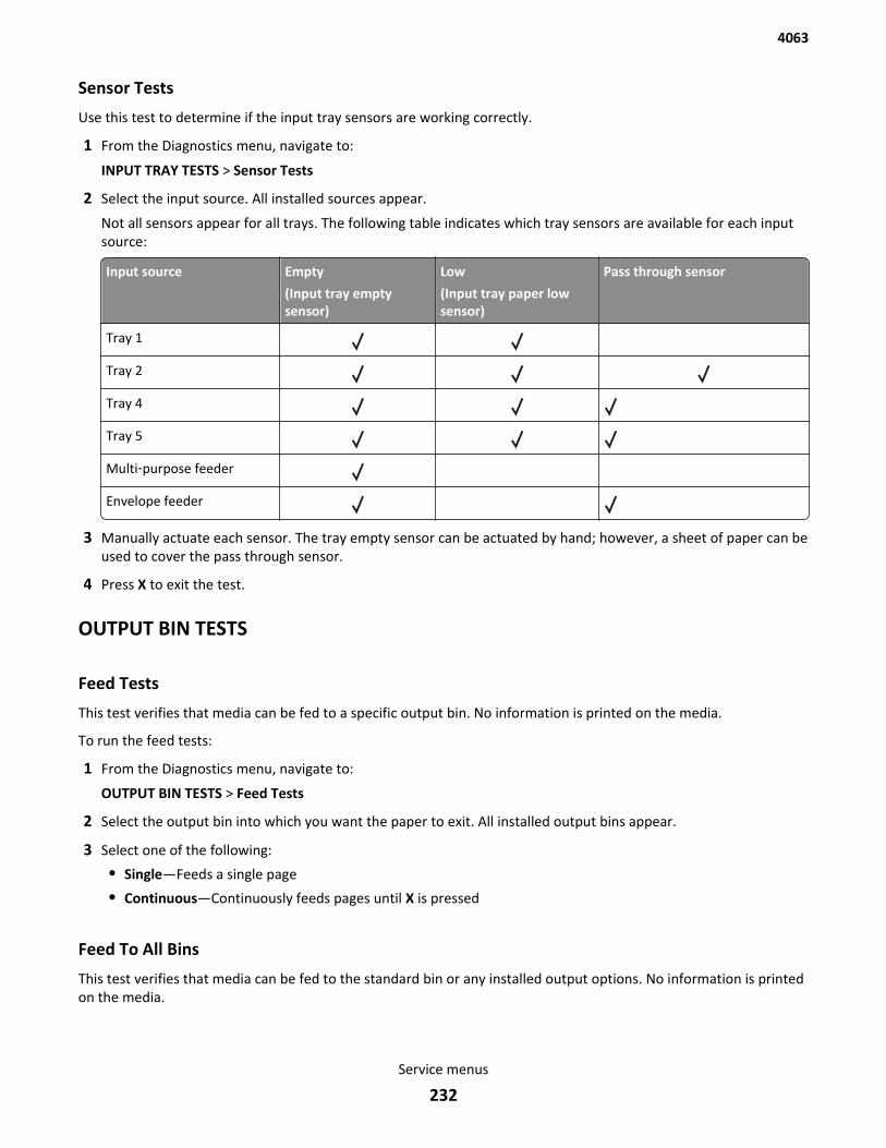
Sensor Tests
Use this test to determine if the input tray sensors are working correctly.
1 From the Diagnostics menu, navigate to:
INPUT TRAY TESTS > Sensor Tests
2 Select the input source. All installed sources appear.
Not all sensors appear for all trays. The following table indicates which tray sensors are available for each inputsource:
Input source Empty
(Input tray emptysensor)
Low
(Input tray paper lowsensor)
Pass through sensor
Tray 1
Tray 2
Tray 4
Tray 5
Multi‑purpose feeder
Envelope feeder
3 Manually actuate each sensor. The tray empty sensor can be actuated by hand; however, a sheet of paper can beused to cover the pass through sensor.
4 Press X to exit the test.
OUTPUT BIN TESTS
Feed Tests
This test verifies that media can be fed to a specific output bin. No information is printed on the media.
To run the feed tests:
1 From the Diagnostics menu, navigate to:
OUTPUT BIN TESTS > Feed Tests
2 Select the output bin into which you want the paper to exit. All installed output bins appear.
3 Select one of the following:
• Single—Feeds a single page
• Continuous—Continuously feeds pages until X is pressed
Feed To All Bins
This test verifies that media can be fed to the standard bin or any installed output options. No information is printedon the media.
4063
Service menus
232
To run the Feed To All Bins test:
1 From the Diagnostics menu, navigate to: OUTPUT BIN TESTS > Feed to All Bins.
The printer feeds a separate piece of media to the standard bin first, then it feeds a separate piece of media to eachoutput bin installed in order.
The test continuously prints the Print test pages until X is pressed.
2 Press Back to return to the OUTPUT BIN TESTS menu.
Sensor Test
This test verifies that the output bin sensors are working correctly.
To run the Output Bin Sensor Test:
1 From the Diagnostics menu, navigate to:
Output Bin Tests > Sensor Test > Standard Bin or Output Bin Tests > Sensor Test > [Output bin #]
Testing... appears while the printer is verifying the state of the sensor.
The control panel displays the current state of the sensor.
2 Manually actuate the sensor to make it toggle between empty and full or between open and closed,depending on the sensor. If the sensor does not toggle, then the sensor is malfunctioning.
3 Press X to exit the test.
Diverter Test
This test verifies that the mailbox option’s output media diverters are working correctly. If more than one mailboxoption is installed, then this test exercises the diverters on all installed mailbox devices.
To run the Diverter Test:
1 From the Diagnostics menu, navigate to:
OUTPUT BIN TESTS > Diverter Test.
Diverter Test Testing... appears while the printer is verifying the state of the diverter.
2 Press X to exit the test.
FINISHER TESTS
Staple Test
This test verifies the operation of the staple mechanism in the finisher. The printer feeds eight pieces of media to thefinisher and accumulates all eight pieces in the finisher. After the last sheets are accumulated, the pack is stapled.
To run this test:
1 From the Diagnostics menu, navigate to:
Finisher Tests > Staple Test
2 Select the output bin, and press .
Staple Test Running... appears while the test is running.
4063
Service menus
233
Hole Punch Test
This test verifies that media can be fed to the finisher output bin and then hole punched. The printer feeds eight piecesof blank media to the finisher and then the pages are hole‑punched with a 2‑hole, 3‑hole, or 4‑hole pattern, dependingon the selected punch test.
To run this test:
1 From the Diagnostics menu, navigate to:
Finisher Tests > Hole Punch Test
2 Select one of the following:
• 2 Punch Test
• 3 Punch Test
• 4 Punch Test
Hole Punch Test Running... appears while the test is running.
Feed Test (finisher)
This test verifies that media can be fed from the default source to a finisher output bin. Any size paper that is supportedcan be used. The printer feeds one blank sheet of media from the default paper source to the finisher output bins.
To run this test:
1 From the Diagnostics menu, navigate to:
Finisher Tests > Feed Test
2 Select the output bin, and press .
Feed Tests Running... appears while the test is running.
Finisher Sensor Test
This test determines if the finisher sensors are working correctly. The sensors that are tested include the following:
• Bin Level
– Finisher Bin Empty
– Bin Full sensor
– Bin Near Full
• Cover and Door
– Side Door sensor
• Pass and Media
– Finisher Passthru
– Media sensor
• Staple Sensors
– Cartridge Presence sensor
– Staple Low sensor
– Self-priming sensor
– Home Signal sensor
4063
Service menus
234
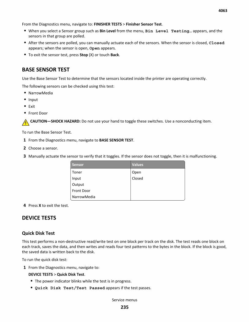
From the Diagnostics menu, navigate to: FINISHER TESTS > Finisher Sensor Test.
• When you select a Sensor group such as Bin Level from the menu, Bin Level Testing… appears, and thesensors in that group are polled.
• After the sensors are polled, you can manually actuate each of the sensors. When the sensor is closed, Closedappears; when the sensor is open, Open appears.
• To exit the sensor test, press Stop (X) or touch Back.
BASE SENSOR TESTUse the Base Sensor Test to determine that the sensors located inside the printer are operating correctly.
The following sensors can be checked using this test:
• NarrowMedia
• Input
• Exit
• Front Door
CAUTION—SHOCK HAZARD: Do not use your hand to toggle these switches. Use a nonconducting item.
To run the Base Sensor Test.
1 From the Diagnostics menu, navigate to BASE SENSOR TEST.
2 Choose a sensor.
3 Manually actuate the sensor to verify that it toggles. If the sensor does not toggle, then it is malfunctioning.
Sensor Values
Toner
Input
Output
Front Door
NarrowMedia
Open
Closed
4 Press X to exit the test.
DEVICE TESTS
Quick Disk Test
This test performs a non-destructive read/write test on one block per track on the disk. The test reads one block oneach track, saves the data, and then writes and reads four test patterns to the bytes in the block. If the block is good,the saved data is written back to the disk.
To run the quick disk test:
1 From the Diagnostics menu, navigate to:
DEVICE TESTS > Quick Disk Test.
• The power indicator blinks while the test is in progress.
• Quick Disk Test/Test Passed appears if the test passes.
4063
Service menus
235
• Quick Disk Test/Test Failed appears if the test fails.
2 Press X to return to the Device Tests menu.
Disk Test/Clean
Warning—Potential Damage: This test destroys all data on the disk and should not be attempted on a good disk.This test may run approximately 1.5 hours, depending on the disk size.
1 From the Diagnostics menu, navigate to:
DEVICE TESTS > Disk Test/Clean
Contents will be lost appears.
2 Do one of the following:
• Touch to continue.
• Press X to cancel.
The test cannot be stopped or canceled after it has begun.
3 After the test is complete, a message appears indicating a pass or fail result.
4 Press X to return to the Device tests menu.
Flash Test
This test verifies the condition of the flash device by writing data to it and then reading data from it.
Warning—Potential Damage: This test destroys all data on the flash device.
Note: After this test is executed, reformat the flash using the Flash Format setting in the Utilities menu.
1 From the Diagnostics menu, navigate to:
Device Tests > Flash Test
Files will be lost. Go/Stop? appears.
2 Do one of the following:
• Depending on the printer model, press OK or touch to continue.
• Press X to cancel.
Note: When the test starts, it cannot be stopped or canceled.
3 After the test is complete, a message appears indicating a pass or fail result.
4 Press X to return to the Device tests menu.
5 Reformat the flash device using the Flash format setting in the Utilities menu.
PRINTER SETUP
Defaults
Warning—Potential Damage: Modification of the printer setting Defaults causes the NVRAM space to be restored tothe printer factory settings.
4063
Service menus
236
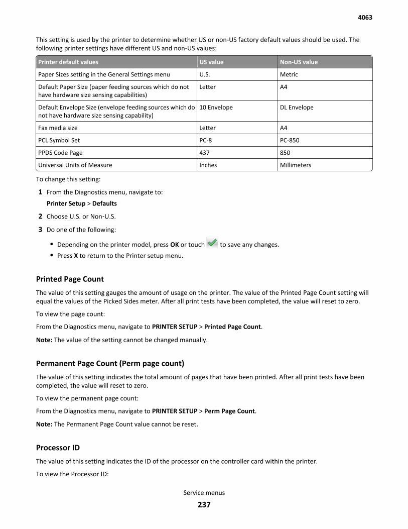
This setting is used by the printer to determine whether US or non-US factory default values should be used. Thefollowing printer settings have different US and non-US values:
Printer default values US value Non-US value
Paper Sizes setting in the General Settings menu U.S. Metric
Default Paper Size (paper feeding sources which do nothave hardware size sensing capabilities)
Letter A4
Default Envelope Size (envelope feeding sources which donot have hardware size sensing capability)
10 Envelope DL Envelope
Fax media size Letter A4
PCL Symbol Set PC-8 PC-850
PPDS Code Page 437 850
Universal Units of Measure Inches Millimeters
To change this setting:
1 From the Diagnostics menu, navigate to:
Printer Setup > Defaults
2 Choose U.S. or Non‑U.S.
3 Do one of the following:
• Depending on the printer model, press OK or touch to save any changes.
• Press X to return to the Printer setup menu.
Printed Page Count
The value of this setting gauges the amount of usage on the printer. The value of the Printed Page Count setting willequal the values of the Picked Sides meter. After all print tests have been completed, the value will reset to zero.
To view the page count:
From the Diagnostics menu, navigate to PRINTER SETUP > Printed Page Count.
Note: The value of the setting cannot be changed manually.
Permanent Page Count (Perm page count)
The value of this setting indicates the total amount of pages that have been printed. After all print tests have beencompleted, the value will reset to zero.
To view the permanent page count:
From the Diagnostics menu, navigate to PRINTER SETUP > Perm Page Count.
Note: The Permanent Page Count value cannot be reset.
Processor ID
The value of this setting indicates the ID of the processor on the controller card within the printer.
To view the Processor ID:
4063
Service menus
237

From the Diagnostics menu, navigate to PRINTER SETUP > Processor ID.
Engine Setting [x]
These settings are used by the Engine code to further customize the behavior of the printer to applications. The valueof [x] is any value from 1 to 16.
Edge to Edge
When set to On, this shifts all four margins (top, bottom, left, and right) to the physical edge of the page (printable areaof a supported paper size). This feature does not work in PPDS emulation.
To change this setting:
From the Diagnostics menu, navigate to PRINTER SETUP > Edge to Edge.
Parallel Strobe Adjustment (Par 1 Strobe Adj)
This setting adjusts the factory setting for the amount of time the strobe is sampled to determine that valid data isavailable on the parallel port.
Each time the value is increased by one, the strobe is sampled 50 nanoseconds longer. Each time the value is decreasedby one, the strobe is sampled 50 nanoseconds less than the default value. The range of values is between -4 and +6, inincrements of one. A value of zero indicates no change is made from the factory setting.
To change this setting:
From the Diagnostics menu, navigate to PRINTER SETUP > Par 1 Strobe Adj.
EP SETUP
EP Defaults
This setting restores each printer setting listed in EP SETUP to its factory default value. Sometimes this is used to helpcorrect print quality problems.
To restore the EP defaults:
1 From the Diagnostics menu, navigate to:
EP Setup > EP Defaults
2 Select Restore to restore the default values, or press X to exit without changing the settings.
Fuser Temperature (Fuser Temp)
This setting adjusts the fuser temperature to solve problems with paper curl on low‑grade paper and/or melting ofletterheads on some papers.
To adjust this setting:
1 From the Diagnostics menu, navigate to:
EP Setup > Fuser Temp
2 Press OK or touch to save any changes.
4063
Service menus
238

Fuser Page Count
The value of this setting indicates the total number of pages that have been printed by the fuser in the space belowthe header.
To view the fuser page count:
From the Diagnostics menu, navigate to EP Setup > Fuser Page Count.
Note: The value of the setting cannot be changed manually.
Warm Up Time
This setting controls the amount of time the printer warms up before allowing pages to print. The range of values isbetween 0 and 5, where 0 is no warm‑up time and 5 is up to 90 seconds of warm‑up time.
To change this setting:
From the Diagnostics menu, navigate to EP Setup > Warm Up Time.
Transfer
This setting controls the transfer roll algorithm.
To adjust this setting:
1 From the Diagnostics menu, navigate to:
EP Setup > Transfer
2 Press Back.
Print Contrast
This setting controls the developer voltage offset.
To adjust this setting:
1 From the Diagnostics menu, navigate to:
EP Setup > Print Contrast
2 Press OK or touch to save any changes.
Charge Roll
This setting controls the charge roll voltage.
To adjust this setting:
1 From the Diagnostics menu, navigate to:
EP Setup > Charge Roll
2 Press OK or touch to save any changes.
4063
Service menus
239
Gap Adjust
The setting adjusts the minimum gap between sheets. Increasing this value may reduce curl of some printed mediaand eliminate some output bin stacking problems. However, increasing this value also results in slower overallperformance, measured in pages per minute.
The range of values is 0 to 255, and the default value is 0.
To adjust this setting:
1 From the Diagnostics menu, navigate to:
EP Setup > Gap Adjust
2 Press OK or touch to save any changes.
Automatic Darkness Adjust (Auto Dark Adj)
When activated, this setting attempts to optimize the amount of toner used when printing with a specific operatingpoint.
Each time this setting executes, the printer performs the following:
• Calibrates its toner density sensor
• Measures the reflectivity of its bare drum
• Prints patches on the drum and measures the reflectivity of the drum through the patches
• Cleans the transfer roll
• Calculates reflectivity ratios and operating points to attain the darkness target of each operating point
• Modifies the EP mechanism as necessary to adjust toner darkness
The cartridge smart chip controls how often this process executes.
Note: No messages are displayed on the control panel to give any indication that this test is running. The devicestores the results of its most recent process in the Auto dark Adj field on the Menu settings page report.
When deactivated, the printer disables and never executes this process.
To adjust this setting:
1 From the Diagnostics menu, navigate to:
EP Setup > Auto Dark Adj
2 Choose Enable or Disable.
3 Press OK to save any changes.
REPORTS
Menu Settings Page
This setting prints the Menu Settings Page. The report prints the Diagnostics Menu settings and their current values.
To print the menu settings page:
From the Diagnostics menu, navigate to EP Setup > Gap Adjust.
4063
Service menus
240
Installed Licenses
This setting prints a report that lists the currently installed licenses and the feature data of each license.
To print the menu settings page:
From the Diagnostics menu, navigate to EP Setup > Installed Licenses.
EVENT LOG
Display Log
This version of the Event log displays the panel text that appeared when the event occurred.
To view the Event log:
1 From the Diagnostics menu, navigate to:
Event Log > Display Log
2 Press or to view the entries.
Print Log
Additional diagnostic information is available when the event log is printed. The first page of the report shows thegeneral device information.
The specific events that appear in the report vary depending on the operational history of the printer. Logs may beprinted from the following events:
• Job accounting log failures
• NV reset failures
• NV mirror entries
• 9xx and 1xx (print engine) service error entries
• Programming error entries
• Maintenance count reset entries
• Clear log entries
• Paper jam entries
• Firmware update entries
• JFFS2 partition format entries
• USB setup pkt info entries
• Supply event entries
To print the Event log:
From the Diagnostics menu, navigate to Event Log > Print Log.
Clear Log
Use this to remove all the current information in the Event log. This affects both the viewed log and the printed loginformation.
4063
Service menus
241
To clear the event log:
1 From the Diagnostics menu, navigate to:
Event Log > Clear Log
2 Choose any of the following:
• Yes—To clear the Event log
• No—To exit the Clear log menu
Exit DiagsSelect this option to exit the Diagnostics menu. The printer performs a POR and restarts in normal mode.
This menu appears as a soft button at the bottom right corner of the panel. This is always accessible to the user fromthe main Diagnostics menu.
Configuration menu• “Entering configuration mode” on page 243
• “Roller Kit Counter Value” on page 243
• “Reset Roller Kit Counter” on page 243
• “Print Quality Pages” on page 244
• “Reports” on page 244
• “Size sensing” on page 244
• “Panel Menus” on page 245
• “PPDS Emulation” on page 245
• “Download Emuls” on page 245
• “Safe Mode” on page 245
• “Factory Defaults” on page 246
• “Energy Conserve” on page 246
• “Paper Prompts” on page 246
• “Envelope Prompts” on page 247
• “Action for Prompts” on page 247
• “Jobs on Disk” on page 248
• “Disk Encryption” on page 248
• “Erase All Information on Disk” on page 248
• “Wipe All Settings” on page 249
• “Font Sharpening” on page 249
• “Require Standby” on page 249
• “A5 Loading” on page 249
• “UI Automation” on page 250
• “LES Applications” on page 250
• “Key Repeat Initial Delay” on page 250
4063
Service menus
242

• “Key Repeat Rate” on page 250
• “Wiper Message” on page 251
• “Clear Supply Usage History” on page 251
• “Clear Custom Status” on page 251
• “USB Speed” on page 251
• “Automatically Display Error Screens” on page 252
• “USB PnP” on page 252
The Configuration menu group consists of menus, settings, and operations that are used to configure a printer foroperation.
Entering configuration modeThe Configuration Menu group contains a set of menus, settings, and operations which are infrequently required by auser. Generally, the options made available in this menu group are used to configure a printer for operation.
1 Turn off the printer.
2 Press and hold the 2 and 6 buttons simultaneously.
3 Turn on the printer.
4 Release the buttons after 10 seconds.
Roller Kit Counter ValueWhen this setting is selected, the printer displays the current value for the Roller Kit counter. A print job containing asingle page increments the counter by one and a duplex page by two. When the value has reached the rated life of theRoller Kit, it reminds the customer that scheduled maintenance is required. Reset this counter after an 81 ReplaceRoller Kit message displays and a Roller Kit is installed. See “Reset Roller Kit Counter” on page 243.
To view the maintenance kit count:
1 From the Configuration menu, navigate to Roller Kit Counter Value.
The value is displayed and cannot be changed.
2 Press Back or X to return to the Configuration menu.
Reset Roller Kit CounterAfter scheduled maintenance, the roller count value must be reset to zero.
To reset the maintenance count value to zero:
1 From the Configuration menu, navigate to Reset Roller Kit Counter.
2 Depending on the printer model, press OK or touch to reset the counter, or press X to exit without resettingthe counter.
Once initiated, the reset operation cannot be canceled. When the operation is complete, the menu returns to the mainConfiguration Menu.
4063
Service menus
243
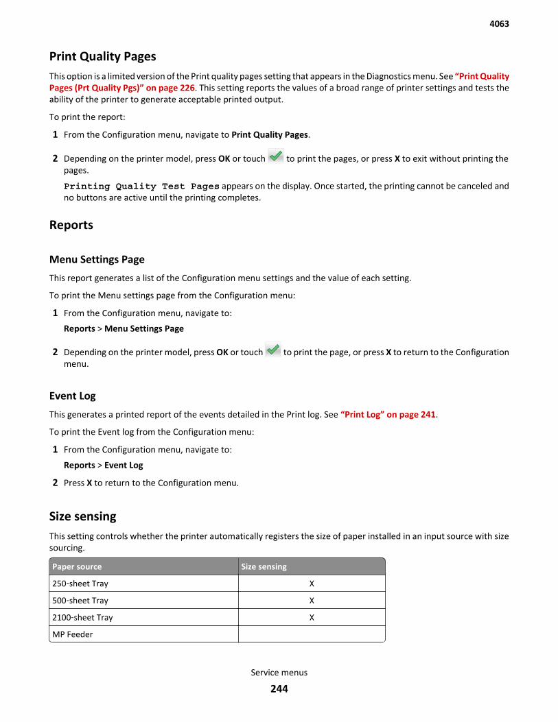
Print Quality PagesThis option is a limited version of the Print quality pages setting that appears in the Diagnostics menu. See “Print QualityPages (Prt Quality Pgs)” on page 226. This setting reports the values of a broad range of printer settings and tests theability of the printer to generate acceptable printed output.
To print the report:
1 From the Configuration menu, navigate to Print Quality Pages.
2 Depending on the printer model, press OK or touch to print the pages, or press X to exit without printing thepages.
Printing Quality Test Pages appears on the display. Once started, the printing cannot be canceled andno buttons are active until the printing completes.
Reports
Menu Settings Page
This report generates a list of the Configuration menu settings and the value of each setting.
To print the Menu settings page from the Configuration menu:
1 From the Configuration menu, navigate to:
Reports > Menu Settings Page
2 Depending on the printer model, press OK or touch to print the page, or press X to return to the Configurationmenu.
Event Log
This generates a printed report of the events detailed in the Print log. See “Print Log” on page 241.
To print the Event log from the Configuration menu:
1 From the Configuration menu, navigate to:
Reports > Event Log
2 Press X to return to the Configuration menu.
Size sensingThis setting controls whether the printer automatically registers the size of paper installed in an input source with sizesourcing.
Paper source Size sensing
250‑sheet Tray X
500‑sheet Tray X
2100‑sheet Tray X
MP Feeder
4063
Service menus
244
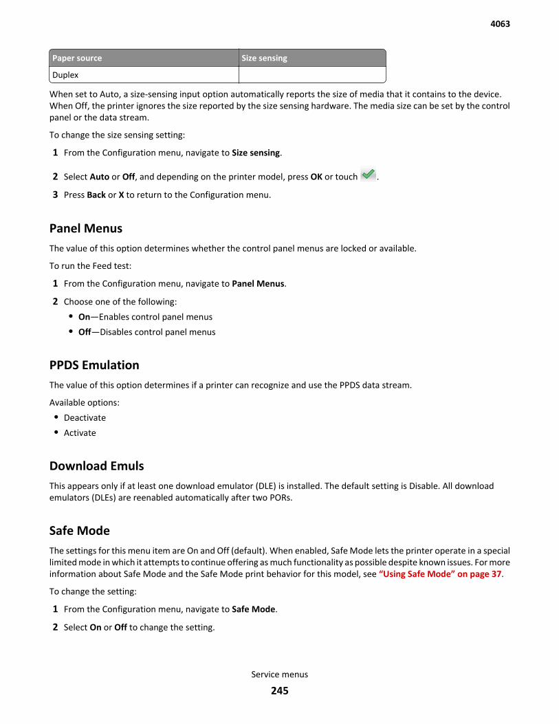
Paper source Size sensing
Duplex
When set to Auto, a size-sensing input option automatically reports the size of media that it contains to the device.When Off, the printer ignores the size reported by the size sensing hardware. The media size can be set by the controlpanel or the data stream.
To change the size sensing setting:
1 From the Configuration menu, navigate to Size sensing.
2 Select Auto or Off, and depending on the printer model, press OK or touch .
3 Press Back or X to return to the Configuration menu.
Panel MenusThe value of this option determines whether the control panel menus are locked or available.
To run the Feed test:
1 From the Configuration menu, navigate to Panel Menus.
2 Choose one of the following:
• On—Enables control panel menus
• Off—Disables control panel menus
PPDS EmulationThe value of this option determines if a printer can recognize and use the PPDS data stream.
Available options:
• Deactivate
• Activate
Download EmulsThis appears only if at least one download emulator (DLE) is installed. The default setting is Disable. All downloademulators (DLEs) are reenabled automatically after two PORs.
Safe ModeThe settings for this menu item are On and Off (default). When enabled, Safe Mode lets the printer operate in a speciallimited mode in which it attempts to continue offering as much functionality as possible despite known issues. For moreinformation about Safe Mode and the Safe Mode print behavior for this model, see “Using Safe Mode” on page 37.
To change the setting:
1 From the Configuration menu, navigate to Safe Mode.
2 Select On or Off to change the setting.
4063
Service menus
245
3 Select Submit.
4 POR the printer.
Factory DefaultsWarning—Potential Damage: This operation cannot be undone.
This setting enables a user to restore all of the printer settings to either the network settings (on network models only)or to the base printer settings.
To restore Factory Default settings:
1 From the Configuration menu, navigate to Factory Defaults.
2 Select from the available options:
• Restore Base—restores all non‑critical base printer NVRAM settings.
• Restore STD Net—restores all network NVRAM settings.
• Restore LES (available on touchscreen model only)—restores the factory default values for all framework,standard applications and eSF configuration by removing all non‑standard applications; and clears the SE logs.
After this setting is changed, the device automatically performs a POR, and restores the appropriate settings to theirfactory default values.
Energy ConserveThis setting controls which values appear on the Power Saver menu.
To change the setting:
1 From the Configuration menu, navigate to Energy Conserve.
2 Select On or Off.
If On (default), then the Sleep Mode cannot be turned off. If Off, then Disabled appears on the Sleep Modemenu, and it can be turned off.
Paper PromptsThis controls which tray a change prompt is directed to when paper is sensed to be the wrong size.
Note: The value of “Action for Prompts” on page 247 may override the value of this setting.
To change this setting:
1 From the Configuration menu, navigate to Paper Prompts.
2 Select from the available options:
• Auto (default)
• Multi‑purpose Feeder
• Manual Paper
3 Depending on the printer model, press OK or touch to save the setting, or press X to return to the Configurationmenu without saving any changes.
4063
Service menus
246
When it is set to Auto, the emulator selected to print the job determines which of the installed input sources will receivethe change prompt. When set to a value other than Auto, the selected source always receives this type of prompt.
Envelope PromptsThis controls which tray a change prompt is directed to when the envelopes are sensed to be the wrong size.
Note: The value of “Action for Prompts” on page 247 may override the value of this setting.
To change this setting:
1 From the Configuration menu, navigate to Envelope Prompts.
2 Select from the available options:
• Auto (default)
• Multi‑purpose Feeder
• Manual Envelope
3 Depending on the printer model, press OK or touch to save the setting, or press X to return to the Configurationmenu without saving any changes.
When it is set to Auto, the emulator selected to print the job determines which of the installed input sources will receivethe change prompt. When set to a value other than Auto, the selected source always receives this type of prompt.
Action for PromptsThis setting enables a user to determine which input source would receive paper-related or envelope-related changeprompts when they occur. Regardless of the target source, the printer always requires some type of user assistance toresolve the change prompt (examples: pushing a button to ignore the prompt and changing the source’s installedmedia). However, this setting gives a user the option of having the printer resolve change prompt situations withoutrequiring any user assistance.
To change this setting:
1 From the Configuration menu, navigate to Action for Prompts.
2 Select from the available options to change the setting.
• Prompt User (default)
• Continue
• Use Current
3 Depending on the printer model, press OK or touch to save the setting, or press X to return to the Configurationmenu without saving any changes.
When set to Prompt user, the printer behaves like the past implementation. When a change prompt occurs, the printerstops printing, posts the change prompt to the target source, and waits for the user to select an action before continuing.
When set to Continue, the printer automatically assumes that the user selects Continue every time a change promptis encountered. Likewise, when the device is set to Use Current, all change prompts will perform as if Use Current wasselected by the user.
4063
Service menus
247
Jobs on DiskThis setting appears only if a hard disk is installed. It allows buffered jobs to be deleted from the disk. This does notaffect Print and Hold or parked jobs.
To change the setting:
1 From the Configuration menu, navigate to Jobs on Disk.
2 Select from the available options to change the setting:
• Delete
• Do Not Delete (default)
3 Press X to return to the Configuration menu.
Disk EncryptionWarning—Potential Damage: If the settings are changed, then the printer completely formats the hard disk. Allinformation on the disk will be unrecoverable.
This setting appears only if a hard disk is installed. It controls whether the printer encrypts the information that it writesto the hard disk.
To change the setting:
1 From the Configuration menu, navigate to Disk Encryption.
2 Select from the available options to change the setting.
• Enable—enables encryption of hard disk.
• Disable (default)—enables formatting of hard disk.
3 Contents will be lost. Continue? appears. Select Yes to proceed with the encryption or formattingof the disk, or No to cancel the operation. If Yes is selected, then a progress bar appears on the display that indicatesthe overall completion of the selected operation. After completion, the display returns to Disk Encryption.
Erase All Information on DiskThis setting performs a wipe of the printer hard disk, erasing all data.
Warning—Potential Damage: This deletes all data on the printer hard disk, including downloaded fonts, macros, andheld jobs. Do not initiate a disk wipe if you have information on the printer that you want to save.
Available options:
• Single Pass Erase—overwrites all data and the file system. This wipe is faster but less secure since it is possible toretrieve the deleted data with forensic data‑retrieval techniques.
• Multi Pass Erase—overwrites all data without rewriting the file system. This wipe is DoD 5220.22-M compliant sincethe deleted data is irretrievable.
Note: If the printer is reset while a disk wipe operation is executing, then Corrupt Disk appears upon regainingpower.
4063
Service menus
248
Wipe All SettingsThis makes any sensitive information that may exist on the volatile or non-volatile storage of the device completelyindecipherable. When selected, the printer performs a non‑critical NVRAM reset and then reboots.
Font SharpeningThis setting allows a user to set a text point-size value below which the high‑frequency screens will be used whenprinting font data.
To change the setting:
1 From the Configuration Menu, navigate to Font Sharpening.
2 To change the value, depending on the model, enter the numerical value or press the arrows, and then pressSubmit.
3 Press Back or X to return to the Configuration menu.
Require StandbyNote: This setting is available on the touch screen models only.
This setting determines whether Standby Mode is On or Off. The default is On.
To change the setting:
1 From the Configuration Menu, navigate to Require Standby.
2 Select On or Off to change the setting.
3 Depending on the printer model, press OK or touch to save the setting, or press X to return to the ConfigurationMenu without saving any changes.
If Standby Mode is On, the printer begins functioning in Standby Mode when it remains idle for an amount of time.
The Standby Mode enables the printer:
• To consume less energy than when operating in normal mode but not as little as when operating in Power Saver.
• To return to the Ready state more quickly than when operating in Power Saver. If set to Off, this setting disablesStandby Mode in the General Settings Menu.
A5 LoadingThis determines the orientation used when printing on A5 paper.
Available options:
• Long Edge—The printer will print A5-size paper in the long-edge feed orientation from all trays.
• Short Edge—The printer will print A5-size paper in the short-edge feed orientation from all trays.
4063
Service menus
249
UI AutomationWhen enabled, this setting creates an ENABLE_UI_AUTOMATION file in the /var/fs/shared/ directory. As long as thisfile exists, the printer permits external developers to test the stability of their applications against the printer to makesure that their applications have an appropriate level of stability. Disabling this setting deletes the file and prohibitsautomated testing.
To change the setting:
1 From the Configuration Menu, navigate to UI Automation.
2 Select from the available options to change the setting.
• Enable
• Disable (default)
3 Depending on the printer model, press OK or touch to save the setting, or press X to return to the ConfigurationMenu without saving any changes.
LES ApplicationsThis setting enables or disables all installed Lexmark Embedded Solution applications.
To change this setting:
1 From the Configuration Menu, navigate to LES Applications.
2 Select from the available options to change the setting.
• Enable (Default)
• Disable
3 Depending on the printer model, press OK or touch Back to save the setting, or press X to return to the ConfigurationMenu without saving any changes.
Key Repeat Initial DelayNote: This setting is available on the touch screen model only.
This setting determines the length of delay before a repeating key starts repeating. The range is 0.25–5 seconds, withincrements of 0.25. The default setting is one second.
To adjust this setting:
1 From the Configuration Menu, navigate to Key Repeat Initial Delay.
2 Touch the arrow keys to adjust the setting.
3 Touch to save the setting, or press X to return to the Configuration Menu without saving any changes.
Key Repeat RateNote: This setting is available on the touch screen model only.
This setting indicates the number of presses per second for repeating keys. The range is 0.5–100, with increments of0.5. The default setting is 15 presses per second.
4063
Service menus
250

To adjust this setting:
1 From the Configuration Menu, navigate to Key Repeat Rate.
2 Touch the arrow keys to adjust the setting.
3 Touch to save the setting, or press X to return to the Configuration Menu without saving any changes.
Wiper MessageThis setting determines whether the printer posts the Replace Wiper message.
To change the setting:
1 From the Configuration Menu, navigate to Wiper Message.
2 Select On or Off to change the setting.
3 Depending on the printer model, press OK or touch to save the setting, or press X to return to the ConfigurationMenu without saving any changes.
Clear Supply Usage HistoryThis setting reverts the supply usage history (number of pages and days remaining) to the factory shipped level.
To clear the supply usage history:
1 From the Configuration menu, navigate to Clear Supply Usage History.
2 Depending on the printer model, press OK or touch Clear Supply Usage History to proceed.
Clear Custom StatusExecuting this operation erases any strings that have been defined by the user for the default or alternate custommessages.
To clear the custom status:
1 From the Configuration menu, navigate to Clear Custom Status.
2 Depending on the printer model, press OK or touch Clear Custom Status to proceed.
USB SpeedThis setting is used to set the throughput of the USB port on the printer.
Available options:
• Auto
• Full—Forces the USB port to run at full speed and also disables its high‑speed capabilities.
4063
Service menus
251
Automatically Display Error ScreensIf On, the panel automatically displays any existing printer-related message after the printer remains inactive on thehome screen for a length of time equal to the Screen Timeout setting in the Timeouts section of the General SettingsMenu. Any message that appears on the display gives the option of returning to the home screen without clearing it.From the home screen, any other workflow or feature can be initiated as usual. When the printer returns to the homescreen, any existing message will again appear after the printer remains inactive for a length of time equal to the ScreenTimeout setting.
To change this setting:
1 From the Configuration Menu, navigate to Automatically Display Error Screens.
2 Select from the available options:
• On (default)
• Off
3 Depending on the printer model, press OK or touch to save the setting, or press X to return to the ConfigurationMenu without saving any changes.
USB PnPIn some cases, the USB port at the back of the printer may be incompatible with the chipset in a user’s PC. This settinglets the user change the USB driver mode to improve its compatibility with these PCs.
Available options:
• 1
• 2
Entering invalid engine modeThis mode is used if the machine has invalid code and needs the correct code loaded. After entering this mode, thefirmware code can be updated.
1 Turn off the printer.
2 Press and hold the 3, 4, and 6 buttons simultaneously.
3 Turn on the printer.
4 Release the buttons after 10 seconds.
Entering recovery modeThis mode will allow the printer to boot from a secondary set of instructions to allow a code flash to the printer. Codecan be flashed from a PC by USB.
1 Turn off the printer.
2 Press and hold the 7, 2, and 8 buttons simultaneously.
3 Turn on the printer.
4 Release the buttons after 10 seconds.
4063
Service menus
252
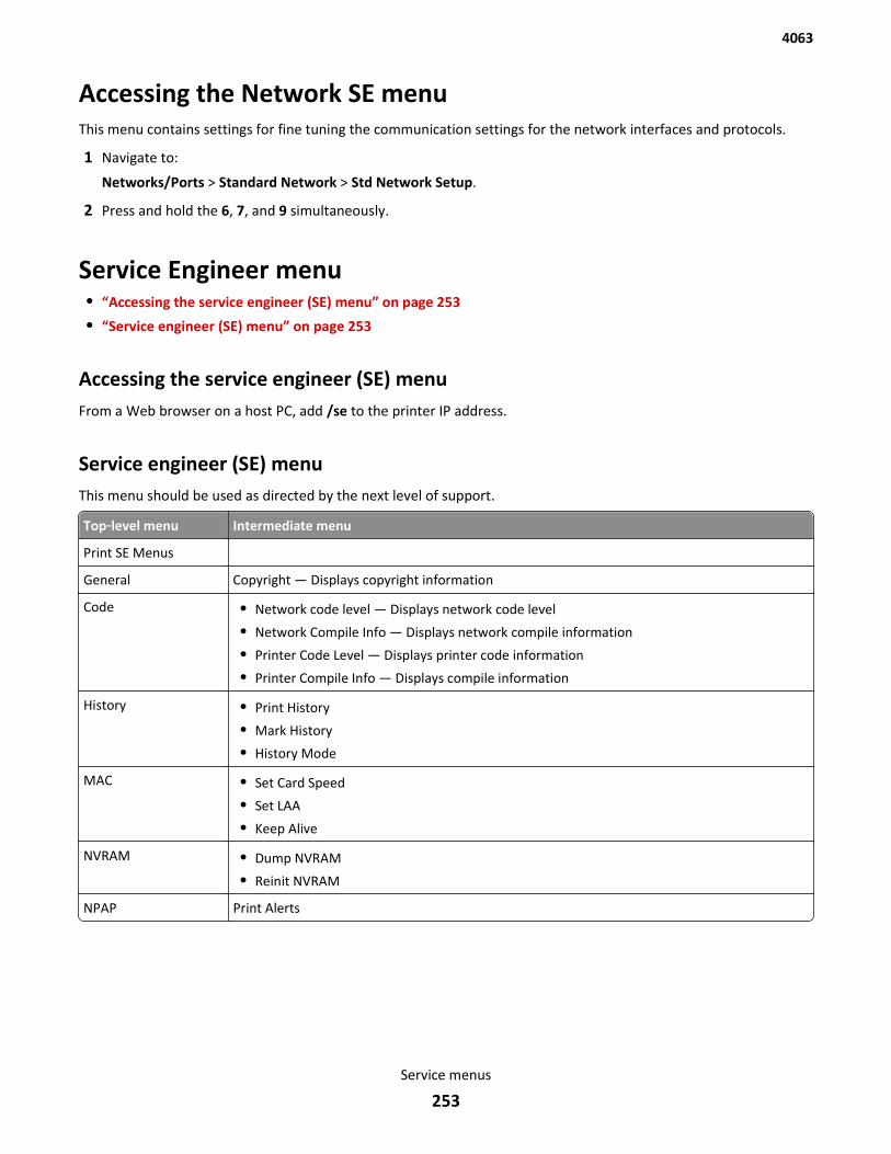
Accessing the Network SE menuThis menu contains settings for fine tuning the communication settings for the network interfaces and protocols.
1 Navigate to:
Networks/Ports > Standard Network > Std Network Setup.
2 Press and hold the 6, 7, and 9 simultaneously.
Service Engineer menu• “Accessing the service engineer (SE) menu” on page 253
• “Service engineer (SE) menu” on page 253
Accessing the service engineer (SE) menuFrom a Web browser on a host PC, add /se to the printer IP address.
Service engineer (SE) menuThis menu should be used as directed by the next level of support.
Top‑level menu Intermediate menu
Print SE Menus
General Copyright — Displays copyright information
Code • Network code level — Displays network code level
• Network Compile Info — Displays network compile information
• Printer Code Level — Displays printer code information
• Printer Compile Info — Displays compile information
History • Print History
• Mark History
• History Mode
MAC • Set Card Speed
• Set LAA
• Keep Alive
NVRAM • Dump NVRAM
• Reinit NVRAM
NPAP Print Alerts
4063
Service menus
253

Top‑level menu Intermediate menu
TCP/IP • netstat‑r• arp‑a• Allow SNMP Set
• MTU
• Meditech Mode
• RAW LPR Mode
• Gather Debug
• Enable Debug
4063
Service menus
254
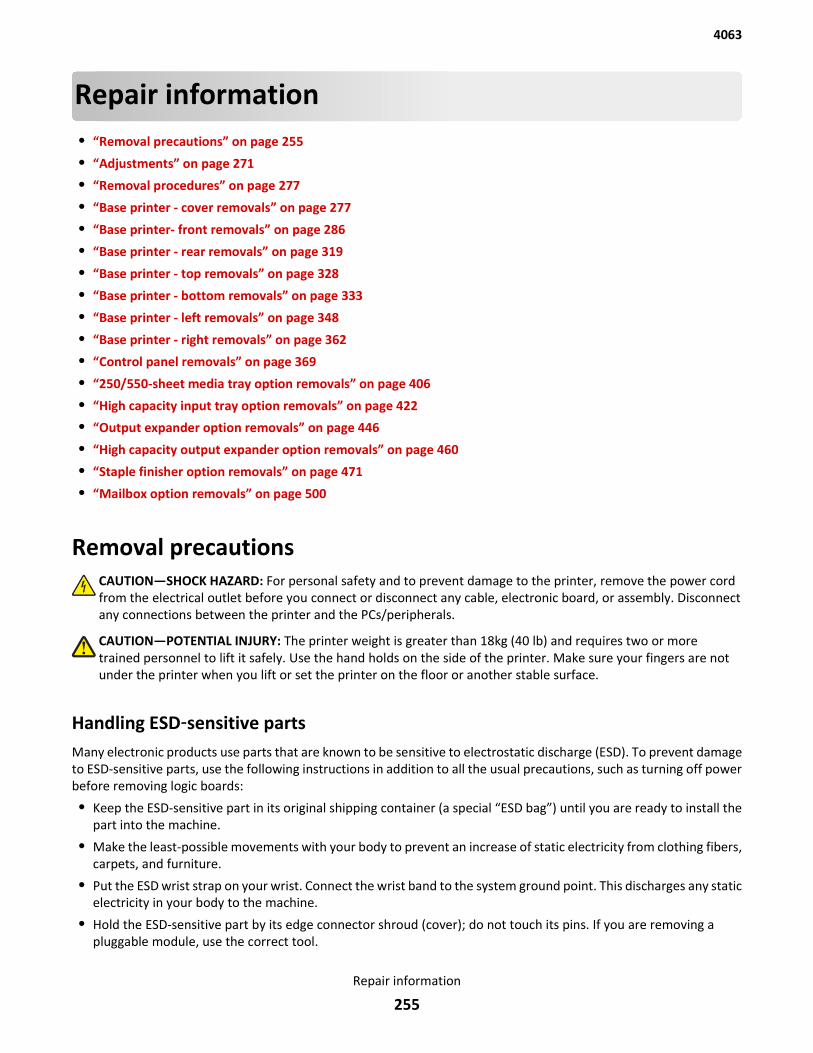
Repair information• “Removal precautions” on page 255
• “Adjustments” on page 271
• “Removal procedures” on page 277
• “Base printer - cover removals” on page 277
• “Base printer- front removals” on page 286
• “Base printer - rear removals” on page 319
• “Base printer - top removals” on page 328
• “Base printer - bottom removals” on page 333
• “Base printer - left removals” on page 348
• “Base printer - right removals” on page 362
• “Control panel removals” on page 369
• “250/550-sheet media tray option removals” on page 406
• “High capacity input tray option removals” on page 422
• “Output expander option removals” on page 446
• “High capacity output expander option removals” on page 460
• “Staple finisher option removals” on page 471
• “Mailbox option removals” on page 500
Removal precautionsCAUTION—SHOCK HAZARD: For personal safety and to prevent damage to the printer, remove the power cordfrom the electrical outlet before you connect or disconnect any cable, electronic board, or assembly. Disconnectany connections between the printer and the PCs/peripherals.
CAUTION—POTENTIAL INJURY: The printer weight is greater than 18kg (40 lb) and requires two or moretrained personnel to lift it safely. Use the hand holds on the side of the printer. Make sure your fingers are notunder the printer when you lift or set the printer on the floor or another stable surface.
Handling ESD‑sensitive partsMany electronic products use parts that are known to be sensitive to electrostatic discharge (ESD). To prevent damageto ESD-sensitive parts, use the following instructions in addition to all the usual precautions, such as turning off powerbefore removing logic boards:
• Keep the ESD-sensitive part in its original shipping container (a special “ESD bag”) until you are ready to install thepart into the machine.
• Make the least-possible movements with your body to prevent an increase of static electricity from clothing fibers,carpets, and furniture.
• Put the ESD wrist strap on your wrist. Connect the wrist band to the system ground point. This discharges any staticelectricity in your body to the machine.
• Hold the ESD-sensitive part by its edge connector shroud (cover); do not touch its pins. If you are removing apluggable module, use the correct tool.
4063
Repair information
255
• Do not place the ESD-sensitive part on the machine cover or on a metal table; if you need to put down the ESD-sensitive part for any reason, first put it into its special bag.
• Machine covers and metal tables are electrical grounds. They increase the risk of damage, because they make adischarge path from your body through the ESD-sensitive part. (Large metal objects can be discharge paths withoutbeing grounded.)
• Prevent ESD-sensitive parts from being accidentally touched by other personnel. Install machine covers when youare not working on the machine, and do not put unprotected ESD-sensitive parts on a table.
• If possible, keep all ESD-sensitive parts in a grounded metal cabinet (case).
• Be extra careful while working with ESD-sensitive parts when cold-weather heating is used, because low humidityincreases static electricity.
Controller board/control panel replacementThis procedure should be followed only if both the controller board and the operator panel fail. If you need to replaceonly one of the FRUs, follow the startup procedure described in the FRU’s removal procedure.
CAUTION—POTENTIAL INJURY
The lithium battery in this product is not intended to be replaced. There is a danger of explosion if a lithiumbattery is incorrectly replaced. Do not recharge, disassemble, or incinerate a lithium battery. Discard usedlithium batteries according to the manufacturer's instructions and local regulations.
Warning—Potential Damage: If the operator panel and the controller board are being replaced at the same time,replace the parts in this order to avoid damage to the machine.
1 Replace the controller board first.
Note: Do not replace the new operator panel and controller board in the machine at the same time.
2 After installing the new controller board, and before installing the new operator panel, start the printer intodiagnostics mode.
3 After the printer has completed startup, turn off the printer and replace the operator panel.
Note: If the operator panel display has failed, the printers’ startup cycle is complete when the driver motor andfans shut down, and the machine is quiet.
4 After installing the new operator panel, start the printer into diagnostics mode, and allow the printer to go througha complete startup cycle and the display to go to Ready.
5 If the problems persist, leave the new operator panel in the machine, place the old controller board back in themachine, and start it up. After the machine startup, shut down the machine, and install the new controller board.After installing the new controller board, restart the machine, and let it go through the startup cycle.
After this procedure is completed successfully, there is no need to adjust any settings.
If the above procedure fails, you must contact the technical support center for further instructions.
eSF solutions backupIf a technician needs to replace the RIP board, the steps below should be taken to backup the eSF solutions and settings:
1 POR the printer into invalid engine code mode.
2 Open a Web browser, and navigate to the printer Web page.
3 Navigate to Settings, and click the link.
4063
Repair information
256
4 Navigate to Solutions, and click the link.
5 Navigate to Embedded Solutions, and click the link.
6 On the Embedded Solutions page, select the apps to be exported by clicking the selection box next to the app.
7 Choose Export.
If the Web page cannot be accessed, or an error persists despite trying to boot in Invalid Engine code mode, then thereis no way to back up the eSF apps. The technician needs to make the customer aware that the applications and theirsettings could not be saved.
There is a size limit on the export file - 128kb. Because of this, it is recommended that you don't use the “global” backupfound in Settings > Import/Export > Export Shortcuts File, Export Settings File, Export Embedded Solutions SettingsFile and Export Security Setups File. Customers with a large number of applications or settings may exceed the file sizelimit and have information truncated in the exported file.
Ribbon cable connectors
Zero Insertion Force (ZIF) connectors
Zero Insertion Force (ZIF) connectors are used on the boards and cards used in this printer. Before inserting or removinga cable from these connectors, read this entire section. Great care must be taken to avoid damaging the connector orcable when inserting or removing the cable.
Warning—Potential Damage: Do not insert the cable so that the contacts are facing the locking actuator. Thecontacts always face away from the actuator.
Warning—Potential Damage: Do not insert the cable diagonally into the ZIF socket. This can cause damage to thecontacts on the cable.
Warning—Potential Damage: Avoid using a fingernail, or sharp object to open the locking mechanism. This coulddamage the cable.
Warning—Potential Damage: Avoid pressing against the cable when opening the locking mechanism. This can alsodamage the cable.
These are the types of ZIF connectors used in this printer:
• Horizontal top contact connector
• Horizontal bottom contact connector
• Vertical mount contact connector
• Horizontal sliding connector
4063
Repair information
257
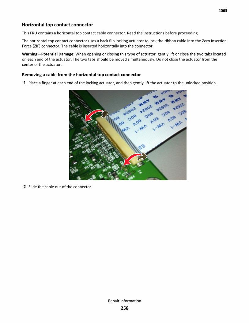
Horizontal top contact connector
This FRU contains a horizontal top contact cable connector. Read the instructions before proceeding.
The horizontal top contact connector uses a back flip locking actuator to lock the ribbon cable into the Zero InsertionForce (ZIF) connector. The cable is inserted horizontally into the connector.
Warning—Potential Damage: When opening or closing this type of actuator, gently lift or close the two tabs locatedon each end of the actuator. The two tabs should be moved simultaneously. Do not close the actuator from thecenter of the actuator.
Removing a cable from the horizontal top contact connector
1 Place a finger at each end of the locking actuator, and then gently lift the actuator to the unlocked position.
2 Slide the cable out of the connector.
4063
Repair information
258
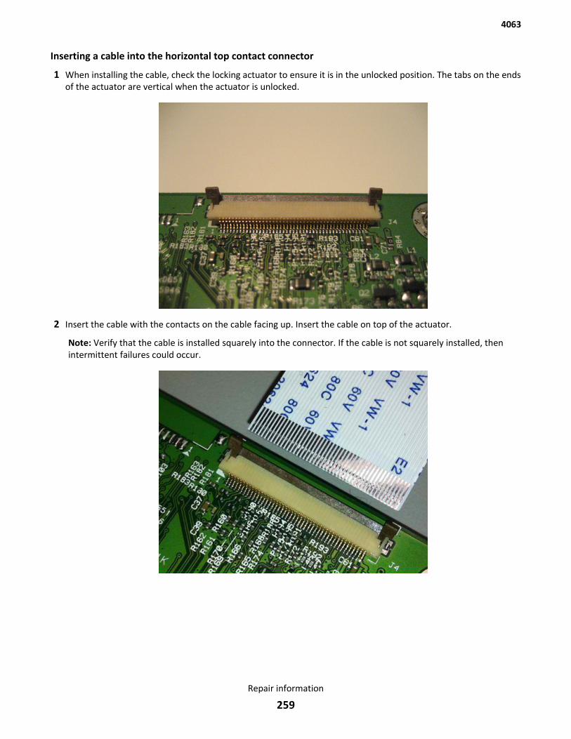
Inserting a cable into the horizontal top contact connector
1 When installing the cable, check the locking actuator to ensure it is in the unlocked position. The tabs on the endsof the actuator are vertical when the actuator is unlocked.
2 Insert the cable with the contacts on the cable facing up. Insert the cable on top of the actuator.
Note: Verify that the cable is installed squarely into the connector. If the cable is not squarely installed, thenintermittent failures could occur.
4063
Repair information
259
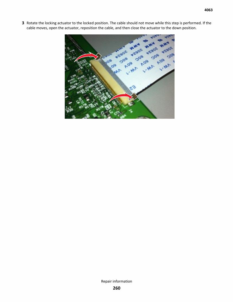
3 Rotate the locking actuator to the locked position. The cable should not move while this step is performed. If thecable moves, open the actuator, reposition the cable, and then close the actuator to the down position.
4063
Repair information
260
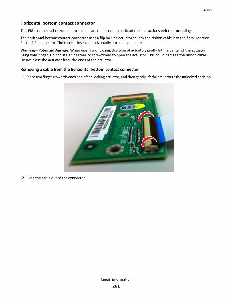
Horizontal bottom contact connector
This FRU contains a horizontal bottom contact cable connector. Read the instructions before proceeding.
The horizontal bottom contact connector uses a flip locking actuator to lock the ribbon cable into the Zero InsertionForce (ZIF) connector. The cable is inserted horizontally into the connector.
Warning—Potential Damage: When opening or closing this type of actuator, gently lift the center of the actuatorusing your finger. Do not use a fingernail or screwdriver to open the actuator. This could damage the ribbon cable.Do not close the actuator from the ends of the actuator.
Removing a cable from the horizontal bottom contact connector
1 Place two fingers towards each end of the locking actuator, and then gently lift the actuator to the unlocked position.
2 Slide the cable out of the connector.
4063
Repair information
261
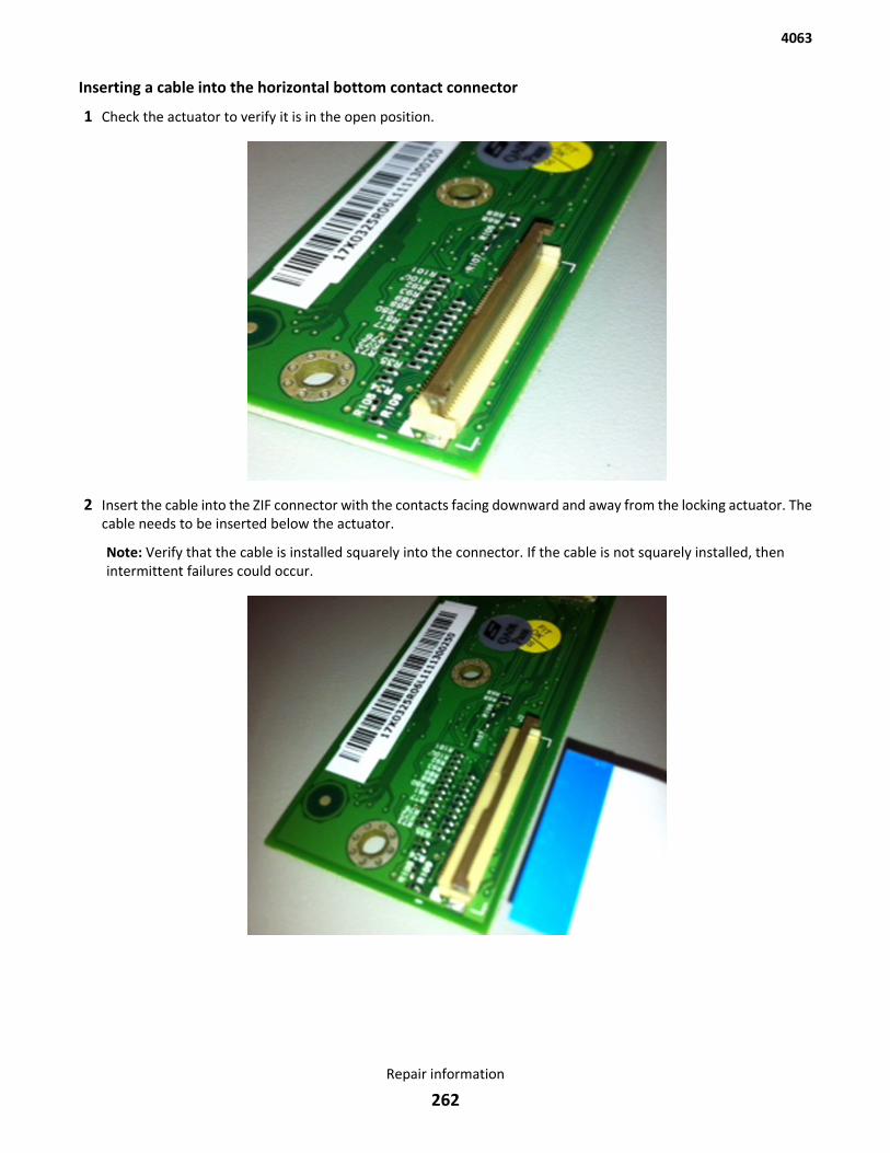
Inserting a cable into the horizontal bottom contact connector
1 Check the actuator to verify it is in the open position.
2 Insert the cable into the ZIF connector with the contacts facing downward and away from the locking actuator. Thecable needs to be inserted below the actuator.
Note: Verify that the cable is installed squarely into the connector. If the cable is not squarely installed, thenintermittent failures could occur.
4063
Repair information
262
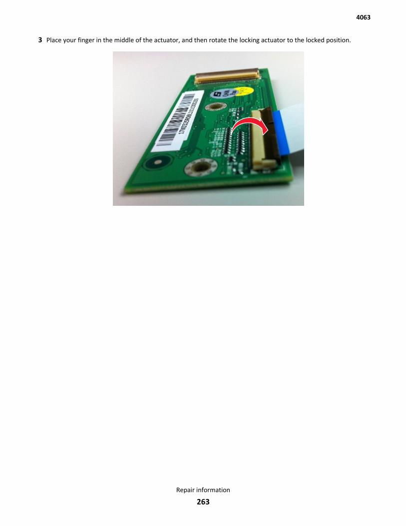
3 Place your finger in the middle of the actuator, and then rotate the locking actuator to the locked position.
4063
Repair information
263
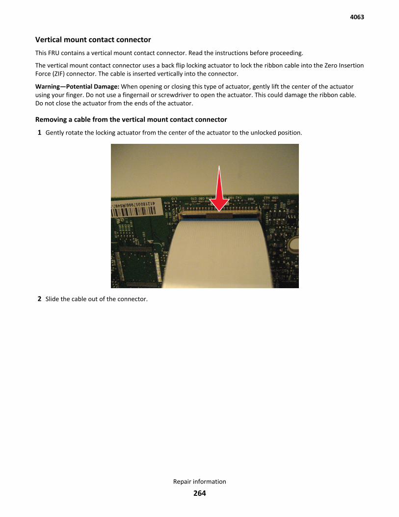
Vertical mount contact connector
This FRU contains a vertical mount contact connector. Read the instructions before proceeding.
The vertical mount contact connector uses a back flip locking actuator to lock the ribbon cable into the Zero InsertionForce (ZIF) connector. The cable is inserted vertically into the connector.
Warning—Potential Damage: When opening or closing this type of actuator, gently lift the center of the actuatorusing your finger. Do not use a fingernail or screwdriver to open the actuator. This could damage the ribbon cable.Do not close the actuator from the ends of the actuator.
Removing a cable from the vertical mount contact connector
1 Gently rotate the locking actuator from the center of the actuator to the unlocked position.
2 Slide the cable out of the connector.
4063
Repair information
264
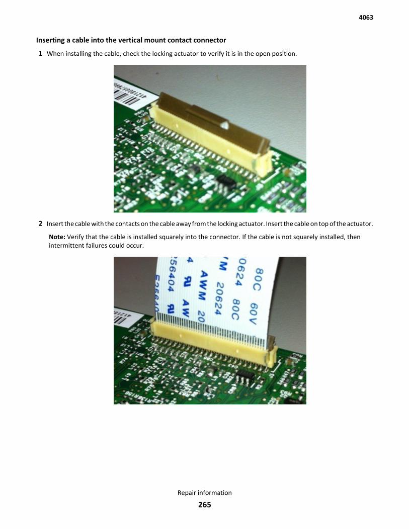
Inserting a cable into the vertical mount contact connector
1 When installing the cable, check the locking actuator to verify it is in the open position.
2 Insert the cable with the contacts on the cable away from the locking actuator. Insert the cable on top of the actuator.
Note: Verify that the cable is installed squarely into the connector. If the cable is not squarely installed, thenintermittent failures could occur.
4063
Repair information
265
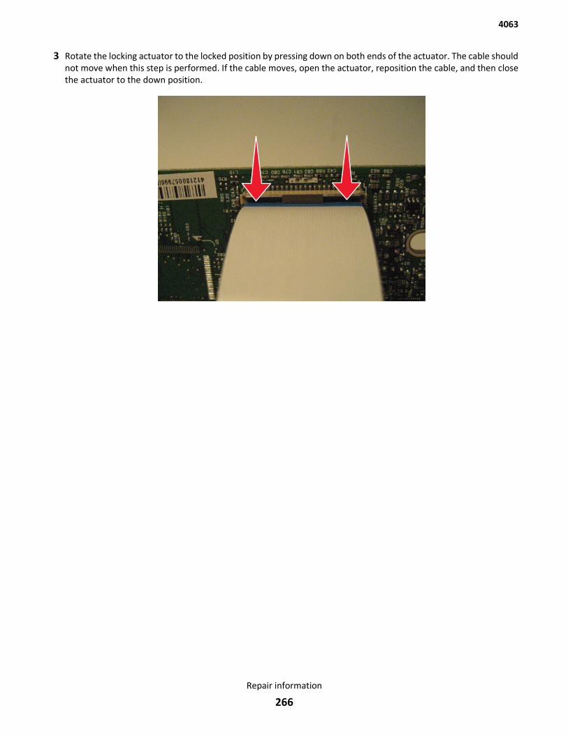
3 Rotate the locking actuator to the locked position by pressing down on both ends of the actuator. The cable shouldnot move when this step is performed. If the cable moves, open the actuator, reposition the cable, and then closethe actuator to the down position.
4063
Repair information
266
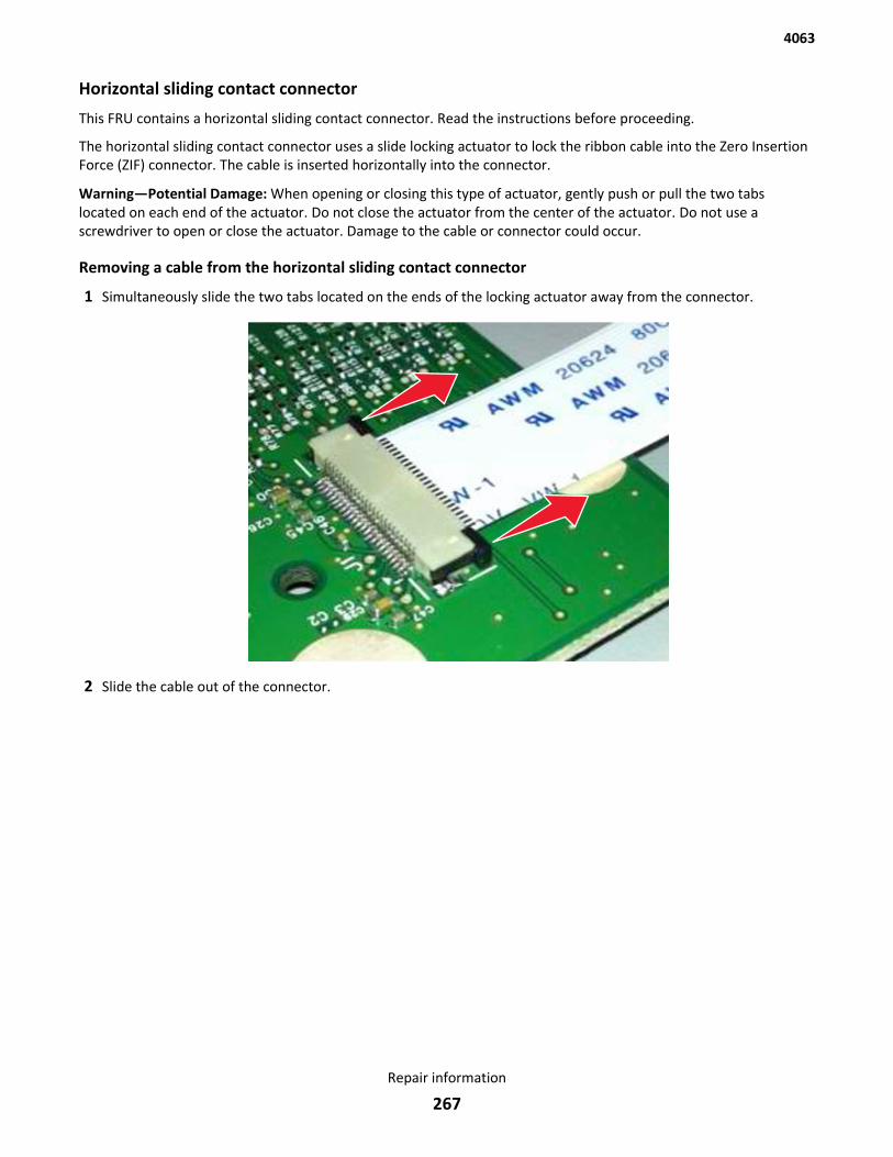
Horizontal sliding contact connector
This FRU contains a horizontal sliding contact connector. Read the instructions before proceeding.
The horizontal sliding contact connector uses a slide locking actuator to lock the ribbon cable into the Zero InsertionForce (ZIF) connector. The cable is inserted horizontally into the connector.
Warning—Potential Damage: When opening or closing this type of actuator, gently push or pull the two tabslocated on each end of the actuator. Do not close the actuator from the center of the actuator. Do not use ascrewdriver to open or close the actuator. Damage to the cable or connector could occur.
Removing a cable from the horizontal sliding contact connector
1 Simultaneously slide the two tabs located on the ends of the locking actuator away from the connector.
2 Slide the cable out of the connector.
4063
Repair information
267
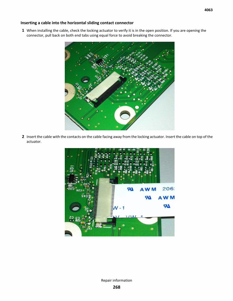
Inserting a cable into the horizontal sliding contact connector
1 When installing the cable, check the locking actuator to verify it is in the open position. If you are opening theconnector, pull back on both end tabs using equal force to avoid breaking the connector.
2 Insert the cable with the contacts on the cable facing away from the locking actuator. Insert the cable on top of theactuator.
4063
Repair information
268
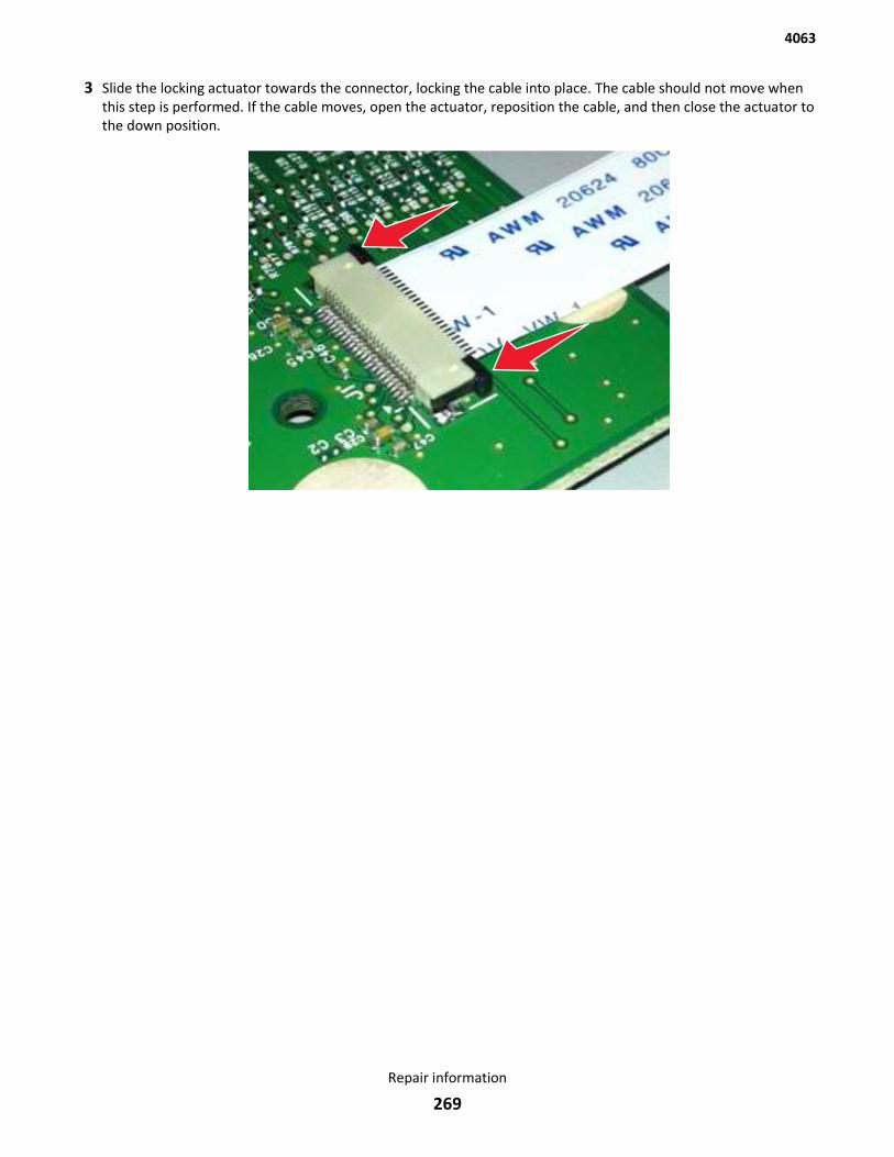
3 Slide the locking actuator towards the connector, locking the cable into place. The cable should not move whenthis step is performed. If the cable moves, open the actuator, reposition the cable, and then close the actuator tothe down position.
4063
Repair information
269
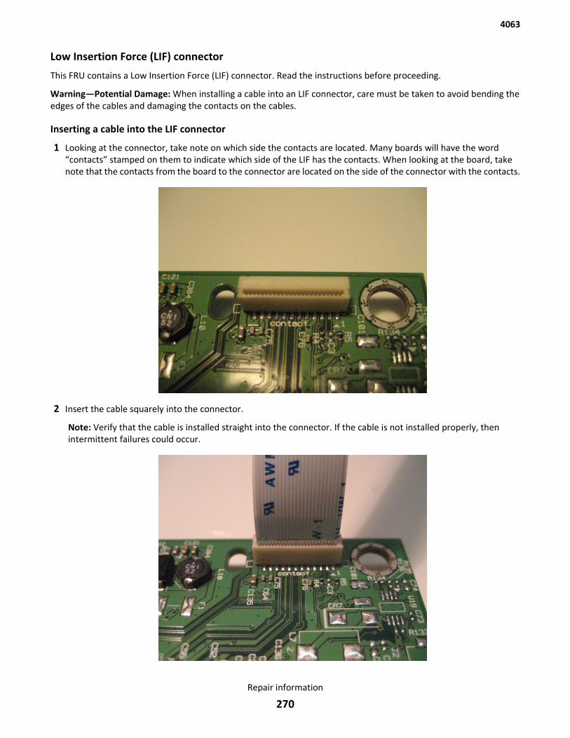
Low Insertion Force (LIF) connector
This FRU contains a Low Insertion Force (LIF) connector. Read the instructions before proceeding.
Warning—Potential Damage: When installing a cable into an LIF connector, care must be taken to avoid bending theedges of the cables and damaging the contacts on the cables.
Inserting a cable into the LIF connector
1 Looking at the connector, take note on which side the contacts are located. Many boards will have the word“contacts” stamped on them to indicate which side of the LIF has the contacts. When looking at the board, takenote that the contacts from the board to the connector are located on the side of the connector with the contacts.
2 Insert the cable squarely into the connector.
Note: Verify that the cable is installed straight into the connector. If the cable is not installed properly, thenintermittent failures could occur.
4063
Repair information
270

Adjustments• “Media aligner roller adjustment” on page 272
• “Polygon printhead mechanical registration adjustment” on page 274
4063
Repair information
271
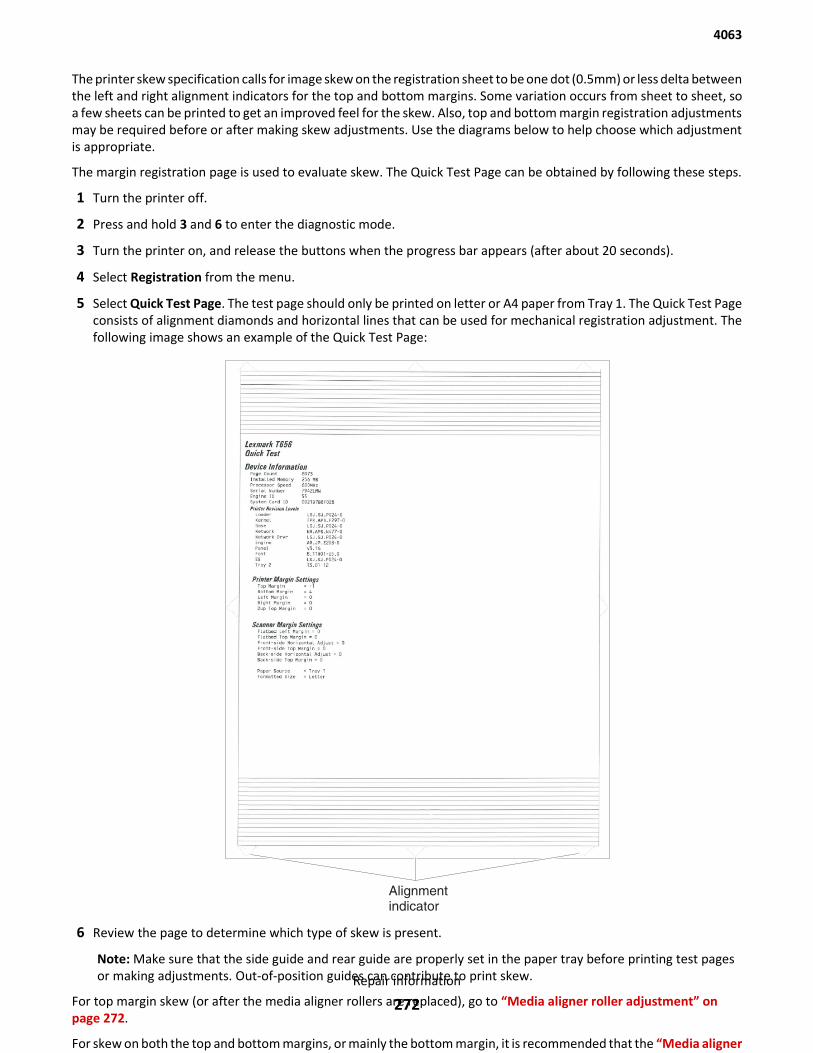
The printer skew specification calls for image skew on the registration sheet to be one dot (0.5mm) or less delta betweenthe left and right alignment indicators for the top and bottom margins. Some variation occurs from sheet to sheet, soa few sheets can be printed to get an improved feel for the skew. Also, top and bottom margin registration adjustmentsmay be required before or after making skew adjustments. Use the diagrams below to help choose which adjustmentis appropriate.
The margin registration page is used to evaluate skew. The Quick Test Page can be obtained by following these steps.
1 Turn the printer off.
2 Press and hold 3 and 6 to enter the diagnostic mode.
3 Turn the printer on, and release the buttons when the progress bar appears (after about 20 seconds).
4 Select Registration from the menu.
5 Select Quick Test Page. The test page should only be printed on letter or A4 paper from Tray 1. The Quick Test Pageconsists of alignment diamonds and horizontal lines that can be used for mechanical registration adjustment. Thefollowing image shows an example of the Quick Test Page:
6 Review the page to determine which type of skew is present.
Note: Make sure that the side guide and rear guide are properly set in the paper tray before printing test pagesor making adjustments. Out-of-position guides can contribute to print skew.
For top margin skew (or after the media aligner rollers are replaced), go to “Media aligner roller adjustment” onpage 272.
For skew on both the top and bottom margins, or mainly the bottom margin, it is recommended that the “Media aligner
4063
Repair information
272
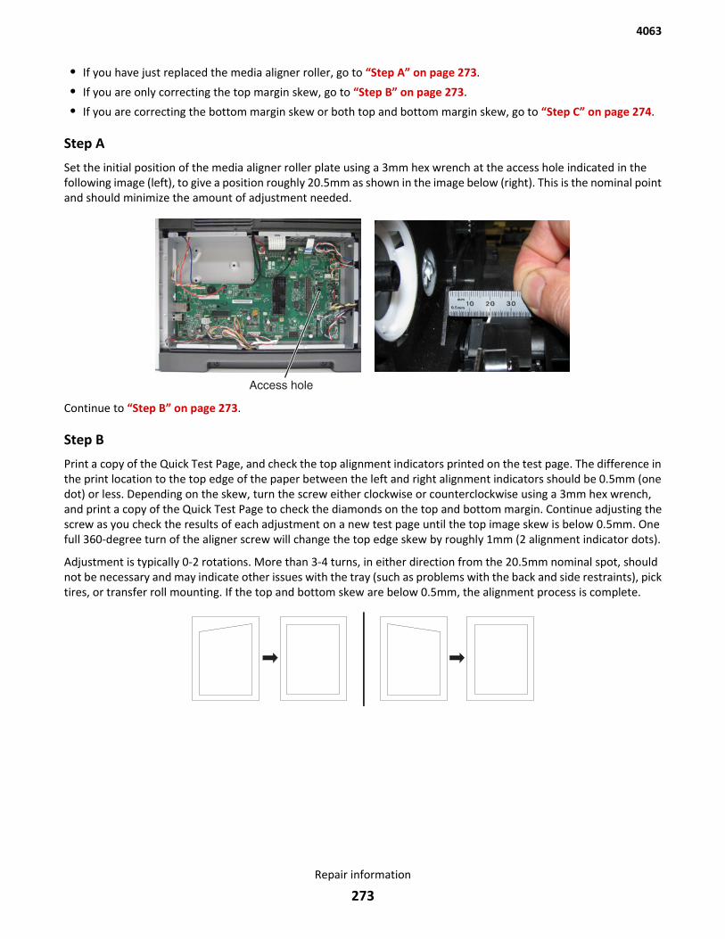
• If you have just replaced the media aligner roller, go to “Step A” on page 273.
• If you are only correcting the top margin skew, go to “Step B” on page 273.
• If you are correcting the bottom margin skew or both top and bottom margin skew, go to “Step C” on page 274.
Step A
Set the initial position of the media aligner roller plate using a 3mm hex wrench at the access hole indicated in thefollowing image (left), to give a position roughly 20.5mm as shown in the image below (right). This is the nominal pointand should minimize the amount of adjustment needed.
Continue to “Step B” on page 273.
Step B
Print a copy of the Quick Test Page, and check the top alignment indicators printed on the test page. The difference inthe print location to the top edge of the paper between the left and right alignment indicators should be 0.5mm (onedot) or less. Depending on the skew, turn the screw either clockwise or counterclockwise using a 3mm hex wrench,and print a copy of the Quick Test Page to check the diamonds on the top and bottom margin. Continue adjusting thescrew as you check the results of each adjustment on a new test page until the top image skew is below 0.5mm. Onefull 360-degree turn of the aligner screw will change the top edge skew by roughly 1mm (2 alignment indicator dots).
Adjustment is typically 0-2 rotations. More than 3-4 turns, in either direction from the 20.5mm nominal spot, shouldnot be necessary and may indicate other issues with the tray (such as problems with the back and side restraints), picktires, or transfer roll mounting. If the top and bottom skew are below 0.5mm, the alignment process is complete.
4063
Repair information
273
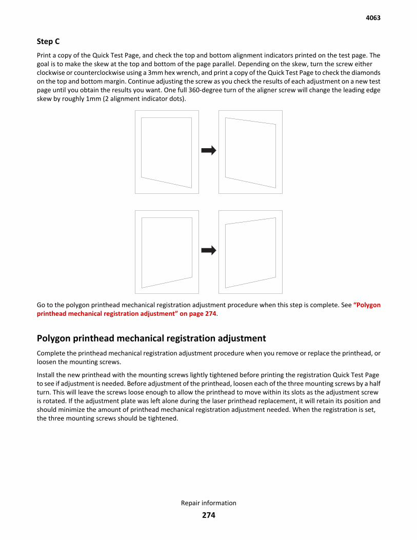
Step C
Print a copy of the Quick Test Page, and check the top and bottom alignment indicators printed on the test page. Thegoal is to make the skew at the top and bottom of the page parallel. Depending on the skew, turn the screw eitherclockwise or counterclockwise using a 3mm hex wrench, and print a copy of the Quick Test Page to check the diamondson the top and bottom margin. Continue adjusting the screw as you check the results of each adjustment on a new testpage until you obtain the results you want. One full 360-degree turn of the aligner screw will change the leading edgeskew by roughly 1mm (2 alignment indicator dots).
Go to the polygon printhead mechanical registration adjustment procedure when this step is complete. See “Polygonprinthead mechanical registration adjustment” on page 274.
Polygon printhead mechanical registration adjustmentComplete the printhead mechanical registration adjustment procedure when you remove or replace the printhead, orloosen the mounting screws.
Install the new printhead with the mounting screws lightly tightened before printing the registration Quick Test Pageto see if adjustment is needed. Before adjustment of the printhead, loosen each of the three mounting screws by a halfturn. This will leave the screws loose enough to allow the printhead to move within its slots as the adjustment screwis rotated. If the adjustment plate was left alone during the laser printhead replacement, it will retain its position andshould minimize the amount of printhead mechanical registration adjustment needed. When the registration is set,the three mounting screws should be tightened.
4063
Repair information
274
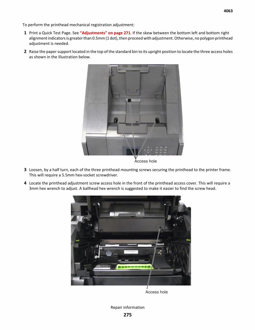
To perform the printhead mechanical registration adjustment:
1 Print a Quick Test Page. See “Adjustments” on page 271. If the skew between the bottom left and bottom rightalignment indicators is greater than 0.5mm (1 dot), then proceed with adjustment. Otherwise, no polygon printheadadjustment is needed.
2 Raise the paper support located in the top of the standard bin to its upright position to locate the three access holesas shown in the illustration below.
3 Loosen, by a half turn, each of the three printhead mounting screws securing the printhead to the printer frame.This will require a 5.5mm hex-socket screwdriver.
4 Locate the printhead adjustment screw access hole in the front of the printhead access cover. This will require a3mm hex wrench to adjust. A ballhead hex wrench is suggested to make it easier to find the screw head.
4063
Repair information
275
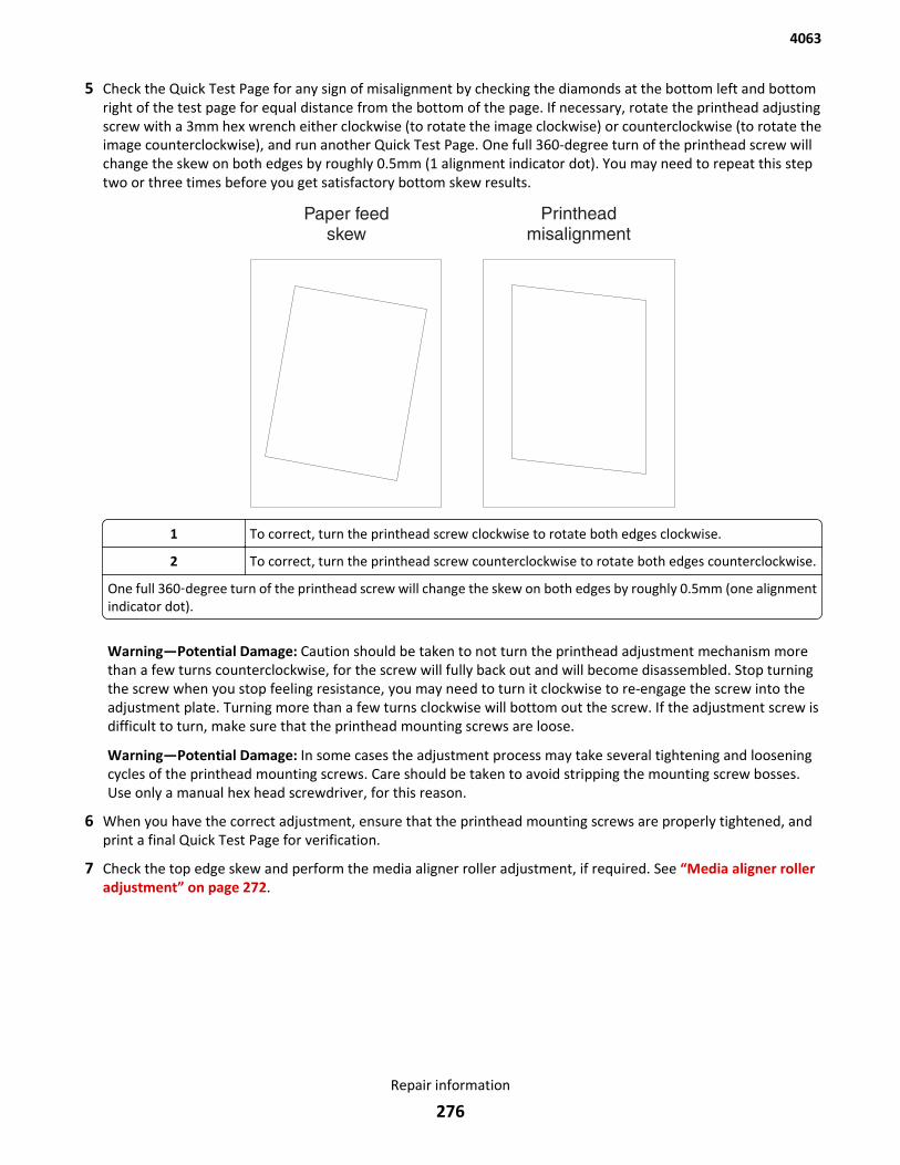
5 Check the Quick Test Page for any sign of misalignment by checking the diamonds at the bottom left and bottomright of the test page for equal distance from the bottom of the page. If necessary, rotate the printhead adjustingscrew with a 3mm hex wrench either clockwise (to rotate the image clockwise) or counterclockwise (to rotate theimage counterclockwise), and run another Quick Test Page. One full 360-degree turn of the printhead screw willchange the skew on both edges by roughly 0.5mm (1 alignment indicator dot). You may need to repeat this steptwo or three times before you get satisfactory bottom skew results.
1 To correct, turn the printhead screw clockwise to rotate both edges clockwise.
2 To correct, turn the printhead screw counterclockwise to rotate both edges counterclockwise.
One full 360‑degree turn of the printhead screw will change the skew on both edges by roughly 0.5mm (one alignmentindicator dot).
Warning—Potential Damage: Caution should be taken to not turn the printhead adjustment mechanism morethan a few turns counterclockwise, for the screw will fully back out and will become disassembled. Stop turningthe screw when you stop feeling resistance, you may need to turn it clockwise to re-engage the screw into theadjustment plate. Turning more than a few turns clockwise will bottom out the screw. If the adjustment screw isdifficult to turn, make sure that the printhead mounting screws are loose.
Warning—Potential Damage: In some cases the adjustment process may take several tightening and looseningcycles of the printhead mounting screws. Care should be taken to avoid stripping the mounting screw bosses.Use only a manual hex head screwdriver, for this reason.
6 When you have the correct adjustment, ensure that the printhead mounting screws are properly tightened, andprint a final Quick Test Page for verification.
7 Check the top edge skew and perform the media aligner roller adjustment, if required. See “Media aligner rolleradjustment” on page 272.
4063
Repair information
276
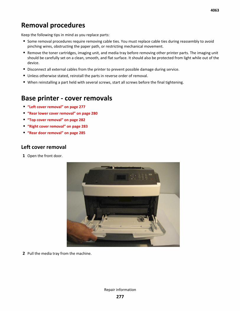
Removal proceduresKeep the following tips in mind as you replace parts:
• Some removal procedures require removing cable ties. You must replace cable ties during reassembly to avoidpinching wires, obstructing the paper path, or restricting mechanical movement.
• Remove the toner cartridges, imaging unit, and media tray before removing other printer parts. The imaging unitshould be carefully set on a clean, smooth, and flat surface. It should also be protected from light while out of thedevice.
• Disconnect all external cables from the printer to prevent possible damage during service.
• Unless otherwise stated, reinstall the parts in reverse order of removal.
• When reinstalling a part held with several screws, start all screws before the final tightening.
Base printer - cover removals• “Left cover removal” on page 277
• “Rear lower cover removal” on page 280
• “Top cover removal” on page 282
• “Right cover removal” on page 283
• “Rear door removal” on page 285
Left cover removal1 Open the front door.
2 Pull the media tray from the machine.
4063
Repair information
277
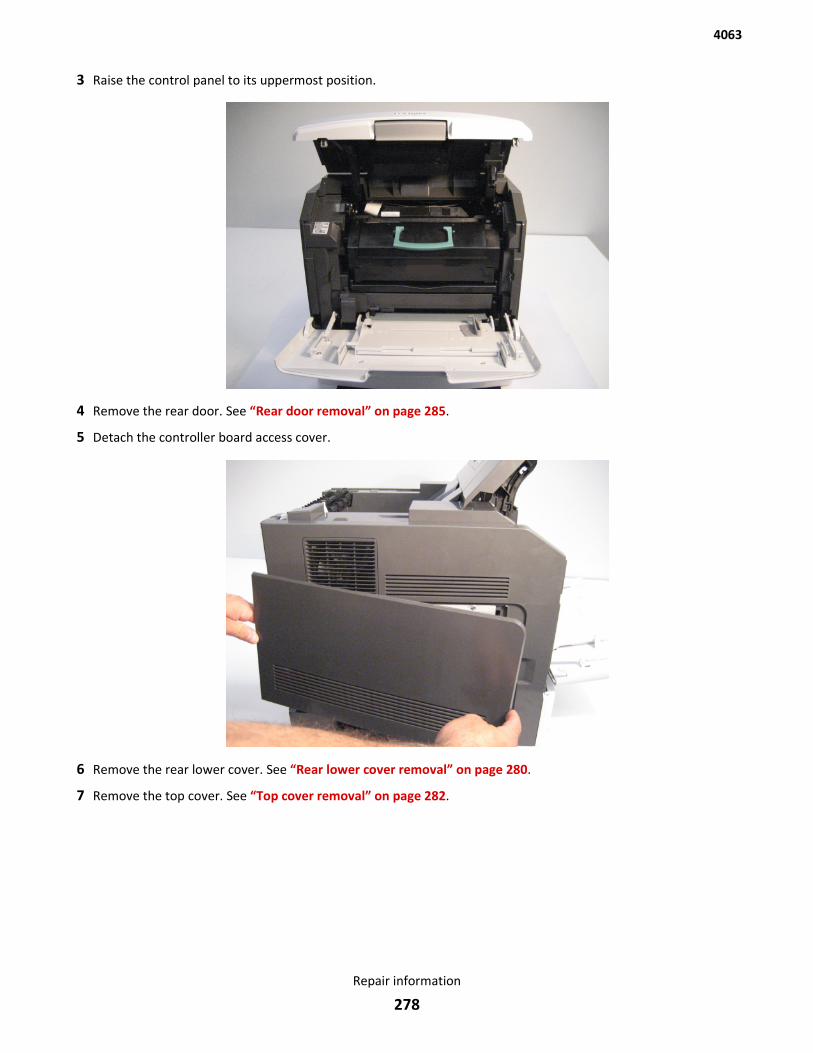
3 Raise the control panel to its uppermost position.
4 Remove the rear door. See “Rear door removal” on page 285.
5 Detach the controller board access cover.
6 Remove the rear lower cover. See “Rear lower cover removal” on page 280.
7 Remove the top cover. See “Top cover removal” on page 282.
4063
Repair information
278

8 Remove the six screws (A) securing the left cover to the machine.
9 Remove the left cover.
Note: When removing the left cover, the charcoal filter might become detached.
4063
Repair information
279
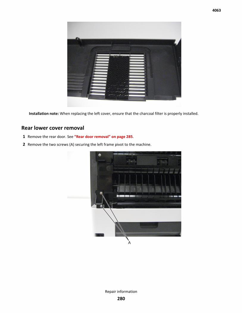
Installation note: When replacing the left cover, ensure that the charcoal filter is properly installed.
Rear lower cover removal1 Remove the rear door. See “Rear door removal” on page 285.
2 Remove the two screws (A) securing the left frame pivot to the machine.
4063
Repair information
280
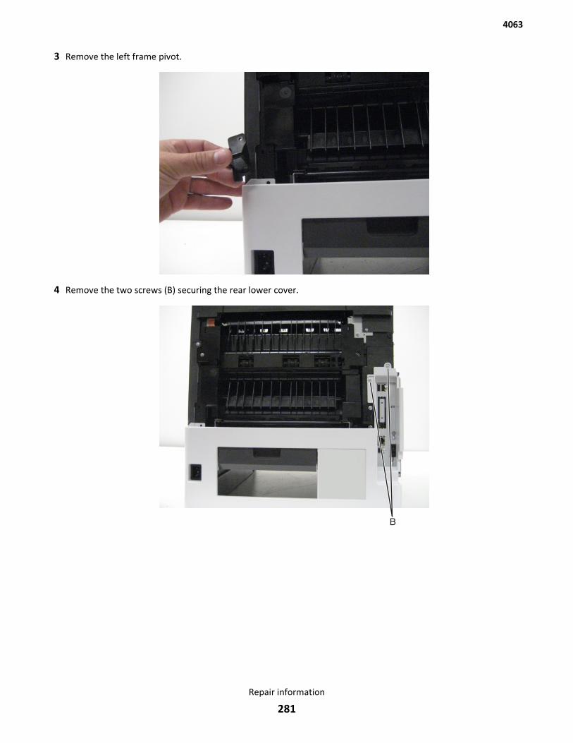
3 Remove the left frame pivot.
4 Remove the two screws (B) securing the rear lower cover.
4063
Repair information
281
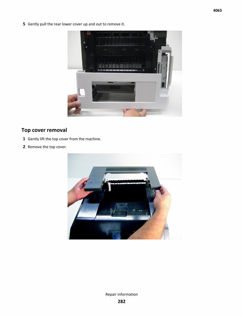
5 Gently pull the rear lower cover up and out to remove it.
Top cover removal1 Gently lift the top cover from the machine.
2 Remove the top cover.
4063
Repair information
282
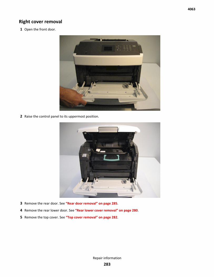
Right cover removal1 Open the front door.
2 Raise the control panel to its uppermost position.
3 Remove the rear door. See “Rear door removal” on page 285.
4 Remove the rear lower door. See “Rear lower cover removal” on page 280.
5 Remove the top cover. See “Top cover removal” on page 282.
4063
Repair information
283
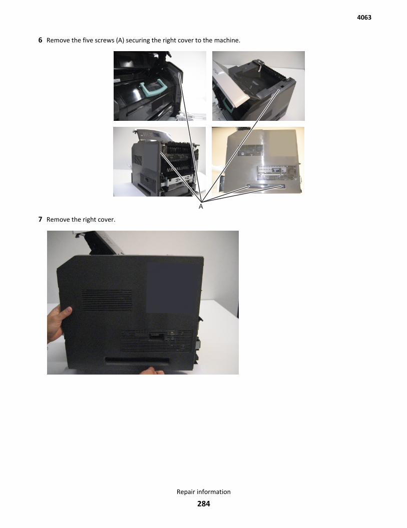
6 Remove the five screws (A) securing the right cover to the machine.
7 Remove the right cover.
4063
Repair information
284
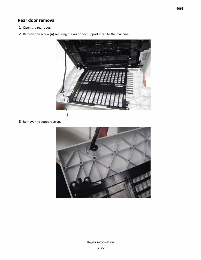
Rear door removal1 Open the rear door.
2 Remove the screw (A) securing the rear door support strap to the machine.
3 Remove the support strap.
4063
Repair information
285
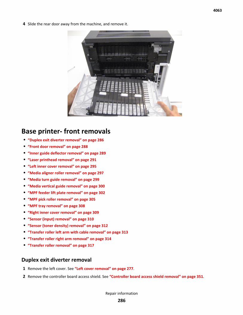
4 Slide the rear door away from the machine, and remove it.
Base printer- front removals• “Duplex exit diverter removal” on page 286
• “Front door removal” on page 288
• “Inner guide deflector removal” on page 289
• “Laser printhead removal” on page 291
• “Left inner cover removal” on page 295
• “Media aligner roller removal” on page 297
• “Media turn guide removal” on page 299
• “Media vertical guide removal” on page 300
• “MPF feeder lift plate removal” on page 302
• “MPF pick roller removal” on page 305
• “MPF tray removal” on page 308
• “Right inner cover removal” on page 309
• “Sensor (input) removal” on page 310
• “Sensor (toner density) removal” on page 312
• “Transfer roller left arm with cable removal” on page 313
• “Transfer roller right arm removal” on page 314
• “Transfer roller removal” on page 317
Duplex exit diverter removal1 Remove the left cover. See “Left cover removal” on page 277.
2 Remove the controller board access shield. See “Controller board access shield removal” on page 351.
4063
Repair information
286
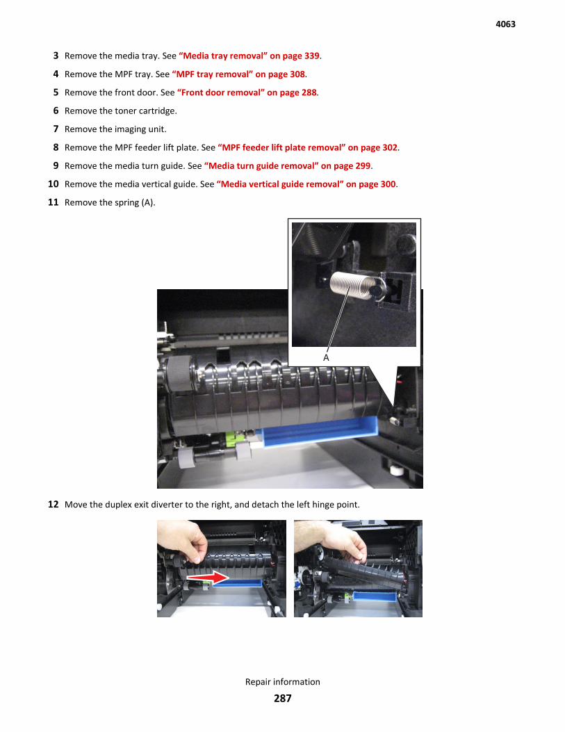
3 Remove the media tray. See “Media tray removal” on page 339.
4 Remove the MPF tray. See “MPF tray removal” on page 308.
5 Remove the front door. See “Front door removal” on page 288.
6 Remove the toner cartridge.
7 Remove the imaging unit.
8 Remove the MPF feeder lift plate. See “MPF feeder lift plate removal” on page 302.
9 Remove the media turn guide. See “Media turn guide removal” on page 299.
10 Remove the media vertical guide. See “Media vertical guide removal” on page 300.
11 Remove the spring (A).
12 Move the duplex exit diverter to the right, and detach the left hinge point.
4063
Repair information
287
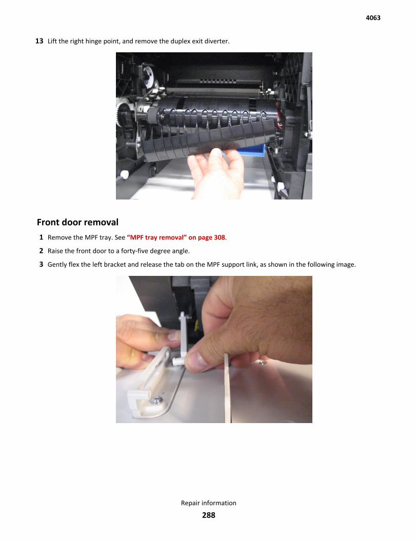
13 Lift the right hinge point, and remove the duplex exit diverter.
Front door removal1 Remove the MPF tray. See “MPF tray removal” on page 308.
2 Raise the front door to a forty-five degree angle.
3 Gently flex the left bracket and release the tab on the MPF support link, as shown in the following image.
4063
Repair information
288
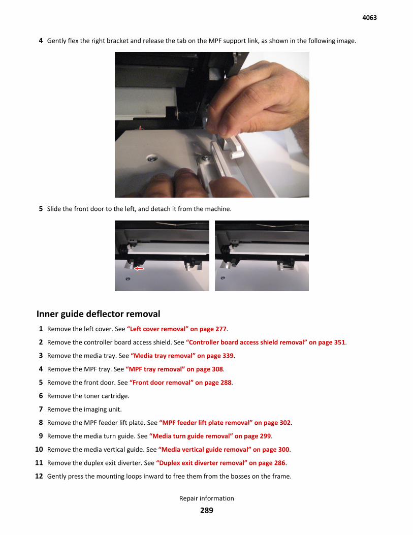
4 Gently flex the right bracket and release the tab on the MPF support link, as shown in the following image.
5 Slide the front door to the left, and detach it from the machine.
Inner guide deflector removal1 Remove the left cover. See “Left cover removal” on page 277.
2 Remove the controller board access shield. See “Controller board access shield removal” on page 351.
3 Remove the media tray. See “Media tray removal” on page 339.
4 Remove the MPF tray. See “MPF tray removal” on page 308.
5 Remove the front door. See “Front door removal” on page 288.
6 Remove the toner cartridge.
7 Remove the imaging unit.
8 Remove the MPF feeder lift plate. See “MPF feeder lift plate removal” on page 302.
9 Remove the media turn guide. See “Media turn guide removal” on page 299.
10 Remove the media vertical guide. See “Media vertical guide removal” on page 300.
11 Remove the duplex exit diverter. See “Duplex exit diverter removal” on page 286.
12 Gently press the mounting loops inward to free them from the bosses on the frame.
4063
Repair information
289
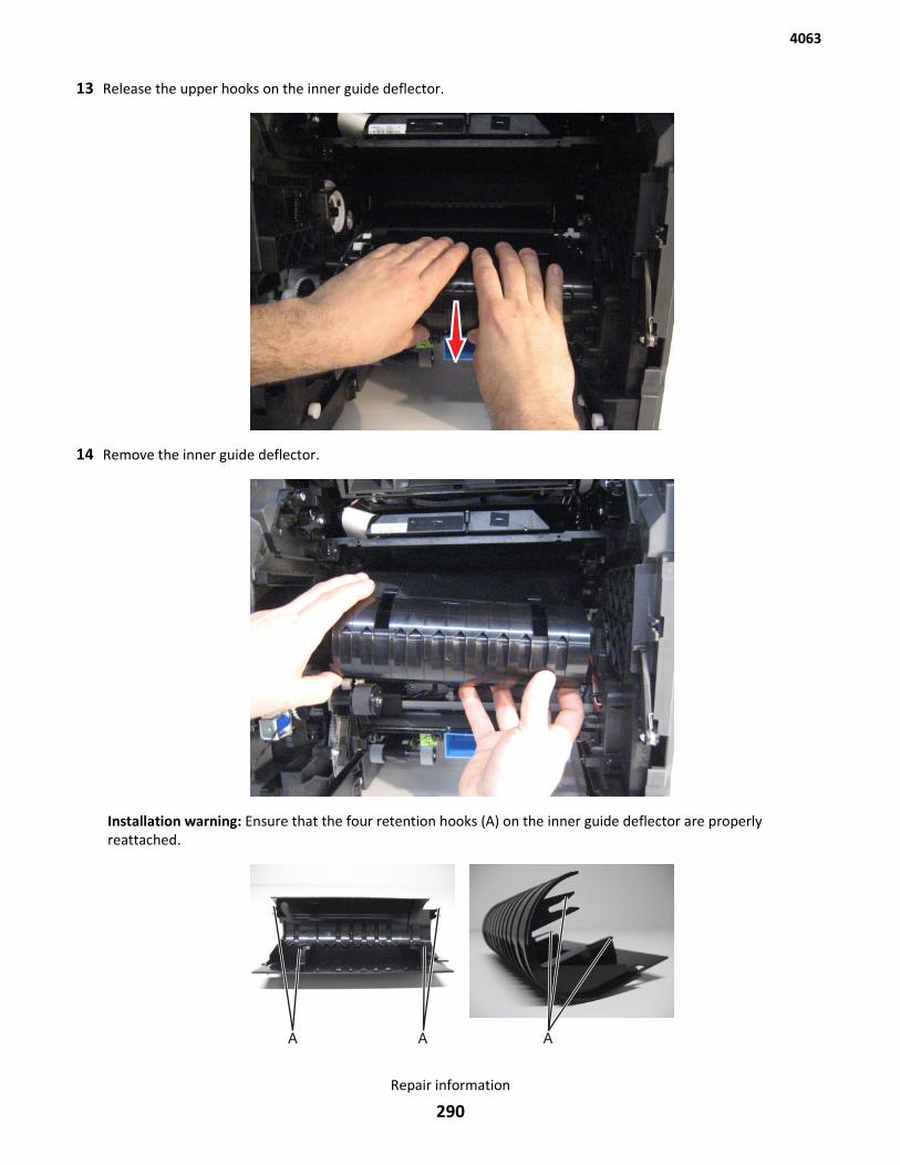
13 Release the upper hooks on the inner guide deflector.
14 Remove the inner guide deflector.
Installation warning: Ensure that the four retention hooks (A) on the inner guide deflector are properlyreattached.
4063
Repair information
290
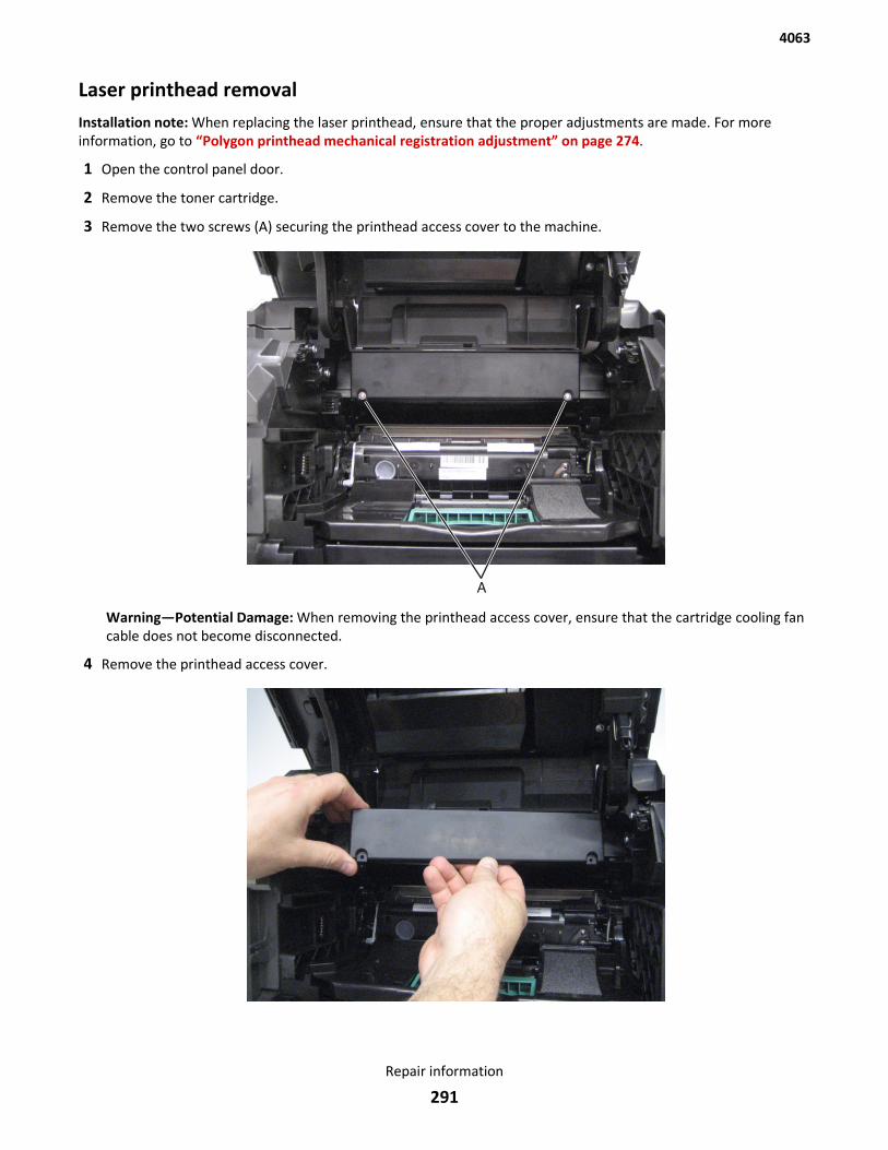
Laser printhead removalInstallation note: When replacing the laser printhead, ensure that the proper adjustments are made. For moreinformation, go to “Polygon printhead mechanical registration adjustment” on page 274.
1 Open the control panel door.
2 Remove the toner cartridge.
3 Remove the two screws (A) securing the printhead access cover to the machine.
Warning—Potential Damage: When removing the printhead access cover, ensure that the cartridge cooling fancable does not become disconnected.
4 Remove the printhead access cover.
4063
Repair information
291
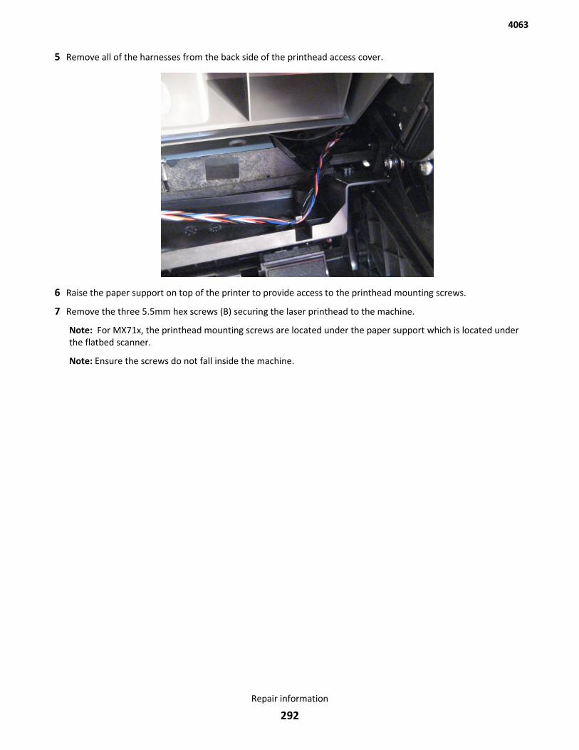
5 Remove all of the harnesses from the back side of the printhead access cover.
6 Raise the paper support on top of the printer to provide access to the printhead mounting screws.
7 Remove the three 5.5mm hex screws (B) securing the laser printhead to the machine.
Note: For MX71x, the printhead mounting screws are located under the paper support which is located underthe flatbed scanner.
Note: Ensure the screws do not fall inside the machine.
4063
Repair information
292
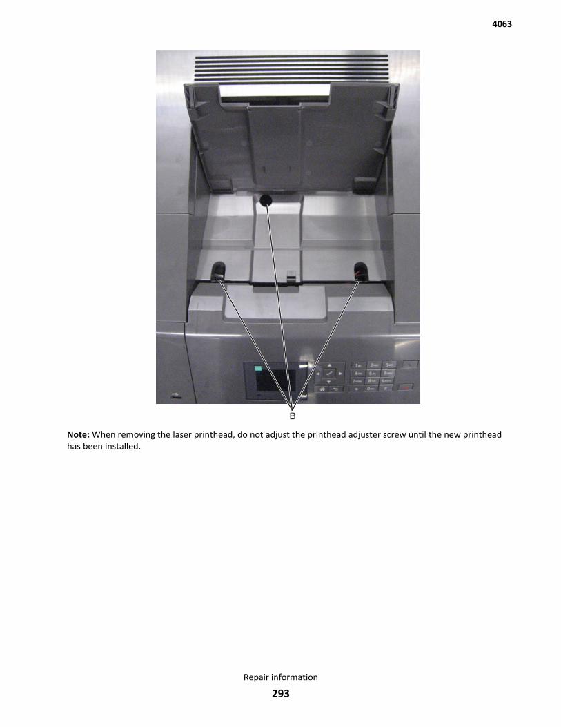
Note: When removing the laser printhead, do not adjust the printhead adjuster screw until the new printheadhas been installed.
4063
Repair information
293
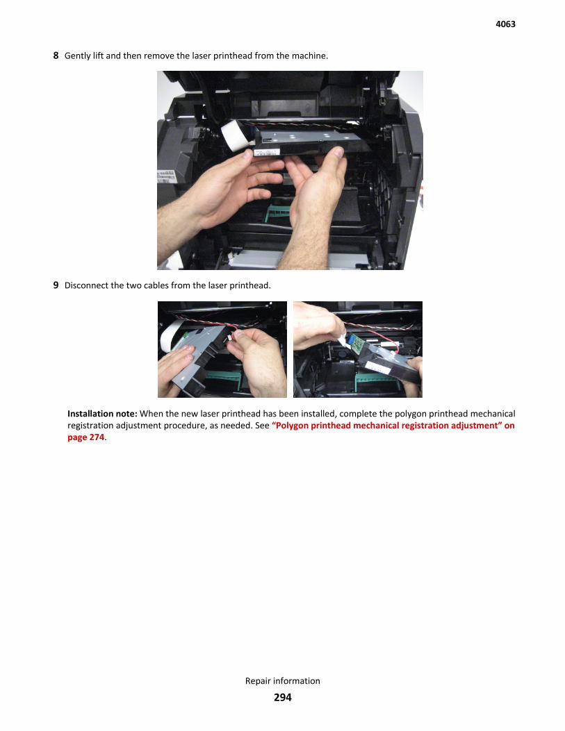
8 Gently lift and then remove the laser printhead from the machine.
9 Disconnect the two cables from the laser printhead.
Installation note: When the new laser printhead has been installed, complete the polygon printhead mechanicalregistration adjustment procedure, as needed. See “Polygon printhead mechanical registration adjustment” onpage 274.
4063
Repair information
294
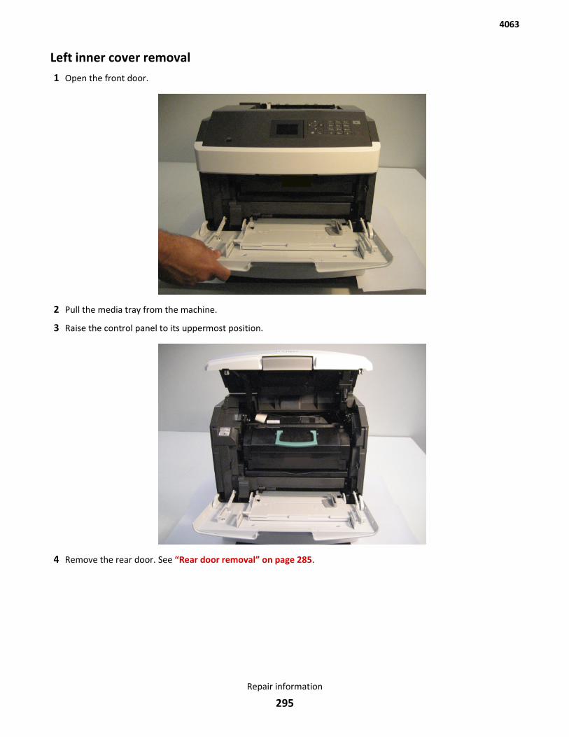
Left inner cover removal1 Open the front door.
2 Pull the media tray from the machine.
3 Raise the control panel to its uppermost position.
4 Remove the rear door. See “Rear door removal” on page 285.
4063
Repair information
295
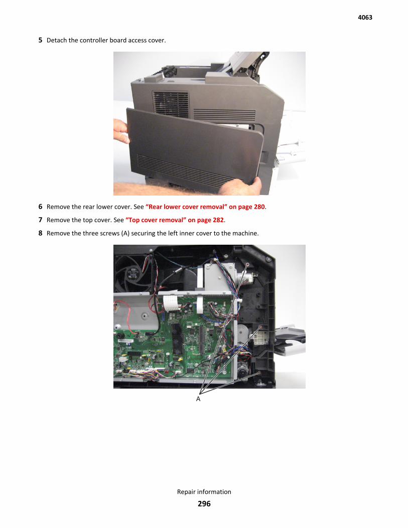
5 Detach the controller board access cover.
6 Remove the rear lower cover. See “Rear lower cover removal” on page 280.
7 Remove the top cover. See “Top cover removal” on page 282.
8 Remove the three screws (A) securing the left inner cover to the machine.
4063
Repair information
296
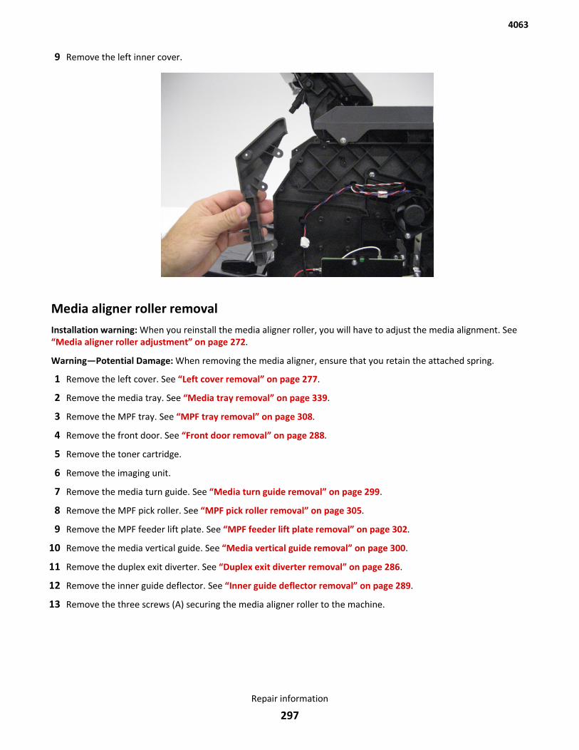
9 Remove the left inner cover.
Media aligner roller removalInstallation warning: When you reinstall the media aligner roller, you will have to adjust the media alignment. See“Media aligner roller adjustment” on page 272.
Warning—Potential Damage: When removing the media aligner, ensure that you retain the attached spring.
1 Remove the left cover. See “Left cover removal” on page 277.
2 Remove the media tray. See “Media tray removal” on page 339.
3 Remove the MPF tray. See “MPF tray removal” on page 308.
4 Remove the front door. See “Front door removal” on page 288.
5 Remove the toner cartridge.
6 Remove the imaging unit.
7 Remove the media turn guide. See “Media turn guide removal” on page 299.
8 Remove the MPF pick roller. See “MPF pick roller removal” on page 305.
9 Remove the MPF feeder lift plate. See “MPF feeder lift plate removal” on page 302.
10 Remove the media vertical guide. See “Media vertical guide removal” on page 300.
11 Remove the duplex exit diverter. See “Duplex exit diverter removal” on page 286.
12 Remove the inner guide deflector. See “Inner guide deflector removal” on page 289.
13 Remove the three screws (A) securing the media aligner roller to the machine.
4063
Repair information
297
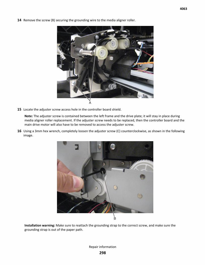
14 Remove the screw (B) securing the grounding wire to the media aligner roller.
15 Locate the adjuster screw access hole in the controller board shield.
Note: The adjuster screw is contained between the left frame and the drive plate; it will stay in place duringmedia aligner roller replacement. If the adjuster screw needs to be replaced, then the controller board and themain drive motor will also have to be removed to access the adjuster screw.
16 Using a 3mm hex wrench, completely loosen the adjuster screw (C) counterclockwise, as shown in the followingimage.
Installation warning: Make sure to reattach the grounding strap to the correct screw, and make sure thegrounding strap is out of the paper path.
4063
Repair information
298
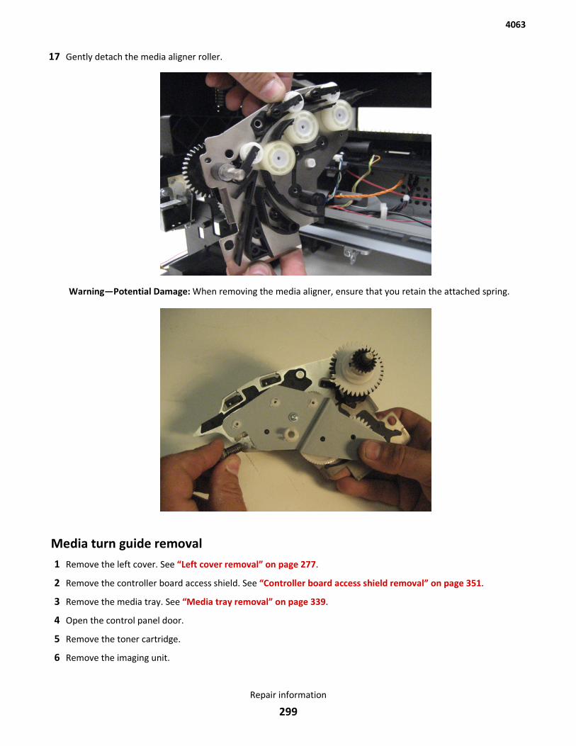
17 Gently detach the media aligner roller.
Warning—Potential Damage: When removing the media aligner, ensure that you retain the attached spring.
Media turn guide removal1 Remove the left cover. See “Left cover removal” on page 277.
2 Remove the controller board access shield. See “Controller board access shield removal” on page 351.
3 Remove the media tray. See “Media tray removal” on page 339.
4 Open the control panel door.
5 Remove the toner cartridge.
6 Remove the imaging unit.
4063
Repair information
299
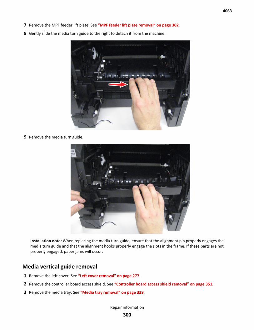
7 Remove the MPF feeder lift plate. See “MPF feeder lift plate removal” on page 302.
8 Gently slide the media turn guide to the right to detach it from the machine.
9 Remove the media turn guide.
Installation note: When replacing the media turn guide, ensure that the alignment pin properly engages themedia turn guide and that the alignment hooks properly engage the slots in the frame. If these parts are notproperly engaged, paper jams will occur.
Media vertical guide removal1 Remove the left cover. See “Left cover removal” on page 277.
2 Remove the controller board access shield. See “Controller board access shield removal” on page 351.
3 Remove the media tray. See “Media tray removal” on page 339.
4063
Repair information
300
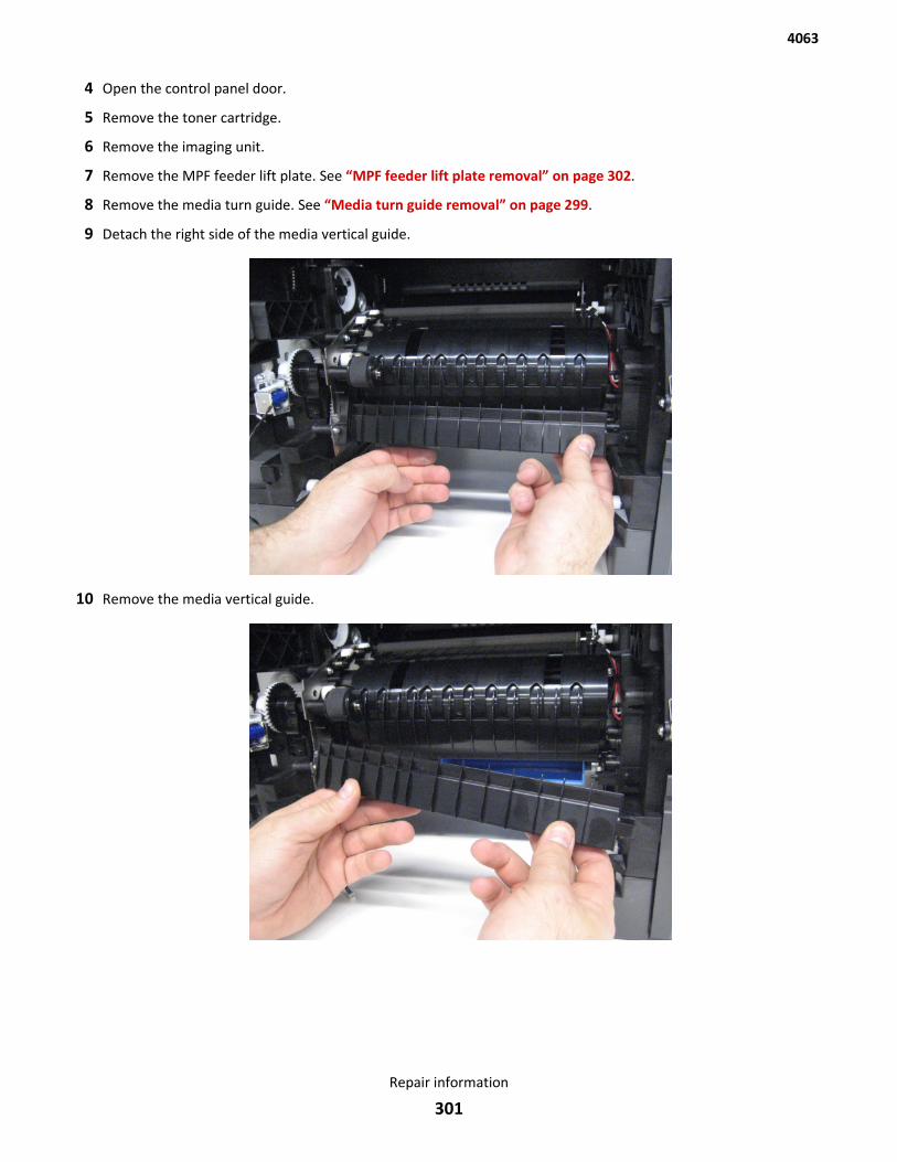
4 Open the control panel door.
5 Remove the toner cartridge.
6 Remove the imaging unit.
7 Remove the MPF feeder lift plate. See “MPF feeder lift plate removal” on page 302.
8 Remove the media turn guide. See “Media turn guide removal” on page 299.
9 Detach the right side of the media vertical guide.
10 Remove the media vertical guide.
4063
Repair information
301
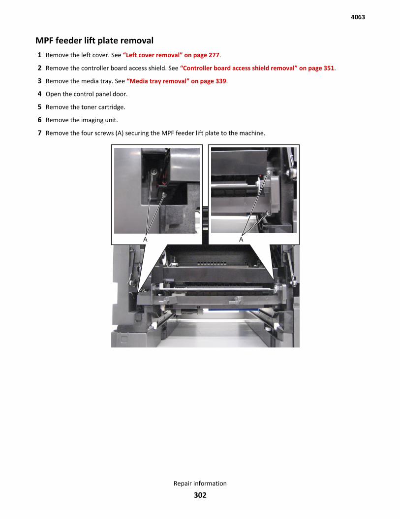
MPF feeder lift plate removal1 Remove the left cover. See “Left cover removal” on page 277.
2 Remove the controller board access shield. See “Controller board access shield removal” on page 351.
3 Remove the media tray. See “Media tray removal” on page 339.
4 Open the control panel door.
5 Remove the toner cartridge.
6 Remove the imaging unit.
7 Remove the four screws (A) securing the MPF feeder lift plate to the machine.
4063
Repair information
302
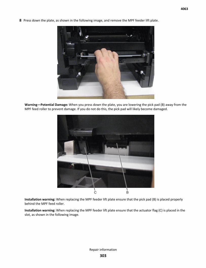
8 Press down the plate, as shown in the following image, and remove the MPF feeder lift plate.
Warning—Potential Damage: When you press down the plate, you are lowering the pick pad (B) away from theMPF feed roller to prevent damage. If you do not do this, the pick pad will likely become damaged.
Installation warning: When replacing the MPF feeder lift plate ensure that the pick pad (B) is placed properlybehind the MPF feed roller.
Installation warning: When replacing the MPF feeder lift plate ensure that the actuator flag (C) is placed in theslot, as shown in the following image.
4063
Repair information
303
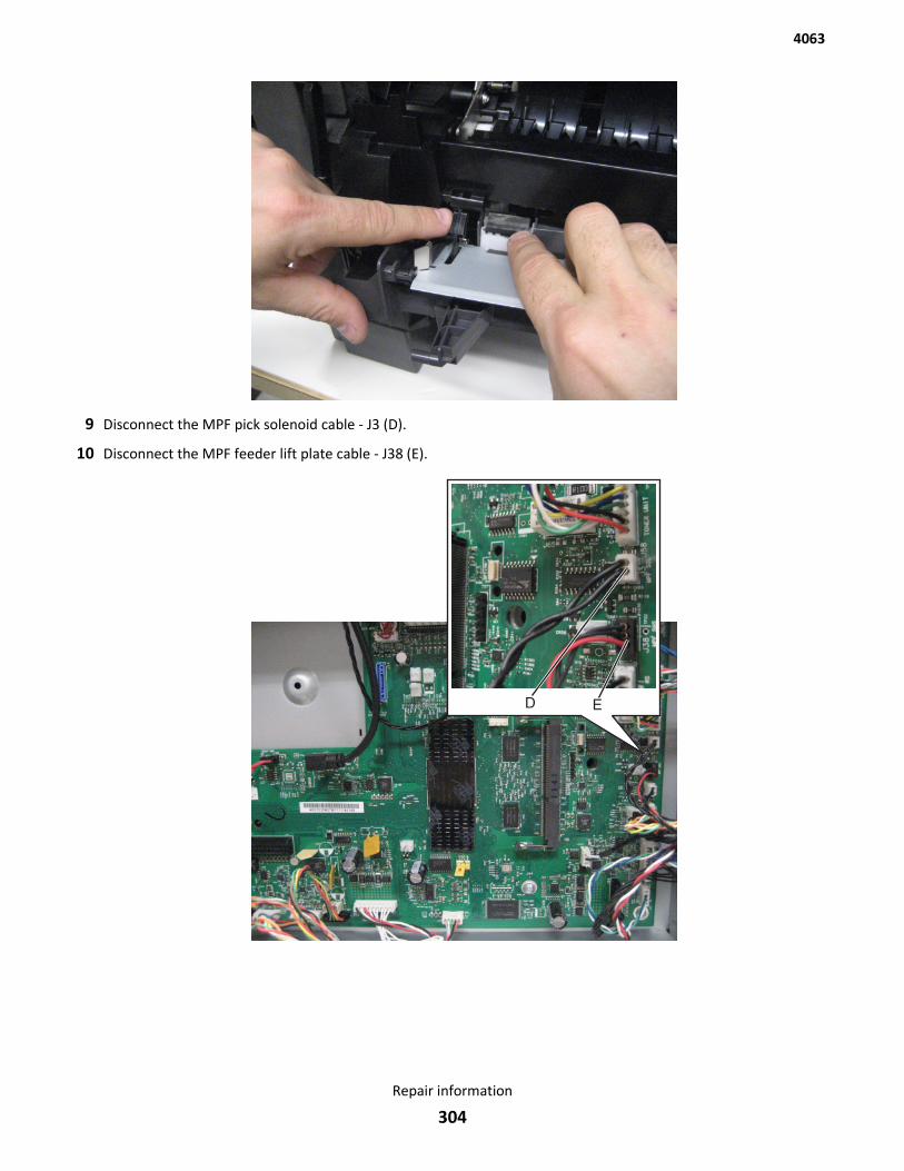
9 Disconnect the MPF pick solenoid cable - J3 (D).
10 Disconnect the MPF feeder lift plate cable - J38 (E).
4063
Repair information
304
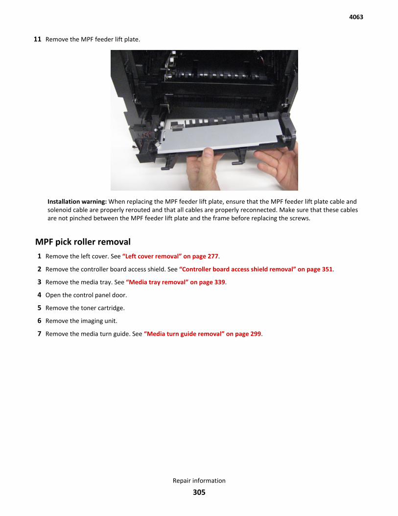
11 Remove the MPF feeder lift plate.
Installation warning: When replacing the MPF feeder lift plate, ensure that the MPF feeder lift plate cable andsolenoid cable are properly rerouted and that all cables are properly reconnected. Make sure that these cablesare not pinched between the MPF feeder lift plate and the frame before replacing the screws.
MPF pick roller removal1 Remove the left cover. See “Left cover removal” on page 277.
2 Remove the controller board access shield. See “Controller board access shield removal” on page 351.
3 Remove the media tray. See “Media tray removal” on page 339.
4 Open the control panel door.
5 Remove the toner cartridge.
6 Remove the imaging unit.
7 Remove the media turn guide. See “Media turn guide removal” on page 299.
4063
Repair information
305

8 Remove the e-clip securing the MPF pick roller to the machine.
9 Remove the flange.
4063
Repair information
306
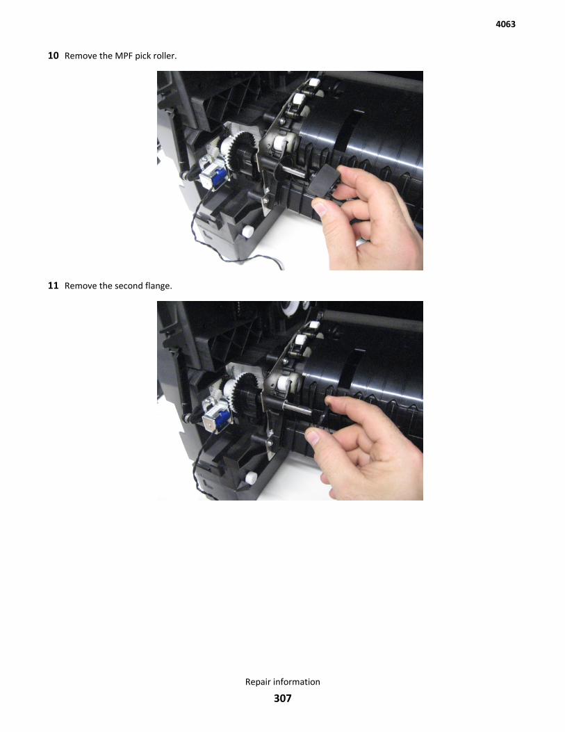
10 Remove the MPF pick roller.
11 Remove the second flange.
4063
Repair information
307

MPF tray removal1 Lower the front door to a 45-degree angle, as shown in the following image.
2 Gently flex the left bracket (A) and detach the left side of the MPF tray.
4063
Repair information
308
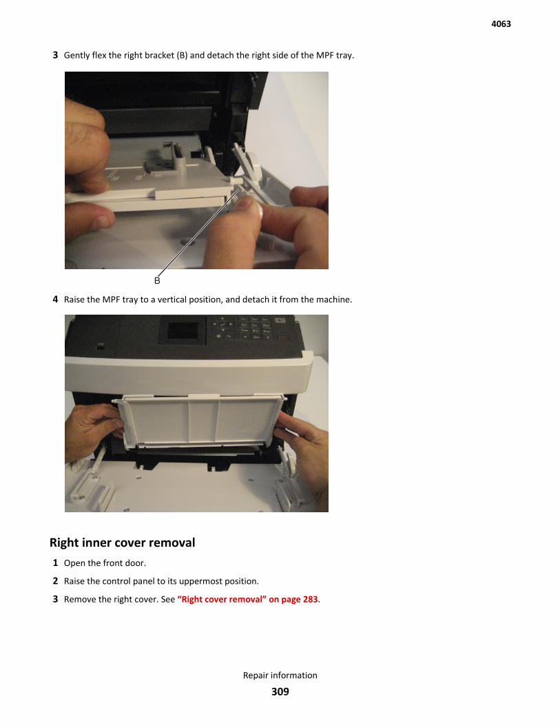
3 Gently flex the right bracket (B) and detach the right side of the MPF tray.
4 Raise the MPF tray to a vertical position, and detach it from the machine.
Right inner cover removal1 Open the front door.
2 Raise the control panel to its uppermost position.
3 Remove the right cover. See “Right cover removal” on page 283.
4063
Repair information
309
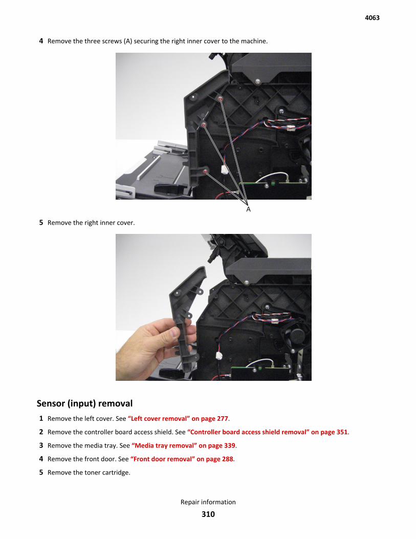
4 Remove the three screws (A) securing the right inner cover to the machine.
5 Remove the right inner cover.
Sensor (input) removal1 Remove the left cover. See “Left cover removal” on page 277.
2 Remove the controller board access shield. See “Controller board access shield removal” on page 351.
3 Remove the media tray. See “Media tray removal” on page 339.
4 Remove the front door. See “Front door removal” on page 288.
5 Remove the toner cartridge.
4063
Repair information
310
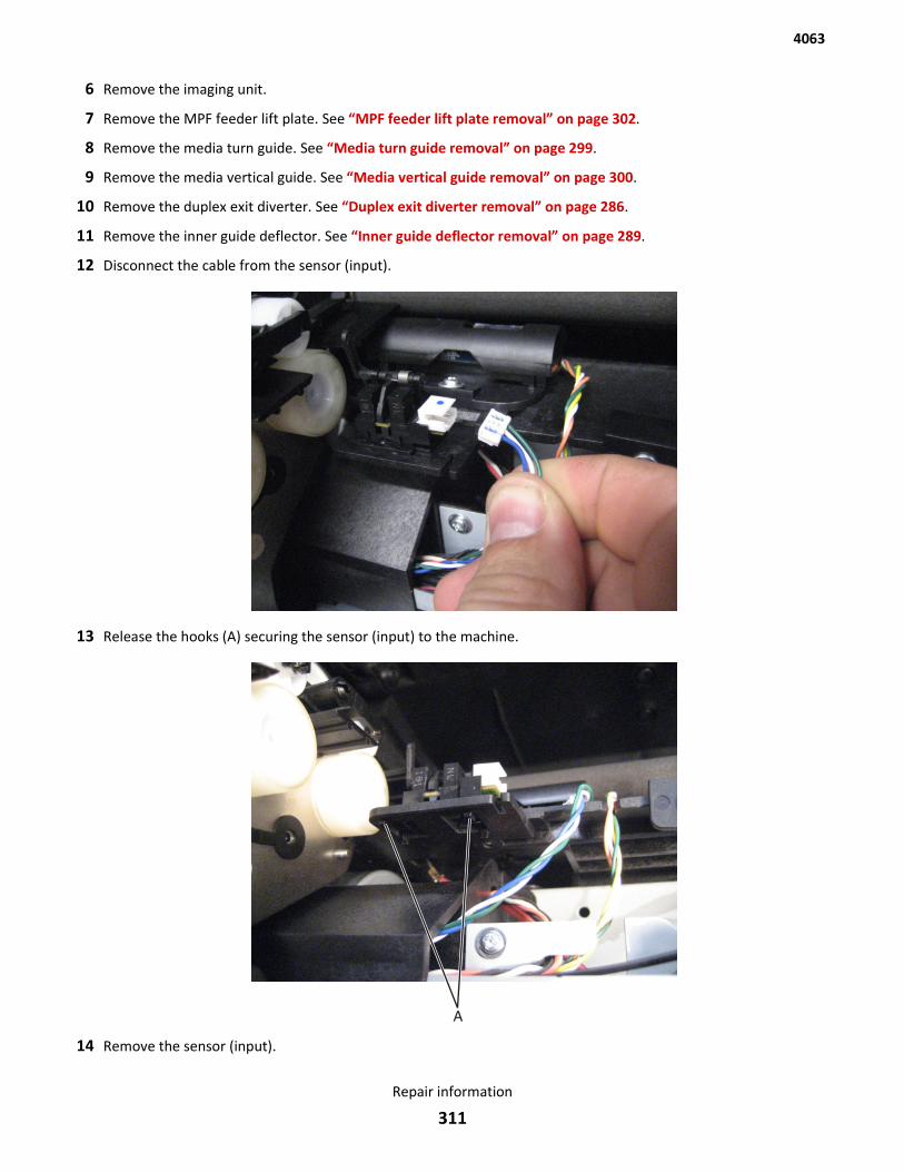
6 Remove the imaging unit.
7 Remove the MPF feeder lift plate. See “MPF feeder lift plate removal” on page 302.
8 Remove the media turn guide. See “Media turn guide removal” on page 299.
9 Remove the media vertical guide. See “Media vertical guide removal” on page 300.
10 Remove the duplex exit diverter. See “Duplex exit diverter removal” on page 286.
11 Remove the inner guide deflector. See “Inner guide deflector removal” on page 289.
12 Disconnect the cable from the sensor (input).
13 Release the hooks (A) securing the sensor (input) to the machine.
14 Remove the sensor (input).
4063
Repair information
311
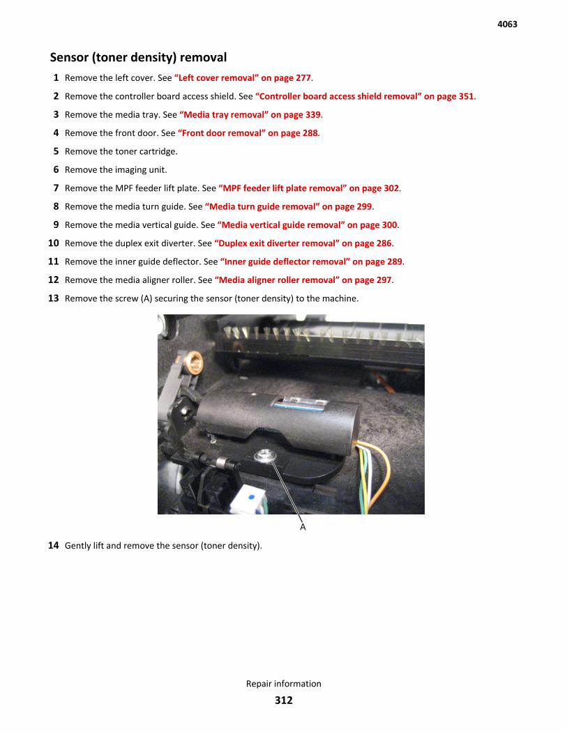
Sensor (toner density) removal1 Remove the left cover. See “Left cover removal” on page 277.
2 Remove the controller board access shield. See “Controller board access shield removal” on page 351.
3 Remove the media tray. See “Media tray removal” on page 339.
4 Remove the front door. See “Front door removal” on page 288.
5 Remove the toner cartridge.
6 Remove the imaging unit.
7 Remove the MPF feeder lift plate. See “MPF feeder lift plate removal” on page 302.
8 Remove the media turn guide. See “Media turn guide removal” on page 299.
9 Remove the media vertical guide. See “Media vertical guide removal” on page 300.
10 Remove the duplex exit diverter. See “Duplex exit diverter removal” on page 286.
11 Remove the inner guide deflector. See “Inner guide deflector removal” on page 289.
12 Remove the media aligner roller. See “Media aligner roller removal” on page 297.
13 Remove the screw (A) securing the sensor (toner density) to the machine.
14 Gently lift and remove the sensor (toner density).
4063
Repair information
312
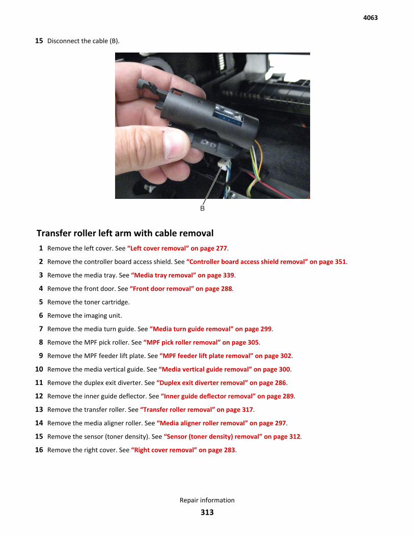
15 Disconnect the cable (B).
Transfer roller left arm with cable removal1 Remove the left cover. See “Left cover removal” on page 277.
2 Remove the controller board access shield. See “Controller board access shield removal” on page 351.
3 Remove the media tray. See “Media tray removal” on page 339.
4 Remove the front door. See “Front door removal” on page 288.
5 Remove the toner cartridge.
6 Remove the imaging unit.
7 Remove the media turn guide. See “Media turn guide removal” on page 299.
8 Remove the MPF pick roller. See “MPF pick roller removal” on page 305.
9 Remove the MPF feeder lift plate. See “MPF feeder lift plate removal” on page 302.
10 Remove the media vertical guide. See “Media vertical guide removal” on page 300.
11 Remove the duplex exit diverter. See “Duplex exit diverter removal” on page 286.
12 Remove the inner guide deflector. See “Inner guide deflector removal” on page 289.
13 Remove the transfer roller. See “Transfer roller removal” on page 317.
14 Remove the media aligner roller. See “Media aligner roller removal” on page 297.
15 Remove the sensor (toner density). See “Sensor (toner density) removal” on page 312.
16 Remove the right cover. See “Right cover removal” on page 283.
4063
Repair information
313
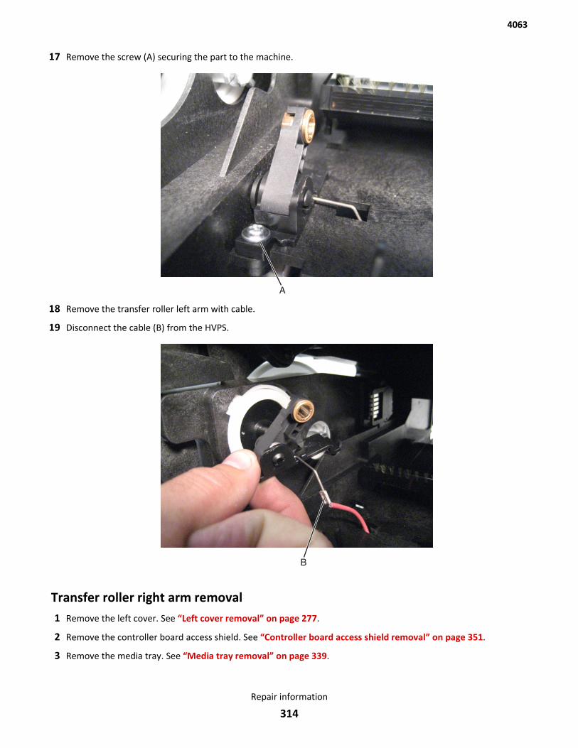
17 Remove the screw (A) securing the part to the machine.
18 Remove the transfer roller left arm with cable.
19 Disconnect the cable (B) from the HVPS.
Transfer roller right arm removal1 Remove the left cover. See “Left cover removal” on page 277.
2 Remove the controller board access shield. See “Controller board access shield removal” on page 351.
3 Remove the media tray. See “Media tray removal” on page 339.
4063
Repair information
314
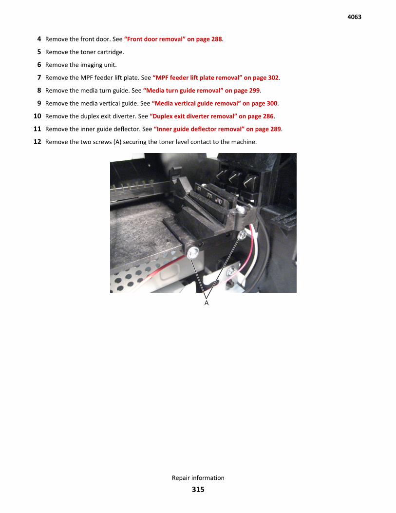
4 Remove the front door. See “Front door removal” on page 288.
5 Remove the toner cartridge.
6 Remove the imaging unit.
7 Remove the MPF feeder lift plate. See “MPF feeder lift plate removal” on page 302.
8 Remove the media turn guide. See “Media turn guide removal” on page 299.
9 Remove the media vertical guide. See “Media vertical guide removal” on page 300.
10 Remove the duplex exit diverter. See “Duplex exit diverter removal” on page 286.
11 Remove the inner guide deflector. See “Inner guide deflector removal” on page 289.
12 Remove the two screws (A) securing the toner level contact to the machine.
4063
Repair information
315
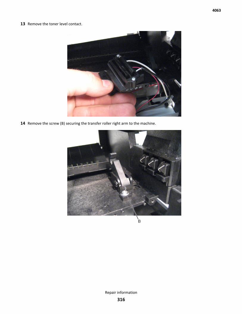
13 Remove the toner level contact.
14 Remove the screw (B) securing the transfer roller right arm to the machine.
4063
Repair information
316
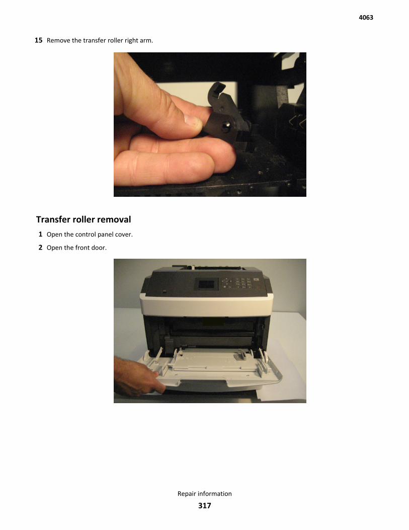
15 Remove the transfer roller right arm.
Transfer roller removal1 Open the control panel cover.
2 Open the front door.
4063
Repair information
317
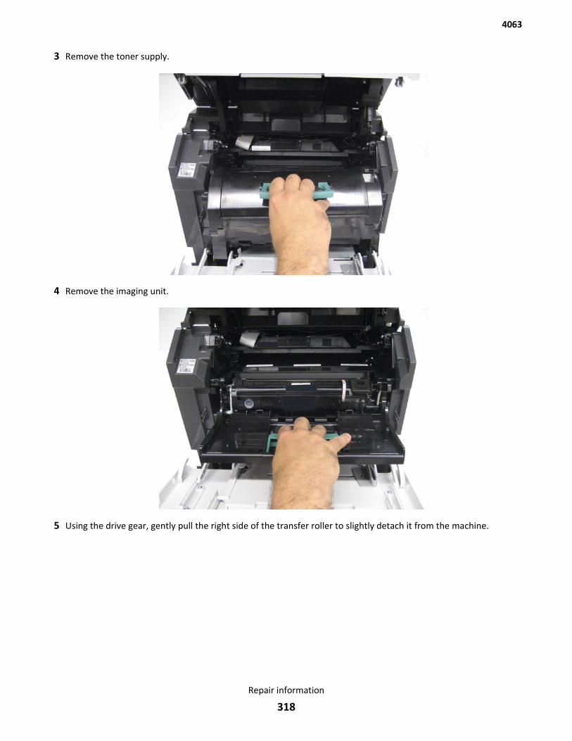
3 Remove the toner supply.
4 Remove the imaging unit.
5 Using the drive gear, gently pull the right side of the transfer roller to slightly detach it from the machine.
4063
Repair information
318
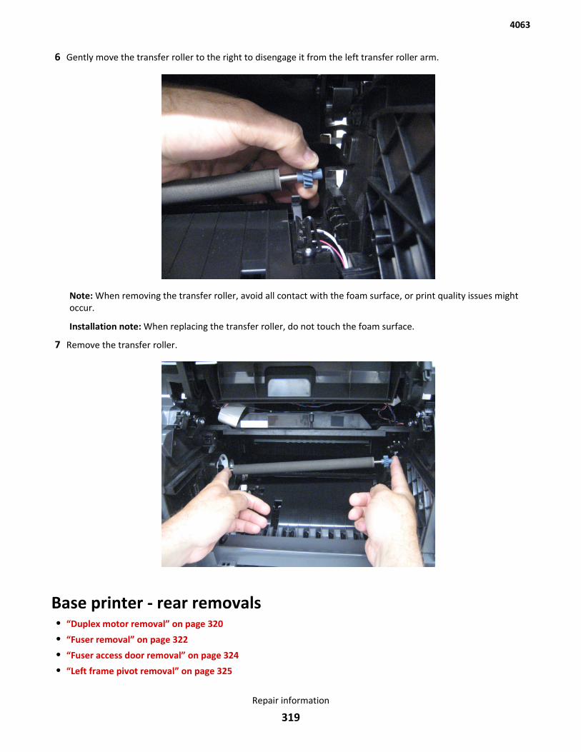
6 Gently move the transfer roller to the right to disengage it from the left transfer roller arm.
Note: When removing the transfer roller, avoid all contact with the foam surface, or print quality issues mightoccur.
Installation note: When replacing the transfer roller, do not touch the foam surface.
7 Remove the transfer roller.
Base printer - rear removals• “Duplex motor removal” on page 320
• “Fuser removal” on page 322
• “Fuser access door removal” on page 324
• “Left frame pivot removal” on page 325
4063
Repair information
319
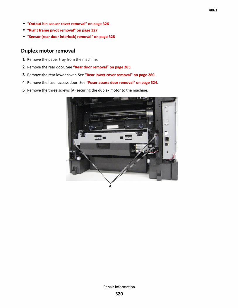
• “Output bin sensor cover removal” on page 326
• “Right frame pivot removal” on page 327
• “Sensor (rear door interlock) removal” on page 328
Duplex motor removal1 Remove the paper tray from the machine.
2 Remove the rear door. See “Rear door removal” on page 285.
3 Remove the rear lower cover. See “Rear lower cover removal” on page 280.
4 Remove the fuser access door. See “Fuser access door removal” on page 324.
5 Remove the three screws (A) securing the duplex motor to the machine.
4063
Repair information
320
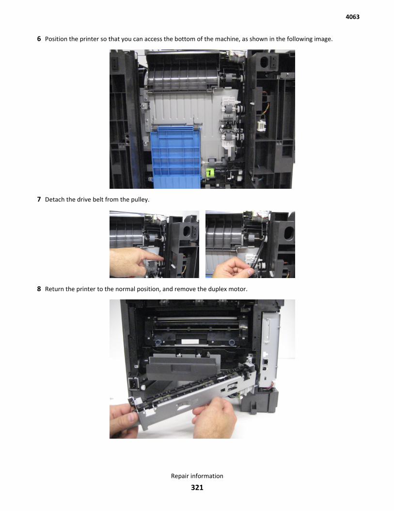
6 Position the printer so that you can access the bottom of the machine, as shown in the following image.
7 Detach the drive belt from the pulley.
8 Return the printer to the normal position, and remove the duplex motor.
4063
Repair information
321
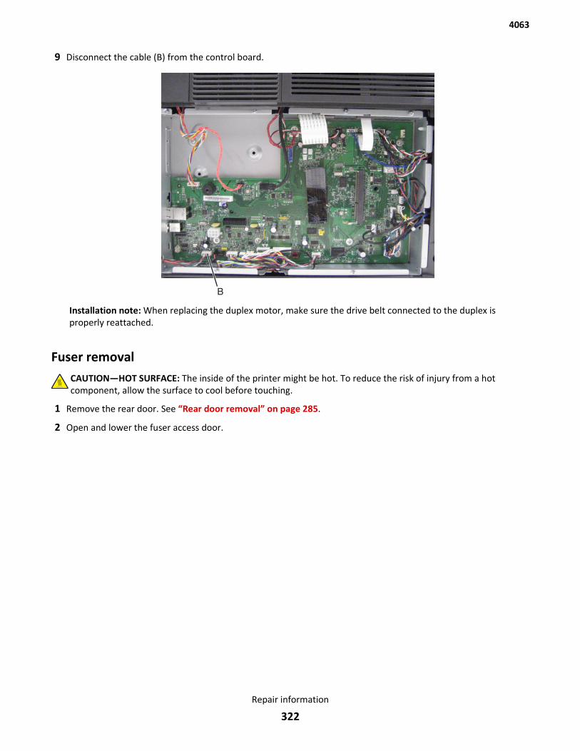
9 Disconnect the cable (B) from the control board.
Installation note: When replacing the duplex motor, make sure the drive belt connected to the duplex isproperly reattached.
Fuser removalCAUTION—HOT SURFACE: The inside of the printer might be hot. To reduce the risk of injury from a hotcomponent, allow the surface to cool before touching.
1 Remove the rear door. See “Rear door removal” on page 285.
2 Open and lower the fuser access door.
4063
Repair information
322
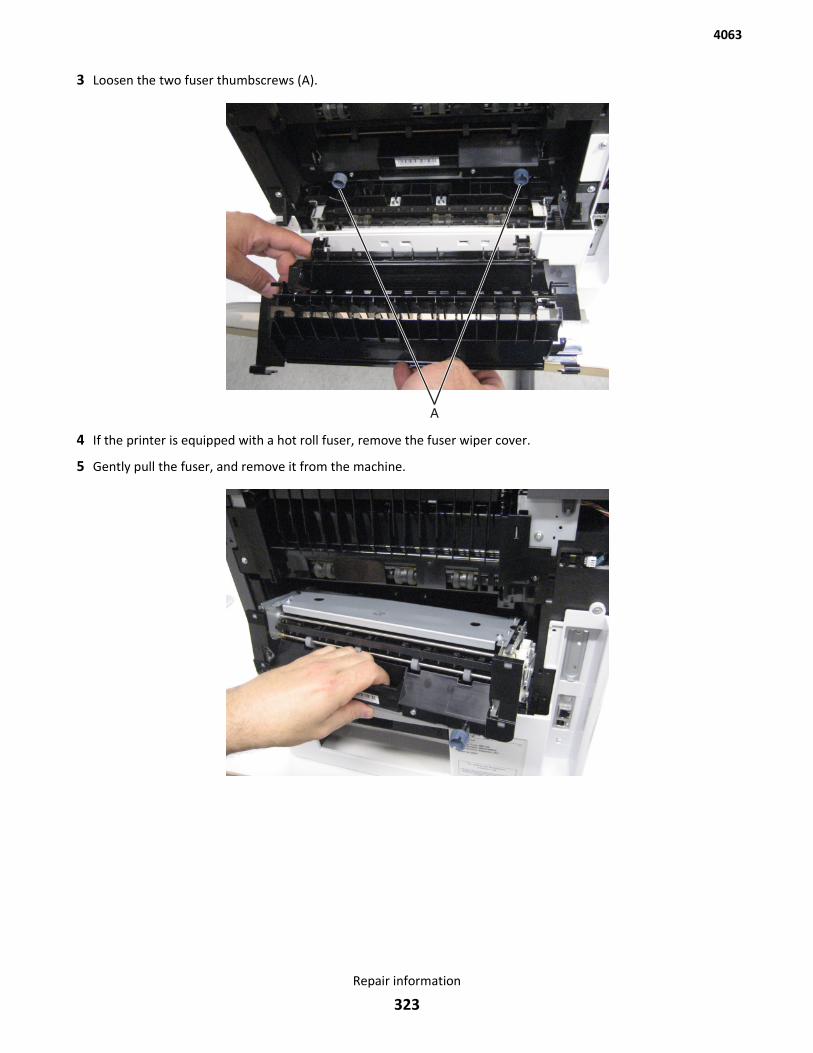
3 Loosen the two fuser thumbscrews (A).
4 If the printer is equipped with a hot roll fuser, remove the fuser wiper cover.
5 Gently pull the fuser, and remove it from the machine.
4063
Repair information
323
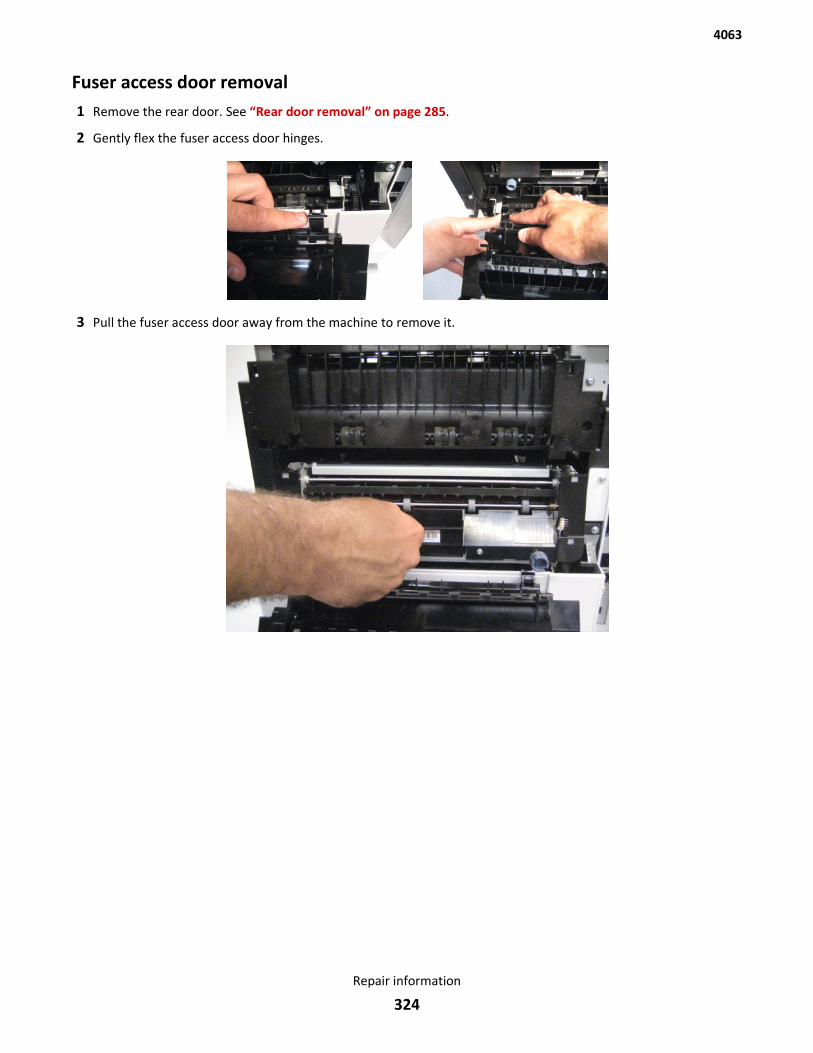
Fuser access door removal1 Remove the rear door. See “Rear door removal” on page 285.
2 Gently flex the fuser access door hinges.
3 Pull the fuser access door away from the machine to remove it.
4063
Repair information
324
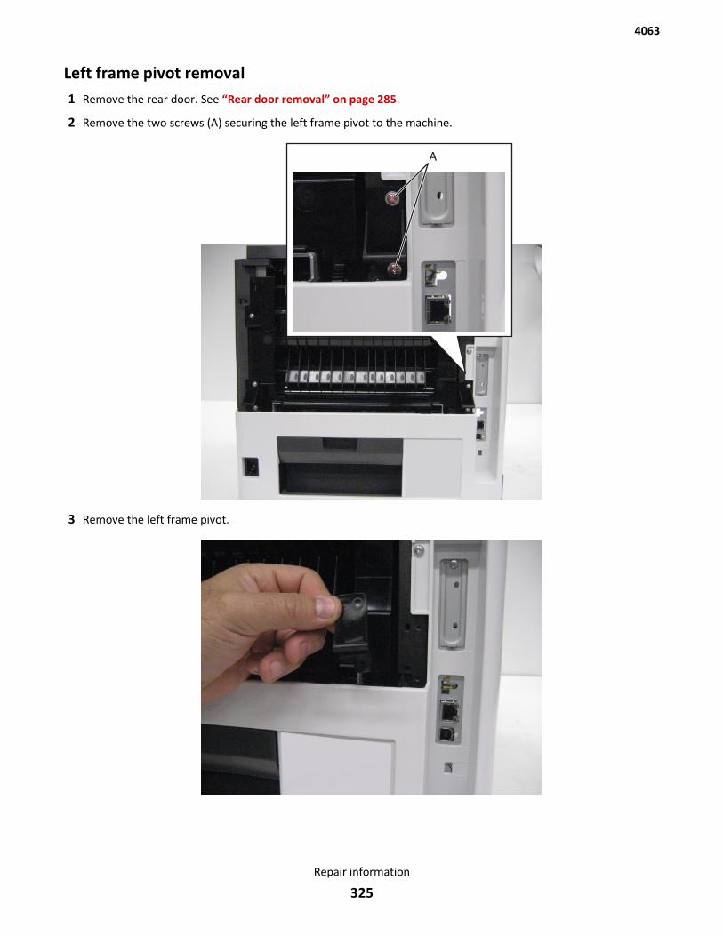
Left frame pivot removal1 Remove the rear door. See “Rear door removal” on page 285.
2 Remove the two screws (A) securing the left frame pivot to the machine.
3 Remove the left frame pivot.
4063
Repair information
325
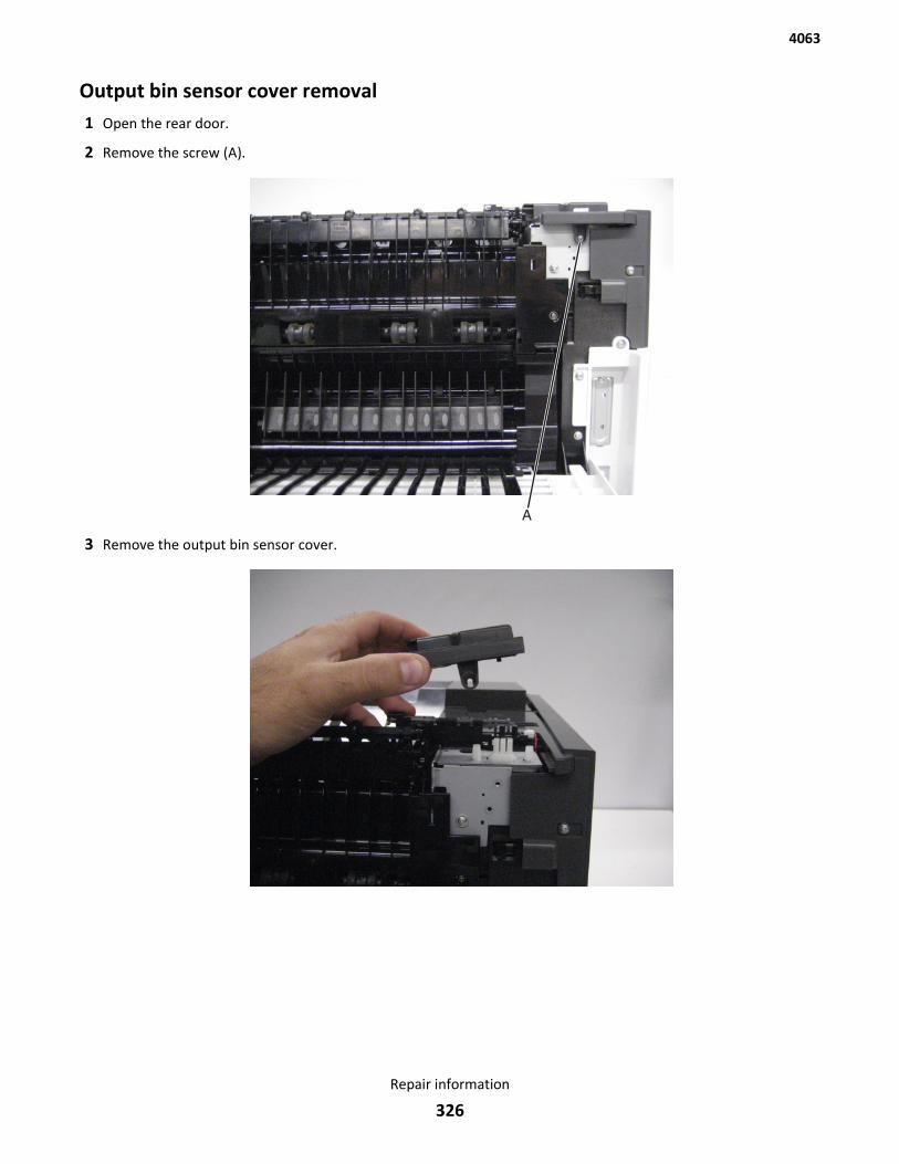
Output bin sensor cover removal1 Open the rear door.
2 Remove the screw (A).
3 Remove the output bin sensor cover.
4063
Repair information
326
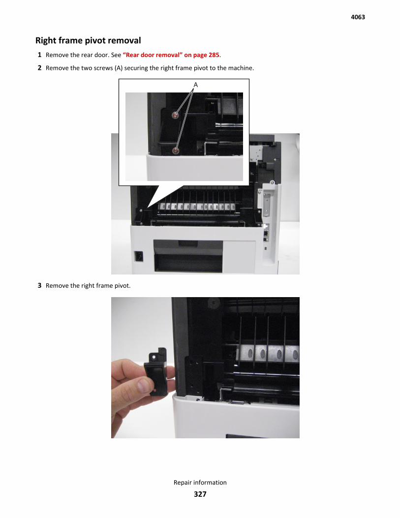
Right frame pivot removal1 Remove the rear door. See “Rear door removal” on page 285.
2 Remove the two screws (A) securing the right frame pivot to the machine.
3 Remove the right frame pivot.
4063
Repair information
327
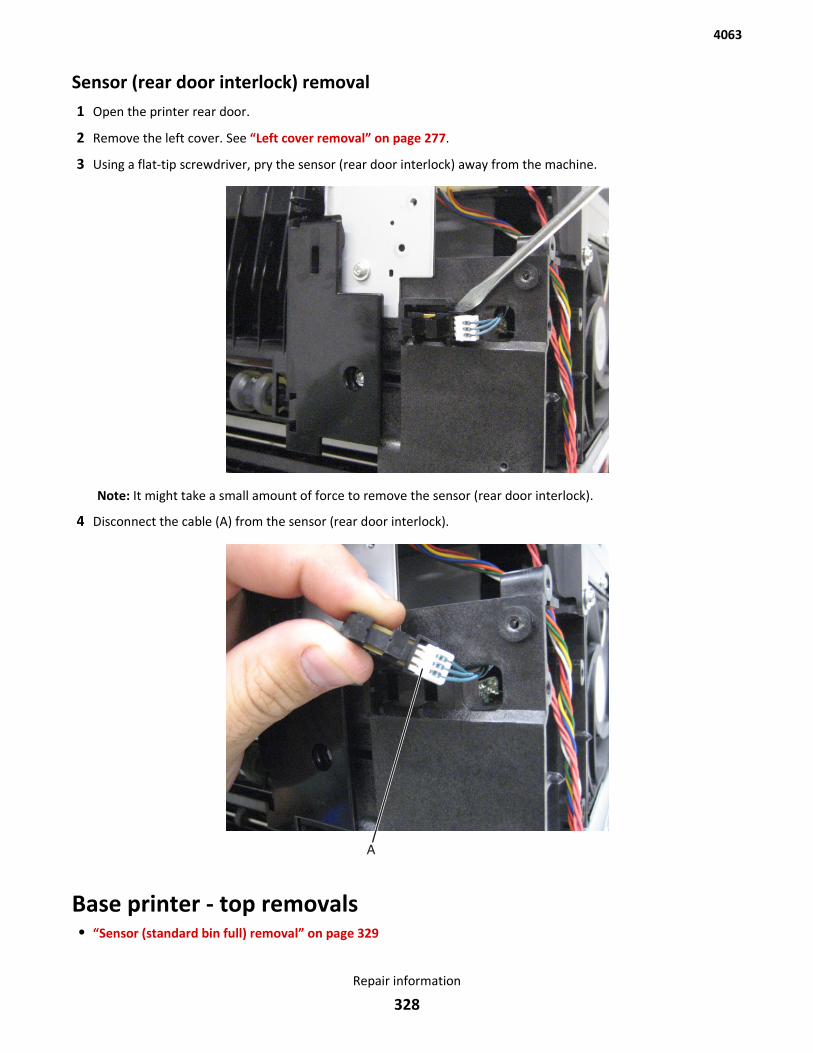
Sensor (rear door interlock) removal1 Open the printer rear door.
2 Remove the left cover. See “Left cover removal” on page 277.
3 Using a flat-tip screwdriver, pry the sensor (rear door interlock) away from the machine.
Note: It might take a small amount of force to remove the sensor (rear door interlock).
4 Disconnect the cable (A) from the sensor (rear door interlock).
Base printer - top removals• “Sensor (standard bin full) removal” on page 329
4063
Repair information
328
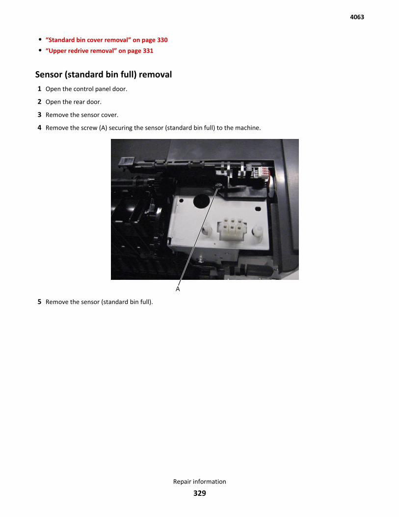
• “Standard bin cover removal” on page 330
• “Upper redrive removal” on page 331
Sensor (standard bin full) removal1 Open the control panel door.
2 Open the rear door.
3 Remove the sensor cover.
4 Remove the screw (A) securing the sensor (standard bin full) to the machine.
5 Remove the sensor (standard bin full).
4063
Repair information
329
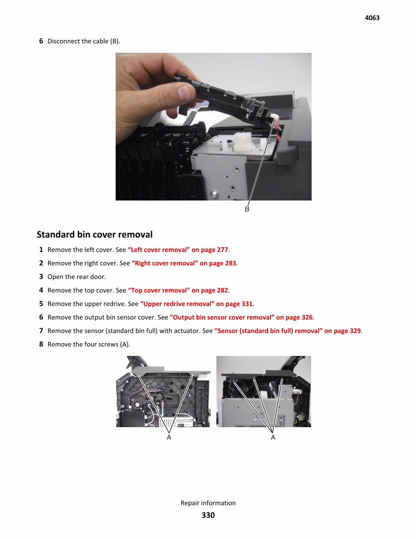
6 Disconnect the cable (B).
Standard bin cover removal1 Remove the left cover. See “Left cover removal” on page 277.
2 Remove the right cover. See “Right cover removal” on page 283.
3 Open the rear door.
4 Remove the top cover. See “Top cover removal” on page 282.
5 Remove the upper redrive. See “Upper redrive removal” on page 331.
6 Remove the output bin sensor cover. See “Output bin sensor cover removal” on page 326.
7 Remove the sensor (standard bin full) with actuator. See “Sensor (standard bin full) removal” on page 329.
8 Remove the four screws (A).
4063
Repair information
330
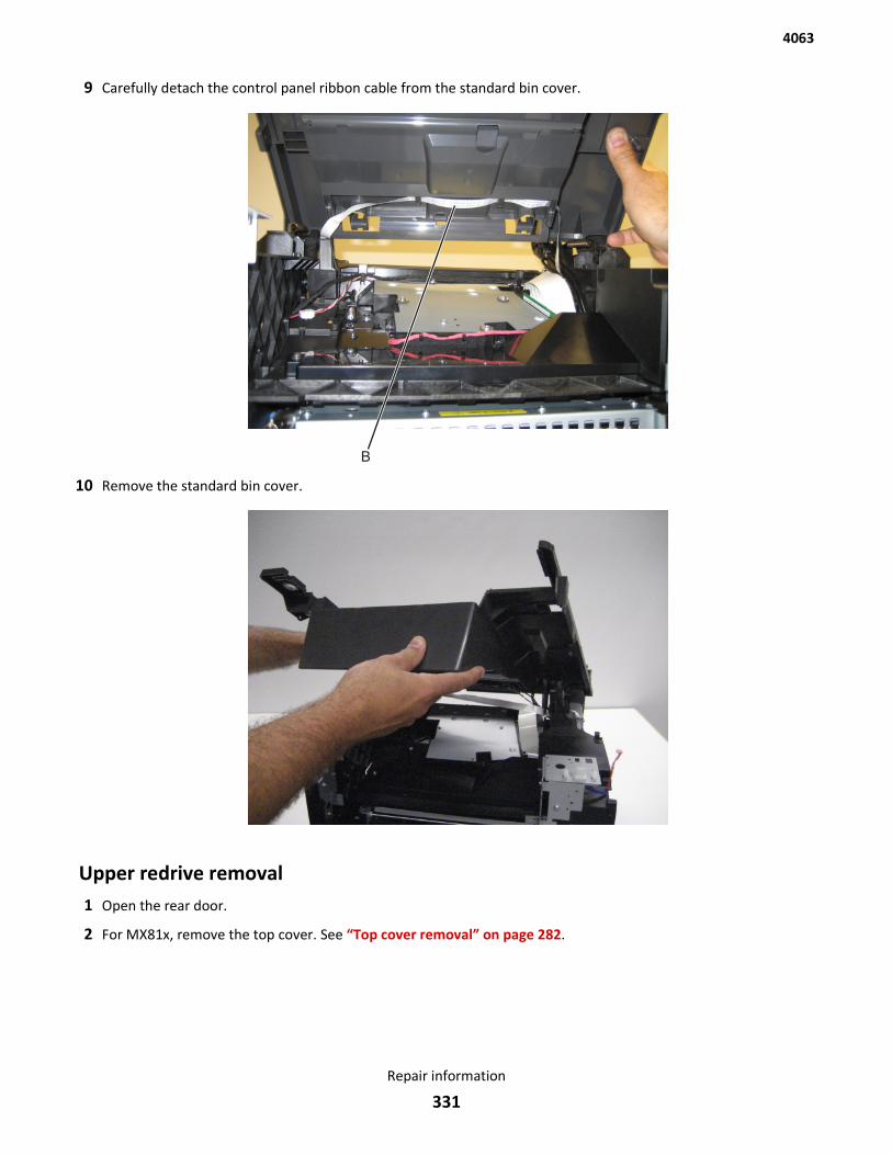
9 Carefully detach the control panel ribbon cable from the standard bin cover.
10 Remove the standard bin cover.
Upper redrive removal1 Open the rear door.
2 For MX81x, remove the top cover. See “Top cover removal” on page 282.
4063
Repair information
331
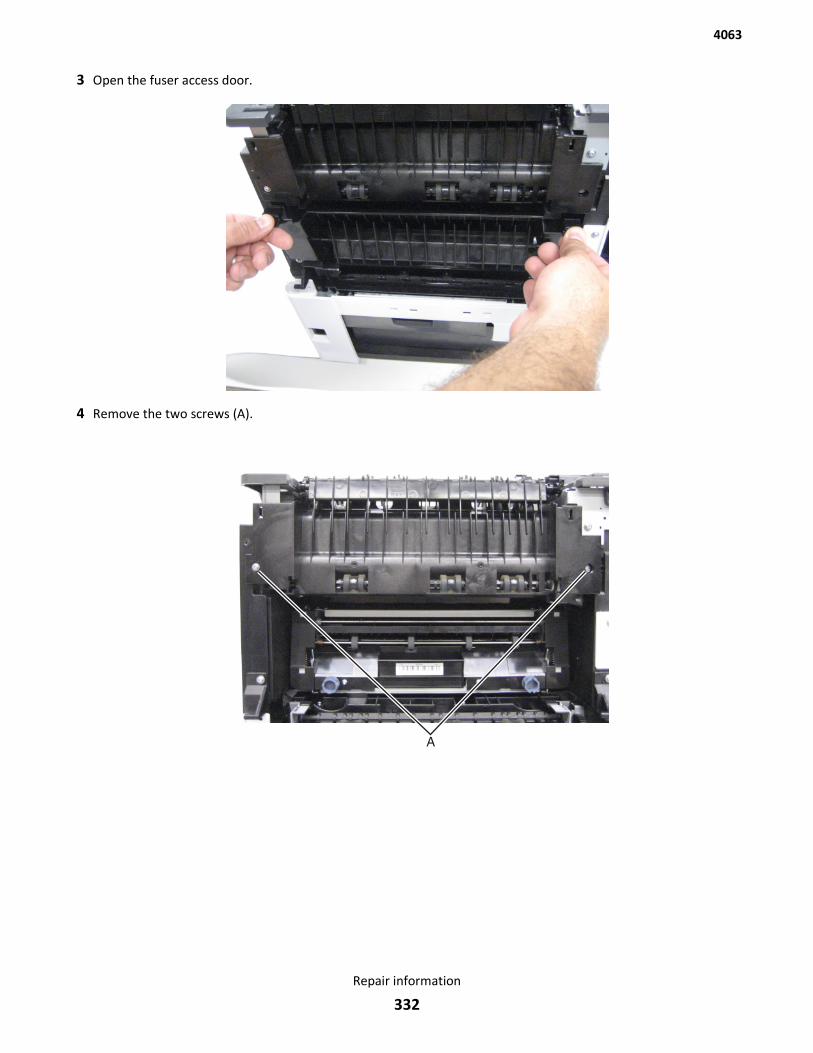
3 Open the fuser access door.
4 Remove the two screws (A).
4063
Repair information
332
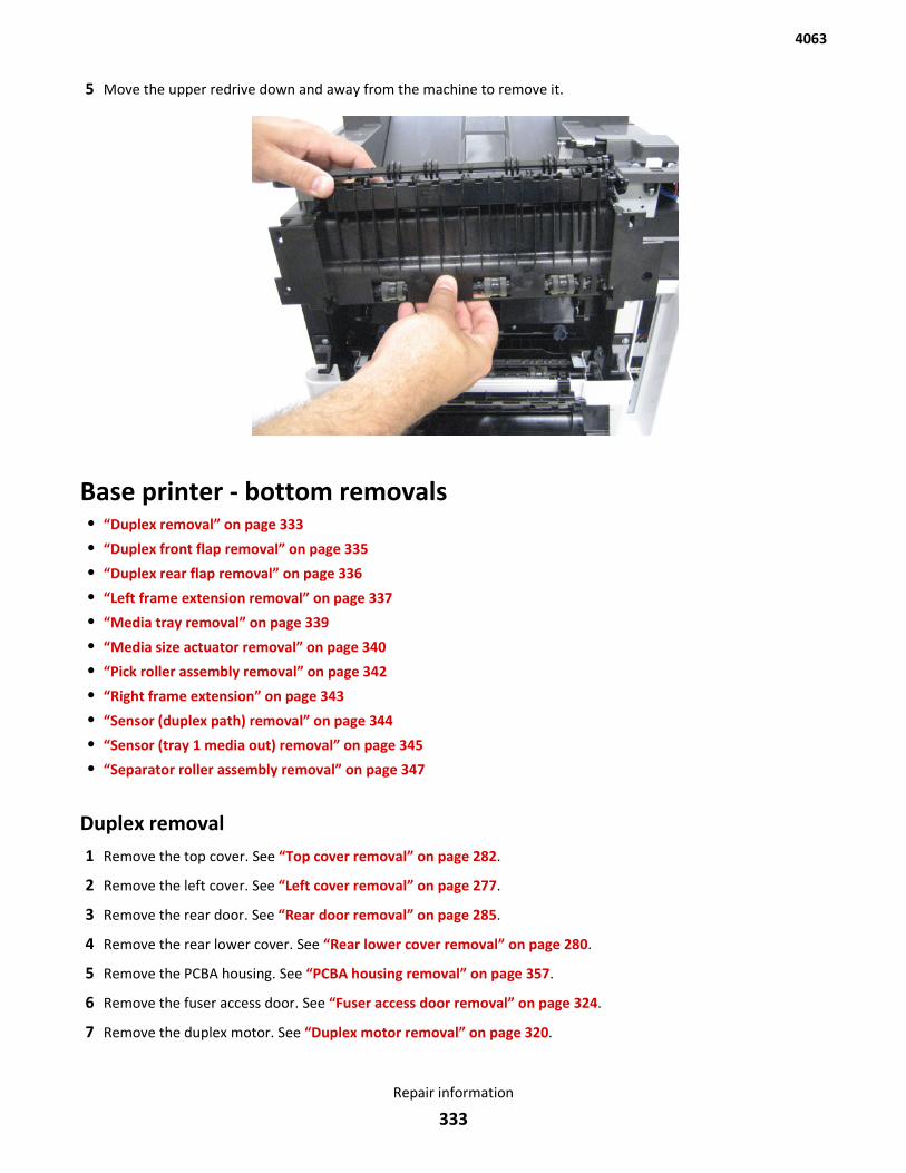
5 Move the upper redrive down and away from the machine to remove it.
Base printer - bottom removals• “Duplex removal” on page 333
• “Duplex front flap removal” on page 335
• “Duplex rear flap removal” on page 336
• “Left frame extension removal” on page 337
• “Media tray removal” on page 339
• “Media size actuator removal” on page 340
• “Pick roller assembly removal” on page 342
• “Right frame extension” on page 343
• “Sensor (duplex path) removal” on page 344
• “Sensor (tray 1 media out) removal” on page 345
• “Separator roller assembly removal” on page 347
Duplex removal1 Remove the top cover. See “Top cover removal” on page 282.
2 Remove the left cover. See “Left cover removal” on page 277.
3 Remove the rear door. See “Rear door removal” on page 285.
4 Remove the rear lower cover. See “Rear lower cover removal” on page 280.
5 Remove the PCBA housing. See “PCBA housing removal” on page 357.
6 Remove the fuser access door. See “Fuser access door removal” on page 324.
7 Remove the duplex motor. See “Duplex motor removal” on page 320.
4063
Repair information
333
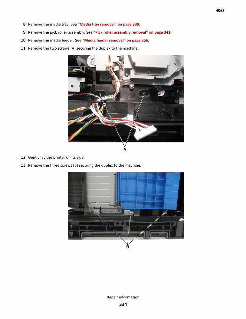
8 Remove the media tray. See “Media tray removal” on page 339.
9 Remove the pick roller assembly. See “Pick roller assembly removal” on page 342.
10 Remove the media feeder. See “Media feeder removal” on page 356.
11 Remove the two screws (A) securing the duplex to the machine.
12 Gently lay the printer on its side.
13 Remove the three screws (B) securing the duplex to the machine.
4063
Repair information
334
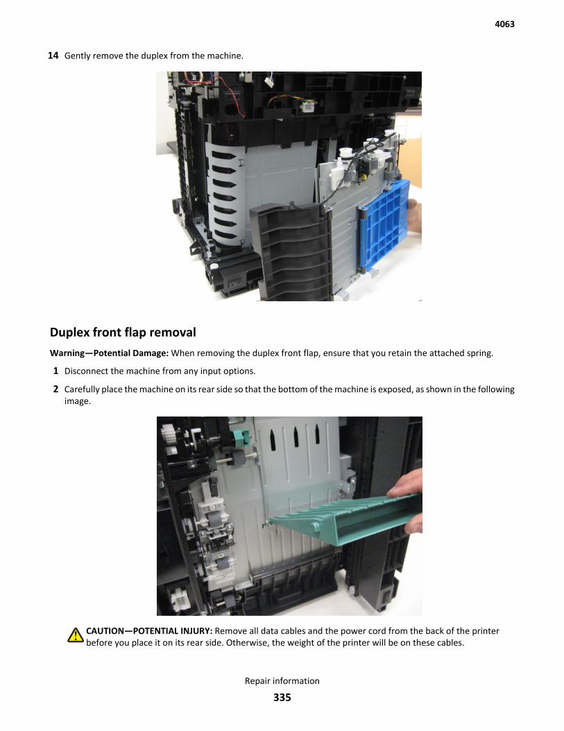
14 Gently remove the duplex from the machine.
Duplex front flap removalWarning—Potential Damage: When removing the duplex front flap, ensure that you retain the attached spring.
1 Disconnect the machine from any input options.
2 Carefully place the machine on its rear side so that the bottom of the machine is exposed, as shown in the followingimage.
CAUTION—POTENTIAL INJURY: Remove all data cables and the power cord from the back of the printerbefore you place it on its rear side. Otherwise, the weight of the printer will be on these cables.
4063
Repair information
335
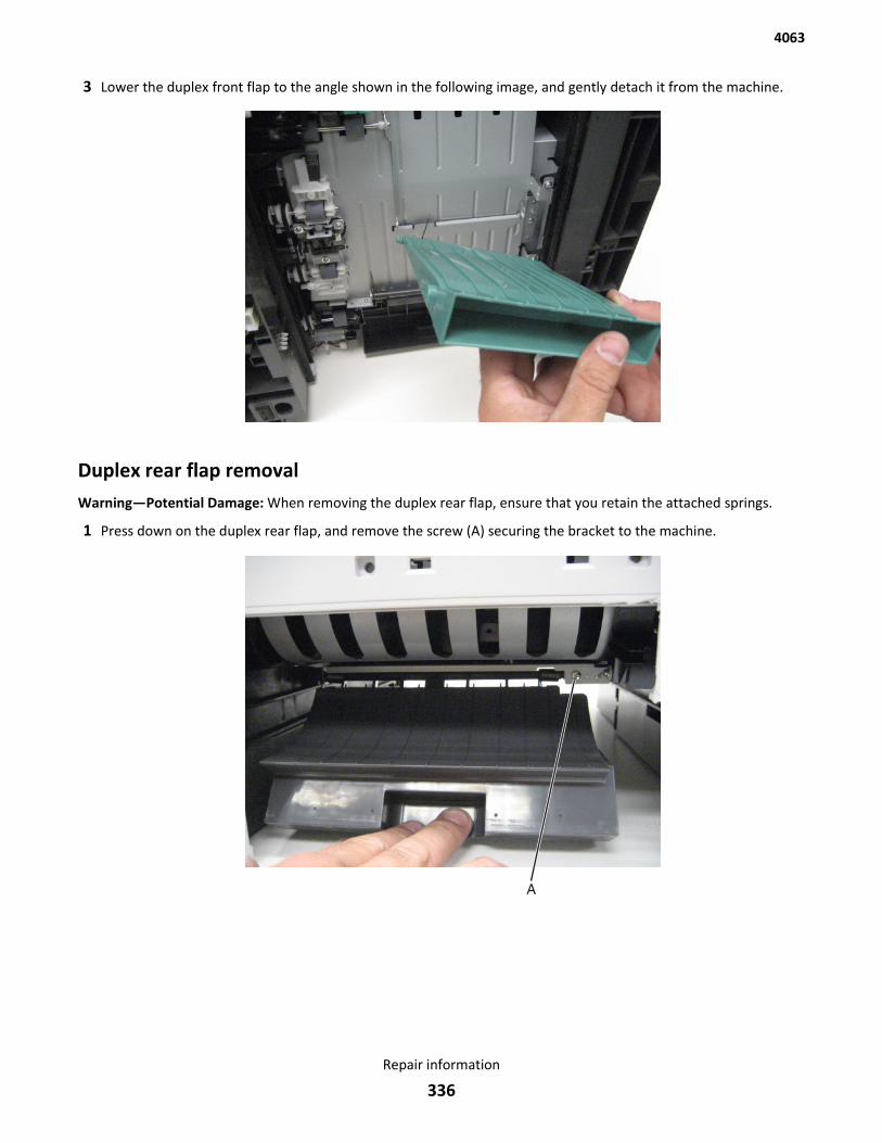
3 Lower the duplex front flap to the angle shown in the following image, and gently detach it from the machine.
Duplex rear flap removalWarning—Potential Damage: When removing the duplex rear flap, ensure that you retain the attached springs.
1 Press down on the duplex rear flap, and remove the screw (A) securing the bracket to the machine.
4063
Repair information
336
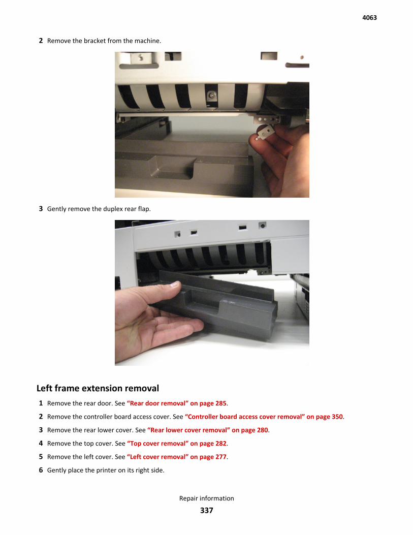
2 Remove the bracket from the machine.
3 Gently remove the duplex rear flap.
Left frame extension removal1 Remove the rear door. See “Rear door removal” on page 285.
2 Remove the controller board access cover. See “Controller board access cover removal” on page 350.
3 Remove the rear lower cover. See “Rear lower cover removal” on page 280.
4 Remove the top cover. See “Top cover removal” on page 282.
5 Remove the left cover. See “Left cover removal” on page 277.
6 Gently place the printer on its right side.
4063
Repair information
337
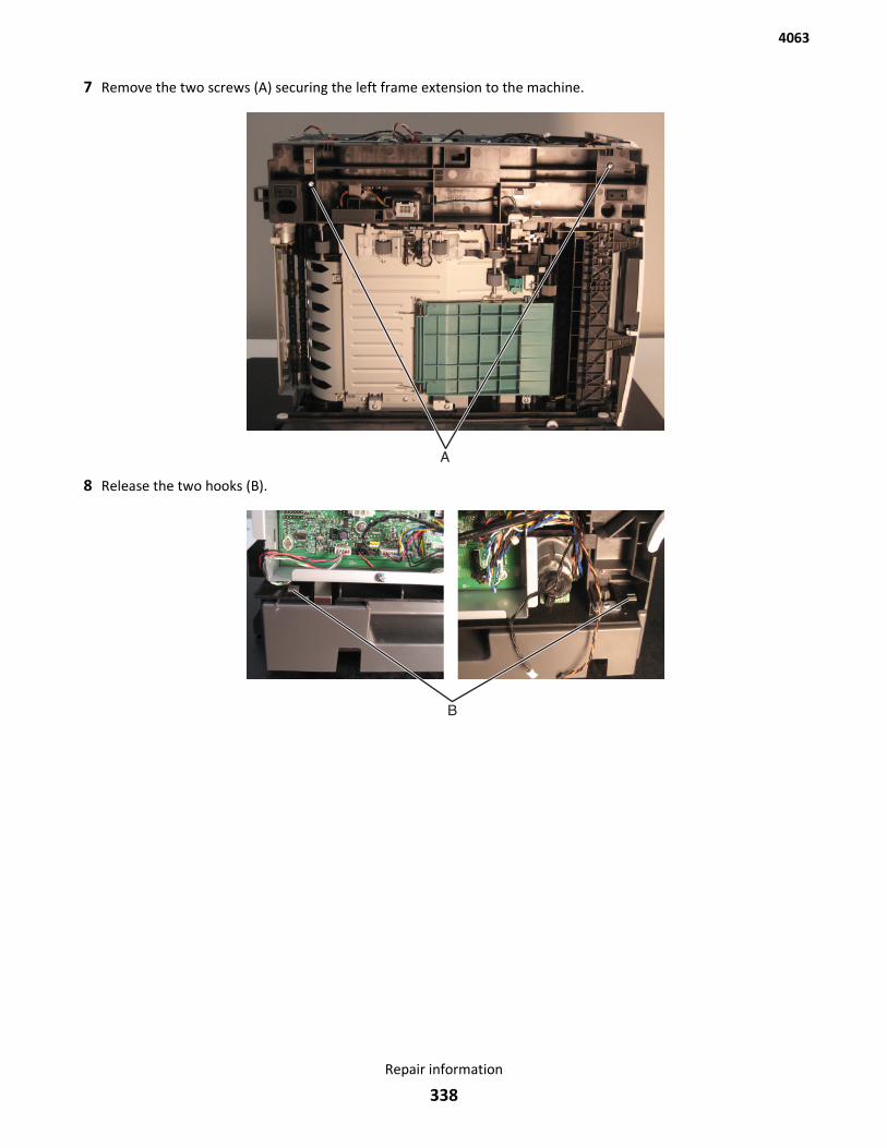
7 Remove the two screws (A) securing the left frame extension to the machine.
8 Release the two hooks (B).
4063
Repair information
338
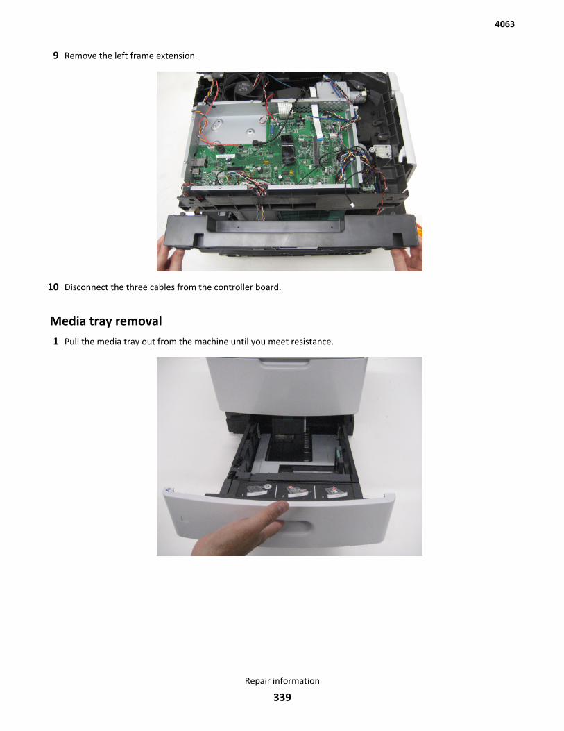
9 Remove the left frame extension.
10 Disconnect the three cables from the controller board.
Media tray removal1 Pull the media tray out from the machine until you meet resistance.
4063
Repair information
339
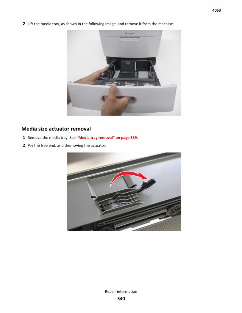
2 Lift the media tray, as shown in the following image, and remove it from the machine.
Media size actuator removal1 Remove the media tray. See “Media tray removal” on page 339.
2 Pry the free end, and then swing the actuator.
4063
Repair information
340
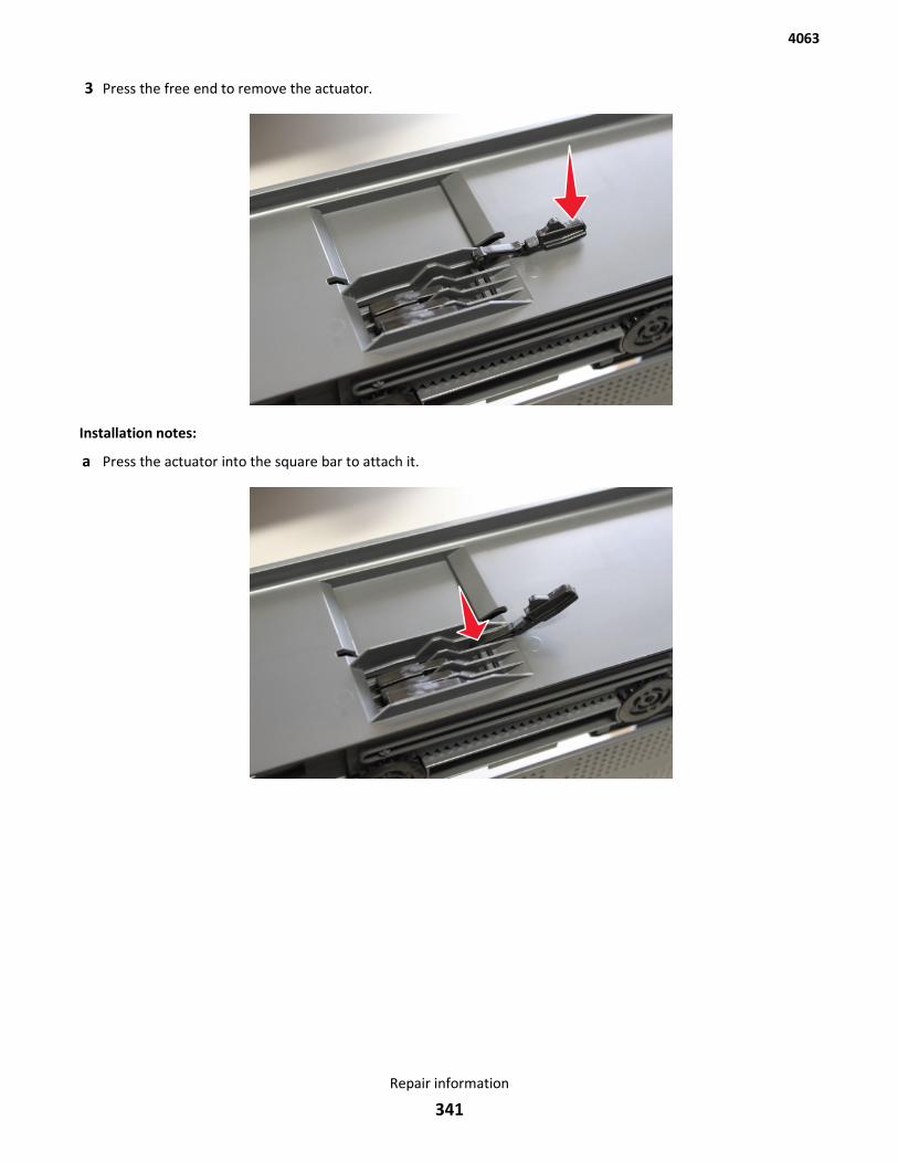
3 Press the free end to remove the actuator.
Installation notes:
a Press the actuator into the square bar to attach it.
4063
Repair information
341
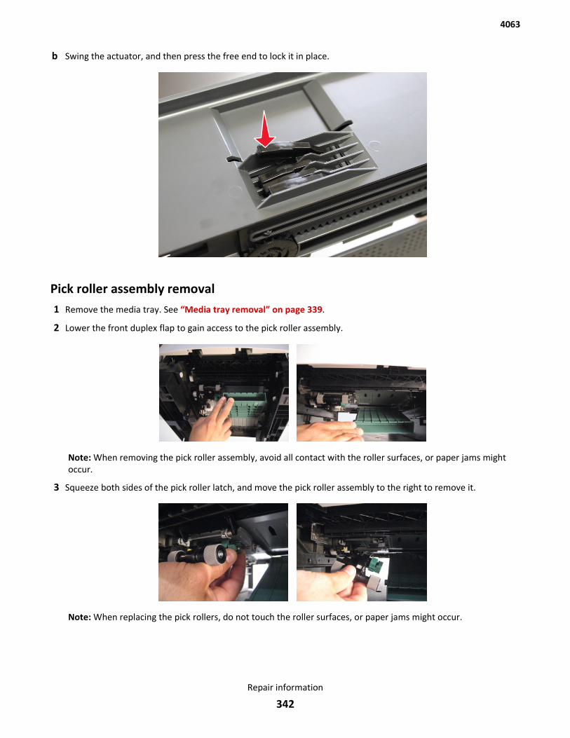
b Swing the actuator, and then press the free end to lock it in place.
Pick roller assembly removal1 Remove the media tray. See “Media tray removal” on page 339.
2 Lower the front duplex flap to gain access to the pick roller assembly.
Note: When removing the pick roller assembly, avoid all contact with the roller surfaces, or paper jams mightoccur.
3 Squeeze both sides of the pick roller latch, and move the pick roller assembly to the right to remove it.
Note: When replacing the pick rollers, do not touch the roller surfaces, or paper jams might occur.
4063
Repair information
342
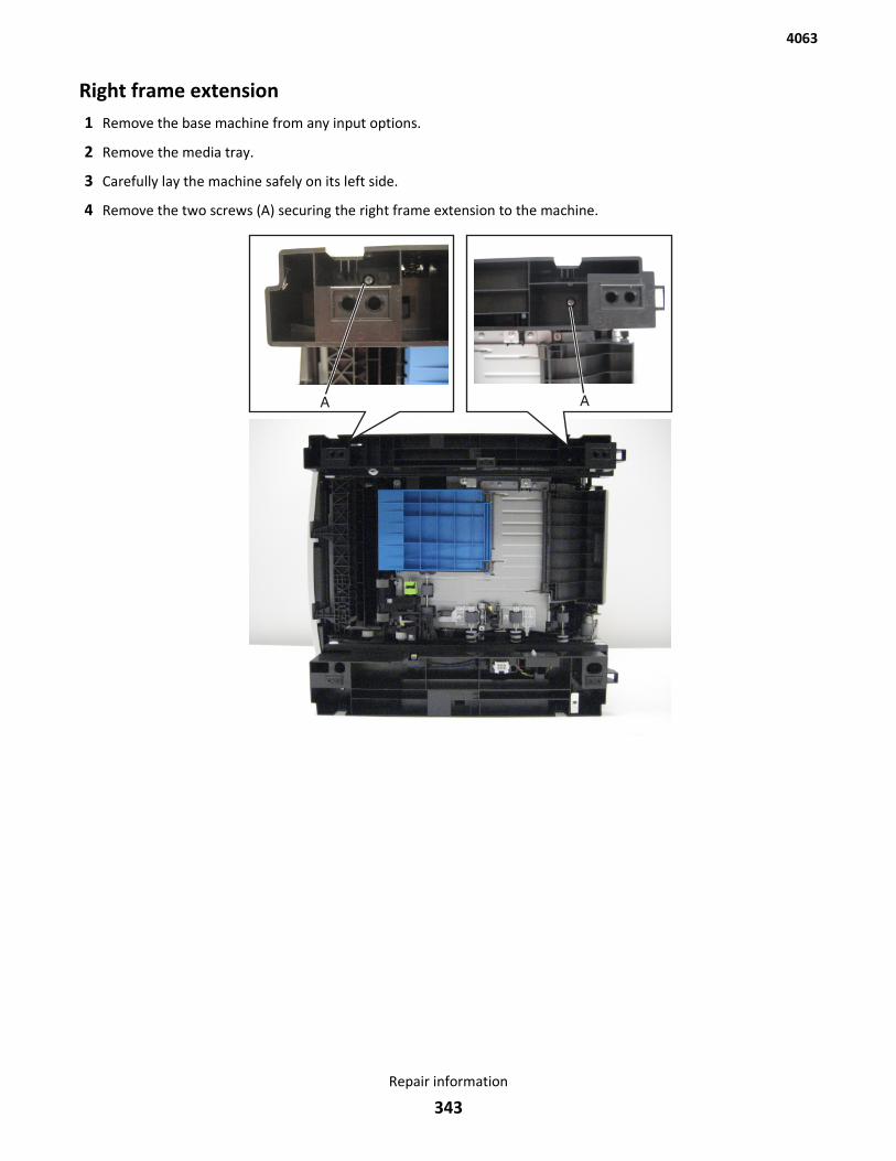
Right frame extension1 Remove the base machine from any input options.
2 Remove the media tray.
3 Carefully lay the machine safely on its left side.
4 Remove the two screws (A) securing the right frame extension to the machine.
4063
Repair information
343
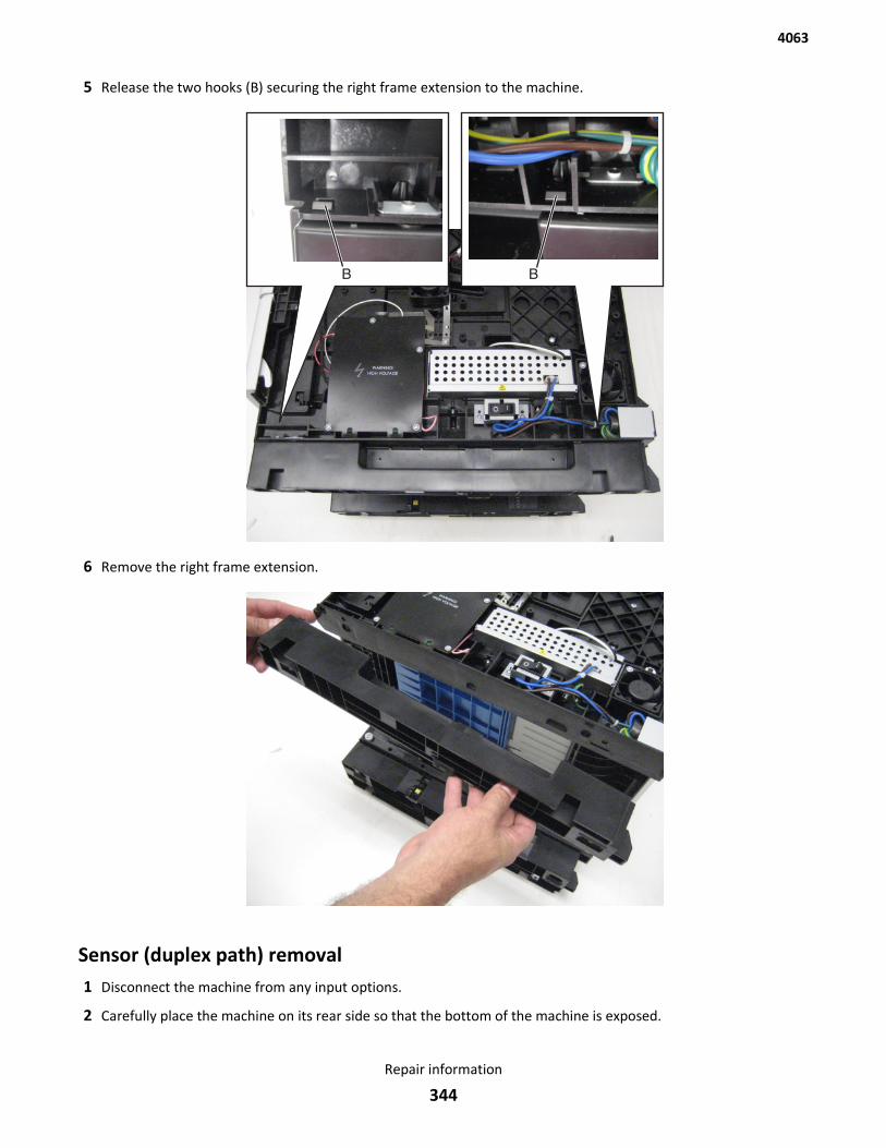
5 Release the two hooks (B) securing the right frame extension to the machine.
6 Remove the right frame extension.
Sensor (duplex path) removal1 Disconnect the machine from any input options.
2 Carefully place the machine on its rear side so that the bottom of the machine is exposed.
4063
Repair information
344
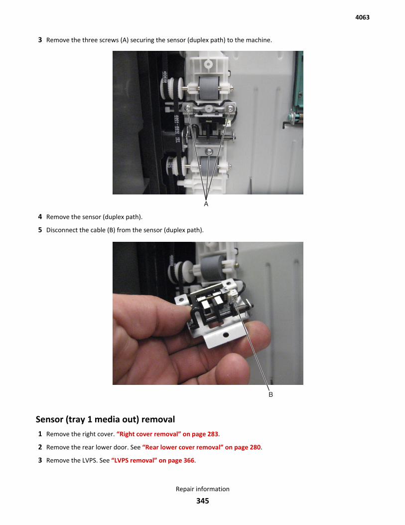
3 Remove the three screws (A) securing the sensor (duplex path) to the machine.
4 Remove the sensor (duplex path).
5 Disconnect the cable (B) from the sensor (duplex path).
Sensor (tray 1 media out) removal1 Remove the right cover. “Right cover removal” on page 283.
2 Remove the rear lower door. See “Rear lower cover removal” on page 280.
3 Remove the LVPS. See “LVPS removal” on page 366.
4063
Repair information
345
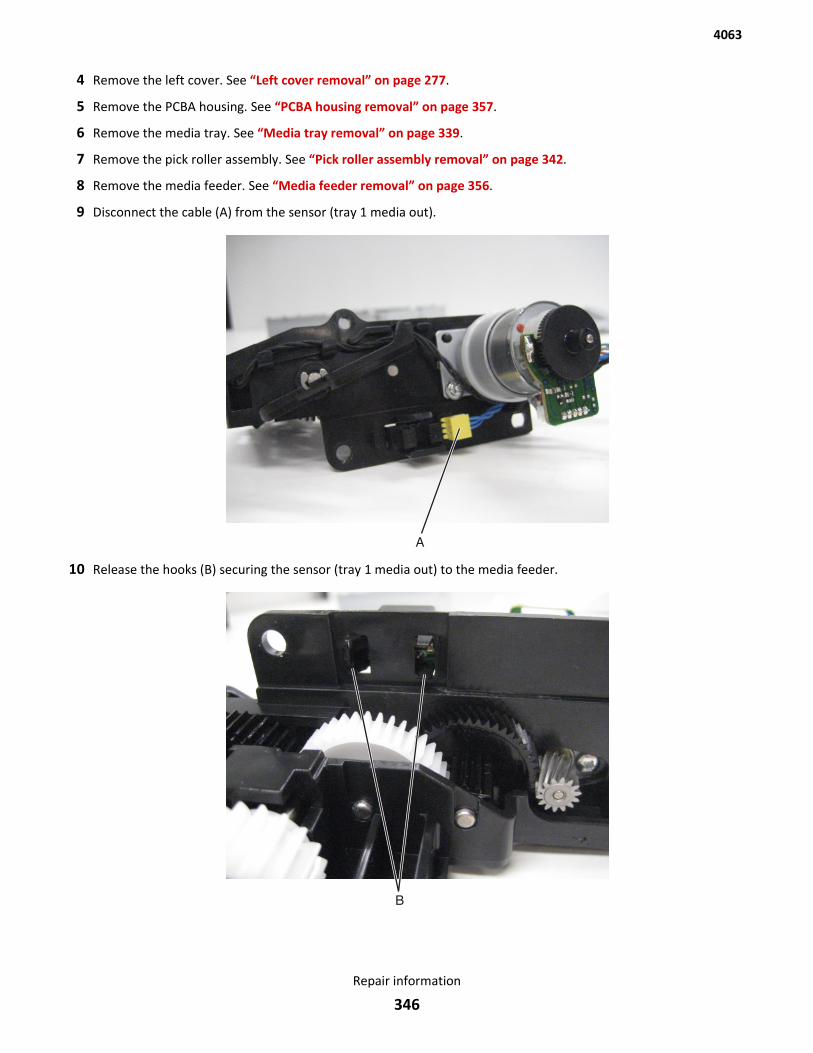
4 Remove the left cover. See “Left cover removal” on page 277.
5 Remove the PCBA housing. See “PCBA housing removal” on page 357.
6 Remove the media tray. See “Media tray removal” on page 339.
7 Remove the pick roller assembly. See “Pick roller assembly removal” on page 342.
8 Remove the media feeder. See “Media feeder removal” on page 356.
9 Disconnect the cable (A) from the sensor (tray 1 media out).
10 Release the hooks (B) securing the sensor (tray 1 media out) to the media feeder.
4063
Repair information
346
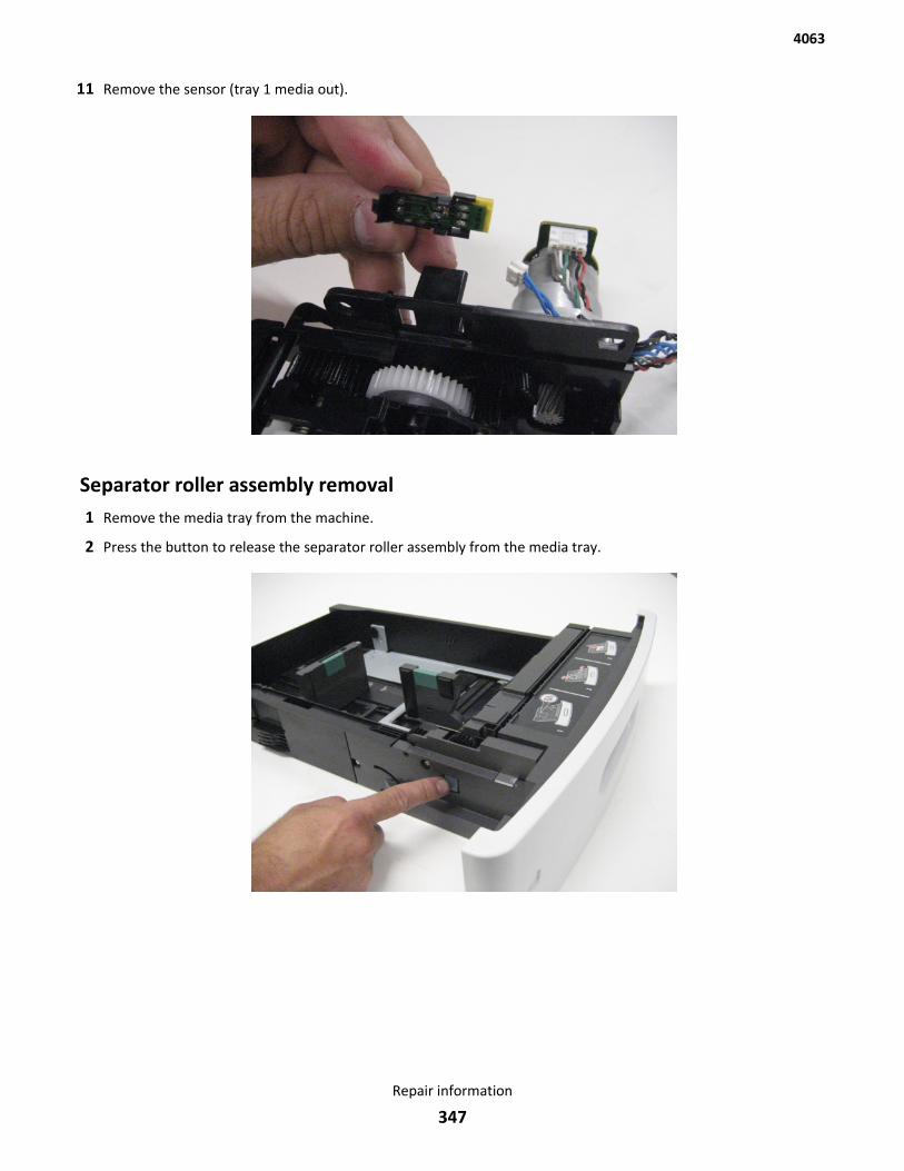
11 Remove the sensor (tray 1 media out).
Separator roller assembly removal1 Remove the media tray from the machine.
2 Press the button to release the separator roller assembly from the media tray.
4063
Repair information
347
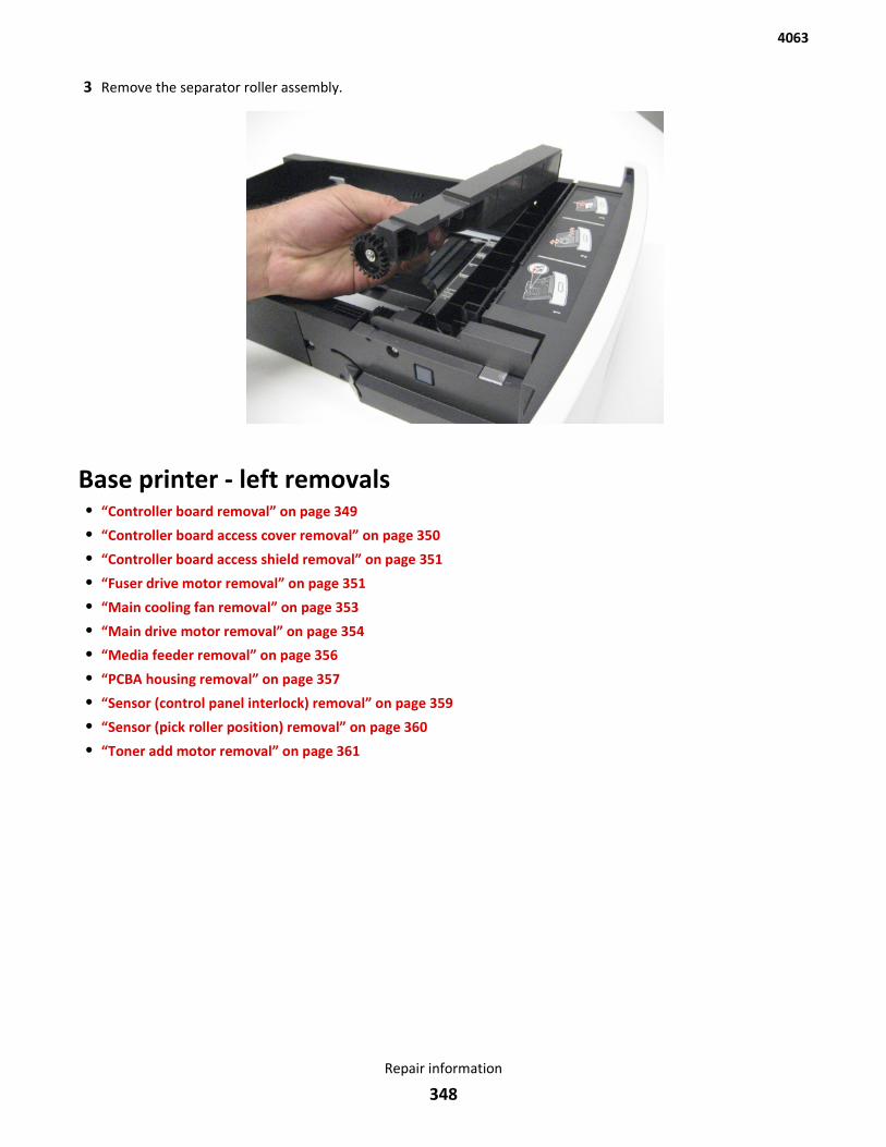
3 Remove the separator roller assembly.
Base printer - left removals• “Controller board removal” on page 349
• “Controller board access cover removal” on page 350
• “Controller board access shield removal” on page 351
• “Fuser drive motor removal” on page 351
• “Main cooling fan removal” on page 353
• “Main drive motor removal” on page 354
• “Media feeder removal” on page 356
• “PCBA housing removal” on page 357
• “Sensor (control panel interlock) removal” on page 359
• “Sensor (pick roller position) removal” on page 360
• “Toner add motor removal” on page 361
4063
Repair information
348
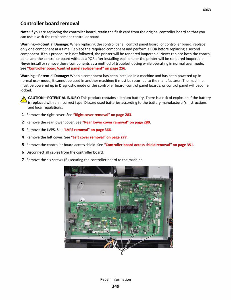
Controller board removalNote: If you are replacing the controller board, retain the flash card from the original controller board so that youcan use it with the replacement controller board.
Warning—Potential Damage: When replacing the control panel, control panel board, or controller board, replaceonly one component at a time. Replace the required component and perform a POR before replacing a secondcomponent. If this procedure is not followed, the printer will be rendered inoperable. Never replace both the controlpanel and the controller board without a POR after installing each one or the printer will be rendered inoperable.Never install or remove these components as a method of troubleshooting while operating in normal user mode.See “Controller board/control panel replacement” on page 256.
Warning—Potential Damage: When a component has been installed in a machine and has been powered up innormal user mode, it cannot be used in another machine; it must be returned to the manufacturer. The machinemust be powered up in Diagnostic mode or the controller board, control panel boards, or control panel will becomelocked.
CAUTION—POTENTIAL INJURY: This product contains a lithium battery. There is a risk of explosion if the batteryis replaced with an incorrect type. Discard used batteries according to the battery manufacturer’s instructionsand local regulations.
1 Remove the right cover. See “Right cover removal” on page 283.
2 Remove the rear lower cover. See “Rear lower cover removal” on page 280.
3 Remove the LVPS. See “LVPS removal” on page 366.
4 Remove the left cover. See “Left cover removal” on page 277.
5 Remove the controller board access shield. See “Controller board access shield removal” on page 351.
6 Disconnect all cables from the controller board.
7 Remove the six screws (B) securing the controller board to the machine.
4063
Repair information
349
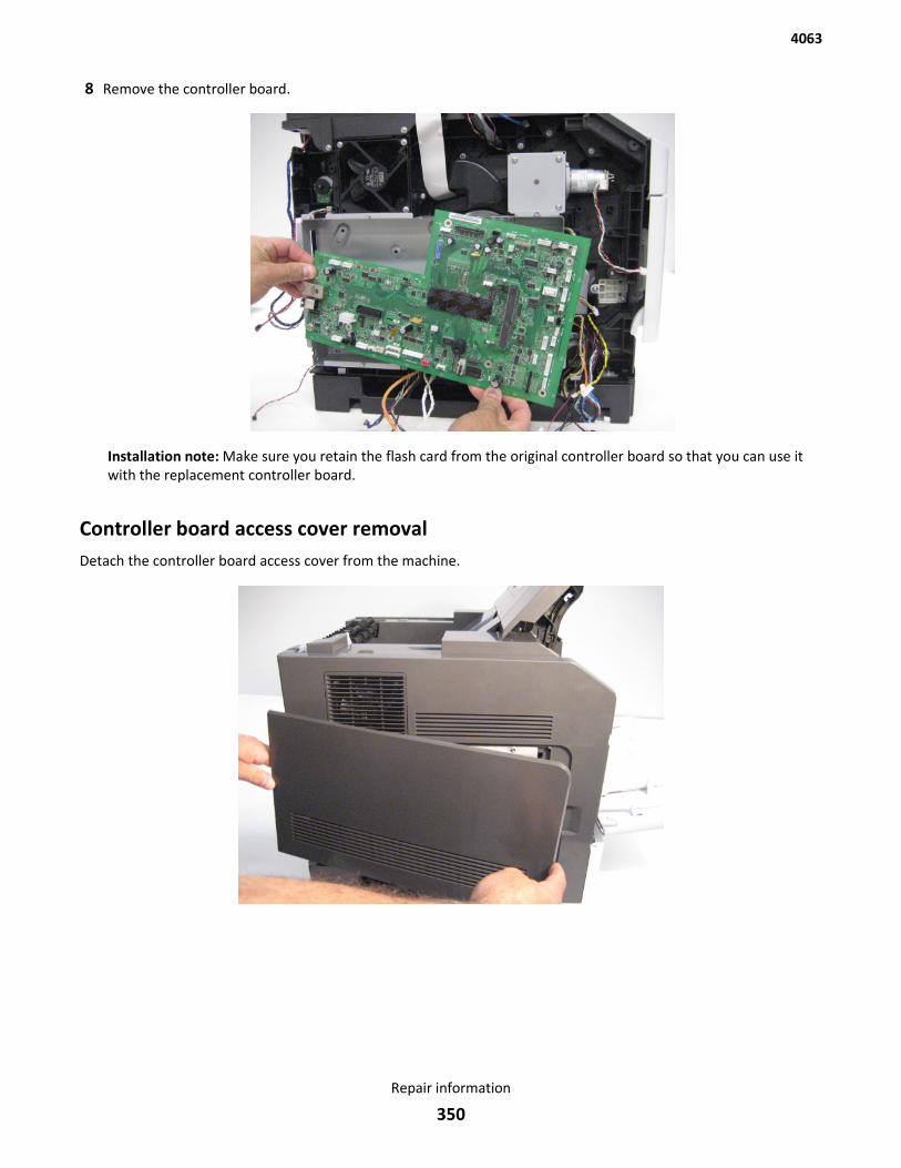
8 Remove the controller board.
Installation note: Make sure you retain the flash card from the original controller board so that you can use itwith the replacement controller board.
Controller board access cover removalDetach the controller board access cover from the machine.
4063
Repair information
350
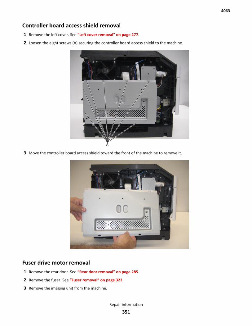
Controller board access shield removal1 Remove the left cover. See “Left cover removal” on page 277.
2 Loosen the eight screws (A) securing the controller board access shield to the machine.
3 Move the controller board access shield toward the front of the machine to remove it.
Fuser drive motor removal1 Remove the rear door. See “Rear door removal” on page 285.
2 Remove the fuser. See “Fuser removal” on page 322.
3 Remove the imaging unit from the machine.
4063
Repair information
351
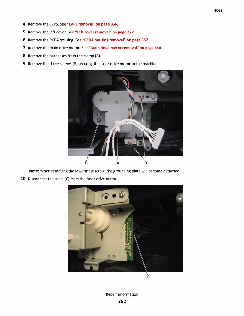
4 Remove the LVPS. See “LVPS removal” on page 366.
5 Remove the left cover. See “Left cover removal” on page 277.
6 Remove the PCBA housing. See “PCBA housing removal” on page 357.
7 Remove the main drive motor. See “Main drive motor removal” on page 354.
8 Remove the harnesses from the clamp (A).
9 Remove the three screws (B) securing the fuser drive motor to the machine.
Note: When removing the lowermost screw, the grounding plate will become detached.
10 Disconnect the cable (C) from the fuser drive motor.
4063
Repair information
352
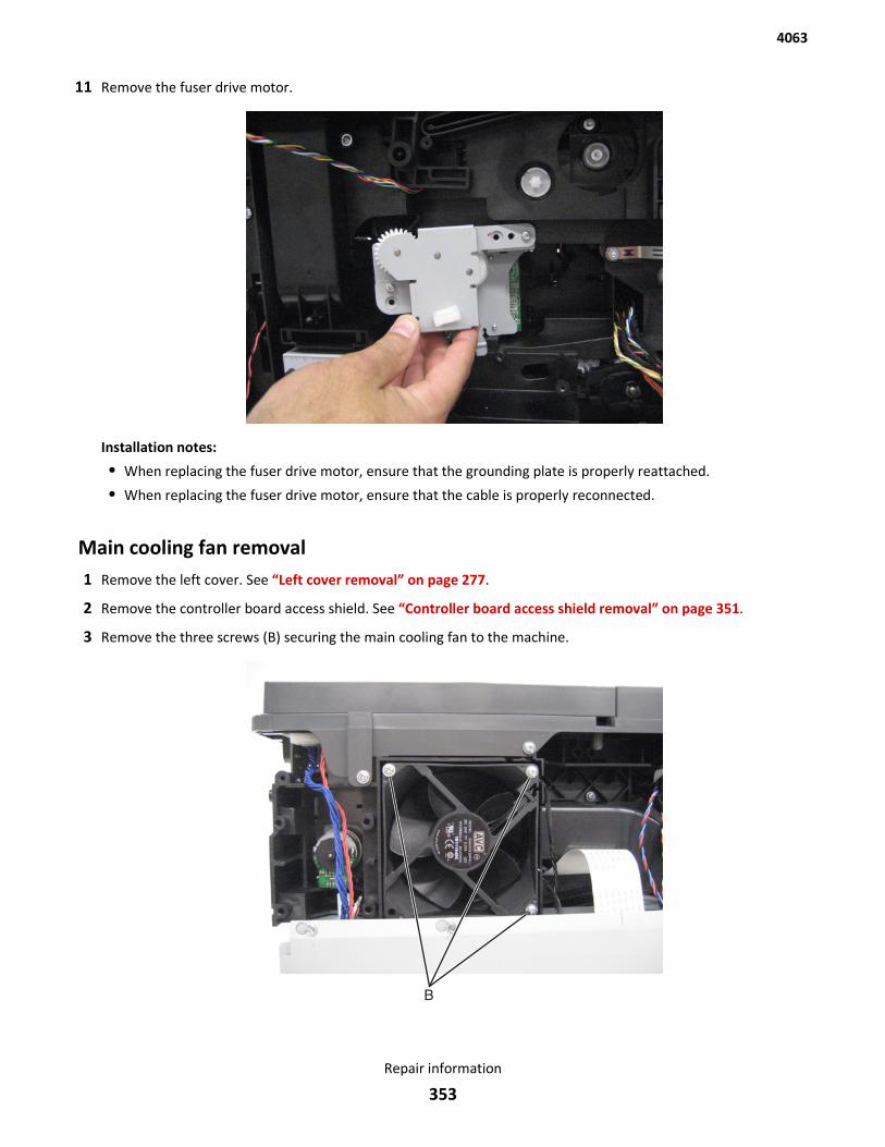
11 Remove the fuser drive motor.
Installation notes:
• When replacing the fuser drive motor, ensure that the grounding plate is properly reattached.
• When replacing the fuser drive motor, ensure that the cable is properly reconnected.
Main cooling fan removal1 Remove the left cover. See “Left cover removal” on page 277.
2 Remove the controller board access shield. See “Controller board access shield removal” on page 351.
3 Remove the three screws (B) securing the main cooling fan to the machine.
4063
Repair information
353
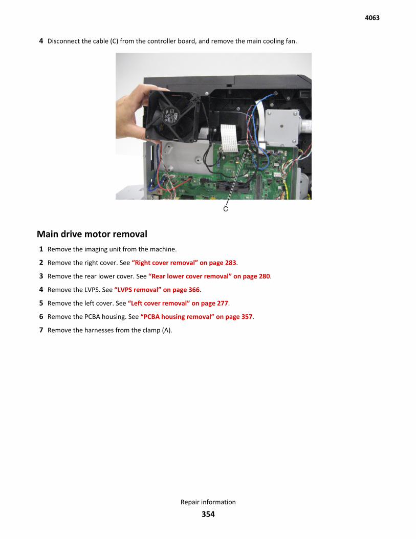
4 Disconnect the cable (C) from the controller board, and remove the main cooling fan.
Main drive motor removal1 Remove the imaging unit from the machine.
2 Remove the right cover. See “Right cover removal” on page 283.
3 Remove the rear lower cover. See “Rear lower cover removal” on page 280.
4 Remove the LVPS. See “LVPS removal” on page 366.
5 Remove the left cover. See “Left cover removal” on page 277.
6 Remove the PCBA housing. See “PCBA housing removal” on page 357.
7 Remove the harnesses from the clamp (A).
4063
Repair information
354
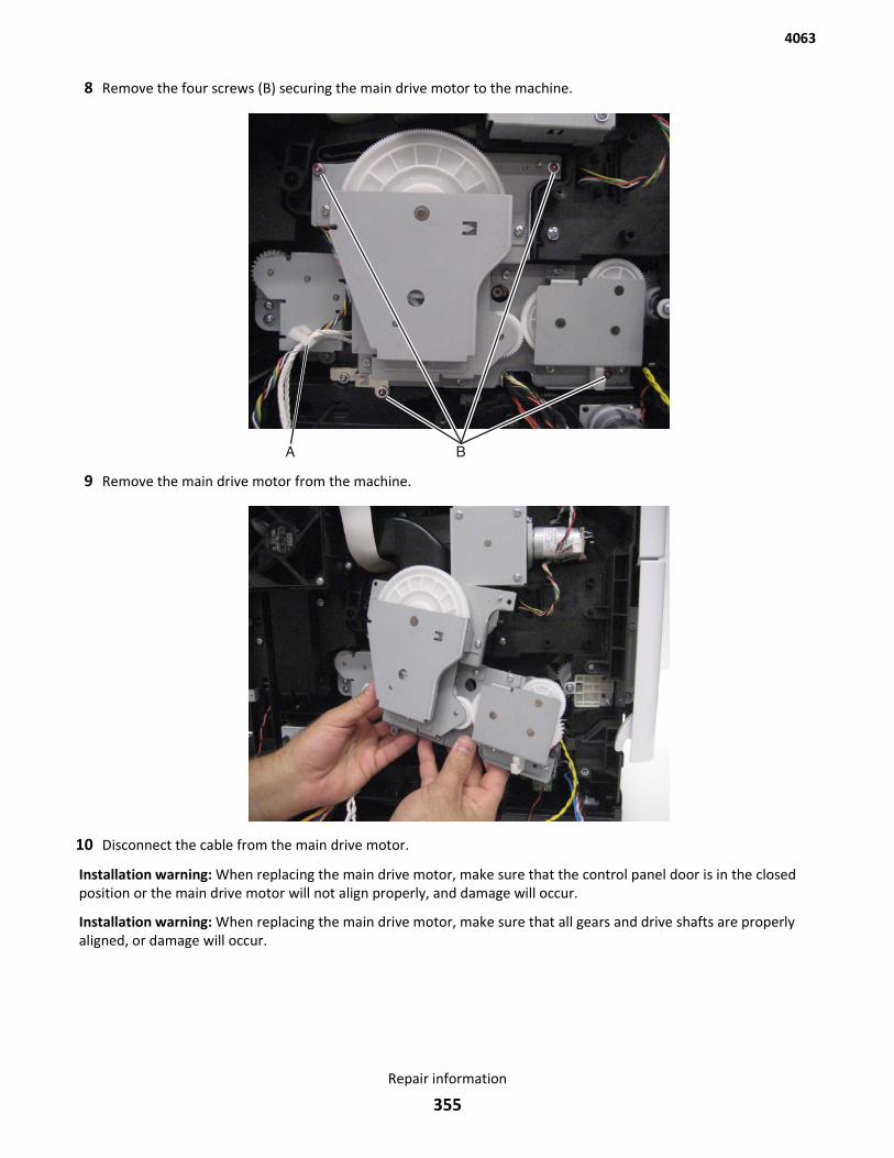
8 Remove the four screws (B) securing the main drive motor to the machine.
9 Remove the main drive motor from the machine.
10 Disconnect the cable from the main drive motor.
Installation warning: When replacing the main drive motor, make sure that the control panel door is in the closedposition or the main drive motor will not align properly, and damage will occur.
Installation warning: When replacing the main drive motor, make sure that all gears and drive shafts are properlyaligned, or damage will occur.
4063
Repair information
355
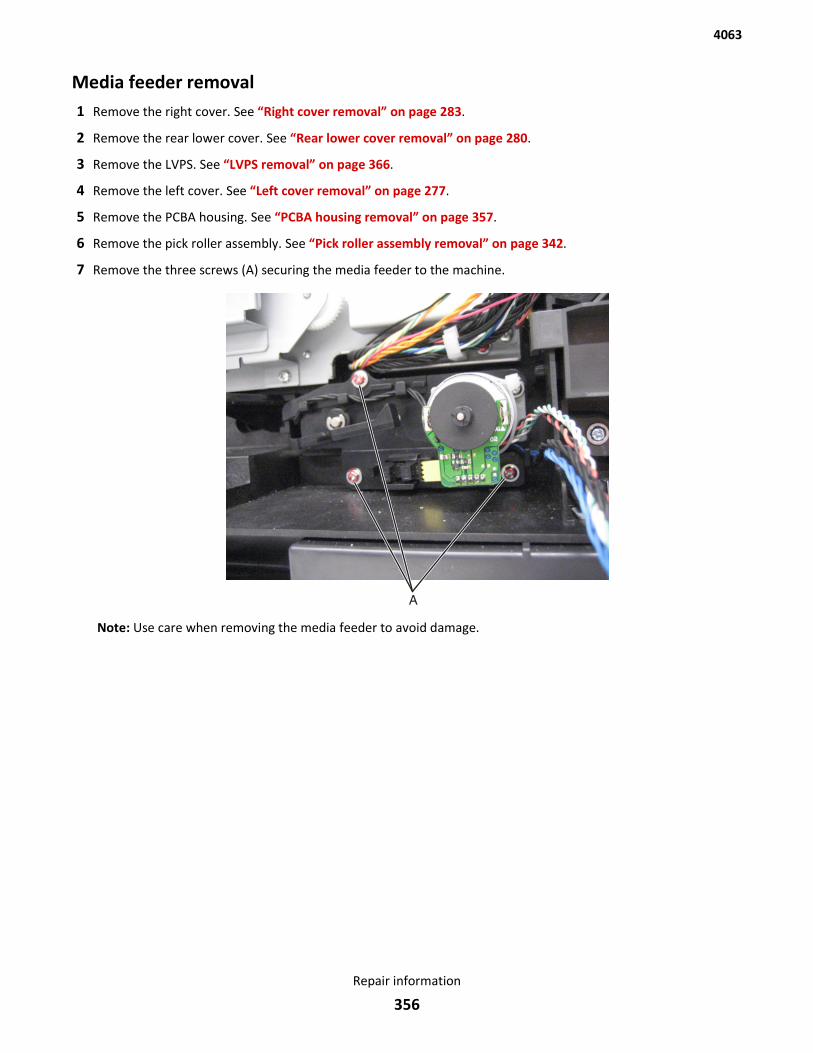
Media feeder removal1 Remove the right cover. See “Right cover removal” on page 283.
2 Remove the rear lower cover. See “Rear lower cover removal” on page 280.
3 Remove the LVPS. See “LVPS removal” on page 366.
4 Remove the left cover. See “Left cover removal” on page 277.
5 Remove the PCBA housing. See “PCBA housing removal” on page 357.
6 Remove the pick roller assembly. See “Pick roller assembly removal” on page 342.
7 Remove the three screws (A) securing the media feeder to the machine.
Note: Use care when removing the media feeder to avoid damage.
4063
Repair information
356
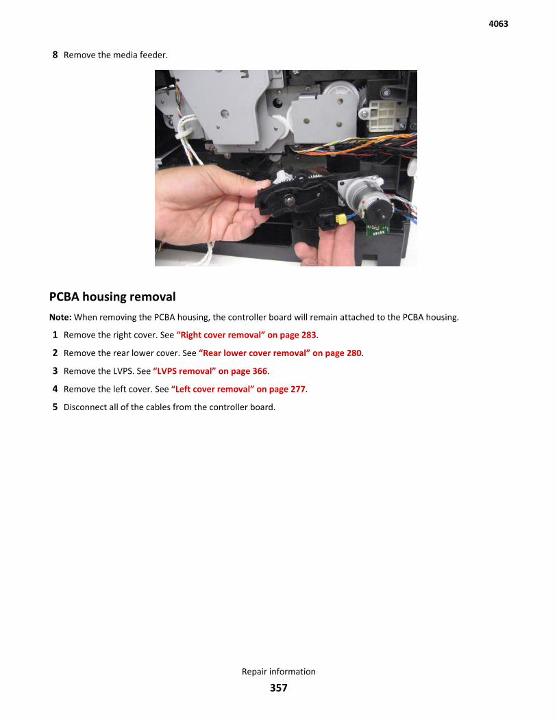
8 Remove the media feeder.
PCBA housing removalNote: When removing the PCBA housing, the controller board will remain attached to the PCBA housing.
1 Remove the right cover. See “Right cover removal” on page 283.
2 Remove the rear lower cover. See “Rear lower cover removal” on page 280.
3 Remove the LVPS. See “LVPS removal” on page 366.
4 Remove the left cover. See “Left cover removal” on page 277.
5 Disconnect all of the cables from the controller board.
4063
Repair information
357
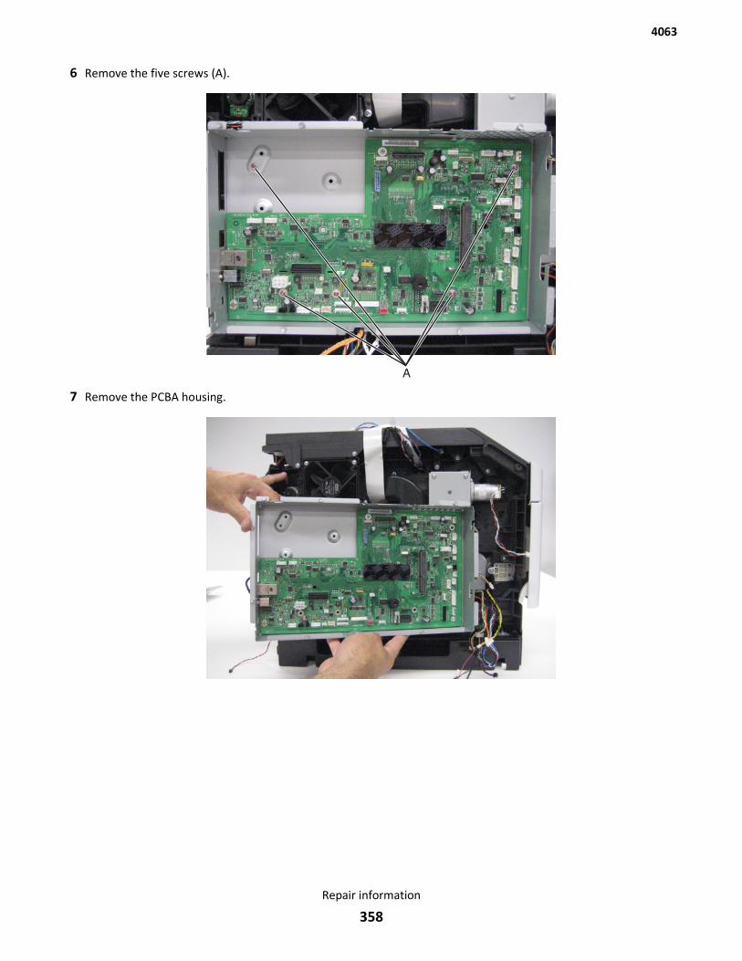
6 Remove the five screws (A).
7 Remove the PCBA housing.
4063
Repair information
358
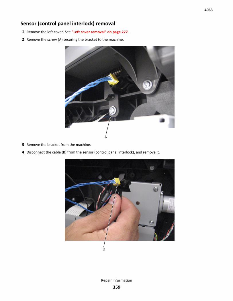
Sensor (control panel interlock) removal1 Remove the left cover. See “Left cover removal” on page 277.
2 Remove the screw (A) securing the bracket to the machine.
3 Remove the bracket from the machine.
4 Disconnect the cable (B) from the sensor (control panel interlock), and remove it.
4063
Repair information
359
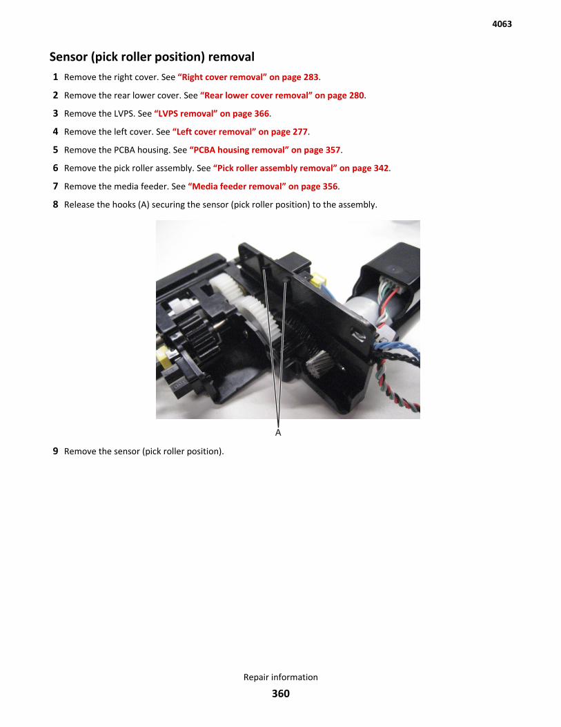
Sensor (pick roller position) removal1 Remove the right cover. See “Right cover removal” on page 283.
2 Remove the rear lower cover. See “Rear lower cover removal” on page 280.
3 Remove the LVPS. See “LVPS removal” on page 366.
4 Remove the left cover. See “Left cover removal” on page 277.
5 Remove the PCBA housing. See “PCBA housing removal” on page 357.
6 Remove the pick roller assembly. See “Pick roller assembly removal” on page 342.
7 Remove the media feeder. See “Media feeder removal” on page 356.
8 Release the hooks (A) securing the sensor (pick roller position) to the assembly.
9 Remove the sensor (pick roller position).
4063
Repair information
360
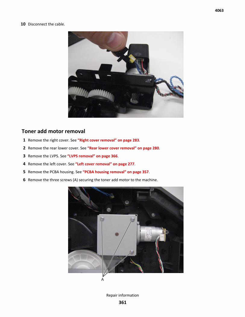
10 Disconnect the cable.
Toner add motor removal1 Remove the right cover. See “Right cover removal” on page 283.
2 Remove the rear lower cover. See “Rear lower cover removal” on page 280.
3 Remove the LVPS. See “LVPS removal” on page 366.
4 Remove the left cover. See “Left cover removal” on page 277.
5 Remove the PCBA housing. See “PCBA housing removal” on page 357.
6 Remove the three screws (A) securing the toner add motor to the machine.
4063
Repair information
361
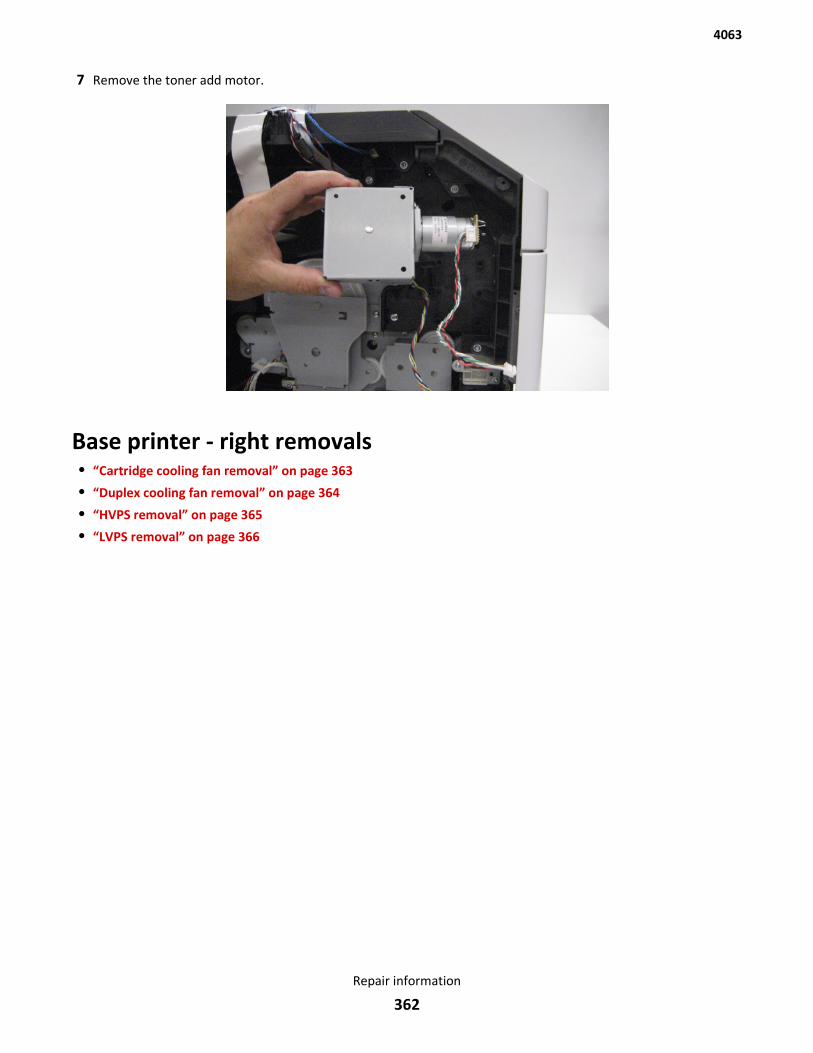
7 Remove the toner add motor.
Base printer - right removals• “Cartridge cooling fan removal” on page 363
• “Duplex cooling fan removal” on page 364
• “HVPS removal” on page 365
• “LVPS removal” on page 366
4063
Repair information
362
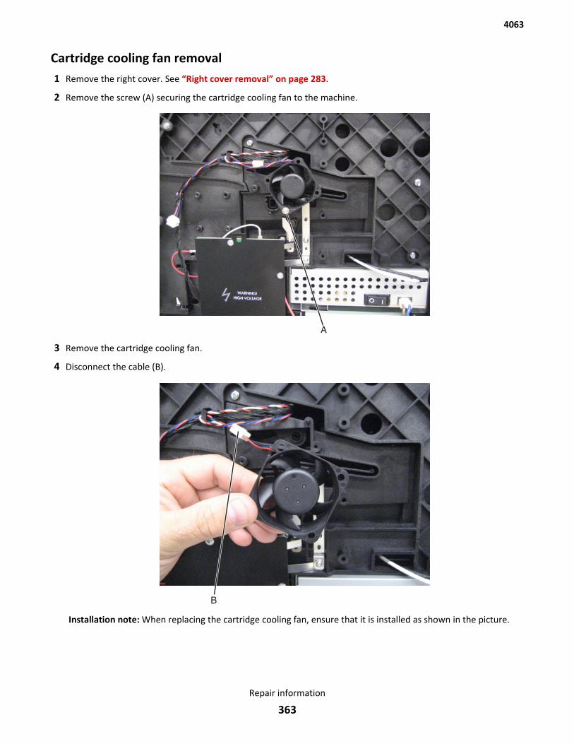
Cartridge cooling fan removal1 Remove the right cover. See “Right cover removal” on page 283.
2 Remove the screw (A) securing the cartridge cooling fan to the machine.
3 Remove the cartridge cooling fan.
4 Disconnect the cable (B).
Installation note: When replacing the cartridge cooling fan, ensure that it is installed as shown in the picture.
4063
Repair information
363
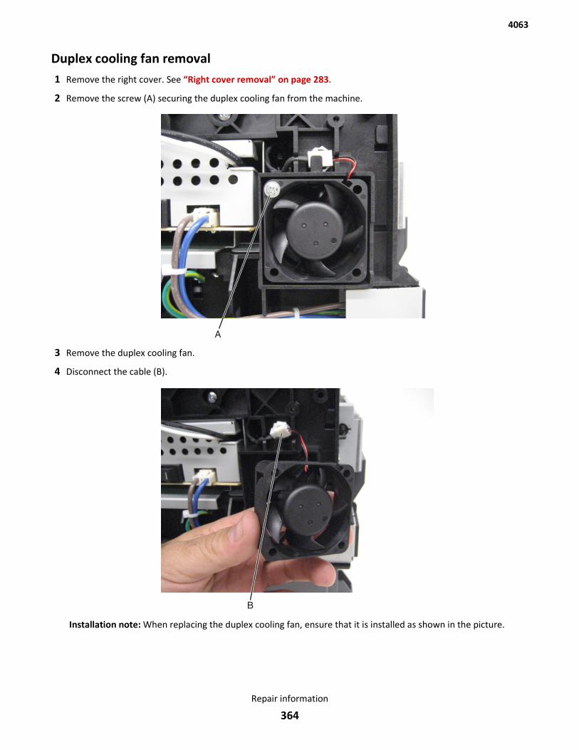
Duplex cooling fan removal1 Remove the right cover. See “Right cover removal” on page 283.
2 Remove the screw (A) securing the duplex cooling fan from the machine.
3 Remove the duplex cooling fan.
4 Disconnect the cable (B).
Installation note: When replacing the duplex cooling fan, ensure that it is installed as shown in the picture.
4063
Repair information
364
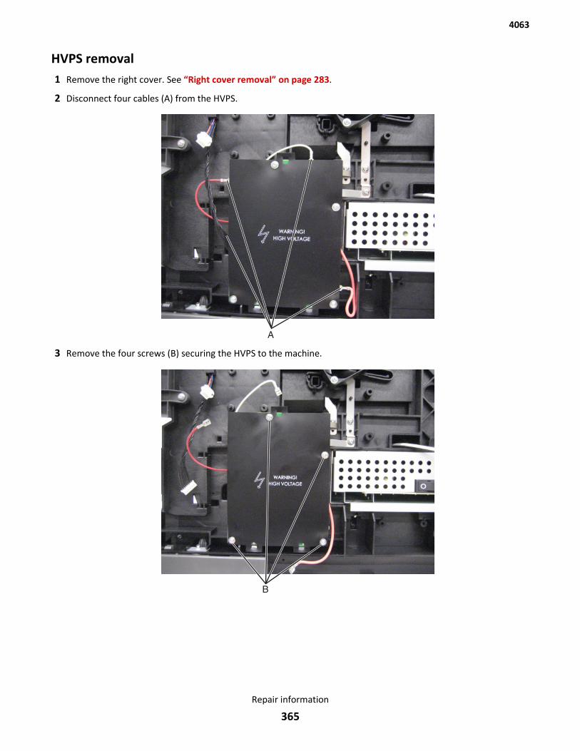
HVPS removal1 Remove the right cover. See “Right cover removal” on page 283.
2 Disconnect four cables (A) from the HVPS.
3 Remove the four screws (B) securing the HVPS to the machine.
4063
Repair information
365
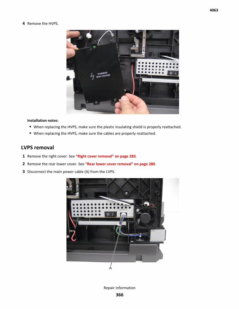
4 Remove the HVPS.
Installation notes:
• When replacing the HVPS, make sure the plastic insulating shield is properly reattached.
• When replacing the HVPS, make sure the cables are properly reattached.
LVPS removal1 Remove the right cover. See “Right cover removal” on page 283.
2 Remove the rear lower cover. See “Rear lower cover removal” on page 280.
3 Disconnect the main power cable (A) from the LVPS.
4063
Repair information
366
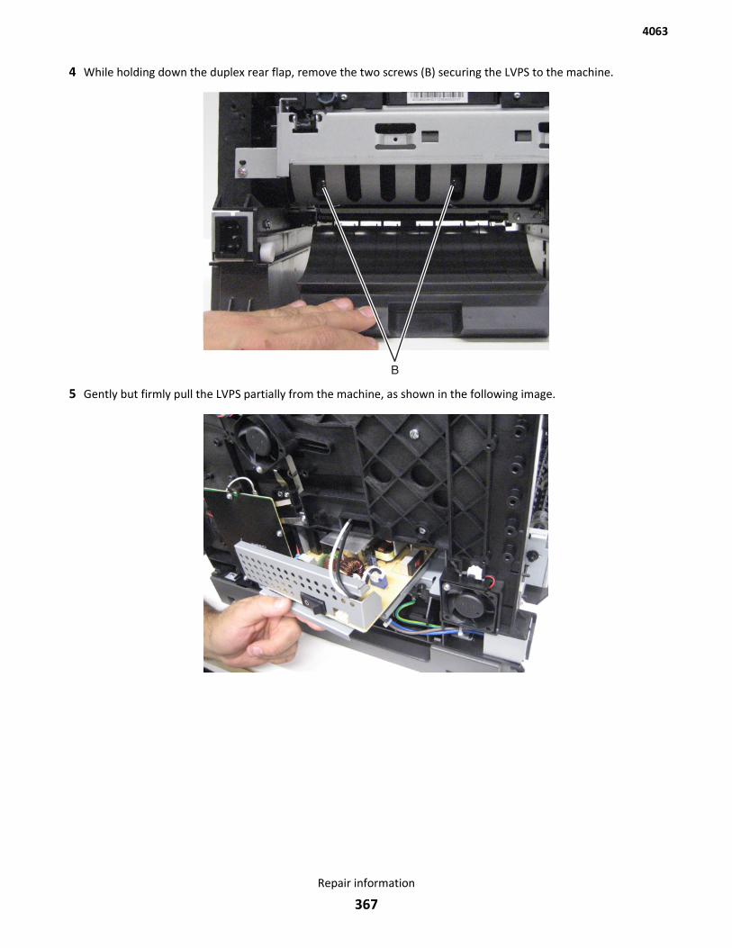
4 While holding down the duplex rear flap, remove the two screws (B) securing the LVPS to the machine.
5 Gently but firmly pull the LVPS partially from the machine, as shown in the following image.
4063
Repair information
367
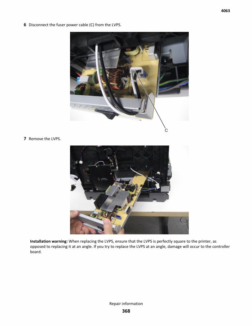
6 Disconnect the fuser power cable (C) from the LVPS.
7 Remove the LVPS.
Installation warning: When replacing the LVPS, ensure that the LVPS is perfectly square to the printer, asopposed to replacing it at an angle. If you try to replace the LVPS at an angle, damage will occur to the controllerboard.
4063
Repair information
368
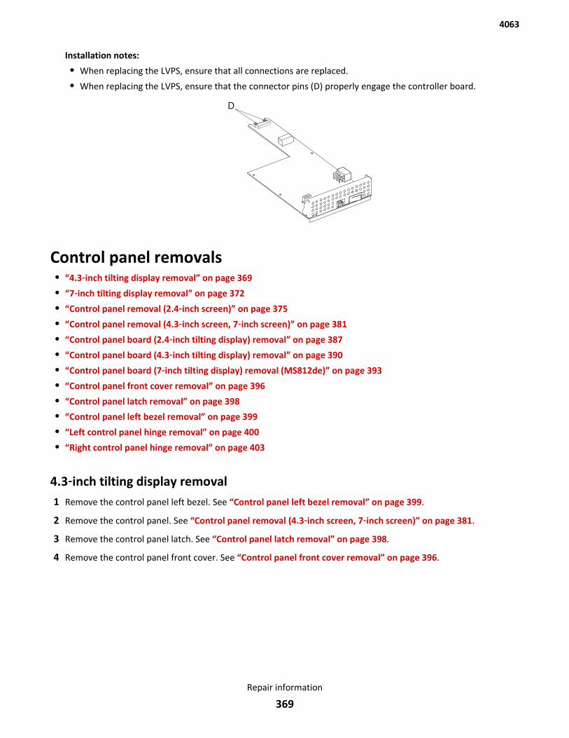
Installation notes:
• When replacing the LVPS, ensure that all connections are replaced.
• When replacing the LVPS, ensure that the connector pins (D) properly engage the controller board.
Control panel removals• “4.3‑inch tilting display removal” on page 369
• “7‑inch tilting display removal” on page 372
• “Control panel removal (2.4‑inch screen)” on page 375
• “Control panel removal (4.3‑inch screen, 7‑inch screen)” on page 381
• “Control panel board (2.4‑inch tilting display) removal” on page 387
• “Control panel board (4.3‑inch tilting display) removal” on page 390
• “Control panel board (7‑inch tilting display) removal (MS812de)” on page 393
• “Control panel front cover removal” on page 396
• “Control panel latch removal” on page 398
• “Control panel left bezel removal” on page 399
• “Left control panel hinge removal” on page 400
• “Right control panel hinge removal” on page 403
4.3‑inch tilting display removal1 Remove the control panel left bezel. See “Control panel left bezel removal” on page 399.
2 Remove the control panel. See “Control panel removal (4.3‑inch screen, 7‑inch screen)” on page 381.
3 Remove the control panel latch. See “Control panel latch removal” on page 398.
4 Remove the control panel front cover. See “Control panel front cover removal” on page 396.
4063
Repair information
369
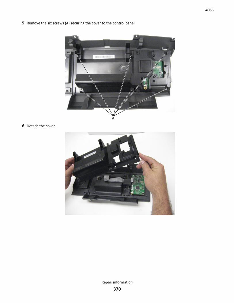
5 Remove the six screws (A) securing the cover to the control panel.
6 Detach the cover.
4063
Repair information
370
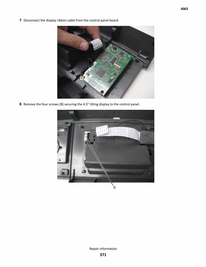
7 Disconnect the display ribbon cable from the control panel board.
8 Remove the four screws (B) securing the 4.3” tilting display to the control panel.
4063
Repair information
371
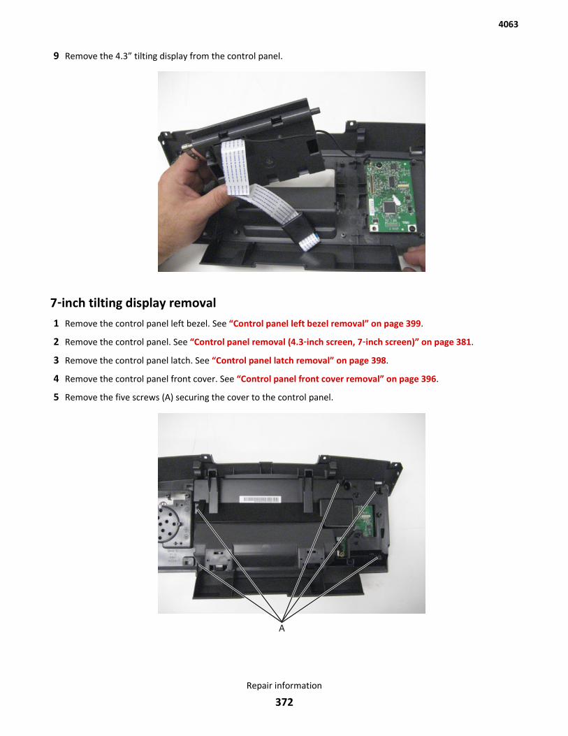
9 Remove the 4.3” tilting display from the control panel.
7‑inch tilting display removal1 Remove the control panel left bezel. See “Control panel left bezel removal” on page 399.
2 Remove the control panel. See “Control panel removal (4.3‑inch screen, 7‑inch screen)” on page 381.
3 Remove the control panel latch. See “Control panel latch removal” on page 398.
4 Remove the control panel front cover. See “Control panel front cover removal” on page 396.
5 Remove the five screws (A) securing the cover to the control panel.
4063
Repair information
372
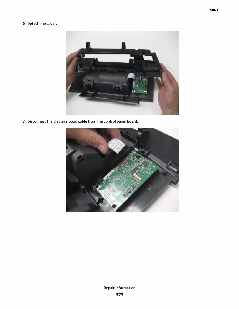
6 Detach the cover.
7 Disconnect the display ribbon cable from the control panel board.
4063
Repair information
373
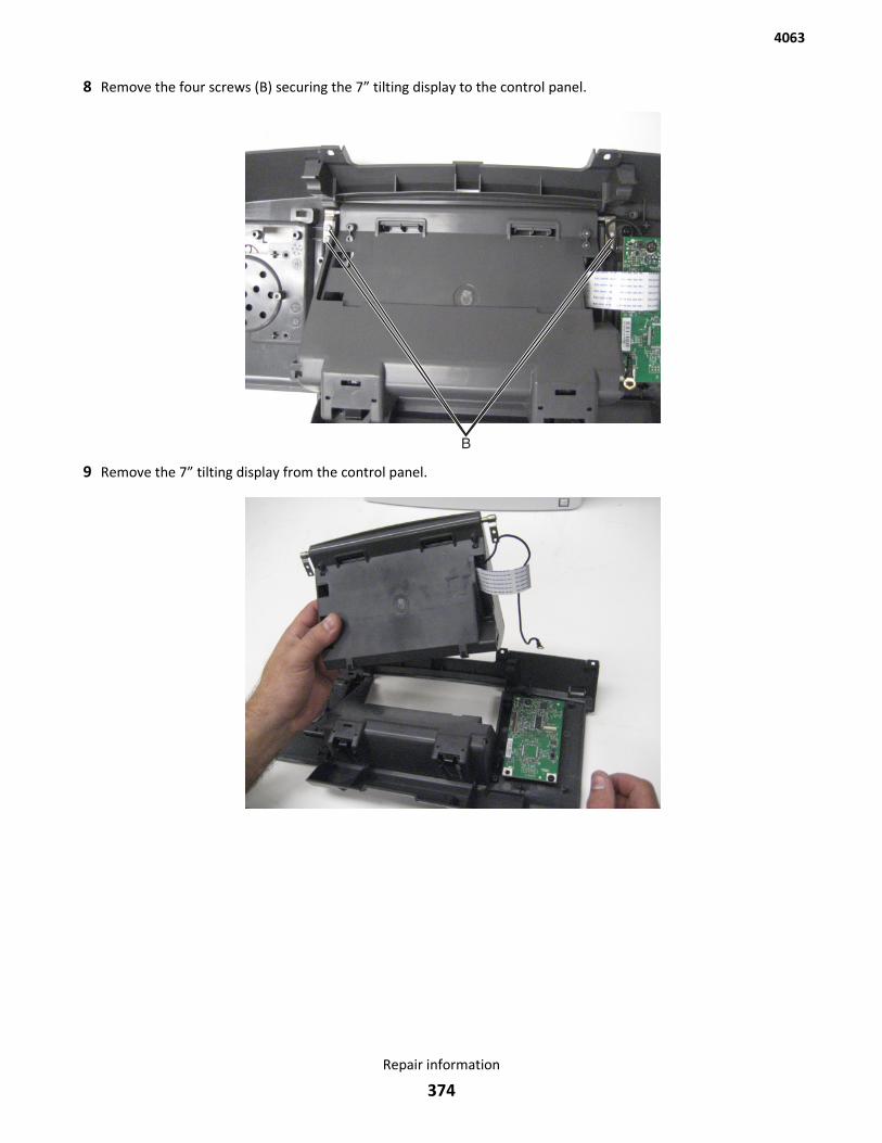
8 Remove the four screws (B) securing the 7” tilting display to the control panel.
9 Remove the 7” tilting display from the control panel.
4063
Repair information
374
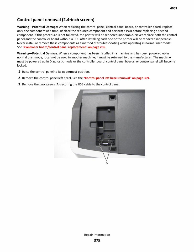
Control panel removal (2.4‑inch screen)Warning—Potential Damage: When replacing the control panel, control panel board, or controller board, replaceonly one component at a time. Replace the required component and perform a POR before replacing a secondcomponent. If this procedure is not followed, the printer will be rendered inoperable. Never replace both the controlpanel and the controller board without a POR after installing each one or the printer will be rendered inoperable.Never install or remove these components as a method of troubleshooting while operating in normal user mode.See “Controller board/control panel replacement” on page 256.
Warning—Potential Damage: When a component has been installed in a machine and has been powered up innormal user mode, it cannot be used in another machine; it must be returned to the manufacturer. The machinemust be powered up in Diagnostic mode or the controller board, control panel boards, or control panel will becomelocked.
1 Raise the control panel to its uppermost position.
2 Remove the control panel left bezel. See the “Control panel left bezel removal” on page 399.
3 Remove the two screws (A) securing the USB cable to the control panel.
4063
Repair information
375
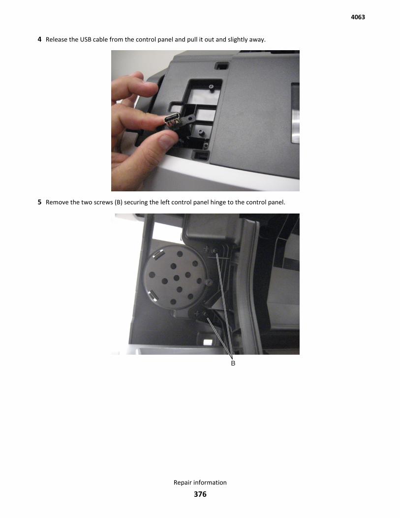
4 Release the USB cable from the control panel and pull it out and slightly away.
5 Remove the two screws (B) securing the left control panel hinge to the control panel.
4063
Repair information
376
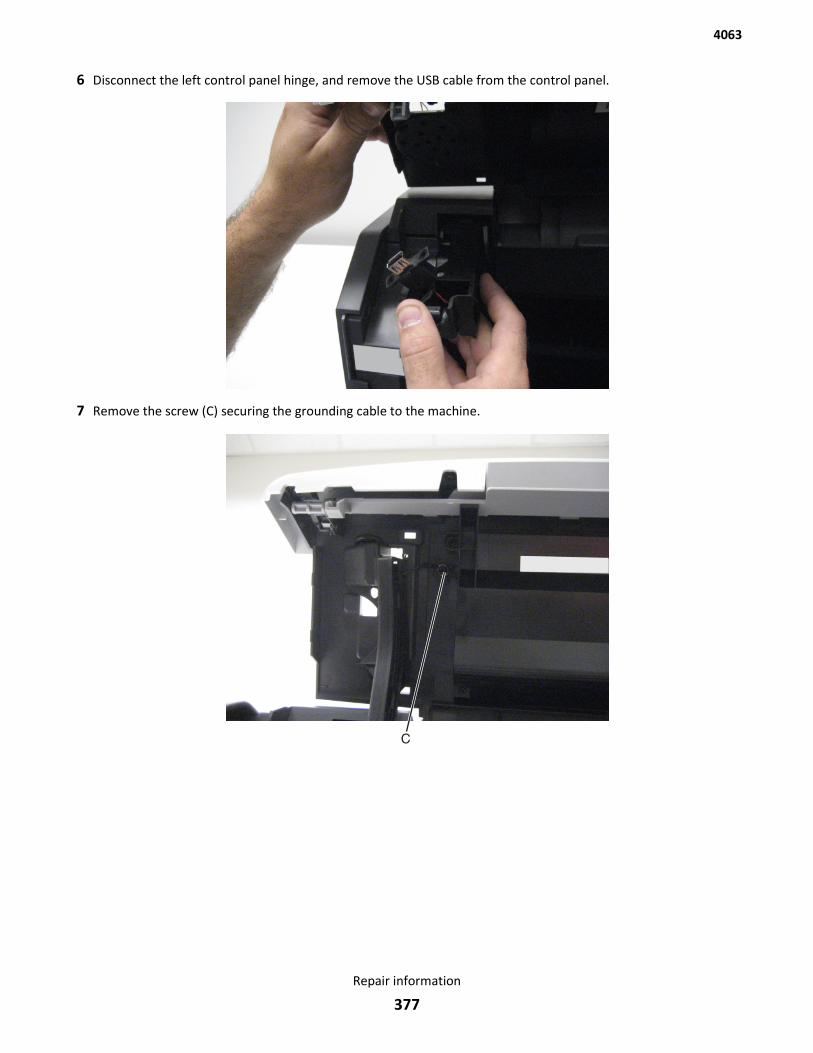
6 Disconnect the left control panel hinge, and remove the USB cable from the control panel.
7 Remove the screw (C) securing the grounding cable to the machine.
4063
Repair information
377
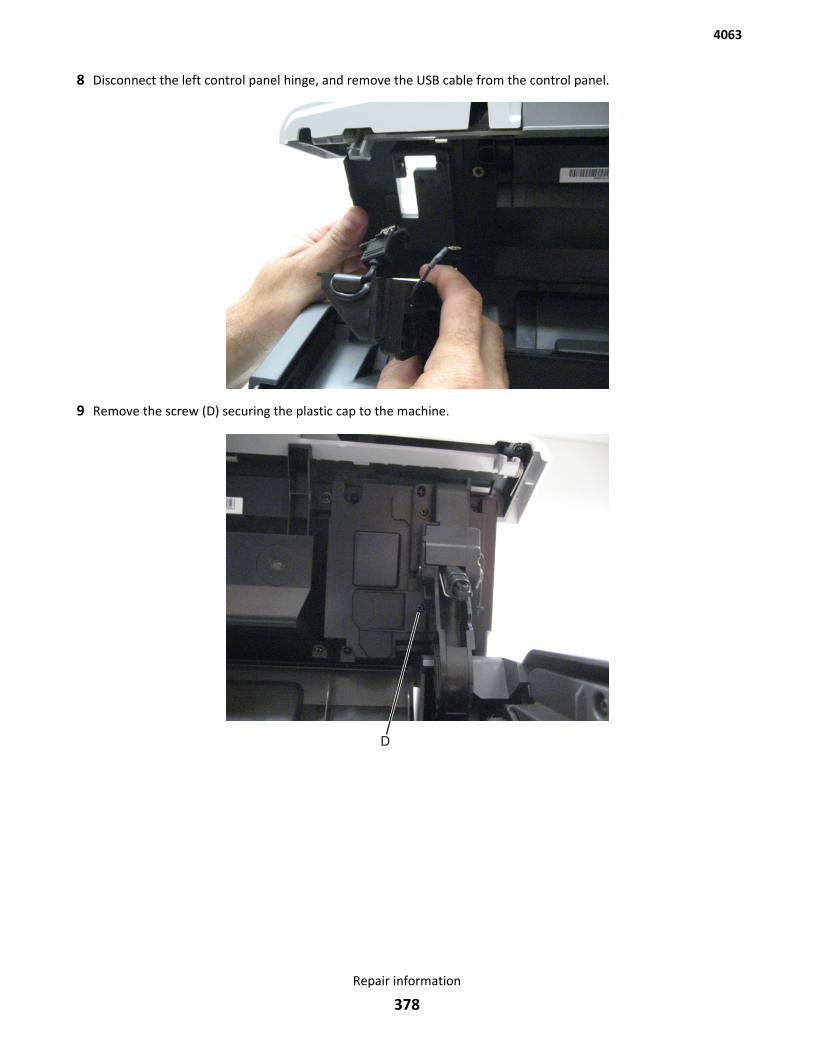
8 Disconnect the left control panel hinge, and remove the USB cable from the control panel.
9 Remove the screw (D) securing the plastic cap to the machine.
4063
Repair information
378
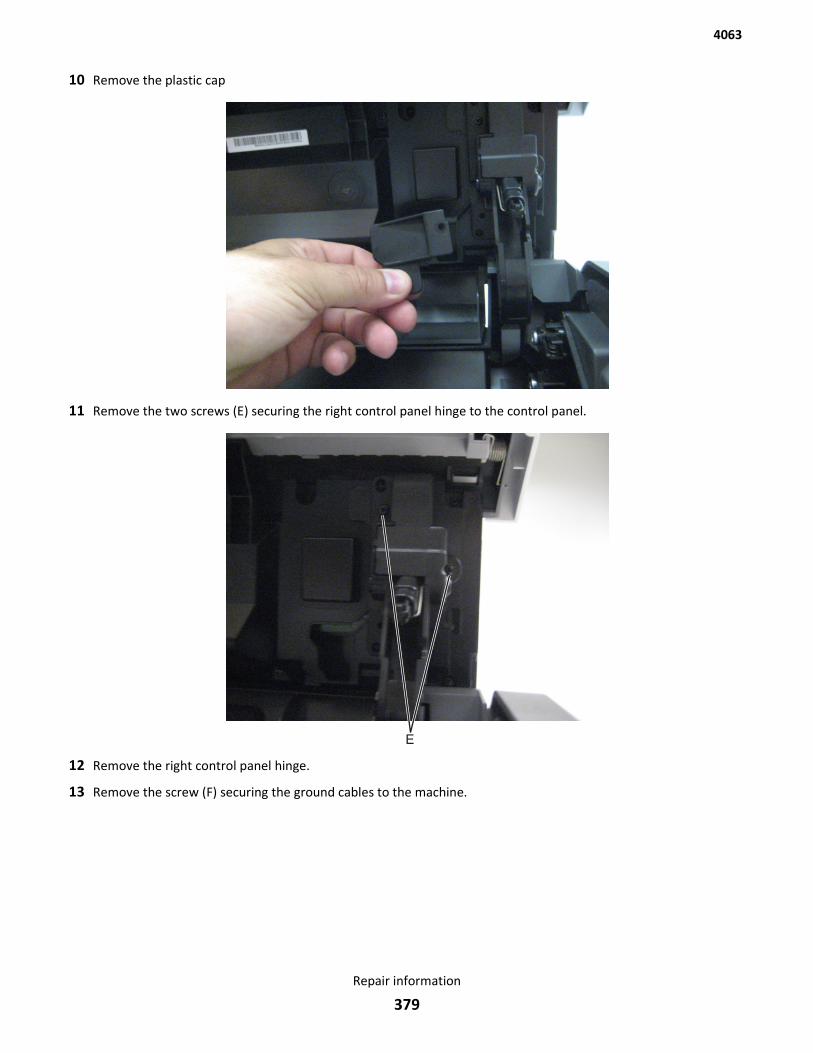
10 Remove the plastic cap
11 Remove the two screws (E) securing the right control panel hinge to the control panel.
12 Remove the right control panel hinge.
13 Remove the screw (F) securing the ground cables to the machine.
4063
Repair information
379
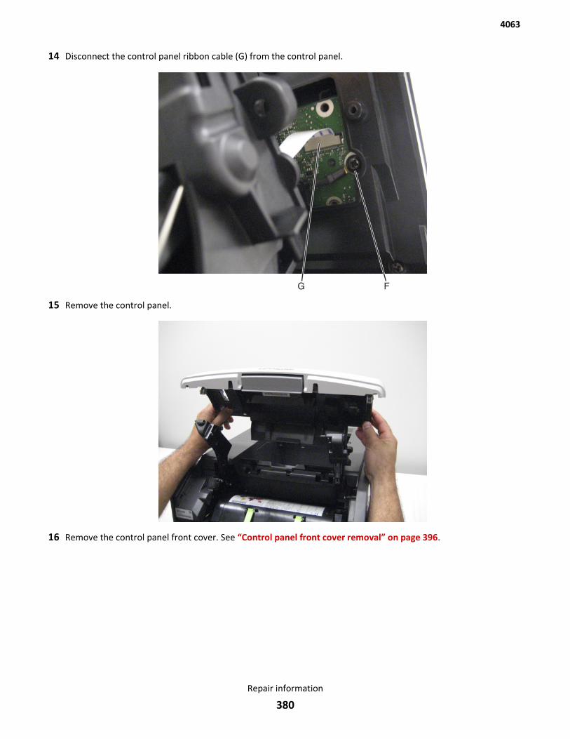
14 Disconnect the control panel ribbon cable (G) from the control panel.
15 Remove the control panel.
16 Remove the control panel front cover. See “Control panel front cover removal” on page 396.
4063
Repair information
380
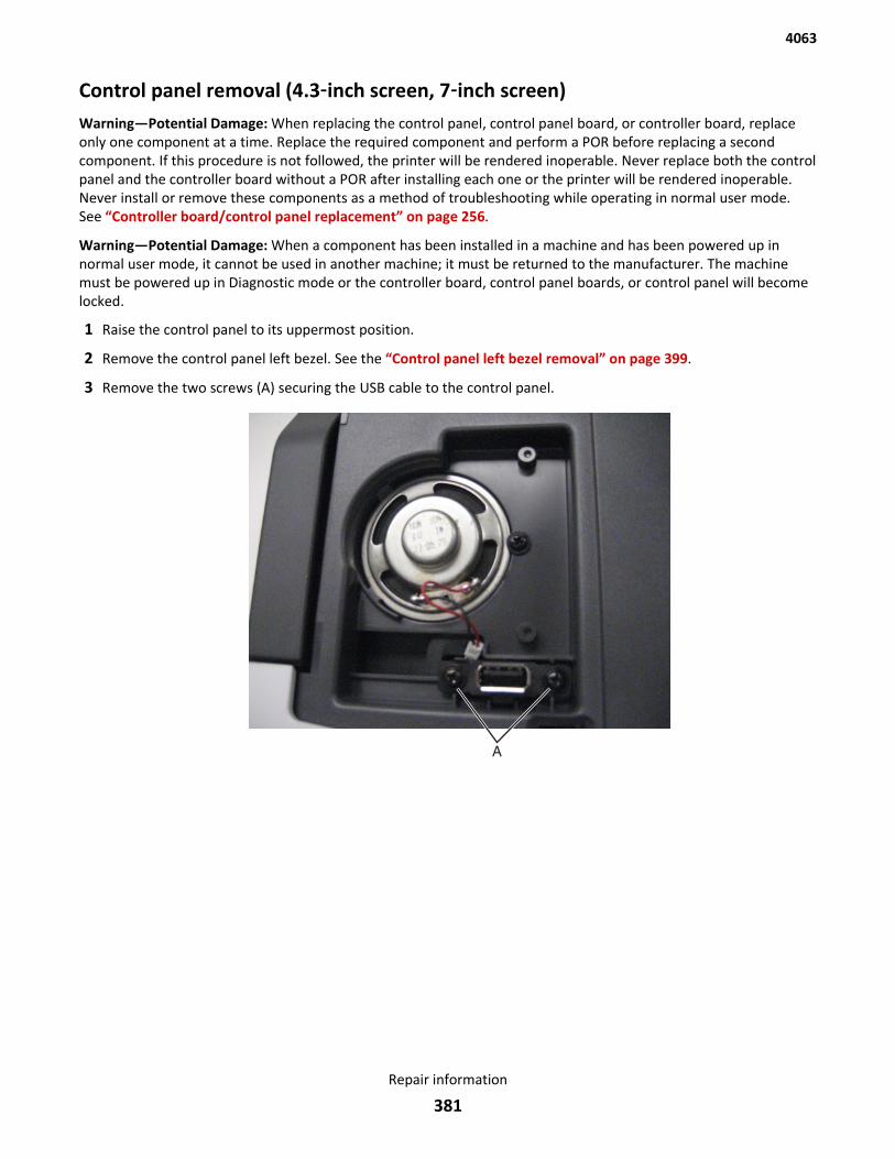
Control panel removal (4.3‑inch screen, 7‑inch screen)Warning—Potential Damage: When replacing the control panel, control panel board, or controller board, replaceonly one component at a time. Replace the required component and perform a POR before replacing a secondcomponent. If this procedure is not followed, the printer will be rendered inoperable. Never replace both the controlpanel and the controller board without a POR after installing each one or the printer will be rendered inoperable.Never install or remove these components as a method of troubleshooting while operating in normal user mode.See “Controller board/control panel replacement” on page 256.
Warning—Potential Damage: When a component has been installed in a machine and has been powered up innormal user mode, it cannot be used in another machine; it must be returned to the manufacturer. The machinemust be powered up in Diagnostic mode or the controller board, control panel boards, or control panel will becomelocked.
1 Raise the control panel to its uppermost position.
2 Remove the control panel left bezel. See the “Control panel left bezel removal” on page 399.
3 Remove the two screws (A) securing the USB cable to the control panel.
4063
Repair information
381
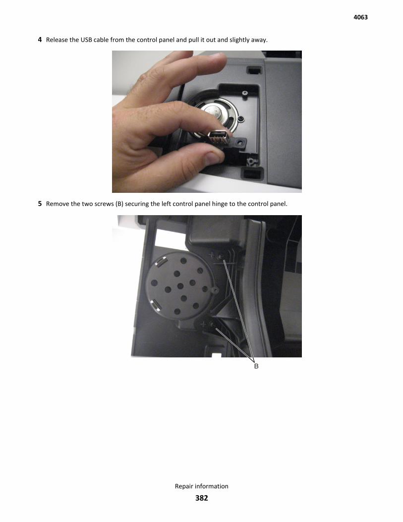
4 Release the USB cable from the control panel and pull it out and slightly away.
5 Remove the two screws (B) securing the left control panel hinge to the control panel.
4063
Repair information
382
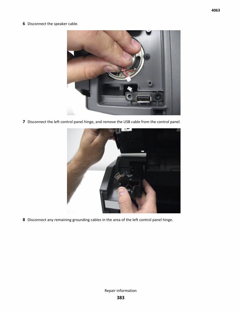
6 Disconnect the speaker cable.
7 Disconnect the left control panel hinge, and remove the USB cable from the control panel.
8 Disconnect any remaining grounding cables in the area of the left control panel hinge.
4063
Repair information
383
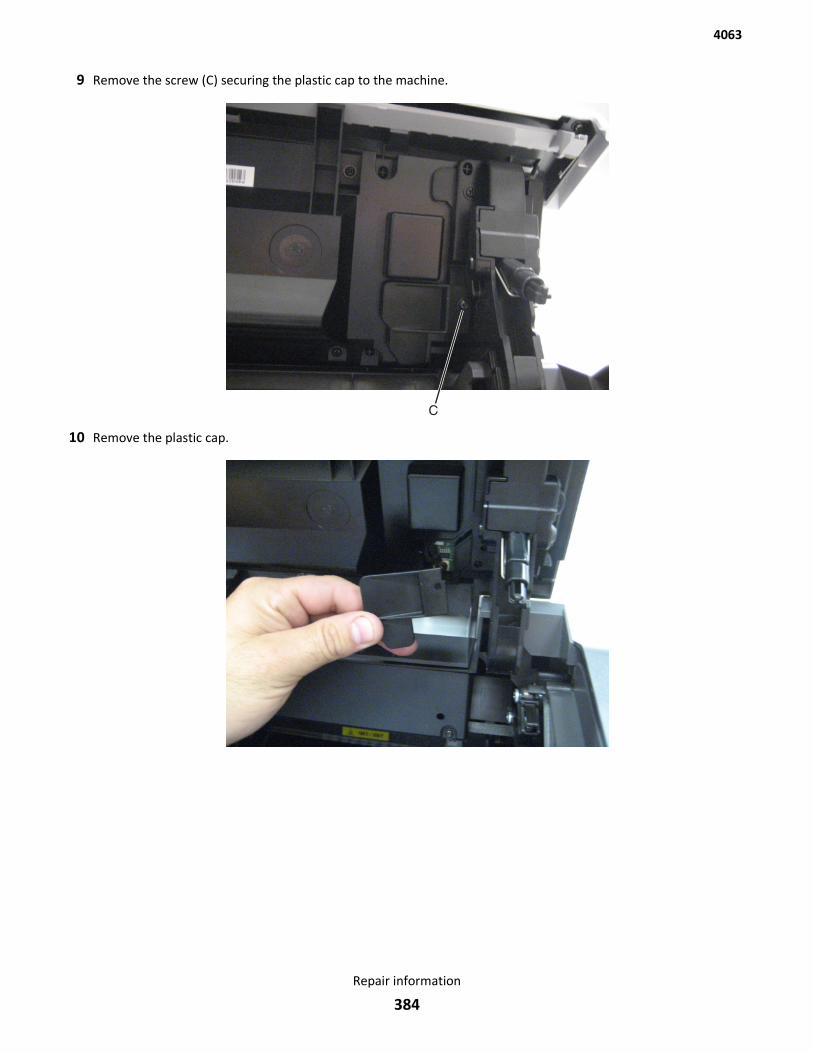
9 Remove the screw (C) securing the plastic cap to the machine.
10 Remove the plastic cap.
4063
Repair information
384
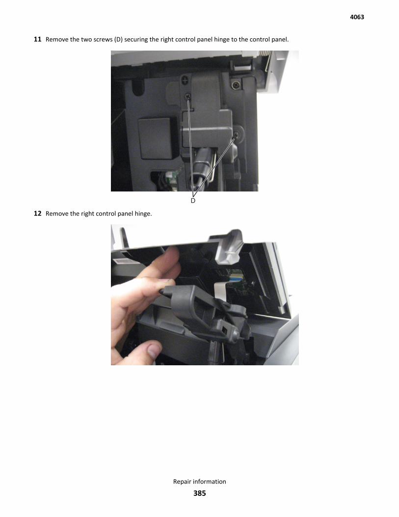
11 Remove the two screws (D) securing the right control panel hinge to the control panel.
12 Remove the right control panel hinge.
4063
Repair information
385
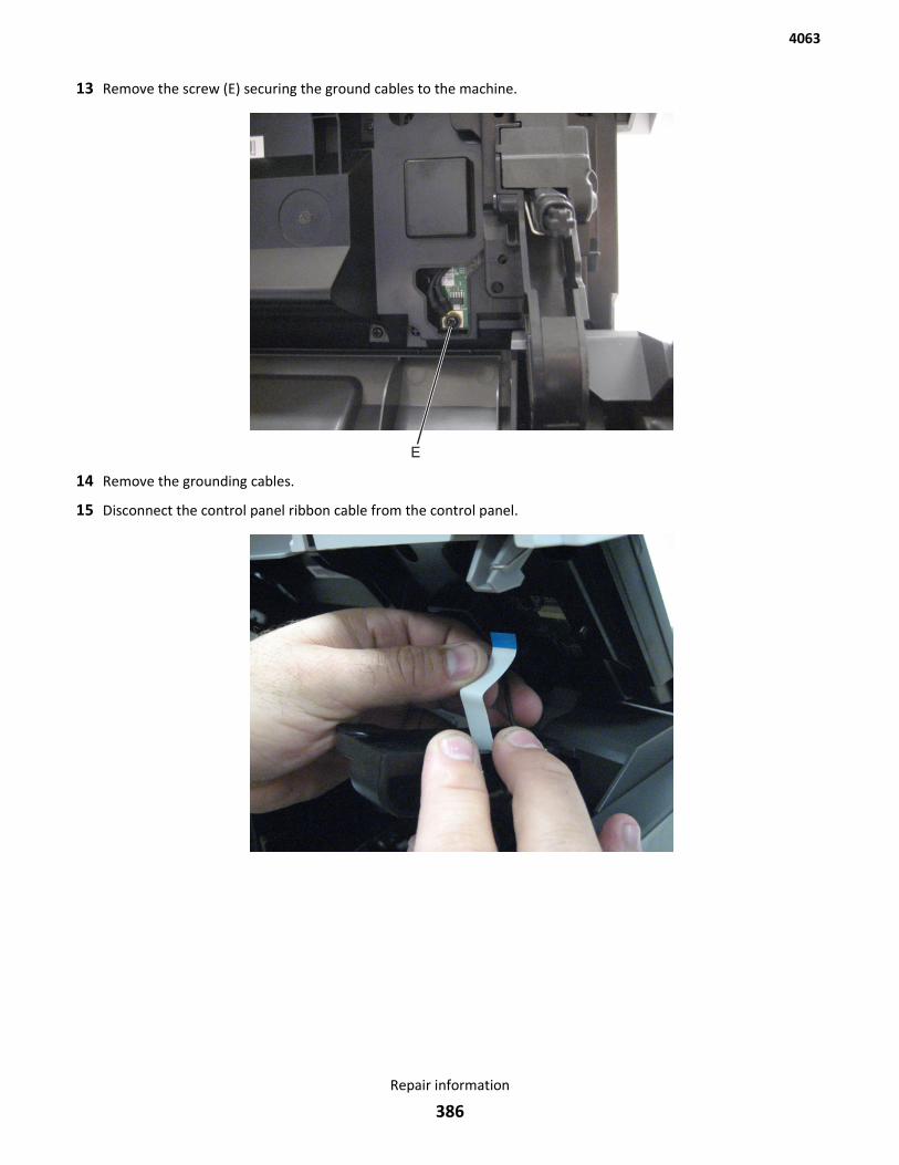
13 Remove the screw (E) securing the ground cables to the machine.
14 Remove the grounding cables.
15 Disconnect the control panel ribbon cable from the control panel.
4063
Repair information
386
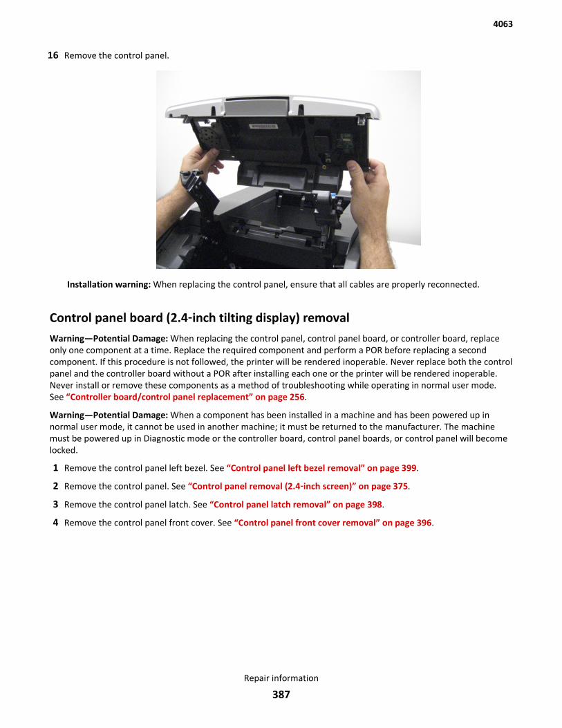
16 Remove the control panel.
Installation warning: When replacing the control panel, ensure that all cables are properly reconnected.
Control panel board (2.4‑inch tilting display) removalWarning—Potential Damage: When replacing the control panel, control panel board, or controller board, replaceonly one component at a time. Replace the required component and perform a POR before replacing a secondcomponent. If this procedure is not followed, the printer will be rendered inoperable. Never replace both the controlpanel and the controller board without a POR after installing each one or the printer will be rendered inoperable.Never install or remove these components as a method of troubleshooting while operating in normal user mode.See “Controller board/control panel replacement” on page 256.
Warning—Potential Damage: When a component has been installed in a machine and has been powered up innormal user mode, it cannot be used in another machine; it must be returned to the manufacturer. The machinemust be powered up in Diagnostic mode or the controller board, control panel boards, or control panel will becomelocked.
1 Remove the control panel left bezel. See “Control panel left bezel removal” on page 399.
2 Remove the control panel. See “Control panel removal (2.4‑inch screen)” on page 375.
3 Remove the control panel latch. See “Control panel latch removal” on page 398.
4 Remove the control panel front cover. See “Control panel front cover removal” on page 396.
4063
Repair information
387
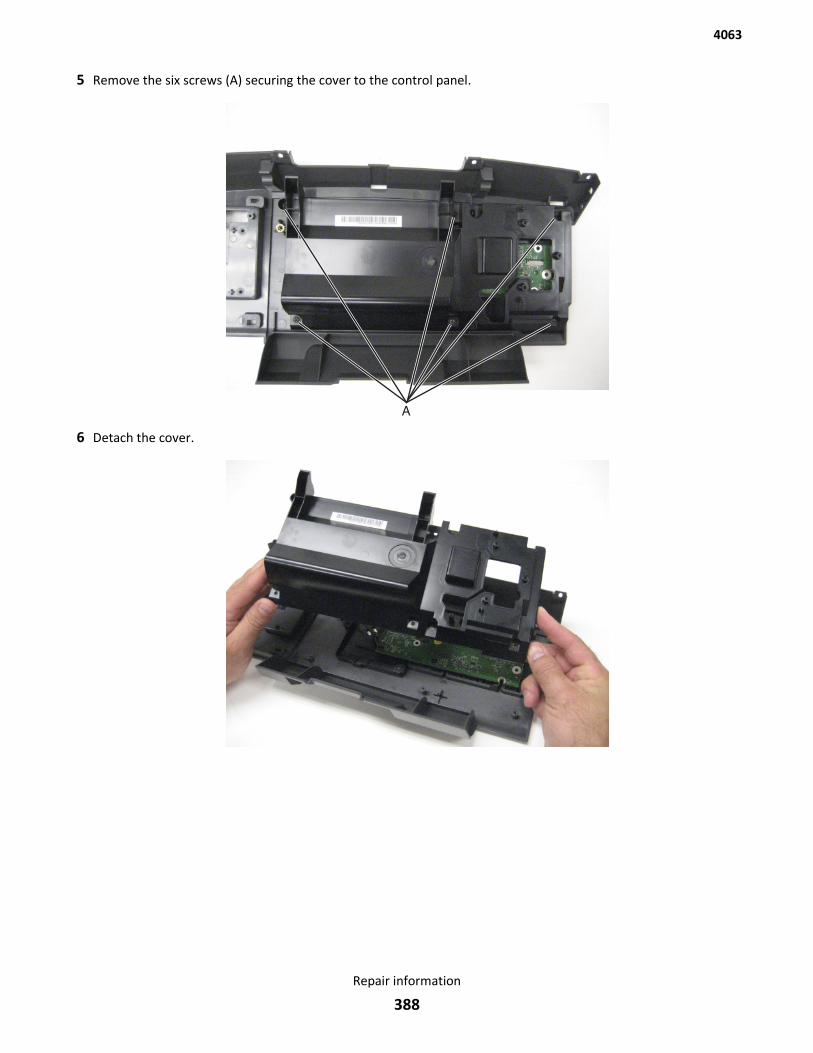
5 Remove the six screws (A) securing the cover to the control panel.
6 Detach the cover.
4063
Repair information
388
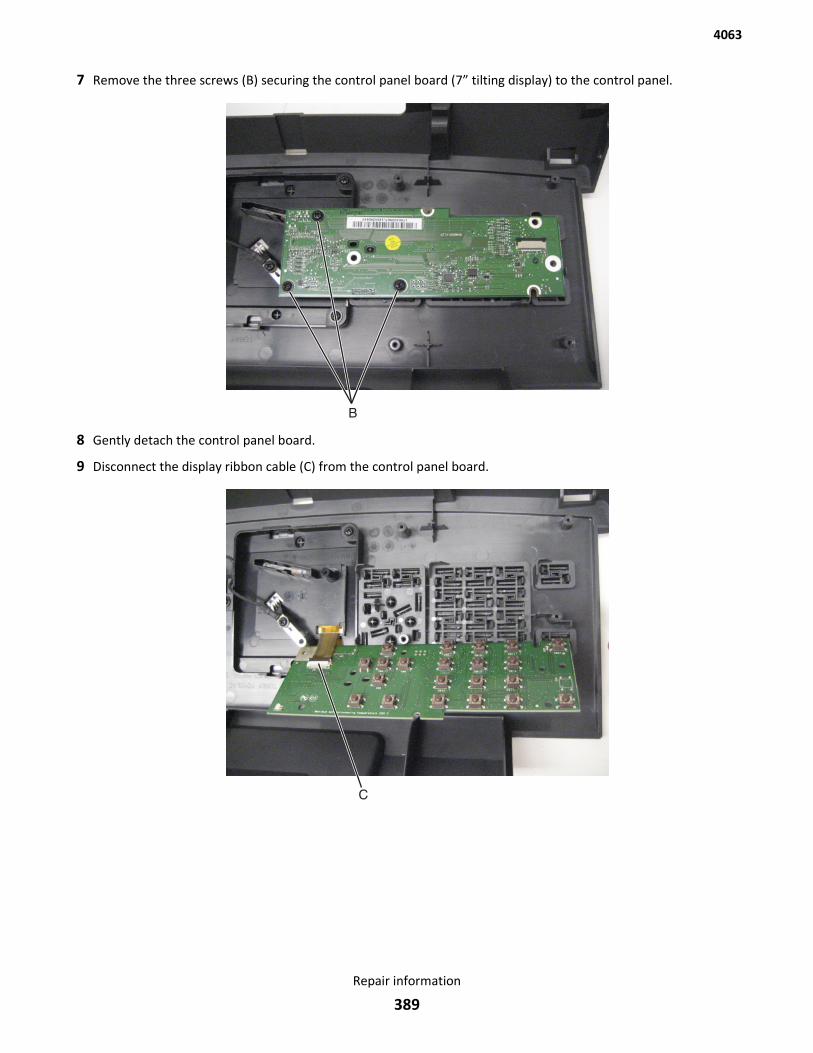
7 Remove the three screws (B) securing the control panel board (7” tilting display) to the control panel.
8 Gently detach the control panel board.
9 Disconnect the display ribbon cable (C) from the control panel board.
4063
Repair information
389
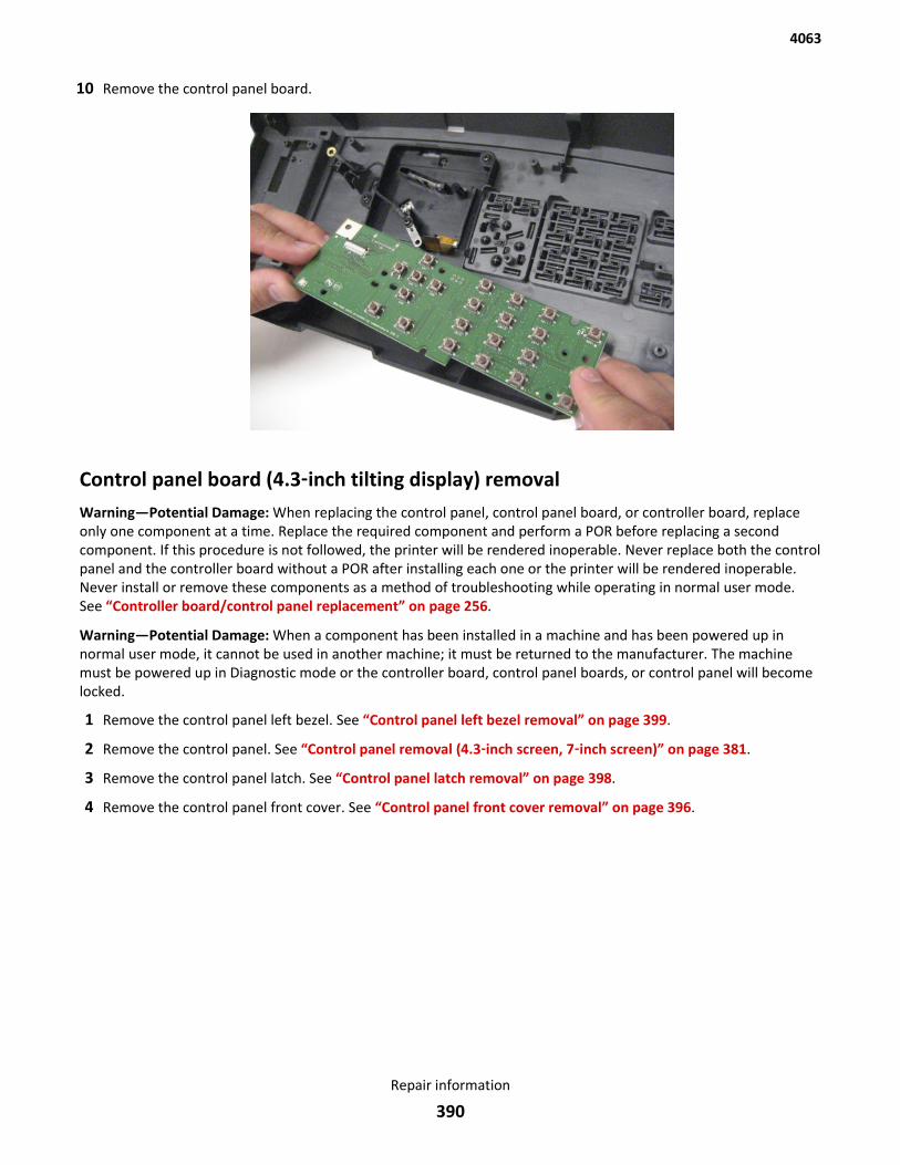
10 Remove the control panel board.
Control panel board (4.3‑inch tilting display) removalWarning—Potential Damage: When replacing the control panel, control panel board, or controller board, replaceonly one component at a time. Replace the required component and perform a POR before replacing a secondcomponent. If this procedure is not followed, the printer will be rendered inoperable. Never replace both the controlpanel and the controller board without a POR after installing each one or the printer will be rendered inoperable.Never install or remove these components as a method of troubleshooting while operating in normal user mode.See “Controller board/control panel replacement” on page 256.
Warning—Potential Damage: When a component has been installed in a machine and has been powered up innormal user mode, it cannot be used in another machine; it must be returned to the manufacturer. The machinemust be powered up in Diagnostic mode or the controller board, control panel boards, or control panel will becomelocked.
1 Remove the control panel left bezel. See “Control panel left bezel removal” on page 399.
2 Remove the control panel. See “Control panel removal (4.3‑inch screen, 7‑inch screen)” on page 381.
3 Remove the control panel latch. See “Control panel latch removal” on page 398.
4 Remove the control panel front cover. See “Control panel front cover removal” on page 396.
4063
Repair information
390
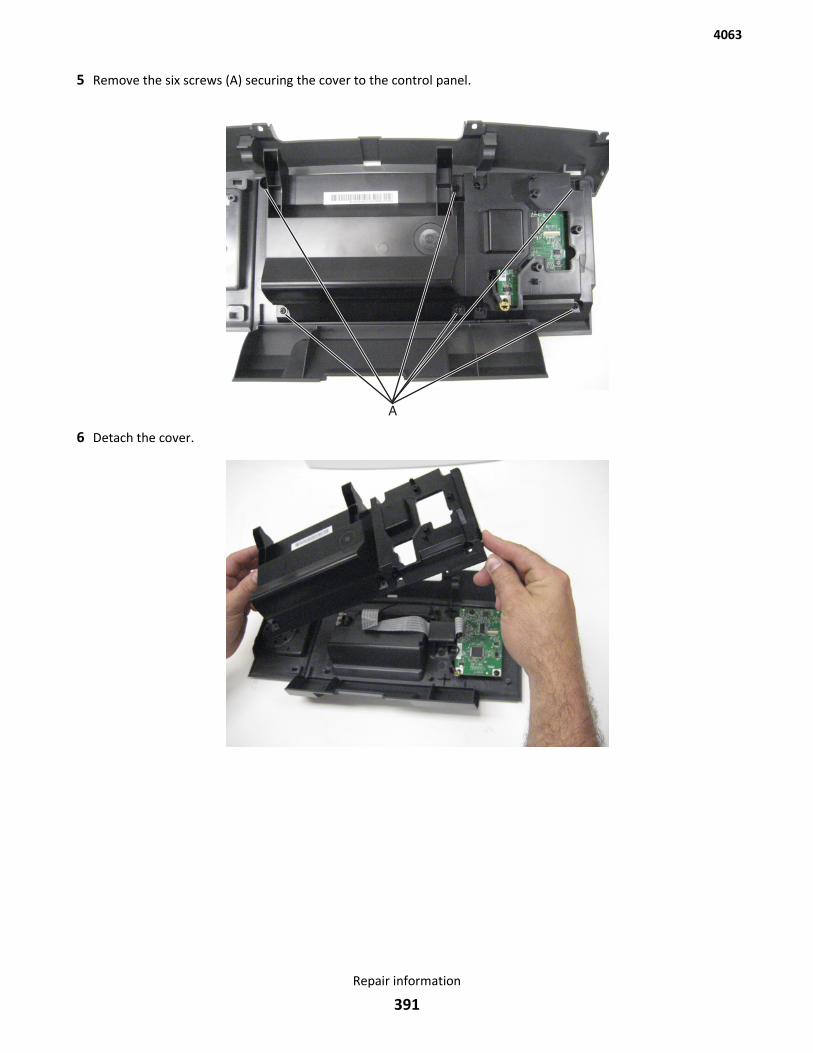
5 Remove the six screws (A) securing the cover to the control panel.
6 Detach the cover.
4063
Repair information
391
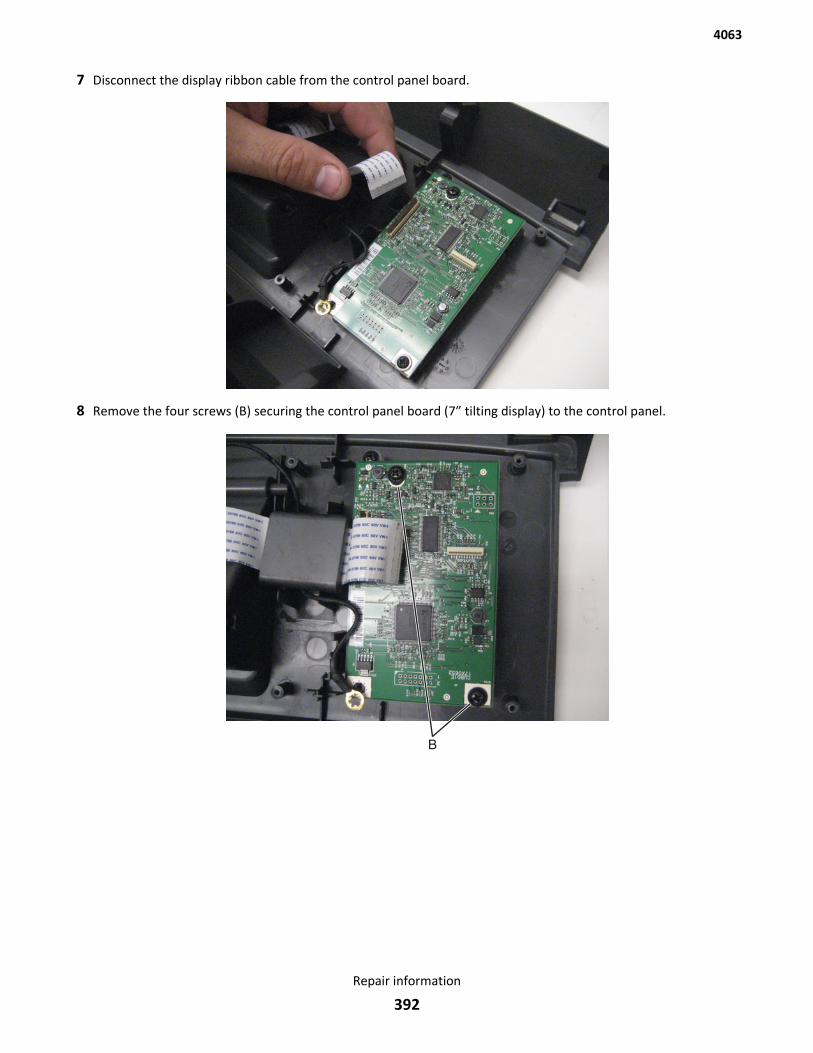
7 Disconnect the display ribbon cable from the control panel board.
8 Remove the four screws (B) securing the control panel board (7” tilting display) to the control panel.
4063
Repair information
392
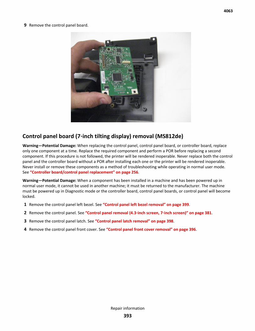
9 Remove the control panel board.
Control panel board (7‑inch tilting display) removal (MS812de)Warning—Potential Damage: When replacing the control panel, control panel board, or controller board, replaceonly one component at a time. Replace the required component and perform a POR before replacing a secondcomponent. If this procedure is not followed, the printer will be rendered inoperable. Never replace both the controlpanel and the controller board without a POR after installing each one or the printer will be rendered inoperable.Never install or remove these components as a method of troubleshooting while operating in normal user mode.See “Controller board/control panel replacement” on page 256.
Warning—Potential Damage: When a component has been installed in a machine and has been powered up innormal user mode, it cannot be used in another machine; it must be returned to the manufacturer. The machinemust be powered up in Diagnostic mode or the controller board, control panel boards, or control panel will becomelocked.
1 Remove the control panel left bezel. See “Control panel left bezel removal” on page 399.
2 Remove the control panel. See “Control panel removal (4.3‑inch screen, 7‑inch screen)” on page 381.
3 Remove the control panel latch. See “Control panel latch removal” on page 398.
4 Remove the control panel front cover. See “Control panel front cover removal” on page 396.
4063
Repair information
393
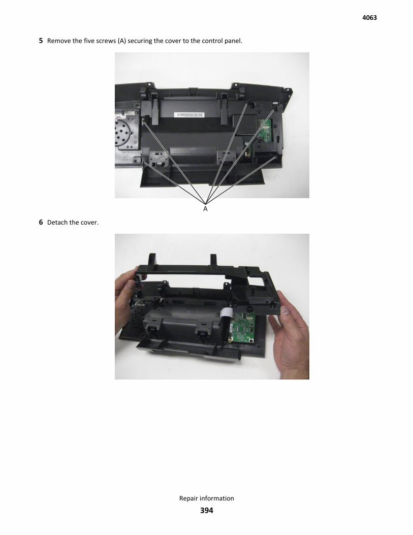
5 Remove the five screws (A) securing the cover to the control panel.
6 Detach the cover.
4063
Repair information
394
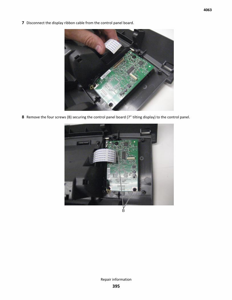
7 Disconnect the display ribbon cable from the control panel board.
8 Remove the four screws (B) securing the control panel board (7” tilting display) to the control panel.
4063
Repair information
395
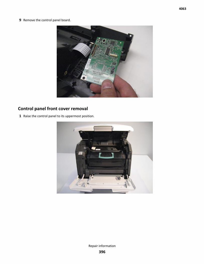
9 Remove the control panel board.
Control panel front cover removal1 Raise the control panel to its uppermost position.
4063
Repair information
396
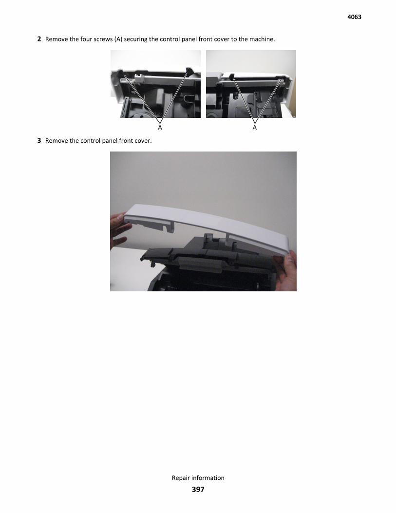
2 Remove the four screws (A) securing the control panel front cover to the machine.
3 Remove the control panel front cover.
4063
Repair information
397
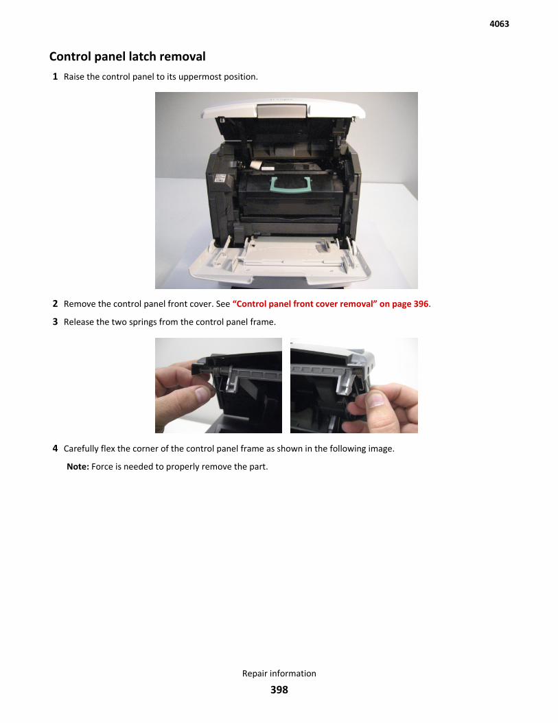
Control panel latch removal1 Raise the control panel to its uppermost position.
2 Remove the control panel front cover. See “Control panel front cover removal” on page 396.
3 Release the two springs from the control panel frame.
4 Carefully flex the corner of the control panel frame as shown in the following image.
Note: Force is needed to properly remove the part.
4063
Repair information
398
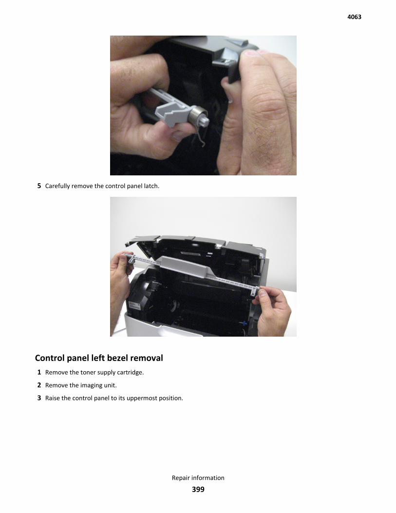
5 Carefully remove the control panel latch.
Control panel left bezel removal1 Remove the toner supply cartridge.
2 Remove the imaging unit.
3 Raise the control panel to its uppermost position.
4063
Repair information
399
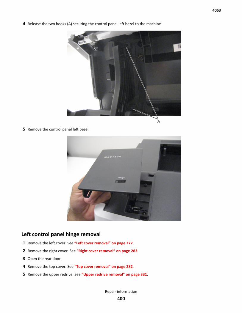
4 Release the two hooks (A) securing the control panel left bezel to the machine.
5 Remove the control panel left bezel.
Left control panel hinge removal1 Remove the left cover. See “Left cover removal” on page 277.
2 Remove the right cover. See “Right cover removal” on page 283.
3 Open the rear door.
4 Remove the top cover. See “Top cover removal” on page 282.
5 Remove the upper redrive. See “Upper redrive removal” on page 331.
4063
Repair information
400
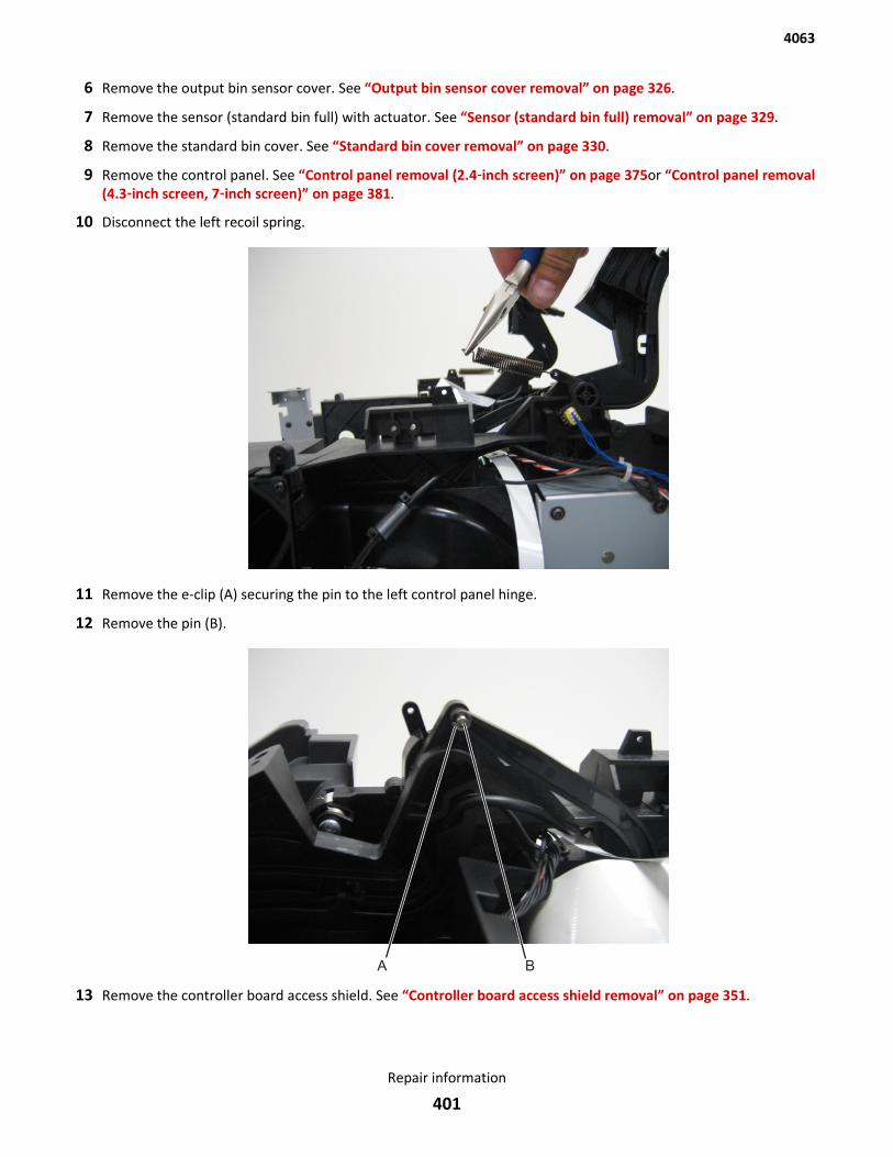
6 Remove the output bin sensor cover. See “Output bin sensor cover removal” on page 326.
7 Remove the sensor (standard bin full) with actuator. See “Sensor (standard bin full) removal” on page 329.
8 Remove the standard bin cover. See “Standard bin cover removal” on page 330.
9 Remove the control panel. See “Control panel removal (2.4‑inch screen)” on page 375or “Control panel removal(4.3‑inch screen, 7‑inch screen)” on page 381.
10 Disconnect the left recoil spring.
11 Remove the e-clip (A) securing the pin to the left control panel hinge.
12 Remove the pin (B).
13 Remove the controller board access shield. See “Controller board access shield removal” on page 351.
4063
Repair information
401
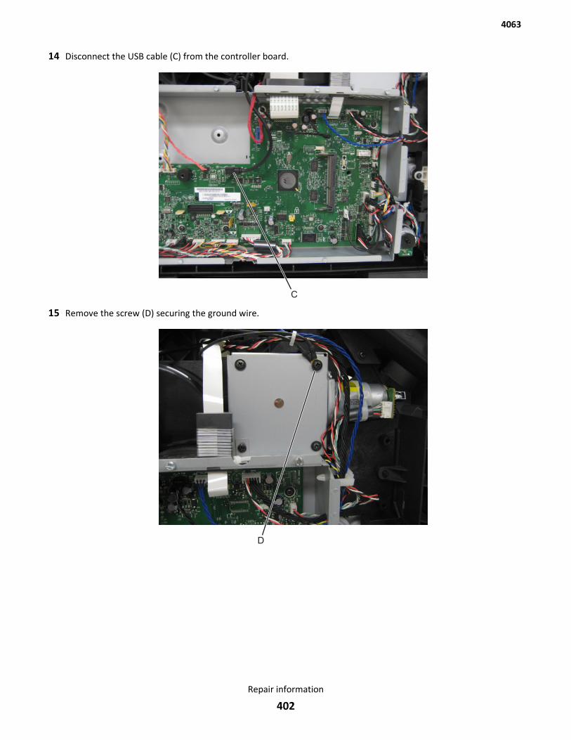
14 Disconnect the USB cable (C) from the controller board.
15 Remove the screw (D) securing the ground wire.
4063
Repair information
402
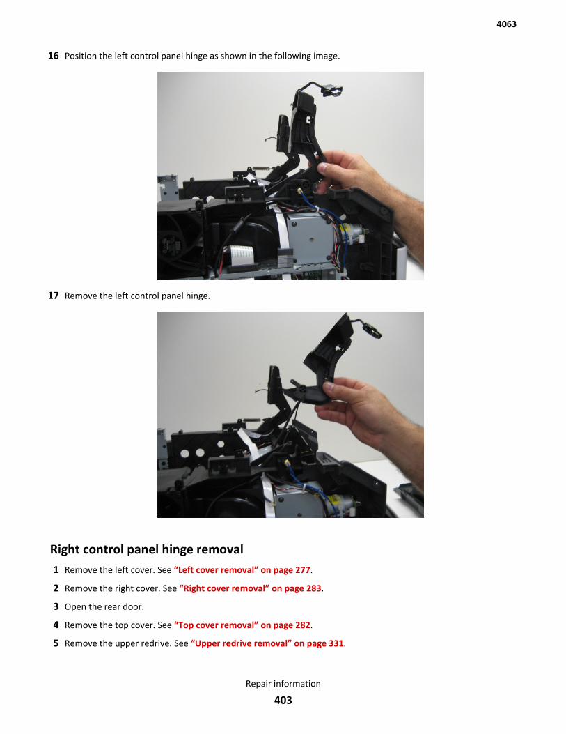
16 Position the left control panel hinge as shown in the following image.
17 Remove the left control panel hinge.
Right control panel hinge removal1 Remove the left cover. See “Left cover removal” on page 277.
2 Remove the right cover. See “Right cover removal” on page 283.
3 Open the rear door.
4 Remove the top cover. See “Top cover removal” on page 282.
5 Remove the upper redrive. See “Upper redrive removal” on page 331.
4063
Repair information
403
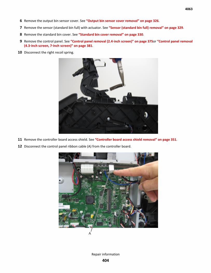
6 Remove the output bin sensor cover. See “Output bin sensor cover removal” on page 326.
7 Remove the sensor (standard bin full) with actuator. See “Sensor (standard bin full) removal” on page 329.
8 Remove the standard bin cover. See “Standard bin cover removal” on page 330.
9 Remove the control panel. See “Control panel removal (2.4‑inch screen)” on page 375or “Control panel removal(4.3‑inch screen, 7‑inch screen)” on page 381.
10 Disconnect the right recoil spring.
11 Remove the controller board access shield. See “Controller board access shield removal” on page 351.
12 Disconnect the control panel ribbon cable (A) from the controller board.
4063
Repair information
404

13 Remove the screw (B) securing the ground wire.
14 Position the right control panel hinge as shown in the following image.
4063
Repair information
405
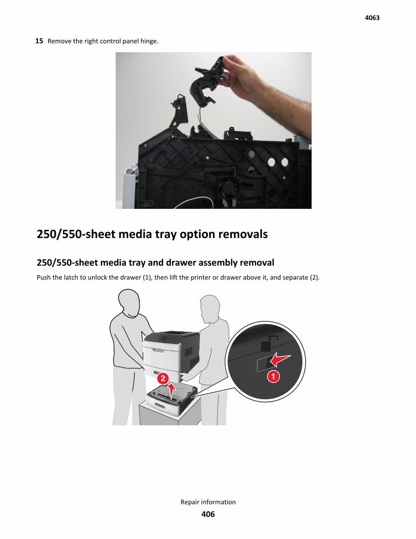
15 Remove the right control panel hinge.
250/550-sheet media tray option removals
250/550-sheet media tray and drawer assembly removalPush the latch to unlock the drawer (1), then lift the printer or drawer above it, and separate (2).
4063
Repair information
406
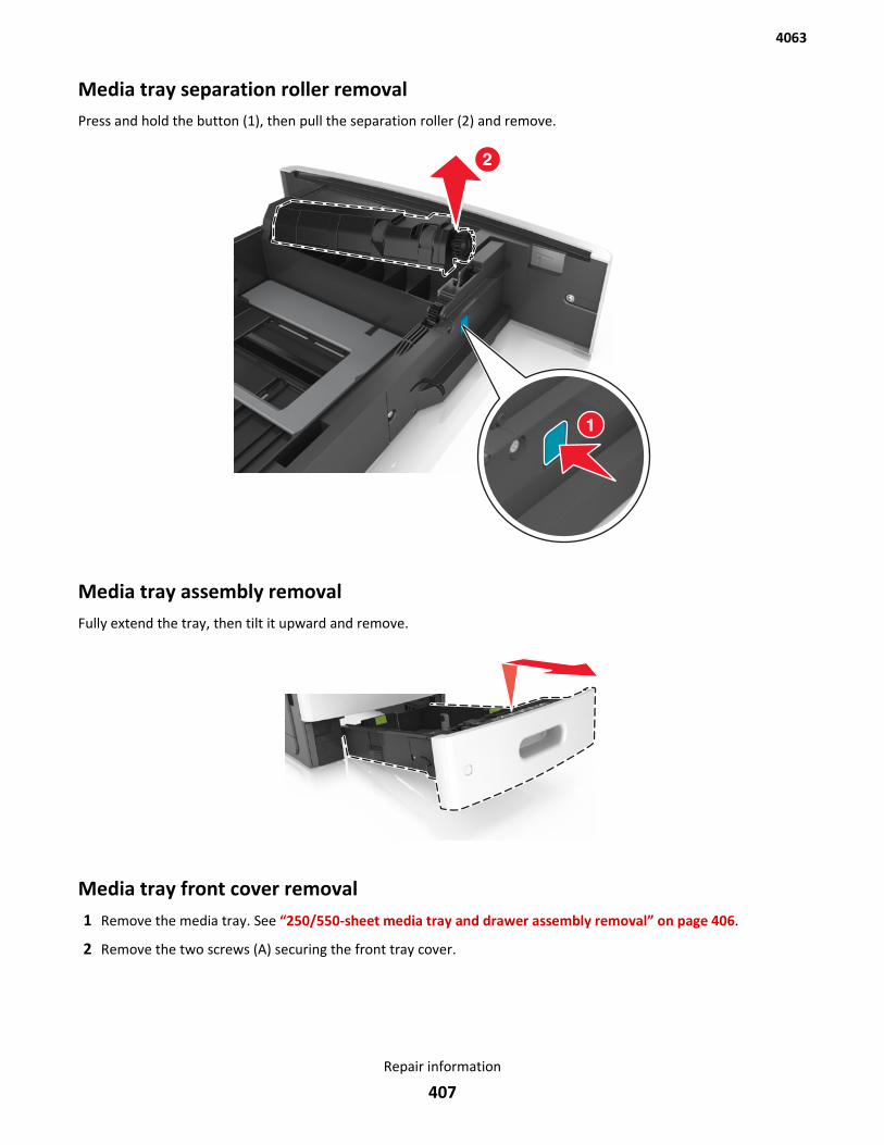
Media tray separation roller removalPress and hold the button (1), then pull the separation roller (2) and remove.
Media tray assembly removalFully extend the tray, then tilt it upward and remove.
Media tray front cover removal1 Remove the media tray. See “250/550-sheet media tray and drawer assembly removal” on page 406.
2 Remove the two screws (A) securing the front tray cover.
4063
Repair information
407
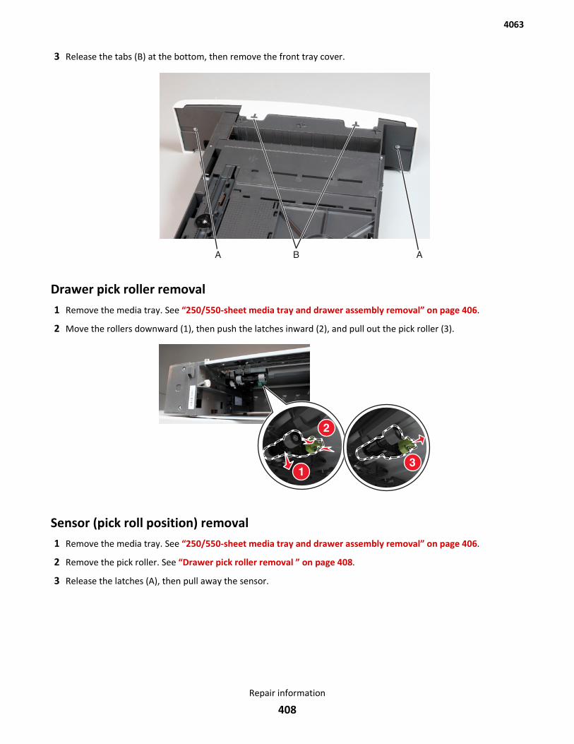
3 Release the tabs (B) at the bottom, then remove the front tray cover.
Drawer pick roller removal1 Remove the media tray. See “250/550-sheet media tray and drawer assembly removal” on page 406.
2 Move the rollers downward (1), then push the latches inward (2), and pull out the pick roller (3).
Sensor (pick roll position) removal1 Remove the media tray. See “250/550-sheet media tray and drawer assembly removal” on page 406.
2 Remove the pick roller. See “Drawer pick roller removal ” on page 408.
3 Release the latches (A), then pull away the sensor.
4063
Repair information
408
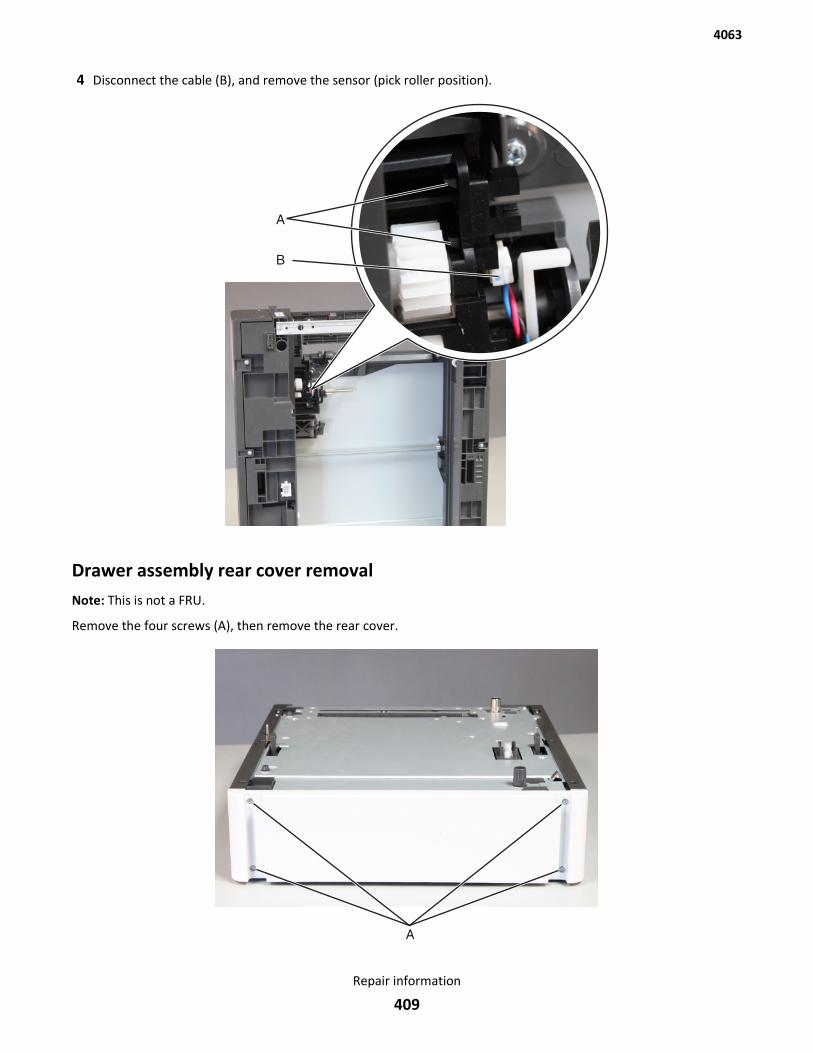
4 Disconnect the cable (B), and remove the sensor (pick roller position).
Drawer assembly rear cover removalNote: This is not a FRU.
Remove the four screws (A), then remove the rear cover.
4063
Repair information
409
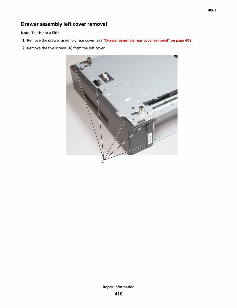
Drawer assembly left cover removalNote: This is not a FRU.
1 Remove the drawer assembly rear cover. See “Drawer assembly rear cover removal” on page 409.
2 Remove the five screws (A) from the left cover.
4063
Repair information
410
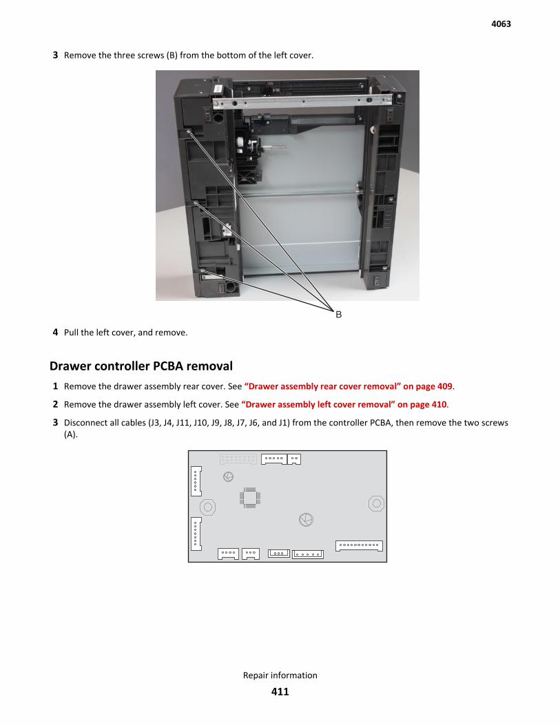
3 Remove the three screws (B) from the bottom of the left cover.
4 Pull the left cover, and remove.
Drawer controller PCBA removal1 Remove the drawer assembly rear cover. See “Drawer assembly rear cover removal” on page 409.
2 Remove the drawer assembly left cover. See “Drawer assembly left cover removal” on page 410.
3 Disconnect all cables (J3, J4, J11, J10, J9, J8, J7, J6, and J1) from the controller PCBA, then remove the two screws(A).
4063
Repair information
411
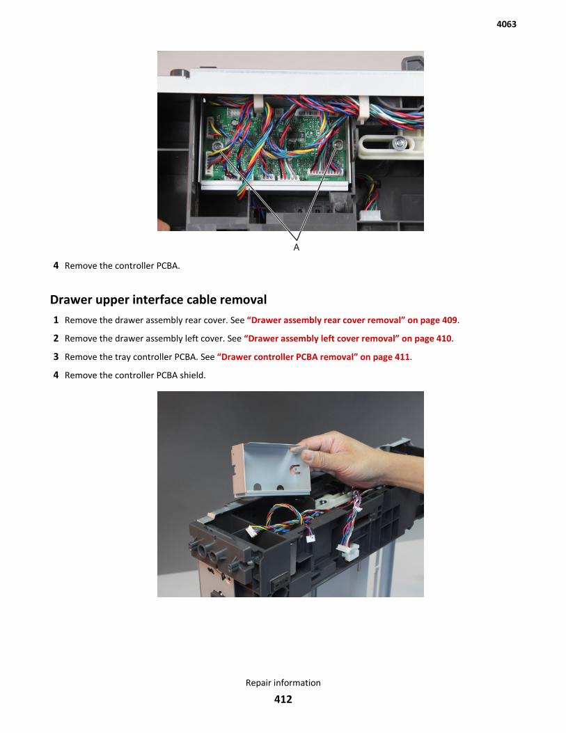
4 Remove the controller PCBA.
Drawer upper interface cable removal1 Remove the drawer assembly rear cover. See “Drawer assembly rear cover removal” on page 409.
2 Remove the drawer assembly left cover. See “Drawer assembly left cover removal” on page 410.
3 Remove the tray controller PCBA. See “Drawer controller PCBA removal” on page 411.
4 Remove the controller PCBA shield.
4063
Repair information
412
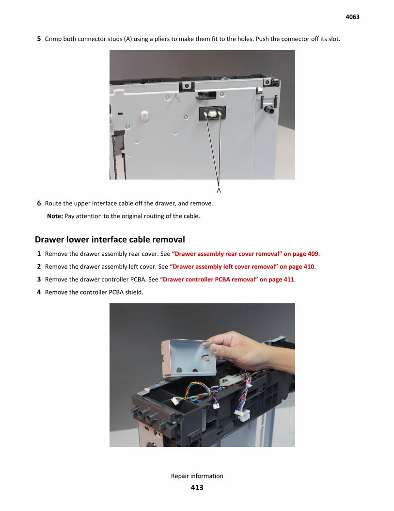
5 Crimp both connector studs (A) using a pliers to make them fit to the holes. Push the connector off its slot.
6 Route the upper interface cable off the drawer, and remove.
Note: Pay attention to the original routing of the cable.
Drawer lower interface cable removal1 Remove the drawer assembly rear cover. See “Drawer assembly rear cover removal” on page 409.
2 Remove the drawer assembly left cover. See “Drawer assembly left cover removal” on page 410.
3 Remove the drawer controller PCBA. See “Drawer controller PCBA removal” on page 411.
4 Remove the controller PCBA shield.
4063
Repair information
413
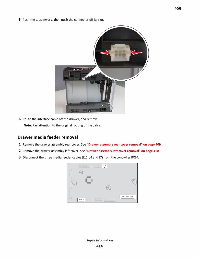
5 Push the tabs inward, then push the connector off its slot.
6 Route the interface cable off the drawer, and remove.
Note: Pay attention to the original routing of the cable.
Drawer media feeder removal1 Remove the drawer assembly rear cover. See “Drawer assembly rear cover removal” on page 409.
2 Remove the drawer assembly left cover. See “Drawer assembly left cover removal” on page 410.
3 Disconnect the three media feeder cables (J11, J4 and J7) from the controller PCBA.
4063
Repair information
414
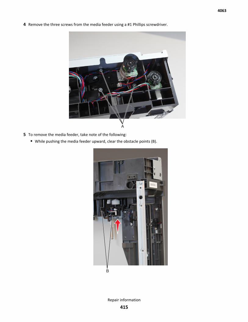
4 Remove the three screws from the media feeder using a #1 Phillips screwdriver.
5 To remove the media feeder, take note of the following:
• While pushing the media feeder upward, clear the obstacle points (B).
4063
Repair information
415
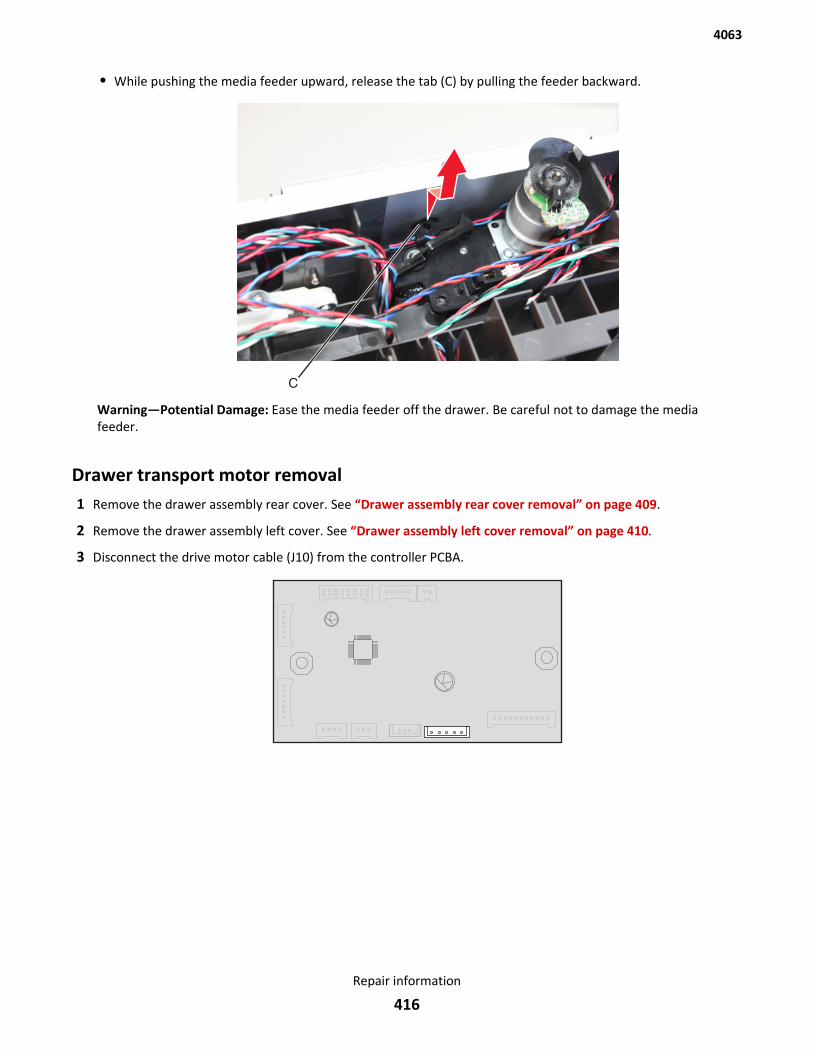
• While pushing the media feeder upward, release the tab (C) by pulling the feeder backward.
Warning—Potential Damage: Ease the media feeder off the drawer. Be careful not to damage the mediafeeder.
Drawer transport motor removal1 Remove the drawer assembly rear cover. See “Drawer assembly rear cover removal” on page 409.
2 Remove the drawer assembly left cover. See “Drawer assembly left cover removal” on page 410.
3 Disconnect the drive motor cable (J10) from the controller PCBA.
4063
Repair information
416
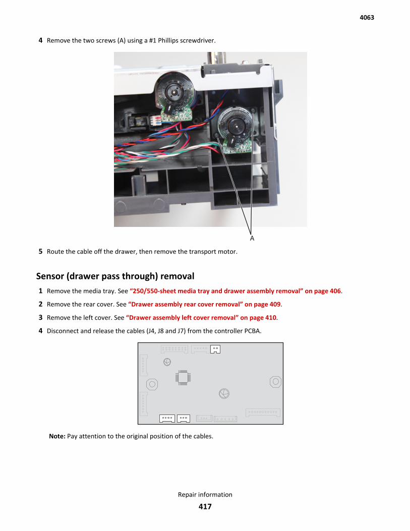
4 Remove the two screws (A) using a #1 Phillips screwdriver.
5 Route the cable off the drawer, then remove the transport motor.
Sensor (drawer pass through) removal1 Remove the media tray. See “250/550-sheet media tray and drawer assembly removal” on page 406.
2 Remove the rear cover. See “Drawer assembly rear cover removal” on page 409.
3 Remove the left cover. See “Drawer assembly left cover removal” on page 410.
4 Disconnect and release the cables (J4, J8 and J7) from the controller PCBA.
Note: Pay attention to the original position of the cables.
4063
Repair information
417
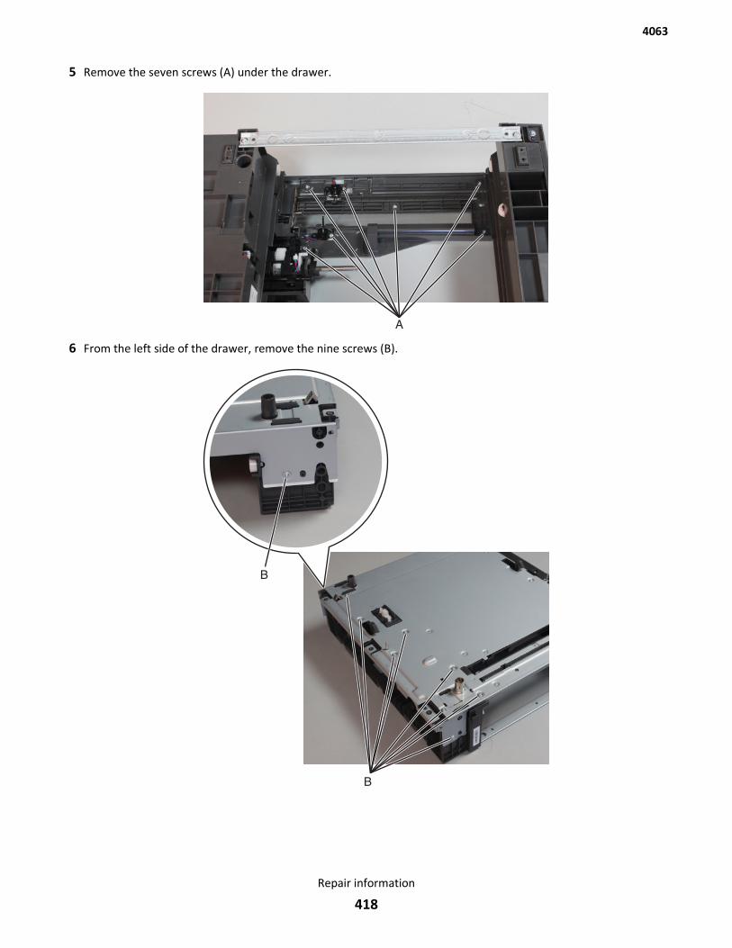
5 Remove the seven screws (A) under the drawer.
6 From the left side of the drawer, remove the nine screws (B).
4063
Repair information
418
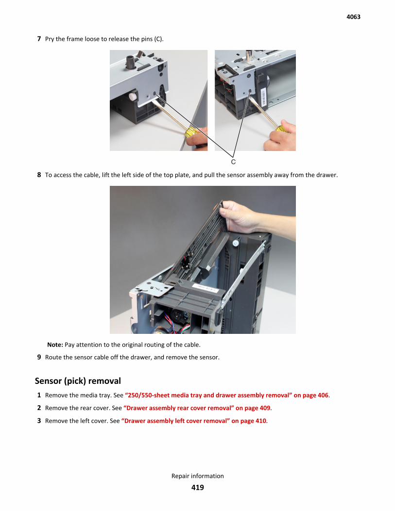
7 Pry the frame loose to release the pins (C).
8 To access the cable, lift the left side of the top plate, and pull the sensor assembly away from the drawer.
Note: Pay attention to the original routing of the cable.
9 Route the sensor cable off the drawer, and remove the sensor.
Sensor (pick) removal1 Remove the media tray. See “250/550-sheet media tray and drawer assembly removal” on page 406.
2 Remove the rear cover. See “Drawer assembly rear cover removal” on page 409.
3 Remove the left cover. See “Drawer assembly left cover removal” on page 410.
4063
Repair information
419
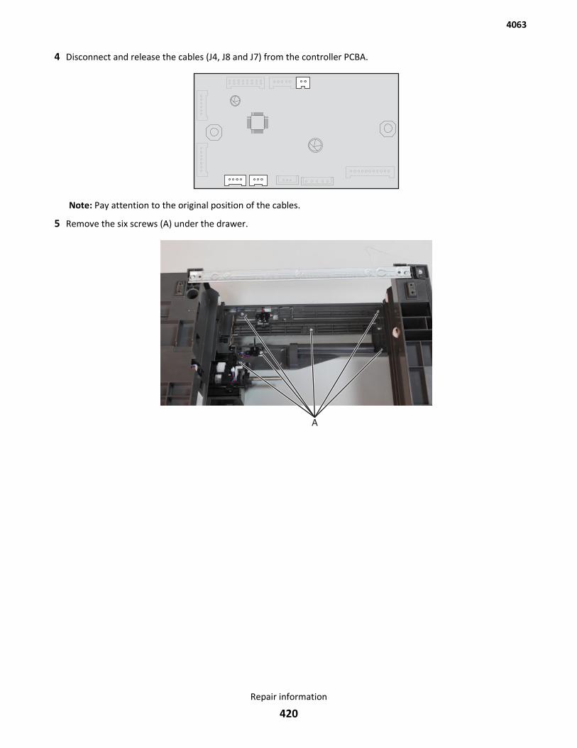
4 Disconnect and release the cables (J4, J8 and J7) from the controller PCBA.
Note: Pay attention to the original position of the cables.
5 Remove the six screws (A) under the drawer.
4063
Repair information
420
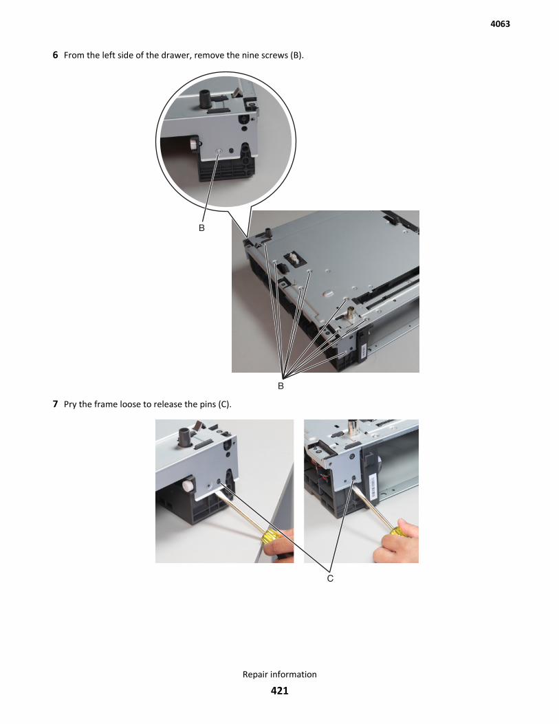
6 From the left side of the drawer, remove the nine screws (B).
7 Pry the frame loose to release the pins (C).
4063
Repair information
421
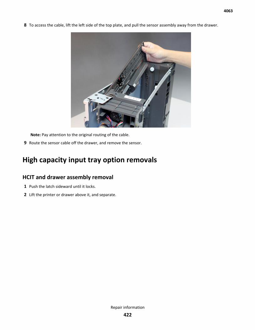
8 To access the cable, lift the left side of the top plate, and pull the sensor assembly away from the drawer.
Note: Pay attention to the original routing of the cable.
9 Route the sensor cable off the drawer, and remove the sensor.
High capacity input tray option removals
HCIT and drawer assembly removal1 Push the latch sideward until it locks.
2 Lift the printer or drawer above it, and separate.
4063
Repair information
422
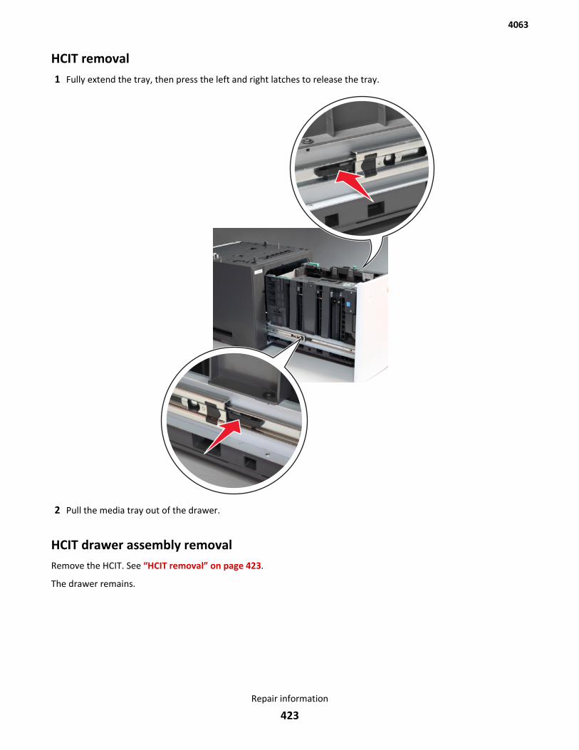
HCIT removal1 Fully extend the tray, then press the left and right latches to release the tray.
2 Pull the media tray out of the drawer.
HCIT drawer assembly removalRemove the HCIT. See “HCIT removal” on page 423.
The drawer remains.
4063
Repair information
423
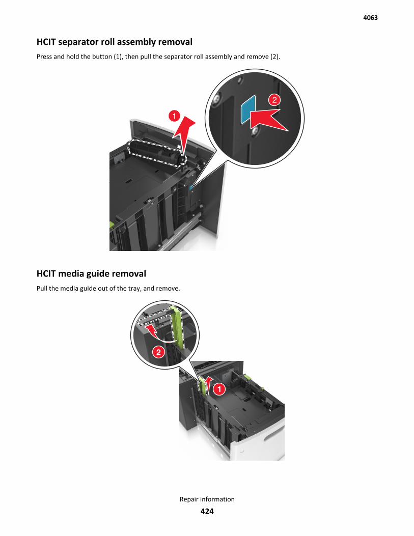
HCIT separator roll assembly removalPress and hold the button (1), then pull the separator roll assembly and remove (2).
HCIT media guide removalPull the media guide out of the tray, and remove.
4063
Repair information
424
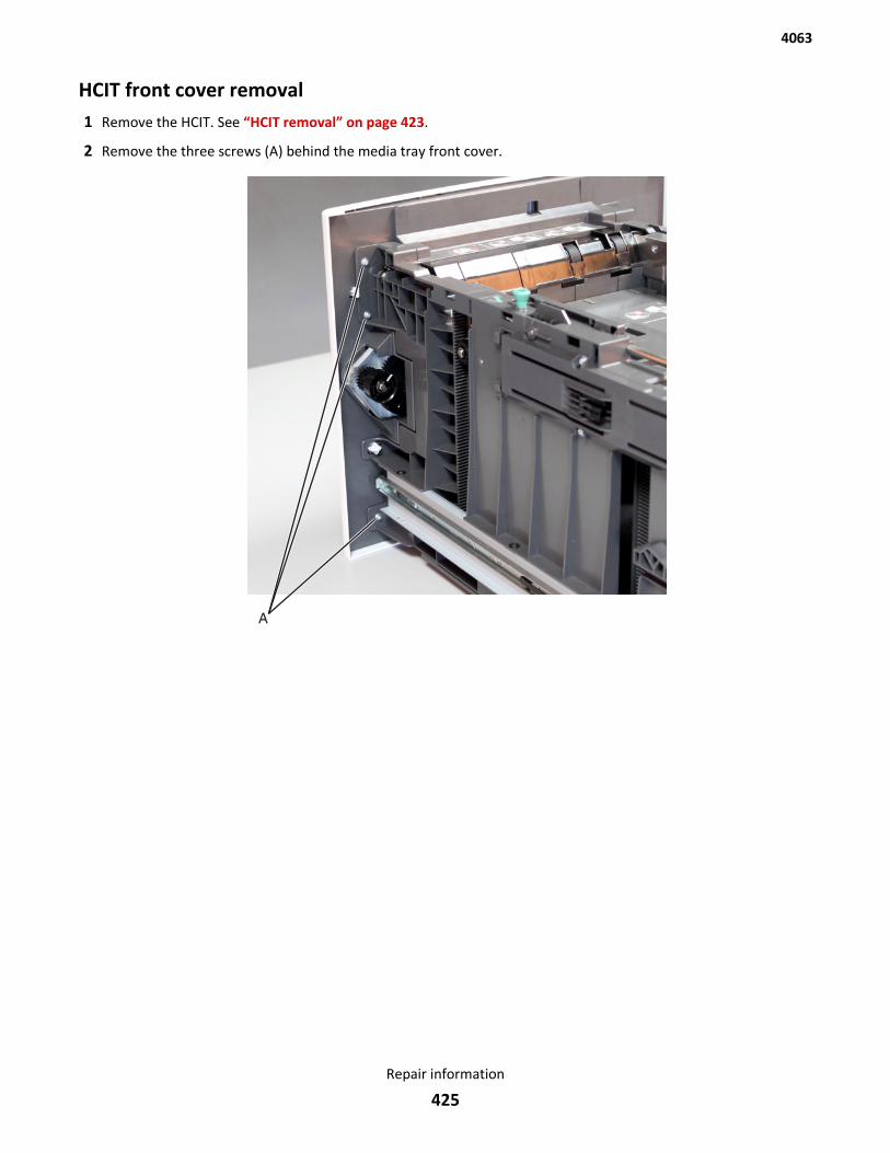
HCIT front cover removal1 Remove the HCIT. See “HCIT removal” on page 423.
2 Remove the three screws (A) behind the media tray front cover.
4063
Repair information
425
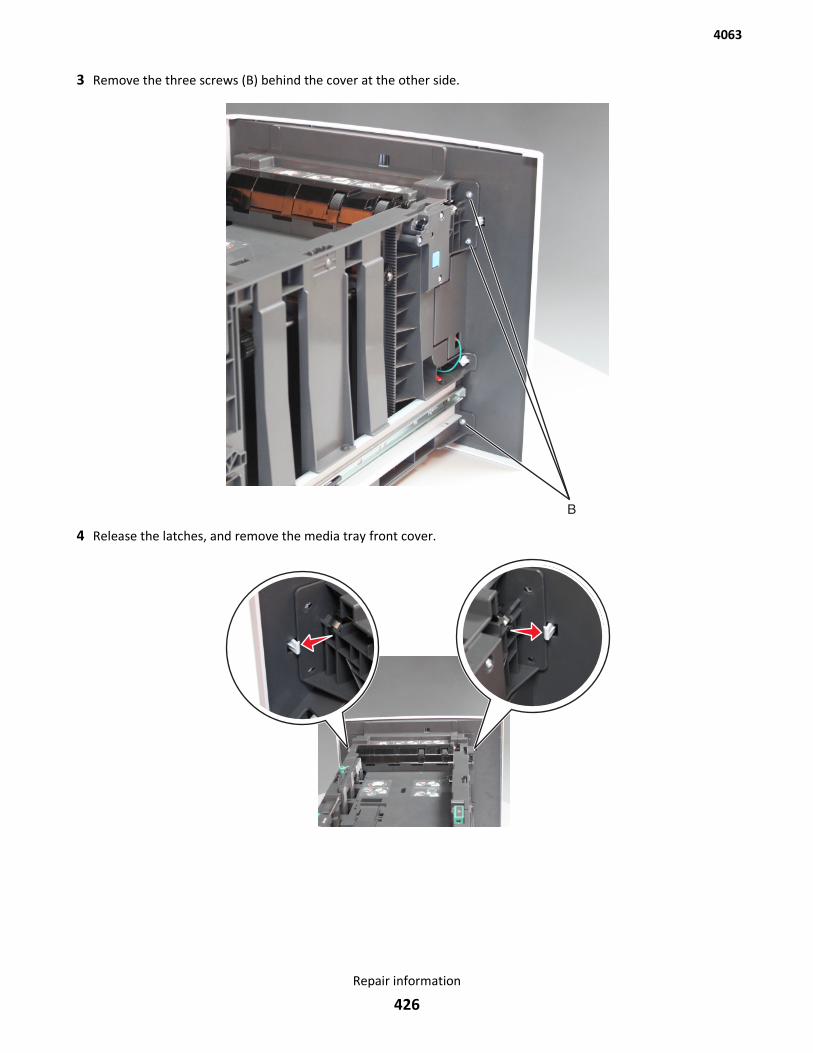
3 Remove the three screws (B) behind the cover at the other side.
4 Release the latches, and remove the media tray front cover.
4063
Repair information
426
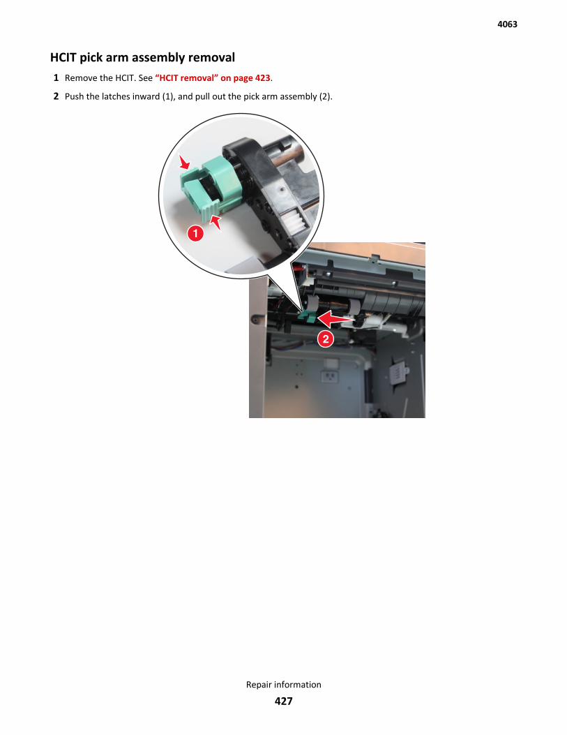
HCIT pick arm assembly removal1 Remove the HCIT. See “HCIT removal” on page 423.
2 Push the latches inward (1), and pull out the pick arm assembly (2).
4063
Repair information
427
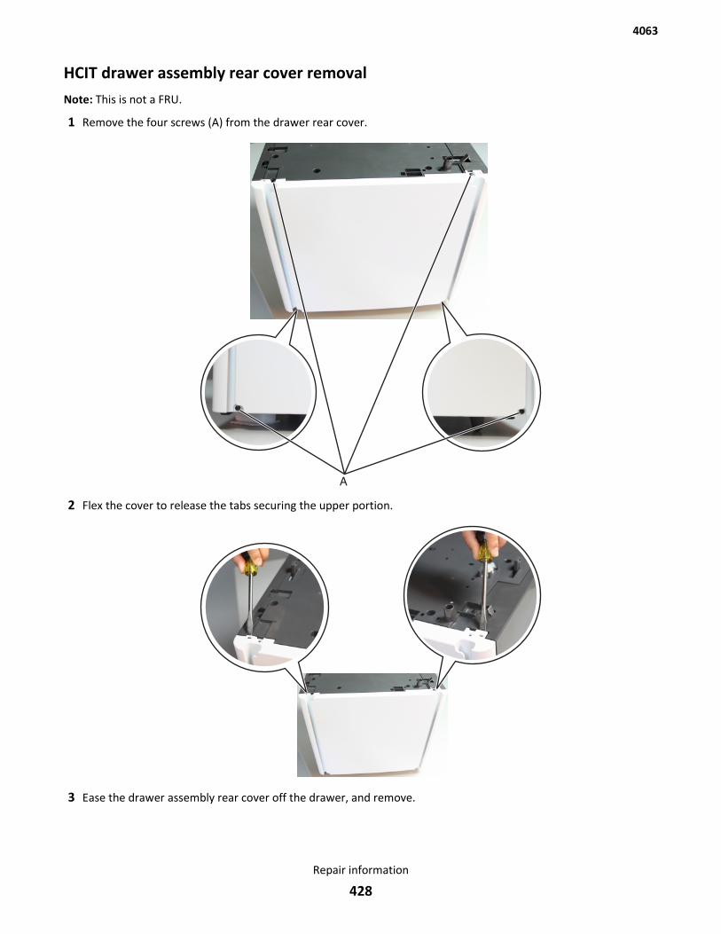
HCIT drawer assembly rear cover removalNote: This is not a FRU.
1 Remove the four screws (A) from the drawer rear cover.
2 Flex the cover to release the tabs securing the upper portion.
3 Ease the drawer assembly rear cover off the drawer, and remove.
4063
Repair information
428
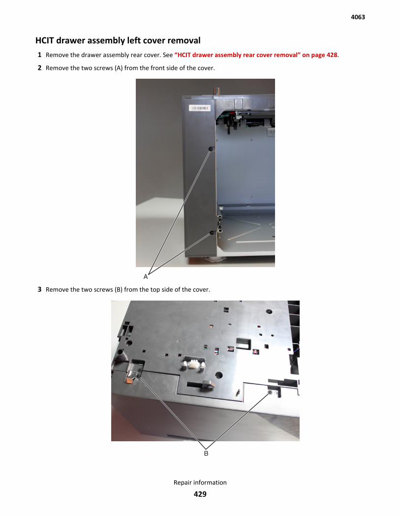
HCIT drawer assembly left cover removal1 Remove the drawer assembly rear cover. See “HCIT drawer assembly rear cover removal” on page 428.
2 Remove the two screws (A) from the front side of the cover.
3 Remove the two screws (B) from the top side of the cover.
4063
Repair information
429
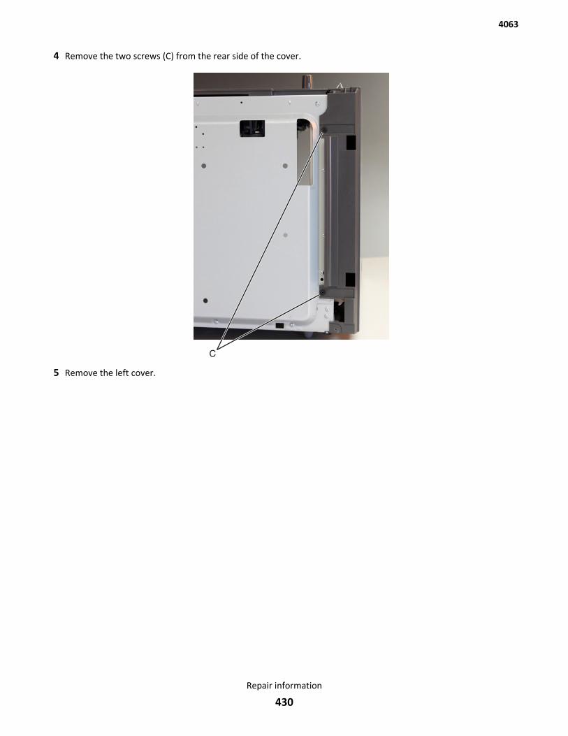
4 Remove the two screws (C) from the rear side of the cover.
5 Remove the left cover.
4063
Repair information
430
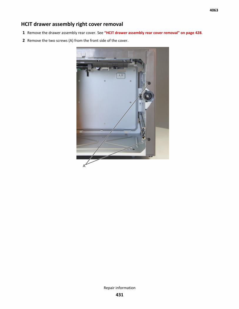
HCIT drawer assembly right cover removal1 Remove the drawer assembly rear cover. See “HCIT drawer assembly rear cover removal” on page 428.
2 Remove the two screws (A) from the front side of the cover.
4063
Repair information
431
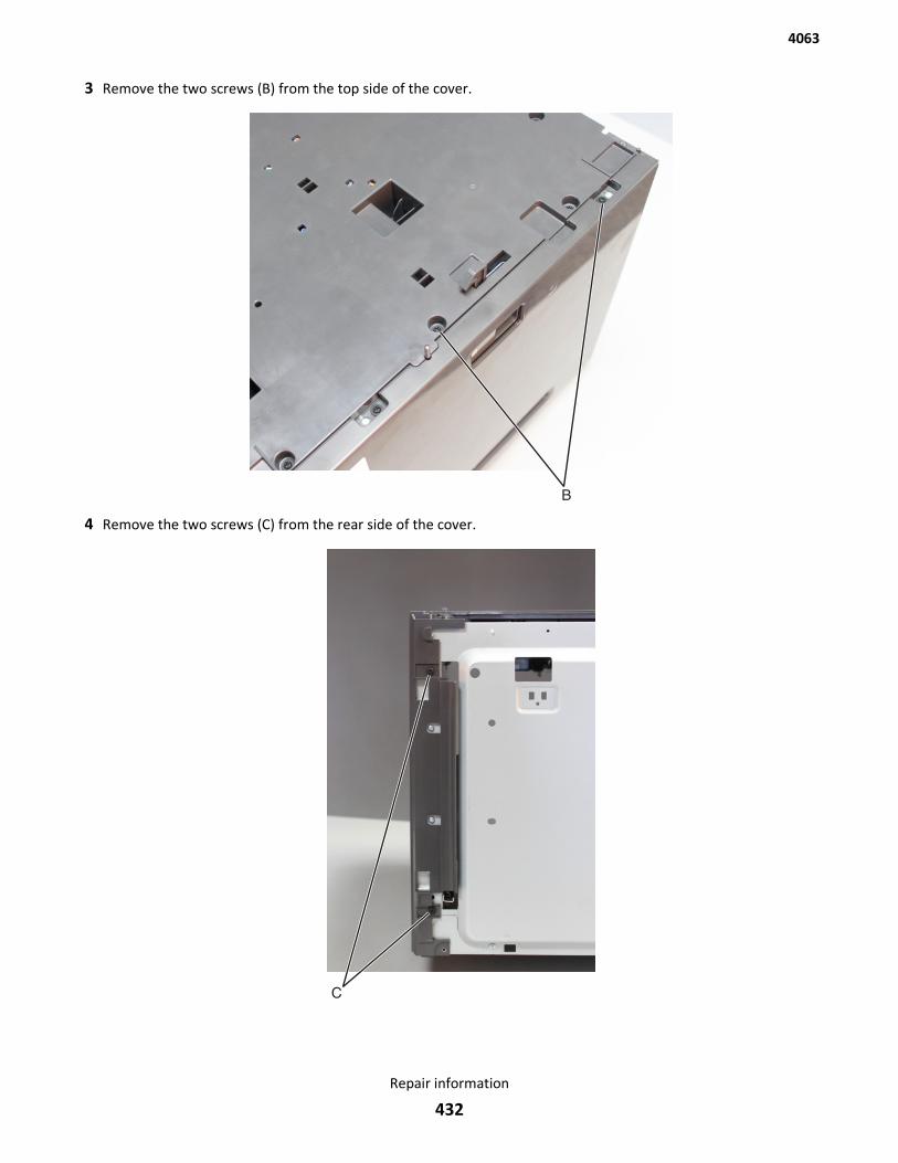
3 Remove the two screws (B) from the top side of the cover.
4 Remove the two screws (C) from the rear side of the cover.
4063
Repair information
432
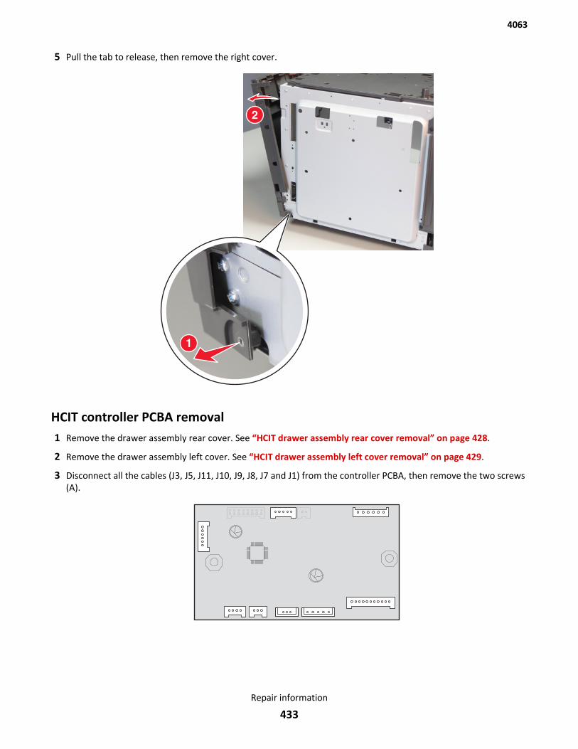
5 Pull the tab to release, then remove the right cover.
HCIT controller PCBA removal1 Remove the drawer assembly rear cover. See “HCIT drawer assembly rear cover removal” on page 428.
2 Remove the drawer assembly left cover. See “HCIT drawer assembly left cover removal” on page 429.
3 Disconnect all the cables (J3, J5, J11, J10, J9, J8, J7 and J1) from the controller PCBA, then remove the two screws(A).
4063
Repair information
433
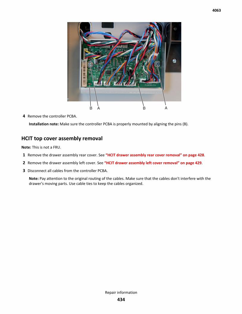
4 Remove the controller PCBA.
Installation note: Make sure the controller PCBA is properly mounted by aligning the pins (B).
HCIT top cover assembly removalNote: This is not a FRU.
1 Remove the drawer assembly rear cover. See “HCIT drawer assembly rear cover removal” on page 428.
2 Remove the drawer assembly left cover. See “HCIT drawer assembly left cover removal” on page 429.
3 Disconnect all cables from the controller PCBA.
Note: Pay attention to the original routing of the cables. Make sure that the cables don't interfere with thedrawer's moving parts. Use cable ties to keep the cables organized.
4063
Repair information
434
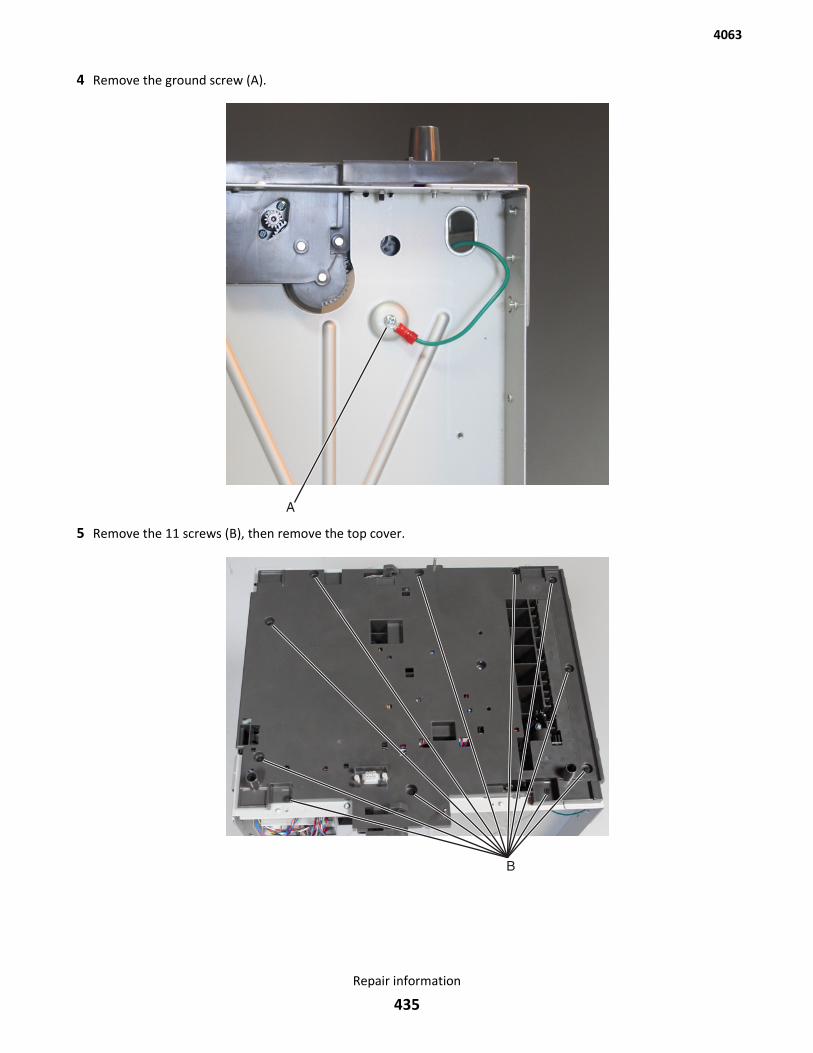
4 Remove the ground screw (A).
5 Remove the 11 screws (B), then remove the top cover.
4063
Repair information
435
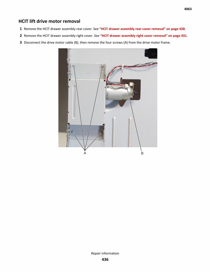
HCIT lift drive motor removal1 Remove the HCIT drawer assembly rear cover. See “HCIT drawer assembly rear cover removal” on page 428.
2 Remove the HCIT drawer assembly right cover. See “HCIT drawer assembly right cover removal” on page 431.
3 Disconnect the drive motor cable (B), then remove the four screws (A) from the drive motor frame.
4063
Repair information
436
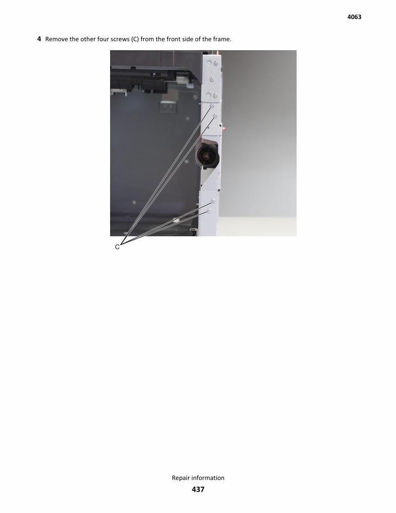
4 Remove the other four screws (C) from the front side of the frame.
4063
Repair information
437
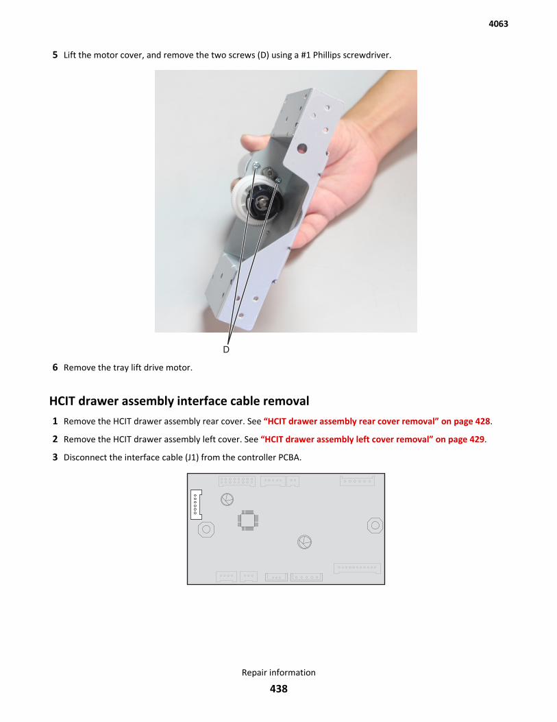
5 Lift the motor cover, and remove the two screws (D) using a #1 Phillips screwdriver.
6 Remove the tray lift drive motor.
HCIT drawer assembly interface cable removal1 Remove the HCIT drawer assembly rear cover. See “HCIT drawer assembly rear cover removal” on page 428.
2 Remove the HCIT drawer assembly left cover. See “HCIT drawer assembly left cover removal” on page 429.
3 Disconnect the interface cable (J1) from the controller PCBA.
4063
Repair information
438
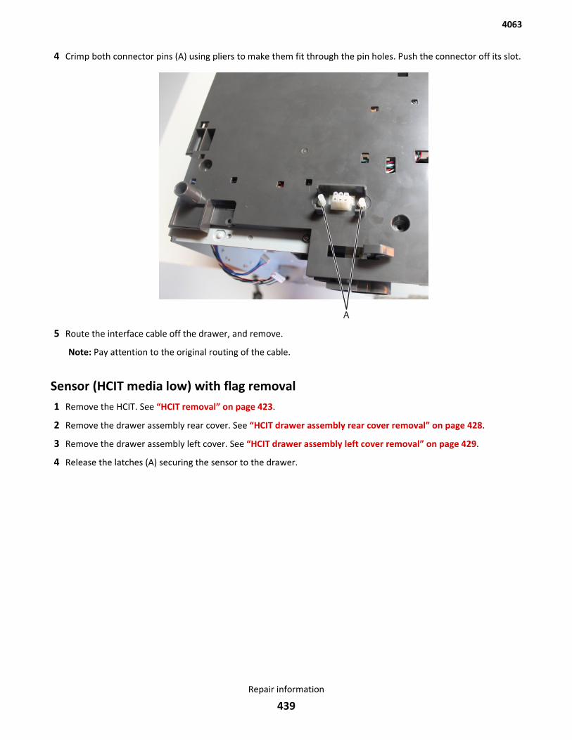
4 Crimp both connector pins (A) using pliers to make them fit through the pin holes. Push the connector off its slot.
5 Route the interface cable off the drawer, and remove.
Note: Pay attention to the original routing of the cable.
Sensor (HCIT media low) with flag removal1 Remove the HCIT. See “HCIT removal” on page 423.
2 Remove the drawer assembly rear cover. See “HCIT drawer assembly rear cover removal” on page 428.
3 Remove the drawer assembly left cover. See “HCIT drawer assembly left cover removal” on page 429.
4 Release the latches (A) securing the sensor to the drawer.
4063
Repair information
439
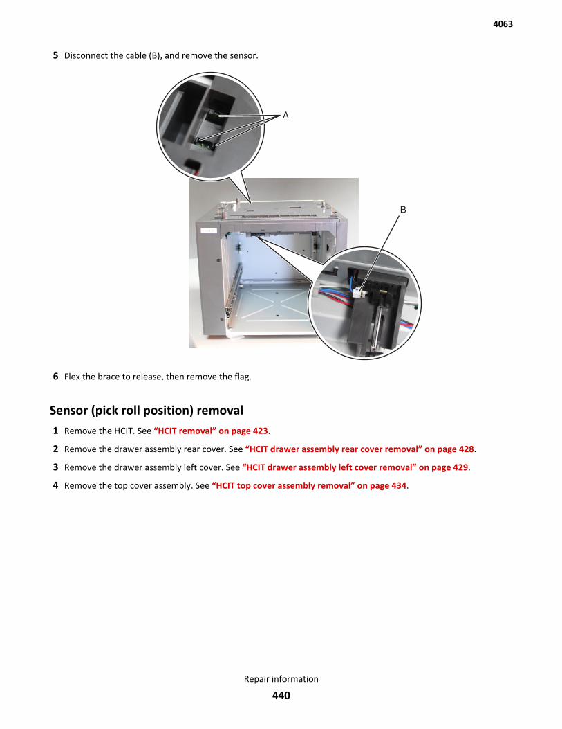
5 Disconnect the cable (B), and remove the sensor.
6 Flex the brace to release, then remove the flag.
Sensor (pick roll position) removal1 Remove the HCIT. See “HCIT removal” on page 423.
2 Remove the drawer assembly rear cover. See “HCIT drawer assembly rear cover removal” on page 428.
3 Remove the drawer assembly left cover. See “HCIT drawer assembly left cover removal” on page 429.
4 Remove the top cover assembly. See “HCIT top cover assembly removal” on page 434.
4063
Repair information
440
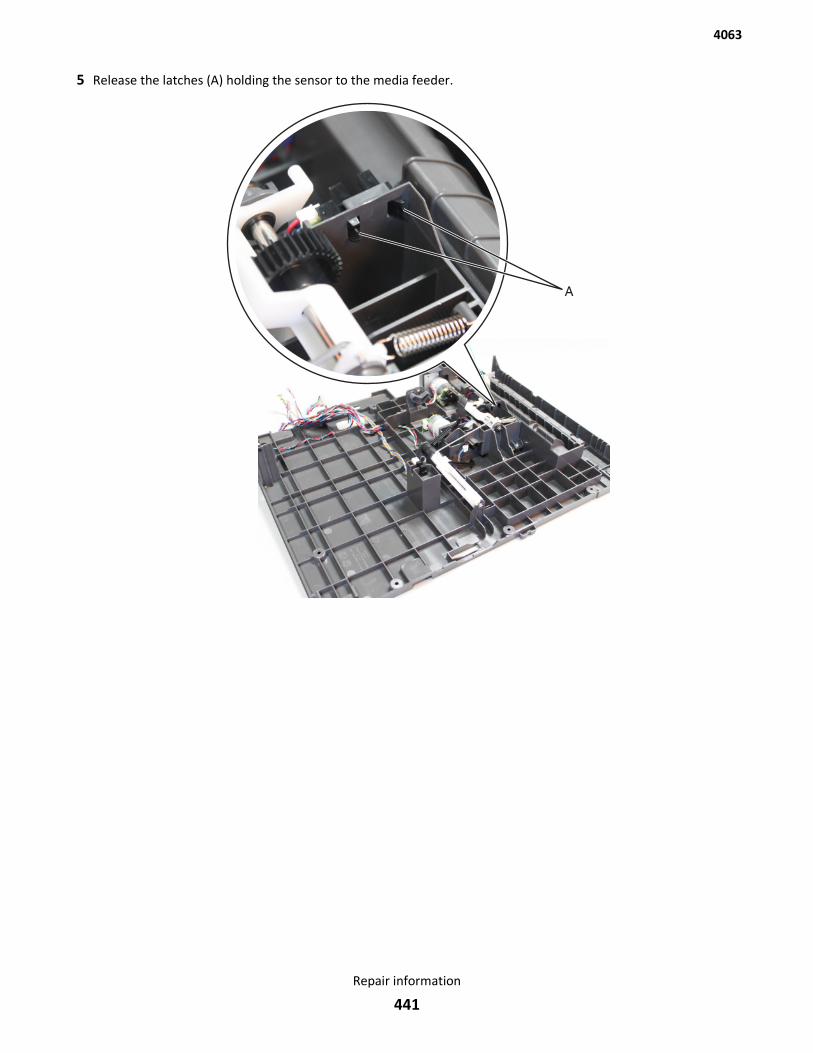
5 Release the latches (A) holding the sensor to the media feeder.
4063
Repair information
441
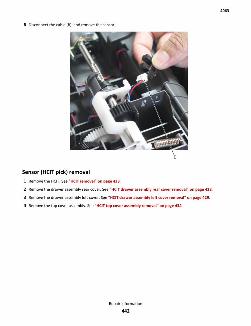
6 Disconnect the cable (B), and remove the sensor.
Sensor (HCIT pick) removal1 Remove the HCIT. See “HCIT removal” on page 423.
2 Remove the drawer assembly rear cover. See “HCIT drawer assembly rear cover removal” on page 428.
3 Remove the drawer assembly left cover. See “HCIT drawer assembly left cover removal” on page 429.
4 Remove the top cover assembly. See “HCIT top cover assembly removal” on page 434.
4063
Repair information
442
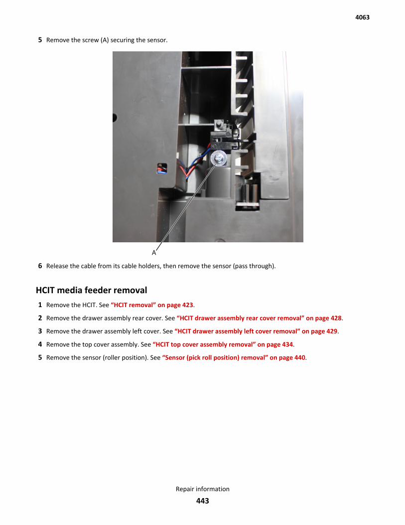
5 Remove the screw (A) securing the sensor.
6 Release the cable from its cable holders, then remove the sensor (pass through).
HCIT media feeder removal1 Remove the HCIT. See “HCIT removal” on page 423.
2 Remove the drawer assembly rear cover. See “HCIT drawer assembly rear cover removal” on page 428.
3 Remove the drawer assembly left cover. See “HCIT drawer assembly left cover removal” on page 429.
4 Remove the top cover assembly. See “HCIT top cover assembly removal” on page 434.
5 Remove the sensor (roller position). See “Sensor (pick roll position) removal” on page 440.
4063
Repair information
443
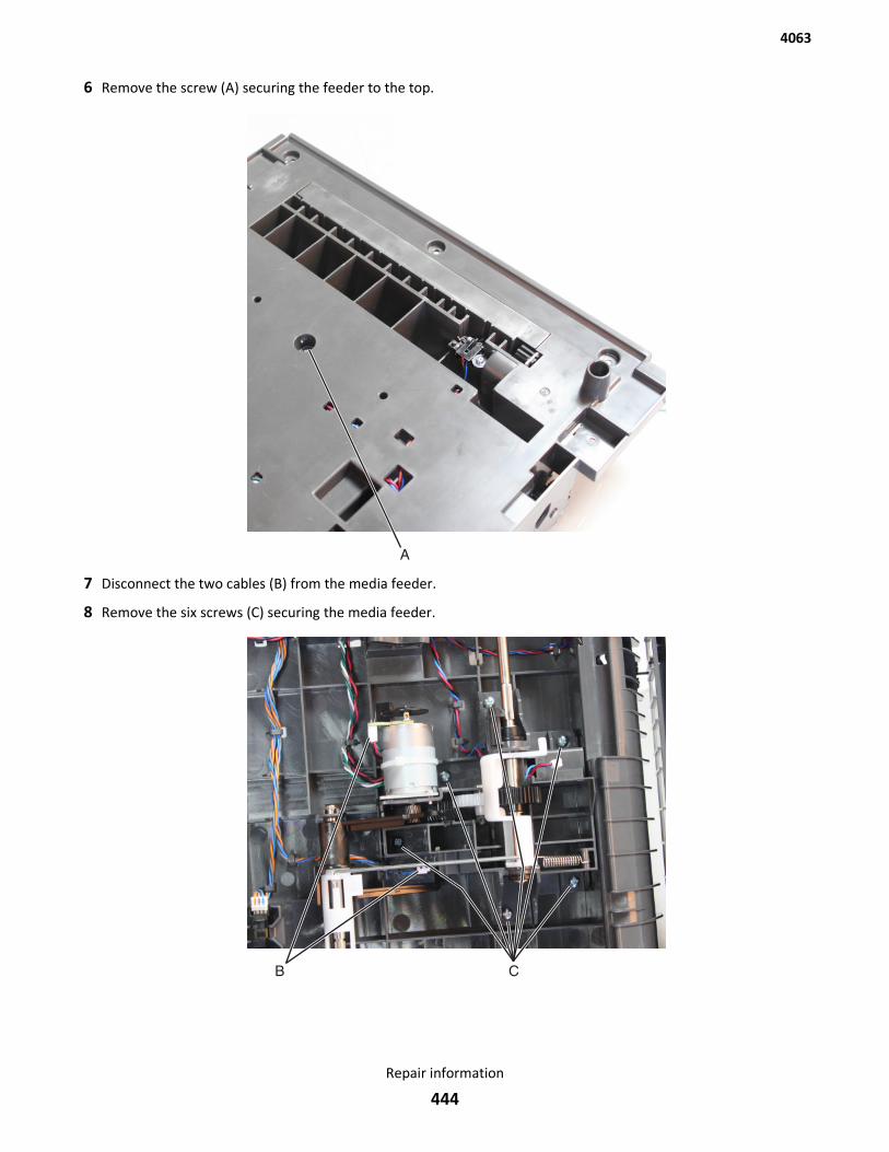
6 Remove the screw (A) securing the feeder to the top.
7 Disconnect the two cables (B) from the media feeder.
8 Remove the six screws (C) securing the media feeder.
4063
Repair information
444
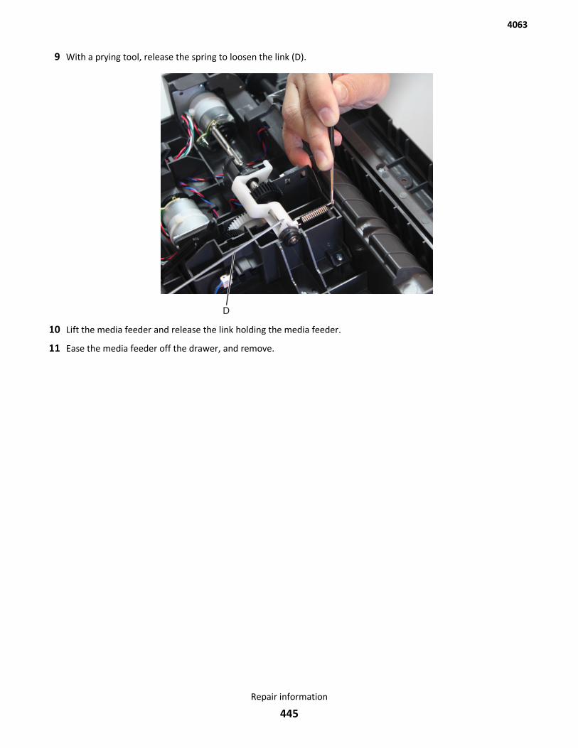
9 With a prying tool, release the spring to loosen the link (D).
10 Lift the media feeder and release the link holding the media feeder.
11 Ease the media feeder off the drawer, and remove.
4063
Repair information
445
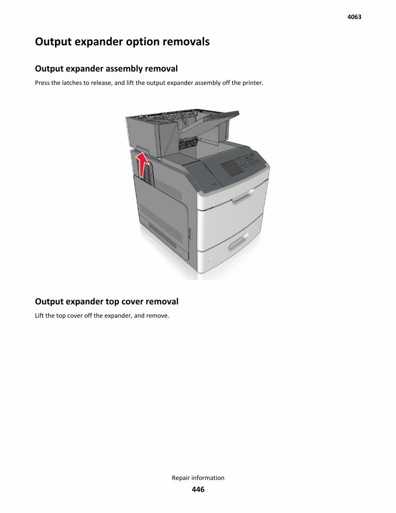
Output expander option removals
Output expander assembly removalPress the latches to release, and lift the output expander assembly off the printer.
Output expander top cover removalLift the top cover off the expander, and remove.
4063
Repair information
446
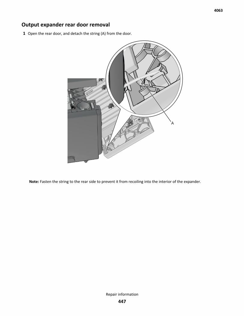
Output expander rear door removal1 Open the rear door, and detach the string (A) from the door.
Note: Fasten the string to the rear side to prevent it from recoiling into the interior of the expander.
4063
Repair information
447
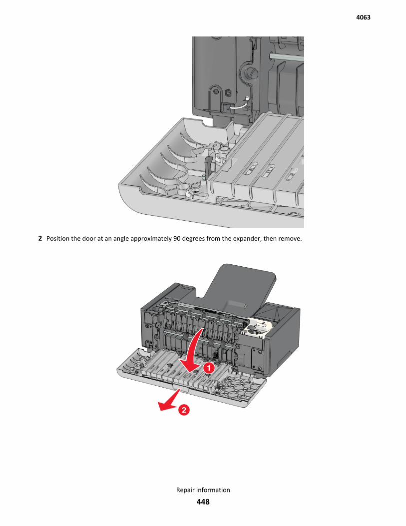
2 Position the door at an angle approximately 90 degrees from the expander, then remove.
4063
Repair information
448
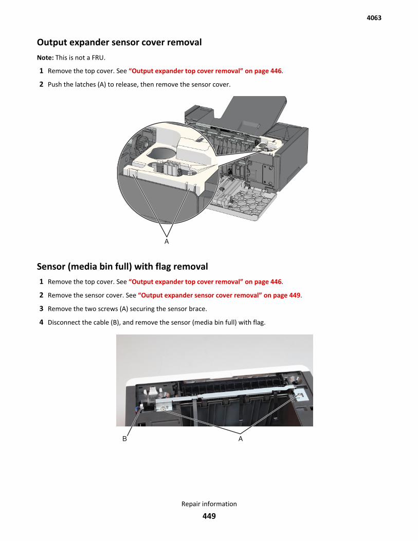
Output expander sensor cover removalNote: This is not a FRU.
1 Remove the top cover. See “Output expander top cover removal” on page 446.
2 Push the latches (A) to release, then remove the sensor cover.
Sensor (media bin full) with flag removal1 Remove the top cover. See “Output expander top cover removal” on page 446.
2 Remove the sensor cover. See “Output expander sensor cover removal” on page 449.
3 Remove the two screws (A) securing the sensor brace.
4 Disconnect the cable (B), and remove the sensor (media bin full) with flag.
4063
Repair information
449

Output expander right cover removal1 Open the rear door, then detach the string (A) from the rear door.
Note: Fasten the string to the rear side to prevent it from recoiling into the interior of the expander.
4063
Repair information
450
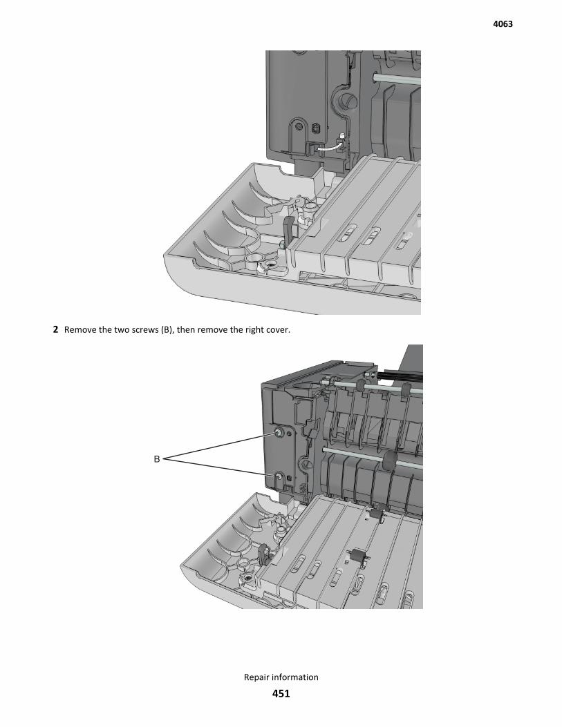
2 Remove the two screws (B), then remove the right cover.
4063
Repair information
451

Output expander left cover removal1 Open the rear door, then detach the string (A) from the rear door.
Note: Fasten the string to the rear side to prevent it from recoiling into the interior of the expander.
4063
Repair information
452
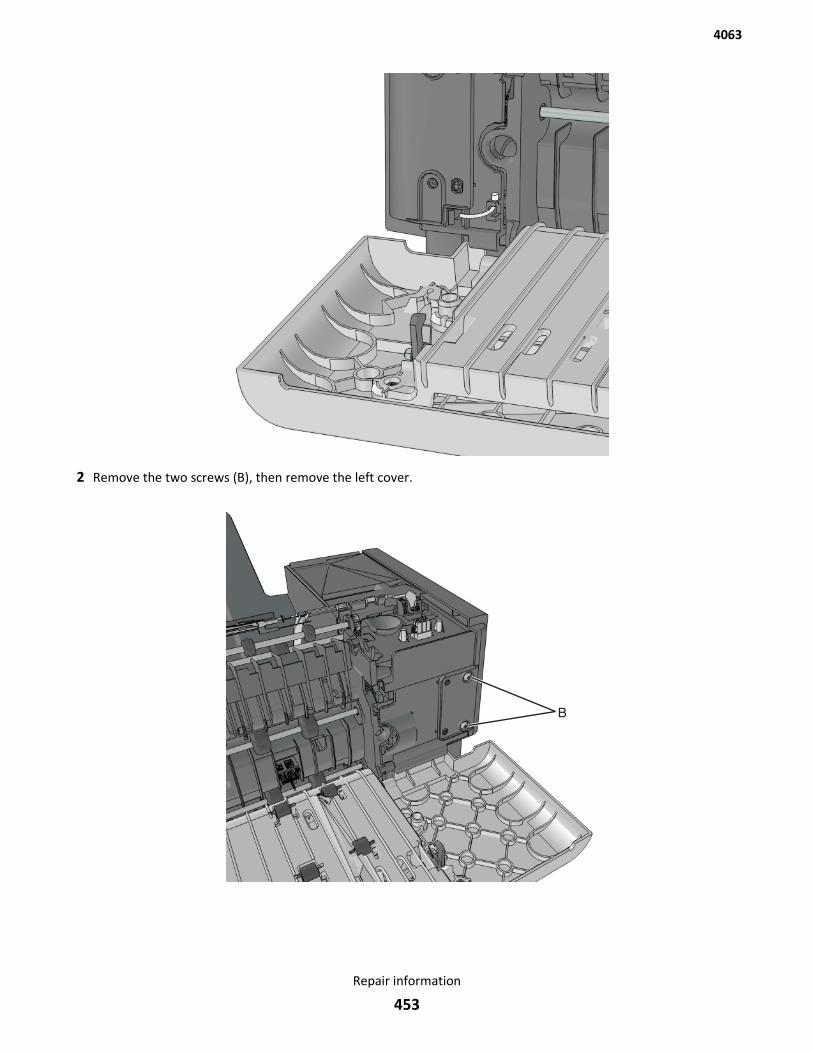
2 Remove the two screws (B), then remove the left cover.
4063
Repair information
453
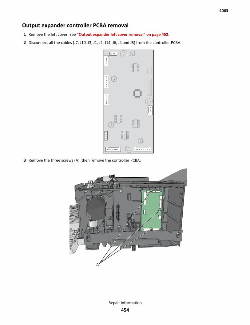
Output expander controller PCBA removal1 Remove the left cover. See “Output expander left cover removal” on page 452.
2 Disconnect all the cables (J7, J10, J3, J1, J2, J14, J6, J4 and J5) from the controller PCBA.
3 Remove the three screws (A), then remove the controller PCBA.
4063
Repair information
454
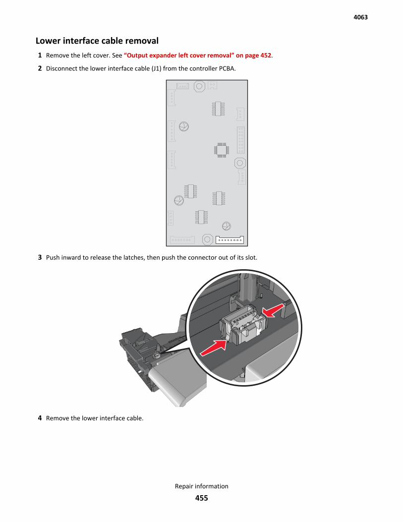
Lower interface cable removal1 Remove the left cover. See “Output expander left cover removal” on page 452.
2 Disconnect the lower interface cable (J1) from the controller PCBA.
3 Push inward to release the latches, then push the connector out of its slot.
4 Remove the lower interface cable.
4063
Repair information
455
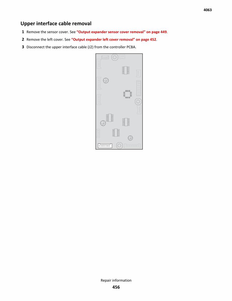
Upper interface cable removal1 Remove the sensor cover. See “Output expander sensor cover removal” on page 449.
2 Remove the left cover. See “Output expander left cover removal” on page 452.
3 Disconnect the upper interface cable (J2) from the controller PCBA.
4063
Repair information
456
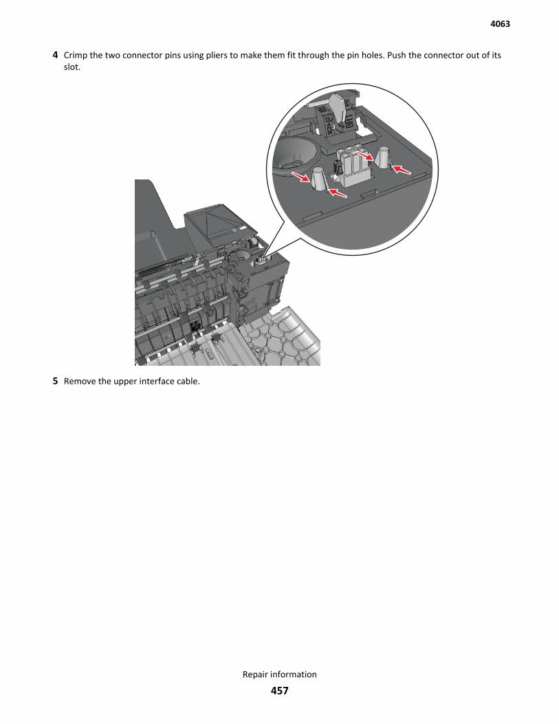
4 Crimp the two connector pins using pliers to make them fit through the pin holes. Push the connector out of itsslot.
5 Remove the upper interface cable.
4063
Repair information
457
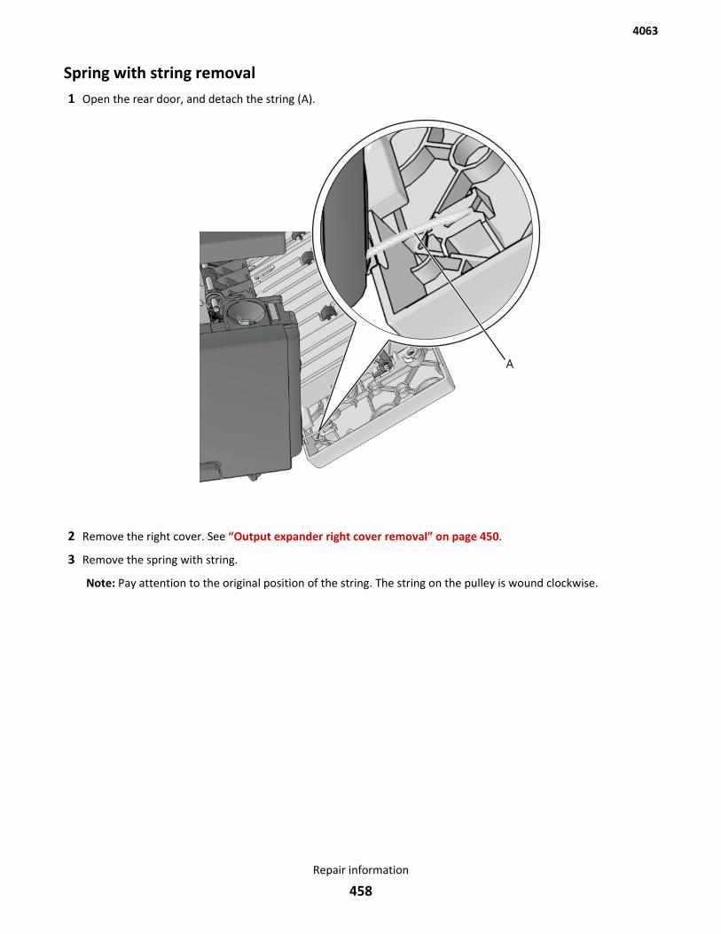
Spring with string removal1 Open the rear door, and detach the string (A).
2 Remove the right cover. See “Output expander right cover removal” on page 450.
3 Remove the spring with string.
Note: Pay attention to the original position of the string. The string on the pulley is wound clockwise.
4063
Repair information
458
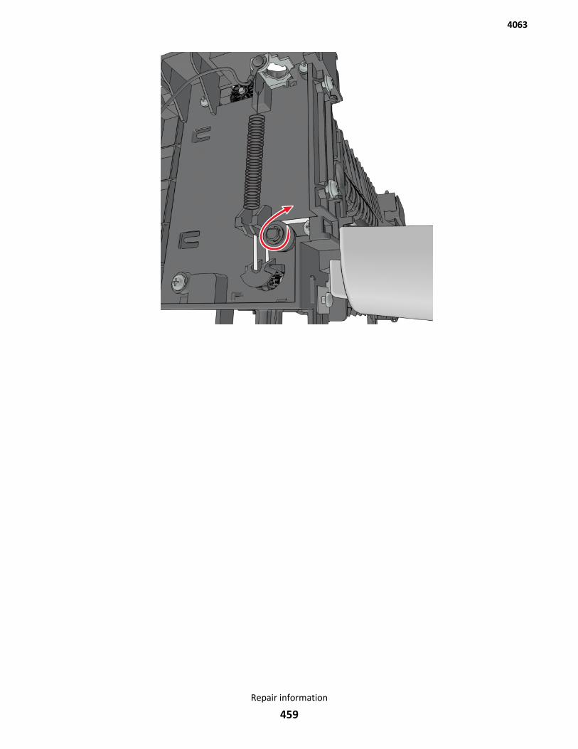
4063
Repair information
459
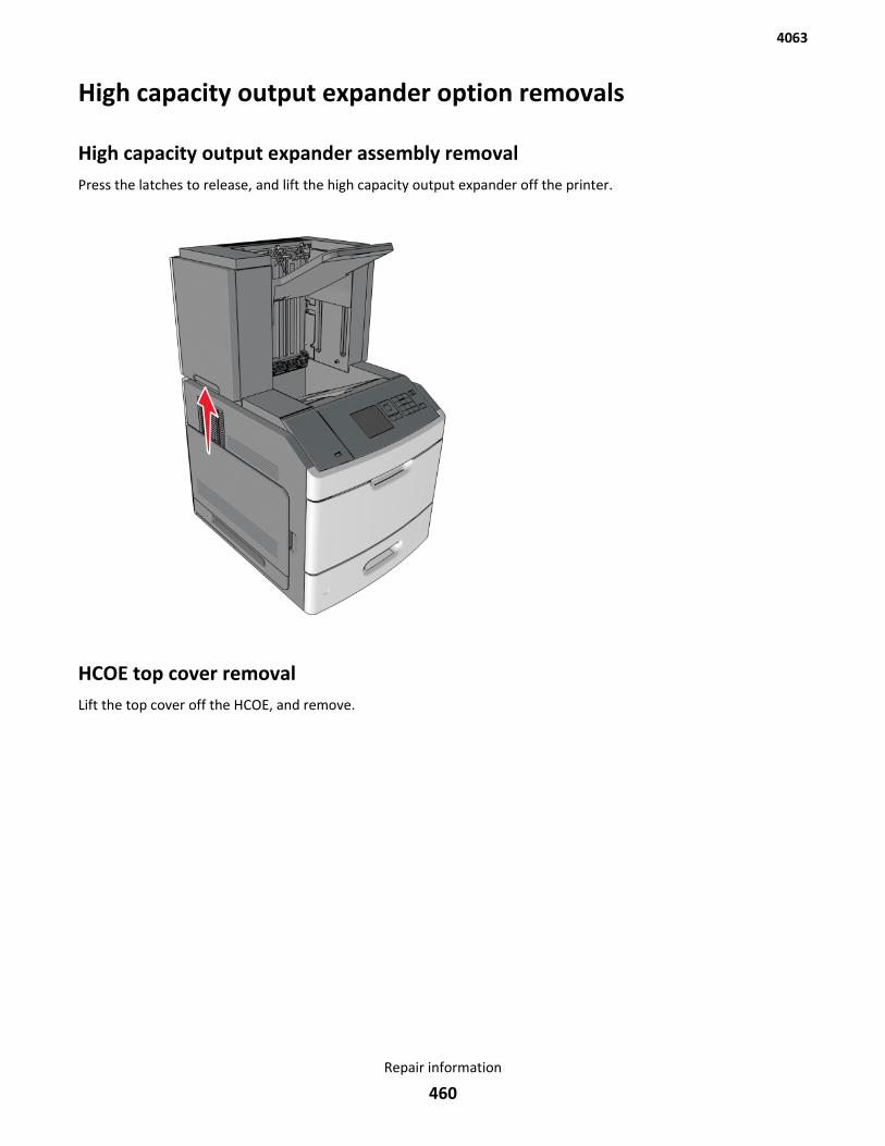
High capacity output expander option removals
High capacity output expander assembly removalPress the latches to release, and lift the high capacity output expander off the printer.
HCOE top cover removalLift the top cover off the HCOE, and remove.
4063
Repair information
460

HCOE rear door removal1 Open the rear door, and disconnect the string (A) from the door.
Note: Fasten the string to the rear side, to prevent it from recoiling into the interior of the HCOE.
4063
Repair information
461
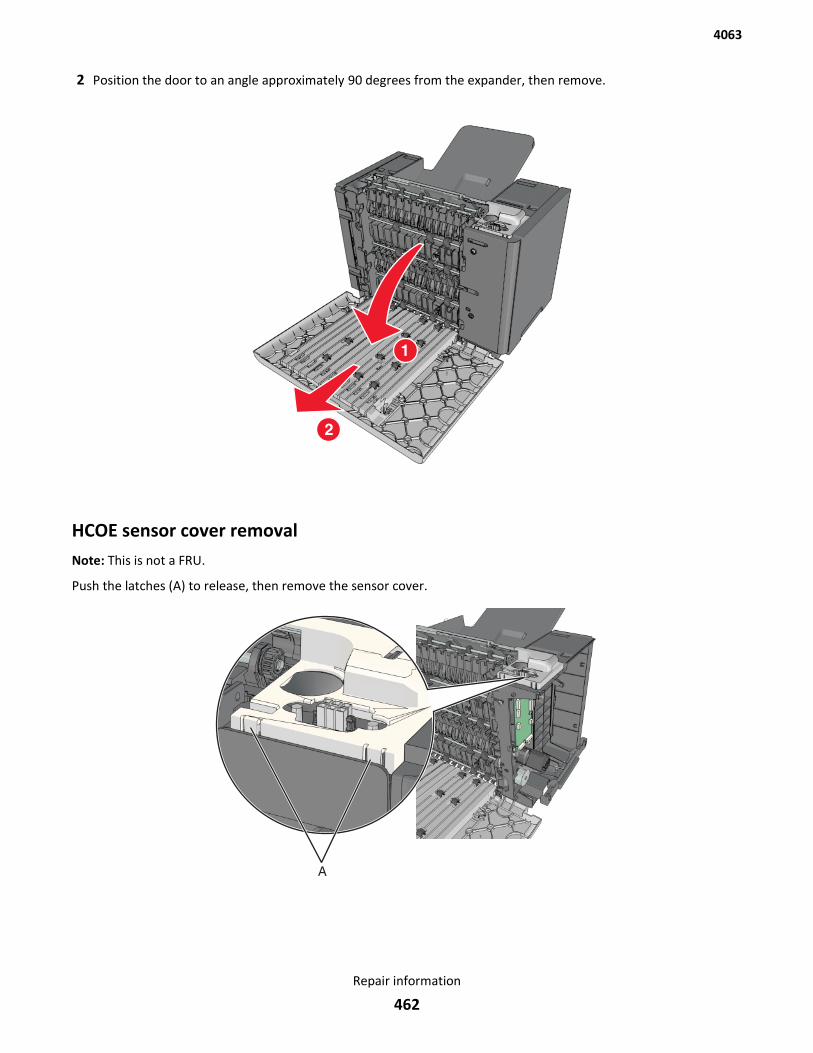
2 Position the door to an angle approximately 90 degrees from the expander, then remove.
HCOE sensor cover removalNote: This is not a FRU.
Push the latches (A) to release, then remove the sensor cover.
4063
Repair information
462
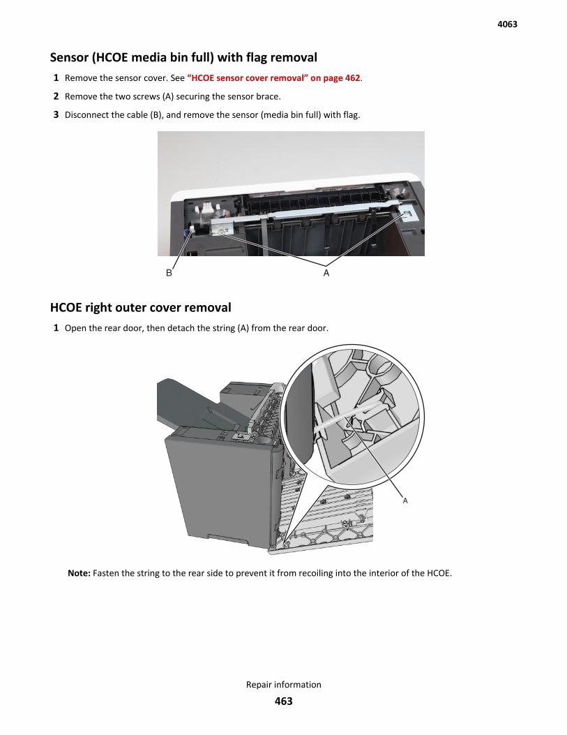
Sensor (HCOE media bin full) with flag removal1 Remove the sensor cover. See “HCOE sensor cover removal” on page 462.
2 Remove the two screws (A) securing the sensor brace.
3 Disconnect the cable (B), and remove the sensor (media bin full) with flag.
HCOE right outer cover removal1 Open the rear door, then detach the string (A) from the rear door.
Note: Fasten the string to the rear side to prevent it from recoiling into the interior of the HCOE.
4063
Repair information
463
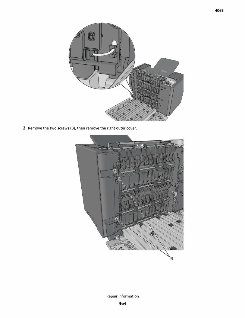
2 Remove the two screws (B), then remove the right outer cover.
4063
Repair information
464
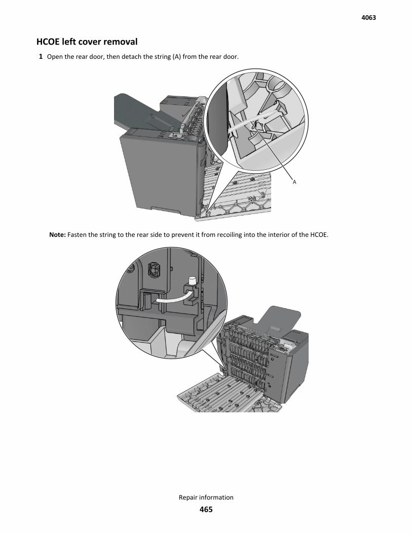
HCOE left cover removal1 Open the rear door, then detach the string (A) from the rear door.
Note: Fasten the string to the rear side to prevent it from recoiling into the interior of the HCOE.
4063
Repair information
465
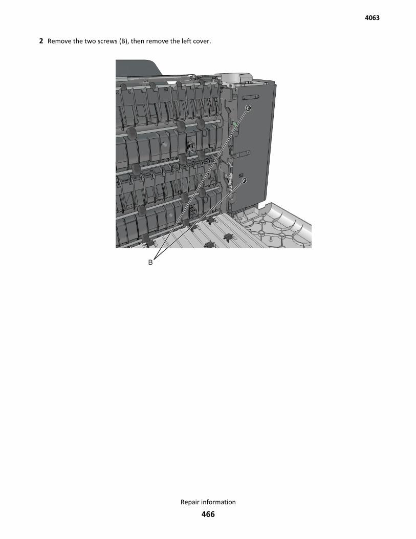
2 Remove the two screws (B), then remove the left cover.
4063
Repair information
466
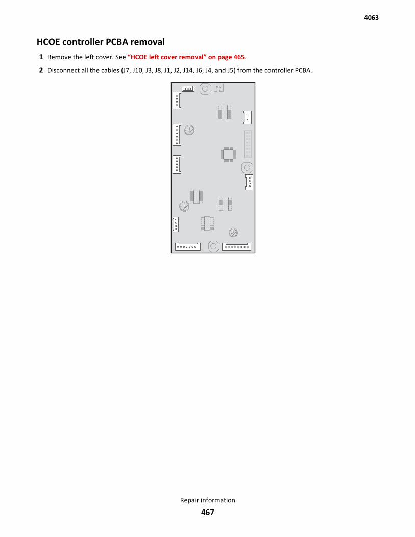
HCOE controller PCBA removal1 Remove the left cover. See “HCOE left cover removal” on page 465.
2 Disconnect all the cables (J7, J10, J3, J8, J1, J2, J14, J6, J4, and J5) from the controller PCBA.
4063
Repair information
467
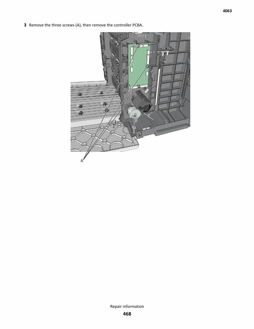
3 Remove the three screws (A), then remove the controller PCBA.
4063
Repair information
468
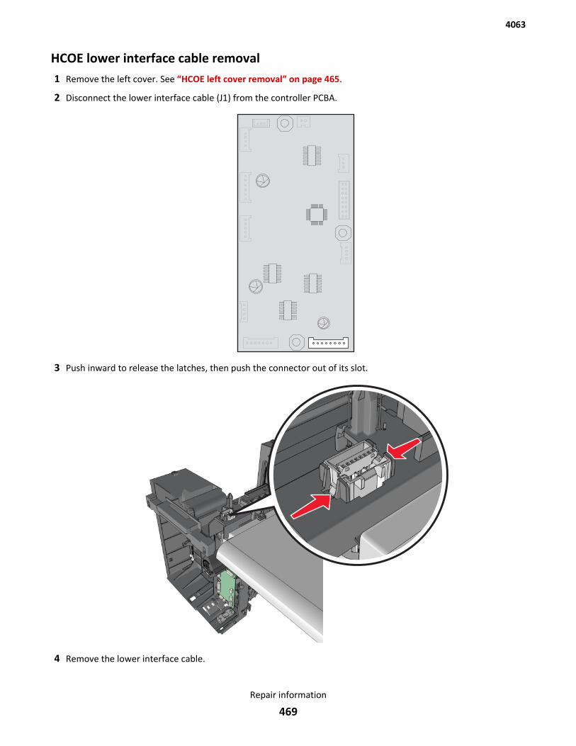
HCOE lower interface cable removal1 Remove the left cover. See “HCOE left cover removal” on page 465.
2 Disconnect the lower interface cable (J1) from the controller PCBA.
3 Push inward to release the latches, then push the connector out of its slot.
4 Remove the lower interface cable.
4063
Repair information
469
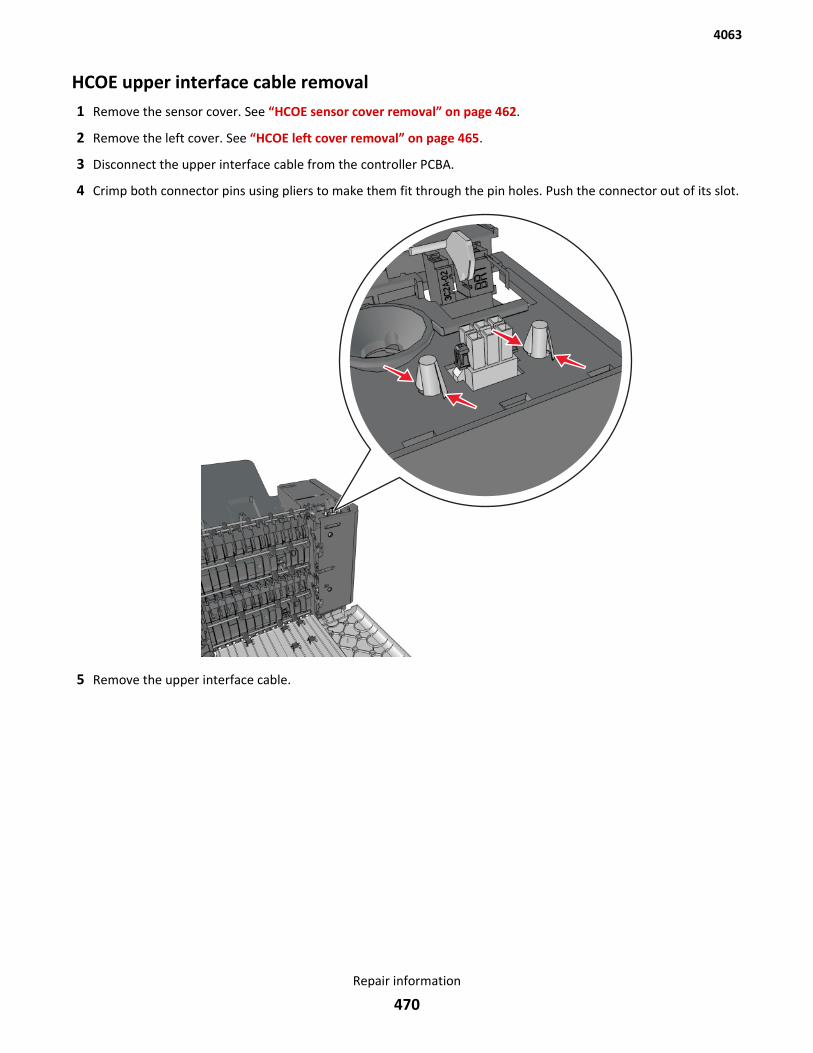
HCOE upper interface cable removal1 Remove the sensor cover. See “HCOE sensor cover removal” on page 462.
2 Remove the left cover. See “HCOE left cover removal” on page 465.
3 Disconnect the upper interface cable from the controller PCBA.
4 Crimp both connector pins using pliers to make them fit through the pin holes. Push the connector out of its slot.
5 Remove the upper interface cable.
4063
Repair information
470
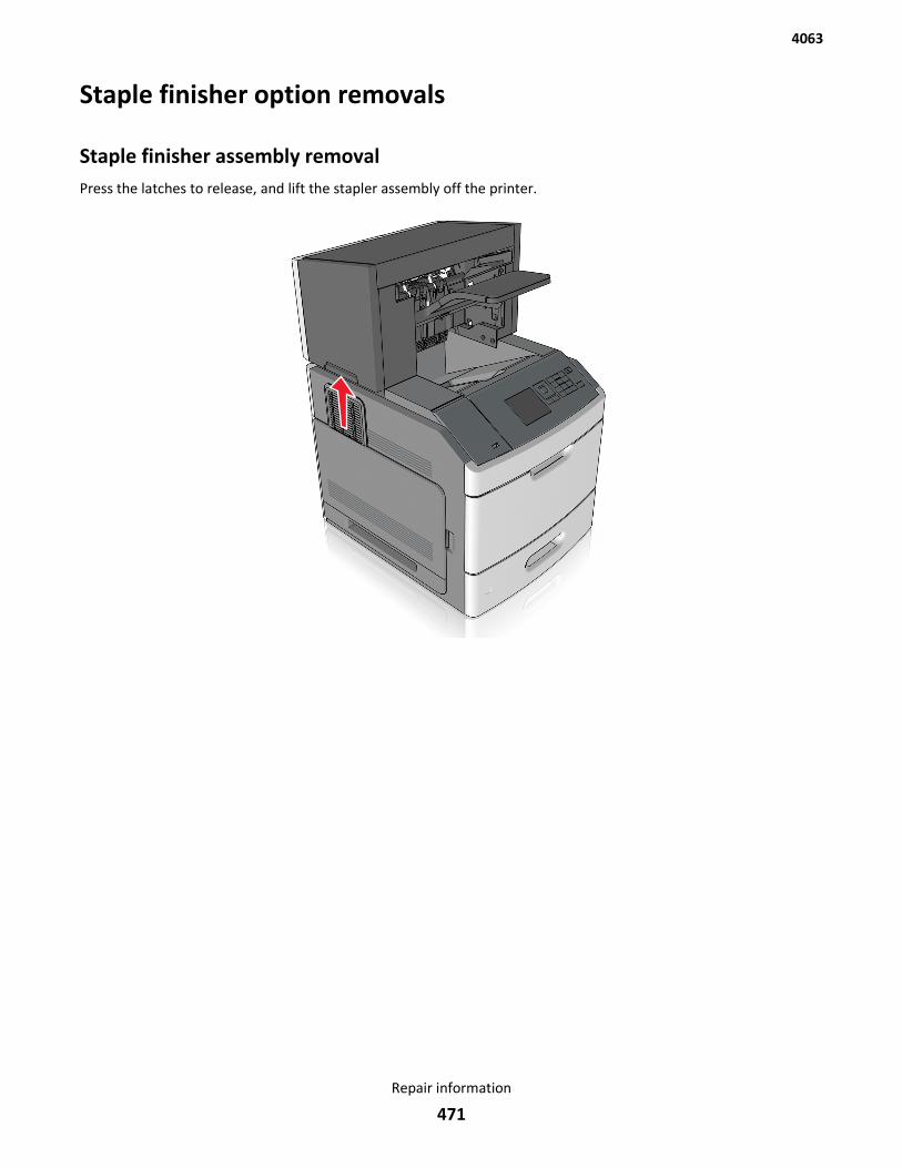
Staple finisher option removals
Staple finisher assembly removalPress the latches to release, and lift the stapler assembly off the printer.
4063
Repair information
471
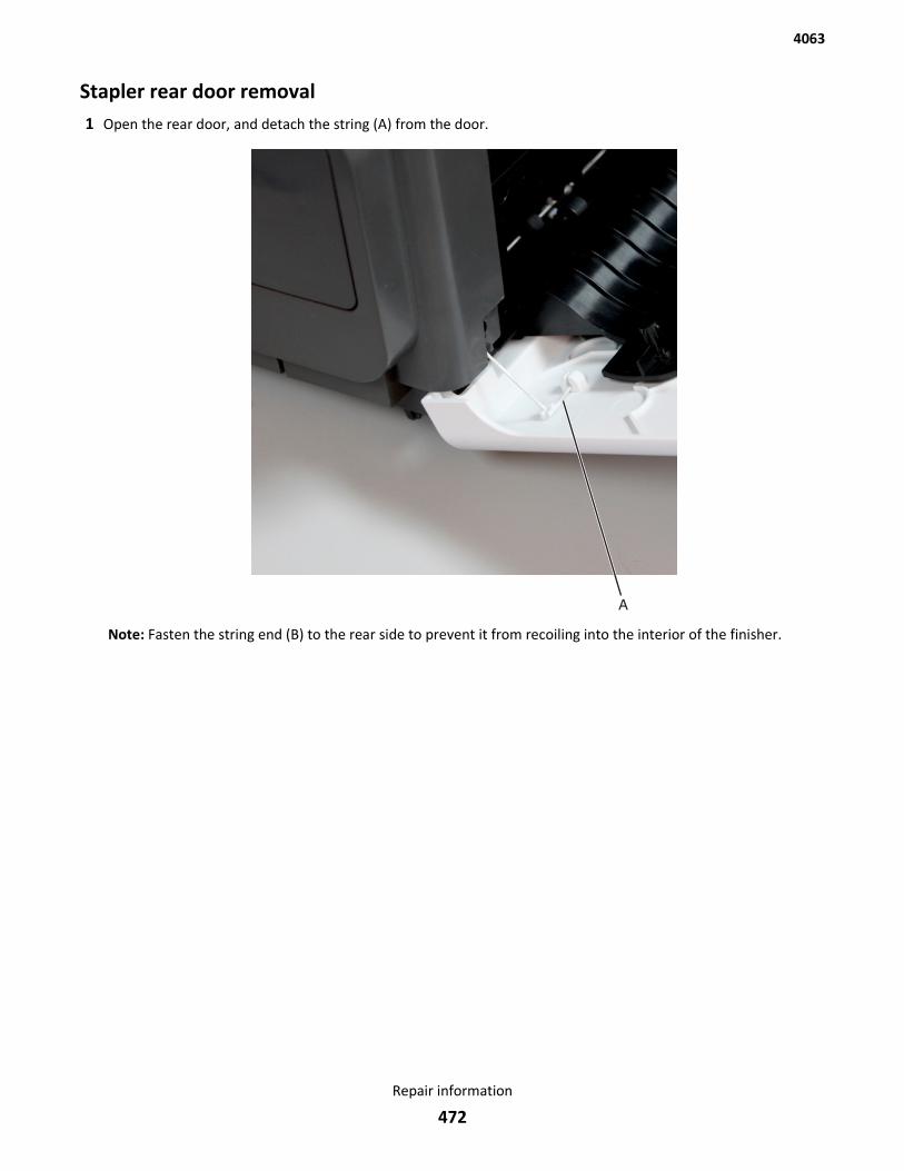
Stapler rear door removal1 Open the rear door, and detach the string (A) from the door.
Note: Fasten the string end (B) to the rear side to prevent it from recoiling into the interior of the finisher.
4063
Repair information
472
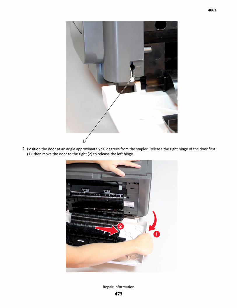
2 Position the door at an angle approximately 90 degrees from the stapler. Release the right hinge of the door first(1), then move the door to the right (2) to release the left hinge.
4063
Repair information
473
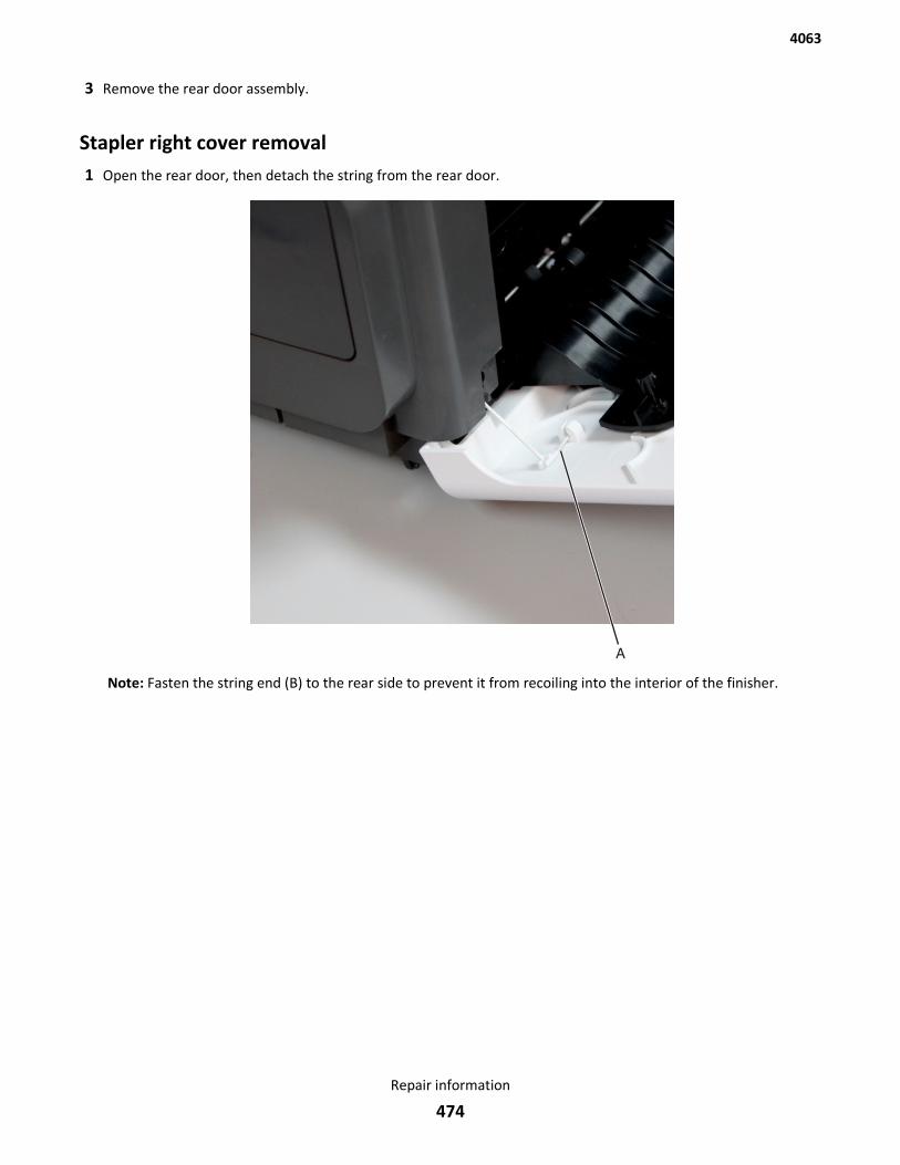
3 Remove the rear door assembly.
Stapler right cover removal1 Open the rear door, then detach the string from the rear door.
Note: Fasten the string end (B) to the rear side to prevent it from recoiling into the interior of the finisher.
4063
Repair information
474
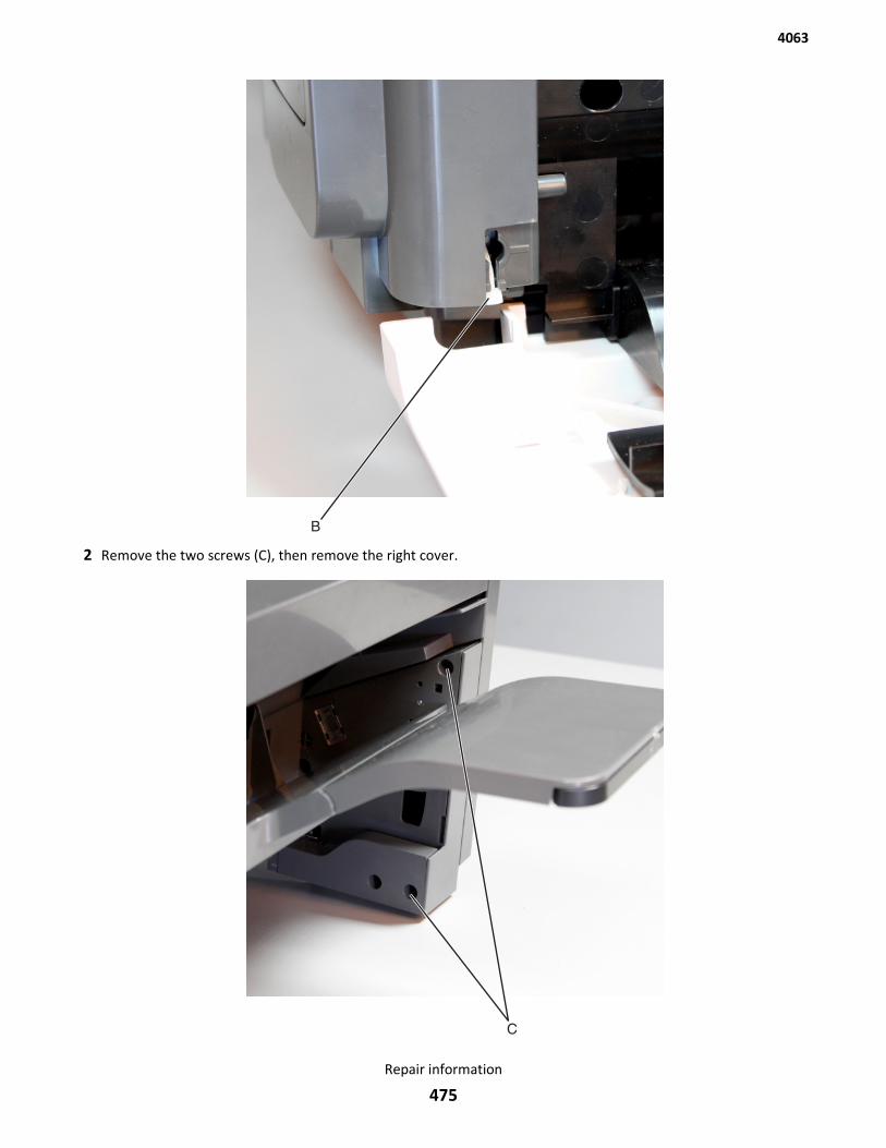
2 Remove the two screws (C), then remove the right cover.
4063
Repair information
475
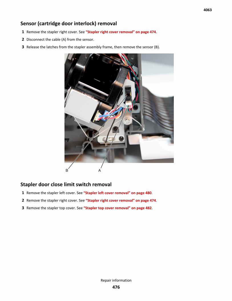
Sensor (cartridge door interlock) removal1 Remove the stapler right cover. See “Stapler right cover removal” on page 474.
2 Disconnect the cable (A) from the sensor.
3 Release the latches from the stapler assembly frame, then remove the sensor (B).
Stapler door close limit switch removal1 Remove the stapler left cover. See “Stapler left cover removal” on page 480.
2 Remove the stapler right cover. See “Stapler right cover removal” on page 474.
3 Remove the stapler top cover. See “Stapler top cover removal” on page 482.
4063
Repair information
476
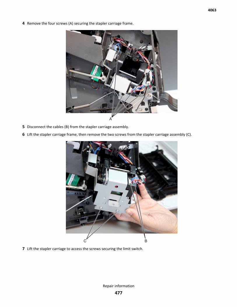
4 Remove the four screws (A) securing the stapler carriage frame.
5 Disconnect the cables (B) from the stapler carriage assembly.
6 Lift the stapler carriage frame, then remove the two screws from the stapler carriage assembly (C).
7 Lift the stapler carriage to access the screws securing the limit switch.
4063
Repair information
477
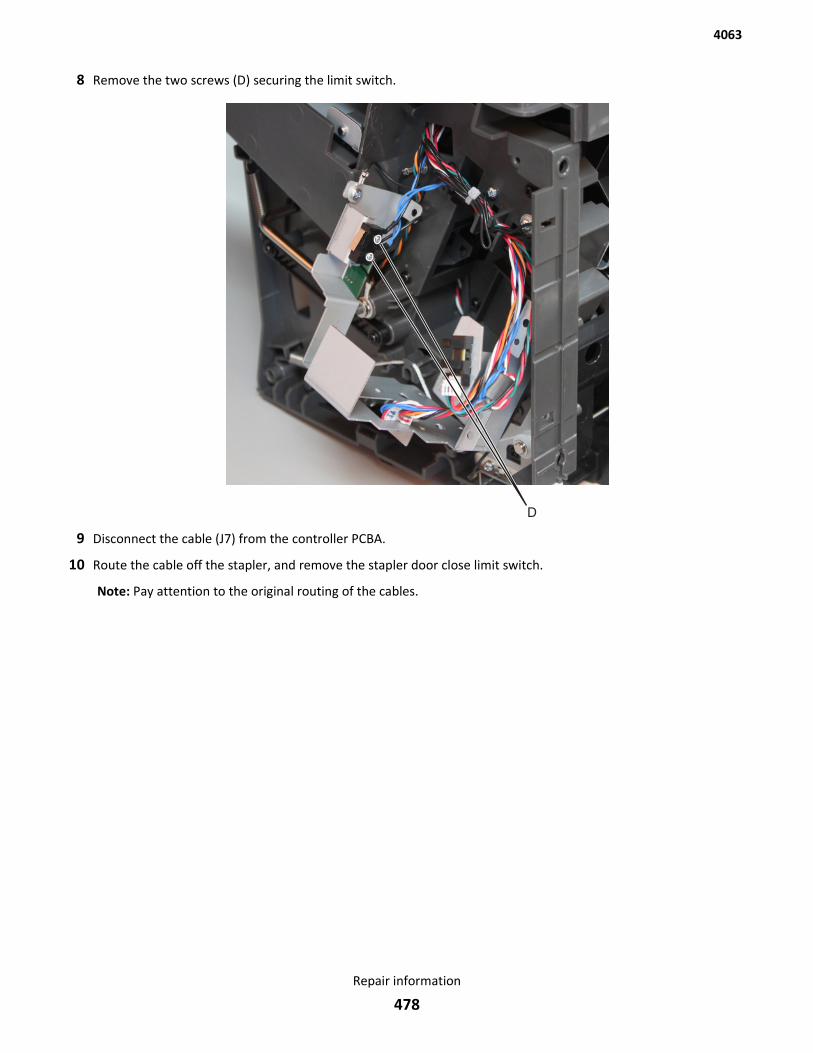
8 Remove the two screws (D) securing the limit switch.
9 Disconnect the cable (J7) from the controller PCBA.
10 Route the cable off the stapler, and remove the stapler door close limit switch.
Note: Pay attention to the original routing of the cables.
4063
Repair information
478
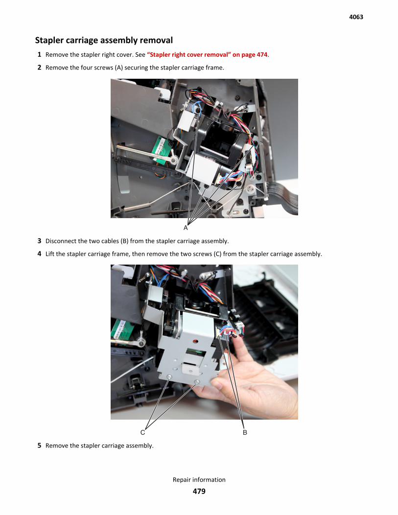
Stapler carriage assembly removal1 Remove the stapler right cover. See “Stapler right cover removal” on page 474.
2 Remove the four screws (A) securing the stapler carriage frame.
3 Disconnect the two cables (B) from the stapler carriage assembly.
4 Lift the stapler carriage frame, then remove the two screws (C) from the stapler carriage assembly.
5 Remove the stapler carriage assembly.
4063
Repair information
479
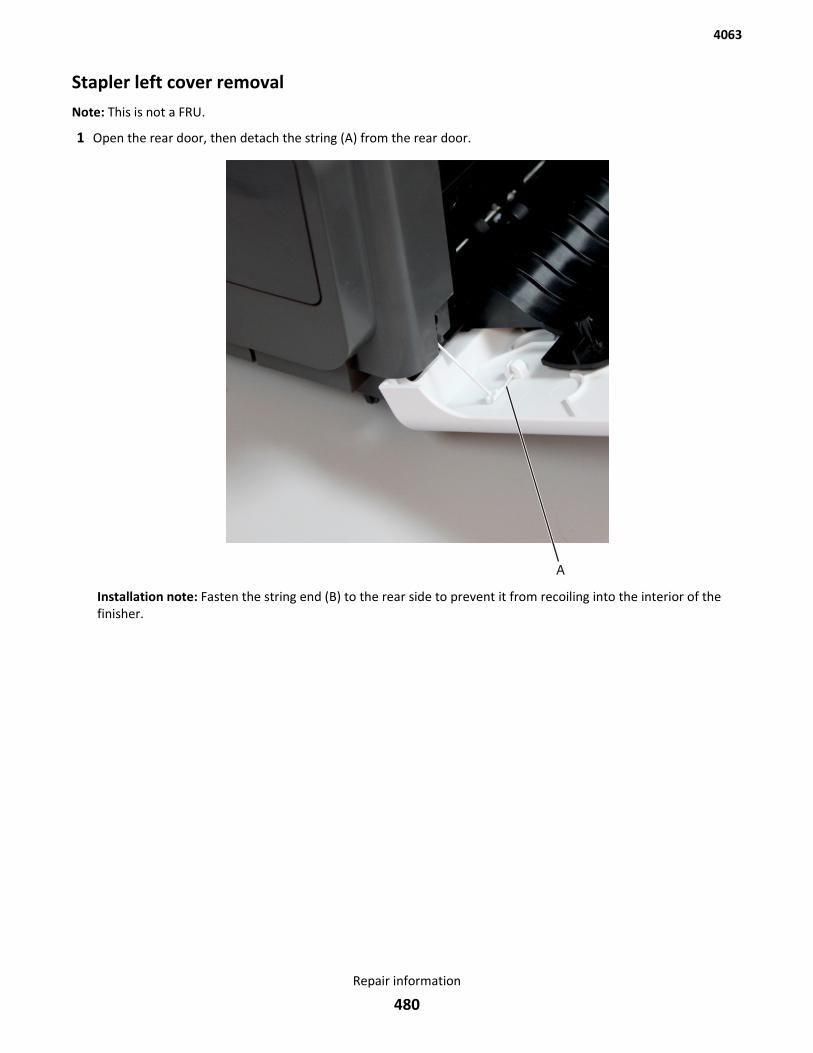
Stapler left cover removalNote: This is not a FRU.
1 Open the rear door, then detach the string (A) from the rear door.
Installation note: Fasten the string end (B) to the rear side to prevent it from recoiling into the interior of thefinisher.
4063
Repair information
480
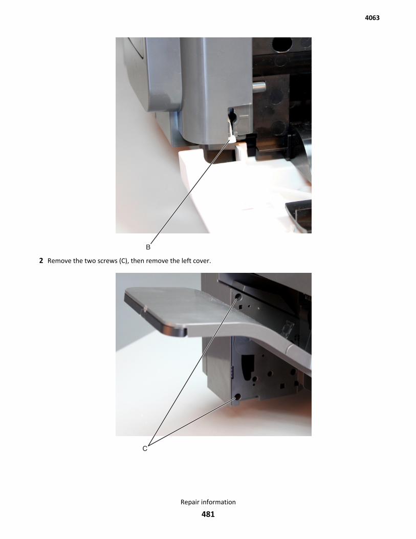
2 Remove the two screws (C), then remove the left cover.
4063
Repair information
481
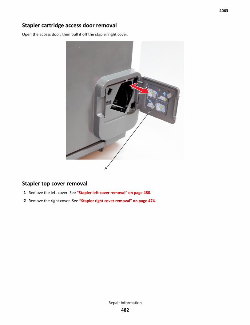
Stapler cartridge access door removalOpen the access door, then pull it off the stapler right cover.
Stapler top cover removal1 Remove the left cover. See “Stapler left cover removal” on page 480.
2 Remove the right cover. See “Stapler right cover removal” on page 474.
4063
Repair information
482
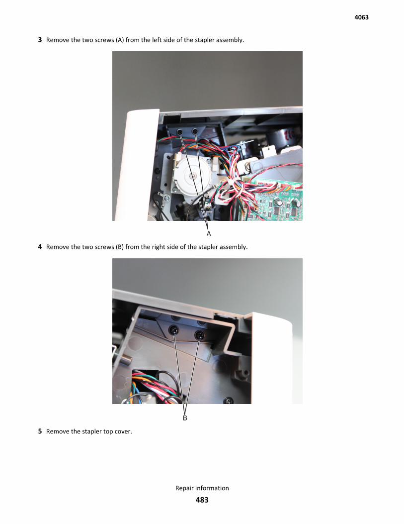
3 Remove the two screws (A) from the left side of the stapler assembly.
4 Remove the two screws (B) from the right side of the stapler assembly.
5 Remove the stapler top cover.
4063
Repair information
483
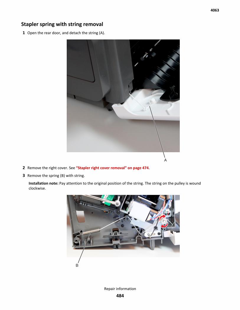
Stapler spring with string removal1 Open the rear door, and detach the string (A).
2 Remove the right cover. See “Stapler right cover removal” on page 474.
3 Remove the spring (B) with string.
Installation note: Pay attention to the original position of the string. The string on the pulley is woundclockwise.
4063
Repair information
484
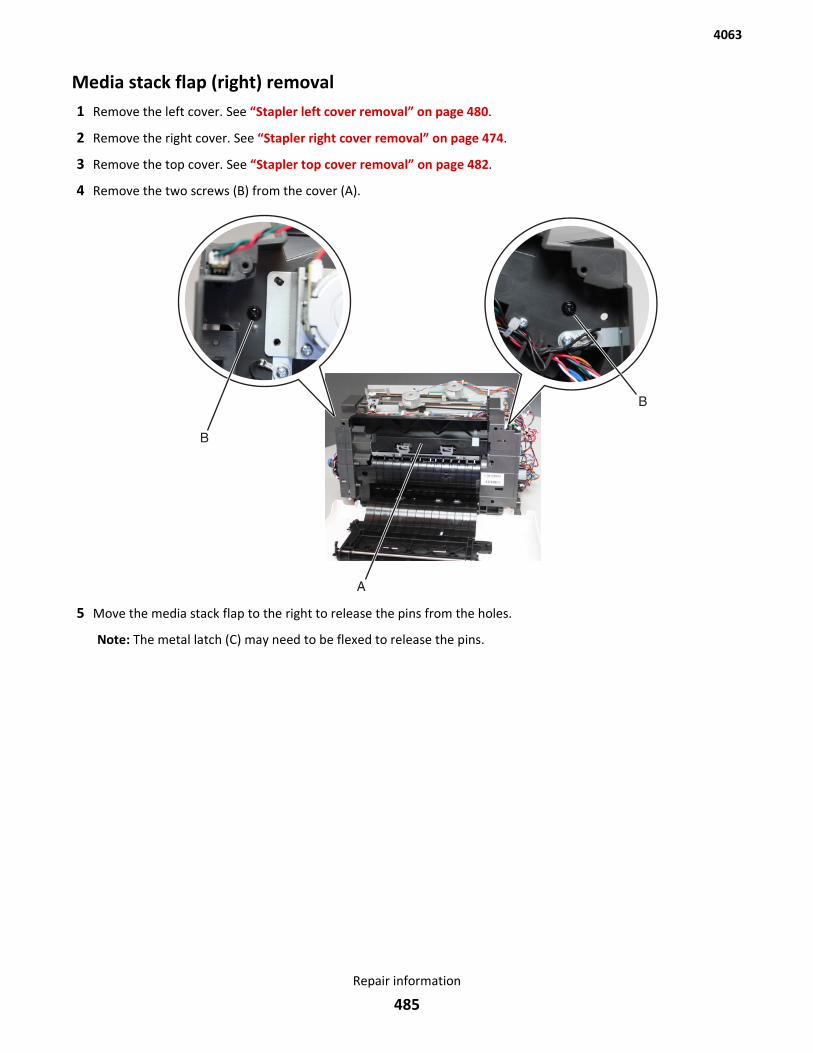
Media stack flap (right) removal1 Remove the left cover. See “Stapler left cover removal” on page 480.
2 Remove the right cover. See “Stapler right cover removal” on page 474.
3 Remove the top cover. See “Stapler top cover removal” on page 482.
4 Remove the two screws (B) from the cover (A).
5 Move the media stack flap to the right to release the pins from the holes.
Note: The metal latch (C) may need to be flexed to release the pins.
4063
Repair information
485
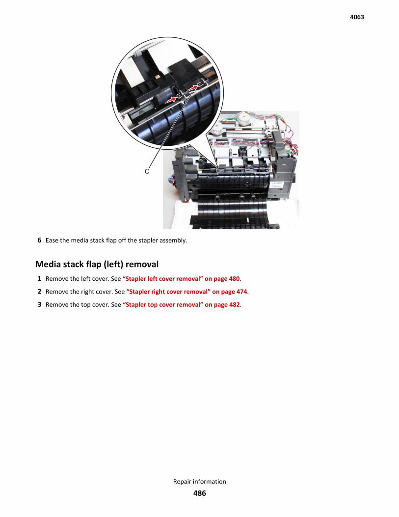
6 Ease the media stack flap off the stapler assembly.
Media stack flap (left) removal1 Remove the left cover. See “Stapler left cover removal” on page 480.
2 Remove the right cover. See “Stapler right cover removal” on page 474.
3 Remove the top cover. See “Stapler top cover removal” on page 482.
4063
Repair information
486
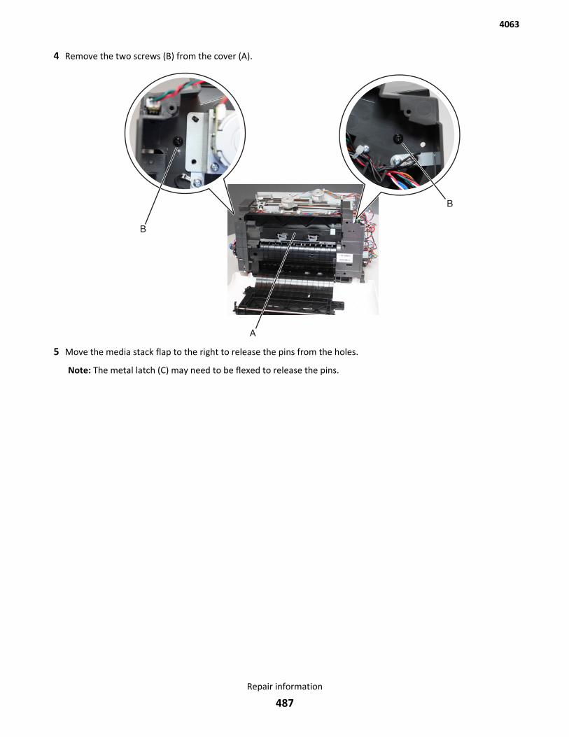
4 Remove the two screws (B) from the cover (A).
5 Move the media stack flap to the right to release the pins from the holes.
Note: The metal latch (C) may need to be flexed to release the pins.
4063
Repair information
487
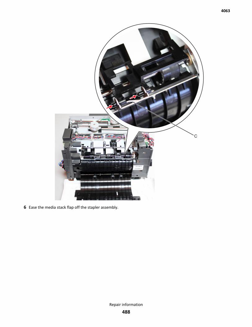
6 Ease the media stack flap off the stapler assembly.
4063
Repair information
488
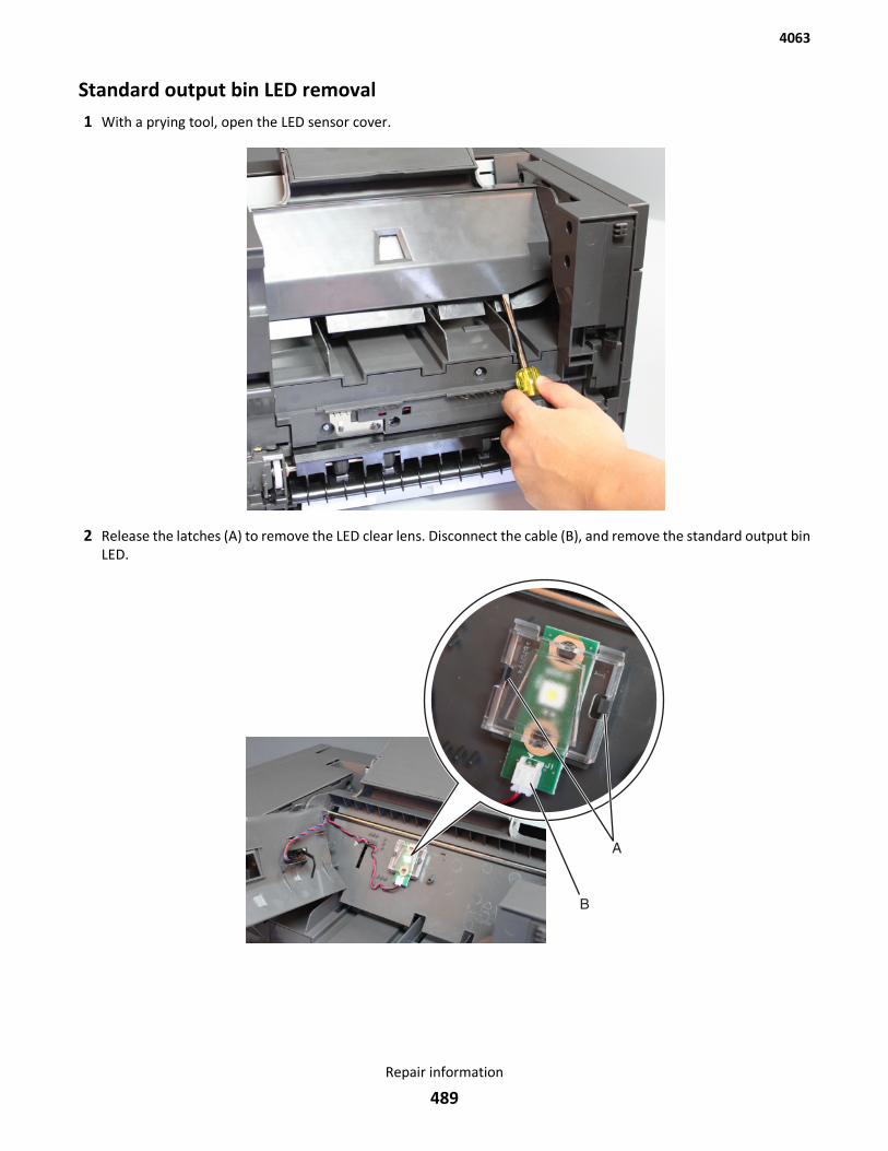
Standard output bin LED removal1 With a prying tool, open the LED sensor cover.
2 Release the latches (A) to remove the LED clear lens. Disconnect the cable (B), and remove the standard output binLED.
4063
Repair information
489
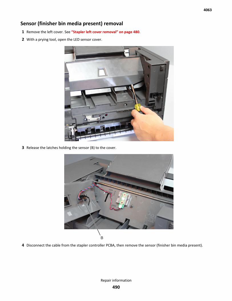
Sensor (finisher bin media present) removal1 Remove the left cover. See “Stapler left cover removal” on page 480.
2 With a prying tool, open the LED sensor cover.
3 Release the latches holding the sensor (B) to the cover.
4 Disconnect the cable from the stapler controller PCBA, then remove the sensor (finisher bin media present).
4063
Repair information
490
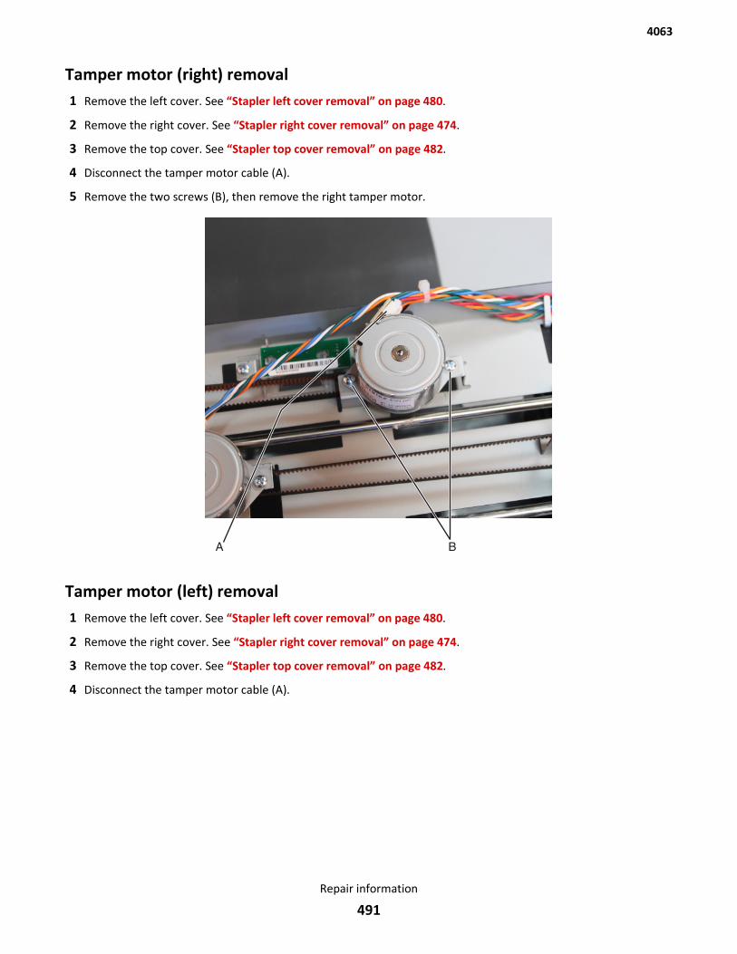
Tamper motor (right) removal1 Remove the left cover. See “Stapler left cover removal” on page 480.
2 Remove the right cover. See “Stapler right cover removal” on page 474.
3 Remove the top cover. See “Stapler top cover removal” on page 482.
4 Disconnect the tamper motor cable (A).
5 Remove the two screws (B), then remove the right tamper motor.
Tamper motor (left) removal1 Remove the left cover. See “Stapler left cover removal” on page 480.
2 Remove the right cover. See “Stapler right cover removal” on page 474.
3 Remove the top cover. See “Stapler top cover removal” on page 482.
4 Disconnect the tamper motor cable (A).
4063
Repair information
491
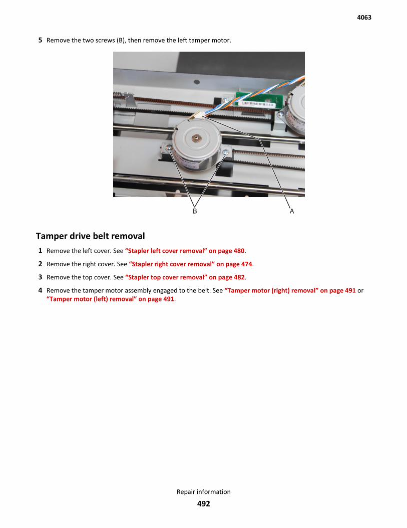
5 Remove the two screws (B), then remove the left tamper motor.
Tamper drive belt removal1 Remove the left cover. See “Stapler left cover removal” on page 480.
2 Remove the right cover. See “Stapler right cover removal” on page 474.
3 Remove the top cover. See “Stapler top cover removal” on page 482.
4 Remove the tamper motor assembly engaged to the belt. See “Tamper motor (right) removal” on page 491 or“Tamper motor (left) removal” on page 491.
4063
Repair information
492
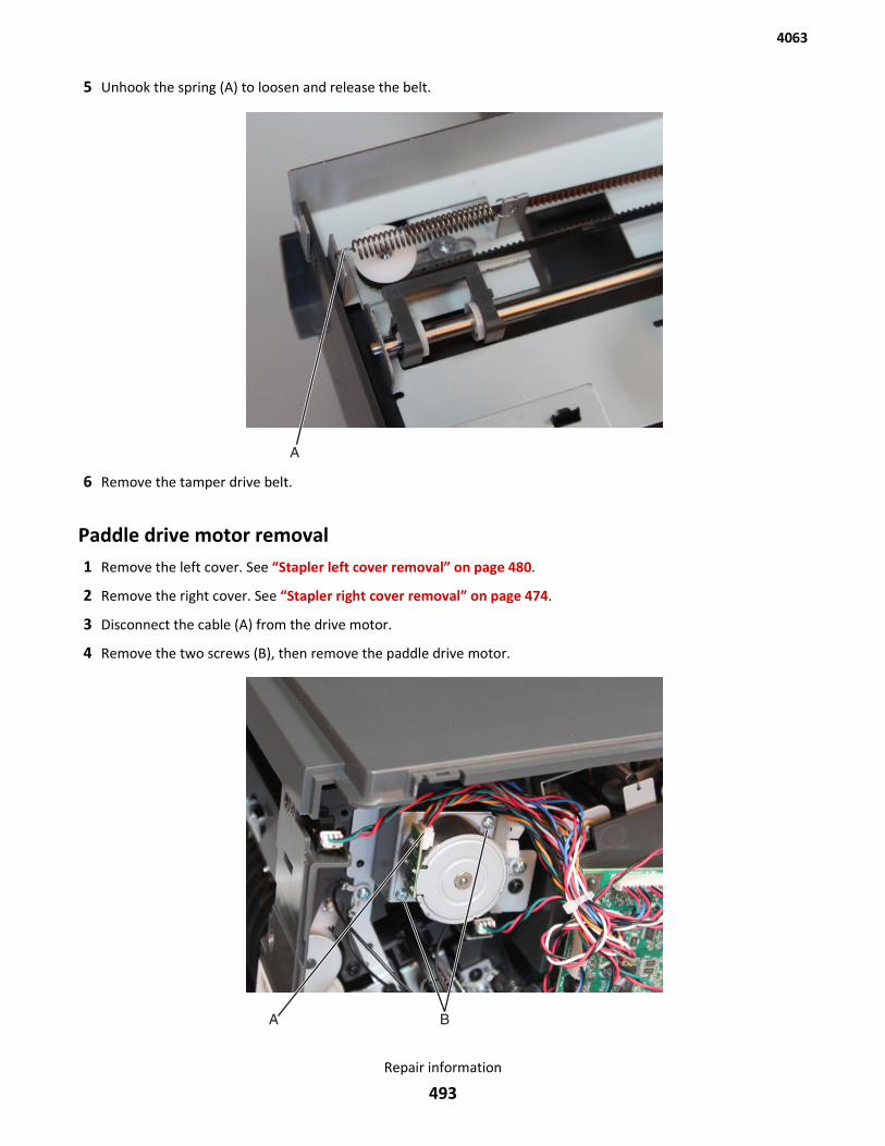
5 Unhook the spring (A) to loosen and release the belt.
6 Remove the tamper drive belt.
Paddle drive motor removal1 Remove the left cover. See “Stapler left cover removal” on page 480.
2 Remove the right cover. See “Stapler right cover removal” on page 474.
3 Disconnect the cable (A) from the drive motor.
4 Remove the two screws (B), then remove the paddle drive motor.
4063
Repair information
493
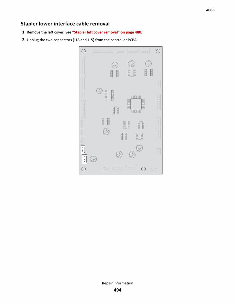
Stapler lower interface cable removal1 Remove the left cover. See “Stapler left cover removal” on page 480.
2 Unplug the two connectors (J18 and J15) from the controller PCBA.
4063
Repair information
494
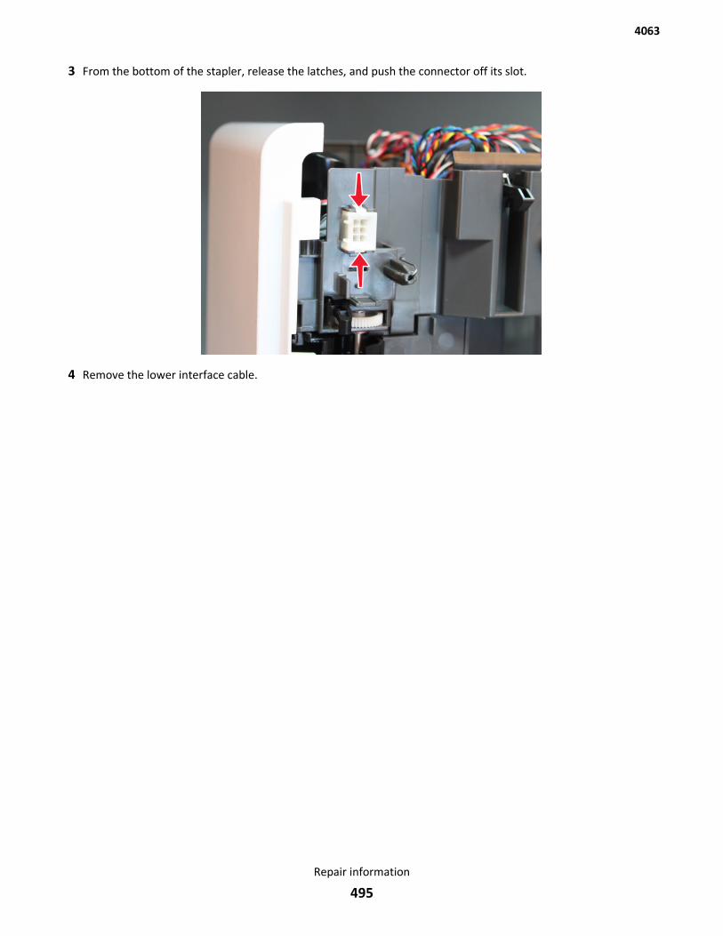
3 From the bottom of the stapler, release the latches, and push the connector off its slot.
4 Remove the lower interface cable.
4063
Repair information
495
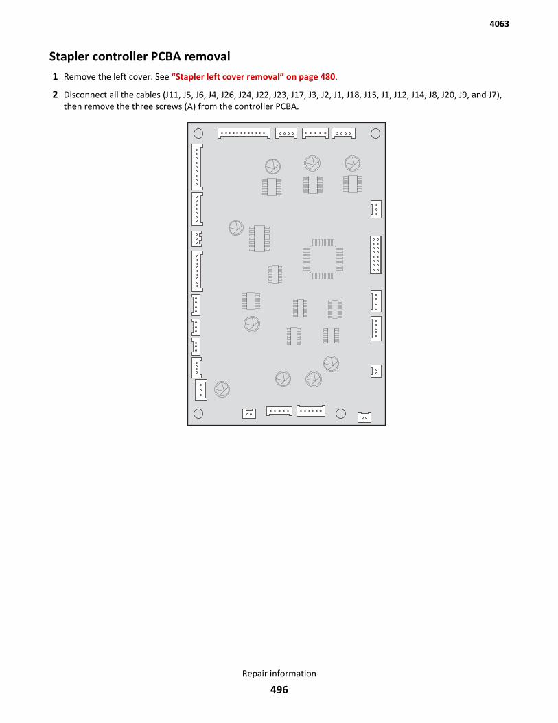
Stapler controller PCBA removal1 Remove the left cover. See “Stapler left cover removal” on page 480.
2 Disconnect all the cables (J11, J5, J6, J4, J26, J24, J22, J23, J17, J3, J2, J1, J18, J15, J1, J12, J14, J8, J20, J9, and J7),then remove the three screws (A) from the controller PCBA.
4063
Repair information
496
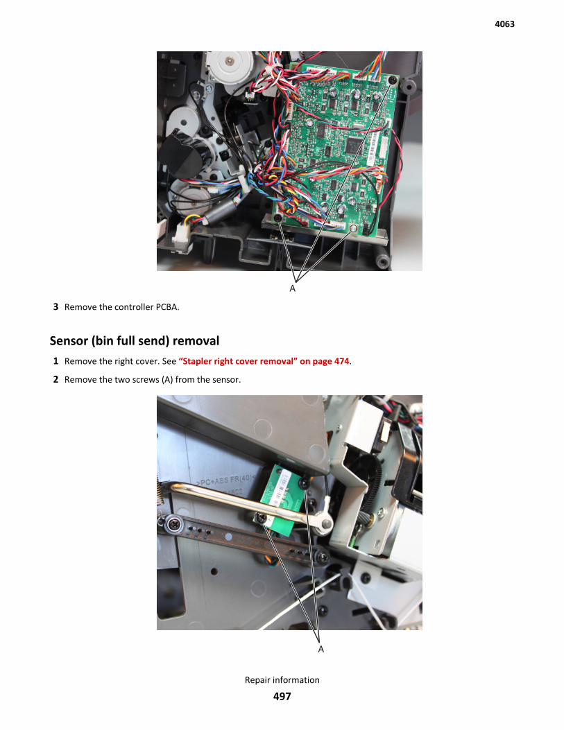
3 Remove the controller PCBA.
Sensor (bin full send) removal1 Remove the right cover. See “Stapler right cover removal” on page 474.
2 Remove the two screws (A) from the sensor.
4063
Repair information
497
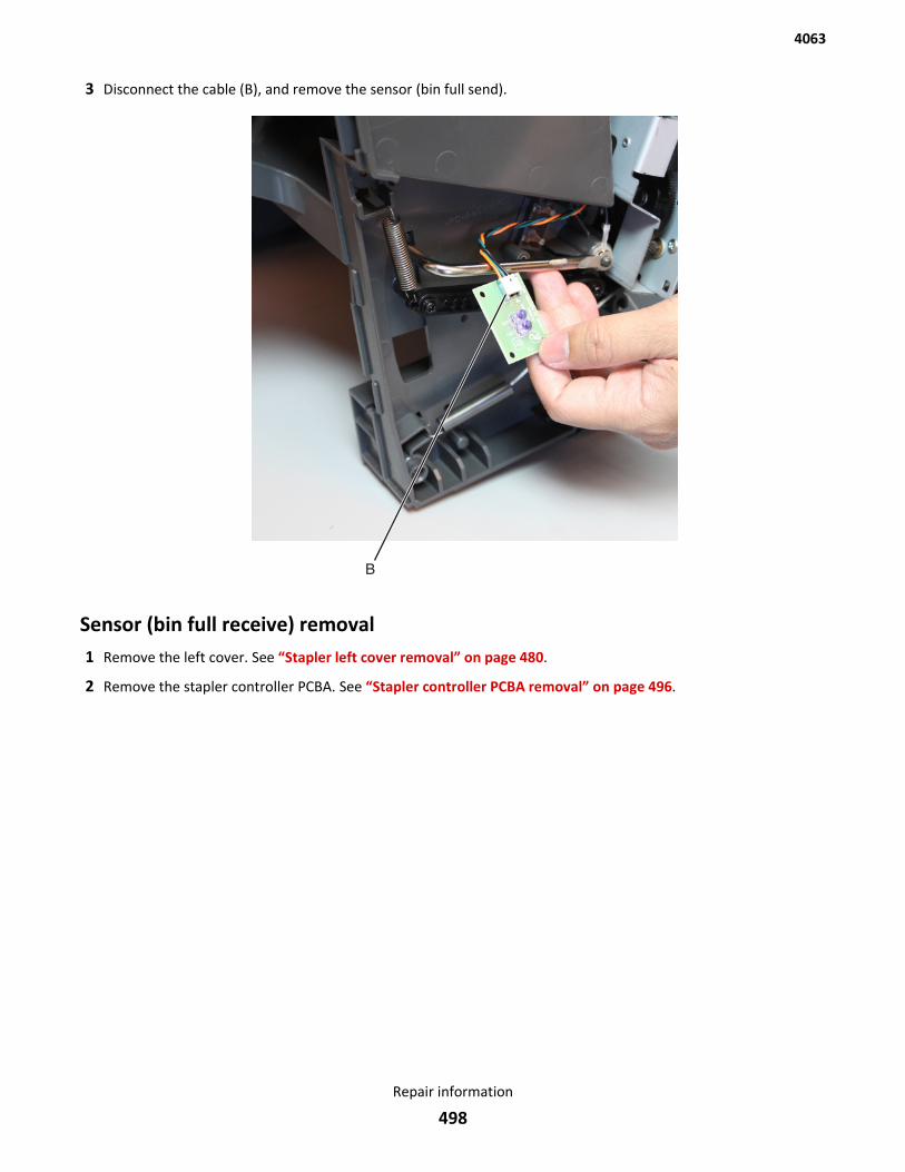
3 Disconnect the cable (B), and remove the sensor (bin full send).
Sensor (bin full receive) removal1 Remove the left cover. See “Stapler left cover removal” on page 480.
2 Remove the stapler controller PCBA. See “Stapler controller PCBA removal” on page 496.
4063
Repair information
498
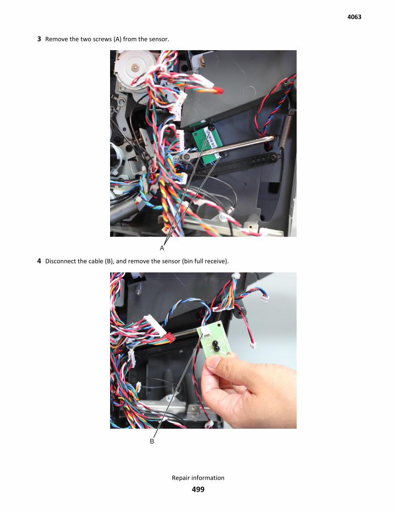
3 Remove the two screws (A) from the sensor.
4 Disconnect the cable (B), and remove the sensor (bin full receive).
4063
Repair information
499
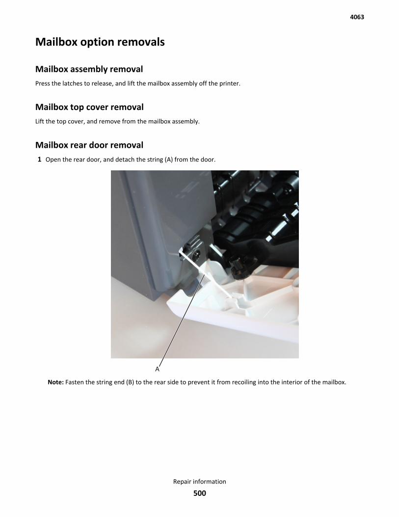
Mailbox option removals
Mailbox assembly removalPress the latches to release, and lift the mailbox assembly off the printer.
Mailbox top cover removalLift the top cover, and remove from the mailbox assembly.
Mailbox rear door removal1 Open the rear door, and detach the string (A) from the door.
Note: Fasten the string end (B) to the rear side to prevent it from recoiling into the interior of the mailbox.
4063
Repair information
500
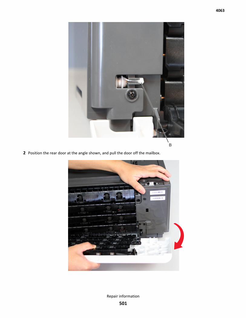
2 Position the rear door at the angle shown, and pull the door off the mailbox.
4063
Repair information
501
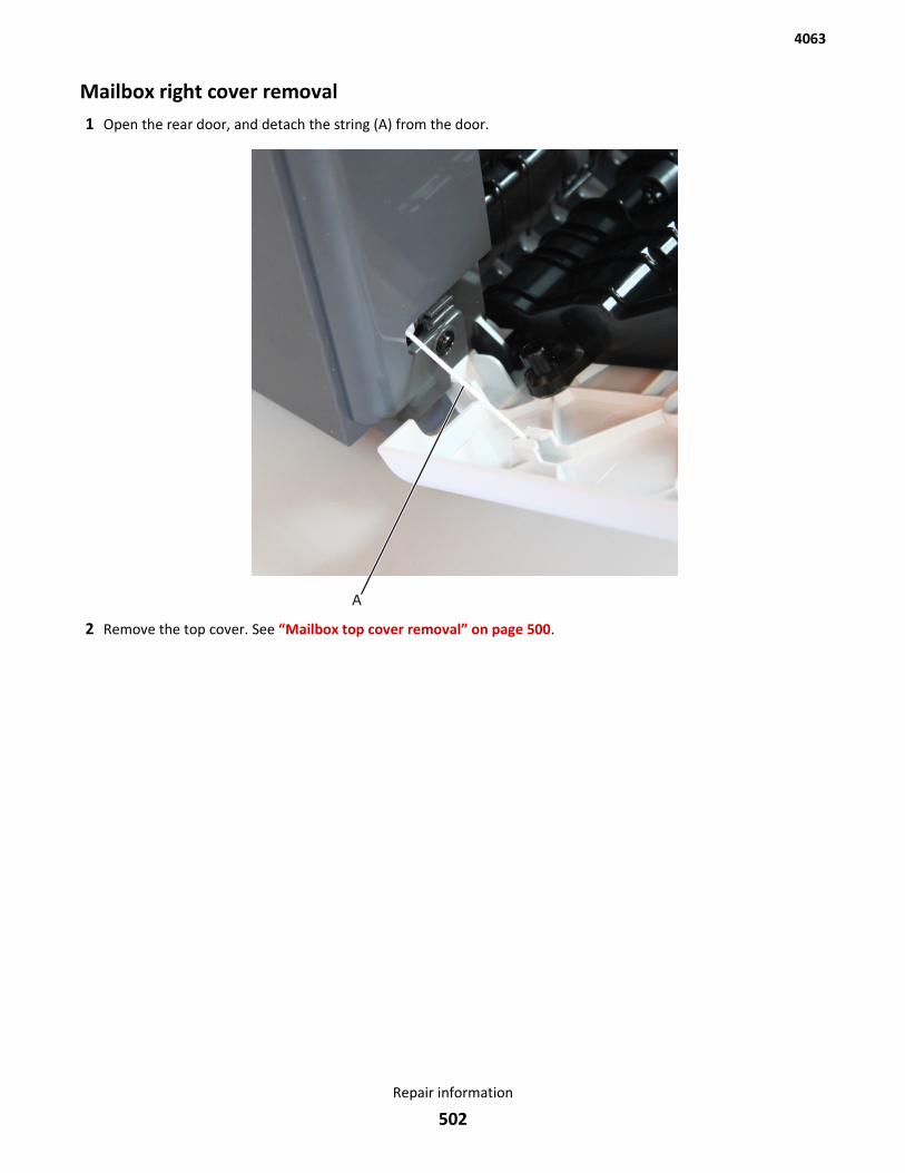
Mailbox right cover removal1 Open the rear door, and detach the string (A) from the door.
2 Remove the top cover. See “Mailbox top cover removal” on page 500.
4063
Repair information
502
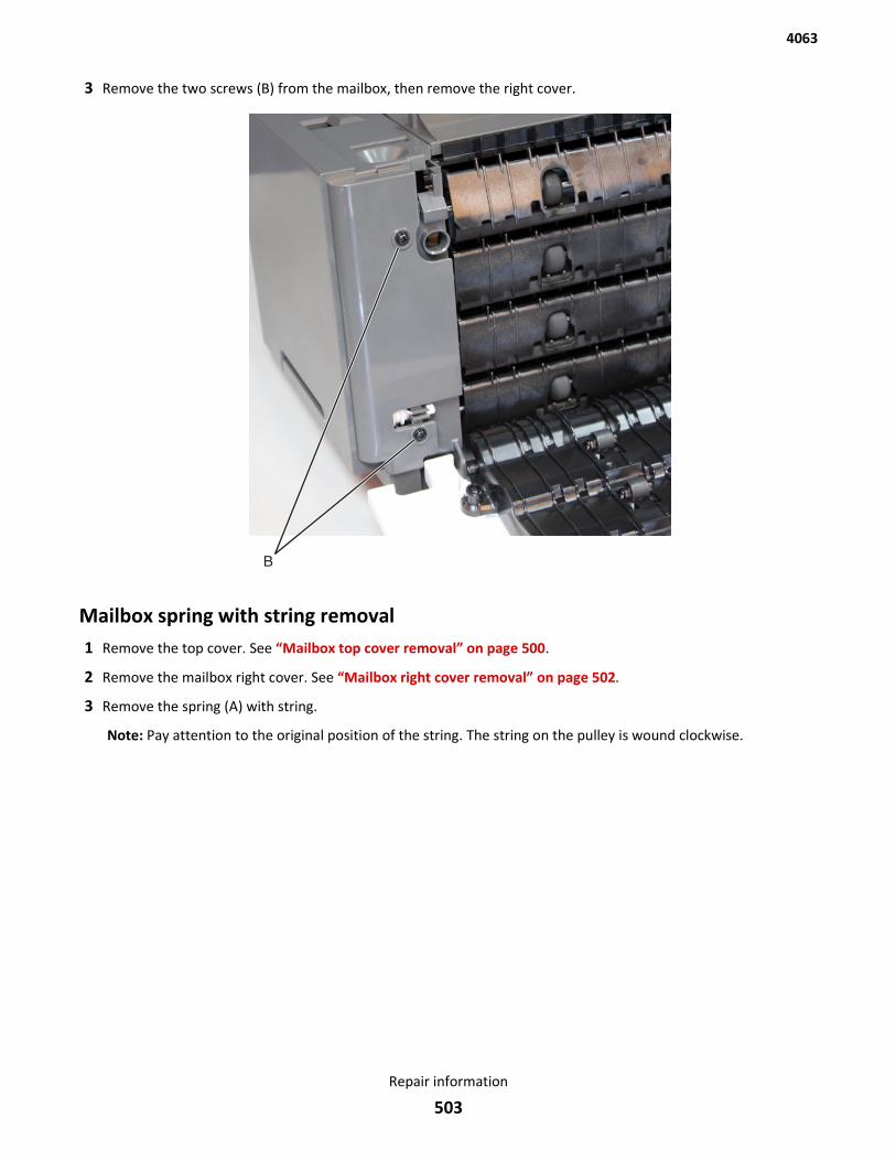
3 Remove the two screws (B) from the mailbox, then remove the right cover.
Mailbox spring with string removal1 Remove the top cover. See “Mailbox top cover removal” on page 500.
2 Remove the mailbox right cover. See “Mailbox right cover removal” on page 502.
3 Remove the spring (A) with string.
Note: Pay attention to the original position of the string. The string on the pulley is wound clockwise.
4063
Repair information
503
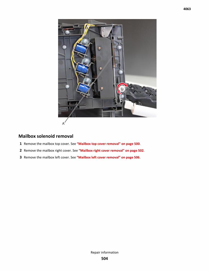
Mailbox solenoid removal1 Remove the mailbox top cover. See “Mailbox top cover removal” on page 500.
2 Remove the mailbox right cover. See “Mailbox right cover removal” on page 502.
3 Remove the mailbox left cover. See “Mailbox left cover removal” on page 506.
4063
Repair information
504
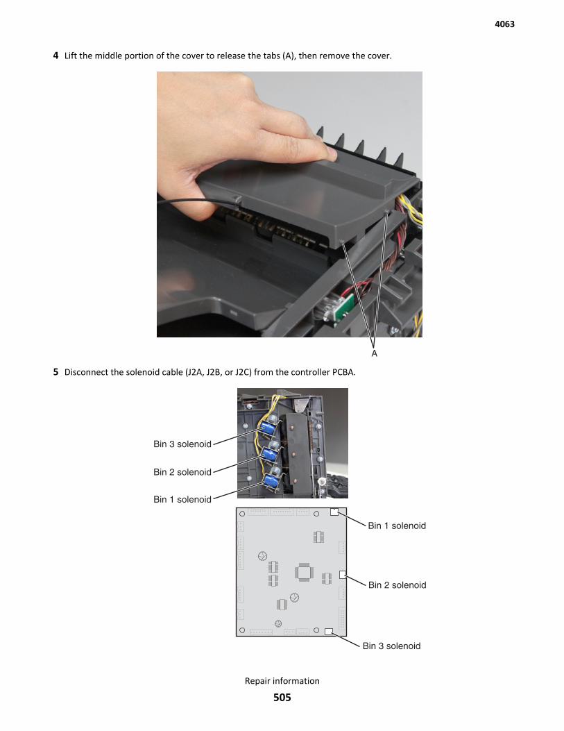
4 Lift the middle portion of the cover to release the tabs (A), then remove the cover.
5 Disconnect the solenoid cable (J2A, J2B, or J2C) from the controller PCBA.
4063
Repair information
505
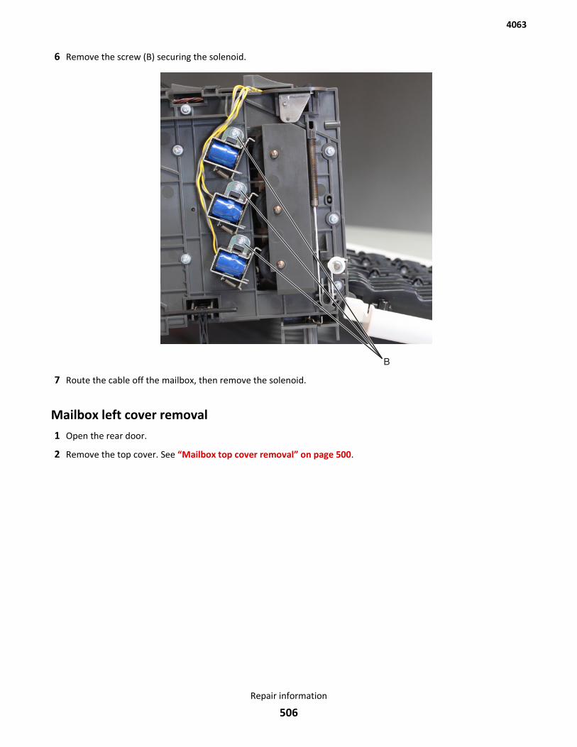
6 Remove the screw (B) securing the solenoid.
7 Route the cable off the mailbox, then remove the solenoid.
Mailbox left cover removal1 Open the rear door.
2 Remove the top cover. See “Mailbox top cover removal” on page 500.
4063
Repair information
506
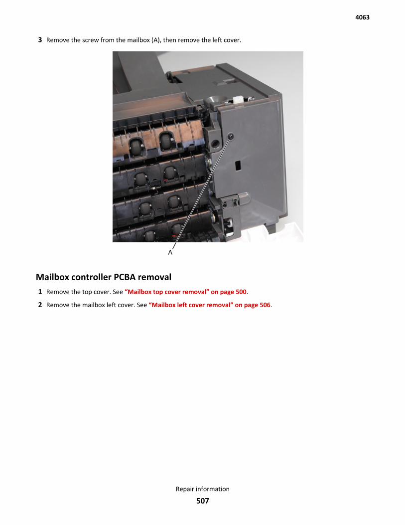
3 Remove the screw from the mailbox (A), then remove the left cover.
Mailbox controller PCBA removal1 Remove the top cover. See “Mailbox top cover removal” on page 500.
2 Remove the mailbox left cover. See “Mailbox left cover removal” on page 506.
4063
Repair information
507
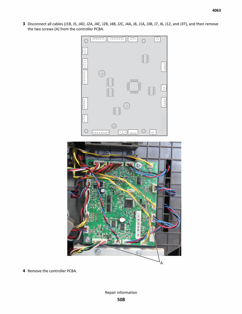
3 Disconnect all cables (J1B, J5, J4D, J2A, J4C, J2B, J4B, J2C, J4A, J8, J1A, J3B, J7, J6, J12, and J3T), and then removethe two screws (A) from the controller PCBA.
4 Remove the controller PCBA.
4063
Repair information
508
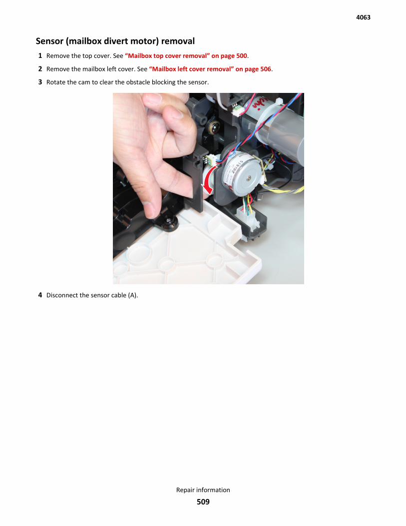
Sensor (mailbox divert motor) removal1 Remove the top cover. See “Mailbox top cover removal” on page 500.
2 Remove the mailbox left cover. See “Mailbox left cover removal” on page 506.
3 Rotate the cam to clear the obstacle blocking the sensor.
4 Disconnect the sensor cable (A).
4063
Repair information
509
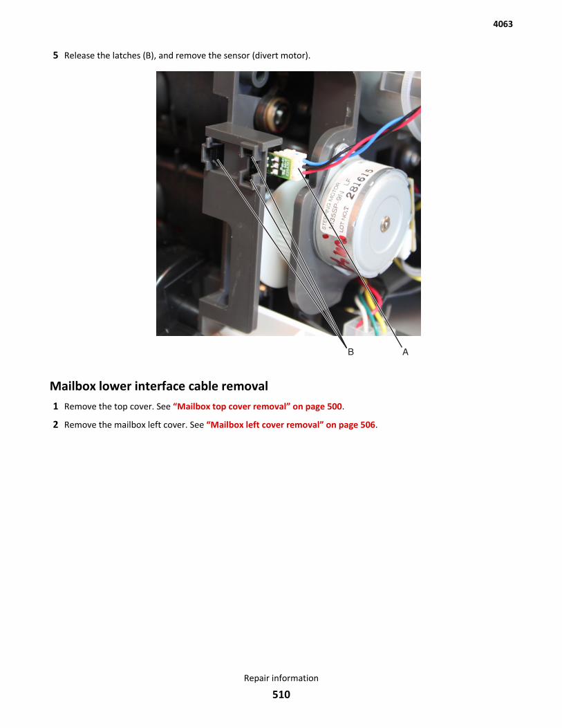
5 Release the latches (B), and remove the sensor (divert motor).
Mailbox lower interface cable removal1 Remove the top cover. See “Mailbox top cover removal” on page 500.
2 Remove the mailbox left cover. See “Mailbox left cover removal” on page 506.
4063
Repair information
510
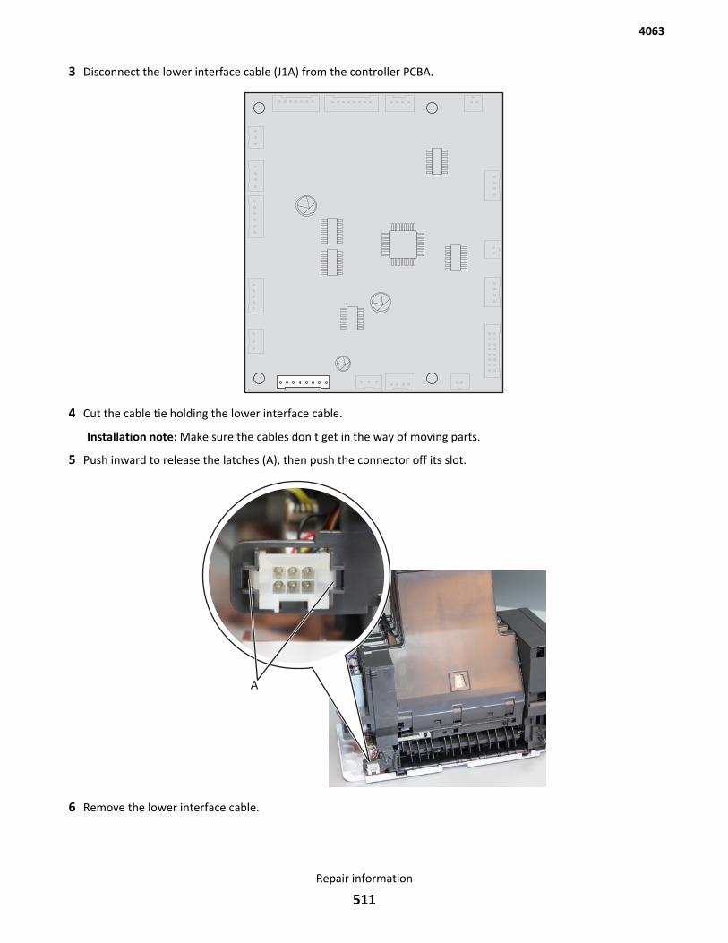
3 Disconnect the lower interface cable (J1A) from the controller PCBA.
4 Cut the cable tie holding the lower interface cable.
Installation note: Make sure the cables don't get in the way of moving parts.
5 Push inward to release the latches (A), then push the connector off its slot.
6 Remove the lower interface cable.
4063
Repair information
511
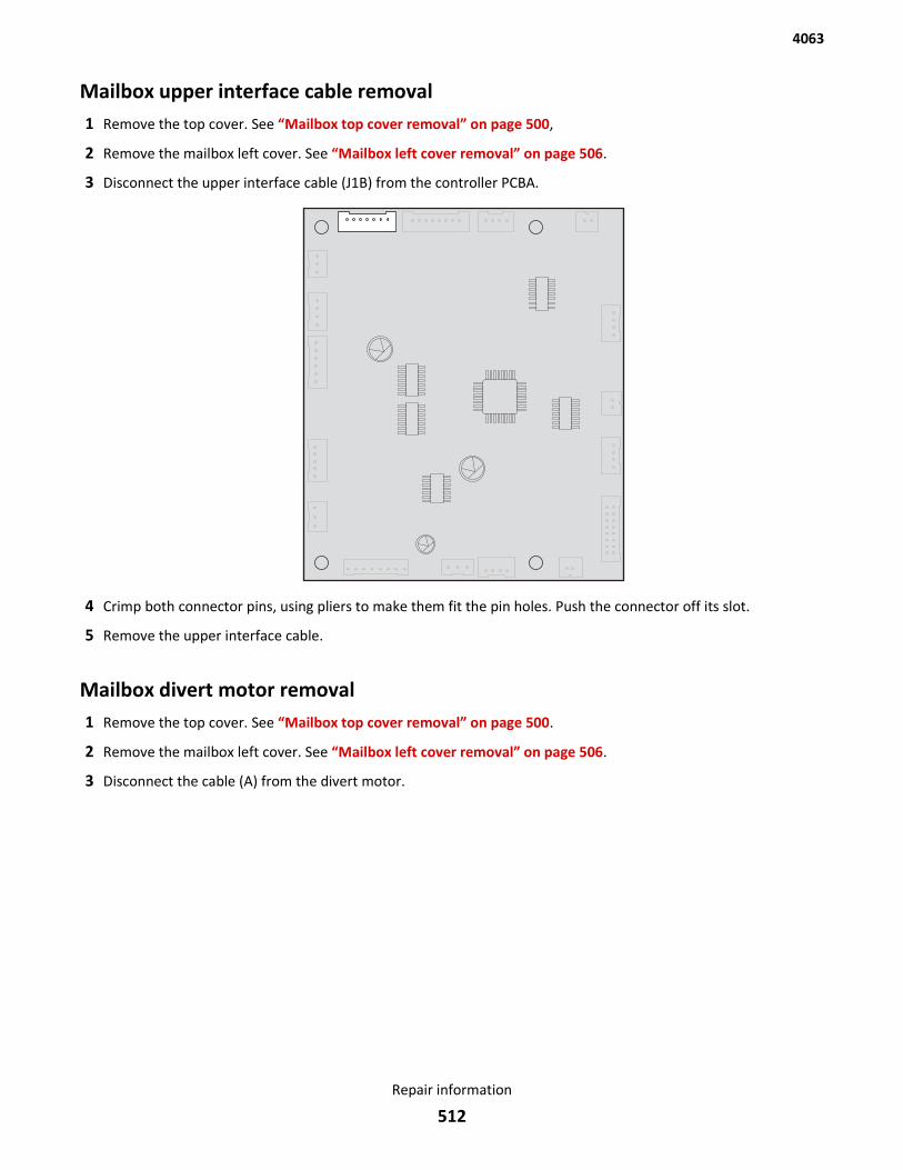
Mailbox upper interface cable removal1 Remove the top cover. See “Mailbox top cover removal” on page 500,
2 Remove the mailbox left cover. See “Mailbox left cover removal” on page 506.
3 Disconnect the upper interface cable (J1B) from the controller PCBA.
4 Crimp both connector pins, using pliers to make them fit the pin holes. Push the connector off its slot.
5 Remove the upper interface cable.
Mailbox divert motor removal1 Remove the top cover. See “Mailbox top cover removal” on page 500.
2 Remove the mailbox left cover. See “Mailbox left cover removal” on page 506.
3 Disconnect the cable (A) from the divert motor.
4063
Repair information
512
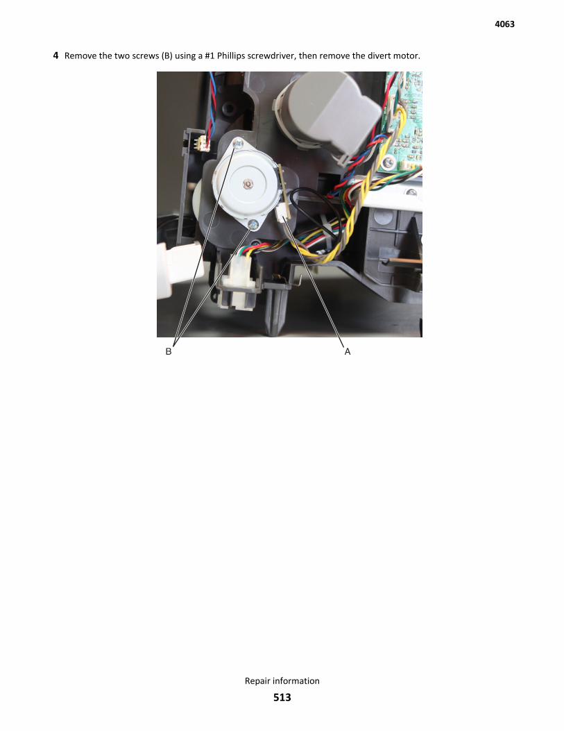
4 Remove the two screws (B) using a #1 Phillips screwdriver, then remove the divert motor.
4063
Repair information
513
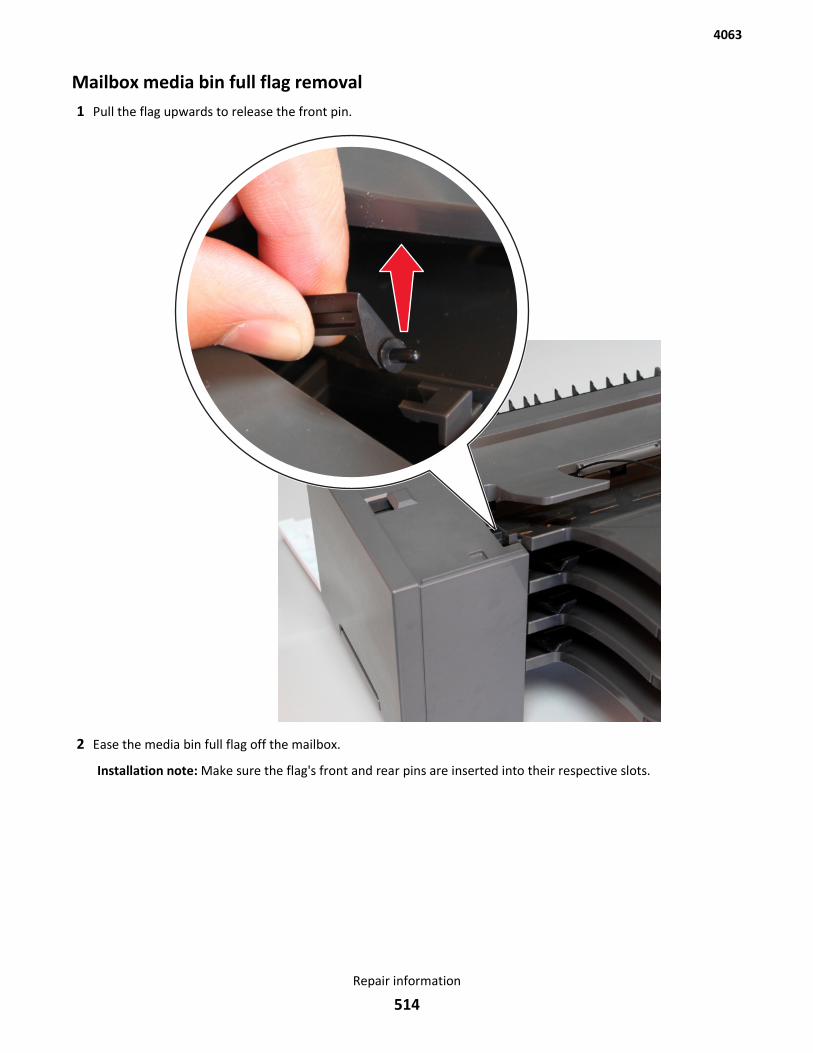
Mailbox media bin full flag removal1 Pull the flag upwards to release the front pin.
2 Ease the media bin full flag off the mailbox.
Installation note: Make sure the flag's front and rear pins are inserted into their respective slots.
4063
Repair information
514
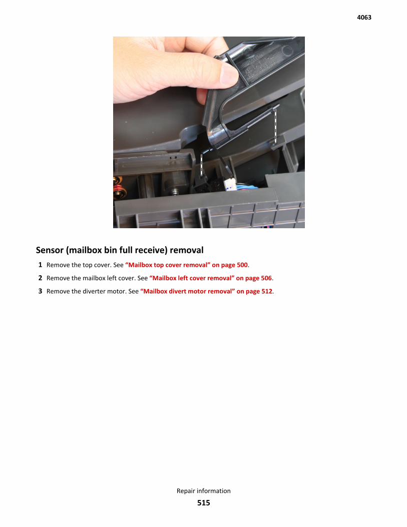
Sensor (mailbox bin full receive) removal1 Remove the top cover. See “Mailbox top cover removal” on page 500.
2 Remove the mailbox left cover. See “Mailbox left cover removal” on page 506.
3 Remove the diverter motor. See “Mailbox divert motor removal” on page 512.
4063
Repair information
515
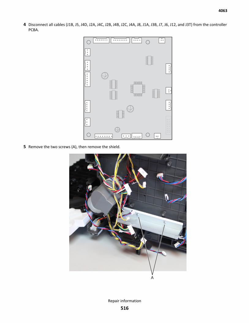
4 Disconnect all cables (J1B, J5, J4D, J2A, J4C, J2B, J4B, J2C, J4A, J8, J1A, J3B, J7, J6, J12, and J3T) from the controllerPCBA.
5 Remove the two screws (A), then remove the shield.
4063
Repair information
516
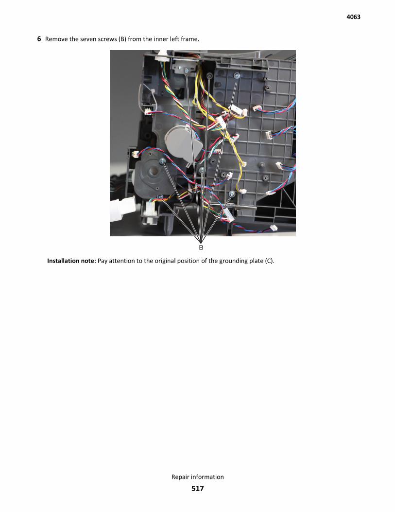
6 Remove the seven screws (B) from the inner left frame.
Installation note: Pay attention to the original position of the grounding plate (C).
4063
Repair information
517
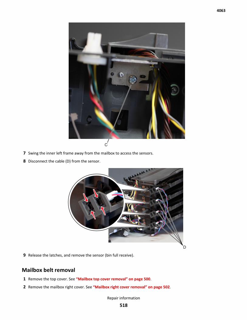
7 Swing the inner left frame away from the mailbox to access the sensors.
8 Disconnect the cable (D) from the sensor.
9 Release the latches, and remove the sensor (bin full receive).
Mailbox belt removal1 Remove the top cover. See “Mailbox top cover removal” on page 500.
2 Remove the mailbox right cover. See “Mailbox right cover removal” on page 502.
4063
Repair information
518
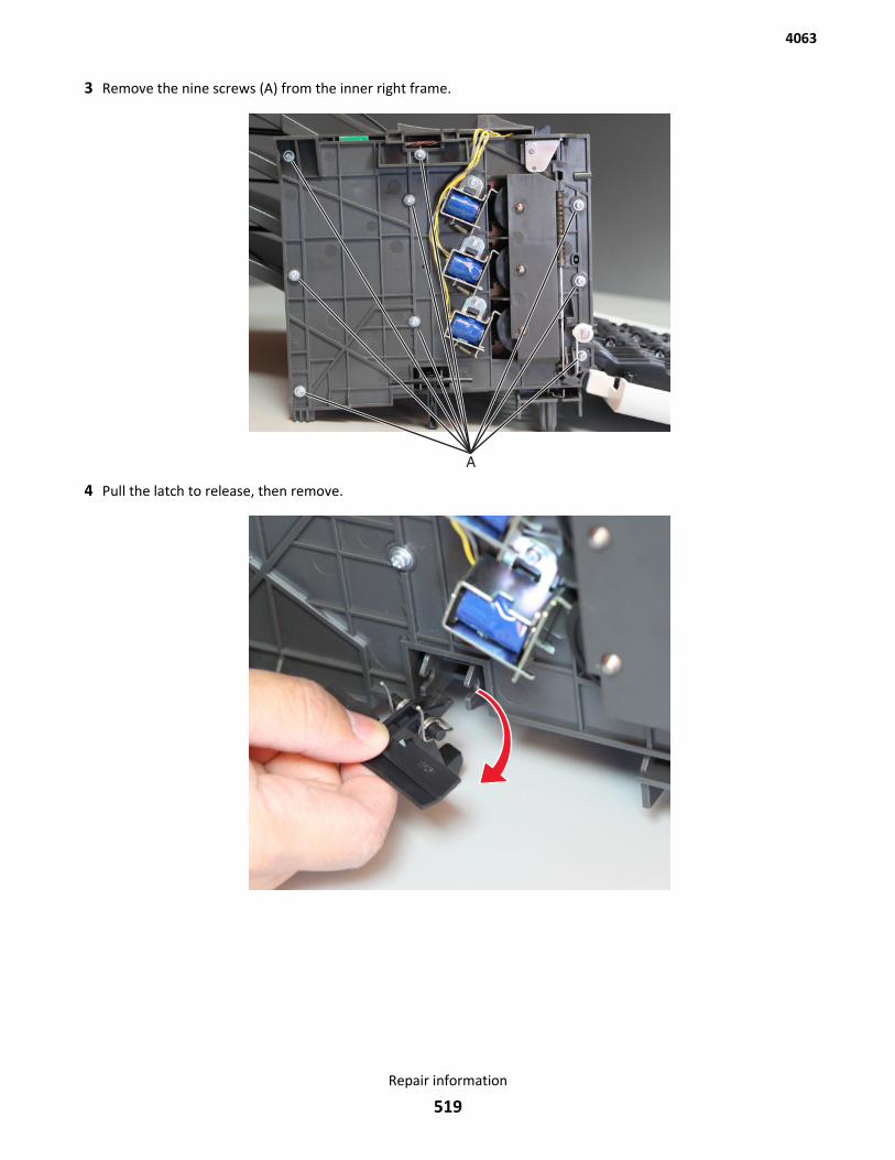
3 Remove the nine screws (A) from the inner right frame.
4 Pull the latch to release, then remove.
4063
Repair information
519
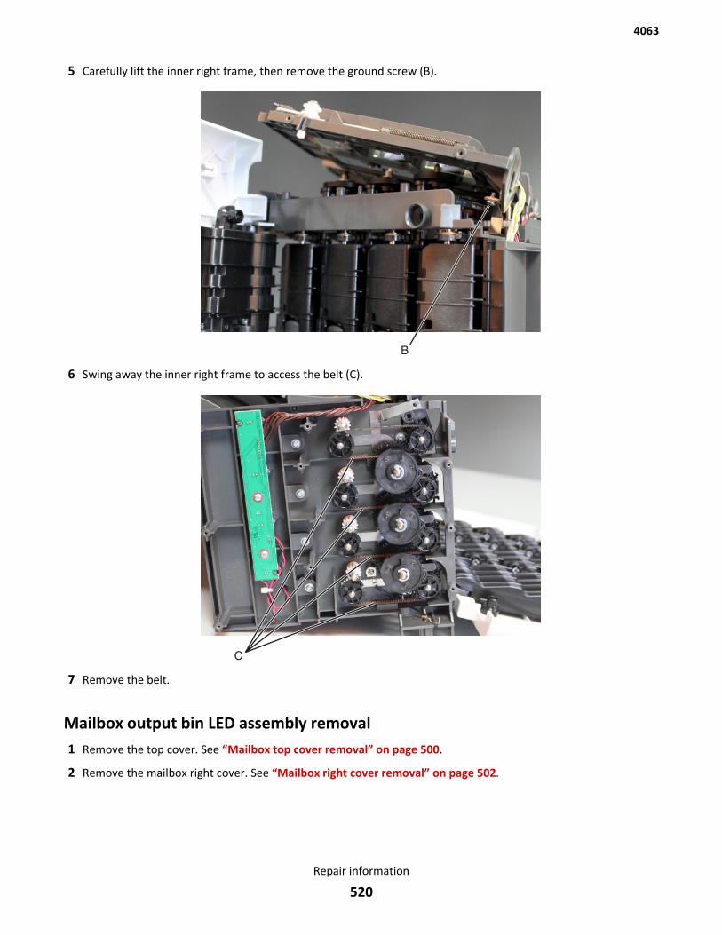
5 Carefully lift the inner right frame, then remove the ground screw (B).
6 Swing away the inner right frame to access the belt (C).
7 Remove the belt.
Mailbox output bin LED assembly removal1 Remove the top cover. See “Mailbox top cover removal” on page 500.
2 Remove the mailbox right cover. See “Mailbox right cover removal” on page 502.
4063
Repair information
520

3 Remove the nine screws (A) from the inner right frame.
4 Pull the latch to release, then remove.
4063
Repair information
521
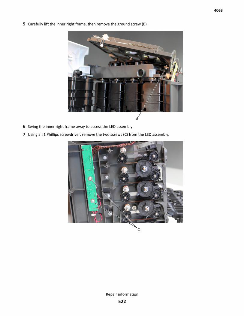
5 Carefully lift the inner right frame, then remove the ground screw (B).
6 Swing the inner right frame away to access the LED assembly.
7 Using a #1 Phillips screwdriver, remove the two screws (C) from the LED assembly.
4063
Repair information
522
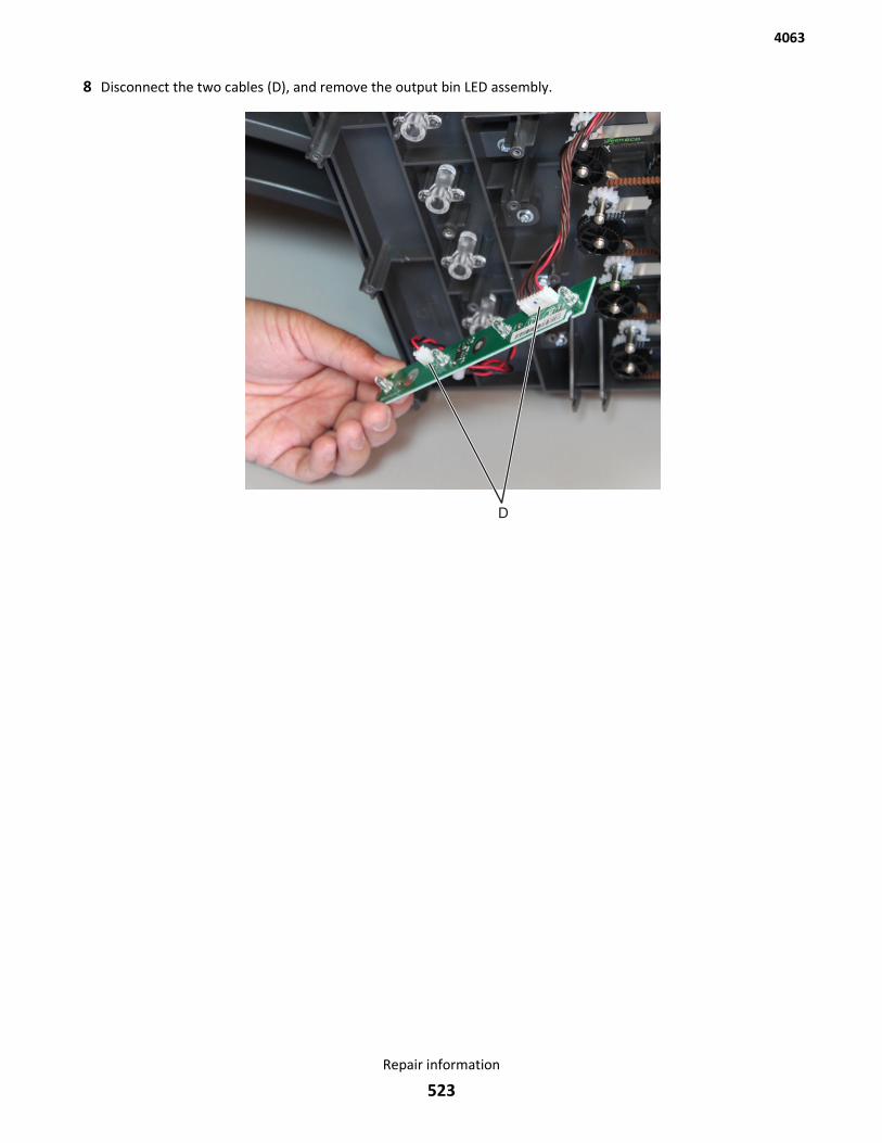
8 Disconnect the two cables (D), and remove the output bin LED assembly.
4063
Repair information
523

4063
524
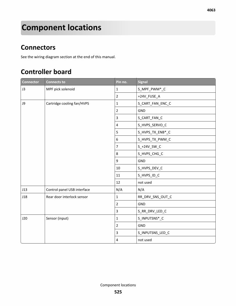
Component locations
ConnectorsSee the wiring diagram section at the end of this manual.
Controller boardConnector Connects to Pin no. Signal
J3 MPF pick solenoid 1 S_MPF_PWM*_C
2 +24V_FUSE_A
J9 Cartridge cooling fan/HVPS 1 S_CART_FAN_ENC_C
2 GND
3 S_CART_FAN_C
4 S_HVPS_SERVO_C
5 S_HVPS_TX_ENB*_C
6 S_HVPS_TX_PWM_C
7 S_+24V_SW_C
8 S_HVPS_CHG_C
9 GND
10 S_HVPS_DEV_C
11 S_HVPS_ID_C
12 not used
J13 Control panel USB interface N/A N/A
J18 Rear door interlock sensor 1 RR_DRV_SNS_OUT_C
2 GND
3 S_RR_DRV_LED_C
J20 Sensor (input) 1 S_INPUTSNS*_C
2 GND
3 S_INPUTSNS_LED_C
4 not used
4063
Component locations
525
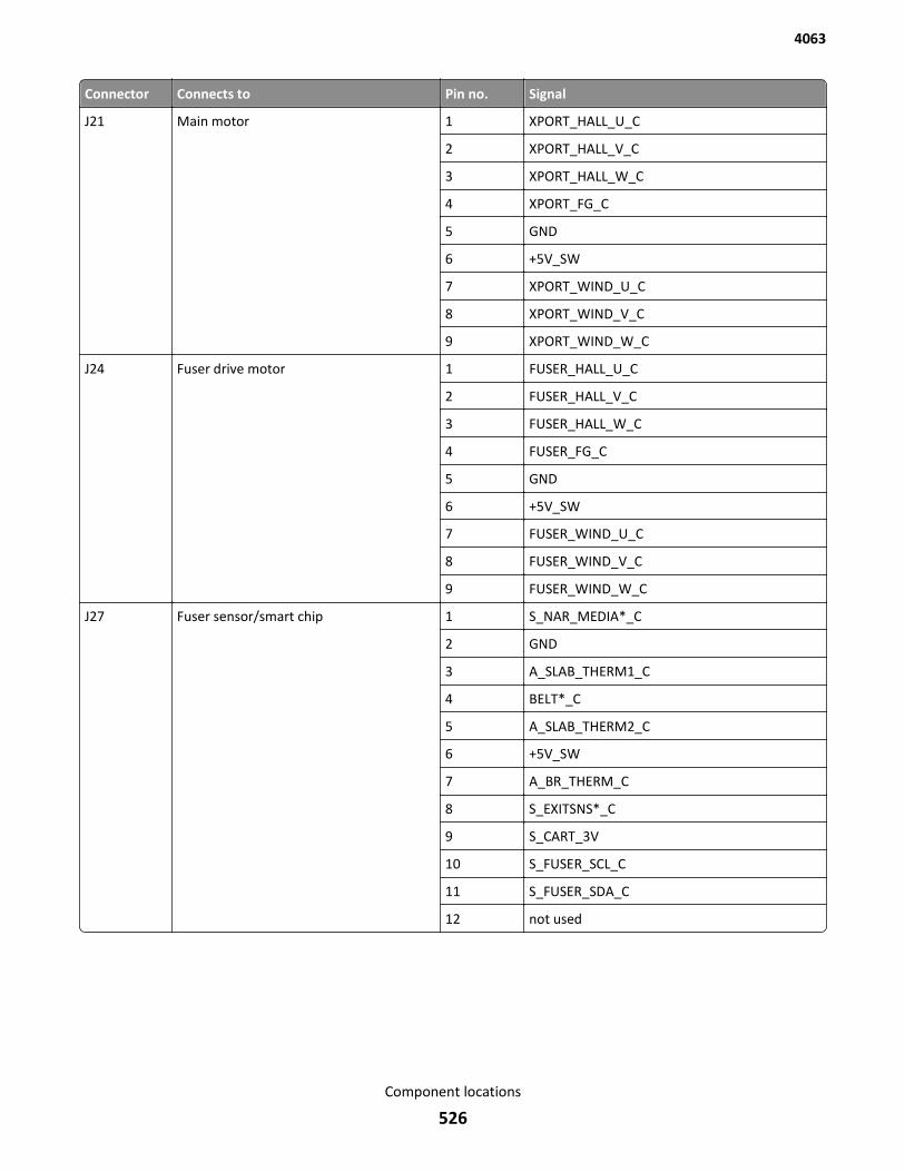
Connector Connects to Pin no. Signal
J21 Main motor 1 XPORT_HALL_U_C
2 XPORT_HALL_V_C
3 XPORT_HALL_W_C
4 XPORT_FG_C
5 GND
6 +5V_SW
7 XPORT_WIND_U_C
8 XPORT_WIND_V_C
9 XPORT_WIND_W_C
J24 Fuser drive motor 1 FUSER_HALL_U_C
2 FUSER_HALL_V_C
3 FUSER_HALL_W_C
4 FUSER_FG_C
5 GND
6 +5V_SW
7 FUSER_WIND_U_C
8 FUSER_WIND_V_C
9 FUSER_WIND_W_C
J27 Fuser sensor/smart chip 1 S_NAR_MEDIA*_C
2 GND
3 A_SLAB_THERM1_C
4 BELT*_C
5 A_SLAB_THERM2_C
6 +5V_SW
7 A_BR_THERM_C
8 S_EXITSNS*_C
9 S_CART_3V
10 S_FUSER_SCL_C
11 S_FUSER_SDA_C
12 not used
4063
Component locations
526
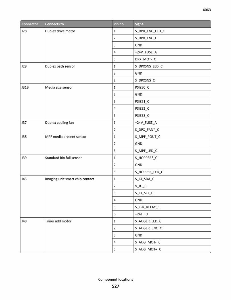
Connector Connects to Pin no. Signal
J28 Duplex drive motor 1 S_DPX_ENC_LED_C
2 S_DPX_ENC_C
3 GND
4 +24V_FUSE_A
5 DPX_MOT-_C
J29 Duplex path sensor 1 S_DPXSNS_LED_C
2 GND
3 S_DPXSNS_C
J31B Media size sensor 1 PSIZE0_C
2 GND
3 PSIZE1_C
4 PSIZE2_C
5 PSIZE3_C
J37 Duplex cooling fan 1 +24V_FUSE_A
2 S_DPX_FAN*_C
J38 MPF media present sensor 1 S_MPF_POUT_C
2 GND
3 S_MPF_LED_C
J39 Standard bin full sensor 1 S_HOPPER*_C
2 GND
3 S_HOPPER_LED_C
J45 Imaging unit smart chip contact 1 S_IU_SDA_C
2 V_IU_C
3 S_IU_SCL_C
4 GND
5 S_FSR_RELAY_C
6 +24F_IU
J48 Toner add motor 1 S_AUGER_LED_C
2 S_AUGER_ENC_C
3 GND
4 S_AUG_MOT-_C
5 S_AUG_MOT+_C
4063
Component locations
527
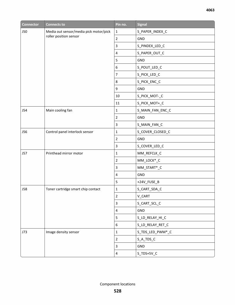
Connector Connects to Pin no. Signal
J50 Media out sensor/media pick motor/pickroller position sensor
1 S_PAPER_INDEX_C
2 GND
3 S_PINDEX_LED_C
4 S_PAPER_OUT_C
5 GND
6 S_POUT_LED_C
7 S_PICK_LED_C
8 S_PICK_ENC_C
9 GND
10 S_PICK_MOT-_C
11 S_PICK_MOT+_C
J54 Main cooling fan 1 S_MAIN_FAN_ENC_C
2 GND
3 S_MAIN_FAN_C
J56 Control panel interlock sensor 1 S_COVER_CLOSED_C
2 GND
3 S_COVER_LED_C
J57 Printhead mirror motor 1 MM_REFCLK_C
2 MM_LOCK*_C
3 MM_START*_C
4 GND
5 +24V_FUSE_B
J58 Toner cartridge smart chip contact 1 S_CART_SDA_C
2 V_CART
3 S_CART_SCL_C
4 GND
5 S_LD_RELAY_HI_C
6 S_LD_RELAY_RET_C
J73 Image density sensor 1 S_TDS_LED_PWM*_C
2 S_A_TDS_C
3 GND
4 S_TDS+5V_C
4063
Component locations
528
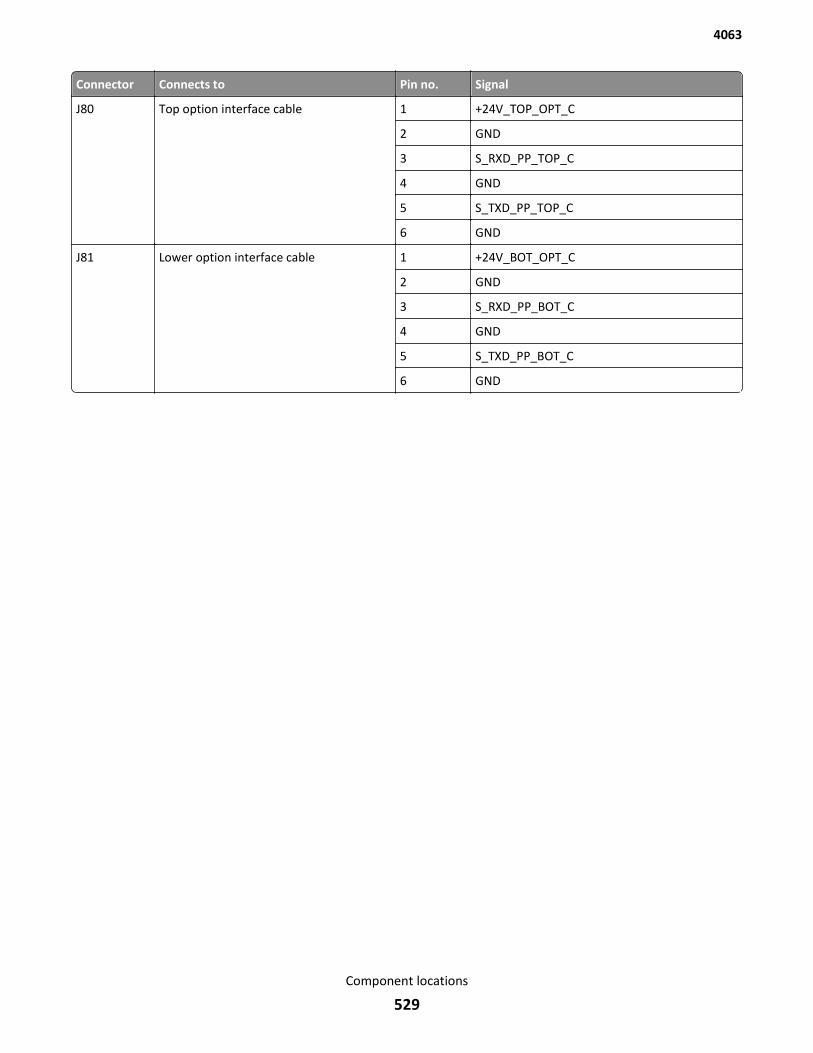
Connector Connects to Pin no. Signal
J80 Top option interface cable 1 +24V_TOP_OPT_C
2 GND
3 S_RXD_PP_TOP_C
4 GND
5 S_TXD_PP_TOP_C
6 GND
J81 Lower option interface cable 1 +24V_BOT_OPT_C
2 GND
3 S_RXD_PP_BOT_C
4 GND
5 S_TXD_PP_BOT_C
6 GND
4063
Component locations
529
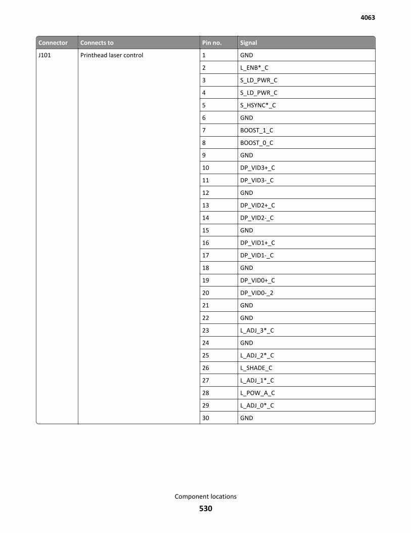
Connector Connects to Pin no. Signal
J101 Printhead laser control 1 GND
2 L_ENB*_C
3 S_LD_PWR_C
4 S_LD_PWR_C
5 S_HSYNC*_C
6 GND
7 BOOST_1_C
8 BOOST_0_C
9 GND
10 DP_VID3+_C
11 DP_VID3-_C
12 GND
13 DP_VID2+_C
14 DP_VID2-_C
15 GND
16 DP_VID1+_C
17 DP_VID1-_C
18 GND
19 DP_VID0+_C
20 DP_VID0-_2
21 GND
22 GND
23 L_ADJ_3*_C
24 GND
25 L_ADJ_2*_C
26 L_SHADE_C
27 L_ADJ_1*_C
28 L_POW_A_C
29 L_ADJ_0*_C
30 GND
4063
Component locations
530
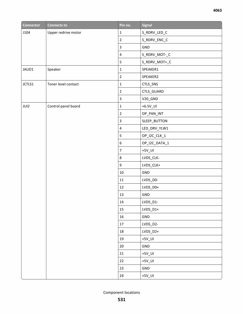
Connector Connects to Pin no. Signal
J104 Upper redrive motor 1 S_RDRV_LED_C
2 S_RDRV_ENC_C
3 GND
4 S_RDRV_MOT-_C
5 S_RDRV_MOT+_C
JAUD1 Speaker 1 SPEAKER1
2 SPEAKER2
JCTLS1 Toner level contact 1 CTLS_SNS
2 CTLS_GUARD
3 V20_GND
JUI2 Control panel board 1 +6.5V_UI
2 OP_PAN_INT
3 SLEEP_BUTTON
4 LED_DRV_YLW1
5 OP_I2C_CLK_1
6 OP_I2C_DATA_1
7 +5V_UI
8 LVDS_CLK-
9 LVDS_CLK+
10 GND
11 LVDS_D0-
12 LVDS_D0+
13 GND
14 LVDS_D1-
15 LVDS_D1+
16 GND
17 LVDS_D2-
18 LVDS_D2+
19 +5V_UI
20 GND
21 +5V_UI
22 +5V_UI
23 GND
24 +5V_UI
4063
Component locations
531

Connector Connects to Pin no. Signal
JUSBH1 USB interface (Den* only) N/A N/A
JW1 Temperature probe 1 A_WS_MACHINE_C
2 GND
4063
Component locations
532
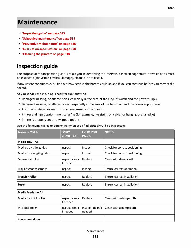
Maintenance• “Inspection guide” on page 533
• “Scheduled maintenance” on page 535
• “Preventive maintenance” on page 538
• “Lubrication specification” on page 538
• “Cleaning the printer” on page 538
Inspection guideThe purpose of this Inspection guide is to aid you in identifying the intervals, based on page count, at which parts mustbe Inspected (for visible physical damage), cleaned, or replaced.
If any unsafe conditions exist, find out how serious the hazard could be and if you can continue before you correct thehazard.
As you service the machine, check for the following:
• Damaged, missing, or altered parts, especially in the area of the On/Off switch and the power supply
• Damaged, missing, or altered covers, especially in the area of the top cover and the power supply cover
• Possible safety exposure from any non-Lexmark attachments
• Printer and input options are sitting flat (for example, not sitting on cables or hanging over a ledge)
• Printer is properly set on any input options
Use the following tables to determine when specified parts should be inspected:
Lexmark MS81x EVERYSERVICE CALL
EVERY 200KPAGES
NOTES
Media tray—All
Media tray side guides Inspect Inspect Check for correct positioning.
Media tray length guides Inspect Inspect Check for correct positioning.
Separation roller Inspect, cleanif needed
Replace Clean with damp cloth.
Tray lift gear assembly Inspect Inspect Ensure correct operation.
Transfer roller Inspect Replace Ensure correct installation.
Fuser Inspect Replace Ensure correct installation.
Media feeders—All
Media tray pick roller Inspect, cleanif needed
Replace Clean with a damp cloth.
MPF pick roller Inspect, cleanif needed
Inspect, clean ifneeded
Clean with a damp cloth.
Covers and doors
4063
Maintenance
533
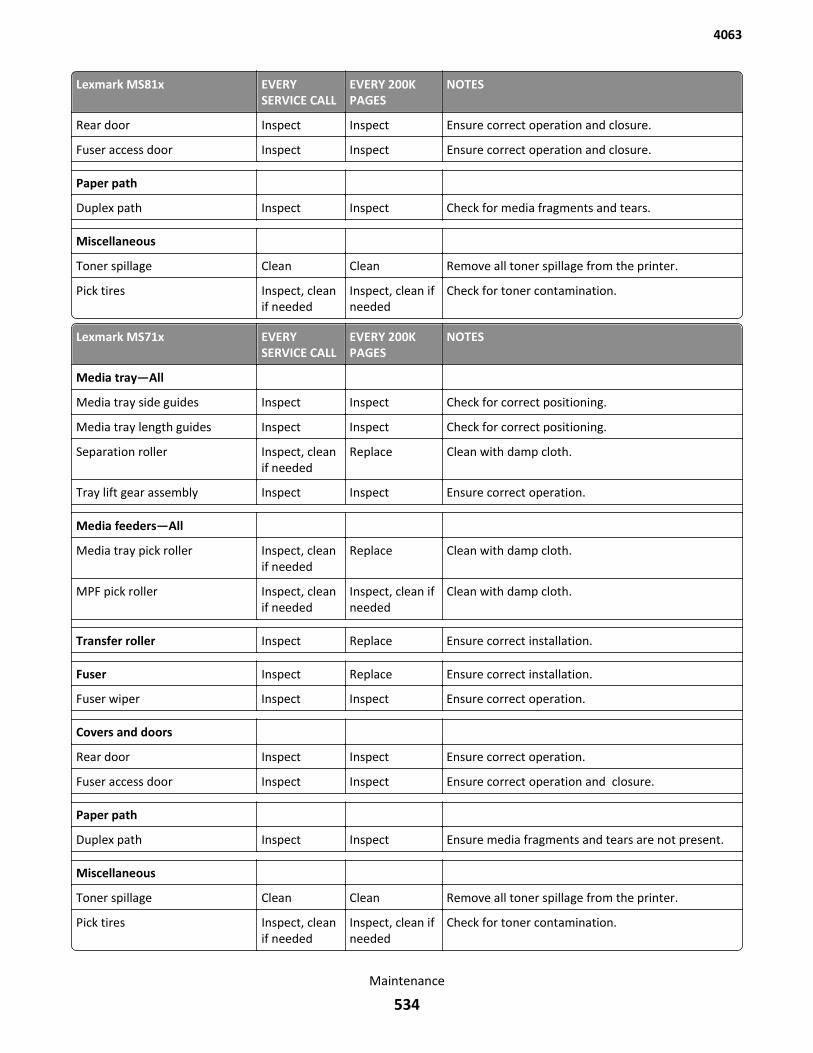
Lexmark MS81x EVERYSERVICE CALL
EVERY 200KPAGES
NOTES
Rear door Inspect Inspect Ensure correct operation and closure.
Fuser access door Inspect Inspect Ensure correct operation and closure.
Paper path
Duplex path Inspect Inspect Check for media fragments and tears.
Miscellaneous
Toner spillage Clean Clean Remove all toner spillage from the printer.
Pick tires Inspect, cleanif needed
Inspect, clean ifneeded
Check for toner contamination.
Lexmark MS71x EVERYSERVICE CALL
EVERY 200KPAGES
NOTES
Media tray—All
Media tray side guides Inspect Inspect Check for correct positioning.
Media tray length guides Inspect Inspect Check for correct positioning.
Separation roller Inspect, cleanif needed
Replace Clean with damp cloth.
Tray lift gear assembly Inspect Inspect Ensure correct operation.
Media feeders—All
Media tray pick roller Inspect, cleanif needed
Replace Clean with damp cloth.
MPF pick roller Inspect, cleanif needed
Inspect, clean ifneeded
Clean with damp cloth.
Transfer roller Inspect Replace Ensure correct installation.
Fuser Inspect Replace Ensure correct installation.
Fuser wiper Inspect Inspect Ensure correct operation.
Covers and doors
Rear door Inspect Inspect Ensure correct operation.
Fuser access door Inspect Inspect Ensure correct operation and closure.
Paper path
Duplex path Inspect Inspect Ensure media fragments and tears are not present.
Miscellaneous
Toner spillage Clean Clean Remove all toner spillage from the printer.
Pick tires Inspect, cleanif needed
Inspect, clean ifneeded
Check for toner contamination.
4063
Maintenance
534
Scheduled maintenanceThe operator panel displays the message 80 or Scheduled Maintenance when it reaches certain page counts. It isnecessary to replace the appropriate maintenance kit at certain intervals to maintain the print quality and reliability ofthe printer. If needed, reset the maintenance counter after performing scheduled maintenance.
Fuser maintenance kitsThe printer stops printing when the fuser rated life is reached. At rated fuser life, a Fuser Maintenance Kit is required.You must install the correct Fuser Maintenance Kit for the type of fuser that is installed in the printer. See “Identifyingthe type of fuser used in the printer” on page 536.
There are multiple warnings to indicate that the fuser is nearing end of life and that a maintenance kit is required,including error codes 80.0x, 80.1x, and 80.2x. If you receive error code 80.3x, the fuser has reached its rated life. Theprinter will not continue until a maintenance kit is installed.
Replacing fuser maintenance kits
The operator panel displays the message 80 “Replace maintenance kit” at required maintenance intervals. You mustreplace the fuser, transfer roller, pick roller, and separation roller at this interval to maintain the print quality andreliability of the printer. The following fuser maintenance kits are available:
Description Part number Maintenance interval
MS81x Return Program Fuser Maintenance Kit Type 00, 110-120V Letter 40X8420 200K
MS81x Return Program Fuser Maintenance Kit Type 01, 220-240V A4 40X8421 200K
MS81x Return Program Fuser Maintenance Kit Type 02, 100V A4 40X8422 200K
MS81x Return Program Fuser Maintenance Kit Type 03, 110-120V A4 40X8423 200K
MS81x Return Program Fuser Maintenance Kit Type 04, 220-240V Letter 40X8424 200K
MS81x Fuser Maintenance Kit Type 05, 110-120V Letter 40X8425 200K
MS81x Fuser Maintenance Kit Type 06, 220-240V A4 40X8426 200K
MS81x Fuser Maintenance Kit Type 07, 100V A4 40X8427 200K
MS81x Fuser Maintenance Kit Type 08, 110-120V A4 40X8428 200K
MS81x Fuser Maintenance Kit Type 09, 220-240V Letter 40X8429 200K
MS71x Return Program Fuser Maintenance Kit Type 11, 110-120V 40X8530 200K
MS71x Return Program Fuser Maintenance Kit Type 13, 220-240V 40X8531 200K
MS71x Return Program Fuser Maintenance Kit Type 15, 100V 40X8532 200K
MS71x Fuser Maint. Kit Type 17, 110-120V 40X8533 200K
MS71x Fuser Maint. Kit Type 19, 220-240V 40X8534 200K
MS71x Fuser Maint. Kit Type 21, 100V 40X8535 200K
After replacing the maintenance kit, the maintenance count will automatically be reset to zero to clear the 80 “Replacemaintenance kit” message.
4063
Maintenance
535
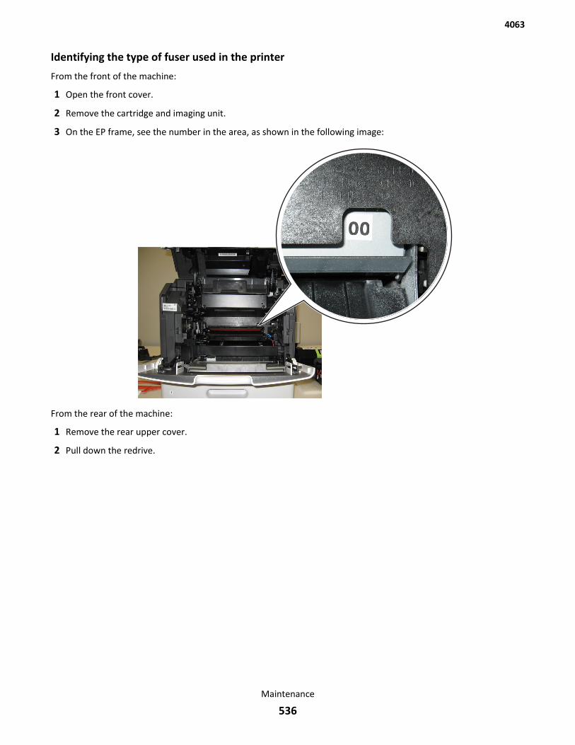
Identifying the type of fuser used in the printer
From the front of the machine:
1 Open the front cover.
2 Remove the cartridge and imaging unit.
3 On the EP frame, see the number in the area, as shown in the following image:
From the rear of the machine:
1 Remove the rear upper cover.
2 Pull down the redrive.
4063
Maintenance
536
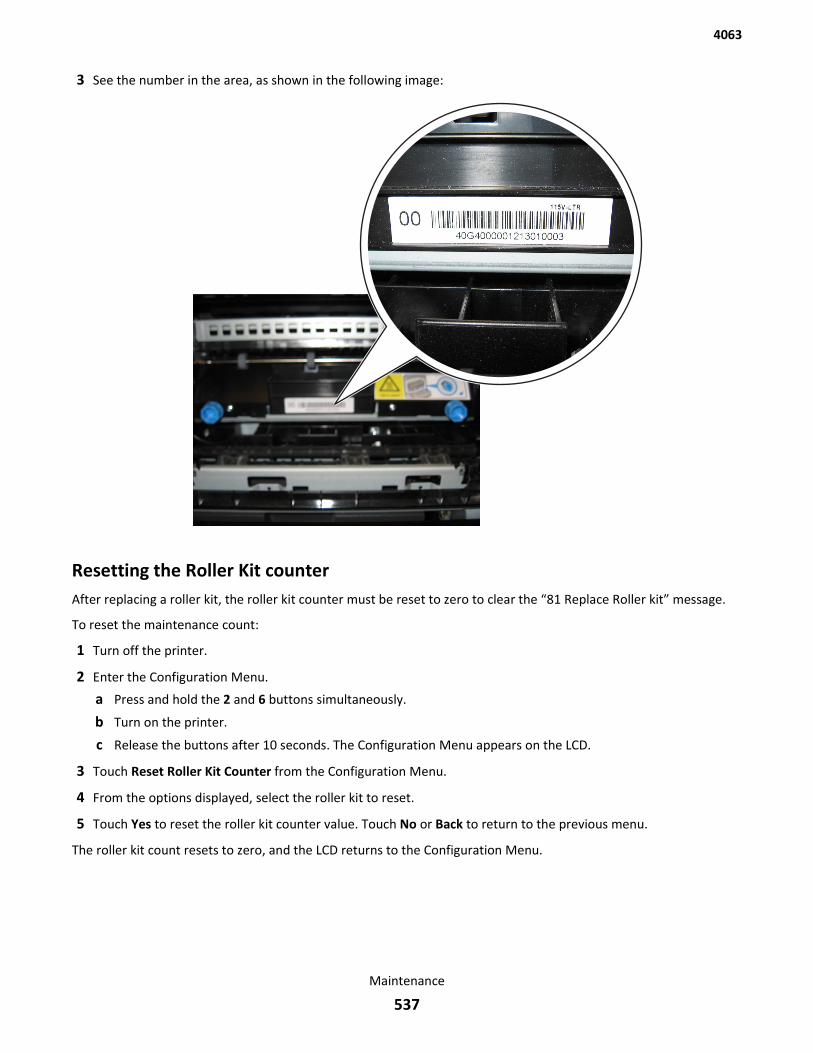
3 See the number in the area, as shown in the following image:
Resetting the Roller Kit counterAfter replacing a roller kit, the roller kit counter must be reset to zero to clear the “81 Replace Roller kit” message.
To reset the maintenance count:
1 Turn off the printer.
2 Enter the Configuration Menu.
a Press and hold the 2 and 6 buttons simultaneously.
b Turn on the printer.
c Release the buttons after 10 seconds. The Configuration Menu appears on the LCD.
3 Touch Reset Roller Kit Counter from the Configuration Menu.
4 From the options displayed, select the roller kit to reset.
5 Touch Yes to reset the roller kit counter value. Touch No or Back to return to the previous menu.
The roller kit count resets to zero, and the LCD returns to the Configuration Menu.
4063
Maintenance
537
Preventive maintenanceBetween scheduled maintenance intervals, paper feed, paper transport, and image quality problems can occur. Somepreventive maintenance procedures can help prevent issues like these.
Device‑specific preventive maintenanceTo clean the touchscreen and keypad, use the LCD cleaning cloth. A single two‑step LCD cleaning cloth is stored in thecompartment beneath the exit tray. Additional cleaning cloths are available.
The following table lists the parts needed to perform preventive maintenance:
Part number Description Maintenance interval
40X0392 LCD cleaning kit As needed
Lubrication specificationThere are no lubrication requirements for this printer.
Cleaning the printerNote: You may need to perform this task after every few months.
Warning—Potential Damage: Damage to the printer caused by improper handling is not covered by the printerwarranty.
1 Make sure that the printer is turned off and unplugged from the electrical outlet.
CAUTION—SHOCK HAZARD: To avoid the risk of electrical shock when cleaning the exterior of the printer,unplug the power cord from the electrical outlet and disconnect all cables from the printer beforeproceeding.
2 Remove paper from the standard bin and multipurpose feeder.
3 Remove any dust, lint, and pieces of paper around the printer using a soft brush or vacuum.
4 Dampen a clean, lint-free cloth with water, and use it to wipe the outside of the printer.
Warning—Potential Damage: Do not use household cleaners or detergents to prevent damage to the exteriorof the printer.
5 Make sure all areas of the printer are dry before sending a new print job.
4063
Maintenance
538

4063
539
Parts catalog• “Legend” on page 540
• “Assembly 1: Covers” on page 543
• “Assembly 2: Paper path” on page 545
• “Assembly 3: Fusers” on page 547
• “Assembly 4: Electronics” on page 549
• “Assembly 5: Drive motors” on page 553
• “Assembly 6: Duplex” on page 555
• “Assembly 7: Frame” on page 557
• “Assembly 8: Control panel” on page 559
• “Assembly 9: Paper tray” on page 563
• “Assembly 10: Input options” on page 565
• “Assembly 11: 250-sheet tray option” on page 567
• “Assembly 12: 550-sheet tray option” on page 569
• “Assembly 13: High capacity input tray option 1” on page 571
• “Assembly 14: High capacity input tray option 2” on page 573
• “Assembly 15: Output options” on page 575
• “Assembly 16: Output expander option” on page 577
• “Assembly 17: High capacity output expander option” on page 579
• “Assembly 18: Staple finisher option 1” on page 581
• “Assembly 19: Staple finisher option 2” on page 583
• “Assembly 20: Mailbox option 1” on page 585
• “Assembly 21: Mailbox option 2” on page 587
• “Assembly 22: Miscellaneous” on page 589
• “Assembly 23: Power cords” on page 593
LegendThe following column headings are used in the parts catalog:
• Asm‑index—Identifies the assembly and the item in the diagram. For example, 3‑1 indicates Assembly 3 and item1 in the table.
• Part number—Identifies the unique number that correlates with the part.
• Units/mach—Refers to the number of units actually used in the base machine or product.
• Units/option—Refers to the number of units in a particular option.
• Units/FRU—Refers to the number of units in a particular FRU.
• Description—A brief description of the part.
4063
Parts catalog
540

The following abbreviations are used in the parts catalog:
• NS (not shown) in the Asm‑index column indicates that the part is procurable but is not pictured in the illustration.
• PP (parts packet) in the Description column indicates that the part is contained in a parts packet.
4063
Parts catalog
541

4063
Parts catalog
542
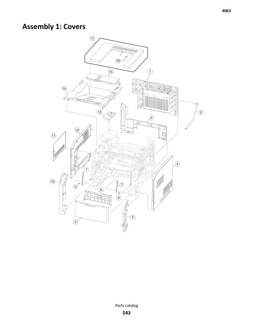
Assembly 1: Covers
4063
Parts catalog
543
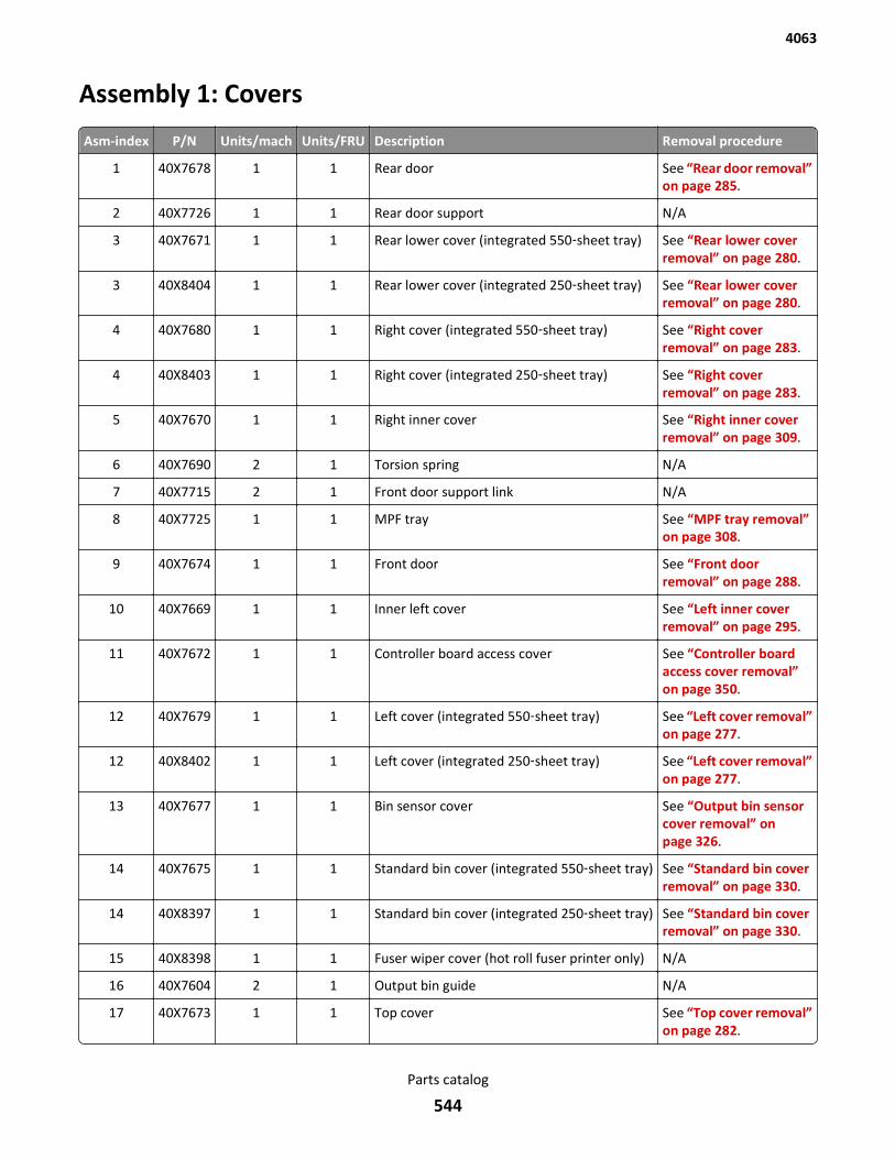
Assembly 1: Covers
Asm-index P/N Units/mach Units/FRU Description Removal procedure
1 40X7678 1 1 Rear door See “Rear door removal”on page 285.
2 40X7726 1 1 Rear door support N/A
3 40X7671 1 1 Rear lower cover (integrated 550‑sheet tray) See “Rear lower coverremoval” on page 280.
3 40X8404 1 1 Rear lower cover (integrated 250‑sheet tray) See “Rear lower coverremoval” on page 280.
4 40X7680 1 1 Right cover (integrated 550‑sheet tray) See “Right coverremoval” on page 283.
4 40X8403 1 1 Right cover (integrated 250‑sheet tray) See “Right coverremoval” on page 283.
5 40X7670 1 1 Right inner cover See “Right inner coverremoval” on page 309.
6 40X7690 2 1 Torsion spring N/A
7 40X7715 2 1 Front door support link N/A
8 40X7725 1 1 MPF tray See “MPF tray removal”on page 308.
9 40X7674 1 1 Front door See “Front doorremoval” on page 288.
10 40X7669 1 1 Inner left cover See “Left inner coverremoval” on page 295.
11 40X7672 1 1 Controller board access cover See “Controller boardaccess cover removal”on page 350.
12 40X7679 1 1 Left cover (integrated 550‑sheet tray) See “Left cover removal”on page 277.
12 40X8402 1 1 Left cover (integrated 250‑sheet tray) See “Left cover removal”on page 277.
13 40X7677 1 1 Bin sensor cover See “Output bin sensorcover removal” onpage 326.
14 40X7675 1 1 Standard bin cover (integrated 550‑sheet tray) See “Standard bin coverremoval” on page 330.
14 40X8397 1 1 Standard bin cover (integrated 250‑sheet tray) See “Standard bin coverremoval” on page 330.
15 40X8398 1 1 Fuser wiper cover (hot roll fuser printer only) N/A
16 40X7604 2 1 Output bin guide N/A
17 40X7673 1 1 Top cover See “Top cover removal”on page 282.
4063
Parts catalog
544
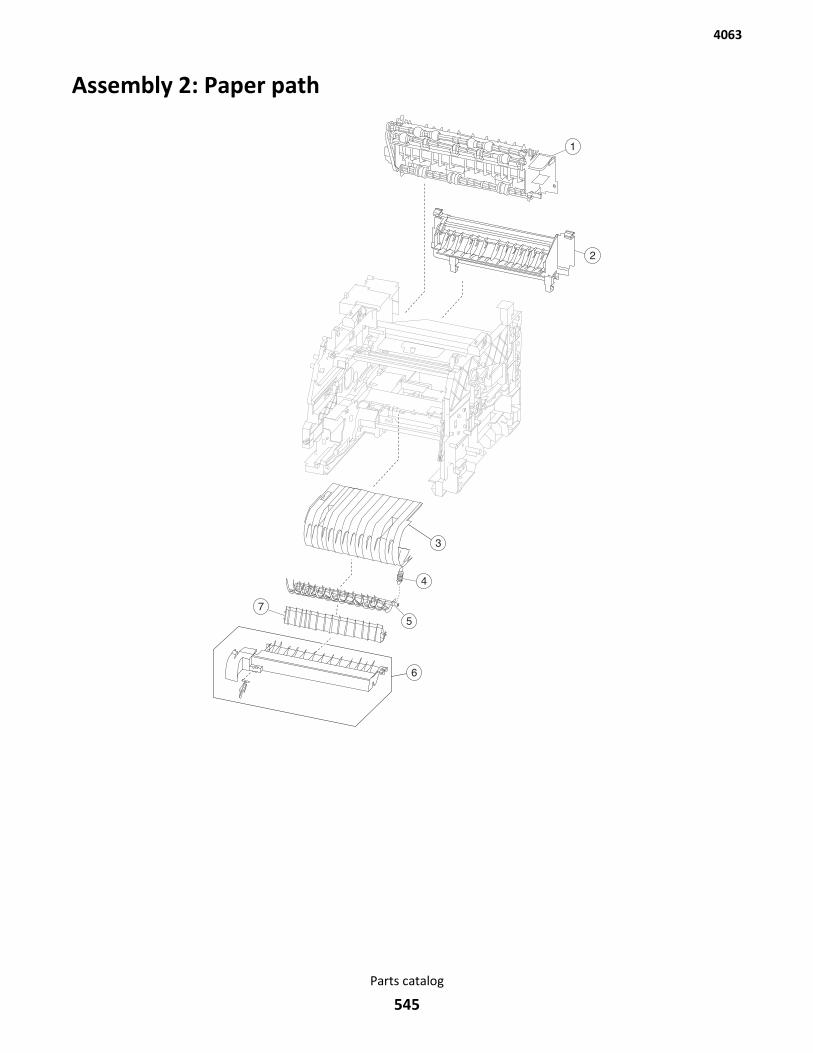
Assembly 2: Paper path
4063
Parts catalog
545

Assembly 2: Paper path
Asm-index P/N Units/mach Units/FRU Description Removal procedure
1 40X7602 1 1 Upper redrive See “Upper redriveremoval” on page 331.
2 40X7588 1 1 Fuser access door (belt fuser printers only) See “Fuser access doorremoval” on page 324.
2 40X8399 1 1 Fuser access door (hot roll fuser printers only) See “Fuser access doorremoval” on page 324.
3 40X7587 1 1 Inner guide deflector See “Inner guidedeflector removal” onpage 289.
4 40X7585 1 1 Recoil spring N/A
5 40X7584 1 1 Duplex exit diverter See “Duplex exit diverterremoval” on page 286.
6 40X7583 1 1 Media turn guide See “Media turn guideremoval” on page 299.
7 40X7586 1 1 Media vertical guide See “Media vertical guideremoval” on page 300.
4063
Parts catalog
546
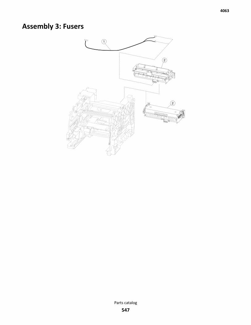
Assembly 3: Fusers
4063
Parts catalog
547
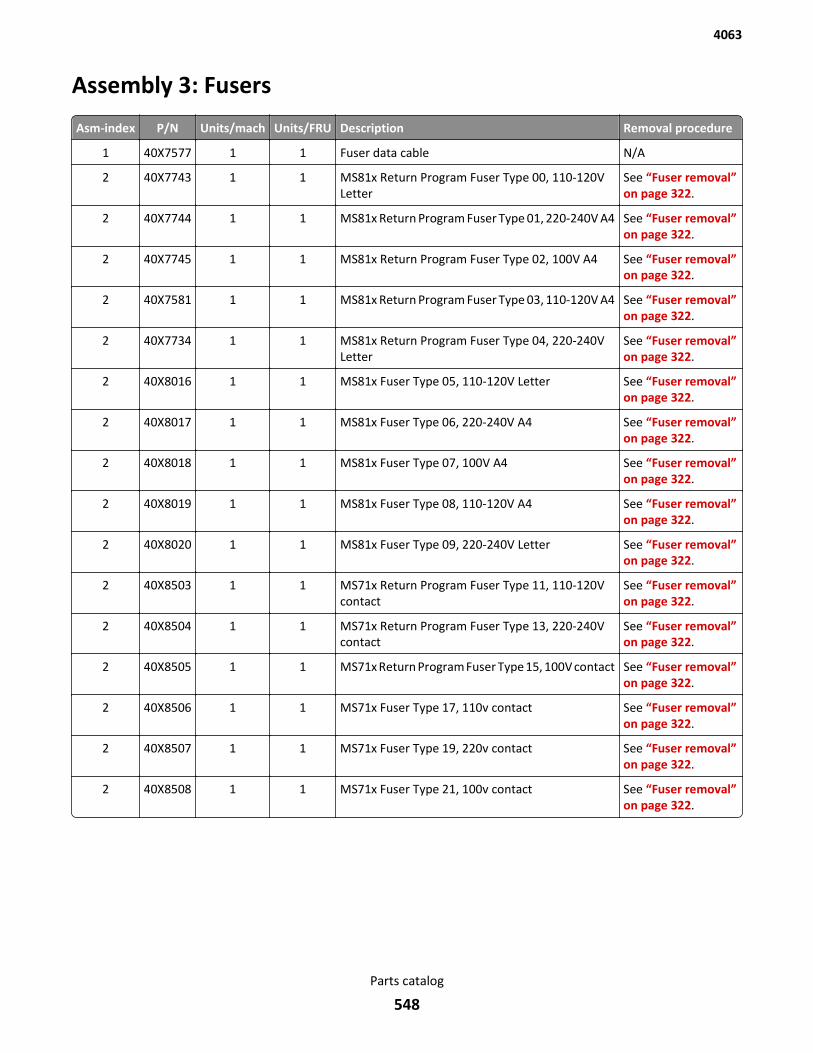
Assembly 3: Fusers
Asm-index P/N Units/mach Units/FRU Description Removal procedure
1 40X7577 1 1 Fuser data cable N/A
2 40X7743 1 1 MS81x Return Program Fuser Type 00, 110-120VLetter
See “Fuser removal”on page 322.
2 40X7744 1 1 MS81x Return Program Fuser Type 01, 220-240V A4 See “Fuser removal”on page 322.
2 40X7745 1 1 MS81x Return Program Fuser Type 02, 100V A4 See “Fuser removal”on page 322.
2 40X7581 1 1 MS81x Return Program Fuser Type 03, 110-120V A4 See “Fuser removal”on page 322.
2 40X7734 1 1 MS81x Return Program Fuser Type 04, 220-240VLetter
See “Fuser removal”on page 322.
2 40X8016 1 1 MS81x Fuser Type 05, 110-120V Letter See “Fuser removal”on page 322.
2 40X8017 1 1 MS81x Fuser Type 06, 220-240V A4 See “Fuser removal”on page 322.
2 40X8018 1 1 MS81x Fuser Type 07, 100V A4 See “Fuser removal”on page 322.
2 40X8019 1 1 MS81x Fuser Type 08, 110-120V A4 See “Fuser removal”on page 322.
2 40X8020 1 1 MS81x Fuser Type 09, 220-240V Letter See “Fuser removal”on page 322.
2 40X8503 1 1 MS71x Return Program Fuser Type 11, 110-120Vcontact
See “Fuser removal”on page 322.
2 40X8504 1 1 MS71x Return Program Fuser Type 13, 220-240Vcontact
See “Fuser removal”on page 322.
2 40X8505 1 1 MS71x Return Program Fuser Type 15, 100V contact See “Fuser removal”on page 322.
2 40X8506 1 1 MS71x Fuser Type 17, 110v contact See “Fuser removal”on page 322.
2 40X8507 1 1 MS71x Fuser Type 19, 220v contact See “Fuser removal”on page 322.
2 40X8508 1 1 MS71x Fuser Type 21, 100v contact See “Fuser removal”on page 322.
4063
Parts catalog
548
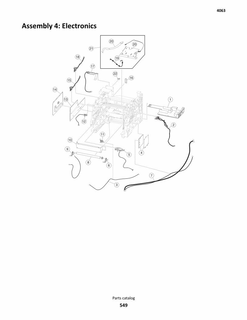
Assembly 4: Electronics
19
2020
21
22
4063
Parts catalog
549
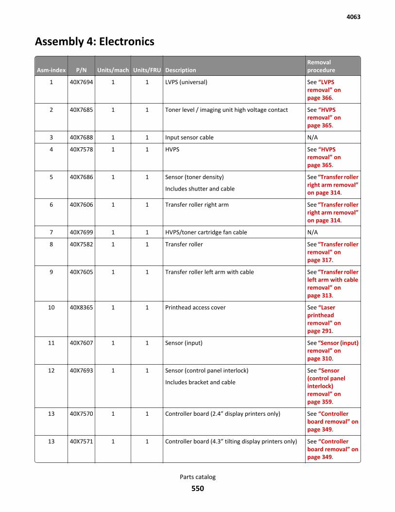
Assembly 4: Electronics
Asm-index P/N Units/mach Units/FRU DescriptionRemovalprocedure
1 40X7694 1 1 LVPS (universal) See “LVPSremoval” onpage 366.
2 40X7685 1 1 Toner level / imaging unit high voltage contact See “HVPSremoval” onpage 365.
3 40X7688 1 1 Input sensor cable N/A
4 40X7578 1 1 HVPS See “HVPSremoval” onpage 365.
5 40X7686 1 1 Sensor (toner density)
Includes shutter and cable
See “Transfer rollerright arm removal”on page 314.
6 40X7606 1 1 Transfer roller right arm See “Transfer rollerright arm removal”on page 314.
7 40X7699 1 1 HVPS/toner cartridge fan cable N/A
8 40X7582 1 1 Transfer roller See “Transfer rollerremoval” onpage 317.
9 40X7605 1 1 Transfer roller left arm with cable See “Transfer rollerleft arm with cableremoval” onpage 313.
10 40X8365 1 1 Printhead access cover See “Laserprintheadremoval” onpage 291.
11 40X7607 1 1 Sensor (input) See “Sensor (input)removal” onpage 310.
12 40X7693 1 1 Sensor (control panel interlock)
Includes bracket and cable
See “Sensor(control panelinterlock)removal” onpage 359.
13 40X7570 1 1 Controller board (2.4” display printers only) See “Controllerboard removal” onpage 349.
13 40X7571 1 1 Controller board (4.3” tilting display printers only) See “Controllerboard removal” onpage 349.
4063
Parts catalog
550
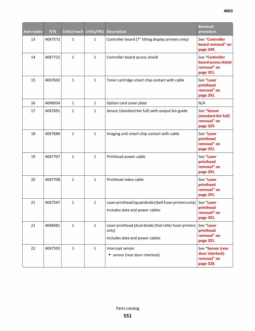
Asm-index P/N Units/mach Units/FRU DescriptionRemovalprocedure
13 40X7572 1 1 Controller board (7” tilting display printers only) See “Controllerboard removal” onpage 349.
14 40X7722 1 1 Controller board access shield See “Controllerboard access shieldremoval” onpage 351.
15 40X7692 1 1 Toner cartridge smart chip contact with cable See “Laserprintheadremoval” onpage 291.
16 40X8034 1 1 Option card cover plate N/A
17 40X7691 1 1 Sensor (standard bin full) with output bin guide See “Sensor(standard bin full)removal” onpage 329.
18 40X7689 1 1 Imaging unit smart chip contact with cable See “Laserprintheadremoval” onpage 291.
19 40X7707 1 1 Printhead power cable See “Laserprintheadremoval” onpage 291.
20 40X7708 1 1 Printhead video cable See “Laserprintheadremoval” onpage 291.
21 40X7597 1 1 Laser printhead (quad diode) (belt fuser printers only)
Includes data and power cables
See “Laserprintheadremoval” onpage 291.
21 40X8481 1 1 Laser printhead (dual diode) (hot roller fuser printersonly)
Includes data and power cables
See “Laserprintheadremoval” onpage 291.
22 40X7592 1 1 Interrupt sensor
• sensor (rear door interlock)
See “Sensor (reardoor interlock)removal” onpage 328.
4063
Parts catalog
551

4063
Parts catalog
552

Assembly 5: Drive motors
1112
4063
Parts catalog
553
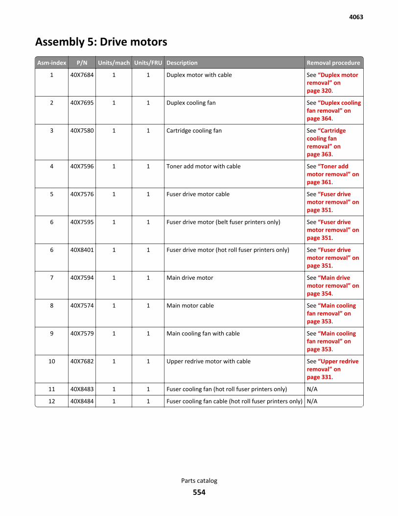
Assembly 5: Drive motors
Asm-index P/N Units/mach Units/FRU Description Removal procedure
1 40X7684 1 1 Duplex motor with cable See “Duplex motorremoval” onpage 320.
2 40X7695 1 1 Duplex cooling fan See “Duplex coolingfan removal” onpage 364.
3 40X7580 1 1 Cartridge cooling fan See “Cartridgecooling fanremoval” onpage 363.
4 40X7596 1 1 Toner add motor with cable See “Toner addmotor removal” onpage 361.
5 40X7576 1 1 Fuser drive motor cable See “Fuser drivemotor removal” onpage 351.
6 40X7595 1 1 Fuser drive motor (belt fuser printers only) See “Fuser drivemotor removal” onpage 351.
6 40X8401 1 1 Fuser drive motor (hot roll fuser printers only) See “Fuser drivemotor removal” onpage 351.
7 40X7594 1 1 Main drive motor See “Main drivemotor removal” onpage 354.
8 40X7574 1 1 Main motor cable See “Main coolingfan removal” onpage 353.
9 40X7579 1 1 Main cooling fan with cable See “Main coolingfan removal” onpage 353.
10 40X7682 1 1 Upper redrive motor with cable See “Upper redriveremoval” onpage 331.
11 40X8483 1 1 Fuser cooling fan (hot roll fuser printers only) N/A
12 40X8484 1 1 Fuser cooling fan cable (hot roll fuser printers only) N/A
4063
Parts catalog
554
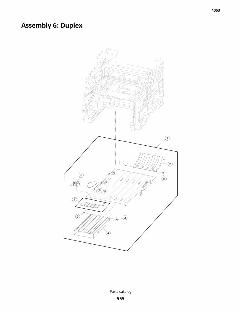
Assembly 6: Duplex
4063
Parts catalog
555
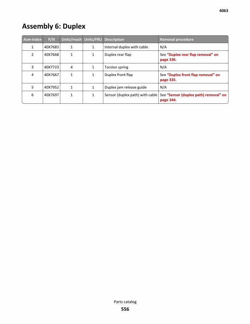
Assembly 6: Duplex
Asm-index P/N Units/mach Units/FRU Description Removal procedure
1 40X7683 1 1 Internal duplex with cable N/A
2 40X7668 1 1 Duplex rear flap See “Duplex rear flap removal” onpage 336.
3 40X7723 4 1 Torsion spring N/A
4 40X7667 1 1 Duplex front flap See “Duplex front flap removal” onpage 335.
5 40X7952 1 1 Duplex jam release guide N/A
6 40X7697 1 1 Sensor (duplex path) with cable See “Sensor (duplex path) removal” onpage 344.
4063
Parts catalog
556
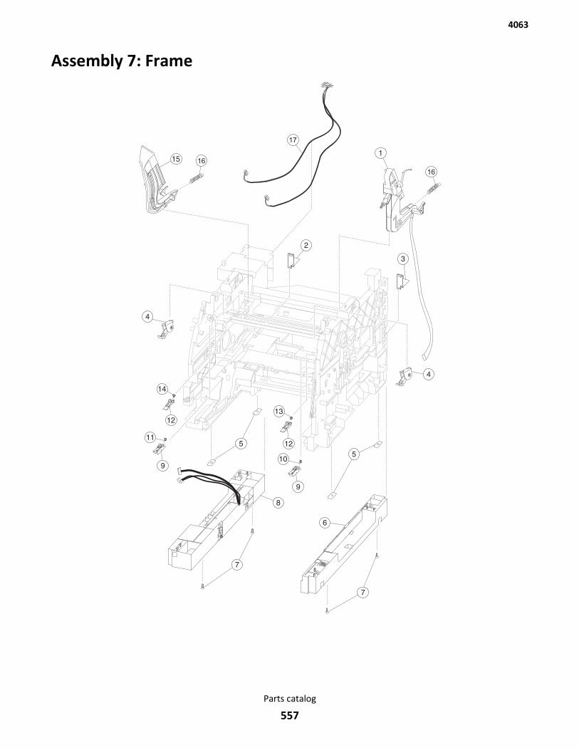
Assembly 7: Frame
16
16
17
4063
Parts catalog
557
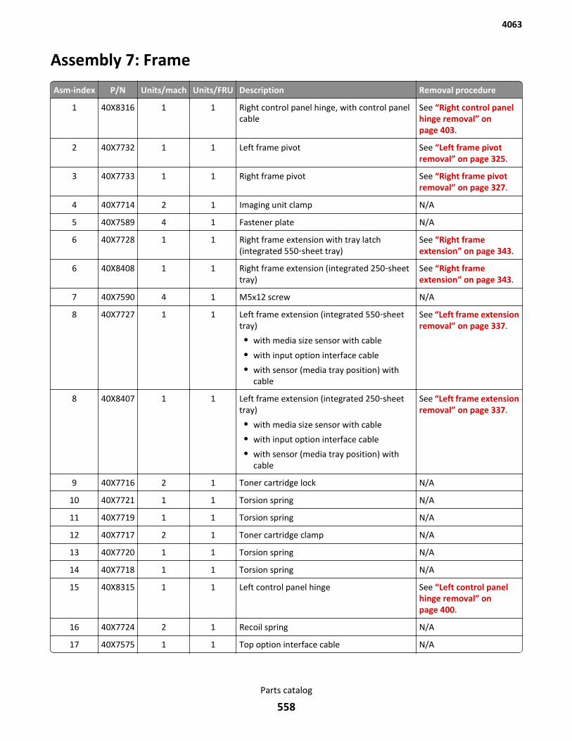
Assembly 7: Frame
Asm-index P/N Units/mach Units/FRU Description Removal procedure
1 40X8316 1 1 Right control panel hinge, with control panelcable
See “Right control panelhinge removal” onpage 403.
2 40X7732 1 1 Left frame pivot See “Left frame pivotremoval” on page 325.
3 40X7733 1 1 Right frame pivot See “Right frame pivotremoval” on page 327.
4 40X7714 2 1 Imaging unit clamp N/A
5 40X7589 4 1 Fastener plate N/A
6 40X7728 1 1 Right frame extension with tray latch(integrated 550‑sheet tray)
See “Right frameextension” on page 343.
6 40X8408 1 1 Right frame extension (integrated 250‑sheettray)
See “Right frameextension” on page 343.
7 40X7590 4 1 M5x12 screw N/A
8 40X7727 1 1 Left frame extension (integrated 550‑sheettray)
• with media size sensor with cable
• with input option interface cable
• with sensor (media tray position) withcable
See “Left frame extensionremoval” on page 337.
8 40X8407 1 1 Left frame extension (integrated 250‑sheettray)
• with media size sensor with cable
• with input option interface cable
• with sensor (media tray position) withcable
See “Left frame extensionremoval” on page 337.
9 40X7716 2 1 Toner cartridge lock N/A
10 40X7721 1 1 Torsion spring N/A
11 40X7719 1 1 Torsion spring N/A
12 40X7717 2 1 Toner cartridge clamp N/A
13 40X7720 1 1 Torsion spring N/A
14 40X7718 1 1 Torsion spring N/A
15 40X8315 1 1 Left control panel hinge See “Left control panelhinge removal” onpage 400.
16 40X7724 2 1 Recoil spring N/A
17 40X7575 1 1 Top option interface cable N/A
4063
Parts catalog
558
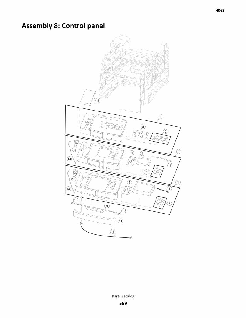
Assembly 8: Control panel
9
10
17
6
7
7
8
5
11
12
13
14
14
15
15
16
4063
Parts catalog
559
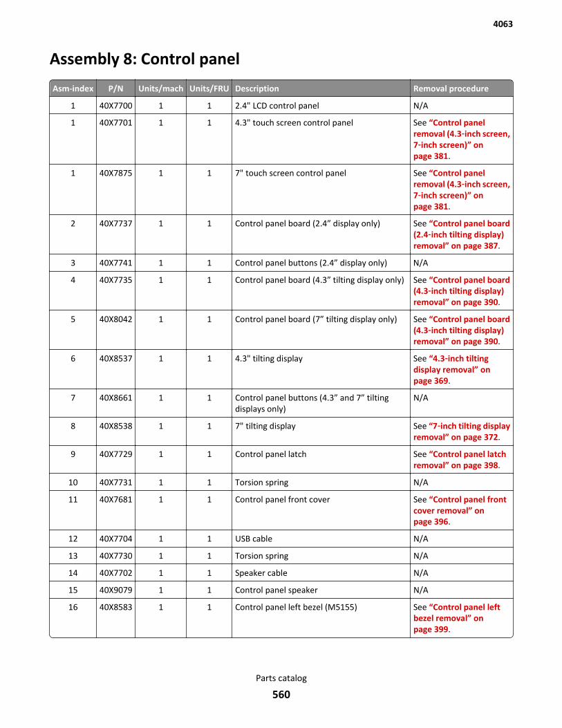
Assembly 8: Control panel
Asm-index P/N Units/mach Units/FRU Description Removal procedure
1 40X7700 1 1 2.4" LCD control panel N/A
1 40X7701 1 1 4.3" touch screen control panel See “Control panelremoval (4.3‑inch screen,7‑inch screen)” onpage 381.
1 40X7875 1 1 7" touch screen control panel See “Control panelremoval (4.3‑inch screen,7‑inch screen)” onpage 381.
2 40X7737 1 1 Control panel board (2.4” display only) See “Control panel board(2.4‑inch tilting display)removal” on page 387.
3 40X7741 1 1 Control panel buttons (2.4” display only) N/A
4 40X7735 1 1 Control panel board (4.3” tilting display only) See “Control panel board(4.3‑inch tilting display)removal” on page 390.
5 40X8042 1 1 Control panel board (7” tilting display only) See “Control panel board(4.3‑inch tilting display)removal” on page 390.
6 40X8537 1 1 4.3" tilting display See “4.3‑inch tiltingdisplay removal” onpage 369.
7 40X8661 1 1 Control panel buttons (4.3” and 7” tiltingdisplays only)
N/A
8 40X8538 1 1 7" tilting display See “7‑inch tilting displayremoval” on page 372.
9 40X7729 1 1 Control panel latch See “Control panel latchremoval” on page 398.
10 40X7731 1 1 Torsion spring N/A
11 40X7681 1 1 Control panel front cover See “Control panel frontcover removal” onpage 396.
12 40X7704 1 1 USB cable N/A
13 40X7730 1 1 Torsion spring N/A
14 40X7702 1 1 Speaker cable N/A
15 40X9079 1 1 Control panel speaker N/A
16 40X8583 1 1 Control panel left bezel (M5155) See “Control panel leftbezel removal” onpage 399.
4063
Parts catalog
560
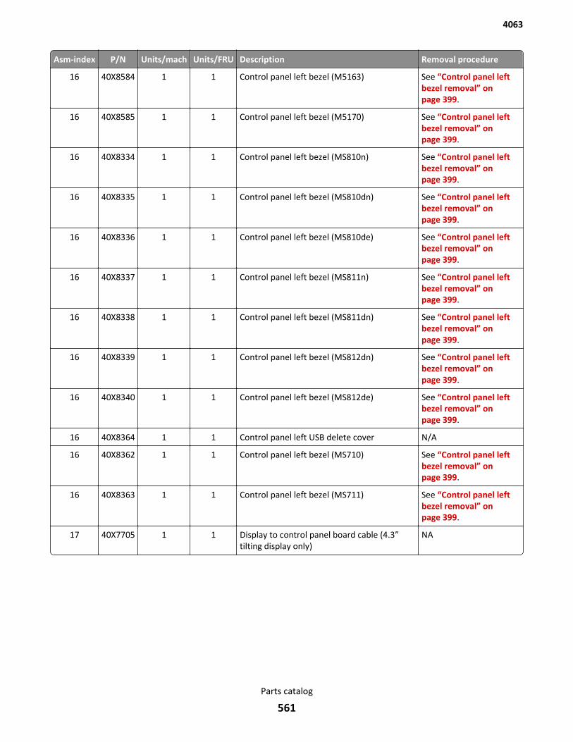
Asm-index P/N Units/mach Units/FRU Description Removal procedure
16 40X8584 1 1 Control panel left bezel (M5163) See “Control panel leftbezel removal” onpage 399.
16 40X8585 1 1 Control panel left bezel (M5170) See “Control panel leftbezel removal” onpage 399.
16 40X8334 1 1 Control panel left bezel (MS810n) See “Control panel leftbezel removal” onpage 399.
16 40X8335 1 1 Control panel left bezel (MS810dn) See “Control panel leftbezel removal” onpage 399.
16 40X8336 1 1 Control panel left bezel (MS810de) See “Control panel leftbezel removal” onpage 399.
16 40X8337 1 1 Control panel left bezel (MS811n) See “Control panel leftbezel removal” onpage 399.
16 40X8338 1 1 Control panel left bezel (MS811dn) See “Control panel leftbezel removal” onpage 399.
16 40X8339 1 1 Control panel left bezel (MS812dn) See “Control panel leftbezel removal” onpage 399.
16 40X8340 1 1 Control panel left bezel (MS812de) See “Control panel leftbezel removal” onpage 399.
16 40X8364 1 1 Control panel left USB delete cover N/A
16 40X8362 1 1 Control panel left bezel (MS710) See “Control panel leftbezel removal” onpage 399.
16 40X8363 1 1 Control panel left bezel (MS711) See “Control panel leftbezel removal” onpage 399.
17 40X7705 1 1 Display to control panel board cable (4.3”tilting display only)
NA
4063
Parts catalog
561

4063
Parts catalog
562
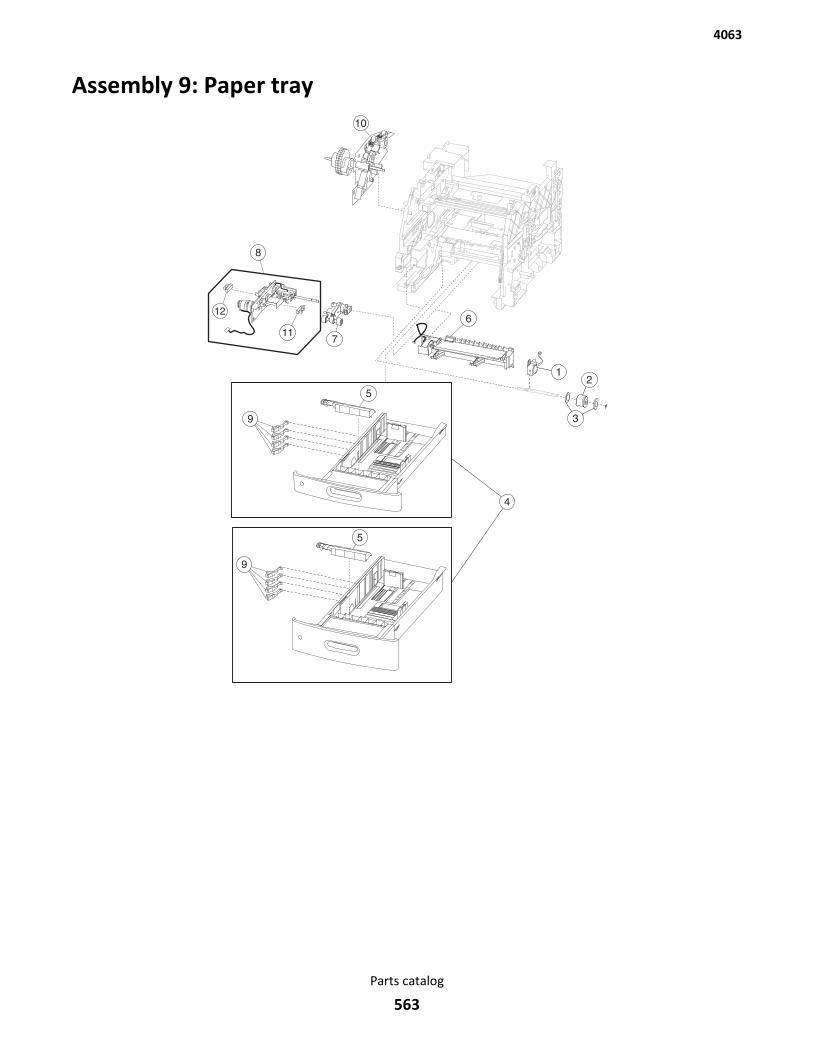
Assembly 9: Paper tray
STAT
DL
7.75
A5/A6
C5
#10
JIS B5
EXEC
LTR
A4
FOLIO
OFC
LGL
STAT
DL
7.75
A5/A6
C5
#10
JIS B5
EXEC
LTR
A4
FOLIO
OFC
LGL
10
12
11
9
9
4063
Parts catalog
563
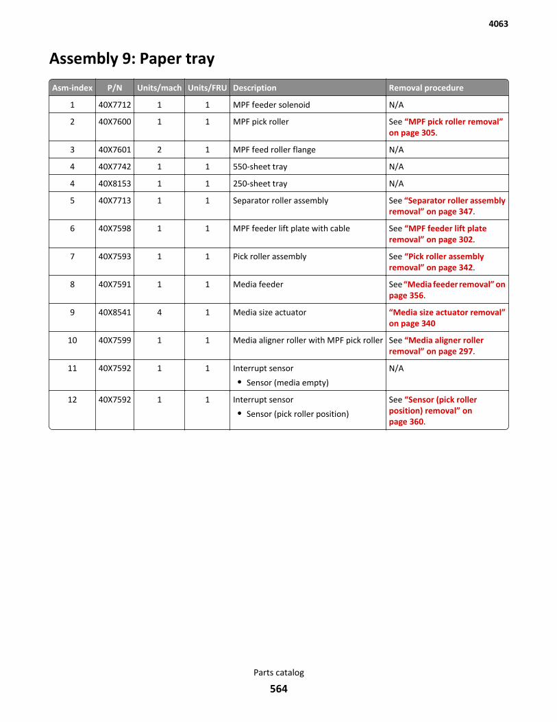
Assembly 9: Paper tray
Asm-index P/N Units/mach Units/FRU Description Removal procedure
1 40X7712 1 1 MPF feeder solenoid N/A
2 40X7600 1 1 MPF pick roller See “MPF pick roller removal”on page 305.
3 40X7601 2 1 MPF feed roller flange N/A
4 40X7742 1 1 550-sheet tray N/A
4 40X8153 1 1 250-sheet tray N/A
5 40X7713 1 1 Separator roller assembly See “Separator roller assemblyremoval” on page 347.
6 40X7598 1 1 MPF feeder lift plate with cable See “MPF feeder lift plateremoval” on page 302.
7 40X7593 1 1 Pick roller assembly See “Pick roller assemblyremoval” on page 342.
8 40X7591 1 1 Media feeder See “Media feeder removal” onpage 356.
9 40X8541 4 1 Media size actuator “Media size actuator removal”on page 340
10 40X7599 1 1 Media aligner roller with MPF pick roller See “Media aligner rollerremoval” on page 297.
11 40X7592 1 1 Interrupt sensor
• Sensor (media empty)
N/A
12 40X7592 1 1 Interrupt sensor
• Sensor (pick roller position)
See “Sensor (pick rollerposition) removal” onpage 360.
4063
Parts catalog
564
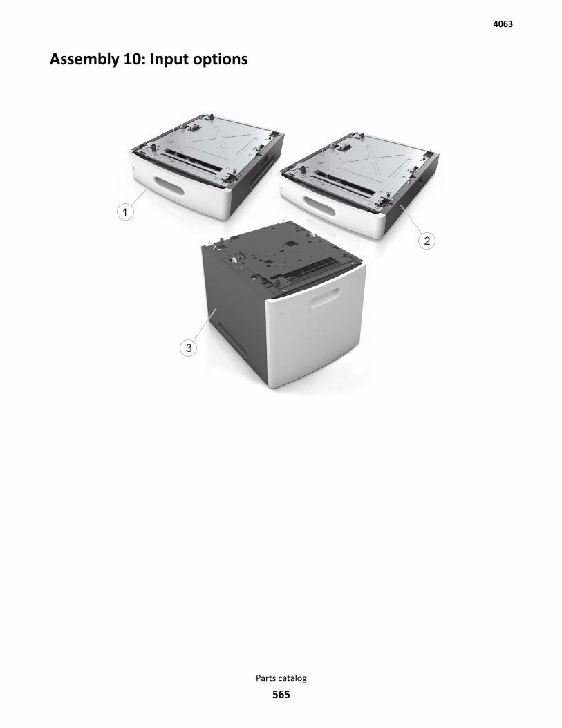
Assembly 10: Input options
1
2
3
4063
Parts catalog
565
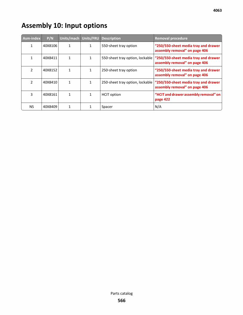
Assembly 10: Input options
Asm-index P/N Units/mach Units/FRU Description Removal procedure
1 40X8106 1 1 550‑sheet tray option “250/550-sheet media tray and drawerassembly removal” on page 406
1 40X8411 1 1 550‑sheet tray option, lockable “250/550-sheet media tray and drawerassembly removal” on page 406
2 40X8152 1 1 250‑sheet tray option “250/550-sheet media tray and drawerassembly removal” on page 406
2 40X8410 1 1 250‑sheet tray option, lockable “250/550-sheet media tray and drawerassembly removal” on page 406
3 40X8161 1 1 HCIT option “HCIT and drawer assembly removal” onpage 422
NS 40X8409 1 1 Spacer N/A
4063
Parts catalog
566
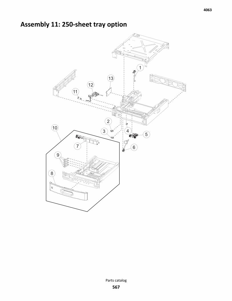
Assembly 11: 250-sheet tray option
4063
Parts catalog
567
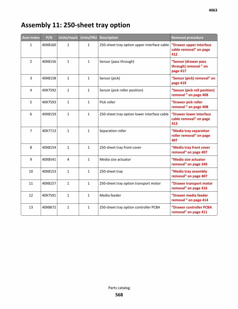
Assembly 11: 250-sheet tray option
Asm-index P/N Units/mach Units/FRU Description Removal procedure
1 40X8160 1 1 250-sheet tray option upper interface cable “Drawer upper interfacecable removal” on page 412
2 40X8156 1 1 Sensor (pass through) “Sensor (drawer passthrough) removal ” onpage 417
3 40X8158 1 1 Sensor (pick) “Sensor (pick) removal” onpage 419
4 40X7592 1 1 Sensor (pick roller position) “Sensor (pick roll position)removal ” on page 408
5 40X7593 1 1 Pick roller “Drawer pick rollerremoval ” on page 408
6 40X8159 1 1 250-sheet tray option lower interface cable “Drawer lower interfacecable removal” on page 413
7 40X7713 1 1 Separation roller “Media tray separationroller removal” on page 407
8 40X8154 1 1 250-sheet tray front cover “Media tray front coverremoval” on page 407
9 40X8541 4 1 Media size actuator “Media size actuatorremoval” on page 340
10 40X8153 1 1 250-sheet tray “Media tray assemblyremoval” on page 407
11 40X8157 1 1 250-sheet tray option transport motor “Drawer transport motorremoval” on page 416
12 40X7591 1 1 Media feeder “Drawer media feederremoval ” on page 414
13 40X8672 1 1 250-sheet tray option controller PCBA “Drawer controller PCBAremoval” on page 411
4063
Parts catalog
568
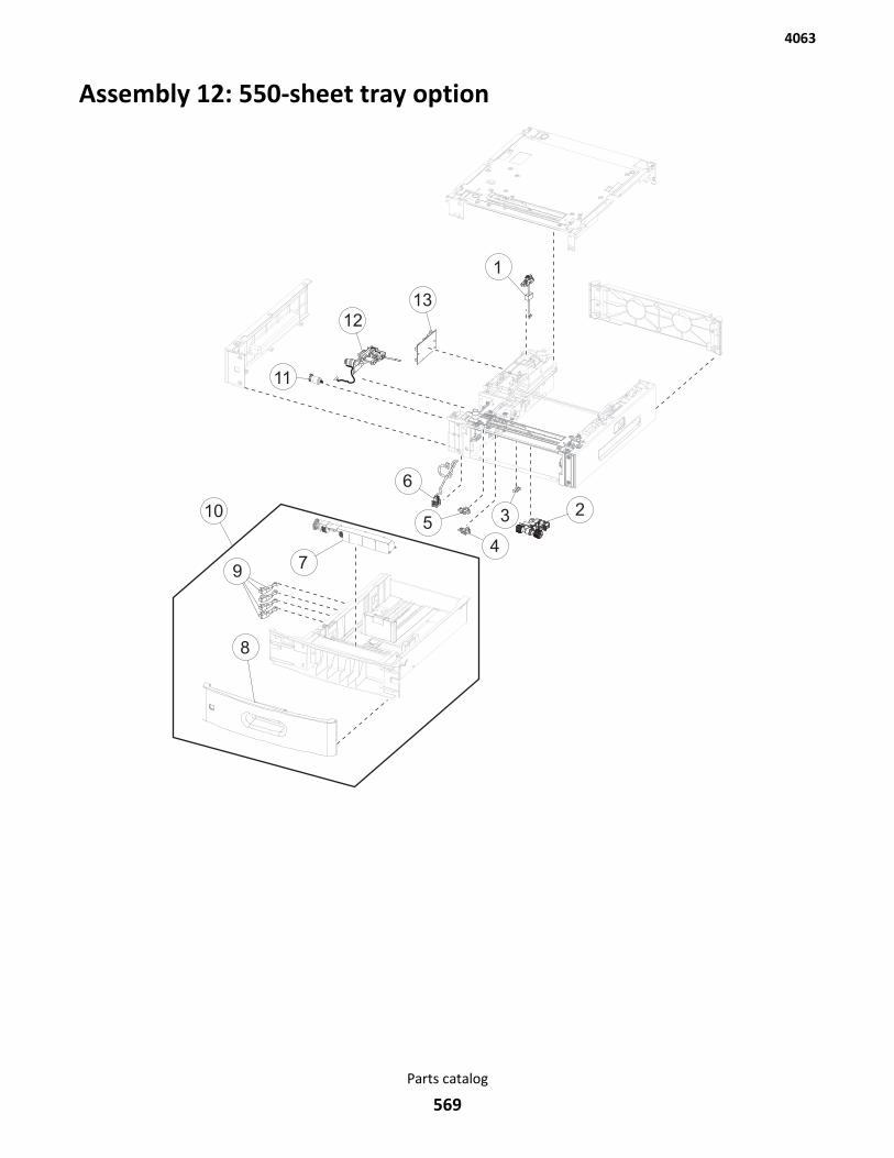
Assembly 12: 550-sheet tray option
4063
Parts catalog
569

Assembly 12: 550-sheet tray option
Asm-index P/N Units/mach Units/FRU Description Removal procedure
1 40X8160 1 1 550-sheet tray option upper interface cable “Drawer upper interfacecable removal” on page 412
2 40X7593 1 1 Pick roller “Drawer pick rollerremoval ” on page 408
3 40X7592 1 1 Sensor (pick roller position) “Sensor (pick roll position)removal ” on page 408
4 40X8158 1 1 Sensor (pick) “Sensor (pick) removal” onpage 419
5 40X8156 1 1 Sensor (pass through) “Sensor (drawer passthrough) removal ” onpage 417
6 40X8159 1 1 550-sheet tray option lower interface cable “Drawer lower interfacecable removal” on page 413
7 40X7713 1 1 Separation roller “Media tray separationroller removal” on page 407
8 40X8109 1 1 550-sheet tray front cover “Media tray front coverremoval” on page 407
9 40X8541 4 1 Media size actuator “Media size actuatorremoval” on page 340
10 40X7742 1 1 550-sheet tray “Media tray assemblyremoval” on page 407
11 40X8157 1 1 550-sheet tray option transport motor “Drawer transport motorremoval” on page 416
12 40X7591 1 1 Media feeder “Drawer media feederremoval ” on page 414
13 40X8155 1 1 550-sheet tray option controller PCBA “Drawer controller PCBAremoval” on page 411
4063
Parts catalog
570
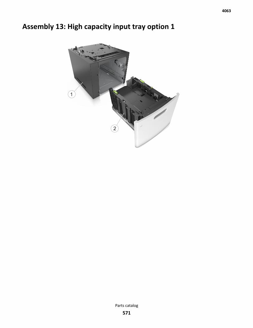
Assembly 13: High capacity input tray option 1
1
2
4063
Parts catalog
571

Assembly 13: High capacity input tray option 1
Asm-index P/N Units/mach Units/FRU Description Removal procedure
1 40X8163 1 1 HCIT drawer assembly See “HCIT drawer assembly removal” on page 423
2 40X8165 1 1 HCIT See “HCIT removal” on page 423
4063
Parts catalog
572
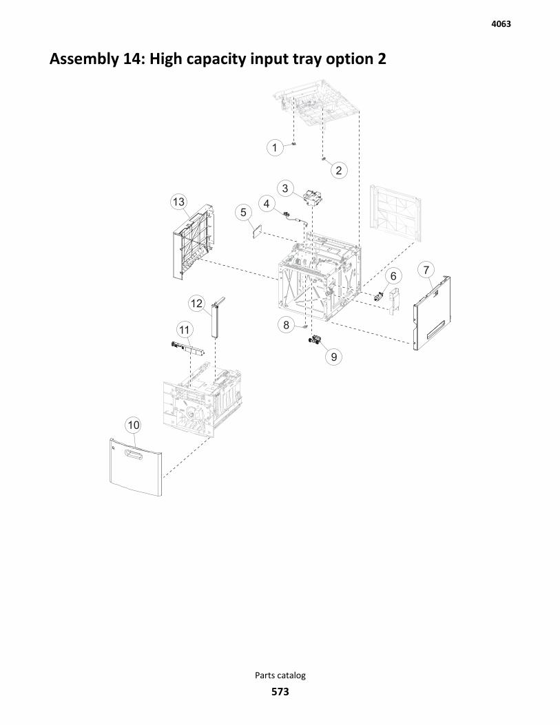
Assembly 14: High capacity input tray option 2
3
54
67
9
13
811
12
10
1
2
4063
Parts catalog
573
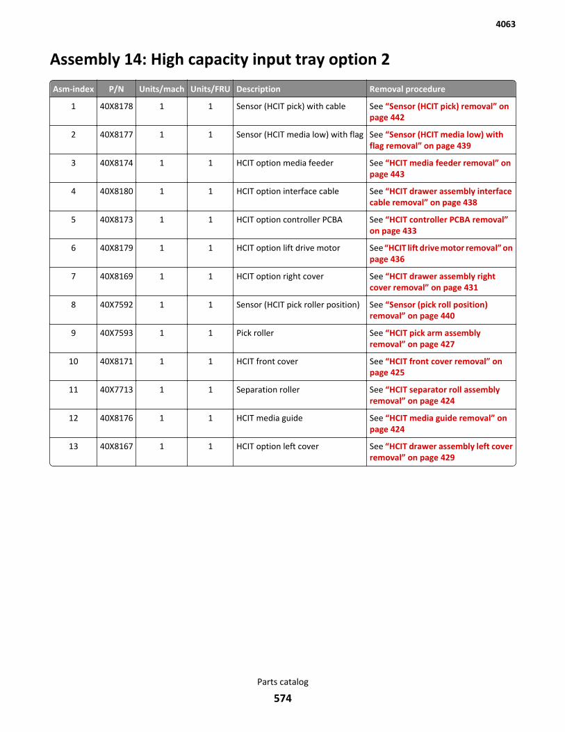
Assembly 14: High capacity input tray option 2
Asm-index P/N Units/mach Units/FRU Description Removal procedure
1 40X8178 1 1 Sensor (HCIT pick) with cable See “Sensor (HCIT pick) removal” onpage 442
2 40X8177 1 1 Sensor (HCIT media low) with flag See “Sensor (HCIT media low) withflag removal” on page 439
3 40X8174 1 1 HCIT option media feeder See “HCIT media feeder removal” onpage 443
4 40X8180 1 1 HCIT option interface cable See “HCIT drawer assembly interfacecable removal” on page 438
5 40X8173 1 1 HCIT option controller PCBA See “HCIT controller PCBA removal”on page 433
6 40X8179 1 1 HCIT option lift drive motor See “HCIT lift drive motor removal” onpage 436
7 40X8169 1 1 HCIT option right cover See “HCIT drawer assembly rightcover removal” on page 431
8 40X7592 1 1 Sensor (HCIT pick roller position) See “Sensor (pick roll position)removal” on page 440
9 40X7593 1 1 Pick roller See “HCIT pick arm assemblyremoval” on page 427
10 40X8171 1 1 HCIT front cover See “HCIT front cover removal” onpage 425
11 40X7713 1 1 Separation roller See “HCIT separator roll assemblyremoval” on page 424
12 40X8176 1 1 HCIT media guide See “HCIT media guide removal” onpage 424
13 40X8167 1 1 HCIT option left cover See “HCIT drawer assembly left coverremoval” on page 429
4063
Parts catalog
574

Assembly 15: Output options
2
1
3
4
4063
Parts catalog
575
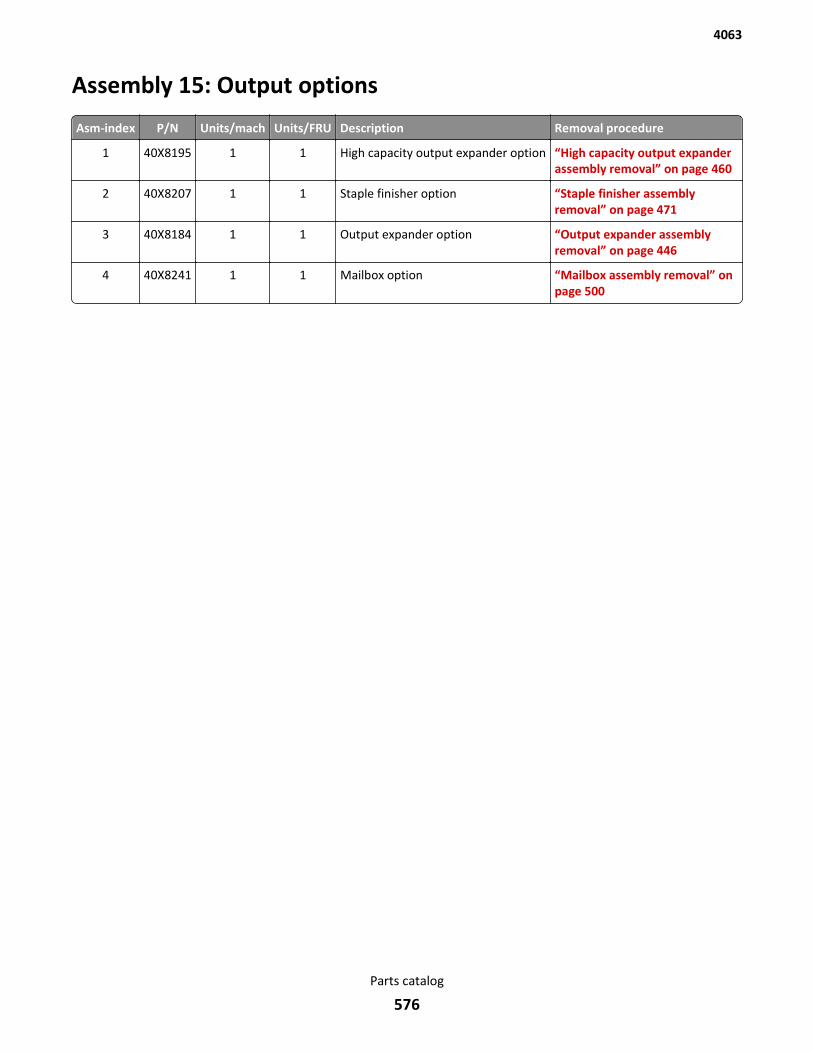
Assembly 15: Output options
Asm-index P/N Units/mach Units/FRU Description Removal procedure
1 40X8195 1 1 High capacity output expander option “High capacity output expanderassembly removal” on page 460
2 40X8207 1 1 Staple finisher option “Staple finisher assemblyremoval” on page 471
3 40X8184 1 1 Output expander option “Output expander assemblyremoval” on page 446
4 40X8241 1 1 Mailbox option “Mailbox assembly removal” onpage 500
4063
Parts catalog
576
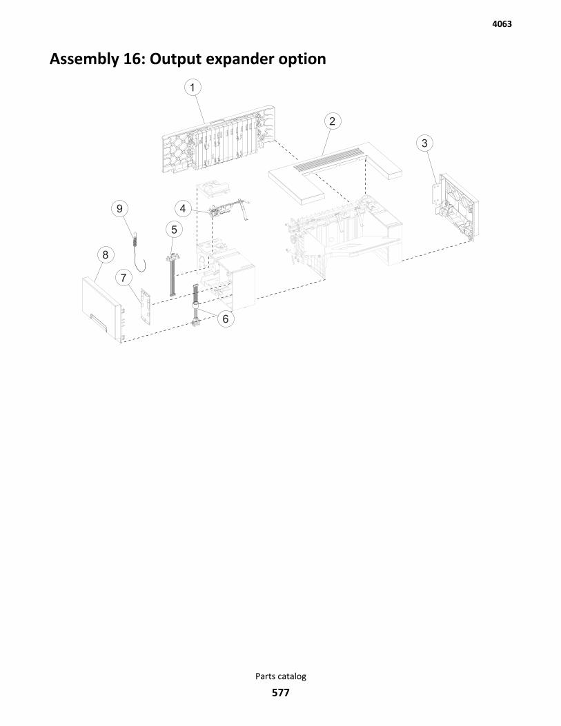
Assembly 16: Output expander option
1
2
3
4
5
6
8
7
9
4063
Parts catalog
577
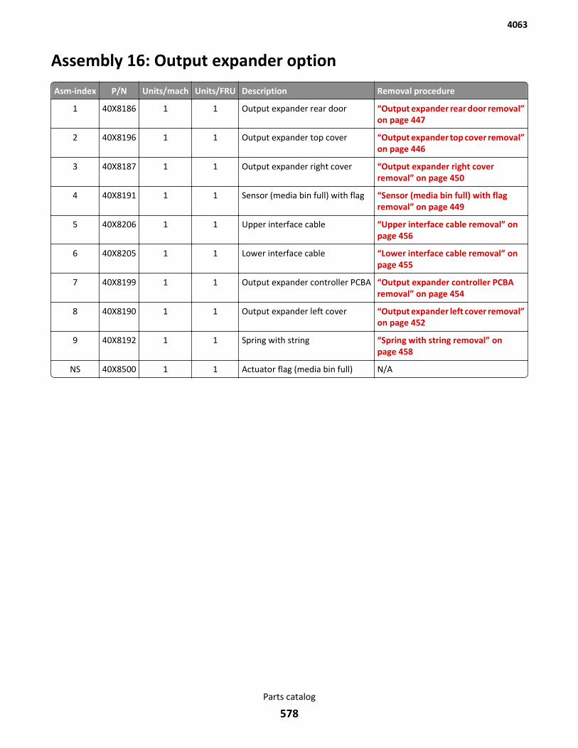
Assembly 16: Output expander option
Asm-index P/N Units/mach Units/FRU Description Removal procedure
1 40X8186 1 1 Output expander rear door “Output expander rear door removal”on page 447
2 40X8196 1 1 Output expander top cover “Output expander top cover removal”on page 446
3 40X8187 1 1 Output expander right cover “Output expander right coverremoval” on page 450
4 40X8191 1 1 Sensor (media bin full) with flag “Sensor (media bin full) with flagremoval” on page 449
5 40X8206 1 1 Upper interface cable “Upper interface cable removal” onpage 456
6 40X8205 1 1 Lower interface cable “Lower interface cable removal” onpage 455
7 40X8199 1 1 Output expander controller PCBA “Output expander controller PCBAremoval” on page 454
8 40X8190 1 1 Output expander left cover “Output expander left cover removal”on page 452
9 40X8192 1 1 Spring with string “Spring with string removal” onpage 458
NS 40X8500 1 1 Actuator flag (media bin full) N/A
4063
Parts catalog
578
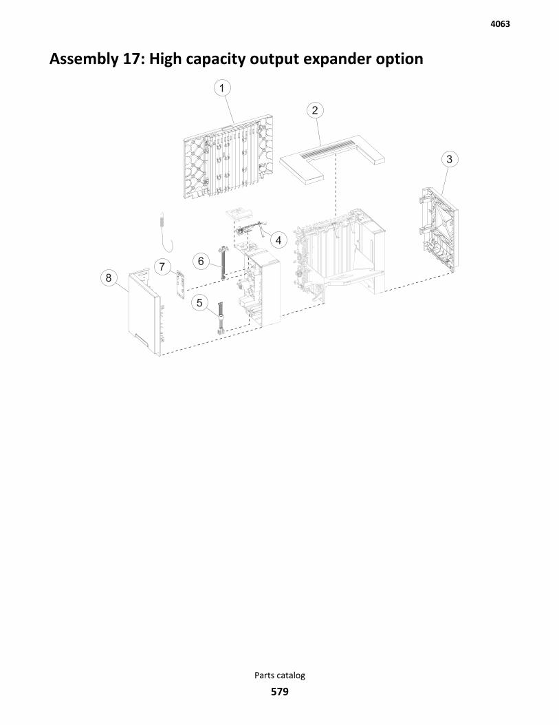
Assembly 17: High capacity output expander option
1
2
3
5
6
4
78
4063
Parts catalog
579
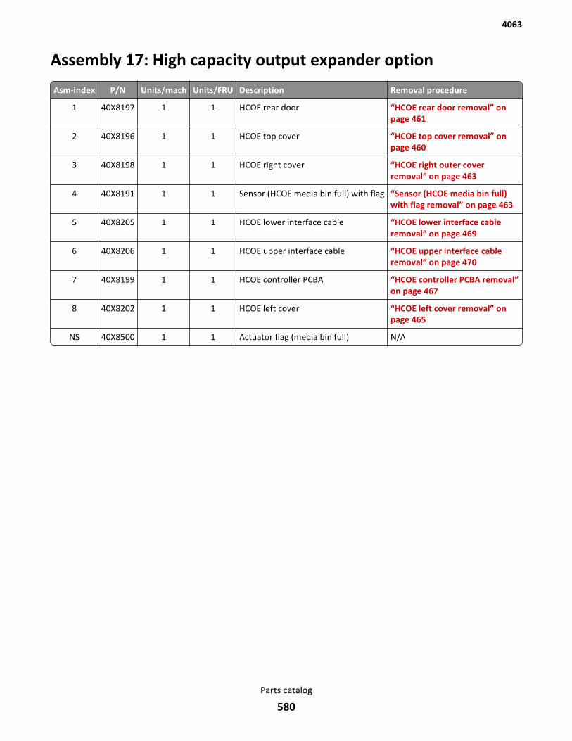
Assembly 17: High capacity output expander option
Asm-index P/N Units/mach Units/FRU Description Removal procedure
1 40X8197 1 1 HCOE rear door “HCOE rear door removal” onpage 461
2 40X8196 1 1 HCOE top cover “HCOE top cover removal” onpage 460
3 40X8198 1 1 HCOE right cover “HCOE right outer coverremoval” on page 463
4 40X8191 1 1 Sensor (HCOE media bin full) with flag “Sensor (HCOE media bin full)with flag removal” on page 463
5 40X8205 1 1 HCOE lower interface cable “HCOE lower interface cableremoval” on page 469
6 40X8206 1 1 HCOE upper interface cable “HCOE upper interface cableremoval” on page 470
7 40X8199 1 1 HCOE controller PCBA “HCOE controller PCBA removal”on page 467
8 40X8202 1 1 HCOE left cover “HCOE left cover removal” onpage 465
NS 40X8500 1 1 Actuator flag (media bin full) N/A
4063
Parts catalog
580
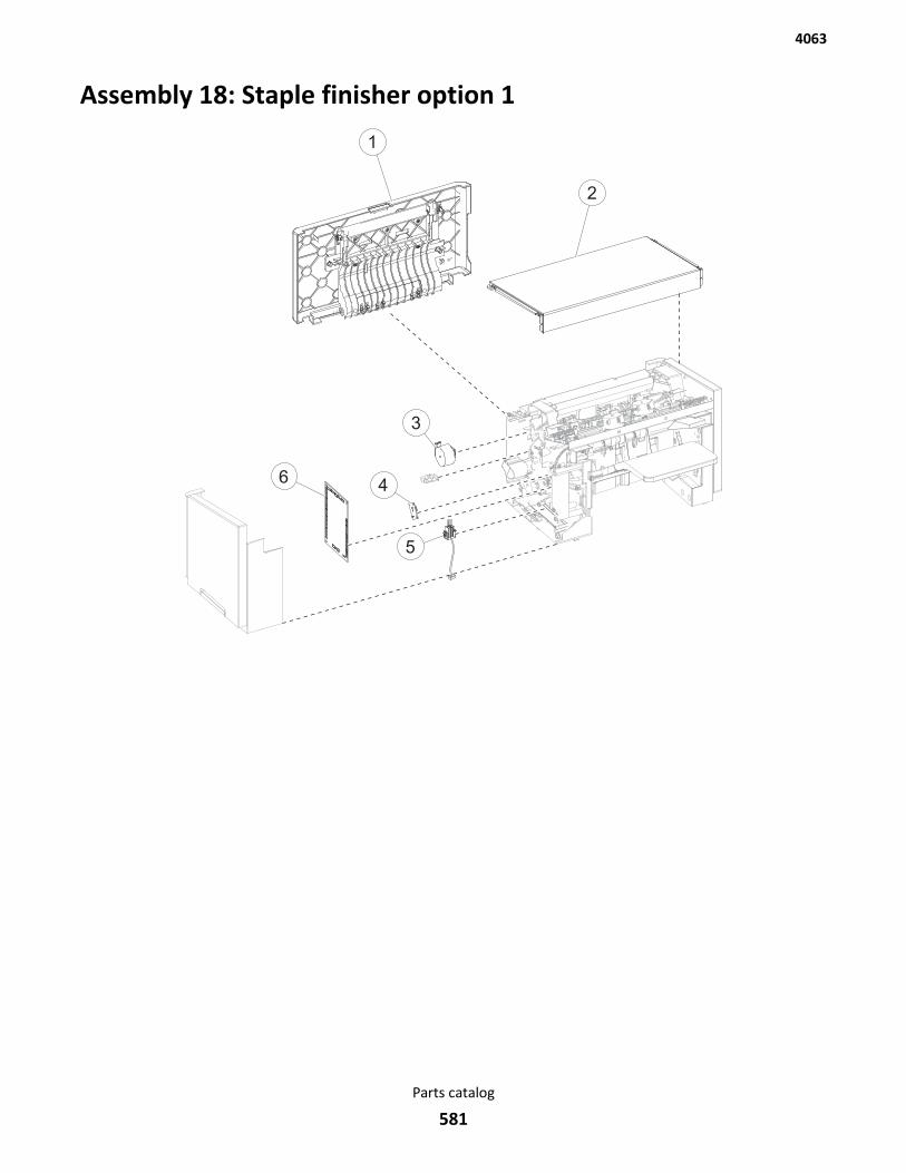
Assembly 18: Staple finisher option 1
5
1
2
3
46
4063
Parts catalog
581
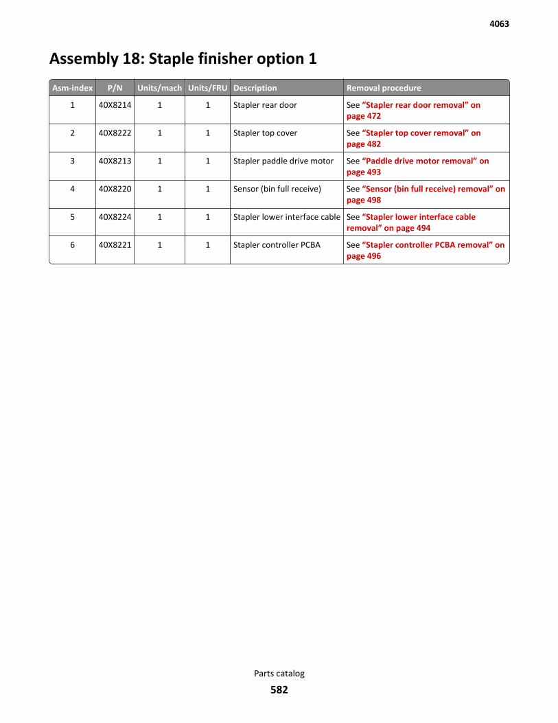
Assembly 18: Staple finisher option 1
Asm-index P/N Units/mach Units/FRU Description Removal procedure
1 40X8214 1 1 Stapler rear door See “Stapler rear door removal” onpage 472
2 40X8222 1 1 Stapler top cover See “Stapler top cover removal” onpage 482
3 40X8213 1 1 Stapler paddle drive motor See “Paddle drive motor removal” onpage 493
4 40X8220 1 1 Sensor (bin full receive) See “Sensor (bin full receive) removal” onpage 498
5 40X8224 1 1 Stapler lower interface cable See “Stapler lower interface cableremoval” on page 494
6 40X8221 1 1 Stapler controller PCBA See “Stapler controller PCBA removal” onpage 496
4063
Parts catalog
582
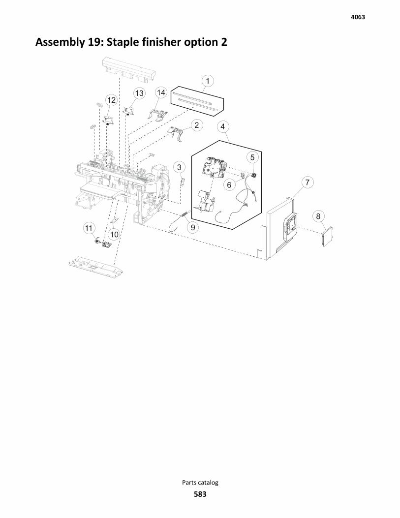
Assembly 19: Staple finisher option 2
1
4
5
6 7
8
3
1011
2
1213 14
9
4063
Parts catalog
583

Assembly 19: Staple finisher option 2
Asm-index P/N Units/mach Units/FRU Description Removal procedure
1 40X8212 1 1 Tamper drive belt “Tamper drive belt removal” onpage 492
2 40X8209 1 1 Media stack flap (right) “Media stack flap (right) removal”on page 485
3 40X8217 1 1 Sensor (bin full send) “Sensor (bin full send) removal” onpage 497
4 40X8223 1 1 Stapler carriage assembly “Stapler carriage assemblyremoval” on page 479
5 40X8225 1 1 Stapler door close limit switch “Stapler door close limit switchremoval” on page 476
6 40X7592 1 1 Sensor (cartridge door interlock) “Sensor (cartridge door interlock)removal” on page 476
7 40X8216 1 1 Stapler right cover “Stapler right cover removal” onpage 474
8 40X8215 1 1 Stapler cartridge access door “Stapler cartridge access doorremoval” on page 482
9 40X8226 1 1 Stapler spring with string “Stapler spring with string removal”on page 484
10 40X8218 1 1 Standard output bin LED “Standard output bin LED removal”on page 489
11 40X8219 1 1 Sensor (finisher bin media present) “Sensor (finisher bin media present)removal” on page 490
12 40X8211 1 1 Tamper motor (left) “Tamper motor (left) removal” onpage 491
13 40X8211 1 1 Tamper motor (right) “Tamper motor (right) removal” onpage 491
14 40X8210 1 1 Media stack flap (left) “Media stack flap (left) removal” onpage 486
4063
Parts catalog
584
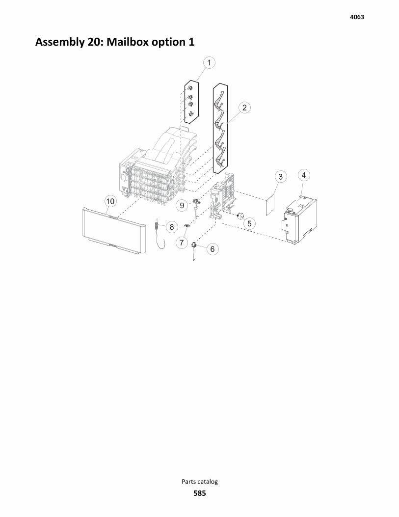
Assembly 20: Mailbox option 1
1
2
3 4
5
67
10
8
9
4063
Parts catalog
585
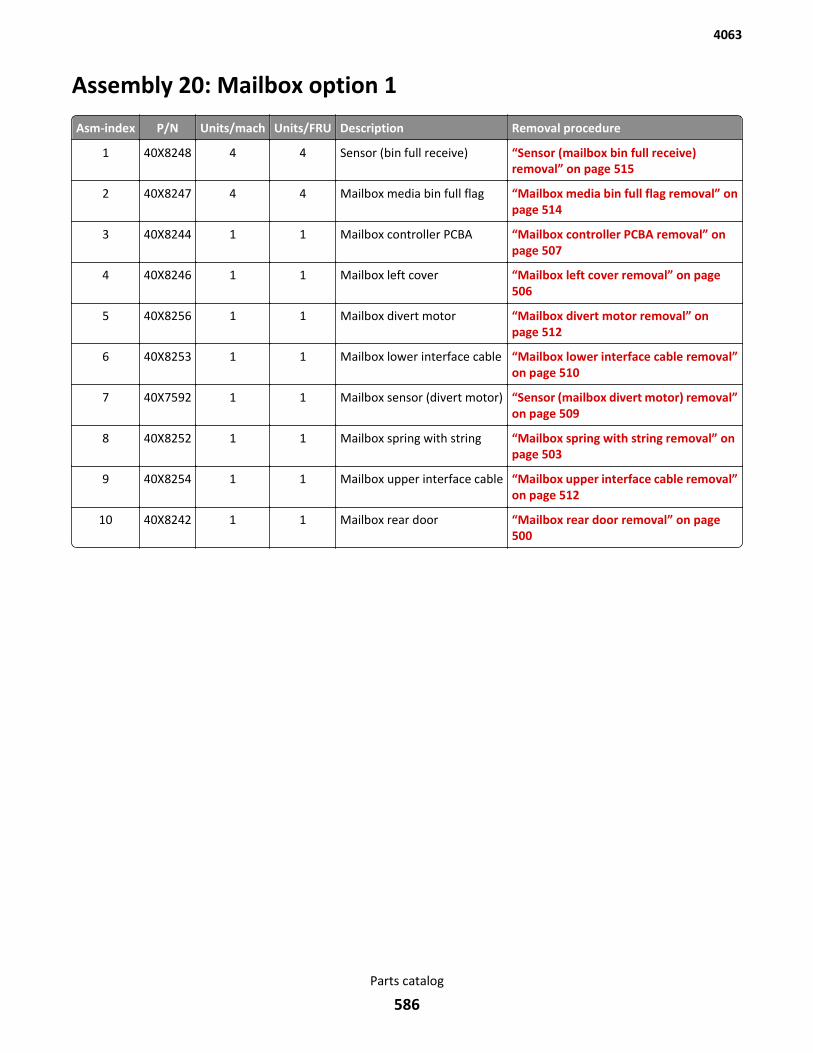
Assembly 20: Mailbox option 1
Asm-index P/N Units/mach Units/FRU Description Removal procedure
1 40X8248 4 4 Sensor (bin full receive) “Sensor (mailbox bin full receive)removal” on page 515
2 40X8247 4 4 Mailbox media bin full flag “Mailbox media bin full flag removal” onpage 514
3 40X8244 1 1 Mailbox controller PCBA “Mailbox controller PCBA removal” onpage 507
4 40X8246 1 1 Mailbox left cover “Mailbox left cover removal” on page 506
5 40X8256 1 1 Mailbox divert motor “Mailbox divert motor removal” onpage 512
6 40X8253 1 1 Mailbox lower interface cable “Mailbox lower interface cable removal”on page 510
7 40X7592 1 1 Mailbox sensor (divert motor) “Sensor (mailbox divert motor) removal”on page 509
8 40X8252 1 1 Mailbox spring with string “Mailbox spring with string removal” onpage 503
9 40X8254 1 1 Mailbox upper interface cable “Mailbox upper interface cable removal”on page 512
10 40X8242 1 1 Mailbox rear door “Mailbox rear door removal” on page 500
4063
Parts catalog
586
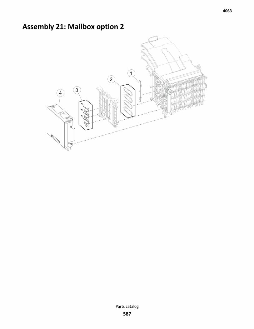
Assembly 21: Mailbox option 2
1
34
2
4063
Parts catalog
587
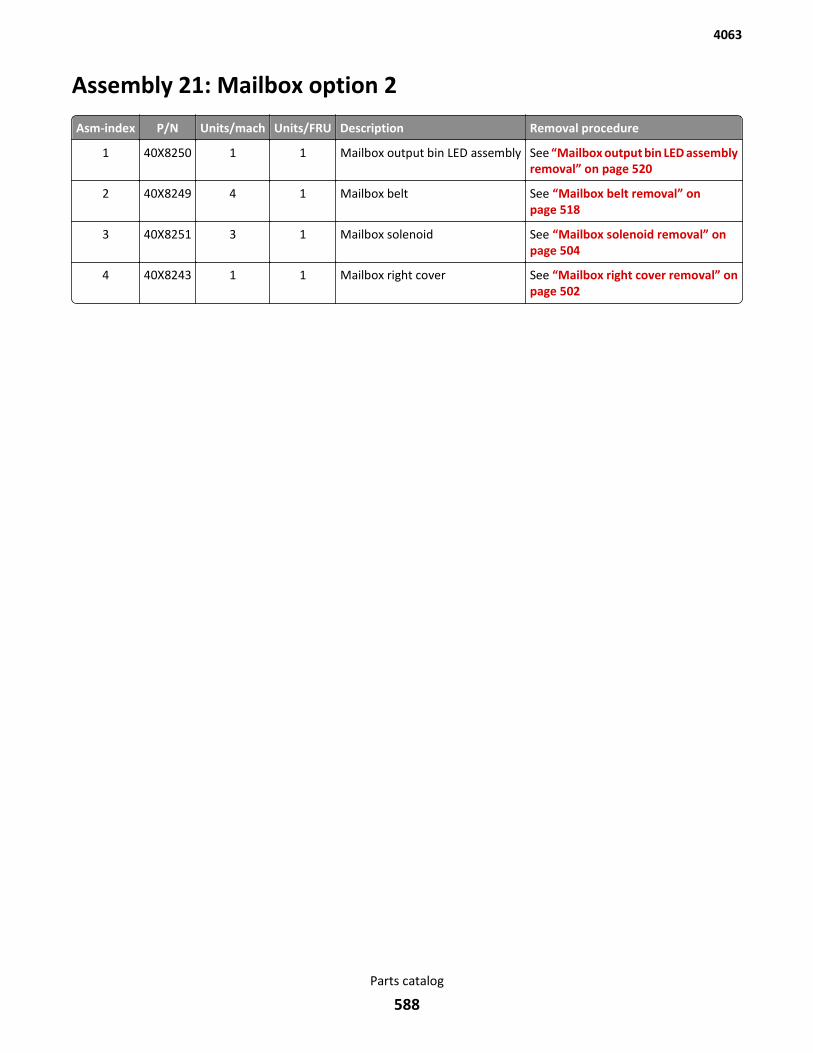
Assembly 21: Mailbox option 2
Asm-index P/N Units/mach Units/FRU Description Removal procedure
1 40X8250 1 1 Mailbox output bin LED assembly See “Mailbox output bin LED assemblyremoval” on page 520
2 40X8249 4 1 Mailbox belt See “Mailbox belt removal” onpage 518
3 40X8251 3 1 Mailbox solenoid See “Mailbox solenoid removal” onpage 504
4 40X8243 1 1 Mailbox right cover See “Mailbox right cover removal” onpage 502
4063
Parts catalog
588

Assembly 22: Miscellaneous
Asm-index P/N Units/mach Units/FRU DescriptionRemovalprocedure
NS 40X4819 1 1 RS232C serial adapter N/A
NS 40X5315 1 1 SHIP-WITH ISP (2PER) screw N/A
NS 40X5316 1 1 14 PIN JST-FOR ISP cable N/A
NS 40X5317 1 1 Tee with thumbscrew standoff N/A
NS 40X4826 1 1 N8120 GIGABIT INA adapter N/A
NS 40X5315 1 1 SHIP-WITH ISP (2PER) screw N/A
NS 40X5316 1 1 14 PIN JST-FOR ISP cable N/A
NS 40X5317 1 1 Tee with thumbscrew standoff N/A
NS 40X4823 1 1 Parallel 1284-B THCK adapter N/A
NS 40X5315 1 1 SHIP-WITH ISP (2PER) screw N/A
NS 40X5316 1 1 14 PIN JST-FOR ISP cable N/A
NS 40X5317 1 1 Tee with thumbscrew standoff N/A
NS 40X4827 1 1 N8130 10/100 fiber adapter N/A
NS 40X5315 1 1 SHIP-WITH ISP (2PER) screw N/A
NS 40X5316 1 1 14 PIN JST-FOR ISP cable N/A
NS 40X5317 1 1 Tee with thumbscrew standoff N/A
NS 40X6522 1 1 DDR3-512Mx16 1GB-400MHZ RAM card N/A
NS 40X7445 1 1 DDR3-512Mx32 2GB RAM card N/A
NS 40X7566 1 1 DDR3-256Mx16 512MB-400MHZ RAM card N/A
NS 40X7567 1 1 DDR3-256Mx32 1GB-400MHZ RAM card N/A
NS 40X8555 1 1 256MB user flash card N/A
NS 40X8556 1 1 Traditional Chinese font card N/A
NS 40X8557 1 1 Simplified Chinese font card N/A
NS 40X8568 1 1 Korean font card N/A
NS 40X8569 1 1 Japanese font card N/A
NS 40X8594 1 1 MS810/1/2 forms and barcode card N/A
NS 40X8597 1 1 MS810de forms and barcode card N/A
NS 40X8600 1 1 MS812de forms and barcode card N/A
NS 40X8596 1 1 MS81xn prescribe card N/A
NS 40X8599 1 1 MS810de prescribe card N/A
NS 40X8602 1 1 MS812de prescribe card N/A
NS 40X8595 1 1 MS81xn IPDS card N/A
4063
Parts catalog
589
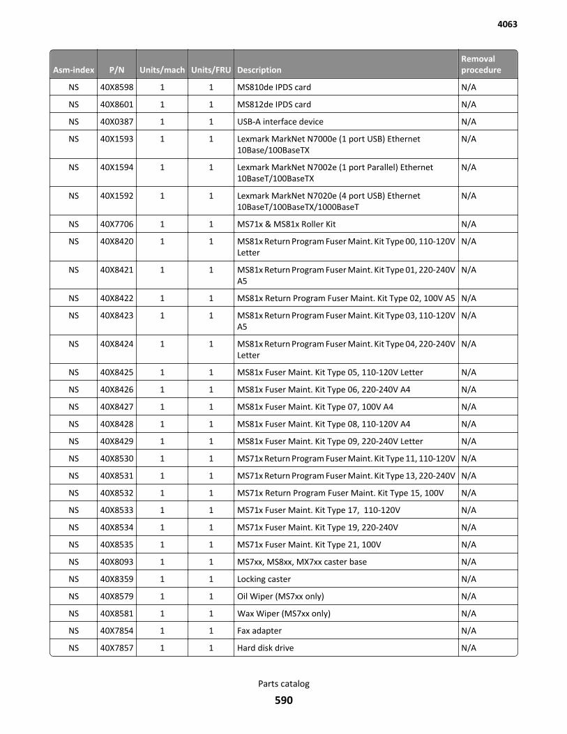
Asm-index P/N Units/mach Units/FRU DescriptionRemovalprocedure
NS 40X8598 1 1 MS810de IPDS card N/A
NS 40X8601 1 1 MS812de IPDS card N/A
NS 40X0387 1 1 USB-A interface device N/A
NS 40X1593 1 1 Lexmark MarkNet N7000e (1 port USB) Ethernet10Base/100BaseTX
N/A
NS 40X1594 1 1 Lexmark MarkNet N7002e (1 port Parallel) Ethernet10BaseT/100BaseTX
N/A
NS 40X1592 1 1 Lexmark MarkNet N7020e (4 port USB) Ethernet10BaseT/100BaseTX/1000BaseT
N/A
NS 40X7706 1 1 MS71x & MS81x Roller Kit N/A
NS 40X8420 1 1 MS81x Return Program Fuser Maint. Kit Type 00, 110-120VLetter
N/A
NS 40X8421 1 1 MS81x Return Program Fuser Maint. Kit Type 01, 220-240VA5
N/A
NS 40X8422 1 1 MS81x Return Program Fuser Maint. Kit Type 02, 100V A5 N/A
NS 40X8423 1 1 MS81x Return Program Fuser Maint. Kit Type 03, 110-120VA5
N/A
NS 40X8424 1 1 MS81x Return Program Fuser Maint. Kit Type 04, 220-240VLetter
N/A
NS 40X8425 1 1 MS81x Fuser Maint. Kit Type 05, 110-120V Letter N/A
NS 40X8426 1 1 MS81x Fuser Maint. Kit Type 06, 220-240V A4 N/A
NS 40X8427 1 1 MS81x Fuser Maint. Kit Type 07, 100V A4 N/A
NS 40X8428 1 1 MS81x Fuser Maint. Kit Type 08, 110-120V A4 N/A
NS 40X8429 1 1 MS81x Fuser Maint. Kit Type 09, 220-240V Letter N/A
NS 40X8530 1 1 MS71x Return Program Fuser Maint. Kit Type 11, 110-120V N/A
NS 40X8531 1 1 MS71x Return Program Fuser Maint. Kit Type 13, 220-240V N/A
NS 40X8532 1 1 MS71x Return Program Fuser Maint. Kit Type 15, 100V N/A
NS 40X8533 1 1 MS71x Fuser Maint. Kit Type 17, 110-120V N/A
NS 40X8534 1 1 MS71x Fuser Maint. Kit Type 19, 220-240V N/A
NS 40X8535 1 1 MS71x Fuser Maint. Kit Type 21, 100V N/A
NS 40X8093 1 1 MS7xx, MS8xx, MX7xx caster base N/A
NS 40X8359 1 1 Locking caster N/A
NS 40X8579 1 1 Oil Wiper (MS7xx only) N/A
NS 40X8581 1 1 Wax Wiper (MS7xx only) N/A
NS 40X7854 1 1 Fax adapter N/A
NS 40X7857 1 1 Hard disk drive N/A
4063
Parts catalog
590

Asm-index P/N Units/mach Units/FRU DescriptionRemovalprocedure
NS 40X7858 1 1 Network adapter 802.11 US N/A
NS 40X8311 1 1 Case card reader—small stick‑on N/A
NS 40X8312 1 1 Case card reader—large stick‑on N/A
NS 40X8313 1 1 Case card reader—small snap‑on N/A
4063
Parts catalog
591

4063
Parts catalog
592
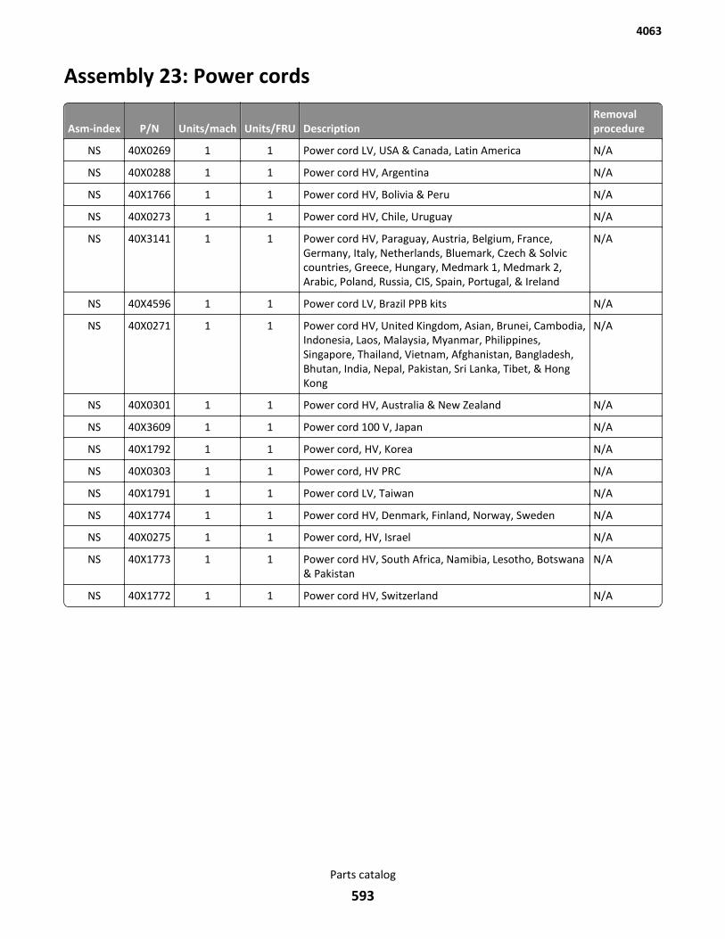
Assembly 23: Power cords
Asm-index P/N Units/mach Units/FRU DescriptionRemovalprocedure
NS 40X0269 1 1 Power cord LV, USA & Canada, Latin America N/A
NS 40X0288 1 1 Power cord HV, Argentina N/A
NS 40X1766 1 1 Power cord HV, Bolivia & Peru N/A
NS 40X0273 1 1 Power cord HV, Chile, Uruguay N/A
NS 40X3141 1 1 Power cord HV, Paraguay, Austria, Belgium, France,Germany, Italy, Netherlands, Bluemark, Czech & Solviccountries, Greece, Hungary, Medmark 1, Medmark 2,Arabic, Poland, Russia, CIS, Spain, Portugal, & Ireland
N/A
NS 40X4596 1 1 Power cord LV, Brazil PPB kits N/A
NS 40X0271 1 1 Power cord HV, United Kingdom, Asian, Brunei, Cambodia,Indonesia, Laos, Malaysia, Myanmar, Philippines,Singapore, Thailand, Vietnam, Afghanistan, Bangladesh,Bhutan, India, Nepal, Pakistan, Sri Lanka, Tibet, & HongKong
N/A
NS 40X0301 1 1 Power cord HV, Australia & New Zealand N/A
NS 40X3609 1 1 Power cord 100 V, Japan N/A
NS 40X1792 1 1 Power cord, HV, Korea N/A
NS 40X0303 1 1 Power cord, HV PRC N/A
NS 40X1791 1 1 Power cord LV, Taiwan N/A
NS 40X1774 1 1 Power cord HV, Denmark, Finland, Norway, Sweden N/A
NS 40X0275 1 1 Power cord, HV, Israel N/A
NS 40X1773 1 1 Power cord HV, South Africa, Namibia, Lesotho, Botswana& Pakistan
N/A
NS 40X1772 1 1 Power cord HV, Switzerland N/A
4063
Parts catalog
593

4063
594
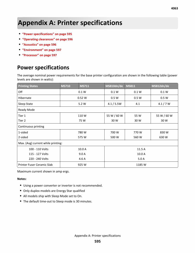
Appendix A: Printer specifications• “Power specifications” on page 595
• “Operating clearances” on page 596
• “Acoustics” on page 596
• “Environment” on page 597
• “Processor” on page 597
Power specificationsThe average nominal power requirements for the base printer configuration are shown in the following table (powerlevels are shown in watts):
Printing States MS710 MS711 MS810dn/de MS811 MS812dn/de
Off 0.1 W 0.1 W 0.1 W 0.1 W
Hibernate 0.52 W 0.5 W 0.5 W 0.5 W
Sleep State 5.2 W 4.1 / 5.5W 4.1 4.1 / 7 W
Ready Mode
Tier 1
Tier 2
110 W
75 W
55 W / 60 W
30 W
55 W
30 W
55 W / 60 W
30 W
Continuous printing
1‑sided
2‑sided
780 W
575 W
700 W
500 W
770 W
560 W
830 W
630 W
Max. (Avg) current while printing:
100 - 110 Volts
115 - 127 Volts
220 - 240 Volts
10.0 A
9.0 A
4.6 A
11.5 A
10.0 A
5.0 A
Printer Fuser Ceramic Slab 925 W 1185 W
Maximum current shown in amp ergs.
Notes:
• Using a power converter or inverter is not recommended.
• Only duplex models are Energy Star qualified
• All models ship with Sleep Mode set to On.
• The default time-out to Sleep mode is 30 minutes.
4063
Appendix A: Printer specifications
595
Operating clearances1 Top 115 mm (4.5 in.)
2 Right 305 mm (12 in.)
3 Front 508 mm (20 in.)
4 Left 305 mm (12 in.)
5 Rear 305 mm (12 in.)
Allow additional clearance around the printer for adding options, clearing misfeeds,and changing toner cartridges and imaging units.
AcousticsAll measurements are made in accordance with ISO 7779 and conform with ISO 9296.
Acoustic measurements
Status 1 Meter average sound pressure (dBA) Declared sound power level (Bels)
MS810
Idle (Standby mode) 32 4.8
Quiet mode 53 6.8
Simplex printing 53 6.8
Duplex printing 57 7.2
MS811
Idle (Standby mode) 32 4.7
Quiet mode 53 6.8
Simplex printing 58 7.3
Duplex printing 57 7.2
MS812
Idle (Standby mode) 32 4.7
Quiet mode 53 6.8
Simplex printing 58 7.3
Duplex printing 58 7.3
Measurements apply to 300 dpi, 600 dpi, and 1200 dpi printing.
4063
Appendix A: Printer specifications
596

EnvironmentPrinter Temperature and Humidity
• Operating
– Temperature: 60 to 90° F (15.6 to 32.2° C)
– Relative humidity: 8 to 80%
– Maximum wet bulb temperature: 73° F (22.8° C)
– Altitude: 9,500 ft. (0 to 2896 meters)
– Atmospheric pressure: 74.6 kPa
• Power off
– Temperature: 50 to 110° F (10 to 43.3° C)
– Relative humidity: 8 to 80%
– Maximum wet bulb temperature: 80.1° F (26.7° C)
– Altitude: 9,500 ft. (0 to 2896 meters)
– Atmospheric pressure: 74.6 kPa
• Ambient operating environment*
– Temperature: 60 to 90° F (15.6 to 32.2° C)
– Relative humidity: 8 to 80%
• Storage and shipping (packaged printer) with or without print cartridge
Temperature: -40 to 110° F (-40 to 43.3° C)
*In some cases, performance specifications (such as paper OCF, EP cartridge usage) are measured at an ambientcondition.
Processor800 MHz, dual core
4063
Appendix A: Printer specifications
597

4063
598
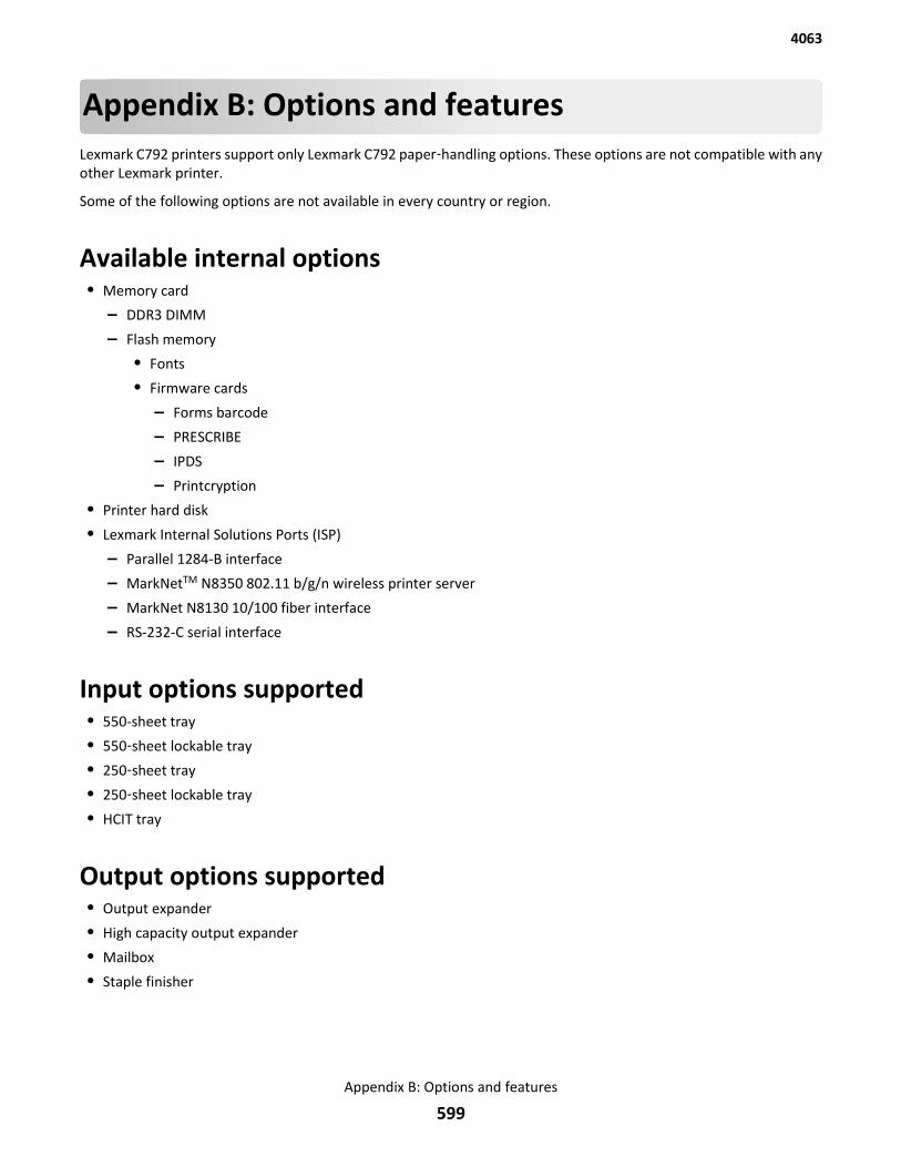
Appendix B: Options and featuresLexmark C792 printers support only Lexmark C792 paper‑handling options. These options are not compatible with anyother Lexmark printer.
Some of the following options are not available in every country or region.
Available internal options• Memory card
– DDR3 DIMM
– Flash memory
• Fonts
• Firmware cards
– Forms barcode
– PRESCRIBE
– IPDS
– Printcryption
• Printer hard disk
• Lexmark Internal Solutions Ports (ISP)
– Parallel 1284-B interface
– MarkNetTM N8350 802.11 b/g/n wireless printer server
– MarkNet N8130 10/100 fiber interface
– RS-232-C serial interface
Input options supported• 550-sheet tray
• 550‑sheet lockable tray
• 250‑sheet tray
• 250‑sheet lockable tray
• HCIT tray
Output options supported• Output expander
• High capacity output expander
• Mailbox
• Staple finisher
4063
Appendix B: Options and features
599
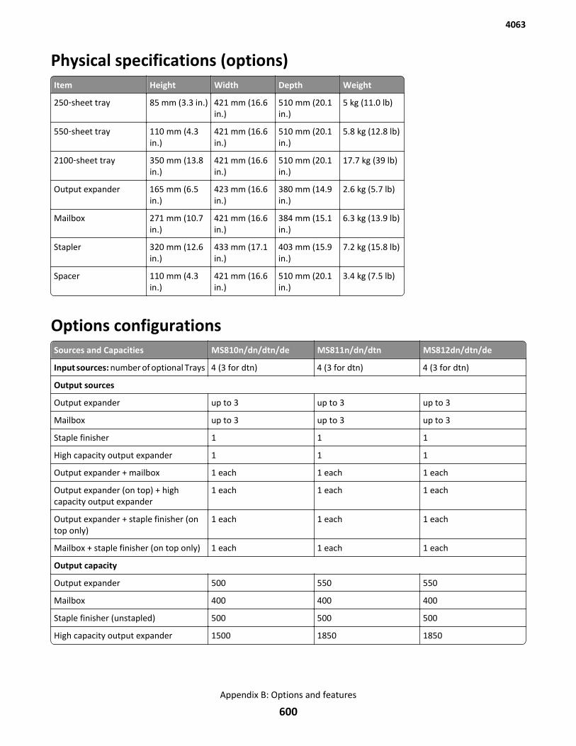
Physical specifications (options)Item Height Width Depth Weight
250‑sheet tray 85 mm (3.3 in.) 421 mm (16.6in.)
510 mm (20.1in.)
5 kg (11.0 lb)
550‑sheet tray 110 mm (4.3in.)
421 mm (16.6in.)
510 mm (20.1in.)
5.8 kg (12.8 lb)
2100‑sheet tray 350 mm (13.8in.)
421 mm (16.6in.)
510 mm (20.1in.)
17.7 kg (39 lb)
Output expander 165 mm (6.5in.)
423 mm (16.6in.)
380 mm (14.9in.)
2.6 kg (5.7 lb)
Mailbox 271 mm (10.7in.)
421 mm (16.6in.)
384 mm (15.1in.)
6.3 kg (13.9 lb)
Stapler 320 mm (12.6in.)
433 mm (17.1in.)
403 mm (15.9in.)
7.2 kg (15.8 lb)
Spacer 110 mm (4.3in.)
421 mm (16.6in.)
510 mm (20.1in.)
3.4 kg (7.5 lb)
Options configurationsSources and Capacities MS810n/dn/dtn/de MS811n/dn/dtn MS812dn/dtn/de
Input sources: number of optional Trays 4 (3 for dtn) 4 (3 for dtn) 4 (3 for dtn)
Output sources
Output expander up to 3 up to 3 up to 3
Mailbox up to 3 up to 3 up to 3
Staple finisher 1 1 1
High capacity output expander 1 1 1
Output expander + mailbox 1 each 1 each 1 each
Output expander (on top) + highcapacity output expander
1 each 1 each 1 each
Output expander + staple finisher (ontop only)
1 each 1 each 1 each
Mailbox + staple finisher (on top only) 1 each 1 each 1 each
Output capacity
Output expander 500 550 550
Mailbox 400 400 400
Staple finisher (unstapled) 500 500 500
High capacity output expander 1500 1850 1850
4063
Appendix B: Options and features
600

Appendix C: Theory of operation• “Models MS81x and MS71x paper path rollers and sensors” on page 602
• “Models MS81x and MS71x sensors” on page 603
• “Functions of main components - need a new title” on page 603
• “Media tray” on page 604
• “Multi-purpose feeder (MPF)” on page 604
• “Registration” on page 605
• “Duplex” on page 606
• “Transfer” on page 606
• “Printhead” on page 608
• “Fuser components” on page 609
• “Exit” on page 611
• “Drive” on page 612
• “Sensors” on page 614
• “Electrical components and controller” on page 614
• “Xerographic and print cartridge components” on page 616
• “Supported paper sizes, types, and weights” on page 620
• “Output options theory” on page 624
4063
Appendix C: Theory of operation
601

Models MS81x and MS71x paper path rollers and sensors
4063
Appendix C: Theory of operation
602
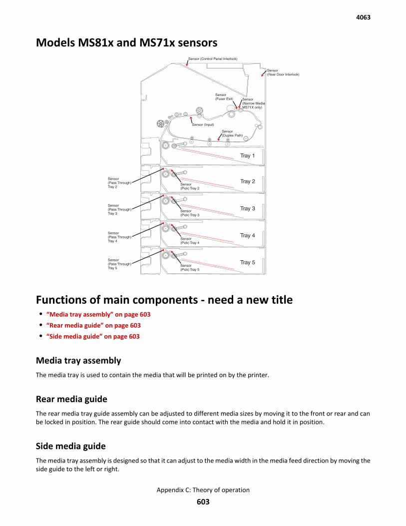
Models MS81x and MS71x sensors
Functions of main components - need a new title• “Media tray assembly” on page 603
• “Rear media guide” on page 603
• “Side media guide” on page 603
Media tray assemblyThe media tray is used to contain the media that will be printed on by the printer.
Rear media guideThe rear media tray guide assembly can be adjusted to different media sizes by moving it to the front or rear and canbe locked in position. The rear guide should come into contact with the media and hold it in position.
Side media guideThe media tray assembly is designed so that it can adjust to the media width in the media feed direction by moving theside guide to the left or right.
4063
Appendix C: Theory of operation
603
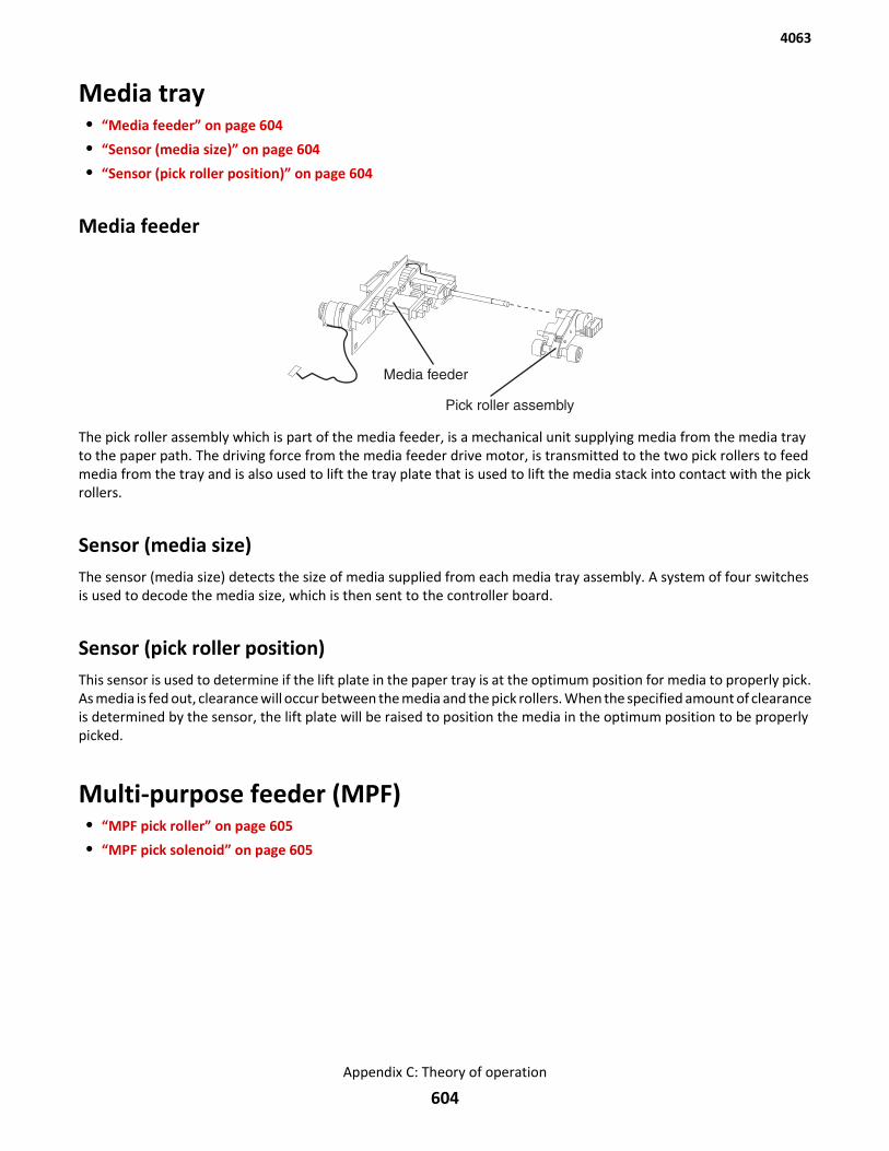
Media tray• “Media feeder” on page 604
• “Sensor (media size)” on page 604
• “Sensor (pick roller position)” on page 604
Media feeder
Media feeder
Pick roller assembly
The pick roller assembly which is part of the media feeder, is a mechanical unit supplying media from the media trayto the paper path. The driving force from the media feeder drive motor, is transmitted to the two pick rollers to feedmedia from the tray and is also used to lift the tray plate that is used to lift the media stack into contact with the pickrollers.
Sensor (media size)The sensor (media size) detects the size of media supplied from each media tray assembly. A system of four switchesis used to decode the media size, which is then sent to the controller board.
Sensor (pick roller position)This sensor is used to determine if the lift plate in the paper tray is at the optimum position for media to properly pick.As media is fed out, clearance will occur between the media and the pick rollers. When the specified amount of clearanceis determined by the sensor, the lift plate will be raised to position the media in the optimum position to be properlypicked.
Multi-purpose feeder (MPF)• “MPF pick roller” on page 605
• “MPF pick solenoid” on page 605
4063
Appendix C: Theory of operation
604
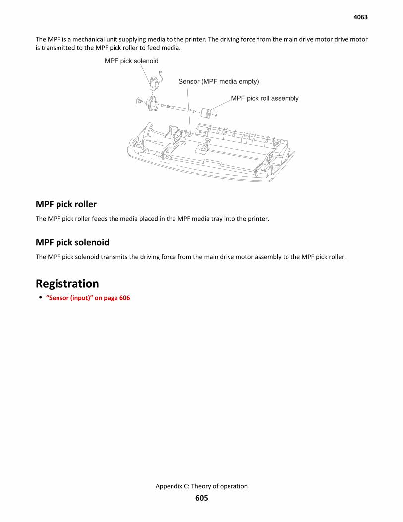
The MPF is a mechanical unit supplying media to the printer. The driving force from the main drive motor drive motoris transmitted to the MPF pick roller to feed media.
MPF pick rollerThe MPF pick roller feeds the media placed in the MPF media tray into the printer.
MPF pick solenoidThe MPF pick solenoid transmits the driving force from the main drive motor assembly to the MPF pick roller.
Registration• “Sensor (input)” on page 606
4063
Appendix C: Theory of operation
605
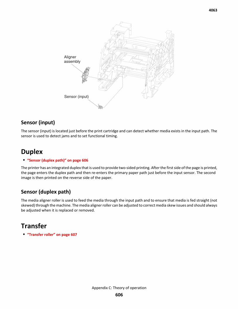
Sensor (input)The sensor (input) is located just before the print cartridge and can detect whether media exists in the input path. Thesensor is used to detect jams and to set functional timing.
Duplex• “Sensor (duplex path)” on page 606
The printer has an integrated duplex that is used to provide two-sided printing. After the first side of the page is printed,the page enters the duplex path and then re-enters the primary paper path just before the input sensor. The secondimage is then printed on the reverse side of the paper.
Sensor (duplex path)The media aligner roller is used to feed the media through the input path and to ensure that media is fed straight (notskewed) through the machine. The media aligner roller can be adjusted to correct media skew issues and should alwaysbe adjusted when it is replaced or removed.
Transfer• “Transfer roller” on page 607
4063
Appendix C: Theory of operation
606
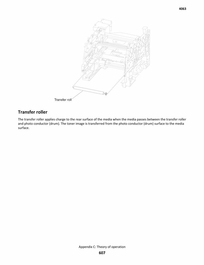
Transfer rollerThe transfer roller applies charge to the rear surface of the media when the media passes between the transfer rollerand photo conductor (drum). The toner image is transferred from the photo conductor (drum) surface to the mediasurface.
4063
Appendix C: Theory of operation
607
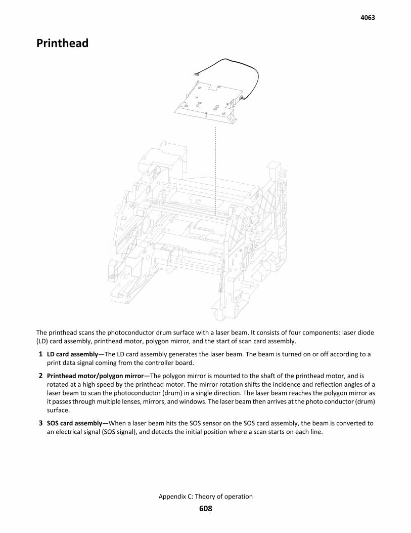
Printhead
The printhead scans the photoconductor drum surface with a laser beam. It consists of four components: laser diode(LD) card assembly, printhead motor, polygon mirror, and the start of scan card assembly.
1 LD card assembly—The LD card assembly generates the laser beam. The beam is turned on or off according to aprint data signal coming from the controller board.
2 Printhead motor/polygon mirror—The polygon mirror is mounted to the shaft of the printhead motor, and isrotated at a high speed by the printhead motor. The mirror rotation shifts the incidence and reflection angles of alaser beam to scan the photoconductor (drum) in a single direction. The laser beam reaches the polygon mirror asit passes through multiple lenses, mirrors, and windows. The laser beam then arrives at the photo conductor (drum)surface.
3 SOS card assembly—When a laser beam hits the SOS sensor on the SOS card assembly, the beam is converted toan electrical signal (SOS signal), and detects the initial position where a scan starts on each line.
4063
Appendix C: Theory of operation
608
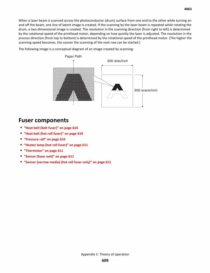
When a laser beam is scanned across the photoconductor (drum) surface from one end to the other while turning onand off the beam, one line of latent image is created. If the scanning by the laser beam is repeated while rotating thedrum, a two-dimensional image is created. The resolution in the scanning direction (from right to left) is determinedby the rotational speed of the printhead motor, depending on how quickly the laser is adjusted. The resolution in theprocess direction (from top to bottom) is determined by the rotational speed of the printhead motor. (The higher thescanning speed becomes, the sooner the scanning of the next row can be started.)
The following image is a conceptual diagram of an image created by scanning:
Fuser components• “Heat belt (belt fuser)” on page 610
• “Heat belt (hot roll fuser)” on page 610
• “Pressure roll” on page 610
• “Heater lamp (hot roll fuser)” on page 611
• “Thermistor” on page 611
• “Sensor (fuser exit)” on page 611
• “Sensor (narrow media) (hot roll fuser only)” on page 611
4063
Appendix C: Theory of operation
609
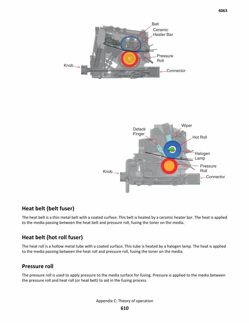
Heat belt (belt fuser)The heat belt is a thin metal belt with a coated surface. This belt is heated by a ceramic heater bar. The heat is appliedto the media passing between the heat belt and pressure roll, fusing the toner on the media.
Heat belt (hot roll fuser)The heat roll is a hollow metal tube with a coated surface. This tube is heated by a halogen lamp. The heat is appliedto the media passing between the heat roll and pressure roll, fusing the toner on the media.
Pressure rollThe pressure roll is used to apply pressure to the media surface for fusing. Pressure is applied to the media betweenthe pressure roll and heat roll (or heat belt) to aid in the fusing process.
4063
Appendix C: Theory of operation
610

Heater lamp (hot roll fuser)The heater lamp is a quartz glass tube containing a halogen heater coil. A terminal is mounted to the end of the heaterrod using a harness.
ThermistorThe thermistor monitors the surface temperature of the media-feed portion of the heat belt or heat roll to providefeedback to the controller board. This information is used to turn the ceramic heater or halogen lamp on and off tomaintain the desired temperature.
Sensor (fuser exit)The sensor (fuser exit) detects the arrival and departure of media as it passes through the fuser.
Sensor (narrow media) (hot roll fuser only)The sensor (narrow media) detects the arrival and departure of media as it passes through the fuser. It also detects thewidth of the media.
Exit• “Sensor (standard bin full)” on page 612
4063
Appendix C: Theory of operation
611
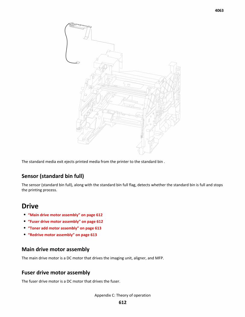
The standard media exit ejects printed media from the printer to the standard bin .
Sensor (standard bin full)The sensor (standard bin full), along with the standard bin full flag, detects whether the standard bin is full and stopsthe printing process.
Drive• “Main drive motor assembly” on page 612
• “Fuser drive motor assembly” on page 612
• “Toner add motor assembly” on page 613
• “Redrive motor assembly” on page 613
Main drive motor assemblyThe main drive motor is a DC motor that drives the imaging unit, aligner, and MFP.
Fuser drive motor assemblyThe fuser drive motor is a DC motor that drives the fuser.
4063
Appendix C: Theory of operation
612
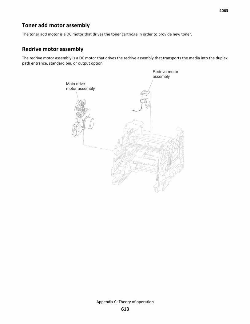
Toner add motor assemblyThe toner add motor is a DC motor that drives the toner cartridge in order to provide new toner.
Redrive motor assemblyThe redrive motor assembly is a DC motor that drives the redrive assembly that transports the media into the duplexpath entrance, standard bin, or output option.
4063
Appendix C: Theory of operation
613
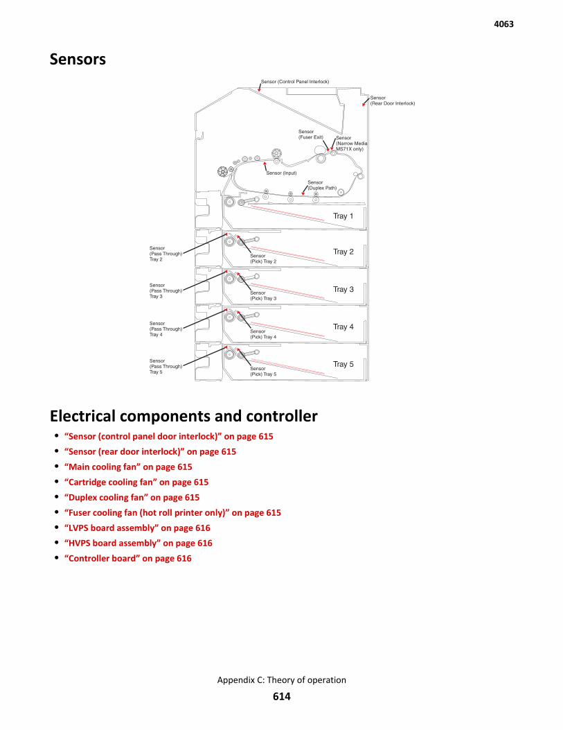
Sensors
Electrical components and controller• “Sensor (control panel door interlock)” on page 615
• “Sensor (rear door interlock)” on page 615
• “Main cooling fan” on page 615
• “Cartridge cooling fan” on page 615
• “Duplex cooling fan” on page 615
• “Fuser cooling fan (hot roll printer only)” on page 615
• “LVPS board assembly” on page 616
• “HVPS board assembly” on page 616
• “Controller board” on page 616
4063
Appendix C: Theory of operation
614
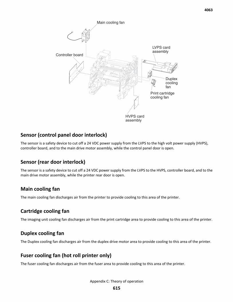
Main cooling fan
Controller board
LVPS cardassembly
Duplexcoolingfan
Print cartridgecooling fan
HVPS cardassembly
Sensor (control panel door interlock)The sensor is a safety device to cut off a 24 VDC power supply from the LVPS to the high volt power supply (HVPS),controller board, and to the main drive motor assembly, while the control panel door is open.
Sensor (rear door interlock)The sensor is a safety device to cut off a 24 VDC power supply from the LVPS to the HVPS, controller board, and to themain drive motor assembly, while the printer rear door is open.
Main cooling fanThe main cooling fan discharges air from the printer to provide cooling to this area of the printer.
Cartridge cooling fanThe imaging unit cooling fan discharges air from the print cartridge area to provide cooling to this area of the printer.
Duplex cooling fanThe Duplex cooling fan discharges air from the duplex drive motor area to provide cooling to this area of the printer.
Fuser cooling fan (hot roll printer only)The fuser cooling fan discharges air from the fuser area to provide cooling to this area of the printer.
4063
Appendix C: Theory of operation
615
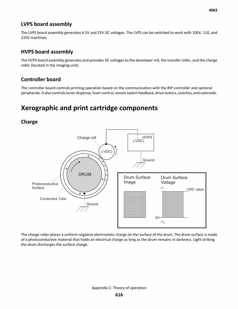
LVPS board assemblyThe LVPS board assembly generates 6.5V and 25V DC voltages. The LVPS can be switched to work with 100V, 110, and220V machines.
HVPS board assemblyThe HVPS board assembly generates and provides DC voltages to the developer roll, the transfer roller, and the chargeroller (located in the imaging unit).
Controller boardThe controller board controls printing operation based on the communication with the RIP controller and optionalperipherals. It also controls toner dispense, fuser control, sensor switch feedback, drive motors, clutches, and solenoids.
Xerographic and print cartridge components
Charge
The charge roller places a uniform negative electrostatic charge on the surface of the drum. The drum surface is madeof a photoconductive material that holds an electrical charge as long as the drum remains in darkness. Light strikingthe drum discharges the surface charge.
4063
Appendix C: Theory of operation
616
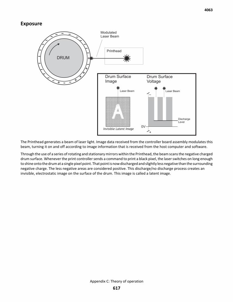
Exposure
The Printhead generates a beam of laser light. Image data received from the controller board assembly modulates thisbeam, turning it on and off according to image information that is received from the host computer and software.
Through the use of a series of rotating and stationary mirrors within the Printhead, the beam scans the negative chargeddrum surface. Whenever the print controller sends a command to print a black pixel, the laser switches on long enoughto shine onto the drum at a single pixel point. That point is now discharged and slightly less negative than the surroundingnegative charge. The less negative areas are considered positive. This discharge/no discharge process creates aninvisible, electrostatic image on the surface of the drum. This image is called a latent image.
4063
Appendix C: Theory of operation
617
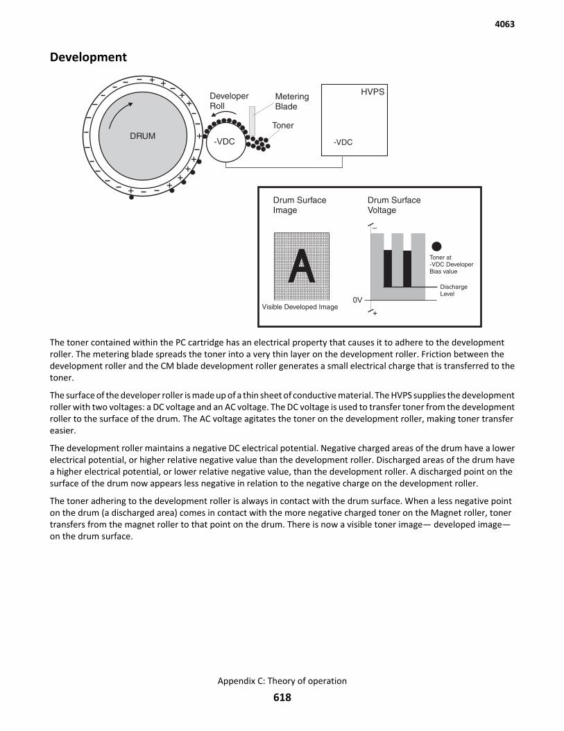
Development
The toner contained within the PC cartridge has an electrical property that causes it to adhere to the developmentroller. The metering blade spreads the toner into a very thin layer on the development roller. Friction between thedevelopment roller and the CM blade development roller generates a small electrical charge that is transferred to thetoner.
The surface of the developer roller is made up of a thin sheet of conductive material. The HVPS supplies the developmentroller with two voltages: a DC voltage and an AC voltage. The DC voltage is used to transfer toner from the developmentroller to the surface of the drum. The AC voltage agitates the toner on the development roller, making toner transfereasier.
The development roller maintains a negative DC electrical potential. Negative charged areas of the drum have a lowerelectrical potential, or higher relative negative value than the development roller. Discharged areas of the drum havea higher electrical potential, or lower relative negative value, than the development roller. A discharged point on thesurface of the drum now appears less negative in relation to the negative charge on the development roller.
The toner adhering to the development roller is always in contact with the drum surface. When a less negative pointon the drum (a discharged area) comes in contact with the more negative charged toner on the Magnet roller, tonertransfers from the magnet roller to that point on the drum. There is now a visible toner image— developed image—on the drum surface.
4063
Appendix C: Theory of operation
618
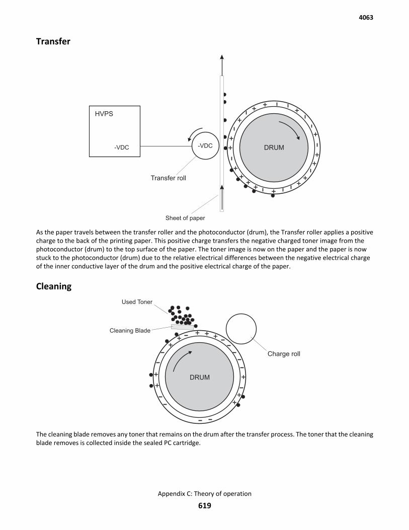
Transfer
As the paper travels between the transfer roller and the photoconductor (drum), the Transfer roller applies a positivecharge to the back of the printing paper. This positive charge transfers the negative charged toner image from thephotoconductor (drum) to the top surface of the paper. The toner image is now on the paper and the paper is nowstuck to the photoconductor (drum) due to the relative electrical differences between the negative electrical chargeof the inner conductive layer of the drum and the positive electrical charge of the paper.
Cleaning
The cleaning blade removes any toner that remains on the drum after the transfer process. The toner that the cleaningblade removes is collected inside the sealed PC cartridge.
4063
Appendix C: Theory of operation
619
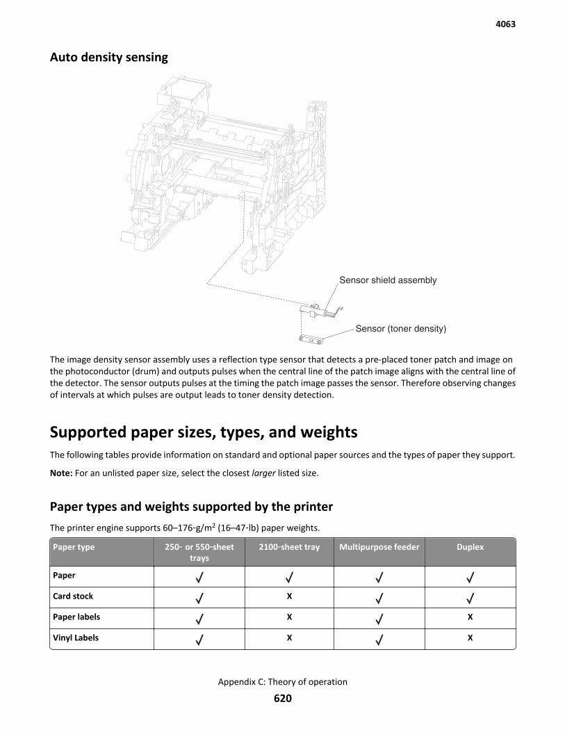
Auto density sensing
The image density sensor assembly uses a reflection type sensor that detects a pre-placed toner patch and image onthe photoconductor (drum) and outputs pulses when the central line of the patch image aligns with the central line ofthe detector. The sensor outputs pulses at the timing the patch image passes the sensor. Therefore observing changesof intervals at which pulses are output leads to toner density detection.
Supported paper sizes, types, and weightsThe following tables provide information on standard and optional paper sources and the types of paper they support.
Note: For an unlisted paper size, select the closest larger listed size.
Paper types and weights supported by the printer
The printer engine supports 60–176‑g/m2 (16–47‑lb) paper weights.
Paper type 250‑ or 550‑sheettrays
2100‑sheet tray Multipurpose feeder Duplex
Paper
Card stock X
Paper labels X X
Vinyl Labels X X
4063
Appendix C: Theory of operation
620
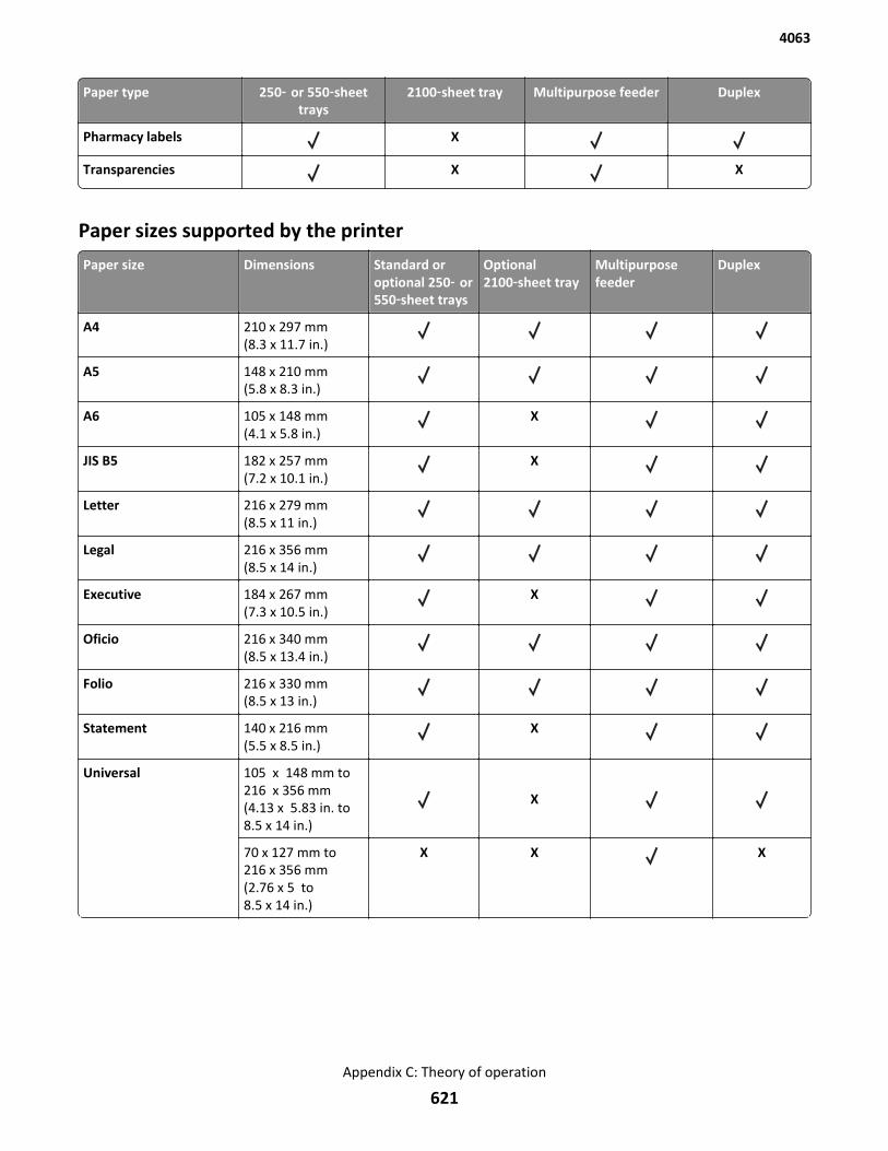
Paper type 250‑ or 550‑sheettrays
2100‑sheet tray Multipurpose feeder Duplex
Pharmacy labels X
Transparencies X X
Paper sizes supported by the printer
Paper size Dimensions Standard oroptional 250‑ or550‑sheet trays
Optional2100‑sheet tray
Multipurposefeeder
Duplex
A4 210 x 297 mm(8.3 x 11.7 in.)
A5 148 x 210 mm(5.8 x 8.3 in.)
A6 105 x 148 mm(4.1 x 5.8 in.)
X
JIS B5 182 x 257 mm(7.2 x 10.1 in.)
X
Letter 216 x 279 mm(8.5 x 11 in.)
Legal 216 x 356 mm(8.5 x 14 in.)
Executive 184 x 267 mm(7.3 x 10.5 in.)
X
Oficio 216 x 340 mm(8.5 x 13.4 in.)
Folio 216 x 330 mm(8.5 x 13 in.)
Statement 140 x 216 mm(5.5 x 8.5 in.)
X
Universal 105 x 148 mm to216 x 356 mm(4.13 x 5.83 in. to8.5 x 14 in.)
X
70 x 127 mm to216 x 356 mm(2.76 x 5 to8.5 x 14 in.)
X X X
4063
Appendix C: Theory of operation
621
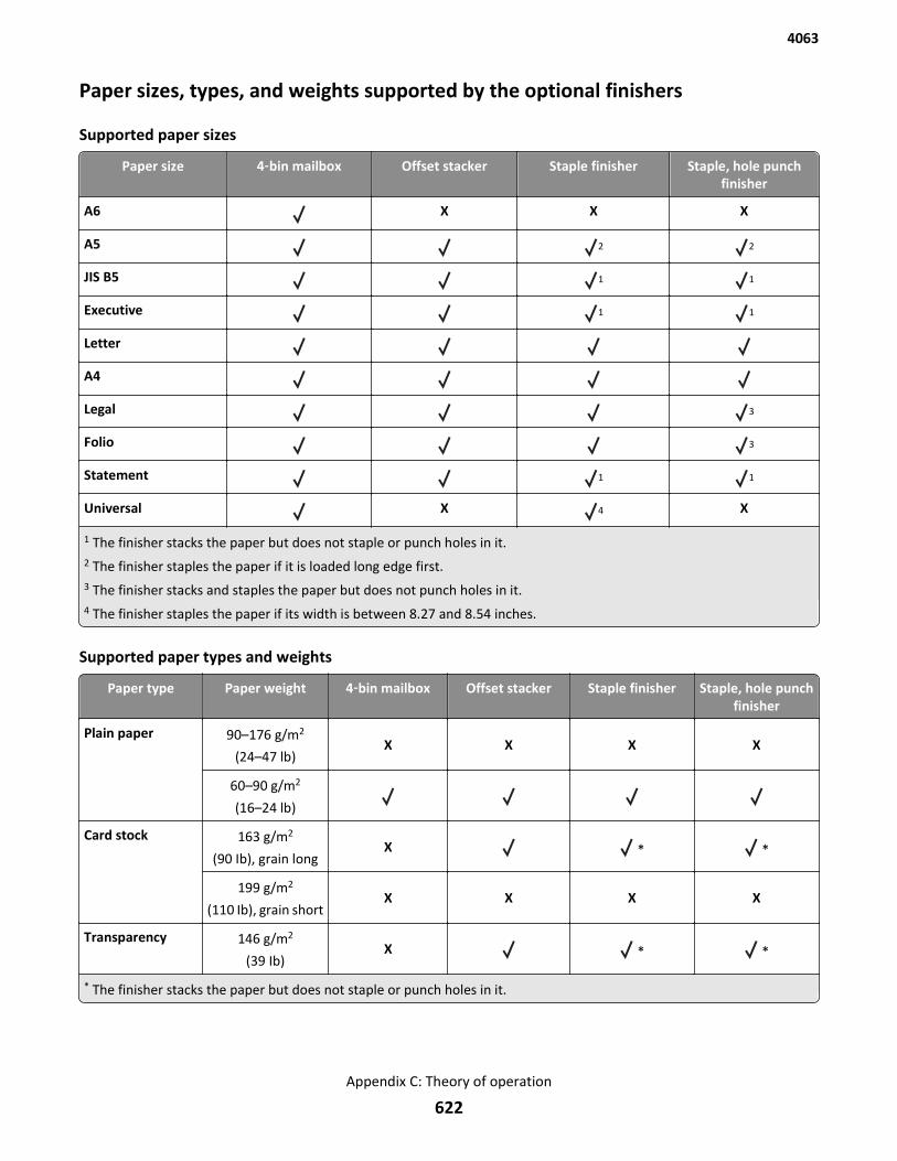
Paper sizes, types, and weights supported by the optional finishers
Supported paper sizes
Paper size 4‑bin mailbox Offset stacker Staple finisher Staple, hole punchfinisher
A6 X X X
A5 2 2
JIS B5 1 1
Executive 1 1
Letter
A4
Legal 3
Folio 3
Statement 1 1
Universal X 4 X
1 The finisher stacks the paper but does not staple or punch holes in it.2 The finisher staples the paper if it is loaded long edge first.3 The finisher stacks and staples the paper but does not punch holes in it.4 The finisher staples the paper if its width is between 8.27 and 8.54 inches.
Supported paper types and weights
Paper type Paper weight 4‑bin mailbox Offset stacker Staple finisher Staple, hole punchfinisher
Plain paper 90–176 g/m2
(24–47 lb)X X X X
60–90 g/m2
(16–24 lb)
Card stock 163 g/m2
(90 Ib), grain longX * *
199 g/m2
(110 Ib), grain shortX X X X
Transparency 146 g/m2
(39 Ib)X * *
* The finisher stacks the paper but does not staple or punch holes in it.
4063
Appendix C: Theory of operation
622
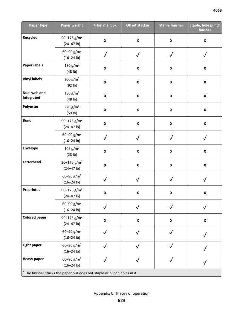
Paper type Paper weight 4‑bin mailbox Offset stacker Staple finisher Staple, hole punchfinisher
Recycled 90–176 g/m2
(24–47 lb)X X X X
60–90 g/m2
(16–24 lb)
Paper labels 180 g/m2
(48 Ib)X X X X
Vinyl labels 300 g/m2
(92 Ib)X X X X
Dual web andIntegrated
180 g/m2
(48 Ib)X X X X
Polyester 220 g/m2
(59 Ib)X X X X
Bond 90–176 g/m2
(24–47 lb)X X X X
60–90 g/m2
(16–24 lb)
Envelope 105 g/m2
(28 Ib)X X X X
Letterhead 90–176 g/m2
(24–47 lb)X X X X
60–90 g/m2
(16–24 lb)
Preprinted 90–176 g/m2
(24–47 lb)X X X X
60–90 g/m2
(16–24 lb)
Colored paper 90–176 g/m2
(24–47 lb)X X X X
60–90 g/m2
(16–24 lb)
Light paper 60–90 g/m2
(16–24 lb)
Heavy paper 60–90 g/m2
(16–24 lb)
* The finisher stacks the paper but does not staple or punch holes in it.
4063
Appendix C: Theory of operation
623
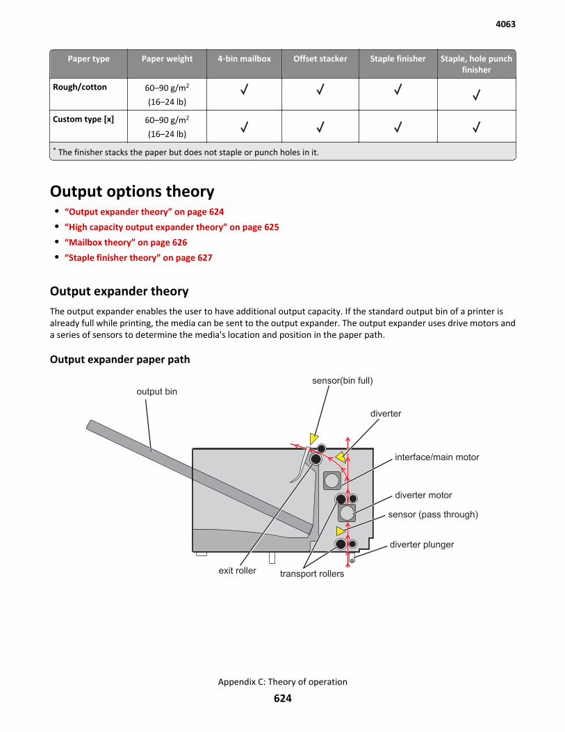
Paper type Paper weight 4‑bin mailbox Offset stacker Staple finisher Staple, hole punchfinisher
Rough/cotton 60–90 g/m2
(16–24 lb)
Custom type [x] 60–90 g/m2
(16–24 lb)
* The finisher stacks the paper but does not staple or punch holes in it.
Output options theory• “Output expander theory” on page 624
• “High capacity output expander theory” on page 625
• “Mailbox theory” on page 626
• “Staple finisher theory” on page 627
Output expander theoryThe output expander enables the user to have additional output capacity. If the standard output bin of a printer isalready full while printing, the media can be sent to the output expander. The output expander uses drive motors anda series of sensors to determine the media's location and position in the paper path.
Output expander paper path
output bin
sensor(bin full)
diverter
interface/main motor
diverter motor
sensor (pass through)
transport rollers
diverter plunger
exit roller
4063
Appendix C: Theory of operation
624
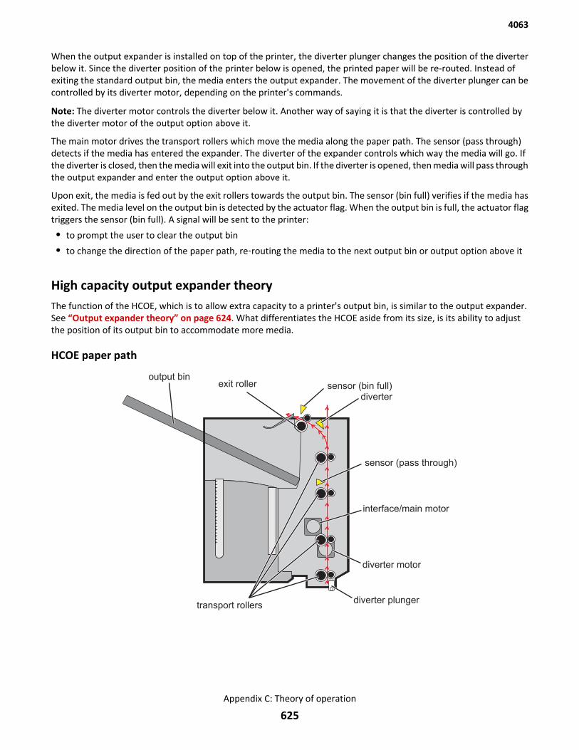
When the output expander is installed on top of the printer, the diverter plunger changes the position of the diverterbelow it. Since the diverter position of the printer below is opened, the printed paper will be re-routed. Instead ofexiting the standard output bin, the media enters the output expander. The movement of the diverter plunger can becontrolled by its diverter motor, depending on the printer's commands.
Note: The diverter motor controls the diverter below it. Another way of saying it is that the diverter is controlled bythe diverter motor of the output option above it.
The main motor drives the transport rollers which move the media along the paper path. The sensor (pass through)detects if the media has entered the expander. The diverter of the expander controls which way the media will go. Ifthe diverter is closed, then the media will exit into the output bin. If the diverter is opened, then media will pass throughthe output expander and enter the output option above it.
Upon exit, the media is fed out by the exit rollers towards the output bin. The sensor (bin full) verifies if the media hasexited. The media level on the output bin is detected by the actuator flag. When the output bin is full, the actuator flagtriggers the sensor (bin full). A signal will be sent to the printer:
• to prompt the user to clear the output bin
• to change the direction of the paper path, re‑routing the media to the next output bin or output option above it
High capacity output expander theoryThe function of the HCOE, which is to allow extra capacity to a printer's output bin, is similar to the output expander.See “Output expander theory” on page 624. What differentiates the HCOE aside from its size, is its ability to adjustthe position of its output bin to accommodate more media.
HCOE paper path
transport rollersdiverter plunger
diverter motor
interface/main motor
sensor (pass through)
divertersensor (bin full)exit roller
output bin
4063
Appendix C: Theory of operation
625
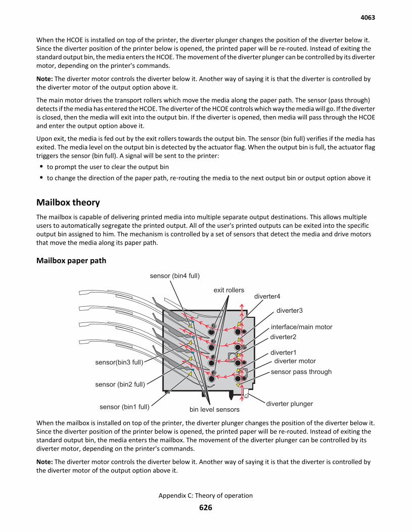
When the HCOE is installed on top of the printer, the diverter plunger changes the position of the diverter below it.Since the diverter position of the printer below is opened, the printed paper will be re-routed. Instead of exiting thestandard output bin, the media enters the HCOE. The movement of the diverter plunger can be controlled by its divertermotor, depending on the printer's commands.
Note: The diverter motor controls the diverter below it. Another way of saying it is that the diverter is controlled bythe diverter motor of the output option above it.
The main motor drives the transport rollers which move the media along the paper path. The sensor (pass through)detects if the media has entered the HCOE. The diverter of the HCOE controls which way the media will go. If the diverteris closed, then the media will exit into the output bin. If the diverter is opened, then media will pass through the HCOEand enter the output option above it.
Upon exit, the media is fed out by the exit rollers towards the output bin. The sensor (bin full) verifies if the media hasexited. The media level on the output bin is detected by the actuator flag. When the output bin is full, the actuator flagtriggers the sensor (bin full). A signal will be sent to the printer:
• to prompt the user to clear the output bin
• to change the direction of the paper path, re‑routing the media to the next output bin or output option above it
Mailbox theoryThe mailbox is capable of delivering printed media into multiple separate output destinations. This allows multipleusers to automatically segregate the printed output. All of the user's printed outputs can be exited into the specificoutput bin assigned to him. The mechanism is controlled by a set of sensors that detect the media and drive motorsthat move the media along its paper path.
Mailbox paper path
sensor (bin4 full)
sensor(bin3 full)
sensor (bin2 full)
sensor (bin1 full)
exit rollersdiverter4
bin level sensorsdiverter plunger
sensor pass through
diverter1
diverter motor
diverter2
interface/main motor
diverter3
When the mailbox is installed on top of the printer, the diverter plunger changes the position of the diverter below it.Since the diverter position of the printer below is opened, the printed paper will be re-routed. Instead of exiting thestandard output bin, the media enters the mailbox. The movement of the diverter plunger can be controlled by itsdiverter motor, depending on the printer's commands.
Note: The diverter motor controls the diverter below it. Another way of saying it is that the diverter is controlled bythe diverter motor of the output option above it.
4063
Appendix C: Theory of operation
626

The main motor drives the transport rollers which move the media along the paper path. The sensor (pass through)detects if the media has entered the mailbox. Four diverters control which way the media will go. If a diverter is opened,then media will pass through it and go to the next diverter above it. The media finally exits when it encounters a closeddiverter.
Upon exit, the media is fed out by the exit rollers towards the assigned output bin. The sensor (bin full) verifies if themedia has exited. The media level on the output bin is detected by the actuator flag. When the output bin is full, theactuator flag triggers the sensor (bin full). A signal will be sent to the printer:
• to prompt the user to clear the output bin
• to change the direction of the paper path, re-routing it to another available output bin.
Staple finisher theoryThe staple finisher is capable of compiling multiple pages and stapling them into one document. Motors drive thestapling process and sensors detect the media's position and location.
Staple finisher paper path
sensor (bin full)
paddle rollerpaddle drive motor
interface/main motor
exit roller
sensor (pass through)
ejector motor diverter motor
When the finisher is installed on top of the printer, the diverter plunger changes the position of the diverter below it.Since the diverter position of the printer below is opened, the printed paper will be re-routed. Instead of exiting thestandard output bin, the media enters the staple finisher. The movement of the diverter plunger can be controlled byits diverter motor, depending on the printer's commands.
Note: The diverter motor controls the diverter below it. Another way of saying it is that the diverter is controlled bythe diverter motor of the output option above it.
The main motor drives the rollers which move the media along the paper path. The sensor (pass through) detects ifthe media has entered the staple finisher.
4063
Appendix C: Theory of operation
627

Stapling process
Exit rollers move the media to the tamper where it will be prepared for stapling. Multiple pages can be stacked on thetamper before the document is stapled. The paddle drive motor rotates the paddle rollers for aligning the trailing edgeof the pages. The paddle rollers align the trailing edges by pushing each page towards a wall. The left and right tamperscompress to align the left and right edges of the document to be stapled. The document is then moved towards thestapler cartridge for stapling. A corner of the trailing edge is held by a paper clamping mechanism controlled by asolenoid. The other corner of the trailing edge is positioned on the stapler throat where it is stapled. When the staplejob is done, the ejector motor drives the ejector belts which push the stapled document into the top of the output bin.Then the tampers move to release the document into the bin. The sensor (bin full) on the left and right side of thestapler detects if the media stacked on the bin is already full.
4063
Appendix C: Theory of operation
628
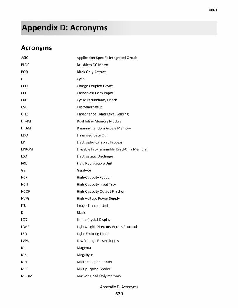
Appendix D: Acronyms
AcronymsASIC Application-Specific Integrated Circuit
BLDC Brushless DC Motor
BOR Black Only Retract
C Cyan
CCD Charge Coupled Device
CCP Carbonless Copy Paper
CRC Cyclic Redundancy Check
CSU Customer Setup
CTLS Capacitance Toner Level Sensing
DIMM Dual Inline Memory Module
DRAM Dynamic Random Access Memory
EDO Enhanced Data Out
EP Electrophotographic Process
EPROM Erasable Programmable Read-Only Memory
ESD Electrostatic Discharge
FRU Field Replaceable Unit
GB Gigabyte
HCF High‑Capacity Feeder
HCIT High-Capacity Input Tray
HCOF High-Capacity Output Finisher
HVPS High Voltage Power Supply
ITU Image Transfer Unit
K Black
LCD Liquid Crystal Display
LDAP Lightweight Directory Access Protocol
LED Light-Emitting Diode
LVPS Low Voltage Power Supply
M Magenta
MB Megabyte
MFP Multi‑Function Printer
MPF Multipurpose Feeder
MROM Masked Read Only Memory
4063
Appendix D: Acronyms
629

MS Microswitch
NVM Nonvolatile Memory
NVRAM Nonvolatile Random Access Memory
OEM Original Equipment Manufacturer
OPT Optical Sensor
PC Photoconductor
pel, pixel Picture element
POR Power-On Reset
POST Power-On Self Test
PSD Position Sensing Device
PWM Pulse Width Modulation
RIP Raster Imaging Processor
ROM Read Only Memory
SDRAM Synchronous Dual Random Access Memory
SIMM Single Inline Memory Module
SRAM Static Random Access Memory
TPS Toner Patch Sensing
UPR Used Parts Return
V ac Volts alternating current
V dc Volts direct current
VTB Vacuum Transport Belt
Y Yellow
4063
Appendix D: Acronyms
630
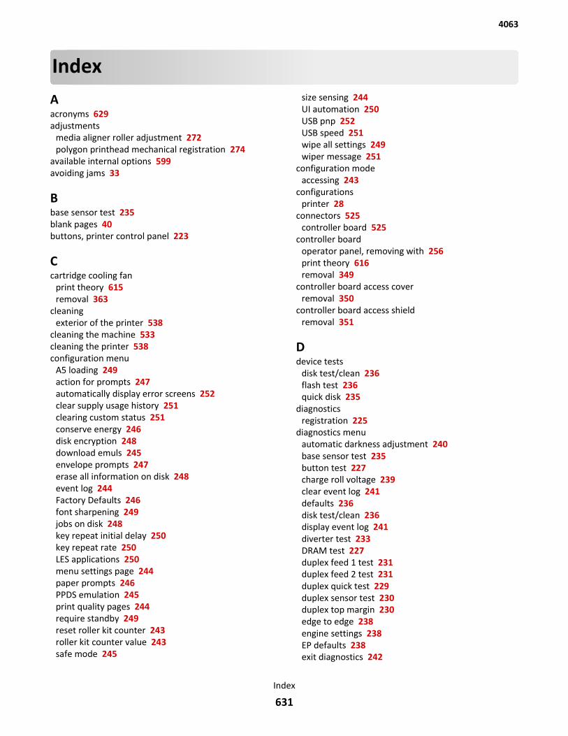
IndexAacronyms 629adjustments
media aligner roller adjustment 272polygon printhead mechanical registration 274
available internal options 599avoiding jams 33
Bbase sensor test 235blank pages 40buttons, printer control panel 223
Ccartridge cooling fan
print theory 615removal 363
cleaning exterior of the printer 538
cleaning the machine 533cleaning the printer 538configuration menu
A5 loading 249action for prompts 247automatically display error screens 252clear supply usage history 251clearing custom status 251conserve energy 246disk encryption 248download emuls 245envelope prompts 247erase all information on disk 248event log 244Factory Defaults 246font sharpening 249jobs on disk 248key repeat initial delay 250key repeat rate 250LES applications 250menu settings page 244paper prompts 246PPDS emulation 245print quality pages 244require standby 249reset roller kit counter 243roller kit counter value 243safe mode 245
size sensing 244UI automation 250USB pnp 252USB speed 251wipe all settings 249wiper message 251
configuration mode accessing 243
configurations printer 28
connectors 525controller board 525
controller board operator panel, removing with 256print theory 616removal 349
controller board access cover removal 350
controller board access shield removal 351
Ddevice tests
disk test/clean 236flash test 236quick disk 235
diagnostics registration 225
diagnostics menu automatic darkness adjustment 240base sensor test 235button test 227charge roll voltage 239clear event log 241defaults 236disk test/clean 236display event log 241diverter test 233DRAM test 227duplex feed 1 test 231duplex feed 2 test 231duplex quick test 229duplex sensor test 230duplex top margin 230edge to edge 238engine settings 238EP defaults 238exit diagnostics 242
4063
Index
631

feed test (finisher) 234feed to all bins test 232flash test 236fuser page count 239fuser temperature 238gap adjust 240hole punch test 234input tray feed test 231input tray sensor tests 232installed licenses 241menu settings page 240motor test 230output bin feed tests 232output bin sensor test 233panel test 226parallel strobe adjustment 238permanent page count 237print contrast 239print event log 241print quality pages 226printed page count 237processor ID 237quick disk 235staple test 233transfer 239USB HS test mode 228warm up time 239
diagnostics mode accessing 225
display, printer control panel 223duplex cooling fan
removal 364duplex exit diverter
removal 286duplex motor
removal 320duplex tests
feed 1 test 231feed 2 test 231motor test 230quick test 229sensor test 230top margin 230
Eelectrostatic‑sensitive parts 255embedded solutions 256energy
conserving 246environment specifications 597EP setup
automatic darkness adjustment 240
charge roll voltage 239EP defaults 238fuser page count 239fuser temperature 238gap adjust 240print contrast 239transfer 239warm up time 239
error codes 0‑99.99 94100.xx 102242.01‑245.46 143300‑399.99 123400‑499.99 1619xx error messages 114key 36
ESD‑sensitive parts 255eSF solutions 256event log
print log 241exterior of the printer
cleaning 538
Ffinisher
finishing features 622supported paper sizes 622
finisher features 622finisher sensors
tests 234finisher tests
feed test (finisher) 234hole punch test 234staple test 233
firmware card 599front door
removal 288fuser
identify the type 536removal 322
fuser access door removal 324
fuser cooling fan print theory 615
fuser drive motor removal 351
fuser drive motor assembly print theory 612
fuser maintenance kits 535
4063
Index
632
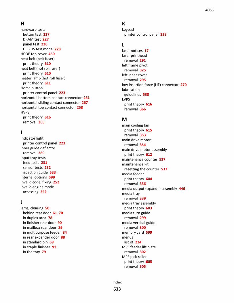
Hhardware tests
button test 227DRAM test 227panel test 226USB HS test mode 228
HCOE top cover 460heat belt (belt fuser)
print theory 610heat belt (hot roll fuser)
print theory 610heater lamp (hot roll fuser)
print theory 611Home button
printer control panel 223horizontal bottom contact connector 261horizontal sliding contact connector 267horizontal top contact connector 258HVPS
print theory 616removal 365
Iindicator light
printer control panel 223inner guide deflector
removal 289input tray tests
feed tests 231sensor tests 232
inspection guide 533internal options 599invalid code, fixing 252invalid engine mode
accessing 252
Jjams, clearing 50
behind rear door 61, 70in duplex area 78in finisher rear door 90in mailbox rear door 89in multipurpose feeder 84in rear expander door 88in standard bin 69in staple finisher 91in the tray 79
Kkeypad
printer control panel 223
Llaser notices 17laser printhead
removal 291left frame pivot
removal 325left inner cover
removal 295low insertion force (LIF) connector 270lubrication
guidelines 538LVPS
print theory 616removal 366
Mmain cooling fan
print theory 615removal 353
main drive motor removal 354
main drive motor assembly print theory 612
maintenance counter 537maintenance kit
resetting the counter 537media feeder
print theory 604removal 356
media output expander assembly 446media tray
removal 339media tray assembly
print theory 603media turn guide
removal 299media vertical guide
removal 300memory card 599menus
list of 224MPF feeder lift plate
removal 302MPF pick roller
print theory 605removal 305
4063
Index
633
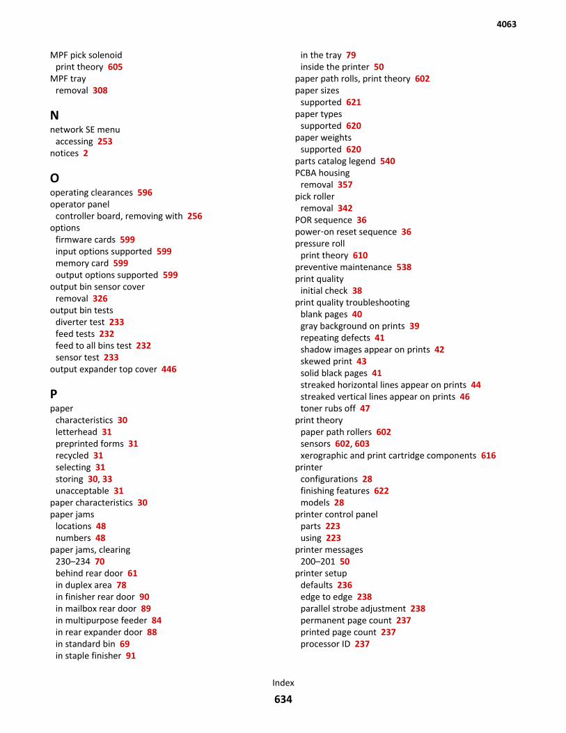
MPF pick solenoid print theory 605
MPF tray removal 308
Nnetwork SE menu
accessing 253notices 2
Ooperating clearances 596operator panel
controller board, removing with 256options
firmware cards 599input options supported 599memory card 599output options supported 599
output bin sensor cover removal 326
output bin tests diverter test 233feed tests 232feed to all bins test 232sensor test 233
output expander top cover 446
Ppaper
characteristics 30letterhead 31preprinted forms 31recycled 31selecting 31storing 30, 33unacceptable 31
paper characteristics 30paper jams
locations 48numbers 48
paper jams, clearing 230–234 70behind rear door 61in duplex area 78in finisher rear door 90in mailbox rear door 89in multipurpose feeder 84in rear expander door 88in standard bin 69in staple finisher 91
in the tray 79inside the printer 50
paper path rolls, print theory 602paper sizes
supported 621paper types
supported 620paper weights
supported 620parts catalog legend 540PCBA housing
removal 357pick roller
removal 342POR sequence 36power‑on reset sequence 36pressure roll
print theory 610preventive maintenance 538print quality
initial check 38print quality troubleshooting
blank pages 40gray background on prints 39repeating defects 41shadow images appear on prints 42skewed print 43solid black pages 41streaked horizontal lines appear on prints 44streaked vertical lines appear on prints 46toner rubs off 47
print theory paper path rollers 602sensors 602, 603xerographic and print cartridge components 616
printer configurations 28finishing features 622models 28
printer control panel parts 223using 223
printer messages 200–201 50
printer setup defaults 236edge to edge 238parallel strobe adjustment 238permanent page count 237printed page count 237processor ID 237
4063
Index
634
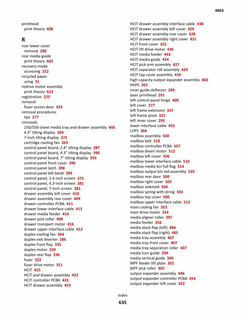
printhead print theory 608
Rrear lower cover
removal 280rear media guide
print theory 603recovery mode
accessing 252recycled paper
using 31redrive motor assembly
print theory 613registration 225removal
fuser access door 324removal procedures
tips 277removals
250/550-sheet media tray and drawer assembly 4064.3” tilting display 3697‑inch tilting display 372cartridge cooling fan 363control panel board, 2.4” tilting display 387control panel board, 4.3” tilting display 390control panel board, 7” tilting display 393control panel front cover 396control panel latch 398control panel left bezel 399control panel, 2.4‑inch screen 375control panel, 4.3‑inch screen 381control panel, 7‑inch screen 381drawer assembly left cover 410drawer assembly rear cover 409drawer controller PCBA 411drawer lower interface cable 413drawer media feeder 414drawer pick roller 408drawer transport motor 416drawer upper interface cable 412duplex cooling fan 364duplex exit diverter 286duplex front flap 335duplex motor 320duplex rear flap 336fuser 322fuser drive motor 351HCIT 423HCIT and drawer assembly 422HCIT controller PCBA 433HCIT drawer assembly 423
HCIT drawer assembly interface cable 438HCIT drawer assembly left cover 429HCIT drawer assembly rear cover 428HCIT drawer assembly right cover 431HCIT front cover 425HCIT lift drive motor 436HCIT media feeder 443HCIT media guide 424HCIT pick arm assembly 427HCIT separator roll assembly 424HCIT top cover assembly 434high capacity output expander assembly 460HVPS 365inner guide deflector 289laser printhead 291left control panel hinge 400left cover 277left frame extension 337left frame pivot 325left inner cover 295lower interface cable 455LVPS 366mailbox assembly 500mailbox belt 518mailbox controller PCBA 507mailbox divert motor 512mailbox left cover 506mailbox lower interface cable 510mailbox media bin full flag 514mailbox output bin led assembly 520mailbox rear door 500mailbox right cover 502mailbox solenoid 504mailbox spring with string 503mailbox top cover 500mailbox upper interface cable 512main cooling fan 353main drive motor 354media aligner roller 297media feeder 356media stack flap (left) 486media stack flap (right) 485media tray assembly 407media tray front cover 407media tray separation roller 407media turn guide 299media vertical guide 300MPF feeder lift plate 302MPF pick roller 305output expander assembly 446output expander controller PCBA 454output expander left cover 452
4063
Index
635

output expander rear door 447output expander right cover 450output expander sensor cover 449output expander top cover 446paddle drive motor 493PCBA housing 357pick roller 342rear door 285right control panel hinge 403right frame extension 343right frame pivot 327right inner cover 309sensor (bin full receive) 498sensor (bin full send) 497sensor (cartridge door interlock) 476sensor (control panel interlock) 359sensor (drawer pass through) 417sensor (duplex path) 344sensor (finisher bin media present) 490sensor (HCIT media low) with flag 439sensor (HCIT pick) 442sensor (input) 310sensor (mailbox bin full receive) 515sensor (mailbox divert motor) 509sensor (media bin full) 449sensor (pick roll position) 408sensor (pick roll position), HCIT 440sensor (pick roller position) 360sensor (pick) 419sensor (stacker media bin full) 463sensor (standard bin full) 329sensor (toner density) 312sensor (tray 1 media out) 345sensor rear door interlock 328separator roller 347spring with string 458stacker controller PCBA 467stacker left cover 465stacker lower interface cable 469stacker rear door 461stacker right outer cover 463stacker sensor cover 462stacker top cover 460stacker upper interface cable 470standard bin cover 330standard output bin led 489staple finisher assembly 471stapler carriage assembly 479stapler cartridge access door 482stapler controller PCBA 496stapler door close limit switch 476stapler left cover 480
stapler lower interface cable 494stapler rear door 472stapler right cover 474stapler spring with string 484stapler top cover 482tamper drive belt 492tamper motor (left) 491tamper motor (right) 491toner add motor 361transfer roller left arm with cable 313transfer roller right arm 314upper interface cable 456upper redrive 331
reports event log 244menu settings page 244
right cover removal 283
right frame pivot removal 327
right inner cover removal 309
Ssafe mode 37safety information 20, 35schedule for Inspection 533scheduled maintenance
fuser maintenance kits 535SE menu 253security, data 33selecting paper 31sensor (control panel door interlock)
print theory 615sensor (control panel interlock)
removal 359sensor (duplex cooling fan)
print theory 615sensor (duplex path)
print theory 606sensor (fuser exit)
print theory 611sensor (input)
print theory 606removal 310
sensor (narrow media) print theory 611
sensor (pick roller position) print theory 604removal 360
sensor (rear door interlock) print theory 615
4063
Index
636

sensor (standard bin full) print theory 612removal 329
sensor (tray 1 media out) removal 345
sensor media size print theory 604
sensor rear door interlock removal 328
sensors print theory 614
sensors, print theory 602, 603serial wrap test 228service checks troubleshooting
network service check 0service engineer (SE) menu 253
accessing 253service manual conventions 25shadow images appear on prints 42side guide
print theory 603skew
polygon printhead mechanical registrationadjustment 274
Sleep button printer control panel 223
solid black pages 41specifications
acoustics 596environment 597operating clearances 596options configurations 600physical 600power 595processor 597
standard bin cover removal 330
Stop or Cancel button printer control panel 223
storing paper 33
streaked horizontal lines appear on prints 44supported paper sizes 621supported paper types 620supported paper weights 620
Ttests
finisher sensors 234theory of operations
high capacity output expander 625mailbox 626
output expander 624staple finisher 627
thermistor print theory 611
toner add motor removal 361
toner add motor assembly print theory 613
tools, required 34top cover
removal 282transfer roller
print theory 607removal 317
transfer roller left arm with cable removal 313
troubleshooting base printer symptoms 194initial check 35options symptoms 198
troubleshooting, print quality blank pages 40gray background on prints 39repeating defects 41shadow images appear on prints 42skewed print 43solid black pages 41streaked horizontal lines appear on prints 44streaked vertical lines appear on prints 46toner rubs off 47
troubleshooting, service checks network service check 0
Uupper redrive
removal 331USB port
printer control panel 223using the printer control panel 223
Vvertical mount contact connector 264
Xxerographic and print cartridge components 616
Zzero insertion force (ZIF) connectors 257
4063
Index
637

4063
Index
638
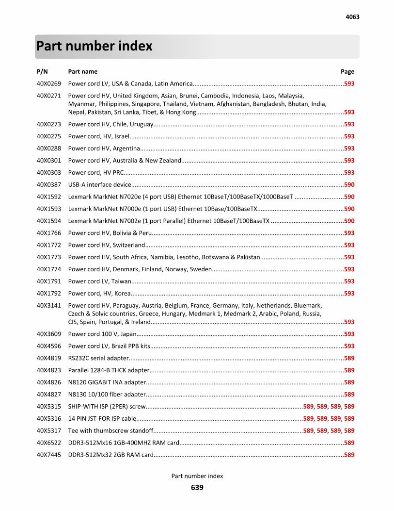
Part number index
P/N Part name Page
40X0269 Power cord LV, USA & Canada, Latin America.......................................................................................593
40X0271 Power cord HV, United Kingdom, Asian, Brunei, Cambodia, Indonesia, Laos, Malaysia,Myanmar, Philippines, Singapore, Thailand, Vietnam, Afghanistan, Bangladesh, Bhutan, India,Nepal, Pakistan, Sri Lanka, Tibet, & Hong Kong.....................................................................................593
40X0273 Power cord HV, Chile, Uruguay..............................................................................................................593
40X0275 Power cord, HV, Israel............................................................................................................................593
40X0288 Power cord HV, Argentina......................................................................................................................593
40X0301 Power cord HV, Australia & New Zealand..............................................................................................593
40X0303 Power cord, HV PRC...............................................................................................................................593
40X0387 USB-A interface device...........................................................................................................................590
40X1592 Lexmark MarkNet N7020e (4 port USB) Ethernet 10BaseT/100BaseTX/1000BaseT ............................590
40X1593 Lexmark MarkNet N7000e (1 port USB) Ethernet 10Base/100BaseTX..................................................590
40X1594 Lexmark MarkNet N7002e (1 port Parallel) Ethernet 10BaseT/100BaseTX ..........................................590
40X1766 Power cord HV, Bolivia & Peru...............................................................................................................593
40X1772 Power cord HV, Switzerland...................................................................................................................593
40X1773 Power cord HV, South Africa, Namibia, Lesotho, Botswana & Pakistan................................................593
40X1774 Power cord HV, Denmark, Finland, Norway, Sweden............................................................................593
40X1791 Power cord LV, Taiwan...........................................................................................................................593
40X1792 Power cord, HV, Korea...........................................................................................................................593
40X3141 Power cord HV, Paraguay, Austria, Belgium, France, Germany, Italy, Netherlands, Bluemark,Czech & Solvic countries, Greece, Hungary, Medmark 1, Medmark 2, Arabic, Poland, Russia,CIS, Spain, Portugal, & Ireland................................................................................................................593
40X3609 Power cord 100 V, Japan........................................................................................................................593
40X4596 Power cord LV, Brazil PPB kits................................................................................................................593
40X4819 RS232C serial adapter............................................................................................................................589
40X4823 Parallel 1284-B THCK adapter................................................................................................................589
40X4826 N8120 GIGABIT INA adapter..................................................................................................................589
40X4827 N8130 10/100 fiber adapter..................................................................................................................589
40X5315 SHIP-WITH ISP (2PER) screw...........................................................................................589, 589, 589, 589
40X5316 14 PIN JST-FOR ISP cable................................................................................................589, 589, 589, 589
40X5317 Tee with thumbscrew standoff......................................................................................589, 589, 589, 589
40X6522 DDR3-512Mx16 1GB-400MHZ RAM card...............................................................................................589
40X7445 DDR3-512Mx32 2GB RAM card..............................................................................................................589
4063
Part number index
639
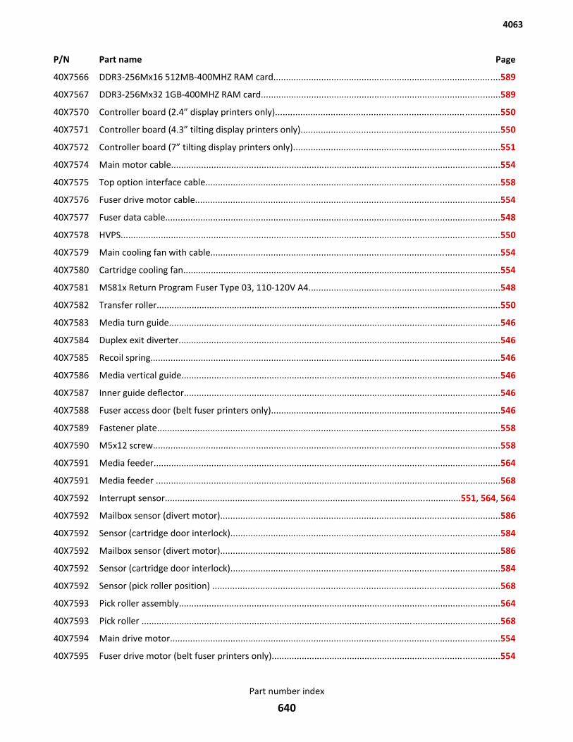
P/N Part name Page
40X7566 DDR3-256Mx16 512MB-400MHZ RAM card..........................................................................................589
40X7567 DDR3-256Mx32 1GB-400MHZ RAM card...............................................................................................589
40X7570 Controller board (2.4” display printers only).........................................................................................550
40X7571 Controller board (4.3” tilting display printers only)...............................................................................550
40X7572 Controller board (7” tilting display printers only)..................................................................................551
40X7574 Main motor cable...................................................................................................................................554
40X7575 Top option interface cable.....................................................................................................................558
40X7576 Fuser drive motor cable.........................................................................................................................554
40X7577 Fuser data cable.....................................................................................................................................548
40X7578 HVPS.......................................................................................................................................................550
40X7579 Main cooling fan with cable...................................................................................................................554
40X7580 Cartridge cooling fan..............................................................................................................................554
40X7581 MS81x Return Program Fuser Type 03, 110-120V A4............................................................................548
40X7582 Transfer roller.........................................................................................................................................550
40X7583 Media turn guide....................................................................................................................................546
40X7584 Duplex exit diverter................................................................................................................................546
40X7585 Recoil spring...........................................................................................................................................546
40X7586 Media vertical guide...............................................................................................................................546
40X7587 Inner guide deflector..............................................................................................................................546
40X7588 Fuser access door (belt fuser printers only)...........................................................................................546
40X7589 Fastener plate........................................................................................................................................558
40X7590 M5x12 screw..........................................................................................................................................558
40X7591 Media feeder..........................................................................................................................................564
40X7591 Media feeder .........................................................................................................................................568
40X7592 Interrupt sensor......................................................................................................................551, 564, 564
40X7592 Mailbox sensor (divert motor)...............................................................................................................586
40X7592 Sensor (cartridge door interlock)...........................................................................................................584
40X7592 Sensor (pick roller position) ..................................................................................................................568
40X7593 Pick roller assembly................................................................................................................................564
40X7593 Pick roller ...............................................................................................................................................568
40X7594 Main drive motor...................................................................................................................................554
40X7595 Fuser drive motor (belt fuser printers only)...........................................................................................554
4063
Part number index
640
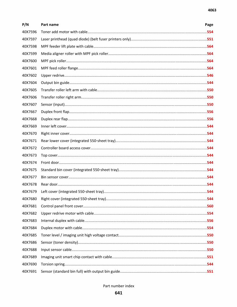
P/N Part name Page
40X7596 Toner add motor with cable...................................................................................................................554
40X7597 Laser printhead (quad diode) (belt fuser printers only).........................................................................551
40X7598 MPF feeder lift plate with cable.............................................................................................................564
40X7599 Media aligner roller with MPF pick roller...............................................................................................564
40X7600 MPF pick roller.......................................................................................................................................564
40X7601 MPF feed roller flange............................................................................................................................564
40X7602 Upper redrive.........................................................................................................................................546
40X7604 Output bin guide....................................................................................................................................544
40X7605 Transfer roller left arm with cable.........................................................................................................550
40X7606 Transfer roller right arm.........................................................................................................................550
40X7607 Sensor (input).........................................................................................................................................550
40X7667 Duplex front flap....................................................................................................................................556
40X7668 Duplex rear flap......................................................................................................................................556
40X7669 Inner left cover.......................................................................................................................................544
40X7670 Right inner cover....................................................................................................................................544
40X7671 Rear lower cover (integrated 550‑sheet tray)........................................................................................544
40X7672 Controller board access cover................................................................................................................544
40X7673 Top cover................................................................................................................................................544
40X7674 Front door..............................................................................................................................................544
40X7675 Standard bin cover (integrated 550‑sheet tray).....................................................................................544
40X7677 Bin sensor cover.....................................................................................................................................544
40X7678 Rear door................................................................................................................................................544
40X7679 Left cover (integrated 550‑sheet tray)...................................................................................................544
40X7680 Right cover (integrated 550‑sheet tray).................................................................................................544
40X7681 Control panel front cover.......................................................................................................................560
40X7682 Upper redrive motor with cable.............................................................................................................554
40X7683 Internal duplex with cable......................................................................................................................556
40X7684 Duplex motor with cable........................................................................................................................554
40X7685 Toner level / imaging unit high voltage contact.....................................................................................550
40X7686 Sensor (toner density)............................................................................................................................550
40X7688 Input sensor cable..................................................................................................................................550
40X7689 Imaging unit smart chip contact with cable...........................................................................................551
40X7690 Torsion spring.........................................................................................................................................544
40X7691 Sensor (standard bin full) with output bin guide...................................................................................551
4063
Part number index
641
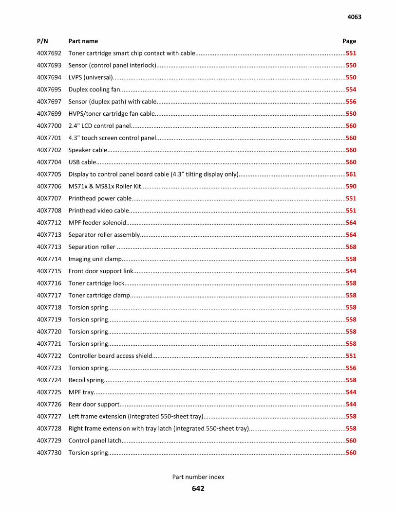
P/N Part name Page
40X7692 Toner cartridge smart chip contact with cable......................................................................................551
40X7693 Sensor (control panel interlock).............................................................................................................550
40X7694 LVPS (universal)......................................................................................................................................550
40X7695 Duplex cooling fan..................................................................................................................................554
40X7697 Sensor (duplex path) with cable.............................................................................................................556
40X7699 HVPS/toner cartridge fan cable..............................................................................................................550
40X7700 2.4" LCD control panel............................................................................................................................560
40X7701 4.3" touch screen control panel.............................................................................................................560
40X7702 Speaker cable.........................................................................................................................................560
40X7704 USB cable................................................................................................................................................560
40X7705 Display to control panel board cable (4.3” tilting display only).............................................................561
40X7706 MS71x & MS81x Roller Kit......................................................................................................................590
40X7707 Printhead power cable...........................................................................................................................551
40X7708 Printhead video cable.............................................................................................................................551
40X7712 MPF feeder solenoid..............................................................................................................................564
40X7713 Separator roller assembly......................................................................................................................564
40X7713 Separation roller ....................................................................................................................................568
40X7714 Imaging unit clamp.................................................................................................................................558
40X7715 Front door support link..........................................................................................................................544
40X7716 Toner cartridge lock...............................................................................................................................558
40X7717 Toner cartridge clamp............................................................................................................................558
40X7718 Torsion spring.........................................................................................................................................558
40X7719 Torsion spring.........................................................................................................................................558
40X7720 Torsion spring.........................................................................................................................................558
40X7721 Torsion spring.........................................................................................................................................558
40X7722 Controller board access shield...............................................................................................................551
40X7723 Torsion spring.........................................................................................................................................556
40X7724 Recoil spring...........................................................................................................................................558
40X7725 MPF tray.................................................................................................................................................544
40X7726 Rear door support..................................................................................................................................544
40X7727 Left frame extension (integrated 550‑sheet tray)..................................................................................558
40X7728 Right frame extension with tray latch (integrated 550‑sheet tray).......................................................558
40X7729 Control panel latch.................................................................................................................................560
40X7730 Torsion spring.........................................................................................................................................560
4063
Part number index
642
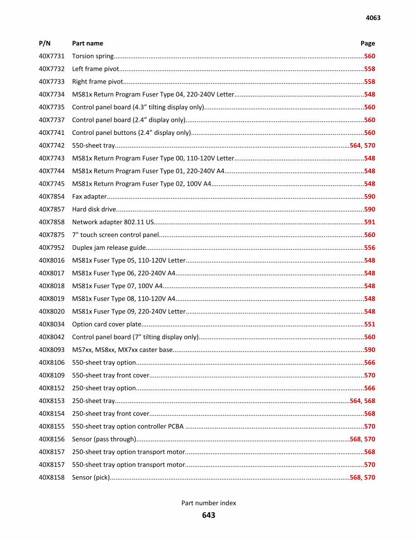
P/N Part name Page
40X7731 Torsion spring.........................................................................................................................................560
40X7732 Left frame pivot......................................................................................................................................558
40X7733 Right frame pivot....................................................................................................................................558
40X7734 MS81x Return Program Fuser Type 04, 220-240V Letter.......................................................................548
40X7735 Control panel board (4.3” tilting display only).......................................................................................560
40X7737 Control panel board (2.4” display only).................................................................................................560
40X7741 Control panel buttons (2.4” display only)..............................................................................................560
40X7742 550-sheet tray................................................................................................................................564, 570
40X7743 MS81x Return Program Fuser Type 00, 110-120V Letter.......................................................................548
40X7744 MS81x Return Program Fuser Type 01, 220-240V A4............................................................................548
40X7745 MS81x Return Program Fuser Type 02, 100V A4...................................................................................548
40X7854 Fax adapter.............................................................................................................................................590
40X7857 Hard disk drive.......................................................................................................................................590
40X7858 Network adapter 802.11 US...................................................................................................................591
40X7875 7" touch screen control panel................................................................................................................560
40X7952 Duplex jam release guide.......................................................................................................................556
40X8016 MS81x Fuser Type 05, 110-120V Letter.................................................................................................548
40X8017 MS81x Fuser Type 06, 220-240V A4.......................................................................................................548
40X8018 MS81x Fuser Type 07, 100V A4..............................................................................................................548
40X8019 MS81x Fuser Type 08, 110-120V A4.......................................................................................................548
40X8020 MS81x Fuser Type 09, 220-240V Letter.................................................................................................548
40X8034 Option card cover plate..........................................................................................................................551
40X8042 Control panel board (7” tilting display only)..........................................................................................560
40X8093 MS7xx, MS8xx, MX7xx caster base........................................................................................................590
40X8106 550‑sheet tray option.............................................................................................................................566
40X8109 550-sheet tray front cover.....................................................................................................................570
40X8152 250‑sheet tray option.............................................................................................................................566
40X8153 250-sheet tray................................................................................................................................564, 568
40X8154 250-sheet tray front cover.....................................................................................................................568
40X8155 550-sheet tray option controller PCBA .................................................................................................570
40X8156 Sensor (pass through).....................................................................................................................568, 570
40X8157 250-sheet tray option transport motor..................................................................................................568
40X8157 550-sheet tray option transport motor..................................................................................................570
40X8158 Sensor (pick)...................................................................................................................................568, 570
4063
Part number index
643
P/N Part name Page
40X8159 250-sheet tray option lower interface cable..........................................................................................568
40X8159 550-sheet tray option lower interface cable..........................................................................................570
40X8160 250-sheet tray option upper interface cable.........................................................................................568
40X8160 550-sheet tray option upper interface cable.........................................................................................570
40X8161 HCIT option.............................................................................................................................................566
40X8163 HCIT drawer assembly............................................................................................................................572
40X8165 HCIT........................................................................................................................................................572
40X8167 HCIT option left cover............................................................................................................................574
40X8169 HCIT option right cover..........................................................................................................................574
40X8171 HCIT front cover.....................................................................................................................................574
40X8173 HCIT option controller PCBA..................................................................................................................574
40X8174 HCIT option media feeder......................................................................................................................574
40X8176 HCIT media guide...................................................................................................................................574
40X8177 Sensor (HCIT media low) with flag.........................................................................................................574
40X8178 Sensor (HCIT pick) with cable.................................................................................................................574
40X8179 HCIT option lift drive motor...................................................................................................................574
40X8180 HCIT option interface cable....................................................................................................................574
40X8184 Output expander option ........................................................................................................................576
40X8186 Output expander rear door....................................................................................................................578
40X8187 Output expander right cover..................................................................................................................578
40X8190 Output expander left cover....................................................................................................................578
40X8191 Sensor (HCOE media bin full) with flag..................................................................................................580
40X8191 Sensor (media bin full) with flag............................................................................................................578
40X8192 Spring with string...................................................................................................................................578
40X8195 High capacity output expander option ..................................................................................................576
40X8196 HCOE top cover......................................................................................................................................580
40X8196 Output expander top cover....................................................................................................................578
40X8197 HCOE rear door......................................................................................................................................580
40X8198 HCOE right cover....................................................................................................................................580
40X8199 HCOE controller PCBA............................................................................................................................580
40X8199 Output expander controller PCBA..........................................................................................................578
40X8199 HCOE controller PCBA............................................................................................................................580
40X8202 HCOE left cover......................................................................................................................................580
40X8205 HCOE lower interface cable....................................................................................................................580
4063
Part number index
644
P/N Part name Page
40X8205 Lower interface cable.............................................................................................................................578
40X8206 HCOE upper interface cable...................................................................................................................580
40X8206 Upper interface cable.............................................................................................................................578
40X8207 Staple finisher option ............................................................................................................................576
40X8209 Media stack flap (right)..........................................................................................................................584
40X8210 Media stack flap (left)............................................................................................................................584
40X8211 Tamper motor (left)...............................................................................................................................584
40X8211 Tamper motor (right).............................................................................................................................584
40X8212 Tamper drive belt...................................................................................................................................584
40X8213 Stapler paddle drive motor....................................................................................................................582
40X8214 Stapler rear door....................................................................................................................................582
40X8215 Stapler cartridge access door.................................................................................................................584
40X8216 Stapler right cover..................................................................................................................................584
40X8217 Sensor (bin full send)..............................................................................................................................584
40X8218 Standard output bin LED........................................................................................................................584
40X8219 Sensor (finisher bin media present).......................................................................................................584
40X8220 Sensor (bin full receive)..........................................................................................................................582
40X8221 Stapler controller PCBA..........................................................................................................................582
40X8222 Stapler top cover....................................................................................................................................582
40X8223 Stapler carriage assembly......................................................................................................................584
40X8224 Stapler lower interface cable.................................................................................................................582
40X8225 Stapler door close limit switch...............................................................................................................584
40X8226 Stapler spring with string.......................................................................................................................584
40X8241 Mailbox option ......................................................................................................................................576
40X8242 Mailbox rear door..................................................................................................................................586
40X8243 Mailbox right cover................................................................................................................................588
40X8244 Mailbox controller PCBA........................................................................................................................586
40X8246 Mailbox left cover..................................................................................................................................586
40X8247 Mailbox media bin full flag.....................................................................................................................586
40X8248 Sensor (bin full receive)..........................................................................................................................586
40X8249 Mailbox belt...........................................................................................................................................588
40X8250 Mailbox output bin LED assembly..........................................................................................................588
40X8251 Mailbox solenoid....................................................................................................................................588
40X8252 Mailbox spring with string......................................................................................................................586
4063
Part number index
645
P/N Part name Page
40X8253 Mailbox lower interface cable................................................................................................................586
40X8254 Mailbox upper interface cable...............................................................................................................586
40X8256 Mailbox divert motor.............................................................................................................................586
40X8311 Case card reader—small stick‑on...........................................................................................................591
40X8312 Case card reader—large stick‑on...........................................................................................................591
40X8313 Case card reader—small snap‑on..........................................................................................................591
40X8315 Left control panel hinge.........................................................................................................................558
40X8316 Right control panel hinge.......................................................................................................................558
40X8334 Control panel left bezel (MS810n).........................................................................................................561
40X8335 Control panel left bezel (MS810dn).......................................................................................................561
40X8336 Control panel left bezel (MS810de).......................................................................................................561
40X8337 Control panel left bezel (MS811n).........................................................................................................561
40X8338 Control panel left bezel (MS811dn).......................................................................................................561
40X8339 Control panel left bezel (MS812dn).......................................................................................................561
40X8340 Control panel left bezel (MS812de).......................................................................................................561
40X8359 Locking caster.........................................................................................................................................590
40X8362 Control panel left bezel (MS710)...........................................................................................................561
40X8363 Control panel left bezel (MS711)...........................................................................................................561
40X8364 Control panel left USB delete cover.......................................................................................................561
40X8365 Printhead access cover...........................................................................................................................550
40X8397 Standard bin cover (integrated 250‑sheet tray).....................................................................................544
40X8398 Fuser wiper cover (hot roll fuser printer only).......................................................................................544
40X8399 Fuser access door (hot roll fuser printers only)......................................................................................546
40X8401 Fuser drive motor (hot roll fuser printers only).....................................................................................554
40X8402 Left cover (integrated 250‑sheet tray)...................................................................................................544
40X8403 Right cover (integrated 250‑sheet tray).................................................................................................544
40X8404 Rear lower cover (integrated 250‑sheet tray)........................................................................................544
40X8407 Left frame extension (integrated 250‑sheet tray)..................................................................................558
40X8408 Right frame extension (integrated 250‑sheet tray)................................................................................558
40X8409 Spacer.....................................................................................................................................................566
40X8410 250‑sheet tray option, lockable.............................................................................................................566
40X8411 550‑sheet tray option, lockable.............................................................................................................566
40X8420 MS81x Return Program Fuser Maint. Kit Type 00, 110-120V Letter......................................................590
40X8421 MS81x Return Program Fuser Maint. Kit Type 01, 220-240V A4...........................................................590
4063
Part number index
646
P/N Part name Page
40X8422 MS81x Return Program Fuser Maint. Kit Type 02, 100V A4...................................................................590
40X8423 MS81x Return Program Fuser Maint. Kit Type 03, 110-120V A4...........................................................590
40X8424 MS81x Return Program Fuser Maint. Kit Type 04, 220-240V Letter......................................................590
40X8425 MS81x Fuser Maint. Kit Type 05, 110-120V Letter.................................................................................590
40X8426 MS81x Fuser Maint. Kit Type 06, 220-240V A4......................................................................................590
40X8427 MS81x Fuser Maint. Kit Type 07, 100V A4.............................................................................................590
40X8428 MS81x Fuser Maint. Kit Type 08, 110-120V A4......................................................................................590
40X8429 MS81x Fuser Maint. Kit Type 09, 220-240V Letter.................................................................................590
40X8481 Laser printhead (dual diode) (hot roller fuser printers only).................................................................551
40X8483 Fuser cooling fan (hot roll fuser printers only).......................................................................................554
40X8484 Fuser cooling fan cable (hot roll fuser printers only).............................................................................554
40X8500 Actuator flag (media bin full).........................................................................................................578, 580
40X8503 MS71x Return Program Fuser Type 11, 110-120V contact....................................................................548
40X8504 MS71x Return Program Fuser Type 13, 220-240V contact....................................................................548
40X8505 MS71x Return Program Fuser Type 15, 100V contact............................................................................548
40X8506 MS71x Fuser Type 17, 110v contact.......................................................................................................548
40X8507 MS71x Fuser Type 19, 220v contact.......................................................................................................548
40X8508 MS71x Fuser Type 21, 100v contact.......................................................................................................548
40X8530 MS71x Return Program Fuser Maint. Kit Type 11, 110-120V.................................................................590
40X8531 MS71x Return Program Fuser Maint. Kit Type 13, 220-240V.................................................................590
40X8532 MS71x Return Program Fuser Maint. Kit Type 15, 100V........................................................................590
40X8533 MS71x Fuser Maint. Kit Type 17, 110-120V..........................................................................................590
40X8534 MS71x Fuser Maint. Kit Type 19, 220-240V...........................................................................................590
40X8535 MS71x Fuser Maint. Kit Type 21, 100V..................................................................................................590
40X8537 4.3" tilting display...................................................................................................................................560
40X8538 7" tilting display......................................................................................................................................560
40X8541 Media size actuator................................................................................................................564, 568, 570
40X8555 256MB user flash card............................................................................................................................589
40X8556 Traditional Chinese font card.................................................................................................................589
40X8557 Simplified Chinese font card..................................................................................................................589
40X8568 Korean font card....................................................................................................................................589
40X8569 Japanese font card.................................................................................................................................589
40X8579 Oil Wiper (MS7xx only)...........................................................................................................................590
40X8581 Wax Wiper (MS7xx only)........................................................................................................................590
4063
Part number index
647
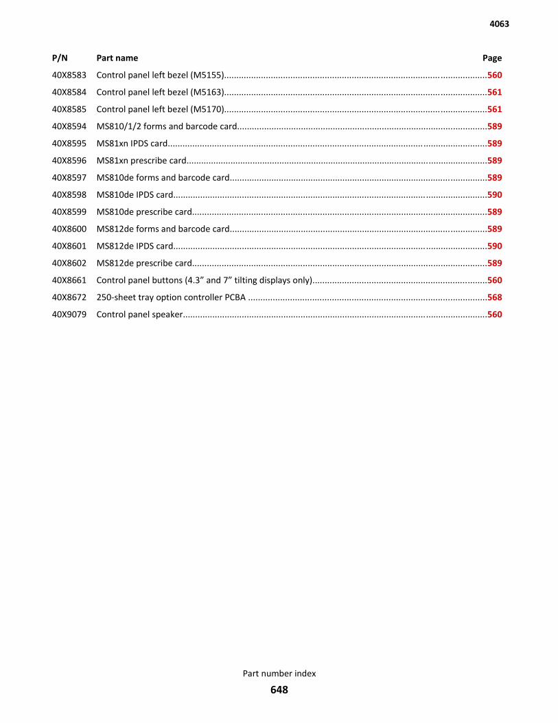
P/N Part name Page
40X8583 Control panel left bezel (M5155)...........................................................................................................560
40X8584 Control panel left bezel (M5163)...........................................................................................................561
40X8585 Control panel left bezel (M5170)...........................................................................................................561
40X8594 MS810/1/2 forms and barcode card......................................................................................................589
40X8595 MS81xn IPDS card..................................................................................................................................589
40X8596 MS81xn prescribe card...........................................................................................................................589
40X8597 MS810de forms and barcode card.........................................................................................................589
40X8598 MS810de IPDS card................................................................................................................................590
40X8599 MS810de prescribe card........................................................................................................................589
40X8600 MS812de forms and barcode card.........................................................................................................589
40X8601 MS812de IPDS card................................................................................................................................590
40X8602 MS812de prescribe card........................................................................................................................589
40X8661 Control panel buttons (4.3” and 7” tilting displays only).......................................................................560
40X8672 250-sheet tray option controller PCBA .................................................................................................568
40X9079 Control panel speaker............................................................................................................................560
4063
Part number index
648
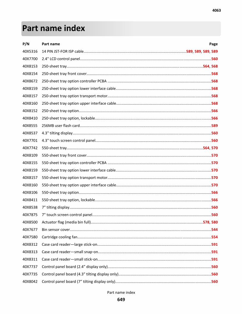
Part name index
P/N Part name Page
40X5316 14 PIN JST-FOR ISP cable................................................................................................589, 589, 589, 589
40X7700 2.4" LCD control panel............................................................................................................................560
40X8153 250-sheet tray................................................................................................................................564, 568
40X8154 250-sheet tray front cover.....................................................................................................................568
40X8672 250-sheet tray option controller PCBA .................................................................................................568
40X8159 250-sheet tray option lower interface cable..........................................................................................568
40X8157 250-sheet tray option transport motor..................................................................................................568
40X8160 250-sheet tray option upper interface cable.........................................................................................568
40X8152 250‑sheet tray option.............................................................................................................................566
40X8410 250‑sheet tray option, lockable.............................................................................................................566
40X8555 256MB user flash card............................................................................................................................589
40X8537 4.3" tilting display...................................................................................................................................560
40X7701 4.3" touch screen control panel.............................................................................................................560
40X7742 550-sheet tray................................................................................................................................564, 570
40X8109 550-sheet tray front cover.....................................................................................................................570
40X8155 550-sheet tray option controller PCBA .................................................................................................570
40X8159 550-sheet tray option lower interface cable..........................................................................................570
40X8157 550-sheet tray option transport motor..................................................................................................570
40X8160 550-sheet tray option upper interface cable.........................................................................................570
40X8106 550‑sheet tray option.............................................................................................................................566
40X8411 550‑sheet tray option, lockable.............................................................................................................566
40X8538 7" tilting display......................................................................................................................................560
40X7875 7" touch screen control panel................................................................................................................560
40X8500 Actuator flag (media bin full).........................................................................................................578, 580
40X7677 Bin sensor cover.....................................................................................................................................544
40X7580 Cartridge cooling fan..............................................................................................................................554
40X8312 Case card reader—large stick‑on...........................................................................................................591
40X8313 Case card reader—small snap‑on..........................................................................................................591
40X8311 Case card reader—small stick‑on...........................................................................................................591
40X7737 Control panel board (2.4” display only).................................................................................................560
40X7735 Control panel board (4.3” tilting display only).......................................................................................560
40X8042 Control panel board (7” tilting display only)..........................................................................................560
4063
Part name index
649
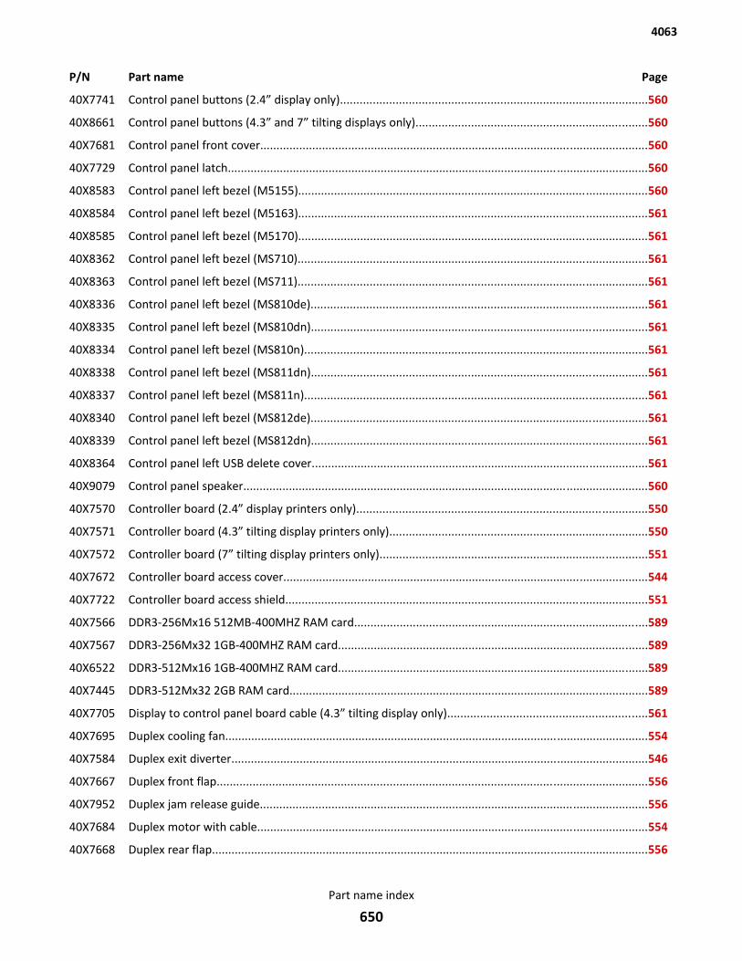
P/N Part name Page
40X7741 Control panel buttons (2.4” display only)..............................................................................................560
40X8661 Control panel buttons (4.3” and 7” tilting displays only).......................................................................560
40X7681 Control panel front cover.......................................................................................................................560
40X7729 Control panel latch.................................................................................................................................560
40X8583 Control panel left bezel (M5155)...........................................................................................................560
40X8584 Control panel left bezel (M5163)...........................................................................................................561
40X8585 Control panel left bezel (M5170)...........................................................................................................561
40X8362 Control panel left bezel (MS710)...........................................................................................................561
40X8363 Control panel left bezel (MS711)...........................................................................................................561
40X8336 Control panel left bezel (MS810de).......................................................................................................561
40X8335 Control panel left bezel (MS810dn).......................................................................................................561
40X8334 Control panel left bezel (MS810n).........................................................................................................561
40X8338 Control panel left bezel (MS811dn).......................................................................................................561
40X8337 Control panel left bezel (MS811n).........................................................................................................561
40X8340 Control panel left bezel (MS812de).......................................................................................................561
40X8339 Control panel left bezel (MS812dn).......................................................................................................561
40X8364 Control panel left USB delete cover.......................................................................................................561
40X9079 Control panel speaker............................................................................................................................560
40X7570 Controller board (2.4” display printers only).........................................................................................550
40X7571 Controller board (4.3” tilting display printers only)...............................................................................550
40X7572 Controller board (7” tilting display printers only)..................................................................................551
40X7672 Controller board access cover................................................................................................................544
40X7722 Controller board access shield...............................................................................................................551
40X7566 DDR3-256Mx16 512MB-400MHZ RAM card..........................................................................................589
40X7567 DDR3-256Mx32 1GB-400MHZ RAM card...............................................................................................589
40X6522 DDR3-512Mx16 1GB-400MHZ RAM card...............................................................................................589
40X7445 DDR3-512Mx32 2GB RAM card..............................................................................................................589
40X7705 Display to control panel board cable (4.3” tilting display only).............................................................561
40X7695 Duplex cooling fan..................................................................................................................................554
40X7584 Duplex exit diverter................................................................................................................................546
40X7667 Duplex front flap....................................................................................................................................556
40X7952 Duplex jam release guide.......................................................................................................................556
40X7684 Duplex motor with cable........................................................................................................................554
40X7668 Duplex rear flap......................................................................................................................................556
4063
Part name index
650
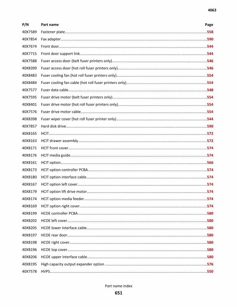
P/N Part name Page
40X7589 Fastener plate........................................................................................................................................558
40X7854 Fax adapter.............................................................................................................................................590
40X7674 Front door..............................................................................................................................................544
40X7715 Front door support link..........................................................................................................................544
40X7588 Fuser access door (belt fuser printers only)...........................................................................................546
40X8399 Fuser access door (hot roll fuser printers only)......................................................................................546
40X8483 Fuser cooling fan (hot roll fuser printers only).......................................................................................554
40X8484 Fuser cooling fan cable (hot roll fuser printers only).............................................................................554
40X7577 Fuser data cable.....................................................................................................................................548
40X7595 Fuser drive motor (belt fuser printers only)...........................................................................................554
40X8401 Fuser drive motor (hot roll fuser printers only).....................................................................................554
40X7576 Fuser drive motor cable.........................................................................................................................554
40X8398 Fuser wiper cover (hot roll fuser printer only).......................................................................................544
40X7857 Hard disk drive.......................................................................................................................................590
40X8165 HCIT........................................................................................................................................................572
40X8163 HCIT drawer assembly............................................................................................................................572
40X8171 HCIT front cover.....................................................................................................................................574
40X8176 HCIT media guide...................................................................................................................................574
40X8161 HCIT option.............................................................................................................................................566
40X8173 HCIT option controller PCBA..................................................................................................................574
40X8180 HCIT option interface cable....................................................................................................................574
40X8167 HCIT option left cover............................................................................................................................574
40X8179 HCIT option lift drive motor...................................................................................................................574
40X8174 HCIT option media feeder......................................................................................................................574
40X8169 HCIT option right cover..........................................................................................................................574
40X8199 HCOE controller PCBA............................................................................................................................580
40X8202 HCOE left cover......................................................................................................................................580
40X8205 HCOE lower interface cable....................................................................................................................580
40X8197 HCOE rear door......................................................................................................................................580
40X8198 HCOE right cover....................................................................................................................................580
40X8196 HCOE top cover......................................................................................................................................580
40X8206 HCOE upper interface cable...................................................................................................................580
40X8195 High capacity output expander option ..................................................................................................576
40X7578 HVPS.......................................................................................................................................................550
4063
Part name index
651
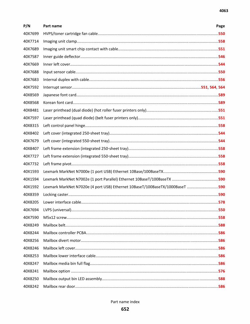
P/N Part name Page
40X7699 HVPS/toner cartridge fan cable..............................................................................................................550
40X7714 Imaging unit clamp.................................................................................................................................558
40X7689 Imaging unit smart chip contact with cable...........................................................................................551
40X7587 Inner guide deflector..............................................................................................................................546
40X7669 Inner left cover.......................................................................................................................................544
40X7688 Input sensor cable..................................................................................................................................550
40X7683 Internal duplex with cable......................................................................................................................556
40X7592 Interrupt sensor......................................................................................................................551, 564, 564
40X8569 Japanese font card.................................................................................................................................589
40X8568 Korean font card....................................................................................................................................589
40X8481 Laser printhead (dual diode) (hot roller fuser printers only).................................................................551
40X7597 Laser printhead (quad diode) (belt fuser printers only).........................................................................551
40X8315 Left control panel hinge.........................................................................................................................558
40X8402 Left cover (integrated 250‑sheet tray)...................................................................................................544
40X7679 Left cover (integrated 550‑sheet tray)...................................................................................................544
40X8407 Left frame extension (integrated 250‑sheet tray)..................................................................................558
40X7727 Left frame extension (integrated 550‑sheet tray)..................................................................................558
40X7732 Left frame pivot......................................................................................................................................558
40X1593 Lexmark MarkNet N7000e (1 port USB) Ethernet 10Base/100BaseTX..................................................590
40X1594 Lexmark MarkNet N7002e (1 port Parallel) Ethernet 10BaseT/100BaseTX ..........................................590
40X1592 Lexmark MarkNet N7020e (4 port USB) Ethernet 10BaseT/100BaseTX/1000BaseT ............................590
40X8359 Locking caster.........................................................................................................................................590
40X8205 Lower interface cable.............................................................................................................................578
40X7694 LVPS (universal)......................................................................................................................................550
40X7590 M5x12 screw..........................................................................................................................................558
40X8249 Mailbox belt...........................................................................................................................................588
40X8244 Mailbox controller PCBA........................................................................................................................586
40X8256 Mailbox divert motor.............................................................................................................................586
40X8246 Mailbox left cover..................................................................................................................................586
40X8253 Mailbox lower interface cable................................................................................................................586
40X8247 Mailbox media bin full flag.....................................................................................................................586
40X8241 Mailbox option ......................................................................................................................................576
40X8250 Mailbox output bin LED assembly..........................................................................................................588
40X8242 Mailbox rear door..................................................................................................................................586
4063
Part name index
652
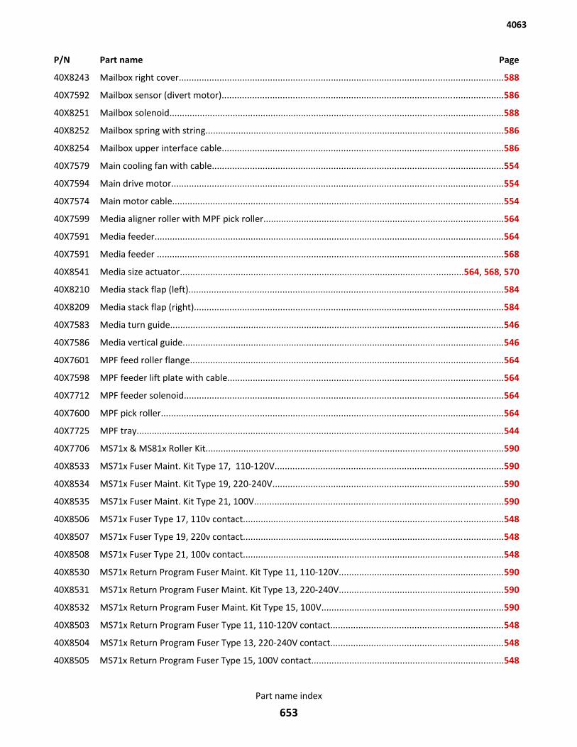
P/N Part name Page
40X8243 Mailbox right cover................................................................................................................................588
40X7592 Mailbox sensor (divert motor)...............................................................................................................586
40X8251 Mailbox solenoid....................................................................................................................................588
40X8252 Mailbox spring with string......................................................................................................................586
40X8254 Mailbox upper interface cable...............................................................................................................586
40X7579 Main cooling fan with cable...................................................................................................................554
40X7594 Main drive motor...................................................................................................................................554
40X7574 Main motor cable...................................................................................................................................554
40X7599 Media aligner roller with MPF pick roller...............................................................................................564
40X7591 Media feeder..........................................................................................................................................564
40X7591 Media feeder .........................................................................................................................................568
40X8541 Media size actuator................................................................................................................564, 568, 570
40X8210 Media stack flap (left)............................................................................................................................584
40X8209 Media stack flap (right)..........................................................................................................................584
40X7583 Media turn guide....................................................................................................................................546
40X7586 Media vertical guide...............................................................................................................................546
40X7601 MPF feed roller flange............................................................................................................................564
40X7598 MPF feeder lift plate with cable.............................................................................................................564
40X7712 MPF feeder solenoid..............................................................................................................................564
40X7600 MPF pick roller.......................................................................................................................................564
40X7725 MPF tray.................................................................................................................................................544
40X7706 MS71x & MS81x Roller Kit......................................................................................................................590
40X8533 MS71x Fuser Maint. Kit Type 17, 110-120V..........................................................................................590
40X8534 MS71x Fuser Maint. Kit Type 19, 220-240V...........................................................................................590
40X8535 MS71x Fuser Maint. Kit Type 21, 100V..................................................................................................590
40X8506 MS71x Fuser Type 17, 110v contact.......................................................................................................548
40X8507 MS71x Fuser Type 19, 220v contact.......................................................................................................548
40X8508 MS71x Fuser Type 21, 100v contact.......................................................................................................548
40X8530 MS71x Return Program Fuser Maint. Kit Type 11, 110-120V.................................................................590
40X8531 MS71x Return Program Fuser Maint. Kit Type 13, 220-240V.................................................................590
40X8532 MS71x Return Program Fuser Maint. Kit Type 15, 100V........................................................................590
40X8503 MS71x Return Program Fuser Type 11, 110-120V contact....................................................................548
40X8504 MS71x Return Program Fuser Type 13, 220-240V contact....................................................................548
40X8505 MS71x Return Program Fuser Type 15, 100V contact............................................................................548
4063
Part name index
653
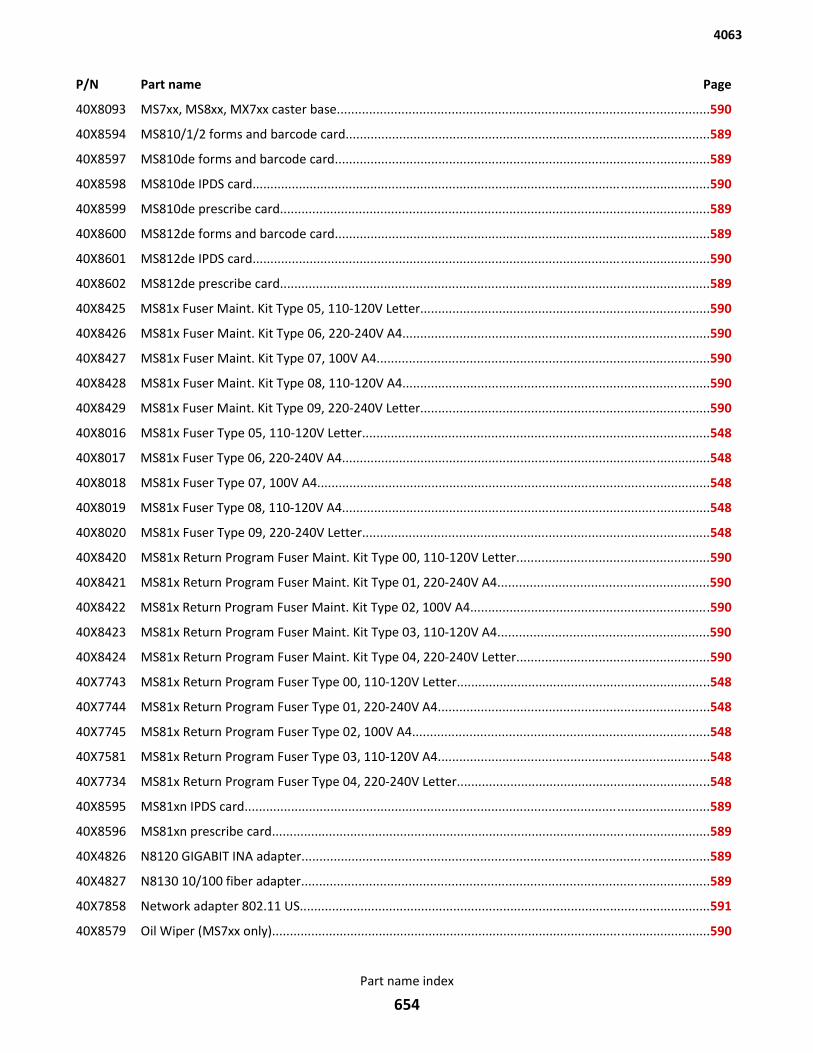
P/N Part name Page
40X8093 MS7xx, MS8xx, MX7xx caster base........................................................................................................590
40X8594 MS810/1/2 forms and barcode card......................................................................................................589
40X8597 MS810de forms and barcode card.........................................................................................................589
40X8598 MS810de IPDS card................................................................................................................................590
40X8599 MS810de prescribe card........................................................................................................................589
40X8600 MS812de forms and barcode card.........................................................................................................589
40X8601 MS812de IPDS card................................................................................................................................590
40X8602 MS812de prescribe card........................................................................................................................589
40X8425 MS81x Fuser Maint. Kit Type 05, 110-120V Letter.................................................................................590
40X8426 MS81x Fuser Maint. Kit Type 06, 220-240V A4......................................................................................590
40X8427 MS81x Fuser Maint. Kit Type 07, 100V A4.............................................................................................590
40X8428 MS81x Fuser Maint. Kit Type 08, 110-120V A4......................................................................................590
40X8429 MS81x Fuser Maint. Kit Type 09, 220-240V Letter.................................................................................590
40X8016 MS81x Fuser Type 05, 110-120V Letter.................................................................................................548
40X8017 MS81x Fuser Type 06, 220-240V A4.......................................................................................................548
40X8018 MS81x Fuser Type 07, 100V A4..............................................................................................................548
40X8019 MS81x Fuser Type 08, 110-120V A4.......................................................................................................548
40X8020 MS81x Fuser Type 09, 220-240V Letter.................................................................................................548
40X8420 MS81x Return Program Fuser Maint. Kit Type 00, 110-120V Letter......................................................590
40X8421 MS81x Return Program Fuser Maint. Kit Type 01, 220-240V A4...........................................................590
40X8422 MS81x Return Program Fuser Maint. Kit Type 02, 100V A4...................................................................590
40X8423 MS81x Return Program Fuser Maint. Kit Type 03, 110-120V A4...........................................................590
40X8424 MS81x Return Program Fuser Maint. Kit Type 04, 220-240V Letter......................................................590
40X7743 MS81x Return Program Fuser Type 00, 110-120V Letter.......................................................................548
40X7744 MS81x Return Program Fuser Type 01, 220-240V A4............................................................................548
40X7745 MS81x Return Program Fuser Type 02, 100V A4...................................................................................548
40X7581 MS81x Return Program Fuser Type 03, 110-120V A4............................................................................548
40X7734 MS81x Return Program Fuser Type 04, 220-240V Letter.......................................................................548
40X8595 MS81xn IPDS card..................................................................................................................................589
40X8596 MS81xn prescribe card...........................................................................................................................589
40X4826 N8120 GIGABIT INA adapter..................................................................................................................589
40X4827 N8130 10/100 fiber adapter..................................................................................................................589
40X7858 Network adapter 802.11 US...................................................................................................................591
40X8579 Oil Wiper (MS7xx only)...........................................................................................................................590
4063
Part name index
654
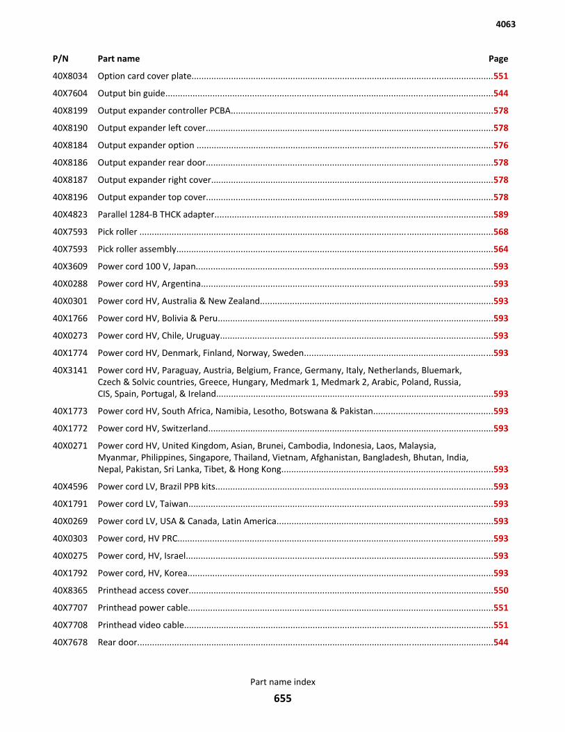
P/N Part name Page
40X8034 Option card cover plate..........................................................................................................................551
40X7604 Output bin guide....................................................................................................................................544
40X8199 Output expander controller PCBA..........................................................................................................578
40X8190 Output expander left cover....................................................................................................................578
40X8184 Output expander option ........................................................................................................................576
40X8186 Output expander rear door....................................................................................................................578
40X8187 Output expander right cover..................................................................................................................578
40X8196 Output expander top cover....................................................................................................................578
40X4823 Parallel 1284-B THCK adapter................................................................................................................589
40X7593 Pick roller ...............................................................................................................................................568
40X7593 Pick roller assembly................................................................................................................................564
40X3609 Power cord 100 V, Japan........................................................................................................................593
40X0288 Power cord HV, Argentina......................................................................................................................593
40X0301 Power cord HV, Australia & New Zealand..............................................................................................593
40X1766 Power cord HV, Bolivia & Peru...............................................................................................................593
40X0273 Power cord HV, Chile, Uruguay..............................................................................................................593
40X1774 Power cord HV, Denmark, Finland, Norway, Sweden............................................................................593
40X3141 Power cord HV, Paraguay, Austria, Belgium, France, Germany, Italy, Netherlands, Bluemark,Czech & Solvic countries, Greece, Hungary, Medmark 1, Medmark 2, Arabic, Poland, Russia,CIS, Spain, Portugal, & Ireland................................................................................................................593
40X1773 Power cord HV, South Africa, Namibia, Lesotho, Botswana & Pakistan................................................593
40X1772 Power cord HV, Switzerland...................................................................................................................593
40X0271 Power cord HV, United Kingdom, Asian, Brunei, Cambodia, Indonesia, Laos, Malaysia,Myanmar, Philippines, Singapore, Thailand, Vietnam, Afghanistan, Bangladesh, Bhutan, India,Nepal, Pakistan, Sri Lanka, Tibet, & Hong Kong.....................................................................................593
40X4596 Power cord LV, Brazil PPB kits................................................................................................................593
40X1791 Power cord LV, Taiwan...........................................................................................................................593
40X0269 Power cord LV, USA & Canada, Latin America.......................................................................................593
40X0303 Power cord, HV PRC...............................................................................................................................593
40X0275 Power cord, HV, Israel............................................................................................................................593
40X1792 Power cord, HV, Korea...........................................................................................................................593
40X8365 Printhead access cover...........................................................................................................................550
40X7707 Printhead power cable...........................................................................................................................551
40X7708 Printhead video cable.............................................................................................................................551
40X7678 Rear door................................................................................................................................................544
4063
Part name index
655
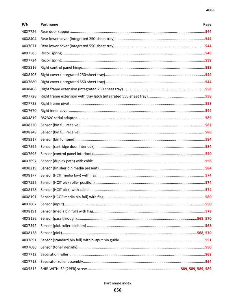
P/N Part name Page
40X7726 Rear door support..................................................................................................................................544
40X8404 Rear lower cover (integrated 250‑sheet tray)........................................................................................544
40X7671 Rear lower cover (integrated 550‑sheet tray)........................................................................................544
40X7585 Recoil spring...........................................................................................................................................546
40X7724 Recoil spring...........................................................................................................................................558
40X8316 Right control panel hinge.......................................................................................................................558
40X8403 Right cover (integrated 250‑sheet tray).................................................................................................544
40X7680 Right cover (integrated 550‑sheet tray).................................................................................................544
40X8408 Right frame extension (integrated 250‑sheet tray)................................................................................558
40X7728 Right frame extension with tray latch (integrated 550‑sheet tray).......................................................558
40X7733 Right frame pivot....................................................................................................................................558
40X7670 Right inner cover....................................................................................................................................544
40X4819 RS232C serial adapter............................................................................................................................589
40X8220 Sensor (bin full receive)..........................................................................................................................582
40X8248 Sensor (bin full receive)..........................................................................................................................586
40X8217 Sensor (bin full send)..............................................................................................................................584
40X7592 Sensor (cartridge door interlock)...........................................................................................................584
40X7693 Sensor (control panel interlock).............................................................................................................550
40X7697 Sensor (duplex path) with cable.............................................................................................................556
40X8219 Sensor (finisher bin media present).......................................................................................................584
40X8177 Sensor (HCIT media low) with flag.........................................................................................................574
40X7592 Sensor (HCIT pick roller position) ..........................................................................................................574
40X8178 Sensor (HCIT pick) with cable.................................................................................................................574
40X8191 Sensor (HCOE media bin full) with flag..................................................................................................580
40X7607 Sensor (input).........................................................................................................................................550
40X8191 Sensor (media bin full) with flag............................................................................................................578
40X8156 Sensor (pass through).....................................................................................................................568, 570
40X7592 Sensor (pick roller position) ..................................................................................................................568
40X8158 Sensor (pick)...................................................................................................................................568, 570
40X7691 Sensor (standard bin full) with output bin guide...................................................................................551
40X7686 Sensor (toner density)............................................................................................................................550
40X7713 Separation roller ....................................................................................................................................568
40X7713 Separator roller assembly......................................................................................................................564
40X5315 SHIP-WITH ISP (2PER) screw...........................................................................................589, 589, 589, 589
4063
Part name index
656
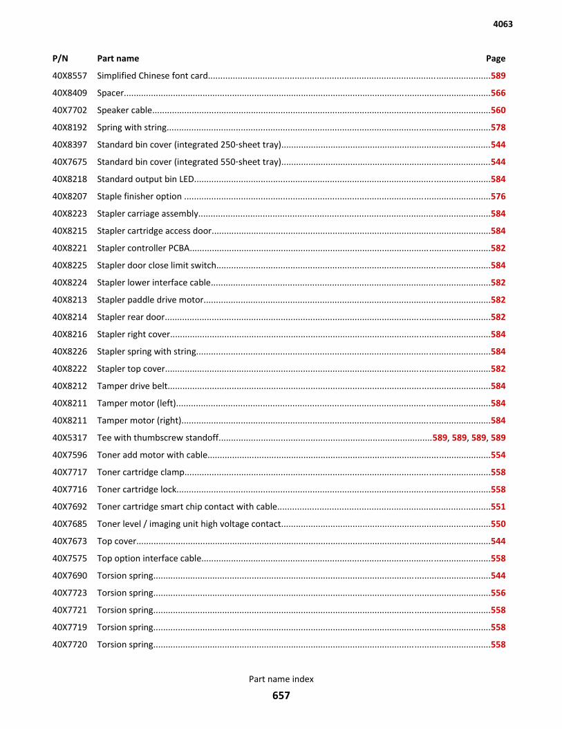
P/N Part name Page
40X8557 Simplified Chinese font card..................................................................................................................589
40X8409 Spacer.....................................................................................................................................................566
40X7702 Speaker cable.........................................................................................................................................560
40X8192 Spring with string...................................................................................................................................578
40X8397 Standard bin cover (integrated 250‑sheet tray).....................................................................................544
40X7675 Standard bin cover (integrated 550‑sheet tray).....................................................................................544
40X8218 Standard output bin LED........................................................................................................................584
40X8207 Staple finisher option ............................................................................................................................576
40X8223 Stapler carriage assembly......................................................................................................................584
40X8215 Stapler cartridge access door.................................................................................................................584
40X8221 Stapler controller PCBA..........................................................................................................................582
40X8225 Stapler door close limit switch...............................................................................................................584
40X8224 Stapler lower interface cable.................................................................................................................582
40X8213 Stapler paddle drive motor....................................................................................................................582
40X8214 Stapler rear door....................................................................................................................................582
40X8216 Stapler right cover..................................................................................................................................584
40X8226 Stapler spring with string.......................................................................................................................584
40X8222 Stapler top cover....................................................................................................................................582
40X8212 Tamper drive belt...................................................................................................................................584
40X8211 Tamper motor (left)...............................................................................................................................584
40X8211 Tamper motor (right).............................................................................................................................584
40X5317 Tee with thumbscrew standoff......................................................................................589, 589, 589, 589
40X7596 Toner add motor with cable...................................................................................................................554
40X7717 Toner cartridge clamp............................................................................................................................558
40X7716 Toner cartridge lock...............................................................................................................................558
40X7692 Toner cartridge smart chip contact with cable......................................................................................551
40X7685 Toner level / imaging unit high voltage contact.....................................................................................550
40X7673 Top cover................................................................................................................................................544
40X7575 Top option interface cable.....................................................................................................................558
40X7690 Torsion spring.........................................................................................................................................544
40X7723 Torsion spring.........................................................................................................................................556
40X7721 Torsion spring.........................................................................................................................................558
40X7719 Torsion spring.........................................................................................................................................558
40X7720 Torsion spring.........................................................................................................................................558
4063
Part name index
657

P/N Part name Page
40X7718 Torsion spring.........................................................................................................................................558
40X7731 Torsion spring.........................................................................................................................................560
40X7730 Torsion spring.........................................................................................................................................560
40X8556 Traditional Chinese font card.................................................................................................................589
40X7582 Transfer roller.........................................................................................................................................550
40X7605 Transfer roller left arm with cable.........................................................................................................550
40X7606 Transfer roller right arm.........................................................................................................................550
40X8206 Upper interface cable.............................................................................................................................578
40X7602 Upper redrive.........................................................................................................................................546
40X7682 Upper redrive motor with cable.............................................................................................................554
40X7704 USB cable................................................................................................................................................560
40X0387 USB-A interface device...........................................................................................................................590
40X8581 Wax Wiper (MS7xx only)........................................................................................................................590
4063
Part name index
658
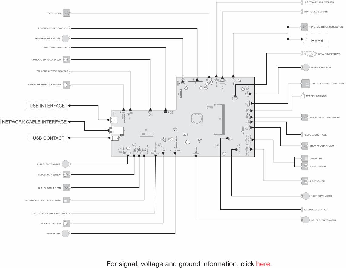
INP
UT
SN
S
1
IND
EX
/PA
PO
UT
/PIC
K M
TR
1
JCT
LS1
1
1
J50
J20
J73
TD
S
1
J19
1
JW1
11
MP
F S
NSJ3
8J3
TON
ER
UN
IT
11
1J5
8J4
8
JAU
D1
J9H
VP
S
J56
CV
SN
S
1
1
M F
AN
J54
J101
VID
EO
1
1
J14
1J5
7M
IR M
TR
1
J47
JT10
1
J13
JT5
J24
1
J104
RE
DR
IVE
1
F9
F3
J21
1
J81
BO
T O
PT
ION
S
J31
IMA
G U
NIT
J45
1
11
1
J37
DFA
N1
J29
DS
NS
1
DU
PLE
X M
TR
1J2
8J1
J4
1
J80
TOP
OP
T
1
RE
DR
IVE
DO
OR
SE
NS
OR
J83
1
J53
1
F12
F2
1
J27
TR
AN
SP
OR
T M
OTO
R
J39
OU
T H
OP
1
CO
NT
AC
T 1F
6
JT20
F17
F18
JUS
BH
1
PRINTER MIRROR MOTOR
PRINTHEAD LASER CONTROL
COOLING FANCONTROL PANEL BOARD
HVPS
TONER CARTRIDGE COOLING FAN
TONER ADD MOTOR
SPEAKER (IF EQUIPED)
CARTRIDGE SMART CHIP CONTACT
MPF PICK SOLENOID
MPF MEDIA PRESENT SENSOR
TEMPERATURE PROBE
IMAGE DENSITY SENSOR
FUSER SENSOR
SMART CHIP
INPUT SENSOR
FUSER DRIVE MOTOR
TONER LEVEL CONTACT
PANEL USB CONNECTOR
STANDARD BIN FULL SENSOR
TOP OPTION INTERFACE CABLE
REAR DOOR INTERLOCK SENSOR
USB INTERFACE
NETWORK CABLE INTERFACE
USB CONTACT
DUPLEX DRIVE MOTOR
DUPLEX PATH SENSOR
DUPLEX COOLING FAN
IMAGING UNIT SMART CHIP CONTACT
LOWER OPTION INTERFACE CABLE
MEDIA SIZE SENSOR
MAIN MOTOR
UPPER REDRIVE MOTOR
CONTROL PANEL INTERLOCK
For signal, voltage and ground information, click .here