Embed Size (px)
Citation preview
LG TRAINING PRESENTATIONFall 2011 Appliance TrainingLG TRAINING PRESENTATIONS
LDF6920
Dual-Evaporator Refrigerator
WT5101
Dishwasher
Top-Load Washing Machine
LFX31925
Name (Optional): Company: Date:
Trainer: Location:
Have you attended a LG Technical Training Seminar prior to today?
Strongly Disagree Disagree Neither Nor Agree
Strongly Agree Excellent
The Trainer 1 2 3 4 5 6
… was well prepared … was professional … was knowledgeable … was able to keep my attention … was able to answer/address my questions
The Manuals
… easy to follow and understand … were accurate and complete, without flaws … easy to read with good print quality … were professional in appearance
The Content
… was correctly and completely covered … was applicable to my training needs … easy to follow and understand
The Product
… was in good working order … was in clear view and accessible … was items that I have worked on before … was items that I plan to work on What products would you like to receive training on?
The Classroom
… was well marked and easy to find … was clean and professional … was laid-out so that everything was in clear view
The Venue
… was easy to find and drive to … was in close proximity and not too far away … clean and professional
Very Dissatisfied Dissatisfied Neither Nor Satisfied
Very Satisfied Excellent
Level of satisfaction 1 2 3 4 5 6
… with the Trainer … with the Training Materials … with LG Training … with LG Service
LG Electronics Alabama Inc., attn: John Ferguson, 201 James Record Road Bldg 3, Huntsville AL 35813
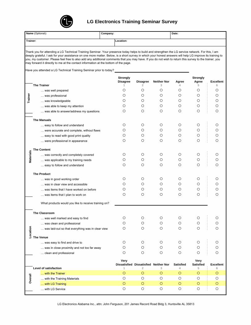
LG Electronics Training Seminar Survey
Thank you for attending a LG Technical Training Seminar. Your presence today helps to build and strengthen the LG service network. For this, I am deeply grateful. I ask for your assistance on one more matter. Below, is a short survey in which your honest answers will help LG improve its training to you, my customer. Please feel free to also add any additional comments that you may have. If you do not wish to return this survey to the trainer, youmay forward it directly to me at the contact information at the bottom of the page.
Ove
rall
Trai
ner
Mat
eria
lsLo
catio
n
Comments:
LG Electronics Alabama Inc., attn: John Ferguson, 201 James Record Road Bldg 3, Huntsville AL 35813
LG Electronics Training Seminar Survey
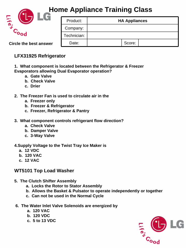
Home Appliance Training ClassProduct: HA Appliances
Company:
Technician:
Date: Score:Circle the best answer
LFX31925 Refrigerator
1. What component is located between the Refrigerator & Freezer Evaporators allowing Dual Evaporator operation?
a. Gate Valve b. Check Valve c. Drier
2. The Freezer Fan is used to circulate air in the a. Freezer only b. Freezer & Refrigerator c. Freezer, Refrigerator & Pantry
3. What component controls refrigerant flow direction?a. Check Valve b. Damper Valve c. 3-Way Valve
4.Supply Voltage to the Twist Tray Ice Maker is a. 12 VDC b. 120 VAC c. 12 VAC
WT5101 Top Load Washer
5. The Clutch Shifter Assembly a. Locks the Rotor to Stator Assembly b. Allows the Basket & Pulsator to operate independently or together c. Can not be used in the Normal Cycle
6. The Water Inlet Valve Solenoids are energized by a. 120 VAC b. 120 VDC c. 5 to 13 VDC
Circle the best answer
7. The Tub Heater Hi Limit Thermostat a. is in series with the Tub Heater b. can create a LE Error Code c. controls the ‘Extra Hot’ water temperature
LDF6920ST Dishwasher
8. The spray arms switch between upper and lower bya. gate valve b. vario motor and vario valvec. reversing main wash motor
9. To dry dishes LG usesa. a 1200 watt heaterb. by using rinse aid and flash drying by opening doorc. a hybrid condensing system
10. Water fill is controlled bya. flow sensorb. time and orifice in inlet valvec. float valve
Slide # 1
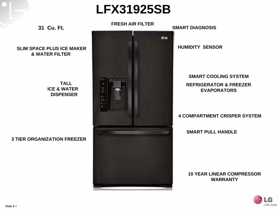
SMART PULL HANDLE
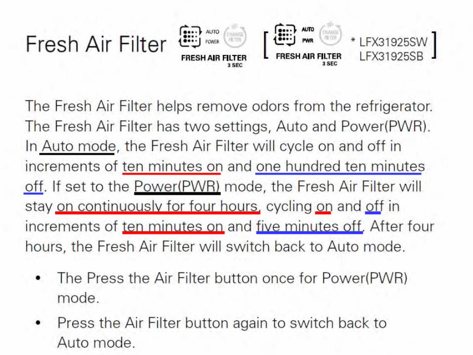
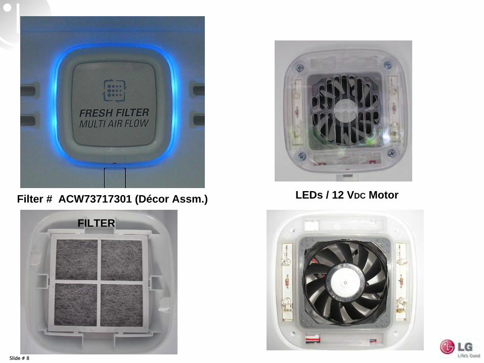
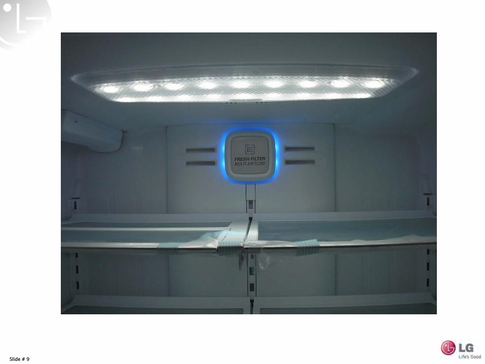
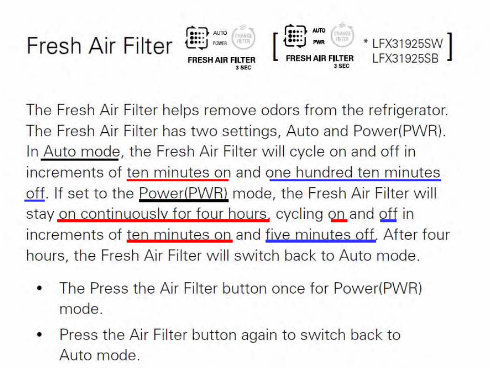
FRESH AIR FILTER
4 COMPARTMENT CRISPER SYSTEM
SLIM SPACE PLUS ICE MAKER & WATER FILTER
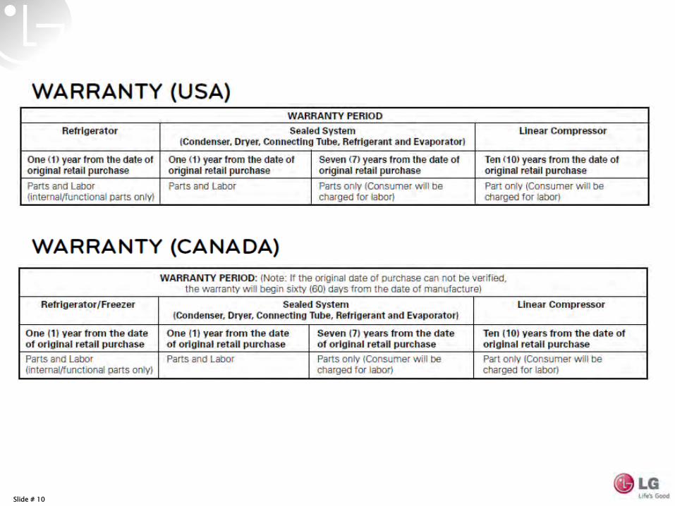
10 YEAR LINEAR COMPRESSOR WARRANTY
3 TIER ORGANIZATION FREEZER
TALL ICE & WATER
DISPENSER
SMART COOLING SYSTEM
REFRIGERATOR & FREEZER EVAPORATORS
31 Cu. Ft. SMART DIAGNOSIS
LFX31925SB
HUMIDITY SENSOR
Slide # 2
Slide # 3
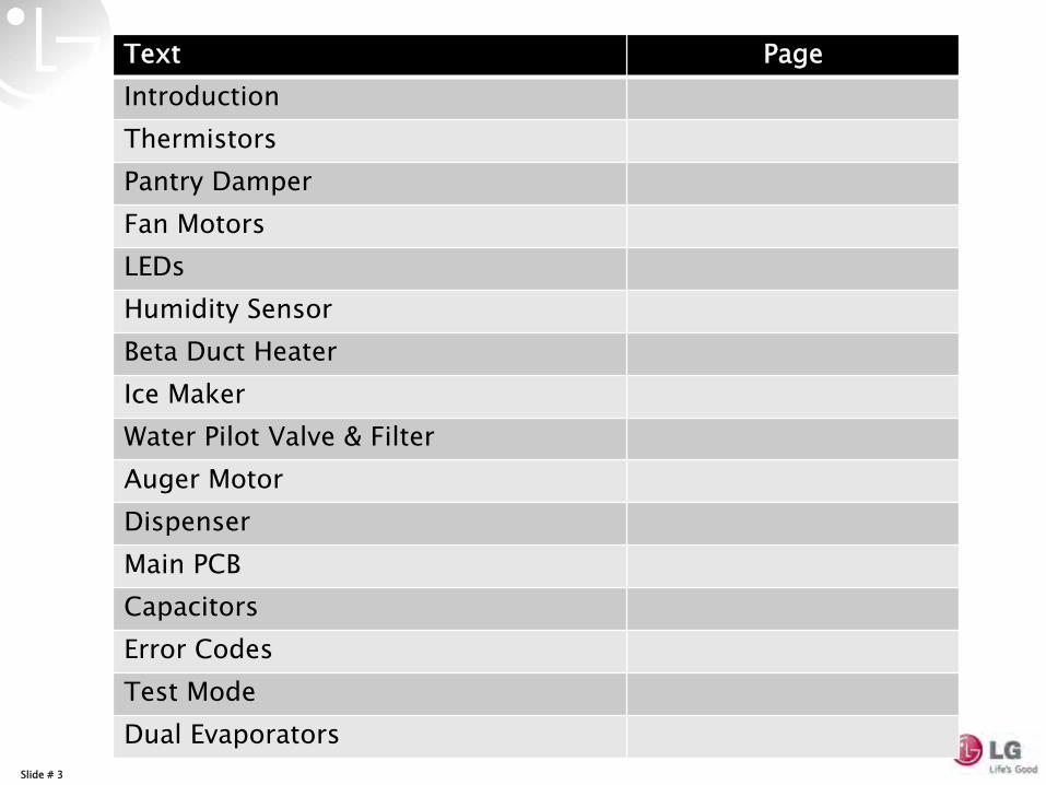
Text PageIntroductionThermistorsPantry DamperFan MotorsLEDsHumidity SensorBeta Duct HeaterIce MakerWater Pilot Valve & FilterAuger MotorDispenserMain PCBCapacitorsError CodesTest ModeDual Evaporators
Slide # 4
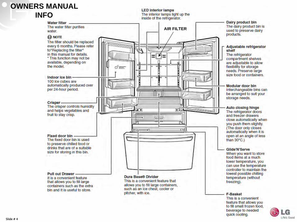
OWNERS MANUAL INFO
AIR FILTER
Slide # 5
Slide # 6
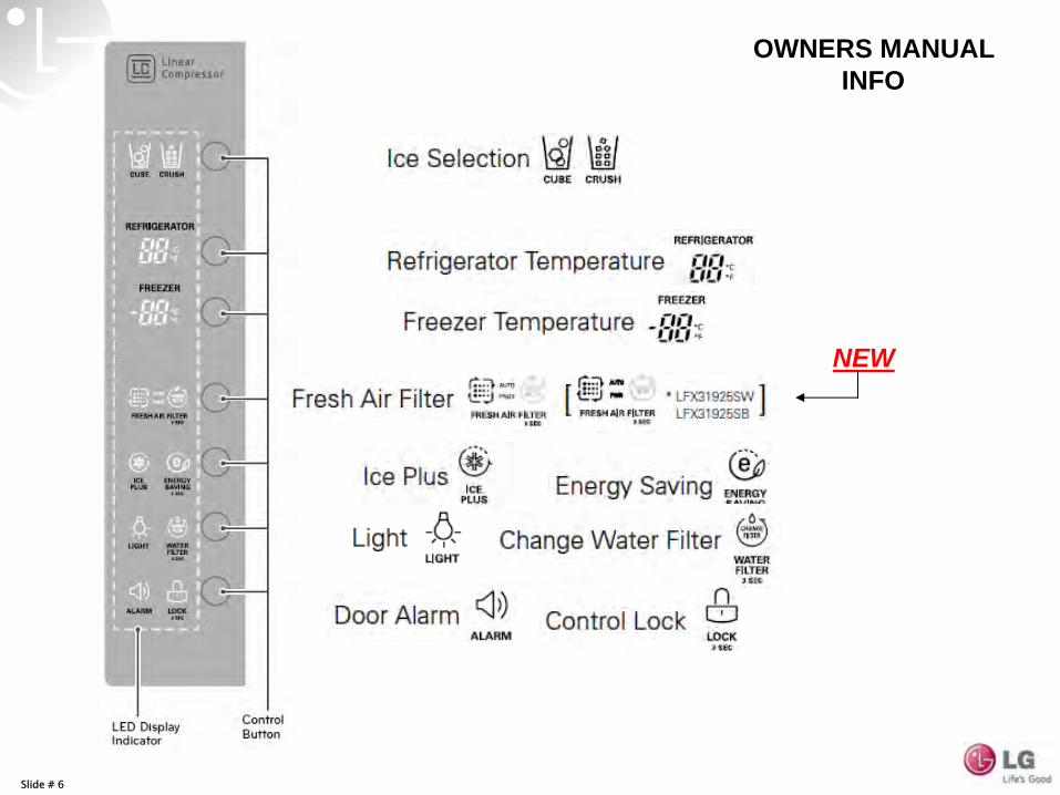
OWNERS MANUAL INFO
NEW
Slide # 7
Slide # 8
FILTER
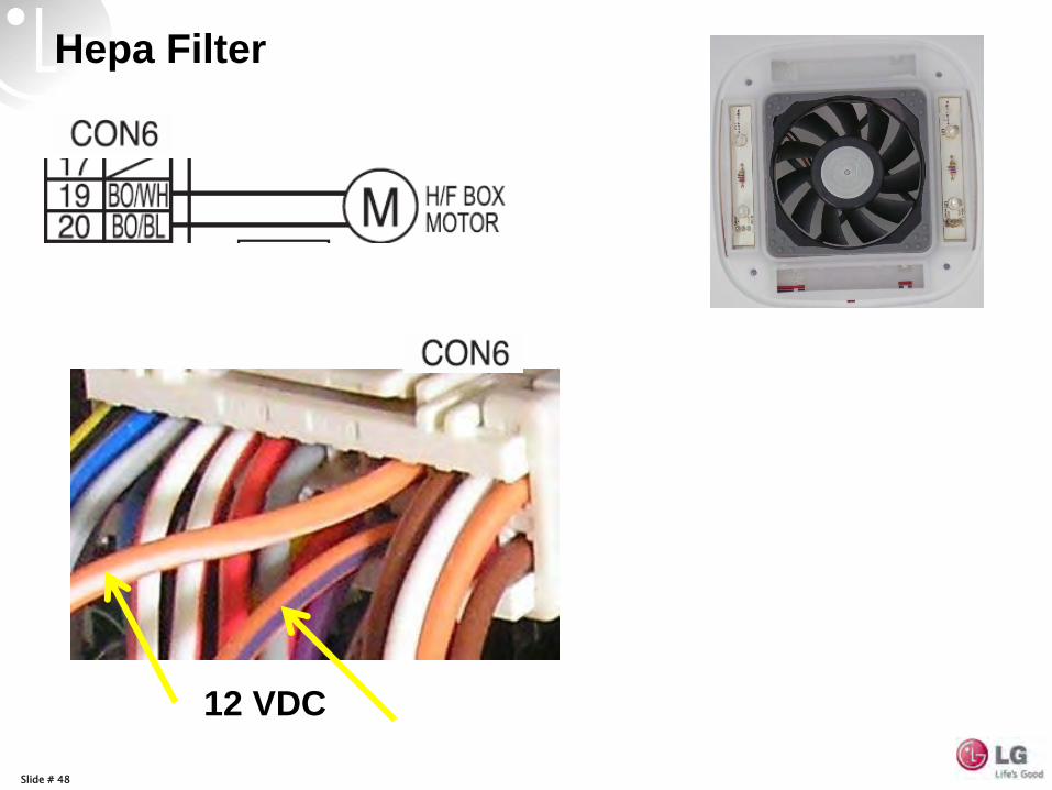
LEDs / 12 VDC MotorFilter # ACW73717301 (Décor Assm.)
Slide # 9
Slide # 10
Slide # 11
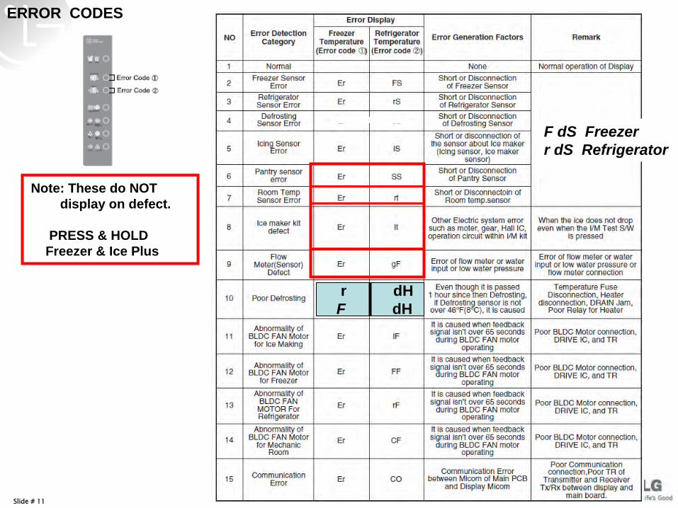
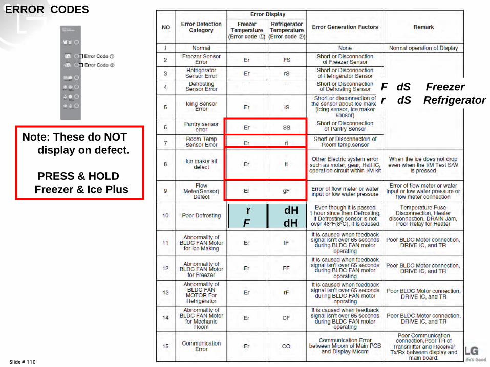
r dH F dH
F dS Freezer r dS Refrigerator
ERROR CODES
Note: These do NOT display on defect.
PRESS & HOLD Freezer & Ice Plus
Slide # 12
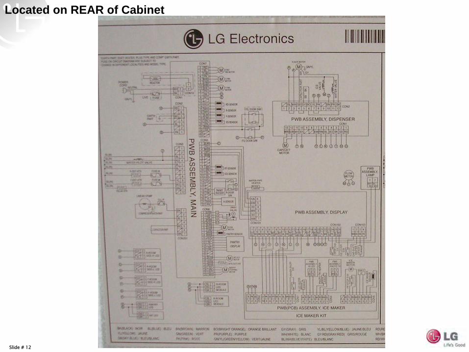
Located on REAR of Cabinet
Slide # 13
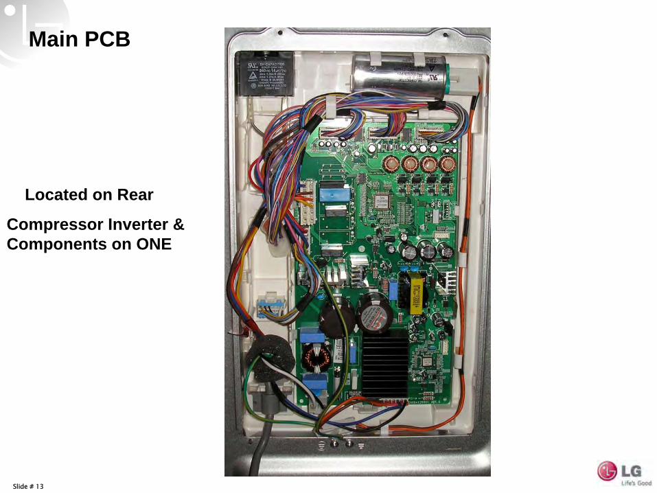
Main PCB
Located on Rear
Compressor Inverter & Components on ONE
Slide # 14
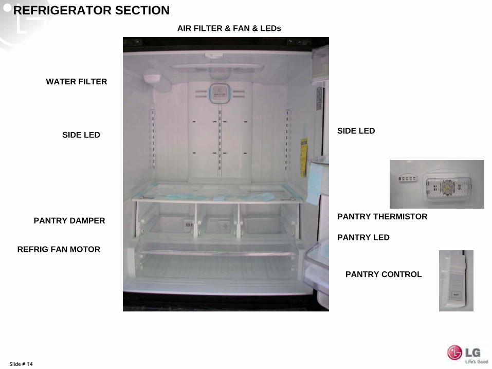
REFRIGERATOR SECTIONAIR FILTER & FAN & LEDs
WATER FILTER
PANTRY DAMPER PANTRY THERMISTOR
REFRIG FAN MOTOR
PANTRY CONTROL
PANTRY LED
SIDE LEDSIDE LED
Slide # 15
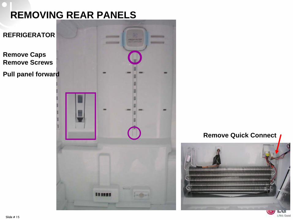
REMOVING REAR PANELS
REFRIGERATOR
Remove Caps Remove Screws
Pull panel forward
Remove Quick Connect
Slide # 16
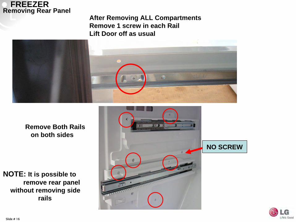
FREEZERAfter Removing ALL Compartments Remove 1 screw in each Rail Lift Door off as usual
Remove Both Rails on both sides
NO SCREW
NOTE: It is possible to remove rear panel
without removing side rails
Removing Rear Panel
Slide # 17
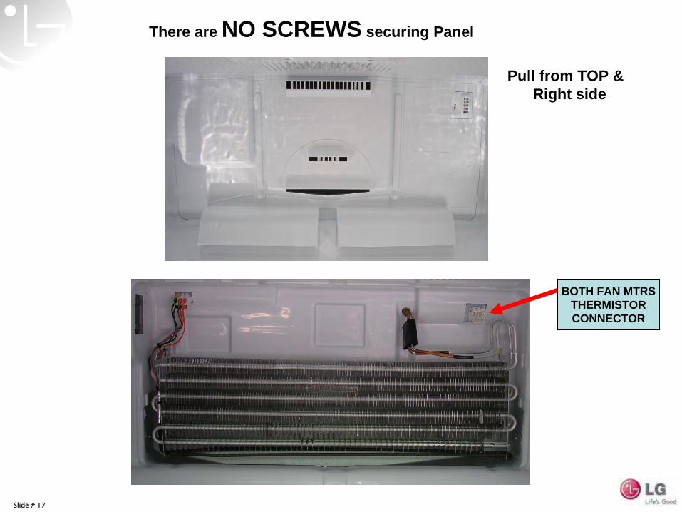
There are NO SCREWS securing Panel
BOTH FAN MTRS THERMISTOR CONNECTOR
Pull from TOP & Right side
Slide # 18
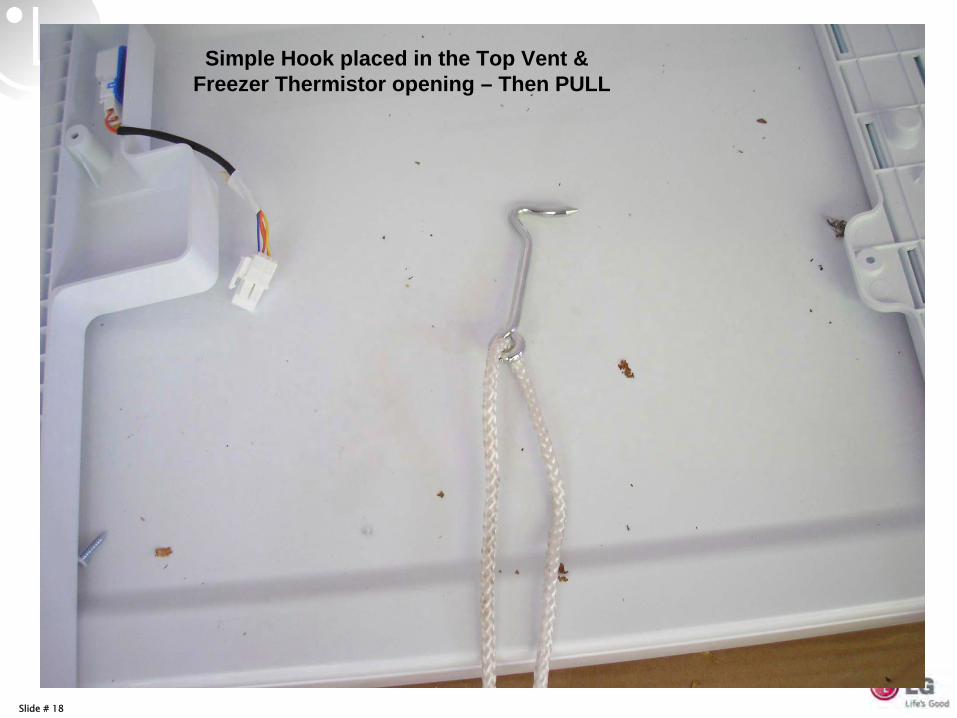
Simple Hook placed in the Top Vent & Freezer Thermistor opening – Then PULL
Slide # 19
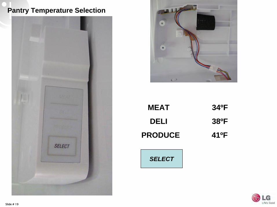
Pantry Temperature Selection
MEAT 34ºF
DELI 38ºF
PRODUCE 41ºF
SELECT
Slide # 20
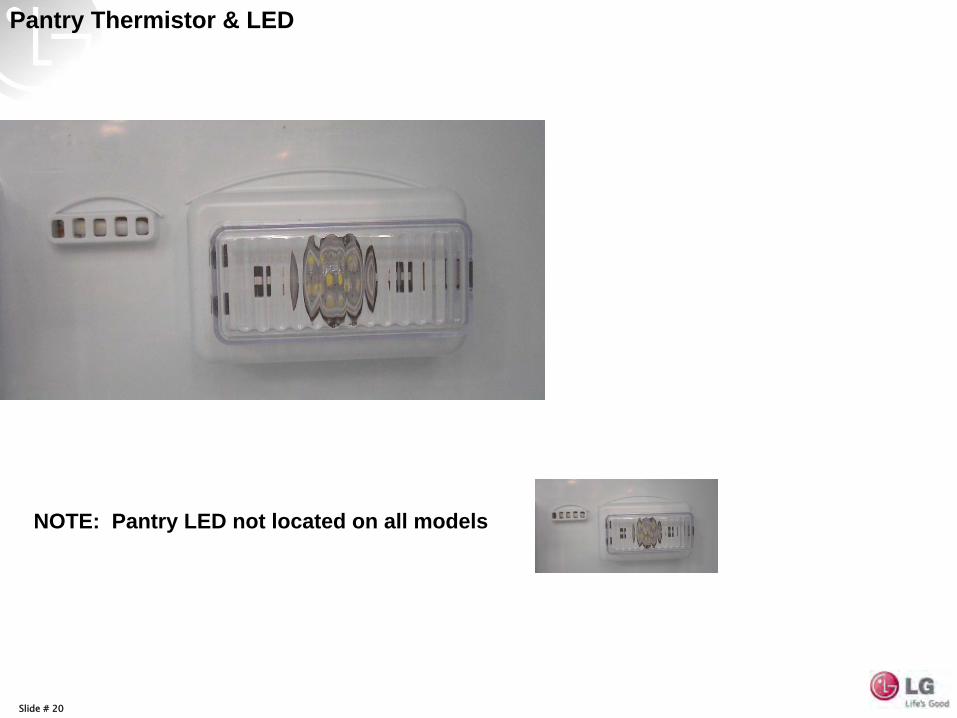
Pantry Thermistor & LED
NOTE: Pantry LED not located on all models
Slide # 21
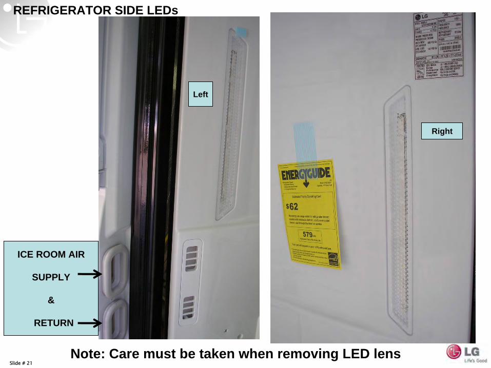
REFRIGERATOR SIDE LEDs
ICE ROOM AIR
SUPPLY
&
RETURN
Left
Right
Note: Care must be taken when removing LED lens
Slide # 22
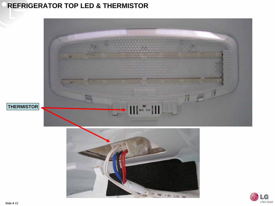
REFRIGERATOR TOP LED & THERMISTOR
THERMISTOR
Slide # 23
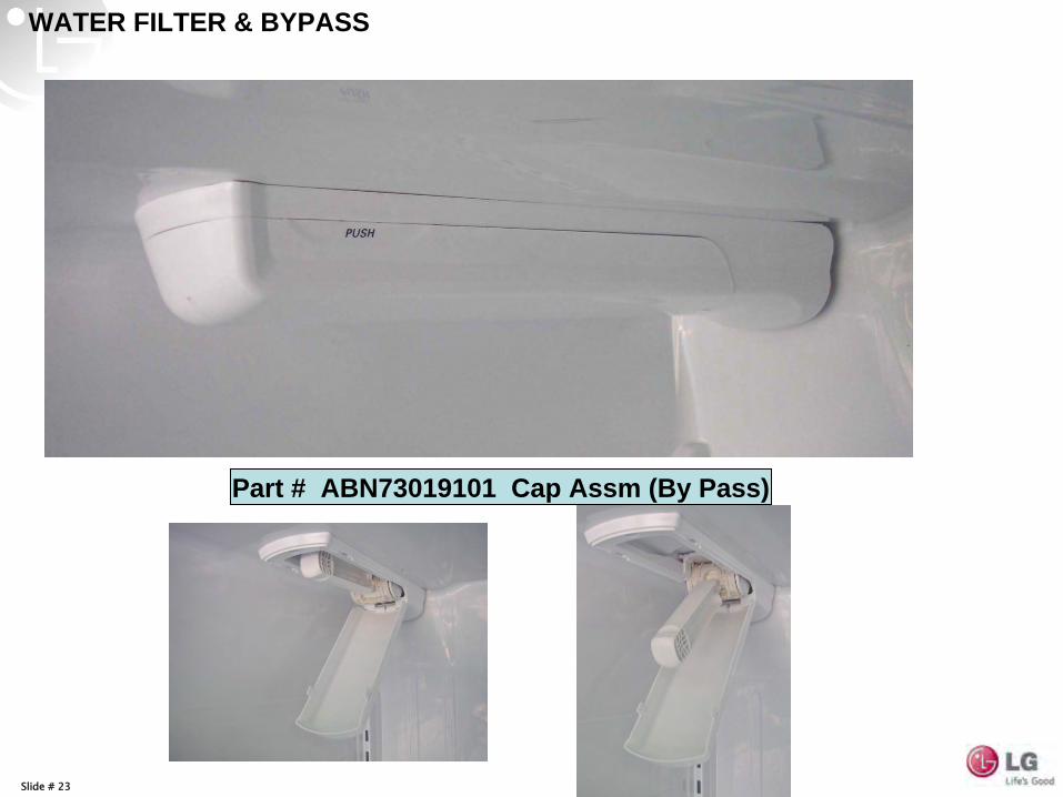
WATER FILTER & BYPASS
Part # ABN73019101 Cap Assm (By Pass)
Slide # 24
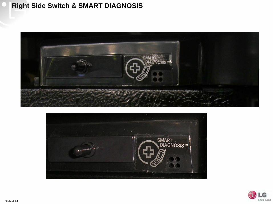
Right Side Switch & SMART DIAGNOSIS
Slide # 25
Slide # 26
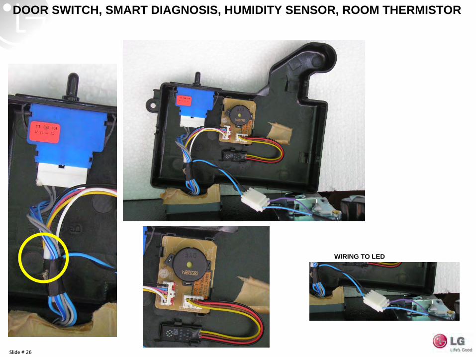
DOOR SWITCH, SMART DIAGNOSIS, HUMIDITY SENSOR, ROOM THERMISTOR
WIRING TO LED
Slide # 27
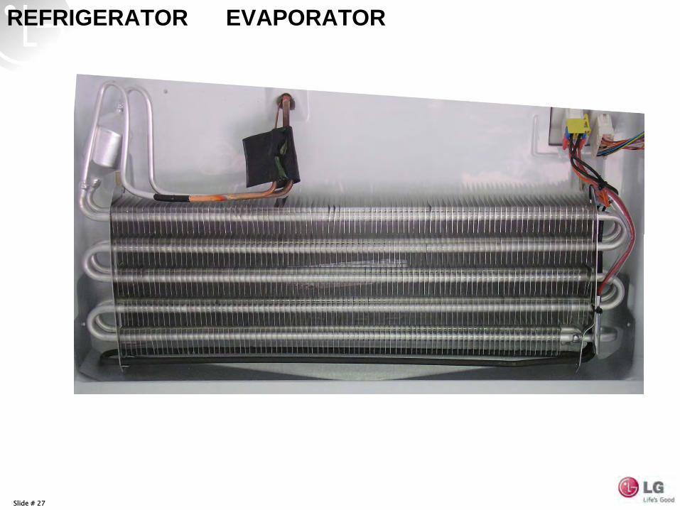
REFRIGERATOR EVAPORATOR
Slide # 28
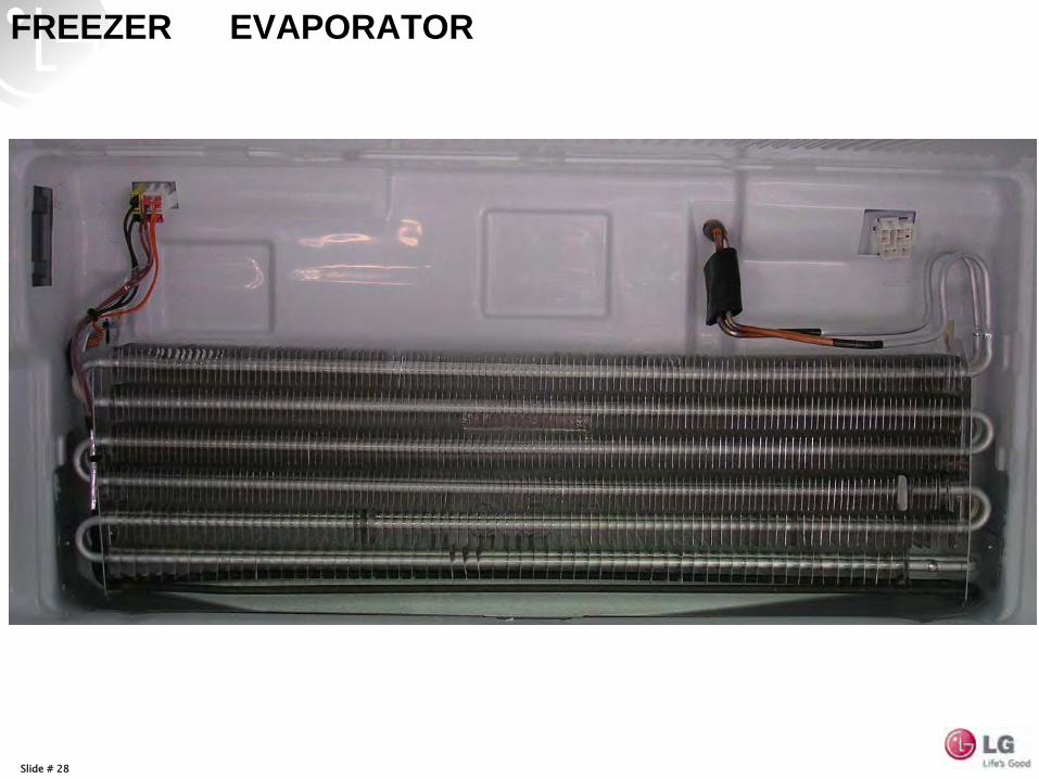
FREEZER EVAPORATOR
Slide # 29
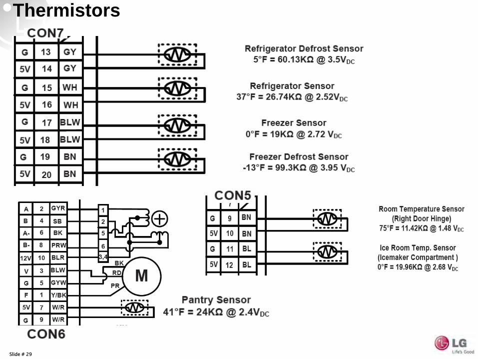
Thermistors
Slide # 30
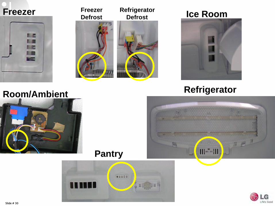
Freezer
RefrigeratorRoom/Ambient
Pantry
Ice RoomFreezer Refrigerator Defrost Defrost
Slide # 31
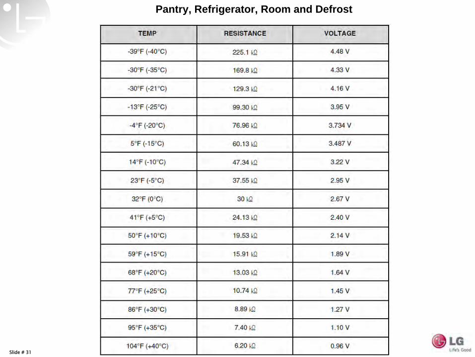
Pantry, Refrigerator, Room and Defrost
Slide # 32
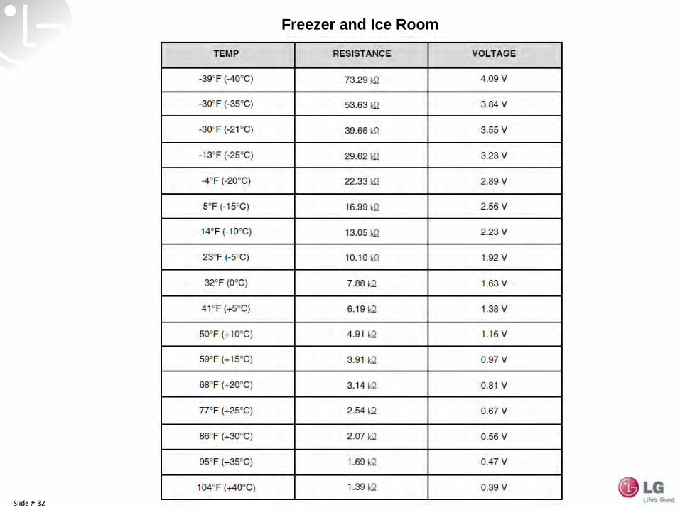
Freezer and Ice Room
Slide # 33
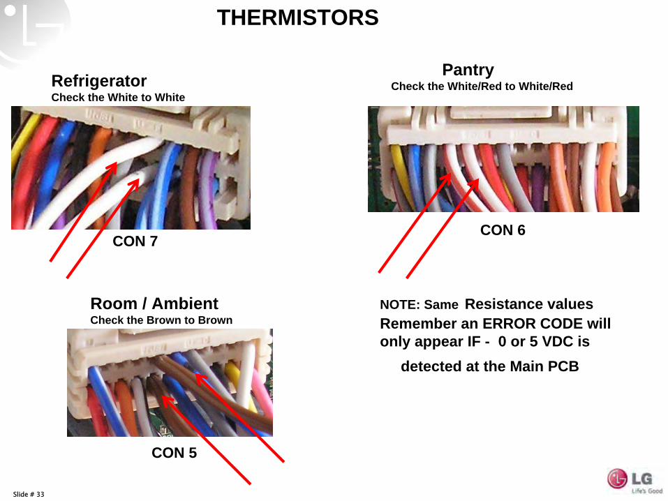
Refrigerator Check the White to White
CON 7
THERMISTORS
NOTE: Same Resistance values Remember an ERROR CODE will only appear IF - 0 or 5 VDC is
detected at the Main PCB
Pantry Check the White/Red to White/Red
CON 6
CON 5
Room / Ambient Check the Brown to Brown
Slide # 34
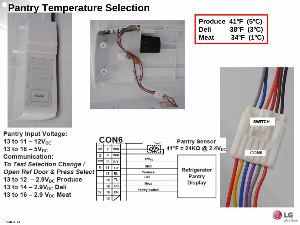
Pantry Temperature Selection
SWITCH
Produce 41ºF (5ºC) Deli 38ºF (3ºC) Meat 34ºF (1ºC)
Slide # 35
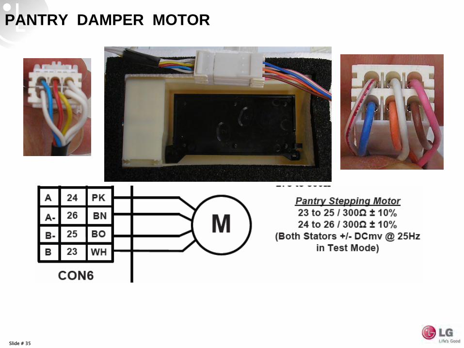
PANTRY DAMPER MOTOR
Slide # 36
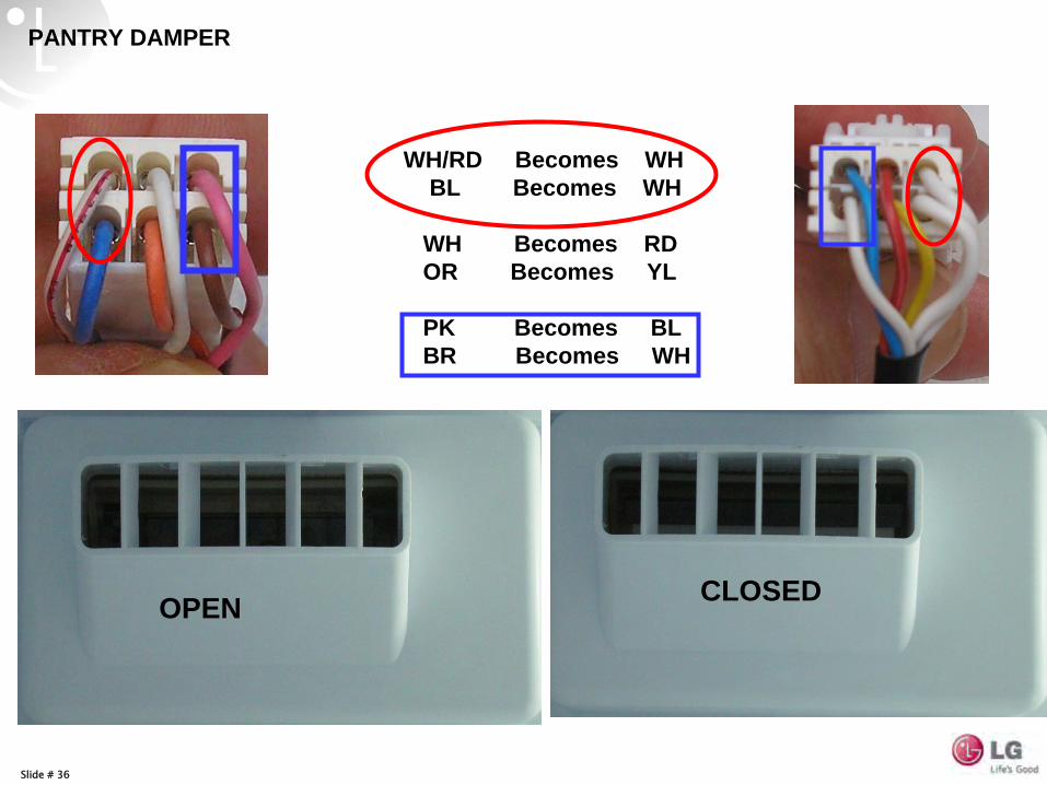
WH/RD Becomes WH BL Becomes WH
WH Becomes RD OR Becomes YL
PK Becomes BL BR Becomes WH
OPEN CLOSED
PANTRY DAMPER
Slide # 37
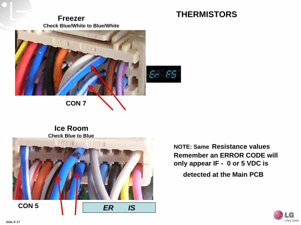
Ice Room Check Blue to Blue
NOTE: Same Resistance values Remember an ERROR CODE will only appear IF - 0 or 5 VDC is
detected at the Main PCB
Freezer Check Blue/White to Blue/White
THERMISTORS
ER IS
CON 7
CON 5
Slide # 38
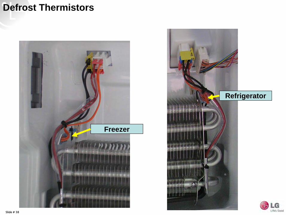
Defrost Thermistors
Freezer
Refrigerator
Slide # 39
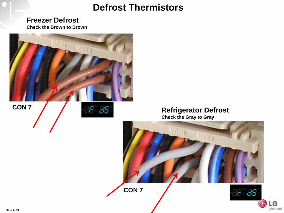
Freezer Defrost Check the Brown to Brown
Refrigerator Defrost Check the Gray to Gray
Defrost Thermistors
CON 7
CON 7
Slide # 40
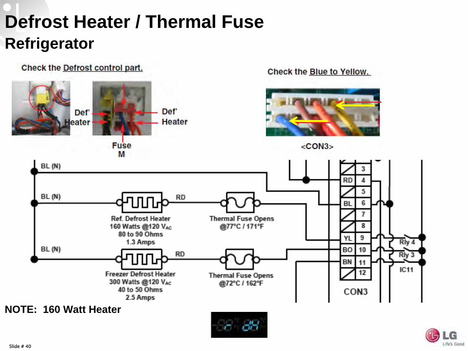
Defrost Heater / Thermal FuseRefrigerator
NOTE: 160 Watt Heater
Slide # 41
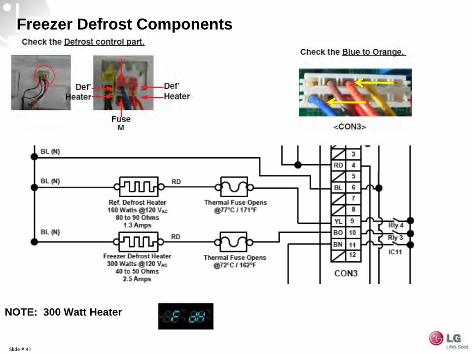
Freezer Defrost Components
NOTE: 300 Watt Heater
Slide # 42
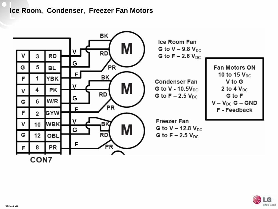
Ice Room, Condenser, Freezer Fan Motors
V
V
V
G
G
G
F
F
F
Slide # 43
V
G
F
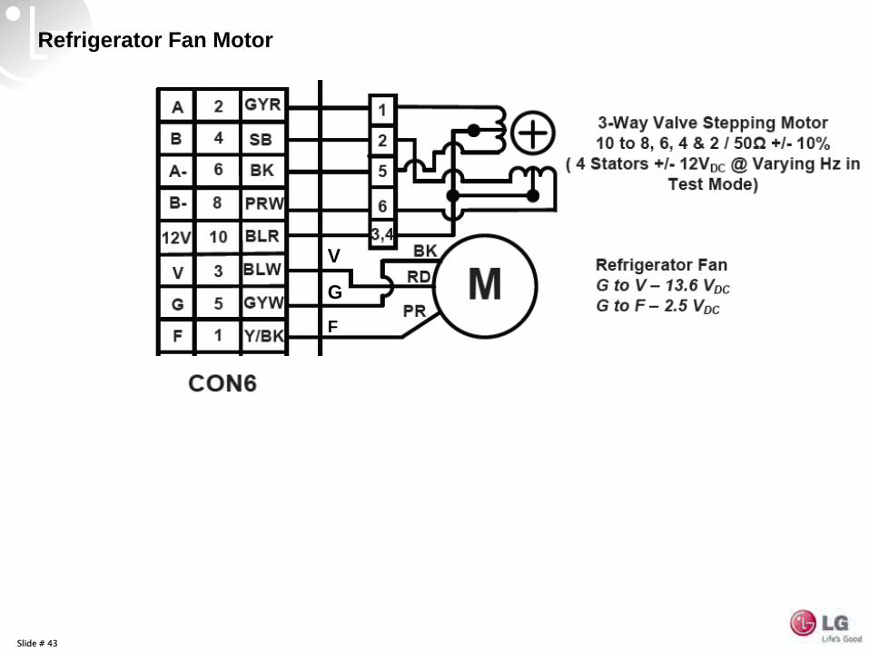
Refrigerator Fan Motor
Slide # 44
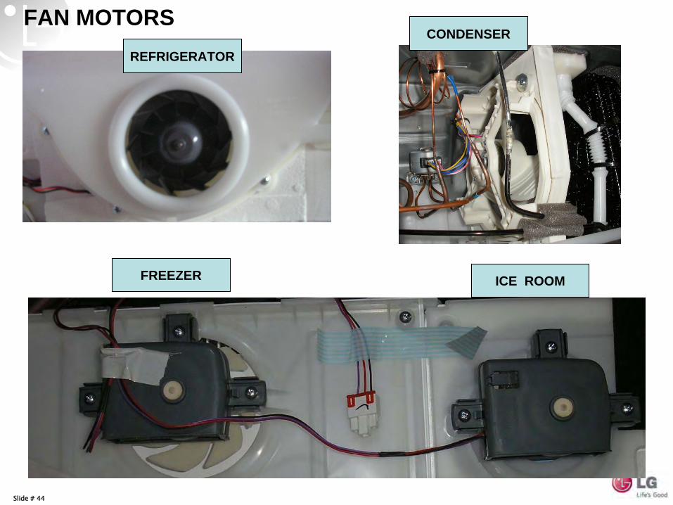
FAN MOTORSREFRIGERATOR
CONDENSER
ICE ROOMFREEZER
Slide # 45
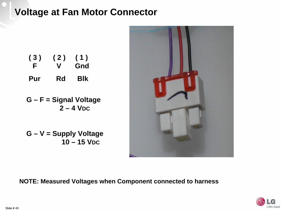
( 3 ) ( 2 ) ( 1 ) F V Gnd
Pur Rd Blk
G – F = Signal Voltage 2 – 4 VDC
G – V = Supply Voltage 10 – 15 VDC
Voltage at Fan Motor Connector
NOTE: Measured Voltages when Component connected to harness
Slide # 46
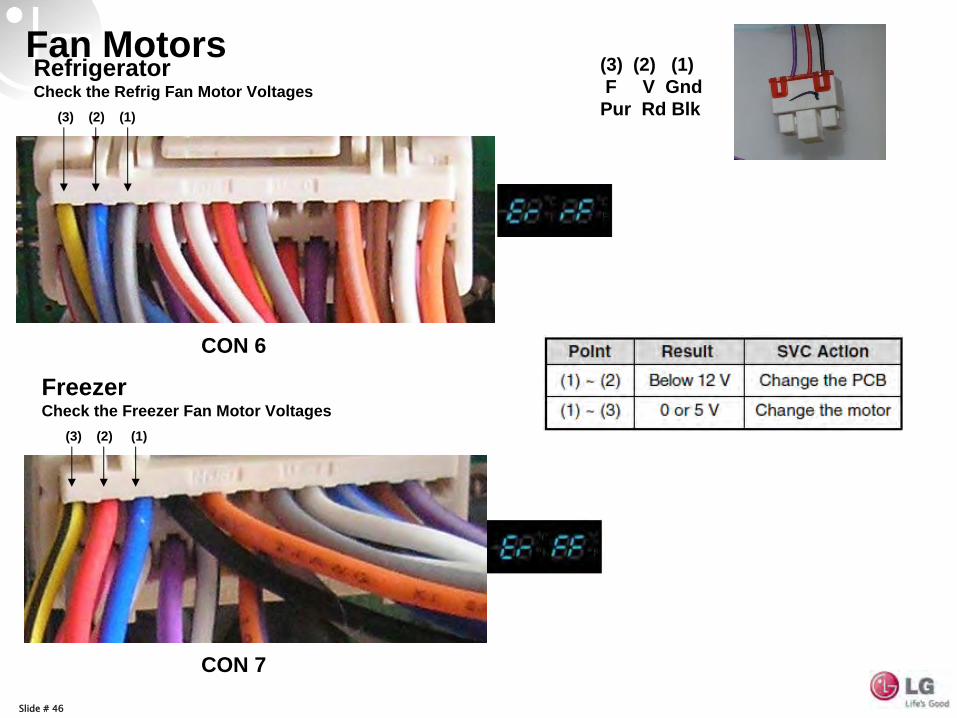
Fan MotorsRefrigerator Check the Refrig Fan Motor Voltages
(3) (2) (1)
(3) (2) (1)
Freezer Check the Freezer Fan Motor Voltages
(3) (2) (1) F V Gnd
Pur Rd Blk
CON 6
CON 7
Slide # 47
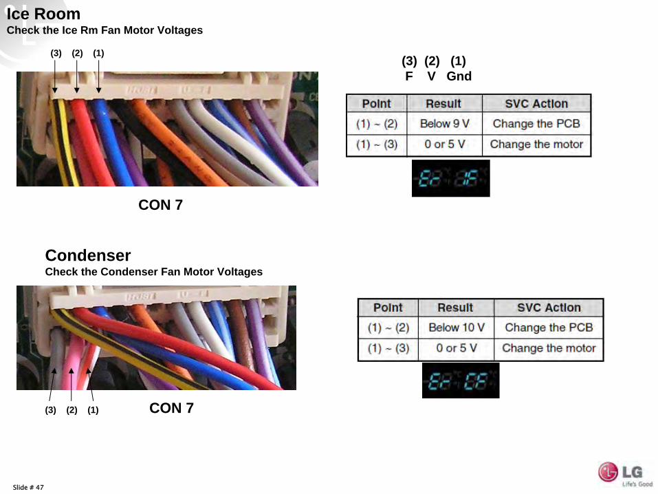
Ice Room Check the Ice Rm Fan Motor Voltages
Condenser Check the Condenser Fan Motor Voltages
(3) (2) (1)
(3) (2) (1)
(3) (2) (1) F V Gnd
CON 7
CON 7
Slide # 48
Hepa Filter
12 VDC
Slide # 49
Slide # 50
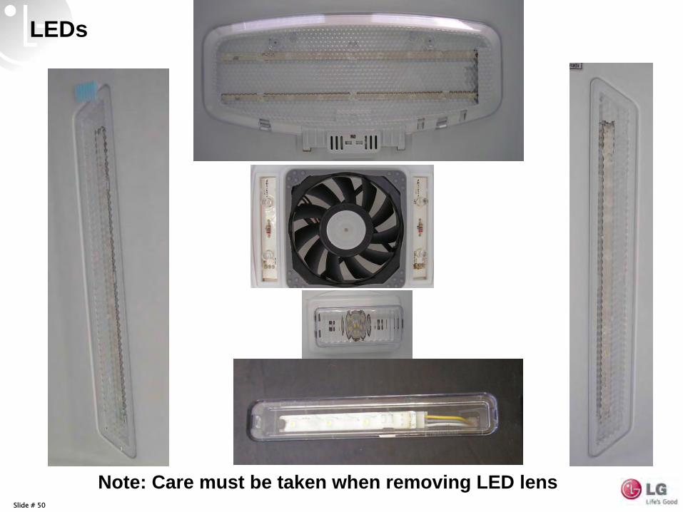
LEDs
Note: Care must be taken when removing LED lens
Slide # 51
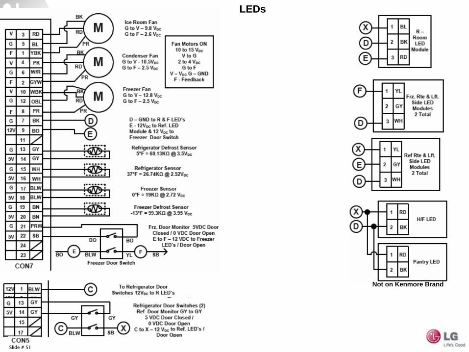
Not on Kenmore Brand
LEDs
Slide # 52
LEDs
Slide # 53
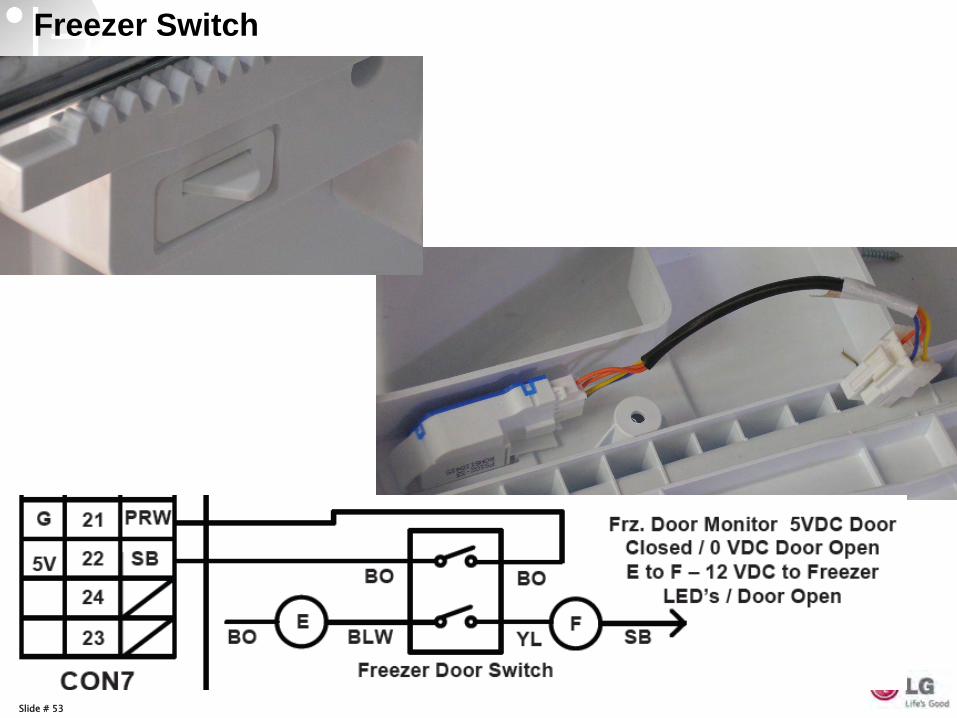
Freezer Switch
Slide # 54
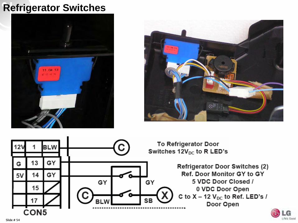
Refrigerator Switches
Slide # 55
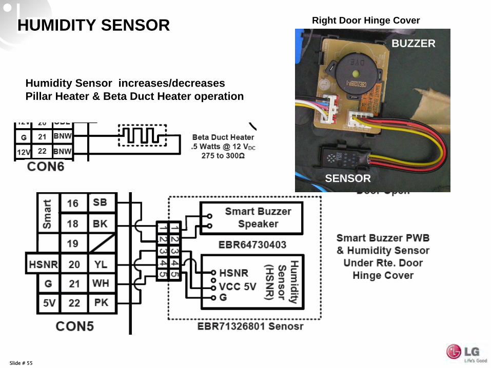
HUMIDITY SENSOR
Humidity Sensor increases/decreases Pillar Heater & Beta Duct Heater operation
Right Door Hinge Cover
BUZZER
SENSOR
Slide # 56
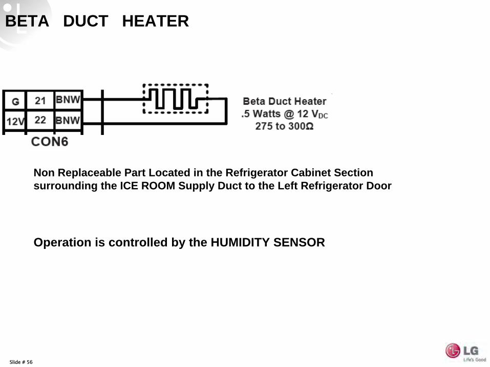
Non Replaceable Part Located in the Refrigerator Cabinet Section surrounding the ICE ROOM Supply Duct to the Left Refrigerator Door
BETA DUCT HEATER
Operation is controlled by the HUMIDITY SENSOR
Slide # 57
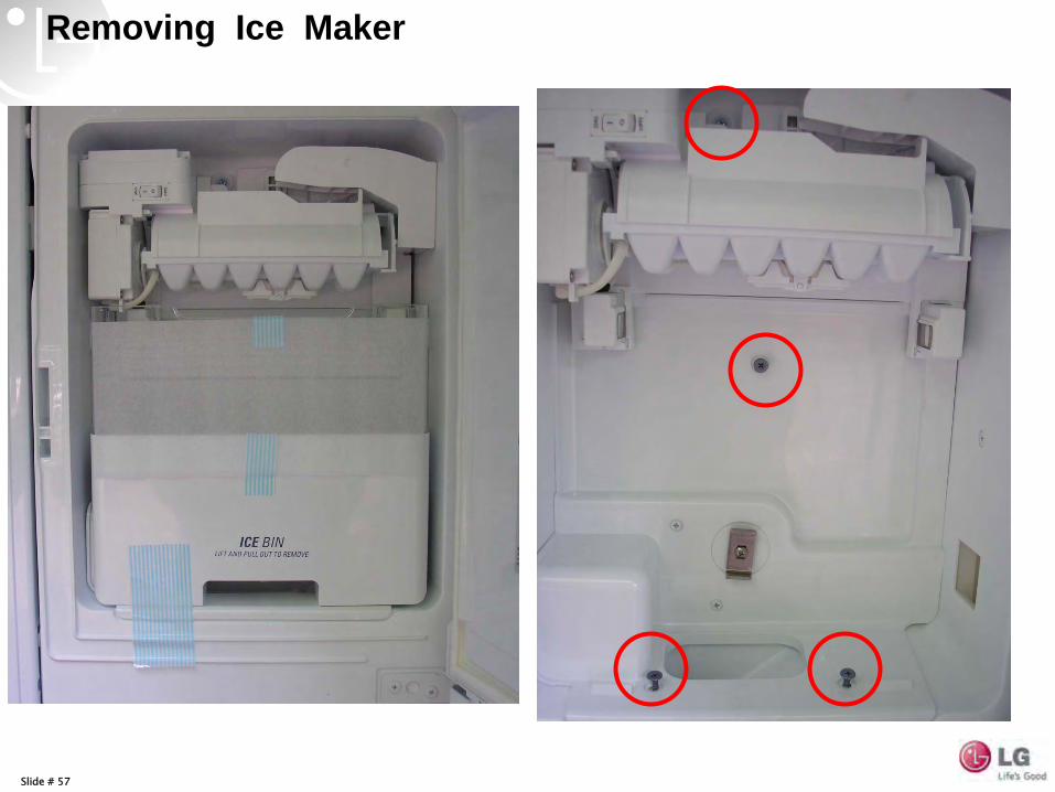
Removing Ice Maker
Slide # 58
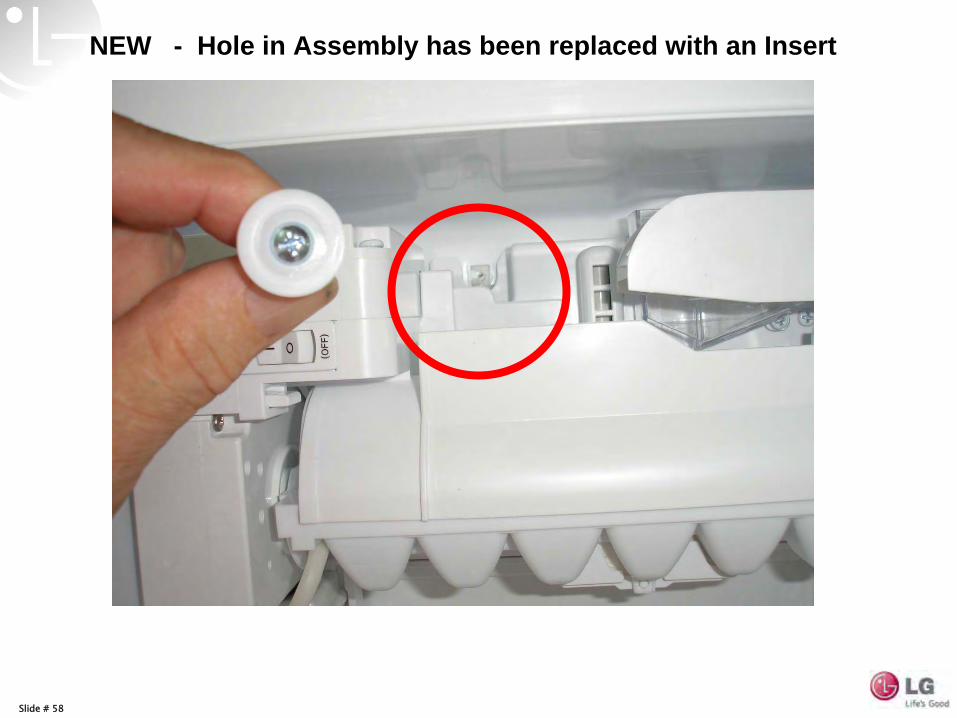
NEW - Hole in Assembly has been replaced with an Insert
Slide # 59
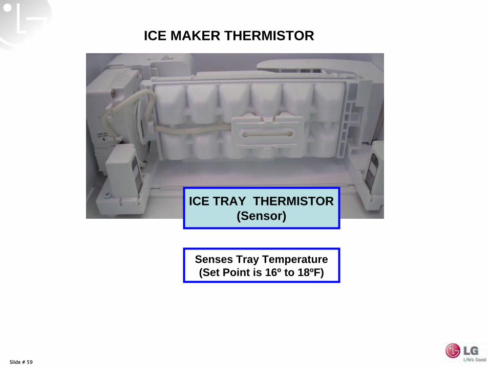
ICE MAKER THERMISTOR
Senses Tray Temperature (Set Point is 16º to 18ºF)
ICE TRAY THERMISTOR(Sensor)
Slide # 60
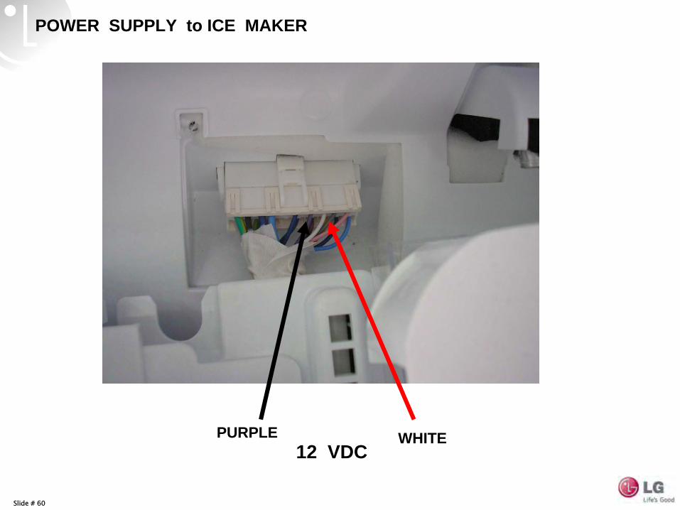
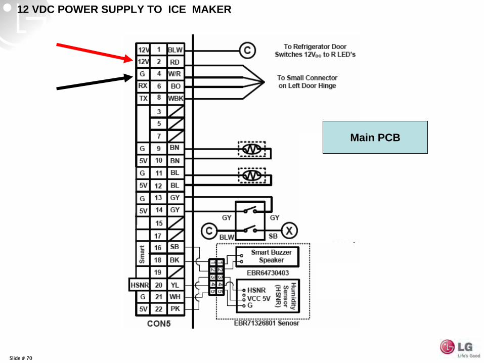
POWER SUPPLY to ICE MAKER
PURPLE WHITE12 VDC
Slide # 61
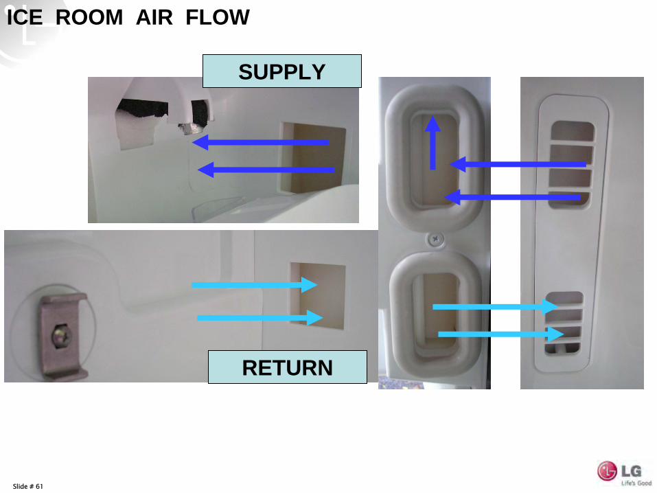
RETURN
SUPPLY
ICE ROOM AIR FLOW
Slide # 62
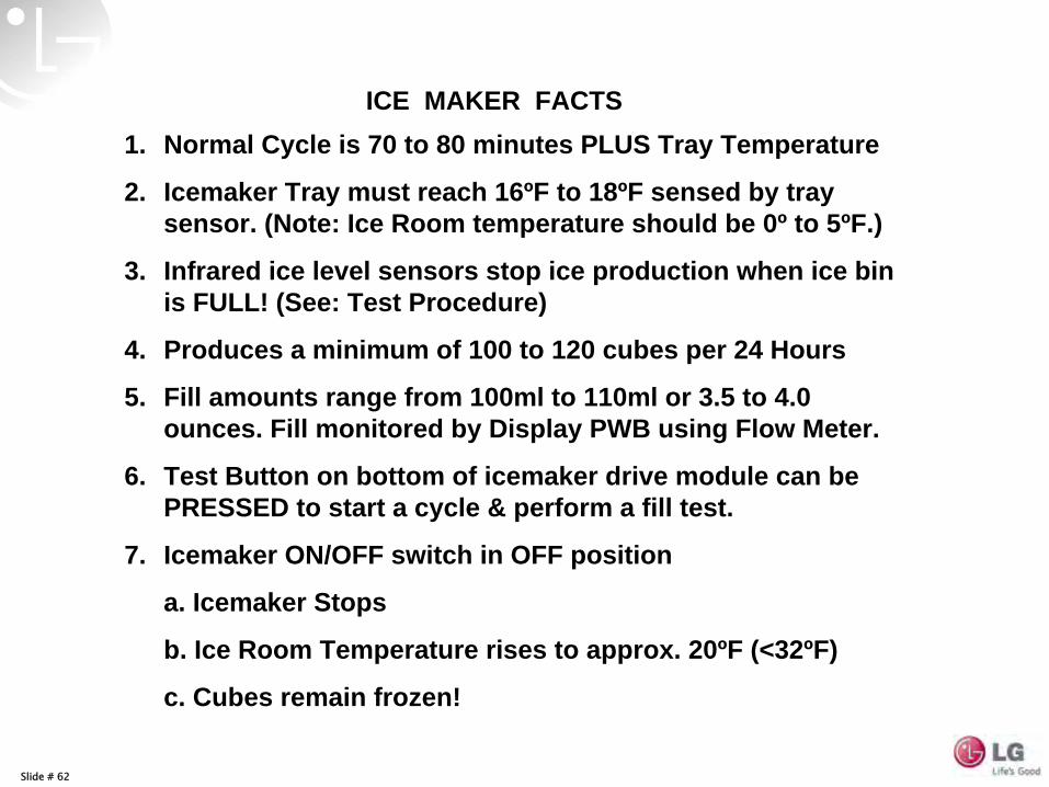
1. Normal Cycle is 70 to 80 minutes PLUS Tray Temperature
2. Icemaker Tray must reach 16ºF to 18ºF sensed by tray sensor. (Note: Ice Room temperature should be 0º to 5ºF.)
3. Infrared ice level sensors stop ice production when ice bin is FULL! (See: Test Procedure)
4. Produces a minimum of 100 to 120 cubes per 24 Hours
5. Fill amounts range from 100ml to 110ml or 3.5 to 4.0 ounces. Fill monitored by Display PWB using Flow Meter.
6. Test Button on bottom of icemaker drive module can be PRESSED to start a cycle & perform a fill test.
7. Icemaker ON/OFF switch in OFF position
a. Icemaker Stops
b. Ice Room Temperature rises to approx. 20ºF (<32ºF)
c. Cubes remain frozen!
ICE MAKER FACTS
Slide # 63
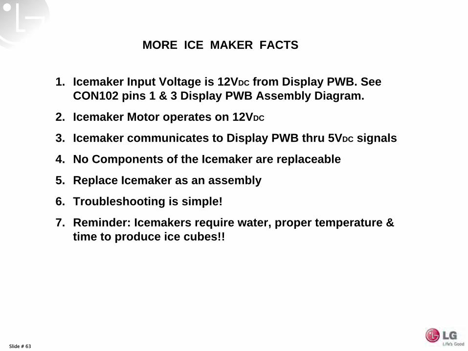
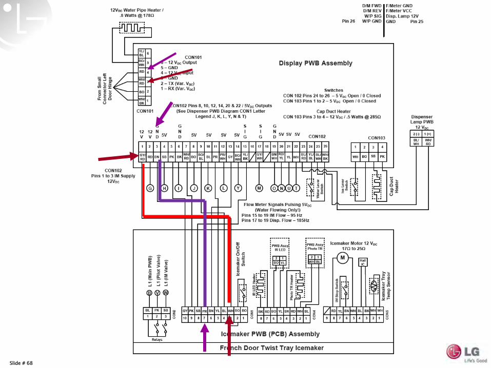
1. Icemaker Input Voltage is 12VDC from Display PWB. See CON102 pins 1 & 3 Display PWB Assembly Diagram.
2. Icemaker Motor operates on 12VDC
3. Icemaker communicates to Display PWB thru 5VDC signals
4. No Components of the Icemaker are replaceable
5. Replace Icemaker as an assembly
6. Troubleshooting is simple!
7. Reminder: Icemakers require water, proper temperature & time to produce ice cubes!!
MORE ICE MAKER FACTS
Slide # 64
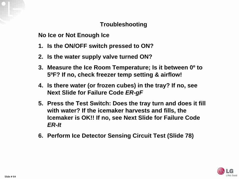
Troubleshooting
No Ice or Not Enough Ice
1. Is the ON/OFF switch pressed to ON?
2. Is the water supply valve turned ON?
3. Measure the Ice Room Temperature; Is it between 0º to 5ºF? If no, check freezer temp setting & airflow!
4. Is there water (or frozen cubes) in the tray? If no, see Next Slide for Failure Code ER-gF
5. Press the Test Switch: Does the tray turn and does it fill with water? If the icemaker harvests and fills, the Icemaker is OK!! If no, see Next Slide for Failure Code ER-It
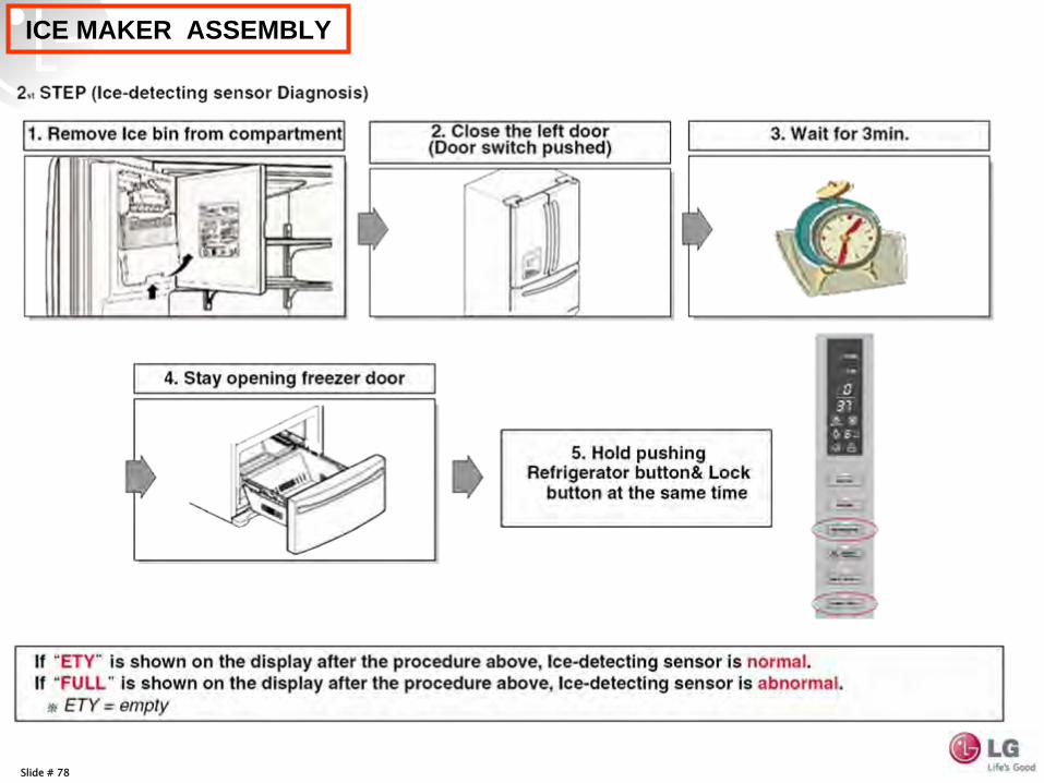
6. Perform Ice Detector Sensing Circuit Test (Slide 78)
Slide # 65
ICE MAKER ASSEMBLY
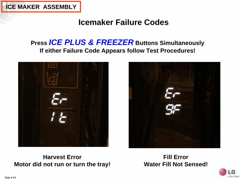
Icemaker Failure Codes
Fill Error Water Fill Not Sensed!
Harvest Error Motor did not run or turn the tray!
Press ICE PLUS & FREEZER Buttons Simultaneously If either Failure Code Appears follow Test Procedures!
Slide # 66
ICE MAKER ASSEMBLY
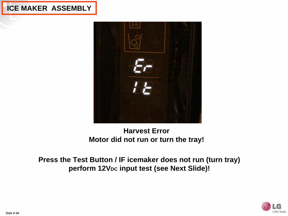
Harvest Error Motor did not run or turn the tray!
Press the Test Button / IF icemaker does not run (turn tray) perform 12VDC input test (see Next Slide)!
Slide # 67
ICE MAKER ASSEMBLY
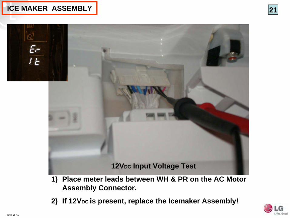
12VDC Input Voltage Test
1) Place meter leads between WH & PR on the AC Motor Assembly Connector.
2) If 12VDC is present, replace the Icemaker Assembly!
21
Slide # 68
Slide # 69
Slide # 70
12 VDC POWER SUPPLY TO ICE MAKER
Main PCB
Slide # 71
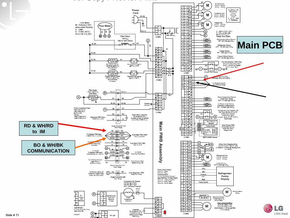
Main PCB
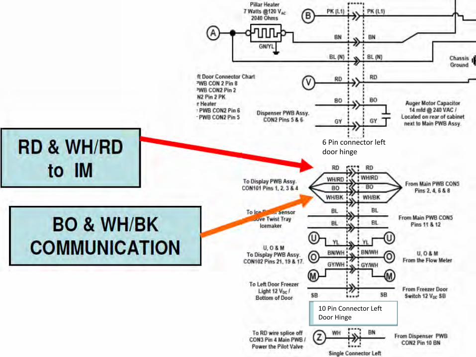
RD & WH/RD to IM
BO & WH/BK COMMUNICATION
Slide # 72
6 Pin connector left
door hinge
10 Pin Connector Left
Door Hinge
Slide # 73
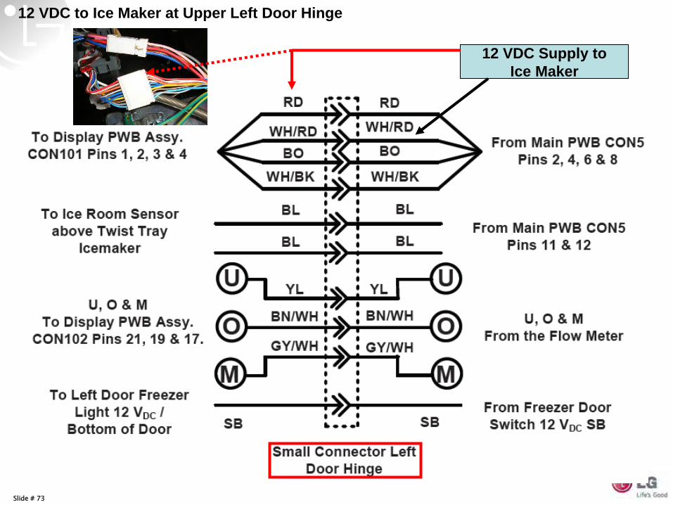
12 VDC Supply to Ice Maker
12 VDC to Ice Maker at Upper Left Door Hinge
Slide # 74
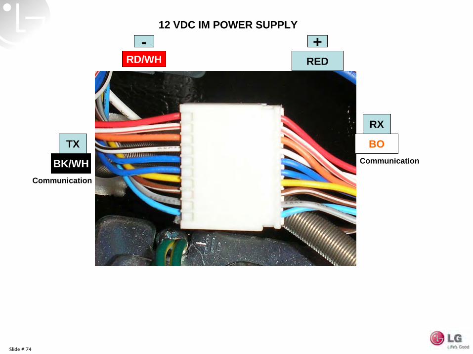
REDRD/WH
BO
BK/WH
12 VDC IM POWER SUPPLY
- +
RX
TX
Communication
Communication
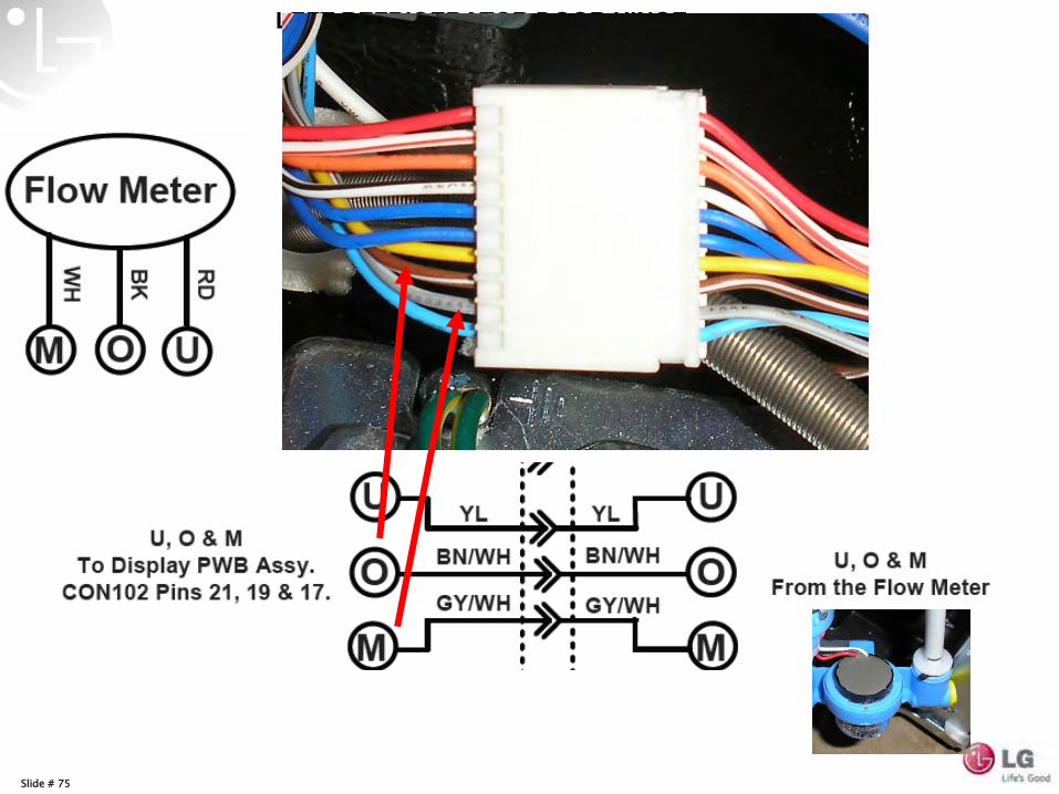
Slide # 75
LEFT REFRIGERATOR DOOR HINGE
Slide # 76
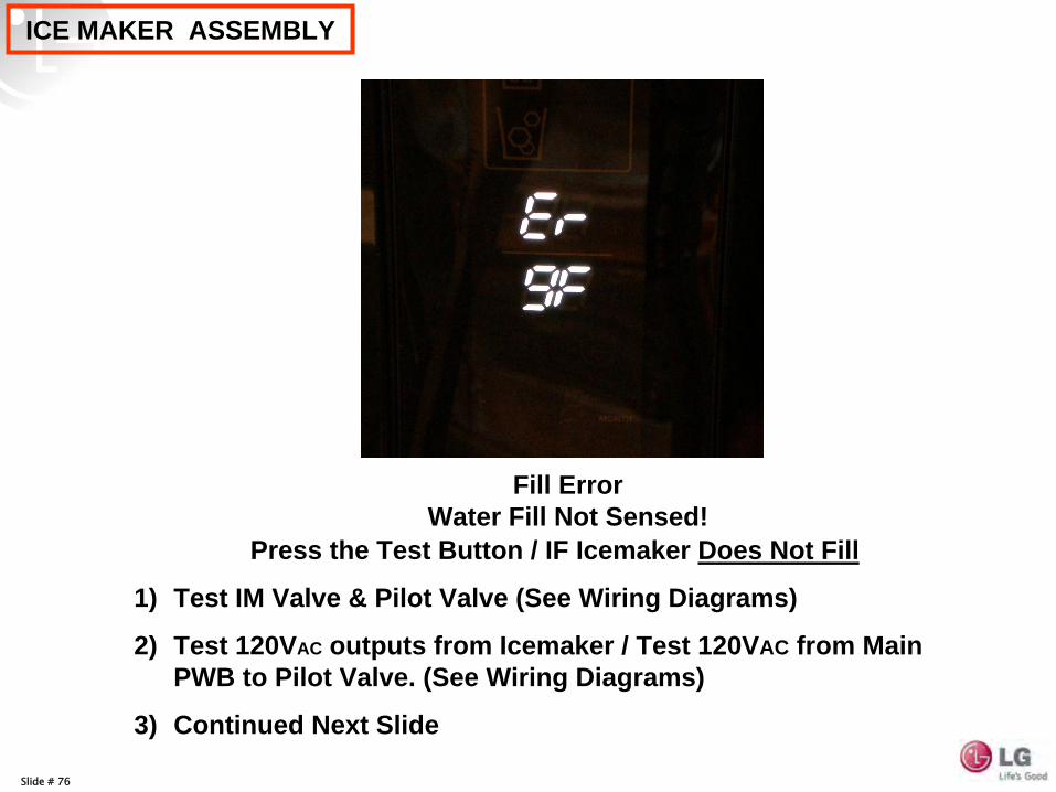
ICE MAKER ASSEMBLY
Fill Error Water Fill Not Sensed!
Press the Test Button / IF Icemaker Does Not Fill
1) Test IM Valve & Pilot Valve (See Wiring Diagrams)
2) Test 120VAC outputs from Icemaker / Test 120VAC from Main PWB to Pilot Valve. (See Wiring Diagrams)
3) Continued Next Slide
Slide # 77
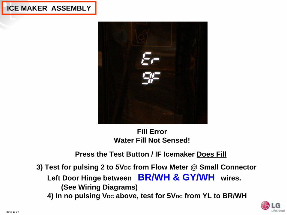
ICE MAKER ASSEMBLY
Fill Error Water Fill Not Sensed!
Press the Test Button / IF Icemaker Does Fill
3) Test for pulsing 2 to 5VDC from Flow Meter @ Small Connector Left Door Hinge between BR/WH & GY/WH wires.
(See Wiring Diagrams) 4) In no pulsing VDC above, test for 5VDC from YL to BR/WH
Slide # 78
ICE MAKER ASSEMBLY
Slide # 79
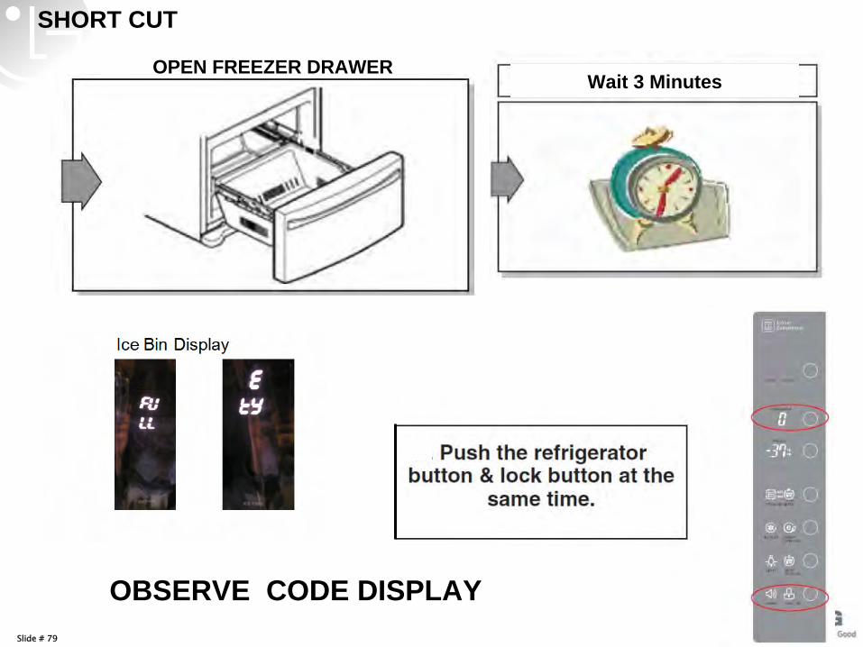
SHORT CUT
OPEN FREEZER DRAWER
OBSERVE CODE DISPLAY
Wait 3 Minutes
Slide # 80
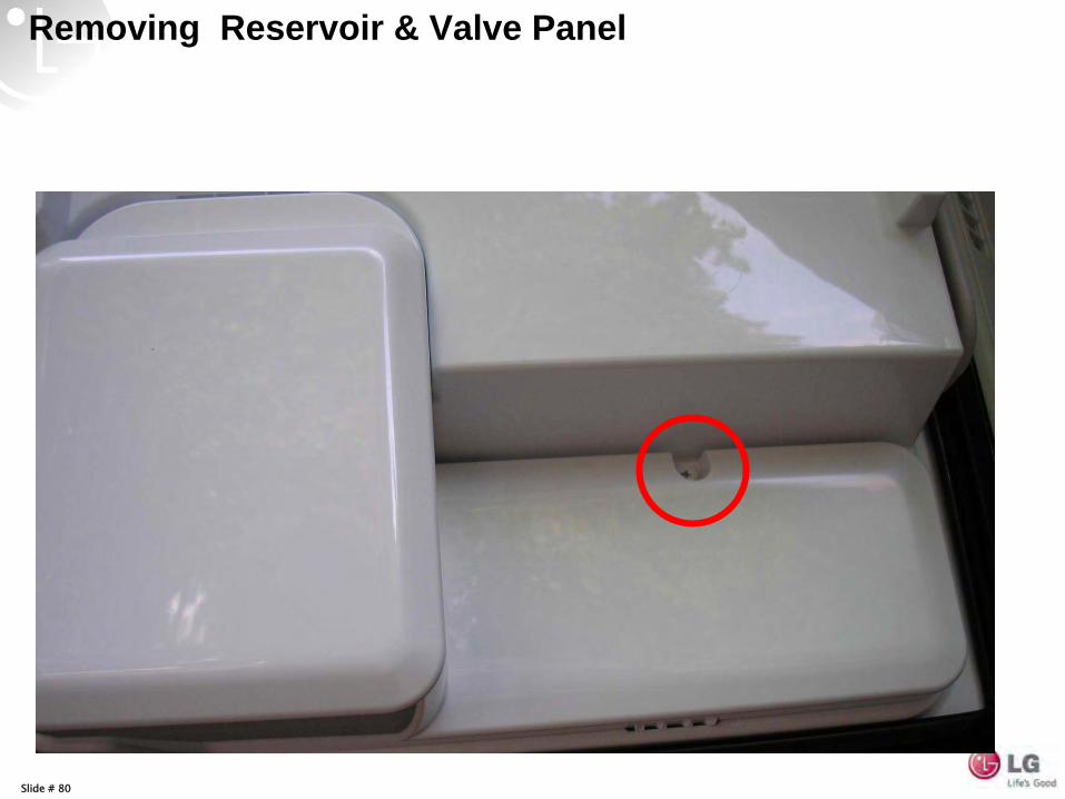
Removing Reservoir & Valve Panel
Slide # 81
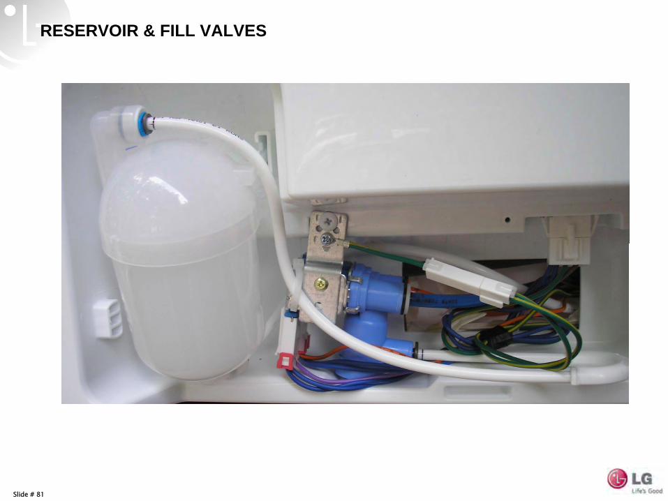
RESERVOIR & FILL VALVES
Slide # 82
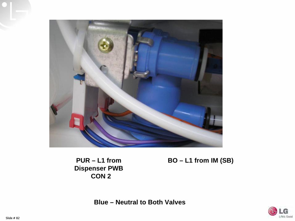
Blue – Neutral to Both Valves
BO – L1 from IM (SB)PUR – L1 from Dispenser PWB
CON 2
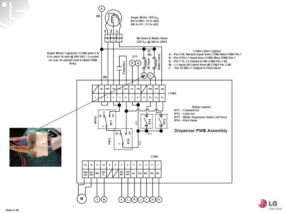
Slide # 83
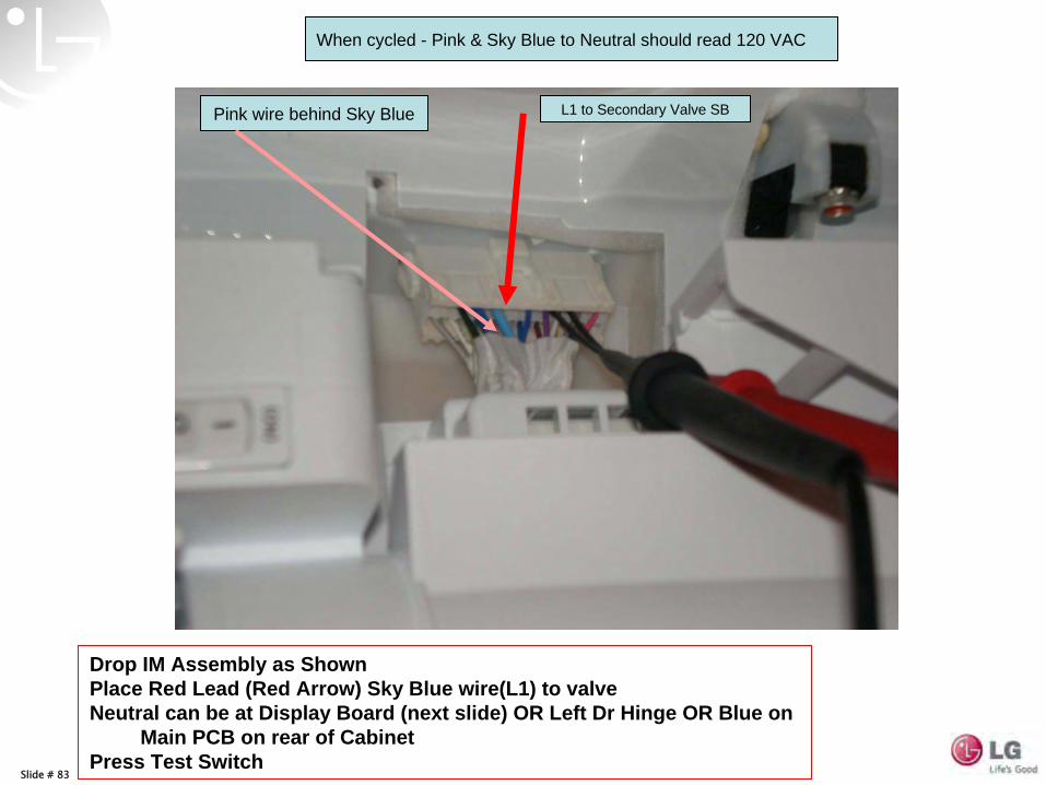
Drop IM Assembly as Shown Place Red Lead (Red Arrow) Sky Blue wire(L1) to valve Neutral can be at Display Board (next slide) OR Left Dr Hinge OR Blue on
Main PCB on rear of Cabinet Press Test Switch
L1 to Secondary Valve SBPink wire behind Sky Blue
When cycled - Pink & Sky Blue to Neutral should read 120 VAC
Slide # 84
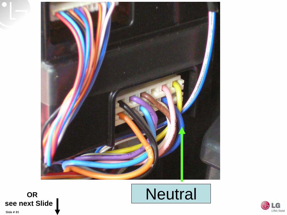
Slide # 85
NeutralOR see next Slide
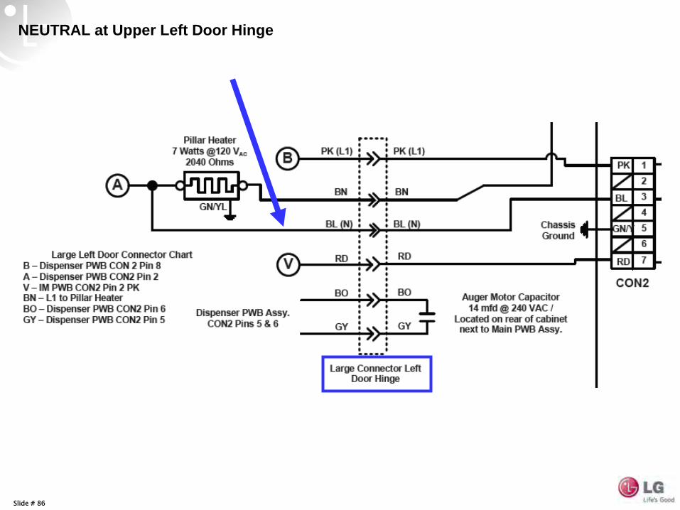
Slide # 86
NEUTRAL at Upper Left Door Hinge
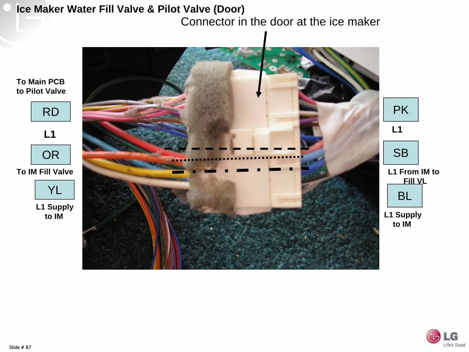
Slide # 87
OR SBTo IM Fill Valve L1 From IM to
Fill VL
Connector in the door at the ice maker
L1 L1
Ice Maker Water Fill Valve & Pilot Valve (Door)
PKRD
To Main PCB to Pilot Valve
YLL1 Supply
to IM
BLL1 Supply
to IM
Slide # 88
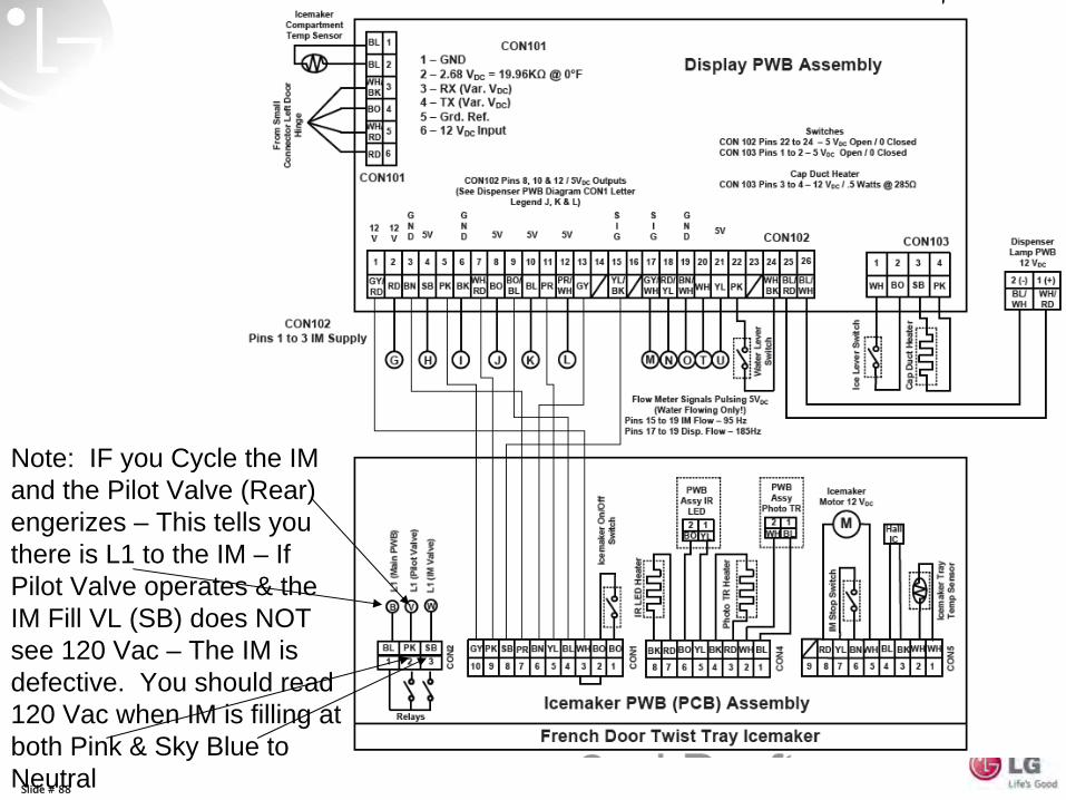
Note: IF you Cycle the IM and the Pilot Valve (Rear) engerizes – This tells you there is L1 to the IM – If Pilot Valve operates & the IM Fill VL (SB) does NOT see 120 Vac – The IM is defective. You should read 120 Vac when IM is filling at both Pink & Sky Blue to Neutral
Slide # 89
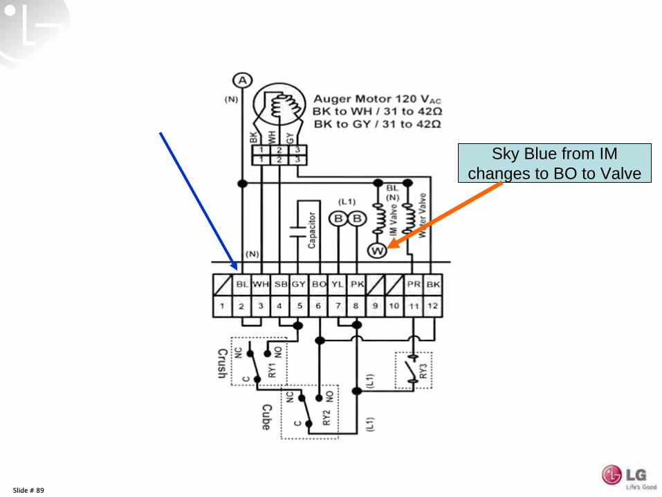
Sky Blue from IM changes to BO to Valve
Slide # 90
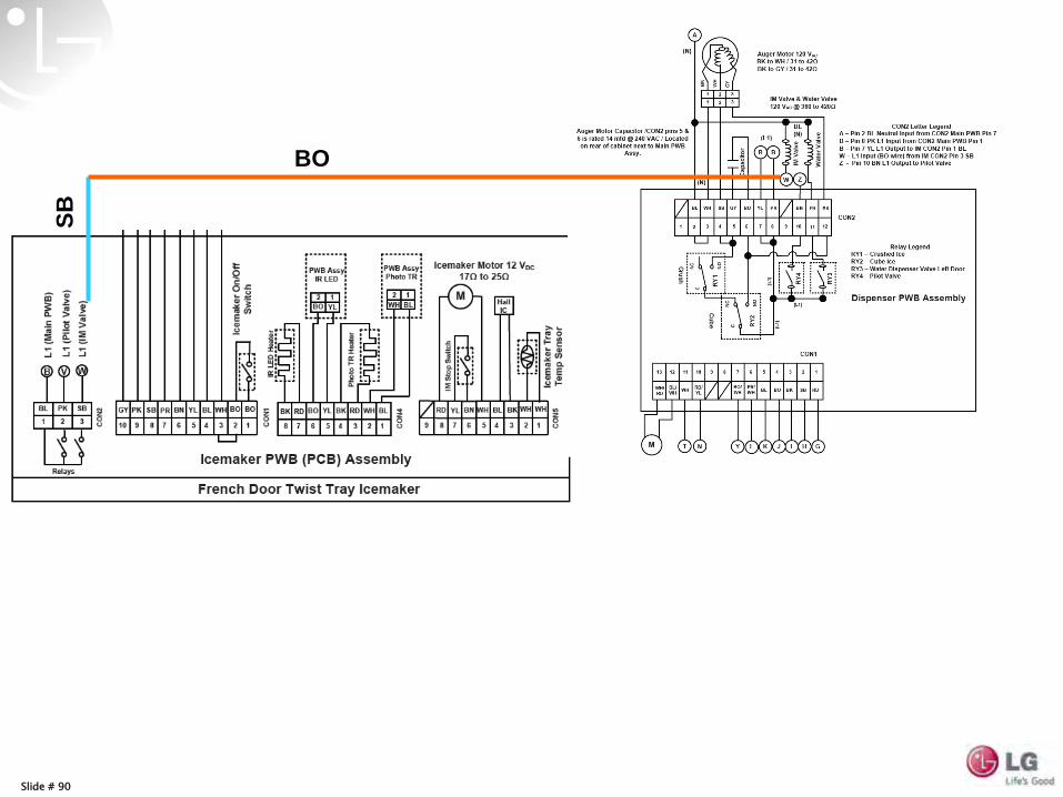
BO
SB
Slide # 92
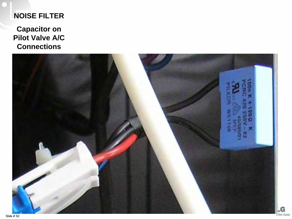
NOISE FILTER
Capacitor on Pilot Valve A/C Connections
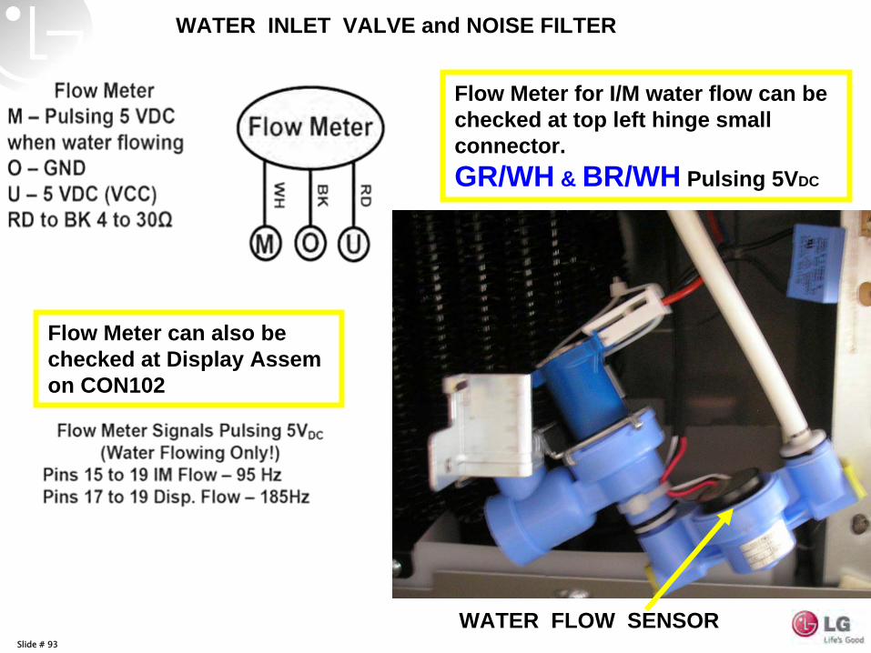
Slide # 93
WATER FLOW SENSOR
Flow Meter for I/M water flow can be checked at top left hinge small connector. GR/WH & BR/WH Pulsing 5VDC
Flow Meter can also be checked at Display Assem on CON102
WATER INLET VALVE and NOISE FILTER
Slide # 94
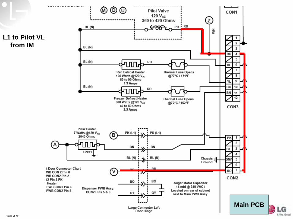
Slide # 95
L1 to Pilot VL from IM
Main PCB
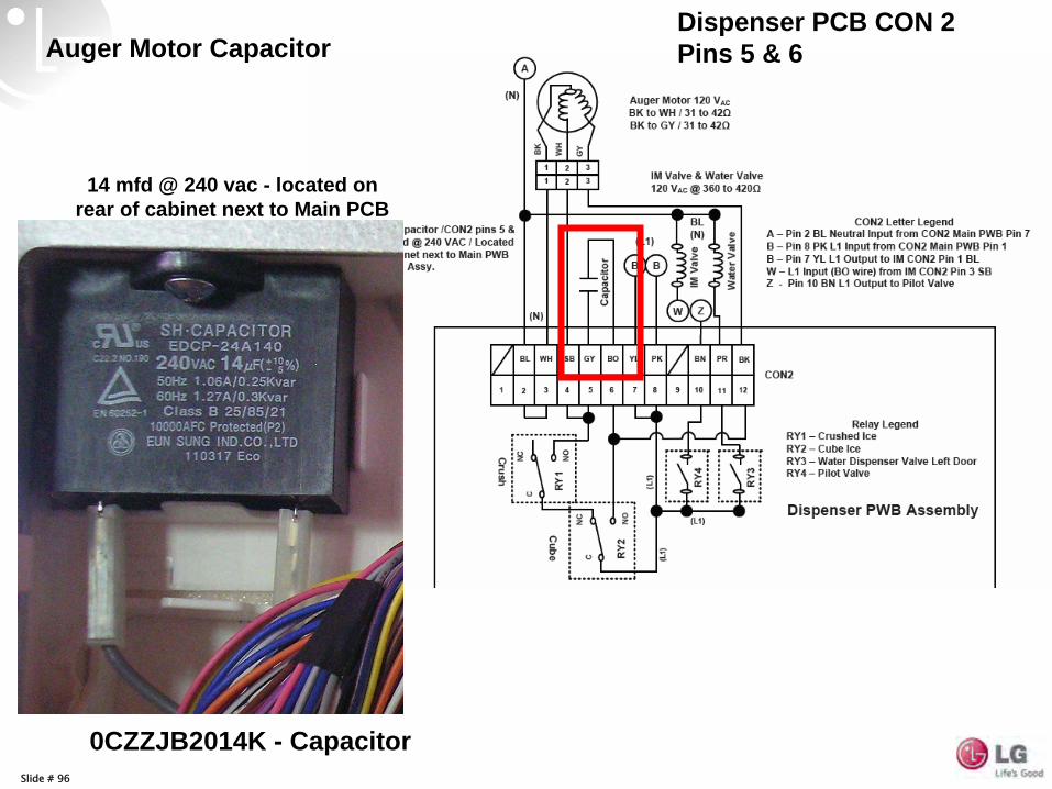
Slide # 96
14 mfd @ 240 vac - located on rear of cabinet next to Main PCB
Auger Motor CapacitorDispenser PCB CON 2 Pins 5 & 6
0CZZJB2014K - Capacitor
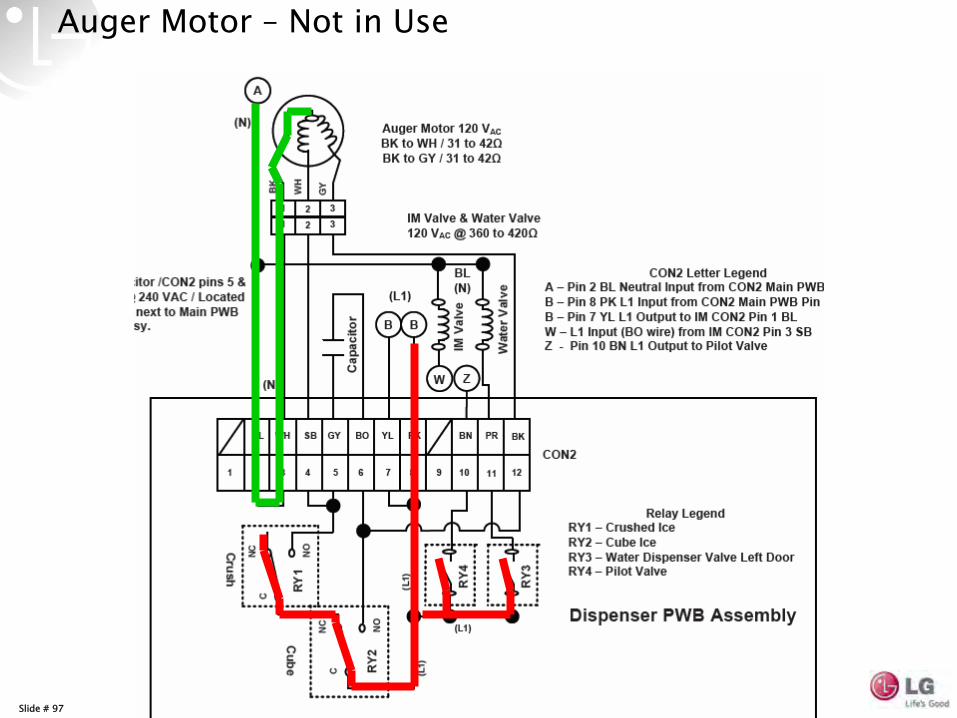
Slide # 97
Auger Motor –
Not in Use
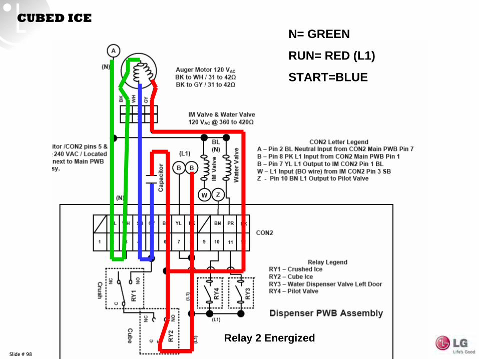
Slide # 98
CUBED ICEN= GREEN
RUN= RED (L1)
START=BLUE
Relay 2 Energized
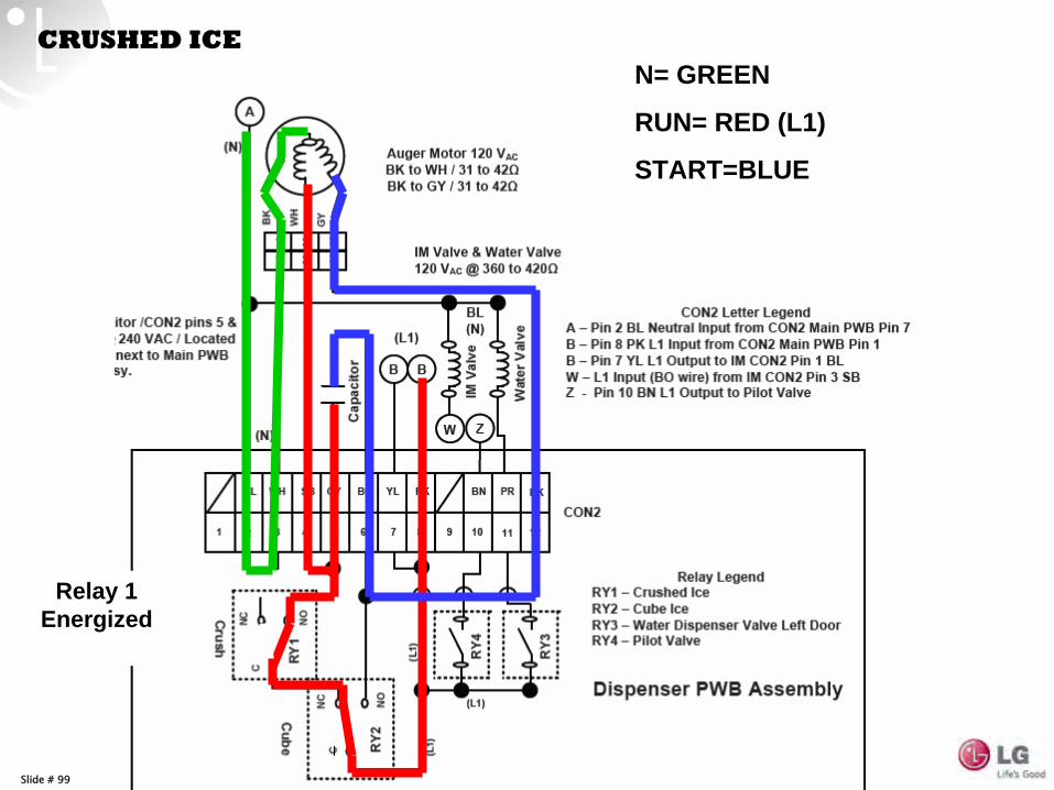
Slide # 99
N= GREEN
RUN= RED (L1)
START=BLUE
CRUSHED ICE
Relay 1 Energized
Slide # 100
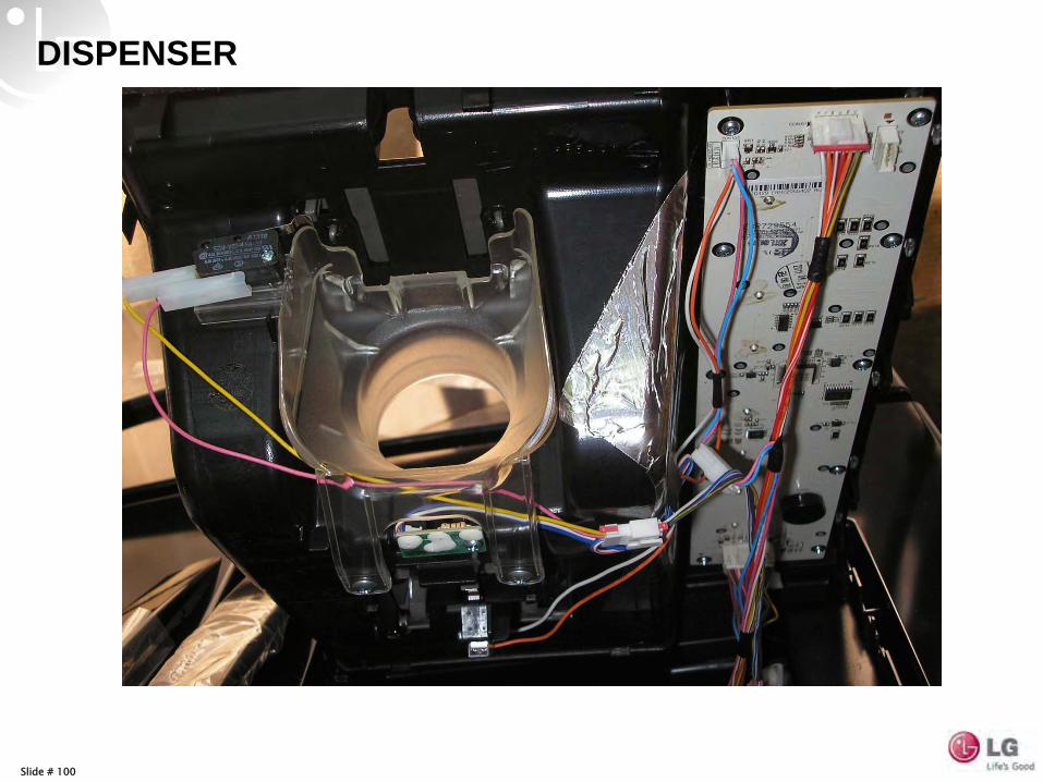
DISPENSER
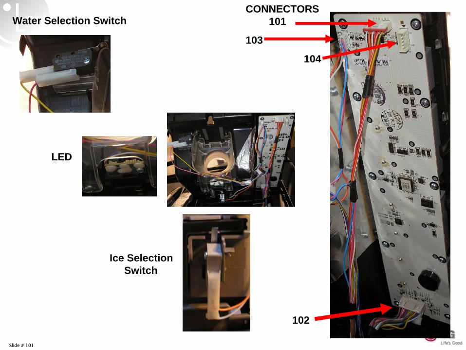
Slide # 101
Water Selection Switch
LED
Ice Selection Switch
CONNECTORS 101
103
104
102
Slide # 102
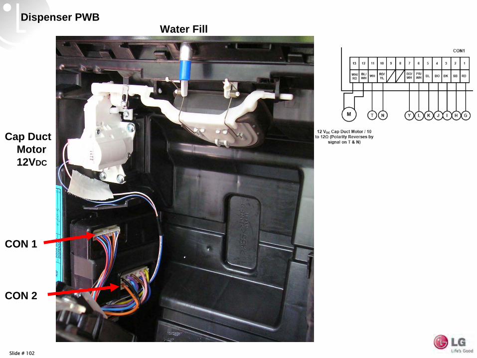
Cap Duct Motor 12VDC
Water FillDispenser PWB
CON 2
CON 1
Slide # 103
Slide # 104
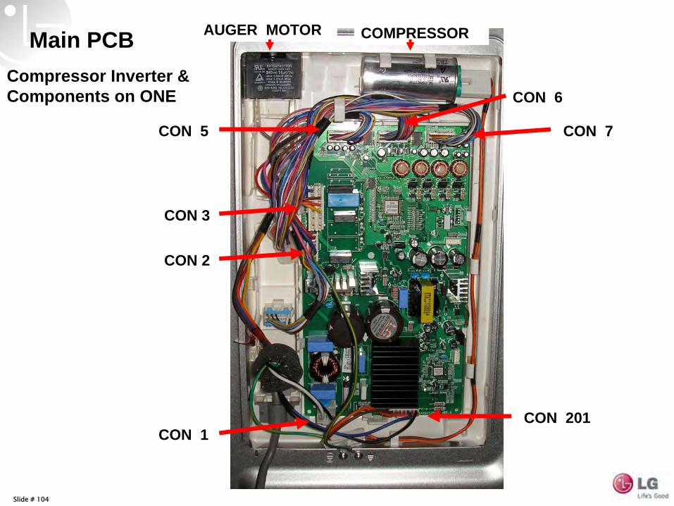
Main PCBCompressor Inverter & Components on ONE
CON 5
CON 6
CON 7
CON 3
CON 2
CON 1CON 201
AUGER MOTOR COMPRESSOR
Slide # 106
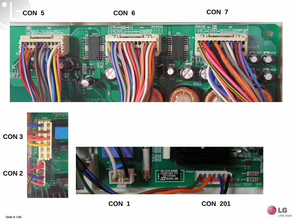
CON 5 CON 6 CON 7
CON 201CON 1
CON 3
CON 2
Slide # 107
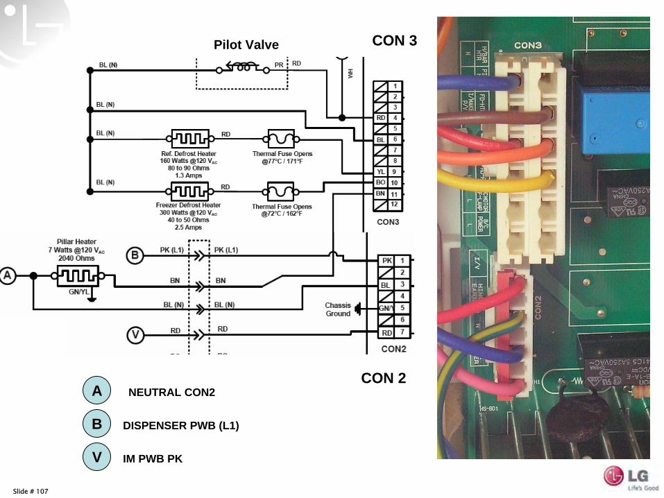
CON 3
CON 2
PILLAR HTR
B DISPENSER PWB (L1)
V IM PWB PK
A NEUTRAL CON2
Pilot Valve
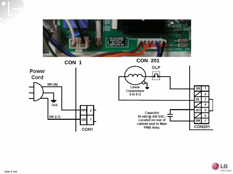
Slide # 108
CON 1 CON 201
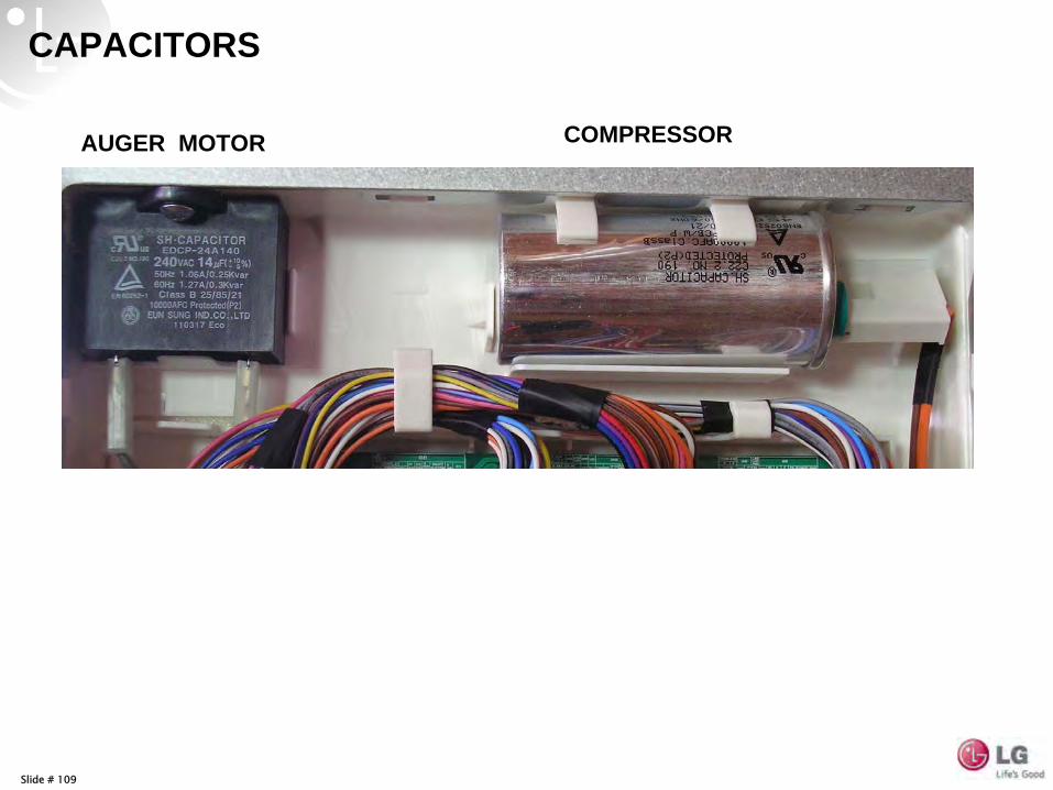
Slide # 109
AUGER MOTOR COMPRESSOR
CAPACITORS
Slide # 110
r dH F dH
F dS Freezer r dS Refrigerator
ERROR CODES
Note: These do NOT display on defect.
PRESS & HOLD Freezer & Ice Plus
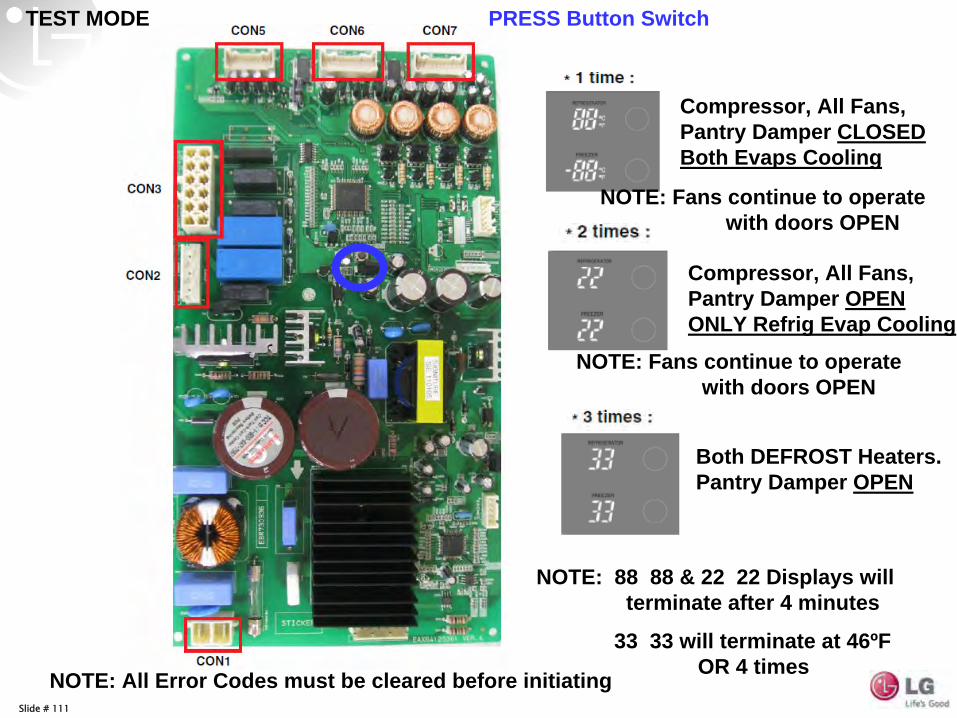
Slide # 111
Compressor, All Fans, Pantry Damper CLOSED Both Evaps Cooling
Compressor, All Fans, Pantry Damper OPEN ONLY Refrig Evap Cooling
Both DEFROST Heaters. Pantry Damper OPEN
PRESS Button Switch
NOTE: Fans continue to operate with doors OPEN
NOTE: Fans continue to operate with doors OPEN
NOTE: 88 88 & 22 22 Displays will terminate after 4 minutes
33 33 will terminate at 46ºF OR 4 times
TEST MODE
NOTE: All Error Codes must be cleared before initiating
Slide # 112
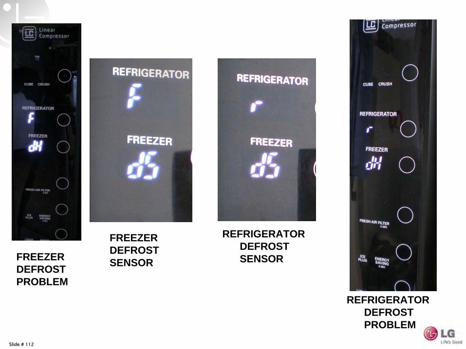
FREEZER DEFROST PROBLEM
FREEZER DEFROST SENSOR
REFRIGERATOR DEFROST PROBLEM
REFRIGERATOR DEFROST SENSOR
Slide # 113
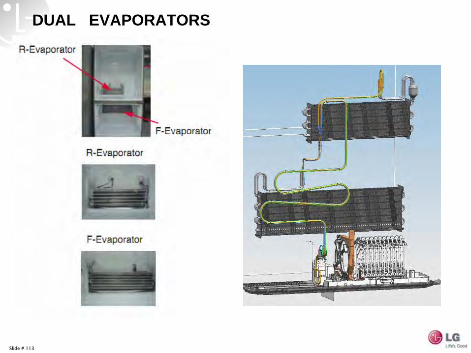
DUAL EVAPORATORS
Slide # 114
1 Evaporator vs 2 Evaporator
Condenser
Compressor
Evaporator
Dryer
Capillary
1 Evaporator System
Condenser
Compressor
R-Evaporator
Dryer
R-Capillary
Parallel 2 Evaporator System
F-Evaporator
3 way Valve
F-Capillary Check Valve
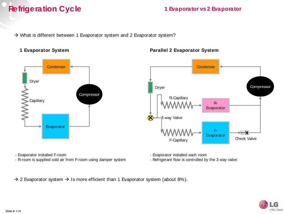
What is different between 1 Evaporator system and 2 Evaporator system?
- Evaporator installed F-room- R-room is supplied cold air from F-room using damper system
- Evaporator installed each room- Refrigerant flow is controlled by the 3 way valve
2 Evaporator system Is more efficient than 1 Evaporator system (about 8%).
Refrigeration Cycle
Slide # 115Thursday, August 11, 2011 Confidential
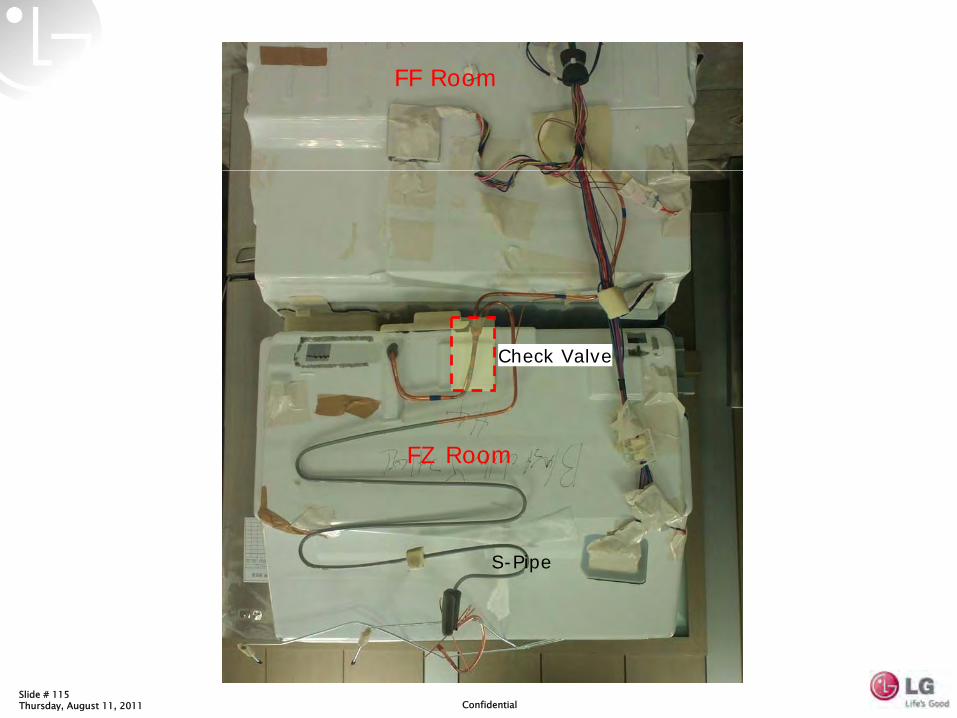
FF Room
FZ Room
S-Pipe
Check Valve
Slide # 116
Condenser
Compressor
R-Evaporator
Dryer
R-Capillary
F-Evaporator
3 way Valve
F-Capillary Check Valve
R-Room Operation
Condenser
Compressor
R-Evaporator
Dryer
R-Capillary
F-Evaporator
3 way Valve
F-Capillary Check Valve
F-Room Operation
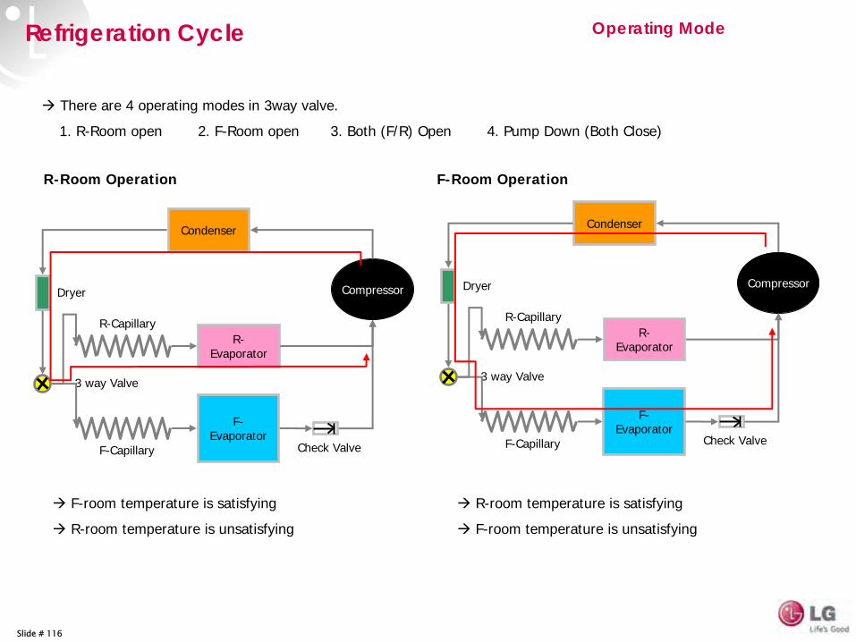
Operating Mode
There are 4 operating modes in 3way valve.
1. R-Room open 2. F-Room open 3. Both (F/R) Open 4. Pump Down (Both Close)
F-room temperature is satisfying
R-room temperature is unsatisfying
R-room temperature is satisfying
F-room temperature is unsatisfying
Refrigeration Cycle
Slide # 117
Condenser
Compressor
R-Evaporator
Dryer
R-Capillary
F-Evaporator
3 way Valve
F-Capillary Check Valve
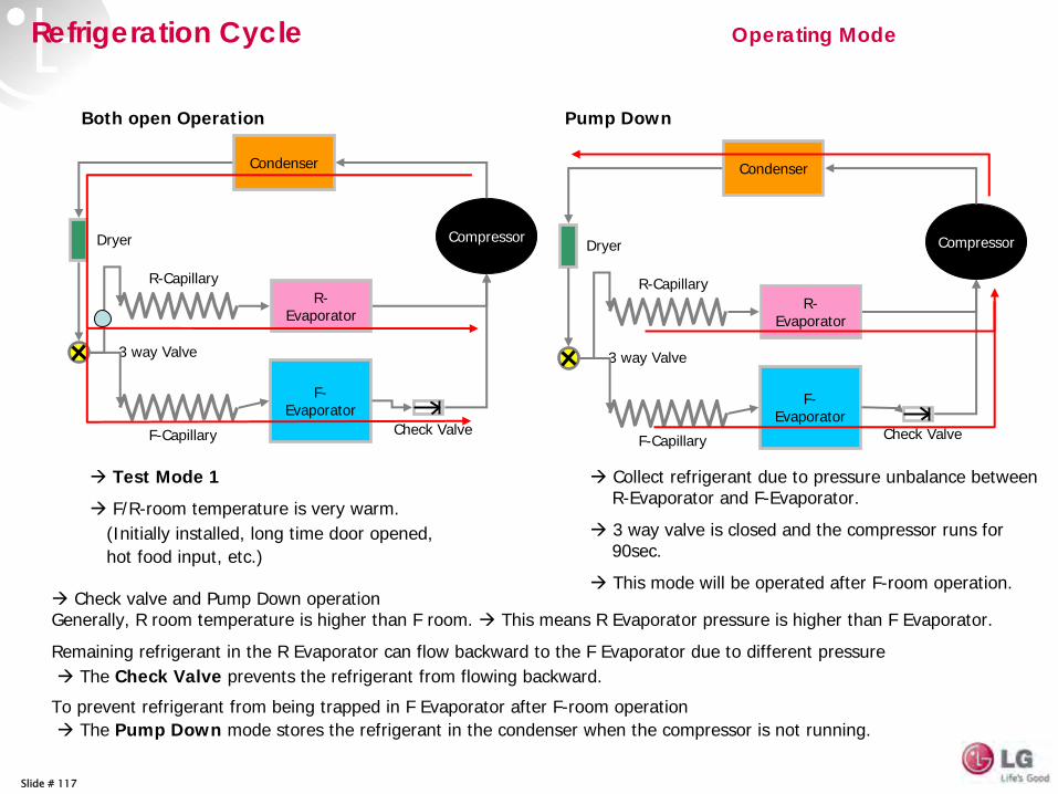
Both open Operation
Test Mode 1
F/R-room temperature is very warm.(Initially installed, long time door opened, hot food input, etc.)
Condenser
Compressor
R-Evaporator
Dryer
R-Capillary
F-Evaporator
3 way Valve
F-Capillary
Pump Down
Collect refrigerant due to pressure unbalance between R-Evaporator and F-Evaporator.
3 way valve is closed and the compressor runs for 90sec.
This mode will be operated after F-room operation.Check valve and Pump Down operation
Generally, R room temperature is higher than F room. This means R Evaporator pressure is higher than F Evaporator.
Remaining refrigerant in the R Evaporator can flow backward to the F Evaporator due to different pressureThe Check Valve prevents the refrigerant from flowing backward.
To prevent refrigerant from being trapped in F Evaporator after F-room operationThe Pump Down mode stores the refrigerant in the condenser when the compressor is not running.
Check Valve
Operating ModeRefrigeration Cycle
Slide # 118
HA R& D Lab in N. America
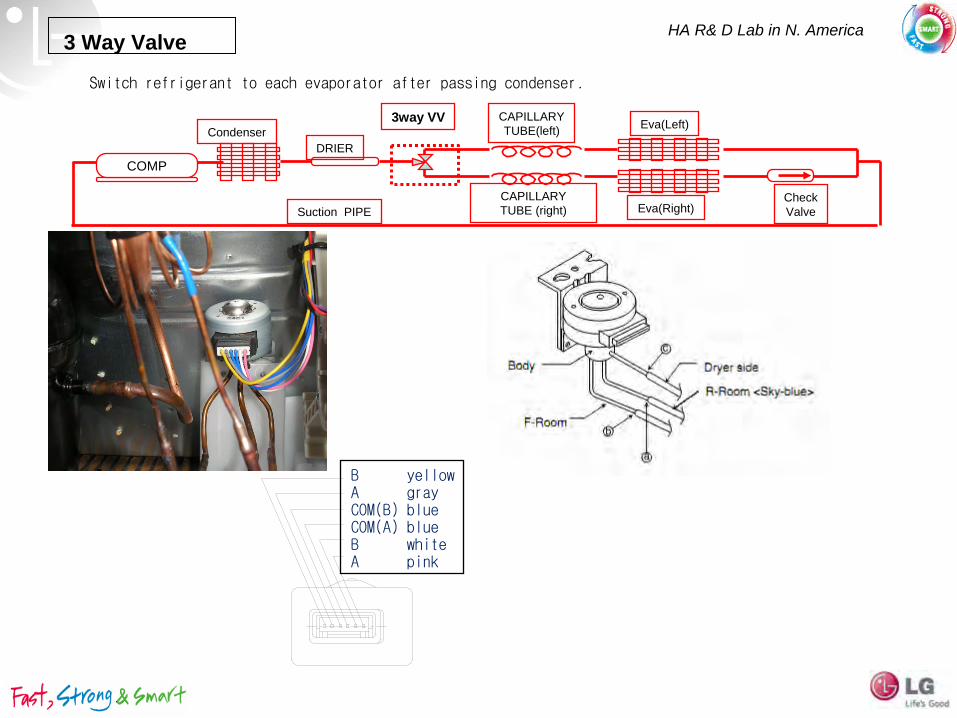
Switch refrigerant to each evaporator after passing condenser.
3 Way Valve
CondenserEva(Left)
Eva(Right)
DRIER
3way VV CAPILLARYTUBE(left)
CAPILLARYTUBE (right)
COMP
Suction PIPE
OperatingCoil
ValveBODY
CheckValve
B yellowA grayCOM(B) blueCOM(A) blueB whiteA pink
Slide # 119
CON6
Slide # 120
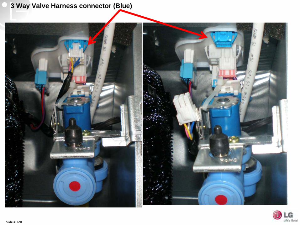
3 Way Valve Harness connector (Blue)
Slide # 121
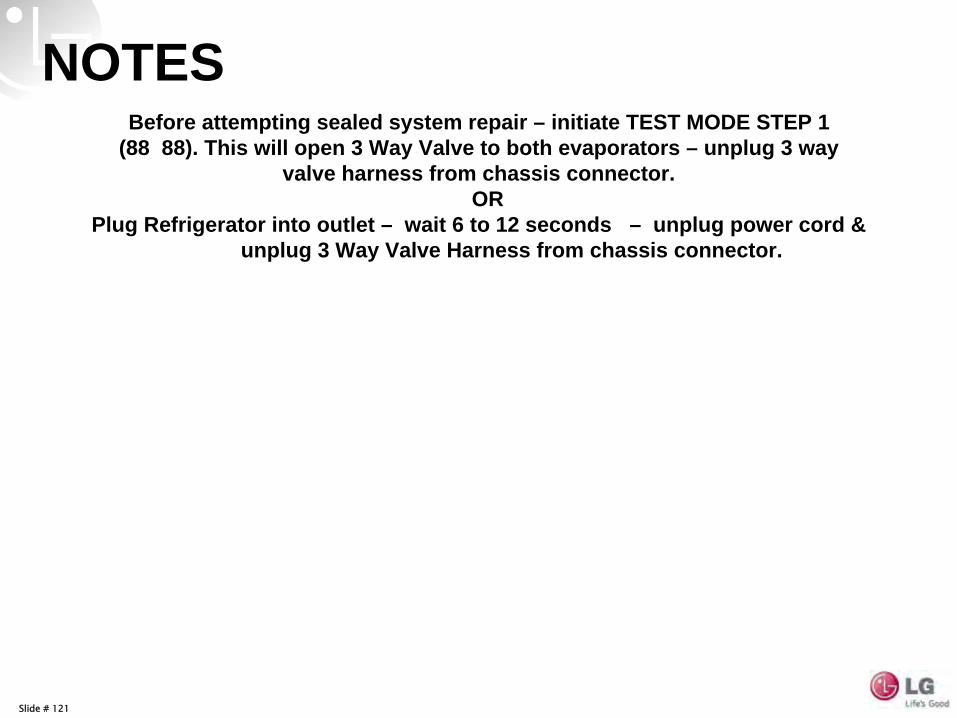
NOTESBefore attempting sealed system repair – initiate TEST MODE STEP 1
(88 88). This will open 3 Way Valve to both evaporators – unplug 3 way valve harness from chassis connector.
OR Plug Refrigerator into outlet – wait 6 to 12 seconds – unplug power cord &
unplug 3 Way Valve Harness from chassis connector.
Slide # 122
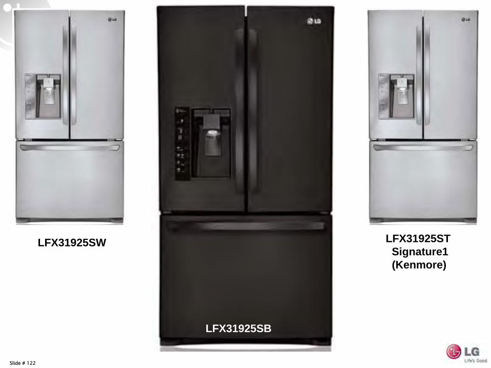
LFX31925SW
LFX31925SB
LFX31925ST Signature1 (Kenmore)
Slide # 1Thursday, August 11, 2011 Confidential
Model # LDF6920BB
Slide # 2
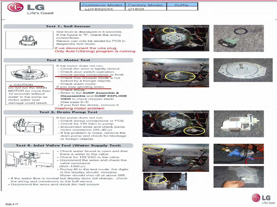
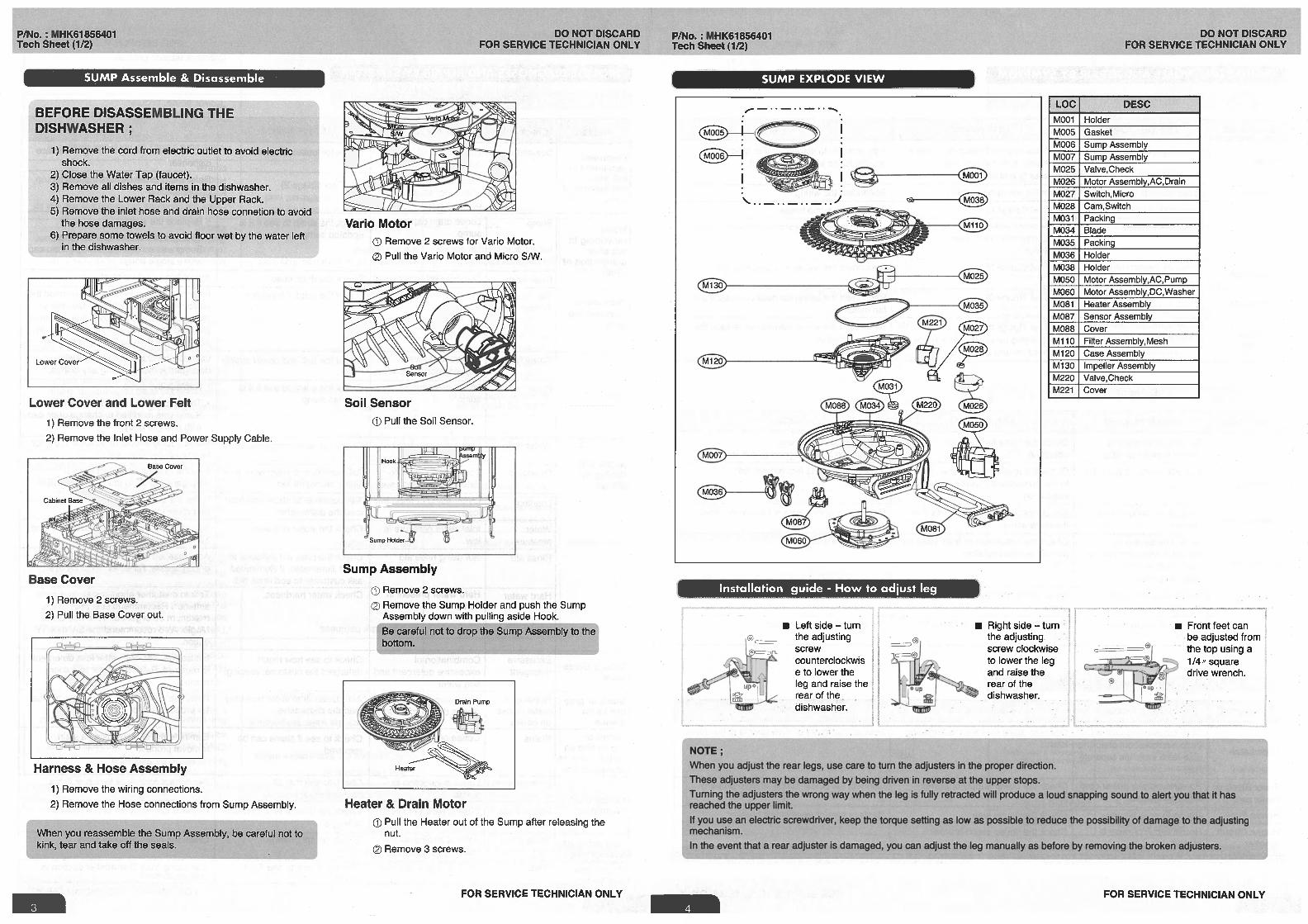
Basic operation of LG dishwashersWash Motor; Direct drive variable speed brushless DC motor
Drain motor; 120 VAC motor
Water heating; 1200 Watt heater submerged in sump assembly
Water Fill; 120 VAC solenoid valve, Flow sensor to fill to exact
amount regardless of water pressure within prescribed limits
Two level wash system to save energy and reduce water consumption by use of a diverter valve (Vario
valve)
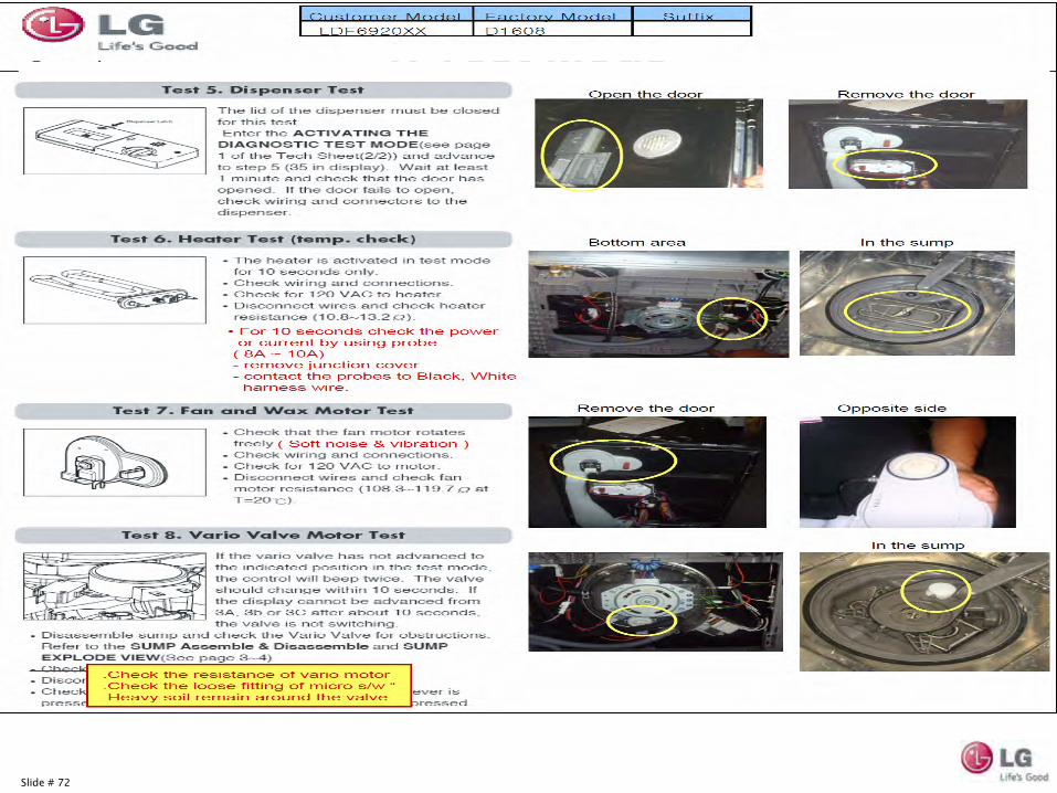
Dry System; Condensing dry using a sealed dishwasher tank during
wash and rinse cycles to retain heat. In the dry cycle the damper is opened and
a 120 VAC fan motor is energized to draw hot moist air from the tank and cool room air from the floor area to cause condensation in the blower housing which drains by
a hose to the sump. The drain pump is energized to pump water to the drain.
Soil Sensing uses a Turbidly Sensor to add additional pre rinses
if needed based on soil level.
Dispensers; 120 VAC Wax motor.
Slide # 3
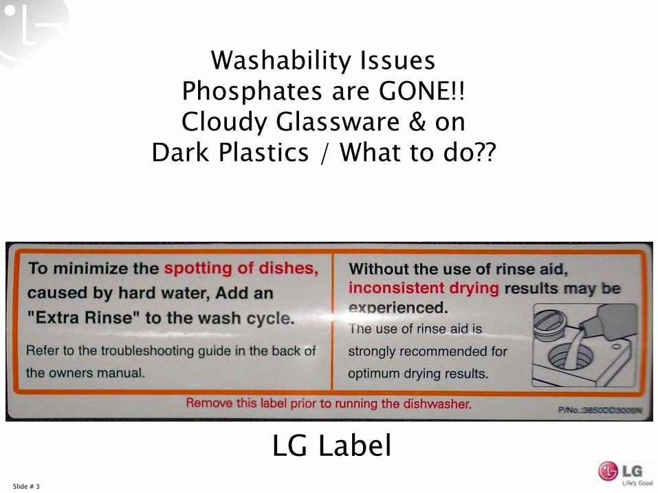
Washability
IssuesPhosphates are GONE!!Cloudy Glassware & on
Dark Plastics / What to do??
LG Label
Slide # 4
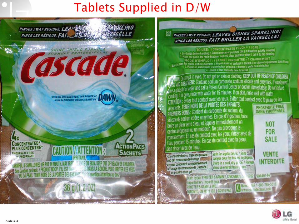
Tablets Supplied in D/W

Slide # 5
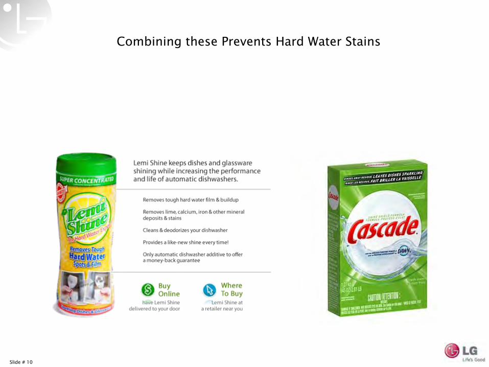
Dishwasher Detergent Additive
Use with Powder Detergent!
Slide # 6
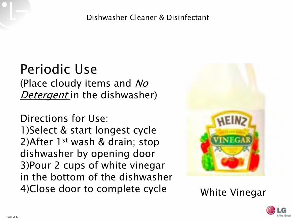
Dishwasher Cleaner & Disinfectant
Periodic Use(Place cloudy items and No
Detergent in the dishwasher)
Directions for Use:1)Select & start longest cycle2)After 1st
wash & drain; stop dishwasher by opening door3)Pour 2 cups of white vinegar in the bottom of the dishwasher4)Close door to complete cycle White Vinegar
Slide # 7
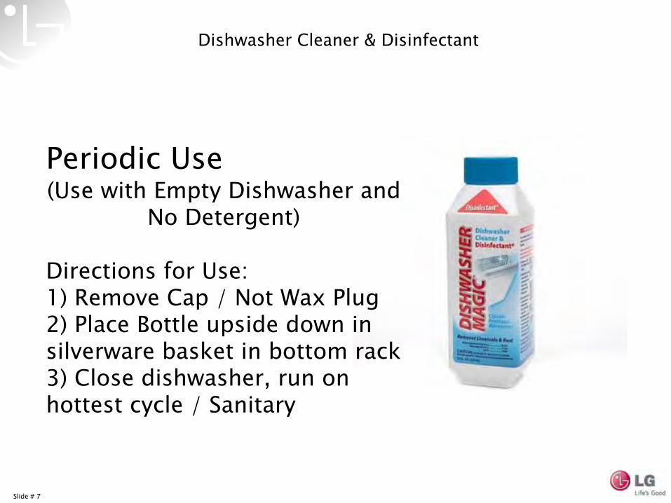
Dishwasher Cleaner & Disinfectant
Periodic Use(Use with Empty Dishwasher and
No Detergent)
Directions for Use:1) Remove Cap / Not Wax Plug2) Place Bottle upside down in silverware basket in bottom rack3) Close dishwasher, run on hottest cycle / Sanitary

Slide # 8
Hard Water Areas
Slide # 9
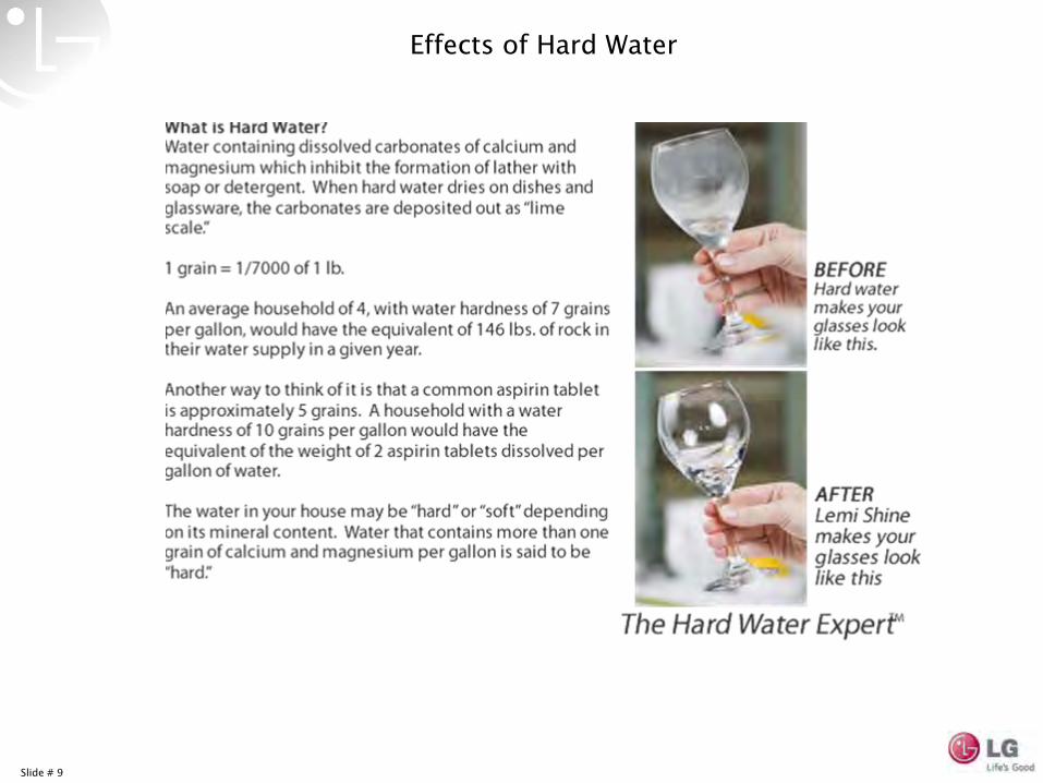
Effects of Hard Water
Slide # 10
Combining these Prevents Hard Water Stains
Slide # 11
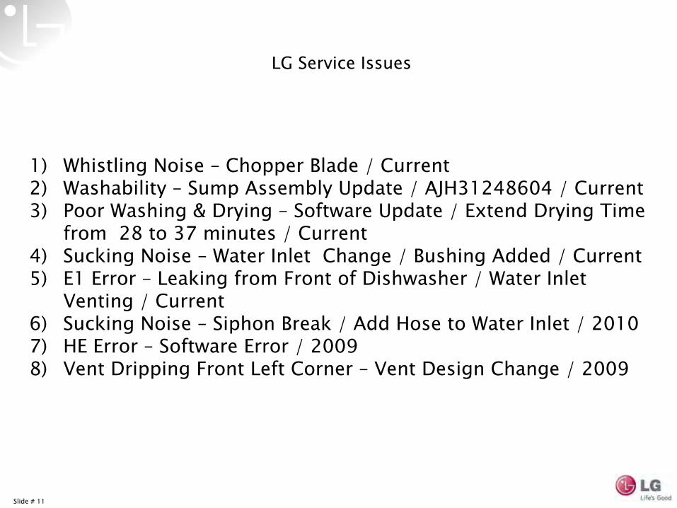
LG Service Issues
1)
Whistling Noise –
Chopper Blade / Current 2)
Washability
–
Sump Assembly Update / AJH31248604 / Current3)
Poor Washing & Drying –
Software Update / Extend Drying Time from 28 to 37 minutes / Current
4)
Sucking Noise –
Water Inlet Change / Bushing Added / Current5)
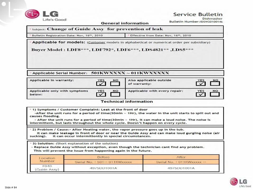
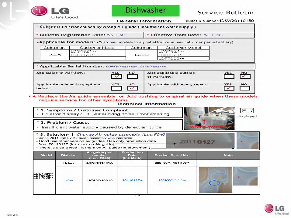
E1 Error –
Leaking from Front of Dishwasher / Water Inlet Venting / Current
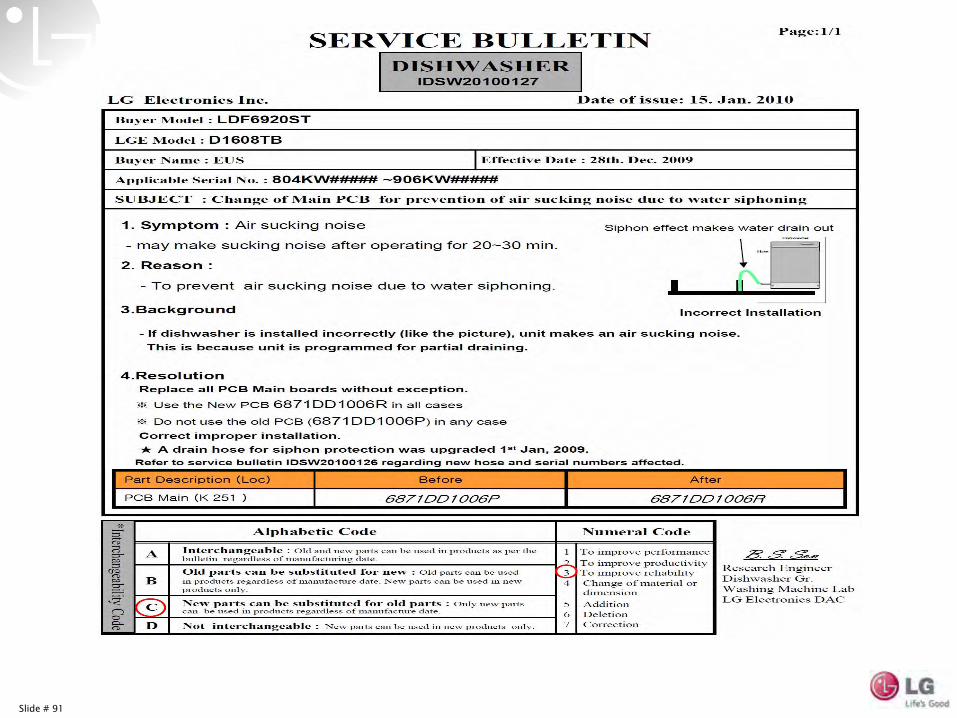
6)
Sucking Noise –
Siphon Break / Add Hose to Water Inlet / 20107)
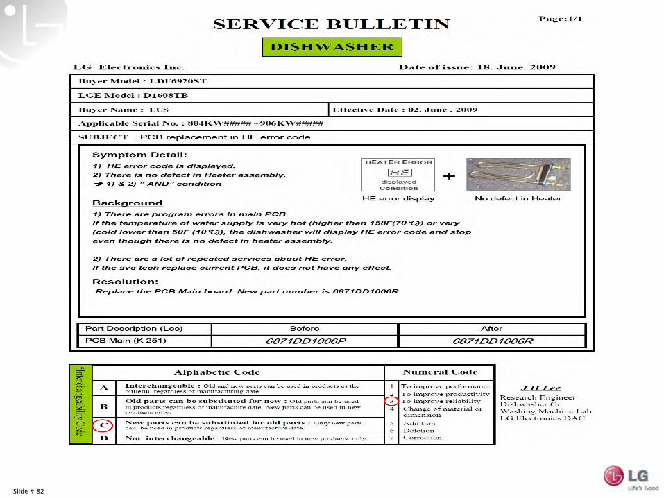
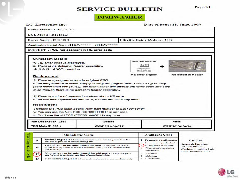
HE Error –
Software Error / 20098)
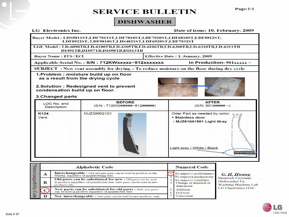
Vent Dripping Front Left Corner –
Vent Design Change / 2009
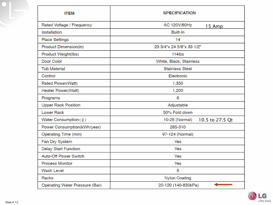
Slide # 12
15 Amp
10.5 to 27.5 Qt

Slide # 13
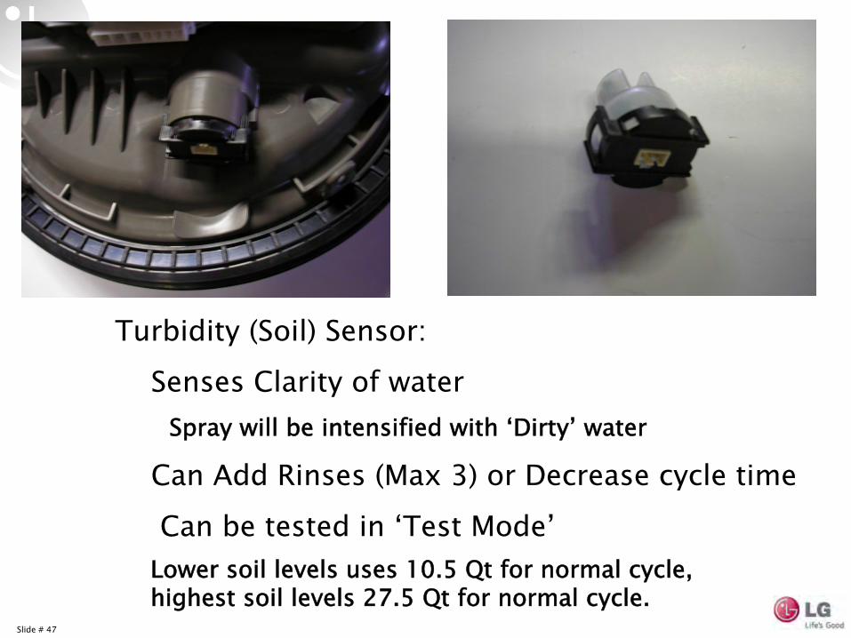
Turbidity (Soil) Sensor:Senses Clarity of water
Spray will be intensified with ‘Dirty’
water
Can Add Rinses (Max 3) or Decrease cycle time
Can be tested in ‘Test Mode’Lower soil levels uses 10.5 Qt for normal cycle, highest soil levels 27.5 Qt for normal cycle.
Slide # 14
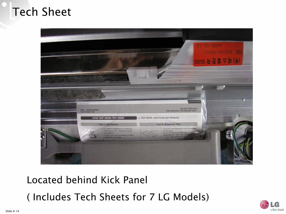
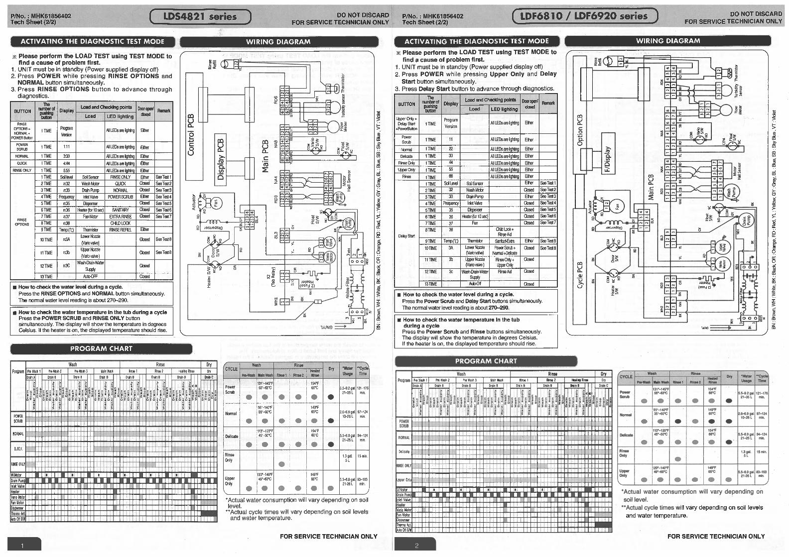
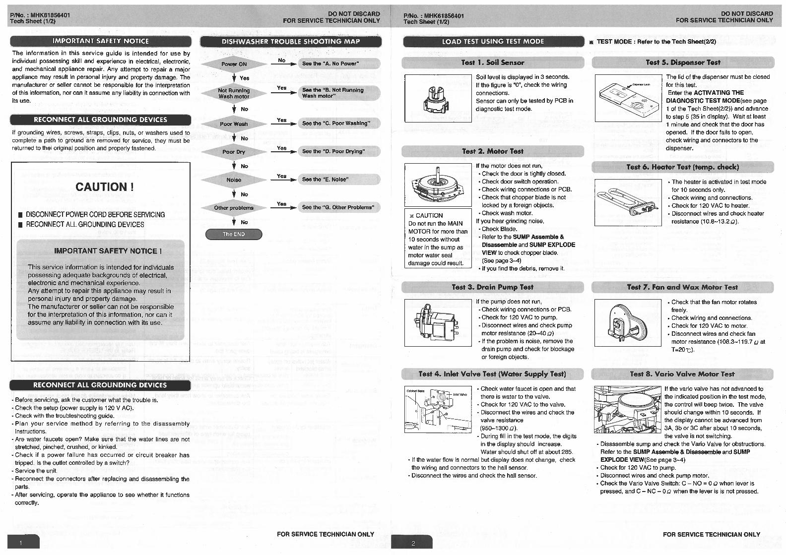
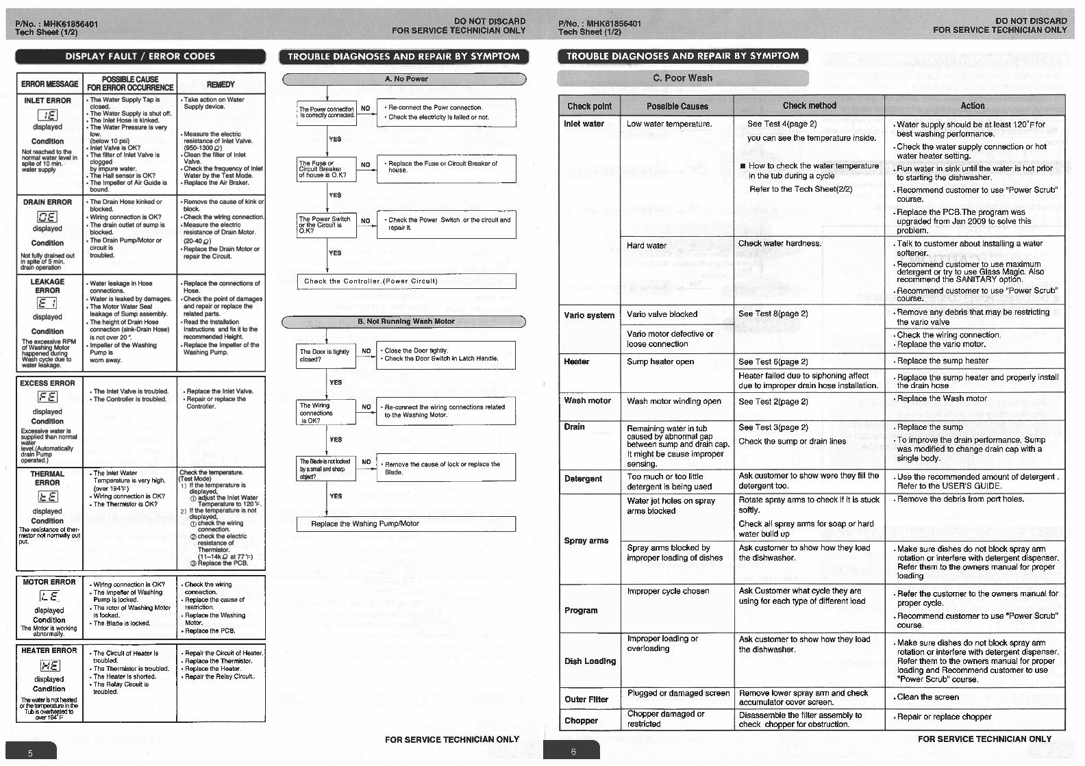
Tech Sheet
Located behind Kick Panel( Includes Tech Sheets for 7 LG Models)
Slide # 15
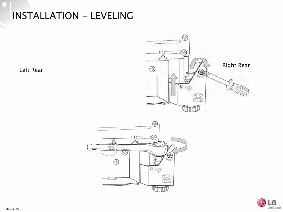
INSTALLATION -
LEVELING
Left RearRight Rear
Slide # 16
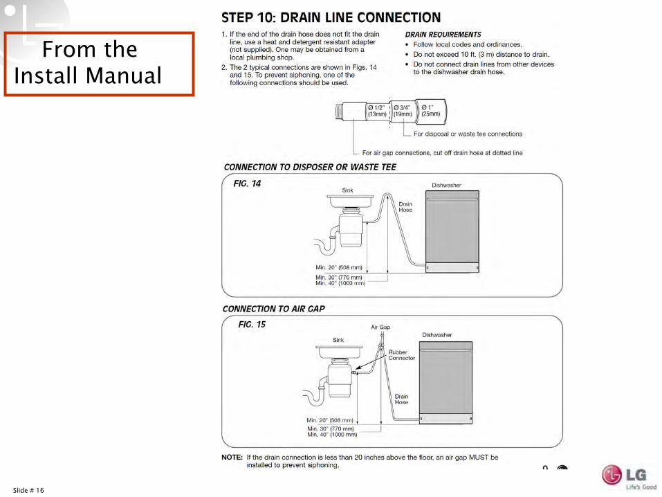
From the Install Manual
Slide # 17
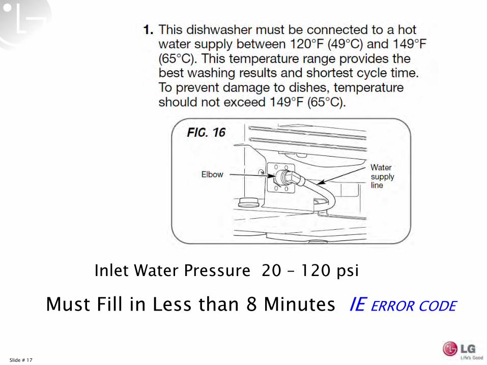
Inlet Water Pressure 20 –
120 psi
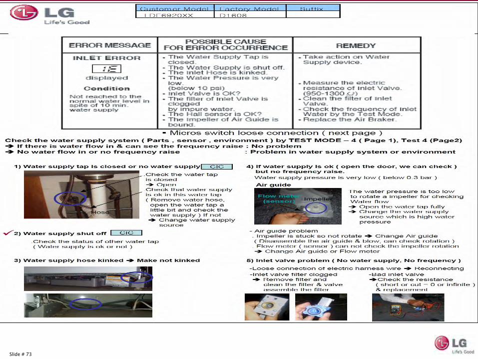
Must Fill in Less than 8 Minutes IE ERROR CODE
Slide # 18
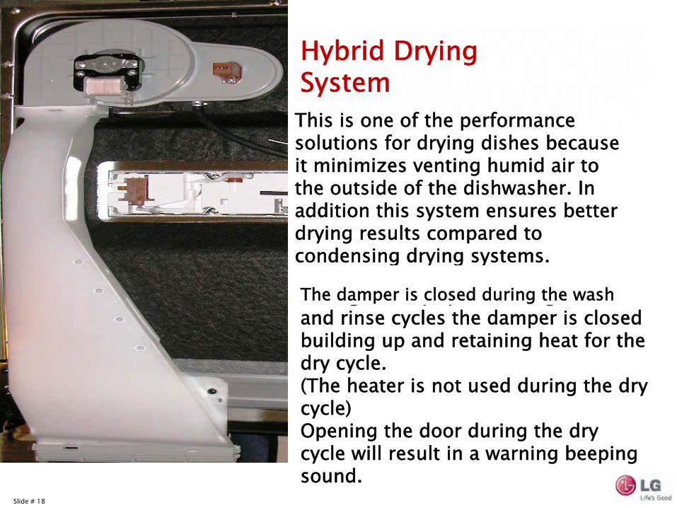
The only time the damper is open is during the dry cycle. During the wash and rinse cycles the damper is closed building up and retaining heat for the dry cycle.
(The heater is not used during the dry cycle)Opening the door during the dry cycle will result in a warning beeping sound.
This is one of the performance solutions for drying dishes because it minimizes venting humid air to the outside of the dishwasher. In addition this system ensures better drying results compared to condensing drying systems.
Hybrid Drying System
The damper is closed during the wash
Slide # 19
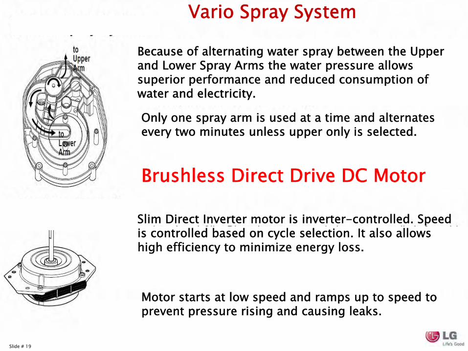
Only one spray arm is used at a time and alternates every two minutes unless upper only is selected.
Motor starts at low speed and ramps up to speed to prevent pressure rising and causing leaks.
Because of alternating water spray between the Upper and Lower Spray Arms the water pressure allows superior performance and reduced consumption of water and electricity.
Vario
Spray System
Slim Direct Inverter motor is inverter-controlled. Speed is controlled based on cycle selection. It also allows high efficiency to minimize energy loss.
Brushless Direct Drive DC Motor
Slide # 20
Slide # 21
Slide # 22
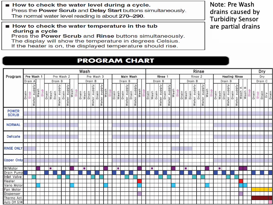
Note: Pre Wash drains caused by Turbidity Sensor are partial drains
Slide # 23
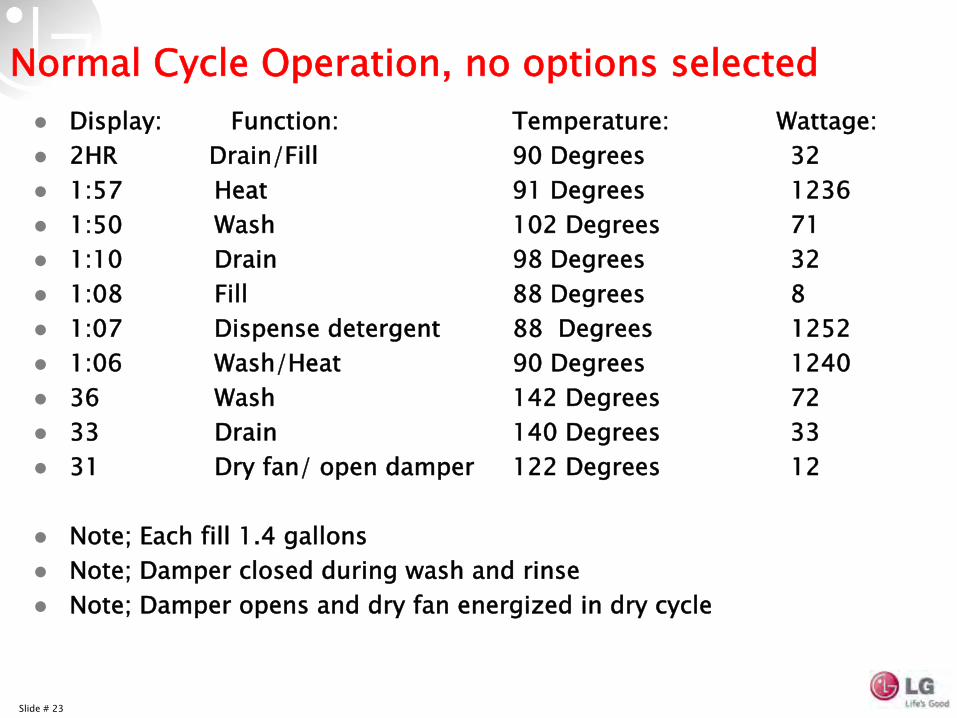
Normal Cycle Operation, no options selectedDisplay: Function: Temperature: Wattage:2HR Drain/Fill 90 Degrees 321:57 Heat 91 Degrees 12361:50 Wash 102 Degrees 711:10 Drain 98 Degrees 321:08 Fill 88 Degrees 81:07 Dispense detergent 88 Degrees 12521:06 Wash/Heat 90 Degrees 1240 36 Wash 142 Degrees 7233 Drain 140 Degrees 3331 Dry fan/ open damper 122 Degrees 12
Note; Each fill 1.4 gallonsNote; Damper closed during wash and rinseNote; Damper opens and dry fan energized in dry cycle
Slide # 24
Slide # 25
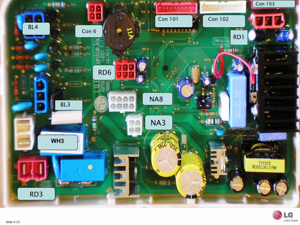
RD1BL4
BL3
WH3
RD3
NA3
NA8
RD6
Con 6
Con 101 Con 102
Con 103
Slide # 26
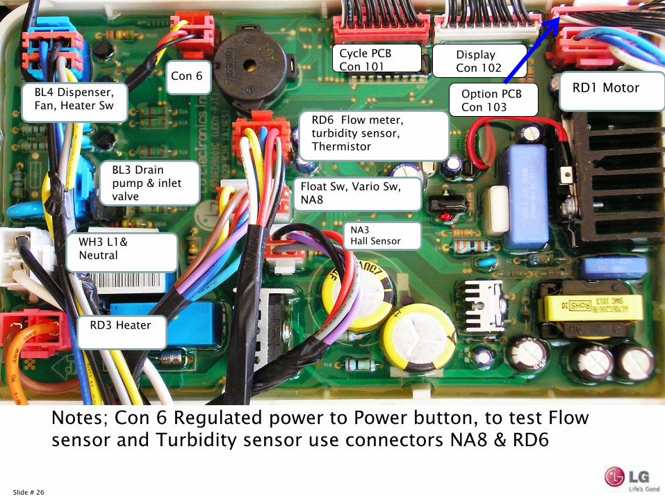
Con 6RD1 Motor
WH3 L1& Neutral
RD3 Heater
NA3 Hall Sensor
BL4 Dispenser, Fan, Heater Sw
RD6 Flow meter, turbidity sensor, Thermistor
Float Sw, Vario
Sw,NA8
BL3 Drain pump & inlet valve
Notes; Con 6 Regulated power to Power button, to test Flow sensor and Turbidity sensor use connectors NA8 & RD6
Cycle PCB Con 101
DisplayCon 102
Option PCB Con 103
Slide # 27
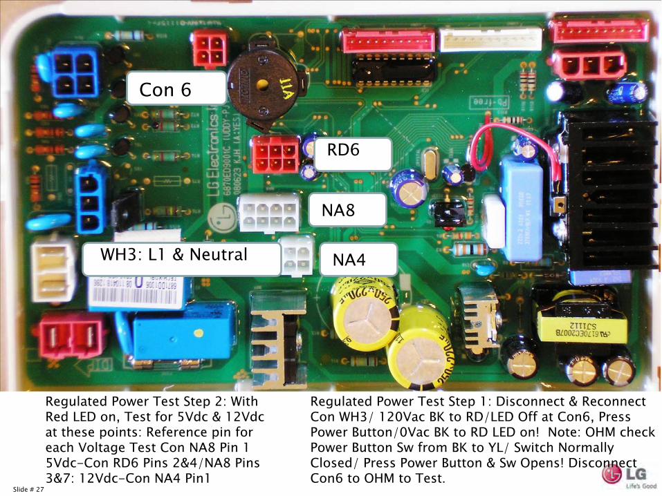
Con 6
RD6
NA8NA8
NA4WH3: L1 & Neutral
Regulated Power Test Step 1: Disconnect & Reconnect Con WH3/ 120Vac BK to RD/LED Off at Con6, Press Power Button/0Vac BK to RD LED on! Note: OHM check Power Button Sw
from BK to YL/ Switch Normally Closed/ Press Power Button & Sw
Opens! Disconnect Con6 to OHM to Test.
Regulated Power Test Step 2: With Red LED on, Test for 5Vdc & 12Vdc at these points: Reference pin for each Voltage Test Con NA8 Pin 1 5Vdc-Con RD6 Pins 2&4/NA8 Pins 3&7: 12Vdc-Con NA4 Pin1
Slide # 28
Slide # 29
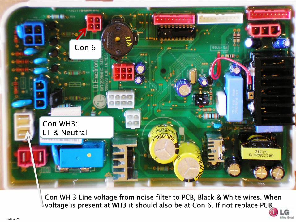
Con WH 3 Line voltage from noise filter to PCB, Black & White wires. When voltage is present at WH3 it should also be at Con 6. If not replace PCB.
Con 6
Con WH3: L1 & Neutral
Slide # 30
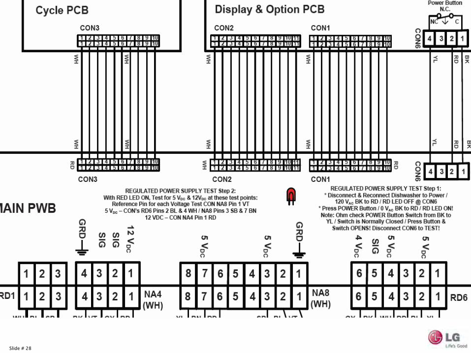
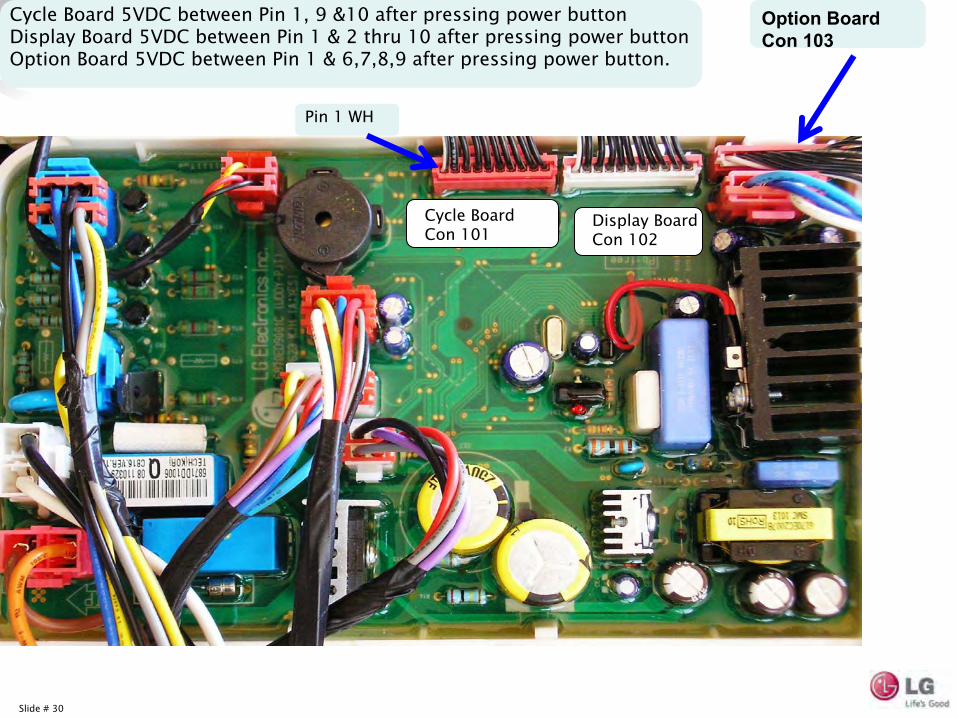
Cycle Board Con 101
Display Board Con 102
Option Board Con 103
Pin 1 WH
Cycle Board 5VDC between Pin 1, 9 &10 after pressing power buttonDisplay Board 5VDC between Pin 1 & 2 thru 10 after pressing power buttonOption Board 5VDC between Pin 1 & 6,7,8,9 after pressing power button.
Slide # 31
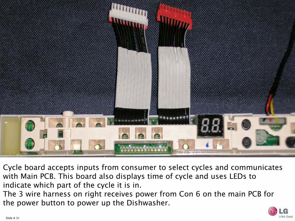
Cycle board accepts inputs from consumer to select cycles and communicates with Main PCB. This board also displays time of cycle and uses LEDs
to indicate which part of the cycle it is in.The 3 wire harness on right receives power from Con 6 on the main PCB for the power button to power up the Dishwasher.
Slide # 32
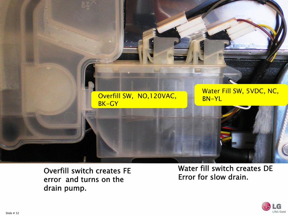
Overfill SW, NO,120VAC, BK-GY
Water Fill SW, 5VDC, NC, BN-YL
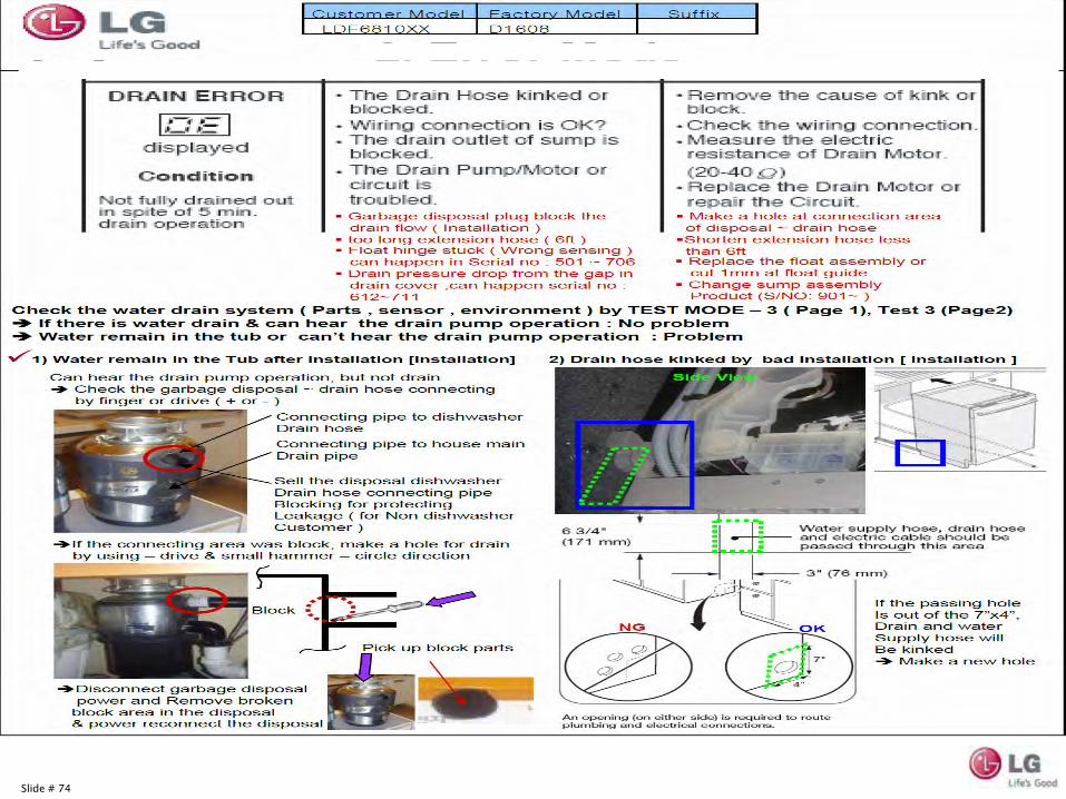
Water fill switch creates DE Error for slow drain.
Overfill switch creates FE error and turns on the drain pump.
Slide # 33
Slide # 34
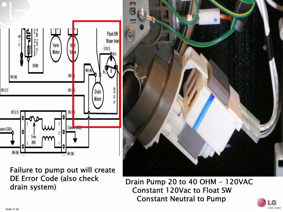
Drain Pump 20 to 40 OHM -
120VAC
Constant 120Vac to Float SW
Constant Neutral to Pump
Failure to pump out will create DE Error Code (also check drain system)
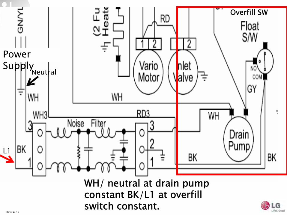
Slide # 35
L1
Neutral
Power Supply
WH/ neutral at drain pump constant BK/L1 at overfill switch constant.
Overfill SW
Slide # 36
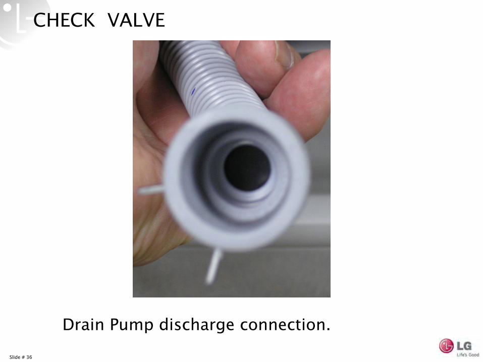
CHECK VALVE
Drain Pump discharge connection.
Slide # 37
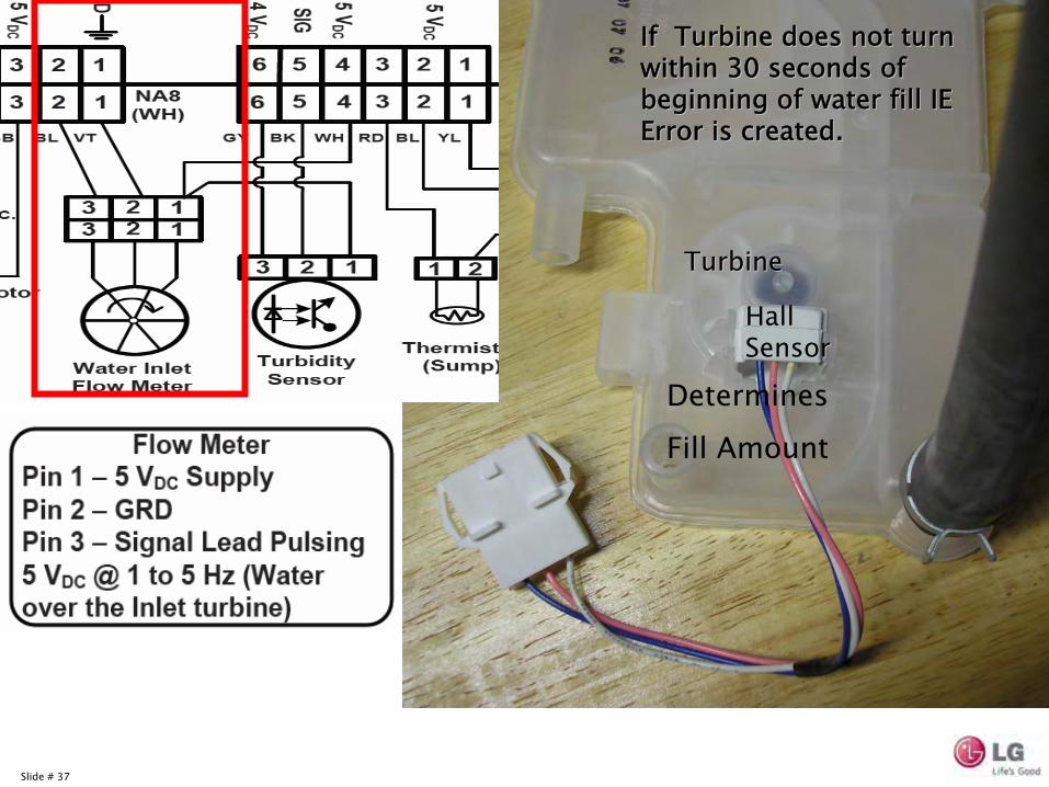
Turbine Turbine
Determines
Fill Amount
If Turbine does not turn If Turbine does not turn within 30 seconds of within 30 seconds of beginning of water fill IE beginning of water fill IE Error is created.Error is created.
Hall Hall SensorSensor
Slide # 38
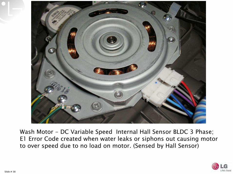
Wash Motor -
DC Variable Speed Internal Hall Sensor BLDC 3 Phase; E1 Error Code created when water leaks or siphons out causing motor to over speed due to no load on motor. (Sensed by Hall Sensor)
Slide # 39
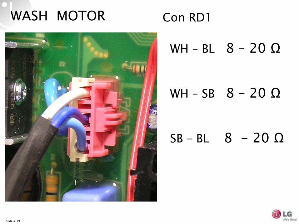
WASH MOTOR
WH –
BL 8 –
20 Ω
WH –
SB 8 –
20 Ω
SB –
BL 8 -
20 Ω
Con RD1
Slide # 40
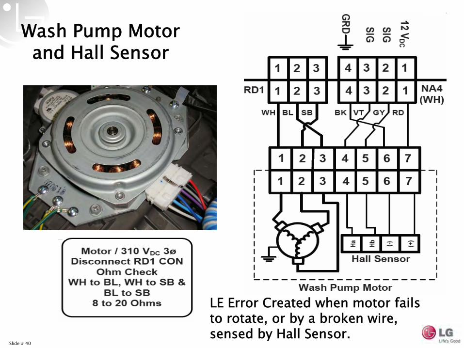
Wash Pump Motor and Hall Sensor
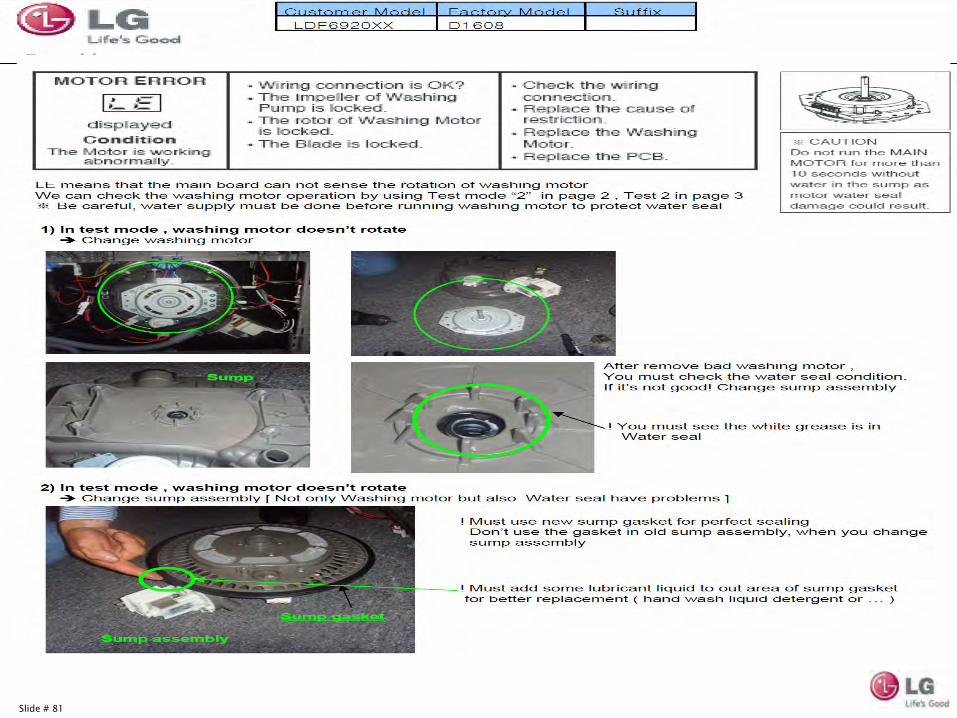
LE Error Created when motor fails to rotate, or by a broken wire, sensed by Hall Sensor.
Slide # 41
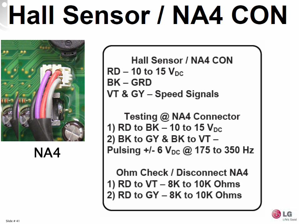
NA4
Slide # 42
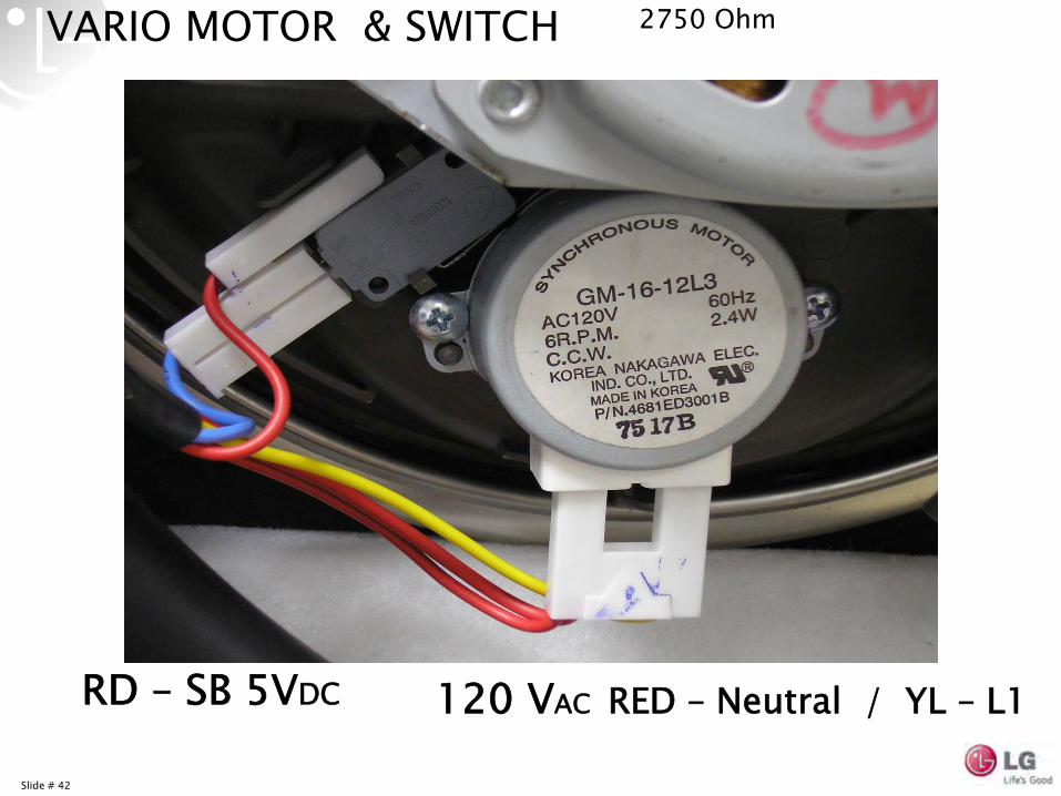
VARIO MOTOR & SWITCH
120 VAC RED – Neutral / YL – L1RD –
SB 5VDC
2750 Ohm
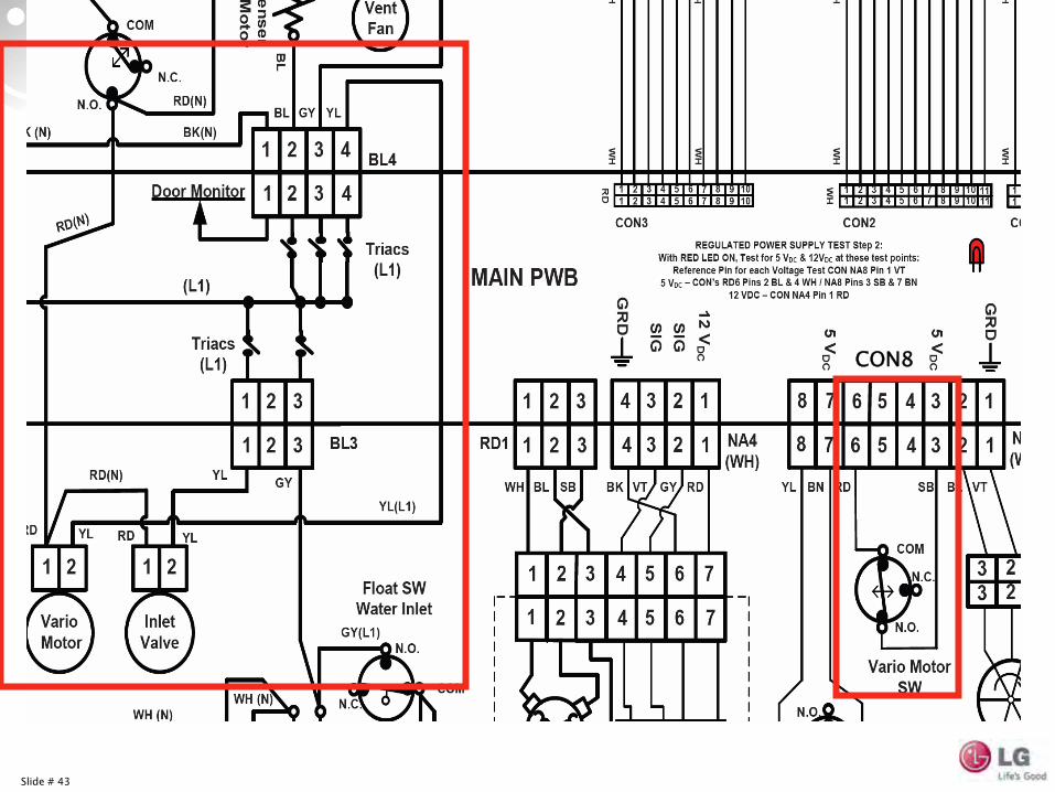
Slide # 43
CON8
Slide # 44
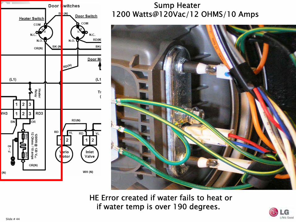
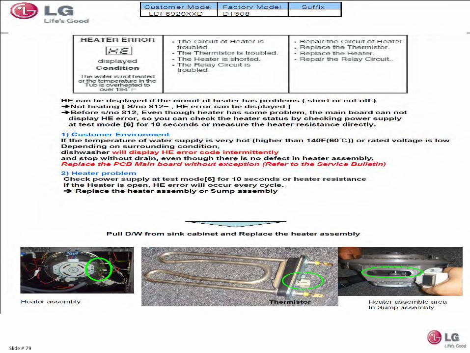
Sump Heater 1200 Watts@120Vac/12 OHMS/10 Amps
HE Error created if water fails to heat or
if water temp is over 190 degrees.
Slide # 45
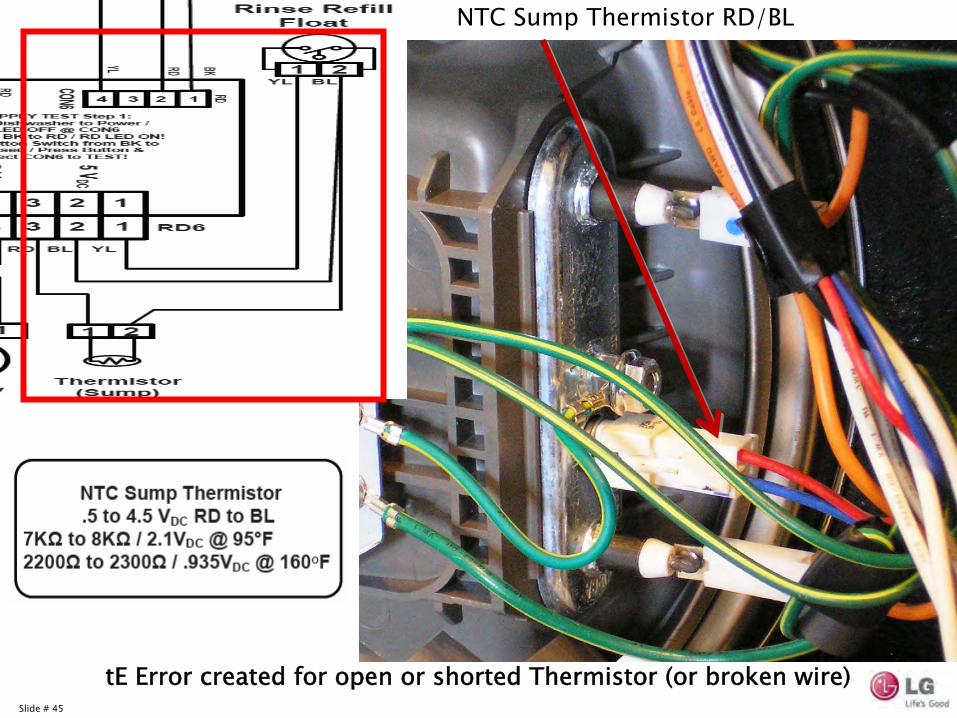
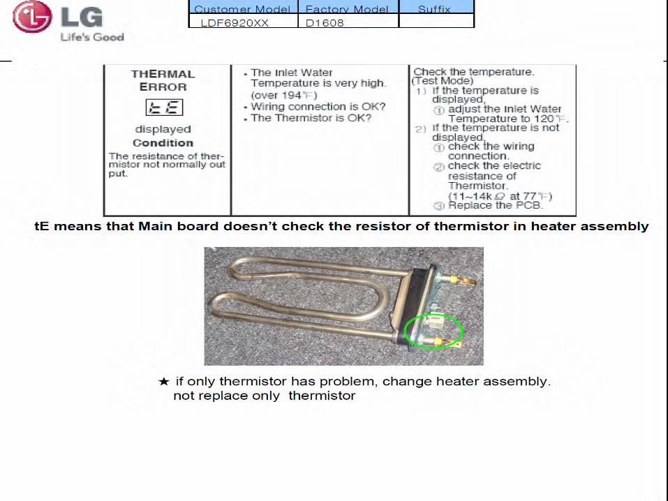
NTC Sump Thermistor
RD/BL
tE
Error created for open or shorted Thermistor
(or broken wire)
Slide # 46
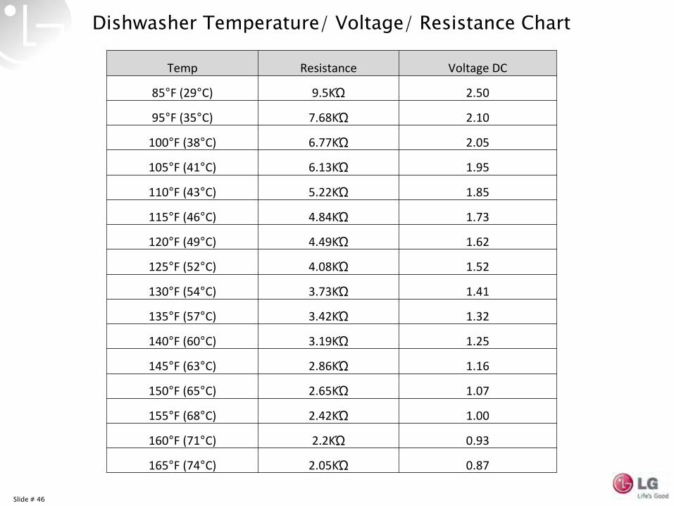
Temp Resistance Voltage DC
85°F (29°C) 9.5KΏ 2.50
95°F (35°C) 7.68KΏ 2.10
100°F (38°C) 6.77KΏ 2.05
105°F (41°C) 6.13KΏ 1.95
110°F (43°C) 5.22KΏ 1.85
115°F (46°C) 4.84KΏ 1.73
120°F (49°C) 4.49KΏ 1.62
125°F (52°C) 4.08KΏ 1.52
130°F (54°C) 3.73KΏ 1.41
135°F (57°C) 3.42KΏ 1.32
140°F (60°C) 3.19KΏ 1.25
145°F (63°C) 2.86KΏ 1.16
150°F (65°C) 2.65KΏ 1.07
155°F (68°C) 2.42KΏ 1.00
160°F (71°C) 2.2KΏ 0.93
165°F (74°C) 2.05KΏ 0.87
Dishwasher Temperature/ Voltage/ Resistance Chart
Slide # 47
Turbidity (Soil) Sensor:Senses Clarity of water
Spray will be intensified with ‘Dirty’
water
Can Add Rinses (Max 3) or Decrease cycle time
Can be tested in ‘Test Mode’Lower soil levels uses 10.5 Qt for normal cycle, highest soil levels 27.5 Qt for normal cycle.
Slide # 48
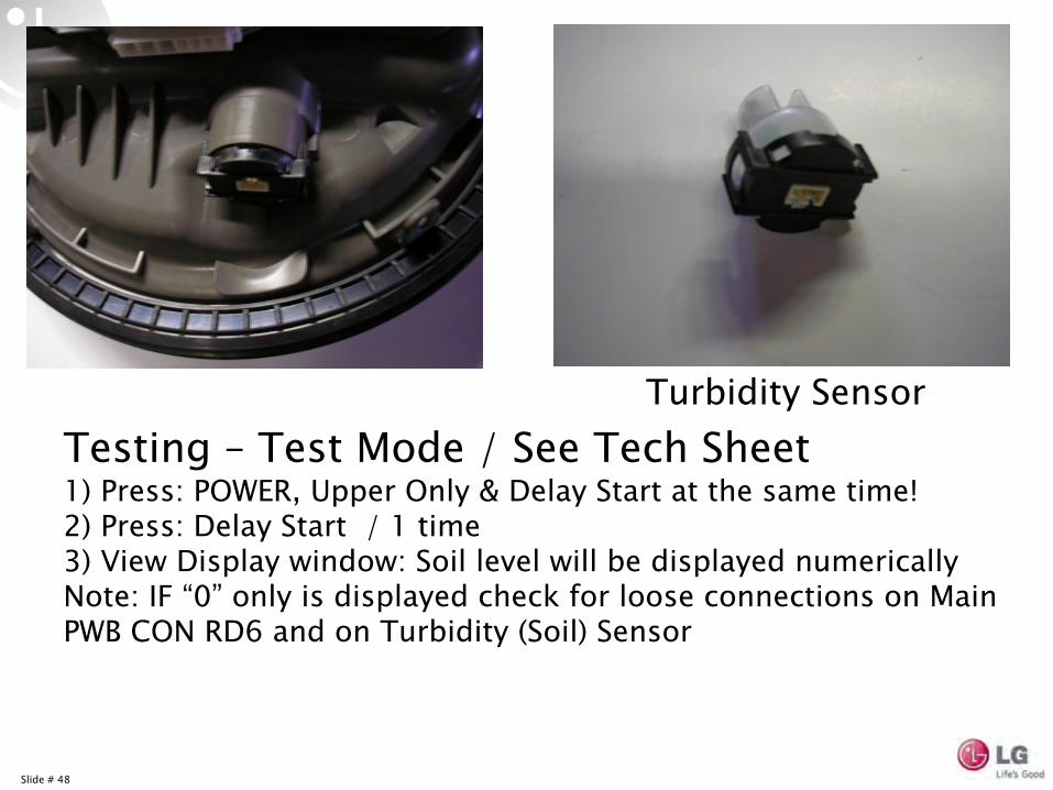
Testing –
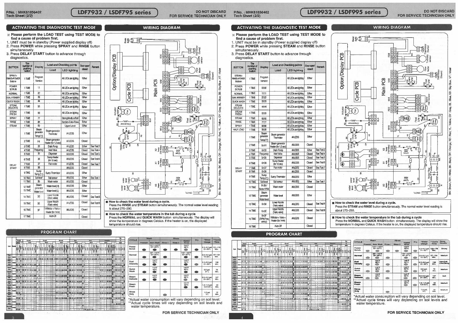
Test Mode / See Tech Sheet1) Press: POWER, Upper Only & Delay Start at the same time!2) Press: Delay Start / 1 time3) View Display window: Soil level will be displayed numericallyNote: IF “0”
only is displayed check for loose connections on Main PWB CON RD6 and on Turbidity (Soil) Sensor
Turbidity Sensor
Slide # 49
Slide # 50
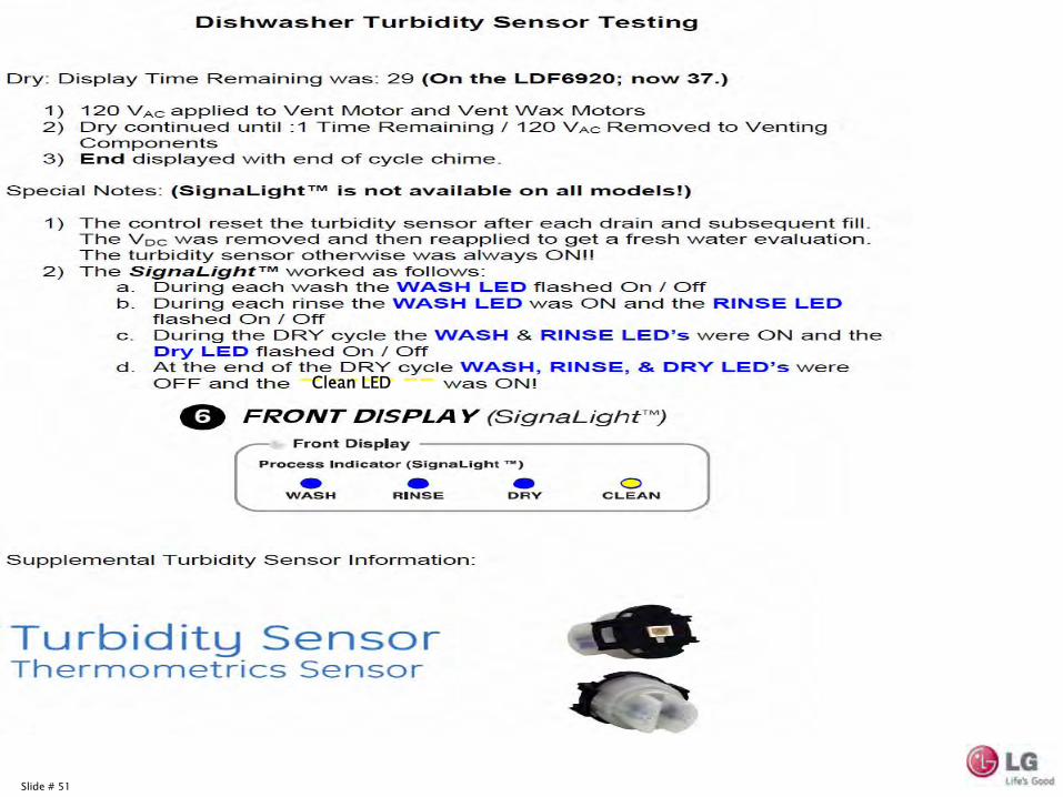
Slide # 51
Clean LED
Slide # 52
Slide # 53
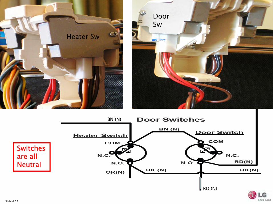
BN (N)
Heater Switch Door Switch
Switches are all Neutral
Heater Sw
Door Sw
RD (N)
Slide # 54
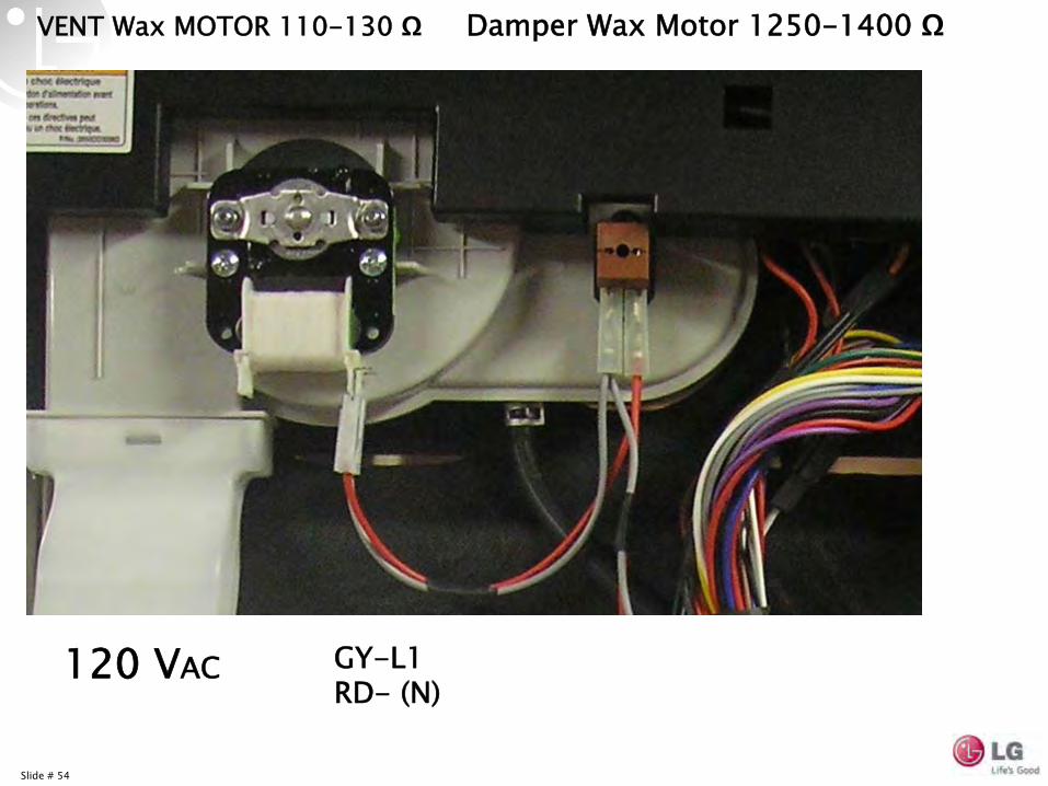
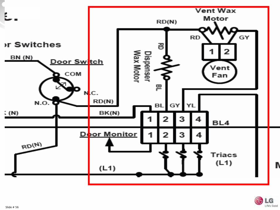
VENT Wax MOTOR 110-130 Ω
Damper Wax Motor 1250-1400 Ω
120 VAC GY-L1
RD-
(N)
Slide # 55
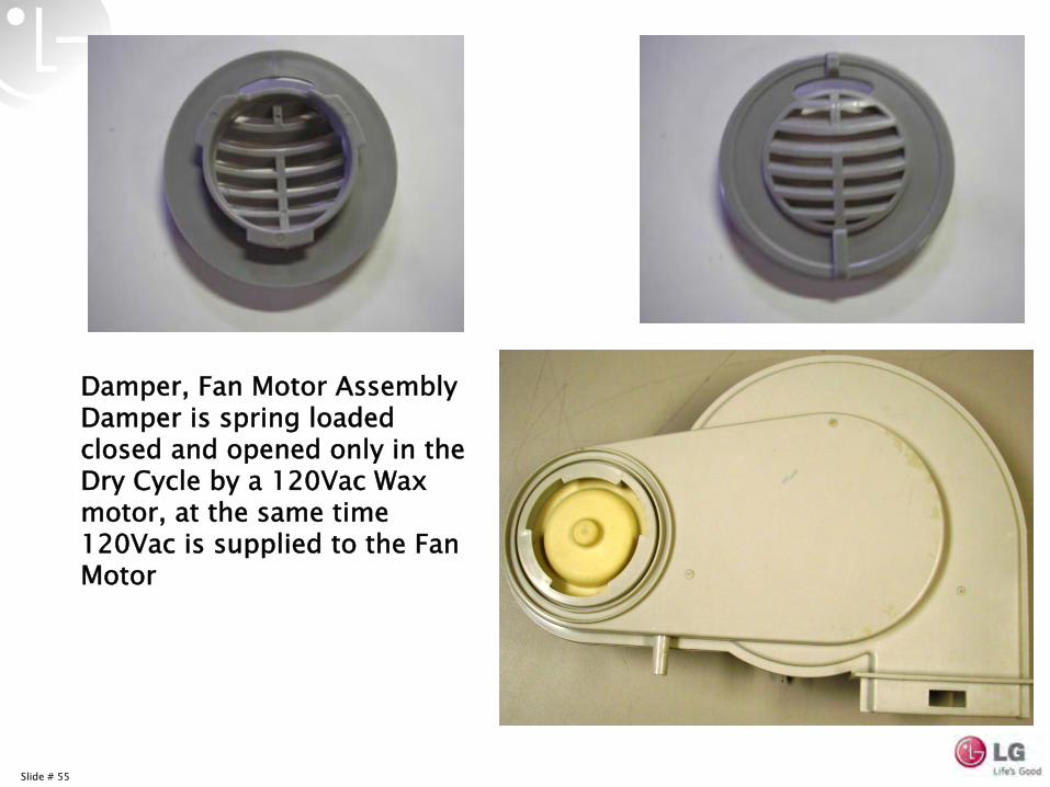
Damper, Fan Motor AssemblyDamper is spring loaded closed and opened only in the Dry Cycle by a 120Vac Wax motor, at the same time 120Vac is supplied to the Fan Motor
Slide # 56
Slide # 57
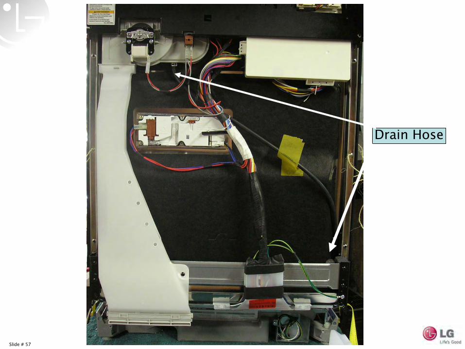
Drain Hose
Slide # 58
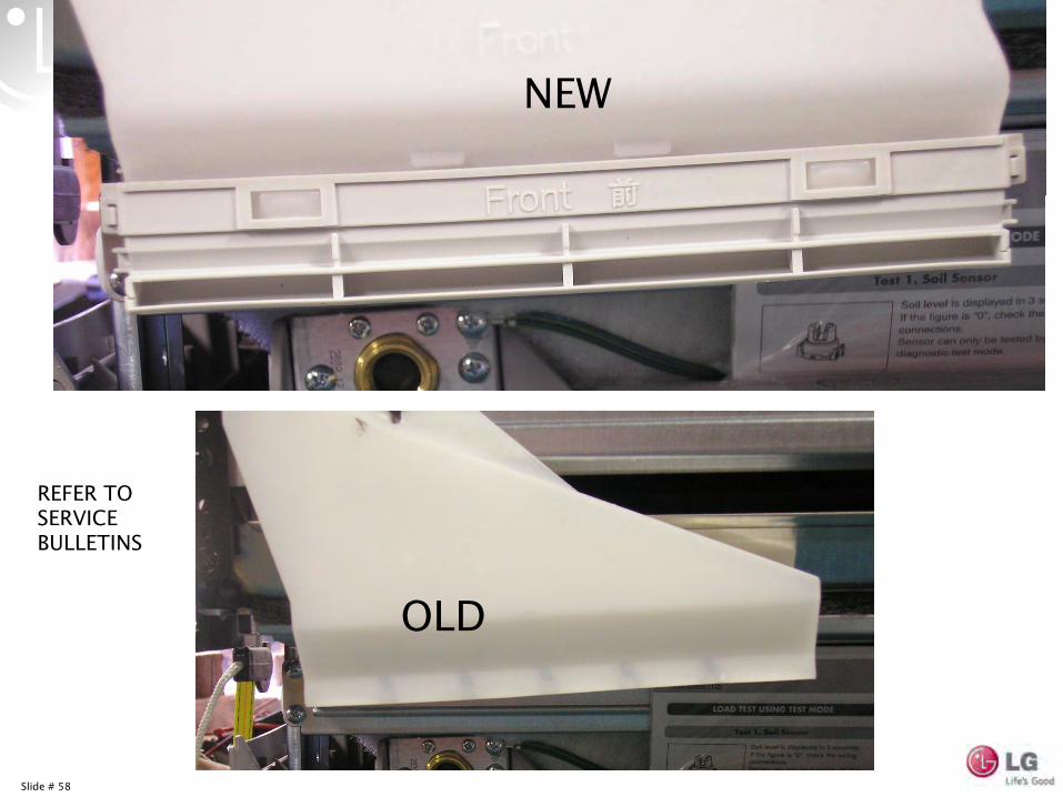
NEW
OLD
REFER TO SERVICE BULLETINS
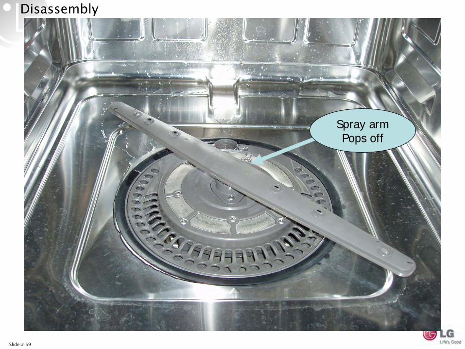
Slide # 59
Spray armPops off
Disassembly
Slide # 60
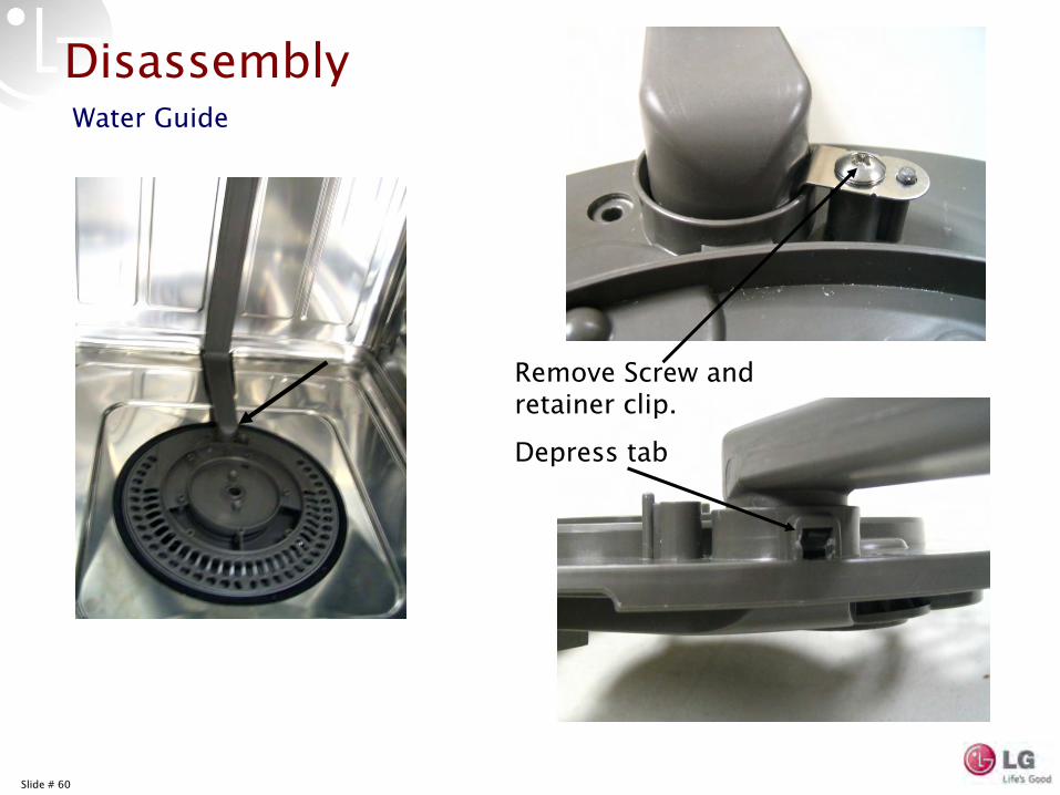
Disassembly
Remove Screw and retainer clip.
Depress tab
Water Guide
Slide # 61
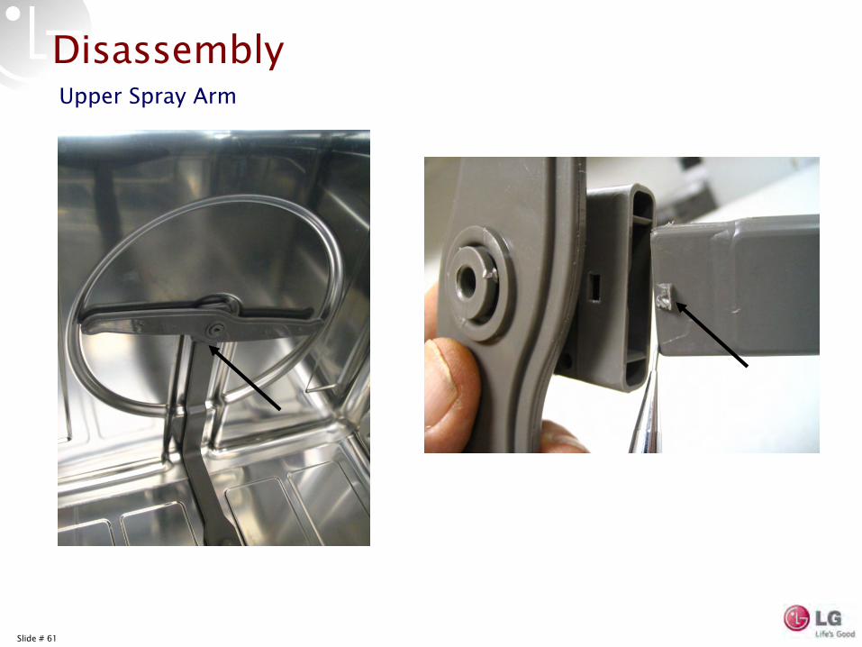
DisassemblyUpper Spray Arm
Slide # 62
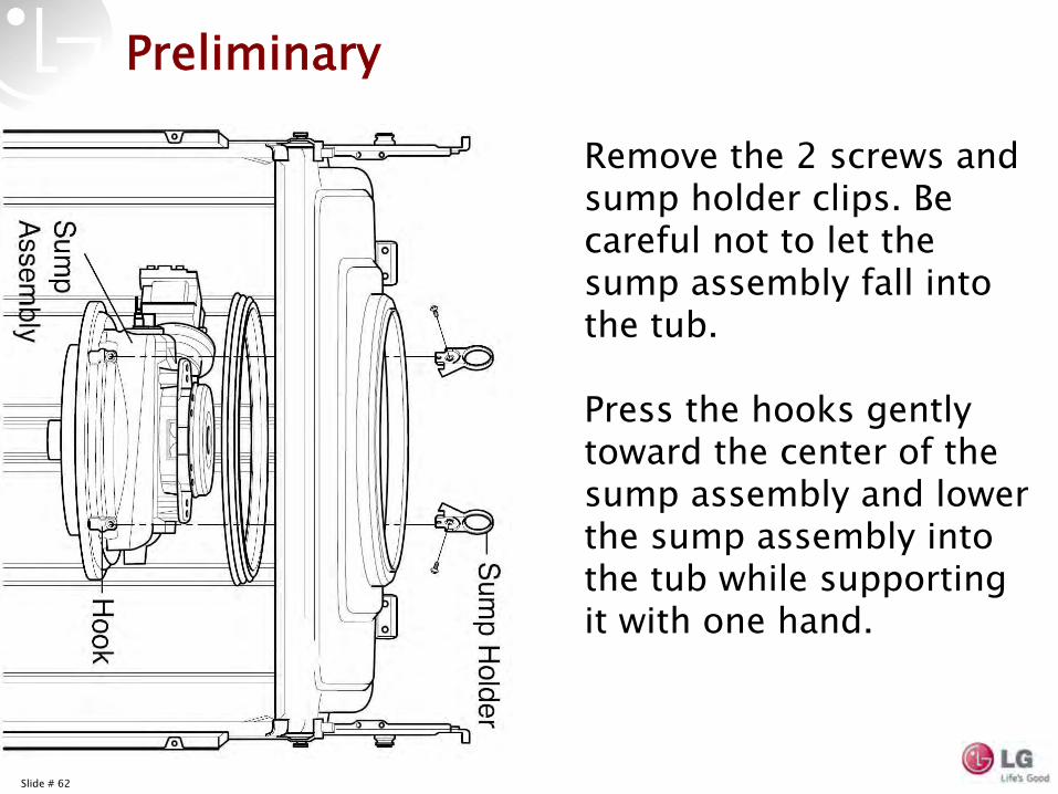
Preliminary
Remove the 2 screws and sump holder clips. Be careful not to let the sump assembly fall into the tub.
Press the hooks gently toward the center of the sump assembly and lower the sump assembly into the tub while supporting it with one hand.
Slide # 63
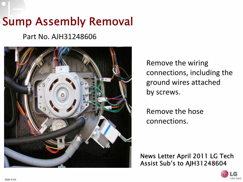
Sump Assembly Removal
Remove the wiring
connections, including the
ground wires attached by screws.
Remove the hose
connections.
Part No. AJH31248606
News Letter April 2011 LG Tech Assist Sub’s to AJH31248604
Slide # 64
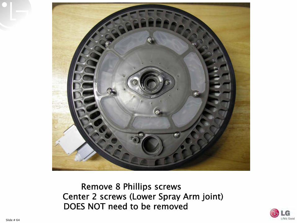
Remove 8 Phillips screws Center 2 screws (Lower Spray Arm joint) DOES NOT need to be removed
Slide # 65
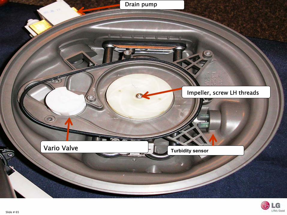
Impeller, screw LH threads
Vario
Valve
Drain pump
Turbidity sensor
Slide # 66
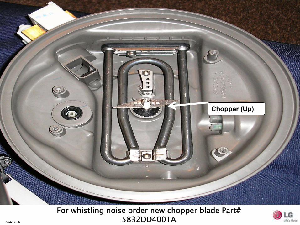
Chopper (Up)
For whistling noise order new chopper blade Part# 5832DD4001A
Slide # 67
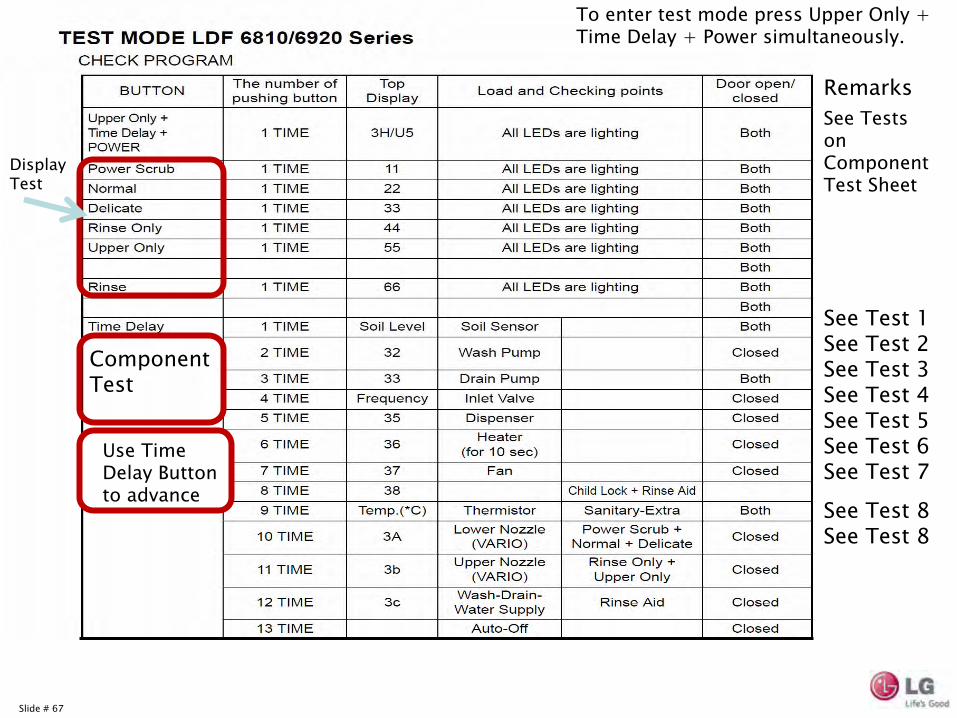
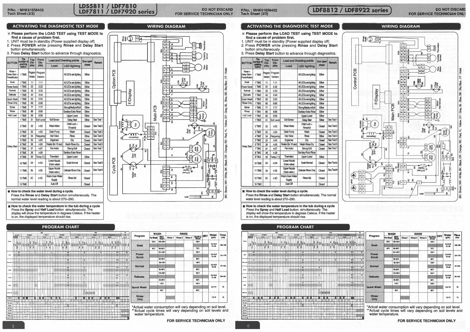
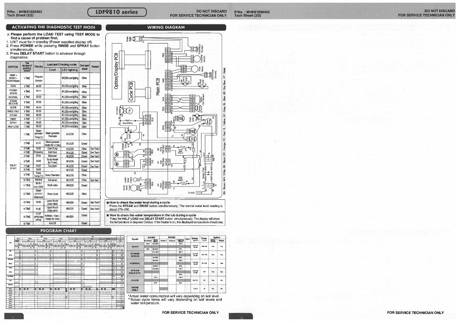
To enter test mode press Upper Only + Time Delay + Power simultaneously.
Display Test
Component Test
Use Time Delay Button to advance
Remarks
See Test 1See Test 2See Test 3See Test 4See Test 5See Test 6See Test 7
See Test 8See Test 8
See Tests on Component Test Sheet
Slide # 68
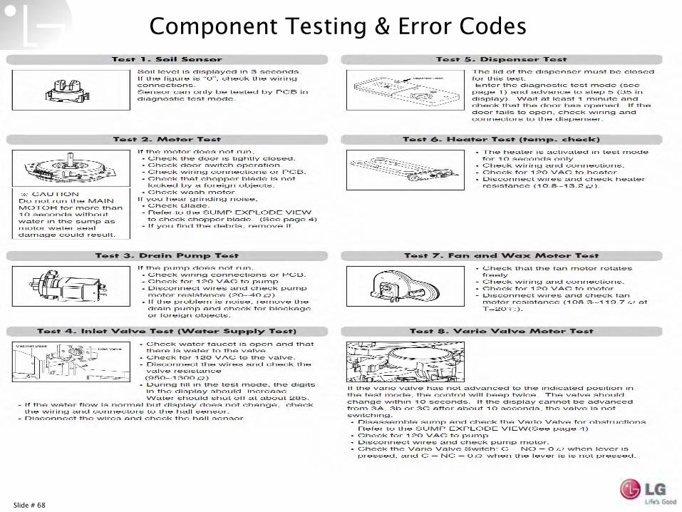
Component Testing & Error Codes
Slide # 69
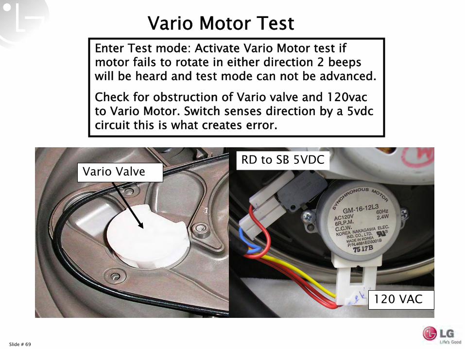
Vario
Motor TestEnter Test mode: Activate Vario
Motor test if motor fails to rotate in either direction 2 beeps will be heard and test mode can not be advanced.
Check for obstruction of Vario
valve and 120vac to Vario
Motor. Switch senses direction by a 5vdc circuit this is what creates error.
Vario
ValveRD to SB 5VDC
120 VAC
Slide # 70
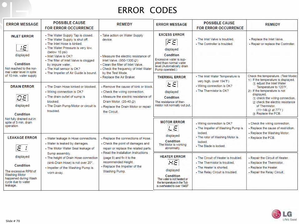
ERROR CODES
Slide # 71
Slide # 72
Slide # 73
Slide # 74
Slide # 75
Slide # 76
Slide # 77
Slide # 78
Slide # 79
Slide # 80
Slide # 81
Slide # 82
Slide # 83
Slide # 84
Slide # 85
SB IDSW201000146
Slide # 86
Dishwasher
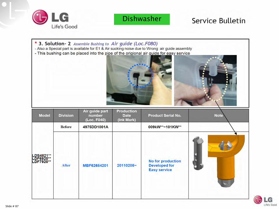
Slide # 87
Dishwasher
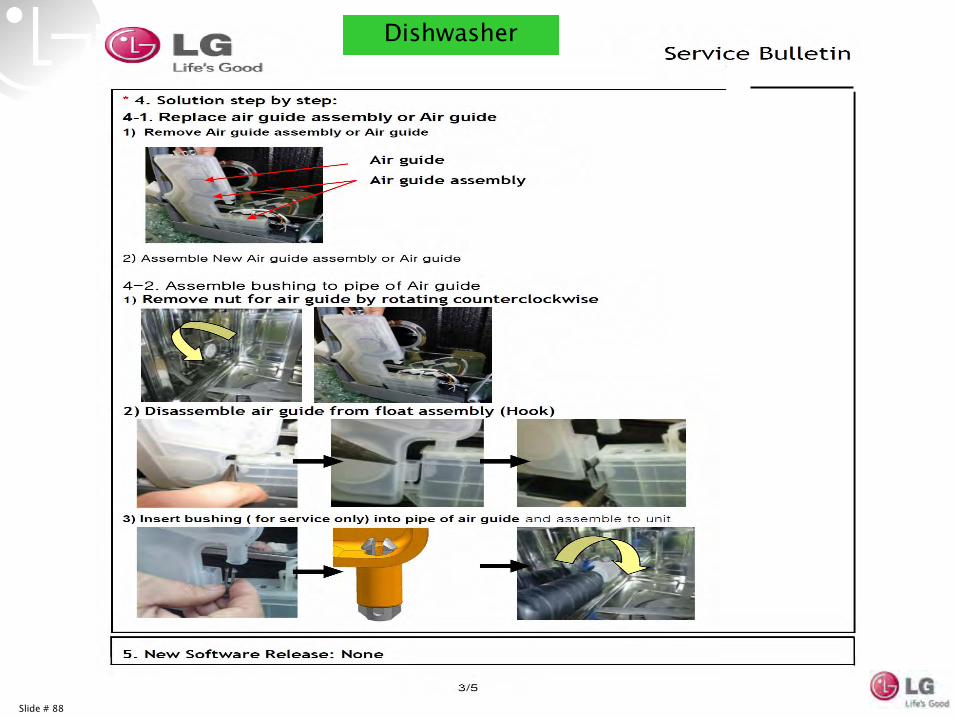
Slide # 88
Dishwasher
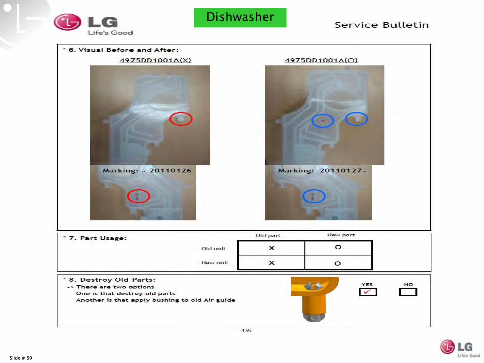
Slide # 89
Dishwasher
Slide # 90
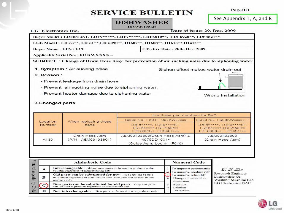
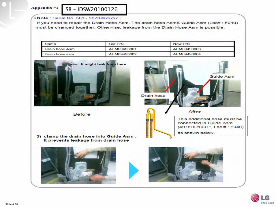
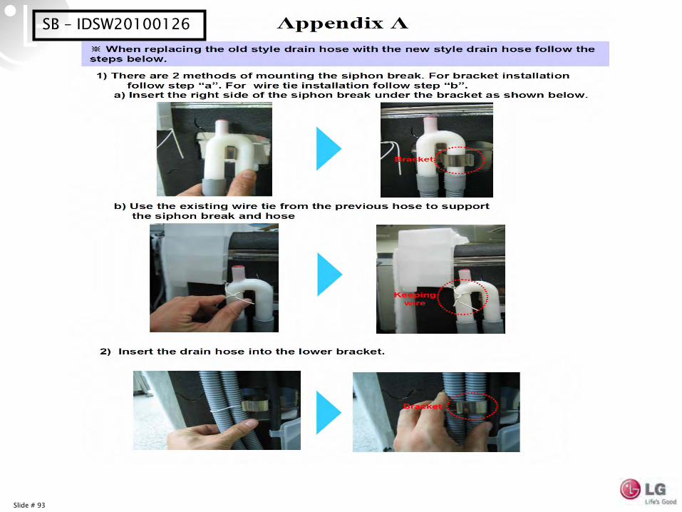
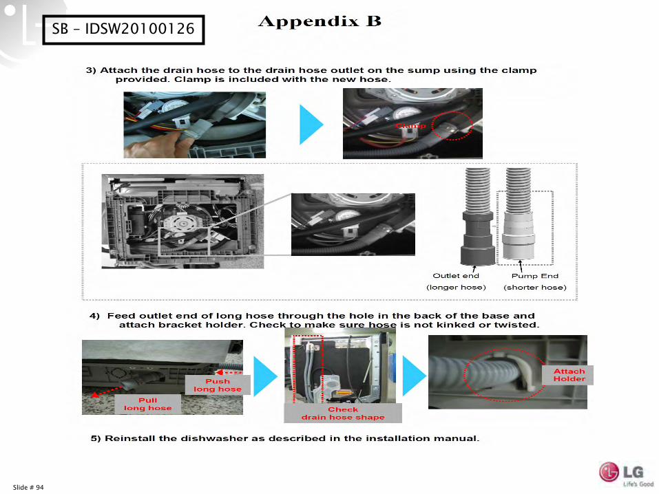
See Appendix 1, A, and B
Slide # 91
Slide # 92
SB –
IDSW20100126
Slide # 93
SB –
IDSW20100126
Slide # 94
SB –
IDSW20100126
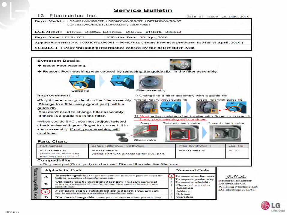
Slide # 95
Slide # 96
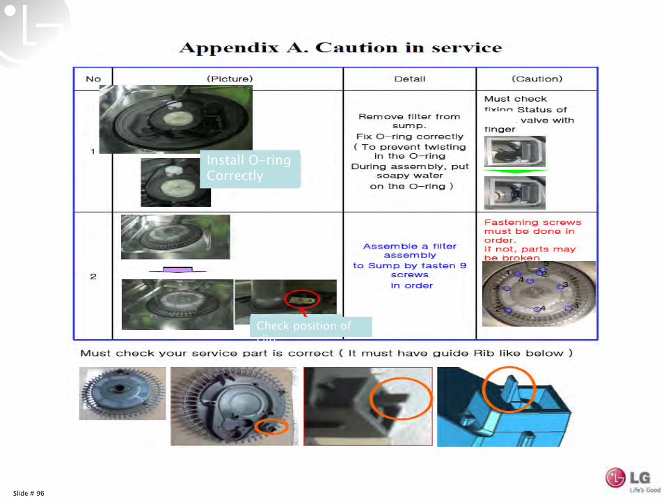
Install O-ring Correctly
Check position of clip
Slide # 97
Slide # 98
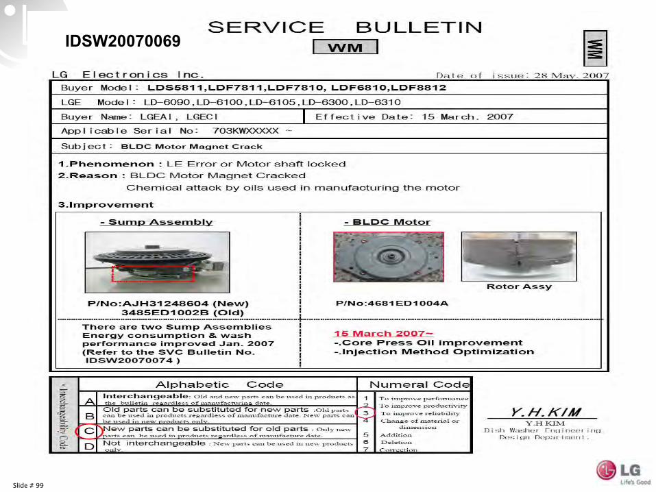
Slide # 99
IDSW20070069
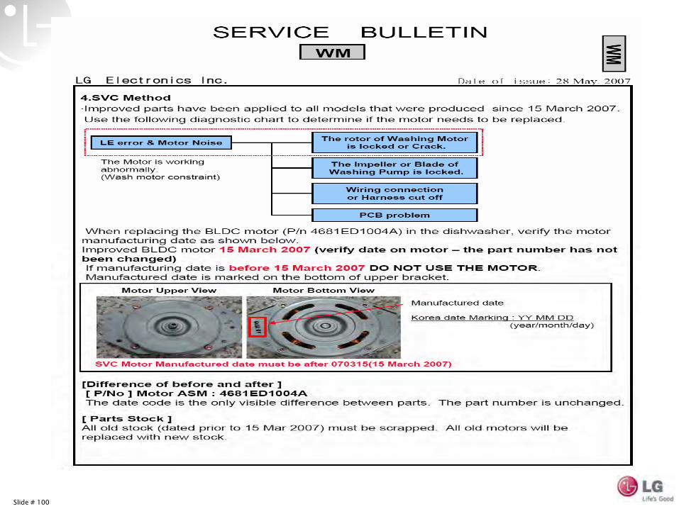
Slide # 100
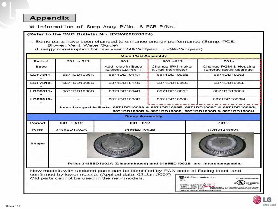
Slide # 101
Slide # 1Thursday, August 11, 2011 Confidential
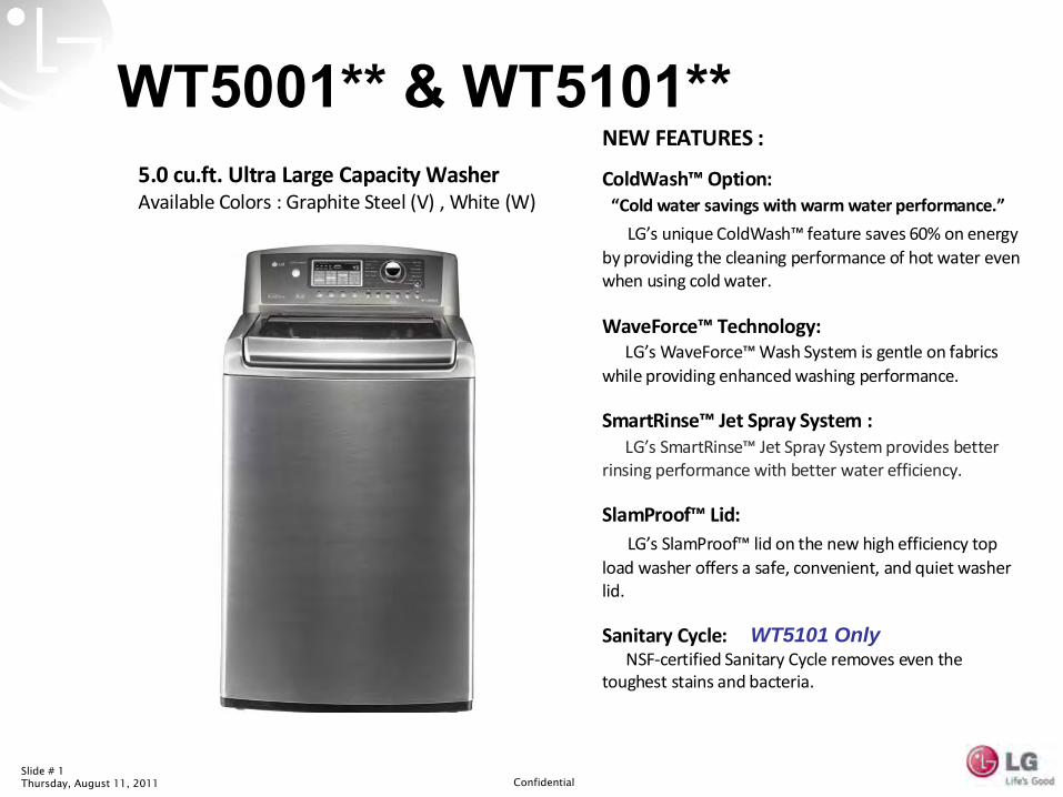
WT5101HVA/HWA$1099/$9995.0 cu.ft. Ultra Large Capacity WasherAvailable Colors : Graphite Steel (V) , White (W)
NEW FEATURES :
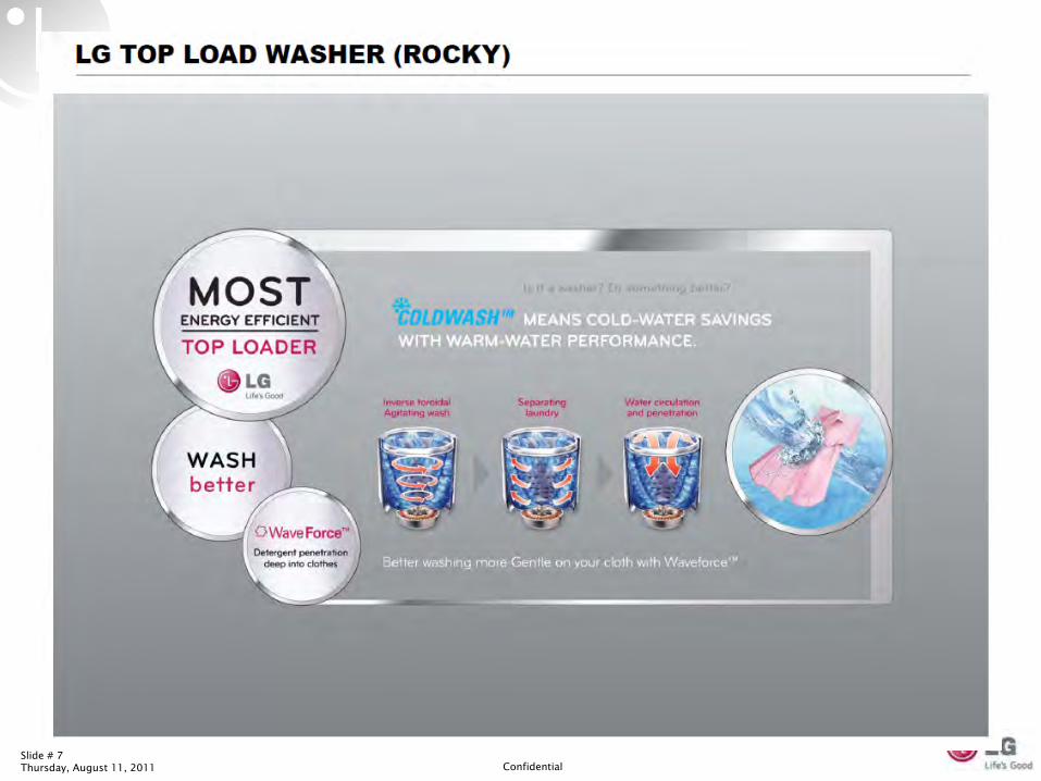
ColdWash™Option: “Cold water savings with warm water performance.”
LG’s unique ColdWash™ feature saves 60% on energy by providing the cleaning performance of hot water even when using cold water.
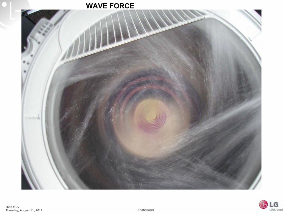
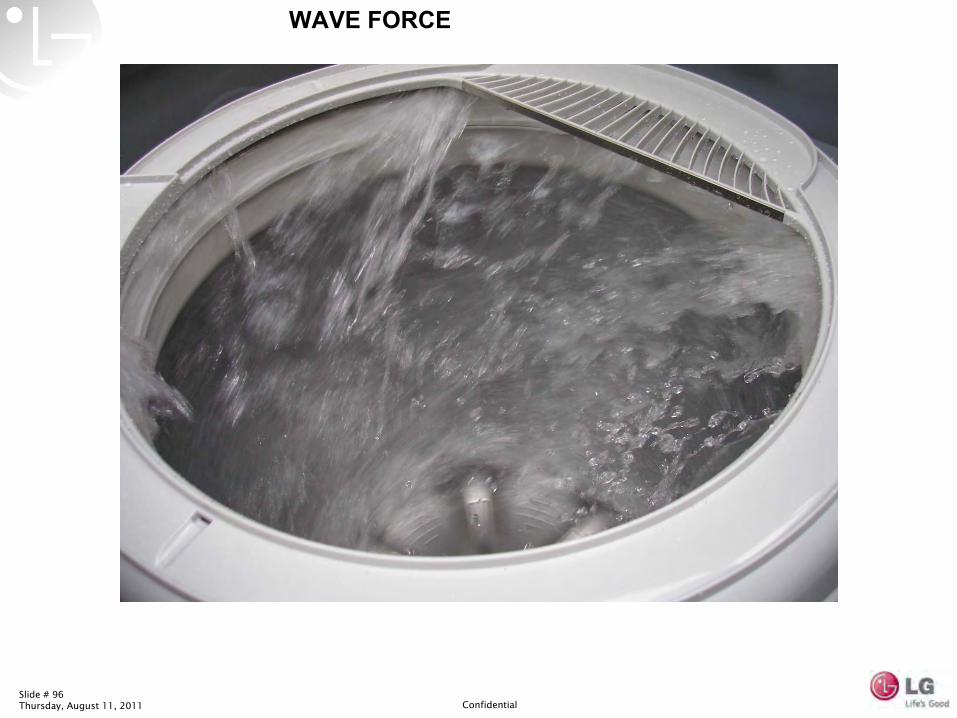
WaveForce™ Technology: LG’s WaveForce™Wash System is gentle on fabrics
while providing enhanced washing performance.
SmartRinse™ Jet Spray System : LG’s SmartRinse™ Jet Spray System provides better
rinsing performance with better water efficiency.
SlamProof™ Lid:LG’s SlamProof™ lid on the new high efficiency top
load washer offers a safe, convenient, and quiet washer lid.
Sanitary Cycle:NSF‐certified Sanitary Cycle removes even the
toughest stains and bacteria.
WT5101 Only
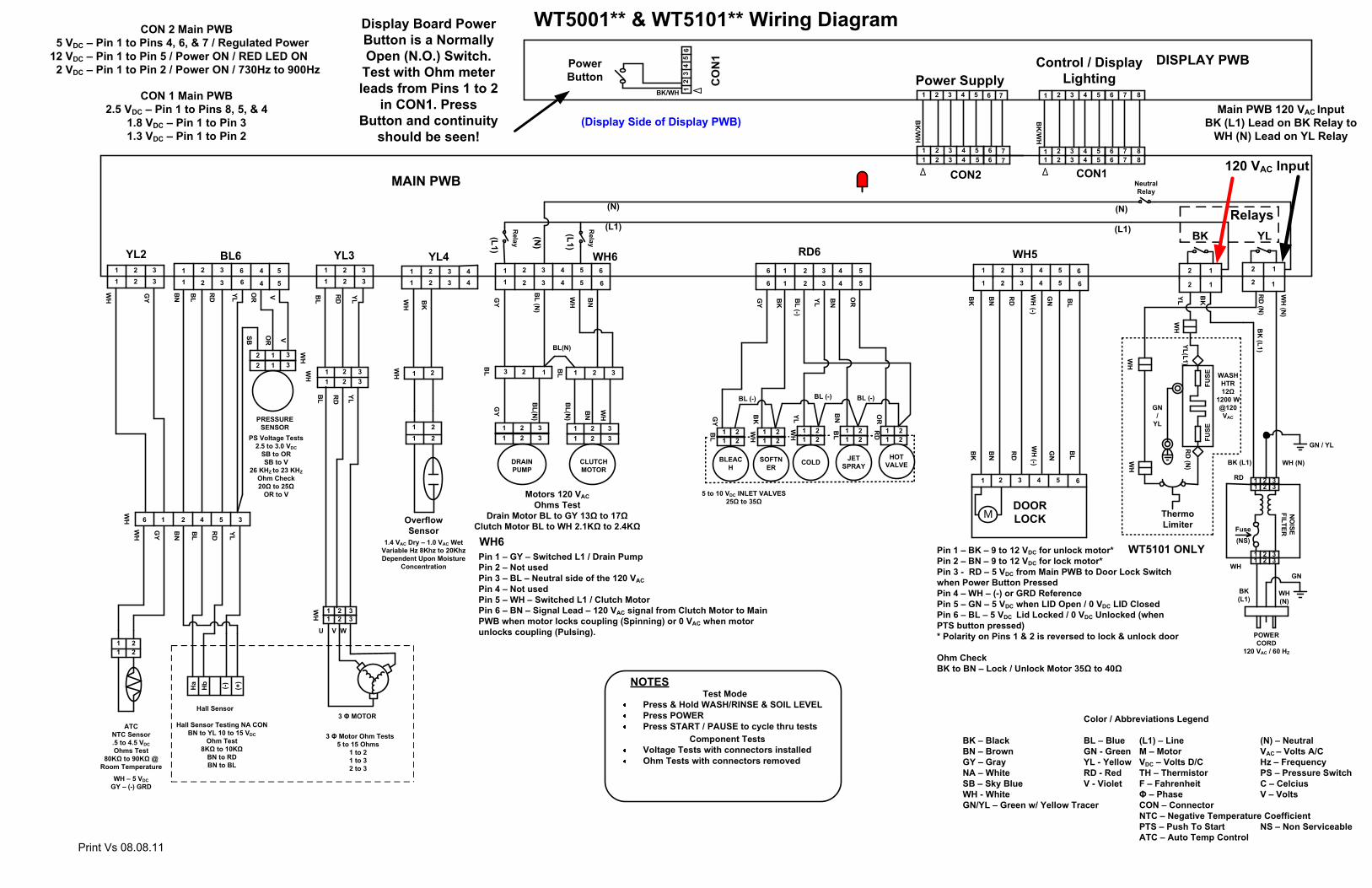
WT5001** & WT5101**
Slide # 2Thursday, August 11, 2011 Confidential
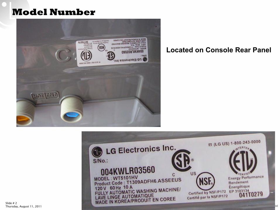
Model Number
Located on Console Rear Panel
Slide # 3Thursday, August 11, 2011 Confidential
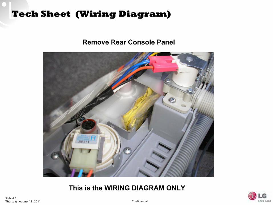
Tech Sheet (Wiring Diagram)
Remove Rear Console Panel
This is the WIRING DIAGRAM ONLY
Slide # 4Thursday, August 11, 2011 Confidential
Slide # 5Thursday, August 11, 2011 Confidential
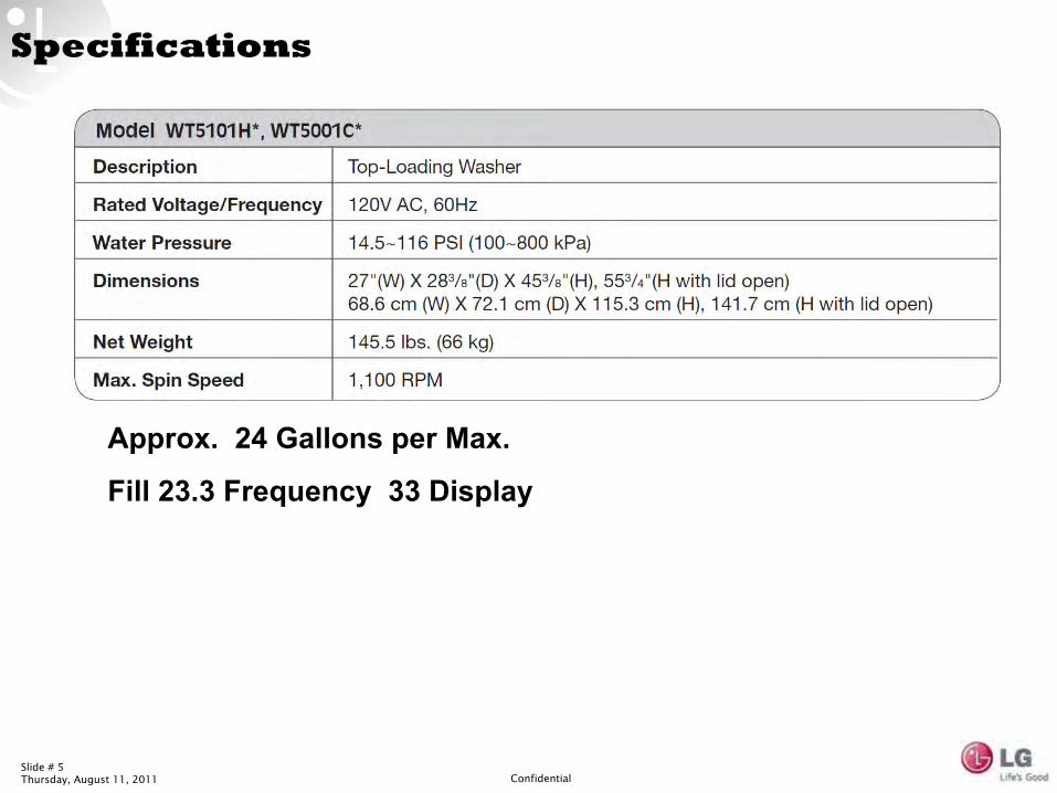
Specifications
Approx. 24 Gallons per Max.
Fill 23.3 Frequency 33 Display
Slide # 6Thursday, August 11, 2011 Confidential
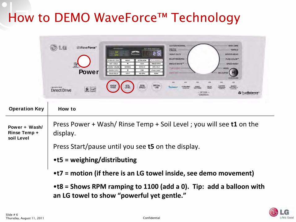
Power
Press Power + Wash/ Rinse Temp + Soil Level ; you will see
t1 on the
display.
Press Start/pause until you see t5 on the display.
•t5 = weighing/distributing
•t7 = motion (if there is an LG towel inside, see demo movement)
•t8 = Shows RPM ramping to 1100 (add a 0). Tip: add a balloon with
an LG towel to show “powerful yet gentle.”
How to DEMO WaveForce™
Technology
Operation Key How to
Power + Wash/ Rinse Temp + soil Level
Slide # 7Thursday, August 11, 2011 Confidential
Slide # 8Thursday, August 11, 2011 Confidential
Slide # 9Thursday, August 11, 2011 Confidential
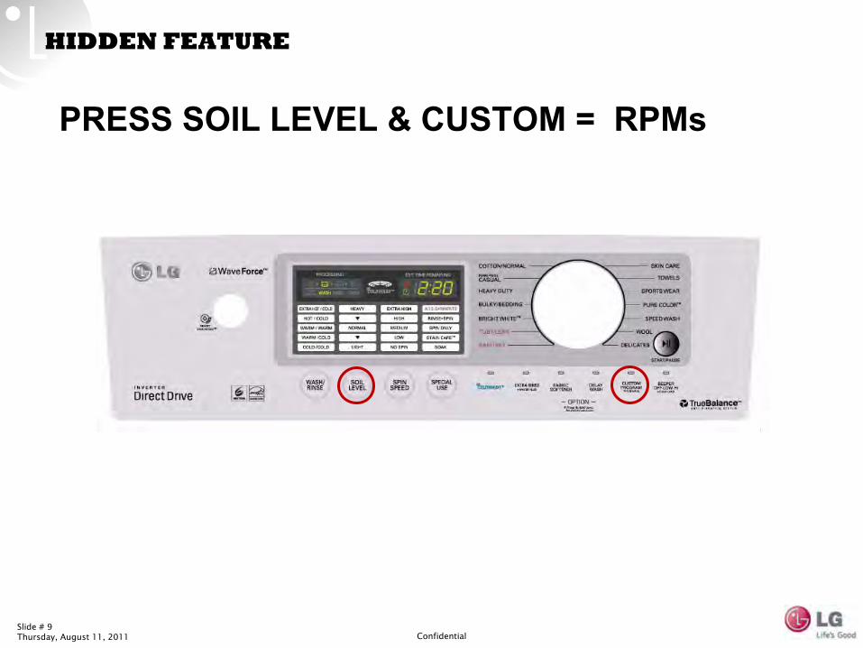
HIDDEN FEATURE
PRESS SOIL LEVEL & CUSTOM = RPMs
Slide # 10Thursday, August 11, 2011 Confidential
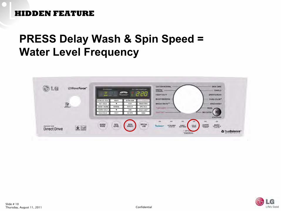
HIDDEN FEATURE
PRESS Delay Wash & Spin Speed = Water Level Frequency
Slide # 11Thursday, August 11, 2011 Confidential
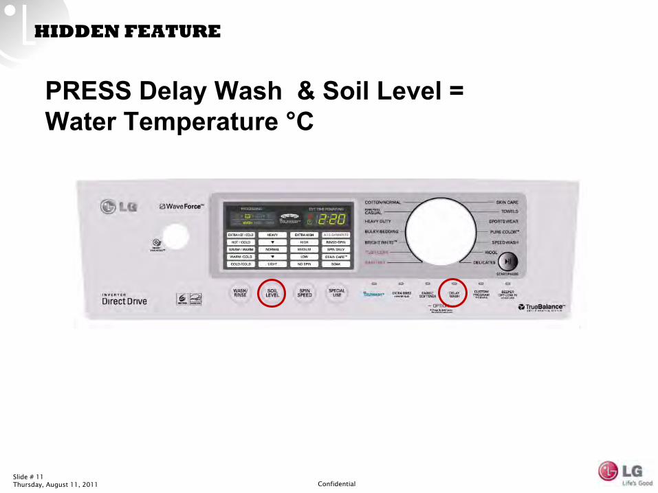
HIDDEN FEATURE
PRESS Delay Wash & Soil Level = Water Temperature °C
Slide # 12Thursday, August 11, 2011 Confidential
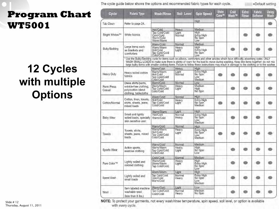
Program Chart WT5001
12 Cycles with multiple
Options
Slide # 13Thursday, August 11, 2011 Confidential
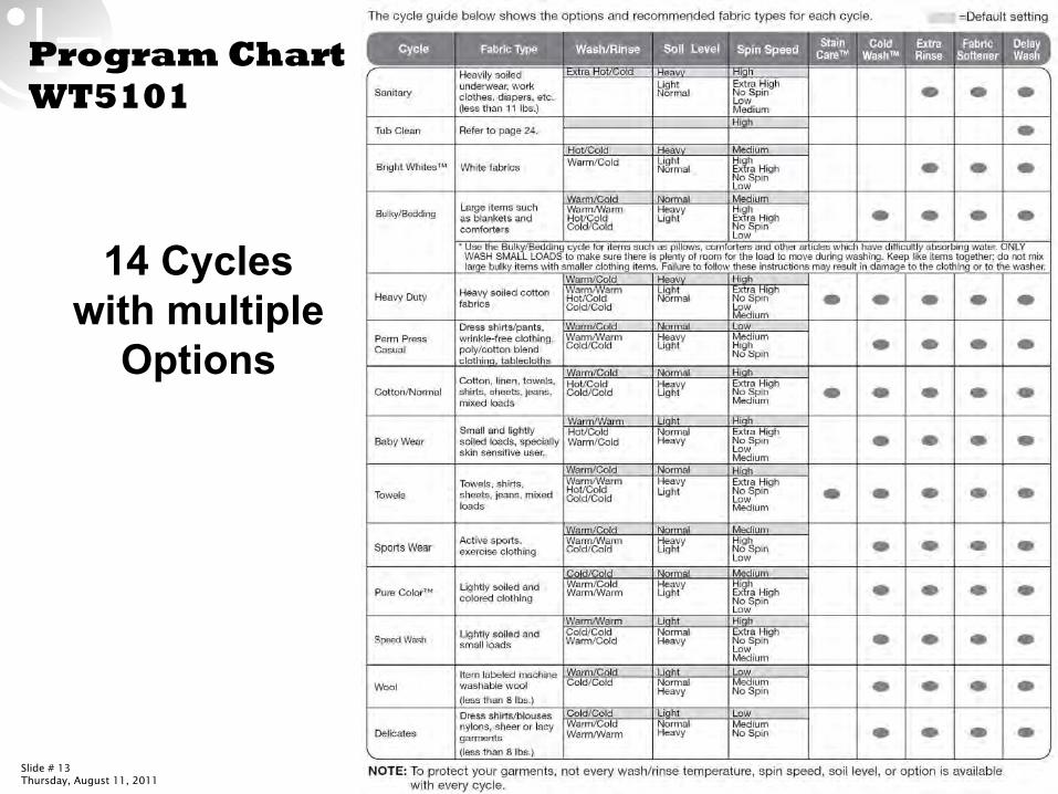
Program Chart WT5101
14 Cycles with multiple
Options
Slide # 14Thursday, August 11, 2011 Confidential
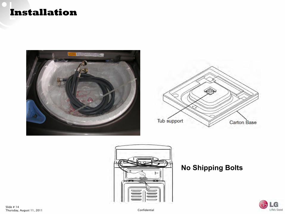
Installation
No Shipping Bolts
Slide # 15Thursday, August 11, 2011 Confidential
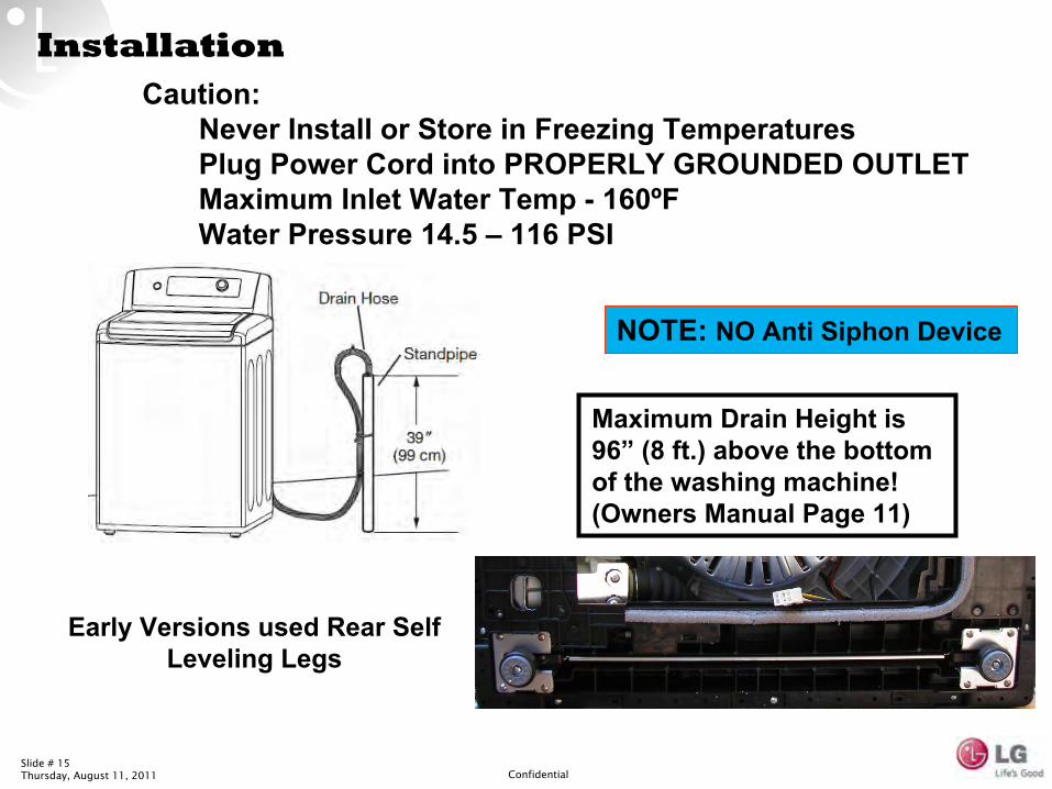
InstallationCaution:
Never Install or Store in Freezing Temperatures
Plug Power Cord into PROPERLY GROUNDED OUTLET
Maximum Inlet Water Temp -
160ºF
Water Pressure 14.5 –
116 PSI
Early Versions used Rear Self Leveling Legs
NOTE: NO Anti Siphon Device
Maximum Drain Height is 96”
(8 ft.) above the bottom of the washing machine! (Owners Manual Page 11)
Slide # 16Thursday, August 11, 2011 Confidential
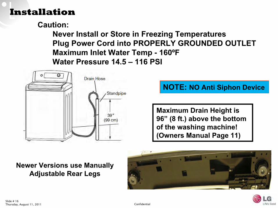
InstallationCaution:
Never Install or Store in Freezing Temperatures
Plug Power Cord into PROPERLY GROUNDED OUTLET
Maximum Inlet Water Temp -
160ºF
Water Pressure 14.5 –
116 PSI
Newer Versions use Manually Adjustable Rear Legs
NOTE: NO Anti Siphon Device
Maximum Drain Height is 96”
(8 ft.) above the bottom of the washing machine! (Owners Manual Page 11)
Slide # 17Thursday, August 11, 2011 Confidential
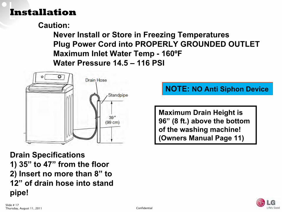
InstallationCaution:
Never Install or Store in Freezing Temperatures
Plug Power Cord into PROPERLY GROUNDED OUTLET
Maximum Inlet Water Temp -
160ºF
Water Pressure 14.5 –
116 PSI
NOTE: NO Anti Siphon Device
Maximum Drain Height is 96”
(8 ft.) above the bottom of the washing machine! (Owners Manual Page 11)
Drain Specifications 1) 35”
to 47”
from the floor 2) Insert no more than 8”
to 12”
of drain hose into stand pipe!
Slide # 18Thursday, August 11, 2011 Confidential
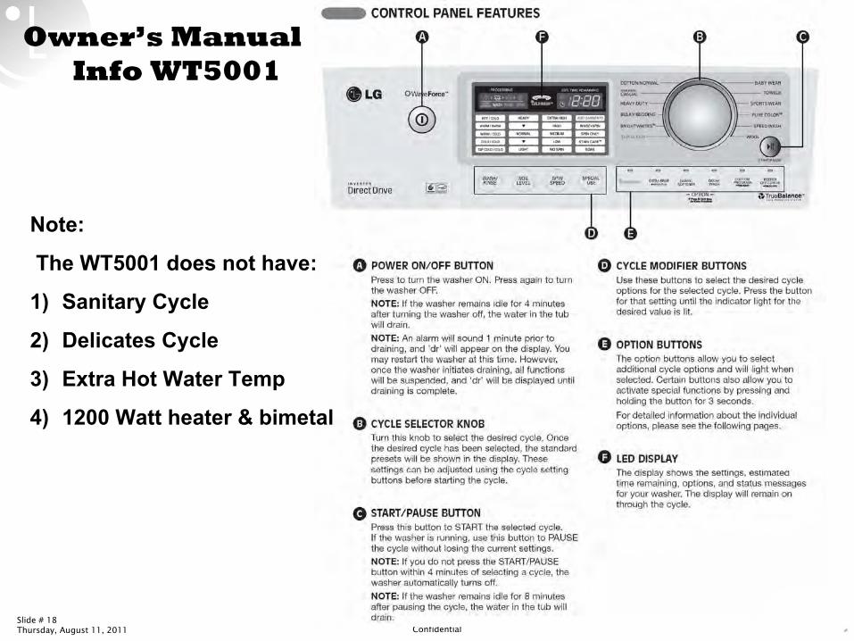
Owner’s Manual
Info WT5001
Note:
The WT5001 does not have:
1)
Sanitary Cycle
2)
Delicates Cycle
3)
Extra Hot Water Temp
4)
1200 Watt heater & bimetal
Slide # 19Thursday, August 11, 2011 Confidential
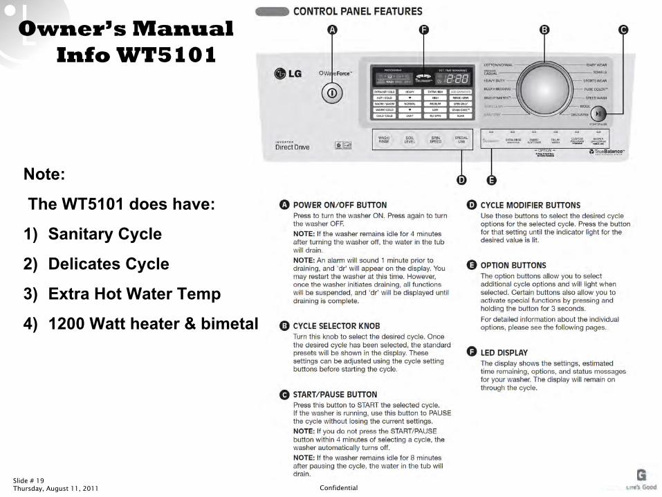
Owner’s Manual
Info WT5101
Note:
The WT5101 does have:
1)
Sanitary Cycle
2)
Delicates Cycle
3)
Extra Hot Water Temp
4)
1200 Watt heater & bimetal
Slide # 20Thursday, August 11, 2011 Confidential
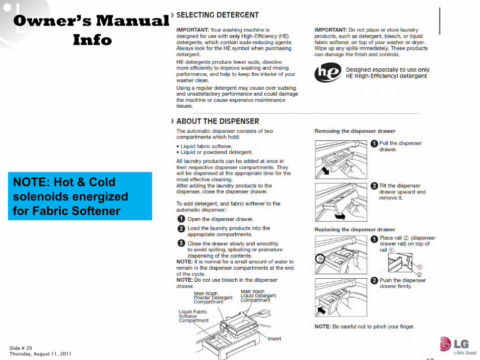
Owner’s Manual
Info
NOTE: Hot & Cold solenoids energized for Fabric Softener
Slide # 21Thursday, August 11, 2011 Confidential
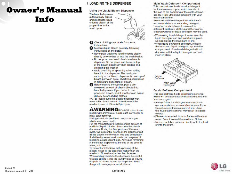
Owner’s Manual
Info
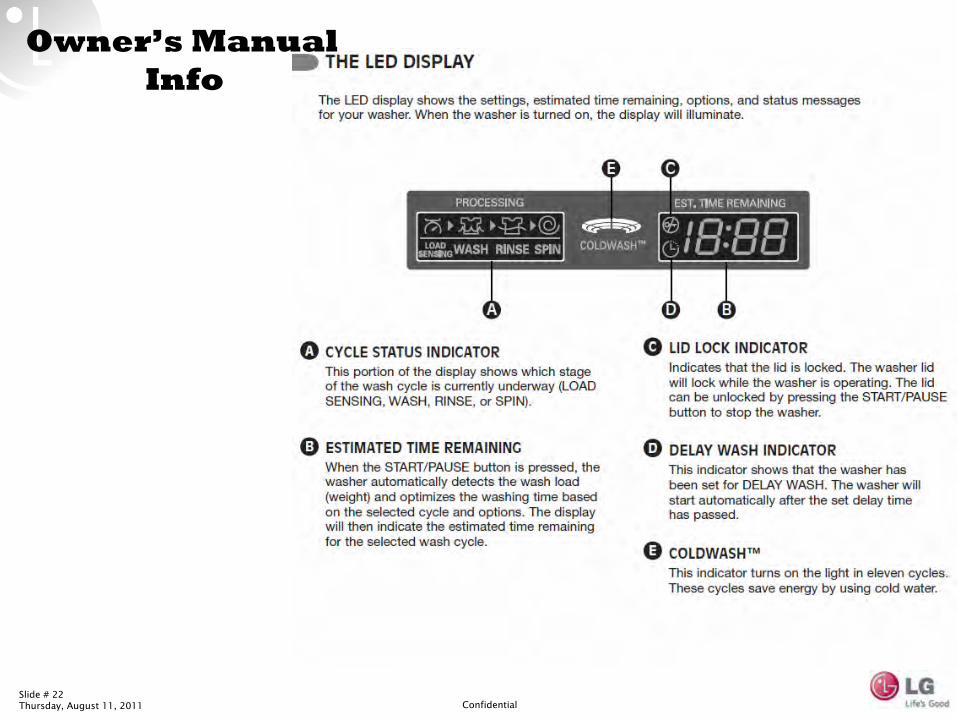
Slide # 22Thursday, August 11, 2011 Confidential
Owner’s Manual
Info
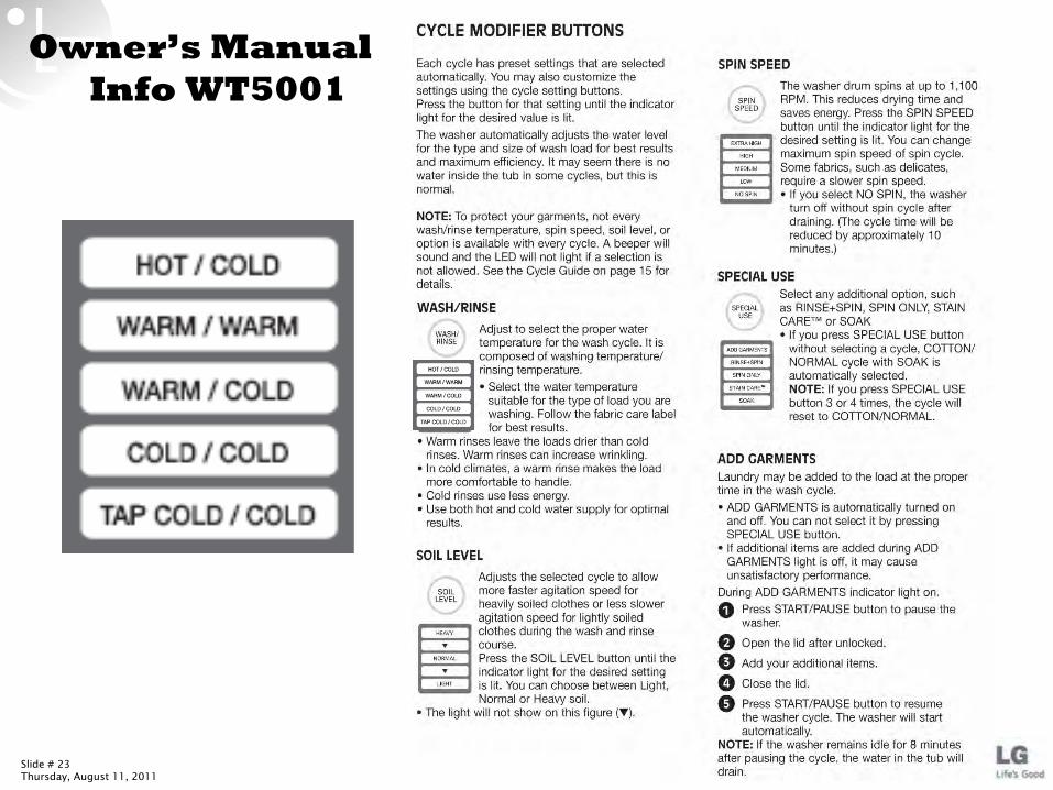
Slide # 23Thursday, August 11, 2011 Confidential
Owner’s Manual
Info WT5001
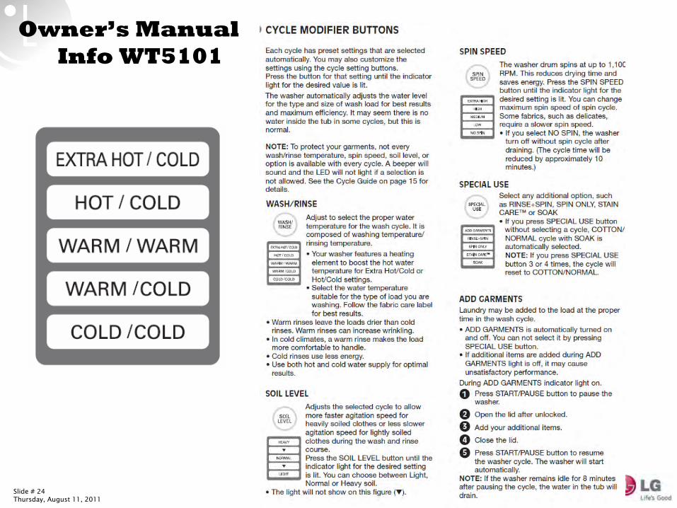
Slide # 24Thursday, August 11, 2011 Confidential
Owner’s Manual
Info WT5101
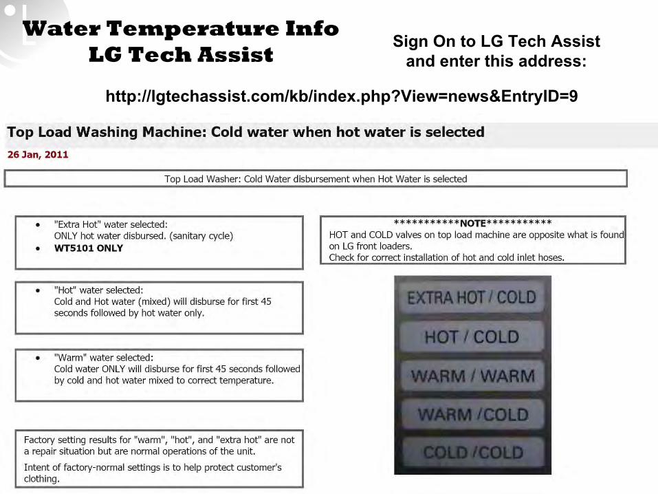
Slide # 25Thursday, August 11, 2011 Confidential
Water Temperature Info LG Tech Assist
http://lgtechassist.com/kb/index.php?View=news&EntryID=9
Sign On to LG Tech Assist and enter this address:
Slide # 26Thursday, August 11, 2011 Confidential
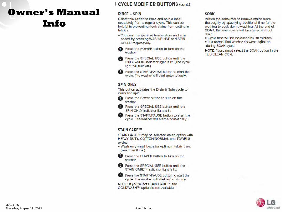
Owner’s Manual
Info
Slide # 27Thursday, August 11, 2011 Confidential
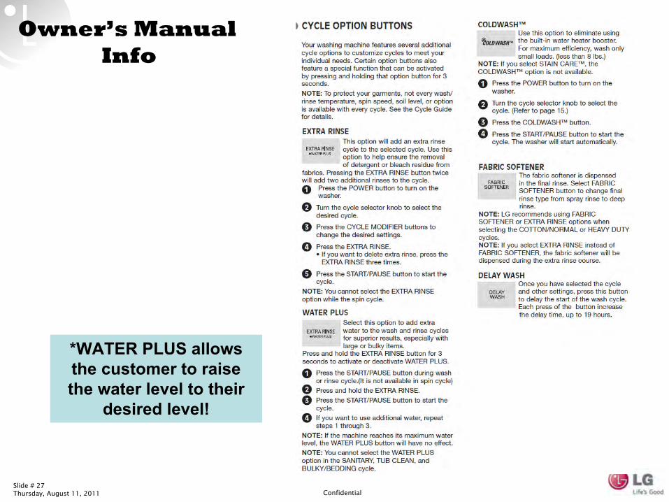
Owner’s Manual
Info
*WATER PLUS allows the customer to raise the water level to their
desired level!
Slide # 28Thursday, August 11, 2011 Confidential
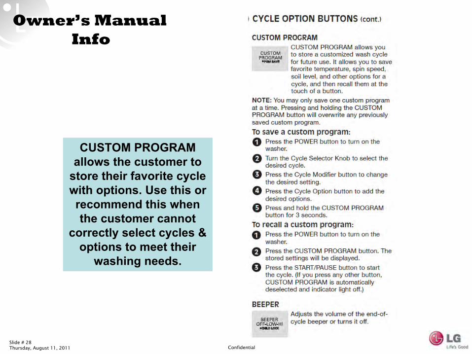
Owner’s Manual
Info
CUSTOM PROGRAM allows the customer to
store their favorite cycle with options. Use this or recommend this when the customer cannot
correctly select cycles & options to meet their
washing needs.
Slide # 29Thursday, August 11, 2011 Confidential
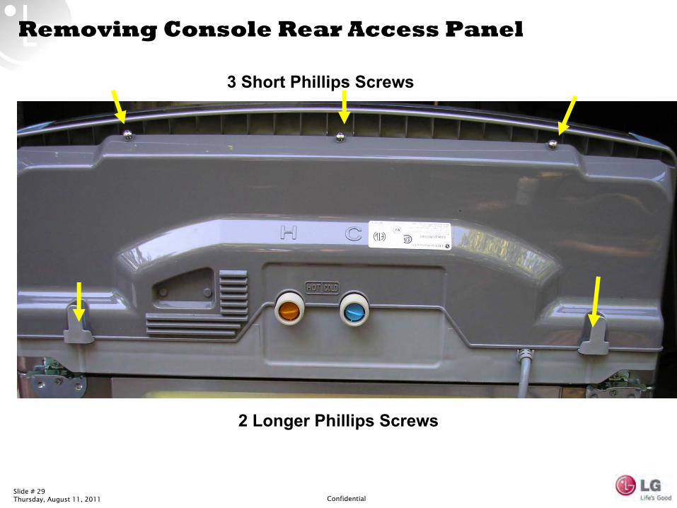
Removing Console Rear Access Panel
3 Short Phillips Screws
2 Longer Phillips Screws
Slide # 30Thursday, August 11, 2011 Confidential
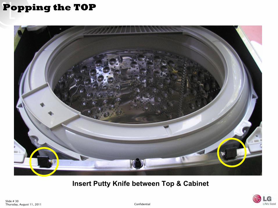
Popping the TOP
Insert Putty Knife between Top & Cabinet
Slide # 31Thursday, August 11, 2011 Confidential
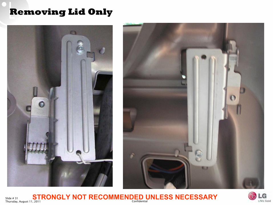
Removing Lid Only
STRONGLY NOT RECOMMENDED UNLESS NECESSARY
Slide # 32Thursday, August 11, 2011 Confidential
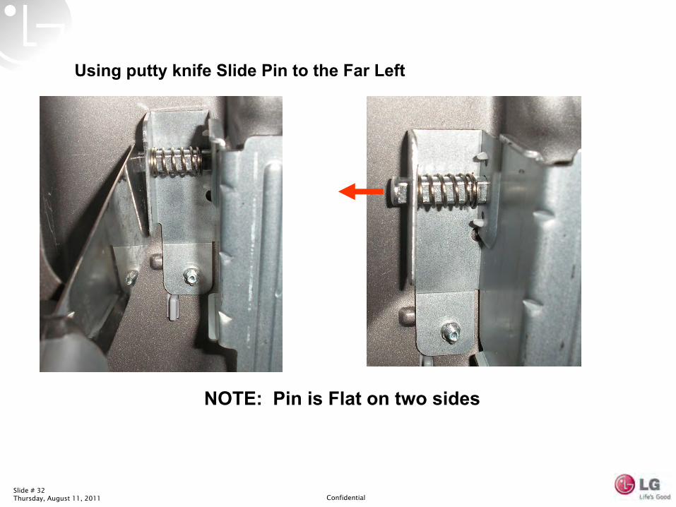
Using putty knife Slide Pin to the Far Left
NOTE: Pin is Flat on two sides

Slide # 33Thursday, August 11, 2011 Confidential
When Pin is Depressed –
Lid can be Lifted from Right Hinge
NOTE: Flat sides must align
Slide # 34Thursday, August 11, 2011 Confidential
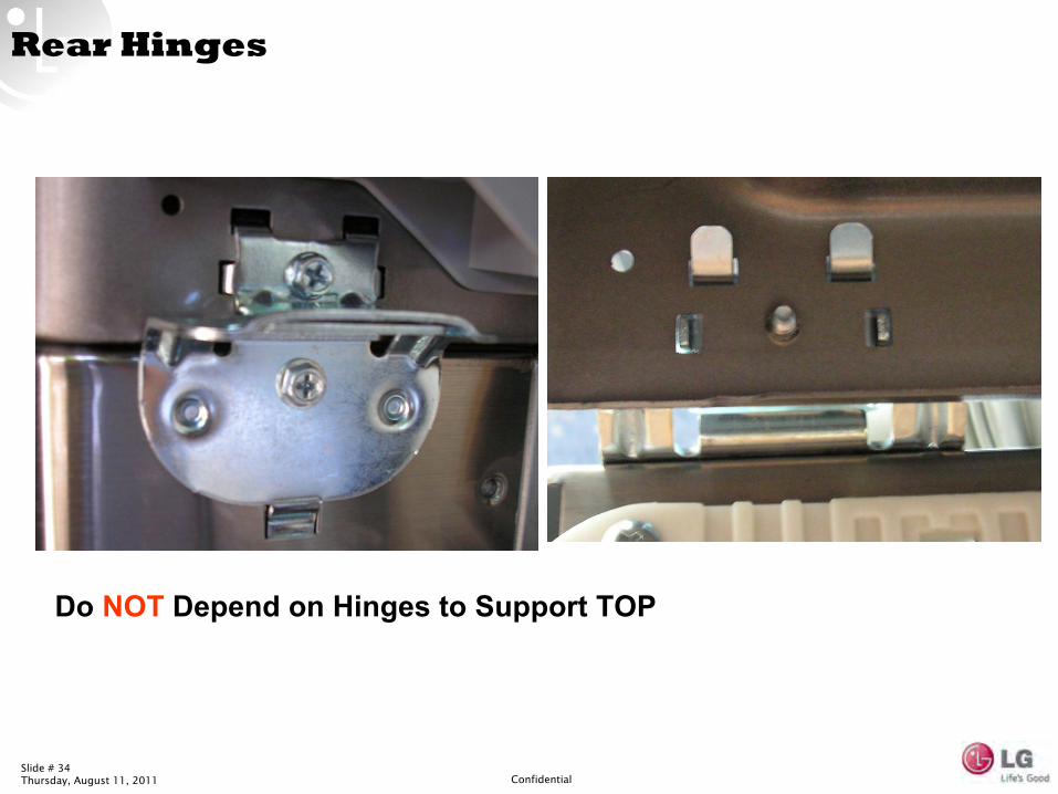
Rear Hinges
Do NOT
Depend on Hinges to Support TOP
Slide # 35Thursday, August 11, 2011 Confidential
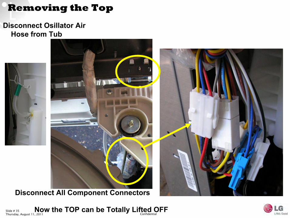
Removing the Top
Disconnect All Component Connectors
Now the TOP can be Totally Lifted OFF
Disconnect Osillator
Air
Hose from Tub
Slide # 36Thursday, August 11, 2011 Confidential
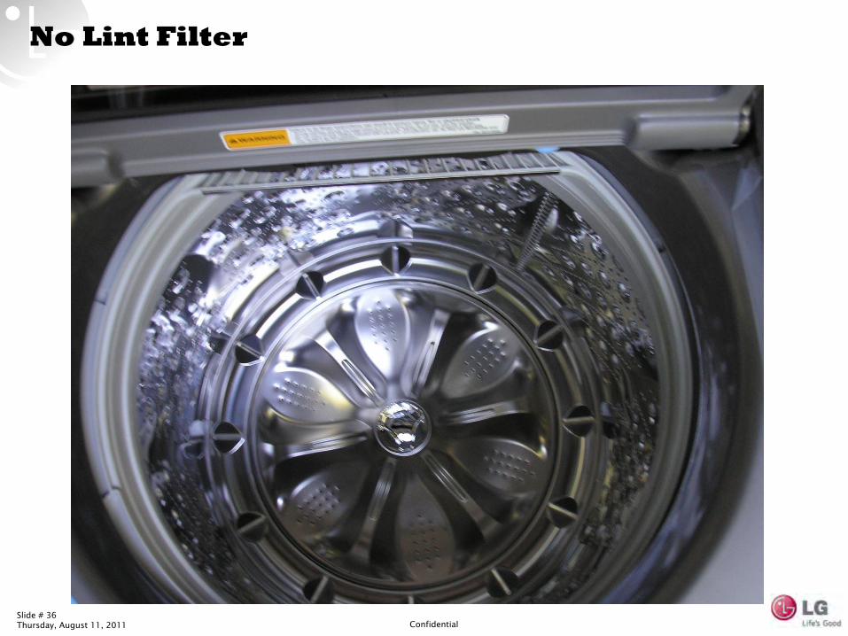
No Lint Filter
Slide # 37Thursday, August 11, 2011 Confidential
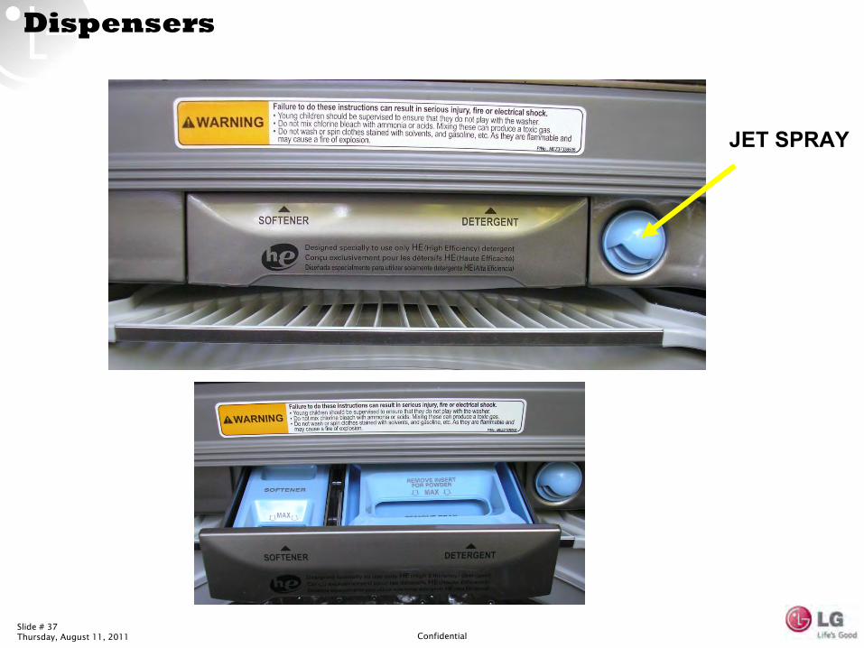
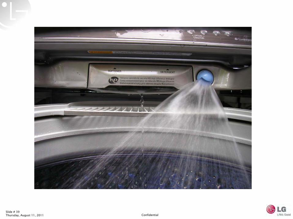
Dispensers
JET SPRAY
Slide # 38Thursday, August 11, 2011 Confidential
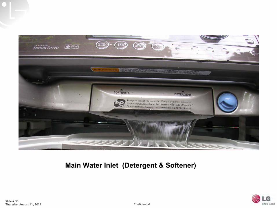
Main Water Inlet (Detergent & Softener)
Slide # 39Thursday, August 11, 2011 Confidential
Slide # 40Thursday, August 11, 2011 Confidential
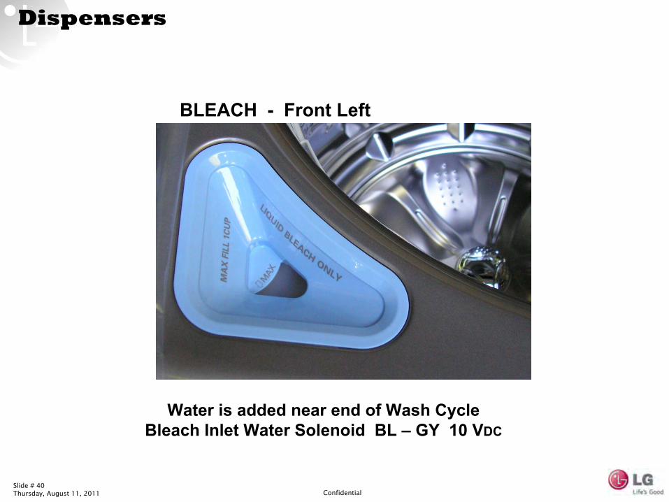
Dispensers
BLEACH -
Front Left
Water is added near end of Wash Cycle
Bleach Inlet Water Solenoid BL –
GY 10 VDC
Slide # 41Thursday, August 11, 2011 Confidential
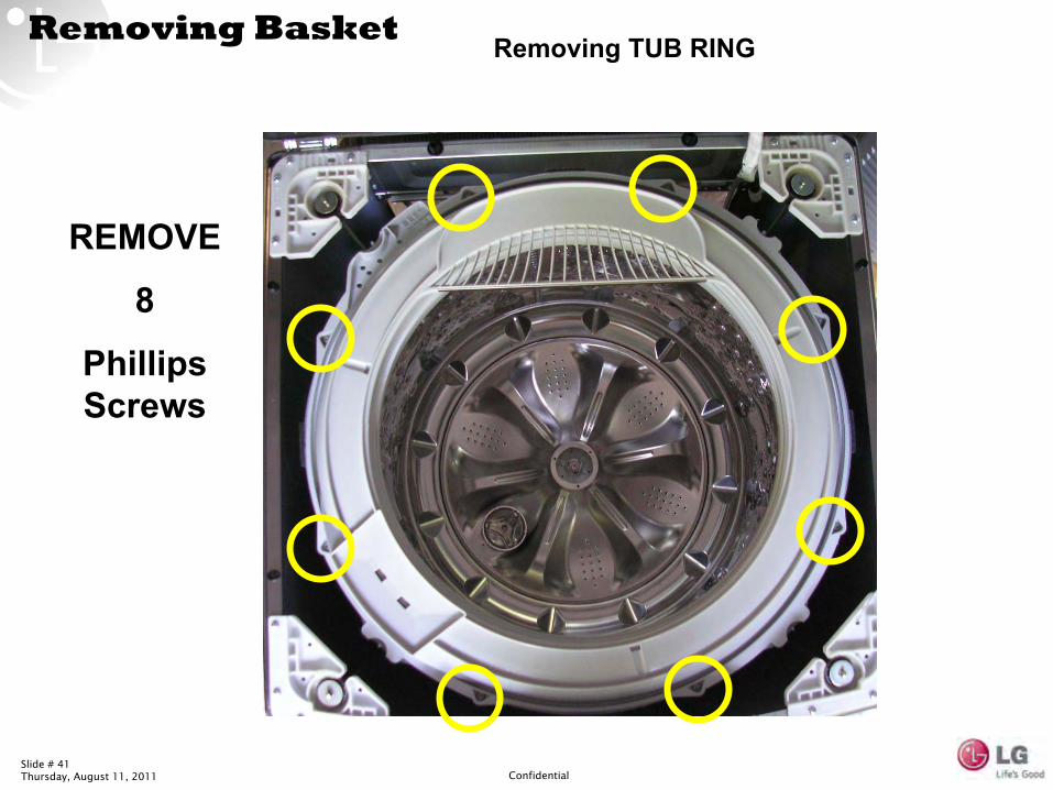
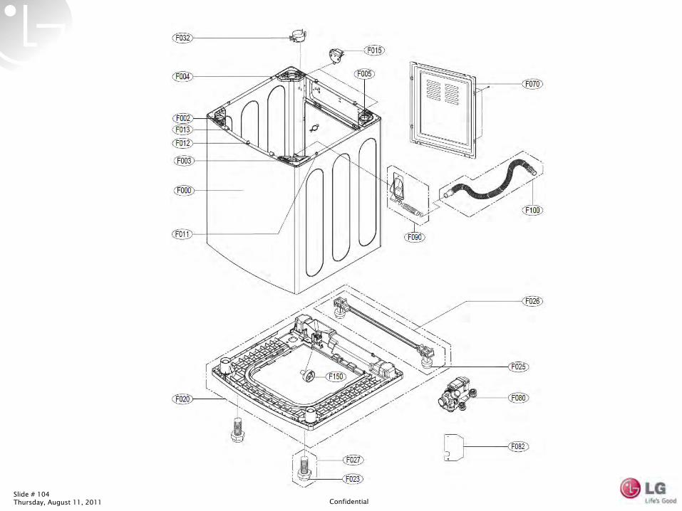
Removing Basket Removing TUB RING
REMOVE
8
Phillips Screws
Slide # 42Thursday, August 11, 2011 Confidential
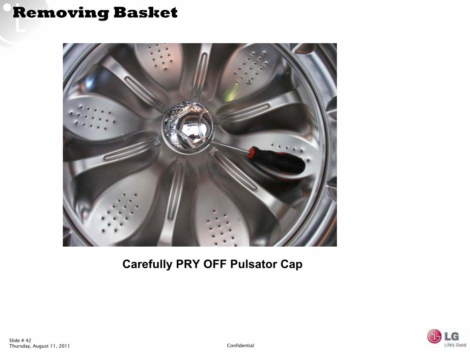
Removing Basket
Carefully PRY OFF Pulsator
Cap
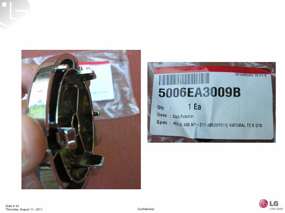
Slide # 43Thursday, August 11, 2011 Confidential
Slide # 44Thursday, August 11, 2011 Confidential
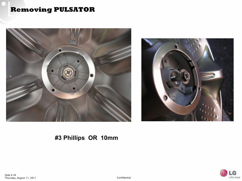
Removing PULSATOR
#3 Phillips OR 10mm
Slide # 45Thursday, August 11, 2011 Confidential
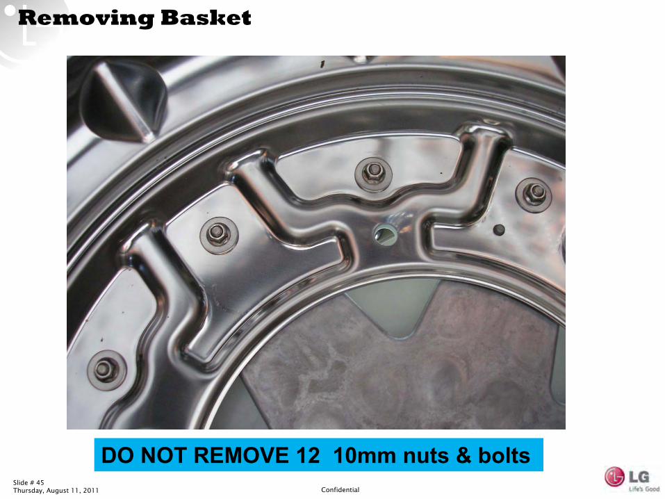
Removing Basket
DO NOT REMOVE 12 10mm nuts & bolts
Slide # 46Thursday, August 11, 2011 Confidential
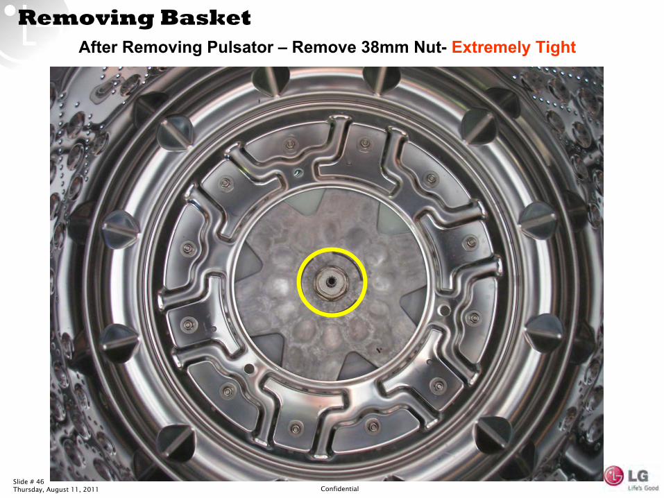
Removing BasketAfter Removing Pulsator
–
Remove 38mm Nut-
Extremely Tight
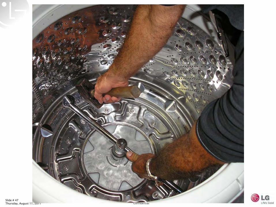
Slide # 47Thursday, August 11, 2011 Confidential
Slide # 48Thursday, August 11, 2011 Confidential
Slide # 49Thursday, August 11, 2011 Confidential
Removing Basket
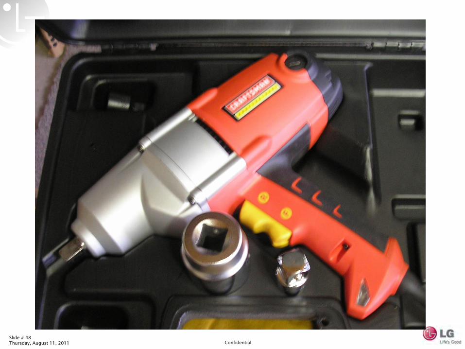
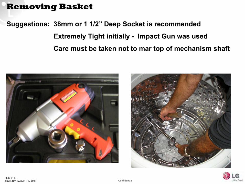
Suggestions: 38mm or 1 1/2”
Deep Socket is recommended
Extremely Tight initially -
Impact Gun was used
Care must be taken not to mar top of mechanism shaft
Slide # 50Thursday, August 11, 2011 Confidential
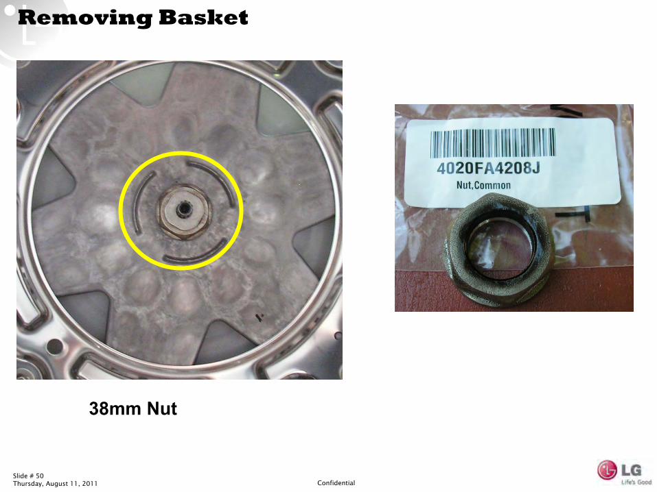
Removing Basket
38mm Nut
Slide # 51Thursday, August 11, 2011 Confidential
Slide # 52Thursday, August 11, 2011 Confidential
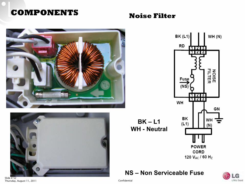
COMPONENTS Noise Filter
BK –
L1
WH -
Neutral
NS –
Non Serviceable Fuse
Slide # 53Thursday, August 11, 2011 Confidential
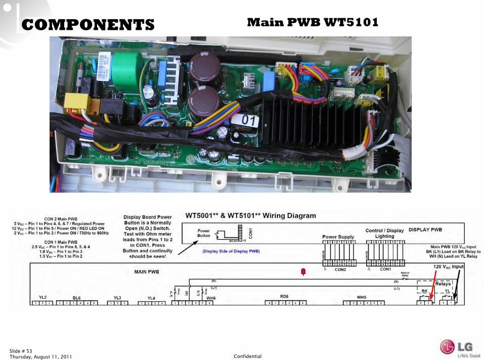
COMPONENTS Main PWB WT5101
Slide # 54Thursday, August 11, 2011 Confidential
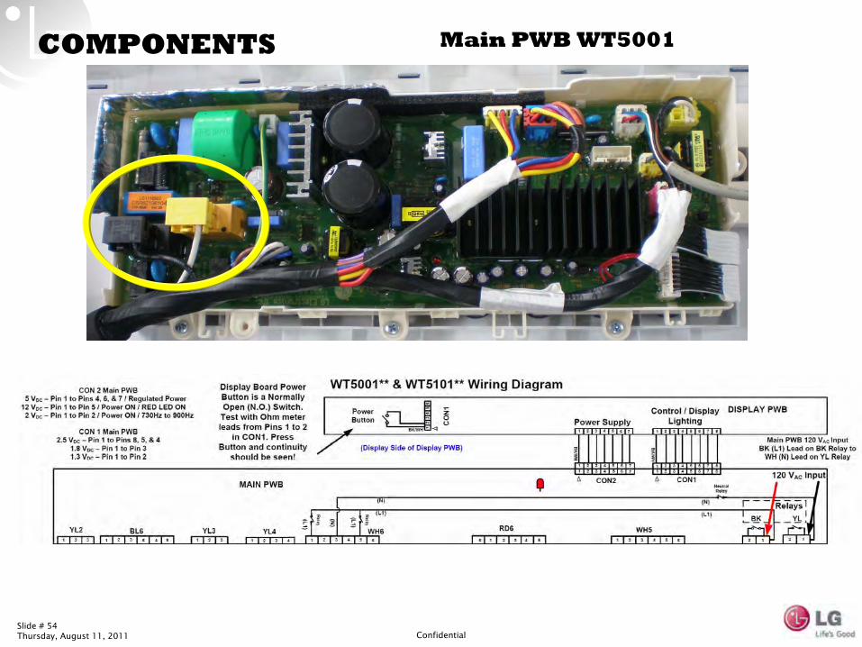
COMPONENTS Main PWB WT5001
Slide # 55Thursday, August 11, 2011 Confidential
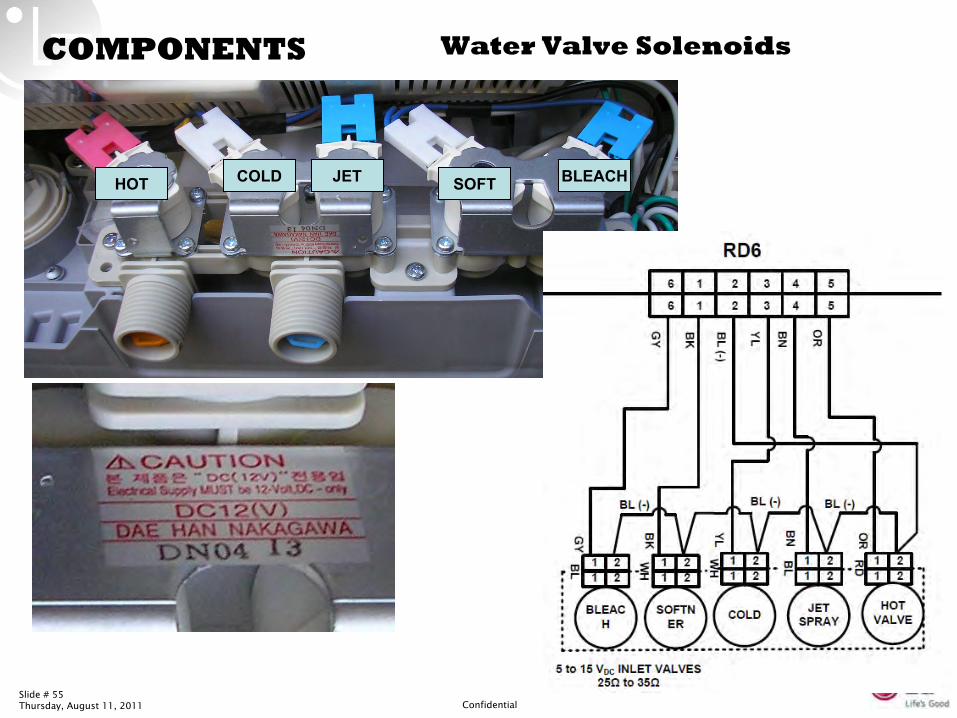
COMPONENTS Water Valve Solenoids
BLEACHSOFTJETCOLDHOT
Slide # 56Thursday, August 11, 2011 Confidential
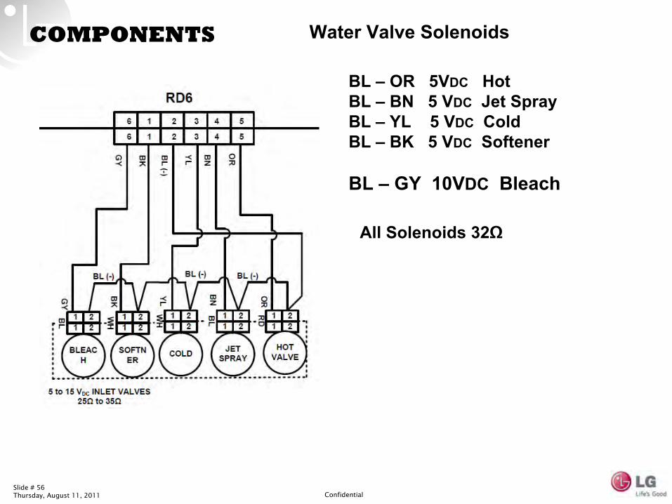
COMPONENTS Water Valve Solenoids
BL –
OR 5VDC
Hot
BL –
BN 5 VDC
Jet Spray
BL –
YL 5 VDC
Cold
BL –
BK 5 VDC
Softener
BL –
GY 10VDC
Bleach
All Solenoids 32Ω
Slide # 57Thursday, August 11, 2011 Confidential
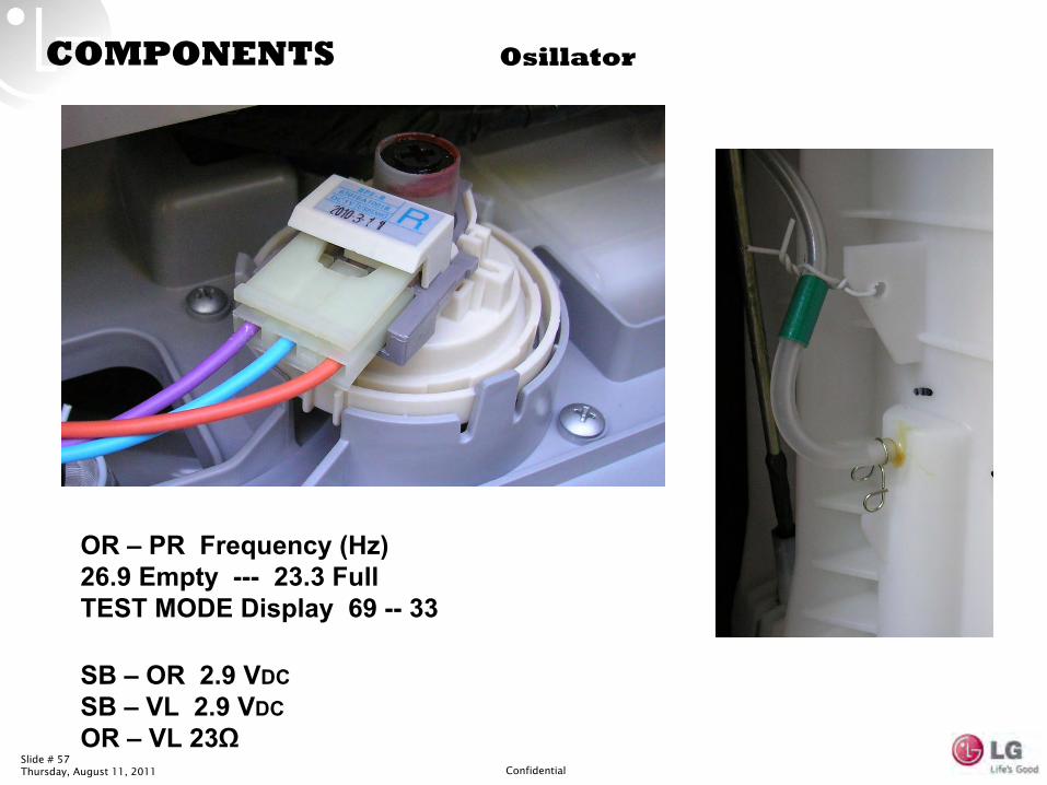
COMPONENTS Osillator
OR –
PR Frequency (Hz)
26.9 Empty ---
23.3 Full
TEST MODE Display 69 --
33
SB –
OR 2.9 VDC
SB –
VL 2.9 VDC
OR –
VL 23Ω
Slide # 58Thursday, August 11, 2011 Confidential
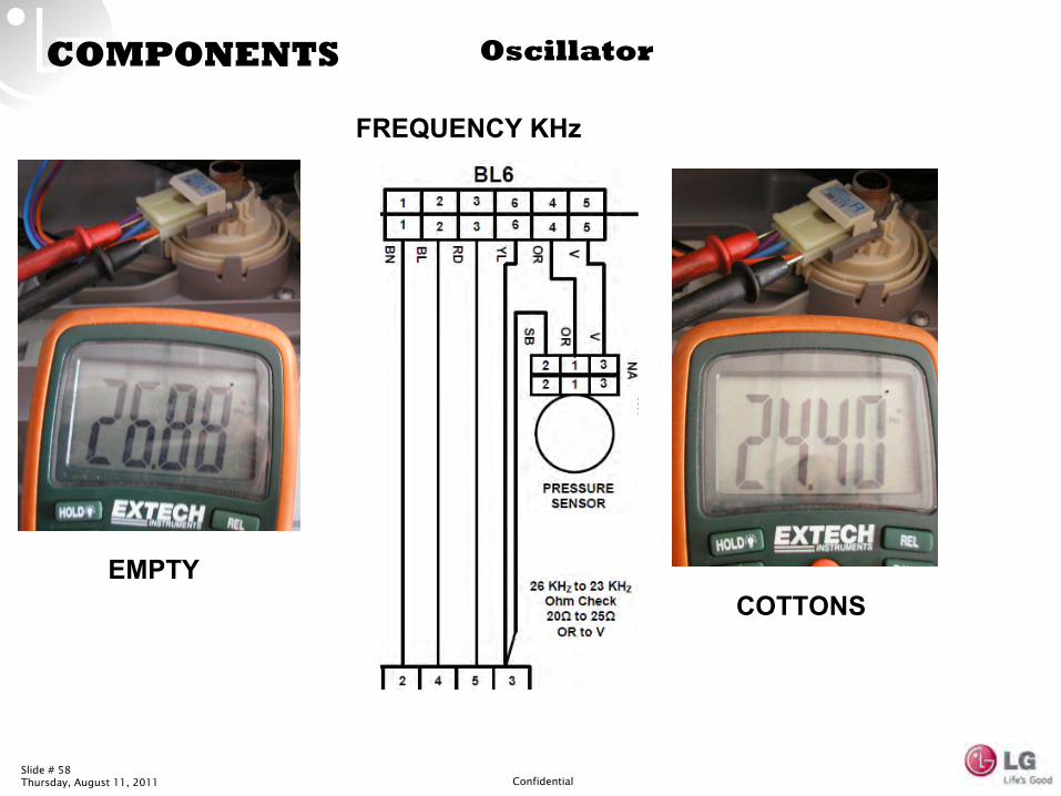
COMPONENTS Oscillator
EMPTYCOTTONS
FREQUENCY KHz
Slide # 59Thursday, August 11, 2011 Confidential
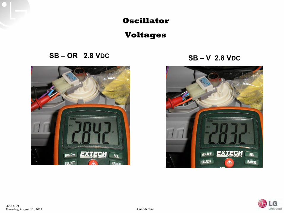
SB –
OR 2.8 VDC SB –
V 2.8 VDC
Oscillator
Voltages
Slide # 60Thursday, August 11, 2011 Confidential
COMPONENTS
Magnet
Lid Switch
Slide # 61Thursday, August 11, 2011 Confidential
COMPONENTS Lid Switch
Slide # 62Thursday, August 11, 2011 Confidential
COMPONENTS Lid Switch
Ohm Testing the Lid Switch
Lock Plunger
Door Magnet
Slide # 63Thursday, August 11, 2011 Confidential
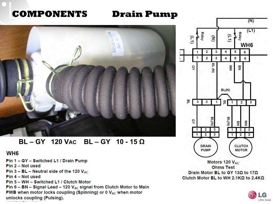
COMPONENTS Drain Pump
BL –
GY 120 VAC BL –
GY 10 -
15 Ω
Slide # 64Thursday, August 11, 2011 Confidential
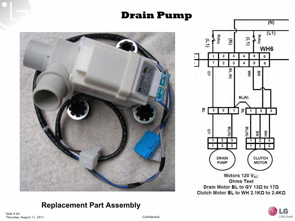
Drain Pump
Replacement Part Assembly
Slide # 65Thursday, August 11, 2011 Confidential
Slide # 66Thursday, August 11, 2011 Confidential
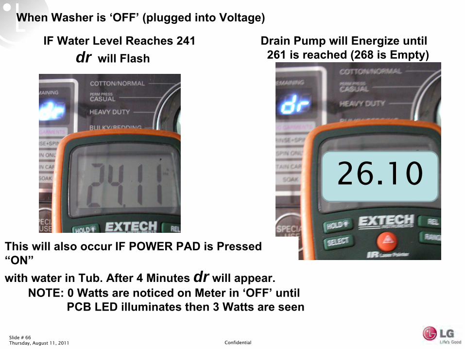
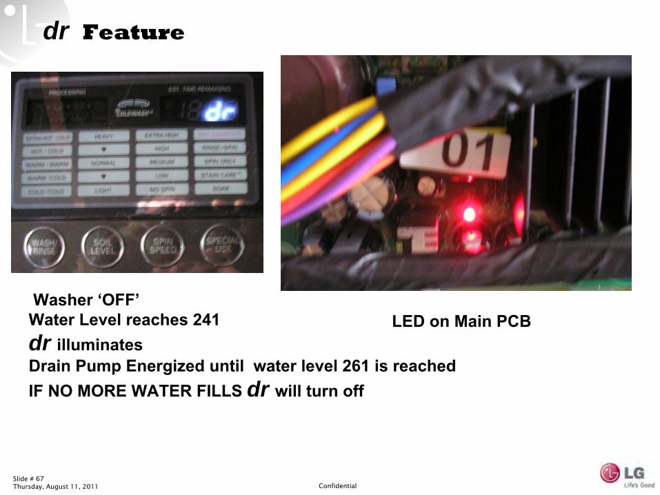
IF Water Level Reaches 241
dr will FlashDrain Pump will Energize until 261 is reached (268 is Empty)
When Washer is ‘OFF’
(plugged into Voltage)
This will also occur IF POWER PAD is Pressed “ON”
with water in Tub. After 4 Minutes dr will appear.NOTE: 0 Watts are noticed on Meter in ‘OFF’
until PCB LED illuminates then 3 Watts are seen
26.10
Slide # 67Thursday, August 11, 2011 Confidential
LED on Main PCBWasher ‘OFF’
Water Level reaches 241
dr illuminates
Drain Pump Energized until water level 261 is reached
IF NO MORE WATER FILLS dr will turn off
dr Feature
Slide # 68Thursday, August 11, 2011 Confidential
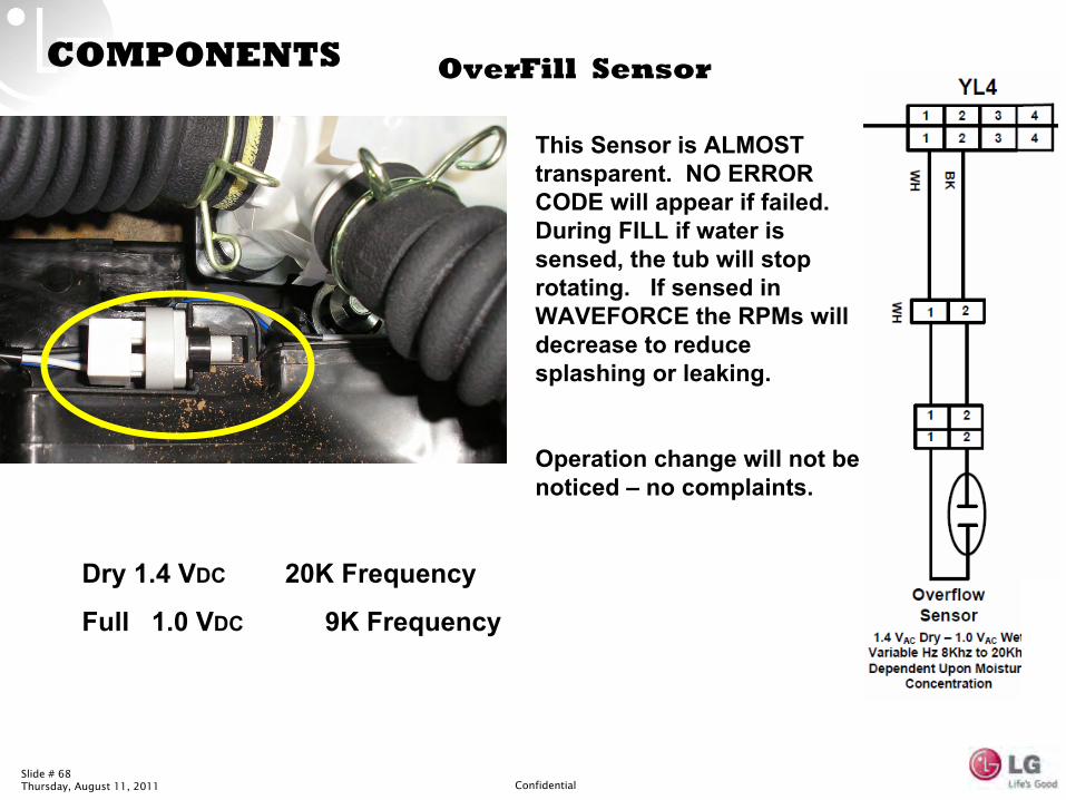
COMPONENTS OverFill
Sensor
Dry 1.4 VDC
20K Frequency
Full 1.0 VDC
9K Frequency
This Sensor is ALMOST transparent. NO ERROR CODE will appear if failed. During FILL if water is sensed, the tub will stop rotating. If sensed in WAVEFORCE the RPMs
will decrease to reduce splashing or leaking.
Operation change will not be noticed –
no complaints.
Slide # 69Thursday, August 11, 2011 Confidential
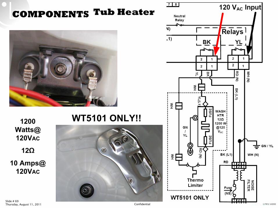
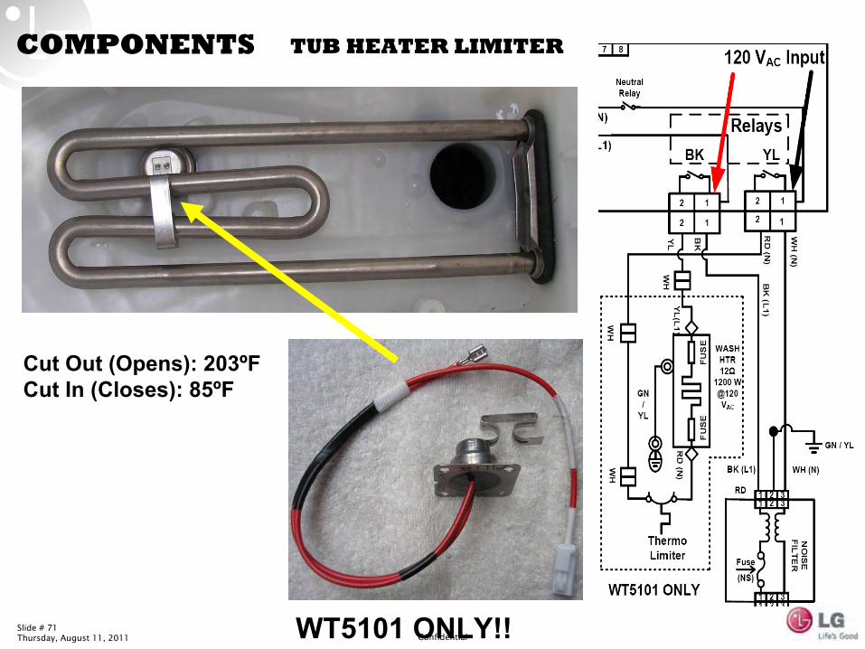
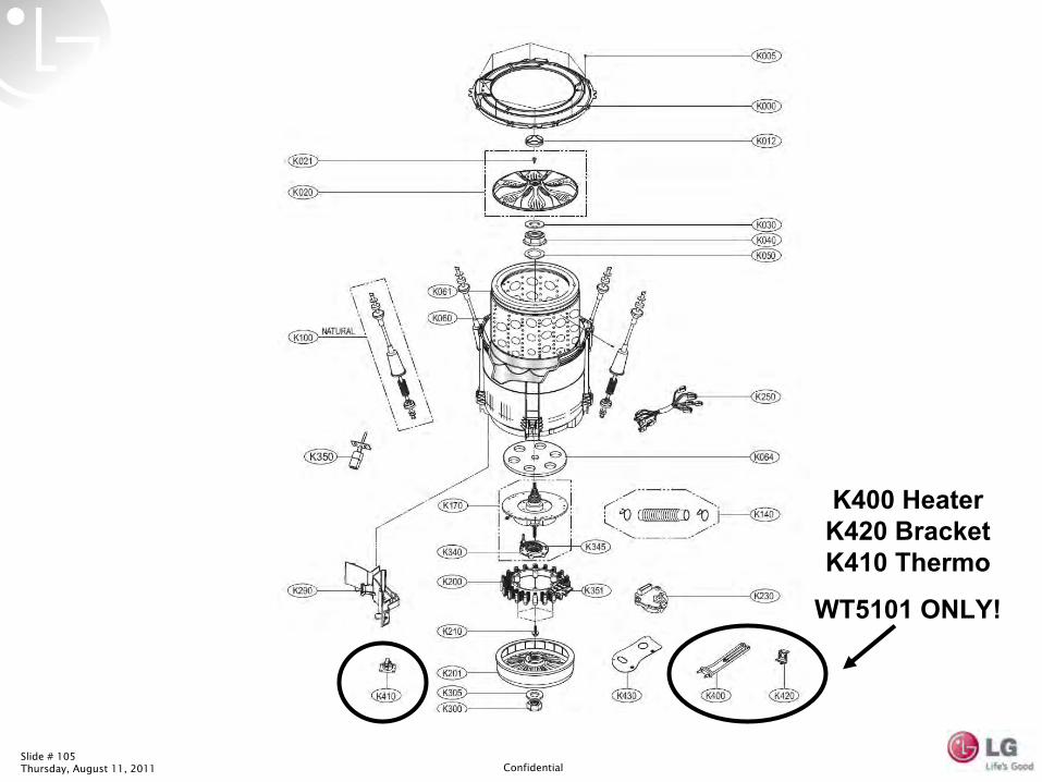
COMPONENTS Tub Heater
1200 Watts@ 120VAC
12Ω
10 Amps@ 120VAC
WT5101 ONLY!!
Slide # 70Thursday, August 11, 2011 Confidential
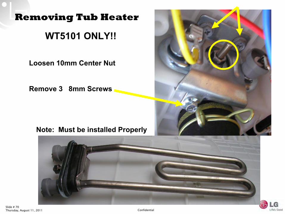
Loosen 10mm Center Nut
Remove 3 8mm Screws
Note: Must be installed Properly
Removing Tub Heater
WT5101 ONLY!!
Slide # 71Thursday, August 11, 2011 Confidential
COMPONENTS
Cut Out (Opens): 203ºF
Cut In (Closes): 85ºF
TUB HEATER LIMITER
WT5101 ONLY!!
Slide # 72Thursday, August 11, 2011 Confidential
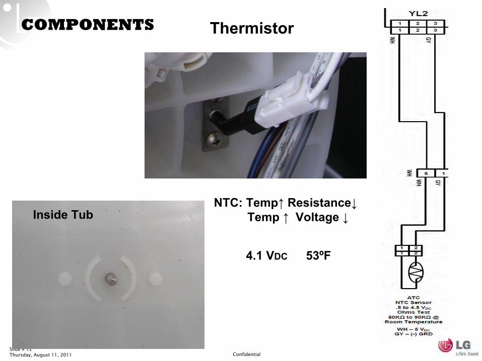
COMPONENTS Thermistor
Inside Tub
4.1 VDC 53ºF
NTC: Temp↑
Resistance↓
Temp ↑
Voltage ↓
Slide # 73Thursday, August 11, 2011 Confidential
Slide # 74Thursday, August 11, 2011 Confidential
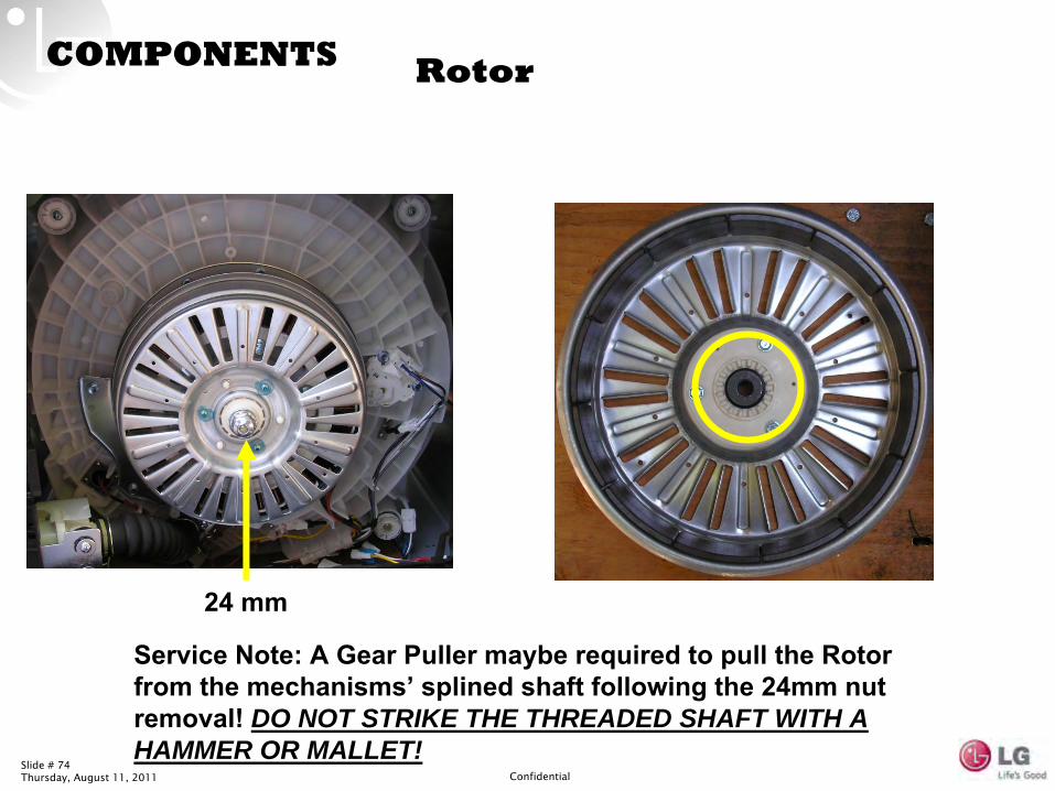
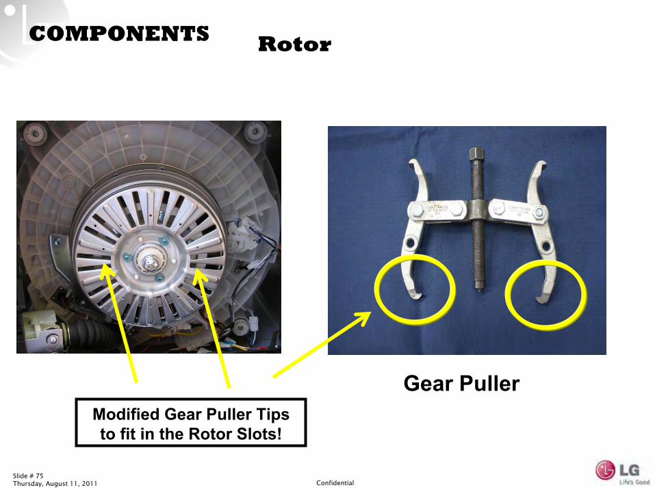
COMPONENTS Rotor
24 mm
Service Note: A Gear Puller maybe required to pull the Rotor from the mechanisms’
splined shaft following the 24mm nut removal! DO NOT STRIKE THE THREADED SHAFT WITH A HAMMER OR MALLET!
Slide # 75Thursday, August 11, 2011 Confidential
COMPONENTS Rotor
Gear PullerModified Gear Puller Tips to fit in the Rotor Slots!
Slide # 76Thursday, August 11, 2011 Confidential
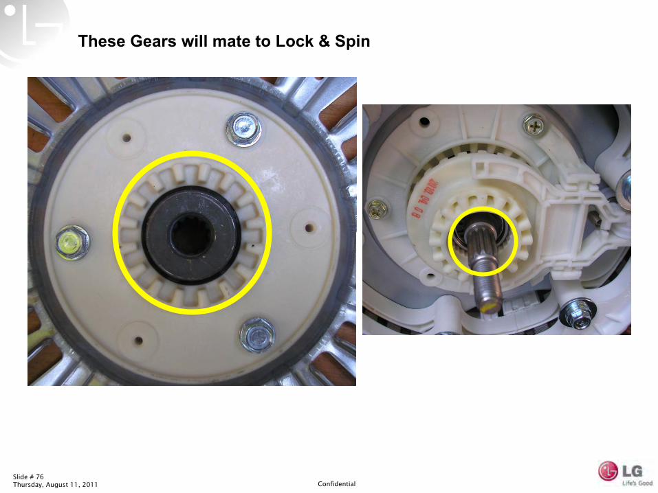
These Gears will mate to Lock & Spin
Slide # 77Thursday, August 11, 2011 Confidential
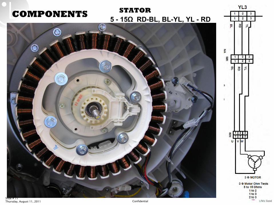
COMPONENTS STATOR5 -
15Ω
RD-BL, BL-YL, YL -
RD
Slide # 78Thursday, August 11, 2011 Confidential
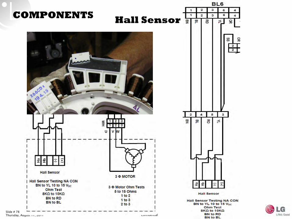
COMPONENTS Hall Sensor
Slide # 79Thursday, August 11, 2011 Confidential
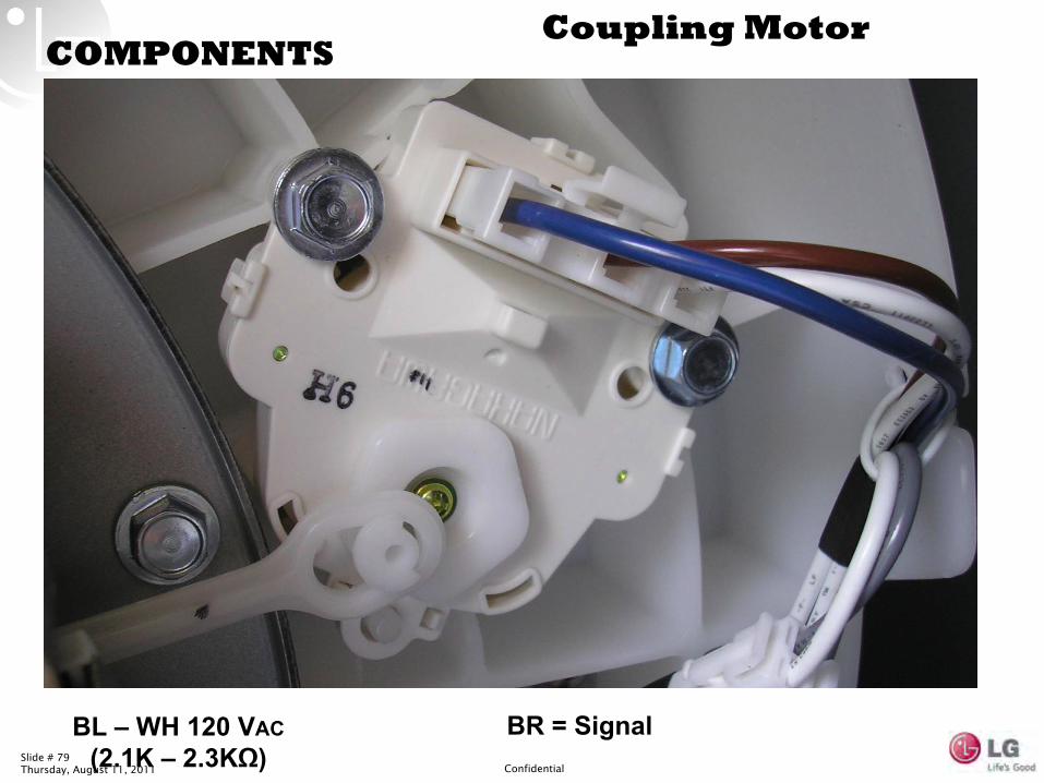
Coupling MotorCOMPONENTS
BL –
WH 120 VAC (2.1K –
2.3KΩ)BR = Signal
Slide # 80Thursday, August 11, 2011 Confidential
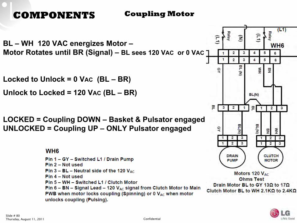
COMPONENTS Coupling Motor
BL –
WH 120 VAC energizes Motor –
Motor
Rotates until BR (Signal) –
BL sees 120 VAC
or 0 VAC
Locked to Unlock = 0 VAC
(BL –
BR)
Unlock to Locked = 120 VAC
(BL –
BR)
LOCKED = Coupling DOWN –
Basket & Pulsator
engaged
UNLOCKED = Coupling UP –
ONLY Pulsator
engaged
Slide # 81Thursday, August 11, 2011 Confidential
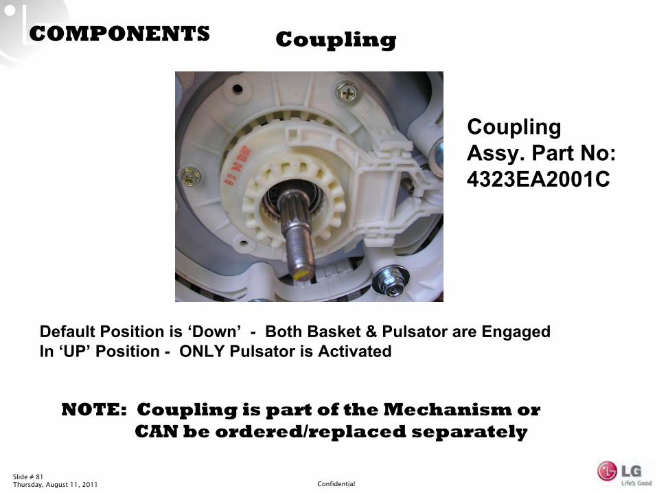
COMPONENTS Coupling
Default Position is ‘Down’
-
Both Basket & Pulsator
are Engaged
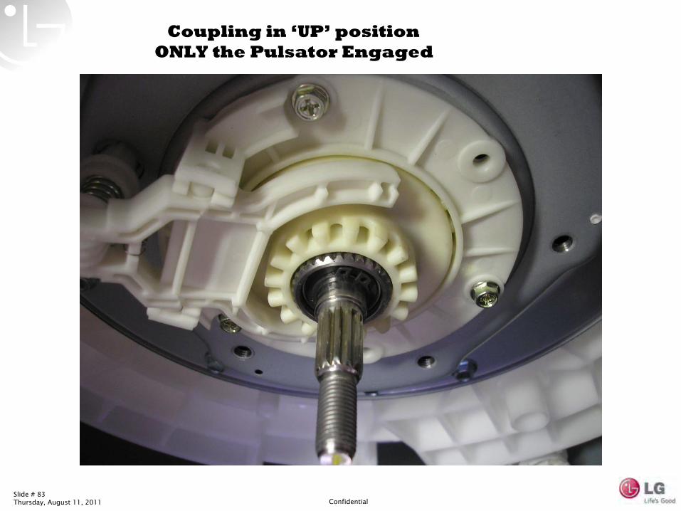
In ‘UP’
Position -
ONLY Pulsator
is Activated
NOTE: Coupling is part of the Mechanism or
CAN be ordered/replaced separately
Coupling Assy. Part No: 4323EA2001C
Slide # 82Thursday, August 11, 2011 Confidential
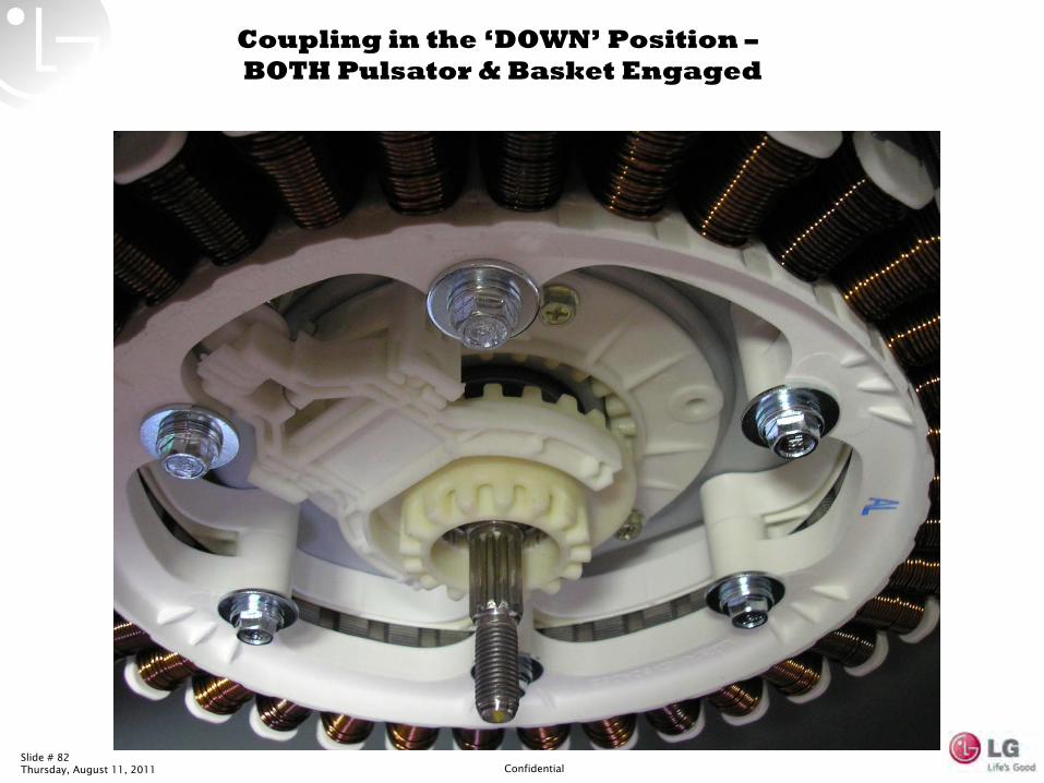
Coupling in the ‘DOWN’
Position –
BOTH Pulsator
& Basket Engaged
Slide # 83Thursday, August 11, 2011 Confidential
Coupling in ‘UP’
position
ONLY the Pulsator
Engaged
Slide # 84Thursday, August 11, 2011 Confidential
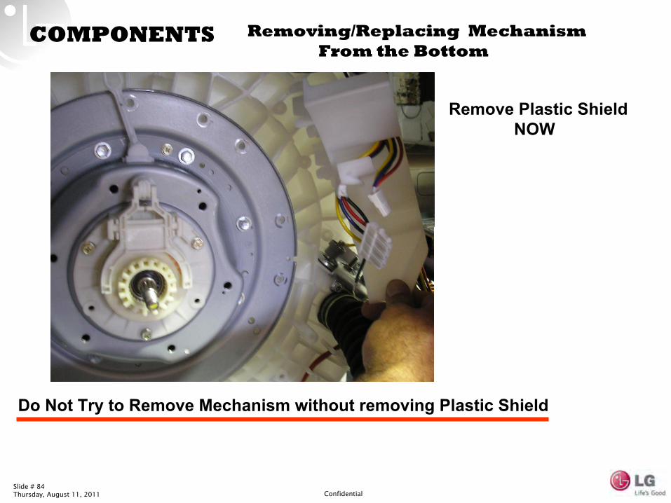
COMPONENTS Removing/Replacing Mechanism
From the Bottom
Remove Plastic Shield
NOW
Do Not Try to Remove Mechanism without removing Plastic Shield
Slide # 85Thursday, August 11, 2011 Confidential
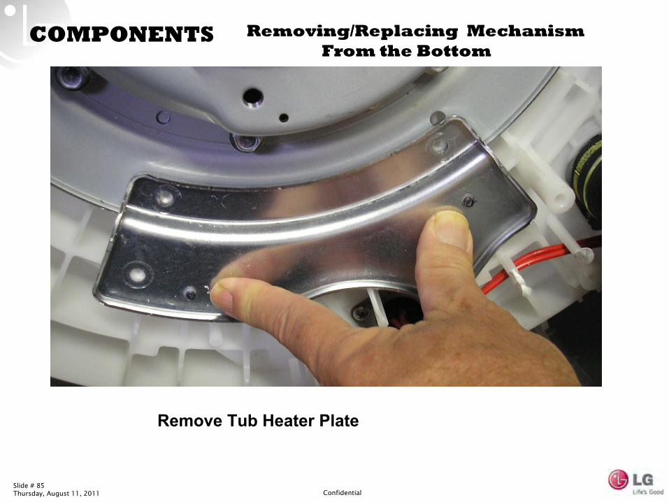
COMPONENTS Removing/Replacing Mechanism
From the Bottom
Remove Tub Heater Plate
Slide # 86Thursday, August 11, 2011 Confidential
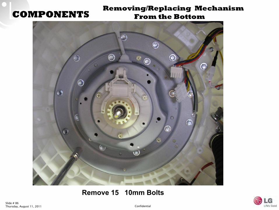
COMPONENTS
Remove 15 10mm Bolts
Removing/Replacing Mechanism
From the Bottom
Slide # 87Thursday, August 11, 2011 Confidential
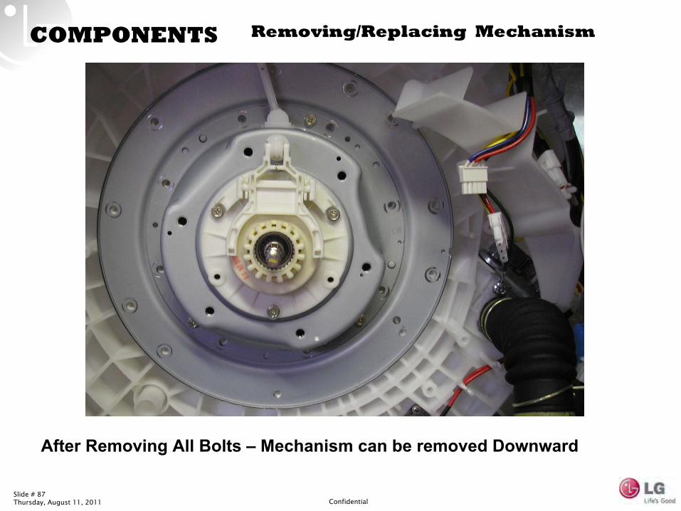
COMPONENTS Removing/Replacing Mechanism
After Removing All Bolts –
Mechanism can be removed Downward
Slide # 88Thursday, August 11, 2011 Confidential
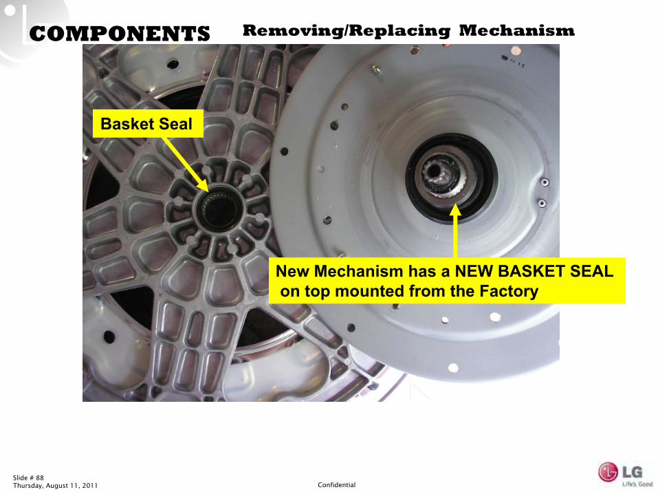
COMPONENTS Removing/Replacing Mechanism
Basket Seal
New Mechanism has a NEW BASKET SEAL
on top mounted from the Factory
Slide # 89Thursday, August 11, 2011 Confidential
IMPORTANT NOTE:
Be sure to remove ‘old’
Basket Seal Before installing New Mechanism
If Reassembled with TWO Basket Seals – Basket will Rub TUB RING
Immediate Rubbing Sound during Operation
Slide # 90Thursday, August 11, 2011 Confidential
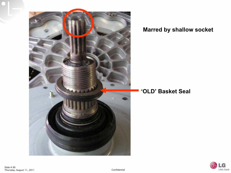
Marred by shallow socket
‘OLD’
Basket Seal
Slide # 91Thursday, August 11, 2011 Confidential
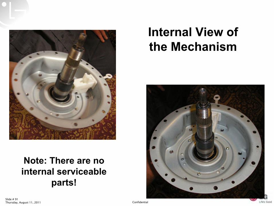
Internal View of the Mechanism
Note: There are no internal serviceable
parts!
Slide # 92Thursday, August 11, 2011 Confidential
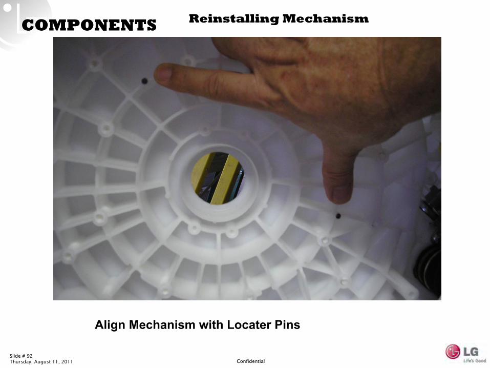
COMPONENTS Reinstalling Mechanism
Align Mechanism with Locater Pins
Slide # 93Thursday, August 11, 2011 Confidential
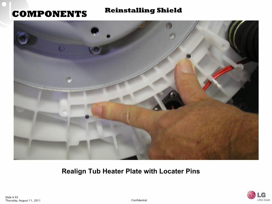
COMPONENTS Reinstalling Shield
Realign Tub Heater Plate with Locater Pins

Slide # 94Thursday, August 11, 2011 Confidential
Power
Press Power + Wash/ Rinse Temp + Soil Level ; you will see
t1 on the
display.
Press Start/pause until you see t5 on the display.
•t5 = weighing/distributing
•t7 = motion (if there is an LG towel inside, see demo movement)
•t8 = Shows RPM ramping to 1100 (add a 0). Tip: add a balloon with
an LG towel to show “powerful yet gentle.”
How to DEMO WaveForce™
Technology
Operation Key How to
Power + Wash/ Rinse Temp + soil Level
Slide # 95Thursday, August 11, 2011 Confidential
WAVE FORCE
Slide # 96Thursday, August 11, 2011 Confidential
WAVE FORCE
Slide # 97Thursday, August 11, 2011 Confidential
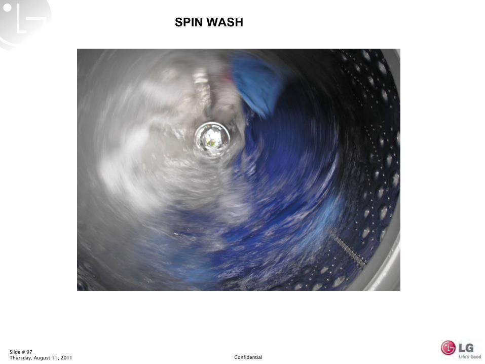
SPIN WASH
Slide # 98Thursday, August 11, 2011 Confidential
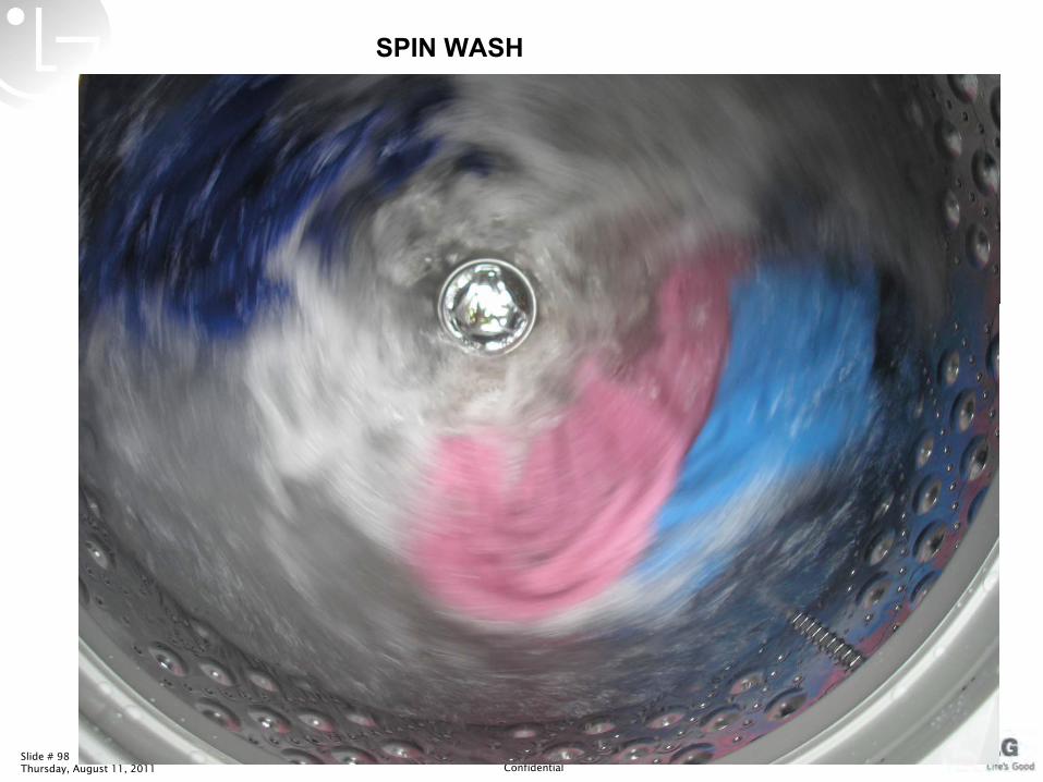
SPIN WASH
Slide # 99Thursday, August 11, 2011 Confidential
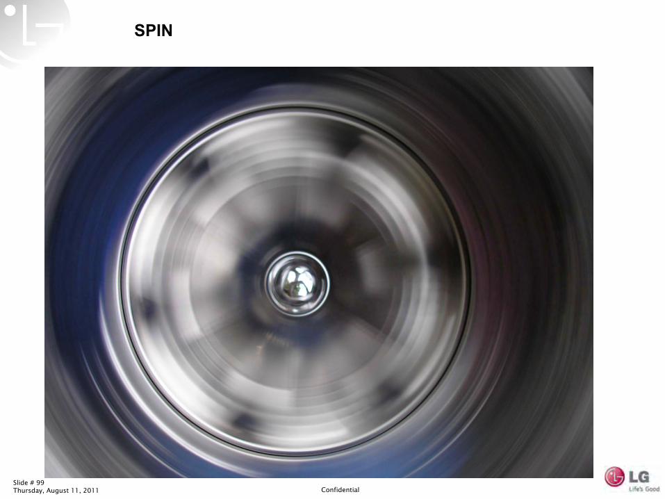
SPIN
Slide # 100Thursday, August 11, 2011 Confidential
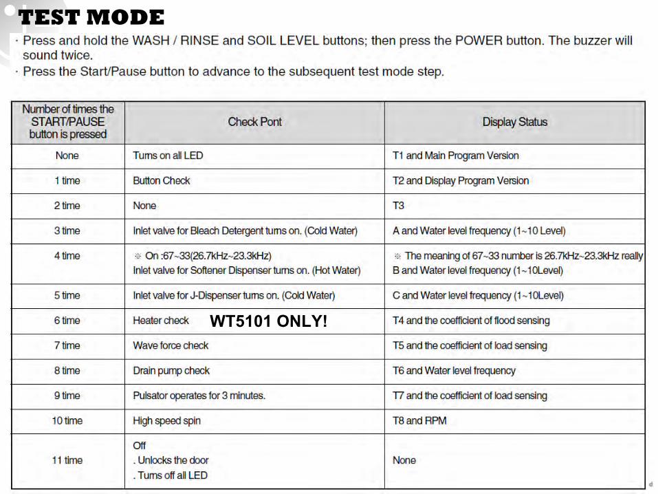
TEST MODE
WT5101 ONLY!
Slide # 101Thursday, August 11, 2011 Confidential
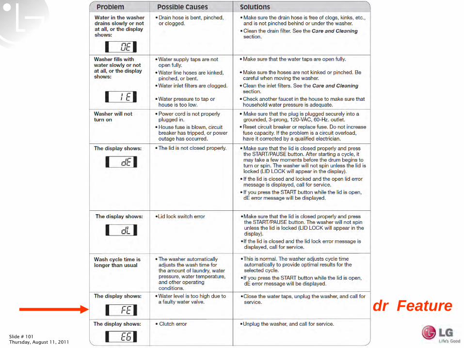
dr Feature
Slide # 102Thursday, August 11, 2011 Confidential
Slide # 103Thursday, August 11, 2011 Confidential
Slide # 104Thursday, August 11, 2011 Confidential
Slide # 105Thursday, August 11, 2011 Confidential
K400 Heater K420 Bracket K410 Thermo
WT5101 ONLY!
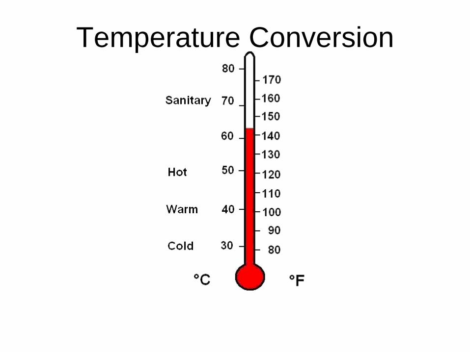
Temperature Conversion
French Door Twist Tray Icemaker
L1 (M
ain
PWB
)
BL PK SB
1 32 CO
N2
L1 (P
ilot V
alve
)L1
(IM
Val
ve)
B V W
Relays
12345678910
GY PK SB PR BN YL BL WH BO BO
CO
N1
Icemaker PWB (PCB) Assembly
12345678
BK RD BO YL BK WHRD BL
CO
N4
123456789
RD YL BN BKBLWH WH WH
CO
N5
Icem
aker
On/
Off
Switc
h
IR L
ED H
eate
r
Icem
aker
Tra
y Te
mp
Sens
or
IM S
top
Switc
h
M
Icemaker Motor 12 VDC17Ω to 25Ω
Hall IC
12BO YL
12WH BL
PWB Assy IR LED
PWB Assy Photo TR
Phot
o TR
Hea
ter
1 2 3 4 5 6 7 8 9 10 11 12 13 14 15 16 17 18 19 20 21 22 23 24 25 26
GY/RD RD BN SB PK BK WH/
RD BO BLBO/ BL PR PR/
WH GY YL/BK
GY/WH
RD/YL
BN/WH YL WH
YL/BL
BL/WH
WH/BK
Display PWB AssemblyRD
6
5
4
YL/BL
WH/BK
BO/WH
3
BO 2
WH/RD
1
CON101
CON102
1 2 3
WH SBBO
4
PK
CON103
Ice
Leve
r S
witc
h
Cap
Duc
t H
eate
r
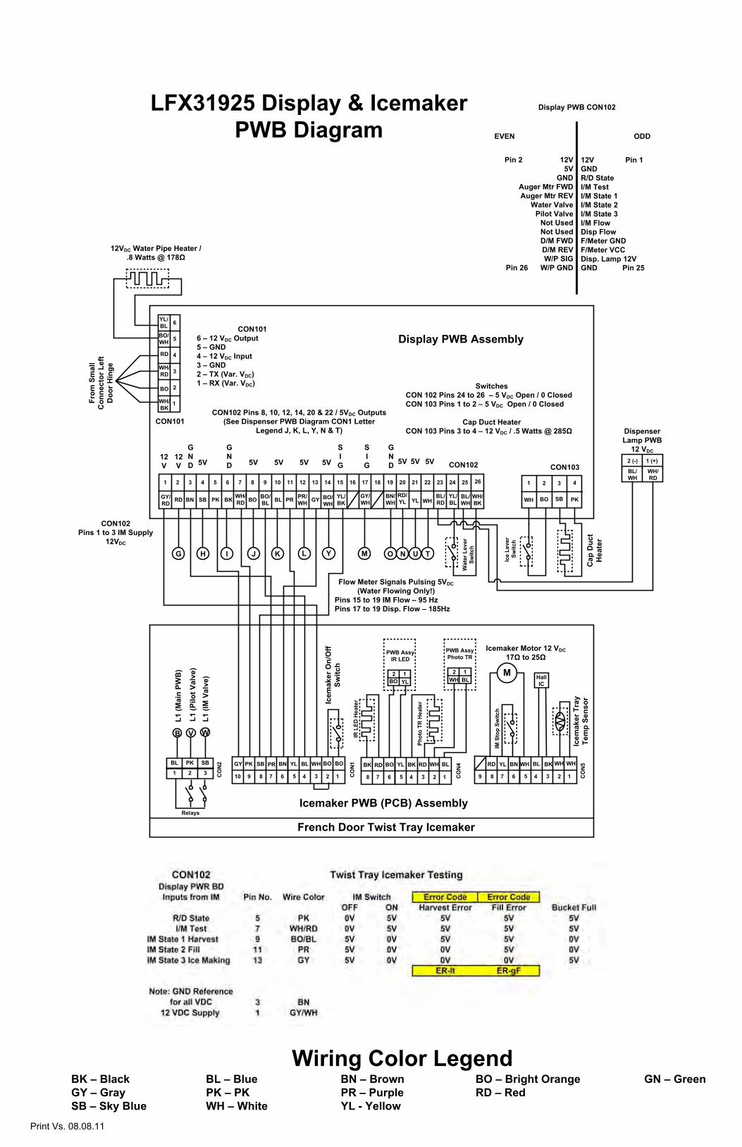
CON1016 – 12 VDC Output5 – GND4 – 12 VDC Input3 – GND2 – TX (Var. VDC)1 – RX (Var. VDC)
1 (+)2 (-)
WH/RD
BL/ WH
Dispenser Lamp PWB
12 VDC
Wat
er L
ever
Switc
h
M NO T UG H I J K L
12V
12V 5V
GND 5V
From
Sm
all
Con
nect
or L
eft
Doo
r Hin
ge
GND
GND
SIG
SIG5V 5V 5V
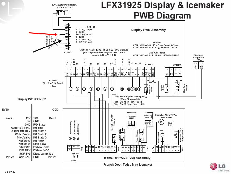
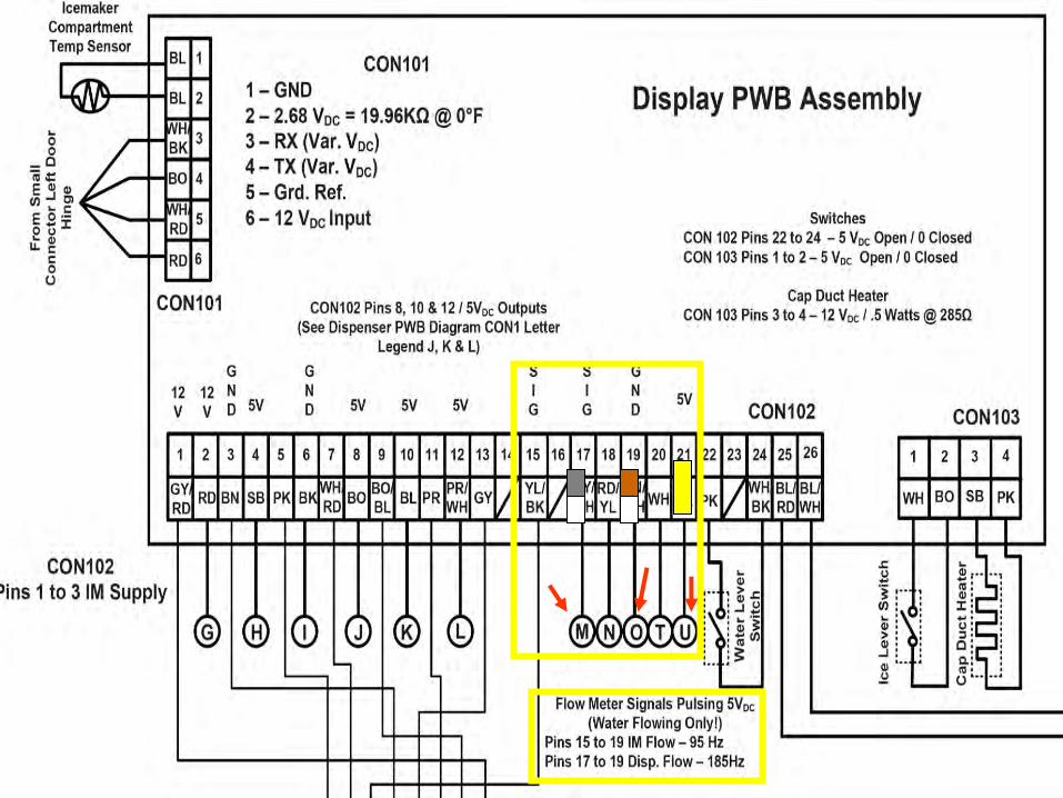
LFX31925 Display & Icemaker PWB Diagram
CON102Pins 1 to 3 IM Supply
12VDC
Flow Meter Signals Pulsing 5VDC(Water Flowing Only!)
Pins 15 to 19 IM Flow – 95 HzPins 17 to 19 Disp. Flow – 185Hz
SwitchesCON 102 Pins 24 to 26 – 5 VDC Open / 0 ClosedCON 103 Pins 1 to 2 – 5 VDC Open / 0 Closed
Cap Duct HeaterCON 103 Pins 3 to 4 – 12 VDC / .5 Watts @ 285Ω
CON102 Pins 8, 10, 12, 14, 20 & 22 / 5VDC Outputs(See Dispenser PWB Diagram CON1 Letter
Legend J, K, L, Y, N & T)
5V
Wiring Color LegendBK – Black BL – Blue BN – Brown BO – Bright Orange GN – GreenGY – Gray PK – PK PR – Purple RD – RedSB – Sky Blue WH – White YL - Yellow
12VDC Water Pipe Heater / .8 Watts @ 178Ω
BO/WH
Y
5V
Pin 2 12V5V
GNDAuger Mtr FWDAuger Mtr REV
Water ValvePilot Valve
Not UsedNot UsedD/M FWDD/M REVW/P SIG
Pin 26 W/P GND
BL/RD
Display PWB CON102
EVEN ODD
12V Pin 1GNDR/D StateI/M TestI/M State 1I/M State 2I/M State 3I/M FlowDisp FlowF/Meter GNDF/Meter VCCDisp. Lamp 12VGND Pin 25
5V
Print Vs. 08.08.11
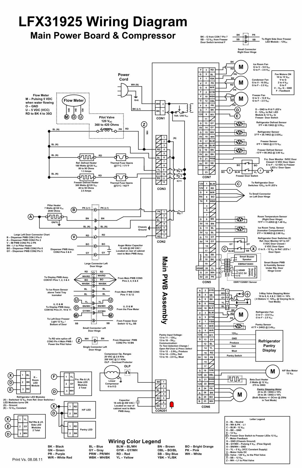
Main Power Board & Compressor
3
5
1
4
6
2
10
12
8
7
9
11
13
14
15
16
17
18
19
20
21
22
24
23
RD
BL
YBK
PK
W/R
GYW
WBK
OBL
BK
PR
BO
GY
WH
BLW
BN
PRW
SB
GY
1
2
3
4
5
6
7
8
9
10
1112
RD
BL
BO
YL
1
2WH
BK
CON1
CON3
CON2
CON5
CON7
Main PW
B A
ssembly
Pilot Valve120 VAC
360 to 420 Ohms
Rly 3
Rly 7
Rly 4
RD
Ref. Defrost Heater160 Watts @120 VAC
80 to 90 Ohms1.3 Amps
Thermal Fuse Opens @77°C / 171°F
BL (N)
10A / 250 VAC
BL (N)
BL (N)
BL (N)
BK (L1)
WH (N)
Grd.
Power Cord
(N)
Chassis Ground
PR RD
Large Connector Left Door Hinge
Auger Motor Capacitor 14 mfd @ 240 VAC /
Located on rear of cabinet next to Main PWB Assy.
Dispenser PWB Assy. CON2 Pins 5 & 6
Large Left Door Connector ChartB – Dispenser PWB CON 2 Pin 8A – Dispenser PWB CON2 Pin 2V – IM PWB CON2 Pin 2 PKBN – L1 to Pillar HeaterBO – Dispenser PWB CON2 Pin 6GY – Dispenser PWB CON2 Pin 5
Pantry Stepping Motor23 to 25 / 300Ω ± 10%24 to 26 / 300Ω ± 10%
(Both Stators +/- DCmv @ 25Hz in Test Mode)
5V
5V
5V
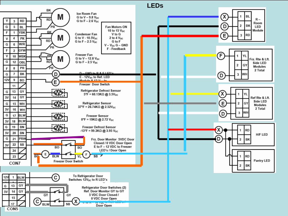
Ice Room FanG to V – 9.8 VDCG to F – 2.6 VDC
5V
G
Room Temperature Sensor(Right Door Hinge)
75°F = 11.42KΩ @ 1.48 VDC
G
5V
G
F
V
XC
To Small Connector on Left Door Hinge
Wiring Color LegendBK – Black BL – Blue BLW – BL/WH BN – Brown BO – Bright OrangeGN – Green GY – Gray GYW – GY/WH OBL – BO/BL PK – PinkPR – Purple PRW – PR/WH RD – Red SB – Sky Blue WH – WhiteW/R – White Red WBK – WH/BK YL – Yellow YBK – YL/BK
Flow MeterM – Pulsing 5 VDC when water flowingO – GNDU – 5 VDC (VCC)RD to BK 4 to 30Ω
Refrigerator Door Switches (2)Ref. Door Monitor GY to GY
5 VDC Door Closed / 0 VDC Door Open
C to X – 12 VDC to Ref. LED’s / Door Open
Frz. Door Monitor 5VDC Door Closed / 0 VDC Door OpenE to F – 12 VDC to Freezer
LED’s / Door Open
G
Flow Meter
UOM
RD
BK
WH
1
2
3
4
5
6
7
PK
BL
GN/Y
RD
BL (N)
BN
BL (N)
V
B
RDRD
BN
PK (L1)
BO
GY
PK (L1)
BO
GY
Pillar Heater7 Watts @120 VAC
2040 Ohms
AGN/YL
BNRD
Freezer Defrost Heater300 Watts @120 VAC
40 to 50 Ohms2.5 Amps
Thermal Fuse Opens @72°C / 162°F
IC11
Small Connector Left Door Hinge
WH/BK
WH/RDBO
RD
From Main PWB CON5 Pins 2, 4, 6 & 8
U, O & MFrom the Flow Meter
To Display PWB Assy. CON101 Pins 1, 2, 3 & 4
U, O & MTo Display PWB Assy.
CON102 Pins 21, 19 & 17.
WH/BKBO
WH/RD
RD
Z
WH
1
2
3
4
5
6
7
8
9
10
11
12
13
14
15
16
17
18
19
20
21
22
RD
HSNR
G
5V
5V
G
12V
12V
G
RX
G
5V
CON201
Linear Compressor
6 to 8 Ω
Capacitor18 mfd @ 450 VAC /Located on rear of
cabinet next to Main PWB Assy.
Compressor Op. Ranges20 VAC @ 2.6 KHz200 VAC @ 3.1 KHzOLP – Overload Protector
76
5
43
2
1BK
BN
BO
BL
OLP
2
4
6
8
10
3
5
1
7
9
11
13
12
14
16
18
15
17
19
20
21
22
23
GYR
SB
BK
PRW
BLR
BLW
GYW
Y/BK
W/R
W/R
R/Y
GY
BL
PR
PK
O/W
OBL
BNW
BNW
BN
YL
F
12V
A
G
A-
A
B-
B
G
5V
24
25
26
CON6
MWH
BOA-
B-B
Letter Legend A – BL - NeutralB – WH & PK - L1C – BLW - 12 VDCD – BK – GNDE – 12 VDCF – Freezer Door Switch to Freezer LEDs 12 VDCF – Motor FeedbackG – GND (Chassis Ground)M – GY/WH – Pulsing 5 VDC (Flow Signal)O – BN/WH – GNDU – YL – 5 VDC (VCC Constant Supply)V – Motor Volts DCV – Valve - 120 VAC to the Pilot Valve X – SB – 12 VDCZ – WH – L1 to Pilot Valve
Beta Duct Heater.5 Watts @ 12 VDC
275 to 300Ω
MG
12V
G
RD
H/F Box Motor 12 VDC
12V
RefrigeratorPantry Display
Pantry Switch
Meat
Produce
12VDC
GND
Pantry Sensor41°F = 24KΩ @ 2.4VDC
MG
V Refrigerator FanG to V – 13.6 VDCG to F – 2.5 VDC
12V
M
Freezer FanG to V – 12.8 VDCG to F – 2.5 VDC
5
1
2
63,4
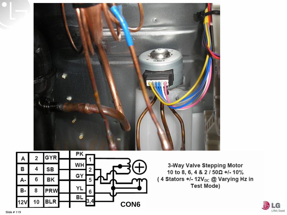
3-Way Valve Stepping Motor 10 to 8, 6, 4 & 2 / 50Ω +/- 10%
( 4 Stators +/- 12VDC @ Varying Hz in Test Mode)
5V
BLW
W/R
BO
WBK
BN
BN
BL
BL
GY
GY
SB
BK
YL
WH
PK
Ice Room Temp. Sensor(Icemaker Compartment )0°F = 19.96KΩ @ 2.68 VDC
TX
C To Refrigerator Door Switches 12VDC to R LED’s
G
5V
Smart Buzzer Speaker
Hum
idity Sensor(H
SNR
)
12
31
32
4455
Smar
t
GVCC 5VHSNR
Smart Buzzer PWB & Humidity Sensor
Under Rte. Door Hinge Cover
EBR64730403
M
M Condenser FanG to V - 10.5VDCG to F – 2.5 VDC
Freezer Door Switch
FE
Fan Motors ON10 to 15 VDC
V to G2 to 4 VDC
G to FV – VDC G – GND
F - Feedback
Freezer Defrost Sensor-13°F = 99.3KΩ @ 3.95 VDC
Refrigerator Sensor37°F = 26.74KΩ @ 2.52VDC
Freezer Sensor0°F = 19KΩ @ 2.72 VDC
BN
BLW
WH
G
G
G
ED
12V
Refrigerator Defrost Sensor5°F = 60.13KΩ @ 3.5VDC
D – GND to R & F LED’sE - 12VDC to Ref. LED Module & 12 VDC to Freezer Door Switch
F
V
G
F
G
V
BK
RD
PR
RD
BK
PR
BK
RD
PR
BO BO
BLW YL
BLW SB
GY GY
M
YL
BN/WH
GY/WHO
U YL
BN/WH
GY/WH
M
O
U
From Main PWB CON5 Pins 11 & 12
To Ice Room Sensor above Twist Tray
Icemaker
BLBL
BL BL
SB
From Freezer Door Switch 12 VDC SBSB
To Left Door Freezer Light 12 VDC /
Bottom of Door SB
BO
2 BKH/F LED
1 RDX
D
2 BKPantry LED
1 RD
Refrigerator LED Modules(X) – Switched 12 VDC from Ref. Door Switches / LED Modules turns ON(D) – Ground (E) – 12 VDC Constant
3
2
RD
BK
R –Room LED
Module
1 BLX
E
D
3
2
WH
GY
Frz. Rte & Lft. Side LED Modules2 Total
1 YLF
D
Single Connector Left Door Hinge
WH BN From Dispenser PWB CON2 Pin 10 BN
To RD wire splice off CON3 Pin 4 Main PWB / Power the Pilot Valve
Z
Small Connector Right Door Hinge
PRBKBK – G from CON 7 Pin 7SB – 12 VDC from Freezer Door Switch terminal F
To Right Side Door Freezer LED Module – 12VDC
SB SB
BKRD
PR
EBR71326801 Senosr
Deli
Pantry Input Voltage:13 to 11 – 12VDC13 to 18 – 5VDCCommunication:To Test Selection Change / Open Ref Door & Press Select13 to 12 – 2.9VDC Produce13 to 14 – 2.9VDC Deli13 to 16 – 2.9 VDC Meat
3
2
WH
GY
Ref Rte & Lft. Side LED Modules2 Total
1 YLX
D
E
WH
RD
PK
WH
GY
YLBL
Print Vs. 08.08.11
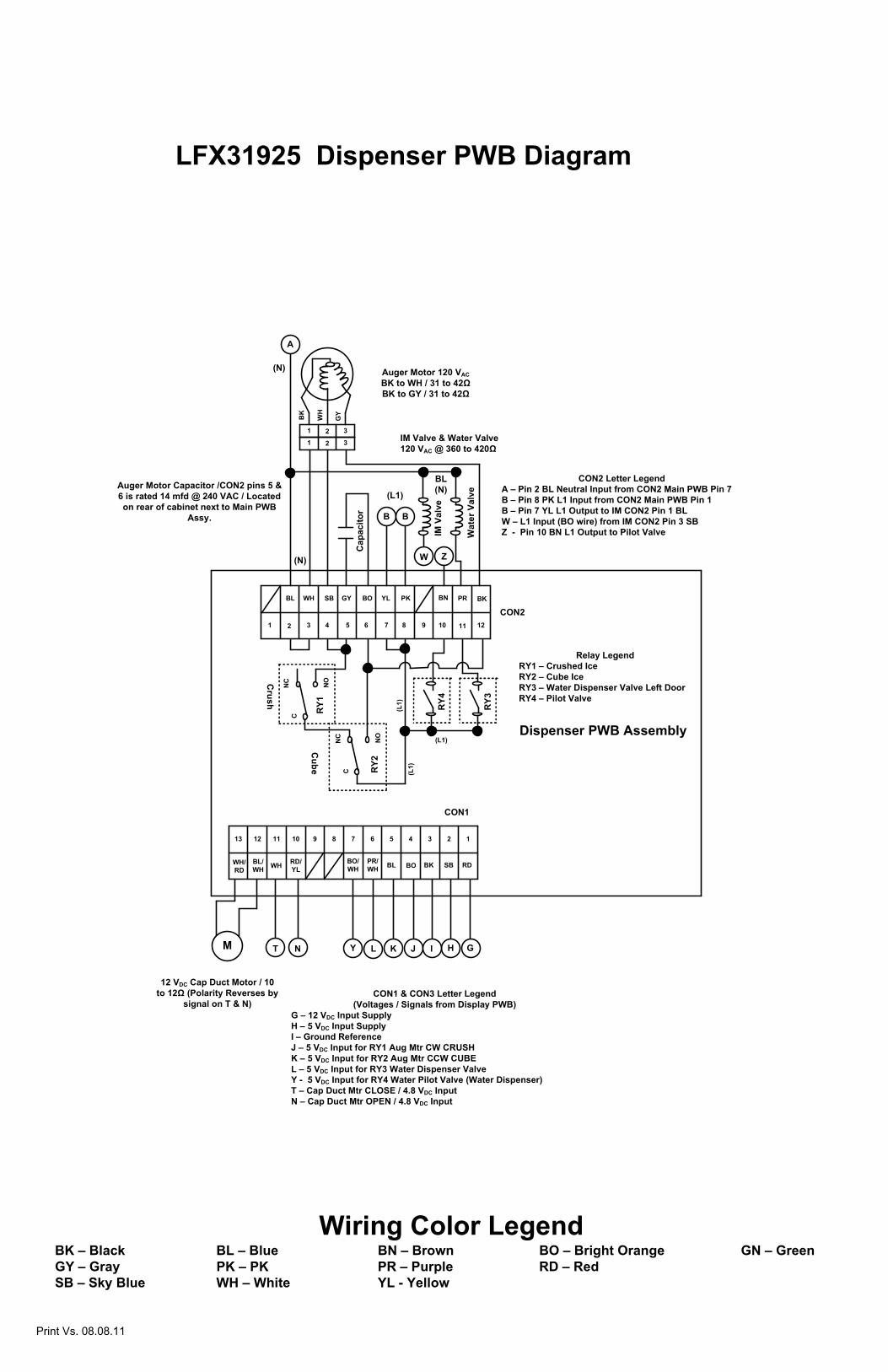
LFX31925 Dispenser PWB Diagram
13 12 11 10 9 8 7 6 5 4 3 2 1
WH/RD
BL/WH WH RD/
YL BL BO SB
Dispenser PWB Assembly
CON21 2 3 4 5 6 7 8 9 10 11
WH PRBL BOSB
12
GY YL PK
CON1
BK
T N L K J HM
1 2 3
1 32
AG
YBK
WH
Cap
acito
r B B
W
IM V
alve
Auger Motor 120 VACBK to WH / 31 to 42ΩBK to GY / 31 to 42Ω
(N)
(L1)
(N)
BL (N)
Wat
er V
alve
RY2
RY1 (L1)
CN
C NO
CN
C NO
(L1)
IM Valve & Water Valve 120 VAC @ 360 to 420Ω
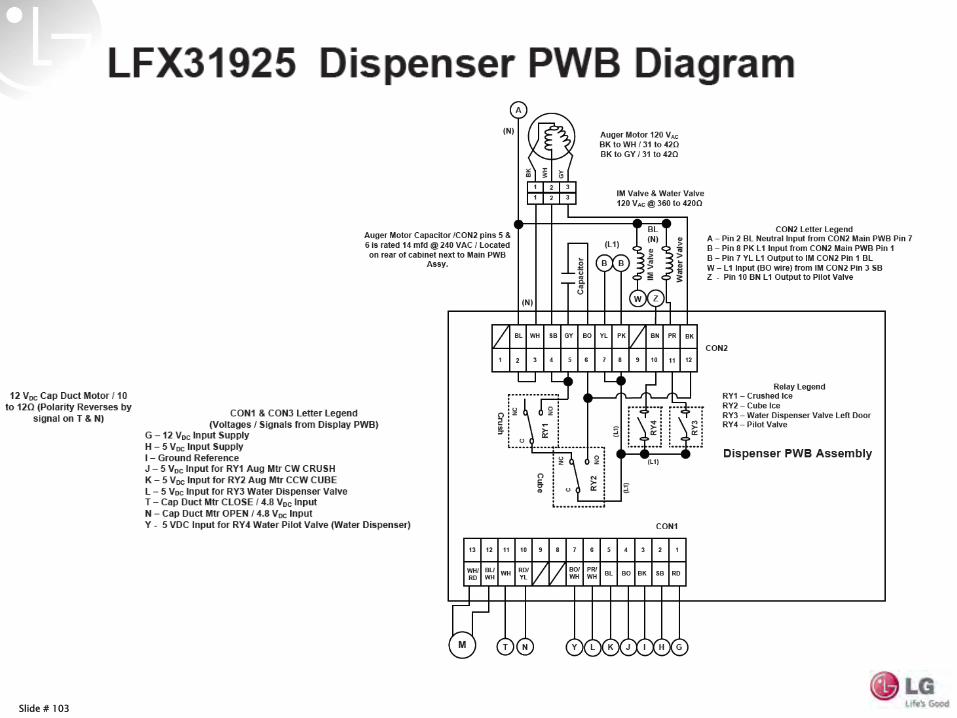
Auger Motor Capacitor /CON2 pins 5 & 6 is rated 14 mfd @ 240 VAC / Located on rear of cabinet next to Main PWB
Assy.
CON2 Letter LegendA – Pin 2 BL Neutral Input from CON2 Main PWB Pin 7B – Pin 8 PK L1 Input from CON2 Main PWB Pin 1B – Pin 7 YL L1 Output to IM CON2 Pin 1 BLW – L1 Input (BO wire) from IM CON2 Pin 3 SB Z - Pin 10 BN L1 Output to Pilot Valve
Cube
Crush
CON1 & CON3 Letter Legend(Voltages / Signals from Display PWB)
G – 12 VDC Input SupplyH – 5 VDC Input SupplyI – Ground ReferenceJ – 5 VDC Input for RY1 Aug Mtr CW CRUSHK – 5 VDC Input for RY2 Aug Mtr CCW CUBEL – 5 VDC Input for RY3 Water Dispenser ValveY - 5 VDC Input for RY4 Water Pilot Valve (Water Dispenser)T – Cap Duct Mtr CLOSE / 4.8 VDC InputN – Cap Duct Mtr OPEN / 4.8 VDC Input
12 VDC Cap Duct Motor / 10 to 12Ω (Polarity Reverses by
signal on T & N)
RY3
RY4
BN
Z
(L1)
BO/WH
Y
PR/WH RDBK
GI
Relay LegendRY1 – Crushed IceRY2 – Cube IceRY3 – Water Dispenser Valve Left Door RY4 – Pilot Valve
Wiring Color LegendBK – Black BL – Blue BN – Brown BO – Bright Orange GN – GreenGY – Gray PK – PK PR – Purple RD – RedSB – Sky Blue WH – White YL - Yellow
Print Vs. 08.08.11
6 RD6
1
1
2
2
3
3
4
4
5
5
6
6
7
7
8
8 NA8 (WH)
1
1
2
2
3
3
4
4
5
5
61
1
2
2
3
3
4
4
3
3
2
2
1
1RD1 NA4 (WH)
3
3
2
2
1
1 BL3
WH BL SB BK VT GY RD
7
7
6
6
5
5
4
4
3
3
2
2
1
1
Ha
Hb (-) (+)
Hall Sensor
Wash Pump Motor
12313 2
13 2
GY BK WH RD
Water Inlet Flow Meter
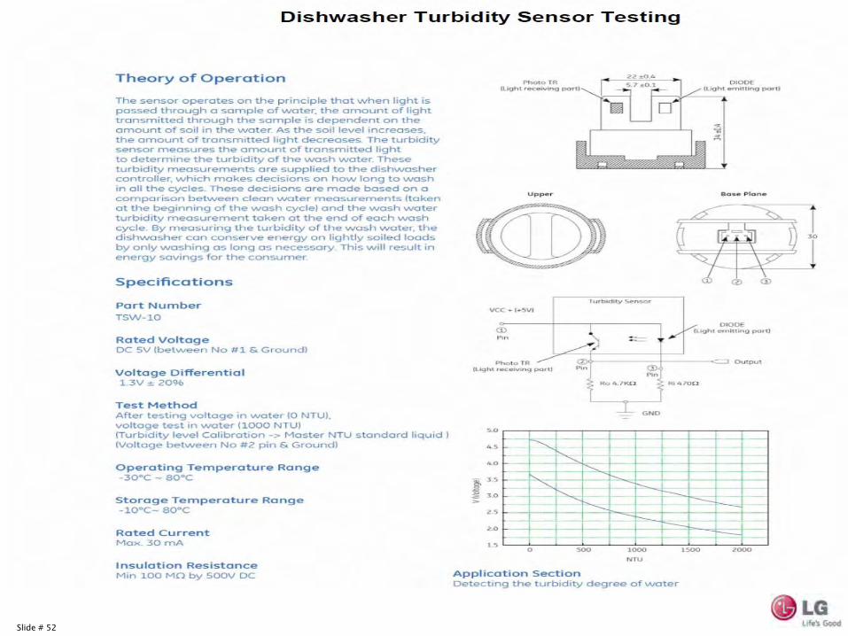
Turbidity Sensor
1 2
Thermistor(Sump)
BL
5 VD
C
GR
D
VTBL YL
GR
D
12 VD
C
21YL BL
Rinse Refill Float
4
4
3
3
2
2
1
1BL4
2
2
2
2
1
1
Heater
Relay
RD3
(N)(L1)
120 VACInput
COM
N.C.
N.O.
COM
N.O.
N.C.
FUSE
FUSE
GN/
YL Vario Motor
Inlet Valve
Drain Motor
SIG
COM
N.C.
N.O.
Vario Motor SW
Float SW Water Inlet
YL BN RD SB
4 VD
C
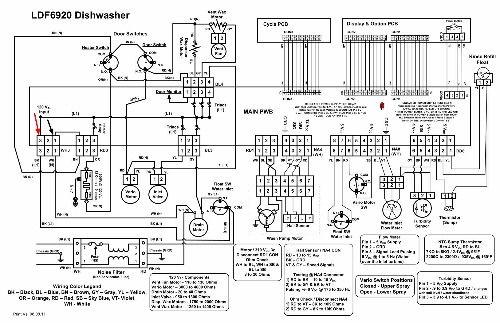
Motor / 310 VDC 3øDisconnect RD1 CON
Ohm Check WH to BL, WH to SB &
BL to SB 8 to 20 Ohms
Hall Sensor / NA4 CONRD – 10 to 15 VDCBK – GRDVT & GY – Speed Signals
Testing @ NA4 Connector1) RD to BK – 10 to 15 VDC2) BK to GY & BK to VT –Pulsing +/- 6 VDC @ 175 to 350 Hz
Ohm Check / Disconnect NA41) RD to VT – 8K to 10K Ohms2) RD to GY – 8K to 10K Ohms
Noise FilterWH (N)
BK (L1)
BK (L1)
WH
1
2
3
1
3
WH (N)
BK
BN (N)
BN (N)
OR(N)
OR(N)
BK(N)BK (N)
(L1) (L1)
Triacs
Triacs
Door Switches
Heater Switch Door Switch
OR
21 21
YL
YL(L1)
YL
RD(N)
RD RD
YL
YL
GY
GY(L1)
WH (N)
RD(N)
SIGSIG
(L1)
(L1)
BL GY
Door Monitor
BK (L1)
WH (N)
Chassis (GRD)
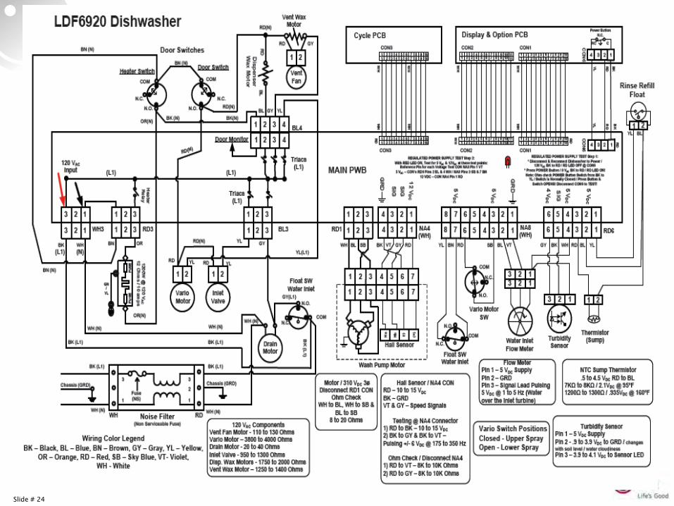
Flow MeterPin 1 – 5 VDC SupplyPin 2 – GRD Pin 3 – Signal Lead Pulsing 5 VDC @ 1 to 5 Hz (Water over the Inlet turbine)
Turbidity SensorPin 1 – 5 VDC SupplyPin 2 - .9 to 3.9 VDC to GRD / changes with soil level / water cloudinessPin 3 – 3.9 to 4.1 VDC to Sensor LED
NTC Sump Thermistor.5 to 4.5 VDC RD to BL
7KΩ to 8KΩ / 2.1VDC @ 95°F 2200Ω to 2300Ω / .935VDC @ 160°F
Dispenser
Wax M
otor
RD(N)
RD(N)
21
Vent Wax Motor
Vent Fan
1200W @
120 VA
C12 O
hms / 10 am
ps
GYRD
MAIN PWB
5 VD
C
5 VD
C
Wiring Color LegendBK – Black, BL – Blue, BN – Brown, GY – Gray, YL – Yellow,
OR – Orange, RD – Red, SB – Sky Blue, VT- Violet, WH - White
5 VD
C
120 VAC Components Vent Fan Motor - 110 to 130 OhmsVario Motor – 3800 to 4000 OhmsDrain Motor - 20 to 40 OhmsInlet Valve - 950 to 1300 OhmsDisp. Wax Motors - 1750 to 2000 OhmsVent Wax Motor – 1250 to 1400 Ohms
BL
RD
Float SW Water Inlet
COMN.C.
N.O.COM
N.C.
N.O.
BK
(L1)
Vario Switch PositionsClosed - Upper SprayOpen - Lower Spray
LDF6920 Dishwasher
3
3
3
3
1
1
BK (L1)
WH (N)
BN (N)
BN
Chassis (GRD)
1234
REGULATED POWER SUPPLY TEST Step 1: * Disconnect & Reconnect Dishwasher to Power /
120 VAC BK to RD / RD LED OFF @ CON6* Press POWER Button / 0 VAC BK to RD / RD LED ON!Note: Ohm check POWER Button Switch from BK to
YL / Switch is Normally Closed / Press Button & Switch OPENS! Disconnect CON6 to TEST!
1234B
K
RD
YL
BK
RDYL
Power Button N.C.
CO
N6
CO
N6
Display & Option PCBCNC
1 2 31 32
44
55
6 7 86 87
99
1010
1111
1 2 31 32
44
55
6 7 86 87
99
1010
1111
1 2 31 32
44
55
6 7 86 87
99
1010
1 2 31 32
44
55
6 7 86 87
99
1010
1 2 31 32
44
55
6 7 86 87
99
1010
1 2 31 32
44
55
6 7 86 87
99
1010
Cycle PCB
WH
WH
WH
WH
WH
WH
WH
WH
CON1CON2CON3
CON1CON2CON3
RD
WH
RD
WH3
Fuse (NS)
WH RD(Non Serviceable Fuse)
REGULATED POWER SUPPLY TEST Step 2: With RED LED ON, Test for 5 VDC & 12VDC at these test points:
Reference Pin for each Voltage Test CON NA8 Pin 1 VT5 VDC – CON’s RD6 Pins 2 BL & 4 WH / NA8 Pins 3 SB & 7 BN
12 VDC – CON NA4 Pin 1 RD
RD
Print Vs. 08.08.11
2 1
122 1
2 1
FUSE
FUSE
GN/
YL
1 2 31 32
NO
ISEFILTER
1 2 31 32
WH
RD
BK (L1)
WH (N)
GN
POWERCORD
120 VAC / 60 HZ
GN / YL
BK (L1)
WH
(N)
BK
(L1)
RD
(N) WH (N)
YL
Relays
WASHHTR 12Ω
1200 W @120 VAC
MAIN PWB
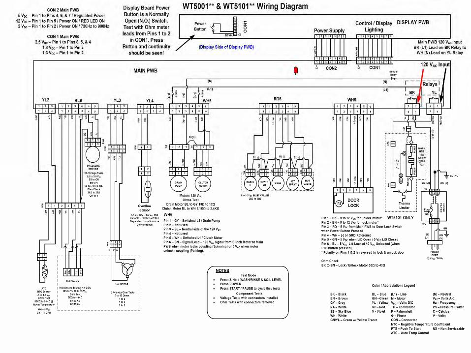
Motors 120 VACOhms Test
Drain Motor BL to GY 13Ω to 17ΩClutch Motor BL to WH 2.1KΩ to 2.4KΩ
1 2 31 32
44
55
6 76 7
BK
/WH
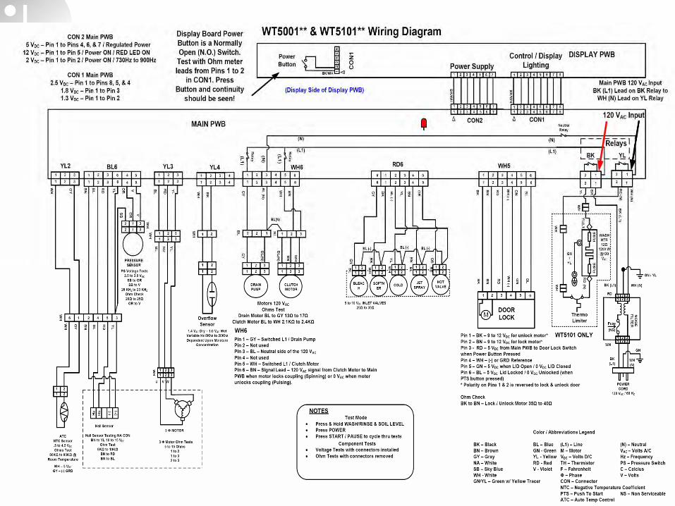
WT5001** & WT5101** Wiring Diagram
DISPLAY PWB
YL(L1)
BK
RD
(N)
1 2 3 4 5 6
Thermo Limiter
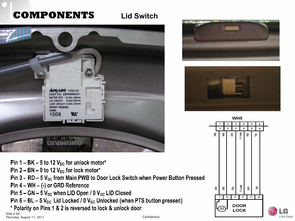
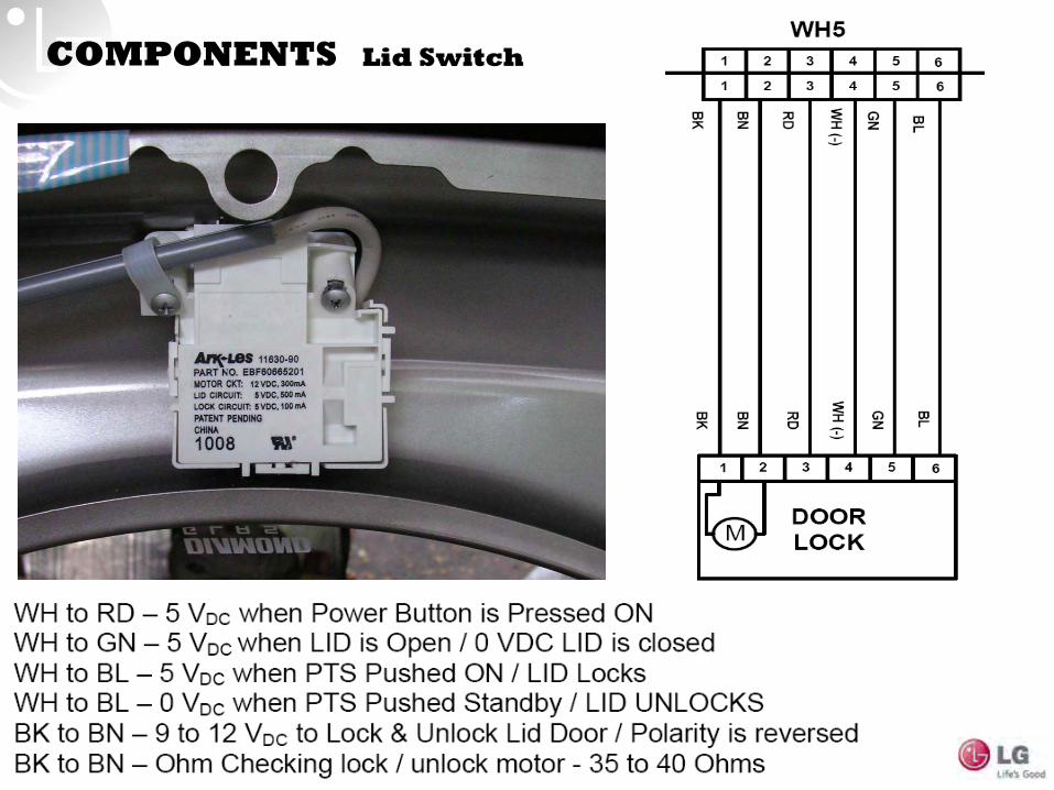
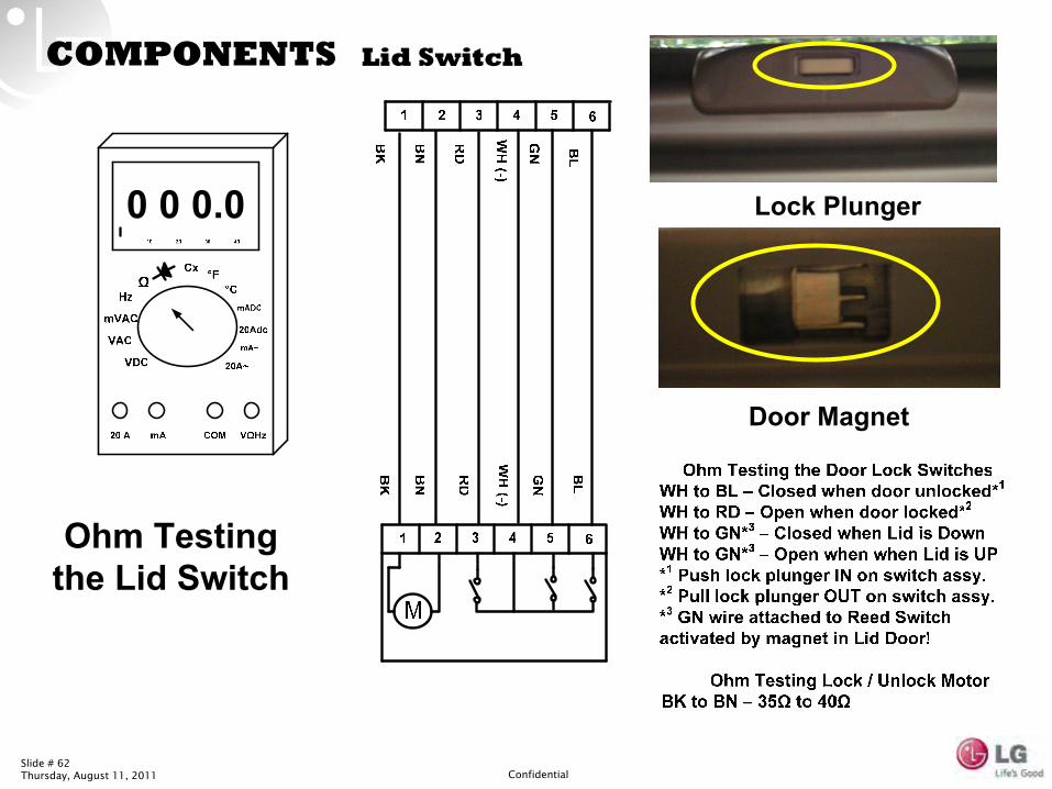
Pin 1 – BK – 9 to 12 VDC for unlock motor*Pin 2 – BN – 9 to 12 VDC for lock motor*Pin 3 - RD – 5 VDC from Main PWB to Door Lock Switch when Power Button Pressed Pin 4 – WH – (-) or GRD ReferencePin 5 – GN – 5 VDC when LID Open / 0 VDC LID ClosedPin 6 – BL – 5 VDC Lid Locked / 0 VDC Unlocked (when PTS button pressed)* Polarity on Pins 1 & 2 is reversed to lock & unlock door
Ohm Check BK to BN – Lock / Unlock Motor 35Ω to 40Ω
NOTESTest Mode
Press & Hold WASH/RINSE & SOIL LEVELPress POWERPress START / PAUSE to cycle thru tests
Component TestsVoltage Tests with connectors installed Ohm Tests with connectors removed
WH
3 Φ MOTOR
YL2
3 Φ Motor Ohm Tests5 to 15 Ohms
1 to 21 to 32 to 3
Hall Sensor Testing NA CONBN to YL 10 to 15 VDC
Ohm Test8KΩ to 10KΩ
BN to RDBN to BL
1 21 2
ATC NTC Sensor.5 to 4.5 VDCOhms Test
80KΩ to 90KΩ @ Room Temperature
1 2 3
1 32
4
4
5
5
6
6
1 2 3
1 32
4
4
5
5
66
1 2 31 32
44
1 2 31 32
1 2 31 32 6
1 2 3
1 32
4
4
5
5
6
WH5
BN
BK
RD
WH
(-)
GN BL
1 632 4 5
DOORLOCK
BK
BN
RD
WH
(-)
GN
BL
RD6
5 to 10 VDC INLET VALVES 25Ω to 35Ω
BLEACH
1 21 2
SOFTNER
1 21 2
COLD
1 21 2
JET SPRAY
1 21 2
1 21 2
BL
BLWH
WH
BL (-) BL (-)
HOTVALVE
RD
ORGY
BNYLBK
BL (-)
16 32 4 5
16 32 4 5
GY
BK
YLBL (-)
BN
OR
1 2 31 32
1 2 31 32
1 2 3123
BL BL
GY
GY
BL (N
)B
L(N)
BL(N
)
BL(N)
WH
WH
BN
BN
DRAIN PUMP
CLUTCH MOTOR
WH6
Pin 1 – GY – Switched L1 / Drain PumpPin 2 – Not usedPin 3 – BL – Neutral side of the 120 VACPin 4 – Not usedPin 5 – WH – Switched L1 / Clutch MotorPin 6 – BN – Signal Lead – 120 VAC signal from Clutch Motor to Main PWB when motor locks coupling (Spinning) or 0 VAC when motor unlocks coupling (Pulsing).
WH6
1 2
WH
BK
WH
YL4
1 21 2
Overflow Sensor
12 31 32
WH
PRESSURESENSOR
SB VOR
PS Voltage Tests2.5 to 3.0 VDC
SB to ORSB to V
26 KHZ to 23 KHZOhm Check20Ω to 25Ω
OR to V
1 2 31 32
U V W
1 2 31 32
BL RD
YL
YL3
BL
RD YL
WH
1 2 34 56
BL6
Ha
Hb (-) (+)
Hall Sensor
OR VYL
BN BL
RD
BN BL
RD YL
WH
WH
GY
WH
GY
WH – 5 VDCGY – (-) GRD
8181
2 3 4 5 6 72 3 4 5 6 7
7
CON2 CON1
Color / Abbreviations Legend
BK – Black BL – BlueBN – Brown GN - GreenGY – Gray YL - YellowNA – White RD - RedSB – Sky Blue V - VioletWH - WhiteGN/YL – Green w/ Yellow Tracer
120 VAC Input
Main PWB 120 VAC InputBK (L1) Lead on BK Relay to
WH (N) Lead on YL Relay
81 2 3 4 5 6 7
BK
/WH
12
34
56
Power Button C
ON
1
Display Board Power Button is a Normally Open (N.O.) Switch.
Test with Ohm meter leads from Pins 1 to 2
in CON1. Press Button and continuity
should be seen!
BK/WH
(Display Side of Display PWB)
Relay
Relay
(L1)(L1)
WH
WH
WH
1.4 VAC Dry – 1.0 VAC WetVariable Hz 8Khz to 20KhzDependent Upon Moisture
Concentration
(L1)
(N)
(N)(N)
(L1)YLBK
Neutral Relay
CON 2 Main PWB 5 VDC – Pin 1 to Pins 4, 6, & 7 / Regulated Power12 VDC – Pin 1 to Pin 5 / Power ON / RED LED ON 2 VDC – Pin 1 to Pin 2 / Power ON / 730Hz to 900Hz
Power SupplyControl / Display
LightingCON 1 Main PWB
2.5 VDC – Pin 1 to Pins 8, 5, & 4 1.8 VDC – Pin 1 to Pin 3 1.3 VDC – Pin 1 to Pin 2
M
WT5101 ONLY(NS)Fuse
(L1) – Line (N) – Neutral M – Motor VAC – Volts A/CVDC – Volts D/C Hz – FrequencyTH – Thermistor PS – Pressure SwitchF – Fahrenheit C – CelciusΦ – Phase V – VoltsCON – ConnectorNTC – Negative Temperature CoefficientPTS – Push To Start NS – Non ServiceableATC – Auto Temp Control
Print Vs 08.08.11

Fall 2011 Appliance Training


