Embed Size (px)
Citation preview
LIT 4321890Printed in U.S.A.July, 1996
SERVICE MANUAL for the
FREESTANDINGSTANDARDGAS RANGE
- ii -
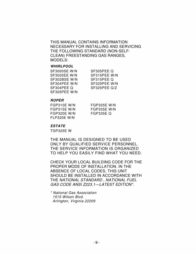
THIS MANUAL CONTAINS INFORMATIONNECESSARY FOR INSTALLING AND SERVICINGTHE FOLLOWING STANDARD (NON-SELF-CLEAN) FREESTANDING GAS RANGES,MODELS:
WHIRLPOOLSF3000SE W/N SF305PEE QSF3020EE W/N SF315PEE W/NSF302BSE W/N SF315PEE QSF304PEE W/N SF325PEE W/NSF304PEE Q SF325PEE Q/ZSF305PEE W/N
ROPERFGP310E W/N FGP325E W/NFGP315E W/N FGP335E W/NFGP320E W/N FGP335E QFLP320E W/N
ESTATETGP325E W
THE MANUAL IS DESIGNED TO BE USEDONLY BY QUALIFIED SERVICE PERSONNEL.THE SERVICE INFORMATION IS ORGANIZEDTO HELP YOU EASILY FIND WHAT YOU NEED.
CHECK YOUR LOCAL BUILDING CODE FOR THEPROPER MODE OF INSTALLATION. IN THEABSENCE OF LOCAL CODES, THIS UNITSHOULD BE INSTALLED IN ACCORDANCE WITHTHE NATIONAL STANDARD , NATIONAL FUELGAS CODE ANSI Z223.1—LATEST EDITION*.
* National Gas Association 1515 Wilson Blvd. Arlington, Virginia 22209
Page iii
- iii -
Cooking Products Service ManualOriginal July, 1996 4321890© 1996 Whirlpool Corporation
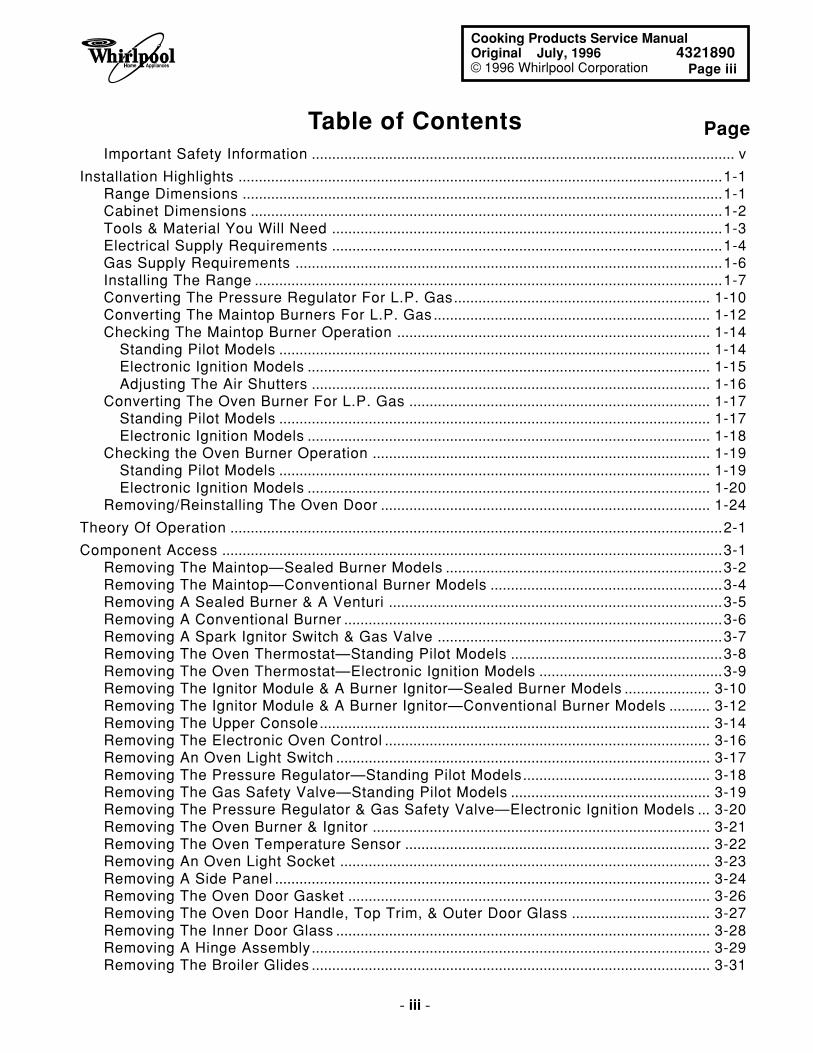
Table of Contents PageImportant Safety Information ........................................................................................................ v
Installation Highlights .......................................................................................................................1-1Range Dimensions ......................................................................................................................1-1Cabinet Dimensions ....................................................................................................................1-2Tools & Material You Will Need ................................................................................................1-3Electrical Supply Requirements ................................................................................................1-4Gas Supply Requirements .........................................................................................................1-6Installing The Range ...................................................................................................................1-7Converting The Pressure Regulator For L.P. Gas............................................................... 1-10Converting The Maintop Burners For L.P. Gas .................................................................... 1-12Checking The Maintop Burner Operation ............................................................................. 1-14
Standing Pilot Models .......................................................................................................... 1-14Electronic Ignition Models ................................................................................................... 1-15Adjusting The Air Shutters .................................................................................................. 1-16
Converting The Oven Burner For L.P. Gas .......................................................................... 1-17Standing Pilot Models .......................................................................................................... 1-17Electronic Ignition Models ................................................................................................... 1-18
Checking the Oven Burner Operation ................................................................................... 1-19Standing Pilot Models .......................................................................................................... 1-19Electronic Ignition Models ................................................................................................... 1-20
Removing/Reinstalling The Oven Door ................................................................................. 1-24
Theory Of Operation .........................................................................................................................2-1
Component Access ...........................................................................................................................3-1Removing The Maintop—Sealed Burner Models ....................................................................3-2Removing The Maintop—Conventional Burner Models .........................................................3-4Removing A Sealed Burner & A Venturi ..................................................................................3-5Removing A Conventional Burner .............................................................................................3-6Removing A Spark Ignitor Switch & Gas Valve ......................................................................3-7Removing The Oven Thermostat—Standing Pilot Models ....................................................3-8Removing The Oven Thermostat—Electronic Ignition Models .............................................3-9Removing The Ignitor Module & A Burner Ignitor—Sealed Burner Models ..................... 3-10Removing The Ignitor Module & A Burner Ignitor—Conventional Burner Models .......... 3-12Removing The Upper Console................................................................................................ 3-14Removing The Electronic Oven Control ................................................................................ 3-16Removing An Oven Light Switch ............................................................................................ 3-17Removing The Pressure Regulator—Standing Pilot Models.............................................. 3-18Removing The Gas Safety Valve—Standing Pilot Models ................................................. 3-19Removing The Pressure Regulator & Gas Safety Valve—Electronic Ignition Models ... 3-20Removing The Oven Burner & Ignitor ................................................................................... 3-21Removing The Oven Temperature Sensor ........................................................................... 3-22Removing An Oven Light Socket ........................................................................................... 3-23Removing A Side Panel ........................................................................................................... 3-24Removing The Oven Door Gasket ......................................................................................... 3-26Removing The Oven Door Handle, Top Trim, & Outer Door Glass .................................. 3-27Removing The Inner Door Glass ............................................................................................ 3-28Removing A Hinge Assembly.................................................................................................. 3-29Removing The Broiler Glides .................................................................................................. 3-31
- iv -
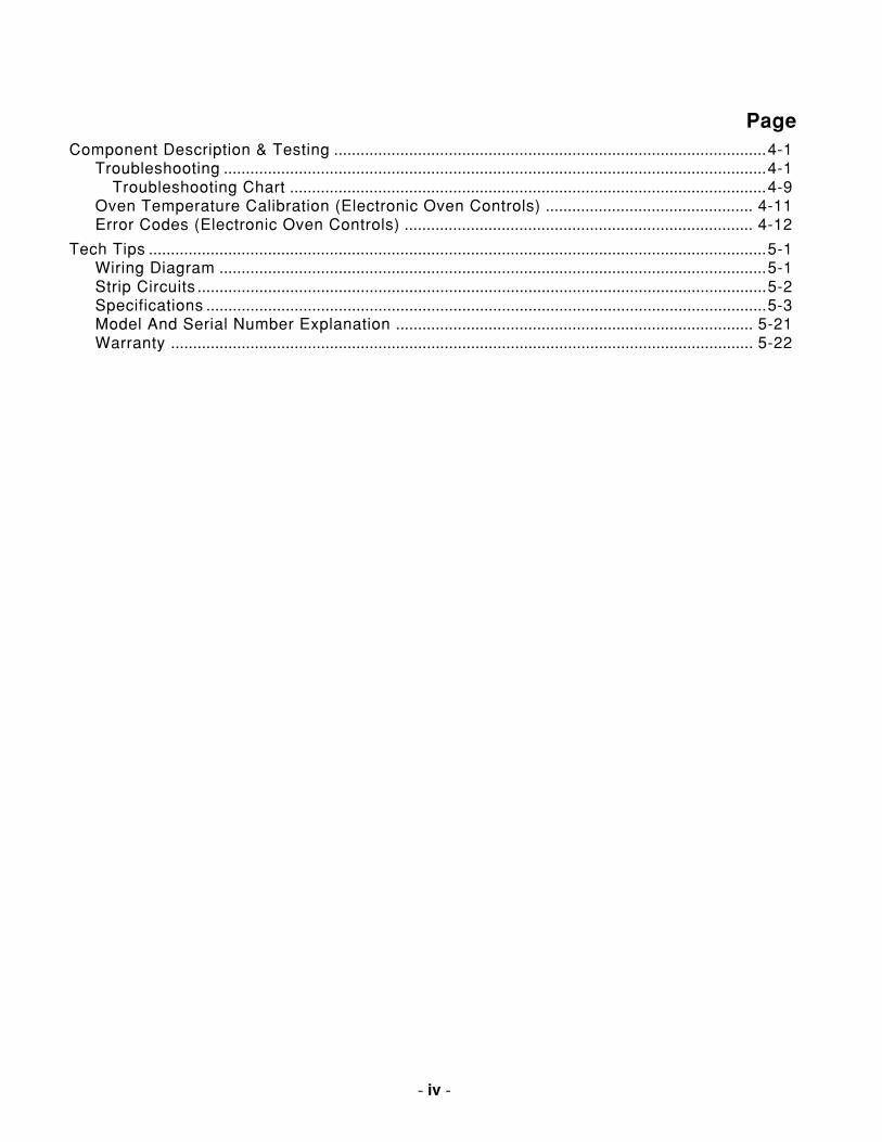
PageComponent Description & Testing ..................................................................................................4-1
Troubleshooting ...........................................................................................................................4-1Troubleshooting Chart ............................................................................................................4-9
Oven Temperature Calibration (Electronic Oven Controls) ............................................... 4-11Error Codes (Electronic Oven Controls) ............................................................................... 4-12
Tech Tips ............................................................................................................................................5-1Wiring Diagram ............................................................................................................................5-1Strip Circuits .................................................................................................................................5-2Specifications ...............................................................................................................................5-3Model And Serial Number Explanation ................................................................................. 5-21Warranty .................................................................................................................................... 5-22
Page v
- v -
Cooking Products Service ManualOriginal July, 1996 4321890© 1996 Whirlpool Corporation
IMPORTANT SAFETY INFORMATION
Fire Hazard
Do not obstruct the flow of combustion andventilation air.
Electrical Shock Hazard
It is the customer’s responsibility to:
• Contact a qualified electrical installer.• Assure that electrical installation is adequate
and in conformance with the National Elec-trical Code, ANSI/NFPA 70—latest edition*,and all local codes and ordinances.
Failure to do so could result in fire, electricalshock, or other personal injury.
Take special care when drilling holes into thewall for venting or electrical wiring. Electricalwires may be concealed behind the wall cover-ing.
Failure to do so could result in fire, electricalshock, or other personal injury.
WARNINGThis service manual is intended for factory-servicetechnicians only. We recommend that customersDO NOT service their own units, because of thecomplexity and risk of high-voltage electrical shock.
The following information is used throughout thismanual, and should be read carefully.
Information that will help you avoid actionsthat could cause product damage (scratches,dents, etc.) and damage to personal property.
NOTEHelpful information that explains a more com-plicated step, prior to carrying it out .
CAUTION
WARNINGInformation that alerts you to potentially dan-gerous conditions. These conditions cancause serious personal injury (burns, fire andelectrical shock, etc.) if the suggested proce-dures are not observed.
* National Fire Protection Association Batterymarch Park Quincy, Massachusetts 02269
WHIRLPOOL CORPORATION ASSUMES NO RE-
SPONSIBILITY FOR ANY REPAIRS MADE ON
OUR PRODUCTS BY ANYONE OTHER THAN AU-
THORIZED WHIRLPOOLSM SERVICE TECHNI-
CIANS.
- vi -
WARNINGTo reduce the risk of fire, electrical shock,injury to persons, or damage when usingthe range, follow these basic precautions:
1. Read all instructions before using therange.
2. Install or locate the range only in accor-dance with the provided installation in-structions. It is recommended that therange be installed by a qualified installer.The range must be properly connected tothe correct gas supply and checked forleaks. The range must also be properlyconnected to a grounded electrical sup-ply.
3. Gas fuels and combustion can result inpotential exposure to chemicals known tocause cancer or reproductive harm. Forexample, benzene is a chemical which isa part of the gas supplied to the range. Itis consumed in the flame during combus-tion. However, exposure to a small amountof benzene is possible if a gas leak oc-curs. Formaldehyde and soot are by-prod-ucts of incomplete combustion. Properlyadjusted burners with a bluish rather thana yellow flame will minimize incompletecombustion.
4. Do not use the range for heating the room.Persons could be burned or injured, or afire could start.
5. Do not leave children alone or unattendedin area where the range is in use. Theyshould never be allowed to sit or stand onany part of the range. They could beburned or injured.
6. Do not wear loose or hanging garmentswhen using the range. Clothing could ig-nite if it touches a surface burner and youcould be burned.
7. Do not repair or replace any part of therange unless specifically recommendedin this manual. All other servicing shouldbe referred to a qualified technician.
8. Do not operate the range if it is not work-ing properly, or if it has been damaged ordropped.
9. Know where your main gas shut off valveis located.
10. Clean your range regularly. See “Careand Cleaning” instructions that are in-cluded with the range.
11. Use the range only for its intended use asdescribed in this manual.
12. Do not store flammable materials on ornear the range. They could explode orburn.
13. Do not use water on grease fires. Neverpick up a flaming pan. Smother flamingpan on range by covering with a well-fitting lid, cookie sheet or flat tray. Flam-ing grease outside of pan can be extin-guished with baking soda, or if available,a multipurpose dry chemical or foam-typeextinguisher.
14. Use only dry potholders. Moist or damppotholders on hot surfaces may result inburns from steam. Do not let potholdertouch an open flame. Do not use a towelor bulky cloth for a potholder. It couldcatch on fire.
15. Make sure the utensils you use are largeenough to contain food and avoid boiloversand spil lovers. Heavy splattering orspillovers left on a range can ignite andburn you. Pan size is especially importantin deep fat frying.
16. Never leave burners unattended at highflame settings. A boilover could resultand cause smoking and greasy spilloversthat may ignite.
Page vii
- vii -
Cooking Products Service ManualOriginal July, 1996 4321890© 1996 Whirlpool Corporation
17. Grease is flammable and should behandled carefully. Let fat cool before at-tempting to handle it. Do not allow greaseto collect around range or in vents. Wipespillovers immediately.
18. Check to be sure glass cooking utensilsare safe for use on the range. Only certaintypes of glass, glass-ceramic, earthen-ware or other glazed utensils are suitablefor ranges. Other types may break due tothe sudden change in temperature.
19. Turn pan handles inward, but not overother burners. This will help reduce thechance of burns, igniting of flammablematerials, and spills due to bumping thepan.
20. Do not heat unopened containers. Theycould explode. The hot contents couldcause burns and container particles couldcause injury.
21. Do not use decorative covers or trivetsover the surface burners.
22. Do not store things children might wantabove the range. Children could be burnedor injured while climbing on range.
23. Do not touch hot burners or areas nearburners. Areas near burners become hotenough to cause burns. During use, donot touch or let clothing or other flam-mable materials contact burners, or ar-eas near burners.
24. Do not block the ventilation.
25. Never use a match or other flame to lookfor a gas leak. Explosion and injury couldresult.
26. Make sure the burners are off when youare finished, and when you are not watch-ing.
27. Be sure all range parts are cool beforecleaning.

- viii -
— NOTES —
Page 1-1
1-1
Cooking Products Service ManualOriginal July, 1996 4321890© 1996 Whirlpool Corporation
RANGE DIMENSIONSGENERALProper installation is your responsibility. A quali-fied technician must install this range. Make sureyou have everything necessary for correct installa-tion. It is the responsibility of the installer to complywith the installation clearances specified on theoven model/serial rating plate. This plate is locatedon the frame behind the broiler door panel. IMPOR-TANT: Be sure to observe all governing codes andordinances. In the absence of local codes, installa-tion must conform with American National Stan-dard, National Fuel Gas Code ANSI Z223.1 —latest edition*.
* American Gas Association 1515 Wilson Boulevard Arlington, Virginia 22209
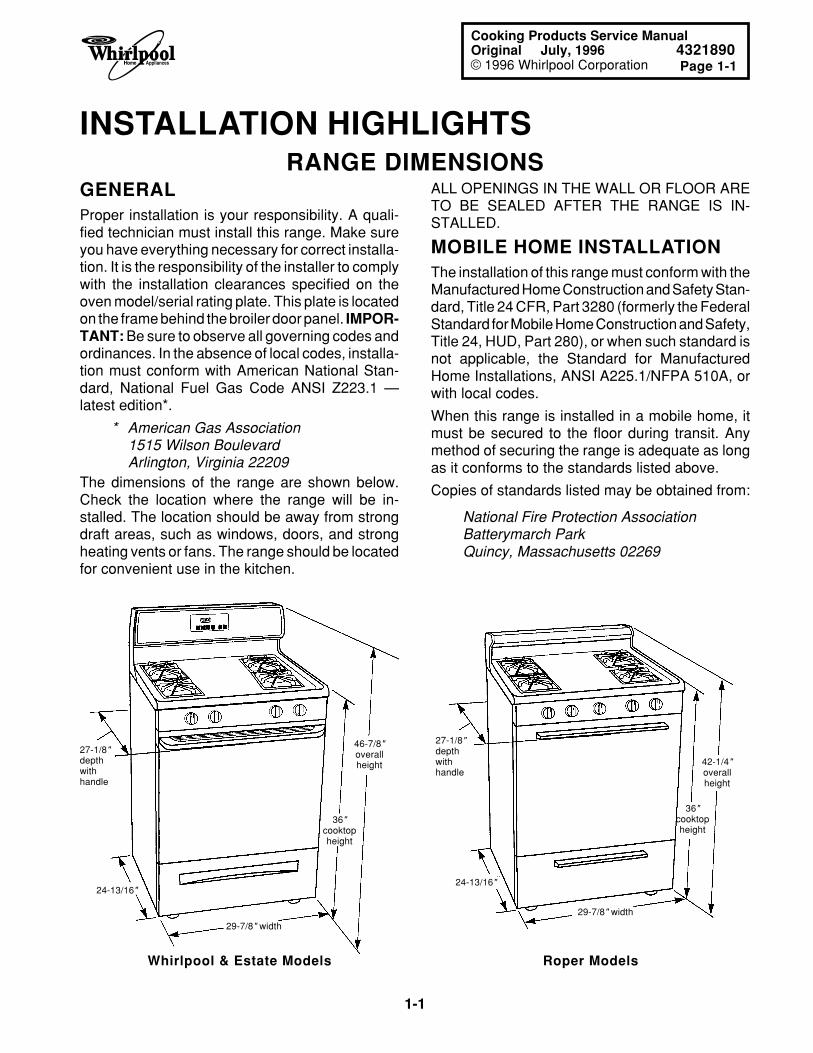
The dimensions of the range are shown below.Check the location where the range will be in-stalled. The location should be away from strongdraft areas, such as windows, doors, and strongheating vents or fans. The range should be locatedfor convenient use in the kitchen.
ALL OPENINGS IN THE WALL OR FLOOR ARETO BE SEALED AFTER THE RANGE IS IN-STALLED.
MOBILE HOME INSTALLATIONThe installation of this range must conform with theManufactured Home Construction and Safety Stan-dard, Title 24 CFR, Part 3280 (formerly the FederalStandard for Mobile Home Construction and Safety,Title 24, HUD, Part 280), or when such standard isnot applicable, the Standard for ManufacturedHome Installations, ANSI A225.1/NFPA 510A, orwith local codes.
When this range is installed in a mobile home, itmust be secured to the floor during transit. Anymethod of securing the range is adequate as longas it conforms to the standards listed above.
Copies of standards listed may be obtained from:
INSTALLATION HIGHLIGHTS
National Fire Protection AssociationBatterymarch ParkQuincy, Massachusetts 02269
46-7/8"overallheight
36"cooktopheight
29-7/8" width
24-13/16"
36"cooktopheight
42-1/4"overallheight
24-13/16"
29-7/8" width
Roper ModelsWhirlpool & Estate Models
27-1/8"depthwithhandle
27-1/8"depthwithhandle
1-2
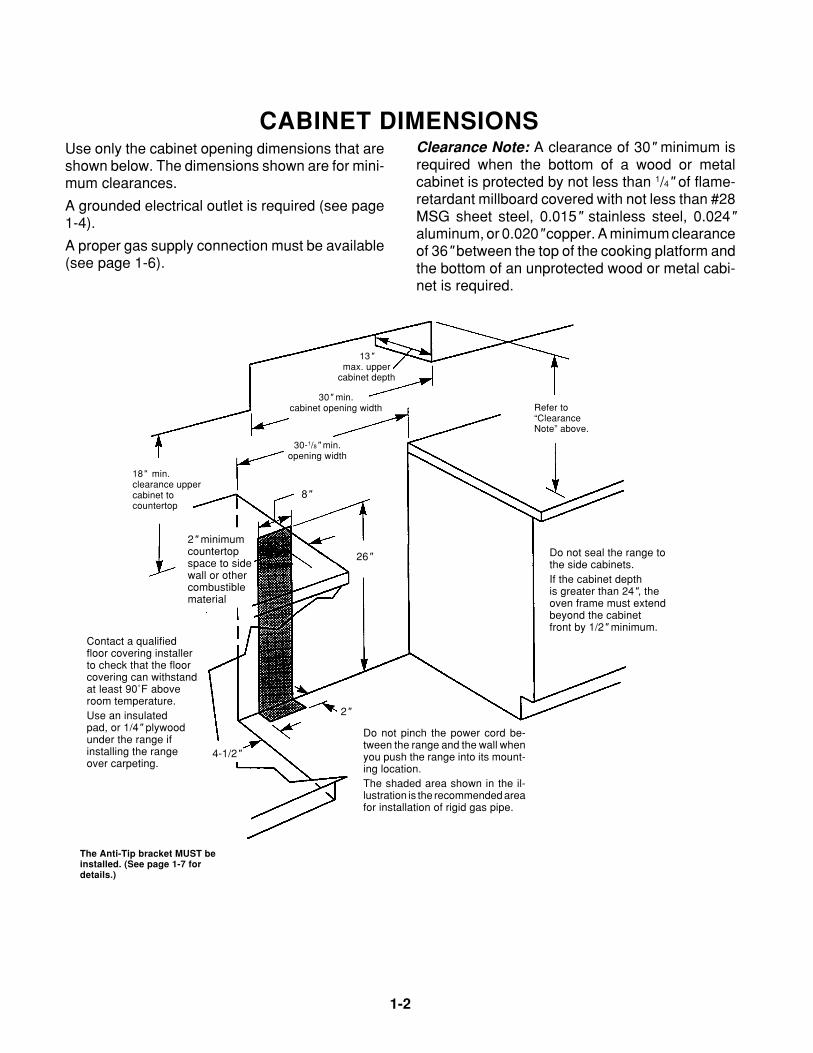
CABINET DIMENSIONSClearance Note: A clearance of 30" minimum isrequired when the bottom of a wood or metalcabinet is protected by not less than 1/4" of flame-retardant millboard covered with not less than #28MSG sheet steel, 0.015" stainless steel, 0.024"aluminum, or 0.020" copper. A minimum clearanceof 36" between the top of the cooking platform andthe bottom of an unprotected wood or metal cabi-net is required.
Use only the cabinet opening dimensions that areshown below. The dimensions shown are for mini-mum clearances.
A grounded electrical outlet is required (see page1-4).
A proper gas supply connection must be available(see page 1-6).
Refer to“ClearanceNote” above.
Do not seal the range tothe side cabinets.If the cabinet depthis greater than 24", theoven frame must extendbeyond the cabinetfront by 1/2" minimum.
30" min.cabinet opening width
13"max. upper
cabinet depth
18" min.clearance uppercabinet tocountertop
2" minimumcountertopspace to sidewall or othercombustiblematerial
Contact a qualifiedfloor covering installerto check that the floorcovering can withstandat least 90˚F aboveroom temperature.Use an insulatedpad, or 1/4" plywoodunder the range ifinstalling the rangeover carpeting.
Do not pinch the power cord be-tween the range and the wall whenyou push the range into its mount-ing location.The shaded area shown in the il-lustration is the recommended areafor installation of rigid gas pipe.
8"
26"
2"
4-1/2"
30-1/8" min.opening width
The Anti-Tip bracket MUST beinstalled. (See page 1-7 fordetails.)
Page 1-3
1-3
Cooking Products Service ManualOriginal July, 1996 4321890© 1996 Whirlpool Corporation
ANTI-TIP BRACKET
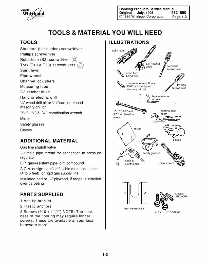
TOOLS & MATERIAL YOU WILL NEED
3/8" ratchetdrive flat-blade
screwdriver
Phillipsscrewdriver
wood floor:1/8" drill bit
channel lockpliers
gloves
safety glasses
tape measureor ruler
mirror
15/16", 1/2" and3/8" combinationwrench
concrete/ceramic floors:3/16" carbide-tippedmasonry drill bit
pipe wrenchhand orelectric drill
spirit level
ILLUSTRATIONS
#10 X 1-1/2" SCREWS
PLASTIC ANCHORS
TOOLSStandard (flat-bladed) screwdriver
Phillips screwdriver
Robertson (S2) screwdriver
Torx (T10 & T20) screwdrivers
Spirit level
Pipe wrench
Channel lock pliers
Measuring tape3/8" ratchet drive
Hand or electric drill1/8" wood drill bit or 3/16" carbide-tippedmasonry drill bit15/16" , 1/2", & 3/8" combination wrench
Mirror
Safety glasses
Gloves
ADDITIONAL MATERIALGas line shutoff valve1/2" male pipe thread for connection to pressureregulator
L.P. gas-resistant pipe-joint compound
A.G.A. design-certified flexible metal connector(4 to 5 feet), or rigid gas supply line
Insulated pad or 1/4" plywood, if range is installedover carpeting
PARTS SUPPLIED1 Anti-tip bracket
2 Plastic anchors
2 Screws (#10 x 1-1/2" ) NOTE: The thick-ness of the flooring may require longerscrews. These are available at your localhardware store.
1-4
ELECTRICAL SUPPLY REQUIREMENTSThe following information applies to the gas rangewiring:
• A 3-wire, single phase, 120-volt, 60 Hz, AC-only electrical supply is required on a sepa-rate 10-ampere circuit, fused on both sides ofthe line. A time-delay fuse, or circuit breaker,is recommended. The fuse must be sized asper local codes in accordance with the electri-cal rating of the appliance specified on themodel/serial rating plate, which is located onthe frame behind the broiler door.
• The gas range must be connected with cop-per wire only.
• Wire sizes and connections must conform tothe requirements of the National ElectricalCode, ANSI/NFPA 70—latest edition*, and alllocal codes and ordinances. Wire sizes andconnections must conform with the rating ofthe appliance. Copies of the standards listedabove may be obtained from:
* National Fire Protection AssociationBatterymarch ParkQuincy, Massachusetts 02269
• The gas range should be connected directlyto the fused disconnect (or circuit breaker)through flexible, armored, or nonmetallicsheathed, copper cable. The flexible, armoredcable that extends from the appliance shouldbe connected directly to the junction box.
• Locate the junction box to allow as much slackas possible between the junction box and theappliance so that the appliance can be movedif servicing is ever necessary. Do not cut theconduit.
• A U.L.-listed, 1/2" conduit connector must beprovided at the junction box.
• A wiring diagram is located in the “Tech Tips”(Section 5) of this manual.
WARNINGElectrical Shock Hazard
An electrical ground is required on this appli-ance.
If a cold water pipe is interrupted by plastic,nonmetallic gaskets, or other insulating materi-als, do not use for grounding.
Do not ground to a gas pipe.
Do not change the power supply cord plug. If theplug will not fit the outlet, have a proper outletinstalled by a qualified electrician.
Do not use a fuse in the neutral or groundingcircuit. It could result in an electrical shock.
Do not use an extension cord with this range.
Check with a qualified electrician if you are indoubt as to whether the appliance is properlygrounded.
Failure to follow these instructions could result inserious injury or death.
Equipment & Property Damage
Use a separate power line for this gas range,and make sure that you connect it to the propervoltage source. Failure to do so could result inimproper operation, equipment, or property dam-age.
GENERALIf codes permit, and a separate grounding wire isused, it is recommended that a qualified electriciandetermine that the grounding path is adequate.
Page 1-5
1-5
Cooking Products Service ManualOriginal July, 1996 4321890© 1996 Whirlpool Corporation
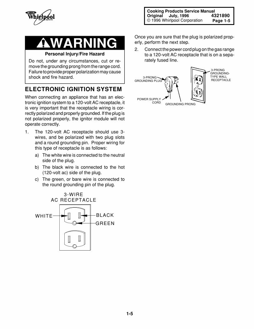
Once you are sure that the plug is polarized prop-erly, perform the next step.
2. Connect the power cord plug on the gas rangeto a 120-volt AC receptacle that is on a sepa-rately fused line.
3-PRONGGROUNDING PLUG
POWER SUPPLY CORD GROUNDING PRONG
3-PRONG GROUNDING- TYPE WALL RECEPTACLE
1. The 120-volt AC receptacle should use 3-wires, and be polarized with two plug slotsand a round grounding pin. Proper wiring forthis type of receptacle is as follows:
a) The white wire is connected to the neutralside of the plug.
b) The black wire is connected to the hot(120-volt ac) side of the plug.
c) The green, or bare wire is connected tothe round grounding pin of the plug.
3-WIREAC RECEPTACLE
BLACK
GREEN
WHITE
ELECTRONIC IGNITION SYSTEMWhen connecting an appliance that has an elec-tronic ignition system to a 120-volt AC receptacle, itis very important that the receptacle wiring is cor-rectly polarized and properly grounded. If the plug isnot polarized properly, the ignitor module will notoperate correctly.
WARNINGPersonal Injury/Fire Hazard
Do not, under any circumstances, cut or re-move the grounding prong from the range cord.Failure to provide proper polarization may causeshock and fire hazard.
1-6
GAS SUPPLY REQUIREMENTS
Fire Hazard
The gas appliance must be connected to aregulated gas supply.
Do not use an open flame to test for gas leaksfrom gas connections.
New A.G.A.-designed and certified flexible gasline should be used, when codes permit.
Do not store or use gasoline, or any otherflammable vapors and liquids, in the vicinity ofthis, or any other appliance.
If you smell gas:
• Do not light any appliance.
• Do not operate any electrical switches.
• Do not use the telephone.
• Call the gas supplier immediately from aneighbor’s telephone, and follow the gassupplier’s instructions carefully.
• If you cannot reach the gas supplier, call thefire department.
Failure to follow these instructions could result infire, explosion, or other personal injury.
WARNINGThis range is factory set for use with natural gas. Itis designed-certified by the American Gas Asso-ciation (A.G.A.) for natural or L.P. gases with theappropriate conversion. The model/serial ratingplate has information on the type of gas that can beused. If the type of gas listed does not agree withthe type of gas available, check with the local gassupplier. Conversion must be done by a qualifiedservice technician.
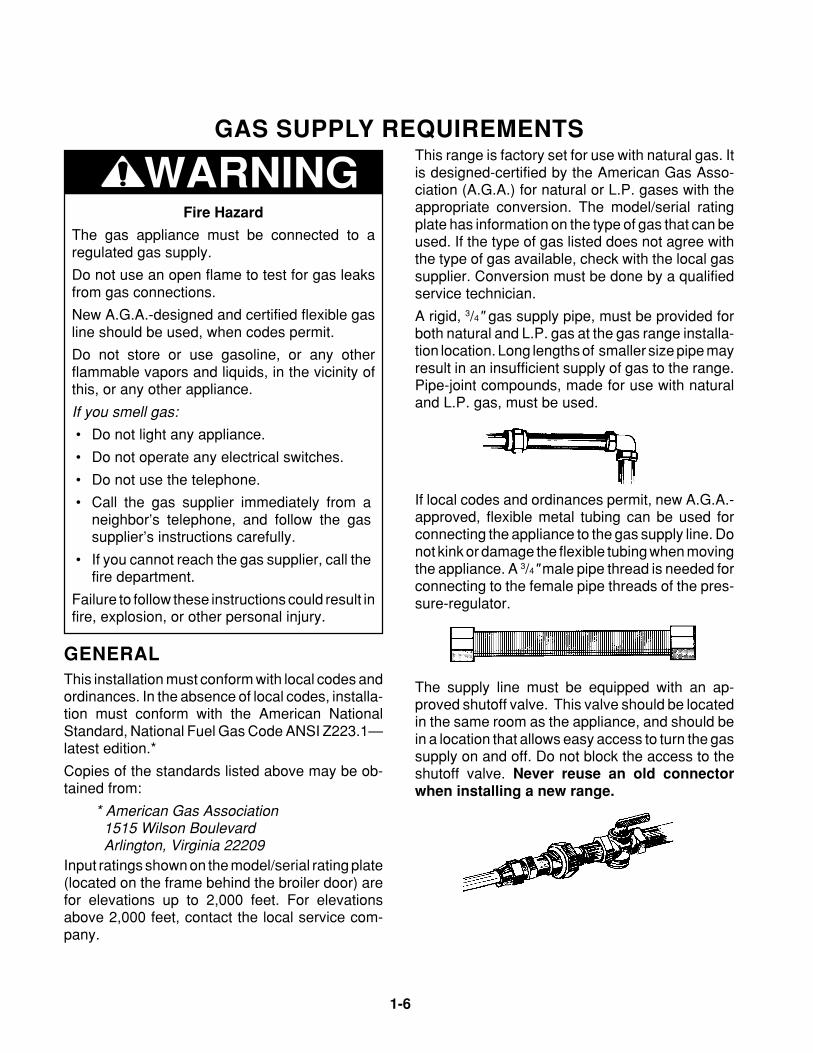
A rigid, 3/4" gas supply pipe, must be provided forboth natural and L.P. gas at the gas range installa-tion location. Long lengths of smaller size pipe mayresult in an insufficient supply of gas to the range.Pipe-joint compounds, made for use with naturaland L.P. gas, must be used.
GENERALThis installation must conform with local codes andordinances. In the absence of local codes, installa-tion must conform with the American NationalStandard, National Fuel Gas Code ANSI Z223.1—latest edition.*
Copies of the standards listed above may be ob-tained from:
* American Gas Association 1515 Wilson Boulevard Arlington, Virginia 22209
Input ratings shown on the model/serial rating plate(located on the frame behind the broiler door) arefor elevations up to 2,000 feet. For elevationsabove 2,000 feet, contact the local service com-pany.
If local codes and ordinances permit, new A.G.A.-approved, flexible metal tubing can be used forconnecting the appliance to the gas supply line. Donot kink or damage the flexible tubing when movingthe appliance. A 3/4" male pipe thread is needed forconnecting to the female pipe threads of the pres-sure-regulator.
The supply line must be equipped with an ap-proved shutoff valve. This valve should be locatedin the same room as the appliance, and should bein a location that allows easy access to turn the gassupply on and off. Do not block the access to theshutoff valve. Never reuse an old connectorwhen installing a new range.
Page 1-7
1-7
Cooking Products Service ManualOriginal July, 1996 4321890© 1996 Whirlpool Corporation
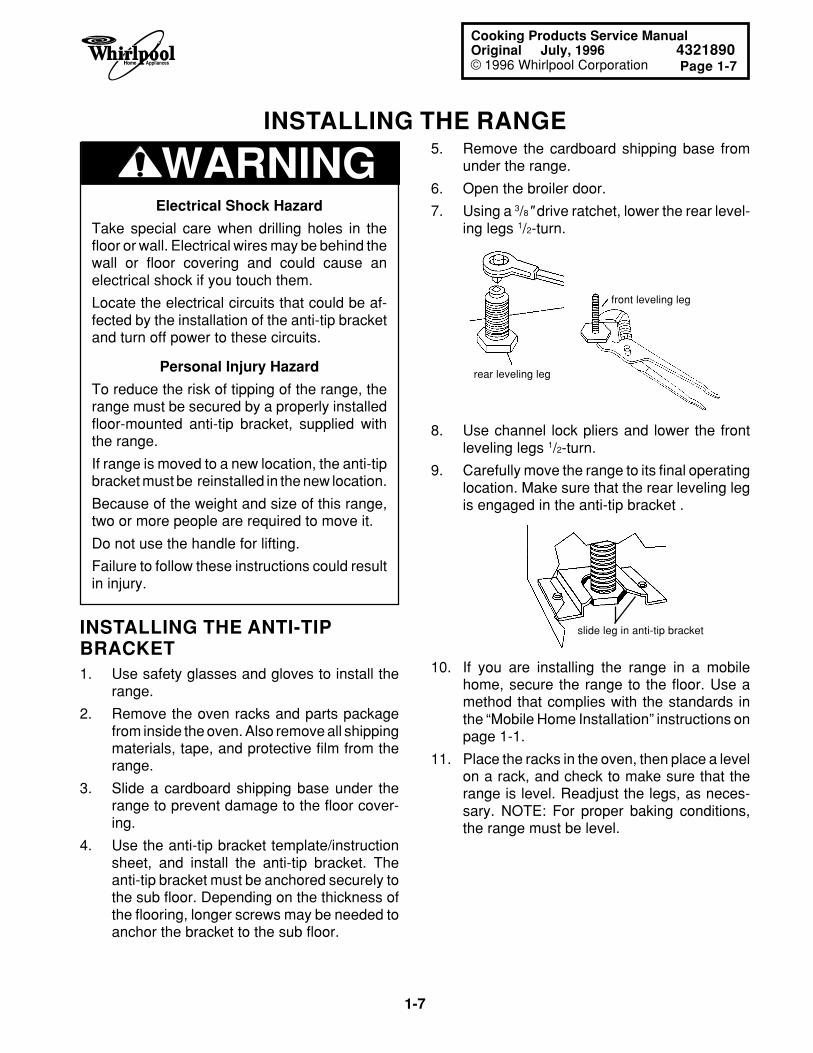
5. Remove the cardboard shipping base fromunder the range.
6. Open the broiler door.
7. Using a 3/8" drive ratchet, lower the rear level-ing legs 1/2-turn.
INSTALLING THE RANGE
WARNINGElectrical Shock Hazard
Take special care when drilling holes in thefloor or wall. Electrical wires may be behind thewall or floor covering and could cause anelectrical shock if you touch them.
Locate the electrical circuits that could be af-fected by the installation of the anti-tip bracketand turn off power to these circuits.
Personal Injury Hazard
To reduce the risk of tipping of the range, therange must be secured by a properly installedfloor-mounted anti-tip bracket, supplied withthe range.
If range is moved to a new location, the anti-tipbracket must be reinstalled in the new location.
Because of the weight and size of this range,two or more people are required to move it.
Do not use the handle for lifting.
Failure to follow these instructions could resultin injury.
front leveling leg
rear leveling leg
8. Use channel lock pliers and lower the frontleveling legs 1/2-turn.
9. Carefully move the range to its final operatinglocation. Make sure that the rear leveling legis engaged in the anti-tip bracket .
slide leg in anti-tip bracket
10. If you are installing the range in a mobilehome, secure the range to the floor. Use amethod that complies with the standards inthe “Mobile Home Installation” instructions onpage 1-1.
11. Place the racks in the oven, then place a levelon a rack, and check to make sure that therange is level. Readjust the legs, as neces-sary. NOTE: For proper baking conditions,the range must be level.
INSTALLING THE ANTI-TIPBRACKET1. Use safety glasses and gloves to install the
range.
2. Remove the oven racks and parts packagefrom inside the oven. Also remove all shippingmaterials, tape, and protective film from therange.
3. Slide a cardboard shipping base under therange to prevent damage to the floor cover-ing.
4. Use the anti-tip bracket template/instructionsheet, and install the anti-tip bracket. Theanti-tip bracket must be anchored securely tothe sub floor. Depending on the thickness ofthe flooring, longer screws may be needed toanchor the bracket to the sub floor.
1-8
INSTALLING THE GAS LINE
Fire Hazard
When you make gas line connections, espe-cially to the pressure regulator, do not make theconnections too tight. If you do, you may crackthe regulator (or pipe) and cause a gas leak,which could result in a possible fire, or explosion.
WARNING
The following procedure is for a typical gas lineinstallation and its associated components to thegas range. Use pipe-joint compound that is madefor use with natural and L.P. gas to seal all of theconnections. Tighten all of the connections with anadjustable (pipe) wrench.
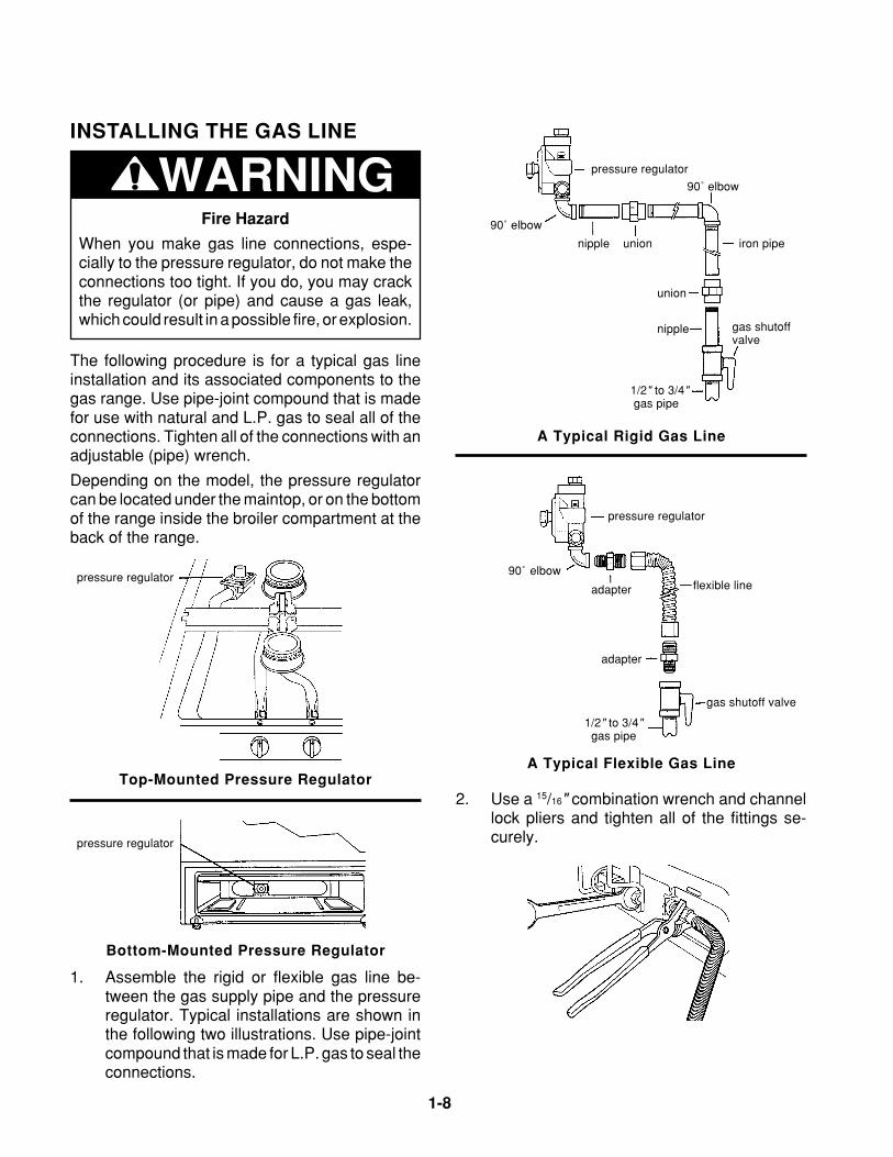
Depending on the model, the pressure regulatorcan be located under the maintop, or on the bottomof the range inside the broiler compartment at theback of the range.
pressure regulator
90˚ elbow
nipple union iron pipe
90˚ elbow
union
nipple gas shutoff valve
1/2" to 3/4" gas pipe
A Typical Rigid Gas Line
pressure regulator
90˚ elbow
adapter flexible line
adapter
gas shutoff valve
1/2" to 3/4" gas pipe
A Typical Flexible Gas Line
2. Use a 15/16" combination wrench and channellock pliers and tighten all of the fittings se-curely.
pressure regulator
1. Assemble the rigid or flexible gas line be-tween the gas supply pipe and the pressureregulator. Typical installations are shown inthe following two illustrations. Use pipe-jointcompound that is made for L.P. gas to seal theconnections.
pressure regulator
Bottom-Mounted Pressure Regulator
Top-Mounted Pressure Regulator
Page 1-9
1-9
Cooking Products Service ManualOriginal July, 1996 4321890© 1996 Whirlpool Corporation
Fire Hazard
Turn off the main gas supply before you try tostop a leak.
Be sure that all leaks are stopped before lightingpilots or burners.
Do not use an open flame to test for gas leaks.
Failure to follow these instructions could result ina possible fire, or explosion.
WARNINGCHECKING FOR LEAKS
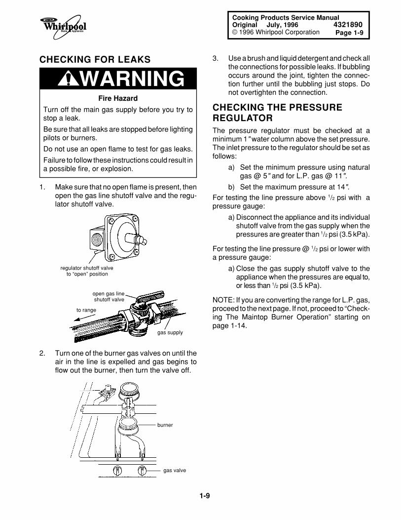
1. Make sure that no open flame is present, thenopen the gas line shutoff valve and the regu-lator shutoff valve.
regulator shutoff valve to “open” position
open gas line shutoff valve
gas supply
to range
2. Turn one of the burner gas valves on until theair in the line is expelled and gas begins toflow out the burner, then turn the valve off.
burner
gas valve
3. Use a brush and liquid detergent and check allthe connections for possible leaks. If bubblingoccurs around the joint, tighten the connec-tion further until the bubbling just stops. Donot overtighten the connection.
CHECKING THE PRESSUREREGULATORThe pressure regulator must be checked at aminimum 1" water column above the set pressure.The inlet pressure to the regulator should be set asfollows:
a) Set the minimum pressure using naturalgas @ 5" and for L.P. gas @ 11".
b) Set the maximum pressure at 14".For testing the line pressure above 1/2 psi with apressure gauge:
a) Disconnect the appliance and its individualshutoff valve from the gas supply when thepressures are greater than 1/2 psi (3.5 kPa).
For testing the line pressure @ 1/2 psi or lower witha pressure gauge:
a) Close the gas supply shutoff valve to theappliance when the pressures are equal to,or less than 1/2 psi (3.5 kPa).
NOTE: If you are converting the range for L.P. gas,proceed to the next page. If not, proceed to “Check-ing The Maintop Burner Operation” starting onpage 1-14.
1-10
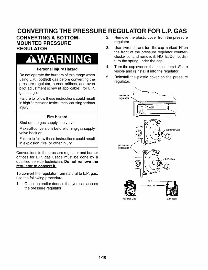
CONVERTING THE PRESSURE REGULATOR FOR L.P. GAS2. Remove the plastic cover from the pressure
regulator.
3. Use a wrench, and turn the cap marked “N” onthe front of the pressure regulator counter-clockwise, and remove it. NOTE: Do not dis-turb the spring under the cap.
4. Turn the cap over so that the letters L.P. arevisible and reinstall it into the regulator.
5. Reinstall the plastic cover on the pressureregulator.
CONVERTING A BOTTOM-MOUNTED PRESSUREREGULATOR
WARNINGPersonal Injury Hazard
Do not operate the burners of this range whenusing L.P. (bottled) gas before converting thepressure regulator, burner orifices, and ovenpilot adjustment screw (if applicable), for L.P.gas usage.
Failure to follow these instructions could resultin high flames and toxic fumes, causing seriousinjury.
Fire Hazard
Shut off the gas supply line valve.
Make all conversions before turning gas supplyvalve back on.
Failure to follow these instructions could resultin explosion, fire, or other injury.
Conversions to the pressure regulator and burnerorifices for L.P. gas usage must be done by aqualified service technician. Do not remove theregulator to convert it.
To convert the regulator from natural to L.P. gas,use the following procedure:
1. Open the broiler door so that you can accessthe pressure regulator.
Natural Gas
cap
washer
L.P. Gas
Natural Gas
L.P. Gas
pressureregulator
pressureregulator
Page 1-11
1-11
Cooking Products Service ManualOriginal July, 1996 4321890© 1996 Whirlpool Corporation
WARNINGPersonal Injury Hazard
Do not operate the burners of this range whenusing L.P. (bottled) gas before converting thepressure regulator, burner orifices, and ovenpilot adjustment screw (if applicable), for L.P.gas usage.
Failure to follow these instructions could resultin high flames and toxic fumes, causing seriousinjury.
Fire Hazard
Shut off the gas supply line valve.
Make all conversions before turning gas supplyvalve back on.
Failure to follow these instructions could resultin explosion, fire, or other injury.
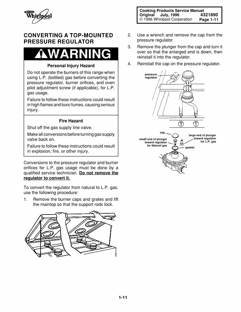
CONVERTING A TOP-MOUNTEDPRESSURE REGULATOR
Conversions to the pressure regulator and burnerorifices for L.P. gas usage must be done by aqualified service technician. Do not remove theregulator to convert it.
To convert the regulator from natural to L.P. gas,use the following procedure:
1. Remove the burner caps and grates and liftthe maintop so that the support rods lock.
2. Use a wrench and remove the cap from thepressure regulator.
3. Remove the plunger from the cap and turn itover so that the enlarged end is down, thenreinstall it into the regulator.
4. Reinstall the cap on the pressure regulator.
gasket
pressureregulator
caplarge end of plunger
toward regulatorfor L.P. gas
small end of plungertoward regulator
for Natural gas
1-12
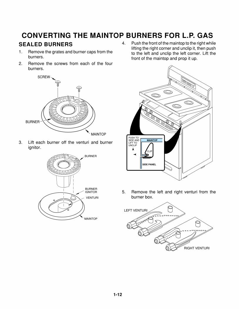
CONVERTING THE MAINTOP BURNERS FOR L.P. GASSEALED BURNERS1. Remove the grates and burner caps from the
burners.
2. Remove the screws from each of the fourburners.
4. Push the front of the maintop to the right whilelifting the right corner and unclip it, then pushto the left and unclip the left corner. Lift thefront of the maintop and prop it up.
PUSH TOSIDE ANDLIFT TOUNCLIP
CLIP
MAINTOP
SIDE PANEL
LEFT VENTURI
RIGHT VENTURI
5. Remove the left and right venturi from theburner box.
SCREW
MAINTOP
BURNER
3. Lift each burner off the venturi and burnerignitor.
VENTURI
MAINTOP
BURNER
BURNERIGNITOR
Page 1-13
1-13
Cooking Products Service ManualOriginal July, 1996 4321890© 1996 Whirlpool Corporation
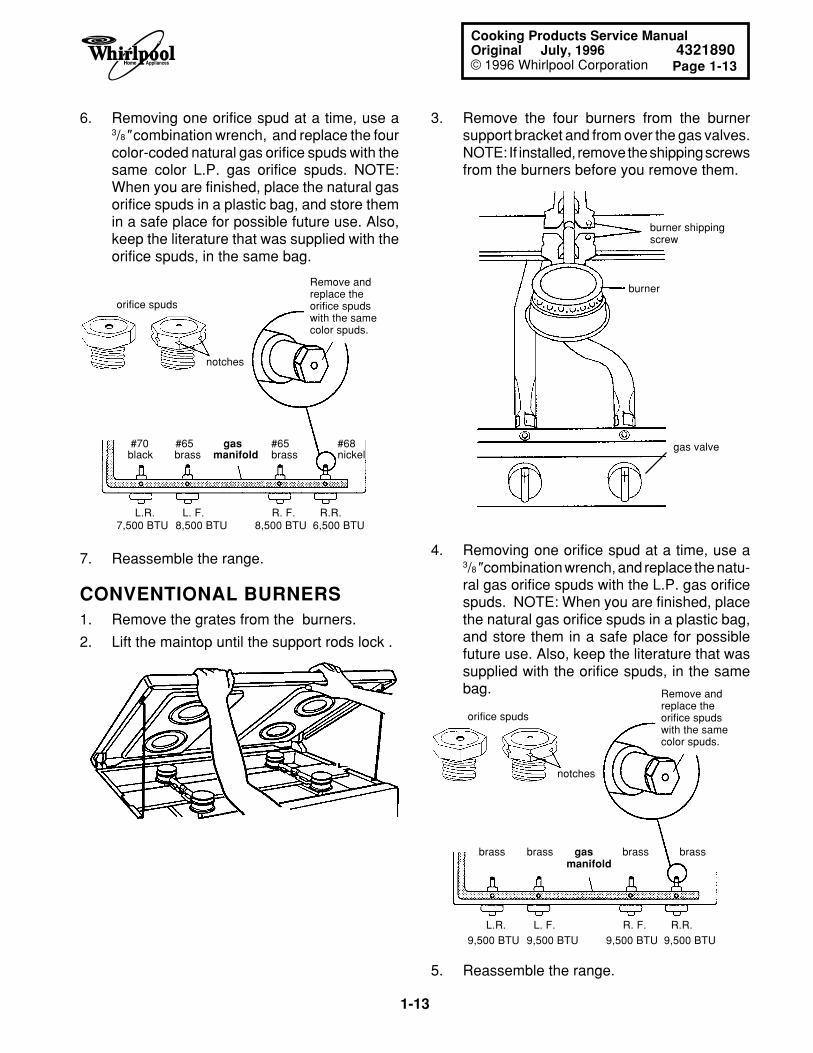
3. Remove the four burners from the burnersupport bracket and from over the gas valves.NOTE: If installed, remove the shipping screwsfrom the burners before you remove them.
6. Removing one orifice spud at a time, use a3/8" combination wrench, and replace the fourcolor-coded natural gas orifice spuds with thesame color L.P. gas orifice spuds. NOTE:When you are finished, place the natural gasorifice spuds in a plastic bag, and store themin a safe place for possible future use. Also,keep the literature that was supplied with theorifice spuds, in the same bag.
orifice spuds
notches
Remove andreplace theorifice spudswith the samecolor spuds.
7. Reassemble the range.
CONVENTIONAL BURNERS1. Remove the grates from the burners.
2. Lift the maintop until the support rods lock .
burner
burner shipping screw
orifice spuds
notches
Remove andreplace theorifice spudswith the samecolor spuds.
5. Reassemble the range.
gas valve
L.R. L. F. R. F. R.R. 7,500 BTU 8,500 BTU 8,500 BTU 6,500 BTU
#70 #65 gas #65 #68black brass manifold brass nickel
4. Removing one orifice spud at a time, use a3/8" combination wrench, and replace the natu-ral gas orifice spuds with the L.P. gas orificespuds. NOTE: When you are finished, placethe natural gas orifice spuds in a plastic bag,and store them in a safe place for possiblefuture use. Also, keep the literature that wassupplied with the orifice spuds, in the samebag.
brass brass gas brass brass manifold
L.R. L. F. R. F. R.R. 9,500 BTU 9,500 BTU 9,500 BTU 9,500 BTU
1-14
CHECKING THE MAINTOP BURNER OPERATIONStanding Pilot Models
1. If not already done, turn on the gas andelectrical supplies to the range.
2. Lift the maintop until the support rods lock.
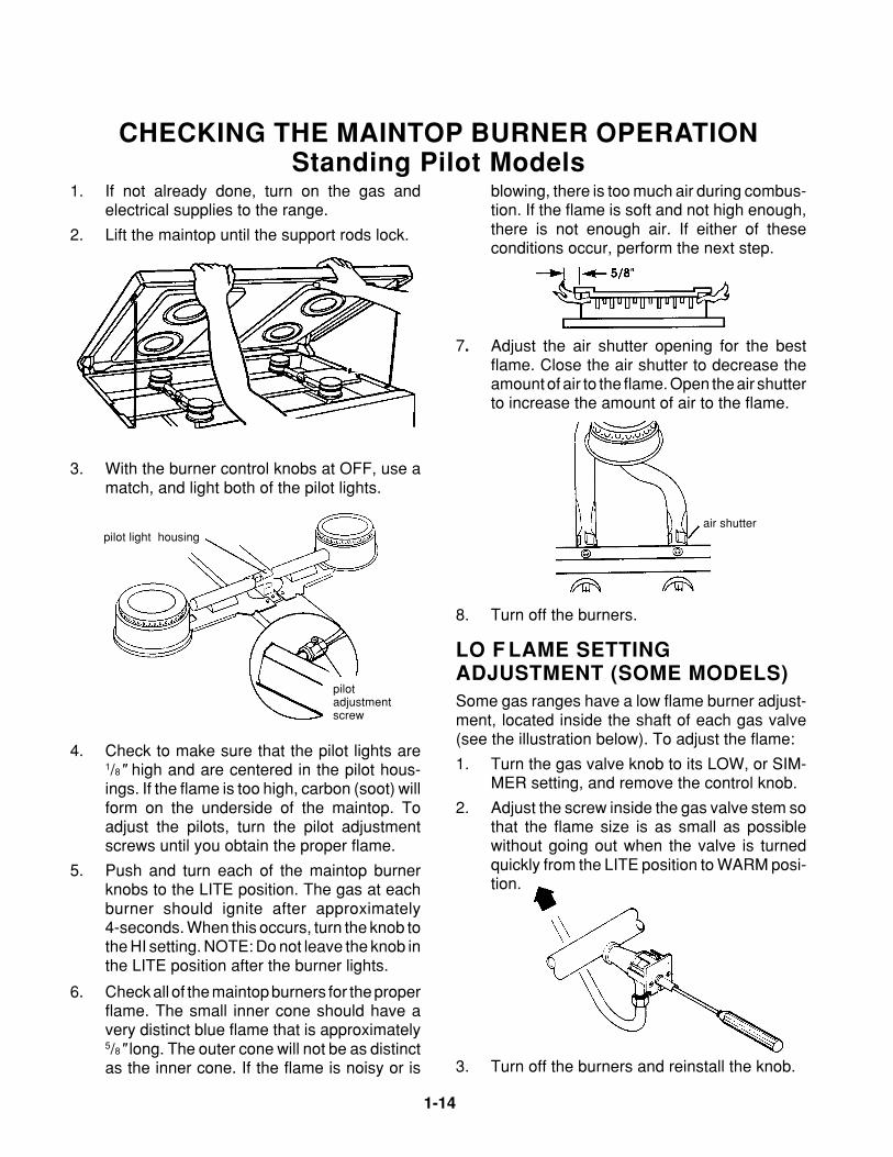
3. With the burner control knobs at OFF, use amatch, and light both of the pilot lights.
pilot light housing
pilotadjustmentscrew
4. Check to make sure that the pilot lights are1/8" high and are centered in the pilot hous-ings. If the flame is too high, carbon (soot) willform on the underside of the maintop. Toadjust the pilots, turn the pilot adjustmentscrews until you obtain the proper flame.
5. Push and turn each of the maintop burnerknobs to the LITE position. The gas at eachburner should ignite after approximately4-seconds. When this occurs, turn the knob tothe HI setting. NOTE: Do not leave the knob inthe LITE position after the burner lights.
blowing, there is too much air during combus-tion. If the flame is soft and not high enough,there is not enough air. If either of theseconditions occur, perform the next step.
6. Check all of the maintop burners for the properflame. The small inner cone should have avery distinct blue flame that is approximately5/8" long. The outer cone will not be as distinctas the inner cone. If the flame is noisy or is
7. Adjust the air shutter opening for the bestflame. Close the air shutter to decrease theamount of air to the flame. Open the air shutterto increase the amount of air to the flame.
3. Turn off the burners and reinstall the knob.
air shutter
8. Turn off the burners.
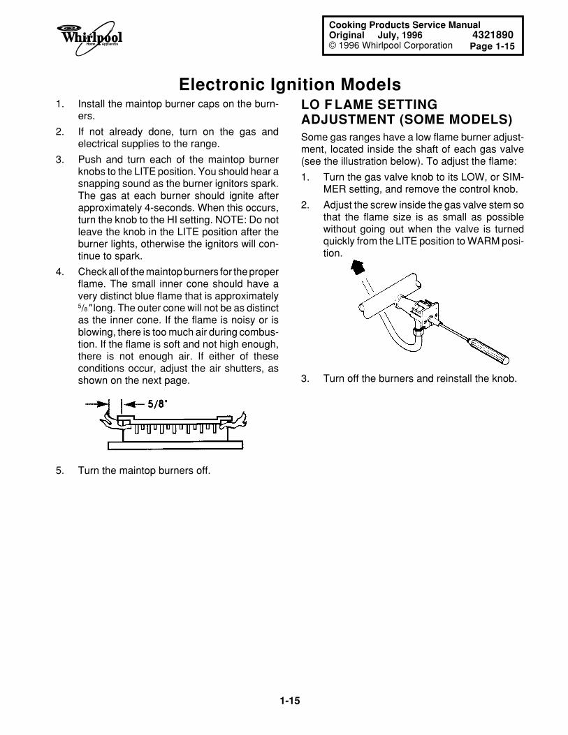
LO F LAME SETTINGADJUSTMENT (SOME MODELS)Some gas ranges have a low flame burner adjust-ment, located inside the shaft of each gas valve(see the illustration below). To adjust the flame:
1. Turn the gas valve knob to its LOW, or SIM-MER setting, and remove the control knob.
2. Adjust the screw inside the gas valve stem sothat the flame size is as small as possiblewithout going out when the valve is turnedquickly from the LITE position to WARM posi-tion.
Page 1-15
1-15
Cooking Products Service ManualOriginal July, 1996 4321890© 1996 Whirlpool Corporation
Electronic Ignition ModelsLO F LAME SETTINGADJUSTMENT (SOME MODELS)Some gas ranges have a low flame burner adjust-ment, located inside the shaft of each gas valve(see the illustration below). To adjust the flame:
1. Turn the gas valve knob to its LOW, or SIM-MER setting, and remove the control knob.
2. Adjust the screw inside the gas valve stem sothat the flame size is as small as possiblewithout going out when the valve is turnedquickly from the LITE position to WARM posi-tion.
1. Install the maintop burner caps on the burn-ers.
2. If not already done, turn on the gas andelectrical supplies to the range.
3. Push and turn each of the maintop burnerknobs to the LITE position. You should hear asnapping sound as the burner ignitors spark.The gas at each burner should ignite afterapproximately 4-seconds. When this occurs,turn the knob to the HI setting. NOTE: Do notleave the knob in the LITE position after theburner lights, otherwise the ignitors will con-tinue to spark.
4. Check all of the maintop burners for the properflame. The small inner cone should have avery distinct blue flame that is approximately5/8" long. The outer cone will not be as distinctas the inner cone. If the flame is noisy or isblowing, there is too much air during combus-tion. If the flame is soft and not high enough,there is not enough air. If either of theseconditions occur, adjust the air shutters, asshown on the next page.
5. Turn the maintop burners off.
3. Turn off the burners and reinstall the knob.
1-16
Adjusting The Air ShuttersSEALED BURNERS1. Lift the maintop and prop it up (see page 1-12
for the procedure).
2. Remove the control knobs.
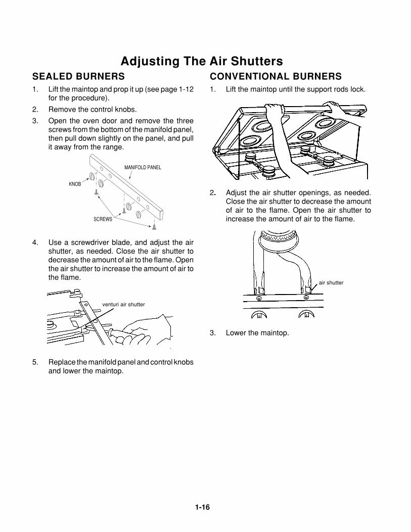
3. Open the oven door and remove the threescrews from the bottom of the manifold panel,then pull down slightly on the panel, and pullit away from the range.
CONVENTIONAL BURNERS1. Lift the maintop until the support rods lock.
2. Adjust the air shutter openings, as needed.Close the air shutter to decrease the amountof air to the flame. Open the air shutter toincrease the amount of air to the flame.
air shutter
3. Lower the maintop.
MANIFOLD PANEL
KNOB
SCREWS
4. Use a screwdriver blade, and adjust the airshutter, as needed. Close the air shutter todecrease the amount of air to the flame. Openthe air shutter to increase the amount of air tothe flame.
venturi air shutter
5. Replace the manifold panel and control knobsand lower the maintop.
Page 1-17
1-17
Cooking Products Service ManualOriginal July, 1996 4321890© 1996 Whirlpool Corporation
CONVERTING THE OVEN BURNER FOR L.P. GASStanding Pilot Models
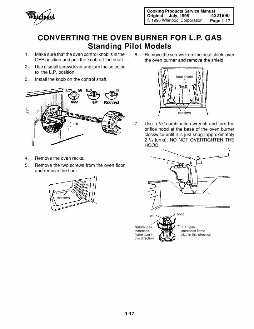
1. Make sure that the oven control knob is in theOFF position and pull the knob off the shaft.
2. Use a small screwdriver and turn the selectorto the L.P. position.
3. Install the knob on the control shaft.
screws
4. Remove the oven racks.
5. Remove the two screws from the oven floorand remove the floor.
6. Remove the screws from the heat shield overthe oven burner and remove the shield.
screws
heat shield
pin hood
Natural gas L.P. gasincreases increases flameflame size in size in this directionthis direction
7. Use a 1/2" combination wrench and turn theorifice hood at the base of the oven burnerclockwise until it is just snug (approximately2-1/2 turns). NO NOT OVERTIGHTEN THEHOOD.
1-18
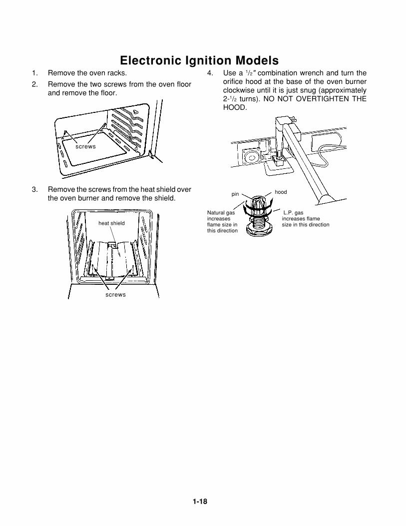
Electronic Ignition Models4. Use a 1/2" combination wrench and turn the
orifice hood at the base of the oven burnerclockwise until it is just snug (approximately2-1/2 turns). NO NOT OVERTIGHTEN THEHOOD.
1. Remove the oven racks.
2. Remove the two screws from the oven floorand remove the floor.
pin hood
Natural gas L.P. gasincreases increases flameflame size in size in this directionthis direction
screws
3. Remove the screws from the heat shield overthe oven burner and remove the shield.
screws
heat shield
Page 1-19
1-19
Cooking Products Service ManualOriginal July, 1996 4321890© 1996 Whirlpool Corporation
CHECKING THE OVEN BURNER OPERATIONStanding Pilot Models
THE BAKE/BROIL BURNERNOTE: The oven burner is used for both bake andbroil functions.
1. Open the broiler door so that you can accessthe oven burner.
2. Hold a match flame against the opening in thetop of the pilot area at the rear of the ovenburner until the pilot lights. (NOTE: There areno adjustments for this pilot light.)
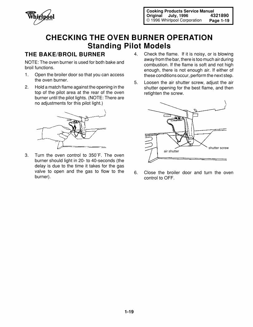
4. Check the flame. If it is noisy, or is blowingaway from the bar, there is too much air duringcombustion. If the flame is soft and not highenough, there is not enough air. If either ofthese conditions occur, perform the next step.
5. Loosen the air shutter screw, adjust the airshutter opening for the best flame, and thenretighten the screw.
air shuttershutter screw
6. Close the broiler door and turn the ovencontrol to OFF.
3. Turn the oven control to 350˚F. The ovenburner should light in 20- to 40-seconds (thedelay is due to the time it takes for the gasvalve to open and the gas to flow to theburner).
1-20
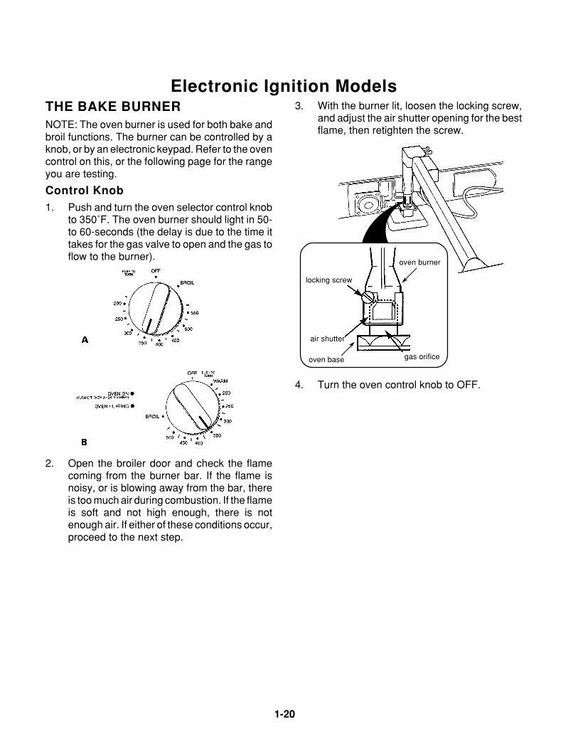
Electronic Ignition Models3. With the burner lit, loosen the locking screw,
and adjust the air shutter opening for the bestflame, then retighten the screw.
THE BAKE BURNERNOTE: The oven burner is used for both bake andbroil functions. The burner can be controlled by aknob, or by an electronic keypad. Refer to the ovencontrol on this, or the following page for the rangeyou are testing.
Control Knob1. Push and turn the oven selector control knob
to 350˚F. The oven burner should light in 50-to 60-seconds (the delay is due to the time ittakes for the gas valve to open and the gas toflow to the burner).
air shutter
gas orifice
locking screw
oven base
oven burner
4. Turn the oven control knob to OFF.
2. Open the broiler door and check the flamecoming from the burner bar. If the flame isnoisy, or is blowing away from the bar, thereis too much air during combustion. If the flameis soft and not high enough, there is notenough air. If either of these conditions occur,proceed to the next step.
Page 1-21
1-21
Cooking Products Service ManualOriginal July, 1996 4321890© 1996 Whirlpool Corporation
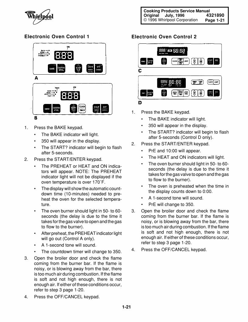
Electronic Oven Control 1 Electronic Oven Control 2
1. Press the BAKE keypad.
• The BAKE indicator will light.
• 350 will appear in the display.
• The START? indicator will begin to flashafter 5-seconds.
2. Press the START/ENTER keypad.
• The PREHEAT or HEAT and ON indica-tors will appear. NOTE: The PREHEATindicator light will not be displayed if theoven temperature is over 170˚F.
• The display will show the automatic count-down time (10-minutes) needed to pre-heat the oven for the selected tempera-ture.
• The oven burner should light in 50- to 60-seconds (the delay is due to the time ittakes for the gas valve to open and the gasto flow to the burner).
• After preheat, the PREHEAT indicator lightwill go out (Control A only).
• A 1-second tone will sound.
• The countdown timer will change to 350.
3. Open the broiler door and check the flamecoming from the burner bar. If the flame isnoisy, or is blowing away from the bar, thereis too much air during combustion. If the flameis soft and not high enough, there is notenough air. If either of these conditions occur,refer to step 3 page 1-20.
4. Press the OFF/CANCEL keypad.
1. Press the BAKE keypad.
• The BAKE indicator will light.
• 350 will appear in the display.
• The START? indicator will begin to flashafter 5-seconds (Control D only).
2. Press the START/ENTER keypad.
• PrE and 10:00 will appear.
• The HEAT and ON indicators will light.
• The oven burner should light in 50- to 60-seconds (the delay is due to the time ittakes for the gas valve to open and the gasto flow to the burner).
• The oven is preheated when the time inthe display counts down to 0:00.
• A 1-second tone will sound.
• PrE will change to 350.
3. Open the broiler door and check the flamecoming from the burner bar. If the flame isnoisy, or is blowing away from the bar, thereis too much air during combustion. If the flameis soft and not high enough, there is notenough air. If either of these conditions occur,refer to step 3 page 1-20.
4. Press the OFF/CANCEL keypad.
1-22
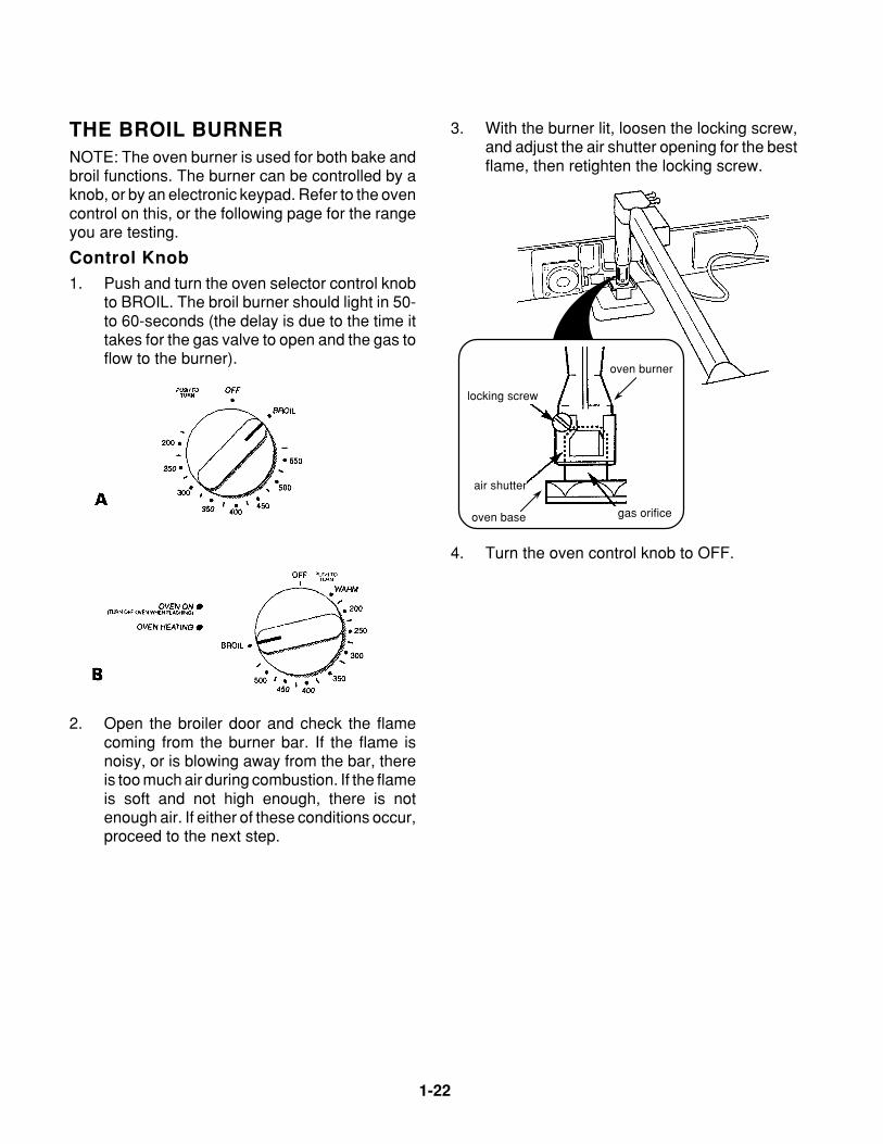
THE BROIL BURNERNOTE: The oven burner is used for both bake andbroil functions. The burner can be controlled by aknob, or by an electronic keypad. Refer to the ovencontrol on this, or the following page for the rangeyou are testing.
Control Knob1. Push and turn the oven selector control knob
to BROIL. The broil burner should light in 50-to 60-seconds (the delay is due to the time ittakes for the gas valve to open and the gas toflow to the burner).
3. With the burner lit, loosen the locking screw,and adjust the air shutter opening for the bestflame, then retighten the locking screw.
air shutter
gas orifice
locking screw
oven base
oven burner
4. Turn the oven control knob to OFF.
2. Open the broiler door and check the flamecoming from the burner bar. If the flame isnoisy, or is blowing away from the bar, thereis too much air during combustion. If the flameis soft and not high enough, there is notenough air. If either of these conditions occur,proceed to the next step.
Page 1-23
1-23
Cooking Products Service ManualOriginal July, 1996 4321890© 1996 Whirlpool Corporation
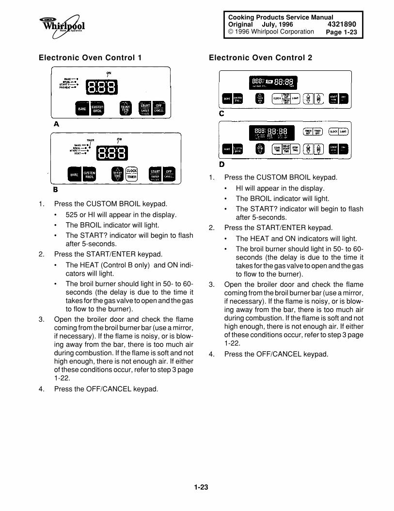
Electronic Oven Control 2Electronic Oven Control 1
1. Press the CUSTOM BROIL keypad.
• 525 or HI will appear in the display.
• The BROIL indicator will light.
• The START? indicator will begin to flashafter 5-seconds.
2. Press the START/ENTER keypad.
• The HEAT (Control B only) and ON indi-cators will light.
• The broil burner should light in 50- to 60-seconds (the delay is due to the time ittakes for the gas valve to open and the gasto flow to the burner).
3. Open the broiler door and check the flamecoming from the broil burner bar (use a mirror,if necessary). If the flame is noisy, or is blow-ing away from the bar, there is too much airduring combustion. If the flame is soft and nothigh enough, there is not enough air. If eitherof these conditions occur, refer to step 3 page1-22.
4. Press the OFF/CANCEL keypad.
1. Press the CUSTOM BROIL keypad.
• HI will appear in the display.
• The BROIL indicator will light.
• The START? indicator will begin to flashafter 5-seconds.
2. Press the START/ENTER keypad.
• The HEAT and ON indicators will light.
• The broil burner should light in 50- to 60-seconds (the delay is due to the time ittakes for the gas valve to open and the gasto flow to the burner).
3. Open the broiler door and check the flamecoming from the broil burner bar (use a mirror,if necessary). If the flame is noisy, or is blow-ing away from the bar, there is too much airduring combustion. If the flame is soft and nothigh enough, there is not enough air. If eitherof these conditions occur, refer to step 3 page1-22.
4. Press the OFF/CANCEL keypad.
1-24
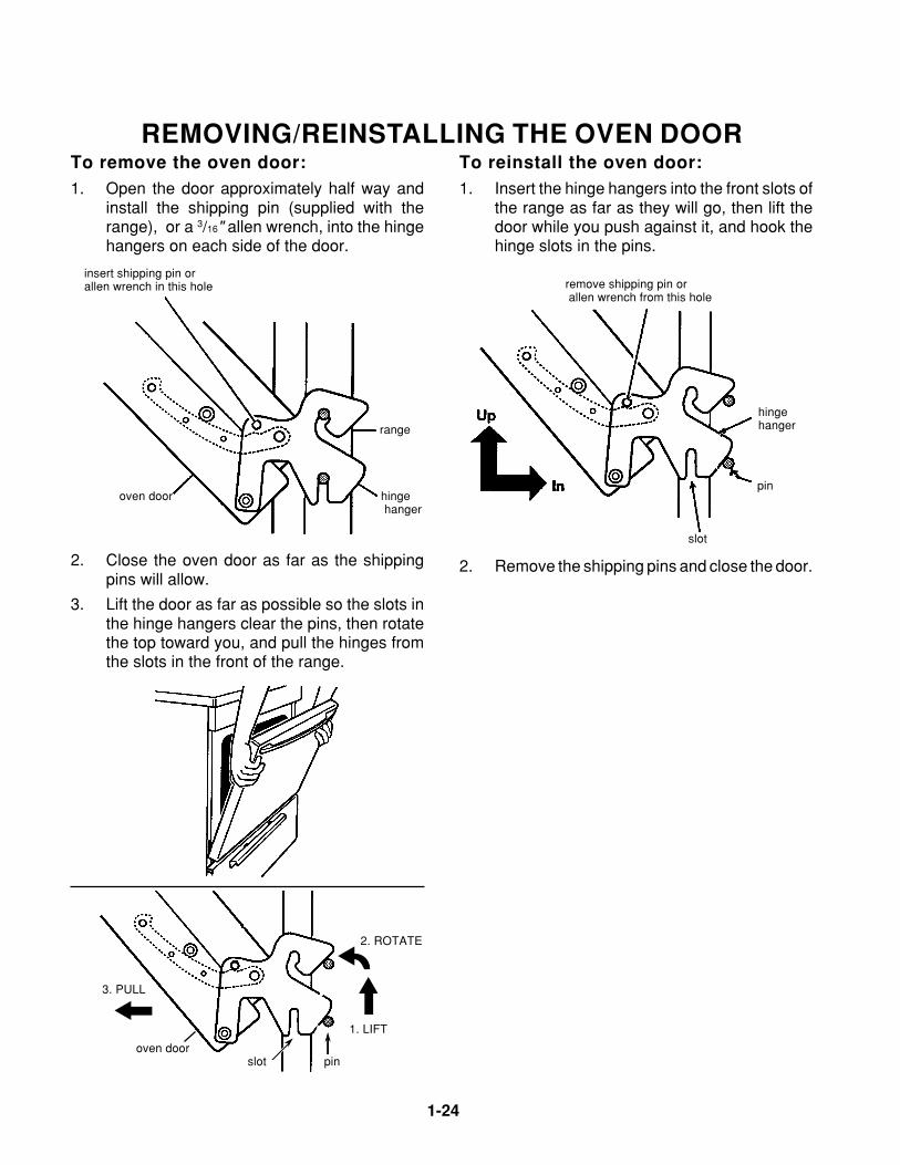
REMOVING/REINSTALLING THE OVEN DOOR
insert shipping pin or allen wrench in this hole
To remove the oven door:1. Open the door approximately half way and
install the shipping pin (supplied with therange), or a 3/16" allen wrench, into the hingehangers on each side of the door.
range
oven door hinge hanger
To reinstall the oven door:1. Insert the hinge hangers into the front slots of
the range as far as they will go, then lift thedoor while you push against it, and hook thehinge slots in the pins.
remove shipping pin or allen wrench from this hole
pin
2. Remove the shipping pins and close the door.
hinge hanger
slot
2. Close the oven door as far as the shippingpins will allow.
3. Lift the door as far as possible so the slots inthe hinge hangers clear the pins, then rotatethe top toward you, and pull the hinges fromthe slots in the front of the range.
3. PULL
oven door slot pin
2. ROTATE
1. LIFT
Page 2-1
2-1
Cooking Products Service ManualOriginal July, 1996 4321890© 1996 Whirlpool Corporation
THEORY OF OPERATIONTHE COOKTOP BURNERS
WITH ELECTRONIC IGNITION
PRESSURE REGULATOR
GAS INLET
IGNITORMODULE
VENTURI
GAS VALVE
IGNITOR SWITCH
BURNER CONTROL
KNOB
GAS MANIFOLD
BURNERIGNITOR
BURNER CAP
TO BURNERIGNITOR
SPARK
BURNER
BURNER FLAME
GAS FLOW
120 VACLINE VOLTAGE
GAS FLOW
HIGH VOLTAGEPULSES
OFF LITE
4
7
9
8
10
2 56
1
3
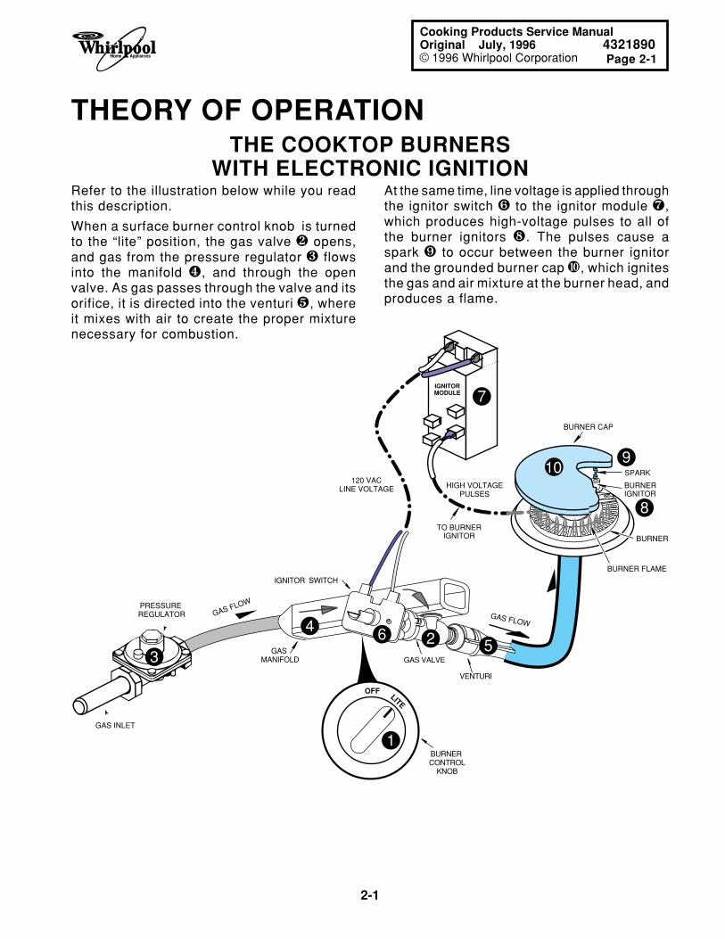
Refer to the illustration below while you readthis description.
When a surface burner control knob is turnedto the “lite” position, the gas valve r opens,and gas from the pressure regulator s flowsinto the manifold t, and through the openvalve. As gas passes through the valve and itsorifice, it is directed into the venturi u, whereit mixes with air to create the proper mixturenecessary for combustion.
At the same time, line voltage is applied throughthe ignitor switch v to the ignitor module w,which produces high-voltage pulses to all ofthe burner ignitors x. The pulses cause aspark y to occur between the burner ignitorand the grounded burner cap z, which ignitesthe gas and air mixture at the burner head, andproduces a flame.
2-2
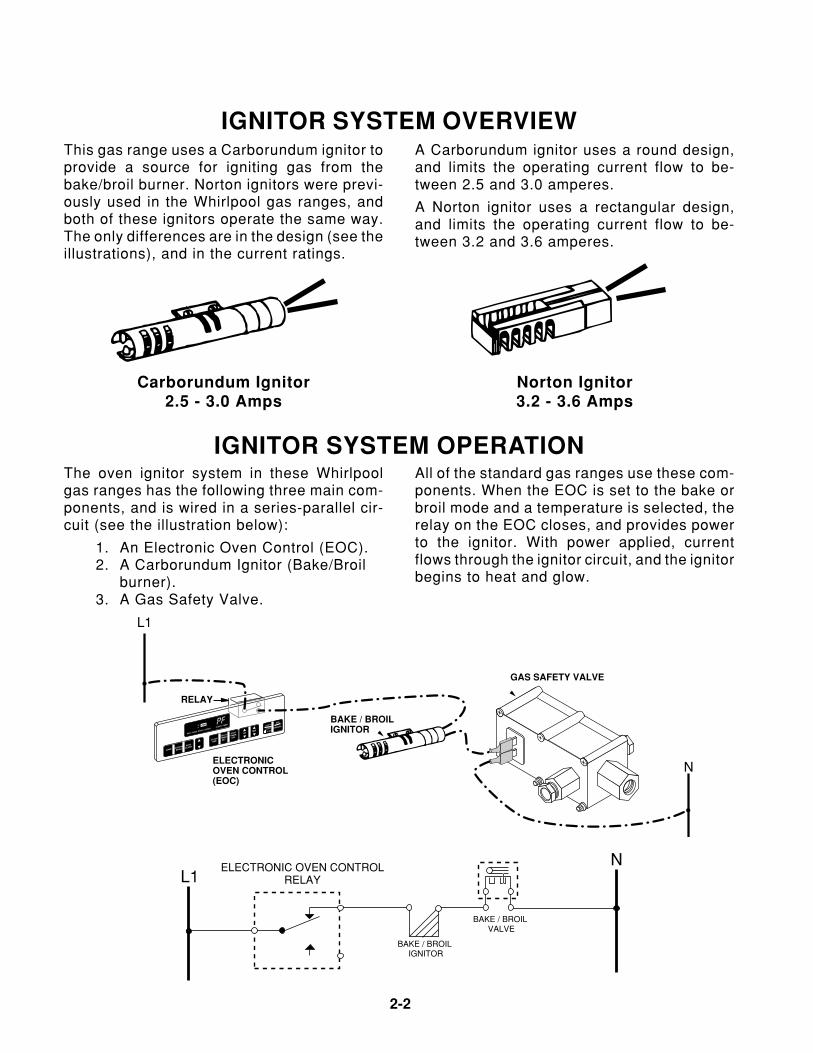
IGNITOR SYSTEM OVERVIEWA Carborundum ignitor uses a round design,and limits the operating current flow to be-tween 2.5 and 3.0 amperes.
A Norton ignitor uses a rectangular design,and limits the operating current flow to be-tween 3.2 and 3.6 amperes.
This gas range uses a Carborundum ignitor toprovide a source for igniting gas from thebake/broil burner. Norton ignitors were previ-ously used in the Whirlpool gas ranges, andboth of these ignitors operate the same way.The only differences are in the design (see theillustrations), and in the current ratings.
Norton Ignitor3.2 - 3.6 Amps
Carborundum Ignitor2.5 - 3.0 Amps
The oven ignitor system in these Whirlpoolgas ranges has the following three main com-ponents, and is wired in a series-parallel cir-cuit (see the illustration below):
1. An Electronic Oven Control (EOC).2. A Carborundum Ignitor (Bake/Broil
burner).3. A Gas Safety Valve.
All of the standard gas ranges use these com-ponents. When the EOC is set to the bake orbroil mode and a temperature is selected, therelay on the EOC closes, and provides powerto the ignitor. With power applied, currentflows through the ignitor circuit, and the ignitorbegins to heat and glow.
IGNITOR SYSTEM OPERATION
L1N
BAKE / BROIL VALVE
BAKE / BROIL IGNITOR
ELECTRONIC OVEN CONTROLRELAY
BAKE
HRMIN
CUSTOM
BROIL
AUTO
CLEAN
CLOCK
TIME
DELAY
TIMER
SET
STOP
TIMER
OFF
OFF
CANCELSTART
ENTER
5 SEC
HEAT BAKE BROIL LOCKED CLEAN TIMERO
FON PF
ELECTRONICOVEN CONTROL(EOC)
L1
N
RELAY
GAS SAFETY VALVE
BAKE / BROILIGNITOR
Page 2-3
2-3
Cooking Products Service ManualOriginal July, 1996 4321890© 1996 Whirlpool Corporation
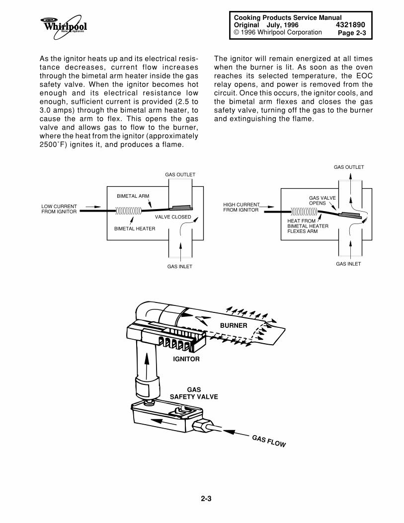
As the ignitor heats up and its electrical resis-tance decreases, current f low increasesthrough the bimetal arm heater inside the gassafety valve. When the ignitor becomes hotenough and its electrical resistance lowenough, sufficient current is provided (2.5 to3.0 amps) through the bimetal arm heater, tocause the arm to flex. This opens the gasvalve and allows gas to flow to the burner,where the heat from the ignitor (approximately2500˚F) ignites it, and produces a flame.
The ignitor will remain energized at all timeswhen the burner is lit. As soon as the ovenreaches its selected temperature, the EOCrelay opens, and power is removed from thecircuit. Once this occurs, the ignitor cools, andthe bimetal arm flexes and closes the gassafety valve, turning off the gas to the burnerand extinguishing the flame.
LOW CURRENT FROM IGNITOR
VALVE CLOSED
BIMETAL ARM
BIMETAL HEATER
GAS INLET
HIGH CURRENT FROM IGNITOR
GAS VALVEOPENS
HEAT FROMBIMETAL HEATERFLEXES ARM
GAS OUTLET
GAS INLET
GAS OUTLET
IGNITOR
BURNER
GASSAFETY VALVE
GAS FLOW
2-4
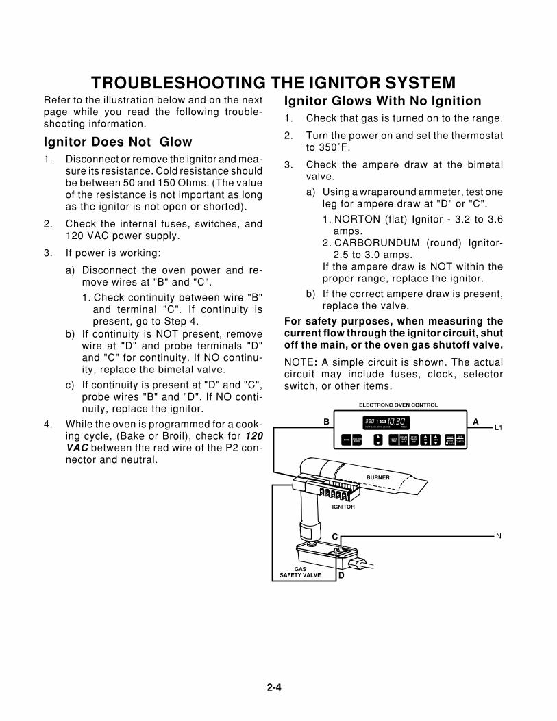
Refer to the illustration below and on the nextpage while you read the following trouble-shooting information.
Ignitor Does Not Glow1. Disconnect or remove the ignitor and mea-
sure its resistance. Cold resistance shouldbe between 50 and 150 Ohms. (The valueof the resistance is not important as longas the ignitor is not open or shorted).
2. Check the internal fuses, switches, and120 VAC power supply.
3. If power is working:
a) Disconnect the oven power and re-move wires at "B" and "C".
1. Check continuity between wire "B"and terminal "C". If continuity ispresent, go to Step 4.
b) If continuity is NOT present, removewire at "D" and probe terminals "D"and "C" for continuity. If NO continu-ity, replace the bimetal valve.
c) If continuity is present at "D" and "C",probe wires "B" and "D". If NO conti-nuity, replace the ignitor.
4. While the oven is programmed for a cook-ing cycle, (Bake or Broil), check for 120VAC between the red wire of the P2 con-nector and neutral.
TROUBLESHOOTING THE IGNITOR SYSTEMIgnitor Glows With No Ignition1. Check that gas is turned on to the range.
2. Turn the power on and set the thermostatto 350˚F.
3. Check the ampere draw at the bimetalvalve.
a) Using a wraparound ammeter, test oneleg for ampere draw at "D" or "C".
1. NORTON (flat) Ignitor - 3.2 to 3.6amps.
2. CARBORUNDUM (round) Ignitor-2.5 to 3.0 amps.
If the ampere draw is NOT within theproper range, replace the ignitor.
b) If the correct ampere draw is present,replace the valve.
For safety purposes, when measuring thecurrent flow through the ignitor circuit, shutoff the main, or the oven gas shutoff valve.
NOTE: A simple circuit is shown. The actualcircuit may include fuses, clock, selectorswitch, or other items.
L1
N
ELECTRONC OVEN CONTROL
IGNITOR
BURNER
GASSAFETY VALVE
BAKE HR MINCUSTOMBROIL
CLOCKTIME
DELAYTIMER
SET
STOPTIMEROFF
OFF
CANCEL
START
ENTER
5 SEC
HEAT BAKE BROIL LOCKED TIMER
OF
ON350 10:30 AB
C
D
Page 2-5
2-5
Cooking Products Service ManualOriginal July, 1996 4321890© 1996 Whirlpool Corporation
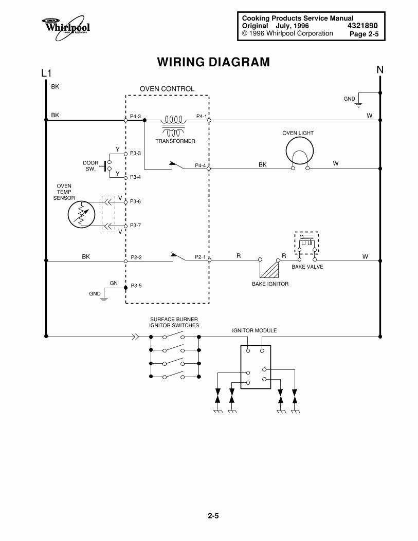
WIRING DIAGRAML1 N
BK
BK
V
V
R R
W
W
W
BK
Y
Y
BK
OVENTEMP
SENSOR
SURFACE BURNERIGNITOR SWITCHES
IGNITOR MODULE
DOORSW.
OVEN CONTROL
TRANSFORMER
P3-6
P3-7
P3-3
P4-3 P4-1
P3-4
P2-2
P3-5
P2-1
P4-4
BAKE VALVE
BAKE IGNITOR
OVEN LIGHT
GND
GND
GN
2-6
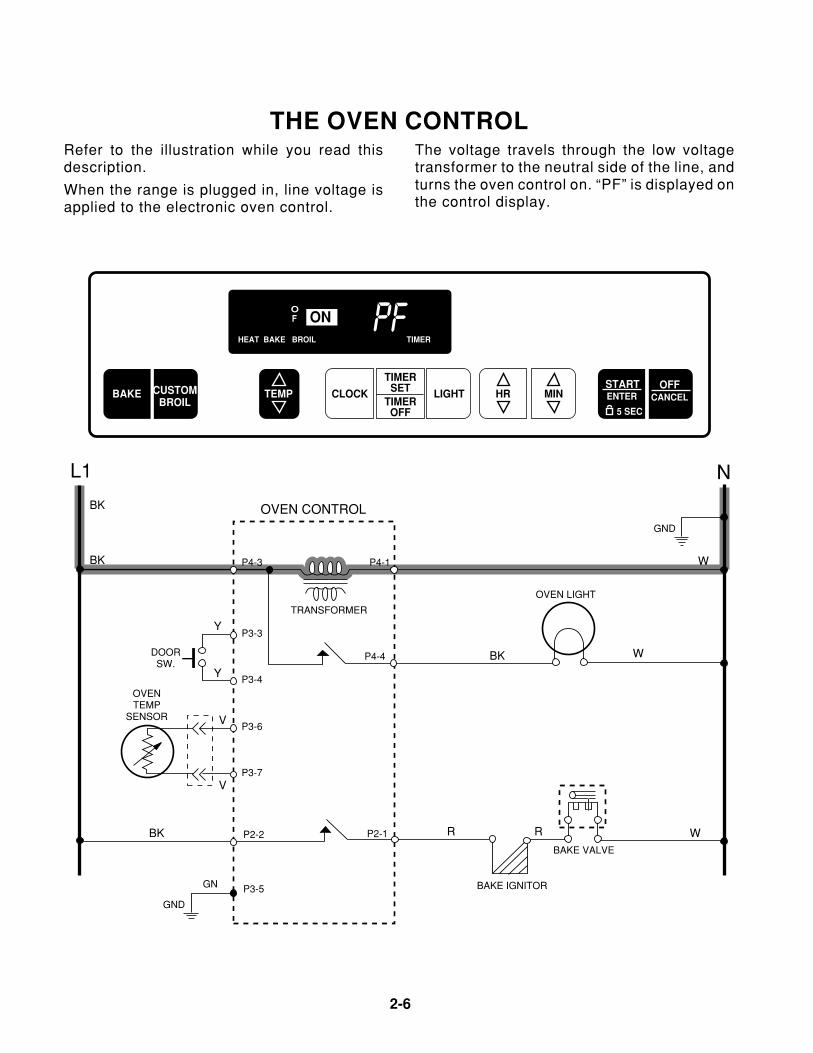
THE OVEN CONTROLRefer to the illustration while you read thisdescription.
When the range is plugged in, line voltage isapplied to the electronic oven control.
The voltage travels through the low voltagetransformer to the neutral side of the line, andturns the oven control on. “PF” is displayed onthe control display.
L1 N
BK
BK
V
V
R R
W
W
W
BK
Y
Y
BK
OVENTEMP
SENSOR
DOORSW.
OVEN CONTROL
TRANSFORMER
P3-6
P3-7
P3-3
P4-3 P4-1
P3-4
P2-2
P3-5
P2-1
P4-4
BAKE VALVE
BAKE IGNITOR
OVEN LIGHT
GND
GND
GN
PFOF
HEAT BAKE BROIL TIMER
ON
BAKESTART
TEMPCUSTOMBROIL
OFFCANCELCLOCK LIGHT
TIMERSET
TIMEROFF
HR MIN ENTER
5 SEC
Page 2-7
2-7
Cooking Products Service ManualOriginal July, 1996 4321890© 1996 Whirlpool Corporation
350 10 30OF
HEAT BAKE BROIL TIMER
ON
BAKESTART
TEMPCUSTOMBROIL
OFFCANCELCLOCK LIGHT
TIMERSET
TIMEROFF
HR MIN ENTER
5 SEC
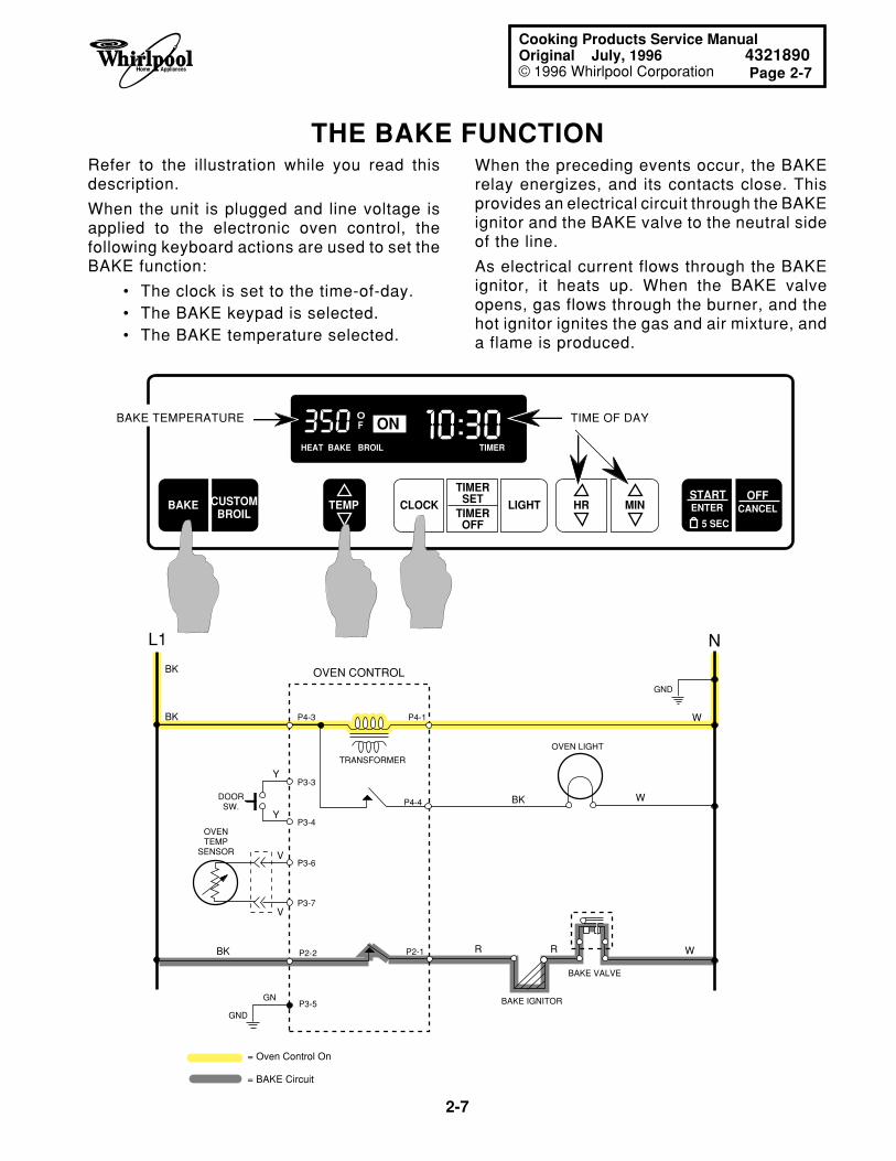
Refer to the illustration while you read thisdescription.
When the unit is plugged and line voltage isapplied to the electronic oven control, thefollowing keyboard actions are used to set theBAKE function:
• The clock is set to the time-of-day.• The BAKE keypad is selected.• The BAKE temperature selected.
When the preceding events occur, the BAKErelay energizes, and its contacts close. Thisprovides an electrical circuit through the BAKEignitor and the BAKE valve to the neutral sideof the line.
As electrical current flows through the BAKEignitor, it heats up. When the BAKE valveopens, gas flows through the burner, and thehot ignitor ignites the gas and air mixture, anda flame is produced.
THE BAKE FUNCTION
BAKE TEMPERATURE TIME OF DAY
L1 N
BK
BK
V
V
R R
W
W
W
BK
Y
Y
BK
OVENTEMP
SENSOR
DOORSW.
OVEN CONTROL
TRANSFORMER
OVEN LIGHT
GND
GND
GN
= Oven Control On
= BAKE Circuit
P3-6
P3-7
P3-3
P4-3 P4-1
P3-4
P2-2
P3-5
P2-1
P4-4
BAKE VALVE
BAKE IGNITOR
2-8
HI 10 30OF
HEAT BAKE BROIL TIMER
ON
BAKESTART
TEMPCUSTOMBROIL
OFFCANCELCLOCK LIGHT
TIMERSET
TIMEROFF
HR MIN ENTER
5 SEC
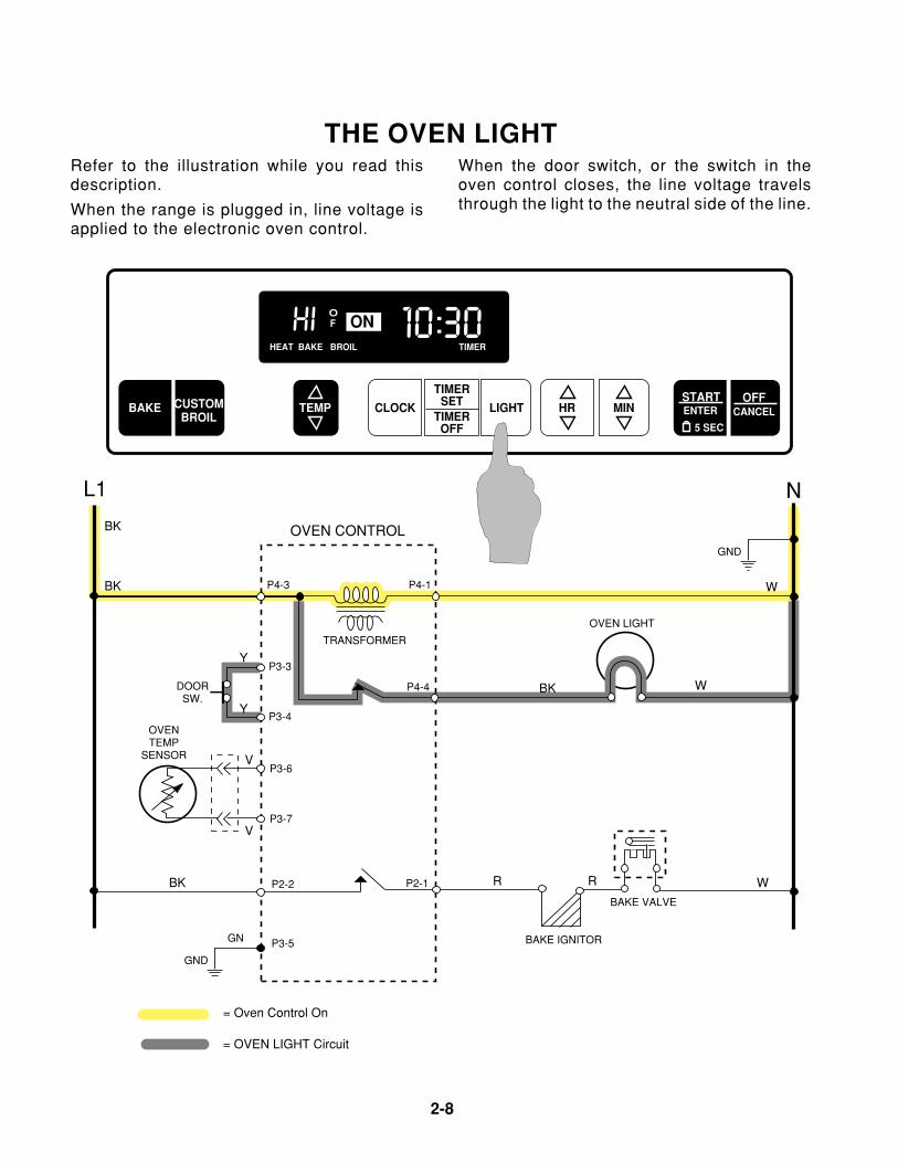
THE OVEN LIGHTRefer to the illustration while you read thisdescription.
When the range is plugged in, line voltage isapplied to the electronic oven control.
When the door switch, or the switch in theoven control closes, the line voltage travelsthrough the light to the neutral side of the line.
L1 N
BK
BK
V
V
R R
W
W
W
BK
Y
Y
BK
OVENTEMP
SENSOR
DOORSW.
OVEN CONTROL
TRANSFORMER
P3-6
P3-7
P3-3
P4-3 P4-1
P3-4
P2-2
P3-5
P2-1
P4-4
BAKE VALVE
BAKE IGNITOR
OVEN LIGHT
GND
GND
GN
= Oven Control On
= OVEN LIGHT Circuit
Page 3-1
3-1
Cooking Products Service ManualOriginal July, 1996 4321890© 1996 Whirlpool Corporation
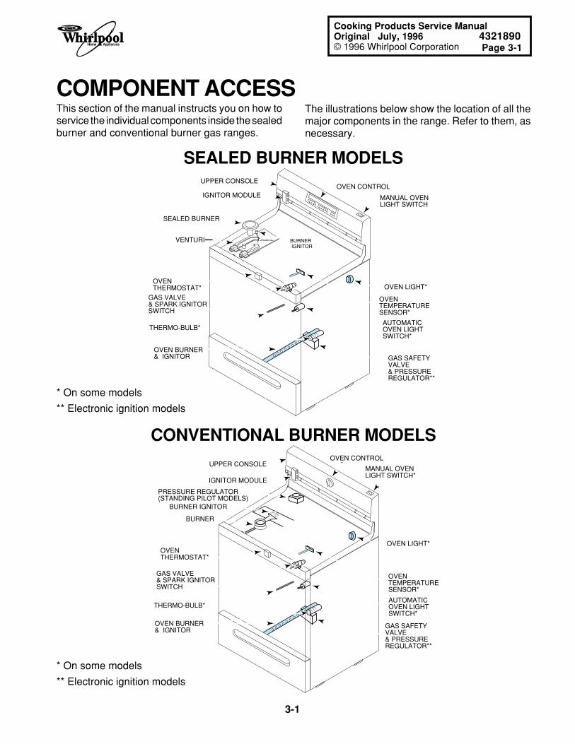
The illustrations below show the location of all themajor components in the range. Refer to them, asnecessary.
COMPONENT ACCESSThis section of the manual instructs you on how toservice the individual components inside the sealedburner and conventional burner gas ranges.
UPPER CONSOLE
OVEN THERMOSTAT*
GAS VALVE & SPARK IGNITORSWITCH
MANUAL OVENLIGHT SWITCH
GAS SAFETYVALVE& PRESSUREREGULATOR**
OVEN TEMPERATURESENSOR*
OVEN LIGHT*
BURNER IGNITOR
OVEN CONTROLIGNITOR MODULE
OVEN BURNER& IGNITOR
THERMO-BULB*
SEALED BURNER
VENTURI
AUTOMATICOVEN LIGHTSWITCH*
SEALED BURNER MODELS
* On some models
** Electronic ignition models
CONVENTIONAL BURNER MODELS
* On some models
** Electronic ignition models
UPPER CONSOLE
BURNER
BURNER IGNITOR
OVEN THERMOSTAT*
GAS VALVE & SPARK IGNITORSWITCH
OVEN TEMPERATURESENSOR*
AUTOMATICOVEN LIGHTSWITCH*
OVEN CONTROL
IGNITOR MODULE
PRESSURE REGULATOR(STANDING PILOT MODELS)
OVEN BURNER& IGNITOR
THERMO-BULB*
GAS SAFETYVALVE& PRESSUREREGULATOR**
MANUAL OVENLIGHT SWITCH*
OVEN LIGHT*
3-2
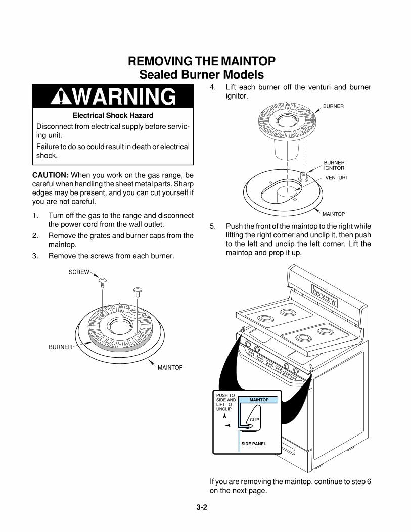
4. Lift each burner off the venturi and burnerignitor.
Electrical Shock Hazard
Disconnect from electrical supply before servic-ing unit.
Failure to do so could result in death or electricalshock.
WARNING
PUSH TOSIDE ANDLIFT TOUNCLIP
CLIP
MAINTOP
SIDE PANEL
VENTURI
MAINTOP
BURNER
BURNERIGNITOR
5. Push the front of the maintop to the right whilelifting the right corner and unclip it, then pushto the left and unclip the left corner. Lift themaintop and prop it up.
If you are removing the maintop, continue to step 6on the next page.
REMOVING THE MAINTOPSealed Burner Models
CAUTION: When you work on the gas range, becareful when handling the sheet metal parts. Sharpedges may be present, and you can cut yourself ifyou are not careful.
SCREW
MAINTOP
BURNER
1. Turn off the gas to the range and disconnectthe power cord from the wall outlet.
2. Remove the grates and burner caps from themaintop.
3. Remove the screws from each burner.
Page 3-3
3-3
Cooking Products Service ManualOriginal July, 1996 4321890© 1996 Whirlpool Corporation
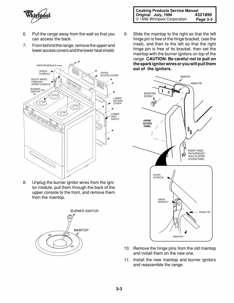
UPPER ACCESS COVER
LOWER ACCESS COVER
LOWER HEAT SHIELD
IGNITOR MODULE
UPPER CONSOLE
BURNERIGNITOR (4)
ROUTE WIRESTHROUGHUPPER CONSOLE
BURNER IGNITOR
MAINTOP
9. Slide the maintop to the right so that the lefthinge pin is free of the hinge bracket, (see theinset), and then to the left so that the righthinge pin is free of its bracket, then set themaintop with the burner ignitors on top of therange. CAUTION: Be careful not to pull onthe spark ignitor wires or you will pull themout of the ignitors.
6. Pull the range away from the wall so that youcan access the back.
7. From behind the range, remove the upper andlower access covers and the lower heat shield.
8. Unplug the burner ignitor wires from the igni-tor module, pull them through the back of theupper console to the front, and remove themfrom the maintop.
HINGE PIN
MOUNTINGSCREW
UPPER ACCESSPANEL
MAINTOP
INSERT HINGEPIN IN BRACKETHOLE IN UPPER ACCESS PANEL
HINGEBRACKET
HINGE PIN
UPPERCONSOLE
MAINTOP
10. Remove the hinge pins from the old maintopand install them on the new one.
11. Install the new maintop and burner ignitorsand reassemble the range.
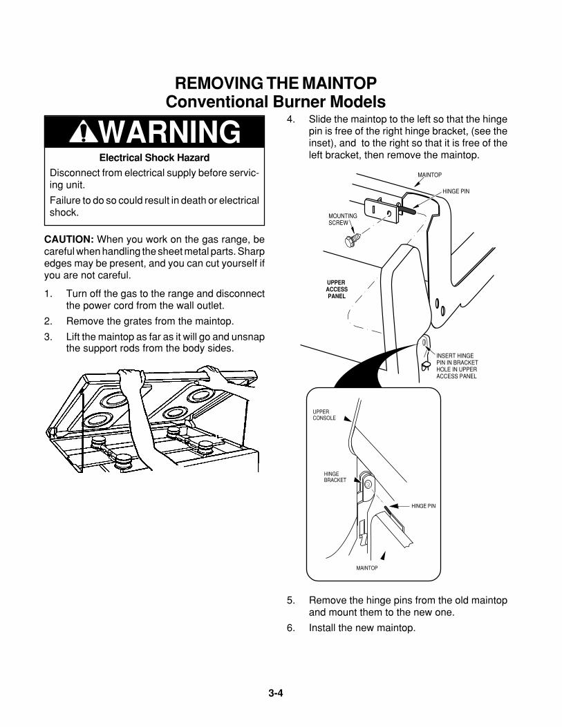
3-4
HINGE PIN
MOUNTINGSCREW
UPPER ACCESSPANEL
MAINTOP
INSERT HINGEPIN IN BRACKETHOLE IN UPPER ACCESS PANEL
WARNING4. Slide the maintop to the left so that the hinge
pin is free of the right hinge bracket, (see theinset), and to the right so that it is free of theleft bracket, then remove the maintop.
5. Remove the hinge pins from the old maintopand mount them to the new one.
6. Install the new maintop.
HINGEBRACKET
HINGE PIN
UPPERCONSOLE
MAINTOP
REMOVING THE MAINTOPConventional Burner Models
Electrical Shock Hazard
Disconnect from electrical supply before servic-ing unit.
Failure to do so could result in death or electricalshock.
CAUTION: When you work on the gas range, becareful when handling the sheet metal parts. Sharpedges may be present, and you can cut yourself ifyou are not careful.
1. Turn off the gas to the range and disconnectthe power cord from the wall outlet.
2. Remove the grates from the maintop.
3. Lift the maintop as far as it will go and unsnapthe support rods from the body sides.
Page 3-5
3-5
Cooking Products Service ManualOriginal July, 1996 4321890© 1996 Whirlpool Corporation
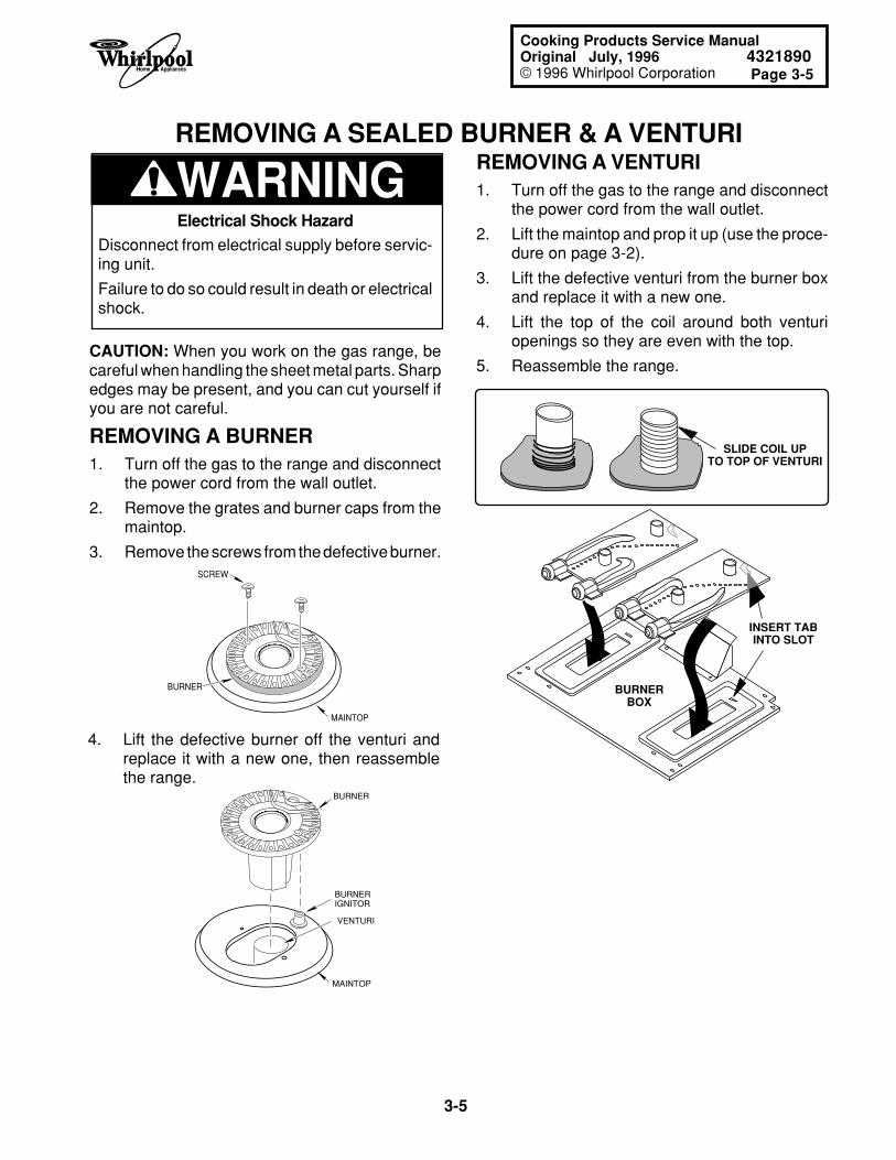
WARNING
BURNERBOX
INSERT TABINTO SLOT
SLIDE COIL UPTO TOP OF VENTURI
REMOVING A SEALED BURNER & A VENTURIREMOVING A VENTURI1. Turn off the gas to the range and disconnect
the power cord from the wall outlet.
2. Lift the maintop and prop it up (use the proce-dure on page 3-2).
3. Lift the defective venturi from the burner boxand replace it with a new one.
4. Lift the top of the coil around both venturiopenings so they are even with the top.
5. Reassemble the range.
Electrical Shock Hazard
Disconnect from electrical supply before servic-ing unit.
Failure to do so could result in death or electricalshock.
CAUTION: When you work on the gas range, becareful when handling the sheet metal parts. Sharpedges may be present, and you can cut yourself ifyou are not careful.
REMOVING A BURNER1. Turn off the gas to the range and disconnect
the power cord from the wall outlet.
2. Remove the grates and burner caps from themaintop.
3. Remove the screws from the defective burner.
VENTURI
MAINTOP
BURNER
BURNERIGNITOR
SCREW
MAINTOP
BURNER
4. Lift the defective burner off the venturi andreplace it with a new one, then reassemblethe range.
3-6
WARNING
SHIPPING SCREWS
BURNER
BURNER BRACKET
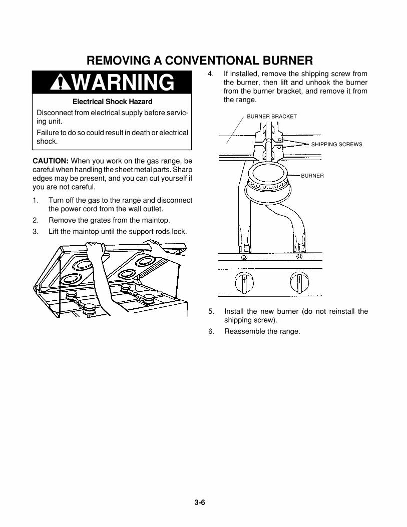
REMOVING A CONVENTIONAL BURNER4. If installed, remove the shipping screw from
the burner, then lift and unhook the burnerfrom the burner bracket, and remove it fromthe range.
5. Install the new burner (do not reinstall theshipping screw).
6. Reassemble the range.
Electrical Shock Hazard
Disconnect from electrical supply before servic-ing unit.
Failure to do so could result in death or electricalshock.
CAUTION: When you work on the gas range, becareful when handling the sheet metal parts. Sharpedges may be present, and you can cut yourself ifyou are not careful.
1. Turn off the gas to the range and disconnectthe power cord from the wall outlet.
2. Remove the grates from the maintop.
3. Lift the maintop until the support rods lock.
Page 3-7
3-7
Cooking Products Service ManualOriginal July, 1996 4321890© 1996 Whirlpool Corporation
REMOVING A SPARK IGNITOR SWITCH & GAS VALVE
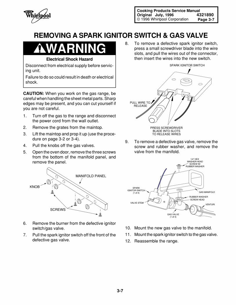
WARNING8. To remove a defective spark ignitor switch,
press a small screwdriver blade into the wireslots, and pull the wires out of the connector,then insert the wires into the new switch.Electrical Shock Hazard
Disconnect from electrical supply before servic-ing unit.
Failure to do so could result in death or electricalshock.
CAUTION: When you work on the gas range, becareful when handling the sheet metal parts. Sharpedges may be present, and you can cut yourself ifyou are not careful.
1. Turn off the gas to the range and disconnectthe power cord from the wall outlet.
2. Remove the grates from the maintop.
3. Lift the maintop and prop it up (use the proce-dure on page 3-2 or 3-4).
4. Pull the knobs off the gas valves.
5. Open the oven door, remove the three screwsfrom the bottom of the manifold panel, andremove the panel.
MANIFOLD PANEL
KNOB
SCREWS
6. Remove the burner from the defective ignitorswitch/gas valve.
7. Pull the spark ignitor switch off the front of thedefective gas valve.
PRESS SCREWDRIVERBLADE INTO SLOTSTO RELEASE WIRES
SPARK IGNITOR SWITCH
PULL WIRE TO RELEASE
1/4" HEX WASHER-HEAD
SCREW W/RUBBER WASHER
GAS VALVE(1 of 4)
VALVE STEMVENTURI
SPARKIGNITOR SWITCH
(1 of 4) GAS MANIFOLD
SCREW HEADRUBBER WASHER
10. Mount the new gas valve to the manifold.
11. Mount the spark ignitor switch to the gas valve.
12. Reassemble the range.
9. To remove a defective gas valve, remove thescrew and rubber washer, and remove thevalve from the manifold.
3-8
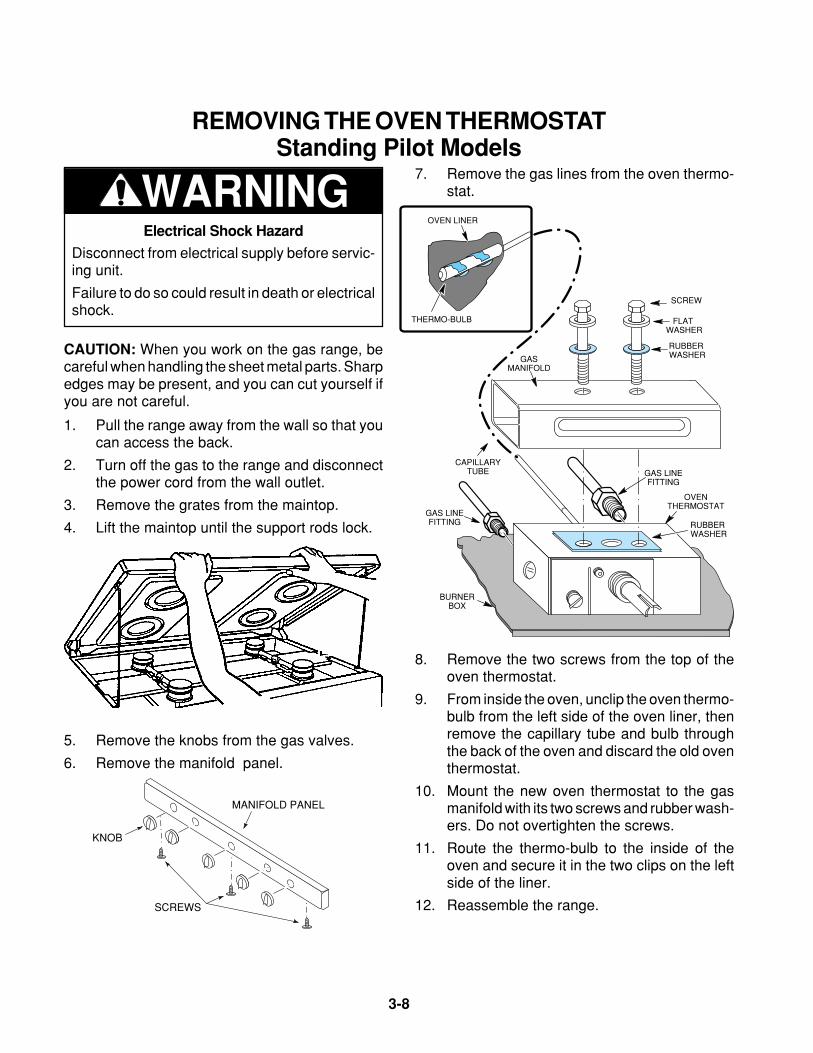
WARNING7. Remove the gas lines from the oven thermo-
stat.
GAS LINEFITTING
RUBBER WASHER
RUBBER WASHER
FLAT WASHER
SCREW
CAPILLARYTUBE
GAS LINEFITTING
BURNERBOX
OVENTHERMOSTAT
GASMANIFOLD
OVEN LINER
THERMO-BULB
8. Remove the two screws from the top of theoven thermostat.
9. From inside the oven, unclip the oven thermo-bulb from the left side of the oven liner, thenremove the capillary tube and bulb throughthe back of the oven and discard the old oventhermostat.
10. Mount the new oven thermostat to the gasmanifold with its two screws and rubber wash-ers. Do not overtighten the screws.
11. Route the thermo-bulb to the inside of theoven and secure it in the two clips on the leftside of the liner.
12. Reassemble the range.
REMOVING THE OVEN THERMOSTATStanding Pilot Models
Electrical Shock Hazard
Disconnect from electrical supply before servic-ing unit.
Failure to do so could result in death or electricalshock.
CAUTION: When you work on the gas range, becareful when handling the sheet metal parts. Sharpedges may be present, and you can cut yourself ifyou are not careful.
1. Pull the range away from the wall so that youcan access the back.
2. Turn off the gas to the range and disconnectthe power cord from the wall outlet.
3. Remove the grates from the maintop.
4. Lift the maintop until the support rods lock.
5. Remove the knobs from the gas valves.
6. Remove the manifold panel.
MANIFOLD PANEL
KNOB
SCREWS
Page 3-9
3-9
Cooking Products Service ManualOriginal July, 1996 4321890© 1996 Whirlpool Corporation
REMOVING THE OVEN THERMOSTATElectronic Ignition Models
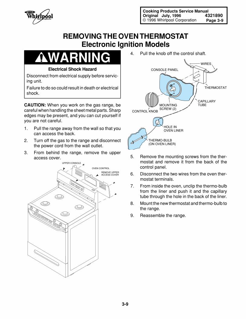
4. Pull the knob off the control shaft.WARNING
5. Remove the mounting screws from the ther-mostat and remove it from the back of thecontrol panel.
6. Disconnect the two wires from the oven ther-mostat terminals.
7. From inside the oven, unclip the thermo-bulbfrom the liner and push it and the capillarytube through the hole in the back of the liner.
8. Mount the new thermostat and thermo-bulb tothe range.
9. Reassemble the range.
WIRES
CONSOLE PANEL
THERMO-BULB (ON OVEN LINER)
HOLE IN OVEN LINER
THERMOSTAT
CAPILLARYTUBE
CONTROL KNOB
MOUNTINGSCREW (2)
450
Electrical Shock Hazard
Disconnect from electrical supply before servic-ing unit.
Failure to do so could result in death or electricalshock.
CAUTION: When you work on the gas range, becareful when handling the sheet metal parts. Sharpedges may be present, and you can cut yourself ifyou are not careful.
REMOVE UPPER ACCESS COVER
OVEN CONTROL
UPPER CONSOLE
1. Pull the range away from the wall so that youcan access the back.
2. Turn off the gas to the range and disconnectthe power cord from the wall outlet.
3. From behind the range, remove the upperaccess cover.
3-10
REMOVING THE IGNITOR MODULE & A BURNER IGNITORSealed Burner Models
WARNING
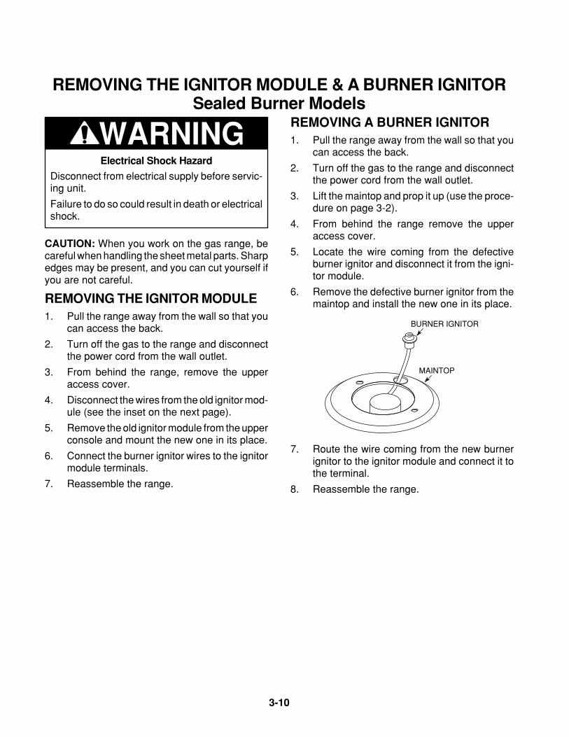
BURNER IGNITOR
MAINTOP
REMOVING A BURNER IGNITOR1. Pull the range away from the wall so that you
can access the back.
2. Turn off the gas to the range and disconnectthe power cord from the wall outlet.
3. Lift the maintop and prop it up (use the proce-dure on page 3-2).
4. From behind the range remove the upperaccess cover.
5. Locate the wire coming from the defectiveburner ignitor and disconnect it from the igni-tor module.
6. Remove the defective burner ignitor from themaintop and install the new one in its place.
7. Route the wire coming from the new burnerignitor to the ignitor module and connect it tothe terminal.
8. Reassemble the range.
Electrical Shock Hazard
Disconnect from electrical supply before servic-ing unit.
Failure to do so could result in death or electricalshock.
CAUTION: When you work on the gas range, becareful when handling the sheet metal parts. Sharpedges may be present, and you can cut yourself ifyou are not careful.
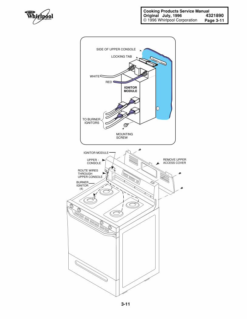
REMOVING THE IGNITOR MODULE1. Pull the range away from the wall so that you
can access the back.
2. Turn off the gas to the range and disconnectthe power cord from the wall outlet.
3. From behind the range, remove the upperaccess cover.
4. Disconnect the wires from the old ignitor mod-ule (see the inset on the next page).
5. Remove the old ignitor module from the upperconsole and mount the new one in its place.
6. Connect the burner ignitor wires to the ignitormodule terminals.
7. Reassemble the range.
Page 3-11
3-11
Cooking Products Service ManualOriginal July, 1996 4321890© 1996 Whirlpool Corporation
REMOVE UPPER ACCESS COVER
IGNITOR MODULE
UPPER CONSOLE
BURNERIGNITOR (4)
ROUTE WIRESTHROUGHUPPER CONSOLE
RED
WHITE
TO BURNER IGNITORS
LOCKING TAB
MOUNTINGSCREW
SIDE OF UPPER CONSOLE
IGNITORMODULE
3-12
REMOVING THE IGNITOR MODULE & A BURNER IGNITORConventional Burner Models
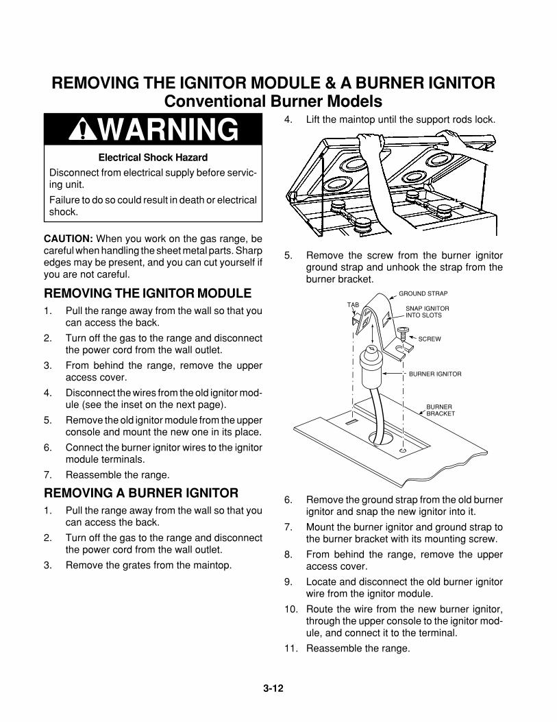
WARNING 4. Lift the maintop until the support rods lock.
6. Remove the ground strap from the old burnerignitor and snap the new ignitor into it.
7. Mount the burner ignitor and ground strap tothe burner bracket with its mounting screw.
8. From behind the range, remove the upperaccess cover.
9. Locate and disconnect the old burner ignitorwire from the ignitor module.
10. Route the wire from the new burner ignitor,through the upper console to the ignitor mod-ule, and connect it to the terminal.
11. Reassemble the range.
5. Remove the screw from the burner ignitorground strap and unhook the strap from theburner bracket.
SNAP IGNITORINTO SLOTS
BURNER IGNITOR
GROUND STRAP
BURNERBRACKET
TAB
SCREW
Electrical Shock Hazard
Disconnect from electrical supply before servic-ing unit.
Failure to do so could result in death or electricalshock.
CAUTION: When you work on the gas range, becareful when handling the sheet metal parts. Sharpedges may be present, and you can cut yourself ifyou are not careful.
REMOVING THE IGNITOR MODULE1. Pull the range away from the wall so that you
can access the back.
2. Turn off the gas to the range and disconnectthe power cord from the wall outlet.
3. From behind the range, remove the upperaccess cover.
4. Disconnect the wires from the old ignitor mod-ule (see the inset on the next page).
5. Remove the old ignitor module from the upperconsole and mount the new one in its place.
6. Connect the burner ignitor wires to the ignitormodule terminals.
7. Reassemble the range.
REMOVING A BURNER IGNITOR1. Pull the range away from the wall so that you
can access the back.
2. Turn off the gas to the range and disconnectthe power cord from the wall outlet.
3. Remove the grates from the maintop.
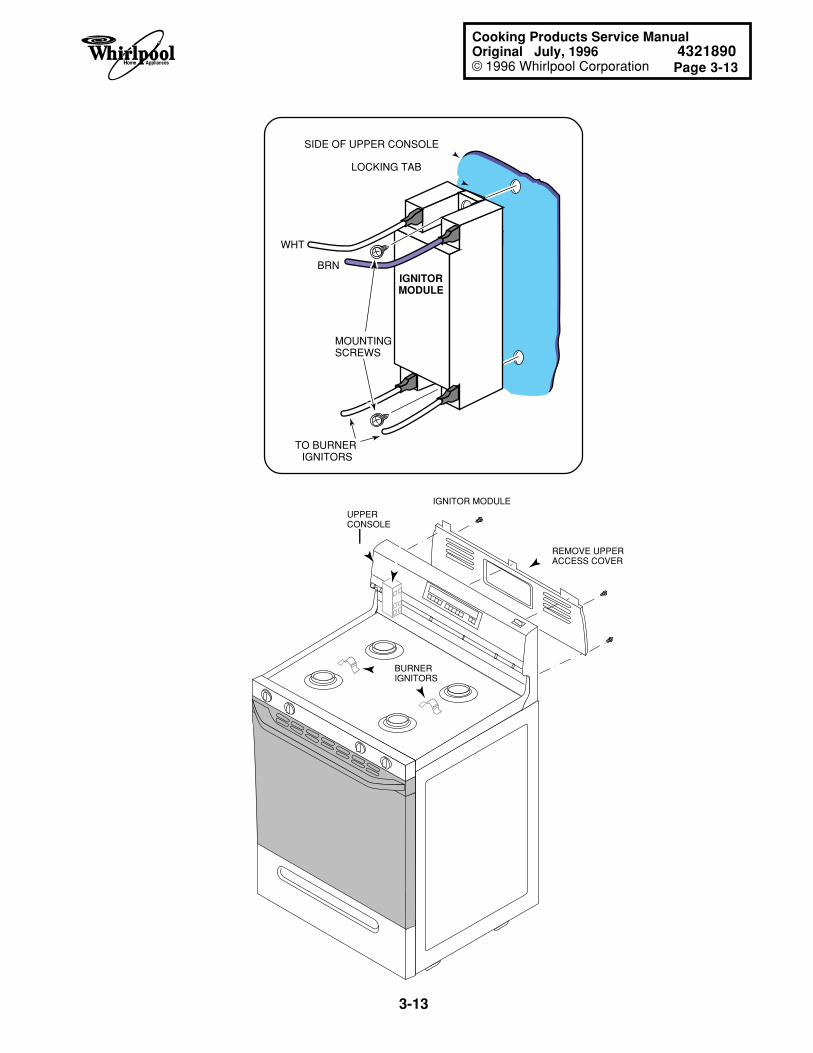
Page 3-13
3-13
Cooking Products Service ManualOriginal July, 1996 4321890© 1996 Whirlpool Corporation
REMOVE UPPER ACCESS COVER
IGNITOR MODULE
UPPER CONSOLE
BURNERIGNITORS
BRN
WHT
TO BURNER IGNITORS
LOCKING TAB
MOUNTINGSCREWS
SIDE OF UPPER CONSOLE
IGNITORMODULE
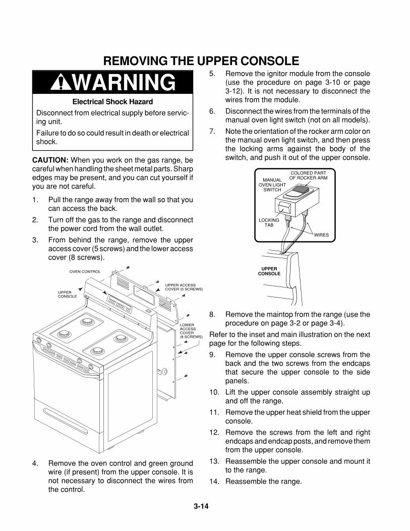
3-14
REMOVING THE UPPER CONSOLE
WARNING5. Remove the ignitor module from the console
(use the procedure on page 3-10 or page3-12). It is not necessary to disconnect thewires from the module.
6. Disconnect the wires from the terminals of themanual oven light switch (not on all models).
7. Note the orientation of the rocker arm color onthe manual oven light switch, and then pressthe locking arms against the body of theswitch, and push it out of the upper console.
Electrical Shock Hazard
Disconnect from electrical supply before servic-ing unit.
Failure to do so could result in death or electricalshock.
CAUTION: When you work on the gas range, becareful when handling the sheet metal parts. Sharpedges may be present, and you can cut yourself ifyou are not careful.
1. Pull the range away from the wall so that youcan access the back.
2. Turn off the gas to the range and disconnectthe power cord from the wall outlet.
3. From behind the range, remove the upperaccess cover (5 screws) and the lower accesscover (8 screws).
UPPER ACCESS COVER (5 SCREWS)
LOWER ACCESS COVER(8 SCREWS)
UPPER CONSOLE
OVEN CONTROL
4. Remove the oven control and green groundwire (if present) from the upper console. It isnot necessary to disconnect the wires fromthe control.
MANUALOVEN LIGHT
SWITCH
WIRES
COLORED PARTOF ROCKER ARM
LOCKINGTAB
UPPER CONSOLE
8. Remove the maintop from the range (use theprocedure on page 3-2 or page 3-4).
Refer to the inset and main illustration on the nextpage for the following steps.
9. Remove the upper console screws from theback and the two screws from the endcapsthat secure the upper console to the sidepanels.
10. Lift the upper console assembly straight upand off the range.
11. Remove the upper heat shield from the upperconsole.
12. Remove the screws from the left and rightendcaps and endcap posts, and remove themfrom the upper console.
13. Reassemble the upper console and mount itto the range.
14. Reassemble the range.
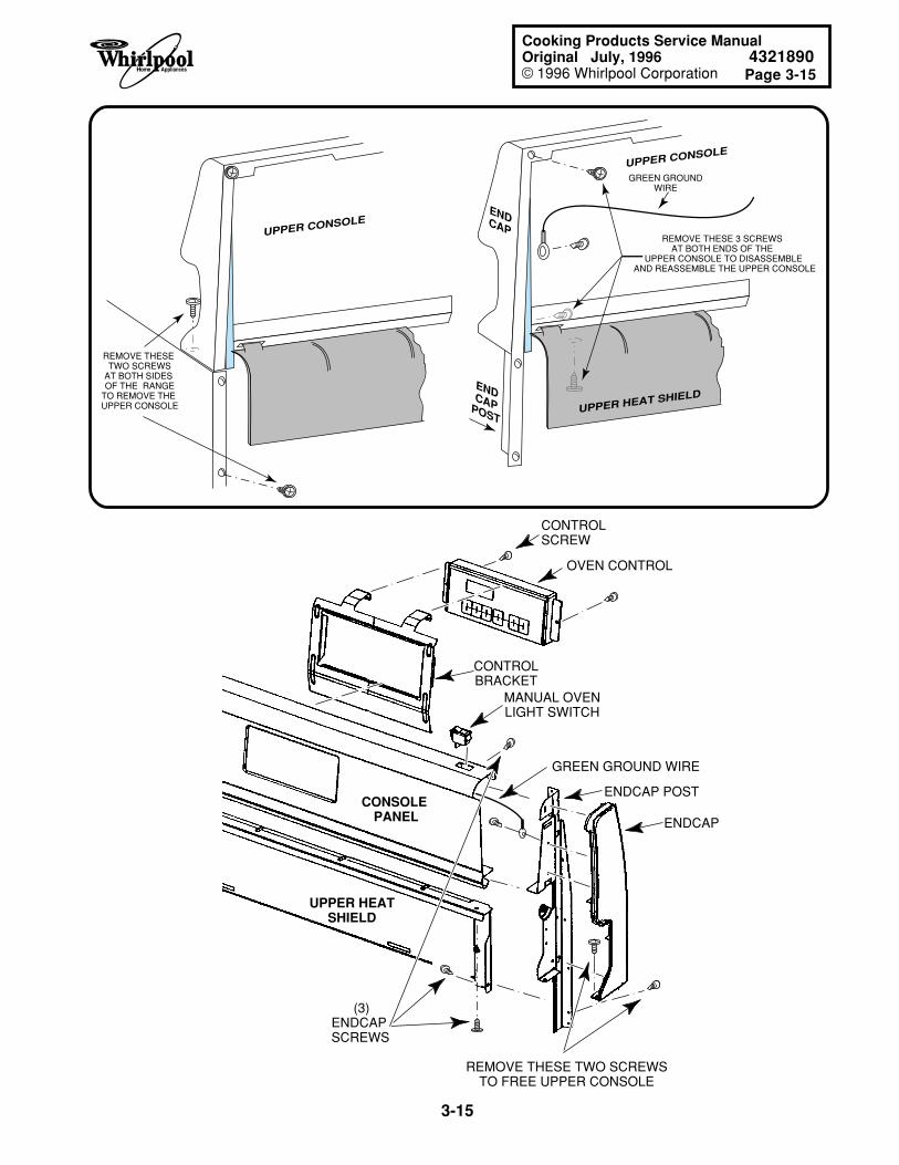
Page 3-15
3-15
Cooking Products Service ManualOriginal July, 1996 4321890© 1996 Whirlpool Corporation
REMOVE THESE TWO SCREWSTO FREE UPPER CONSOLE
MANUAL OVENLIGHT SWITCH
CONTROLBRACKET
ENDCAP
ENDCAP POST
GREEN GROUND WIRE
CONSOLE PANEL
OVEN CONTROL
CONTROLSCREW
UPPER HEATSHIELD
(3)ENDCAPSCREWS
UPPER CONSOLE
REMOVE THESE TWO SCREWS
AT BOTH SIDES OF THE RANGE
TO REMOVE THE UPPER CONSOLE
UPPER CONSOLE
ENDCAP
ENDCAPPOSTUPPER HEAT SHIELD
REMOVE THESE 3 SCREWS AT BOTH ENDS OF THE
UPPER CONSOLE TO DISASSEMBLE AND REASSEMBLE THE UPPER CONSOLE
GREEN GROUNDWIRE
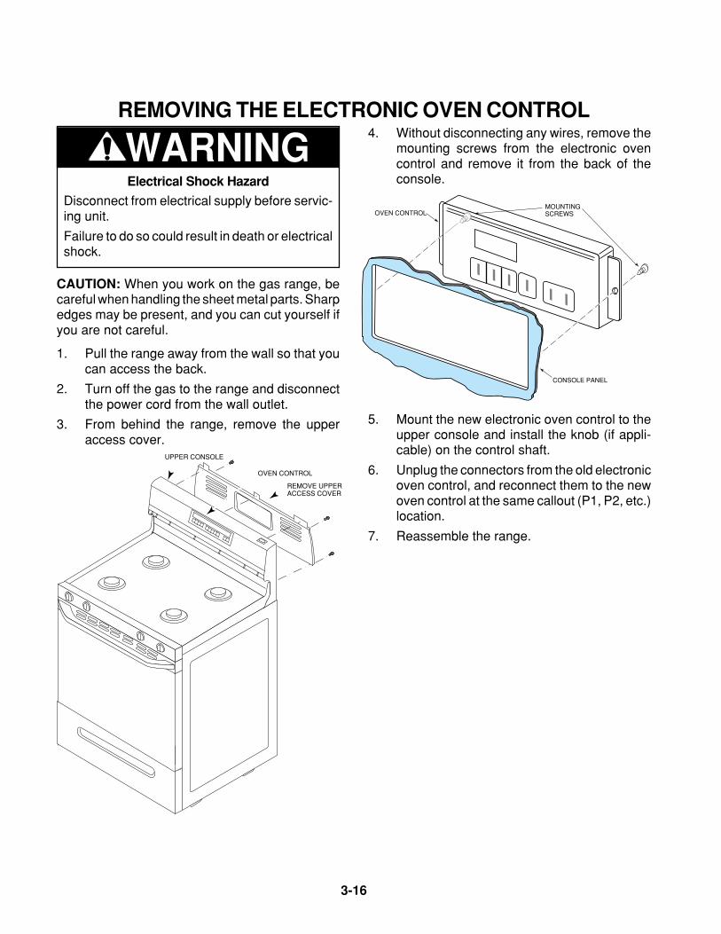
3-16
WARNINGREMOVING THE ELECTRONIC OVEN CONTROL
Electrical Shock Hazard
Disconnect from electrical supply before servic-ing unit.
Failure to do so could result in death or electricalshock.
CAUTION: When you work on the gas range, becareful when handling the sheet metal parts. Sharpedges may be present, and you can cut yourself ifyou are not careful.
1. Pull the range away from the wall so that youcan access the back.
2. Turn off the gas to the range and disconnectthe power cord from the wall outlet.
3. From behind the range, remove the upperaccess cover.
REMOVE UPPER ACCESS COVER
OVEN CONTROL
UPPER CONSOLE
4. Without disconnecting any wires, remove themounting screws from the electronic ovencontrol and remove it from the back of theconsole.
OVEN CONTROL
CONSOLE PANEL
MOUNTINGSCREWS
5. Mount the new electronic oven control to theupper console and install the knob (if appli-cable) on the control shaft.
6. Unplug the connectors from the old electronicoven control, and reconnect them to the newoven control at the same callout (P1, P2, etc.)location.
7. Reassemble the range.
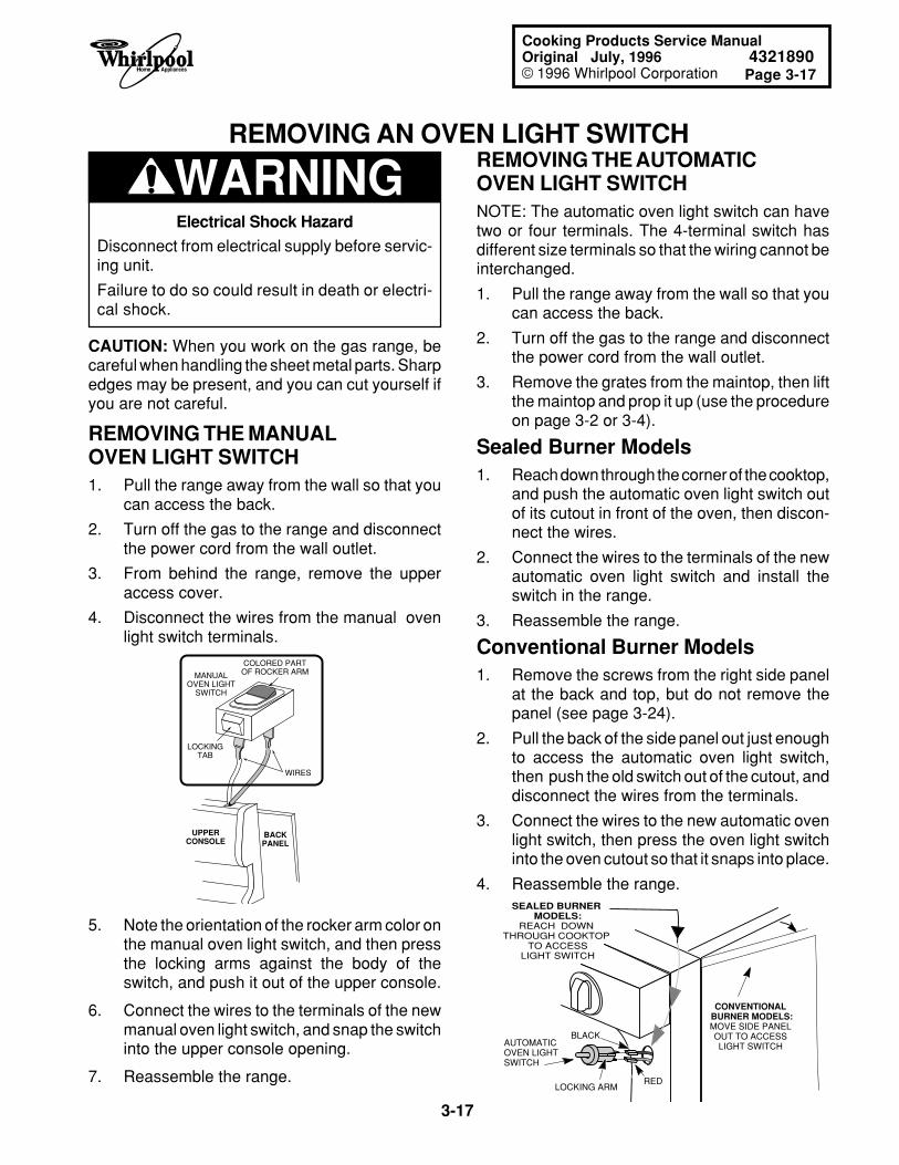
Page 3-17
3-17
Cooking Products Service ManualOriginal July, 1996 4321890© 1996 Whirlpool Corporation
WARNINGREMOVING AN OVEN LIGHT SWITCH
REMOVING THE MANUALOVEN LIGHT SWITCH1. Pull the range away from the wall so that you
can access the back.
2. Turn off the gas to the range and disconnectthe power cord from the wall outlet.
3. From behind the range, remove the upperaccess cover.
4. Disconnect the wires from the manual ovenlight switch terminals.
CAUTION: When you work on the gas range, becareful when handling the sheet metal parts. Sharpedges may be present, and you can cut yourself ifyou are not careful.
5. Note the orientation of the rocker arm color onthe manual oven light switch, and then pressthe locking arms against the body of theswitch, and push it out of the upper console.
6. Connect the wires to the terminals of the newmanual oven light switch, and snap the switchinto the upper console opening.
7. Reassemble the range.
MANUALOVEN LIGHT
SWITCH
WIRES
COLORED PARTOF ROCKER ARM
LOCKINGTAB
UPPER CONSOLE
BACKPANEL
REMOVING THE AUTOMATICOVEN LIGHT SWITCHNOTE: The automatic oven light switch can havetwo or four terminals. The 4-terminal switch hasdifferent size terminals so that the wiring cannot beinterchanged.
1. Pull the range away from the wall so that youcan access the back.
2. Turn off the gas to the range and disconnectthe power cord from the wall outlet.
3. Remove the grates from the maintop, then liftthe maintop and prop it up (use the procedureon page 3-2 or 3-4).
Sealed Burner Models1. Reach down through the corner of the cooktop,
and push the automatic oven light switch outof its cutout in front of the oven, then discon-nect the wires.
2. Connect the wires to the terminals of the newautomatic oven light switch and install theswitch in the range.
3. Reassemble the range.
Conventional Burner Models1. Remove the screws from the right side panel
at the back and top, but do not remove thepanel (see page 3-24).
2. Pull the back of the side panel out just enoughto access the automatic oven light switch,then push the old switch out of the cutout, anddisconnect the wires from the terminals.
3. Connect the wires to the new automatic ovenlight switch, then press the oven light switchinto the oven cutout so that it snaps into place.
4. Reassemble the range.
LOCKING ARM
AUTOMATICOVEN LIGHTSWITCH
RED
BLACK
CONVENTIONAL BURNER MODELS:MOVE SIDE PANELOUT TO ACCESSLIGHT SWITCH
SEALED BURNER MODELS:
REACH DOWN THROUGH COOKTOP
TO ACCESSLIGHT SWITCH
Electrical Shock Hazard
Disconnect from electrical supply before servic-ing unit.
Failure to do so could result in death or electri-cal shock.
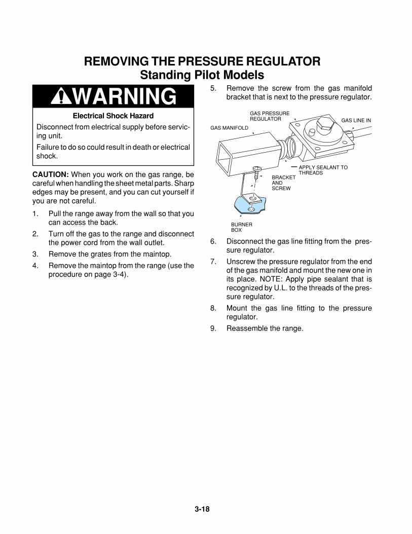
3-18
REMOVING THE PRESSURE REGULATORStanding Pilot Models
WARNING5. Remove the screw from the gas manifold
bracket that is next to the pressure regulator.
BRACKETANDSCREW
BURNERBOX
GAS MANIFOLD
GAS PRESSUREREGULATOR GAS LINE IN
APPLY SEALANT TO THREADS
6. Disconnect the gas line fitting from the pres-sure regulator.
7. Unscrew the pressure regulator from the endof the gas manifold and mount the new one inits place. NOTE: Apply pipe sealant that isrecognized by U.L. to the threads of the pres-sure regulator.
8. Mount the gas line fitting to the pressureregulator.
9. Reassemble the range.
Electrical Shock Hazard
Disconnect from electrical supply before servic-ing unit.
Failure to do so could result in death or electricalshock.
CAUTION: When you work on the gas range, becareful when handling the sheet metal parts. Sharpedges may be present, and you can cut yourself ifyou are not careful.
1. Pull the range away from the wall so that youcan access the back.
2. Turn off the gas to the range and disconnectthe power cord from the wall outlet.
3. Remove the grates from the maintop.
4. Remove the maintop from the range (use theprocedure on page 3-4).
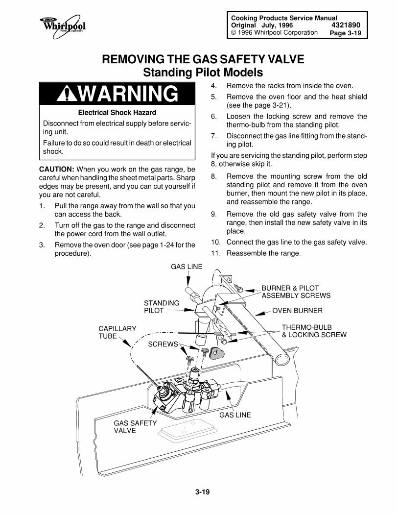
Page 3-19
3-19
Cooking Products Service ManualOriginal July, 1996 4321890© 1996 Whirlpool Corporation
REMOVING THE GAS SAFETY VALVEStanding Pilot Models
4. Remove the racks from inside the oven.
5. Remove the oven floor and the heat shield(see the page 3-21).
6. Loosen the locking screw and remove thethermo-bulb from the standing pilot.
7. Disconnect the gas line fitting from the stand-ing pilot.
If you are servicing the standing pilot, perform step8, otherwise skip it.
8. Remove the mounting screw from the oldstanding pilot and remove it from the ovenburner, then mount the new pilot in its place,and reassemble the range.
9. Remove the old gas safety valve from therange, then install the new safety valve in itsplace.
10. Connect the gas line to the gas safety valve.
11. Reassemble the range.
WARNINGElectrical Shock Hazard
Disconnect from electrical supply before servic-ing unit.
Failure to do so could result in death or electricalshock.
CAUTION: When you work on the gas range, becareful when handling the sheet metal parts. Sharpedges may be present, and you can cut yourself ifyou are not careful.
1. Pull the range away from the wall so that youcan access the back.
2. Turn off the gas to the range and disconnectthe power cord from the wall outlet.
3. Remove the oven door (see page 1-24 for theprocedure).
CAPILLARYTUBE
GAS SAFETYVALVE
GAS LINE
GAS LINE
STANDINGPILOT
SCREWS
OVEN BURNER
BURNER & PILOTASSEMBLY SCREWS
THERMO-BULB& LOCKING SCREW
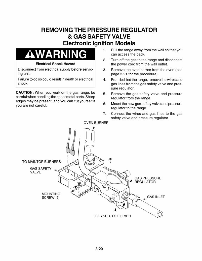
3-20
REMOVING THE PRESSURE REGULATOR& GAS SAFETY VALVE
Electronic Ignition Models
WARNING1. Pull the range away from the wall so that you
can access the back.
2. Turn off the gas to the range and disconnectthe power cord from the wall outlet.
3. Remove the oven burner from the oven (seepage 3-21 for the procedure).
4. From behind the range, remove the wires andgas lines from the gas safety valve and pres-sure regulator.
5. Remove the gas safety valve and pressureregulator from the range.
6. Mount the new gas safety valve and pressureregulator to the range.
7. Connect the wires and gas lines to the gassafety valve and pressure regulator.
Electrical Shock Hazard
Disconnect from electrical supply before servic-ing unit.
Failure to do so could result in death or electricalshock.
CAUTION: When you work on the gas range, becareful when handling the sheet metal parts. Sharpedges may be present, and you can cut yourself ifyou are not careful.
GAS INLET
OVEN BURNER
MOUNTING SCREW (2)
TO MAINTOP BURNERS
GAS SAFETY VALVE
GAS PRESSUREREGULATOR
GAS SHUTOFF LEVER
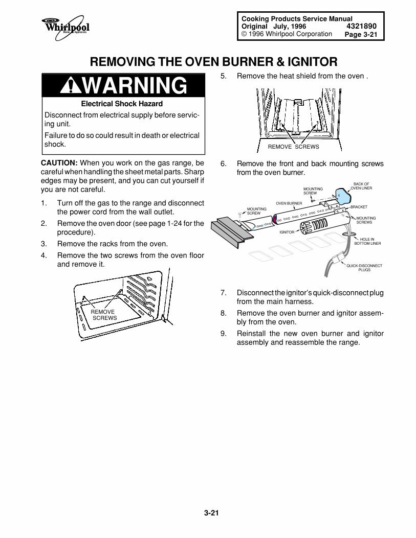
Page 3-21
3-21
Cooking Products Service ManualOriginal July, 1996 4321890© 1996 Whirlpool Corporation
REMOVING THE OVEN BURNER & IGNITOR
WARNING
REMOVE SCREWS
OVEN BURNER
IGNITOR
MOUNTING SCREW
MOUNTING SCREW
MOUNTING SCREWS
HOLE IN BOTTOM LINER
BACK OFOVEN LINER
BRACKET
QUICK-DISCONNECTPLUGS
7. Disconnect the ignitor’s quick-disconnect plugfrom the main harness.
8. Remove the oven burner and ignitor assem-bly from the oven.
9. Reinstall the new oven burner and ignitorassembly and reassemble the range.
6. Remove the front and back mounting screwsfrom the oven burner.
5. Remove the heat shield from the oven .
Electrical Shock Hazard
Disconnect from electrical supply before servic-ing unit.
Failure to do so could result in death or electricalshock.
CAUTION: When you work on the gas range, becareful when handling the sheet metal parts. Sharpedges may be present, and you can cut yourself ifyou are not careful.
REMOVE SCREWS
1. Turn off the gas to the range and disconnectthe power cord from the wall outlet.
2. Remove the oven door (see page 1-24 for theprocedure).
3. Remove the racks from the oven.
4. Remove the two screws from the oven floorand remove it.
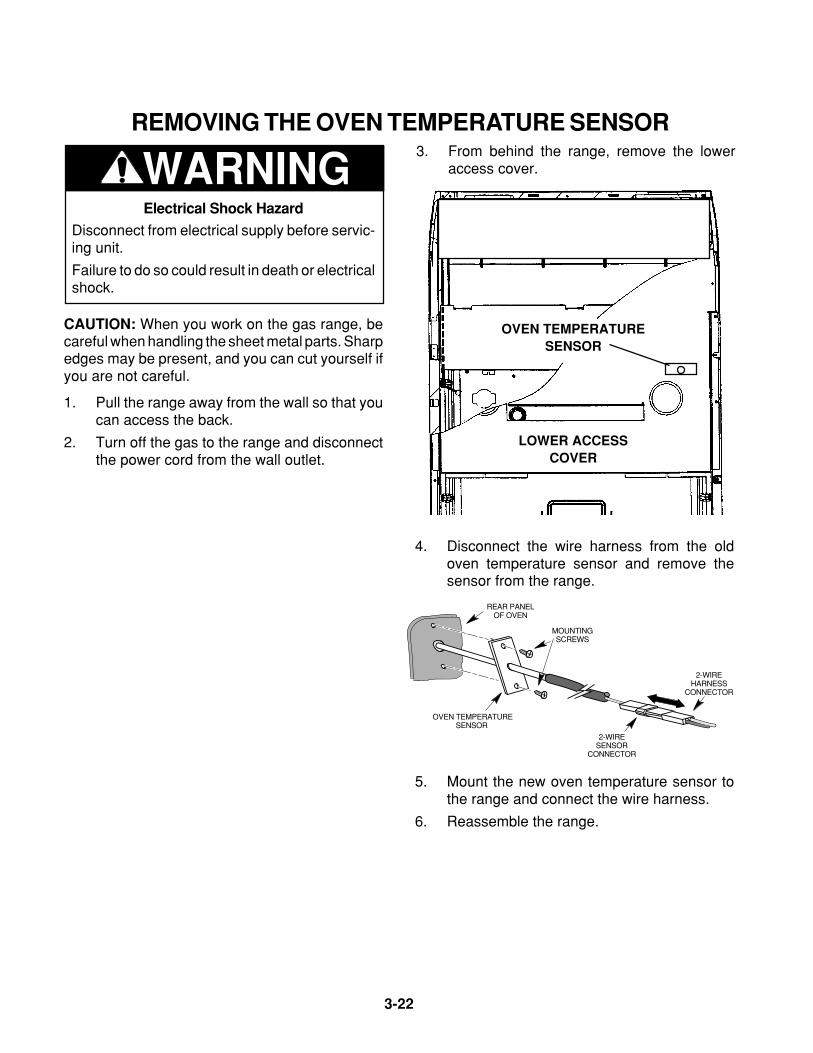
3-22
REMOVING THE OVEN TEMPERATURE SENSOR
WARNING3. From behind the range, remove the lower
access cover.
4. Disconnect the wire harness from the oldoven temperature sensor and remove thesensor from the range.
MOUNTINGSCREWS
OVEN TEMPERATURESENSOR
REAR PANELOF OVEN
2-WIRESENSOR
CONNECTOR
2-WIREHARNESS
CONNECTOR
5. Mount the new oven temperature sensor tothe range and connect the wire harness.
6. Reassemble the range.
LOWER ACCESSCOVER
OVEN TEMPERATURESENSOR
Electrical Shock Hazard
Disconnect from electrical supply before servic-ing unit.
Failure to do so could result in death or electricalshock.
CAUTION: When you work on the gas range, becareful when handling the sheet metal parts. Sharpedges may be present, and you can cut yourself ifyou are not careful.
1. Pull the range away from the wall so that youcan access the back.
2. Turn off the gas to the range and disconnectthe power cord from the wall outlet.
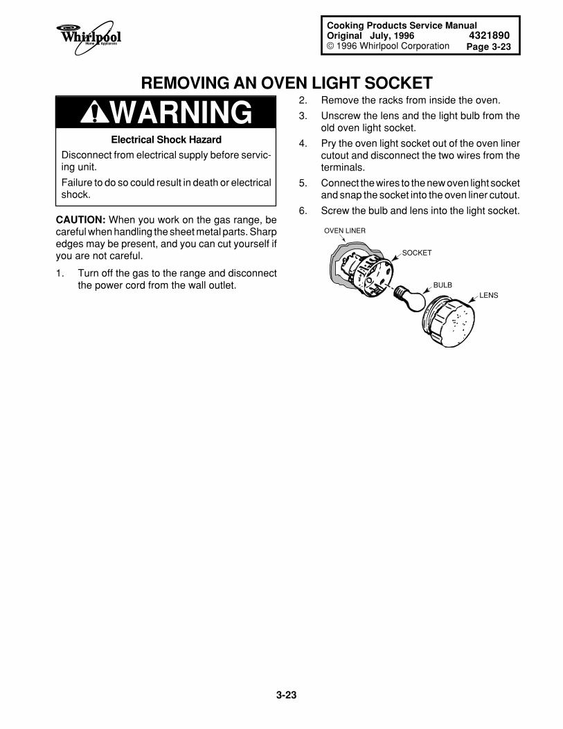
Page 3-23
3-23
Cooking Products Service ManualOriginal July, 1996 4321890© 1996 Whirlpool Corporation
REMOVING AN OVEN LIGHT SOCKET
WARNING
OVEN LINER
SOCKET
BULBLENS
2. Remove the racks from inside the oven.
3. Unscrew the lens and the light bulb from theold oven light socket.
4. Pry the oven light socket out of the oven linercutout and disconnect the two wires from theterminals.
5. Connect the wires to the new oven light socketand snap the socket into the oven liner cutout.
6. Screw the bulb and lens into the light socket.
Electrical Shock Hazard
Disconnect from electrical supply before servic-ing unit.
Failure to do so could result in death or electricalshock.
CAUTION: When you work on the gas range, becareful when handling the sheet metal parts. Sharpedges may be present, and you can cut yourself ifyou are not careful.
1. Turn off the gas to the range and disconnectthe power cord from the wall outlet.
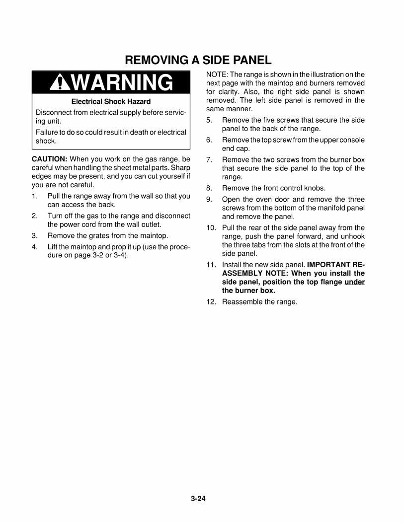
3-24
WARNINGREMOVING A SIDE PANEL
NOTE: The range is shown in the illustration on thenext page with the maintop and burners removedfor clarity. Also, the right side panel is shownremoved. The left side panel is removed in thesame manner.
5. Remove the five screws that secure the sidepanel to the back of the range.
6. Remove the top screw from the upper consoleend cap.
7. Remove the two screws from the burner boxthat secure the side panel to the top of therange.
8. Remove the front control knobs.
9. Open the oven door and remove the threescrews from the bottom of the manifold paneland remove the panel.
10. Pull the rear of the side panel away from therange, push the panel forward, and unhookthe three tabs from the slots at the front of theside panel.
11. Install the new side panel. IMPORTANT RE-ASSEMBLY NOTE: When you install theside panel, position the top flange underthe burner box.
12. Reassemble the range.
Electrical Shock Hazard
Disconnect from electrical supply before servic-ing unit.
Failure to do so could result in death or electricalshock.
CAUTION: When you work on the gas range, becareful when handling the sheet metal parts. Sharpedges may be present, and you can cut yourself ifyou are not careful.
1. Pull the range away from the wall so that youcan access the back.
2. Turn off the gas to the range and disconnectthe power cord from the wall outlet.
3. Remove the grates from the maintop.
4. Lift the maintop and prop it up (use the proce-dure on page 3-2 or 3-4).
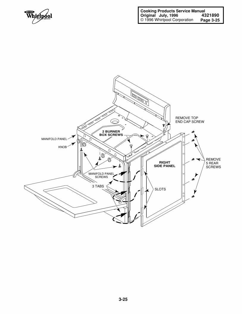
Page 3-25
3-25
Cooking Products Service ManualOriginal July, 1996 4321890© 1996 Whirlpool Corporation
REMOVE TOPEND CAP SCREW
REMOVE 5 REAR SCREWS
SLOTS3 TABS
RIGHTSIDE PANEL
2 BURNERBOX SCREWS
MANIFOLD PANEL
MANIFOLD PANELSCREWS
KNOB
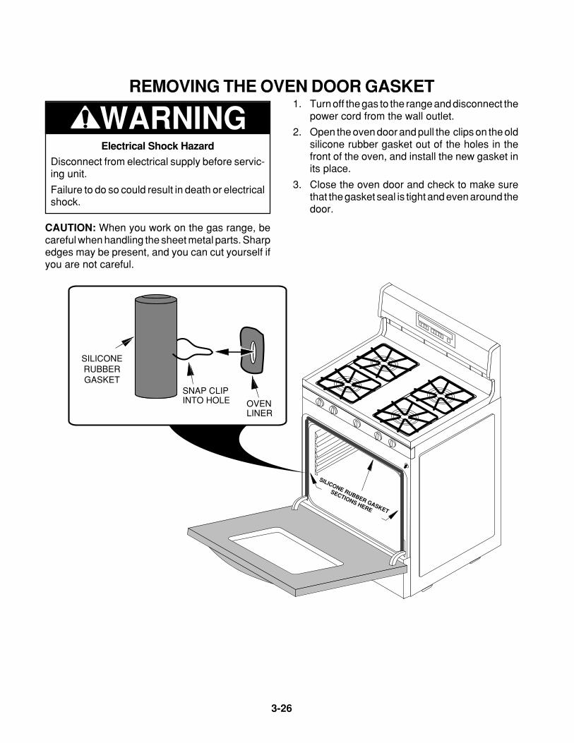
3-26
REMOVING THE OVEN DOOR GASKET
WARNING1. Turn off the gas to the range and disconnect the
power cord from the wall outlet.
2. Open the oven door and pull the clips on the oldsilicone rubber gasket out of the holes in thefront of the oven, and install the new gasket inits place.
3. Close the oven door and check to make surethat the gasket seal is tight and even around thedoor.
Electrical Shock Hazard
Disconnect from electrical supply before servic-ing unit.
Failure to do so could result in death or electricalshock.
CAUTION: When you work on the gas range, becareful when handling the sheet metal parts. Sharpedges may be present, and you can cut yourself ifyou are not careful.
SILICONE RUBBER GASKET
SECTIONS HERE
SILICONERUBBERGASKET
SNAP CLIPINTO HOLE OVEN
LINER
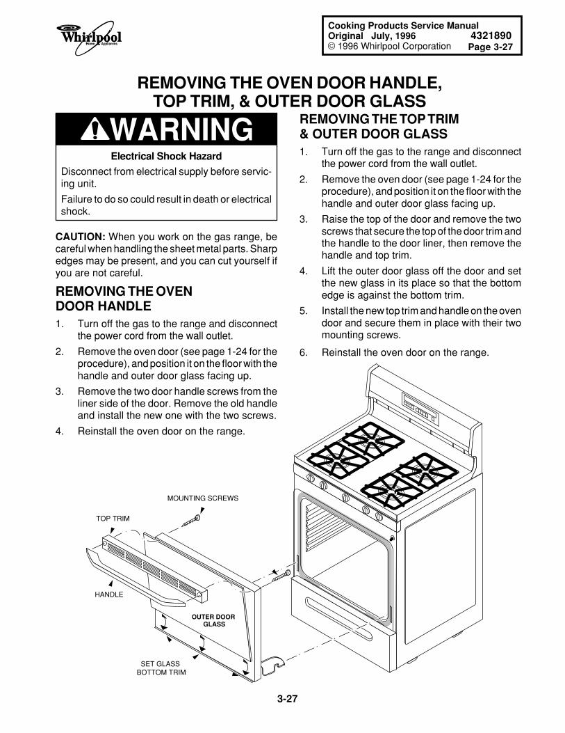
Page 3-27
3-27
Cooking Products Service ManualOriginal July, 1996 4321890© 1996 Whirlpool Corporation
REMOVING THE OVEN DOOR HANDLE,TOP TRIM, & OUTER DOOR GLASS
WARNING REMOVING THE TOP TRIM& OUTER DOOR GLASS1. Turn off the gas to the range and disconnect
the power cord from the wall outlet.
2. Remove the oven door (see page 1-24 for theprocedure), and position it on the floor with thehandle and outer door glass facing up.
3. Raise the top of the door and remove the twoscrews that secure the top of the door trim andthe handle to the door liner, then remove thehandle and top trim.
4. Lift the outer door glass off the door and setthe new glass in its place so that the bottomedge is against the bottom trim.
5. Install the new top trim and handle on the ovendoor and secure them in place with their twomounting screws.
6. Reinstall the oven door on the range.
Electrical Shock Hazard
Disconnect from electrical supply before servic-ing unit.
Failure to do so could result in death or electricalshock.
CAUTION: When you work on the gas range, becareful when handling the sheet metal parts. Sharpedges may be present, and you can cut yourself ifyou are not careful.
REMOVING THE OVENDOOR HANDLE1. Turn off the gas to the range and disconnect
the power cord from the wall outlet.
2. Remove the oven door (see page 1-24 for theprocedure), and position it on the floor with thehandle and outer door glass facing up.
3. Remove the two door handle screws from theliner side of the door. Remove the old handleand install the new one with the two screws.
4. Reinstall the oven door on the range.
TOP TRIM
HANDLE
MOUNTING SCREWS
OUTER DOOR GLASS
SET GLASS BOTTOM TRIM
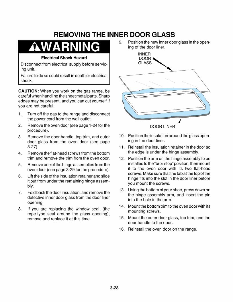
3-28
REMOVING THE INNER DOOR GLASS
WARNING9. Position the new inner door glass in the open-
ing of the door liner.
Electrical Shock Hazard
Disconnect from electrical supply before servic-ing unit.
Failure to do so could result in death or electricalshock.
CAUTION: When you work on the gas range, becareful when handling the sheet metal parts. Sharpedges may be present, and you can cut yourself ifyou are not careful.
1. Turn off the gas to the range and disconnectthe power cord from the wall outlet.
2. Remove the oven door (see page 1-24 for theprocedure).
3. Remove the door handle, top trim, and outerdoor glass from the oven door (see page3-27).
4. Remove the flat-head screws from the bottomtrim and remove the trim from the oven door.
5. Remove one of the hinge assemblies from theoven door (see page 3-29 for the procedure).
6. Lift the side of the insulation retainer and slideit out from under the remaining hinge assem-bly.
7. Fold back the door insulation, and remove thedefective inner door glass from the door lineropening.
8. If you are replacing the window seal, (therope-type seal around the glass opening),remove and replace it at this time.
INNER DOORGLASS
DOOR LINER
10. Position the insulation around the glass open-ing in the door liner.
11. Reinstall the insulation retainer in the door sothe edge is under the hinge assembly.
12. Position the arm on the hinge assembly to beinstalled to the “broil stop” position, then mountit to the oven door with its two flat-headscrews. Make sure that the tab at the top of thehinge fits into the slot in the door liner beforeyou mount the screws.
13. Using the bottom of your shoe, press down onthe hinge assembly arm, and insert the pininto the hole in the arm.
14. Mount the bottom trim to the oven door with itsmounting screws.
15. Mount the outer door glass, top trim, and thedoor handle to the door.
16. Reinstall the oven door on the range.
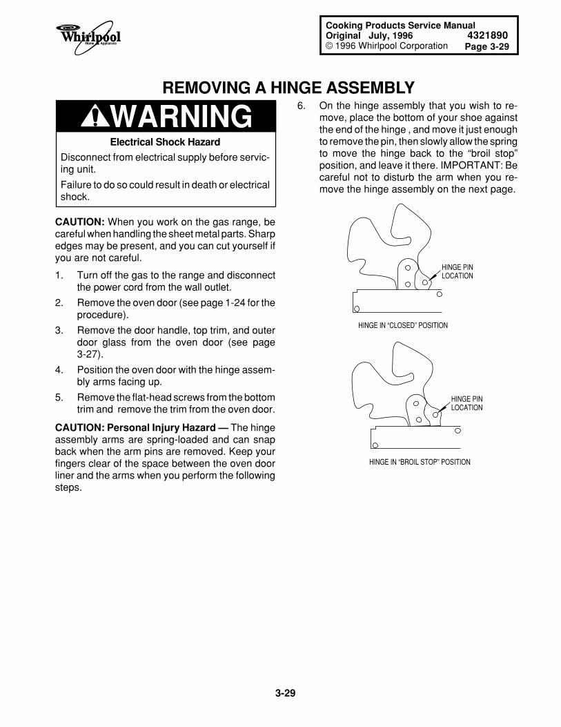
Page 3-29
3-29
Cooking Products Service ManualOriginal July, 1996 4321890© 1996 Whirlpool Corporation
REMOVING A HINGE ASSEMBLY
HINGE IN “CLOSED” POSITION
HINGE IN “BROIL STOP” POSITION
HINGE PINLOCATION
HINGE PINLOCATION
WARNING6. On the hinge assembly that you wish to re-
move, place the bottom of your shoe againstthe end of the hinge , and move it just enoughto remove the pin, then slowly allow the springto move the hinge back to the “broil stop”position, and leave it there. IMPORTANT: Becareful not to disturb the arm when you re-move the hinge assembly on the next page.
1. Turn off the gas to the range and disconnectthe power cord from the wall outlet.
2. Remove the oven door (see page 1-24 for theprocedure).
3. Remove the door handle, top trim, and outerdoor glass from the oven door (see page3-27).
4. Position the oven door with the hinge assem-bly arms facing up.
5. Remove the flat-head screws from the bottomtrim and remove the trim from the oven door.
CAUTION: Personal Injury Hazard — The hingeassembly arms are spring-loaded and can snapback when the arm pins are removed. Keep yourfingers clear of the space between the oven doorliner and the arms when you perform the followingsteps.
Electrical Shock Hazard
Disconnect from electrical supply before servic-ing unit.
Failure to do so could result in death or electricalshock.
CAUTION: When you work on the gas range, becareful when handling the sheet metal parts. Sharpedges may be present, and you can cut yourself ifyou are not careful.
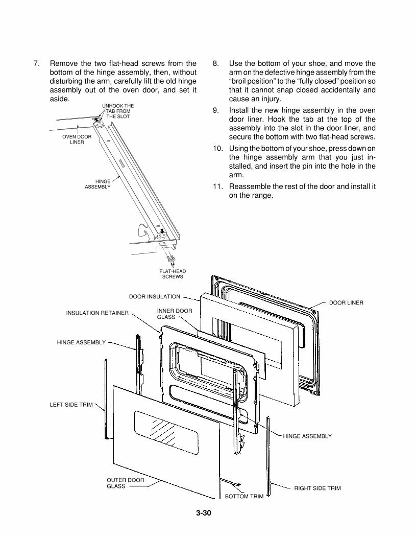
3-30
7. Remove the two flat-head screws from thebottom of the hinge assembly, then, withoutdisturbing the arm, carefully lift the old hingeassembly out of the oven door, and set itaside.
8. Use the bottom of your shoe, and move thearm on the defective hinge assembly from the“broil position” to the “fully closed” position sothat it cannot snap closed accidentally andcause an injury.
9. Install the new hinge assembly in the ovendoor liner. Hook the tab at the top of theassembly into the slot in the door liner, andsecure the bottom with two flat-head screws.
10. Using the bottom of your shoe, press down onthe hinge assembly arm that you just in-stalled, and insert the pin into the hole in thearm.
11. Reassemble the rest of the door and install iton the range.
FLAT-HEADSCREWS
UNHOOK THETAB FROMTHE SLOT
HINGEASSEMBLY
OVEN DOORLINER
INNER DOORGLASS
DOOR LINERDOOR INSULATION
INSULATION RETAINER
RIGHT SIDE TRIM
LEFT SIDE TRIM
BOTTOM TRIM
OUTER DOORGLASS
HINGE ASSEMBLY
HINGE ASSEMBLY
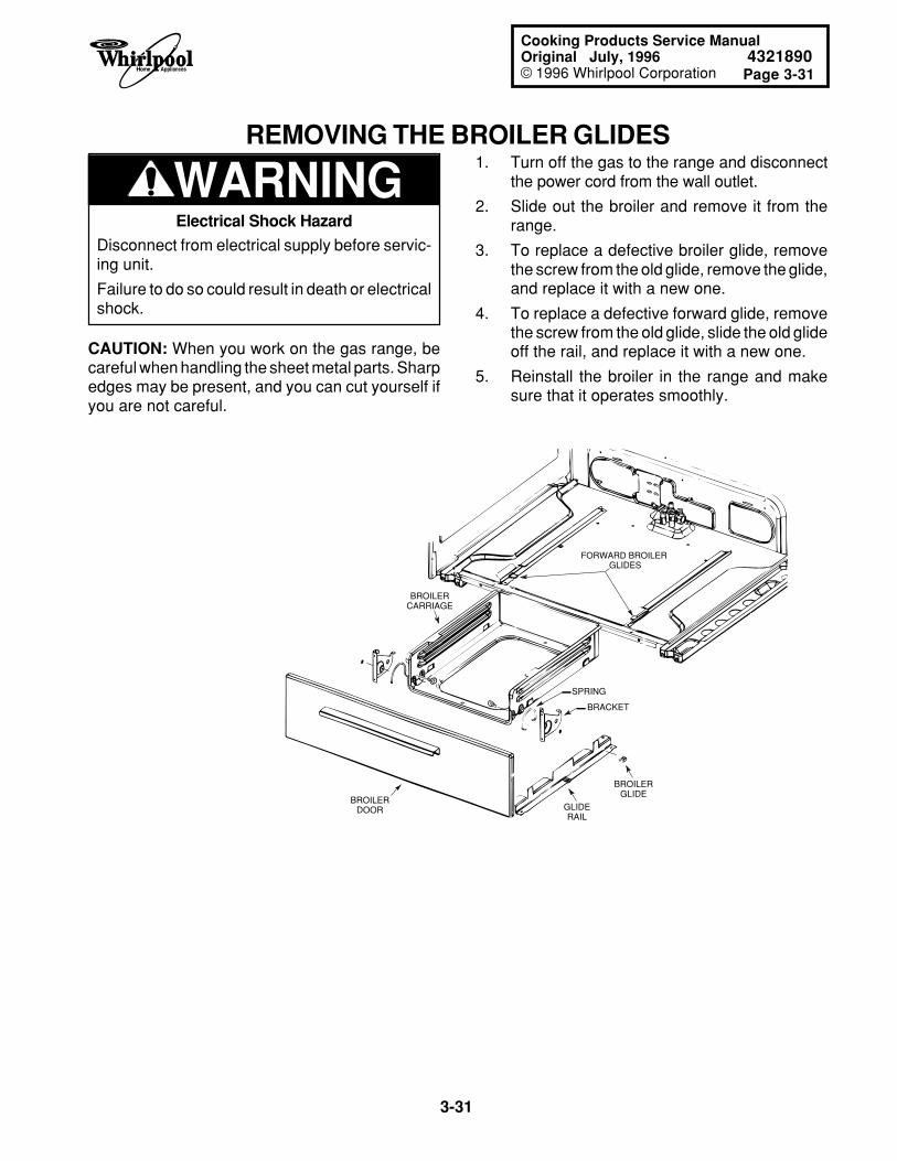
Page 3-31
3-31
Cooking Products Service ManualOriginal July, 1996 4321890© 1996 Whirlpool Corporation
REMOVING THE BROILER GLIDES
WARNING1. Turn off the gas to the range and disconnect
the power cord from the wall outlet.
2. Slide out the broiler and remove it from therange.
3. To replace a defective broiler glide, removethe screw from the old glide, remove the glide,and replace it with a new one.
4. To replace a defective forward glide, removethe screw from the old glide, slide the old glideoff the rail, and replace it with a new one.
5. Reinstall the broiler in the range and makesure that it operates smoothly.
FORWARD BROILER GLIDES
BROILERGLIDE
BROILERDOOR
BROILERCARRIAGE
GLIDERAIL
SPRING
BRACKET
Electrical Shock Hazard
Disconnect from electrical supply before servic-ing unit.
Failure to do so could result in death or electricalshock.
CAUTION: When you work on the gas range, becareful when handling the sheet metal parts. Sharpedges may be present, and you can cut yourself ifyou are not careful.

3-32
— NOTES —
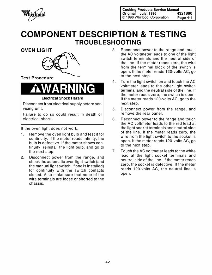
4-1
Page 4-1
Cooking Products Service ManualOriginal July, 1996 4321890© 1996 Whirlpool Corporation
COMPONENT DESCRIPTION & TESTINGTROUBLESHOOTING
3. Reconnect power to the range and touchthe AC voltmeter leads to one of the lightswitch terminals and the neutral side ofthe line. If the meter reads zero, the wirefrom the terminal block of the switch isopen. If the meter reads 120-volts AC, goto the next step.
4. Turn the light switch on and touch the ACvoltmeter leads to the other light switchterminal and the neutral side of the line. Ifthe meter reads zero, the switch is open.If the meter reads 120-volts AC, go to thenext step.
5. Disconnect power from the range, andremove the rear panel.
6. Reconnect power to the range and touchthe AC voltmeter leads to the red lead atthe light socket terminals and neutral sideof the line. If the meter reads zero, thewire from the light switch to the socket isopen. If the meter reads 120-volts AC, goto the next step.
7. Touch the AC voltmeter leads to the whitelead at the light socket terminals andneutral side of the line. If the meter readszero, the socket is defective. If the meterreads 120-volts AC, the neutral line isopen.
OVEN LIGHT
WARNING
If the oven light does not work:
1. Remove the oven light bulb and test it forcontinuity. If the meter reads infinity, thebulb is defective. If the meter shows con-tinuity, reinstall the light bulb, and go tothe next step.
2. Disconnect power from the range, andcheck the automatic oven light switch (andthe manual light switch, if one is installed)for continuity with the switch contactsclosed. Also make sure that none of thewire terminals are loose or shorted to thechassis.
Test Procedure
Electrical Shock Hazard
Disconnect from electrical supply before ser-vicing unit.
Failure to do so could result in death orelectrical shock.
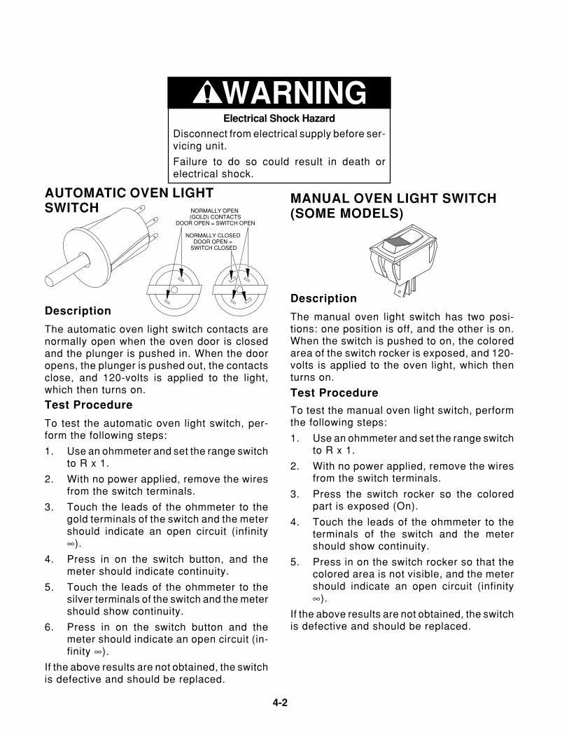
4-2
To test the automatic oven light switch, per-form the following steps:
1. Use an ohmmeter and set the range switchto R x 1.
2. With no power applied, remove the wiresfrom the switch terminals.
3. Touch the leads of the ohmmeter to thegold terminals of the switch and the metershould indicate an open circuit (infinity∞).
4. Press in on the switch button, and themeter should indicate continuity.
5. Touch the leads of the ohmmeter to thesilver terminals of the switch and the metershould show continuity.
6. Press in on the switch button and themeter should indicate an open circuit (in-finity ∞).
If the above results are not obtained, the switchis defective and should be replaced.
To test the manual oven light switch, performthe following steps:
1. Use an ohmmeter and set the range switchto R x 1.
2. With no power applied, remove the wiresfrom the switch terminals.
3. Press the switch rocker so the coloredpart is exposed (On).
4. Touch the leads of the ohmmeter to theterminals of the switch and the metershould show continuity.
5. Press in on the switch rocker so that thecolored area is not visible, and the metershould indicate an open circuit (infinity∞).
If the above results are not obtained, the switchis defective and should be replaced.
AUTOMATIC OVEN LIGHTSWITCH
Description
The automatic oven light switch contacts arenormally open when the oven door is closedand the plunger is pushed in. When the dooropens, the plunger is pushed out, the contactsclose, and 120-volts is applied to the light,which then turns on.
Test Procedure
NORMALLY OPEN (GOLD) CONTACTS
DOOR OPEN = SWITCH OPEN
NORMALLY CLOSED DOOR OPEN =
SWITCH CLOSED
MANUAL OVEN LIGHT SWITCH(SOME MODELS)
Description
The manual oven light switch has two posi-tions: one position is off, and the other is on.When the switch is pushed to on, the coloredarea of the switch rocker is exposed, and 120-volts is applied to the oven light, which thenturns on.
Test Procedure
WARNINGElectrical Shock Hazard
Disconnect from electrical supply before ser-vicing unit.
Failure to do so could result in death orelectrical shock.
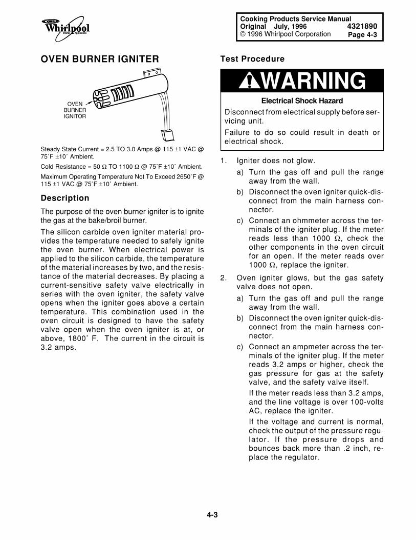
4-3
Page 4-3
Cooking Products Service ManualOriginal July, 1996 4321890© 1996 Whirlpool Corporation
OVEN BURNER IGNITER
OVENBURNERIGNITOR
Steady State Current = 2.5 TO 3.0 Amps @ 115 ±1 VAC @75˚F ±10˚ Ambient.
Cold Resistance = 50 Ω TO 1100 Ω @ 75˚F ±10˚ Ambient.
Maximum Operating Temperature Not To Exceed 2650˚F @115 ±1 VAC @ 75˚F ±10˚ Ambient.
Description
The purpose of the oven burner igniter is to ignitethe gas at the bake/broil burner.
The silicon carbide oven igniter material pro-vides the temperature needed to safely ignitethe oven burner. When electrical power isapplied to the silicon carbide, the temperatureof the material increases by two, and the resis-tance of the material decreases. By placing acurrent-sensitive safety valve electrically inseries with the oven igniter, the safety valveopens when the igniter goes above a certaintemperature. This combination used in theoven circuit is designed to have the safetyvalve open when the oven igniter is at, orabove, 1800˚ F. The current in the circuit is3.2 amps.
WARNING
1. Igniter does not glow.
a) Turn the gas off and pull the rangeaway from the wall.
b) Disconnect the oven igniter quick-dis-connect from the main harness con-nector.
c) Connect an ohmmeter across the ter-minals of the igniter plug. If the meterreads less than 1000 Ω, check theother components in the oven circuitfor an open. If the meter reads over1000 Ω, replace the igniter.
2. Oven igniter glows, but the gas safetyvalve does not open.
a) Turn the gas off and pull the rangeaway from the wall.
b) Disconnect the oven igniter quick-dis-connect from the main harness con-nector.
c) Connect an ampmeter across the ter-minals of the igniter plug. If the meterreads 3.2 amps or higher, check thegas pressure for gas at the safetyvalve, and the safety valve itself.
If the meter reads less than 3.2 amps,and the line voltage is over 100-voltsAC, replace the igniter.
If the voltage and current is normal,check the output of the pressure regu-lator. I f the pressure drops andbounces back more than .2 inch, re-place the regulator.
Test Procedure
Electrical Shock Hazard
Disconnect from electrical supply before ser-vicing unit.
Failure to do so could result in death orelectrical shock.
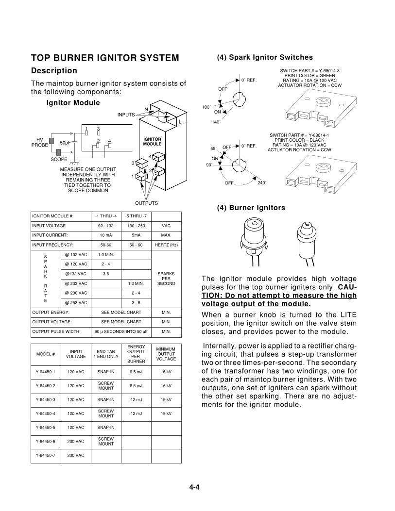
4-4
IGNITOR MODULE #: -1 THRU -4 -5 THRU -7
INPUT VOLTAGE 92 - 132 190 - 253 VAC
INPUT CURRENT: 10 mA 5mA MAX.
INPUT FREQUENCY: 50-60 50 - 60 HERTZ (Hz)
SPARK
RATE
@ 102 VAC 1.0 MIN.
SPARKSPER
SECOND
@ 120 VAC 2 - 4
@132 VAC 3-6
@ 203 VAC 1.2 MIN.
@ 230 VAC 2 - 4
@ 253 VAC 3 - 6
OUTPUT ENERGY: SEE MODEL CHART MIN.
OUTPUT VOLTAGE: SEE MODEL CHART MIN.
OUTPUT PULSE WIDTH: 90 µ SECONDS INTO 50 pF MIN.
MODEL #INPUT
VOLTAGEEND TAB
1 END ONLY
ENERGYOUTPUT
PER BURNER
MINIMUM OUTPUT
VOLTAGE
Y-64450-1 120 VAC SNAP-IN 6.5 mJ 16 kV
Y-64450-2 120 VACSCREWMOUNT
6.5 mJ 16 kV
Y-64450-3 120 VAC SNAP-IN 12 mJ 19 kV
Y-64450-4 120 VACSCREWMOUNT
12 mJ 19 kV
Y-64450-5 120 VAC SNAP-IN
Y-64450-6 230 VACSCREWMOUNT
Y-64450-7 230 VAC
TOP BURNER IGNITOR SYSTEMDescription
The maintop burner ignitor system consists ofthe following components:
Ignitor Module
(4) Burner Ignitors
IGNITORMODULE
12
43
N
L
INPUTS
OUTPUTS
1 3
2 450pFHV
PROBE
SCOPE
MEASURE ONE OUTPUTINDEPENDENTLY WITH
REMAINING THREETIED TOGETHER TO
SCOPE COMMON
(4) Spark Ignitor Switches
0˚ REF.
OFF
ON
140˚
100˚
SWITCH PART # = Y-68014-3PRINT COLOR = GREEN
RATING = 10A @ 120 VACACTUATOR ROTATION = CCW
0˚ REF.OFF
OFF
ON
55˚
90˚
240˚
SWITCH PART # = Y-68014-1PRINT COLOR = BLACK
RATING = 10A @ 120 VACACTUATOR ROTATION = CCW
The ignitor module provides high voltagepulses for the top burner igniters only. CAU-TION: Do not attempt to measure the highvoltage output of the module.
When a burner knob is turned to the LITEposition, the ignitor switch on the valve stemcloses, and provides power to the module.
Internally, power is applied to a rectifier charg-ing circuit, that pulses a step-up transformertwo or three times-per-second. The secondaryof the transformer has two windings, one foreach pair of maintop burner igniters. With twooutputs, one set of igniters can spark withoutthe other set sparking. There are no adjust-ments for the ignitor module.
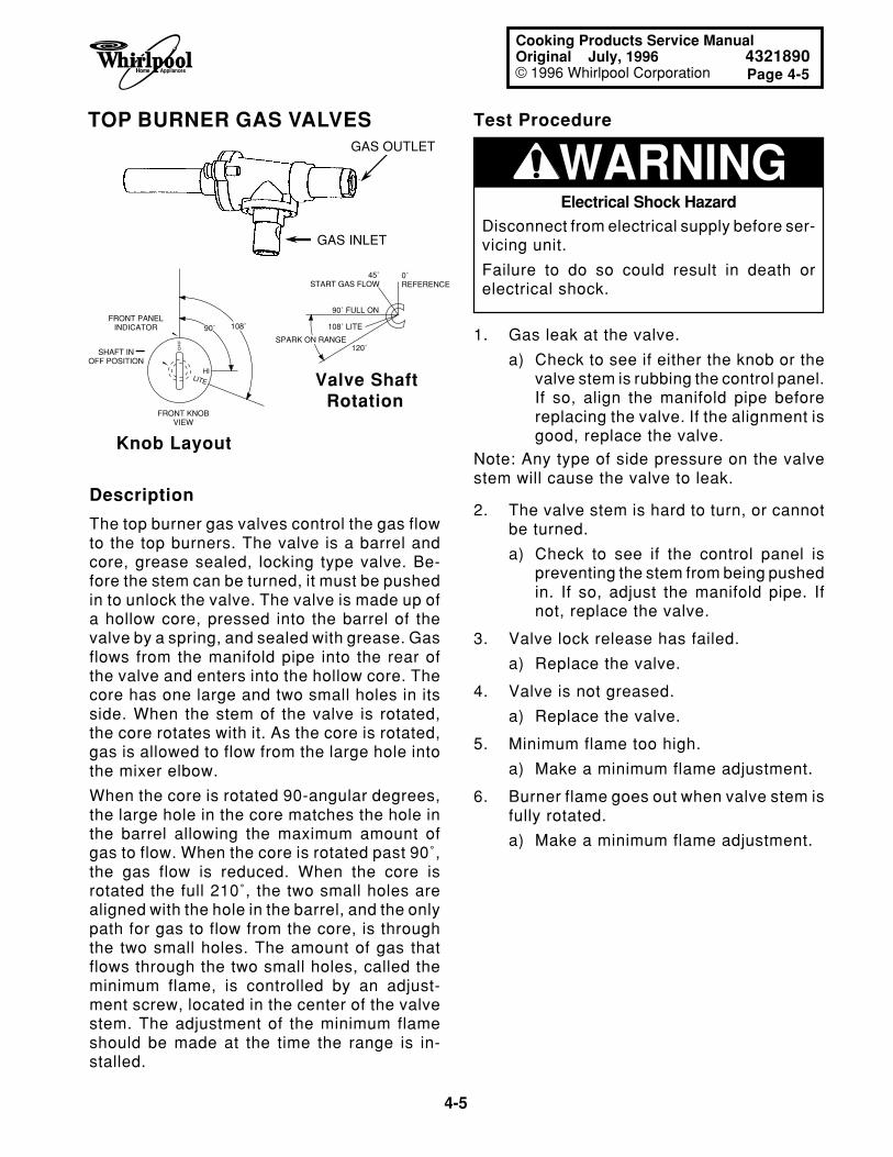
4-5
Page 4-5
Cooking Products Service ManualOriginal July, 1996 4321890© 1996 Whirlpool Corporation
TOP BURNER GAS VALVES
Description
The top burner gas valves control the gas flowto the top burners. The valve is a barrel andcore, grease sealed, locking type valve. Be-fore the stem can be turned, it must be pushedin to unlock the valve. The valve is made up ofa hollow core, pressed into the barrel of thevalve by a spring, and sealed with grease. Gasflows from the manifold pipe into the rear ofthe valve and enters into the hollow core. Thecore has one large and two small holes in itsside. When the stem of the valve is rotated,the core rotates with it. As the core is rotated,gas is allowed to flow from the large hole intothe mixer elbow.
When the core is rotated 90-angular degrees,the large hole in the core matches the hole inthe barrel allowing the maximum amount ofgas to flow. When the core is rotated past 90˚,the gas flow is reduced. When the core isrotated the full 210˚, the two small holes arealigned with the hole in the barrel, and the onlypath for gas to flow from the core, is throughthe two small holes. The amount of gas thatflows through the two small holes, called theminimum flame, is controlled by an adjust-ment screw, located in the center of the valvestem. The adjustment of the minimum flameshould be made at the time the range is in-stalled.
GAS INLET
GAS OUTLET WARNING
1. Gas leak at the valve.
a) Check to see if either the knob or thevalve stem is rubbing the control panel.If so, align the manifold pipe beforereplacing the valve. If the alignment isgood, replace the valve.
Note: Any type of side pressure on the valvestem will cause the valve to leak.
2. The valve stem is hard to turn, or cannotbe turned.
a) Check to see if the control panel ispreventing the stem from being pushedin. If so, adjust the manifold pipe. Ifnot, replace the valve.
3. Valve lock release has failed.
a) Replace the valve.
4. Valve is not greased.
a) Replace the valve.
5. Minimum flame too high.
a) Make a minimum flame adjustment.
6. Burner flame goes out when valve stem isfully rotated.
a) Make a minimum flame adjustment.
Test Procedure
Knob Layout
Valve Shaft Rotation
0˚REFERENCE
45˚START GAS FLOW
90˚ FULL ON
108˚ LITE
120˚SPARK ON RANGE
OF
F
HILITE
90˚ 108˚FRONT PANEL
INDICATOR
SHAFT INOFF POSITION
FRONT KNOBVIEW
Electrical Shock Hazard
Disconnect from electrical supply before ser-vicing unit.
Failure to do so could result in death orelectrical shock.
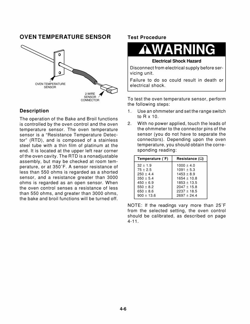
4-6
OVEN TEMPERATURE SENSOR
OVEN TEMPERATURESENSOR
2-WIRESENSOR
CONNECTOR
WARNING
To test the oven temperature sensor, performthe following steps:
1. Use an ohmmeter and set the range switchto R x 10.
2. With no power applied, touch the leads ofthe ohmmeter to the connector pins of thesensor (you do not have to separate theconnectors). Depending upon the oventemperature, you should obtain the corre-sponding reading:
Temperature (˚F) Resistance (Ω)
32 ± 1.9 1000 ± 4.075 ± 2.5 1091 ± 5.3250 ± 4.4 1453 ± 8.9350 ± 5.4 1654 ± 10.8450 ± 6.9 1853 ± 13.5550 ± 8.2 2047 ± 15.8650 ± 8.6 2237 ± 18.5900 ± 13.6 2697 ± 24.4
Test Procedure
Description
The operation of the Bake and Broil functionsis controlled by the oven control and the oventemperature sensor. The oven temperaturesensor is a “Resistance Temperature Detec-tor” (RTD), and is composed of a stainlesssteel tube with a thin film of platinum at theend. It is located at the upper left rear cornerof the oven cavity. The RTD is a nonadjustableassembly, but may be checked at room tem-perature, or at 350˚F. A sensor resistance ofless than 550 ohms is regarded as a shortedsensor, and a resistance greater than 3000ohms is regarded as an open sensor. Whenthe oven control senses a resistance of lessthan 550 ohms, and greater than 3000 ohms,the bake and broil functions will be turned off.
NOTE: If the readings vary more than 25˚Ffrom the selected setting, the oven controlshould be calibrated, as described on page4-11.
Electrical Shock Hazard
Disconnect from electrical supply before ser-vicing unit.
Failure to do so could result in death orelectrical shock.
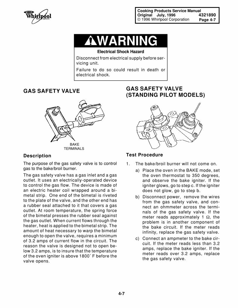
4-7
Page 4-7
Cooking Products Service ManualOriginal July, 1996 4321890© 1996 Whirlpool Corporation
GAS SAFETY VALVE GAS SAFETY VALVE(STANDING PILOT MODELS)
BAKE TERMINALS
Electrical Shock Hazard
Disconnect from electrical supply before ser-vicing unit.
Failure to do so could result in death orelectrical shock.
WARNING
Description
The purpose of the gas safety valve is to controlgas to the bake/broil burner.
The gas safety valve has a gas inlet and a gasoutlet. It uses an electrically-operated deviceto control the gas flow. The device is made ofan electric heater coil wrapped around a bi-metal strip. One end of the bimetal is rivetedto the plate of the valve, and the other end hasa rubber seal attached to it that covers a gasoutlet. At room temperature, the spring forceof the bimetal presses the rubber seal againstthe gas outlet. When current flows through theheater, heat is applied to the bimetal strip. Theamount of heat necessary to warp the bimetalenough to open the valve, requires a minimumof 3.2 amps of current flow in the circuit. Thereason the valve is designed not to open be-low 3.2 amps, is to insure that the temperatureof the oven igniter is above 1800˚ F before thevalve opens.
1. The bake/broil burner will not come on.
a) Place the oven in the BAKE mode, setthe oven thermostat to 350 degrees,and observe the bake igniter. If theigniter glows, go to step c. If the igniterdoes not glow, go to step b.
b) Disconnect power, remove the wiresfrom the gas safety valve, and con-nect an ohmmeter across the termi-nals of the gas safety valve. If themeter reads approximately 1 Ω, theproblem is in another component ofthe bake circuit. If the meter readsinfinity, replace the gas safety valve.
c) Connect an ampmeter to the bake cir-cuit. If the meter reads less than 3.2amps, replace the bake igniter. If themeter reads over 3.2 amps, replacethe gas safety valve.
Test Procedure
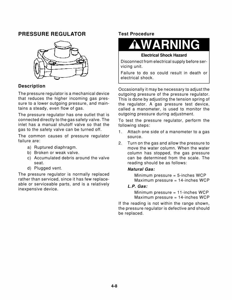
4-8
PRESSURE REGULATOR Test Procedure
WARNING
Occasionally it may be necessary to adjust theoutgoing pressure of the pressure regulator.This is done by adjusting the tension spring ofthe regulator. A gas pressure test device,called a manometer, is used to monitor theoutgoing pressure during adjustment.
To test the pressure regulator, perform thefollowing steps:
1. Attach one side of a manometer to a gassource.
2. Turn on the gas and allow the pressure tomove the water column. When the watercolumn has stopped, the gas pressurecan be determined from the scale. Thereading should be as follows:
Natural Gas:Minimum pressure = 5-inches WCPMaximum pressure = 14-inches WCP
L.P. Gas:Minimum pressure = 11-inches WCPMaximum pressure = 14-inches WCP
If the reading is not within the range shown,the pressure regulator is defective and shouldbe replaced.
Description
The pressure regulator is a mechanical devicethat reduces the higher incoming gas pres-sure to a lower outgoing pressure, and main-tains a steady, even flow of gas.
The pressure regulator has one outlet that isconnected directly to the gas safety valve. Theinlet has a manual shutoff valve so that thegas to the safety valve can be turned off.
The common causes of pressure regulatorfailure are:
a) Ruptured diaphragm.b) Broken or weak valve.c) Accumulated debris around the valve
seat.d) Plugged vent.
The pressure regulator is normally replacedrather than serviced, since it has few replace-able or serviceable parts, and is a relativelyinexpensive device.
Electrical Shock Hazard
Disconnect from electrical supply before ser-vicing unit.
Failure to do so could result in death orelectrical shock.
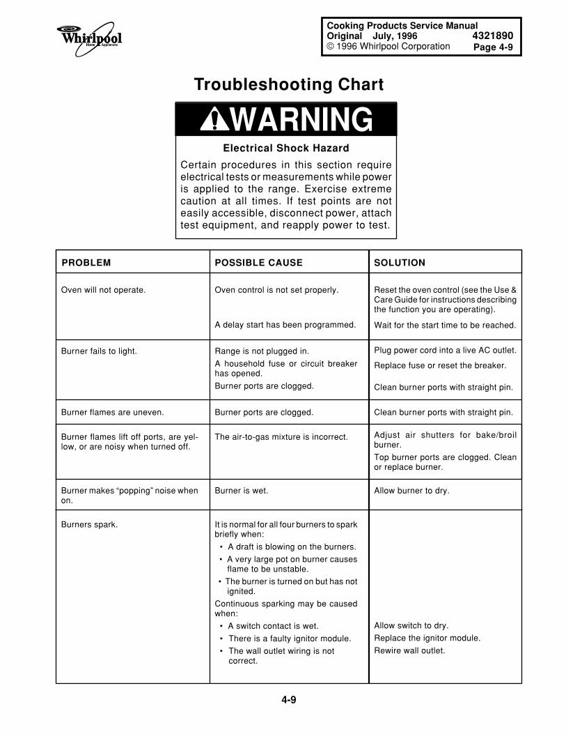
4-9
Page 4-9
Cooking Products Service ManualOriginal July, 1996 4321890© 1996 Whirlpool Corporation
Oven will not operate. Oven control is not set properly.
A delay start has been programmed.
Reset the oven control (see the Use &Care Guide for instructions describingthe function you are operating).
Range is not plugged in.
A household fuse or circuit breakerhas opened.
Burner ports are clogged.
Burner fails to light.
Burner flames are uneven. Burner ports are clogged. Clean burner ports with straight pin.
WARNINGElectrical Shock Hazard
Certain procedures in this section requireelectrical tests or measurements while poweris applied to the range. Exercise extremecaution at all times. If test points are noteasily accessible, disconnect power, attachtest equipment, and reapply power to test.
Wait for the start time to be reached.
Plug power cord into a live AC outlet.
Replace fuse or reset the breaker.
Clean burner ports with straight pin.
Burner flames lift off ports, are yel-low, or are noisy when turned off.
Adjust air shutters for bake/broilburner.
Top burner ports are clogged. Cleanor replace burner.
The air-to-gas mixture is incorrect.
Burner is wet.Burner makes “popping” noise whenon.
It is normal for all four burners to sparkbriefly when:
• A draft is blowing on the burners.
• A very large pot on burner causes flame to be unstable.
• The burner is turned on but has not ignited.
Continuous sparking may be causedwhen:
• A switch contact is wet.
• There is a faulty ignitor module.
• The wall outlet wiring is notcorrect.
Burners spark.
Allow burner to dry.
Allow switch to dry.
Replace the ignitor module.
Rewire wall outlet.
Troubleshooting Chart
PROBLEM POSSIBLE CAUSE SOLUTION
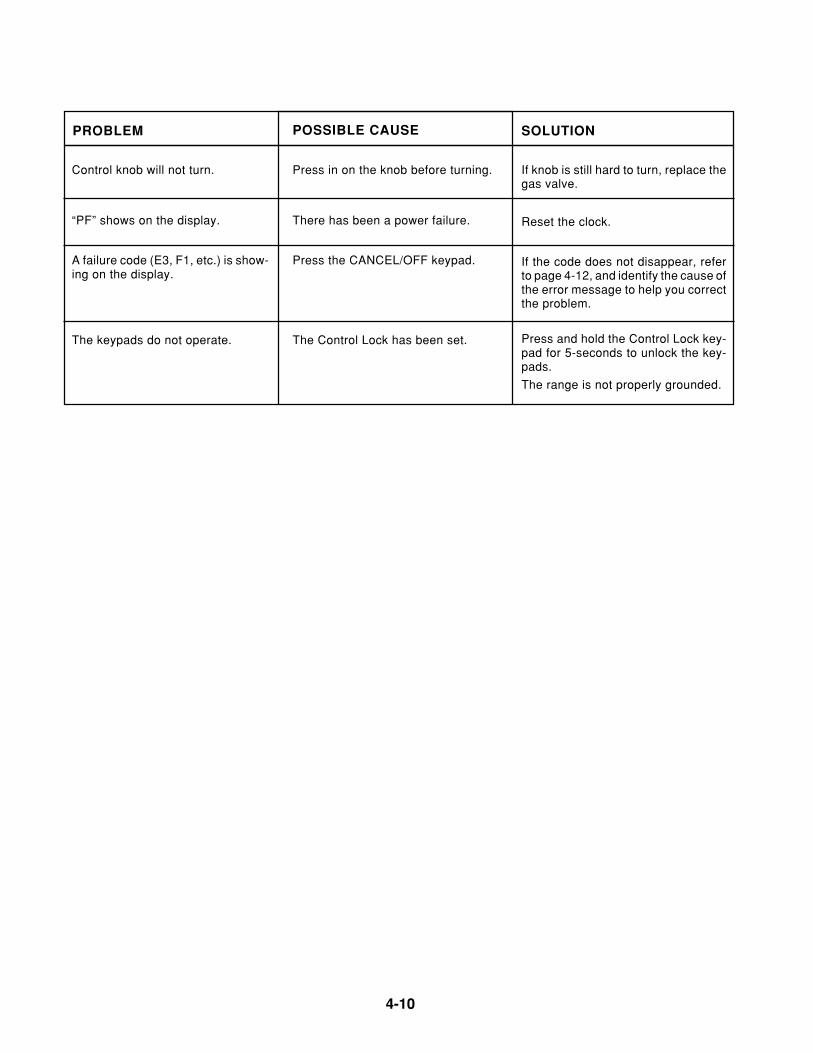
4-10
PROBLEM SOLUTION
Control knob will not turn. Press in on the knob before turning. If knob is still hard to turn, replace thegas valve.
POSSIBLE CAUSE
“PF” shows on the display. There has been a power failure. Reset the clock.
A failure code (E3, F1, etc.) is show-ing on the display.
Press the CANCEL/OFF keypad. If the code does not disappear, referto page 4-12, and identify the cause ofthe error message to help you correctthe problem.
The keypads do not operate. The Control Lock has been set. Press and hold the Control Lock key-pad for 5-seconds to unlock the key-pads.
The range is not properly grounded.
4-11
Page 4-11
Cooking Products Service ManualOriginal July, 1996 4321890© 1996 Whirlpool Corporation
OVEN TEMPERATURE CALIBRATION(ELECTRONIC OVEN CONTROLS)
The oven temperature is factory-calibrated.The calibration temperature can be increasedto a maximum 35˚, in 5˚ increments. To changethe calibration temperature,perform the fol-lowing steps.
1. Touch and hold the BAKE keypad for4-seconds, and the display will indicatethe present “oven calibration” tempera-ture.
2. Touch the BAKE keypad until the displayincreases by 5˚, then remove your fingerfrom the keypad for 1-second. To con-
tinue increasing the temperature in 5˚increments, touch and release the key-pad in 1-second intervals, until the de-sired temperature is reached (up to +35˚).
3. To decrease the calibration temperaturefrom the maximum setting, press and re-lease the BAKE keypad in 1-second inter-vals. The readings will change to –35˚, anddecrease to 0, or its original temperaturesetting. The cycle will then start over.
4. To exit the “temperature calibration” mode,press the CANCEL/OFF keypad.
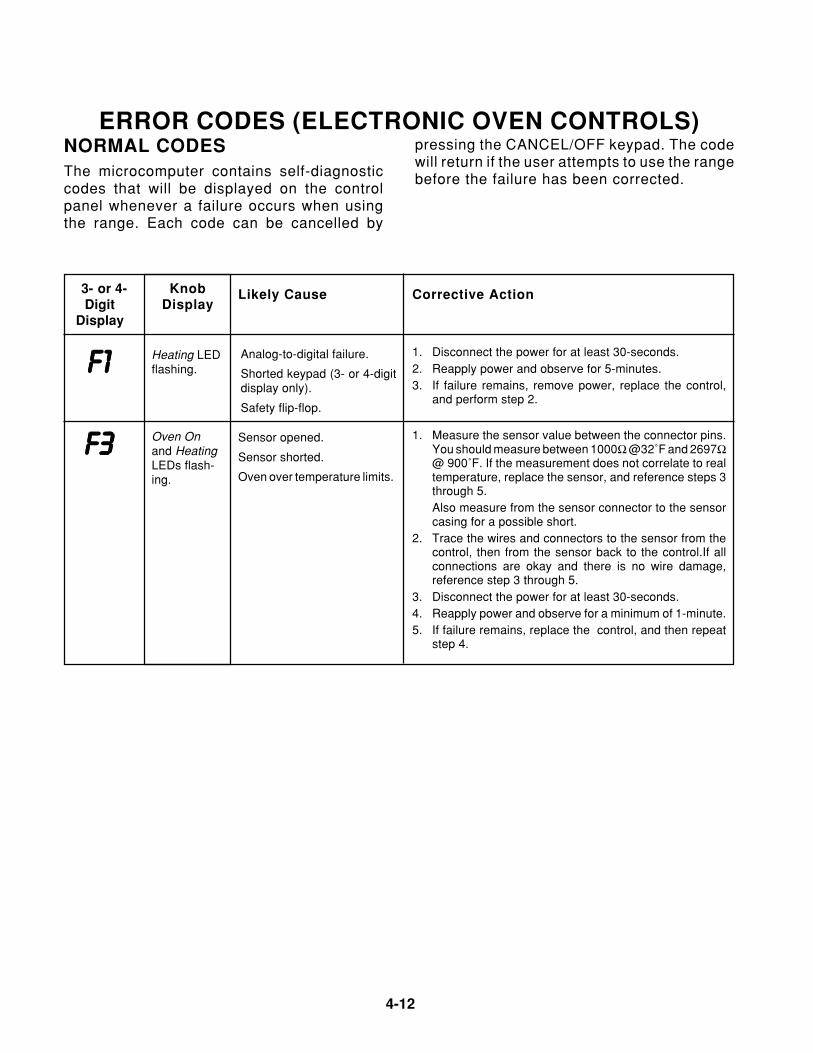
4-12
ERROR CODES (ELECTRONIC OVEN CONTROLS)
KnobDisplay
3- or 4-Digit
Display
Corrective ActionLikely Cause
F1F1F1F1F11. Disconnect the power for at least 30-seconds.2. Reapply power and observe for 5-minutes.3. If failure remains, remove power, replace the control,
and perform step 2.
Heating LEDflashing.
Analog-to-digital failure.
Shorted keypad (3- or 4-digitdisplay only).
Safety flip-flop.
Oven Onand HeatingLEDs flash-ing.
F3F3F3F3F31. Measure the sensor value between the connector pins.
You should measure between 1000Ω @32˚F and 2697Ω@ 900˚F. If the measurement does not correlate to realtemperature, replace the sensor, and reference steps 3through 5.Also measure from the sensor connector to the sensorcasing for a possible short.
2. Trace the wires and connectors to the sensor from thecontrol, then from the sensor back to the control.If allconnections are okay and there is no wire damage,reference step 3 through 5.
3. Disconnect the power for at least 30-seconds.4. Reapply power and observe for a minimum of 1-minute.5. If failure remains, replace the control, and then repeat
step 4.
Sensor opened.
Sensor shorted.
Oven over temperature limits.
NORMAL CODESThe microcomputer contains self-diagnosticcodes that will be displayed on the controlpanel whenever a failure occurs when usingthe range. Each code can be cancelled by
pressing the CANCEL/OFF keypad. The codewill return if the user attempts to use the rangebefore the failure has been corrected.
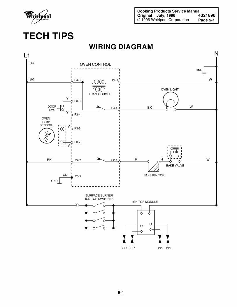
Page 5-1
5-1
Cooking Products Service ManualOriginal July, 1996 4321890© 1996 Whirlpool Corporation
TECH TIPSWIRING DIAGRAM
L1 N
BK
BK
V
V
R R
W
W
W
BK
Y
Y
BK
OVENTEMP
SENSOR
SURFACE BURNERIGNITOR SWITCHES
IGNITOR MODULE
DOORSW.
OVEN CONTROL
TRANSFORMER
P3-6
P3-7
P3-3
P4-3 P4-1
P3-4
P2-2
P3-5
P2-1
P4-4
BAKE VALVE
BAKE IGNITOR
OVEN LIGHT
GND
GND
GN
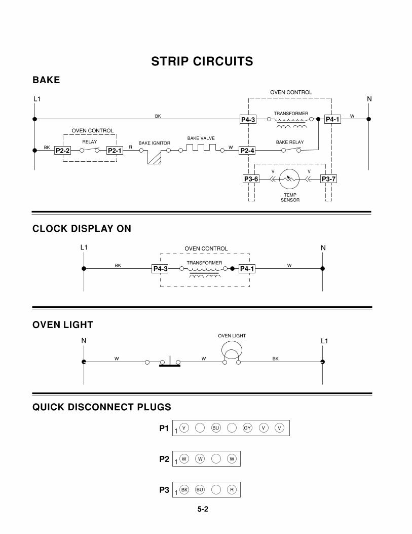
5-2
STRIP CIRCUITSBAKE
L1 N
WBK
BK R W
V V
OVEN CONTROL
OVEN CONTROL
TRANSFORMER
TEMPSENSOR
BAKE RELAYBAKE VALVE
BAKE IGNITORRELAY
P2-1P2-2
P3-6 P3-7
P4-3 P4-1
P2-4
CLOCK DISPLAY ON
L1 N
WBK
OVEN CONTROL
TRANSFORMER
P4-3 P4-1
OVEN LIGHT
1 Y V VBU GYP1
1 W W WP2
1 BK BUP3 R
N L1
W W BK
OVEN LIGHT
QUICK DISCONNECT PLUGS
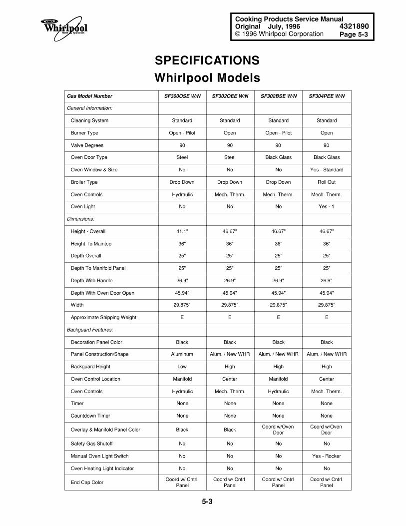
Page 5-3
5-3
Cooking Products Service ManualOriginal July, 1996 4321890© 1996 Whirlpool Corporation
SPECIFICATIONSWhirlpool Models
Gas Model Number SF300OSE W/N SF302OEE W/N SF302BSE W/N SF304PEE W/N
General Information:
Cleaning System Standard Standard Standard Standard
Burner Type Open - Pilot Open Open - Pilot Open
Valve Degrees 90 90 90 90
Oven Door Type Steel Steel Black Glass Black Glass
Oven Window & Size No No No Yes - Standard
Broiler Type Drop Down Drop Down Drop Down Roll Out
Oven Controls Hydraulic Mech. Therm. Mech. Therm. Mech. Therm.
Oven Light No No No Yes - 1
Dimensions:
Height - Overall 41.1" 46.67" 46.67" 46.67"
Height To Maintop 36" 36" 36" 36"
Depth Overall 25" 25" 25" 25"
Depth To Manifold Panel 25" 25" 25" 25"
Depth With Handle 26.9" 26.9" 26.9" 26.9"
Depth With Oven Door Open 45.94" 45.94" 45.94" 45.94"
Width 29.875" 29.875" 29.875" 29.875"
Approximate Shipping Weight E E E E
Backguard Features:
Decoration Panel Color Black Black Black Black
Panel Construction/Shape Aluminum Alum. / New WHR Alum. / New WHR Alum. / New WHR
Backguard Height Low High High High
Oven Control Location Manifold Center Manifold Center
Oven Controls Hydraulic Mech. Therm. Hydraulic Mech. Therm.
Timer None None None None
Countdown Timer None None None None
Overlay & Manifold Panel Color Black BlackCoord w/Oven
DoorCoord w/Oven
Door
Safety Gas Shutoff No No No No
Manual Oven Light Switch No No No Yes - Rocker
Oven Heating Light Indicator No No No No
End Cap ColorCoord w/ Cntrl
PanelCoord w/ Cntrl
PanelCoord w/ Cntrl
PanelCoord w/ Cntrl
Panel
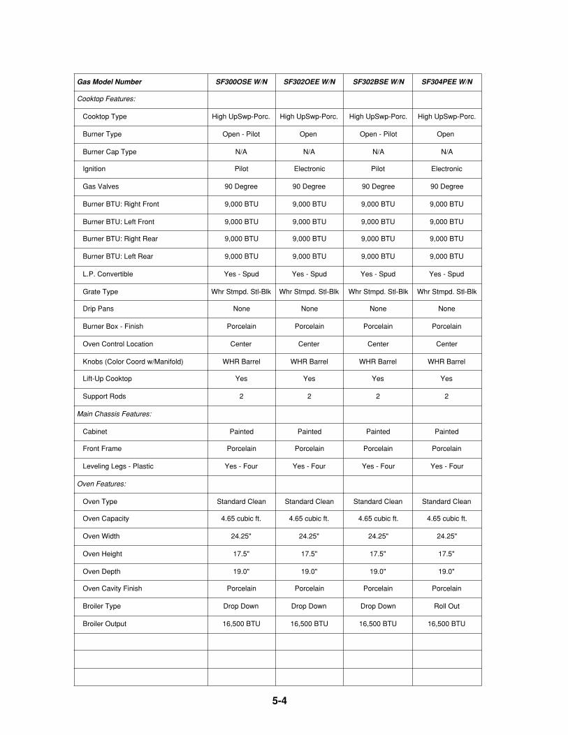
5-4
Gas Model Number SF300OSE W/N SF302OEE W/N SF302BSE W/N SF304PEE W/N
Cooktop Features:
Cooktop Type High UpSwp-Porc. High UpSwp-Porc. High UpSwp-Porc. High UpSwp-Porc.
Burner Type Open - Pilot Open Open - Pilot Open
Burner Cap Type N/A N/A N/A N/A
Ignition Pilot Electronic Pilot Electronic
Gas Valves 90 Degree 90 Degree 90 Degree 90 Degree
Burner BTU: Right Front 9,000 BTU 9,000 BTU 9,000 BTU 9,000 BTU
Burner BTU: Left Front 9,000 BTU 9,000 BTU 9,000 BTU 9,000 BTU
Burner BTU: Right Rear 9,000 BTU 9,000 BTU 9,000 BTU 9,000 BTU
Burner BTU: Left Rear 9,000 BTU 9,000 BTU 9,000 BTU 9,000 BTU
L.P. Convertible Yes - Spud Yes - Spud Yes - Spud Yes - Spud
Grate Type Whr Stmpd. Stl-Blk Whr Stmpd. Stl-Blk Whr Stmpd. Stl-Blk Whr Stmpd. Stl-Blk
Drip Pans None None None None
Burner Box - Finish Porcelain Porcelain Porcelain Porcelain
Oven Control Location Center Center Center Center
Knobs (Color Coord w/Manifold) WHR Barrel WHR Barrel WHR Barrel WHR Barrel
Lift-Up Cooktop Yes Yes Yes Yes
Support Rods 2 2 2 2
Main Chassis Features:
Cabinet Painted Painted Painted Painted
Front Frame Porcelain Porcelain Porcelain Porcelain
Leveling Legs - Plastic Yes - Four Yes - Four Yes - Four Yes - Four
Oven Features:
Oven Type Standard Clean Standard Clean Standard Clean Standard Clean
Oven Capacity 4.65 cubic ft. 4.65 cubic ft. 4.65 cubic ft. 4.65 cubic ft.
Oven Width 24.25" 24.25" 24.25" 24.25"
Oven Height 17.5" 17.5" 17.5" 17.5"
Oven Depth 19.0" 19.0" 19.0" 19.0"
Oven Cavity Finish Porcelain Porcelain Porcelain Porcelain
Broiler Type Drop Down Drop Down Drop Down Roll Out
Broiler Output 16,500 BTU 16,500 BTU 16,500 BTU 16,500 BTU
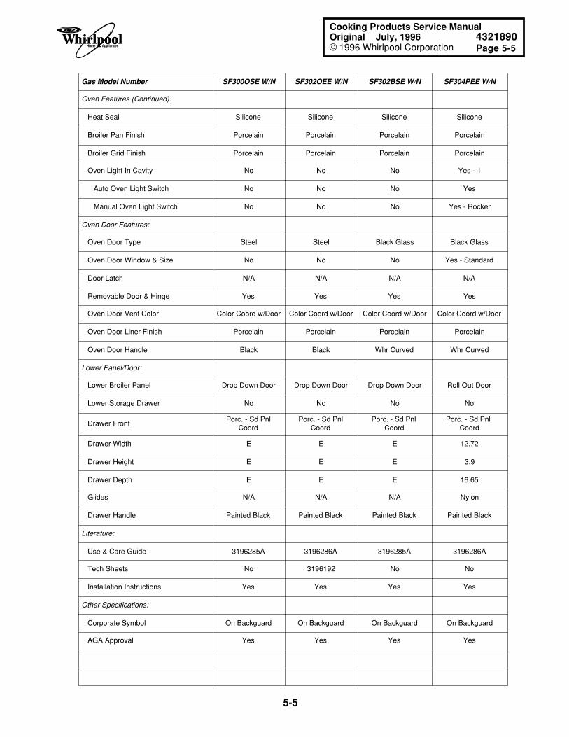
Page 5-5
5-5
Cooking Products Service ManualOriginal July, 1996 4321890© 1996 Whirlpool Corporation
Gas Model Number SF300OSE W/N SF302OEE W/N SF302BSE W/N SF304PEE W/N
Oven Features (Continued):
Heat Seal Silicone Silicone Silicone Silicone
Broiler Pan Finish Porcelain Porcelain Porcelain Porcelain
Broiler Grid Finish Porcelain Porcelain Porcelain Porcelain
Oven Light In Cavity No No No Yes - 1
Auto Oven Light Switch No No No Yes
Manual Oven Light Switch No No No Yes - Rocker
Oven Door Features:
Oven Door Type Steel Steel Black Glass Black Glass
Oven Door Window & Size No No No Yes - Standard
Door Latch N/A N/A N/A N/A
Removable Door & Hinge Yes Yes Yes Yes
Oven Door Vent Color Color Coord w/Door Color Coord w/Door Color Coord w/Door Color Coord w/Door
Oven Door Liner Finish Porcelain Porcelain Porcelain Porcelain
Oven Door Handle Black Black Whr Curved Whr Curved
Lower Panel/Door:
Lower Broiler Panel Drop Down Door Drop Down Door Drop Down Door Roll Out Door
Lower Storage Drawer No No No No
Drawer FrontPorc. - Sd Pnl
CoordPorc. - Sd Pnl
CoordPorc. - Sd Pnl
CoordPorc. - Sd Pnl
Coord
Drawer Width E E E 12.72
Drawer Height E E E 3.9
Drawer Depth E E E 16.65
Glides N/A N/A N/A Nylon
Drawer Handle Painted Black Painted Black Painted Black Painted Black
Literature:
Use & Care Guide 3196285A 3196286A 3196285A 3196286A
Tech Sheets No 3196192 No No
Installation Instructions Yes Yes Yes Yes
Other Specifications:
Corporate Symbol On Backguard On Backguard On Backguard On Backguard
AGA Approval Yes Yes Yes Yes
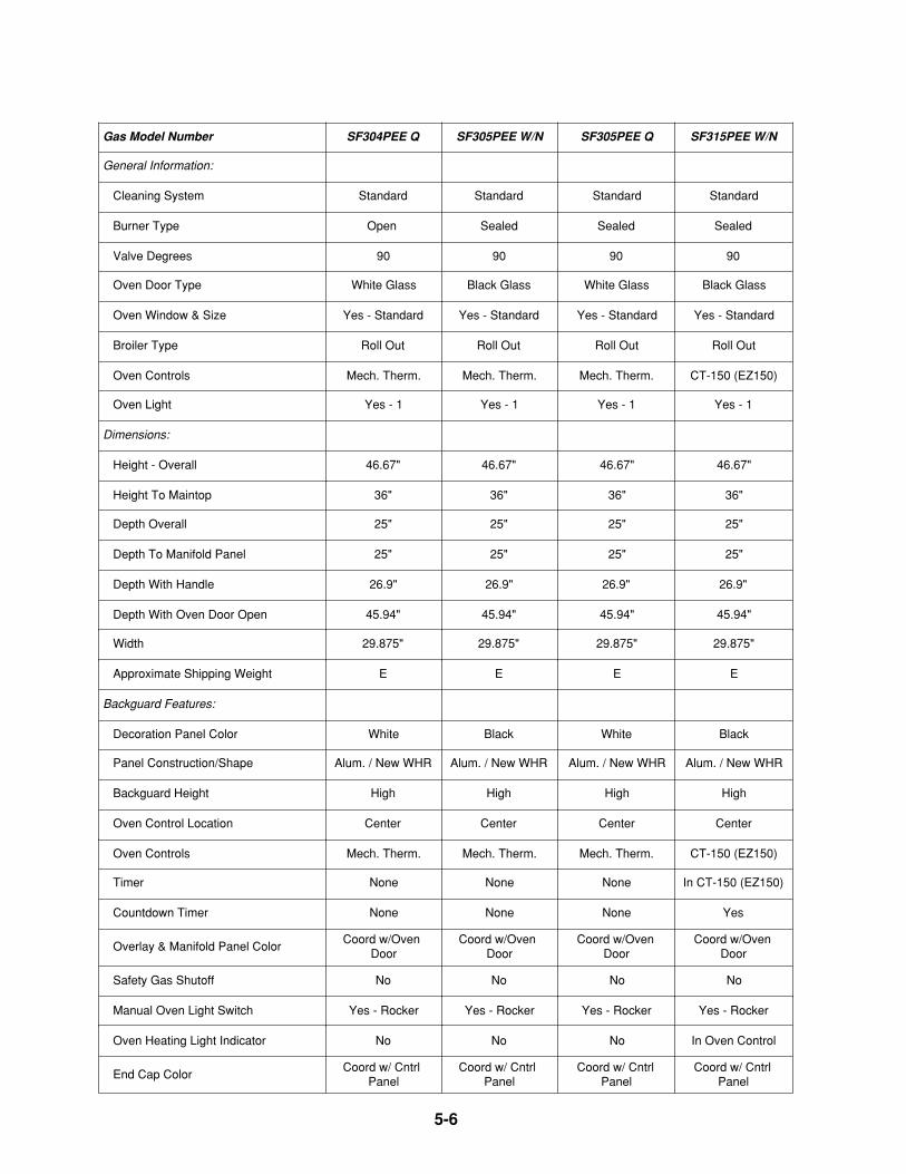
5-6
Gas Model Number SF304PEE Q SF305PEE W/N SF305PEE Q SF315PEE W/N
General Information:
Cleaning System Standard Standard Standard Standard
Burner Type Open Sealed Sealed Sealed
Valve Degrees 90 90 90 90
Oven Door Type White Glass Black Glass White Glass Black Glass
Oven Window & Size Yes - Standard Yes - Standard Yes - Standard Yes - Standard
Broiler Type Roll Out Roll Out Roll Out Roll Out
Oven Controls Mech. Therm. Mech. Therm. Mech. Therm. CT-150 (EZ150)
Oven Light Yes - 1 Yes - 1 Yes - 1 Yes - 1
Dimensions:
Height - Overall 46.67" 46.67" 46.67" 46.67"
Height To Maintop 36" 36" 36" 36"
Depth Overall 25" 25" 25" 25"
Depth To Manifold Panel 25" 25" 25" 25"
Depth With Handle 26.9" 26.9" 26.9" 26.9"
Depth With Oven Door Open 45.94" 45.94" 45.94" 45.94"
Width 29.875" 29.875" 29.875" 29.875"
Approximate Shipping Weight E E E E
Backguard Features:
Decoration Panel Color White Black White Black
Panel Construction/Shape Alum. / New WHR Alum. / New WHR Alum. / New WHR Alum. / New WHR
Backguard Height High High High High
Oven Control Location Center Center Center Center
Oven Controls Mech. Therm. Mech. Therm. Mech. Therm. CT-150 (EZ150)
Timer None None None In CT-150 (EZ150)
Countdown Timer None None None Yes
Overlay & Manifold Panel ColorCoord w/Oven
DoorCoord w/Oven
DoorCoord w/Oven
DoorCoord w/Oven
Door
Safety Gas Shutoff No No No No
Manual Oven Light Switch Yes - Rocker Yes - Rocker Yes - Rocker Yes - Rocker
Oven Heating Light Indicator No No No In Oven Control
End Cap ColorCoord w/ Cntrl
PanelCoord w/ Cntrl
PanelCoord w/ Cntrl
PanelCoord w/ Cntrl
Panel
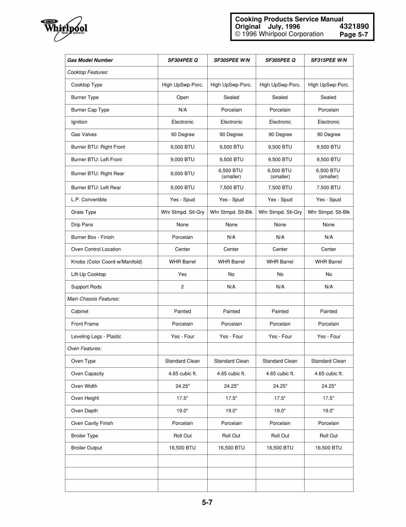
Page 5-7
5-7
Cooking Products Service ManualOriginal July, 1996 4321890© 1996 Whirlpool Corporation
Gas Model Number SF304PEE Q SF305PEE W/N SF305PEE Q SF315PEE W/N
Cooktop Features:
Cooktop Type High UpSwp-Porc. High UpSwp-Porc. High UpSwp-Porc. High UpSwp-Porc.
Burner Type Open Sealed Sealed Sealed
Burner Cap Type N/A Porcelain Porcelain Porcelain
Ignition Electronic Electronic Electronic Electronic
Gas Valves 90 Degree 90 Degree 90 Degree 90 Degree
Burner BTU: Right Front 9,000 BTU 9,500 BTU 9,500 BTU 9,500 BTU
Burner BTU: Left Front 9,000 BTU 9,500 BTU 9,500 BTU 9,500 BTU
Burner BTU: Right Rear 9,000 BTU6,500 BTU
(smaller)6,500 BTU
(smaller)6,500 BTU
(smaller)
Burner BTU: Left Rear 9,000 BTU 7,500 BTU 7,500 BTU 7,500 BTU
L.P. Convertible Yes - Spud Yes - Spud Yes - Spud Yes - Spud
Grate Type Whr Stmpd. Stl-Gry Whr Stmpd. Stl-Blk Whr Stmpd. Stl-Gry Whr Stmpd. Stl-Blk
Drip Pans None None None None
Burner Box - Finish Porcelain N/A N/A N/A
Oven Control Location Center Center Center Center
Knobs (Color Coord w/Manifold) WHR Barrel WHR Barrel WHR Barrel WHR Barrel
Lift-Up Cooktop Yes No No No
Support Rods 2 N/A N/A N/A
Main Chassis Features:
Cabinet Painted Painted Painted Painted
Front Frame Porcelain Porcelain Porcelain Porcelain
Leveling Legs - Plastic Yes - Four Yes - Four Yes - Four Yes - Four
Oven Features:
Oven Type Standard Clean Standard Clean Standard Clean Standard Clean
Oven Capacity 4.65 cubic ft. 4.65 cubic ft. 4.65 cubic ft. 4.65 cubic ft.
Oven Width 24.25" 24.25" 24.25" 24.25"
Oven Height 17.5" 17.5" 17.5" 17.5"
Oven Depth 19.0" 19.0" 19.0" 19.0"
Oven Cavity Finish Porcelain Porcelain Porcelain Porcelain
Broiler Type Roll Out Roll Out Roll Out Roll Out
Broiler Output 16,500 BTU 16,500 BTU 16,500 BTU 16,500 BTU
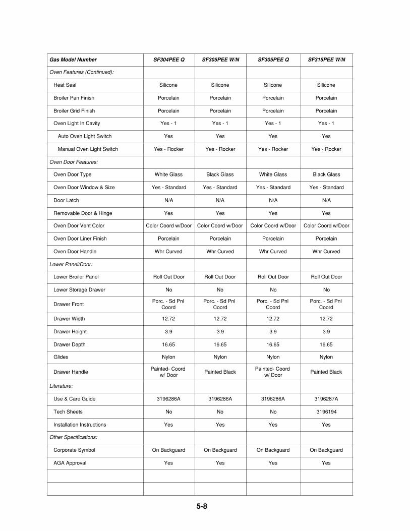
5-8
Gas Model Number SF304PEE Q SF305PEE W/N SF305PEE Q SF315PEE W/N
Oven Features (Continued):
Heat Seal Silicone Silicone Silicone Silicone
Broiler Pan Finish Porcelain Porcelain Porcelain Porcelain
Broiler Grid Finish Porcelain Porcelain Porcelain Porcelain
Oven Light In Cavity Yes - 1 Yes - 1 Yes - 1 Yes - 1
Auto Oven Light Switch Yes Yes Yes Yes
Manual Oven Light Switch Yes - Rocker Yes - Rocker Yes - Rocker Yes - Rocker
Oven Door Features:
Oven Door Type White Glass Black Glass White Glass Black Glass
Oven Door Window & Size Yes - Standard Yes - Standard Yes - Standard Yes - Standard
Door Latch N/A N/A N/A N/A
Removable Door & Hinge Yes Yes Yes Yes
Oven Door Vent Color Color Coord w/Door Color Coord w/Door Color Coord w/Door Color Coord w/Door
Oven Door Liner Finish Porcelain Porcelain Porcelain Porcelain
Oven Door Handle Whr Curved Whr Curved Whr Curved Whr Curved
Lower Panel/Door:
Lower Broiler Panel Roll Out Door Roll Out Door Roll Out Door Roll Out Door
Lower Storage Drawer No No No No
Drawer FrontPorc. - Sd Pnl
CoordPorc. - Sd Pnl
CoordPorc. - Sd Pnl
CoordPorc. - Sd Pnl
Coord
Drawer Width 12.72 12.72 12.72 12.72
Drawer Height 3.9 3.9 3.9 3.9
Drawer Depth 16.65 16.65 16.65 16.65
Glides Nylon Nylon Nylon Nylon
Drawer HandlePainted- Coord
w/ DoorPainted Black
Painted- Coord w/ Door
Painted Black
Literature:
Use & Care Guide 3196286A 3196286A 3196286A 3196287A
Tech Sheets No No No 3196194
Installation Instructions Yes Yes Yes Yes
Other Specifications:
Corporate Symbol On Backguard On Backguard On Backguard On Backguard
AGA Approval Yes Yes Yes Yes
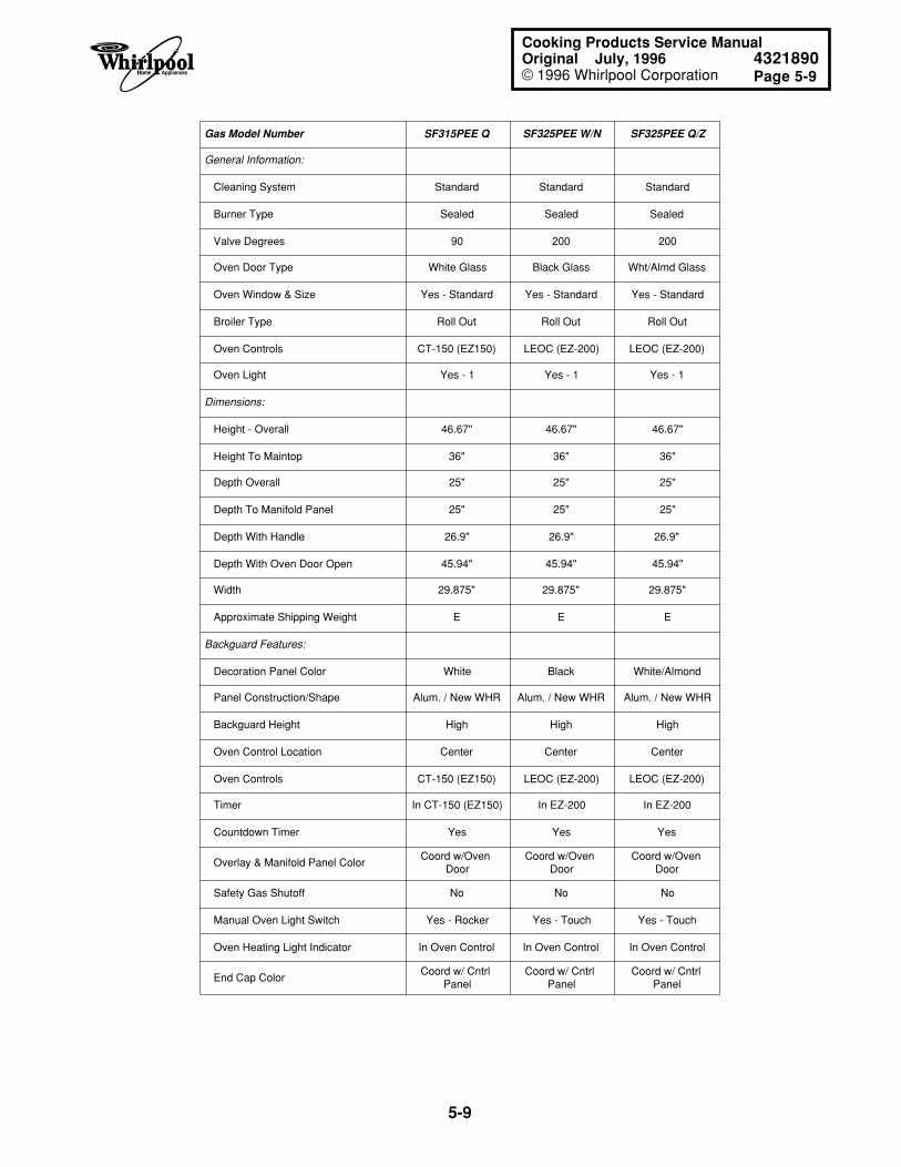
Page 5-9
5-9
Cooking Products Service ManualOriginal July, 1996 4321890© 1996 Whirlpool Corporation
Gas Model Number SF315PEE Q SF325PEE W/N SF325PEE Q/Z
General Information:
Cleaning System Standard Standard Standard
Burner Type Sealed Sealed Sealed
Valve Degrees 90 200 200
Oven Door Type White Glass Black Glass Wht/Almd Glass
Oven Window & Size Yes - Standard Yes - Standard Yes - Standard
Broiler Type Roll Out Roll Out Roll Out
Oven Controls CT-150 (EZ150) LEOC (EZ-200) LEOC (EZ-200)
Oven Light Yes - 1 Yes - 1 Yes - 1
Dimensions:
Height - Overall 46.67" 46.67" 46.67"
Height To Maintop 36" 36" 36"
Depth Overall 25" 25" 25"
Depth To Manifold Panel 25" 25" 25"
Depth With Handle 26.9" 26.9" 26.9"
Depth With Oven Door Open 45.94" 45.94" 45.94"
Width 29.875" 29.875" 29.875"
Approximate Shipping Weight E E E
Backguard Features:
Decoration Panel Color White Black White/Almond
Panel Construction/Shape Alum. / New WHR Alum. / New WHR Alum. / New WHR
Backguard Height High High High
Oven Control Location Center Center Center
Oven Controls CT-150 (EZ150) LEOC (EZ-200) LEOC (EZ-200)
Timer In CT-150 (EZ150) In EZ-200 In EZ-200
Countdown Timer Yes Yes Yes
Overlay & Manifold Panel ColorCoord w/Oven
DoorCoord w/Oven
DoorCoord w/Oven
Door
Safety Gas Shutoff No No No
Manual Oven Light Switch Yes - Rocker Yes - Touch Yes - Touch
Oven Heating Light Indicator In Oven Control In Oven Control In Oven Control
End Cap ColorCoord w/ Cntrl
PanelCoord w/ Cntrl
PanelCoord w/ Cntrl
Panel
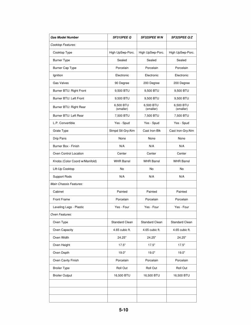
5-10
Gas Model Number SF315PEE Q SF325PEE W/N SF325PEE Q/Z
Cooktop Features:
Cooktop Type High UpSwp-Porc. High UpSwp-Porc. High UpSwp-Porc.
Burner Type Sealed Sealed Sealed
Burner Cap Type Porcelain Porcelain Porcelain
Ignition Electronic Electronic Electronic
Gas Valves 90 Degree 200 Degree 200 Degree
Burner BTU: Right Front 9,500 BTU 9,500 BTU 9,500 BTU
Burner BTU: Left Front 9,500 BTU 9,500 BTU 9,500 BTU
Burner BTU: Right Rear6,500 BTU
(smaller)6,500 BTU
(smaller)6,500 BTU
(smaller)
Burner BTU: Left Rear 7,500 BTU 7,500 BTU 7,500 BTU
L.P. Convertible Yes - Spud Yes - Spud Yes - Spud
Grate Type Stmpd Stl-Gry/Alm Cast Iron-Blk Cast Iron-Gry/Alm
Drip Pans None None None
Burner Box - Finish N/A N/A N/A
Oven Control Location Center Center Center
Knobs (Color Coord w/Manifold) WHR Barrel WHR Barrel WHR Barrel
Lift-Up Cooktop No No No
Support Rods N/A N/A N/A
Main Chassis Features:
Cabinet Painted Painted Painted
Front Frame Porcelain Porcelain Porcelain
Leveling Legs - Plastic Yes - Four Yes - Four Yes - Four
Oven Features:
Oven Type Standard Clean Standard Clean Standard Clean
Oven Capacity 4.65 cubic ft. 4.65 cubic ft. 4.65 cubic ft.
Oven Width 24.25" 24.25" 24.25"
Oven Height 17.5" 17.5" 17.5"
Oven Depth 19.0" 19.0" 19.0"
Oven Cavity Finish Porcelain Porcelain Porcelain
Broiler Type Roll Out Roll Out Roll Out
Broiler Output 16,500 BTU 16,500 BTU 16,500 BTU
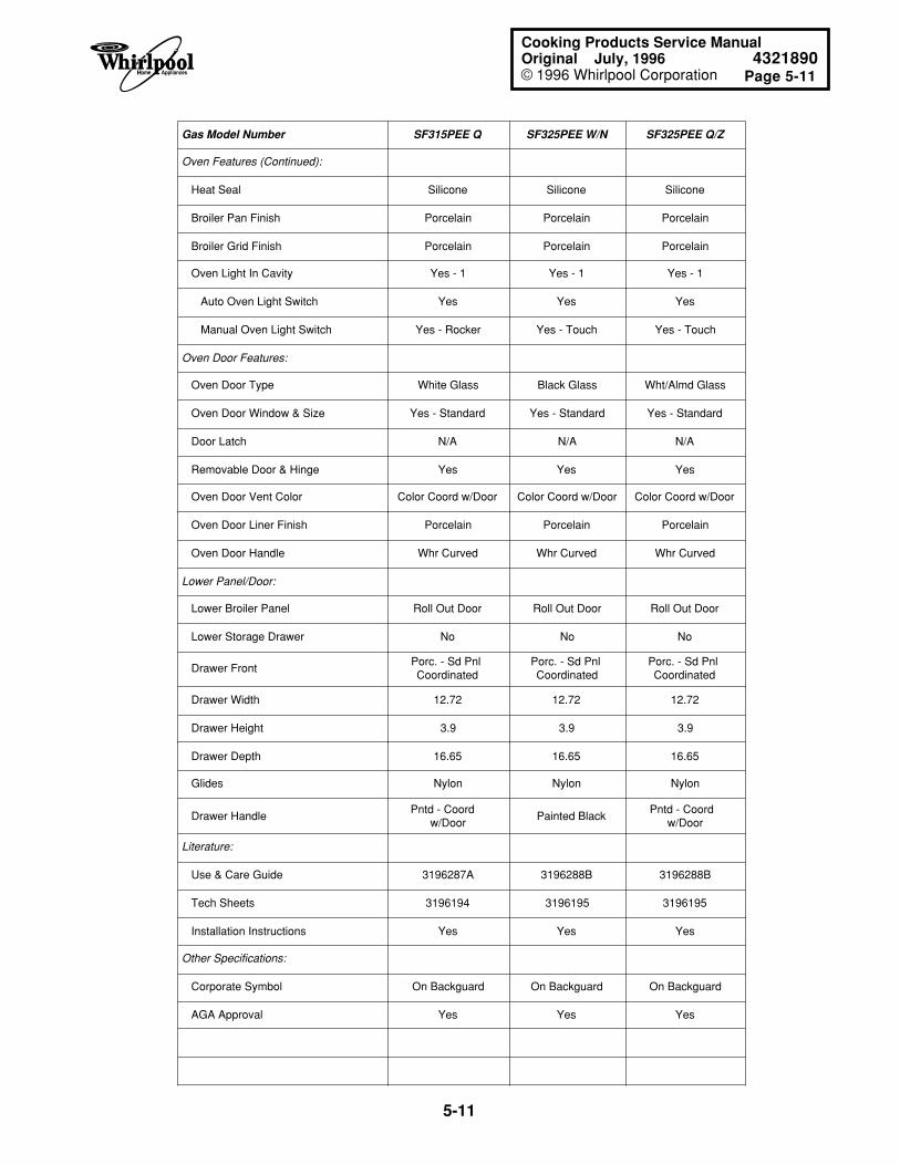
Page 5-11
5-11
Cooking Products Service ManualOriginal July, 1996 4321890© 1996 Whirlpool Corporation
Gas Model Number SF315PEE Q SF325PEE W/N SF325PEE Q/Z
Oven Features (Continued):
Heat Seal Silicone Silicone Silicone
Broiler Pan Finish Porcelain Porcelain Porcelain
Broiler Grid Finish Porcelain Porcelain Porcelain
Oven Light In Cavity Yes - 1 Yes - 1 Yes - 1
Auto Oven Light Switch Yes Yes Yes
Manual Oven Light Switch Yes - Rocker Yes - Touch Yes - Touch
Oven Door Features:
Oven Door Type White Glass Black Glass Wht/Almd Glass
Oven Door Window & Size Yes - Standard Yes - Standard Yes - Standard
Door Latch N/A N/A N/A
Removable Door & Hinge Yes Yes Yes
Oven Door Vent Color Color Coord w/Door Color Coord w/Door Color Coord w/Door
Oven Door Liner Finish Porcelain Porcelain Porcelain
Oven Door Handle Whr Curved Whr Curved Whr Curved
Lower Panel/Door:
Lower Broiler Panel Roll Out Door Roll Out Door Roll Out Door
Lower Storage Drawer No No No
Drawer FrontPorc. - Sd Pnl Coordinated
Porc. - Sd Pnl Coordinated
Porc. - Sd Pnl Coordinated
Drawer Width 12.72 12.72 12.72
Drawer Height 3.9 3.9 3.9
Drawer Depth 16.65 16.65 16.65
Glides Nylon Nylon Nylon
Drawer Handle Pntd - Coord
w/Door Painted Black
Pntd - Coord w/Door
Literature:
Use & Care Guide 3196287A 3196288B 3196288B
Tech Sheets 3196194 3196195 3196195
Installation Instructions Yes Yes Yes
Other Specifications:
Corporate Symbol On Backguard On Backguard On Backguard
AGA Approval Yes Yes Yes
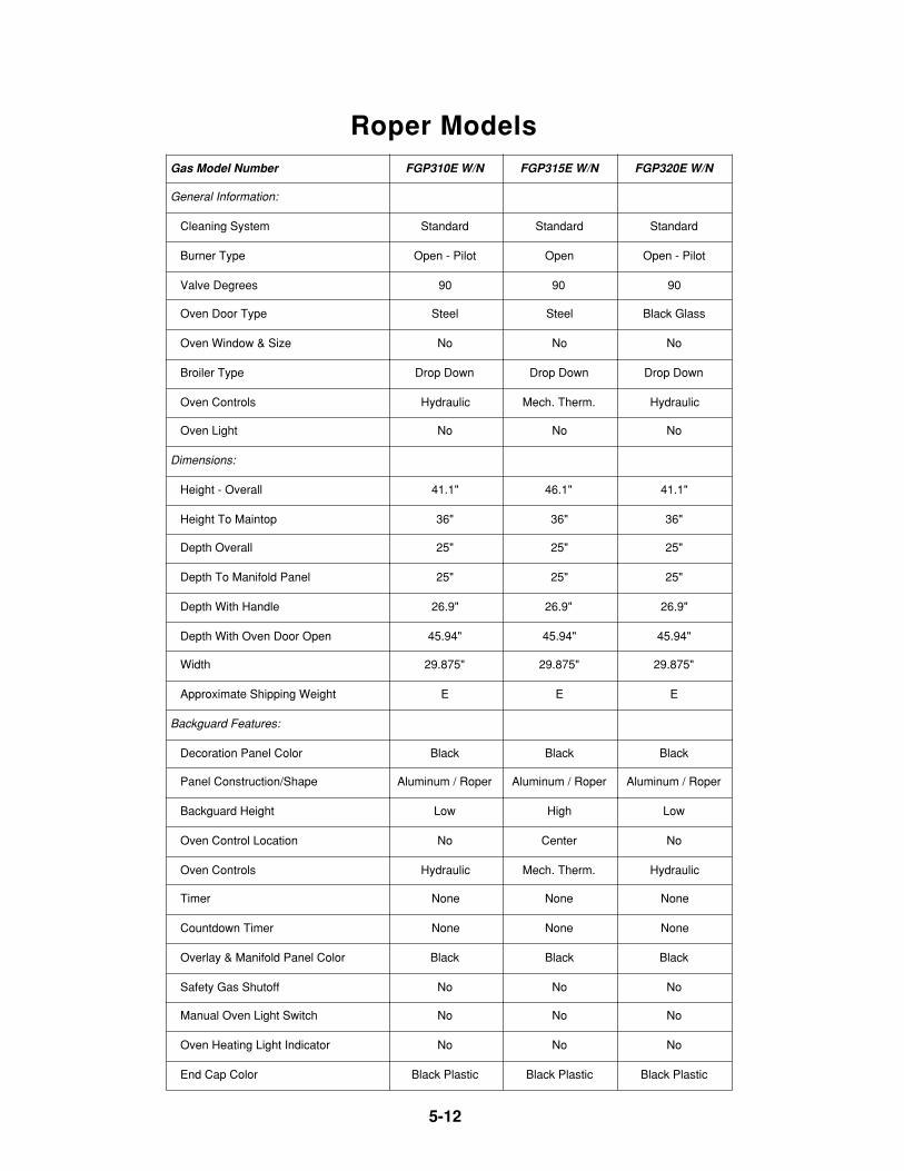
5-12
Roper ModelsGas Model Number FGP310E W/N FGP315E W/N FGP320E W/N
General Information:
Cleaning System Standard Standard Standard
Burner Type Open - Pilot Open Open - Pilot
Valve Degrees 90 90 90
Oven Door Type Steel Steel Black Glass
Oven Window & Size No No No
Broiler Type Drop Down Drop Down Drop Down
Oven Controls Hydraulic Mech. Therm. Hydraulic
Oven Light No No No
Dimensions:
Height - Overall 41.1" 46.1" 41.1"
Height To Maintop 36" 36" 36"
Depth Overall 25" 25" 25"
Depth To Manifold Panel 25" 25" 25"
Depth With Handle 26.9" 26.9" 26.9"
Depth With Oven Door Open 45.94" 45.94" 45.94"
Width 29.875" 29.875" 29.875"
Approximate Shipping Weight E E E
Backguard Features:
Decoration Panel Color Black Black Black
Panel Construction/Shape Aluminum / Roper Aluminum / Roper Aluminum / Roper
Backguard Height Low High Low
Oven Control Location No Center No
Oven Controls Hydraulic Mech. Therm. Hydraulic
Timer None None None
Countdown Timer None None None
Overlay & Manifold Panel Color Black Black Black
Safety Gas Shutoff No No No
Manual Oven Light Switch No No No
Oven Heating Light Indicator No No No
End Cap Color Black Plastic Black Plastic Black Plastic
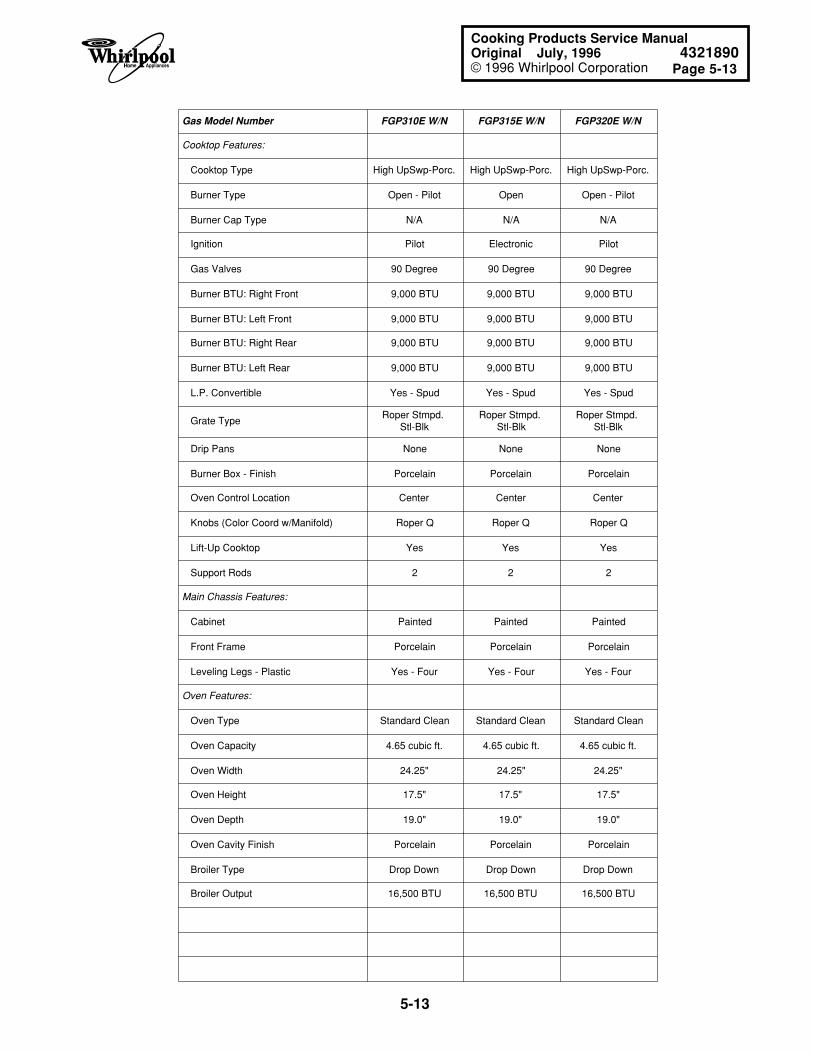
Page 5-13
5-13
Cooking Products Service ManualOriginal July, 1996 4321890© 1996 Whirlpool Corporation
Gas Model Number FGP310E W/N FGP315E W/N FGP320E W/N
Cooktop Features:
Cooktop Type High UpSwp-Porc. High UpSwp-Porc. High UpSwp-Porc.
Burner Type Open - Pilot Open Open - Pilot
Burner Cap Type N/A N/A N/A
Ignition Pilot Electronic Pilot
Gas Valves 90 Degree 90 Degree 90 Degree
Burner BTU: Right Front 9,000 BTU 9,000 BTU 9,000 BTU
Burner BTU: Left Front 9,000 BTU 9,000 BTU 9,000 BTU
Burner BTU: Right Rear 9,000 BTU 9,000 BTU 9,000 BTU
Burner BTU: Left Rear 9,000 BTU 9,000 BTU 9,000 BTU
L.P. Convertible Yes - Spud Yes - Spud Yes - Spud
Grate TypeRoper Stmpd.
Stl-BlkRoper Stmpd.
Stl-BlkRoper Stmpd.
Stl-Blk
Drip Pans None None None
Burner Box - Finish Porcelain Porcelain Porcelain
Oven Control Location Center Center Center
Knobs (Color Coord w/Manifold) Roper Q Roper Q Roper Q
Lift-Up Cooktop Yes Yes Yes
Support Rods 2 2 2
Main Chassis Features:
Cabinet Painted Painted Painted
Front Frame Porcelain Porcelain Porcelain
Leveling Legs - Plastic Yes - Four Yes - Four Yes - Four
Oven Features:
Oven Type Standard Clean Standard Clean Standard Clean
Oven Capacity 4.65 cubic ft. 4.65 cubic ft. 4.65 cubic ft.
Oven Width 24.25" 24.25" 24.25"
Oven Height 17.5" 17.5" 17.5"
Oven Depth 19.0" 19.0" 19.0"
Oven Cavity Finish Porcelain Porcelain Porcelain
Broiler Type Drop Down Drop Down Drop Down
Broiler Output 16,500 BTU 16,500 BTU 16,500 BTU
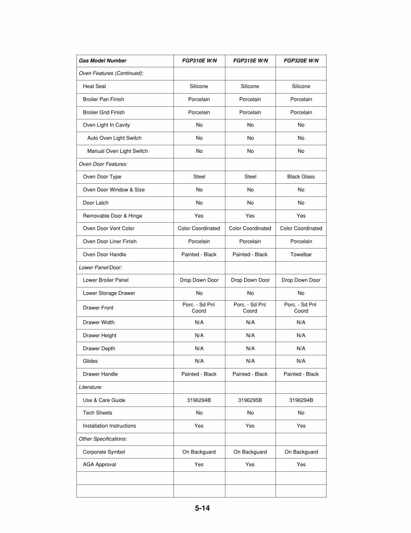
5-14
Gas Model Number FGP310E W/N FGP315E W/N FGP320E W/N
Oven Features (Continued):
Heat Seal Silicone Silicone Silicone
Broiler Pan Finish Porcelain Porcelain Porcelain
Broiler Grid Finish Porcelain Porcelain Porcelain
Oven Light In Cavity No No No
Auto Oven Light Switch No No No
Manual Oven Light Switch No No No
Oven Door Features:
Oven Door Type Steel Steel Black Glass
Oven Door Window & Size No No No
Door Latch No No No
Removable Door & Hinge Yes Yes Yes
Oven Door Vent Color Color Coordinated Color Coordinated Color Coordinated
Oven Door Liner Finish Porcelain Porcelain Porcelain
Oven Door Handle Painted - Black Painted - Black Towelbar
Lower Panel/Door:
Lower Broiler Panel Drop Down Door Drop Down Door Drop Down Door
Lower Storage Drawer No No No
Drawer FrontPorc. - Sd Pnl
CoordPorc. - Sd Pnl
CoordPorc. - Sd Pnl
Coord
Drawer Width N/A N/A N/A
Drawer Height N/A N/A N/A
Drawer Depth N/A N/A N/A
Glides N/A N/A N/A
Drawer Handle Painted - Black Painted - Black Painted - Black
Literature:
Use & Care Guide 3196294B 3196295B 3196294B
Tech Sheets No No No
Installation Instructions Yes Yes Yes
Other Specifications:
Corporate Symbol On Backguard On Backguard On Backguard
AGA Approval Yes Yes Yes
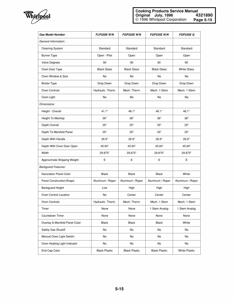
Page 5-15
5-15
Cooking Products Service ManualOriginal July, 1996 4321890© 1996 Whirlpool Corporation
Gas Model Number FLP320E W/N FGP325E W/N FGP335E W/N FGP335E Q
General Information:
Cleaning System Standard Standard Standard Standard
Burner Type Open - Pilot Open Open Open
Valve Degrees 90 90 90 90
Oven Door Type Black Glass Black Glass Black Glass White Glass
Oven Window & Size No No No No
Broiler Type Drop Down Drop Down Drop Down Drop Down
Oven Controls Hydraulic Therm. Mech. Therm. Mech. 1-Stem Mech. 1-Stem
Oven Light No No No No
Dimensions:
Height - Overall 41.1" 46.1" 46.1" 46.1"
Height To Maintop 36" 36" 36" 36"
Depth Overall 25" 25" 25" 25"
Depth To Manifold Panel 25" 25" 25" 25"
Depth With Handle 26.9" 26.9" 26.9" 26.9"
Depth With Oven Door Open 45.94" 45.94" 45.94" 45.94"
Width 29.875" 29.875" 29.875" 29.875"
Approximate Shipping Weight E E E E
Backguard Features:
Decoration Panel Color Black Black Black White
Panel Construction/Shape Aluminum / Roper Aluminum / Roper Aluminum / Roper Aluminum / Roper
Backguard Height Low High High High
Oven Control Location No Center Center Center
Oven Controls Hydraulic Therm. Mech. Therm. Mech. 1-Stem Mech. 1-Stem
Timer None None 1 Stem Analog 1 Stem Analog
Countdown Timer None None None None
Overlay & Manifold Panel Color Black Black Black White
Safety Gas Shutoff No No No No
Manual Oven Light Switch No No No No
Oven Heating Light Indicator No No No No
End Cap Color Black Plastic Black Plastic Black Plastic White Plastic
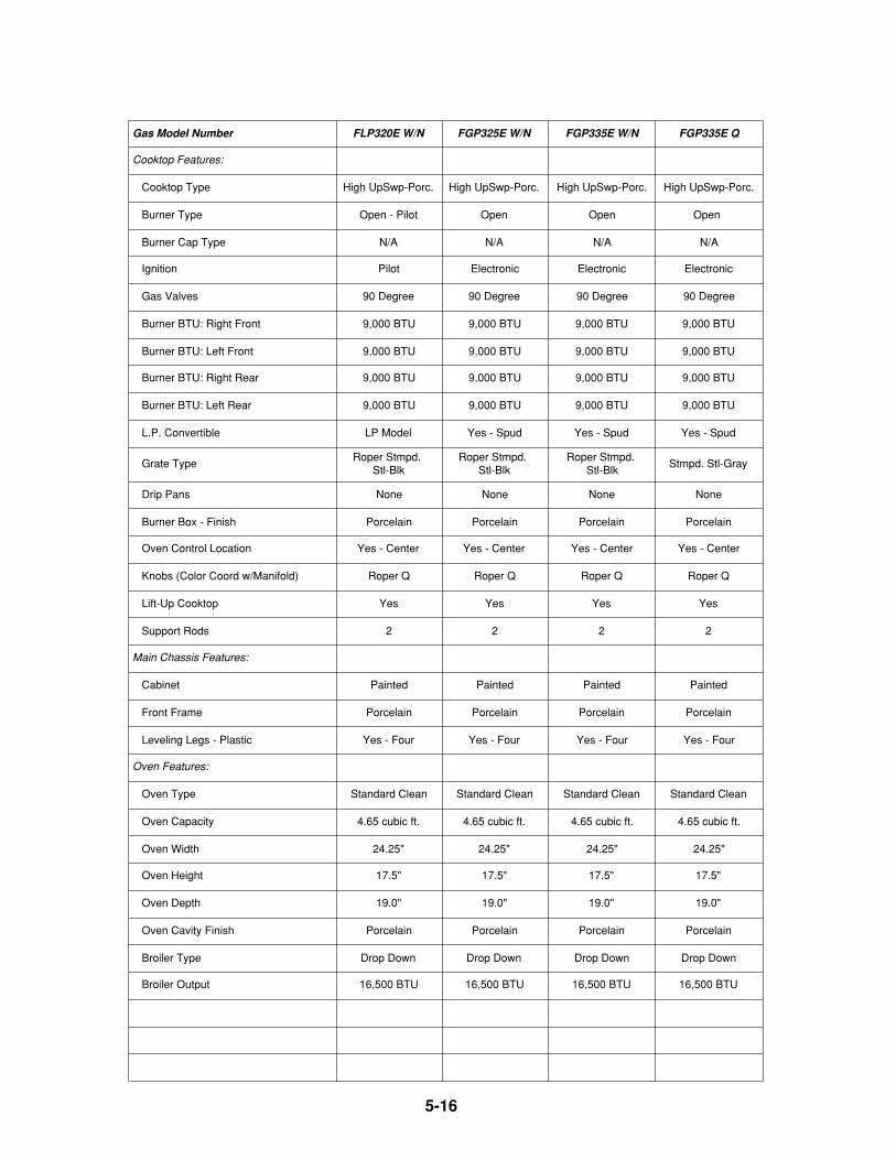
5-16
Gas Model Number FLP320E W/N FGP325E W/N FGP335E W/N FGP335E Q
Cooktop Features:
Cooktop Type High UpSwp-Porc. High UpSwp-Porc. High UpSwp-Porc. High UpSwp-Porc.
Burner Type Open - Pilot Open Open Open
Burner Cap Type N/A N/A N/A N/A
Ignition Pilot Electronic Electronic Electronic
Gas Valves 90 Degree 90 Degree 90 Degree 90 Degree
Burner BTU: Right Front 9,000 BTU 9,000 BTU 9,000 BTU 9,000 BTU
Burner BTU: Left Front 9,000 BTU 9,000 BTU 9,000 BTU 9,000 BTU
Burner BTU: Right Rear 9,000 BTU 9,000 BTU 9,000 BTU 9,000 BTU
Burner BTU: Left Rear 9,000 BTU 9,000 BTU 9,000 BTU 9,000 BTU
L.P. Convertible LP Model Yes - Spud Yes - Spud Yes - Spud
Grate TypeRoper Stmpd.
Stl-BlkRoper Stmpd.
Stl-BlkRoper Stmpd.
Stl-BlkStmpd. Stl-Gray
Drip Pans None None None None
Burner Box - Finish Porcelain Porcelain Porcelain Porcelain
Oven Control Location Yes - Center Yes - Center Yes - Center Yes - Center
Knobs (Color Coord w/Manifold) Roper Q Roper Q Roper Q Roper Q
Lift-Up Cooktop Yes Yes Yes Yes
Support Rods 2 2 2 2
Main Chassis Features:
Cabinet Painted Painted Painted Painted
Front Frame Porcelain Porcelain Porcelain Porcelain
Leveling Legs - Plastic Yes - Four Yes - Four Yes - Four Yes - Four
Oven Features:
Oven Type Standard Clean Standard Clean Standard Clean Standard Clean
Oven Capacity 4.65 cubic ft. 4.65 cubic ft. 4.65 cubic ft. 4.65 cubic ft.
Oven Width 24.25" 24.25" 24.25" 24.25"
Oven Height 17.5" 17.5" 17.5" 17.5"
Oven Depth 19.0" 19.0" 19.0" 19.0"
Oven Cavity Finish Porcelain Porcelain Porcelain Porcelain
Broiler Type Drop Down Drop Down Drop Down Drop Down
Broiler Output 16,500 BTU 16,500 BTU 16,500 BTU 16,500 BTU
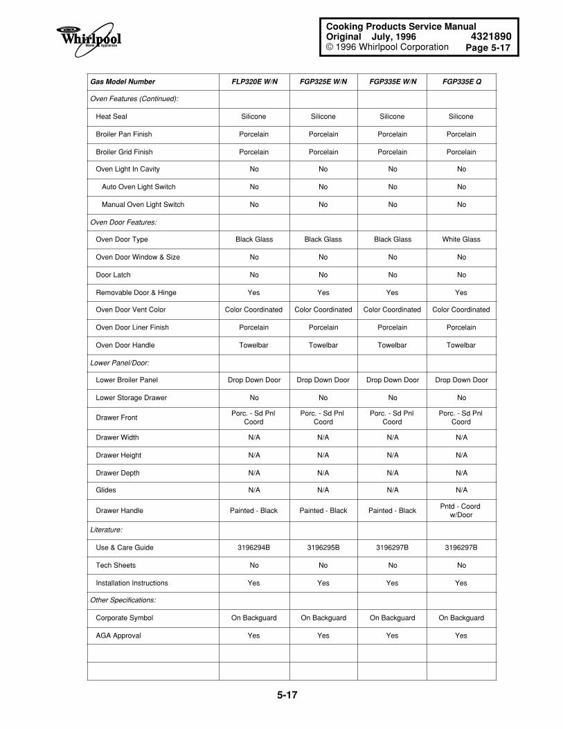
Page 5-17
5-17
Cooking Products Service ManualOriginal July, 1996 4321890© 1996 Whirlpool Corporation
Gas Model Number FLP320E W/N FGP325E W/N FGP335E W/N FGP335E Q
Oven Features (Continued):
Heat Seal Silicone Silicone Silicone Silicone
Broiler Pan Finish Porcelain Porcelain Porcelain Porcelain
Broiler Grid Finish Porcelain Porcelain Porcelain Porcelain
Oven Light In Cavity No No No No
Auto Oven Light Switch No No No No
Manual Oven Light Switch No No No No
Oven Door Features:
Oven Door Type Black Glass Black Glass Black Glass White Glass
Oven Door Window & Size No No No No
Door Latch No No No No
Removable Door & Hinge Yes Yes Yes Yes
Oven Door Vent Color Color Coordinated Color Coordinated Color Coordinated Color Coordinated
Oven Door Liner Finish Porcelain Porcelain Porcelain Porcelain
Oven Door Handle Towelbar Towelbar Towelbar Towelbar
Lower Panel/Door:
Lower Broiler Panel Drop Down Door Drop Down Door Drop Down Door Drop Down Door
Lower Storage Drawer No No No No
Drawer FrontPorc. - Sd Pnl
CoordPorc. - Sd Pnl
CoordPorc. - Sd Pnl
CoordPorc. - Sd Pnl
Coord
Drawer Width N/A N/A N/A N/A
Drawer Height N/A N/A N/A N/A
Drawer Depth N/A N/A N/A N/A
Glides N/A N/A N/A N/A
Drawer Handle Painted - Black Painted - Black Painted - BlackPntd - Coord
w/Door
Literature:
Use & Care Guide 3196294B 3196295B 3196297B 3196297B
Tech Sheets No No No No
Installation Instructions Yes Yes Yes Yes
Other Specifications:
Corporate Symbol On Backguard On Backguard On Backguard On Backguard
AGA Approval Yes Yes Yes Yes
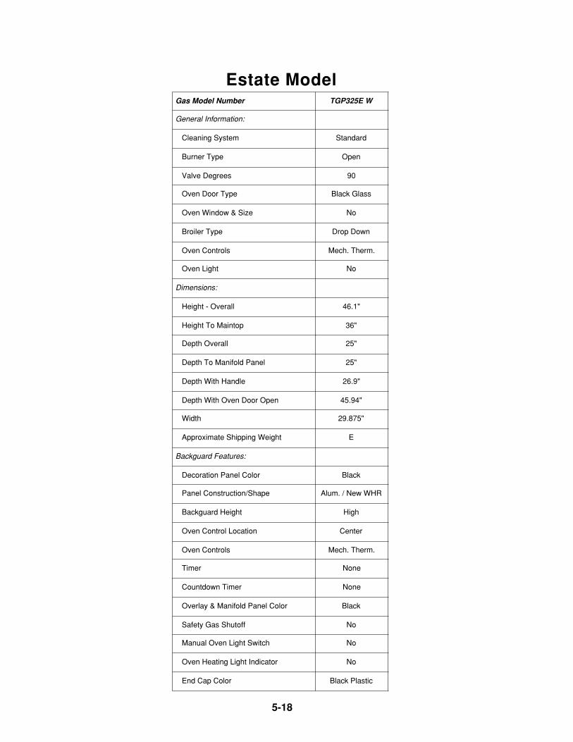
5-18
Estate ModelGas Model Number TGP325E W
General Information:
Cleaning System Standard
Burner Type Open
Valve Degrees 90
Oven Door Type Black Glass
Oven Window & Size No
Broiler Type Drop Down
Oven Controls Mech. Therm.
Oven Light No
Dimensions:
Height - Overall 46.1"
Height To Maintop 36"
Depth Overall 25"
Depth To Manifold Panel 25"
Depth With Handle 26.9"
Depth With Oven Door Open 45.94"
Width 29.875"
Approximate Shipping Weight E
Backguard Features:
Decoration Panel Color Black
Panel Construction/Shape Alum. / New WHR
Backguard Height High
Oven Control Location Center
Oven Controls Mech. Therm.
Timer None
Countdown Timer None
Overlay & Manifold Panel Color Black
Safety Gas Shutoff No
Manual Oven Light Switch No
Oven Heating Light Indicator No
End Cap Color Black Plastic
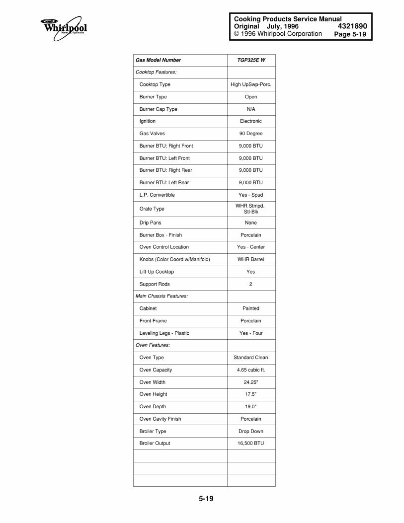
Page 5-19
5-19
Cooking Products Service ManualOriginal July, 1996 4321890© 1996 Whirlpool Corporation
Gas Model Number TGP325E W
Cooktop Features:
Cooktop Type High UpSwp-Porc.
Burner Type Open
Burner Cap Type N/A
Ignition Electronic
Gas Valves 90 Degree
Burner BTU: Right Front 9,000 BTU
Burner BTU: Left Front 9,000 BTU
Burner BTU: Right Rear 9,000 BTU
Burner BTU: Left Rear 9,000 BTU
L.P. Convertible Yes - Spud
Grate TypeWHR Stmpd.
Stl-Blk
Drip Pans None
Burner Box - Finish Porcelain
Oven Control Location Yes - Center
Knobs (Color Coord w/Manifold) WHR Barrel
Lift-Up Cooktop Yes
Support Rods 2
Main Chassis Features:
Cabinet Painted
Front Frame Porcelain
Leveling Legs - Plastic Yes - Four
Oven Features:
Oven Type Standard Clean
Oven Capacity 4.65 cubic ft.
Oven Width 24.25"
Oven Height 17.5"
Oven Depth 19.0"
Oven Cavity Finish Porcelain
Broiler Type Drop Down
Broiler Output 16,500 BTU
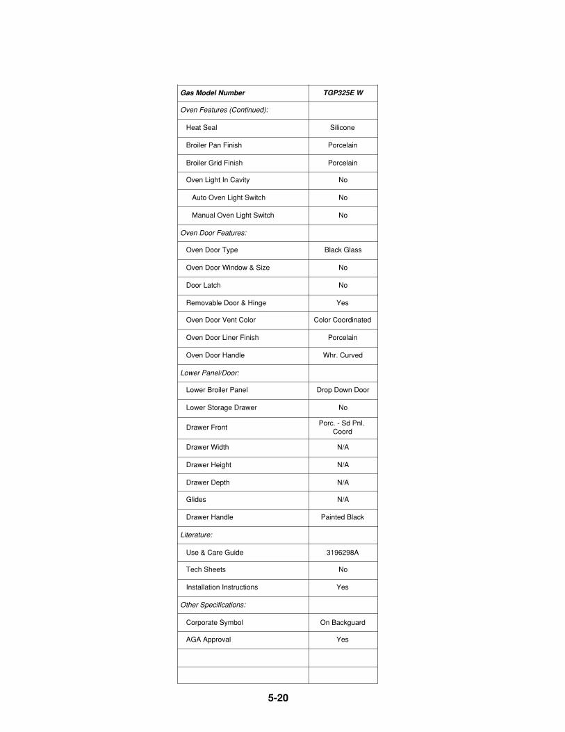
5-20
Gas Model Number TGP325E W
Oven Features (Continued):
Heat Seal Silicone
Broiler Pan Finish Porcelain
Broiler Grid Finish Porcelain
Oven Light In Cavity No
Auto Oven Light Switch No
Manual Oven Light Switch No
Oven Door Features:
Oven Door Type Black Glass
Oven Door Window & Size No
Door Latch No
Removable Door & Hinge Yes
Oven Door Vent Color Color Coordinated
Oven Door Liner Finish Porcelain
Oven Door Handle Whr. Curved
Lower Panel/Door:
Lower Broiler Panel Drop Down Door
Lower Storage Drawer No
Drawer FrontPorc. - Sd Pnl.
Coord
Drawer Width N/A
Drawer Height N/A
Drawer Depth N/A
Glides N/A
Drawer Handle Painted Black
Literature:
Use & Care Guide 3196298A
Tech Sheets No
Installation Instructions Yes
Other Specifications:
Corporate Symbol On Backguard
AGA Approval Yes
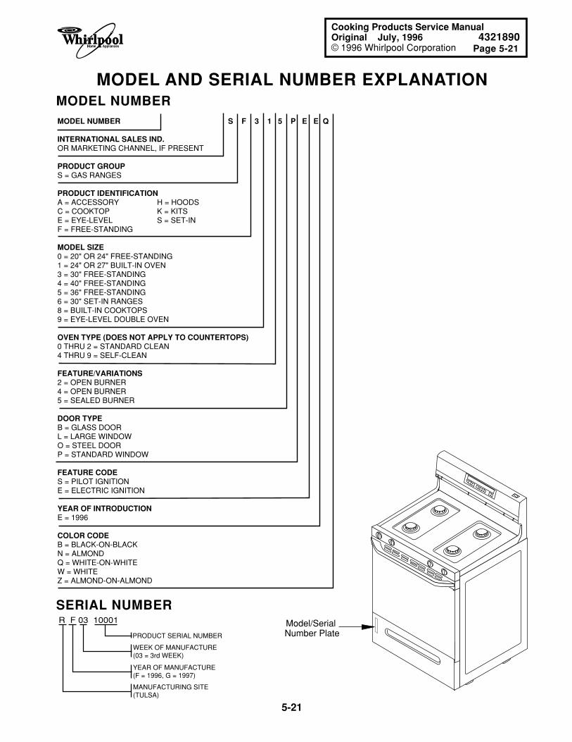
Page 5-21
5-21
Cooking Products Service ManualOriginal July, 1996 4321890© 1996 Whirlpool Corporation
MODEL AND SERIAL NUMBER EXPLANATIONMODEL NUMBERMODEL NUMBER S F 3 1 5 P E E Q
INTERNATIONAL SALES IND. OR MARKETING CHANNEL, IF PRESENT
PRODUCT GROUPS = GAS RANGES
PRODUCT IDENTIFICATIONA = ACCESSORY H = HOODSC = COOKTOP K = KITSE = EYE-LEVEL S = SET-INF = FREE-STANDING
MODEL SIZE0 = 20" OR 24" FREE-STANDING1 = 24" OR 27" BUILT-IN OVEN3 = 30" FREE-STANDING4 = 40" FREE-STANDING5 = 36" FREE-STANDING6 = 30" SET-IN RANGES8 = BUILT-IN COOKTOPS9 = EYE-LEVEL DOUBLE OVEN
OVEN TYPE (DOES NOT APPLY TO COUNTERTOPS) 0 THRU 2 = STANDARD CLEAN4 THRU 9 = SELF-CLEAN
FEATURE/VARIATIONS2 = OPEN BURNER4 = OPEN BURNER5 = SEALED BURNER
DOOR TYPEB = GLASS DOORL = LARGE WINDOWO = STEEL DOORP = STANDARD WINDOW
FEATURE CODES = PILOT IGNITIONE = ELECTRIC IGNITION
YEAR OF INTRODUCTION E = 1996
COLOR CODEB = BLACK-ON-BLACKN = ALMONDQ = WHITE-ON-WHITEW = WHITE Z = ALMOND-ON-ALMOND
SERIAL NUMBER R F 03 10001
PRODUCT SERIAL NUMBER
WEEK OF MANUFACTURE(03 = 3rd WEEK)
YEAR OF MANUFACTURE(F = 1996, G = 1997)
MANUFACTURING SITE(TULSA)
Model/Serial Number Plate
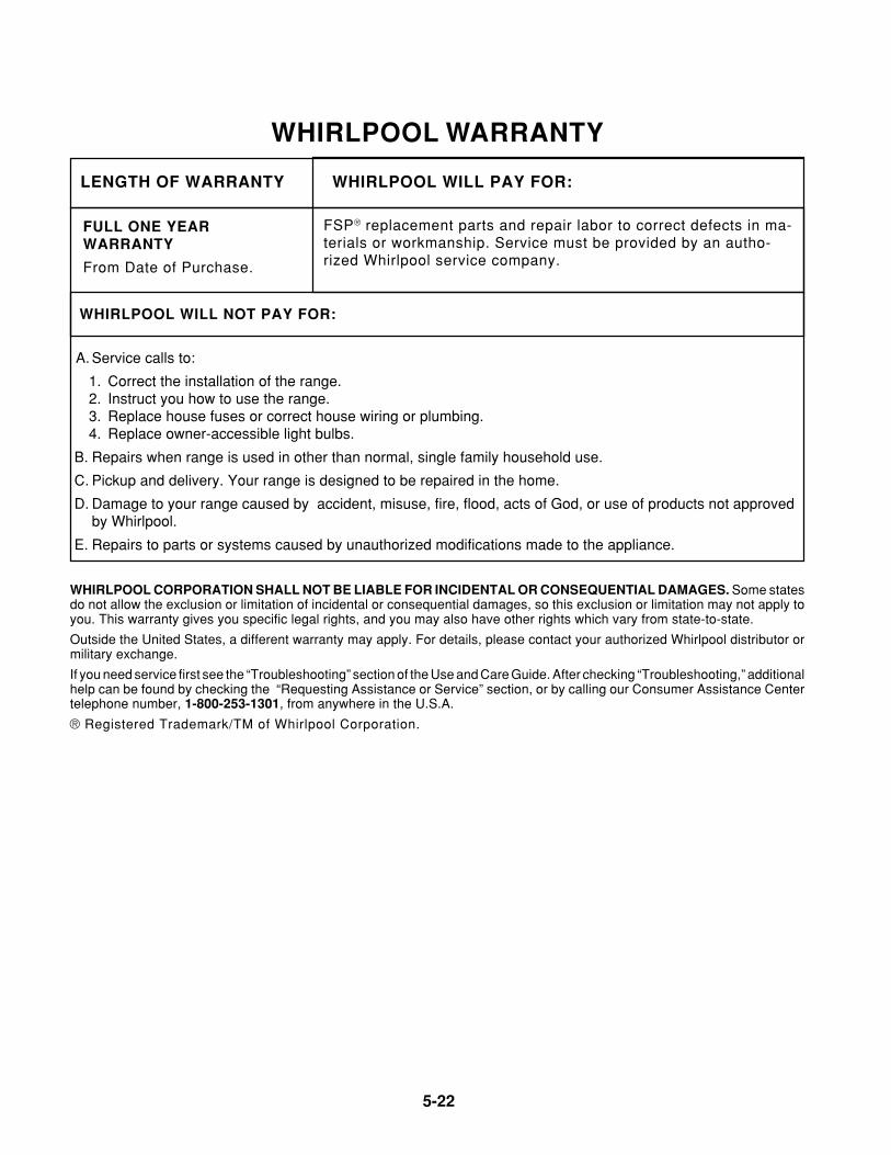
5-22
WHIRLPOOL WARRANTY
WHIRLPOOL WILL PAY FOR:
FSP® replacement parts and repair labor to correct defects in ma-terials or workmanship. Service must be provided by an autho-rized Whirlpool service company.
LENGTH OF WARRANTY
FULL ONE YEARWARRANTY
From Date of Purchase.
WHIRLPOOL WILL NOT PAY FOR:
A. Service calls to:
1. Correct the installation of the range.2. Instruct you how to use the range.3. Replace house fuses or correct house wiring or plumbing.4. Replace owner-accessible light bulbs.
B. Repairs when range is used in other than normal, single family household use.
C. Pickup and delivery. Your range is designed to be repaired in the home.
D. Damage to your range caused by accident, misuse, fire, flood, acts of God, or use of products not approvedby Whirlpool.
E. Repairs to parts or systems caused by unauthorized modifications made to the appliance.
WHIRLPOOL CORPORATION SHALL NOT BE LIABLE FOR INCIDENTAL OR CONSEQUENTIAL DAMAGES. Some statesdo not allow the exclusion or limitation of incidental or consequential damages, so this exclusion or limitation may not apply toyou. This warranty gives you specific legal rights, and you may also have other rights which vary from state-to-state.
Outside the United States, a different warranty may apply. For details, please contact your authorized Whirlpool distributor ormilitary exchange.
If you need service first see the “Troubleshooting” section of the Use and Care Guide. After checking “Troubleshooting,” additionalhelp can be found by checking the “Requesting Assistance or Service” section, or by calling our Consumer Assistance Centertelephone number, 1-800-253-1301, from anywhere in the U.S.A.
® Registered Trademark/TM of Whirlpool Corporation.


