Embed Size (px)
Citation preview
LGS UFSAR
CHAPTER 03 3-i REV. 16, SEPTEMBER 2012
CHAPTER 3 - DESIGN OF STRUCTURES, COMPONENTS, EQUIPMENT, AND SYSTEMS
TABLE OF CONTENTS
3.1 CONFORMANCE WITH NRC GENERAL DESIGN CRITERIA
3.2 CLASSIFICATION OF STRUCTURES, COMPONENTS, AND SYSTEMS
3.2.1 Seismic Classification3.2.2 System Quality Group Classifications3.2.3 Quality Assurance
3.3 WIND AND TORNADO LOADINGS
3.3.1 Wind Loadings3.3.1.1 Design Wind Velocity3.3.1.2 Determination of Applied Forces3.3.2 Tornado Loadings3.3.2.1 Applicable Design Parameters3.3.2.2 Determination of Forces on Structures3.3.2.3 Effect of Failure of Structures or Components Not Designed for Tornado
Loadings3.3.3 References
3.4 WATER LEVEL (FLOOD) DESIGN
3.4.1 Flood Protection3.4.1.1 Flood Protection Measures for Seismic Category I Structures3.4.1.2 Permanent Dewatering System
3.4.2 Analytical and Test Procedures
3.5 MISSILE PROTECTION
3.5.1 Missile Selection and Description3.5.1.1 Internally Generated Missiles (Outside Primary Containment)3.5.1.1.1 Rotating Component Failure Missiles3.5.1.1.2 Pressurized Component Failure Missiles3.5.1.1.3 Gravitationally Generated Missiles3.5.1.2 Internally Generated Missiles (Inside Containment)3.5.1.2.1 Rotating Component Failure Missiles3.5.1.2.2 Pressurized Component Failure Missiles3.5.1.2.3 Gravitationally Generated Missiles3.5.1.3 Turbine Missiles3.5.1.4 Missiles Generated by Natural Phenomena3.5.1.5 Missiles Generated by Events Near the Site3.5.1.6 Aircraft Hazards3.5.1.6.1 Design of Safety-Related Structures
LGS UFSAR
TABLE OF CONTENTS (Cont'd)
CHAPTER 03 3-ii REV. 16, SEPTEMBER 2012
3.5.1.6.2 Analysis Method3.5.1.6.3 Crash Probabilities3.5.1.6.4 Probability of Aircraft Strike Resulting in Unacceptable Consequences3.5.2 Systems to be Protected3.5.3 Barrier Design Procedures3.5.4 References
3.6 PROTECTION AGAINST DYNAMIC EFFECTS ASSOCIATED WITH THE POSTULATED RUPTURE OF PIPING
3.6.1 Postulated Piping Failures in Fluid Systems3.6.1.1 Design Bases3.6.1.2 Description3.6.1.2.1 High Energy Fluid Systems3.6.1.2.2 Moderate Energy Fluid Systems3.6.1.3 Safety Evaluation3.6.2 Determination of Pipe Failure Locations and Dynamic Effects Associated with
Postulated Piping Failures3.6.2.1 Criteria Used to Determine Pipe Break and Crack Locations and Their
Configurations3.6.2.1.1 Break Locations in High Energy Fluid System Piping3.6.2.1.2 Crack Locations in Moderate Energy Fluid System Piping3.6.2.1.3 Types of Breaks and Cracks in Fluid System Piping3.6.2.2 Analytical Models to Define Forcing Functions and Response Models
(Recirculation System Only)3.6.2.2.1 Analytical Methods to Define Blowdown Forcing Functions3.6.2.2.2 Pipe Whip Dynamic Response Analyses3.6.2.3 Analytical Models to Define Forcing Functions and Response Models (Systems
Other Than Recirculation System)3.6.2.4 Dynamic Analysis Methods to Verify Integrity and Operability (Recirculation
System Only)3.6.2.5 Dynamic Analysis Method to Verify Integrity and Operability (Systems Other
Than Recirculation System)3.6.2.5.1 Design Loading Combinations3.6.2.5.2 Design Stress Limits3.6.2.6 Guard Pipe Assembly Design Criteria3.6.3 Definitions3.6.4 References
3.7 SEISMIC DESIGN
3.7.1 Seismic Input3.7.1.1 Design Response Spectra3.7.1.2 Design Time History3.7.1.3 Critical Damping Values3.7.1.3.1 Critical Damping Values (NSSS)3.7.1.3.2 Critical Damping Values (Non-NSSS)3.7.1.3.3 Alternative Critical Damping Values and Spectral Peak Broadening for Piping
(NSSS and Non-NSSS)3.7.1.4 Supporting Media for Seismic Category I Structures
LGS UFSAR
TABLE OF CONTENTS (Cont'd)
CHAPTER 03 3-iii REV. 16, SEPTEMBER 2012
3.7.2 Seismic System Analysis3.7.2.1 Seismic Analysis Method3.7.2.1.1 Seismic Analysis Methods (NSSS)3.7.2.1.2 Seismic Analysis Methods (Non-NSSS)3.7.2.2 Natural Frequencies and Response Loads3.7.2.3 Procedures Used for Modeling3.7.2.3.1 Procedures Used for Modeling (NSSS)3.7.2.3.2 Procedures Used for Modeling (Non-NSSS)3.7.2.4 Soil-Structure Interaction3.7.2.5 Development of Floor Response Spectra3.7.2.5.1 Floor Response Spectra (NSSS)3.7.2.5.2 Floor Response Spectra (Non-NSSS)3.7.2.6 Three Components of Earthquake Motion3.7.2.6.1 NSSS3.7.2.6.2 Non-NSSS3.7.2.7 Combination of Modal Responses3.7.2.7.1 Combination of Modal Responses (NSSS)3.7.2.7.2 Combination of Modal Responses (Non-NSSS)3.7.2.8 Interaction of Non-Category I Structures with Seismic Category I Structures3.7.2.9 Effects of Parameter Variations on Floor Response Spectra3.7.2.9.1 Effects of Parameter Variations on Floor Response Spectra (NSSS)3.7.2.9.2 Effects of Parameter Variations on Floor Response Spectra (Non-NSSS)3.7.2.10 Use of Constant Vertical Static Factors3.7.2.11 Methods Used to Account for Torsional Effects3.7.2.12 Comparison of Responses3.7.2.13 Methods for Seismic Analysis of Dams3.7.2.14 Determination of Seismic Category I Structure Overturning Moments3.7.2.15 Analysis Procedure for Damping3.7.2.15.1 Analysis Procedure for Damping (NSSS)3.7.2.15.2 Analysis Procedure for Damping (Non-NSSS)3.7.3 Seismic Subsystem Analysis3.7.3.1 Seismic Analysis Methods3.7.3.1.1 Equipment3.7.3.1.2 Piping Systems3.7.3.1.3 Class 1E Cable Trays3.7.3.1.4 Supports for Seismic Category I HVAC Ducts3.7.3.1.5 Supports for Seismic Category I Electrical Raceway Systems3.7.3.2 Determination of Number of Earthquake Cycles3.7.3.2.1 Determination of Number of Earthquake Cycles (NSSS)3.7.3.2.2 Determination of Number of Earthquake Cycles (Non-NSSS)3.7.3.3 Procedures Used for Modeling3.7.3.3.1 Procedures Used for Modeling (NSSS)3.7.3.3.2 Procedures Used for Modeling (Non-NSSS)3.7.3.4 Basis of Selection of Frequencies3.7.3.4.1 Basis of Selection of Frequencies (NSSS)3.7.3.4.2 Basis of Selection of Frequencies (Non-NSSS)3.7.3.5 Use of Equivalent Static Load Method of Analysis (Non-NSSS)3.7.3.6 Three Components of Earthquake Motion3.7.3.6.1 Three Components of Earthquake Motion (NSSS)3.7.3.6.2 Three Components of Earthquake Motion (Non-NSSS)
LGS UFSAR
TABLE OF CONTENTS (Cont'd)
CHAPTER 03 3-iv REV. 16, SEPTEMBER 2012
3.7.3.7 Combination of Modal Responses3.7.3.7.1 Combination of Modal Responses (NSSS)3.7.3.7.2 Combination of Modal Responses (Non-NSSS)3.7.3.8 Analytical Procedure for Piping3.7.3.8.1 Analytical Procedure for Piping (NSSS)3.7.3.8.2 Analytical Procedure for Piping (Non-NSSS)3.7.3.9 Multiple Supported Equipment Components with Distinct Inputs3.7.3.9.1 Multiple Supported Equipment Components with Distinct Inputs (NSSS)3.7.3.9.2 Multiple Supported Equipment Components with Distinct Inputs (Non-NSSS)3.7.3.10 Use of Constant Vertical Static Factors3.7.3.10.1 Use of Constant Vertical Static Factors (NSSS)3.7.3.10.2 Use of Constant Vertical Static Factors (Non-NSSS)3.7.3.11 Torsional Effects of Eccentric Masses3.7.3.11.1 Torsional Effects of Eccentric Masses (NSSS)3.7.3.11.2 Torsional Effects of Eccentric Masses (Non-NSSS)3.7.3.12 Buried Seismic Category I Piping Systems and Tunnels (Non-NSSS)3.7.3.13 Interaction of Other Piping with Seismic Category I Piping3.7.3.13.1 Interaction of Other Piping with Seismic Category I Piping (NSSS)3.7.3.13.2 Interaction of Other Piping with Seismic Category I Piping (Non-NSSS)3.7.3.14 Seismic Analysis for Reactor Internals (NSSS)3.7.3.15 Analysis Procedures for Damping3.7.3.15.1 Analysis Procedures for Damping (NSSS)3.7.3.15.2 Analysis Procedure for Damping (Non-NSSS)3.7.4 Seismic Instrumentation3.7.4.1 Comparison with Regulatory Guide 1.12 (Rev 1)3.7.4.2 Location and Description of Instrumentation3.7.4.2.1 Triaxial Time History Accelerographs3.7.4.2.2 Triaxial Peak Recording Accelerographs3.7.4.2.3 Triaxial Seismic Switch3.7.4.2.4 Response Spectrum Analyzer3.7.4.2.5 System Control Panel3.7.4.3 Control Room Operator Notification3.7.4.4 Comparison of Measured and Predicted Responses3.7.5 References
LGS UFSAR
TABLE OF CONTENTS (Cont'd)
CHAPTER 03 3-v REV. 16, SEPTEMBER 2012
3.8 DESIGN OF CATEGORY I STRUCTURES
3.8.1 Concrete Containment3.8.1.1 Description of the Containment3.8.1.1.1 Base Foundation Slab3.8.1.1.2 Containment Wall3.8.1.2 Applicable Codes, Standards, and Specifications3.8.1.3 Loads and Loading Combinations3.8.1.3.1 Dead Load3.8.1.3.2 Live Load3.8.1.3.3 Design Basis Accident Pressure Load3.8.1.3.4 Thermal Loads3.8.1.3.5 Wind and Tornado Loads3.8.1.3.6 Seismic Loads3.8.1.3.7 External Pressure Load3.8.1.3.8 Pipe Rupture Loads3.8.1.3.9 Prestress Loads3.8.1.4 Design and Analysis Procedures3.8.1.4.1 Containment Wall3.8.1.4.2 Base Foundation Slab3.8.1.4.3 Analysis of Area Around Equipment Hatches3.8.1.4.4 Liner Plate and Anchorages3.8.1.5 Structural Acceptance Criteria3.8.1.5.1 Reinforced Concrete3.8.1.5.2 Liner Plate and Anchorages3.8.1.6 Materials, Quality Control, and Special Construction Techniques3.8.1.6.1 Concrete Containment3.8.1.6.2 Liner Plate, Anchorages, and Attachments3.8.1.7 Testing and Inservice Surveillance Requirements3.8.1.7.1 Preoperational Testing3.8.1.7.2 Inservice Leak Rate Testing3.8.2 ASME Class MC Steel Components of the Containment3.8.2.1 Description of the ASME Class MC Components3.8.2.1.1 Drywell Head Assembly3.8.2.1.2 Equipment Hatches and Personnel Lock3.8.2.1.3 Suppression Chamber Access Hatches3.8.2.1.4 Control Rod Drive Removal Hatch3.8.2.1.5 Piping and Electrical Penetrations3.8.2.2 Applicable Codes, Standards, and Specifications3.8.2.3 Loads and Loading Combinations3.8.2.3.1 Dead and Live Load3.8.2.3.2 Design Basis Accident Pressure Load3.8.2.3.3 External Pressure Load3.8.2.3.4 Thermal Loads3.8.2.3.5 Seismic Loads3.8.2.3.6 Pipe Rupture Loads3.8.2.3.7 Missile Impact Loads3.8.2.4 Design and Analysis Procedures
LGS UFSAR
TABLE OF CONTENTS (Cont'd)
CHAPTER 03 3-vi REV. 16, SEPTEMBER 2012
3.8.2.4.1 Drywell Head Assembly3.8.2.4.2 Access Hatches3.8.2.4.3 Piping and Electrical Penetrations3.8.2.5 Structural Acceptance Criteria3.8.2.6 Materials, Quality Control, and Special Construction Techniques3.8.2.6.1 Materials3.8.2.6.2 Welding3.8.2.6.3 Nondestructive Examination of Welds3.8.2.6.4 Quality Control3.8.2.6.5 Erection Tolerances3.8.2.7 Testing and Inservice Inspection Requirements3.8.2.7.1 Preoperational Testing3.8.2.7.2 Inservice Leak Rate Testing3.8.3 Containment Internal Structures3.8.3.1 Description of the Internal Structures3.8.3.1.1 Diaphragm Slab3.8.3.1.2 Reactor Pedestal3.8.3.1.3 Reactor Shield Wall3.8.3.1.4 Suppression Chamber Columns3.8.3.1.5 Drywell Platforms3.8.3.1.6 Seismic Truss and Reactor Vessel Stabilizer3.8.3.2 Applicable Codes, Standards, and Specifications3.8.3.3 Loads and Loading Combinations3.8.3.3.1 Diaphragm Slab and Reactor Pedestal3.8.3.3.2 Reactor Shield Wall3.8.3.3.3 Suppression Chamber Columns3.8.3.3.4 Pipe Whip Restraints/Drywell Platforms3.8.3.3.5 Seismic Truss3.8.3.4 Design and Analysis Procedures3.8.3.4.1 Diaphragm Slab3.8.3.4.2 Diaphragm Slab Liner Plate and Anchorages3.8.3.4.3 Reactor Pedestal3.8.3.4.4 Reactor Shield Wall3.8.3.4.5 Suppression Chamber Columns3.8.3.4.6 Drywell Platforms3.8.3.4.7 Seismic Truss3.8.3.5 Structural Acceptance Criteria3.8.3.5.1 Reinforced Concrete3.8.3.5.2 Diaphragm Slab Liner Plate and Anchorages3.8.3.5.3 Structural Steel3.8.3.6 Materials, Quality Control, and Special Construction Techniques3.8.3.6.1 Concrete Containment Internal Structures3.8.3.6.2 Diaphragm Slab Liner Plate, Anchorages, and Attachments3.8.3.6.3 Reactor Shield Wall and Seismic Truss3.8.3.6.4 Suppression Chamber Columns3.8.3.6.5 Drywell Platforms3.8.3.6.6 Quality Control3.8.3.7 Testing and Inservice Inspection Requirements3.8.3.7.1 Preoperational Testing3.8.3.7.2 Inservice Leak Rate Testing
LGS UFSAR
TABLE OF CONTENTS (Cont'd)
CHAPTER 03 3-vii REV. 16, SEPTEMBER 2012
3.8.4 Other Seismic Category I Structures3.8.4.1 Description of Structures3.8.4.1.1 Secondary Containment3.8.4.1.2 Control Structure3.8.4.1.3 Diesel Generator Enclosure3.8.4.1.4 Spray Pond Pump Structure3.8.4.1.5 Spray Pond3.8.4.1.6 Miscellaneous Structures3.8.4.1.7 Radwaste Enclosure3.8.4.1.8 Turbine Enclosure3.8.4.2 Applicable Codes, Standards, and Specifications3.8.4.3 Loads and Load Combinations3.8.4.3.1 Description of Loads3.8.4.3.2 Load Combinations3.8.4.4 Design and Analysis Procedures3.8.4.5 Structural Acceptance Criteria3.8.4.5.1 Reinforced and Prestressed Concrete3.8.4.5.2 Structural Steel3.8.4.5.3 Concrete Masonry Block Walls3.8.4.6 Materials, Quality Control, and Special Construction Techniques3.8.4.6.1 Reinforced Concrete, Masonry, and Prestressed Concrete3.8.4.6.2 Structural Steel3.8.4.6.3 Quality Control3.8.4.6.4 Special Construction Techniques3.8.4.7 Testing and Inservice Inspection Requirements3.8.5 Foundations3.8.5.1 Description of the Foundations3.8.5.1.1 Reactor Enclosure and Control Structure3.8.5.1.2 Diesel Generator Enclosure3.8.5.1.3 Spray Pond Pump Structure3.8.5.1.4 Radwaste Enclosure3.8.5.1.5 Turbine Enclosure3.8.5.1.6 Miscellaneous Structures3.8.5.2 Applicable Codes, Standards, and Specifications3.8.5.3 Loads and Load Combinations3.8.5.4 Design and Analysis Procedures3.8.5.5 Structural Acceptance Criteria3.8.5.6 Materials, Quality Control, and Special Construction Techniques3.8.5.7 Testing and Inservice Inspection Requirements3.8.6 Concrete, Reinforcing, Prestressed Concrete, and Masonry Materials3.8.6.1 Concrete and Concrete Materials3.8.6.1.1 Concrete Material Qualifications3.8.6.1.2 Concrete Mix Design3.8.6.1.3 Grout3.8.6.1.4 Batching, Placing, Curing, and Protection3.8.6.1.5 Construction Testing of Concrete and Concrete Materials3.8.6.2 Concrete Reinforcement Materials
LGS UFSAR
TABLE OF CONTENTS (Cont'd)
CHAPTER 03 3-viii REV. 16, SEPTEMBER 2012
3.8.6.2.1 Qualification3.8.6.2.2 Fabrication3.8.6.2.3 Construction Testing of Concrete Reinforcement Materials3.8.6.2.4 Formwork and Construction Joints3.8.6.3 Prestressed Concrete3.8.6.3.1 Post-Tensioning System for Prestressed Concrete3.8.6.3.2 Concrete for Prestressed Members3.8.6.3.3 Prestressed Steel3.8.6.3.4 Sheathing3.8.6.3.5 Anchorage Assembly3.8.6.3.6 Grout3.8.6.3.7 Post-Tensioning System Performance Tests3.8.6.4 Concrete Unit Masonry and Masonry Material3.8.6.4.1 Material Qualification3.8.6.4.2 Construction Testing3.8.7 Computer Programs for Structural Analysis3.8.7.1 3D/SAP (Finite-Element Analysis of Three-Dimensional Elastic Solids)3.8.7.1.1 Application3.8.7.1.2 Program Background3.8.7.2 ASHSD (Axisymmetric Shell and Solid)3.8.7.2.1 Application3.8.7.2.2 Program Background3.8.7.2.3 Sample Problems3.8.7.3 CECAP (Concrete Element Cracking Analysis Program)3.8.7.3.1 Application3.8.7.3.2 Program Background3.8.7.3.3 Sample Problems3.8.7.4 CE668 (Plate Bending Analysis)3.8.7.4.1 Application3.8.7.4.2 Sample Problems3.8.7.5 EASE (Elastic Analysis for Structural Engineering)3.8.7.5.1 Application3.8.7.5.2 Program Background3.8.7.6 E01193.8.7.6.1 Application3.8.7.6.2 Program Background3.8.7.6.3 Sample Problems3.8.7.7 E0781 (Shells of Revolution Program)3.8.7.7.1 Application3.8.7.7.2 Program Background3.8.7.7.3 Sample Problems3.8.7.8 FINEL (Finite-Element Program for Cracking Analysis)3.8.7.8.1 Application3.8.7.8.2 Program Background3.8.7.8.3 Sample Problems3.8.7.9 ME620 (Transient Temperature Analysis of Plane and Axisymmetric Solids)3.8.7.9.1 Application3.8.7.9.2 Program Background
LGS UFSAR
TABLE OF CONTENTS (Cont'd)
CHAPTER 03 3-ix REV. 16, SEPTEMBER 2012
3.8.7.9.3 Sample Problems3.8.7.10 ANSYS3.8.7.10.1 Application3.8.7.10.2 Program Background3.8.8 References
3.9 MECHANICAL SYSTEMS AND COMPONENTS
3.9.1 Special Topics for Mechanical Components3.9.1.1 Design Transients3.9.1.1.1 Control Rod Drive Transients3.9.1.1.2 CRD Housing and Incore Housing Transients3.9.1.1.3 Hydraulic Control Unit Transients3.9.1.1.4 Core Support and Reactor Internals Transients3.9.1.1.5 Main Steam System Transients3.9.1.1.6 Recirculation System Transients3.9.1.1.7 Reactor Assembly Transients3.9.1.1.8 Main Steam Isolation Valve Transients3.9.1.1.9 Main Steam Relief Valve Transients3.9.1.1.10 Recirculation Flow Control Valve Transients3.9.1.1.11 Recirculation Pump Transients3.9.1.1.12 Recirculation Gate Valve Transients3.9.1.2 Computer Programs Used in Analysis3.9.1.2.1 Reactor Vessel and Internals3.9.1.2.2 Piping3.9.1.2.3 Pumps and Motors3.9.1.2.4 Dynamic Loads Analysis3.9.1.2.5 Residual Heat Removal Heat Exchangers3.9.1.2.6 Seismic Category I Items Other than NSSS3.9.1.2.7 Computer Programs Used for Component Supports3.9.1.3 Experimental Stress Analysis3.9.1.3.1 Experimental Stress Analysis of NSSS Seismic Category I Items3.9.1.3.2 Seismic Category I Items Other than NSSS3.9.1.4 Considerations for the Evaluation of Faulted Conditions3.9.1.4.1 Control Rod Drive System Components3.9.1.4.2 Standard Reactor Internal Components3.9.1.4.3 Reactor Pressure Vessel Assembly3.9.1.4.4 Core Support Structure3.9.1.4.5 Main Steam Isolation, Recirculation Gate, and MSRVs3.9.1.4.6 Main Steam and Recirculation Piping3.9.1.4.7 NSSS Pumps, Heat Exchangers, and Turbines3.9.1.4.8 Control Rod Drive Housing Supports3.9.1.4.9 Fuel Storage Racks3.9.1.4.10 Fuel Assembly (Including Channel)3.9.1.4.11 Refueling Equipment3.9.1.4.12 Seismic Category I Items Other than NSSS3.9.2 Dynamic Testing and Analysis
LGS UFSAR
TABLE OF CONTENTS (Cont'd)
CHAPTER 03 3-x REV. 16, SEPTEMBER 2012
3.9.2.1a Piping Vibration, Thermal Expansion, and Dynamic Effects Testing for NSSS Piping
3.9.2.1a.1 Piping Vibration3.9.2.1a.2 Thermal Expansion Testing of Main Steam and Recirculation Piping3.9.2.1a.3 Dynamic Effects Testing of Main Steam and Recirculation Piping3.9.2.1a.4 Test Evaluation and Acceptance Criteria for Main Steam and Recirculation
Piping3.9.2.1a.5 Corrective Actions for Main Steam and Recirculation Piping3.9.2.1a.6 Measurement Locations for Main Steam and Recirculation Piping3.9.2.1b Piping Vibration, Thermal Expansion, and Dynamic Effects Testing for Non-
NSSS Piping3.9.2.1b.1 Piping Dynamic Transient Tests3.9.2.1b.2 Piping Steady-State Vibration Testing3.9.2.2 Dynamic Qualification of Safety-Related Mechanical Equipment3.9.2.2a Dynamic Qualification of NSSS Safety-Related Mechanical Equipment3.9.2.2a.1 Tests and Analysis Criteria Methods3.9.2.2a.2 Dynamic Qualification of Specific NSSS Mechanical Components3.9.2.2b Dynamic Qualification of Non-NSSS Safety-Related Mechanical Equipment3.9.2.2b.1 Dynamic Qualification3.9.2.2b.2 Criteria3.9.2.3 Dynamic Response of Reactor Internals Under Operational Flow Transients and
Steady-State Conditions3.9.2.4 Confirmatory Flow-Induced Vibration Testing of Reactor Internals3.9.2.5 Dynamic System Analysis of the Reactor Internals Under Faulted Conditions3.9.2.6 Correlations of Reactor Internals Vibration Tests with the Analytical Results3.9.3 ASME Code Class 1, 2, and 3 Components, Component Supports, and Core
Support Structures3.9.3.1 Loading Combinations, Design Transients, and Stress Limits3.9.3.1.1 Plant Conditions3.9.3.1.2 Reactor Pressure Vessel Assembly3.9.3.1.3 Main Steam Piping3.9.3.1.4 Recirculation Loop Piping3.9.3.1.5 Recirculation System Valves3.9.3.1.6 Recirculation Pump3.9.3.1.7 SLCS Tank3.9.3.1.8 RHR Heat Exchangers3.9.3.1.9 RCIC Turbine3.9.3.1.10 RCIC Pump3.9.3.1.11 ECCS Pump3.9.3.1.12 SLCS Pump3.9.3.1.13 MSIVs and MSRVs3.9.3.1.14 HPCI Turbine3.9.3.1.15 HPCI Pump3.9.3.1.16 RWCU System3.9.3.1.17 Non-NSSS ASME Code Constructed Items3.9.3.2a NSSS Pump and Valve Operability Assurance3.9.3.2a.1 ECCS Pumps3.9.3.2a.2 SLCS Pump and Motor Assemblies and RCIC Pump Assembly
LGS UFSAR
TABLE OF CONTENTS (Cont'd)
CHAPTER 03 3-xi REV. 16, SEPTEMBER 2012
3.9.3.2a.3 RCIC Turbine3.9.3.2a.4 ECCS Motors3.9.3.2a.5 HPCI Pump3.9.3.2a.6 NSSS Valves3.9.3.2b Non-NSSS Pump and Valve Operability Assurance3.9.3.2b.1 Pumps3.9.3.2b.2 Valves3.9.3.3 Design and Installation of Pressure Relief Devices3.9.3.3.1 Main Steam Relief Valves (NSSS)3.9.3.3.2 Design and Installation Details for Mounting of Pressure Relief Devices in ASME
Class 1, 2, and 3 Systems (Non-NSSS)3.9.3.4 Component Supports Furnished with the NSSS3.9.3.4.1 Piping3.9.3.4.2 NSSS Floor-Mounted Equipment (Pumps, Heat Exchangers, and RCIC and
HPCI Turbines)3.9.3.4.3 Supports for ASME Code 1, 2, and 3 Active Components3.9.3.4.4 RPV Support Skirt3.9.3.4.5 Bolting Stress Limits (NSSS)3.9.3.5 Component Supports Not Furnished with the NSSS3.9.3.5.1 Design Basis3.9.3.5.2 Snubbers3.9.3.5.3 Struts3.9.3.5.4 Bolting Stress Limits (Non-NSSS)3.9.4 Control Rod Drive System3.9.4.1 Descriptive Information on CRD System3.9.4.2 Applicable CRD System Design Specifications3.9.4.3 Design Loads, Stress Limits, and Allowable Deformation3.9.4.3.1 CRD Housing Supports3.9.4.4 CRD Performance Assurance Program3.9.5 Reactor Pressure Vessel Internals3.9.5.1 Design Arrangements3.9.5.1.1 Core Support Structures3.9.5.2 Design Loading Conditions3.9.5.2.1 Events to be Evaluated3.9.5.2.2 Pressure Differential During Rapid Depressurization3.9.5.2.3 Recirculation Line and Steam Line Break3.9.5.2.4 Seismic and Hydrodynamic Loads3.9.5.3 Design Bases3.9.5.3.1 Safety Design Bases3.9.5.3.2 Power Generation Design Bases3.9.5.3.3 Design Loading Categories3.9.5.3.4 Response of Internals Due to Inside Steam Break Accident3.9.5.3.5 Stress, Deformation, and Fatigue Limits for ESF Reactor Internals (Except Core
Support Structure)3.9.5.3.6 Stress, Deformation, and Fatigue Limits for Core Support Structure3.9.6 Inservice Testing of Pumps and Valves3.9.6.1 Inservice Testing of Pumps3.9.6.2 Inservice Testing of Valves
LGS UFSAR
TABLE OF CONTENTS (Cont'd)
CHAPTER 03 3-xii REV. 16, SEPTEMBER 2012
3.9.7 References
3.10 QUALIFICATION OF SEISMIC CATEGORY I INSTRUMENTATION AND ELECTRICAL EQUIPMENT
3.10.1 Seismic Qualification Criteria3.10.1.1 Dynamic Loading Design Criteria (NSSS Equipment)3.10.1.2 Dynamic Loading Design Criteria (Non-NSSS Equipment)3.10.2 Methods and Procedures for Qualifying Electrical Equipment and Instrumentation3.10.2.1 Methods and Procedures for Qualifying NSSS Electrical Equipment and
Instruments (Excluding Motors and Valve-Mounted Equipment)3.10.2.1.1 Methods of Showing NSSS Equipment Compliance with IEEE 344 (1971) and
Regulatory Guide 1.1003.10.2.1.2 Testing Procedures for Qualifying NSSS Electrical Equipment and Instruments
(Excluding Motors and Valve-Mounted Equipment)3.10.2.1.3 Qualification for Valve-Mounted Equipment3.10.2.1.4 Qualification of NSSS Motors3.10.2.2 Methods and Procedures for Qualifying Non-NSSS Instruments and Electrical
Equipment3.10.2.2.1 Dynamic Analysis3.10.2.2.2 Dynamic Tests3.10.3 Methods and Procedures of Analysis or Testing of Supports of Electrical
Equipment and Instrumentation3.10.3.1 Seismic Analysis Testing Procedures and Restraint Measures for NSSS
Equipment Supports (Other Than Motors and Valve-Mounted Equipment)3.10.3.2 Non-NSSS Equipment Supports3.10.4 Operating License Review3.10.4.1 NSSS Equipment3.10.4.1.1 NSSS Control and Electrical Equipment (Other Than Motors and Valve-Mounted
Equipment)3.10.4.1.2 NSSS Motors3.10.4.1.3 Valve-Mounted Equipment3.10.4.2 Non-NSSS Equipment
3.11 ENVIRONMENTAL DESIGN OF ELECTRICAL EQUIPMENT
3.11.1 Environmental Design Criteria for Electrical Equipment3.11.2 Equipment Requiring Environmental Qualification3.11.3 Environmental Service Conditions3.11.3.1 Environmental Conditions During Normal Plant Operation3.11.3.2 Accident Environmental Conditions3.11.4 Qualification Testing and Analysis of Equipment3.11.5 Methodology for Evaluating Environmental Qualification to Service Conditions3.11.6 Maintenance/Surveillance Program3.11.7 Replacement Parts Program3.11.8 Mild Environment Qualification
LGS UFSAR
TABLE OF CONTENTS (Cont'd)
CHAPTER 03 3-xiii REV. 16, SEPTEMBER 2012
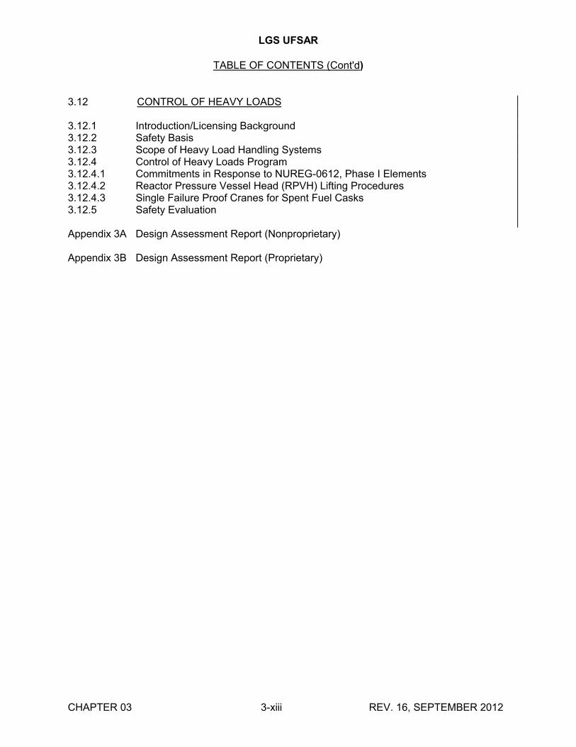
3.12 CONTROL OF HEAVY LOADS
3.12.1 Introduction/Licensing Background3.12.2 Safety Basis3.12.3 Scope of Heavy Load Handling Systems3.12.4 Control of Heavy Loads Program3.12.4.1 Commitments in Response to NUREG-0612, Phase I Elements3.12.4.2 Reactor Pressure Vessel Head (RPVH) Lifting Procedures3.12.4.3 Single Failure Proof Cranes for Spent Fuel Casks3.12.5 Safety Evaluation
Appendix 3A Design Assessment Report (Nonproprietary)
Appendix 3B Design Assessment Report (Proprietary)
LGS UFSAR
LIST OF TABLES
TABLE TITLE
CHAPTER 03 3-xiv REV. 16, SEPTEMBER 2012
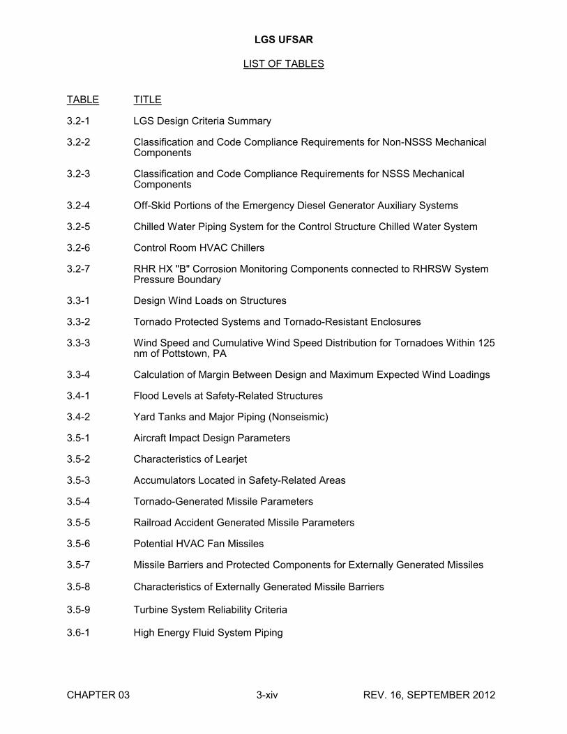
3.2-1 LGS Design Criteria Summary
3.2-2 Classification and Code Compliance Requirements for Non-NSSS Mechanical Components
3.2-3 Classification and Code Compliance Requirements for NSSS Mechanical Components
3.2-4 Off-Skid Portions of the Emergency Diesel Generator Auxiliary Systems
3.2-5 Chilled Water Piping System for the Control Structure Chilled Water System
3.2-6 Control Room HVAC Chillers
3.2-7 RHR HX "B" Corrosion Monitoring Components connected to RHRSW System Pressure Boundary
3.3-1 Design Wind Loads on Structures
3.3-2 Tornado Protected Systems and Tornado-Resistant Enclosures
3.3-3 Wind Speed and Cumulative Wind Speed Distribution for Tornadoes Within 125 nm of Pottstown, PA
3.3-4 Calculation of Margin Between Design and Maximum Expected Wind Loadings
3.4-1 Flood Levels at Safety-Related Structures
3.4-2 Yard Tanks and Major Piping (Nonseismic)
3.5-1 Aircraft Impact Design Parameters
3.5-2 Characteristics of Learjet
3.5-3 Accumulators Located in Safety-Related Areas
3.5-4 Tornado-Generated Missile Parameters
3.5-5 Railroad Accident Generated Missile Parameters
3.5-6 Potential HVAC Fan Missiles
3.5-7 Missile Barriers and Protected Components for Externally Generated Missiles
3.5-8 Characteristics of Externally Generated Missile Barriers
3.5-9 Turbine System Reliability Criteria
3.6-1 High Energy Fluid System Piping
LGS UFSAR
LIST OF TABLES (cont'd)
TABLE TITLE
CHAPTER 03 3-xv REV. 16, SEPTEMBER 2012
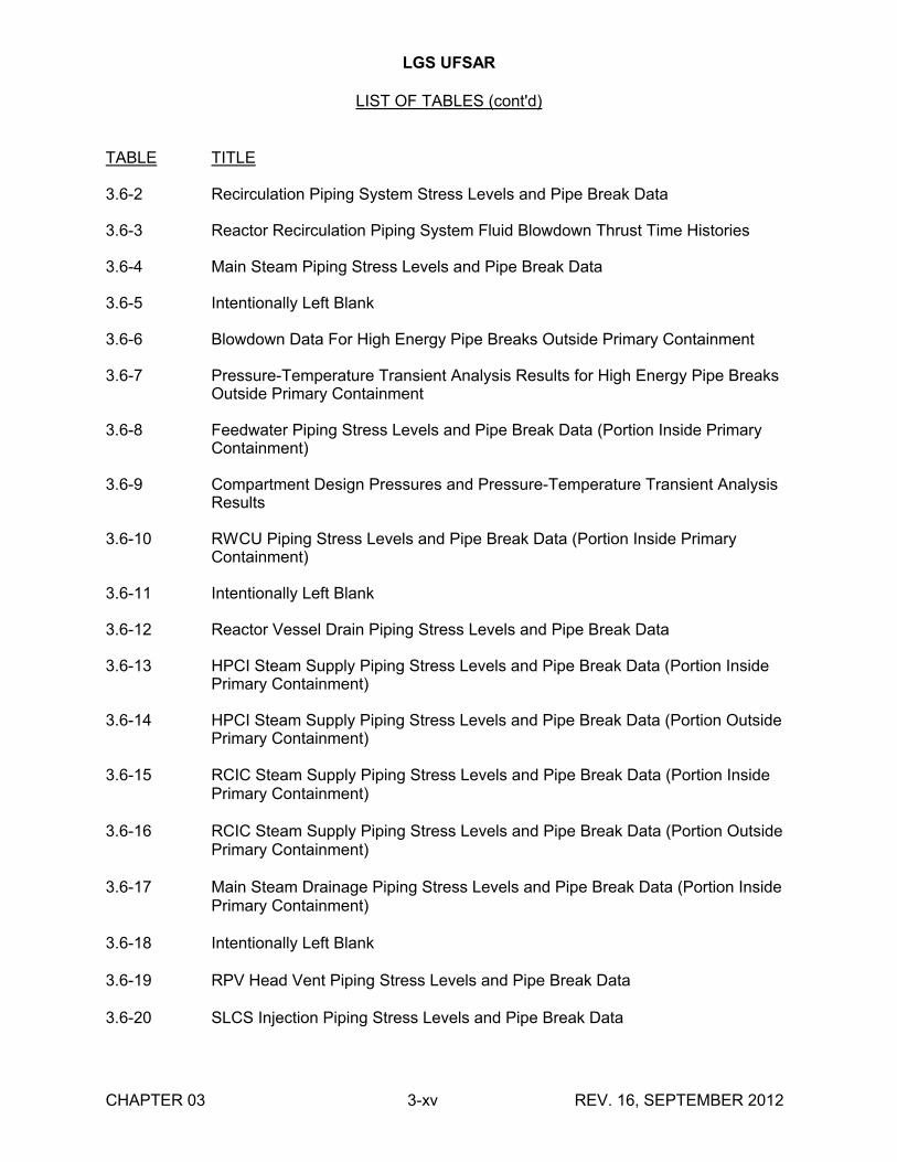
3.6-2 Recirculation Piping System Stress Levels and Pipe Break Data
3.6-3 Reactor Recirculation Piping System Fluid Blowdown Thrust Time Histories
3.6-4 Main Steam Piping Stress Levels and Pipe Break Data
3.6-5 Intentionally Left Blank
3.6-6 Blowdown Data For High Energy Pipe Breaks Outside Primary Containment
3.6-7 Pressure-Temperature Transient Analysis Results for High Energy Pipe Breaks Outside Primary Containment
3.6-8 Feedwater Piping Stress Levels and Pipe Break Data (Portion Inside Primary Containment)
3.6-9 Compartment Design Pressures and Pressure-Temperature Transient Analysis Results
3.6-10 RWCU Piping Stress Levels and Pipe Break Data (Portion Inside Primary Containment)
3.6-11 Intentionally Left Blank
3.6-12 Reactor Vessel Drain Piping Stress Levels and Pipe Break Data
3.6-13 HPCI Steam Supply Piping Stress Levels and Pipe Break Data (Portion Inside Primary Containment)
3.6-14 HPCI Steam Supply Piping Stress Levels and Pipe Break Data (Portion Outside Primary Containment)
3.6-15 RCIC Steam Supply Piping Stress Levels and Pipe Break Data (Portion Inside Primary Containment)
3.6-16 RCIC Steam Supply Piping Stress Levels and Pipe Break Data (Portion Outside Primary Containment)
3.6-17 Main Steam Drainage Piping Stress Levels and Pipe Break Data (Portion Inside Primary Containment)
3.6-18 Intentionally Left Blank
3.6-19 RPV Head Vent Piping Stress Levels and Pipe Break Data
3.6-20 SLCS Injection Piping Stress Levels and Pipe Break Data
LGS UFSAR
LIST OF TABLES (cont'd)
TABLE TITLE
CHAPTER 03 3-xvi REV. 16, SEPTEMBER 2012
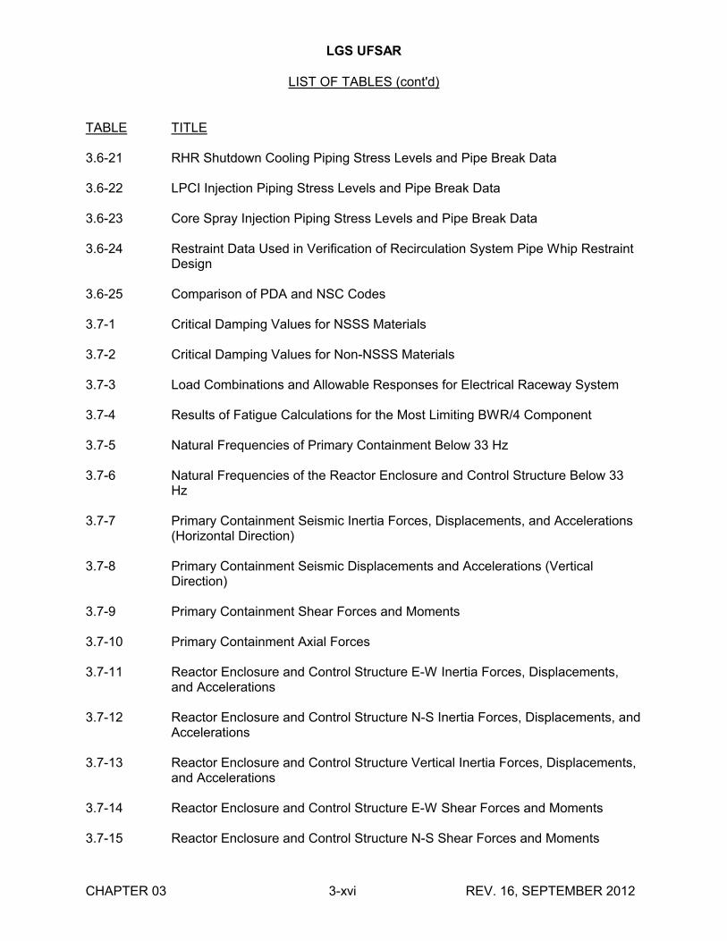
3.6-21 RHR Shutdown Cooling Piping Stress Levels and Pipe Break Data
3.6-22 LPCI Injection Piping Stress Levels and Pipe Break Data
3.6-23 Core Spray Injection Piping Stress Levels and Pipe Break Data
3.6-24 Restraint Data Used in Verification of Recirculation System Pipe Whip Restraint Design
3.6-25 Comparison of PDA and NSC Codes
3.7-1 Critical Damping Values for NSSS Materials
3.7-2 Critical Damping Values for Non-NSSS Materials
3.7-3 Load Combinations and Allowable Responses for Electrical Raceway System
3.7-4 Results of Fatigue Calculations for the Most Limiting BWR/4 Component
3.7-5 Natural Frequencies of Primary Containment Below 33 Hz
3.7-6 Natural Frequencies of the Reactor Enclosure and Control Structure Below 33 Hz
3.7-7 Primary Containment Seismic Inertia Forces, Displacements, and Accelerations (Horizontal Direction)
3.7-8 Primary Containment Seismic Displacements and Accelerations (Vertical Direction)
3.7-9 Primary Containment Shear Forces and Moments
3.7-10 Primary Containment Axial Forces
3.7-11 Reactor Enclosure and Control Structure E-W Inertia Forces, Displacements, and Accelerations
3.7-12 Reactor Enclosure and Control Structure N-S Inertia Forces, Displacements, and Accelerations
3.7-13 Reactor Enclosure and Control Structure Vertical Inertia Forces, Displacements, and Accelerations
3.7-14 Reactor Enclosure and Control Structure E-W Shear Forces and Moments
3.7-15 Reactor Enclosure and Control Structure N-S Shear Forces and Moments
LGS UFSAR
LIST OF TABLES (cont'd)
TABLE TITLE
CHAPTER 03 3-xvii REV. 16, SEPTEMBER 2012
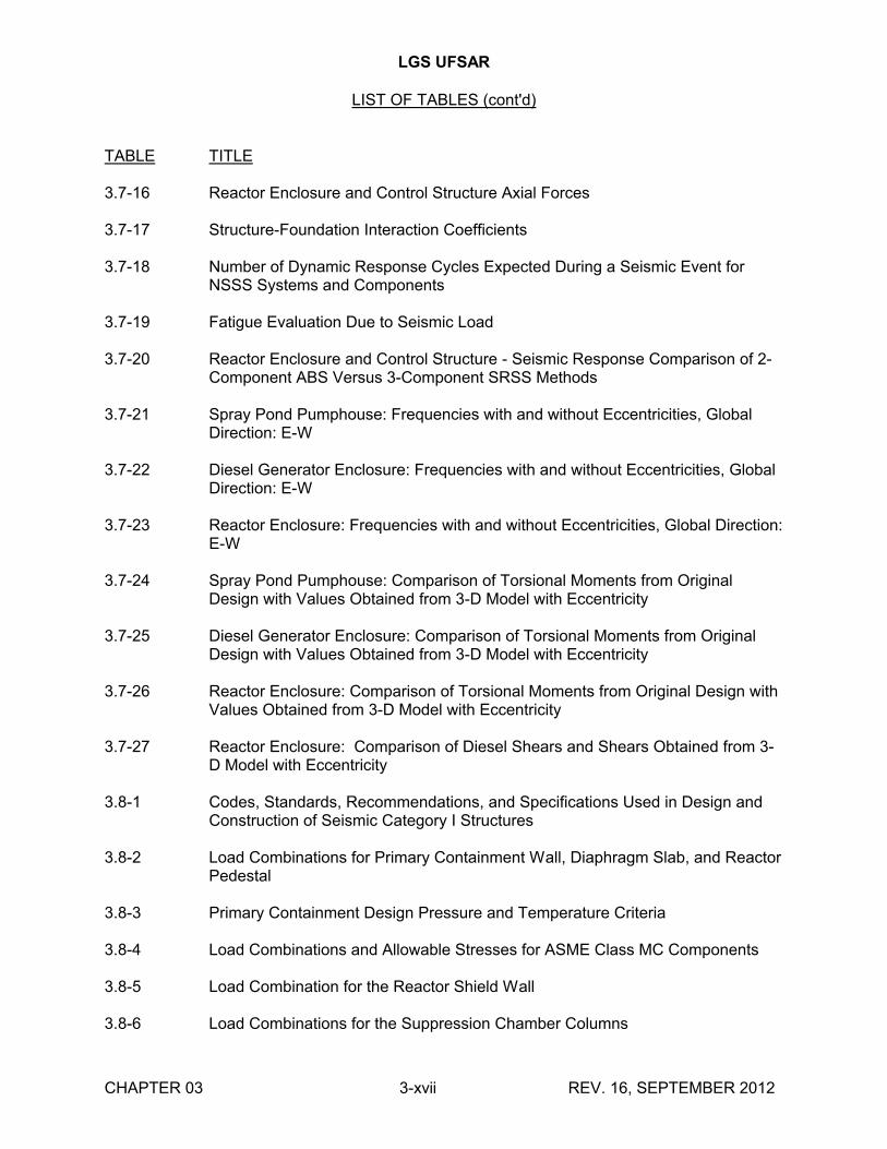
3.7-16 Reactor Enclosure and Control Structure Axial Forces
3.7-17 Structure-Foundation Interaction Coefficients
3.7-18 Number of Dynamic Response Cycles Expected During a Seismic Event for NSSS Systems and Components
3.7-19 Fatigue Evaluation Due to Seismic Load
3.7-20 Reactor Enclosure and Control Structure - Seismic Response Comparison of 2-Component ABS Versus 3-Component SRSS Methods
3.7-21 Spray Pond Pumphouse: Frequencies with and without Eccentricities, Global Direction: E-W
3.7-22 Diesel Generator Enclosure: Frequencies with and without Eccentricities, Global Direction: E-W
3.7-23 Reactor Enclosure: Frequencies with and without Eccentricities, Global Direction: E-W
3.7-24 Spray Pond Pumphouse: Comparison of Torsional Moments from Original Design with Values Obtained from 3-D Model with Eccentricity
3.7-25 Diesel Generator Enclosure: Comparison of Torsional Moments from Original Design with Values Obtained from 3-D Model with Eccentricity
3.7-26 Reactor Enclosure: Comparison of Torsional Moments from Original Design with Values Obtained from 3-D Model with Eccentricity
3.7-27 Reactor Enclosure: Comparison of Diesel Shears and Shears Obtained from 3-D Model with Eccentricity
3.8-1 Codes, Standards, Recommendations, and Specifications Used in Design and Construction of Seismic Category I Structures
3.8-2 Load Combinations for Primary Containment Wall, Diaphragm Slab, and ReactorPedestal
3.8-3 Primary Containment Design Pressure and Temperature Criteria
3.8-4 Load Combinations and Allowable Stresses for ASME Class MC Components
3.8-5 Load Combination for the Reactor Shield Wall
3.8-6 Load Combinations for the Suppression Chamber Columns
LGS UFSAR
LIST OF TABLES (cont'd)
TABLE TITLE
CHAPTER 03 3-xviii REV. 16, SEPTEMBER 2012
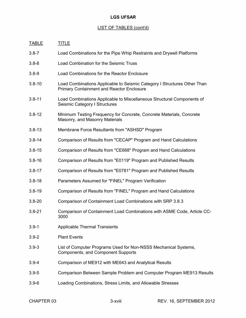
3.8-7 Load Combinations for the Pipe Whip Restraints and Drywell Platforms
3.8-8 Load Combination for the Seismic Truss
3.8-9 Load Combinations for the Reactor Enclosure
3.8-10 Load Combinations Applicable to Seismic Category I Structures Other Than Primary Containment and Reactor Enclosure
3.8-11 Load Combinations Applicable to Miscellaneous Structural Components of Seismic Category I Structures
3.8-12 Minimum Testing Frequency for Concrete, Concrete Materials, Concrete Masonry, and Masonry Materials
3.8-13 Membrane Force Resultants from "ASHSD" Program
3.8-14 Comparison of Results from "CECAP" Program and Hand Calculations
3.8-15 Comparison of Results from "CE668" Program and Hand Calculations
3.8-16 Comparison of Results from "E0119" Program and Published Results
3.8-17 Comparison of Results from "E0781" Program and Published Results
3.8-18 Parameters Assumed for "FINEL" Program Verification
3.8-19 Comparison of Results from "FINEL" Program and Hand Calculations
3.8-20 Comparison of Containment Load Combinations with SRP 3.8.3
3.8-21 Comparison of Containment Load Combinations with ASME Code, Article CC-3000
3.9-1 Applicable Thermal Transients
3.9-2 Plant Events
3.9-3 List of Computer Programs Used for Non-NSSS Mechanical Systems, Components, and Component Supports
3.9-4 Comparison of ME912 with ME643 and Analytical Results
3.9-5 Comparison Between Sample Problem and Computer Program ME913 Results
3.9-6 Loading Combinations, Stress Limits, and Allowable Stresses
LGS UFSAR
LIST OF TABLES (cont'd)
TABLE TITLE
CHAPTER 03 3-xix REV. 16, SEPTEMBER 2012
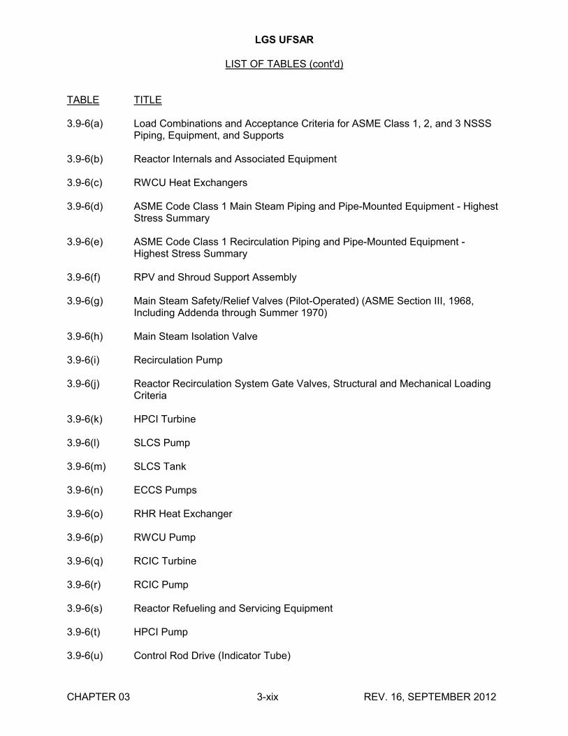
3.9-6(a) Load Combinations and Acceptance Criteria for ASME Class 1, 2, and 3 NSSS Piping, Equipment, and Supports
3.9-6(b) Reactor Internals and Associated Equipment
3.9-6(c) RWCU Heat Exchangers
3.9-6(d) ASME Code Class 1 Main Steam Piping and Pipe-Mounted Equipment - Highest Stress Summary
3.9-6(e) ASME Code Class 1 Recirculation Piping and Pipe-Mounted Equipment -Highest Stress Summary
3.9-6(f) RPV and Shroud Support Assembly
3.9-6(g) Main Steam Safety/Relief Valves (Pilot-Operated) (ASME Section III, 1968, Including Addenda through Summer 1970)
3.9-6(h) Main Steam Isolation Valve
3.9-6(i) Recirculation Pump
3.9-6(j) Reactor Recirculation System Gate Valves, Structural and Mechanical Loading Criteria
3.9-6(k) HPCI Turbine
3.9-6(l) SLCS Pump
3.9-6(m) SLCS Tank
3.9-6(n) ECCS Pumps
3.9-6(o) RHR Heat Exchanger
3.9-6(p) RWCU Pump
3.9-6(q) RCIC Turbine
3.9-6(r) RCIC Pump
3.9-6(s) Reactor Refueling and Servicing Equipment
3.9-6(t) HPCI Pump
3.9-6(u) Control Rod Drive (Indicator Tube)
LGS UFSAR
LIST OF TABLES (cont'd)
TABLE TITLE
CHAPTER 03 3-xx REV. 16, SEPTEMBER 2012
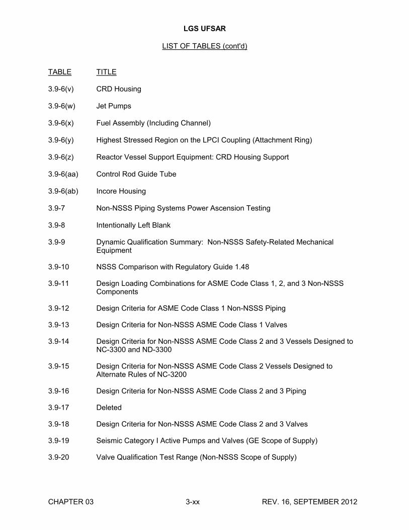
3.9-6(v) CRD Housing
3.9-6(w) Jet Pumps
3.9-6(x) Fuel Assembly (Including Channel)
3.9-6(y) Highest Stressed Region on the LPCI Coupling (Attachment Ring)
3.9-6(z) Reactor Vessel Support Equipment: CRD Housing Support
3.9-6(aa) Control Rod Guide Tube
3.9-6(ab) Incore Housing
3.9-7 Non-NSSS Piping Systems Power Ascension Testing
3.9-8 Intentionally Left Blank
3.9-9 Dynamic Qualification Summary: Non-NSSS Safety-Related Mechanical Equipment
3.9-10 NSSS Comparison with Regulatory Guide 1.48
3.9-11 Design Loading Combinations for ASME Code Class 1, 2, and 3 Non-NSSS Components
3.9-12 Design Criteria for ASME Code Class 1 Non-NSSS Piping
3.9-13 Design Criteria for Non-NSSS ASME Code Class 1 Valves
3.9-14 Design Criteria for Non-NSSS ASME Code Class 2 and 3 Vessels Designed to NC-3300 and ND-3300
3.9-15 Design Criteria for Non-NSSS ASME Code Class 2 Vessels Designed to Alternate Rules of NC-3200
3.9-16 Design Criteria for Non-NSSS ASME Code Class 2 and 3 Piping
3.9-17 Deleted
3.9-18 Design Criteria for Non-NSSS ASME Code Class 2 and 3 Valves
3.9-19 Seismic Category I Active Pumps and Valves (GE Scope of Supply)
3.9-20 Valve Qualification Test Range (Non-NSSS Scope of Supply)
LGS UFSAR
LIST OF TABLES (cont'd)
TABLE TITLE
CHAPTER 03 3-xxi REV. 16, SEPTEMBER 2012
3.9-21 Design Loading Combinations for Supports for ASME Code Class 1, 2 and 3 Components
3.9-22 Fatigue Limit (for Safety Class Reactor Internal Structures Only)
3.9-23 Core Support Structures: Stress Categories and Limits of Stress Intensity for Service Levels A and B (Normal and Upset) Conditions
3.9-24 Core Support Structures: Stress Categories and Limits of Stress Intensity for Service Level C (Emergency) Conditions
3.9-25 Maximum Pressure Differentials Across Reactor Vessel Internals During a Steam Line Break
3.9-26 Core Support Structure Design Loading Conditions and Combinations
3.9-27 Deformation Limit (for Reactor Internal Structures Only)
3.9-28 Primary Stress Limit (for Safety Class Reactor Internal Structures Only)
3.9-29 Buckling Stability Limit (for Safety Class Reactor Internal Structures Only)
3.9-30 Core Support Structures: Stress Categories and Limits of Stress Intensity for Service Level D (Fault) Conditions
3.9-31 Intentionally Left Blank
3.9-32 SRV Test Program
3.10-1 NSSS Essential Electrical Components and Instruments (Class 1E)
3.10-2 Seismic Qualification Test Summary: NSSS Safeguard Control Panels, Local Panels and Racks
3.10-3 Dynamic Qualification Test Summary: Non-NSSS Safety-Related Instruments and Electrical Equipment
LGS UFSAR
LIST OF FIGURES
FIGURE TITLE
CHAPTER 03 3-xxii REV. 16, SEPTEMBER 2012
3.3-1 Percent Probability of Exceeding Ordinate Value of Wind speed for Tornadoes Within 125 nm of Pottstown, PA
3.5-1 Resultant Load Curve on Structure Due to Impact of Design Aircraft
3.5-2 Reactor Enclosure Wall Section at Column Line D
3.5-3 Floor Plan, Diesel Generator, Unit 1
3.6-1 Typical Pipe Whip Restraint Details
3.6-2 Arrangement of Recirculation Loop Pipe Whip Restraints
3.6-3 Typical Recirculation System Pipe Whip Restraint
3.6-4 Recirculation System Isometric
3.6-5 Main Steam Piping Layout Outside Primary Containment
3.6-6 Main Steam Tunnel Elevation View
3.6-7 Main Steam Piping Restraints Inside Main Steam Tunnel
3.6-8 Main Steam Piping Isometric (Portion Inside Primary Containment)
3.6-9 Main Steam Piping Isometric (Portion Outside Primary Containment)
3.6-10 Rate of Coolant Loss for Main Steam Line Break Outside Primary Containment
3.6-11 Pressure-Temperature Transient Analysis Model for Main Steam Line Break in Main Steam Tunnel
3.6-12 Pressure-Temperature Transient Analysis Model for Main Steam Line Break in Turbine Enclosure
3.6-13 Feedwater Piping Restraints Inside Main Steam Tunnel
3.6-14 Feedwater Piping Restraints in Turbine Enclosure
3.6-15 Feedwater Piping Isometric (Portion Inside Primary Containment)
3.6-16 Feedwater Piping Isometric (Portion Outside Primary Containment)
3.6-17 RWCU Pump Suction Piping Isometric (Portion Inside Primary Containment)
3.6-18 RWCU Return Piping Isometric (Portion Inside Main Steam Tunnel)
LGS UFSAR
LIST OF FIGURES (cont'd)
FIGURE TITLE
CHAPTER 03 3-xxiii REV. 16, SEPTEMBER 2012
3.6-19 Pressure-Temperature Transient Analysis Model for RWCU Line Breaks in RWCU Equipment Compartments
3.6-20 Reactor Vessel Drain Piping Isometric
3.6-21 HPCI Steam Supply Piping Isometric (Portion Inside Primary Containment)
3.6-22 HPCI Steam Supply Piping Isometric (Portion Outside Primary Containment)
3.6-23 Pressure-Temperature Transient Analysis Model for HPCI Steam Supply Line Break in HPCI Compartment
3.6-24 Pressure-Temperature Transient Analysis Model for HPCI Steam Supply Line Break in Isolation Valve Compartment
3.6-25 RCIC Steam Supply Piping Isometric (Portion Inside Primary Containment)
3.6-26 RCIC Steam Supply Piping Isometric (Portion Outside Primary Containment)
3.6-27 Pressure-Temperature Transient Analysis Model for RCIC Steam Supply Line Break in Pump Compartment
3.6-28 Main Steam Drainage Piping Isometric (Portion Inside Primary Containment)
3.6-29 Intentionally Left Blank
3.6-30 RPV Head Vent Piping Isometric
3.6-31 Standby Liquid Control Injection Piping Isometric
3.6-32 RHR Shutdown Cooling Piping Isometric
3.6-33 LPCI Injection Piping Isometric
3.6-34 Core Spray Injection Piping Isometric
3.6-35 Intentionally Left Blank
3.6-36 Typical Force-Deflection Curve for Recirculation System Pipe Whip Restraint
3.6-37 Break Locations and Restraints Analyzed for PDA Verification Program
3.6-38 Typical Pipe Break Analysis Models
3.6-39 RWCU Pump Suction Piping Isometric (Portion Inside RWCU Isolation Valve Compartment)
LGS UFSAR
LIST OF FIGURES (cont'd)
FIGURE TITLE
CHAPTER 03 3-xxiv REV. 16, SEPTEMBER 2012
3.6-40 Intentionally Left Blank
3.6-41 Generic Presentation of Pipe
3.6-42 Representative of Pipe with Both Ends Built-in
3.6-43 Environmental Conditions and Compartment Dimensions for HPCI Steam Line Break
3.6-44 HPCI Steam Supply Line Break in HPCI Compartment Temperature Transient
3.6-45 HPCI Steam Supply Line Break in HPCI Compartment Pressure Transient
3.7-1 Design Response Spectra for Operating Basis Earthquake (Horizontal Component)
3.7-2 Design Response Spectra for Safe Shutdown Earthquake (Horizontal Component)
3.7-3 Synthetic Time History Normalized to 1g
3.7-4 Comparison of Time History Response Spectra and Design Response Spectra (0.5% Damping)
3.7-5 Comparison of Time History Response Spectra and Design Response Spectra (1% Damping) (Normalized to 1g)
3.7-6 Comparison of Time History Response Spectra and Design Response Spectra (2% Damping) (Normalized to 1g)
3.7-7 Comparison of Time History Response Spectra and Design Response Spectra (3% Damping) (Normalized to 1g)
3.7-8 Comparison of Time History Response Spectra and Design Response Spectra (5% Damping) (Normalized to 1g)
3.7-9 Comparison of Time History Response Spectra and Design Response Spectra (7% Damping) (Normalized to 1g)
3.7-10 Horizontal Seismic Model of Primary Containment
3.7-11 Vertical Seismic Model of Primary Containment
3.7-12 Horizontal Seismic Model of Primary Containment with Soil-Structure Interaction
3.7-13 Vertical Seismic Model of Primary Containment with Soil-Structure Interaction
LGS UFSAR
LIST OF FIGURES (cont'd)
FIGURE TITLE
CHAPTER 03 3-xxv REV. 16, SEPTEMBER 2012
3.7-14 Horizontal Seismic Model of Reactor Enclosure and Control Structure
3.7-15 Vertical Seismic Model of Reactor Enclosure and Control Structure
3.7-16 Horizontal Seismic Model of Reactor Enclosure and Control Structure with Soil-Structure Interaction
3.7-17 Vertical Seismic Model of Reactor Enclosure and Control Structure with Soil-Structure Interaction
3.7-18 Correlation of Vertical Seismic Model Mass Points to the Physical Structure
3.7-19 Seismic Model of Reactor Pressure Vessel and Internals
3.7-20 Containment Horizontal Mode Shapes - Uncracked Condition
3.7-21 Containment Horizontal Mode Shapes - Cracked Condition
3.7-22 Containment Vertical Mode Shapes - Uncracked Condition
3.7-23 Containment Vertical Mode Shapes - Cracked Condition
3.7-24 Reactor Enclosure and Control Structure N-S Mode Shapes
3.7-25 Reactor Enclosure and Control Structure E-W Mode Shapes
3.7-26 Reactor Enclosure and Control Structure Vertical Mode Shapes (Mode 1)
3.7-27 Reactor Enclosure and Control Structure Vertical Mode Shapes (Mode 7)
3.7-28 Reactor Enclosures and Control Structure Vertical Mode Shapes (Mode 14)
3.7-29 Reactor Enclosure and Control Structure Vertical Model Shapes (Mode 22)
3.7-30 Reactor Enclosure and Control Structure Vertical Mode Shapes (Mode 39)
3.7-31 Response Spectrum at RPV Pedestal Horizontal OBE (Damping = 0.005) -Uncracked Condition
3.7-32 Response Spectrum at RPV Pedestal Horizontal SSE (Damping = 0.005) -Uncracked Condition
3.7-33 Response Spectrum at RPV Pedestal Vertical OBE (Damping = 0.005) -Uncracked Condition
3.7-34 Response Spectrum at RPV Pedestal Vertical SSE (Damping = 0.005) -Uncracked Condition
LGS UFSAR
LIST OF FIGURES (cont'd)
FIGURE TITLE
CHAPTER 03 3-xxvi REV. 16, SEPTEMBER 2012
3.7-35 Response Spectrum at Refueling Area E-W OBE (Damping = 0.005)
3.7-36 Response Spectrum at Refueling Area E-W SSE (Damping = 0.005)
3.7-37 Response Spectrum at Refueling Area N-S OBE (Damping = 0.005)
3.7-38 Response Spectrum at Refueling Area N-S SSE (Damping = 0.005)
3.7-39 Response Spectrum at Refueling Area Vertical OBE (Damping = 0.005)
3.7-40 Response Spectrum at Refueling Area Vertical SSE (Damping = 0.005)
3.7-41 Response Spectrum at Refueling Area N-S SSE (Damping = 0.005) Soil-Structure Interaction
3.7-42 Response Spectrum at Refueling Area Vertical SSE (Damping = 0.005) Soil-Structure Interaction
3.7-43 Earthquake Response Spectra
3.7-44 Postseismic Event Plant Procedures
3.7-45 Damping versus ZPA for Raceway System
3.7-46 Comparison of 3-Component SRSS to 2-Component ABS
3.7-47 Relative Conservatism of the Two-Component Absolute and Three-Component SRSS Techniques
3.7-48 Spray Pond Pumphouse 3-D Stick Model (E-W Direction)
3.7-49 Diesel Generator Enclosure 3-D Stick Model (E-W Direction)
3.7-50 Reactor Enclosure 3-D Stick Model (E-W Direction)
3.8-1 Primary Containment Elevation View
3.8-2 Primary Containment Plan View at el 203'-5"
3.8-3 Primary Containment Plan View at el 253'-0"
3.8-4 Primary Containment Plan View at el 272'-9"
3.8-5 Primary Containment Plan View at el 277'-6"
LGS UFSAR
LIST OF FIGURES (cont'd)
FIGURE TITLE
CHAPTER 03 3-xxvii REV. 16, SEPTEMBER 2012
3.8-6 Primary Containment Plan View at el 286'-1"
3.8-7 Primary Containment Plan View at el 295'-11"
3.8-8 Primary Containment Plan View at el 303'-6"
3.8-9 Drywell Head Connection to Containment Wall
3.8-10 Diaphragm Slab Connection to Containment Wall
3.8-11 Base Foundation Slab Reinforcement
3.8-12 Base Foundation Slab Liner Plate and Anchorages
3.8-13 Reactor Pedestal Base Liner Anchorage
3.8-14 Suppression Chamber Column Base Liner Anchorage
3.8-15 Suppression Chamber Wall Reinforcement
3.8-16 Drywell Wall Reinforcement
3.8-17 Suppression Chamber Wall Liner Plate and Anchorages
3.8-18 Drywell Wall Liner Plate and Anchorages
3.8-19 Suppression Chamber Wall Reinforcement Detail at Typical Penetration
3.8-20 Drywell Wall Reinforcement Detail at Typical Penetration
3.8-21 Pipe Penetration Details
3.8-22 Electrical Penetration Details
3.8-23 Reinforcement Detail at Equipment Hatches
3.8-24 Beam Seat Embedment
3.8-25 Pipe Whip Restraint Embedment
3.8-26 Seismic Truss Support (Embedment)
3.8-27 Containment Wall Analytical Model for Axisymmetric Loads
3.8-28 Drywell Wall Analytical Model for Nonaxisymmetric Postulated Pipe Rupture Loads
LGS UFSAR
LIST OF FIGURES (cont'd)
FIGURE TITLE
CHAPTER 03 3-xxviii REV. 16, SEPTEMBER 2012
3.8-29 Base Foundation Slab Analytical Model
3.8-30 Equipment Hatch Analytical Model
3.8-31 Drywell Head
3.8-32 Equipment Hatch
3.8-33 Equipment Hatch with Personnel Lock
3.8-34 Control Rod Drive Removal Hatch
3.8-35 Analytical Model of Drywell Head Assembly
3.8-36 Diaphragm Slab Reinforcement
3.8-37 Diaphragm Slab Liner Plate and Anchorages
3.8-38 Reactor Vessel and Reactor Shield Wall Base Connections
3.8-39 Reactor Pedestal Reinforcement above Diaphragm Slab
3.8-40 Reactor Pedestal Reinforcement below Diaphragm Slab
3.8-41 Reactor Shield Wall
3.8-42 Suppression Chamber Columns
3.8-43 Seismic Truss
3.8-44 Diaphragm Slab Analytical Model
3.8-45 Analytical Model for Suppression Chamber Columns and Lower Reactor Pedestal
3.8-46 Analytical Model for Upper Reactor Pedestal
3.8-47 Reactor Shield Wall Analytical Model for "FINEL" and "ASHSD" Programs
3.8-48 Reactor Shield Wall Analytical Model for "EASE" Program
3.8-49 Suppression Chamber Column Analytical Model for "ASHSD" Program
3.8-50 Suppression Chamber Column Seismic Model
3.8-51 Suppression Chamber Column Analytical Model for "CE668" Program

LGS UFSAR
LIST OF FIGURES (cont'd)
FIGURE TITLE
CHAPTER 03 3-xxix REV. 16, SEPTEMBER 2012
3.8-52 Seismic Truss Analytical Model for "STRESS" Program
3.8-53 Reactor Enclosure, Fuel Pool Girder
3.8-54 Reactor Enclosure Upper Frame and Crane Runway Details
3.8-55 Spray Pond Excavation Plan View
3.8-56 Spray Pond Excavation and Grading Sections and Details
3.8-57 Spray Pond Roads, Pavings, and Finished Gradings
3.8-58 Safety-Related Structures and Yard Piping
3.8-59 Radwaste Enclosure Foundation Details
3.8-60 Reactor Enclosure and Control Structures-Foundation Details
3.8-61 Diesel Generator Enclosure Foundation Details
3.8-62 Spray Pond Pump Structure-Foundation Details
3.8-63 Turbine Enclosure Foundation Details
3.8-64 Miscellaneous Structures-Foundation Details
3.8-65 Thin-Shell Cylinder Model (ASHSD Program, Sample Problem a)
3.8-66 Axisymmetric Solid Cylinder Model (ASHSD Program, Sample Problem a)
3.8-67 Cylinder Model (ASHSD Program, Sample Problem b)
3.8-68 Finite-Element Model (ASHSD Program, Sample Problem b)
3.8-69 Comparison of Computer Results and Theoretical Solution (ASHSD Program, Sample Problem b)
3.8-70 Cylinder Model (ASHSD Program, Sample Problem c)
3.8-71 Finite-Element Model (ASHSD Program, Sample Problem c)
3.8-72 Comparison of Computer Results and Theoretical Solution (ASHSD Program, Sample Problem c)
3.8-73 Reinforced Concrete Beam (CECAP Program)
LGS UFSAR
LIST OF FIGURES (cont'd)
FIGURE TITLE
CHAPTER 03 3-xxx REV. 16, SEPTEMBER 2012
3.8-74 Concrete Beam Model (CECAP Program, Sample Problem a)
3.8-75 Beam Cross-Section and Thermal-Stress Distribution (CECAP Program, Sample Problem a)
3.8-76 Stress Diagram (CECAP Program, Sample Problem a)
3.8-77 Concrete Beam Model (CECAP Program, Sample Problem b)
3.8-78 Beam Cross-Section, Stress Block, and Transformed Section (CECAP Program, Sample Problem b)
3.8-79 Concrete Beam Model (CECAP Program, Sample Problem c)
3.8-80 Beam Cross-Section and Stress Block (CECAP Program, Sample Problem c)
3.8-81 Plate Geometry, Loading, and Finite-Element Mesh (CE668 Program, Sample Problem a)
3.8-82 Plate Geometry, Loading, and Finite-Element Mesh (CE668 Program, Sample Problem b)
3.8-83 Welding Neck Flange Detail (E0119 Program, Sample Problem a)
3.8-84 Slip-on Flange Detail (E0119 Program, Sample Problem b)
3.8-85 Geometry of Ellipsoidal and Torispherical Heads (E0781 Program, Sample Problem a)
3.8-86 Analytical Model with Boundary Conditions (E0781 Program, Sample Problem a)
3.8-87 Plots of Hoop Force (N) and Longitudinal Moment (M) (E0781 Program, Sample Problem a)
3.8-88 Plot of Stress in the Hoop () Direction on the Inside Surface ( = 0) (E0781 Program, Sample Problem a)
3.8-89 Plot of Stress in the Hoop () Direction on the Outside Surface ( = 0) (E0781 Program, Sample Problem a)
3.8-90 Plot of Stress in the Longitudinal Direction () on the Inside Surface ( = 0)
(E0781 Program, Sample Problem a) 3.8-91 Plot of Stress in the Longitudinal Direction () on the Outside Surface ( = 0)
(E0781 Program, Sample Problem a)
LGS UFSAR
LIST OF FIGURES (cont'd)
FIGURE TITLE
CHAPTER 03 3-xxxi REV. 16, SEPTEMBER 2012
3.8-92 Plot of Membrane Stress ( = 0) (E0781 Program, Sample Problem a)
3.8-93 Thickness Variation in Experimental Head No. 1 (E0781 Program, Sample Problem a)
3.8-94 Thickness Variation in Cylinder No. 1 (E0781 Program, Sample Problem a)
3.8-95 Geometry of Cylindrical Water Tank (E0781 Program, Sample Problem b)
3.8-96 Experimental Beam Geometry (FINEL Program, Sample Problem a)
3.8-97 Finite-Element Mesh Used in Reference 3.8-14 (FINEL Program, Sample Problem a)
3.8-98 Finite-Element Mesh Used in Program Verification (FINEL Program, Sample Problem a)
3.8-99 Regions of Cracking from Reference 3.8-14 and FINEL Analysis (FINEL Program, Sample Problem a)
3.8-100 Load-Deflection Curves from Reference 3.8-13, Reference 3.8-14, and FINEL Analysis (FINEL Program, Sample Program a)
3.8-101 Finite-Element Model for Hollow Cylinder with Distributed Pressure Loading (FINEL Program, Sample Problem b)
3.8-102 Finite-Element Model for Hollow Cylinder with Linear Temperature Gradient (FINEL Program, Sample Problem c)
3.8-103 Temperature Gradient Through-Wall of Hollow Cylinder (FINEL Program, Sample Problem c)
3.8-104 Temperature Conditions and Arrangement of Square Plate (ME620 Program, Sample Problem a)
3.8-105 Finite-Element Model of Square Plate (ME620 Program, Sample Problem a)
3.8-106 Comparison of Temperature Transients from ME620 and Reference 3.8-19 (ME620 Program, Sample Problem a)
3.8-107 Size and Temperature Conditions of Solid Steel Sphere (ME620 Program, Sample Problem b)
3.8-108 Finite-Element Model of Solid Steel Sphere (ME620 Program, Sample Problem b)
LGS UFSAR
LIST OF FIGURES (cont'd)
FIGURE TITLE
CHAPTER 03 3-xxxii REV. 16, SEPTEMBER 2012
3.9-1 Transient Temperature Response of a Small Pipe
3.9-2 Transient Pressure Differentials Following a Steam Line Break
3.9-3 Typical Relief Valve Transient
3.9-4 Reactor Vessel Cutaway
3.9-5 Reactor Internals Flow Paths
3.9-6 Fuel Support Pieces
3.9.7 Jet Pump
3.9-8 Pressure Nodes Used for Depressurization Analysis
3.9-9 Jurisdictional Boundary Between Pipe Supports and Supporting Structure for Supports not Furnished with NSSS
3.9-10 Jurisdictional Boundary Between Pipe Supports and Supporting Structure for Supports Furnished with Control Rod Drive System and TIP System
3.10-1 Typical Bench Board
3.10-2 Instrument Rack
3.10-3 Typical Local Rack
3.10-4 NEMA Type 12 Enclosure (Instruments Mounted Inside on Internal Membrane Mounted on Standoffs Attached to Back)
LGS UFSAR
CHAPTER 03 3.1-1 REV. 15, SEPTEMBER 2010
CHAPTER 3 - DESIGN OF STRUCTURES, COMPONENTS, EQUIPMENT, AND SYSTEMS
3.1 CONFORMANCE WITH NRC GENERAL DESIGN CRITERIA
This section discusses the extent to which the design criteria for the plant structures, systems, and components important to safety meet the General Design Criteria for Nuclear Power Plants specified in 10CFR50, Appendix A. For each criterion, a summary is provided to show how the principal design features meet the criterion. The discussion of each criterion also gives the section of the UFSAR where more detailed information is presented to demonstrate compliance with the criterion.
GDC 1 - Quality Standards and Records
Structures, systems, and components important to safety shall be designed, fabricated, erected, and tested to quality standards commensurate with the importance of the safety functions to be performed. Where generally recognized codes and standards are used, they shall be identified and evaluated to determine their applicability, adequacy, and sufficiency and shall be supplemented or modified as necessary to assure a quality product in keeping with the required safety function. A quality assurance program shall be established and implemented in order to provide adequate assurance that these structures, systems, and components will satisfactorily perform their safety functions. Appropriate records of the design, fabrication, erection, and testing of structures, systems, and components important to safety shall be maintained by or under the control of the nuclear power unit licensee throughout the life of the unit.
Design Evaluation
Structures, systems, and components important to safety are designed, fabricated, erected, tested, and operated under a QA program that satisfies the requirements of 10CFR50, Appendix B. Chapter 17.2 of the UFSAR discusses the QA program during operation, which is designed and implemented to ensure that LGS is tested and operated in conformance with the regulatory requirements and design bases outlined in the license application.
Design requirements and other information regarding implementation of the QA program are described in various sections of the UFSAR. Codes and standards that apply to safety-related, pressure-retaining piping and equipment are discussed in Section 3.2. Building codes and standards are discussed in Section 3.8. Detailed seismic design is outlined in Section 3.7.
Structures, systems, and components are classified with regard to location, service, and relationship to the safety function to be performed. Recognized codes and standards are applied to the equipment in keeping with the appropriate classification. Where codes are not available or where the existing code must be modified, justification is provided in the UFSAR.
Documents and records are available to show objective evidence that the requirements of the QA program have been satisfied. The documentation shows that the required codes, standards, and specifications were observed; specified materials were used; correct procedures were used; qualified personnel performed the work; and inspections and tests verified that finished parts and components meet the applicable specifications. Appropriate records are maintained during the operational life of the plant.
LGS UFSAR
CHAPTER 03 3.1-2 REV. 15, SEPTEMBER 2010
The QA program developed by the licensee and it's contractors satisfies the requirements of GDC 1.
GDC 2 - Design Bases for Protection Against Natural Phenomena
Structures, systems, and components important to safety shall be designed to withstand the effect of natural phenomena such as earthquakes, tornadoes, hurricanes, floods, tsunami, and seiches without loss of capability to perform their safety functions. The design bases for these structures, systems, and components shall reflect: 1) appropriate consideration of the most severe of the natural phenomena that have been historically reported for the site and surrounding area, with sufficient margin for the limited accuracy, quantity, and period of time in which the historical data have been accumulated, 2) appropriate combinations of the effects of normal and accident conditions with the effects of the natural phenomena, and 3) the importance of the safety functions to be performed.
Design Evaluation
The design basis for protection against natural phenomena is in accordance with GDC 2. Structures, systems, and components important to safety are designed to withstand the effects of natural phenomena such as earthquakes, tornadoes, and floods without loss of the capability to perform required safety functions, with appropriate margin to account for uncertainties in the historical data. The natural phenomena postulated in the design are presented in Sections 2.3, 2.4, and 2.5. The design criteria for the structures, systems, and components affected by each natural phenomenon are presented in Sections 3.2, 3.3, 3.4, 3.5, 3.7, and 3.8. Those combinations of natural phenomena and plant originated accidents that are considered in the design are identified in Sections 3.8, 3.9, 3.10, and 3.11.
GDC 3 - Fire Protection
Structures, systems, and components important to safety shall be designed and located to minimize, consistent with other safety requirements, the probability and effect of fires and explosions. Noncombustible and heat-resistant materials shall be used wherever practical throughout the unit, particularly in locations such as the containment and control room. Fire detection and fighting systems of appropriate capacity and capability shall be provided and designed to minimize the adverse effects of fires on structures, systems, and components important to safety. Fire fighting systems shall be designed to assure that their rupture or inadvertent operation does not significantly impair the safety capability of these structures, systems, and components.
Design Evaluation
Structures, systems, and components important to safety are designed to minimize the probability and effect of fires and explosions. Noncombustible and heat-resistant materials are used wherever practicable throughout the plant, particularly in the containment, control room, and areas containing engineered safeguards.
Appropriate equipment and facilities for fire protection, including the detection, alarm, and extinguishing of fires, are provided to protect plant equipment and personnel from fire, explosions, and the resultant release of toxic vapors. Automatic and manual types of fire protection equipment are provided.
LGS UFSAR
CHAPTER 03 3.1-3 REV. 15, SEPTEMBER 2010
The fire protection system provides an adequate supply of water to the deluge systems, sprinkler systems, and hose stations located throughout the plant. A carbon dioxide system provides protection for the cable spreading room. Two separate Halon extinguishing systems are provided for the raised flooring in the auxiliary equipment room. Portable fire extinguishers are provided throughout the plant. A detailed description of the fire protection system and its design bases is provided in Section 9.5.1.
Early warning of incipient fires is provided by a fire detection system utilizing smoke detectors and/or heat-responsive devices located in areas of the plant where significant fire potential exists.
The fire protection system is designed, fabricated, and installed in accordance with the requirements of the NFPA, ANI, OSHA, and applicable local codes and regulations as listed in Section 9.5.1.
The fire protection system was inspected and functionally tested prior to plant operation in order to ensure its proper operation. The fire suppression systems are provided with test valves and facilities for periodic testing. All equipment is accessible for periodic inspection.
Although it can be postulated that failure or inadvertent operation of the fire suppression system may incapacitate some safety-related systems or components, such failure or inadvertent operation will not prevent safe shutdown from being achieved through the use of redundant safety-related systems.
Structures, systems, and components important to safety are designed to meet the requirements of GDC 3. Fire protection systems meeting the requirements of GDC 3 are provided.
GDC 4 - Environmental and Missile Design Bases
Structures, systems, and components important to safety shall be designed to accommodate the effects of and to be compatible with the environmental conditions associated with normal operation, maintenance, testing, and postulated accidents, including LOCAs. These structures, systems, and components shall be appropriately protected against dynamic effects, including the effects of missiles, pipe whipping, and discharging fluids, that may result from equipment failures and from events and conditions outside the nuclear power unit.
Design Evaluation
Structures, systems, and components important to safety are designed to accommodate the effects of and to be compatible with the environmental conditions associated with normal operation, maintenance, testing, and postulated accidents, including the design basis LOCA. These structures, systems, and components are appropriately protected against dynamic effects and discharging fluids that may result from equipment failures. Normal and postulated accident effects and load combinations are given in Sections 3.6, 3.8, 3.9, 3.10, and 3.11.
Special attention has been directed to the effects of pipe movement, jet forces, and missiles within the primary containment. Pipe whip restraints have been provided to the extent practicable (Section 3.6). Primary containment integrity protection is discussed in Section 6.2.1. The structures, systems, and components important to safety are protected from dynamic effects by separating redundant counterparts so that no single event can prevent a required safety action, and by routing and locating these components, to the extent practicable, to avoid potentially
LGS UFSAR
CHAPTER 03 3.1-4 REV. 15, SEPTEMBER 2010
hazardous areas. The means used to preserve the independence of redundant counterparts of safety-related systems are discussed in Chapter 6.
Dynamic effects external to the plant, induced by natural phenomena (e.g., tornado-produced missiles), are discussed in Section 3.5. Section 3.11 contains a discussion of design environmental conditions.
Environmental and missile design bases are in accordance with GDC 4.
GDC 5 - Sharing of Structures, Systems, and Components
Structures, systems, and components important to safety shall not be shared among nuclear power units unless it can be shown that such sharing will not significantly impair their ability to perform their safety functions, including, in the event of an accident in one unit, an orderly shutdown and cooldown of the remaining units.
Design Evaluation
Although LGS Units 1 and 2 share certain structures, systems, and components, sharing them does not significantly impair the performance of their safety functions.
The following safety-related structures are shared between both units:
a. Control enclosure and support subsystems
b. Spray pond pumphouse and support subsystems
c. Spray pond
The safety-related structures are designed to remain functional during and following the most severe natural phenomena. Therefore sharing these structures does not impair their ability to perform their safety functions.
Seismic Category I structures that house safety-related systems and equipment are discussed in Section 3.8.
The below listed safety systems and subsystems are shared by both units. Refer to the section listed by each system or subsystem for discussion of design criteria for instrumentation. The instrumentation for these systems is available on common panels in the control room and therefore is available to the operators of both units.
LGS UFSAR
CHAPTER 03 3.1-5 REV. 15, SEPTEMBER 2010
SHARED SAFETY SYSTEMS SECTION
ESW system 7.3.2.11
RHRSW system 7.3.2.12
RHRSW-RMS 7.6.1.1
Control structure support systems
Habitability, control room isolation subsystem 7.3.2.10
Emergency switchgear and battery room cooling 7.3.2.15subsystem
CECWS 7.3.2.13
AERVS 7.3.2.15
CRV-RMS 7.6.1.1
CREFA-RMS 7.6.1.1
SGTS 7.3.2.7
SGTS-UC 7.3.2.15
RAVE-RMS and REVE-RMS 7.6.1.1
North stack radiation monitoring system 7.6.1.1
Spray pond pumphouse support system 7.3.2.15
The shared systems that are important to safety are discussed below. A more detailed discussion may be found in these referenced sections.
Emergency Service Water System
The ESW system is designed to supply cooling water to safety- related components, including the diesel generators, room coolers and chillers, and the RHR pumps during LOOP and accident conditions. Certain nonessential components can be cooled by the ESW system also, at the operator's option.
The ESW pumps are located in the spray pond pumphouse with the RHRSW pumps. The spray pond pumphouse is designed as seismic Category I. The ESW system consists of two redundant loops, each capable of simultaneously providing 100% of the cooling water required by both Units 1 and 2. The system is designed so that no single active or passive electrical or control component failure or active mechanical component failure can prevent it from achieving its safety-related objective.
LGS UFSAR
CHAPTER 03 3.1-6 REV. 15, SEPTEMBER 2010
For additional discussion, see Section 9.2.2.
RHR Service Water System
The RHRSW system is designed to supply cooling water to the RHR heat exchangers during normal shutdown cooling operations as well as during LOOP and accident conditions.
The RHRSW pumps are located in the spray pond pumphouse with the ESW pumps. The spray pond pumphouse is designed as seismic Category I. The RHRSW system consists of two redundant loops, each supplying one RHR heat exchanger in each unit and capable of simultaneously providing 100% of the cooling water required by both Units 1 and 2. The system is designed so that no single active or passive component failure can prevent it from achieving its safety-related objective.
For additional discussion, see Section 9.2.3.
Ultimate Heat Sink (Spray Pond)
The spray pond provides the water for both the ESW and the RHRSW systems. It is the UHS for both Units 1 and 2. The return lines from the ESW and the RHRSW system are combined, and the total quantity of water from both these systems is discharged through spray networks, which dissipate the heat. There are two redundant return loops. Either one is capable of handling the full flow from the ESW and RHRSW systems when shutting down two units simultaneously.
Each return loop supplies two spray networks. Two of the four networks provide sufficient cooling for the design basis conditions.
The spray pond contains sufficient water to meet the requirements for shutting down one unit if there is an accident and to permit the safe shutdown of the second unit for a period of 30 days without makeup.
For additional discussion, see Section 9.2.6.
Standby Gas Treatment System
The SGTS is designed to maintain both reactor enclosures and refueling area at the required negative pressure when any of these areas are isolated.
The SGTS filter train and fans are located in the control enclosure. The control enclosure is a seismic Category I structure. The SGTS consists of two 100% capacity redundant filter trains and two 100% capacity fans. The system is designed so that no single failure can prevent it from achieving its safety-related objective.
Additional discussion is given in Section 6.5.1.1.
LGS UFSAR
CHAPTER 03 3.1-7 REV. 15, SEPTEMBER 2010
Control Room and Control Structure HVAC Systems
The control room and control structure HVAC systems are designed to maintain the space temperature and pressure in the various areas within the common control structure at their design conditions.
Each system consists of two 100% capacity redundant HVAC units and the system is designed so that a single failure will not prevent the system from achieving its safety-related objective.
Additional discussion is given in Section 9.4.1.
Control Structure Chilled Water System
The CSCWS provides chilled water to maintain stipulated ambient air temperature in various areas inside the common control structure.
The system consists of two 100% capacity redundant chillers and pumps and is designed so that a single failure will not prevent the system from achieving its safety-related objective.
Additional discussion is given in Section 9.2.10.2.
GDC 10 - Reactor Design
The reactor core and associated coolant, control, and protection systems shall be designed with appropriate margin to assure that specified acceptable fuel design limits are not exceeded during any condition of normal operation, including the effects of anticipated operational occurrences.
Design Evaluation
The reactor core components consist of fuel assemblies, control rods, incore ion chambers, neutron sources, and related items. The mechanical design is based on a conservative application of stress limits, operating experience, and experimental test results.
The core has sufficient heat transfer area and coolant flow to ensure that there is no fuel damage under normal conditions or anticipated operational occurrences. The RPS is designed to monitor certain reactor parameters, sense abnormalities, and shut down the reactor, thereby preventing fuel damage when trip setpoints are exceeded. Trip setpoints are selected according to operating experience and the design bases. There is no case in which the scram-trip setpoints allow the core to exceed the thermal-hydraulic safety limits. Power for the RPS is provided by dc-ac static inverters. Alternate electrical power is available to the RPS buses. The RPS is fail-safe, i.e., scram is initiated on loss of power.
An analysis and evaluation have been made of the effects on core fuel following adverse plant operating conditions. The results of abnormal operational transients are presented in Chapter 15 and show that the MCPR does not fall below the specified limit, thereby satisfying the transient design basis. The conditions assumed in the analysis and the control systems used to accommodate these transients are identified in Chapter 15.

LGS UFSAR
CHAPTER 03 3.1-8 REV. 15, SEPTEMBER 2010
The reactor core and associated coolant, control, and protection systems are designed to ensure that the specified fuel design limits are not exceeded during conditions of normal or abnormal operation and therefore meet the requirements of GDC 10.
Referenced sections are as follows:
a. Fuel system design Section 4.2
b. Nuclear design Section 4.3
c. Thermal and hydraulic design Section 4.4
d. Component and subsystem design Section 5.4
e. RPS Section 7.2
f. All other instrumentation systems required for safety
Section 7.6
g. Control systems not required for safety Section 7.7
h. Accident analyses Chapter 15
GDC 11 - Reactor Inherent Protection
The reactor core and associated coolant systems shall be designed so that, in the power operating range, the net effect of the prompt inherent nuclear feedback characteristics tends to compensate for a rapid increase in reactivity.
Design Evaluation
The reactor core is designed to have a reactivity response that regulates or damps changes in power level and spatial distributions of power production to a level consistent with safe and efficient operation.
The inherent dynamic behavior of the core is characterized in terms of:
a. Fuel temperature or Doppler coefficient
b. Moderator void coefficient
c. Moderator temperature coefficient
The combined effect of these coefficients in the power range is termed the power coefficient.
Doppler reactivity feedback occurs simultaneously with a change in fuel temperature and opposes the power change that caused it. Thus, it contributes to system stability. Since the Doppler reactivity opposes load changes, it is desirable to maintain a large ratio of moderator void coefficient to Doppler coefficient for optimum load-following capability. The BWR has an
LGS UFSAR
CHAPTER 03 3.1-9 REV. 15, SEPTEMBER 2010
inherently large moderator-to-Doppler coefficient ratio that permits the use of coolant flow rate for load-following.
In a BWR, the moderator void coefficient is of primary importance during operation at power. Nuclear design is based on the void coefficient inside the fuel channel being negative. The negative void reactivity coefficient provides an inherent negative feedback during power transients. Because of the large negative moderator coefficients of reactivity, the BWR has a number of inherent advantages, such as:
a. Use of coolant flow as opposed to control rods for load-following
b. Inherent self-flattening of the radial power distribution
c. Ease of control
d. Spatial xenon stability
The reactor is designed so that the moderator temperature coefficient is small and positive in the cold condition; however, the overall power reactivity coefficient is negative.
The reactor core and associated coolant system are designed so that, in the power operating range, prompt inherent dynamic behavior tends to compensate for any rapid increase in reactivity in accordance with GDC 11. Referenced sections are as follows:
a. Nuclear design Section 4.3
b. Thermal and hydraulic design Section 4.4
GDC 12 - Suppression of Reactor Power Oscillations
The reactor core and associated coolant, control, and protection systems shall be designed to ensure that power oscillations which can result in conditions exceeding specified acceptable fuel design limits are not possible or can be reliably and readily detected and suppressed.
Design Evaluation
The reactor core is designed to ensure that no power oscillation can cause fuel design limits to be exceeded. The power reactivity coefficient is the composite simultaneous effect of the fuel temperature or Doppler coefficient, moderator void coefficient, and moderator temperature coefficient to the change in power level. It is negative and well within the range required for adequate damping of power and spatial xenon disturbances. Operating experience has shown large BWRs to be inherently stable against xenon-induced power instability.
The RPS design and the recirculation pump trip system provide protection from excessive fuel cladding temperatures and protect the nuclear system process barrier from excessive pressures that threaten the integrity of the system. Local abnormalities are sensed, and, if protection system limits are reached, corrective action is initiated through an automatic scram and recirculation pump trip. High reliability of the RPS is achieved through the combination of logic arrangement, trip channel redundancy, power supply redundancy, and physical separation.
LGS UFSAR
CHAPTER 03 3.1-10 REV. 15, SEPTEMBER 2010
The reactor core and associated coolant, control, and protection systems are designed to suppress any power oscillations that could result in exceeding the fuel design limits. These systems ensure that GDC 12 is met. Referenced sections are as follows:
a. Fuel system design Section 4.2
b. Nuclear design Section 4.3
c. Thermal and hydraulic design Section 4.4
d. Integrity of RCPB Section 5.2
e. RPS Section 7.2
f. All other instrumentation systems required for safety
Section 7.6
g. Accident analyses Chapter 15
GDC 13 - Instrumentation and Control
Instrumentation shall be provided to monitor variables and systems over their anticipated ranges for normal operations, for anticipated operational occurrences, and for accident conditions as appropriate to assure adequate safety, including those variables and systems that can affect the fission process, the integrity of the reactor core, the RCPB, and the containment and its associated systems. Appropriate controls shall be provided to maintain these variables and systems within prescribed operating ranges.
Design Evaluation
Instrumentation is provided to monitor variables and systems over their anticipated ranges for normal operations, for anticipated operational occurrences, and for accident conditions as appropriate to assure adequate safety. Appropriate controls are provided to maintain these variables and systems within prescribed operating ranges. A summary description for each instrumentation and control system is provided in Section 7.1. The instrumentation and controls provided meet the requirements of GDC 13. Referenced sections are as follows:
a. Reactor Trip System (Reactor Protection Section 7.2System) – Instrumentation And Controls
b. ESF Systems Section 7.3
c. Systems Required For Safe Shutdown Section 7.4
d. Information Systems Important To Safety Section 7.5
e. All Other Instrumentation Systems Important Section 7.6To Safety
LGS UFSAR
CHAPTER 03 3.1-11 REV. 15, SEPTEMBER 2010
f. Control Systems Not Required For Safety Section 7.7
GDC 14 - Reactor Coolant Pressure Boundary
The RCPB shall be designed, fabricated, erected, and tested so as to have an extremely low probability of abnormal leakage, of rapidly propagating failure, and of gross rupture.
Design Evaluation
The piping and equipment pressure parts within the RCPB through the outer isolation valves are designed, fabricated, erected, and tested to provide a high degree of integrity throughout the plant lifetime. Section 3.2 classifies the systems and components within the RCPB. The design requirements and codes and standards applied to the quality group ensure a quality product in keeping with the safety functions to be performed.
To minimize the possibility of brittle fracture within the RCPB, the fracture or notch properties and the operating temperature of ferritic materials are controlled to ensure adequate toughness when the system is pressurized to more than 20% of the design pressure. Section 5.2 describes the methods used to control toughness properties. Materials to be impact-tested are tested by the Charpy
V-notch method in accordance with ASME B&PV Code, Section III. The service temperature of these materials is maintained above the NDTT. The fracture toughness temperature requirements of the RCPB materials also apply for the RCPB piping that penetrates the containment.
Piping and equipment pressure parts of the RCPB are assembled and erected by welding unless applicable codes permit flanged or screwed joints. Assembly is according to ANSI B31.7 and ASME Section III. Erection is according to ASME Section III. Welding procedures are employed that produce welds of complete penetration, complete fusion, and freedom from unacceptable defects. All welding procedures, welders, and welding machine operators are qualified in accordance with the requirements of ASME B&PV Code, Section IX for the materials to be welded.
Section 5.2 contains the detailed material and examination requirements for the piping and equipment of the RCPB before and after its assembly and erection. Leakage testing and surveillance is accomplished as described in the evaluation against GDC 30.
The design, fabrication, erection, and testing of the RCPB ensure an extremely low probability of failure or abnormal leakage, thus satisfying the requirements of GDC 14. Referenced sections are as follows:
a. Design of structures, components, Chapter 3 equipment, and systems
b. Integrity of RCPB Section 5.2
c. Reactor vessel and appurtenances Section 5.3
d. Component and subsystem design Section 5.4
LGS UFSAR
CHAPTER 03 3.1-12 REV. 15, SEPTEMBER 2010
e. Accident analyses Chapter 15
f. QA Chapter 17
GDC 15 - Reactor Coolant System Design
The RCS and associated auxiliary, control, and protection systems shall be designed with sufficient margin to assure that the design conditions of the reactor coolant pressure boundary are not exceeded during any condition of normal operation, including anticipated operational occurrences.
Design Evaluation
The RCS consists of the reactor vessel and appurtenances, the reactor recirculation system, the pressure relief system, and the main steam and feedwater lines. This system is designed, fabricated, erected, and tested to stringent requirements and appropriate codes and standards that ensure high integrity of the RCPB throughout the plant lifetime. The RCS is designed and fabricated to meet the requirements of the ASME B&PV Code, Section III.
The auxiliary, control, and protection systems associated with the RCS provide sufficient margin toensure that the design conditions of the RCPB are not exceeded during any condition of normal operation, including anticipated operational occurrences. As described in the evaluation of GDC 13, instrumentation is provided to monitor essential variables to ensure that they are within prescribed operating limits. If the monitored variables exceed their predetermined settings, the auxiliary, control, and protection systems automatically respond to maintain the variables and systems within allowable design limits.
An example of the integrated protective action scheme that provides sufficient margin to ensure that the design conditions of the RCPB are not exceeded is the automatic initiation of the pressure relief system on receipt of an overpressure signal. To accomplish overpressure protection, a number of pressure-operated relief valves are provided that can discharge steam from the nuclear system to the pressure-suppression pool. The pressure relief system also provides for automatic depressurization of the nuclear system if there is a LOCA in which the vessel is not depressurized by the accident. The depressurization of the nuclear system in this situation allows operation of the low pressure ECCS to supply enough cooling water to adequately cool the core. In a similar manner, other auxiliary, control, and protection systems provide assurance that the design conditions of the RCPB are not exceeded during any conditions of normal operation, including anticipated operational occurrences.
The application of appropriate codes, standards, and high quality requirements to the RCS and the design features of its associated auxiliary, control, and protection systems ensure that therequirements of GDC 15 are satisfied.Referenced sections are as follows:
LGS UFSAR
CHAPTER 03 3.1-13 REV. 15, SEPTEMBER 2010
a. Integrity of RCPB Section 5.2
b. Reactor vessel and appurtenances Section 5.3
c. Component and subsystem design Section 5.4
d. ECCS Section 6.3
e. ESF systems Section 7.3
f. Control systems not required for safety Section 7.7
g. Accident analyses Chapter 15
GDC 16 - Containment Design
Reactor containment and associated systems shall be provided to establish an essentially leak-tight barrier against the uncontrolled release of radioactivity to the environment and to assure that the containment design conditions important to safety are not exceeded for as long as postulated accident conditions require.
Design Evaluation
The primary containment system, which includes the drywell and suppression chamber, is designed, fabricated, and erected to accommodate, without failure, the pressures and temperatures resulting from the double-ended rupture or equivalent failure of any coolant pipe within the primary containment. The reactor enclosure encompassing the primary containment provides secondary containment. To provide protection against the consequences of accidents involving the release of radioactive materials from the fuel and nuclear system process barrier, the PCRVICS initiates automatic isolation of appropriate pipelines that penetrate the primary containment whenever monitored variables exceed preselected operational limits. The two containment systems and their associated safety systems are designed and maintained so that offsite doses, which could result from postulated design basis accidents, remain below the values stated in 10CFR50.67 when calculated by the methods of Regulatory Guide 1.183. The referenced sections provide detailed information that demonstrates compliance with GDC 16. Referenced sections are as follows:
a. Containment systems Section 6.2
b. MSIV Leakage Alternate Drain Pathway Section 6.7
c. Primary containment ventilation system Section 9.4.5
d. Accident analysis Chapter 15
LGS UFSAR
CHAPTER 03 3.1-14 REV. 15, SEPTEMBER 2010
GDC 17 - Electric Power Systems
An onsite electric power system and an offsite electric power system shall be provided to permit functioning of structures, systems, and components important to safety. The safety function for each system (assuming the other system is not functioning) shall be to provide sufficient capacity and capability to assure that 1) specified acceptable fuel design limits and design conditions of the RCPB are not exceeded as a result of anticipated operational occurrences and 2) the core is cooled and containment integrity and other vital functions are maintained in the event of postulated accidents.
The onsite electric power supplies (including the batteries) and the onsite electric distribution system shall have sufficient independence, redundancy, and testability to perform their safety functions assuming a single failure.
Electric power from the transmission network to the onsite electric distribution system shall be supplied by two physically independent circuits (not necessarily on separate rights of way) designed and located so as to minimize to the extent practical the likelihood of their simultaneous failure under operating and postulated accident and environmental conditions. A switchyard common to both circuits is acceptable. Each of these circuits shall be designed to be available in sufficient time, following a loss of all onsite alternating current power supplies and the other offsite electric power circuit, to assure that specified acceptable fuel design limits and design conditions of the reactor coolant pressure boundary are not exceeded. One of these circuits shall be designed to be available within a few seconds following a LOCA to assure that core cooling, containment integrity, and other vital safety functions are maintained.
Provisions shall be included to minimize the probability of losing electric power from any of the remaining supplies as a result of, or coincident with, the loss of power generated by the nuclear power unit, the loss of power from the transmission network, or the loss of power from the onsite electric power supplies.
Design Evaluation
Two separate offsite power systems that are common to both units and four physically independent, onsite, standby diesel generators per unit, with associated battery systems, are provided to supply adequate power to all the functions important to safety. Either of the two offsite power systems or any three of the four onsite standby diesel generator systems in each unit have sufficient capability to operate safety-related equipment so that specified acceptable fuel design limits and design conditions of the RCPB are not exceeded as a result of anticipated operational occurrences and to cool the reactor core and maintain primary containment integrity and other vital functions if there are postulated accidents. For a further and more detailed discussion on safety-related load distribution on diesel generators, including safety-related equipment common to both units, see Chapter 8.
The two independent offsite power systems supply electric power to the onsite power distribution system via the 220 kV and 500 kV switchyards. The two switchyards are approximately 1.7 miles apart. These two power systems are physically independent and are designed to minimize the possibility of their simultaneous failure under operating and postulated accident and environmental conditions. Each offsite source is capable of supplying all safety-related loads during a LOCA in

LGS UFSAR
CHAPTER 03 3.1-15 REV. 15, SEPTEMBER 2010
one unit with a simultaneous safe shutdown of the other unit while maintaining proper voltage regulation.
Each offsite power source can supply all engineered safeguard buses through its associated transformer. Power is available to the safeguard buses from their preferred offsite power source during normal operation and from the alternate offsite power source if the preferred power is unavailable. Each of the offsite power sources is available immediately following a loss of all onsite alternating current power supplies and the other offsite electric power circuit to ensure that fuel design limits and design conditions of the RCPB are not exceeded. The loss of both offsite power sources to a safeguard bus results in the automatic starting and connection of the associated diesel generator. Loads are progressively and sequentially added to prevent generator instabilities. The sequential loading is such that core cooling, containment integrity, and other vital safety functions are maintained.
In addition to the two offsite sources described above, a third offsite source is available from the 33 kV distribution system to supply power to the engineered safeguard loads. This source can be connected to the safeguard buses within 72 hours if there is a loss of one of the two offsite sources or of one of the safeguard transformers.
The onsite safeguard power supplies, including the safeguard batteries and onsite safeguard electric distribution systems, are independent, redundant, and testable, thus ensuring their operability and ability to perform their safety functions, assuming that there is a single failure. For a further and detailed discussion of electric power systems, see Chapter 8.
Onsite and offsite electric power systems are provided in accordance with GDC 17. Provisions are included in the design of the electric power system to minimize the probability of losing electric power from any of the remaining supplies as a result of, or coincident with, the loss of power generated by the nuclear power unit, the loss of power from the transmission network, or the loss of power from the onsite electric power supplies.
GDC 18 - Inspection and Testing of Electric Power Systems
Electric power systems important to safety shall be designed to permit appropriate periodic inspection and testing of important areas and features, such as wiring, insulation, connections, and switchboards, to assess the continuity of the systems and the condition of their components. The systems shall be designed with a capability to test periodically 1) the operability and functional performance of the components of the systems, such as onsite power sources, relays, switches, and buses, and 2) the operability of the systems as a whole and, under conditions as close to design as practical, the full operational sequence that brings the systems into operation, including operation of applicable portions of the protection system, and the transfer of power among the nuclear power unit, the offsite power system, and the onsite power system.
Design Evaluation
Transmission line protective relaying will be tested on a routine basis. This can be accomplished without removing the transmission lines from service.
LGS UFSAR
CHAPTER 03 3.1-16 REV. 15, SEPTEMBER 2010
The onsite power systems, consisting of the standby diesel generators with their associated switchgear assemblies (supplying power to safety-related equipment) and the associated battery systems, are designed and arranged for periodic testing of each system independently.
Full load testing of each standby diesel generator can be performed while the plant is at power by manually starting each standby generator and by manual synchronization to the normal power supply. These tests prove the operability of the electric power systems under conditions as close to design as practicable to assess the continuity of these systems and the condition of the components. The inspection and testing of electric power systems, described in Chapters 8 and 16, conform to GDC 18.
GDC 19 - Control Room
A control room shall be provided from which actions can be taken to operate the nuclear power unit safely under normal conditions and to maintain it in a safe condition under accident conditions, including LOCAs. Adequate radiation protection shall be provided to permit access and occupancy of the control room under accident conditions without personnel receiving radiation exposures in excess of 5 rem whole body, or its equivalent to any part of the body, for the duration of the accident.
Equipment at appropriate locations outside the control room shall be provided 1) with a design capability for prompt hot shutdown of the reactor, including necessary instrumentation and controls to maintain the unit in a safe condition during hot shutdown and 2) with a potential capability for subsequent cold shutdown of the reactor through the use of suitable procedures.
Note: The application of Alternative Source Terms in accordance with 10CFR50.67 modified the GDC 19 dose limit from 5 Rem whole body to 5 Rem TEDE.
Design Evaluation
A control room is provided in which appropriate controls and instrumentation are located to permit personnel to operate the unit safely under normal conditions or maintain it in a safe condition under accident conditions. The control room and associated postaccident ventilation systems are designed in accordance with seismic Category I requirements.
The design of the control room permits access and occupancy during a LOCA. Sufficient shielding and ventilation are provided to permit occupancy of the control room for a period of 30 days following the LOCA, without receiving more than a 5 Rem total effective dose equivalent (TEDE). An analysis of exposures within the control room for each of the postulated accidents is presented in Chapter 15.
The capability for prompt hot shutdown of the reactor and the capability for subsequent cold shutdown through suitable procedures from locations outside the control room is provided by the remote shutdown system, if the control room becomes inaccessible. The remote shutdown system has the capability for prompt hot shutdown of the reactor, including necessary instrumentation and controls to maintain the unit in a safe condition during hot shutdown, and subsequent cold shutdown of the reactor. The remote shutdown system panel contains controls for the following equipment:
LGS UFSAR
CHAPTER 03 3.1-17 REV. 15, SEPTEMBER 2010
a. RHR system - The controls for one loop of the RHR system and associated RHRSW system are provided on the remote shutdown panel. The suppression pool cooling and shutdown cooling modes of RHR system operation can be controlled from the remote shutdown panel.
b. RCIC system - All basic RCIC equipment can be controlled from the remote shutdown panel.
c. Reactor recirculation system - The suction valve of one recirculation pump can be controlled from the remote shutdown panel.
d. MSRVs - Three MSRVs can be operated from the remote shutdown panel.
e. Ac power supplies for the above systems can be controlled from the remote shutdown panel.
See Section 7.4 for a further detailed discussion of remote shutdown capabilities. The controlroom and the remote shutdown panels conform to GDC 19.
GDC 20 - Protection System Functions
The protection system shall be designed 1) to initiate automatically the operation of appropriate systems, including the reactivity control system, to assure that specified acceptable fuel design limits are not exceeded as a result of anticipated operational occurrences and 2) to sense accident conditions and to initiate the operation of systems and components important to safety.
Design Evaluation
The RPS is designed to provide timely protection against the onset and consequences of conditions that threaten the integrity of the fuel barrier and nuclear system process barrier. Fuel damage is prevented by initiation of an automatic reactor shutdown if monitored nuclear system variables exceed pre-established limits of anticipated operational occurrences. Trip settings are selected and verified to be far enough above or below operating levels to provide proper protection but not be subject to spurious actuation. The RPS includes the sensors, relays, bypass circuitry, and switches that signal the control rod system to shut down the reactor. The shutdowns initiated by neutron monitoring system variables, nuclear system high pressure, turbine stop valve closure, TCV fast closure, and reactor vessel low water level prevent fuel damage following abnormal operational transients. Specifically, these process parameters initiate a shutdown in time to prevent the core from exceeding thermal-hydraulic safety limits during abnormal operational transients. Response by the RPS is prompt, and the total shutdown time is short.
A fully withdrawn control rod (withdrawn to 144 inches) traverses 90% of its full stroke at Technical Specification insertion rates which is sufficient to ensure that acceptable fuel design limits are not exceeded.
In addition to the RPS, which provides for automatic shutdown of the reactor to prevent fuel damage, other portions of the protection systems are provided to sense accident conditions and automatically initiate the operation of other systems and components important to safety. The ECCS and the primary containment and reactor containment isolation control system are initiated
LGS UFSAR
CHAPTER 03 3.1-18 REV. 15, SEPTEMBER 2010
automatically following a LOCA to limit the extent of fuel damage and prevent the release of significant amounts of radioactive materials from the fuel and the nuclear system process barrier. The control and instrumentation for the ECCS and the isolation systems are initiated automatically when monitored variables exceed preselected operational limits.
The design of the protection system satisfies the functional requirements as specified in GDC 20. Referenced sections are as follows:
a. Fuel System Design Section 4.2
b. ECCS Section 6.3
c. Reactor Trip System (Reactor Protection Section 7.2System) – Instrumentation And Controls
d. ESF systems Section 7.3
e. All Other Instrumentation Systems Section 7.6Important To Safety
f. Accident analyses Chapter 15
GDC 21 - Protection System Reliability and Testability
The protection system shall be designed for high functional reliability and inservice testability commensurate with the safety functions to be performed. Redundancy and independence designed into the protection system shall be sufficient to assure that 1) no single failure results in loss of the protection function and 2) removal from service of any component or channel does not result in loss of the required minimum redundancy unless the acceptable reliability of operation of the protection system can be otherwise demonstrated. The protection system shall be designed to permit periodic testing of its functioning when the reactor is in operation, including capability to test channels independently to determine failures and losses of redundancy that may have occurred.
Design Evaluation
The protection system is designed for high functional reliability and inservice testability. The protection system design fulfills the single failure criterion by providing redundant channels. No single component failure, intentional bypass, maintenance operation, calibration operation, or test to verify operational availability can impair the ability of the system to perform its intended safety functions. The system design ensures that when a trip setpoint is exceeded there is a high probability of successful completion of the required safety functions. There is sufficient electrical and physical separation between channels and between trip logics monitoring the same variable to prevent environmental factors, electrical transients, and physical events from impairing the ability of the system to respond correctly.
The protection system includes design features that permit inservice testing. This ensures the functional reliability of the system if the monitored variables exceed the corrective action setpoint.
LGS UFSAR
CHAPTER 03 3.1-19 REV. 15, SEPTEMBER 2010
The RPS initiates an automatic reactor shutdown if the monitored plant variables exceed pre-established limits. The RPS consists of two independent trip systems. Each trip system has two trip logics arranged in a one-out-of-two-twice logic, to produce an automatic trip signal.
Both the manual and automatic portions of each trip logic of the RPS can be tested independently during reactor operation. The test verifies the ability to de-energize the scram pilot valve solenoids. Indicating lights verify that the actuator contacts have opened. This capability for a thorough testing program determines if failures or losses of redundancy have occurred. CRD operability can be tested during normal reactor operation. CRD position indicators and the incore neutron detectors are used to verify control rod movement. Each control rod can be withdrawn one notch and then reinserted to the original position without significantly disturbing the reactor system. One control rod is tested at a time. The control rod mechanism overdrive demonstrates rod-to-drive coupling integrity. Hydraulic supply subsystem pressures can be observed on control room instrumentation. The HCU scram accumulator pressure is monitored and the scram discharge volume level is continuously monitored.
The ESFs are designed to be operable for test purposes during normal operation of the nuclear system. The high functional reliability, redundancy, independence, and inservice testability of the protection system satisfy the requirements specified in GDC 21. Referenced sections are as follows:
a. Component and subsystem design Section 5.4
b. Containment systems Section 6.2
c. ECCS Section 6.3
d. RPS Section 7.2
e. ESF systems Section 7.3
f. All other instrumentation systems required Section 7.6for safety
g. Accident analyses Chapter 15
GDC 22 - Protection System Independence
The protection system shall be designed to assure that the effects of natural phenomena and of normal operating, maintenance, testing, and postulated accident conditions on redundant channels do not result in loss of the protection function, or shall be demonstrated to be acceptable on some other defined basis. Design techniques, such as functional diversity or diversity in component design and principles of operation, shall be used to the extent practical to prevent loss of the protection function.
Design Evaluation
The components of protection systems are designed so that the mechanical and thermal environment resulting from any potential accident condition in which the components are required

LGS UFSAR
CHAPTER 03 3.1-20 REV. 15, SEPTEMBER 2010
to function does not interfere with that function. The wiring for the protection system outside the control room is run in rigid metallic conduit or enclosed raceways segregated from all other wiring.
Only one trip actuator logic circuit from each trip system may be run in the same wireway.The system sensors are electrically and physically separated. In general, redundant sensors haveseparate process taps. Where common process taps are used, analysis shows that failure of the common process tap will not interfere with the protection function. The wires from duplicate sensors on a common process tap are run in separate wireways.
The RPS is designed to permit maintenance and diagnostic work while the reactor is operating without restricting the plant operation or hindering any safety functions.
The design uses multiple trip logics so that an intentional bypass, maintenance operation, calibration operation, or test will not prevent completion of a protection function when required.
The protection system meets the design requirements for functional and physical independence as specified in GDC 22. Referenced sections are as follows:
a. Component and subsystem design Section 5.4
b. ECCS Section 6.3
c. RPS Section 7.2
d. ESF system Section 7.3
e. All other instrumentation systems required Section 7.6for safety
f. Accident analyses Chapter 15
GDC 23 - Protection System Failure Modes
The protection system shall be designed to fail into a safe state or into a state demonstrated to be acceptable on some other defined basis if conditions such as disconnection of the system, loss of energy (e.g., electric power, instrument air), or postulated adverse environments (e.g., extreme heat or cold, fire, pressure, steam, water, and radiation) are experienced.
Design Evaluation
The RPS and the normally energized portion of the PCRVICS are designed to fail in a safe state on disconnection or loss of energy supply. The rest of the ESFs will not initiate a protection function on disconnection or loss of energy supply. This is acceptable since these systems are designed with more than one independent trip logic, each with its own independent power supply. Disconnection of one of the trip logics or loss of one of the power supplies will not prevent accomplishing a protection function when required. The environmental conditions in which the instrumentation and equipment of the protection system must operate were considered in establishing the component specifications. Instrumentation specifications are based on the worst expected ambient conditions in which the instruments must operate.
LGS UFSAR
CHAPTER 03 3.1-21 REV. 15, SEPTEMBER 2010
The failure modes of the protection system are such that it fails in an acceptable state as required by GDC 23. Referenced sections are as follows:
a. Environmental design of mechanical and Section 3.11electrical equipment
b. RPS Section 7.2
c. ESF systems Section 7.3
d. All other instrumentation systems required Section 7.6 for safety
GDC 24 - Separation of Protection and Control Systems
The protection system shall be separated from control systems to the extent that failure of any single control system component or channel or failure or removal from service of any single protection system component or channel which is common to the control and protection systems leaves intact a system satisfying all reliability, redundancy, and independence requirements of the protection system. Interconnection of the protection and control systems shall be limited to assure that safety is not significantly impaired.
Design Evaluation
There is separation between the protection system and the control systems. Outputs from the control system components and channels are not used as protection system inputs. The sensors, trip channels, and trip logics of the protection system are not used for automatic control of process systems. Therefore, failure in the controls and instrumentation of process systems cannot induce failure of any portion of the protection system.
For additional details of evaluation of the reactivity control system, see the evaluation for GDC 25.
The protection system is separated from control systems as required in GDC 24. Referenced sections are as follows:
a. RPS Section 7.2
b. ESF systems Section 7.3
c. All other instrumentation systems required Section 7.6for safety
GDC 25 - Protection System Requirements for Reactivity Control Malfunctions
The protection system shall be designed to assure that specified acceptable fuel design limits are not exceeded for any single malfunction of the reactivity control systems, such as accidental withdrawal (not ejection or dropout) of control rods.
LGS UFSAR
CHAPTER 03 3.1-22 REV. 15, SEPTEMBER 2010
Design Evaluation
The RPS provides protection against the onset and consequences of conditions that threaten the integrity of the fuel barrier and the nuclear system process barrier. Any monitored variable that exceeds the scram setpoint initiates an automatic scram and does not prevent the remaining variables from being monitored, and if one channel fails, the remaining portions of the RPS can function.
The reactor manual control system is designed so that no single failure can negate the effectiveness of a reactor scram. The circuitry for the reactor manual control system is completely independent of the circuitry controlling the scram valves. This separation of the scram and normal rod control functions prevents failures in the reactor manual control circuitry from affecting the scram circuitry. Because each control rod is controlled as an individual unit, a failure that results in energizing any of the insert or withdraw solenoid valves can affect only one control rod. The effectiveness of a reactor scram is not impaired by the malfunctioning of any one control rod.
The most serious rod withdrawal errors occur when an out-of-sequence rod is continuously withdrawn while the reactor is just subcritical. The RWM normally prevents the withdrawal of out-of-sequence control rods. If such a continuous rod withdrawal were to occur, the increase in fuel temperature subsequent to scram would not be sufficient to exceed acceptable fuel design limits.
The design of the protection system ensures that specified acceptable fuel design limits are not exceeded for any single malfunction of the reactivity control systems as specified in GDC 25. Referenced sections are as follows:
a. Fuel mechanical design Section 4.2
b. Nuclear design Section 4.3
c. Thermal and hydraulic design Section 4.4
d. RPS Section 7.2
e. All other instrument systems required for safety
Section 7.6
f. Control systems not required for safety Section 7.7
g. Accident analyses Chapter 15
GDC 26 - Reactivity Control System Redundancy and Capability
Two independent reactivity control systems of different design principles shall be provided. One of the systems shall use control rods, preferably including a positive means for inserting the rods, and shall be capable of reliably controlling reactivity changes to assure that under conditions of normal operation, including anticipated operational occurrences, and with appropriate margin for malfunctions such as stuck rods, specified acceptable fuel design limits are not exceeded. The second reactivity control system shall be capable of reliably controlling the rate of reactivity changes resulting from planned, normal power
LGS UFSAR
CHAPTER 03 3.1-23 REV. 15, SEPTEMBER 2010
changes (including xenon burnout) to assure that acceptable fuel design limits are not exceeded. One of the systems shall be capable of holding the reactor core subcritical under cold conditions.
Design Evaluation
Two independent reactivity control systems using different design principles are provided. The normal method of reactivity control employs control rod assemblies that contain a neutron absorbing material as described in Section 4.2. Control of reactivity is operationally provided by a combination of these movable control rods, burnable poisons, and reactor coolant recirculation system flow. These systems accommodate fuel burnup, load changes, and long-term reactivity changes.
Reactor shutdown by the CRD system is sufficiently rapid to prevent the exceeding of acceptable fuel design limits for normal operation and all abnormal operational transients. The circuitry for manual insertion or withdrawal of control rods is completely independent of the circuitry for reactor scram. Two sources of scram energy (accumulator pressure and reactor vessel pressure) provide the needed scram performance over the entire range of reactor pressure (i.e., from operating conditions to cold shutdown).
The design of the control rod system includes appropriate margin for malfunctions, such as stuck rods, in the highly unlikely event that they do occur. Control rod withdrawal sequences and patterns are selected before operation to achieve optimum core performance and, simultaneously, low individual rod worths. The operating procedures for accomplishing such patterns are supplemented by the RWM, which prevents rod withdrawals yielding a rod worth greater than permitted by the preselected rod withdrawal pattern. An additional design basis of the control rod system requires that the core in its maximum reactivity condition be subcritical with the control rod of the highest worth fully withdrawn and all other rods fully inserted. Because of the carefully planned and regulated rod withdrawal sequence, prompt shutdown of the reactor can be achieved with the insertion of a small number of the many independent control rods. If a reactor scram is necessary, the unlikely occurrence of a limited number of stuck rods does not impair the capability of the control rod system to render the core subcritical.
A SLCS containing a neutron-absorbing sodium pentaborate solution is the independent backup system. This system has the capability to shut the reactor down from full power and maintain it in a subcritical condition at any time during the core life. The reactivity control provided to reduce reactor power from rated power to a shutdown condition with the control rods withdrawn in the power pattern accounts for the reactivity effects of xenon decay, elimination of steam voids, change in water density due to the reduction in water temperature, Doppler effect in uranium, change in neutron leakage from boiling to cold, and change in rod worth as boron affects the neutron migration length.
The redundancy and capabilities of the reactivity control systems satisfy the requirements of GDC 26. Referenced sections are as follows:
a. Fuel mechanical design Section 4.2
b. Reactor trip system Section 7.2
c. Systems required for safe shutdown Section 7.4
LGS UFSAR
CHAPTER 03 3.1-24 REV. 15, SEPTEMBER 2010
d. Control systems not required for safety Section 7.7
GDC 27 - Combined Reactivity Control Systems Capability
The reactivity control systems shall be designed to have a combined capability, in conjunction with poison addition by the ECCS, of reliably controlling reactivity changes to assure that, under postulated accident conditions and with appropriate margin for stuck rods, the capability to cool the core is maintained.
Design Evaluation
There is no credible event applicable to the BWR that requires combined capability of the control rod system and poison additions by SLCS. The primary reactivity control system for the BWR during postulated accident conditions is the control rod system. Abnormalities are sensed, and, if protection system limits are reached, corrective action is initiated through an automatic scram. High integrity of the protection system is achieved through the combination of logic arrangement, trip channel redundancy, power supply redundancy, and physical separation. High reliability of reactor scram is further achieved by separation of scram and manual control circuitry, individual control units for each control rod, and fail-safe design features built into the CRD system. Response by the RPS is prompt, and the total scram time is short.
In operating the reactor, there is a spectrum of possible control rod worths, depending on the reactor state and on the control rod pattern chosen for operation. Control rod withdrawal sequences and patterns are selected to achieve optimum core performance and low individual rod worths. The RWM prevents rod withdrawal other than by a preselected rod withdrawal pattern. This function provides the operator with an effective backup control rod monitoring routine that enforces adherence to established startup, shutdown, and low power level operations. As a result of this carefully planned procedure, prompt shutdown of the reactor can be achieved with scram insertion of fewer than half of the many independent control rods. If accident conditions require a reactor scram, this can be accomplished rapidly with appropriate margin for the unlikely occurrence of malfunctions such as stuck rods.
The reactor core design assists in maintaining the stability of the core under accident conditions as well as during power operation. Reactivity coefficients in the power range that contribute to system stability are: the fuel temperature or Doppler coefficient, moderator void coefficient, and moderator temperature coefficient. The overall power reactivity coefficient is negative and provides a strong negative reactivity feedback under severe power transient conditions.
The design of the reactivity control system ensures reliable control of reactivity under postulated accident conditions with appropriate margin for stuck rods. The capability to cool the core is maintained under all postulated accident conditions. Thus, GDC 27 is satisfied. Referenced sections are as follows:
a. Fuel mechanical design Section 4.2
b. Nuclear design Section 4.3
c. Thermal and hydraulic design Section 4.4
LGS UFSAR
CHAPTER 03 3.1-25 REV. 15, SEPTEMBER 2010
d. RPS Section 7.2
e. All other instrumentation systems Section 7.6required for safety
f. Control systems not required Section 7.7for safety
g. Accident analyses Chapter 15
GDC 28 - Reactivity Limits
The reactivity control systems shall be designed with appropriate limits on the potential amount and rate of reactivity increase to assure that the effect of postulated reactivity accidents can neither 1) result in damage to the RCPB greater than limited local yielding nor 2) sufficiently disturb the core, its support structures, or other reactor pressure vessel internals to impair significantly the capability to cool the core. These postulated reactivity accidents shall include consideration of rod ejection (unless prevented by positive means), rod dropout, steam line rupture, changes in reactor coolant temperature and pressure, and cold water addition.
Design Evaluation
The control rod system design incorporates appropriate limits on the potential amount and rate of reactivity increase. Control rod withdrawal sequences and patterns are selected to achieve optimum core performance and low individual rod worths. The RWM prevents withdrawal other than by the preselected rod withdrawal pattern. This function provides the operator with an effective backup control rod monitoring routine that enforces adherence to established startup, shutdown, and low power level operations control rod procedures.
The control rod mechanical design incorporates a hydraulic velocity limiter in the control rod that prevents rapid rod ejection. This engineered safeguard protects against a high reactivity insertion rate by limiting the control rod velocity to less than 5 ft/sec. Normal rod movement is limited to 6 inch increments, and the rod withdrawal rate is limited through the hydraulic valve to 3 in/sec.
The accident analyses in Chapter 15 evaluate in detail postulated reactivity accidents as well as the abnormal operational transients. Analyses are included for rod dropout, steam line rupture, changes in reactor coolant temperature and pressure, and cold water addition. The initial conditions, assumptions, calculational models, sequences of events, and anticipated results of each postulated occurrence are covered in detail. The results of these analyses indicate that none of the postulated reactivity transients or accidents results in damage to the RCPB. In addition, the integrity of the core, its support structures, or other RPV internals is maintained so that the capability to cool the core is not impaired for any of the postulated reactivity accidents described in Chapter 15.
The design features of the reactivity control system, which limit the potential amount and rate of reactivity increase, ensure that GDC 28 is satisfied for all postulated reactivity accidents.Referenced sections are as follows:
a. Design of structures, components, equipment, and systems
Chapter 3
LGS UFSAR
CHAPTER 03 3.1-26 REV. 15, SEPTEMBER 2010
b. Fuel mechanical design Section 4.2
c. Nuclear design Section 4.3
d. Nuclear design Section 4.5
e. Integrity of RCPB Section 5.2
f. Reactor vessel and appurtenances Section 5.3
g. Component and subsystem design Section 5.4
h. Reactor trip system Section 7.2
i. All other instrumentation systems required for safety
Section 7.6
j. Accident analyses Chapter 15
GDC 29 - Protection Against Anticipated Operational Occurrences
The protection and reactivity control systems shall be designed to assure an extremely high probability of accomplishing their safety functions in the event of anticipated operational occurrences.
Design Evaluation
The high functional reliability of the protection and reactivity control systems is achieved through the combination of logic arrangement, redundancy, physical and electrical independence, functional separation, fail-safe design, and inservice testability. These design features are discussed in GDC 21, 22, 23, 24, 25, and 26.
An extremely high probability of correct protection and reactivity control systems response to anticipated operational occurrences is maintained by a thorough program of inservice testing and surveillance. Active components can be tested or removed from service for maintenance during reactor operation without compromising the protection or reactivity control functions. Components important to safety such as CRDs, MSIVs, RHR pumps, etc, are tested during normal reactor operation. Functional testing and calibration schedules are developed using available failure rate data, reliability analyses, and operating experience. These schedules represent an optimization of protection and reactivity control system reliability by considering the reliability effects during individual component testing on the portion of the system not undergoing testing. The capability for inservice testing ensures the high functional reliability of protection and reactivity control systems if a reactor variable exceeds the corrective action setpoint.
The capabilities of the protection and reactivity control systems to perform their safety functions if there are anticipated operational occurrences satisfy the requirements of GDC 29. Referenced sections are as follows:
a. Fuel mechanical design Section 4.2
LGS UFSAR
CHAPTER 03 3.1-27 REV. 15, SEPTEMBER 2010
b. Component and subsystem design Section 5.4
c. Containment systems Section 6.2
d. ECCS Section 6.3
e. RPS Section 7.2
f. ESF system Section 7.3
g. All other instrumentation systems Section 7.6required for safety
h. Accident analyses Chapter 15
LGS UFSAR
CHAPTER 03 3.1-28 REV. 15, SEPTEMBER 2010
GDC 30 - Quality of Reactor Coolant Pressure Boundary
Components which are part of the RCPB shall be designed, fabricated, erected, and tested to the highest quality standards practical. Means shall be provided for detecting and, to the extent practical, identifying the location of the source of reactor coolant leakage.
Design Evaluation
By using conservative design practices and detailed quality control procedures, the pressure-retaining components of the RCPB are designed and fabricated to retain their integrity during normal and postulated accident conditions. Accordingly, components that comprise the RCPB aredesigned, fabricated, erected, and tested in accordance with recognized industry codes and standards listed in Chapter 5. Further product and process quality planning is provided as discussed in the evaluation of GDC 1 to ensure conformance with the applicable codes and standards and to retain appropriate documented evidence verifying compliance. Because the subject matter of this criterion deals with the aspects of the RCPB, further discussion of this subject appears in the response to GDC 14.
Means are provided for detecting reactor coolant leakage. The leak detection system consists of sensors and instruments to detect, annunciate, and, in some cases, isolate the RCPB from potential hazardous leaks before predetermined limits are exceeded. As described in Section 5.2.5, small leaks are detected by temperature and pressure changes, increased frequency of sump pump operation, and measurement of airborne radioactivity in the primary containment atmosphere. In addition to these means of detection, large leaks are detected by flow rates in process lines and changes in reactor water level. The allowable leakage rates are based on the predicted and experimentally determined behavior of cracks in pipes, the ability to make up coolant system leakage, the normally expected background leakage due to equipment design, and the detection capability of the various sensors and instruments. The total leakage rate limit is established so that, in the absence of normal ac power concurrent with a loss of feedwater supply, makeup capabilities are provided by the RCIC system. While the leak detection system provides protection from small leaks, the ECCS network provides protection for the complete range of discharges from ruptured pipes. Thus, protection is provided for the full spectrum of possible discharges. The RCPB and the leak detection system are designed to meet the requirements of GDC 30. Referenced sections are as follows:
a. Design of structures, components, Chapter 3 equipment, and systems
b. Integrity of RCPB Section 5.2
c. Reactor vessel and appurtenances Section 5.3
d. Component and subsystem design Section 5.4
e. All other instrumentation systems Section 7.6required for safety
f. Accident analyses Chapter 15
LGS UFSAR
CHAPTER 03 3.1-29 REV. 15, SEPTEMBER 2010
GDC 31 - Fracture Prevention of Reactor Coolant Pressure Boundary
The RCPB shall be designed with sufficient margin to assure that, when stressed under operating, maintenance, testing, and postulated accident conditions, 1) the boundary behaves in a nonbrittle manner and 2) the probability of rapidly propagating fracture is minimized. The design shall reflect consideration of service temperatures and other conditions of the boundary material under operating, maintenance, testing, and postulated accident conditions and the uncertainties in determining 1) material properties, 2) the effects of irradiation on material properties, 3) residual, steady-state, and transient stresses, and 4) size of flaws.
Design Evaluation
Brittle fracture control of pressure-retaining ferritic materials is provided to ensure protection against nonductile fracture. To minimize the possibility of brittle fracture failure of the RPV, it is designed to meet the requirements of the ASME B&PV Code, Section III.
The NDTT is defined as the temperature below which ferritic steel breaks in a brittle rather than ductile manner. The NDTT increases as a function of neutron exposure at integrated neutron exposures greater than about 1x10¹⁷ nvt with neutrons of energies in excess of 1 MeV. Since the material NDTT dictates the minimum operating temperature at which the reactor vessel can be pressurized, it is desirable to keep the NDTT as low as possible.
The reactor assembly design provides an annular space from the outermost fuel assemblies to the inner surface of the reactor vessel that serves to attenuate the fast neutron flux incident on the reactor vessel wall. This annular volume contains the core shroud, jet pump assemblies, and reactor coolant. Assuming that plant operation is at rated power and the plant has an availability of 100% for the plant lifetime, the neutron fluence at the inner surface of the vessel is not sufficient to appreciably shift the transition temperature. Expected shifts in transition temperature during design life as a result of environmental conditions, such as neutron flux, are considered in the design. Operational limitations assume that NDTT shifts are accounted for in the reactor operation.
The RCPB is designed, maintained, and tested so that adequate assurance is provided that the boundary will behave in a nonbrittle manner throughout the life of the plant. Therefore, the RCPB is in conformance with GDC 31. Referenced sections are as follows:
a. Design of structures, components, Chapter 3 equipment, and systems
b. Integrity of RCPB Section 5.2
c. Reactor vessel and appurtenances Section 5.3
GDC 32 - Inspection of Reactor Coolant Pressure Boundary
Components which are part of the RCPB shall be designed to permit 1) periodic inspection and testing of important areas and features to assess their structural and leak-tight integrity and 2) an appropriate material surveillance program for the RPV.
LGS UFSAR
CHAPTER 03 3.1-30 REV. 15, SEPTEMBER 2010
Design Evaluation
The LGS design conforms to GDC 32. The RCPB design meets the requirements of the ASME B&PV Code, Section XI, including Summer 1971 Addenda, which requires access for all mandatory inspections. The design also permits the conduct of a material surveillance program for the RPV. Additional details of these features are in Section 5.2.4.
The reactor recirculation piping and main steam piping are hydrostatically tested with the RPV at a test pressure that is in accordance with ASME Section III.
Vessel material surveillance samples are located within the RPV to enable periodic monitoring of material properties with exposure. The program includes specimens of the base metal, the heat-affected zone within the base metal, and weld metal.
The plant testing and inspection programs ensure that the requirements of GDC 32 are met. Referenced sections are as follows:
a. Design of structures, components, Chapter 3 equipment, and systems
b. RCPB Section 5.2
c. Reactor vessel and appurtenances Section 5.3
d. Component and subsystem design Section 5.4
GDC 33 - Reactor Coolant Makeup
A system to supply reactor coolant makeup for protection against small breaks in the RCPB shall be provided. The system safety function shall be to assure that specified acceptable fuel design limits are not exceeded as a result of reactor coolant loss due to leakage from the RCPB and rupture of small piping or other small components which are part of the boundary. The system shall be designed to assure that for onsite electric power system operation (assuming offsite power is not available) and for offsite electric power system operation (assuming onsite power is not available) the system safety function can be accomplished using the piping, pumps, and valves used to maintain coolant inventory during normal reactor operation.
Design Evaluation
Means are provided for detecting reactor coolant leakage. The leak detection system consists of sensors and instruments to detect, annunciate, and in some cases isolate the RCPB from potential hazardous leaks before predetermined limits are exceeded. As described in Section 5.2.5, small leaks are detected by temperature and pressure changes, increased frequency of sump pump operation, and the measurement of airborne radioactivity. The allowable leakage rates are based on predicted and experimentally determined behavior of cracks in pipes, the ability to make up coolant system leakage, the normal expected background leakage due to equipment design, and the detection capability of the various sensors and instruments. The total leakage rate limit is established so that,
LGS UFSAR
CHAPTER 03 3.1-31 REV. 15, SEPTEMBER 2010
in the absence of normal ac power concurrent with a loss of feedwater supply, makeup capabilities are provided by the RCIC systems. Thus, protection is provided to ensure that fuel clad temperature limits are not exceeded.
The plant is designed to provide ample reactor coolant makeup for protection against small leaks in the RCPB. The design of these systems meets the requirements of GDC 33. Referenced sections are as follows:
a. Integrity of RCPB Section 5.2
b. ECCS Section 6.3
c. ESF Systems Section 7.3
GDC 34 - Residual Heat Removal
A system to remove residual heat shall be provided. The system safety function shall be to transfer fission product decay heat and other residual heat from the reactor core at a rate such that specified acceptable fuel design limits and the design conditions of the RCPB are not exceeded.
Suitable redundancy in components and features and suitable interconnections, leak detection, and isolation capabilities shall be provided to assure that for onsite electric power system operation (assuming offsite power is not available) and for offsite electric power system operation (assuming onsite power is not available) the system safety function can be accomplished, assuming a single failure.
Design Evaluation
The RHR system provides the means to:
a. Remove decay heat and residual heat from the nuclear system so that refueling and nuclear system servicing can be performed.
b. Deleted
The major equipment of the RHR system consists of two heat exchangers, four main system pumps, and two service water pumps. The equipment is connected by associated valves and piping, and the controls and instrumentation are provided for proper system operation.
One loop consists of a heat exchanger, two main system pumps, and associated piping, and is located in one area of the reactor enclosure. A redundant loop is located in another area of the reactor enclosure to minimize the possibility of a single physical event causing the loss of the entire system.
Each heat exhanger is alignable to one of two RHR pumps. During cold shutdown and refueling operations, this results in availability of four subsystems of shutdown cooling.
LGS UFSAR
CHAPTER 03 3.1-32 REV. 15, SEPTEMBER 2010
As described in the evaluation for GDC 44, the RHRSW system is used to remove heat from the RHR heat exchanger.
Both RHR loops take suction from a common line coming from the reactor. A failure of either containment isolation valve in this common suction line would therefore prevent use of this flow path. In the event of such a failure, a flow path can be established through the ADS valves (Section 15.2.9).
During cold shutdown and refueling operation conditions when two subsystems of shutdown cooling may be aligned to a common passive heat exchanger and discharge piping, a failure of the associated shutdown cooling discharge valve or check valve will require manual actions to repair the valve to restore flow, or if unsuccessful, may require cooling water flow to be returned through the LPCI injection line.
The systems used for residual heat removal are powered from the safeguard buses. The design of the safeguard buses, as described in the evaluation for GDC 17, assures that residual heat can be removed, assuming a single failure, when onsite electric power is available (assuming offsite power is not available) and when offsite electric power is available (assuming onsite power is not available).
The RHR system is adequate to remove residual heat from the reactor core to ensure that fuel and RCPB design limits are not exceeded. Redundant offsite and onsite electric power systems are provided. The design of the systems used to remove residual heat, including their powersupplies, meets the requirements of GDC 34. Referenced sections are as follows:
a. Component and subsystem design Section 5.4b. ECCS Section 6.3c. ESF systems Section 7.3d. Systems required for safe shutdown Section 7.4e. Onsite power systems Section 8.3f. Water systems Section 9.2g. Accident analyses Chapter 15
GDC 35 - Emergency Core Cooling
A system to provide abundant emergency core cooling shall be provided. The system safety function shall be to transfer heat from the reactor core following any loss of reactor coolant at a rate such that 1) fuel and clad damage that could interfere with continued effective core cooling is prevented and 2) clad metal-water reaction is limited to negligible amounts.
Suitable redundancy in components and features and suitable interconnections, leak detection, isolation, and containment capabilities shall be provided to assure that for onsite electric power system operation (assuming offsite power is not available) and for offsite electric power system operation (assuming onsite power is not available) the system safety function can be accomplished, assuming a single failure.
Design Evaluation
LGS UFSAR
CHAPTER 03 3.1-33 REV. 15, SEPTEMBER 2010
The ECCS consists of the following: HPCI system; ADS; CS system; and LPCI system (an operating mode of the RHR system). The ECCS is designed to limit fuel cladding temperature over the complete spectrum of possible break sizes in the nuclear system process barrier, including a complete and sudden circumferential rupture of the largest pipe connected to the reactor vessel.
The HPCI system consists of a steam turbine, a constant flow pump, system piping, valves, controls, and instrumentation. The HPCI system is provided to ensure that the reactor core is adequately cooled to prevent excessive fuel clad temperatures for breaks in the nuclear system that do not result in rapid depressurization of the reactor vessel. The HPCI system continues to operate until the reactor vessel pressure is below the pressure at which LPCI operation or CS system operation maintains core cooling. Two sources of water are available, the CST and the suppression pool.
In case the capability of the feedwater pumps, CRD water pumps, and RCIC and HPCI systems is not sufficient to maintain the reactor water level, the ADS functions to reduce the reactor pressure so that flow from the LPCI and the CS systems enters the reactor vessel in time to cool the core and prevent excessive fuel clad temperature. The ADS uses several of the nuclear system pressure relief valves to relieve the high pressure steam to the suppression pool.
Two independent loops are provided as a part of the CS system. Each loop consists of two centrifugal water pumps driven by electric motors, a spray sparger in the reactor vessel above the core, piping and valves to convey water from the suppression pool to the sparger, and the associated controls and instrumentation. In case of low water level in the reactor vessel or high pressure in the drywell, the CS system automatically sprays water onto the top of the fuel assemblies in time and at a sufficient flow rate to cool the core and prevent excessive fuel temperature. The LPCI system starts from the same signals that initiate the CS system and operates independently to achieve the same objective by flooding the reactor vessel.
LPCI and CS operation provide protection to the core if there is a large break in the nuclear system when the feedwater pumps, CRD, RCIC, and the HPCI systems are unable to maintain reactor vessel water level. Protection provided by LPCI and CS also extends to a small break for which the ADS has operated to lower the reactor vessel pressure so that these systems start to provide core cooling.
The results of ECCS performance for the entire spectrum of liquid line breaks are discussed in Section 6.3.
The RHR and CS systems are powered from the safeguard buses. The design of the safeguard buses, as described in the evaluation for GDC 17, assures that emergency core cooling can be provided, assuming a single failure, when onsite electric power is available (assuming offsite power is not available) and when offsite electric power is available (assuming onsite power is not available).
The ECCS provided is adequate to prevent fuel and clad damage that could interfere with effective core cooling and to limit clad metal-water reaction to a negligible amount. Redundant offsite and onsite electric power systems are provided. The design of the ECCS, including its power supplies, meets the requirements of GDC 35. Referenced sections are as follows:
a. Component and subsystem design Section 5.4
LGS UFSAR
CHAPTER 03 3.1-34 REV. 15, SEPTEMBER 2010
b. ECCS Section 6.3
c. ESF systems Section 7.3
d. Onsite power systems Section 8.3
e. Water systems Section 9.2
f. Accident analyses Chapter 15
GDC 36 - Inspection of Emergency Core Cooling System
The ECCS shall be designed to permit appropriate periodic inspection of important components, such as spray rings in the reactor pressure vessel, water injection nozzles, and piping, to assure the integrity and capability of the system.
Design Evaluation
The ECCS discussion in GDC 35 includes inservice inspection considerations.
The CS spargers within the reactor vessel are accessible for remote visual inspection during refueling outages. Removable plugs in the sacrificial shield and/or panels in the insulation provide access for the examination of nozzles from the outside of the vessel. Removable insulation is provided on the ECCS piping out to and including the first isolation valve outside containment. Inspection of the ECCS is in accordance with Section XI of the ASME B&PV Code.
During plant operations, the pumps, valves, piping, instrumentation, wiring, and other components outside the primary containment can be visually inspected at any time. Components inside the primary containment can be inspected when the drywell is open for access. When the reactor vessel is open for refueling or other purposes, the spargers and other internals can be inspected. Portions of the ECCS that are part of the RCPB are designed to specifications for inservice inspection to detect defects that might affect the cooling performance. The design of the reactor vessel and internals for inservice inspection and the plant testing and inspection program ensures that the requirements of GDC 36 are met. See Section 5.2.4 for further discussion of ECCS inservice inspection.
GDC 37 - Testing of Emergency Core Cooling System
The ECCS shall be designed to permit appropriate periodic pressure and functional testing to assure 1) the structural and leak-tight integrity of its components, 2) the operability and performance of the active components of the system, and 3) the operability of the system as a whole and, under conditions as close to design as practical, the performance of the full operational sequence that brings the system into operation, including operation of applicable portions of the protection system, the transfer between normal and emergency power sources, and the operation of the associated cooling water system.
Design Evaluation
LGS UFSAR
CHAPTER 03 3.1-35 REV. 15, SEPTEMBER 2010
The ECCS consists of the HPCI system, ADS, LPCI mode of the RHR system, and CS system. Each of these systems is provided with sufficient test connections and isolation valves to permit appropriate periodic pressure testing to ensure the structural and leak-tight integrity of its components.
The HPCI, ADS, LPCI, and CS systems are designed to permit periodic testing to ensure the operability and performance of the active components of each system.
The pumps and valves of these systems are capable of being tested periodically to verify operability. Flow rate tests can be conducted on the CS, LPCI, and HPCI systems.
Each system of the ECCS is capable of being tested under conditions as close to design as practicable to verify the performance of the full operational sequence that brings each system into operation, including the transfer between normal and emergency power sources. The operation of the associated cooling water system is discussed in the evaluation of GDC 46 design conformance. It is concluded that the requirements of GDC 37 are met. Referenced sections are as follows:
a. Overpressurization protection Section 5.2
b. ECCS inspection and testing Section 6.3
c. ECCS instrumentation and controls Section 7.3
d. Standby ac power system Section 8.3
GDC 38 - Containment Heat Removal
A system to remove heat from the reactor containment shall be provided. The system safety function shall be to reduce rapidly, consistent with the functioning of other associated systems, the containment pressure and temperature following any LOCA and to maintain them at acceptably low levels.
Suitable redundancy in components and features and suitable interconnections, leak detection, isolation, and containment capabilities shall be provided to assure that for onsite electric power system operation (assuming offsite power is not available) and for offsite electric power system operation (assuming onsite power is not available) the system safety function can be accomplished, assuming a single failure.
Design Evaluation
If there is a LOCA, the pressure-suppression system rapidly condenses the steam to prevent containment overpressure. The containment feature of pressure-suppression employs two separate compartmented sections of the primary containment: the drywell that houses the nuclear system and the suppression chamber containing a large volume of water. Any increase in pressure in the drywell from a leak in the nuclear system is relieved below the surface of thesuppression chamber water pool by connecting vent lines. The pressure buildup in the suppression chamber is equalized with the drywell by a vent line and vacuum breaker arrangement. Cooling systems remove heat from the reactor core, the drywell, and from the
LGS UFSAR
CHAPTER 03 3.1-36 REV. 15, SEPTEMBER 2010
water in the suppression chamber during an accident condition; thus, continuous cooling of the primary containment is provided.
Sufficient water is provided in the suppression pool to accommodate the initial energy that can be transiently released into the drywell from a postulated pipe failure.
The suppression chamber is sized to contain this water plus the water displaced from the reactor primary system, together with the free air initially contained in the drywell.
The containment heat removal function is accomplished by the containment cooling mode of the RHR system. This mode consists of the suppression pool cooling subsystem and the containment spray subsystem.
Either or both RHR heat exchangers can be manually activated to remove energy from the containment. The redundancy and capability of the offsite and onsite electrical power systems for the RHR system, discussed in the evaluation against GDC 34, ensure that the system safety function can be accomplished, assuming there is a single failure, for onsite electric power system operation (assuming that offsite power is not available) and for offsite electric power system operation (assuming that onsite power is not available).
The pressure-suppression system is capable of rapid containment pressure and temperature reduction following a LOCA to ensure that the design limits are not exceeded. Redundant offsite and onsite electrical power systems are provided. The design of the containment heat removal system meets the requirements of GDC 38. Referenced sections are as follows:
a. Component and subsystem design Section 5.4
b. Containment systems Section 6.2
c. ECCS Section 6.3
d. ESF systems Section 7.3
e. Electric power systems Chapter 8
f. Auxiliary systems Chapter 9
g. Accident analyses Chapter 15
GDC 39 - Inspection of Containment Heat Removal System
The containment heat removal system shall be designed to permit appropriate periodic inspection of important components, such as torus, sumps, spray nozzles, and piping, to assure the integrity and capability of the system.
Design Evaluation
Provisions are made to facilitate periodic inspections of active components and other important equipment of the containment pressure-reducing systems. During plant operations, the pumps, valves, piping, instrumentation, wiring, and other components outside the primary containment
LGS UFSAR
CHAPTER 03 3.1-37 REV. 15, SEPTEMBER 2010
can be periodically visually inspected. Components inside the primary containment can be inspected when the drywell is open for access. The testing frequencies of most components are correlated with the component inspection.
The pressure-suppression chamber is designed to permit appropriate periodic inspection. Space is provided inside the chamber for inspection and maintenance. There are two hatches that permit access to the suppression chamber for inspection.
The containment heat removal system is designed to permit periodic inspection of major components both outside and within the primary containment. This design meets the requirements of GDC 39. Referenced sections are as follows:
a. Component and subsystem design Section 5.4
b. Containment systems Section 6.2
c. ECCS Section 6.3
d. Water systems Section 9.2
GDC 40 - Testing of Containment Heat Removal System
The containment heat removal system shall be designed to permit appropriate periodic pressure and functional testing to assure 1) the structural and leak-tight integrity of its components, 2) the operability and performance of the active components of the system, and 3) the operability of the system as a whole and, under conditions as close to the design as practical, the performance of the full operational sequence that brings the system into operation, including operation of applicable portions of the protection system, the transfer between normal and emergency power sources, and the operation of the associated cooling water system.
Design Evaluation
The containment heat removal function is accomplished by the containment cooling mode of the RHR system. This mode consists of the suppression pool cooling subsystem and containment spray subsystem.
The RHR system is provided with sufficient test connections and isolation valves to permit periodic pressure and flow rate testing.
The pumps and valves of the RHR system can be operated periodically to verify operability. The containment cooling mode is not automatically initiated, but operation of the components can be periodically verified. The operation of associated cooling water systems is discussed in the conformance to GDC 46. It is concluded that the requirements of GDC 40 are met.
GDC 41 - Containment Atmosphere Cleanup
Systems to control fission products, hydrogen, oxygen, and other substances which may be released into the reactor containment shall be provided as necessary to reduce, consistent with the functioning of other associated systems, the concentration and quantity of fission products released to the environment following postulated accidents and to
LGS UFSAR
CHAPTER 03 3.1-38 REV. 15, SEPTEMBER 2010
control the concentration of hydrogen or oxygen and other substances in the containment atmosphere following postulated accidents to assure that containment integrity is maintained. Each system shall have suitable redundancy in components and features and suitable interconnections, leak detection, isolation, and containment capabilities to assure that, for onsite electric power system operation (assuming offsite power is not available) and for offsite electric power system operation (assuming onsite power is not available), its safety function can be accomplished, assuming a single failure.
Design Evaluation
Fission products released into the secondary containment following postulated accidents are automatically processed by the RERS and/or the SGTS. Initiation of the SGTS and RERS follows high radiation signals from monitors located in the reactor enclosure exhaust ducts, a high drywell pressure signal, or a low reactor level signal. Initiation of the SGTS follows a high radiation signal from monitors in the refueling area exhaust ducts.
The ability of these systems to remove radioactivity from the process stream is discussed in Section 6.5. The SGTS and RERS are each composed of two trains that are separated physically and electrically so that a single failure does not prevent their function, except as described in Table 6.5-2. The redundancy of these systems is also discussed in Section 6.5.3.
A combustible gas control system consisting of redundant hydrogen recombiners maintains hydrogen and oxygen concentrations below flammable limits following a postulated LOCA. The system continuously processes the primary containment atmosphere following manual initiation. As a backup to the combustible gas control system, the containment atmosphere can be purged through the SGTS filters to the turbine enclosure north vent stack. A detailed description is provided in Section 6.2.5.
The SGTS, RERS, and the combustible gas control system meet the requirements of GDC 41 except as described above.
The containment atmospheric cleanup systems are connected to the safeguard buses. The design of the safeguard buses, as described in the evaluation for GDC 17, ensures that the containment atmospheric cleanup function can be provided, assuming a single failure, when onsite electric power is available (assuming that offsite power is not available) and when offsite electric power is available (assuming that onsite power is not available).
GDC 42 - Inspection of Containment Atmosphere Cleanup Systems
The containment atmosphere cleanup systems shall be designed to permit appropriate periodic inspection of important components, such as filter frames, ducts, and piping, to assure the integrity and capability of the systems.
Design Evaluation
Inspection of the internal structure of the SGTS and RERS filter banks is facilitated by access doors installed in each unit to allow entry to the unit for visual inspection of structural members and filter faces.
The charcoal beds are provided with removable canisters for taking charcoal samples.
LGS UFSAR
CHAPTER 03 3.1-39 REV. 15, SEPTEMBER 2010
For a further discussion of the SGTS and RERS inspection features, see Section 6.5.
All active components of the combustible gas control system are located externally to the primary containment and are accessible for inspection during normal operation of the plant. For a discussion of inspection, see Section 6.5.
The design of the containment atmosphere cleanup systems meets the requirements of GDC 42.
GDC 43 - Testing of Containment Atmosphere Cleanup Systems
The containment atmosphere cleanup systems shall be designed to permit appropriate periodic pressure and functional testing to assure 1) the structural and leak-tight integrity of its components, 2) the operability and performance of the active components of the systems such as fans, filters, dampers, and valves, and 3) the operability of the systems as a whole and, under conditions as close to design as practical, the performance of the full operational sequence that brings the system into operation, including operation of applicable portions of the protection system, the transfer between normal and emergency power sources, and the operation of associated systems.
Design Evaluation
Each unit of the SGTS and the RERS is operated periodically to ascertain the operability and performance of the major active components, such as fans, filters, motors, pumps, and valves, as well as the structural integrity of the unit. This test verifies the operability of the system as a whole and the operability of all associated subsystems. See Section 8.3.1 for a discussion of the testing of the auxiliary power system.
The leak-tightness of the HEPA filters is measured by the DOP test. A halogenated hydrocarbon refrigerant system is provided to test the activated charcoal filters. For a further discussion of testing, see Section 6.5. Each loop of the combustible gas control system is designed for periodic pressure and operability testing. For a further discussion of testing, see Section 6.5.
The design of the containment atmosphere cleanup systems meets the requirements of GDC 43.
GDC 44 - Cooling Water
A system to transfer heat from structures, systems, and components important to safety to an UHS shall be provided. The system safety function shall be to transfer the combined heat load of these structures, systems, and components under normal operating and accident conditions. Suitable redundancy in components and features and suitable interconnections, leak detection, and isolation capabilities shall be provided to assure that for onsite electric power system operation (assuming offsite power is not available) and for offsite electric power system operation (assuming onsite power is not available) the system safety function can be accomplished, assuming a single failure.
Design Evaluation
The ESW system and the RHRSW system provide cooling water for the removal of excess heat from all structures, systems, and components that are necessary to maintain safety during all abnormal and accident conditions. These include the standby diesel generators, the RHR motor
LGS UFSAR
CHAPTER 03 3.1-40 REV. 15, SEPTEMBER 2010
oil coolers and pump compartment unit coolers, the control room chillers, the CS pump compartment unit coolers, the RCIC pump compartment unit coolers, the HPCI pump compartment unit coolers, and the RHR heat exchangers.
The ESW system and the RHRSW system are designed to seismic Category I requirements. Redundant safety-related components served by the systems are supplied through redundant supply headers and returned through redundant discharge or return lines. Electric power for operation of redundant safety-related components of these systems is supplied from separate independent offsite and redundant onsite standby power sources. No single failure renders these systems incapable of performing their safety functions.
The ESW system and RHRSW system meet the requirements of GDC 44. Referenced sections are as follows:
a. AC power systems Section 8.3
b. Service water system Section 9.2.1
c. ESW system Section 9.2.2
d. RHRSW system Section 9.2.3
e. UHS Section 9.2.6
GDC 45 - Inspection of Cooling Water System
The cooling water system shall be designed to permit appropriate periodic inspection of important components, such as heat exchangers and piping, to assure the integrity and capability of the system.
Design Evaluation
The ESW system and RHRSW system are designed to permit appropriate periodic inspection to ensure the integrity of system components, thus meeting the requirements of GDC 45. Referenced sections are as follows:
a. ESW system Section 9.2.2
b. RHRSW system Section 9.2.3
GDC 46 - Testing of Cooling Water System
The cooling water system shall be designed to permit appropriate periodic pressure and functional testing to assure 1) the structural and leak-tight integrity of its components, 2) the operability and the performance of the active components of the system, and 3) the operability of the system as a whole and, under conditions as close to design as practical, the performance of the full operational sequence that brings the system into operation for reactor shutdown and for LOCAs, including operation of applicable portions of the protection system and the transfer between normal and emergency power sources.
LGS UFSAR
CHAPTER 03 3.1-41 REV. 15, SEPTEMBER 2010
Design Evaluation
The RHRSW system described in GDC 44 is in operation during all plant shutdowns. The ESW system is periodically tested when the diesel generators are tested. This testing includes transfer between the normal offsite power supply and the emergency onsite power system. These systems are designed to the extent practicable to permit demonstration of operability of the systems as required for operation during a LOCA or a LOOP. Thus, the ESW and RHRSW systems meet the requirements of GDC 46. Referenced sections are as follows:
a. ESW system Section 9.2.2
b. RHRSW system Section 9.2.3
GDC 50 - Containment Design Basis
The reactor containment structure, including access openings, penetrations, and the containment heat removal system, shall be designed so that the containment structure and its internal compartments can accommodate, without exceeding the design leakage rate and, with sufficient margin, the calculated pressure and temperature conditions resulting from any LOCA. This margin shall reflect consideration of 1) the effects of potential energy sources which have not been included in the determination of the peak conditions, such as energy in steam generators and energy from metal-water and other chemical reactions that may result from degraded emergency core cooling functioning, 2) the limited experience and experimental data available for defining accident phenomena and containment responses, and 3) the conservatism of the calculational model and input parameters.
Design Evaluation
The primary containment structure, access openings, penetrations, heat removal system, and internal compartments are designed with sufficient margin to meet the requirements of GDC 50. Containment design is described in Section 6.2.
GDC 51 - Fracture Prevention of Containment Pressure Boundary
The reactor containment boundary shall be designed with sufficient margin to assure that under operating, maintenance, testing, and postulated accident conditions 1) its ferritic materials behave in a nonbrittle manner and 2) the probability of rapidly propagating fracture is minimized. The design shall reflect consideration of service temperatures and other conditions of the containment boundary material during operation, maintenance, testing, and postulated accident conditions, and the uncertainties in determining 1) material properties, 2) residual, steady-state, and transient stresses, and 3) size of flaws.
Design Evaluation
The primary containment boundary is designed to the load combination shown in Section 3.8, which covers the operational, testing, and postulated accident conditions. Each condition results in a stress level that is related to its corresponding temperature and is the basis for comparison with the allowable limits.
LGS UFSAR
CHAPTER 03 3.1-42 REV. 15, SEPTEMBER 2010
The ferritic steel used for the primary containment boundary is specified so that the toughness of the material meets the above established conditions.
The weld procedure qualification ensures that the toughness of the weld metal and heat-affected zones follow the same criteria as for the base metal.
Since the primary containment is located within the reactor enclosure, the possibility of brittle fracture of ferritic material under low temperature is considerably reduced.
The lowest design service temperature is conservatively taken as 30ºF. The actual service temperature is calculated to be approximately 135ºF. Thus sufficient margin is inherent in the design to account for the various uncertainties involved in design and fabrication. The design of the reactor containment boundary meets the requirements of GDC 51. Actual service conditions above 135F do not adversely affect this conclusion.
Records for the materials of the flued head fittings, main steam piping, and MSIVs are available for inspection. Additional information is provided in Section 5.2.3.3.
GDC 52 - Capability for Containment Leakage Rate Testing
The reactor containment and other equipment which may be subjected to containment test conditions shall be designed so that periodic integrated leakage rate testing can be conducted at containment design pressure.
Design Evaluation
The primary containment liner plate and all other equipment that may be subjected to containment test conditions are designed to permit Type A, integrated leak rate testing as described in 10CFR50, Appendix J. The design of the primary containment thus meets the requirements of GDC 52. A more complete discussion is in Section 6.2.6 and Chapter 16.
GDC 53 - Provisions for Containment Testing and Inspection
The reactor containment shall be designed to permit 1) appropriate periodic inspection of all important areas, such as penetrations, 2) an appropriate surveillance program, and 3) periodic testing at containment design pressure of the leak-tightness of penetrations which have resilient seals and expansion bellows.
Design Evaluation
The primary containment is designed to optimize the accessibility of important areas to permit required inspection and surveillance.
All penetrations with resilient seals are designed to permit local leak rate testing as described in 10CFR50, Appendix J. This is discussed further in Section 6.2.6.
Expansion bellows are not used on containment penetrations.
The reactor containment meets the requirements of GDC 53.
LGS UFSAR
CHAPTER 03 3.1-43 REV. 15, SEPTEMBER 2010
GDC 54 - Piping Systems Penetrating Containment
Piping systems penetrating primary reactor containment shall be provided with leak detection, isolation, and containment capabilities having redundancy, reliability, and performance capabilities which reflect the importance to safety of isolating these piping systems. Such piping systems shall be designed with a capability to test periodically the operability of the isolation valves and associated apparatus and to determine if valve leakage is within acceptable limits.
Design Evaluation
Piping systems that penetrate the primary containment have been accorded special design considerations to reflect their importance in accomplishing safety-related functions and in achieving isolation, if required. The penetrations are discussed in Section 6.2.4. Both the isolation valves and the system that initiates isolation use components whose quality maximizes reliability. Sufficient independence and redundancy is provided to ensure effective isolation. Containment isolation is discussed in Section 6.2.4.
Piping systems penetrating the primary containment are designed to permit Type C local leak rate testing as described in Section 6.2.6. The operability of the isolation valves and associated equipment can be verified during the leak rate testing program. Containment leakage testing is further discussed in Section 6.2.6. Piping systems penetrating primary reactor containment meet GDC 54.
GDC 55 - Reactor Coolant Pressure Boundary Penetrating Containment Each line that is part of the RCPB and that penetrates the primary reactor containment shall be provided with containment isolation valves as follows unless it can be demonstrated that the containment isolation provisions for a specific class of lines, such as instrument lines, are acceptable on some other defined basis:
a. One locked closed isolation valve inside and one locked closed isolation valve outside containment, or
b. One automatic isolation valve inside and one locked closed isolation valve outside containment, or
c. One locked closed isolation valve inside and one automatic isolation valve outside containment. A simple check valve may not be used as the automatic isolation valve outside containment; or
d. One automatic isolation valve inside and one automatic isolation valve outside containment. A simple check valve may not be used as the automatic isolation valve outside containment.
Isolation valves outside containment shall be located as close to the containment as practical and upon loss of actuating power automatic isolation valves shall be designed to take the position that provides greater safety.
LGS UFSAR
CHAPTER 03 3.1-44 REV. 15, SEPTEMBER 2010
Other appropriate requirements to minimize the probability or consequences of an accidental rupture of these lines or of lines connected to them shall be provided as necessary to assure adequate safety. Determination of the appropriateness of these requirements (such as higher quality in design, fabrication, and testing, additional provisions for inservice inspection, protection against more severe natural phenomena, and additional isolation valves and containment) shall include consideration of the population density, use characteristics, and physical characteristics of the site environs.
Design Evaluation
The piping systems that are part of the RCPB and penetrate primary containment conform to the requirements of GDC 55 as described in Section 6.2.4. Similarly, for lines that do not penetrate the primary containment but form a portion of the RCPB, the design ensures that isolation from the RCPB can be achieved.
GDC 56 - Primary Containment Isolation
Each line that connects directly to the containment atmosphere and penetrates the primary reactor containment shall be provided with containment isolation valves, as follows, unless it can be demonstrated that the containment isolation provisions for a specific class of lines, such as instrument lines, are acceptable on some other defined basis:
a. One locked closed isolation valve inside and one locked closed isolation valve outside containment, or
b. One automatic isolation valve inside and one locked closed isolation valve outside containment, or
c. One locked closed isolation valve inside and one automatic isolation valve outside containment. A simple check valve may not be used as the automatic isolation valve outside containment; or
d. One automatic isolation valve inside and one automatic isolation valve outside containment. A simple check valve may not be used as the automatic isolation valve outside containment.
Isolation valves outside containment shall be located as close to the containment as practical and, upon loss of actuating power, automatic isolation valves shall be designed to take the position that provides greater safety.
Design Evaluation
The piping systems penetrating primary containment conform to the requirements of GDC 56 asdescribed in Section 6.2.4.
GDC 57 - Closed System Isolation Valves
Each line that penetrates the primary reactor containment and is neither part of the RCPB nor connected directly to the containment atmosphere shall have at least one containment isolation valve which shall be either automatic, locked closed, or capable of remote manual
LGS UFSAR
CHAPTER 03 3.1-45 REV. 15, SEPTEMBER 2010
operation. This valve shall be outside the containment and located as close to the containment as practical. A simple check valve may not be used as the automatic isolation valve.
Design Evaluation
The piping systems penetrating primary containment conform to the requirements of GDC 57 as described in Section 6.2.4.
GDC 60 - Control of Releases of Radioactive Materials to the Environment
The nuclear power unit design shall include means to control suitably the release of radioactive materials in gaseous and liquid effluents and to handle radioactive solid wastes produced during normal reactor operation, including anticipated operational occurrences. Sufficient holdup capacity shall be provided for retention of gaseous and liquid effluents containing radioactive materials, particularly where unfavorable site environmental conditions can be expected to impose unusual operational limitations upon the release of such effluents to the environment.
Design Evaluation
In all cases, the design for radioactivity control is on the basis of the requirements of 10CFR20, 10CFR50, and applicable regulations for normal operations and for any transient situation that might reasonably be anticipated to occur, and is on the basis of 10CFR50.67 dose limits for potential accidents of exceedingly low probability of occurrence. The activity level of waste gas effluents is substantially reduced by holdup of noble gases from the offgas system in charcoal decay beds and subsequent release at the plant exhaust duct.
Control of liquid waste effluents is maintained by batch processing of all liquids, sampling before discharge, and controlled rate of release. Radioactive liquid waste system tankage and external processing capacity is sufficient to handle any expected transient in the processing of liquid waste volume.
Solid wastes are shipped offsite for disposal in shielded and reinforced containers that meet applicable NRC and DOT requirements (Section 11.4).
The liquid, gaseous, and solid waste systems meet the requirements of GDC 60. Referenced sections are as follows:
a. Liquid waste system Section 11.2
b. Gaseous waste system Section 11.3
c. Solid waste system Section 11.4
d. Process and effluent radiological Section 11.5monitoring system
e. Accident analyses Chapter 15
LGS UFSAR
CHAPTER 03 3.1-46 REV. 15, SEPTEMBER 2010
f. Technical Specifications Chapter 16
GDC 61 - Fuel Storage and Handling and Radioactivity Control
The fuel storage and handling, radioactive waste, and other systems which may contain radioactivity shall be designed to assure adequate safety under normal and postulated accident conditions. These systems shall be designed 1) with a capability to permit appropriate periodic inspection and testing of components important to safety, 2) with suitable shielding for radiation protection, 3) with appropriate containment, confinement, and filtering systems, 4) with a residual heat removal capability having reliability and testability that reflects the importance to safety of decay heat and other residual heat removal, and 5) to prevent significant reduction in fuel storage coolant inventory under accident conditions.
Design Evaluation
a. New fuel storage
New fuel is stored in the spent fuel storage pool.
b. Spent fuel handling and storage
Irradiated fuel is stored submerged in the spent fuel storage pool located in the reactor enclosure. Fuel pool water is circulated through the FPCC system to maintain fuel pool water temperature, purity, water clarity, and water level. Storage racks preclude accidental criticality (GDC 62 design evaluation).
Reliable decay heat removal is provided by the FPCC system. The pool water is circulated through the system with suction taken from the pool and is discharged through diffusers at the bottom of the fuel pool. Pool water temperature will not exceed 143oF during removal of the maximum normal heat load from the pool with the service water temperature at its maximum. The RHR system with its substantially larger heat removal capacity can be used as a backup for fuel pool cooling.
If there is a complete loss of capability to remove heat from the spent fuel pool using heat exchangers, heat can be removed by allowing the pool to boil and adding makeup water from the UHS (spray pond), by either of two seismic Category I flow paths, to maintain the pool water level.
High and low level switches indicate pool water level changes in the control room. Fission product concentration in the pool water is minimized by the fuel pool filter/demineralizer. This minimizes the radioactivity release from the pool to the reactor enclosure.
The reactor enclosure ventilation system and secondary containment are designed to limit the release of radioactive materials to the environment and ensure that offsite doses are lower than the limiting values specified in 10CFR50.67 during operation and all accident conditions.
LGS UFSAR
CHAPTER 03 3.1-47 REV. 15, SEPTEMBER 2010
No special tests are required, because at least one pump and one heat exchanger are continuously in operation while fuel is stored in the pool. Other cooling trainsare operated periodically to handle high heat loads or to replace a unit for servicing. Routine visual inspection of the system components, instrumentation, and trouble alarms is adequate to verify system operability.
c. Radioactive waste systems
The radioactive waste systems provide all equipment necessary to collect, process, and prepare for disposal all radioactive liquids, gases, and solid waste produced as a result of reactor operation.
Liquid radwastes are classified, contained, and treated as high or low conductivity, chemical, detergent or sludge wastes. Processing includes filtration, ion exchange, analysis, and dilution. Wet solid wastes are dewatered and packaged in steel containers. Dry solid wastes are compressed and packaged in steel drums. Gaseous radwastes are monitored, processed, recorded, and released so that radiation doses to persons outside the controlled area are below those allowed by applicable regulations.
Accessible portions of the spent fuel pool area and radwaste enclosure have sufficient shielding to maintain dose rates within the limits set forth in 10CFR20 and 10CFR50. The radwaste enclosure is designed to preclude an accidental release of radioactive materials to the environment that exceeds the limits allowed by the applicable regulations.
The radwaste systems are used on a routine basis and do not require specific testing to ensure operability. Performance is monitored by radiation monitors during operation.
The fuel storage and handling and the radioactive waste systems are designed to ensure adequate safety under normal and postulated accident conditions. The design of these systems meets the requirements of GDC 61.
Referenced sections are as follows:
a. RHR system Section 5.4
b. Containment systems Section 6.2
c. New fuel storage Section 9.1
d. Spent fuel storage Section 9.1
e. FPCC system Section 9.1
f. HVAC systems Section 9.4
g. Radioactive waste management Chapter 11
LGS UFSAR
CHAPTER 03 3.1-48 REV. 15, SEPTEMBER 2010
h. Radiation protection Chapter 12
GDC 62 - Prevention of Criticality in Fuel Storage and Handling
Criticality in the fuel storage and handling system shall be prevented by physical systems or processes, preferably by use of geometrically safe configurations.
Design Evaluation
Appropriate plant fuel handling and storage facilities are provided to preclude accidental criticality for new and spent fuel. Criticality in new and spent fuel storage is prevented by the geometrically safe configuration of the storage rack. There is sufficient spacing between the assemblies to ensure that the array, when fully loaded, is substantially subcritical. Fuel elements are limited by rack design to only top loading and fuel assembly positions. The new and spent fuel storage racks are designed to seismic Category I requirements.
New fuel storage is discussed in Section 9.1.1. New fuel is stored in the spent fuel pool.
Spent fuel is stored underwater in the spent fuel pool. The racks in which spent fuel assemblies are placed are designed and arranged to ensure subcriticality in the storage pool. Spent fuel storage is discussed in Section 9.1.2.
Refueling interlocks include circuitry that senses conditions of the refueling equipment and control rods. These interlocks reinforce operational procedures that prohibit making the reactor critical. The fuel handling system is designed to provide a safe, effective means of transporting and handling fuel and is designed to minimize the possibility of mishandling or misoperation.
The use of geometrically safe configurations for new and spent fuel storage and the design of fuel handling systems precludes accidental criticality in accordance with GDC 62. Referenced section is as follows:
a. Fuel storage and handling Section 9.1
GDC 63 - Monitoring Fuel and Waste Storage
Appropriate systems shall be provided in fuel storage and radioactive waste systems and associated handling areas 1) to detect conditions that may result in loss of residual heat removal capability and excessive radiation levels and 2) to initiate appropriate safety actions.
Design Evaluation
Appropriate systems are provided to meet the requirements of GDC 63. A malfunction of the FPCC system that could result in a loss of residual heat removal capability and excessive radiation levels is alarmed in the control room. Alarmed conditions include low fuel pool cooling water pump discharge pressure, high and low levels in the fuel storage pool and skimmer surge tanks, and flow in the drain lines between the fuel pool gates between fuel pool and reactor well. System temperature is also continuously monitored and alarmed in the control room. Spent fuel storage is discussed in Section 9.1.2, and fuel pool cooling and cleanup are discussed in Section 9.1.3.
LGS UFSAR
CHAPTER 03 3.1-49 REV. 15, SEPTEMBER 2010
The reactor enclosure and refueling floor ventilation radiation monitoring systems detect abnormal amounts of radioactivity and initiate appropriate action to control the release of radioactive material to the environment. These systems are discussed in Sections 9.4 and 11.5.
Area radiation and tank and sump levels are monitored and alarmed to indicate conditions that may result in excessive radiation levels in radioactive waste system areas. Area radiation monitoring is discussed in Section 12.3.
GDC 64 - Monitoring Radioactivity Releases
Means shall be provided for monitoring the reactor containment atmosphere, spaces containing components for recirculation of LOCA fluids, effluent discharge paths, and the plant environs for radioactivity that may be released from normal operations, including anticipated operational occurrences, and from postulated accidents.
Design Evaluation
Appropriate means are provided for monitoring radioactivity releases to meet the requirements of GDC 64.
A fission products monitoring system is provided to sample the containment (both drywell and suppression pool) atmosphere for radioactive particulates, noble gases, and iodine during normal operation. A hydrogen-oxygen analyzer system is provided to monitor the hydrogen-oxygen concentration in the containment during normal operation and following an accident.
Means are provided to monitor radioactive effluent discharge paths and the site environment for radioactivity releases. Referenced sections are as follows:
a. RCPB leakage detection system Section 5.2
b. ESF systems Section 7.3
c. All other systems required for safety Section 7.6
d. Control systems not required for safety Section 7.7
e. Radioactive waste management Chapter 11
f. Airborne radioactivity monitoring Section 12.3
LGS UFSAR
CHAPTER 03 3.2-1 REV. 14, SEPTEMBER 2008
3.2 CLASSIFICATION OF STRUCTURES, COMPONENTS, AND SYSTEMS
Certain structures, components, and systems of the nuclear plant are considered important to safety because they perform safety actions required to avoid, or to mitigate the consequences of abnormal operational transients or accidents. The purpose of this section is to classify structures, components, and systems according to the importance of the safety functions they perform. In addition, design requirements are specified to ensure the proper performance of safety actions when required.
3.2.1 SEISMIC CLASSIFICATION
GDC 2 and 10CFR100, Appendix A require that nuclear power plant structures, systems, and components important to safety be designed to withstand the effect of earthquakes. Regulatory Guide 1.29 (Rev 3) provides additional guidance, and defines seismic Category I structures, components, and systems and those necessary to ensure:
a. The integrity of the RCPB,
b. The capability to shut down the reactor and maintain it in a safe shutdown condition,
c. The capability to prevent, or mitigate the consequences of accidents which could result in potential offsite exposures in excess of the dose limits of 10CFR50.67.
Plant structures, systems, and components, including their foundations and supports, that are designed to remain functional if there is a SSE are designated as seismic Category I, as indicated in Table 3.2-1. Class 1E electric equipment is seismic Category I equipment. Seismic classification of systems instrumentation is discussed in Chapter 7.
All seismic Category I structures, systems, and components are analyzed under the loading conditions of the SSE and OBE. Since the two earthquakes vary in intensity, the design of seismic Category I structures, components, equipment, and systems to resist each earthquake and other loads is based on levels of material stress, or load factors, whichever is applicable, and yields margins of safety appropriate for each earthquake. The margins of safety provided for safety-related structures, components, equipment, and systems for the SSE are sufficiently large to ensure that their design functions are not jeopardized.
Seismic Category I structures are sufficiently isolated, or protected, from other structures to ensure that their integrity is maintained at all times.
Components and their supporting structures that are not seismic Category I, but are located in the vicinity of seismic Category I items, are listed as seismic Category IIA in Table 3.2-1. Those components listed as seismic Category IIA are either designed to seismic Category I criteria orare reviewed to identify those whose failure could result in loss of required function of seismic Category I structures, equipment, or systems required after an SSE. Components identified by this review are considered safety-impact items and are either analytically checked to confirm their integrity against collapse when subjected to seismic loading from the SSE or are separated from seismic Category I equipment by a barrier.
Structures, systems, and components that are not required to maintain their structural integrity or function during or after, the SSE are classified nonseismic (seismic Category II). The boundaries
LGS UFSAR
CHAPTER 03 3.2-2 REV. 14, SEPTEMBER 2008
of each seismic category portion of the systems are shown on the piping and instrument diagrams in appropriate sections of this document. A cross reference of system to former UFSAR figure number is provided in Section 1.7.
Clarifications and alternate approaches to the guidelines of Regulatory Guide 1.29, as applied to LGS, are the following:
a. Regarding the seismic design of the reactor core and internals of paragraph C.1.b, reactor internals that are not required for safe shutdown of the plant are designed to maintain their relative positions following an SSE, but may not remain functional.
These internals are listed below:
1. Feedwater spargers
2. Initial startup neutron sources
3. Surveillance sample holders
4. Incore instrument housings
5. Steam dryer
6. Shroud head and separator assembly
7. Guide rods
Generic evaluation has demonstrated that the failure of these structures will not jeopardize the safety function of other safety-related internals during a seismic event.
b. The spent fuel pool cooling system, and the associated service water supply, discussed in paragraph C.1.d and C.1.g of the guide, are seismic Category IIA rather than seismic Category I systems. However, two alternate seismic Category I cooling sources are provided via connections from the RHR system and the ESW system, as discussed in Section 9.1.3. The portions of the spent fuel pool cooling system necessary for use of these alternate cooling sources are seismic Category I. This arrangement meets the intent of the guide.
c. The seismic Category I boundary of the main steam system and connected piping outside primary containment may not always be at a valve that is normally closed, or capable of automatic isolation, as discussed in paragraph C.1.e of the guide. In these cases, the boundary is at a valve that is capable of remote manual closure to avoid unnecessary complication in lines that normally would not be provided with automatically closing valves. The remote manual valves are the following (shown in drawing M-01):
1. Main steam to air ejectors isolation valve, HV-150and HV-250
2. Main steam to steam seal evaporator isolation valve, HV-111 and HV-211
LGS UFSAR
CHAPTER 03 3.2-3 REV. 14, SEPTEMBER 2008
3. Main steam to reactor feed pump-turbine high pressure steam supply valve, HV-108 and HV-208.
The use of remotely operated manual valves in lieu of normally closed or automatic valves is justifiable for the following reasons:
Those portions of the steam system extending from the outermost containment isolation valve up to but not including the turbine stop valves, and connected piping of 2½ inches nominal pipe size or larger up to and including the remotely operated manual valves are classified seismic Category I. In addition, these valves are Class 1E powered, and the controls are installed on seismic Category I panels located in the control room for ready operator access to remotely close the valves when required.
During normal plant operation, in case of a pipe break downstream of any one of the remotely operated manual valves, radiation monitors in the turbine enclosure exhaust will detect radiation and alert the operator in the control room. Temperature elements will also show an increase in temperature.
Each of the three remotely operated manual valves in question is downstream of the MSIVs which automatically close in the event of a large pipe break in the main steam line.
Following a Design Basis Large Break LOCA, the operator can manually align the MSIV Leakage Alternate Drain Pathway, as described in section 6.7. This alignment includes the shutting of each three remotely operated manual valves in question.
Even assuming the unlikely event of a pipe break downstream of any one of these remotely operated manual valves coincident with a LOCA, during the time period before the MSIV Leakage Alternate Drain Pathway is aligned, the radiation doses are well below the values of 10CFR50.67. The activity levels in the residual steam would be comparable to normal operation activity levels. Core activity would not be transported past the already closed MSIVs due to the transport delay time of the residual steam and water.
Consistent with Regulatory Guide 1.26, the turbine bypass valve chest is designed to Quality Group D. In accordance with the Regulatory Guide 1.29 for the turbine stop valve, the turbine bypass valve chest is not designed to seismic Category I requirements.
d. Paragraph C.3 of Regulatory Guide 1.29 recommends seismic Category I design requirements be extended "to the first seismic restraint beyond the defined boundaries." Since seismic analysis of a piping system required division of the system into discrete segments terminated by fixed points, this means that the seismic design cannot be terminated at a seismic restraint, but is extended to the first point in the system which can be treated as an anchor to the plant structure. In addition, paragraph C.4 of Regulatory Guide 1.29 states that the pertinent quality assurance requirement of 10CFR50, Appendix B, should be applied to the safety requirements of such items. Both these guidelines are considered to be metadequately by applying the following practices to such items:
LGS UFSAR
CHAPTER 03 3.2-4 REV. 14, SEPTEMBER 2008
1. Design and design control for such items are carried out in the same manner as that for items directly important to safety. This includes the performance of appropriate design reviews.
2. Field audits are performed by representatives of the originating design group to ensure that the final installation of such items is in accordance with documents that formed the basis for the seismic analysis of the items.
3. Such items are not included in the Q-List.
3.2.2 SYSTEM QUALITY GROUP CLASSIFICATIONS
GDC 1 of 10CFR50, Appendix A, requires that structures, systems and components important to safety be designed, fabricated, erected, and tested to quality standards commensurate with their importance to safety. Components of the RCPB meet the requirements of Class 1 components of the ASME B&PV Code, Section III, or equivalent quality standards, as required by 10CFR50.55a. Regulatory Guide 1.26 (Rev 3), describes a quality classification system that may be used to determine applicable standards for other components in nuclear power plants. Quality group classifications are assigned to systems and components in accordance with the reliance placed on these systems to:
a. Prevent, or mitigate the consequences of, accidents and malfunctions originating within the RCPB
b. Permit shutdown or the reactor, and maintain it in the safe shutdown condition
c. Contain radioactive material
A tabulation of quality group classification for each component so defined is shown in Table 3.2-1under the heading "Quality Group Classification." The applicable codes and standards of each quality group, as described by Regulatory Guide 1.26, are given in Tables 3.2-2 and 3.2-3. The locations of these components, and the quality group classification of the piping, valves, and interfaces between components of different classifications, are indicated on the system piping and instrumentation diagrams in the pertinent section of the UFSAR. A cross reference of system to former UFSAR figure number is provided in Section 1.7.
System quality group classifications, and design and fabrication requirements as indicated in Table 3.2-1, meet the guidelines of Regulatory Guide 1.26, except as noted below.
The LGS design is based on quality group commitments made before Regulatory Guide 1.26 was issued, as shown in Table 3.2-3, and in some cases alternate approaches to the guide have been used, as follows:
a. Regarding systems important for reactor shutdown, as discussed in paragraph C.1.b (Quality Group B) of the guide, the CRD system HCUs are classified as "special equipment" by GE because the codes and standard of a quality group are not strictly applicable to the HCUs. A detailed discussion is given in the notes of Table 3.2-1.
LGS UFSAR
CHAPTER 03 3.2-5 REV. 14, SEPTEMBER 2008
b. The Quality Group B classification may terminate on some steam system connected piping at the first valve capable of remote manual closure, rather than at a normally, or automatically, closed valve. Additionally, Quality Group B is applied only to piping 2½ inches in diameter and larger, similar to the guidelines of Regulatory Guide 1.29 for application of seismic Category I classification.
c. Certain components in the normal spent fuel pool cooling system were designed , fabricated, procured, installed, and tested to the requirements of ASME Section III, Class 3, prior to May 1978. After May 1978, system design, fabrication, materials, procurement, installation, and testing are, at a minimum, in accordance with Quality Group D and the intent of Regulatory Guide 1.143 (Rev 1). However, as discussed in Section 3.2.1, backup cooling and makeup sources are provided. These sources are at least Quality Group C, as are the connecting portions of the normal cooling system.
d. The standby diesel generator piping is designed as shown in drawing M-20. Supplementary material certification, design, and examination requirements have been applied to the Seismic Category I off-skid portions of the emergency diesel auxiliary systems to ensure that their quality is essentially equivalent to ASME Section III, Class 3. The technical differences between ANSI B31.1 and ASME Section III, Class 3 are few. The major differences were addressed by supplemental requirements and are listed in Table 3.2-4.
The on-skid piping and components in the diesel generator auxiliary systems were provided in accordance with ASME Section III, Class 3 or manufacturer's standards, as shown in the vendor manual and also drawing M-20. Auxiliary system components were supplied to ASME Section III, Class 3 to the greatest extend practicable at the time of procurement. The referenced drawing indicate that this encompasses most of the equipment within the main process loop of each skid-mounted auxiliary system.
All skid-mounted components, regardless of design code, have been designed to withstand seismic accelerations (Seismic Category I) as well as normal diesel operating loads. Portions of the Air Start System, which do not have a safety related function, have been downgraded to Seismic Category IIA as shown ondrawing M-20. Motors Associated with stand-by components such as the Oil Pre-Lube Pump, The Oil Circulating Pump and the Jacket Water Keep Warm Pump, have been reclassified as non-safety related. The associated pumps are considered safety related (passive) since they are required for pressure boundary integrity only. These non-safety related components will have mountings that are calssified as seismic Category IIA. Each assembled diesel generator skid was subjected to a series of operating tests including load acceptance and rejection, air start capacity, variable load, overspeed, 300 hr rating, normal operating, and contract acceptance tests. In addition, to the operating tests, the following specific component tests were conducted:
1. Fuel Oil Injectors - These were functionally tested and calibrated to deliver a metered amount of fuel to the combustion chamber. Each injector has a unique serial number which permits traceability to its shop test and calibration records.
LGS UFSAR
CHAPTER 03 3.2-6 REV. 14, SEPTEMBER 2008
2. Flexible Hose Assemblies and Pipe Coupling Connectors - These components (drawing M-20) are manufacturer unique designs used to ensure flexibility in the piping systems and are not supplied to ASME Section III, Class 3. However, these components were fabricated in accordance with engineering specifications, and each component was hydrotested to in excess of 1.25 times design pressure.
3. ASME Section III, Class 3 and non-ASME Section III, Class 3 Piping - All piping systems were hydrostatically tested to 1.5 times the design pressure regardless of design code, except for the on-skid starting air system piping which was pneumatically tested to 1.25 times the design pressure. These tests are documented in the shop test records.
All diesel components were supplied or manufactured in accordance with the following vendor's quality control standards:
1. Subsupplied Components - Design and procurement controls were used in the procurement of all subsupplied components. These components were purchased to detailed engineering specifications and drawings. Upon receipt, all components (or a representative sample) were inspected against the specification, drawings, and purchase order requirements, and affixed with appropriate tags to be removed at the point of use in the manufacturing cycle. Periodic reviews of subsupplier performance and audits or vendor records were conducted to ensure that the quality of the items provided remained acceptable.
Typical examples of subsupplied items procured under this program are as follows:
• Air start solenoid valves, filters, strainers, and compressors
• Inlet and exhaust expansion joints and the exhaust silencer
• Motor-driven fuel oil, jacket water, and lube oil pumps
• Combustion air coolers, lube oil and jacket water standby heaters
• Fuel and lube oil strainers
• Jacket water, air cooler coolant, and lube oil thermostatic bypass valves
• Electrical and pneumatic instrumentation and controls.
2. Supplier Manufactured Components - Equipment and componentsdesigned and manufactured by the diesel generator vendor were designed in accordance with written procedures for design control which required appropriate reviews and approvals of all detail drawings, specifications, procedures, and instructions. During the manufacturing process, visual inspection, dimensional checks, final inspections, and customer hold and witness points were used. Also, procedures were developed and
LGS UFSAR
CHAPTER 03 3.2-7 REV. 14, SEPTEMBER 2008
implemented for rejection of components, recall of materials, and internal audits. Typical examples of supplier manufactured components incorporating the above standards include the following:
• Air admission check valves, pilot valves, and air start distributors
• Engine-mounted intake and exhaust air piping, scavenger air receivers, evacuation system components
• Fuel injectors, dirty fuel drip tank, fuel and oil drip pan
• Governor control linkage.
The above standards are fully documented in the diesel generator suppliers' Quality Assurance Plan, which addresses the 18 criteria contained with 10CFR50, Appendix B. It is invoked upon all diesel generators supplied by this manufacturer for use in nuclear plants and has received the approval of the appropriate operating utilities and the NRC.
The above described controls were invoked on all piping and components supplied by the manufacturer. In addition to these requirements, the applicant invoked supplemental quality assurance requirements on the following selected diesel generator and auxiliary system components:
1. Subsupplier Items:
• Generators, generator controls, and static exciters
• Starting air receivers and inlet valves
• Jacket water, lube oil, and air cooler coolant heat exchangers
• Lube oil strainers and filters
• Governors
• Inlet air filters
• Turbochargers
• Fuel oil day tank
• Lube oil storage tank
• Jacket water expansion tank.
2. Diesel Generator Supplier Manufactured Items:
• Engine blocks
• Subbase oil pan
LGS UFSAR
CHAPTER 03 3.2-8 REV. 14, SEPTEMBER 2008
• Cylinder liners
• Exhaust belts
• Pistons and piston inserts
• Crankshafts and connecting rods
• Vertical drive assembly
• Scavenging air blower gears, housings, impellers
• Engine driven lube oil, jacket water, and air cooler coolant pumps
• Jacket liners
• Skid-mounted piping and valves provided to ASME Section III, Class 3.
The additional quality assurance requirements invoked by the applicant include: (1) periodic documented subsupplier audits (including plant visits), (2) review and approval of subsupplier QA programs and manuals, (3) test and inspection audits, (4) calibration of test gauges before and after use, and (5) control of calibration records and acceptance devices.With the imposition of the above design, manufacturing, and testing controls, the on-skid and off-skid piping and components have been made to be equivalent to Quality Group C.
e. The chilled water piping system for the control structure chilled water system is designed to ANSI B31.1 with supplementary material certification and design requirements to ensure that the quality is essentially equivalent to ASME Section III, Class 3. The technical differences between ANSI B31.1 and ASME Section III, Class 3 are few. The major differences were addressed by supplemental requirements and are listed in Table 3.2-5.
f. Instrument tubing downstream of the containment isolation valve of instrument lines connected to the RCPB is Quality Group D for instruments that are "passive": (i.e., do not actuate safety systems), rather than Quality Group B or C as discussed in paragraphs 1.e and 2.c of the regulatory guide. This is based on considerations given in Regulatory Guide 1.11 for instrument lines penetrating containment and having two restriction devices.
g. The piping between the two containment isolation valves, and the outboard isolation valves, on the drywell chilled water system are the equivalent of Quality Group B although they were originally designed and constructed as ANSI B31.1. Equivalency has been assured through the imposition of supplemental design, fabrication, and testing requirements:
• Piping material properties are essentially equivalent to the requirements of ASME Section III, Class 2
LGS UFSAR
CHAPTER 03 3.2-9 REV. 14, SEPTEMBER 2008
• Seismic and hydrodynamic accelerations were considered in design and analysis
• Design temperatures and pressures are greater than design values for the primary containment
• Documented quality control inspections were performed (by trained and qualified inspectors) on piping installation, welds, valves, and hangers
• The installation is of fully welded construction except for the outboard isolation valves, which are flanged
• A hydrostatic test was performed at a pressure 3 times greater than containment design pressure
These provisions meet or exceed the commitments made in PSAR Appendix A and PSAR Figure A.2.1.
h. The water chillers in the control room HVAC system are designed and fabricated in accordance with ASME Section VIII, Division I requirements, with the exception of the ASME Section III, Class 3 condenser. The condenser is connected to the ESW system. Supplementary material certification and design requirements have been applied to the ASME Section VIII portions of the chillers to ensure that their quality is essentially equivalent to ASME Section III, Class 3 at the time of purchase. The chillers were designed to seismic Category I requirements and fabricated under an approved quality assurance program. The major similarities and differences are listed in Table 3.2-6 along with the supplementary requirements.
i. The control structure chilled water pumps are designed and fabricated in accordance with the manufacturer's standards with supplementary requirements applied. The pumps are designed to seismic Category I requirements and fabricated under an approved quality assurance program used for ASME Section III, Class 3 pumps. The pressure-retaining materials used are approved for use in ASME Section III, Class 3 pumps and were supplied with CMTRs. The pumps were hydrotested at a pressure greater than that required by the code. The electrical components were environmentally qualified. Therefore, the quality of the pumps is essentially equivalent to ASME Section III, Class 3.
j. The seismic Category I control structure chilled water cooling coils in safety-related air handling units are fabricated from ASME Section III, Class 3 approved materials, with CMTRs, for the pressure-retaining parts. The coils are fabricated in accordance with the same quality assurance program using equivalent processes, are tested to the same procedures, and are of the same design as the ASME Section III, Class 3 ECCS unit cooler cooling coils, but are not N-stamped.
k. The seismic Category I SLCS tank was designed to API-650 standards and supplementary ASME Section III, Class C testing and examination requirements.
LGS UFSAR
CHAPTER 03 3.2-10 REV. 14, SEPTEMBER 2008
The tank meets key later requirements of NC-3800, ASME Section III, Class 2, and is judged to be of equivalent quality.
l. All three of the Unit 1 and one of the Unit 2 SLCS pump discharge accumulator vessels were designed to ASME Section VIII, Division 1 requirements. These weldless vessels, except for stamping, meet the code requirements of ASME Section III, Class C cited in Table 3.2-3.
m. The HPCI turbine exhaust line globe stop-check valves meet the material, design, fabrication, inspection, and testing requirements of the 1968 Draft ASME Code for Pumps and Valves indicated in Table 3.2-3 and the nondestructive inspection requirements of ASME Section III. They are, therefore, equivalent to Quality Group B. These valves were manufactured, however, to ANSI B31.1 (1967), ANSI B16.5 and MSS-SP-66 requirements.
n. The CRD system piping between the HCUs and the containment isolation boundary valves was originally designed and constructed according to ANSI B31.1. This piping has been reanalyzed and reevaluated as part of the modification which provided new isolation valves. This piping is now considered to be equivalent to ASME Section III, Class 2. The Upgrade Program included the following:
• The design requirements of the piping and the applicable stress calculations have been reviewed and found adequate to meet the requirements of ASME III, Class 2 and Seismic Category I.
• The installation rules and processes have been reviewed and found adequate to meet the intent of ASME III, Class 2.
• The inspection and testing procedures and acceptance criteria have been reviewed and found adequate to meet the requirements of ASME III, Class 2.
• The documentation required by the specifications and programs satisfies the intent of ASME III, Class 2 to provide written evidence of an acceptable level of quality. Engineering review of the documents has been found to be satisfactory.
o. The Unit 1 Corrosion Monitoring Piping and Components for the RHR Heat Exchanger IBE205 (RHR HX "B") connected to the RHRSW system was installed using ANSI B31.1 materials. This piping and components are considered to be equivalent to ASME Section III, Class 3. This consideration is based on the following:
• The design requirements of the piping and the applicable stress calculations have been performed in accordance with the requirements of ASME III, Class 3 and Seismic Category I.
• This equipment and piping was installed in accordance with the requirements of ASME III, Class 3.
LGS UFSAR
CHAPTER 03 3.2-11 REV. 14, SEPTEMBER 2008
• The inspection and testing procedures and acceptance criteria have been done in accordance with the requirements of ASME III, Class 3.
• The documentation required by the specifications and programs satisfies the intent of ASME III, Class 3 to provide written evidence of an acceptable level of quality. Engineering review of the documents has been found to be satisfactory.
3.2.3 QUALITY ASSURANCE
Those structures, components, and systems necessary to ensure:
a. the integrity of the RCPB,
b. the capability to shut down the reactor and maintain it in a safe shutdown condition,
c. the capability to prevent, or mitigate the consequences of, accidents that could result in potential offsite exposures in excess of the values of 10CFR50.67.
are classified as Q-listed, require conformance to the applicable quality assurance requirements of 10CFR50, Appendix B and are summarized in Table 3.2-1 under the heading, "Q-List". Table 3.2-1 (LGS Design Criteria Summary) is intended, in part, to provide identification of safety-related structures, systems, and components. The LGS Q-List is not part of the UFSAR; it is a controlled QA program document that serves to identify structures, systems and components requiring compliance with 10CFR50, Appendix B.
Quality assurance during construction is discussed in the document "Limerick Generating Station Units 1 and 2; Summary Description of the Quality Assurance Program for Design and Construction," referenced in Section 17.1. The Quality Assurance Program during the Operational Phase is described in Section 17.2.
The Q-listed boundaries for piping systems terminate at the outermost containment or system isolation valve. The piping downstream of this boundary is not required to ensure items a, b, or c above and is therefore not required to be Q-listed. However, in order that failure of the non Q-listed piping not affect the Q-listed piping or the isolation valves, the non Q-listed piping is designed to seismic Category I requirements up to and including the first point in the system that can be treated as an anchor to the plant structure except as indicated in part c of the discussion on Regulatory Guide 1.29 in Section 3.2.1. Stress analysis, support design, and design control for this non Q-listed piping, classified as seismic Category IIA, is carried out in the same manner as it is for Q-listed, seismic Category I items.
The pertinent quality assurance requirements of 10CFR50, Appendix B, are considered to be adequately met for the seismic Category IIA piping as indicated in Section 3.2.1, part d.
The design control and construction control practices that were used during the design and construction phase are also applied during the operations phase to ensure that the same stringent requirements are maintained for any changes to seismic Category IIA piping. In addition, seismic Category IIA piping and supports which are included in seismic Category I stress calculations will be included as part of the ISI program, to the extent that repairs and replacements to the IIA
LGS UFSAR
CHAPTER 03 3.2-12 REV. 14, SEPTEMBER 2008
supports are performed in accordance with the ASME Section XI Repair and Replacement Program. The ISI program is included in the operations phase of the Nuclear Quality Assurance Plan.
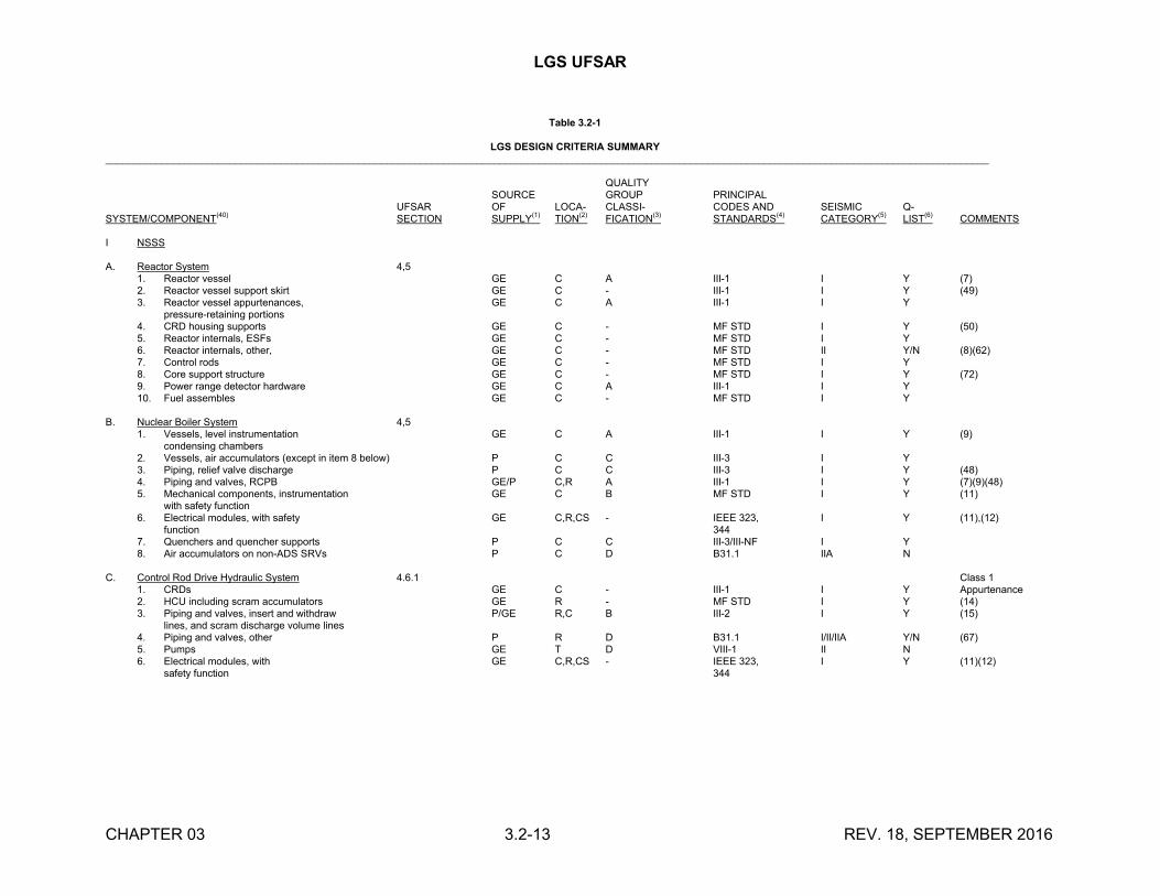
LGS UFSAR
CHAPTER 03 3.2-13 REV. 18, SEPTEMBER 2016
Table 3.2-1
LGS DESIGN CRITERIA SUMMARY_____________________________________________________________________________________________________________________________________________________________
QUALITYSOURCE GROUP PRINCIPAL
UFSAR OF LOCA- CLASSI- CODES AND SEISMIC Q-SYSTEM/COMPONENT
(40)SECTION SUPPLY
(1)TION
(2)FICATION
(3)STANDARDS
(4)CATEGORY
(5)LIST
(6)COMMENTS
I NSSS
A. Reactor System 4,51. Reactor vessel GE C A III-1 I Y (7)2. Reactor vessel support skirt GE C - III-1 I Y (49)3. Reactor vessel appurtenances, GE C A III-1 I Y
pressure-retaining portions4. CRD housing supports GE C - MF STD I Y (50)5. Reactor internals, ESFs GE C - MF STD I Y6. Reactor internals, other, GE C - MF STD II Y/N (8)(62)7. Control rods GE C - MF STD I Y8. Core support structure GE C - MF STD I Y (72)9. Power range detector hardware GE C A III-1 I Y10. Fuel assembles GE C - MF STD I Y
B. Nuclear Boiler System 4,51. Vessels, level instrumentation GE C A III-1 I Y (9)
condensing chambers2. Vessels, air accumulators (except in item 8 below) P C C III-3 I Y3. Piping, relief valve discharge P C C III-3 I Y (48)4. Piping and valves, RCPB GE/P C,R A III-1 I Y (7)(9)(48)5. Mechanical components, instrumentation GE C B MF STD I Y (11)
with safety function6. Electrical modules, with safety GE C,R,CS - IEEE 323, I Y (11),(12)
function 3447. Quenchers and quencher supports P C C III-3/III-NF I Y8. Air accumulators on non-ADS SRVs P C D B31.1 IIA N
C. Control Rod Drive Hydraulic System 4.6.1 Class 11. CRDs GE C - III-1 I Y Appurtenance2. HCU including scram accumulators GE R - MF STD I Y (14)3. Piping and valves, insert and withdraw P/GE R,C B III-2 I Y (15)
lines, and scram discharge volume lines4. Piping and valves, other P R D B31.1 I/II/IIA Y/N (67)5. Pumps GE T D VIII-1 II N6. Electrical modules, with GE C,R,CS - IEEE 323, I Y (11)(12)
safety function 344
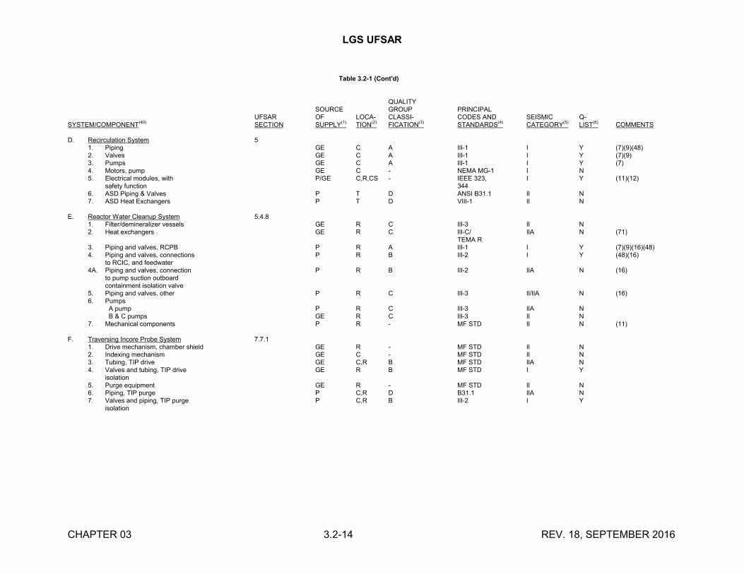
LGS UFSAR
CHAPTER 03 3.2-14 REV. 18, SEPTEMBER 2016
Table 3.2-1 (Cont'd)
QUALITYSOURCE GROUP PRINCIPAL
UFSAR OF LOCA- CLASSI- CODES AND SEISMIC Q-SYSTEM/COMPONENT
(40)SECTION SUPPLY
(1)TION
(2)FICATION
(3)STANDARDS
(4)CATEGORY
(5)LIST
(6)COMMENTS
D. Recirculation System 51. Piping GE C A III-1 I Y (7)(9)(48)2. Valves GE C A III-1 I Y (7)(9)3. Pumps GE C A III-1 I Y (7)4. Motors, pump GE C - NEMA MG-1 I N5. Electrical modules, with P/GE C,R,CS - IEEE 323, I Y (11)(12)
safety function 3446. ASD Piping & Valves P T D ANSI B31.1 II N7. ASD Heat Exchangers P T D VIII-1 II N
E. Reactor Water Cleanup System 5.4.81. Filter/demineralizer vessels GE R C III-3 II N2. Heat exchangers GE R C III-C/ IIA N (71)
TEMA R3. Piping and valves, RCPB P R A III-1 I Y (7)(9)(16)(48)4. Piping and valves, connections P R B III-2 I Y (48)(16)
to RCIC, and feedwater4A. Piping and valves, connection P R B III-2 IIA N (16)
to pump suction outboard containment isolation valve
5. Piping and valves, other P R C III-3 II/IIA N (16)6. Pumps
A pump P R C III-3 IIA N B & C pumps GE R C III-3 II N
7. Mechanical components P R - MF STD II N (11)
F. Traversing Incore Probe System 7.7.11. Drive mechanism, chamber shield GE R - MF STD II N2. Indexing mechanism GE C - MF STD II N3. Tubing, TIP drive GE C,R B MF STD IIA N4. Valves and tubing, TIP drive GE R B MF STD I Y
isolation5. Purge equipment GE R - MF STD II N6. Piping, TIP purge P C,R D B31.1 IIA N7. Valves and piping, TIP purge P C,R B III-2 I Y
isolation
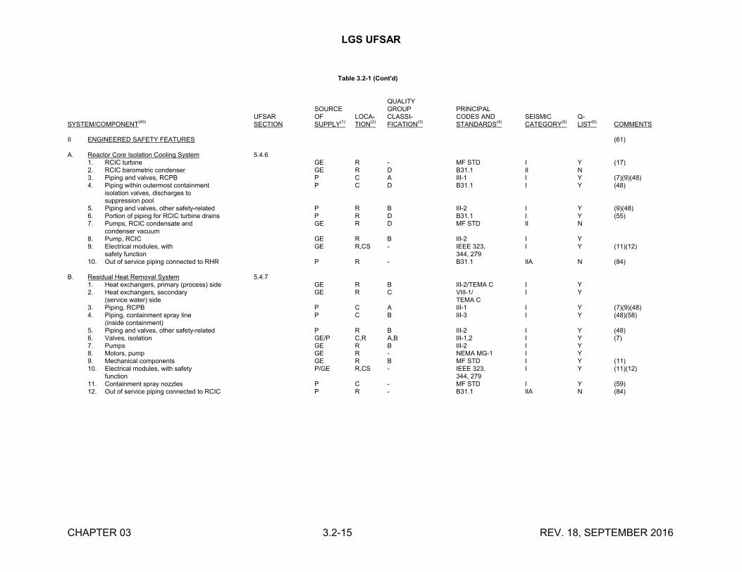
LGS UFSAR
CHAPTER 03 3.2-15 REV. 18, SEPTEMBER 2016
Table 3.2-1 (Cont'd)
QUALITYSOURCE GROUP PRINCIPAL
UFSAR OF LOCA- CLASSI- CODES AND SEISMIC Q-SYSTEM/COMPONENT
(40)SECTION SUPPLY
(1)TION
(2)FICATION
(3)STANDARDS
(4)CATEGORY
(5)LIST
(6)COMMENTS
II ENGINEERED SAFETY FEATURES (61)
A. Reactor Core Isolation Cooling System 5.4.61. RCIC turbine GE R - MF STD I Y (17)2. RCIC barometric condenser GE R D B31.1 II N3. Piping and valves, RCPB P C A III-1 I Y (7)(9)(48)4. Piping within outermost containment P C D B31.1 I Y (48)
isolation valves, discharges tosuppression pool
5. Piping and valves, other safety-related P R B III-2 I Y (9)(48)6. Portion of piping for RCIC turbine drains P R D B31.1 I Y (55)7. Pumps, RCIC condensate and GE R D MF STD II N
condenser vacuum8. Pump, RCIC GE R B III-2 I Y9. Electrical modules, with GE R,CS - IEEE 323, I Y (11)(12)
safety function 344, 27910. Out of service piping connected to RHR P R - B31.1 IIA N (84)
B. Residual Heat Removal System 5.4.71. Heat exchangers, primary (process) side GE R B III-2/TEMA C I Y2. Heat exchangers, secondary GE R C VIII-1/ I Y
(service water) side TEMA C3. Piping, RCPB P C A III-1 I Y (7)(9)(48)4. Piping, containment spray line P C B III-3 I Y (48)(58)
(inside containment)5. Piping and valves, other safety-related P R B III-2 I Y (48)6. Valves, isolation GE/P C,R A,B III-1,2 I Y (7)7. Pumps GE R B III-2 I Y8. Motors, pump GE R - NEMA MG-1 I Y9. Mechanical components GE R B MF STD I Y (11)10. Electrical modules, with safety P/GE R,CS - IEEE 323, I Y (11)(12)
function 344, 27911. Containment spray nozzles P C - MF STD I Y (59)12. Out of service piping connected to RCIC P R - B31.1 IIA N (84)
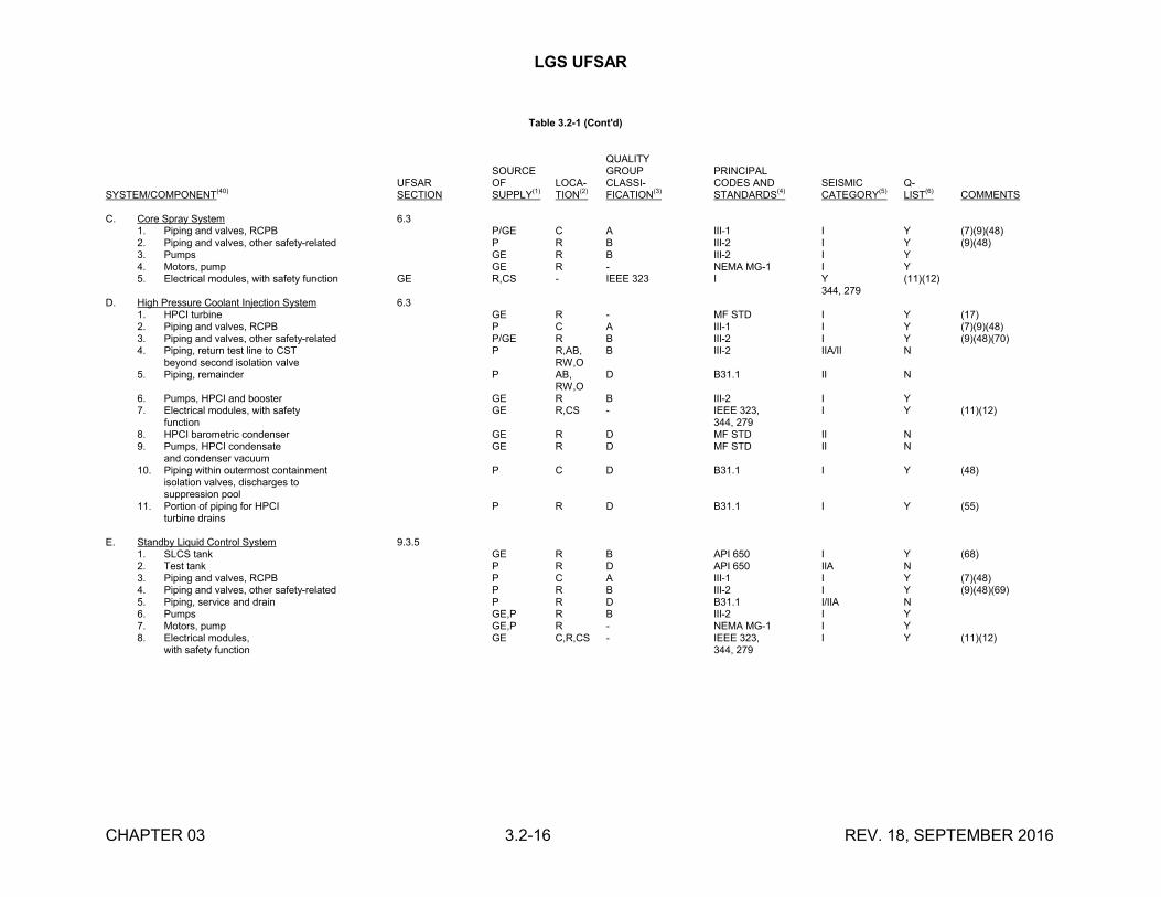
LGS UFSAR
CHAPTER 03 3.2-16 REV. 18, SEPTEMBER 2016
Table 3.2-1 (Cont'd)
QUALITYSOURCE GROUP PRINCIPAL
UFSAR OF LOCA- CLASSI- CODES AND SEISMIC Q-SYSTEM/COMPONENT
(40)SECTION SUPPLY
(1)TION
(2)FICATION
(3)STANDARDS
(4)CATEGORY
(5)LIST
(6)COMMENTS
C. Core Spray System 6.31. Piping and valves, RCPB P/GE C A III-1 I Y (7)(9)(48)2. Piping and valves, other safety-related P R B III-2 I Y (9)(48)3. Pumps GE R B III-2 I Y4. Motors, pump GE R - NEMA MG-1 I Y5. Electrical modules, with safety function GE R,CS - IEEE 323 I Y (11)(12)
344, 279D. High Pressure Coolant Injection System 6.3
1. HPCI turbine GE R - MF STD I Y (17)2. Piping and valves, RCPB P C A III-1 I Y (7)(9)(48)3. Piping and valves, other safety-related P/GE R B III-2 I Y (9)(48)(70)4. Piping, return test line to CST P R,AB, B III-2 IIA/II N
beyond second isolation valve RW,O5. Piping, remainder P AB, D B31.1 II N
RW,O6. Pumps, HPCI and booster GE R B III-2 I Y7. Electrical modules, with safety GE R,CS - IEEE 323, I Y (11)(12)
function 344, 2798. HPCI barometric condenser GE R D MF STD II N9. Pumps, HPCI condensate GE R D MF STD II N
and condenser vacuum10. Piping within outermost containment P C D B31.1 I Y (48)
isolation valves, discharges tosuppression pool
11. Portion of piping for HPCI P R D B31.1 I Y (55)turbine drains
E. Standby Liquid Control System 9.3.51. SLCS tank GE R B API 650 I Y (68)2. Test tank P R D API 650 IIA N3. Piping and valves, RCPB P C A III-1 I Y (7)(48)4. Piping and valves, other safety-related P R B III-2 I Y (9)(48)(69)5. Piping, service and drain P R D B31.1 I/IIA N6. Pumps GE,P R B III-2 I Y7. Motors, pump GE,P R - NEMA MG-1 I Y8. Electrical modules, GE C,R,CS - IEEE 323, I Y (11)(12)
with safety function 344, 279
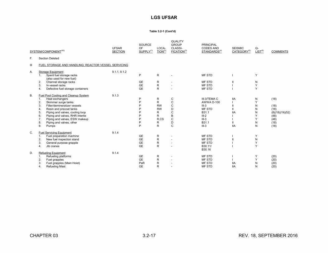
LGS UFSAR
CHAPTER 03 3.2-17 REV. 18, SEPTEMBER 2016
Table 3.2-1 (Cont'd)
QUALITYSOURCE GROUP PRINCIPAL
UFSAR OF LOCA- CLASSI- CODES AND SEISMIC Q-SYSTEM/COMPONENT(40) SECTION SUPPLY(1) TION(2) FICATION(3) STANDARDS(4) CATEGORY(5) LIST(6) COMMENTS
F. Section Deleted
III FUEL STORAGE AND HANDLING; REACTOR VESSEL SERVICING
A. Storage Equipment 9.1.1, 9.1.21. Spent fuel storage racks P R - MF STD I Y
(also used for new fuel)2. Channel storage racks GE R - MF STD II N3. In-vessel racks GE R - MF STD I Y4. Defective fuel storage containers GE R - MF STD I Y
B. Fuel Pool Cooling and Cleanup System 9.1.31. Heat exchangers P R C III-3/TEMA C IIA N (18)2. Skimmer surge tanks P R C AWWA D-100 I Y3. Filter/demineralizer vessels P RW C III-3 II N (18)4. Resin and precoat tanks P RW D MF STD II N (18)5. Piping and valves, cooling loop P R C B31.1 IIA N (8)(18)(19)(52)6. Piping and valves, RHR intertie P R B III-2 I Y (48)7. Piping and valves, ESW makeup P R,CS C III-3 I Y (48)8. Piping and valves, other P R D B31.1 II N (18)9. Pumps P R C III-3 IIA N (18)
C. Fuel Servicing Equipment 9.1.41. Fuel preparation machine GE R - MF STD I Y2. New fuel inspection stand GE R - MF STD II N3. General purpose grapple GE R - MF STD I Y4. Jib cranes GE R - B30.11/ I Y
B30.16D. Refueling Equipment 9.1.4
1. Refueling platforms GE R - MF STD I Y (20)2. Fuel grapples GE R - MF STD I Y (20)3. Fuel grapples (Main Hoist) PaR R - MF STD IIA N (20)4. Refueling Mast GE R - MF STD IIA N (20)
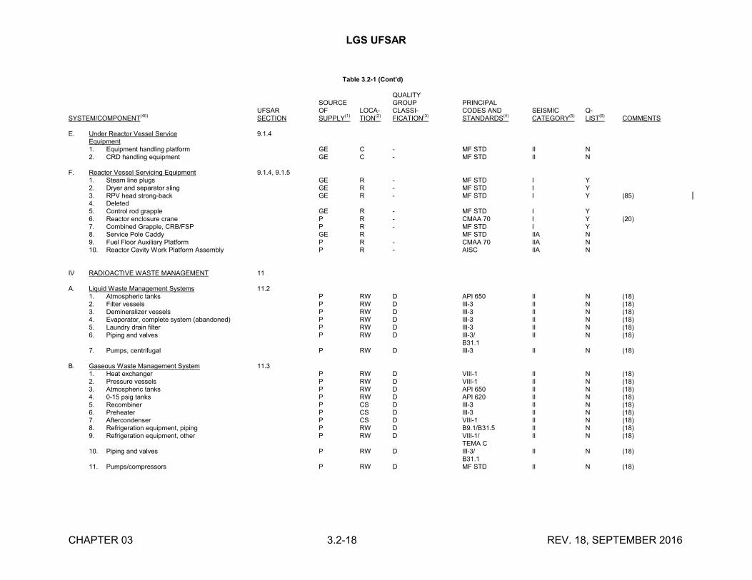
LGS UFSAR
CHAPTER 03 3.2-18 REV. 18, SEPTEMBER 2016
Table 3.2-1 (Cont'd)
QUALITYSOURCE GROUP PRINCIPAL
UFSAR OF LOCA- CLASSI- CODES AND SEISMIC Q-SYSTEM/COMPONENT(40) SECTION SUPPLY(1) TION(2) FICATION(3) STANDARDS(4) CATEGORY(5) LIST(6) COMMENTS
E. Under Reactor Vessel Service 9.1.4Equipment1. Equipment handling platform GE C - MF STD II N2. CRD handling equipment GE C - MF STD II N
F. Reactor Vessel Servicing Equipment 9.1.4, 9.1.51. Steam line plugs GE R - MF STD I Y2. Dryer and separator sling GE R - MF STD I Y3. RPV head strong-back GE R - MF STD I Y (85)4. Deleted5. Control rod grapple GE R - MF STD I Y6. Reactor enclosure crane P R - CMAA 70 I Y (20)7. Combined Grapple, CRB/FSP P R - MF STD I Y8. Service Pole Caddy GE R MF STD IIA N9. Fuel Floor Auxiliary Platform P R - CMAA 70 IIA N10. Reactor Cavity Work Platform Assembly P R - AISC IIA N
IV RADIOACTIVE WASTE MANAGEMENT 11
A. Liquid Waste Management Systems 11.21. Atmospheric tanks P RW D API 650 II N (18)2. Filter vessels P RW D III-3 II N (18)3. Demineralizer vessels P RW D III-3 II N (18)4. Evaporator, complete system (abandoned) P RW D III-3 II N (18)5. Laundry drain filter P RW D III-3 II N (18)6. Piping and valves P RW D III-3/ II N (18)
B31.17. Pumps, centrifugal P RW D III-3 II N (18)
B. Gaseous Waste Management System 11.31. Heat exchanger P RW D VIII-1 II N (18)2. Pressure vessels P RW D VIII-1 II N (18)3. Atmospheric tanks P RW D API 650 II N (18)4. 0-15 psig tanks P RW D API 620 II N (18)5. Recombiner P CS D III-3 II N (18)6. Preheater P CS D III-3 II N (18)7. Aftercondenser P CS D VIII-1 II N (18)8. Refrigeration equipment, piping P RW D B9.1/B31.5 II N (18)9. Refrigeration equipment, other P RW D VIII-1/ II N (18)
TEMA C10. Piping and valves P RW D III-3/ II N (18)
B31.111. Pumps/compressors P RW D MF STD II N (18)
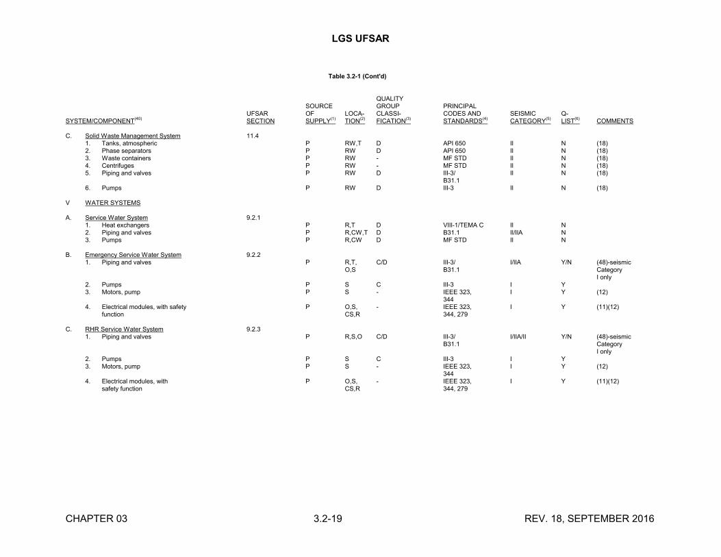
LGS UFSAR
CHAPTER 03 3.2-19 REV. 18, SEPTEMBER 2016
Table 3.2-1 (Cont'd)
QUALITYSOURCE GROUP PRINCIPAL
UFSAR OF LOCA- CLASSI- CODES AND SEISMIC Q-SYSTEM/COMPONENT
(40)SECTION SUPPLY
(1)TION
(2)FICATION
(3)STANDARDS
(4)CATEGORY
(5)LIST
(6)COMMENTS
C. Solid Waste Management System 11.41. Tanks, atmospheric P RW,T D API 650 II N (18)2. Phase separators P RW D API 650 II N (18)3. Waste containers P RW - MF STD II N (18)4. Centrifuges P RW - MF STD II N (18)5. Piping and valves P RW D III-3/ II N (18)
B31.16. Pumps P RW D III-3 II N (18)
V WATER SYSTEMS
A. Service Water System 9.2.11. Heat exchangers P R,T D VIII-1/TEMA C II N2. Piping and valves P R,CW,T D B31.1 II/IIA N3. Pumps P R,CW D MF STD II N
B. Emergency Service Water System 9.2.21. Piping and valves P R,T, C/D III-3/ I/IIA Y/N (48)-seismic
O,S B31.1 CategoryI only
2. Pumps P S C III-3 I Y3. Motors, pump P S - IEEE 323, I Y (12)
3444. Electrical modules, with safety P O,S, - IEEE 323, I Y (11)(12)
function CS,R 344, 279
C. RHR Service Water System 9.2.31. Piping and valves P R,S,O C/D III-3/ I/IIA/II Y/N (48)-seismic
B31.1 CategoryI only
2. Pumps P S C III-3 I Y 3. Motors, pump P S - IEEE 323, I Y (12)
3444. Electrical modules, with P O,S, - IEEE 323, I Y (11)(12)
safety function CS,R 344, 279
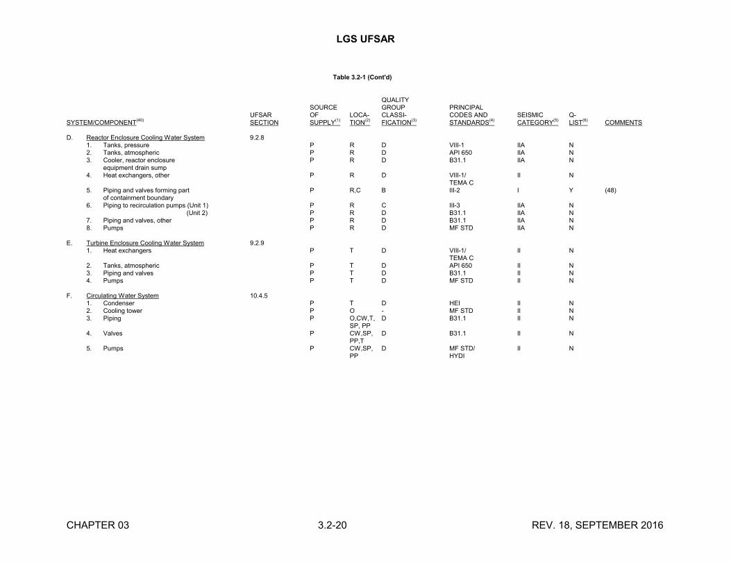
LGS UFSAR
CHAPTER 03 3.2-20 REV. 18, SEPTEMBER 2016
Table 3.2-1 (Cont'd)
QUALITYSOURCE GROUP PRINCIPAL
UFSAR OF LOCA- CLASSI- CODES AND SEISMIC Q-SYSTEM/COMPONENT
(40)SECTION SUPPLY
(1)TION
(2)FICATION
(3)STANDARDS
(4)CATEGORY
(5)LIST
(6)COMMENTS
D. Reactor Enclosure Cooling Water System 9.2.81. Tanks, pressure P R D VIII-1 IIA N2. Tanks, atmospheric P R D API 650 IIA N3. Cooler, reactor enclosure P R D B31.1 IIA N
equipment drain sump4. Heat exchangers, other P R D VIII-1/ II N
TEMA C5. Piping and valves forming part P R,C B III-2 I Y (48)
of containment boundary6. Piping to recirculation pumps (Unit 1) P R C III-3 IIA N
(Unit 2) P R D B31.1 IIA N7. Piping and valves, other P R D B31.1 IIA N8. Pumps P R D MF STD IIA N
E. Turbine Enclosure Cooling Water System 9.2.91. Heat exchangers P T D VIII-1/ II N
TEMA C2. Tanks, atmospheric P T D API 650 II N3. Piping and valves P T D B31.1 II N4. Pumps P T D MF STD II N
F. Circulating Water System 10.4.51. Condenser P T D HEI II N2. Cooling tower P O - MF STD II N3. Piping P O,CW,T, D B31.1 II N
SP, PP4. Valves P CW,SP, D B31.1 II N
PP,T5. Pumps P CW,SP, D MF STD/ II N
PP HYDI
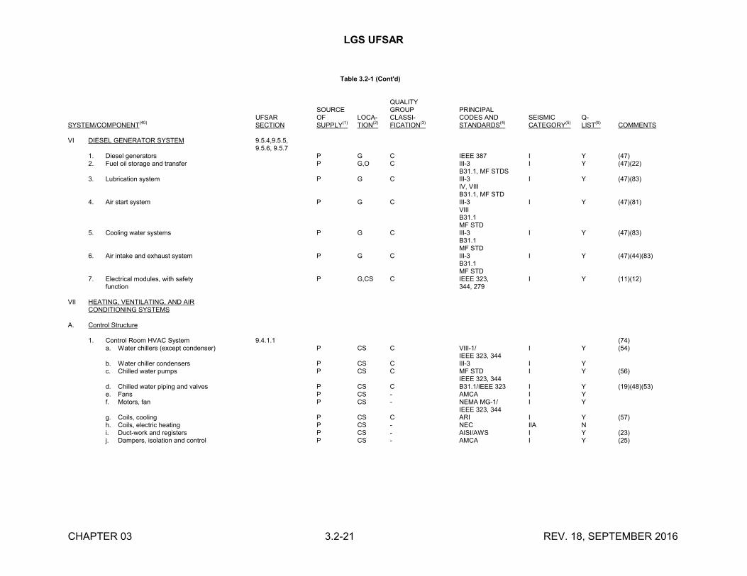
LGS UFSAR
CHAPTER 03 3.2-21 REV. 18, SEPTEMBER 2016
Table 3.2-1 (Cont'd)
QUALITYSOURCE GROUP PRINCIPAL
UFSAR OF LOCA- CLASSI- CODES AND SEISMIC Q-SYSTEM/COMPONENT
(40)SECTION SUPPLY
(1)TION
(2)FICATION
(3)STANDARDS
(4)CATEGORY
(5)LIST
(6)COMMENTS
VI DIESEL GENERATOR SYSTEM 9.5.4,9.5.5,9.5.6, 9.5.7
1. Diesel generators P G C IEEE 387 I Y (47)2. Fuel oil storage and transfer P G,O C III-3 I Y (47)(22)
B31.1, MF STDS3. Lubrication system P G C III-3 I Y (47)(83)
IV, VIIIB31.1, MF STD
4. Air start system P G C III-3 I Y (47)(81)VIIIB31.1MF STD
5. Cooling water systems P G C III-3 I Y (47)(83)B31.1MF STD
6. Air intake and exhaust system P G C III-3 I Y (47)(44)(83)B31.1MF STD
7. Electrical modules, with safety P G,CS C IEEE 323, I Y (11)(12)function 344, 279
VII HEATING, VENTILATING, AND AIRCONDITIONING SYSTEMS
A. Control Structure
1. Control Room HVAC System 9.4.1.1 (74)a. Water chillers (except condenser) P CS C VIII-1/ I Y (54)
IEEE 323, 344b. Water chiller condensers P CS C III-3 I Yc. Chilled water pumps P CS C MF STD I Y (56)
IEEE 323, 344d. Chilled water piping and valves P CS C B31.1/IEEE 323 I Y (19)(48)(53)e. Fans P CS - AMCA I Yf. Motors, fan P CS - NEMA MG-1/ I Y
IEEE 323, 344g. Coils, cooling P CS C ARI I Y (57)h. Coils, electric heating P CS - NEC IIA Ni. Duct-work and registers P CS - AISI/AWS I Y (23)j. Dampers, isolation and control P CS - AMCA I Y (25)
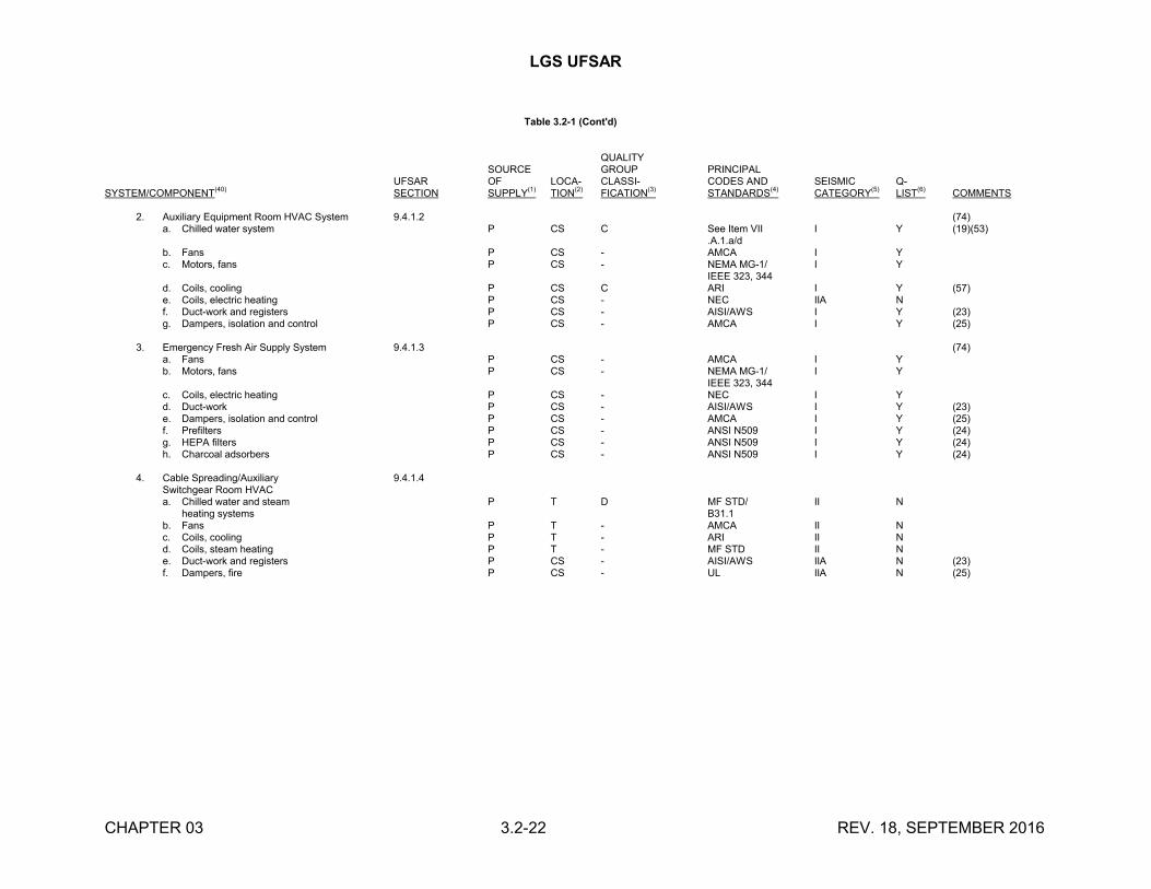
LGS UFSAR
CHAPTER 03 3.2-22 REV. 18, SEPTEMBER 2016
Table 3.2-1 (Cont'd)
QUALITYSOURCE GROUP PRINCIPAL
UFSAR OF LOCA- CLASSI- CODES AND SEISMIC Q-SYSTEM/COMPONENT
(40)SECTION SUPPLY
(1)TION
(2)FICATION
(3)STANDARDS
(4)CATEGORY
(5)LIST
(6)COMMENTS
2. Auxiliary Equipment Room HVAC System 9.4.1.2 (74)a. Chilled water system P CS C See Item VII I Y (19)(53)
.A.1.a/db. Fans P CS - AMCA I Yc. Motors, fans P CS - NEMA MG-1/ I Y
IEEE 323, 344d. Coils, cooling P CS C ARI I Y (57)e. Coils, electric heating P CS - NEC IIA Nf. Duct-work and registers P CS - AISI/AWS I Y (23)g. Dampers, isolation and control P CS - AMCA I Y (25)
3. Emergency Fresh Air Supply System 9.4.1.3 (74)a. Fans P CS - AMCA I Yb. Motors, fans P CS - NEMA MG-1/ I Y
IEEE 323, 344c. Coils, electric heating P CS - NEC I Yd. Duct-work P CS - AISI/AWS I Y (23)e. Dampers, isolation and control P CS - AMCA I Y (25)f. Prefilters P CS - ANSI N509 I Y (24)g. HEPA filters P CS - ANSI N509 I Y (24)h. Charcoal adsorbers P CS - ANSI N509 I Y (24)
4. Cable Spreading/Auxiliary 9.4.1.4Switchgear Room HVACa. Chilled water and steam P T D MF STD/ II N
heating systems B31.1b. Fans P T - AMCA II Nc. Coils, cooling P T - ARI II Nd. Coils, steam heating P T - MF STD II Ne. Duct-work and registers P CS - AISI/AWS IIA N (23)f. Dampers, fire P CS - UL IIA N (25)
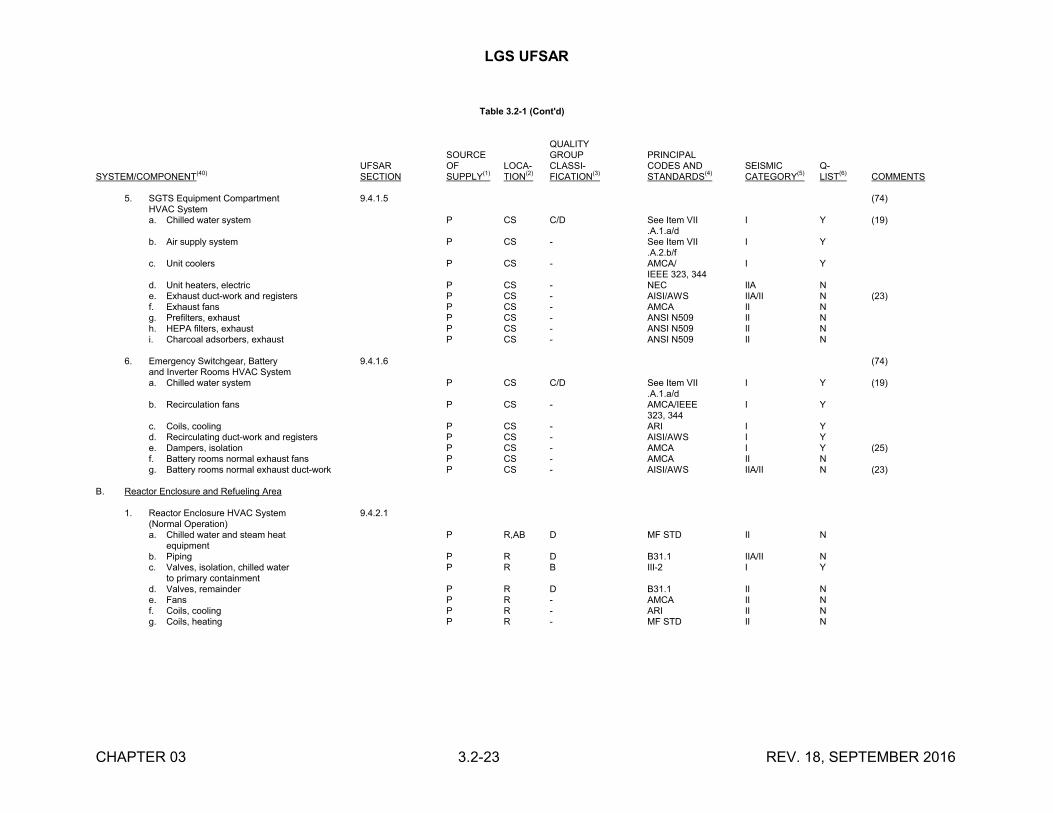
LGS UFSAR
CHAPTER 03 3.2-23 REV. 18, SEPTEMBER 2016
Table 3.2-1 (Cont'd)
QUALITYSOURCE GROUP PRINCIPAL
UFSAR OF LOCA- CLASSI- CODES AND SEISMIC Q-SYSTEM/COMPONENT
(40)SECTION SUPPLY
(1)TION
(2)FICATION
(3)STANDARDS
(4)CATEGORY
(5)LIST
(6)COMMENTS
5. SGTS Equipment Compartment 9.4.1.5 (74)HVAC Systema. Chilled water system P CS C/D See Item VII I Y (19)
.A.1.a/db. Air supply system P CS - See Item VII I Y
.A.2.b/fc. Unit coolers P CS - AMCA/ I Y
IEEE 323, 344d. Unit heaters, electric P CS - NEC IIA Ne. Exhaust duct-work and registers P CS - AISI/AWS IIA/II N (23)f. Exhaust fans P CS - AMCA II Ng. Prefilters, exhaust P CS - ANSI N509 II Nh. HEPA filters, exhaust P CS - ANSI N509 II Ni. Charcoal adsorbers, exhaust P CS - ANSI N509 II N
6. Emergency Switchgear, Battery 9.4.1.6 (74)and Inverter Rooms HVAC Systema. Chilled water system P CS C/D See Item VII I Y (19)
.A.1.a/db. Recirculation fans P CS - AMCA/IEEE I Y
323, 344c. Coils, cooling P CS - ARI I Yd. Recirculating duct-work and registers P CS - AISI/AWS I Ye. Dampers, isolation P CS - AMCA I Y (25)f. Battery rooms normal exhaust fans P CS - AMCA II Ng. Battery rooms normal exhaust duct-work P CS - AISI/AWS IIA/II N (23)
B. Reactor Enclosure and Refueling Area
1. Reactor Enclosure HVAC System 9.4.2.1(Normal Operation)a. Chilled water and steam heat P R,AB D MF STD II N
equipmentb. Piping P R D B31.1 IIA/II Nc. Valves, isolation, chilled water P R B III-2 I Y
to primary containmentd. Valves, remainder P R D B31.1 II Ne. Fans P R - AMCA II Nf. Coils, cooling P R - ARI II Ng. Coils, heating P R - MF STD II N
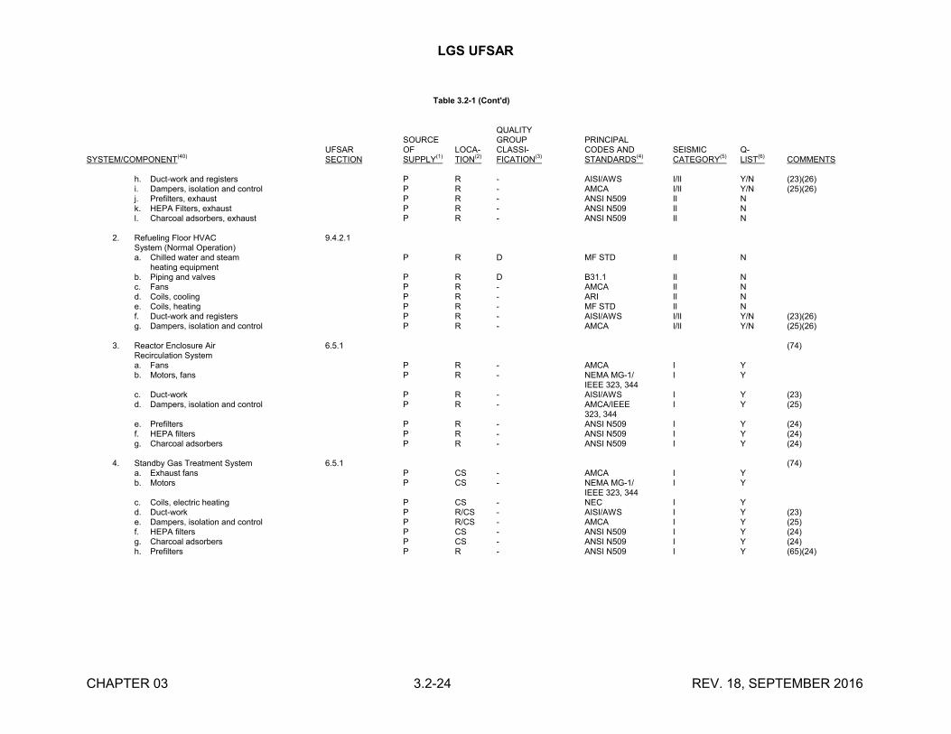
LGS UFSAR
CHAPTER 03 3.2-24 REV. 18, SEPTEMBER 2016
Table 3.2-1 (Cont'd)
QUALITYSOURCE GROUP PRINCIPAL
UFSAR OF LOCA- CLASSI- CODES AND SEISMIC Q-SYSTEM/COMPONENT
(40)SECTION SUPPLY
(1)TION
(2)FICATION
(3)STANDARDS
(4)CATEGORY
(5)LIST
(6)COMMENTS
h. Duct-work and registers P R - AISI/AWS I/II Y/N (23)(26)i. Dampers, isolation and control P R - AMCA I/II Y/N (25)(26)j. Prefilters, exhaust P R - ANSI N509 II Nk. HEPA Filters, exhaust P R - ANSI N509 II Nl. Charcoal adsorbers, exhaust P R - ANSI N509 II N
2. Refueling Floor HVAC 9.4.2.1System (Normal Operation)a. Chilled water and steam P R D MF STD II N
heating equipmentb. Piping and valves P R D B31.1 II Nc. Fans P R - AMCA II Nd. Coils, cooling P R - ARI II Ne. Coils, heating P R - MF STD II Nf. Duct-work and registers P R - AISI/AWS I/II Y/N (23)(26)g. Dampers, isolation and control P R - AMCA I/II Y/N (25)(26)
3. Reactor Enclosure Air 6.5.1 (74)Recirculation Systema. Fans P R - AMCA I Yb. Motors, fans P R - NEMA MG-1/ I Y
IEEE 323, 344c. Duct-work P R - AISI/AWS I Y (23)d. Dampers, isolation and control P R - AMCA/IEEE I Y (25)
323, 344e. Prefilters P R - ANSI N509 I Y (24)f. HEPA filters P R - ANSI N509 I Y (24)g. Charcoal adsorbers P R - ANSI N509 I Y (24)
4. Standby Gas Treatment System 6.5.1 (74)a. Exhaust fans P CS - AMCA I Yb. Motors P CS - NEMA MG-1/ I Y
IEEE 323, 344c. Coils, electric heating P CS - NEC I Yd. Duct-work P R/CS - AISI/AWS I Y (23)e. Dampers, isolation and control P R/CS - AMCA I Y (25)f. HEPA filters P CS - ANSI N509 I Y (24)g. Charcoal adsorbers P CS - ANSI N509 I Y (24)h. Prefilters P R - ANSI N509 I Y (65)(24)
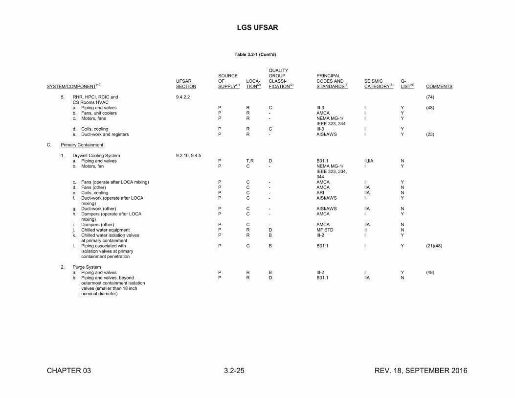
LGS UFSAR
CHAPTER 03 3.2-25 REV. 18, SEPTEMBER 2016
Table 3.2-1 (Cont'd)
QUALITYSOURCE GROUP PRINCIPAL
UFSAR OF LOCA- CLASSI- CODES AND SEISMIC Q-SYSTEM/COMPONENT
(40)SECTION SUPPLY
(1)TION
(2)FICATION
(3)STANDARDS
(4)CATEGORY
(5)LIST
(6)COMMENTS
5. RHR, HPCI, RCIC and 9.4.2.2 (74)CS Rooms HVACa. Piping and valves P R C III-3 I Y (48)b. Fans, unit coolers P R - AMCA I Yc. Motors, fans P R - NEMA MG-1/ I Y
IEEE 323, 344d. Coils, cooling P R C III-3 I Ye. Duct-work and registers P R - AISI/AWS I Y (23)
C. Primary Containment
1. Drywell Cooling System 9.2.10, 9.4.5a. Piping and valves P T,R D B31.1 II,IIA Nb. Motors, fan P C - NEMA MG-1/ I Y
IEEE 323, 334,344
c. Fans (operate after LOCA mixing) P C - AMCA I Yd. Fans (other) P C - AMCA IIA Ne. Coils, cooling P C - ARI IIA Nf. Duct-work (operate after LOCA P C - AISI/AWS I Y
mixing)g. Duct-work (other) P C - AISI/AWS IIA Nh. Dampers (operate after LOCA P C - AMCA I Y
mixing)i. Dampers (other) P C - AMCA IIA Nj. Chilled water equipment P R D MF STD II Nk. Chilled water isolation valves P R B III-2 I Y
at primary containmentl. Piping associated with P C B B31.1 I Y (21)(48)
isolation valves at primarycontainment penetration
2. Purge Systema. Piping and valves P R B III-2 I Y (48)b. Piping and valves, beyond P R D B31.1 IIA N
outermost containment isolationvalves (smaller than 18 inchnominal diameter)
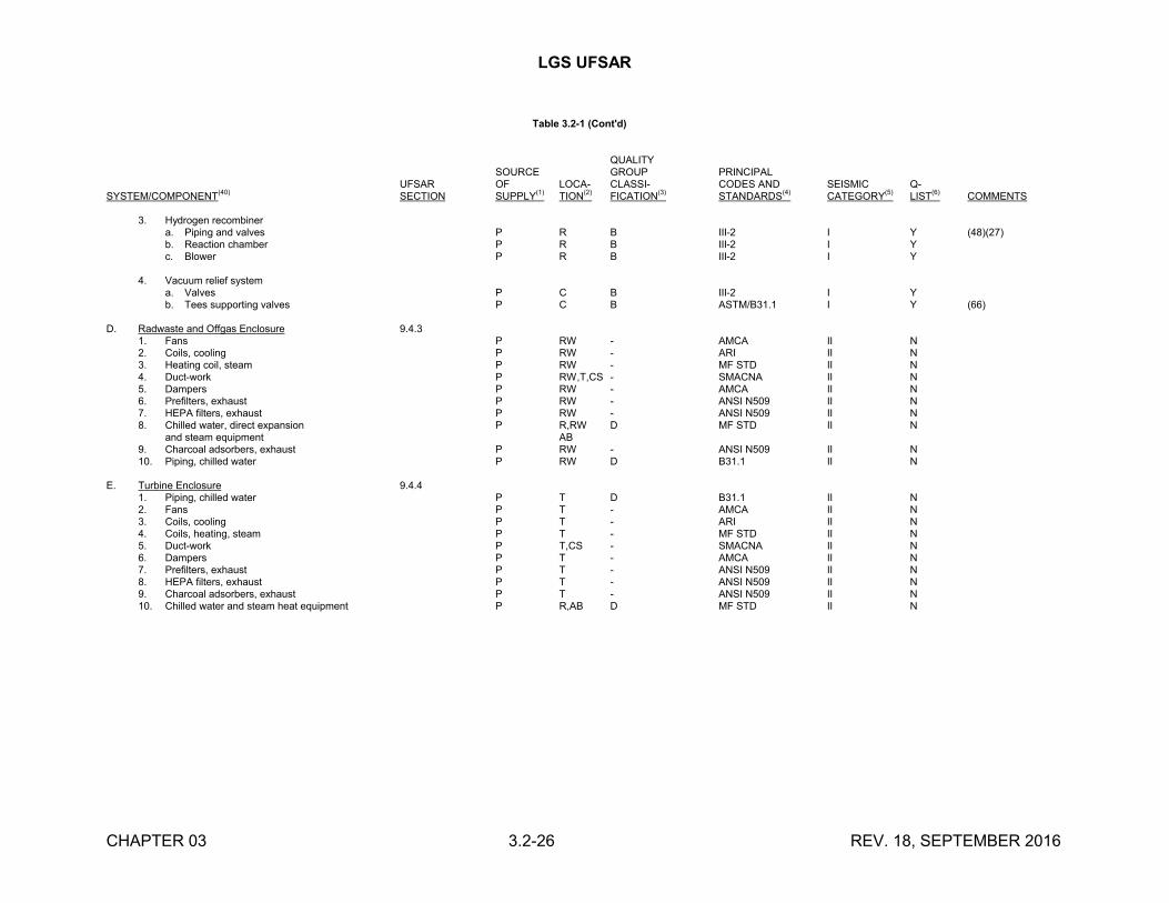
LGS UFSAR
CHAPTER 03 3.2-26 REV. 18, SEPTEMBER 2016
Table 3.2-1 (Cont'd)
QUALITYSOURCE GROUP PRINCIPAL
UFSAR OF LOCA- CLASSI- CODES AND SEISMIC Q-SYSTEM/COMPONENT
(40)SECTION SUPPLY
(1)TION
(2)FICATION
(3)STANDARDS
(4)CATEGORY
(5)LIST
(6)COMMENTS
3. Hydrogen recombinera. Piping and valves P R B III-2 I Y (48)(27)b. Reaction chamber P R B III-2 I Yc. Blower P R B III-2 I Y
4. Vacuum relief systema. Valves P C B III-2 I Yb. Tees supporting valves P C B ASTM/B31.1 I Y (66)
D. Radwaste and Offgas Enclosure 9.4.31. Fans P RW - AMCA II N2. Coils, cooling P RW - ARI II N3. Heating coil, steam P RW - MF STD II N4. Duct-work P RW,T,CS - SMACNA II N5. Dampers P RW - AMCA II N6. Prefilters, exhaust P RW - ANSI N509 II N7. HEPA filters, exhaust P RW - ANSI N509 II N8. Chilled water, direct expansion P R,RW D MF STD II N
and steam equipment AB9. Charcoal adsorbers, exhaust P RW - ANSI N509 II N10. Piping, chilled water P RW D B31.1 II N
E. Turbine Enclosure 9.4.41. Piping, chilled water P T D B31.1 II N2. Fans P T - AMCA II N3. Coils, cooling P T - ARI II N4. Coils, heating, steam P T - MF STD II N5. Duct-work P T,CS - SMACNA II N6. Dampers P T - AMCA II N7. Prefilters, exhaust P T - ANSI N509 II N8. HEPA filters, exhaust P T - ANSI N509 II N9. Charcoal adsorbers, exhaust P T - ANSI N509 II N10. Chilled water and steam heat equipment P R,AB D MF STD II N
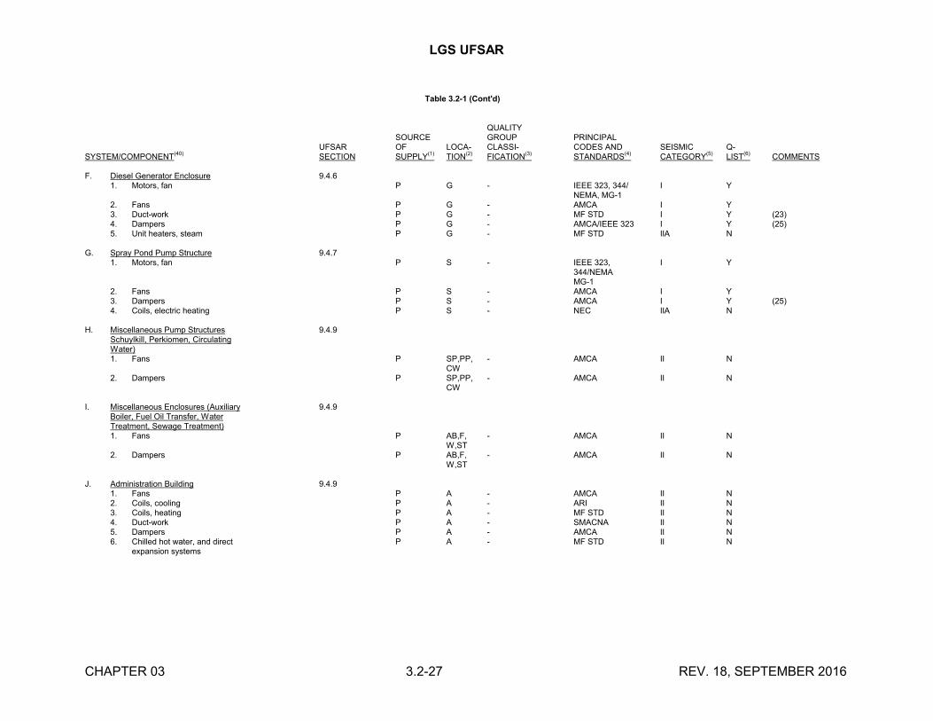
LGS UFSAR
CHAPTER 03 3.2-27 REV. 18, SEPTEMBER 2016
Table 3.2-1 (Cont'd)
QUALITYSOURCE GROUP PRINCIPAL
UFSAR OF LOCA- CLASSI- CODES AND SEISMIC Q-SYSTEM/COMPONENT
(40)SECTION SUPPLY
(1)TION
(2)FICATION
(3)STANDARDS
(4)CATEGORY
(5)LIST
(6)COMMENTS
F. Diesel Generator Enclosure 9.4.61. Motors, fan P G - IEEE 323, 344/ I Y
NEMA, MG-12. Fans P G - AMCA I Y3. Duct-work P G - MF STD I Y (23)4. Dampers P G - AMCA/IEEE 323 I Y (25)5. Unit heaters, steam P G - MF STD IIA N
G. Spray Pond Pump Structure 9.4.71. Motors, fan P S - IEEE 323, I Y
344/NEMAMG-1
2. Fans P S - AMCA I Y3. Dampers P S - AMCA I Y (25)4. Coils, electric heating P S - NEC IIA N
H. Miscellaneous Pump Structures 9.4.9Schuylkill, Perkiomen, CirculatingWater)1. Fans P SP,PP, - AMCA II N
CW2. Dampers P SP,PP, - AMCA II N
CW
I. Miscellaneous Enclosures (Auxiliary 9.4.9Boiler, Fuel Oil Transfer, WaterTreatment, Sewage Treatment)1. Fans P AB,F, - AMCA II N
W,ST2. Dampers P AB,F, - AMCA II N
W,ST
J. Administration Building 9.4.91. Fans P A - AMCA II N2. Coils, cooling P A - ARI II N3. Coils, heating P A - MF STD II N4. Duct-work P A - SMACNA II N5. Dampers P A - AMCA II N6. Chilled hot water, and direct P A - MF STD II N
expansion systems
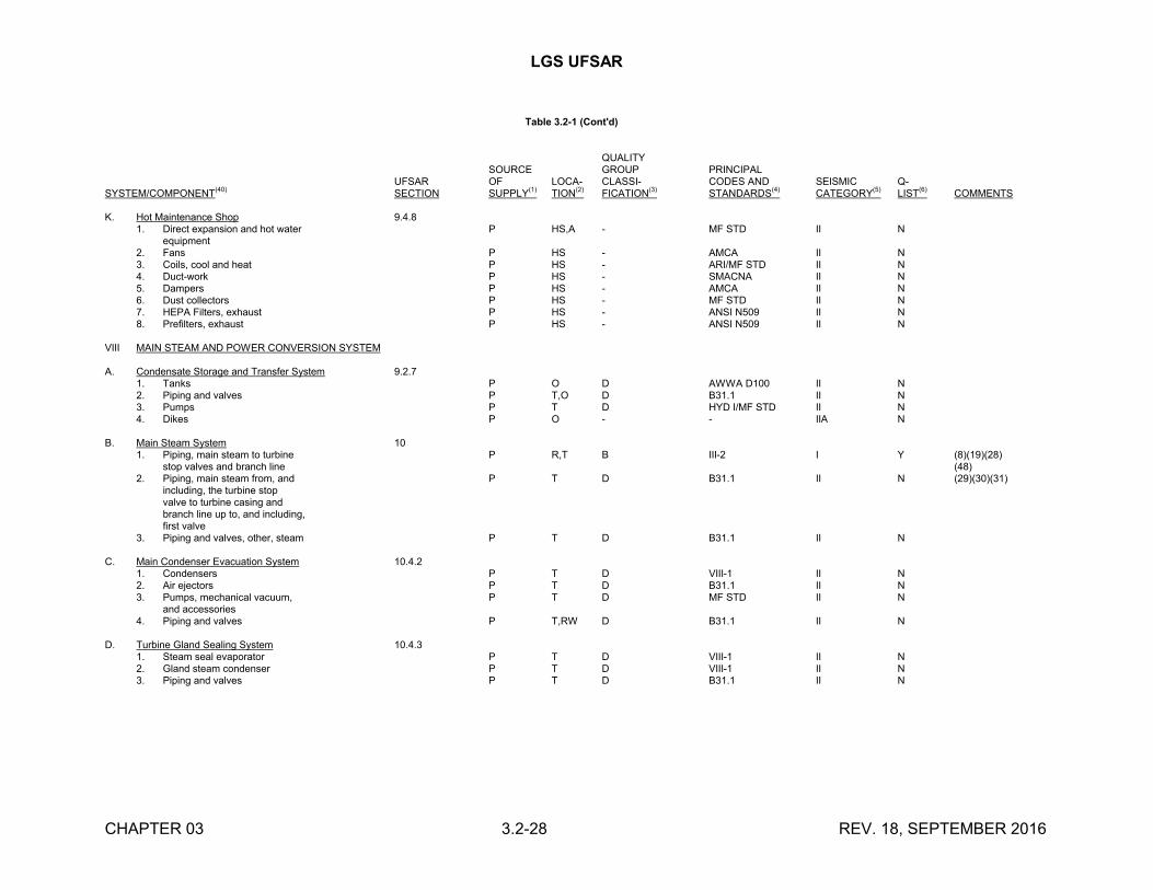
LGS UFSAR
CHAPTER 03 3.2-28 REV. 18, SEPTEMBER 2016
Table 3.2-1 (Cont'd)
QUALITYSOURCE GROUP PRINCIPAL
UFSAR OF LOCA- CLASSI- CODES AND SEISMIC Q-SYSTEM/COMPONENT
(40)SECTION SUPPLY
(1)TION
(2)FICATION
(3)STANDARDS
(4)CATEGORY
(5)LIST
(6)COMMENTS
K. Hot Maintenance Shop 9.4.81. Direct expansion and hot water P HS,A - MF STD II N
equipment2. Fans P HS - AMCA II N3. Coils, cool and heat P HS - ARI/MF STD II N4. Duct-work P HS - SMACNA II N5. Dampers P HS - AMCA II N6. Dust collectors P HS - MF STD II N7. HEPA Filters, exhaust P HS - ANSI N509 II N8. Prefilters, exhaust P HS - ANSI N509 II N
VIII MAIN STEAM AND POWER CONVERSION SYSTEM
A. Condensate Storage and Transfer System 9.2.71. Tanks P O D AWWA D100 II N2. Piping and valves P T,O D B31.1 II N3. Pumps P T D HYD I/MF STD II N4. Dikes P O - - IIA N
B. Main Steam System 101. Piping, main steam to turbine P R,T B III-2 I Y (8)(19)(28)
stop valves and branch line (48)2. Piping, main steam from, and P T D B31.1 II N (29)(30)(31)
including, the turbine stopvalve to turbine casing andbranch line up to, and including,first valve
3. Piping and valves, other, steam P T D B31.1 II N
C. Main Condenser Evacuation System 10.4.21. Condensers P T D VIII-1 II N2. Air ejectors P T D B31.1 II N3. Pumps, mechanical vacuum, P T D MF STD II N
and accessories4. Piping and valves P T,RW D B31.1 II N
D. Turbine Gland Sealing System 10.4.31. Steam seal evaporator P T D VIII-1 II N2. Gland steam condenser P T D VIII-1 II N3. Piping and valves P T D B31.1 II N
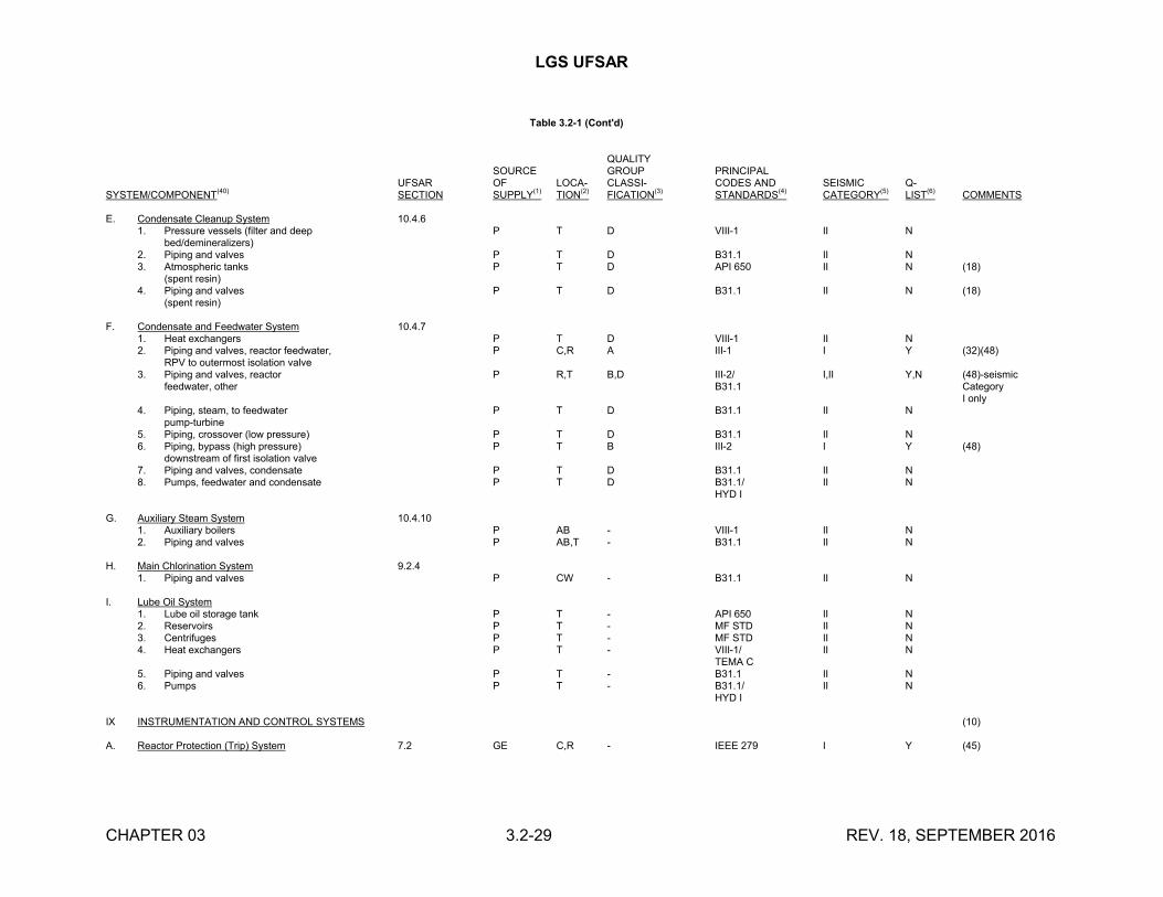
LGS UFSAR
CHAPTER 03 3.2-29 REV. 18, SEPTEMBER 2016
Table 3.2-1 (Cont'd)
QUALITYSOURCE GROUP PRINCIPAL
UFSAR OF LOCA- CLASSI- CODES AND SEISMIC Q-SYSTEM/COMPONENT
(40)SECTION SUPPLY
(1)TION
(2)FICATION
(3)STANDARDS
(4)CATEGORY
(5)LIST
(6)COMMENTS
E. Condensate Cleanup System 10.4.61. Pressure vessels (filter and deep P T D VIII-1 II N
bed/demineralizers)2. Piping and valves P T D B31.1 II N3. Atmospheric tanks P T D API 650 II N (18)
(spent resin)4. Piping and valves P T D B31.1 II N (18)
(spent resin)
F. Condensate and Feedwater System 10.4.71. Heat exchangers P T D VIII-1 II N2. Piping and valves, reactor feedwater, P C,R A III-1 I Y (32)(48)
RPV to outermost isolation valve3. Piping and valves, reactor P R,T B,D III-2/ I,II Y,N (48)-seismic
feedwater, other B31.1 CategoryI only
4. Piping, steam, to feedwater P T D B31.1 II Npump-turbine
5. Piping, crossover (low pressure) P T D B31.1 II N6. Piping, bypass (high pressure) P T B III-2 I Y (48)
downstream of first isolation valve7. Piping and valves, condensate P T D B31.1 II N8. Pumps, feedwater and condensate P T D B31.1/ II N
HYD I
G. Auxiliary Steam System 10.4.101. Auxiliary boilers P AB - VIII-1 II N2. Piping and valves P AB,T - B31.1 II N
H. Main Chlorination System 9.2.41. Piping and valves P CW - B31.1 II N
I. Lube Oil System1. Lube oil storage tank P T - API 650 II N2. Reservoirs P T - MF STD II N3. Centrifuges P T - MF STD II N4. Heat exchangers P T - VIII-1/ II N
TEMA C5. Piping and valves P T - B31.1 II N6. Pumps P T - B31.1/ II N
HYD I
IX INSTRUMENTATION AND CONTROL SYSTEMS (10)
A. Reactor Protection (Trip) System 7.2 GE C,R - IEEE 279 I Y (45)
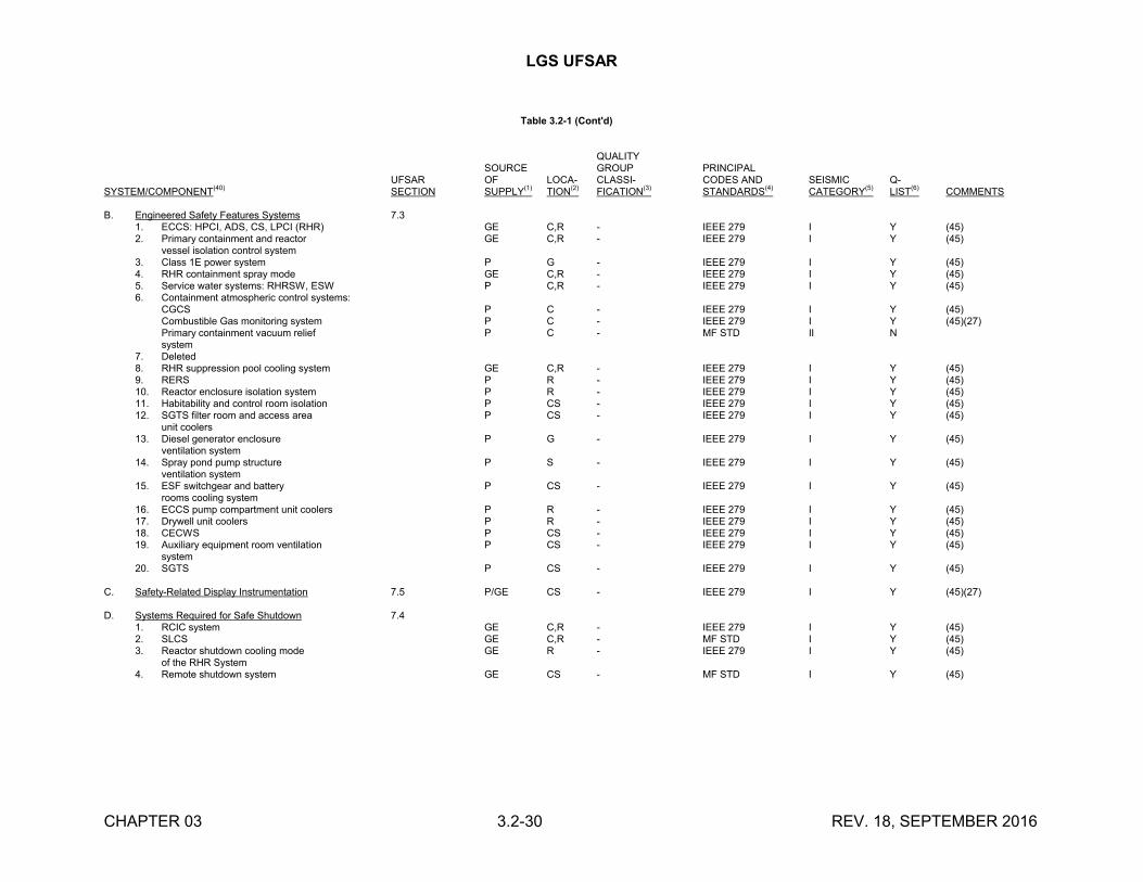
LGS UFSAR
CHAPTER 03 3.2-30 REV. 18, SEPTEMBER 2016
Table 3.2-1 (Cont'd)
QUALITYSOURCE GROUP PRINCIPAL
UFSAR OF LOCA- CLASSI- CODES AND SEISMIC Q-SYSTEM/COMPONENT
(40)SECTION SUPPLY
(1)TION
(2)FICATION
(3)STANDARDS
(4)CATEGORY
(5)LIST
(6)COMMENTS
B. Engineered Safety Features Systems 7.31. ECCS: HPCI, ADS, CS, LPCI (RHR) GE C,R - IEEE 279 I Y (45)2. Primary containment and reactor GE C,R - IEEE 279 I Y (45)
vessel isolation control system3. Class 1E power system P G - IEEE 279 I Y (45)4. RHR containment spray mode GE C,R - IEEE 279 I Y (45)5. Service water systems: RHRSW, ESW P C,R - IEEE 279 I Y (45)6. Containment atmospheric control systems:
CGCS P C - IEEE 279 I Y (45)Combustible Gas monitoring system P C - IEEE 279 I Y (45)(27)Primary containment vacuum relief P C - MF STD II Nsystem
7. Deleted8. RHR suppression pool cooling system GE C,R - IEEE 279 I Y (45)9. RERS P R - IEEE 279 I Y (45)10. Reactor enclosure isolation system P R - IEEE 279 I Y (45)11. Habitability and control room isolation P CS - IEEE 279 I Y (45)12. SGTS filter room and access area P CS - IEEE 279 I Y (45)
unit coolers13. Diesel generator enclosure P G - IEEE 279 I Y (45)
ventilation system14. Spray pond pump structure P S - IEEE 279 I Y (45)
ventilation system15. ESF switchgear and battery P CS - IEEE 279 I Y (45)
rooms cooling system16. ECCS pump compartment unit coolers P R - IEEE 279 I Y (45)17. Drywell unit coolers P R - IEEE 279 I Y (45)18. CECWS P CS - IEEE 279 I Y (45)19. Auxiliary equipment room ventilation P CS - IEEE 279 I Y (45)
system20. SGTS P CS - IEEE 279 I Y (45)
C. Safety-Related Display Instrumentation 7.5 P/GE CS - IEEE 279 I Y (45)(27)
D. Systems Required for Safe Shutdown 7.41. RCIC system GE C,R - IEEE 279 I Y (45)2. SLCS GE C,R - MF STD I Y (45)3. Reactor shutdown cooling mode GE R - IEEE 279 I Y (45)
of the RHR System4. Remote shutdown system GE CS - MF STD I Y (45)
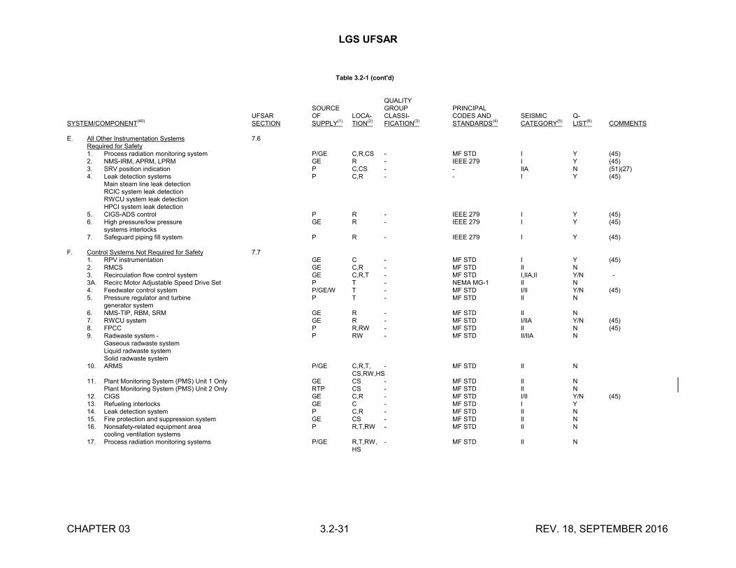
LGS UFSAR
CHAPTER 03 3.2-31 REV. 18, SEPTEMBER 2016
Table 3.2-1 (cont'd)
QUALITYSOURCE GROUP PRINCIPAL
UFSAR OF LOCA- CLASSI- CODES AND SEISMIC Q-SYSTEM/COMPONENT
(40)SECTION SUPPLY
(1)TION
(2)FICATION
(3)STANDARDS
(4)CATEGORY
(5)LIST
(6)COMMENTS
E. All Other Instrumentation Systems 7.6Required for Safety1. Process radiation monitoring system P/GE C,R,CS - MF STD I Y (45)2. NMS-IRM, APRM, LPRM GE R - IEEE 279 I Y (45)3. SRV position indication P C,CS - - IIA N (51)(27)4. Leak detection systems P C,R - - I Y (45)
Main steam line leak detectionRCIC system leak detectionRWCU system leak detectionHPCI system leak detection
5. CIGS-ADS control P R - IEEE 279 I Y (45)6. High pressure/low pressure GE R - IEEE 279 I Y (45)
systems interlocks7. Safeguard piping fill system P R - IEEE 279 I Y (45)
F. Control Systems Not Required for Safety 7.71. RPV instrumentation GE C - MF STD I Y (45)2. RMCS GE C,R - MF STD II N3. Recirculation flow control system GE C,R,T - MF STD I,IIA,II Y/N -3A. Recirc Motor Adjustable Speed Drive Set P T - NEMA MG-1 II N4. Feedwater control system P/GE/W T - MF STD I/II Y/N (45)5. Pressure regulator and turbine P T - MF STD II N
generator system6. NMS-TIP, RBM, SRM GE R - MF STD II N7. RWCU system GE R - MF STD I/IIA Y/N (45)8. FPCC P R,RW - MF STD II N (45)9. Radwaste system - P RW - MF STD II/IIA N
Gaseous radwaste systemLiquid radwaste systemSolid radwaste system
10. ARMS P/GE C,R,T, - MF STD II NCS,RW,HS
11. Plant Monitoring System (PMS) Unit 1 Only GE CS - MF STD II NPlant Monitoring System (PMS) Unit 2 Only RTP CS - MF STD II N
12. CIGS GE C,R - MF STD I/II Y/N (45)13. Refueling interlocks GE C - MF STD I Y14. Leak detection system P C,R - MF STD II N15. Fire protection and suppression system GE CS - MF STD II N16. Nonsafety-related equipment area P R,T,RW - MF STD II N
cooling ventilation systems17. Process radiation monitoring systems P/GE R,T,RW, - MF STD II N
HS

LGS UFSAR
CHAPTER 03 3.2-32 REV. 18, SEPTEMBER 2016
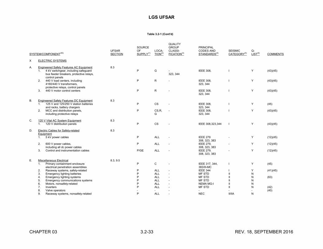
LGS UFSAR
CHAPTER 03 3.2-33 REV. 18, SEPTEMBER 2016
Table 3.2-1 (Cont'd)
QUALITYSOURCE GROUP PRINCIPAL
UFSAR OF LOCA- CLASSI- CODES AND SEISMIC Q-SYSTEM/COMPONENT
(40)SECTION SUPPLY
(1)TION
(2)FICATION
(3)STANDARDS
(4)CATEGORY
(5)LIST
(6)COMMENTS
X ELECTRIC SYSTEMS
A. Engineered Safety Features AC Equipment 8.31. 4 kV switchgear, including safeguard P G - IEEE 308, I Y (43)(45)
bus feeder breakers, protective relays, 323, 344control panels
2. 440 V load centers, including P R - IEEE 308, I Y (43)(45)4160/440 V transformers, 323, 344protective relays, control panels
3. 440 V motor control centers P R - IEEE 308, I Y (43)(45)323, 344
B. Engineered Safety Features DC Equipment 8.31. 125 V and 125/250 V station batteries P CS - IEEE 308, I Y (45)
and racks, battery chargers 323, 3442. MCC and distribution panels, P CS,R, - IEEE 308, I Y (43)(45)
including protective relays G 323, 344
C. 120 V Vital AC System Equipment 8.31. 120 V distribution panels P CS - IEEE 308,323,344 I Y (43)(45)
D. Electric Cables for Safety-related 8.3Equipment1. 5 kV power cables P ALL - IEEE 279 - Y (12)(45)
308, 323, 3832. 600 V power cables, P ALL - IEEE 279, - Y (12)(45)
including all dc power cables 308, 323, 3833. Control and instrumentation cables P/GE ALL - IEEE 279, - Y (12)(45)
308, 323, 383
E. Miscellaneous Electrical 8.3, 9.51. Primary containment enclosure P C - IEEE 317, 344, I Y (45)
electrical penetration assemblies 383/III-MC2. Raceway systems, safety-related P ALL - IEEE 344 I Y (41)(45)3. Emergency lighting batteries P ALL - MF STD II N4. Emergency lighting systems P ALL - MF STD II N (63)5. Emergency communications systems P ALL - MF STD II N6. Motors, nonsafety-related P ALL - NEMA MG-I II N7. Inverters P ALL - MF STD II N (42)8. Valve operators - - - - - - (40)9. Raceway systems, nonsafety-related P ALL - NEC II/IIA N
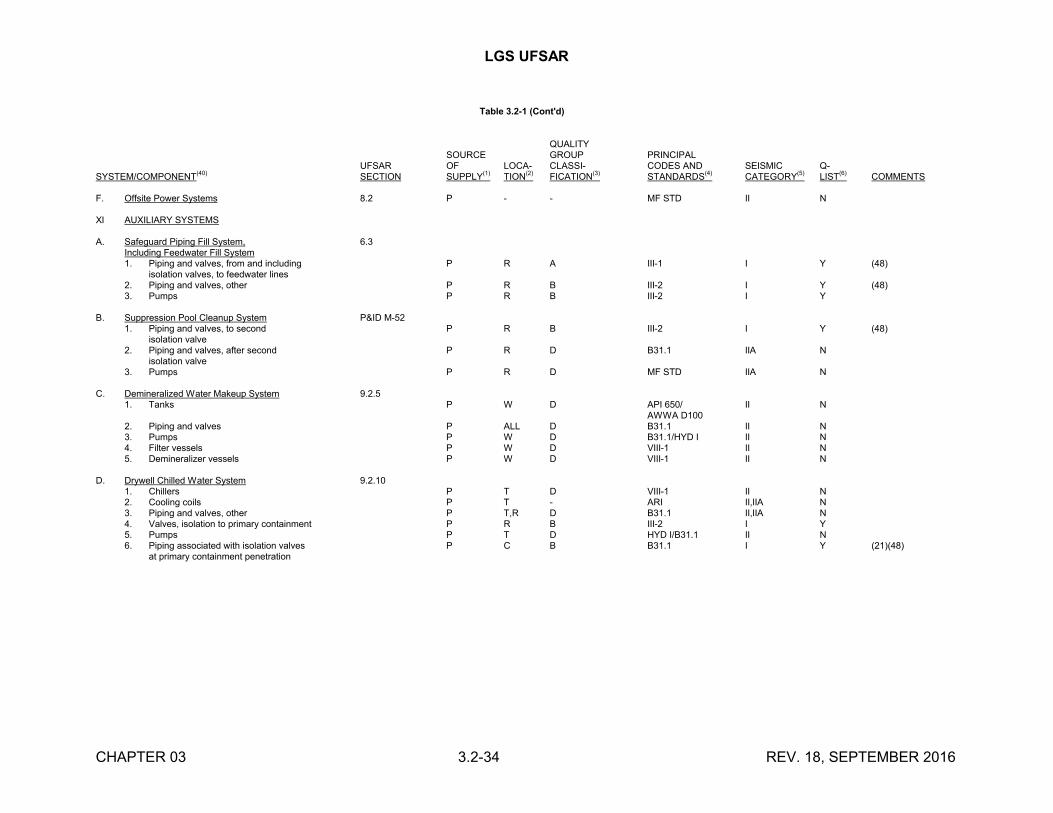
LGS UFSAR
CHAPTER 03 3.2-34 REV. 18, SEPTEMBER 2016
Table 3.2-1 (Cont'd)
QUALITYSOURCE GROUP PRINCIPAL
UFSAR OF LOCA- CLASSI- CODES AND SEISMIC Q-SYSTEM/COMPONENT
(40)SECTION SUPPLY
(1)TION
(2)FICATION
(3)STANDARDS
(4)CATEGORY
(5)LIST
(6)COMMENTS
F. Offsite Power Systems 8.2 P - - MF STD II N
XI AUXILIARY SYSTEMS
A. Safeguard Piping Fill System, 6.3Including Feedwater Fill System1. Piping and valves, from and including P R A III-1 I Y (48)
isolation valves, to feedwater lines2. Piping and valves, other P R B III-2 I Y (48)3. Pumps P R B III-2 I Y
B. Suppression Pool Cleanup System P&ID M-521. Piping and valves, to second P R B III-2 I Y (48)
isolation valve2. Piping and valves, after second P R D B31.1 IIA N
isolation valve3. Pumps P R D MF STD IIA N
C. Demineralized Water Makeup System 9.2.51. Tanks P W D API 650/ II N
AWWA D1002. Piping and valves P ALL D B31.1 II N3. Pumps P W D B31.1/HYD I II N4. Filter vessels P W D VIII-1 II N5. Demineralizer vessels P W D VIII-1 II N
D. Drywell Chilled Water System 9.2.101. Chillers P T D VIII-1 II N2. Cooling coils P T - ARI II,IIA N3. Piping and valves, other P T,R D B31.1 II,IIA N4. Valves, isolation to primary containment P R B III-2 I Y5. Pumps P T D HYD I/B31.1 II N6. Piping associated with isolation valves P C B B31.1 I Y (21)(48)
at primary containment penetration
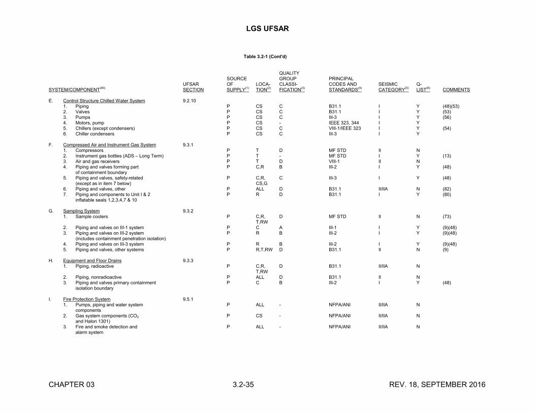
LGS UFSAR
CHAPTER 03 3.2-35 REV. 18, SEPTEMBER 2016
Table 3.2-1 (Cont'd)
QUALITYSOURCE GROUP PRINCIPAL
UFSAR OF LOCA- CLASSI- CODES AND SEISMIC Q-SYSTEM/COMPONENT
(40)SECTION SUPPLY
(1)TION
(2)FICATION
(3)STANDARDS
(4)CATEGORY
(5)LIST
(6)COMMENTS
E. Control Structure Chilled Water System 9.2.101. Piping P CS C B31.1 I Y (48)(53)2. Valves P CS C B31.1 I Y (53)3. Pumps P CS C III-3 I Y (56)4. Motors, pump P CS - IEEE 323, 344 I Y5. Chillers (except condensers) P CS C VIII-1/IEEE 323 I Y (54)6. Chiller condensers P CS C III-3 I Y
F. Compressed Air and Instrument Gas System 9.3.11. Compressors P T D MF STD II N2. Instrument gas bottles (ADS – Long Term) P T - MF STD I Y (13)3. Air and gas receivers P T D VIII-1 II N4. Piping and valves forming part P C,R B III-2 I Y (48)
of containment boundary5. Piping and valves, safety-related P C,R, C III-3 I Y (48)
(except as in item 7 below) CS,G6. Piping and valves, other P ALL D B31.1 II/IIA N (82)7. Piping and components to Unit I & 2 P R D B31.1 I Y (80)
inflatable seals 1,2,3,4,7 & 10
G. Sampling System 9.3.21. Sample coolers P C,R, D MF STD II N (73)
T,RW2. Piping and valves on III-1 system P C A III-1 I Y (9)(48)3. Piping and valves on III-2 system P R B III-2 I Y (9)(48)
(includes containment penetration isolation)4. Piping and valves on III-3 system P R B III-2 I Y (9)(48)5. Piping and valves, other systems P R,T,RW D B31.1 II N (9)
H. Equipment and Floor Drains 9.3.31. Piping, radioactive P C,R, D B31.1 II/IIA N
T,RW2. Piping, nonradioactive P ALL D B31.1 II N3. Piping and valves primary containment P C B III-2 I Y (48)
isolation boundary
I. Fire Protection System 9.5.11. Pumps, piping and water system P ALL - NFPA/ANI II/IIA N
components2. Gas system components (CO2 P CS - NFPA/ANI II/IIA N
and Halon 1301)3. Fire and smoke detection and P ALL - NFPA/ANI II/IIA N
alarm system
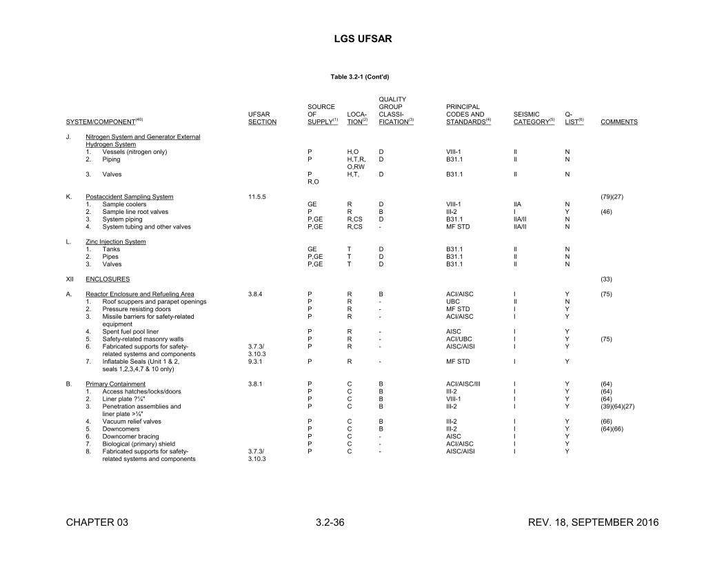
LGS UFSAR
CHAPTER 03 3.2-36 REV. 18, SEPTEMBER 2016
Table 3.2-1 (Cont'd)
QUALITYSOURCE GROUP PRINCIPAL
UFSAR OF LOCA- CLASSI- CODES AND SEISMIC Q-SYSTEM/COMPONENT
(40)SECTION SUPPLY
(1)TION
(2)FICATION
(3)STANDARDS
(4)CATEGORY
(5)LIST
(6)COMMENTS
J. Nitrogen System and Generator ExternalHydrogen System1. Vessels (nitrogen only) P H,O D VIII-1 II N2. Piping P H,T,R, D B31.1 II N
O,RW3. Valves P H,T, D B31.1 II N
R,O
K. Postaccident Sampling System 11.5.5 (79)(27)1. Sample coolers GE R D VIII-1 IIA N2. Sample line root valves P R B III-2 I Y (46)3. System piping P,GE R,CS D B31.1 IIA/II N4. System tubing and other valves P,GE R,CS - MF STD IIA/II N
L. Zinc Injection System1. Tanks GE T D B31.1 II N2. Pipes P,GE T D B31.1 II N3. Valves P,GE T D B31.1 II N
XII ENCLOSURES (33)
A. Reactor Enclosure and Refueling Area 3.8.4 P R B ACI/AISC I Y (75)1. Roof scuppers and parapet openings P R - UBC II N2. Pressure resisting doors P R - MF STD I Y3. Missile barriers for safety-related P R - ACI/AISC I Y
equipment4. Spent fuel pool liner P R - AISC I Y5. Safety-related masonry walls P R - ACI/UBC I Y (75)6. Fabricated supports for safety- 3.7.3/ P R - AISC/AISI I Y
related systems and components 3.10.37. Inflatable Seals (Unit 1 & 2, 9.3.1 P R - MF STD I Y
seals 1,2,3,4,7 & 10 only)
B. Primary Containment 3.8.1 P C B ACI/AISC/III I Y (64)1. Access hatches/locks/doors P C B III-2 I Y (64)2. Liner plate ?¼" P C B VIII-1 I Y (64)3. Penetration assemblies and P C B III-2 I Y (39)(64)(27)
liner plate >¼"4. Vacuum relief valves P C B III-2 I Y (66)5. Downcomers P C B III-2 I Y (64)(66)6. Downcomer bracing P C - AISC I Y7. Biological (primary) shield P C - ACI/AISC I Y8. Fabricated supports for safety- 3.7.3/ P C - AISC/AISI I Y
related systems and components 3.10.3
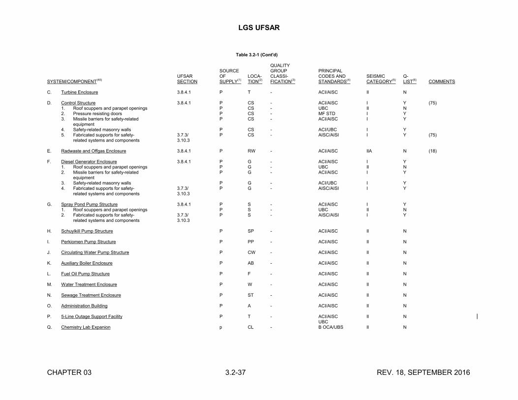
LGS UFSAR
CHAPTER 03 3.2-37 REV. 18, SEPTEMBER 2016
Table 3.2-1 (Cont'd)
QUALITYSOURCE GROUP PRINCIPAL
UFSAR OF LOCA- CLASSI- CODES AND SEISMIC Q-SYSTEM/COMPONENT(40) SECTION SUPPLY(1) TION(2) FICATION(3) STANDARDS(4) CATEGORY(5) LIST(6) COMMENTS
C. Turbine Enclosure 3.8.4.1 P T - ACI/AISC II N
D. Control Structure 3.8.4.1 P CS - ACI/AISC I Y (75)1. Roof scuppers and parapet openings P CS - UBC II N2. Pressure resisting doors P CS - MF STD I Y3. Missile barriers for safety-related P CS - ACI/AISC I Y
equipment4. Safety-related masonry walls P CS - ACI/UBC I Y5. Fabricated supports for safety- 3.7.3/ P CS - AISC/AISI I Y (75)
related systems and components 3.10.3
E. Radwaste and Offgas Enclosure 3.8.4.1 P RW - ACI/AISC IIA N (18)
F. Diesel Generator Enclosure 3.8.4.1 P G - ACI/AISC I Y1. Roof scuppers and parapet openings P G - UBC II N2. Missile barriers for safety-related P G - ACI/AISC I Y
equipment3. Safety-related masonry walls P G - ACI/UBC I Y4. Fabricated supports for safety- 3.7.3/ P G - AISC/AISI I Y
related systems and components 3.10.3
G. Spray Pond Pump Structure 3.8.4.1 P S - ACI/AISC I Y1. Roof scuppers and parapet openings P S - UBC II N2. Fabricated supports for safety- 3.7.3/ P S - AISC/AISI I Y
related systems and components 3.10.3
H. Schuylkill Pump Structure P SP - ACI/AISC II N
I. Perkiomen Pump Structure P PP - ACI/AISC II N
J. Circulating Water Pump Structure P CW - ACI/AISC II N
K. Auxiliary Boiler Enclosure P AB - ACI/AISC II N
L. Fuel Oil Pump Structure P F - ACI/AISC II N
M. Water Treatment Enclosure P W - ACI/AISC II N
N. Sewage Treatment Enclosure P ST - ACI/AISC II N
O. Administration Building P A - ACI/AISC II N
P. 5-Line Outage Support Facility P T - ACI/AISC II NUBC
Q. Chemistry Lab Expanion p CL - B OCA/UBS II N
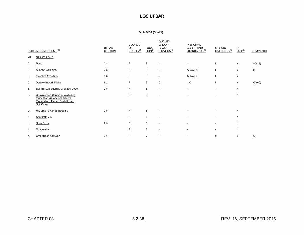
LGS UFSAR
CHAPTER 03 3.2-38 REV. 18, SEPTEMBER 2016
Table 3.2-1 (Cont'd)
QUALITYSOURCE GROUP PRINCIPAL
UFSAR OF LOCA- CLASSI- CODES AND SEISMIC Q-SYSTEM/COMPONENT
(40)SECTION SUPPLY
(1)TION
(2)FICATION
(3)STANDARDS
(4)CATEGORY
(5)LIST
(6)COMMENTS
XIII SPRAY POND
A. Pond 3.8 P S - - I Y (34)(35) B. Support Columns 3.8 P S - ACI/AISC I Y (36)
C. Overflow Structure 3.8 P S - ACI/AISC I Y
D. Spray-Network Piping 9.2 P S C III-3 I Y (38)(60)
E. Soil-Bentonite Lining and Soil Cover 2.5 P S - - - N
F. Unreinforced Concrete (excluding P S - - - Nfoundations) Concrete Backfill,Exploration, Trench Backfill, andSoil Cover
G. Riprap and Riprap Bedding 2.5 P S - - - N
H. Shotcrete 2.5 P S - - - N
I. Rock Bolts 2.5 P S - - - N
J. Roadwork- P S - - - N
K. Emergency Spillway 3.8 P S - - II Y (37)
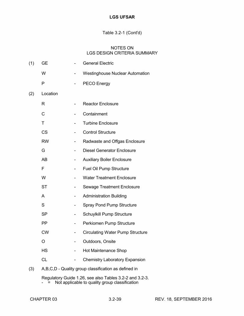
LGS UFSAR
Table 3.2-1 (Cont'd)
CHAPTER 03 3.2-39 REV. 18, SEPTEMBER 2016
NOTES ONLGS DESIGN CRITERIA SUMMARY
(1) GE - General Electric
W - Westinghouse Nuclear Automation
P - PECO Energy
(2) Location
R - Reactor Enclosure
C - Containment
T - Turbine Enclosure
CS - Control Structure
RW - Radwaste and Offgas Enclosure
G - Diesel Generator Enclosure
AB - Auxiliary Boiler Enclosure
F - Fuel Oil Pump Structure
W - Water Treatment Enclosure
ST - Sewage Treatment Enclosure
A - Administration Building
S - Spray Pond Pump Structure
SP - Schuylkill Pump Structure
PP - Perkiomen Pump Structure
CW - Circulating Water Pump Structure
O - Outdoors, Onsite
HS - Hot Maintenance Shop
CL - Chemistry Laboratory Expansion
(3) A,B,C,D - Quality group classification as defined in
Regulatory Guide 1.26, see also Tables 3.2-2 and 3.2-3.- = Not applicable to quality group classification
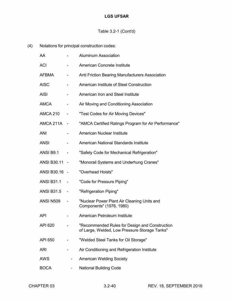
LGS UFSAR
Table 3.2-1 (Cont'd)
CHAPTER 03 3.2-40 REV. 18, SEPTEMBER 2016
(4) Notations for principal construction codes:
AA - Aluminum Association
ACI - American Concrete Institute
AFBMA - Anti Friction Bearing Manufacturers Association
AISC - American Institute of Steel Construction
AISI - American Iron and Steel Institute
AMCA - Air Moving and Conditioning Association
AMCA 210 - "Test Codes for Air Moving Devices"
AMCA 211A - "AMCA Certified Ratings Program for Air Performance"
ANI - American Nuclear Institute
ANSI - American National Standards Institute
ANSI B9.1 - "Safety Code for Mechanical Refrigeration"
ANSI B30.11 - "Monorail Systems and Underhung Cranes"
ANSI B30.16 - "Overhead Hoists"
ANSI B31.1 - "Code for Pressure Piping"
ANSI B31.5 - "Refrigeration Piping"
ANSI N509 - "Nuclear Power Plant Air Cleaning Units andComponents" (1976, 1980)
API - American Petroleum Institute
API 620 - "Recommended Rules for Design and Constructionof Large, Welded, Low Pressure Storage Tanks"
API 650 - "Welded Steel Tanks for Oil Storage"
ARI - Air Conditioning and Refrigeration Institute
AWS - American Welding Society
BOCA - National Building Code

LGS UFSAR
Table 3.2-1 (Cont'd)
CHAPTER 03 3.2-41 REV. 18, SEPTEMBER 2016
CMAA 70 - Crane Manufacturers Association of America, Specification Number 70, "Electric Overhead Traveling Cranes"
HEI - Heat Exchange Institute
HYD I - Hydraulic Institute
IEEE - Institute of Electrical and Electronics Engineers
IEEE 279 - "Criteria for Protection Systems for Nuclear Power Generating Stations" (1971)
IEEE 308 - "Standard Criteria for Class 1E Electric Systems for Nuclear Power Generating Stations" (1971)
IEEE 317 - "Standard for Electrical Penetration Assemblies in Containment Structures for Nuclear Fueled Power Generating Stations" (April 1971)
IEEE 323 - "General Guide for Qualifying Class 1E Electric Equipment for Nuclear Power Generating Stations" (1971, 1974)
IEEE 334 - "Trial Use Guide for Type Test of Continuous-Duty Class 1 Motors Installed Inside the Containment of Nuclear Power Generating Stations (ANSI N41.9)" (1971)
IEEE 344 - "Guide for Seismic Qualification of Class 1E Electric Equipment for Nuclear Power Generating Stations" (1971, 1975)
IEEE 383 - "Type Test of Class 1E Electrical Cables, Field Splices, and Connections for Nuclear Power Generating Stations" (1974)
IEEE 387 - "Criteria for Diesel Generator Units Applied as Standby Power Supplies for Nuclear Power Generating Stations" (1972)
MF STD - Manufacturer's Standard
NEC - National Electric Code
NEMA MG-1 - National Electrical Manufacturers' Association, "Motors and Generators" (1971)
NFPA - National Fire Protection Association
RDT-M-16-1T- Reactor Research and Development Gas Phase Adsorbents for Trapping Radioactive Iodine and Iodine Compounds
SMACNA - Sheet Metal and Air Conditioning Contractors National Association Inc.
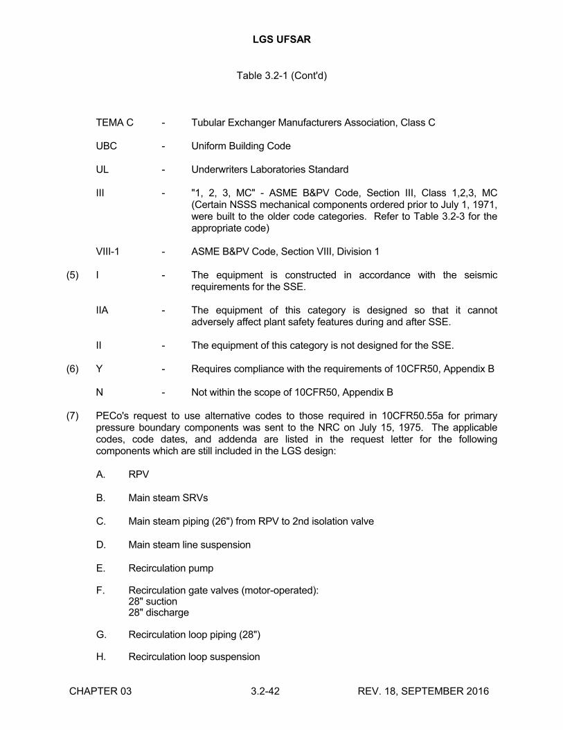
LGS UFSAR
Table 3.2-1 (Cont'd)
CHAPTER 03 3.2-42 REV. 18, SEPTEMBER 2016
TEMA C - Tubular Exchanger Manufacturers Association, Class C
UBC - Uniform Building Code
UL - Underwriters Laboratories Standard
III - "1, 2, 3, MC" - ASME B&PV Code, Section III, Class 1,2,3, MC (Certain NSSS mechanical components ordered prior to July 1, 1971, were built to the older code categories. Refer to Table 3.2-3 for the appropriate code)
VIII-1 - ASME B&PV Code, Section VIII, Division 1
(5) I - The equipment is constructed in accordance with the seismic requirements for the SSE.
IIA - The equipment of this category is designed so that it cannot adversely affect plant safety features during and after SSE.
II - The equipment of this category is not designed for the SSE.
(6) Y - Requires compliance with the requirements of 10CFR50, Appendix B
N - Not within the scope of 10CFR50, Appendix B
(7) PECo's request to use alternative codes to those required in 10CFR50.55a for primary pressure boundary components was sent to the NRC on July 15, 1975. The applicable codes, code dates, and addenda are listed in the request letter for the following components which are still included in the LGS design:
A. RPV
B. Main steam SRVs
C. Main steam piping (26") from RPV to 2nd isolation valve
D. Main steam line suspension
E. Recirculation pump
F. Recirculation gate valves (motor-operated):28" suction28" discharge
G. Recirculation loop piping (28")
H. Recirculation loop suspension
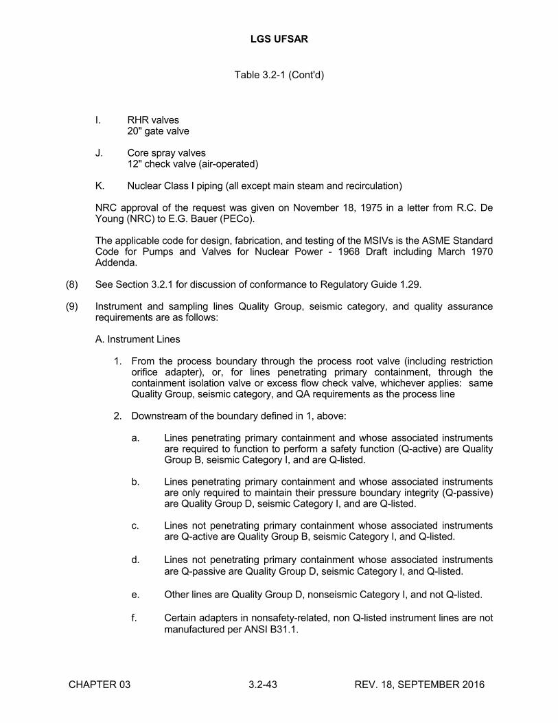
LGS UFSAR
Table 3.2-1 (Cont'd)
CHAPTER 03 3.2-43 REV. 18, SEPTEMBER 2016
I. RHR valves20" gate valve
J. Core spray valves12" check valve (air-operated)
K. Nuclear Class I piping (all except main steam and recirculation)
NRC approval of the request was given on November 18, 1975 in a letter from R.C. De Young (NRC) to E.G. Bauer (PECo).
The applicable code for design, fabrication, and testing of the MSIVs is the ASME StandardCode for Pumps and Valves for Nuclear Power - 1968 Draft including March 1970 Addenda.
(8) See Section 3.2.1 for discussion of conformance to Regulatory Guide 1.29.
(9) Instrument and sampling lines Quality Group, seismic category, and quality assurancerequirements are as follows:
A. Instrument Lines
1. From the process boundary through the process root valve (including restriction orifice adapter), or, for lines penetrating primary containment, through the containment isolation valve or excess flow check valve, whichever applies: same Quality Group, seismic category, and QA requirements as the process line
2. Downstream of the boundary defined in 1, above:
a. Lines penetrating primary containment and whose associated instruments are required to function to perform a safety function (Q-active) are Quality Group B, seismic Category I, and are Q-listed.
b. Lines penetrating primary containment and whose associated instruments are only required to maintain their pressure boundary integrity (Q-passive) are Quality Group D, seismic Category I, and are Q-listed.
c. Lines not penetrating primary containment whose associated instruments are Q-active are Quality Group B, seismic Category I, and Q-listed.
d. Lines not penetrating primary containment whose associated instruments are Q-passive are Quality Group D, seismic Category I, and Q-listed.
e. Other lines are Quality Group D, nonseismic Category I, and not Q-listed.
f. Certain adapters in nonsafety-related, non Q-listed instrument lines are not manufactured per ANSI B31.1.
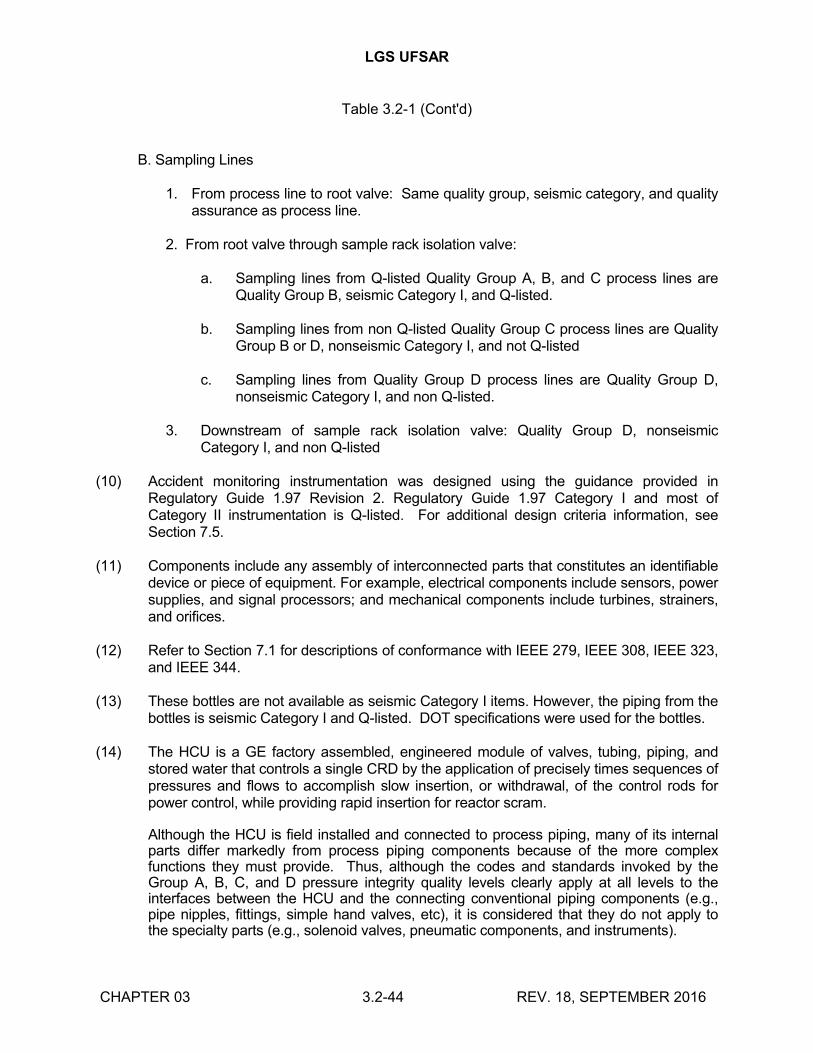
LGS UFSAR
Table 3.2-1 (Cont'd)
CHAPTER 03 3.2-44 REV. 18, SEPTEMBER 2016
B. Sampling Lines
1. From process line to root valve: Same quality group, seismic category, and quality assurance as process line.
2. From root valve through sample rack isolation valve:
a. Sampling lines from Q-listed Quality Group A, B, and C process lines are Quality Group B, seismic Category I, and Q-listed.
b. Sampling lines from non Q-listed Quality Group C process lines are Quality Group B or D, nonseismic Category I, and not Q-listed
c. Sampling lines from Quality Group D process lines are Quality Group D, nonseismic Category I, and non Q-listed.
3. Downstream of sample rack isolation valve: Quality Group D, nonseismic Category I, and non Q-listed
(10) Accident monitoring instrumentation was designed using the guidance provided in Regulatory Guide 1.97 Revision 2. Regulatory Guide 1.97 Category I and most of Category II instrumentation is Q-listed. For additional design criteria information, see Section 7.5.
(11) Components include any assembly of interconnected parts that constitutes an identifiable device or piece of equipment. For example, electrical components include sensors, power supplies, and signal processors; and mechanical components include turbines, strainers, and orifices.
(12) Refer to Section 7.1 for descriptions of conformance with IEEE 279, IEEE 308, IEEE 323, and IEEE 344.
(13) These bottles are not available as seismic Category I items. However, the piping from the bottles is seismic Category I and Q-listed. DOT specifications were used for the bottles.
(14) The HCU is a GE factory assembled, engineered module of valves, tubing, piping, and stored water that controls a single CRD by the application of precisely times sequences of pressures and flows to accomplish slow insertion, or withdrawal, of the control rods for power control, while providing rapid insertion for reactor scram.
Although the HCU is field installed and connected to process piping, many of its internal parts differ markedly from process piping components because of the more complex functions they must provide. Thus, although the codes and standards invoked by the Group A, B, C, and D pressure integrity quality levels clearly apply at all levels to the interfaces between the HCU and the connecting conventional piping components (e.g., pipe nipples, fittings, simple hand valves, etc), it is considered that they do not apply to the specialty parts (e.g., solenoid valves, pneumatic components, and instruments).
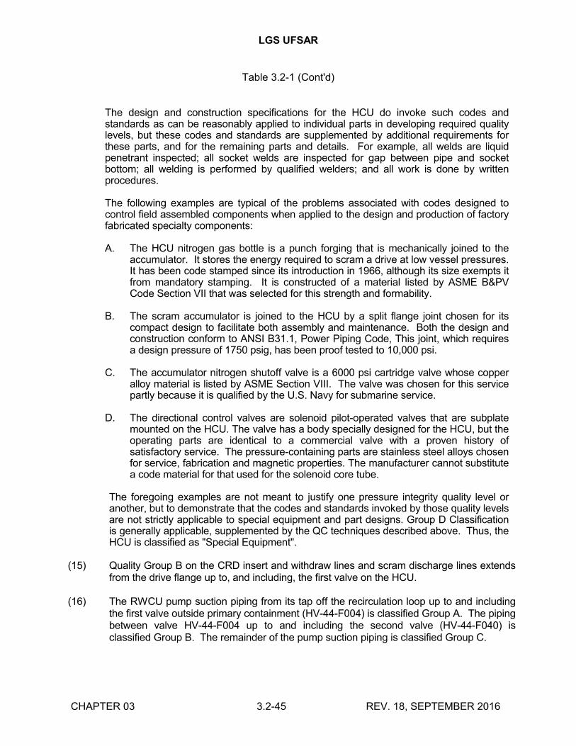
LGS UFSAR
Table 3.2-1 (Cont'd)
CHAPTER 03 3.2-45 REV. 18, SEPTEMBER 2016
The design and construction specifications for the HCU do invoke such codes and standards as can be reasonably applied to individual parts in developing required quality levels, but these codes and standards are supplemented by additional requirements for these parts, and for the remaining parts and details. For example, all welds are liquid penetrant inspected; all socket welds are inspected for gap between pipe and socket bottom; all welding is performed by qualified welders; and all work is done by written procedures.
The following examples are typical of the problems associated with codes designed to control field assembled components when applied to the design and production of factory fabricated specialty components:
A. The HCU nitrogen gas bottle is a punch forging that is mechanically joined to the accumulator. It stores the energy required to scram a drive at low vessel pressures. It has been code stamped since its introduction in 1966, although its size exempts it from mandatory stamping. It is constructed of a material listed by ASME B&PV Code Section VII that was selected for this strength and formability.
B. The scram accumulator is joined to the HCU by a split flange joint chosen for its compact design to facilitate both assembly and maintenance. Both the design and construction conform to ANSI B31.1, Power Piping Code, This joint, which requires a design pressure of 1750 psig, has been proof tested to 10,000 psi.
C. The accumulator nitrogen shutoff valve is a 6000 psi cartridge valve whose copper alloy material is listed by ASME Section VIII. The valve was chosen for this service partly because it is qualified by the U.S. Navy for submarine service.
D. The directional control valves are solenoid pilot-operated valves that are subplate mounted on the HCU. The valve has a body specially designed for the HCU, but the operating parts are identical to a commercial valve with a proven history of satisfactory service. The pressure-containing parts are stainless steel alloys chosen for service, fabrication and magnetic properties. The manufacturer cannot substitute a code material for that used for the solenoid core tube.
The foregoing examples are not meant to justify one pressure integrity quality level or another, but to demonstrate that the codes and standards invoked by those quality levels are not strictly applicable to special equipment and part designs. Group D Classification is generally applicable, supplemented by the QC techniques described above. Thus, the HCU is classified as "Special Equipment".
(15) Quality Group B on the CRD insert and withdraw lines and scram discharge lines extends from the drive flange up to, and including, the first valve on the HCU.
(16) The RWCU pump suction piping from its tap off the recirculation loop up to and including the first valve outside primary containment (HV-44-F004) is classified Group A. The piping between valve HV-44-F004 up to and including the second valve (HV-44-F040) is classified Group B. The remainder of the pump suction piping is classified Group C.
LGS UFSAR
Table 3.2-1 (Cont'd)
CHAPTER 03 3.2-46 REV. 18, SEPTEMBER 2016
The RWCU system discharges into the feedwater lines and the RCIC line. There are three RWCU discharge paths: a tap into the RCIC line outside containment, a tap to feedwater loop A outside containment, and a tap to feedwater loop A inside containment. The RWCU piping upstream of the feedwater outboard containment isolation valve (HV-44-F039) is classified Group C. Valve HV-44-F039 and piping up to the feedwater and RCIC line taps (outside primary containment) is classified Group B. The RWCU tap into the feedwater line inside primary containment is classified Group B up to the outboard containment isolation valve (41-1016). Valve 41-1016 and piping up to the tap into the feedwater line is classified Group A.
(17) The HPCI and RCIC turbine do not fall within the applicable design codes. To ensure that the turbine is fabricated to the standards commensurate with their safety and performance requirements, GE has established specific design requirements for this component in their specification.
(18) Certain major liquid, solid, and gaseous radwaste system components were designed, fabricated, procured, installed, and tested to the requirements of ASME Section III, Class 3, prior to May 1978. After May 1978, radwaste and deep bed spent resin system design, fabrication, materials, procurement, installation, and testing are at a minimum, in accordance with quality group D and the intent of Regulatory Guide 1.143 (Rev 1), subject to the following clarifications and exceptions:
A. Certain atmospheric tanks are welded to API/AWS standards in lieu of ASME Section IX.
B. Curbs or elevated thresholds are not provided for indoor tanks because of the watertight integrity of the surrounding structure.
C. Hydrotest pressure is held for 10 minutes, in accordance with ASME Section III, rather than 30 minutes. When in-place pressure testing is not practical, the tie-in welds will be examined via NDE per ANSI B31.1.
D. The radwaste enclosure is designed in accordance with seismic Category I criteria (Section 3.8.4). LGS does not use Regulatory Guide 1.60, as stated in Section 1.8. Alternate methods are discussed in Sections 3.7 and 3.8.
E. LGS's quality program during construction did not require audits of activities associated with radwaste systems, and items of nonconformance and theirregulation are not always documented. Beginning February 14, 1983, auditing or monitoring is required for activities associated with radwaste systems, and items of nonconformance and their regulation shall be documented.
F. Cleaning and welding of piping is conducted in accordance with the specified piping quality group.
LGS UFSAR
Table 3.2-1 (Cont'd)
CHAPTER 03 3.2-47 REV. 18, SEPTEMBER 2016
G. Inspection of all Q-listed instrument installation is performed by Bechtel QC personnel. Inspection of BOP instrumentation installations is performed by Bechtel field engineering personnel. In addition, final inspection of instrumentation up to the first root valve is performed by PECo QC personnel. Calibration and functional testing of all instrumentation is performed by PECo personnel.
Decontamination equipment and facilities are associated with the liquid radwaste system and are not safety-related.
(19) See Section 3.2.2 for discussion of conformance to Regulatory Guide 1.26.
(20) These components and associated supporting structures must be designed to retain structural integrity during, and after, the SSE, but do not have to retain operability for protection of public safety. The basic requirement is prevention of structural collapse, and damage to equipment and structures required for protection of the public safety and health.
(21) The basis for classification of non-ASME Section III equipment as Quality Group B is given in Section 3.2.2.g.
(22) Diesel fuel oil storage tanks and transfer pumps were designed to ASME Section III, Class 3 but were not stamped.
(23) The structural design of seismic Category I and IIA HVAC ducts was verified by testing duct specimens as permitted by the AISI Code, to substantiate the duct width to duct sheet thickness ratio (w/t) and cut height to duct sheet thickness ratio (h/t) of up to 1500. Seismic Category II ducts were designed and constructed in accordance with SMACNA.
(24) Regulatory Guide 1.52 (July 1976) suggests various industry standards and codes for this equipment. These references were used for system design, with exceptions as noted in Section 6.5.
(25) Dampers with electro-hydraulic operators were designed to IEEE 323. Fire dampers are labeled by UL.
(26) Portions of ducts and dampers in the reactor enclosure and refueling floor HVAC system are seismic Category II non Q-listed, and the remainder are seismic Category I, Q-listed.
(27) For discussion of design criteria related to TMI Action Plan requirements, see Section 1.13.2.
(28) The main steam system from its outer isolation valve up to, but not including, the turbine stop valve and bypass valve chest, and all branch lines 2½ inches in diameter and larger up to, and including, the first valve (including their restraints), will be designed by the use of an appropriate dynamic seismic-system analysis to withstand the OBE and SSE design loads in combination with other appropriate loads, within the limits specified for Class 2 pipe in the ASME Section III Code. The mathematical model for the dynamic seismic analyses of the main steam system and branch line piping includes the turbine
LGS UFSAR
Table 3.2-1 (Cont'd)
CHAPTER 03 3.2-48 REV. 18, SEPTEMBER 2016
stop valves and the piping from the stop valves to the turbine casing. The dynamic input loads for design of the main steam system are derived from a history model analysis (or an equivalent method) of the reactor and applicable portions of the turbine building. An elastic multi-degree-of-freedom system analysis is used to determine the input to the main steam system. The allowable stress and associated deformation limits for piping are in accordance with the ASME Section III Class 2 requirements for the OBE loading combinations. The main steam system supporting structures (those portions of the turbine enclosure) are such that the main steam system and its supports can maintain their integrity.
(29) The following qualification has been met with respect to the certification requirements:
A. The manufacturer of the turbine stop valves, turbine control valves, turbine bypass valves, and main steam leads from turbine control valve to turbine casing has used quality control procedures equivalent to those defined in GE Publication GEZ-4982A, "General Electric Large Steam Turbine-Generator Quality Control Program".
B. The manufacturer of these valves and steam leads has certified that the quality control program so defined has been accomplished.
(30) This section of steam piping was seismically analyzed to ensure that it will not fail under loadings normally associated with an SSE.
(31) The main steam loads from the turbine control valve to the turbine casing meet all of the requirements of Group D, plus the addition of the following requirements:
A. All longitudinal and circumferential butt weld joints are radiographed (or ultrasonically tested to equivalent standards). Where size or configuration does not permit effective volumetric examination, magnetic particle or liquid penetrant examination may be substituted. Examination procedures and acceptance standards are at least equivalent to those specified in appropriate sections of ANSI B31.1.
B. All fillet and socket welds are examined by either magnetic particle or liquid penetrant methods. All structural attachment welds to pressure-retaining materials are examined by either magnetic particle or liquid penetrant methods. Examination procedures and acceptance standards are at least equivalent to those specified in appropriate sections of ANSI B31.1.
C. All inspection records are maintained for the life of the plant. These records include data pertaining to qualification of inspection personnel, examination procedures, and examination results.
(32) The classification of the feedwater line from the reactor vessel through the second isolation valve is Group A. The classification of the feedwater line from the second isolation valve through the third valve is Group B. Beyond the third valve the classification is Group D.
LGS UFSAR
Table 3.2-1 (Cont'd)
CHAPTER 03 3.2-49 REV. 18, SEPTEMBER 2016
(33) The listed design criteria apply to the external and internal structure of each enclosure. Refer to Sections 3.7 and 3.8 for discussion of seismic design and Category I structure design, respectively.
(34) The following construction activities are conducted under the quality assurance program to ensure that the pond will perform its safety function:
A. Inspection and treatment of the rock surface at the pond bottom and sides to ensure that permeability requirements are met.
B. Final survey and measurement of the as-built pond to ensure that the water volume and side slopes satisfy design requirements.
C. Performance of a seepage test to ensure that the design basis seepage rate assumptions are not exceeded.
In addition, material used for treatment of fracture zones and capping observation wells is Q-listed.
(35) The pond is built completely by excavation. Ability to meet seismic Category I criteria is verified by measurement of as-built side slope areas (see Note 34.b) to ensure that design requirements are met.
(36) Includes unreinforced concrete used for support column foundations.
(37) The final survey and measurement of the as-built emergency spillway are conducted under the applicable portions of the QA program to ensure that the geometry satisfies design requirements.
(38) A complete description of the codes and standards, seismic category, and Q-list status of piping and instrumentation within the spray pond is shown on drawing M-12.
(39) Containment isolation barriers listed in Table 6.2-17 are Q-listed. Containment isolation valves are also included in the entries for each applicable system in this table.
(40) Specific components that comprise parts of major components with the same design criteria are generally not listed. For example, transformers are a part of load centers or switchgear, and valves operators are a part of motor-operated valves. Class 1E valve operators are in compliance with IEEE 323 and IEEE 344.
(41) Raceway systems include conduit, cable trays, and their supports. Raceway fire stops and seals are not Q-listed. However, quality control provisions commensurate with BTP CMEB 9.5-1 are applied to the raceway fire stops and seals.
(42) Inverters do not supply power to safety-related loads. The Class 1E battery loads are discussed in Section 8.3.2.1.1.4.
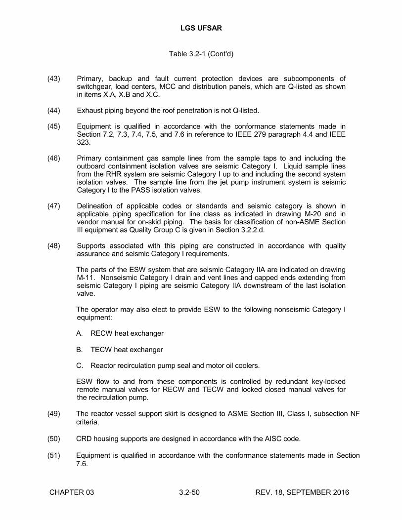
LGS UFSAR
Table 3.2-1 (Cont'd)
CHAPTER 03 3.2-50 REV. 18, SEPTEMBER 2016
(43) Primary, backup and fault current protection devices are subcomponents of switchgear, load centers, MCC and distribution panels, which are Q-listed as shown in items X.A, X.B and X.C.
(44) Exhaust piping beyond the roof penetration is not Q-listed.
(45) Equipment is qualified in accordance with the conformance statements made in Section 7.2, 7.3, 7.4, 7.5, and 7.6 in reference to IEEE 279 paragraph 4.4 and IEEE 323.
(46) Primary containment gas sample lines from the sample taps to and including the outboard containment isolation valves are seismic Category I. Liquid sample lines from the RHR system are seismic Category I up to and including the second system isolation valves. The sample line from the jet pump instrument system is seismic Category I to the PASS isolation valves.
(47) Delineation of applicable codes or standards and seismic category is shown in applicable piping specification for line class as indicated in drawing M-20 and in vendor manual for on-skid piping. The basis for classification of non-ASME Section III equipment as Quality Group C is given in Section 3.2.2.d.
(48) Supports associated with this piping are constructed in accordance with quality assurance and seismic Category I requirements.
The parts of the ESW system that are seismic Category IIA are indicated on drawing M-11. Nonseismic Category I drain and vent lines and capped ends extending from seismic Category I piping are seismic Category IIA downstream of the last isolation valve.
The operator may also elect to provide ESW to the following nonseismic Category I equipment:
A. RECW heat exchanger
B. TECW heat exchanger
C. Reactor recirculation pump seal and motor oil coolers.
ESW flow to and from these components is controlled by redundant key-locked remote manual valves for RECW and TECW and locked closed manual valves for the recirculation pump.
(49) The reactor vessel support skirt is designed to ASME Section III, Class I, subsection NF criteria.
(50) CRD housing supports are designed in accordance with the AISC code.
(51) Equipment is qualified in accordance with the conformance statements made in Section 7.6.
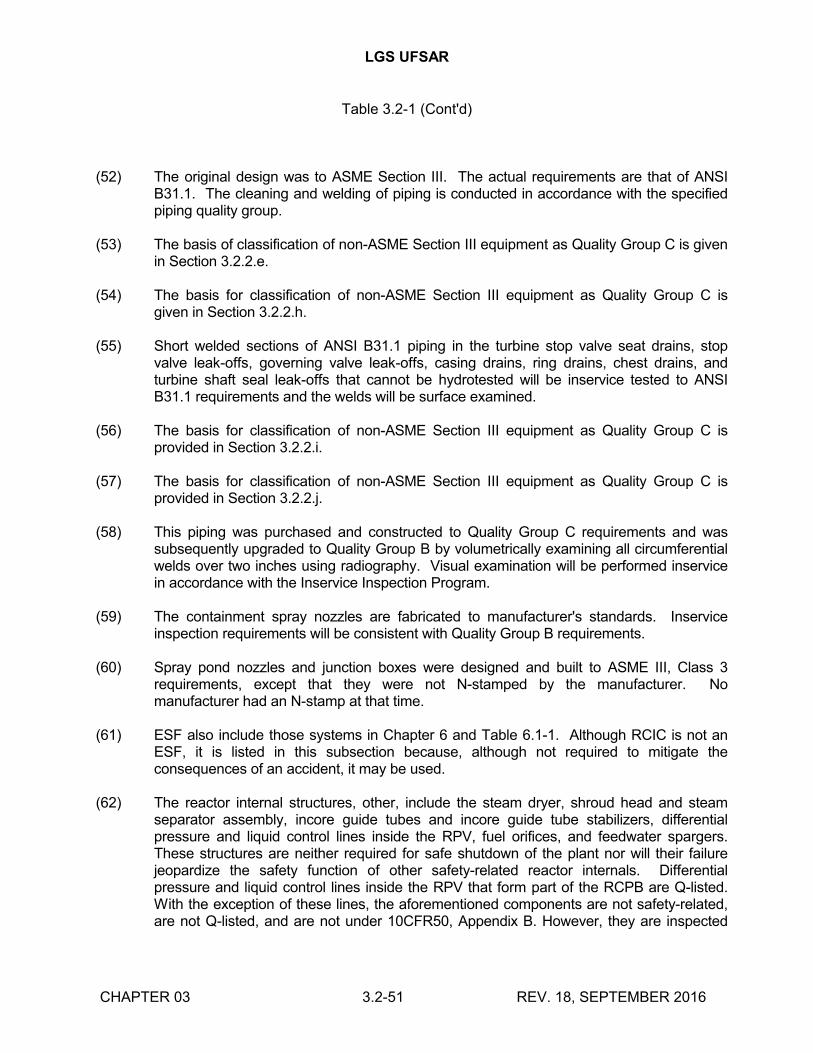
LGS UFSAR
Table 3.2-1 (Cont'd)
CHAPTER 03 3.2-51 REV. 18, SEPTEMBER 2016
(52) The original design was to ASME Section III. The actual requirements are that of ANSI B31.1. The cleaning and welding of piping is conducted in accordance with the specified piping quality group.
(53) The basis of classification of non-ASME Section III equipment as Quality Group C is given in Section 3.2.2.e.
(54) The basis for classification of non-ASME Section III equipment as Quality Group C is given in Section 3.2.2.h.
(55) Short welded sections of ANSI B31.1 piping in the turbine stop valve seat drains, stop valve leak-offs, governing valve leak-offs, casing drains, ring drains, chest drains, and turbine shaft seal leak-offs that cannot be hydrotested will be inservice tested to ANSI B31.1 requirements and the welds will be surface examined.
(56) The basis for classification of non-ASME Section III equipment as Quality Group C is provided in Section 3.2.2.i.
(57) The basis for classification of non-ASME Section III equipment as Quality Group C is provided in Section 3.2.2.j.
(58) This piping was purchased and constructed to Quality Group C requirements and was subsequently upgraded to Quality Group B by volumetrically examining all circumferential welds over two inches using radiography. Visual examination will be performed inservice in accordance with the Inservice Inspection Program.
(59) The containment spray nozzles are fabricated to manufacturer's standards. Inservice inspection requirements will be consistent with Quality Group B requirements.
(60) Spray pond nozzles and junction boxes were designed and built to ASME III, Class 3 requirements, except that they were not N-stamped by the manufacturer. No manufacturer had an N-stamp at that time.
(61) ESF also include those systems in Chapter 6 and Table 6.1-1. Although RCIC is not an ESF, it is listed in this subsection because, although not required to mitigate the consequences of an accident, it may be used.
(62) The reactor internal structures, other, include the steam dryer, shroud head and steam separator assembly, incore guide tubes and incore guide tube stabilizers, differential pressure and liquid control lines inside the RPV, fuel orifices, and feedwater spargers. These structures are neither required for safe shutdown of the plant nor will their failure jeopardize the safety function of other safety-related reactor internals. Differential pressure and liquid control lines inside the RPV that form part of the RCPB are Q-listed. With the exception of these lines, the aforementioned components are not safety-related, are not Q-listed, and are not under 10CFR50, Appendix B. However, they are inspected
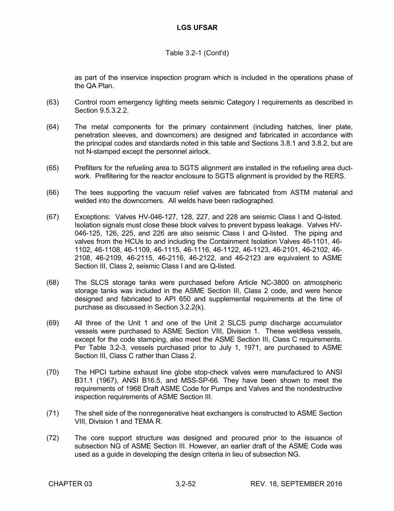
LGS UFSAR
Table 3.2-1 (Cont'd)
CHAPTER 03 3.2-52 REV. 18, SEPTEMBER 2016
as part of the inservice inspection program which is included in the operations phase of the QA Plan.
(63) Control room emergency lighting meets seismic Category I requirements as described in Section 9.5.3.2.2.
(64) The metal components for the primary containment (including hatches, liner plate, penetration sleeves, and downcomers) are designed and fabricated in accordance with the principal codes and standards noted in this table and Sections 3.8.1 and 3.8.2, but are not N-stamped except the personnel airlock.
(65) Prefilters for the refueling area to SGTS alignment are installed in the refueling area duct-work. Prefiltering for the reactor enclosure to SGTS alignment is provided by the RERS.
(66) The tees supporting the vacuum relief valves are fabricated from ASTM material and welded into the downcomers. All welds have been radiographed.
(67) Exceptions: Valves HV-046-127, 128, 227, and 228 are seismic Class I and Q-listed. Isolation signals must close these block valves to prevent bypass leakage. Valves HV-046-125, 126, 225, and 226 are also seismic Class I and Q-listed. The piping and valves from the HCUs to and including the Containment Isolation Valves 46-1101, 46-1102, 46-1108, 46-1109, 46-1115, 46-1116, 46-1122, 46-1123, 46-2101, 46-2102, 46-2108, 46-2109, 46-2115, 46-2116, 46-2122, and 46-2123 are equivalent to ASME Section III, Class 2, seismic Class I and are Q-listed.
(68) The SLCS storage tanks were purchased before Article NC-3800 on atmospheric storage tanks was included in the ASME Section III, Class 2 code, and were hence designed and fabricated to API 650 and supplemental requirements at the time of purchase as discussed in Section 3.2.2(k).
(69) All three of the Unit 1 and one of the Unit 2 SLCS pump discharge accumulator vessels were purchased to ASME Section VIII, Division 1. These weldless vessels, except for the code stamping, also meet the ASME Section III, Class C requirements. Per Table 3.2-3, vessels purchased prior to July 1, 1971, are purchased to ASME Section III, Class C rather than Class 2.
(70) The HPCI turbine exhaust line globe stop-check valves were manufactured to ANSI B31.1 (1967), ANSI B16.5, and MSS-SP-66. They have been shown to meet the requirements of 1968 Draft ASME Code for Pumps and Valves and the nondestructive inspection requirements of ASME Section III.
(71) The shell side of the nonregenerative heat exchangers is constructed to ASME Section VIII, Division 1 and TEMA R.
(72) The core support structure was designed and procured prior to the issuance of subsection NG of ASME Section III. However, an earlier draft of the ASME Code was used as a guide in developing the design criteria in lieu of subsection NG.
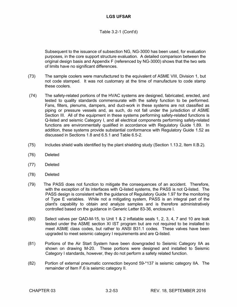
LGS UFSAR
Table 3.2-1 (Cont'd)
CHAPTER 03 3.2-53 REV. 18, SEPTEMBER 2016
Subsequent to the issuance of subsection NG, NG-3000 has been used, for evaluation purposes, in the core support structure evaluation. A detailed comparison between the original design basis and Appendix F (referenced by NG-3000) shows that the two sets of limits have no significant differences.
(73) The sample coolers were manufactured to the equivalent of ASME VIII, Division 1, but not code stamped. It was not customary at the time of manufacture to code stamp these coolers.
(74) The safety-related portions of the HVAC systems are designed, fabricated, erected, and tested to quality standards commensurate with the safety function to be performed. Fans, filters, plenums, dampers, and duct-work in these systems are not classified as piping or pressure vessels and, as such, do not fall under the jurisdiction of ASME Section III. All of the equipment in these systems performing safety-related functions is Q-listed and seismic Category I, and all electrical components performing safety-related functions are environmentally qualified in accordance with Regulatory Guide 1.89. In addition, these systems provide substantial conformance with Regulatory Guide 1.52 as discussed in Sections 1.8 and 6.5.1 and Table 6.5-2.
(75) Includes shield walls identified by the plant shielding study (Section 1.13.2, Item II.B.2).
(76) Deleted
(77) Deleted
(78) Deleted
(79) The PASS does not function to mitigate the consequences of an accident. Therefore, with the exception of its interfaces with Q-listed systems, the PASS is not Q-listed. The PASS design is consistent with the guidance of Regulatory Guide 1.97 for the monitoring of Type E variables. While not a mitigating system, PASS is an integral part of the plant's capability to obtain and analyze samples and is therefore administratively controlled based on the guidance in Generic Letter 83-36, enclosure I.
(80) Select valves per QAD-M-15, to Unit 1 & 2 inflatable seals 1, 2, 3, 4, 7 and 10 are leak tested under the ASME section XI IST program but are not required to be installed to meet ASME class codes, but rather to ANSI B31.1 codes. These valves have been upgraded to meet seismic category I requirements and are Q-listed.
(81) Portions of the Air Start System have been downgraded to Seismic Category IIA as shown on drawing M-20. These portions were designed and installed to Seismic Category I standards, however, they do not perform a safety related function.
(82) Portion of external pneumatic connection beyond 59-*137 is seismic category IIA. The remainder of Item F.6 is seismic category II.
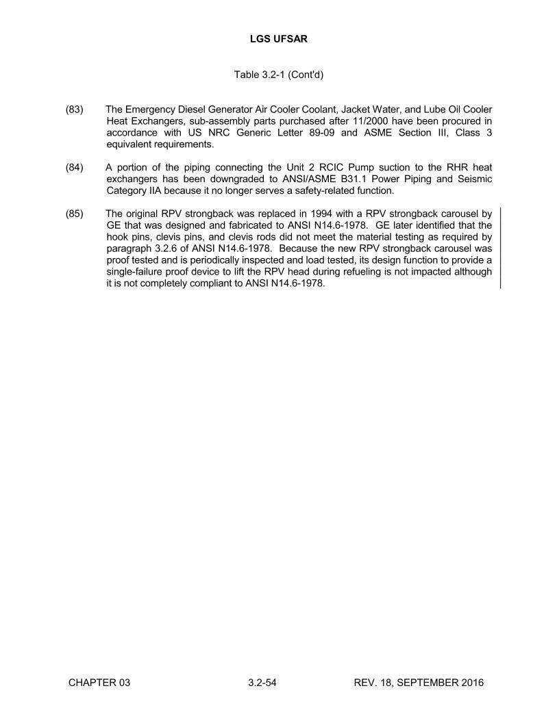
LGS UFSAR
Table 3.2-1 (Cont'd)
CHAPTER 03 3.2-54 REV. 18, SEPTEMBER 2016
(83) The Emergency Diesel Generator Air Cooler Coolant, Jacket Water, and Lube Oil Cooler Heat Exchangers, sub-assembly parts purchased after 11/2000 have been procured in accordance with US NRC Generic Letter 89-09 and ASME Section III, Class 3 equivalent requirements.
(84) A portion of the piping connecting the Unit 2 RCIC Pump suction to the RHR heat exchangers has been downgraded to ANSI/ASME B31.1 Power Piping and Seismic Category IIA because it no longer serves a safety-related function.
(85) The original RPV strongback was replaced in 1994 with a RPV strongback carousel by GE that was designed and fabricated to ANSI N14.6-1978. GE later identified that the hook pins, clevis pins, and clevis rods did not meet the material testing as required by paragraph 3.2.6 of ANSI N14.6-1978. Because the new RPV strongback carousel was proof tested and is periodically inspected and load tested, its design function to provide a single-failure proof device to lift the RPV head during refueling is not impacted although it is not completely compliant to ANSI N14.6-1978.
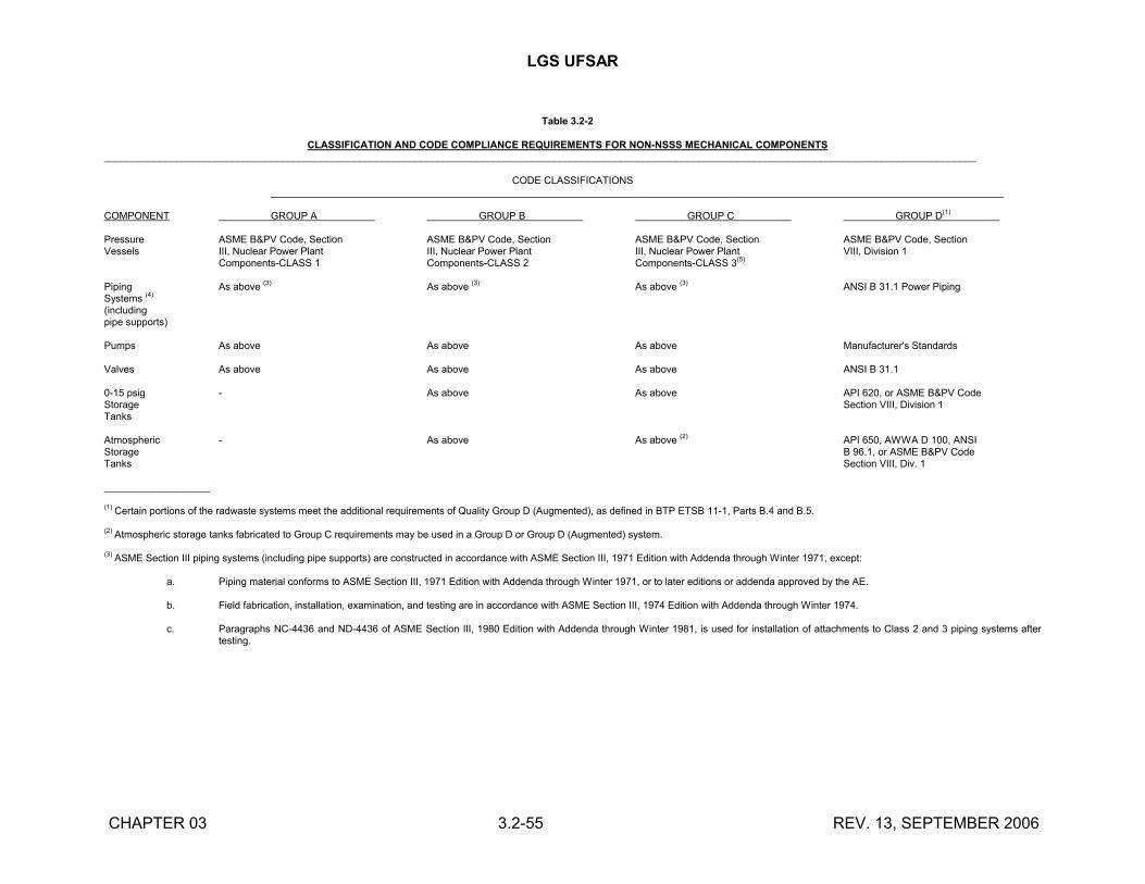
LGS UFSAR
CHAPTER 03 3.2-55 REV. 13, SEPTEMBER 2006
Table 3.2-2
CLASSIFICATION AND CODE COMPLIANCE REQUIREMENTS FOR NON-NSSS MECHANICAL COMPONENTS_____________________________________________________________________________________________________________________________________________________________
CODE CLASSIFICATIONS____________________________________________________________________________________________________________________________________
COMPONENT GROUP A GROUP B GROUP C GROUP D(1)
Pressure ASME B&PV Code, Section ASME B&PV Code, Section ASME B&PV Code, Section ASME B&PV Code, SectionVessels III, Nuclear Power Plant III, Nuclear Power Plant III, Nuclear Power Plant VIII, Division 1
Components-CLASS 1 Components-CLASS 2 Components-CLASS 3(5)
Piping As above (3) As above (3) As above (3) ANSI B 31.1 Power PipingSystems (4)
(includingpipe supports)
Pumps As above As above As above Manufacturer's Standards
Valves As above As above As above ANSI B 31.1
0-15 psig - As above As above API 620, or ASME B&PV CodeStorage Section VIII, Division 1Tanks
Atmospheric - As above As above (2) API 650, AWWA D 100, ANSIStorage B 96.1, or ASME B&PV CodeTanks Section VIII, Div. 1
___________________
(1) Certain portions of the radwaste systems meet the additional requirements of Quality Group D (Augmented), as defined in BTP ETSB 11-1, Parts B.4 and B.5.
(2) Atmospheric storage tanks fabricated to Group C requirements may be used in a Group D or Group D (Augmented) system.
(3) ASME Section III piping systems (including pipe supports) are constructed in accordance with ASME Section III, 1971 Edition with Addenda through Winter 1971, except:
a. Piping material conforms to ASME Section III, 1971 Edition with Addenda through Winter 1971, or to later editions or addenda approved by the AE.
b. Field fabrication, installation, examination, and testing are in accordance with ASME Section III, 1974 Edition with Addenda through Winter 1974.
c. Paragraphs NC-4436 and ND-4436 of ASME Section III, 1980 Edition with Addenda through Winter 1981, is used for installation of attachments to Class 2 and 3 piping systems after testing.
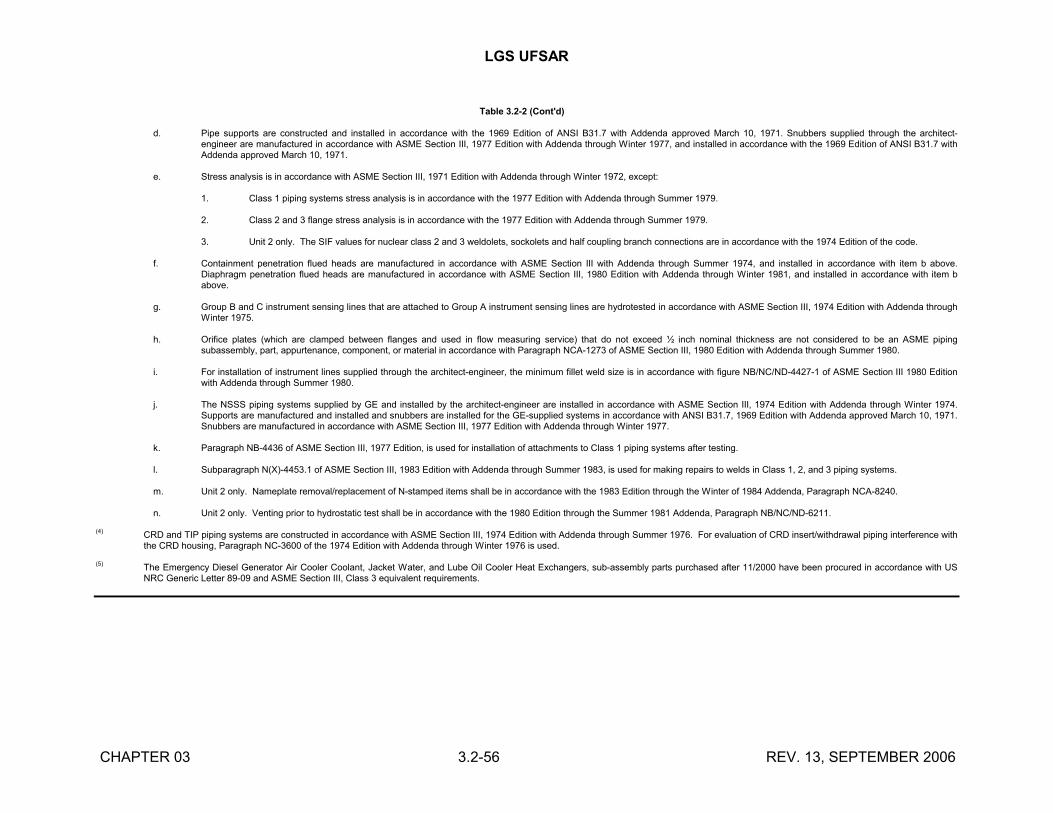
LGS UFSAR
CHAPTER 03 3.2-56 REV. 13, SEPTEMBER 2006
Table 3.2-2 (Cont'd)
d. Pipe supports are constructed and installed in accordance with the 1969 Edition of ANSI B31.7 with Addenda approved March 10, 1971. Snubbers supplied through the architect-engineer are manufactured in accordance with ASME Section III, 1977 Edition with Addenda through Winter 1977, and installed in accordance with the 1969 Edition of ANSI B31.7 with Addenda approved March 10, 1971.
e. Stress analysis is in accordance with ASME Section III, 1971 Edition with Addenda through Winter 1972, except:
1. Class 1 piping systems stress analysis is in accordance with the 1977 Edition with Addenda through Summer 1979.
2. Class 2 and 3 flange stress analysis is in accordance with the 1977 Edition with Addenda through Summer 1979.
3. Unit 2 only. The SIF values for nuclear class 2 and 3 weldolets, sockolets and half coupling branch connections are in accordance with the 1974 Edition of the code.
f. Containment penetration flued heads are manufactured in accordance with ASME Section III with Addenda through Summer 1974, and installed in accordance with item b above. Diaphragm penetration flued heads are manufactured in accordance with ASME Section III, 1980 Edition with Addenda through Winter 1981, and installed in accordance with item b above.
g. Group B and C instrument sensing lines that are attached to Group A instrument sensing lines are hydrotested in accordance with ASME Section III, 1974 Edition with Addenda through Winter 1975.
h. Orifice plates (which are clamped between flanges and used in flow measuring service) that do not exceed ½ inch nominal thickness are not considered to be an ASME piping subassembly, part, appurtenance, component, or material in accordance with Paragraph NCA-1273 of ASME Section III, 1980 Edition with Addenda through Summer 1980.
i. For installation of instrument lines supplied through the architect-engineer, the minimum fillet weld size is in accordance with figure NB/NC/ND-4427-1 of ASME Section III 1980 Edition with Addenda through Summer 1980.
j. The NSSS piping systems supplied by GE and installed by the architect-engineer are installed in accordance with ASME Section III, 1974 Edition with Addenda through Winter 1974. Supports are manufactured and installed and snubbers are installed for the GE-supplied systems in accordance with ANSI B31.7, 1969 Edition with Addenda approved March 10, 1971. Snubbers are manufactured in accordance with ASME Section III, 1977 Edition with Addenda through Winter 1977.
k. Paragraph NB-4436 of ASME Section III, 1977 Edition, is used for installation of attachments to Class 1 piping systems after testing.
l. Subparagraph N(X)-4453.1 of ASME Section III, 1983 Edition with Addenda through Summer 1983, is used for making repairs to welds in Class 1, 2, and 3 piping systems.
m. Unit 2 only. Nameplate removal/replacement of N-stamped items shall be in accordance with the 1983 Edition through the Winter of 1984 Addenda, Paragraph NCA-8240.
n. Unit 2 only. Venting prior to hydrostatic test shall be in accordance with the 1980 Edition through the Summer 1981 Addenda, Paragraph NB/NC/ND-6211.
(4) CRD and TIP piping systems are constructed in accordance with ASME Section III, 1974 Edition with Addenda through Summer 1976. For evaluation of CRD insert/withdrawal piping interference with the CRD housing, Paragraph NC-3600 of the 1974 Edition with Addenda through Winter 1976 is used.
(5) The Emergency Diesel Generator Air Cooler Coolant, Jacket Water, and Lube Oil Cooler Heat Exchangers, sub-assembly parts purchased after 11/2000 have been procured in accordance with US NRC Generic Letter 89-09 and ASME Section III, Class 3 equivalent requirements.
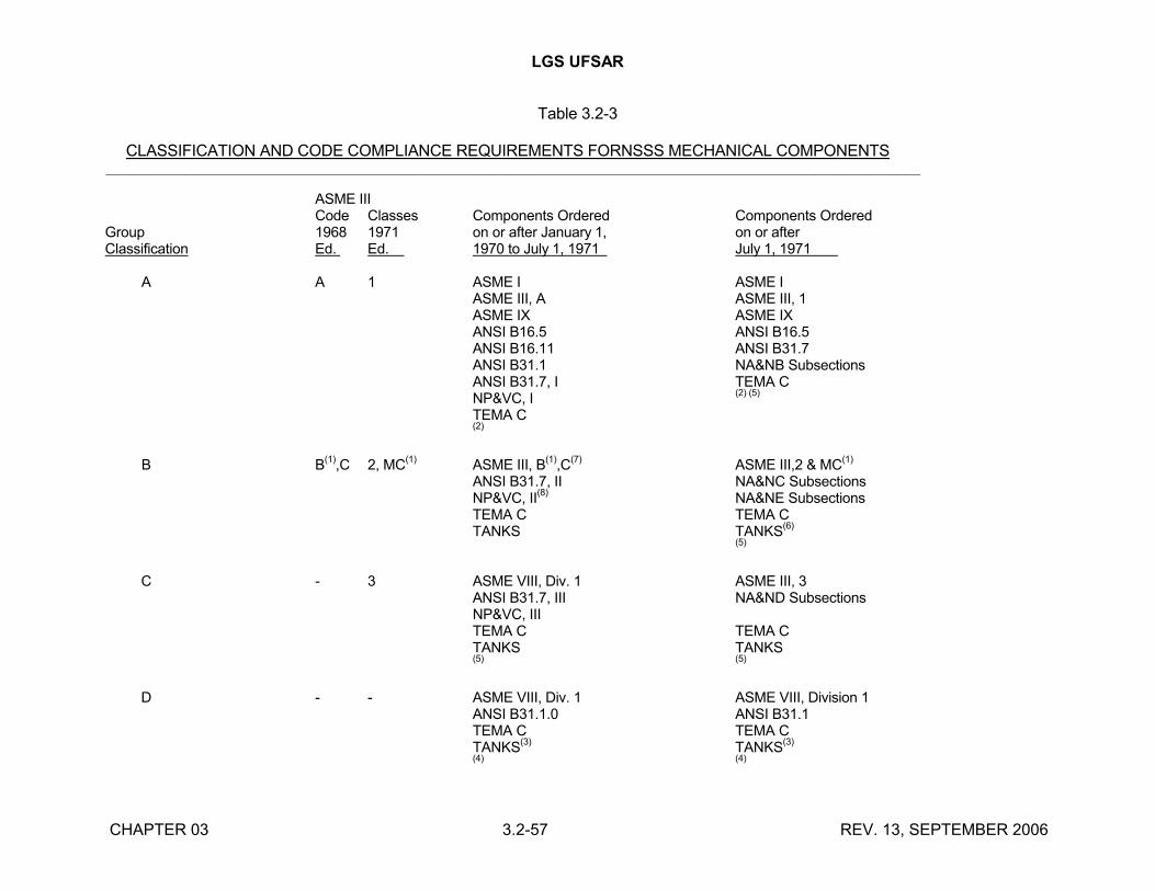
LGS UFSAR
CHAPTER 03 3.2-57 REV. 13, SEPTEMBER 2006
Table 3.2-3
CLASSIFICATION AND CODE COMPLIANCE REQUIREMENTS FORNSSS MECHANICAL COMPONENTS_______________________________________________________________________________________________
ASME IIICode Classes Components Ordered Components Ordered
Group 1968 1971 on or after January 1, on or afterClassification Ed. Ed. 1970 to July 1, 1971 July 1, 1971
A A 1 ASME I ASME IASME III, A ASME III, 1ASME IX ASME IXANSI B16.5 ANSI B16.5ANSI B16.11 ANSI B31.7ANSI B31.1 NA&NB SubsectionsANSI B31.7, I TEMA CNP&VC, I
(2) (5)
TEMA C(2)
B B(1)
,C 2, MC(1)
ASME III, B(1)
,C(7)
ASME III,2 & MC(1)
ANSI B31.7, II NA&NC SubsectionsNP&VC, II
(8)NA&NE Subsections
TEMA C TEMA CTANKS TANKS
(6)
(5)
C - 3 ASME VIII, Div. 1 ASME III, 3ANSI B31.7, III NA&ND SubsectionsNP&VC, IIITEMA C TEMA CTANKS TANKS(5) (5)
D - - ASME VIII, Div. 1 ASME VIII, Division 1ANSI B31.1.0 ANSI B31.1TEMA C TEMA CTANKS
(3)TANKS
(3)
(4) (4)
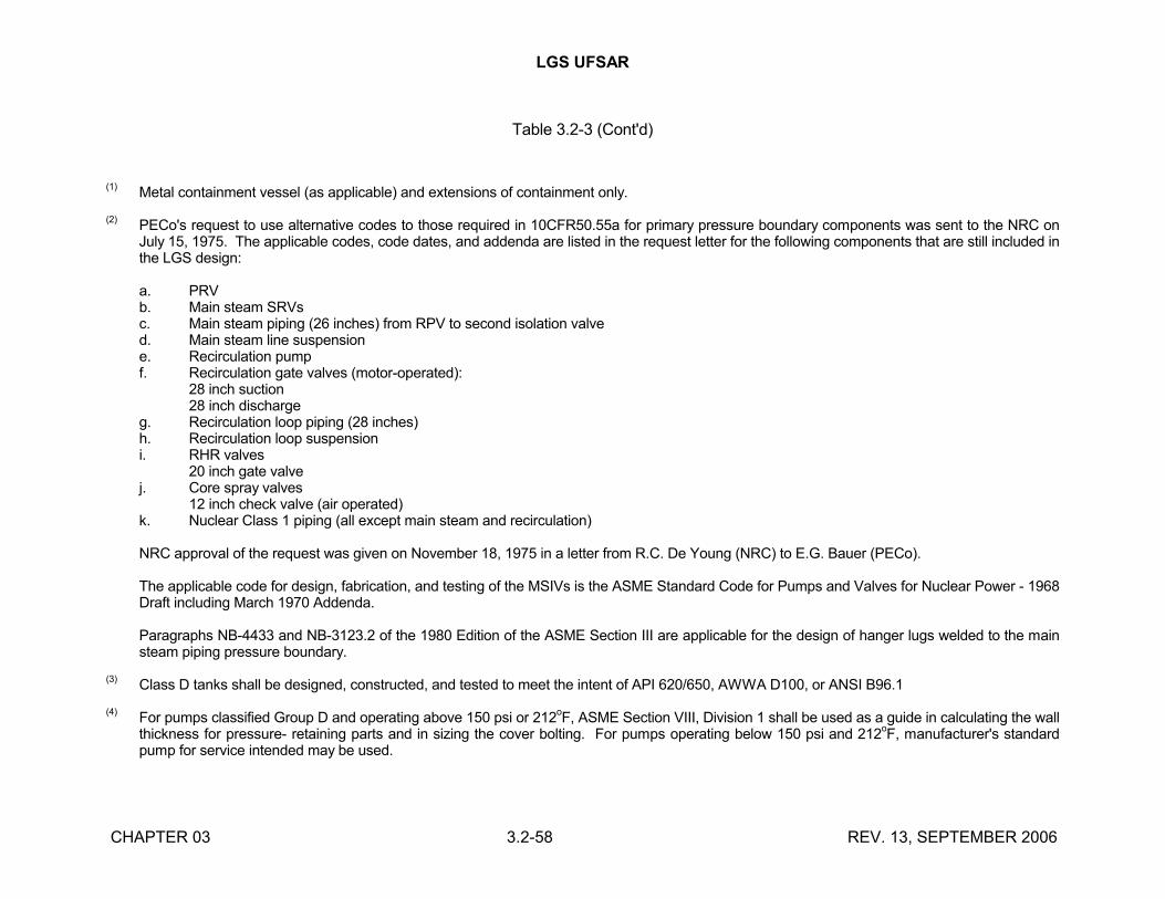
LGS UFSAR
CHAPTER 03 3.2-58 REV. 13, SEPTEMBER 2006
Table 3.2-3 (Cont'd)
(1)Metal containment vessel (as applicable) and extensions of containment only.
(2)PECo's request to use alternative codes to those required in 10CFR50.55a for primary pressure boundary components was sent to the NRC on July 15, 1975. The applicable codes, code dates, and addenda are listed in the request letter for the following components that are still included in the LGS design:
a. PRVb. Main steam SRVsc. Main steam piping (26 inches) from RPV to second isolation valved. Main steam line suspensione. Recirculation pumpf. Recirculation gate valves (motor-operated):
28 inch suction28 inch discharge
g. Recirculation loop piping (28 inches)h. Recirculation loop suspensioni. RHR valves
20 inch gate valvej. Core spray valves
12 inch check valve (air operated)k. Nuclear Class 1 piping (all except main steam and recirculation)
NRC approval of the request was given on November 18, 1975 in a letter from R.C. De Young (NRC) to E.G. Bauer (PECo).
The applicable code for design, fabrication, and testing of the MSIVs is the ASME Standard Code for Pumps and Valves for Nuclear Power - 1968 Draft including March 1970 Addenda.
Paragraphs NB-4433 and NB-3123.2 of the 1980 Edition of the ASME Section III are applicable for the design of hanger lugs welded to the main steam piping pressure boundary.
(3)Class D tanks shall be designed, constructed, and tested to meet the intent of API 620/650, AWWA D100, or ANSI B96.1
(4)For pumps classified Group D and operating above 150 psi or 212
oF, ASME Section VIII, Division 1 shall be used as a guide in calculating the wall
thickness for pressure- retaining parts and in sizing the cover bolting. For pumps operating below 150 psi and 212oF, manufacturer's standard
pump for service intended may be used.
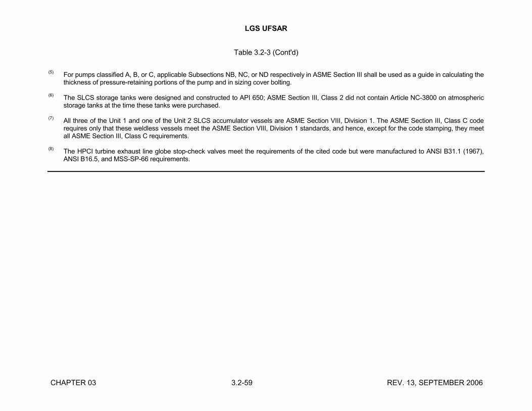
LGS UFSAR
CHAPTER 03 3.2-59 REV. 13, SEPTEMBER 2006
Table 3.2-3 (Cont'd)
(5)For pumps classified A, B, or C, applicable Subsections NB, NC, or ND respectively in ASME Section III shall be used as a guide in calculating the thickness of pressure-retaining portions of the pump and in sizing cover bolting.
(6)The SLCS storage tanks were designed and constructed to API 650; ASME Section III, Class 2 did not contain Article NC-3800 on atmospheric storage tanks at the time these tanks were purchased.
(7)All three of the Unit 1 and one of the Unit 2 SLCS accumulator vessels are ASME Section VIII, Division 1. The ASME Section III, Class C code requires only that these weldless vessels meet the ASME Section VIII, Division 1 standards, and hence, except for the code stamping, they meet all ASME Section III, Class C requirements.
(8)The HPCI turbine exhaust line globe stop-check valves meet the requirements of the cited code but were manufactured to ANSI B31.1 (1967), ANSI B16.5, and MSS-SP-66 requirements.
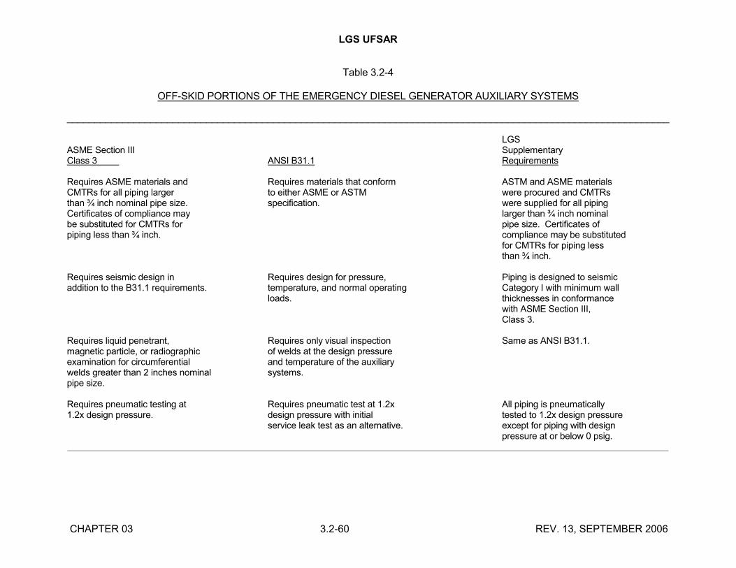
LGS UFSAR
CHAPTER 03 3.2-60 REV. 13, SEPTEMBER 2006
Table 3.2-4
OFF-SKID PORTIONS OF THE EMERGENCY DIESEL GENERATOR AUXILIARY SYSTEMS
____________________________________________________________________________________________________________
LGSASME Section III SupplementaryClass 3 ANSI B31.1 Requirements Requires ASME materials and Requires materials that conform ASTM and ASME materialsCMTRs for all piping larger to either ASME or ASTM were procured and CMTRsthan ¾ inch nominal pipe size. specification. were supplied for all pipingCertificates of compliance may larger than ¾ inch nominalbe substituted for CMTRs for pipe size. Certificates ofpiping less than ¾ inch. compliance may be substituted
for CMTRs for piping lessthan ¾ inch.
Requires seismic design in Requires design for pressure, Piping is designed to seismicaddition to the B31.1 requirements. temperature, and normal operating Category I with minimum wall
loads. thicknesses in conformancewith ASME Section III,Class 3.
Requires liquid penetrant, Requires only visual inspection Same as ANSI B31.1.magnetic particle, or radiographic of welds at the design pressureexamination for circumferential and temperature of the auxiliarywelds greater than 2 inches nominal systems.pipe size.
Requires pneumatic testing at Requires pneumatic test at 1.2x All piping is pneumatically1.2x design pressure. design pressure with initial tested to 1.2x design pressure
service leak test as an alternative. except for piping with designpressure at or below 0 psig.
______________________________________________________________________________________________________________
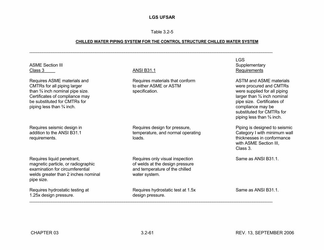
LGS UFSAR
CHAPTER 03 3.2-61 REV. 13, SEPTEMBER 2006
Table 3.2-5
CHILLED WATER PIPING SYSTEM FOR THE CONTROL STRUCTURE CHILLED WATER SYSTEM
______________________________________________________________________________________________________________
LGSASME Section III SupplementaryClass 3 ANSI B31.1 Requirements
Requires ASME materials and Requires materials that conform ASTM and ASME materialsCMTRs for all piping larger to either ASME or ASTM were procured and CMTRsthan ¾ inch nominal pipe size. specification. were supplied for all pipingCertificates of compliance may larger than ¾ inch nominalbe substituted for CMTRs for pipe size. Certificates ofpiping less than ¾ inch. compliance may be
substituted for CMTRs forpiping less than ¾ inch.
Requires seismic design in Requires design for pressure, Piping is designed to seismicaddition to the ANSI B31.1 temperature, and normal operating Category I with minimum wallrequirements. loads. thicknesses in conformance
with ASME Section III,Class 3.
Requires liquid penetrant, Requires only visual inspection Same as ANSI B31.1.magnetic particle, or radiographic of welds at the design pressureexamination for circumferential and temperature of the chilledwelds greater than 2 inches nominal water system.pipe size.
Requires hydrostatic testing at Requires hydrostatic test at 1.5x Same as ANSI B31.1.1.25x design pressure. design pressure.______________________________________________________________________________________________________________
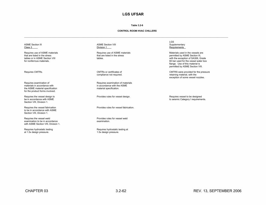
LGS UFSAR
CHAPTER 03 3.2-62 REV. 13, SEPTEMBER 2006
Table 3.2-6
CONTROL ROOM HVAC CHILLERS
______________________________________________________________________________________________________________________________________________________________
LGSASME Section III ASME Section VIII SupplementaryClass 3 Division 1 Requirements
Requires use of ASME materials Requires use of ASME materials Materials used in the vessels arethat are listed in the stress that are listed in the stress permitted by ASME Section III,tables or in ASME Section VIII tables. with the exception of SA306, Gradefor nonferrous materials. 60 bar used for the vessel water box
flange. Use of this material ispermitted by ASME Section VIII.
Requires CMTRs. CMTRs or certificates of CMTRS were provided for the pressurecompliance not required. retaining material, with the
exception of some vessel nozzles.
Requires examination of Requires examination of materialsmaterials in accordance with in accordance with the ASMEthe ASME material specification material specification.for the product forms involved.
Requires the vessel design to Provides rules for vessel design. Requires vessel to be designedbe in accordance with ASME to seismic Category I requirements.Section VIII, Division 1.
Requires the vessel fabrication Provides rules for vessel fabrication.to be in accordance with ASMESection VIII, Division 1.
Requires the vessel weld Provides rules for vessel weldexamination to be in accordance examination.with ASME Section VIII, Division 1.
Requires hydrostatic testing Requires hydrostatic testing atat 1.5x design pressure. 1.5x design pressure.
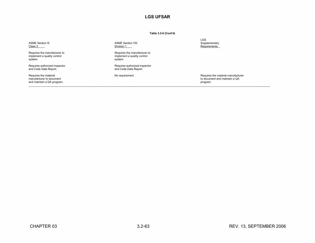
LGS UFSAR
CHAPTER 03 3.2-63 REV. 13, SEPTEMBER 2006
Table 3.2-6 (Cont'd)
LGSASME Section III ASME Section VIII SupplementaryClass 3 Division 1 Requirements
Requires the manufacturer to Requires the manufacturer toimplement a quality control implement a quality controlsystem. system.
Requires authorized inspector Requires authorized inspectorand Code Data Report. and Code Data Report.
Requires the material No requirement. Requires the material manufacturermanufacturer to document to document and maintain a QAand maintain a QA program. program.______________________________________________________________________________________________________________________________________________________________
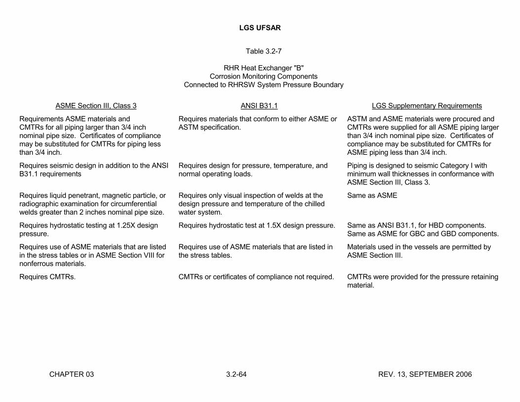
LGS UFSAR
CHAPTER 03 3.2-64 REV. 13, SEPTEMBER 2006
Table 3.2-7
RHR Heat Exchanger "B"Corrosion Monitoring Components
Connected to RHRSW System Pressure Boundary
ASME Section III, Class 3 ANSI B31.1 LGS Supplementary Requirements
Requirements ASME materials andCMTRs for all piping larger than 3/4 inch nominal pipe size. Certificates of compliance may be substituted for CMTRs for piping less than 3/4 inch.
Requires materials that conform to either ASME or ASTM specification.
ASTM and ASME materials were procured and CMTRs were supplied for all ASME piping larger than 3/4 inch nominal pipe size. Certificates of compliance may be substituted for CMTRs for ASME piping less than 3/4 inch.
Requires seismic design in addition to the ANSI B31.1 requirements
Requires design for pressure, temperature, and normal operating loads.
Piping is designed to seismic Category I with minimum wall thicknesses in conformance with ASME Section III, Class 3.
Requires liquid penetrant, magnetic particle, or radiographic examination for circumferential welds greater than 2 inches nominal pipe size.
Requires only visual inspection of welds at the design pressure and temperature of the chilled water system.
Same as ASME
Requires hydrostatic testing at 1.25X design pressure.
Requires hydrostatic test at 1.5X design pressure. Same as ANSI B31.1, for HBD components. Same as ASME for GBC and GBD components.
Requires use of ASME materials that are listed in the stress tables or in ASME Section VIII for nonferrous materials.
Requires use of ASME materials that are listed in the stress tables.
Materials used in the vessels are permitted by ASME Section III.
Requires CMTRs. CMTRs or certificates of compliance not required. CMTRs were provided for the pressure retaining material.
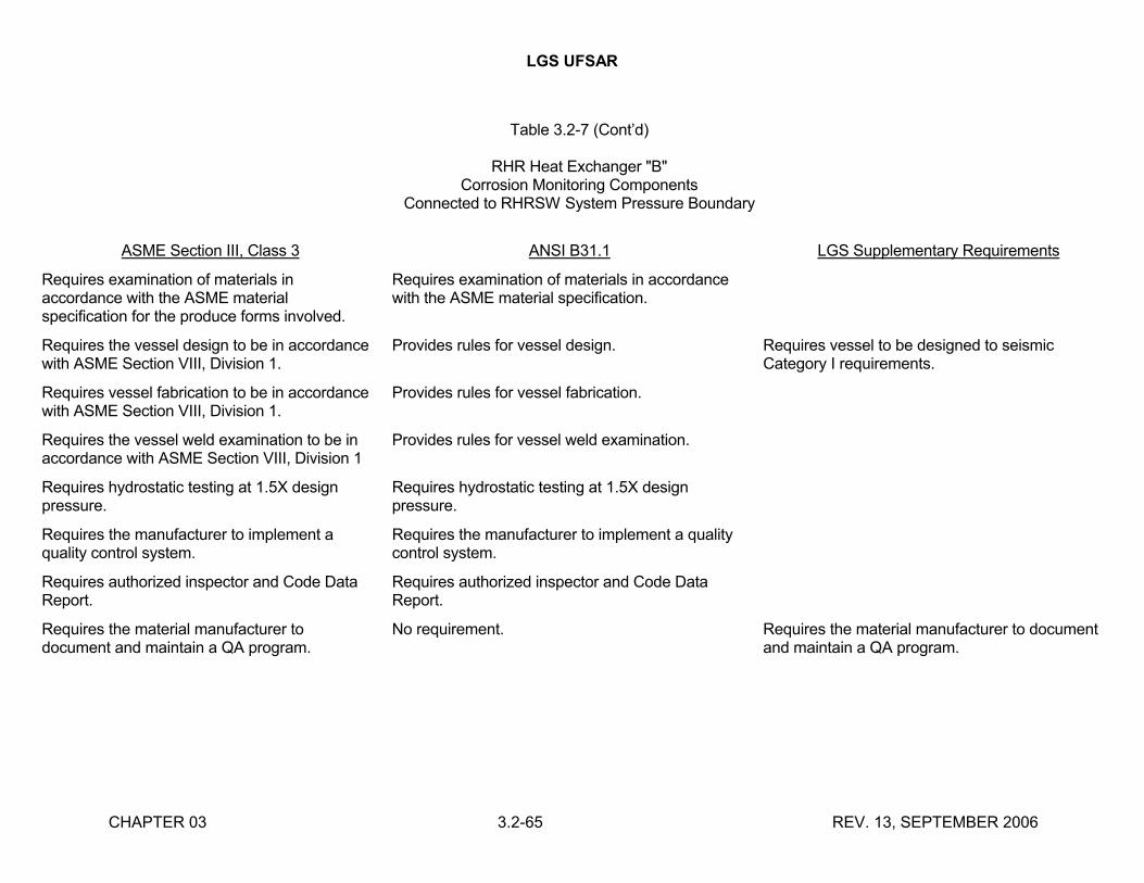
LGS UFSAR
CHAPTER 03 3.2-65 REV. 13, SEPTEMBER 2006
Table 3.2-7 (Cont’d)
RHR Heat Exchanger "B"Corrosion Monitoring Components
Connected to RHRSW System Pressure Boundary
ASME Section III, Class 3 ANSI B31.1 LGS Supplementary Requirements
Requires examination of materials in accordance with the ASME material specification for the produce forms involved.
Requires examination of materials in accordance with the ASME material specification.
Requires the vessel design to be in accordance with ASME Section VIII, Division 1.
Provides rules for vessel design. Requires vessel to be designed to seismic Category I requirements.
Requires vessel fabrication to be in accordance with ASME Section VIII, Division 1.
Provides rules for vessel fabrication.
Requires the vessel weld examination to be in accordance with ASME Section VIII, Division 1
Provides rules for vessel weld examination.
Requires hydrostatic testing at 1.5X design pressure.
Requires hydrostatic testing at 1.5X design pressure.
Requires the manufacturer to implement a quality control system.
Requires the manufacturer to implement a quality control system.
Requires authorized inspector and Code Data Report.
Requires authorized inspector and Code Data Report.
Requires the material manufacturer to document and maintain a QA program.
No requirement. Requires the material manufacturer to document and maintain a QA program.
LGS UFSAR
CHAPTER 03 3.3-1 REV. 13, SEPTEMBER 2006
3.3 WIND AND TORNADO LOADINGS
3.3.1 WIND LOADINGS
Design wind loads for all exposed structures are based on Reference 3.3-1 and Reference 3.3-2.
3.3.1.1 Design Wind Velocity
Exposed structures are designed to withstand a basic wind velocity of 90 mph at 30 feet above ground. The recurrence interval of this wind velocity is estimated to be at least 100 years (Reference 3.3-1). A gust factor of 1.1 is used in conjunction with this basic wind velocity. The variation of wind velocity with height is given in Table 3.3-1.
3.3.1.2 Determination of Applied Forces
The dynamic pressures on the exposed structural surfaces due to the design wind are computed in accordance with the requirements of Reference 3.3-1, which are summarized as follows:
q = 0.002558V2
where:
q = dynamic pressure (psf)
V = design wind velocity, mph
V = G (v)
where:
G = gust factor
v = basic wind velocity
The total design pressure for a structure is the product of dynamic pressure and shape coefficient. A shape coefficient of 1.3 is applied with all wind loads. This total design pressure is distributed among different exposed surfaces of the structure, on the basis of location with respect to the wind direction. Pressures and suction developed by using the above procedure and used in the design of plant structures are given in Table 3.3-1.
Table 3.3-4 provides a comparison between the maximum expected external pressure and the external design pressures. This table shows that an adequate margin of safety for wind loadings exists for the secondary containment structure.
3.3.2 TORNADO LOADINGS
Structures that directly affect the ultimate safe shutdown of the plant are designed to resist applicable design basis tornado forces. Table 3.3-2 lists the systems and components that are protected against tornados and the enclosures that provide this protection. The radwaste enclosure is tornado-resistant only to the extent of protecting the gaseous radwaste treatment
LGS UFSAR
CHAPTER 03 3.3-2 REV. 13, SEPTEMBER 2006
system and retaining approximately 500,000 gallons of solid and liquid radwaste within the confines of the enclosure.
3.3.2.1 Applicable Design Parameters
Structures required to be tornado-resistant are designed for the following effects of a design basis tornado:
a. Dynamic wind loadings - These are the external pressure or suction forces on a structure due to the passage of a tornado funnel. The design basis tornado has a rotational speed of 300 mph and a translational speed of 60 mph. Conservatively, this is taken as a 300 mph wind applied uniformly over an entire structure.
b. Differential pressures - When the low pressure within a tornado funnel engulfs a structure, a rapid depressurization occurs and produces differential pressures between the inside and outside of the structure and between the compartments inside the structure depending on the available vent paths. The pressure transient caused by the design basis tornado is a 3 psi pressure drop at the rate of 1 psi/sec, followed by a 2 second calm and then a repressurization to the original pressure at a rate of 1 psi/sec.
c. Tornado missiles - The types of missiles postulated to be generated by a tornado are discussed in Section 3.5.1.4.
Regulatory Guide 1.76, "Design Basis Tornado for Nuclear Power Plants", calls for a pressure drop of 3 psi at the rate of 2 psi/sec, however, the increased depressurization rate of 2 psi/sec in Regulatory Guide 1.76 would have no significant effect on the external structural elements of tornado-resistant structures. These structures are designed for the maximum pressure differential due to a tornado of 3 psi regardless of the rate of depressurization.
The increased depressurization rate would increase the maximum differential pressure for internal structural elements. These elements were checked for the maximum differential pressure caused by the following design basis tornado pressurization profile: a 1 psi/sec pressure decrease for 3 seconds; a 2 second calm; a 1 psi/sec pressure increase for 3 seconds. An analysis to determine the effects of the increased maximum differential pressures on the internal structural elements has not been performed because the 1 psi/sec depressurization rate is considered to be conservative. The design basis tornado pressurization profile used was committed to in the LGS PSAR, Appendix C, Section C.2.4, prior to the issuance of Regulatory Guide 1.76. This pressurization profile was based on Reference 3.3-4. Previous documents used as the design basis for tornado effects were References 3.3-5 and 3.3-6. Actual tornado parameters weredeveloped by studies of the tornado damage, eyewitness accounts of the maximum tornado depressurization on barometric instruments, and analysis of films of actual tornadoes. The depressurization effects defined in References 3.3-4, 3.3-5, and 3.3-6 substantiate the conservatism of the 1 psi/sec depressurization rate because they exceed the observed effects of actual tornadoes.
To further demonstrate the conservatism of the 1 psi/sec depressurization rate, site specific tornado parameters have been determined for LGS using the methodology of Reference 3.3-7. This reference is the basis document for Regulatory Guide 1.76.

LGS UFSAR
CHAPTER 03 3.3-3 REV. 13, SEPTEMBER 2006
In accordance with Regulatory Guide 1.76, LGS is in zone I, a region which encompasses a wide variation of tornado risks, from high tornado risk areas such as the Midwest to low risk areas such as New England. For the following analysis, a site specific tornado risk data base is used to determine the design basis tornado parameters.
Tornado data was obtained from the National Severe Storms Forecast Center for the years 1950 through 1981 for an area 125 nautical miles in radius centered on Pottstown, Pennsylvania. During this period, these were 322 tornadoes, or 10.1 tornadoes per year.
The probability that a tornado will strike a particular area is given by Reference 3.3-7 as:
Ps = n (a/A)
where:
Ps = tornado strike probability
n = average number of tornadoes per year
a = average individual tornado area
A = land area within 125 nm of Pottstown (1 square nautical mile = 1.32 square miles)
From the tornado data, tornado areas were calculated for 307 tornadoes (data was not available for 15 tornadoes). The average area was 0.24 square miles. The land area within 125 nm of Pottstown is approximately 53,500 square miles (the total area is 64,900 square miles), of which 82% is land area. Therefore, the average probability of a tornado strike is:
Ps = 10.1(0.24) = 4.6x10⁻⁵
per year 53,500
In accordance with Reference 3.3-7, the probability of occurrence of a tornado that exceeds the design basis tornado should be on the order of 10-7 per year to adequately protect public health and safety. Therefore:
Ps · Pi 10-7
where:
Pi = acceptable intensity probability
Thus,
Pi = 10-7/4.6x10-5 = 2.2x10⁻³ per year = 0.22%
Each tornado in the tornado data base has been classified according to a wind speed scale (the Fujita parameters). The distribution of tornadoes with respect to wind speed is given in Table 3.3-
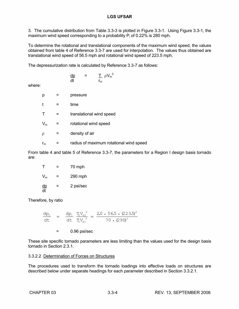
LGS UFSAR
CHAPTER 03 3.3-4 REV. 13, SEPTEMBER 2006
3. The cumulative distribution from Table 3.3-3 is plotted in Figure 3.3-1. Using Figure 3.3-1, the maximum wind speed corresponding to a probability Pi of 0.22% is 280 mph.
To determine the rotational and translational components of the maximum wind speed, the values obtained from table 4 of Reference 3.3-7 are used for interpolation. The values thus obtained are translational wind speed of 56.5 mph and rotational wind speed of 223.5 mph.
The depressurization rate is calculated by Reference 3.3-7 as follows:
dp = T Vm2
dt rm
where:
p = pressure
t = time
T = translational wind speed
Vm = rotational wind speed
= density of air
rm = radius of maximum rotational wind speed
From table 4 and table 5 of Reference 3.3-7, the parameters for a Region I design basis tornado are:
T = 70 mph
Vm = 290 mph
dp = 2 psi/secdt
Therefore, by ratio
dp
dt
dp
dt
TV
TVm
m
2 1 2 22
1 12
2
2
20 565 2235
70 290
. . ( .)
( )
= 0.96 psi/sec
These site specific tornado parameters are less limiting than the values used for the design basis tornado in Section 2.3.1.
3.3.2.2 Determination of Forces on Structures
The procedures used to transform the tornado loadings into effective loads on structures are described below under separate headings for each parameter described in Section 3.3.2.1.
LGS UFSAR
CHAPTER 03 3.3-5 REV. 13, SEPTEMBER 2006
a. Dynamic wind loadings - The procedure used to transform the tornado wind velocity into an effective pressure is the same as described in Section 3.3.1.2, with the following exceptions: velocity and velocity pressure are not assumed to vary with height, and a gust factor of 1.0 is used. The resulting pressure loadings are as follows:
1. Pressure on windward side (0.8q) 185 psf
2. Suction on leeward side (0.5q) 115 psf
3. Total pressure on structure (1.3q) 300 psf
4. Uplift on roof (0.6q) 140 psf
b. Differential pressures - The maximum differential pressure between the inside and outside of fully enclosed areas is taken as 3.0 psi. Blowout panels are provided where necessary to lower the design differential pressures. For vented compartments, a flow analysis of all interconnecting air volumes is performed and the maximum transient pressure differentials across walls, floors, and roofs are calculated. All structural components in the vented and nonvented compartments are then checked to confirm that they can withstand the maximum calculated transient differential pressure.
c. Tornado missiles - The procedures and methods outlined in Reference 3.3-3 are used to transform the dynamic loads into effective loads and to determine the structural response of the elements subjected to missile impingement.
All of the above design basis tornado loadings are considered as loadings that act simultaneously.
Analytical techniques were used for estimating the values of tornado parameters for purposes of design with an adequate level of conservatism. Although the tornado parameters used in the LGS external design pressure analyses differ slightly from those defined in Regulatory Guide 1.76, the LGS analyses are either equivalent or conservative compared to analyses using the Regulatory Guide 1.76 parameters (Section 2.3.1.2.4). The use of these parameters for calculating the external design pressure ensures an adequate margin above the maximum expected external pressure.
3.3.2.3 Effect Of Failure Of Structures Or Components Not Designed For Tornado Loadings
Structures such as the turbine enclosure and outdoor storage tanks, which are not designed for tornado loads, are investigated and checked to ensure that they cannot produce missiles that have more severe effects than those listed in Section 3.5.1.4. The modes of failure of these structures are analyzed to verify that their failure due to tornado loading cannot prevent structures or components needed for safe shutdown from performing their intended functions.
LGS UFSAR
CHAPTER 03 3.3-6 REV. 13, SEPTEMBER 2006
3.3.3 REFERENCES
3.3-1 "Wind Forces on Structures", Transactions, Volume 126, Part II, ASCE paper No. 3269, (1961).
3.3-2 H.C. Thom, "New Distributions of Extreme Winds in the United States", Journal of the Structural Division, ASCE, (1969).
3.3-3 "Design of Structures For Missile Impact", BC-TOP-9-A, Rev. 2, Bechtel Power Corporation, (September 1974).
3.3-4 J.A. Dunlop and K. Wiedner, "Nuclear Power Plant Tornado Design Considerations", Journal of the Power Division, Proceedings of the ASCE, (March 1971).
3.3-5 "Design Criteria for Nuclear Power Plants Against Tornadoes", Bechtel Power Corporation, B-TOP-3, (March 12, 1970).
3.3-6 "Tornado Criteria for Nuclear Plants", Bechtel Power Corporation, (July 1969).
3.3-7 "Technical Basis for Interim Regional Tornado Criteria", AEC, WASH-1300, (May 1974).
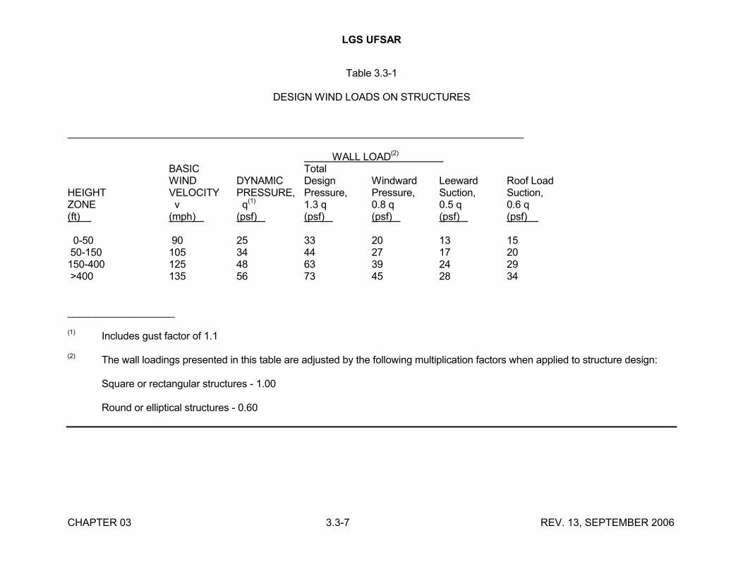
LGS UFSAR
CHAPTER 03 3.3-7 REV. 13, SEPTEMBER 2006
Table 3.3-1
DESIGN WIND LOADS ON STRUCTURES
_________________________________________________________________________________
WALL LOAD(2) BASIC TotalWIND DYNAMIC Design Windward Leeward Roof Load
HEIGHT VELOCITY PRESSURE, Pressure, Pressure, Suction, Suction,ZONE v q(1) 1.3 q 0.8 q 0.5 q 0.6 q(ft) (mph) (psf) (psf) (psf) (psf) (psf)
0-50 90 25 33 20 13 1550-150 105 34 44 27 17 20150-400 125 48 63 39 24 29>400 135 56 73 45 28 34
___________________
(1) Includes gust factor of 1.1
(2) The wall loadings presented in this table are adjusted by the following multiplication factors when applied to structure design:
Square or rectangular structures - 1.00
Round or elliptical structures - 0.60
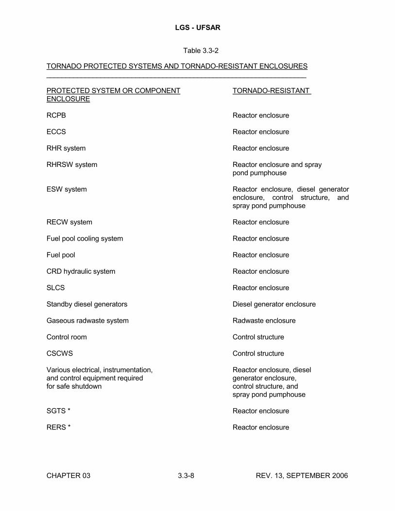
LGS - UFSAR
CHAPTER 03 3.3-8 REV. 13, SEPTEMBER 2006
Table 3.3-2
TORNADO PROTECTED SYSTEMS AND TORNADO-RESISTANT ENCLOSURES___________________________________________________________________
PROTECTED SYSTEM OR COMPONENT TORNADO-RESISTANT ENCLOSURE
RCPB Reactor enclosure
ECCS Reactor enclosure
RHR system Reactor enclosure
RHRSW system Reactor enclosure and spraypond pumphouse
ESW system Reactor enclosure, diesel generator enclosure, control structure, and spray pond pumphouse
RECW system Reactor enclosure
Fuel pool cooling system Reactor enclosure
Fuel pool Reactor enclosure
CRD hydraulic system Reactor enclosure
SLCS Reactor enclosure
Standby diesel generators Diesel generator enclosure
Gaseous radwaste system Radwaste enclosure
Control room Control structure
CSCWS Control structure
Various electrical, instrumentation, Reactor enclosure, dieseland control equipment required generator enclosure,for safe shutdown control structure, and
spray pond pumphouse
SGTS * Reactor enclosure
RERS * Reactor enclosure

LGS - UFSAR
CHAPTER 03 3.3-9 REV. 13, SEPTEMBER 2006
Table 3.3-2 (Cont’d)
NOTE * The SGTS and the RERS are provided to reduce airborne radiation concentrations in the secondary containment prior to release to the environment for low probability events such as a LOCA. They are not required to achieve safe shutdown. In accordance with Regulatory Guide 1.117, such systems are not required to be protected against tornadoes. However, they are totally enclosed in the reactor enclosure and control structure, which are tornado-resistant enclosures.
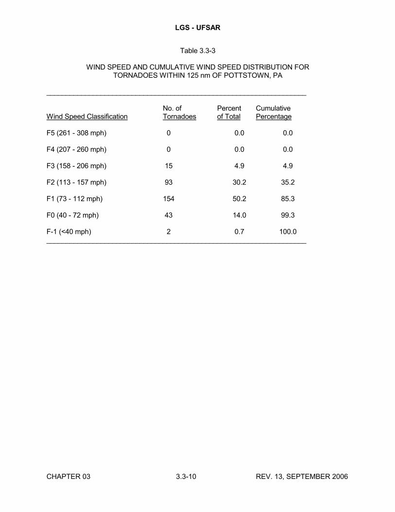
LGS - UFSAR
CHAPTER 03 3.3-10 REV. 13, SEPTEMBER 2006
Table 3.3-3
WIND SPEED AND CUMULATIVE WIND SPEED DISTRIBUTION FORTORNADOES WITHIN 125 nm OF POTTSTOWN, PA
___________________________________________________________________
No. of Percent CumulativeWind Speed Classification Tornadoes of Total Percentage
F5 (261 - 308 mph) 0 0.0 0.0
F4 (207 - 260 mph) 0 0.0 0.0
F3 (158 - 206 mph) 15 4.9 4.9
F2 (113 - 157 mph) 93 30.2 35.2
F1 (73 - 112 mph) 154 50.2 85.3
F0 (40 - 72 mph) 43 14.0 99.3
F-1 (<40 mph) 2 0.7 100.0___________________________________________________________________
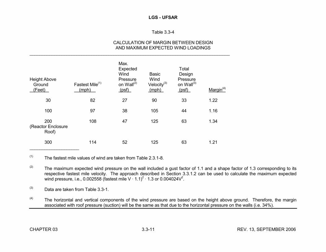
LGS - UFSAR
CHAPTER 03 3.3-11 REV. 13, SEPTEMBER 2006
Table 3.3-4
CALCULATION OF MARGIN BETWEEN DESIGNAND MAXIMUM EXPECTED WIND LOADINGS
_________________________________________________________________________________
Max.Expected TotalWind Basic Design
Height Above Pressure Wind Pressure Ground Fastest Mile(1) on Wall(2) Velocity(3) on Wall(3)
(Feet) (mph) (psf) (mph) (psf) Margin(4)
30 82 27 90 33 1.22
100 97 38 105 44 1.16
200 108 47 125 63 1.34(Reactor Enclosure
Roof)
300 114 52 125 63 1.21____________________
(1) The fastest mile values of wind are taken from Table 2.3.1-8.
(2) The maximum expected wind pressure on the wall included a gust factor of 1.1 and a shape factor of 1.3 corresponding to its respective fastest mile velocity. The approach described in Section 3.3.1.2 can be used to calculate the maximum expected wind pressure, i.e., 0.002558 (fastest mile V · 1.1)2 · 1.3 or 0.004024V2.
(3) Data are taken from Table 3.3-1.
(4) The horizontal and vertical components of the wind pressure are based on the height above ground. Therefore, the margin associated with roof pressure (suction) will be the same as that due to the horizontal pressure on the walls (i.e. 34%).
LGS UFSAR
CHAPTER 03 3.4-1 REV. 13, SEPTEMBER 2006
3.4 WATER LEVEL (FLOOD) DESIGN
3.4.1 FLOOD PROTECTION
3.4.1.1 Flood Protection Measures for Seismic Category I Structures
Seismic Category I structures and the safety-related systems and components housed within them are listed in Table 3.4-1. As discussed in Section 2.4.2.2, the design basis flood level of the Schuylkill River at the site is 207 feet, including wave activity. The shortest horizontal distance from the contour at el 207' to the nearest safety-related structure is approximately 200 feet. Grade level is no lower than el 215' at any of the safety-related structures, and none of the safety-related structures has exterior openings below el 217'. Therefore, the safety-related structures are secure from Schuylkill River flooding and no special provisions for flood protection are necessary. Flooding from internal events is discussed in Section 3.6.1. The impact of local intense precipitation is discussed in Section 2.4.2.3.
Table 2.4-1 lists the access openings in safety-related structures. Two of these doors are below the design basis flood (el 207' MSL) but do not represent a flooding concern. The doors between the reactor enclosure and water pipe tunnel room 202 at el 201' are watertight. The doors between the control structure and the turbine enclosure at el 200' are watertight because the turbine enclosure is not watertight against the PMP as discussed in Section 2.4.2.3.
The failure of nonseismic Category I and nontornado protected tanks, vessels, and major pipes located outside buildings (Table 3.4-2) has also been evaluated and determined to not adversely affect safety-related structures, systems, and components as discussed below.
Tank Failure
The location of tanks in the yard area is shown in Figure 3.8-58. Failure of the tanks on the west and south sides of the power plant complex (Table 3.4-2, items 1 through 5) will not cause potential flooding of safety-related structures, systems, and components. Any flooding due to a failure of these tanks will be contained within seismic Category IIA earth dikes, which will remain stable under both static and dynamic conditions. The design of the earth dikes is discussed in Sections 2.4.12 and 2.5.5.5.
The tanks on the north side of the power plant complex (Table 3.4-2, items 6 through 9) do not have seismically designed containments around them. Failure of these tanks could cause local flooding. This flooding would not adversely affect safety-related facilities for the following reasons:
a. Surface drainage in this area will drain water towards the Schuylkill River and Possum Hollow Run before it can reach the power plant complex.
b. Seismic Category I electrical cable and duct banks located in the vicinity of these tanks are adequate, as discussed below.
Even if the above dikes were to fail, there would be no impact on other safety-related structures, systems, or components due to site drainage.
LGS UFSAR
CHAPTER 03 3.4-2 REV. 13, SEPTEMBER 2006
Failure of Cooling Tower Basin Wall
The failure of the cooling tower basin wall (Table 3.4-2, items 10 & 11) would not adversely affect safety-related structures, systems, and components as discussed below.
The runoff pattern of water from the cooling tower basin wall failure would be similar to that caused by intense storm precipitation as discussed in Section 2.4.2.3 and shown in Figures 2.4-4, 2.4-5 and 2.4-6. Most of the flood water from the cooling tower basin would run away from the power plant complex. The worst case flood conditions for the power plant complex would be created by a failure of the south side of the Unit 1 cooling tower basin wall. For this case, a portion of the cooling tower basin water would flow towards the turbine enclosure. Although some limited turbine enclosure flooding may occur, there would be no impact on safety-related components.
The seismic Category I electrical cable and duct banks and valve pits located in the flow path of the water from the failed cooling tower basin are adequately protected as discussed below.
Failure of Circulating Water Conduit
Failure of the conduit within the yard area between the cooling tower basin and the turbine enclosure (Table 3.4-2, item 12) will cause flooding of this area. Water from the damaged conduit will erode the soil cover and flood the yard.
The runoff pattern will be similar to that shown in Figure 2.4-4. The seismic Category I electrical cable and duct banks and valve pits, located in this area are adequate, as discussed below.
In the most severe case, all the water from the cooling tower basin could drain through the damaged conduit into the yard area between the cooling water pumphouse and turbine enclosure and cause flooding of the condenser pit. However, safety-related systems and components would not be damaged, as discussed in Section 10.4.1.3.3.
Failure of Major Yard Piping
Failure of any of the pipes identified in Table 3.4-2, items 13 through 17, may cause local flooding. However, the intensity and volume of water discharge from any of the pipes is less than that of the cooling water conduit failure discussed above and would not cause damage to any safety-related facilities. Soil erosion caused by failure of these pipes is discussed in Section 3.8.4.1.6.
Safety-related structures, systems, and components, including underground cables, will not be adversely affected by flooding or wetting caused by (1) design basis flood, (2) design basis precipitation or (3) failure of an outdoor tank or tank truck.
The safety-related structures, systems, and components located within the yard area are shown in Figure 3.8-58. Excavation for seismic Category I structures, pipelines, electrical duct banks, manholes, and underground diesel oil storage tanks are shown in Figure 2.5-37.
The design basis flood is not applicable to structures and yard facilities. The design basis flood level with respect to the Schuylkill River is 207 ft (Section 2.4.2.2), which is 10 feet lower than the lowest grade level entrance to any of the safety-related facilities.
LGS UFSAR
CHAPTER 03 3.4-3 REV. 13, SEPTEMBER 2006
The protection of safety-related structures, systems, and components with respect to flooding caused by the design basis precipitation is discussed in Section 2.4.2.3. The runoff patterns for flood water caused by precipitation are shown in Figures 2.4-4 and 2.4-5. Below-grade parts of structures are protected from water intrusion as stated in Table 3.4-1.
The following seismic Category I yard facilities may be susceptible to flooding:
a. 5 Valve pits for RHRSW and ESW piping
b. 8 Valve pits for diesel generator fuel oil storage tanks
The valve pits may be temporarily covered with water during an intense storm or major failure of an outdoor tank. However, the following protective features have been provided to resist resultant flooding of these facilities:
a. They are built as reinforced concrete boxes and are equipped with solid steel manhole covers with gaskets.
b. The tops of slabs of these facilities are elevated 3 to 12 inches above grade.
c. The RHRSW/ESW valve pits are equipped with drain pipes leading seepage water into normal waste drainage system.
d. The diesel generator fuel oil storage tank valve pits’ drain lines have been sealed off from the normal waste drainage system to minimize the potential for back flow from the downstream drainage pipe. Administrative controls shall assure that:
These pits are periodically inspected (at least quarterly) at a frequency sufficient to assure that seepage water does not accumulate to a level at which it would enter the fuel oil tank or jeopardize safety related components in the pits.
Accumulated seepage water is pumped out of the pits and out of the collection sumps of the concrete base surrounding the fuel oil storage tanks, as necessary.
The pits are periodically inspected for material conditions adverse to pit flood resistance.
All electrical cables are designed to operate under water. Water absorption characteristics for all cables have been reviewed to confirm that even under flooded conditions, electrical cabling in manholes and duct banks will continue to operate properly. In addition, all electrical conduits that travel to electrical manholes outside the structures are sealed to prevent water from entering the structures through the electrical duct banks (Table 3.4-1).
The design features described above will also protect seismic Category I structures and yard facilities against internal flooding in case of failure of an outdoor tank or tank truck.
3.4.1.2 Permanent Dewatering System
LGS UFSAR
CHAPTER 03 3.4-4 REV. 13, SEPTEMBER 2006
All safety-related structures founded below the design basis groundwater levels can withstand the resulting hydrostatic loading. Safety-related systems and components not located within structures are founded above the maximum groundwater levels. Furthermore, the groundwater levels by safety-related structures, systems, and components are located below the top of rock. Therefore, a permanent dewatering system to protect safety-related structures, systems, and components is not required.
Groundwater does not affect the yard facilities because the design groundwater elevation (Section 2.4.13.5) is generally below yard facilities.
Rubberized flat dumbbell-type water stops have been provided at construction joints below the maximum expected groundwater level listed in Section 2.4.13.5 for all safety-related enclosures.
3.4.2 ANALYTICAL AND TEST PROCEDURES
The safety-related structures listed in Table 3.4-1 are built of reinforced concrete with below-grade exterior walls that are a minimum of 1 foot thick for yard structures and 2 feet thick for the remaining listed structures. The roofs and parapets of all safety-related structures have been analyzed to verify their ability to withstand the static loading resulting from any water confined on the top of the structures due to local intense precipitation (discussed in Section 2.4.2.3).
The safety-related structures founded below the design basis groundwater levels (see Section 2.4.13.5) have been analyzed to verify their ability to withstand the resulting hydrostatic loading.
The spray pond pump structure and other safety-related structures at the spray pond have been designed to withstand the maximum water level in the spray pond.
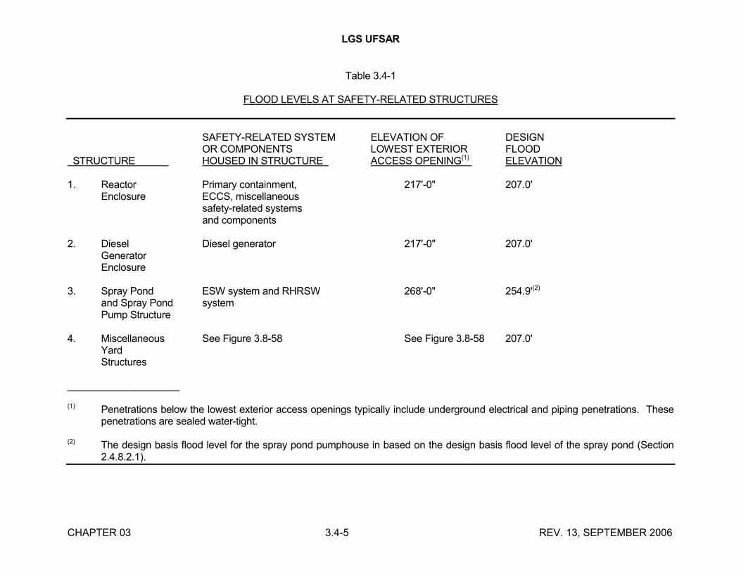
LGS UFSAR
CHAPTER 03 3.4-5 REV. 13, SEPTEMBER 2006
Table 3.4-1
FLOOD LEVELS AT SAFETY-RELATED STRUCTURES
SAFETY-RELATED SYSTEM ELEVATION OF DESIGNOR COMPONENTS LOWEST EXTERIOR FLOOD
STRUCTURE HOUSED IN STRUCTURE ACCESS OPENING(1) ELEVATION
1. Reactor Primary containment, 217'-0" 207.0'Enclosure ECCS, miscellaneous
safety-related systemsand components
2. Diesel Diesel generator 217'-0" 207.0'GeneratorEnclosure
3. Spray Pond ESW system and RHRSW 268'-0" 254.9'(2)
and Spray Pond systemPump Structure
4. Miscellaneous See Figure 3.8-58 See Figure 3.8-58 207.0'YardStructures
____________________
(1) Penetrations below the lowest exterior access openings typically include underground electrical and piping penetrations. These penetrations are sealed water-tight.
(2) The design basis flood level for the spray pond pumphouse in based on the design basis flood level of the spray pond (Section2.4.8.2.1).
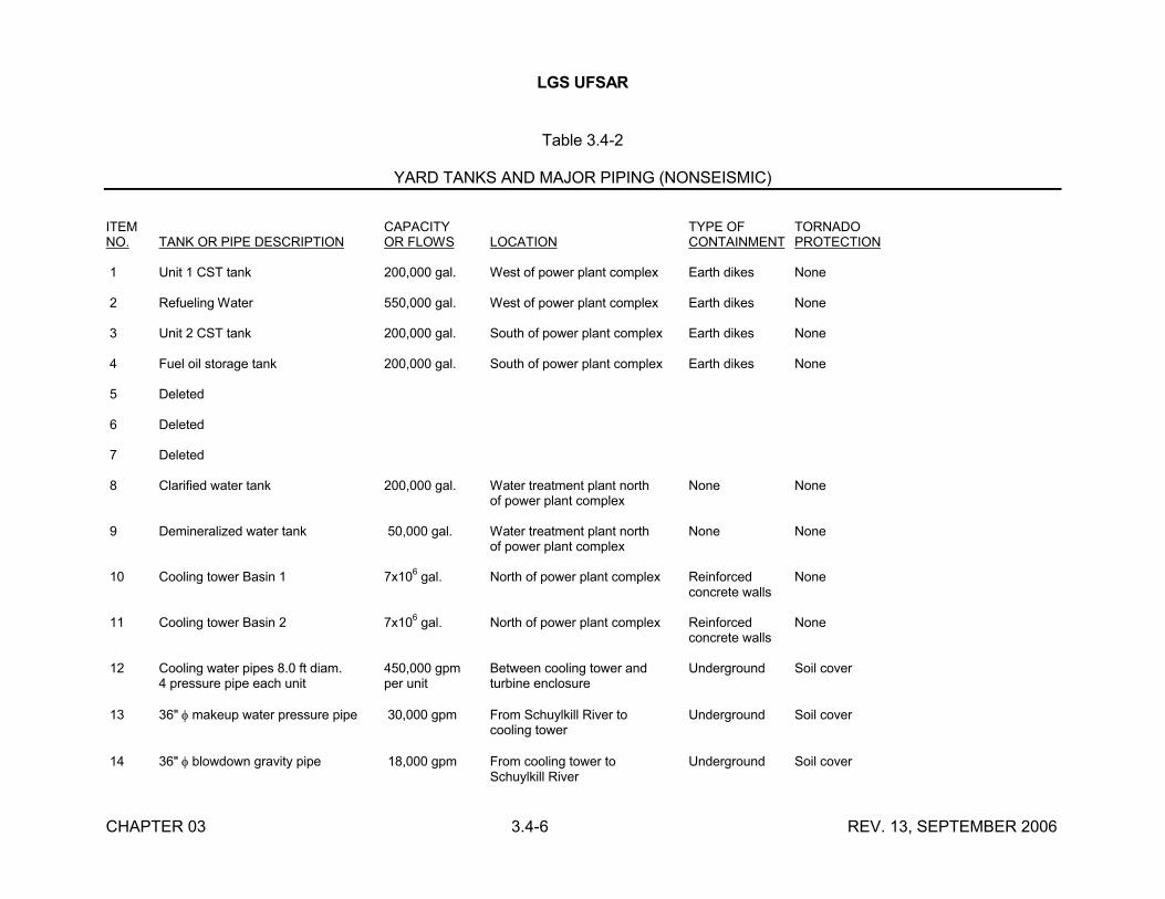
LGS UFSAR
CHAPTER 03 3.4-6 REV. 13, SEPTEMBER 2006
Table 3.4-2
YARD TANKS AND MAJOR PIPING (NONSEISMIC)
ITEM CAPACITY TYPE OF TORNADONO. TANK OR PIPE DESCRIPTION OR FLOWS LOCATION CONTAINMENT PROTECTION
1 Unit 1 CST tank 200,000 gal. West of power plant complex Earth dikes None
2 Refueling Water 550,000 gal. West of power plant complex Earth dikes None
3 Unit 2 CST tank 200,000 gal. South of power plant complex Earth dikes None
4 Fuel oil storage tank 200,000 gal. South of power plant complex Earth dikes None
5 Deleted
6 Deleted
7 Deleted
8 Clarified water tank 200,000 gal. Water treatment plant north None Noneof power plant complex
9 Demineralized water tank 50,000 gal. Water treatment plant north None Noneof power plant complex
10 Cooling tower Basin 1 7x10⁶
gal. North of power plant complex Reinforced Noneconcrete walls
11 Cooling tower Basin 2 7x10⁶
gal. North of power plant complex Reinforced Noneconcrete walls
12 Cooling water pipes 8.0 ft diam. 450,000 gpm Between cooling tower and Underground Soil cover4 pressure pipe each unit per unit turbine enclosure
13 36" makeup water pressure pipe 30,000 gpm From Schuylkill River to Underground Soil covercooling tower
14 36" blowdown gravity pipe 18,000 gpm From cooling tower to Underground Soil coverSchuylkill River
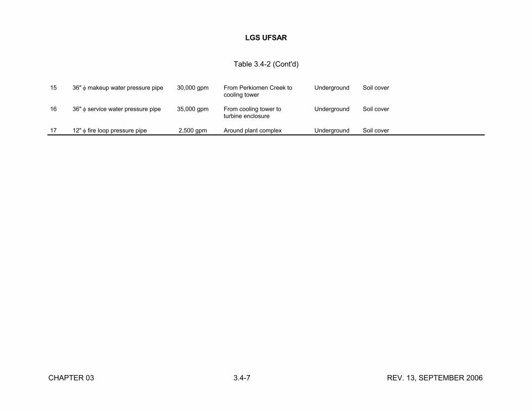
LGS UFSAR
CHAPTER 03 3.4-7 REV. 13, SEPTEMBER 2006
Table 3.4-2 (Cont'd)
15 36" makeup water pressure pipe 30,000 gpm From Perkiomen Creek to Underground Soil covercooling tower
16 36" service water pressure pipe 35,000 gpm From cooling tower to Underground Soil coverturbine enclosure
17 12" fire loop pressure pipe 2,500 gpm Around plant complex Underground Soil cover
LGS UFSAR
CHAPTER 03 3.5-1 REV. 18, SEPTEMBER 2016
3.5 MISSILE PROTECTION
Where possible, the seismic Category I and safety-related structures, equipment, and systems are protected from missiles through basic station component arrangement so that the missile does not cause the failure of these structures, equipment, or systems. Where it is impossible to provide protection through plant layout, suitable physical barriers are provided to isolate the missile or to shield the critical system or component. Also, redundant seismic Category I components are suitably protected so that a single missile cannot simultaneously damage a critical system component and its backup system. Missile protection provides for either safe operation or shutdown during all operating conditions, operational transients, and postulated accident conditions. Table 3.2-1 provides a tabulation of safety-related structures, systems, and components, along with their applicable seismic category and quality group classification.
3.5.1 MISSILE SELECTION AND DESCRIPTION
3.5.1.1 Internally Generated Missiles (Outside Primary Containment)
There are three general sources of postulated missiles outside the primary containment:
a. Rotating component failure missiles
b. Pressurized component failure missiles
c. Gravitationally generated missiles
3.5.1.1.1 Rotating Component Failure Missiles
The systems located outside the primary containment have been examined to identify and classify potential missiles. Redundant equipment is normally located in different areas of the plant or separated by walls so that a single missile from a rotating mass does not damage both redundant systems.
Catastrophic failure of rotating equipment such as pumps, fans, and compressors leading to the generation of missiles is not considered credible. Massive and rapid failure of these components is unlikely because of the conservative design, material characteristics, inspections, quality control during fabrication and erection, and prudent operation as applied to the particular component.
Additionally, the bases for considering it unlikely for rotating components, other than those identified in this section, to break through their casings and adversely impact safety-related equipment are the following:
A review of event reports on file at the Nuclear Safety Information Center, Oak Ridge National Laboratory, concerning failures of fans and missile generation indicated that a few fan failures have resulted in generation of missiles in safety-related areas of a nuclear facility. Small pump failures resulting in generation of missiles are considered more improbable than fan failures resulting in generation of missiles because pump casings are generally thicker than fan casings and pump speeds are generally lower than fan speeds. Even in the unlikely event that a rotating component does break through its casing, much of the component's kinetic energy would be dissipated in moving through the casing, thereby decreasing the probability of the component adversely
LGS UFSAR
CHAPTER 03 3.5-2 REV. 18, SEPTEMBER 2016
damaging a safety-related component. Therefore, generation of secondary missiles from the internally generated missiles described above is not considered credible. It is an even lower probability that a rotating component would adversely affect redundant safety-related systems because redundant equipment is generally located in different areas or separated by barriers.
Large pumps, such as the RHR and CS pumps, are installed so that the impeller section is surrounded by concrete; additionally, these pumps are located in separate compartments. Therefore, they are not considered a missile hazard to other systems.
Missiles from HPCI or RCIC turbines would be contained by the walls of their compartments that form suitable barriers so that no other systems can be affected by a HPCI or RCIC turbine failure.
Other rotating equipment is not considered to constitute missile hazards because of its small size and/or the unlikelihood that it could move its rotating components through its housing. A review of the analyses of internally generated missiles performed for Palo Verde and San Onofre verified that postulated missiles from pumps and fans (e.g., a pump impeller or fan blade) typically do not have sufficient energy to penetrate the component casings. Because LGS uses pumps and fans that are generally designed and constructed in accordance with the same recognized industry codes and standards as those installed at Palo Verde and San Onofre, the results of the rigorous structural analyses conducted for those plants are indicative of the integrity of LGS equipment.
It was further verified that no internally generated missiles will cause loss of function of any system required for safe shutdown. The plant arrangement was reviewed to ensure that all essential systems or components are either remote from or separated by adequate barriers from potential missile sources.
In any case where a direct path exists between a potential missile source and equipment required for safe shutdown, potential missiles cannot impact more than a single component; therefore redundant equipment will be available to effect safe shutdown.
All HVAC fans located in safety-related enclosures are listed in Table 3.5-6, along with the reason why they are not credible missiles that could adversely affect redundant equipment needed for safe shutdown. For many fans, there are barriers that separate the potential fan blade missiles from essential systems. These barriers consist of walls, floors, and ceilings that totally enclose the potential missile and are sufficiently thick to prevent spalling. All redundant fans needed for safe shutdown are separated by adequate barriers. Class I seismic duct-work of a thickness substantially greater than normal duct-work is utilized in safety-related areas that have duct-work, which should preclude escape of a potential missile from connecting duct-work.
A review was also made of the fan installation drawings to ensure no inlet conditions to fans existed that could result in operating conditions that would impose cyclical fatigue on fan blades resulting in blade cracks. No such conditions exist.
The only fan blades that have the potential for damaging redundant components needed for safe shutdown, if they escape through their casing, are the drywell area unit cooler fans. A study was performed for these fans which demonstrated that the fan blades do not have sufficient kinetic energy to penetrate their casings. In addition, a complete physical inspection of all drywell unit cooler fan blades for blade angle, verification of proper torque on blade retaining bolts, and lock
LGS UFSAR
CHAPTER 03 3.5-3 REV. 18, SEPTEMBER 2016
wiring of the bolts by the manufacturer's representative was conducted to ensure that no blades would loosen during operation. This inspection is documented in the quality records.
3.5.1.1.2 Pressurized Component Failure Missiles
The following are potential internal missiles from pressurized equipment:
a. Valve bonnets
b. Valve stems
c. Temperature detectors
d. Nuts and bolts
Pressurized components in systems where service pressure exceeds 275 psig are evaluated as to their potential for becoming missiles.
Most valves of ANSI 900 psig rating and above and most valves of 600 psig rating, constructed in accordance with ASME Section III, are pressure seal bonnet type valves. For pressure seal bonnet valves, valve bonnets are prevented from becoming missiles by the retaining ring, which would have to fail in shear, and by the yoke, which would capture the bonnet or reduce bonnet energy. Because of the highly conservative design of the retaining ring of these valves, bonnet ejection is highly improbable and hence the bonnets are not considered credible missiles.
The remaining valves of ANSI rating 900 psig and below are valves with bolted bonnets. Valve bonnets are prevented from becoming missiles by limiting stresses in the bonnet-to-body bolting material by requirements set forth in the ASME Section III and by designing flanges in accordance with applicable code requirements. Even if bolt failure were to occur, the likelihood of all bolts experiencing simultaneous complete severance failure is remote. The widespread use of valves with bolted bonnets and the low historical incidence of complete severance failure of bonnets confirm that bolted valve bonnets need not be considered as credible missiles.
Valve stems are not considered potential missiles if at least one feature in addition to the stem threads is included in their design to prevent ejection. Valves with back-seats are prevented from becoming missiles by this feature. In addition, air or motor-operated valve stems are effectively restrained by the valve operators.
Temperature or other detectors installed on piping or in wells are considered highly improbable missiles, since a complete and sudden failure of a circumferential weld is needed for a detector to become a missile.
Nuts, bolts, nut and bolt combinations, and nut and stud combinations have little stored energy and thus are of no concern as potential missiles.
In addition, high pressure gas cylinders and accumulators are not considered credible internally generated missiles impacting on redundant safety-related equipment for the following reasons:
LGS UFSAR
CHAPTER 03 3.5-4 REV. 18, SEPTEMBER 2016
a. All accumulators located in areas that contain safety-related equipment are listed in Table 3.5-3, along with the maximum pressure and temperature at which they operate. These accumulators have low stresses and operate in the "moderate energy" range. Therefore, any failures would not be of concern for missile generation.
b. Safety-related gas cylinders and accumulators are seismically supported, which ensures that they will not become gravity-generated missiles during design basis conditions. Nonsafety-related cylinders and accumulators are seismically restrained if they are located in the vicinity of safety-related components.
c. High pressure gas (H2, O2, N2, Kr) cylinders meet the manufacturing and test requirements of the DOT standards, 49CFR178.37, Specification 3AA and ICC standards. Vessel wall thickness requirements of both standards are comparable to ASME Section III, Class 3 requirements. Because of this highly conservative design, any failure of these cylinders that would cause them to become missiles is highly improbable.
d. Halon gas cylinders used in the fire protection system are located in the turbine enclosure and are isolated from safety-related equipment.
3.5.1.1.3 Gravitationally Generated Missiles
Installed equipment and components in safety-related plant areas outside containment are designed and installed so that they would not present gravitational missile hazards to safety-related structures, systems, or components during or after an SSE. This is achieved for safety-related equipment by seismic Category I design and installation (in accordance with Regulatory Guide 1.29 criteria) and for nonsafety-related equipment by seismic Category IIA design and installation (Section 3.2). Nonpermanently installed equipment is either removed from the safety-related areas, adequately separated from safety-related components, or secured in place before reactor operation to ensure that it would not present a missile hazard.
The information requested in the generic letter dated December 22, 1980 regarding conformance to the criteria contained in NUREG-0612, "Control of Heavy Loads at Nuclear Power Plants" is provided in Reference 9.1-1.
3.5.1.2 Internally Generated Missiles (Inside Containment)
There are three general sources of postulated missiles inside the primary containment:
a. Rotating component failure missiles
b. Pressurized component failure missiles
c. Gravitationally generated missiles
3.5.1.2.1 Rotating Component Failure Missiles
LGS UFSAR
CHAPTER 03 3.5-5 REV. 18, SEPTEMBER 2016
The most substantial piece of NSSS rotating equipment is the recirculation pump and motor. This potential missile source is covered in detail in Reference 3.5-1.
It is concluded in Reference 3.5-1 that destructive pump overspeed can result in certain types of missiles. A careful examination of shaft and coupling failures shows that the fragments do not result in damage to the containment or to vital equipment.
a. Low energy missiles (kinetic energy less than 1,000 ft-lbs):
Low energy level missiles may be created at motor speeds of 300% of rated through failure of the end structure of the rotor. The structure consists of the retaining ring, the end ring, and the fans. Missiles potentially generated in this manner would strike the overhanging ends of the stator coils, the stator coil bracing, support structures, and two walls of ½ inch thick steel plate. Due to the ability of these structures to absorb energy, it is concluded that missiles would not escape this structure. It is at this point that frictional forces would tend to bring the overspeed sequence to a stop.
b. Medium energy missiles (kinetic energy less than 20,000 ft-lbs):
In the postulated event that the body of the rotor bursts, medium energy missiles could be created. The likelihood that these missiles would escape the motor is considered less than the likelihood of escape for the low energy missiles described above, due to the additional amount of material constraining missile escape, such as the stator coils and stator frame directly adjacent to the rotor.
c. The motor as a potential missile:
Since bolting is capable of carrying greater torque loads than the pump shaft, pump bolt failure is precluded. Since pump shaft failure decouples the rotor for the overspeed driving blowdown force, only those cases with peak torques less than that required to fail the pump shaft (five times rated) have the capability to drive the motor to overspeed. When missile generation probabilities are considered along with a discussion of the actual load-bearing capabilities of the system, it is evident that these considerations support the conclusion that it is unrealistic that the motor would become a missile.
It is concluded that the other rotating components inside the containment, such as fans, do not have sufficient energy to move the masses of their rotating parts through the housings in which they are contained and therefore are not considered missile hazards. Additional evaluation and discussion of the potential for rotating equipment generated missiles to impact safety-related equipment is provided in Section 3.5.1.1.1 above.
3.5.1.2.2 Pressurized Component Failure Missiles
It is concluded that potential internal missiles inside the containment from pressurized components are not considered credible for the same reasons listed in Section 3.5.1.1.2.
3.5.1.2.3 Gravitationally Generated Missiles
Installed equipment and components in the containment are designed so that they would not present gravitational missile hazards to safety-related structures, systems, or components during or
LGS UFSAR
CHAPTER 03 3.5-6 REV. 18, SEPTEMBER 2016
after an SSE. This is achieved for safety-related equipment by seismic Category I design and fornonsafety-related equipment by seismic Category IIA design, as discussed in Section 3.2. Nonpermanently installed equipment is either removed from the containment or secured in place before reactor operation to ensure that it does not become dislodged and present a missile hazard.
3.5.1.3 Turbine Missiles
The turbine inspection program which is being implemented in Section 10.2.3.6 uses a probabilistic approach for scheduling the inspection and replacement of the low pressure turbine rotors with shrunk-on discs. This turbine inspection program is based upon the missile probability analysis methodology in Reference 3.5-15 and the probabilistic approach established in NUREG 1048 (Reference 3.5-14). The approach in Reference 3.5-14 was found acceptable by the NRC for use in establishing maintenance and inspection schedules for specific turbine systems including the original Main Turbines installed at Limerick Generating Station. As a result of the replacement of the original Main Turbines, the missile probability analysis methodology in Reference 3.5-15 has been adopted to maintain the probabilistic approach to determine the inspection program for the installed turbine system. The overspeed protection system test interval was determined by Reference 3.5-16 in accordance with the missile probability analysis methodology in Reference 3.5-15.
The intent of the program is to ensure that the probability of a turbine generating a missile is maintained less than 1x10⁻⁵ per year. The program takes into account specific turbine wheel operating conditions, material properties, results of periodic in service inspections, and other factors. The program's determination of missile probability is based on the probabilities of individual parameters which may lead to the generation of the turbine missile. As a result, the program can facilitate evaluations of the effects of changes in any parameter. Table 3.5-9, Turbine System Reliability Criteria, has been extracted from table U.1 of Reference 3.5-14, for use with anunfavorably oriented turbine. The probability of unacceptable damage from turbine missile will be maintained at less than or equal to 1x10⁻⁷ per year.
Schedules for future inspection and replacement of low pressure turbine rotors with shrunk-on discs will be based on the probabilistic approach.
3.5.1.4 Missiles Generated by Natural Phenomena
Only tornado-generated missiles have been considered. Missiles used in the design and assessment of structures and openings are listed in Table 3.5-4. All safety-related structures, systems, and components listed in Table 3.2-1 were reviewed for adequacy against tornado-generated missiles listed in Table 3.5-4. These safety-related structures, systems, and components are designed either to resist tornado missiles in accordance with Reference 3.5-6 or are protected by these tornado-resistant enclosures. The structures designed for these tornado missiles and the systems protected are listed in Table 3.3-2. Table 3.5-8 provides information on the characteristics of these barriers. Additionally, ESW and RHRSW systems yard piping is protected by burial and separation of redundant loops.
The exterior walls and roof thicknesses have been evaluated for the tornado-resistant enclosures listed in Table 3.3-2 and are capable of withstanding all of the missiles listed in Table 3.5-4. The 4000 psi strength concrete walls and roofs have minimum thicknesses of 24 inches and 18 inches, respectively (Table 3.5-8). This exceeds the minimum acceptable missile barrier thickness requirements specified in table 1 of SRP (NUREG-0800, July 1981) section 3.5.3.
LGS UFSAR
CHAPTER 03 3.5-7 REV. 18, SEPTEMBER 2016
Where necessary to protect safety-related components, the doors in these enclosures have been designed to withstand the 1 inch steel rod, the utility pole, the 6 inch steel pipe, and the 12 inch pipe in addition to the original three design basis missiles. This design is in accordance with the SRP (NUREG-0800, July 1981).
The probability of any of the above tornado missiles penetrating any of the openings and structures (not specifically designed to be resistant to the above missiles) and adversely impacting safety-related components, such that safe shutdown is prevented, is considered low for the following reasons:
a. The total area of the nontornado-resistant features that have safety-related components located behind them is extremely small compared to the total area of the tornado-resistant portions of the enclosures.
b. To penetrate a nontornado-resistant feature and travel a sufficient distance to impact a safety-related component, a missile would need to strike the feature at a perpendicular angle.
c. Much of the missile's kinetic energy would be dissipated in breaking through the nontornado-resistant feature, which reduces the possibility of the missile adversely damaging a safety-related component even if it strikes one.
d. Redundant safety-related components are normally located in different areas of the plant or yard or are separated by walls so that a single tornado missile would not damage both redundant systems.
Evaluations have been carried out considering all seven tornado missiles listed in Table 3.5-4 and their penetration/impact on the openings and nontornado designed structures of the plant including manhole covers and valve pit roofs. Even though some singular safety-related components may be affected, damage would not occur to all redundant systems, and safe shutdown could be achieved even when assuming an additional single active failure.
LGS is in conformance with Regulatory Guide 1.117 regarding systems to be protected from tornado missiles except as discussed below where unacceptable damage to unprotected spray networks is not considered credible.
As described in Section 9.2.6, the ultimate heat sink at LGS is an excavated spray pond with a surface area of 9.9 acres. Four spray networks, each having 50% capacity for shutdown of two units, are provided.
Details of the spray pond excavation and finished grading are shown in Figures 3.8-55, 3.8-56, and 3.8-57. The general arrangement of the spray pond, spray networks, and spray pond pump structure is shown in Figure 9.2-6. The layout of the spray networks is shown in M-384.
As discussed in Section 3.5.1.4, all essential structures, systems, and components related to the ESW system, RHRSW system, and the UHS are protected from the effects of tornadoes and tornado missiles. Protection of the spray networks from tornado missiles is provided by location of
LGS UFSAR
CHAPTER 03 3.5-8 REV. 18, SEPTEMBER 2016
the network piping and sprays below the surrounding grade and by physical separation of the networks:
a. In all but the spillway area, the surrounding grade is in excess of el 260' while the top of the sprays are at el 258' and the spray network piping is between el 253'-5" and el 256'-8".
b. The closest branches of adjacent spray networks are separated by 65 ft.
c. The supply piping to adjacent networks is separated by 215 ft.
d. The networks are located at a minimum distance of 72 ft from the edge of the pond.
The use of elevational differences and physical separation to provide protection of the spray pond networks from tornado missiles is justified by the following considerations:
a. Only two spray networks are required for the safe shutdown of both units.
b. The only active failure that can compromise the operability of a spray network is failure of its supply valve (HV-012-032A, B, C or D). These valves may be manually operated to isolate damaged networks or to initiate the use of undamaged networks if their controls or motors are inoperable.
c. The physical arrangement of the spray networks precludes the possibility that large missiles can damage more than one spray network due to trajectory considerations. Multiple missiles of sufficient energy and distribution to substantially damage multiple networks are unlikely. Network piping varies in size from the 30 inch diameter supply headers to the 2 inch diameter piping at the extreme ends of the distribution branches. Network piping wall thickness varies from 0.337-0.500 inch.
d. The loss of some sprays in a network does not result in substantial loss of heat removal capability for the entire network (each network contains 240 spray nozzles).
e. The design thermal performance of the spray pond is based on conservative design values of initial pond temperature and meteorology as described in Section 9.2.6.4. For all expected conditions, the margin in thermal performance would be considerably greater than the 10% margin demonstrated under design conditions. In fact, for average meteorological conditions, a single spray network is sufficient for the removal of the heat rejected from both units for at least a 24 hour period.
f. Interconnections are provided that allow the use of the cooling towers as a heat sink for ESW and RHRSW systems. Such operation may be initiated from the control room or locally by manual operation.
It is unlikely that tornado winds would compromise the heat removal capability of the spray pond networks, or the cooling towers, to the extent that safe shutdown of the units would be affected. The spray networks have been designed to withstand design basis tornado winds. While not specifically designed to withstand design
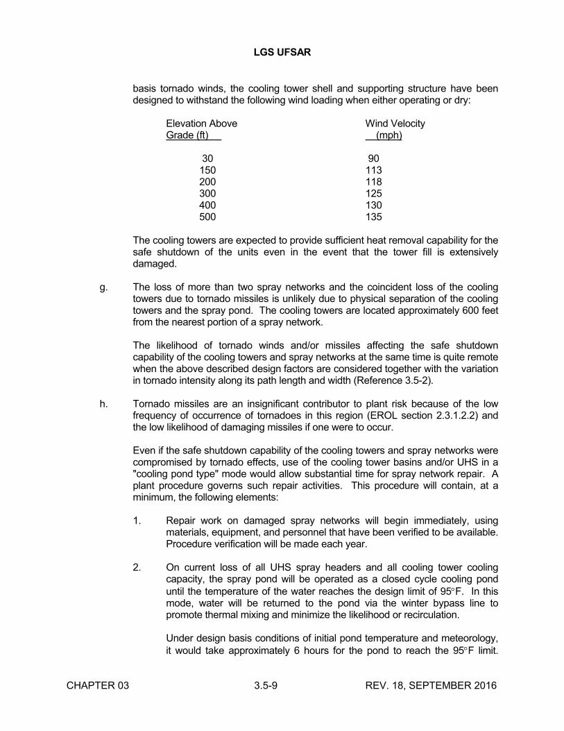
LGS UFSAR
CHAPTER 03 3.5-9 REV. 18, SEPTEMBER 2016
basis tornado winds, the cooling tower shell and supporting structure have been designed to withstand the following wind loading when either operating or dry:
Elevation Above Wind VelocityGrade (ft) (mph)
30 90150 113200 118300 125400 130500 135
The cooling towers are expected to provide sufficient heat removal capability for the safe shutdown of the units even in the event that the tower fill is extensively damaged.
g. The loss of more than two spray networks and the coincident loss of the cooling towers due to tornado missiles is unlikely due to physical separation of the cooling towers and the spray pond. The cooling towers are located approximately 600 feet from the nearest portion of a spray network.
The likelihood of tornado winds and/or missiles affecting the safe shutdown capability of the cooling towers and spray networks at the same time is quite remote when the above described design factors are considered together with the variation in tornado intensity along its path length and width (Reference 3.5-2).
h. Tornado missiles are an insignificant contributor to plant risk because of the low frequency of occurrence of tornadoes in this region (EROL section 2.3.1.2.2) and the low likelihood of damaging missiles if one were to occur.
Even if the safe shutdown capability of the cooling towers and spray networks were compromised by tornado effects, use of the cooling tower basins and/or UHS in a "cooling pond type" mode would allow substantial time for spray network repair. A plant procedure governs such repair activities. This procedure will contain, at a minimum, the following elements:
1. Repair work on damaged spray networks will begin immediately, using materials, equipment, and personnel that have been verified to be available. Procedure verification will be made each year.
2. On current loss of all UHS spray headers and all cooling tower cooling capacity, the spray pond will be operated as a closed cycle cooling pond until the temperature of the water reaches the design limit of 95F. In this mode, water will be returned to the pond via the winter bypass line to promote thermal mixing and minimize the likelihood or recirculation.
Under design basis conditions of initial pond temperature and meteorology, it would take approximately 6 hours for the pond to reach the 95F limit.
LGS UFSAR
CHAPTER 03 3.5-10 REV. 18, SEPTEMBER 2016
Under average conditions, it would take approximately 10 hours to reach this limit. Both numbers are for two-unit, full power operation. For single-unit operation, these times would be approximately 12 hours and 20 hours, respectively. The heat rejection rate can be further reduced by depressurizing the reactor at a slower rate than 100oF/hr assumed in the design basis analysis.
3. When the pond reaches the design temperature limit, the sluice gates between the spray pond pumphouse wet wells and the spray pond will be closed. Water will be released from the cooling tower basins into the wet wells and pumped through the plant to service the required heat loads. The water will be returned to the spray pond and allowed to discharge over the blowdown weir and storm spillway.
The two cooling tower basins contain a total of 14 million gallons. If it is conservatively assumed that only one-half of this volume of water is available, there is sufficient water to provide makeup for the ESW and RHRSW pumps, operating in a once-through mode, for an additional 4 hours. In the unlikely event that the cooling tower basin walls have failed due to tornado missiles, the additional time of 4 hours would not be available. However, the spray pond PRA demonstrates that it is extremely improbable that the four spray pond networks would not be available.
4. Sufficient makeup water can be supplied to the cooling tower basins to sustain continuous operation in this mode for a number of sources as described in Item i.
i. The Schuylkill River makeup pumphouse is located approximately 1500 ft from the nearest cooling tower, making it unlikely that the pumphouse would be damaged by a tornado that would also compromise the spray pond networks and the cooling towers. The pumphouse is powered from the 2300 V plant services switchgear. The switchgear can be fed using offsite power from either of the two plant substation via underground lines. The two substations are approximately 2000 ft apart, making it highly unlikely that both substation would be disabled by a tornado that would also compromise the spray pond networks and the cooling towers.
While an additional source of water is available from the pump station to provide the Perkiomen makeup supply located approximately 8 miles from the plant site, no reliance is being placed on this intake for the purpose of safety analysis nor the safety licensing basis for the facility.
If existing sources of makeup cannot be made available in a timely manner, makeup will be provided using available portable pumps of required size and capacity to pump water from the Schuylkill River to the spray pond pumphouse wet wells. The water would be pumped via a tie-in to the existing underground water pipeline from the Schuylkill River intake pumphouse to the cooling tower basins. It would flow via gravity to the pump pits. If a tie-in to the existing pipeline is not possible, the water would be pumped directly to the wetwell through temporary
LGS UFSAR
CHAPTER 03 3.5-11 REV. 18, SEPTEMBER 2016
lines. The portable pumps that would be used are either licensee owned or rental pumps. The required pumps will be verified to be available on an annual basis.
j. Plant EOPs address the various contingency actions available to the operators to deal with degraded UHS conditions. As indicated in the above discussions, substantial time is available for corrective operator actions. If UHS capability should be lost for such a period of time that conditions degraded considerably, the EOPswould direct the use of equipment that would achieve a safe stable state regardless of UHS capability.
3.5.1.5 Missiles Generated by Events Near the Site
The safety-related structures, systems, and components were reviewed for adequacy against missiles externally generated by railroad explosions. The safety-related facilities are either designed to resist the externally generated missiles in accordance with Reference 3.5-6 or are protected by these missile-resistant barriers. The barriers designed to resist externally generated missiles and the corresponding systems and components protected by these missile barriers are listed in Table 3.5-7.
The nearest possible train explosion accident and its consequent missiles are considered to be the most severe missile-generating event that could occur near the site. The postulated missiles resulting from such an accident considered in the design of structures protecting safety-related systems are listed in Table 3.5-5. Missiles resulting from truck, industrial, and pipeline explosions would be less severe and therefore are not considered. As demonstrated in Section 2.2, there is no potential for missiles from ship or barge explosions or military installations. Descriptions of the railroad, its location relative to the plant, the railroad explosion, and explosions from other sources are given in Section 2.2.
3.5.1.6 Aircraft Hazards
The safety-related structures, systems, and components were reviewed for adequacy against missiles externally generated by aircraft accidents. The safety-related facilities are either designed to resist the externally generated missiles in accordance with Reference 3.5-6 or are protected by these missile-resistant barriers. The barriers designed to resist externally generated missiles and the corresponding systems and components protected by these missile barriers are listed in Table 3.5-7.
Airports and aircraft activity in the vicinity of the site are discussed in Section 2.2.2. Based on the airport and aircraft information provided in Section 2.2.2, an analysis has been performed using the methodology of SRP section 3.5.1.6 to demonstrate that the probability of an aircraft accident causing damage to safety-related equipment or structures sufficient to result in radiological consequences that are a significant fraction of 10CFR50.67 exposure guidelines is lower than the acceptance criteria of SRP section 3.5.1.6.
3.5.1.6.1 Design of Safety-Related Structures
Aircraft operating or capable of operating out of nearby airports are listed in Table 3.5-1. Based on the estimated maximum kinetic energy at impact and corresponding local damage to concrete elements, the Learjet is determined as the design aircraft for the design of safety-related structures.
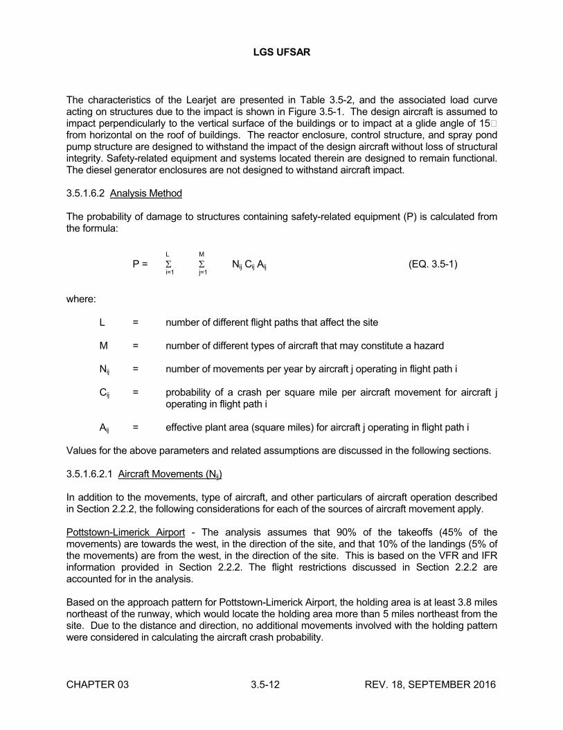
LGS UFSAR
CHAPTER 03 3.5-12 REV. 18, SEPTEMBER 2016
The characteristics of the Learjet are presented in Table 3.5-2, and the associated load curve acting on structures due to the impact is shown in Figure 3.5-1. The design aircraft is assumed to impact perpendicularly to the vertical surface of the buildings or to impact at a glide angle of 15�from horizontal on the roof of buildings. The reactor enclosure, control structure, and spray pond pump structure are designed to withstand the impact of the design aircraft without loss of structural integrity. Safety-related equipment and systems located therein are designed to remain functional. The diesel generator enclosures are not designed to withstand aircraft impact.
3.5.1.6.2 Analysis Method
The probability of damage to structures containing safety-related equipment (P) is calculated from the formula:
L M
P = Nij Cij Aij (EQ. 3.5-1)i=1 j=1
where:
L = number of different flight paths that affect the site
M = number of different types of aircraft that may constitute a hazard
Nij = number of movements per year by aircraft j operating in flight path i
Cij = probability of a crash per square mile per aircraft movement for aircraft j operating in flight path i
Aij = effective plant area (square miles) for aircraft j operating in flight path i
Values for the above parameters and related assumptions are discussed in the following sections.
3.5.1.6.2.1 Aircraft Movements (Nij)
In addition to the movements, type of aircraft, and other particulars of aircraft operation described in Section 2.2.2, the following considerations for each of the sources of aircraft movement apply.
Pottstown-Limerick Airport - The analysis assumes that 90% of the takeoffs (45% of the movements) are towards the west, in the direction of the site, and that 10% of the landings (5% of the movements) are from the west, in the direction of the site. This is based on the VFR and IFR information provided in Section 2.2.2. The flight restrictions discussed in Section 2.2.2 are accounted for in the analysis.
Based on the approach pattern for Pottstown-Limerick Airport, the holding area is at least 3.8 miles northeast of the runway, which would locate the holding area more than 5 miles northeast from the site. Due to the distance and direction, no additional movements involved with the holding pattern were considered in calculating the aircraft crash probability.
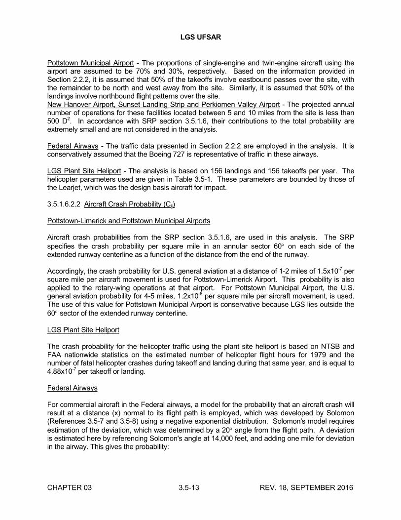
LGS UFSAR
CHAPTER 03 3.5-13 REV. 18, SEPTEMBER 2016
Pottstown Municipal Airport - The proportions of single-engine and twin-engine aircraft using the airport are assumed to be 70% and 30%, respectively. Based on the information provided in Section 2.2.2, it is assumed that 50% of the takeoffs involve eastbound passes over the site, with the remainder to be north and west away from the site. Similarly, it is assumed that 50% of the landings involve northbound flight patterns over the site.New Hanover Airport, Sunset Landing Strip and Perkiomen Valley Airport - The projected annual number of operations for these facilities located between 5 and 10 miles from the site is less than 500 D2. In accordance with SRP section 3.5.1.6, their contributions to the total probability are extremely small and are not considered in the analysis.
Federal Airways - The traffic data presented in Section 2.2.2 are employed in the analysis. It is conservatively assumed that the Boeing 727 is representative of traffic in these airways.
LGS Plant Site Heliport - The analysis is based on 156 landings and 156 takeoffs per year. The helicopter parameters used are given in Table 3.5-1. These parameters are bounded by those of the Learjet, which was the design basis aircraft for impact.
3.5.1.6.2.2 Aircraft Crash Probability (Cij)
Pottstown-Limerick and Pottstown Municipal Airports
Aircraft crash probabilities from the SRP section 3.5.1.6, are used in this analysis. The SRP specifies the crash probability per square mile in an annular sector 60 on each side of the extended runway centerline as a function of the distance from the end of the runway.
Accordingly, the crash probability for U.S. general aviation at a distance of 1-2 miles of 1.5x10⁻⁷ per square mile per aircraft movement is used for Pottstown-Limerick Airport. This probability is also applied to the rotary-wing operations at that airport. For Pottstown Municipal Airport, the U.S. general aviation probability for 4-5 miles, 1.2x10⁻⁸ per square mile per aircraft movement, is used. The use of this value for Pottstown Municipal Airport is conservative because LGS lies outside the 60 sector of the extended runway centerline.
LGS Plant Site Heliport
The crash probability for the helicopter traffic using the plant site heliport is based on NTSB and FAA nationwide statistics on the estimated number of helicopter flight hours for 1979 and the number of fatal helicopter crashes during takeoff and landing during that same year, and is equal to 4.88x10⁻⁷ per takeoff or landing.
Federal Airways
For commercial aircraft in the Federal airways, a model for the probability that an aircraft crash will result at a distance (x) normal to its flight path is employed, which was developed by Solomon (References 3.5-7 and 3.5-8) using a negative exponential distribution. Solomon's model requires estimation of the deviation, which was determined by a 20 angle from the flight path. A deviation is estimated here by referencing Solomon's angle at 14,000 feet, and adding one mile for deviation in the airway. This gives the probability:
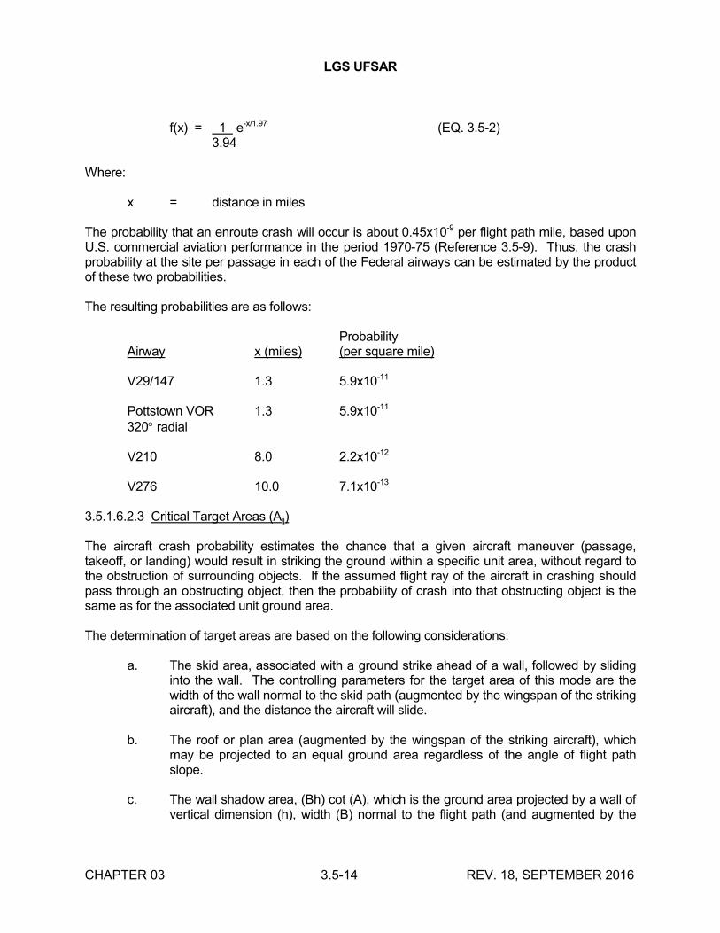
LGS UFSAR
CHAPTER 03 3.5-14 REV. 18, SEPTEMBER 2016
f(x) = 1 e-x/1.97 (EQ. 3.5-2)3.94
Where:
x = distance in miles
The probability that an enroute crash will occur is about 0.45x10⁻⁹ per flight path mile, based upon U.S. commercial aviation performance in the period 1970-75 (Reference 3.5-9). Thus, the crash probability at the site per passage in each of the Federal airways can be estimated by the product of these two probabilities.
The resulting probabilities are as follows:
ProbabilityAirway x (miles) (per square mile)
V29/147 1.3 5.9x10⁻¹¹
Pottstown VOR 1.3 5.9x10⁻¹¹
320 radial
V210 8.0 2.2x10⁻¹²
V276 10.0 7.1x10⁻¹³
3.5.1.6.2.3 Critical Target Areas (Aij)
The aircraft crash probability estimates the chance that a given aircraft maneuver (passage, takeoff, or landing) would result in striking the ground within a specific unit area, without regard to the obstruction of surrounding objects. If the assumed flight ray of the aircraft in crashing should pass through an obstructing object, then the probability of crash into that obstructing object is the same as for the associated unit ground area.
The determination of target areas are based on the following considerations:
a. The skid area, associated with a ground strike ahead of a wall, followed by sliding into the wall. The controlling parameters for the target area of this mode are the width of the wall normal to the skid path (augmented by the wingspan of the striking aircraft), and the distance the aircraft will slide.
b. The roof or plan area (augmented by the wingspan of the striking aircraft), which may be projected to an equal ground area regardless of the angle of flight path slope.
c. The wall shadow area, (Bh) cot (A), which is the ground area projected by a wall of vertical dimension (h), width (B) normal to the flight path (and augmented by the
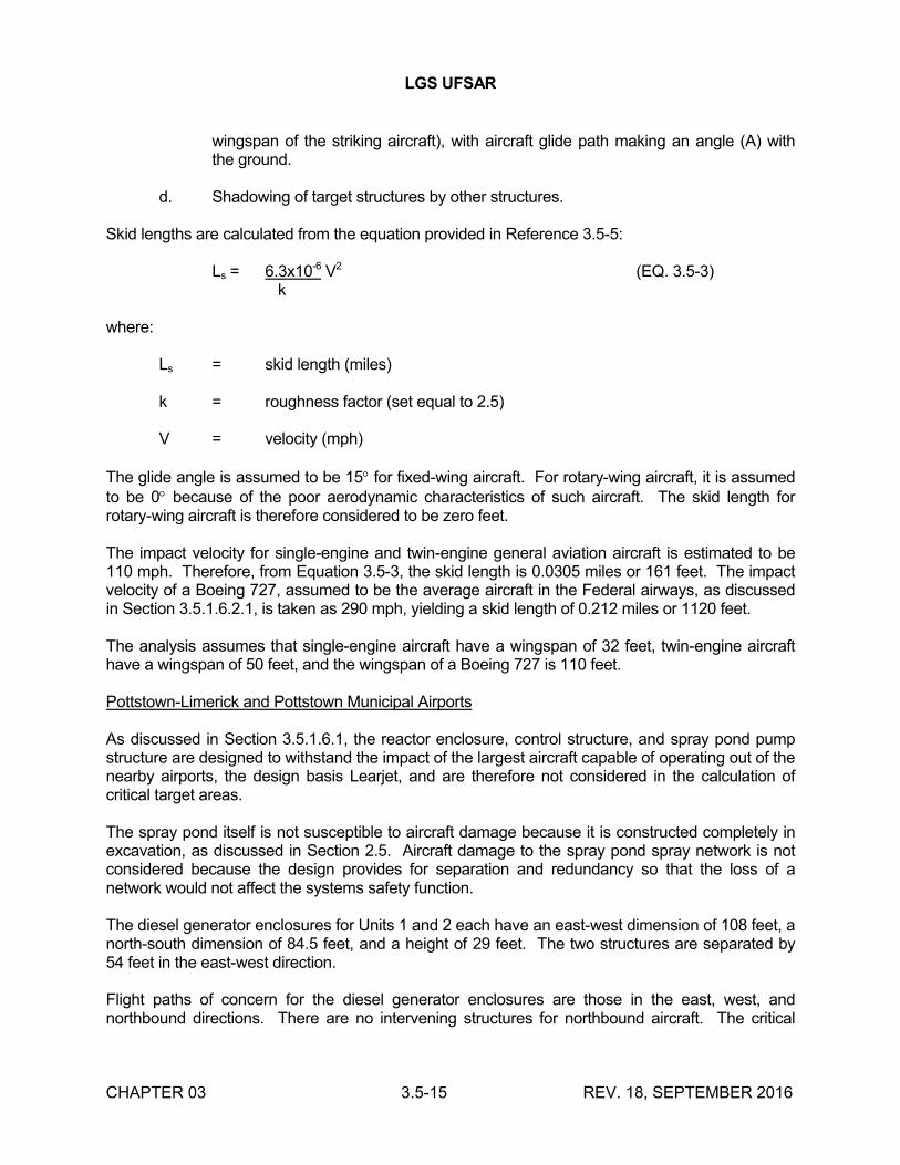
LGS UFSAR
CHAPTER 03 3.5-15 REV. 18, SEPTEMBER 2016
wingspan of the striking aircraft), with aircraft glide path making an angle (A) with the ground.
d. Shadowing of target structures by other structures.
Skid lengths are calculated from the equation provided in Reference 3.5-5:
Ls = 6.3x10⁻⁶ V2 (EQ. 3.5-3) k
where:
Ls = skid length (miles)
k = roughness factor (set equal to 2.5)
V = velocity (mph)
The glide angle is assumed to be 15 for fixed-wing aircraft. For rotary-wing aircraft, it is assumed to be 0 because of the poor aerodynamic characteristics of such aircraft. The skid length for rotary-wing aircraft is therefore considered to be zero feet.
The impact velocity for single-engine and twin-engine general aviation aircraft is estimated to be 110 mph. Therefore, from Equation 3.5-3, the skid length is 0.0305 miles or 161 feet. The impact velocity of a Boeing 727, assumed to be the average aircraft in the Federal airways, as discussed in Section 3.5.1.6.2.1, is taken as 290 mph, yielding a skid length of 0.212 miles or 1120 feet.
The analysis assumes that single-engine aircraft have a wingspan of 32 feet, twin-engine aircraft have a wingspan of 50 feet, and the wingspan of a Boeing 727 is 110 feet.
Pottstown-Limerick and Pottstown Municipal Airports
As discussed in Section 3.5.1.6.1, the reactor enclosure, control structure, and spray pond pump structure are designed to withstand the impact of the largest aircraft capable of operating out of the nearby airports, the design basis Learjet, and are therefore not considered in the calculation of critical target areas.
The spray pond itself is not susceptible to aircraft damage because it is constructed completely in excavation, as discussed in Section 2.5. Aircraft damage to the spray pond spray network is not considered because the design provides for separation and redundancy so that the loss of a network would not affect the systems safety function.
The diesel generator enclosures for Units 1 and 2 each have an east-west dimension of 108 feet, a north-south dimension of 84.5 feet, and a height of 29 feet. The two structures are separated by 54 feet in the east-west direction.
Flight paths of concern for the diesel generator enclosures are those in the east, west, and northbound directions. There are no intervening structures for northbound aircraft. The critical
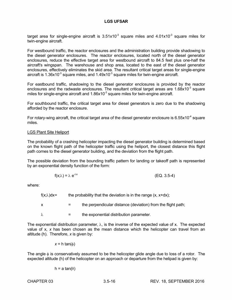
LGS UFSAR
CHAPTER 03 3.5-16 REV. 18, SEPTEMBER 2016
target area for single-engine aircraft is 3.51x10⁻³ square miles and 4.01x10⁻³ square miles for twin-engine aircraft.
For westbound traffic, the reactor enclosures and the administration building provide shadowing to the diesel generator enclosures. The reactor enclosures, located north of the diesel generator enclosures, reduce the effective target area for westbound aircraft to 84.5 feet plus one-half the aircraft's wingspan. The warehouse and shop area, located to the east of the diesel generator enclosures, effectively eliminates the skid area. The resultant critical target areas for single-engine aircraft is 1.36x10⁻³ square miles, and 1.49x10⁻³ square miles for twin-engine aircraft.
For eastbound traffic, shadowing to the diesel generator enclosures is provided by the reactor enclosures and the radwaste enclosures. The resultant critical target areas are 1.68x10⁻³ square miles for single-engine aircraft and 1.86x10⁻³ square miles for twin-engine aircraft.
For southbound traffic, the critical target area for diesel generators is zero due to the shadowing afforded by the reactor enclosure.
For rotary-wing aircraft, the critical target area of the diesel generator enclosure is 6.55x10⁻⁴ square miles.
LGS Plant Site Heliport
The probability of a crashing helicopter impacting the diesel generator building is determined based on the known flight path of the helicopter traffic using the heliport, the closest distance this flight path comes to the diesel generator building, and the deviation from the flight path.
The possible deviation from the bounding traffic pattern for landing or takeoff path is represented by an exponential density function of the form:
f(x;) = e-x (EQ. 3.5-4)
where:
f(x;)dx= the probability that the deviation is in the range (x, x+dx);
x = the perpendicular distance (deviation) from the flight path;
= the exponential distribution parameter.
The exponential distribution parameter, , is the inverse of the expected value of x. The expected value of x, x has been chosen as the mean distance which the helicopter can travel from an altitude (h). Therefore, x is given by:
x = h tan()
The angle is conservatively assumed to be the helicopter glide angle due to loss of a rotor. The expected altitude (h) of the helicopter on an approach or departure from the helipad is given by:
h = a tan()
LGS UFSAR
CHAPTER 03 3.5-17 REV. 18, SEPTEMBER 2016
The angle , the approach angle, is conservatively assumed to be 15, and (a) is the distance from the helipad.
Using the above information, is given by:
= 1 a tan() tan()
The probability of impacting at a distance greater than (d) perpendicular to the flight path on one side of the flight path, is then given by the cumulative distribution function:
P(>d) = 0.5 e-|d|
The probability of impact on the diesel generator enclosure is greatest when the helicopter is on the approach path 675 feet from the helipad and 1,100 feet laterally from the diesel generator enclosure. The average conditional probability of impacting the diesel generator enclosure from a crash for all three types of helicopters given in Table 3.5-1 is 7.66x10⁻⁴.
Federal Airways
The reactor enclosure, control structure, and diesel generator enclosures are considered in the calculation of critical target areas. The spray pond pump structure represents only about 5% of the total target areas of safety-related structures, and its contribution to the overall probability is considered negligible.
The spray pond is not susceptible to aircraft damage because it is constructed completely in excavation, as discussed in Section 2.5. Aircraft damage to the spray pond spray network is not considered because the design provides for separation and redundancy so that the loss of a network would not affect the systems safety function.
Because the majority of airway traffic is northbound, the analysis considers the south faces of the diesel generator enclosures and the reactor enclosures as the target area. The calculated critical target area is 3.33x10⁻² square miles.
3.5.1.6.3 Crash Probabilities
Based on the given data and assumptions regarding the number of aircraft movements (Nij), aircraft crash probability (Cij), and critical target areas for the plant (Aij), the probability of an aircraft striking to safety-related structures has been calculated.
For operations out of the Pottstown Municipal Airport, the probability of an aircraft striking the diesel generator enclosures is given by:
P = 1.2x10⁻⁸ [1.73Ne + 1.40Nw + 3.66Nn]x10-3 yr-1 (EQ. 3.5-5)
where:
Ne = number of eastbound movements over the site
LGS UFSAR
CHAPTER 03 3.5-18 REV. 18, SEPTEMBER 2016
Nw = number of westbound movements over the site
Nn = number of northbound movements over the site
and the target areas have been weighted to reflect the proportion of single and twin-engine traffic.
For
Ne = Nn = 4000; Nw = 0,
this yields a crash probability of 2.59x10⁻⁷ per year.
Similarly, for operations out of the Pottstown-Limerick Airport, the probability is given by:
P = 1.5x10-7 · [1.73Ne + 1.40Nw + 3.66Nn + 0.655Nr]x10-3 yr-1
(EQ. 3.5-6)
where:
Nr = number of rotary-wing operations over the site from the Pottstown-Limerick Airport.
For
Ne = 1500, Nw = 13500, Nn = 0; Nr = 0,
this yields a crash probability of 3.2x10⁻⁶ per year.
For operations out of the LGS plant site heliport, the probability of a helicopter striking the diesel generator enclosure is the product of the number of takeoffs and landings per year, the probability of the helicopter crashing during takeoff or landing, and the probability that the crashing helicopter will impact the diesel generator building:
P = 312 · 4.88x10-7 · 7.66x10-4
= 1.17x10⁻⁷ per year
The probability of an aircraft in one of the airways near thesite striking the diesel generator enclosures, or the reactorenclosures is given by:
P = [(8395 + 20240)(590) + (46355)(22) + (4745)(7.1)]x10-13 · 0.0333
= 5.98x10⁻⁸ yr-1 (EQ. 3.5-7)
3.5.1.6.4 Probability of Aircraft Strike Resulting in Unacceptable Consequences
LGS UFSAR
CHAPTER 03 3.5-19 REV. 18, SEPTEMBER 2016
Given the aircraft impact resistant design of all safety-related structures except the diesel generator enclosures, an aircraft strike could jeopardize safe shutdown capability or have potential offsite dose consequences only under the following scenarios:
(1) The impacting aircraft is larger in size than the design basis aircraft described in Section 3.5.1.6.1, and the impact causes structural failure and/or damage to systems required to achieve or maintain safe shutdown, resulting in the possibility of offsite consequences in excess of 10CFR50.67 guidelines.
(2) The impacting aircraft strikes a diesel generator enclosure, damaging more than 2 diesel generators, thereby leaving that unit dependent on offsite power for achieving and maintaining shutdown. During the period required to return at least 2 diesel generators to service, a complete loss of offsite power occurs, which leaves the affected unit dependent on its Class 1E battery system to achieve and/or maintain safe shutdown. If offsite power is not restored before the batteries are exhausted, inadequate core cooling and offsite radiological consequences in excess of 10CFR50.67 guidelines could result.
The probabilities of scenarios (1) and (2) occurring are calculated as follows:
Scenario 1: Impact By Aircraft Larger Than Design Basis Aircraft
This scenario is credible only for aircraft in Federal airways. It is conservatively assumed for this analysis that the impact of any aircraft using the Federal airways causes damage such that offsite radiological consequences in excess of 10CFR50.67 occur. The probability of such an impact causing unacceptable radiological consequences is therefore equal to the crash probability of an aircraft in one of the airways near the site, shown in Section 3.5.1.6.3 to be 5.98x10⁻⁸ per year.
Scenario 2: Diesel Generator Damage Caused By Impact Of Design Basis or Smaller Aircraft
The probability that aircraft operating out of the Pottstown- Limerick Airport, the Pottstown Municipal Airport, and the LGS plant site heliport will impact the diesel generator enclosures is shown in Section 3.5.1.6.3 to be 3.2x10⁻⁶ per year, 2.59x10⁻⁷ per year, and 1.17x10⁻⁷ per year respectively, or a total probability,
Pac = 3.58x10⁻⁶ per year.
Given that each unit's diesel generator enclosure is 108 ft wide, and that each of the 4 diesels per unit is located in a separate compartment inside that unit's diesel generator enclosure, it is highly unlikely that the impact of a typical twin-engine plane with a wingspan of 50 ft could disable more than 2 diesel generators.
In addition, only 2 of a unit's 4 diesel generators are required to achieve and maintain safe shutdown, assuming no additional failures. Despite the above, it is conservatively assumed for this analysis that any aircraft impacting a diesel generator enclosure disables all 4 diesel generators therein, leaving that unit dependent on offsite power for achieving and maintaining safe shutdown. It is further conservatively assumed that immediate action would be taken to repair the diesel generators, and that at least 2 of the 4 would be restored to service 1 year following the aircraft impact.
LGS UFSAR
CHAPTER 03 3.5-20 REV. 18, SEPTEMBER 2016
Using the methodology of appendix III of Reference 3.5-10, the probability, PLOOP, that a LOOP occurs (during the 1 year in which the affected unit would have no onsite ac backup power) is conservatively determined to be 0.2 per year, thus leaving that unit dependent on its Class 1E dc battery system to achieve or maintain shutdown.
It has been shown (Reference 3.5-11) that under loss of all ac power (station blackout) conditions, in a BWR with electrical and mechanical system designs similar to LGS, the batteries could power all systems required to achieve or maintain safe shutdown for as long as 7 hours before exhaustion. For this analysis, it is conservatively assumed that battery exhaustion occurs 4 hours after the LOOP occurs, after which inadequate core cooling and offsite radiological consequences in excess of 10CFR50.67 could occur.
Again using the methodology of appendix III of Reference 3.5-10, the probability, P4, that at least one offsite source of power is not returned to service within 4 hours following the LOOP is conservatively estimated to be 0.05 per LOOP event.
Based on the preceding information, the probability per year of an aircraft crash that disables one unit's diesel generators, leading to offsite radiological consequences in excess of 10CFR50.67 dose limits, can be calculated as follows:
P = PAC · PLOOP · P4
= (3.58x10⁻⁶ yr-1)(0.2 yr-1)(0.05) (EQ. 3.5-8)
= 3.58x10⁻⁸ per year.
Conclusion
The total probability per year of an aircraft impact resulting in offsite radiological consequences in excess of 10CFR50.67 dose limits is the sum of the probabilities associated with Scenarios 1 and 2, or 9.56x10⁻⁸ per year. Realistically, this probability would be lower.
It is concluded that the acceptance criteria of SRP section 3.5.1.6 are met.
3.5.2 SYSTEMS TO BE PROTECTED
Safety-related systems and structures are reviewed for missile protection and are listed in Table 3.2-1. Structures and barriers designed to provide for protection from external missiles are discussed in Section 3.5.1 and listed in Table 3.5-7, and their characteristics are listed in Table 3.5-8.
As discussed in Section 3.5.1, the only postulated internally generated missiles are those arising from failure of the HPCI and RCIC pump turbines. In this case, the pump-room walls are designed as barriers to isolate such missiles from other safety-related components.
The locations of safety-related equipment and the arrangement of the various compartments are shown in drawings M-110, M-111, M-112, M-113, M-114, M-115, M-116, M-117, M-118, M-119, M-120, M-121,M-122, M-123, M-124, M-125, M-126, M-127, M-128, M-129, M-130, M-131, M-132,
LGS UFSAR
CHAPTER 03 3.5-21 REV. 18, SEPTEMBER 2016
M-133, M-134, M-135, M-136, M-137, M-138, M-140, M-141, M-142, M-143, M-144, M-145, M-146, M-388, M-389, and M-390.
3.5.3 BARRIER DESIGN PROCEDURES
Safety-related components necessary for safe shutdown and housed in the Category I structures are adequately protected against tornado missiles. The characteristics of structural wall barriers for Category I structures are shown in Table 3.5-8. Figure 3.5-2 shows typical reinforcement provided in the southernmost reactor enclosure concrete wall barrier.
The structures and barriers are designed to resist missile hazards in accordance with the procedures detailed in Reference 3.5-6.
The procedures include:
a. Prediction of local damage (penetration, perforation, and spalling) in the impact area, including estimation of the depth of penetration
b. Estimation of the barrier thickness required to prevent perforation
c. Prediction of the overall structural response of the barrier, and portions thereof, to missile impact
Tornado missiles, as described in Table 3.5-4, were considered as deformable upon impact, and the structures were considered as rigid targets. Eighteen inch thick concrete, with a compressive strength of 4000 psi, was used in concrete walls and roofs subject to tornado missile impact. This satisfies the penetration formulae for elements subject to missiles as specified in Reference 3.5-6.
The ESW and RHRSW piping located within the yard area are installed underground with adequate cover for missile protection. A detailed assessment of soil cover for Category I yard piping shows a minimum depth of 4 feet, with most soil coverings exceeding 6 feet. The 4 foot depth was found to be adequate for tornado missiles (Table 3.5-4) in accordance with the criteria set forth in Reference 3.5-3.
The physical routing of the piping and typical profiles showing soil cover and installation details are shown in Figure 2.5-37. The cementitious backfill for pipe bedding is shown in detail 3 of Figure 2.5-37. This backfill was used predominantly for Category I piping to provide additional missile protection. The properties of cementitious backfill are defined in Section 2.5.4.5.4. Figure 2.5-37 shows the 4 foot minimum depth dimension of soil cover for Category I yard piping.
Doors are designed for tornado missiles unless internal secondary barriers are provided to protect safety-related components. Louvers are not designed for tornado missiles; however, internal secondary barriers are provided to protect safety-related components which are located behind the louvers. Figure 3.5-3 shows a typical secondary barrier for the south wall of the diesel generator enclosure (concrete labyrinth behind the door) used for tornado missile protection.

LGS UFSAR
CHAPTER 03 3.5-22 REV. 18, SEPTEMBER 2016
3.5.4 REFERENCES
3.5-1 Letter, E.A. Hughes (GE) to R.C. DeYoung (NRC), "GE Recirculation Pump Potential Overspeed", (January 18, 1977).
3.5-2 NUREG/CR-2944, "Tornado Damage Risk Assessment", Reinhold & Ellingwood, Brookhaven National Lab, (September 1982).
3.5-3 "Depth Prediction for Earth-Penetrating Projectiles", Soil Mechanics and Foundation Division, ASCE, p. 6558, (May 1969).
3.5-4 "Probability of Missile Generation in General Electric Nuclear Turbines", GE Proprietary Report.
3.5-5 D.C. Gonyea, "An Analysis of the Energy of Hypothetical Wheel Missiles Escaping from Turbine Casings", GE Technical Information Series No. DF735L12, (February 1973).
3.5-6 "Design of Structures for Missile Impact", BC-TOP-9A, Revision 2, Bechtel Power Corporation, San Francisco, California, (September 1974).
3.5-7 Solomon, K.A., "Hazards Associated with Aircraft and Missiles", presented at American and Canadian Nuclear Society Meeting, Toronto, Canada, (June 1976).
3.5-8 Solomon, K.A., "Estimate of probability that an Aircraft will impact the PVNGS", NUS-1416, NUS Corp., (June 1975).
3.5-9 National Air Transportation Safety Board, "Annual Review of Aircraft Accident Data", (Published 1972 and annually thereafter).
3.5-10 ASH-1400, "Reactor Safety Study: An Assessment of Accident Risks in U.S. Commercial Nuclear Power Plants", NRC, (October 1975).
3.5-11 NUREG/CR-2182, Vol. I, "Station Blackout at Browns Ferry Unit One - Accident Sequence Analysis, Oak Ridge National Laboratory", (November 1981).
3.5-12 Barber, R.B., "Steel Road/Concrete Slab Impact Test (Experimental Simulation)", Bechtel Power Corporation, (October 1973).
3.5-13 F.A. Vasallo, "Missile Impact Testing of Reinforced Concrete Panels", prepared for Bechtel Power Corporation, Calspan Corp., (January 1975).
3.5-14 "Safety Evaluation Report Relates to the Operation of Hope Creek Generating Station", NUREG-1048, Supplement 6, (July 1986).
LGS UFSAR
CHAPTER 03 3.5-23 REV. 18, SEPTEMBER 2016
3.5-15 “Missile Analysis Report, Limerick Units 1 and 2," Siemens Energy, Inc., CT-27544, March 4, 2016 (including, as Appendix A: "Missile Probability Analysis Methodology for Limerick Generating Station, Units 1 and 2, with Siemens Retrofit Turbines” Siemens Power Corporation Engineering Report – ER-9605, Revision 2, June 18, 1997 - SIEMENS PROPRIETARY)
3.5-16 “Impact of Increasing Test Interval for Turbine Overspeed Protection System on Turbine Missile Probability,” MPR Associates Inc., MPR-2892 Revision 0, April 4, 2006
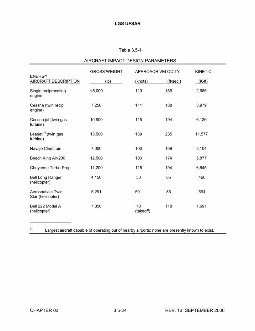
LGS UFSAR
CHAPTER 03 3.5-24 REV. 13, SEPTEMBER 2006
Table 3.5-1
AIRCRAFT IMPACT DESIGN PARAMETERS
GROSS WEIGHT APPROACH VELOCITY KINETIC ENERGYAIRCRAFT DESCRIPTION (lb) (knots) (ft/sec.) (K-ft)
Single reciprocating <5,000 110 186 2,686engine
Cessna (twin recip 7,250 111 188 3,979engine)
Cessna jet (twin gas 10,500 115 194 6,136turbine)
Learjet(1)
(twin gas 13,500 139 235 11,577turbine)
Navajo Chieftrain 7,000 100 169 3,104
Beech King Air-200 12,500 103 174 5,877
Cheyenne Turbo-Prop 11,200 115 194 6,545
Bell Long Ranger 4,150 50 85 466(helicopter)
Aerospatiale Twin 5,291 50 85 594Star (helicopter)
Bell 222 Model A 7,850 70 118 1,697(helicopter) (takeoff)
__________________
(1)Largest aircraft capable of operating out of nearby airports; none are presently known to exist.
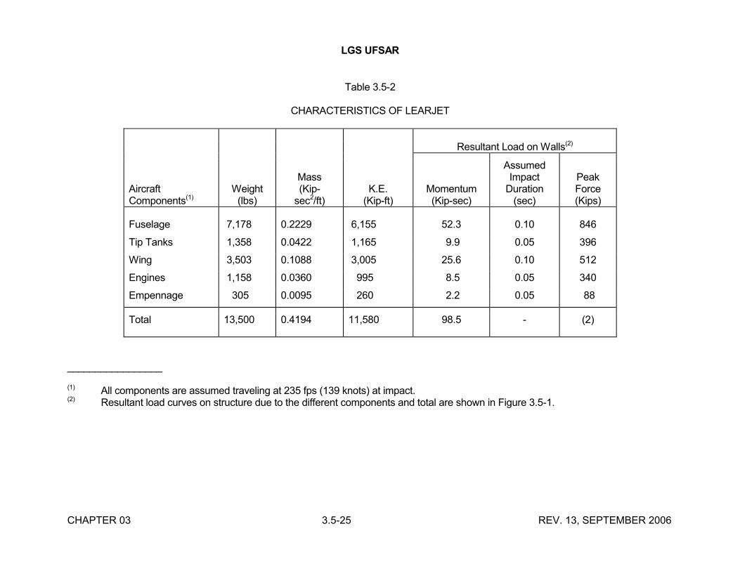
LGS UFSAR
CHAPTER 03 3.5-25 REV. 13, SEPTEMBER 2006
Table 3.5-2
CHARACTERISTICS OF LEARJET
Resultant Load on Walls(2)
AircraftComponents(1)
Weight(lbs)
Mass(Kip-
sec2/ft)K.E.
(Kip-ft)Momentum(Kip-sec)
AssumedImpact
Duration(sec)
PeakForce(Kips)
Fuselage 7,178 0.2229 6,155 52.3 0.10 846
Tip Tanks 1,358 0.0422 1,165 9.9 0.05 396
Wing 3,503 0.1088 3,005 25.6 0.10 512
Engines 1,158 0.0360 995 8.5 0.05 340
Empennage 305 0.0095 260 2.2 0.05 88
Total 13,500 0.4194 11,580 98.5 - (2)
_________________
(1) All components are assumed traveling at 235 fps (139 knots) at impact.(2) Resultant load curves on structure due to the different components and total are shown in Figure 3.5-1.
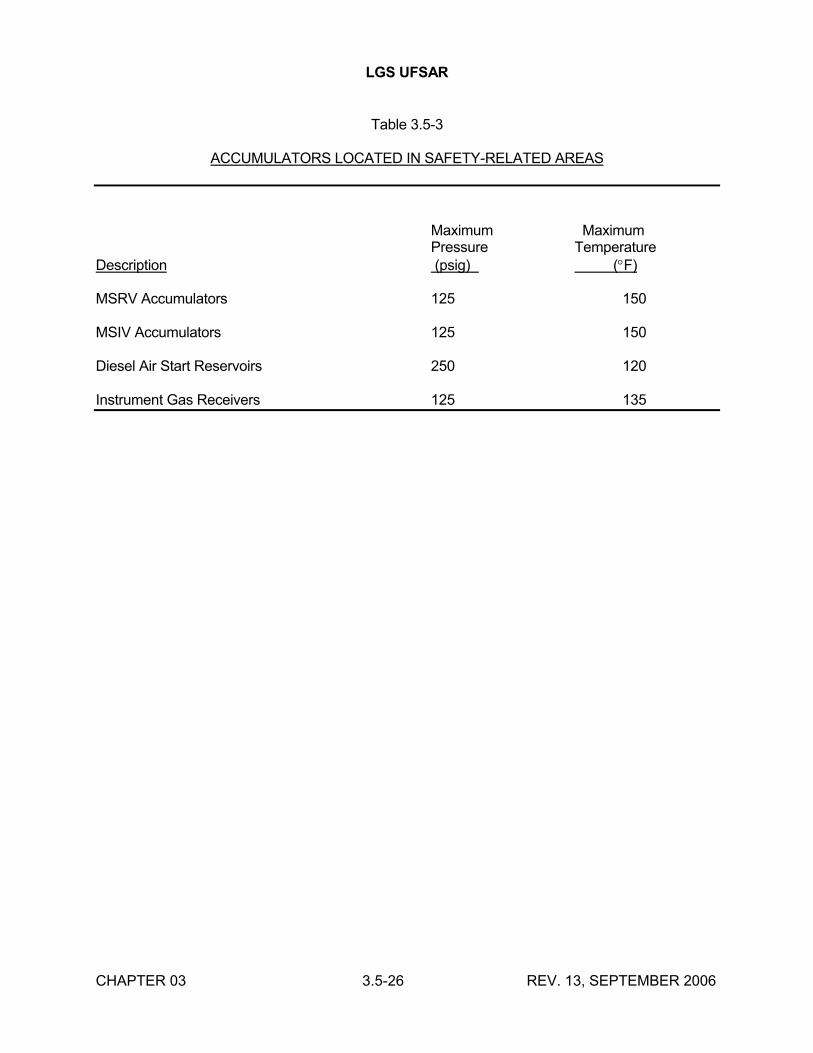
LGS UFSAR
CHAPTER 03 3.5-26 REV. 13, SEPTEMBER 2006
Table 3.5-3
ACCUMULATORS LOCATED IN SAFETY-RELATED AREAS
Maximum MaximumPressure Temperature
Description (psig) (F)
MSRV Accumulators 125 150
MSIV Accumulators 125 150
Diesel Air Start Reservoirs 250 120
Instrument Gas Receivers 125 135
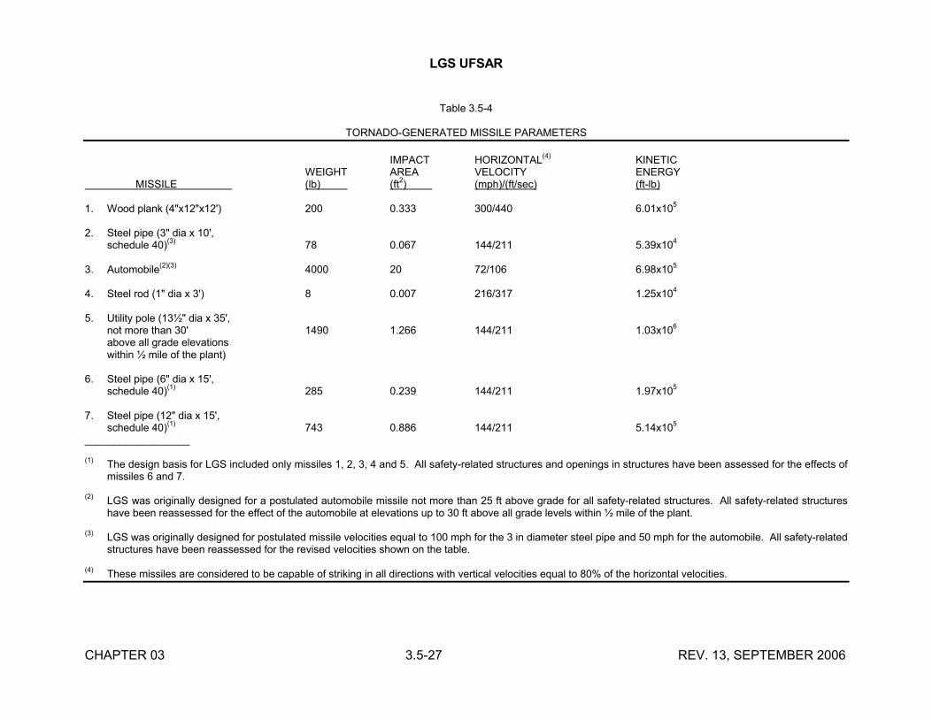
LGS UFSAR
CHAPTER 03 3.5-27 REV. 13, SEPTEMBER 2006
Table 3.5-4
TORNADO-GENERATED MISSILE PARAMETERS
IMPACT HORIZONTAL(4)
KINETICWEIGHT AREA VELOCITY ENERGY
MISSILE (lb) (ft2) (mph)/(ft/sec) (ft-lb)
1. Wood plank (4"x12"x12') 200 0.333 300/440 6.01x10⁵
2. Steel pipe (3" dia x 10',schedule 40)
(3)78 0.067 144/211 5.39x10
4
3. Automobile(2)(3)
4000 20 72/106 6.98x10⁵
4. Steel rod (1" dia x 3') 8 0.007 216/317 1.25x10⁴
5. Utility pole (13½" dia x 35',not more than 30' 1490 1.266 144/211 1.03x10
6
above all grade elevationswithin ½ mile of the plant)
6. Steel pipe (6" dia x 15',schedule 40)
(1)285 0.239 144/211 1.97x10
5
7. Steel pipe (12" dia x 15',schedule 40)
(1)743 0.886 144/211 5.14x10
5
__________________
(1)The design basis for LGS included only missiles 1, 2, 3, 4 and 5. All safety-related structures and openings in structures have been assessed for the effects of missiles 6 and 7.
(2)LGS was originally designed for a postulated automobile missile not more than 25 ft above grade for all safety-related structures. All safety-related structures have been reassessed for the effect of the automobile at elevations up to 30 ft above all grade levels within ½ mile of the plant.
(3)LGS was originally designed for postulated missile velocities equal to 100 mph for the 3 in diameter steel pipe and 50 mph for the automobile. All safety-related structures have been reassessed for the revised velocities shown on the table.
(4)These missiles are considered to be capable of striking in all directions with vertical velocities equal to 80% of the horizontal velocities.
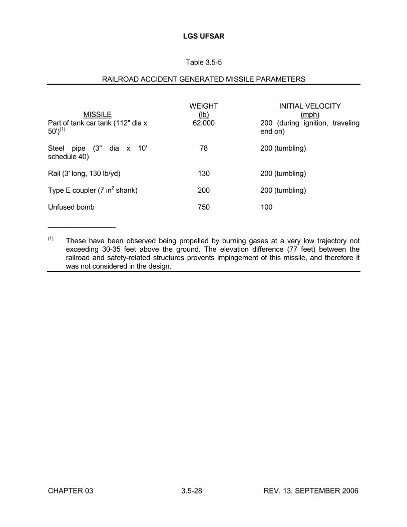
LGS UFSAR
CHAPTER 03 3.5-28 REV. 13, SEPTEMBER 2006
Table 3.5-5
RAILROAD ACCIDENT GENERATED MISSILE PARAMETERS
MISSILEWEIGHT
(lb)INITIAL VELOCITY
(mph)Part of tank car tank (112" dia x 50')(1)
62,000 200 (during ignition, traveling end on)
Steel pipe (3" dia x 10' schedule 40)
78 200 (tumbling)
Rail (3' long, 130 lb/yd) 130 200 (tumbling)
Type E coupler (7 in2 shank) 200 200 (tumbling)
Unfused bomb 750 100
_________________
(1) These have been observed being propelled by burning gases at a very low trajectory not exceeding 30-35 feet above the ground. The elevation difference (77 feet) between the railroad and safety-related structures prevents impingement of this missile, and therefore it was not considered in the design.
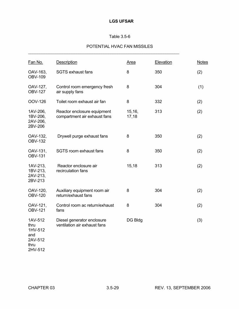
LGS UFSAR
CHAPTER 03 3.5-29 REV. 13, SEPTEMBER 2006
Table 3.5-6
POTENTIAL HVAC FAN MISSILES__________________________________________________________________
Fan No. Description Area Elevation Notes
OAV-163, SGTS exhaust fans 8 350 (2)OBV-109
OAV-127, Control room emergency fresh 8 304 (1)OBV-127 air supply fans
OOV-126 Toilet room exhaust air fan 8 332 (2)
1AV-206, Reactor enclosure equipment 15,16, 313 (2)1BV-206, compartment air exhaust fans 17,182AV-206,2BV-206
OAV-132, Drywell purge exhaust fans 8 350 (2)OBV-132
OAV-131, SGTS room exhaust fans 8 350 (2)OBV-131
1AV-213, Reactor enclosure air 15,18 313 (2)1BV-213, recirculation fans2AV-213,2BV-213
OAV-120, Auxiliary equipment room air 8 304 (2)OBV-120 return/exhaust fans
OAV-121, Control room ac return/exhaust 8 304 (2)OBV-121 fans
1AV-512 Diesel generator enclosure DG Bldg (3)thru ventilation air exhaust fans1HV-512and2AV-512thru2HV-512
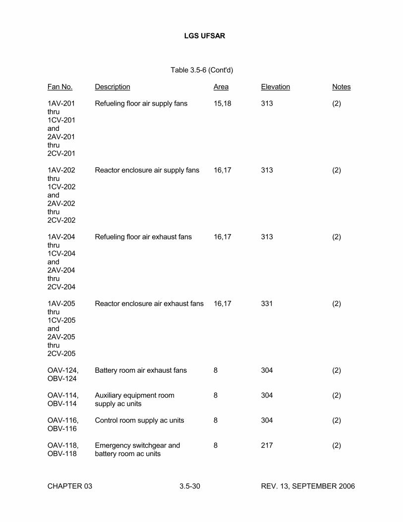
LGS UFSAR
CHAPTER 03 3.5-30 REV. 13, SEPTEMBER 2006
Table 3.5-6 (Cont'd)
Fan No. Description Area Elevation Notes
1AV-201 Refueling floor air supply fans 15,18 313 (2)thru1CV-201and2AV-201thru2CV-201
1AV-202 Reactor enclosure air supply fans 16,17 313 (2)thru1CV-202and2AV-202thru2CV-202
1AV-204 Refueling floor air exhaust fans 16,17 313 (2)thru1CV-204and2AV-204thru2CV-204
1AV-205 Reactor enclosure air exhaust fans 16,17 331 (2)thru1CV-205and2AV-205thru2CV-205
OAV-124, Battery room air exhaust fans 8 304 (2)OBV-124
OAV-114, Auxiliary equipment room 8 304 (2)OBV-114 supply ac units
OAV-116, Control room supply ac units 8 304 (2)OBV-116
OAV-118, Emergency switchgear and 8 217 (2)OBV-118 battery room ac units
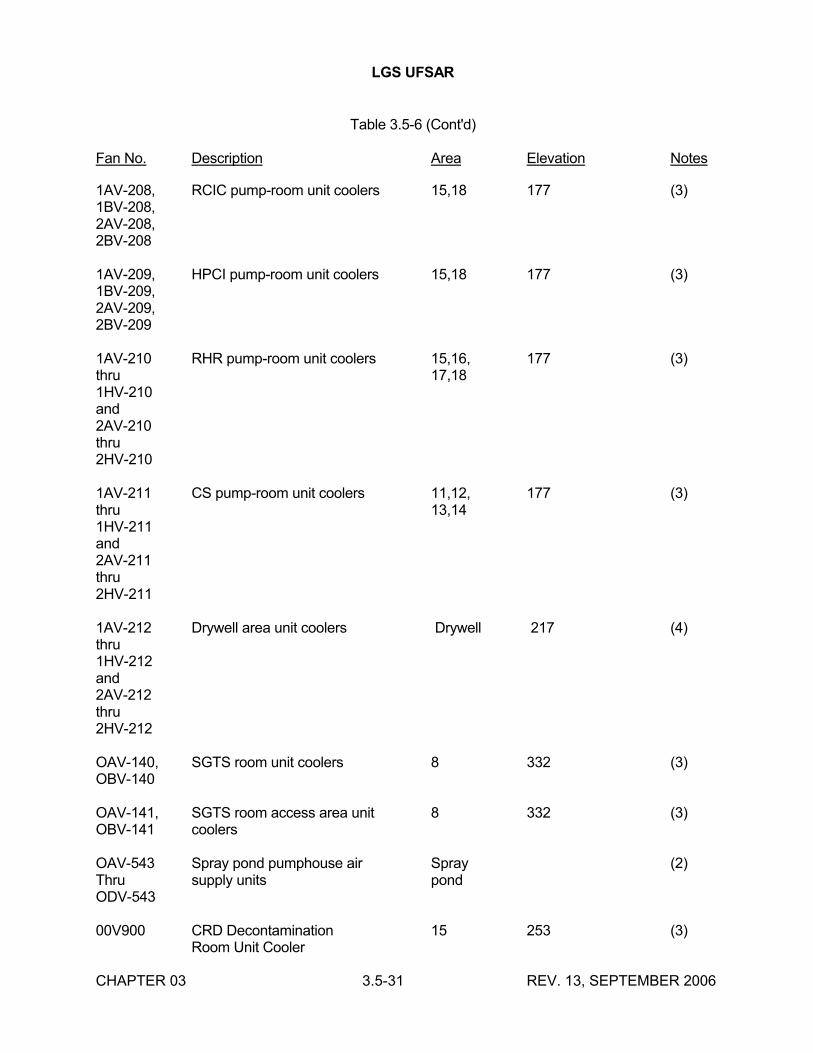
LGS UFSAR
CHAPTER 03 3.5-31 REV. 13, SEPTEMBER 2006
Table 3.5-6 (Cont'd)
Fan No. Description Area Elevation Notes
1AV-208, RCIC pump-room unit coolers 15,18 177 (3)1BV-208,2AV-208,2BV-208
1AV-209, HPCI pump-room unit coolers 15,18 177 (3)1BV-209,2AV-209,2BV-209
1AV-210 RHR pump-room unit coolers 15,16, 177 (3)thru 17,181HV-210and2AV-210thru2HV-210
1AV-211 CS pump-room unit coolers 11,12, 177 (3)thru 13,141HV-211and2AV-211thru2HV-211
1AV-212 Drywell area unit coolers Drywell 217 (4)thru1HV-212and2AV-212thru2HV-212
OAV-140, SGTS room unit coolers 8 332 (3)OBV-140
OAV-141, SGTS room access area unit 8 332 (3)OBV-141 coolers
OAV-543 Spray pond pumphouse air Spray (2)Thru supply units pondODV-543
00V900 CRD Decontamination 15 253 (3)Room Unit Cooler
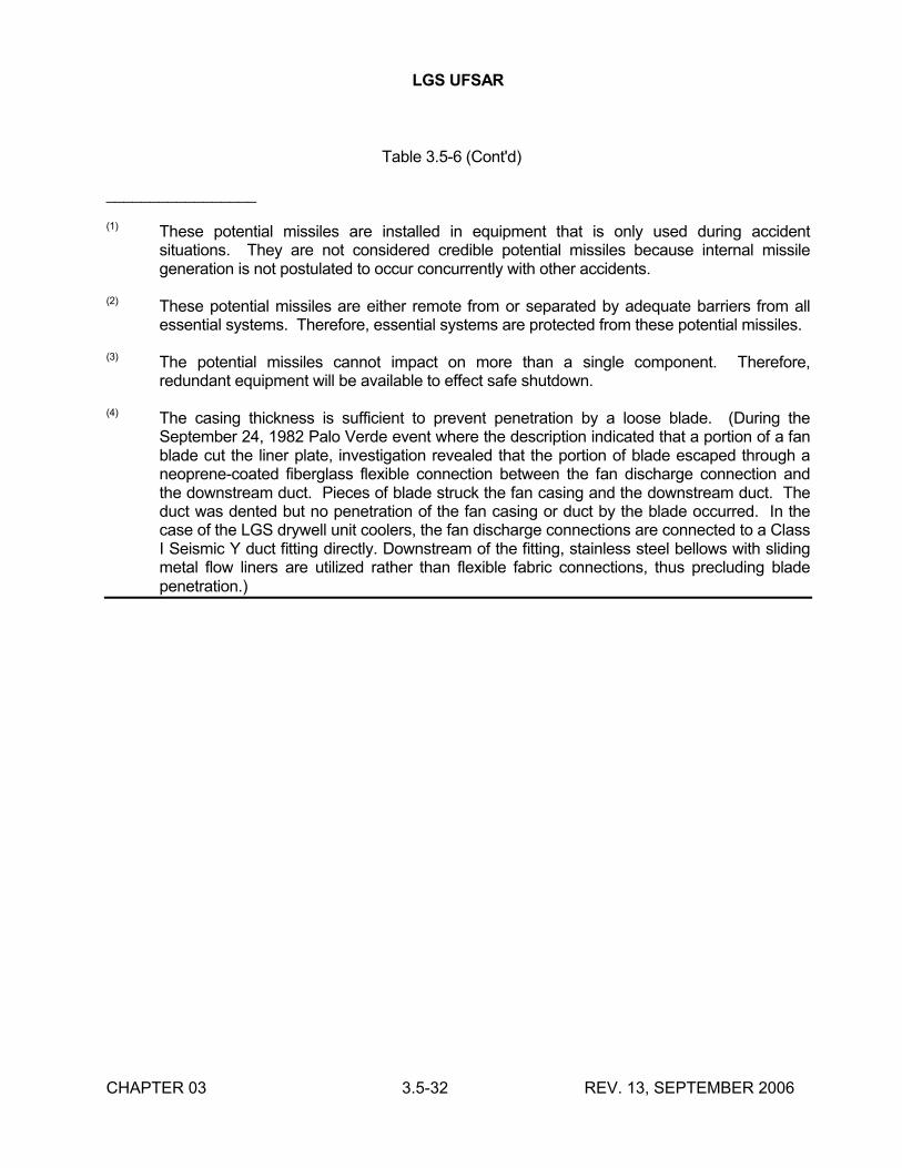
LGS UFSAR
CHAPTER 03 3.5-32 REV. 13, SEPTEMBER 2006
Table 3.5-6 (Cont'd)
_________________
(1) These potential missiles are installed in equipment that is only used during accident situations. They are not considered credible potential missiles because internal missile generation is not postulated to occur concurrently with other accidents.
(2) These potential missiles are either remote from or separated by adequate barriers from all essential systems. Therefore, essential systems are protected from these potential missiles.
(3) The potential missiles cannot impact on more than a single component. Therefore, redundant equipment will be available to effect safe shutdown.
(4) The casing thickness is sufficient to prevent penetration by a loose blade. (During the September 24, 1982 Palo Verde event where the description indicated that a portion of a fan blade cut the liner plate, investigation revealed that the portion of blade escaped through a neoprene-coated fiberglass flexible connection between the fan discharge connection and the downstream duct. Pieces of blade struck the fan casing and the downstream duct. The duct was dented but no penetration of the fan casing or duct by the blade occurred. In the case of the LGS drywell unit coolers, the fan discharge connections are connected to a Class I Seismic Y duct fitting directly. Downstream of the fitting, stainless steel bellows with sliding metal flow liners are utilized rather than flexible fabric connections, thus precluding blade penetration.)
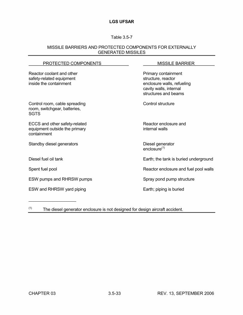
LGS UFSAR
CHAPTER 03 3.5-33 REV. 13, SEPTEMBER 2006
Table 3.5-7
MISSILE BARRIERS AND PROTECTED COMPONENTS FOR EXTERNALLYGENERATED MISSILES
PROTECTED COMPONENTS MISSILE BARRIER
Reactor coolant and other Primary containmentsafety-related equipment structure, reactorinside the containment enclosure walls, refueling
cavity walls, internalstructures and beams
Control room, cable spreading Control structureroom, switchgear, batteries,SGTS
ECCS and other safety-related Reactor enclosure andequipment outside the primary internal wallscontainment
Standby diesel generators Diesel generatorenclosure(1)
Diesel fuel oil tank Earth; the tank is buried underground
Spent fuel pool Reactor enclosure and fuel pool walls
ESW pumps and RHRSW pumps Spray pond pump structure
ESW and RHRSW yard piping Earth; piping is buried
____________________
(1) The diesel generator enclosure is not designed for design aircraft accident.
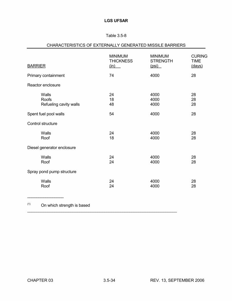
LGS UFSAR
CHAPTER 03 3.5-34 REV. 13, SEPTEMBER 2006
Table 3.5-8
CHARACTERISTICS OF EXTERNALLY GENERATED MISSILE BARRIERS
MINIMUM MINIMUM CURINGTHICKNESS STRENGTH TIME
BARRIER (in) (psi) (days)
Primary containment 74 4000 28
Reactor enclosure
Walls 24 4000 28Roofs 18 4000 28Refueling cavity walls 48 4000 28
Spent fuel pool walls 54 4000 28
Control structure
Walls 24 4000 28Roof 18 4000 28
Diesel generator enclosure
Walls 24 4000 28Roof 24 4000 28
Spray pond pump structure
Walls 24 4000 28Roof 24 4000 28
________________
(1) On which strength is based__________________________________________________________________
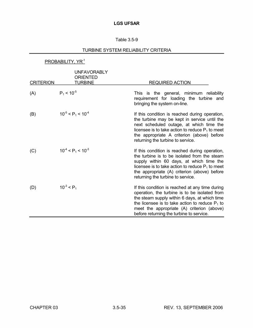
LGS UFSAR
CHAPTER 03 3.5-35 REV. 13, SEPTEMBER 2006
Table 3.5-9
TURBINE SYSTEM RELIABILITY CRITERIA
PROBABILITY, YR-1
UNFAVORABLYORIENTED
CRITERION TURBINE REQUIRED ACTION
(A) P1 < 10-5 This is the general, minimum reliability requirement for loading the turbine and bringing the system on-line.
(B) 10-5 < P1 < 10-4 If this condition is reached during operation, the turbine may be kept in service until the next scheduled outage, at which time the licensee is to take action to reduce P1 to meet the appropriate A criterion (above) before returning the turbine to service.
(C) 10-4 < P1 < 10-3 If this condition is reached during operation, the turbine is to be isolated from the steam supply within 60 days, at which time the licensee is to take action to reduce P1 to meet the appropriate (A) criterion (above) before returning the turbine to service.
(D) 10-3 < P1 If this condition is reached at any time during operation, the turbine is to be isolated from the steam supply within 6 days, at which time the licensee is to take action to reduce P1 to meet the appropriate (A) criterion (above) before returning the turbine to service.
LGS UFSAR
CHAPTER 03 3.6-1 REV. 18, SEPTEMBER 2016
3.6 PROTECTION AGAINST DYNAMIC EFFECTS ASSOCIATED WITH THEPOSTULATED RUPTURE OF PIPING
This section describes the treatment of postulated ruptures in high energy and moderate energy piping located both inside and outside of the primary containment. The methods used to determine pipe rupture locations and to analyze the results of the ruptures, including jet thrust forces, jet impingement forces, piping dynamic responses, and compartment pressure-temperature transients, are described. Description is also provided for the design measures that have been implemented to ensure that the effects of any postulated rupture do not result in the loss of a required function that is necessary to mitigate the consequences of that pipe rupture.
The definitions of certain terms used within this section are provided in Section 3.6.3. The use of the term "low reactor level" in this section is generic rather than referring to a specific isolation signal set point.
NOTE: The computer program "COPDA", as described in Bechtel Topical Report BN-TOP-4 (Reference 3.6-1), was originally used to determine compartment pressure and temperature resulting from line breaks in Unit 1. The computer program "FLUD" (Reference 3.6.3), which replaced COPDA, was typically used for the same analysis in Unit 2. The mainframe program "FLUD" was later replaced in 1985 with a personal computer version "PCFLUD” (Reference 3.6-12). The "PCFLUD" program had additional features added in 1993 (hot pipes, multiple HVAC fans, and "CONCOIL" room air cooler routine) and was renamed "CONCOIL-FLUD" or "CFLUD" (Reference 3.6-13). The supporting calculations for UFSAR Table 3.6-7 must be consulted for information regarding which specific program was used.
3.6.1 POSTULATED PIPING FAILURES IN FLUID SYSTEMS
The failure of piping containing high energy or moderate energy has the potential of causing damage to surrounding structures, systems, and components. Depending on the fluid system involved and the rupture location, postulated piping failures can result in one or more of the effects described below. Essential systems and components are protected from these effects unless it can be demonstrated that their function is not impaired.
Pipe Whip
Pipe whip is the unrestrained movement of a pipe due to the reaction force imposed on the pipe by fluid discharging from a rupture. Protection against pipe whip can be provided by intervening structural members between high energy piping and the essential systems and components, by providing pipe whip restraints on the high energy piping, or by locating essential systems and components sufficiently distant from high energy piping. Examples of typical pipe whip restraints and bumpers are shown in Figure 3.6-1.
Jet Impingement
The blowdown of fluid from a rupture of a high energy pipe can exert forces on nearby equipment that could be high enough to cause damage to the equipment. Protection against jet impingement can be provided by installing jet impingement barriers to deflect the blowdown jet, or by locating essential systems and components a sufficient distance from high energy piping.
LGS UFSAR
CHAPTER 03 3.6-2 REV. 18, SEPTEMBER 2016
Environmental Effects
Pipe ruptures in high energy and moderate energy lines release fluid that can increase temperature, pressure, and humidity in the vicinity of the pipe rupture and also in remote areas that communicate with the local atmosphere. Essential systems and components may be exposed to abnormal conditions that have the potential of degrading the capability of the equipment to perform its function.
Piping systems whose rupture might generate hazardous environmental conditions are generally located in compartments that are capable of being isolated from other compartments containing essential systems and components. Isolation of compartments that enclose high energy lines is provided by maintaining normally closed access ways, automatically isolating ventilation duct-work, and sealing penetrations through walls and slabs. Compartments are designed to withstand the maximum internal pressurization developed as a result of a pipe rupture. Essential systems and components are either located in areas not affected by pipe ruptures or are qualified for operation under the maximum environmental conditions that they may be subjected to as a result of pipe ruptures.
Figures 3.6-43 through 3.6-45 are provided to show additional details of a typical pipe break analysis performed in accordance with SRP 3.6.1 and BTP ASB 3-1. The pipe break chosen is a break of the HPCI steam supply line in the HPCI compartment.
Water Spray
Water released from pipe ruptures is a hazard to certain equipment, particularly electrical components. In most cases, spatial separation is adequate to prevent water spray from reaching essential systems and components. Essential systems and components that can potentially be subjected to water spray are either designed to operate when wetted or will be provided with barriers to deflect the spray.
Flooding
Significant ruptures of fluid system piping may result in flooding in the vicinity of the rupture and in compartments through which the released fluid drains. The flooding rate and the total fluid volume released are computed based on the rupture configuration, the service of the fluid system, and the time required to isolate the rupture. The plant's drainage system handles minor releases of fluid with no adverse effects on essential systems and components.
Compartments that contain fluid systems with the potential for major releases of fluid are designed to contain the flooding and prevent significant leakage to adjoining compartments containing essential systems and components. Essential systems and components are either located in areas not subject to significant flooding or are designed to operate in a flooded environment.
3.6.1.1 Design Bases
Pipe breaks are postulated to occur in high energy fluid system piping in accordance with the criteria stated in Section 3.6.2.1.1. Pipe cracks are postulated to occur in moderate energy fluid system piping in accordance with the criteria stated in Section 3.6.2.1.2. The effects of these piping ruptures require special consideration to ensure the following:
LGS UFSAR
CHAPTER 03 3.6-3 REV. 18, SEPTEMBER 2016
a. The ability to shut the reactor down safely is maintained.
b. Primary containment integrity is maintained.
c. Resultant offsite doses are below the values of 10CFR50.67.
In analyzing the effects of postulated piping ruptures, the following assumptions are made:
a Each break in high energy fluid system piping or crack in moderate energy fluid system piping is considered separately as a single postulated initial event occurring during normal plant conditions.
b. Offsite power is assumed to be unavailable if a trip of the turbine-generator or the RPS is a direct consequence of the postulated piping rupture.
c. A single active component failure is assumed to occur in systems used to mitigate the consequences of the postulated piping rupture and to shut the reactor down, except as noted in item d. below.
d. Where the postulated piping rupture is assumed to occur in one of the two redundant loops of either the RHR system or the RHRSW system, single active failures of components in the other loop of that system need not be assumed. These two systems are dual-purpose moderate energy systems powered from both onsite and offsite sources and are designed, constructed, and inspected tostandards appropriate for nuclear safety systems.
e. All available systems, including those actuated by operator actions, may be employed to mitigate the consequences of the postulated piping rupture. In judging the availability of systems, the postulated piping rupture and its direct consequences, and the assumed single active component failure and its direct consequences are considered. The feasibility of carrying out operator actions is judged on the availability of ample time and adequate access to equipment for the required actions.
f. An unrestrained whipping pipe is considered capable of causing breaks in impacted piping of smaller nominal pipe size and developing through-wall leakage cracks in impacted piping of equal or larger nominal pipe size with thinner wall thickness, except where experimental or analytical data demonstrates the capability to withstand the impact without failure. If such experimental or analytical data are used, additional documentation will be submitted to the NRC for review.
g. The effect of the jets resulting from each postulated pipe break in high energy fluid systems is reviewed and is evaluated only when such jets may have an effect on specific safety-related components that are required to effect a safe shutdown,maintain containment integrity, provide post-LOCA monitoring, or limit radioactive releases to site-allowable limits, as a result of a specific postulated pipe break event.
LGS UFSAR
CHAPTER 03 3.6-4 REV. 18, SEPTEMBER 2016
The effects of jet impingement on the piping required to effect a safe shutdown, maintain containment integrity, provide post-LOCA monitoring, or limit radioactive releases to site-allowable limits, regardless of size or wall thickness, are also reviewed. Bounding cases are evaluated to ensure that acceptable stress levels in such piping are not exceeded.
3.6.1.2 Description
A listing of high energy fluid system piping is provided in Table 3.6-1. All other piping in the plant that is pressurized above atmospheric pressure is considered to be moderate energy piping. The routing of piping within the reactor enclosure and the primary containment is shown in Figures 1.2-40 through 1.2-72.
For each pipe rupture location determined in accordance with the criteria of Section 3.6.2.1, an analysis is performed using the assumptions of Section 3.6.1.1 to verify that the consequences of the pipe rupture are acceptable. These analyses are summarized below for high energy and moderate energy fluid systems.
3.6.1.2.1 High Energy Fluid Systems
3.6.1.2.1.1 Reactor Recirculation System
The two reactor recirculation loops are located entirely within the primary containment and are arranged on opposite sides of the reactor pedestal and reactor shield wall. Pipe whip restraints anchored in the reactor pedestal and reactor shield wall are provided for the recirculation loops and are arranged as shown in Figure 3.6-2. This system of restraints prevents unrestrained pipe whip resulting from a postulated rupture at any of the identified break locations. The restraints consist of two basic components: the frame attached to a support member and straps attached to the frame (two straps per frame). Either carbon steel cables or stainless steel bars are used as straps. The restraints on the 28-inch recirculation loop piping utilize stainless steel bars. The restraints on the 22-inch discharge header and the 12-inch risers utilize carbon steel cables. A schematic detail of a restraint is shown in Figure 3.6-3.
A review of the potential consequences of jet impingement resulting from recirculation loop ruptures has shown that breaks at the lower end of two of the 12-inch risers in each recirculation loop could result in impingement on the CRD withdraw piping. An evaluation of the consequences of damage to CRD withdraw piping resulting from jet impingement has shown that such damage would not prevent the associated control rods from being inserted into the reactor as necessary to affect a reactor shutdown. Electrical cabling associated with essential systems and components is routed to avoid jet impingement from postulated ruptures of recirculation loop piping.
Pipe Break Locations
The postulated pipe break locations for the recirculation loop piping are shown in Figure 3.6-4. The calculated stress levels and usage factors, and the postulated break types, are listed in Table 3.6-2. Blowdown thrust time histories for each break location are provided in Table 3.6-3. The recirculation piping design basis has been evaluated for the effects of power rerate and demonstrated to be adequate for the increases in pressure, temperature and flow due to power rerate. Details of the evaluation performed are documented in Reference 3.6-11.
LGS UFSAR
CHAPTER 03 3.6-5 REV. 18, SEPTEMBER 2016
Compartment Pressure-Temperature Transient
The pressure-temperature transient in the primary containment resulting from a complete circumferential rupture of one recirculation loop is discussed in Section 6.2.1.
Verification of Reactor Shutdown Capability
The sequence of events that would occur automatically to shut the reactor down and cool the core in the event of a recirculation loop rupture is discussed in Section 6.3.3. A combination of pipe whip restraints, jet impingement barriers, and separation by distance is used to ensure the availability of sufficient equipment to accomplish these functions.
3.6.1.2.1.2 Main Steam System
The four 26-inch main steam lines are routed as shown in Figure 5.1-7 for the portion inside the primary containment, and in Figure 3.6-5 for the portion outside the primary containment. The A and B steam lines are connected to the east side of the reactor vessel and the C and D steam lines are connected to the west side of the vessel. All four steam lines penetrate the north side of the primary containment. The portion of the reactor enclosure through which the main steam lines are routed (between the primary containment and the turbine enclosure) is referred to as the main steam tunnel and is separated from other areas of the reactor enclosure by concrete walls and slabs. Only piping, valves, and associated instrumentation are located in the main steam tunnel. Figure 3.6-6 shows an elevation view of the main steam tunnel.
The following features are incorporated into the design of the main steam line and nearby structures to mitigate the consequences of a main steam line break or to minimize the probability of its occurrence:
a. A venturi-type flow restrictor is located in each main steam line inside the primary containment. The flow restrictor reduces the rate of loss of reactor coolant from a main steam line break for break locations downstream of the restrictor. (The flow restrictors are described in Section 5.4.)
b. Each main steam line is provided with either three or four MSRVs that reduce the probability of breaks by protecting the steam line against overpressurization. (The MSRVs are described in Section 5.2.)
c. Each main steam line is provided with two fast-acting fail-safe MSIVs, one upstream and one downstream of the primary containment penetration. These valves close automatically upon receipt of signals indicating high steam flow or high temperature in the vicinity of the piping outside the primary containment (as well as upon receipt of other initiating signals), in order to terminate blowdown through breaks outside the primary containment. (The MSIVs are described in Section 5.4.)
d. Moment-limiting pipe whip restraints are located upstream of the inboard MSIVs and downstream of the outboard MSIVs in order to ensure the operability of these valves in the event of a main steam line break in the general vicinity of the valves.
The main steam lines are provided with pipe whip restraints inside the primary containment and in the main steam tunnel. Typical restraints inside the primary containment are shown in Figure
LGS UFSAR
CHAPTER 03 3.6-6 REV. 18, SEPTEMBER 2016
3.6-1. Figure 3.6-6 shows the locations of the restraints in the main steam tunnel. As shown in Figure 3.6-7, the first two restraints downstream of the outboard MSIVs span between the east and west walls of the tunnel and restrain all four steam lines. Corbels extending out from the north wall of the main steam tunnel limit the possible upward movement of the upper elbow of each steam line in the tunnel. Additionally, the vertical portion of the steam line run in the tunnel is restrained against the north wall of the tunnel at two separate locations.
After entering the Unit 1 turbine enclosure from the main steam tunnel, the main steam lines are routed along the west side of the control structure before turning westward to run the length of the turbine enclosure. This arrangement is shown in Figure 3.6-5. In order to prevent a main steam line break in this portion of piping from causing pipe whip impact on the control structure wall, bumpers are provided between the control structure and the elbows of the two steam lines closest to the control structure (26" EBB-103 and 26" EBB-104). The Unit 2 arrangement is similar, but opposite hand.
In reviewing the potential consequences of jet impingement resulting from main steam line breaks, it was determined that breaks at the elbow at the lower end of the near-vertical piping run inside the primary containment could result in impingement on the CRD withdraw piping. An evaluation of the consequences of damage to CRD withdraw piping resulting from jet impingement has shown that such damage would not prevent the associated control rods from being inserted into the reactor core as necessary to affect a reactor shutdown. Electrical cabling associated with essential systems and components is routed to avoid jet impingement from postulated breaks of main steam piping.
Pipe Break Locations
The postulated pipe break locations for the main steam piping, and also the pipe whip restraint locations, are shown in Figures 3.6-8 and 3.6-9. The calculated stress levels and usage factors, and the postulated break types, for the main steam piping inside the primary containment are listed in Table 3.6-4. Breaks for the main steam piping outside containment are postulated to occur at each location of potential high stress, such as pipe fittings, valves, and welded attachments. The main steam piping basis has been evaluated for the effects of power rerate and demonstrated to be adequate for the increases in pressure, temperature and flow due to power rerate. Details of the evaluation performed are documented in Reference 3.6-11.
Compartment Pressure-Temperature Transients
The pressure-temperature transient in the primary containment resulting from a complete circumferential break of one main steam line is discussed in Section 6.2.1.
Protection against overpressurization of the main steam tunnel in the event of a main steam line break in the tunnel is provided by two sets of blowout panels. One set of blowout panels is located in the north wall of the tunnel and vents to the turbine enclosure. The second set of blowout panels is located in the vent stack that leads upward from the tunnel and discharges to the atmosphere above the top of the reactor enclosure. This vent stack can be seen in drawings M-123 and M-138.
A pressure-temperature transient analysis for the case of a main steam line break in the tunnel was performed using the analytical technique described in BN-TOP-4 (Reference 3.6-1) and the blowdown data provided in Table 3.6-6 and Figure 3.6-10. The flow model is shown in Figure 3.6-11 and the results of the analysis are listed in Table 3.6-7. The main steam tunnel is designed
LGS UFSAR
CHAPTER 03 3.6-7 REV. 18, SEPTEMBER 2016
to withstand the maximum pressure developed, and the MSIVs are qualified to operate under environmental conditions more severe than those calculated to occur.
Protection against overpressurization of the Unit 1 turbine enclosure as a result of a main steam line break within its boundaries is provided by blowout panels along the north exterior wall of the turbine enclosure. As shown in drawings M-111 and 112, these blowout panels are located between column lines 12 and 18 and vent the main condenser area of the turbine enclosure directly to the atmosphere. The main steam lines are routed in areas that communicate directly with the main condenser area for the entire length of their run within the turbine enclosure. The Unit 2 arrangement is similar.
A pressure-temperature transient analysis for the case of a main steam line break in the turbine enclosure was performed using the analytical technique described in Reference 3.6-1 and with the blowdown data provided in Table 3.6-6. The flow model is shown in Figure 3.6-12 and the results of the analysis are listed in Table 3.6-7. The turbine enclosure is designed to withstand the maximum pressure developed.
The secondary containment structure is capable of withstanding the effects of a high energy pipe rupture occurring inside the secondary containment without loss of integrity. For all pipe breaks except those in the RWCU system, the time-dependent mass and energy release rates are calculated using the Moody model including friction effects. Blowdown for the main steam line breaks is determined in accordance with the assumptions in Reference 3.6-14. A double-ended guillotine break is assumed, and both forward and reverse flows are included for all cases except for HPCI and RCIC line breaks in the HPCI and RCIC compartments, respectively. The postulated pipe breaks in the HPCI and RCIC compartments are at the upstream side of a normally closed isolation valve, therefore only forward flow is considered.
Mass and energy release rates for pipe breaks in the RWCU system are calculated with RELAP4/MOD5 using the Henry-Fauske model option for subcooled conditions and the Moody critical flow model option for saturated conditions.
Verification of Reactor Shutdown Capability
Breakage of a main steam line inside the primary containment would result in an unisolable blowdown of the reactor vessel. The sequence of events that would occur automatically to shut the reactor down and cool the core is discussed in Section 6.3.3.
For a main steam line break outside the primary containment, the MSIVs will be closed automatically because of high steam flow, low reactor water level, or high temperature in the vicinity of the main steam lines. Closure of the MSIVs will cut off steam flow to the feedwater pump turbines, causing the pumps to coast down and stop. The reactor will be scrammed by low reactor water level or closure of the MSIVs. After isolation of the reactor vessel, the RCS pressure will increase until the setpoint of the MSRVs is reached. Steam will then be automatically discharged to the suppression pool to limit the pressure rise.
Low reactor water level will initiate operation of the HPCI and RCIC systems to maintain reactor water level. If both the HPCI and RCIC systems are unavailable, the ADS will be automatically initiated to depressurize the reactor vessel so that the LPCI and core spray systems can inject
LGS UFSAR
CHAPTER 03 3.6-8 REV. 18, SEPTEMBER 2016
water into the vessel. These latter two systems are initiated automatically by low reactor water level, and will provide sufficient flow to restore reactor water level and cool the core.
After reactor water level has been restored, and the RCS pressure and temperature have decreased sufficiently, the shutdown cooling mode of the RHR system can be initiated to bring the reactor to cold shutdown.
A combination of pipe whip restraints, jet impingement barriers, and separation by distance or intervening structure is used to ensure the availability of essential systems and components in the event of a main steam line break in either the primary containment or the main steam tunnel. Essential systems and components located in these areas are qualified to operate under the environmental conditions resulting from a break. Since no essential systems and components are located in the turbine enclosure, no special provisions are necessary to provide protection for equipment in this area from the effects of pipe breaks. Blowout panels are provided to prevent overpressurization of the turbine enclosure, and bumpers are provided to prevent a whipping main steam line from impacting the control structure.
3.6.1.2.1.3 Feedwater System
The discharge lines from the three feedwater pumps are routed into a common mixing header in the turbine enclosure. From this header, two parallel 24-inch feedwater lines enter the main steam tunnel and then penetrate the primary containment. Inside the primary containment, the two lines diverge to form symmetrical headers on opposite sides of the reactor vessel. Each header splits into three 12-inch risers that attach to the reactor vessel nozzles. The routing of the feedwater lines in the main steam tunnel and primary containment is shown in drawings M-234, M-305 and Figure 3.6-6.
Each feedwater containment penetration is provided with three check valves as containment isolation valves, one inside the drywell and two in the main steam tunnel. In the event of a feedwater line break outside the primary containment, these check valves will, as described below, close to prevent backflow from the reactor vessel. Thus, flow from the break would be from the feedwater pump side only.
The operability of the first outboard containment isolation valve (i.e. closest to the drywell penetration) is ensured in the event of a feedwater line break by providing moment-limiting whip restraints designed for this purpose. The operability of the check valve inside containment and the second outboard check valve need not be protected from overstress due to pipe whip, since only two isolation valves are necessary to provide adequate redundancy to ensure the containment isolation function, and it is not possible for one pipe break to affect both the inboard and second outboard check valves. More detailed discussion of feedwater check valve operability is provided in Section 3.9.3.2b.2.
The feedwater lines are provided with pipe whip restraints inside the primary containment, in the main steam tunnel, and in the turbine enclosure immediately outside the main steam tunnel. Typical restraints inside the primary containment are shown in Figure 3.6-1. As shown in Figure 3.6-13, the restraint in the tunnel spans between the east and west walls of the tunnel and restrains both feedwater lines. Corbels extending out from the north wall of the main steam tunnel limit the possible upward movement of the upper elbows of the feedwater startup recirculation lines that connect to the feedwater lines in the main steam tunnel. Feedwater line restraints located in the turbine enclosure and which are attached to the control structure and reactor enclosure walls are
LGS UFSAR
CHAPTER 03 3.6-9 REV. 18, SEPTEMBER 2016
shown in Figure 3.6-14. Bumpers on the control structure walls protect the control structure from a whipping feedwater line.
Electrical cabling associated with other essential systems and components is routed to avoid jet impingement from postulated breaks of feedwater piping.
Pipe Break Locations
The postulated pipe break locations for the feedwater piping, and also the pipe whip restraint locations, are shown in Figures 3.6-15 and 3.6-16. The calculated stress levels and usage factors, and the postulated break types, for the feedwater piping inside the primary containment are listed in Table 3.6-8. Breaks for the feedwater piping outside containment are postulated to occur at each location of potential high stress, such as pipe fittings, valves, and welded attachments.
Compartment Pressure-Temperature Transients
The pressure-temperature transient in the primary containment resulting from a break of any of the sizes of feedwater lines in the drywell is exceeded in severity by the transients resulting from recirculation loop and main steam line breaks, which are discussed in Section 6.2.1. The pressure-temperature transient resulting from a feedwater line break in the main steam tunnel or turbine enclosure is exceeded in severity by the transient resulting from a main steam line break, which is discussed in Section 3.6.1.2.1.2.
Verification of Reactor Shutdown Capability
Breakage of a feedwater line inside the primary containment would result in an unisolable blowdown of the reactor vessel. The sequence of events that would occur automatically to shut the reactor down and cool the core is discussed in Section 6.3.3.
For a feedwater line break outside the primary containment, differential pressure across the containment isolation check valves in the reverse direction will cause these valves to close rapidly, isolating the reactor vessel from the break. The loss of feedwater flow will cause the reactor water level to drop, initiating a reactor scram. Water level will continue to drop because of steam generation from decay heat, causing closure of the MSIVs as well as initiation of the RCIC and HPCI systems. Once the reactor has been scrammed and the RCS isolated, the sequence of events is similar to that for a main steam line break outside the primary containment.
A combination of pipe whip restraints, jet impingement barriers, and separation by distance or intervening structure is used to ensure the availability of essential systems and components in the event of a feedwater line break in either the drywell or the main steam tunnel. Since no essential systems and components are located in the turbine enclosure, no special provisions are necessaryto provide protection for equipment in this area from the effects of pipe breaks. Bumpers are provided in the turbine enclosure to protect the control structure from the impact of a whipping feedwater line.
3.6.1.2.1.4 Condensate System
The condensate system is located entirely within the turbine enclosure. No pipe whip restraints are provided for the condensate piping.
LGS UFSAR
CHAPTER 03 3.6-10 REV. 18, SEPTEMBER 2016
Pipe Break Locations
Since the condensate system consists of non-nuclear class piping, breaks are postulated to occur at each location of potential high stress, such as pipe fittings, valves, and welded attachments.
Compartment Pressure-Temperature Transients
Since the normal fluid temperature in the condensate system is less than 135F, no significant pressure-temperature transient would result from condensate line breaks.
Verification of Reactor Shutdown Capability
In the event of a condensate line break, the feedwater pumps would trip because of low suction pressure. The resulting loss of feedwater flow would result in closure of the containment isolation check valves, preventing reactor blowdown through the break. The sequence of events that would occur from this point on is the same as for breakage of a feedwater line outside the primary containment.
Since no essential systems and components are located in the turbine enclosure, no special provisions are necessary to provide protection for equipment in this area from the effects of pipe breaks. The flooding effects of a condensate line break are exceeded by the effects of a circulating water line expansion joint rupture in the turbine enclosure, a discussion of which is contained in Sections 10.4.1 and 10.4.5.
3.6.1.2.1.5 Reactor Water Cleanup System
The RWCU system takes suction from reactor recirculation loop B via the RHR shutdown cooling suction line inside primary containment. The 6-inch RWCU suction line is routed up to el 297'-3", at which point it penetrates the primary containment. The RWCU piping is then routed through the various RWCU equipment compartments at el 283' and el 313' in the reactor enclosure, including the containment penetration compartment, three RWCU pump compartments, the regenerative heat exchanger compartment, two nonregenerative heat exchanger compartments, two RWCU holding pump compartments, and two RWCU filter/demineralizer compartments. The RWCU return piping is routed from the containment penetration compartment directly into the main steam tunnel, where the piping splits into two 4-inch lines. One line connects to the A feedwater line (DBB-103) and the other line connects to the RCIC injection line immediately upstream of its connection to the B feedwater line (DBB-104). Both of these connections to the feedwater lines are located between the two outboard containment isolation valves in the feedwater lines. Another RWCU line, the 4-inch RWCU alternate return line, has a branch connection to the RWCU return line at a point just upstream of the location where the return line splits into the two lines leading to the feedwater lines. From this branch connection, the RWCU alternate return line is routed downward to a containment penetration at elevation 261 feet, which is also in the main steam tunnel. The routing of this RWCU piping is shown in drawings M-210, M-211, M-225, M-231, M-232, M-235, M-296, M-302, M-303, M-306, M-322, and M-323.
The RWCU suction line is provided with two fast-acting isolation valves, one upstream and one downstream of the primary containment penetration. These valves close automatically upon receipt of signals indicating high differential flow (RWCU suction vs. return) or high temperature in
LGS UFSAR
CHAPTER 03 3.6-11 REV. 18, SEPTEMBER 2016
the vicinity of the piping outside the drywell (as well as upon receipt of other initiating signals), in order to terminate blowdown through breaks outside the drywell. In order to ensure the operability of these valves in the event of an RWCU suction line break, moment-limiting pipe whip restraints are located upstream of the inboard containment isolation valve and downstream of the outboard containment isolation valve. Whip restraints are also located on the portion of the RWCU suction line within the drywell and on the portion of the return line within the main steam tunnel.
In reviewing the potential consequences of jet impingement resulting from RWCU line breaks, it was determined that breaks near the connection of the RWCU return lines to the RCIC injection and feedwater line in the main steam tunnel could result in impingement
on the outboard MSIV operators. A steel plate barrier is provided to protect the MSIV operators from this potential source of jet impingement. It was also determined that RWCU line breaks in the RWCU containment penetration compartment could result in impingement on the RWCU outboard containment isolation valve. A steel plate barrier is provided to protect the isolation valve from this potential source of jet impingement.
Pipe Break Locations
The postulated pipe break locations for the RWCU pump suction piping inside the primary containment, and also the pipe whip restraint locations, are shown in Figure 3.6-17. The calculated stress levels and usage factors, and the postulated break types, for this portion of the RWCU piping are listed in Table 3.6-10. Piping isometrics for the RWCU pump suction piping in the RWCU isolation valve compartment and for the RWCU return piping in the main steam tunnel are shown in Figures 3.6-39 and 3.6-18, respectively. Breaks in the latter portions of the RWCU piping are postulated to occur at each location of potential high stress, such as pipe fittings, valves, and welded attachments.
Compartment Pressure-Temperature Transients
The pressure-temperature transient in the primary containment resulting from a break in the portion of the RWCU suction line in the drywell is exceeded in severity by the transients resulting from recirculation loop breaks, main steam line breaks, and small steam leaks, which are discussed in Section 6.2.1.
Protection against overpressurization of the RWCU equipment compartments in the reactor enclosure as a result of RWCU line breaks in these areas is provided by interconnecting steam venting paths between the various compartments and by blowout panels leading to the outside atmosphere. The two nonregenerative heat exchanger compartments are vented into the regenerative heat exchanger compartment via a short steam venting plenum. The regenerative heat exchanger compartment is vented in turn to the adjacent containment penetration compartment. Each of the three pump rooms is vented individually to the containment penetration compartment. The containment penetration compartment is vented, via a blowout panel, to an exhaust stack located on the west side of the reactor enclosure for Unit 1 and on the east side of the reactor enclosure for Unit 2. The stack is open to the atmosphere at its upper and lower ends. The venting pathway from the containment penetration compartment to the exhaust stack is shown in drawings M-215 and M-316.
LGS UFSAR
CHAPTER 03 3.6-12 REV. 18, SEPTEMBER 2016
Pressure-temperature transient analyses for the cases involving RWCU line breaks in the RWCU equipment compartments were performed using the analytical technique described in Reference 3.6-1 and with the blowdown data provided in Table 3.6-6. These blowdown data were developed using Reference 3.6-2. The flow model for breaks in the RWCU equipment compartments is shown in Figure 3.6-19, and the results of the analyses are listed in Table 3.6-7. No analyses are performed for the RWCU holding pump compartments and filter/demineralizer compartments since the piping in these areas contains fluid at a temperature of 150F or less, so that no significant pressure-temperature transient results from a pipe break.
The RWCU equipment compartments are designed to withstand the maximum pressure developed due to a pipe break. The outboard containment isolation valves for the RWCU system and other systems located in the containment penetration compartment are qualified to operate under environmental conditions more severe than those calculated to occur due to pipe break.
Verification of Reactor Shutdown Capability
Breakage of the RWCU suction line inside the drywell would result in an unisolable blowdown of the reactor vessel. The sequence of events that would occur automatically to shut the reactor down and cool the core is discussed in Section 6.3.3.
For an RWCU line break outside the drywell, the RWCU containment isolation valves will be closed automatically due to high flow in the RWCU suction line or high temperature in the RWCU equipment compartments. Backflow from the feedwater lines into the RWCU return line will be prevented by closure of the check valve in the return line. If the break occurs in the RWCU piping within the main steam tunnel, the MSIVs will close automatically due to high temperature in the tunnel. Once MSIV isolation has occurred, the sequence of events is similar to that for a main steam line break outside the primary containment. If the break occurs in the RWCU equipment compartments, no reactor scram or MSIV closure will occur, due to the isolation of the RWCU system and rapid termination of the blowdown. After an RWCU isolation, there is sufficient capability to shutdown the reactor. The operator will investigate the cause of the RWCU isolation and take appropriate actions, in accordance with the plant Technical Specifications and approved operating procedures. The Technical Specifications and/or the operating procedures, which include off normal and EOPs, may, based on plant conditions, require the operator to initiate a normal shutdown of the reactor.
A combination of pipe whip restraints, jet impingement barriers, and separation by distance or intervening structure is used to ensure the availability of essential systems and components in the event of an RWCU line break occurring in the drywell, main steam tunnel, or RWCU equipment compartments. Essential systems and components located in these areas are qualified to operate under the environmental conditions resulting from the break. Among the RWCU equipment compartments, only the containment penetration compartment contains safety-related equipment: the primary containment purge line, two of the four LPCI injection lines, and the RWCU outboard containment isolation valve. The containment isolation valves in the purge line and the LPCI injection lines are normally closed during reactor operation and are not required to operate after a RWCU line break outside primary containment; therefore they require no protection. The RWCU outboard containment isolation valve is protected from jet impingement by a steel plate barrier, and the cabling to the valve is routed so as to avoid jet impingement.
LGS UFSAR
CHAPTER 03 3.6-13 REV. 18, SEPTEMBER 2016
3.6.1.2.1.6 Reactor Vessel Drain
The reactor vessel drain consists of 2-inch piping originating at a nozzle on the reactor vessel bottom head. From this location inside the reactor vessel pedestal, the piping increases to 2½ inches in diameter, penetrates the pedestal into the general drywell area, increases to 4 inches in diameter, and is routed upward to its point of connection to the 6-inch RWCU suction line inside the drywell.
Pipe Break Locations
The postulated pipe break locations for the reactor vessel drain line, and also the pipe whip restraint locations, are shown in Figure 3.6-20. The calculated stress levels and usage factors, and the postulated break types, are listed in Table 3.6-12.
Compartment Pressure-Temperature Transients
Since the reactor vessel drain line is located entirely within the drywell, breakage of this line would have no effect on plant areas outside the primary containment. The pressure-temperature transient in the primary containment resulting from a reactor vessel drain line break is exceeded in severity by the transients resulting from recirculation loop breaks and main steam line breaks, which are discussed in Section 6.2.1.
Verification of Reactor Shutdown Capability
Breakage of the reactor vessel drain line would result in an unisolable blowdown of the reactor vessel. The sequence of events that would occur automatically to shut the reactor down and cool the core is discussed in Section 6.3.3. A combination of pipe whip restraints and separation by distance or intervening structure is used to ensure the availability of essential systems and components in the event of a reactor vessel drain line break.
3.6.1.2.1.7 HPCI Steam Supply Line
The HPCI steam supply piping has a nominal diameter of 10 inches for the portion inside the drywell and 12 inches for the portion outside the drywell. The supply line connects to main steam line C inside the drywell. From its connection to the main steam line, the HPCI steam supply line is routed downward and then horizontally along the drywell wall. The line then penetrates the drywell at el 244'-8", entering the isolation valve compartment located at floor el 217' in the reactor enclosure. The steam supply line penetrates the floor of the isolation valve compartment and enters the HPCI pump compartment located at el 177'. The routing of this line is shown in drawings M-213, M-225, M-226, M-227, M-228, M-295, M-297, M-296, M-318, M-319, M-229, and M-320. During normal reactor operation, the line is pressurized from main steam line C up to the HPCI turbine steam supply valve (HV-55-F001).
The HPCI steam supply line is provided with two fast-acting isolation valves, one upstream and one downstream of the primary containment penetration. These valves close automatically upon receipt of signals indicating high steam flow or high temperature in the vicinity of the piping outside the drywell (as well as upon receipt of other initiating signals), in order to terminate blowdown through breaks outside the drywell.
LGS UFSAR
CHAPTER 03 3.6-14 REV. 18, SEPTEMBER 2016
Moment-limiting pipe whip restraints are located upstream of the inboard containment isolation valve and downstream of the outboard containment isolation valve in order to ensure the operability of these valves in the event of a break in the HPCI steam supply line near the valves.
Whip restraints are also located on the HPCI steam supply line and in the isolation valve compartment at el 217' in the reactor enclosure. A typical restraint inside the drywell is shown in Figure 3.6-1.
Pipe Break Locations
The postulated pipe break locations for the HPCI steam supply line, and also the pipe whip restraint locations, are shown in Figure 3.6-21 for the portion of the line inside the drywell and in Figure 3.6-22 for the portion of the line outside the drywell. The calculated stress levels and usage factors, and the postulated break types, are listed in Tables 3.6-13 and 3.6-14.
Compartment Pressure-Temperature Transients
The pressure-temperature transient in the primary containment resulting from a break in the portion of the HPCI steam supply line in the drywell is exceeded in severity by the transients resulting from recirculation loop breaks and main steam line breaks, which are discussed in Section 6.2.1.
Protection against overpressurization of the HPCI pump compartment and the isolation valve compartment at el 217' in the reactor enclosure as a result of HPCI steam supply line breaks in these areas is provided by steam venting paths and blowout panels leading to the outside atmosphere. The isolation valve compartment is vented to the atmosphere via blowout panels located on the south side of the reactor enclosure, as shown in drawings M-118, M-123 and M-138. The HPCI pump compartment is vented to the isolation valve compartment via hinged, metal plate blowout panels located in the floor at el 217'. These latter panels lift to relieve pressurization in the HPCI pump compartment but do not allow pressurization in the isolation valve compartment to result in steam flow in the reverse direction, i.e., down into the HPCI pump compartment.
Pressure-temperature transient analyses for the cases involving HPCI steam supply line breaks in the HPCI pump compartment and the HPCI piping area were performed using the analytical technique described in Reference 3.6-1 and the blowdown data provided in Table 3.6-6. The flow model for breaks in these two compartments is shown in Figure 3.6-23, and the results of the analyses are listed in Table 3.6-7. Figures 3.6-43 through 3.6-45 provide additional details of a typical pipe break analysis. The case of an HPCI steam supply line break in the isolation valve compartment was analyzed using the CFLUD computer program (Reference 3.6-13) and the blowdown data provided in Table 3.6-6. The flow model for this case is shown in Figure 3.6-24, and the results of the analysis are listed in Table 3.6-7.
The HPCI pump compartment and the isolation valve compartment are designed to withstand the maximum pressures developed due to pipe break. All equipment located in the isolation valve compartment that is required to operate following breakage of the HPCI steam supply line is qualified to operate under environmental conditions more severe than those calculated to occur due to pipe break. No equipment located in the HPCI pump compartment is required to operate following breakage of the HPCI steam supply line.
LGS UFSAR
CHAPTER 03 3.6-15 REV. 18, SEPTEMBER 2016
Verification of Reactor Shutdown Capability
Breakage of the HPCI steam supply line inside the drywell would result in an unisolable blowdown of the reactor vessel. The sequence of events that would occur automatically to shut the reactor down and cool the core is discussed in Section 6.3.3.
For an HPCI steam supply line break outside the drywell, the steam supply line containment isolation valves will be closed automatically, terminating reactor vessel blowdown. No reactor scram will occur, due to the isolation of the HPCI steam line and rapid termination of the blowdown. After a HPCI isolation, there is sufficient capability to shutdown the reactor. The operator will investigate the cause of the HPCI isolation and take the appropriate actions, in accordance with the plant Technical Specifications and approved operating procedures, to assure that the plant is in safe condition. The Technical Specifications and/or the operating procedures, which include off normal and EOPs, may, based on plant conditions, require the operator to initiate a normal shutdown of the reactor.
A combination of pipe whip restraints and separation by distance or intervening structure is used to ensure the availability of essential systems and components in the event of an HPCI steam supply line break occurring in the drywell, the isolation valve compartment, or the HPCI pump compartment. Essential systems and components located in these areas are qualified to operate under the environmental conditions resulting from the break. Electrical cabling associated with essential systems and components is routed so as to avoid jet impingement from the postulated break.
No pipe whip restraints are provided for the portion of the HPCI steam supply line located within the HPCI pump compartment. Since no essential systems and components (other than the HPCI system itself) are located in the HPCI pump compartment, such protection is not necessary.
3.6.1.2.1.8 RCIC Steam Supply Line
The RCIC steam supply line has a nominal diameter of 4 inches for the portion inside the drywell and 6 inches for the portion outside the drywell. The supply line connects to main steam line B inside the drywell. From its connection to the main steam line, the RCIC steam supply line is routed generally downward and then horizontally along the drywell wall. The line then penetrates the drywell at el 243'-6", entering the isolation valve compartment located at floor el 217' in the reactor enclosure. The steam supply line penetrates the floor of the isolation valve compartment and enters the RCIC pump compartment located at el 177'. The routing of this line is shown in drawings M-213, M-215, M-225, M-226, M-227, M-229, M-239, M-295, M-296, M-297, M-310, M-316, M-318, and M-320. During normal reactor operation, the line is pressurized from main steam line B up to the RCIC turbine steam supply valve (HV-50-F045).
The RCIC steam supply line is provided with two fast-acting isolation valves, one upstream and one downstream of the primary containment penetration. These valves close automatically upon receipt of signals indicating high steam flow or high temperature in the vicinity of the piping outside the drywell (as well as upon receipt of other initiating signals), in order to terminate blowdown through breaks outside the drywell.
Moment-limiting pipe whip restraints are located upstream of the inboard containment isolation valve and downstream of the outboard containment isolation valve in order to ensure the
LGS UFSAR
CHAPTER 03 3.6-16 REV. 18, SEPTEMBER 2016
operability of these valves in the event of a break in the RCIC steam supply line near the valves. Whip restraints are also located on the RCIC steam supply line inside the drywell and in the isolation valve compartment at el 217' in the reactor enclosure. A typical restraint inside the drywell is shown in Figure 3.6-1.
Pipe Break Locations
The postulated pipe break locations for the RCIC steam supply line, and also the pipe whip restraint locations, are shown in Figure 3.6-25 for the portion of the line inside the drywell and in Figure 3.6-26 for the portion of the line outside the drywell. The calculated stress levels and usage factors, and the postulated break types, are listed in Tables 3.6-15 and 3.6-16.
Compartment Pressure-Temperature Transients
The pressure-temperature transient in the primary containment resulting from a break in the portion of the RCIC steam supply line in the drywell is exceeded in severity by the transients resulting from recirculation loop breaks and main steam line breaks, which are discussed in Section 6.2.1.
Protection against overpressurization of the RCIC pump compartment and the isolation valve compartment at el 217' in the reactor enclosure as a result of RCIC steam supply line breaks in these areas is provided by steam venting paths and blowout panels leading to the outside atmosphere. The isolation valve compartment is vented to the atmosphere via blowout panels located on the south side of the reactor enclosure, as shown in drawings M-118, M-123 and M-138. The RCIC pump compartment is vented to the isolation valve compartment via hinged, metal plate blowout panels located in the floor at el 217'. These latter panels lift to relieve pressurization in the RCIC pump compartment but do not allow pressurization in the isolation valve compartment to result in steam flow in the reverse direction, i.e., down into the RCIC pump compartment.
Pressure-temperature transient analyses for the cases involving RCIC steam supply line breaks in the RCIC pump compartment and the RCIC upper pipe tunnel were performed using the analytical technique described in Reference 3.6-1 and the blowdown data provided in Table 3.6-6. The flow model for breaks in these two compartments is shown in Figure 3.6-27, and the results of the analyses are listed in Table 3.6-7.
The RCIC pump compartment is designed to withstand the maximum pressure developed due to pipe break. No equipment located in the RCIC pump compartment is required to operate following breakage of the RCIC steam supply line. The pressure-temperature transient in the isolation valve compartment at el 217' resulting from a break in the portion of the RCIC steam supply line within that compartment is exceeded in severity by the transient resulting from HPCI steam supply line breakage in the same compartment. All equipment located in the isolation valve compartment that is required to operate following breakage of the RCIC steam supply line is qualified to operate under environmental conditions more severe than those calculated to occur due to breakage of the HPCI steam supply line.
Verification of Reactor Shutdown Capability
Breakage of the RCIC steam supply line inside the drywell would result in an unisolable blowdown of the reactor vessel. The sequence of events that would occur automatically to shut the reactor down and cool the core is discussed in Section 6.3.3.
LGS UFSAR
CHAPTER 03 3.6-17 REV. 18, SEPTEMBER 2016
For an RCIC steam supply line break outside the drywell, the steam supply line containment isolation valves will be closed automatically, terminating reactor vessel blowdown. No reactor scram will occur, due to the isolation of the RCIC steam line and rapid termination of the blowdown. After a RCIC isolation, there is sufficient capability to shutdown the reactor. The operator will investigate the cause of the RCIC isolation and take appropriate actions, in accordance with the plant Technical Specifications and approved operating procedures, to assure that the plant is in a safe condition. The Technical Specifications and/or the operating procedures, which include off normal and EOPs, may, based on plant conditions, require the operator to initiate a normal shutdown of the reactor.
A combination of pipe whip restraints and separation by distance or intervening structure is used to ensure the availability of essential systems and components in the event of an RCIC steam supply line break occurring in the drywell, the isolation valve compartment, or the RCIC pump compartment. Essential systems and components located in these areas are qualified to operate under the environmental conditions resulting from the break. Electrical cabling associated with essential systems and components is routed so as to avoid jet impingement from the postulated break.
No pipe whip restraints are provided for the portion of the RCIC steam supply line located within the RCIC pump compartment. Since no essential systems and components are located within the RCIC pump compartment, such protection is not necessary.
3.6.1.2.1.9 Main Steam Drain Lines
The main steam drainage piping connects to the four main steam lines both inside and outside the drywell. Inside the drywell, 2-inch drain lines that connect to each of the main steam lines are headered together into a single 3-inch line, which then penetrates the drywell wall. This 3-inchdrain header is provided with two containment isolation valves, one upstream and one downstream of the containment penetration, both of which are normally closed. Outside the drywell (in the main steam tunnel), 2-inch drain lines that connect to each of the main steam lines are headered together into a single 3-inch line, which then connects to the drain header from the drain lines inside the drywell. Downstream of the connection of the two drain headers, the common line splits into two 3-inch lines again, one routed to the main condenser and one routed to the liquid waste management system. These latter two lines are both provided with normally closed valves located within the main steam tunnel. The routing of the main steam drain lines is shown in drawings M-217, M-226, M-297, and M-326.
Pipe Break Locations
The postulated pipe break locations for the main steam drain lines inside the drywell are shown in Figure 3.6-28. The calculated stress levels and usage factors, and the postulated break types, are listed in Table 3.6-17. Breaks in the main steam drain lines within the main steam tunnel are postulated to occur at each location of potential high stress, such as pipe fittings, valves, and welded attachments.
Compartment Pressure-Temperature Transients
The pressure transient in the primary containment resulting from a break in a main steam drain line within the drywell is exceeded in severity by transients resulting from recirculation loop breaks and main steam line breaks. The temperature transient in the primary containment resulting from a
LGS UFSAR
CHAPTER 03 3.6-18 REV. 18, SEPTEMBER 2016
main steam drain line break is exceeded in severity by the transient resulting from a small steam leak. These design basis transients are discussed in Section 6.2.1.
The pressure-temperature transient in the main steam tunnel resulting from a main steam drain line break within the tunnel is exceeded in severity by the transient resulting from a main steam line break.
Verification of Reactor Shutdown Capability
Breakage of a main steam drain line inside the drywell would result in an unisolable blowdown of steam from the reactor vessel through the broken line. The sequence of events that would occur automatically to shut the reactor down and cool the core is discussed in Section 6.3.3.
For the case of a main steam drain line break inside the main steam tunnel, the resultant temperature rise in the tunnel would cause the MSIVs and the MSL drain isolation valves, if open to close automatically, thereby terminating steam blowdown through the break. Once the MSIVs and MSL drain isolation valves have been closed, the sequence of events is similar to that for a main steam line break outside the drywell.
Separation by distance and intervening structure is used to ensure the availability of essential systems and components in the event of a main steam drain line break in either the drywell or the main steam tunnel.
3.6.1.2.1.10 RPV Head Vent Line
The RPV head vent line is located entirely within the drywell. From its connection point to a 4-inchflanged nozzle on the RPV head, the line reduces to 2 inches in diameter and then is routed generally downward to a penetration through the containment seal plate. From this point, the line continues on downward to its connection with 26-inch main steam line C.
Pipe Break Locations
The postulated pipe break locations for the RPV head vent line, and also the pipe whip restraint locations, are shown in Figure 3.6-30. The calculated stress levels and usage factors, and the postulated break types, are listed in Table 3.6-19.
Compartment Pressure-Temperature Transients
Since the RPV head vent line is located entirely within the drywell, breakage of this line has no effect on plant areas outside the primary containment. The pressure transient in the primary containment resulting from a break in the RPV head vent line is exceeded in severity by transients resulting from recirculation loop breaks and main steam line breaks. The temperature transient in the primary containment resulting from a break in the RPV head vent line is exceeded in severity by the transient resulting from a small steam leak. These design basis transients are discussed in Section 6.2.1.
LGS UFSAR
CHAPTER 03 3.6-19 REV. 18, SEPTEMBER 2016
Verification of Reactor Shutdown Capability
Breakage of the RPV head vent line would result in an unisolable blowdown of steam into the drywell. The sequence of events that would occur automatically to shut the reactor down and cool the core is discussed in Section 6.3.3.
Separation by distance and intervening structure is used to ensure the availability of essential systems and components in the event of an RPV head vent line break.
3.6.1.2.1.11 Standby Liquid Control System Injection Line
The discharge lines from the SLCS injection pumps penetrate the drywell through two separate penetrations and are headered together inside the drywell to form a single 2-inch line. From the vicinity of the drywell penetrations (between el 265' and el 271'), this line is routed horizontally and upward to its connection to core spray injection line B (12" DCA-319). In addition to the containment isolation valves, the SLCS injection line is provided with a check valve near the connection to the core spray line. Only that portion of the SLCS injection line between the core spray line and the inboard check valve is considered high energy during periods when the reactor is pressurized.
Pipe Break Locations
The postulated pipe break locations for the SLCS injection line are shown in Figure 3.6-31. The calculated stress levels and usage factors, and the postulated break types, are listed in Table 3.6-20.
Compartment Pressure-Temperature Transients
Since the high energy portion of the SLCS injection line is located entirely within the drywell, breakage of this line would have no effect on plant areas outside the primary containment. The pressure-temperature transient in the primary containment resulting from a break in the SLCS injection line is exceeded in severity by the transients resulting from recirculation loop breaks and main steam line breaks, which are discussed in Section 6.2.1.
Verification of Reactor Shutdown Capability
Breakage of the SLCS injection line between the RPV and the first check valve in that line would result in an unisolable blowdown from the reactor vessel into the drywell. The sequence of events that would occur automatically to shut the reactor down and cool the core is discussed in Section 6.3.3.
Separation by distance and intervening structure is used to ensure the availability of essential systems and components in the event of an SLCS injection line break.
3.6.1.2.1.12 RHR Shutdown Cooling Suction Line
The RHR shutdown cooling suction line is a 20-inch line connected to recirculation loop B in the drywell. The line is routed downward and then horizontally to its containment penetration at el 244'-8". The line is provided with two containment isolation valves (one inboard and one outboard
LGS UFSAR
CHAPTER 03 3.6-20 REV. 18, SEPTEMBER 2016
of the penetration), both of which are normally closed. Thus, only that portion of the line between the recirculation loop and the inboard containment isolation valve is considered high energy. The routing of the line is shown in drawings M-213, M-217, M-225, M-295, M-296, and M-326.
The RHR shutdown cooling suction line is provided with pipe whip restraints on the portion of the line inside the drywell. Examples of these restraints are shown in Figure 3.6-1.
Pipe Break Locations
The postulated pipe break locations for the RHR shutdown cooling suction line, and also the pipe whip restraint locations, are shown in Figure 3.6-32. The calculated stress levels and usage factors, and the postulated break types, are listed in Table 3.6-21.
Compartment Pressure-Temperature Transients
Since the high energy portion of the RHR shutdown cooling suction line is located entirely within the drywell, breakage of the line would have no effect on plant areas outside the primary containment. The pressure-temperature transient in the primary containment resulting from a break in the RHR shutdown cooling suction line is exceeded in severity by the transients resulting from recirculation loop breaks and main steam line breaks, which are discussed in Section 6.2.1.
Verification of Reactor Shutdown Capability
Breakage of the RHR shutdown cooling suction line would result in an unisolable blowdown of the reactor vessel. The sequence of events that would occur automatically to shut the reactor down and cool the core is discussed in Section 6.3.3.
A combination of pipe whip restraints and separation by distance and intervening structure is used to ensure the availability of essential systems and components in the event of a break in the RHR shutdown cooling suction line.
3.6.1.2.1.13 RHR Shutdown Cooling Return Line
One 12-inch RHR shutdown cooling return line is associated with RHR loop A and a second return line is associated with RHR loop B. Since the two return lines are routed symmetrically on opposite sides of the drywell, the following discussion applies to both lines. The RHR shutdown cooling return line, from the discharge of the associated RHR pump and heat exchanger, penetrates the south side of the drywell at el 244'-8". The line is then routed horizontally following the curvature of the drywell wall until a point due west (for loop A; due east for loop B) of the reactor vessel centerline is reached. From this point, the line is routed upward to el 265'-4" and then horizontally to its connection with the discharge riser of the reactor recirculation loop. The routing of this piping is shown in drawings M-213, M-217, M-225, M-295, M-296, and M-326.
The RHR shutdown cooling return line is provided with two containment isolation valves: a normally closed globe valve outside the drywell and a check valve inside the drywell. Only that portion of the line between the reactor recirculation line and the inboard check valve is considered high energy during periods when the reactor is pressurized.
The RHR shutdown cooling return line is provided with one pipe whip restraint, located at the upper elbow of the vertical portion of the line. A detail of this restraint is shown in Figure 3.6-1.
LGS UFSAR
CHAPTER 03 3.6-21 REV. 18, SEPTEMBER 2016
Pipe Break Locations
The postulated pipe break locations for the RHR shutdown cooling return line, and also the pipe whip restraint locations, are shown in Figure 3.6-32. The calculated stress levels and usage factors, and the postulated break types, are listed in Table 3.6-21.
Compartment Pressure-Temperature Transients
Since the high energy portion of the RHR shutdown cooling return line is located entirely within the drywell, breakage of the line would have no effect on plant areas outside the primary containment. The pressure-temperature transient in the primary containment resulting from a break in the RHR shutdown cooling return line is exceeded in severity by the transients resulting from recirculation loop breaks and main steam line breaks, which are discussed in Section 6.2.1.
Verification of Reactor Shutdown Capability
Breakage of the RHR shutdown cooling return line would result in an unisolable blowdown of the reactor vessel. The sequence of events that would occur automatically to shut the reactor down and cool the core is discussed in Section 6.3.3.
A combination of pipe whip restraints and separation by distance and intervening structure is used to ensure the availability of essential systems and components in the event of a break in the RHR shutdown cooling return line.
3.6.1.2.1.14 LPCI Injection Line
There are four 12-inch LPCI injection lines, one associated with each of the four RHR pumps. The four lines are routed symmetrically inside the drywell, with the A and C injection lines entering the west side of the drywell and the B and D lines entering the east side of the drywell. The following discussion applies to all four lines. The LPCI injection line penetrates the drywell at el 285'-2" and is routed up to el 297'-3" inches where it connects to the reactor vessel nozzle. The routing of this piping is shown in drawings M-215, M-217, M-234, M-235, M-305, M-306, M-316, and M-326.
The LPCI injection line is provided with two containment isolation valves: a normally closed gate valve outside the drywell and a check valve inside the drywell. Only that portion of the line between the reactor vessel nozzle and the inboard check valve is considered high energy during periods when the reactor is pressurized.
The LPCI injection line is restrained to prevent pipe whip inside the drywell. A typical restraint is shown in Figure 3.6-1.
Pipe Break Locations
The postulated pipe break locations for the LPCI injection line, and also the pipe whip restraint locations, are shown in Figure 3.6-33. The calculated stress levels and usage factors, and the postulated break types, are listed in Table 3.6-22
LGS UFSAR
CHAPTER 03 3.6-22 REV. 18, SEPTEMBER 2016
Compartment Pressure-Temperature Transients
Since the high energy portion of the LPCI injection line is located entirely within the drywell, breakage of the line would have no effect on plant areas outside the primary containment. The pressure-temperature transient in the primary containment resulting from a break in the LPCI injection line is exceeded in severity by the transients resulting from recirculation loop breaks and main steam line breaks, which are discussed in Section 6.2.1.
Verification of Reactor Shutdown Capability
Breakage of the LPCI injection line would result in an unisolable blowdown of the reactor vessel. The sequence of events that would occur automatically to shut the reactor down and cool the core is discussed in Section 6.3.3.
A combination of pipe whip restraints and separation by distance and intervening structure is used to ensure the availability of essential systems and components in the event of a break in the LPCI injection line.
3.6.1.2.1.15 Core Spray Injection Line
There are two core spray injection lines, one associated with core spray pumps A and C and one associated with core spray pumps B and D. Since the two lines are routed symmetrically within the drywell, the following discussion applies to both lines. The core spray injection line penetrates the north side of the drywell at el 297'-3" and is routed up to el 306'-7" before connecting to the RPV nozzle. The routing of the piping is shown in drawings M-217, M-235, M-306, and M-326.
The core spray injection line is provided with containment isolation valves both inside and outside the drywell, the inboard valve being a check valve. Only that portion of the line between the reactor vessel nozzle and the inboard check valve is considered high energy during periods when thereactor is pressurized.
The core spray injection line is restrained to prevent pipe whip inside the drywell. Typical restraints are shown in Figure 3.6-1.
Pipe Break Locations
The postulated pipe break locations for the core spray injection line, and also the pipe whip restraint locations, are shown in Figure 3.6-34. The calculated stress levels and usage factors, and the postulated break types, are listed in Table 3.6-23.
Compartment Pressure-Temperature Transients
Since the high energy portion of the core spray injection line is located entirely within the drywell, breakage of the line would have no effect on plant areas outside the primary containment. The pressure-temperature transient in the primary containment resulting from a break in the core spray injection line is exceeded in severity by the transients resulting from recirculation loop breaks and main steam line breaks, which are discussed in Section 6.2.1.
LGS UFSAR
CHAPTER 03 3.6-23 REV. 18, SEPTEMBER 2016
Verification of Reactor Shutdown Capability
Breakage of the core spray injection line would result in an unisolable blowdown of the reactor vessel. The sequence of events that would occur automatically to shut the reactor down and cool the core is discussed in Section 6.3.3.
A combination of pipe whip restraints and separation by distance and intervening structure is used to ensure the availability of essential systems and components in the event of a break in the core spray injection line.
3.6.1.2.1.16 Control Rod Drive Hydraulic
The 2 CRD water pumps are located in the turbine enclosure. The high energy discharge pipes from the 2 pumps are headered together, and a single 2-inch pipe is routed from the turbine enclosure into the reactor enclosure at el 201'. This 2-inch line is then routed upward to the CRD hydraulic system master control station located at el 253' of the reactor enclosure. From the master control station, a 2-inch cooling water header and a 2-inch charging water header are routed to the groups of HCUs on the west side and east side of the drywell. Containment isolation valves are provided in each header between the master control station and the HCUs. The piping between the isolation valves has been upgraded to be equivalent to ASME III, Class 2.
Pipe Break Locations
Since the CRD pump discharge line, the cooling water header, and the charging water header originally consisted entirely of non-nuclear class piping, breaks are postulated to occur at each location of potential high stress, such as pipe fittings, valves, and welded attachments. The original analysis bounds the effects of the addition of containment isolation valves in the headers.
Compartment Pressure-Temperature Transients
Since the normal fluid temperature in the CRD hydraulic system is less than 120F, no significant pressure-temperature transient would result from postulated breaks.
Verification of Reactor Shutdown Capability
Loss of water pressure due to a break in the CRD pump discharge line, cooling water header, or charging water header will not prevent the control rods from being inserted into the reactor core. At reactor pressures of 450 psig or higher, reactor pressure alone is sufficient to fully insert the control rods. At lower reactor pressures, the scram accumulators assist in supplying the energy necessary to insert the control rods.
3.6.1.2.1.17 Auxiliary Steam Line
From the auxiliary boiler, auxiliary steam is distributed via an 8-inch header to the various steam-consuming components in the turbine enclosure and the radwaste enclosure. This auxiliary steam header passes through the offgas pipe tunnel north of the control structure at el 187'. The auxiliary steam system also provides steam to the RCIC and HPCI systems for testing purposes.
LGS UFSAR
CHAPTER 03 3.6-24 REV. 18, SEPTEMBER 2016
Pipe Break Locations
Since the auxiliary steam line consists of non-nuclear class piping, breaks are postulated to occur at each location of potential high stress, such as pipe fittings, valves, and welded attachments.
Compartment Pressure-Temperature Transients
A pressure-temperature transient analysis for the case of an auxiliary steam line break in a safety-related area was not performed because the piping does not pass through any safety related areas with the exception of the test lines to HPCI and RCIC. However, a pressure-temperature transient analysis was performed for the auxiliary steam line break in the offgas pipe tunnel to ensure control structure integrity. The HPCI and RCIC test lines are normally isolated from the reactor enclosure by closed valves. The lines are only energized in the reactor enclosure for short periods (i.e., less than 1% of the time) and are therefore considered as moderate energy lines.
Verification of Reactor Shutdown Capability
Breakage of the auxiliary steam line would have no effect on operation of the reactor. Except for the test lines for HPCI and RCIC, auxiliary steam lines are not located in areas containing safety related equipment. In the case of the HPCI and RCIC test lines, they are considered to be moderate energy lines based on the short periods in which they are energized. As moderate energy lines, they are acceptable since all rooms containing safety related equipment are qualified for a moderate energy line break.
3.6.1.2.1.18 Plant Heating Steam Piping
From the auxiliary boiler, plant heating steam is distributed to various steam-consuming components in the turbine enclosure and the diesel generator compartments. Additionally, heating steam is provided to the refueling floor and the railroad air-lock in the reactor enclosure and in the diesel corridor outside of the reactor enclosure, however, none of these areas contain safety related equipment necessary to shut down the reactor or maintain primary containment integrity.
Pipe Break Locations
Because the plant heating steam piping consists of non-nuclear class piping, breaks are postulated to occur at each location of potential high stress, such as pipe fittings, valves, and welded attachments.
Verification of Reactor Shutdown Capability
Breakage of the plant heating steam piping would have no effect on operation of the reactorbecause reactor systems are not located in areas through which the heating steam piping is routed. The only areas of the plant through which heating steam piping is routed that contain safety-related systems are the diesel generator compartments, the refuel floor, the diesel corridor, and the railroad air lock. In addition to the diesel generators, the safeguard MCCs for the following valves are located within diesel generator enclosures:
a. ESW to RHRSW valves (HV-11-11A, 11B, 15A, 15B; drawing M-11).
b. ESW to TECW heat exchanger valves (HV-11-105, 107, 205, 207; Figure 9.2-2).
LGS UFSAR
CHAPTER 03 3.6-25 REV. 18, SEPTEMBER 2016
c. TECW heat exchanger to RHRSW valves (HV-12-110, 210; drawing M-12).
d. CST to ECCS (HV-55-124, 224; drawing M-55).
The MCCs for these valves are distributed throughout the diesel generator cells such that the loss of the MCCs in any one cell would not compromise the safety function of the systems. Thus, an HELB in one cell would not affect the safe shutdown capability of the plant.
A rupture of the plant steam heating piping in one cell would not affect the diesel generators located in other cells. Thus, a failure of this system would result in loss of only the one diesel. The safe shutdown capability of the plant would therefore not be compromised because only three of the four diesels are required in the event of a LOOP.
Because the loss of components in any diesel generator compartment from a high or moderate energy line break would not precipitate a trip of the turbine-generator or a trip of the RPS, offsite power is assumed to remain available in the analysis of the effects of postulated piping failures in these systems (BTP ASB 3.1, paragraph 3.b.1).
There are no essential systems or components as defined in Branch Technical Position SPLB 3-1 (Protection against postulated piping failures in fluid systems outside containment) on the refueling floor, the diesel corridor or the railroad airlock.
3.6.1.2.2 Moderate Energy Fluid Systems
Each room, compartment, or area containing components essential for safe shutdown has been evaluated for the effects of postulated ruptures in moderate energy piping.
Safe shutdown components were evaluated for operability in the postulated water spray and/or flooding environment. Safe shutdown components in the reactor enclosure, the control structure, the diesel generator enclosure, the spray pond pumphouse, the main steam tunnel, and the RHRSW pipe tunnel were considered.
Those components not designed for operability in a water spray and/or a flooding environment were assumed to fail. Electrical components that are needed for safe shutdown, but that would fail under the water spray/flooding conditions, were protected from water spray and flooding conditions.
The synergistic effects of an independent single active failure, in addition to the effects of the pipe break, were evaluated and were found acceptable subject to any limitations discussed below. For some systems (such as RHR), a single active failure in the redundant loop of the same system has been excluded in accordance with Section 3.6.1.1.
The crack sizes postulated, and the nominal pipe sizes in which moderate energy pipe cracks are postulated to occur, are discussed in Section 3.6.2.1.3. Additional criteria used in the moderate energy fluid systems analysis are discussed in Section 3.6.1.1.
3.6.1.2.2.1 Primary Containment
All equipment within the primary containment that must operate during or after a LOCA is qualified for the appropriate environmental conditions, as described in Section 3.11. Wetting associated
LGS UFSAR
CHAPTER 03 3.6-26 REV. 18, SEPTEMBER 2016
with the postulated failure of any moderate energy pipe is within the bounds of that qualification. Consequently, no item-by-item discussion of this less severe event is required to verify that capability of safely shutting down the plant.
3.6.1.2.2.2 Reactor Enclosure
Compartments or areas on each elevation that contain safe shutdown electrical equipment were evaluated. Piping and mechanical drawings for each elevation of the reactor enclosure are provided in Section 1.2. All safety-related equipment whose operability in a water spray or flooding environment must be ensured were either protected from the consequences of the pipe break or are designed to remain operable in that environment.
3.6.1.2.2.3 Control Structure
Compartments or areas that contain safety-related equipment on each elevation were evaluated beginning with el 200', the lowest elevation of the control structure. All safety-related equipment whose operability in a water spray or flooding environment must be ensured were either protected from the consequences of the pipe break or were designed to operate in that environment. Piping and mechanical drawings for each elevation of the control structure are provided in Section 1.2.
3.6.1.2.2.4 Diesel Generator Compartments
Moderate energy piping systems that are routed through the diesel generator compartments include:
a. ESW to the diesel generator heat exchangers
b. diesel fuel oil supply lines
c. diesel generator starting air
d. demineralized water from the jacket water expansion tank to the diesel generator
e. lube oil from the storage tank to the diesel generator
f. fire protection system (normally dry)
Each of the moderate energy piping systems is integral to the operation or protection of the diesel generator located in the same compartment as the piping. Thus, a failure of one or more of these systems would result in loss of only the one diesel. The safe shutdown capability of the plant would therefore not be compromised because only three of the four diesels are required in the event of a LOOP.
In addition to the diesel generators, a safeguard MCC is located within each diesel generator enclosure. The impact of a pipe break in the diesel generator enclosure on these MCCs is discussed in Section 3.6.1.2.1.18.
LGS UFSAR
CHAPTER 03 3.6-27 REV. 18, SEPTEMBER 2016
3.6.1.2.2.5 Spray Pond Pumphouse
The spray pond pumphouse contains two separate ESW and RHRSW pump areas, two RHRSW and ESW pipe-ways, two RHRSW valve compartments, and several other compartments.
Each pump-room contains two RHRSW pump motors and two ESW pump motors. The pumps are common to both Unit 1 and Unit 2.
During normal plant operation, the ESW and RHRSW piping is depressurized except during surveillance testing of ESW, RHRSW, and the diesel generators; and during operation for reactor shutdown cooling, suppression pool cooling, and spray pond cooling/chemistry control. The frequency of the surveillance tests is in accordance with the Technical Specifications, and the frequency of operation for other purposes varies with plant conditions.
A moderate energy line break in these lines during normal plant operation is unlikely. However, if a line break should occur, water spray could impinge on the pump motors in the room. In this event, up to two ESW and two RHRSW pumps could be disabled. The loss of the two ESW pumps is of no concern because shutdown cooling loads would be provided by the service water system. Because nonsafeguard heat removal systems are available, the RHRSW system is not critical for safe shutdown of the reactors.
The RHRSW valve compartments contain valves that are essential for the safe operation of the ESW system. However, as discussed above, shutdown cooling loads would be provided by the service water system because offsite power would be assumed to be available.
A pipe break in the wet pit, the ESW and RHRSW pipe-way, or the access hatch area would not impact safe shutdown capability because these compartments do not contain components that are essential for safe shutdown.
Spray pond pumphouse flooding is limited to the compartments adjoining the pump area. The pump area itself cannot flood because water would flow through open grating into the spray pond.
Flooding in the adjacent compartments could damage at most a single mechanical division. Because it is not necessary to postulate a single active failure in the redundant RHRSW system, and because flooding can damage only one mechanical division of RHRSW, safe shutdown capability will not be impaired.
3.6.1.2.2.6 Main Steam Tunnel
Safe shutdown components in the main steam tunnel include the outboard MSIVs.
The MSIVs are qualified to operate in environments more severe than that caused by moderate energy water spray. The valves are located well above the maximum water flood level. Therefore, the occurrence of a moderate energy pipe crack in this compartment would have no effect on safe shutdown capability.
LGS UFSAR
CHAPTER 03 3.6-28 REV. 18, SEPTEMBER 2016
3.6.1.2.2.7 RHRSW Pipe Tunnel
A moderate energy pipe break in the RHRSW pipe tunnel would not impact safe shutdown capability.
The only safe shutdown components on this elevation are two RHRSW valves. Each of these valves are qualified to be submersible and would withstand postulated water spray and flooding conditions.
3.6.1.3 Safety Evaluation
The analyses of postulated pipe ruptures summarized in Section 3.6.1.2 verify that the consequences of any single rupture of fluid system piping in the plant will not prevent safe shutdown of the reactor from being achieved.
The offsite radiological consequences of piping ruptures are enveloped by a reactor recirculation system break for all breaks inside primary containment, and by main steam system and feedwater system breaks for all breaks outside primary containment. The radiological consequences of these breaks are presented in Sections 15.6.5, 15.6.4, and 15.6.6, respectively.
Special consideration has been given to protecting the control room and other areas of the control structure containing essential systems and components from the effects of postulated pipe ruptures. Exterior walls of the control structure above the slab at el 217' are designed as steam-tight in those areas where the walls could be subject to steam pressurization resulting from rupture of high energy fluid system piping outside the control structure. HVAC ducts penetrating these portions of the control structure walls are equipped with back pressure dampers, and other types of penetrations through the walls are designed as steam-tight.
As described in Sections 3.6.1.2.1.2 and 3.6.1.2.1.3, those portions of the main steam and feedwater lines routed near the control structure are provided with pipe whip restraints and bumpers to prevent a postulated rupture of these lines from causing unacceptable damage to the control structure walls.
3.6.2 DETERMINATION OF PIPE FAILURE LOCATIONS AND DYNAMIC EFFECTS ASSOCIATED WITH POSTULATED PIPING FAILURES
Information concerning break and crack location criteria and methods of analysis is presented in this section. The location criteria and methods of analysis are needed to evaluate the dynamic effects associated with postulated ruptures of high energy and moderate energy piping inside and outside the primary containment.
3.6.2.1 Criteria Used to Determine Pipe Break and Crack Locations and Their Configurations
3.6.2.1.1 Break Locations in High Energy Fluid System Piping
3.6.2.1.1.1 Piping in Containment Penetration Areas
High energy pipes penetrating the primary containment are provided with moment-limiting restraints that are located reasonably close to the containment isolation valves and are designed to
LGS UFSAR
CHAPTER 03 3.6-29 REV. 18, SEPTEMBER 2016
withstand the loadings resulting from a pipe break either inboard of the inboard isolation valve or outboard of the outboard isolation valve so that neither isolation valve operability nor leak-tight integrity of the containment penetration would be impaired as a result of such pipe breaks. Terminal ends of high energy piping that penetrate the containment are considered to originate beyond the containment isolation valve and its moment-limiting restraint, both inboard and outboard.
Breaks are not postulated in these portions of high energy piping in containment penetration areas provided that the following design stress and fatigue limits are satisfied:
For ASME Section III, Class 1 Piping
a. The stress intensity range Sn, calculated for normal and upset conditions by equation (10) of paragraph NB-3653, does not exceed 2.4 Sm, and the cumulative usage factor associated with normal, upset, and testing conditions is less than 0.1, or
b. The stress intensity range Sn, calculated for normal and upset conditions by equation (10) of paragraph NB-3653 exceeds 2.4 Sm but does not exceed 3.0 Sm
and the cumulative usage factor associated with normal, upset, and testing conditions is less than 0.1, or
c. The stress intensity range Sn, calculated for normal and upset conditions by equation (10), exceeds 3.0 Sm, but the stress intensity ranges computed by equations (12) and (13) of paragraph NB-3653 are less than 2.4 Sm and the cumulative usage factor associated with normal, upset, and testing conditions is less than 0.1
d. Breaks are always postulated whenever the usage factor exceeds 0.1 regardless of stress.
e. The loading resulting from a postulated pipe break beyond these portions of the piping does not cause the stress as calculated by equation (9) in paragraph NB-3652 to exceed 2.25 Sm, except for the portion of piping between the isolation valve and the adjacent restraints protecting the operability of the valve. For this latter portion of piping, higher stresses are permitted provided that a plastic-hinge is not formed and the operability of the isolation valve is ensured.
After the as-built analysis is completed, the licensee will conduct a comparison against the SRP criteria (NUREG-0800) (BTP MEB 3-1) and demonstrate no additional breaks for the following situations:
a. The stress calculated by equation (10) is between 2.4 Sm and 3.0 Sm and
b. The ASME Code version of 1979 Summer Addenda or later is used for analysis.
LGS UFSAR
CHAPTER 03 3.6-30 REV. 18, SEPTEMBER 2016
For ASME Section III, Class 2 and 3 Piping
a. The maximum stress ranges as calculated by the sum of equations (9) and (10) in paragraph NC-3652, considering normal and upset plant conditions, does not exceed 0.8(1.2 Sh + SA).
b. The maximum stress, as calculated by equation (9) in paragraph NC-3652, under the loadings resulting from a postulated rupture of fluid system piping beyond these portions of piping does not exceed 1.8 Sh, except for the portion of the piping between the isolation valve and the adjacent restraints protecting the operability of the valve. For this latter portion of the piping, higher stress is permitted, provided that a plastic-hinge is not formed and the operability of the isolation valve is assured.
In addition to these stress and fatigue criteria, high energy piping in containment penetration areas must meet the following requirements:
a. Welded pipe support attachments are avoided to eliminate stress concentrations.
b. The number of circumferential and longitudinal pipe welds and branch connections is minimized.
c. The length of the piping run is minimized, consistent with requirements to keep stress levels low and provide access for inservice inspection.
d. The design at points of pipe fixity (such as pipe anchors or welded connections at containment penetrations) does not require welding directly to the outer surface of the piping (flued, integrally forged pipe fittings are acceptable), except where such welds are 100% volumetrically examinable in service and a detailed stress analysis is performed to demonstrate compliance with the limits of the stress and fatigue criteria stated above.
e. In accordance with the inservice inspection plan, the inservice examination completed during each inspection interval will provide either a 100% volumetric examination of circumferential pipe welds within these portions of piping or those examinations required by the Risk Informed Inservice Inspection (RISI) Program as applied to these portions of piping also known as the Break Exclusion Region (BER). Inservice inspection of the RCPB is discussed in Section 5.2.4.
f. For piping constructed in accordance with ANSI B31.1, all welds will be fully radiographed.
After the as-built analysis is completed, the licensee will conduct a comparison against the SRP criteria (NUREG-0800) (BTP MEB 3-1) and demonstrate no additional breaks for the following situations:
a. The stress calculated by equation (10) is between 2.4 Sm and 3.0 Sm and
b. The ASME Code version of 1979 Summer Addenda or later is used for analysis.
LGS UFSAR
CHAPTER 03 3.6-31 REV. 18, SEPTEMBER 2016
3.6.2.1.1.2 Recirculation System Piping
Pipe breaks in the Unit 1 recirculation system are postulated to occur at the following locations:
a. Terminal ends of a piping run or branch run.
b. At intermediate locations between terminal ends where the maximum stress range between any two load sets (including the zero load set), as calculated according to ASME Section III, subarticle NB-3600, for upset plant conditions and an independent OBE event, meets the following requirements:
1. The stress range, as calculated using equation (12) or (13), exceeds 2.4 Sm
and the cumulative usage factor associated with normal, upset, and testing conditions is less than 0.1.
2. The stress range calculated using equation (10) exceeds 2.4 Sm but is less than 3.0 Sm, and the cumulative usage factor exceeds 0.1.
3. The stress range calculated using equation (10) exceeds 3.0 Sm, and the cumulative usage factor exceeds 0.1.
4. Breaks are always postulated whenever the usage factor exceeds 0.1 regardless of stress.
5. If two or more intermediate break locations cannot be determined by stress or usage factor limits, two arbitrary intermediate break locations are selected on a reasonable basis. This basis includes consideration of fitting locations and/or highest stress or usage factor locations. Where more than two such intermediate locations are possible using the application of the above reasonable basis, those two locations possessing the greatest damage potential are used. A break at each end of a fitting can be classified as two discrete break locations when the stress analysis is sufficiently detailed to differentiate stresses at each postulated break.
After the as-built analysis is completed, the licensee will conduct a comparison against the SRP criteria (NUREG-0800) (BTP MEB 3-1) and demonstrate no additional breaks for the following situations:
a. The stress calculated by equation (10) is between 2.4 Sm and 3.0 Sm, and
b. The ASME Code version of 1979 Summer Addenda or later is used for analysis.
For Unit 2, break locations are similarly postulated except that the two arbitrary intermediate break locations of b.4 above need not be postulated provided the following criteria are met:
a. The piping system is adequately resistant to IGSCC and is not susceptible to unanticipated water hammer thermal transient events.
LGS UFSAR
CHAPTER 03 3.6-32 REV. 18, SEPTEMBER 2016
b. The piping system is included in the startup testing program for piping steady-state vibrations.
c. The elimination of the break location does not change equipment environmental qualification or structural design criteria.
3.6.2.1.1.3 Class 1 Piping (Other Than Recirculation System Piping and Piping in Containment Penetration Areas)
Breaks in Class 1 piping (ASME Section III) for Unit 1 are postulated to occur at the following locations:
a. At terminal ends of piping runs or branch runs.
b. At intermediate locations between terminal ends, as determined by one of the two following criteria:
1. At each location of potential high stress such as pipe fittings (elbows, tees, reducers, etc) valves, and welded attachments.
2. At each location where, for normal and upset load conditions, none of the following stress and fatigue limits are met:
(a) The stress intensity range Sn, calculated by equation (10) of paragraph NB-3653, does not exceed 2.4 Sm and the cumulative usage factor associated with normal, upset, and testing conditions is less than 0.1.
(b) The stress intensity range Sn, as calculated by equation (10) of paragraph NB-3653, exceeds 2.4 Sm but is less than 3.0 Sm, and the cumulative usage factor is less than 0.1.
(c) The stress intensity range Sn exceeds 3.0 Sm, but the stresses computed by equations (12) and (13) of paragraph NB-3653 are less than 2.4 Sm, and the cumulative usage factor is less than 0.1.
(d) Breaks are always postulated whenever the usage factor exceeds 0.1 regardless of stress.
3. When the above stress and fatigue criteria result in less than two intermediate break locations, a minimum of two locations are chosen based on highest stress, as calculated by equation (10) of paragraph NB-3653. The two locations are separated by a change of direction of the force resulting from pipe break. If the piping run has no more than one change of direction, a minimum of one intermediate break location is chosen. Any given fitting is considered as a single break location regardless of the number of breaks postulated at different locations on that fitting.
LGS UFSAR
CHAPTER 03 3.6-33 REV. 18, SEPTEMBER 2016
Intermediate pipe break locations are initially based on committed design piping stress calculations in accordance with the above criteria. As a result of piping reanalysis, the highest stress locations may be shifted. An initially determined pipe break location will not be changed as a consequence, however, unless one of the following conditions exists:
(a) Reanalysis shows that maximum stress range or cumulative usage factor at another location not only exceeds that for the initial pipe break location but also exceeds the above pipe break criteria. In addition, the break at the new location results in more serious consequences to safety-related systems than the initial break location.
(b) Significant changes are made in the routing, size, or wall thickness of the pipe after the initial pipe break determination.
4. After the as-built analysis is completed, the licensee will conduct a comparison against the SRP criteria (NUREG-0800) (BTP MEB 3-1) and demonstrate no additional breaks for the following situations:
(a) The stress calculated by equation (10) is between 2.4 Sm and 3.0 Sm
and
(b) The ASME Code version of 1979 Summer Addenda or later is used for analysis.
For Unit 2, break locations are similarly postulated except that arbitrary intermediate breaks from b.3 above need not be postulated provided the following criteria are met:
a. The piping system is adequately resistant to IGSCC and is not susceptible to unanticipated water hammer thermal transient events.
b. The piping system is included in the startup testing program for piping steady-state vibrations.
c. The elimination of the break location does not change equipment environmental qualification or structural design criteria.
The following Unit 2 class 1 piping systems meet all of the above criteria:
• Main Steam Inside Containment
• Feedwater Inside Containment
• RWCU Inside Containment
• Reactor Vessel Drain
• HPCI Steam Supply Inside Containment
LGS UFSAR
CHAPTER 03 3.6-34 REV. 18, SEPTEMBER 2016
• RCIC Steam Supply Inside Containment
• SLCS
• RHR Shutdown Cooling Suction
• RHR Shutdown Cooling Return
• LPCI Injection
• Core Spray Injection
3.6.2.1.1.4 Class 2 and 3 Piping (Other Than Recirculation System Piping and Piping in Containment Penetration Areas)
Breaks in Class 2 and 3 piping (ASME Section III) for Unit 1 are postulated to occur at the following locations:
a. At terminal ends of piping runs or branch runs.
b. At intermediate locations between terminal ends, as determined by one of the three following criteria:
1. At each location of potential high stress, such as pipe fittings (elbows, tees, reducers, etc), valves, and welded attachments.
2. At each location where the maximum stress range, as calculated by the sum of equations (9) and (10) of paragraph NC-3652, considering normal and upset plant conditions, exceeds 0.8(1.2 Sh + SA).
3. When the above stress and fatigue criteria result in less than two intermediate break locations, a minimum of two locations are chosen based on highest stress, as calculated by the sum of equations (9) and (10) of paragraph NC-3652. The two locations are separated by a change of direction of the force resulting from pipe break. If the piping run has no more than one change of direction, a minimum of one intermediate break location is chosen. Any given fitting is considered as a single break location regardless of the number of breaks postulated at different locations on that fitting.
Intermediate pipe break locations are initially based on committed design piping stress calculations in accordance with the above criteria. As a result of piping reanalysis, the highest stress locations may be shifted. An initially determined pipe break location will not be changed as a consequence, however, unless one of the following conditions exists:
(a) Reanalysis shows that maximum stress range or cumulative usage factor at another location not only exceeds that for the initial pipe
LGS UFSAR
CHAPTER 03 3.6-35 REV. 18, SEPTEMBER 2016
break location but also exceeds the above pipe break criteria. In addition, the break at the new location results in more serious consequences to safety-related systems than the initial break location.
(b) Significant changes are made in the routing, size, or wall thickness of the pipe after the initial pipe break determination.
4. At each extreme of the piping run adjacent to basic protective structures, when the piping system contains no fitting, valve, or welded attachment.
For Unit 2, break locations are similarly postulated except that the arbitrary intermediate breaks from b.3 above need not be postulated provided the following criteria are met:
a. The piping system is adequately resistant to IGSCC and is not susceptible to unanticipated water hammer thermal transient events.
b. The piping system is included in the startup testing program for piping steady-state vibrations.
c. The elimination of the break location does not change equipment environmental qualification or structural design criteria.
The following Unit 2 Class 2, 3 piping systems meet all of the above criteria:
• RWCU Outside Containment
• HPCI Steam Supply Outside Containment
• RCIC Steam Supply Outside Containment
• Main Steam Outside Containment
3.6.2.1.1.5 Non-Nuclear Class Piping
Breaks in non-nuclear class piping are postulated to occur at the following locations:
a. At terminal ends of piping runs or branch runs.
b. At each intermediate location of potential high stress, such as pipe fittings (elbows, tees, reducers, etc), valves, and welded attachments.
Alternatively, the break locations for non-nuclear class piping can be selected according to the same criteria used for Class 2 and 3 piping, provided that all necessary analyses are made.
These breaks in nonseismic Category I piping have been postulated at those locations that would result in the maximum amount of damage and the safety-related systems and components have adequate protection from these piping breaks as discussed below.
LGS UFSAR
CHAPTER 03 3.6-36 REV. 18, SEPTEMBER 2016
The only high energy seismic Category II piping in the control structure is the portion of the steam supply line to the offgas recombiner preheater that is located within the recombiner compartments. The only high energy seismic Category II piping in the reactor enclosure is the RWCU piping inside the RWCU filter/demineralizer compartments and the RWCU holding pump compartments. In both cases, the walls of the compartments are capable of withstanding the pipe whip and jet impingement forces and the compartment pressurization that could result from breaks at the most adverse locations. Because there are no safety-related components located in these compartments, safety-related components will not be affected by high energy pipe breaks within these compartments.
The diesel generator enclosures have high energy seismic Category IIA piping in the form of heating steam supply lines (1½" JBD-330/430). A rupture of such a line could create maximum temperatures of less than 340F and pressures less than 15 psia (0.3 psig) due to the large "bird grill" vent openings. As only one diesel generator enclosure is affected at any one time, the assumed loss of one diesel generator is acceptable.
Other safety-related structures, such as the spray pond pumphouse, do not contain high energy seismic Category II piping.
Safety-related components are protected from the effects of high energy pipe breaks in nonsafety-related structures by the walls that separate the safety-related structures from the nonsafety-related structures. To the extent necessary to prevent unacceptable damage to safety-related components, these walls are designed to withstand the pipe whip and jet impingement forces and compartment pressurization that could result from breaks at the most adverse locations in high energy seismic Category II piping within the nonsafety-related structures.
3.6.2.1.2 Crack Locations in Moderate Energy Fluid System Piping
Through-wall leakage cracks are postulated to occur in moderate energy piping located in areas containing essential systems and components. Cracks are postulated to occur at terminal ends of piping runs or branch runs, and at intermediate locations selected in accordance with either of the two following criteria:
a. At each location of potential high stress, such as pipe fittings (elbows, tees, reducers, etc), valves, and welded attachments
b. For Class 1 piping (ASME Section III), at locations where the maximum range of stress intensity as calculated by equation (10) of paragraph NB-3653 exceeds 1.2 Sm, and for Class 2 or 3 piping (ASME Section III) or non-nuclear piping, at locations where the maximum stress range as calculated by the sum of equations (9) and (10) of paragraph NC-3652 exceeds 0.4(1.2 Sh + SA).
The above criteria notwithstanding, cracks are not postulated in those portions of moderate energy piping located in the following areas:
a. Areas in which high energy pipe breaks are postulated, provided that moderate energy piping cracks would not result in more severe environmental conditions than the high energy pipe breaks.
LGS UFSAR
CHAPTER 03 3.6-37 REV. 18, SEPTEMBER 2016
b. Between containment isolation valves, provided that:
1. The piping meets the requirements of subarticle NE- 1120 of the ASME B&PV Code
2. The maximum range of stress intensity for Class 1 piping (ASME Section III) as calculated by equation (10) of paragraph NB-3653 does not exceed 1.2 Sm, and the maximum stress range for Class 2 and 3 (ASME Section III) or non-nuclear piping as calculated by the sum of equations (9) and (10) of paragraph NC-3652 does not exceed 0.4(1.2 Sh + SA).
3.6.2.1.3 Types of Breaks and Cracks in Fluid System Piping
Circumferential Breaks
A circumferential break is assumed to result in (a) severance of a high energy pipe on a plane perpendicular to the pipe axis, and (b) separation amounting to at least a one diameter lateral displacement of the ruptured piping ends unless physically limited by piping restraints, structural members, or piping stiffness. Pipe whipping is assumed to occur in the plane defined by the piping geometry and configuration, and to cause pipe movement in the direction of the jet reaction.
All analyses to determine the blowdown (reaction) force on the segment of piping that contains a circumferential break are based on unobstructed discharge from 100% of the cross-sectional area of the pipe. This is consistent with the assumption of a one diameter lateral displacement of the ruptured piping ends. The only pipe break analyses that have involved lateral displacements of less than one pipe diameter are analyses concerning jet impingement forces. In certain cases where pipe whip restraints are located on both sides of a postulated circumferential break, and the design of the restraints prevents the two ends of the break from achieving a one diameter displacement, credit is taken for one end of the broken pipe causing partial blockage of the fluid being discharged from the opposite side of the break. Similarly, in certain cases where one side of the break is an RPV nozzle safe-end and the other side of the break is restrained from achieving a one diameter displacement relative to the nozzle, credit is taken for partial blockage of the fluid discharging from the restraint pipe end. This methodology can result in a reduction of the jet impingement force on potential impingement targets.
Circumferential breaks are postulated in high energy fluid system piping of nominal pipe size greater than 1-inch, at the locations determined by the criteria listed in Section 3.6.2.1.1, except where it can be shown that the maximum stress is in the circumferential direction and is at least 1.5 times the longitudinal stress, in which case only a longitudinal break is postulated.
Longitudinal Breaks
A longitudinal break is assumed to result in an axial split parallel to the pipe axis, without causing pipe severance. The break opening area is assumed to be equal to the effective cross- sectional flow area of the pipe at the break location. The split is assumed to be oriented (but not concurrently) at two diametrically opposed points on the piping circumference so that the jet reaction force causes out-of-plane bending of the piping configuration. Piping movement is assumed to occur in the direction of the jet reaction unless limited by piping restraints, structural members, or piping stiffness.
LGS UFSAR
CHAPTER 03 3.6-38 REV. 18, SEPTEMBER 2016
Longitudinal breaks are postulated in high energy fluid system piping of nominal pipe sizes of 4 inches and larger, at the locations determined by the criteria listed in Section 3.6.2.1.1, with the following exceptions. Longitudinal breaks are not postulated:
a. At terminal ends
b. At intermediate break locations chosen to satisfy the criterion for a minimum number of break locations
c. At locations where it can be shown that the maximum stress is in the longitudinal direction and is at least 1.5 times the circumferential stress, in which case only circumferential breaks need to be postulated.
Through-Wall Leakage Cracks
Through-wall leakage cracks are postulated to occur in moderate energy fluid system piping exceeding a nominal pipe size of 1 inch, at the locations determined by the criteria listed in Section 3.6.2.1.2. A crack is assumed to occur at any orientation about the circumference of a pipe. Fluid flow from a crack is based on a circular opening with an area equal to that of a rectangle one-half pipe diameter in length and one-half pipe wall thickness in width.
3.6.2.2 Analytical Models to Define Forcing Functions and Response Models (Recirculation System Only)
3.6.2.2.1 Analytical Methods to Define Blowdown Forcing Functions
The rupture of a pressurized pipe causes the flow characteristics of the system to change, creating reaction forces that can dynamically excite the piping system. The reaction forces are a function of time and space and depend upon the fluid state within the pipe prior to rupture, break flow area, frictional losses, plant system characteristics, piping system, and other factors. The methods used to calculate the reaction forces for recirculation system piping are presented below.
The criteria that are used for calculation of fluid blowdown forcing functions include:
a. The dynamic force of the jet discharge at the break location is based on the effective cross-sectional flow area of the pipe and on a calculated fluid pressure as modified by an analytically or experimentally determined thrust coefficient. Limited pipe displacement at the break location, line restrictions, flow limiters, positive pump-controlled flow, and the absence of energy reservoirs may be taken into account, as applicable, in the reduction of jet discharge.
b. All breaks are assumed to attain full pipe break area instantaneously, i.e., a rise time not exceeding one millisecond is used for the initial pulse.
Blowdown forcing functions are determined by either of two methods as described below.
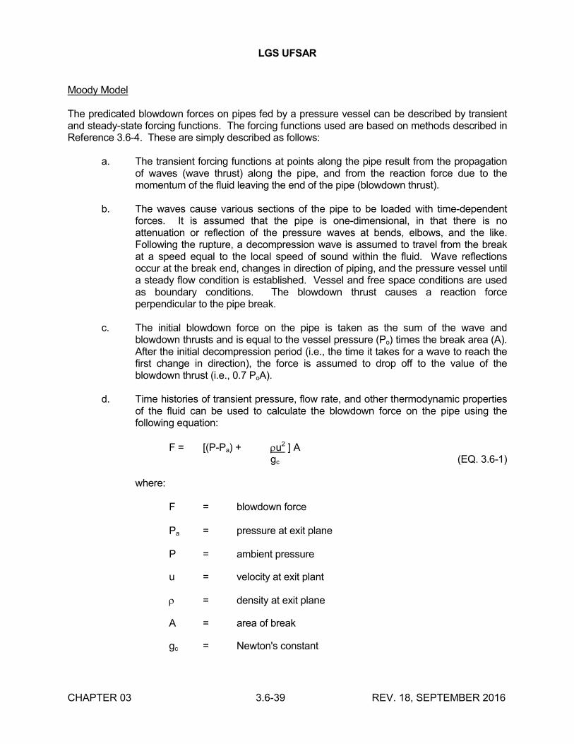
LGS UFSAR
CHAPTER 03 3.6-39 REV. 18, SEPTEMBER 2016
Moody Model
The predicated blowdown forces on pipes fed by a pressure vessel can be described by transient and steady-state forcing functions. The forcing functions used are based on methods described inReference 3.6-4. These are simply described as follows:
a. The transient forcing functions at points along the pipe result from the propagation of waves (wave thrust) along the pipe, and from the reaction force due to the momentum of the fluid leaving the end of the pipe (blowdown thrust).
b. The waves cause various sections of the pipe to be loaded with time-dependent forces. It is assumed that the pipe is one-dimensional, in that there is no attenuation or reflection of the pressure waves at bends, elbows, and the like. Following the rupture, a decompression wave is assumed to travel from the break at a speed equal to the local speed of sound within the fluid. Wave reflections occur at the break end, changes in direction of piping, and the pressure vessel until a steady flow condition is established. Vessel and free space conditions are used as boundary conditions. The blowdown thrust causes a reaction force perpendicular to the pipe break.
c. The initial blowdown force on the pipe is taken as the sum of the wave and blowdown thrusts and is equal to the vessel pressure (Po) times the break area (A). After the initial decompression period (i.e., the time it takes for a wave to reach the first change in direction), the force is assumed to drop off to the value of the blowdown thrust (i.e., 0.7 PoA).
d. Time histories of transient pressure, flow rate, and other thermodynamic properties of the fluid can be used to calculate the blowdown force on the pipe using the following equation:
F = [(P-Pa) + u2 ] Agc (EQ. 3.6-1)
where:
F = blowdown force
Pa = pressure at exit plane
P = ambient pressure
u = velocity at exit plant
= density at exit plane
A = area of break
gc = Newton's constant
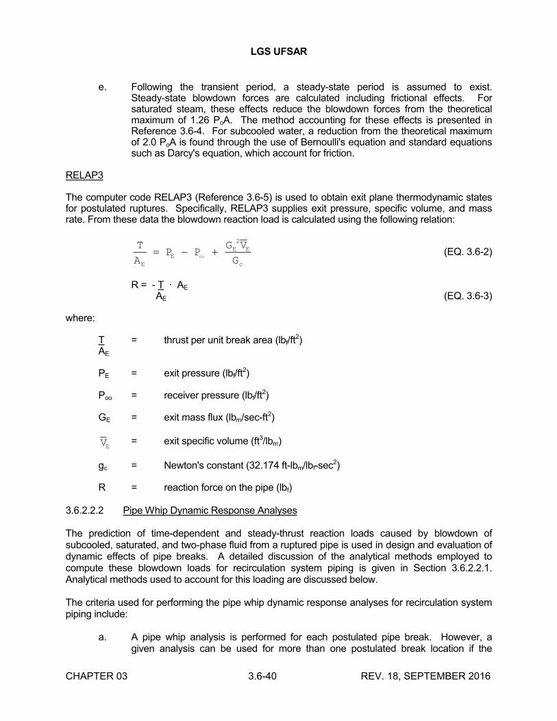
LGS UFSAR
CHAPTER 03 3.6-40 REV. 18, SEPTEMBER 2016
e. Following the transient period, a steady-state period is assumed to exist. Steady-state blowdown forces are calculated including frictional effects. For saturated steam, these effects reduce the blowdown forces from the theoretical maximum of 1.26 PoA. The method accounting for these effects is presented in Reference 3.6-4. For subcooled water, a reduction from the theoretical maximum of 2.0 PoA is found through the use of Bernoulli's equation and standard equations such as Darcy's equation, which account for friction.
RELAP3
The computer code RELAP3 (Reference 3.6-5) is used to obtain exit plane thermodynamic states for postulated ruptures. Specifically, RELAP3 supplies exit pressure, specific volume, and mass rate. From these data the blowdown reaction load is calculated using the following relation:
T
AP P
G V
GE
EE E
c
oo
2
(EQ. 3.6-2)
R = - T · AE
AE (EQ. 3.6-3)
where:
T = thrust per unit break area (lbf/ft2)
AE
PE = exit pressure (lbf/ft2)
Poo = receiver pressure (lbf/ft2)
GE = exit mass flux (lbm/sec-ft2)
VE = exit specific volume (ft3/lbm)
gc = Newton's constant (32.174 ft-lbm/lbf-sec2)
R = reaction force on the pipe (lbf)
3.6.2.2.2 Pipe Whip Dynamic Response Analyses
The prediction of time-dependent and steady-thrust reaction loads caused by blowdown of subcooled, saturated, and two-phase fluid from a ruptured pipe is used in design and evaluation of dynamic effects of pipe breaks. A detailed discussion of the analytical methods employed to compute these blowdown loads for recirculation system piping is given in Section 3.6.2.2.1. Analytical methods used to account for this loading are discussed below.
The criteria used for performing the pipe whip dynamic response analyses for recirculation system piping include:
a. A pipe whip analysis is performed for each postulated pipe break. However, a given analysis can be used for more than one postulated break location if the
LGS UFSAR
CHAPTER 03 3.6-41 REV. 18, SEPTEMBER 2016
blowdown forcing function, piping and restraint system geometry, and piping and restraint system properties are conservative for other break locations.
b. The analysis includes the dynamic response of the pipe in question and the pipe whip restraints that transmit loading to the structures.
c. The analytical model adequately represents the mass/inertia and stiffness properties of the system.
d. Pipe whipping is assumed to occur in the plane defined by the piping geometry and configuration, and is assumed to cause pipe movement in the direction of the jet reaction.
e. Piping within the broken loop is no longer considered part of the RCPB. Plastic deformation in the pipe is considered as a potential energy absorber. Limits of strain are imposed that are similar to strain levels allowed in restraint plastic members. Piping systems are designed so that plastic instability does not occur in the pipe at the design dynamic and static loads, unless damage studies are performed to show that the consequences do not result in direct damage to any essential system or component.
f. Components such as vessel safe ends and valves that are attached to the broken piping system and do not serve a safety function, or whose failure would not further escalate the consequences of the accident, are not designed to meet limits imposed by the ASME B&PV Code for essential components under faulted loading.
The pipe whip analysis was performed using the PDA computer program (Reference 3.6-6). PDA is a computer program used to determine the response of a pipe subjected to the thrust-force occurring after a pipe break. The program treats the situation in terms of generic pipe break configuration, which involves a straight, uniform pipe fixed at one end and subjected to a time-dependent thrust-force at the other end. A typical restraint used to reduce the resulting deformation is also included at a location between the two ends. Nonlinear and time-independent stress-strain relations are used for the pipe and the restraint. A static nonlinear cantilever beam analysis is used for these locations to obtain the relationship between the pipe bending moment and the deflection (or rotation). Similar to the plastic-hinge concept, bending of the pipe is assumed to occur only at the fixed end and at the location supported by the restraint.
Shear deformation is also neglected. The pipe bending moment- deflection (or rotation) relation used for these locations is obtained from a static nonlinear cantilever beam analysis. Using the moment-rotation relation, nonlinear equations of pipe motion are formulated using an energy consideration, and the equations are numerically integrated in small time steps to yield time history information of the deformed pipe.
Considerable testing and analyses have demonstrated that potential rebound does not cause unacceptable increases in restraint deformation following the first quarter cycle loading for the GE restraint design and piping system experiencing blowdown thrust forces. Generic tests were performed on a 12-inch pipe size restraint with two primary loading configurations that represent the typical conditions during the postulated pipe rupture. Any other loading condition results in a combination of these two extremes. These loading configurations are:
LGS UFSAR
CHAPTER 03 3.6-42 REV. 18, SEPTEMBER 2016
a. Load applied perpendicular to the restraint frame base against the cable
b. Load applied parallel to the base against one side of the frame.
The mass/inertia and stiffness properties of the recirculation system in the pipe dynamic analysis (PDA model) are represented as described below. A generic representation of the pipe in any given analysis is shown in Figure 3.6-41. If the stiffness of the piping segment located between A and B is such that:
a. The slope of BD at B = 0, then in the analysis, the pipe is treated as built-in at B.
b. The slope of BD at B /= 0 (considerably different), then in the analysis, the pipe is considered to have a fixed, simple support (pinned end) at B.
To analyze the pipe with both ends supported (Figure 3.6-42) with the above computer model, two simplifications were made in the PDA program. First, an equivalent point mass is assumed at D instead of pipe length DE. The inertia characteristics of this mass rotating around point B are calculated to be identical to those of pipe length DE rotating around point E. Secondly, an equivalent resisting force is calculated for any deflection for the case of a built-in end from the bending moment-angular deflection relationship for pipe length DE. This equivalent force is subtracted from the applied thrust-force when calculating the net energy. The new model resulting from these simplifications is shown in Figure 3.6-42. The PDA computer program is further described in Section 3.9.1.2.2.6.
A comprehensive verification has been performed to demonstrate the conservatisms inherent in the PDA pipe whip computer program and the analytical methods utilized. This is described in Reference 3.6-7. Part of this verification program included an independent analysis of the recirculation system piping for the 1969 Standard Plant Design by Nuclear Services Corporation, under contract to GE. The recirculation system piping was chosen for study due to its complex piping arrangement and assorted pipe sizes. The analysis included elastic-plastic pipe properties, elastic-plastic restraint properties, and gaps between the restraint and pipe as documented in Reference 3.6-7. The piping/restraint system geometry and properties and fluid blowdown forces were the same in both analyses. However, a linear approximation was made by Nuclear Services Corporation for the restraint load-deflection curve supplied by GE. This approximation is demonstrated in Figure 3.6-36. The effect of this approximation is to give lower energy absorption of a given restraint deflection. Typically, this yields higher restraint deflections and lower restraint-to-structure loads than the GE analysis. The deflection limit used by Nuclear Services Corporation is the design deflection at one-half of the ultimate uniform strain for the GE restraint design. The restraint properties used for both analyses are provided in Table 3.6-24.
A comparison of the Nuclear Services Corporation analysis with the PDA analysis, as presented in Table 3.6-25 and Figure 3.6-37, shows that PDA predicts higher loads in 15 of the 18 restraints analyzed. This is due to the Nuclear Services Corporation model including energy-absorbing effects in secondary pipe elements and structural members. However, PDA predicts higher restraint deflections in 50% of the restraints. The higher deflections predicted by Nuclear ServicesCorporation for the lower loads are caused by the linear approximation used for the force-deflection curve rather than by differences in computer techniques. This comparison demonstrates that the simplified modeling system used in PDA is adequate for pipe rupture loading, restraint
LGS UFSAR
CHAPTER 03 3.6-43 REV. 18, SEPTEMBER 2016
performance, and pipe movement predictions within the meaningful design requirements for these low probability postulated accidents.
3.6.2.3 Analytical Models to Define Forcing Functions and Response Models (Systems Other Than Recirculation System)
Analyses to determine the jet impingement effects and the piping and restraint displacements resulting from a pipe break are performed in accordance with BN-TOP-2 (Reference 3.6-8). Analysis of jet thrust forces are described in section 2.2 of BN-TOP-2. Fluid jet impingement forces are discussed in section 2.3 of BN-TOP-2. Impulsive loading and impact combined with impulsive loading are described in sections 3.2 and 3.3, respectively, of BN-TOP-2.
Alternatively, nonlinear time history dynamic analyses are performed. The forcing function used in piping dynamic analysis is obtained using either Reference 3.6-2 or 3.6-9. A typical forcing function and the piping system model used for the dynamic response analysis is provided in Figure 3.6-38. Pipe restraint rebound effects are also considered in this analysis.
A specific case for which time history dynamic analyses are used is the analysis of pipe breaks near containment isolation valves whose operability following the break must be ensured. For each break postulated to occur near a containment isolation valve in a high energy line, a dynamic analysis is performed using the appropriate pipe break forcing function in order to determine the stresses in the pipe and the loads on the moment-limiting restraints near the valve. The dynamic analysis verifies that the stress in the pipe at the isolation valve is maintained below the yield strength of material, in order to ensure valve operability. Since the section modulus of the valve is much greater than that of the pipe, the stress in the valve body is kept below the yield strength of the valve. Therefore, deformation in the valve body as a result of nearby pipe breaks is severely limited and remains in the elastic range so that binding of the valve internals cannot occur.
The criteria for dynamic analyses when used in verifying valve operability are as follows:
a. An analysis of the piping system is performed for the most severe of the postulated longitudinal and circumferential breaks at the break locations determined in accordance with the criteria of Section 3.6.2.1.
b. The loading condition of a piping system prior to a postulated rupture in terms of internal pressure, temperature, and stress state is that condition associated with reactor operation at 100% power.
The basis of selecting 100% power as the loading condition of a piping system prior to rupture is as follows:
1. Pipe rupture analysis state-of-the-art involves several conservative steps and assumptions in all phases of break design (e.g., probability of break, the postulated speed of break propagation, the structural material properties, and the structural stability characteristics of pipe break restraint structures).
2. For those portions of piping systems that are normally pressurized during normal plant operation at power mode, the thermodynamic states in the piping systems are those of full (100%) thermal power.
LGS UFSAR
CHAPTER 03 3.6-44 REV. 18, SEPTEMBER 2016
3. There is a much higher probability for scheduled plant operation at 100% power (or less) than at higher ratings.
The combined effects of these considerations result in designs sufficiently capable of sustaining breaks at higher power levels.
c. For a circumferential break, pipe break dynamic transient force analyses are performed only for that end (or ends) of the pipe or branch that is connected to a contained fluid energy reservoir having sufficient capacity to develop a jet stream.
d. Dynamic analytic methods used for calculating the piping and piping/restraint system response to the pipe break forces adequately account for the effects of the following:
1. Translational masses (and rotational masses for major components) and stiffness properties of the piping system, restraint system, major components, and support walls
2. Transient forcing function(s) acting on the piping system
3. Elastic and inelastic deformation of piping and/or restraint
4. The design clearance between the pipe and the restraint
e. A 10% increase in minimum specified design yield strength (Sy) is used to account for strain rate effects in dynamic analyses.
The criteria for dynamic analyses when used in verifying the design of pipe whip restraints other than valve operability restraints are as follows:
a. A design analysis of the pipe whip restraint system is performed for each postulated longitudinal and circumferential break at the break locations determined in accordance with Section 3.6.2.1.
b. The loading condition of a piping system prior to a postulated break in terms of internal pressure, temperature, and stress state is that condition associated with reactor operation at 100% power.
c. For a circumferential break, pipe break dynamic transient forcing function calculations are performed only for that end (or ends) of the pipe or branch that is connected to a contained fluid energy reservoir having sufficient capacity to develop a jet stream.
d. An energy balance is established between the work done by the pipe break force on the pipe during the first quarter cycle of movement and the sum of the strain energy temporarily stored as elastic strain energy and that energy dissipated as plastic strain energy in members of the whip restraint.
LGS UFSAR
CHAPTER 03 3.6-45 REV. 18, SEPTEMBER 2016
e. In the event that the energy balance design analysis criteria are not satisfied, a dynamic analysis of the piping and piping restraint system is performed. This analysis is described by the same criteria described for valve operability dynamic analysis.
f. Dynamic analytical methods used for designing the pipe whip restraints adequately account for the effects of the following:
1. Transient forcing functions acting on the piping system.
2. Design clearance between the pipe and the restraint in the direction of pipe whip motion 3. Elastic stiffness and yield load capacity of the restraint underload applied in the direction of the pipe motion
4. Impact energy-absorbing capacity of crushable material used in the restraint is equivalent to 100% of the available capacity
5. Ductility capacity of the restraint loaded under impact beyond its yield load corresponds to not more than 50% of the ultimate uniform strain of the material.
3.6.2.4 Dynamic Analysis Methods to Verify Integrity and Operability (Recirculation System Only)
Pipe whip restraints, as differentiated from piping supports, are designed to function and carry load for an extremely low probability gross failure in a piping system carrying high energy fluid. The piping integrity does not usually depend on the piping whip restraints for any loading combination. When the piping integrity is lost because of a postulated break, the pipe whip restraint acts to limit the movement of the broken pipe to an acceptable distance. The pipe whip restraints (i.e., those devices that serve only to control the movement of a ruptured pipe following gross failure) will be subjected to once in a lifetime loading. For the purpose of design, the pipe break event is considered to be a faulted plant condition and the pipe, its restraints, and the structure to which the restraint is attached, are analyzed and designed accordingly.
As described in Section 3.6.1.2.1.1, the pipe whip restraints used for the recirculation system consist of straps (either carbon steel wire ropes or stainless steel bars) attached to a steel frame. The analytical methods used in the design of these restraints are similar to those used for the Fermi Unit 2 and Duane Arnold plants. They have, however, been improved by incorporation of the latest force-deflection data available for wire rope and by using the GE PDA code for the dynamic analysis. Load capacities for the restraint frames were developed by using the SAP code (a finite-element structural analysis program), and were confirmed by a test series using slowly applied loading methods to determine restraint load-deflection data in the tangential direction (parallel to the restraint base). The results of this test program are presented in Reference 3.6-10. The specific design objectives for the restraints are:
a. The restraints shall in no way increase the RCPB stresses by their presence during any normal mode of reactor operation or condition
LGS UFSAR
CHAPTER 03 3.6-46 REV. 18, SEPTEMBER 2016
b. The restraint system shall function to stop the movement of pipe failure (gross loss of piping integrity) without allowing damage to critical components or missile development
c. The restraints shall provide minimum hinderance to inservice inspection of the process piping.
For the purposes of design, the pipe whip restraints are designed for the following dynamic loads:
a. Blowdown thrust of the pipe section that impacts the restraint
b. Dynamic inertia loads of the moving pipe section that is accelerated by the blowdown thrust and subsequent impact on the restraint
c. Design characteristics of the pipe whip restraints are included and verified by the pipe whip dynamic analysis described in Section 3.6.2.2.2
d. Since the pipe whip restraints are not contacted during normal plant operation, the postulated pipe rupture event is the only design loading condition.
As previously described, the recirculation loop pipe whip restraints are composed of two parts, the straps and the restraint frame. Both parts of the restraining device function as load-carrying members, and will deflect under load. The load configurations for a restraint are shown in Figure 3.6-3. The components of the restraints are categorized as Type I and II, as described below:
a. Type I - radial load-carrying members: These members, consisting of cables or bars, will absorb energy when loaded in the direction perpendicular to the restraint base by elastic and plastic deformations (Figure 3.6-3).
b. Type II - tangential load-carry members: These members, consisting of restraint frames, will absorb energy when loaded in the direction parallel to the base by plastic deformation (Figure 3.6-3).
Each of these components is constructed of a different material in order to fulfill different design objectives. The design requirements and design limits for each component are therefore different. They are specified as below:
a. Type I - Straps
1. For carbon steel wire ropes, the maximum acceptable load is 90% of the load-carrying capacity of the cable in the restraint configuration. This limit takes into consideration the efficiency reduction experienced when a cable is wrapped around a pipe. This means that the design load is limited to about 75% of the minimum certified load-carrying capacity of the cable in tension.
2. For stainless steel bars, the design limit base was 50% of the minimum uniform ultimate tensile elongation.
LGS UFSAR
CHAPTER 03 3.6-47 REV. 18, SEPTEMBER 2016
b. Type 2 - Restraint Frames
Design limits for the ASTM A36 restraint frames are as follows:
1. Design Load
The load-bearing member is primarily a cantilever beam with an extra support (the diagonal plate) at approximately mid-span. At loads approaching the plastic moment capability of the beam, the plastic-hinge forms at the section determined by an elastic structural analysis. The maximum design load and the ultimate load are calculated based on plastic moment capability of this section, with the diagonal plate stressed uniformly at the minimum ultimate stress of 58,000 psi as specified for ASTM A36 material.
2. Design Deflection
The design and ultimate deflection are calculated assuming the beam remains straight and rotates about a point on the upper surface of the beam. The maximum design deflection at the load point is calculated assuming the diagonal plate undergoes 10% elongation. This corresponds to 50% of the minimum ultimate elongation of 20%, as specified for ASTM A36 material. The ultimate deflection of the beam is based on 20% ultimate elongation of the diagonal plate.
3.6.2.5 Dynamic Analysis Methods to Verify Integrity and Operability (Systems Other Than Recirculation System
The pipe whip restraints provided for protection from high energy pipe breaks are of two basic types: independent restraints and operability restraints. Independent restraints are provided solely to protect nearby structures and equipment from damage due to whipping pipes, and are designed so that a gap is maintained between the pipe and the restraint during normal plant conditions. Operability restraints are provided near primary containment isolation valves whose operability is required following a break of the pipe in which they are installed. These operability restraints are designed to limit the stress in the piping near the valve to below the yield strength of the material in order to ensure operability of the valve. To accomplish this function, it is necessary to minimize the gap between the pipe and the restraint so that contact will occur during normal plant conditions.
The following high energy piping systems in the drywell are not provided with pipe whip restraints:
a. Reactor vessel drain line (4" DCA-101)
b. Main steam drain lines (2" and 3" DBA-105)
c. RPV head vent line (2" DBA-108)
d. SLCS injection line (2" DCA-112)
LGS UFSAR
CHAPTER 03 3.6-48 REV. 18, SEPTEMBER 2016
Each of these lines has been evaluated, using the guidance of Regulatory Guide 1.46, to verify that in the event of a pipe break, damage to structures, systems, or components needed for safeshutdown would not occur. Therefore, the ability to shut the reactor down safely is maintained if a break should occur in any of these lines.
3.6.2.5.1 Design Loading Combinations
The design loading combinations applied in the design of pipe whip restraints are categorized with respect to the plant operating conditions which are identified as normal, upset, emergency, and faulted as described in Section 3.9.3.1.1. Pipe break is considered as a faulted plant condition.
3.6.2.5.2 Design Stress Limits
Operability Restraints
When restraints for piping are designed so that contact between pipe and restraint will occur during normal plant conditions, the design loading combinations for normal, upset, emergency, and faulted conditions are applicable. In evaluating the supports and restraints for ASME Section III Class 1, 2, and 3, the design stress limits applied in evaluating loading combinations for normal, upset, emergency, and faulted (except for pipe rupture) conditions are those given in Tables 3.9-12and 3.9-16. After rupture of the supported pipe occurs, the piping system is no longer within the jurisdiction of ASME Section III because the pressure boundary has been breached. The restraints are evaluated for pipe rupture loads as described in Section 3.6.2.3.
Pipe restraints are included on main steam, feedwater, RWCU, HPCI, and RCIC system to ensure the operability of the containment isolation valves during a postulated break event that touch the pipe during normal operation. The restraints are modeled in the thermal and dynamic analysis as active (1/16 inch or less gaps) during all loading conditions.
The operability of the isolation valves protected by operability restraints is assured by limiting the pipe break dynamic stress in the adjacent pipe. Stresses at the junction of this component with the pipe are limited to the dynamic yield strength of the pipe material (1.1 Sy). Between the containment penetration inboard/outboard isolation valves, pipe dynamic stress is limited to be less than 2.25 Sm.
Independent Restraints
When restraints are designed solely to control movement following a postulated pipe rupture and to function independently of the normal support system, only the design pipe rupture loads are applicable.
To ensure that restraints function independently of the normal support system, the motions of the intact pipe due to all normal and upset plant conditions and the vibratory motion of the SSE are calculated and used to specify a minimum clearance between the pipe and the restraint. Wherever possible, gaps between pipes and restraints are maximized to avoid possible contact during plant operation. Where a particular location requires minimizing a gap, special features are provided to permit adjustment of the gap size during hot functional testing.
Independent restraints are evaluated for the pipe rupture loads as described in Section 3.6.2.3.
LGS UFSAR
CHAPTER 03 3.6-49 REV. 18, SEPTEMBER 2016
3.6.2.6 Guard Pipe Assembly Design Criteria
Guard pipe assemblies are not used in this plant.
3.6.3 DEFINITIONS
Certain terms used in Sections 3.6.1 and 3.6.2 have specified meanings as described below:
Essential Systems and Components - Systems and components required to shut down the reactor and mitigate the consequences of a postulated piping failure, without offsite power.
High Energy Fluid Systems - Fluid systems that, during normal plant conditions, are either in operation or maintained pressurized under conditions where either or both of the following are met:
a. Maximum operating temperature exceeds 200F
b. Maximum operating pressure exceeds 275 psig
Moderate Energy Fluid Systems - Fluid systems that, during normal plant conditions, are either in operation or maintained pressurized (above atmospheric pressure) under conditions where both of the following are met:
a. Maximum operating temperature is 200F or less
b. Maximum operating pressure is 275 psig or less
A system that qualifies as a high energy fluid system for only short periods and qualifies as moderate energy fluid system for the majority of the time is classified as a moderate energy fluid system provided that the total time the system operates within high energy pressure/temperature conditions is less than either of the following:
a. 2% of the time that the system operates as a moderate energy fluid system
b. 1% of the normal operating life span of the plant
Normal Plant Conditions - Plant operating conditions during reactor startup, operation at power, hot standby, or reactor cooldown to cold shutdown condition.
Upset Plant Conditions - Plant operating conditions during system transients that may occur with moderate frequency during plant service life and are anticipated operational occurrences, but not during system testing.
Sh and SA - Allowable stresses at maximum (hot) temperature and allowable stress range for thermal expansion, respectively, as defined in ASME Section III, Article NC-3600.
Sm - Design stress intensity as defined in ASME Section III, Article NB-3600.
LGS UFSAR
CHAPTER 03 3.6-50 REV. 18, SEPTEMBER 2016
Sn - Primary plus secondary stress intensity range for normal and upset conditions as defined in ASME Section III, paragraph NB-3653.
Single Active Component Failure - Malfunction or loss of function of a component of electrical or fluid systems. The failure of an active component of a fluid system is considered to be a loss of component function as a result of mechanical, hydraulic, pneumatic, or electrical malfunction, but not the loss of component structural integrity. The direct consequences of a single active component failure are considered to be part of the single failure.
Terminal Ends - Extremities of piping runs that connect to structures, components (e.g., vessels, pumps, valves), or pipe anchors that act as rigid constraints to piping thermal expansion. A branch connection to a main piping run is a terminal end of the branch run, except when all three of the following conditions are in effect:
a. The nominal size of the branch run is at least half that of the main run
b. The intersection is not rigidly constrained to the building structure
c. The branch run and main run are included together in the same piping stress analysis model
For piping in containment penetration areas, terminal ends are selected at points located immediately beyond the required moment-limiting restraints inside and outside containment. In piping runs which are maintained pressurized during normal plant conditions for only a portion of the run (i.e., up to the first normally closed valve), a terminal end of such runs is the piping connection to this closed valve.
3.6.4 REFERENCES
3.6-1 "Subcompartment Pressure Analyses", BN-TOP-4, Rev. 0, Bechtel Power Corporation, San Francisco, California, (July 1976).
3.6-2 RELAP4/MOD5, "Computer Program for Transient Thermal-Hydraulic Analysis of Nuclear Reactors and Related Systems," ANCR-NUREG-1335, (September 1976).
3.6-3 FLUD, "Thermofluid Dynamics for a System of Interconnected Compartments," NE017, version 3, (July 18, 1980).
3.6-4 "System Criteria and Applications for Protection Against the Dynamic Effects of Pipe Break", GE Specification No. 22A2625.
3.6-5 RELAP3, "A Computer Program for Reactor Blowdown Analysis", IN-1321, Reactor Technology TID-4500, (June 1970).
3.6-6 "PDA - Pipe Dynamic Analysis Program for Pipe Rupture Movement" (proprietary filing), GE Report NEDE-10813.
3.6-7 "Final Report Pipe Rupture Analysis of Recirculation System for 1969 Standard Plant Design", Nuclear Services Corporation Report No. GEN-02-02.
LGS UFSAR
CHAPTER 03 3.6-51 REV. 18, SEPTEMBER 2016
3.6-8 "Design for Pipe Break Effects", BN-TOP-2, Rev. 2, Bechtel Power Corporation, San Francisco, California, (May 1974).
3.6-9 F.J. Moody, "Fluid Reaction and Impingement Loads", ASCE Specialty Conference on Structural Design of Nuclear Plant Facilities, Vol 1, pp. 219-262, (December 1973).
3.6-10 "Recirculation System Pipe Whip Restraint for the BWR 4, 218 and 251, Mark I and Mark II Product Line Plant", GE Design.
3.6-11 "Limerick Atomic Power Stations Units 1 & 2 Power Rerate Evaluation of Main Steam & Recirculation Piping System, "GE Report GE-NE-123-E014-0193, Rev. 0 (July 1993) (part of N-00E-177-00003).
3.6-12 PCFLUD, "Thermofluid Dynamics for a System of Interconnected Compartments," MAP-120, Version 4.0 (July 15, 1992).
3.6-13 CONCOIL-FLUD (CFLUD), "Thermofluid Dynamics for a System of Interconnected Compartments," Version 1.0 (December 1, 1993).
3.6-14 GEH 0000-0158-9651-NP, Revision 0, October 2013, LGS Main Steam Isolation Valve Response Time Testing Analysis (SDOC G-080-VC-00489).
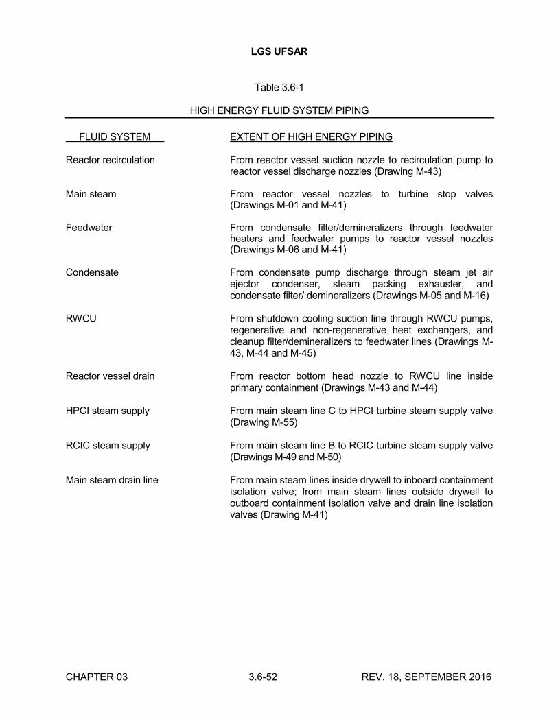
LGS UFSAR
CHAPTER 03 3.6-52 REV. 18, SEPTEMBER 2016
Table 3.6-1
HIGH ENERGY FLUID SYSTEM PIPING
FLUID SYSTEM EXTENT OF HIGH ENERGY PIPING
Reactor recirculation From reactor vessel suction nozzle to recirculation pump to reactor vessel discharge nozzles (Drawing M-43)
Main steam From reactor vessel nozzles to turbine stop valves (Drawings M-01 and M-41)
Feedwater From condensate filter/demineralizers through feedwater heaters and feedwater pumps to reactor vessel nozzles (Drawings M-06 and M-41)
Condensate From condensate pump discharge through steam jet air ejector condenser, steam packing exhauster, and condensate filter/ demineralizers (Drawings M-05 and M-16)
RWCU From shutdown cooling suction line through RWCU pumps, regenerative and non-regenerative heat exchangers, and cleanup filter/demineralizers to feedwater lines (Drawings M-43, M-44 and M-45)
Reactor vessel drain From reactor bottom head nozzle to RWCU line inside primary containment (Drawings M-43 and M-44)
HPCI steam supply From main steam line C to HPCI turbine steam supply valve (Drawing M-55)
RCIC steam supply From main steam line B to RCIC turbine steam supply valve (Drawings M-49 and M-50)
Main steam drain line From main steam lines inside drywell to inboard containment isolation valve; from main steam lines outside drywell to outboard containment isolation valve and drain line isolation valves (Drawing M-41)
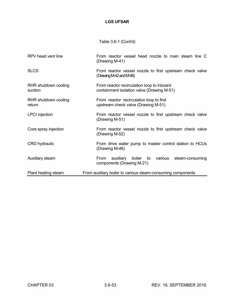
LGS UFSAR
CHAPTER 03 3.6-53 REV. 18, SEPTEMBER 2016
Table 3.6-1 (Cont'd)
RPV head vent line From reactor vessel head nozzle to main steam line C (Drawing M-41)
SLCS From reactor vessel nozzle to first upstream check valve (Drawing M-42 and M-48)
RHR shutdown cooling From reactor recirculation loop to inboardsuction containment isolation valve (Drawing M-51)
RHR shutdown cooling From reactor recirculation loop to firstreturn upstream check valve (Drawing M-51)
LPCI injection From reactor vessel nozzle to first upstream check valve (Drawing M-51)
Core spray injection From reactor vessel nozzle to first upstream check valve (Drawing M-52)
CRD hydraulic From drive water pump to master control station to HCUs (Drawing M-46)
Auxiliary steam From auxiliary boiler to various steam-consuming components (Drawing M-21)
Plant heating steam From auxiliary boiler to various steam-consuming components
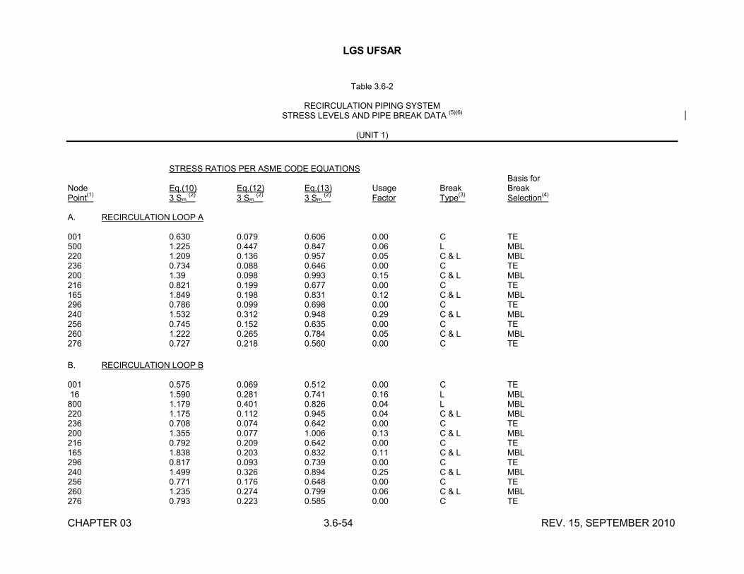
LGS UFSAR
CHAPTER 03 3.6-54 REV. 15, SEPTEMBER 2010
Table 3.6-2
RECIRCULATION PIPING SYSTEMSTRESS LEVELS AND PIPE BREAK DATA
(5)(6)
(UNIT 1)
STRESS RATIOS PER ASME CODE EQUATIONSBasis for
Node Eq.(10) Eq.(12) Eq.(13) Usage Break BreakPoint
(1)3 Sm
(2)3 Sm
(2)3 Sm
(2)Factor Type
(3)Selection
(4)
A. RECIRCULATION LOOP A
001 0.630 0.079 0.606 0.00 C TE500 1.225 0.447 0.847 0.06 L MBL220 1.209 0.136 0.957 0.05 C & L MBL236 0.734 0.088 0.646 0.00 C TE200 1.39 0.098 0.993 0.15 C & L MBL216 0.821 0.199 0.677 0.00 C TE165 1.849 0.198 0.831 0.12 C & L MBL296 0.786 0.099 0.698 0.00 C TE240 1.532 0.312 0.948 0.29 C & L MBL256 0.745 0.152 0.635 0.00 C TE260 1.222 0.265 0.784 0.05 C & L MBL276 0.727 0.218 0.560 0.00 C TE
B. RECIRCULATION LOOP B
001 0.575 0.069 0.512 0.00 C TE16 1.590 0.281 0.741 0.16 L MBL
800 1.179 0.401 0.826 0.04 L MBL220 1.175 0.112 0.945 0.04 C & L MBL236 0.708 0.074 0.642 0.00 C TE200 1.355 0.077 1.006 0.13 C & L MBL216 0.792 0.209 0.642 0.00 C TE165 1.838 0.203 0.832 0.11 C & L MBL296 0.817 0.093 0.739 0.00 C TE240 1.499 0.326 0.894 0.25 C & L MBL256 0.771 0.176 0.648 0.00 C TE260 1.235 0.274 0.799 0.06 C & L MBL276 0.793 0.223 0.585 0.00 C TE
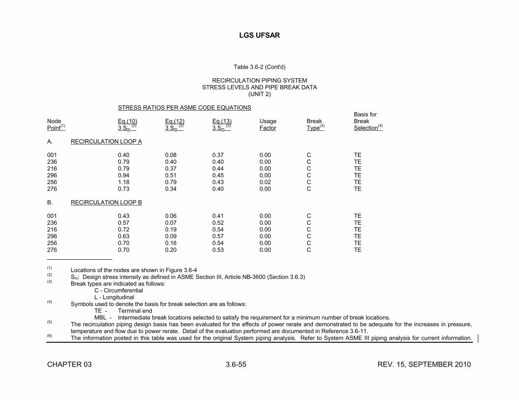
LGS UFSAR
CHAPTER 03 3.6-55 REV. 15, SEPTEMBER 2010
Table 3.6-2 (Cont'd)
RECIRCULATION PIPING SYSTEMSTRESS LEVELS AND PIPE BREAK DATA
(UNIT 2)
STRESS RATIOS PER ASME CODE EQUATIONSBasis for
Node Eq.(10) Eq.(12) Eq.(13) Usage Break BreakPoint
(1)3 Sm
(2)3 Sm
(2)3 Sm
(2)Factor Type
(3)Selection
(4)
A. RECIRCULATION LOOP A
001 0.40 0.08 0.37 0.00 C TE236 0.79 0.40 0.40 0.00 C TE216 0.79 0.37 0.44 0.00 C TE296 0.94 0.51 0.45 0.00 C TE256 1.18 0.79 0.43 0.02 C TE276 0.73 0.34 0.40 0.00 C TE
B. RECIRCULATION LOOP B
001 0.43 0.06 0.41 0.00 C TE236 0.57 0.07 0.52 0.00 C TE216 0.72 0.19 0.54 0.00 C TE296 0.63 0.09 0.57 0.00 C TE256 0.70 0.16 0.54 0.00 C TE276 0.70 0.20 0.53 0.00 C TE____________________
(1)Locations of the nodes are shown in Figure 3.6-4
(2)Sm: Design stress intensity as defined in ASME Section III, Article NB-3600 (Section 3.6.3)
(3)Break types are indicated as follows:
C - CircumferentialL - Longitudinal
(4)Symbols used to denote the basis for break selection are as follows:
TE - Terminal endMBL - Intermediate break locations selected to satisfy the requirement for a minimum number of break locations.
(5)The recirculation piping design basis has been evaluated for the effects of power rerate and demonstrated to be adequate for the increases in pressure, temperature and flow due to power rerate. Detail of the evaluation performed are documented in Reference 3.6-11.
(6)The information posted in this table was used for the original System piping analysis. Refer to System ASME III piping analysis for current information.
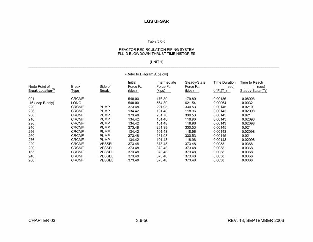
LGS UFSAR
CHAPTER 03 3.6-56 REV. 13, SEPTEMBER 2006
Table 3.6-3
REACTOR RECIRCULATION PIPING SYSTEMFLUID BLOWDOWN THRUST TIME HISTORIES
(UNIT 1)________________________________________________________________________________________________________________________________
(Refer to Diagram A below)
Initial Intermediate Steady-State Time Duration Time to ReachNode Point of Break Side of Force Fo Force Fint Force Fss sec) (sec)Break Location
(1)Type Break (kips) (kips) (kips) of Fo(T1) Steady-State (T2)
001 CRCMF 540.00 476.80 179.80 0.00186 0.0800616 (loop B only) LONG 540.00 564.30 621.54 0.00064 0.0032
220 CRCMF PUMP 373.48 291.98 330.53 0.00145 0.0210236 CRCMF PUMP 134.42 101.48 118.96 0.00143 0.02098200 CRCMF PUMP 373.48 281.78 330.53 0.00145 0.021216 CRCMF PUMP 134.42 101.48 118.96 0.00143 0.02098296 CRCMF PUMP 134.42 101.48 118.96 0.00143 0.02098240 CRCMF PUMP 373.48 281.98 330.53 0.00145 0.021256 CRCMF PUMP 134.42 101.48 118.96 0.00143 0.02098260 CRCMF PUMP 373.48 281.98 330.53 0.00145 0.021276 CRCMF PUMP 134.42 101.48 118.96 0.00143 0.02098220 CRCMF VESSEL 373.48 373.48 373.48 0.0038 0.0368200 CRCMF VESSEL 373.48 373.48 373.48 0.0038 0.0368165 CRCMF VESSEL 373.48 373.48 373.48 0.0038 0.0368240 CRCMF VESSEL 373.48 373.48 373.48 0.0038 0.0368260 CRCMF VESSEL 373.48 373.48 373.48 0.0038 0.0368
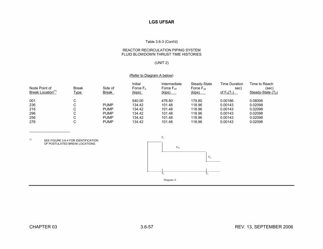
LGS UFSAR
CHAPTER 03 3.6-57 REV. 13, SEPTEMBER 2006
Table 3.6-3 (Cont'd)
REACTOR RECIRCULATION PIPING SYSTEMFLUID BLOWDOWN THRUST TIME HISTORIES
(UNIT 2)
(Refer to Diagram A below)
Initial Intermediate Steady-State Time Duration Time to ReachNode Point of Break Side of Force Fo Force Fint Force Fss sec) (sec)Break Location
(1)Type Break (kips) (kips) (kips) of Fo(T1) Steady-State (T2)
001 C 540.00 476.80 179.80 0.00186 0.08006236 C PUMP 134.42 101.48 118.96 0.00143 0.02098216 C PUMP 134.42 101.48 118.96 0.00143 0.02098296 C PUMP 134.42 101.48 118.96 0.00143 0.02098256 C PUMP 134.42 101.48 118.96 0.00143 0.02098276 C PUMP 134.42 101.48 118.96 0.00143 0.02098
____________________
Fo(1) SEE FIGURE 3.6-4 FOR IDENTIFICATION
OF POSTULATED BREAK LOCATIONS. │ ││ │ Fint
│ ││ ││ │ Fss
│ ││ │ │ │ │
T1 T2
Diagram A
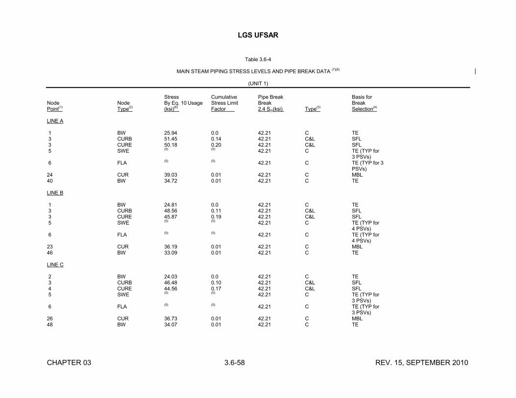
LGS UFSAR
CHAPTER 03 3.6-58 REV. 15, SEPTEMBER 2010
Table 3.6-4
MAIN STEAM PIPING STRESS LEVELS AND PIPE BREAK DATA (7)(8)
(UNIT 1)
Stress Cumulative Pipe Break Basis forNode Node By Eq. 10 Usage Stress Limit Break BreakPoint(1) Type(2) (ksi)(6) Factor 2.4 Sm(ksi) Type(3) Selection(4)
LINE A
1 BW 25.94 0.0 42.21 C TE3 CURB 51.45 0.14 42.21 C&L SFL3 CURE 50.18 0.20 42.21 C&L SFL5 SWE (5) (5) 42.21 C TE (TYP for
3 PSVs)6 FLA (5) (5) 42.21 C TE (TYP for 3
PSVs)24 CUR 39.03 0.01 42.21 C MBL40 BW 34.72 0.01 42.21 C TE
LINE B
1 BW 24.81 0.0 42.21 C TE3 CURB 48.56 0.11 42.21 C&L SFL3 CURE 45.87 0.19 42.21 C&L SFL5 SWE (5) (5) 42.21 C TE (TYP for
4 PSVs)6 FLA (5) (5) 42.21 C TE (TYP for
4 PSVs)23 CUR 36.19 0.01 42.21 C MBL46 BW 33.09 0.01 42.21 C TE
LINE C
2 BW 24.03 0.0 42.21 C TE3 CURB 46.48 0.10 42.21 C&L SFL4 CURE 44.56 0.17 42.21 C&L SFL5 SWE (5) (5) 42.21 C TE (TYP for
3 PSVs)6 FLA (5) (5) 42.21 C TE (TYP for
3 PSVs)26 CUR 36.73 0.01 42.21 C MBL48 BW 34.07 0.01 42.21 C TE
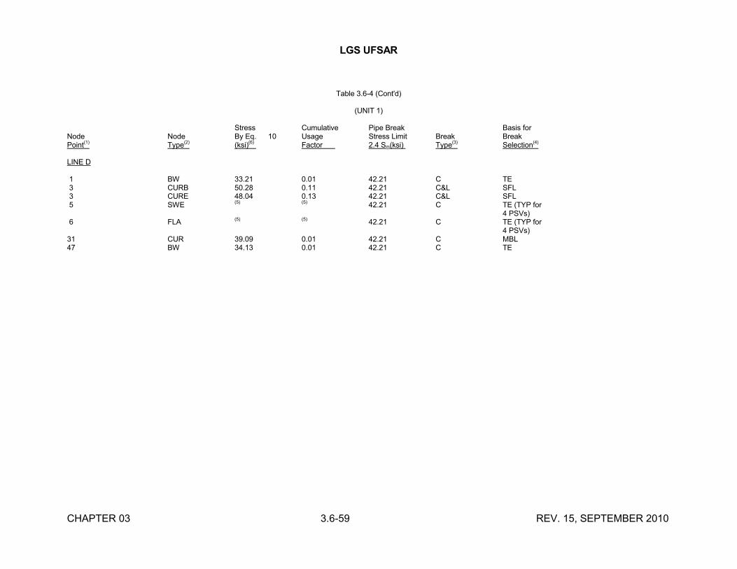
LGS UFSAR
CHAPTER 03 3.6-59 REV. 15, SEPTEMBER 2010
Table 3.6-4 (Cont'd)
(UNIT 1)
Stress Cumulative Pipe Break Basis forNode Node By Eq. 10 Usage Stress Limit Break BreakPoint(1) Type(2) (ksi)(6) Factor 2.4 Sm(ksi) Type(3) Selection(4)
LINE D
1 BW 33.21 0.01 42.21 C TE3 CURB 50.28 0.11 42.21 C&L SFL3 CURE 48.04 0.13 42.21 C&L SFL5 SWE (5) (5) 42.21 C TE (TYP for
4 PSVs)6 FLA (5) (5) 42.21 C TE (TYP for
4 PSVs)31 CUR 39.09 0.01 42.21 C MBL47 BW 34.13 0.01 42.21 C TE
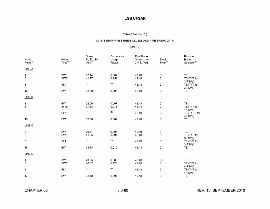
LGS UFSAR
CHAPTER 03 3.6-60 REV. 15, SEPTEMBER 2010
Table 3.6-4 (Cont'd)
MAIN STEAM PIPE STRESS LEVELS AND PIPE BREAK DATA
(UNIT 2)
Stress Cumulative Pipe Break Basis forNode Node By Eq. 10 Usage Stress Limit Break BreakPoint(1) Type(2) (ksi)(6) Factor 2.4 Sm(ksi) Type(3) Selection(4)
LINE A
1 BW 32.44 0.007 42.48 C TE5 SWE 41.77 0.251 42.48 C TE (TYP for
3 PSVs)6 FLA (5) (5) 42.48 C TE (TYP for
3 PSVs)40 BW 32.30 0.008 42.48 C TE
LINE B
1 BW 32.00 0.007 42.48 C TE5 SWE 37.58 0.218 42.48 C TE (TYP for
4 PSVs)6 FLA (5) (5) 42.48 C TE (TYPE for
4 PSVs)46 BW 32.60 0.009 42.48 C TE
LINE C
2 BW 29.77 0.007 42.48 C TE5 SWE 41.65 0.294 42.48 C TE (TYP for
3 PSVs)6 FLA (5) (5) 42.48 C TE (TYP for
3 PSVs)48 BW 33.78 0.010 42.48 C TE
LINE D
1 BW 29.95 0.006 42.48 C TE5 SWE 40.32 0.126 42.48 C TE (TYP for
4 PSVs)6 FLA (5) (5) 42.48 C TE (TYP for
4 PSVs)47 BW 32.18 0.007 42.48 C TE
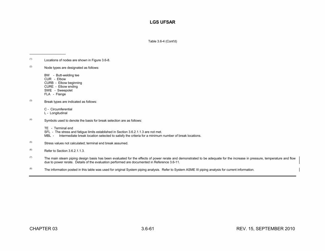
LGS UFSAR
CHAPTER 03 3.6-61 REV. 15, SEPTEMBER 2010
Table 3.6-4 (Cont'd)
____________________
(1) Locations of nodes are shown in Figure 3.6-8.
(2) Node types are designated as follows:
BW - Butt-welding teeCUR - ElbowCURB - Elbow beginningCURE - Elbow endingSWE - SweepoletFLA - Flange
(3) Break types are indicated as follows:
C - CircumferentialL - Longitudinal
(4) Symbols used to denote the basis for break selection are as follows:
TE - Terminal endSFL - The stress and fatigue limits established in Section 3.6.2.1.1.3 are not met.MBL - Intermediate break location selected to satisfy the criteria for a minimum number of break locations.
(5) Stress values not calculated; terminal end break assumed.
(6) Refer to Section 3.6.2.1.1.3.
(7) The main steam piping design basis has been evaluated for the effects of power rerate and demonstrated to be adequate for the increase in pressure, temperature and flow due to power rerate. Details of the evaluation performed are documented in Reference 3.6-11.
(8) The information posted in this table was used for original System piping analysis. Refer to System ASME III piping analysis for current information.
LGS UFSAR
CHAPTER 03 3.6-62 REV. 13, SEPTEMBER 2006
Table 3.6-5
INTENTIONALLY LEFT BLANK
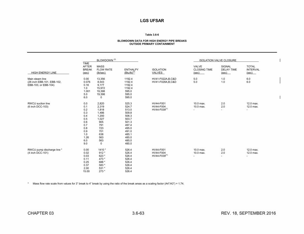
LGS UFSAR
CHAPTER 03 3.6-63 REV. 18, SEPTEMBER 2016
Table 3.6-6
BLOWDOWN DATA FOR HIGH ENERGY PIPE BREAKSOUTSIDE PRIMARY CONTAINMENT
BLOWDOWN (2) ISOLATION VALVE CLOSURETIMEAFTER MASS VALVE SIGNAL TOTALBREAK FLOW RATE ENTHALPY ISOLATION CLOSING TIME DELAY TIME INTERVAL
HIGH ENERGY LINE (sec) (lb/sec) (Btu/lb)(3) VALVES (sec) (sec) (sec) .
Main steam line 0.00 13,356 1192.4 HV41-F022A,B,C&D 5.0 1.0 6.0(26 inch EBB-101, EBB-102, 0.076 8,543 1192.4 HV41-F028A,B,C&D 5.0 1.0 6.0EBB-103, or EBB-104) 0.16 9,177 1192.4
1.0 15,972 1192.41.001 19,398 595.05.0 19,398 595.06.0 0 595.0
RWCU suction line 0.0 2,820 525.3 HV44-F001 10.0 max. 2.0 12.0 max.(6 inch DCC-103) 0.1 2,319 524.7 HV44-F004 10.0 max. 2.0 12.0 max.
0.2 1,818 513.0 HV44-F039(1) - - -0.3 1,486 509.80.4 1,200 506.30.5 1,027 503.70.6 905 501.30.7 791 497.40.8 723 495.00.9 701 491.01.0 638 485.11.26 563 485.06.0 563 485.09.0 0 485.0
RWCU pump discharge line * 0.00 1410 * 526.4 HV44-F001 10.0 max. 2.0 12.0 max.(4 inch DCC-101) 0.02 912 * 526.4 HV44-F004 10.0 max. 2.0 12.0 max.
0.03 623 * 526.4 HV44-F039(1) - - -0.11 473 * 526.40.25 688 * 526.40.37 583 * 526.42.00 531 * 526.415.00 273 * 526.4
* Mass flow rate scale from values for 3” break to 4” break by using the ratio of the break areas as a scaling factor (A4”/A3”) = 1.74.
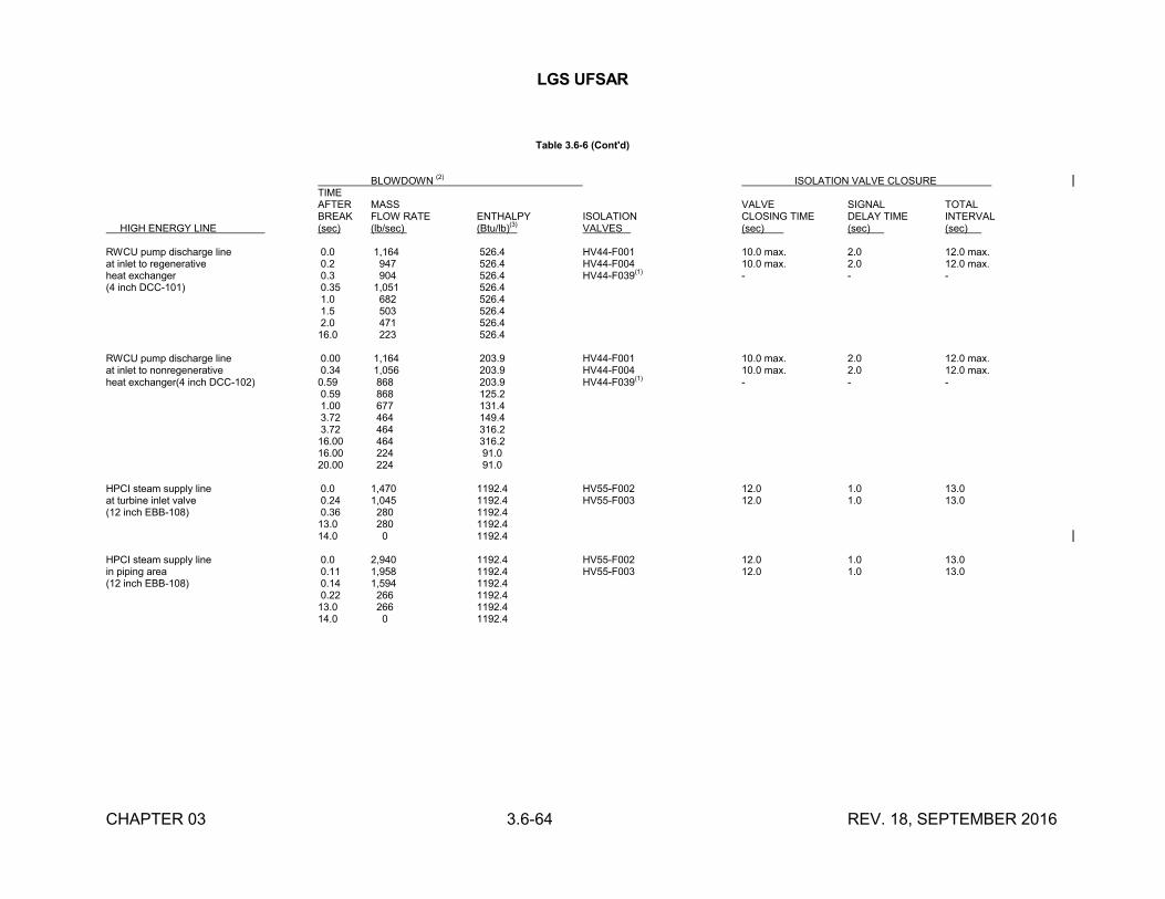
LGS UFSAR
CHAPTER 03 3.6-64 REV. 18, SEPTEMBER 2016
Table 3.6-6 (Cont'd)
BLOWDOWN(2)
ISOLATION VALVE CLOSURETIMEAFTER MASS VALVE SIGNAL TOTALBREAK FLOW RATE ENTHALPY ISOLATION CLOSING TIME DELAY TIME INTERVAL
HIGH ENERGY LINE (sec) (lb/sec) (Btu/lb)(3)
VALVES (sec) (sec) (sec) .
RWCU pump discharge line 0.0 1,164 526.4 HV44-F001 10.0 max. 2.0 12.0 max.at inlet to regenerative 0.2 947 526.4 HV44-F004 10.0 max. 2.0 12.0 max.heat exchanger 0.3 904 526.4 HV44-F039
(1)- - -
(4 inch DCC-101) 0.35 1,051 526.41.0 682 526.41.5 503 526.42.0 471 526.416.0 223 526.4
RWCU pump discharge line 0.00 1,164 203.9 HV44-F001 10.0 max. 2.0 12.0 max.at inlet to nonregenerative 0.34 1,056 203.9 HV44-F004 10.0 max. 2.0 12.0 max.heat exchanger(4 inch DCC-102) 0.59 868 203.9 HV44-F039(1) - - -
0.59 868 125.21.00 677 131.43.72 464 149.43.72 464 316.216.00 464 316.216.00 224 91.020.00 224 91.0
HPCI steam supply line 0.0 1,470 1192.4 HV55-F002 12.0 1.0 13.0at turbine inlet valve 0.24 1,045 1192.4 HV55-F003 12.0 1.0 13.0(12 inch EBB-108) 0.36 280 1192.4
13.0 280 1192.414.0 0 1192.4
HPCI steam supply line 0.0 2,940 1192.4 HV55-F002 12.0 1.0 13.0in piping area 0.11 1,958 1192.4 HV55-F003 12.0 1.0 13.0(12 inch EBB-108) 0.14 1,594 1192.4
0.22 266 1192.413.0 266 1192.414.0 0 1192.4
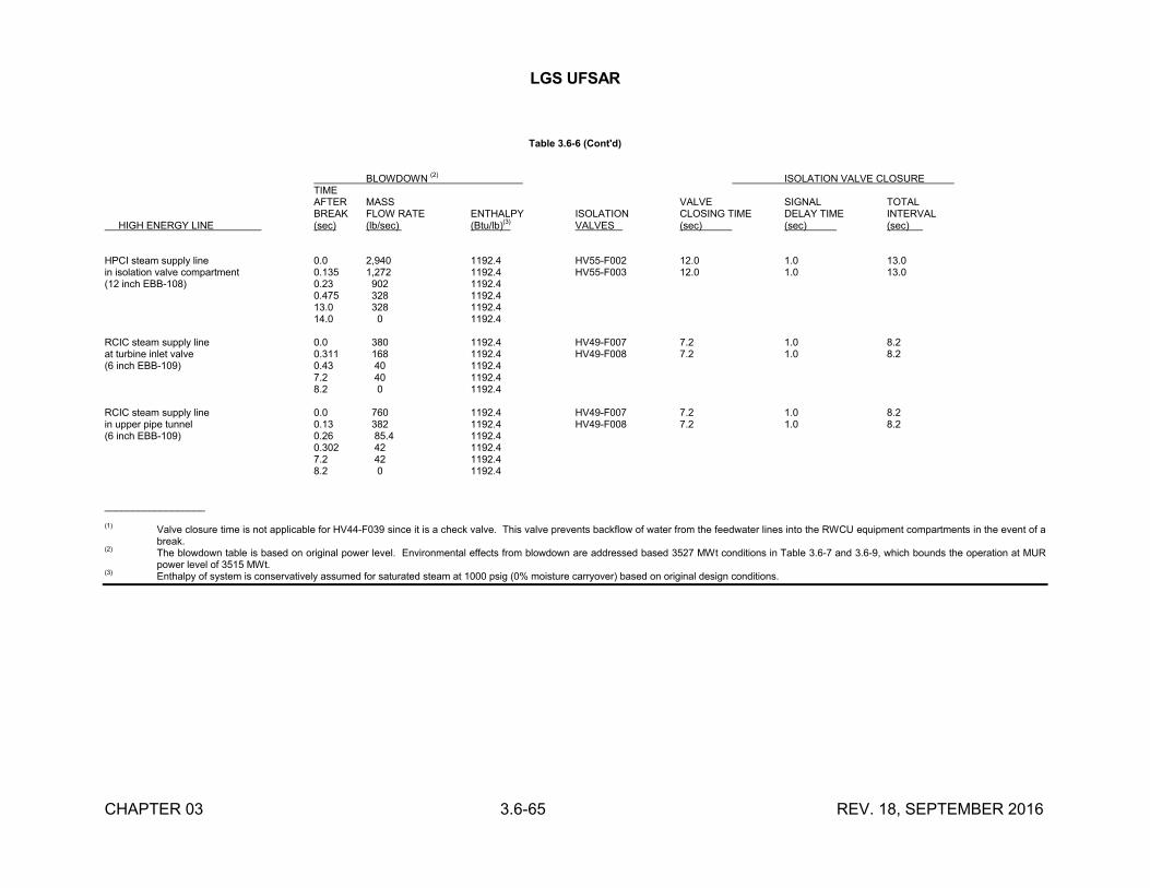
LGS UFSAR
CHAPTER 03 3.6-65 REV. 18, SEPTEMBER 2016
Table 3.6-6 (Cont'd)
BLOWDOWN (2)
ISOLATION VALVE CLOSURETIMEAFTER MASS VALVE SIGNAL TOTALBREAK FLOW RATE ENTHALPY ISOLATION CLOSING TIME DELAY TIME INTERVAL
HIGH ENERGY LINE (sec) (lb/sec) (Btu/lb)(3)
VALVES (sec) (sec) (sec) .
HPCI steam supply line 0.0 2,940 1192.4 HV55-F002 12.0 1.0 13.0in isolation valve compartment 0.135 1,272 1192.4 HV55-F003 12.0 1.0 13.0(12 inch EBB-108) 0.23 902 1192.4
0.475 328 1192.413.0 328 1192.414.0 0 1192.4
RCIC steam supply line 0.0 380 1192.4 HV49-F007 7.2 1.0 8.2at turbine inlet valve 0.311 168 1192.4 HV49-F008 7.2 1.0 8.2(6 inch EBB-109) 0.43 40 1192.4
7.2 40 1192.48.2 0 1192.4
RCIC steam supply line 0.0 760 1192.4 HV49-F007 7.2 1.0 8.2in upper pipe tunnel 0.13 382 1192.4 HV49-F008 7.2 1.0 8.2(6 inch EBB-109) 0.26 85.4 1192.4
0.302 42 1192.47.2 42 1192.48.2 0 1192.4
__________________
(1) Valve closure time is not applicable for HV44-F039 since it is a check valve. This valve prevents backflow of water from the feedwater lines into the RWCU equipment compartments in the event of a break.
(2) The blowdown table is based on original power level. Environmental effects from blowdown are addressed based 3527 MWt conditions in Table 3.6-7 and 3.6-9, which bounds the operation at MUR power level of 3515 MWt.
(3) Enthalpy of system is conservatively assumed for saturated steam at 1000 psig (0% moisture carryover) based on original design conditions.
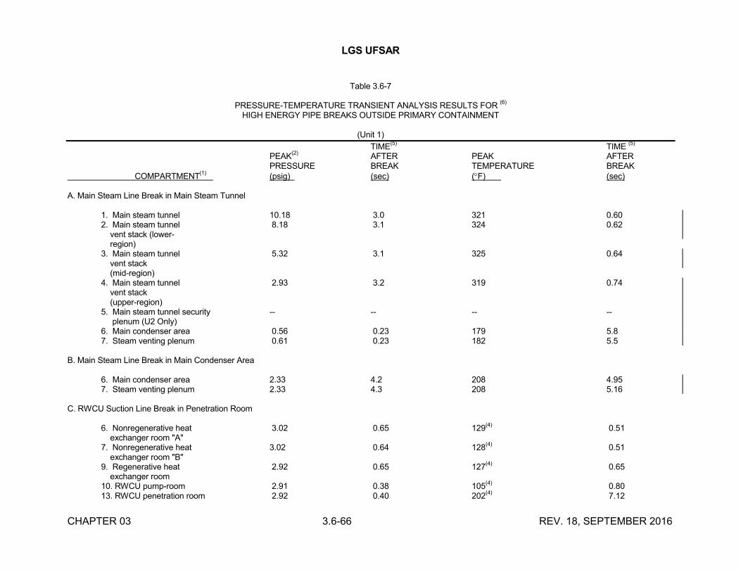
LGS UFSAR
CHAPTER 03 3.6-66 REV. 18, SEPTEMBER 2016
Table 3.6-7
PRESSURE-TEMPERATURE TRANSIENT ANALYSIS RESULTS FOR (6)
HIGH ENERGY PIPE BREAKS OUTSIDE PRIMARY CONTAINMENT
(Unit 1)
TIME(5)
TIME (5)
PEAK(2)
AFTER PEAK AFTERPRESSURE BREAK TEMPERATURE BREAK
COMPARTMENT(1)
(psig) (sec) (F) (sec)
A. Main Steam Line Break in Main Steam Tunnel
1. Main steam tunnel 10.18 3.0 321 0.602. Main steam tunnel 8.18 3.1 324 0.62 vent stack (lower- region)3. Main steam tunnel 5.32 3.1 325 0.64 vent stack (mid-region)4. Main steam tunnel 2.93 3.2 319 0.74 vent stack (upper-region)5. Main steam tunnel security -- -- -- -- plenum (U2 Only)6. Main condenser area 0.56 0.23 179 5.87. Steam venting plenum 0.61 0.23 182 5.5
B. Main Steam Line Break in Main Condenser Area
6. Main condenser area 2.33 4.2 208 4.957. Steam venting plenum 2.33 4.3 208 5.16
C. RWCU Suction Line Break in Penetration Room
6. Nonregenerative heat 3.02 0.65 129(4)
0.51 exchanger room "A"7. Nonregenerative heat 3.02 0.64 128
(4)0.51
exchanger room "B"9. Regenerative heat 2.92 0.65 127
(4)0.65
exchanger room10. RWCU pump-room 2.91 0.38 105
(4)0.80
13. RWCU penetration room 2.92 0.40 202(4)
7.12
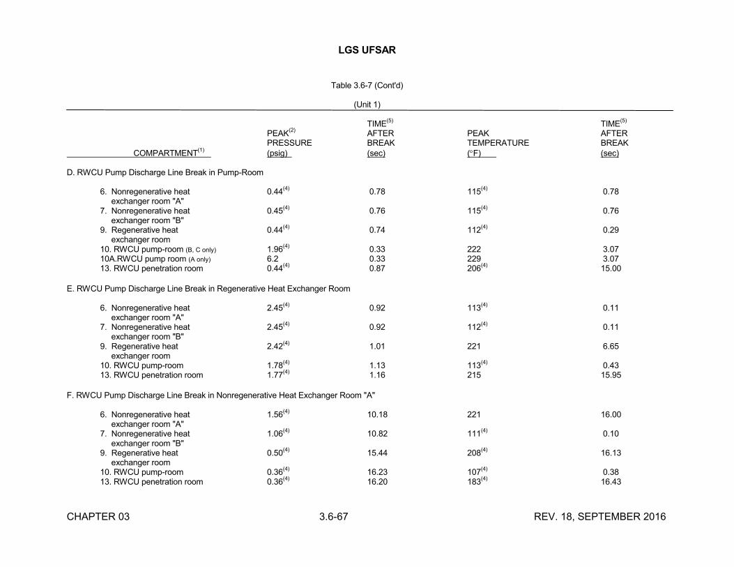
LGS UFSAR
CHAPTER 03 3.6-67 REV. 18, SEPTEMBER 2016
Table 3.6-7 (Cont'd)
(Unit 1)
TIME(5)
TIME(5)
PEAK(2)
AFTER PEAK AFTERPRESSURE BREAK TEMPERATURE BREAK
COMPARTMENT(1)
(psig) (sec) (F) (sec)
D. RWCU Pump Discharge Line Break in Pump-Room
6. Nonregenerative heat 0.44(4)
0.78 115(4)
0.78 exchanger room "A"7. Nonregenerative heat 0.45
(4)0.76 115
(4)0.76
exchanger room "B"9. Regenerative heat 0.44
(4)0.74 112
(4)0.29
exchanger room10. RWCU pump-room (B, C only) 1.96
(4)0.33 222 3.07
10A.RWCU pump room (A only) 6.2 0.33 229 3.0713. RWCU penetration room 0.44
(4)0.87 206
(4)15.00
E. RWCU Pump Discharge Line Break in Regenerative Heat Exchanger Room
6. Nonregenerative heat 2.45(4)
0.92 113(4)
0.11 exchanger room "A"7. Nonregenerative heat 2.45
(4)0.92 112
(4)0.11
exchanger room "B"9. Regenerative heat 2.42
(4)1.01 221 6.65
exchanger room10. RWCU pump-room 1.78
(4)1.13 113
(4)0.43
13. RWCU penetration room 1.77(4)
1.16 215 15.95
F. RWCU Pump Discharge Line Break in Nonregenerative Heat Exchanger Room "A"
6. Nonregenerative heat 1.56(4)
10.18 221 16.00 exchanger room "A"7. Nonregenerative heat 1.06
(4)10.82 111
(4)0.10
exchanger room "B"9. Regenerative heat 0.50
(4)15.44 208
(4)16.13
exchanger room10. RWCU pump-room 0.36
(4)16.23 107
(4)0.38
13. RWCU penetration room 0.36(4)
16.20 183(4)
16.43
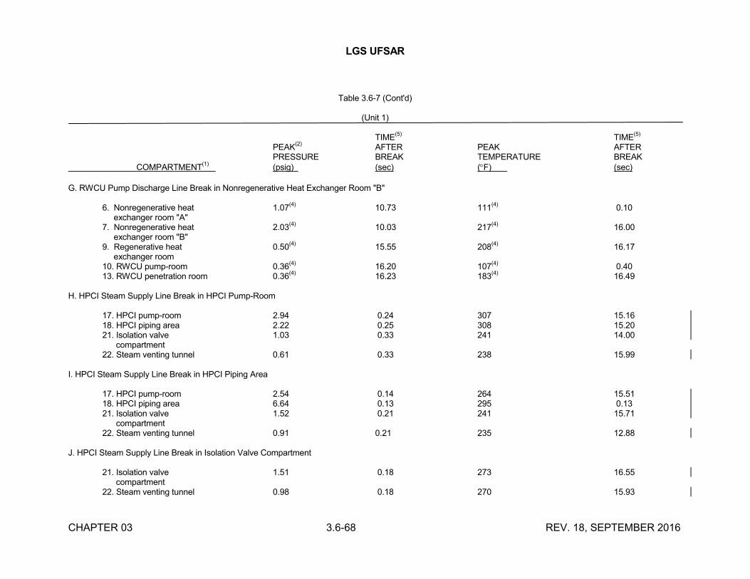
LGS UFSAR
CHAPTER 03 3.6-68 REV. 18, SEPTEMBER 2016
Table 3.6-7 (Cont'd)
(Unit 1)
TIME(5)
TIME(5)
PEAK(2)
AFTER PEAK AFTERPRESSURE BREAK TEMPERATURE BREAK
COMPARTMENT(1)
(psig) (sec) (F) (sec)
G. RWCU Pump Discharge Line Break in Nonregenerative Heat Exchanger Room "B"
6. Nonregenerative heat 1.07(4)
10.73 111(4)
0.10 exchanger room "A"7. Nonregenerative heat 2.03
(4)10.03 217
(4)16.00
exchanger room "B"9. Regenerative heat 0.50
(4)15.55 208
(4)16.17
exchanger room10. RWCU pump-room 0.36
(4)16.20 107
(4)0.40
13. RWCU penetration room 0.36(4)
16.23 183(4)
16.49
H. HPCI Steam Supply Line Break in HPCI Pump-Room
17. HPCI pump-room 2.94 0.24 307 15.1618. HPCI piping area 2.22 0.25 308 15.2021. Isolation valve 1.03 0.33 241 14.00 compartment22. Steam venting tunnel 0.61 0.33 238 15.99
I. HPCI Steam Supply Line Break in HPCI Piping Area
17. HPCI pump-room 2.54 0.14 264 15.5118. HPCI piping area 6.64 0.13 295 0.1321. Isolation valve 1.52 0.21 241 15.71 compartment22. Steam venting tunnel 0.91 0.21 235 12.88
J. HPCI Steam Supply Line Break in Isolation Valve Compartment
21. Isolation valve 1.51 0.18 273 16.55 compartment22. Steam venting tunnel 0.98 0.18 270 15.93
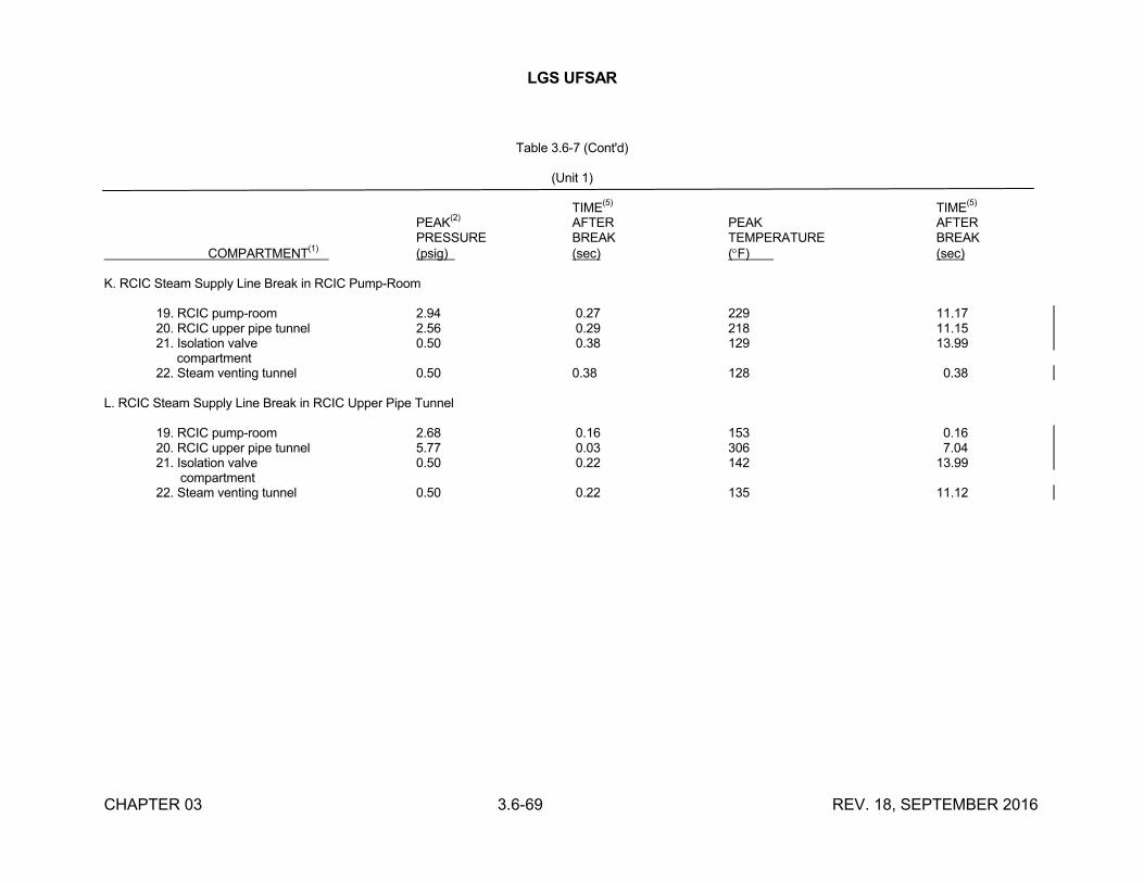
LGS UFSAR
CHAPTER 03 3.6-69 REV. 18, SEPTEMBER 2016
Table 3.6-7 (Cont'd)
(Unit 1)
TIME(5)
TIME(5)
PEAK(2)
AFTER PEAK AFTERPRESSURE BREAK TEMPERATURE BREAK
COMPARTMENT(1)
(psig) (sec) (F) (sec)
K. RCIC Steam Supply Line Break in RCIC Pump-Room
19. RCIC pump-room 2.94 0.27 229 11.1720. RCIC upper pipe tunnel 2.56 0.29 218 11.1521. Isolation valve 0.50 0.38 129 13.99 compartment22. Steam venting tunnel 0.50 0.38 128 0.38
L. RCIC Steam Supply Line Break in RCIC Upper Pipe Tunnel
19. RCIC pump-room 2.68 0.16 153 0.1620. RCIC upper pipe tunnel 5.77 0.03 306 7.0421. Isolation valve 0.50 0.22 142 13.99 compartment22. Steam venting tunnel 0.50 0.22 135 11.12
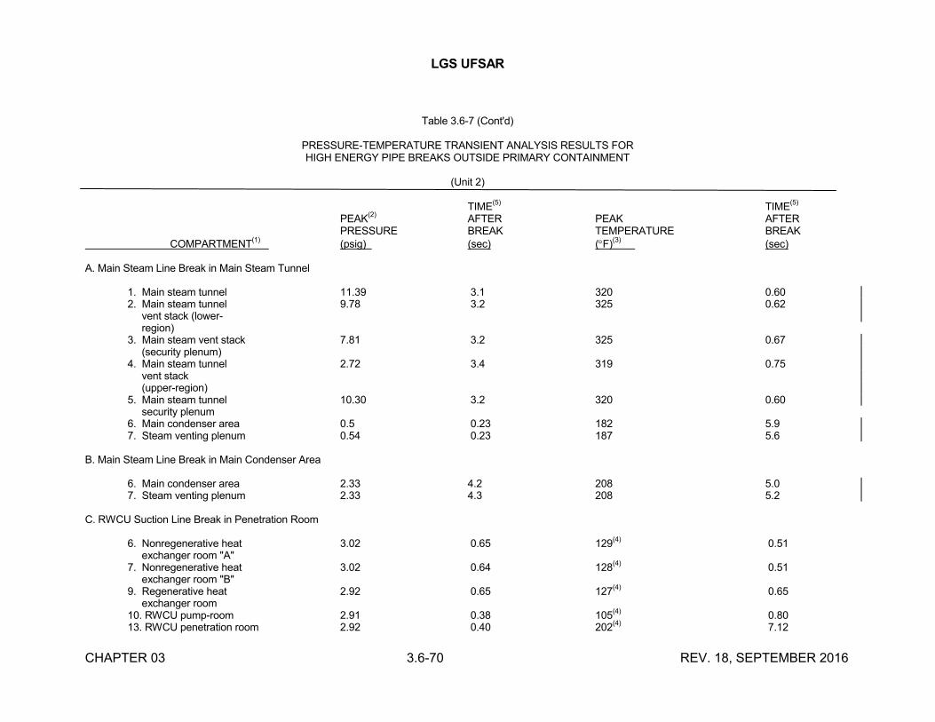
LGS UFSAR
CHAPTER 03 3.6-70 REV. 18, SEPTEMBER 2016
Table 3.6-7 (Cont'd)
PRESSURE-TEMPERATURE TRANSIENT ANALYSIS RESULTS FORHIGH ENERGY PIPE BREAKS OUTSIDE PRIMARY CONTAINMENT
(Unit 2)
TIME(5)
TIME(5)
PEAK(2)
AFTER PEAK AFTERPRESSURE BREAK TEMPERATURE BREAK
COMPARTMENT(1)
(psig) (sec) (F)(3)
(sec)
A. Main Steam Line Break in Main Steam Tunnel
1. Main steam tunnel 11.39 3.1 320 0.602. Main steam tunnel 9.78 3.2 325 0.62 vent stack (lower- region)3. Main steam vent stack 7.81 3.2 325 0.67 (security plenum)4. Main steam tunnel 2.72 3.4 319 0.75 vent stack (upper-region)5. Main steam tunnel 10.30 3.2 320 0.60 security plenum6. Main condenser area 0.5 0.23 182 5.97. Steam venting plenum 0.54 0.23 187 5.6
B. Main Steam Line Break in Main Condenser Area
6. Main condenser area 2.33 4.2 208 5.07. Steam venting plenum 2.33 4.3 208 5.2
C. RWCU Suction Line Break in Penetration Room
6. Nonregenerative heat 3.02 0.65 129(4)
0.51 exchanger room "A"7. Nonregenerative heat 3.02 0.64 128
(4)0.51
exchanger room "B"9. Regenerative heat 2.92 0.65 127
(4)0.65
exchanger room10. RWCU pump-room 2.91 0.38 105
(4)0.80
13. RWCU penetration room 2.92 0.40 202(4)
7.12
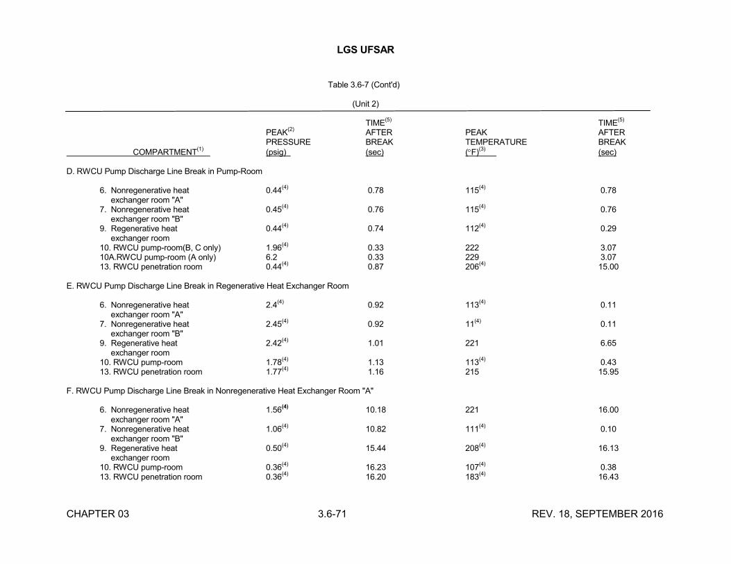
LGS UFSAR
CHAPTER 03 3.6-71 REV. 18, SEPTEMBER 2016
Table 3.6-7 (Cont'd)
(Unit 2)
TIME(5)
TIME(5)
PEAK(2)
AFTER PEAK AFTERPRESSURE BREAK TEMPERATURE BREAK
COMPARTMENT(1)
(psig) (sec) (F)(3)
(sec)
D. RWCU Pump Discharge Line Break in Pump-Room
6. Nonregenerative heat 0.44(4)
0.78 115(4)
0.78 exchanger room "A"7. Nonregenerative heat 0.45
(4)0.76 115
(4)0.76
exchanger room "B"9. Regenerative heat 0.44
(4)0.74 112
(4)0.29
exchanger room10. RWCU pump-room(B, C only) 1.96
(4)0.33 222 3.07
10A.RWCU pump-room (A only) 6.2 0.33 229 3.0713. RWCU penetration room 0.44
(4)0.87 206
(4)15.00
E. RWCU Pump Discharge Line Break in Regenerative Heat Exchanger Room
6. Nonregenerative heat 2.4(4)
0.92 113(4)
0.11 exchanger room "A"7. Nonregenerative heat 2.45
(4)0.92 11
(4)0.11
exchanger room "B"9. Regenerative heat 2.42
(4)1.01 221 6.65
exchanger room10. RWCU pump-room 1.78
(4)1.13 113
(4)0.43
13. RWCU penetration room 1.77(4)
1.16 215 15.95
F. RWCU Pump Discharge Line Break in Nonregenerative Heat Exchanger Room "A"
6. Nonregenerative heat 1.56(4)
10.18 221 16.00 exchanger room "A"7. Nonregenerative heat 1.06
(4)10.82 111
(4)0.10
exchanger room "B"9. Regenerative heat 0.50
(4)15.44 208
(4)16.13
exchanger room10. RWCU pump-room 0.36
(4)16.23 107
(4)0.38
13. RWCU penetration room 0.36(4)
16.20 183(4)
16.43
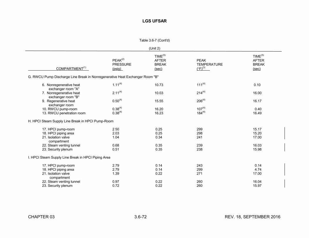
LGS UFSAR
CHAPTER 03 3.6-72 REV. 18, SEPTEMBER 2016
Table 3.6-7 (Cont'd)
(Unit 2)
TIME(5)
TIME(5)
PEAK(2)
AFTER PEAK AFTERPRESSURE BREAK TEMPERATURE BREAK
COMPARTMENT(1)
(psig) (sec) (F)(3)
(sec)
G. RWCU Pump Discharge Line Break in Nonregenerative Heat Exchanger Room "B"
6. Nonregenerative heat 1.11(4)
10.73 111(4)
0.10 exchanger room "A"7. Nonregenerative heat 2.11
(4)10.03 214
(4)16.00
exchanger room "B"9. Regenerative heat 0.50
(4)15.55 206
(4)16.17
exchanger room10. RWCU pump-room 0.38
(4)16.20 107
(4)0.40
13. RWCU penetration room 0.38(4)
16.23 184(4)
16.49
H. HPCI Steam Supply Line Break in HPCI Pump-Room
17. HPCI pump-room 2 50 0.25 299 15.1718. HPCI piping area 2.03 0.25 298 15.2021. Isolation valve 1.04 0.34 241 17.00 compartment22. Steam venting tunnel 0.68 0.35 239 16.0323. Security plenum 0.51 0.35 238 15.98
I. HPCI Steam Supply Line Break in HPCI Piping Area
17. HPCI pump-room 2.79 0.14 243 0.1418. HPCI piping area 2.79 0.14 299 4.7421. Isolation valve 1.39 0.22 271 17.00 compartment22. Steam venting tunnel 0.97 0.22 260 16.0423. Security plenum 0.72 0.22 260 15.97
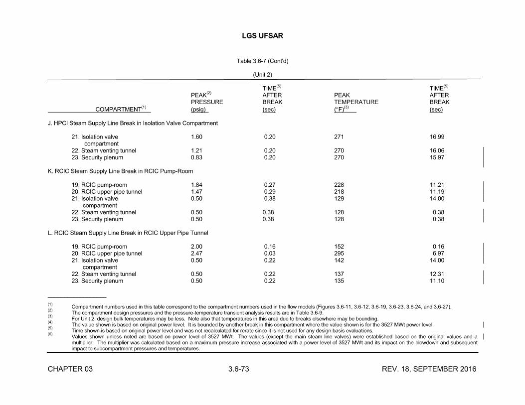
LGS UFSAR
CHAPTER 03 3.6-73 REV. 18, SEPTEMBER 2016
Table 3.6-7 (Cont'd)
(Unit 2)
TIME(5)
TIME(5)
PEAK(2)
AFTER PEAK AFTERPRESSURE BREAK TEMPERATURE BREAK
COMPARTMENT(1)
(psig) (sec) (F)(3)
(sec)
J. HPCI Steam Supply Line Break in Isolation Valve Compartment
21. Isolation valve 1.60 0.20 271 16.99 compartment22. Steam venting tunnel 1.21 0.20 270 16.0623. Security plenum 0.83 0.20 270 15.97
K. RCIC Steam Supply Line Break in RCIC Pump-Room
19. RCIC pump-room 1.84 0.27 228 11.2120. RCIC upper pipe tunnel 1.47 0.29 218 11.1921. Isolation valve 0.50 0.38 129 14.00 compartment22. Steam venting tunnel 0.50 0.38 128 0.3823. Security plenum 0.50 0.38 128 0.38
L. RCIC Steam Supply Line Break in RCIC Upper Pipe Tunnel
19. RCIC pump-room 2.00 0.16 152 0.1620. RCIC upper pipe tunnel 2.47 0.03 295 6.9721. Isolation valve 0.50 0.22 142 14.00 compartment22. Steam venting tunnel 0.50 0.22 137 12.3123. Security plenum 0.50 0.22 135 11.10
__________________
(1)Compartment numbers used in this table correspond to the compartment numbers used in the flow models (Figures 3.6-11, 3.6-12, 3.6-19, 3.6-23, 3.6-24, and 3.6-27).
(2)The compartment design pressures and the pressure-temperature transient analysis results are in Table 3.6-9.
(3)For Unit 2, design bulk temperatures may be less. Note also that temperatures in this area due to breaks elsewhere may be bounding.
(4)The value shown is based on original power level. It is bounded by another break in this compartment where the value shown is for the 3527 MWt power level.
(5)Time shown is based on original power level and was not recalculated for rerate since it is not used for any design basis evaluations.
(6)Values shown unless noted are based on power level of 3527 MWt. The values (except the main steam line valves) were established based on the original values and a multiplier. The multiplier was calculated based on a maximum pressure increase associated with a power level of 3527 MWt and its impact on the blowdown and subsequent impact to subcompartment pressures and temperatures.
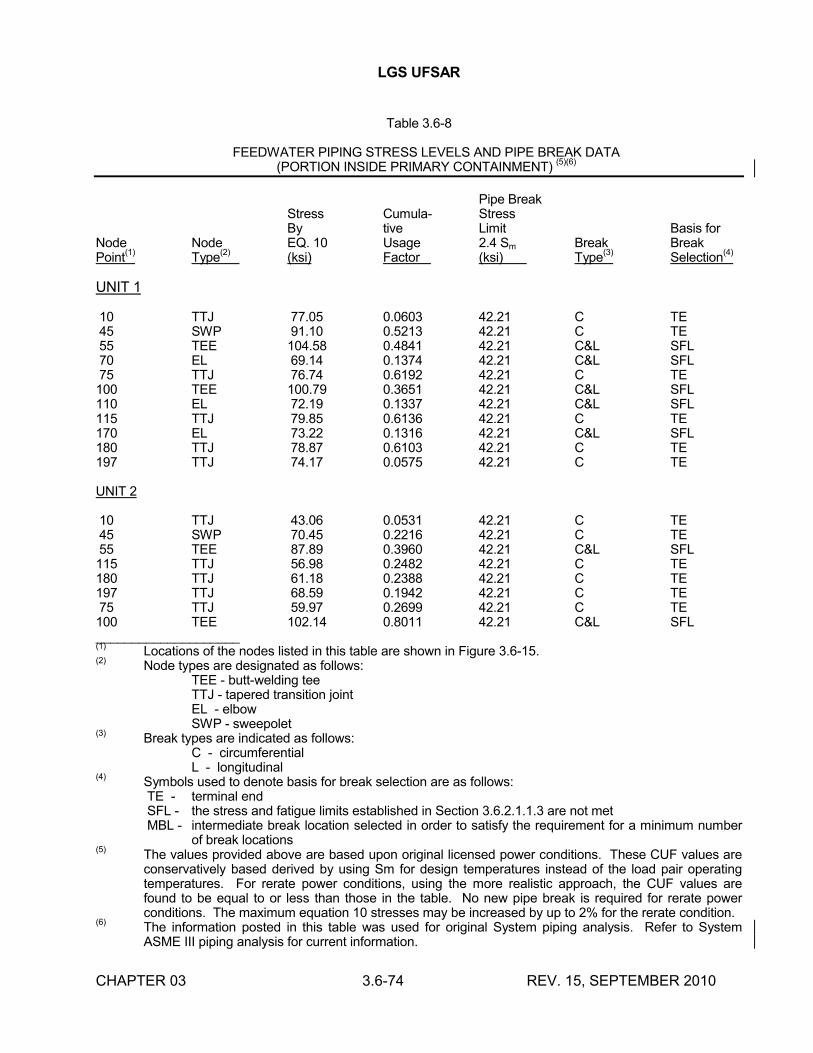
LGS UFSAR
CHAPTER 03 3.6-74 REV. 15, SEPTEMBER 2010
Table 3.6-8
FEEDWATER PIPING STRESS LEVELS AND PIPE BREAK DATA(PORTION INSIDE PRIMARY CONTAINMENT)
(5)(6)
Pipe BreakStress Cumula- StressBy tive Limit Basis for
Node Node EQ. 10 Usage 2.4 Sm Break BreakPoint
(1)Type
(2)(ksi) Factor (ksi) Type
(3) Selection
(4)
UNIT 1
10 TTJ 77.05 0.0603 42.21 C TE45 SWP 91.10 0.5213 42.21 C TE55 TEE 104.58 0.4841 42.21 C&L SFL70 EL 69.14 0.1374 42.21 C&L SFL75 TTJ 76.74 0.6192 42.21 C TE100 TEE 100.79 0.3651 42.21 C&L SFL110 EL 72.19 0.1337 42.21 C&L SFL115 TTJ 79.85 0.6136 42.21 C TE170 EL 73.22 0.1316 42.21 C&L SFL180 TTJ 78.87 0.6103 42.21 C TE197 TTJ 74.17 0.0575 42.21 C TE
UNIT 2
10 TTJ 43.06 0.0531 42.21 C TE45 SWP 70.45 0.2216 42.21 C TE55 TEE 87.89 0.3960 42.21 C&L SFL115 TTJ 56.98 0.2482 42.21 C TE180 TTJ 61.18 0.2388 42.21 C TE197 TTJ 68.59 0.1942 42.21 C TE75 TTJ 59.97 0.2699 42.21 C TE100 TEE 102.14 0.8011 42.21 C&L SFL____________________(1)
Locations of the nodes listed in this table are shown in Figure 3.6-15.(2)
Node types are designated as follows:TEE - butt-welding teeTTJ - tapered transition jointEL - elbowSWP - sweepolet
(3)Break types are indicated as follows:
C - circumferentialL - longitudinal
(4)Symbols used to denote basis for break selection are as follows:TE - terminal endSFL - the stress and fatigue limits established in Section 3.6.2.1.1.3 are not metMBL - intermediate break location selected in order to satisfy the requirement for a minimum number
of break locations(5)
The values provided above are based upon original licensed power conditions. These CUF values are conservatively based derived by using Sm for design temperatures instead of the load pair operatingtemperatures. For rerate power conditions, using the more realistic approach, the CUF values are found to be equal to or less than those in the table. No new pipe break is required for rerate power conditions. The maximum equation 10 stresses may be increased by up to 2% for the rerate condition.
(6)The information posted in this table was used for original System piping analysis. Refer to System ASME III piping analysis for current information.
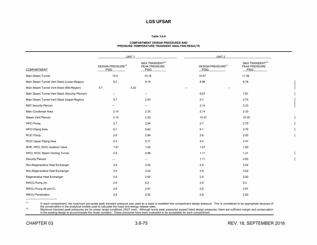
LGS UFSAR
CHAPTER 03 3.6-75 REV. 18, SEPTEMBER 2016
Table 3.6-9
COMPARTMENT DESIGN PRESSURES ANDPRESSURE-TEMPERATURE TRANSIENT ANALYSIS RESULTS
UNIT 1 UNIT 2
MAX TRANSIENT(2) MAX TRANSIENT(2)
DESIGN PRESSURE(1)
PEAK PRESSURE DESIGN PRESSURE(1)
PEAK PRESSURECOMPARTMENT PSIG PSIG PSIG PSIG .
Main Steam Tunnel 10.2 10.18 10.47 11.39
Main Steam Tunnel Vent Stack (Lower-Region) 8.2 8.18 8.99 9.78
Main Steam Tunnel Vent Stack (Mid-Region) 5.7 5.32 -- --
Main Steam Tunnel Vent Stack (Security Plenum) -- -- 6.97 7.81
Main Steam Tunnel Vent Stack (Upper-Region) 5.7 2.93 5.7 2.72
MST Security Plenum -- -- 2.14 2.33
Main Condenser Area 2.14 2.33 2.14 2.33
Steam Vent Plenum 2.14 2.33 10.47 10.30
HPCI Pump 2.7 2.94 2.7 2.79
HPCI Piping Area 6.1 6.64 6.1 2.79
RCIC Pump 2.8 2.94 2.8 2.00
RCIC Upper Piping Area 5.4 5.77 5.4 2.47
RHR, HPCI, RCIC Isolation Valve 1.41 1.52 1.47 1.60
HPCI, RCIC Steam Venting Tunnel 0.9 0.98 1.11 1.21
Security Plenum - - - - 1.11 0.83
Non-Regenerative Heat Exchanger 2.9 3.02 2.9 3.02
Non-Regenerative Heat Exchanger 2.9 3.02 2.9 3.02
Regenerative Heat Exchanger 2.9 2.92 2.9 2.92
RWCU Pump (A) 2.8 6.2 2.8 6.2
RWCU Pump (B and C) 2.8 2.91 2.8 2.91
RWCU Penetration 2.8 2.92 2.8 2.92____________________
(1) In each compartment, the maximum pre-rerate peak transient pressure was used as a basis to establish the compartment design pressure. This is considered to be appropriate because of the conservatism in the analytical models used to calculate the mass and energy release rates.
(2) Maximum transient peak pressures are for power rerate conditions (3527 mwt). Although some peak pressures exceed listed design pressures, there are sufficient margin and conservatism in the existing design to accommodate the rerate condition. These pressures have been evaluated to be acceptable for each compartment.
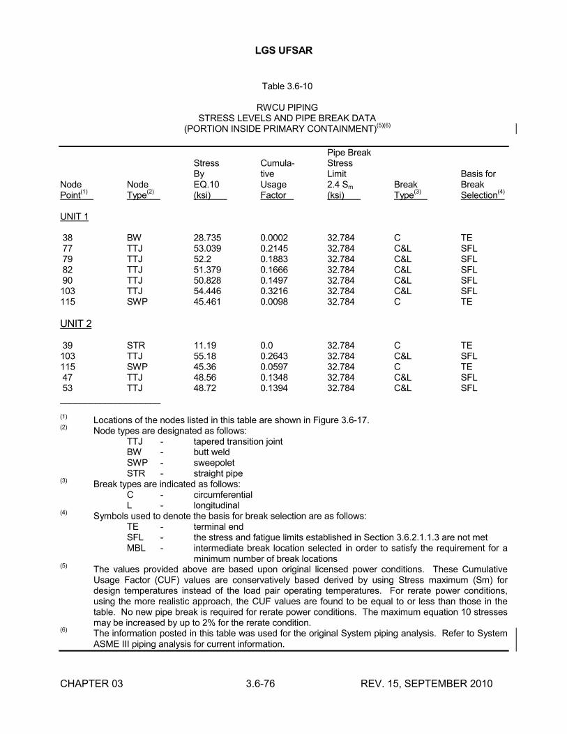
LGS UFSAR
CHAPTER 03 3.6-76 REV. 15, SEPTEMBER 2010
Table 3.6-10
RWCU PIPINGSTRESS LEVELS AND PIPE BREAK DATA
(PORTION INSIDE PRIMARY CONTAINMENT)(5)(6)
Pipe BreakStress Cumula- StressBy tive Limit Basis for
Node Node EQ.10 Usage 2.4 Sm Break BreakPoint
(1)Type
(2)(ksi) Factor (ksi) Type
(3)Selection
(4)
UNIT 1
38 BW 28.735 0.0002 32.784 C TE77 TTJ 53.039 0.2145 32.784 C&L SFL79 TTJ 52.2 0.1883 32.784 C&L SFL82 TTJ 51.379 0.1666 32.784 C&L SFL90 TTJ 50.828 0.1497 32.784 C&L SFL103 TTJ 54.446 0.3216 32.784 C&L SFL115 SWP 45.461 0.0098 32.784 C TE
UNIT 2
39 STR 11.19 0.0 32.784 C TE103 TTJ 55.18 0.2643 32.784 C&L SFL115 SWP 45.36 0.0597 32.784 C TE47 TTJ 48.56 0.1348 32.784 C&L SFL53 TTJ 48.72 0.1394 32.784 C&L SFL____________________
(1)Locations of the nodes listed in this table are shown in Figure 3.6-17.
(2)Node types are designated as follows:
TTJ - tapered transition jointBW - butt weldSWP - sweepoletSTR - straight pipe
(3)Break types are indicated as follows:
C - circumferentialL - longitudinal
(4)Symbols used to denote the basis for break selection are as follows:
TE - terminal endSFL - the stress and fatigue limits established in Section 3.6.2.1.1.3 are not metMBL - intermediate break location selected in order to satisfy the requirement for a
minimum number of break locations(5)
The values provided above are based upon original licensed power conditions. These Cumulative Usage Factor (CUF) values are conservatively based derived by using Stress maximum (Sm) for design temperatures instead of the load pair operating temperatures. For rerate power conditions, using the more realistic approach, the CUF values are found to be equal to or less than those in the table. No new pipe break is required for rerate power conditions. The maximum equation 10 stresses may be increased by up to 2% for the rerate condition.
(6)The information posted in this table was used for the original System piping analysis. Refer to System ASME III piping analysis for current information.
LGS UFSAR
CHAPTER 03 3.6-77 REV. 13, SEPTEMBER 2006
Table 3.6-11
INTENTIONALLY LEFT BLANK
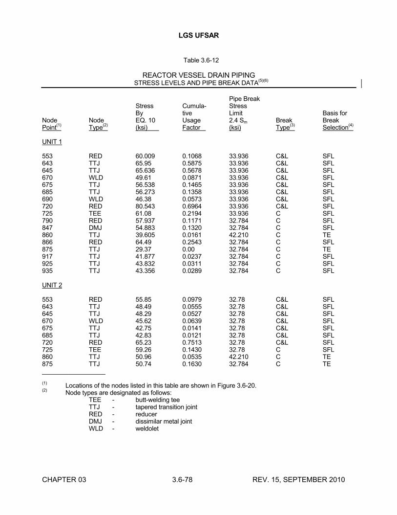
LGS UFSAR
CHAPTER 03 3.6-78 REV. 15, SEPTEMBER 2010
Table 3.6-12
REACTOR VESSEL DRAIN PIPINGSTRESS LEVELS AND PIPE BREAK DATA
(5)(6)
Pipe BreakStress Cumula- StressBy tive Limit Basis for
Node Node EQ. 10 Usage 2.4 Sm Break BreakPoint
(1)Type
(2)(ksi) Factor (ksi) Type
(3)Selection
(4)
UNIT 1
553 RED 60.009 0.1068 33.936 C&L SFL643 TTJ 65.95 0.5875 33.936 C&L SFL645 TTJ 65.636 0.5678 33.936 C&L SFL670 WLD 49.61 0.0871 33.936 C&L SFL675 TTJ 56.538 0.1465 33.936 C&L SFL685 TTJ 56.273 0.1358 33.936 C&L SFL690 WLD 46.38 0.0573 33.936 C&L SFL720 RED 80.543 0.6964 33.936 C&L SFL725 TEE 61.08 0.2194 33.936 C SFL790 RED 57.937 0.1171 32.784 C SFL847 DMJ 54.883 0.1320 32.784 C SFL860 TTJ 39.605 0.0161 42.210 C TE866 RED 64.49 0.2543 32.784 C SFL875 TTJ 29.37 0.00 32.784 C TE917 TTJ 41.877 0.0237 32.784 C SFL925 TTJ 43.832 0.0311 32.784 C SFL935 TTJ 43.356 0.0289 32.784 C SFL
UNIT 2
553 RED 55.85 0.0979 32.78 C&L SFL643 TTJ 48.49 0.0555 32.78 C&L SFL645 TTJ 48.29 0.0527 32.78 C&L SFL670 WLD 45.62 0.0639 32.78 C&L SFL675 TTJ 42.75 0.0141 32.78 C&L SFL685 TTJ 42.83 0.0121 32.78 C&L SFL720 RED 65.23 0.7513 32.78 C&L SFL725 TEE 59.26 0.1430 32.78 C SFL860 TTJ 50.96 0.0535 42.210 C TE875 TTJ 50.74 0.1630 32.784 C TE__________________
(1)Locations of the nodes listed in this table are shown in Figure 3.6-20.
(2)Node types are designated as follows:
TEE - butt-welding teeTTJ - tapered transition jointRED - reducerDMJ - dissimilar metal jointWLD - weldolet
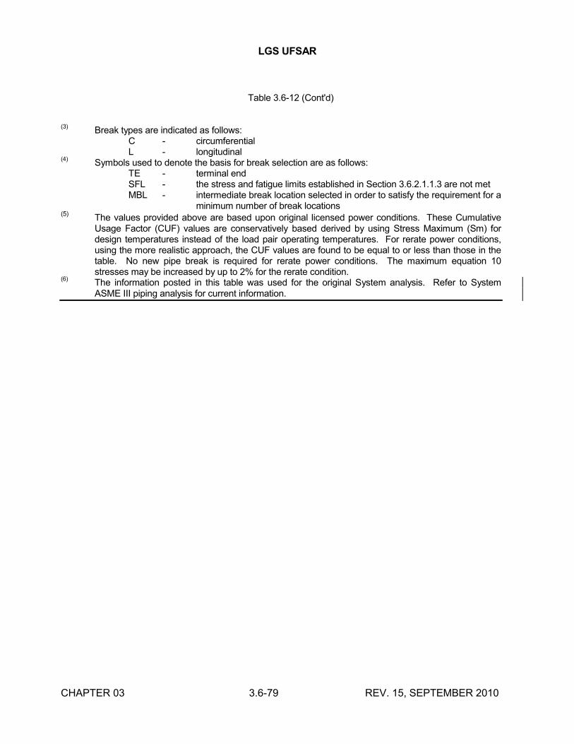
LGS UFSAR
CHAPTER 03 3.6-79 REV. 15, SEPTEMBER 2010
Table 3.6-12 (Cont'd)
(3)Break types are indicated as follows:
C - circumferentialL - longitudinal
(4)Symbols used to denote the basis for break selection are as follows:
TE - terminal endSFL - the stress and fatigue limits established in Section 3.6.2.1.1.3 are not metMBL - intermediate break location selected in order to satisfy the requirement for a
minimum number of break locations(5)
The values provided above are based upon original licensed power conditions. These Cumulative Usage Factor (CUF) values are conservatively based derived by using Stress Maximum (Sm) for design temperatures instead of the load pair operating temperatures. For rerate power conditions, using the more realistic approach, the CUF values are found to be equal to or less than those in the table. No new pipe break is required for rerate power conditions. The maximum equation 10 stresses may be increased by up to 2% for the rerate condition.
(6)The information posted in this table was used for the original System analysis. Refer to System ASME III piping analysis for current information.
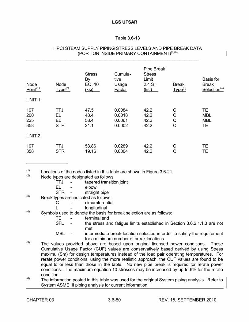
LGS UFSAR
CHAPTER 03 3.6-80 REV. 15, SEPTEMBER 2010
Table 3.6-13
HPCI STEAM SUPPLY PIPING STRESS LEVELS AND PIPE BREAK DATA(PORTION INSIDE PRIMARY CONTAINMENT)(5)(6)
_______________________________________________________________________
Pipe BreakStress Cumula- StressBy tive Limit Basis for
Node Node EQ. 10 Usage 2.4 Sm Break BreakPoint(1) Type(2) (ksi) Factor (ksi) Type(3) Selection(4)
UNIT 1
197 TTJ 47.5 0.0084 42.2 C TE200 EL 48.4 0.0018 42.2 C MBL225 EL 58.4 0.0061 42.2 C MBL358 STR 21.1 0.0002 42.2 C TE
UNIT 2
197 TTJ 53.86 0.0289 42.2 C TE358 STR 19.16 0.0004 42.2 C TE
_________________
(1) Locations of the nodes listed in this table are shown in Figure 3.6-21.(2) Node types are designated as follows:
TTJ - tapered transition jointEL - elbowSTR - straight pipe
(3) Break types are indicated as follows:C - circumferentialL - longitudinal
(4) Symbols used to denote the basis for break selection are as follows:TE - terminal endSFL - the stress and fatigue limits established in Section 3.6.2.1.1.3 are not
metMBL - intermediate break location selected in order to satisfy the requirement
for a minimum number of break locations(5) The values provided above are based upon original licensed power conditions. These
Cumulative Usage Factor (CUF) values are conservatively based derived by using Stress maximu (Sm) for design temperatures instead of the load pair operating temperatures. For rerate power conditions, using the more realistic approach, the CUF values are found to be equal to or less than those in the table. No new pipe break is required for rerate power conditions. The maximum equation 10 stresses may be increased by up to 6% for the rerate condition.
(6) The information posted in this table was used for the original System piping analysis. Refer to System ASME III piping analysis for current information.
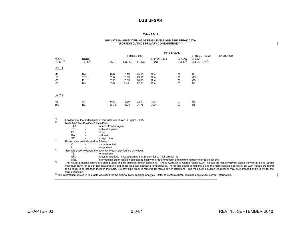
LGS UFSAR
CHAPTER 03 3.6-81 REV. 15, SEPTEMBER 2010
Table 3.6-14
HPCI STEAM SUPPLY PIPING STRESS LEVELS AND PIPE BREAK DATA(PORTION OUTSIDE PRIMARY CONTAINMENT)
(5)(6)
_______________________________________________________________________________________________________________
PIPE BREAK STRESS (ksi) STRESS LIMIT BASIS FOR
NODE NODE 0.8(1.2Sh+SA) BREAK BREAKPOINT
(1)TYPE
(2)EQ. 9 EQ. 10 TOTAL (ksi) TYPE
(3)SELECTION
(4)
UNIT 1
45 BW 6.87 18.19 25.06 32.4 C TE55 TEE 7.52 15.59 23.11 32.4 C MBL65 EL 7.50 10.83 18.33 32.4 C MBL85 BW 7.02 5.49 12.51 32.4 C TE
UNIT 2
95 ST 9.62 12.39 22.01 32.4 C TE150 EL 10.72 11.03 21.75 32.4 C TE
____________________
(1) Locations of the nodes listed in this table are shown in Figure 3.6-22.(2) Node type are designated as follows:
TTJ - tapered transition jointTEE - butt-welding teeEL - elbowBW - butt weldST - straight pipe
(3) Break types are indicated as follows:C - circumferentialL - longitudinal
(4) Symbols used to denote the basis for break selection are as follows:TE - terminal endSFL - stress and fatigue limits established in Section 3.6.2.1.1.3 are not metMBL - intermediate break location selected to satisfy the requirement for a minimum number of break locations
(5) The values provided above are based upon original licensed power conditions. These Cumulative Usage Factor (CUF) values are conservatively based derived by using Stress maximum (Sm) for design temperatures instead of the load pair operating temperatures. For rerate power conditions, using the more realistic approach, the CUF values are found to be equal to or less than those in the table. No new pipe break is required for rerate power conditions. The maximum equation 10 stresses may be increased by up to 6% for the rerate condition.
(6) The information posted in this table was used for the original System piping analysis. Refer to System ASME III piping analysis for current information._______________________________________________________________________________________________________________
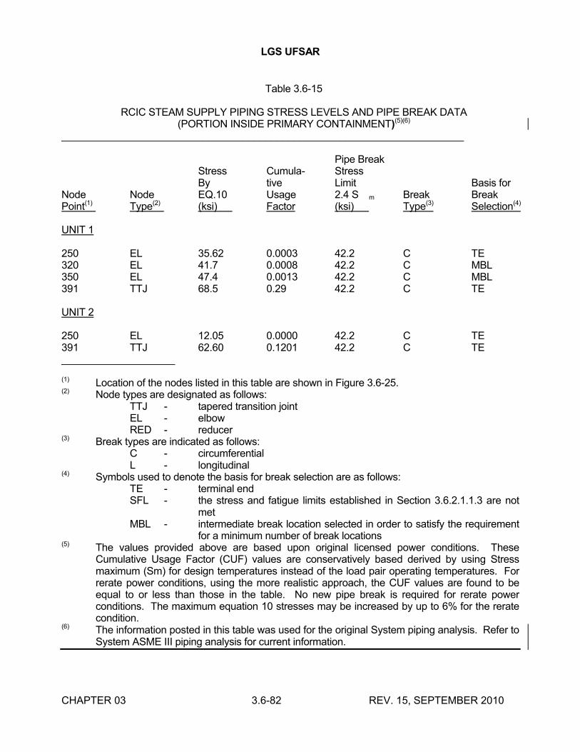
LGS UFSAR
CHAPTER 03 3.6-82 REV. 15, SEPTEMBER 2010
Table 3.6-15
RCIC STEAM SUPPLY PIPING STRESS LEVELS AND PIPE BREAK DATA(PORTION INSIDE PRIMARY CONTAINMENT)(5)(6)
_______________________________________________________________________
Pipe BreakStress Cumula- StressBy tive Limit Basis for
Node Node EQ.10 Usage 2.4 S m Break BreakPoint(1) Type(2) (ksi) Factor (ksi) Type(3) Selection(4)
UNIT 1
250 EL 35.62 0.0003 42.2 C TE320 EL 41.7 0.0008 42.2 C MBL350 EL 47.4 0.0013 42.2 C MBL391 TTJ 68.5 0.29 42.2 C TE
UNIT 2
250 EL 12.05 0.0000 42.2 C TE391 TTJ 62.60 0.1201 42.2 C TE____________________
(1) Location of the nodes listed in this table are shown in Figure 3.6-25.(2) Node types are designated as follows:
TTJ - tapered transition jointEL - elbowRED - reducer
(3) Break types are indicated as follows:C - circumferentialL - longitudinal
(4) Symbols used to denote the basis for break selection are as follows:TE - terminal endSFL - the stress and fatigue limits established in Section 3.6.2.1.1.3 are not
metMBL - intermediate break location selected in order to satisfy the requirement
for a minimum number of break locations(5) The values provided above are based upon original licensed power conditions. These
Cumulative Usage Factor (CUF) values are conservatively based derived by using Stress maximum (Sm) for design temperatures instead of the load pair operating temperatures. For rerate power conditions, using the more realistic approach, the CUF values are found to be equal to or less than those in the table. No new pipe break is required for rerate power conditions. The maximum equation 10 stresses may be increased by up to 6% for the rerate condition.
(6) The information posted in this table was used for the original System piping analysis. Refer to System ASME III piping analysis for current information.
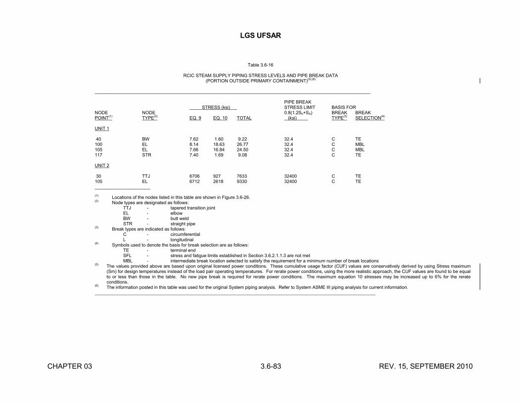
LGS UFSAR
CHAPTER 03 3.6-83 REV. 15, SEPTEMBER 2010
Table 3.6-16
RCIC STEAM SUPPLY PIPING STRESS LEVELS AND PIPE BREAK DATA(PORTION OUTSIDE PRIMARY CONTAINMENT)
(5),(6)
_____________________________________________________________________________________________________________
PIPE BREAK STRESS (ksi) STRESS LIMIT BASIS FOR
NODE NODE 0.8(1.2Sh+SA) BREAK BREAKPOINT(1) TYPE(2) EQ. 9 EQ. 10 TOTAL (ksi) TYPE(3) SELECTION(4)
UNIT 1
40 BW 7.62 1.60 9.22 32.4 C TE100 EL 8.14 18.63 26.77 32.4 C MBL105 EL 7.66 16.84 24.50 32.4 C MBL117 STR 7.40 1.69 9.08 32.4 C TE
UNIT 2
30 TTJ 6706 927 7633 32400 C TE105 EL 6712 2618 9330 32400 C TE______________________
(1) Locations of the nodes listed in this table are shown in Figure 3.6-26.(2) Node types are designated as follows:
TTJ - tapered transition jointEL - elbowBW - butt weldSTR - straight pipe
(3) Break types are indicated as follows:C - circumferentialL - longitudinal
(4) Symbols used to denote the basis for break selection are as follows:TE - terminal endSFL - stress and fatigue limits established in Section 3.6.2.1.1.3 are not metMBL - intermediate break location selected to satisfy the requirement for a minimum number of break locations
(5) The values provided above are based upon original licensed power conditions. These cumulative usage factor (CUF) values are conservatively derived by using Stress maximum (Sm) for design temperatures instead of the load pair operating temperatures. For rerate power conditions, using the more realistic approach, the CUF values are found to be equal to or less than those in the table. No new pipe break is required for rerate power conditions. The maximum equation 10 stresses may be increased up to 6% for the rerate conditions.
(6) The information posted in this table was used for the original System piping analysis. Refer to System ASME III piping analysis for current information. _______________________________________________________________________________________________________________
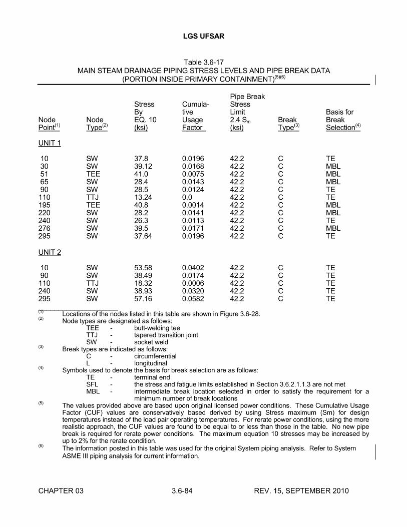
LGS UFSAR
CHAPTER 03 3.6-84 REV. 15, SEPTEMBER 2010
Table 3.6-17MAIN STEAM DRAINAGE PIPING STRESS LEVELS AND PIPE BREAK DATA
(PORTION INSIDE PRIMARY CONTAINMENT)(5)(6)
Pipe BreakStress Cumula- StressBy tive Limit Basis for
Node Node EQ. 10 Usage 2.4 Sm Break BreakPoint(1) Type(2) (ksi) Factor (ksi) Type(3) Selection(4)
UNIT 1
10 SW 37.8 0.0196 42.2 C TE30 SW 39.12 0.0168 42.2 C MBL51 TEE 41.0 0.0075 42.2 C MBL65 SW 28.4 0.0143 42.2 C MBL90 SW 28.5 0.0124 42.2 C TE110 TTJ 13.24 0.0 42.2 C TE195 TEE 40.8 0.0014 42.2 C MBL220 SW 28.2 0.0141 42.2 C MBL240 SW 26.3 0.0113 42.2 C TE276 SW 39.5 0.0171 42.2 C MBL295 SW 37.64 0.0196 42.2 C TE
UNIT 2
10 SW 53.58 0.0402 42.2 C TE90 SW 38.49 0.0174 42.2 C TE110 TTJ 18.32 0.0006 42.2 C TE240 SW 38.93 0.0320 42.2 C TE295 SW 57.16 0.0582 42.2 C TE____________________(1)
Locations of the nodes listed in this table are shown in Figure 3.6-28.(2)
Node types are designated as follows:TEE - butt-welding teeTTJ - tapered transition jointSW - socket weld
(3)Break types are indicated as follows:
C - circumferentialL - longitudinal
(4)Symbols used to denote the basis for break selection are as follows:
TE - terminal endSFL - the stress and fatigue limits established in Section 3.6.2.1.1.3 are not metMBL - intermediate break location selected in order to satisfy the requirement for a
minimum number of break locations(5)
The values provided above are based upon original licensed power conditions. These Cumulative Usage Factor (CUF) values are conservatively based derived by using Stress maximum (Sm) for design temperatures instead of the load pair operating temperatures. For rerate power conditions, using the more realistic approach, the CUF values are found to be equal to or less than those in the table. No new pipe break is required for rerate power conditions. The maximum equation 10 stresses may be increased by up to 2% for the rerate condition.
(6)The information posted in this table was used for the original System piping analysis. Refer to System ASME III piping analysis for current information.
LGS UFSAR
CHAPTER 03 3.6-85 REV. 13, SEPTEMBER 2006
Table 3.6-18 _________________________________________________________________
INTENTIONALLY LEFT BLANK
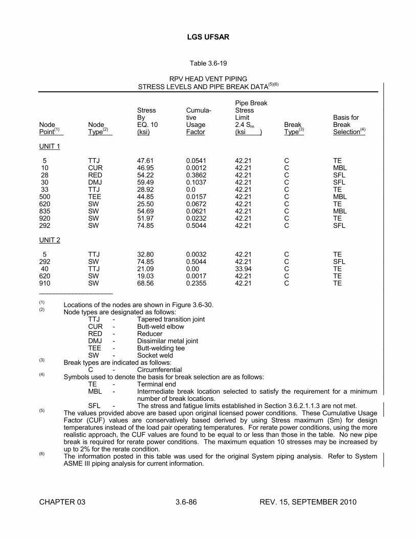
LGS UFSAR
CHAPTER 03 3.6-86 REV. 15, SEPTEMBER 2010
Table 3.6-19
RPV HEAD VENT PIPINGSTRESS LEVELS AND PIPE BREAK DATA
(5)(6)
Pipe BreakStress Cumula- StressBy tive Limit Basis for
Node Node EQ. 10 Usage 2.4 Sm Break BreakPoint
(1)Type
(2)(ksi) Factor (ksi ) Type
(3)Selection
(4)
UNIT 1
5 TTJ 47.61 0.0541 42.21 C TE10 CUR 46.95 0.0012 42.21 C MBL28 RED 54.22 0.3862 42.21 C SFL30 DMJ 59.49 0.1037 42.21 C SFL33 TTJ 28.92 0.0 42.21 C TE500 TEE 44.85 0.0157 42.21 C MBL620 SW 25.50 0.0672 42.21 C TE835 SW 54.69 0.0621 42.21 C MBL920 SW 51.97 0.0232 42.21 C TE292 SW 74.85 0.5044 42.21 C SFL
UNIT 2
5 TTJ 32.80 0.0032 42.21 C TE292 SW 74.85 0.5044 42.21 C SFL40 TTJ 21.09 0.00 33.94 C TE620 SW 19.03 0.0017 42.21 C TE910 SW 68.56 0.2355 42.21 C TE____________________
(1)Locations of the nodes are shown in Figure 3.6-30.
(2)Node types are designated as follows:
TTJ - Tapered transition jointCUR - Butt-weld elbowRED - ReducerDMJ - Dissimilar metal jointTEE - Butt-welding teeSW - Socket weld
(3)Break types are indicated as follows:
C - Circumferential(4)
Symbols used to denote the basis for break selection are as follows:TE - Terminal endMBL - Intermediate break location selected to satisfy the requirement for a minimum
number of break locations.SFL - The stress and fatigue limits established in Section 3.6.2.1.1.3 are not met.
(5)The values provided above are based upon original licensed power conditions. These Cumulative Usage Factor (CUF) values are conservatively based derived by using Stress maximum (Sm) for design temperatures instead of the load pair operating temperatures. For rerate power conditions, using the more realistic approach, the CUF values are found to be equal to or less than those in the table. No new pipe break is required for rerate power conditions. The maximum equation 10 stresses may be increased by up to 2% for the rerate condition.
(6)The information posted in this table was used for the original System piping analysis. Refer to System ASME III piping analysis for current information.
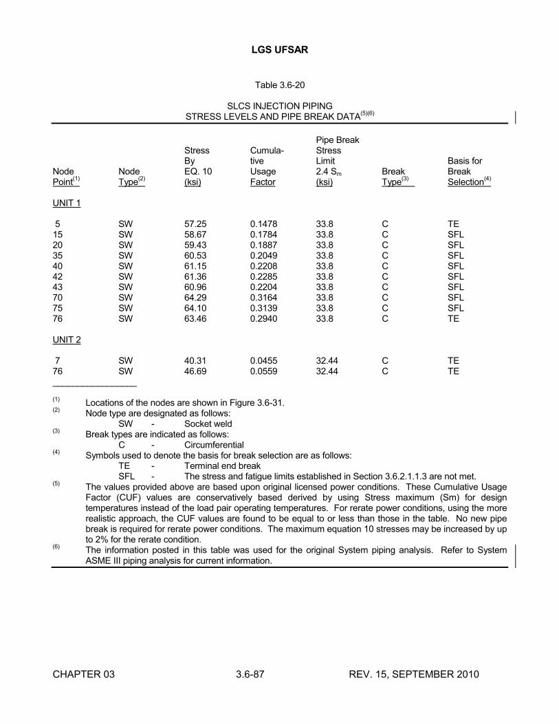
LGS UFSAR
CHAPTER 03 3.6-87 REV. 15, SEPTEMBER 2010
Table 3.6-20
SLCS INJECTION PIPINGSTRESS LEVELS AND PIPE BREAK DATA
(5)(6)
Pipe BreakStress Cumula- StressBy tive Limit Basis for
Node Node EQ. 10 Usage 2.4 Sm Break BreakPoint
(1)Type
(2)(ksi) Factor (ksi) Type
(3)Selection
(4)
UNIT 1
5 SW 57.25 0.1478 33.8 C TE15 SW 58.67 0.1784 33.8 C SFL20 SW 59.43 0.1887 33.8 C SFL35 SW 60.53 0.2049 33.8 C SFL40 SW 61.15 0.2208 33.8 C SFL42 SW 61.36 0.2285 33.8 C SFL43 SW 60.96 0.2204 33.8 C SFL70 SW 64.29 0.3164 33.8 C SFL75 SW 64.10 0.3139 33.8 C SFL76 SW 63.46 0.2940 33.8 C TE
UNIT 2
7 SW 40.31 0.0455 32.44 C TE76 SW 46.69 0.0559 32.44 C TE_________________
(1)Locations of the nodes are shown in Figure 3.6-31.
(2)Node type are designated as follows:
SW - Socket weld(3)
Break types are indicated as follows:C - Circumferential
(4)Symbols used to denote the basis for break selection are as follows:
TE - Terminal end breakSFL - The stress and fatigue limits established in Section 3.6.2.1.1.3 are not met.
(5)The values provided above are based upon original licensed power conditions. These Cumulative Usage Factor (CUF) values are conservatively based derived by using Stress maximum (Sm) for design temperatures instead of the load pair operating temperatures. For rerate power conditions, using the more realistic approach, the CUF values are found to be equal to or less than those in the table. No new pipe break is required for rerate power conditions. The maximum equation 10 stresses may be increased by up to 2% for the rerate condition.
(6)The information posted in this table was used for the original System piping analysis. Refer to System ASME III piping analysis for current information.
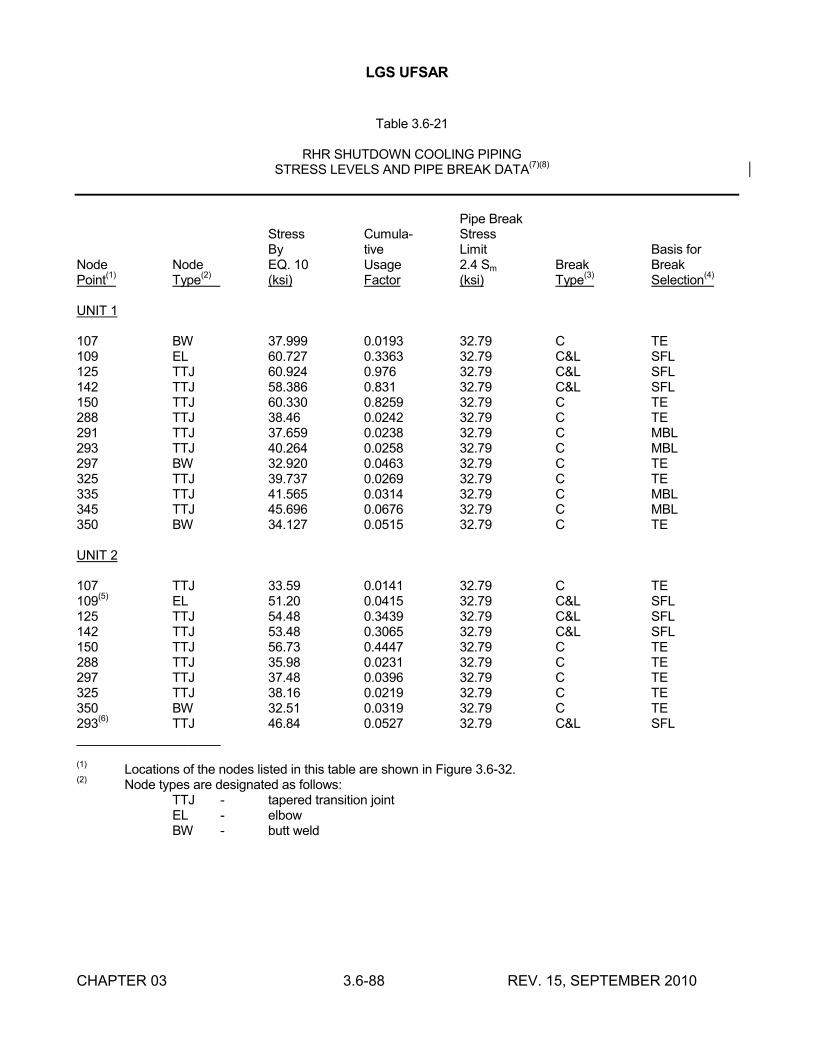
LGS UFSAR
CHAPTER 03 3.6-88 REV. 15, SEPTEMBER 2010
Table 3.6-21
RHR SHUTDOWN COOLING PIPINGSTRESS LEVELS AND PIPE BREAK DATA
(7)(8)
Pipe BreakStress Cumula- StressBy tive Limit Basis for
Node Node EQ. 10 Usage 2.4 Sm Break BreakPoint
(1)Type
(2)(ksi) Factor (ksi) Type
(3)Selection
(4)
UNIT 1
107 BW 37.999 0.0193 32.79 C TE 109 EL 60.727 0.3363 32.79 C&L SFL125 TTJ 60.924 0.976 32.79 C&L SFL142 TTJ 58.386 0.831 32.79 C&L SFL150 TTJ 60.330 0.8259 32.79 C TE288 TTJ 38.46 0.0242 32.79 C TE291 TTJ 37.659 0.0238 32.79 C MBL293 TTJ 40.264 0.0258 32.79 C MBL297 BW 32.920 0.0463 32.79 C TE325 TTJ 39.737 0.0269 32.79 C TE335 TTJ 41.565 0.0314 32.79 C MBL345 TTJ 45.696 0.0676 32.79 C MBL350 BW 34.127 0.0515 32.79 C TE
UNIT 2
107 TTJ 33.59 0.0141 32.79 C TE109
(5)EL 51.20 0.0415 32.79 C&L SFL
125 TTJ 54.48 0.3439 32.79 C&L SFL142 TTJ 53.48 0.3065 32.79 C&L SFL150 TTJ 56.73 0.4447 32.79 C TE288 TTJ 35.98 0.0231 32.79 C TE297 TTJ 37.48 0.0396 32.79 C TE325 TTJ 38.16 0.0219 32.79 C TE350 BW 32.51 0.0319 32.79 C TE293
(6)TTJ 46.84 0.0527 32.79 C&L SFL
____________________
(1)Locations of the nodes listed in this table are shown in Figure 3.6-32.
(2)Node types are designated as follows:
TTJ - tapered transition jointEL - elbowBW - butt weld
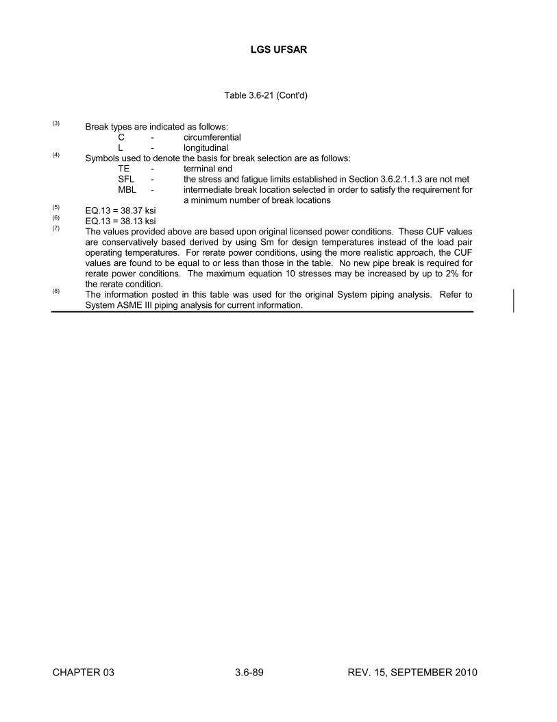
LGS UFSAR
CHAPTER 03 3.6-89 REV. 15, SEPTEMBER 2010
Table 3.6-21 (Cont'd)
(3)Break types are indicated as follows:
C - circumferentialL - longitudinal
(4)Symbols used to denote the basis for break selection are as follows:
TE - terminal endSFL - the stress and fatigue limits established in Section 3.6.2.1.1.3 are not metMBL - intermediate break location selected in order to satisfy the requirement for
a minimum number of break locations(5)
EQ.13 = 38.37 ksi(6)
EQ.13 = 38.13 ksi(7)
The values provided above are based upon original licensed power conditions. These CUF values are conservatively based derived by using Sm for design temperatures instead of the load pair operating temperatures. For rerate power conditions, using the more realistic approach, the CUF values are found to be equal to or less than those in the table. No new pipe break is required for rerate power conditions. The maximum equation 10 stresses may be increased by up to 2% for the rerate condition.
(8)The information posted in this table was used for the original System piping analysis. Refer to System ASME III piping analysis for current information.
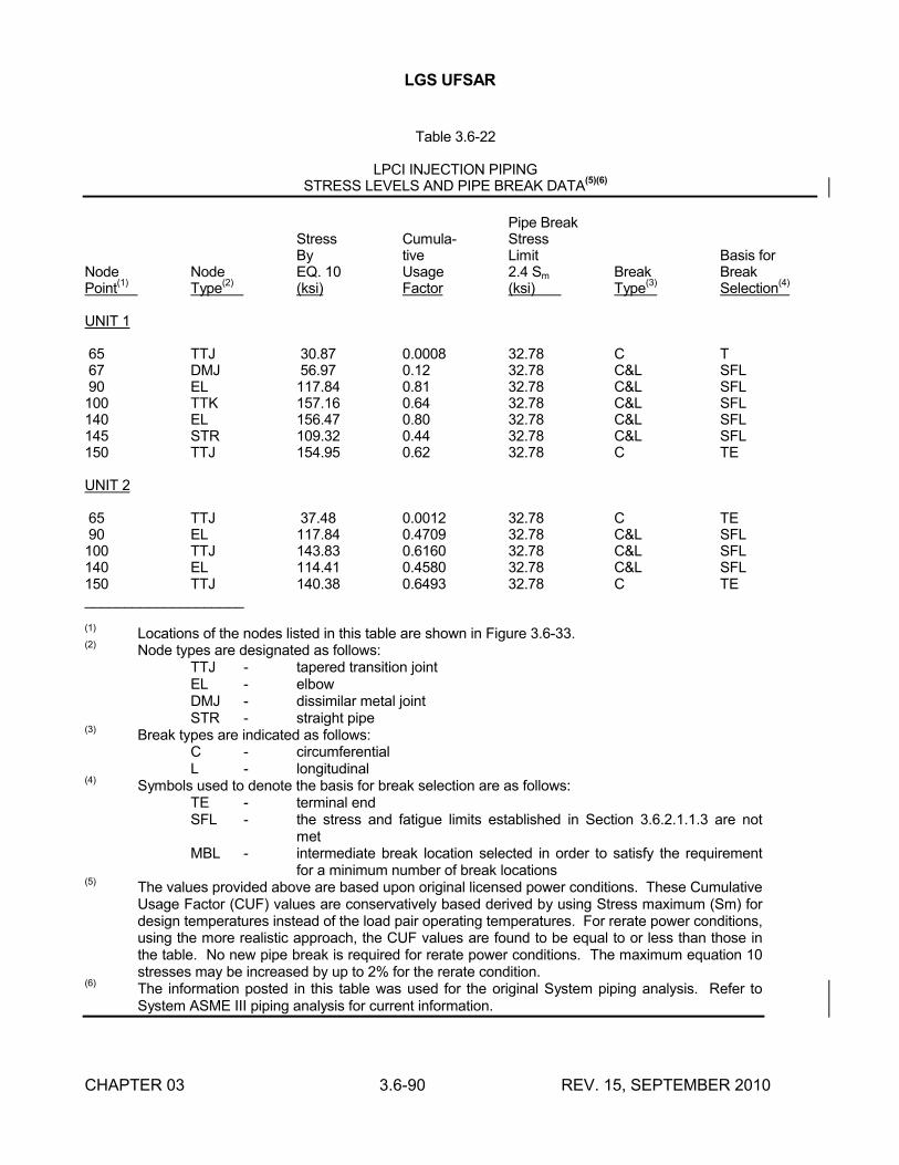
LGS UFSAR
CHAPTER 03 3.6-90 REV. 15, SEPTEMBER 2010
Table 3.6-22
LPCI INJECTION PIPINGSTRESS LEVELS AND PIPE BREAK DATA
(5)(6)
Pipe BreakStress Cumula- StressBy tive Limit Basis for
Node Node EQ. 10 Usage 2.4 Sm Break BreakPoint
(1)Type
(2)(ksi) Factor (ksi) Type
(3)Selection
(4)
UNIT 1
65 TTJ 30.87 0.0008 32.78 C T67 DMJ 56.97 0.12 32.78 C&L SFL90 EL 117.84 0.81 32.78 C&L SFL100 TTK 157.16 0.64 32.78 C&L SFL140 EL 156.47 0.80 32.78 C&L SFL145 STR 109.32 0.44 32.78 C&L SFL150 TTJ 154.95 0.62 32.78 C TE
UNIT 2
65 TTJ 37.48 0.0012 32.78 C TE90 EL 117.84 0.4709 32.78 C&L SFL100 TTJ 143.83 0.6160 32.78 C&L SFL140 EL 114.41 0.4580 32.78 C&L SFL150 TTJ 140.38 0.6493 32.78 C TE____________________
(1)Locations of the nodes listed in this table are shown in Figure 3.6-33.
(2)Node types are designated as follows:
TTJ - tapered transition jointEL - elbowDMJ - dissimilar metal jointSTR - straight pipe
(3)Break types are indicated as follows:
C - circumferentialL - longitudinal
(4)Symbols used to denote the basis for break selection are as follows:
TE - terminal endSFL - the stress and fatigue limits established in Section 3.6.2.1.1.3 are not
metMBL - intermediate break location selected in order to satisfy the requirement
for a minimum number of break locations(5)
The values provided above are based upon original licensed power conditions. These Cumulative Usage Factor (CUF) values are conservatively based derived by using Stress maximum (Sm) for design temperatures instead of the load pair operating temperatures. For rerate power conditions, using the more realistic approach, the CUF values are found to be equal to or less than those in the table. No new pipe break is required for rerate power conditions. The maximum equation 10 stresses may be increased by up to 2% for the rerate condition.
(6)The information posted in this table was used for the original System piping analysis. Refer to System ASME III piping analysis for current information.
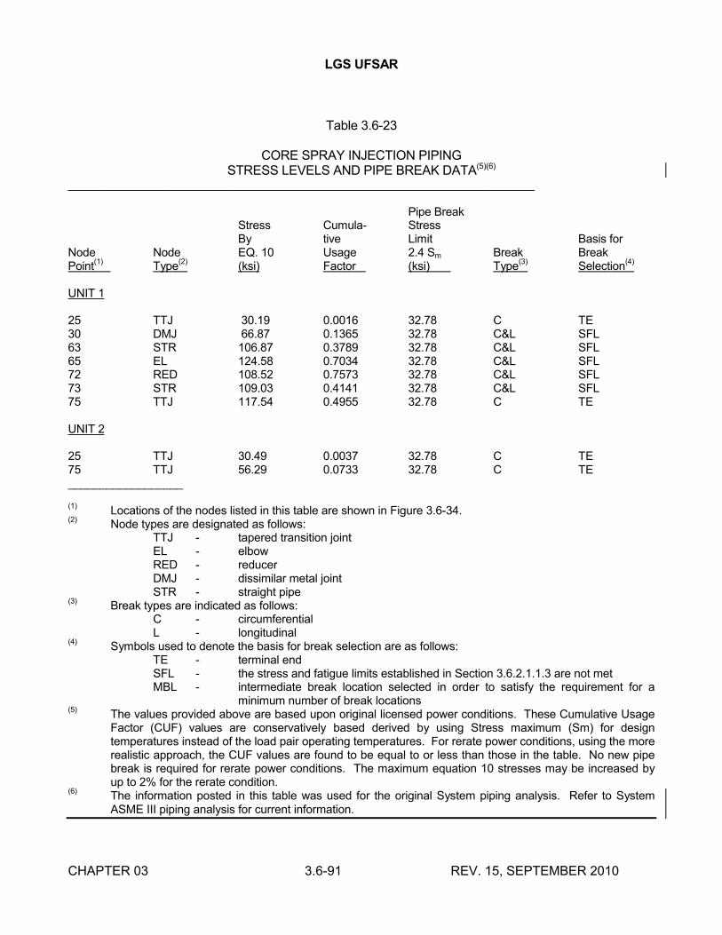
LGS UFSAR
CHAPTER 03 3.6-91 REV. 15, SEPTEMBER 2010
Table 3.6-23
CORE SPRAY INJECTION PIPINGSTRESS LEVELS AND PIPE BREAK DATA(5)(6)
_________________________________________________________________________
Pipe BreakStress Cumula- StressBy tive Limit Basis for
Node Node EQ. 10 Usage 2.4 Sm Break BreakPoint
(1)Type
(2)(ksi) Factor (ksi) Type
(3)Selection
(4)
UNIT 1
25 TTJ 30.19 0.0016 32.78 C TE30 DMJ 66.87 0.1365 32.78 C&L SFL63 STR 106.87 0.3789 32.78 C&L SFL65 EL 124.58 0.7034 32.78 C&L SFL72 RED 108.52 0.7573 32.78 C&L SFL73 STR 109.03 0.4141 32.78 C&L SFL75 TTJ 117.54 0.4955 32.78 C TE
UNIT 2
25 TTJ 30.49 0.0037 32.78 C TE75 TTJ 56.29 0.0733 32.78 C TE__________________
(1)Locations of the nodes listed in this table are shown in Figure 3.6-34.
(2)Node types are designated as follows:
TTJ - tapered transition jointEL - elbowRED - reducerDMJ - dissimilar metal jointSTR - straight pipe
(3)Break types are indicated as follows:
C - circumferentialL - longitudinal
(4)Symbols used to denote the basis for break selection are as follows:
TE - terminal endSFL - the stress and fatigue limits established in Section 3.6.2.1.1.3 are not metMBL - intermediate break location selected in order to satisfy the requirement for a
minimum number of break locations(5)
The values provided above are based upon original licensed power conditions. These Cumulative Usage Factor (CUF) values are conservatively based derived by using Stress maximum (Sm) for design temperatures instead of the load pair operating temperatures. For rerate power conditions, using the more realistic approach, the CUF values are found to be equal to or less than those in the table. No new pipe break is required for rerate power conditions. The maximum equation 10 stresses may be increased by up to 2% for the rerate condition.
(6)The information posted in this table was used for the original System piping analysis. Refer to System ASME III piping analysis for current information.
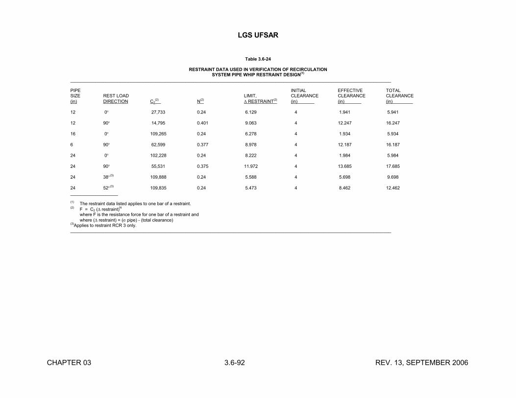
LGS UFSAR
CHAPTER 03 3.6-92 REV. 13, SEPTEMBER 2006
Table 3.6-24
RESTRAINT DATA USED IN VERIFICATION OF RECIRCULATIONSYSTEM PIPE WHIP RESTRAINT DESIGN
(1)
________________________________________________________________________________________________________________________________
PIPE INITIAL EFFECTIVE TOTALSIZE REST LOAD LIMIT, CLEARANCE CLEARANCE CLEARANCE(in) DIRECTION C2
(2) N
(2) RESTRAINT
(2)(in) (in) (in)
12 0 27,733 0.24 6.129 4 1.941 5.941
12 90 14,795 0.401 9.063 4 12.247 16.247
16 0 109,265 0.24 6.278 4 1.934 5.934
6 90 62,599 0.377 8.978 4 12.187 16.187
24 0 102,228 0.24 8.222 4 1.984 5.984
24 90 55,531 0.375 11.972 4 13.685 17.685
24 38(3) 109,888 0.24 5.588 4 5.698 9.698
24 52(3) 109,835 0.24 5.473 4 8.462 12.462___________________
(1) The restraint data listed applies to one bar of a restraint.(2) F = C2 ( restraint)N
where F is the resistance force for one bar of a restraint andwhere ( restraint) = ( pipe) - (total clearance)
(3)Applies to restraint RCR 3 only.________________________________________________________________________________________________________________________________
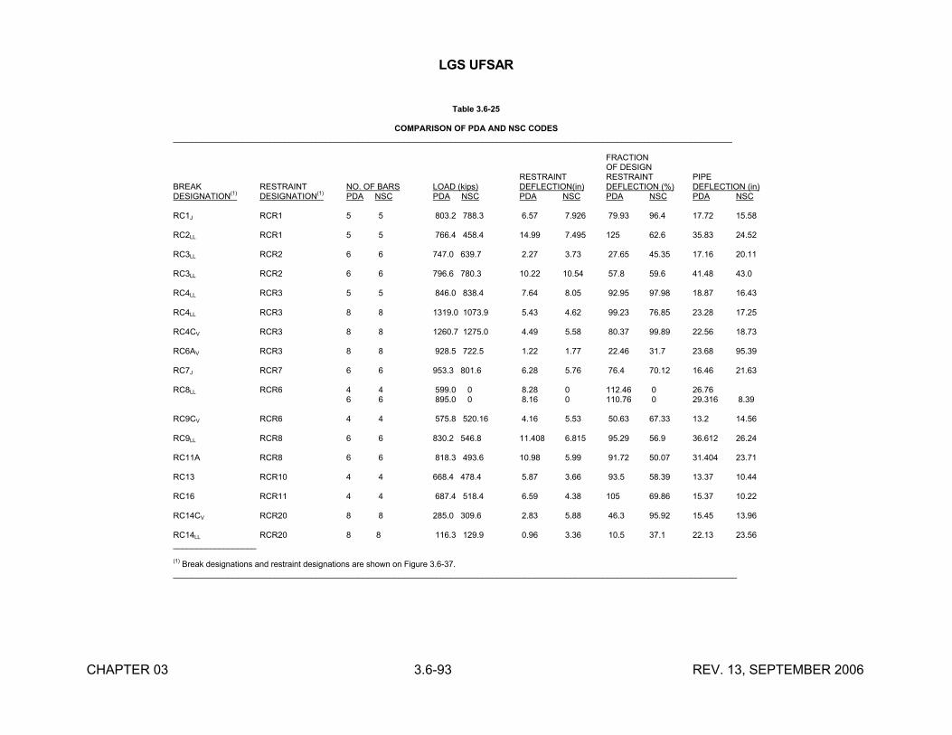
LGS UFSAR
CHAPTER 03 3.6-93 REV. 13, SEPTEMBER 2006
Table 3.6-25
COMPARISON OF PDA AND NSC CODES_________________________________________________________________________________________________________________________
FRACTIONOF DESIGN
RESTRAINT RESTRAINT PIPEBREAK RESTRAINT NO. OF BARS LOAD (kips) DEFLECTION(in) DEFLECTION (%) DEFLECTION (in)DESIGNATION
(1)DESIGNATION
(1)PDA NSC PDA NSC PDA NSC PDA NSC PDA NSC
RC1J RCR1 5 5 803.2 788.3 6.57 7.926 79.93 96.4 17.72 15.58
RC2LL RCR1 5 5 766.4 458.4 14.99 7.495 125 62.6 35.83 24.52
RC3LL RCR2 6 6 747.0 639.7 2.27 3.73 27.65 45.35 17.16 20.11
RC3LL RCR2 6 6 796.6 780.3 10.22 10.54 57.8 59.6 41.48 43.0
RC4LL RCR3 5 5 846.0 838.4 7.64 8.05 92.95 97.98 18.87 16.43
RC4LL RCR3 8 8 1319.0 1073.9 5.43 4.62 99.23 76.85 23.28 17.25
RC4CV RCR3 8 8 1260.7 1275.0 4.49 5.58 80.37 99.89 22.56 18.73
RC6AV RCR3 8 8 928.5 722.5 1.22 1.77 22.46 31.7 23.68 95.39
RC7J RCR7 6 6 953.3 801.6 6.28 5.76 76.4 70.12 16.46 21.63
RC8LL RCR6 4 4 599.0 0 8.28 0 112.46 0 26.766 6 895.0 0 8.16 0 110.76 0 29.316 8.39
RC9CV RCR6 4 4 575.8 520.16 4.16 5.53 50.63 67.33 13.2 14.56
RC9LL RCR8 6 6 830.2 546.8 11.408 6.815 95.29 56.9 36.612 26.24
RC11A RCR8 6 6 818.3 493.6 10.98 5.99 91.72 50.07 31.404 23.71
RC13 RCR10 4 4 668.4 478.4 5.87 3.66 93.5 58.39 13.37 10.44
RC16 RCR11 4 4 687.4 518.4 6.59 4.38 105 69.86 15.37 10.22
RC14CV RCR20 8 8 285.0 309.6 2.83 5.88 46.3 95.92 15.45 13.96
RC14LL RCR20 8 8 116.3 129.9 0.96 3.36 10.5 37.1 22.13 23.56__________________
(1) Break designations and restraint designations are shown on Figure 3.6-37.__________________________________________________________________________________________________________________________
LGS UFSAR
CHAPTER 03 3.7-1 REV. 18, SEPTEMBER 2016
3.7 SEISMIC DESIGN
All systems and equipment of the NSSS are defined as either seismic Category I or nonseismic Category I. The requirements for seismic Category I qualification are given in Section 3.2, along with a list of systems, components, and equipment which are so categorized. Seismic design requirements for nonseismic Category I items are also defined in Section 3.2. These items are classified as either Category II or Category IIA.
All systems, components, and equipment related to plant safety are designed to withstand SSE and OBE.
The SSE is that earthquake which is based upon an evaluation of the maximum earthquake potential considering the regional and local geology, and seismology and specific characteristics of local subsurface material. It is that earthquake which produces the maximum vibratory ground motion for which seismic Category I systems and components are designed to remain functional. These systems and components are those necessary to ensure:
a. The integrity of the RCPB.
b. The capability to shut down the reactor and maintain it in a safe shutdown condition.
c. The capability to prevent or mitigate the radiological consequences of accidents which could result in potential offsite exposures, comparable to the dose limits of 10CFR 50.67.
The OBE is that earthquake which, considering the regional and local geology, and seismology and specific characteristics of local subsurface material, could reasonably be expected to affect the plant site during the operating life of the plant. It is that earthquake which produces the vibratory ground motion for which those features of the nuclear power plant necessary for continued operation, without undue risk to the health and safety of the public, are designed to remain functional.
In addition to seismic loads, Category I structures, systems and components are also reviewed for hydrodynamic loads as described in Appendix 3A.
3.7.1 SEISMIC INPUT
3.7.1.1 Design Response Spectra
The site design response spectra used are shown in Figures 3.7-1 and 3.7-2. These spectra are for the horizontal components of the OBE and the SSE respectively. The response spectra for the OBE are scaled or normalized to a maximum horizontal ground acceleration of 7½% of gravity. The response spectra for the SSE are normalized to a maximum horizontal ground acceleration of 15% of gravity. The values for the vertical component of the design response spectra are 2/3 of the horizontal design response spectra described above. The response spectra are based on data developed from records of previous earthquake activity and represent an envelope of motion expected at a sound rock site from a nearby earthquake (Section 2.5.2).
Regulatory Guide 1.60 (December, 1973) "Design Response Spectra for Seismic Design of Nuclear Power Plants" was not used for the development of the spectra, because LGS Units 1 and 2 were docketed for construction permit review in March 1970, and the spectra were finalized in
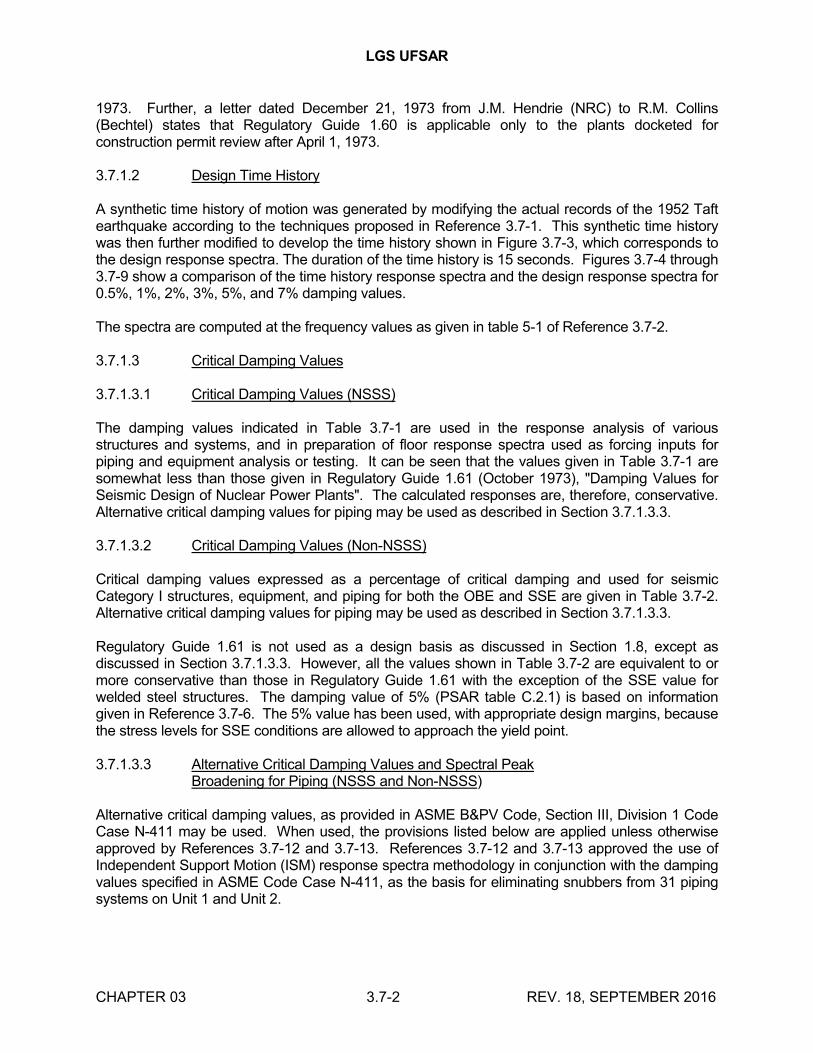
LGS UFSAR
CHAPTER 03 3.7-2 REV. 18, SEPTEMBER 2016
1973. Further, a letter dated December 21, 1973 from J.M. Hendrie (NRC) to R.M. Collins (Bechtel) states that Regulatory Guide 1.60 is applicable only to the plants docketed for construction permit review after April 1, 1973.
3.7.1.2 Design Time History
A synthetic time history of motion was generated by modifying the actual records of the 1952 Taft earthquake according to the techniques proposed in Reference 3.7-1. This synthetic time history was then further modified to develop the time history shown in Figure 3.7-3, which corresponds to the design response spectra. The duration of the time history is 15 seconds. Figures 3.7-4 through 3.7-9 show a comparison of the time history response spectra and the design response spectra for 0.5%, 1%, 2%, 3%, 5%, and 7% damping values.
The spectra are computed at the frequency values as given in table 5-1 of Reference 3.7-2.
3.7.1.3 Critical Damping Values
3.7.1.3.1 Critical Damping Values (NSSS)
The damping values indicated in Table 3.7-1 are used in the response analysis of various structures and systems, and in preparation of floor response spectra used as forcing inputs for piping and equipment analysis or testing. It can be seen that the values given in Table 3.7-1 are somewhat less than those given in Regulatory Guide 1.61 (October 1973), "Damping Values for Seismic Design of Nuclear Power Plants". The calculated responses are, therefore, conservative. Alternative critical damping values for piping may be used as described in Section 3.7.1.3.3.
3.7.1.3.2 Critical Damping Values (Non-NSSS)
Critical damping values expressed as a percentage of critical damping and used for seismic Category I structures, equipment, and piping for both the OBE and SSE are given in Table 3.7-2. Alternative critical damping values for piping may be used as described in Section 3.7.1.3.3.
Regulatory Guide 1.61 is not used as a design basis as discussed in Section 1.8, except as discussed in Section 3.7.1.3.3. However, all the values shown in Table 3.7-2 are equivalent to or more conservative than those in Regulatory Guide 1.61 with the exception of the SSE value for welded steel structures. The damping value of 5% (PSAR table C.2.1) is based on information given in Reference 3.7-6. The 5% value has been used, with appropriate design margins, because the stress levels for SSE conditions are allowed to approach the yield point.
3.7.1.3.3 Alternative Critical Damping Values and Spectral PeakBroadening for Piping (NSSS and Non-NSSS)
Alternative critical damping values, as provided in ASME B&PV Code, Section III, Division 1 Code Case N-411 may be used. When used, the provisions listed below are applied unless otherwise approved by References 3.7-12 and 3.7-13. References 3.7-12 and 3.7-13 approved the use of Independent Support Motion (ISM) response spectra methodology in conjunction with the damping values specified in ASME Code Case N-411, as the basis for eliminating snubbers from 31 piping systems on Unit 1 and Unit 2.
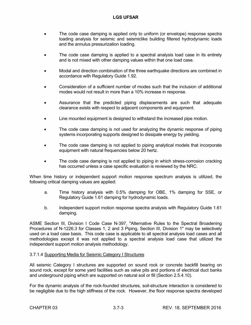
LGS UFSAR
CHAPTER 03 3.7-3 REV. 18, SEPTEMBER 2016
The code case damping is applied only to uniform (or envelope) response spectra loading analysis for seismic and seismiclike building filtered hydrodynamic loads and the annulus pressurization loading.
The code case damping is applied to a spectral analysis load case in its entirety and is not mixed with other damping values within that one load case.
Modal and direction combination of the three earthquake directions are combined in accordance with Regulatory Guide 1.92.
Consideration of a sufficient number of modes such that the inclusion of additional modes would not result in more than a 10% increase in response.
Assurance that the predicted piping displacements are such that adequate clearance exists with respect to adjacent components and equipment.
Line mounted equipment is designed to withstand the increased pipe motion.
The code case damping is not used for analyzing the dynamic response of piping systems incorporating supports designed to dissipate energy by yielding.
The code case damping is not applied to piping analytical models that incorporate equipment with natural frequencies below 20 hertz.
The code case damping is not applied to piping in which stress-corrosion cracking has occurred unless a case specific evaluation is reviewed by the NRC.
When time history or independent support motion response spectrum analysis is utilized, the following critical damping values are applied:
a. Time history analysis with 0.5% damping for OBE, 1% damping for SSE, or Regulatory Guide 1.61 damping for hydrodynamic loads.
b. Independent support motion response spectra analysis with Regulatory Guide 1.61 damping.
ASME Section III, Division I Code Case N-397, "Alternative Rules to the Spectral Broadening Procedures of N-1226.3 for Classes 1, 2 and 3 Piping, Section III, Division 1" may be selectively used on a load case basis. This code case is applicable to all spectral analysis load cases and all methodologies except it was not applied to a spectral analysis load case that utilized the independent support motion analysis methodology.
3.7.1.4 Supporting Media for Seismic Category I Structures
All seismic Category I structures are supported on sound rock or concrete backfill bearing on sound rock, except for some yard facilities such as valve pits and portions of electrical duct banks and underground piping which are supported on natural soil or fill (Section 2.5.4.10).
For the dynamic analysis of the rock-founded structures, soil-structure interaction is considered to be negligible due to the high stiffness of the rock. However, the floor response spectra developed
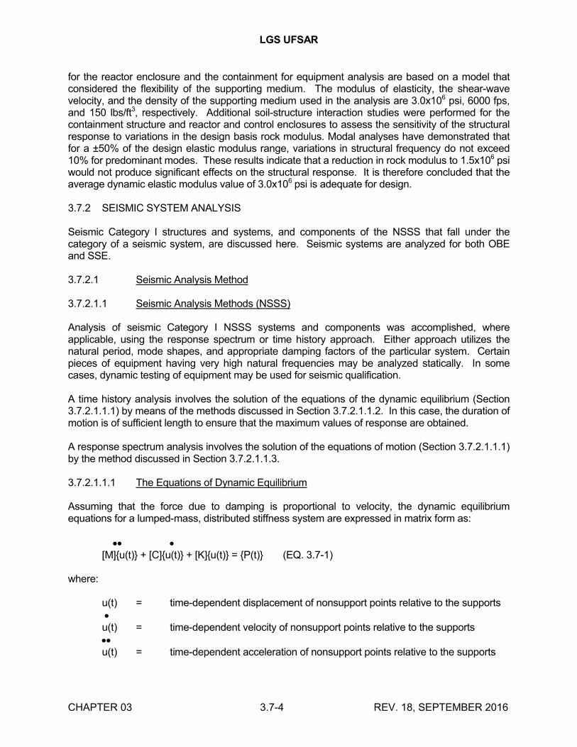
LGS UFSAR
CHAPTER 03 3.7-4 REV. 18, SEPTEMBER 2016
for the reactor enclosure and the containment for equipment analysis are based on a model that considered the flexibility of the supporting medium. The modulus of elasticity, the shear-wave velocity, and the density of the supporting medium used in the analysis are 3.0x10⁶ psi, 6000 fps, and 150 lbs/ft3, respectively. Additional soil-structure interaction studies were performed for the containment structure and reactor and control enclosures to assess the sensitivity of the structural response to variations in the design basis rock modulus. Modal analyses have demonstrated that for a ±50% of the design elastic modulus range, variations in structural frequency do not exceed 10% for predominant modes. These results indicate that a reduction in rock modulus to 1.5x10⁶ psi would not produce significant effects on the structural response. It is therefore concluded that the average dynamic elastic modulus value of 3.0x10⁶ psi is adequate for design.
3.7.2 SEISMIC SYSTEM ANALYSIS
Seismic Category I structures and systems, and components of the NSSS that fall under the category of a seismic system, are discussed here. Seismic systems are analyzed for both OBE and SSE.
3.7.2.1 Seismic Analysis Method
3.7.2.1.1 Seismic Analysis Methods (NSSS)
Analysis of seismic Category I NSSS systems and components was accomplished, where applicable, using the response spectrum or time history approach. Either approach utilizes the natural period, mode shapes, and appropriate damping factors of the particular system. Certain pieces of equipment having very high natural frequencies may be analyzed statically. In some cases, dynamic testing of equipment may be used for seismic qualification.
A time history analysis involves the solution of the equations of the dynamic equilibrium (Section 3.7.2.1.1.1) by means of the methods discussed in Section 3.7.2.1.1.2. In this case, the duration of motion is of sufficient length to ensure that the maximum values of response are obtained.
A response spectrum analysis involves the solution of the equations of motion (Section 3.7.2.1.1.1) by the method discussed in Section 3.7.2.1.1.3.
3.7.2.1.1.1 The Equations of Dynamic Equilibrium
Assuming that the force due to damping is proportional to velocity, the dynamic equilibrium equations for a lumped-mass, distributed stiffness system are expressed in matrix form as:
[M]{u(t)} + [C]{u(t)} + [K]{u(t)} = {P(t)} (EQ. 3.7-1)
where:
u(t) = time-dependent displacement of nonsupport points relative to the supportsu(t) = time-dependent velocity of nonsupport points relative to the supportsu(t) = time-dependent acceleration of nonsupport points relative to the supports
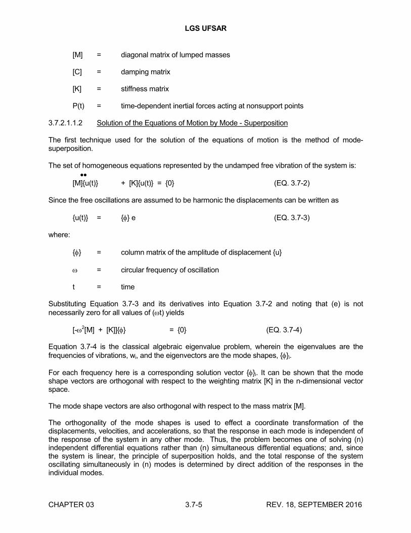
LGS UFSAR
CHAPTER 03 3.7-5 REV. 18, SEPTEMBER 2016
[M] = diagonal matrix of lumped masses
[C] = damping matrix
[K] = stiffness matrix
P(t) = time-dependent inertial forces acting at nonsupport points
3.7.2.1.1.2 Solution of the Equations of Motion by Mode - Superposition
The first technique used for the solution of the equations of motion is the method of mode-superposition.
The set of homogeneous equations represented by the undamped free vibration of the system is: [M]{u(t)} + [K]{u(t)} = {0} (EQ. 3.7-2)
Since the free oscillations are assumed to be harmonic the displacements can be written as
{u(t)} = {} e (EQ. 3.7-3)
where:
{} = column matrix of the amplitude of displacement {u}
= circular frequency of oscillation
t = time
Substituting Equation 3.7-3 and its derivatives into Equation 3.7-2 and noting that (e) is not necessarily zero for all values of (t) yields
[-2[M] + [K]]{} = {0} (EQ. 3.7-4)
Equation 3.7-4 is the classical algebraic eigenvalue problem, wherein the eigenvalues are the frequencies of vibrations, wi, and the eigenvectors are the mode shapes, {}i.
For each frequency here is a corresponding solution vector {}i. It can be shown that the mode shape vectors are orthogonal with respect to the weighting matrix [K] in the n-dimensional vector space.
The mode shape vectors are also orthogonal with respect to the mass matrix [M].
The orthogonality of the mode shapes is used to effect a coordinate transformation of the displacements, velocities, and accelerations, so that the response in each mode is independent of the response of the system in any other mode. Thus, the problem becomes one of solving (n) independent differential equations rather than (n) simultaneous differential equations; and, since the system is linear, the principle of superposition holds, and the total response of the system oscillating simultaneously in (n) modes is determined by direct addition of the responses in the individual modes.
LGS UFSAR
CHAPTER 03 3.7-6 REV. 18, SEPTEMBER 2016
3.7.2.1.1.3 Analysis by Response Spectrum
As an alternative to the step-by-step mode-superposition method described in Section 3.7.2.1.1.2, the response spectrum method may be used. The response spectrum method is based on the fact that the modal responses can be expressed as a set of integral equations, rather than a set of differential equations. The advantage of this form of solution is that for a given ground motion, the only variables under the integral are the damping factor and the frequency. Thus, for a specified damping factor, it is possible to construct a curve which gives a maximum value of the integral as a function of frequency. This curve is called a response spectrum for the particular input motion and the specified damping factor. The integral has units of velocity, consequently the maximum of the integral is called the spectral velocity.
Using the calculated natural frequencies of vibration of the system, the maximum values of the modal responses are determined directly from the appropriate response spectrum. The modal maxima are then combined as discussed in Section 3.7.3.7.1.
The total seismic structural response is predicted by combining the response calculated from the two horizontal and the vertical analyses. When the response spectrum method is used, the methods for combining the loads from the three analyses is based on the method described in Section 3.7.2.6.
3.7.2.1.1.4 Support Displacements in Multisupported Structure
The methods described in Section 3.7.2.1.1.5 are used, where applicable, to account for the effects of relative anchor motion in the case of a multisupported structure.
3.7.2.1.1.5 Dynamic Analysis of Seismic Category I Systems and Components
The time history technique and the response spectrum technique were used as applicable for the dynamic analysis of seismic Category I NSSS systems and components which are sensitive to dynamic seismic events.
a. Dynamic Analysis of Piping Systems
Each pipeline is idealized as a mathematical model consisting of lumped masses connected by elastic members. The stiffness matrix for the piping system is determined using the elastic properties of the pipe. This includes the effects of torsional, bending, shear, and axial deformations, as well as change in stiffness due to curved members. Next the mode shapes and the undamped natural frequencies are obtained. The dynamic response of the system is calculated by using the response spectrum method of analysis. When the piping system is being anchored and supported at points with different excitations, the response spectrum analysis is performed using a response spectrum which envelopes all the response spectra of anchors and supports. Alternatively, except as restricted by Section 3.7.1.3.3, the multiple response spectra/independent support motion method of analysis may be used where distinct time histories or response spectra are applied to all piping system attachment points.
The relative modal displacement between anchors is determined from the dynamic analysis of the primary structures. The results of the relative anchor point
LGS UFSAR
CHAPTER 03 3.7-7 REV. 18, SEPTEMBER 2016
displacement per mode are used for a static analysis to determine the secondary stresses due to relative anchor point displacements. The modal stresses are combined by the SRSS method to obtain the resultant secondary stresses.
b. Dynamic Analysis of Equipment
Equipment is idealized as a mathematical model consisting of lumped masses connected by elastic members or springs. The Table 3.9-6 series documents calculated and allowable loads for various loading combinations, including seismic loads, applied to major NSSS systems and components.
The response spectrum analysis is performed using the enveloped response spectrum of all attachment points. Alternatively, for equipment supported at two or more points located at different elevations in the same primary structure, the response spectrum for the most severe single support can be applied uniformly to all support points. As a second alternative, if appropriate, the response spectra at the elevation near the center of gravity of the equipment may be taken as the design spectra.
The relative modal displacement between supports is determined from the dynamic analysis of the structure. The relative support point displacements per mode are used for a static analysis to determine the secondary stresses due to support displacements. The modal stresses are combined by the SRSS method to obtain the resultant secondary stresses. Further details are given below.
c. Differential Seismic Movement of Interconnected Components
The procedure for considering differential displacements for equipment anchored and supported at points with different displacement excitations is as follows:
The relative displacements between the supporting points induces additional stresses in the equipment supported at these points. These stresses can be evaluated by performing a static analysis where each of the supporting points is displaced a prescribed amount. From the dynamic analysis of the complete structure, the time history of displacement at each supporting point is available. These displacements are used to calculate stresses by determining the peak modal responses. The stresses thus obtained for each natural mode are then superimposed for all modal displacements of the structure by the SRSS method.
In the static calculation of the stresses due to relative displacements in the response spectrum method, the maximum value of the modal displacement is used. Therefore, the mathematical model of the equipment is subjected to the maximum displacement at its supporting points obtained from the modal displacements. This procedure is repeated for the significant modes (modes contributing most to the total displacement response at the supporting point) of the structure. The total stresses due to relative displacement are obtained by combining the modal results using the SRSS method. Since the maximum displacements for different modes do not occur at the same time, the SRSS method is a realistic and practical method.
When a component is covered by the ASME B&PV Code, then the stresses due to relative displacement as obtained above are treated as secondary stresses.
LGS UFSAR
CHAPTER 03 3.7-8 REV. 18, SEPTEMBER 2016
3.7.2.1.1.6 Seismic Qualification by Testing
For certain seismic Category I equipment and components where dynamic testing is necessary to ensure functional integrity, test performance data and results reflect the following:
a. Performance data of equipment which, under the specified conditions, has been subjected to dynamic loads equal to or greater than those to be experienced under the specified seismic conditions
b. Test data from previously tested comparable equipment which, under similar conditions, has been subjected to dynamic loads equal to or greater than those specified
c. Actual testing of equipment in accordance with one of the methods described in Sections 3.9 and 3.10
Alternate test procedures that satisfy the requirements of these criteria are allowed, subject to review by the responsible engineer.
3.7.2.1.2 Seismic Analysis Methods (Non-NSSS)
In the analysis of seismic Category I structures, two distinct objectives must be satisfied:
a. Development of in-structure seismic response characteristics, where necessary, for use in the analysis and design of seismic Category I systems, equipment, and components
b. Determination of seismic force distribution within the various structures resulting from the design criteria free-field seismic input, for use in the design of seismic Category I structures
Two analytical procedures were employed to determine the seismic responses to the Category I structures. In general, a modal response spectrum analysis was used to compute the in-structure seismic responses, including nodal accelerations, nodal displacements, and member forces. Alternatively, a time history analysis procedure was used to generate the in-structure seismic responses discussed above. In addition, time history analysis was used to generate all floor response spectra. The mathematical idealization of the structural characteristics of the various seismic Category I structures was accomplished by a lumped-parameter beam-stick model. The general analytical methods and modeling techniques used in these analyses are in accordance with Reference 3.7-2. The seismic design criteria input is defined in terms of the OBE and SSE design response spectra (Section 3.7.1.1), the synthetic time history (Section 3.7.1.2), and the soil-structure interaction parameters (Section 3.7.2.4) used for development of floor response spectra for equipment assessment. Refer to Figures 3.7-10 through 3.7-19 for either a pictorial representation or an actual sketch of the mathematical models used. A complete description of the formulation of the mathematical models and their use is provided in Section 3.7.2.3.2.
3.7.2.2 Natural Frequencies and Response Loads
The natural frequencies of the primary containment, the reactor enclosure, and the control structure below 33 cps are shown in Tables 3.7-5 and 3.7-6 respectively. The significant mode
LGS UFSAR
CHAPTER 03 3.7-9 REV. 18, SEPTEMBER 2016
shapes of the containment and the reactor enclosure and control structure are shown on Figures 3.7-20 through 3.7-30. The mode shapes for the primary containment are for the horizontal and vertical directions. The reactor enclosure and control structure mode shapes are for each of the three principal directions: east-west, north-south, and vertical.
Tables 3.7-7 through 3.7-16 show the response (i.e., displacements, accelerations, shear forces, bending moments, and axial forces) of the primary containment and the reactor enclosure and control structure for both OBE and SSE.
Response spectra at critical locations are shown on Figures 3.7-31 through 3.7-40. The curves are shown for each of the principal directions at the damping values shown (Section 3.7.2.15 for further discussion of damping values). Figures 3.7-41 and 3.7-42 represent the response spectra of the refueling area using soil-structure interaction.
3.7.2.3 Procedures Used for Modeling
3.7.2.3.1 Procedures Used for Modeling (NSSS)
3.7.2.3.1.1 Modeling Techniques for Seismic Category I Systems and Components
An important step in the seismic analysis of seismic Category I NSSS systems and components is the procedure used for modeling. The techniques currently being used are represented by lumped masses and a set of spring-dashpots idealizing both the inertial and stiffness properties of the system. The details of the mathematical models are determined by the complexity of the actual structures and the information required for the analysis.
3.7.2.3.1.2 Modeling of Reactor Pressure Vessel and Internals
The seismic loads on the RPV and internals are based on a dynamic analysis of an entire RPV enclosure complex, with the appropriate forcing function applied at ground level. For this analysis, the models shown in Figure 3.7-19 and the mathematical model of the enclosure are coupled together.
This mathematical model consists of lumped masses connected by elastic (linear) members. The stiffness properties of the model are determined using the elastic properties of the structural components. This includes the effects of both bending and shear. In order to facilitate hydrodynamic mass calculations, several mass points (fuel, shroud, vessel) are selected at the same elevation. The various lengths of CRD housings are grouped into the two representative lengths as shown in Figure 3.7-19. These lengths represent the longest and shortest housings in order to adequately represent the full range of frequency response of the housings. The high fundamental natural frequencies of the CRD housings result in very small seismic loads. Furthermore, the small frequency differences between the various housings, due to the length differences, result in negligible differences in dynamic response. Hence, the modeling of intermediate length members becomes unnecessary. Not included in the mathematical model are the stiffnesses of light components such as jet pumps, incore guide tubes and housings, spargers, and their supply headers. This is done to reduce the complexity of the dynamic model. To find seismic responses of these components, the floor response spectra generated from the system analysis are used.
The presence of fluid and other structural components (e.g., fuel within the RPV) introduces a dynamic coupling effect. Dynamic effects of water enclosed by the RPV are accounted for by
LGS UFSAR
CHAPTER 03 3.7-10 REV. 18, SEPTEMBER 2016
introduction of a hydrodynamic mass matrix, which serves to link the acceleration terms of the equations of motion of points at the same elevation in concentric cylinders with a fluid entrapped in the annulus. The details of the hydrodynamic mass derivation are given in Reference 3.7-5. The seismic model of the RPV and internals has two generalized coordinates in the horizontal directions for each mass point considered in the analysis. The remaining generalized vertical coordinate is excluded because the vertical mode frequencies of RPV and internals are well above the significant horizontal mode frequencies. A separate vertical analysis is performed. The two rotational coordinates about each node point are excluded because the moment contribution from rotary inertia is negligible. Since all deflections are assumed to be within the elastic range, the rigidity of some components may be accounted for by equivalent linear springs.
The shroud support plate is loaded in its own plane during a seismic event and hence is extremely stiff, and, therefore, may be modeled as a rigid link in the translational direction. The shroud support legs and the local flexibilities of the vessel and shroud contribute to the rotational flexibilities and are modeled as an equivalent torsional spring.
3.7.2.3.2 Procedures Used for Modeling (Non-NSSS)
The mathematical models used for the analysis of all major Category I structures are fixed base, lumped-mass, elastic spring models, except for the primary containment, the reactor enclosure and control structure, where the lumped-mass seismic model considers a rigid mass resting on soil springs. The soil spring constants are determined from formulae given in table 3-2 of Reference 3.7-2. Two separate and independent analyses are done for the containment structure. The section properties for these two analyses are based on uncracked and cracked concrete sections, respectively. The same models are used both for the response spectrum and time history analyses. The mathematical models of the primary containment are shown in Figures 3.7-10 and 3.7-11, and those of the reactor enclosure and control structure are shown in Figures 3.7-14 and 3.7-15. The additional mathematical models used for development of floor response spectra, using soil-structure interaction for these structures, are shown in Figures 3.7-12, 3.7-13, 3.7-16, and 3.7-17.
For all models, the masses are located at elevations of mass concentrations, such as floors and roofs. However, in the case of the containment, a structure of continuous mass distribution, masses are lumped at approximate maximum intervals of 15 feet along the containment shell and reactor pedestal. These methods of mass distribution are in accordance with the procedures of section 3.2 of Reference 3.7-2. All equipment, components, and piping systems are lumped into the supporting structure except for the reactor vessel, which is incorporated into the lumped-parameter analysis of the containment structure to account for potential coupling. The detailed analysis of the NSSS is performed using a decoupled model as discussed in Section 3.7.2.3.1.
A more refined RPV model is being used in the DAR (Appendix 3A) to evaluate the anticipated effects of hydrodynamic loads in combination with seismic loads.
3.7.2.4 Soil-Structure Interaction
Since the seismic Category I structures are founded on competent bedrock, a soil spring approach to characterize soil-structure interaction is not used in the dynamic analysis. A simplified lumped-mass method using a fixed base model is used. However, for a more refined analysis of containment and reactor enclosure, the underlying foundation medium is considered to interact with the structure. The equivalent soil spring constant and damping coefficient are computed in accordance with the formulae of table 3-2 of Reference 3.7-2, and the analysis carried out by the
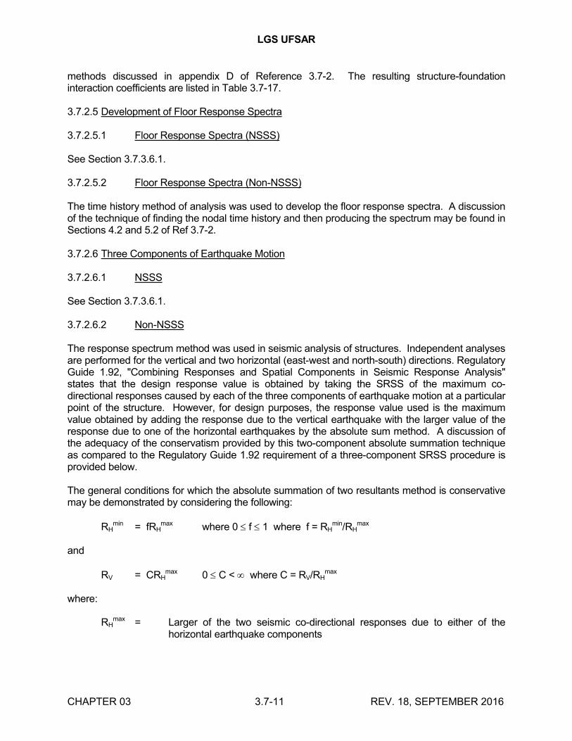
LGS UFSAR
CHAPTER 03 3.7-11 REV. 18, SEPTEMBER 2016
methods discussed in appendix D of Reference 3.7-2. The resulting structure-foundation interaction coefficients are listed in Table 3.7-17.
3.7.2.5 Development of Floor Response Spectra
3.7.2.5.1 Floor Response Spectra (NSSS)
See Section 3.7.3.6.1.
3.7.2.5.2 Floor Response Spectra (Non-NSSS)
The time history method of analysis was used to develop the floor response spectra. A discussion of the technique of finding the nodal time history and then producing the spectrum may be found in Sections 4.2 and 5.2 of Ref 3.7-2.
3.7.2.6 Three Components of Earthquake Motion
3.7.2.6.1 NSSS
See Section 3.7.3.6.1.
3.7.2.6.2 Non-NSSS
The response spectrum method was used in seismic analysis of structures. Independent analyses are performed for the vertical and two horizontal (east-west and north-south) directions. Regulatory Guide 1.92, "Combining Responses and Spatial Components in Seismic Response Analysis" states that the design response value is obtained by taking the SRSS of the maximum co-directional responses caused by each of the three components of earthquake motion at a particular point of the structure. However, for design purposes, the response value used is the maximum value obtained by adding the response due to the vertical earthquake with the larger value of the response due to one of the horizontal earthquakes by the absolute sum method. A discussion of the adequacy of the conservatism provided by this two-component absolute summation technique as compared to the Regulatory Guide 1.92 requirement of a three-component SRSS procedure is provided below.
The general conditions for which the absolute summation of two resultants method is conservative may be demonstrated by considering the following:
RHmin = fRH
max where 0 f 1 where f = RHmin/RH
max
and
RV = CRHmax 0 C < where C = RV/RH
max
where:
RHmax = Larger of the two seismic co-directional responses due to either of the
horizontal earthquake components
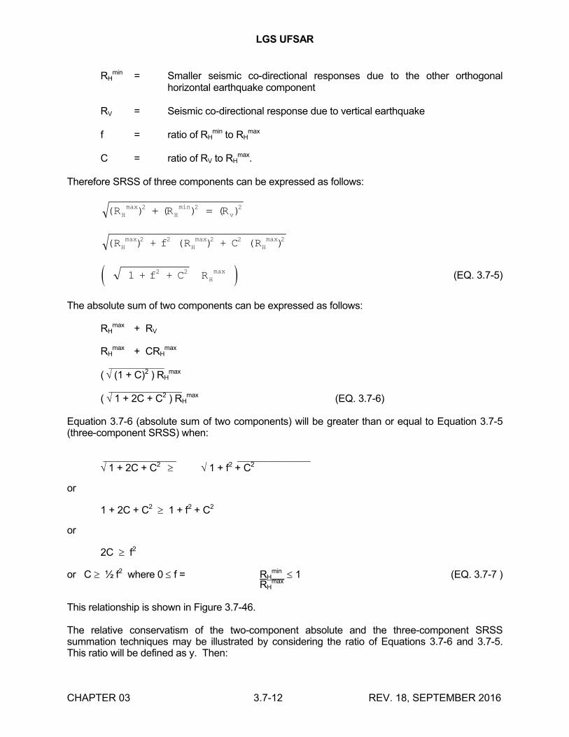
LGS UFSAR
CHAPTER 03 3.7-12 REV. 18, SEPTEMBER 2016
RHmin = Smaller seismic co-directional responses due to the other orthogonal
horizontal earthquake component
RV = Seismic co-directional response due to vertical earthquake
f = ratio of RHmin to RH
max
C = ratio of RV to RHmax.
Therefore SRSS of three components can be expressed as follows:
(R )Hmax 2 ( ) ( )minR RH v
2 2
(R ) + f (R ) + C (R )Hmax 2 2
Hmax 2 2
Hmax 2
1 + f + C R2 2Hmax
(EQ. 3.7-5)
The absolute sum of two components can be expressed as follows:
RHmax + RV
RHmax + CRH
max
________________
( (1 + C)2 ) RHmax
_____________________
( 1 + 2C + C2 ) RHmax (EQ. 3.7-6)
Equation 3.7-6 (absolute sum of two components) will be greater than or equal to Equation 3.7-5 (three-component SRSS) when:
_____________________ _____________________
1 + 2C + C2 1 + f2 + C2
or
1 + 2C + C2 1 + f2 + C2
or
2C f2
or C ½ f2 where 0 f = RHmin 1 (EQ. 3.7-7 )
RHmax
This relationship is shown in Figure 3.7-46.
The relative conservatism of the two-component absolute and the three-component SRSS summation techniques may be illustrated by considering the ratio of Equations 3.7-6 and 3.7-5. This ratio will be defined as y. Then:
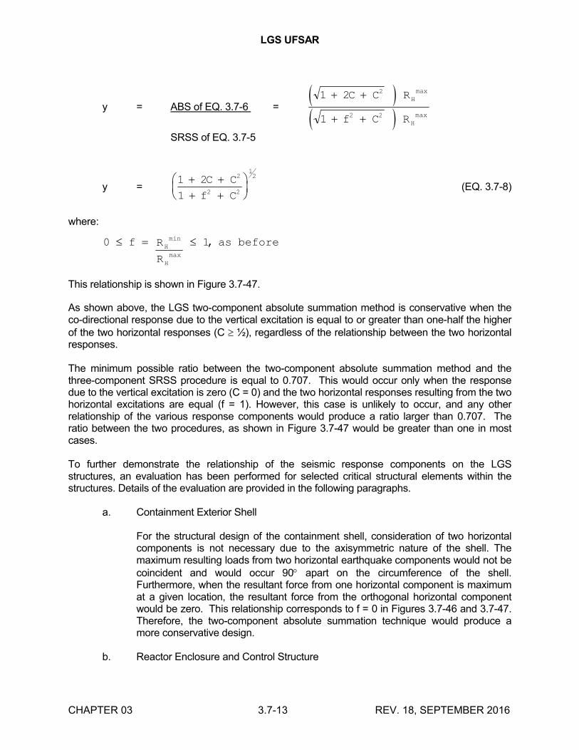
LGS UFSAR
CHAPTER 03 3.7-13 REV. 18, SEPTEMBER 2016
y = ABS of EQ. 3.7-6 = 1 2
1
2
2 2
C C R
f C R
H
H
max
max
SRSS of EQ. 3.7-5
y =1 2
1
2
2 2
12
C C
f C(EQ. 3.7-8)
where:
0 1 f R
R
as beforeH
H
min
max
,
This relationship is shown in Figure 3.7-47.
As shown above, the LGS two-component absolute summation method is conservative when the co-directional response due to the vertical excitation is equal to or greater than one-half the higher of the two horizontal responses (C ½), regardless of the relationship between the two horizontal responses.
The minimum possible ratio between the two-component absolute summation method and the three-component SRSS procedure is equal to 0.707. This would occur only when the response due to the vertical excitation is zero (C = 0) and the two horizontal responses resulting from the two horizontal excitations are equal (f = 1). However, this case is unlikely to occur, and any other relationship of the various response components would produce a ratio larger than 0.707. The ratio between the two procedures, as shown in Figure 3.7-47 would be greater than one in most cases.
To further demonstrate the relationship of the seismic response components on the LGS structures, an evaluation has been performed for selected critical structural elements within the structures. Details of the evaluation are provided in the following paragraphs.
a. Containment Exterior Shell
For the structural design of the containment shell, consideration of two horizontal components is not necessary due to the axisymmetric nature of the shell. The maximum resulting loads from two horizontal earthquake components would not be coincident and would occur 90 apart on the circumference of the shell. Furthermore, when the resultant force from one horizontal component is maximum at a given location, the resultant force from the orthogonal horizontal component would be zero. This relationship corresponds to f = 0 in Figures 3.7-46 and 3.7-47. Therefore, the two-component absolute summation technique would produce a more conservative design.
b. Reactor Enclosure and Control Structure
LGS UFSAR
CHAPTER 03 3.7-14 REV. 18, SEPTEMBER 2016
Stress evaluations were performed for critical locations in the reactor enclosure and control structure. The northeast control structure and southwest reactor enclosure corner model locations are selected because of their sensitivity to large orthogonal responses due to out-of-plane seismic motion. The results obtained from the SSE seismic analysis are combined by the two-component ABS and three-component SRSS methods and are compared in Table 3.7-20. For 14 out of 20 wall locations evaluated, the seismic stress response comparison shows that the two-component ABS method is more conservative than the three-component SRSS method. In general, the two-component ABS method and the three-component SRSS method produce comparable results. Although the differences between the combined stress from the two methods are small, the values for some locations suggest that the two-component ABS method may be conservative when the seismic load is considered to act alone.
There are 6 wall locations where the two-component ABS method is less conservative. The critical wall location is the southwest corner of the reactor enclosure, at el 177', where the differential between ABS stresses and SRSS stresses equals 14% (Table 3.7-20). (This location is considered critical not only because of the difference between the ABS and SRSS stresses but also because of the level of the stresses.) However, when the seismic stresses are combined with the stresses due to other design loads, the effect of the differential between ABS stresses and SRSS stresses is reduced in proportion with the ratio of seismic wall load to total wall load. In addition, the critical wall (wall line "D" at el 177') is loaded to only 52% of its capacity (based on combined axial and bending stresses due to all design loads as shown in Figure 3A-432).
Therefore, when considering the reduced effect of ABS vs. SRSS in conjunction with the ample excess capacity of the wall, the use of the ABS method for calculating seismic stresses provides adequate conservatism when considered in combination with other loads in the design of the reactor enclosure and control structure.
3.7.2.7 Combination of Modal Responses
3.7.2.7.1 Combination of Modal Responses (NSSS)
See Section 3.7.3.7.1.
3.7.2.7.2 Combination of Modal Responses (Non-NSSS)
The modal responses (i.e., shears, moments, deflections, accelerations, and inertia forces) are combined by either the sum of the ABS method, or by the SRSS method with consideration of closely spaced modes. Two consecutive modes are defined as closely spaced when their frequencies differ from each other by 10% or less of the lower frequency. When the SRSS method is used, Regulatory Guide 1.92 shall be adopted for the combination of modal responses.
3.7.2.8 Interaction of Non-Category I Structures with Seismic Category I Structures
The turbine enclosure, auxiliary boiler enclosure, and the administration building are the only major non-Category I structures adjacent to seismic Category I structures. These non-Category I
LGS UFSAR
CHAPTER 03 3.7-15 REV. 18, SEPTEMBER 2016
structures are designed for seismic loading in accordance with the UBC (Reference 3.7-3). In addition, the turbine enclosure was dynamically analyzed to ensure the capacity to withstand a SSE without collapsing on or impairing the integrity of the adjacent reactor and control structures. Similarly, the other non-Category I structures were analytically evaluated to ensure that they will not collapse on or otherwise impair the integrity of adjacent seismic Category I structures when subjected to the design seismic loads.
Structural separations have been provided to ensure that interaction between Category I and non-Category I structures does not occur. The minimum separation gap between the buildings is twice the relative displacement for the design seismic loads.
3.7.2.9 Effects of Parameter Variations on Floor Response Spectra
3.7.2.9.1 Effects of Parameter Variations on Floor Response Spectra (NSSS)
To account for potential variations in the primary structure frequencies due to uncertainties in material properties of the soil and structure, soil-structure interaction techniques, approximation in damping, and approximation in dynamic modeling, the computed floor response spectra are peak-broadened by ±15%. This is consistent with the requirements of Regulatory Guide 1.122, although this regulatory guide is not the design basis requirement for the LGS construction permit.
3.7.2.9.2 Effects of Parameter Variations on Floor Response Spectra (Non-NSSS)
To account for variations in the structural frequencies owing to uncertainties in the material properties of the structure and to approximations in the modeling techniques used in the seismic analysis, the computed floor response spectra are smoothed, and peaks associated with each of the structural frequencies are broadened. In lieu of making a parametric study considering changes in the material properties and other variables, the spectrum is broadened on either side of the peak value by 15% of the frequency at which the peaks occur.
3.7.2.10 Use of Constant Vertical Static Factors
Vertical seismic system multimass dynamic models are used to obtain vertical response loads for the seismic design of seismic Category I structures. Therefore, constant vertical static factors arenot used to account for vertical response to earthquakes for the seismic design of Category I structures.
3.7.2.11 Methods Used to Account for Torsional Effects
Torsional effects for the reactor enclosure, diesel generator enclosure, spray pond pumphouse, and radwaste enclosure are accounted for as follows:
A static analysis is performed to account for torsion on these structures. The eccentricity is determined using the distance between the center of mass and the center of rigidity of the individual structure. The inertial force from the response spectrum analysis is applied at the center of mass. The resulting torsional moment is equal to the inertial force times the eccentricity. The shear forces due to the torsional moment are then distributed to the walls. The total seismic shear in a given structural element is equal to the sum of the absolute values of the shear due to translation and torsion. Torsional effects are negligible for the containment because of the symmetry of the structure about the vertical center line.
LGS UFSAR
CHAPTER 03 3.7-16 REV. 18, SEPTEMBER 2016
Dynamic analyses have been performed to verify the adequacy of the static-equivalent method described above. These dynamic analyses were performed for the reactor enclosure, diesel generator enclosure and spray pond pumphouse where structural eccentricities are larger than 5% of the larger building plan dimension.
Inertia forces, obtained from dynamic analysis, are multiplied by the mass eccentricity (distance between center of mass and center of rigidity) to obtain a torsional moment, which is distributed to structural walls for design assessment. This equivalent static method was found to produce conservative design torsional moments; more so than results obtained from a 3-D dynamic analysis which included structural eccentricities. The dynamic analysis was performed as follows:
a. 3-D horizontal stick models were constructed for the reactor enclosure, diesel generator enclosure, and spray pond pumphouse with structural masses at calculated eccentricities (Figures 3.7-48, 3.7-49, and 3.7-50). The direction that has the larger mass eccentricity was selected for dynamic response analysis.
b. Modal analysis was performed to determine the vibration frequencies of the structures with eccentricity accounted for. The vibration frequencies with eccentricity were compared to the vibration frequencies with zero eccentricity (Tables 3.7-21 through 3.7-23).
c. Time history analyses were performed for the east-west models of the spray pond pumphouse, diesel generator enclosure, and reactor enclosure.
Torsional moments and shear forces at the base slab were compared with the moments and shear forces of the original design obtained using the equivalent static approach (Tables 3.7-24 through 3.7-27) .
Torsional moment and shear data comparisons show that the original design values using the static approach are conservative.
3.7.2.12 Comparison of Responses
A comparison of the results of modal design response spectrum analysis and modal time history analysis for the containment is shown in Figures 3.7-4 through 3.7-9. The responses are calculated for both OBE and SSE. The uncracked containment model as described in Section 3.7.2.3.2 is used for the analyses. The responses due to synthetic time history input are lower than those due to response spectrum, because the sum of the absolute modal responses are used in the latter analysis, whereas the phase differences of the modal responses are considered in the time history analysis.
3.7.2.13 Methods for Seismic Analysis of Dams
Dams are not provided on LGS.
3.7.2.14 Determination of Seismic Category I Structure Overturning Moments
The overturning moment for seismic Category I structures is the absolute sum of the moments at the base of each stick of the mathematical model. For each stick, the moment at the base is
LGS UFSAR
CHAPTER 03 3.7-17 REV. 18, SEPTEMBER 2016
determined by combining the modal overturning moments. The modal moments are combined by the methods described in Section 3.7.2.7.
The components of the earthquake motion used are the same as those discussed in Section 3.7.2.6. Section 3.8.5 discusses the factor of safety against overturning for several loadings, including seismic loads.
3.7.2.15 Analysis Procedure for Damping
3.7.2.15.1 Analysis Procedure for Damping (NSSS)
In a linear dynamic analysis, the procedure to be utilized to properly account for damping in different elements of a coupled system model is as follows:
a. The values for structural damping of the various structural elements of the model are first specified. Each value is referred to as the damping ratio (Bj) of a particular component which contributes to the complete stiffness of the system.
b. Perform a modal analysis of the linear system model. This will result in a modal matrix () normalized so that:
i
T Ki = Wi2
where:
K = the stiffness matrix
Wi = circular natural frequency of mode i
i
T = the transpose () which is a column vector of ()
corresponding to the mode shape of mode i
Matrix () contains all translational and rotational coordinates.
c. Using the strain energy of the individual components as a weighting function, the following equation can be derived to obtain a suitable damping ratio (Bi) for the ith
mode.
N
[ i
T j Kj i] (EQ. 3.7-9)
Bi j=1
Wi2
where:
N = Total number of structural elements
i = Mode shape for mode i ( i
T as transpose)
i = Percent damping associated with element j
LGS UFSAR
CHAPTER 03 3.7-18 REV. 18, SEPTEMBER 2016
Kj = Stiffness matrix of element j
Wi = Circular natural frequency of mode i
3.7.2.15.2 Analysis Procedure for Damping (Non-NSSS)
The structures consist of reinforced concrete and welded/bolted structural steel. Damping values for these materials are shown in Table 3.7-2. However, in the seismic analysis of structures supported on rock, damping values of 2% and 5% are used for OBE and SSE respectively for welded/bolted structural steel, as well as for reinforced concrete. Therefore, the analysis by composite modal damping is not necessary.
For the time history analysis of containment and reactor enclosure where the soil-structure interaction is taken into account, the composite modal damping technique was used as described in appendix D of Reference 3.7-2.
3.7.3 SEISMIC SUBSYSTEM ANALYSIS
This section discusses the seismic analysis of subsystems, i.e., equipment, piping, Class 1E cable trays, and supports for seismic Category I HVAC ducts and cable trays.
3.7.3.1 Seismic Analysis Methods
3.7.3.1.1 Equipment
Seismic qualification of equipment was performed by using one of the following methods:
a. Analysis
b. Dynamic testing
c. Combination of analysis and dynamic testing
3.7.3.1.1.1 Analysis
For the purpose of analysis, equipment is idealized as a system of lumped masses and springs, for which frequencies and mode shapes are determined for vibration in the vertical direction and two orthogonal horizontal directions. For each direction of vibration, the spectral acceleration per mode is obtained from the appropriate response spectrum curve (i.e., corresponding to the location of the equipment) at the natural frequency of the equipment. Seismic loading, in terms of inertia forces, moments and shears, is determined for each direction using the response spectrum technique, summing the absolute values per mode. If the orientation of the equipment is not designated on the equipment location drawing, the horizontal seismic loading is taken as the maximum loading (worst case) obtained, using each horizontal direction of vibration and the appropriate horizontal response spectrum curve(s). If the frequencies of all equipment modes (determined by either analysis or testing) are above the frequency of the appropriate response spectrum curve at which the acceleration is constant in the rigid (high frequency) range, the seismic loading consists of static loading corresponding to that acceleration level. If the equipment damping is unknown, the response spectrum curve for 0.5% damping is used to arrive at a conservative seismic loading.
LGS UFSAR
CHAPTER 03 3.7-19 REV. 18, SEPTEMBER 2016
The damping value used for the OBE is increased for the SSE, where sufficient justification is established.
3.7.3.1.1.2 Dynamic Testing
In lieu of performing dynamic analysis, seismic adequacy may be established by providing dynamic test or previous dynamic environmental (performance) data which demonstrate that the equipment meets the seismic design criteria. The data include at least one of the following:
a. Recent test data acquired from dynamic tests of equipment
b. Dynamic test data from previously tested comparable equipment
c. Performance data from equipment which, during normal operating conditions, have been subjected to dynamic loads equal to or greater than those defined in Section 3.7.3.1.1.1
Typical test methods used are as follows:
a. Single-frequency sine beat test
b. Single-frequency dwell test
c. Multifrequency test
3.7.3.1.1.3 Combination of Analysis and Dynamic Testing
Certain equipment was qualified by a combination of analysis and dynamic testing. Experimental methods are used to aid in the formulation of the mathematical model for the equipment. Mode shapes and frequencies are determined experimentally and incorporated in the mathematical model of the equipment. The model is then subsequently analyzed by the procedure described in Section 3.7.3.1.1.1.
3.7.3.1.2 Piping Systems
Reference 3.7-4 describes the methods used for seismic analysis of piping systems. Reference 3.7-4 is followed on LGS with the following exceptions:
In seismic analysis the modal responses are combined by SRSS, and lower damping values than specified in Reference 3.7-4 are used. Alternative analytical methods and damping values may be utilized as described in Section 3.7.1.3.3.
See Section 3.7.3.7.2.
3.7.3.1.3 Class 1E Cable Trays
The cable trays are seismically qualified by the capacity evaluation method which consists of the following:
LGS UFSAR
CHAPTER 03 3.7-20 REV. 18, SEPTEMBER 2016
a. Calculation of the fundamental frequency of the cable tray based on the tray properties obtained from static tests
b. Seismic load computation based upon the tray frequency and the design spectra
c. Calculation of the tray allowable capacity
d. Evaluation of the tray capacity by interaction formula
3.7.3.1.4 Supports for Seismic Category I HVAC Ducts
The supports for HVAC ducts are analyzed by the response spectrummethod (Reference 3.7-2).
3.7.3.1.5 Supports for Seismic Category I Electrical Raceway Systems
This section defines the procedures used for the design of the supports of electrical raceway systems, i.e., cable tray, conduit, and wireway gutter systems, subject to the seismic and other applicable loads. The raceway support system usually consists of raceways, horizontal and vertical support members, and lateral and longitudinal bracing members.
3.7.3.1.5.1 Loading Combinations
The adequacy of raceway systems to withstand seismic and other applicable static loads is determined according to the loading combinations and allowable responses given in Table 3.7-3. Load combinations and allowable stresses including the effects of hydrodynamic loads due to LOCA and SRV discharge are given in Table 3A-21.
3.7.3.1.5.2 Analytical Techniques
Either of two methods of analysis is used. Method 1 is a simplified method of analysis which determine the fundamental frequency of braced supports using two-dimensional analysis. Frequencies are determined in each of three principal directions. Then loads are determined by taking the spectral accelerations times the weight; and stresses are determined from static analysis. All members and connections are checked using stress criteria.
Method 2 uses a three-dimensional computer analysis and includes springs to represent joint stiffnesses. Response spectrum analyses are done to determine stresses and deformations. The number of stress cycles is determined by multiplying the time of maximum earthquake motion by the natural frequency of the system.
The allowable number of cycles is taken from Reference 3.7-8 for the joint rotations calculated. Only overhead connections are checked for fatigue because the test results (Reference 3.7-8, p. 7-19) demonstrate that failures occur only in overhead connections.
The basis for the design criteria and analysis Method 2 is the "Cable Tray and Conduit Raceway Test Program" (References 3.7-7 through 3.7-10).
3.7.3.1.5.3 Damping
LGS UFSAR
CHAPTER 03 3.7-21 REV. 18, SEPTEMBER 2016
Damping of 10% of the critical is used for the design of cable tray support systems; 7% damping for conduit and wireway gutter trapeze-type support systems; 5% damping for conduit and wireway gutter nontrapeze-type support systems. The recommended damping values for cable tray and conduit systems, developed from the test program, are shown in Figure 3.7-45. Wireway gutters were not tested: however, the manner in which they are constructed (with more bolted connections and more cables than conduit) provides more damping mechanisms than are present in conduit systems so that using the same damping value as in conduit systems is conservative.
3.7.3.1.5.4 Operating Basis Earthquake
The OBE is considered in the load combinations only for the overhead connections which are checked for fatigue. The OBE stresses are not checked during design for two reasons: first, raceway systems do not fail in a brittle or catastrophic mode as demonstrated by the test program in which such failures did not occur and the electrical systems were able to continue to function in all cases. Thus, there is no need to limit the OBE stresses to the low levels usually used to preclude such failures. Second, the OBE stresses will always be less than the SSE stresses as demonstrated below.
Based on Figure 3.7-45, a comparison of response spectra for corresponding damping values specified in Section 3.7.3.1.5.3 demonstrates that for all response spectra the OBE acceleration values are less than the corresponding SSE acceleration values (References 3.7-8 and 3.7-10). Thus, the OBE acceleration response and stresses are below the SSE acceleration response and stresses.
3.7.3.2 Determination of Number of Earthquake Cycles
3.7.3.2.1 Determination of Number of Earthquake Cycles (NSSS)
3.7.3.2.1.1 NSSS Piping
Fifty peak OBE cycles are postulated for fatigue evaluation.
3.7.3.2.1.2 Other NSSS Equipment and Components
To evaluate the number of cycles which exist within a given earthquake, a typical BWR enclosure/reactor dynamic model was excited by three different recorded time histories: May 18, 1940, El Centro NS component 29.4 sec; 1952, Taft N 69o W component, 30 sec; and March 1957, Golden Gate S 80o E component, 13.2 seconds. The modal response is truncated so that the response of three different frequency bandwidths could be studied: 0-10 Hz; 10-20 Hz; and 20-50 Hz. This is done to give a good approximation to the cyclic behavior expected from structures with different frequency content.
Enveloping the results from the three earthquakes and averaging the results from several different points of the dynamic model, the cyclic behavior as given in Table 3.7-18 was formed. A comparison has shown that the LGS design basis response spectrum is bounded by the spectra of the three earthquakes (Golden Gate, Taft, and El Centro) in the GE base study (Figure 3.7-43).
Independent of earthquake or component frequency, 99.5% of the stress reversals occur below 75% of the maximum stress level, and 95% of the reversals lie below 50% of the maximum stress level.
In summary, the cyclic behavior number of fatigue cycles of a component during an earthquake was found in the following manner:
LGS UFSAR
CHAPTER 03 3.7-22 REV. 18, SEPTEMBER 2016
a. The fundamental frequency and peak seismic loads are found by a standard seismic analysis.
b. The number of cycles which the component experiences are found from Table 3.7-18 according to the frequency range within which the fundamental frequency lies.
c. For fatigue evaluation, 0.5% (0.005) of these cycles are conservatively assumed to be at the peak load and 4.5% (0.045) at or above three quarter peak. The remainder of the cycles have negligible contribution to fatigue usage.
The SSE has the highest level of response. However, the encounter probability of the SSE is so small that it is not necessary to postulate the possibility of more than one SSE during the 40 year life of a plant. Fatigue evaluation due to the SSE is not necessary, since it is a faulted condition, and thus the evaluation is not required by ASME Section III.
The OBE is an upset condition, and therefore, must be included in fatigue evaluations according to ASME Section III. Investigation of seismic histories for many plants show that during a 40 year life, it is probable that five earthquakes with intensities of one-tenth of the SSE intensity, and one earthquake of approximately 20% of the proposed SSE intensity, will occur. To cover the combined effects of these earthquakes and the cumulative effects of even lesser earthquakes, ten peak OBE cycles are postulated for fatigue evaluation.
Table 3.7-19 shows the calculated number of fatigue cycles and the number of fatigue cycles used in design.
3.7.3.2.2 Determination of Number of Earthquake Cycles (Non-NSSS)
In general, the design of the equipment is not fatigue controlled. For equipment qualified by analysis, fatigue is not a controlling factor because the equipment is designed to remain below 90% of the yield strength of the material for the extreme loading condition. The number of stress cycles considered is 60 (5 OBE and 1 SSE events at 10 cycles each). Based on ASME Section III, appendix I criteria (figure I-9-1), this number of cycles will not result in a reduction of allowable stresses.
Any fatigue effects in tested equipment are accounted for by the duration of the test. Consequently, the number of cycles of the earthquake is considered.
In order to conduct a fatigue evaluation for nuclear Class I piping, the number of cycles for a given load set is obtained. This is done by considering ten maximum stress cycles per earthquake and 5 OBEs and 1 SSE to occur within the life of the plant. The results of the fatigue calculations for the most limiting BWR/4 component are shown in Table 3.7-4.
3.7.3.3 Procedures Used for Modeling
3.7.3.3.1 Procedures Used for Modeling (NSSS)
3.7.3.3.1.1 Modeling of Piping Systems
LGS UFSAR
CHAPTER 03 3.7-23 REV. 18, SEPTEMBER 2016
The continuous piping system is modeled as an assemblage of beams. The mass of each beam is lumped at the nodes connected by weightless elastic members representing the physical properties of each segment. The pipe lengths between mass points are no greater than the length which would have a natural frequency of 33 Hz, when calculated as a simply supported beam. All concentrated weights on the piping system such as main valves, relief valves, pumps, and motors are modeled as lumped masses. The torsional effects of the valve operators and other equipment with offset centers of gravity, with respect to the center line of the pipe, is included in the analytical model. Where the torsional effect is found to cause pipe stresses less than 500 psi, this effect is neglected.
3.7.3.3.1.2 Modeling of Equipment
For dynamic analysis, seismic Category I equipment is represented by lumped-mass systems which consist of discrete masses connected by weightless springs. The criteria used to lump masses are:
a. The number of modes of a dynamic system is controlled by the number of masses used. Therefore, the number of masses is chosen so that all significant modes areincluded. A mode is considered significant if the corresponding natural frequency is less than 33 Hz, and the stresses calculated from this mode are greater than 10% of the total stresses obtained from lower modes.
b. Mass is lumped at any point where a significant concentrated weight is located. Examples are: the motor in the analysis of pump motor stand; the impeller in the analysis of pump shaft; etc.
c. If the equipment has a free-end overhang span whose flexibility is significant compared to the center span, a mass is lumped at the overhang span.
d. When a mass is lumped between two supports, it is located at a point where the maximum displacement is expected to occur. This tends to conservatively lower the natural frequencies of the equipment, because the natural frequencies of the equipment are generally in the higher frequency range of the floor spectra. Similarly, in the case of live loads (mobile) and a variable support stiffness, the location of the load and the magnitude of support stiffness are chosen so as to yield the lowest frequency content for the system. This is to ensure conservative dynamic loads, since equipment frequencies are higher than the frequency at which the floor spectra peak occurs. If such is not the case, the model is adjusted to give more conservative results.
3.7.3.3.1.3 Field Location of Supports and Restraints
The field location of seismic supports and restraints for seismic Category I piping and piping systems components was selected to satisfy the following two conditions:
a. The location selected must furnish the required response to control strain within allowable limits.
b. Adequate structure strength for attachment of the components must be available.
The final location of seismic supports and restraints for seismic Category I piping, piping system components, and equipment (including the placement of snubbers), was checked against the
LGS UFSAR
CHAPTER 03 3.7-24 REV. 18, SEPTEMBER 2016
drawings and instructions issued by the engineer. An additional examination of these supports and restraining devices was made to ensure that the location and characteristics of these supports and restraining devices are consistent with the dynamic and static analyses of the systems.
3.7.3.3.2 Procedures Used for Modeling (Non-NSSS)
Mathematical models which describe the mass and the stiffness properties of the equipment are used. The models define the dynamic behavior of the equipment within the frequency range of interest. The boundary conditions are modeled to reflect the actual mounting conditions. The equipment is represented by lumped-mass models. Massless elastic members are used to connect the masses.
Supports for HVAC ducts are modeled as two-dimensional, lumped- mass, plane frame models. The masses are lumped at the center of the ducts. The electrical raceway support system analytical techniques are discussed in Section 3.7.3.1.5.2. Equivalent structural properties for cable tray analysis were determined from the load-deflection tests (Reference 3.7-11).
Sections 2 and 3 of Reference 3.7-4 discuss the techniques and procedures used to model piping other than the buried type.
3.7.3.4 Basis of Selection of Frequencies
3.7.3.4.1 Basis of Selection of Frequencies (NSSS)
All frequencies in the range of 0.25-33 Hz are considered in the analysis and testing of structures, systems, and components. These frequencies cover the natural frequencies of most of the components and structures under consideration. If the fundamental frequency of a component is 33 Hz, it is treated as rigid and analyzed accordingly. Frequencies less than 0.25 Hz are not considered, as they represent very flexible structures and are not encountered in this plant.
The frequency range of between 0.25 Hz and 33 Hz covers the range of the broad-band response spectrum used in the design.
3.7.3.4.2 Basis of Selection of Frequencies (Non-NSSS)
The natural frequencies of components are calculated. Only those modes which have natural frequencies <33 Hz are considered in the dynamic analysis. If a component has a frequency 33 Hz, it is considered as rigid. If the natural frequency of the component falls within the broadened peak of the response spectrum curve, then it is designed to take the applied load.
3.7.3.5 Use of Equivalent Static Load Method of Analysis (Non-NSSS)
The equivalent static load method is used when the natural frequency of the equipment is not determined. If the equipment can be adequately represented by a single-degree-of-freedom system, then the applied inertia load is equal to the weight of the equipment times the peak value of the response spectrum curve. Seismic acceleration coefficients for multidegree of freedom systems, which may be in the resonance region of the amplified response spectra curves, are increased by 50% to account conservatively for the increased modal participation.
Appendix D of Reference 3.7-4 discusses the use of equivalent static load method of analysis as applicable to piping.
LGS UFSAR
CHAPTER 03 3.7-25 REV. 18, SEPTEMBER 2016
3.7.3.6 Three Components of Earthquake Motion
3.7.3.6.1 Three Components of Earthquake Motion (NSSS)
The simultaneous use of three components of earthquake motion was not a design basis requirement of the construction permit for the LGS plant. However, the NSSS systems and components are evaluated to the requirement of Regulatory Guide 1.92.
a. Response Spectrum Method
Response spectra generated by GE are developed considering three components of earthquake motion. The individual responses in each orthogonal direction are combined by SRSS of the colinear contribution due to the three directions of earthquake motion. These are used to predict the total response at each frequency.
b. Time history Method
When the time history method of analysis is used, one of the following options is used to obtain the peak value of any particular response of interest:
1. When maximum colinear contributions due to the three directions of earthquake motion are calculated separately, the total response is obtained as the SRSS combination of the colinear values.
2. When colinear time history responses from each of the three components of the earthquake motion are calculated individually by the step-by-step method and then combined algebraically at each time step, the maximum response is obtained as the peak value from the combined time solution.
3. When a response at each time step is calculated directly based on the simultaneous application of the three earthquake components, the maximum response is determined by scanning the combined time history solution.
The components of earthquake motion must be statistically independent for Options 2 and 3. Also, the time history method precludes the need to consider closely spaced modes.
3.7.3.6.2 Three Components of Earthquake Motion (Non-NSSS)
For equipment, cable trays, and supports for cable trays and HVAC ducts, the three spatial components of the earthquake are considered in the same manner as for structures (Section 3.7.2.6).
The criteria used for combining the results of horizontal and vertical seismic responses for piping systems are described in section 5.1 of Reference 3.7-4.
3.7.3.7 Combination of Modal Responses
3.7.3.7.1 Combination of Modal Responses (NSSS)
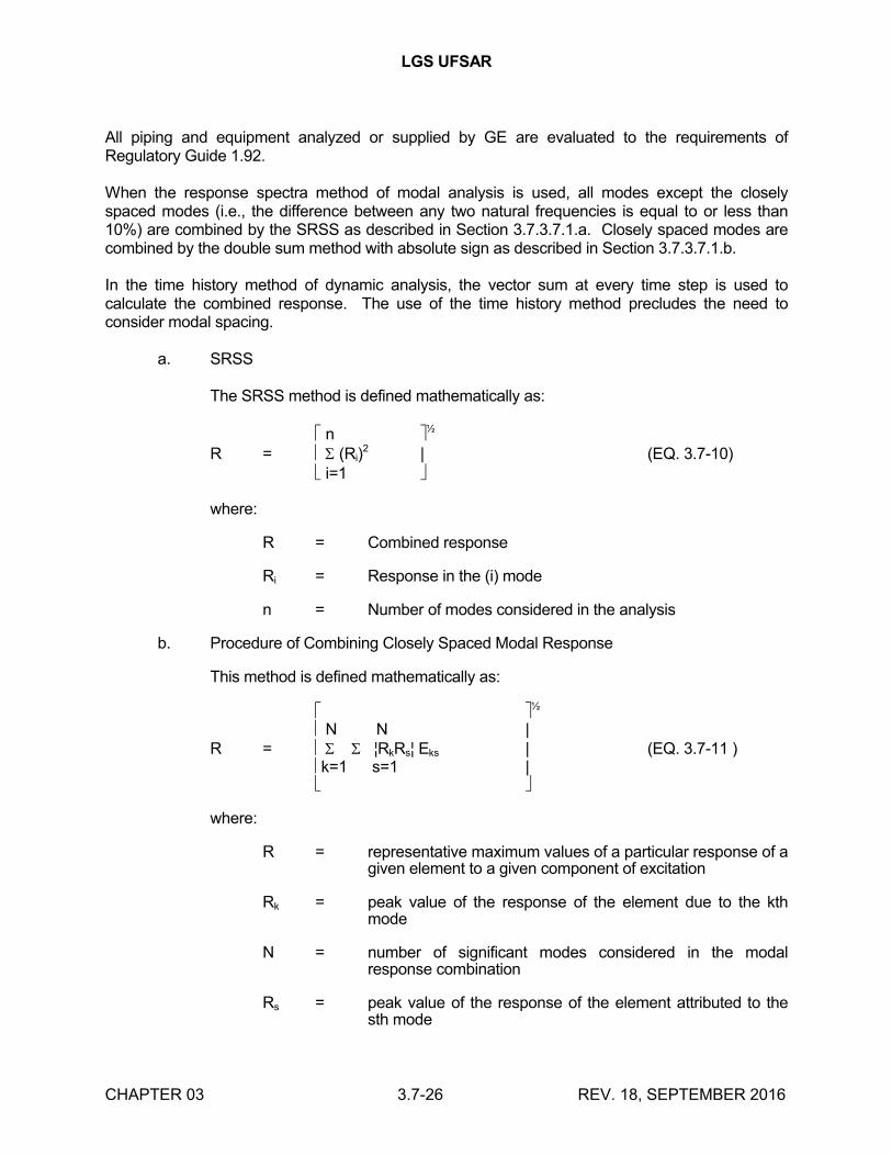
LGS UFSAR
CHAPTER 03 3.7-26 REV. 18, SEPTEMBER 2016
All piping and equipment analyzed or supplied by GE are evaluated to the requirements of Regulatory Guide 1.92.
When the response spectra method of modal analysis is used, all modes except the closely spaced modes (i.e., the difference between any two natural frequencies is equal to or less than 10%) are combined by the SRSS as described in Section 3.7.3.7.1.a. Closely spaced modes are combined by the double sum method with absolute sign as described in Section 3.7.3.7.1.b.
In the time history method of dynamic analysis, the vector sum at every time step is used to calculate the combined response. The use of the time history method precludes the need to consider modal spacing.
a. SRSS
The SRSS method is defined mathematically as:
n ½
R = (Ri)2 | (EQ. 3.7-10)
i=1
where:
R = Combined response
Ri = Response in the (i) mode
n = Number of modes considered in the analysis
b. Procedure of Combining Closely Spaced Modal Response
This method is defined mathematically as:
½
N N | R = ¦RkRs¦ Eks | (EQ. 3.7-11 )
k=1 s=1 |
where:
R = representative maximum values of a particular response of a given element to a given component of excitation
Rk = peak value of the response of the element due to the kth mode
N = number of significant modes considered in the modal response combination
Rs = peak value of the response of the element attributed to the sth mode
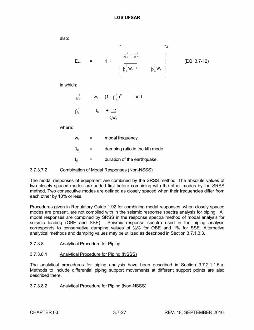
LGS UFSAR
CHAPTER 03 3.7-27 REV. 18, SEPTEMBER 2016
also:
2
kW1
-sW1
|
Eks = 1 + | (EQ. 3.7-12)
k
1
wk +s
1
ws |
in which:
kw1
= wk (1 -k
2
)½ and
k
1
= k + 2
tdwk
where:
wk = modal frequency
k = damping ratio in the kth mode
td = duration of the earthquake.
3.7.3.7.2 Combination of Modal Responses (Non-NSSS)
The modal responses of equipment are combined by the SRSS method. The absolute values of two closely spaced modes are added first before combining with the other modes by the SRSS method. Two consecutive modes are defined as closely spaced when their frequencies differ from each other by 10% or less.
Procedures given in Regulatory Guide 1.92 for combining modal responses, when closely spaced modes are present, are not complied with in the seismic response spectra analysis for piping. All modal responses are combined by SRSS in the response spectra method of modal analysis for seismic loading (OBE and SSE). Seismic response spectra used in the piping analysis corresponds to conservative damping values of ½% for OBE and 1% for SSE. Alternative analytical methods and damping values may be utilized as described in Section 3.7.1.3.3.
3.7.3.8 Analytical Procedure for Piping
3.7.3.8.1 Analytical Procedure for Piping (NSSS)
The analytical procedures for piping analysis have been described in Section 3.7.2.1.1.5.a. Methods to include differential piping support movements at different support points are also described there.
3.7.3.8.2 Analytical Procedure for Piping (Non-NSSS)
LGS UFSAR
CHAPTER 03 3.7-28 REV. 18, SEPTEMBER 2016
The design criteria and the analytical procedures applicable to piping systems are as described in section 2 of Reference 3.7-4. Alternatively, except as restricted by Section 3.7.1.3.3, the multiple response spectra/independent support motion method of analysis may be used where distinct response spectra are applied to the piping system attachment points. The methods used to consider differential piping support movements at different support points are described in section 4 of Reference 3.7-4.
3.7.3.9 Multiple Supported Equipment Components with Distinct Inputs
3.7.3.9.1 Multiple Supported Equipment Components with Distinct Inputs (NSSS)
The procedure and criteria for analysis has been described in Section 3.7.2.1.1.5.b.
3.7.3.9.2 Multiple Supported Equipment Components with Distinct Inputs (Non-NSSS)
For cable trays and HVAC ducts whose supports have two or more distinct inputs, a response spectrum curve envelopes the curves at all support locations. When a piping system whose supports have two or more distinct inputs, a response spectrum curve may be used for analysis that envelopes the curves at all locations. Alternatively, except as restricted by Section 3.7.1.3.3, the multiple response spectra/independent support motion method of analysis may be used where distinct response spectra are applied to the piping system attachment points. Section 4 of Reference 3.7-4 discusses the methods used for the analysis of multiple supported piping due to differential seismic anchor movement.
3.7.3.10 Use of Constant Vertical Static Factors
3.7.3.10.1 Use of Constant Vertical Static Factors (NSSS)
Constant vertical static factors are not used for NSSS components.
3.7.3.10.2 Use of Constant Vertical Static Factors (Non-NSSS)
Constant vertical static factors are not used in the seismic design of subsystems.
3.7.3.11 Torsional Effects of Eccentric Masses
3.7.3.11.1 Torsional Effects of Eccentric Masses (NSSS)
Torsional effects of eccentric masses is discussed in Section 3.7.3.3.1.1.
3.7.3.11.2 Torsional Effects of Eccentric Masses (Non-NSSS)
The torsional effects of valves and other eccentric masses are considered in the seismic analysis of piping by the techniques discussed in section 3.2 of Reference 3.7-4.
LGS UFSAR
CHAPTER 03 3.7-29 REV. 18, SEPTEMBER 2016
3.7.3.12 Buried Seismic Category I Piping Systems and Tunnels (Non-NSSS)
Buried seismic Category I piping is analyzed and designed for seismic effects in accordance with section 6.0 of Reference 3.7-2. For portions of buried piping in soil, the soil response along the pipeline is determined in accordance with the procedure in Section 2.5.4.7.1.
The diesel oil storage tank structures and the ESW/RHRSW pipe tunnel (located beneath the diesel generator enclosure) are seismic Category I and are analyzed using an equivalent static load method.
Other tunnels at LGS are nonseismic Category I.
3.7.3.13 Interaction of other Piping with Seismic category I Piping
3.7.3.13.1 Interaction of other Piping with seismic Category I Piping (NSSS)
When other piping is attached to seismic Category I piping, the other piping is analytically simulated in a manner that does not significantly degrade the accuracy of the seismic Category I piping analysis. Furthermore, the other piping is designed to withstand the SSE without failing in a manner that would cause the seismic Category I piping to fail.
3.7.3.13.2 Interaction of Other Piping with seismic Category I Piping (Non-NSSS)
The techniques used to consider the interaction of seismic Category I piping with non-Category I piping are as follows:
Seismic boundary anchors are designed for the combined loads generated from both sides of a boundary anchor. The loads from the seismic Category I side are actual calculated loads, and the loads from the nonseismic Category I side are determined by one of the following:
a. The actual calculated seismic loads if the nonseismic side piping is dynamically analyzed for seismic events
b. The actual calculated loads if the nonseismic side piping is designed to a conservative simplified seismic design criteria (e.g., by simplified span methods such as those used for designed of small piping)
c. The loads determined by the plastic capability of the piping.
3.7.3.14 Seismic Analysis for Reactor Internals (NSSS)
The modeling of RPV internals is discussed in section 3.7.2.3.1.2. The damping values are given in Table 3.7-1.
3.7.3.15 Analysis Procedures for Damping
3.7.3.15.1 Analysis Procedures for Damping (NSSS)
Analysis procedures for damping are discussed in section 3.7.2.15.1.
LGS UFSAR
CHAPTER 03 3.7-30 REV. 18, SEPTEMBER 2016
3.7.3.15.2 Analysis Procedure for Damping (Non-NSSS)
If the equipment damping is unknown, the response spectrum curve for 0.5% damping is used to arrive at a conservative seismic loading. The damping values used for the OBE are increased for the SSE, where sufficient justification is established.
3.7.4 SEISMIC INSTRUMENTATION
3.7.4.1 Comparison with Regulatory Guide 1.12 (Rev 1)
The seismic instrumentation program complies with the intent of Regulatory Guide 1.12 (Rev. 1) and section 5 of ANSI N18.5-1974. The original analog system was replaced by a digital system. The digital system provides the function and information equivalent of that required in RG 1.12 and ANSI N18.5. The triaxial peak recording accelerographs are no longer a part of the seismic monitoring system. The digital system will perform the same functions as the accelerographs.
Regulatory Guide 1.12 paragraph C.1.b specifies the requirement for a containment foundation sensor. The sensor is physically located on the reactor enclosure basemat about 6 inches from primary containment foundation. This is an exception to RG 1.12; however, the location provides an equivalent response to primary containment foundation and meets the intent of RG 1.12. Further details for sensor locations is provided in 3.7.4.2.
3.7.4.2 Location and Description of Instrumentation
The following instrumentation is provided for Unit 1 only, as essentially the same response is expected at Unit 2.
a. Six triaxial time history accelerometers.
b. One response spectrum analyzer
c. A system control panel which includes seismic event visual and audible annunciators
d. Digital recorders and a playback unit
All instrument characteristics meet the requirements of section 5 of ANSI N18.5 (1974).
The operability of the seismic monitoring instrumentation ensures that sufficient capability is available to promptly determine the magnitude of a seismic event and evaluate the response of those features important to safety, This capability is required to permit comparison of the measured response to that used in the design basis for the unit.
3.7.4.2.1 Triaxial Time History Accelerometers
Triaxial time history accelerometers (T/A) produce a record of the time-varying acceleration at the sensor location. These data are recorded at the system control panel and may be used directly for analysis and comparison with reference information, and may be converted to response spectra form for spectral comparisons with design parameters.
LGS UFSAR
CHAPTER 03 3.7-31 REV. 18, SEPTEMBER 2016
Each T/A contains three accelerometers mounted in a mutually orthogonal array. All T/As have their principal axes oriented identically, with one horizontal axis parallel to the major horizontal axis assumed in the seismic analysis. T/As are located as shown in Table 3.7-28.
A recording system located in the control room is provided for multiple channel recording of the signals from the T/As mounted on items shown in Table 3.7-28.
3.7.4.2.2 Triaxial Peak Recording Accelerographs
A self contained T/A recording system is located in the Spray Pond Pumphouse. This T/A is not connected to the Control Room equipment. A separate portable computer is available to retrieve recorded data and transport to the Control Room. A single playback unit is located in the Control Room for playback of any of the recorder data.
3.7.4.2.3 Triaxial Seismic Switch (DELETED)
3.7.4.2.4 Response Spectrum Analyzer
The response spectrum analyzer is an electronic device which generates response spectra from a time-based complex waveform. The analyzer is a part of the computer driven unit. This data can be compared with the spectra generated from the mathematical model and used to make timely operating decisions.
3.7.4.2.5 System Control Panel
A panel located in the control room houses the recording, playback, and spectrum analysis units which are used in conjunction with the T/A sensors to produce a time history and frequency-amplitude record of the seismic event. The panel also contains signal conditioning and display equipment associated with the response spectrum analyzer and the system power supply unit.
3.7.4.3 Control Room Operator Notification
Activation of the Seismic Monitoring System causes an audible and visual annunciation in the control room to alert the plant operator that the T/A recording system has been activated.
Should the acceleration and response spectra exceed the design values or a loss of power condition arises, the system will activate an audible and visible alarm in the control room. The pumphouse time history accelerograph will operate independently and light its event indicator. However, it does not cause any audible or visual annunciation in the control room. The setpoint will be at a vertical acceleration level slightly higher than the expected background level.
The peak acceleration level and response spectra experienced on the sensors is available immediately following a seismic event. The level is obtained by reading the peak value from a chart recorder or the spectrum analyzer.
3.7.4.4 Comparison of Measured and Predicted Responses
Initial determination of the seismic event level is performed immediately after the event by comparing the measured response spectra from the containment base slab with the calculated OBE and SSE response spectra for the corresponding location. An outline of the order of actions to be taken after a seismic event is provided in Figure 3.7-44.
LGS UFSAR
CHAPTER 03 3.7-32 REV. 18, SEPTEMBER 2016
3.7.4.5 Controls
Applicability: The seismic monitoring instrumentation shall be operable at all times. This instrumentation is considered operable when it is capable of performing its specified functions and when all necessary attendant instrumentation, controls, electrical power, cooling or seal water, lubrication or other auxiliary equipment that are required for the system, subsystem, train, component, or device to perform its functions are also capable of performing their related support functions.
Actions: For requirements when one or more seismic monitoring instruments are inoperable, reference the TRM actions.
3.7.4.6 Surveillance Requirements
Each of the seismic monitoring instruments shall be demonstrated operable by the performance of the channel check, channel functional test and channel calibration at the frequencies shown and defined in Table 3.7-29.
Each of the seismic monitoring instruments which is accessible during power operation and which is actuated during a seismic event greater than or equal to 0.01g, and which does not self-reset, shall be restored to operable status within 24 hours and a channel calibration performed within 5 days following the seismic event. Data shall be retrieved from the actuated instruments and analyzed to determine the magnitude of the vibratory ground motion. A Special Report shall be prepared and submitted to the Nuclear Regulatory Commission pursuant to Specification 6.9.2 of the Technical Specifications within ten days describing the magnitude, frequency spectrum and resultant effect upon unit features important to safety.
3.7.5 REFERENCES
3.7-1 N.C, Tsai, "Spectrum Compatible Motions for Design Purposes", Journal of Engineering Mechanics Division, ASCE, Vol, 98, No. EM2, Proc, Paper 8807, pp. 345-356 (April 1972) .
3.7-2 "Seismic Analyses of Structures and Equipment for Nuclear Power Plants", BC-TOP-4A, Rev. 3, Bechtel Power Corporation, San Francisco, California, (November 1974).
3.7-3 "Uniform Building Code", by International Conference of Building Officials, Whittier, California, 1970 Edition.
3.7-4 "Seismic Analysis of Piping Systems" BP-TOP-1 Rev. 3. Bechtel Power Corporation, San Francisco, California, (January 1976).
3.7-5 L.K. Liu, "Seismic Analysis of the Boiling Water Reactor", Symposium on Seismic Analysis of Pressure Vessel and Piping Components, First National Congress on Pressure Vessel and Piping, San Francisco, California, (May 1971).
3.7-6 N.M. Newmark, "Design Criteria for Nuclear Reactors Subject to Earthquake Hazards", Proc IAEA Panel on Aseismic Design and Testing of Nuclear Facilities, Japan Earthquake Engineering Promotion Society, Tokyo, Japan, (1967).
LGS UFSAR
CHAPTER 03 3.7-33 REV. 18, SEPTEMBER 2016
3.7-7 "Development of Analysis and Design Techniques from Dynamic Testing of Electrical Raceway Support Systems", Technical Report, Bechtel Power Corporation, (July 1979).
3.7-8 Cable Tray and Conduit Raceway Seismic Test Program- Release 4", Test Report #1053-21.1-4, Volumes 1 and 2, ANCO Engineers, Inc., (December 15, 1978).
3.7-9 P.Y. Hatago and G.S. Reimer, "Dynamic Testing of Electrical Raceway Support Systems for Economical Nuclear Power Plant Installations", presented at the IEEE-PES, (February 4-9, 1979).
3.7-10 "Cable Tray and Conduit Raceway Seismic Test Program- Release 4", Addendum to Test Report #1053-21.1-4, Volume 3, ANCO Engineers, Inc., (May 1980).
3.7-11 "Cable Trays Seismic Qualification Report for the Limerick Generating Station Units 1 and 2", Specification 8031-E-49, P-W Industries, Inc., (September 18, 1975).
3.7-12 "Safety Evaluation Report Relating to the Use of ASME Code Case N-411 for Limerick Generating Station, Unit 2", R.M. Bernero (NRC), (March 27, 1987).
3.7-13 NRC Letter to PECO, dated April 10, 1991, Snubber Reduction Program, Limerick Generating Station, Unit 1 (TAC No. 80069).
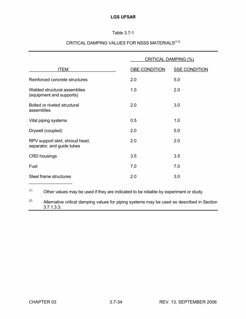
LGS UFSAR
CHAPTER 03 3.7-34 REV. 13, SEPTEMBER 2006
Table 3.7-1
CRITICAL DAMPING VALUES FOR NSSS MATERIALS(1,2)
CRITICAL DAMPING (%)
ITEM OBE CONDITION SSE CONDITION
Reinforced concrete structures 2.0 5.0
Welded structural assemblies 1.0 2.0(equipment and supports)
Bolted or riveted structural 2.0 3.0assemblies
Vital piping systems 0.5 1.0
Drywell (coupled) 2.0 5.0
RPV support skirt, shroud head, 2.0 2.0separator, and guide tubes
CRD housings 3.5 3.5
Fuel 7.0 7.0
Steel frame structures 2.0 3.0__________________
(1) Other values may be used if they are indicated to be reliable by experiment or study.
(2) Alternative critical damping values for piping systems may be used as described in Section 3.7.1.3.3.
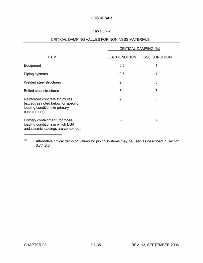
LGS UFSAR
CHAPTER 03 3.7-35 REV. 13, SEPTEMBER 2006
Table 3.7-2
CRITICAL DAMPING VALUES FOR NON-NSSS MATERIALS(1)
CRITICAL DAMPING (%)
ITEM OBE CONDITION SSE CONDITION
Equipment 0.5 1
Piping systems 0.5 1
Welded steel structures 2 5
Bolted steel structures 3 7
Reinforced concrete structures 2 5(except as noted below for specificloading conditions in primarycontainment)
Primary containment (for those 3 7loading conditions in which DBAand seismic loadings are combined)___________________
(1) Alternative critical damping values for piping systems may be used as described in Section 3.7.1.3.3
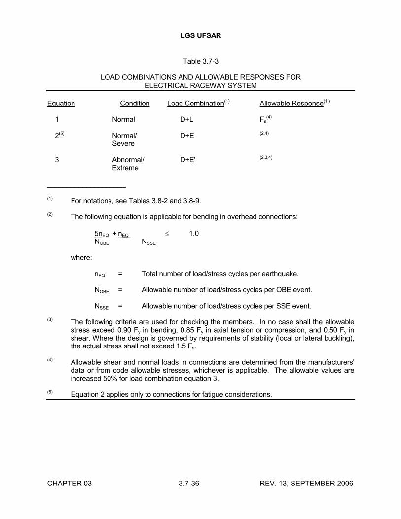
LGS UFSAR
CHAPTER 03 3.7-36 REV. 13, SEPTEMBER 2006
Table 3.7-3
LOAD COMBINATIONS AND ALLOWABLE RESPONSES FORELECTRICAL RACEWAY SYSTEM
Equation Condition Load Combination(1) Allowable Response(1 )
1 Normal D+L Fs(4)
2(5) Normal/ D+E (2,4)
Severe
3 Abnormal/ D+E' (2,3,4)
Extreme
____________________
(1) For notations, see Tables 3.8-2 and 3.8-9.
(2) The following equation is applicable for bending in overhead connections:
5nEQ + nEQ 1.0NOBE NSSE
where:
nEQ = Total number of load/stress cycles per earthquake.
NOBE = Allowable number of load/stress cycles per OBE event.
NSSE = Allowable number of load/stress cycles per SSE event.
(3) The following criteria are used for checking the members. In no case shall the allowable stress exceed 0.90 Fy in bending, 0.85 Fy in axial tension or compression, and 0.50 Fy in shear. Where the design is governed by requirements of stability (local or lateral buckling), the actual stress shall not exceed 1.5 Fs.
(4) Allowable shear and normal loads in connections are determined from the manufacturers' data or from code allowable stresses, whichever is applicable. The allowable values are increased 50% for load combination equation 3.
(5) Equation 2 applies only to connections for fatigue considerations.
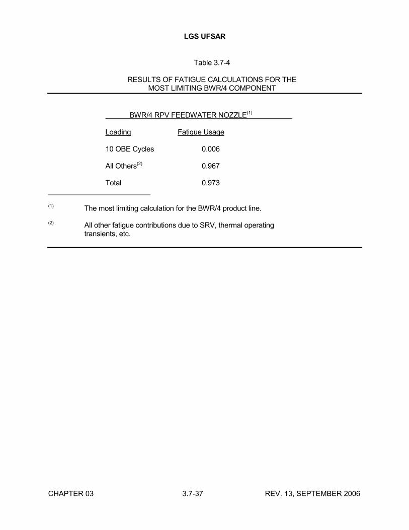
LGS UFSAR
CHAPTER 03 3.7-37 REV. 13, SEPTEMBER 2006
Table 3.7-4
RESULTS OF FATIGUE CALCULATIONS FOR THEMOST LIMITING BWR/4 COMPONENT
BWR/4 RPV FEEDWATER NOZZLE(1)
Loading Fatigue Usage
10 OBE Cycles 0.006
All Others(2) 0.967
Total 0.973
(1) The most limiting calculation for the BWR/4 product line.
(2) All other fatigue contributions due to SRV, thermal operatingtransients, etc.
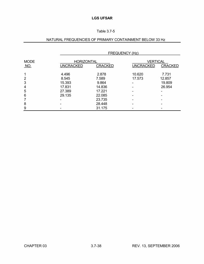
LGS UFSAR
CHAPTER 03 3.7-38 REV. 13, SEPTEMBER 2006
Table 3.7-5
NATURAL FREQUENCIES OF PRIMARY CONTAINMENT BELOW 33 Hz
FREQUENCY (Hz)
MODE HORIZONTAL VERTICALNO. UNCRACKED CRACKED UNCRACKED CRACKED
1 4.496 2.878 10.620 7.7312 8.545 7.589 17.573 12.8573 15.393 9.864 - 19.8094 17.831 14.836 - 26.9545 27.389 17.221 - -6 29.135 22.085 - -7 - 23.735 - -8 - 28.448 - -9 - 31.175 - -
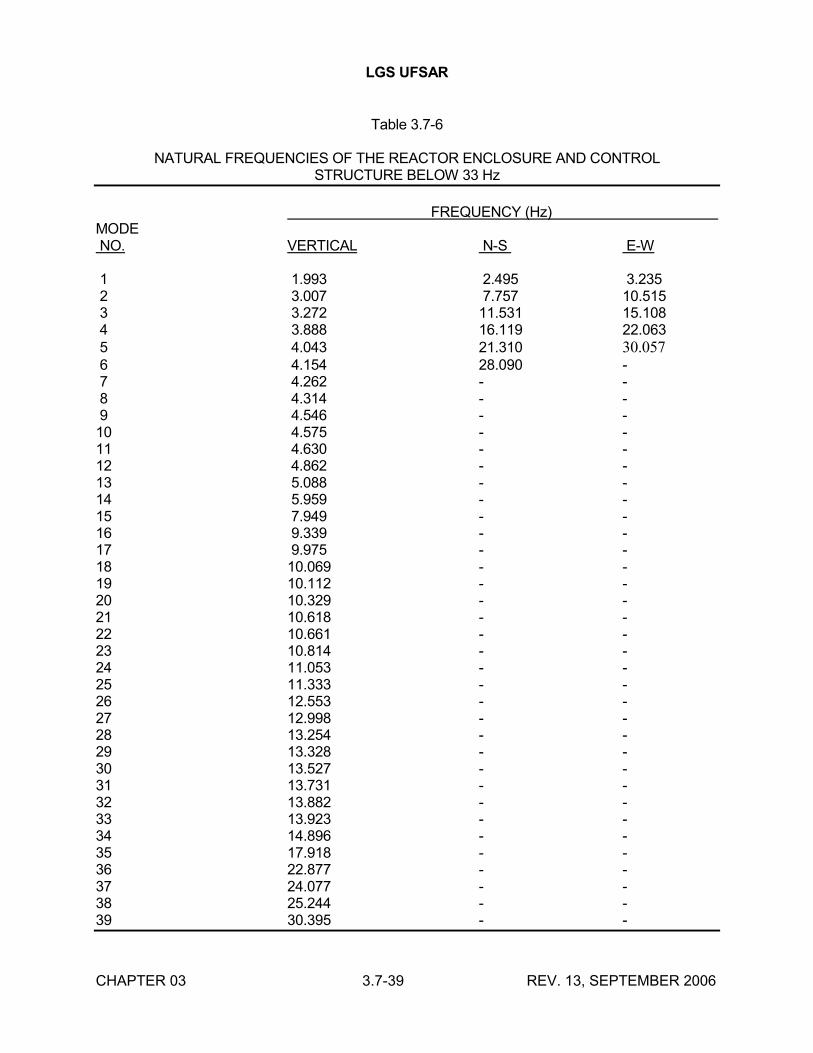
LGS UFSAR
CHAPTER 03 3.7-39 REV. 13, SEPTEMBER 2006
Table 3.7-6
NATURAL FREQUENCIES OF THE REACTOR ENCLOSURE AND CONTROLSTRUCTURE BELOW 33 Hz
FREQUENCY (Hz)MODENO. VERTICAL N-S E-W
1 1.993 2.495 3.2352 3.007 7.757 10.5153 3.272 11.531 15.1084 3.888 16.119 22.0635 4.043 21.310 30.0576 4.154 28.090 -7 4.262 - -8 4.314 - -9 4.546 - -10 4.575 - -11 4.630 - -12 4.862 - -13 5.088 - -14 5.959 - -15 7.949 - -16 9.339 - -17 9.975 - -18 10.069 - -19 10.112 - -20 10.329 - -21 10.618 - -22 10.661 - -23 10.814 - -24 11.053 - -25 11.333 - -26 12.553 - -27 12.998 - -28 13.254 - -29 13.328 - -30 13.527 - -31 13.731 - -32 13.882 - -33 13.923 - -34 14.896 - -35 17.918 - -36 22.877 - -37 24.077 - -38 25.244 - -39 30.395 - -
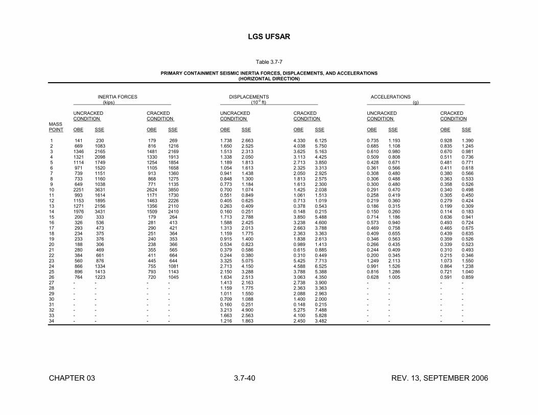
LGS UFSAR
CHAPTER 03 3.7-40 REV. 13, SEPTEMBER 2006
Table 3.7-7
PRIMARY CONTAINMENT SEISMIC INERTIA FORCES, DISPLACEMENTS, AND ACCELERATIONS(HORIZONTAL DIRECTION)
INERTIA FORCES DISPLACEMENTS ACCELERATIONS (kips) (10
-2ft) (g)
UNCRACKED CRACKED UNCRACKED CRACKED UNCRACKED CRACKEDCONDITION CONDITION CONDITION CONDITION CONDITION CONDITION
MASSPOINT OBE SSE OBE SSE OBE SSE OBE SSE OBE SSE OBE SSE
1 141 230 179 269 1.738 2.663 4.330 6.125 0.735 1.193 0.928 1.3902 669 1083 816 1216 1.650 2.525 4.038 5.750 0.685 1.108 0.835 1.2453 1346 2165 1481 2169 1.513 2.313 3.625 5.163 0.610 0.980 0.670 0.9814 1321 2098 1330 1913 1.338 2.050 3.113 4.425 0.509 0.808 0.511 0.7365 1114 1749 1254 1854 1.189 1.813 2.713 3.850 0.428 0.671 0.481 0.7716 971 1520 1105 1658 1.054 1.613 2.325 3.313 0.361 0.566 0.411 0.6187 739 1151 913 1360 0.941 1.438 2.050 2.925 0.308 0.480 0.380 0.5668 733 1160 868 1275 0.848 1.300 1.813 2.575 0.306 0.488 0.363 0.5339 649 1038 771 1135 0.773 1.184 1.613 2.300 0.300 0.480 0.358 0.52610 2251 3631 2624 3850 0.700 1.074 1.425 2.038 0.291 0.470 0.340 0.49811 993 1614 1171 1730 0.551 0.849 1.061 1.513 0.258 0.419 0.305 0.45012 1153 1895 1463 2226 0.405 0.625 0.713 1.019 0.219 0.360 0.279 0.42413 1271 2156 1356 2110 0.263 0.409 0.378 0.543 0.186 0.315 0.199 0.30914 1976 3431 1509 2410 0.160 0.251 0.148 0.215 0.150 0.260 0.114 0.18315 200 333 179 264 1.713 2.788 3.850 5.488 0.714 1.186 0.636 0.94116 326 536 281 413 1.588 2.425 3.238 4.600 0.573 0.940 0.493 0.72417 293 473 290 421 1.313 2.013 2.663 3.788 0.469 0.758 0.465 0.67518 234 375 251 364 1.159 1.775 2.363 3.363 0.409 0.655 0.439 0.63519 233 376 240 353 0.915 1.400 1.838 2.613 0.346 0.563 0.359 0.52620 188 306 238 366 0.534 0.823 0.989 1.413 0.266 0.435 0.339 0.52321 280 469 355 565 0.379 0.586 0.615 0.885 0.244 0.409 0.310 0.49322 384 661 411 664 0.244 0.380 0.310 0.449 0.200 0.345 0.215 0.34623 560 876 445 644 3.325 5.075 5.425 7.713 1.249 2.113 1.073 1.55024 866 1334 755 1081 2.713 4.150 4.588 6.525 0.991 1.526 0.864 1.23825 896 1413 793 1143 2.150 3.288 3.788 5.388 0.816 1.286 0.721 1.04026 764 1223 720 1045 1.634 2.513 3.063 4.350 0.628 1.005 0.591 0.85927 - - - - 1.413 2.163 2.738 3.900 - - - -28 - - - - 1.159 1.775 2.363 3.363 - - - -29 - - - - 1.011 1.550 2.088 2.963 - - - -30 - - - - 0.709 1.088 1.400 2.000 - - - -31 - - - - 0.160 0.251 0.148 0.215 - - - -32 - - - - 3.213 4.900 5.275 7.488 - - - -33 - - - - 1.663 2.563 4.100 5.828 - - - -34 - - - - 1.216 1.863 2.450 3.482 - - - -
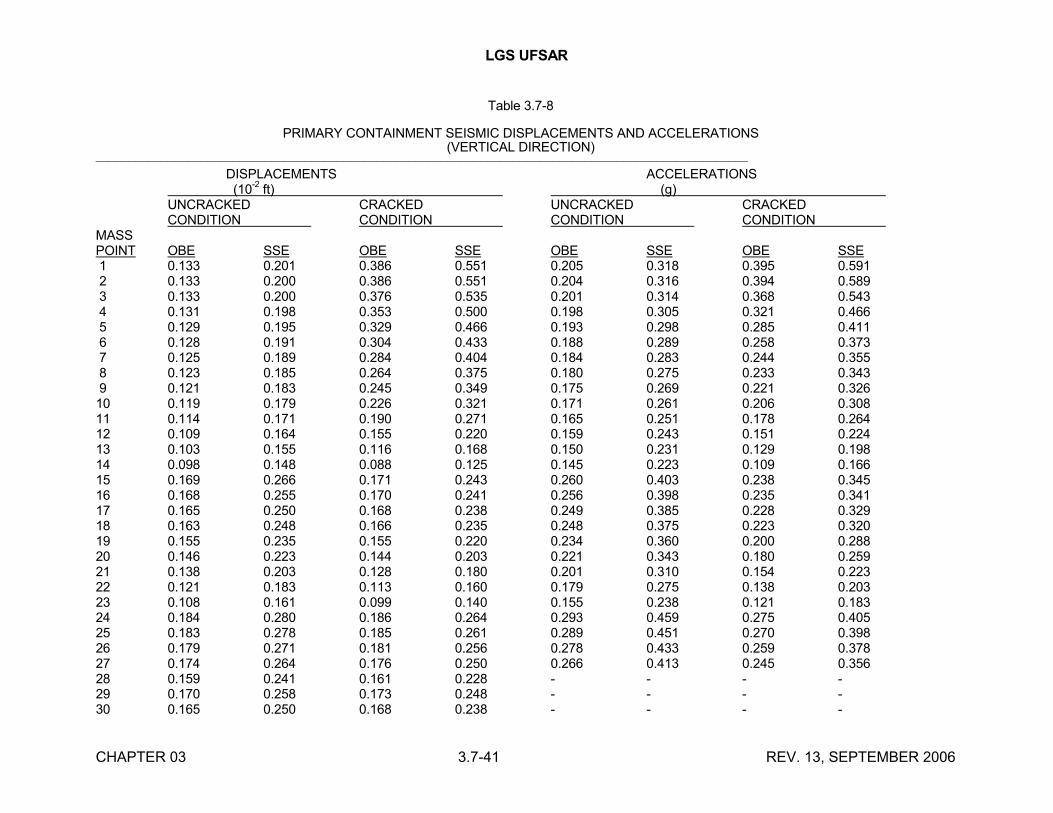
LGS UFSAR
CHAPTER 03 3.7-41 REV. 13, SEPTEMBER 2006
Table 3.7-8
PRIMARY CONTAINMENT SEISMIC DISPLACEMENTS AND ACCELERATIONS(VERTICAL DIRECTION)
____________________________________________________________________________________________________
DISPLACEMENTS ACCELERATIONS (10
-2ft) (g)
UNCRACKED CRACKED UNCRACKED CRACKEDCONDITION CONDITION CONDITION CONDITION
MASSPOINT OBE SSE OBE SSE OBE SSE OBE SSE1 0.133 0.201 0.386 0.551 0.205 0.318 0.395 0.5912 0.133 0.200 0.386 0.551 0.204 0.316 0.394 0.5893 0.133 0.200 0.376 0.535 0.201 0.314 0.368 0.5434 0.131 0.198 0.353 0.500 0.198 0.305 0.321 0.4665 0.129 0.195 0.329 0.466 0.193 0.298 0.285 0.4116 0.128 0.191 0.304 0.433 0.188 0.289 0.258 0.3737 0.125 0.189 0.284 0.404 0.184 0.283 0.244 0.3558 0.123 0.185 0.264 0.375 0.180 0.275 0.233 0.3439 0.121 0.183 0.245 0.349 0.175 0.269 0.221 0.32610 0.119 0.179 0.226 0.321 0.171 0.261 0.206 0.30811 0.114 0.171 0.190 0.271 0.165 0.251 0.178 0.26412 0.109 0.164 0.155 0.220 0.159 0.243 0.151 0.22413 0.103 0.155 0.116 0.168 0.150 0.231 0.129 0.19814 0.098 0.148 0.088 0.125 0.145 0.223 0.109 0.16615 0.169 0.266 0.171 0.243 0.260 0.403 0.238 0.34516 0.168 0.255 0.170 0.241 0.256 0.398 0.235 0.34117 0.165 0.250 0.168 0.238 0.249 0.385 0.228 0.32918 0.163 0.248 0.166 0.235 0.248 0.375 0.223 0.32019 0.155 0.235 0.155 0.220 0.234 0.360 0.200 0.28820 0.146 0.223 0.144 0.203 0.221 0.343 0.180 0.25921 0.138 0.203 0.128 0.180 0.201 0.310 0.154 0.22322 0.121 0.183 0.113 0.160 0.179 0.275 0.138 0.20323 0.108 0.161 0.099 0.140 0.155 0.238 0.121 0.18324 0.184 0.280 0.186 0.264 0.293 0.459 0.275 0.40525 0.183 0.278 0.185 0.261 0.289 0.451 0.270 0.39826 0.179 0.271 0.181 0.256 0.278 0.433 0.259 0.37827 0.174 0.264 0.176 0.250 0.266 0.413 0.245 0.35628 0.159 0.241 0.161 0.228 - - - -29 0.170 0.258 0.173 0.248 - - - -30 0.165 0.250 0.168 0.238 - - - -
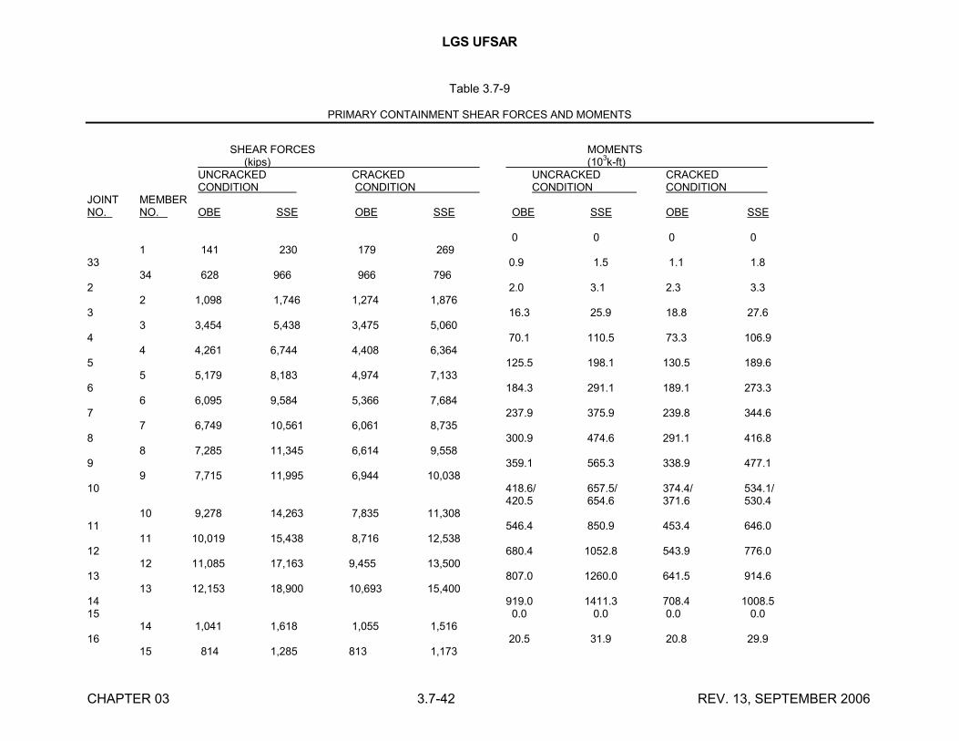
LGS UFSAR
CHAPTER 03 3.7-42 REV. 13, SEPTEMBER 2006
Table 3.7-9
PRIMARY CONTAINMENT SHEAR FORCES AND MOMENTS
SHEAR FORCES MOMENTS (kips) (10
3k-ft)
UNCRACKED CRACKED UNCRACKED CRACKED CONDITION CONDITION CONDITION CONDITION
JOINT MEMBERNO. NO. OBE SSE OBE SSE OBE SSE OBE SSE
0 0 0 01 141 230 179 269
33 0.9 1.5 1.1 1.834 628 966 966 796
2 2.0 3.1 2.3 3.32 1,098 1,746 1,274 1,876
3 16.3 25.9 18.8 27.63 3,454 5,438 3,475 5,060
4 70.1 110.5 73.3 106.94 4,261 6,744 4,408 6,364
5 125.5 198.1 130.5 189.65 5,179 8,183 4,974 7,133
6 184.3 291.1 189.1 273.36 6,095 9,584 5,366 7,684
7 237.9 375.9 239.8 344.67 6,749 10,561 6,061 8,735
8 300.9 474.6 291.1 416.88 7,285 11,345 6,614 9,558
9 359.1 565.3 338.9 477.19 7,715 11,995 6,944 10,038
10 418.6/ 657.5/ 374.4/ 534.1/420.5 654.6 371.6 530.4
10 9,278 14,263 7,835 11,30811 546.4 850.9 453.4 646.0
11 10,019 15,438 8,716 12,53812 680.4 1052.8 543.9 776.0
12 11,085 17,163 9,455 13,50013 807.0 1260.0 641.5 914.6
13 12,153 18,900 10,693 15,40014 919.0 1411.3 708.4 1008.515 0.0 0.0 0.0 0.0
14 1,041 1,618 1,055 1,51616 20.5 31.9 20.8 29.9
15 814 1,285 813 1,173
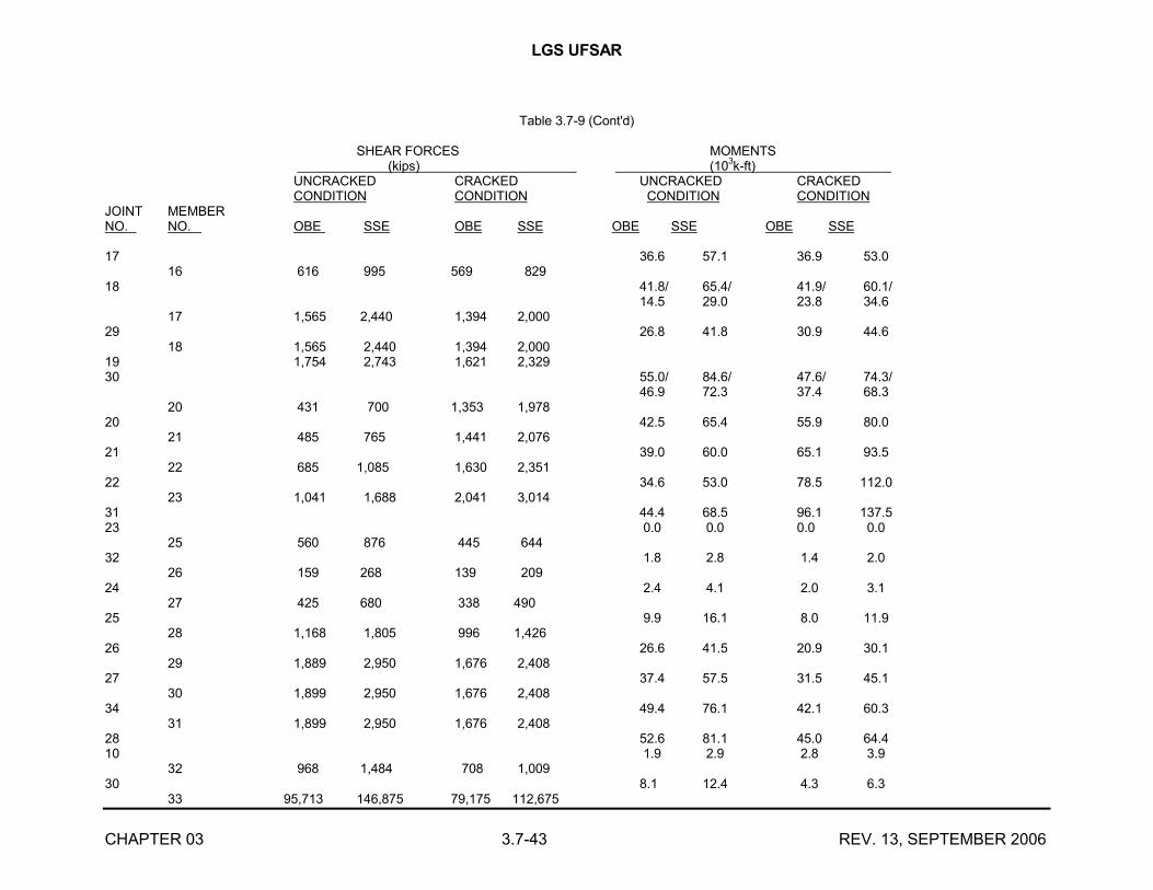
LGS UFSAR
CHAPTER 03 3.7-43 REV. 13, SEPTEMBER 2006
Table 3.7-9 (Cont'd)
SHEAR FORCES MOMENTS(kips) (10
3k-ft)
UNCRACKED CRACKED UNCRACKED CRACKED CONDITION CONDITION CONDITION CONDITION
JOINT MEMBERNO. NO. OBE SSE OBE SSE OBE SSE OBE SSE
17 36.6 57.1 36.9 53.016 616 995 569 829
18 41.8/ 65.4/ 41.9/ 60.1/14.5 29.0 23.8 34.6
17 1,565 2,440 1,394 2,00029 26.8 41.8 30.9 44.6
18 1,565 2,440 1,394 2,00019 1,754 2,743 1,621 2,32930 55.0/ 84.6/ 47.6/ 74.3/
46.9 72.3 37.4 68.320 431 700 1,353 1,978
20 42.5 65.4 55.9 80.021 485 765 1,441 2,076
21 39.0 60.0 65.1 93.522 685 1,085 1,630 2,351
22 34.6 53.0 78.5 112.023 1,041 1,688 2,041 3,014
31 44.4 68.5 96.1 137.523 0.0 0.0 0.0 0.0
25 560 876 445 64432 1.8 2.8 1.4 2.0
26 159 268 139 20924 2.4 4.1 2.0 3.1
27 425 680 338 49025 9.9 16.1 8.0 11.9
28 1,168 1,805 996 1,42626 26.6 41.5 20.9 30.1
29 1,889 2,950 1,676 2,40827 37.4 57.5 31.5 45.1
30 1,899 2,950 1,676 2,40834 49.4 76.1 42.1 60.3
31 1,899 2,950 1,676 2,40828 52.6 81.1 45.0 64.410 1.9 2.9 2.8 3.9
32 968 1,484 708 1,00930 8.1 12.4 4.3 6.3
33 95,713 146,875 79,175 112,675
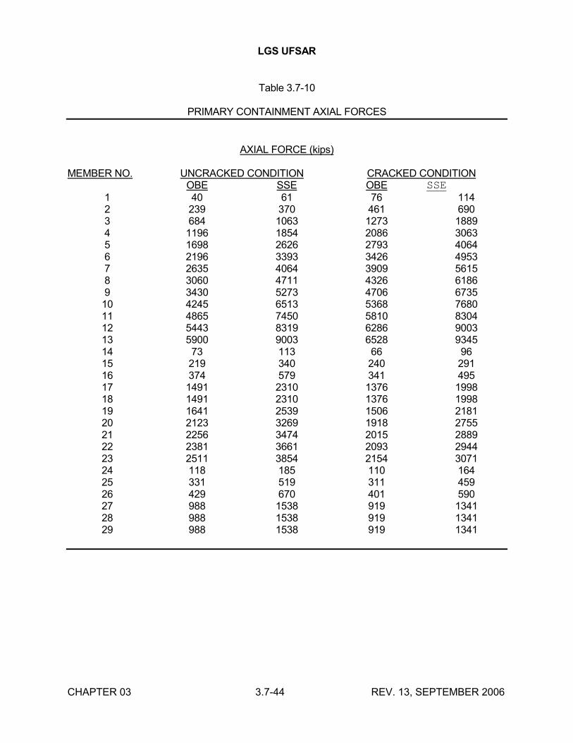
LGS UFSAR
CHAPTER 03 3.7-44 REV. 13, SEPTEMBER 2006
Table 3.7-10
PRIMARY CONTAINMENT AXIAL FORCES
AXIAL FORCE (kips)
MEMBER NO. UNCRACKED CONDITION CRACKED CONDITIONOBE SSE OBE SSE
1 40 61 76 1142 239 370 461 6903 684 1063 1273 18894 1196 1854 2086 30635 1698 2626 2793 40646 2196 3393 3426 49537 2635 4064 3909 56158 3060 4711 4326 61869 3430 5273 4706 673510 4245 6513 5368 768011 4865 7450 5810 830412 5443 8319 6286 900313 5900 9003 6528 934514 73 113 66 9615 219 340 240 29116 374 579 341 49517 1491 2310 1376 199818 1491 2310 1376 199819 1641 2539 1506 218120 2123 3269 1918 275521 2256 3474 2015 288922 2381 3661 2093 294423 2511 3854 2154 307124 118 185 110 16425 331 519 311 45926 429 670 401 59027 988 1538 919 134128 988 1538 919 134129 988 1538 919 1341
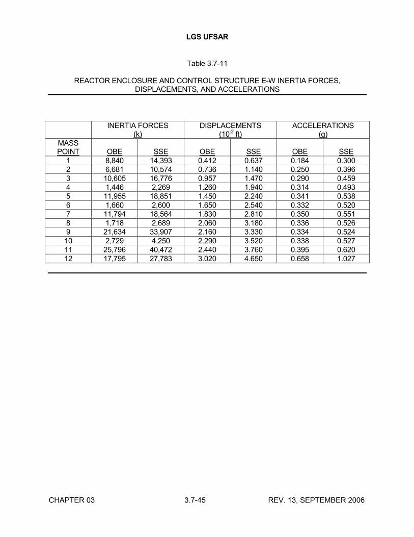
LGS UFSAR
CHAPTER 03 3.7-45 REV. 13, SEPTEMBER 2006
Table 3.7-11
REACTOR ENCLOSURE AND CONTROL STRUCTURE E-W INERTIA FORCES,DISPLACEMENTS, AND ACCELERATIONS
INERTIA FORCES(k)
DISPLACEMENTS(10-2 ft)
ACCELERATIONS(g)
MASSPOINT OBE SSE OBE SSE OBE SSE
1 8,840 14,393 0.412 0.637 0.184 0.3002 6,681 10,574 0.736 1.140 0.250 0.3963 10,605 16,776 0.957 1.470 0.290 0.4594 1,446 2,269 1.260 1.940 0.314 0.4935 11,955 18,851 1.450 2.240 0.341 0.5386 1,660 2,600 1.650 2.540 0.332 0.5207 11,794 18,564 1.830 2.810 0.350 0.5518 1,718 2,689 2.060 3.180 0.336 0.5269 21,634 33,907 2.160 3.330 0.334 0.52410 2,729 4,250 2.290 3.520 0.338 0.52711 25,796 40,472 2.440 3.760 0.395 0.62012 17,795 27,783 3.020 4.650 0.658 1.027
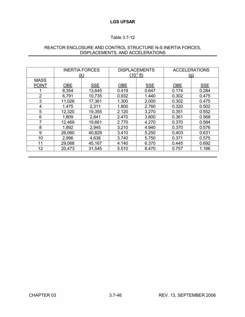
LGS UFSAR
CHAPTER 03 3.7-46 REV. 13, SEPTEMBER 2006
Table 3.7-12
REACTOR ENCLOSURE AND CONTROL STRUCTURE N-S INERTIA FORCES,DISPLACEMENTS, AND ACCELERATIONS
INERTIA FORCES(k)
DISPLACEMENTS(10-2 ft)
ACCELERATIONS(g)
MASSPOINT OBE SSE OBE SSE OBE SSE
1 8,354 13,645 0.419 0.647 0.174 0.2842 6,791 10,735 0.932 1.440 0.302 0.4753 11,026 17,361 1.300 2.000 0.302 0.4754 1,475 2,311 1.800 2.760 0.320 0.5025 12,320 19,355 2.120 3.270 0.351 0.5526 1,809 2,841 2.470 3.800 0.361 0.5687 12,469 19,661 2.770 4.270 0.370 0.5848 1,892 2,945 3.210 4.940 0.370 0.5769 26,060 40,829 3.410 5.250 0.403 0.63110 2,996 4,638 3.740 5.750 0.371 0.57511 29,068 45,167 4.140 6.370 0.445 0.69212 20,473 31,545 5.510 8.470 0.757 1.166
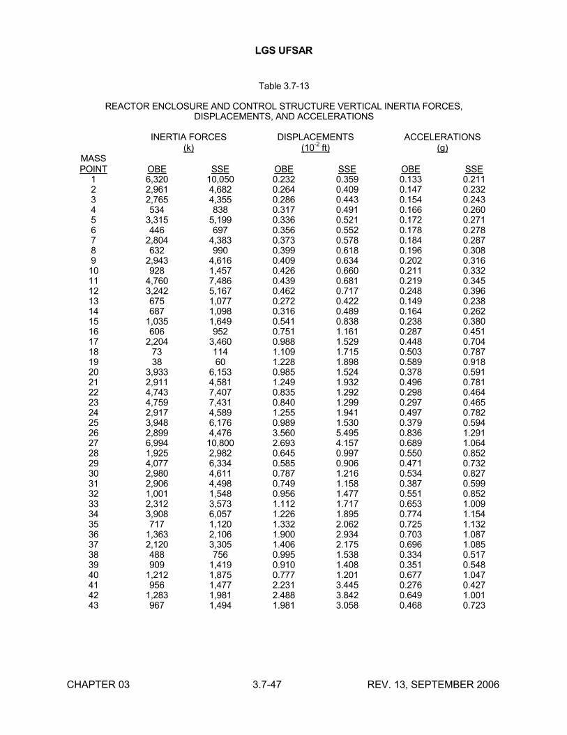
LGS UFSAR
CHAPTER 03 3.7-47 REV. 13, SEPTEMBER 2006
Table 3.7-13
REACTOR ENCLOSURE AND CONTROL STRUCTURE VERTICAL INERTIA FORCES,DISPLACEMENTS, AND ACCELERATIONS
INERTIA FORCES(k)
DISPLACEMENTS(10
-2ft)
ACCELERATIONS(g)
MASSPOINT OBE SSE OBE SSE OBE SSE
1 6,320 10,050 0.232 0.359 0.133 0.2112 2,961 4,682 0.264 0.409 0.147 0.2323 2,765 4,355 0.286 0.443 0.154 0.2434 534 838 0.317 0.491 0.166 0.2605 3,315 5,199 0.336 0.521 0.172 0.2716 446 697 0.356 0.552 0.178 0.2787 2,804 4,383 0.373 0.578 0.184 0.2878 632 990 0.399 0.618 0.196 0.3089 2,943 4,616 0.409 0.634 0.202 0.31610 928 1,457 0.426 0.660 0.211 0.33211 4,760 7,486 0.439 0.681 0.219 0.34512 3,242 5,167 0.462 0.717 0.248 0.39613 675 1,077 0.272 0.422 0.149 0.23814 687 1,098 0.316 0.489 0.164 0.26215 1,035 1,649 0.541 0.838 0.238 0.38016 606 952 0.751 1.161 0.287 0.45117 2,204 3,460 0.988 1.529 0.448 0.70418 73 114 1.109 1.715 0.503 0.78719 38 60 1.228 1.898 0.589 0.91820 3,933 6,153 0.985 1.524 0.378 0.59121 2,911 4,581 1.249 1.932 0.496 0.78122 4,743 7,407 0.835 1.292 0.298 0.46423 4,759 7,431 0.840 1.299 0.297 0.46524 2,917 4,589 1.255 1.941 0.497 0.78225 3,948 6,176 0.989 1.530 0.379 0.59426 2,899 4,476 3.560 5.495 0.836 1.29127 6,994 10,800 2.693 4.157 0.689 1.06428 1,925 2,982 0.645 0.997 0.550 0.85229 4,077 6,334 0.585 0.906 0.471 0.73230 2,980 4,611 0.787 1.216 0.534 0.82731 2,906 4,498 0.749 1.158 0.387 0.59932 1,001 1,548 0.956 1.477 0.551 0.85233 2,312 3,573 1.112 1.717 0.653 1.00934 3,908 6,057 1.226 1.895 0.774 1.15435 717 1,120 1.332 2.062 0.725 1.13236 1,363 2,106 1.900 2.934 0.703 1.08737 2,120 3,305 1.406 2.175 0.696 1.08538 488 756 0.995 1.538 0.334 0.51739 909 1,419 0.910 1.408 0.351 0.54840 1,212 1,875 0.777 1.201 0.677 1.04741 956 1,477 2.231 3.445 0.276 0.42742 1,283 1,981 2.488 3.842 0.649 1.00143 967 1,494 1.981 3.058 0.468 0.723
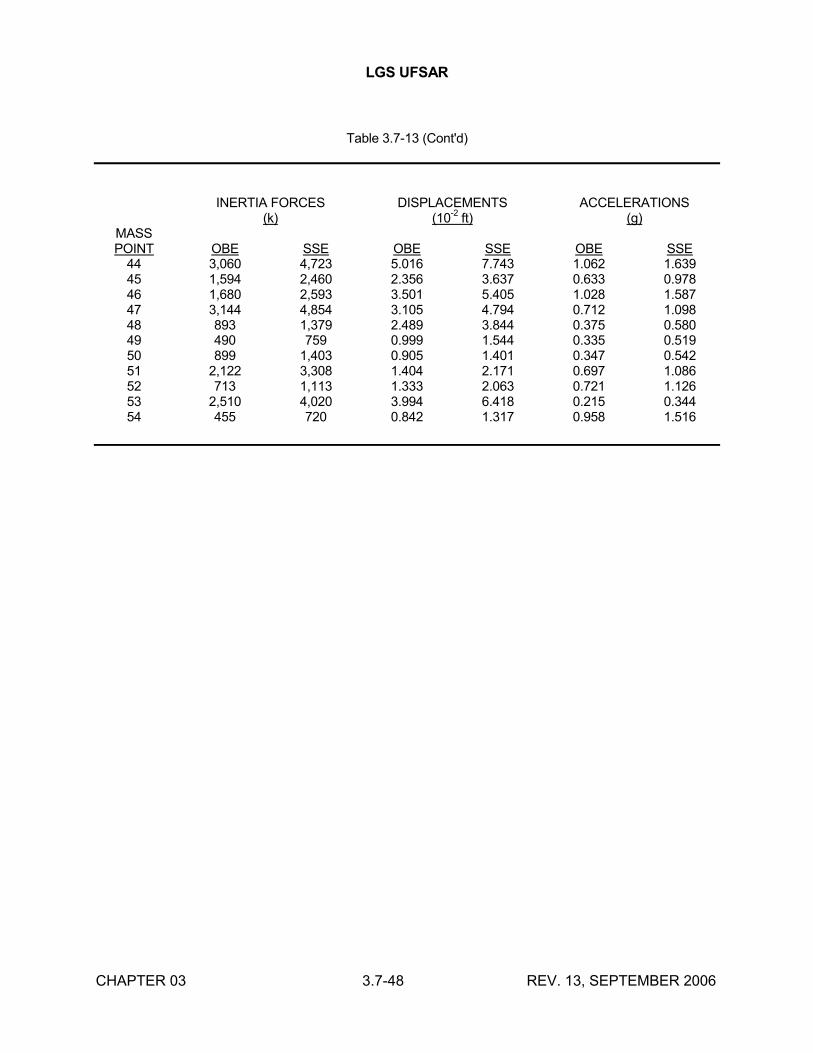
LGS UFSAR
CHAPTER 03 3.7-48 REV. 13, SEPTEMBER 2006
Table 3.7-13 (Cont'd)
INERTIA FORCES(k)
DISPLACEMENTS(10
-2ft)
ACCELERATIONS(g)
MASSPOINT OBE SSE OBE SSE OBE SSE
44 3,060 4,723 5.016 7.743 1.062 1.63945 1,594 2,460 2.356 3.637 0.633 0.97846 1,680 2,593 3.501 5.405 1.028 1.58747 3,144 4,854 3.105 4.794 0.712 1.09848 893 1,379 2.489 3.844 0.375 0.58049 490 759 0.999 1.544 0.335 0.51950 899 1,403 0.905 1.401 0.347 0.54251 2,122 3,308 1.404 2.171 0.697 1.08652 713 1,113 1.333 2.063 0.721 1.12653 2,510 4,020 3.994 6.418 0.215 0.34454 455 720 0.842 1.317 0.958 1.516
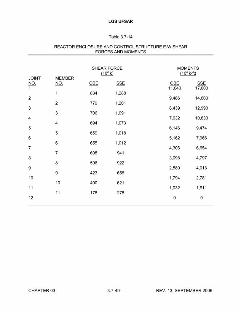
LGS UFSAR
CHAPTER 03 3.7-49 REV. 13, SEPTEMBER 2006
Table 3.7-14
REACTOR ENCLOSURE AND CONTROL STRUCTURE E-W SHEARFORCES AND MOMENTS
SHEAR FORCE
(102 k)MOMENTS
(103 k-ft)JOINTNO.
MEMBERNO. OBE SSE OBE SSE
1 11,040 17,0001 834 1,288
2 9,486 14,6002 779 1,201
3 8,439 12,9903 706 1,091
4 7,032 10,8304 694 1,073
5 6,146 9,4745 659 1,018
6 5,162 7,9666 655 1,012
7 4,306 6,6547 608 941
8 3,098 4,7978 596 922
9 2,589 4,0139 423 656
10 1,794 2,78110 400 621
11 1,032 1,61111 178 278
12 0 0
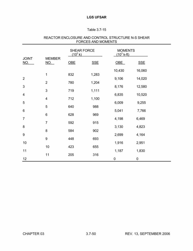
LGS UFSAR
CHAPTER 03 3.7-50 REV. 13, SEPTEMBER 2006
Table 3.7-15
REACTOR ENCLOSURE AND CONTROL STRUCTURE N-S SHEARFORCES AND MOMENTS
SHEAR FORCE MOMENTS (102 k) (103 k-ft)
JOINT MEMBERNO. NO. OBE SSE OBE SSE
10,430 16,0601 832 1,283
2 9,106 14,0202 780 1,204
3 8,176 12,5803 719 1,111
4 6,835 10,5204 712 1,100
5 6,009 9,2555 640 988
6 5,041 7,7666 628 969
7 4,198 6,4697 592 915
8 3,130 4,8238 584 902
9 2,699 4,1649 448 693
10 1,916 2,95110 423 655
11 1,187 1,83011 205 316
12 0 0
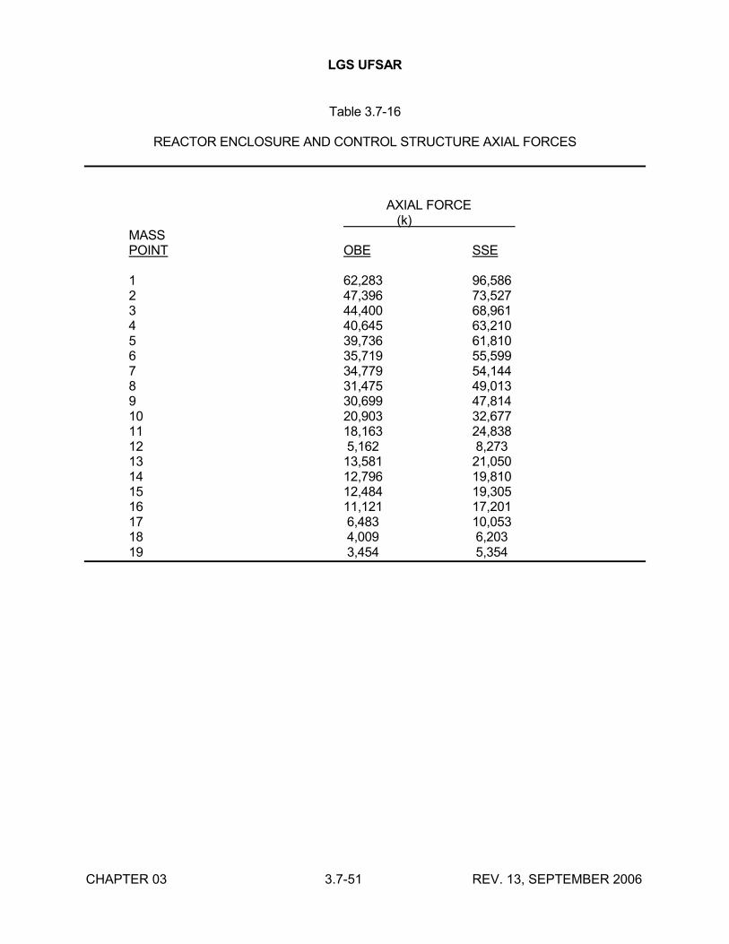
LGS UFSAR
CHAPTER 03 3.7-51 REV. 13, SEPTEMBER 2006
Table 3.7-16
REACTOR ENCLOSURE AND CONTROL STRUCTURE AXIAL FORCES
AXIAL FORCE (k)
MASSPOINT OBE SSE
1 62,283 96,5862 47,396 73,5273 44,400 68,9614 40,645 63,2105 39,736 61,8106 35,719 55,5997 34,779 54,1448 31,475 49,0139 30,699 47,81410 20,903 32,67711 18,163 24,83812 5,162 8,27313 13,581 21,05014 12,796 19,81015 12,484 19,30516 11,121 17,20117 6,483 10,05318 4,009 6,20319 3,454 5,354
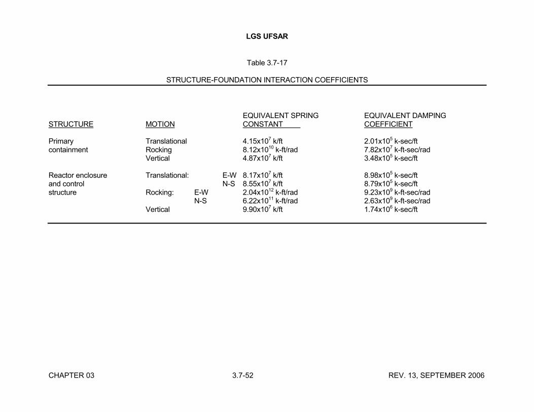
LGS UFSAR
CHAPTER 03 3.7-52 REV. 13, SEPTEMBER 2006
Table 3.7-17
STRUCTURE-FOUNDATION INTERACTION COEFFICIENTS
EQUIVALENT SPRING EQUIVALENT DAMPINGSTRUCTURE MOTION CONSTANT COEFFICIENT
Primary Translational 4.15x10⁷ k/ft 2.01x10⁵ k-sec/ftcontainment Rocking 8.12x10¹⁰ k-ft/rad 7.82x10⁷ k-ft-sec/rad
Vertical 4.87x10⁷ k/ft 3.48x10⁵ k-sec/ft
Reactor enclosure Translational: E-W 8.17x10⁷ k/ft 8.98x10⁵ k-sec/ftand control N-S 8.55x10⁷ k/ft 8.79x10⁵ k-sec/ftstructure Rocking: E-W 2.04x10¹² k-ft/rad 9.23x10⁹ k-ft-sec/rad
N-S 6.22x10¹¹ k-ft/rad 2.63x10⁹ k-ft-sec/radVertical 9.90x10⁷ k/ft 1.74x10⁶ k-sec/ft
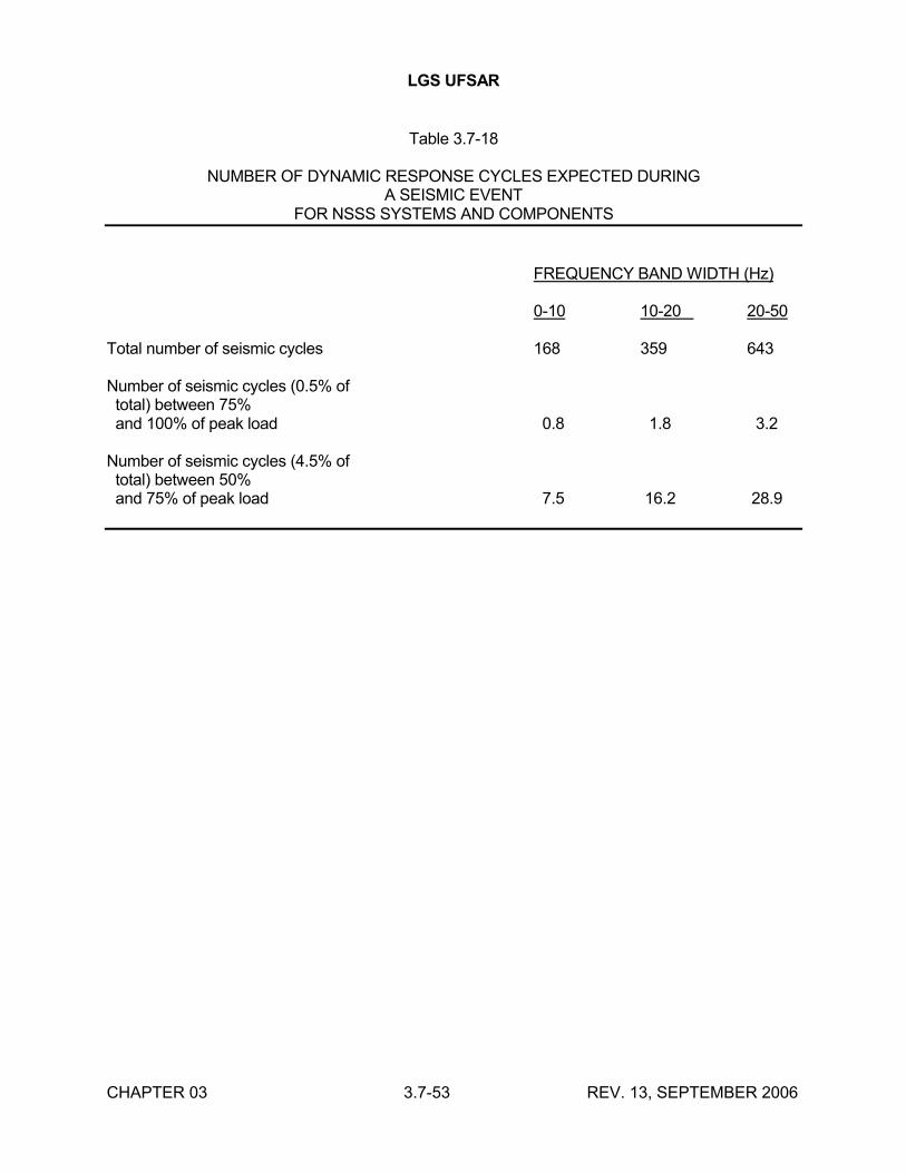
LGS UFSAR
CHAPTER 03 3.7-53 REV. 13, SEPTEMBER 2006
Table 3.7-18
NUMBER OF DYNAMIC RESPONSE CYCLES EXPECTED DURINGA SEISMIC EVENT
FOR NSSS SYSTEMS AND COMPONENTS
FREQUENCY BAND WIDTH (Hz)
0-10 10-20 20-50
Total number of seismic cycles 168 359 643
Number of seismic cycles (0.5% of total) between 75% and 100% of peak load 0.8 1.8 3.2
Number of seismic cycles (4.5% of total) between 50% and 75% of peak load 7.5 16.2 28.9
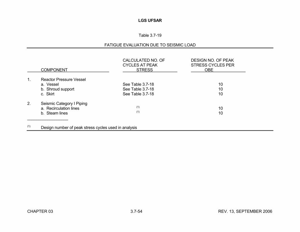
LGS UFSAR
CHAPTER 03 3.7-54 REV. 13, SEPTEMBER 2006
Table 3.7-19
FATIGUE EVALUATION DUE TO SEISMIC LOAD
CALCULATED NO. OF DESIGN NO. OF PEAKCYCLES AT PEAK STRESS CYCLES PER
COMPONENT STRESS OBE
1. Reactor Pressure Vessela. Vessel See Table 3.7-18 10b. Shroud support See Table 3.7-18 10c. Skirt See Table 3.7-18 10
2. Seismic Category I Pipinga. Recirculation lines (1) 10b. Steam lines (1) 10
__________________
(1) Design number of peak stress cycles used in analysis
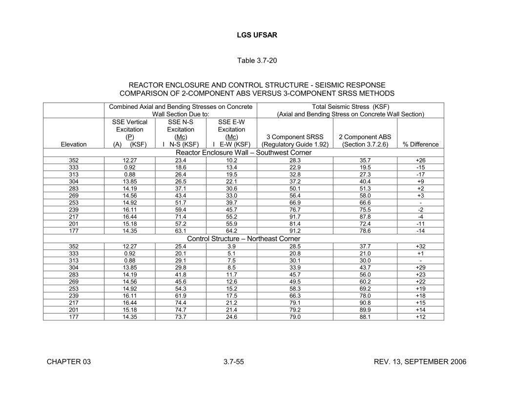
LGS UFSAR
CHAPTER 03 3.7-55 REV. 13, SEPTEMBER 2006
Table 3.7-20
REACTOR ENCLOSURE AND CONTROL STRUCTURE - SEISMIC RESPONSECOMPARISON OF 2-COMPONENT ABS VERSUS 3-COMPONENT SRSS METHODS
Combined Axial and Bending Stresses on ConcreteWall Section Due to:
Total Seismic Stress (KSF)(Axial and Bending Stress on Concrete Wall Section)
Elevation
SSE VerticalExcitation
(P)(A) (KSF)
SSE N-SExcitation
(Mc)I N-S (KSF)
SSE E-WExcitation
(Mc)I E-W (KSF)
3 Component SRSS(Regulatory Guide 1.92)
2 Component ABS(Section 3.7.2.6) % Difference
Reactor Enclosure Wall – Southwest Corner352 12.27 23.4 10.2 28.3 35.7 +26333 0.92 18.6 13.4 22.9 19.5 -15313 0.88 26.4 19.5 32.8 27.3 -17304 13.85 26.5 22.1 37.2 40.4 +9283 14.19 37.1 30.6 50.1 51.3 +2269 14.56 43.4 33.0 56.4 58.0 +3253 14.92 51.7 39.7 66.9 66.6 -239 16.11 59.4 45.7 76.7 75.5 -2217 16.44 71.4 55.2 91.7 87.8 -4201 15.18 57.2 55.9 81.4 72.4 -11177 14.35 63.1 64.2 91.2 78.6 -14
Control Structure – Northeast Corner352 12.27 25.4 3.9 28.5 37.7 +32333 0.92 20.1 5.1 20.8 21.0 +1313 0.88 29.1 7.5 30.1 30.0 -304 13.85 29.8 8.5 33.9 43.7 +29283 14.19 41.8 11.7 45.7 56.0 +23269 14.56 45.6 12.6 49.5 60.2 +22253 14.92 54.3 15.2 58.3 69.2 +19239 16.11 61.9 17.5 66.3 78.0 +18217 16.44 74.4 21.2 79.1 90.8 +15201 15.18 74.7 21.4 79.2 89.9 +14177 14.35 73.7 24.6 79.0 88.1 +12
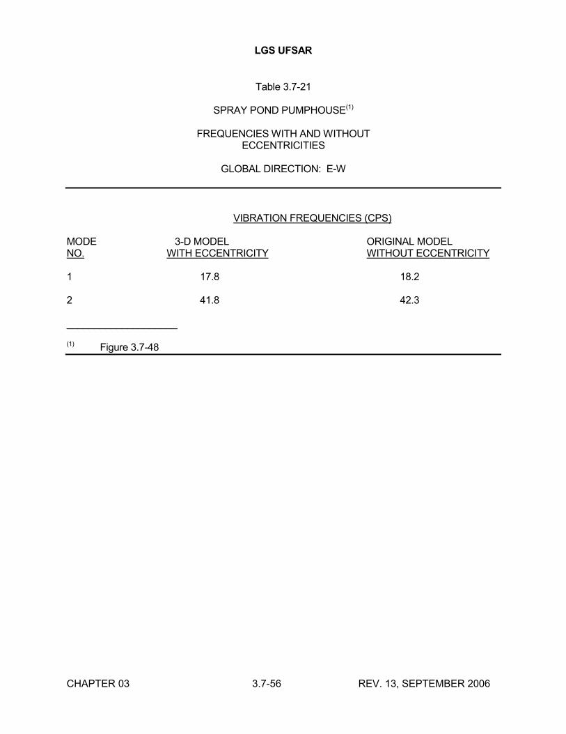
LGS UFSAR
CHAPTER 03 3.7-56 REV. 13, SEPTEMBER 2006
Table 3.7-21
SPRAY POND PUMPHOUSE(1)
FREQUENCIES WITH AND WITHOUTECCENTRICITIES
GLOBAL DIRECTION: E-W
VIBRATION FREQUENCIES (CPS)
MODE 3-D MODEL ORIGINAL MODELNO. WITH ECCENTRICITY WITHOUT ECCENTRICITY
1 17.8 18.2
2 41.8 42.3
____________________
(1) Figure 3.7-48
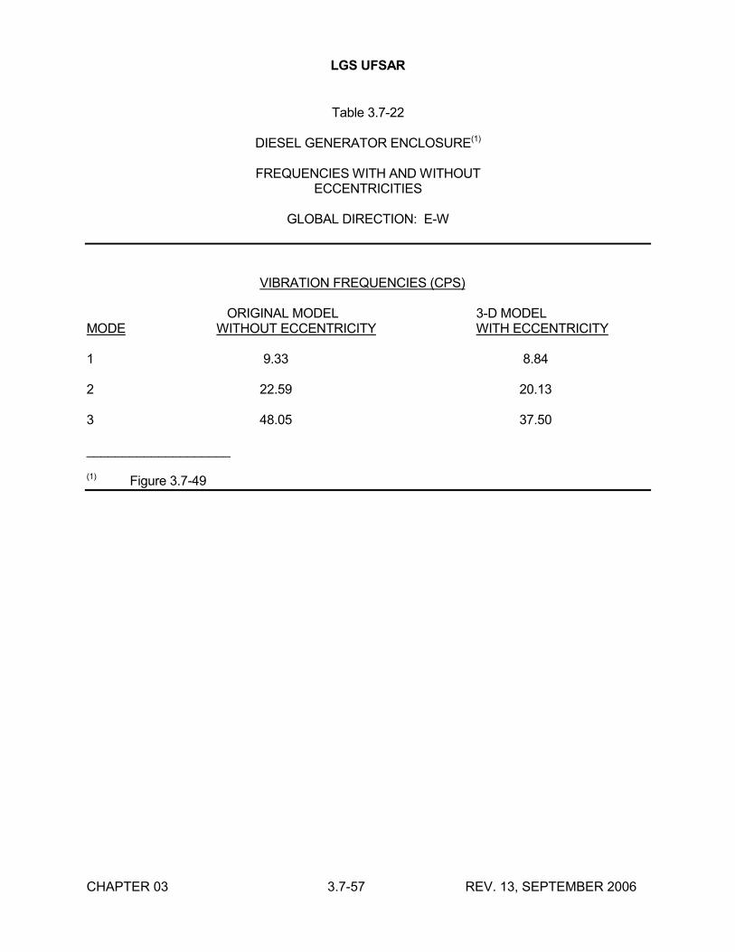
LGS UFSAR
CHAPTER 03 3.7-57 REV. 13, SEPTEMBER 2006
Table 3.7-22
DIESEL GENERATOR ENCLOSURE(1)
FREQUENCIES WITH AND WITHOUTECCENTRICITIES
GLOBAL DIRECTION: E-W
VIBRATION FREQUENCIES (CPS)
ORIGINAL MODEL 3-D MODELMODE WITHOUT ECCENTRICITY WITH ECCENTRICITY
1 9.33 8.84
2 22.59 20.13
3 48.05 37.50
____________________
(1) Figure 3.7-49
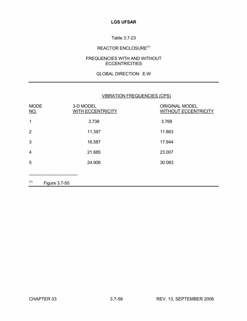
LGS UFSAR
CHAPTER 03 3.7-58 REV. 13, SEPTEMBER 2006
Table 3.7-23
REACTOR ENCLOSURE(1)
FREQUENCIES WITH AND WITHOUTECCENTRICITIES
GLOBAL DIRECTION: E-W
VIBRATION FREQUENCIES (CPS)
MODE 3-D MODEL ORIGINAL MODELNO. WITH ECCENTRICITY WITHOUT ECCENTRICITY
1 3.738 3.769
2 11.397 11.863
3 16.587 17.944
4 21.685 23.007
5 24.906 30.083
____________________
(1) Figure 3.7-50
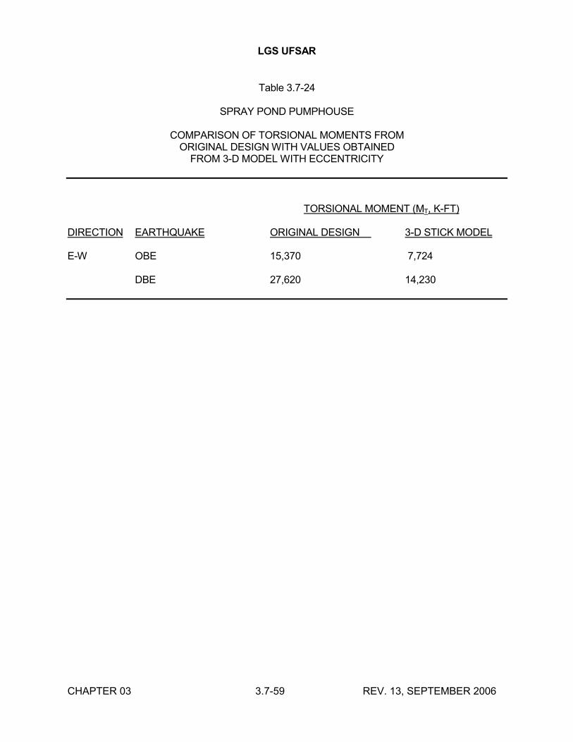
LGS UFSAR
CHAPTER 03 3.7-59 REV. 13, SEPTEMBER 2006
Table 3.7-24
SPRAY POND PUMPHOUSE
COMPARISON OF TORSIONAL MOMENTS FROMORIGINAL DESIGN WITH VALUES OBTAINED
FROM 3-D MODEL WITH ECCENTRICITY
TORSIONAL MOMENT (MT, K-FT)
DIRECTION EARTHQUAKE ORIGINAL DESIGN 3-D STICK MODEL
E-W OBE 15,370 7,724
DBE 27,620 14,230
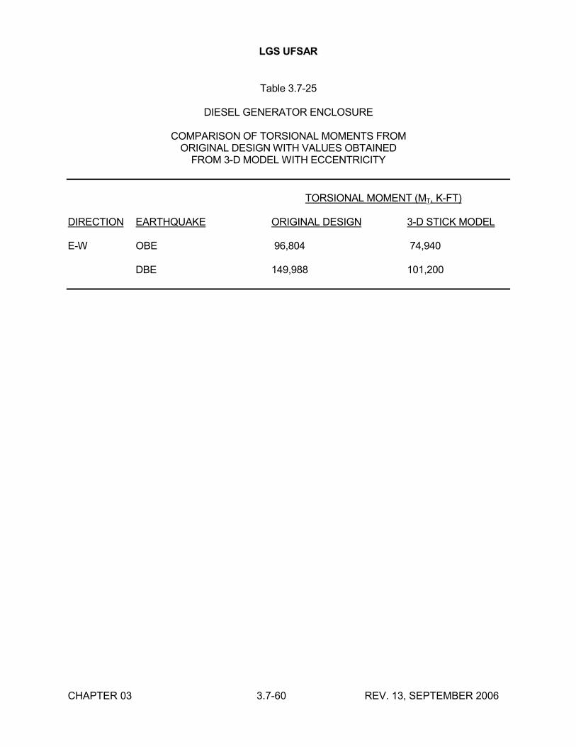
LGS UFSAR
CHAPTER 03 3.7-60 REV. 13, SEPTEMBER 2006
Table 3.7-25
DIESEL GENERATOR ENCLOSURE
COMPARISON OF TORSIONAL MOMENTS FROMORIGINAL DESIGN WITH VALUES OBTAINED
FROM 3-D MODEL WITH ECCENTRICITY
TORSIONAL MOMENT (MT, K-FT)
DIRECTION EARTHQUAKE ORIGINAL DESIGN 3-D STICK MODEL
E-W OBE 96,804 74,940
DBE 149,988 101,200
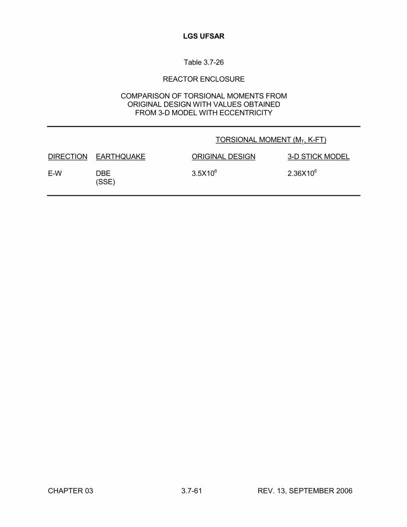
LGS UFSAR
CHAPTER 03 3.7-61 REV. 13, SEPTEMBER 2006
Table 3.7-26
REACTOR ENCLOSURE
COMPARISON OF TORSIONAL MOMENTS FROMORIGINAL DESIGN WITH VALUES OBTAINED
FROM 3-D MODEL WITH ECCENTRICITY
TORSIONAL MOMENT (MT, K-FT)
DIRECTION EARTHQUAKE ORIGINAL DESIGN 3-D STICK MODEL
E-W DBE 3.5X10⁶ 2.36X10⁶
(SSE)
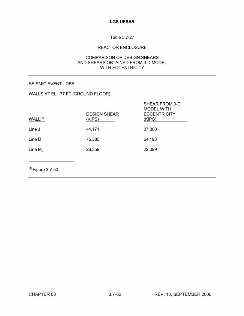
LGS UFSAR
CHAPTER 03 3.7-62 REV. 13, SEPTEMBER 2006
Table 3.7-27
REACTOR ENCLOSURE
COMPARISON OF DESIGN SHEARSAND SHEARS OBTAINED FROM 3-D MODEL
WITH ECCENTRICITY
SEISMIC EVENT - DBE
WALLS AT EL 177 FT (GROUND FLOOR)
SHEAR FROM 3-DMODEL WITH
DESIGN SHEAR ECCENTRICITYWALL(1) (KIPS) (KIPS)
Line J 44,171 37,800
Line D 75,385 64,193
Line ML 26,359 22,099
___________________
(1) Figure 3.7-50
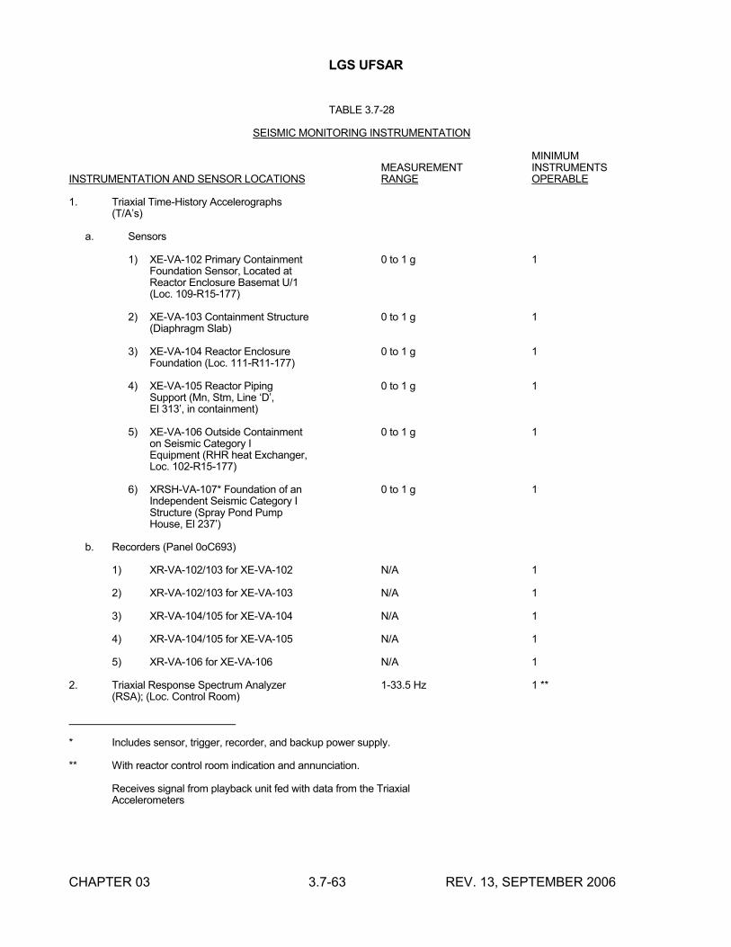
LGS UFSAR
CHAPTER 03 3.7-63 REV. 13, SEPTEMBER 2006
TABLE 3.7-28
SEISMIC MONITORING INSTRUMENTATION
MINIMUMMEASUREMENT INSTRUMENTS
INSTRUMENTATION AND SENSOR LOCATIONS RANGE OPERABLE
1. Triaxial Time-History Accelerographs(T/A’s)
a. Sensors
1) XE-VA-102 Primary Containment 0 to 1 g 1Foundation Sensor, Located atReactor Enclosure Basemat U/1(Loc. 109-R15-177)
2) XE-VA-103 Containment Structure 0 to 1 g 1(Diaphragm Slab)
3) XE-VA-104 Reactor Enclosure 0 to 1 g 1Foundation (Loc. 111-R11-177)
4) XE-VA-105 Reactor Piping 0 to 1 g 1Support (Mn, Stm, Line ‘D’,El 313’, in containment)
5) XE-VA-106 Outside Containment 0 to 1 g 1on Seismic Category IEquipment (RHR heat Exchanger,Loc. 102-R15-177)
6) XRSH-VA-107* Foundation of an 0 to 1 g 1Independent Seismic Category IStructure (Spray Pond PumpHouse, El 237’)
b. Recorders (Panel 0oC693)
1) XR-VA-102/103 for XE-VA-102 N/A 1
2) XR-VA-102/103 for XE-VA-103 N/A 1
3) XR-VA-104/105 for XE-VA-104 N/A 1
4) XR-VA-104/105 for XE-VA-105 N/A 1
5) XR-VA-106 for XE-VA-106 N/A 1
2. Triaxial Response Spectrum Analyzer 1-33.5 Hz 1 **(RSA); (Loc. Control Room)
* Includes sensor, trigger, recorder, and backup power supply.
** With reactor control room indication and annunciation.
Receives signal from playback unit fed with data from the TriaxialAccelerometers
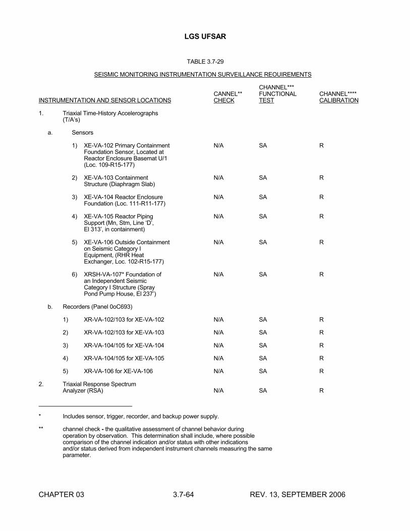
LGS UFSAR
CHAPTER 03 3.7-64 REV. 13, SEPTEMBER 2006
TABLE 3.7-29
SEISMIC MONITORING INSTRUMENTATION SURVEILLANCE REOUIREMENTS
CHANNEL***CANNEL** FUNCTIONAL CHANNEL****
INSTRUMENTATION AND SENSOR LOCATIONS CHECK TEST CALIBRATION
1. Triaxial Time-History Accelerographs(T/A’s)
a. Sensors
1) XE-VA-102 Primary Containment N/A SA RFoundation Sensor, Located atReactor Enclosure Basemat U/1(Loc. 109-R15-177)
2) XE-VA-103 Containment N/A SA RStructure (Diaphragm Slab)
3) XE-VA-104 Reactor Enclosure N/A SA RFoundation (Loc. 111-R11-177)
4) XE-VA-105 Reactor Piping N/A SA RSupport (Mn, Stm, Line ‘D’,El 313’, in containment)
5) XE-VA-106 Outside Containment N/A SA Ron Seismic Category IEquipment, (RHR Heat Exchanger, Loc. 102-R15-177)
6) XRSH-VA-107* Foundation of N/A SA Ran Independent Seismic Category I Structure (Spray Pond Pump House, El 237’)
b. Recorders (Panel 0oC693)
1) XR-VA-102/103 for XE-VA-102 N/A SA R
2) XR-VA-102/103 for XE-VA-103 N/A SA R
3) XR-VA-104/105 for XE-VA-104 N/A SA R
4) XR-VA-104/105 for XE-VA-105 N/A SA R
5) XR-VA-106 for XE-VA-106 N/A SA R
2. Triaxial Response SpectrumAnalyzer (RSA) N/A SA R
* Includes sensor, trigger, recorder, and backup power supply.
** channel check - the qualitative assessment of channel behavior during operation by observation. This determination shall include, where possiblecomparison of the channel indication and/or status with other indicationsand/or status derived from independent instrument channels measuring the sameparameter.
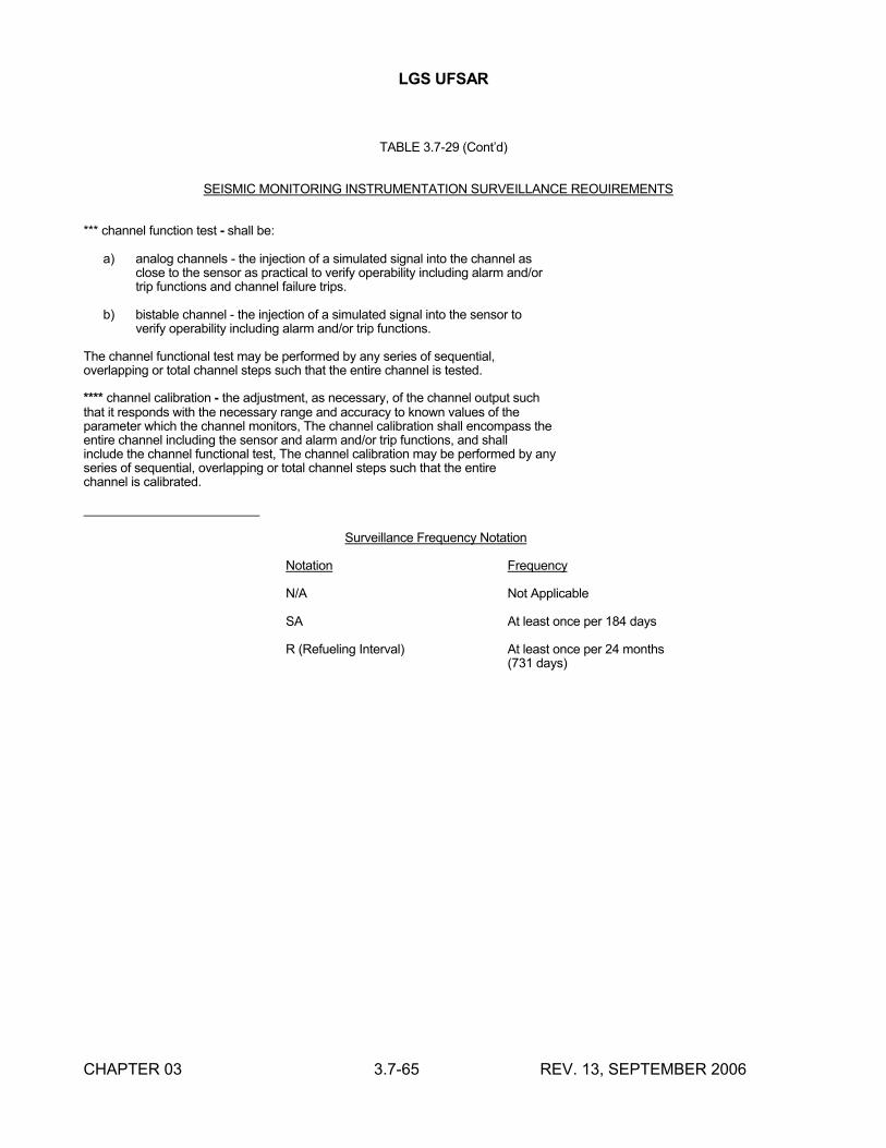
LGS UFSAR
CHAPTER 03 3.7-65 REV. 13, SEPTEMBER 2006
TABLE 3.7-29 (Cont’d)
SEISMIC MONITORING INSTRUMENTATION SURVEILLANCE REOUIREMENTS
*** channel function test - shall be:
a) analog channels - the injection of a simulated signal into the channel asclose to the sensor as practical to verify operability including alarm and/ortrip functions and channel failure trips.
b) bistable channel - the injection of a simulated signal into the sensor toverify operability including alarm and/or trip functions.
The channel functional test may be performed by any series of sequential,overlapping or total channel steps such that the entire channel is tested.
**** channel calibration - the adjustment, as necessary, of the channel output suchthat it responds with the necessary range and accuracy to known values of theparameter which the channel monitors, The channel calibration shall encompass theentire channel including the sensor and alarm and/or trip functions, and shallinclude the channel functional test, The channel calibration may be performed by anyseries of sequential, overlapping or total channel steps such that the entirechannel is calibrated.
Surveillance Frequency Notation
Notation Frequency
N/A Not Applicable
SA At least once per 184 days
R (Refueling Interval) At least once per 24 months(731 days)
LGS UFSAR
CHAPTER 03 3.8-1 REV. 18, SEPTEMBER 2016
3.8 DESIGN OF CATEGORY I STRUCTURES
3.8.1 CONCRETE CONTAINMENT
3.8.1.1 Description of the Containment
The primary containment is divided by a horizontal diaphragm slab into two major volumes: the drywell and the suppression chamber. The drywell encloses the reactor vessel, reactor recirculation system, and associated piping and valves. The suppression chamber stores a large volume of water.
The primary containment, shown on Figures 3.8-1 through 3.8-8, is in the form of a truncated cone over a cylindrical section, with the drywell being the upper conical section and the suppression chamber being the lower cylindrical section. These two sections comprise a structurally integrated, reinforced concrete pressure vessel, lined with welded steel plate and provided with a steel domed head for closure at the top of the drywell. Connection of the drywell head to the top of the drywell wall is shown on Figure 3.8-9. The diaphragm slab is a reinforced concrete slab structurally connected to the containment wall, as shown on Figure 3.8-10.
The primary containment is structurally separated from the surrounding reactor enclosure.
The concrete dimensions of the primary containment are as follows:
a. Inside diameter
1. Suppression chamber - 88'-0"
2. Base of drywell - 86'-4"
3. Top of drywell - 36'-4½"
b. Height
1. Suppression chamber - 52'-6"
2. Drywell - 87'-9"
c. Thickness
1. Base foundation slab - 8'-0"
2. Containment wall - 6'-2"
3.8.1.1.1 Base Foundation Slab
The containment base foundation slab is a reinforced concrete mat, the top of which is lined with carbon steel plate.
3.8.1.1.1.1 Reinforcement
LGS UFSAR
CHAPTER 03 3.8-2 REV. 18, SEPTEMBER 2016
The base foundation slab is reinforced with #18, Grade 60 rebar at the top and bottom faces. The maximum rebar spacing is 18 inches. Shear reinforcement consists of #8 and #9 vertical and inclined ties. Cadweld splices are used for splicing all main reinforcing bars. Figure 3.8-11 shows the plan and section views of reinforcement.
3.8.1.1.1.2 Liner Plate and Anchorages
The steel liner plate is ¼ inch thick, and is anchored to the concrete slab by structural steel beams embedded in the concrete and welded to the plate. Figure 3.8-12 shows details of the liner plate and anchorages.
3.8.1.1.1.3 Reactor Pedestal and Suppression Chamber Column, Base Liner Anchorages
Figures 3.8-13 and 3.8-14 show the base foundation slab liner anchorages for the reactor pedestal and the suppression chamber columns, respectively. For the pedestal anchorage, Cadweld sleeves are welded to the top and bottom surfaces of the thickened base liner to permit anchoring of the pedestal vertical rebar into the base foundation slab. Metal studs are welded to the top and bottom surfaces of the thickened base liner in order to transfer radial and tangential shear forces from the pedestal to the base foundation slab. For the suppression chamber column anchorage, pipe caps are welded to the thickened base liner at the locations where the column anchor bolts penetrate the base liner, in order to ensure the leak-tight integrity of the base liner.
3.8.1.1.2 Containment Wall
The containment wall is constructed of reinforced concrete 6'-2" thick, and is lined with carbon steel plate on the inside surface.
3.8.1.1.2.1 Reinforcement
The containment wall is reinforced with #18, Grade 60 rebar at the inner and outer faces. The inner rebar curtain consists of two meridional layers and one hoop layer. The outer rebar curtain consists of one meridional layer, two hoop layers, and two helical layers. Radial shear reinforcement consists of #6 horizontal and inclined ties. Cadweld splices are used for splicing all main reinforcing bars. Figures 3.8-15 and 3.8-16 show sections and developed elevation views of the suppression chamber wall reinforcement and drywell wall reinforcement, respectively.
3.8.1.1.2.2 Liner Plate and Anchorages
The steel liner plate is ¼ inch thick, and is anchored to the concrete wall by vertical stiffeners, using structural tees spaced horizontally every 2 feet, or less. Horizontal plate stiffeners provide additional stiffening. Figures 3.8-17 and 3.8-18 show details of the liner plate and anchorages.
Loads from internal containment attachments, such as beam seats and pipe restraints, are transferred directly into the containment concrete wall. This is accomplished by thickening the liner plate, and attaching structural weldments that transfer any type of load to the concrete, without relying on the liner plate or its anchorages. Where internal containment attachment loads are large, the structural weldments penetrate the liner plate, rather than being welded to opposite sides of the liner plate. This eliminates the possibility of lamellar tearing. Section 3.8.1.1.2.5 contains a further description of internal containment attachments.
3.8.1.1.2.3 Penetrations
LGS UFSAR
CHAPTER 03 3.8-3 REV. 18, SEPTEMBER 2016
Services and communications between the inside and the outside of the containment are performed through penetrations. Basic penetration types include pipe penetrations, electrical penetrations, and access hatches (equipment hatches, personnel lock, suppression chamber access hatches, and CRD removal hatch). Each penetration consists of a pipe sleeve with an annular ring welded to it. The ring is embedded in the concrete wall, and provides an anchorage for the penetration to resist normal operating and accident loads. The pipe sleeve is also welded to the containment liner plate to provide a leak-tight penetration.
Meridional and hoop reinforcement is bent around typical penetrations. Additional local reinforcement in the hoop and diagonal directions is added at all large penetrations, as shown on Figures 3.8-19 and 3.8-20. Local thickening of the containment wall at penetrations is generally not required. Section 3.8.2.1 contains further discussion of penetrations.
a. Pipe Penetrations
Details of typical pipe penetrations are shown on Figure 3.8-21. There are two basic types of pipe penetrations. For piping systems containing high temperature fluids, a sleeved penetration is furnished, providing an air gap between the containment concrete wall and the hot pipe. This air gap is large enough to maintain the concrete temperature below 200°F in the penetration area. A flued head outside the containment connects the process pipe to the pipe sleeve. For piping systems containing low temperature fluid, a separate sleeve for the penetration is not furnished. For this type of penetration, the process pipe is welded directly to the two ends of the embedded pipe penetration.
b. Electrical Penetrations
Figure 3.8-22 shows a typical electrical penetration assembly used to extend electrical conductors through the containment. The penetrations are hermetically sealed, and provide for leak testing at design pressure.
c. Equipment Hatches and Personnel Lock
Two equipment hatches, with inside diameters of 12 feet, are furnished in the drywell wall. One of these equipment hatches includes a personnel lock. Figure 3.8-21 shows a detail of an equipment hatch. Figures 3.8-16 and 3.8-23 show details of reinforcement around the equipment hatches. Additional meridional, hoop, helical, and shear reinforcement is used to accommodate local stress concentrations at the opening. The containment wall is thickened at the equipment hatches to accommodate the additional rebars.
d. Suppression Chamber Access Hatches
Two access hatches, with internal diameters of 4'-4", are furnished in the suppression chamber wall, as shown on Figure 3.8-21. Figure 3.8-15 shows a detail of reinforcement around the suppression chamber access hatches. Additional local reinforcement in the meridional and diagonal directions is added as shown on this figure.
3.8.1.1.2.4 Drywell Head Assembly
LGS UFSAR
CHAPTER 03 3.8-4 REV. 18, SEPTEMBER 2016
The drywell head lower flange is anchored to the top of the drywell wall by rigid attachment to 108 meridional reinforcing bars in the inner curtain of the containment wall, as shown on Figure 3.8-9. The remainder of the drywell head assembly is discussed in Section 3.8.2.1.1.
3.8.1.1.2.5 Internal Containment Attachments
The principal items attached to the containment wall from the interior are the diaphragm slab, beam seats, pipe restraints, and the seismic truss.
a. Diaphragm Slab Embedments
The diaphragm slab is attached to the containment wall by a structural weldment at the junction of the two components, as shown on Figure 3.8-10. Radial force and bending moment, carried by the diaphragm slab main reinforcement, are transferred to the containment wall by Cadwelding the diaphragm slab rebar to the top and bottom flanges of the structural weldment. The top and bottom flanges of the structural weldment are embedded in the containment concrete wall, and are anchored using structural steel anchors. Flexural shear in the diaphragm slab is transferred to the containment wall through the web of the structural weldment, which is welded to opposite sides of the thickened containment liner plate.
b. Beam Seat Embedments
Beam seats are provided to support the drywell platforms. A typical beam seat embedment is shown on Figure 3.8-24.
c. Pipe Restraint Embedments
Pipe restraints are provided to prevent pipe whip caused by rupture of high energy piping. Typical pipe restraint embedments are shown on Figure 3.8-25.
d. Seismic Truss Support Embedments
The seismic truss provides lateral support for the reactor vessel and reactor shield. A typical seismic truss support embedment in the drywell wall is shown on Figure 3.8-26.
3.8.1.1.2.6 External Containment Attachments
There are no major external structural attachments to the primary containment wall, except brackets providing vertical support for some of the reactor enclosure floor beams. These floor beams support checkered plate blowout panels, and are small enough to not cause any vertical interaction between the containment structure and the reactor enclosure. In addition, the beam-to-bracket connections are sliding connections, preventing horizontal interaction between the containment structure and the reactor enclosure.
3.8.1.1.2.7 Steel Components Not Backed by Structural Concrete
Descriptions of steel portions of the primary containment that are not backed by concrete, such as the drywell head, equipment hatches, personnel lock, suppression chamber access hatches, CRD removal hatch, and piping and electrical penetrations, are given in Section 3.8.2.
LGS UFSAR
CHAPTER 03 3.8-5 REV. 18, SEPTEMBER 2016
3.8.1.2 Applicable Codes, Standards, and Specifications
The codes, standards, and specifications used in the design and construction of the primary containment are listed in Table 3.8-1.
Specifications were prepared to cover the areas related to the design and construction of the containment. These specifications were prepared by Bechtel specifically for this containment. These specifications emphasize important points of the industry standards for this containment, and reduce options such as would otherwise be permitted by the industry standards. Unless specifically noted otherwise, these specifications do not deviate from the applicable industry standards, and, as such, are not included in the UFSAR. These specifications cover the following areas:
a. Furnishing and delivering concrete
b. Forming, placing, finishing, and curing concrete
c. Furnishing, detailing, fabricating, delivering, and placing reinforcing steel
d. Splicing reinforcing bars
e. Furnishing, delivering, and erecting liner plate
Section 1.8 provides references to regulatory guides discussed in the UFSAR. Regulatory guides specific to this section are discussed in this section.
3.8.1.3 Loads and Loading Combinations
Table 3.8-2 lists the loading combinations used for the design and analysis of the containment. Loading combinations listed in ASME Section III, Division 2 were considered for the containment design. Table 3.8-21 identifies and explains differences between the loads listed in Table 3.8-2 and the ASME Code.
The containment is also analyzed and designed for hydrodynamic loads resulting from MSRV discharge and LOCA phenomena. For a definition of these loads and loading combinations, including hydrodynamic loads, refer to Reference 3.8-1 and Appendix 3A.
3.8.1.3.1 Dead Load
The dead load includes the weight of the structure and major equipment, plus any other permanent loads, such as soil or hydrostatic loads, or operating pressure.
3.8.1.3.2 Live Load
The live load includes those loads expected to be present when the plant is operating, such as movable equipment, piping, and cables.
3.8.1.3.3 Design Basis Accident Pressure Load
Transients resulting from the DBA LOCA are presented in Section 6.2.1, and serve as the basis for the containment internal design maximum pressure of 55 psig.
LGS UFSAR
CHAPTER 03 3.8-6 REV. 18, SEPTEMBER 2016
3.8.1.3.4 Thermal Loads
The thermal loads used in the design of the primary containment are shown in Table 3.8-3 for the operating and the postulated accident conditions.
Thermal effects anticipated at the time of the structural integrity test are not considered. The ambient air temperature during testing is close to that of construction; therefore, the effects of thermal gradient are negligible.
3.8.1.3.5 Wind and Tornado Loads
Wind and tornado loads are not considered because the containment is enclosed by the reactor enclosure.
3.8.1.3.6 Seismic Loads
Loads from the OBE result from a horizontal ground acceleration of 0.075 g and a vertical ground acceleration of 0.05 g, acting simultaneously.
Loads from the SSE result from a horizontal ground acceleration of 0.15 g and a vertical ground acceleration of 0.10 g, acting simultaneously.
3.8.1.3.7 External Pressure Load
The containment shell is designed to withstand an external pressure of 5 psi above the internal pressure.
3.8.1.3.8 Pipe Rupture Loads
The containment wall is designed to withstand the loads due to a postulated rupture of a 26 inch diameter main steam pipe, which produces the largest loads on the containment wall. These loads include the effects of jet impingement, pipe whip, and pipe reaction. An equivalent static load of 1000 kips is considered. This load includes an appropriate dynamic load factor to account for the dynamic nature of the load. Section 3.6 contains a detailed discussion of postulated pipe ruptures and their effects. For pipe whip and impact on restraints, the steel stress may exceed yield stress. For jet impingement, these stresses should not exceed yield stress. See Section 3.8.1.4 for further explanation.
3.8.1.3.9 Prestress Loads
The primary containment uses reinforced concrete; therefore, prestress loads have not been considered.
3.8.1.4 Design and Analysis Procedures
This section describes the procedures used for the design and analysis of the containment. For a description of the design and analysis procedures that consider the effects of hydrodynamic loads resulting from MSRV discharge and LOCA phenomena, refer to Reference 3.8-1 and Appendix 3A.
The analysis procedure consists of two parts. First, the uncracked forces, moments, and shears for both axisymmetric and nonaxisymmetric loads are determined. Axisymmetric loads are dead
LGS UFSAR
CHAPTER 03 3.8-7 REV. 18, SEPTEMBER 2016
load, live load, design accident pressure load, vertical seismic load, and operating and design accident thermal loads. Nonaxisymmetric loads are horizontal seismic load and localized pipe rupture load. The second part of the procedure consists of taking into account the expected cracking of the concrete, and determining the concrete and reinforcing steel stresses and strains. The liner plate is not assumed to resist any load.
The 3D/SAP computer program, described in Section 3.8.7.1, is used to determine the uncracked forces, moments, and shears due to axisymmetric loads. The operating and design accident temperature gradients are computed using the ME 620 computer program, which is described in Section 3.8.7.9. For transient loads such as design accident pressure and thermal loads, the most critical combination of these loads is considered.
The seismic loads on the structure are determined by seismic analysis using the methods described in Section 3.7. The 3D/SAP program is used to analyze the containment for nonaxisymmetric loads due to missile and postulated pipe rupture, and for local construction loads.
The Concrete Element Cracking Analysis Program (CECAP), described in Section 3.8.7.3, is used to determine the extent of concrete cracking, and the concrete and rebar stresses and strains. The input data for the CECAP program consist of the uncracked forces, moments, and shears calculated by the 3D/SAP and seismic analysis programs. The CECAP program models a single element of unit height, unit width, and depth equal to the thickness of the wall or slab. The program assumes isotropic, linear-elastic material properties, and uses an iterative technique to obtain stresses, considering their redistribution due to cracking. The program determines the redistribution of thermal-stresses due to the relieving effect of concrete cracking.
3.8.1.4.1 Containment Wall
Figure 3.8-27 shows the 3D/SAP finite-element model used to analyze the containment wall for axisymmetric loads. A 10° wedge of the containment is modeled using solid finite-elements having isotropic, linear-elastic material properties. The model includes the containment wall, base foundation slab, diaphragm slab, reactor pedestal, and the foundation material. Boundary conditions are imposed on the analytical model by specifying nodal point forces or displacements. With reference to Figure 3.8-27, the nodal points lying along boundary A are allowed to move within the X-Z plane, and those along boundary B within the X-Y plane. Points along boundary C are prevented from moving in the radial direction, and points along boundary D are prevented from moving in the hoop direction. Nodal forces, moments, and shears are applied to boundaries E and F to account for reaction loads from the drywell head, and from the reactor vessel and reactor shield wall, respectively.
Figure 3.8-28 shows the 3D/SAP finite-element model used to analyze the drywell wall for nonaxisymmetric pipe rupture loads. A 180 half-model of the drywell wall, consisting of isotropic, linear-elastic, solid finite-elements, is used. With reference to Figure 3.8-28, the nodal points lying along boundary A are allowed to move within the X-Z plane. Points along boundary B are prevented from moving in the vertical and radial directions. Nodal forces, moments, and shears are applied to boundary C to account for reaction loads from the drywell head.
Tangential shears caused by seismic loads are totally resisted by helical reinforcing bars and concrete in compression. In calculating the reinforcing steel requirement, the helical reinforcement is designed to resist stresses due to design accident pressure and thermal loads, as well as tangential shears caused by seismic loads.
LGS UFSAR
CHAPTER 03 3.8-8 REV. 18, SEPTEMBER 2016
3.8.1.4.2 Base Foundation Slab
Figure 3.8-29 shows the 3D/SAP finite-element model used to analyze the base foundation slab. A 180° half-model of the base foundation slab, consisting of isotropic, linear-elastic solid finite-elements is used. The model includes the base foundation slab, a portion of the containment wall, and the foundation material. By virtue of continuous modeling of base slab and wall elements as finite elements in the 3D/SAP analysis, strain compatibility and stress equilibrium at the wall and slab boundary are satisfied. With reference to Figure 3.8-29, the nodal points lying along boundary A are allowed to move within the X-Z plane, and those along boundary B within the X-Y plane. Points along boundary C are prevented from moving in the radial direction. Axisymmetric forces, moments, and shears calculated using the 3D/SAP containment model, and seismically induced, tangential shears are applied to boundary D. The height of the model is chosen so that the overturning moment caused by the tangential shear is the same as the overturning moment determined by the seismic analysis. In order to be able to consider uplifting of the base foundation slab from its foundation, a thin layer of foundation material immediately beneath the foundation slab is considered separately from the remainder of the foundation material. If the computer output indicates tension in any of the elements in this thin layer of foundation material, the elements' modulus of elasticity is reduced to almost zero. Then a second computer run is made, and any additional uplift is identified. Further iterations and modifications of foundation material properties are made until the complete extent of uplift is determined.
3.8.1.4.3 Analysis of Areas Around Equipment Hatches
Figure 3.8-30 shows the 3D/SAP finite-element model used to analyze the areas of the containment wall around the equipment hatches. A 60° wedge of the containment wall is modeled using solid finite-elements having isotropic, linear-elastic material properties. To reduce the size of the analytical model, boundary A follows the equipment hatch's vertical plane of symmetry. The points delineating the outermost boundaries of the model are located at a sufficient distance from the opening so that the behavior of the model along the boundaries is compatible with that of the undisturbed shell. With reference to Figure 3.8-30, the nodal points lying along boundary A are allowed to move within the X-Z plane, and those lying along boundary B within the X-Y plane.Points along boundary C are prevented from moving in the hoop direction. Axisymmetric forces, moments, and shears calculated using the 3D/SAP containment model are applied to boundary D. Seismic loads calculated by the seismic analysis are applied locally to the elements. Seismically induced tangential shears around the equipment hatches are resisted by helical reinforcing bars and concrete in compression.
3.8.1.4.4 Liner Plate and Anchorages
The design and analysis of the liner plate and anchorages are performed in accordance with Reference 3.8-3.
3.8.1.5 Structural Acceptance Criteria
3.8.1.5.1 Reinforced Concrete
The containment wall, the diaphragm slab, and the reactor pedestal are designed for the factored load combinations listed in Table 3.8-2, in accordance with the strength method of ACI 318. The following allowable stresses are used:
a. Concrete
1. Compression - 0.85 fc'
LGS UFSAR
CHAPTER 03 3.8-9 REV. 18, SEPTEMBER 2016
2. Tension - not permitted
3. Radial shear - as specified in Chapter 11 of ACI 318 (1971)
4. Tangential shear - not permitted
b. Reinforcing Steel
1. Tension - 0.90 F
2. Compression - 0.90 F
The notations are defined as:
fc' = specified compressive strength of concrete
F = specified yield strength of reinforcing steel
The calculated stresses are within the allowable limits.
3.8.1.5.2 Liner Plate and Anchorages
The structural acceptance criteria for the liner plate and anchorages are in accordance with Reference 3.8-3.
3.8.1.6 Materials, Quality Control, and Special Construction Techniques
3.8.1.6.1 Concrete Containment
The concrete and reinforcing steel materials for the containment are discussed in Section 3.8.6.
3.8.1.6.2 Liner Plate, Anchorages, and Attachments
a. Materials
Liner plate materials conform to the requirements of the standard specifications listed below:
Item Specification
Liner plate (¼ inch ASTM A285, Grade A,thick) Firebox Quality
Liner plate (>¼ inch ASME SA516, Grade 60 conformingthick) to the requirements of ASME Section III, Subsection
B, Article 12
Structural steel shapes, ASTM A36plates, and bars used for anchorages andattachments to the liner plate
LGS UFSAR
CHAPTER 03 3.8-10 REV. 18, SEPTEMBER 2016
Pipe restraint ASTM A36 or ASTM A441attachments
b. Welding
Liner plate and structural steel welding conforms to the applicable portions of Part UW, "Requirements for Unfired Pressure Vessels Fabricated by Welding" of ASME Section VIII. Welders and weld procedures are qualified in accordance with ASME Section IX. For seam welds of liner plate and attachments that penetrate the liner plate (penetrations), Paragraphs UW-26 through UW-38, except UW-35, apply in their entirety. In lieu of Paragraph UW-35, undercuts that do not exceed 1/32 inch and do not encroach on the required section thickness are in accordance with ASME Section III, Subsection NB(4424). The welding of liner plate butt welds and penetration attachment welds are performed by either the shielded metal arc, or the automatic, submerged arc process. The minimum number of individual weld layers for welds that must maintain leak-tightness is two. In addition, liner plate seam and penetration attachment welds are inspected in accordance with paragraph (d) below. Welding of liner anchorages and internal containment attachments to the liner plates are also performed in accordance with ASME Section VIII Paragraphs UW-26 through UW-38, and the visual inspection/acceptance of the nonpressure-retaining attachment weldments are in accordance with NCIG-01 (Reference 3.8-22).
c. Materials Testing
Liner plate material greater than ¼ inch thick, used with Cadweld connectors and other anchorages, is vacuum- degassed and ultrasonically tested, in accordance with the ASME Section III, Section A-N321-1, and conforms to the requirements of Article 12, Materials, of ASME Section III, Subsection B.
d. Nondestructive Examination of Liner Plate Seam Welds
Nondestructive examination of welds complies with Regulatory Guide 1.19, with the following alternate approaches:
Spot radiographic examination is performed for all radiographable liner plate seam welds. Radiography is performed in accordance with ASME Section V, Article 2. Personnel performing radiographic examinations are qualified in accordance with the Society for Nondestructive Testing's Recommended Practice No. SNT-TC-1A, Supplement A, Radiographic Testing Method, plus any additional requirements of the ASME Section V. Acceptance standards are in accordance with Paragraph UW-51 of ASME Section VIII, Division 1. Twelve inches of the first 10 feet of weld for each welder, and welding position are radiographed. Thereafter, one 12 inch long radiograph is taken for each welder and weld position, for each additional 50 foot increment of weld. A minimum of 2% of all liner seam welds are examined by radiography.
Where nonradiographable weld joints are used, the entire length of weld is magnetic particle examined. All magnetic particle examinations conform to the ASME Section V. Personnel performing magnetic particle examinations are qualified in accordance with SNT-TC-1A, plus any additional requirements of the ASME Section V. Acceptance standards are in accordance with the ASME Section VIII, Division 1, Appendix VI.
LGS UFSAR
CHAPTER 03 3.8-11 REV. 18, SEPTEMBER 2016
The vacuum box soap bubble test is performed on all accessible liner plate seam welds, except welds connecting thickened reinforcing liner plate to penetration nozzles with nominal diameter of 6 inches or less. A 5 psi minimum pressure differential is maintained for a minimum of 20 seconds. The leak detecting solution is continuously observed for bubbles that indicate leaks. If a leak is detected, the defective weld is repaired, and reinspected by vacuum box testing.
Welds that are inaccessible for vacuum box testing are 100% liquid penetrant tested. Liquid penetrant examinations conform to the ASME Section V. Personnel performing liquid penetrant examinations are qualified in accordance with SNT-TC-1A, plus any additional requirements of the ASME Section V. Acceptance standards conform to the ASME Section VIII, Division 1, Appendix VIII.
A leak chase channel system is provided only on liner plate seam welds which are inaccessible after the completion of construction, and those under water in the suppression chamber. Following installation, the leak chase system is pressurized with air to 72 psig. The pressure is monitored by valving off the air supply, and measuring any pressure decay with a pressure gauge. Any pressure decay in excess of the pressure gauge rated accuracy, observed within 15 minutes, is cause to reject that portion of the liner plate seam welds and the leak chase system. All leaks are repaired, and following repair, the affected portion of the leak chase system is retested.
e. Quality Control
Quality control requirements during construction are discussed in the document "Limerick Generating Station Units 1 and 2; Summary Description of the Quality Assurance Program for Design and Construction," referenced in FSAR Section 17.1.
f. Erection Tolerances
The erection tolerances for the liner plate are summarized as follows:
1. The slope of any 10 foot section of cylindrical liner plate, referred to as true vertical, does not exceed 1:180. The deviation from the theoretical slope of any 10 foot section of conical liner plate, measured within a vertical plane, does not exceed 1:120.
2. The cylindrical shell is plumb within 1/400 of the height, plus a 2 inch allowance for local "out-of- roundness." The vertical axis of the conical shell, as established at the top and bottom of the conical section, is plumb within 1/200 of the height.
3. The radial dimension to any point on the liner plate does not vary from the design radius by more than ±1 inch in the suppression chamber, or ±1½ inches in the drywell, except that the radial tolerance is ±2 inches for local "out-of-roundness." Local "out-of-roundness" tolerance is used where the maximum diameter minus the minimum diameter at the elevation does not exceed 4 inches. Radial measurements are taken at 24 locations, spaced equally around the containment at any elevation.
LGS UFSAR
CHAPTER 03 3.8-12 REV. 18, SEPTEMBER 2016
4. Plates joined by butt-welding are matched accurately, and retained in position during the welding operation. Misalignment in completed joints does not exceed the limitations of Paragraph UW-33 of ASME Section VIII, Division 1.
3.8.1.7 Testing and Inservice Surveillance Requirements
3.8.1.7.1 Preoperational Testing
3.8.1.7.1.1 Structural Acceptance Test
Structural and Pressure Integrity Tests were performed according to Article CC-6000 of the ASME Section III, Division 2, as applicable, after complete installation of all penetrations in the drywell and suppression chamber, and prior to initial fuel loading. The Structural and Pressure Integrity Tests complies with Regulatory Guide 1.18, with the following alternate approaches:
Paragraph C.1
A continuous increase in containment pressure, rather than incremental pressure increases, was used. This was considered justifiable because data observations at each pressure level were made rapidly by the computerized data acquisition system. "Rapidly" is defined as requiring a time interval for the data point sample sufficiently short so that the change in pressure during the observation would cause a change in structural response of less than 5% of the total anticipated change. Also, the rate of pressurization was limited to 3 psig/hr average to ensure that the structure responds to the pressure loading without any time lag. However, retesting for Unit 2 is performed at a rate of pressurization limited to 8 psig/hr average with adequate hold time at peak pressure to assure there is no time lag for the structural response. For a description of the structural integrity test for each unit, see the alternate approach to Paragraph C.12 in this section (3.8.1.7.1.1).
Measurements were recorded at atmospheric pressure, and at 5 psi increments of the pressurization and depressurization cycles. The data acquisition system allowed the measurements at all locations to be made and recorded simultaneously.
The pressure was held constant for at least 1 hour at the maximum test pressure, or for such time as was necessary for recording crack patterns.
Paragraph C.2
The number and distribution of measuring points for monitoring radial deflections were selected so that the as-built condition could be considered in the assessment of general shell response. In general, the locations of the measuring points for radial deflections were in agreement with figure B of the Regulatory Guide, with the exception of Point 1. Point 1 was provided at a distance of two times the wall thickness (12 feet) from the basemat. This variation was made to properly predict the containment behavior near the basemat to wall connection. If Point 1 was located at a height of three times the wall thickness (18 feet), it would be very close to Point 2 (suppression chamber wall midheight is 26 feet) and would not yield any additional behavior pattern of the containment.
LGS UFSAR
CHAPTER 03 3.8-13 REV. 18, SEPTEMBER 2016
Paragraph C.3
Radial deflections, but not tangential deflections, were recorded. The magnitude of the expected local tangential deformation under the test pressure conditions is negligibly small. The diametrical displacement of the hatch parallel to the tangential direction was measured and compared to the predicted displacement. This was in the location of largest predicted displacements for the hatch discontinuity and provided the most comprehensive check on structural integrity. The measurement of absolute tangential deflections at locations away from the immediate edge of the discontinuity was difficult because fixed reference points are difficult to define, making it impractical to attempt measurement of these small local deflections.
Paragraph C.9
The LGS containment is located inside and isolated from the reactor enclosure. The environmental conditions under which the test was conducted were controlled by the reactor enclosure internal environment. Therefore, limitations on testing during periods of extreme weather conditions, such as snow, heavy rain, and strong wind, had negligible effect on structural response and were not applicable.
Paragraph C.10
Rather than as suggested in the guide, if the test pressure dropped to, or below, the next lower pressure level due to an unexpected condition, the test would have continued without a restart at atmospheric pressure, unless the structural response deviated significantly from that expected. The LGS containment pressurization was not conducted using pressure increments. Therefore, the provisions of ASME Section III, Division 2, subsection CC-6252(b) were met, using a 3 psi pressure drop as a criterion for investigating deviation in structural response.
Paragraph C.12
LGS has provided a detailed description of the structural integrity test in the report prepared after the test.
The Structural and Pressure Integrity Test was conducted at 115% of the following design conditions:
a. A design pressure condition of 55 psig in both the drywell and suppression chamber
b. A design pressure condition of 55 psig in the drywell, and 25 psig in the suppression chamber
Additional pressure integrity tests may be made subsequently, during periods of plant shutdown.
The differential pressure test of the diaphragm slab described in item (b) above was accomplished by capping the downcomers above the diaphragm slab's upper surface.
The LGS Unit 1 test was performed in one test sequence which demonstrated the structural adequacy of the containment structure for both of the design conditions described above. However, for LGS Unit 2, the structural integrity test was conducted in two stages because the maximum differential pressure on the diaphragm slab could not be maintained during the initial
LGS UFSAR
CHAPTER 03 3.8-14 REV. 18, SEPTEMBER 2016
pressurization of the containment structure. During the initial test, the structural adequacy of the containment structure for the design condition of 55 psig in both the drywell and the suppression chamber was satisfactorily demonstrated. Subsequent to the re-isolation of the drywell and the suppression chamber, the containment structure was retested at a rate of pressurization limited to 8 psig/hr average to 115% of the design condition "b" described above (drywell pressure equal to 63.25 psig and suppression chamber pressure equal to 28.75 psig).
Provisions are made to test the integrity of the primary containment system during the life of the plant.
The seals on the personnel airlock doors, hatches, and drywell head are capable of being tested for leakage at design pressure without pressurizing the drywell. In addition, provisions are made so that the space between the airlock doors can be pressurized to full drywell design pressure.
Electrical penetrations are testable at 115% of design pressure. Locations of test taps and seals allow electrical penetrations to be tested without entering or pressurizing the drywell or suppression chamber.
A more detailed description of the structural integrity test was provided in the report prepared after the initial test.
3.8.1.7.1.2 Leak Rate Testing
Preoperational leak rate testing is discussed in Section 6.2.6.
3.8.1.7.2 Inservice Leak Rate Testing
Inservice leak rate testing is discussed in Section 6.2.6.
3.8.2 ASME CLASS MC STEEL COMPONENTS OF THE CONTAINMENT
This section pertains to the ASME Class MC steel components of the concrete containment that form a portion of the containment pressure boundary, and are not backed by structural concrete. These components include the drywell head assembly, the equipment hatches, the personnel lock, the suppression chamber access hatches, the CRD removal hatch, and piping and electrical penetrations.
3.8.2.1 Description of the ASME Class MC Components
3.8.2.1.1 Drywell Head Assembly
The drywell head provides a removable closure at the top of the containment for reactor access during refueling operations. The drywell head assembly consists of a 2:1 hemi-ellipsoidal head and a cylindrical lower flange. The lower flange is supported on the top of the drywell wall as shown on Figure 3.8-9. The head is made of 1½ inch thick plate and is secured with eighty 2¾ inch diameter bolts at the 4 inch thick mating flange. The head-to-lower flange connection is made leak-tight by two replaceable gaskets. The space between the gaskets is provided with test connections to allow pneumatic testing from a remote location, outside the primary containment. The inside diameter of the drywell head at the mating flange is 37 feet 7½ inches. A double-gasketed manhole is provided in the drywell head. Figure 3.8-31 shows details of the drywell head assembly.
LGS UFSAR
CHAPTER 03 3.8-15 REV. 18, SEPTEMBER 2016
3.8.2.1.2 Equipment Hatches and Personnel Lock
Two 12 foot diameter equipment hatches are furnished in the drywell wall to permit the transfer of equipment and components into and out of the drywell. One hatch consists of a double-gasketed flange and a bolted dished door. The other hatch is furnished with a personnel lock welded to the removable door. The personnel lock is an 8'-7" diameter cylindrical pressure vessel, with inner and outer flat bulkheads. Interlocked doors, 2'-6" wide by 6' high, with double tongue-and-groove single element compression seals, are furnished in each bulkhead. A quick-acting, equalizing valve vents the personnel lock to the drywell to equalize the pressure in the two systems when the doors are opened and then closed. The two doors in the personnel lock are mechanically interlocked to prevent them from being opened simultaneously, and to ensure that one door is closed before the opposite door can be opened. The personnel lock has an ASME Code N-stamp. Figures 3.8-32 and 3.8-33 show details of the equipment hatch, and the equipment hatch with personnel lock, respectively.
3.8.2.1.3 Suppression Chamber Access Hatches
Two 4'-4" diameter access hatches are furnished in the suppression chamber wall to permit personnel access, and the transfer of equipment and components into and out of the suppression chamber. Each hatch consists of a double-gasketed flange and a bolted flat cover. Details of a suppression chamber access hatch are shown in Figure 3.8-21.
3.8.2.1.4 Control Rod Drive Removal Hatch
One 3 foot diameter CRD removal hatch is furnished in the drywell wall to permit transfer of the CRD assemblies into and out of the drywell. The hatch is furnished with a double-gasketed flange and a bolted flat cover. Figure 3.8-34 shows details of the CRD removal hatch.
3.8.2.1.5 Piping and Electrical Penetrations
A portion of each of the penetration sleeves extends beyond the containment wall, and is not backed by concrete. The entire length of any penetration sleeve, therefore, is considered an MC component, and, as such, is designed in accordance with ASME Section III, subsection B. Figures 3.8-21 and 3.8-22 show details of typical pipe and electrical penetrations, respectively.
3.8.2.2 Applicable Codes, Standards, and Specifications
The codes, standards, and specifications used in the design and construction of the containment are listed in Table 3.8-1.
Specifications are prepared to cover the areas related to the design and construction of the containment. These specifications are prepared by Bechtel specifically for this containment. These specifications emphasize important points of the industry standards for this containment, and reduce options that would otherwise be permitted by the industry standards. Unless specifically noted otherwise, these specifications do not deviate from the applicable industry standards, and as such are not included in the UFSAR. These specifications cover the following areas:
a. Furnishing and delivering concrete
LGS UFSAR
CHAPTER 03 3.8-16 REV. 18, SEPTEMBER 2016
b. Forming, placing, finishing, and curing concrete
c. Furnishing, detailing, fabricating, delivering, and placing reinforcing steel
d. Splicing reinforcing bars
e. Furnishing, delivering, and erecting liner plate
Section 1.8 provides references to regulatory guides discussed in the UFSAR. Regulatory guides specific to this section are discussed in this section.
3.8.2.3 Loads and Loading Combinations
Table 3.8-4 lists the loading combinations used for the design and analysis of the ASME Class MC components.
The ASME Class MC components are also assessed for Mark II hydrodynamic loads resulting from MSRV discharge and LOCA phenomena. For a definition of loads and loading combinations including hydrodynamic loads, refer to Reference 3.8-1 and Appendix 3A.
3.8.2.3.1 Dead and Live Load
For descriptions of dead and live load, see Sections 3.8.1.3.1 and 3.8.1.3.2, respectively.
3.8.2.3.2 Design Basis Accident Pressure Load
The drywell head is designed for a DBA internal pressure of 56 psi. The other MC components are designed for a DBA internal pressure of 62 psi.
3.8.2.3.3 External Pressure Load
The MC components are designed to withstand an external pressure of 5 psi above the containment internal pressure.
3.8.2.3.4 Thermal Loads
The operating and postulated design accident temperatures for the MC components are as follows:
Temperature (F) Suppression
Condition Drywell Chamber
Operating 135 95 (maximum)Design Accident 340 220
Thermal cycles used in design are as follows:
a. Startup and shutdown - 500 cycles, 105F range
b. Design Basis Accident - 1 cycle, 220F range
3.8.2.3.5 Seismic Loads
The MC components are designed for acceleration values which were calculated using the methods described in Section 3.7.
The following seismic acceleration values are used for the design of the drywell head assembly:
LGS UFSAR
CHAPTER 03 3.8-17 REV. 18, SEPTEMBER 2016
a. OBE - 0.60 g horizontal, ±0.30 g vertical
b. SSE - 0.80 g horizontal, ±0.40 g vertical
The following seismic acceleration values are used for the design of the equipment hatch, personnel lock, and CRD hatch:
a. OBE - 0.40 g horizontal, ±0.20 g vertical
b. SSE - 0.45 g horizontal, ±0.25 g vertical
The following seismic acceleration values are used in the design of the suppression chamber hatches:
a. OBE - 0.20 g horizontal, ±0.15 g vertical
b. SSE - 0.30 g horizontal, ±0.20 g vertical
This information is based on original design basis conditions. Further evaluation has validated the MC components for a drywell operating temperature of 150F. The Stresses indicated in UFSAR Figures 3A-362 to 3A-380, Design Assessment Report for Containment Structures reflect current plant conditions.
3.8.2.3.6 Pipe Rupture Loads
The drywell head assembly is designed for a local pipe rupture load of 48,000 pounds, uniformly distributed over a circular area of 0.56 square foot, at any location on the drywell head. This load is due to the postulated rupture of the 6 inch diameter reactor head spray pipe, which produces the largest load on the drywell head. The head spray line does not exist for Unit 2 and has been removed from Unit 1. However, the analysis is still applicable because it envelopes loads from rupture of any other pipe in this region.
The equipment hatches are designed for a postulated pipe rupture load of 130,000 pounds, uniformly distributed over a circular area 12 feet in diameter.
The CRD removal hatch is designed for a postulated pipe rupture load of 160,000 pounds, uniformly distributed over a circular area 3 feet in diameter.
The loads on the equipment hatches and the CRD removal hatch are based on the rupture of a 28 inch diameter recirculation loop outlet pipe, which produces the largest load on the components.
The above values of static load include an appropriate dynamic load factor to account for the dynamic nature of the load. Section 3.6 contains a detailed discussion of postulated pipe ruptures and their effects, including pipe whip, jet impingement, environmental effects, flooding, and water spray.
3.8.2.3.7 Missile Impact Loads
As discussed in Section 3.5.1 and summarized in Table 3.5-7, missile impact is not considered credible for safety-related components inside the containment or the reactor enclosure.
3.8.2.4 Design and Analysis Procedures
This section describes the procedures used for the design and analysis of ASME Class MC steel components.
LGS UFSAR
CHAPTER 03 3.8-18 REV. 18, SEPTEMBER 2016
ASME Class MC components are also assessed for Mark II hydrodynamic loads resulting from MSRV discharge and LOCA phenomena. Assessment procedures that consider the effect of hydrodynamic loads are described in Appendix 3A.
3.8.2.4.1 Drywell Head Assembly
The analysis of the drywell head assembly uses the thin-shell computer program E0781, described in Section 3.8.7.7. This program calculates the stresses and displacements in thin-walled, elastic shells of revolution, when subjected to static edge, surface, and/or temperature loads with an arbitrary distribution over the surface of the shell.
The drywell head assembly is divided into two analytical models. Figure 3.8-35 shows the drywell head model and the lower flange model. Displacement compatibility of the two models at the mating flange surface is maintained in the analysis. Boundary conditions are imposed on the analytical models by specifying boundary forces or displacements. With reference to Figure 3.8-35, the translation and rotation of the top of the drywell wall are imposed as boundary conditions to boundary A. Boundary forces applied to boundary B are calculated in accordance with thin-shell theory.
See Section 3A.7.2.1.9.1 for discussion of analysis to reduce the drywell head bolt preload.
3.8.2.4.2 Access Hatches
Access hatches, including the equipment hatches, personnel lock, suppression chamber access hatches, and the CRD removal hatch, are designed as pressure-retaining components. The portions of the sleeves not backed by concrete are designed and analyzed according to the provisions of ASME Section III, Subsection B.
At the junction of the hatch cover to the flange on the sleeve, where local bending and secondary stresses occur, the computer program E0119, described in Section 3.8.7.7, is used for analysis. This program is also used for the analysis of the flat head covers.
3.8.2.4.3 Piping and Electrical Penetrations
For nuclear Class I flued head penetrations, the procedures used in design and analysis comply with ASME Section III, Subsection B.
For Class 1E electrical cable penetrations, the procedures used in design and analysis comply with ASME Section III, Subsection B.
3.8.2.5 Structural Acceptance Criteria
The structural acceptance criteria comply with Regulatory Guide 1.57, with the clarification that the Code Addenda in effect at the time of design rather than that cited in the guide were used. Table 3.8-4 lists the allowable stress criteria for the design and analysis of the ASME Class MC components.
3.8.2.6 Materials, Quality Control, and Special Construction Techniques
LGS UFSAR
CHAPTER 03 3.8-19 REV. 18, SEPTEMBER 2016
3.8.2.6.1 Materials
All carbon steel materials and stainless steel materials for the CRD hydraulic line penetrations conform to the requirements of ASME Section III, Subsection B. The drywell head assembly and other steel components are painted to protect against corrosion.
3.8.2.6.1.1 Drywell Head Assembly
Materials used in construction of the drywell head assembly conform to the following ASME specifications:
Item Specification
Drywell head and SA516, Grade 70, normalizedlower flange
Bolts SA320, Grade L43
Nuts SA194, Grade 7
3.8.2.6.1.2 Access Hatches
Materials used in construction of the access hatches conform to the following ASME specifications:
Item Specification
Sleeve and cover SA516, Grade 60 or 70, normalized
Bolts SA193, Grade B7
Nuts SA194, Grade 7
3.8.2.6.1.3 Penetrations
Materials used in construction of piping and electrical penetrations conform to the following ASME specifications:
Item SpecificationCarbon steel sleeves SA333, Grade 1
orSA516, Grade 60 or 70, normalized
Carbon steel caps for SA234, Grade WPBspare penetrations
Stainless steel sleeves SA312, Type 304Lfor CRD hydraulicline penetrations
LGS UFSAR
CHAPTER 03 3.8-20 REV. 18, SEPTEMBER 2016
Stainless steel SA182, Type 304fittings for CRDhydraulic linepenetrations
3.8.2.6.2 Welding
Welding conforms to the requirements of ASME Section III, Subsection NE-4000 except that all welding of the CRD hydraulic line penetrations conforms to the requirements of ASME Section III, Subsection NC. All pressure boundary welds are full penetration welds of double-welded, bevel-type. Welders and weld procedures are qualified in accordance with ASME Section IX.
Penetrations, access hatches, and the drywell head flange are postweld heat treated in accordance with ASME Section III, Article NE-4000. Penetrations are preassembled into the liner plate sections, and postweld heat treated as complete subassemblies.
3.8.2.6.3 Nondestructive Examination of Welds
All welds between penetrations and liner plate, access hatches and liner plate, and pressure-retaining welds not backed by concrete are examined in accordance with ASME Section III, Article NE-5000. Nondestructive examination of welds complies with Regulatory Guide 1.19, with the following alternate approaches:
Paragraph C.1.a
LGS uses an alternate approach with respect to radiographic examination of the first 10 feet of weld. For each welder and welding position, only 12 inches of the first 10 feet of weld is examined radiographically, instead of the entire 10 foot length. LGS conforms with all other guidelines for nondestructive examination of liner seam welds.
Paragraph C.4
LGS conforms with the intent, subject to the following interpretation: Nondestructive examinations are performed by employees of the liner plate Subcontractor. Bechtel, as licensee's agent, verifies that all personnel performing nondestructive testing are qualified in accordance with ASME Section V.
Paragraph C.7.a
LGS radiography acceptance standards are in accordance with UW-51 of the ASME Section VIII, Division I.
Paragraph C.7.b
Magnetic particle acceptance standards are in accordance with the ASME Section VIII, Division I, Appendix VI.
3.8.2.6.4 Quality Control
Quality control requirements during construction are discussed in the document "Limerick Generating Station Units 1 and 2; Summary Description of the Quality Assurance Program for Design and Construction," referenced in FSAR Section 17.1.
LGS UFSAR
CHAPTER 03 3.8-21 REV. 18, SEPTEMBER 2016
3.8.2.6.5 Erection Tolerances
The specified erection tolerances for ASME Class MC steel components of the containment are summarized as follows:
a. Suppression chamber penetrations are within 1 inch of their design elevations and circumferential locations.
b. Drywell penetrations are within 1 inch of their design circumferential locations. Critical penetrations, such as main steam, feedwater, core spray, etc, are within 1 inch of their design elevations. All other drywell penetrations vary from within 1 inch of design elevations for penetrations near the base of the drywell wall, to within 2 inches of design elevations for penetrations near the top of the drywell wall.
c. Alignments of penetrations are within 1 of the design alignments.
d. The average elevation of the drywell head lower flange is within 3 inches of the design elevation. The lower flange is within ½ inch of level.
3.8.2.7 Testing and Inservice Inspection Requirements
3.8.2.7.1 Preoperational Testing
3.8.2.7.1.1 Structural Acceptance Test
The drywell head assembly, equipment hatches, suppression chamber access hatches, CRD removal hatch, and piping and electrical penetrations are pneumatically tested to 1.15 times the design accident pressure during the containment structural acceptance test.
The personnel lock is pneumatically tested to 1.25 times the design pressure of 62 psig, following shop fabrication, or following field erection if final assembly of lock is performed in the field, to verify its structural integrity.
The CRD hydraulic line penetrations are hydrotested to 1.5 times the design pressure of 1250 psig following shop fabrication, in accordance with the ASME Section III, Subsection NC.
3.8.2.7.1.2 Leak Rate Testing
Leak-tightness of the containment pressure-retaining Class MC components is verified during the integrated leak rate test. Section 6.2.6 contains a description of the containment integrated leak rate test.
The personnel air lock is leak rate tested to 100% of the design accident pressure following shop fabrication, and following field erection. The maximum allowable leak rate for the personnel air lock shall be 5% of the allowable leak rate for the containment, La. La is 0.5% by weight of the air in the containment per 24 hours at test pressure, Pa (44.0 psig).
3.8.2.7.2 Inservice Leak Rate Testing
Inservice leak rate testing is discussed in Section 6.2.6.
LGS UFSAR
CHAPTER 03 3.8-22 REV. 18, SEPTEMBER 2016
3.8.3 CONTAINMENT INTERNAL STRUCTURES
3.8.3.1 Description of the Internal Structures
The functions of the containment internal structures include: support and shielding of the reactor vessel, support of piping and equipment, and formation of the pressure-suppression boundary. The containment internal structures are constructed of reinforced concrete and structural steel. The containment internal structures include the following:
a. Diaphragm slab
b. Reactor pedestal
c. Reactor shield wall
d. Suppression chamber columns
e. Drywell platforms
f. Seismic truss
Figures 3.8-1 through 3.8-8 show an overview of the containment including the internal structures.
3.8.3.1.1 Diaphragm Slab
The diaphragm slab serves as a barrier between the drywell and the suppression chamber. It is a reinforced concrete circular slab, with an outside diameter of 88 feet, and a thickness of 3'-6". Figure 3.8-36 shows details of the diaphragm slab reinforcement.
The diaphragm slab is supported by the reactor pedestal, the containment wall, and 12 steel columns. The connection of the diaphragm slab to the containment wall is shown on Figure 3.8-10. The diaphragm slab is penetrated by 87, 24 inch diameter downcomers. Additional reinforcement is furnished at downcomer penetrations. Section 6.2.1 contains a description of the downcomers.
A ¼ inch thick, carbon steel liner plate is provided on top of the diaphragm slab, and is anchored to it. The liner plate prevents bypass flow around the downcomers during a LOCA. Refer to Section 6.2.1, for a description of the bypass leakage requirements. Figure 3.8-37 shows the diaphragm slab liner plate and anchorage system.
3.8.3.1.2 Reactor Pedestal
The reactor pedestal is an 82 foot high, upright cylindrical reinforced concrete shell that rests on the containment base foundation slab, and supports the diaphragm slab, reactor vessel, and reactor shield wall, as well as drywell platforms, pipe restraints, and recirculation pumps. The connection of the reactor pedestal to the base foundation slab is shown on Figure 3.8-13. The reactor pedestal below the diaphragm slab has an inside diameter of 20'-1", and a wall thickness of 4'-9". The reactor pedestal above the diaphragm slab has an inside diameter of 20'-3", and a wall thickness of 4'-5". The thickness at the top of the pedestal increases to 5'-4" where it supports the reactor vessel and the reactor shield wall. Attachment of the reactor shield wall to the pedestal is described in Section 3.8.3.1.3. Attachment of the reactor vessel to the pedestal is accomplished
LGS UFSAR
CHAPTER 03 3.8-23 REV. 18, SEPTEMBER 2016
through a ring girder, as described in Section 5.3.3.1.4.1. The ring girder is attached to the pedestal by 120, 3¼ inch diameter high strength anchor bolts, as shown on Figure 3.8-38.
Figures 3.8-39 and 3.8-40 show reinforcement details. Openings are provided in the reactor pedestal, to permit the flow of air and suppression pool water into and out of the pedestal cavity. Additional reinforcement is furnished at the openings. A ¼ inch thick carbon steel form plate is provided on the inside and outside surfaces of the reactor pedestal below the diaphragm slab. This plate acts as a concrete form during construction, and preserves the water quality of the suppression pool by preventing the leaching of chemicals from the reactor pedestal concrete into the suppression pool.
3.8.3.1.3 Reactor Shield Wall
The reactor shield wall is a 49 foot high upright cylindrical shell which rests on the top of the reactor pedestal, and provides primary radiation shielding, as well as support for pipe restraints and drywell platforms. The reactor shield wall is constructed of inner and outer carbon steel plates, with unreinforced concrete between the two plates. Figure 3.8-41 shows details of the reactor shield wall. The reactor shield wall has an inside diameter of 25'-7", and a wall thickness of 1'-9". The outer steel plate is 1½ inches thick, and is designed to withstand local loads transferred through pipe restraints and drywell platform attachments. The inner steel plate is ½ inch thick, and is designed to act with the outer plate to withstand local and nonlocal loads. The inner and outer plates are connected with shear ties spaced on approximately 5 centers in the hoop direction. The annular space between the inner and outer plates is filled with unreinforced high density concrete for radiation shielding. The reactor shield wall is connected to the top of the reactor pedestal by 48, 2 inch diameter high strength anchor bolts, as shown on Figure 3.8-38.
The seismic truss and reactor vessel stabilizer, which provide lateral support to the reactor vessel and reactor shield, are attached to the top of the reactor shield wall. Penetrations with hingeddoors or removable plugs are provided in the reactor shield wall to accommodate piping connections to the reactor vessel, and to provide access for inservice inspection. The wall thicknesses of penetration sleeves are large enough to prevent local stress concentrations in the inner and outer plates.
3.8.3.1.4 Suppression Chamber Columns
Twelve hollow steel pipe columns are furnished to support the diaphragm slab. Each column is 52'-3" long, with an outside diameter of 42 inches, and a wall thickness of 1¼ inches. The columns are connected to the base foundation slab at the bottom, and to the diaphragm slab at the top with embedded anchor bolts. Figure 3.8-14 shows the connection to the base foundation slab; and Figure 3.8-42 shows the connection to the diaphragm slab.
3.8.3.1.5 Drywell Platforms
Platforms are furnished at six elevations in the drywell to provide access and support to electrical and mechanical components. The platforms consist of structural steel framing, with steel grating. Built-up box shapes are used for beams that must resist biaxial bending. Beams that span between the pedestal or reactor shield wall, and the containment wall are provided with sliding connections at one end. Figures 3.8-3 through 3.8-8 show details of the drywell platforms.
3.8.3.1.6 Seismic Truss and Reactor Vessel Stabilizer
LGS UFSAR
CHAPTER 03 3.8-24 REV. 18, SEPTEMBER 2016
The seismic truss and the reactor vessel stabilizer provide lateral support for the reactor vessel during earthquake and pipe rupture loading. The seismic truss horizontally spans the gap between the containment wall and the reactor shield wall; the reactor vessel stabilizer spans the gap between the reactor shield wall and the reactor vessel. The seismic truss is shaped like an eight-pointed star, and is fabricated of steel plates. Figure 3.8-43 shows details of the seismic truss. Figure 3.8-26 shows the connection of the seismic truss to the containment wall. This connection is designed to allow vertical and radial movement of the seismic truss relative to the containment wall, but to prevent tangential movement.
3.8.3.2 Applicable Codes, Standards, and Specifications
The codes, standards, and specifications used in the design and construction of the containment internal structures are listed in Table 3.8-1.
Specifications were prepared to cover the areas related to design and construction of the containment. These specifications were prepared by Bechtel specifically for this containment. These specifications emphasize important points of the industry standards for this containment, and reduce options that would otherwise be permitted by the industry standards. Unless specifically noted otherwise, these specifications do not deviate from the applicable industry standards, and as such are not included in the UFSAR. These specifications cover the following areas:
a. Furnishing and delivering concrete
b. Forming, placing, finishing, and curing concrete
c. Furnishing, detailing, fabricating, delivering, and placing reinforcing steel
d. Splicing reinforcing bars
e. Furnishing, detailing, fabrication, and delivering the suppression chamber columns, pedestal liner, structural steel for the diaphragm slab, and miscellaneous structural steel
f. Furnishing, delivering, and erecting liner plate
Section 1.8 provides references to regulatory guides discussed in the UFSAR. Regulatory guides specific to this section are discussed in this section.
3.8.3.3 Loads and Loading Combinations
Tables 3.8-2 and 3.8-5 through 3.8-8 lists the loading combinations used for the design and analysis of the containment internal structures. Tables 3.8-5 through 3.8-8 list only the most severe factored loading combinations used for miscellaneous internal steel components of the containment. These structures have been designed according to the working stress methods, except for the pipe restraints supported on the drywell platforms. Design of the pipe restraints and their box beam supports allows inelastic deformations due to postulated pipe rupture loads. However, there is no loss of restraint function due to pipe break load.
LGS UFSAR
CHAPTER 03 3.8-25 REV. 18, SEPTEMBER 2016
Apparent differences between the loads listed in Tables 3.8-5 through 3.8-8 and SRP 3.8.3, for the governing loading conditions, are identified and explained in Table 3.8-20.
The internal structures are also analyzed for hydrodynamic loads resulting from MSRV discharge and LOCA phenomena. For a definition of loads and loading combinations (including hydrodynamic loads), see Reference 3.8-1 and Appendix 3A.
3.8.3.3.1 Diaphragm Slab and Reactor Pedestal
Table 3.8-2 lists the loading combinations used for the design of the diaphragm slab and reactor pedestal. Descriptions of the loads are as follows:
a. Dead Load, Live Load, and Seismic Loads
For a description of dead load, live load, and seismic loads, see Section 3.8.1.3.
b. DBA Pressure Load
The diaphragm slab and the reactor pedestal are designed for the following pressures:
1. Maximum pressure: 55 psig in the drywell and the suppression chamber
2. Maximum differential pressure: 30 psig downward (55 psig in the drywell and 25 psig in the suppression chamber); 20 psig upward (55 psig in the suppression chamber and 35 psig in the drywell).
c. Thermal Loads
The temperatures above and below the diaphragm slab for the operating and the postulated design accident conditions are shown in Table 3.8-3. The portions of the reactor pedestal above and below the diaphragm slab are designed for the drywell and suppression chamber maximum temperatures listed in Table 3.8-3.
Thermal effects anticipated at the time of the structural acceptance test are insignificant, since the difference in temperatures inside and outside the containment during the test is small.
d. Pipe Rupture Loads
The diaphragm slab and the reactor pedestal are designed to withstand the pipe rupture loads due to a postulated rupture of a 28 inch diameter recirculation loop pipe, which produces the largest loads on the structures. These loads include the effects of jet impingement, pipe whip, and pipe reaction. An equivalent static load of 1000 kips is considered. This load includes an appropriate dynamic load factor to account for the dynamic nature of the load. Section 3.6 contains a detailed discussion of postulated pipe ruptures and their effects.
3.8.3.3.2 Reactor Shield Wall
The reactor shield wall was designed as a steel member using AISC working stress methods. This wall is filled with a high density grout that has a main function of shielding. No composite action is
LGS UFSAR
CHAPTER 03 3.8-26 REV. 18, SEPTEMBER 2016
assumed between the steel and the concrete. Table 3.8-5 lists the load combination used for the design of the reactor shield wall. The governing loading combination is the abnormal/extreme loading condition that combines the design basis accident loads with the maximum seismic loads. Descriptions of the loads are as follows:
a. Dead Load, Live Load, and Seismic Loads
For a description of dead load, live load, and seismic loads, see Section 3.8.1.3.
b. DBA Pressure Load
The reactor shield wall is designed for internal pressurization due to a postulated pipe rupture at the connection of the pipe to the reactor vessel nozzle safe end. The two following pressure conditions are considered:
1. Maximum unbalanced pressure: a pressure condition shortly after pipe break, which produces the largest lateral load on the reactor shield wall, resulting in a jet force of 1330 kips.
2. Maximum uniform pressure: a 94 psig internal pressure
c. Thermal Loads
The reactor shield wall is designed for the maximum drywell temperature listed in Table 3.8-3.
d. Pipe Rupture Loads
The reactor shield wall is designed to withstand the pipe rupture loads due to a postulated rupture of any high energy pipe penetrating the reactor shield wall, and connecting to the reactor vessel, such as the recirculation and feedwater pipes. These loads include the effects of jet impingement, pipe whip, and pipe reaction. Equivalent static loads are considered, which include an appropriate dynamic load factor to account for the dynamic nature of the load. Section 3.6 contains a detaileddiscussion of postulated pipe ruptures and their effects.
3.8.3.3.3 Suppression Chamber Columns
Table 3.8-6 lists the load combinations used for the design of the suppression chamber columns. The columns are designed to resist the reaction loads from the diaphragm slab, for the LOCA conditions. Section 3.8.3.3.1 includes a description of the diaphragm slab loads. Normal loading conditions are not listed because the abnormal loading conditions govern the design. Allowable stresses for the suppression chamber columns are in accordance with AISC (1970), 7th edition, for steel.
3.8.3.3.4 Pipe Whip Restraints/Drywell Platforms
The drywell platforms are designed using the AISC working stress design methods, except for the pipe whip restraints supported on the platforms. Design of the pipe whip restraints and their support structure allows inelastic deformations due to postulated pipe rupture loads. When considering elastic behavior, the design of pipe whip restraints is based on AISC working stress method with allowables up to 0.9 times the yield strength. For elasto-plastic behavior, the design is
LGS UFSAR
CHAPTER 03 3.8-27 REV. 18, SEPTEMBER 2016
in accordance with the procedure outlined in Reference 3.8-6. However, there is no loss of restraint function due to pipe break loads. All safety-related items which the inelastic deformations may affect are evaluated to verify that no required safety function would be compromised.
Table 3.8-7 lists the load combinations used to design the pipe whip restraints and the drywell platforms. Design accident pressure loads are small in comparison with pipe restraint and jet force loads and therefore do not affect the designs of the drywell platforms. The thermal load has been included in the loading combination as given in Table 3.8-7. Seismic loads due to the dead weight of the platform members are insignificant when compared with pipe rupture loads and are ignored. The uniform design live load for the grating and framing beams is 200 lb/ft2. The live load for the framing beams also includes the gravity load, thermal reaction load, and seismic SSE reaction load of all piping and equipment supported on the beams. This design procedure is also applicable to pipe whip restraints and their support structures outside of the containment structure.
3.8.3.3.5 Seismic Truss
The seismic truss is designed using the AISC working stress design methods. It is designed primarily for lateral seismic loads. However, it is also designed for jet impingement loads due to the postulated rupture of a 26 inch diameter main steam pipe. Design accident pressure and design live loads are negligible in comparison with the main steam pipe jet forces and therefore do not affect the design of the seismic truss. The expansion of structural members under thermal loadings is permitted. Therefore, thermal loads are negligible. Table 3.8-8 lists the governing load combination used to design the seismic truss.
3.8.3.4 Design and Analysis Procedures
This section describes the procedures used for design and analysis of the containment internal structures. All computer programs referenced are described in Section 3.8.7.
For a description of the design and analysis procedures that consider the effects of hydrodynamic loads resulting from MSRV discharge and LOCA phenomena, refer to Reference 3.8-1 and Appendix 3A.
3.8.3.4.1 Diaphragm Slab
The design and analysis procedures used for the diaphragm slab are similar to those used for the containment wall. Computer programs used in the analysis include 3D/SAP, CECAP, ME620, and seismic programs. See Section 3.8.1.4 for a detailed description of the analysis procedures.
Figure 3.8-44 shows the 3D/SAP finite-element model used to analyze the diaphragm slab for all loads, other than the seismic loads. A 15 wedge of the diaphragm slab is modeled using solid finite-elements having isotropic, linear-elastic material properties. The model includes the diaphragm slab, suppression chamber wall, reactor pedestal below the diaphragm slab, and a suppression chamber column. One vertical boundary plane goes through a suppression chamber column, and the other is halfway between two columns. Boundary conditions are imposed on the analytical model by specifying nodal point forces, or displacements. With reference to Figure 3.8-44, the nodal points lying along boundary A are allowed to move within the X-Z plane, and those along boundary B within the X-Y plane. Points along boundary C are prevented from moving in the hoop direction. Points along boundary D are prevented from moving in the radial direction, to account for the restraining effect of the inner portion of the diaphragm slab. Nodal forces, moments,
LGS UFSAR
CHAPTER 03 3.8-28 REV. 18, SEPTEMBER 2016
and shears are applied to boundaries E and F, to account for reaction loads from the drywell wall and the reactor pedestal above the diaphragm slab, respectively.
Analytical techniques as described in Section 3.7 are used to analyze the diaphragm slab for seismic loads.
3.8.3.4.2 Diaphragm Slab Liner Plate and Anchorages
The design and analysis of the diaphragm slab liner plate and anchorages is in accordance with Reference 3.8-3.
3.8.3.4.3 Reactor Pedestal
The reactor pedestal is designed for axisymmetric loads using the FINEL computer program. Both concrete and reinforcing steel materials are included in the model. The operating and design accident temperature gradients are computed using the ME620 computer program. For transient loads such as design accident pressure and thermal loads, the most critical combination of these loads is considered. Figure 3.8-45 shows a vertical section through the FINEL model of the containment, used to analyze the reactor pedestal below the diaphragm slab. Points along boundary A are prevented from moving in the vertical direction, and points along boundary B are prevented from moving in the radial direction.
Figure 3.8-46 shows the FINEL model used to analyze the reactor pedestal above the diaphragm slab. The model includes the reactor pedestal above the diaphragm slab, and portions of the reactor vessel and the reactor shield wall. Local thermal effects at the top of the reactor pedestal due to heat input from the reactor vessel are determined by using the ME620 computer program. With reference to Figure 3.8-46, nodal points along boundary A are prevented from moving vertically and radially. Nodal forces, moments, and shears are applied to boundaries B and C to account for reaction loads from the reactor vessel and the reactor shield wall, respectively.
Nonaxisymmetric loads on the reactor pedestal include seismic loads, and reactor vessel and reactor shield reaction loads. Seismic forces, moments, and shears are calculated by the methods described in Section 3.7. Vertical forces, horizontal shears, and overturning moments at the base of the reactor shield wall are determined as described in Section 3.8.3.4.4. These loads are applied to the top of the reactor pedestal. Concrete and reinforcing steel stresses in the reactor pedestal due to the above loads are calculated using the design methods of ACI 307. ACI 307 includes equations for determining the neutral axis of reinforced concrete cylindrical shells subjected to axial force and overturning moment. The position of the neutral axis satisfies the equilibrium of internal stresses and external forces and moments.
Concrete and reinforcing steel stresses due to axisymmetric and nonaxisymmetric loads are combined to determine the total stress. Additional meridional, hoop, and shear reinforcement is provided at the top of the pedestal, as shown in Figure 3.8-38, to resist local loads on the pedestal from the reactor vessel and the reactor shield wall. Helical reinforcement is not needed in the reactor pedestal to resist seismically induced tangential shears. Meridional and hoop reinforcement is designed to carry the entire tangential shear by shear friction, using the design methods of ACI 318.
LGS UFSAR
CHAPTER 03 3.8-29 REV. 18, SEPTEMBER 2016
3.8.3.4.4 Reactor Shield Wall
The reactor shield wall is analyzed as an axisymmetric structure. The FINEL computer program is used for the axisymmetric loads, which include dead load and design accident thermal load. The temperature gradient across the thickness of the wall is determinedby using the ME620 computer program. For nonaxisymmetic loads, which include design accident pressure load, seismic load, and pipe rupture load, the ASHSD computer program is used. Figure 3.8-47 shows a vertical section through the model used for FINEL and ASHSD programs. Points along boundary A are prevented from moving vertically and radially. For nonaxisymmetric loads, boundary B, at the connection of the seismic truss to the containment wall, is prevented from moving radially. Total stresses in the reactor shield wall are determined by summing the axisymmetric and nonaxisymmetric stresses.
A second set of analyses of the reactor shield wall, as shown in Figure 3.8-48, was done by modeling a full 360 section of the wall, and by using the EASE finite-element computer program. This analysis ensures the integrity of the shield for loads equivalent to the DBA. The model includes one 64 inch diameter recirculation outlet penetration, and two adjacent 48 inch diameter recirculation inlet penetrations. Finer mesh sizes are used in the areas of the openings to obtain a good representation of the stress gradient. With reference to Figure 3.8-48, points along boundary A are prevented from moving vertically and radially. Boundary B is a free edge. No significant local stress concentrations are noted around the openings. The stiffening of the shell is provided by the thick walled penetration sleeves.
3.8.3.4.5 Suppression Chamber Columns
Axial force, shear, and moment in the columns due to axisymmetric loads, such as dead load, and design accident pressure and thermal loads, were determined using the FINEL computer program. Figure 3.8-45 shows the FINEL model of the containment used to analyze the suppression chamber columns. Boundary conditions are described in Section 3.8.3.4.3. Since the FINEL program can consider only axisymmetric structures, the 12 columns are modeled as an equivalent cylinder having the same axial stiffness as the total of the individual column stiffnesses. The axial force in the columns is calculated from the axial stress determined by the FINEL program. Shear and moment in the columns are calculated from relative displacements of the diaphragm slab and the base foundation slab determined by the FINEL program.
Axial force, shear, and moment in the columns due to seismic loads are determined using several methods. Axial force in the columns due to horizontal seismic load is determined using the ASHSD program. Figure 3.8-49 shows the model. Axisymmetric shell and solid finite-elements having isotropic, linear-elastic material properties are used. Nodal points lying along boundary A are prevented from moving vertically, and points along boundary B are prevented from moving radially. The load applied to the ASHSD model is the seismic horizontal shear and overturning moment for the containment calculated by the methods described in Section 3.7.
Shear and moment in the columns due to horizontal seismic load are determined using the analytical procedures described in Section 3.7. The lumped-mass model of the containment, including columns and downcomers, is shown in Figure 3.8-50.
Axial force in the columns due to vertical seismic load is determined by applying the vertical forces calculated from the containment seismic analysis, to the diaphragm slab at its connections to the containment wall and the reactor pedestal. The vertical force transmitted to the columns through the diaphragm slab is calculated considering the relative vertical stiffnesses of the containment wall, reactor pedestal, and columns.
LGS UFSAR
CHAPTER 03 3.8-30 REV. 18, SEPTEMBER 2016
The postulated rupture of a 28 inch diameter recirculation loop pipe produces a vertical jet impingement load on the top of the diaphragm slab, and, therefore, produces loads in the columns. Axial force, shear, and moment in the columns due to jet force are calculated by the CE 668 computer program. Figure 3.8-51 shows the 180 model of the diaphragm slab. A vertical jet force is applied along the axis of symmetry, and the reaction is calculated in the column adjacent to the applied load. Edges of the diaphragm slab along boundaries A and B are considered to have fixed supports.
The total axial force, shear, and moment in the columns for all load combinations are determined by summing the results of the separate analyses. Stability of the columns for the most critical load combinations is checked using the plastic design methods of Part 2 of the AISC "Specification for the Design, Fabrication, and Erection of Structural Steel for Buildings."
3.8.3.4.6 Drywell Platforms
The drywell platforms are designed using conventional elastic design methods, in accordance with the AISC Specification, Part 1.
3.8.3.4.7 Seismic Truss
Seismic forces in the seismic truss are calculated using the methods described in Section 3.7. Axial force, shear force, and moment in the seismic truss due to postulated pipe rupture loads are calculated using moment distribution. Figure 3.8-52 shows the rigid frame model including boundary conditions.
3.8.3.5 Structural Acceptance Criteria
3.8.3.5.1 Reinforced Concrete
The allowable stresses for the reinforced concrete portions of the containment internal structures are the same as the allowable stresses for the reinforced concrete portions of the containment, as discussed in Section 3.8.1.5.1. The calculated stresses are within the allowable limits.
3.8.3.5.2 Diaphragm Slab Liner Plate and Anchorages
The structural acceptance criteria for the diaphragm slab liner plate and anchorages are in accordance with Reference 3.8-3.
3.8.3.5.3 Structural Steel
Structural steel portions of the containment internal structures include the reactor shield wall, suppression chamber columns, drywell platforms, and seismic truss. For normal loading conditions, the allowable stresses are in accordance with the AISC Specification. For extreme environmental and abnormal loading conditions, the allowable stresses are as follows:
a. Bending - 0.90 Fy
b. Axial tension or compression - 0.85 Fy, except that where allowable stress is governed by requirements of stability (local or lateral buckling), allowable stress does not exceed 1.5 Fs
LGS UFSAR
CHAPTER 03 3.8-31 REV. 18, SEPTEMBER 2016
c. Shear - 0.50 Fy
where:
Fs = allowable stress according to the AISC Specification, Part 1
Fy = specified yield strength of structural steel
The calculated stresses in all the structural steel elements are within the above allowable limits.
3.8.3.6 Materials, Quality Control, and Special Construction Techniques
The criteria of ACI 349, "Proposed ACI Standard: Code Requirements for Nuclear Safety-Related Concrete Structures," applicable to this section of the UFSAR are not used by LGS. This section discusses the alternate criteria used.
3.8.3.6.1 Concrete Containment Internal Structures
The concrete and reinforcing steel materials for the containment internal structures are discussed in Section 3.8.6.
3.8.3.6.2 Diaphragm Slab Liner Plate, Anchorages, and Attachments
a. Materials
Liner plate materials conform to the requirements of the following standard specifications:
Item Specification
Liner plate (¼ inch ASTM A285, Grade A,thick) Firebox Quality
Liner plate (>¼ inch ASME SA516, Grade 60thick) conforming to the requirements of the ASME
Section III, Article NE-2000
Anchorages and attachments ASTM A36 or ASTM A441
b. Welding
Welding requirements for the diaphragm slab liner plate and anchorages are the same as the welding requirements for the containment liner plate and anchorages. See Section 3.8.1.6.2 for a description of the welding requirements.
c. Nondestructive Examination of Liner Plate Seam Welds
Spot radiographic examination is performed for all radiographable liner plate seam welds. All nonradiographable liner plate seam welds are 100% magnetic particle examined, and 100% vacuum box soap bubble tested. Welds that are inaccessible
LGS UFSAR
CHAPTER 03 3.8-32 REV. 18, SEPTEMBER 2016
for vacuum box testing are 100% liquid penetrant tested. Examination procedures, personnel qualification, and acceptance standards are as described in Section 3.8.1.6.2.
3.8.3.6.3 Reactor Shield Wall and Seismic Truss
a. Materials
Materials used in construction of the reactor shield wall and the seismic truss conform to the following standard specifications:
Item Specification
Inner reactor shield plate, ASTM A36 or ASTMseismic truss, and pipe A516, Grade 70restraint
Outer reactor shield plate ASTM A516, Grade 70
b. Welding and Nondestructive Examination of Welds
All welding and welder qualification procedures are in accordance with the requirements of ASME Section IX.
c. Materials Testing
The 1½ inch thick outer plate of the reactor shield wall is vacuum-degassed in accordance with supplementary requirements S-1 of ASTM A20, and is ultrasonically tested in accordance with ASME Section III, Subsection NB-2532-1.
d. Erection Tolerances
1. Each of the two concentric cylinders of the reactor shield wall is plumb within 1:500 of the height, plus a 1 inch allowance for local "out-of-roundness."
2. The radial dimension to any point on the reactor shield plates does not vary by more than ±1 inch from the center line as established by the design.
3. The clear distance between the two steel plates does not vary more than ±½ inch from the theoretical distance at any point.
4. The penetration sleeve center line is within ±1 inch of the projected center line of the theoretical location of RPV nozzles.
5. The elevation of the top of the shield is within ±¼ inch of that shown on the design drawings.
6. Seismic truss members do not deviate from axial straightness by more than 1/1000 of axial length.
LGS UFSAR
CHAPTER 03 3.8-33 REV. 18, SEPTEMBER 2016
3.8.3.6.4 Suppression Chamber Columns
a. Materials
The column shafts, base plates, and top plates are fabricated of ASME SA516, Grade 70 material.
b. Welding
Weld procedures and qualifications conform to the provisions of ASME Section III, Subsection NE, Class MC. All welders are qualified in accordance with ASME Section IX.
c. Nondestructive Examination of Welds
Complete magnetic particle examinations are performed on the welds of the suppression chamber columns, and on the top plate welds (anchor bolts to top plate and column to top plate) in accordance with the requirements of the ASME Section III, Subsection NE-5000.
d. Fabrication Tolerances
The specified fabrication tolerances for the suppression chamber columns are as follows:
1. The outside diameter, based on circumferential measurements, does not deviate from the theoretical outside diameter by more than 0.5%.
2. Out-of-roundness, defined by the difference between the maximum and minimum diameters related to the theoretical diameter, is in accordance with the ASME Section VIII, Division 1, Paragraph UG-80.
3. The finished length does not differ from the theoretical length by more than ¼ inch.
4. The finished column shaft does not deviate from straightness by more than 1/8 inch in 1 foot, with a maximum for the full length of 1/1000 of the total length.
3.8.3.6.5 Drywell Platforms
a. Materials
Materials used in construction of the drywell platforms conform to the following standard specifications.
Item Specification
Box beams and built-up ASTM A441 and ASTM A588,wide flange beams Grade A
Structural shapes, plate, ASTM A36
LGS UFSAR
CHAPTER 03 3.8-34 REV. 18, SEPTEMBER 2016
and bar
Connection bolts ASTM A325
b. Welding
Welding is performed in accordance with the Structural Welding Code, AWS D1.1. Visual inspection and acceptance of structural welds is performed in accordance with NCIG-01 (Reference 3.8-22).
c. Nondestructive Examination of Welds
Welds in box beams and fabricated wide flange beams are subjected to magnetic particle examination in accordance with ASTM E109 (Reapproved 1971); the standards of acceptance are in accordance with paragraph 8.15 of AWS D1.1.
d. Erection Tolerances
Erection tolerances for the drywell platforms are in accordance with the AISC Specification.
3.8.3.6.6 Quality Control
Quality control requirements during construction are discussed in the document "Limerick Generating Station Units 1 and 2; Summary Description of the Quality Assurance Program for Design and Construction," referenced in FSAR Section 17.1.
3.8.3.7 Testing and Inservice Inspection Requirements
3.8.3.7.1 Preoperational Testing
3.8.3.7.1.1 Structural Acceptance Test
The diaphragm slab is tested to 1.15 times the design downward differential pressure. Section 3.8.1.7 contains a description of the structural acceptance test. Structural acceptance test results are available after testing is complete.
3.8.3.7.1.2 Leak Rate Testing
Preoperational leak rate testing is discussed in Section 6.2.6.
3.8.3.7.2 Inservice Leak Rate Testing
Inservice leak rate testing is discussed in Section 6.2.6.
3.8.4 OTHER SEISMIC CATEGORY I STRUCTURES
This section gives information on all seismic Category I structures, other than the primary containment and its internal structures. It also describes the turbine enclosure, which is a nonseismic Category I structure. The following structures are included in this section:
LGS UFSAR
CHAPTER 03 3.8-35 REV. 18, SEPTEMBER 2016
Seismic Category I, Safety-Related Structures
Secondary containment (Reactor enclosures and refueling area)Control structureDiesel generator enclosureSpray pond pump structureSpray pondMiscellaneous structures
Seismic Category I, Nonsafety-Related Structure
Radwaste enclosure (including offgas portion)
Nonseismic Category I, Nonsafety-Related Structure
Turbine enclosure
The general arrangement of these structures is shown on drawing C-2.
3.8.4.1 Description of Structures
3.8.4.1.1 Secondary Containment
The reactor enclosures enclose the primary containments and, with the refueling area, provide secondary containment (Figures 1.2-2 through 1.2-16). The secondary containment houses the auxiliary systems of the NSSS, the spent fuel pool, the refueling facility, and equipment essential to the safe shutdown of the reactor. The secondary containment is structurally integral with the control structure described in Section 3.8.4.1.2.
The secondary containment, up to and including the roof slab, is of reinforced concrete construction. Exterior bearing walls are reinforced concrete, and are additionally designed as shear walls to resist lateral loads. The floors and roof are constructed of reinforced concrete, supported by steel beam and column framing systems. The concrete slabs are designed as diaphragms to transmit lateral loads to the shear walls. The structural steel beams and girders are supported by either structural steel columns, or reinforced concrete bearing walls. The steel columns are supported by base plates attached to the foundation. The reinforced concrete walls and floors meet structural, as well as radiation shielding, requirements. At certain locations, concrete block masonry walls are used to provide better access for erecting and installing equipment. The block walls also meet the structural and the radiation shielding requirements.
The refueling facility is located above the reactor enclosures. It consists of the spent fuel pool, the steam dryer and separator storage pool, the reactor well, the cask loading pit, the skimmer surge tank vaults, a 48 foot long refueling platform crane, and a 129 foot long reactor enclosure crane. The facility is supported by end bearing walls, and by two post-tensioned concrete girders with grouted tendons. The girders run east-west, and span over the primary containments without intermediate supports. Each girder spans approximately 162 feet, and is 6 feet wide. The depth is 46 feet at the supports, and is reduced to 26 feet at midspan, where the girders straddle the containments. The ends of the girders are supported by concrete pilasters. A gap between the bottom of the girders and the top of the containments ensures that loads from the refueling facility
LGS UFSAR
CHAPTER 03 3.8-36 REV. 18, SEPTEMBER 2016
are not transferred to the containment. The details of the post-tensioned girders, including the tendon layout, are shown in Figure 3.8-53. The walls and slabs of the spent fuel pool, the cask loading pit, the reactor cavity, and the steam dryer and separator storage pool are lined on the inside with a stainless steel liner plate. The refueling facility meets the radiation shielding requirements.
The reactor enclosure crane consists of a main and an auxiliary hoist, with capacities of 125 tons and 15 tons, respectively. The crane is used during maintenance and refueling operations. It spans approximately 129 feet, and is 28 feet above the refueling floor. The crane is mounted on two 175 pound rails, supported by a pair of runway girders. The runway girders are supported by a series of built-up columns spaced at 27 foot centers, which in turn are supported by bearing walls. Figure 3.8-54 shows the details of the runway girders and the supporting columns. The reactor enclosure crane is discussed in Section 9.1.5.
The reactor enclosure is separated from the primary containment by a gap filled with compressible material. A gap is also provided at the interface of the secondary containment with the diesel generator, radwaste, and turbine enclosures.
3.8.4.1.2 Control Structure
The control structure, shown in drawings M-110, M-111, M-112, M-113, M-114, M-115, M-124, M-125, M-126, M-127, M-128, M-129, and M-130, is a reinforced concrete enclosure, structurally integrated with the secondary containment. The bearing walls are of reinforced concrete, and are additionally designed as shear walls to resist lateral loads. The floors and roof are constructed of reinforced concrete supported by steel beams. They are designed as diaphragms to transmit lateral loads to the shear walls. The beams span in the north-south direction and are supported at the ends by the bearing walls. The reinforced concrete walls and floors meet structural, as well as radiation shielding requirements. At certain locations, concrete block masonry walls are used to provide better access for erection and installation of equipment. The block walls also meet the structural and radiation shielding requirements.
The control structure is separated from the turbine enclosure by a seismic gap.
3.8.4.1.3 Diesel Generator Enclosure
The diesel generator enclosures, shown in drawings M-145 and M-146, house the standby diesel generators, which are essential for safe shutdown of the plant.
Concrete walls separate each diesel generator enclosure into four cells, one for each of the four diesel generators provided per unit. Each diesel generator unit is enclosed in its own concrete missile-protected cell. The walls between each generator unit are 2 feet thick and are 3 hour fire rated. All penetrations are small (2-3 inches), cast in concrete conduits for electrical cables. A concrete overhang on the south side of the enclosure serves as an air intake plenum. A concrete exhaust plenum is located on the north side of the enclosure roof.
The diesel generator enclosure is a reinforced concrete structure on wall foundations. The bearing walls are of reinforced concrete, and are additionally designed as shear walls to resist lateral loads. The floors and roof are constructed of reinforced concrete supported by steel beams. They are designed as diaphragms to transmit lateral loads to the shear walls. The north side of the enclosure bears on the pipe tunnel beneath. At certain locations, concrete block masonry walls are used to provide better access for erection and installation of equipment. The diesel generators are supported by the floors.
LGS UFSAR
CHAPTER 03 3.8-37 REV. 18, SEPTEMBER 2016
The diesel generator structures provide protection from missiles generated by internal rotating or pressurized mechanisms to prevent any credible missiles from damaging more than one engine. Any postulated missiles from a crankcase explosion are expected to be of low energy and incapable of penetrating the concrete barrier into any other cell. Failure of one or all of the starting air receivers by explosion is not expected to produce any credible missiles capable of penetrating the 2 foot thick cell walls. The diesel generator piping is designed to withstand pipe breaks and cracks.
3.8.4.1.4 Spray Pond Pump Structure
The spray pond pump structure, shown in drawings M-388, M-389 and M-390, contains the ESW and RHRSW pumps, auxiliary equipment, and related piping and valves.
The spray pond pump structure is a two-story reinforced concrete structure. The bearing walls are of reinforced concrete, and are additionally designed as shear walls to resist lateral loads. The operating floor and roof are constructed of reinforced concrete supported by steel beams. They are designed as diaphragms to transmit lateral loads to the shear walls. A mezzanine floor composed of grating over steel beams is provided to support the heating and ventilating equipment. An intermediate floor in the wing areas is provided to support valves and piping.
3.8.4.1.5 Spray Pond
The spray pond serves as the UHS for the plant. It is shown in Figures 3.8-55 through 3.8-57. The operation of the spray pond system is discussed in Section 9.2.6.
Spray pond dimensions are given in Table 9.2-18. The spray pond is designed so that normal operating water is retained in excavation only, i.e., not by constructed embankments.
An emergency spillway is provided at the north side of the pond. The only anticipated use of this spillway is either during a malfunction of the blowdown line, or during certain postulated conditions of heavy rainfall. The emergency spillway is designed to ensure that the maximum water level does not adversely affect the spray pond system, and to direct run-off water away from safety-related facilities in a controlled manner. The roadway surrounding the remainder of thespray pond provides a minimum freeboard of 4 feet.
The bottom and soil cut slopes of the spray pond are lined with a 12 inch thick layer of soil-bentonite lining. The soil-bentonite lining is covered with a 12 inch thick layer of soil. The rock-cut slopes are lined with shotcrete.
The stability of the subsurface materials, slopes, and lining at the spray pond site are discussed in Sections 2.5.4 and 2.5.5. Protection of slopes against waves is discussed in Section 2.5.5.
The spray network piping, which is located above the water, is supported by reinforced concrete columns. The columns are founded on bedrock or on concrete fill on top of bedrock.
3.8.4.1.6 Miscellaneous Structures
Subgrade pits, manholes, and tunnels which contain safety-related components are constructed of reinforced concrete. The locations of these miscellaneous structures are shown on Figure 3.8-58.
Safety-related piping, tanks, and electrical ducts, which are not located inside structures, are buried underground with adequate cover for missile protection. Additionally, soil erosion due to failure of
LGS UFSAR
CHAPTER 03 3.8-38 REV. 18, SEPTEMBER 2016
nonseismic piping has also been considered. The integrity of safety-related seismic Category I buried pipe will not be impaired through soil erosion by a failure of one buried nonseismic Category I pipe. This conclusion was based on the following conditions.
a. All but approximately 170 feet of common trench has been constructed in rock, where erosion of the supporting medium would be insignificant.
b. The 170 feet of trench not constructed in rock is in Type 1 fill.
The nonpressure pipes (gravity lines) in this section, such as the blowdown line and waste and storm lines, do not pose a significant erosion problem. The nonseismic Category I pressure lines in this section consist of a 36 inch Schuylkill River makeup water line and a 12 inch fire line (Figure 3.8-58).
Failure of the nonseismic Category I pressure pipe may create progressive erosion in the Type 1 fill. It is anticipated that water under pressure would penetrate to the surface, creating a progressively enlarging crater. However, because the water will flow in the direction of least resistance, once the water penetrates to the surface, the crater will be enlarged at a relatively slow pace. The span capacity needed to support the weight of the safety-related pipes in the trench is conservatively estimated to be in excess of 30 feet, based on the maximum allowable spans given in the ASME code. A considerably long time would be required to erode a crater large enough to exceed this span capacity.
c. Instrumentation would give indication in the control room if a break occurred in the nonseismic Category I pressure pipe. Loss of flow from the makeup water line to the cooling tower would result in an alarm in the control room when low level is reached in the cooling tower basin. It is conservatively estimated that low level would be reached within 30 minutes.
Low pressure in the 12 inch fire line, following a break, starts a fire pump that gives an alarm in the control room without a fire signal.
Following an SSE, if either alarm described above is activated, personnel will investigate for evidence of a faulty condition in the pipelines described in (b) above and will initiate any necessary corrective action.
d. The procedures for operator response to a seismic event will include the requirement that, within two hours after an SSE, personnel will investigate for evidence of a faulty condition in the pipelines described in (b) above and will initiate any necessary corrective action.
3.8.4.1.7 Radwaste Enclosure
The radwaste enclosure is designed in accordance with seismic Category I criteria, even though: its integrity is not required to protect the RCBP, or to ensure the capability to safely shut down the reactor; and its failure would not result in potential offsite exposures comparable to the guideline exposures of 10CFR50.67. The radwaste enclosure, shown in drawings M-140 through M-144, houses systems for receiving, processing, and temporarily storing the radioactive waste products generated during the operation of the plant.
The radwaste enclosure, which includes the offgas enclosure, is a reinforced concrete structure. The bearing walls are of reinforced concrete, and are additionally designed as shear walls to resist
LGS UFSAR
CHAPTER 03 3.8-39 REV. 18, SEPTEMBER 2016
lateral loads. The exterior walls are waterproofed, and are designed for hydrostatic effects as necessary. The floors and roof in the main portion of the radwaste enclosure are constructed of reinforced concrete supported by beam and column framing systems. They are designed as diaphragms to resist lateral loads. The columns are supported by base plates on the foundation. The floors and roof of the offgas portion of the radwaste enclosure are of reinforced concrete supported by steel beams and bearing walls. The reinforced concrete walls and floors meet structural, as well as radiation shielding requirements. At certain locations, concrete block masonry walls are used to provide better access for erection and installation of equipment. The block walls also meet the structural and radiation shielding requirements.
The radwaste enclosure is separated from the turbine enclosure and reactor enclosure by seismic gaps.
3.8.4.1.8 Turbine Enclosure
The turbine enclosure, which is shown in drawings M-110, M-111, M-112, M-113, M-114, M-115, M-124, M-125, M-126, M-127, M-128, M-129, and M-130, is divided into two units, separated by an expansion joint. It houses two inline turbine-generator units, and auxiliary equipment including condensers, condensate pumps, moisture separators, air ejectors, feedwater heaters, reactor feed pumps, ASDs for reactor recirculation pumps, interconnecting piping and valves, switchgear, and heating and ventilating equipment.
Three 110 ton overhead cranes are provided above the operating floor for servicing both turbine-generator units. Two reinforced concrete tunnels, one for each unit, are provided for the offgas pipelines at the foundation level, running from the area around the control structure to the radwaste enclosure.
The turbine enclosure rests on a reinforced concrete mat foundation. The superstructure is framed with structural steel and reinforced concrete. Rigid steel frames support the two turbine enclosure cranes. They also resist all transverse (north-south) lateral loads. Steel bracings resist longitudinal (east-west) lateral loads above the operating floor. Below this level, reinforced concrete shear walls transfer all lateral loads to the foundations.
Seismic separation gaps are provided at the interface of the turbine enclosure with the reactor, control, and radwaste enclosures.
The floors of the turbine enclosure are of reinforced concrete supported by structural steel beams. They are designed as diaphragms for lateral load transfer to the shear walls. The roof is built-up roofing on metal decking.
Exterior walls are covered by nonstructural precast reinforced concrete panels.
Interior walls required for radiation shielding or fire protection are constructed of reinforced concrete block. These walls are not used as elements of the load resistant system.
The seismic Category II turbine enclosure may undergo some plastic deformation under seismic loading resulting from the SSE, but the plastic deformation is limited to a ductility factor of 2. Those portions of the turbine enclosure which support the main steam lines are designed so that the main steam lines and their supports maintain their integrity under the seismic loading resulting from the SSE. Furthermore, the Turbine Enclosure will maintain its integrity to ensure that the MSIV Leakage Alternate Drain Pathway will be capable of performing its function as described in Section 6.7 during and following an SSE.
LGS UFSAR
CHAPTER 03 3.8-40 REV. 18, SEPTEMBER 2016
The turbine-generator units are supported on freestanding reinforced concrete pedestals. The mat foundations for the pedestals are founded on rock at the same levels as the basemat for the turbine enclosure. Separation joints are provided between the pedestals, and the turbine enclosure floors and walls, to prevent transfer of vibration to the enclosure. The operating floor of the turbine enclosure is supported on vibration damping pads at the top edge of the pedestal.
3.8.4.2 Applicable Codes, Standards, and Specifications
The codes, standards, and specifications used in the design, fabrication, and construction of seismic Category I structures are listed in Table 3.8-1.
3.8.4.3 Loads and Load Combinations
Tables 3.8-9, 3.8-10, and 3.8-11 list the loading combinations considered in the design seismic Category I structures (other than the primary containment).
The reactor enclosure and control structure are also assessed for Mark II hydrodynamic loads resulting from MSRV discharge and LOCA phenomena. For a definition of loads and loading combinations including hydrodynamic loads, refer to Reference 3.8-1 and Appendix 3A. Hydrodynamic loads have no significant effect on other seismic Category I structures described in Section 3.8.4.
3.8.4.3.1 Description of Loads
3.8.4.3.1.1 Normal Loads
Normal loads are loads which are encountered during normal plant operation and shutdown. They include dead loads, live loads, thermal loads due to operating temperature, and other permanent loads contributing stress, such as hydrostatic loads. Dead and live loads are described in Sections 3.8.1.3.1 and 3.8.1.3.2, respectively.
3.8.4.3.1.2 Severe Environmental Loads
Severe environmental loads are loads that could infrequently be encountered during the plant life. They include those loads induced by the OBE and the design wind. Loads due to OBE are discussed in Sections 3.7 and 3.8.1.3.6. Wind loads are discussed in Section 3.3.
3.8.4.3.1.3 Extreme Environmental Loads
Extreme environmental loads are loads which are credible, but which are highly improbable. They include those loads induced by the SSE and the design tornado. Loads due to the SSE are discussed in Sections 3.7 and 3.8.1.3.6. Tornado loads are discussed in Section 3.3.
3.8.4.3.1.4 Abnormal Loads
Abnormal loads are loads generated by a DBA. Abnormal plant conditions generated by a DBA include the postulated rupture of high energy piping. Loads induced by such an accident include elevated temperatures and pressures within or across compartments, and jet impingement and impact forces associated with such ruptures. Loads due to postulated rupture of piping are discussed in Section 3.6. Other loads that may be generated by a DBA include railroad accident
LGS UFSAR
CHAPTER 03 3.8-41 REV. 18, SEPTEMBER 2016
blast loads and tornado loading (including missiles generated from both), and loading from aircraft impact, as described in Sections 2.2.3 and 3.5.1.6.
3.8.4.3.2 Load Combinations
Table 3.8-9 describes the load combinations applicable to the reactor enclosure and control structure. Table 3.8-10 contains the load combinations applicable to seismic Category I structures, other than the primary containment, reactor enclosure, and control structure. Load combinations considered in the design of miscellaneous structural components of seismic Category I structures are listed in Table 3.8-11. Applicable load combinations from Table 3.8-10 are used in the design of the turbine enclosure.
3.8.4.4 Design and Analysis Procedures
The structures are designed to maintain elastic behavior for the load combinations defined in Section 3.8.4.3. All reinforced concrete components of the structure are designed by the ultimate strength method, in accordance with ACI 318. Design of major reinforced and prestressed concrete structural components was completed prior to the formal adoption of ACI 349, and this standard was therefore not used for LGS. All structural steel components are designed by the working stress method, in accordance with the AISC Specification.
Roof and floor diaphragms transfer the horizontal loads to the shear walls, which then transfer the loads to the foundation. Standard analytical procedure is used to analyze the distribution of lateral loads from the diaphragms to the shear walls. Vertical loads are transferred to the foundation by bearing walls and steel columns.
Seismic analysis of the structures uses the techniques described in Section 3.7. The enclosures are analyzed dynamically.
Design of structures for missile and aircraft protection is covered in Section 3.5.3.
The design and analysis of the fuel pool girders of the reactor enclosures are in accordance with ACI 318.
Design and analysis of concrete block walls are by the working stress method, in accordance with the UBC.
The stainless steel liner plates, used on the inside of the spent fuel pool, the cask loading pit, the reactor well, and the steam dryer and separator storage pool, are designed to function as a leak-tight membrane and to facilitate decontamination. The liner plate is designed to accommodate stresses due to the combined effect of long-term shrinkage of the underlying structural concrete and temperature effects inside the pools.
The spray pond is basically a soil-structure. Its design is discussed in Sections 2.5.4 and 2.5.5.
The reactor enclosure and control structure are also assessed for Mark II hydrodynamic loads resulting from MSRV discharge and LOCA phenomena. Assessment procedures that consider the effect of hydrodynamic loads are described in Appendix 3A.
3.8.4.5 Structural Acceptance Criteria
3.8.4.5.1 Reinforced and Prestressed Concrete
LGS UFSAR
CHAPTER 03 3.8-42 REV. 18, SEPTEMBER 2016
The reinforced and prestressed concrete structural components are designed by the strength method, in accordance with ACI 318, for the loads and load combinations described in Section 3.8.4.3. The stresses resulting from the load combinations are within allowable limits.
3.8.4.5.2 Structural Steel
The structural steel components are designed by the working stress method in accordance with the AISC Specification for the loads and load combinations described in Section 3.8.4.3. The allowable stresses for different load combinations are indicated therein. The stresses developed in the structural components are within the allowable limits.
3.8.4.5.3 Concrete Masonry Block Walls
The design of masonry walls was performed in accordance with the criteria in the UBC. The masonry wall design was re-evaluated for conformance with the criteria in NRC IE Bulletin 80-11. A comparison of the LGS design criteria for masonry walls with the SEB criteria shows that the two are in good agreement except in the following two areas:
a. Under extreme environmental loading conditions, the LGS criteria (appendix I, part 1, Reference 3.8-21) lists the following combinations:
1. D + L + Ta + Ha + R + P + E'
2. D + L + W' + To + Ho
where:
D = Dead load of structure and equipment plus any other permanent loads
L = Live loads expected to be present when the plant is operating
E' = Design basis earthquake loads
W' = Tornado loads
To = Operating temperature loads
Ta = Accident temperature loads
Ho = Thermal operating condition pipe load
Ha = Thermal accident condition pipe load
R = Jet impingement load and/or pipe whip
P = Pressurization load due to HELB
LGS UFSAR
CHAPTER 03 3.8-43 REV. 18, SEPTEMBER 2016
The SEB criteria, under similar conditions, lists the following load combinations:
1. D + L + To + Ro + E'
2. D + L + To + Ro + Wt
3. D + L + Ta + Ra + 1.5Pa
4. D + L + Ta + Ra + 1.25Pa + 1.0 (Yr + Yj + Ym) + 1.25E
5. D + L + Ta + Ra + 1.0Pa + 1.0 (Yr + Yj + Ym) + 1.0E'
where:
Ro = Ho of the LGS criteria
E = OBE loads
Wt = W' of the LGS criteria
Ra = Ha of the LGS criteria
Pa = P of the LGS criteria
Yr = Equivalent static load on the structure generated by the reaction on the broken high energy pipe during the postulated break, and including an appropriate dynamic load factor to account for the dynamic nature of the load.
Yj = Jet impingement equivalent static load on a structure generated by the postulated break, and including an appropriate dynamic load factor to account for the dynamic nature of the load, = R of the LGS criteria.
Ym = Missile impact equivalent static load on a structure generated by or during the postulated break, as from pipe whipping, and including an appropriate dynamic load factor to account for the dynamic nature of the load, = R of the LGS criteria.
Comparing the load combination under the two criteria, it is seen that combinations (1) and (2) of the LGS criteria are the same as combinations (v) and (ii) of the SEB criteria. Further, combination (v) of SEB is clearly more severe than combination (k) of SEB which is, therefore, not used in the LGS criteria. A study made on the masonry walls and their applicable load combinations indicated that load combination (v) of SEB will, in most cases, be more severe than combinations (iii) and (iv). For the cases where this was not true, the difference in loadings was not significant and additional calculations were made to ensure that the walls would be structurally adequate under SEB load combinations (iii) and (iv).
The results of the re-evaluation contained in Reference 3.8-21 are unaffected if the SEB load combinations (iii) and (iv) are considered in addition to the LGS load combinations in the re-evaluation of the masonry walls.
LGS UFSAR
CHAPTER 03 3.8-44 REV. 18, SEPTEMBER 2016
b. The LGS criteria permits the use of an increase factor for shear and bond of 1.67 which, when multiplied with the allowable stresses for normal operating conditions, gives that allowables for extreme environmental conditions. The increase factors under the SEB criteria are 1.5 for tension parallel to bed joint and shear in the reinforcement and 1.3 for tension normal to the bed joint and masonry shear.
All block walls at LGS contain steel tension reinforcement which takes all tension normal or parallel to the bed joint. Therefore the LGS allowable masonry tension stress normal or parallel to the bed joint was not used, i.e., zero psi was assumed for the reanalysis of block walls. Because the masonry tension strength at the bed joint was assumed to be zero, the increase factor stated in the question was also not used in the reanalysis of the block walls. Further, the factor 1.67 has also not been used for shear or bond calculations for the masonry wall re-evaluation; instead a factor of 1.0 has been used.
Because the code allowable stresses (Reference 3.8-23, chapter 10.1 of the commentary) are generally associated with a safety factor of 3, the 1.67 increase factor for stresses for masonry load combinations involving abnormal and/or extreme environmental conditions, provides a factor of safety against failure of 1.8 (3 divided by 1.67). The factor of safety of 1.8 is conservative and allows sufficient margin for abnormal and/or extreme conditions.
Reference 3.8-21 provides additional details and results of this evaluation.
3.8.4.6 Materials, Quality Control, and Special Construction Techniques
3.8.4.6.1 Reinforced Concrete, Masonry, and Prestressed Concrete
The reinforced concrete, masonry, and prestressed concrete materials are discussed in Section 3.8.6.
3.8.4.6.2 Structural Steel
3.8.4.6.2.1 Materials
The various structural steel components conform to the following ASTM Specifications:
Item ASTM Specification
Beams, girders, and plates A36 or A441
High strength bolts A325 or A490
Anchor bolts A36 or A307
3.8.4.6.2.2 Welding and Nondestructive Testing
All welding and nondestructive testing is performed in accordancewith the AWS Structural Welding Code.
LGS UFSAR
CHAPTER 03 3.8-45 REV. 18, SEPTEMBER 2016
3.8.4.6.2.3 Fabrication
The fabrication of structural steel conforms to the AISC Specification.
3.8.4.6.3 Quality Control
Quality control requirements during construction are discussed in the document "Limerick Generating Station Units 1 and 2; Summary Description of the Quality Assurance Program for Design and Construction," referenced in FSAR Section 17.1.
3.8.4.6.4 Special Construction Techniques
No special construction techniques are involved in the construction of seismic Category I structures.
3.8.4.7 Testing and Inservice Inspection Requirements
Testing and inservice inspections are not required for seismic Category I structures (other than the primary and secondary containment). The operational test, to verify the inleakage requirements of SGTS in the reactor enclosure, is covered in Sections 6.5.3 and 9.4.2.
3.8.5 FOUNDATIONS
This section describes foundations for all seismic Category I structures, other than the primary containment and the spray pond. The primary containment foundation is described in Section 3.8.1. The spray pond is basically a soil-structure; its design is discussed in Sections 2.5.4 and 2.5.5. A description of the foundation for the turbine enclosure, which is a nonseismic Category I structure, is also included in this section.
3.8.5.1 Description of the Foundations
Reinforced concrete foundations resting on sound rock, or lean concrete on sound rock, are provided for the structures.
Bearing walls of the structures are rigidly connected to the foundation. Steel columns are attached to the foundation by base plates and anchor bolts. The bearing walls and the steel columns carry all the vertical loads; they also carry the vertical axial loads due to the overturning effect of lateral forces, from the structure to the foundation. Horizontal shears due to wind, tornado, and seismic loads are transferred to the shear walls by the roof and floor diaphragms. The shear walls transfer the horizontal shears to the foundation, and from there, to the foundation medium through friction and/or direct bearing. The sides of all structure foundations are keyed to the foundation rock by poured concrete. This helps transfer the horizontal shears to the foundation rock.
The foundation for each structure is separated from each adjacent foundation by a 1 inch minimum seismic gap, except along the east side of the radwaste enclosure foundation, which is supported by the reactor enclosure foundation (Figure 3.8-59).
Peripheral subterranean walls are designed to resist lateral pressures due to backfill and surcharge loads, in addition to dead loads, live loads, and seismic loads.
LGS UFSAR
CHAPTER 03 3.8-46 REV. 18, SEPTEMBER 2016
3.8.5.1.1 Reactor Enclosure and Control Structure
The foundation for the reactor enclosure and control structure is a single integral unit. The foundation plan and representative sections are shown in Figure 3.8-60. The reactor enclosure and control structure walls are supported on continuous wall footings. Columns are supported on spread footings. The wall footings and spread footings vary in dimension and reinforcing.
All of these elements of the foundation for the reactor enclosure and control structure are joined together by a continuous 3'-0" thick mat in the reactor structure area, and by a continuous 2'-0" thick mat in the control structure. The 3'-0" thick mat surrounds the primary containment basement, with a 1 inch seismic gap separating the two.
3.8.5.1.2 Diesel Generator Enclosure
Figure 3.8-61 shows the foundation plan and typical sections of the diesel generator enclosure. The wall foundations extend well below the diesel generator base slab to competent bedrock. The base slab is supported on fill, which for design purposes is considered to be both yielding and nonyielding. In addition, the base slab is designed to span between the wall foundations, without support from the fill.
3.8.5.1.3 Spray Pond Pump Structure
Figure 3.8-62 shows the foundation plan and typical sections of the spray pond pump structure. The walls are founded on competent bedrock. The walls do not have independent footings, but are connected monolithically by a 2'-0" thick slab at the foundation level.
3.8.5.1.4 Radwaste Enclosure
Figure 3.8-59 shows the foundation plan and typical sections of the radwaste enclosure. The walls of the radwaste enclosure are founded on competent bedrock and are supported on continuous wall footings. Columns are supported on spread footings. The wall footings and spread footings of the main portion of the radwaste enclosure are joined together by a 1'-10" thick slab at the foundation level.
The walls of the offgas portion of the radwaste enclosure are supported on continuous wall footings, connected by a 1'-6", or 2'-2" thick slab at the foundation level.
3.8.5.1.5 Turbine Enclosure
Figure 3.8-63 shows the foundation plan and typical sections of the turbine enclosure. The walls are supported on continuous wall footings. Columns are supported on spread footings. The wall footings and spread footings vary in dimension and reinforcing. All of these elements of the foundation are joined together by a continuous 1'-3" to 1'-6" thick mat.3.8.5.1.6 Miscellaneous Structures
Figure 3.8-64 shows typical foundation details of some safety-related miscellaneous structures. These structures are founded on competent bedrock, compacted fill, or lean concrete which can safely withstand the superimposed loads. The walls of the subgrade pits, manholes, and trenches are connected monolithically with the floor slabs at the foundation level. The minimum thicknesses of the walls and the floor slabs are 1'-6" and 1'-0", respectively.
LGS UFSAR
CHAPTER 03 3.8-47 REV. 18, SEPTEMBER 2016
3.8.5.2 Applicable Codes, Standards, and Specifications
The codes, standards, and specifications used in the design, fabrication, and construction of structure foundations are listed in Table 3.8-1.
3.8.5.3 Loads and Load Combinations
The loads and load combinations used in the design of the primary containment foundation are described in Section 3.8.1.3. The loads and load combinations used in the design of other seismic Category I structure foundations are discussed in Section 3.8.4.3.
3.8.5.4 Design and Analysis Procedures
The foundations of all seismic Category I structures are designed in accordance with the same codes and standards as used in the design of the superstructure. The design and analysis procedures are discussed in Section 3.8.1.4 and Section 3.8.4.4 for the primary containment and other seismic Category I structures, respectively. The design loads and load combinations are discussed in Section 3.8.5.3.
The bearing walls and steel columns carry all the vertical loads from the structure to the foundation. The lateral loads are transferred to the shear walls by the roof and floor diaphragms, which then transmit them to the foundation. Determination of overturning moment due to seismic loads is discussed in Section 3.7.
Settlement of all seismic Category I structure foundations is considered negligible, as the foundations are supported by sound rock, or lean concrete on top of sound rock, except those of some yard facilities, such as valve pits, manholes, pipe trenches, electrical ducts, etc, which are supported on select fill and yard fill on dense residual fill, or on sound rock.
The sliding of seismic Category I structure foundations cannot occur because, as explained in Section 3.8.5.1, the sides of the foundations are keyed to the foundation rock by poured concrete.
Detailed description of the foundation rock and soil is contained in Section 2.5.4.
3.8.5.5 Structural Acceptance Criteria
The seismic Category I structure foundations are designed to meet the same structural acceptance criteria as the structures themselves. These criteria are discussed in Sections 3.8.1.5 and 3.8.4.5. In addition, for the load combinations described in Section 3.8.5.3, the minimum factor of safety against overturning is 1.5.
3.8.5.6 Materials, Quality Control, and Special Construction Techniques
The seismic Category I structure foundations are constructed of reinforced concrete. The reinforced concrete materials are discussed in Section 3.8.6. Cement for the ESW/RHRSW cross tie valve pits in the spray pond pump house yard is Type II. Concrete for these pits is commercial grade material dedicated for nuclear safety related use. The material characteristics identified in Section 3.8.6 were used as a basis for the dedication plan.
LGS UFSAR
CHAPTER 03 3.8-48 REV. 18, SEPTEMBER 2016
No special construction techniques are involved in the construction of these foundations.
3.8.5.7 Testing and Inservice Inspection Requirements
Foundation testing and inservice inspection are not considered necessary, since all seismic Category I structure foundations are supported on sound rock, or lean concrete on sound rock. The only testing carried out is as described in Section 3.8.1.7.
3.8.6 CONCRETE, REINFORCING, PRESTRESSED CONCRETE, AND MASONRY MATERIALS
Materials, workmanship, and quality control associated with the construction of reinforced concrete, prestressed concrete, and masonry features of seismic Category I structures are based on the codes, standards, recommendations, and specifications listed in Table 3.8-1. These documents are modified as required to suit the particular conditions associated with nuclear power plant design and construction while maintaining structural adequacy. The extent of application and principal exceptions are indicated herein, and as follows:
a. ACI 301-66
The provisions of ACI 301-66, "Specification for Structural Concrete for Buildings", are modified as follows:
1. The requirements of section 7.3.2 of ACI 318-71 apply in lieu of section 504(b).
2. The following requirements apply in lieu of section 804(b)2:
(b)2 Hot weather - Concrete deposited in hot weather shall have a placing temperature which shall not cause difficulty from loss of slump, flash set, or cold joints and not greater than 90F.
3. Vertical construction joints are cleaned and roughened by waterblasting, sandblasting, or bush hammering after the concrete has reached its finalset. Prior to receiving additional concrete, vertical construction joints are wetted in lieu of the use of neat cement grout as specified in section 805(c).
4. The following requirements apply in lieu of section 901(a) and the fifth sentence of section 902(d):
(a) Surface defects, such as form blowholes, honeycomb, etc., are repaired as soon as practicable, but no later than 28 days after form removal.
(b) Form tie holes on the structures below grade level and in concrete which is coated with a special protective coating are patched as soon as practicable, but no later than 28 days after form removal. Form tie holes in areas other than the above need not be patched. Form tie holes which are patched need not be cured or kept moist.
5. The following requirements apply in lieu of the requirements specified in section 1202(a) and (c) and 1405(d):
LGS UFSAR
CHAPTER 03 3.8-49 REV. 18, SEPTEMBER 2016
The requirements of ACI 306-66 apply during cold weather. In addition, when heated enclosures are used for curing and freezing protection for all thicknesses of concrete, the temperature at the surface of the concrete is maintained between 50°F and 70°F. Any housing, covering, or other protection remains in place and intact for at least 24 hours after the artificial heating is discontinued. The maximum allowable gradual drop in temperature throughout the first 24 hours after the end of the 7 day curing period is 30F for concrete thicknesses greater than 36 inches.
6. The following requirements apply in lieu of the requirements of sections 1401(a), 1404(a), 1404(c), 1405(a), and 1405(c), respectively:
(a) Concrete sections more than 3 feet in the least dimension are termed mass concrete.
(b) The maximum working limit slump of the concrete is 3 inches, with an inadvertency margin of +2 inches, except for starter mixes, which have a maximum slump of 5 inches.
(c) Concrete is placed in layers not more than 24 inches, with vibrator heads extending into the previously placed layer.
(d) The minimum curing period is 7 days.
(e) The concrete is either moist cured or liquid membrane cured for 7 days. Liquid membrane compounds are applied at the time that the free water on the surface has disappeared, and no water sheen is seen, but not so late that the liquid curing compound is absorbed into the surface pores of the concrete.
(f) The following requirements apply in lieu of section 601(c):
The surface of the concrete at all joints is thoroughly cleaned, and all laitance removed, except where a mechanical joint is used, in which case all laitance need not be removed. The use of a mechanical joint without the removal of laitance is permitted in areas not exposed to excessive moisture.
b. ACI 318-71
The provisions of ACI 318-71, "Building Code Requirements for Reinforced Concrete", are modified as follows:
1. Section 3.5.1(a) of the 1974 Supplement to ACI 318-71 applies in lieu of section 3.5.1(a) of ACI 318-71.
2. Starter mixes, defined as concrete with a 1 inch maximum size aggregate 3 inches and 5 inches, are used as an alternate to mortar in section 5.4.4 and grout in section 6.4.1.
LGS UFSAR
CHAPTER 03 3.8-50 REV. 18, SEPTEMBER 2016
3. The following requirements apply in place of the requirements specified in section 5.5.1:
The concrete is moist cured or liquid membrane cured for 7 days. Liquid membrane compounds are applied at the time that the free water on the surface has disappeared and no water sheen is seen, but not so late that the liquid curing compound is absorbed into the surface pores of the concrete.
4. The following requirements apply in place of the requirements specified in section 6.3.2.2:
The temperature of the liquid, gas or vapor shall not exceed 150°F except in local areas such as penetrations through walls and slabs where the temperature shall not exceed 200°F.
5. The following requirements apply in place of the requirements specified in section 6.3.2.4:
Piping and fittings are tested in accordance with the requirements of the code governing that piping system (e.g., ASME B&PV Code, ANSI B31.1, state or local plumbing codes, etc.), as specified in other sections of the UFSAR.
Whenever the piping system is not governed by such applicable codes orcode cases, such systems are tested for leaks prior to concreting. The testing pressure above atmospheric pressure is 50% above the pressure to which the piping and fittings may be subjected in service; but the minimum testing pressure is not less than 150 psig. The pressure test is held for 4 hours, with no drop in pressure, except that which may be attributable to changes in ambient air temperatures; or the system is maintained at the hydrostatic test pressure for a minimum of 10 minutes, while all joints are visually examined for leakage.
6. The following requirements apply in place of the requirements specified in section 6.3.2.6:
Piping systems not governed by applicable codes or code cases, carrying liquid, gas, or vapor, which is potentially explosive or injurious to health, are retested in accordance with item b.4 above, subsequent to the hardening of the concrete.
7. The following requirements apply in place of the requirements specified in section 6.3.2.7:
Piping systems may be energized with water exceeding neither 50 psig, nor 90°F at any time, if approved by the responsible field engineer.
Piping systems, including systems governed by piping system codes, may be energized above either 50 psig or 90°F, or energized with fluids other
LGS UFSAR
CHAPTER 03 3.8-51 REV. 18, SEPTEMBER 2016
than water during the period beyond 7 days after the concrete placement, provided that the temperature of the fluid does not exceed 150°F, and the pressure does not exceed 200 psig. Piping systems may be energized prior to, and remain energized during, placement of concrete, provided that: the above temperature and pressure restrictions are applied, and if the pressure in the energized system drops during concrete placement, the lowest pressure reached becomes the limiting pressure until the 7 day postplacement time limit has elapsed. However, if the pressure drops further within 24 hours after completion of the concrete placement, the system can be re-energized only up to the limiting pressure at any time after the 24 hour period has elapsed.
8. Vertical construction joints are cleaned and roughened by waterblasting, sandblasting, or bush hammering after the concrete reaches its final set. Prior to receiving additional concrete, vertical construction joints are wetted, in lieu of the use of neat cement grout specified in section 6.4.1.
9. The following requirements apply in lieu of the second sentence of section 6.4.1:
Where a joint is to be made, the surface of the concrete is thoroughly cleaned. All standing water and laitance are removed, except where a mechanical joint is used, in which case all laitance need not be removed. The use of a mechanical joint without removing the laitance is permitted only in areas not exposed to excessive moisture.
10. The following requirements apply in lieu of the first sentence of section 4.14:
f'c for 5000 psi design strength concrete shall be based on tests of 90 days. f'c for all other concrete design strengths shall be based on 28 day tests.
11. The following requirements apply in lieu of the last sentence of section 4.3.1:
Each strength test result shall be the average of two cylinders from the same sample tested at 28 days for concrete with a design strength of 4000 psi or less and at 90 days for concrete with a design strength of 5000 psi.
c. ACI 613-54
The provisions of ACI 613-54, "Recommended Practice for Selecting Proportions for Concrete", are adhered to, except that the following recommended laboratory tests, mentioned on pages 211-14 through 211-16, are not used:
1. Fineness of Portland-Cement by Air Permeability Apparatus - ASTM Designation C204
2. Specific Gravity of Hydraulic Cement - ASTM Designation C188
3. Percentage of Shale in Aggregate - AASHTO Designation T10.
LGS UFSAR
CHAPTER 03 3.8-52 REV. 18, SEPTEMBER 2016
4. Alkali Reactivity, Potential, of Cement-aggregate Combinations - ASTM Designation C227
5. Air Content (volumetric) of Freshly Mixed Concrete - ASTM Designation C173
6. Air Content of Fresh Concrete by Pressure Methods (Washington-type meter) - Bureau of Reclamation Concrete Manual, Designation 24
7. Air Content of Freshly Mixed Concrete - U.S. Army Corps of Engineers Handbook for Concrete and Cement, Designation CRD-C 41
8. Laboratory Concrete Mixing - Bureau of Reclamation Concrete Manual, Designation 28
9. Flow of Portland-cement Concrete by Use of the Flow Table - ASTM Designation C124
10. Compressive Strength of Concrete Using Portions of Beams Broken in Flexure (modified cube method) - ASTM Designation C116
11. Flexural Strength of Concrete (using beam with third-point loading) - ASTM Designation C78
12. Fundamental Transverse and Torsional Frequencies of Concrete Specimens - ASTM Designation C215
13. Hardened Concrete, Securing, Preparing, and Testing Specimens from, for Compressive and Flexural Strengths - ASTM Designation C42
14. Cement Content of Hardened Portland-cement Concrete - ASTM Designation C85
15. Volume Change of Cement, Mortar and Concrete - ASTM Designation C157
16. Absorption of Concrete - AASHTO Designation T25
d. ACI 614-59
The provisions of ACI 614-59, "Recommended Practice for Measuring, Mixing, Transporting, and Placing Concrete", are modified as follows:
1. In addition to the requirements of ACI 614-59, storage of concrete materials shall be in accordance with ACI 304-73.
2. The following requirement applies in lieu of the second sentence of part II, item 6:
The fineness modulus does not vary more than 0.20 from the value assumed in selecting proportions for the concrete.
LGS UFSAR
CHAPTER 03 3.8-53 REV. 18, SEPTEMBER 2016
3. The following requirements apply in lieu of the fourth sentence of part V, item 2:
Concrete is not allowed or caused to flow to a distance, within the mass, more than the amount required for proper consolidation, and in no case more than 5 feet from the point of deposition.
4. The following requirements apply in lieu of the requirements of part VI, item 6:
Immediately before the concrete is placed, all horizontal surfaces are covered with a nominal ½ inch of flowable grout mix thoroughly broomed into horizontal surfaces. For congested areas where brooming is impossible, the grout mix is forced ahead of the concrete. If the congestion may cause segregation, the grout thickness is increased to a nominal 1 inch thickness. Starter mixes, as defined above in item b.2, may be used as an alternate to the ½ inch or 1 inch grout. Starter mixes may be used to cover the bottom mat of reinforcing steel to a nominal depth of 2 inches above the reinforcing steel, or 6 inches above existing concrete on construction joints where no reinforcing mat exists.
5. The following requirement applies in lieu of the requirement of the fourth sentence of part VI, item 7:
The maximum working limit slump of the concrete is 3 inches, with an inadvertency margin of +2 inches, except for starter mixes, which have a maximum slump of 5 inches.
e. ACI SP-2, Fifth Edition
The provisions of ACI SP-2, "Manual of Concrete Inspection", are modified as follows:
1. All samples are taken in accordance with ASTM C172.
2. Samples for cylinder strength tests of central mixed concrete are taken at the point of discharge from the central mixer plant. Samples for cylinder strength tests of truck mixed concrete, and slump, air content, and concrete temperature tests for all concrete are taken at the point of discharge from the delivery truck or at the end of the pump line for pumped concrete.
3. In order to establish a correlation between concrete properties at the central mixer plant and at the end of the pump line, pumped concrete is sampled at both of these locations to determine slump, air content, and concrete temperature. These correlation samples are taken from the same batch of concrete that is sampled for concrete cylinder strength tests at the central mixer plant, and again from this same batch of concrete as it reaches the end of the pump line. The correlation samples are taken at the following frequencies:
LGS UFSAR
CHAPTER 03 3.8-54 REV. 18, SEPTEMBER 2016
(a) Samples for slump and concrete temperature are taken from the first batch of each class of concrete produced per day, and for every 200 cubic yards of each class of concrete produced thereafter.
(b) Samples for air content are taken from every 400 cubic yards of each class of concrete produced, with a minimum of once per day for each class of concrete produced.
4. Vertical construction joints are cleaned and roughened by waterblasting, sandblasting, or bush hammering after the concrete has reached its final set. Prior to receiving additional concrete, vertical construction joints are wetted in lieu of using neat cement grout.
3.8.6.1 Concrete and Concrete Materials
3.8.6.1.1 Concrete Material Qualifications
3.8.6.1.1.1 Cement
Cement is Type II, Type I after June 1983, Portland-cement conforming to ASTM C150 except for RPV pedestal repair where the cement used is an expansive cement Type E-1(K) complying with ASTM C845. The following initial user tests are performed to ascertain conformance with ASTM Specification C-150:
Test Designation
Chemical Analysis of Hydraulic Cement ASTM C114
Fineness of Portland-Cement by the ASTM C115Turbidimeter
Autoclave Expansion of Portland-Cement ASTM C151
Time of Setting of Hydraulic Cement by ASTM C266Gillmore Needles
Compressive Strength of Hydraulic Cement ASTM C109Mortars
Air Content of Hydraulic Cement Mortar ASTM C185
In addition, these tests are repeated during construction to check storage environmental effects on cement characteristics. The tests supplement visual inspection of material storage procedures.
Certified copies of material test reports showing chemical composition of the cement and verification that the cement being furnished complies with requirements are furnished by the manufacturer for each batch or lot.
3.8.6.1.1.2 Normal Weight Aggregate
LGS UFSAR
CHAPTER 03 3.8-55 REV. 18, SEPTEMBER 2016
Fine and coarse aggregates conform to ASTM C33. The following initial user tests are performed to ascertain conformance with ASTM C33:
Test Designation
Organic Impurities in Sand for Concrete ASTM C40
Effect of Organic Impurities in Fine ASTM C87Aggregate on Strength of Mortar
Soundness of Aggregates by Use of Sodium ASTM C88Sulfate or Magnesium Sulfate
Materials Finer Than No. 200 Sieve in ASTM C117Mineral Aggregates by Washing
Lightweight Pieces in Aggregate ASTM C123
Specific Gravity and Absorption of ASTM C127Coarse Aggregate
Specific Gravity and Absorption of ASTM C128
Fine Aggregate
Resistance to Abrasion of Small Size Coarse ASTM C131Aggregate by Use of the Los Angeles Machine
Sieve or Screen Analysis of Fine and Coarse ASTM C136Aggregates
Clay Lumps and Friable Particles in ASTM C142Aggregates
Scratch Hardness of Coarse Aggregate ASTM C235Particles
Potential Reactivity of Aggregates ASTM C289
Petrographic Examination of Aggregates ASTM C295for Concrete
Test for Flat and Elongated Particles in CRD C119Coarse Aggregate (except that the acceptancecriteria for the ratio of flatness andelongation shall be 4 in lieu of 3)
Coarse aggregate grading is in accordance with size Nos. 4, 57, and 67, as defined in ASTM C33. The quantity of flat and elongated particles in the coarse aggregate is limited to 15% by weight.
LGS UFSAR
CHAPTER 03 3.8-56 REV. 18, SEPTEMBER 2016
3.8.6.1.1.3 High Density Aggregates
The requirements specified for normal density aggregates apply for high density aggregates, except as noted below.
Fine and coarse aggregates have a minimum bulk specific gravity of 4.4, as determined by ASTM C127 and ASTM C128. The high density aggregates are combined to produce a workable mix which meets all shielding requirements.
Certified test reports are prepared by the supplier for each material shipment, attesting to aggregate conformance to cleanliness requirements when tested per ASTM C117, and specific gravity requirements when tested per ASTM C127 and ASTM C128.
Metal aggregate consists of commercial S-930 and S-780 chilled iron or steel shot. This shot conforms to the appropriate SAE gradation presented in table 1 of the SAE Handbook.
3.8.6.1.1.4 Mixing Water and Ice
Water and ice used in mixing concrete is free of injurious amounts of oil, acid, alkali, organic matter, or other deleterious substances, as determined by AASHTO T26. Such water and ice contains no injurious impurities that would cause either a change in the setting time of portland-cement of more than 25%, as determined in accordance with ASTM C266, or a reduction in compressive strength of mortar of more than 5%, compared with results obtained with distilled water, as determined in accordance with ASTM C109 (using 2 inch cube specimens).
3.8.6.1.1.5 Admixtures
Air entraining admixtures conform to ASTM C260. Water reducing and retarding admixtures conform to ASTM C494, Type A and/or D. Types A and D are used in accordance with the manufacturer's recommendations. Certificates stating conformance to the applicable ASTM specification are furnished with each shipment. The use of any other admixture is not permitted.
3.8.6.1.2 Concrete Mix Design
3.8.6.1.2.1 Concrete Properties
Concrete properties required for each type of mix design are verified by testing for the applicable properties indicated below:
Property Test Designation
Compressive strength ASTM C39
Unit weight ASTM C138
Slump ASTM C143
Air content ASTM C231
Samples for property testing are taken in accordance with ASTM C172.

LGS UFSAR
CHAPTER 03 3.8-57 REV. 18, SEPTEMBER 2016
The following additional properties of selected mix designs have been determined to ascertain material compatibility with design assumptions:
Property Test Designation
Modulus of elasticity ASTM C469
Poisson's ratio ASTM C469
Thermal diffusivity CRD C36
Thermal coefficient of CRD C39expansion
3.8.6.1.2.2 Concrete Mix Proportions
Concrete mix designs are prepared in accordance with paragraphs 4.2.2.2 and 4.2.3 of ACI 318-71. Trial batches are prepared in accordance with ACI 613-54.
Four compressive strength cylinders are cast at each time of sampling for all normal density concrete. Two of these cylinders are tested at 7 days. The two remaining cylinders are tested at 28 days for concrete with a design strength of 4000 psi or less and at 90 days for concrete with a design strength of 5000 psi. For high density concrete, three compressive strength cylinders are cast at each time of sampling; one is tested at 7 days, and the other two are tested at 28 days.
Concrete design strengths for the various structures are in accordance with the following table:
Strength Item (psi)
Fuel pool girders, critically stressed 5000walls in the reactor enclosure
Reactor enclosure, primary containment, 4000control structure, spray pond pumpstructures, diesel generator enclosure,radwaste enclosure, cooling towers,turbine enclosure foundation and wallsbelow el 217'
All other structural concrete 3000
Mass concrete fill 2000
The total air content of the concrete, except for grout, varies with the concrete mix and aggregate size as follows:
Concrete mixes with a 1 inch maximum aggregate size (except for D-1 (5000 psi) concrete mix) have a total air content of not less than 4%, nor more than 7% of the concrete volume.
LGS UFSAR
CHAPTER 03 3.8-58 REV. 18, SEPTEMBER 2016
D-1 (5000 psi) concrete mix with a 1 inch maximum aggregate size has a total air content of not less than 4%, nor more than 6% of the concrete volume for onsite concrete, 7% for offsite concrete.
Concrete mixes with a maximum aggregate size of 1½ inches have a total air content of not less than 3%, nor more than 6% of the concrete volume.
Testing for air content is in accordance with ASTM C231.
In lieu of establishing limits on the water-cement ratio, the concrete is proportioned, mixed, and placed at specified slumps. The average slump at the point of placement is less than the "working limit", which is the maximum slump for estimating the quantity of mixing water used in the concrete. An "inadvertency margin" is the allowable deviation from the "working limit" for those occasional batches which may inadvertently exceed the "working limit." Job-site tests indicate that concrete with slumps at the "inadvertency margin" produce acceptable quality concrete.
3.8.6.1.3 Grout
3.8.6.1.3.1 Construction Grout
Construction grout for use at horizontal construction joints and similar applications is proportioned from the same materials as for concrete. Such grouts have a sand/cement ratio comparable to the concrete with which it is to be used. Grout strength is determined in accordance with ASTM C109.
3.8.6.1.3.2 Starter Mix
Starter mixes are used in applications, such as at the bottom of foundation slabs, and in lieu of construction grout. They are defined as concrete with a 1 inch maximum size aggregate, with a slump between 3 inches and 5 inches.
3.8.6.1.3.3 Nonshrink Grout
Nonshrink grout is prepared from proprietary materials such as Embeco 636 by Master Builders Company, or Five Star Grout by US Grout Corporation. Such grouts are proportioned in accordance with the manufacturer's recommendations, and are tested prior to use for expansion, compressive strength, and flow characteristics, with maximum water content recommended by the manufacturer.
3.8.6.1.4 Batching, Placing, Curing, and Protection
3.8.6.1.4.1 Storage
Storage of aggregates, cement, and admixtures is in accordance with the recommendations of ACI 614-59.
3.8.6.1.4.2 Batching, Mixing, and Delivering
Concrete for principal structures is provided as central mixed concrete from an onsite batch plant, or as truck mixed concrete from an offsite plant after June 1983. Concrete blockout grout, however, may be batched by volume and provided from a mortar mixer. Batch plant facilities are certified by the National Ready Mix Concrete Association. Measuring devices are calibrated at required intervals, and more frequently where deemed appropriate.
The measuring of materials, batching, mixing, and delivery of all concrete conforms to ASTM C94, except as otherwise noted.
LGS UFSAR
CHAPTER 03 3.8-59 REV. 18, SEPTEMBER 2016
3.8.6.1.4.3 Placing
Placing of concrete is in accordance with the recommendations of ACI 301-66, ACI 306-66, ACI 318-71, ACI 605-59, and ACI 614-59.
3.8.6.1.4.4 Consolidation
Consolidation of concrete is in accordance with the recommendations of ACI 614-59, and as specified below.
Concrete is placed with the aid of mechanical vibrating equipment, and supplemental hand spading and tamping. The vibrating equipment is of the internal type, with a minimum frequency of 7000 revolutions per minute.
Surface vibrators, or manual jitterbugs are permitted to consolidate concrete in slabs 8 inches thick or less.
3.8.6.1.4.5 Curing
Curing of concrete is in accordance with the recommendations of ACI 301-66, ACI 306-66, ACI 318-71, and ACI 605-59.
3.8.6.1.4.6 Hot and Cold Weather Concreting
Methods and means of placing and curing concrete in cold and hot weather comply with the recommended practices of ACI 306-66 and ACI 605-59, respectively.
3.8.6.1.5 Construction Testing of Concrete and Concrete Materials
A concrete and concrete materials testing laboratory operated by Bechtel QC personnel is established at the project site to monitor the quality of such work and materials, and to promptly report any deviations from specified conditions. Such testing personnel are qualified to meet the guidelines of Regulatory Guide 1.58. Qualifications and procedures in use by Bechtel QC personnel conform with Regulatory Guide 1.94. During operation, if repairs to concrete or concrete materials are required, the Company and contractor personnel performing NDE are trained, tested, qualified, or certified in accordance with a company procedure that meets applicable requirements of 10 CFR 50.55a and ASME Section XI with specific exceptions and clarifications as discussed in the QATR.
Production testing for concrete and concrete materials is as shown in Table 3.8-12. Production testing for concrete conforms with Regulatory Guide 1.94, with the following clarification.
For central mixed concrete, samples for concrete cylinder strength and unit weight tests are taken at the point of discharge from the central mixing plant. The concrete temperature is taken at the point of discharge from the central mixer when obtaining compressive strength samples. In addition, for each load of concrete represented by compressive strength samples, the concrete temperature is taken at the point of discharge from the delivery trucks, or at the end of the pump line for pumped concrete. For truck mixed concrete furnished from an offsite source, samples for concrete cylinder strength and unit weight tests, together with temperature readings, are taken at the point of discharge from the delivery truck or at the end of the pump line for pumped concrete. Materials that do not meet test requirements are not used in the construction.
LGS UFSAR
CHAPTER 03 3.8-60 REV. 18, SEPTEMBER 2016
Concrete cylinder test results are reviewed for compliance with section 4.3.3 of ACI 318-71, and are evaluated in accordance with ACI 214-65. Materials or portions thereof that do not meet the above criteria, but may inadvertently be used are handled as described in the document "Limerick Generating Station Units 1 and 2; Summary Description of the Quality Assurance Program for Design and Construction," referenced in FSAR Section 17.1.
3.8.6.2 Concrete Reinforcement Materials
3.8.6.2.1 Qualification
Reinforcing steel for concrete structures conforms to ASTM A615, Grade 60, including section S1 for bar sizes 14 and 18. Certified copies of material test reports indicating chemical composition, physical properties, and dimensional compliance are furnished by the manufacturer for each heat. Spiral reinforcing steel is plain wire conforming to ASTM A82.
Prior to installation at the job-site, all reinforcing steel is subjected to a testing program meeting the guidelines of Regulatory Guide 1.15. Any reinforcing steel which does not meet these requirements is not used in the construction.
Sleeves for reinforcing steel mechanical splices conform to ASTM A519 for Grades 1018 and 1026. Certified copies of material test reports indicating chemical composition and physical properties are furnished by the manufacturer for each sleeve lot.
3.8.6.2.2 Fabrication
3.8.6.2.2.1 Bending of Reinforcement
Hooks and bends are fabricated in accordance with ACI 318-71, section 7.1. Bars partially embedded in concrete are bent subject to the following conditions:
a. Bending Partially Embedded Reinforcement
Bending of reinforcement partially embedded in concrete is performed in accordance with the following description. The diameter of the bend measured on the inside of the bar, and the distance between the beginning of the bend and the existing concrete surface is not less than "D", shown below:
Bar Size "D"
Nos. 3 through 8 6 bar diameters
Nos. 9, 10, and 11 8 bar diameters
Nos. 14S and 18S 10 bar diameters
Bar Nos. 3 to 5 inclusive may be bent once, and straightened once, cold.
Bar Nos. 6 to 9 inclusive may be bent once, and subsequently straightened. Heating is required for both bending and straightening, as described below.
LGS UFSAR
CHAPTER 03 3.8-61 REV. 18, SEPTEMBER 2016
However, when the bending does not exceed 30, bar Nos. 6 to 9 *inclusive may be bent once, and straightened once, cold.
When only cold bending is applied, the distance between the beginning of the bend and the existing concrete may be decreased to a minimum of 0.5 "D" as shown above.
When heat is used, it is applied as uniformly as possible over a length of bar equal to 10 bar diameters, and is centered at the middle of the arc of the completed bend. The maximum bar temperature is between 1100F and 1200F, and is maintained at that level until bending (or straightening) is complete.
Temperature-measuring crayons, or a contact pyrometer is used to determine the temperature. Heat is applied with care so as to avoid damage to the concrete. Care is taken to prevent rapid quenching of heated bars.
The bars, which are heated for straightening and bending, are visually inspected to determine whether they are cracked, reduced in cross-section, or otherwise damaged. Any damaged portions are removed and replaced.
3.8.6.2.2.2 Splicing of Reinforcement
Lap Splices
In general, lapped splices are used for No. 11 and smaller bars. Such lap splices are in accordance with sections 7.5, 7.6, and 7.7 of ACI 318-71.
Mechanical Splices
Cadweld splices conform with Regulatory Guide 1.10, except for the alternate approaches to tensile testing frequency, and the procedure for substandard tensile test results, discussed below.
Cadweld splices are used most frequently for Nos. 14 and 18 main bars in the category I concrete structures. Cadweld splices are used most frequently for Nos. 14 and 18 main bars in other Category I concrete structures. Most completed splices are visually inspected for the presence of slag, excessive porosity, or voids in the filler metal, and for proper alignment and centering of the reinforcing bar. However, there are some instances where longitudinal centering of the splice sleeve on the splice ends is off center, and probing for voids in the filler metal cannot be performed due to interferences. In these instances, a test program simulating these conditions is performed. The test results conform with the tensile strength guidelines of Regulatory Guide 1.10.
For purposes of quality control, splices representing the work of each splicing crew are tensile tested for each position, bar size, and series (T or B). Bar-to-bar splices are designated as T-series splices. Bar-to-embedment splices are designated as B-series splices.
A crew is defined as the unique combination of persons preparing, assembling, and igniting the splice. Each unique combination of persons on a crew is considered as a separate crew. In the event that one or more members of the crew is unavailable for completing a production splice lot, or performing a sister splice, the remaining member or members of the crew complete the production splice lot, or perform the sister splice. For purposes of the tensile testing program, the remaining member or members are considered as comprising the crew.
LGS UFSAR
CHAPTER 03 3.8-62 REV. 18, SEPTEMBER 2016
A T-series "sister splice" consists of two 14 inch (+1 inch) bars spliced in sequence with, at the same location, under the same condition, and in an otherwise identical manner as the corresponding production splice. Straight sister splice samples are taken in lieu of production splice test samples for curved reinforcing bars, and for the splices in locations outside the primary containment where space limitations prohibit taking production splice test samples.
A B-series "sister splice" is made in the configuration shown on the design drawings, and is spliced in sequence with, at the same location, under the same condition, and in an otherwise identical manner as the corresponding production splice.
The number and frequency of Cadweld splice tensile tests performed by each crew for each position, bar size, and series are as follows:
a. One sister splice is tested, prior to the start of any production splicing. Qualification splices meet this requirement if performed by each member of the crew within the previous three calendar days, and the crew has made no production splices with visual defects or which fail tensile testing since making the qualification splices.
Deviation from this criteria was allowed in some cases for the Cadweld splice installation. This deviating condition was documented in nonconformance reportNCR#14244. The Cadweld splices installed without prior sister splice testing are acceptable per engineering review documented in the nonconformance report. The omission of sister splice testing prior to production splicing does not affect the performance safety-related structures because LGS meets the intent of Regulatory Guide 1.10. For the Cadweld installation without prior sister splice testing, the test frequency as stated in paragraph (b) below was implemented and completed satisfactorily. Therefore, the satisfactory completion of the testing frequency of paragraph (b) in conjunction with the crew qualification requirements, and the visual inspection requirement for production splices, combined to assure that the level of safety required for mechanical splices discussed in Regulatory Guide 1.10 is provided.
b. One test sample out of each lot of 25 consecutive production splices is tested, including the first group of 25.
For T-series splices, each consecutive group of three such samples consists of one production splice and two sister splices. All test samples are sister splices for the B-series splices, and for splices of No. 18 bars to square Cadweld bars of the flange skirt assembly.
Production splice test samples are selected at random by the inspector from any within the lot of 25 splices represented. Sister splice samples are made upon completion of the lot of 25 production splices. Horizontal sister splices are side or top filled to conform to the fill location of the majority of the splices.
If fewer than a complete lot of 25 splices are made prior to the date of a concrete placement containing any of the splices in the incomplete lot, the test splices for that lot are made prior to the placement to determine the acceptability of the splices in that lot, and the lot is then treated as a complete lot.
LGS UFSAR
CHAPTER 03 3.8-63 REV. 18, SEPTEMBER 2016
Welded Splices
Whenever both lap and mechanical splices have been determined to be impractical, welded splices are used on a case-by-case approval basis. Such welding is performed by qualified welders using a procedure conforming to the basic recommendations of AWS D12.1.
3.8.6.2.2.3 Placing of Reinforcement
Reinforcement is securely tied with wire, and held in position by spacers, chairs, and other supports to maintain placement accuracy within the tolerances established for reinforcement protection, and the design requirements.
3.8.6.2.2.4 Spacing of Reinforcement
Spacing of reinforcement is in accordance with ACI 318-71.
3.8.6.2.2.5 Surface Condition of Reinforcement
Reinforcement surface conditions at the time of concrete placement are in compliance with section 7.2 of ACI 318-71.
3.8.6.2.3 Construction Testing of Concrete Reinforcement Materials
Inspection of reinforcement materials to ensure that bending, placing, splicing, spacing, and surface condition requirements are met is in accordance with Regulatory Guide 1.94, except as described in Section 3.8.6.2.2.2.
3.8.6.2.4 Formwork and Construction Joints
Formwork is constructed in accordance with the applicable provisions of ACI 347-68, so that the finished concrete surfaces do not exceed the tolerances of ACI 347-68.
Construction joints are made in accordance with ACI 301-66, ACI 318-71, and ACI 614-59. In addition, all horizontal construction joints are covered, immediately before the concrete is placed, with a nominal ½ inch of flowable grout mix, or a nominal ¾ inch of starter mix.
Concrete is placed in accordance with Regulatory Guide 1.55, except as discussed below.
Regulatory positions 2 and 3 of the Regulatory Guide state the presumed functional responsibilities of the "designer" and the "constructor." Under the designer's role, are listed the responsibilities for checking shop drawings and locations of construction joints. On this project, the former responsibility is fully delegated to the Bechtel field, although the design engineering office may check significant portions, and may advise the field accordingly. The responsibility for construction joint location is partly delegated to the field, in the sense that the field has to follow the guidelines set out in the design drawings and specifications prepared by the design engineering office.Also, Regulatory Guide 1.55 references ACI 301-72 and ACI 305-72. However, concrete at LGS is placed in accordance with ACI 301-66 and ACI 605-59 respectively.
3.8.6.3 Prestressed Concrete

LGS UFSAR
CHAPTER 03 3.8-64 REV. 18, SEPTEMBER 2016
3.8.6.3.1 Post-Tensioning System for Prestressed Concrete
The post-tensioning system used for prestressed concrete is the VSL E5-55 post-tensioning system, described in the 1976 Edition of the Post-Tensioning Manual, published by the Post-Tensioning Institute.
3.8.6.3.2 Concrete for Prestressed Members
The concrete used for prestressed members is a 5000 psi concrete, designed and tested in accordance with Section 3.8.6.1.
3.8.6.3.3 Prestressing Steel
Prestressing steel consists of 7 wire, stress-relieved prestressing strands meeting the requirements of ASTM A416, and having a guaranteed minimum ultimate tensile strength of 270 ksi. Stress relaxation tests in accordance with ASTM E328 are also performed. The tests are performed for each 50 tons of a heat or fraction thereof. Any prestressing steel which does not meet the test requirements is not used in the construction.
3.8.6.3.4 Sheathing
Sheathing is spiral-wrapped, semirigid corrugated tubing, fabricated from a galvanized sheet, 24 gauge minimum split strip of lock-forming quality. The sheathing meets the requirements of ASTM A527, Coating Designation G90. It is not chemically treated, or oiled.
3.8.6.3.5 Anchorage Assembly
The anchorage assembly is the system of components consisting of the anchor head, wedge, bearing plate, and trumpet. The anchor head, wedge, and bearing plate materials meet the requirements of AISI 1026, AISI 86L20, and ASTM A537, respectively. After fabrication, bearing plates are galvanized in accordance with ASTM A123. Trumpets are fabricated from galvanized sheet meeting the requirements of ASTM A569.
3.8.6.3.6 Grout
The prestressing steel is bonded to the concrete by completely filling the entire void space between the sheathing and the tendon with grout. The grout consists of a mixture of Portland-cement, water, and admixture. The cement and water used to make the grout meet the testing requirements stipulated in Section 3.8.6.1. The grout is designed to have a minimum 7 day compressive strength of 2500 psi, in accordance with ASTM C109, and a minimum 28 day compressive strength of 3500 psi, in accordance with U.S. Army Corps of Engineers CRD-C589. Three samples for each test are taken each day grouting is performed for every 5 cubic yards, or fraction thereof produced.
3.8.6.3.7 Post-Tensioning System Performance Tests
Prior to actual post-tensioning operations, the post-tensioning system is subjected to static and dynamic tests in accordance with the recommendations of section 3.1.8 of the 1976 Edition of the Post-Tensioning Manual, published by the Post-Tensioning Institute.
LGS UFSAR
CHAPTER 03 3.8-65 REV. 18, SEPTEMBER 2016
3.8.6.4 Concrete Unit Masonry and Masonry Material
3.8.6.4.1 Material Qualification
3.8.6.4.1.1 Concrete Unit Masonry and Building Brick
Concrete unit masonry conforms to either ASTM C90, Type I, Grade N for hollow masonry units, or ASTM C145, Type I, Grade N for solid masonry units. Concrete building brick conforms to ASTM C55, Type I, Grade N. Certified test reports are prepared for each material.
3.8.6.4.1.2 Masonry Mortar
Masonry mortar conforms to ASTM C476, Type PL.
3.8.6.4.1.3 Masonry Grout
The three types of masonry grout described below have been used for filling cavities in masonry.
a. Chemtree Grout
Chemtree grout is a premixed grout manufactured by Chemtree Corporation. It has a minimum plastic unit weight of 206 lb/ft3, and a minimum compressive strength of 1500 psi. Tests for unit weight and compressive strength are in accordance with Section 3.8.6.1.2.1.
Chemtree grout is used to fill the cavity and cells of a small number of multiple wythe walls in the radwaste enclosure and in the auxiliary bay portion of the turbine enclosure.
b. 2000 psi Masonry Grout
The second masonry grout used for filling cavities in masonry is a 2000 psi grout designed and tested in accordance with Section 3.8.6.1, as modified below:
1. Aggregate
Coarse and fine aggregate are combined as a single aggregate, graded to produce a workable mix that meets all shielding requirements.
2. User Tests
The following user tests are performed every 6 months during production:
Test Designation
Potential Reactivity of ASTM C289Aggregates
Specific Gravity and ASTM C128Absorption of Fine Aggregate
LGS UFSAR
CHAPTER 03 3.8-66 REV. 18, SEPTEMBER 2016
Soundness of Aggregates by Use ASTM C88of Sodium Sulfate or MagnesiumSulfate
Materials Finer than No. 200 ASTM C117Sieve in Mineral Aggregatesby Washing
Organic Impurities in Sand for ASTM C40Concrete
3. Compressive Strength, Unit Weight, and Slump
Three compressive strength cylinders are cast. One cylinder is tested at 7 days, and two are tested at 28 days. The minimum compressive strength, determined at 28 days, is 2000 psi.
The minimum plastic unit weight for the masonry grout is 152 lb/ft3.
The masonry grout is allowed a slump of 9 inches ±1 inch.
c. 2000 psi Masonry Grout Using High Density Aggregates
The third masonry grout used for filling cavities is a 2000 psi grout using high density and normal weight aggregates, designed and tested in accordance with Section 3.8.6.1, as modified below:
1. Aggregate
Normal weight and high density fine aggregate are used to produce a workable mix that meets all shielding requirements.
2. User tests
The user tests for normal weight fine aggregate are defined in Section 3.8.6.1.1.2. The user tests for high density fine aggregate are defined in Section 3.8.6.1.1.3
3. Compressive Strength, Unit Weight, and Slump
These requirements are the same as those discussed in Section 3.8.6.4.1.3.b.3
3.8.6.4.1.4 Concrete Infill
Concrete infill is used as an alternative to masonry grout for filling cavities in masonry. Concrete infill conforms to the requirements described in Section 3.8.6.1.
3.8.6.4.1.5 Steel Reinforcement
LGS UFSAR
CHAPTER 03 3.8-67 REV. 18, SEPTEMBER 2016
Steel reinforcement conforms to the requirements described in Section 3.8.6.2.
3.8.6.4.2 Construction Testing
Testing to monitor the quality of masonry work and masonry materials is in accordance with the program described in the document "Limerick Generating Station Units 1 and 2; Summary Description of the Quality Assurance Program for Design and Construction," referenced in FSAR Section 17.1.
Test frequency during the construction of concrete unit masonry is as shown in Table 3.8-12.
Materials that are inadvertently used in the construction, but do not meet test requirements, are handled as described in the document "Limerick Generating Station Units 1 and 2; Summary Description of the Quality Assurance Program for Design and Construction," referenced in FSAR Section 17.1.
3.8.7 COMPUTER PROGRAMS FOR STRUCTURAL ANALYSIS
This section describes the computer programs used for the structural analysis of all seismic Category I structures. Each program description includes a statement of the program's area of application, and a discussion of the modifications and assumptions made. In addition, the descriptions of the computer programs not in the public domain include a selection of the sample problems used to verify their solution accuracy.
3.8.7.1 3D/SAP (Finite-Element Analysis of Three-Dimensional Elastic Solids)
3.8.7.1.1 Application
Finite-element structural analysis program 3D/SAP is capable of performing static analyses of three-dimensional solid structures subjected to concentrated or distributed loadings, thermal expansion, and/or arbitrarily directed static body forces. It is a modern version of SAP (Reference 3.8-4) written as a general purpose structural analysis computer program.
3.8.7.1.2 Program Background
Program 3D/SAP was developed by the Control Data Corporation, and is in the public domain.
3.8.7.2 ASHSD (Axisymmetric Shell and Solid)
3.8.7.2.1 Application
ASHSD is a special purpose program which can be used in the elastic, static, or dynamic analysis of structural systems capable of being represented as axisymmetric shells and/or solids.
This program allows a useful study of the interaction between a typical nuclear containment structure, modeled as an axisymmetric shell, and the subsoil, modeled as an axisymmetric solid.
3.8.7.2.2 Program Background
LGS UFSAR
CHAPTER 03 3.8-68 REV. 18, SEPTEMBER 2016
This program is a refinement of the original ASHSD code developed at the University of California at Berkeley. The present program is highly modified for the special purpose of static and dynamic analysis of nuclear containment structures. The modified program has the following features:
a. The code has a shell finite-element which uses an interaction stiffness, allowing analysis of layered shells.
b. Since shell layers may be bonded or unbonded from each other, it is possible to describe concrete shells in their actual geometric form. For example, it is possible to describe liner plate, concrete, reinforcing steel, and post-tensioning steel in their real spatial locations.
c. Post-tension forces may be applied to the shell by subjecting only the unbonded post-tensioning elements to a pseudothermal loading.
d. Isotropic or orthotropic elastic constants are possible for both shell and solid elements. The orthotropic material properties may be used to describe the different stiffness of reinforcing steel in the hoop and meridional directions, for example.
e. Nonuniform thermal gradients through the wall thickness may be imposed.
f. Eigenvalues and eigenvectors may be computed by the program.
g. Three dynamic response routines are available in the program. They are:
1. Arbitrary dynamic loading, or earthquake-based excitation using an uncoupled (modal) technique.
2. Arbitrary dynamic loading, or earthquake-based excitation using a coupled (direct integration) technique.
3. Response spectrum modal analysis for ABS and SRSS displacements and element stresses.
h. The coupled time history solution has the capability to allow an arbitrary damping matrix.
i. The stiffness and mass matrices may be obtained as punched output for input into other programs.
The version of this program currently used by Bechtel is maintained by the Control Data Corporation.
3.8.7.2.3 Sample Problems
This program is verified by comparing the computer results with hand-calculated solutions and published references. Three sample problems are presented as examples of verification.
a. Sample Problem A: Closed Cylinder Under Internal Pressure
LGS UFSAR
CHAPTER 03 3.8-69 REV. 18, SEPTEMBER 2016
This problem demonstrates the membrane state of stress in a closed cylinder subjected to a uniformly distributed internal pressure. Hand calculations are used to verify this aspect of the program.
The selected problem is a cylinder with closed ends subjected to internal pressure. Only one-half of the cylinder is required in the model because of symmetry. Furthermore, it is assumed that the closed ends are distant from the section being analyzed, and they are therefore excluded.
Two models of the cylinder are actually analyzed. One model uses the thin-shell elements, and the other uses the axisymmetric solid elements. These models are shown in Figures 3.8-65 and 3.8-66 with their key dimensions.
The problem parameters for both test cases are as follows:
Boundary Conditions
Node 1: Z displacement = 0 displacement = 0
Rotation in R-Z plane = 0(free to move radially)
Node 16: displacement = 0(free to move axially, radially, and to rotateabout the axis)
Numerical Data
Material: concrete
Modulus of elasticity (E) = 4.031x10⁶ psi
Thickness (t) = 36 inches
Radius (R) = 900 inches
Poisson's ratio () = 0.17
Pressure (p) = 60 psi
Length (L) = 1800 inches
N = 27,000 lb/in (an equivalent node load applied atNode 16)
The theoretical values for the membrane force resultants are calculated to be pR/2 ( = 27,000 lb/in) axial force, and pR ( = 54,000 lb/in) for the circumferential force (hoop stress).
The results obtained from the ASHSD program are presented in Table 3.8-13, both for the thin-shell and the layered shell models. Analytical computations indicate
LGS UFSAR
CHAPTER 03 3.8-70 REV. 18, SEPTEMBER 2016
maximum errors at Node 16 of 0.4% for the longitudinal force and 3.2% for the circumferential force.
b. Sample Problem B: Cylindrical Shell Subjected to Internal Pressure and Uniform Temperature Rise
This test example demonstrates the use of a combined static load and thermal load condition. A short circular cylindrical shell clamped at both ends is subjected to an internal pressure and a uniform temperature rise.
The theoretical solutions given in Reference 3.8-4 are used to verify this analysis.
The general arrangement of the cylinder is shown in Figure 3.8-67. Only one-half of the cylinder is used for the finite-element model because of symmetry. This is shown in Figure 3.8-68, with Node 1 located at the middle of the cylinder.
The problem parameters are as follows:
Boundary Conditions
At center of cylinder,Node 1: Z displacement = 0
displacement = 0Rotation in the R-Z plane = 0
At end of cylinder,Node 26: R displacement = 0
Z displacement = 0 displacement = 0 (tangential)Rotation in the R-Z plane = 0
Numerical Data
Material: concrete
Modulus of elasticity (E) = 4.031x10⁶ psi
Poisson's ratio = 0.17
Thermal coefficient of expansion () = 55x10-7 in/in/F
Thickness (t) = 30 inches
Radius (R) = 600 inches
Length (L) = 1200 inches
Height (Z) = 600 inches
Pressure (p) = 60 psi
Temperature (T) = 150F
LGS UFSAR
CHAPTER 03 3.8-71 REV. 18, SEPTEMBER 2016
R/t = 20
L/R = 2
The theoretical results are shown in Figure 3.8-69. These values are obtained by using the following equations from Reference 3.8-4:
Axial Moment: M D PR R TEt
x x 2 2 2 ( ) (EQ. 3.8-1)
where:
2 =3 1 2
2 2
( )
R t
Dx =Et3
212 1( )
Normalized length: Ln = (Z/R)(L/2R)
Figure 3.8-69 compares the results obtained from the ASHSD program and the theoretical solution. The results of ASHSD agree well with those of the reference.
c. Sample Problem C: Asymmetric Bending of a Cylindrical Shell
This sample problem illustrates the use of higher harmonics for asymmetric loading cases. As a comparison to the computer output, results for this problem are taken from Reference 3.8-5.
The cylindrical shell analyzed is a short, wide cylinder as shown in Figure 3.8-70. The finite-element idealization of the cylinder and the pertinent data are illustrated in Figure 3.8-71. At each end of the cylinder, moments of the form M = Mo coswere input for harmonics = 0, 2, 5, 20.
The problem parameters are:
Material: steel
Modulus of elasticity (E) = 29x106 psi
Thickness (t) = 1.25 inches
Radius (R) = 60.0 inches
Poisson's ratio = 0.3
Length (L) = 60.0 inches
L/R = 1
LGS UFSAR
CHAPTER 03 3.8-72 REV. 18, SEPTEMBER 2016
R/t = 48
Mo = Et2 = 497939.56 in-lb/in (EQ. 3.8-2)100(1- 2)
The comparison results are taken directly from Reference 3.8-5. Those results are plotted in Figure 3.8-72.
The comparison of the computer results to the reference results are shown in Figure 3.8-72. (Note that the longitudinal moments and radial displacements are expressed as nondimensional ratios).
The reference and computer program results show good agreement. This verifies the accuracy of the program for this type of analysis.
3.8.7.3 CECAP (Concrete Element Cracking Analysis Program)
3.8.7.3.1 Application
CECAP computes stresses in a concrete element under thermal and/or nonthermal (real) loads, considering effects of concrete cracking. The element represents a section of a concrete shell or slab, and may include two layers of reinforcing, transverse reinforcing, prestressing tendons, and a liner plate.
The program outputs stresses and strains at selected locations in the concrete, reinforcement, tendons, and liner plate, and resultant forces and moments for the composite concrete element.
3.8.7.3.2 Program Background
CECAP assumes linear stress-strain relationships for steel and for concrete in compression. Concrete is assumed to have no tensile strength. The solution is an iterative process, whereby tensile stresses found initially in concrete are relieved (by cracking) and redistributed in the element. The equilibrium of nonthermal loads is preserved. For thermal effects, the element is assumed free to expand inplane, but is fixed against rotation. The capability for expansion and cracking generally results in a reduction in thermal-stresses from the initial condition.
The version of this program currently used by Bechtel is maintained by the Control Data Corporation.
3.8.7.3.3 Sample Problems
Sample problems are analyzed by CECAP and compared with hand-calculated solutions. These sample problems consider a reinforced concrete beam as shown in Figure 3.8-73. The parameters for all sample problems are as follows:
Modulus of elasticity of concrete (Ec) = 3x10⁶ psi
Modulus of elasticity of reinforcing steel (Es) = 30x106 psi
Poisson's ratio for concrete ( c) = 0.22
Coefficient of thermal expansion of concrete(c) = 6x10⁻⁶ in/in/F
LGS UFSAR
CHAPTER 03 3.8-73 REV. 18, SEPTEMBER 2016
Temperature difference (T) = 100F
Coefficient of thermal expansion of reinforcing steel(r) = c
Three sample problems are presented as examples of verification.
a. Sample Problem A: Beam with a Thermal Moment
The analysis of a reinforced concrete beam subjected to a linear thermal gradient is performed to test the redistribution of thermal-stresses due to the relieving effect of concrete cracking.
Figure 3.8-74 shows the reinforced concrete beam, and the corresponding CECAP concrete element used in the analysis. Boundary conditions, geometry, and applied loads are illustrated.
The following illustrates how thermal loads are treated in a cracked section analysis of a reinforced concrete beam. The main assumptions pertaining to thermal boundary conditions are:
1. The beam is allowed to freely expand axially.
2. There is no rotation of the initial thermal-stress slope.
The beam cross-section and initial thermal-stress distribution are shown in Figure 3.8-75. For T = 100F, the equivalent thermal moment and thermal-stresses in concrete and steel are:
Thermal moment (M) = TcEcbt2/12 (EQ. 3.8-3)= 3,175,000 in-lbs
Concrete stress (c) = TcEc/2 (EQ. 3.8-4)= 900 psi (compression)
Rebar stress ( c' ) = (t/2-2) c
t/2 (EQ. 3.8-5)= 814 psi (tension)
where:
b = width of beam = 12 inches
t = depth of beam = 42 inches
Ec = modulus of elasticity = 3x10⁶ psi
c = coefficient of linear expansion for concrete= 6x10⁻⁶ in/in/F
LGS UFSAR
CHAPTER 03 3.8-74 REV. 18, SEPTEMBER 2016
The stress diagram used for the cracked section analysis with thermal loading is shown in Figure 3.8-76. The assumptions of free movement axially and constant thermal-stress slope are maintained by a lateral translation of the initial reference axis to a final cracked position.
From force equilibrium:
Frebar + Fconcrete = 0 (EQ. 3.8-6)
where:
Frebar = fs = total stress in steel
= 1.0 (814 + c) 10 psi
Fconcrete = fc = total stress in concrete
= - 900(42)(12)+ c (12)[21+(900-c)2]2 2 2 900
Solving for c:
c = 582 psi
From above, the rebar and concrete stresses are:
fs = (814+582)10 = 13,970 psi (tension)
fc = 900-582 = 318 psi (compression)
The location of the cracked neutral axis is:
kd = x = 900-582 (21) = 7.42 in (EQ. 3.8-7) 900
The self-relieved thermal moment is:
MT = fsAs(d - x/3) = 43,690 in-lb (EQ. 3.8-8) 12
The rebar and concrete stresses, self-relieved thermal moment, and neutral axis location obtained from the CECAP program are compared with the hand calculations in Table 3.8-14. It can be seen that the CECAP results compare favorably with the hand calculation.
b. Sample Problem B: Beam with a Real Moment
The analysis of a reinforced concrete beam subjected to a real moment tests the CECAP program for nonthermal moments.
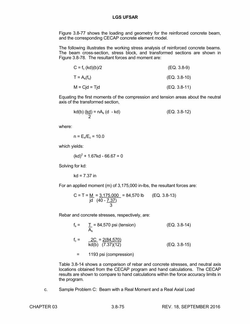
LGS UFSAR
CHAPTER 03 3.8-75 REV. 18, SEPTEMBER 2016
Figure 3.8-77 shows the loading and geometry for the reinforced concrete beam, and the corresponding CECAP concrete element model.
The following illustrates the working stress analysis of reinforced concrete beams. The beam cross-section, stress block, and transformed sections are shown in Figure 3.8-78. The resultant forces and moment are:
C = fc (kd)(b)/2 (EQ. 3.8-9)
T = As(fs) (EQ. 3.8-10)
M = Cjd = Tjd (EQ. 3.8-11)
Equating the first moments of the compression and tension areas about the neutral axis of the transformed section,
kd(b) (kd) = nAs (d - kd) (EQ. 3.8-12)2
where:
n = Es/Ec = 10.0
which yields:
(kd)2 + 1.67kd - 66.67 = 0
Solving for kd:
kd = 7.37 in
For an applied moment (m) of 3,175,000 in-lbs, the resultant forces are:
C = T = M = 3,175,000 = 84,570 lb (EQ. 3.8-13)jd (40 - 7.37) 3
Rebar and concrete stresses, respectively, are:
fs = T = 84,570 psi (tension) (EQ. 3.8-14)As
fc = 2C = 2(84,570) kd(b) (7.37)(12) (EQ. 3.8-15)
= 1193 psi (compression)
Table 3.8-14 shows a comparison of rebar and concrete stresses, and neutral axis locations obtained from the CECAP program and hand calculations. The CECAP results are shown to compare to hand calculations within the force accuracy limits in the program.
c. Sample Problem C: Beam with a Real Moment and a Real Axial Load
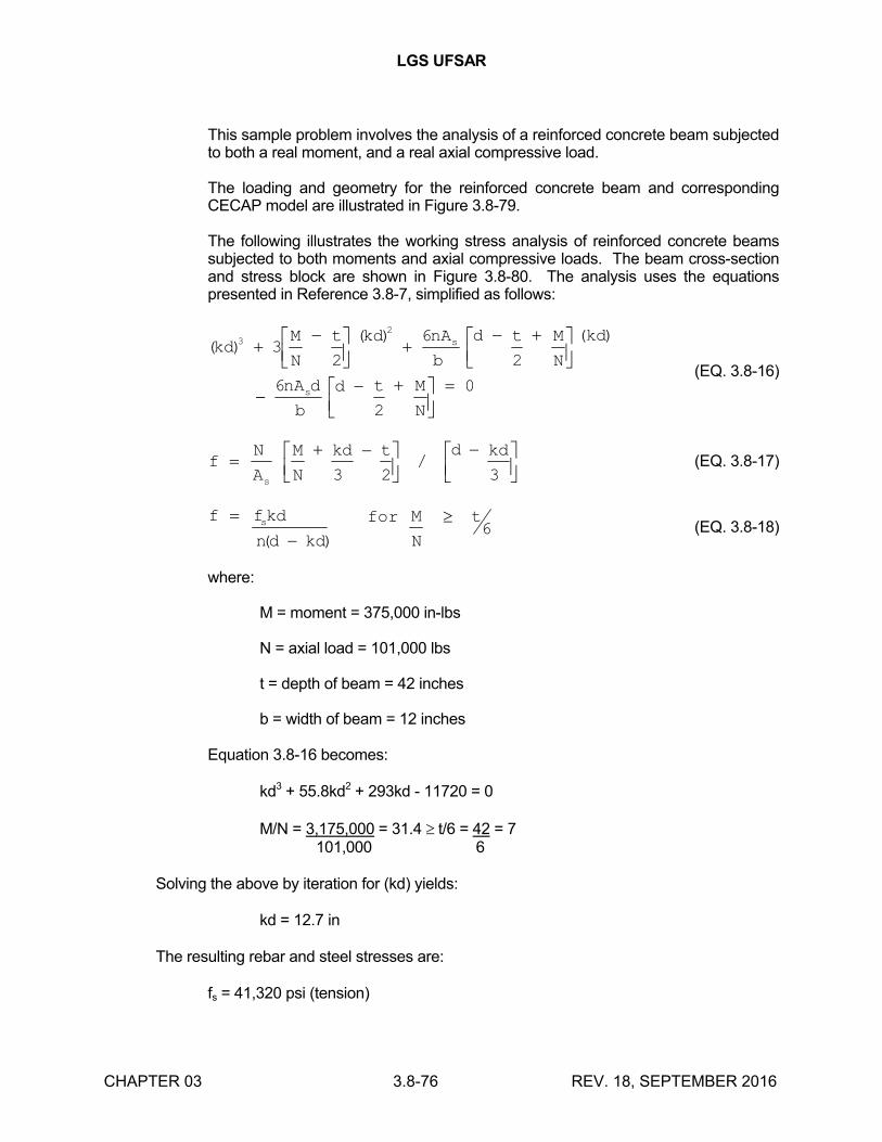
LGS UFSAR
CHAPTER 03 3.8-76 REV. 18, SEPTEMBER 2016
This sample problem involves the analysis of a reinforced concrete beam subjected to both a real moment, and a real axial compressive load.
The loading and geometry for the reinforced concrete beam and corresponding CECAP model are illustrated in Figure 3.8-79.
The following illustrates the working stress analysis of reinforced concrete beams subjected to both moments and axial compressive loads. The beam cross-section and stress block are shown in Figure 3.8-80. The analysis uses the equations presented in Reference 3.8-7, simplified as follows:
( )( ) ( )
kdM
N
t kd nA
b
d t M
N
kd
nA d
b
d t M
N
s
s
32
32
6
2
6
2
0
(EQ. 3.8-16)
fN
A
M
N
kd t d kd
s
3 2 3/ (EQ. 3.8-17)
f fkd
nd kd
for M
N
ts
( )6 (EQ. 3.8-18)
where:
M = moment = 375,000 in-lbs
N = axial load = 101,000 lbs
t = depth of beam = 42 inches
b = width of beam = 12 inches
Equation 3.8-16 becomes:
kd3 + 55.8kd2 + 293kd - 11720 = 0
M/N = 3,175,000 = 31.4 t/6 = 42 = 7101,000 6
Solving the above by iteration for (kd) yields:
kd = 12.7 in
The resulting rebar and steel stresses are:
fs = 41,320 psi (tension)
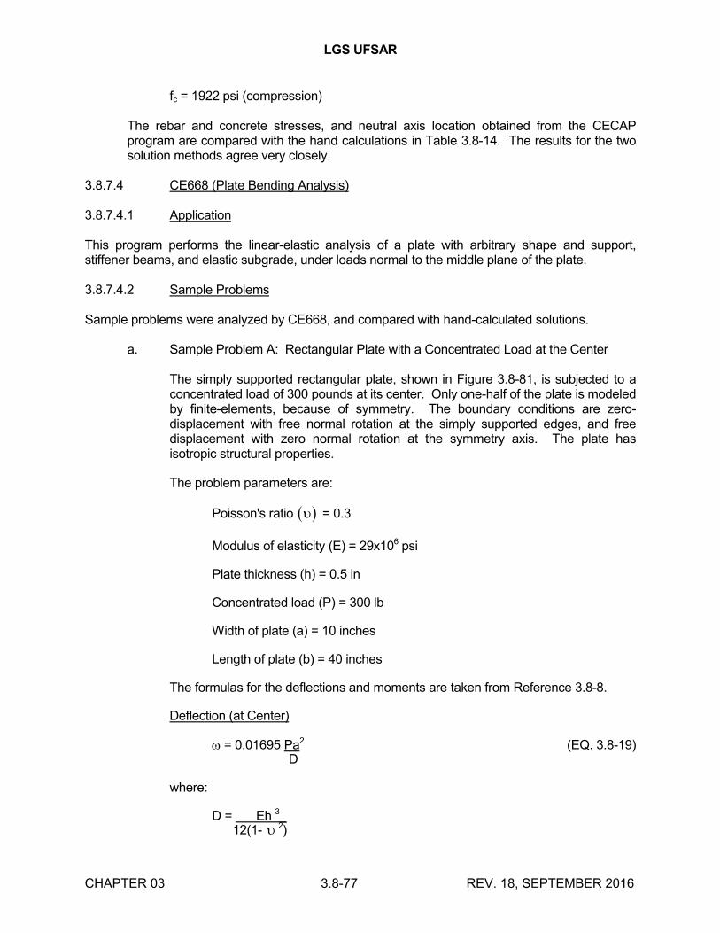
LGS UFSAR
CHAPTER 03 3.8-77 REV. 18, SEPTEMBER 2016
fc = 1922 psi (compression)
The rebar and concrete stresses, and neutral axis location obtained from the CECAP program are compared with the hand calculations in Table 3.8-14. The results for the two solution methods agree very closely.
3.8.7.4 CE668 (Plate Bending Analysis)
3.8.7.4.1 Application
This program performs the linear-elastic analysis of a plate with arbitrary shape and support, stiffener beams, and elastic subgrade, under loads normal to the middle plane of the plate.
3.8.7.4.2 Sample Problems
Sample problems were analyzed by CE668, and compared with hand-calculated solutions.
a. Sample Problem A: Rectangular Plate with a Concentrated Load at the Center
The simply supported rectangular plate, shown in Figure 3.8-81, is subjected to a concentrated load of 300 pounds at its center. Only one-half of the plate is modeled by finite-elements, because of symmetry. The boundary conditions are zero-displacement with free normal rotation at the simply supported edges, and free displacement with zero normal rotation at the symmetry axis. The plate has isotropic structural properties.
The problem parameters are:
Poisson's ratio = 0.3
Modulus of elasticity (E) = 29x106 psi
Plate thickness (h) = 0.5 in
Concentrated load (P) = 300 lb
Width of plate (a) = 10 inches
Length of plate (b) = 40 inches
The formulas for the deflections and moments are taken from Reference 3.8-8.
Deflection (at Center)
= 0.01695 Pa2 (EQ. 3.8-19) D
where:
D = Eh 3_ 12(1- 2)
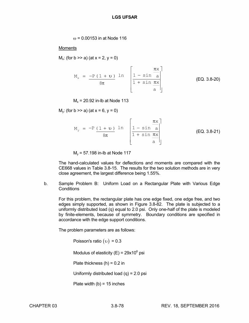
LGS UFSAR
CHAPTER 03 3.8-78 REV. 18, SEPTEMBER 2016
= 0.00153 in at Node 116
Moments
Mx: (for b >> a) (at x = 2, y = 0)
M P
x
a
x
a
x
( ) ln sin
sin
1
8
1
1
(EQ. 3.8-20)
Mx = 20.92 in-lb at Node 113
My: (for b >> a) (at x = 6, y = 0)
M P
x
a
x
a
y
( ) ln sin
sin
1
8
1
1
(EQ. 3.8-21)
My = 57.198 in-lb at Node 117
The hand-calculated values for deflections and moments are compared with the CE668 values in Table 3.8-15. The results for the two solution methods are in very close agreement, the largest difference being 1.55%.
b. Sample Problem B: Uniform Load on a Rectangular Plate with Various Edge Conditions
For this problem, the rectangular plate has one edge fixed, one edge free, and two edges simply supported, as shown in Figure 3.8-82. The plate is subjected to a uniformly distributed load (q) equal to 2.0 psi. Only one-half of the plate is modeled by finite-elements, because of symmetry. Boundary conditions are specified in accordance with the edge support conditions.
The problem parameters are as follows:
Poisson's ratio = 0.3
Modulus of elasticity (E) = 29x106 psi
Plate thickness (h) = 0.2 in
Uniformly distributed load (q) = 2.0 psi
Plate width (b) = 15 inches
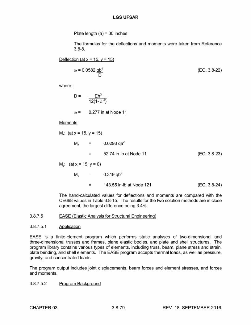
LGS UFSAR
CHAPTER 03 3.8-79 REV. 18, SEPTEMBER 2016
Plate length (a) = 30 inches
The formulas for the deflections and moments were taken from Reference 3.8-8.
Deflection (at x = 15, y = 15)
= 0.0582 qb4 (EQ. 3.8-22) D
where:
D = Eh3__12(1- 2)
= 0.277 in at Node 11
Moments
Mx: (at x = 15, y = 15)
Mx = 0.0293 qa2
= 52.74 in-lb at Node 11 (EQ. 3.8-23)
My: (at x = 15, y = 0)
My = 0.319 qb2
= 143.55 in-lb at Node 121 (EQ. 3.8-24)
The hand-calculated values for deflections and moments are compared with the CE668 values in Table 3.8-15. The results for the two solution methods are in close agreement, the largest difference being 3.4%.
3.8.7.5 EASE (Elastic Analysis for Structural Engineering)
3.8.7.5.1 Application
EASE is a finite-element program which performs static analyses of two-dimensional and three-dimensional trusses and frames, plane elastic bodies, and plate and shell structures. The program library contains various types of elements, including truss, beam, plane stress and strain, plate bending, and shell elements. The EASE program accepts thermal loads, as well as pressure, gravity, and concentrated loads.
The program output includes joint displacements, beam forces and element stresses, and forces and moments.
3.8.7.5.2 Program Background
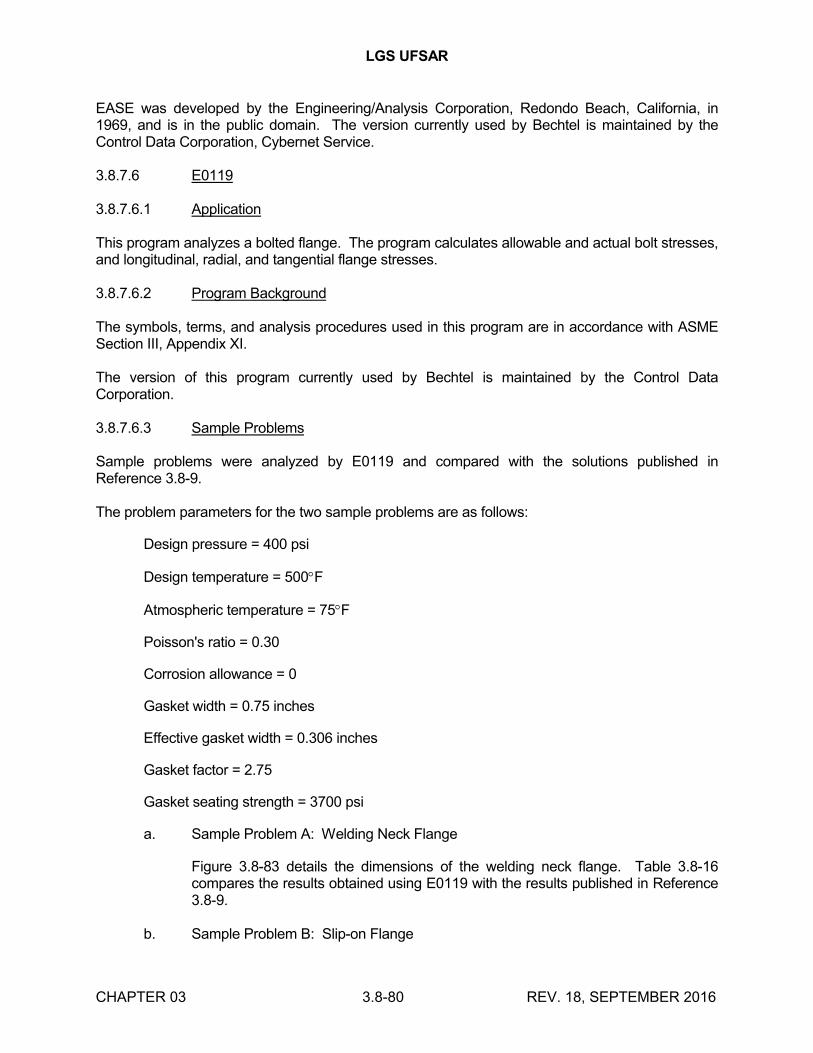
LGS UFSAR
CHAPTER 03 3.8-80 REV. 18, SEPTEMBER 2016
EASE was developed by the Engineering/Analysis Corporation, Redondo Beach, California, in 1969, and is in the public domain. The version currently used by Bechtel is maintained by the Control Data Corporation, Cybernet Service.
3.8.7.6 E0119
3.8.7.6.1 Application
This program analyzes a bolted flange. The program calculates allowable and actual bolt stresses, and longitudinal, radial, and tangential flange stresses.
3.8.7.6.2 Program Background
The symbols, terms, and analysis procedures used in this program are in accordance with ASME Section III, Appendix XI.
The version of this program currently used by Bechtel is maintained by the Control Data Corporation.
3.8.7.6.3 Sample Problems
Sample problems were analyzed by E0119 and compared with the solutions published in Reference 3.8-9.
The problem parameters for the two sample problems are as follows:
Design pressure = 400 psi
Design temperature = 500F
Atmospheric temperature = 75F
Poisson's ratio = 0.30
Corrosion allowance = 0
Gasket width = 0.75 inches
Effective gasket width = 0.306 inches
Gasket factor = 2.75
Gasket seating strength = 3700 psi
a. Sample Problem A: Welding Neck Flange
Figure 3.8-83 details the dimensions of the welding neck flange. Table 3.8-16 compares the results obtained using E0119 with the results published in Reference 3.8-9.
b. Sample Problem B: Slip-on Flange
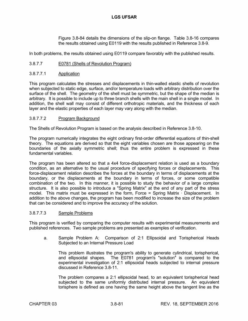
LGS UFSAR
CHAPTER 03 3.8-81 REV. 18, SEPTEMBER 2016
Figure 3.8-84 details the dimensions of the slip-on flange. Table 3.8-16 compares the results obtained using E0119 with the results published in Reference 3.8-9.
In both problems, the results obtained using E0119 compare favorably with the published results.
3.8.7.7 E0781 (Shells of Revolution Program)
3.8.7.7.1 Application
This program calculates the stresses and displacements in thin-walled elastic shells of revolution when subjected to static edge, surface, and/or temperature loads with arbitrary distribution over the surface of the shell. The geometry of the shell must be symmetric, but the shape of the median is arbitrary. It is possible to include up to three branch shells with the main shell in a single model. In addition, the shell wall may consist of different orthotropic materials, and the thickness of each layer and the elastic properties of each layer may vary along with the median.
3.8.7.7.2 Program Background
The Shells of Revolution Program is based on the analysis described in Reference 3.8-10.
The program numerically integrates the eight ordinary first-order differential equations of thin-shell theory. The equations are derived so that the eight variables chosen are those appearing on the boundaries of the axially symmetric shell; thus the entire problem is expressed in these fundamental variables.
The program has been altered so that a 4x4 force-displacement relation is used as a boundary condition, as an alternative to the usual procedure of specifying forces or displacements. This force-displacement relation describes the forces at the boundary in terms of displacements at the boundary, or the displacements at the boundary in terms of forces, or some compatible combination of the two. In this manner, it is possible to study the behavior of a large complex structure. It is also possible to introduce a "Spring Matrix" at the end of any part of the stress model. This matrix must be expressed in the form, Force = Spring Matrix · Displacement. In addition to the above changes, the program has been modified to increase the size of the problem that can be considered and to improve the accuracy of the solution.
3.8.7.7.3 Sample Problems
This program is verified by comparing the computer results with experimental measurements and published references. Two sample problems are presented as examples of verification.
a. Sample Problem A: Comparison of 2:1 Ellipsoidal and Torispherical Heads Subjected to an Internal Pressure Load
This problem illustrates the program's ability to generate cylindrical, torispherical, and ellipsoidal shapes. The E0781 program's "solution" is compared to the experimental investigation of 2:1 ellipsoidal heads subjected to internal pressure discussed in Reference 3.8-11.
The problem compares a 2:1 ellipsoidal head, to an equivalent torispherical head subjected to the same uniformly distributed internal pressure. An equivalent torisphere is defined as one having the same height above the tangent line as the
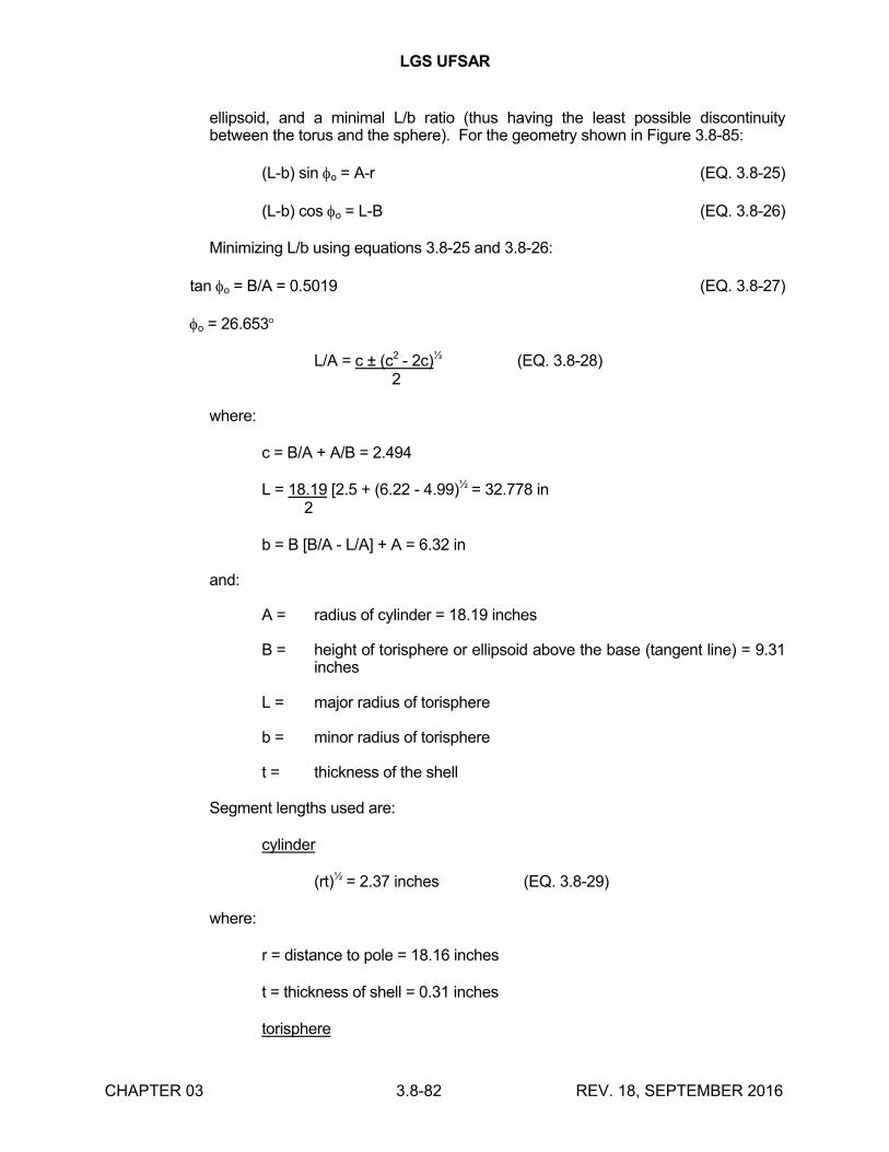
LGS UFSAR
CHAPTER 03 3.8-82 REV. 18, SEPTEMBER 2016
ellipsoid, and a minimal L/b ratio (thus having the least possible discontinuity between the torus and the sphere). For the geometry shown in Figure 3.8-85:
(L-b) sin o = A-r (EQ. 3.8-25)
(L-b) cos o = L-B (EQ. 3.8-26)
Minimizing L/b using equations 3.8-25 and 3.8-26:
tan o = B/A = 0.5019 (EQ. 3.8-27)
o = 26.653
L/A = c ± (c2 - 2c)½ (EQ. 3.8-28) 2
where:
c = B/A + A/B = 2.494
L = 18.19 [2.5 + (6.22 - 4.99)½ = 32.778 in 2
b = B [B/A - L/A] + A = 6.32 in
and:
A = radius of cylinder = 18.19 inches
B = height of torisphere or ellipsoid above the base (tangent line) = 9.31 inches
L = major radius of torisphere
b = minor radius of torisphere
t = thickness of the shell
Segment lengths used are:
cylinder
(rt)½ = 2.37 inches (EQ. 3.8-29)
where:
r = distance to pole = 18.16 inches
t = thickness of shell = 0.31 inches
torisphere
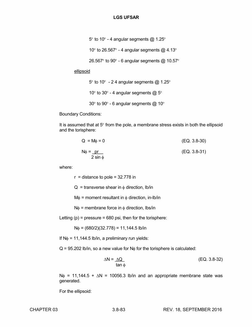
LGS UFSAR
CHAPTER 03 3.8-83 REV. 18, SEPTEMBER 2016
5 to 10 - 4 angular segments @ 1.25
10 to 26.567 - 4 angular segments @ 4.13
26.567 to 90 - 6 angular segments @ 10.57
ellipsoid
5 to 10 - 2 4 angular segments @ 1.25
10 to 30 - 4 angular segments @ 5
30 to 90- 6 angular segments @ 10
Boundary Conditions:
It is assumed that at 5 from the pole, a membrane stress exists in both the ellipsoid and the torisphere:
Q = M = 0 (EQ. 3.8-30)
N = pr (EQ. 3.8-31) 2 sin
where:
r = distance to pole = 32.778 in
Q = transverse shear in direction, lb/in
M = moment resultant in direction, in-lb/in
N = membrane force in direction, lbs/in
Letting (p) = pressure = 680 psi, then for the torisphere:
N = (680/2)(32.778) = 11,144.5 lb/in
If N = 11,144.5 lb/in, a preliminary run yields:
Q = 95.202 lb/in, so a new value for N for the torisphere is calculated:
N = Q (EQ. 3.8-32) tan
N = 11,144.5 + N = 10056.3 lb/in and an appropriate membrane state was generated.
For the ellipsoid:
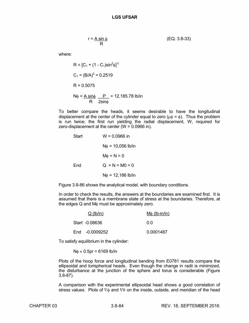
LGS UFSAR
CHAPTER 03 3.8-84 REV. 18, SEPTEMBER 2016
r = A sin (EQ. 3.8-33) R
where:
R = [C1 + (1 - C1)sin2]½
C1 = (B/A)2 = 0.2519
R = 0.5075
N = A sin P = 12,185.78 lb/inR 2sin
To better compare the heads, it seems desirable to have the longitudinal displacement at the center of the cylinder equal to zero ( = ). Thus the problem is run twice; the first run yielding the radial displacement, W, required for zero-displacement at the center (W = 0.0966 in).
Start W = 0.0966 in
N = 10,056 lb/in
M = N = 0
End Q = N = M0 = 0
N = 12,186 lb/in
Figure 3.8-86 shows the analytical model, with boundary conditions.
In order to check the results, the answers at the boundaries are examined first. It is assumed that there is a membrane state of stress at the boundaries. Therefore, at the edges Q and M must be approximately zero.
Q (lb/in) M (lb-in/in)
Start -0.08636 0.0
End -0.0009252 0.0001487
To satisfy equilibrium in the cylinder:
N 0.5pr = 6169 lb/in
Plots of the hoop force and longitudinal bending from E0781 results compare the ellipsoidal and torispherical heads. Even though the change in radii is minimized, the disturbance at the junction of the sphere and torus is considerable (Figure 3.8-87).
A comparison with the experimental ellipsoidal head shows a good correlation of stress values. Plots of and on the inside, outside, and meridian of the head
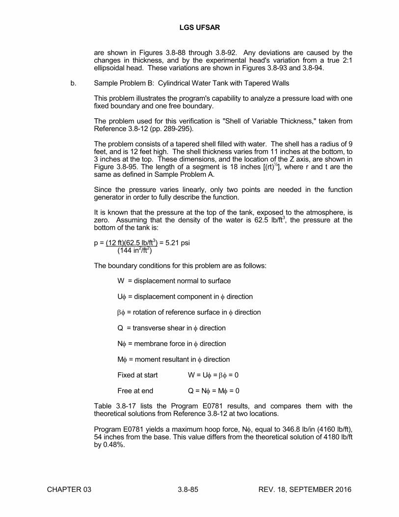
LGS UFSAR
CHAPTER 03 3.8-85 REV. 18, SEPTEMBER 2016
are shown in Figures 3.8-88 through 3.8-92. Any deviations are caused by the changes in thickness, and by the experimental head's variation from a true 2:1 ellipsoidal head. These variations are shown in Figures 3.8-93 and 3.8-94.
b. Sample Problem B: Cylindrical Water Tank with Tapered Walls
This problem illustrates the program's capability to analyze a pressure load with one fixed boundary and one free boundary.
The problem used for this verification is "Shell of Variable Thickness," taken from Reference 3.8-12 (pp. 289-295).
The problem consists of a tapered shell filled with water. The shell has a radius of 9 feet, and is 12 feet high. The shell thickness varies from 11 inches at the bottom, to 3 inches at the top. These dimensions, and the location of the Z axis, are shown in Figure 3.8-95. The length of a segment is 18 inches [(rt)½], where r and t are the same as defined in Sample Problem A.
Since the pressure varies linearly, only two points are needed in the function generator in order to fully describe the function.
It is known that the pressure at the top of the tank, exposed to the atmosphere, is zero. Assuming that the density of the water is 62.5 lb/ft3, the pressure at the bottom of the tank is:
p = (12 ft)(62.5 lb/ft3) = 5.21 psi(144 in2/ft2)
The boundary conditions for this problem are as follows:
W = displacement normal to surface
U = displacement component in direction
= rotation of reference surface in direction
Q = transverse shear in direction
N = membrane force in direction
M = moment resultant in direction
Fixed at start W = U = = 0
Free at end Q = N = M = 0
Table 3.8-17 lists the Program E0781 results, and compares them with the theoretical solutions from Reference 3.8-12 at two locations.
Program E0781 yields a maximum hoop force, N, equal to 346.8 lb/in (4160 lb/ft), 54 inches from the base. This value differs from the theoretical solution of 4180 lb/ft by 0.48%.
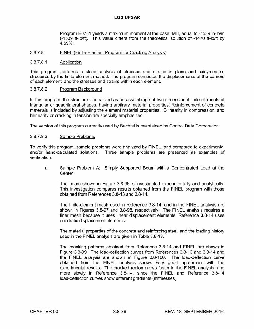
LGS UFSAR
CHAPTER 03 3.8-86 REV. 18, SEPTEMBER 2016
Program E0781 yields a maximum moment at the base, M�, equal to -1539 in-lb/in (-1539 ft-lb/ft). This value differs from the theoretical solution of -1470 ft-lb/ft by 4.69%.
3.8.7.8 FINEL (Finite-Element Program for Cracking Analysis)
3.8.7.8.1 Application
This program performs a static analysis of stresses and strains in plane and axisymmetric structures by the finite-element method. The program computes the displacements of the corners of each element, and the stresses and strains within each element.
3.8.7.8.2 Program Background
In this program, the structure is idealized as an assemblage of two-dimensional finite-elements of triangular or quadrilateral shapes, having arbitrary material properties. Reinforcement of concrete materials is included by adjusting the element material properties. Bilinearity in compression, and bilinearity or cracking in tension are specially emphasized.
The version of this program currently used by Bechtel is maintained by Control Data Corporation.
3.8.7.8.3 Sample Problems
To verify this program, sample problems were analyzed by FINEL, and compared to experimental and/or hand-calculated solutions. Three sample problems are presented as examples of verification.
a. Sample Problem A: Simply Supported Beam with a Concentrated Load at the Center
The beam shown in Figure 3.8-96 is investigated experimentally and analytically. This investigation compares results obtained from the FINEL program with those obtained from References 3.8-13 and 3.8-14.
The finite-element mesh used in Reference 3.8-14, and in the FINEL analysis are shown in Figures 3.8-97 and 3.8-98, respectively. The FINEL analysis requires a finer mesh because it uses linear displacement elements. Reference 3.8-14 uses quadratic displacement elements.
The material properties of the concrete and reinforcing steel, and the loading history used in the FINEL analysis are given in Table 3.8-18.
The cracking patterns obtained from Reference 3.8-14 and FINEL are shown in Figure 3.8-99. The load-deflection curves from References 3.8-13 and 3.8-14 and the FINEL analysis are shown in Figure 3.8-100. The load-deflection curve obtained from the FINEL analysis shows very good agreement with the experimental results. The cracked region grows faster in the FINEL analysis, and more slowly in Reference 3.8-14, since the FINEL and Reference 3.8-14 load-deflection curves show different gradients (stiffnesses).
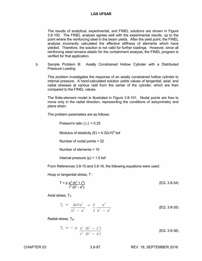
LGS UFSAR
CHAPTER 03 3.8-87 REV. 18, SEPTEMBER 2016
The results of analytical, experimental, and FINEL solutions are shown in Figure 3.8-100. The FINEL analysis agrees well with the experimental results, up to the point where the reinforcing steel in the beam yields. After the yield point, the FINEL analysis incorrectly calculated the effective stiffness of elements which have yielded. Therefore, the solution is not valid for further loadings. However, since all reinforcing steel remains elastic for the containment analysis, the FINEL program is verified for that application.
b. Sample Problem B: Axially Constrained Hollow Cylinder with a Distributed Pressure Loading
This problem investigates the response of an axially constrained hollow cylinder to internal pressure. A hand-calculated solution yields values of tangential, axial, and radial stresses at various radii from the center of the cylinder, which are then compared to the FINEL values.
The finite-element model is illustrated in Figure 3.8-101. Nodal points are free to move only in the radial direction, representing the conditions of axisymmetry and plane strain.
The problem parameters are as follows:
Poisson's ratio = 0.25
Modulus of elasticity (E) = 4.32x10⁵ ksf
Number of nodal points = 22
Number of elements = 10
Internal pressure (p) = 1.0 ksf
From References 3.8-15 and 3.8-16, the following equations were used:
Hoop or tangential stress, T :
T = p a2 (b2 + r2) (EQ. 3.8-34) r2 (b2 - a2)
Axial stress, T2:
T Pa
b a
P a
b a
22
2 2
2
2 2
2
2
(EQ. 3.8-35)
Radial stress, TR:
T p a b r
r b a
R
2 2 2
2 2 2
( )
( )(EQ. 3.8-36)
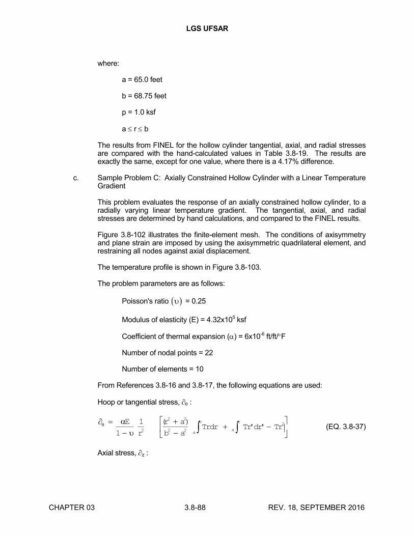
LGS UFSAR
CHAPTER 03 3.8-88 REV. 18, SEPTEMBER 2016
where:
a = 65.0 feet
b = 68.75 feet
p = 1.0 ksf
a r b
The results from FINEL for the hollow cylinder tangential, axial, and radial stresses are compared with the hand-calculated values in Table 3.8-19. The results are exactly the same, except for one value, where there is a 4.17% difference.
c. Sample Problem C: Axially Constrained Hollow Cylinder with a Linear Temperature Gradient
This problem evaluates the response of an axially constrained hollow cylinder, to a radially varying linear temperature gradient. The tangential, axial, and radial stresses are determined by hand calculations, and compared to the FINEL results.
Figure 3.8-102 illustrates the finite-element mesh. The conditions of axisymmetry and plane strain are imposed by using the axisymmetric quadrilateral element, and restraining all nodes against axial displacement.
The temperature profile is shown in Figure 3.8-103.
The problem parameters are as follows:
Poisson's ratio = 0.25
Modulus of elasticity (E) = 4.32x10⁵ ksf
Coefficient of thermal expansion () = 6x10⁻⁶ ft/ft/F
Number of nodal points = 22
Number of elements = 10
From References 3.8-16 and 3.8-17, the following equations are used:
Hoop or tangential stress, :
E
r
r a
b aTrdr Tr dr Tr
a
b
a
r
1
12
2 2
2 2
2( )' ' (EQ. 3.8-37)
Axial stress, z :
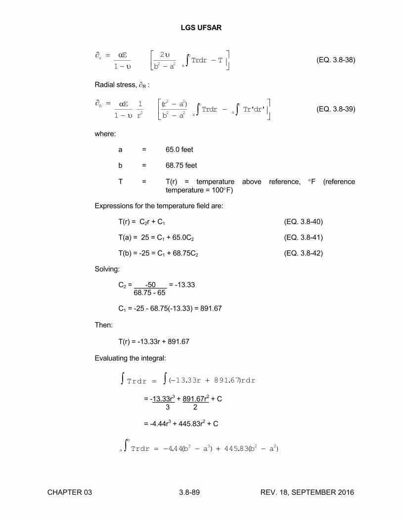
LGS UFSAR
CHAPTER 03 3.8-89 REV. 18, SEPTEMBER 2016
z
a
bE
b aTrdr T
1
22 2
(EQ. 3.8-38)
Radial stress, R :
R
a
b
a
rE
r
r a
b aTrdr Tr dr
1
12
2 2
2 2
( )' ' (EQ. 3.8-39)
where:
a = 65.0 feet
b = 68.75 feet
T = T(r) = temperature above reference, F (reference temperature = 100F)
Expressions for the temperature field are:
T(r) = C2r + C1 (EQ. 3.8-40)
T(a) = 25 = C1 + 65.0C2 (EQ. 3.8-41)
T(b) = -25 = C1 + 68.75C2 (EQ. 3.8-42)
Solving:
C2 = -50 = -13.33 68.75 - 65
C1 = -25 - 68.75(-13.33) = 891.67
Then:
T(r) = -13.33r + 891.67
Evaluating the integral:
Trdr r rdr ( . . )13 33 89167
= -13.33r3 + 891.67r2 + C3 2
= -4.44r3 + 445.83r2 + C
a
b
Trdr b a b a 444 445833 3 2 2. ( ) . ( )
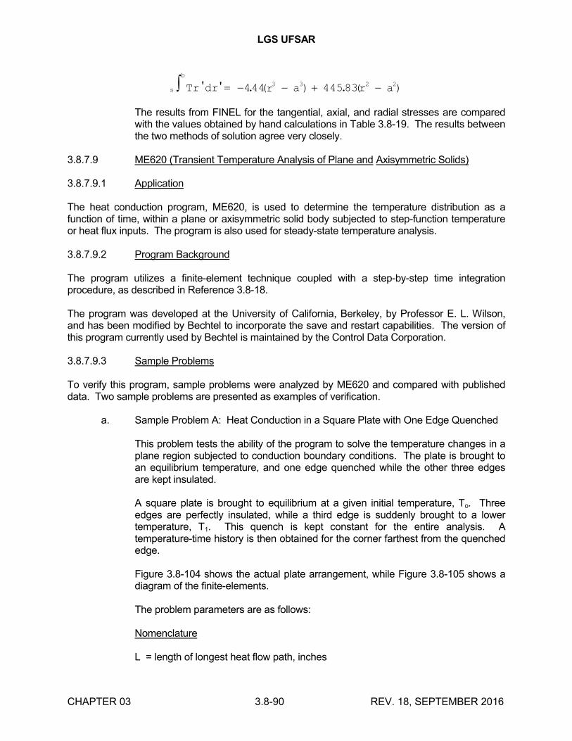
LGS UFSAR
CHAPTER 03 3.8-90 REV. 18, SEPTEMBER 2016
s
b
Tr dr r a r a' ' . ( ) . ( ) 444 445833 3 2 2
The results from FINEL for the tangential, axial, and radial stresses are compared with the values obtained by hand calculations in Table 3.8-19. The results between the two methods of solution agree very closely.
3.8.7.9 ME620 (Transient Temperature Analysis of Plane and Axisymmetric Solids)
3.8.7.9.1 Application
The heat conduction program, ME620, is used to determine the temperature distribution as a function of time, within a plane or axisymmetric solid body subjected to step-function temperature or heat flux inputs. The program is also used for steady-state temperature analysis.
3.8.7.9.2 Program Background
The program utilizes a finite-element technique coupled with a step-by-step time integration procedure, as described in Reference 3.8-18.
The program was developed at the University of California, Berkeley, by Professor E. L. Wilson, and has been modified by Bechtel to incorporate the save and restart capabilities. The version of this program currently used by Bechtel is maintained by the Control Data Corporation.
3.8.7.9.3 Sample Problems
To verify this program, sample problems were analyzed by ME620 and compared with published data. Two sample problems are presented as examples of verification.
a. Sample Problem A: Heat Conduction in a Square Plate with One Edge Quenched
This problem tests the ability of the program to solve the temperature changes in a plane region subjected to conduction boundary conditions. The plate is brought to an equilibrium temperature, and one edge quenched while the other three edges are kept insulated.
A square plate is brought to equilibrium at a given initial temperature, To. Three edges are perfectly insulated, while a third edge is suddenly brought to a lower temperature, T1. This quench is kept constant for the entire analysis. A temperature-time history is then obtained for the corner farthest from the quenched edge.
Figure 3.8-104 shows the actual plate arrangement, while Figure 3.8-105 shows a diagram of the finite-elements.
The problem parameters are as follows:
Nomenclature
L = length of longest heat flow path, inches
LGS UFSAR
CHAPTER 03 3.8-91 REV. 18, SEPTEMBER 2016
To = initial temperature of plate, F
T1 = quenching temperature of edge, F
Data
The plate is 10 inches square
To = 100F
T1 = 0F
Diffusivity = 1.0 in2/sec (chosen for convenience)
Time increment (T) = 1 second for numerical solution
At any time, t, during the transient state, the time factor T (or characteristic time) is given by:
T = t/L2
The time to reach steady-state is given when T = 1.0; hence the transient time is t = L2/ = 100 seconds. The results derived from Reference 3.8-19 are plotted in Figure 3.8-106.
The temperature variation at point A is plotted in Figure 3.8-106 according to the results of ME620, and is compared with the theoretical transient change. The curves are seen to agree quite well. Deviations are due to the selected finite-element mesh size, and to the selected time step for the analysis.
b. Sample Problem B: Heat Conduction in a Surface Quenched Sphere
This problem tests the ability of ME620 to analyze the temperature distribution in an axisymmetric solid, with given temperature boundary conditions. The results of the program analysis are compared to a closed-form solution derived from Reference 3.8-20.
This problem considers a solid steel sphere (shown in Figure 3.8-107) which is brought to an equilibrium temperature, and suddenly quenched to a lower uniform temperature on its surface. The quenching environment is held at a constant temperature. A temperature-time history for three seconds is obtained from the program for all node points. The points used for the comparison are at a radius of 0.2 inches; only one time period is checked. The finite-element model is shown in Figure 3.8-108.
The problem parameters are as follows:
Nomenclature
LGS UFSAR
CHAPTER 03 3.8-92 REV. 18, SEPTEMBER 2016
L = length of the longest heat flow path (radius of sphere), inches
To = initial temperature of sphere, F
T1 = quenching temperature of outer surface, F
Data
Radius of sphere (R) = 0.59 inches
To = 1472F
T1 = 68F
Conductivity = 6.02x10⁻⁴ Btu/(in-sec-F)
Diffusivity () = 0.0193 in2/sec
Specific heat = 0.11 Btu/(lb-F)
Density (p) = 0.284 lb/in3
Time increment = 0.2 sec
At any time, t, during the transient state, the time factor T (or characteristic time) is given by:
T = t/L2
The time to reach steady-state is given when T = 1.0; hence the transient time is t = L2/ = 3.0 seconds.
The result from Reference 3.8-20 for the temperature at a radius of 0.2 inches and at time t = 1.8 seconds, is 933.8F. The result obtained from ME620 is 923.4F. The difference between these two values is 1.1%.
3.8.7.10 ANSYS
3.8.7.10.1 Application
The ANSYS engineering analysis system computer program is a large-scale general purpose computer program employing finite-element technology for the solution of several classes of engineering analysis problems. Analysis capabilities include static and dynamic; plastic, creep, and swelling; small and large deflections; steady-state and transient heat transfer; and steady-state fluid flow. A variety of finite-elements are available for use in the program. Structural loadings may be forces, displacements, pressures, temperatures, or response spectra. The program output includes joint displacements, element stresses, forces, and moments.
LGS UFSAR
CHAPTER 03 3.8-93 REV. 18, SEPTEMBER 2016
3.8.7.10.2 Program Background
ANSYS was developed by Swanson Analysis Systems, Inc, and is in the public domain. The version of the program currently used by Bechtel is maintained by the Control Data Corporation, Cybernet Service. Version 5.0 was used to evaluate the Spent Fuel Pool for increase storage capacity. This evaluation was performed by Gilbert/Commonwealth and Version 5.0 is maintained by Gilbert/Commonwealth.
3.8.7.11 IMAGES 3D
3.8.7.11.1 Application
The IMAGES 3D computer program is a three-dimensional general purpose finite element program for use on an IBM-compatible personal computer. Analysis capabilities include static, modal, and dynamic analysis of structures composed of frame, plates, shell and solid elements. Structural loadings may be forces, displacements, pressures, temperatures, response spectra, or time history. The program output includes joint displacements, element stresses, forces and moments. It also calculates natural frequencies and mode shapes.
3.8.7.11.2 Program Background
IMAGES 3D was developed by Celestial Software, which is a division of Robert L. Cloud & Associates. The program is in the public domain. Version 3.0 of the program is currently used by the licensee. The documentation package for IMAGES 3D includes a verification manual which documents a series of test problems that demonstrates that the results from IMAGES 3D are similar to those results of other public domain programs or classical solutions.
3.8.8 REFERENCES
3.8-1 General Electric Co., "Mark II Containment Dynamic Forcing Functions Information Report", (NEDO-21061) Rev 4.
3.8-2 INTENTIONALLY LEFT BLANK
3.8-3 Bechtel Power Corporation, "Containment Building Liner Plate Design Report," Topical Report BC-TOP-1, Rev 1, (December 1972).
3.8-4 E. L. Wilson, "SAP; A General Structural Engineering Program", Report No. UCSESM 70-20, Structures and Materials Research, Department of Civil Engineering, University of California at Berkeley, (September 1970).
3.8-5 H. Kraus, "Thin Elastic Shells", John Wiley, (1967), p. 136, (1967).
3.8-6 B. Budiansky and P. P. Radkowski, "Numerical Analysis of Unsymmetric Bending of Shells of Revolution", AIAA Journal, Vol. 1, No. 8, (August 1963).
3.8-7 O. W. Blodgett, "Design of Welded Structures", The James F. Lincoln Arc Welding Foundation, pp. 3.3-8 to 3.3-10, (June 1966).
3.8-8 Timoshenko, "Theory of Plates And Shells", 2nd Edition, McGraw-Hill, pp. 208-2211, (1959).
3.8-9 Bulletin 502, "Modern Flange Design", Gulf and Western Manufacturing Company.
LGS UFSAR
CHAPTER 03 3.8-94 REV. 18, SEPTEMBER 2016
3.8-10 A. Kalnin, "Analysis of Shells of Revolution Subjected to Symmetrical and Non-Symmetrical Loads", Journal of Applied Mechanics, Vol. 31, (September 1964).
3.8-11 J. M. Horowitz and R. Henschel, "Experimental Investigation of 2:1 Ellipsoidal Heads Subjected to Internal Pressure (Volume One)", Progress Report January 17, 1974 to April 16, 1976, Foster Wheeler Energy Corp., for Welding Research Council.
3.8-12 W. Flugge, "Stresses in Shells", Springer-Verlag, New York, (1973).
3.8-13 Beam-Column Connections in Reinforced Concrete", Structural Research Series No. 234, Civil Engineering Studies, University of Illinois, Urbana-Champaign, Illinois, (January 1962).
3.8-14 M. Suidan and W. C. Schnobrich, "Finite-Element Analysis of Reinforced Concrete", Journal of the Structural Division, ASCE, Vol. 99, No. ST10, pp. 2109-2122, (October 1973).
3.8-15 R. J. Roark, "Formulas for Stress and Strain", McGraw-Hill, Fourth Edition, p. 308, (1965).
3.8-16 Timoshenko and Goodier, "Theory of Elasticity", Second Edition, McGraw-Hill, pp. 412 and 60, (1951).
3.8-17 Manson, "Thermal-Stress and Low Cycle Fatigue", McGraw-Hill, pp. 28-29, (1960).
3.8-18 E. L. Wilson and R. E. Nickell, "Application of the Finite-Element Method to Heat Conduction Analysis", Journal of Nuclear Engineering and Design, (1966).
3.8-19 V. S. Arpaci, "Conduction Heat Transfer", Addition-Wesley, (1966).
3.8-20 Ingersol, Zobel, Ingersol, "Heat Conduction With Engineering, Geological, and Other Applications", Maple Press Co., Inc., York, Pennsylvania, p. 165, (1954).
3.8-21 "Report on the Re-evaluation of Concrete Masonry Walls for the Limerick Generating Station, Units 1 and 2", Bechtel Power Corporation, (April 1982).
3.8-22 "Visual Weld Acceptance Criteria for Structural Welding at Nuclear Power Plants, NCIG-01", Nuclear Construction Issues Group, Revision 2, (May 7, 1985).
3.8-23 "Building Code Requirements for Concrete Masonry Structures", ACI 531 and ACI 531-R, American Concrete Institute, Detroit, (1979).
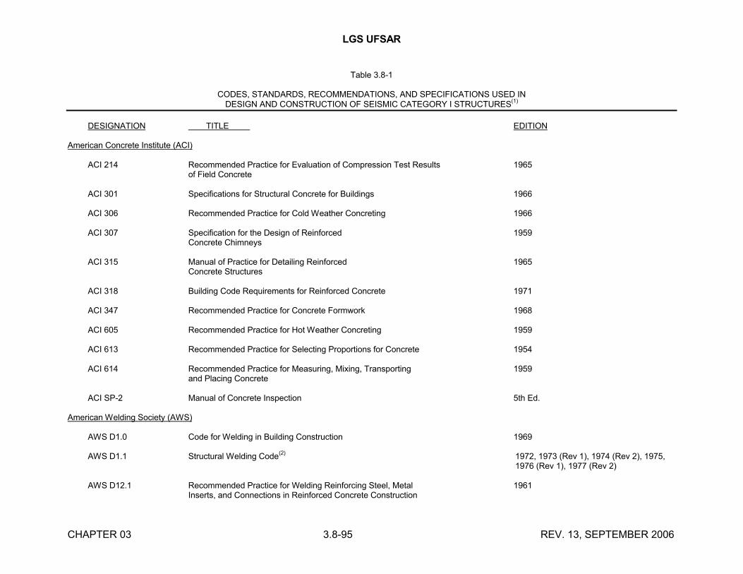
LGS UFSAR
CHAPTER 03 3.8-95 REV. 13, SEPTEMBER 2006
Table 3.8-1
CODES, STANDARDS, RECOMMENDATIONS, AND SPECIFICATIONS USED INDESIGN AND CONSTRUCTION OF SEISMIC CATEGORY I STRUCTURES
(1)
DESIGNATION TITLE EDITION
American Concrete Institute (ACI)
ACI 214 Recommended Practice for Evaluation of Compression Test Results 1965of Field Concrete
ACI 301 Specifications for Structural Concrete for Buildings 1966
ACI 306 Recommended Practice for Cold Weather Concreting 1966
ACI 307 Specification for the Design of Reinforced 1959Concrete Chimneys
ACI 315 Manual of Practice for Detailing Reinforced 1965Concrete Structures
ACI 318 Building Code Requirements for Reinforced Concrete 1971
ACI 347 Recommended Practice for Concrete Formwork 1968
ACI 605 Recommended Practice for Hot Weather Concreting 1959
ACI 613 Recommended Practice for Selecting Proportions for Concrete 1954
ACI 614 Recommended Practice for Measuring, Mixing, Transporting 1959and Placing Concrete
ACI SP-2 Manual of Concrete Inspection 5th Ed.
American Welding Society (AWS)
AWS D1.0 Code for Welding in Building Construction 1969
AWS D1.1 Structural Welding Code(2)
1972, 1973 (Rev 1), 1974 (Rev 2), 1975, 1976 (Rev 1), 1977 (Rev 2)
AWS D12.1 Recommended Practice for Welding Reinforcing Steel, Metal 1961Inserts, and Connections in Reinforced Concrete Construction
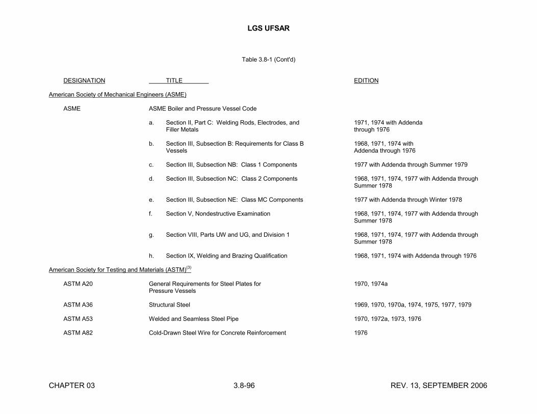
LGS UFSAR
CHAPTER 03 3.8-96 REV. 13, SEPTEMBER 2006
Table 3.8-1 (Cont'd)
DESIGNATION TITLE EDITION
American Society of Mechanical Engineers (ASME)
ASME ASME Boiler and Pressure Vessel Code
a. Section II, Part C: Welding Rods, Electrodes, and 1971, 1974 with AddendaFiller Metals through 1976
b. Section III, Subsection B: Requirements for Class B 1968, 1971, 1974 withVessels Addenda through 1976
c. Section III, Subsection NB: Class 1 Components 1977 with Addenda through Summer 1979
d. Section III, Subsection NC: Class 2 Components 1968, 1971, 1974, 1977 with Addenda through Summer 1978
e. Section III, Subsection NE: Class MC Components 1977 with Addenda through Winter 1978
f. Section V, Nondestructive Examination 1968, 1971, 1974, 1977 with Addenda through Summer 1978
g. Section VIII, Parts UW and UG, and Division 1 1968, 1971, 1974, 1977 with Addenda through Summer 1978
h. Section IX, Welding and Brazing Qualification 1968, 1971, 1974 with Addenda through 1976
American Society for Testing and Materials (ASTM)(3)
ASTM A20 General Requirements for Steel Plates for 1970, 1974aPressure Vessels
ASTM A36 Structural Steel 1969, 1970, 1970a, 1974, 1975, 1977, 1979
ASTM A53 Welded and Seamless Steel Pipe 1970, 1972a, 1973, 1976
ASTM A82 Cold-Drawn Steel Wire for Concrete Reinforcement 1976
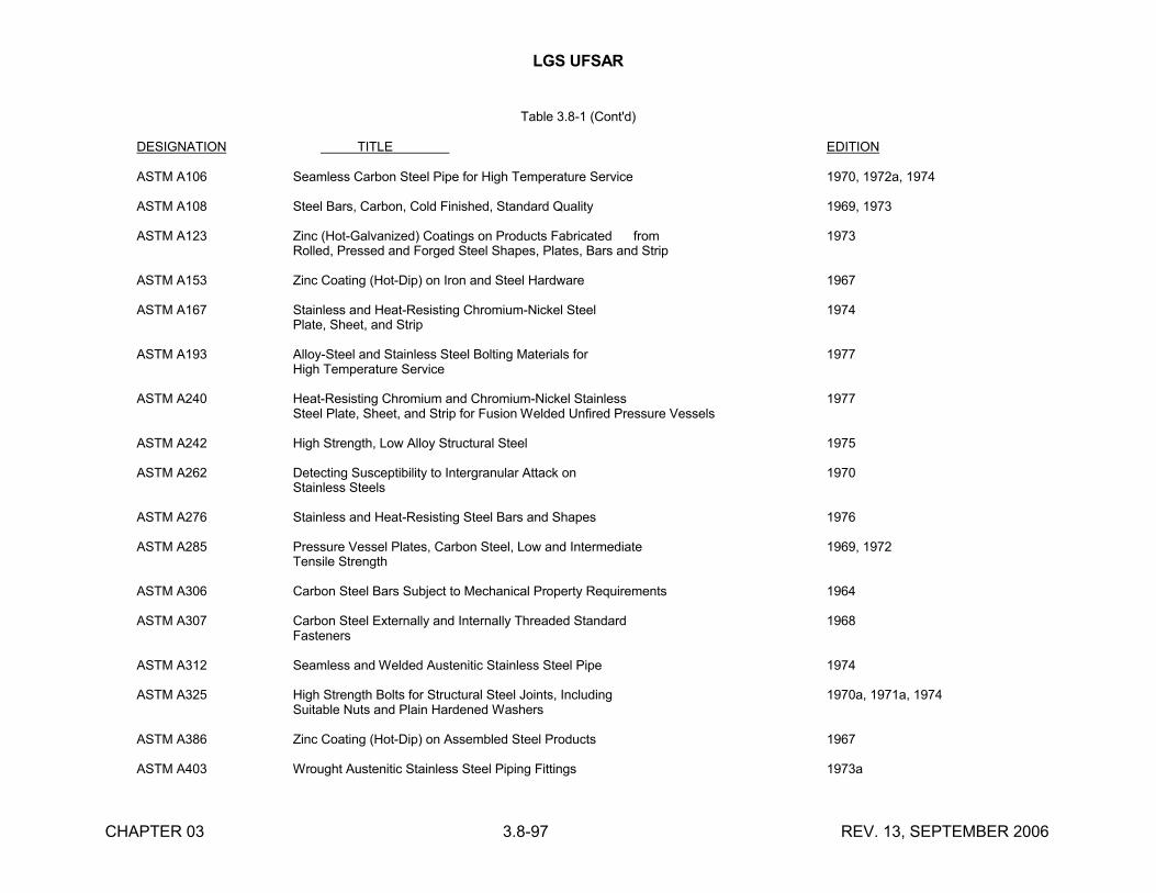
LGS UFSAR
CHAPTER 03 3.8-97 REV. 13, SEPTEMBER 2006
Table 3.8-1 (Cont'd)
DESIGNATION TITLE EDITION
ASTM A106 Seamless Carbon Steel Pipe for High Temperature Service 1970, 1972a, 1974
ASTM A108 Steel Bars, Carbon, Cold Finished, Standard Quality 1969, 1973
ASTM A123 Zinc (Hot-Galvanized) Coatings on Products Fabricated from 1973Rolled, Pressed and Forged Steel Shapes, Plates, Bars and Strip
ASTM A153 Zinc Coating (Hot-Dip) on Iron and Steel Hardware 1967
ASTM A167 Stainless and Heat-Resisting Chromium-Nickel Steel 1974Plate, Sheet, and Strip
ASTM A193 Alloy-Steel and Stainless Steel Bolting Materials for 1977High Temperature Service
ASTM A240 Heat-Resisting Chromium and Chromium-Nickel Stainless 1977Steel Plate, Sheet, and Strip for Fusion Welded Unfired Pressure Vessels
ASTM A242 High Strength, Low Alloy Structural Steel 1975
ASTM A262 Detecting Susceptibility to Intergranular Attack on 1970Stainless Steels
ASTM A276 Stainless and Heat-Resisting Steel Bars and Shapes 1976
ASTM A285 Pressure Vessel Plates, Carbon Steel, Low and Intermediate 1969, 1972Tensile Strength
ASTM A306 Carbon Steel Bars Subject to Mechanical Property Requirements 1964
ASTM A307 Carbon Steel Externally and Internally Threaded Standard 1968Fasteners
ASTM A312 Seamless and Welded Austenitic Stainless Steel Pipe 1974
ASTM A325 High Strength Bolts for Structural Steel Joints, Including 1970a, 1971a, 1974Suitable Nuts and Plain Hardened Washers
ASTM A386 Zinc Coating (Hot-Dip) on Assembled Steel Products 1967
ASTM A403 Wrought Austenitic Stainless Steel Piping Fittings 1973a
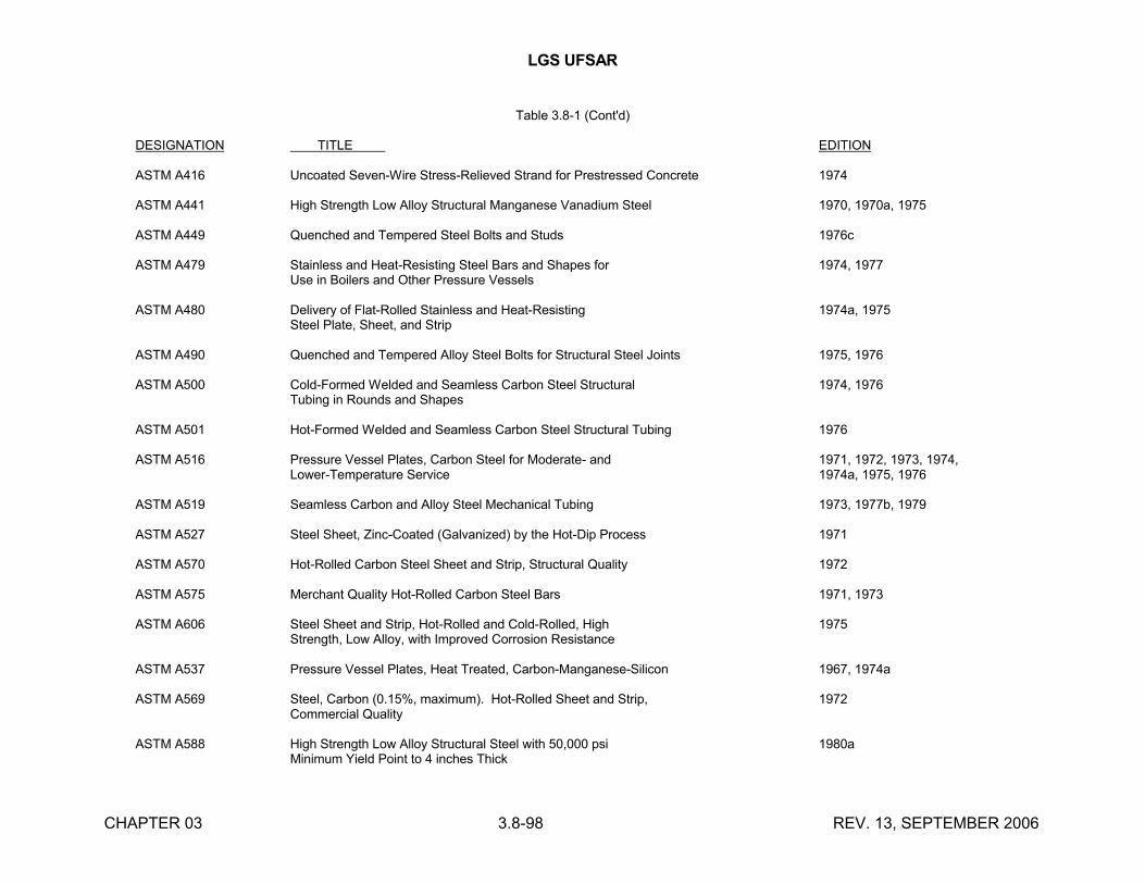
LGS UFSAR
CHAPTER 03 3.8-98 REV. 13, SEPTEMBER 2006
Table 3.8-1 (Cont'd)
DESIGNATION TITLE EDITION
ASTM A416 Uncoated Seven-Wire Stress-Relieved Strand for Prestressed Concrete 1974
ASTM A441 High Strength Low Alloy Structural Manganese Vanadium Steel 1970, 1970a, 1975
ASTM A449 Quenched and Tempered Steel Bolts and Studs 1976c
ASTM A479 Stainless and Heat-Resisting Steel Bars and Shapes for 1974, 1977Use in Boilers and Other Pressure Vessels
ASTM A480 Delivery of Flat-Rolled Stainless and Heat-Resisting 1974a, 1975Steel Plate, Sheet, and Strip
ASTM A490 Quenched and Tempered Alloy Steel Bolts for Structural Steel Joints 1975, 1976
ASTM A500 Cold-Formed Welded and Seamless Carbon Steel Structural 1974, 1976Tubing in Rounds and Shapes
ASTM A501 Hot-Formed Welded and Seamless Carbon Steel Structural Tubing 1976
ASTM A516 Pressure Vessel Plates, Carbon Steel for Moderate- and 1971, 1972, 1973, 1974,Lower-Temperature Service 1974a, 1975, 1976
ASTM A519 Seamless Carbon and Alloy Steel Mechanical Tubing 1973, 1977b, 1979
ASTM A527 Steel Sheet, Zinc-Coated (Galvanized) by the Hot-Dip Process 1971
ASTM A570 Hot-Rolled Carbon Steel Sheet and Strip, Structural Quality 1972
ASTM A575 Merchant Quality Hot-Rolled Carbon Steel Bars 1971, 1973
ASTM A606 Steel Sheet and Strip, Hot-Rolled and Cold-Rolled, High 1975Strength, Low Alloy, with Improved Corrosion Resistance
ASTM A537 Pressure Vessel Plates, Heat Treated, Carbon-Manganese-Silicon 1967, 1974a
ASTM A569 Steel, Carbon (0.15%, maximum). Hot-Rolled Sheet and Strip, 1972Commercial Quality
ASTM A588 High Strength Low Alloy Structural Steel with 50,000 psi 1980aMinimum Yield Point to 4 inches Thick
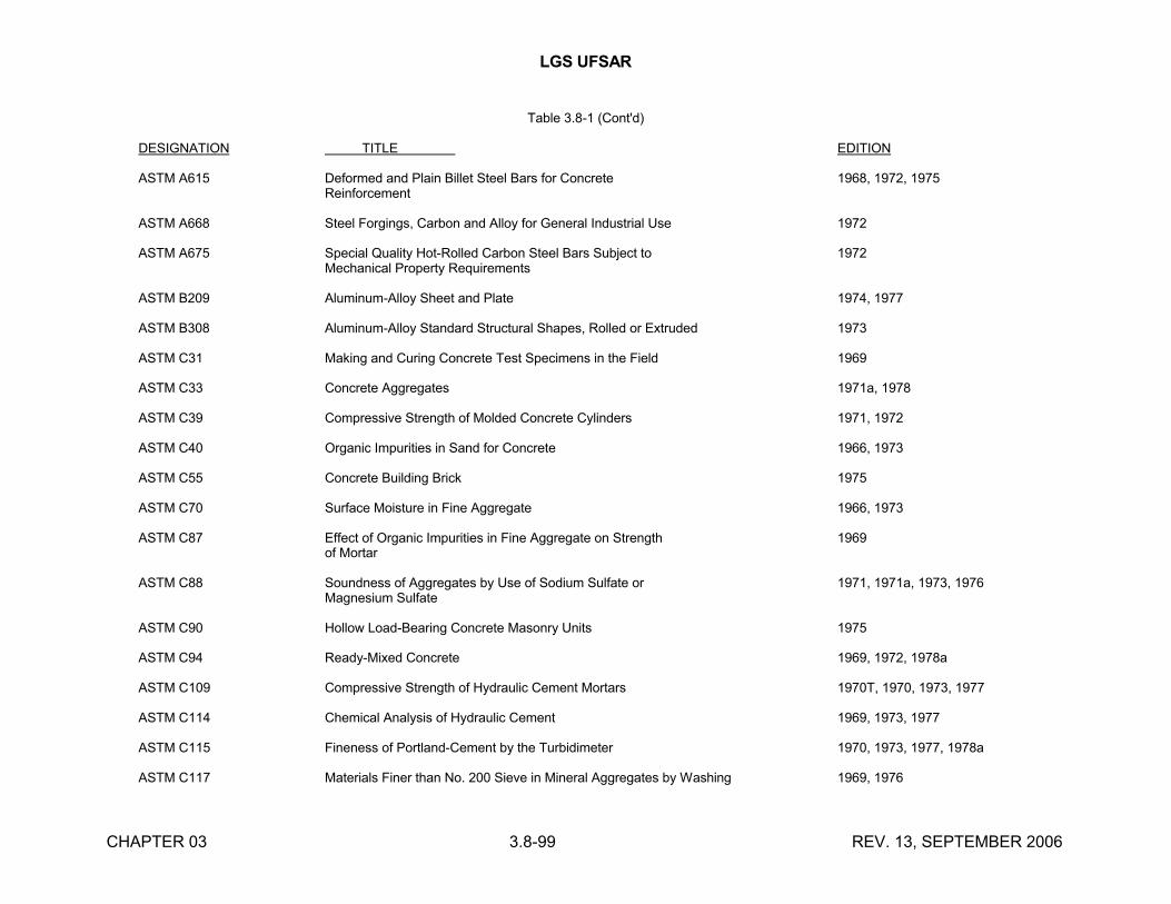
LGS UFSAR
CHAPTER 03 3.8-99 REV. 13, SEPTEMBER 2006
Table 3.8-1 (Cont'd)
DESIGNATION TITLE EDITION
ASTM A615 Deformed and Plain Billet Steel Bars for Concrete 1968, 1972, 1975Reinforcement
ASTM A668 Steel Forgings, Carbon and Alloy for General Industrial Use 1972
ASTM A675 Special Quality Hot-Rolled Carbon Steel Bars Subject to 1972Mechanical Property Requirements
ASTM B209 Aluminum-Alloy Sheet and Plate 1974, 1977
ASTM B308 Aluminum-Alloy Standard Structural Shapes, Rolled or Extruded 1973
ASTM C31 Making and Curing Concrete Test Specimens in the Field 1969
ASTM C33 Concrete Aggregates 1971a, 1978
ASTM C39 Compressive Strength of Molded Concrete Cylinders 1971, 1972
ASTM C40 Organic Impurities in Sand for Concrete 1966, 1973
ASTM C55 Concrete Building Brick 1975
ASTM C70 Surface Moisture in Fine Aggregate 1966, 1973
ASTM C87 Effect of Organic Impurities in Fine Aggregate on Strength 1969of Mortar
ASTM C88 Soundness of Aggregates by Use of Sodium Sulfate or 1971, 1971a, 1973, 1976Magnesium Sulfate
ASTM C90 Hollow Load-Bearing Concrete Masonry Units 1975
ASTM C94 Ready-Mixed Concrete 1969, 1972, 1978a
ASTM C109 Compressive Strength of Hydraulic Cement Mortars 1970T, 1970, 1973, 1977
ASTM C114 Chemical Analysis of Hydraulic Cement 1969, 1973, 1977
ASTM C115 Fineness of Portland-Cement by the Turbidimeter 1970, 1973, 1977, 1978a
ASTM C117 Materials Finer than No. 200 Sieve in Mineral Aggregates by Washing 1969, 1976
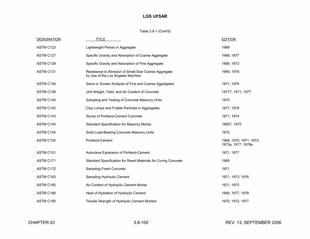
LGS UFSAR
CHAPTER 03 3.8-100 REV. 13, SEPTEMBER 2006
Table 3.8-1 (Cont'd)
DESIGNATION TITLE EDITION
ASTM C123 Lightweight Pieces in Aggregate 1969
ASTM C127 Specific Gravity and Absorption of Coarse Aggregate 1968, 1977
ASTM C128 Specific Gravity and Absorption of Fine Aggregate 1968, 1973
ASTM C131 Resistance to Abrasion of Small Size Coarse Aggregate 1969, 1976by Use of the Los Angeles Machine
ASTM C136 Sieve or Screen Analysis of Fine and Coarse Aggregates 1971, 1976
ASTM C138 Unit Weight, Yield, and Air Content of Concrete 1971T, 1971, 1977
ASTM C140 Sampling and Testing of Concrete Masonry Units 1970
ASTM C142 Clay Lumps and Friable Particles in Aggregates 1971, 1978
ASTM C143 Slump of Portland-Cement Concrete 1971, 1974
ASTM C144 Standard Specification for Masonry Mortar 1966T, 1970
ASTM C145 Solid Load-Bearing Concrete Masonry Units 1975
ASTM C150 Portland-Cement 1968, 1970, 1971, 1972,1973a, 1977, 1978a
ASTM C151 Autoclave Expansion of Portland-Cement 1971, 1977
ASTM C171 Standard Specification for Sheet Materials for Curing Concrete 1969
ASTM C172 Sampling Fresh Concrete 1971
ASTM C183 Sampling Hydraulic Cement 1971, 1973, 1976
ASTM C185 Air Content of Hydraulic Cement Mortar 1971, 1975
ASTM C186 Heat of Hydration of Hydraulic Cement 1968, 1977, 1978
ASTM C190 Tensile Strength of Hydraulic Cement Mortars 1970, 1972, 1977
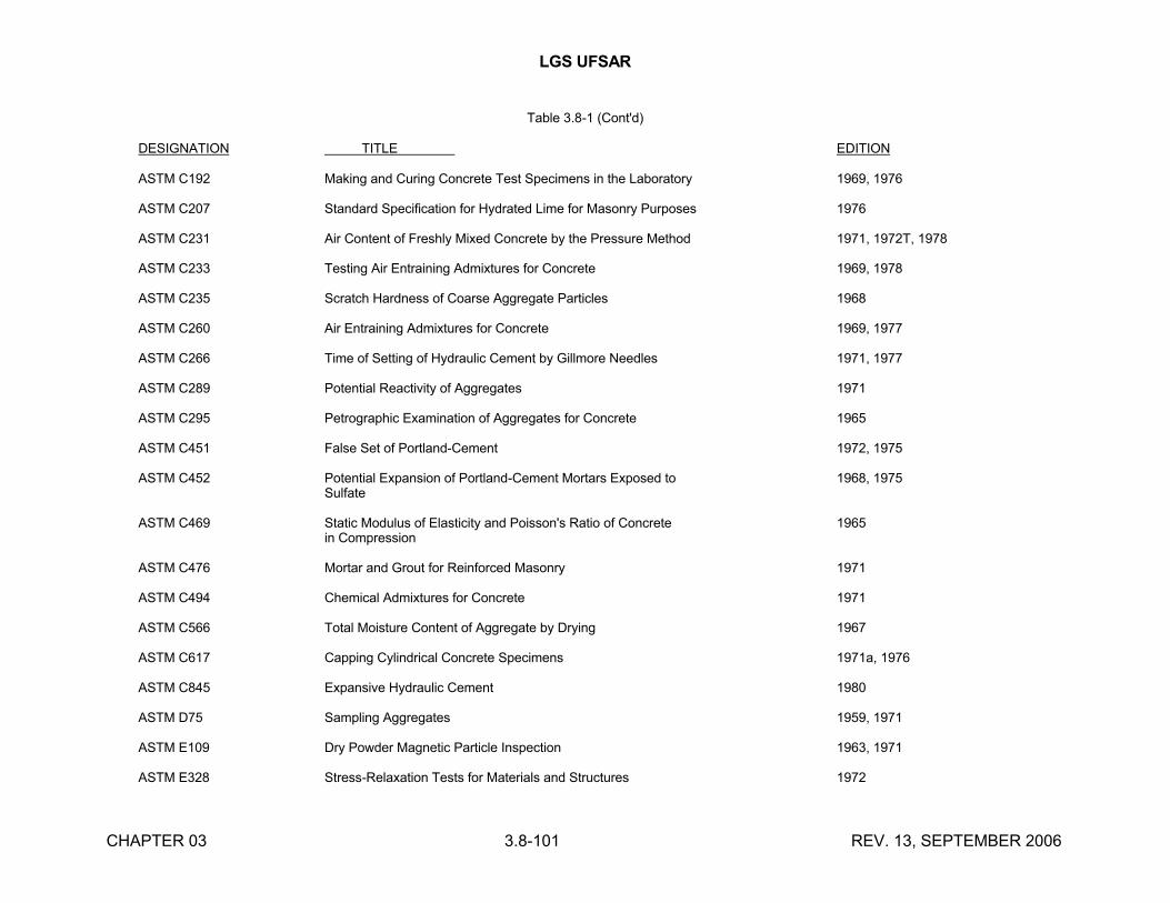
LGS UFSAR
CHAPTER 03 3.8-101 REV. 13, SEPTEMBER 2006
Table 3.8-1 (Cont'd)
DESIGNATION TITLE EDITION
ASTM C192 Making and Curing Concrete Test Specimens in the Laboratory 1969, 1976
ASTM C207 Standard Specification for Hydrated Lime for Masonry Purposes 1976
ASTM C231 Air Content of Freshly Mixed Concrete by the Pressure Method 1971, 1972T, 1978
ASTM C233 Testing Air Entraining Admixtures for Concrete 1969, 1978
ASTM C235 Scratch Hardness of Coarse Aggregate Particles 1968
ASTM C260 Air Entraining Admixtures for Concrete 1969, 1977
ASTM C266 Time of Setting of Hydraulic Cement by Gillmore Needles 1971, 1977
ASTM C289 Potential Reactivity of Aggregates 1971
ASTM C295 Petrographic Examination of Aggregates for Concrete 1965
ASTM C451 False Set of Portland-Cement 1972, 1975
ASTM C452 Potential Expansion of Portland-Cement Mortars Exposed to 1968, 1975Sulfate
ASTM C469 Static Modulus of Elasticity and Poisson's Ratio of Concrete 1965in Compression
ASTM C476 Mortar and Grout for Reinforced Masonry 1971
ASTM C494 Chemical Admixtures for Concrete 1971
ASTM C566 Total Moisture Content of Aggregate by Drying 1967
ASTM C617 Capping Cylindrical Concrete Specimens 1971a, 1976
ASTM C845 Expansive Hydraulic Cement 1980
ASTM D75 Sampling Aggregates 1959, 1971
ASTM E109 Dry Powder Magnetic Particle Inspection 1963, 1971
ASTM E328 Stress-Relaxation Tests for Materials and Structures 1972
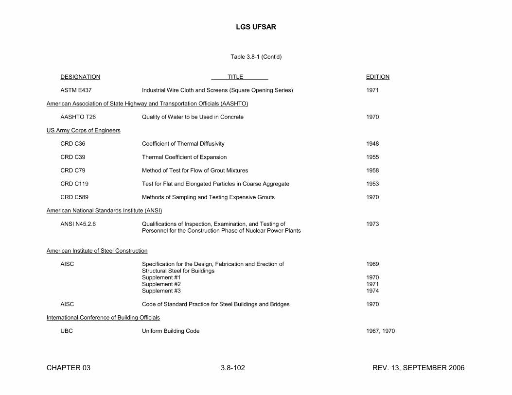
LGS UFSAR
CHAPTER 03 3.8-102 REV. 13, SEPTEMBER 2006
Table 3.8-1 (Cont'd)
DESIGNATION TITLE EDITION
ASTM E437 Industrial Wire Cloth and Screens (Square Opening Series) 1971
American Association of State Highway and Transportation Officials (AASHTO)
AASHTO T26 Quality of Water to be Used in Concrete 1970
US Army Corps of Engineers
CRD C36 Coefficient of Thermal Diffusivity 1948
CRD C39 Thermal Coefficient of Expansion 1955
CRD C79 Method of Test for Flow of Grout Mixtures 1958
CRD C119 Test for Flat and Elongated Particles in Coarse Aggregate 1953
CRD C589 Methods of Sampling and Testing Expensive Grouts 1970
American National Standards Institute (ANSI)
ANSI N45.2.6 Qualifications of Inspection, Examination, and Testing of 1973Personnel for the Construction Phase of Nuclear Power Plants
American Institute of Steel Construction
AISC Specification for the Design, Fabrication and Erection of 1969Structural Steel for BuildingsSupplement #1 1970Supplement #2 1971Supplement #3 1974
AISC Code of Standard Practice for Steel Buildings and Bridges 1970
International Conference of Building Officials
UBC Uniform Building Code 1967, 1970
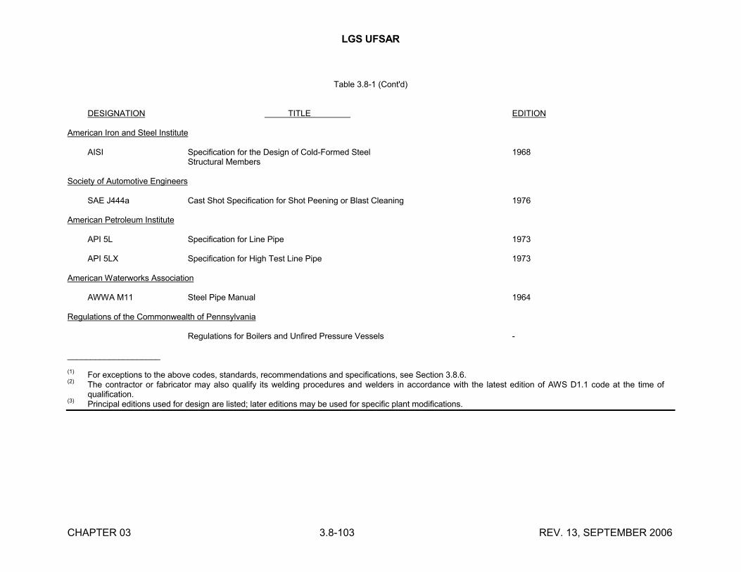
LGS UFSAR
CHAPTER 03 3.8-103 REV. 13, SEPTEMBER 2006
Table 3.8-1 (Cont'd)
DESIGNATION TITLE EDITION
American Iron and Steel Institute
AISI Specification for the Design of Cold-Formed Steel 1968Structural Members
Society of Automotive Engineers
SAE J444a Cast Shot Specification for Shot Peening or Blast Cleaning 1976
American Petroleum Institute
API 5L Specification for Line Pipe 1973
API 5LX Specification for High Test Line Pipe 1973
American Waterworks Association
AWWA M11 Steel Pipe Manual 1964
Regulations of the Commonwealth of Pennsylvania
Regulations for Boilers and Unfired Pressure Vessels -
____________________
(1)For exceptions to the above codes, standards, recommendations and specifications, see Section 3.8.6.
(2)The contractor or fabricator may also qualify its welding procedures and welders in accordance with the latest edition of AWS D1.1 code at the time of qualification.
(3)Principal editions used for design are listed; later editions may be used for specific plant modifications.
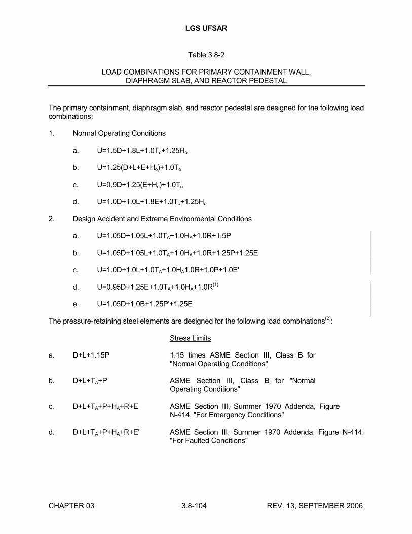
LGS UFSAR
CHAPTER 03 3.8-104 REV. 13, SEPTEMBER 2006
Table 3.8-2
LOAD COMBINATIONS FOR PRIMARY CONTAINMENT WALL,DIAPHRAGM SLAB, AND REACTOR PEDESTAL
The primary containment, diaphragm slab, and reactor pedestal are designed for the following load combinations:
1. Normal Operating Conditions
a. U=1.5D+1.8L+1.0To+1.25Ho
b. U=1.25(D+L+E+Ho)+1.0To
c. U=0.9D+1.25(E+Ho)+1.0To
d. U=1.0D+1.0L+1.8E+1.0To+1.25Ho
2. Design Accident and Extreme Environmental Conditions
a. U=1.05D+1.05L+1.0TA+1.0HA+1.0R+1.5P
b. U=1.05D+1.05L+1.0TA+1.0HA+1.0R+1.25P+1.25E
c. U=1.0D+1.0L+1.0TA+1.0HA1.0R+1.0P+1.0E'
d. U=0.95D+1.25E+1.0TA+1.0HA+1.0R(1)
e. U=1.05D+1.0B+1.25P'+1.25E
The pressure-retaining steel elements are designed for the following load combinations(2):
Stress Limits
a. D+L+1.15P 1.15 times ASME Section III, Class B for "Normal Operating Conditions"
b. D+L+TA+P ASME Section III, Class B for "Normal Operating Conditions"
c. D+L+TA+P+HA+R+E ASME Section III, Summer 1970 Addenda, Figure N-414, "For Emergency Conditions"
d. D+L+TA+P+HA+R+E' ASME Section III, Summer 1970 Addenda, Figure N-414, "For Faulted Conditions"
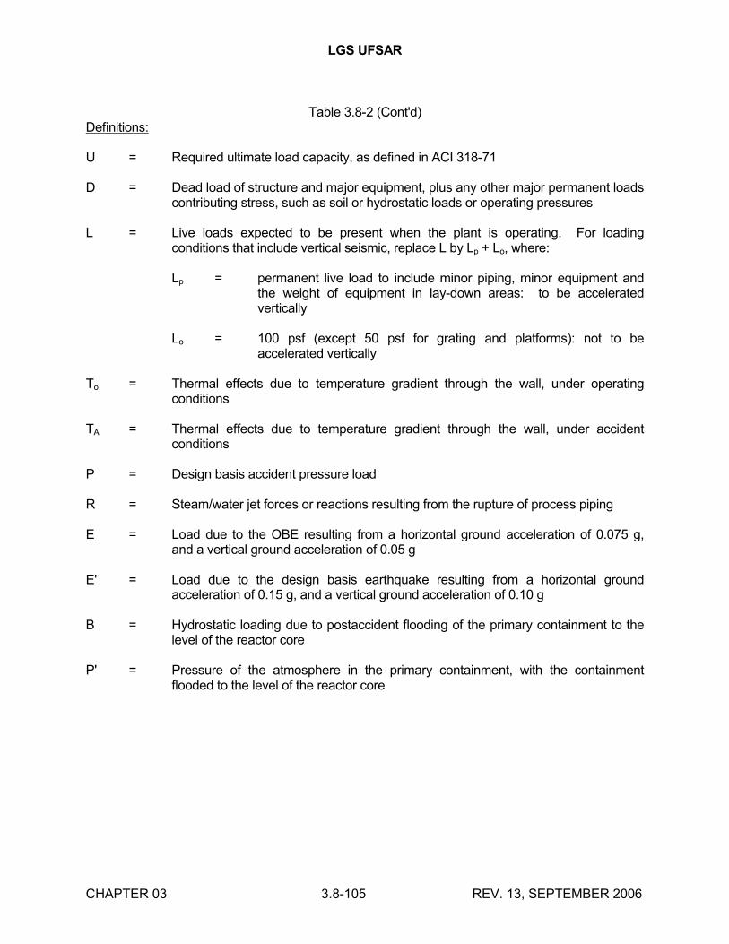
LGS UFSAR
CHAPTER 03 3.8-105 REV. 13, SEPTEMBER 2006
Table 3.8-2 (Cont'd)Definitions:
U = Required ultimate load capacity, as defined in ACI 318-71
D = Dead load of structure and major equipment, plus any other major permanent loads contributing stress, such as soil or hydrostatic loads or operating pressures
L = Live loads expected to be present when the plant is operating. For loading conditions that include vertical seismic, replace L by Lp + Lo, where:
Lp = permanent live load to include minor piping, minor equipment and the weight of equipment in lay-down areas: to be accelerated vertically
Lo = 100 psf (except 50 psf for grating and platforms): not to be accelerated vertically
To = Thermal effects due to temperature gradient through the wall, under operating conditions
TA = Thermal effects due to temperature gradient through the wall, under accident conditions
P = Design basis accident pressure load
R = Steam/water jet forces or reactions resulting from the rupture of process piping
E = Load due to the OBE resulting from a horizontal ground acceleration of 0.075 g, and a vertical ground acceleration of 0.05 g
E' = Load due to the design basis earthquake resulting from a horizontal ground acceleration of 0.15 g, and a vertical ground acceleration of 0.10 g
B = Hydrostatic loading due to postaccident flooding of the primary containment to the level of the reactor core
P' = Pressure of the atmosphere in the primary containment, with the containment flooded to the level of the reactor core
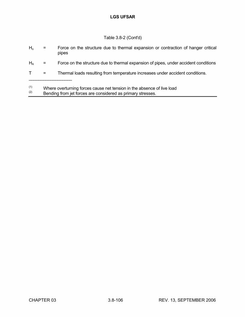
LGS UFSAR
CHAPTER 03 3.8-106 REV. 13, SEPTEMBER 2006
Table 3.8-2 (Cont'd)
Ho = Force on the structure due to thermal expansion or contraction of hanger critical pipes
HA = Force on the structure due to thermal expansion of pipes, under accident conditions
T = Thermal loads resulting from temperature increases under accident conditions.__________________
(1) Where overturning forces cause net tension in the absence of live load(2) Bending from jet forces are considered as primary stresses.
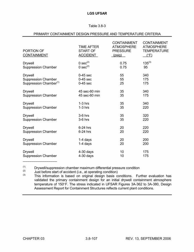
LGS UFSAR
CHAPTER 03 3.8-107 REV. 13, SEPTEMBER 2006
Table 3.8-3
PRIMARY CONTAINMENT DESIGN PRESSURE AND TEMPERATURE CRITERIA
CONTAINMENT CONTAINMENTTIME AFTER ATMOSPHERE ATMOSPHERE
PORTION OF START OF PRESSURE TEMPERATURECONTAINMENT ACCIDENT (psig) (F)
Drywell 0 sec(2) 0.75 135(3)
Suppression Chamber 0 sec(2) 0.75 95
Drywell 0-45 sec 55 340Suppression Chamber 0-45 sec 55 175Suppression Chamber(1) 0-45 sec 25 175
Drywell 45 sec-60 min 35 340Suppression Chamber 45 sec-60 min 35 175
Drywell 1-3 hrs 35 340Suppression Chamber 1-3 hrs 35 220
Drywell 3-6 hrs 35 320Suppression Chamber 3-6 hrs 35 220
Drywell 6-24 hrs 20 220Suppression Chamber 6-24 hrs 20 220
Drywell 1-4 days 20 200Suppression Chamber 1-4 days 20 200
Drywell 4-30 days 10 175Suppression Chamber 4-30 days 10 175__________________
(1) Drywell/suppression chamber maximum differential pressure condition(2) Just before start of accident (i.e., at operating condition)(3) This information is based on original design basis conditions. Further evaluation has
validated the primary containment design for an initial drywell containment atmosphere temperature of 150F. The stress indicated in UFSAR Figures 3A-362 to 3A-380, Design Assessment Report for Containment Structures reflects current plant conditions.
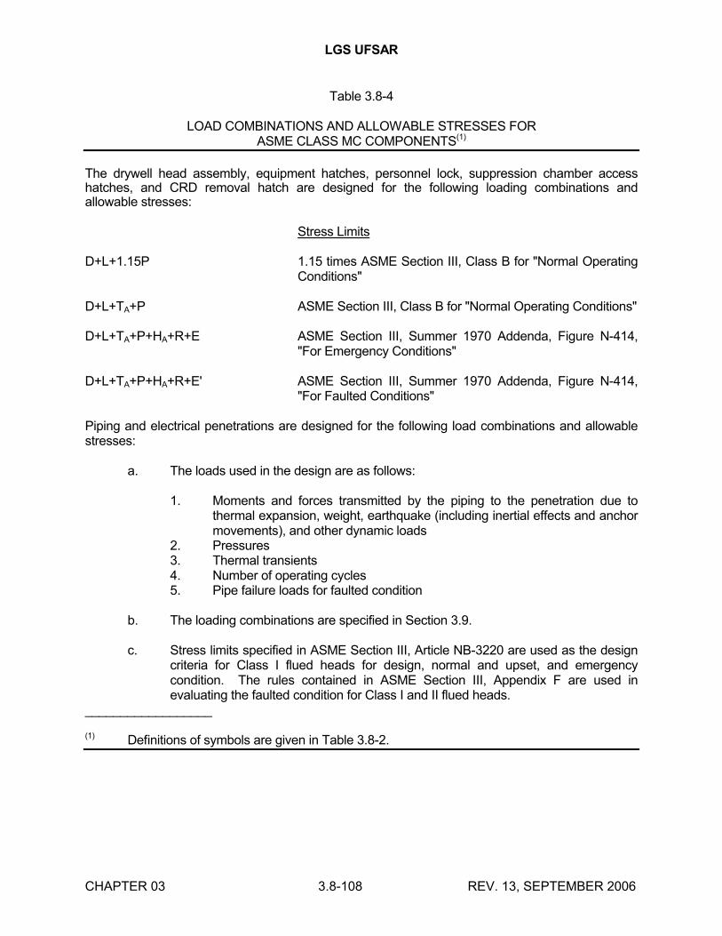
LGS UFSAR
CHAPTER 03 3.8-108 REV. 13, SEPTEMBER 2006
Table 3.8-4
LOAD COMBINATIONS AND ALLOWABLE STRESSES FORASME CLASS MC COMPONENTS(1)
The drywell head assembly, equipment hatches, personnel lock, suppression chamber access hatches, and CRD removal hatch are designed for the following loading combinations and allowable stresses:
Stress Limits
D+L+1.15P 1.15 times ASME Section III, Class B for "Normal Operating Conditions"
D+L+TA+P ASME Section III, Class B for "Normal Operating Conditions"
D+L+TA+P+HA+R+E ASME Section III, Summer 1970 Addenda, Figure N-414, "For Emergency Conditions"
D+L+TA+P+HA+R+E' ASME Section III, Summer 1970 Addenda, Figure N-414, "For Faulted Conditions"
Piping and electrical penetrations are designed for the following load combinations and allowable stresses:
a. The loads used in the design are as follows:
1. Moments and forces transmitted by the piping to the penetration due to thermal expansion, weight, earthquake (including inertial effects and anchor movements), and other dynamic loads
2. Pressures3. Thermal transients4. Number of operating cycles5. Pipe failure loads for faulted condition
b. The loading combinations are specified in Section 3.9.
c. Stress limits specified in ASME Section III, Article NB-3220 are used as the design criteria for Class I flued heads for design, normal and upset, and emergency condition. The rules contained in ASME Section III, Appendix F are used in evaluating the faulted condition for Class I and II flued heads.
__________________
(1) Definitions of symbols are given in Table 3.8-2.
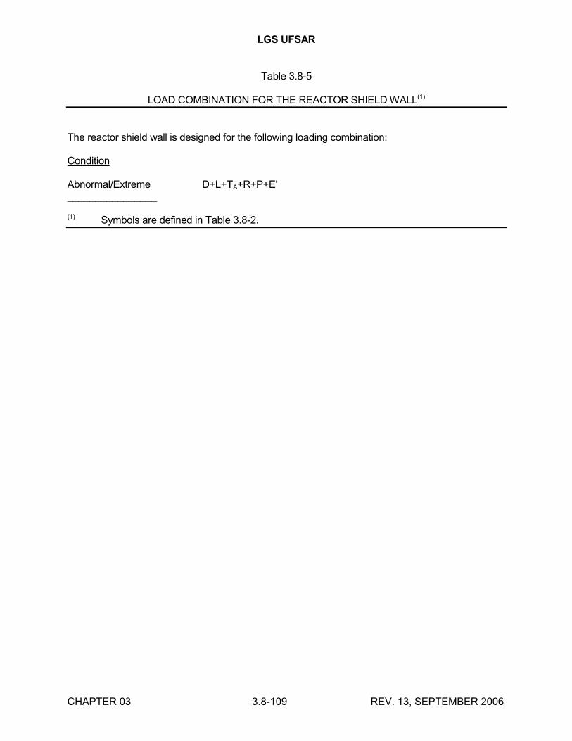
LGS UFSAR
CHAPTER 03 3.8-109 REV. 13, SEPTEMBER 2006
Table 3.8-5
LOAD COMBINATION FOR THE REACTOR SHIELD WALL(1)
The reactor shield wall is designed for the following loading combination:
Condition
Abnormal/Extreme D+L+TA+R+P+E'________________
(1) Symbols are defined in Table 3.8-2.
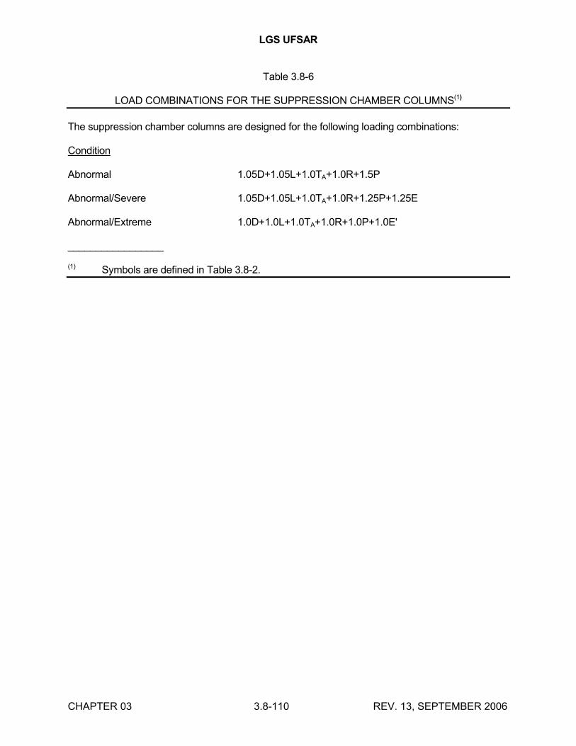
LGS UFSAR
CHAPTER 03 3.8-110 REV. 13, SEPTEMBER 2006
Table 3.8-6
LOAD COMBINATIONS FOR THE SUPPRESSION CHAMBER COLUMNS(1)
The suppression chamber columns are designed for the following loading combinations:
Condition
Abnormal 1.05D+1.05L+1.0TA+1.0R+1.5P
Abnormal/Severe 1.05D+1.05L+1.0TA+1.0R+1.25P+1.25E
Abnormal/Extreme 1.0D+1.0L+1.0TA+1.0R+1.0P+1.0E'
_________________
(1) Symbols are defined in Table 3.8-2.
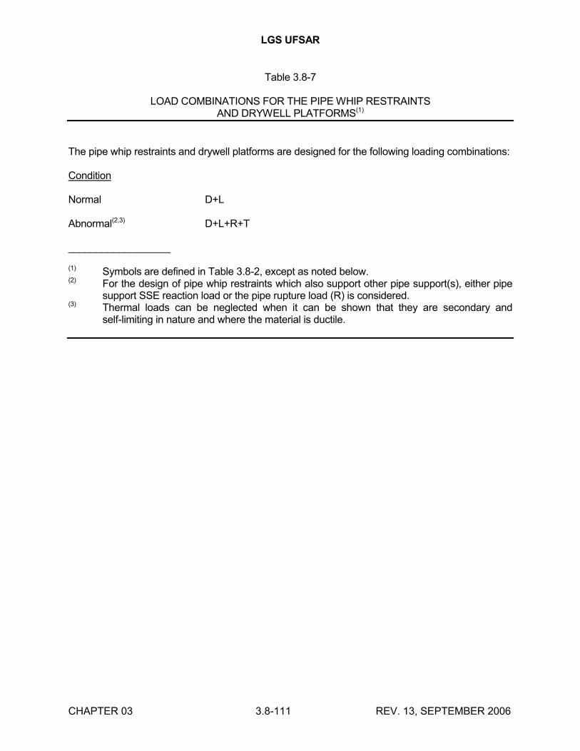
LGS UFSAR
CHAPTER 03 3.8-111 REV. 13, SEPTEMBER 2006
Table 3.8-7
LOAD COMBINATIONS FOR THE PIPE WHIP RESTRAINTSAND DRYWELL PLATFORMS(1)
The pipe whip restraints and drywell platforms are designed for the following loading combinations:
Condition
Normal D+L
Abnormal(2,3) D+L+R+T
__________________
(1) Symbols are defined in Table 3.8-2, except as noted below.(2) For the design of pipe whip restraints which also support other pipe support(s), either pipe
support SSE reaction load or the pipe rupture load (R) is considered.(3) Thermal loads can be neglected when it can be shown that they are secondary and
self-limiting in nature and where the material is ductile.
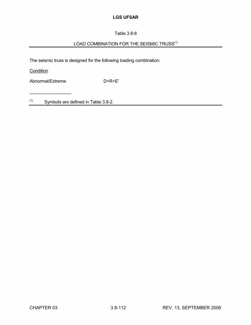
LGS UFSAR
CHAPTER 03 3.8-112 REV. 13, SEPTEMBER 2006
Table 3.8-8
LOAD COMBINATION FOR THE SEISMIC TRUSS(1)
The seismic truss is designed for the following loading combination:
Condition
Abnormal/Extreme D+R+E'
_________________
(1) Symbols are defined in Table 3.8-2.
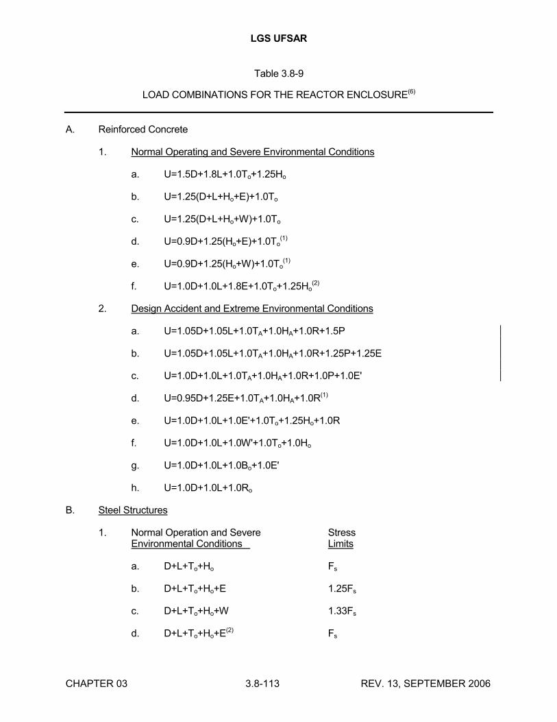
LGS UFSAR
CHAPTER 03 3.8-113 REV. 13, SEPTEMBER 2006
Table 3.8-9
LOAD COMBINATIONS FOR THE REACTOR ENCLOSURE(6)
A. Reinforced Concrete
1. Normal Operating and Severe Environmental Conditions
a. U=1.5D+1.8L+1.0To+1.25Ho
b. U=1.25(D+L+Ho+E)+1.0To
c. U=1.25(D+L+Ho+W)+1.0To
d. U=0.9D+1.25(Ho+E)+1.0To(1)
e. U=0.9D+1.25(Ho+W)+1.0To(1)
f. U=1.0D+1.0L+1.8E+1.0To+1.25Ho(2)
2. Design Accident and Extreme Environmental Conditions
a. U=1.05D+1.05L+1.0TA+1.0HA+1.0R+1.5P
b. U=1.05D+1.05L+1.0TA+1.0HA+1.0R+1.25P+1.25E
c. U=1.0D+1.0L+1.0TA+1.0HA+1.0R+1.0P+1.0E'
d. U=0.95D+1.25E+1.0TA+1.0HA+1.0R(1)
e. U=1.0D+1.0L+1.0E'+1.0To+1.25Ho+1.0R
f. U=1.0D+1.0L+1.0W'+1.0To+1.0Ho
g. U=1.0D+1.0L+1.0Bo+1.0E'
h. U=1.0D+1.0L+1.0Ro
B. Steel Structures
1. Normal Operation and Severe StressEnvironmental Conditions Limits
a. D+L+To+Ho Fs
b. D+L+To+Ho+E 1.25Fs
c. D+L+To+Ho+W 1.33Fs
d. D+L+To+Ho+E(2) Fs
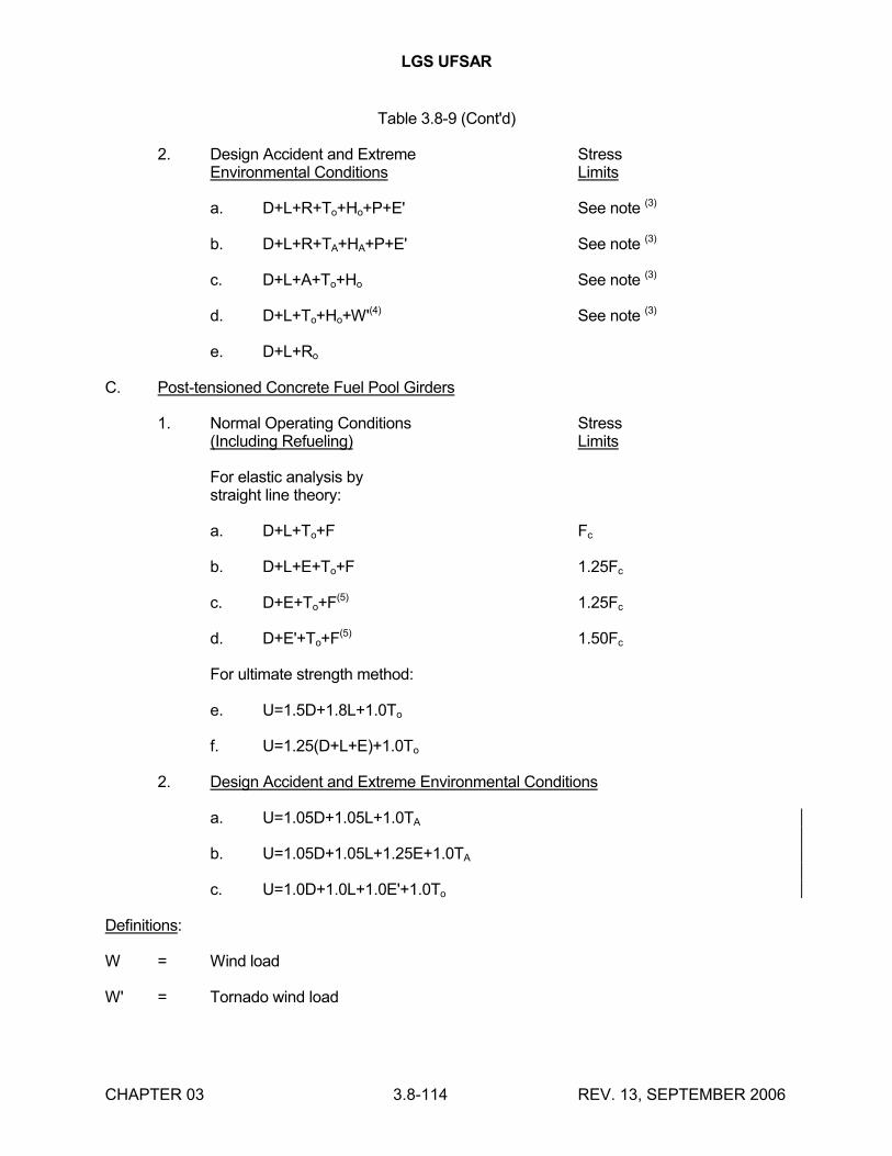
LGS UFSAR
CHAPTER 03 3.8-114 REV. 13, SEPTEMBER 2006
Table 3.8-9 (Cont'd)
2. Design Accident and Extreme StressEnvironmental Conditions Limits
a. D+L+R+To+Ho+P+E' See note (3)
b. D+L+R+TA+HA+P+E' See note (3)
c. D+L+A+To+Ho See note (3)
d. D+L+To+Ho+W'(4) See note (3)
e. D+L+Ro
C. Post-tensioned Concrete Fuel Pool Girders
1. Normal Operating Conditions Stress(Including Refueling) Limits
For elastic analysis bystraight line theory:
a. D+L+To+F Fc
b. D+L+E+To+F 1.25Fc
c. D+E+To+F(5) 1.25Fc
d. D+E'+To+F(5) 1.50Fc
For ultimate strength method:
e. U=1.5D+1.8L+1.0To
f. U=1.25(D+L+E)+1.0To
2. Design Accident and Extreme Environmental Conditions
a. U=1.05D+1.05L+1.0TA
b. U=1.05D+1.05L+1.25E+1.0TA
c. U=1.0D+1.0L+1.0E'+1.0To
Definitions:
W = Wind load
W' = Tornado wind load
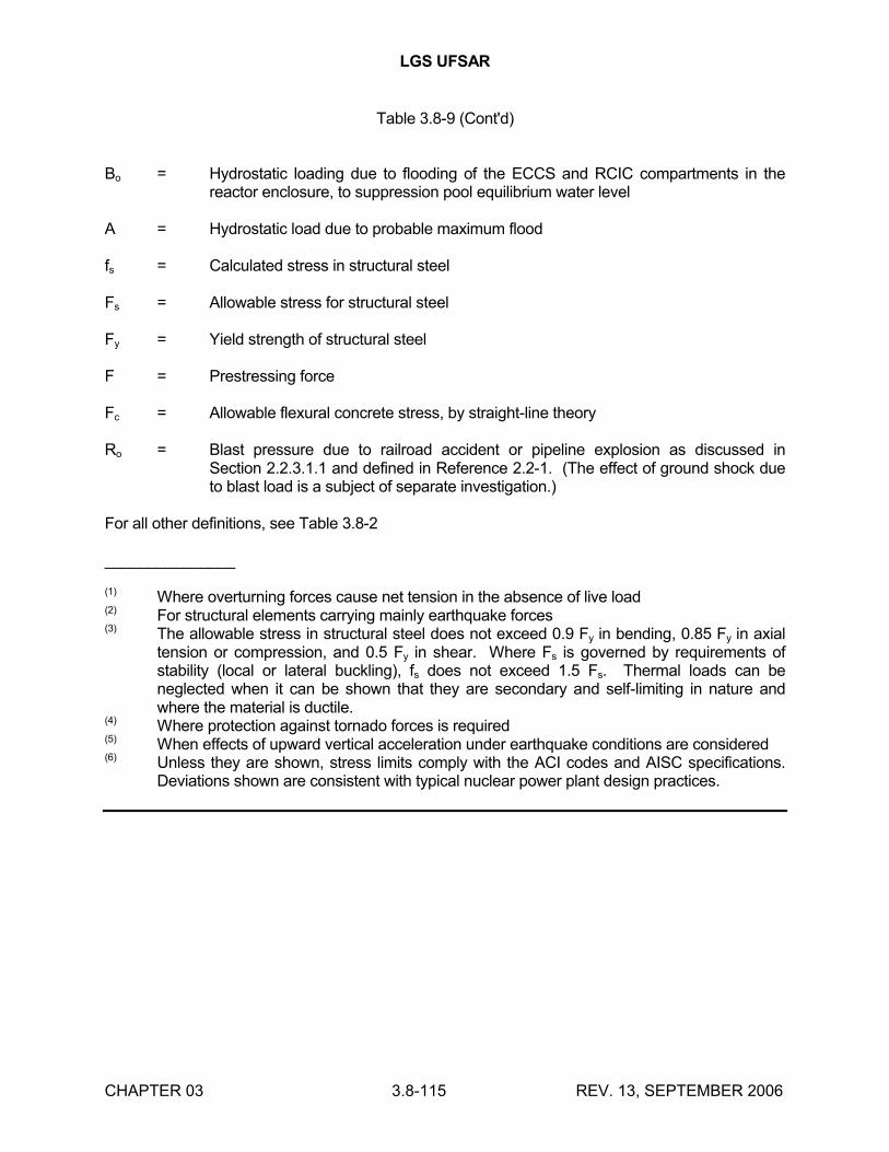
LGS UFSAR
CHAPTER 03 3.8-115 REV. 13, SEPTEMBER 2006
Table 3.8-9 (Cont'd)
Bo = Hydrostatic loading due to flooding of the ECCS and RCIC compartments in the reactor enclosure, to suppression pool equilibrium water level
A = Hydrostatic load due to probable maximum flood
fs = Calculated stress in structural steel
Fs = Allowable stress for structural steel
Fy = Yield strength of structural steel
F = Prestressing force
Fc = Allowable flexural concrete stress, by straight-line theory
Ro = Blast pressure due to railroad accident or pipeline explosion as discussed in Section 2.2.3.1.1 and defined in Reference 2.2-1. (The effect of ground shock due to blast load is a subject of separate investigation.)
For all other definitions, see Table 3.8-2
_______________
(1) Where overturning forces cause net tension in the absence of live load(2) For structural elements carrying mainly earthquake forces(3) The allowable stress in structural steel does not exceed 0.9 Fy in bending, 0.85 Fy in axial
tension or compression, and 0.5 Fy in shear. Where Fs is governed by requirements of stability (local or lateral buckling), fs does not exceed 1.5 Fs. Thermal loads can be neglected when it can be shown that they are secondary and self-limiting in nature and where the material is ductile.
(4) Where protection against tornado forces is required(5) When effects of upward vertical acceleration under earthquake conditions are considered(6) Unless they are shown, stress limits comply with the ACI codes and AISC specifications.
Deviations shown are consistent with typical nuclear power plant design practices.
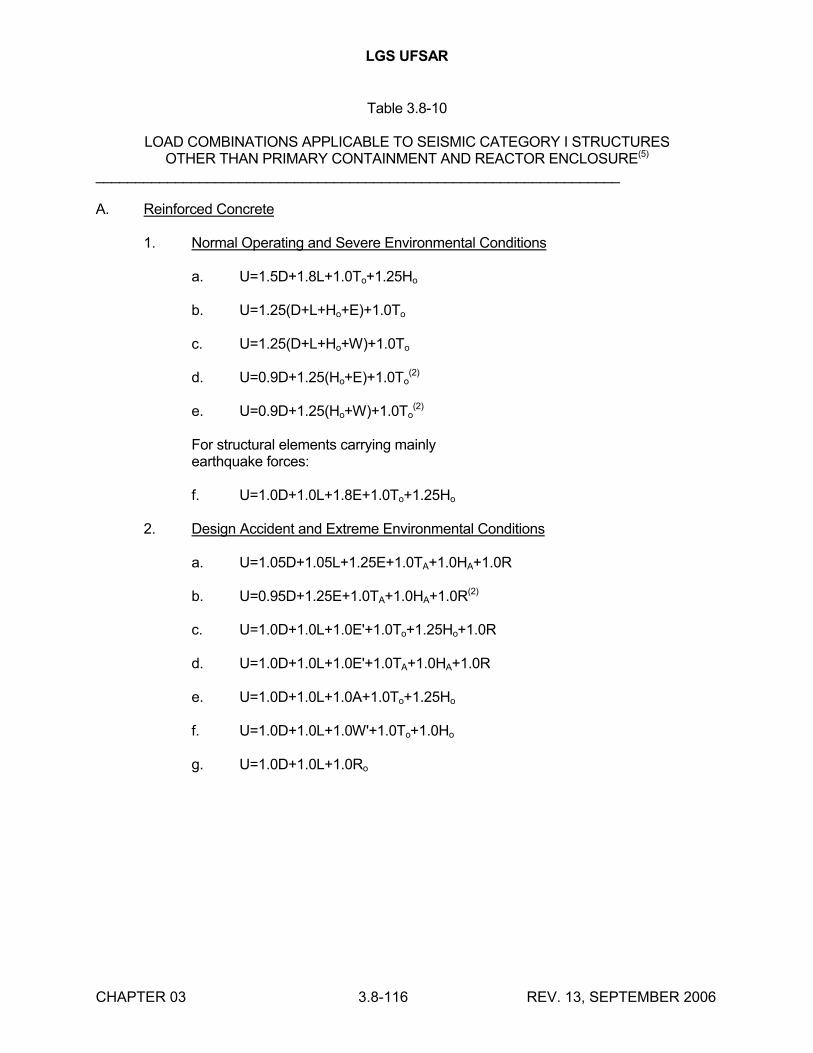
LGS UFSAR
CHAPTER 03 3.8-116 REV. 13, SEPTEMBER 2006
Table 3.8-10
LOAD COMBINATIONS APPLICABLE TO SEISMIC CATEGORY I STRUCTURESOTHER THAN PRIMARY CONTAINMENT AND REACTOR ENCLOSURE(5)
__________________________________________________________________
A. Reinforced Concrete
1. Normal Operating and Severe Environmental Conditions
a. U=1.5D+1.8L+1.0To+1.25Ho
b. U=1.25(D+L+Ho+E)+1.0To
c. U=1.25(D+L+Ho+W)+1.0To
d. U=0.9D+1.25(Ho+E)+1.0To(2)
e. U=0.9D+1.25(Ho+W)+1.0To(2)
For structural elements carrying mainlyearthquake forces:
f. U=1.0D+1.0L+1.8E+1.0To+1.25Ho
2. Design Accident and Extreme Environmental Conditions
a. U=1.05D+1.05L+1.25E+1.0TA+1.0HA+1.0R
b. U=0.95D+1.25E+1.0TA+1.0HA+1.0R(2)
c. U=1.0D+1.0L+1.0E'+1.0To+1.25Ho+1.0R
d. U=1.0D+1.0L+1.0E'+1.0TA+1.0HA+1.0R
e. U=1.0D+1.0L+1.0A+1.0To+1.25Ho
f. U=1.0D+1.0L+1.0W'+1.0To+1.0Ho
g. U=1.0D+1.0L+1.0Ro
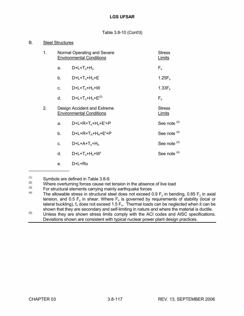
LGS UFSAR
CHAPTER 03 3.8-117 REV. 13, SEPTEMBER 2006
Table 3.8-10 (Cont'd)
B. Steel Structures
1. Normal Operating and Severe StressEnvironmental Conditions Limits
a. D+L+To+Ho Fs
b. D+L+To+Ho+E 1.25Fs
c. D+L+To+Ho+W 1.33Fs
d. D+L+To+Ho+E(3) Fs
2. Design Accident and Extreme StressEnvironmental Conditions Limits
a. D+L+R+To+Ho+E'+P See note (4)
b. D+L+R+TA+HA+E'+P See note (4)
c. D+L+A+To+Ho See note (4)
d. D+L+To+Ho+W' See note (4)
e. D+L+Ro_________________
(1) Symbols are defined in Table 3.8-9.(2) Where overturning forces cause net tension in the absence of live load(3) For structural elements carrying mainly earthquake forces(4) The allowable stress in structural steel does not exceed 0.9 Fy in bending, 0.85 Fy in axial
tension, and 0.5 Fy in shear. Where Fs is governed by requirements of stability (local or lateral buckling), fs does not exceed 1.5 Fs. Thermal loads can be neglected when it can be shown that they are secondary and self-limiting in nature and where the material is ductile.
(5) Unless they are shown stress limits comply with the ACI codes and AISC specifications. Deviations shown are consistent with typical nuclear power plant design practices.
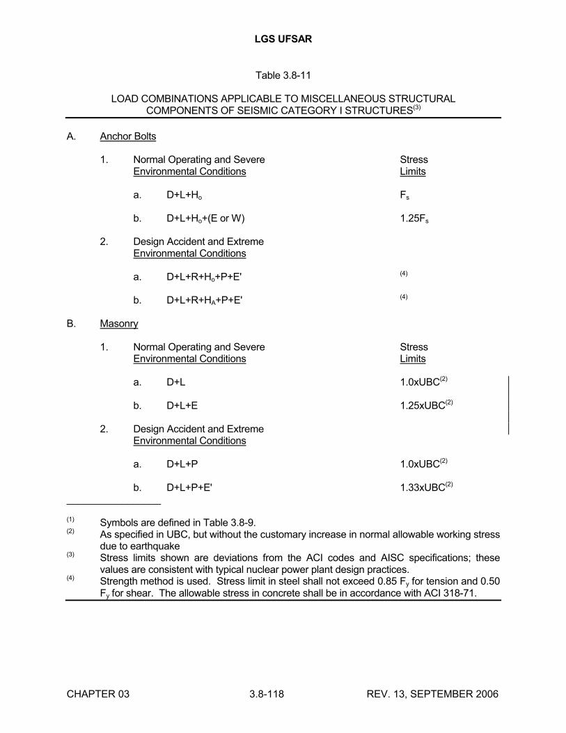
LGS UFSAR
CHAPTER 03 3.8-118 REV. 13, SEPTEMBER 2006
Table 3.8-11
LOAD COMBINATIONS APPLICABLE TO MISCELLANEOUS STRUCTURALCOMPONENTS OF SEISMIC CATEGORY I STRUCTURES(3)
A. Anchor Bolts
1. Normal Operating and Severe StressEnvironmental Conditions Limits
a. D+L+Ho Fs
b. D+L+Ho+(E or W) 1.25Fs
2. Design Accident and ExtremeEnvironmental Conditions
a. D+L+R+Ho+P+E' (4)
b. D+L+R+HA+P+E' (4)
B. Masonry
1. Normal Operating and Severe StressEnvironmental Conditions Limits
a. D+L 1.0xUBC(2)
b. D+L+E 1.25xUBC(2)
2. Design Accident and ExtremeEnvironmental Conditions
a. D+L+P 1.0xUBC(2)
b. D+L+P+E' 1.33xUBC(2)
_________________
(1) Symbols are defined in Table 3.8-9.(2) As specified in UBC, but without the customary increase in normal allowable working stress
due to earthquake(3) Stress limits shown are deviations from the ACI codes and AISC specifications; these
values are consistent with typical nuclear power plant design practices.(4) Strength method is used. Stress limit in steel shall not exceed 0.85 Fy for tension and 0.50
Fy for shear. The allowable stress in concrete shall be in accordance with ACI 318-71.
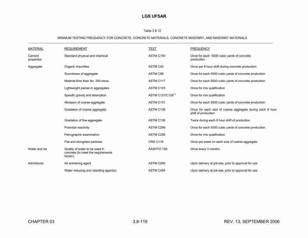
LGS UFSAR
CHAPTER 03 3.8-119 REV. 13, SEPTEMBER 2006
Table 3.8-12
MINIMUM TESTING FREQUENCY FOR CONCRETE, CONCRETE MATERIALS, CONCRETE MASONRY, AND MASONRY MATERIALS_______________________________________________________________________________________________________________________________________________
MATERIAL REQUIREMENT TEST FREQUENCY
Cement Standard physical and chemical ASTM C150 Once for each 5000 cubic yards of concreteproperties production
Aggregate Organic impurities ASTM C40 Once per 8 hour shift during concrete production
Soundness of aggregate ASTM C88 Once for each 5000 cubic yards of concrete production
Material finer than No. 200 sieve ASTM C117 Once for each 5000 cubic yards of concrete production
Lightweight pieces in aggregates ASTM C123 Once for mix qualification
Specific gravity and absorption ASTM C127/C128(1) Once for mix qualification
Abrasion of coarse aggregate ASTM C131 Once for each 5000 cubic yards of concrete production
Gradation of coarse aggregate ASTM C136 Once for each size of coarse aggregate during each 8 hour shift of production
Gradation of fine aggregate ASTM C136 Twice during each 8 hour shift of production
Potential reactivity ASTM C289 Once for each 5000 cubic yards of concrete production
Petrographic examination ASTM C295 Once for mix qualification
Flat and elongated particles CRD C119 Once per week on each size of coarse aggregate
Water and ice Quality of water to be used in AASHTO T26 Once every 3 monthsconcrete (to meet the requirementsherein)
Admixtures Air entraining agent ASTM C260 Upon delivery at job-site, prior to approval for use
Water reducing and retarding agent(s) ASTM C494 Upon delivery at job-site, prior to approval for use
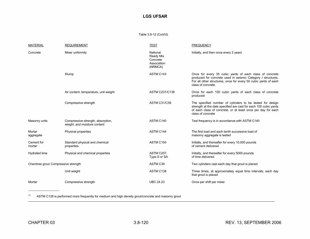
LGS UFSAR
CHAPTER 03 3.8-120 REV. 13, SEPTEMBER 2006
Table 3.8-12 (Cont'd)
MATERIAL REQUIREMENT TEST FREQUENCY
Concrete Mixer uniformity National Initially, and then once every 2 yearsReady MixConcreteAssociation(NRMCA)
Slump ASTM C143 Once for every 35 cubic yards of each class of concrete produced for concrete used in seismic Category I structures. For all other structures, once for every 50 cubic yards of each class of concrete.
Air content, temperature, unit weight ASTM C231/C138 Once for each 100 cubic yards of each class of concrete produced
Compressive strength ASTM C31/C39 The specified number of cylinders to be tested for design strength at the date specified are cast for each 100 cubic yards of each class of concrete, or at least once per day for each class of concrete
Masonry units Compressive strength, absorption, ASTM C140 Test frequency is in accordance with ASTM C140weight, and moisture content
Mortar Physical properties ASTM C144 The first load and each tenth successive load ofaggregate masonry aggregate is tested
Cement for Standard physical and chemical ASTM C150 Initially, and thereafter for every 10,000 poundsmortar properties of cement delivered
Hydrated lime Physical and chemical properties ASTM C207, Initially, and thereafter for every 5000 poundsType S or SA of lime delivered
Chemtree grout Compressive strength ASTM C39 Two cylinders cast each day that grout is placed
Unit weight ASTM C138 Three times, at approximately equal time intervals, each day that grout is placed
Mortar Compressive strength UBC 24.23 Once per shift per mixer
__________________
(1) ASTM C128 is performed more frequently for medium and high density grout/concrete and masonry grout_______________________________________________________________________________________________________________________________________________
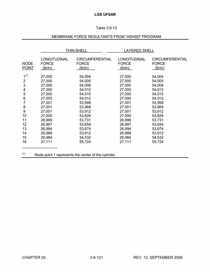
LGS UFSAR
CHAPTER 03 3.8-121 REV. 13, SEPTEMBER 2006
Table 3.8-13
MEMBRANE FORCE RESULTANTS FROM "ASHSD" PROGRAM
THIN-SHELL LAYERED SHELL
LONGITUDINAL CIRCUMFERENTIAL LONGITUDINAL CIRCUMFERENTIALNODE FORCE FORCE FORCE FORCEPOINT (lb/in) (lb/in) (lb/in) (lb/in)
1(1) 27,000 54,004 27,000 54,0042 27,000 54,005 27,000 54,0053 27,000 54,008 27,000 54,0084 27,000 54,012 27,000 54,0125 27,000 54,015 27,000 54,0156 27,000 54,012 27,000 54,0127 27,001 53,999 27,001 53,9998 27,001 53,968 27,001 53,9689 27,001 53,912 27,001 53,91210 27,000 53,829 27,000 53,82911 26,999 53,731 26,999 53,73112 26,997 53,654 26,997 53,65413 26,994 53,674 26,994 53,67414 26,989 53,912 26,989 53,91215 26,984 54,532 26,984 54,53216 27,111 55,724 27,111 55,724_________________
(1) Node point 1 represents the center of the cylinder.
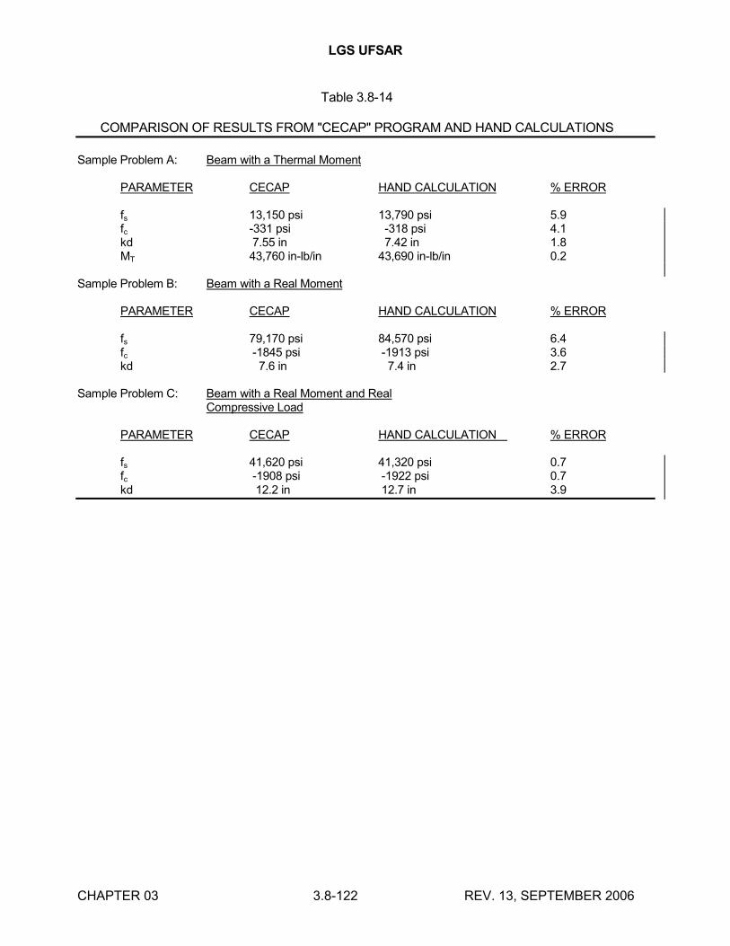
LGS UFSAR
CHAPTER 03 3.8-122 REV. 13, SEPTEMBER 2006
Table 3.8-14
COMPARISON OF RESULTS FROM "CECAP" PROGRAM AND HAND CALCULATIONS
Sample Problem A: Beam with a Thermal Moment
PARAMETER CECAP HAND CALCULATION % ERROR
fs 13,150 psi 13,790 psi 5.9fc -331 psi -318 psi 4.1kd 7.55 in 7.42 in 1.8MT 43,760 in-lb/in 43,690 in-lb/in 0.2
Sample Problem B: Beam with a Real Moment
PARAMETER CECAP HAND CALCULATION % ERROR
fs 79,170 psi 84,570 psi 6.4fc -1845 psi -1913 psi 3.6kd 7.6 in 7.4 in 2.7
Sample Problem C: Beam with a Real Moment and RealCompressive Load
PARAMETER CECAP HAND CALCULATION % ERROR
fs 41,620 psi 41,320 psi 0.7fc -1908 psi -1922 psi 0.7kd 12.2 in 12.7 in 3.9
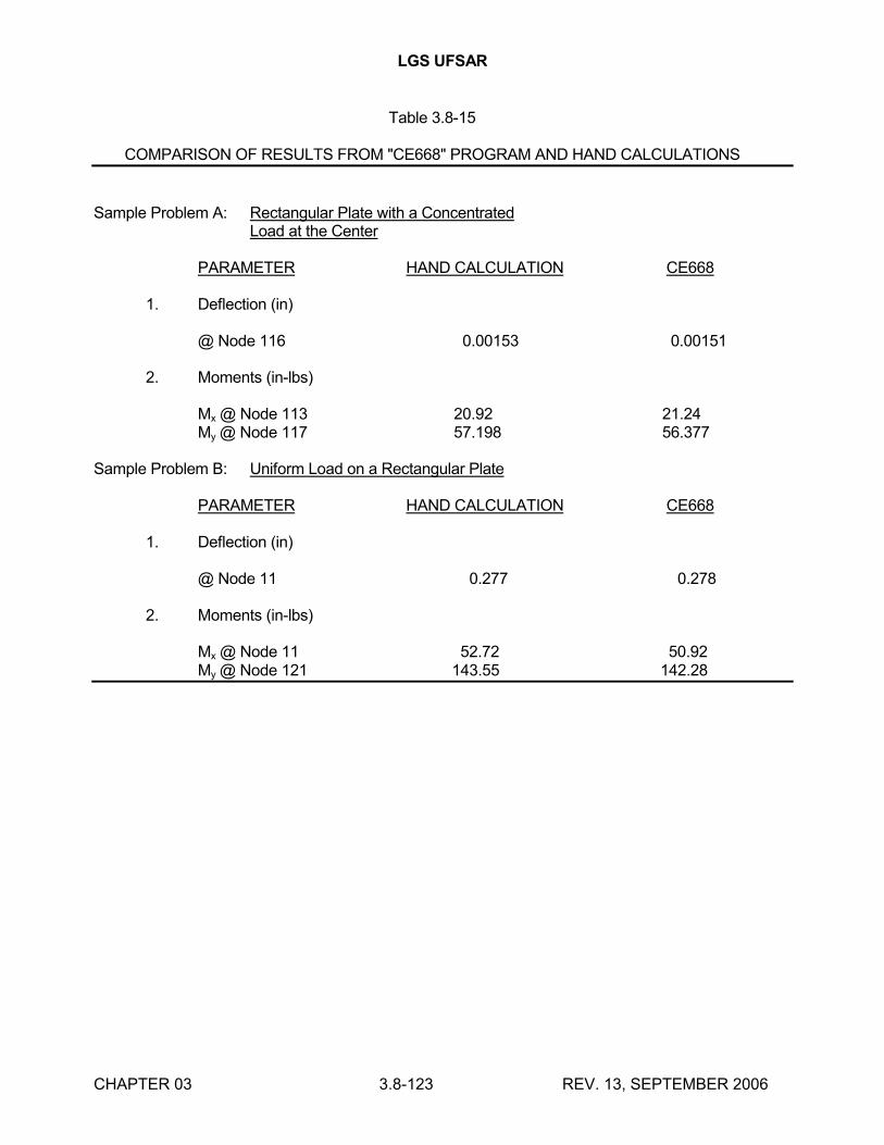
LGS UFSAR
CHAPTER 03 3.8-123 REV. 13, SEPTEMBER 2006
Table 3.8-15
COMPARISON OF RESULTS FROM "CE668" PROGRAM AND HAND CALCULATIONS
Sample Problem A: Rectangular Plate with a ConcentratedLoad at the Center
PARAMETER HAND CALCULATION CE668
1. Deflection (in)
@ Node 116 0.00153 0.00151
2. Moments (in-lbs)
Mx @ Node 113 20.92 21.24My @ Node 117 57.198 56.377
Sample Problem B: Uniform Load on a Rectangular Plate
PARAMETER HAND CALCULATION CE668
1. Deflection (in)
@ Node 11 0.277 0.278
2. Moments (in-lbs)
Mx @ Node 11 52.72 50.92My @ Node 121 143.55 142.28
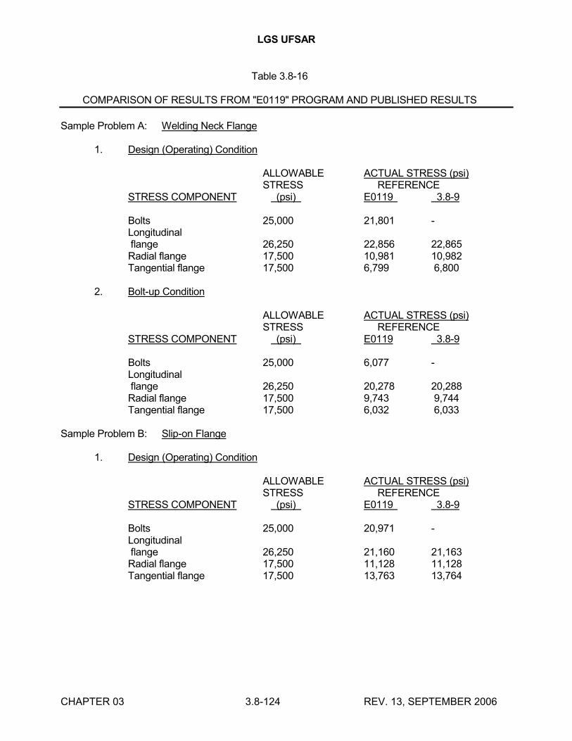
LGS UFSAR
CHAPTER 03 3.8-124 REV. 13, SEPTEMBER 2006
Table 3.8-16
COMPARISON OF RESULTS FROM "E0119" PROGRAM AND PUBLISHED RESULTS
Sample Problem A: Welding Neck Flange
1. Design (Operating) Condition
ALLOWABLE ACTUAL STRESS (psi)STRESS REFERENCE
STRESS COMPONENT (psi) E0119 3.8-9
Bolts 25,000 21,801 -Longitudinalflange 26,250 22,856 22,865Radial flange 17,500 10,981 10,982Tangential flange 17,500 6,799 6,800
2. Bolt-up Condition
ALLOWABLE ACTUAL STRESS (psi)STRESS REFERENCE
STRESS COMPONENT (psi) E0119 3.8-9
Bolts 25,000 6,077 -Longitudinalflange 26,250 20,278 20,288Radial flange 17,500 9,743 9,744Tangential flange 17,500 6,032 6,033
Sample Problem B: Slip-on Flange
1. Design (Operating) Condition
ALLOWABLE ACTUAL STRESS (psi)STRESS REFERENCE
STRESS COMPONENT (psi) E0119 3.8-9
Bolts 25,000 20,971 -Longitudinalflange 26,250 21,160 21,163Radial flange 17,500 11,128 11,128Tangential flange 17,500 13,763 13,764
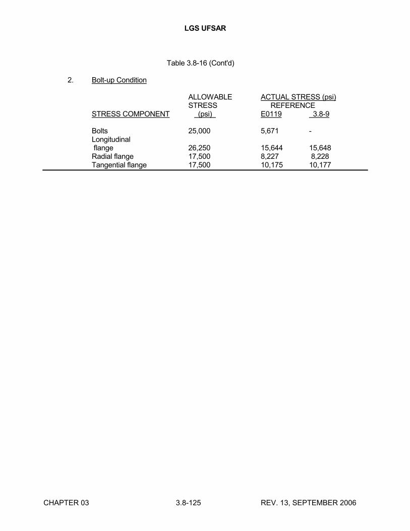
LGS UFSAR
CHAPTER 03 3.8-125 REV. 13, SEPTEMBER 2006
Table 3.8-16 (Cont'd)
2. Bolt-up Condition
ALLOWABLE ACTUAL STRESS (psi)STRESS REFERENCE
STRESS COMPONENT (psi) E0119 3.8-9
Bolts 25,000 5,671 -Longitudinalflange 26,250 15,644 15,648Radial flange 17,500 8,227 8,228Tangential flange 17,500 10,175 10,177
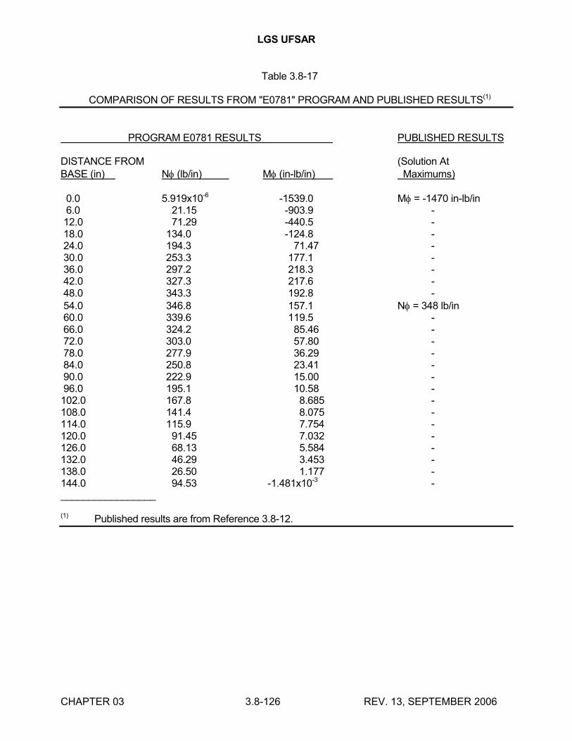
LGS UFSAR
CHAPTER 03 3.8-126 REV. 13, SEPTEMBER 2006
Table 3.8-17
COMPARISON OF RESULTS FROM "E0781" PROGRAM AND PUBLISHED RESULTS(1)
PROGRAM E0781 RESULTS PUBLISHED RESULTS
DISTANCE FROM (Solution AtBASE (in) N (lb/in) M (in-lb/in) Maximums)
0.0 5.919x10⁻⁶ -1539.0 M = -1470 in-lb/in 6.0 21.15 -903.9 -12.0 71.29 -440.5 -18.0 134.0 -124.8 -24.0 194.3 71.47 -30.0 253.3 177.1 -36.0 297.2 218.3 -42.0 327.3 217.6 -48.0 343.3 192.8 -54.0 346.8 157.1 N = 348 lb/in60.0 339.6 119.5 -66.0 324.2 85.46 -72.0 303.0 57.80 -78.0 277.9 36.29 -84.0 250.8 23.41 -90.0 222.9 15.00 -96.0 195.1 10.58 -102.0 167.8 8.685 -108.0 141.4 8.075 -114.0 115.9 7.754 -120.0 91.45 7.032 -126.0 68.13 5.584 -132.0 46.29 3.453 -138.0 26.50 1.177 -144.0 94.53 -1.481x10⁻³ -_________________
(1) Published results are from Reference 3.8-12.
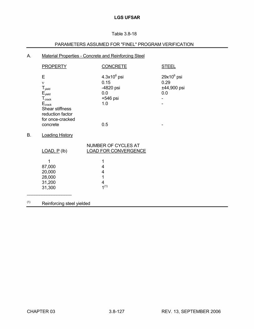
LGS UFSAR
CHAPTER 03 3.8-127 REV. 13, SEPTEMBER 2006
Table 3.8-18
PARAMETERS ASSUMED FOR "FINEL" PROGRAM VERIFICATION
A. Material Properties - Concrete and Reinforcing Steel
PROPERTY CONCRETE STEEL
E 4.3x10⁶ psi 29x106 psi 0.15 0.29Tyield -4820 psi ±44,900 psiEyield 0.0 0.0Tcrack +546 psi -Ecrack 1.0 -Shear stiffnessreduction factorfor once-crackedconcrete 0.5 -
B. Loading History
NUMBER OF CYCLES ATLOAD, P (lb) LOAD FOR CONVERGENCE
1 187,000 420,000 428,000 131,200 431,300 1(1)
__________________
(1) Reinforcing steel yielded
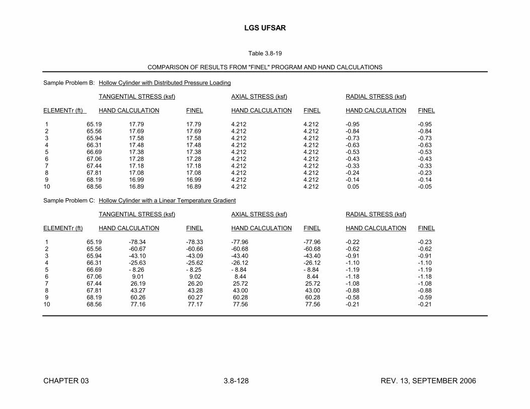
LGS UFSAR
CHAPTER 03 3.8-128 REV. 13, SEPTEMBER 2006
Table 3.8-19
COMPARISON OF RESULTS FROM "FINEL" PROGRAM AND HAND CALCULATIONS
Sample Problem B: Hollow Cylinder with Distributed Pressure Loading
TANGENTIAL STRESS (ksf) AXIAL STRESS (ksf) RADIAL STRESS (ksf)
ELEMENTr (ft) HAND CALCULATION FINEL HAND CALCULATION FINEL HAND CALCULATION FINEL
1 65.19 17.79 17.79 4.212 4.212 -0.95 -0.952 65.56 17.69 17.69 4.212 4.212 -0.84 -0.843 65.94 17.58 17.58 4.212 4.212 -0.73 -0.734 66.31 17.48 17.48 4.212 4.212 -0.63 -0.635 66.69 17.38 17.38 4.212 4.212 -0.53 -0.536 67.06 17.28 17.28 4.212 4.212 -0.43 -0.437 67.44 17.18 17.18 4.212 4.212 -0.33 -0.338 67.81 17.08 17.08 4.212 4.212 -0.24 -0.239 68.19 16.99 16.99 4.212 4.212 -0.14 -0.14
10 68.56 16.89 16.89 4.212 4.212 0.05 -0.05
Sample Problem C: Hollow Cylinder with a Linear Temperature Gradient
TANGENTIAL STRESS (ksf) AXIAL STRESS (ksf) RADIAL STRESS (ksf)
ELEMENTr (ft) HAND CALCULATION FINEL HAND CALCULATION FINEL HAND CALCULATION FINEL
1 65.19 -78.34 -78.33 -77.96 -77.96 -0.22 -0.232 65.56 -60.67 -60.66 -60.68 -60.68 -0.62 -0.623 65.94 -43.10 -43.09 -43.40 -43.40 -0.91 -0.914 66.31 -25.63 -25.62 -26.12 -26.12 -1.10 -1.105 66.69 - 8.26 - 8.25 - 8.84 - 8.84 -1.19 -1.196 67.06 9.01 9.02 8.44 8.44 -1.18 -1.187 67.44 26.19 26.20 25.72 25.72 -1.08 -1.088 67.81 43.27 43.28 43.00 43.00 -0.88 -0.889 68.19 60.26 60.27 60.28 60.28 -0.58 -0.59
10 68.56 77.16 77.17 77.56 77.56 -0.21 -0.21
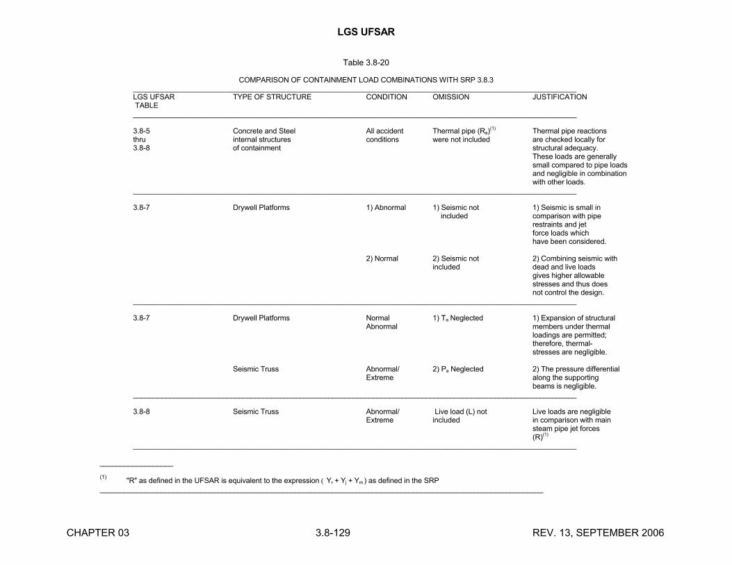
LGS UFSAR
CHAPTER 03 3.8-129 REV. 13, SEPTEMBER 2006
Table 3.8-20
COMPARISON OF CONTAINMENT LOAD COMBINATIONS WITH SRP 3.8.3_____________________________________________________________________________________________________________LGS UFSAR TYPE OF STRUCTURE CONDITION OMISSION JUSTIFICATIONTABLE_____________________________________________________________________________________________________________
3.8-5 Concrete and Steel All accident Thermal pipe (Ra)(1) Thermal pipe reactions
thru internal structures conditions were not included are checked locally for3.8-8 of containment structural adequacy.
These loads are generallysmall compared to pipe loadsand negligible in combinationwith other loads.
_____________________________________________________________________________________________________________
3.8-7 Drywell Platforms 1) Abnormal 1) Seismic not 1) Seismic is small in included comparison with pipe
restraints and jetforce loads whichhave been considered.
2) Normal 2) Seismic not 2) Combining seismic withincluded dead and live loads
gives higher allowablestresses and thus doesnot control the design.
_____________________________________________________________________________________________________________
3.8-7 Drywell Platforms Normal 1) Ta Neglected 1) Expansion of structuralAbnormal members under thermal
loadings are permitted;therefore, thermal-stresses are negligible.
Seismic Truss Abnormal/ 2) Pa Neglected 2) The pressure differentialExtreme along the supporting
beams is negligible._____________________________________________________________________________________________________________
3.8-8 Seismic Truss Abnormal/ Live load (L) not Live loads are negligibleExtreme included in comparison with main
steam pipe jet forces(R)(1)
_____________________________________________________________________________________________________________
__________________
(1)"R" as defined in the UFSAR is equivalent to the expression Yr + Yj + Ym) as defined in the SRP
_____________________________________________________________________________________________________________
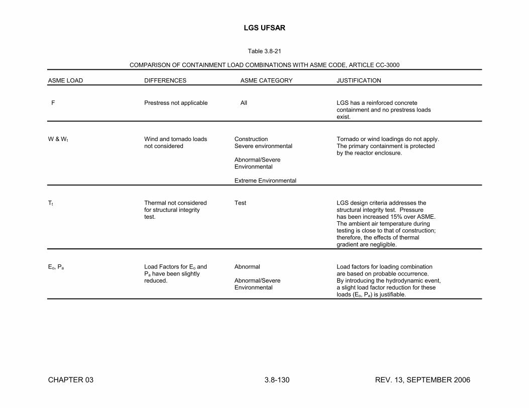
LGS UFSAR
CHAPTER 03 3.8-130 REV. 13, SEPTEMBER 2006
Table 3.8-21
COMPARISON OF CONTAINMENT LOAD COMBINATIONS WITH ASME CODE, ARTICLE CC-3000
ASME LOAD DIFFERENCES ASME CATEGORY JUSTIFICATION
F Prestress not applicable All LGS has a reinforced concretecontainment and no prestress loadsexist.
W & Wt Wind and tornado loads Construction Tornado or wind loadings do not apply.not considered Severe environmental The primary containment is protected
by the reactor enclosure.Abnormal/SevereEnvironmental
Extreme Environmental
Tt Thermal not considered Test LGS design criteria addresses thefor structural integrity structural integrity test. Pressuretest. has been increased 15% over ASME.
The ambient air temperature duringtesting is close to that of construction;therefore, the effects of thermalgradient are negligible.
Eo, Pa Load Factors for Eo and Abnormal Load factors for loading combinationPa have been slightly are based on probable occurrence.reduced. Abnormal/Severe By introducing the hydrodynamic event,
Environmental a slight load factor reduction for theseloads (Eo, Pa) is justifiable.
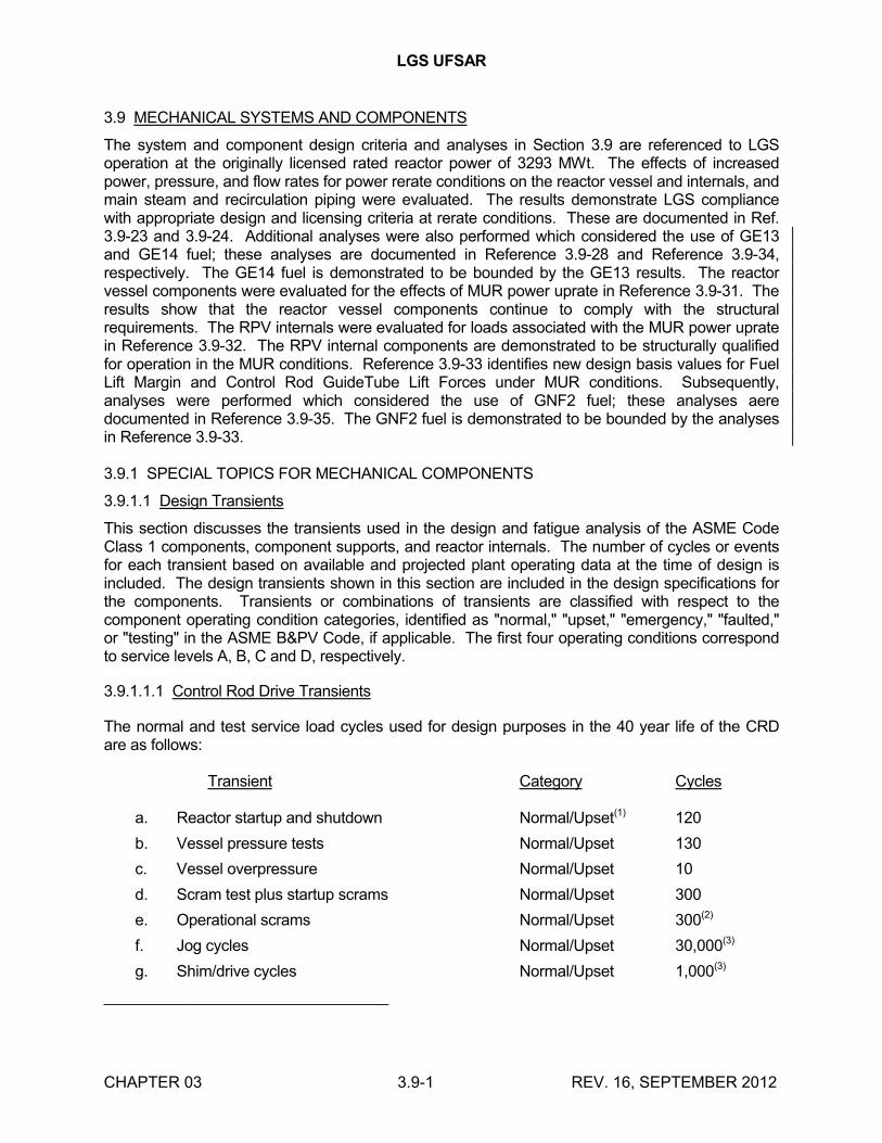
LGS UFSAR
CHAPTER 03 3.9-1 REV. 16, SEPTEMBER 2012
3.9 MECHANICAL SYSTEMS AND COMPONENTS
The system and component design criteria and analyses in Section 3.9 are referenced to LGS operation at the originally licensed rated reactor power of 3293 MWt. The effects of increased power, pressure, and flow rates for power rerate conditions on the reactor vessel and internals, and main steam and recirculation piping were evaluated. The results demonstrate LGS compliance with appropriate design and licensing criteria at rerate conditions. These are documented in Ref. 3.9-23 and 3.9-24. Additional analyses were also performed which considered the use of GE13and GE14 fuel; these analyses are documented in Reference 3.9-28 and Reference 3.9-34, respectively. The GE14 fuel is demonstrated to be bounded by the GE13 results. The reactor vessel components were evaluated for the effects of MUR power uprate in Reference 3.9-31. The results show that the reactor vessel components continue to comply with the structural requirements. The RPV internals were evaluated for loads associated with the MUR power uprate in Reference 3.9-32. The RPV internal components are demonstrated to be structurally qualified for operation in the MUR conditions. Reference 3.9-33 identifies new design basis values for Fuel Lift Margin and Control Rod GuideTube Lift Forces under MUR conditions. Subsequently, analyses were performed which considered the use of GNF2 fuel; these analyses aere documented in Reference 3.9-35. The GNF2 fuel is demonstrated to be bounded by the analyses in Reference 3.9-33.
3.9.1 SPECIAL TOPICS FOR MECHANICAL COMPONENTS
3.9.1.1 Design Transients
This section discusses the transients used in the design and fatigue analysis of the ASME Code Class 1 components, component supports, and reactor internals. The number of cycles or events for each transient based on available and projected plant operating data at the time of design is included. The design transients shown in this section are included in the design specifications for the components. Transients or combinations of transients are classified with respect to the component operating condition categories, identified as "normal," "upset," "emergency," "faulted," or "testing" in the ASME B&PV Code, if applicable. The first four operating conditions correspond to service levels A, B, C and D, respectively.
3.9.1.1.1 Control Rod Drive Transients
The normal and test service load cycles used for design purposes in the 40 year life of the CRD are as follows:
Transient Category Cycles
a. Reactor startup and shutdown Normal/Upset(1) 120
b. Vessel pressure tests Normal/Upset 130
c. Vessel overpressure Normal/Upset 10
d. Scram test plus startup scrams Normal/Upset 300
e. Operational scrams Normal/Upset 300(2)
f. Jog cycles Normal/Upset 30,000(3)
g. Shim/drive cycles Normal/Upset 1,000(3)
_________________________________

LGS UFSAR
CHAPTER 03 3.9-2 REV. 16, SEPTEMBER 2012
(1) In Section 3.9.1.1, whenever a transient is categorized with two classifications, i.e., normal/upset, the most limiting of the two is considered in the design.
(2) 180 scram cycles constitute the design basis; however, 300 cycles are applied to the CRD for conservatism.
(3) 30,000 jog cycles and 1000 shim/drive cycles are applied because they impose mechanical loads on the CRD while contributing negligible thermal loads.
In addition to the above cycles, the following have been considered in the design of the CRD:
Transient Category Cycles
h. Scram with inoperative buffer Normal/Upset 10
i. Scram with stuck control Normal/Upset 1
blade
j. OBE(3) Upset 10
k. SSE Faulted 1
All ASME Class 1 components of the CRD have been analyzed according to ASME Section III. The capability of the CRD to withstand other emergency and faulted conditions is verified by test rather than analysis.
3.9.1.1.2 CRD Housing and Incore Housing Transients
Transients, classifications, and number of cycles considered in the design and fatigue analysis of the CRD housing and incore housing are as follows:
Transient Category Cycles
a. Normal startup and shutdown Normal/Upset 120
b. Vessel pressure tests Normal/Upset 130
c. Vessel overpressure tests Normal/Upset 10
d. Interruption of feedwater Normal/Upset 80(1)
flow
e. Scram Normal/Upset 200(2)
f. OBE Upset 10
g. SSE Faulted 1
____________________
(1) The interruption of feedwater flow imposes thermal loads on the CRD housing while contributing negligible mechanical loads.
(2) 180 scram cycles constitute the design basis; however, 200 cycles are applied to the CRD housing for conservatism.
(3) The frequency of occurrence of this transient indicates the emergency category. However, for conservatism, the OBE was analyzed as an upset condition. Ten peak stress cycles are postulated.
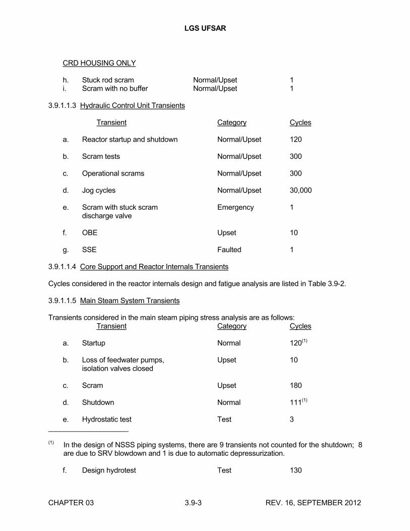
LGS UFSAR
CHAPTER 03 3.9-3 REV. 16, SEPTEMBER 2012
CRD HOUSING ONLY
h. Stuck rod scram Normal/Upset 1i. Scram with no buffer Normal/Upset 1
3.9.1.1.3 Hydraulic Control Unit Transients
Transient Category Cycles
a. Reactor startup and shutdown Normal/Upset 120
b. Scram tests Normal/Upset 300
c. Operational scrams Normal/Upset 300
d. Jog cycles Normal/Upset 30,000
e. Scram with stuck scram Emergency 1discharge valve
f. OBE Upset 10
g. SSE Faulted 1
3.9.1.1.4 Core Support and Reactor Internals Transients
Cycles considered in the reactor internals design and fatigue analysis are listed in Table 3.9-2.
3.9.1.1.5 Main Steam System Transients
Transients considered in the main steam piping stress analysis are as follows:Transient Category Cycles
a. Startup Normal 120(1)
b. Loss of feedwater pumps, Upset 10isolation valves closed
c. Scram Upset 180
d. Shutdown Normal 111(1)
e. Hydrostatic test Test 3____________________
(1) In the design of NSSS piping systems, there are 9 transients not counted for the shutdown; 8 are due to SRV blowdown and 1 is due to automatic depressurization.
f. Design hydrotest Test 130
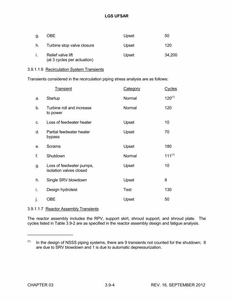
LGS UFSAR
CHAPTER 03 3.9-4 REV. 16, SEPTEMBER 2012
g. OBE Upset 50
h. Turbine stop valve closure Upset 120
i. Relief valve lift Upset 34,200(at 3 cycles per actuation)
3.9.1.1.6 Recirculation System Transients
Transients considered in the recirculation piping stress analysis are as follows:
Transient Category Cycles
a. Startup Normal 120(1)
b. Turbine roll and increase Normal 120to power
c. Loss of feedwater heater Upset 10
d. Partial feedwater heater Upset 70bypass
e. Scrams Upset 180
f. Shutdown Normal 111(1)
g. Loss of feedwater pumps, Upset 10isolation valves closed
h. Single SRV blowdown Upset 8
i. Design hydrotest Test 130
j. OBE Upset 50
3.9.1.1.7 Reactor Assembly Transients
The reactor assembly includes the RPV, support skirt, shroud support, and shroud plate. The cycles listed in Table 3.9-2 are as specified in the reactor assembly design and fatigue analysis.
____________________
(1) In the design of NSSS piping systems, there are 9 transients not counted for the shutdown; 8 are due to SRV blowdown and 1 is due to automatic depressurization.
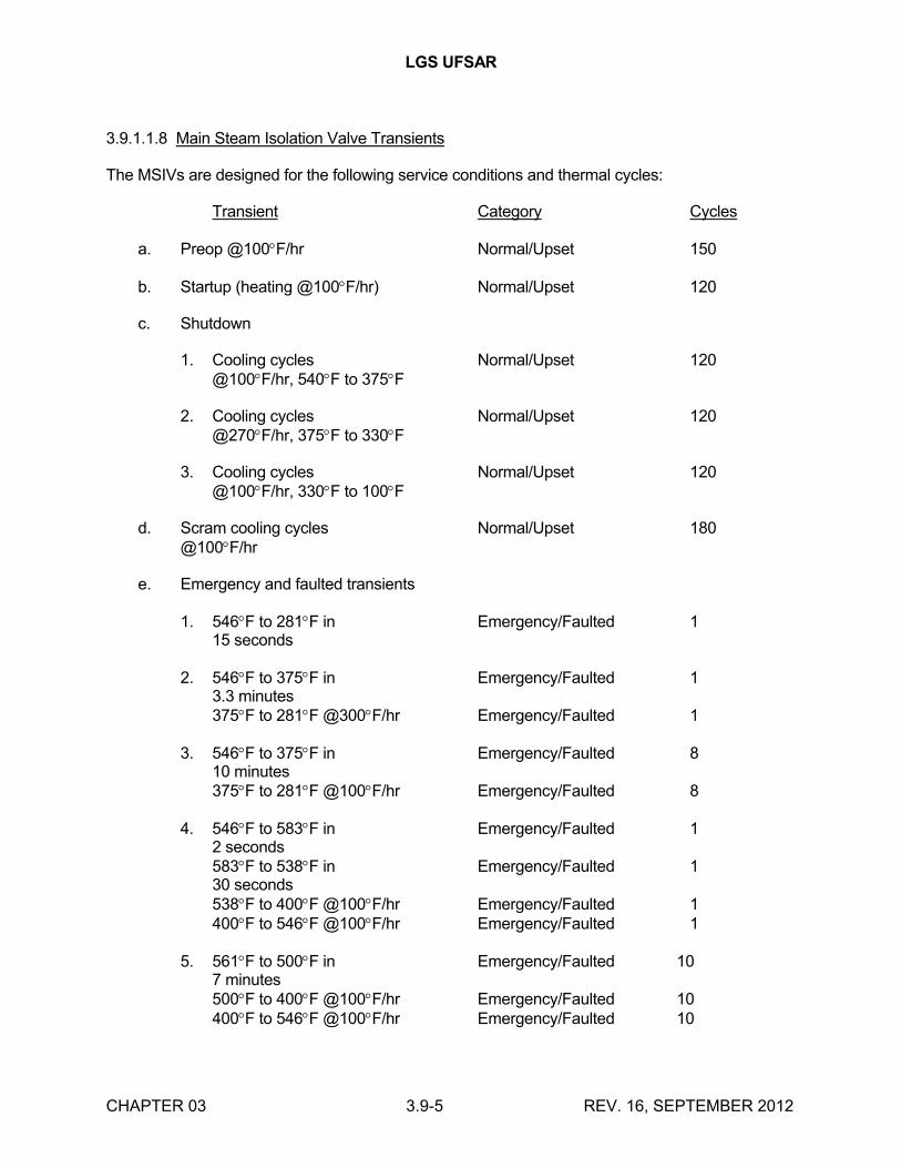
LGS UFSAR
CHAPTER 03 3.9-5 REV. 16, SEPTEMBER 2012
3.9.1.1.8 Main Steam Isolation Valve Transients
The MSIVs are designed for the following service conditions and thermal cycles:
Transient Category Cycles
a. Preop @100F/hr Normal/Upset 150
b. Startup (heating @100F/hr) Normal/Upset 120
c. Shutdown
1. Cooling cycles Normal/Upset 120@100F/hr, 540F to 375F
2. Cooling cycles Normal/Upset 120@270F/hr, 375F to 330F
3. Cooling cycles Normal/Upset 120@100F/hr, 330F to 100F
d. Scram cooling cycles Normal/Upset 180@100F/hr
e. Emergency and faulted transients
1. 546F to 281F in Emergency/Faulted 115 seconds
2. 546F to 375F in Emergency/Faulted 13.3 minutes375F to 281F @300F/hr Emergency/Faulted 1
3. 546F to 375F in Emergency/Faulted 810 minutes375F to 281F @100F/hr Emergency/Faulted 8
4. 546F to 583F in Emergency/Faulted 12 seconds583F to 538F in Emergency/Faulted 130 seconds538F to 400F @100F/hr Emergency/Faulted 1400F to 546F @100F/hr Emergency/Faulted 1
5. 561F to 500F in Emergency/Faulted 107 minutes500F to 400F @100F/hr Emergency/Faulted 10400F to 546F @100F/hr Emergency/Faulted 10
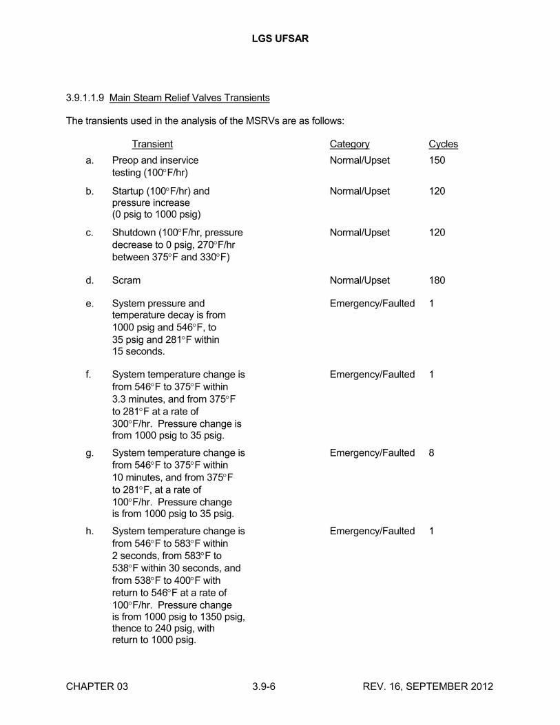
LGS UFSAR
CHAPTER 03 3.9-6 REV. 16, SEPTEMBER 2012
3.9.1.1.9 Main Steam Relief Valves Transients
The transients used in the analysis of the MSRVs are as follows:
Transient Category Cycles
a. Preop and inservice Normal/Upset 150testing (100F/hr)
b. Startup (100F/hr) and Normal/Upset 120pressure increase(0 psig to 1000 psig)
c. Shutdown (100F/hr, pressure Normal/Upset 120decrease to 0 psig, 270F/hrbetween 375F and 330F)
d. Scram Normal/Upset 180
e. System pressure and Emergency/Faulted 1temperature decay is from1000 psig and 546F, to35 psig and 281F within15 seconds.
f. System temperature change is Emergency/Faulted 1from 546F to 375F within3.3 minutes, and from 375Fto 281F at a rate of300F/hr. Pressure change isfrom 1000 psig to 35 psig.
g. System temperature change is Emergency/Faulted 8from 546F to 375F within10 minutes, and from 375Fto 281F, at a rate of100F/hr. Pressure changeis from 1000 psig to 35 psig.
h. System temperature change is Emergency/Faulted 1from 546F to 583F within2 seconds, from 583F to538F within 30 seconds, andfrom 538F to 400F withreturn to 546F at a rate of100F/hr. Pressure changeis from 1000 psig to 1350 psig,thence to 240 psig, withreturn to 1000 psig.
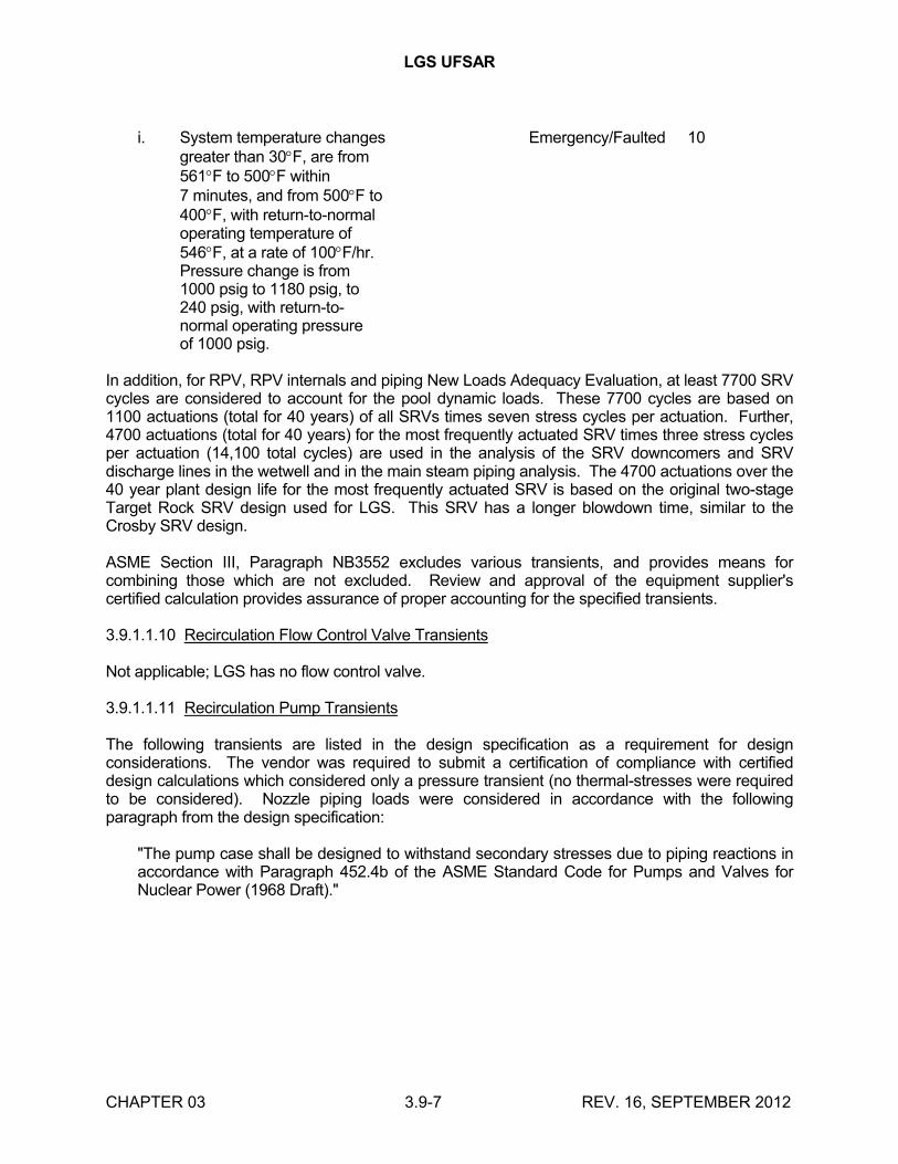
LGS UFSAR
CHAPTER 03 3.9-7 REV. 16, SEPTEMBER 2012
i. System temperature changes Emergency/Faulted 10greater than 30F, are from561F to 500F within7 minutes, and from 500F to400F, with return-to-normaloperating temperature of546F, at a rate of 100F/hr.Pressure change is from1000 psig to 1180 psig, to240 psig, with return-to-normal operating pressureof 1000 psig.
In addition, for RPV, RPV internals and piping New Loads Adequacy Evaluation, at least 7700 SRV cycles are considered to account for the pool dynamic loads. These 7700 cycles are based on 1100 actuations (total for 40 years) of all SRVs times seven stress cycles per actuation. Further, 4700 actuations (total for 40 years) for the most frequently actuated SRV times three stress cycles per actuation (14,100 total cycles) are used in the analysis of the SRV downcomers and SRV discharge lines in the wetwell and in the main steam piping analysis. The 4700 actuations over the 40 year plant design life for the most frequently actuated SRV is based on the original two-stage Target Rock SRV design used for LGS. This SRV has a longer blowdown time, similar to the Crosby SRV design.
ASME Section III, Paragraph NB3552 excludes various transients, and provides means for combining those which are not excluded. Review and approval of the equipment supplier's certified calculation provides assurance of proper accounting for the specified transients.
3.9.1.1.10 Recirculation Flow Control Valve Transients
Not applicable; LGS has no flow control valve.
3.9.1.1.11 Recirculation Pump Transients
The following transients are listed in the design specification as a requirement for design considerations. The vendor was required to submit a certification of compliance with certified design calculations which considered only a pressure transient (no thermal-stresses were required to be considered). Nozzle piping loads were considered in accordance with the following paragraph from the design specification:
"The pump case shall be designed to withstand secondary stresses due to piping reactions in accordance with Paragraph 452.4b of the ASME Standard Code for Pumps and Valves for Nuclear Power (1968 Draft)."
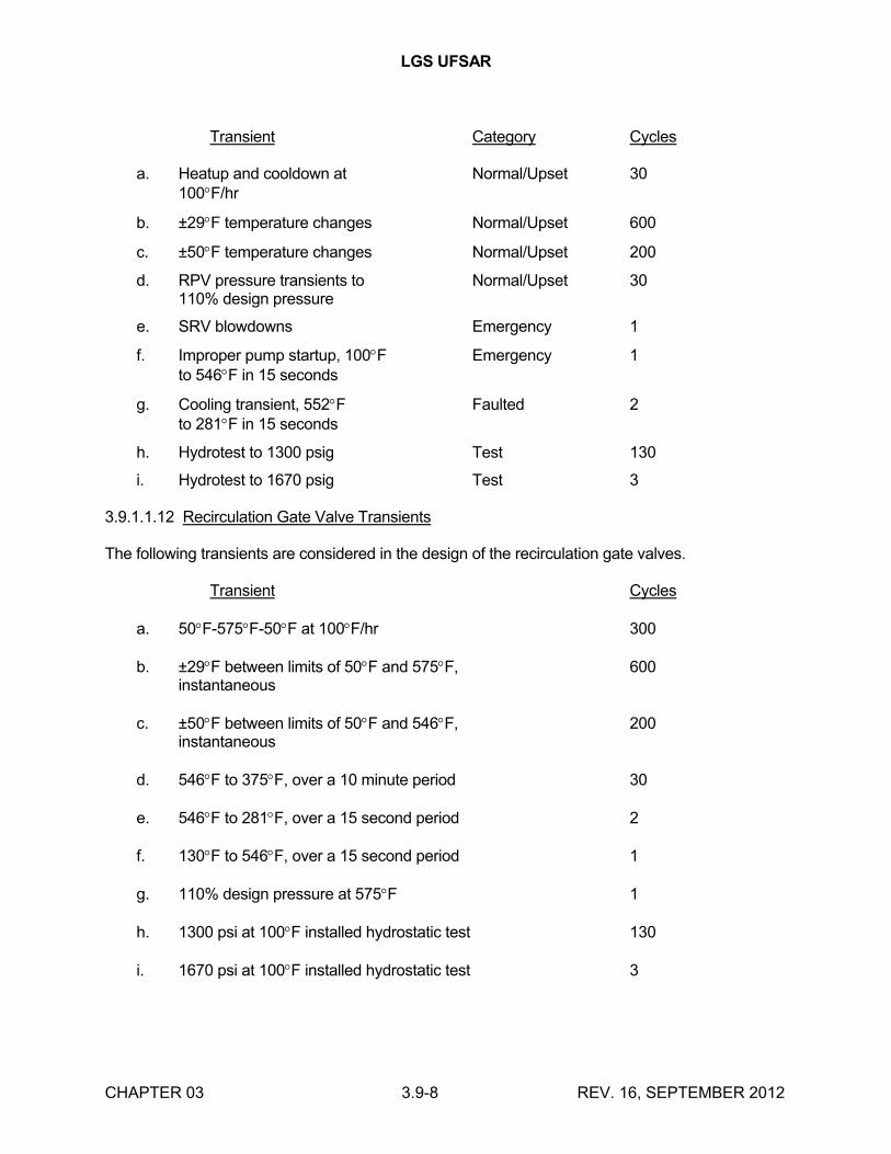
LGS UFSAR
CHAPTER 03 3.9-8 REV. 16, SEPTEMBER 2012
Transient Category Cycles
a. Heatup and cooldown at Normal/Upset 30100F/hr
b. ±29F temperature changes Normal/Upset 600
c. ±50F temperature changes Normal/Upset 200
d. RPV pressure transients to Normal/Upset 30110% design pressure
e. SRV blowdowns Emergency 1
f. Improper pump startup, 100F Emergency 1to 546F in 15 seconds
g. Cooling transient, 552F Faulted 2to 281F in 15 seconds
h. Hydrotest to 1300 psig Test 130
i. Hydrotest to 1670 psig Test 3
3.9.1.1.12 Recirculation Gate Valve Transients
The following transients are considered in the design of the recirculation gate valves.
Transient Cycles
a. 50F-575F-50F at 100F/hr 300
b. ±29F between limits of 50F and 575F, 600instantaneous
c. ±50F between limits of 50F and 546F, 200instantaneous
d. 546F to 375F, over a 10 minute period 30
e. 546F to 281F, over a 15 second period 2
f. 130F to 546F, over a 15 second period 1
g. 110% design pressure at 575F 1
h. 1300 psi at 100F installed hydrostatic test 130
i. 1670 psi at 100F installed hydrostatic test 3
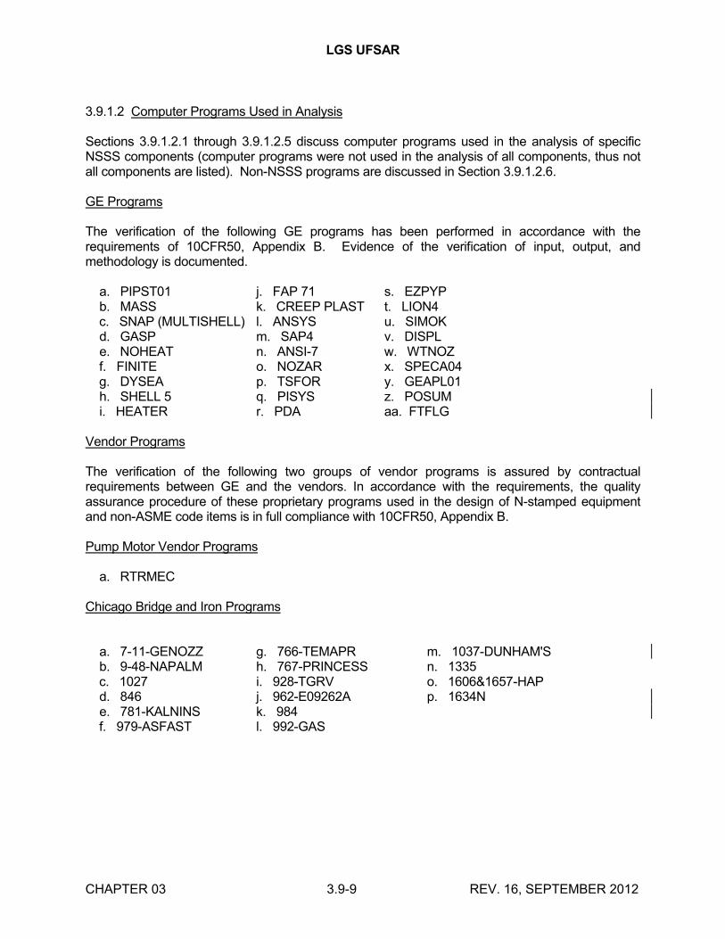
LGS UFSAR
CHAPTER 03 3.9-9 REV. 16, SEPTEMBER 2012
3.9.1.2 Computer Programs Used in Analysis
Sections 3.9.1.2.1 through 3.9.1.2.5 discuss computer programs used in the analysis of specific NSSS components (computer programs were not used in the analysis of all components, thus not all components are listed). Non-NSSS programs are discussed in Section 3.9.1.2.6.
GE Programs
The verification of the following GE programs has been performed in accordance with the requirements of 10CFR50, Appendix B. Evidence of the verification of input, output, and methodology is documented.
a. PIPST01 j. FAP 71 s. EZPYP b. MASS k. CREEP PLAST t. LION4 c. SNAP (MULTISHELL) l. ANSYS u. SIMOK d. GASP m. SAP4 v. DISPL e. NOHEAT n. ANSI-7 w. WTNOZ f. FINITE o. NOZAR x. SPECA04 g. DYSEA p. TSFOR y. GEAPL01 h. SHELL 5 q. PISYS z. POSUM i. HEATER r. PDA aa. FTFLG
Vendor Programs
The verification of the following two groups of vendor programs is assured by contractual requirements between GE and the vendors. In accordance with the requirements, the quality assurance procedure of these proprietary programs used in the design of N-stamped equipment and non-ASME code items is in full compliance with 10CFR50, Appendix B.
Pump Motor Vendor Programs
a. RTRMEC
Chicago Bridge and Iron Programs
a. 7-11-GENOZZ g. 766-TEMAPR m. 1037-DUNHAM'S b. 9-48-NAPALM h. 767-PRINCESS n. 1335 c. 1027 i. 928-TGRV o. 1606&1657-HAP d. 846 j. 962-E09262A p. 1634N e. 781-KALNINS k. 984 f. 979-ASFAST l. 992-GAS
LGS UFSAR
CHAPTER 03 3.9-10 REV. 16, SEPTEMBER 2012
3.9.1.2.1 Reactor Vessel and Internals
3.9.1.2.1.1 Reactor Vessel
The computer programs used in the preparation of the reactor vessel stress report are identified, and their use summarized in the following paragraphs.
3.9.1.2.1.1.1 Chicago Bridge and Iron Program 7-11 - GENOZZ
The GENOZZ computer program is used to proportion barrel and double taper-type nozzles to comply with the specifications of ASME Section III, and contract documents. The program either designs such a configuration or analyzes the configuration input to comply to code. If the input configuration does not comply with the specifications, the program modifies the design and redesigns it to yield an acceptable result.
3.9.1.2.1.1.2 Chicago Bridge and Iron Program 9-48 - NAPALM
The basis for the Nozzle Analysis Program - All Loads Mechanical (NAPALM) is to analyze nozzles for mechanical loads and find the maximum stress intensity and location. The program provides analyses at each mechanical load point of application. The maximum stress intensity is calculated for both the inside and outside surfaces at each reference location. The program measures the maximum stress intensity for both the inside and outside surfaces of the nozzle, as well as their angular locations as measured from the 0 reference location. The principle stresses are also listed.
Stresses resulting from each component of loading (bending, axial, shear, and torsion) are listed, as well as the loadings which cause these stresses.
3.9.1.2.1.1.3 Chicago Bridge and Iron Program 1027
This program is a computerized version of the analysis method contained in Reference 3.9-1.
Part of this program provides for the determination of the shell stress intensities (S) around the perimeter of a loaded attachment on a cylindrical or spherical vessel. Eight (S) values are calculated, one at each of four cardinal points, for both the upper and lower shell plate surfaces (ordinarily considered outside and inside surfaces). With the determination of each (S), the components of that (S) (two normal stresses, x and y, and shear stress ) are also determined. This program provides the same information as the manual calculation, and the input data is essentially the geometry of the vessel and attachment.
3.9.1.2.1.1.4 Chicago Bridge and Iron Program 846
This program computes the required thickness of a hemispherical head with a large number of circular parallel penetrations, by means of the area replacement method, in accordance with ASME Code, Section III.
In cases where the penetration has a counterbore, the thickness is determined so that the counterbore does not penetrate the outside surface of the head.
3.9.1.2.1.1.5 Chicago Bridge and Iron Program 781 - KALNINS
LGS UFSAR
CHAPTER 03 3.9-11 REV. 16, SEPTEMBER 2012
The KALNINS thin-shell program is used to establish the shell influence coefficient, and to perform the detailed stress analysis of the vessel. The stresses and the deformations of the vessel can be computed for any combination of the following axisymmetric loading:
a. Preload condition
b. Internal pressure
c. Thermal load
This program is a thin elastic shell program for shells of revolution developed by Dr. A. Kalnins of Lehigh University. Extensive revisions and improvements have been made by Dr. J. Endicott, to yield the Chicago Bridge and Iron version of this program.
The basic method of analysis was published by Professor Kalnins (Reference 3.9-2).
3.9.1.2.1.1.6 Chicago Bridge and Iron Program 979 - ASFAST
The ASFAST program performs the stress analysis of axisymmetric, bolted closure flanges between the head and cylindrical shell.
3.9.1.2.1.1.6.1 ANSYS Engineering Analysis System, Revision 5.6, ANSYS, Inc.
ANSYS Program performed the stress analysis of the reactor vessel head, flange & upper shell for reduced pass tensioning/detensioning of RPV studs connecting RPV head to RPV shell.
3.9.1.2.1.1.7 Chicago Bridge and Iron Program 766 - TEMAPR
This program reduces any arbitrary temperature gradient through the wall thickness to an equivalent linear gradient. The resulting equivalent gradient has the same average temperature, and the same temperature-moment as the given temperature gradient. The input consists of the wall thickness and actual temperature distribution. The output contains the average temperature and total gradient through the wall thickness. The program is written in FORTRAN IV.
3.9.1.2.1.1.8 Chicago Bridge and Iron Program 767 - PRINCESS
The PRINCESS program calculates the maximum alternating stress amplitudes from a series of stress values, by the method in ASME Section III.
3.9.1.2.1.1.9 Chicago Bridge and Iron Program 928 - TGRV
The TGRV program is used to calculate temperature distributions in structures or vessels. Although it is primarily a program for solving the heat conduction equations, some provisions have been made for including radiation and convection effects at the surfaces of the vessel.
The TGRV program is a highly modified version of the TIGER heat transfer program, written about 1958 at Knolls Atomic Power Laboratory, by A.P. Bray.
The program utilizes an electrical network analogy to obtain the temperature distribution of any given system as a function of time. The finite-difference representation of the three-dimensional equations of heat transfer are repeatedly solved for small time increments, and continually
LGS UFSAR
CHAPTER 03 3.9-12 REV. 16, SEPTEMBER 2012
summed. Linear mathematics is used to solve the mesh network for every time interval. Three basic forms of heat transfer (conduction, radiation, and convection), as well as internal heat generation, are included in the analysis.
TGRV calculates and outputs the steady-state or transient temperature distributions in a given structure, as a function of time. The program inputs are any odd-shaped structure which can be represented by a three-dimensional field, its geometry and physical properties, boundary conditions, and internal heat generation rates.
3.9.1.2.1.1.10 Chicago Bridge and Iron Program 962 - E0962A
Program E0962A is one of a group of programs (E0953A, E1606A, E0962A, E0992N, E1037N, and E0984N) which are used together to determine the temperature distribution and stresses in pressure vessel components, using the finite-element method.
Program E0962A is primarily a plotting program. Using the nodal temperatures calculated by program E1606A or Program E0928A, and the node and element cards for the finite-element model, it calculates and plots lines of constant temperature (isotherms). These isotherm plots are used as part of the stress report to present the results of the thermal analysis. They are also useful in determining at which points in time the thermal-stresses should be determined.
In addition to its plotting capability, the program can also determine the temperatures of some of the nodal points by interpolation. This feature of the program is intended primarily for use with the compatible TGRV and finite-element models that are generated by program E0953A.
3.9.1.2.1.1.11 Chicago Bridge and Iron Program 984
Program 984 is used to calculate the stress intensity of stress differences, on a component level, between two different stress conditions. The calculation of the stress intensity of stress component differences (the range of stress intensity) is required by ASME Section III.
3.9.1.2.1.1.12 Chicago Bridge and Iron Program 992 GASP
The GASP program, originated by Professor E.L. Wilson of the University of California at Berkeley, uses the finite-element method to determine the stresses and displacements of plane or axisymmetric structures of arbitrary geometry, and is written in FORTRAN IV. See Reference 3.9-3, for a detailed account. GASP structures may have arbitrary geometry, and have linear or nonlinear material properties. The loadings may be thermal, mechanical, accelerational, or a combination of these.
A structure to be analyzed is broken up into a finite number of discrete elements or "finite-elements", which are interconnected at a finite number of "nodal points" or "nodes." The actual loads on the structure are simulated by statically equivalent loads acting at the appropriate nodes. The basic input to the program consists of the geometry of the stress model and the boundary conditions. The program then gives the stress components at the center of each element and the displacements at the nodes, consistent with the prescribed boundary conditions.
LGS UFSAR
CHAPTER 03 3.9-13 REV. 16, SEPTEMBER 2012
3.9.1.2.1.1.13 Chicago Bridge and Iron Program 1037 - DUNHAM'S
DUNHAM'S program is a finite ring element stress analysis program. It determines the stresses and displacements of axisymmetric structures of arbitrary geometry subjected to either axisymmetric loads, or nonaxisymmetric loads represented by a Fourier series.
This program is similar to the GASP program (Chicago Bridge and Iron Program 992). The major differences are that DUNHAM'S can handle nonaxisymmetric loads (which requires that each node have three degrees of freedom), while the material properties for DUNHAM'S must be constant. As in GASP, the loadings may be thermal, mechanical, and accelerational.
3.9.1.2.1.1.14 Chicago Bridge and Iron Program 1335
To obtain stresses in the shroud support, the baffle plate must be made a continuous circular plate. The program makes this modification and allows the baffle plate to be included in Chicago Bridge and Iron program 781 (KALNINS) as two isotropic parts, with an orthotropic portion at the middle (where the diffuser holes are located).
3.9.1.2.1.1.15 Chicago Bridge and Iron Programs 1606 and 1657 - HAP
The HAP program is an axisymmetric nonlinear heat analysis program. It is a finite-element program, used to determine nodal temperatures in a two-dimensional or axisymmetric body subject to transient disturbances. Programs 1606 and 1657 are identical, except that 1606 has a larger storage area allocated, and can thus be used to solve larger problems. The model for program 1606 is compatible with Chicago Bridge and Iron stress programs 992 (GASP) and 1037 (DUNHAM'S).
3.9.1.2.1.1.16 Chicago Bridge and Iron Program 1634N
This program is used to analyze thin cylindrical shells subjected to local loading beyond the range where Bijlaard's curves are directly applicable, i.e., R/t >300.
This program computes stress and displacements in thin-walled elastic cylindrical shells subjected to mechanical loading such as radial loads, longitudinal and circumferential moments.
3.9.1.2.1.2 Reactor Internals
3.9.1.2.1.2.1 Core Plate Beam Buckling - PIPST01
PIPST01 is a computer program that calculates approximate core plate beam buckling capability. It uses the Rayleigh-Ritz energy method to determine the applied moment needed to begin yielding and then to buckle a given tee beam. The tee beam models a segment of a BWR/2-5 core plate with a stiffener beam. The pressure differential across the plate that would have created this moment is calculated for a given length of beam or size of core plate.
Generic dimension and material properties are all input by the user.
LGS UFSAR
CHAPTER 03 3.9-14 REV. 16, SEPTEMBER 2012
3.9.1.2.1.2.2 Other Programs
Other computer codes used for the analysis of the internal components are:
a. MASS g. SHELL 5 b. SNAP (MULTISHELL) h. HEATER c. GASP i. FAP 71 d. NOHEAT j. CREEP PLAST e. FINITE k. ANSYS f. DYSEA
Descriptions of these programs are given in Section 4.1.4.1.
3.9.1.2.2 Piping
3.9.1.2.2.1 Structural Analysis Program - SAP4
SAP4 is a general Structural Analysis Program for static and dynamic analysis of linear elastic complex structures. The finite-element displacement method is used to solve the displacements, and to compute the stresses of each element of the structure. The structure can be composed of unlimited numbers of three-dimensional truss, beam, plate, shell, solid, plate strain-plane stress, brick, thick shell, spring, or axisymmetric elements. The program can treat thermal and various forms of mechanical loading, as well as internal element loading. The dynamic analysis includes mode- superposition, time history, and response spectrum analyses. Earthquake loading, as well as time-varying pressure, can be treated. The program is very versatile and efficient in solving large and complex structural systems. The output contains displacements of each nodal point, as well as stresses at the surface of each element.
3.9.1.2.2.2 Component Analysis - ANSI-7
The ANSI-7 Computer Program determines stress and accumulative usage factors in accordance with NB-3600 of ASME Section III. The program performs stress analyses in accordance with the ASME sample problem, and has been verified by reproducing the results of the sample problem analysis.
3.9.1.2.2.3 Area Reinforcement - NOZAR
The computer program Nozzle Area Reinforcement Program (NOZAR) performs an analysis of the required reinforcement area for openings. The calculations performed by NOZAR are in accordance with the rules of the 1974 edition of ASME Section III.
3.9.1.2.2.4 Turbine Stop Valve Closure - TSFOR
The TSFOR program computes the time history forcing function in the main steam piping due to turbine stop valve closure. The program utilizes the method of characteristics to compute fluid momentum and pressure loads at each change in pipe section or direction.
LGS UFSAR
CHAPTER 03 3.9-15 REV. 16, SEPTEMBER 2012
3.9.1.2.2.5 Piping Analysis Program/PISYS
PISYS is a computer code for analyzing piping systems subjected to both static and dynamic piping loads. Stiffness matrices representing standard piping components are assembled by the program to form a finite-element model of a piping system. The piping elements are connected to each other via nodes called pipe joints. It is through these joints that the model interacts with the environment, and loading of the piping system becomes possible. PISYS is based on the linear-elastic analysis in which the resultant deformations, forces, moments, and accelerations at each joint are proportional to the loading and the superposition of loading is valid.
PISYS has a full range of static and dynamic load analysis options. Static analysis includes dead weight, uniformly distributed weight, thermal expansion, externally applied forces, moments, imposed displacements, and differential support movement (pseudostatic load case). Dynamic analysis includes mode shape extraction, response spectrum analysis, and time history analysis by modal combination or direct integration. In the response spectrum analysis, i.e., Uniform Support Motion Response Spectrum Analysis (USMA) or Independent Support Motion Response Spectrum Analysis (ISMA), the user may request modal response combination in accordance with Regulatory Guide 1.92. In the ground motion (uniform motion) or independent support time history analysis, the normal mode solution procedure is selected. In analysis involving time-varying nodal loads, the step-by-step direct integration method is used.
The PISYS program has been benchmarked against NRC piping models. The results are documented in a report to the Commission, "PISYS Analysis of NRC Benchmark Problems," NEDO-24210, August 1979, for mode shapes and USMA options. The ISMA option has been validated against NUREG/CR-1677, "Piping Benchmark Problems Dynamic Analysis Independent Support Motion Response Spectrum Method," published in August 1985.
3.9.1.2.2.6 Piping Dynamic Analysis Program - PDA
The pipe whip analysis was performed using the PDA computer program. PDA is used to determine the response of a pipe subjected to the thrust-force occurring after a pipe break. The program treats the situation in terms of generic pipe break configuration, which involves a straight, uniform pipe fixed at one end, subjected to a time-dependent thrust-force at the other end. A typical restraint used to reduce the resulting deformation is also included at a location between the two ends. Nonlinear and time-independent stress-strain relations are used to model the pipe and the restraint. Similar to the popular elastic-hinge concept, bending of the pipe is assumed to occur at the fixed end, and at the location supported by the restraint, only.
Shear deformation is also neglected. The pipe bending moment-deflection (or rotation) relation used for these locations is obtained from a static nonlinear cantilever beam analysis. Using moment-rotation relations, nonlinear equations of motion are formulated using energy considerations, and the equations are numerically integrated in small time steps to yield the time history of the pipe motion. Additional discussion of PDA is provided in Section 3.6.2.2.2.
3.9.1.2.2.7 Piping Analysis Program - EZPYP
EZPYP links the ANSI-7 and SAP programs together. The EZPYP program can be used to run several SAP cases by making user- specified changes to a basic SAP pipe model. By controlling
LGS UFSAR
CHAPTER 03 3.9-16 REV. 16, SEPTEMBER 2012
files and SAP runs, the EZPYP program makes it possible to perform a complete piping analysis in one computer run.
3.9.1.2.2.8 Thermal Transient Program - LION4
The LION4 program is used to compute radial axialthermal gradients in piping. The program calculates a time history of T1, T2, Ta, and Tb (defined in ASME Section III, Class 1 piping analysis) for uniform and tapered pipe wall thickness.
3.9.1.2.2.9 Synthetic Time History Program - SIMOK
The SIMOK program provides a time history that is equivalent to an input response spectrum. The synthetic time history is used to generate a new spectrum that is plotted with the input spectrum, to verify that the time history and spectrum are equivalent. Synthetic time histories are used in a multiple input analysis of the piping.
3.9.1.2.2.10 Differential Displacement Program - DISPL
The DISPL program provides differential movements at each piping attachment point, based on building modal displacements.
3.9.1.2.2.11 WTNOZ Computer Program
WTNOZ is a time-share program for piping weight calculations.
3.9.1.2.3 Pumps and Motors
3.9.1.2.3.1 Recirculation Pumps
No computer programs were used in the design of the recirculationpumps.
3.9.1.2.3.2 Core Spray Pumps and Motors
The RTRMEC computer program is used in the analysis of a motor design representative of (or very similar in mechanical construction to) the core spray pump motor.
RTRMEC calculates and displays the results of a mechanical analysis of a motor rotor assembly acted upon by external forces at any point along the shaft (rotating parts only). The shaft deflection analysis, including magnetic and centrifugal forces, was conducted. The calculation for the seismic condition assumes that the motor is operating, and that the seismic, magnetic, and centrifugal forces all act simultaneously and in phase on the rotor-shaft assembly. Note that the distributed motor assembly weight is lumped at the various stations. The shaft weight at a station is the sum of one-half the weight of the incremental shaft length just before the station, plus one-half the weight of the adjacent incremental shaft length just after the station. Bending and shear effects are accounted for in the calculations.
The FTFLG computer program was used to analyze the flange joints connecting the pump bowl castings. The description of this program is provided in Section 3.9.1.2.5.3.
LGS UFSAR
CHAPTER 03 3.9-17 REV. 16, SEPTEMBER 2012
3.9.1.2.4 Dynamic Loads Analysis
3.9.1.2.4.1 Acceleration Response Spectrum Program/SPECA04
The SPECA04 computer program generates acceleration response spectrum, consistent with Regulatory Guide 1.122 for an arbitrary input of time history of piecewise-linear accelerations, i.e., to compute maximum acceleration responses for a series of single-degree-of-freedom systems subjected to the same input. It can accept acceleration time histories from a random file.It also has the capability of generating the broadened/enveloping spectra in conformance with Regulatory Guide 1.122 when the spectral points are generated equally spaced in a logarithmic scale axis of period/frequency. This program is also used in seismic and SRV transient analysis.
3.9.1.2.4.2 Forces and Moment Time Histories Program/GEAPL01
The GEAPL01 computer program converts distributed asymmetric pressure time histories over a given area into equivalent time- varying nodal forces and moments for use as input to perform dynamic analysis of a system. The overall resultant forces and moment time histories at specified points of resolution can also be obtained from GEAPL01.
3.9.1.2.5 Residual Heat Removal Heat Exchangers
3.9.1.2.5.1 Structural Analysis Program - SAP4
SAP4 is used to analyze the structural and functional integrity of the RHR heat exchangers. The description of this program is provided in Section 3.9.1.2.2.1.
3.9.1.2.5.2 Beam Element Data Processing Program/POSUM
POSUM is used to process SAP4 generated data. POSUM is a computer code designed to process SAP4 generated beam element data for pump or heat exchanger models. The purpose is to determine the load combination that would produce the maximum stress in a selected beam element. It is intended for use on RHR heat exchangers with four nozzles or core spray pumps with two nozzles.
3.9.1.2.5.3 Effects of Flange Joint Connections/FTFLG
The flange joints connecting the pump bowl castings are analyzed using FTFLG program. This program uses the local forces and moments determined by SAP4 to perform flat flange calculations in accordance with the rules set forth in ASME Appendix II and ASME Section III.
3.9.1.2.6 Seismic Category I Items Other than NSSS
A list of computer programs used in the non-NSSS system components is provided in Table 3.9-3. This list consists of computer programs developed and/or owned by Bechtel, and of computer programs that are recognized and widely used in industry.
The Bechtel developed and/or owned computer programs are documented, verified, and maintained by Bechtel, and meet the requirements of 10CFR50, Appendix B. A brief description of each of these Bechtel programs is provided below.
LGS UFSAR
CHAPTER 03 3.9-18 REV. 16, SEPTEMBER 2012
3.9.1.2.6.1 ME101, Linear-Elastic Analysis
ME101 is a finite-element computer program that performs linear-elastic analysis of piping systems using standard beam theory techniques. The input data format is specifically designed for pipe stress engineering. ME101 performs a thorough check of the input prior to analysis. In addition, the program automatically modifies the geometry to improve the finite-element model.
The output may be used directly for piping design, for conformation to Code, and for other regulatory requirements. Both ASME Section III and ANSI B31.1 piping code editions are incorporated in ME101 to the extent of computing flexibility factors, stress intensification factors, and stresses.
ME101 performs static and dynamic load analysis of piping systems, effective weight calculations, and ASME Section III, Class 2 and 3, and ANSI B31.1 Code stress checks.
Static analysis considers one or more of the following: thermal expansion, dead weight, uniformly distributed loads, and externally applied forces, moments, imposed displacements and rotations, individual force loads, static seismic (uniform directional acceleration) loads, or seismic anchor movement analysis.
Dynamic analysis is based on the standard normal superposition techniques. The input excitation may be in the form of seismic response spectra or time-dependent loading functions. In the single or multiple response spectrum analysis, the user may request modal synthesis by SRSS method or by Regulatory Guide 1.92 closely spaced mode 10% (equation 4) method. ME101 can consider further differential damping for large and small pipe according to Regulatory Guide 1.61. Various methods of eigenvalue solution are available. Determinant search or subspace iteration considers all data points as mass points. In the time history analysis, the excitation may be in the form of arbitrary nodal forces, support displacements, rotations, or support accelerations that are not necessarily in phase.
ME101 checks stresses from design loads versus allowable stresses according to ASME/ANSI Code equations. The user may request design load checks for sustained loads, occasional loads, multimode thermal expansion and pipe break, except for time history load cases.
The ME101 restraint load summary report prints the support load results from several load cases together in the same report, except for time history load cases.
The general loading combinations capability for ME101 can combine the results of several load cases together, according to certain algebraic rules, to form a new load case. The new load case resulting from this may be used in stress comparisons or restraint load summaries, except for time history load cases. ME101 has the capability of saving load case results on a tape and using these results in late runs for stress checks, restraint load summary reports, and general loading combinations, except for time history load cases.
For piping configurations with optional node numbering, ME101 generates isometric plots. The user may obtain plots on ZETA or CALCOMP plotters on a Tektronix 4014 graphics terminal, or on a RMS-600 printer/plotter.
ME101 uses out-of-core techniques for both static and response spectra analysis and has no practical limitations to the number of equations or band width. However, the use of very large
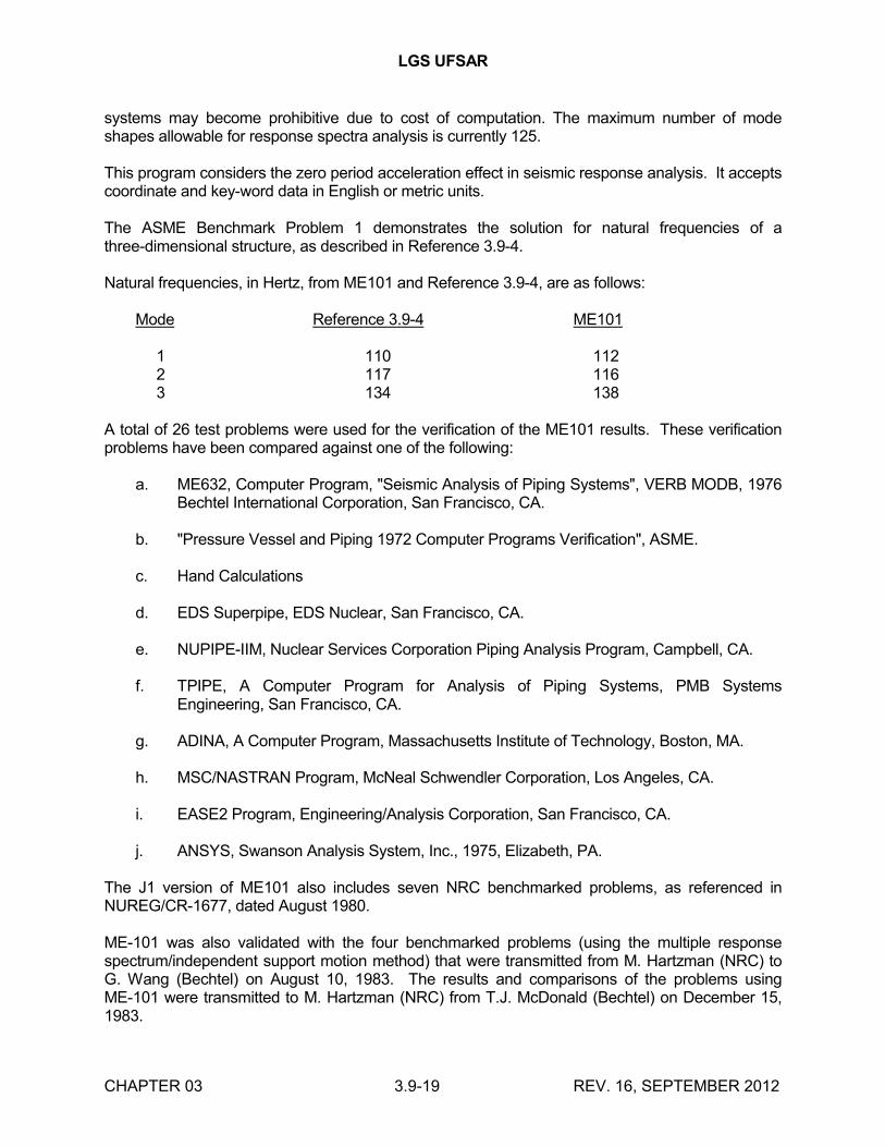
LGS UFSAR
CHAPTER 03 3.9-19 REV. 16, SEPTEMBER 2012
systems may become prohibitive due to cost of computation. The maximum number of mode shapes allowable for response spectra analysis is currently 125.
This program considers the zero period acceleration effect in seismic response analysis. It accepts coordinate and key-word data in English or metric units.
The ASME Benchmark Problem 1 demonstrates the solution for natural frequencies of a three-dimensional structure, as described in Reference 3.9-4.
Natural frequencies, in Hertz, from ME101 and Reference 3.9-4, are as follows:
Mode Reference 3.9-4 ME101
1 110 1122 117 1163 134 138
A total of 26 test problems were used for the verification of the ME101 results. These verification problems have been compared against one of the following:
a. ME632, Computer Program, "Seismic Analysis of Piping Systems", VERB MODB, 1976 Bechtel International Corporation, San Francisco, CA.
b. "Pressure Vessel and Piping 1972 Computer Programs Verification", ASME.
c. Hand Calculations
d. EDS Superpipe, EDS Nuclear, San Francisco, CA.
e. NUPIPE-IIM, Nuclear Services Corporation Piping Analysis Program, Campbell, CA.
f. TPIPE, A Computer Program for Analysis of Piping Systems, PMB Systems Engineering, San Francisco, CA.
g. ADINA, A Computer Program, Massachusetts Institute of Technology, Boston, MA.
h. MSC/NASTRAN Program, McNeal Schwendler Corporation, Los Angeles, CA.
i. EASE2 Program, Engineering/Analysis Corporation, San Francisco, CA.
j. ANSYS, Swanson Analysis System, Inc., 1975, Elizabeth, PA.
The J1 version of ME101 also includes seven NRC benchmarked problems, as referenced in NUREG/CR-1677, dated August 1980.
ME-101 was also validated with the four benchmarked problems (using the multiple response spectrum/independent support motion method) that were transmitted from M. Hartzman (NRC) to G. Wang (Bechtel) on August 10, 1983. The results and comparisons of the problems using ME-101 were transmitted to M. Hartzman (NRC) from T.J. McDonald (Bechtel) on December 15, 1983.
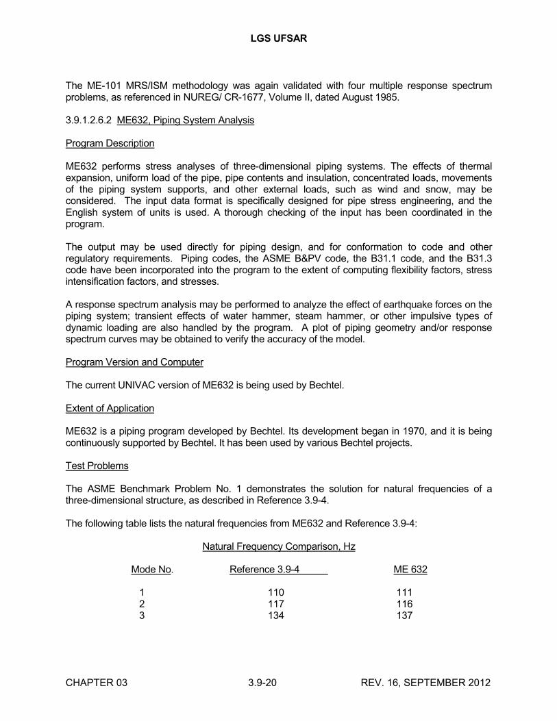
LGS UFSAR
CHAPTER 03 3.9-20 REV. 16, SEPTEMBER 2012
The ME-101 MRS/ISM methodology was again validated with four multiple response spectrum problems, as referenced in NUREG/ CR-1677, Volume II, dated August 1985.
3.9.1.2.6.2 ME632, Piping System Analysis
Program Description
ME632 performs stress analyses of three-dimensional piping systems. The effects of thermal expansion, uniform load of the pipe, pipe contents and insulation, concentrated loads, movements of the piping system supports, and other external loads, such as wind and snow, may be considered. The input data format is specifically designed for pipe stress engineering, and the English system of units is used. A thorough checking of the input has been coordinated in the program.
The output may be used directly for piping design, and for conformation to code and other regulatory requirements. Piping codes, the ASME B&PV code, the B31.1 code, and the B31.3 code have been incorporated into the program to the extent of computing flexibility factors, stress intensification factors, and stresses.
A response spectrum analysis may be performed to analyze the effect of earthquake forces on the piping system; transient effects of water hammer, steam hammer, or other impulsive types of dynamic loading are also handled by the program. A plot of piping geometry and/or response spectrum curves may be obtained to verify the accuracy of the model.
Program Version and Computer
The current UNIVAC version of ME632 is being used by Bechtel.
Extent of Application
ME632 is a piping program developed by Bechtel. Its development began in 1970, and it is being continuously supported by Bechtel. It has been used by various Bechtel projects.
Test Problems
The ASME Benchmark Problem No. 1 demonstrates the solution for natural frequencies of a three-dimensional structure, as described in Reference 3.9-4.
The following table lists the natural frequencies from ME632 and Reference 3.9-4:
Natural Frequency Comparison, Hz
Mode No. Reference 3.9-4 ME 632
1 110 111 2 117 116 3 134 137
LGS UFSAR
CHAPTER 03 3.9-21 REV. 16, SEPTEMBER 2012
3.9.1.2.6.3 ME912, Thermal-Stress
Program Description
Finite-difference representation of the heat diffusion equation is used for the pipe or component wall section in contact with fluid of specified temperature and flow rate time histories. The program is quasi-two-dimensional, so that reduction of severity of a given transient with distance from inlet is accounted for.
Thermal properties of water, and stainless and carbon steel are built in the program. Film transfer coefficients for water are computed by the program for each time step and pipe section. For other fluids such as steam, the program is used on a one-dimensional basis with user-supplied film coefficients. Sequential computations are done for pipe lengths of different diameters or wall thicknesses. Fluid outlet temperature data from one pipe length are stored for use as the inlet to the next pipe length downstream. Average temperature differences, Ta - Tb, are thus calculated for structural discontinuity.
Program Version and Computer
The ME912 program has been used by Bechtel on various Bechtel projects. A Univac 1110 computer is used to run the ME912 program.
Extent of Application
The ME912 program was developed from References 3.9-7, 3.9-8, and 3.9-9 by Bechtel. The ME912 program has been extensively used since 1975 for nuclear Class 1 component design on the Fast Flux Test Facility project.
Test Problem
For local gradients, the program has been compared with analytical flat plate data of Reference 3.9-8, and numerical results by in-house program ME643. The results are acceptable. Table 3.9-4 shows the comparison of ME912 with ME643 and analytical results from Reference 3.9-8. For axial variations of fluid and wall temperatures, the program agrees closely with the analytical solution of Reference 3.9-9.
The ME643 program was developed from References 3.9-11 and 3.9-12 by Bechtel.
The results of ME643 transient temperature responses on both inside and outside surfaces of a sample pipe are compared with Chart 36 of Reference 3.9-13, and plotted in Figure 3.9-1.
3.9.1.2.6.4 ME913, Nuclear Class 1 Piping Stress Analysis
Program Description
ME913 can determine stress intensity levels for Class 1 nuclear power piping components, equations 9 through 14 of subarticle NB-3650, "Analysis of Piping Components", ASME Section III.
Prior to using this program, the following information external to the program is required:
LGS UFSAR
CHAPTER 03 3.9-22 REV. 16, SEPTEMBER 2012
a. Piping configuration
b. Piping and piping component properties
c. Moment reactions due to:
1. Thermal expansion loads
2. Weight loads
3. Dynamic loads
d. The thermal response of the piping system due to the specified transients is:
T1, T2 and the (Ta-Tb) values for the key points during system life.
Program Version and Computer
The current ME913 version is being used by Bechtel. A Univac 1100 computer is used to run the ME913 program.
Extent of Application
ME913 is the revised and expanded version of the LOTEMP program, originally developed by Bechtel, and made available for use through the CDC 6600 computer. The LOTEMP program has been extensively used by the Bechtel Fast Flux Test Facility Systems Analysis Group since 1972, in the preliminary design of Fast Flux Test Facility Class 1 piping. The ME913 program has been used to analyze nuclear Class 1 piping for Bechtel nuclear power plant projects.
Test Problems
The Grand Gulf Project feedwater line was selected as a test problem. Hand calculations of a selected component in the piping system were performed in accordance with the sample problem (Reference 3.9-14). The results were compared with the computer output for code equations 9 through 14 in ME913. Table 3.9-5 shows the comparison between the ASME sample problem (Reference 3.9-14) and ME913 results.
3.9.1.2.6.5 NE452, Submerged Steam Line Reflood Analysis
Program Description
NE452 is used to analyze reflood transient in steam relief valve discharge lines that discharge to a water pool and are equipped with a vacuum relief valve. The code models the effect of the vacuum relief valve (considering both the air flow and the valve dynamics) on the line reflood phenomenon by calculating the dynamics of the slug motion of the reflooding water. The slug motion is affected by the steam condensation on the surface of the reflooding water and by the presence of noncondensable air admitted by the vacuum relief valve.

LGS UFSAR
CHAPTER 03 3.9-23 REV. 16, SEPTEMBER 2012
The output (predicted maximum reflood) can be used in relief line clearing transient analysis codes (such as NE805, discussed in Section 3.9.1.2.6.6) to determine pipe run forces. NE452, together with NE805, can be used for vacuum relief valve sizing.
Program Version and Computer
The current NE452 version is being used by Bechtel. A UNIVAC 1100 computer is used to run the NE452 program.
Extent of Application
Development of the NE452 program began in 1977 and is being continuously supported by Bechtel. It has been used for various Bechtel nuclear power plant projects.
Test Problems
The NE452 program was verified against PBAPS and Monticello ramshead and Mark I T-quencher test data. It has also been verified against Karlstein Mark II T-quencher and Caorso X-quencher test data. The predicted results agreed reasonably well with test data.
3.9.1.2.6.6 NE805, Relief Valve Clearing Analysis
Program Description
NE805 is a computer code that analyzes transients in discharge lines of changing cross-sectional area following a relief valve opening. The code predicts the time-dependent forces on the various pipe segments of the relief valve discharge line. It models the steam flow through the relief valve and the steam/air flows in the line. It also models the water flow in the submerged part of the line. The options for the exit device are a straight pipe, a ramshead, or a quencher model in the reservoir. The quencher model considers sequential uncovering of the quencher holes during air/water clearing. NE805 uses the method of characteristics and allows for heat transfer through the pipe wall. It calculates flow parameters, pressure, velocity, and density as functions of time and the distance along the discharge line. Using these calculated values, the code computes the dynamic forcing functions induced on various pipe segments of the relief valve discharge line.
The force output can be used directly for piping stress analysis in codes such as ME101, described in Section 3.9.1.2.6.1.
NE805 generates plots of flow parameter time histories and/or force time histories, an option specified by the user. The plots are obtained by CALCOMP 1036 plotter.
Program Version and Computer
The current UNIVAC version of NE805 is being used by Bechtel. A UNIVAC 1100 computer is used to run the NE805 program.
Extent of Application
NE805 was developed by Bechtel. Its development began in 1975 and is being continuously supported by Bechtel. It has been used by various Bechtel projects.
LGS UFSAR
CHAPTER 03 3.9-24 REV. 16, SEPTEMBER 2012
Test Problems
The NE805 program has been verified against Monticello Mark I T-quencher test, Karlstein Mark II T-quencher test, and Caorso X-quencher test. Comparison with test data was found to be reasonable.
3.9.1.2.6.7 ANSYS
Refer to Section 3.8.7.10
3.9.1.2.6.8 ME210 - Local Stress in Cylindrical Shells Due to External Loads
This standard presents a method of analyzing and determining local stresses in cylindrical shells due to external moments and forces acting on rigid attachments of circular or rectangular shape. This program is based on a paper "Local Stresses in Spherical and Cylindrical Shells Due to External Loadings" by Wichman, Hopper, and Mershon, published in Welding Research Council Bulletin No. 107, August 1965 and March 1979 Revision. Values from Bijlaard curves are obtained by interpolation procedures.
This program also calculates piping stress intensity due to internal pressures and moments in accordance with the pressure and moment stress calculations specified in equation 9 and equation 10 of ASME Section III, NB-3650. The local stress intensity and piping stress intensity are summed and printed out if the required information for piping stress calculation is specified in the input. If no information for piping stress calculation is given, only the local stresses including primary plus secondary stress intensity and primary membrane stress intensities are printed out.
3.9.1.2.6.9 ME602 - Spectra Merging and Simplified Seismic Analysis
ME602 performs the seismic analysis of small diameter piping systems (2 inch and under) using the modified response spectrum method described in BP-TOP-1, Revision 3. The program generates a set of tables of seismic spans, support reactions, and stresses for various pipe sizes.
This program performs response spectrum curve merging along with the calculation of the seismic span. The program can also be used independently for the sole purpose of merging spectrum curves and storing the combined spectrum data for ME101 analysis. A neutral plot file of the "RAW" or "COMBINED" spectrum curves can be generated for plotting on RMS, TEKTRONIX, CALCOMP, or any neutral file compatible plotter.
3.9.1.2.6.10 ME351 - Pipe Rupture Analysis Program
This program performs nonlinear elastic-plastic analysis of three-dimensional piping systems subjected to concentrated static or dynamic time history forcing functions. These forces may result from fluid jet thrust at the location of a postulated rupture of high energy piping. PIPERUP is an adaptation of the finite-element method to the specific requirements of pipe rupture analysis. Straight and curved beam (elbow) elements are used to mathematically represent the piping, and axial and rotational springs are used to represent restraints. The stiffness characteristics of piping and restraints can reflect elastic/linear strain hardening material properties, and gaps between piping and restraints can be modeled.
LGS UFSAR
CHAPTER 03 3.9-25 REV. 16, SEPTEMBER 2012
3.9.1.2.7 Computer Programs Used for Component Supports
A list of computer programs used in pipe support analysis is provided in Table 3.9-3. The list consists of computer programs developed and/or owned by Bechtel, and computer programs that are recognized and widely used in the industry.
The Bechtel developed and/or owned computer programs are documented, verified, and maintained by Bechtel and meet the requirements of 10CFR50, Appendix B. A brief description of each of these programs is provided below.
3.9.1.2.7.1 CE050 - BOLTS
BOLTS is an interactive program for determining the loads on concrete expansion anchors used for baseplates with symmetrical bolt patterns. The program incorporates the effects of plate flexibility, bolt stiffness, and attachment size. BOLTS is particularly well suited for the evaluation of baseplate expansion anchors commonly used in pipe, conduit, HVAC, cable tray, and such other small equipment supports.
3.9.1.2.7.2 ME150 - FAPPS - Frame Analysis for Pipe Supports
ME150 is an interactive program for the analysis and design of pipe support frames. It has built-in standard frames and the capability to design any other nonstandard ones. It optimizes member sizes, welds, and embedments based on various user-specified design criteria.
3.9.1.2.7.3 ME225 - Anchor Plate
ME225 presents a method of designing plate-type piping anchors. It determines thickness of anchor plate, thickness of guide plate, weld joining the plate and process pipe, weld joining the supporting structure, and take out dimension of anchor plate and guide plate.
3.9.1.2.7.4 ME035 - BASEPLATE
ME035 analyzes baseplate-type structural supports. It assumes a flexible plate resting on a nonlinear foundation. It gives concrete stresses, bolt factors of safety, and weld forces. It can analyze baseplates with variable thickness with multiple columnlike attachments.
3.9.1.2.7.5 ME226 - PICLAMP
PICLAMP will design the components of six special cases of pipe support clamps. It computes the minimum required thickness at two critical sections of the clamp. It also calculates the stress in the clamp studs. It computes the stresses in the stanchion and baseplate, when applicable, and the minimum weld size based on the stress. It also computes certain clamp dimensions and the total weight of the clamp and its associated hardware.
3.9.1.2.7.6 ME425 - STAND
STAND will design and evaluate pipe support base plates with concrete anchor bolt assemblies. Plates can be of arbitrary geometry anchored with bolts that can be located in a random pattern.
LGS UFSAR
CHAPTER 03 3.9-26 REV. 16, SEPTEMBER 2012
3.9.1.2.7.7 ME120 - WELD
The program presents a method of determining fillet weld sizes for connecting structural members. It accepts five different types of structural shapes and analyzes for 2-weld to 16-weld configurations. It is based on the approach described in "Design of Welded Structures" by O.W. Blodgett and "Solutions to Design of Weldments" by O.W. Blodgett.
3.9.1.2.7.8 ME152 - SMAPPS
SMAPPS analyzes and designs commonly used standard frames for pipe support including associated welds and baseplates with anchors for AISC and ASME Section III, Subsection NF requirements, as well as project deflection/stiffness requirements.
SMAPPS provides the benefits of a structural frame analysis program and the simplicity of pre-engineering standards. SMAPPS provides margin factors for frame, welds, and baseplate with anchors that minimize the need for re-evaluation of pipe support due to load changes and as-built reconciliation.
3.9.1.2.7.9 CE-901 - ICES STRUDL II
STRUDL is a broad, extensive, and general program for solving problems in structural engineering.
3.9.1.2.7.10 ME153 - MAPPS
MAPPS is a miscellaneous application program for pipe supports which enables the user to access any or all of the following pipe support analysis computer programs within the same run:
• Uniform weld
• Nonuniform welded
• Beta angle
• Clip angle
• Bolt spacing
• Anchor plate
• Local effects
• Clamp (PI clamp)
3.9.1.3 Experimental Stress Analysis
When experimental stress analysis is used in lieu of analytical methods for seismic Category I ASME Code items, the applicable ASME Code requirements for experimental testing of the specific component are applied. If testing is required for seismic Category I non-ASME code items, consideration is given to size effects, dimensional tolerances, and material properties of the tested
LGS UFSAR
CHAPTER 03 3.9-27 REV. 16, SEPTEMBER 2012
part to ensure that the test results are a conservative representation of the load-carrying capability of the item installed at LGS.
3.9.1.3.1 Experimental Stress Analysis of NSSS Seismic Category I Items
No experimental stress analysis methods are used.
3.9.1.3.2 Seismic Category I Items Other Than NSSS
No experimental stress analysis methods are used.
3.9.1.4 Considerations for the Evaluation of Faulted Conditions
All seismic Category I equipment is evaluated for the faulted loading conditions. However, emergency stress limits rather than faulted stress limits are used in many cases. The following paragraphs in this section show examples of the treatment of faulted conditions for the major components on a component-by- component basis. Additional discussion of faulted analysis can be found in Sections 3.9.3 and 3.9.5, and Table 3.9-6. These analyses are based on the power rerate analysis, and do not reflect the use of GE13 and GE14 fuel. The impact of GE13 fuel is documented in Reference 3.9-28. The impact of GE14 fuel is documented to be bounded by GE13 fuel in Reference 3.9-34. The impact of the MUR power uprate on GE14 fuel is evaluated in Reference 3.9-31 and Reference 3.9-32. Reference 3.9-33 identifies new design basis values for Fuel Lift Margin and Control Rod Guide Tube Lift Forces under MUR conditions. Additional analyses which consider the use of GNF2 fuel are documented in Reference 3.9-35. The GNF2 fuel is demonstrated to be bounded by the analyses in Reference 3.9-33.
Sections 3.9.2.2 and 3.7 discuss the treatment of dynamic loads resulting from the postulated seismic and hydrodynamic events. Section 3.9.2.5 discusses the dynamic analysis of loads on the reactor internals under faulted conditions including additional blowdown forces. Deformations under faulted conditions have been evaluated in critical areas, and no cases have been identified where design limits, such as clearance limits, are violated.
Elastic-plastic analysis has not been used in evaluating LGS seismic Category I systems and components for compliance with service Level D Limits. The stress levels of these components are below the ASME allowable stress.
3.9.1.4.1 Control Rod Drive System Components
3.9.1.4.1.1 Control Rod Drives
The ASME Section III Code components of the CRD have been analyzed for faulted conditions shown in Section 3.9.1.1.1. The loading criteria, calculated, and allowable stresses for various operating conditions are summarized in Table 3.9-6(u).
The design adequacy of non-ASME code components of the CRD has been verified by analysis and extensive testing programs on component parts, specially instrumented prototype drives, and production drives. The testing included postulated abnormal events, as well as the service life cycle listed in Section 3.9.1.1.1. The following three types of tests were performed:
LGS UFSAR
CHAPTER 03 3.9-28 REV. 16, SEPTEMBER 2012
a. A test was conducted with the lower CRD flange oscillating with a 2 inch peak-to-peak displacement. No adverse effects were observed during the normal continuous drive-in or jog operation.
b. To simulate the seismic interaction, the core plate and top guide structures of the test vessel were displaced relative to the CRD housing centerline. The results showed no effect in CRD performance.
c. The test vessel fuel channels were deflected to simulate the seismic interactions. The test was performed with fuel channel deflections up to 1.5 inches, which are greater than the expected deflection values. Because the CRD and control rod were not permanently deformed, the drive operability was maintained.
The load criteria, calculated, and allowable stresses for various operating conditions is summarized in Table 3.9-6(v) including the results of the New Loads Adequacy Evaluation program.
3.9.1.4.1.2 Hydraulic Control Unit
The HCU was analyzed for the faulted condition. The seismic and hydrodynamic loads adequacy was demonstrated by test and analysis. The results show peak dynamic loads of 6.2 g (vertical) at the natural frequency of 8-12 Hz and 6 g (horizontal) at a natural frequency of 3-4 Hz. For comparison, the capability of the HCU to withstand loading is 15 g (vertical) at 8-12 Hz, 7 g (horizontal) at 3-4 Hz, and 9 g (horizontal z displacement) at 3-4 Hz.
In addition, a detailed analysis was performed to confirm that the test-mounting configuration is applicable to the LGS unique field installation.
The analysis of the HCU under faulted condition loads establishes the structural integrity of the system.
3.9.1.4.1.3 CRD Housing
The SSE is classified as a faulted condition; however, in the CRD housing analysis, the SSE event is treated as an emergency condition. The calculated and allowable stresses at various loading conditions are given in Table 3.9-6(v).
3.9.1.4.2 Standard Reactor Internal Components
3.9.1.4.2.1 Control Rod Guide Tube
The maximum calculated stress on the control rod guide tube occurs in the base during a faulted condition. In accordance with ASME Section III, the faulted limit is 2.4 Sm, where Sm = 16,000 psi at 575F. The analysis and limiting stresses are summarized in Table 3.9-6(aa).
3.9.1.4.2.2 Incore Housing
The maximum calculated stress on the incore housing occurs at the outer surface of the vessel penetration during a faulted condition. The maximum allowable stress for the elastic analysis used is 2.4 Sm (39,948 psi), which bounds the calculated stress as given in Table 3.9-6(ab).
LGS UFSAR
CHAPTER 03 3.9-29 REV. 16, SEPTEMBER 2012
3.9.1.4.2.3 Jet Pump
The elastic analysis for the jet pump faulted conditions shows that the maximum stress is due to diffuser impulse loading during a pipe rupture and blowdown. The maximum allowable for this condition, in accordance with ASME Section III, is 3.6 Sm (60,840 psi). Table 3.9-6(w) summarizes the results of the analysis.
3.9.1.4.2.4 Low Pressure Coolant Injection Coupling
The maximum stress during a faulted condition on the LPCI coupling occurs at the "Bellows" (a purchased component designed to GE requirements for 120 normal operating condition cycles and 10 SSE cycles). Table 3.9-6(y) shows that calculated stresses are within allowable limits.
3.9.1.4.2.5 Orificed Fuel Support
Due to its complex configuration, a series of vertical and horizontal load tests were performed on the orificed fuel support to verify the design. The results show that the seismic and hydrodynamic loading is below the allowable limit with an average safety margin of 1.21 for normal and upset and 1.26 for faulted conditions.
3.9.1.4.3 Reactor Pressure Vessel Assembly
The RPV assembly was evaluated using elastic analysis methods for faulted conditions. Table 3.9-6(f) lists the calculated and allowable stresses for the various loading combinations.
3.9.1.4.4 Core Support Structure
The evaluations for faulted conditions for the core support structure are discussed in Section 3.9.5. The calculated and allowable stresses are summarized in Table 3.9-6(b).
3.9.1.4.5 Main Steam Isolation, Recirculation Gate, and MSRVs
Tables 3.9-6(g), 3.9-6(h), and 3.9-6(j) provide a summary of the analysis for the MSRVs, MSIVs, and recirculation gate valves, respectively.
Standard design rules, as defined in applied codes, are utilized in analyzing pressure boundary components of Class 1 active valves. Conventional, elastic stress analysis is used to evaluate components not defined in the code. The code allowable stresses are applied to determine acceptability of structure under applicable loading conditions, including faulted condition.
3.9.1.4.6 Main Steam and Recirculation Piping
For main steam and recirculation system piping, elastic analysis methods are used to evaluate faulted loading conditions. The allowable stresses using elastic techniques are obtained from the ASME Section III, Appendix F, "Rules for Evaluation of Faulted Conditions" (these are above elastic limits). Additional information for the main steam, recirculation piping, and pipe-mounted equipment is contained in Tables 3.9-6(d) and 3.9-6(e), respectively.
3.9.1.4.7 NSSS Pumps, Heat Exchangers, and Turbines
LGS UFSAR
CHAPTER 03 3.9-30 REV. 16, SEPTEMBER 2012
The recirculation, ECCS, RCIC, and SLC pumps, RHR heat exchangers and RCIC turbine are analyzed for the faulted loading conditions identified in Section 3.9.1.1. In all cases, stresses are within the elastic limits. The analytical methods, stress limits, and allowable stresses are discussed in Sections 3.9.2.2a and 3.9.3.1.
3.9.1.4.8 Control Rod Drive Housing Supports
Design adequacy of the CRD housing supports is shown by comparing the static and dynamic loads to the original design loads. The comparison, summarized in Table 3.9-6(z), shows that the hydrodynamic loads combined with other loads are less than the design load capability of the CRD housing supports.
3.9.1.4.9 Fuel Storage Racks
All analyses related to the Fuel Storage Racks are provided in UFSAR Section 9.1.
3.9.1.4.10 Fuel Assembly (Including Channel)
GE BWR fuel assembly (including channel) design bases, analytical methods, and evaluation results, including those applicable to the faulted conditions are contained in References 3.9-16 and 3.9-17. Evaluations specific to the LGS fuel assemblies have been performed in accordance with the methodology presented in Reference 3.9-17. The resulting acceleration profiles and fuel lift gap are summarized in Table 3.9-6(x).
3.9.1.4.11 Refueling Equipment
Refueling and servicing equipment which is important to safety is classified under essential components, per the requirements of 10CFR50, Appendix A. This equipment and other equipment whose failure would degrade an essential component is defined in Section 9.1 and is classified as seismic Category I. These components are subjected to an elastic dynamic finite-element analysis to generate loadings. This analysis utilizes appropriate seismic floor response spectra, and combines loads at frequencies up to 33 Hz for seismic and up to 100 Hz for hydrodynamic loads, in three directions. Imposed stresses are generated and combined for normal, upset, and faulted conditions. Stresses are compared, depending on the specific safety class of the equipment, to allowables of Industrial Codes, ASME, ANSI or Industrial standards, or AISC. Loading conditions, acceptance criteria, calculated and allowable stresses are shown in Table 3.9-6(s).
3.9.1.4.12 Seismic Category I Items Other than NSSS
The stress allowables for statically applied loads, of ASME Section III, Appendix F, Winter 1972, are used for code components. For noncode components, allowables are based on tests or accepted standards consistent with those in Appendix F of the code.
Dynamic loads for components loaded in the elastic range are calculated using dynamic load factors, time history analysis, or any other method that assumes the elastic behavior of the component.
The limits of the elastic range are defined in paragraph 1323 of Appendix F for the code components. The local yielding due to stress concentration is assumed not to affect the validity of the assumptions of elastic behavior. The stress allowables of Appendix F for elastically analyzed
LGS UFSAR
CHAPTER 03 3.9-31 REV. 16, SEPTEMBER 2012
components are used for code components. For noncode components, allowables are based on tests or accepted material standards consistent with those in Appendix F for elastically analyzed components.
The methods used in evaluating the pipe break effects are discussed in Section 3.6.
3.9.2 DYNAMIC TESTING AND ANALYSIS
3.9.2.1a Piping Vibration, Thermal Expansion, and Dynamic Effects Testing for NSSS Piping
The test program is divided into three phases: piping vibration, thermal expansion, and dynamic effects.
3.9.2.1a.1 Piping Vibration
3.9.2.1a.1.1 Preoperational Vibration Testing of Recirculation Piping
The purpose of the preoperational vibration test phase is to verify that operating vibrations in the recirculation piping are within acceptable limits. This phase of the test uses visual observation and manual measurements by hand-held vibrograph to supplement remote measurements. If, during steady-state operation, visual observation indicates that vibration is significant, measurements are made with a hand-held vibrograph. Visual observations, and manual and remote measurements are made during the following steady-state conditions:
a. Recirculation pumps minimum flow
b. Recirculation pumps at 50% of rated flow
c. Recirculation pumps at 75% of rated flow
d. Recirculation pumps at 100% of rated flow
3.9.2.1a.1.2 Preoperational Vibration Testing of Small Attached Piping
During visual observation of each of the above test conditions (a. through d.), special attention is given to small attached piping and instrument connections to ensure that they are not in resonance with the recirculation pump motors or flow-induced vibrations. If the operating vibration acceptance criteria are not met, corrective action, such as modification of supports, is taken.
3.9.2.1a.1.3 Startup Vibration Testing of Main Steam Recirculation and RCIC Piping
The purpose of this phase of the program is to verify that the main steam, recirculation, and RCIC piping are within acceptable limits. The main steam and recirculation piping are instrumented with transducers to measure temperature, thermal movement, and vibration deflections. Because of limited access due to high radiation levels, no visual observation is required during this phase of the test. Remote measurements are made during the following steady-state conditions:
a. Main steam flow at 25% of rated
b. Main steam flow at 50% of rated
LGS UFSAR
CHAPTER 03 3.9-32 REV. 16, SEPTEMBER 2012
c. Main steam flow at 75% of rated
d. Main steam flow at 100% of rated
3.9.2.1a.1.4 Operating Transient Loads on Main Steam and Recirculation Piping
The purpose of the operating transient test phase is to verify that pipe stresses are within code limits. The amplitude of displacements and the number of cycles per transient of the main steam and recirculation piping are measured, and the displacements are compared with the acceptance criteria. The deflections are correlated with stresses to verify that pipe stresses remain within code limits. Remote vibration and deflection measurements are taken during the following transients:
a. Recirculation pump starts
b. Recirculation pump trip at 100% of rated flow
c. Turbine stop valve closure at 100% power
d. Manual discharge of each SRV at 1000 psig, and at planned transient tests that result in SRV discharge
3.9.2.1a.2 Thermal Expansion Testing of Main Steam and Recirculation Piping
The thermal expansion preoperational and startup testing program verifies that normal thermal movement occurs in the piping systems, and is performed through the use of potentiometer sensors. The main purpose of this program is to ensure the following:
a. The piping system is free to expand and move without unplanned obstruction or restraint in the x, y, and z directions, during system heatup and cooldown.
b. The piping system does "shake down" after a few thermal expansion cycles.
c. The piping system is working in a manner consistent with the assumption of the NSSS stress analysis
d. There is adequate agreement between calculated and measured displacements.
e. Thermal displacements are consistent and repeatable during heatup and cooldown of the NSSS systems.
Thermal expansion displacement limits are established prior to the start of piping testing. These are compared with the actual measured displacements to determine the acceptability of the actual motion. If the measured displacement does not vary by more than the specified tolerance from the acceptance limit, the piping system is responding in a manner consistent with predictions, and is therefore acceptable. Two levels of displacement limits are established to check the systems, as discussed in Section 3.9.2.1a.4.
3.9.2.1a.3 Dynamic Effects Testing of Main Steam and Recirculation Piping
LGS UFSAR
CHAPTER 03 3.9-33 REV. 16, SEPTEMBER 2012
To verify that snubbers adequately perform their intended function during plant operation, a dynamic testing program is planned, as part of the normal startup operation testing. The main purpose of this program is to ensure the following:
a. The vibration levels from the various dynamic loadings during transient and steady-state conditions are below the predetermined acceptable limits.
b. Due to underestimating the dynamic effects caused by cyclic loading during plant transient operations, long-term fatigue failure does not occur.
This dynamic testing is to account for the acoustic wave due to the SRV lifts (RV1), SRV load resulting from air clearing (RV2), and turbine stop valve closure load. The maximum stresses developed in the piping by the RV1, RV2, and turbine stop valve closure transients analysis are used as a basis for establishing criteria which assures proper functioning of the snubbers. If field measurements exceed criteria limits, this may indicate that the snubbers are not operating properly. If field measurements are within criteria limits, it is assumed that the snubbers are functioning properly. Sample production snubbers of each size (i.e. 10 kips, 20 kips, 50 kips, etc.) will also be qualified and tested for design and faulted condition loadings, prior to shipment to field. Snubbers will be tested to allow free piping movements at low velocity. During plant startup, the snubbers will be checked for improper settings and checked for any evidence of oil leak.
The criteria for vibration displacements is based on the assumed linear relationship between displacements, snubber loads and magnitudes of applied loads, for any function and response of the system. Thus the magnitudes of limits of displacements, snubber loads, and nozzle loads are all proportional. Maximum displacements (Level 1 limits) are established to prevent the maximum stress in the piping systems from exceeding the normal and upset primary stress limits, and/or the maximum snubber load from exceeding the maximum load to which the snubber has been tested.
Based on the above criteria, Level 1 displacement limits are established for all instrumented points in the piping system. These limits will be compared with the field measured piping displacements. Method of acceptance is as explained in Section 3.9.2.1a.4.
3.9.2.1a.4 Test Evaluation and Acceptance Criteria for Main Steam and Recirculation Piping
The piping response to test conditions is considered acceptable if the organization responsible for the stress report reviews the test results, and determines that the tests verify that the piping responded in a manner consistent with the predictions of the stress report, and/or that the tests verify that piping stresses are within code limits (ASME Section III, NB-3600). Acceptable deflection limits are determined after the completion of the piping systems stress analysis and are provided in the startup test specifications.
To ensure test data integrity and test safety, criteria have been established to facilitate assessment of the test while it is in progress. These criteria, designated Level 1 and Level 2, are described in the following paragraphs.
3.9.2.1a.4.1 Level 1 Criteria
Level 1 establishes the maximum limits for the level of pipe motion which, if exceeded, makes a test hold or termination mandatory.
LGS UFSAR
CHAPTER 03 3.9-34 REV. 16, SEPTEMBER 2012
If the Level 1 limit is exceeded, the plant will be placed in a satisfactory hold condition, and the responsible piping design engineer will be advised. Following resolution, applicable tests must be repeated to verify that the requirements of the Level 1 limits are satisfied.
3.9.2.1a.4.2 Level 2 Criteria
If the Level 2 criteria are satisfied for both steady-state and operating transient vibrations, there will be no fatigue damage to the piping system due to steady-state vibration, and all operating transient vibrations are bounded by the values in the stress report.
Exceeding the Level 2 specified pipe motion requires that the responsible piping design engineer be advised. Plant operating and startup testing plans would not necessarily be altered. Investigations of the measurements, criteria, and calculations used to generate the pipe motion limits would be initiated. An acceptable resolution must be reached by all appropriate and involved parties, including the responsible piping design engineer.
Detailed evaluation is needed to develop corrective action or to show that the measurements are acceptable. Depending on the nature of such resolution, the applicable tests may or may not be repeated.
3.9.2.1a.4.3 Acceptance Limits
For steady-state vibration, the piping break stress due to vibration only (neglecting pressure) will not exceed 10,000 psi for Level 1 criteria and 5,000 psi for Level 2 criteria. These limits are below the piping material fatigue endurance limits as defined in Design Fatigue Curves in appendix I of ASME code for 106 cycles.
For operating transient vibration, the piping bending stress (zero to peak) due to operating transient only will not exceed 1.2 Sm or pipe support loads will not exceed the Service Level D ratings for Level 1 criteria. The 1.2 Sm limit ensures that the total primary stress including pressure and dead weight will not exceed 1.8 Sm, the new Code Service Level B limit. Level 2 criteria are based on pipe stresses and support loads not to exceed design basis predictions. Design basis criteria require that operating transients stresses and loads not to exceed any of the Service Level B limits including primary stress limits, fatigue usage factor limits, and allowable loads on snubbers.
3.9.2.1a.5 Corrective Actions for Main Steam and Recirculation Piping
During the course of the tests, the remote measurements are regularly checked to determine compliance with Level 1 criteria. If trends indicate that Level 1 criteria may be violated, the measurements are monitored at more frequent intervals. The test is held or terminated as soon as Level 1 criteria are violated. As soon as possible after the test hold or termination, the following corrective actions are taken:
a. Installation Inspection: A walkdown of the piping and suspension is made to identify any obstruction or improperly operating suspension components. Snubbers are located close to the midpoint of the total travel range at the operating temperature. Hangers are in their operating range between the hot and cold settings. If vibration exceeds the criteria, the source of the excitation must be identified to determine if it is related to equipment failure. Action is taken to correct any discrepancies before repeating the test.
LGS UFSAR
CHAPTER 03 3.9-35 REV. 16, SEPTEMBER 2012
b. Instrumentation Inspection: The instrumentation installation and calibration is checked, and any discrepancies are corrected. Additional instrumentation is added, if necessary.
c. Repeat Test: If actions a. or b. identify discrepancies that could account for failure to meet Level 1 criteria, the test is repeated.
d. Resolution of Findings: If the Level 1 criteria are violated on the repeat test, or no relevant discrepancies are identified in a. or b., the organization responsible for the stress report reviews the test results and the criteria to determine if the test can be safely continued.
If the test measurements indicate failure to meet Level 2 criteria, the following corrective actions are taken after completion of the test:
a. Installation Inspection: A walkdown of the piping and suspension is made to identify any obstruction or improperly operating suspension components. Snubbers are located close to the midpoint of the total travel range at the operating temperature. Hangers are in their operating range between the hot and cold settings. If the vibration exceeds limits, the source of the vibration must be identified. Actions, such as suspension adjustment, are taken to correct any discrepancies.
b. Instrumentation Inspection: The instrumentation installation and calibration are checked, and any discrepancies are corrected.
c. Repeat Test: If a. or b. above identify a malfunction or discrepancy that could account for failure to comply with Level 2 criteria, and appropriate corrective action is taken, the test may be repeated.
d. Documentation of Discrepancies: If the test is not repeated, the discrepancies found under actions a. or b. above are documented in the test evaluation report and correlated with the test condition. The test is not considered complete until the test results are reconciled with the acceptance criteria.
3.9.2.1a.6 Measurement Locations for Main Steam and Recirculation Piping
Remote vibration measurements during initial startup will be made for each of the main steam lines and recirculation lines. The locations of the measurements will be described in the startup test specification.
During preoperational testing of recirculation piping, visual observation and manual measurements by hand-held vibrograph are made to supplement the remote measurements.
3.9.2.1b Piping Vibration, Thermal Expansion, and Dynamic Effects Testing of Non-NSSS Piping
The dynamic effects on all safety-related ASME Class 1, 2, and 3 piping systems, including their supports and restraints, are considered as required by NB-3622.3, NC-3622, and ND-3622 of ASME Section III. The structural and functional integrity of each piping system under postulated seismic events is verified by dynamic analysis only. Piping systems having significant anticipated transient loads, caused by main stop valve closure or relief valve discharge for example, are
LGS UFSAR
CHAPTER 03 3.9-36 REV. 16, SEPTEMBER 2012
analyzed for time-dependent forces. In addition, piping steady-state vibration and dynamic transient tests will be performed as summarized below, to ensure that:
a. Excessive steady-state vibration is not present in the piping that would result in piping stresses and restraint loads above the allowables
b. The piping is adequately restrained to withstand the dynamic transient loads.
The power ascension tests performed for each non-NSSS piping system are provided in Table 3.9-7. The table also describes the systems as to ASME Code class, high energy or moderate energy piping designation, and seismic category.
The startup test program specifications describe in detail the piping that is instrumented for remote monitoring of vibrations and thermal expansion and the piping that is accessible for preoperational or startup walkdown testing by test personnel. The test criteria limit the permissible pipe vibratory stress to the allowable limits prescribed in the industry standard for startup testing of nuclear power systems, ANSI/ASME OM3.
The LGS startup testing program requires that the following conditions be demonstrated in accordance with Regulatory Guide 1.70:
a. Thermal expansion is free from significant and unacceptable restraint not accounted for in the design.
b. Piping vibration is within acceptable limits for long-term vibratory stress.
c. Dynamic transient response of the piping is compared to the design analysis expected values. If those values are exceeded, the test results are compared with the maximum that would be allowed under the ASME Code stress limits.
Cognizant design personnel familiar with the systems to be tested participate in the development of test procedures, and in the evaluation of the test results. The data acquired from the tests are compared with the anticipated results to determine the acceptability of the total system response. Refer to STP-17, STP-33 and STP-36 in Table 14.2-3 for these startup test program procedures.
Test specifications governing the scope of startup testing of BOP piping were prepared and were intended to be the repository for all primary information relating to the scope, objectives, methods, instrumentation, measurements, and criteria for evaluation of the test results. The BOP piping systems are categorized in terms of the following:
a. Test environment (hot deflection, steady-state vibration or dynamic transient response).
b. Test measurements (remotely monitored, visual or none required due to small expected response to test environment).
c. The appropriate testing phase (preoperational or power ascension).
Piping thermal expansion tests are performed for the safety-related piping systems with normal operating temperatures exceeding 300F. Safety-related piping systems with normal operating temperatures less than 300F do not have significant thermal expansion to warrant these tests. Engineering review of all seismic Category I piping systems, including their supports, and restraints
LGS UFSAR
CHAPTER 03 3.9-37 REV. 16, SEPTEMBER 2012
or snubbers, was performed after completion of construction and prior to fuel load. This ensures that no restraint of normal thermal movement occurs due to interferences and obstructions, and that the support and restraints are in accordance with the design intent. For those systems receiving thermal expansion tests, pipe movements are monitored to ensure that no restraint of normal thermal movement occurs at locations other than at the designed restraint locations.
By monitoring the thermal movement, the thermal expansion test program verifies that the free thermal expansion of piping systems takes place at the snubbers. Performance of the snubbers designed for transient loads, such as those resulting from main stop valve closure or MSRV discharge, are verified by measuring the load in the snubber during the dynamic transient tests. The snubbers are qualified by dynamic testing for cyclic loading as described in Section 3.9.3.5.2.
The acceptance criterion for thermal expansion tests and dynamic transient tests is that the measured pipe displacements, accelerations, dynamic pressures, or restraint loads are below the calculated or design values.
3.9.2.1b.1 Piping Dynamic Transient Tests
During the power ascension, the piping dynamic transient tests identified in Table 3.9-7 are performed. The following modes are considered:
a. Main steam piping outside the containment for main steam turbine stop valve trip at 25%, 75% (Unit 1 only), and 100% power. Main Steam Turbine trip test for Unit 2 at 100% power will be performed during commercial operation of that Unit.
b. Main steam bypass piping for the turbine stop valve closure
c. MSRV discharge piping for the MSRV opening
d. HPCI turbine steam supply piping for HPCI turbine trip.
e. Feedwater piping for reactor feed pump trip/coastdown
f. Feedwater heater drain piping for dump and drain valve actuation (Unit 1 only)
g. Moisture separator drain piping for flashing during normal operation and moisture separator depressurization (Unit 1 only).
From past experience, the dynamic transients in other piping systems are not significant.
Dynamic transient analysis of the subject lines is performed to determine the response of the piping system and the restraint loads. During the test the accelerations of the pipe, loads in the snubbers and restraints and the pressure at representative locations will be measured as required.
The acceptance criterion for this test is that the measured response of the piping system, the snubber, and restraint loads are below the design values. When the measured response exceeds the calculated response, or restraint loads, detailed evaluation of the design will be made to determine the acceptability.3.9.2.1b.2 Piping Steady-State Vibration Testing
LGS UFSAR
CHAPTER 03 3.9-38 REV. 16, SEPTEMBER 2012
The piping systems identified in Table 3.9-7 are tested for steady-state vibration during preoperational test programs or during power ascension. The following operating modes are considered:
a. RHR pump operation
b. HPCI pump and turbine operation
c. RCIC pump and turbine operation
d. Core spray pump operation
e. Main steam
f. Feedwater
g. RWCU
In addition, during the system walkdown, upon initial startup or power escalation, any abnormal vibrations of other systems observed are reviewed and instrumented, if necessary, to determine the acceptability of such vibration.
All safety-related process piping systems and safety-related instrument lines are included in the vibration monitoring program (Table 3.9-7). A vibration monitoring test specification is prepared to categorize the requirements for the testing program. Safety-related systems are categorized as follows:
a. Systems or portions of systems having no flow within a significant portion of their lines; for those system, no testing is required.
b. Systems with flow:
• Accessible lines (including attached instrument lines) monitored visually or with hand-held instruments.
• Inaccessible lines other than instrumentation lines will be monitored by remote instrumentation.
• Inaccessible instrument lines.
The inside containment instrumentation lines listed below that are inaccessible for visual inspection during power ascension testing will be included in the vibration monitoring program:
• RPV level indicator instrumentation lines
• Main steam instrumentation lines used for monitoring main steam flow
• RCIC steam supply instrument lines used for monitoring steam flow
• CRD lines
LGS UFSAR
CHAPTER 03 3.9-39 REV. 16, SEPTEMBER 2012
• Main steam sample lines.
The vibration monitoring program for the above lines consists of walkdown by stress analysts experienced in vibration assessment prior to power ascension testing. The review is to include proper restraining of the lines near the vibration source, at elbows and bends, and at the concentrated masses. Prior to walkdown, the stress engineer will review the mode shapes and piping analytical responses to normal and upset conditions. Any lines found to be inadequately restrained, resulting in the potential for excessive vibration, will be evaluated on a case-by-case basis to assess the impact on plant safety that could result from operation of the lines. The evaluation will identify the mode(s) of operation of such lines that cause the excessive vibration. Corrective action to prevent excessive vibration will be taken prior to operating any lines in the operating mode(s) that cause excessive vibration.
Steady-state vibration is primarily induced by the flow in the pipe and the equipment motion. In general, the nature of the steady-state vibration is not known a priori. Therefore, design engineers with stress analysis experience and with familiarity with the subject piping system observe the linesduring significant modes of system operation as shown in Items a. through g. above, and classify each line as acceptable, if the vibration is not significant, or as questionable, if the vibration is significant. The lines with questionable steady-state vibration are monitored as applicable by suitable instrumentation to determine the system response.
The type of any necessary instrumentation is determined by the design engineer, so that the maximum amplitude and frequency response of the piping system can be determined. The instrumentation does not screen out the significant frequencies.
The acceptance criterion for the steady-state vibration tests is that the maximum measured amplitude of the piping vibration does not induce more stress in the pipe than the endurance limit of the material. By limiting the maximum stress in the pipe due to steady-state vibration below the allowable limits prescribed in the industry standard for startup testing of nuclear power systems (ANSI/ASME OM3), the steady-state vibration induced stress does not contribute to reducing piping fatigue life. These limits are based on the piping design fatigue curves of up to 106 cycles of vibration given in ASME Section III, Appendix I. To account for fatigue with higher cycles, the design fatigue strength of carbon steels will be reduced by applying a factor of 0.8 and further employing a safety factor of 1.3. Austenitic pipe steels design fatigue strength reduction factor will be 0.6, and is further reduced by employing a safety factor of 1.3. Piping stress indices (K2C2) and intensification factors (2i) as applicable to each particular system are also applied in accordance with the standard.
When required, additional restraints are provided to reduce the steady-state vibration, and to keep the stresses below the acceptance criteria levels. Table 3.9-7 provides a reference to the appropriate test descriptions in Chapter 14.
3.9.2.2 Dynamic Qualification of Safety-Related Mechanical Equipment
The qualification discussion in the following sections is generally divided into two types of equipment: NSSS equipment and non-NSSS equipment. The design criteria and qualification procedures for NSSS equipment includes the effects of both seismic and hydrodynamic loads. The non-NSSS equipment qualification discussions include only seismic design criteria and qualification procedures. Refer to Appendix 3A.6.8 and 3A.7.1.7 for discussion of non-NSSS equipment subject to hydrodynamic loads. Appendix 3A.6.7 and 3A.7.1.5 contain further discussion of NSSS equipment qualification.
LGS UFSAR
CHAPTER 03 3.9-40 REV. 16, SEPTEMBER 2012
Safety-related NSSS and Non-NSSS mechanical equipment were reviewed to SRP 3.10 Seismic Qualification Review Team (SQRT) requirements including IEEE 344-1975 and Reg. Guides 1.100 and 1.92. The SQRT re-assessment concluded that the seismic and dynamic qualification program meets the intent of IEEE 344-1975 and Reg. Guides 1.100 and 1.92. Refer to Section 3.10.2.
3.9.2.2a Dynamic Qualification of NSSS Safety-Related Mechanical Equipment
This section describes the criteria for dynamic qualification of safety-related mechanical equipment, and the qualification testing and/or analysis applicable to this plant for all the major components, on a component-by-component basis. In some cases, a module or assembly consisting of mechanical and electrical equipment is qualified as a unit, for example, ECCS pumps. These modules are generally discussed in this section, rather than in Sections 3.10 and 3.11. Electrical supporting equipment, such as control consoles, cabinets, and panels, which are part of the NSSS, are discussed in Section 3.10. Dynamic qualification of NSSS pumps and valves is discussed in Section 3.9.3.2a.
3.9.2.2a.1 Tests and Analysis Criteria and Methods
The ability of equipment to perform its safety function during and after application of dynamic loads is demonstrated by tests and/or analysis. Selection of testing, analysis, or a combination of the two is determined by the type, size, shape, and complexity of the equipment being considered. When practical, equipment operability is demonstrated by testing. Otherwise, operability is demonstrated by analysis.
Analysis is also used to show there are no natural frequencies below 33 Hz for seismic loads and 100 Hz for hydrodynamic loads. If a natural frequency lower than these is discovered, dynamic tests may be conducted, and in conjunction with mathematical analysis, used to verify operability and structural integrity at the required dynamic input conditions.
When the equipment is qualified by dynamic testing, the response spectrum or time history of the attachment point is used in determining input motion.
Natural frequency may be determined by running a continuous sweep frequency search, using a sinusoidal steady-state input of low magnitude. Dynamic conditions are simulated by tests using random vibration input or single-frequency input (within equipment capability) at frequencies of interest. Whichever method is used, the input motion during testing envelopes the input amplitude expected during dynamic loading conditions.
Equipment having an extended structure, such as a valve operator, is analyzed by applying static-equivalent dynamic loads at the extended structure's center of gravity. In cases where the equipment's structural complexity makes mathematical analysis impractical, a test is used to determine operational capability at maximum equivalent dynamic load conditions. Pipe-mounted equipment are represented in the model used for the piping system dynamic analysis.
3.9.2.2a.1.1 Random Vibration Input
When random vibration input is used, the actual input motion envelopes the appropriate floor input motion at the individual modes. However, single-frequency input, such as sine beats, can be used, provided one of the following conditions are met:
LGS UFSAR
CHAPTER 03 3.9-41 REV. 16, SEPTEMBER 2012
a. The characteristics of the required input motion are dominated by one frequency.
b. The anticipated response of the equipment is adequately represented by no resonances, one resonance, or widely spaced resonances.
c. The input has sufficient intensity and duration to excite all modes to the required magnitude, so that the testing response spectra envelope the corresponding response spectra of the individual modes.
3.9.2.2a.1.2 Application of Input Motion
When dynamic tests are performed, the input motion is applied to one vertical and one horizontal axis simultaneously. However, if the equipment response along the vertical direction is not sensitive to the vibratory motion along the horizontal direction, and vice-versa, then the input motion is applied to one direction at a time. In the case of single-frequency input, the time phasing of the inputs in the vertical and horizontal directions is such that a purely rectilinear resultant input is avoided.
3.9.2.2a.1.3 Fixture Design
The fixture design simulates the actual service mounting, and causes no dynamic coupling to the equipment.
3.9.2.2a.1.4 Prototype Testing
Equipment testing is conducted on prototypes of the equipment installed in this plant.
3.9.2.2a.2 Dynamic Qualification of Specific NSSS Mechanical Components
The following sections discuss the testing or analytical qualification of NSSS equipment. Seismic and hydrodynamic qualification is also described in Sections 3.9.1.4, 3.9.3.1, and 3.9.3.2 and in Appendix 3A.6.7 and 3A.7.1.6.
3.9.2.2a.2.1 Jet Pumps
A dynamic analysis of the jet pumps was performed. The stresses resulting from the analysis are below the design allowables.
3.9.2.2a.2.2 CRD and CRD Housing
A dynamic analysis of the CRD housing (with enclosed CRD) was performed. The results of the analyses established the structural integrity of these components. Preliminary dynamic tests verified the operability of the CRD subjected to displacements resulting from a dynamic event. A simulation test, imposing a static bow in the fuel channels, was performed with the CRD functioning satisfactorily.
3.9.2.2a.2.3 Core Support (Fuel Support and Control Rod Guide Tube)
LGS UFSAR
CHAPTER 03 3.9-42 REV. 16, SEPTEMBER 2012
A detailed analysis imposing dynamic effects due to seismic and hydrodynamic events shows that the maximum stresses developed during these events are much lower than the maximum allowed for the component material.

LGS UFSAR
CHAPTER 03 3.9-43 REV. 16, SEPTEMBER 2012
3.9.2.2a.2.4 Hydraulic Control Unit
The HCU was evaluated by comparing the RRS with the TRS at mounting points through test and analysis.
3.9.2.2a.2.5 Fuel Assembly Including Channels
GE BWR fuel channel design bases, analytical methods, and evaluation results, including seismic and hydrodynamic considerations, are contained in References 3.9-16 and 3.9-17.
3.9.2.2a.2.6 Recirculation Pump and Motor Assembly
Calculations were made to assure that the recirculation pump and motor assembly is designed to withstand the specific static-equivalent seismic and hydrodynamic forces. The flooded assembly was analyzed as a free body supported by constant support hangers from the brackets on the motor mounting member, with snubbers attached to brackets located on the pump case and the top of the motor frame.
Primary stresses due to horizontal and vertical dynamic forces were considered to act simultaneously, and as a conservative measure, they were added directly. Horizontal and vertical seismic forces were applied at mass centers, and equilibrium reactions were determined for motor and pump brackets.
3.9.2.2a.2.7 ECCS Pump and Motor Assembly
The dynamic qualification of each ECCS pump and motor assembly (as a unit), while operating under faulted conditions, was met in the form of a response spectrum analysis. The maximum specified vertical and horizontal accelerations were applied, simultaneously, in the worst case combination. The results of the analysis indicate that the pumps are capable of sustaining the applicable loadings without overstressing the pump components.
A similarly designed motor was dynamically qualified by a combination of static analysis and dynamic testing. The complete motor assembly was seismically qualified by dynamic testing, in accordance with IEEE 344 (1975). The qualification test program included demonstration of startup and shutdown capabilities, as well as no-load operability during dynamic loading conditions. Refer to Section 3.10.
3.9.2.2a.2.8 RCIC Pump Assembly
The RCIC pump assembly was analytically qualified by static analysis for seismic and hydrodynamic loadings as well as the design operating loads of pressure, temperature, and external piping loads. The results of this analysis confirm that the stresses are less than the allowable.
3.9.2.2a.2.9 RCIC Turbine Assembly
The RCIC turbine was qualified for seismic and hydrodynamic loads by a combination of static analysis and dynamic testing.
LGS UFSAR
CHAPTER 03 3.9-44 REV. 16, SEPTEMBER 2012
The turbine assembly and its components were considered to be supported as designed, and horizontal/vertical accelerations were applied to the mass centers of gravity. The static analysis indicated that the turbine assembly is capable of sustaining the design accelerations and loadings without overstressing any components.
The complete turbine assembly was qualified by dynamic testing, in accordance with IEEE 344 (1975). The qualification test program demonstrated startup, steady-state operability, and shutdown capabilities. Refer to Section 3.10.
3.9.2.2a.2.10 SLCS Pump and Motor Assembly
The SLCS positive displacement pump and motor assembly is mounted on a common baseplate and qualified by a combination of static analysis and single-frequency testing.
The SLCS pump and motor assembly was analytically qualified by static analysis for dynamic loading, as well as for the design operating loads of pressure, temperature, and external piping loads. The results of this analysis confirm that the stresses are less than the allowable.
3.9.2.2a.2.11 RHR Heat Exchangers
A three-dimensional finite-element model of the RHR heat exchanger and its support was developed and analyzed using the response spectrum method to verify that the heat exchanger can withstand seismic and hydrodynamic loads. The same model was statically analyzed to evaluate the effect of the external piping loads and dead weight to ensure that the nozzle load criteria and stress limits were met. Critical location stresses were evaluated and found to be lower than the corresponding allowable values.
3.9.2.2a.2.12 SLCS Tank
The SLCS storage tank is a cylindrical tank, 9 feet in diameter and 12 feet high, bolted to the concrete floor. The SLCS tank was qualified by analysis for:
a. Stresses in the tank bearing plate
b. Bolt stresses
c. Sloshing loads imposed at the natural frequency of sloshing (0.58 Hz). The natural frequency of the tank is 58.8 Hz.
d. Minimum wall thickness
e. Buckling
The results confirm that the stresses at the investigated locations are below the allowable.
3.9.2.2a.2.13 Main Steam Isolation Valves
The MSIVs are qualified by dynamic testing and analysis. The dynamic characteristics of the MSIVs were modeled in the main steam piping analysis. The resulting moments and stresses from the piping interaction were below the test proven valve capability. This assured the structural
LGS UFSAR
CHAPTER 03 3.9-45 REV. 16, SEPTEMBER 2012
integrity. The operability of the valve is demonstrated by the closure test while it was subjected to the faulted dynamic loads.
3.9.2.2a.2.14 Main Steam Relief Valves
Due to the complexity of this structure and the performance requirements of the valve, the total assembly of the MSRV (including electrical and pneumatic devices) was dynamically tested at accelerations equal to or greater than the combined SSE and hydrodynamic loading of this plant.
3.9.2.2a.2.15 HPCI Turbine
The HPCI turbine was dynamically qualified by a combination of static analysis and dynamic testing.
The turbine assembly and its components were considered to be supported as designed, and horizontal/vertical accelerations applied to the mass centers of gravity. The results of the analysis indicate that the turbine assembly is capable of sustaining the design accelerations and loadings without overstressing any components.
The complete turbine assembly was qualified by dynamic testing, in accordance with IEEE 344 (1975). The qualification test program demonstrated startup, steady-state operability, and shutdown capabilities. Refer to Section 3.10.
3.9.2.2a.2.16 HPCI Pumps
The HPCI booster pump and main pump assembly is a split body type, mounted on one common baseplate. The pump assembly was analytically qualified by three-dimensional dynamic analysis using the response spectrum modal analysis technique. Results are obtained by using acceleration forces acting simultaneously in two directions, one vertical and one horizontal.
3.9.2.2b Dynamic Qualification of Non-NSSS Safety-Related Mechanical Equipment
All non-NSSS seismic Category I equipment is designed to withstand the simultaneous horizontal and vertical accelerations caused by the OBE and the SSE, as defined herein, in conjunction with other applicable loads. Seismic Category I non-NSSS mechanical equipment and supports located in the containment, reactor enclosure, and control structure are also subjected to dynamic loads due to LOCA and MSRV discharge hydrodynamic phenomena. Appendix 3A.5.6, 3A.6.8 and 3A.7.1.7 provide a summary of the load combinations, capability assessment criteria, and methodology used to qualify the equipment to withstand these additional hydrodynamic loads in combination with seismic and all other applicable loads. The functions of instrumentation and controls, or other parts necessary for the functional requirements of the equipment, are not impaired when the equipment is subjected to these loads.
The criteria for the seismic qualifications of non-NSSS mechanical and electrical equipment, with the exception of valves and valve operators (other than relief valves), are contained in a project specification. IEEE 344, "Seismic Qualification of Class 1E Equipment for Nuclear Power Generating Stations," is used as a supplement to the project seismic specification in some of the individual equipment specifications. Both Standard IEEE 344 and the project specification address the requirements of the demonstration of the seismic adequacy of equipment by analysis and/or tests.
LGS UFSAR
CHAPTER 03 3.9-46 REV. 16, SEPTEMBER 2012
Seismic qualification of non-NSSS motor and air operated valves is addressed in Section 3.9.3.2b.2, and qualification of control valves is addressed in Section 3.10.
3.9.2.2b.1 Dynamic Qualification
Seismic Category I non-NSSS mechanical equipment is qualified by any one of the following methods:
a. Dynamic analysis
b. Testing
c. Combination of analysis and testing
d. Similarity to previously tested equipment.
A list of dynamic qualification package numbers for non-NSSS safety-related mechanical equipment is provided in Table 3.9-9. The qualification packages will be maintained by the licensee in a centrally located, readably auditable permanent file.
3.9.2.2b.2 Criteria
The criteria for dynamic qualification of the equipment are given below (Refer to Appendix 3A.6.8 for the criteria for the equipment subjected to hydrodynamic loads in addition to seismic loads).
3.9.2.2b.2.1 Response Spectrum Curves
The appropriate response spectrum curves for the equipment in question are issued with the material requisition or the equipment specification, for both OBE and SSE. Response spectrum curves are based upon the seismic analysis of the supporting structure, and represent a plot of the maximum dynamic response to a family of a single-degree-of-freedom damped oscillators at a particular location within the structure. Response spectrum curves, plotted in terms of acceleration versus frequency, correspond to various locations within the buildings, and are identified with respect to the points noted on the mathematical model for each direction of vibration to be considered. This may include the vertical, as well as both the north-south and the east-west horizontal directions. In addition, each response spectrum curve corresponds to a particular damping ratio, i.e., the ratio of damping of the single-degree-of-freedom system to critical damping. See Section 3.7 for the appropriate response spectrum curves.
3.9.2.2b.2.2 Load Combinations and Allowable Stress Limits
Seismic Category I equipment is designed to withstand the more severe of the following load combinations:
a. OBE Conditions
This includes gravity loads and operating loads (or DBA loads, if applicable), including associated temperatures and pressures combined by absolute sums, with the dynamic seismic loading of the OBE.
LGS UFSAR
CHAPTER 03 3.9-47 REV. 16, SEPTEMBER 2012
Allowable stresses in the structural steel portions may be increased to 125% of the allowable working stress limits as set forth in ASME Section III, or other applicable industrial codes. The customary increase in normal allowable working stress due to an earthquake is used if, according to the appropriate code, it is less than 25%. Resulting deflections, misalignment or binding of parts, or effects on electrical performance (for example, contact bounce) do not prevent operation of the mechanical equipment during or after the seismic disturbance.
b. SSE Conditions
This includes gravity loads and operating loads (or DBA loads, if applicable), including associated temperatures and pressures combined by absolute sums with the dynamic seismic loading of the SSE. Allowable stresses in the structural portions may be increased to 150% of allowable working stress limits (the appropriate codes listed in a.) but may not exceed 0.9 Fy in bending, 0.85 Fy for axial tension, and 0.5 Fy in shear, where (Fy) equals the material minimum yield stress at the design temperature. For equipment designed by the maximum shear stress theory, the difference between the maximum and minimum principal stresses does not exceed 0.9 Fy. The resulting deflections, misalignment, or binding of parts, or effects on electrical performance (for example, contact bounce) do not prevent operation of the mechanical equipment during or after the seismic disturbance.
3.9.2.2b.2.3 Prevention of Overturning and Sliding
Stationary equipment is designed to prevent overturning or sliding, by using anchor bolts or other suitable mechanical anchoring devices. The effect of friction on the ability to resist sliding is neglected. The effect of upward vertical seismic loads on reducing overturning resistance is considered. Anchoring devices are designed in accordance with the requirements of a. and b. above, and the AISC Manual of Steel Construction. The proposed anchoring system is shown on the Seller's drawings, so that the Buyer can provide the proper foundation.
3.9.2.2b.2.4 Dynamic Testing
For equipment qualified by testing, seismic adequacy was established by dynamically testing the equipment in accordance with the project specifications. The equipment was tested with its mountings simulating the actual installation conditions.
3.9.2.2b.2.5 Combined Analysis and Test
Some equipment is qualified by a combination of analysis and testing procedures.
An analysis is conducted on the overall assembly to determine its stress level and the transmissibility of motion from the base of the equipment to the critical components. The critical components are removed from the assembly and subjected to a simulation of the environment on a test table.
Testing methods are also used to aid the formulation of the mathematical model for any piece of equipment. Mode shapes and frequencies are determined experimentally and incorporated into a mathematical model of the equipment.
LGS UFSAR
CHAPTER 03 3.9-48 REV. 16, SEPTEMBER 2012
3.9.2.2b.2.6 Criteria for the Diesel Fuel Oil Storage Tanks
These tanks are buried below-grade under a cover of 9 feet of earth.
Tanks and tank supports are designed to withstand Cooper E80 loading, applied above 9 feet of saturated overburden. Tank walls and ends do not deflect more than 3% maximum under the most unfavorable loading conditions.
The diesel fuel oil storage tanks conform to the requirements of the UL 58 Code.
Tanks and their supports are designated seismic Category I, and are designed to resist the increased earth pressure from the OBE and the SSE.
Tanks are designed to withstand external pressure resulting from being buried in the ground when the tanks are empty. Uplift forces on buried tanks are resisted by the weight of the empty tank and the foundation mat, plus 9 feet of overburden.
The tanks were analyzed using a mathematical model considering soil/structure interaction.
3.9.2.3 Dynamic Response of Reactor Internals Under Operational Flow Transients and Steady-State Conditions
The major reactor internal components are subjected to extensive testing, coupled with dynamic system analyses, to properly describe the flow-induced vibration phenomena resulting from normal reactor operation, and from anticipated operational transients.
In general, the vibration forcing functions for operational flow transients and steady-state conditions are not predetermined by detailed analysis. Special analyses of the response signals, measured from reactor internals of similar designs, are performed to obtain the parameters that determine the amplitude and modal contributions in the vibration responses. These studies are useful for extrapolating the results from tests of internals and components of similar designs, are also performed. This vibration prediction method is appropriate where standard hydrodynamic theory cannot be applied due to the complexity of the structure and flow conditions. Elements of the vibration prediction method are outlined as follows:
a. Dynamic analysis of major components and subassemblies is performed to identify natural vibration modes and frequencies. The analysis models used for seismic Category I structures are similar to those outlined in Section 3.7.2.
b. Data from previous plant vibration measurements are assembled and examined to identify predominant vibration response modes of major components. In general, response modes are similar, but response amplitudes vary among BWRs of differing size and design.
c. Parameters are identified which are expected to influence vibration response amplitudes among the several reference plants. These include hydraulic parameters such as velocity and steam flow rates, and structural parameters such as natural frequency and significant dimensions.
LGS UFSAR
CHAPTER 03 3.9-49 REV. 16, SEPTEMBER 2012
d. Correlation functions of the variable parameters are developed which, when multiplied by response amplitudes, tend to minimize the statistical variability between plants. A correlation function is obtained for each major component and response mode.
e. Predicted vibration amplitudes for components of the prototype plant are obtained from these correlation functions, based on applicable values of the parameters for the prototype plant. The predicted amplitude for each dominant response mode is stated in terms of a range, taking into account the degree of statistical variability in each of the correlations. The predicted mode and frequency are obtained from the dynamic analysis of a. above.
The dynamic modal analysis also forms the basis for interpreting prototype plant preoperational and initial startup test results (Section 3.9.2.4 below). Modal stresses are calculated, and relationships are obtained between sensor response amplitudes and peak component stresses, for each of the lower normal modes. The allowable amplitude in each mode is that which produces a peak stress amplitude of ±10,000 psi.
3.9.2.4 Confirmatory Flow-Induced Vibration Testing of Reactor Internals
The LGS reactor internals are tested in accordance with the provisions of Regulatory Guide 1.20 (Rev 2) for nonprototype Category I plants. The test procedure requires operating the recirculation system at the rated flow, with internals installed (less fuel), followed by inspection for evidence of vibration, wear, or loose parts. The test duration is sufficient to subject critical components to at least 106 cycles of vibration during two-loop and single-loop operation of the recirculation system. At the completion of the flow test, the vessel head and shroud head are removed. The vessel is drained, and the major components are inspected on a selected basis. The inspection covers all components which were examined on the prototype design, including the shroud, shroud head, core support structures, the jet pumps, and the peripheral CRD and incore guide tubes. Access is provided to the reactor lower plenum. The prototype reactor for LGS is the Browns Ferry-3 design docketed on July 31, 1968 (Reference 3.9-18).
Reactor internals for LGS are substantially the same as the internal design configurations which have been tested in prototype BWR/4 plants. Results of the prototype tests are presented in a Licensing Topical Report, Reference 3.9-18. This report also contains additional information on the confirmatory inspection program.
3.9.2.5 Dynamic System Analysis of the Reactor Internals Under Faulted Conditions
In order to assure that no significant dynamic amplification of load occurs as a result of the oscillatory nature of the blowdown forces (Figure 3.9-2), a comparison is made between the periods of the applied forces and the natural periods of the core support structures being acted upon by the applied forces. These periods are determined from a 12 node vertical dynamic model of the RPV and internals. In addition to the masses of the RPV and core support structures, allowance is made for the water inside the RPV.
The time-varying pressures are applied to the dynamic model of the reactor internals described above. Except for the nature and locations of the forcing functions and the dynamic model, the dynamic analysis method is identical to that described for seismic analysis, and is detailed in Section 3.7.2.1. These dynamic components are combined with other dynamic loads (including hydrodynamic and seismic) by the SRSS method. The resultant force is then combined with other
LGS UFSAR
CHAPTER 03 3.9-50 REV. 16, SEPTEMBER 2012
steady-state and static loads on an ABS basis to determine the design load. The results of the dynamic analysis of the reactor internals are summarized in Table 3.9-6(b). These results are based on the power rerate analysis, and do not reflect the use of GE13 or GE14 fuel. The impact of GE13 fuel is documented in reference 3.9-28. The impact of GE14 fuel is documented to be bounded by GE13 fuel in Reference 3.9-24. The impact of the MUR power uprate is evaluated in Reference 3.9-31 and Reference 3.9-32. Reference 3.9-33 identifies new design basis values for Fuel Lift Margin and Control Rod Guide Tube Lift Forces under MUR conditions. Additional analyses which considered the use o GNF2 fuel are documented in Reference 3.9-35. The GNF2 fuel is demonstrated to be bonded by the analyses in Reference 3.9-33.
3.9.2.6 Correlations of Reactor Internals Vibration Tests with the Analytical Results
Prior to initiating the instrumented vibration test program for the prototype plant, extensive dynamic analyses of the reactor and internals are performed. The results of these analyses are used to generate the allowable vibration levels during the vibration test. The vibration data obtained during the test are always analyzed in detail. The results of the data analysis, vibration amplitudes, natural frequencies, and mode shapes are then compared to those obtained from the theoretical analysis.
Such comparisons provide insight into the dynamic behavior of the reactor internals. The additional knowledge gained is utilized in the generation of the dynamic models for seismic and LOCA analyses for this plant. The models used for this plant are the same as those used for the vibration analysis of the prototype plant.
The vibration test data are supplemented by data from forced oscillation tests of reactor internal components, thereby providing the analysts with additional information concerning the dynamic behavior of the reactor internals.
3.9.3 ASME CODE CLASS 1, 2, AND 3 COMPONENTS, COMPONENT SUPPORTS, AND CORE SUPPORT STRUCTURES
3.9.3.1 Loading Combinations, Design Transients, and Stress Limits
This section delineates the criteria for selecting and defining design limits and loading combinations associated with normal operation, postulated accidents, and specified seismic and hydrodynamic events for the design of safety-related ASME Code components (except containment components, which are discussed in Section 3.8).
This section also lists the major ASME Class 1, 2, and 3 associated equipment and pressure-retaining parts and on a component-by-component basis, and identifies the applicable loadings, calculation methods, calculated stresses, and allowable stresses. Design transients for ASME Class 2 equipment are not addressed in the section, they are covered in Section 3.9.1.1; seismic and hydrodynamic related loads are discussed in Section 3.9.2.2.
Table 3.9-6 is the major part of this section; it presents the loading combination analytical methods (by reference or example) and also the calculated stress or other design values for the most critical areas of all ASME Class 1, 2, and 3 components supports and core support structures. These values (which are based on the power rerate analysis and do not reflect the use of GE13 or GE14 fuel) are also compared to applicable code allowables. The impact of GE13 fuel is documented in Reference 3.9-28. The impact of GE14 fuel is documented to be bounded by GE13 fuel in Reference 3.9-34. The impact of the MUR power uprate is evaluated in Reference 3.9-31 and
LGS UFSAR
CHAPTER 03 3.9-51 REV. 16, SEPTEMBER 2012
Reference 3.9-32. Reference 3.9-33 identifies new design basis values for Fuel Lift Margin and Control Rod Guide Tube Lift Forces under MUR conditions. Additional analyses which consider the use of GNF2 fuel are documented in Reference 3.9-35. The GNF2 fuel is demonstrated to be bounded by the analyses in Reference 3.9-33.
3.9.3.1.1 Plant Conditions
All events that the plant might credibly experience during a reactor year are evaluated to establish a design basis for plant equipment. These events are divided into four plant conditions.
The plant conditions described in the following paragraphs are based on event probability (i.e., frequency of occurrence) and correlated design conditions as defined in the ASME Section III.
3.9.3.1.1.1 Normal Condition
Normal conditions are any conditions in the course of system startup; operation in the design power range; normal hot standby (with condenser available); and system shutdown other than upset, emergency, faulted, or testing.
3.9.3.1.1.2 Upset Condition
Upset conditions are any deviations from normal conditions which are anticipated to occur often enough that the design should include a capability to withstand the conditions without operational impairment. The upset conditions include those transients which result from any single operator error or control malfunction, transients caused by a fault in a system component requiring its isolation from the system, and transients due to loss of load or power. Vibratory motions due to an OBE are conservatively treated as upset. Hot standby with the main condenser isolated is an upset condition.
3.9.3.1.1.3 Emergency Condition
Emergency conditions are those deviations from normal conditions which require shutdown to correct the conditions or to repair damage in the RCPB. These conditions have a low probability of occurrence, but are included to provide assurance that no gross loss of structural integrity results as a concomitant effect of any damage developed in the system. Emergency condition events include, but are not limited to, transients caused by one or more of the following: a multiple valve blowdown of the reactor vessel; loss of reactor coolant from a small break or crack which does not depressurize the reactor system, nor result in leakage beyond normal makeup system capacity, but which does require the safety functions of containment isolation and reactor shutdown; improper assembly of the core during refueling; or vibratory motions of an OBE in combination with associated system transients.
3.9.3.1.1.4 Faulted Condition
Faulted conditions are those combinations of conditions associated with extremely unlikely postulated events, with consequences such that the integrity and operability of the system may be so impaired that considerations of public health and safety are involved. Faulted conditions encompass events that are postulated because their consequences include the potential for releasing significant amounts of radioactive material. These postulated events are the most drastic that must be designed against, and thus represent limiting design bases. Faulted condition events include, but are not limited to, one or more of the following: a control rod-drop accident; a fuel
LGS UFSAR
CHAPTER 03 3.9-52 REV. 16, SEPTEMBER 2012
handling accident; a main steam line break; a recirculation loop break; the combination of small break/large break accident, dynamic motion associated with an SSE and hydrodynamic, and a LOOP; or the SSE.
3.9.3.1.1.5 Correlation of Plant Conditions with Event Probability
The probability per reactor year, (P), of an event associated with the plant conditions is listed below. This correlation can be used to identify the appropriate plant condition for any hypothesized event or sequence of events.
EVENT ENCOUNTEREDPLANT CONDITIONS (Probability per reactor year)
Normal (planned) 1.0
Upset (moderate probability) 1.0>P>10-2
Emergency (low probability) 10-2>P>10-4
Faulted (extremely low probability) 10-4>P>10-6
3.9.3.1.1.6 Regulatory Guide 1.48
Regulatory Guide 1.48 was issued after the design of this plant was established, and is therefore not used as a design basis requirement. However, the GE design basis was representative of good industry practices at the time of design, procurement, and manufacture, and is shown to be in general agreement with the guidelines of Regulatory Guide 1.48 through the use of the alternate approaches. For a comparison of NSSS compliance with Regulatory Guide 1.48, refer to Table 3.9-10. This comparison reflects general GE practice on BWR/4s and BWR/5s, and therefore is applicable to LGS.
The design limits and loading combinations for non-NSSS seismic Category I fluid systems components have been evaluated as being in conformance with Regulatory Guide 1.48, although in some cases the guidelines were not specifically a design basis.
Pump and valve operability assurance during and after design loading events, as discussed in footnotes 6 and 11 in section C of the regulatory guide, is discussed in Section 3.9.3.2b.
3.9.3.1.2 Reactor Pressure Vessel Assembly
The reactor vessel assembly consists of the RPV, RPV support skirt, shroud support, and shroud plate.
The RPV, RPV support skirt, and shroud support are constructed in accordance with ASME Section III. The shroud support consists of the shroud support plate, and the shroud support cylinder and its legs. The RPV is an ASME Class 1 component. Complete stress reports on these components have been prepared in accordance with ASME requirements. Table 3.9-6(f) provides a summary of stress criteria load combinations, calculated stress, and available stresses. The stress analyses performed for the reactor vessel assembly, including the faulted condition, were
LGS UFSAR
CHAPTER 03 3.9-53 REV. 16, SEPTEMBER 2012
completed using elastic methods. The stress load combinations and stress analyses for core support structures and other reactor internals are discussed in Section 3.9.5.
3.9.3.1.3 Main Steam Piping
The main steam piping discussed in this paragraph includes that piping extending from the reactor pressure vessel to the outboard MSIV. This piping is designed in accordance with the ASME Section III, Class 1, Subsection NB-3650. The load combinations and stress criteria for the main steam piping and pipe-mounted equipment are shown in Table 3.9-6(d).
The rules contained in ASME Section III, Appendix F are used in evaluating faulted loading conditions, independently of all other design and operating conditions. Stresses calculated on an elastic basis are evaluated in accordance with F-1360.
3.9.3.1.4 Recirculation Loop Piping
The recirculation system piping which is bounded by the RPV nozzles is designed in accordance with the ASME Section III, Class 1, Subsection NB-3650. The load combinations and allowables for the recirculation piping and pipe-mounted equipment are shown in Table 3.9-6(e). The rules contained in ASME Section III, Appendix F are used in evaluating faulted loading conditions, independently of all other design and operating conditions. Stresses calculated on an elastic basis are evaluated in accordance with F-1360.
3.9.3.1.5 Recirculation System Valves
The recirculation system suction and discharge gate valves are designed in accordance with the ASME Section III, Class 1, Subsection NB-3600. Loading combinations and other stress analysis data are presented in Table 3.9-6(j).
3.9.3.1.6 Recirculation Pump
In the design of the recirculation pumps, the ASME Section VIII, Division 1, 1971 Edition (with latest addenda) is used as a guide in calculations made to determine the thickness of pressure-retaining parts and to size the pressure-retaining bolting. At the time the LGS recirculation pump was procured, ASME Section III design rules for pumps were under development. The New Loads Adequacy Evaluation has demonstrated that the design meets ASME Section III requirements.
The pump vendor's calculations for the design of the pressure- containing components include the determination of minimum wall thickness and allowable stress and pressures. Loading conditions and stress information of those calculations are shown in Table 3.9-6(i).
Load, shear, and moment diagrams were constructed to scale, using live loads, dead loads, and calculated snubber reactions. Combined bending, tension and shear stresses were determined for each major component of the assembly, including the pump driver mount, motor flange bolting, and pump case.
The maximum combined tensile stress in the cover bolting was calculated using tensile stress from design pressure.
LGS UFSAR
CHAPTER 03 3.9-54 REV. 16, SEPTEMBER 2012
Combined primary stresses did not exceed 150% of the Code allowable stress shown in ASME Section VIII, 1971 Edition.
These methods and calculations demonstrate that the pump will maintain pressure integrity.
3.9.3.1.7 SLCS Tank
The ASME Code allowable stress limits for the faulted category are 1.2 Sm for general membrane, and 1.8 Sm for bending plus local membrane.
The SLCS tank is designed in accordance with ASME Section III. A summary of the design calculations and stress criteria used is shown in Table 3.9-6(m).
3.9.3.1.8 RHR Heat Exchangers
The RHR heat exchangers are designed in accordance with ASME Section III. The loading combinations and stress analyses for the RHR heat exchangers are given in Table 3.9-6(o).
3.9.3.1.9 RCIC Turbine
Although not under the jurisdiction of the ASME Code, the RCIC turbine is designed and fabricated following the basic guidelines for an ASME Section III, Class 2 component.
Operating conditions for the RCIC turbine include:
a. Surveillance Testing - Periodic operation with the reactor pressure at 1000 psia, nominal, and saturated temperature; and turbine exhaust pressure at 25 psia, peak, and saturated temperature.
b. Auto-Startup - 30 cycles per year with the reactor pressure at 1150 psia, nominal, and saturated temperature; and turbine exhaust pressure at 25 psia, peak, and saturated temperature.
Design conditions for the RCIC turbine include:
a. Turbine Inlet - 1250 psig at saturated temperature
b. Turbine Exhaust - 165 psig at saturated temperature
Table 3.9-6(q) contains a summary of the loading conditions, stress criteria, calculated stresses and allowable stresses of the RCIC turbine.
3.9.3.1.10 RCIC Pump
The RCIC pump has been designed and fabricated to the requirements for an ASME Section III, Class 2 component.
The RCIC pump is surveillance tested in conjunction with the RCIC turbine. An operational test is performed, in which the RCIC pump takes condensate from the CST, and discharges back to the CST at the design flow through a closed test loop.
LGS UFSAR
CHAPTER 03 3.9-55 REV. 16, SEPTEMBER 2012
Design conditions for the RCIC pump include:
a. Required NPSH - 20 feet
b. Total head - High speed 2800 feetLow speed 525 feet
c. Pump capacity - 625 gpm
d. Normal ambient operating temperature - 60F to 100F
e. Normal plus upset conditions which control the pump design include:
1. Design pressure 1500 psig
2. Design temperature 40F - 140F
3. OBE(1) ½ of SSE
Table 3.9-6(r) contains a summary of the loading conditions, stress criteria, calculated and allowable stresses for the RCIC pump components.
3.9.3.1.11 ECCS Pumps
The RHR and core spray pumps are designed in accordance with ASME Section III. The stress criteria and calculated and allowable stresses are summarized in Table 3.9-6(n).
Design conditions for the RHR and core spray pumps are as follows:
RHR Core Spray
a. Design pressure
1. Suction 220 psig 125 psig
2. Discharge 500 psig 500 psig
b. Design Temperature 40-360F 40-212F
3.9.3.1.12 SLCS Pump
The SLCS pumps are designed and fabricated following the requirements for an ASME Section III, Class 2 component.
The SLCS pumps and motors are functionally tested by pumping demineralized water through a closed test loop.
Design conditions for each SLCS pump include:
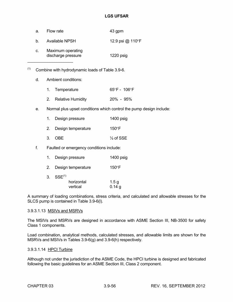
LGS UFSAR
CHAPTER 03 3.9-56 REV. 16, SEPTEMBER 2012
a. Flow rate 43 gpm
b. Available NPSH 12.9 psi @ 110F
c. Maximum operating discharge pressure 1220 psig
____________________
(1) Combine with hydrodynamic loads of Table 3.9-6.
d. Ambient conditions:
1. Temperature 65F - 106F
2. Relative Humidity 20% - 95%
e. Normal plus upset conditions which control the pump design include:
1. Design pressure 1400 psig
2. Design temperature 150F
3. OBE ½ of SSE
f. Faulted or emergency conditions include:
1. Design pressure 1400 psig
2. Design temperature 150F
3. SSE(1)
horizontal 1.5 gvertical 0.14 g
A summary of loading combinations, stress criteria, and calculated and allowable stresses for the SLCS pump is contained in Table 3.9-6(l).
3.9.3.1.13 MSIVs and MSRVs
The MSIVs and MSRVs are designed in accordance with ASME Section III, NB-3500 for safety Class 1 components.
Load combination, analytical methods, calculated stresses, and allowable limits are shown for the MSRVs and MSIVs in Tables 3.9-6(g) and 3.9-6(h) respectively.
3.9.3.1.14 HPCI Turbine
Although not under the jurisdiction of the ASME Code, the HPCI turbine is designed and fabricated following the basic guidelines for an ASME Section III, Class 2 component.
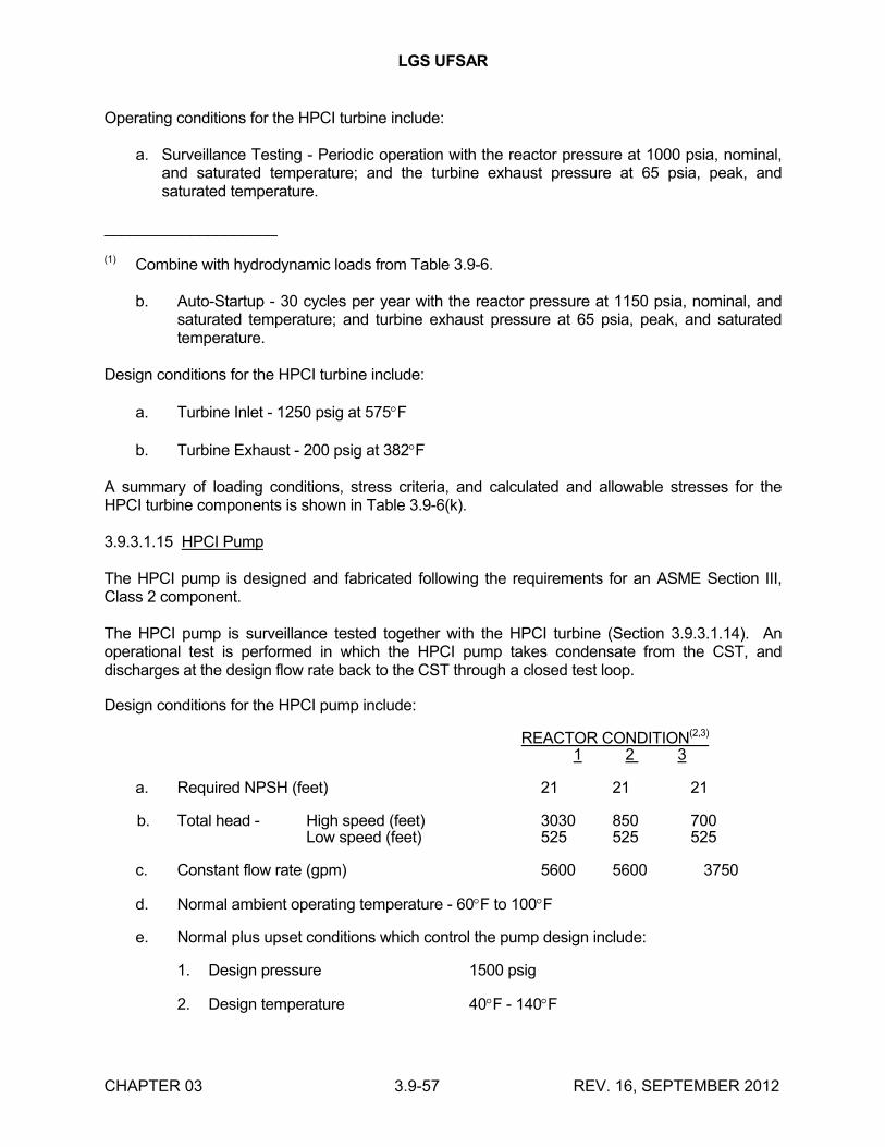
LGS UFSAR
CHAPTER 03 3.9-57 REV. 16, SEPTEMBER 2012
Operating conditions for the HPCI turbine include:
a. Surveillance Testing - Periodic operation with the reactor pressure at 1000 psia, nominal, and saturated temperature; and the turbine exhaust pressure at 65 psia, peak, and saturated temperature.
____________________
(1) Combine with hydrodynamic loads from Table 3.9-6.
b. Auto-Startup - 30 cycles per year with the reactor pressure at 1150 psia, nominal, and saturated temperature; and turbine exhaust pressure at 65 psia, peak, and saturated temperature.
Design conditions for the HPCI turbine include:
a. Turbine Inlet - 1250 psig at 575F
b. Turbine Exhaust - 200 psig at 382F
A summary of loading conditions, stress criteria, and calculated and allowable stresses for the HPCI turbine components is shown in Table 3.9-6(k).
3.9.3.1.15 HPCI Pump
The HPCI pump is designed and fabricated following the requirements for an ASME Section III, Class 2 component.
The HPCI pump is surveillance tested together with the HPCI turbine (Section 3.9.3.1.14). An operational test is performed in which the HPCI pump takes condensate from the CST, and discharges at the design flow rate back to the CST through a closed test loop.
Design conditions for the HPCI pump include:
REACTOR CONDITION(2,3)
1 2 3
a. Required NPSH (feet) 21 21 21
b. Total head - High speed (feet) 3030 850 700Low speed (feet) 525 525 525
c. Constant flow rate (gpm) 5600 5600 3750
d. Normal ambient operating temperature - 60F to 100F
e. Normal plus upset conditions which control the pump design include:
1. Design pressure 1500 psig
2. Design temperature 40F - 140F
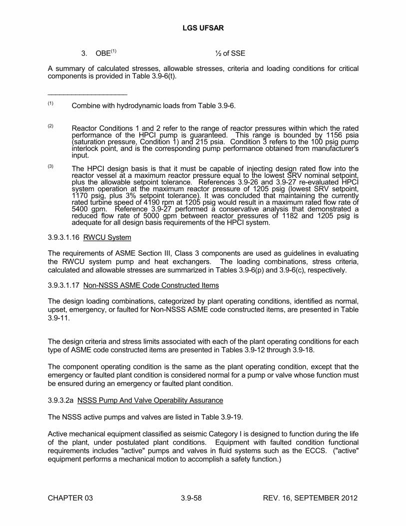
LGS UFSAR
CHAPTER 03 3.9-58 REV. 16, SEPTEMBER 2012
3. OBE(1) ½ of SSE
A summary of calculated stresses, allowable stresses, criteria and loading conditions for critical components is provided in Table 3.9-6(t).
____________________
(1) Combine with hydrodynamic loads from Table 3.9-6.
(2) Reactor Conditions 1 and 2 refer to the range of reactor pressures within which the rated performance of the HPCI pump is guaranteed. This range is bounded by 1156 psia (saturation pressure, Condition 1) and 215 psia. Condition 3 refers to the 100 psig pump interlock point, and is the corresponding pump performance obtained from manufacturer's input.
(3) The HPCI design basis is that it must be capable of injecting design rated flow into the reactor vessel at a maximum reactor pressure equal to the lowest SRV nominal setpoint, plus the allowable setpoint tolerance. References 3.9-26 and 3.9-27 re-evaluated HPCI system operation at the maximum reactor pressure of 1205 psig (lowest SRV setpoint, 1170 psig, plus 3% setpoint tolerance). It was concluded that maintaining the currently rated turbine speed of 4190 rpm at 1205 psig would result in a maximum rated flow rate of 5400 gpm. Reference 3.9-27 performed a conservative analysis that demonstrated a reduced flow rate of 5000 gpm between reactor pressures of 1182 and 1205 psig is adequate for all design basis requirements of the HPCI system.
3.9.3.1.16 RWCU System
The requirements of ASME Section III, Class 3 components are used as guidelines in evaluating the RWCU system pump and heat exchangers. The loading combinations, stress criteria, calculated and allowable stresses are summarized in Tables 3.9-6(p) and 3.9-6(c), respectively.
3.9.3.1.17 Non-NSSS ASME Code Constructed Items
The design loading combinations, categorized by plant operating conditions, identified as normal, upset, emergency, or faulted for Non-NSSS ASME code constructed items, are presented in Table 3.9-11.
The design criteria and stress limits associated with each of the plant operating conditions for each type of ASME code constructed items are presented in Tables 3.9-12 through 3.9-18.
The component operating condition is the same as the plant operating condition, except that the emergency or faulted plant condition is considered normal for a pump or valve whose function must be ensured during an emergency or faulted plant condition.
3.9.3.2a NSSS Pump And Valve Operability Assurance
The NSSS active pumps and valves are listed in Table 3.9-19.
Active mechanical equipment classified as seismic Category I is designed to function during the life of the plant, under postulated plant conditions. Equipment with faulted condition functional requirements includes "active" pumps and valves in fluid systems such as the ECCS. ("active" equipment performs a mechanical motion to accomplish a safety function.)
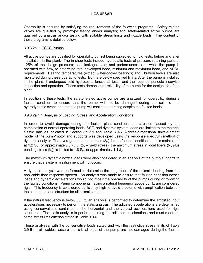
LGS UFSAR
CHAPTER 03 3.9-59 REV. 16, SEPTEMBER 2012
Operability is ensured by satisfying the requirements of the following programs. Safety-related valves are qualified by prototype testing and/or analysis; and safety-related active pumps are qualified by analysis and/or testing with suitable stress limits and nozzle loads. The content of these programs is detailed below.
3.9.3.2a.1 ECCS Pumps
All active pumps are qualified for operability by first being subjected to rigid tests, before and after installation in the plant. The in-shop tests include hydrostatic tests of pressure-retaining parts at 125% of the design pressure; seal leakage tests; and performance tests, while the pump is operated with flow, to determine total developed head, minimum and maximum head, and NPSH requirements. Bearing temperatures (except water-cooled bearings) and vibration levels are also monitored during these operating tests. Both are below specified limits. After the pump is installed in the plant, it undergoes cold hydrotests, functional tests, and the required periodic inservice inspection and operation. These tests demonstrate reliability of the pump for the design life of the plant.
In addition to these tests, the safety-related active pumps are analyzed for operability during a faulted condition to ensure that the pump will not be damaged during the seismic and hydrodynamic event, and that the pump will continue operating despite the faulted loads.
3.9.3.2a.1.1 Analysis of Loading, Stress, and Acceleration Conditions
In order to avoid damage during the faulted plant condition, the stresses caused by the combination of normal operating loads, SSE, and dynamic system loads are limited to the material elastic limit, as indicated in Section 3.9.3.1 and Table 3.9-6. A three-dimensional finite-element model of the pump/motor and supports was developed using the response spectrum method of dynamic analysis. The average membrane stress (m) for the faulted condition loads is maintained at 1.2 Sm, or approximately 0.75 y (y = yield stress); the maximum stress in local fibers (m plus bending stress (b)) is limited to 1.8 Sm, or approximately 1.1 y.
The maximum dynamic nozzle loads were also considered in an analysis of the pump supports to ensure that a system misalignment will not occur.
A dynamic analysis was performed to determine the magnitude of the seismic loading from the applicable floor response spectra. An analysis was made to ensure that faulted condition nozzle loads and dynamic accelerations would not impair the operability of the pumps during or following the faulted conditions. Pump components having a natural frequency above 33 Hz are considered rigid. This frequency is considered sufficiently high to avoid problems with amplification between the component and structure for all seismic areas.
If the natural frequency is below 33 Hz, an analysis is performed to determine the amplified input accelerations necessary to perform the static analysis. The adjusted accelerations are determined using conservatisms contained in the horizontal and the vertical accelerations used for rigid structures. The static analysis is performed using the adjusted accelerations and must meet the same stress limit criterion stated in Table 3.9-6.
These analyses, with the conservative loads stated and with the restrictive stress limits of Table 3.9-6 as allowables, assure that critical parts of the pump are not damaged during the faulted
LGS UFSAR
CHAPTER 03 3.9-60 REV. 16, SEPTEMBER 2012
condition, and that, therefore, the reliability of the pump for postfaulted condition operation will not be impaired by a hydrodynamic or seismic event.
3.9.3.2a.1.2 Pump Operation During and Following Faulted Condition Loading
Active pump/motor rotor combinations are designed to rotate at a constant speed under all conditions. Motors are designed to withstand short periods of severe overload. The high rotary inertia in the operating pump rotor and the nature of the random shot-duration loading characteristics of the seismic and hydrodynamic events prevents the rotor from becoming seized. The dynamic loadings cause a slight increase, if any, in the torque (i.e., motor current) necessary to drive the pump at constant design speed. Therefore the pump does not shut down during the faulted condition but operates at the design speed despite the faulted loads.
The functional ability of the active pumps after a faulted condition is assured, since only normal operating loads and steady-state nozzle loads exist at this time. For the active pumps, the faulted condition is greater than the normal condition due to seismic and hydrodynamic loads on the equipment and the increase in nozzle loads from the SSE on the connecting pipe. The SSE event is infrequent and of short duration compared to the design life of the equipment. Because it is demonstrated that the pumps would not be damaged during the faulted condition, the postfaulted condition operating loads are less than the normal plant operating limits. This is assured by requiring that the imposed nozzle loads (steady-state loads) for normal conditions and postfaulted conditions are limited by the normal condition nozzle loads. The postfaulted condition ability of the pumps to function under these applied loads is proven during the normal operating plant conditions.
3.9.3.2a.2 SLCS Pump and Motor Assemblies and RCIC Pump Assembly
These equipment assemblies are small, compact, rigid assemblies, with natural frequencies greater than 100 Hz. With this fact verified, each equipment assembly is dynamically qualified by static analysis only. This static qualification verifies operability under seismic and hydrodynamic conditions, and ensures that structural loading stresses are within code limitations.
3.9.3.2a.3 RCIC Turbine
Refer to Section 3.9.2.2a.2.9 and Table 3.9-6(q).
3.9.3.2a.4 ECCS Motors
Qualification of the Class 1E motors used for the ECCS motors is in compliance with IEEE 323 (1971). The qualification of all motor sizes is based on completion of a type test, followed with review and comparison of design and material details and seismic analysis of production units, ranging from 500 Bhp to 3500 Bhp, with the motor used in the type test. All manufacturing, inspection, and routine tests by motor manufacturer on production units are performed on the test motor.
The type test was performed on a 1250 hp vertical motor, in accordance with IEEE 323 (1971). First normal operation during the design life was simulated; then the motor was subjected to a number of seismic events; and then subjected to the abnormal environmental conditions possible during and after a LOCA. The type test plan was as follows:
LGS UFSAR
CHAPTER 03 3.9-61 REV. 16, SEPTEMBER 2012
a. Thermal aging of the motor electrical insulation system (which is a part of the stator only) was based on extrapolation, in accordance with the temperature life of the characteristic curve from IEEE 275 (1966) for the insulation type used on the ECCS motors. The amount of aging equals the total estimated operation days of maximum insulation surface temperature.
b. Radiation aging of the motor electrical insulation equals the maximum estimated integrated gamma dose during normal and abnormal conditions.
c. The normal induced current vibration effect on the insulation system was simulated by a 1.5 g horizontal vibration acceleration for one hour at current frequency.
d. Motor bearings were selected and their operating life established on the basis of bearing manufacturer's tests and operating data using the loads calculated to act on the bearings.
e. The dynamic load-deflection analysis on the rotor-shaft, performed to ensure adequate rotation clearance, is verified by static loading and deflection of the rotor for the type test motor.
f. Dynamic loading aging and testing were performed on a biaxial test table in accordance with IEEE 344 (1971). During this type test, the shake table was activated, simulating the maximum design limit of the SSE and hydrodynamic loads with motor starts and operation combination, as may possibly occur during the life of the plant. Refer to Section 3.10.
g. An environmental test simulating a LOCA condition was performed for 100 days with the test motor fully loaded, simulating pump operation. The test consists of startup and six hours of operation at 212F ambient temperature, and a 100% steam environment. After 1 hour standstill in the same environment, another startup and operation of the test motor was followed by sufficient operation at high humidity and temperature. This was based on extrapolation in accordance with the temperature life characteristic curve from IEEE 275 (1966) for the insulation type used on the ECCS motors.
3.9.3.2a.5 HPCI Pump
Operability of the HPCI pump assembly is demonstrated by a combination of analytical stress calculations, pump manufacturer's operating experience, and testing. The stress definitions and the allowable stress criteria are based on the ASME Section III. The code is directly applicable to the stamped pressure boundary components of the pump.
The witnessed hydrostatic and performance tests, as performed at the pump manufacturer's plant, demonstrate that the pump as designed meets the ASME Code requirements and the parameters of the design specification.
A dynamic analysis was performed by the pump manufacturer. A static analysis was performed for dead weight and nozzle loads. Dynamic analysis was used for the SSE loading condition.
LGS UFSAR
CHAPTER 03 3.9-62 REV. 16, SEPTEMBER 2012
Rotating parts are verified by analysis to ensure no contact with the stationary parts, except atengineered wear points, therefore, continued operation during and after an SSE is assured because the calculated stresses and deformations are less than the prescribed limits.
3.9.3.2a.6 NSSS Valves
3.9.3.2a.6.1 Class 1 Active Valves
The Class 1 active valves are the MSIVs and the MSRVs and SLCS valves. Each of these valves is designed to perform its mechanical motion in conjunction with a design basis accident. Dynamic qualification for operability is unique for each valve type; therefore, each method of qualification is detailed individually below.
3.9.3.2a.6.1.1 Main Steam Isolation Valve
The MSIVs were evaluated for operability during a dynamic loading event by analysis and test as follows:
a. The valve body was designed in accordance with ASME Section III, Class 1, which limits deformations in the operating area of the valve body to those within the elastic limit of the material by limiting pressure and pipe reaction input loads (including seismic and hydrodynamic), thereby ensuring no interference with valve operability.
b. The complete valve topworks, including the bonnet and a simulated stem of a similar design MSIV, was dynamically tested for upset loads and faulted load. The test sample was subjected to 30 seconds of bi-directional random frequency input for each test event. There were a total of 10 upset test events and 2 faulted test events. Valve closure was simulated half way through the testing duration during each event. After the complete test program, there was no significant change to the valve closure rate.
To ensure that design limits were not exceeded for both piping input loads and actuator dynamic loads, the MSIV was mathematically modeled in the main steam line system analysis. The valve dynamic characteristics were modeled in the overall steam line analysis. Pipe anchors and restraints are applied as required to limit pipe system resonance frequencies and amplified accelerations to within acceptable limits for the MSIVs. Details concerning the analysis of these valves is given in Table 3.9-6(h).
The MSIV operability during LOCA conditions is demonstrated as defined in report APED-5750 (March 1969). The test specimen is a 20 inch valve representative in design to the MSIVs. Operability during seismic acceleration is addressed in Section 3.9.2.2a.
3.9.3.2a.6.1.2 Main Steam Relief Valves
The MSRVs were evaluated for operability during seismic and hydrodynamic events. Structural integrity of the configuration during a seismic event was demonstrated by both code analysis and dynamic testing.
a. Each valve was designed for maximum moments which may be imposed on it when installed in service. These moments result from the dead weight, hydrodynamic, and
LGS UFSAR
CHAPTER 03 3.9-63 REV. 16, SEPTEMBER 2012
seismic loading of both the valve and the connecting pipe, thermal expansion of the connecting pipe, and reaction forces from valve discharge.
b. Dynamic tests were performed on the LGS MSRV configuration. The tests validated the design static analysis and determined that the equipment remains functional during application of the specified "g" loads.
A mathematical model of this valve was included in the overall main steam line system analysis, along with the MSIVs, to ensure that design limits were not exceeded.
The MSRV analytical qualification results are shown in Table 3.9-6(g).
3.9.3.2a.6.1.3 Explosive Valves
The SLCS explosive valves are qualified to IEEE 344 (1975). The generic qualification test demonstrated the absence of natural frequencies below 35 Hz and the ability to remain operable after the application of horizontal dynamic loading equivalent to 6.5 g and a vertical dynamic loading equivalent to 4.5 g at 33 Hz. In addition, analysis shows that there are no natural frequencies below 100 Hz.
3.9.3.2a.6.2 Class 2 and 3 Active Valves
3.9.3.2a.6.2.1 Gate/Globe Valves
Class 2 active gate/globe valves provided by GE include five RHR valves, one HPCI valve, one RCIC valve, and three core spray valves; all valves are motor-operated. There are no Class 3 active valves in the GE scope of supply. The gate/globe valves are generically qualified by testing valves that are typical of the valves supplied by GE. Operability is ensured by testing under the maximum capability static load which envelopes the static design basis load. These tests ensure operability during and after the design basis load. The actuators are qualified to IEEE 382 (1972), up to levels that exceed the design loadings.
3.9.3.2a.6.2.2 Check Valves
GE provides one swing-check valve and one stop-check valve which are Class 2 active in each of the HPCI and RCIC systems. In addition, GE provides six Class 2 check valves for the RHR system and two Class 2 check valves for the core spray system. Operability of check valves is assured by performing design calculations and by providing sufficient structural margins so that movement of the disc/hinge pin is not impaired under any loading conditions. There are no Class 3 active valves in the GE scope of supply.
3.9.3.2b Non-NSSS Pump and Valve Operability Assurance
3.9.3.2b.1 Pumps
The following pumps are active pumps:
a. Diesel oil transfer pumps
b. RHRSW pumps
LGS UFSAR
CHAPTER 03 3.9-64 REV. 16, SEPTEMBER 2012
c. ESW pumps
d. Control room chilled water pumps
e. Safeguard piping fill pumps.
The safeguard piping fill pumps are Class 2. All the remaining pumps are Class 3.
Safety-related active pumps are subjected to stringent tests both prior to and after installation in the plant. The in-shop tests include: hydrostatic tests of pressure-retaining parts to 150% of the design pressure; seal leakage tests at the same pressure used in the hydrostatic tests; and performance tests which are conducted while the pump is operated with flow to determine total developed head, minimum and maximum head, NPSH requirements, and other pump/motor properties. Bearing temperatures and vibration levels are also monitored during these operating tests. Both are shown to be within the limits specified by the manufacturer. After the pump is installed at the plant, it undergoes startup tests and required inservice inspection and operation.
In addition to these tests, the active pumps are qualified for operation during and after a faulted condition. That is, safety-related active pumps are qualified for operability during an SSE condition by assuring that the pump will not be damaged during the seismic event, and that the pump will continue operating despite the SSE loads. (Refer to 3A.7.1.7 for pumps subjected to hydrodynamic loads.)
In order to meet the first criterion, that the pump will not be damaged during the seismic event, the pump manufacturer is required to determine by test or dynamic analysis whether the lowest natural frequency of the pump is greater than 33 Hz. The pump, when having a natural frequency above 33 Hz, is considered essentially rigid. This frequency is considered sufficiently high to avoid problems with amplification between the component and structure for all seismic areas. A static shaft deflection analysis of the rotor is performed with the conservative SSE accelerations of 1.5 times the applicable floor acceleration. The deflections determined from the static shaft analysis are compared to the allowable rotor clearances.
If the lowest natural frequency is found to be below 33 hertz, the equipment is considered flexible. If flexible, the equipment is analyzed using the response spectrum modal analysis technique. The frequencies and mode shapes are determined in the vertical and horizontal directions. The loads due to the excitation of each mode and the loads due to the accelerations in the three orthogonal directions are added using the square root of the sum of the squares method. Coupling effects are included in the mathematical model.
In order to avoid damage to the pumps during the faulted plant condition, the stresses caused by the combination of normal operating loads, SSE, and dynamic system loads are limited. The maximum seismic nozzle loads are also considered in an analysis of the pump supports to assure that a system misalignment cannot occur. Performance of these analyses, based upon conservative loads and restrictive stress limits, assures that critical parts of the pump will not be damaged during the faulted condition and, therefore, that the reliability of the pump for postfaulted condition operation will not be impaired by the seismic events.
The second criterion necessary to assure operability is that the pump will function throughout the SSE. The pump/motor combination is designed to rotate at a constant speed under all conditions
LGS UFSAR
CHAPTER 03 3.9-65 REV. 16, SEPTEMBER 2012
unless the rotor becomes completely seized, i.e., with no rotation. Typically, the rotor can be seized five full seconds before a circuit breaker, used to prevent damage to the motor, opens to stop the pump. However, the high rotary inertia in the operating pump rotor and the nature of the random, short duration loading characteristics of the seismic event prevent the rotor from becoming seized. Actually, the seismic loadings cause only a slight increase, if any, in the torque, i.e., motor current, necessary to drive the pump at the constant design speed. Therefore, the pump will not shut down during the SSE and will operate at the design speed despite the SSE loads.
To complete the seismic qualification procedures, the pump motor and all appurtenances vital to the operation of the pump are independently qualified for operation during the maximum seismic event as discussed in Section 3.10.
From this regimen, it is concluded that the safety-related pump/motor assemblies will not be damaged and will continue to operate under SSE loadings and, therefore, will perform their intended functions. These proposed requirements take into account the complex characteristics of the pump and are sufficient to demonstrate and assure the seismic operability of the active pumps.
The functional ability of active pumps after a faulted condition is assured since only operating loads and steady-state nozzle loads exist. Since it is demonstrated that the pumps would not be damaged during the faulted condition, the postfaulted operating loads will be limited to the normal plant operating loads. This is assured by requiring that the imposed nozzle loads (steady-state loads) for normal conditions and postfaulted conditions are limited by the magnitudes of the normal condition nozzle loads. The postfaulted ability of the pumps to function under these applied loads is proved during the normal operating plant conditions for active pumps.
3.9.3.2b.2 Valves
The active valves are tabulated in Reference 3.9-25. Those active valves which are supplied by the NSSS vendor are identified. See Section 3.9.3.2a for a discussion of operability assurance of these valves.
Safety-related active valves are subjected to a series of stringent tests prior to service, and during the plant life. Before installation, the following tests are performed: the shell hydrostatic test, in accordance with ASME Section III requirements; back-seat and main-seat leakage tests; the disc hydrostatic test; functional tests which verify that the valve opens and closes within the specified time limits; and the operability qualification of motor operators for the environmental conditions over the installed life (i.e., aging, radiation, accident environment simulation, etc.), in accordance with IEEE 382 (1972). After installation, cold hydrostatic tests, functional tests (in accordance with the requirements of Chapter 14), and periodic inservice operation (in accordance with the requirements of Chapter 16) are performed to verify and ensure the functional ability of the valve.
The valves are designed using either stress analyses, or the pressure-containing minimum wall thickness requirements. For all active valves with extended topworks, an analysis is also performed for static-equivalent SSE loads applied at the extended structure's center of gravity. The maximum stress limits allowed in the analyses demonstrate structural integrity, and are equal to the limits recommended by the ASME for the particular ASME class of valve analyzed. Limits for each of the loading combinations are presented in Tables 3.9-13 and 3.9-18.
LGS UFSAR
CHAPTER 03 3.9-66 REV. 16, SEPTEMBER 2012
In addition to these tests and analyses, a representative valve of each design type is tested to verify operability during a simulated seismic event by demonstrating operational capabilities within the specified limits. The qualification testing procedures are described below.
The valve is mounted in a manner that conservatively represents typical valve installations. The valve unit includes the actuator and all appurtenances normally attached to the valve in service. The operability of the valve during an SSE is demonstrated by satisfying the following criteria. (Refer to Appendix 3A.7.1.7 for valves subjected to hydrodynamic loads.)
a. All the active valves with topworks are basically designed to have a first natural frequency greater than 33 Hz. This may be shown by suitable testing or analysis. Regardless of value, the first natural frequency of the topworks is modeled into the piping analysis for determination of maximum accelerations.
b. While in the shop and installed in a suitable test rig, the extended topworks of the valve are subjected to a statically applied equivalent seismic load. The load (the specified g-force times the weight of the topworks) is applied at the center of gravity of the topworks, in the direction of the weakest axis of the yoke. The design pressure of the valve is simultaneously applied to the valve during the static load tests.
c. The valve is then operated at the minimum specified actuation supply voltage or pressure, with the equivalent seismic static load applied. The valve must perform its safety-related function within the specified operating time limits.
d. Motor operators are qualified as operable during and after the SSE prior to their installation on the valve, as discussed in Section 3.10.2.2.
The equivalent seismic static load, which is used for the static valve qualification, is the maximum load which the valve is designed to withstand. The piping designer must maintain the motor operator accelerations to these levels.
The valve is leak tested following the test described above, to show that the valve has not been damaged. The leak rates must not exceed the original allowable leakage rate specified for the valve.
The above factory testing program applies only to valves with overhanging structures, e.g., the motor operator or air actuator assembly. The testing is conducted on a representative number of valves. According to the size and pressure rating, valves from each of the primary safety-related design types, e.g., motor- operated gate valves, are tested. Valves that cover the range of sizes in service are qualified by tests, and the results are used to qualify all valves within the intermediate range of sizes, as shown in Table 3.9-20. Stress analyses are used to support the interpolation. Because of their simple characteristics, check and other compact valves are not adversely affected by seismic acceleration. Check valves have no extended structures to distort the valves and cause malfunctions. Check valve discs are designed to allow sufficient clearance around the disc to prevent binding or interference due to distortions from nozzle or other imposed loads. They are qualified by a combination of the following factory tests and analysis:
a. Stress analysis of critical areas and parts for SSE loads in accordance with the allowable specified in Tables 3.9-13 and 3.9-18
b. In-shop hydrostatic test
LGS UFSAR
CHAPTER 03 3.9-67 REV. 16, SEPTEMBER 2012
c. In-shop seat leakage test
d. Periodic valve exercise and inspection to ensure the functional ability of the valve in accordance with the requirements of Chapter 16
A study was also performed that considered a feedwater pipe rupture outside containment to assure that the feedwater isolation check valves can perform their function following a postulated pipe break of the feedwater line outside containment. Analysis of a full circumferential break showed that the check valve inside containment (one of 3 feedwater PCIV's that are check valves) would close rapidly because of flow reversal in the pipe between the reactor and break location just outside containment. This results in a pressure surge of 2780 psia between the valve and reactor. It was determined that the piping and valves could adequately sustain this pressure.
To determine the capability of the check valve seat to withstand the initial impact caused by rapid closure and to sustain the pressure surge that follows, an estimate of check valve seat energy absorption capability was made for a postulated feedwater pipe break accident occurring upstream of the containment isolation valves. The basis for the seat stress calculation was for a valve disk closing velocity of 100 rad/sec and a pressure break in the pipe of 2780 psia.
The valve seat was assumed to consist of an assembly of six discrete, bilinear, elastic-plastic elements. The analysis assumed that the disc kinetic energy at impact equals work done in terms of seat under load, or area under the seat load-displacement curve. Valve seat yield strength was based on its being stressed to 50% of yield at a design pressure of 2132 psi. The load-displacement curve was constructed using Roark's stiffness equations for an annular plate loaded at the inner radius and fixed at the outer radius. Failure was assumed to occur at a ductility ratio of 30.
The analysis indicated that all of the seat elements reach yield, but none reach ultimate strain or fail. Effects not included that are believed to make the analysis conservative are:
a. No credit was taken for disc deformation and energy absorption
b. No credit was taken for hinge deformation and energy absorption
c. No credit was taken for valve body deformation and energy absorption
d. Hinge friction was omitted
e. No strain hardening or rate of strain effects in the seat were included.
The water hammer effects on the closed seat were determined. It was shown that the natural frequency of the combined valve seat stiffness and disc mass was much larger than the frequency of the pressure pulse, so that the effective pressure that the seat must withstand is only the peak pressure in the water hammer surge. The seat is able to withstand this maximum pressure.
Results of this analysis show that, although the conditions of a hypothetical pipe rupture on the feedwater check valves are severe, the valves should remain together at impact and are capable of withstanding 2800 psi. The valve seat should yield at disc impact but not fail, and the water hammer pressure pulse following closure will not cause failure.
LGS UFSAR
CHAPTER 03 3.9-68 REV. 16, SEPTEMBER 2012
An additional confirmatory analysis was also conducted which used a simplified model of single-phase, liquid flow from the reactor vessel to the pipe break, with the check valve disk being closed by drag forces.
Results of this simplified analysis indicate that the check valve disk closes in approximately 70 msec, with a closing velocity at impact of approximately 65 rad/sec. The peak pressure at the closed disk is estimated to be 2157 psi for a finite valve closure time of 70 msec. The precise pressure at valve closure cannot be predicted rigorously by the simplified method used in this study.
The results of this study confirmed the validity of the original design analysis and are consistent with the results of the analysis done for SSES and in particular for the Atwood Morrill check valves.
Operability testing is also not performed for relief valves. Due to the particular, simple characteristics of these SRVs, they are qualified by a combination of the following tests and analyses:
a. Stress analysis, including seismic loads where applicable
b. In-shop hydrostatic test
c. In-shop seat leakage test
d. Performance tests
e. Periodic in situ valve inspection as applicable and periodic valve removal, refurbishment, performance testing and reinstallation
The above testing and analysis is sufficient to ensure the functional capability of the valve.
During a seismic event, it is anticipated that the seismic acceleration imposed upon the valve may cause it to open momentarily and discharge under system conditions that otherwise would not result in valve opening, but this is considered to be of no real safety or other consequence.
Using the methods described, all the safety-related active valves in the systems are qualified for operability during a seismic event. These methods conservatively simulate the seismic event and ensure that the active valves perform their safety-related functions when necessary.
3.9.3.3 Design and Installation of Pressure Relief Devices
3.9.3.3.1 Main Steam Relief Valves (NSSS)
Lifting of an MSRV results in a transient that produces momentary unbalanced forces acting on the discharge piping system from the time the MSRV opens, until a steady discharge flow from the RPV to the suppression pool is established. This period includes clearing the water slug from the end of the discharge piping submerged in the suppression pool. Pressure waves traveling through the discharge piping following the relatively rapid opening of the MSRV cause the MSRV discharge piping to vibrate. This in turn produces forces that act on the main steam piping.
LGS UFSAR
CHAPTER 03 3.9-69 REV. 16, SEPTEMBER 2012
The analysis of the relief valve discharge transient consists of a step-wise time history solution of the fluid flow equation, to generate a time history of the fluid properties at numerous locations along the pipe. The fluid transient properties are calculated based on the maximum set pressure specified in the steam system specification, and the value of ASME flow rating increased by a factor to account for the conservative method of establishing the rating. Simultaneous discharge of all valves is assumed in the analysis, because simultaneous discharge is considered to induce maximum stress in the piping. Reaction loads on the pipe are determined at each location corresponding to the position of an elbow. These loads are composed of pressure times area, momentum change, and fluid friction terms. Figure 3.9-3 shows a set of fluid property and pipe section load transients typical of those produced by relief valve discharge.
The method of analysis applied to determine piping system response to MSRV operation is time history integration. The forces are applied at locations on the piping system where the fluid flow changes direction, thus causing momentary reactions. The resulting loads on the MSRV, the main steam line, and the discharge piping are combined with loads due to other effects, as specified in Section 3.9.3.1. The code stress limits corresponding to load combination classifications of normal, upset, emergency, and faulted, are applied to the main steam lines and MSRV discharge piping.
In addition, a series of water discharge tests of SRVs used in BWRs was conducted to demonstrate the operational adequacy of the SRV and SRV discharge piping integrity for expected operating conditions for transients and accidents. The tests were performed to satisfy requirements of NUREG-0737, Item II.D.1.
The tests were run at the Wyle Laboratories test facility in Huntsville, Alabama. The facility included a steam and water supply system, the test SRV mounted on a representative steam line, and a representative SRV discharge line routed to a pool of water. Opening and closing of the SRVs were monitored. Fluid conditions and flows were measured, as were strains, accelerations, temperatures, and pressures in the SRV and associated piping.
The water discharge test conditions simulated the alternate shutdown cooling condition, which is an operating condition which is considered in the design evaluation of many BWR plants. The results show that all of the tested SRVs opened and closed on command for all water tests. The measured SRV discharge line loads for water discharge were significantly less than those for the high pressure steam discharge condition for which the piping is designed. LGS specific analyses have been performed (Reference 3.9-22) to establish RPV temperature and pressure conditions where initiation of alternate shutdown cooling will result in acceptable SRV discharge line loads. Alternate shutdown cooling is manually initiated only.
The tests and analyses as described in NEDE-24988-P (Reference 3.9-15) verify the adequacy of SRV operation and the integrity of the SRV discharge piping under expected liquid discharge conditions, and satisfy requirements of NUREG-0737, Item II.D.1.
A basis for concluding that the test results presented in NEDE-24988-P on SRV testing are applicable to LGS is described in the following paragraphs:
a. The SRV discharge piping configuration at LGS uses a T-quencher at the discharge pipe exit. The average length of the 14 SRV discharge line is 132 feet of 12 inch diameter pipe, and the submergence length in the suppression pool is approximately 18'-6". The SRV test program used a ramshead at the discharge pipe exit, a pipe length of 112 feet, a diameter of 10 inches, and a submergence length of approximately 13
LGS UFSAR
CHAPTER 03 3.9-70 REV. 16, SEPTEMBER 2012
feet. Loads on valve internals in the LGS configuration are within acceptable limits for the following reasons:
1. No dynamic mechanical load originating at the T-quencher is transmitted to the valve in the LGS configuration because there is at least one anchor point between the valve and the T-quencher.
2. The length of the first segment of piping downstream of the SRV in the test facility was selected to result in the test program having a bounding dynamic mechanical load on the valve. The LGS SRV discharge line piping configuration differs from the test facility in that the first line segment does not terminate in a 90 elbow, and the pipe size increases in the first segment. An assessment of the LGS configuration has confirmed that the mechanical loads imposed on the LGS valves by the low pressure water flow are enveloped by the high pressure steam loads.
3. Dynamic hydraulic loads (back pressure) are experienced by the valve internals in the LGS configuration. The back pressure loads may be either transient back pressures occurring during valve actuation or steady-state back pressures occurring during steady-state flow following valve actuation.
The key parameters affecting the transient back pressures are the fluid pressure upstream of the valve, the valve opening time, the fluid inertia in the submerged SRV discharge line 0, and the SRV discharge line air volume. Transient back pressures increase with higher upstream pressure, shorter valve opening times, greater line submergence, and smaller SRV discharge line air volume. An evaluation of these differences has confirmed that the test facility and the LGS configuration have comparable back pressures. The maximum transient back pressure occurs with high pressure steam flow conditions. The transient back pressure for the alternate shutdown cooling mode of operation is always much less than the design for steam flow conditions because of the lower upstream pressure and the longer valve opening time.
The steady-state back pressure in the test program was maximized by using an orifice plate in the SRV discharge line above the water level and before the ramshead. The orifice was sized to produce a back pressure greater than that calculated for any of the LGS SRV discharge lines.
An additional consideration in the selection of the ramshead for the test facility was to allow more direct measurement of the thrust load in the final pipe segment. The use of a T-quencher in the test program would have required quencher supports that would unnecessarily obscure accurate measurement of the pipe thrust loads.
The differences in the line configuration between the LGS plant and the test program as discussed above result in loads on the LGS valve internals that are within acceptable limits.
b. The LGS SRV discharge lines are supported by a combination of snubbers, rigid supports, and spring hangers. These supports were designed to accommodate combinations of loads resulting from piping, dead weight, thermal conditions, seismic and suppression pool hydrodynamic events, and a high pressure steam discharge
LGS UFSAR
CHAPTER 03 3.9-71 REV. 16, SEPTEMBER 2012
transient. Each SRV discharge line at LGS has 2 to 5 spring hangers, all of which are located in the drywell. The test facility configuration utilized no spring hangers.
The dynamic load effects on the piping and supports of the test facility due to the water discharge events (the alternate shutdown cooling mode) were found to be significantly lower than corresponding loads resulting from the high pressure steam discharge event. As stated in Reference 3.9-15, this finding is considered generic to all BWRs because the test facility was designed to be prototypical of the features pertinent to this issue. Furthermore, assessment of a typical LGS SRV discharge line configuration has confirmed the applicability of the generic statement to LGS. LGS specific analysis for acceptable alternate shutdown cooling initiating conditions has been performed (Reference 3.9-22).
During the water discharge transient, there will be significantly lower dynamic loads acting on the snubbers and rigid supports than during the steam discharge transient. This will more than offset the small increase in the dead load on these supports due to the weight of the water during the alternate shutdown cooling mode of operation. Therefore, design adequacy of the snubbers and rigid supports is assured because they are designed for the larger steam discharge transient loads.
The design adequacy of the spring hangers with respect to the increased dead load due to the weight of the water during the liquid discharge transient has been addressed. As was discussed with respect to snubbers and rigid supports, the dynamic loads resulting from liquid discharge during the alternate shutdown cooling mode of operation are significantly lower than those from the high pressure steam discharge. The spring hangers have been reviewed for the deflections resulting from the steam discharge dynamic event and were found to be acceptable. In addition, the spring hangers have been evaluated for the increased dead load due to a water-filled condition. Both the spring hangers and piping stresses were acceptable. Furthermore, the effects of the water dead weight load does not affect the ability of SRVs to open to establish the alternate shutdown cooling path because the loads occur in the SRV discharge line only after valve opening.
c. The purpose of the SRV test program was to demonstrate that the SRV will open and reclose under all expected flow conditions. The expected valve operating conditions were determined through the use of analyses of accidents and anticipated operational occurrences referenced in Regulatory Guide 1.70 (Rev 2). Single failures were applied to these analyses so that the dynamic forces on the SRVs would be maximized. Test pressures were the highest predicted by conventional safety analysis procedures. The BWROG, in their enclosure to the September 17, 1980 letter from D.B. Waters (BWROG) to R.H. Vollmer (NRC), identified 13 events that may result in liquid or two-phase SRV inlet flow that would maximize the dynamic forces on the SRV. These events were identified by evaluating the initial events described in Regulatory Guide 1.70 (Rev 2), with and without the additional conservatism of a single active component failure or operator error postulated in the event sequence. It was concluded from this evaluation that the alternate shutdown cooling mode is the only expected event that will result in liquid at the valve inlet. Consequently, this was the event simulated in the SRV test program. This conclusion and the test results applicable to LGS are discussed below.
LGS UFSAR
CHAPTER 03 3.9-72 REV. 16, SEPTEMBER 2012
The 13 events and the plant specific features that mitigate these events are summarized in Table 3.9-32. Of these 13 events, only nine are applicable to LGS because of its design and specific plant configuration. Four events (5, 6, 10 and 13) are not applicable to LGS for the reasons listed below:
1. Events 5 and 10 are not applicable because LGS does not have a high pressure core spray system.
2. Event 6 is not applicable because LGS does not have RCIC head sprays.
3. Event 13 is not applicable because large breaks will not be isolated at LGS.
For the nine remaining events, the LGS specific features, such as trip logic, power supplies, instrument line configuration, alarms and operator actions, have been compared to the base case analysis presented in the BWROG submittal of September 17, 1980. The comparison has demonstrated that, in each case, the base case analysis is applicable to LGS because the base case analysis does not include any plant features that are not already present in the LGS design. For these events, Table 3.9-32 demonstrates that the LGS specific features are included in the base case analysis presented in the BWROG submittal of September 17, 1980. It is seen from Table 3.9-32 that all plant features assumed in the event evaluation are also existing features in the LGS plant. All features included in this base case analysis are similar to plant features in the LGS design. Furthermore, the time available for operator action is expected to be longer in the LGS plant than in the base case analysis for each case where operator action is required due to the conservative nature of the base case analysis.
Event 7, the alternate shutdown cooling mode of operation, is the only expected event that will result in liquid or two-phase fluid at the SRV inlet. Consequently, this event was simulated in the BWR SRV test program. In LGS, the event involves flow of subcooled water (approximately 31F subcooled) at a pressure of approximately 156 psig. The SRV inlet fluid conditions tested in the BWROG SRV test program, as documented in Reference 3.9-15, are 15F to 50F subcooled liquid at 20 psig to 250 psig. These fluid conditions envelope the conditions expected to occur at LGS in the alternate shutdown cooling mode of operation.
As discussed above, the BWROG evaluated transients including single active failures that would maximize the dynamic forces on the SRVs. As a result of this evaluation, the alternate shutdown cooling mode is the only expected event involving liquid or two-phase flow. Consequently, this event was tested in the BWR SRV test program. The fluid conditions and flow conditions tested in the BWROG test program conservatively envelope the LGS plant specific fluid conditions expected for the alternate shutdown cooling mode of operation (Reference 3.9-22).
d. The flow coefficient, Cv, for the Target Rock SRV used in LGS was determined in the generic SRV test program (Reference 3.9-15). The average flow coefficient calculated from the test results for the Target Rock valve is reported in table 5.2-1 of Reference 3.9-15. This test value has been used by the licensee to confirm that the liquid discharge flow capacity of the LGS SRVs will be sufficient to remove core decay heat when injected into the RPV in the alternate shutdown cooling mode. The Cv of the valve determined in the SRV test demonstrates that the LGS SRVs are capable of returning
LGS UFSAR
CHAPTER 03 3.9-73 REV. 16, SEPTEMBER 2012
sufficient flow to the suppression pool to accommodate injection by the RHR or core spray pump.
If it were necessary to place the LGS plant in the alternate shutdown cooling mode, the operator would ensure that adequate core cooling was being provided by monitoring the following parameters: RHR or core spray flow rate, reactor vessel pressure, and reactor vessel temperature.
The flow coefficient for the Target Rock valve reported in Reference 3.9-15 was determined from the SRV flow rate when the valve inlet was pressurized to approximately 250 psig. The valve flow rate was measured with the supply line flow venturi upstream of the steam chest. The Cv for the valve was calculated using the nominal measured pressure differential between the valve inlet (steam chest) and 3 feet downstream of the valve and the corresponding measured flow rate. Furthermore, the test conditions and test configuration were representative of LGS plant conditions for the alternate shutdown cooling mode, e.g., pressure upstream of the valve, fluid temperature, friction losses, and liquid flow rate. Therefore, the reported Cv values are appropriate for application to the LGS plant.
3.9.3.3.2 Design and Installation Details for Mounting of Pressure Relief Devices in ASME Class 1, 2, and 3 Systems (Non-NSSS)
The design of the pressure-relieving devices can be grouped into two categories: open discharge and closed discharge.
a. Open Discharge
There are no open discharge pressure-relieving devices with limited runs of discharge piping mounted on ASME Code Class 1, 2, and 3 systems.
b. Closed Discharge
A closed discharge system is characterized by piping between the valve and a tank, or some other terminal end. Under steady-state conditions, there are no net unbalanced forces. The initial transient response and resulting stresses are determined by using either a time history computer solution, or a conservative equivalent static solution. In calculating initial transient forces, pressure and momentum terms are included. Water slug effects are also considered.
Time history dynamic analysis is performed for the discharge piping and its supports. The effect of the loading on the header is also considered. The design load combinations for a given transient are shown in Table 3.9-11, and the design criteria and stress limits are shown in Tables 3.9-12 and 3.9-16.
3.9.3.4 Component Supports Furnished with the NSSS
3.9.3.4.1 Piping
Hangers are designed in accordance with ANSI B31.7. In general, the load combinations for the various operating conditions correspond to those used to design the supported pipe. Design transient cyclic data are not applicable to hangers because no fatigue evaluation is necessary to
LGS UFSAR
CHAPTER 03 3.9-74 REV. 16, SEPTEMBER 2012
meet the code requirements. All hangers are designed, fabricated, and assembled so that they cannot become disengaged by the movement of the supported pipe or equipment after they are installed. The design load on hangers is the load caused by dead weight. The hangers are calibrated to ensure that they support the design load at both their hot and cold load settings. Hangers provide a specified down travel and up travel in excess of the specified thermal movement. Visual inspection and acceptance of pipe supports are performed in accordance with NCIG-01 requirements (Reference 3.9-10).
For pipe supports, reactions produced by primary and secondary pipe loads are categorized as primary. The primary and secondary loads are summed and compared to the load rating to ensure that the rating is not exceeded. Because no distinction is made between primary and secondary loads, and load rated components are designed to primary limits or qualified by testing, the supports meet primary stress criteria for primary and secondary loads combined.
Required load capacity and snubber location for NSSS piping systems are determined by GE as a part of the NSSS piping system design and analysis scope. However, design, installation andinspection of snubbers are included in the non-NSSS scope (Section 3.9.3.5).
The entire piping system, including valves and the suspension system between anchor points, is mathematically modeled for complete structural analysis. In the mathematical model, the snubbers are modeled as springs with a given stiffness depending on the snubber size. The analysis determines the forces and moments acting on each component and the forces acting on the snubbers due to all dynamic loading conditions defined in the piping design specification. The design load on snubbers includes those loads caused by seismic forces (OBE and SSE), system anchor movements, and reaction forces caused by relief valve discharge, turbine stop valve closure, and other hydrodynamic forces (SRV, LOCA, annulus pressurization).
The assessment of all affected piping including their supports and structural modifications necessitated by reconciliation of the suppression pool hydrodynamic loads have been completed.
The snubber location and loading direction are decided by estimation so that the stresses in the piping system have acceptable values. The snubber locations and direction are refined by performing the computer analysis on the piping system as described above.
The spring constant required by the suspension design specification for a given load capacity snubber is compared against the spring constant used in the piping system model. If the spring constants are not in agreement, they are brought into agreement, and the system analysis is redone to confirm the snubber loads.
If the stiffness of the backup structure for the snubber is not large compared to that of the snubbers, the reduced effective snubber stiffness (spring constant) is used in the analysis to account for backup structure flexibility.
Snubber design is discussed in Section 3.9.3.5.2.
3.9.3.4.2 NSSS Floor-Mounted Equipment (Pumps, Heat Exchangers, and RCIC and HPCI Turbines)
The ECCS pumps, RCIC and SLCS pumps, RHR heat exchanger, and RCIC and HPCI turbines are analyzed to verify the adequacy of their support structure under various plant operating conditions. In all cases, the stress loads in the critical support areas are within ASME Code
LGS UFSAR
CHAPTER 03 3.9-75 REV. 16, SEPTEMBER 2012
allowables. The assessment of all affected equipment including their supports and structural modifications necessitated by reconciliation of the suppression pool hydrodynamic loads have been completed. The loading conditions, stress criteria, and allowable and calculated stresses in the critical support areas are summarized in Tables 3.9-6(k), 3.9-6(l), 3.9-6(m), 3.9-6(n), 3.9-6(o), 3.9-6(q), 3.9-6(r), and 3.9-6(t).
3.9.3.4.3 Supports for ASME Code Class 1, 2, and 3 Active Components
ASME Code Class 1, 2, and 3 active components are either pumps or valves. Because valves are supported by piping and are not tied to building structures, pipe design criteria govern.
Seismic Category I active pump supports are qualified for seismic and hydrodynamic loads by testing when the pump supports along with the pumps are fulfilling the following conditions:
a. Simulate actual mounting conditions
b. Simulate all static and dynamic loadings on the pump
c. Monitor pump operability during testing
d. Normal operation of the pump during and after the test indicates that the supports are adequate; any deflection or deformation of the pump supports that precludes the operability of the pump is not accepted.
e. Supports are inspected for structural integrity after the test; any cracking or permanent deformation is not accepted.
Seismic and hydrodynamic qualification of component supports by analysis is generally accomplished as follows:
a. Stresses at all support elements and parts such as pump holddown, baseplate holddown bolts, pump support pads, pump pedestal, and foundation are checked to be within the allowable limits as specified in ASME Subsection NF.
b. For normal and upset plant conditions, the deflections and deformations of the supports are assured to be within the elastic limits and not exceed the values permitted by the designer based on design verification tests to ensure the operability of the pumps.
c. For emergency and faulted plant conditions, the deformations must not exceed the values permitted by the designer to ensure operability of the pumps.
3.9.3.4.4 RPV Support Skirt
The permissible compressive load on the reactor vessel support skirt cylinder (modeled as plate and shell type component support) is limited by the design specification to 90% of the load which produces yield stress, divided by the safety factor for the condition being evaluated. The effects of fabrication and operational eccentricity are included. The safety factor for faulted conditions is 1.125.
LGS UFSAR
CHAPTER 03 3.9-76 REV. 16, SEPTEMBER 2012
An analysis of RPV support skirt buckling for faulted conditions shows that the support skirt has the capability to meet ASME Section III, paragraph F-1370(c), faulted condition limits of 0.67 times the critical buckling strength of the support at temperature. The faulted condition analyzed included the compressive loads due to the design basis maximum earthquake, the overturning moments and shears due to the jet reaction load resulting from a severed pipe, and the compressive effects on the support skirt due to the thermal and pressure expansion of the reactor vessel.
Subsequently, based on currently defined faulted condition loads, the maximum compressive stress in the support skirt including axial and bending loads in less than the faulted condition allowable of appendix F (paragraph F-1325) determined by the methods of ASME Section III, NB 3133.6. (Axial loads include weight, fuel interaction, seismic SSE, and the maximum of condensation oscillation, chugging and vent clearing due to a LOCA. Bending loads include seismic SSE and jet reaction, jet impingement, and annulus pressurization due to a LOCA.) The loading criteria, stress criteria, calculated and allowable stresses are summarized in Table 3.9-6(f).
3.9.3.4.5 Bolting Stress Limits (NSSS)
3.9.3.4.5.1 Component Support Bolting
The support bolting of the RWCU pump that is not essential to safety is designed for the effects of pipe load and SSE load to the requirements of ASME Section III, Appendix XVII. The stress limits of 0.41 Sy for tension and 0.15 Sy for shear are used.
For RCIC/SLCS pumps and RCIC turbine, the equipment-to-base plate bolting satisfies the following design criteria: For normal and upset conditions, 1.0S is used for primary membrane and 1.5S for primary membrane plus bending, where (S) is the allowable stress limit from ASME Section III, Appendix I, table I-7.3. For emergency and faulted conditions, stresses shall be less than 1.2 times the allowable limits for "normal and upset" given above.
There are no flange-type connections in pipe mounted component supports.
3.9.3.4.5.2 Piping Supports and Pipe-Mounted Equipment (Valves and Pump) Supports
The hanger type supports (including clamps) and their bolting are designed in accordance with the requirements of ANSI B31.7. The allowable stress limit for the bolting is equal to or less than the yield strength of the bolt material at temperature.
3.9.3.5 Component Supports Not Furnished with the NSSS
3.9.3.5.1 Design Basis
ASME Section III, Subsection NF, is used for the design and installation of the CRD piping supports and TIP piping supports. For the remainder of the non-NSSS portion of the LGS design and installation, Subsection NF is not used. The codes used instead are ANSI B31.7 for nuclear class piping and ANSI B31.1 for non-nuclear class piping. Visual inspection and acceptance of non-Subsection NF pipe supports are performed in accordance with NCIG-01 requirements (Reference 3.9-10). For a graphical definition of jurisdictional boundaries between pipe supports and supporting structures, refer to Figures 3.9-9 and 3.9-10.
The design loading combinations for supports for ASME Class 1, 2 and 3 components, categorized with respect to plant operating conditions identified as normal, upset, emergency, and faulted are given in Table 3.9-21. This table also provides the stress limits for each plant operating condition.
LGS UFSAR
CHAPTER 03 3.9-77 REV. 16, SEPTEMBER 2012
The loads imposed on the ASME Class 1, 2 and 3 active valves and pumps are limited to values below the code allowable loads to ensure operability of the active components by the design of the supports. The supports are designed to remain elastic under the maximum loads. The minor local deformations associated with the elastic deformation of the support will not impair operability of the active components.
3.9.3.5.2 Snubbers
Snubbers are used in seismic Category I systems. The load ratings of the snubbers are appropriate for the design conditions and load combinations.
3.9.3.5.2.1 Analytical Methods
The methodology used for the stress analysis of seismic Category I, 2½ inches and larger piping systems is as follows:
a. For systems designed to seismic and hydrodynamic loads, the flexibility of the pipe supports are considered in the piping stress analysis. A stiffness tolerance criteria is used to facilitate support design and installation.
b. For systems designed to seismic loads, only the supports are considered as rigid members in the piping stress analysis model and are designed such that their fundamental frequencies in the direction of the applied load is within the rigid range of the seismic response spectra.
3.9.3.5.2.2 Snubber Design Specification
Snubbers for LGS are used to arrest shock due to seismic and other dynamic transient events. Under such applications, the snubbers will be subjected to a limited number of load cycles. Snubbers are not designed for vibration control. Therefore, no fatigue evaluation has been performed.
The purchase specification of new shock suppressors (snubbers) covers the following criteria for supplier's performance qualification tests and load tests. End clearance and lost motion are not considered in the piping stress analysis. Instead, linear average snubber stiffness is used in combination with that of the snubber support structure.
Mechanical Snubbers
a. The friction resistance of the suppressor to normal pipe movement shall be a maximum of 1% of the service level A rated load of the unit or 5 lb, whichever is greater.
b. The suppressor shall limit the acceleration of the pipe to a maximum of 0.02 g when subjected to any load up to the normal rated load.
Based on experience from other plants, the activation threshold has been shown to be above the thermal growth rate of the piping systems.
c. The total lost movement at the suppressor shall not exceed ±0.040 inches due to any applied dynamic cycle load from 3-33 cps up to the rated load at the unit.
LGS UFSAR
CHAPTER 03 3.9-78 REV. 16, SEPTEMBER 2012
d. The suppressor shall be designed for an exposure to a temperature of room temperature (65° to 70°F) prior to initial startup and 200F during continuous operations and to a radiation dose of 6.4x10⁷ rads during the life of the plant. Functioning of the shock suppressor under 340F temperature for a short duration under rated load shall be demonstrated.
Hydraulic Snubbers
a. The friction resistance of the snubbers rated at 20 kips or greater shall have a friction resistance to normal movement of less than or equal to one percent of the service level A rated load. Snubbers rated at less than 20 kips shall have a friction resistance to normal movement of less than or equal to two percent of the rated load.
b. Activation of the snubber shall be defined as the velocity at which the snubber begins to support load, and restricts movement to the maximum bleed rate of the snubber. The activation velocity may be referred to as the lock-up velocity or activation velocity interchangeably. These requirements shall be satisfied under both tension and compression. The activation velocity of new snubbers at room temperature (65 to 75F) shall be greater than or equal to 4.72 IPM and less than or equal to 14.17 IPM for all sizes.
c. The bleed rate shall be defined as that velocity at which the snubber will move under constant rated loads after the activation velocity has been reached and the control valves have closed. These requirements shall be satisfied under both tension and compression. The bleed velocity for the new snubbers at room temperature (65 to 75F) shall be greater than or equal to 0.47 IPM and less than or equal to 4.72 IPM for all sizes.
d. The snubber shall be designed to withstand the normal environmental conditions inside the drywell of -0.5 to 2.0 psig, 160F (based on Drywell Air Cooling System Design Bases described in Section 9.4.5.2), 40 to 90% relative humidity, and a radiation dose of 6.4 x 10⁷ rads during the life of the plant. This bounding radiaton dose may be reduced by component or model specific evaluations of normal and design basis accident radiation environments.
3.9.3.5.2.3 Snubber Performance Test
A production test is required to be performed on each unit.
a. Check unit to confirm that it operates freely over the total stroke.
b. Measure and record the force required to initiate motion over the stroke in tension and compression.
c. On units which allow movement after the initial suppression of load, determine that the maximum allowable acceleration (mechanical snubbers) or velocity (hydraulic snubbers) is not exceeded. This requirement must be met in both tension and compression at room temperature.
d. Measure and record lost motion of the snubber mechanism (mechanical snubbers only).
LGS UFSAR
CHAPTER 03 3.9-79 REV. 16, SEPTEMBER 2012
Qualification tests are to be performed on randomly selected production models. These tests are used to demonstrate the required load performance (load rating) and specified displacement when subjected to dynamic load cycling. Also included in these tests are low temperature, high temperature, humidity, radiation and faulted load conditions.
Preinstallation, installation and postinstallation inspections of snubbers are performed before a preoperational test. Additional inspections are required if more than 6 months have elapsed between the last inspection and initial system power operation (Section 3.9.3.5.2.4).
Steady state vibration conditions will be identified during the preoperational test program. Snubbers have not been used to control steady state vibration. If the snubbers are used to correct such conditions, they will be evaluated for acceptability under those conditions.
In addition, the snubber inservice inspection program ensures that any potential malfunction due to fatigue-type failure will be detected.
3.9.3.5.2.4 Snubber Preservice Examination
Preservice examination of snubbers should be performed after installation, but not more than six months prior to initial system preoperational testing.
The mechanical snubber examination is described as follows. The objective is to verify adequate preservice examination to mechanical snubbers on all safety-related systems. The prerequisites of all preinstallation, installation, and postinstallation inspections have been performed on mechanical snubbers by designated inspection organizations. Verify through document review that all inspection activities have been completed, verified, and signed. Reviews will be made by systems and additional visual inspections will be made if original inspections are performed more than 6 months prior to initial power operation of the system.
The preservice examination should as a minimum verify the following:
a. There are no visible signs of damage or impaired operability as a result of storage, handling or installation.
b. The snubber location, orientation, position setting, and configuration (attachments, extensions, etc.) are according to design drawings and specifications.
c. Snubbers are not seized, frozen, or jammed.
d. Adequate swing clearance is provided to allow snubber movement.
e. Structural connections such as pins, fasteners, and other connecting hardware such as lock nuts, tabs, wire, and cotter pins are installed correctly.
If the period between the initial preservice examination and initial power operation exceeds 6 months, re-examination of items a. and d. shall be performed. Snubbers which are installed incorrectly or otherwise fail to meet the above requirements must be repaired or replaced and re-examined in accordance with the above criteria.
LGS UFSAR
CHAPTER 03 3.9-80 REV. 16, SEPTEMBER 2012
3.9.3.5.3 Struts
The design load on struts includes those loads caused by dead weight, thermal expansion, primary dynamic forces, (i.e., OBE and SSE), system anchor displacements, and reaction forces caused by relief valve discharge, turbine stop valve closure, etc.
For pipe supports, reactions produced by primary and secondary pipe loads are categorized as primary. The primary and secondary loads are summed and compared to the load rating to ensure that the rating is not exceeded. Because no distinction is made between primary and secondary loads, and load rated components are designed to primary limits or qualified by testing, the supports meet primary stress criteria for primary and secondary loads combined.
3.9.3.5.4 Bolting Stress Limits (Non-NSSS)
The bolting used in pipe support components is designed to an allowable stress equal to or less than the yield strength of the bolt material at temperature.
For flanged connections, the bolt allowables used in the piping are ASME Section III, 1979 Summer Addenda, Sections NB, NC and ND for Class 1, 2, and 3, respectively.
3.9.4 CONTROL ROD DRIVE SYSTEM
The discussion in this Section includes the CRDM, the HCU, the condensate supply system, and the scram discharge volume, and extends to the coupling interface with the control rods.
3.9.4.1 Descriptive Information on CRD System
Descriptive information on the CRD system is contained in Section 4.6.
3.9.4.2 Applicable CRD System Design Specifications
The CRD system is designed to meet the functional design criteria as outlined in Section 4.6, and consists of the following:
a. Locking piston CRD
b. HCU
c. Hydraulic power supply (pumps)
d. Interconnecting piping
e. Flow and pressure and isolation valves
f. Instrumentation and electrical controls
Those components of the CRD forming part of the primary pressure boundary are designed according to ASME Section III.
LGS UFSAR
CHAPTER 03 3.9-81 REV. 16, SEPTEMBER 2012
The quality group classification of the CRD hydraulic system is outlined in Table 3.2-1; and the components are designed according to the codes and standards governing the individual quality groups.
Pertinent aspects of the design and qualification of the CRD components are discussed in the following locations: transients in Section 3.9.1.1, faulted conditions in Section 3.9.1.4, and dynamic testing in Section 3.9.2.2a.
3.9.4.3 Design Loads, Stress Limits, and Allowable Deformation
The ASME Code components of the CRD system are evaluated analytically, and the design loading conditions, stress criteria, calculated stresses, and allowable stresses are summarized in Tables 3.9-6(u) and 3.9-6(v). For the noncode components, experimental testing is used to determine the CRD performance under all possible conditions, as described in Section 3.9.4.4.
Deformation is not a limiting factor in the analysis of the CRD components based on the results ofthe numerous tests performed on the drive.
3.9.4.3.1 CRD Housing Supports
The CRD housing support system functions are described in Section 4.6.1.3.
The AISC Manual of Steel Construction, "Specification for the Design, Fabrication, and Erection of Structural Steel for Buildings," was used in designing the CRD housing support system. However, to provide a structure that absorbs as much energy as practical without yielding, the allowable tension and bending stresses used were 90% of yield and the shear stress used was 60% of yield. The design stresses are 1.5 times the AISC allowable stresses (60% and 40% of yield, respectively).
The CRD housing supports are designed as seismic Category I equipment. Loading conditions and examples of stress analysis results and limits are given in Table 3.9-6(z).
3.9.4.4 CRD Performance Assurance Program
The CRD test program consists of the following tests:
a. Development tests
b. Factory quality control tests
c. 5 year maintenance life tests
d. 1.5x design life tests
e. Operational tests
f. Acceptance tests
g. Surveillance tests
LGS UFSAR
CHAPTER 03 3.9-82 REV. 16, SEPTEMBER 2012
All of the above tests except c. and d. are discussed in Section 4.6.3. Tests c. and d. are discussed below:
Test c. - 5 Year Maintenance Life Tests
Four CRDs are normally picked at random from the production stock each year, and subjected to various tests under simulated reactor conditions and 1/6 of the cycles specified in Section 3.9.1.1.
Upon completion of the test program, CRDs must meet, or surpass, the minimum specified requirements.
Test d. - 1.5x Design Life Tests
When a significant design change is made to the components of the drive, the drive is subjected to a series of tests equivalent to 1.5 times the life test cycles specified in Section 3.9.1.1.
Two CRDs underwent such testing in 1976. Upon completion of the test program, these CRDs met or surpassed the minimum specified requirements.
3.9.5 REACTOR PRESSURE VESSEL INTERNALS
This section identifies and discusses the structural and functional integrity of the major RPV internals.
3.9.5.1 Design Arrangements
The core support structures and RPV internals (exclusive of fuel, control rods, CRDs, and incore nuclear instrumentation) are identified below:
Core Support Structures
Shroud
Shroud support
Core support plate and holddown bolts
Top guide (including bolts and keepers)
CRD housing
Fuel supports
Control rod guide tubes
Reactor Internals
*Jet pump assemblies and instrumentation
LGS UFSAR
CHAPTER 03 3.9-83 REV. 16, SEPTEMBER 2012
*Feedwater spargers
Vessel head spray nozzle (Removed-Unit 1. Never installed-Unit 2)
Differential pressure and liquid control lines
Incore flux monitor guide tubes
*Initial startup neutron sources
*Surveillance sample holders
Core spray lines and spargers
*Incore instrument housings
LPCI coupling
*Steam dryer
*Shroud head and steam separator assembly
*Guide rods
CRD thermal sleeves
* = Nonsafety class component
A general assembly drawing of the important reactor components is shown in Figure 3.9-4.
The floodable inner volume of the RPV can be seen in Figure 3.9-5. This is the volume inside the core shroud up to the level of the jet pump suction inlet.
The design arrangement of the reactor internals, such as the jet pumps, steam separators and guide tubes, is such that one end is unrestricted, and thus free to expand.
The LPCI couplings incorporate sleeves to allow free thermal expansion.
3.9.5.1.1 Core Support Structures
The core support structures consist of those items listed in Section 3.9.5.1. These structures form partitions within the reactor vessel, to sustain pressure differentials across the partitions, to direct the flow of the coolant water, and to laterally locate and support the fuel assemblies. Figure 3.9-5 shows the reactor vessel internal flow paths.
3.9.5.1.1.1 Shroud
The shroud support and shroud make up a stainless steel cylindrical assembly that provides a partition to separate the upward flow of coolant through the core, from the downward recirculation flow. This partition separates the core region from the downcomer annulus, thus providing a floodable region following a recirculation line break. The volume enclosed by this assembly is
LGS UFSAR
CHAPTER 03 3.9-84 REV. 16, SEPTEMBER 2012
characterized by three regions. The upper portion surrounds the core discharge plenum, which is bounded by the shroud head on top and the top guide's grid plate below. The central portion of the shroud surrounds the active fuel, and forms the longest section of the assembly. This section is bounded at the top by the grid plate and at the bottom by the core plate. The lower portion, surrounding part of the lower plenum, is welded to the RPV shroud support.
3.9.5.1.1.2 Shroud Support
The shroud support is designed to support the shroud, and to support and locate the jet pumps. The shroud support provides an annular baffle between the RPV and the shroud. The jet pump discharge diffusers penetrate the shroud support to introduce the coolant to the inlet plenum below the core.
3.9.5.1.1.3 Shroud Head and Steam Separator Assembly
This component is not a core support structure. It is discussed here to describe coolant flow paths in the RPV. The shroud head and steam separator assembly is bolted to the top of the shroud, forming the top of the core discharge plenum. This plenum provides a mixing chamber for the steam-water mixture before it enters the steam separators. Individual stainless steel axial flow steam separators are attached to the top of standpipes that are welded into the shroud head. The steam separators have no moving parts. In each separator, the steam-water mixture rising through the standpipe passes vanes that impart a spin that establishes a vortex, separating the water from the steam. The separated water flows from the lower portion of the steam separator into the downcomer annulus.
3.9.5.1.1.4 Core Support Plate
The core support plate is a circular stainless steel plate with bored holes, which is stiffened with a rim and beam structure. The plate provides lateral support and guidance for the control rod guide tubes, incore flux monitor guide tubes, peripheral fuel supports, and startup neutron sources. The last two items are supported vertically by the core support plate.
The entire assembly is bolted to a support ledge on the lower portions of the shroud.
3.9.5.1.1.5 Top Guide
The top guide is formed by a series of stainless steel beams joined at right angles to form square openings, and fastened to a peripheral rim. Each opening provides lateral support and guidance for 4 fuel assemblies, or in the case of peripheral fuel, for less than 4 fuel assemblies. Sockets are provided in the bottom of the beam intersections to anchor the incore flux monitors and startup neutron sources. The rim of the top guide rests on a ledge between the upper and central portions of the shroud. The top guide has alignment pins that engage and bear against slots in the shroud which are used to correctly position the assembly before it is secured. Lateral restraint is provided by wedge blocks between the top guide and the shroud wall.
3.9.5.1.1.6 Fuel Supports
The fuel supports, shown in Figure 3.9-6 are of two basic types; peripheral supports, and four-lobed orificed fuel supports. The peripheral fuel support is located at the outer edge of the active core, and is not adjacent to control rods. Each peripheral fuel support holds one fuel assembly, and contains a single orifice assembly designed to ensure proper coolant flow to the
LGS UFSAR
CHAPTER 03 3.9-85 REV. 16, SEPTEMBER 2012
peripheral fuel assembly. Each four-lobed orificed fuel support holds four fuel assemblies, and is provided with four orifice plates to ensure proper coolant flow distribution to each rod-controlled fuel assembly. The four-lobed orificed fuel supports rest in the top of the control rod guide tubes, which are supported laterally by the core plate. The control rods pass through slots in the center of the four-lobed orificed fuel support. A control rod and the four adjacent fuel assemblies represent a core cell (Section 4.1.2).
3.9.5.1.1.7 Control Rod Guide Tubes
The control rod guide tubes, located inside the vessel, extend from the top of the CRD housings, and up through holes in the core plate. Each tube is designed as the guide for a control rod, and as the vertical support for a four-lobed orificed fuel support piece and the four fuel assemblies surrounding the control rod. The bottom of the guide tube is supported by the CRD housing, which in turn transmits the weight of the guide tube, fuel support, and fuel assemblies to the reactor vessel bottom head. A thermal sleeve is inserted into the CRD housing from below, and is rotated to lock the control rod guide tube in place. A key is inserted into a locking slot in the bottom of the CRD housing to hold the thermal sleeve in position.
3.9.5.1.1.8 Jet Pump Assemblies
The jet pump assemblies are not core support structures, but are discussed here to describe coolant flow paths in the vessel. The jet pump assemblies are located in two semicircular groups in the downcomer annulus, between the core shroud and the reactor vessel wall. The design and performance of the jet pumps are covered in detail in References 3.9-19 and 3.9-20. Each stainless steel jet pump consists of driving nozzles, a suction inlet, a throat or mixing section, and a diffuser (Figure 3.9-7). The driving nozzle, suction inlet, and throat are joined together as a removable unit, and the diffuser is permanently installed. High pressure water from the recirculation pumps is supplied to each pair of jet pumps through a riser pipe welded to the recirculation inlet nozzle thermal sleeve. A riser brace consists of cantilever beams welded to a riser pipe and to pads on the reactor vessel wall.
The nozzle entry section is connected to the riser by a metal-to-metal, spherical-to-conical seal joint. Firm contact is maintained by a holddown clamp. The throat section is supported laterally by a bracket attached to the riser. There is a slip-fit joint between the throat and diffuser. Some jet pumps have been equipped with a clamp on this slip-fit joint to dampen vibration forces. The diffuser is a gradual conical section, changing to a straight cylindrical section at the lower end.
The licensee will reduce the preload on the beams from 30 kips to 25 kips in accordance with GE recommendations. This increases the expected life of the beams to 19-40 years. Inservice inspection of the jet pump holddown beam will be performed to detect cracking. Inspectionfrequencies will be based on a lead-plant experience and GE testing, and will be such that any crack initiation will be detected prior to beam failure.
3.9.5.1.1.9 Steam Dryers
The steam dryer assembly is not a core support structure. It is discussed here to describe coolant flow paths in the vessel. The steam dryers remove moisture from the wet steam leaving the steam separators. The extracted moisture flows down the dryer vanes to the collecting troughs, then flows through tubes and into the downcomer annulus. A skirt extends from the bottom of the dryer vane housing to the steam separator standpipe, below the water level. This skirt forms a seal
LGS UFSAR
CHAPTER 03 3.9-86 REV. 16, SEPTEMBER 2012
between the wet steam plenum and the dry steam flowing from the top of the dryers to the steam outlet nozzles.
The steam dryer and shroud head are positioned in the vessel during installation with the aid of vertical guide rods. The dryer assembly rests on steam dryer support brackets attached to the reactor vessel wall. Upward movement of the dryer assembly, which may occur under accident conditions, is restricted by steam dryer holddown brackets attached to the reactor vessel top head.
3.9.5.1.1.10 Feedwater Spargers
The feedwater nozzle and sparger design follows the resolution presented in Reference 3.9-6. These components are not core support structures. They are discussed here to describe flow paths in the vessel. The feedwater spargers are stainless steel headers located in the mixing plenum above the downcomer annulus. A separate sparger is fitted to each feedwater nozzle, and is shaped to conform to the curvature of the vessel wall. Sparger end brackets are pinned to vessel brackets to support the spargers. Feedwater flow enters the center of the spargers, and is discharged radially inward, mixing the cooler feedwater with the downcomer flow from the steam separators and steam dryer, before it contacts the vessel wall.
The feedwater also serves to condense the steam in the region above the downcomer annulus, and to subcool the water flowing to the jet pumps and recirculation pumps.
3.9.5.1.1.11 Core Spray Lines
This component is not a core support structure. It is discussed here because the core spray lines are the means for directing flow to the core spray nozzles, which distribute coolant during accident conditions.
Two core spray lines enter the reactor vessel through the two core spray nozzles. The lines divide immediately inside the reactor vessel. The two halves are routed to opposite sides of the reactor vessel, and are supported by clamps attached to the vessel wall. The lines are then routed downward into the downcomer annulus, passing through the upper shroud immediately below the flange. The flow divides again as it enters the center of the semicircular sparger, which is routed halfway around the inside of the upper shroud. The two spargers are supported by brackets designed to accommodate thermal expansion. The line routing and supports are designed to accommodate differential movement between the shroud and vessel. The other core spray line is identical, except that it enters the opposite side of the vessel, and the spargers are at a slightly different elevation inside the shroud. The correct spray distribution pattern is provided by a combination of distribution nozzles pointed radially inward and downward from the spargers (Section 6.3).
3.9.5.1.1.12 Head Cooling Spray Nozzle (Removed)
This component is not a core support structure.
The head cooling spray nozzle (component B11-D072) was mounted on a short length of pipe and a flange, which was bolted to a mating flange (RPV Nozzle N6A) on the reactor vessel head. The piping supplying coolant to the nozzle has been disconnected, partially removed and the remainder abandoned in place in Unit 1 and was never installed in Unit 2. The head cooling spray nozzle in Unit 1 was removed with the discontinued piping and never installed in Unit 2. RPV Nozzle N6A is empty and blind flanged in both units.
LGS UFSAR
CHAPTER 03 3.9-87 REV. 16, SEPTEMBER 2012
3.9.5.1.1.13 Differential Pressure Line
This component is not a core support structure. It is discussed here to describe the coolant flow paths in the reactor vessel. The differential pressure line senses the differential pressure across the core support plate (Section 7.7). This line enters the reactor vessel at a point below the core shroud, as two concentric pipes. In the lower plenum, the two pipes separate. The inner pipe terminates inside the lower shroud support, with a capped, perforated length below the core support plate. This section of pipe was formerly utilized as the liquid control sprager but now is only used to sense the pressure below the core support plate. The outer pipe terminates open-ended immediately above the core support plate, and senses the differential pressure across the core support plate and the fuel support assemblies.
3.9.5.1.1.14 Incore Flux Monitor Guide Tubes
This component is not a core support structure, but is discussed here to describe the coolant flow paths in the reactor vessel. Incore flux monitor guide tubes provide a means of positioning fixed detectors in the core, as well as providing a path for calibration monitors (TIP system).
The incore flux monitor guide tubes extend from the top of the incore flux monitor housing (Section 5.3) in the lower plenum, to the top of the core support plate. The power range detectors for the PRNM System units, and the dry tubes for the SRM and IRM detectors are inserted through the guide tubes. A latticework of clamps, tie bars, and spacers give lateral support and rigidity to the guide tubes. The bolts and clamps are welded, after assembly, to prevent loosening during reactor operation.
3.9.5.1.1.15 Surveillance Sample Holders
This component is not a core support structure. It is discussed here to describe the coolant flow paths in the reactor vessel. The surveillance sample holders are welded baskets containing impact and tensile specimen capsules (Section 5.3). The baskets hang from the brackets that are attached to the inside wall of the reactor vessel, and extend to mid-height of the active core. The radial positions are chosen to expose the specimens to the same environment and maximum neutron fluxes experienced by the reactor vessel itself, while avoiding jet pump removal interference or damage.
3.9.5.1.1.16 Low Pressure Coolant Injection Lines
This component is not a core support structure, but is discussed here to describe the coolant flow paths in the reactor vessel. Four LPCI lines penetrate the core shroud through separate LPCI nozzles. Coolant is discharged inside the core shroud.
3.9.5.1.1.17 Startup Neutron Sources
The startup neutron sources are held in place by spring pressure between the top of the core support and the bottom of the top guide. For Unit 1, each source consists of two irradiated antimony rods within a single beryllium cylinder. Both the antimony and the beryllium are encased in stainless steel tubes. For Unit 2, californium is used; it is also encased in stainless steel tubes. The design provides for a sufficient source of neutrons present in the core to ensure that the core neutron flux is continuously detectable by installed neutron monitors and to ensure that significant changes in core reactivity are readily detectable by installed neutron flux instrumentation.
LGS UFSAR
CHAPTER 03 3.9-88 REV. 16, SEPTEMBER 2012
3.9.5.2 Design Loading Conditions
3.9.5.2.1 Events to be Evaluated
Examination of the spectrum of conditions that the safety design basis must satisfy by core support structure and ESF components reveals four significant faulted events:
a. Recirculation line break: a break in a recirculation line between the reactor vessel and the recirculation pump suction
b. Steam line break accident: a break in one main steam line between the reactor vessel and the flow restrictor. This accident results in significant pressure differentials across some of the structures within the reactor.
c. Earthquake: subjects the core support structures and reactor internals to significant forces as a result of ground motion.
d. SSE/relief valve discharge: SRV discharge in combination with SSE.
Analysis of other conditions existing during normal operation, abnormal operational transients, and accidents shows that the loads affecting the core support structures and other ESF reactor internals are less severe than these three postulated events. The faulted conditions for the RPV internals are discussed in Section 3.9.1.4. Loading combination and analysis for the RPV internals are discussed in Section 3.9.3.1, and Tables 3.9-2 and 3.9-6. These results are based on the power rerate analysis and do not reflect the use of GE13 or GE14 fuel; the impact of GE13 fuel is documented in Reference 3.9-28. The impact of GE14 fuel is documented to be bounded by GE13 fuel in Reference 3.9-34. The impact of the MUR power uprate is evaluated in Reference 3.9-31 and Reference 3.9-32. Reference 3.9-33 identifies new design basis values for Fuel Lift Margin and Control Rod Guide Tube Lift Forces under MUR conditions. Additional analyses which consider the use of GNF2 fuel are documented in Reference 3.9-35. The GNF2 fuel is demonstrated to be bounded by the analyses in Reference 3.9-33.
3.9.5.2.2 Pressure Differential During Rapid Depressurization
A digital computer code is used to analyze the transient conditions within the reactor vessel following the recirculation line break accident and the steam line break accident. The analytical model of the vessel consists of nine nodes, connected to the necessary adjoining nodes by flow paths having the required resistance and inertial characteristics. The program solves the energy and mass conservation equations for each node, giving the depressurization rates and pressure in the various regions of the reactor. Figure 3.9-8 shows the nine reactor nodes. The computer code used is the GE Short-Term Thermal-Hydraulic Model, described in Reference 3.9-21. This model is approved for use in ECCS conformance evaluation under 10CFR50, Appendix K. In order to adequately describe the blowdown pressure effect on the individual assembly components, three features are included in the model that are not applicable to the ECCS analysis and are, therefore, not described in Reference 3.9-21. These additional features are discussed below:
a. The liquid level in the steam separator region, and in the annulus between the dryer skirt and the pressure vessel, is tracked to more accurately determine the flow and mixture quality in the steam dryer and in the steam line.
b. The flow path between the bypass region and the shroud head is more accurately modeled, since the fuel assembly pressure differential is influenced by flashing in the
LGS UFSAR
CHAPTER 03 3.9-89 REV. 16, SEPTEMBER 2012
guide tubes and in the bypass region for a steam line break. In the ECCS analysis, the momentum equation is solved in this flow path; but its irreversible loss coefficient is conservatively set at an arbitrary low value.
c. The enthalpies in the guide tubes and the bypass region are calculated separately, since the fuel assembly P is influenced by flashing in these regions. In the ECCS analysis, these regions are lumped.
3.9.5.2.3 Recirculation Line and Steam Line Break
3.9.5.2.3.1 Accident Definition
Both a recirculation line break (the largest liquid break) and an inside steam line break (the largest steam break) are considered in determining the design basis accident for the ESF reactor internals. The recirculation line break is the same as the design basis LOCA described in Section 6.3. A sudden, complete circumferential break is assumed to occur in one recirculation loop. The resulting pressure differentials on the reactor internals and core support structures are in all cases less than for the main steam line break.
The analysis of the steam line break assumes a sudden, complete circumferential break of one main steam line, between the reactor vessel and the main steam line restrictor. A steam line break upstream of the flow restrictors produces a larger blowdown area, and thus a faster depressurization rate, than a break downstream of the restrictors. A larger blowdown area results in greater pressure differentials across the reactor internal structures.
The steam line break accident produces significantly higher pressure differentials across the reactor internal structures than does the recirculation line break. This results from the higher reactor depressurization rate associated with the steam line break. Therefore, the steam line break is the DBA for internal pressure differentials.
3.9.5.2.3.2 Effects of Initial Reactor Power and Core Flow
The maximum internal pressure loads can be considered to be composed of two parts: steady-state and transient pressure differentials. For a given plant, the core flow and the core power are the two major factors which influence the reactor internal pressure differentials. The core flow essentially affects only the steady-state part. For a fixed power, the greater the core flow, the larger the steady-state pressure differentials. The core power affects both the steady-state and the transient parts. As the power is decreased, there is less voiding in the core, and consequently the steady-state core pressure differential is less. However, less voiding in the core also means that less steam is generated in the RPV, thus increasing the depressurization rate and the transient part of the maximum pressure load. As a result, the total loads on some components are higher at low power.
To ensure that the calculated pressure differences bound those which are expected if a steam line break should occur, an analysis is conducted at a low power, high recirculation flow condition, in addition to the standard safety analysis condition at high power-rated recirculation flow. The power chosen for analysis is the minimum value permitted by the recirculation system controls at rated recirculation drive flow (that is, the drive flow necessary to achieve rated core flow at rated power).
LGS UFSAR
CHAPTER 03 3.9-90 REV. 16, SEPTEMBER 2012
This condition maximizes those loads which are inversely proportional to power. It must be noted that this condition, while possible, is unlikely, because the reactor generally operates at or near full power; and because high core flow is neither required, nor desirable at such a reduced powercondition.
3.9.5.2.4 Seismic and Hydrodynamic Loads
The seismic and hydrodynamic loads acting on the structures within the reactor vessel are based on a dynamic analysis, as described in Section 3.7. Seismic analysis is performed by coupling the lumped-mass model of the reactor vessel and internals (Section 3.7), with the building model to determine the acceleration, force, and moment time histories in the reactor vessel and internals. This is accomplished by using the modal superposition method. Acceleration response spectra are also produced for subsystem analysis of selected components.
3.9.5.3 Design Bases
3.9.5.3.1 Safety Design Bases
The reactor core support structures and internals meet the following safety design bases:
a. Core support structures are arranged to provide a floodable volume, in which the core can be adequately cooled in the event of a breach in the nuclear system process barrier, external to the reactor vessel.
b. Deformation is limited to ensure that the control rods and the core standby cooling systems can perform their safety functions.
c. Mechanical design of applicable structures ensures that safety design bases a. and b., above, are satisfied so that the safe shutdown of the plant and removal of decay heat are not impaired.
3.9.5.3.2 Power Generation Design Bases
The reactor core support structures and internals are designed to the following power generation design bases:
a. They provide the proper coolant distribution during all anticipated normal operating conditions up to full power operation of the core without fuel damage.
b. They are arranged to facilitate refueling operations.
c. They are designed to facilitate inspection.
3.9.5.3.3 Design Loading Categories
Loading combinations for the core support structures are shown in Table 3.9-26. The basis for determining faulted loads on the reactor internals is shown for seismic and hydrodynamic loads in Section 3.7, and for pipe rupture loads in Sections 3.9.5.2.3 and 3.9.5.3.4. Table 3.9-6(b) gives analytical methods and allowable and calculated stresses for typical core support structures and reactor internal components.
LGS UFSAR
CHAPTER 03 3.9-91 REV. 16, SEPTEMBER 2012
Stress intensity and other design limits are discussed in Section 3.9.5.3.5. The core support structures which are fabricated as part of the RPV assembly are discussed in Section 3.9.1.3.
LGS reactor internals were designed and procured prior to the issuance of ASME Section III, Subsection NG. However, an earlier draft of the ASME Code was used as a guide in the design of the reactor internals. These criteria are presented in this section and were used in lieu of Subsection NG. Subsequent to the issuance of Subsection NG, comparisons were made to ensure that the pre-NG design meets the equivalent level of safety as presented by Subsection NG.
The design requirements for equipment classified as "other internals," e.g., steam dryers and shroud heads, are specified by the designer with appropriate consideration of the intended service of the equipment and expected plant and environmental conditions under which it operates. Where possible, design requirements are based on applicable industry codes and standards. If these are not available, the designer relies on accepted industry or engineering practices.
3.9.5.3.3.1 Reactor Core Support and Internals Structural Margin Evaluations
The analyses of conditions found during inspections of reactor internal and core support structures use approved industry codes and standards as described in the LGS Inservice Inspection Program, references 5.2-10 and 5.2-11. These analyses are performed as described in the above referenced Sections except that limit load, linear elastic (LEFM), and elastic-plastic (EFPM) fracture mechanic methods may be used as discussed in Tables 3.9-23, 3.9-24, 3.9-28, and 3.9-30.
Neutron fluence is evaluated when the irradiation induced changes in the material fracture toughness properties are judged to be significant. These material properties include yield and ultimate tensile strengths, uniform elongation and upper-shelf Charpy energy. The trends in these properties as a function of fluence level are reviewed to determine a fluence value above which the use of LEFM or EPFM techniques would be necessary and to determine the appropriate flaw growth rate to be used in the structural margin analyses. The fluence calculations use the methodology discussed in Section 4.3.2.8.
a. The design loads for the LGS Unit 1 and Unit 2 core shroud horizontal welds H1 through H8 have been calculated and are documented in reference 3.9-29. The loads and their combinations are based on power rerate and new loads design adequacy evaluations as discussed in reference 3.9-23. The effects of additional loads from GE13 fuel design (reference 3.9-28), fuel lift loads, and increased core flow (3% noise) beyond power rerate and the new loads programs are included in the updated core shroud loads and analysis. The impact of GE14 fuel is documented to be bounded by GE13 fuel in Reference 3.9-34. Reference 3.9-33 identifies new design basis values for Fuel Lift Margin and Control Rod Guide Tube Lift Forces under MUR conditions. Additional analyses which consider the use of GNF2 fuel are documented in Reference 3.9-35. The GNF2 fuel is demonstrated to be bounded by the analyses in Reference 3.9-33.
Reference 3.9-30 was prepared in response to Generic Letter (GL) 94-03, Intergranular Stress Corrosion Cracking of Core Shrouds in Boiling Water Reactors, which required a plant specific safety assessment supporting continued operation of core shrouds. The report provides accident loading information applicable to LGS Unit 1 and Unit 2, as well as the safety assessment for postulated through-wall flaws at core shroud horizontal welds H1 through H7. The analysis
LGS UFSAR
CHAPTER 03 3.9-92 REV. 16, SEPTEMBER 2012
considers both normal plant operations and limiting abnormal operational occurrences. It provides information on the plant response i.e., control rod insertion and ECCS injection, to postulated Main Steam Line Break (MSLB) and Recirculation Line Break (RLB), including a coincident Safe Shutdown Earthquake (SSE). The overall conclusion concerning plant safety is that the core shroud is an extremely flaw tolerant core support structure such that the probability is a very small that flawed welds would result in shroud separation under any desgn basis operational event.
The design requirements for equipment classified as "other internals," e.g., steam dryers and shroud heads, are specified by the designer with appropriate consideration of the intended service of the equipment and expected plant and environmental conditions under which it operates. Where possible, design requirements are based on applicable industry codes and standards. If these are not available, the designer relies on accepted industry or engineering practices.
3.9.5.3.4 Response of Internals Due to Inside Steam Break Accident
The maximum pressure loads acting on the reactor internal components result from an inside steam line break; on some components the loads are maximum when operating at the minimum power associated with the maximum core flow. This is substantiated by the analytical comparison of liquid versus steam breaks, and by the investigation of the effects of core power and core flow.
It has also been pointed out that it is possible but not probable that the reactor is operating at the rather abnormal condition of minimum power and maximum core flow. More realistically, the reactor is at or near a full power condition, and thus the maximum pressure loads acting on the internal components would be less.
3.9.5.3.5 Stress, Deformation, and Fatigue Limits for ESF Reactor Internals (Except Core Support Structure)
Elastic displacement is considered in the design of reactor internal components in which deflection can affect control rod insertability. Plastic deformation will not occur in any permanent core support structure component of the reactor vessel. Radiation-induced deformation can occur in the fuel channel over the core life. These effects are considered in control rod insertability tests. No fatigue analysis is required under the faulted conditions due to the low encounter frequency of faulted events and the low number of cycles. The forcing functions applicable to the reactor internals are discussed in Section 3.9.2.5. The stress, deformation, and fatigue limits are given in Table 3.9-6(b).
3.9.5.3.6 Stress, Deformation, and Fatigue Limits for Core Support Structures
The stress, deformation, and fatigue limits are given in Table 3.9-6(f).
3.9.6 Inservice Testing Of Pumps And Valves
Inservice testing of pumps and valves is accomplished in accordance with the requirements of 10CFR50.55a, using the date of commercial operation for determining test intervals.
The Preservice Testing Program included provisions for design and access to enable the operational readiness testing of pumps and valves, and was required to comply, as a minimum, with the 1971 Edition of Section XI of the ASME B&PV Code, including the winter of 1972 Addenda (this being in effect 6 months prior to the LGS construction permit date of June 1974). That
LGS UFSAR
CHAPTER 03 3.9-93 REV. 16, SEPTEMBER 2012
publication did not include requirements for preservice testing of pumps and valves to ensure operational readiness. The requirements for inservice testing of pumps and valves were added as Subsections IWV and IWP to the ASME B&PV Code, Section XI, Summer 1973 Addenda, effective December 30, 1973. The Preservice Testing Program for assessing operational readiness of pumps and valves was conducted, however, to the extent practical within design limitations, to comply with the 1980 Edition of ASME Section XI, with addenda through Winter 1981.
Inservice testing of pumps and valves to ensure operational readiness for the first 120-month interval was performed in accordance with the requirements of 10CFR50.55a and met, to the extent practical within design limitations, the requirements of the Code in effect 12 months prior to the date of commercial operation. The first 120-month interval for Unit 2 was required to comply with the 1986 Edition of ASME Section XI. As permitted by 10CFR50.55a, the Unit 1 IST Program was updated to comply with the 1986 Edition of ASME Section XI. Subsequently, NRC authorized a one-time extension of the first 120-month interval for Unit 1, resulting in both Units being on concurrent intervals.
During the second and successive 120-month intervals, inservice testing of pumps and valves to ensure operational readiness shall be performed in accordance with the requirements and limitations specified in 10CFR50.55a. Detailed information regarding current Code requirements, component selection, testing requirements, Code Class, and deviations from referenced Code requirements is provided in Reference 3.9-25.
3.9.7 REFERENCES
3.9-1 Welding Research Council, "Bulletin F107," (December 1965).
3.9-2 A. Kalnins, "Analysis of Shells of Revolution Subjected to Symmetrical and Nonsymmetrical Loads," Journal of Applied Mechanics, 31, pp. 467-476, (September 1964).
3.9-3 E.L. Wilson, "A Digital Computer Program for the Finite-Element Analysis of Solids with Nonlinear Material Properties, Technical Memorandum No. 23," Aerojet General Corporation Sacramento, California, (July 1965).
3.9-4 "Pressure Vessel and Piping 1972, Computer Programs Verification," ASME.
3.9-5 "Stress Report for the Target Rock 6x10 Relief Valve," Model # 7567F, 4th Edition, McGraw-Hill, (1965).
3.9-6 "Boiling Water Reactor Feedwater Nozzle/Sparger Final Report," NEDE-21821, GE, (March 1978).
3.9-7 T.K. Tung, and C.Y. Chern, "DELTAT, a Quasi-Two- Dimensional Program for Pipe Thermal Transients," ASME PVP-36, (June 1979).
3.9-8 D.R. McNeil, and J.E. Brock, "Charts for Transient Temperatures in Pipes", Heating/Piping/Air Conditioning, pp. 107-119, (November 1979).
3.9-9 H.S. Carslaw, and J.C. Jaeger, "Conduction of Heat in Solids", Oxford University Press, pp. 392-394, (1959).
LGS UFSAR
CHAPTER 03 3.9-94 REV. 16, SEPTEMBER 2012
3.9-10 "Visual Weld Acceptance Criteria for Structural Welding at Nuclear Power Plants, NCIG-01", Nuclear Construction Issues Group, Revision 2, (May 7, 1985).
3.9-11 E. Wilson, and S.R. Nickell, "Application of the Finite-Element Method to Heat Conduction Analysis", Nuclear Engineering and Design, 4, (1966).
3.9-12 E. Wilson, "Structural Analysis of Axisymmetric Solids", AIAA Journal, 3, (112), (December 1965).
3.9-13 P.J. Schneider, "Temperature Response Charts", John Wiley and Sons, Inc., (1963).
3.9-14 "Sample Analysis of a Class I Piping System", prepared by the Working Group on Piping (SGD, ScIII) of the ASME BP&V Code, (December 1971).
3.9-15 "Analysis of Generic BWR Safety/Relief Valve Operability Test Results", NEDE-24988-P, GE, (October 1981).
3.9-16 "BWR Fuel Channel Mechanical Design and Deflection", NEDE-21354-P, GE, (September 1976).
3.9-17 “BWR Fuel Assembly Evaluation of Combined Safe Shutdown Earthquake (SSE) and Loss-of-Coolant Accident (LOCA) Loadings,” NEDE-21175-3-P, GE, (July 1982).
3.9-18 "Assessment of Reactor Internals Vibration in BWR/4 and BWR/5 Plant", NEDE-24057-P (Class 1II) and NEDO-24057 (Class 1), GE, (November 1977).
3.9-19 "Design and Performance of GE BWR Jet Pumps", APED-5460, GE, Atomic Power Equipment Department, (July 1968).
3.9-20 H.H. Moen, "Testing of Improved Jet Pumps for the BWR/6 Nuclear System", NEDO-10602, GE, Atomic Power Equipment Department, (June 1972).
3.9-21 "Analytical Model for Loss-of-Coolant Accident in Accordance with 10CFR50, Appendix K", NEDE-20566, Proprietary Document, GE.
3.9-22 "Safety/Relief Valve Pipe Forces During Water Discharge for the Limerick Generating Station", MDE-113-0986, GE, (September 1986).
3.9-23 "Reactor Pressure Vessel Power Rerate Stress Report Reconciliation for Limerick Units 1 and 2," NEDC-32234, GE-NE, December 1993.
3.9-24 "Limerick Generating Station Units 1 and 2 Power Rerate Evaluation of Main Steam and Recirculation Piping Systems, "GE-NE-123-E014-019, GE-NE, July 1993.
3.9-25 Program Document ML-008, Limerick Generating Station Units 1 and 2, "IST Program Plan” and “IST Basis Document.”
3.9-26 “Limerick Generating Station, Units 1 and 2, SRV Setpoint Tolerance Relaxation Licensing Report,” NEDC-32645P (December 1998).
LGS UFSAR
CHAPTER 03 3.9-95 REV. 16, SEPTEMBER 2012
3.9-27 “Limerick Generation Station, Units 1 and 2, Analysis of Reduced HPCI Flow,” GENE-L12-00860-00-01, DRF L12-00860-00 (December 1998).
3.9-28 “Assessment of Reactor Internals due to GE13 Fuel Change,” GENE-B13-02005-01, Revision 0, March 1999).
3.9-29 General Electric Nuclear Energy Report, "Core Shroud Loads at Horizontal Welds H1 through H8", B13-02066-00-20 Lt1, dated September 19, 2000, is issued as controlled document DWG, B11-D001-S-005.
3.9-30 General Electric Nuclear Energy Report, "Fermi 2 Hope Creek Unit 1, Limerick Units 1 and 2, Peach Bottom Units 2 and 3, and Susquehanna Units 1 and 2 Shroud Safety Assessment," GENE-523-A094-0995, Dated July 1999, shall be issued as Controlled Document B11-D001-S-011.
3.9-31 Design Analysis LEAM-MUR-0061, "Exelon Nuclear Limerick Units 1 and 2 Nuclear Stations Thermal Power Optimization (TPO) (3517 MWt) Task T0302: Reactor Vessel Integrity Stress and Fatigue Evaluation," GE Hitachi Nuclear Energy, 0000-0097-3401-R0, Revision 0, Janauary 2010.
3.9-32 Design Analysis LEAM-MUR-0050, "Exelon Nuclear Limerick Units 1 and 2 Thermal Power Optimization Task T0303: RPV Internals Mechanical Evaluation," GE Hitachi Nuclear Energy, 0000-0107-2835-R0, Revision 0, December 2009.
3.9-33 Design Analysis LEAM-MUR-0040, "Exelon Nuclear Limerick Units 1 and 2 Nuclear Stations Thermal Power Optimization (TPO) (3517 MWt) Task T0304: Reactor Internal Pressure Differences and Fuel Lift Evaluation," GE Hitachi Nuclear Energy, 0000-0101-4297-R0, Revision 0, July 2009.
3.9-34 “GE14 Fuel Design Cycle-Independent Analyses for Limerick Generating Station Unit 1 and 2,” GE-NE-L12-00884-00-01P, March 2001 (G-080-VC-00146).
3.9-35 “GNF2 Fuel Design Cycle-Independent Analyses for Exelon Limerick Generating Station Unit 1 and 2,” NEDC-33627P, Rev. 1, March 2001 (G-080-VC-00446).
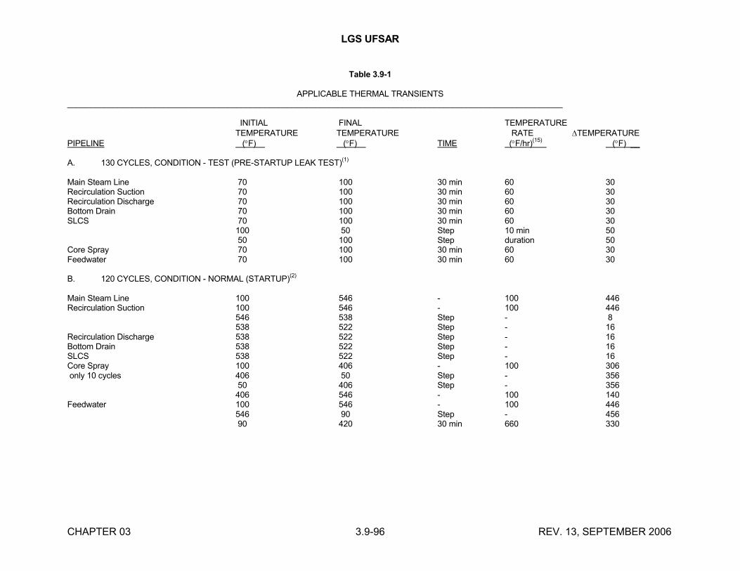
LGS UFSAR
CHAPTER 03 3.9-96 REV. 13, SEPTEMBER 2006
Table 3.9-1
APPLICABLE THERMAL TRANSIENTS____________________________________________________________________________________________________________
INITIAL FINAL TEMPERATURETEMPERATURE TEMPERATURE RATE TEMPERATURE
PIPELINE (F) (F) TIME (F/hr)(15)
(F) __
A. 130 CYCLES, CONDITION - TEST (PRE-STARTUP LEAK TEST)(1)
Main Steam Line 70 100 30 min 60 30Recirculation Suction 70 100 30 min 60 30Recirculation Discharge 70 100 30 min 60 30Bottom Drain 70 100 30 min 60 30SLCS 70 100 30 min 60 30
100 50 Step 10 min 5050 100 Step duration 50
Core Spray 70 100 30 min 60 30Feedwater 70 100 30 min 60 30
B. 120 CYCLES, CONDITION - NORMAL (STARTUP)(2)
Main Steam Line 100 546 - 100 446Recirculation Suction 100 546 - 100 446
546 538 Step - 8538 522 Step - 16
Recirculation Discharge 538 522 Step - 16Bottom Drain 538 522 Step - 16SLCS 538 522 Step - 16Core Spray 100 406 - 100 306only 10 cycles 406 50 Step - 356
50 406 Step - 356406 546 - 100 140
Feedwater 100 546 - 100 446546 90 Step - 45690 420 30 min 660 330
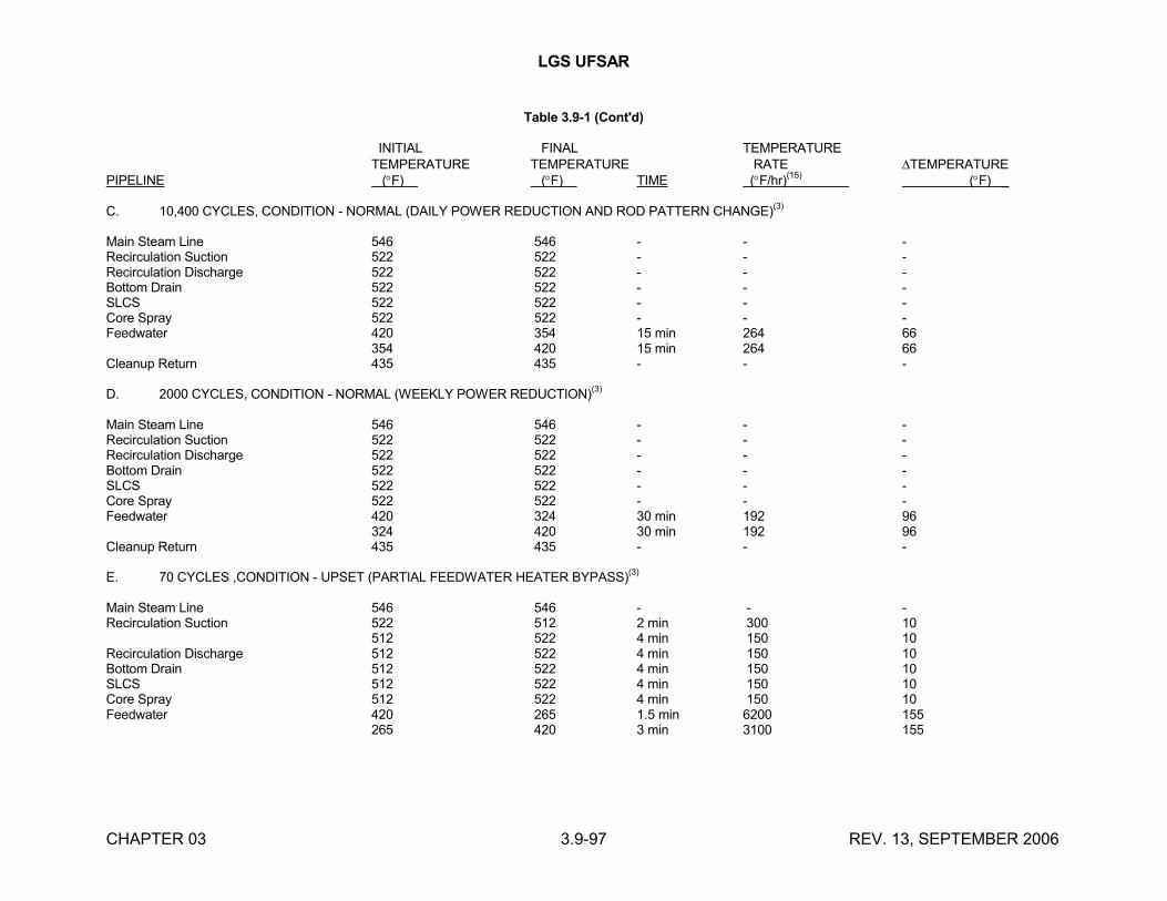
LGS UFSAR
CHAPTER 03 3.9-97 REV. 13, SEPTEMBER 2006
Table 3.9-1 (Cont'd)
INITIAL FINAL TEMPERATURETEMPERATURE TEMPERATURE RATE TEMPERATURE
PIPELINE (F) (F) TIME (F/hr)(15)
(F) _
C. 10,400 CYCLES, CONDITION - NORMAL (DAILY POWER REDUCTION AND ROD PATTERN CHANGE)(3)
Main Steam Line 546 546 - - -Recirculation Suction 522 522 - - -Recirculation Discharge 522 522 - - -Bottom Drain 522 522 - - -SLCS 522 522 - - -Core Spray 522 522 - - -Feedwater 420 354 15 min 264 66
354 420 15 min 264 66Cleanup Return 435 435 - - -
D. 2000 CYCLES, CONDITION - NORMAL (WEEKLY POWER REDUCTION)(3)
Main Steam Line 546 546 - - -Recirculation Suction 522 522 - - -Recirculation Discharge 522 522 - - -Bottom Drain 522 522 - - -SLCS 522 522 - - -Core Spray 522 522 - - -Feedwater 420 324 30 min 192 96
324 420 30 min 192 96Cleanup Return 435 435 - - -
E. 70 CYCLES ,CONDITION - UPSET (PARTIAL FEEDWATER HEATER BYPASS)(3)
Main Steam Line 546 546 - - -Recirculation Suction 522 512 2 min 300 10
512 522 4 min 150 10Recirculation Discharge 512 522 4 min 150 10Bottom Drain 512 522 4 min 150 10SLCS 512 522 4 min 150 10Core Spray 512 522 4 min 150 10Feedwater 420 265 1.5 min 6200 155
265 420 3 min 3100 155
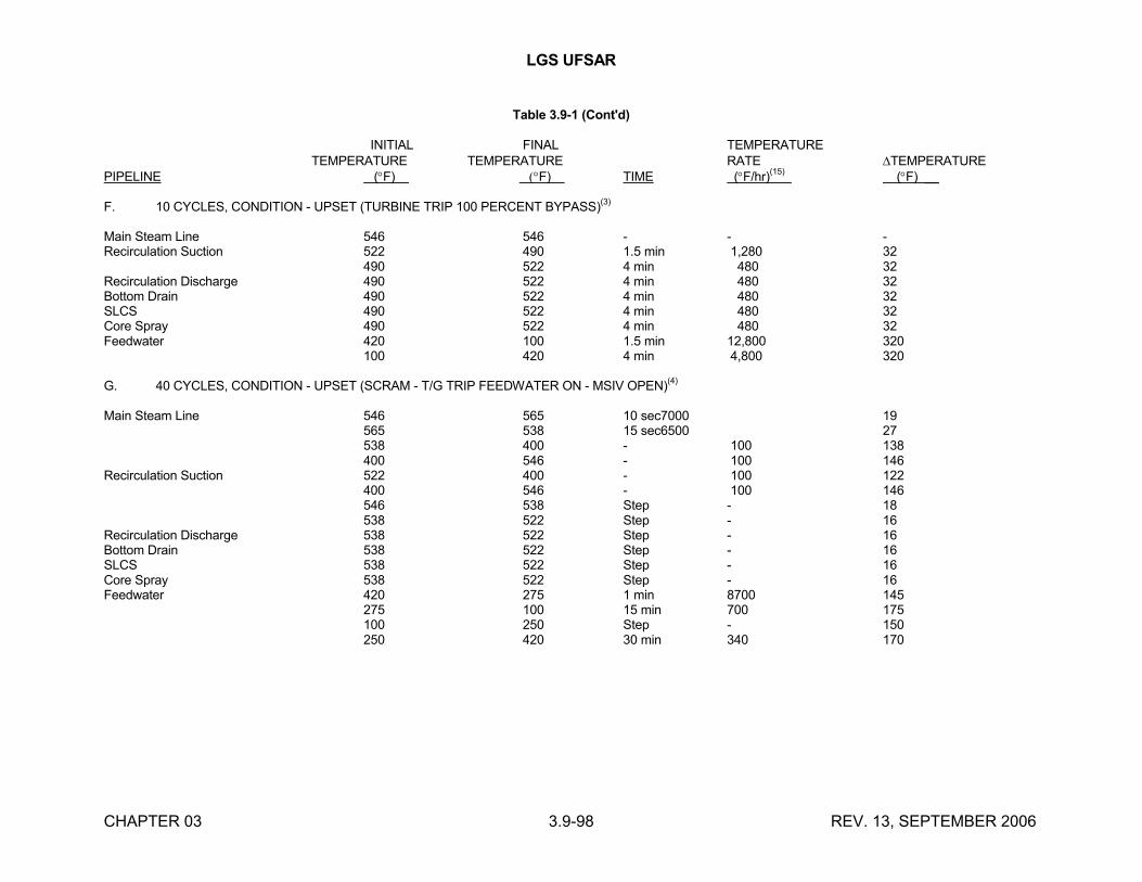
LGS UFSAR
CHAPTER 03 3.9-98 REV. 13, SEPTEMBER 2006
Table 3.9-1 (Cont'd)
INITIAL FINAL TEMPERATURETEMPERATURE TEMPERATURE RATE TEMPERATURE
PIPELINE (F) F) TIME (F/hr)(15)
(F) __
F. 10 CYCLES, CONDITION - UPSET (TURBINE TRIP 100 PERCENT BYPASS)(3)
Main Steam Line 546 546 - - -Recirculation Suction 522 490 1.5 min 1,280 32
490 522 4 min 480 32Recirculation Discharge 490 522 4 min 480 32Bottom Drain 490 522 4 min 480 32SLCS 490 522 4 min 480 32Core Spray 490 522 4 min 480 32Feedwater 420 100 1.5 min 12,800 320
100 420 4 min 4,800 320
G. 40 CYCLES, CONDITION - UPSET (SCRAM - T/G TRIP FEEDWATER ON - MSIV OPEN)(4)
Main Steam Line 546 565 10 sec7000 19565 538 15 sec6500 27538 400 - 100 138400 546 - 100 146
Recirculation Suction 522 400 - 100 122400 546 - 100 146546 538 Step - 18538 522 Step - 16
Recirculation Discharge 538 522 Step - 16Bottom Drain 538 522 Step - 16SLCS 538 522 Step - 16Core Spray 538 522 Step - 16Feedwater 420 275 1 min 8700 145
275 100 15 min 700 175100 250 Step - 150250 420 30 min 340 170
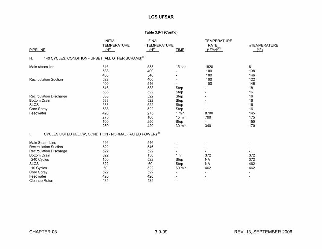
LGS UFSAR
CHAPTER 03 3.9-99 REV. 13, SEPTEMBER 2006
Table 3.9-1 (Cont'd)
INITIAL FINAL TEMPERATURETEMPERATURE TEMPERATURE RATE TEMPERATURE
PIPELINE (F) (F) TIME (F/hr)(15)
(F)
H. 140 CYCLES, CONDITION - UPSET (ALL OTHER SCRAMS)(5)
Main steam line 546 538 15 sec 1920 8538 400 - 100 138400 546 - 100 146
Recirculation Suction 522 400 - 100 122400 546 - 100 146546 538 Step - 18538 522 Step - 16
Recirculation Discharge 538 522 Step - 16Bottom Drain 538 522 Step - 16SLCS 538 522 Step - 16Core Spray 538 522 Step - 16Feedwater 420 275 1 min 8700 145
275 100 15 min 700 175100 250 Step - 150250 420 30 min 340 170
I. CYCLES LISTED BELOW, CONDITION - NORMAL (RATED POWER)(3)
Main Steam Line 546 546 - - -Recirculation Suction 522 546 - - -Recirculation Discharge 522 522 - - -Bottom Drain 522 150 1 hr 372 372 240 Cycles 150 522 Step NA 372SLCS 522 60 Step NA 462 10 Cycles 60 522 60 min 462 462Core Spray 522 522 - - -Feedwater 420 420 - - -Cleanup Return 435 435 - - -
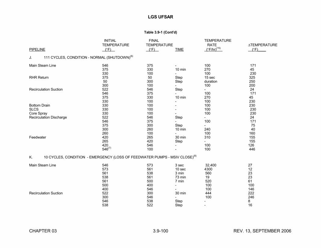
LGS UFSAR
CHAPTER 03 3.9-100 REV. 13, SEPTEMBER 2006
Table 3.9-1 (Cont'd)
INITIAL FINAL TEMPERATURETEMPERATURE TEMPERATURE RATE TEMPERATURE
PIPELINE (F) (F) TIME (F/hr)(15)
(F)____
J. 111 CYCLES, CONDITION - NORMAL (SHUTDOWN)(6)
Main Steam Line 546 375 - 100 171375 330 10 min 270 45330 100 - 100 230
RHR Return 375 50 Step 15 sec 32550 300 Step duration 250300 100 - 100 200
Recirculation Suction 522 546 Step - 24546 375 - 100 171375 330 10 min 270 45330 100 - 100 230
Bottom Drain 330 100 - 100 230SLCS 330 100 - 100 230Core Spray 330 100 - 100 230Recirculation Discharge 522 546 Step - 24
546 375 - 100 171375 300 Step - 75300 260 10 min 240 40260 100 - 100 160
Feedwater 420 265 30 min 310 155265 420 Step - 155420 546 - 100 126546
(7)100 - 100 446
K. 10 CYCLES, CONDITION - EMERGENCY (LOSS OF FEEDWATER PUMPS - MSIV CLOSE)(8)
Main Steam Line 546 573 3 sec 32,400 27573 561 10 sec 4300 12561 538 3 min 560 23538 561 73 min 19 23561 500 7 min 520 61500 400 - 100 100400 546 - 100 146
Recirculation Suction 522 300 30 min 444 222300 546 - 100 246546 538 Step - 8538 522 Step - 16
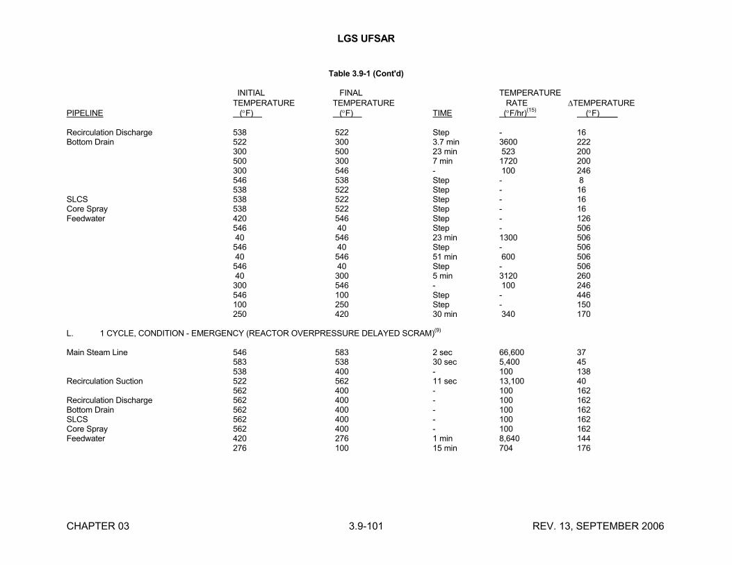
LGS UFSAR
CHAPTER 03 3.9-101 REV. 13, SEPTEMBER 2006
Table 3.9-1 (Cont'd)
INITIAL FINAL TEMPERATURETEMPERATURE TEMPERATURE RATE TEMPERATURE
PIPELINE (F) (F) TIME (F/hr)(15)
(F)____
Recirculation Discharge 538 522 Step - 16Bottom Drain 522 300 3.7 min 3600 222
300 500 23 min 523 200500 300 7 min 1720 200300 546 - 100 246546 538 Step - 8538 522 Step - 16
SLCS 538 522 Step - 16Core Spray 538 522 Step - 16Feedwater 420 546 Step - 126
546 40 Step - 50640 546 23 min 1300 506546 40 Step - 50640 546 51 min 600 506546 40 Step - 50640 300 5 min 3120 260300 546 - 100 246546 100 Step - 446100 250 Step - 150250 420 30 min 340 170
L. 1 CYCLE, CONDITION - EMERGENCY (REACTOR OVERPRESSURE DELAYED SCRAM)(9)
Main Steam Line 546 583 2 sec 66,600 37583 538 30 sec 5,400 45538 400 - 100 138
Recirculation Suction 522 562 11 sec 13,100 40562 400 - 100 162
Recirculation Discharge 562 400 - 100 162Bottom Drain 562 400 - 100 162SLCS 562 400 - 100 162Core Spray 562 400 - 100 162Feedwater 420 276 1 min 8,640 144
276 100 15 min 704 176
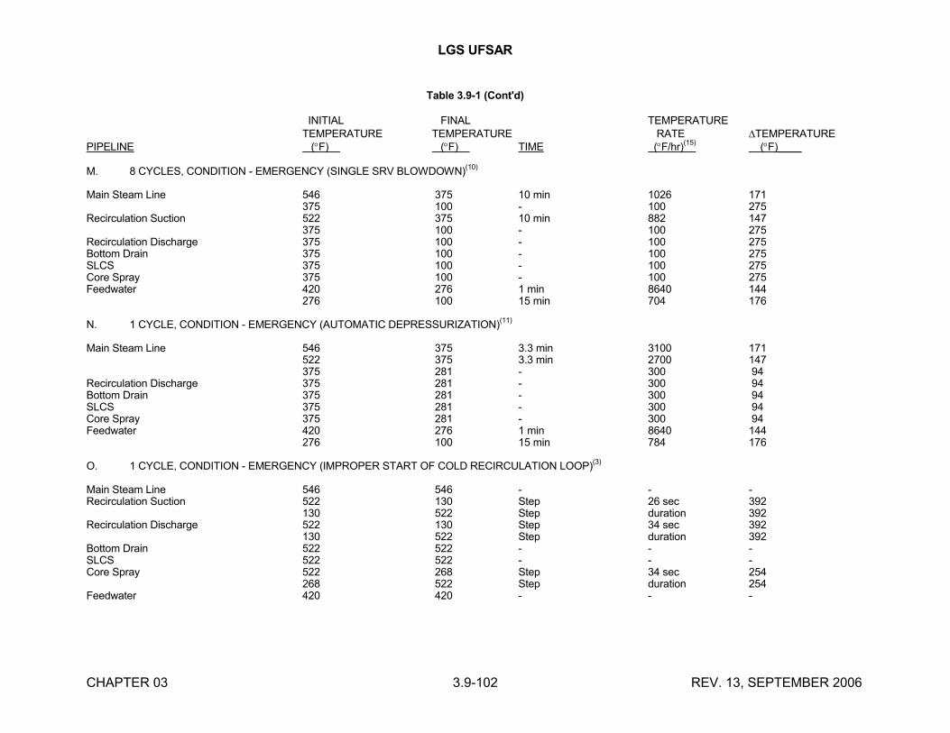
LGS UFSAR
CHAPTER 03 3.9-102 REV. 13, SEPTEMBER 2006
Table 3.9-1 (Cont'd)
INITIAL FINAL TEMPERATURETEMPERATURE TEMPERATURE RATE TEMPERATURE
PIPELINE (F) (F) TIME (F/hr)(15)
(F)____
M. 8 CYCLES, CONDITION - EMERGENCY (SINGLE SRV BLOWDOWN)(10)
Main Steam Line 546 375 10 min 1026 171375 100 - 100 275
Recirculation Suction 522 375 10 min 882 147375 100 - 100 275
Recirculation Discharge 375 100 - 100 275Bottom Drain 375 100 - 100 275SLCS 375 100 - 100 275Core Spray 375 100 - 100 275Feedwater 420 276 1 min 8640 144
276 100 15 min 704 176
N. 1 CYCLE, CONDITION - EMERGENCY (AUTOMATIC DEPRESSURIZATION)(11)
Main Steam Line 546 375 3.3 min 3100 171522 375 3.3 min 2700 147375 281 - 300 94
Recirculation Discharge 375 281 - 300 94Bottom Drain 375 281 - 300 94SLCS 375 281 - 300 94Core Spray 375 281 - 300 94Feedwater 420 276 1 min 8640 144
276 100 15 min 784 176
O. 1 CYCLE, CONDITION - EMERGENCY (IMPROPER START OF COLD RECIRCULATION LOOP)(3)
Main Steam Line 546 546 - - -Recirculation Suction 522 130 Step 26 sec 392
130 522 Step duration 392Recirculation Discharge 522 130 Step 34 sec 392
130 522 Step duration 392Bottom Drain 522 522 - - -SLCS 522 522 - - -Core Spray 522 268 Step 34 sec 254
268 522 Step duration 254Feedwater 420 420 - - -
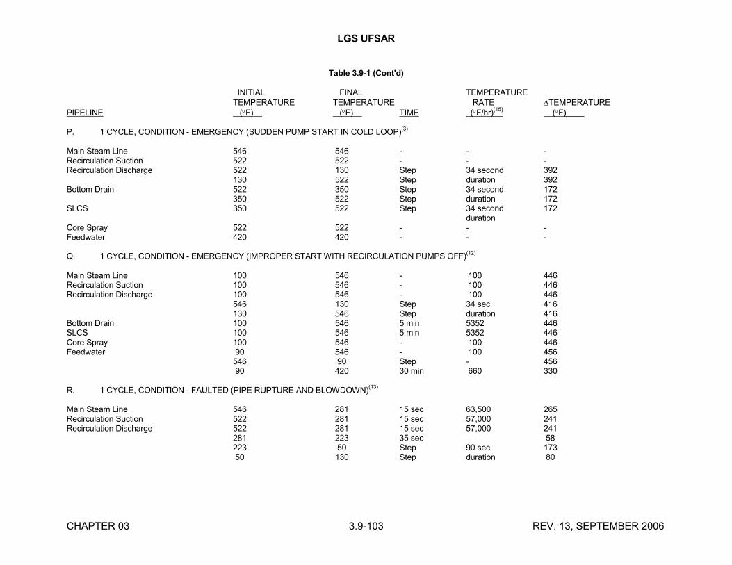
LGS UFSAR
CHAPTER 03 3.9-103 REV. 13, SEPTEMBER 2006
Table 3.9-1 (Cont'd)
INITIAL FINAL TEMPERATURETEMPERATURE TEMPERATURE RATE TEMPERATURE
PIPELINE (F) (F) TIME (F/hr)(15)
(F)____
P. 1 CYCLE, CONDITION - EMERGENCY (SUDDEN PUMP START IN COLD LOOP)(3)
Main Steam Line 546 546 - - -Recirculation Suction 522 522 - - -Recirculation Discharge 522 130 Step 34 second 392
130 522 Step duration 392Bottom Drain 522 350 Step 34 second 172
350 522 Step duration 172SLCS 350 522 Step 34 second 172
durationCore Spray 522 522 - - -Feedwater 420 420 - - -
Q. 1 CYCLE, CONDITION - EMERGENCY (IMPROPER START WITH RECIRCULATION PUMPS OFF)(12)
Main Steam Line 100 546 - 100 446Recirculation Suction 100 546 - 100 446Recirculation Discharge 100 546 - 100 446
546 130 Step 34 sec 416130 546 Step duration 416
Bottom Drain 100 546 5 min 5352 446SLCS 100 546 5 min 5352 446Core Spray 100 546 - 100 446Feedwater 90 546 - 100 456
546 90 Step - 45690 420 30 min 660 330
R. 1 CYCLE, CONDITION - FAULTED (PIPE RUPTURE AND BLOWDOWN)(13)
Main Steam Line 546 281 15 sec 63,500 265Recirculation Suction 522 281 15 sec 57,000 241Recirculation Discharge 522 281 15 sec 57,000 241
281 223 35 sec 58223 50 Step 90 sec 17350 130 Step duration 80
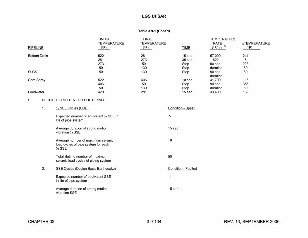
LGS UFSAR
CHAPTER 03 3.9-104 REV. 13, SEPTEMBER 2006
Table 3.9-1 (Cont'd)
INITIAL FINAL TEMPERATURETEMPERATURE TEMPERATURE RATE TEMPERATURE
PIPELINE (F) (F) TIME (F/hr)(15)
(F)____
Bottom Drain 522 281 15 sec 57,000 241281 273 35 sec 822 8273 50 Step 90 sec 22350 130 Step duration 80
SLCS 50 130 Step 90 sec 80duration
Core Spray 522 406 10 sec 41,700 116406 50 Step 90 sec 35650 130 Step duration 80
Feedwater 420 281 15 sec 33,400 139
S. BECHTEL CRITERIA FOR BOP PIPING
1. ½ SSE Cycles (OBE) Condition - Upset
Expected number of equivalent ½ SSE in 5life of pipe system
Average duration of strong motion 15 secvibration ½ SSE
Average number of maximum seismic 10load cycles of pipe system for each½ SSE
Total lifetime number of maximum 50seismic load cycles of piping system
2. SSE Cycles (Design Basis Earthquake) Condition - Faulted
Expected number of equivalent SSE 1in life of pipe system
Average duration of strong motion 15 secvibration SSE
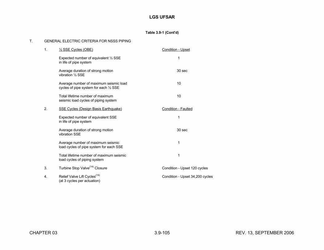
LGS UFSAR
CHAPTER 03 3.9-105 REV. 13, SEPTEMBER 2006
Table 3.9-1 (Cont'd)
T. GENERAL ELECTRIC CRITERIA FOR NSSS PIPING
1. ½ SSE Cycles (OBE) Condition - Upset
Expected number of equivalent ½ SSE 1in life of pipe system
Average duration of strong motion 30 secvibration ½ SSE
Average number of maximum seismic load 10cycles of pipe system for each ½ SSE
Total lifetime number of maximum 10seismic load cycles of piping system
2. SSE Cycles (Design Basis Earthquake) Condition - Faulted
Expected number of equivalent SSE 1in life of pipe system
Average duration of strong motion 30 secvibration SSE
Average number of maximum seismic 1load cycles of pipe system for each SSE
Total lifetime number of maximum seismic 1load cycles of piping system
3. Turbine Stop Valve(14)
Closure Condition - Upset 120 cycles
4. Relief Valve Lift Cycles(14)
Condition - Upset 34,200 cycles(at 3 cycles per actuation)
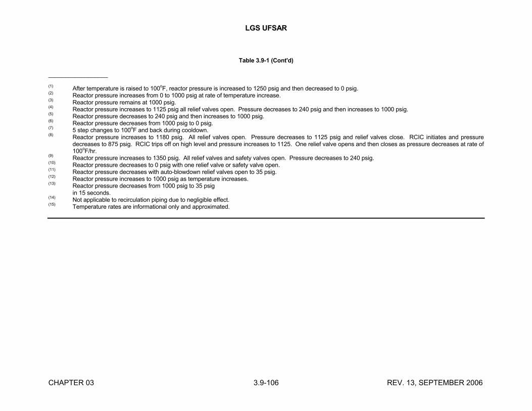
LGS UFSAR
CHAPTER 03 3.9-106 REV. 13, SEPTEMBER 2006
Table 3.9-1 (Cont'd)
__________________
(1)After temperature is raised to 100
oF, reactor pressure is increased to 1250 psig and then decreased to 0 psig.
(2)Reactor pressure increases from 0 to 1000 psig at rate of temperature increase.
(3)Reactor pressure remains at 1000 psig.
(4)Reactor pressure increases to 1125 psig all relief valves open. Pressure decreases to 240 psig and then increases to 1000 psig.
(5)Reactor pressure decreases to 240 psig and then increases to 1000 psig.
(6)Reactor pressure decreases from 1000 psig to 0 psig.
(7)5 step changes to 100
oF and back during cooldown.
(8)Reactor pressure increases to 1180 psig. All relief valves open. Pressure decreases to 1125 psig and relief valves close. RCIC initiates and pressure decreases to 875 psig. RCIC trips off on high level and pressure increases to 1125. One relief valve opens and then closes as pressure decreases at rate of 100
oF/hr.
(9)Reactor pressure increases to 1350 psig. All relief valves and safety valves open. Pressure decreases to 240 psig.
(10)Reactor pressure decreases to 0 psig with one relief valve or safety valve open.
(11)Reactor pressure decreases with auto-blowdown relief valves open to 35 psig.
(12)Reactor pressure increases to 1000 psig as temperature increases.
(13)Reactor pressure decreases from 1000 psig to 35 psigin 15 seconds.
(14)Not applicable to recirculation piping due to negligible effect.
(15)Temperature rates are informational only and approximated.
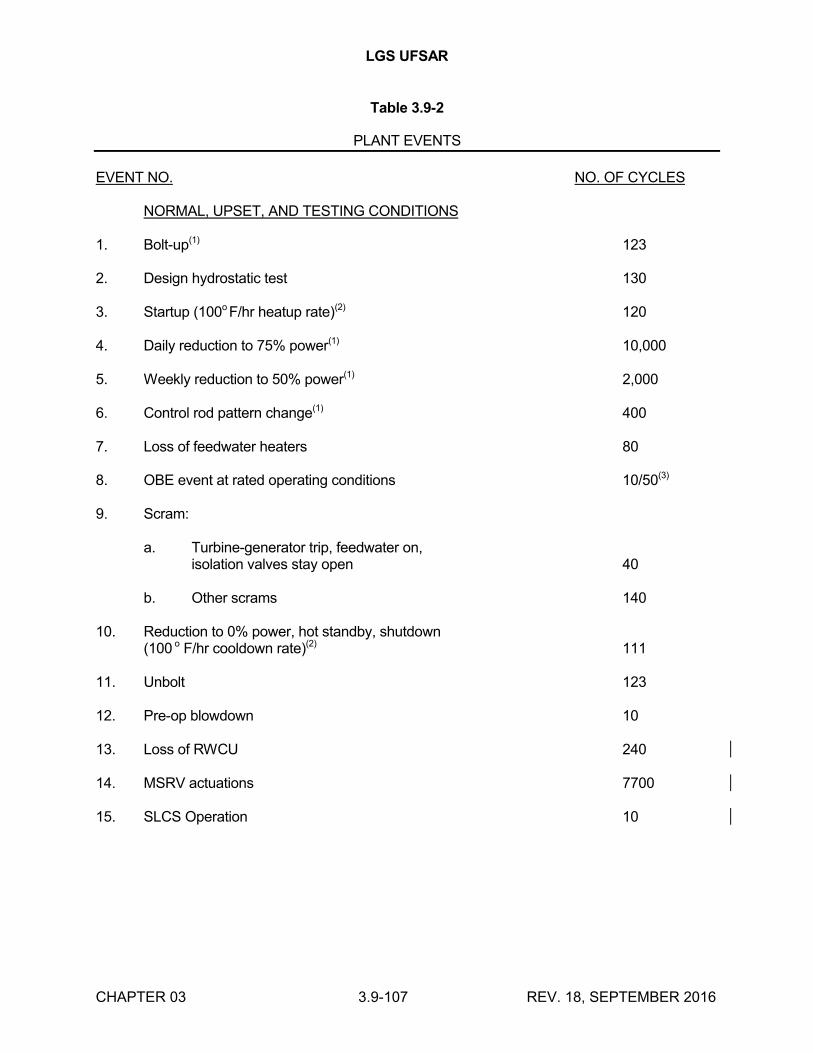
LGS UFSAR
CHAPTER 03 3.9-107 REV. 18, SEPTEMBER 2016
Table 3.9-2
PLANT EVENTS
EVENT NO. NO. OF CYCLES
NORMAL, UPSET, AND TESTING CONDITIONS
1. Bolt-up(1) 123
2. Design hydrostatic test 130
3. Startup (100o F/hr heatup rate)(2) 120
4. Daily reduction to 75% power(1) 10,000
5. Weekly reduction to 50% power(1) 2,000
6. Control rod pattern change(1) 400
7. Loss of feedwater heaters 80
8. OBE event at rated operating conditions 10/50(3)
9. Scram:
a. Turbine-generator trip, feedwater on,isolation valves stay open 40
b. Other scrams 140
10. Reduction to 0% power, hot standby, shutdown(100 o F/hr cooldown rate)(2) 111
11. Unbolt 123
12. Pre-op blowdown 10
13. Loss of RWCU 240
14. MSRV actuations 7700
15. SLCS Operation 10
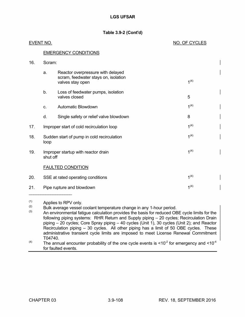
LGS UFSAR
CHAPTER 03 3.9-108 REV. 18, SEPTEMBER 2016
Table 3.9-2 (Cont'd)
EVENT NO. NO. OF CYCLES
EMERGENCY CONDITIONS
16. Scram:
a. Reactor overpressure with delayedscram, feedwater stays on, isolationvalves stay open 1(4)
b. Loss of feedwater pumps, isolationvalves closed 5
c. Automatic Blowdown 1(4)
d. Single safety or relief valve blowdown 8
17. Improper start of cold recirculation loop 1(4)
18. Sudden start of pump in cold recirculation 1(4)
loop
19. Improper startup with reactor drain 1(4)
shut off
FAULTED CONDITION
20. SSE at rated operating conditions 1(4)
21. Pipe rupture and blowdown 1(4)
__________________
(1) Applies to RPV only.(2) Bulk average vessel coolant temperature change in any 1-hour period.(3) An environmental fatigue calculation provides the basis for reduced OBE cycle limits for the
following piping systems: RHR Return and Supply piping – 20 cycles; Recirculation Drain piping – 20 cycles; Core Spray piping – 40 cycles (Unit 1), 30 cycles (Unit 2); and Reactor Recirculation piping – 30 cycles. All other piping has a limit of 50 OBE cycles. These administrative transient cycle limits are imposed to meet License Renewal Commitment T04740.
(4) The annual encounter probability of the one cycle events is <10-2 for emergency and <10-4
for faulted events.
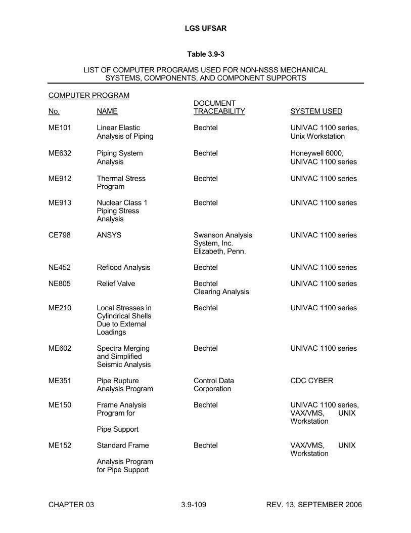
LGS UFSAR
CHAPTER 03 3.9-109 REV. 13, SEPTEMBER 2006
Table 3.9-3
LIST OF COMPUTER PROGRAMS USED FOR NON-NSSS MECHANICALSYSTEMS, COMPONENTS, AND COMPONENT SUPPORTS
COMPUTER PROGRAMDOCUMENT
No. NAME TRACEABILITY SYSTEM USED
ME101 Linear Elastic Bechtel UNIVAC 1100 series,Analysis of Piping Unix Workstation
ME632 Piping System Bechtel Honeywell 6000,Analysis UNIVAC 1100 series
ME912 Thermal Stress Bechtel UNIVAC 1100 seriesProgram
ME913 Nuclear Class 1 Bechtel UNIVAC 1100 seriesPiping StressAnalysis
CE798 ANSYS Swanson Analysis UNIVAC 1100 seriesSystem, Inc.Elizabeth, Penn.
NE452 Reflood Analysis Bechtel UNIVAC 1100 series
NE805 Relief Valve Bechtel UNIVAC 1100 seriesClearing Analysis
ME210 Local Stresses in Bechtel UNIVAC 1100 seriesCylindrical ShellsDue to ExternalLoadings
ME602 Spectra Merging Bechtel UNIVAC 1100 seriesand SimplifiedSeismic Analysis
ME351 Pipe Rupture Control Data CDC CYBERAnalysis Program Corporation
ME150 Frame Analysis Bechtel UNIVAC 1100 series,Program for VAX/VMS, UNIX
WorkstationPipe Support
ME152 Standard Frame Bechtel VAX/VMS, UNIXWorkstation
Analysis Programfor Pipe Support
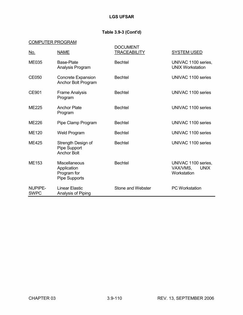
LGS UFSAR
CHAPTER 03 3.9-110 REV. 13, SEPTEMBER 2006
Table 3.9-3 (Cont'd)
COMPUTER PROGRAMDOCUMENT
No. NAME TRACEABILITY SYSTEM USED
ME035 Base-Plate Bechtel UNIVAC 1100 series,Analysis Program UNIX Workstation
CE050 Concrete Expansion Bechtel UNIVAC 1100 seriesAnchor Bolt Program
CE901 Frame Analysis Bechtel UNIVAC 1100 seriesProgram
ME225 Anchor Plate Bechtel UNIVAC 1100 seriesProgram
ME226 Pipe Clamp Program Bechtel UNIVAC 1100 series
ME120 Weld Program Bechtel UNIVAC 1100 series
ME425 Strength Design of Bechtel UNIVAC 1100 seriesPipe SupportAnchor Bolt
ME153 Miscellaneous Bechtel UNIVAC 1100 series,Application VAX/VMS, UNIXProgram for WorkstationPipe Supports
NUPIPE- Linear Elastic Stone and Webster PC WorkstationSWPC Analysis of Piping
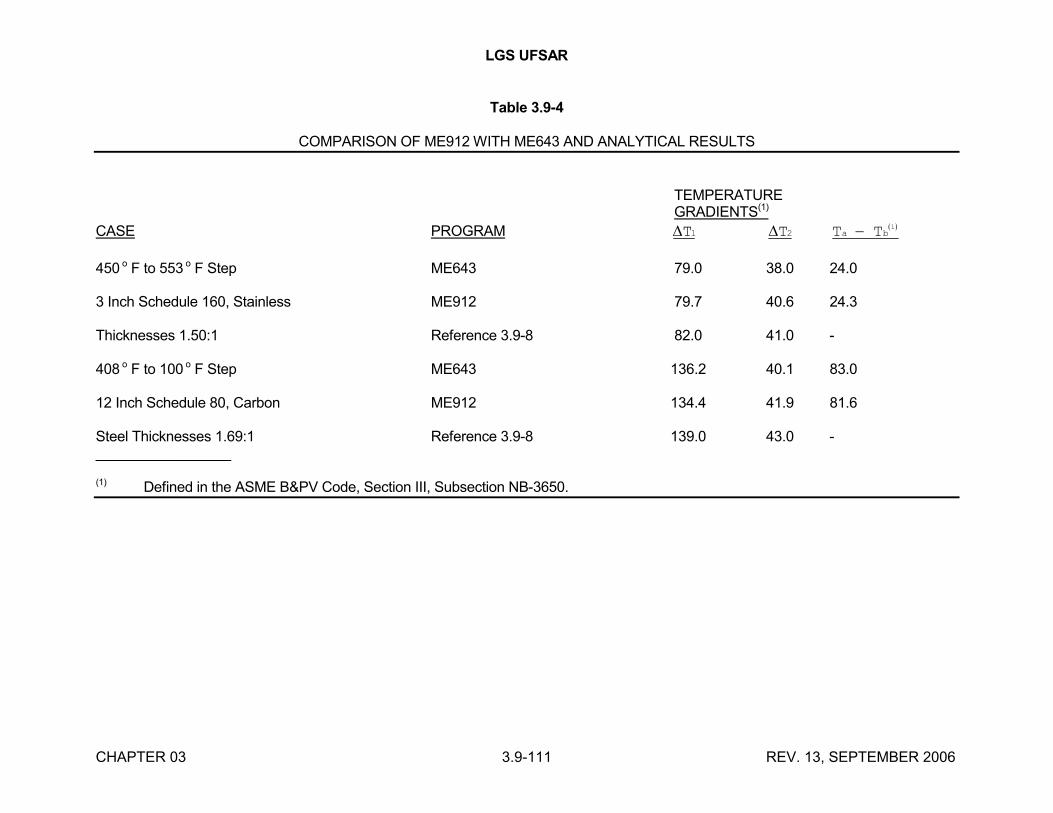
LGS UFSAR
CHAPTER 03 3.9-111 REV. 13, SEPTEMBER 2006
Table 3.9-4
COMPARISON OF ME912 WITH ME643 AND ANALYTICAL RESULTS
TEMPERATUREGRADIENTS(1)
CASE PROGRAM T1 T2 T Ta b 1
450 o F to 553 o F Step ME643 79.0 38.0 24.0
3 Inch Schedule 160, Stainless ME912 79.7 40.6 24.3
Thicknesses 1.50:1 Reference 3.9-8 82.0 41.0 -
408 o F to 100 o F Step ME643 136.2 40.1 83.0
12 Inch Schedule 80, Carbon ME912 134.4 41.9 81.6
Steel Thicknesses 1.69:1 Reference 3.9-8 139.0 43.0 -_________________
(1) Defined in the ASME B&PV Code, Section III, Subsection NB-3650.
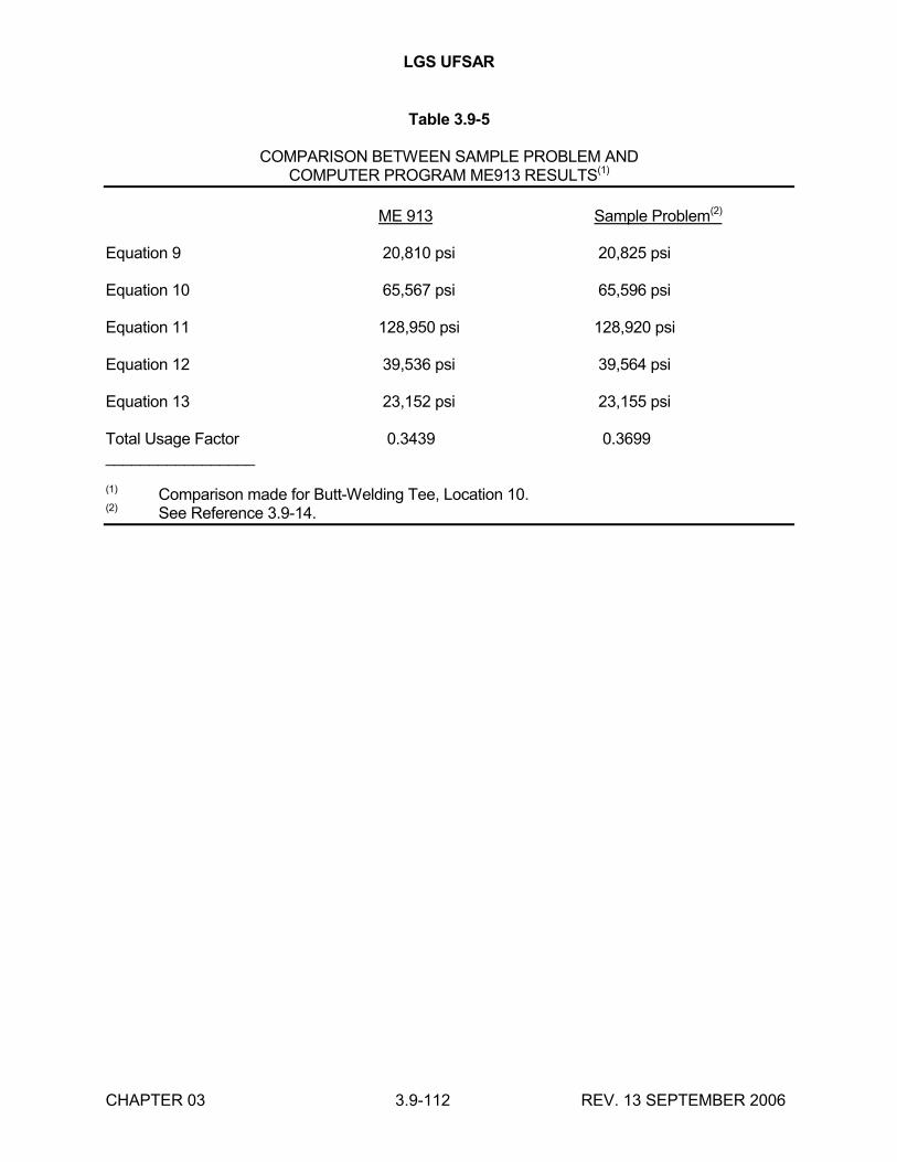
LGS UFSAR
CHAPTER 03 3.9-112 REV. 13 SEPTEMBER 2006
Table 3.9-5
COMPARISON BETWEEN SAMPLE PROBLEM ANDCOMPUTER PROGRAM ME913 RESULTS(1)
ME 913 Sample Problem(2)
Equation 9 20,810 psi 20,825 psi
Equation 10 65,567 psi 65,596 psi
Equation 11 128,950 psi 128,920 psi
Equation 12 39,536 psi 39,564 psi
Equation 13 23,152 psi 23,155 psi
Total Usage Factor 0.3439 0.3699_________________
(1) Comparison made for Butt-Welding Tee, Location 10.(2) See Reference 3.9-14.
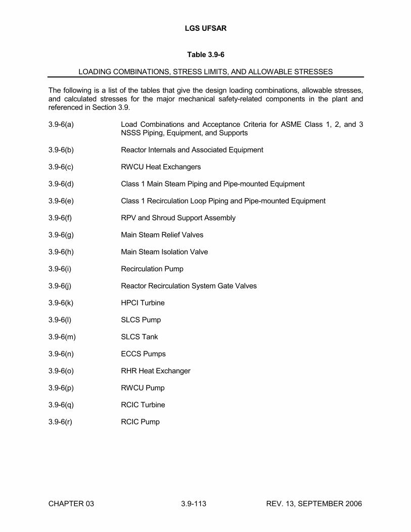
LGS UFSAR
CHAPTER 03 3.9-113 REV. 13, SEPTEMBER 2006
Table 3.9-6
LOADING COMBINATIONS, STRESS LIMITS, AND ALLOWABLE STRESSES
The following is a list of the tables that give the design loading combinations, allowable stresses, and calculated stresses for the major mechanical safety-related components in the plant and referenced in Section 3.9.
3.9-6(a) Load Combinations and Acceptance Criteria for ASME Class 1, 2, and 3 NSSS Piping, Equipment, and Supports
3.9-6(b) Reactor Internals and Associated Equipment
3.9-6(c) RWCU Heat Exchangers
3.9-6(d) Class 1 Main Steam Piping and Pipe-mounted Equipment
3.9-6(e) Class 1 Recirculation Loop Piping and Pipe-mounted Equipment
3.9-6(f) RPV and Shroud Support Assembly
3.9-6(g) Main Steam Relief Valves
3.9-6(h) Main Steam Isolation Valve
3.9-6(i) Recirculation Pump
3.9-6(j) Reactor Recirculation System Gate Valves
3.9-6(k) HPCI Turbine
3.9-6(l) SLCS Pump
3.9-6(m) SLCS Tank
3.9-6(n) ECCS Pumps
3.9-6(o) RHR Heat Exchanger
3.9-6(p) RWCU Pump
3.9-6(q) RCIC Turbine
3.9-6(r) RCIC Pump
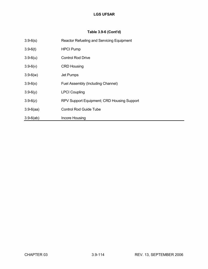
LGS UFSAR
CHAPTER 03 3.9-114 REV. 13, SEPTEMBER 2006
Table 3.9-6 (Cont'd)
3.9-6(s) Reactor Refueling and Servicing Equipment
3.9-6(t) HPCI Pump
3.9-6(u) Control Rod Drive
3.9-6(v) CRD Housing
3.9-6(w) Jet Pumps
3.9-6(x) Fuel Assembly (Including Channel)
3.9-6(y) LPCI Coupling
3.9-6(z) RPV Support Equipment; CRD Housing Support
3.9-6(aa) Control Rod Guide Tube
3.9-6(ab) Incore Housing
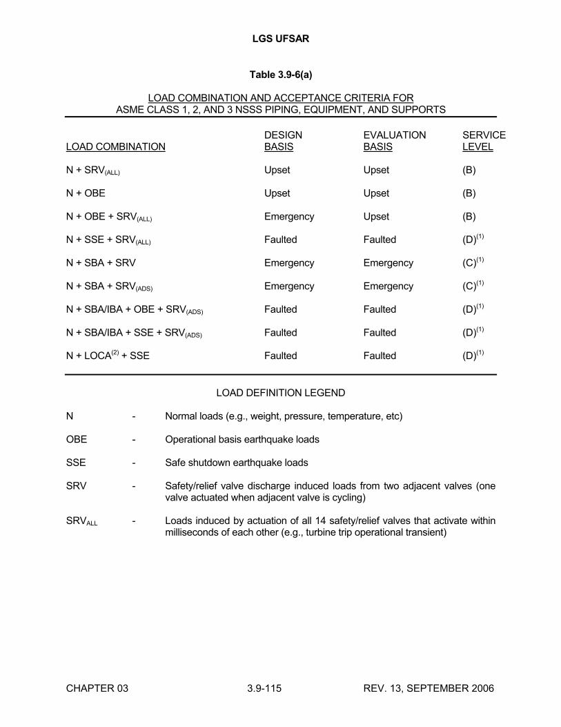
LGS UFSAR
CHAPTER 03 3.9-115 REV. 13, SEPTEMBER 2006
Table 3.9-6(a)
LOAD COMBINATION AND ACCEPTANCE CRITERIA FORASME CLASS 1, 2, AND 3 NSSS PIPING, EQUIPMENT, AND SUPPORTS
DESIGN EVALUATION SERVICELOAD COMBINATION BASIS BASIS LEVEL
N + SRV(ALL) Upset Upset (B)
N + OBE Upset Upset (B)
N + OBE + SRV(ALL) Emergency Upset (B)
N + SSE + SRV(ALL) Faulted Faulted (D)(1)
N + SBA + SRV Emergency Emergency (C)(1)
N + SBA + SRV(ADS) Emergency Emergency (C)(1)
N + SBA/IBA + OBE + SRV(ADS) Faulted Faulted (D)(1)
N + SBA/IBA + SSE + SRV(ADS) Faulted Faulted (D)(1)
N + LOCA(2) + SSE Faulted Faulted (D)(1)
LOAD DEFINITION LEGEND
N - Normal loads (e.g., weight, pressure, temperature, etc)
OBE - Operational basis earthquake loads
SSE - Safe shutdown earthquake loads
SRV - Safety/relief valve discharge induced loads from two adjacent valves (one valve actuated when adjacent valve is cycling)
SRVALL - Loads induced by actuation of all 14 safety/relief valves that activate within milliseconds of each other (e.g., turbine trip operational transient)
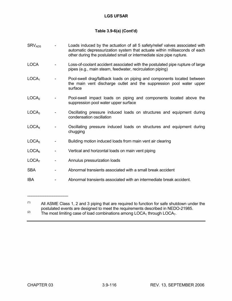
LGS UFSAR
CHAPTER 03 3.9-116 REV. 13, SEPTEMBER 2006
Table 3.9-6(a) (Cont'd)
SRVADS - Loads induced by the actuation of all 5 safety/relief valves associated with automatic depressurization system that actuate within milliseconds of each other during the postulated small or intermediate size pipe rupture.
LOCA - Loss-of-coolant accident associated with the postulated pipe rupture of large pipes (e.g., main steam, feedwater, recirculation piping)
LOCA1 - Pool-swell drag/fallback loads on piping and components located between the main vent discharge outlet and the suppression pool water upper surface
LOCA2 - Pool-swell impact loads on piping and components located above the suppression pool water upper surface
LOCA3 - Oscillating pressure induced loads on structures and equipment during condensation oscillation
LOCA4 - Oscillating pressure induced loads on structures and equipment during chugging
LOCA5 - Building motion induced loads from main vent air clearing
LOCA6 - Vertical and horizontal loads on main vent piping
LOCA7 - Annulus pressurization loads
SBA - Abnormal transients associated with a small break accident
IBA - Abnormal transients associated with an intermediate break accident.
__________________
(1) All ASME Class 1, 2 and 3 piping that are required to function for safe shutdown under the postulated events are designed to meet the requirements described in NEDO-21985.
(2) The most limiting case of load combinations among LOCA1 through LOCA7.
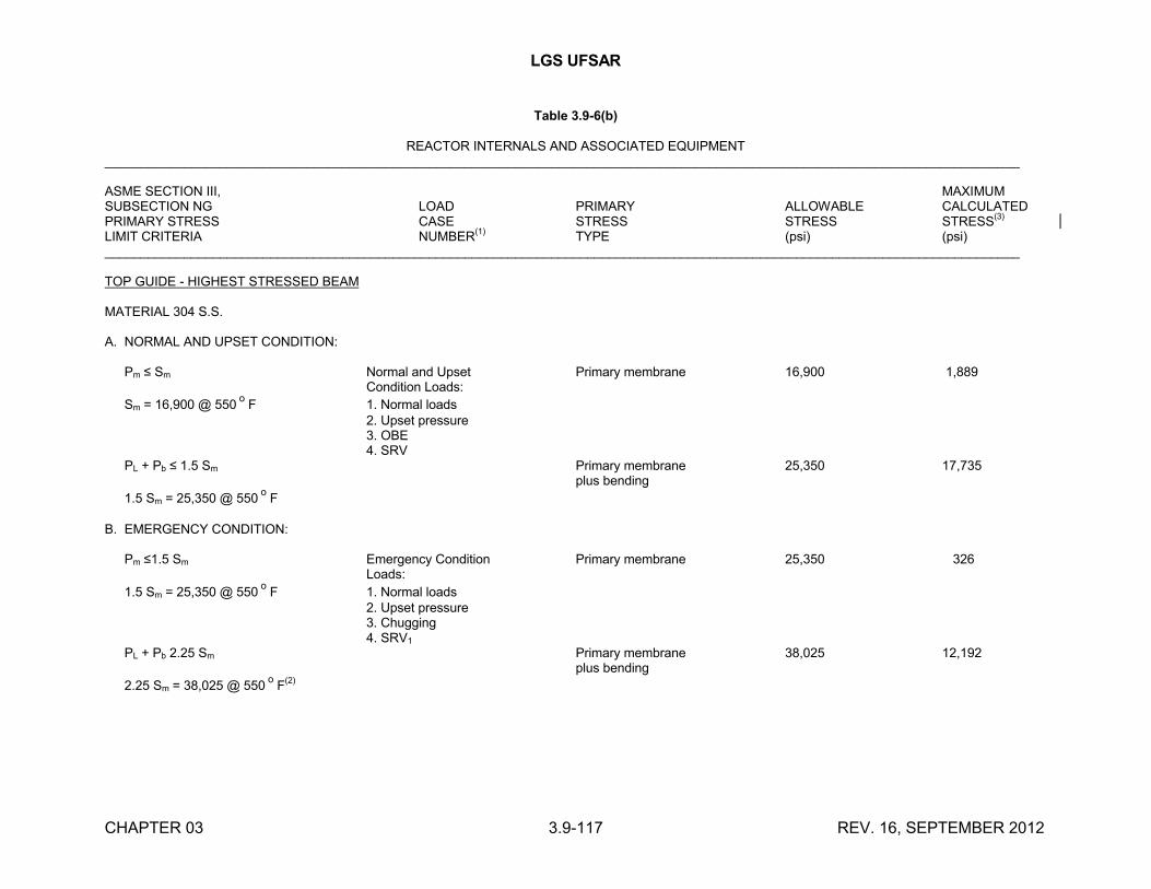
LGS UFSAR
CHAPTER 03 3.9-117 REV. 16, SEPTEMBER 2012
Table 3.9-6(b)
REACTOR INTERNALS AND ASSOCIATED EQUIPMENT_______________________________________________________________________________________________________________________________
ASME SECTION III, MAXIMUMSUBSECTION NG LOAD PRIMARY ALLOWABLE CALCULATEDPRIMARY STRESS CASE STRESS STRESS STRESS
(3)
LIMIT CRITERIA NUMBER(1)
TYPE (psi) (psi)_______________________________________________________________________________________________________________________________
TOP GUIDE - HIGHEST STRESSED BEAM
MATERIAL 304 S.S.
A. NORMAL AND UPSET CONDITION:
Pm ≤ Sm Normal and Upset Primary membrane 16,900 1,889Condition Loads:
Sm = 16,900 @ 550o
F 1. Normal loads2. Upset pressure3. OBE4. SRV
PL + Pb ≤ 1.5 Sm Primary membrane 25,350 17,735plus bending
1.5 Sm = 25,350 @ 550o
F
B. EMERGENCY CONDITION:
Pm ≤1.5 Sm Emergency Condition Primary membrane 25,350 326Loads:
1.5 Sm = 25,350 @ 550o
F 1. Normal loads2. Upset pressure3. Chugging4. SRV1
PL + Pb 2.25 Sm Primary membrane 38,025 12,192plus bending
2.25 Sm = 38,025 @ 550o
F(2)
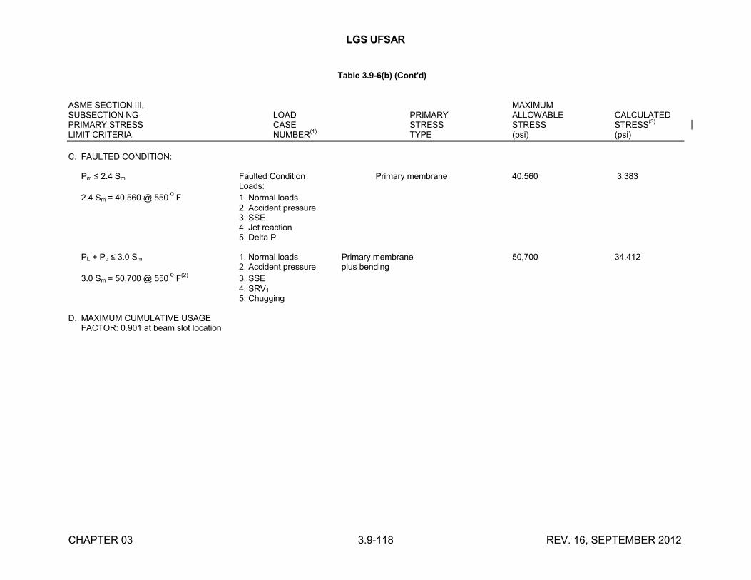
LGS UFSAR
CHAPTER 03 3.9-118 REV. 16, SEPTEMBER 2012
Table 3.9-6(b) (Cont'd)
ASME SECTION III, MAXIMUMSUBSECTION NG LOAD PRIMARY ALLOWABLE CALCULATEDPRIMARY STRESS CASE STRESS STRESS STRESS
(3)
LIMIT CRITERIA NUMBER(1)
TYPE (psi) (psi)
C. FAULTED CONDITION:
Pm ≤ 2.4 Sm Faulted Condition Primary membrane 40,560 3,383Loads:
2.4 Sm = 40,560 @ 550o
F 1. Normal loads2. Accident pressure3. SSE4. Jet reaction5. Delta P
PL + Pb ≤ 3.0 Sm 1. Normal loads Primary membrane 50,700 34,4122. Accident pressure plus bending
3.0 Sm = 50,700 @ 550o
F(2)
3. SSE4. SRV1
5. Chugging
D. MAXIMUM CUMULATIVE USAGEFACTOR: 0.901 at beam slot location
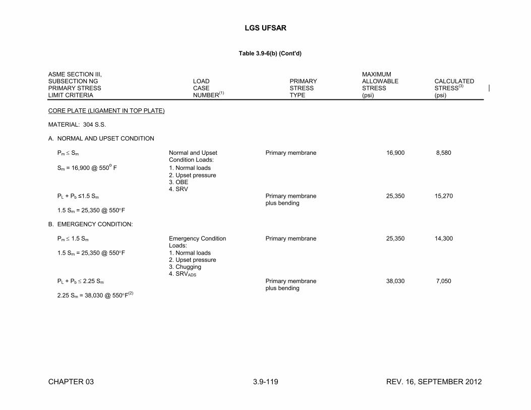
LGS UFSAR
CHAPTER 03 3.9-119 REV. 16, SEPTEMBER 2012
Table 3.9-6(b) (Cont'd)
ASME SECTION III, MAXIMUMSUBSECTION NG LOAD PRIMARY ALLOWABLE CALCULATEDPRIMARY STRESS CASE STRESS STRESS STRESS
(3)
LIMIT CRITERIA NUMBER(1)
TYPE (psi) (psi)
CORE PLATE (LIGAMENT IN TOP PLATE)
MATERIAL: 304 S.S.
A. NORMAL AND UPSET CONDITION
Pm Sm Normal and Upset Primary membrane 16,900 8,580Condition Loads:
Sm = 16,900 @ 550o
F 1. Normal loads2. Upset pressure3. OBE4. SRV
PL + Pb ≤1.5 Sm Primary membrane 25,350 15,270plus bending
1.5 Sm = 25,350 @ 550F
B. EMERGENCY CONDITION:
Pm 1.5 Sm Emergency Condition Primary membrane 25,350 14,300Loads:
1.5 Sm = 25,350 @ 550F 1. Normal loads2. Upset pressure3. Chugging4. SRVADS
PL + Pb 2.25 Sm Primary membrane 38,030 7,050plus bending
2.25 Sm = 38,030 @ 550F(2)
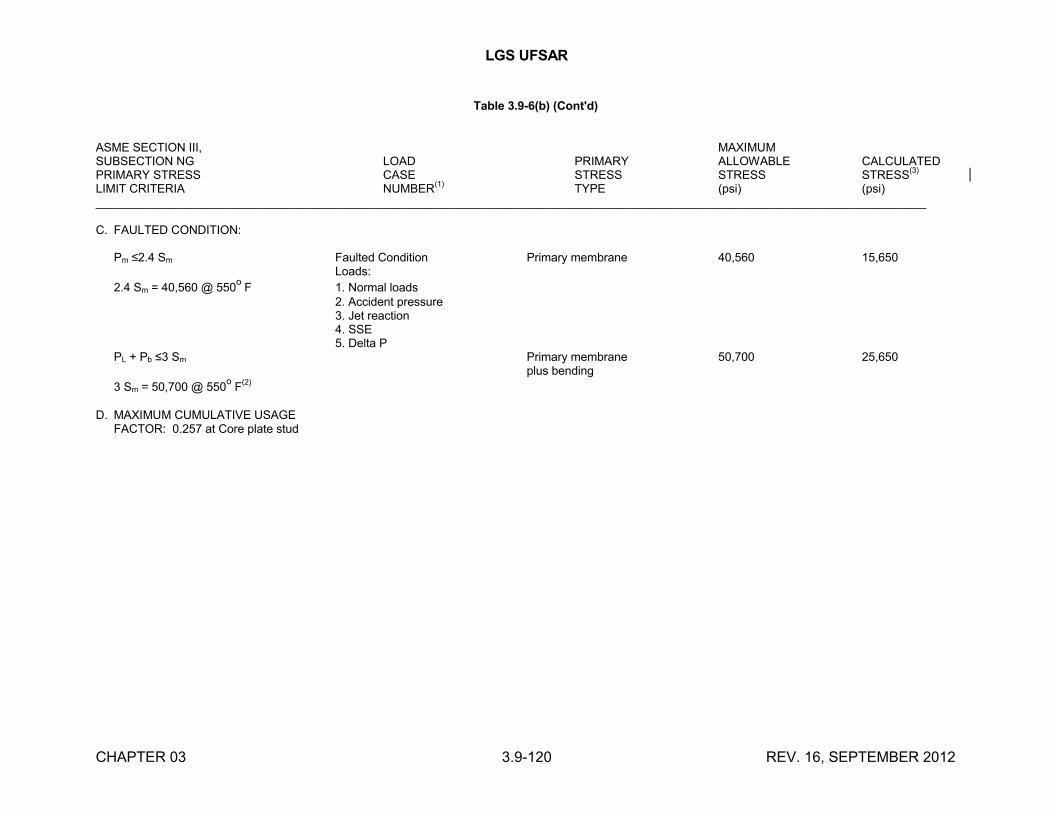
LGS UFSAR
CHAPTER 03 3.9-120 REV. 16, SEPTEMBER 2012
Table 3.9-6(b) (Cont'd)
ASME SECTION III, MAXIMUMSUBSECTION NG LOAD PRIMARY ALLOWABLE CALCULATEDPRIMARY STRESS CASE STRESS STRESS STRESS
(3)
LIMIT CRITERIA NUMBER(1)
TYPE (psi) (psi)______________________________________________________________________________________________________________________________
C. FAULTED CONDITION:
Pm ≤2.4 Sm Faulted Condition Primary membrane 40,560 15,650Loads:
2.4 Sm = 40,560 @ 550o
F 1. Normal loads2. Accident pressure3. Jet reaction4. SSE5. Delta P
PL + Pb ≤3 Sm Primary membrane 50,700 25,650plus bending
3 Sm = 50,700 @ 550o
F(2)
D. MAXIMUM CUMULATIVE USAGEFACTOR: 0.257 at Core plate stud
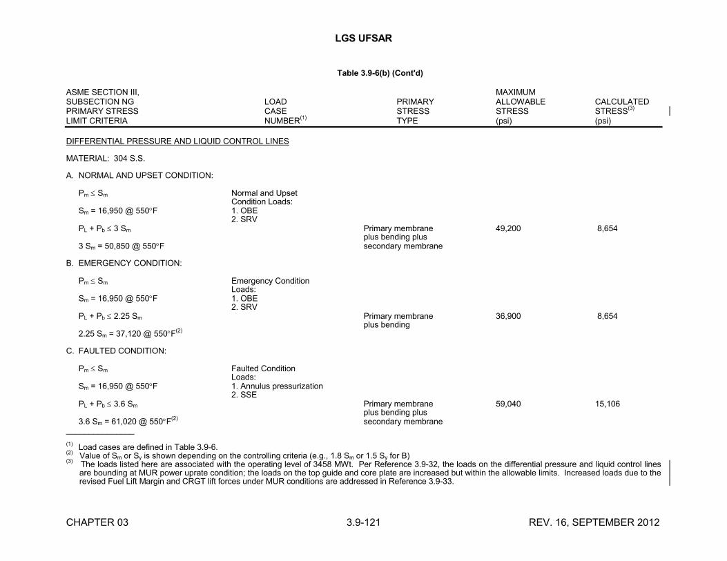
LGS UFSAR
CHAPTER 03 3.9-121 REV. 16, SEPTEMBER 2012
Table 3.9-6(b) (Cont'd)
ASME SECTION III, MAXIMUMSUBSECTION NG LOAD PRIMARY ALLOWABLE CALCULATEDPRIMARY STRESS CASE STRESS STRESS STRESS
(3)
LIMIT CRITERIA NUMBER(1)
TYPE (psi) (psi)
DIFFERENTIAL PRESSURE AND LIQUID CONTROL LINES
MATERIAL: 304 S.S.
A. NORMAL AND UPSET CONDITION:
Pm Sm Normal and UpsetCondition Loads:
Sm = 16,950 @ 550F 1. OBE2. SRV
PL + Pb 3 Sm Primary membrane 49,200 8,654plus bending plus
3 Sm = 50,850 @ 550F secondary membrane
B. EMERGENCY CONDITION:
Pm Sm Emergency ConditionLoads:
Sm = 16,950 @ 550F 1. OBE2. SRV
PL + Pb 2.25 Sm Primary membrane 36,900 8,654plus bending
2.25 Sm = 37,120 @ 550F(2)
C. FAULTED CONDITION:
Pm Sm Faulted ConditionLoads:
Sm = 16,950 @ 550F 1. Annulus pressurization2. SSE
PL + Pb 3.6 Sm Primary membrane 59,040 15,106plus bending plus
3.6 Sm = 61,020 @ 550F(2)
secondary membrane_______________
(1)Load cases are defined in Table 3.9-6.
(2) Value of Sm or Sy is shown depending on the controlling criteria (e.g., 1.8 Sm or 1.5 Sy for B)
(3) The loads listed here are associated with the operating level of 3458 MWt. Per Reference 3.9-32, the loads on the differential pressure and liquid control lines
are bounding at MUR power uprate condition; the loads on the top guide and core plate are increased but within the allowable limits. Increased loads due to the revised Fuel Lift Margin and CRGT lift forces under MUR conditions are addressed in Reference 3.9-33.
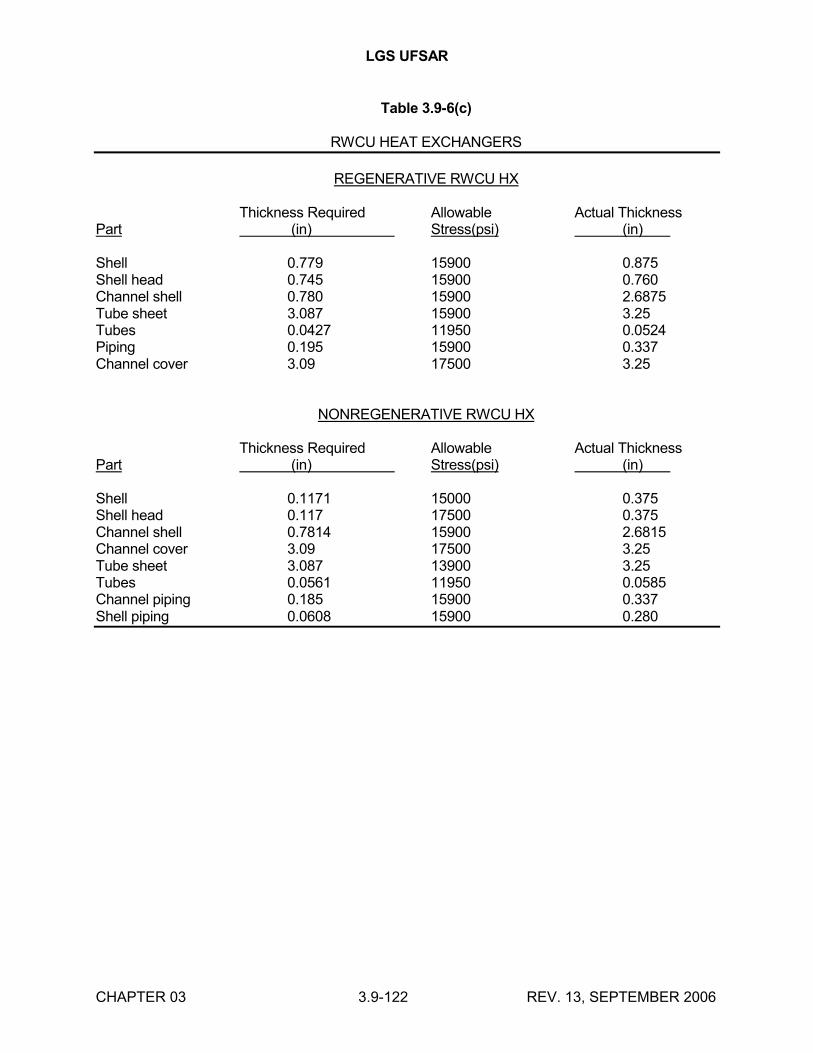
LGS UFSAR
CHAPTER 03 3.9-122 REV. 13, SEPTEMBER 2006
Table 3.9-6(c)
RWCU HEAT EXCHANGERS
REGENERATIVE RWCU HX
Thickness Required Allowable Actual ThicknessPart (in) Stress(psi) (in)
Shell 0.779 15900 0.875 Shell head 0.745 15900 0.760 Channel shell 0.780 15900 2.6875 Tube sheet 3.087 15900 3.25 Tubes 0.0427 11950 0.0524 Piping 0.195 15900 0.337 Channel cover 3.09 17500 3.25
NONREGENERATIVE RWCU HX
Thickness Required Allowable Actual ThicknessPart (in) Stress(psi) (in)
Shell 0.1171 15000 0.375 Shell head 0.117 17500 0.375 Channel shell 0.7814 15900 2.6815 Channel cover 3.09 17500 3.25 Tube sheet 3.087 13900 3.25 Tubes 0.0561 11950 0.0585 Channel piping 0.185 15900 0.337 Shell piping 0.0608 15900 0.280
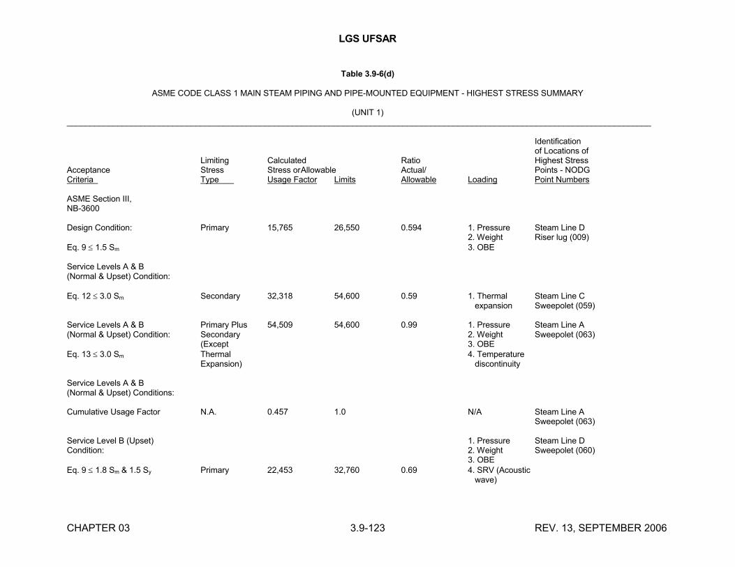
LGS UFSAR
CHAPTER 03 3.9-123 REV. 13, SEPTEMBER 2006
Table 3.9-6(d)
ASME CODE CLASS 1 MAIN STEAM PIPING AND PIPE-MOUNTED EQUIPMENT - HIGHEST STRESS SUMMARY
(UNIT 1)_______________________________________________________________________________________________________________________________
Identificationof Locations of
Limiting Calculated Ratio Highest StressAcceptance Stress Stress orAllowable Actual/ Points - NODGCriteria Type Usage Factor Limits Allowable Loading Point Numbers
ASME Section III,NB-3600
Design Condition: Primary 15,765 26,550 0.594 1. Pressure Steam Line D2. Weight Riser lug (009)
Eq. 9 1.5 Sm 3. OBE
Service Levels A & B(Normal & Upset) Condition:
Eq. 12 3.0 Sm Secondary 32,318 54,600 0.59 1. Thermal Steam Line C expansion Sweepolet (059)
Service Levels A & B Primary Plus 54,509 54,600 0.99 1. Pressure Steam Line A(Normal & Upset) Condition: Secondary 2. Weight Sweepolet (063)
(Except 3. OBEEq. 13 3.0 Sm Thermal 4. Temperature
Expansion) discontinuity
Service Levels A & B(Normal & Upset) Conditions:
Cumulative Usage Factor N.A. 0.457 1.0 N/A Steam Line ASweepolet (063)
Service Level B (Upset) 1. Pressure Steam Line DCondition: 2. Weight Sweepolet (060)
3. OBEEq. 9 1.8 Sm & 1.5 Sy Primary 22,453 32,760 0.69 4. SRV (Acoustic
wave)
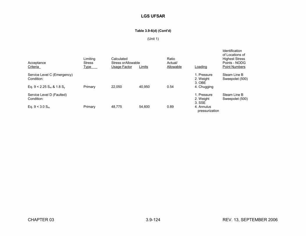
LGS UFSAR
CHAPTER 03 3.9-124 REV. 13, SEPTEMBER 2006
Table 3.9-6(d) (Cont'd)
(Unit 1)
Identificationof Locations of
Limiting Calculated Ratio Highest StressAcceptance Stress Stress orAllowable Actual/ Points - NODGCriteria Type Usage Factor Limits Allowable Loading Point Numbers
Service Level C (Emergency) 1. Pressure Steam Line BCondition: 2. Weight Sweepolet (500)
3. OBEEq. 9 < 2.25 Sm & 1.8 Sy Primary 22,050 40,950 0.54 4. Chugging
Service Level D (Faulted) 1. Pressure Steam Line BCondition: 2. Weight Sweepolet (500)
3. SSEEq. 9 < 3.0 Sm Primary 48,775 54,600 0.89 4. Annulus
pressurization
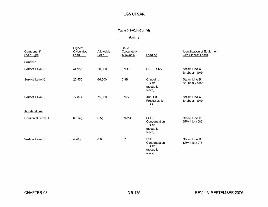
LGS UFSAR
CHAPTER 03 3.9-125 REV. 13, SEPTEMBER 2006
Table 3.9-6(d) (Cont'd)
(Unit 1)
Highest RatioComponent/ Calculated Allowable Calculated/ Identification of EquipmentLoad Type Load Load Allowable Loading with Highest Loads
Snubber
Service Level B 44,988 50,000 0.900 OBE + SRV Steam Line ASnubber - SA9
Service Level C 25,555 66,500 0.384 Chugging Steam Line B+ SRV Snubber - SB2(acousticwave)
Service Level D 72,874 75,000 0.972 Annulus Steam Line APressurization Snubber - SA9+ SSE
Accelerations
Horizontal Level D 6.314g 6.5g 0.9714 SSE + Steam Line DCondensation SRV Inlet (086)+ SRV(acousticwave)
Vertical Level D 4.20g 6.0g 0.7 SSE + Steam Line BCondensation SRV Inlet (075)+ SRV(acousticwave)
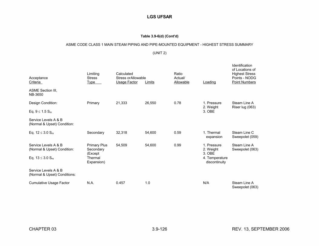
LGS UFSAR
CHAPTER 03 3.9-126 REV. 13, SEPTEMBER 2006
Table 3.9-6(d) (Cont'd)
ASME CODE CLASS 1 MAIN STEAM PIPING AND PIPE-MOUNTED EQUIPMENT - HIGHEST STRESS SUMMARY
(UNIT 2)
Identificationof Locations of
Limiting Calculated Ratio Highest StressAcceptance Stress Stress orAllowable Actual/ Points - NODGCriteria Type Usage Factor Limits Allowable Loading Point Numbers
ASME Section III,NB-3650
Design Condition: Primary 21,333 26,550 0.78 1. Pressure Steam Line A2. Weight Riser lug (063)
Eq. 9 1.5 Sm 3. OBE
Service Levels A & B(Normal & Upset) Condition:
Eq. 12 3.0 Sm Secondary 32,318 54,600 0.59 1. Thermal Steam Line C expansion Sweepolet (059)
Service Levels A & B Primary Plus 54,509 54,600 0.99 1. Pressure Steam Line A(Normal & Upset) Condition: Secondary 2. Weight Sweepolet (063)
(Except 3. OBEEq. 13 3.0 Sm Thermal 4. Temperature
Expansion) discontinuity
Service Levels A & B(Normal & Upset) Conditions:
Cumulative Usage Factor N.A. 0.457 1.0 N/A Steam Line ASweepolet (063)
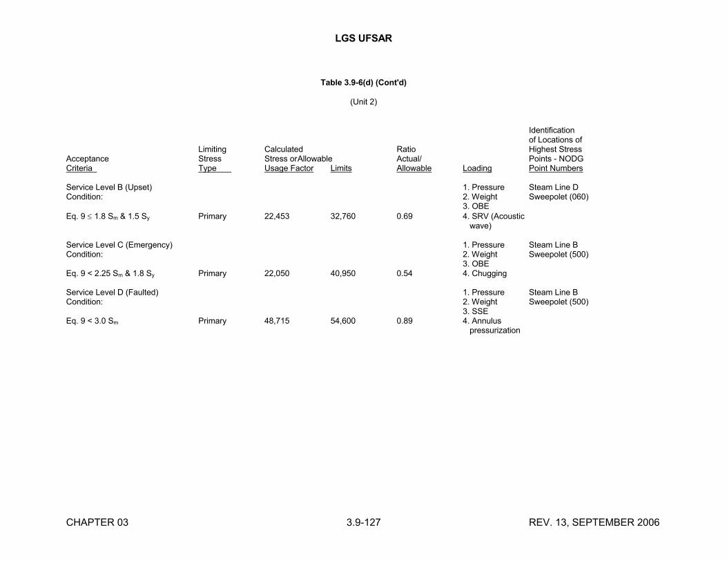
LGS UFSAR
CHAPTER 03 3.9-127 REV. 13, SEPTEMBER 2006
Table 3.9-6(d) (Cont'd)
(Unit 2)
Identificationof Locations of
Limiting Calculated Ratio Highest StressAcceptance Stress Stress orAllowable Actual/ Points - NODGCriteria Type Usage Factor Limits Allowable Loading Point Numbers
Service Level B (Upset) 1. Pressure Steam Line DCondition: 2. Weight Sweepolet (060)
3. OBEEq. 9 1.8 Sm & 1.5 Sy Primary 22,453 32,760 0.69 4. SRV (Acoustic
wave)
Service Level C (Emergency) 1. Pressure Steam Line BCondition: 2. Weight Sweepolet (500)
3. OBEEq. 9 < 2.25 Sm & 1.8 Sy Primary 22,050 40,950 0.54 4. Chugging
Service Level D (Faulted) 1. Pressure Steam Line BCondition: 2. Weight Sweepolet (500)
3. SSEEq. 9 < 3.0 Sm Primary 48,715 54,600 0.89 4. Annulus
pressurization
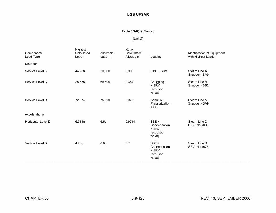
LGS UFSAR
CHAPTER 03 3.9-128 REV. 13, SEPTEMBER 2006
Table 3.9-6(d) (Cont'd)
(Unit 2)
Highest RatioComponent/ Calculated Allowable Calculated/ Identification of EquipmentLoad Type Load Load Allowable Loading with Highest Loads
Snubber
Service Level B 44,988 50,000 0.900 OBE + SRV Steam Line ASnubber - SA9
Service Level C 25,555 66,500 0.384 Chugging Steam Line B+ SRV Snubber - SB2(acousticwave)
Service Level D 72,874 75,000 0.972 Annulus Steam Line APressurization Snubber - SA9+ SSE
Accelerations
Horizontal Level D 6.314g 6.5g 0.9714 SSE + Steam Line DCondensation SRV Inlet (086)+ SRV(acousticwave)
Vertical Level D 4.20g 6.0g 0.7 SSE + Steam Line BCondensation SRV Inlet (075)+ SRV(acousticwave)
_________________________________________________________________________________________________________________________________
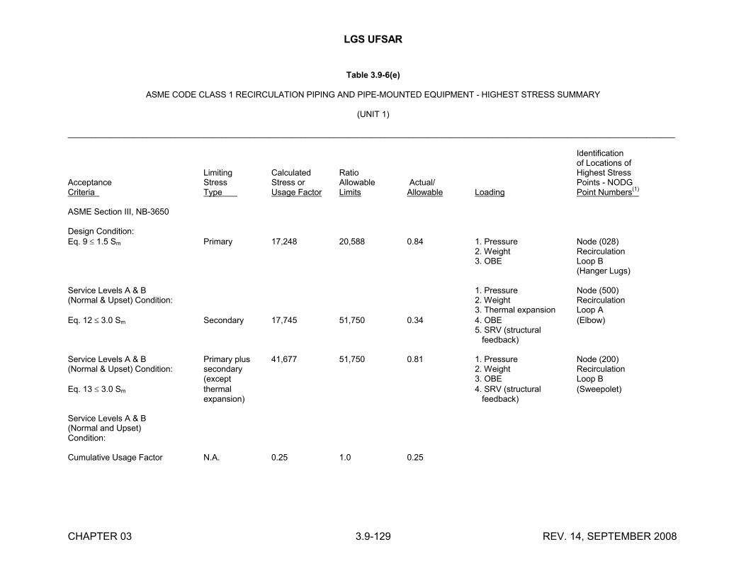
LGS UFSAR
CHAPTER 03 3.9-129 REV. 14, SEPTEMBER 2008
Table 3.9-6(e)
ASME CODE CLASS 1 RECIRCULATION PIPING AND PIPE-MOUNTED EQUIPMENT - HIGHEST STRESS SUMMARY
(UNIT 1)
__________________________________________________________________________________________________________________________________
Identificationof Locations of
Limiting Calculated Ratio Highest StressAcceptance Stress Stress or Allowable Actual/ Points - NODGCriteria Type Usage Factor Limits Allowable Loading Point Numbers
(1)
ASME Section III, NB-3650
Design Condition:Eq. 9 1.5 Sm Primary 17,248 20,588 0.84 1. Pressure Node (028)
2. Weight Recirculation3. OBE Loop B
(Hanger Lugs)
Service Levels A & B 1. Pressure Node (500)(Normal & Upset) Condition: 2. Weight Recirculation
3. Thermal expansion Loop AEq. 12 3.0 Sm Secondary 17,745 51,750 0.34 4. OBE (Elbow)
5. SRV (structural feedback)
Service Levels A & B Primary plus 41,677 51,750 0.81 1. Pressure Node (200)(Normal & Upset) Condition: secondary 2. Weight Recirculation
(except 3. OBE Loop BEq. 13 3.0 Sm thermal 4. SRV (structural (Sweepolet)
expansion) feedback)
Service Levels A & B(Normal and Upset)Condition:
Cumulative Usage Factor N.A. 0.25 1.0 0.25

LGS UFSAR
CHAPTER 03 3.9-130 REV. 14, SEPTEMBER 2008
Table 3.9-6(e) (Cont'd)
(Unit 1)
Identificationof Locations of
Limiting Calculated Ratio Highest StressAcceptance Stress Stress or Allowable Actual/ Points - NODGCriteria Type Usage Factor Limits Allowable Loading Point Numbers
(1)
Service Level B (Upset) 1. Pressure Node (016)Condition: 2. Weight Recirculation
3. OBE Loop BEq. 9 1.8 Sm & 1.5 Sy Primary 19,227 23,472 0.82 4. SRV (structural (Small Tee)
feedback)
Service Level C (Emergency) 1. Pressure Node (016)Condition: 2. Weight Recirculation
3. Chugging Loop BEq. 9 2.25 Sm & 1.8 Sy Primary 18,886 28,166 0.67 4. SRV (structural (Small Tee)
feedback)
Service Level D (Faulted) 1. Pressure Node (016)Condition: 2. Weight Recirculation
3. SSE Loop BEq. 9 3.0 Sm Primary 24,895 31,296 0.80 4. Annulus (Small Tee)
pressurization
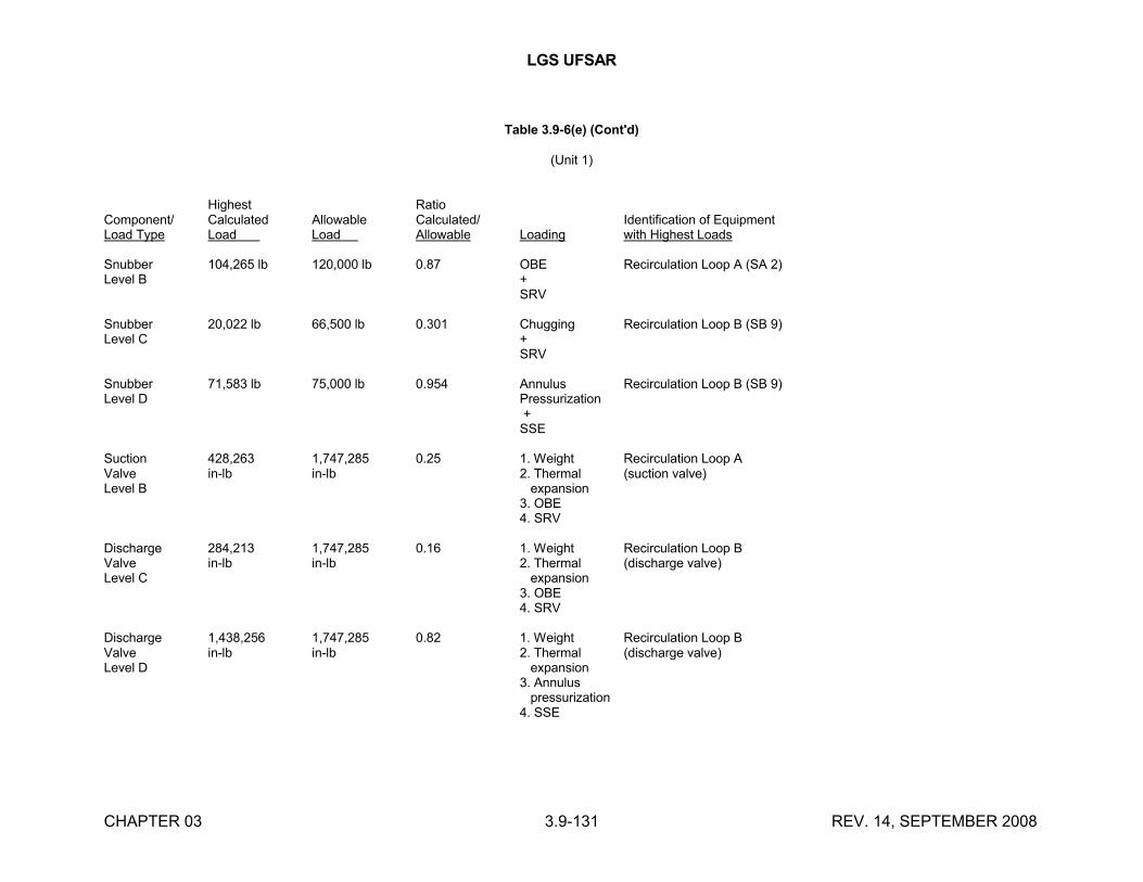
LGS UFSAR
CHAPTER 03 3.9-131 REV. 14, SEPTEMBER 2008
Table 3.9-6(e) (Cont'd)
(Unit 1)
Highest RatioComponent/ Calculated Allowable Calculated/ Identification of EquipmentLoad Type Load Load Allowable Loading with Highest Loads
Snubber 104,265 lb 120,000 lb 0.87 OBE Recirculation Loop A (SA 2)Level B +
SRV
Snubber 20,022 lb 66,500 lb 0.301 Chugging Recirculation Loop B (SB 9)Level C +
SRV
Snubber 71,583 lb 75,000 lb 0.954 Annulus Recirculation Loop B (SB 9)Level D Pressurization
+SSE
Suction 428,263 1,747,285 0.25 1. Weight Recirculation Loop AValve in-lb in-lb 2. Thermal (suction valve)Level B expansion
3. OBE4. SRV
Discharge 284,213 1,747,285 0.16 1. Weight Recirculation Loop BValve in-lb in-lb 2. Thermal (discharge valve)Level C expansion
3. OBE4. SRV
Discharge 1,438,256 1,747,285 0.82 1. Weight Recirculation Loop BValve in-lb in-lb 2. Thermal (discharge valve)Level D expansion
3. Annulus pressurization4. SSE
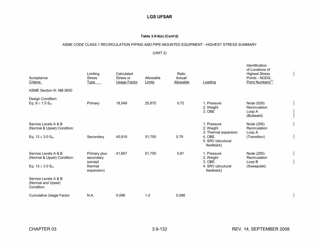
LGS UFSAR
CHAPTER 03 3.9-132 REV. 14, SEPTEMBER 2008
Table 3.9-6(e) (Cont'd)
ASME CODE CLASS 1 RECIRCULATION PIPING AND PIPE-MOUNTED EQUIPMENT - HIGHEST STRESS SUMMARY
(UNIT 2)
Identificationof Locations of
Limiting Calculated Ratio Highest StressAcceptance Stress Stress or Allowable Actual/ Points - NODGCriteria Type Usage Factor Limits Allowable Loading Point Numbers
(1)
ASME Section III, NB-3650
Design Condition:Eq. 9 1.5 Sm Primary 18,549 25,875 0.72 1. Pressure Node (028)
2. Weight Recirculation3. OBE Loop A
(Buttweld)
Service Levels A & B 1. Pressure Node (256)(Normal & Upset) Condition: 2. Weight Recirculation
3. Thermal expansion Loop AEq. 12 3.0 Sm Secondary 40,919 51,750 0.79 4. OBE (Transition)
5. SRV (structural feedback)
Service Levels A & B Primary plus 41,667 51,750 0.81 1. Pressure Node (200)(Normal & Upset) Condition: secondary 2. Weight Recirculation
(except 3. OBE Loop BEq. 13 3.0 Sm thermal 4. SRV (structural (Sweepolet)
expansion) feedback)
Service Levels A & B(Normal and Upset)Condition:
Cumulative Usage Factor N.A. 0.098 1.0 0.098
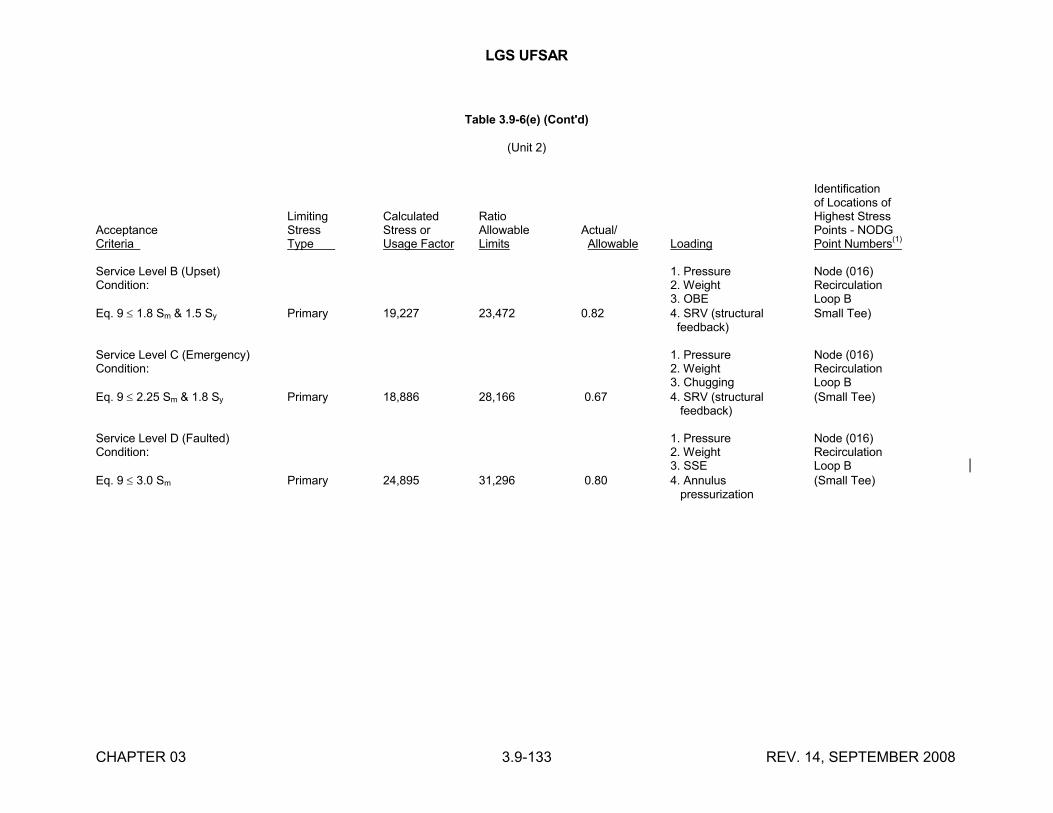
LGS UFSAR
CHAPTER 03 3.9-133 REV. 14, SEPTEMBER 2008
Table 3.9-6(e) (Cont'd)
(Unit 2)
Identificationof Locations of
Limiting Calculated Ratio Highest StressAcceptance Stress Stress or Allowable Actual/ Points - NODGCriteria Type Usage Factor Limits Allowable Loading Point Numbers
(1)
Service Level B (Upset) 1. Pressure Node (016)Condition: 2. Weight Recirculation
3. OBE Loop BEq. 9 1.8 Sm & 1.5 Sy Primary 19,227 23,472 0.82 4. SRV (structural Small Tee)
feedback)
Service Level C (Emergency) 1. Pressure Node (016)Condition: 2. Weight Recirculation
3. Chugging Loop BEq. 9 2.25 Sm & 1.8 Sy Primary 18,886 28,166 0.67 4. SRV (structural (Small Tee)
feedback)
Service Level D (Faulted) 1. Pressure Node (016)Condition: 2. Weight Recirculation
3. SSE Loop BEq. 9 3.0 Sm Primary 24,895 31,296 0.80 4. Annulus (Small Tee)
pressurization
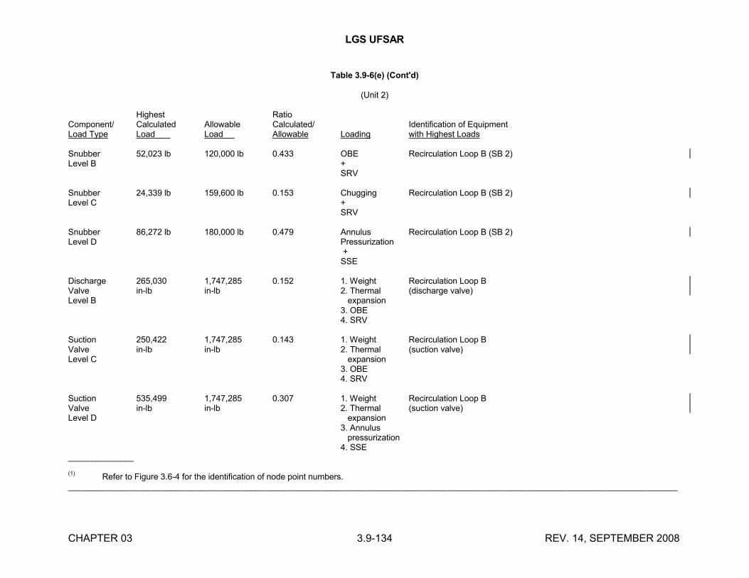
LGS UFSAR
CHAPTER 03 3.9-134 REV. 14, SEPTEMBER 2008
Table 3.9-6(e) (Cont'd)
(Unit 2)
Highest RatioComponent/ Calculated Allowable Calculated/ Identification of EquipmentLoad Type Load Load Allowable Loading with Highest Loads
Snubber 52,023 lb 120,000 lb 0.433 OBE Recirculation Loop B (SB 2)Level B +
SRV
Snubber 24,339 lb 159,600 lb 0.153 Chugging Recirculation Loop B (SB 2)Level C +
SRV
Snubber 86,272 lb 180,000 lb 0.479 Annulus Recirculation Loop B (SB 2)Level D Pressurization
+SSE
Discharge 265,030 1,747,285 0.152 1. Weight Recirculation Loop BValve in-lb in-lb 2. Thermal (discharge valve)Level B expansion
3. OBE4. SRV
Suction 250,422 1,747,285 0.143 1. Weight Recirculation Loop BValve in-lb in-lb 2. Thermal (suction valve)Level C expansion
3. OBE4. SRV
Suction 535,499 1,747,285 0.307 1. Weight Recirculation Loop BValve in-lb in-lb 2. Thermal (suction valve)Level D expansion
3. Annulus pressurization4. SSE
______________
(1)Refer to Figure 3.6-4 for the identification of node point numbers.
__________________________________________________________________________________________________________________________________
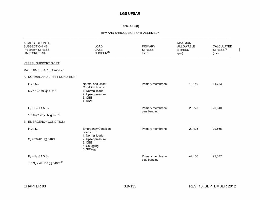
LGS UFSAR
CHAPTER 03 3.9-135 REV. 16, SEPTEMBER 2012
Table 3.9-6(f)
RPV AND SHROUD SUPPORT ASSEMBLY_______________________________________________________________________________________________________________________________
ASME SECTION III, MAXIMUMSUBSECTION NB LOAD PRIMARY ALLOWABLE CALCULATEDPRIMARY STRESS CASE STRESS STRESS STRESS
(4)
LIMIT CRITERIA NUMBER(1)
TYPE (psi) (psi)_______________________________________________________________________________________________________________________________
VESSEL SUPPORT SKIRT
MATERIAL: SA516, Grade 70
A. NORMAL AND UPSET CONDITION:
Pm Sm Normal and Upset Primary membrane 19,150 14,723Condition Loads:
Sm = 19,150 @ 575F 1. Normal loads2. Upset pressure3. OBE4. SRV
PL + Pb 1.5 Sm Primary membrane 28,725 20,640plus bending
1.5 Sm = 28,725 @ 575F
B. EMERGENCY CONDITION:
Pm Sy Emergency Condition Primary membrane 29,425 20,565Loads:1. Normal loads
Sy = 28,425 @ 546F 2. Upset pressure3. OBE4. Chugging5. SRVADS
PL + Pb 1.5 Sy Primary membrane 44,150 29,377plus bending
1.5 Sy = 44,137 @ 546F(2)
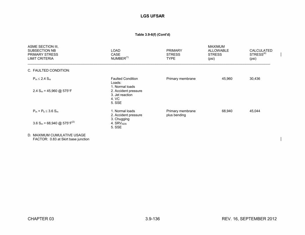
LGS UFSAR
CHAPTER 03 3.9-136 REV. 16, SEPTEMBER 2012
Table 3.9-6(f) (Cont'd)
ASME SECTION III, MAXIMUMSUBSECTION NB LOAD PRIMARY ALLOWABLE CALCULATEDPRIMARY STRESS CASE STRESS STRESS STRESS
(4)
LIMIT CRITERIA NUMBER(1)
TYPE (psi) (psi)_______________________________________________________________________________________________________________________________
C. FAULTED CONDITION:
Pm 2.4 Sm Faulted Condition Primary membrane 45,960 30,436Loads:1. Normal loads
2.4 Sm = 45,960 @ 575F 2. Accident pressure3. Jet reaction4. VC5. SSE
Pm + Pb 3.6 Sm 1. Normal loads Primary membrane 68,940 45,0442. Accident pressure plus bending3. Chugging
3.6 Sm = 68,940 @ 575F(2)
4. SRVADS
5. SSE
D. MAXIMUM CUMULATIVE USAGEFACTOR: 0.83 at Skirt base junction
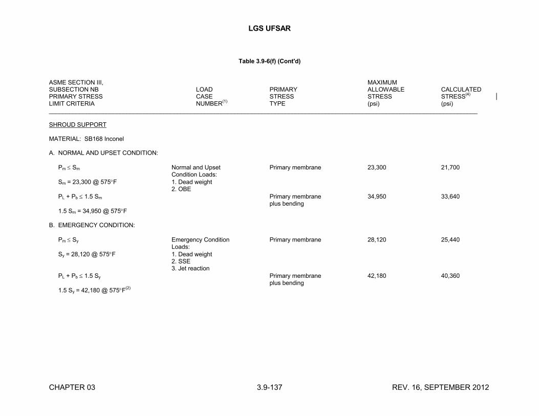
LGS UFSAR
CHAPTER 03 3.9-137 REV. 16, SEPTEMBER 2012
Table 3.9-6(f) (Cont'd)
ASME SECTION III, MAXIMUMSUBSECTION NB LOAD PRIMARY ALLOWABLE CALCULATEDPRIMARY STRESS CASE STRESS STRESS STRESS
(4)
LIMIT CRITERIA NUMBER(1)
TYPE (psi) (psi)_______________________________________________________________________________________________________________________________
SHROUD SUPPORT
MATERIAL: SB168 Inconel
A. NORMAL AND UPSET CONDITION:
Pm Sm Normal and Upset Primary membrane 23,300 21,700Condition Loads:
Sm = 23,300 @ 575F 1. Dead weight2. OBE
PL + Pb 1.5 Sm Primary membrane 34,950 33,640plus bending
1.5 Sm = 34,950 @ 575F
B. EMERGENCY CONDITION:
Pm Sy Emergency Condition Primary membrane 28,120 25,440Loads:
Sy = 28,120 @ 575F 1. Dead weight2. SSE3. Jet reaction
PL + Pb 1.5 Sy Primary membrane 42,180 40,360plus bending
1.5 Sy = 42,180 @ 575F(2)
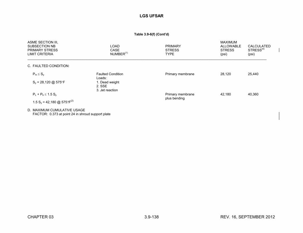
LGS UFSAR
CHAPTER 03 3.9-138 REV. 16, SEPTEMBER 2012
Table 3.9-6(f) (Cont'd)
ASME SECTION III, MAXIMUMSUBSECTION NB LOAD PRIMARY ALLOWABLE CALCULATEDPRIMARY STRESS CASE STRESS STRESS STRESS
(4)
LIMIT CRITERIA NUMBER(1)
TYPE (psi) (psi)______________________________________________________________________________________________________________________________
C. FAULTED CONDITION:
Pm Sy Faulted Condition Primary membrane 28,120 25,440Loads:
Sy = 28,120 @ 575F 1. Dead weight2. SSE3. Jet reaction
PL + Pb 1.5 Sy Primary membrane 42,180 40,360plus bending
1.5 Sy = 42,180 @ 575?F(2)
D. MAXIMUM CUMULATIVE USAGEFACTOR: 0.373 at point 24 in shroud support plate
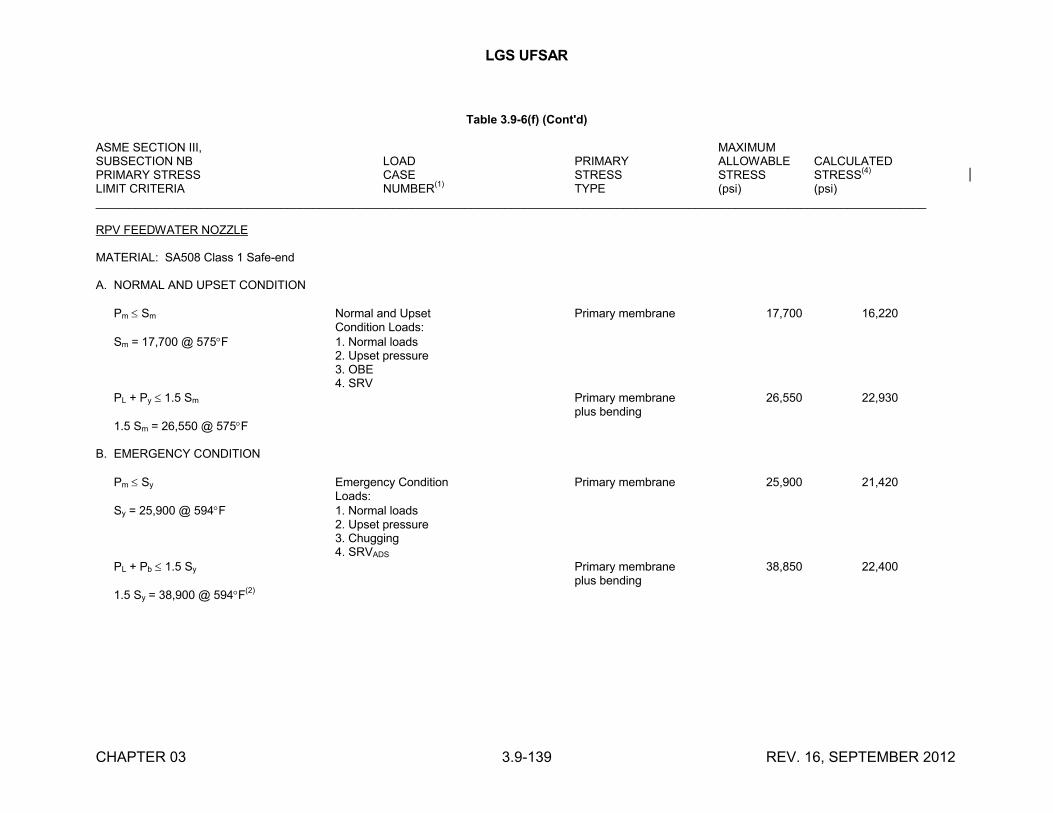
LGS UFSAR
CHAPTER 03 3.9-139 REV. 16, SEPTEMBER 2012
Table 3.9-6(f) (Cont'd)
ASME SECTION III, MAXIMUMSUBSECTION NB LOAD PRIMARY ALLOWABLE CALCULATEDPRIMARY STRESS CASE STRESS STRESS STRESS
(4)
LIMIT CRITERIA NUMBER(1)
TYPE (psi) (psi)______________________________________________________________________________________________________________________________
RPV FEEDWATER NOZZLE
MATERIAL: SA508 Class 1 Safe-end
A. NORMAL AND UPSET CONDITION
Pm Sm Normal and Upset Primary membrane 17,700 16,220Condition Loads:
Sm = 17,700 @ 575F 1. Normal loads2. Upset pressure3. OBE4. SRV
PL + Py 1.5 Sm Primary membrane 26,550 22,930plus bending
1.5 Sm = 26,550 @ 575F
B. EMERGENCY CONDITION
Pm Sy Emergency Condition Primary membrane 25,900 21,420Loads:
Sy = 25,900 @ 594F 1. Normal loads2. Upset pressure3. Chugging4. SRVADS
PL + Pb 1.5 Sy Primary membrane 38,850 22,400plus bending
1.5 Sy = 38,900 @ 594F(2)
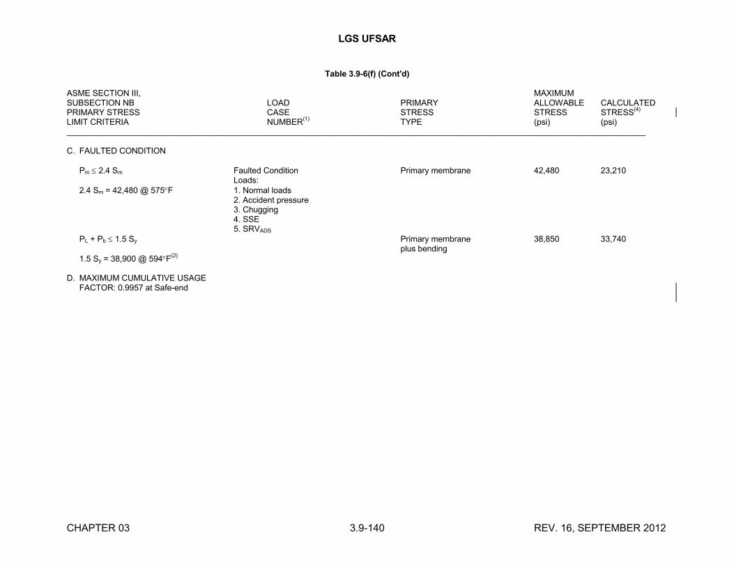
LGS UFSAR
CHAPTER 03 3.9-140 REV. 16, SEPTEMBER 2012
Table 3.9-6(f) (Cont'd)
ASME SECTION III, MAXIMUMSUBSECTION NB LOAD PRIMARY ALLOWABLE CALCULATEDPRIMARY STRESS CASE STRESS STRESS STRESS
(4)
LIMIT CRITERIA NUMBER(1)
TYPE (psi) (psi)______________________________________________________________________________________________________________________________
C. FAULTED CONDITION
Pm 2.4 Sm Faulted Condition Primary membrane 42,480 23,210Loads:
2.4 Sm = 42,480 @ 575F 1. Normal loads2. Accident pressure3. Chugging4. SSE5. SRVADS
PL + Pb 1.5 Sy Primary membrane 38,850 33,740plus bending
1.5 Sy = 38,900 @ 594F(2)
D. MAXIMUM CUMULATIVE USAGEFACTOR: 0.9957 at Safe-end
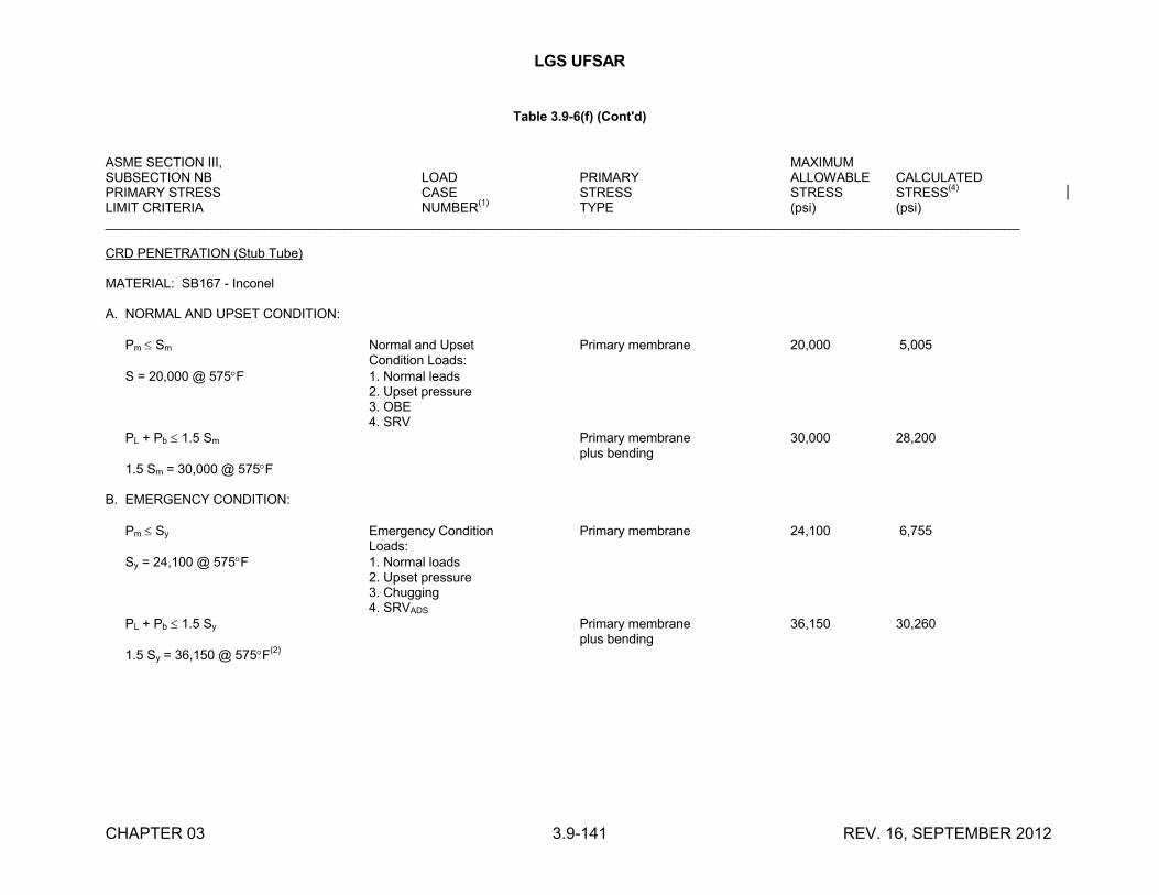
LGS UFSAR
CHAPTER 03 3.9-141 REV. 16, SEPTEMBER 2012
Table 3.9-6(f) (Cont'd)
ASME SECTION III, MAXIMUMSUBSECTION NB LOAD PRIMARY ALLOWABLE CALCULATEDPRIMARY STRESS CASE STRESS STRESS STRESS
(4)
LIMIT CRITERIA NUMBER(1)
TYPE (psi) (psi)______________________________________________________________________________________________________________________________
CRD PENETRATION (Stub Tube)
MATERIAL: SB167 - Inconel
A. NORMAL AND UPSET CONDITION:
Pm Sm Normal and Upset Primary membrane 20,000 5,005Condition Loads:
S = 20,000 @ 575F 1. Normal leads2. Upset pressure3. OBE4. SRV
PL + Pb 1.5 Sm Primary membrane 30,000 28,200plus bending
1.5 Sm = 30,000 @ 575F
B. EMERGENCY CONDITION:
Pm Sy Emergency Condition Primary membrane 24,100 6,755Loads:
Sy = 24,100 @ 575F 1. Normal loads2. Upset pressure3. Chugging4. SRVADS
PL + Pb 1.5 Sy Primary membrane 36,150 30,260plus bending
1.5 Sy = 36,150 @ 575F(2)
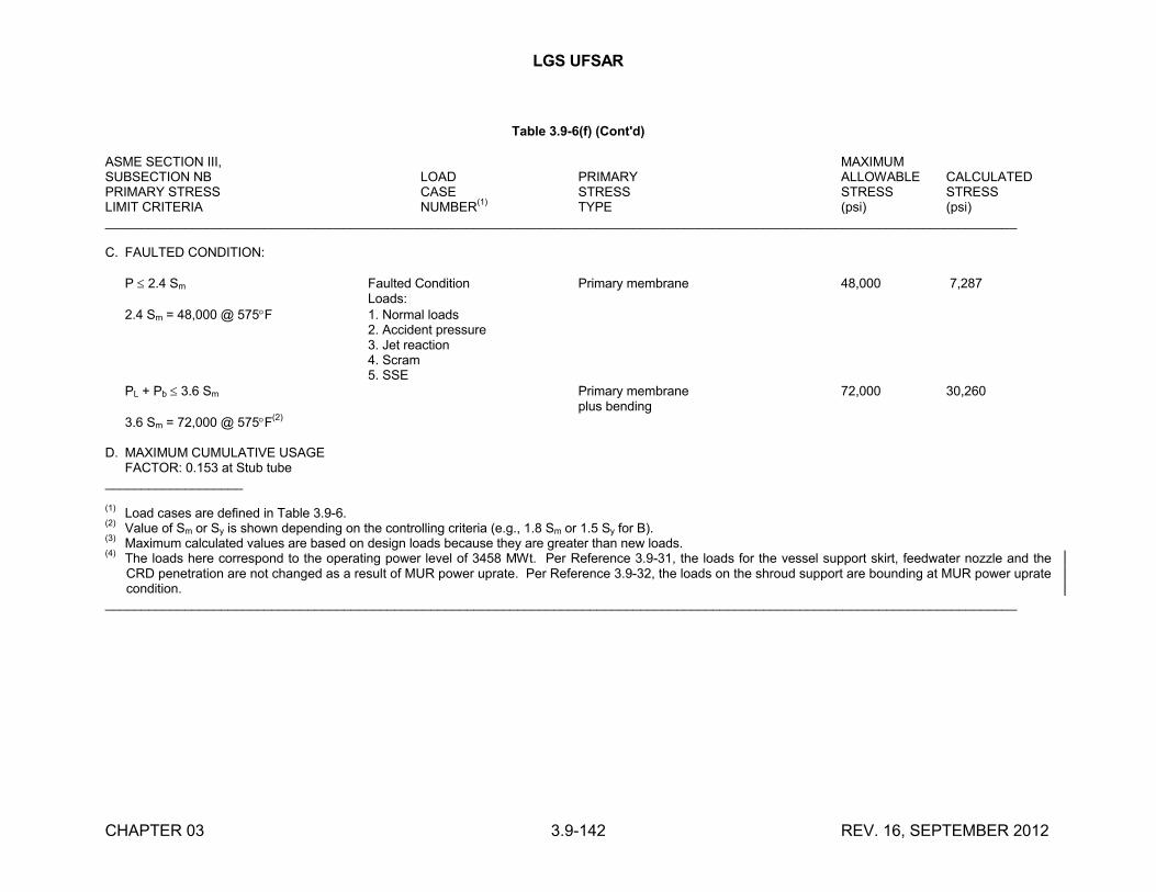
LGS UFSAR
CHAPTER 03 3.9-142 REV. 16, SEPTEMBER 2012
Table 3.9-6(f) (Cont'd)
ASME SECTION III, MAXIMUMSUBSECTION NB LOAD PRIMARY ALLOWABLE CALCULATEDPRIMARY STRESS CASE STRESS STRESS STRESSLIMIT CRITERIA NUMBER
(1)TYPE (psi) (psi)
______________________________________________________________________________________________________________________________
C. FAULTED CONDITION:
P 2.4 Sm Faulted Condition Primary membrane 48,000 7,287Loads:
2.4 Sm = 48,000 @ 575F 1. Normal loads2. Accident pressure3. Jet reaction4. Scram5. SSE
PL + Pb 3.6 Sm Primary membrane 72,000 30,260plus bending
3.6 Sm = 72,000 @ 575F(2)
D. MAXIMUM CUMULATIVE USAGEFACTOR: 0.153 at Stub tube
___________________
(1)Load cases are defined in Table 3.9-6.
(2)Value of Sm or Sy is shown depending on the controlling criteria (e.g., 1.8 Sm or 1.5 Sy for B).
(3)Maximum calculated values are based on design loads because they are greater than new loads.
(4)The loads here correspond to the operating power level of 3458 MWt. Per Reference 3.9-31, the loads for the vessel support skirt, feedwater nozzle and the CRD penetration are not changed as a result of MUR power uprate. Per Reference 3.9-32, the loads on the shroud support are bounding at MUR power uprate condition.
______________________________________________________________________________________________________________________________
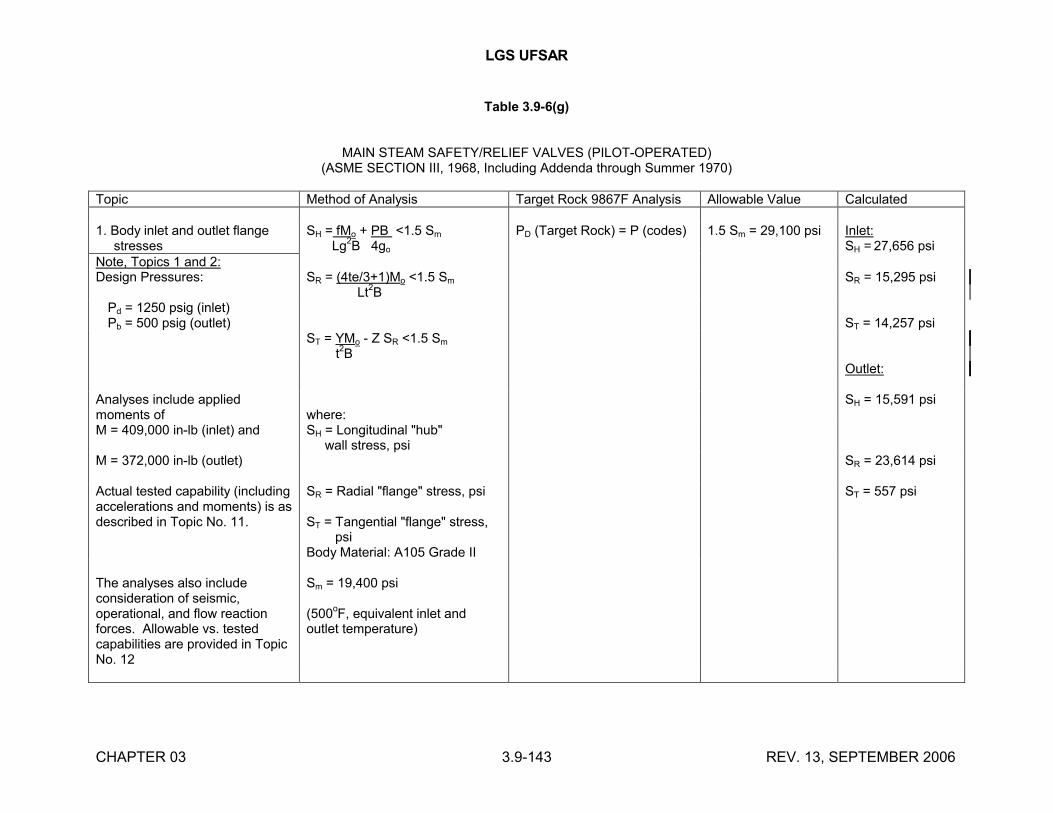
LGS UFSAR
CHAPTER 03 3.9-143 REV. 13, SEPTEMBER 2006
Table 3.9-6(g)
MAIN STEAM SAFETY/RELIEF VALVES (PILOT-OPERATED)(ASME SECTION III, 1968, Including Addenda through Summer 1970)
Topic Method of Analysis Target Rock 9867F Analysis Allowable Value Calculated
1. Body inlet and outlet flange stresses
SH = fMo + PB <1.5 Sm
Lg2B 4go
PD (Target Rock) = P (codes) 1.5 Sm = 29,100 psi Inlet:SH = 27,656 psi
Note, Topics 1 and 2:Design Pressures: SR = (4te/3+1)Mo <1.5 Sm
Lt2B
SR = 15,295 psi
Pd = 1250 psig (inlet)Pb = 500 psig (outlet) ST = 14,257 psi
ST = YMo - Z SR <1.5 Sm
t2B
Outlet:
Analyses include applied moments of where:
SH = 15,591 psi
M = 409,000 in-lb (inlet) and SH = Longitudinal "hub" wall stress, psi
M = 372,000 in-lb (outlet) SR = 23,614 psi
Actual tested capability (including accelerations and moments) is as described in Topic No. 11.
SR = Radial "flange" stress, psi
ST = Tangential "flange" stress, psi
Body Material: A105 Grade II
ST = 557 psi
The analyses also include consideration of seismic, operational, and flow reaction forces. Allowable vs. tested capabilities are provided in Topic No. 12
Sm = 19,400 psi
(500oF, equivalent inlet and
outlet temperature)
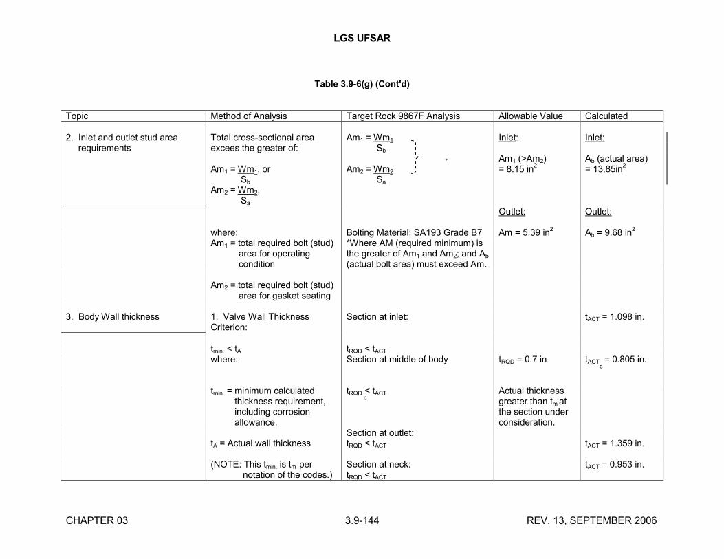
LGS UFSAR
CHAPTER 03 3.9-144 REV. 13, SEPTEMBER 2006
Table 3.9-6(g) (Cont'd)
Topic Method of Analysis Target Rock 9867F Analysis Allowable Value Calculated
2. Inlet and outlet stud area requirements
Total cross-sectional area excees the greater of:
Am1 = Wm1, or Sb
Am2 = Wm2, Sa
Am1 = Wm1
Sb
*
Am2 = Wm2
Sa
Inlet:
Am1 (>Am2)= 8.15 in
2
Inlet:
Ab (actual area)= 13.85in
2
Outlet: Outlet:
where: Bolting Material: SA193 Grade B7 Am = 5.39 in2
Ab = 9.68 in2
Am1 = total required bolt (stud) area for operating condition
*Where AM (required minimum) is the greater of Am1 and Am2; and Ab
(actual bolt area) must exceed Am.
Am2 = total required bolt (stud) area for gasket seating
3. Body Wall thickness 1. Valve Wall Thickness Criterion:
Section at inlet: tACT = 1.098 in.
tmin. < tA tRQD < tACT
where: Section at middle of body tRQD = 0.7 in tACT = 0.805 in. c
tmin. = minimum calculated thickness requirement, including corrosion allowance.
tRQD < tACT
c
Actual thickness greater than tm at the section under consideration.
Section at outlet:tA = Actual wall thickness tRQD < tACT tACT = 1.359 in.
(NOTE: This tmin. is tm per notation of the codes.)
Section at neck:tRQD < tACT
tACT = 0.953 in.
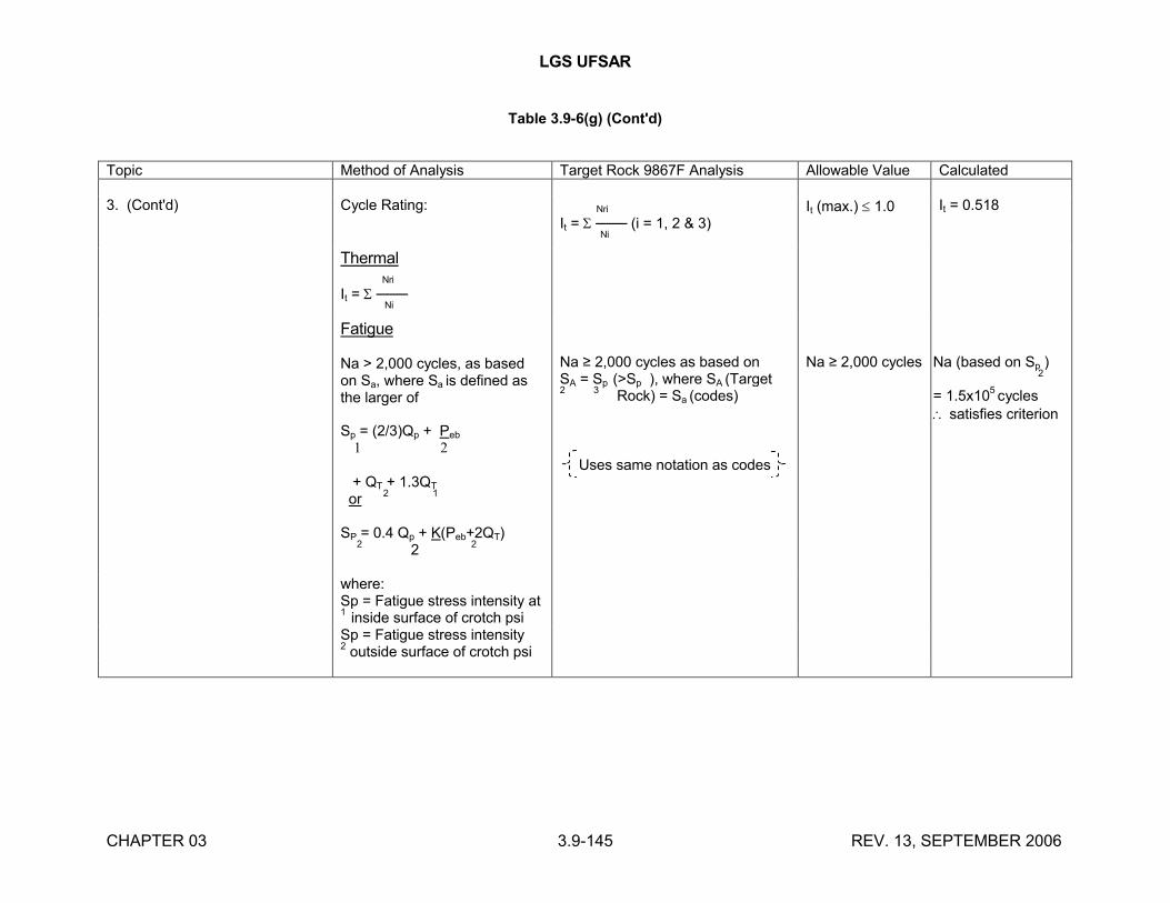
LGS UFSAR
CHAPTER 03 3.9-145 REV. 13, SEPTEMBER 2006
Table 3.9-6(g) (Cont'd)
Topic Method of Analysis Target Rock 9867F Analysis Allowable Value Calculated
3. (Cont'd) Cycle Rating: Nri
It = ─── (i = 1, 2 & 3)
Ni
It (max.) 1.0 It = 0.518
Thermal Nri
It = ─── Ni
Fatigue
Na > 2,000 cycles, as based on Sa, where Sa is defined as the larger of
Na ≥ 2,000 cycles as based on SA = Sp (>Sp ), where SA (Target 2
3 Rock) = Sa (codes)
Na ≥ 2,000 cycles Na (based on Sp )
2
= 1.5x10⁵ cycles
satisfies criterionSp = (2/3)Qp + Peb
1 2
+ QT + 1.3QT
or 2
1
SP = 0.4 Qp + K(Peb+2QT)
2 2
2
Uses same notation as codes
where:Sp = Fatigue stress intensity at 1
inside surface of crotch psiSp = Fatigue stress intensity 2
outside surface of crotch psi
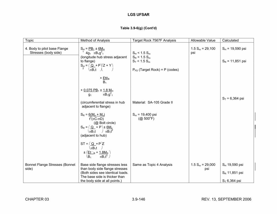
LGS UFSAR
CHAPTER 03 3.9-146 REV. 13, SEPTEMBER 2006
Table 3.9-6(g) (Cont'd)
Topic Method of Analysis Target Rock 7567F Analysis Allowable Value Calculated
4. Body to pilot base Flange Stresses (body side)
SH = PB1 ± 6MH
1 4g1 B1g
21 SH < 1.5 Sm
1.5 Sm = 29,100 psi
SH = 19,590 psi
(longitude hub stress adjacent to flange)
SR < 1.5 Sm
ST < 1.5 Sm SR = 11,851 psiSH = Q + PZ + Y
2 B1t PFD (Target Rock) = P (codes)
+ EtB
B1
+ 0.075 PB1 ± 1.8 MH
g1 B1g21
ST = 6,364 psi(circumferential stress in hub adjacent to flange)
Material: SA-105 Grade II
SR = 6(Mp + Ms) t
2(C-nD)
Sm = 19,400 psi (@ 500
oF)
(@ Bolt circle)SR = Q + P ± 6Ms B1t B1t
2
(adjacent to hub)
ST = Q + PZ B1t ± Et�B + 1.8MS B1 B1t
2
Bonnet Flange Stresses (Bonnet side)
Base side flange stresses less than body side flange stresses (Both sides see identical loads. The base side is thicker than the body side at all points.)
Same as Topic 4 Analysis 1.5 Sm = 29,000 psi
SH 19,590 psi
SR 11,851 psi
ST 6,364 psi
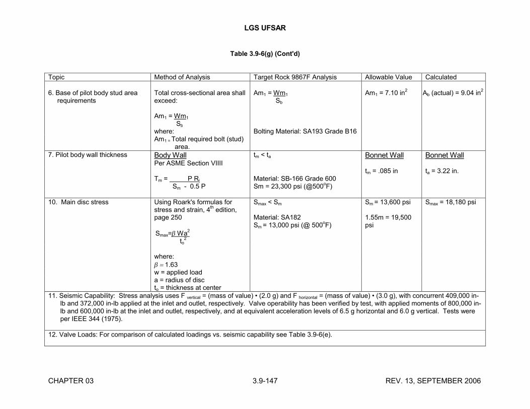
LGS UFSAR
CHAPTER 03 3.9-147 REV. 13, SEPTEMBER 2006
Table 3.9-6(g) (Cont'd)
Topic Method of Analysis Target Rock 9867F Analysis Allowable Value Calculated
6. Base of pilot body stud area requirements
Total cross-sectional area shall exceed:
Am1 = Wm1
Sb
Am1 = Wm1
Sb
Am1 = 7.10 in2
Ab (actual) = 9.04 in2
where: Bolting Material: SA193 Grade B16Am1 = Total required bolt (stud)
area.7. Pilot body wall thickness Body Wall
Per ASME Section VIIII
tm < ta Bonnet Wall Bonnet Wall
tm = .085 in ta = 3.22 in.Tm = P Ri Sm - 0.5 P
Material: SB-166 Grade 600Sm = 23,300 psi (@500
oF)
10. Main disc stress Using Roark's formulas for stress and strain, 4
thedition,
page 250
Smax= Wa2
to2
Smax < Sm
Material: SA182Sm = 13,000 psi (@ 500
oF)
Sm = 13,600 psi
1.55m = 19,500 psi
Smax = 18,180 psi
where:1.63w = applied loada = radius of discto = thickness at center
11. Seismic Capability: Stress analysis uses F vertical = (mass of value) • (2.0 g) and F horizontal = (mass of value) • (3.0 g), with concurrent 409,000 in-lb and 372,000 in-lb applied at the inlet and outlet, respectively. Valve operability has been verified by test, with applied moments of 800,000 in-lb and 600,000 in-lb at the inlet and outlet, respectively, and at equivalent acceleration levels of 6.5 g horizontal and 6.0 g vertical. Tests were per IEEE 344 (1975).
12. Valve Loads: For comparison of calculated loadings vs. seismic capability see Table 3.9-6(e).
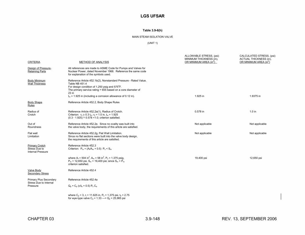
LGS UFSAR
CHAPTER 03 3.9-148 REV. 13, SEPTEMBER 2006
Table 3.9-6(h)
MAIN STEAM ISOLATION VALVE
(UNIT 1)
ALLOWABLE STRESS, (psi) CALCULATED STRESS, (psi)MINIMUM THICKNESS (in), ACTUAL THICKNESS (in),
CRITERIA METHOD OF ANALYSIS OR MINIMUM AREA (in2) OR MINIMUM AREA (in2)
Design of Pressure- All references are made to ASME Code for Pumps and Valves forRetaining Parts Nuclear Power, dated November 1968. Reference the same code
for explanation of the symbols used.
Body Minimum Reference Article 452.1b(2), Nonstandard Pressure - Rated Value.Wall Thickness Table NB 451.4
For design condition of 1,250 psig and 575oF.
The primary service rating = 655 based on a core diameter of 23 intm = 1.925 in (including a corrosion allowance of 0.12 in). 1.925 in 1.9375 in
Body Shape Reference Article 452.2, Body Shape RulesRules
Radius of Reference Article 452.2a(1), Radius of Crotch. 0.578 in 1.0 inCrotch Criterion: r2 > 0.3 tm; r2 = 1.0 in, tm = 1.925
(0.3 · 1.925) = 0.578 <1.0; criterion satisfied.
Out of Reference Article 452.2e. Since no ovality was built into Not applicable Not applicableRoundness the valve body, the requirements of this article are satisfied.
Flat wall Reference Article 452.2g, Flat Wall Limitation. Not applicable Not applicableLimitation Since no flat sections were built into the valve body design,
the requirements of this article are satisfied.
Primary Crotch Reference Article 452.3Stress Due to Criterion: Pm = (Af/Am + 0.5) Ps < Sm
Internal Pressure
where Af = 504 in2, Am = 58 in2, Ps = 1,375 psig, 19,400 psi 12,650 psiPm = 12,650 psi, Sm = 19,400 psi; since Sm > Pm
criterion satisfied.
Valve Body Reference Article 452.4Secondary Stress
Primary Plus Secondary Reference Article 452.4aStress Due to InternalPressure Qp = Cp (ri/te + 0.5) Ps Ca
where Cp = 3, ri = 11.625 in, Ps = 1,375 psi, te = 2.75for wye-type valve Ca = 1.33 ---> Qp = 25,965 psi
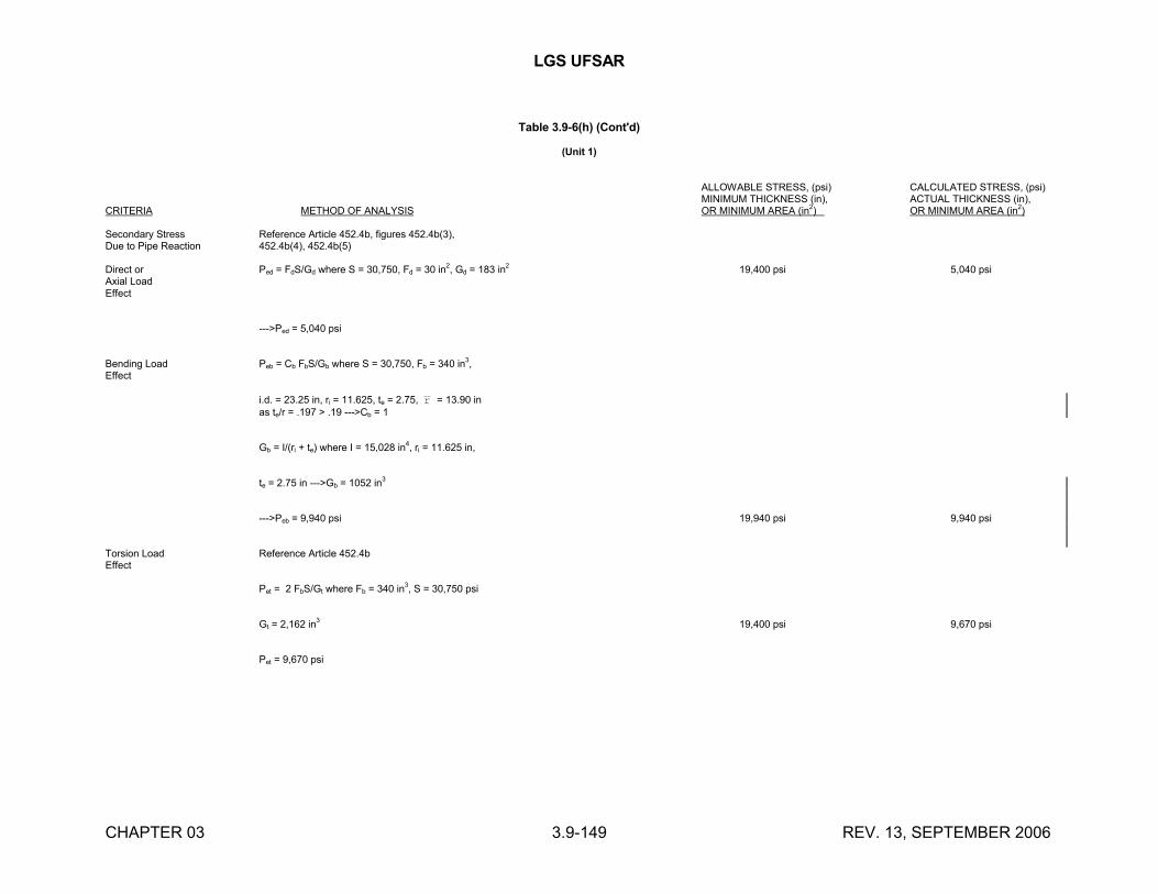
LGS UFSAR
CHAPTER 03 3.9-149 REV. 13, SEPTEMBER 2006
Table 3.9-6(h) (Cont'd)
(Unit 1)
ALLOWABLE STRESS, (psi) CALCULATED STRESS, (psi)MINIMUM THICKNESS (in), ACTUAL THICKNESS (in),
CRITERIA METHOD OF ANALYSIS OR MINIMUM AREA (in2) OR MINIMUM AREA (in2)
Secondary Stress Reference Article 452.4b, figures 452.4b(3),Due to Pipe Reaction 452.4b(4), 452.4b(5)
Direct or Ped = FdS/Gd where S = 30,750, Fd = 30 in2, Gd = 183 in
219,400 psi 5,040 psi
Axial LoadEffect
--->Ped = 5,040 psi
Bending Load Peb = Cb FbS/Gb where S = 30,750, Fb = 340 in3,
Effect
i.d. = 23.25 in, ri = 11.625, te = 2.75, r = 13.90 inas te/r = .197 > .19 --->Cb = 1
Gb = I/(ri + te) where I = 15,028 in4, ri = 11.625 in,
te = 2.75 in --->Gb = 1052 in3
--->Peb = 9,940 psi 19,940 psi 9,940 psi
Torsion Load Reference Article 452.4bEffect
Pet = 2 FbS/Gt where Fb = 340 in3, S = 30,750 psi
Gt = 2,162 in3 19,400 psi 9,670 psi
Pet = 9,670 psi
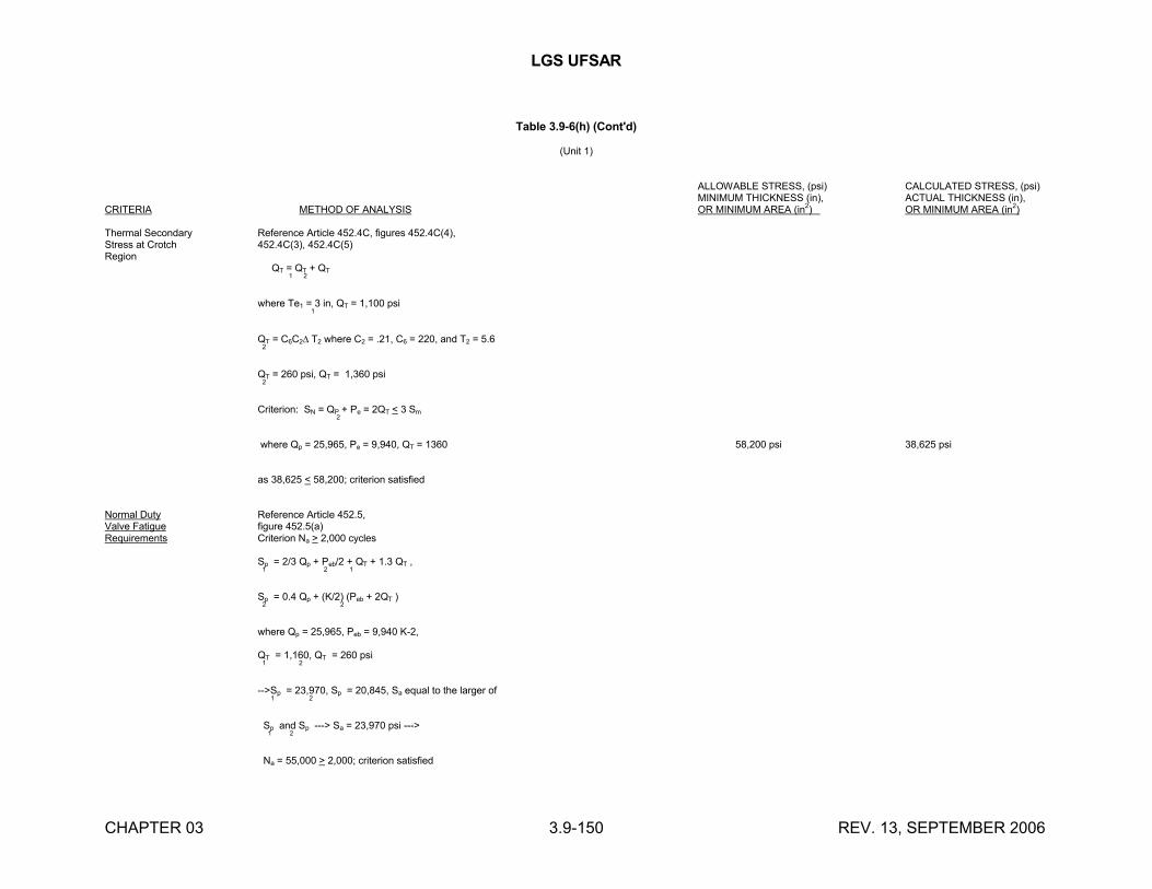
LGS UFSAR
CHAPTER 03 3.9-150 REV. 13, SEPTEMBER 2006
Table 3.9-6(h) (Cont'd)
(Unit 1)
ALLOWABLE STRESS, (psi) CALCULATED STRESS, (psi)MINIMUM THICKNESS (in), ACTUAL THICKNESS (in),
CRITERIA METHOD OF ANALYSIS OR MINIMUM AREA (in2) OR MINIMUM AREA (in2)
Thermal Secondary Reference Article 452.4C, figures 452.4C(4),Stress at Crotch 452.4C(3), 452.4C(5)Region
QT = QT + QT
1 2
where Te1 = 3 in, QT = 1,100 psi
1
QT = C6C2 T2 where C2 = .21, C6 = 220, and T2 = 5.62
QT = 260 psi, QT = 1,360 psi2
Criterion: SN = QP + Pe = 2QT < 3 Sm
2
where Qp = 25,965, Pe = 9,940, QT = 1360 58,200 psi 38,625 psi
as 38,625 < 58,200; criterion satisfied
Normal Duty Reference Article 452.5,Valve Fatigue figure 452.5(a)Requirements Criterion Na > 2,000 cycles
Sp = 2/3 Qp + Peb/2 + QT + 1.3 QT ,1 2 1
Sp = 0.4 Qp + (K/2) (Peb + 2QT )2 2
where Qp = 25,965, Peb = 9,940 K-2,
QT = 1,160, QT = 260 psi1
2
-->Sp = 23,970, Sp = 20,845, Sa equal to the larger of 1 2
Sp and Sp ---> Sa = 23,970 psi ---> 1 2
Na = 55,000 > 2,000; criterion satisfied
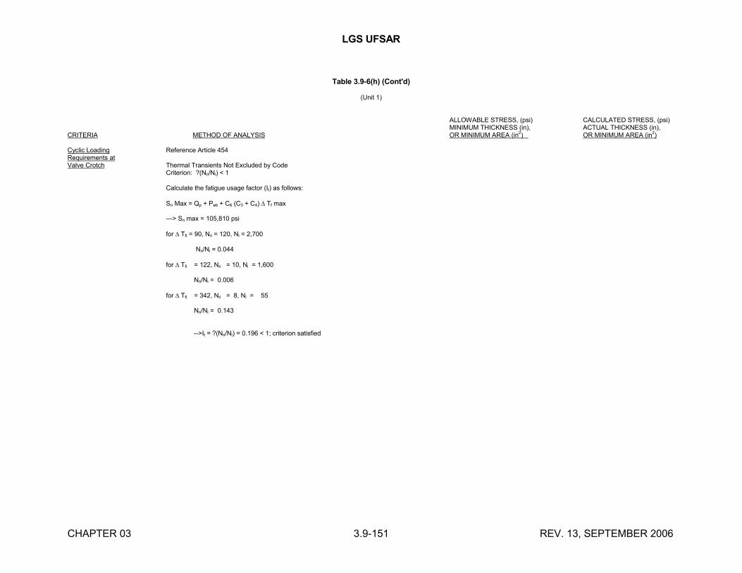
LGS UFSAR
CHAPTER 03 3.9-151 REV. 13, SEPTEMBER 2006
Table 3.9-6(h) (Cont'd)
(Unit 1)
ALLOWABLE STRESS, (psi) CALCULATED STRESS, (psi)MINIMUM THICKNESS (in), ACTUAL THICKNESS (in),
CRITERIA METHOD OF ANALYSIS OR MINIMUM AREA (in2) OR MINIMUM AREA (in2)
Cyclic Loading Reference Article 454Requirements atValve Crotch Thermal Transients Not Excluded by Code
Criterion: ?(Nri/Ni) < 1
Calculate the fatigue usage factor (It) as follows:
Sn Max = Qp + Peb + C6 (C3 + C4) Tf max
---> Sn max = 105,810 psi
for Tfi = 90, Nri = 120, Ni = 2,700
Nri/Ni = 0.044
for Tfi = 122, Nri = 10, Ni = 1,600
Nri/Ni = 0.006
for Tfi = 342, Nri = 8, Ni = 55
Nri/Ni = 0.143
-->It = ?(Nri/Ni) = 0.196 < 1; criterion satisfied
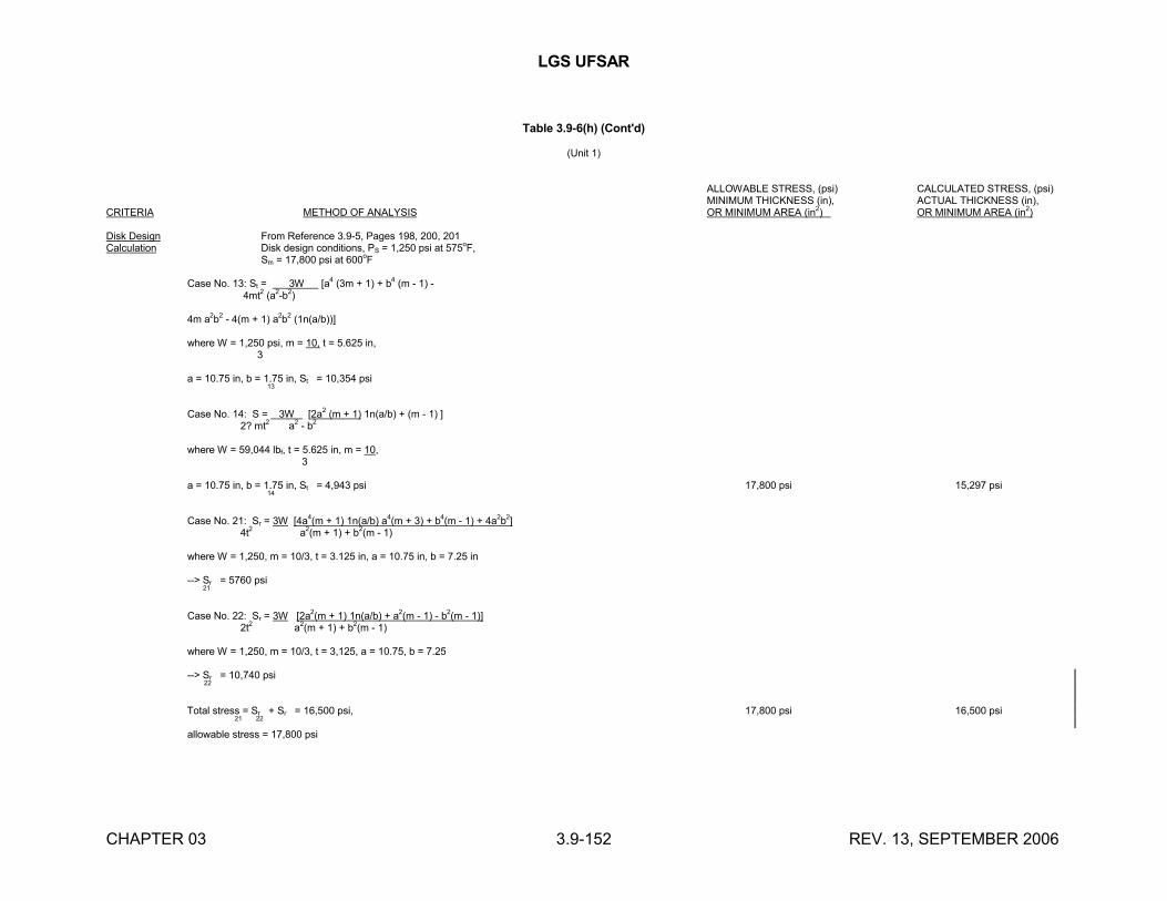
LGS UFSAR
CHAPTER 03 3.9-152 REV. 13, SEPTEMBER 2006
Table 3.9-6(h) (Cont'd)
(Unit 1)
ALLOWABLE STRESS, (psi) CALCULATED STRESS, (psi)MINIMUM THICKNESS (in), ACTUAL THICKNESS (in),
CRITERIA METHOD OF ANALYSIS OR MINIMUM AREA (in2) OR MINIMUM AREA (in2)
Disk Design From Reference 3.9-5, Pages 198, 200, 201Calculation Disk design conditions, PS = 1,250 psi at 575oF,
Sm = 17,800 psi at 600oF
Case No. 13: St = 3W [a4 (3m + 1) + b4 (m - 1) - 4mt2 (a2-b2)
4m a2b
2- 4(m + 1) a
2b
2(1n(a/b))]
where W = 1,250 psi, m = 10, t = 5.625 in, 3
a = 10.75 in, b = 1.75 in, St = 10,354 psi 13
Case No. 14: S = 3W [2a2 (m + 1) 1n(a/b) + (m - 1) ] 2? mt2 a2 - b2
where W = 59,044 lbf, t = 5.625 in, m = 10, 3
a = 10.75 in, b = 1.75 in, St = 4,943 psi 17,800 psi 15,297 psi 14
Case No. 21: Sr = 3W [4a4(m + 1) 1n(a/b) a4(m + 3) + b4(m - 1) + 4a2b2] 4t2 a2(m + 1) + b2(m - 1)
where W = 1,250, m = 10/3, t = 3.125 in, a = 10.75 in, b = 7.25 in
--> Sr = 5760 psi 21
Case No. 22: Sr = 3W [2a2(m + 1) 1n(a/b) + a2(m - 1) - b2(m - 1)] 2t2 a2(m + 1) + b2(m - 1)
where W = 1,250, m = 10/3, t = 3,125, a = 10.75, b = 7.25
--> Sr = 10,740 psi 22
Total stress = Sr + Sr = 16,500 psi, 17,800 psi 16,500 psi 21 22
allowable stress = 17,800 psi
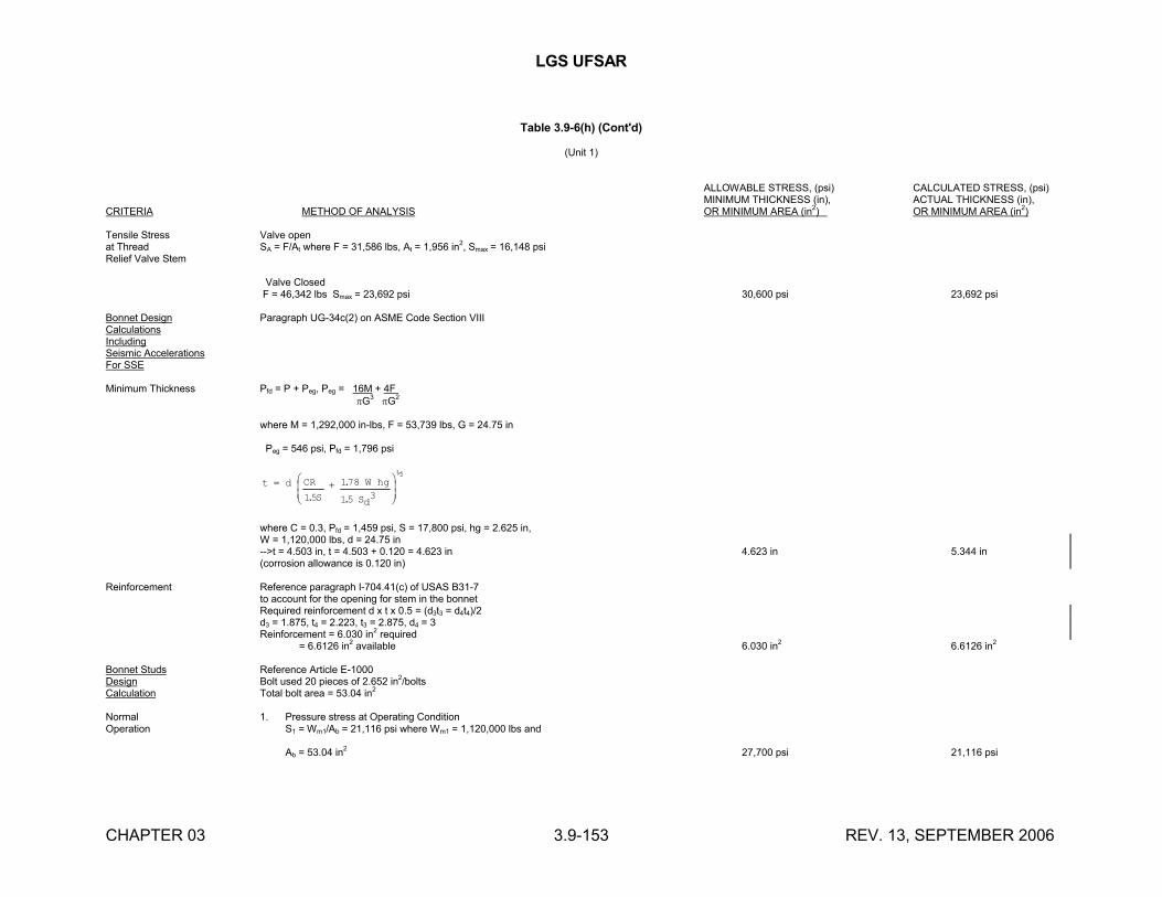
LGS UFSAR
CHAPTER 03 3.9-153 REV. 13, SEPTEMBER 2006
Table 3.9-6(h) (Cont'd)
(Unit 1)
ALLOWABLE STRESS, (psi) CALCULATED STRESS, (psi)MINIMUM THICKNESS (in), ACTUAL THICKNESS (in),
CRITERIA METHOD OF ANALYSIS OR MINIMUM AREA (in2) OR MINIMUM AREA (in2)
Tensile Stress Valve openat Thread SA = F/At where F = 31,586 lbs, At = 1,956 in2, Smax = 16,148 psiRelief Valve Stem
Valve Closed F = 46,342 lbs Smax = 23,692 psi 30,600 psi 23,692 psi
Bonnet Design Paragraph UG-34c(2) on ASME Code Section VIIICalculationsIncludingSeismic AccelerationsFor SSE
Minimum Thickness Pfd = P + Peg, Peg = 16M + 4F G3 G2
where M = 1,292,000 in-lbs, F = 53,739 lbs, G = 24.75 in
Peg = 546 psi, Pfd = 1,796 psi
t d CR
S
W hg
Sd
15
178
15 3.
.
.
½
where C = 0.3, Pfd = 1,459 psi, S = 17,800 psi, hg = 2.625 in,W = 1,120,000 lbs, d = 24.75 in-->t = 4.503 in, t = 4.503 + 0.120 = 4.623 in 4.623 in 5.344 in(corrosion allowance is 0.120 in)
Reinforcement Reference paragraph I-704.41(c) of USAS B31-7to account for the opening for stem in the bonnetRequired reinforcement d x t x 0.5 = (d3t3 = d4t4)/2d3 = 1.875, t4 = 2.223, t3 = 2.875, d4 = 3Reinforcement = 6.030 in2 required = 6.6126 in2 available 6.030 in2 6.6126 in2
Bonnet Studs Reference Article E-1000Design Bolt used 20 pieces of 2.652 in2/boltsCalculation Total bolt area = 53.04 in2
Normal 1. Pressure stress at Operating ConditionOperation S1 = Wm1/Ab = 21,116 psi where Wm1 = 1,120,000 lbs and
Ab = 53.04 in2 27,700 psi 21,116 psi
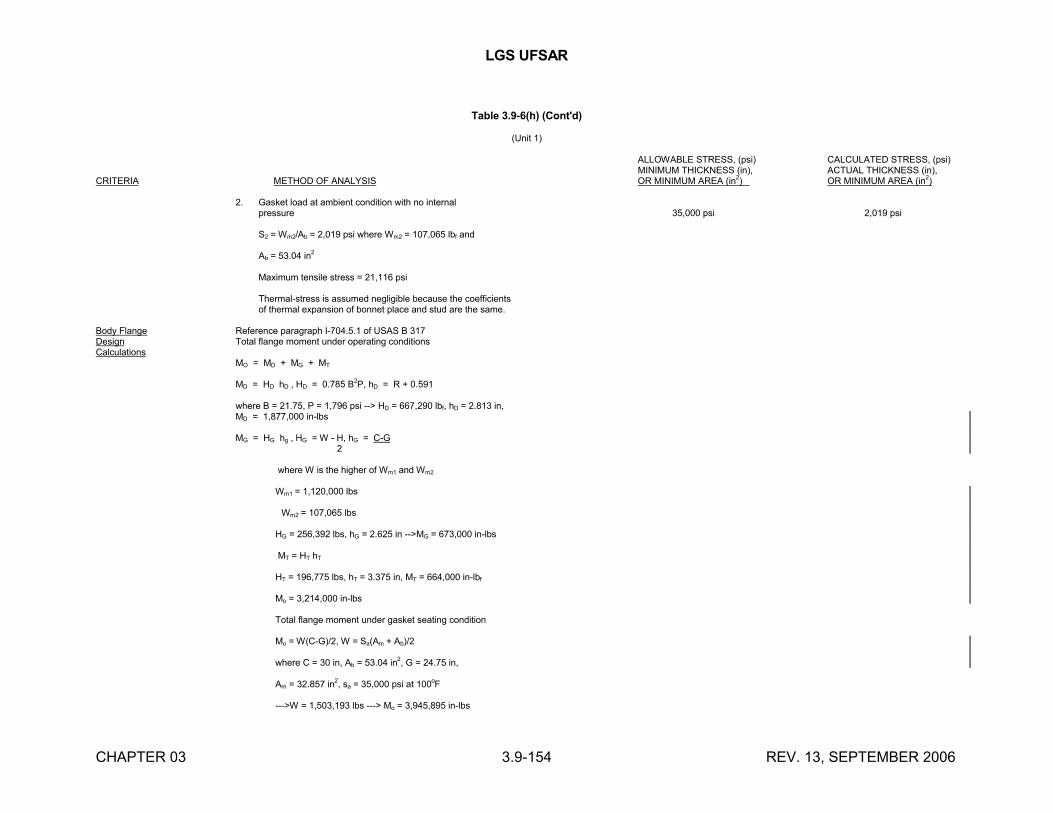
LGS UFSAR
CHAPTER 03 3.9-154 REV. 13, SEPTEMBER 2006
Table 3.9-6(h) (Cont'd)
(Unit 1)
ALLOWABLE STRESS, (psi) CALCULATED STRESS, (psi)MINIMUM THICKNESS (in), ACTUAL THICKNESS (in),
CRITERIA METHOD OF ANALYSIS OR MINIMUM AREA (in2) OR MINIMUM AREA (in2)
2. Gasket load at ambient condition with no internalpressure 35,000 psi 2,019 psi
S2 = Wm2/Ab = 2,019 psi where Wm2 = 107,065 lbf and
Ab = 53.04 in2
Maximum tensile stress = 21,116 psi
Thermal-stress is assumed negligible because the coefficientsof thermal expansion of bonnet place and stud are the same.
Body Flange Reference paragraph I-704.5.1 of USAS B 317Design Total flange moment under operating conditionsCalculations
MO = MD + MG + MT
MD = HD hD , HD = 0.785 B2P, hD = R + 0.591
where B = 21.75, P = 1,796 psi --> HD = 667,290 lbf, hD = 2.813 in,MD = 1,877,000 in-lbs
MG = HG hg , HG = W - H, hG = C-G 2
where W is the higher of Wm1 and Wm2
Wm1 = 1,120,000 lbs
Wm2 = 107,065 lbs
HG = 256,392 lbs, hG = 2.625 in -->MG = 673,000 in-lbs
MT = HT hT
HT = 196,775 lbs, hT = 3.375 in, MT = 664,000 in-lbf
Mo = 3,214,000 in-lbs
Total flange moment under gasket seating condition
Mo = W(C-G)/2, W = Sa(Am + Ab)/2
where C = 30 in, Ab = 53.04 in2, G = 24.75 in,
Am = 32.857 in2, sa = 35,000 psi at 100oF
--->W = 1,503,193 lbs ---> Mo = 3,945,895 in-lbs
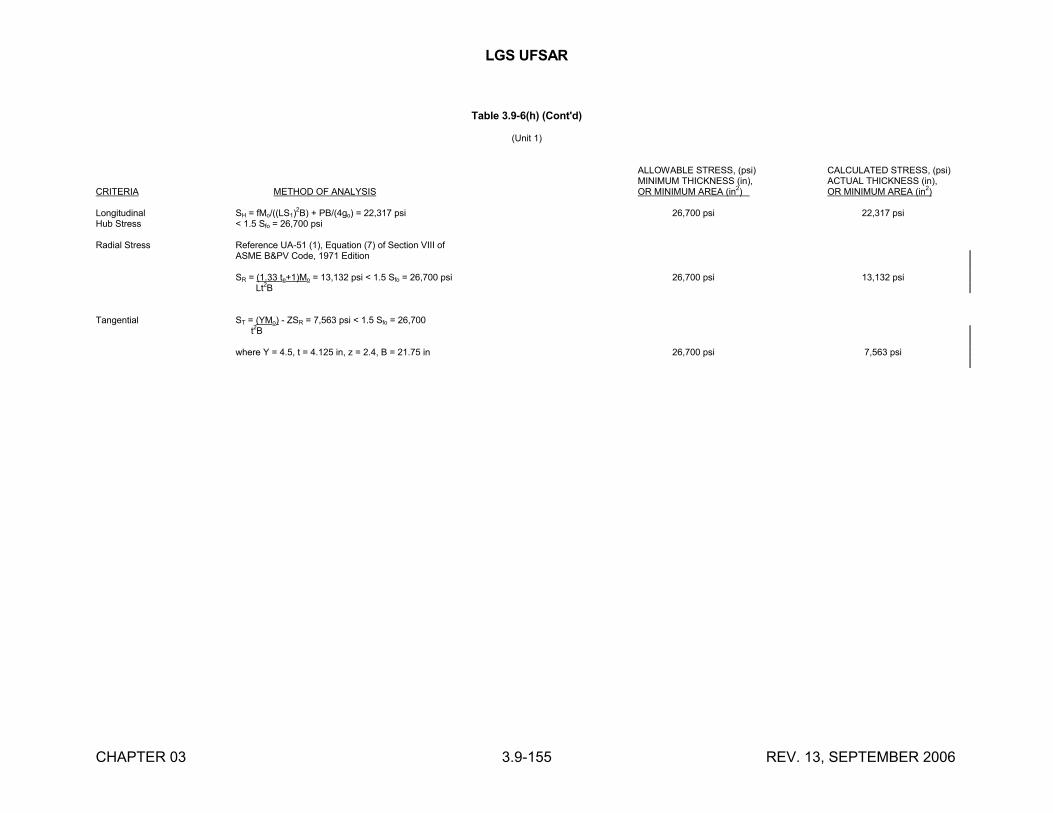
LGS UFSAR
CHAPTER 03 3.9-155 REV. 13, SEPTEMBER 2006
Table 3.9-6(h) (Cont'd)
(Unit 1)
ALLOWABLE STRESS, (psi) CALCULATED STRESS, (psi)MINIMUM THICKNESS (in), ACTUAL THICKNESS (in),
CRITERIA METHOD OF ANALYSIS OR MINIMUM AREA (in2) OR MINIMUM AREA (in2)
Longitudinal SH = fMo/((LS1)2B) + PB/(4go) = 22,317 psi 26,700 psi 22,317 psi
Hub Stress < 1.5 Sfo = 26,700 psi
Radial Stress Reference UA-51 (1), Equation (7) of Section VIII ofASME B&PV Code, 1971 Edition
SR = (1.33 te+1)Mo = 13,132 psi < 1.5 Sfo = 26,700 psi 26,700 psi 13,132 psi Lt
2B
Tangential ST = (YMo) - ZSR = 7,563 psi < 1.5 Sfo = 26,700 t
2B
where Y = 4.5, t = 4.125 in, z = 2.4, B = 21.75 in 26,700 psi 7,563 psi
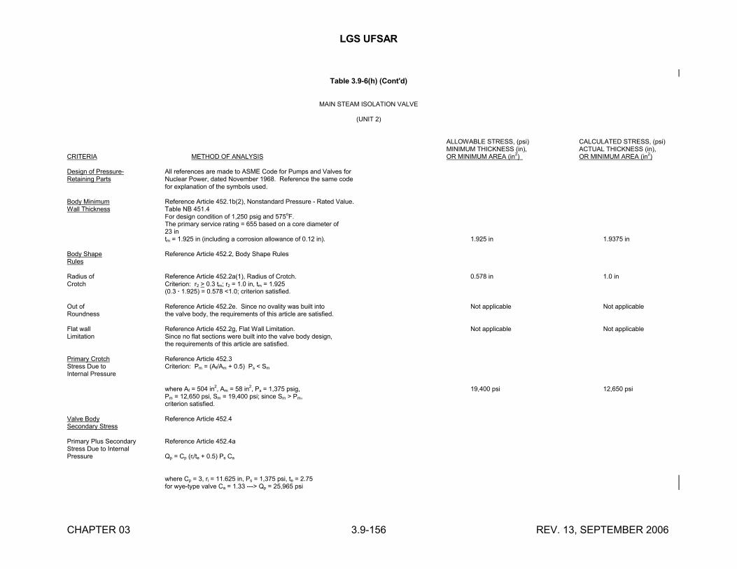
LGS UFSAR
CHAPTER 03 3.9-156 REV. 13, SEPTEMBER 2006
Table 3.9-6(h) (Cont'd)
MAIN STEAM ISOLATION VALVE
(UNIT 2)
ALLOWABLE STRESS, (psi) CALCULATED STRESS, (psi)MINIMUM THICKNESS (in), ACTUAL THICKNESS (in),
CRITERIA METHOD OF ANALYSIS OR MINIMUM AREA (in2) OR MINIMUM AREA (in2)
Design of Pressure- All references are made to ASME Code for Pumps and Valves forRetaining Parts Nuclear Power, dated November 1968. Reference the same code
for explanation of the symbols used.
Body Minimum Reference Article 452.1b(2), Nonstandard Pressure - Rated Value.Wall Thickness Table NB 451.4
For design condition of 1,250 psig and 575oF.The primary service rating = 655 based on a core diameter of 23 intm = 1.925 in (including a corrosion allowance of 0.12 in). 1.925 in 1.9375 in
Body Shape Reference Article 452.2, Body Shape RulesRules
Radius of Reference Article 452.2a(1), Radius of Crotch. 0.578 in 1.0 inCrotch Criterion: r2 > 0.3 tm; r2 = 1.0 in, tm = 1.925
(0.3 · 1.925) = 0.578 <1.0; criterion satisfied.
Out of Reference Article 452.2e. Since no ovality was built into Not applicable Not applicableRoundness the valve body, the requirements of this article are satisfied.
Flat wall Reference Article 452.2g, Flat Wall Limitation. Not applicable Not applicableLimitation Since no flat sections were built into the valve body design,
the requirements of this article are satisfied.
Primary Crotch Reference Article 452.3Stress Due to Criterion: Pm = (Af/Am + 0.5) Ps < Sm
Internal Pressure
where Af = 504 in2, Am = 58 in2, Ps = 1,375 psig, 19,400 psi 12,650 psiPm = 12,650 psi, Sm = 19,400 psi; since Sm > Pm, criterion satisfied.
Valve Body Reference Article 452.4Secondary Stress
Primary Plus Secondary Reference Article 452.4aStress Due to InternalPressure Qp = Cp (ri/te + 0.5) Ps Ca
where Cp = 3, ri = 11.625 in, Ps = 1,375 psi, te = 2.75for wye-type valve Ca = 1.33 ---> Qp = 25,965 psi

LGS UFSAR
CHAPTER 03 3.9-157 REV. 13, SEPTEMBER 2006
Table 3.9-6(h) (Cont'd)
(Unit 2)
ALLOWABLE STRESS, (psi) CALCULATED STRESS, (psi)MINIMUM THICKNESS (in), ACTUAL THICKNESS (in),
CRITERIA METHOD OF ANALYSIS OR MINIMUM AREA (in2) OR MINIMUM AREA (in2)
Secondary Stress Reference Article 452.4b, figures 452.4b(3),Due to Pipe Reaction 452.4b(4), 452.4b(5)
Direct or Ped = FdS/Gd where S = 30,750, Fd = 30 in2, Gd = 183 in2 19,400 psi 5,040 psiAxial LoadEffect
--->Ped = 5,040 psi
Bending Load Peb = Cb FbS/Gb where S = 30,750, Fb = 340 in3,Effect
i.d. = 23.25 in, ri = 11.625, te = 2.75, r = 13.90 inas te/r = .197 > .19 --->Cb = 1
Gb = I/(ri + te) where I = 15,028 in4, ri = 11.625 in,
te = 2.75 in --->Gb = 1052 in3
--->Peb = 9,940 psi 19,940 psi 9,940 psi
Torsion Load Reference Article 452.4bEffect
Pet = 2 FbS/Gt where Fb = 340 in3, S = 30,750 psi
Gt = 2,162 in3 19,400 psi 9,670 psi
Pet = 9,670 psi
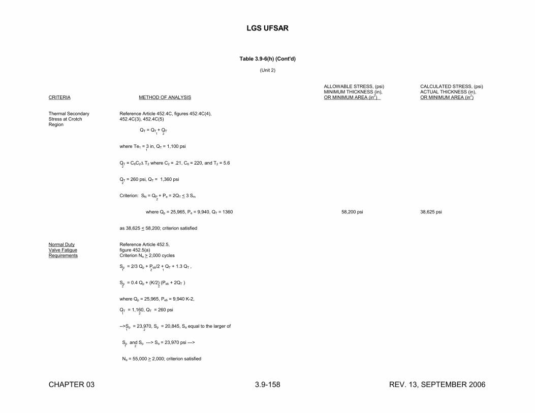
LGS UFSAR
CHAPTER 03 3.9-158 REV. 13, SEPTEMBER 2006
Table 3.9-6(h) (Cont'd)
(Unit 2)
ALLOWABLE STRESS, (psi) CALCULATED STRESS, (psi)MINIMUM THICKNESS (in), ACTUAL THICKNESS (in),
CRITERIA METHOD OF ANALYSIS OR MINIMUM AREA (in2) OR MINIMUM AREA (in2)
Thermal Secondary Reference Article 452.4C, figures 452.4C(4),Stress at Crotch 452.4C(3), 452.4C(5)Region
QT = QT + QT
1 2
where Te1 = 3 in, QT = 1,100 psi
1
QT = C6C2 T2 where C2 = .21, C6 = 220, and T2 = 5.62
QT = 260 psi, QT = 1,360 psi2
Criterion: SN = QP + Pe = 2QT < 3 Sm
2
where Qp = 25,965, Pe = 9,940, QT = 1360 58,200 psi 38,625 psi
as 38,625 < 58,200; criterion satisfied
Normal Duty Reference Article 452.5,Valve Fatigue figure 452.5(a)Requirements Criterion Na > 2,000 cycles
Sp = 2/3 Qp + Peb/2 + QT + 1.3 QT ,1 2 1
Sp = 0.4 Qp + (K/2) (Peb + 2QT )2 2
where Qp = 25,965, Peb = 9,940 K-2,
QT = 1,160, QT = 260 psi1 2
-->Sp = 23,970, Sp = 20,845, Sa equal to the larger of 1 2
Sp and Sp ---> Sa = 23,970 psi ---> 1 2
Na = 55,000 > 2,000; criterion satisfied
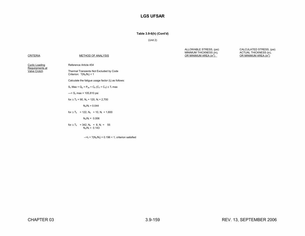
LGS UFSAR
CHAPTER 03 3.9-159 REV. 13, SEPTEMBER 2006
Table 3.9-6(h) (Cont'd)
(Unit 2)
ALLOWABLE STRESS, (psi) CALCULATED STRESS, (psi)MINIMUM THICKNESS (in), ACTUAL THICKNESS (in),
CRITERIA METHOD OF ANALYSIS OR MINIMUM AREA (in2) OR MINIMUM AREA (in2)
Cyclic Loading Reference Article 454Requirements atValve Crotch Thermal Transients Not Excluded by Code
Criterion: ?(Nri/Ni) < 1
Calculate the fatigue usage factor (It) as follows:
Sn Max = Qp + Peb + C6 (C3 + C4) Tf max
---> Sn max = 105,810 psi
for Tfi = 90, Nri = 120, Ni = 2,700
Nri/Ni = 0.044
for Tfi = 122, Nri = 10, Ni = 1,600
Nri/Ni = 0.006
for Tfi = 342, Nri = 8, Ni = 55Nri/Ni = 0.143
-->It = ?(Nri/Ni) = 0.196 < 1; criterion satisfied
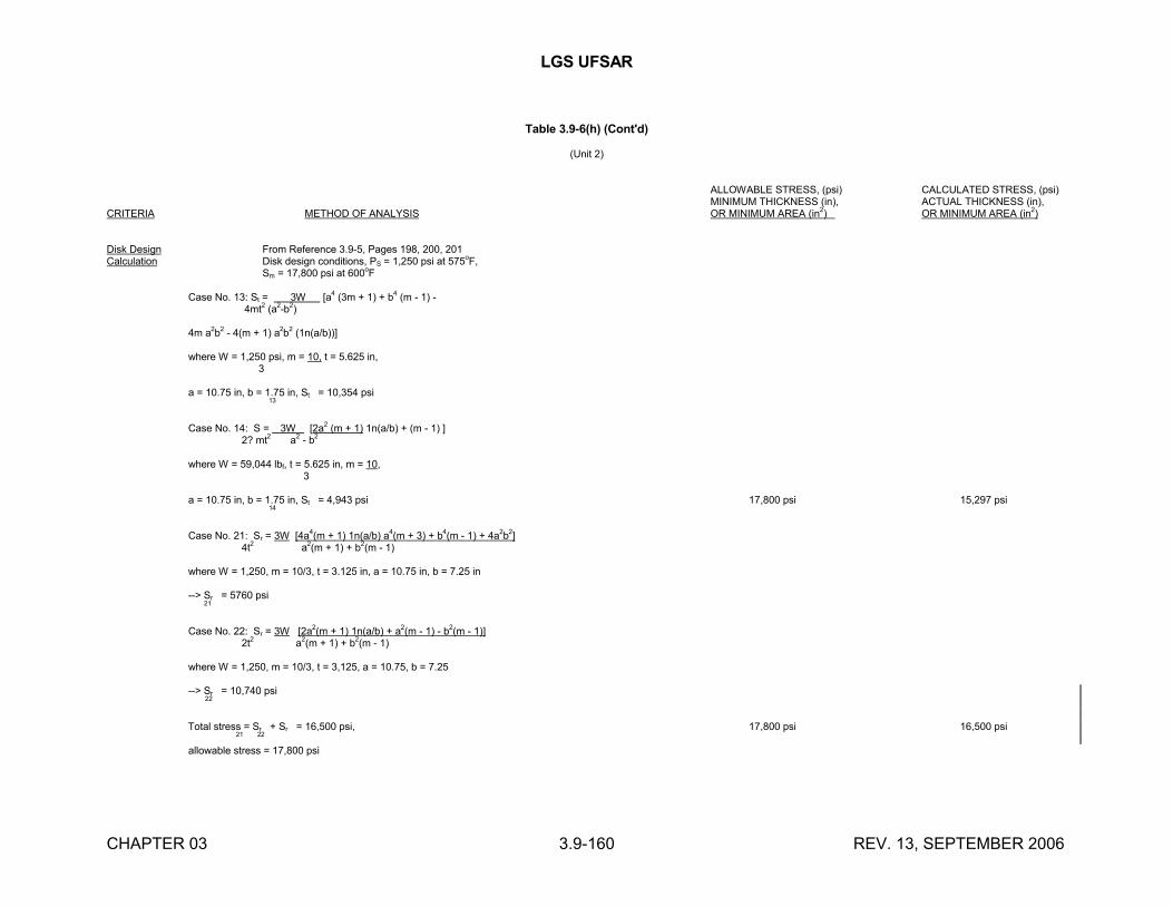
LGS UFSAR
CHAPTER 03 3.9-160 REV. 13, SEPTEMBER 2006
Table 3.9-6(h) (Cont'd)
(Unit 2)
ALLOWABLE STRESS, (psi) CALCULATED STRESS, (psi)MINIMUM THICKNESS (in), ACTUAL THICKNESS (in),
CRITERIA METHOD OF ANALYSIS OR MINIMUM AREA (in2) OR MINIMUM AREA (in2)
Disk Design From Reference 3.9-5, Pages 198, 200, 201Calculation Disk design conditions, PS = 1,250 psi at 575
oF,
Sm = 17,800 psi at 600oF
Case No. 13: St = 3W [a4 (3m + 1) + b4 (m - 1) - 4mt
2(a
2-b
2)
4m a2b
2- 4(m + 1) a
2b
2(1n(a/b))]
where W = 1,250 psi, m = 10, t = 5.625 in, 3
a = 10.75 in, b = 1.75 in, St = 10,354 psi 13
Case No. 14: S = 3W [2a2 (m + 1) 1n(a/b) + (m - 1) ] 2? mt2 a2 - b2
where W = 59,044 lbf, t = 5.625 in, m = 10, 3
a = 10.75 in, b = 1.75 in, St = 4,943 psi 17,800 psi 15,297 psi 14
Case No. 21: Sr = 3W [4a4(m + 1) 1n(a/b) a4(m + 3) + b4(m - 1) + 4a2b2] 4t2 a2(m + 1) + b2(m - 1)
where W = 1,250, m = 10/3, t = 3.125 in, a = 10.75 in, b = 7.25 in
--> Sr = 5760 psi 21
Case No. 22: Sr = 3W [2a2(m + 1) 1n(a/b) + a2(m - 1) - b2(m - 1)] 2t2 a2(m + 1) + b2(m - 1)
where W = 1,250, m = 10/3, t = 3,125, a = 10.75, b = 7.25
--> Sr = 10,740 psi 22
Total stress = Sr + Sr = 16,500 psi, 17,800 psi 16,500 psi 21 22
allowable stress = 17,800 psi
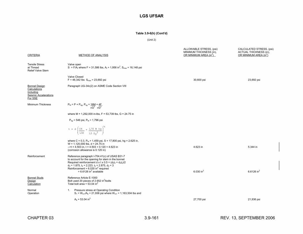
LGS UFSAR
CHAPTER 03 3.9-161 REV. 13, SEPTEMBER 2006
Table 3.9-6(h) (Cont'd)
(Unit 2)
ALLOWABLE STRESS, (psi) CALCULATED STRESS, (psi)MINIMUM THICKNESS (in), ACTUAL THICKNESS (in),
CRITERIA METHOD OF ANALYSIS OR MINIMUM AREA (in2) OR MINIMUM AREA (in2)
Tensile Stress Valve openat Thread S = F/At where F = 31,586 lbs, At = 1,956 in
2, Smax = 16,148 psi
Relief Valve Stem
Valve ClosedF = 46,342 lbs Smax = 23,692 psi 30,600 psi 23,692 psi
Bonnet Design Paragraph UG-34c(2) on ASME Code Section VIIICalculationsIncludingSeismic AccelerationsFor SSE
Minimum Thickness Pfd = P + Peg, Peg = 16M + 4F G3 G2
where M = 1,292,000 in-lbs, F = 53,739 lbs, G = 24.75 in
Peg = 546 psi, Pfd = 1,796 psi
t d CR
S
W hg
Sd
15
178
15 3.
.
.
½
where C = 0.3, Pfd = 1,459 psi, S = 17,800 psi, hg = 2.625 in,W = 1,120,000 lbs, d = 24.75 in-->t = 4.503 in, t = 4.503 + 0.120 = 4.623 in 4.623 in 5.344 in(corrosion allowance is 0.120 in)
Reinforcement Reference paragraph I-704.41(c) of USAS B31-7to account for the opening for stem in the bonnetRequired reinforcement d x t x 0.5 = (d3t3 = d4t4)/2d3 = 1.875, t4 = 2.223, t3 = 2.875, d4 = 3Reinforcement = 6.030 in2 required = 6.6126 in2 available 6.030 in2 6.6126 in2
Bonnet Studs Reference Article E-1000Design Bolt used 20 pieces of 2.652 in2/boltsCalculation Total bolt area = 53.04 in2
Normal 1. Pressure stress at Operating ConditionOperation S1 = Wm1/Ab = 21,936 psi where Wm1 = 1,163,504 lbs and
Ab = 53.04 in2 27,700 psi 21,936 psi
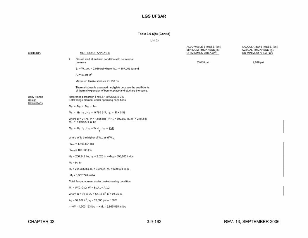
LGS UFSAR
CHAPTER 03 3.9-162 REV. 13, SEPTEMBER 2006
Table 3.9-6(h) (Cont'd)
(Unit 2)
ALLOWABLE STRESS, (psi) CALCULATED STRESS, (psi)MINIMUM THICKNESS (in), ACTUAL THICKNESS (in),
CRITERIA METHOD OF ANALYSIS OR MINIMUM AREA (in2) OR MINIMUM AREA (in2)
2. Gasket load at ambient condition with no internalpressure 35,000 psi 2,019 psi
S2 = Wm2/Ab = 2,019 psi where Wm2 = 107,065 lbf and
Ab = 53.04 in2
Maximum tensile stress = 21,116 psi
Thermal-stress is assumed negligible because the coefficientsof thermal expansion of bonnet place and stud are the same.
Body Flange Reference paragraph I-704.5.1 of USAS B 317Design Total flange moment under operating conditionsCalculations
MO = MD + MG + MT
MD = HD hD , HD = 0.785 B2P, hD = R + 0.591
where B = 21.75, P = 1,865 psi --> HD = 692,927 lbf, hD = 2.813 in,MD = 1,949,204 in-lbs
MG = HG hg , HG = W - H, hG = C-G 2
where W is the higher of Wm1 and Wm2
Wm1 = 1,163,504 lbs
Wm2 = 107,065 lbs
HG = 266,242 lbs, hG = 2.625 in -->MG = 698,885 in-lbs
MT = HT hT
HT = 204,335 lbs, hT = 3.375 in, MT = 689,631 in-lbf
Mo = 3,337,720 in-lbs
Total flange moment under gasket seating condition
Mo = W(C-G)/2, W = Sa(Am + Ab)/2
where C = 30 in, Ab = 53.04 in2, G = 24.75 in,
Am = 32.857 in2, sa = 35,000 psi at 100oF
--->W = 1,503,193 lbs ---> Mo = 3,945,895 in-lbs
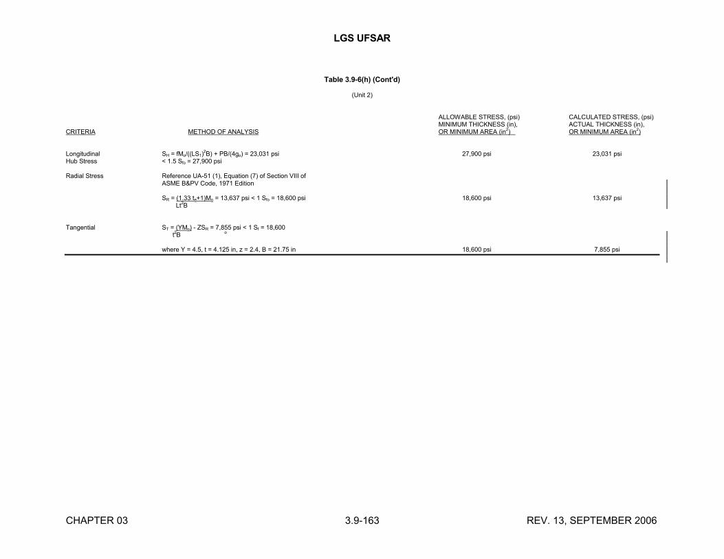
LGS UFSAR
CHAPTER 03 3.9-163 REV. 13, SEPTEMBER 2006
Table 3.9-6(h) (Cont'd)
(Unit 2)
ALLOWABLE STRESS, (psi) CALCULATED STRESS, (psi)MINIMUM THICKNESS (in), ACTUAL THICKNESS (in),
CRITERIA METHOD OF ANALYSIS OR MINIMUM AREA (in2) OR MINIMUM AREA (in2)
Longitudinal SH = fMo/((LS1)2B) + PB/(4go) = 23,031 psi 27,900 psi 23,031 psi
Hub Stress < 1.5 Sfo = 27,900 psi
Radial Stress Reference UA-51 (1), Equation (7) of Section VIII ofASME B&PV Code, 1971 Edition
SR = (1.33 te+1)Mo = 13,637 psi < 1 Sfo = 18,600 psi 18,600 psi 13,637 psi Lt
2B
Tangential ST = (YMo) - ZSR = 7,855 psi < 1 Sf = 18,600 t2B o
where Y = 4.5, t = 4.125 in, z = 2.4, B = 21.75 in 18,600 psi 7,855 psi
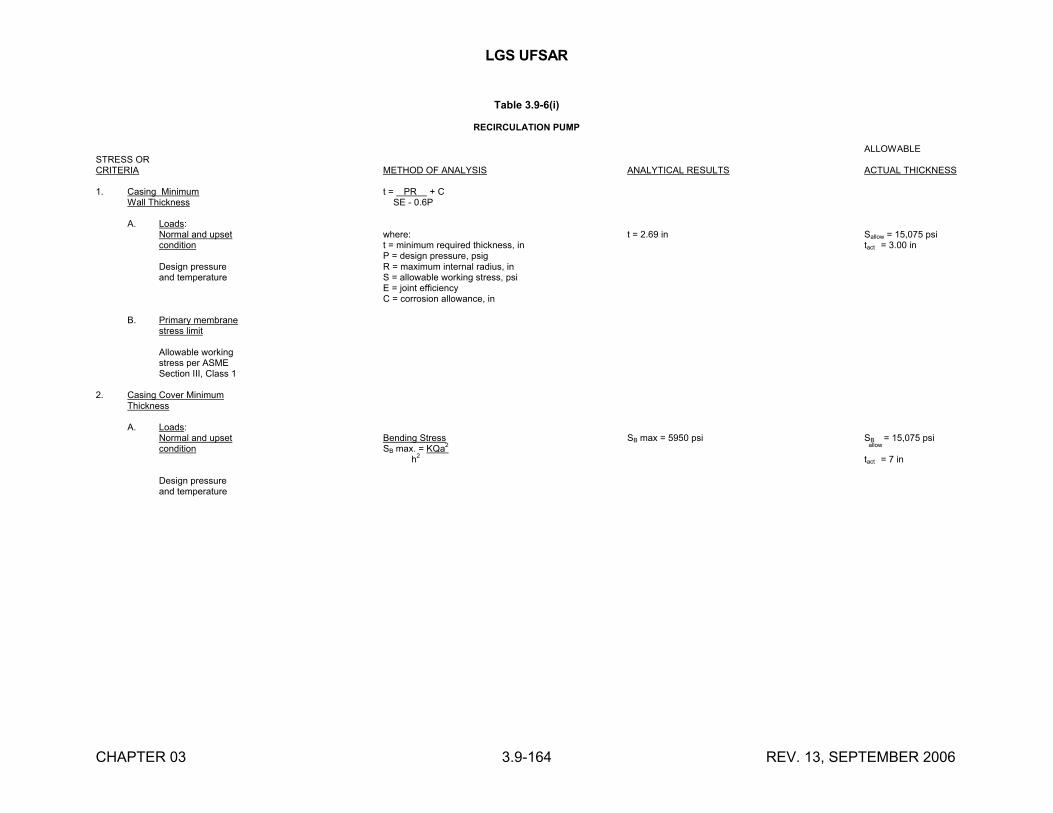
LGS UFSAR
CHAPTER 03 3.9-164 REV. 13, SEPTEMBER 2006
Table 3.9-6(i)
RECIRCULATION PUMP
ALLOWABLE STRESS ORCRITERIA METHOD OF ANALYSIS ANALYTICAL RESULTS ACTUAL THICKNESS
1. Casing Minimum t = PR + CWall Thickness SE - 0.6P
A. Loads:Normal and upset where: t = 2.69 in Sallow = 15,075 psicondition t = minimum required thickness, in tact = 3.00 in
P = design pressure, psigDesign pressure R = maximum internal radius, inand temperature S = allowable working stress, psi
E = joint efficiencyC = corrosion allowance, in
B. Primary membranestress limit
Allowable workingstress per ASMESection III, Class 1
2. Casing Cover MinimumThickness
A. Loads:Normal and upset Bending Stress SB max = 5950 psi SB = 15,075 psicondition SB max. = KQa2 allow
h2 tact = 7 in
Design pressureand temperature
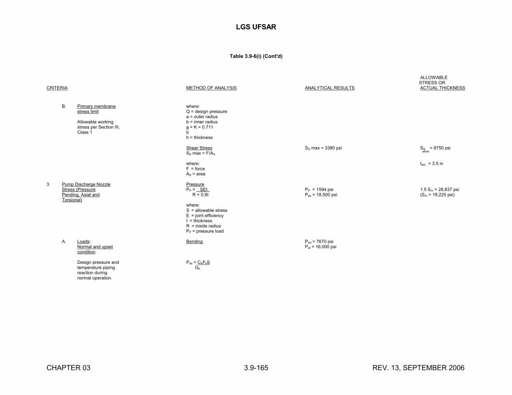
LGS UFSAR
CHAPTER 03 3.9-165 REV. 13, SEPTEMBER 2006
Table 3.9-6(i) (Cont'd)
ALLOWABLE STRESS OR
CRITERIA METHOD OF ANALYSIS ANALYTICAL RESULTS ACTUAL THICKNESS
B. Primary membrane where:stress limit Q = design pressure
a = outer radiusAllowable working b = inner radiusstress per Section III, a = K = 0.711Class 1 b
h = thickness
Shear Stress SS max = 3380 psi SS = 8750 psiSS max = F/AS
allow
where: tact = 3.5 inF = forceAS = area
3. Pump Discharge Nozzle PressureStress (Pressure PP = SEt PP = 1594 psi 1.5 Sm = 28,837 psiPending, Axial and R + 0.6t Peb = 18,500 psi (Sm = 19,225 psi)Torsional)
where:S = allowable stressE = joint efficiencyt = thicknessR = inside radiusPP = pressure load
A. Loads: Bending Ped = 7670 psiNormal and upset Pet = 16,000 psicondition
Design pressure and Peb = CbFbStemperature piping Gb
reaction duringnormal operation
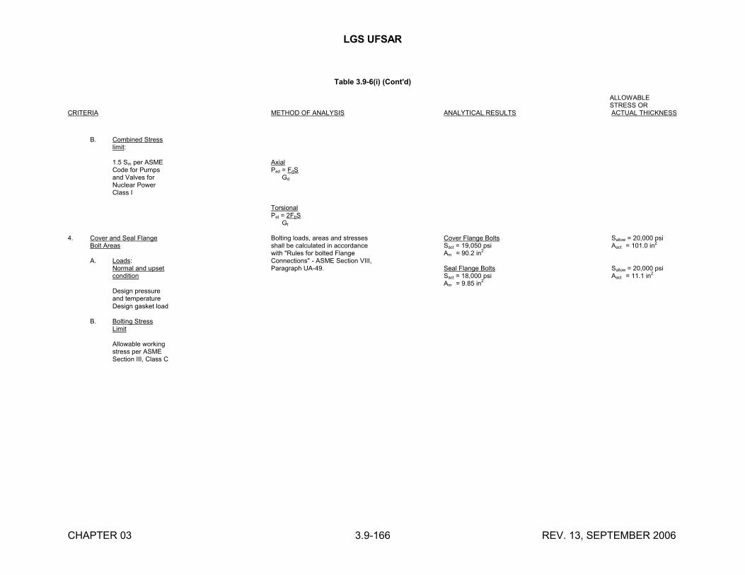
LGS UFSAR
CHAPTER 03 3.9-166 REV. 13, SEPTEMBER 2006
Table 3.9-6(i) (Cont'd)
ALLOWABLE STRESS OR
CRITERIA METHOD OF ANALYSIS ANALYTICAL RESULTS ACTUAL THICKNESS
B. Combined Stresslimit:
1.5 Sm per ASME AxialCode for Pumps Ped = FdSand Valves for Gd
Nuclear PowerClass I
TorsionalPet = 2FbS Gt
4. Cover and Seal Flange Bolting loads, areas and stresses Cover Flange Bolts Sallow = 20,000 psiBolt Areas shall be calculated in accordance Sact = 19,050 psi Aact = 101.0 in2
with "Rules for bolted Flange Am = 90.2 in2
A. Loads: Connections" - ASME Section VIII,Normal and upset Paragraph UA-49. Seal Flange Bolts Sallow = 20,000 psicondition Sact = 18,000 psi Aact = 11.1 in2
Am = 9.85 in2
Design pressureand temperatureDesign gasket load
B. Bolting StressLimit
Allowable workingstress per ASMESection III, Class C
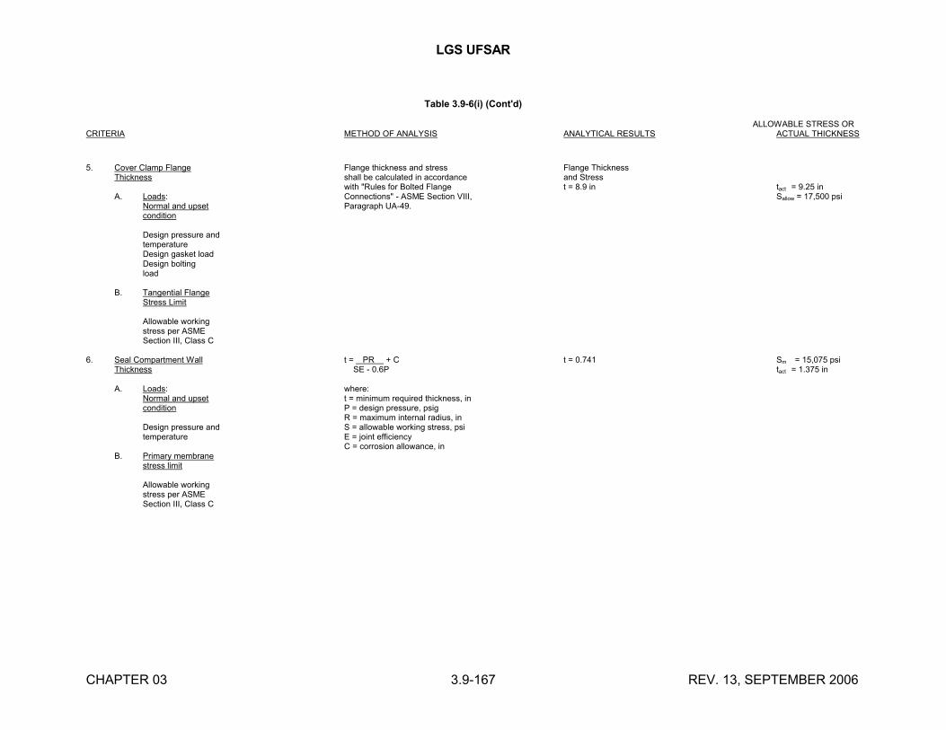
LGS UFSAR
CHAPTER 03 3.9-167 REV. 13, SEPTEMBER 2006
Table 3.9-6(i) (Cont'd)
ALLOWABLE STRESS ORCRITERIA METHOD OF ANALYSIS ANALYTICAL RESULTS ACTUAL THICKNESS
5. Cover Clamp Flange Flange thickness and stress Flange ThicknessThickness shall be calculated in accordance and Stress
with "Rules for Bolted Flange t = 8.9 in tact = 9.25 inA. Loads: Connections" - ASME Section VIII, Sallow = 17,500 psi
Normal and upset Paragraph UA-49.condition
Design pressure andtemperatureDesign gasket loadDesign boltingload
B. Tangential FlangeStress Limit
Allowable workingstress per ASMESection III, Class C
6. Seal Compartment Wall t = PR + C t = 0.741 Sm = 15,075 psiThickness SE - 0.6P tact = 1.375 in
A. Loads: where:Normal and upset t = minimum required thickness, incondition P = design pressure, psig
R = maximum internal radius, inDesign pressure and S = allowable working stress, psitemperature E = joint efficiency
C = corrosion allowance, inB. Primary membrane
stress limit
Allowable workingstress per ASMESection III, Class C
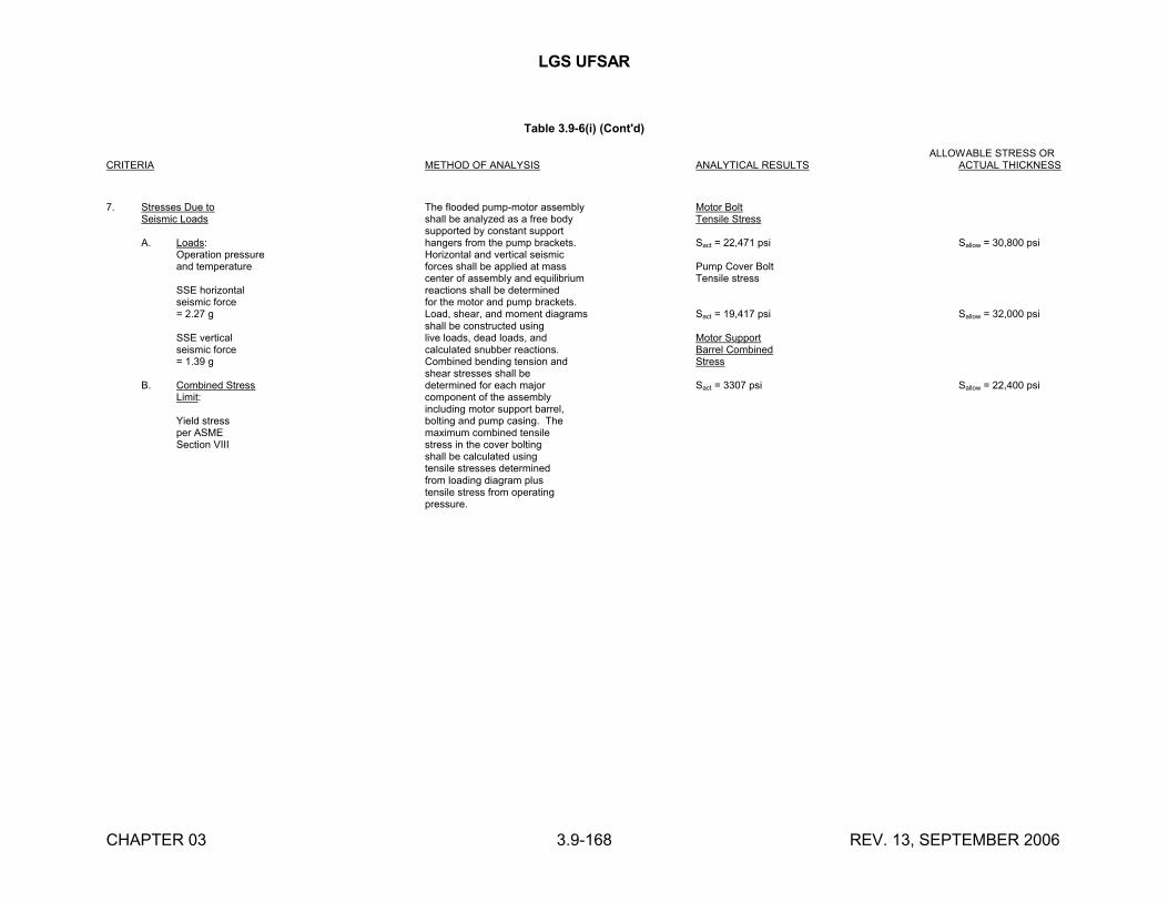
LGS UFSAR
CHAPTER 03 3.9-168 REV. 13, SEPTEMBER 2006
Table 3.9-6(i) (Cont'd)
ALLOWABLE STRESS ORCRITERIA METHOD OF ANALYSIS ANALYTICAL RESULTS ACTUAL THICKNESS
7. Stresses Due to The flooded pump-motor assembly Motor BoltSeismic Loads shall be analyzed as a free body Tensile Stress
supported by constant supportA. Loads: hangers from the pump brackets. Sact = 22,471 psi Sallow = 30,800 psi
Operation pressure Horizontal and vertical seismicand temperature forces shall be applied at mass Pump Cover Bolt
center of assembly and equilibrium Tensile stressSSE horizontal reactions shall be determinedseismic force for the motor and pump brackets.= 2.27 g Load, shear, and moment diagrams Sact = 19,417 psi Sallow = 32,000 psi
shall be constructed usingSSE vertical live loads, dead loads, and Motor Supportseismic force calculated snubber reactions. Barrel Combined= 1.39 g Combined bending tension and Stress
shear stresses shall beB. Combined Stress determined for each major Sact = 3307 psi Sallow = 22,400 psi
Limit: component of the assemblyincluding motor support barrel,
Yield stress bolting and pump casing. Theper ASME maximum combined tensileSection VIII stress in the cover bolting
shall be calculated usingtensile stresses determinedfrom loading diagram plustensile stress from operatingpressure.

LGS UFSAR
CHAPTER 03 3.9-169 REV. 13, SEPTEMBER 2006
Table 3.9-6(j)
REACTOR RECIRCULATION SYSTEM GATE VALVES,STRUCTURAL AND MECHANICAL LOADING CRITERIA
(UNIT 1)___________________________________________________________________________________________________________________________________________
COMPONENT/LOADS/ ALLOWABLE ACTUALDESIGN DESIGN PROCEDURE
(1)DESIGN VALUE
(2)DESIGN VALUE
(2)
I. 28" DISCHARGE VALVE
Body and Bonnet
Loads:Design pressure, System requirement 1525 psi 1525 psidesign temperature, not specified 575?F 575?Fpipe reaction,thermal effects
Pressure rating, Used ASME Section III pr = 800 pr = 800psi Figure NB-3545.1-2
Minimum wall Used ASME Section tm 2.1164 in tm = 2.25 minimumthickness, Para NB-3542inches
Primary membrane Used ASME Section III Pm Sm (500F) = 19,600 psi Pm = 11,068 psistress, psi Para NB-3545.1
Secondary stress Used ASME Section III Pe 1.5 Sm (500F) Ped = 5,580 psidue to pipe Para NB-3545.2 (b)(1) 1.5 (16,800) = 25,200 psi Peb = 12,702 psireaction (S = 30,000 psi) Pet = 12,277 psi
Pe = Peb=12,702 psi
Primary plus Used ASME Section III Sn 3 Sm (500F) = 58,800 psi Qp = 24,284 psisecondary stress Para NB-3545.2(a)(1)due to internalpressure
Thermal secondary Used ASME Section III Sn 3 Sm (500F) = 58,800 psi QT = 5,409 psistress Para NB-3545.2(c)
Sum of primary Used ASME Section III Sn 3 Sm (500F) = 58,800 psi Sn = Qp + Pe + 2QT
plus secondary Para NB-3545.2 = 47,804 psistress
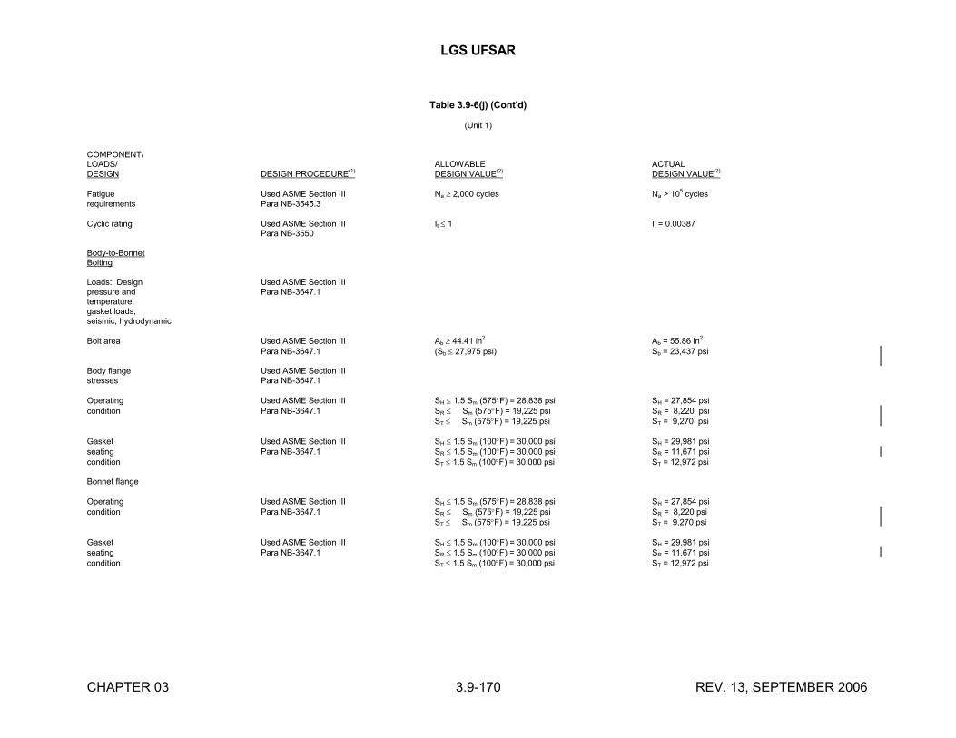
LGS UFSAR
CHAPTER 03 3.9-170 REV. 13, SEPTEMBER 2006
Table 3.9-6(j) (Cont'd)
(Unit 1)
COMPONENT/LOADS/ ALLOWABLE ACTUALDESIGN DESIGN PROCEDURE(1) DESIGN VALUE(2) DESIGN VALUE(2)
Fatigue Used ASME Section III Na 2,000 cycles Na > 105 cyclesrequirements Para NB-3545.3
Cyclic rating Used ASME Section III It 1 It = 0.00387Para NB-3550
Body-to-BonnetBolting
Loads: Design Used ASME Section IIIpressure and Para NB-3647.1temperature, gasket loads, seismic, hydrodynamic
Bolt area Used ASME Section III Ab 44.41 in2 Ab = 55.86 in2
Para NB-3647.1 (Sb 27,975 psi) Sb = 23,437 psi
Body flange Used ASME Section IIIstresses Para NB-3647.1
Operating Used ASME Section III SH 1.5 Sm (575F) = 28,838 psi SH = 27,854 psicondition Para NB-3647.1 SR Sm (575F) = 19,225 psi SR = 8,220 psi
ST Sm (575F) = 19,225 psi ST = 9,270 psi
Gasket Used ASME Section III SH 1.5 Sm (100F) = 30,000 psi SH = 29,981 psiseating Para NB-3647.1 SR 1.5 Sm (100F) = 30,000 psi SR = 11,671 psicondition ST 1.5 Sm (100F) = 30,000 psi ST = 12,972 psi
Bonnet flange
Operating Used ASME Section III SH 1.5 Sm (575F) = 28,838 psi SH = 27,854 psicondition Para NB-3647.1 SR Sm (575F) = 19,225 psi SR = 8,220 psi
ST Sm (575F) = 19,225 psi ST = 9,270 psi
Gasket Used ASME Section III SH 1.5 Sm (100F) = 30,000 psi SH = 29,981 psiseating Para NB-3647.1 SR 1.5 Sm (100F) = 30,000 psi SR = 11,671 psicondition ST 1.5 Sm (100F) = 30,000 psi ST = 12,972 psi
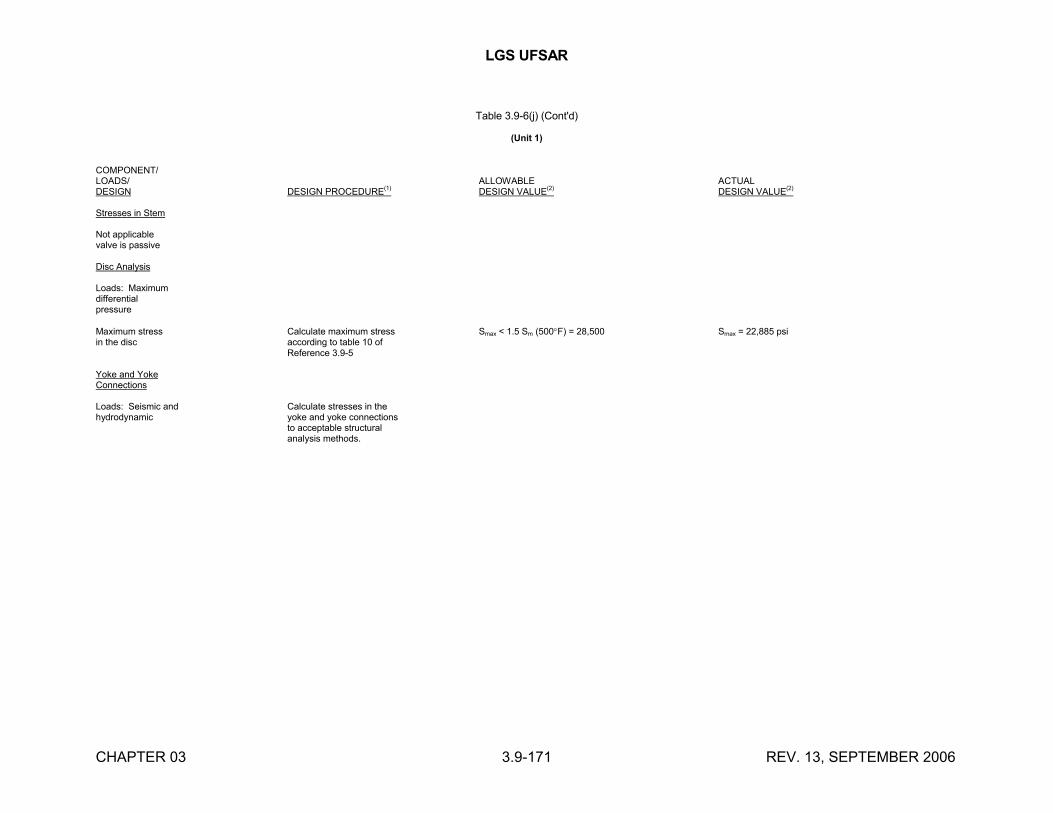
LGS UFSAR
CHAPTER 03 3.9-171 REV. 13, SEPTEMBER 2006
Table 3.9-6(j) (Cont'd)
(Unit 1)
COMPONENT/LOADS/ ALLOWABLE ACTUALDESIGN DESIGN PROCEDURE(1) DESIGN VALUE(2) DESIGN VALUE(2)
Stresses in Stem
Not applicablevalve is passive
Disc Analysis
Loads: Maximumdifferentialpressure
Maximum stress Calculate maximum stress Smax < 1.5 Sm (500F) = 28,500 Smax = 22,885 psiin the disc according to table 10 of
Reference 3.9-5
Yoke and YokeConnections
Loads: Seismic and Calculate stresses in thehydrodynamic yoke and yoke connections
to acceptable structuralanalysis methods.
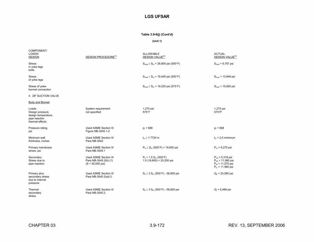
LGS UFSAR
CHAPTER 03 3.9-172 REV. 13, SEPTEMBER 2006
Table 3.9-6(j) (Cont'd)
(Unit 1)
COMPONENT/LOADS/ ALLOWABLE ACTUALDESIGN DESIGN PROCEDURE(1) DESIGN VALUE(2) DESIGN VALUE(2)
Stress Smax Sm = 28,800 psi (500F) Smax = 9,767 psiin yoke legsbolts
Stress Smax Sm = 19,400 psi (500F) Smax = 13,949 psiof yoke legs
Stress of yoke- Smax Sm = 19,225 psi (575F) Smax = 15,650 psibonnet connection
II. 28" SUCTION VALVE
Body and Bonnet
Loads: System requirement 1,275 psi 1,275 psiDesign pressure, not specified 575F 575?Fdesign temperature,pipe reactionthermal effects
Pressure rating, Used ASME Section III pr = 668 pr = 668psi Figure NB-3545.1-2
Minimum wall Used ASME Section III tm 1.7724 in tm = 2.0 minimumthickness, inches Para NB-3542
Primary membrane Used ASME Section III Pm Sm (500F) = 19,600 psi Pm = 9,275 psistress, psi Para NB-3545.1
Secondary Used ASME Section III Pe < 1.5 Sm (500F) Ped = 5,318 psiStress due to Para NB-3545.2(b) (1) 1.5 (16,800) = 25,200 psi Peb = 11,980 psipipe reaction (S = 30,000 psi) Pet = 11,575 psi
Pe = 11,980 psi
Primary plus Used ASME Section III Sn 3 Sm (500F) - 58,800 psi Qp = 20,580 psisecondary stress Para NB-3545.2(a)(1)due to internalpressure
Thermal Used ASME Section III Sn 3 Sm (500F) - 58,800 psi Qt = 5,489 psisecondary Para NB-3545.2stress
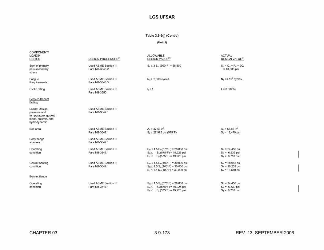
LGS UFSAR
CHAPTER 03 3.9-173 REV. 13, SEPTEMBER 2006
Table 3.9-6(j) (Cont'd)
(Unit 1)
COMPONENT/LOADS/ ALLOWABLE ACTUALDESIGN DESIGN PROCEDURE(1) DESIGN VALUE(2) DESIGN VALUE(2)
Sum of primary Used ASME Section III Sn 3 Sm (500F) = 58,800 Sn = Qp + Pe + 2Qt
plus secondary Para NB-3545.2 = 43,538 psistress
Fatigue Used ASME Section III Na 2,000 cycles Na = >106
cyclesRequirements Para NB-3545.3
Cyclic rating Used ASME Section III It 1 It = 0.00274Para NB-3550
Body-to-BonnetBolting
Loads: Design Used ASME Section IIIpressure and Para NB-3647.1temperature, gasketloads, seismic, andhydrodynamic
Bolt area Used ASME Section III Ab 37.53 in2 Ab = 55.86 in2
Para NB-3647.1 Sb 27,975 psi (575F) Sb = 19,470 psi
Body flange Used ASME Section IIIstresses Para NB-3647.1
Operating Used ASME Section III SH 1.5 Sm(575F) = 28,838 psi SH = 24,456 psicondition Para NB-3647.1 SR Sm(575F) = 19,225 psi SR = 6,539 psi
ST Sm(575F) = 19,225 psi ST = 8,718 psi
Gasket seating Used ASME Section III SH 1.5 Sm(100F) = 30,000 psi SH = 28,945 psicondition Para NB-3647.1 SR 1.5 Sm(100F) = 30,000 psi SR = 10,253 psi
ST 1.5 Sm(100F) = 30,000 psi ST = 13,619 psi
Bonnet flange
Operating Used ASME Section III SH 1.5 Sm(575F) = 28,838 psi SH = 24,456 psicondition Para NB-3647.1 SR Sm(575F) = 19,225 psi SR = 6,539 psi
ST Sm(575F) = 19,225 psi ST = 8,718 psi
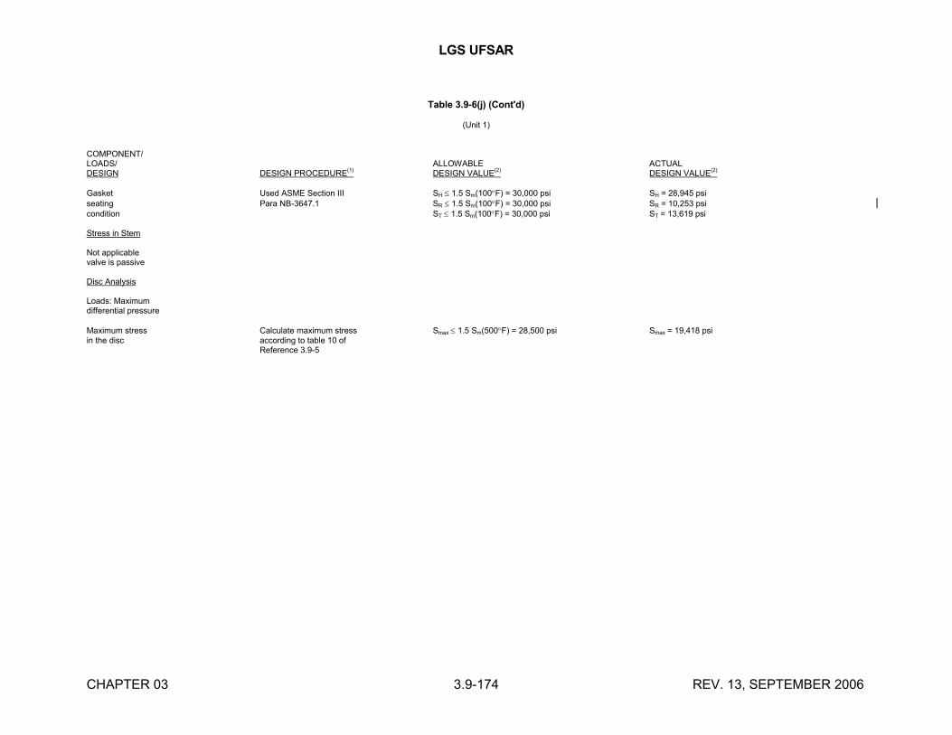
LGS UFSAR
CHAPTER 03 3.9-174 REV. 13, SEPTEMBER 2006
Table 3.9-6(j) (Cont'd)
(Unit 1)
COMPONENT/LOADS/ ALLOWABLE ACTUALDESIGN DESIGN PROCEDURE(1) DESIGN VALUE(2) DESIGN VALUE(2)
Gasket Used ASME Section III SH 1.5 Sm(100F) = 30,000 psi SH = 28,945 psiseating Para NB-3647.1 SR 1.5 Sm(100F) = 30,000 psi SR = 10,253 psicondition ST 1.5 Sm(100F) = 30,000 psi ST = 13,619 psi
Stress in Stem
Not applicablevalve is passive
Disc Analysis
Loads: Maximumdifferential pressure
Maximum stress Calculate maximum stress Smax 1.5 Sm(500F) = 28,500 psi Smax = 19,418 psiin the disc according to table 10 of
Reference 3.9-5
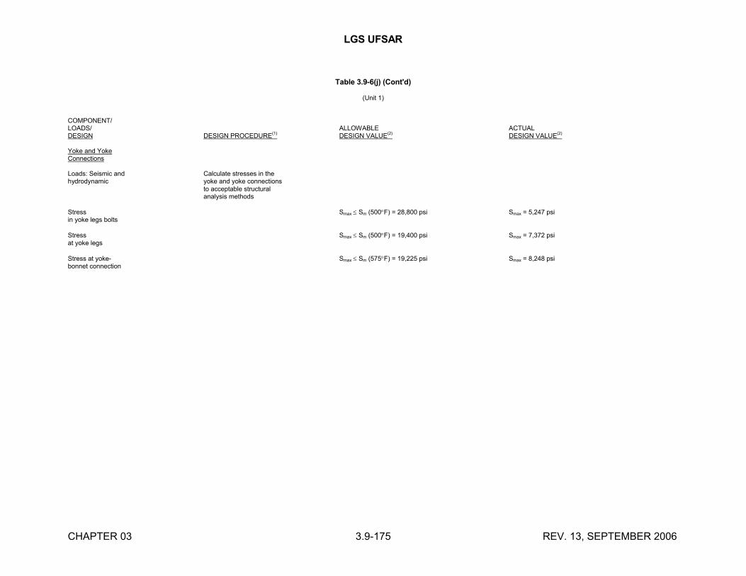
LGS UFSAR
CHAPTER 03 3.9-175 REV. 13, SEPTEMBER 2006
Table 3.9-6(j) (Cont'd)
(Unit 1)
COMPONENT/LOADS/ ALLOWABLE ACTUALDESIGN DESIGN PROCEDURE(1) DESIGN VALUE(2) DESIGN VALUE(2)
Yoke and YokeConnections
Loads: Seismic and Calculate stresses in thehydrodynamic yoke and yoke connections
to acceptable structuralanalysis methods
Stress Smax Sm (500F) = 28,800 psi Smax = 5,247 psiin yoke legs bolts
Stress Smax Sm (500F) = 19,400 psi Smax = 7,372 psiat yoke legs
Stress at yoke- Smax Sm (575F) = 19,225 psi Smax = 8,248 psibonnet connection
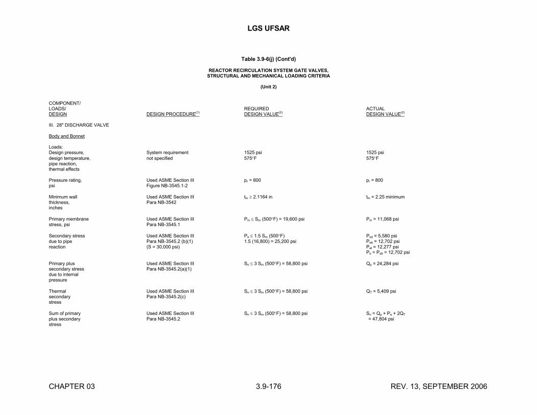
LGS UFSAR
CHAPTER 03 3.9-176 REV. 13, SEPTEMBER 2006
Table 3.9-6(j) (Cont'd)
REACTOR RECIRCULATION SYSTEM GATE VALVES,STRUCTURAL AND MECHANICAL LOADING CRITERIA
(Unit 2)
COMPONENT/LOADS/ REQUIRED ACTUALDESIGN DESIGN PROCEDURE(1) DESIGN VALUE(2) DESIGN VALUE(2)
III. 28" DISCHARGE VALVE
Body and Bonnet
Loads:Design pressure, System requirement 1525 psi 1525 psidesign temperature, not specified 575F 575Fpipe reaction,thermal effects
Pressure rating, Used ASME Section III pr = 800 pr = 800psi Figure NB-3545.1-2
Minimum wall Used ASME Section III tm 2.1164 in tm = 2.25 minimumthickness, Para NB-3542inches
Primary membrane Used ASME Section III Pm Sm (500F) = 19,600 psi Pm = 11,068 psistress, psi Para NB-3545.1
Secondary stress Used ASME Section III Pe 1.5 Sm (500F) Ped = 5,580 psidue to pipe Para NB-3545.2 (b)(1) 1.5 (16,800) = 25,200 psi Peb = 12,702 psireaction (S = 30,000 psi) Pet = 12,277 psi
Pe = Peb = 12,702 psi
Primary plus Used ASME Section III Sn 3 Sm (500F) = 58,800 psi Qp = 24,284 psisecondary stress Para NB-3545.2(a)(1)due to internalpressure
Thermal Used ASME Section III Sn 3 Sm (500F) = 58,800 psi QT = 5,409 psisecondary Para NB-3545.2(c)stress
Sum of primary Used ASME Section III Sn 3 Sm (500F) = 58,800 psi Sn = Qp + Pe + 2QT
plus secondary Para NB-3545.2 = 47,804 psistress
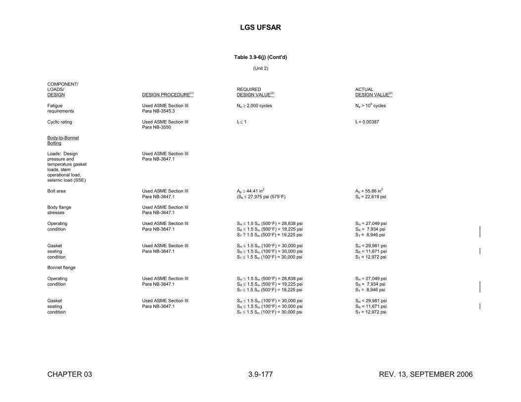
LGS UFSAR
CHAPTER 03 3.9-177 REV. 13, SEPTEMBER 2006
Table 3.9-6(j) (Cont'd)
(Unit 2)
COMPONENT/LOADS/ REQUIRED ACTUALDESIGN DESIGN PROCEDURE(1) DESIGN VALUE(2) DESIGN VALUE(2)
Fatigue Used ASME Section III Na 2,000 cycles Na > 105 cyclesrequirements Para NB-3545.3
Cyclic rating Used ASME Section III It 1 It = 0.00387Para NB-3550
Body-to-BonnetBolting
Loads: Design Used ASME Section IIIpressure and Para NB-3647.1temperature gasketloads, stemoperational load,seismic load (SSE)
Bolt area Used ASME Section III Ab 44.41 in2 Ab = 55.86 in2
Para NB-3647.1 (Sb 27,975 psi (575F) Sb = 22,619 psi
Body flange Used ASME Section IIIstresses Para NB-3647.1
Operating Used ASME Section III SH 1.5 Sm (500F) = 28,838 psi SH = 27,049 psicondition Para NB-3647.1 SR 1.5 Sm (500F) = 19,225 psi SR = 7,934 psi
ST ? 1.5 Sm (500F) = 19,225 psi ST = 8,946 psi
Gasket Used ASME Section III SH 1.5 Sm (100F) = 30,000 psi SH = 29,981 psiseating Para NB-3647.1 SR 1.5 Sm (100F) = 30,000 psi SR = 11,671 psicondition ST 1.5 Sm (100F) = 30,000 psi ST = 12,972 psi
Bonnet flange
Operating Used ASME Section III SH 1.5 Sm (500F) = 28,838 psi SH = 27,049 psicondition Para NB-3647.1 SR 1.5 Sm (500F) = 19,225 psi SR = 7,934 psi
ST 1.5 Sm (500F) = 19,225 psi ST = 8,946 psi
Gasket Used ASME Section III SH 1.5 Sm (100F) = 30,000 psi SH = 29,981 psiseating Para NB-3647.1 SR 1.5 Sm (100F) = 30,000 psi SR = 11,671 psicondition ST 1.5 Sm (100F) = 30,000 psi ST = 12,972 psi
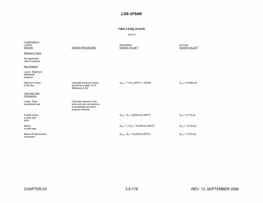
LGS UFSAR
CHAPTER 03 3.9-178 REV. 13, SEPTEMBER 2006
Table 3.9-6(j) (Cont'd)
(Unit 2)
COMPONENT/LOADS/ REQUIRED ACTUALDESIGN DESIGN PROCEDURE DESIGN VALUE(2) DESIGN VALUE(2)
Stresses in Stem
Not applicable,valve is passive
Disc Analysis
Loads: Maximumdifferentialpressure
Maximum stress Calculate maximum stress Smax < 1.5 Sm (500F) = 28,500 Smax = 22,885 psiin the disc according to table 10 of
Reference 3.9-5
Yoke and YokeConnections
Loads: Stem Calculate stresses in theoperational load yoke and yoke connections
to acceptable structuralanalysis methods.
Tensile stress Smax Sm = 28,800 psi (500F) Smax = 3,716 psiin yoke legsbolts
Stress Smax 1.5 Sm = 19,400 psi (500F) Smax = 5,145 psiof yoke legs
Stress of yoke-bonnet Smax Sm = 19,225 psi (575F) Smax = 5,741 psiconnection
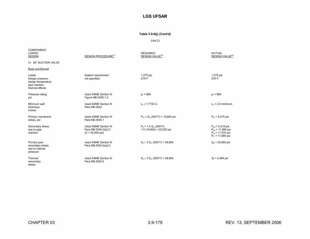
LGS UFSAR
CHAPTER 03 3.9-179 REV. 13, SEPTEMBER 2006
Table 3.9-6(j) (Cont'd)
(Unit 2)
COMPONENT/LOADS/ REQUIRED ACTUALDESIGN DESIGN PROCEDURE(1) DESIGN VALUE(2) DESIGN VALUE(2)
IV. 28" SUCTION VALVE
Body and Bonnet
Loads: System requirement 1,275 psi 1,275 psiDesign pressure, not specified 575F 575Fdesign temperaturepipe reactionthermal effects
Pressure rating, Used ASME Section III pr = 668 pr = 668psi Figure NB-3545.1-2
Minimum wall Used ASME Section III tm 1.7724 in tm = 2.0 minimumthickness, Para NB-3542inches
Primary membrane Used ASME Section III Pm Sm (500F) = 19,600 psi Pm = 9,275 psistress, psi Para NB-3545.1
Secondary stress Used ASME Section III Pe < 1.5 Sm (500F) Ped = 5,318 psidue to pipe Para NB-3545.2(b)(1) 1.5 (16,800) = 25,200 psi Peb = 11,980 psireaction (S = 30,000 psi) Pet = 11,575 psi
Pe = 11,980 psi
Primary plus Used ASME Section III Sn 3 Sm (500F) = 58,800 Qp = 20,580 psisecondary stress Para NB-3545.2(a)(1)due to internalpressure
Thermal Used ASME Section III Sn 3 Sm (500F) = 58,800 Qt = 5,489 psisecondary Para NB-3545.2stress
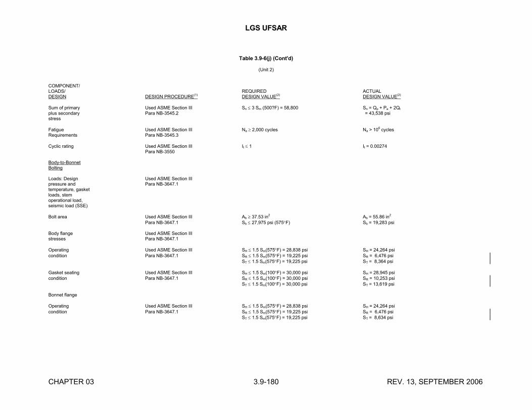
LGS UFSAR
CHAPTER 03 3.9-180 REV. 13, SEPTEMBER 2006
Table 3.9-6(j) (Cont'd)
(Unit 2)
COMPONENT/LOADS/ REQUIRED ACTUALDESIGN DESIGN PROCEDURE(1) DESIGN VALUE(2) DESIGN VALUE(2)
Sum of primary Used ASME Section III Sn 3 Sm (500?F) = 58,800 Sn = Qp + Pe + 2Qt
plus secondary Para NB-3545.2 = 43,538 psistress
Fatigue Used ASME Section III Na 2,000 cycles Na > 106
cyclesRequirements Para NB-3545.3
Cyclic rating Used ASME Section III It 1 It = 0.00274Para NB-3550
Body-to-BonnetBolting
Loads: Design Used ASME Section IIIpressure and Para NB-3647.1temperature, gasketloads, stemoperational load,seismic load (SSE)
Bolt area Used ASME Section III Ab 37.53 in2 Ab = 55.86 in2
Para NB-3647.1 Sb 27,975 psi (575F) Sb = 19,283 psi
Body flange Used ASME Section IIIstresses Para NB-3647.1
Operating Used ASME Section III SH 1.5 Sm(575F) = 28,838 psi SH = 24,264 psicondition Para NB-3647.1 SR 1.5 Sm(575F) = 19,225 psi SR = 6,476 psi
ST 1.5 Sm(575F) = 19,225 psi ST = 8,364 psi
Gasket seating Used ASME Section III SH 1.5 Sm(100F) = 30,000 psi SH = 28,945 psicondition Para NB-3647.1 SR 1.5 Sm(100F) = 30,000 psi SR = 10,253 psi
ST 1.5 Sm(100F) = 30,000 psi ST = 13,619 psi
Bonnet flange
Operating Used ASME Section III SH 1.5 Sm(575F) = 28,838 psi SH = 24,264 psicondition Para NB-3647.1 SR 1.5 Sm(575F) = 19,225 psi SR = 6,476 psi
ST 1.5 Sm(575F) = 19,225 psi ST = 8,634 psi
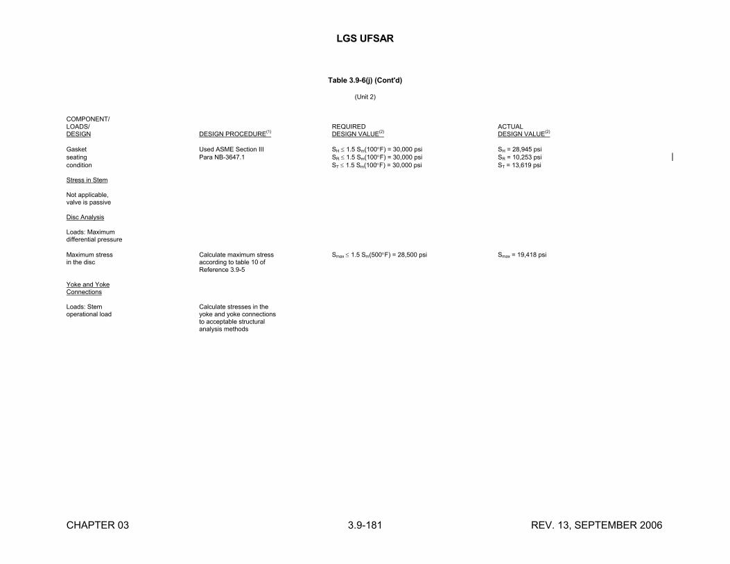
LGS UFSAR
CHAPTER 03 3.9-181 REV. 13, SEPTEMBER 2006
Table 3.9-6(j) (Cont'd)
(Unit 2)
COMPONENT/LOADS/ REQUIRED ACTUALDESIGN DESIGN PROCEDURE
(1)DESIGN VALUE
(2)DESIGN VALUE
(2)
Gasket Used ASME Section III SH 1.5 Sm(100F) = 30,000 psi SH = 28,945 psiseating Para NB-3647.1 SR 1.5 Sm(100F) = 30,000 psi SR = 10,253 psicondition ST 1.5 Sm(100F) = 30,000 psi ST = 13,619 psi
Stress in Stem
Not applicable,valve is passive
Disc Analysis
Loads: Maximumdifferential pressure
Maximum stress Calculate maximum stress Smax 1.5 Sm(500F) = 28,500 psi Smax = 19,418 psiin the disc according to table 10 of
Reference 3.9-5
Yoke and YokeConnections
Loads: Stem Calculate stresses in theoperational load yoke and yoke connections
to acceptable structuralanalysis methods
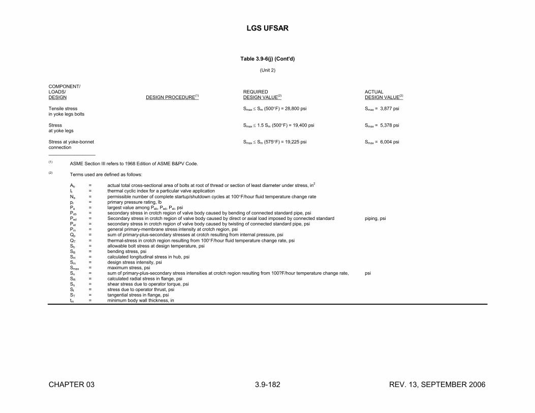
LGS UFSAR
CHAPTER 03 3.9-182 REV. 13, SEPTEMBER 2006
Table 3.9-6(j) (Cont'd)
(Unit 2)
COMPONENT/LOADS/ REQUIRED ACTUALDESIGN DESIGN PROCEDURE(1) DESIGN VALUE(2) DESIGN VALUE(2)
Tensile stress Smax Sm (500F) = 28,800 psi Smax = 3,877 psiin yoke legs bolts
Stress Smax 1.5 Sm (500F) = 19,400 psi Smax = 5,378 psiat yoke legs
Stress at yoke-bonnet Smax Sm (575F) = 19,225 psi Smax = 6,004 psiconnection__________________
(1)ASME Section III refers to 1968 Edition of ASME B&PV Code.
(2) Terms used are defined as follows:
Ab = actual total cross-sectional area of bolts at root of thread or section of least diameter under stress, in2
It = thermal cyclic index for a particular valve applicationNa = permissible number of complete startup/shutdown cycles at 100F/hour fluid temperature change ratepr = primary pressure rating, lbPe = largest value among Peb, Ped, Pet, psiPeb = secondary stress in crotch region of valve body caused by bending of connected standard pipe, psiPed = Secondary stress in crotch region of valve body caused by direct or axial load imposed by connected standard piping, psiPet = secondary stress in crotch region of valve body caused by twisting of connected standard pipe, psiPm = general primary-membrane stress intensity at crotch region, psiQp = sum of primary-plus-secondary stresses at crotch resulting from internal pressure, psiQT = thermal-stress in crotch region resulting from 100F/hour fluid temperature change rate, psiSb = allowable bolt stress at design temperature, psiSB = bending stress, psiSH = calculated longitudinal stress in hub, psiSm = design stress intensity, psiSmax = maximum stress, psiSn = sum of primary-plus-secondary stress intensities at crotch region resulting from 100?F/hour temperature change rate, psiSR = calculated radial stress in flange, psiSs = shear stress due to operator torque, psiSt = stress due to operator thrust, psiST = tangential stress in flange, psitm = minimum body wall thickness, in
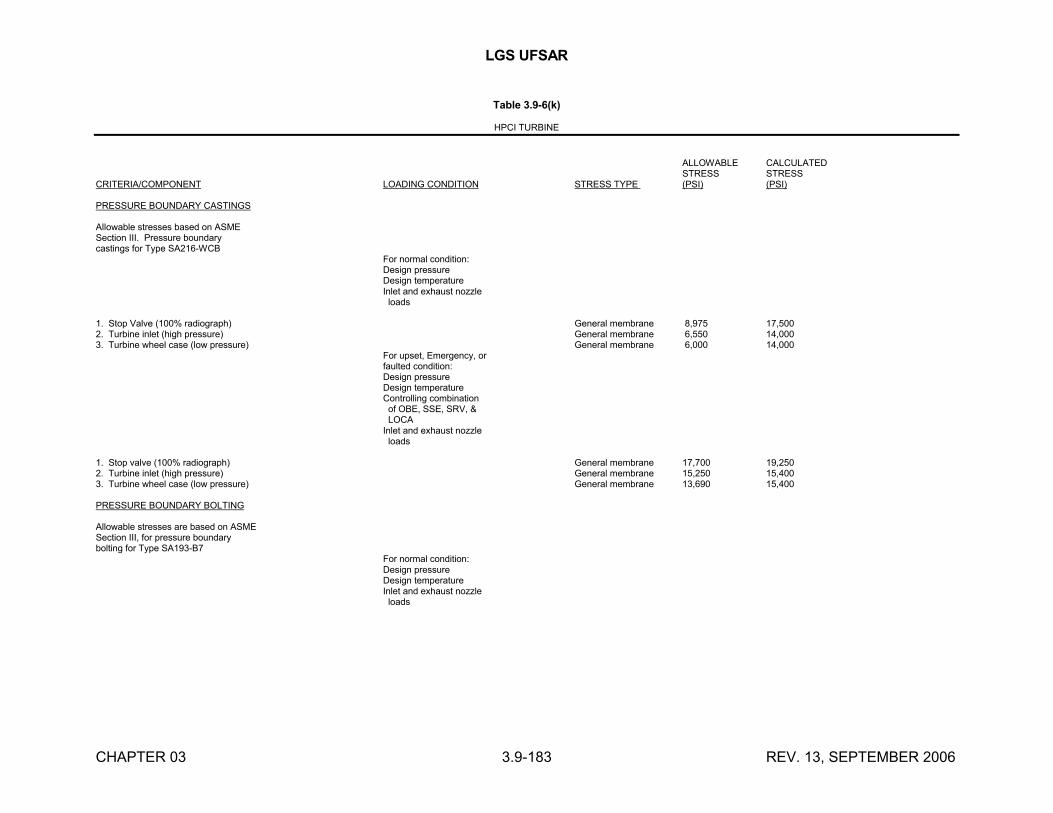
LGS UFSAR
CHAPTER 03 3.9-183 REV. 13, SEPTEMBER 2006
Table 3.9-6(k)
HPCI TURBINE
ALLOWABLE CALCULATEDSTRESS STRESS
CRITERIA/COMPONENT LOADING CONDITION STRESS TYPE (PSI) (PSI)
PRESSURE BOUNDARY CASTINGS
Allowable stresses based on ASMESection III. Pressure boundarycastings for Type SA216-WCB
For normal condition:Design pressureDesign temperatureInlet and exhaust nozzle loads
1. Stop Valve (100% radiograph) General membrane 8,975 17,5002. Turbine inlet (high pressure) General membrane 6,550 14,0003. Turbine wheel case (low pressure) General membrane 6,000 14,000
For upset, Emergency, orfaulted condition:Design pressureDesign temperatureControlling combination of OBE, SSE, SRV, & LOCAInlet and exhaust nozzle loads
1. Stop valve (100% radiograph) General membrane 17,700 19,2502. Turbine inlet (high pressure) General membrane 15,250 15,4003. Turbine wheel case (low pressure) General membrane 13,690 15,400
PRESSURE BOUNDARY BOLTING
Allowable stresses are based on ASMESection III, for pressure boundarybolting for Type SA193-B7
For normal condition:Design pressureDesign temperatureInlet and exhaust nozzle loads
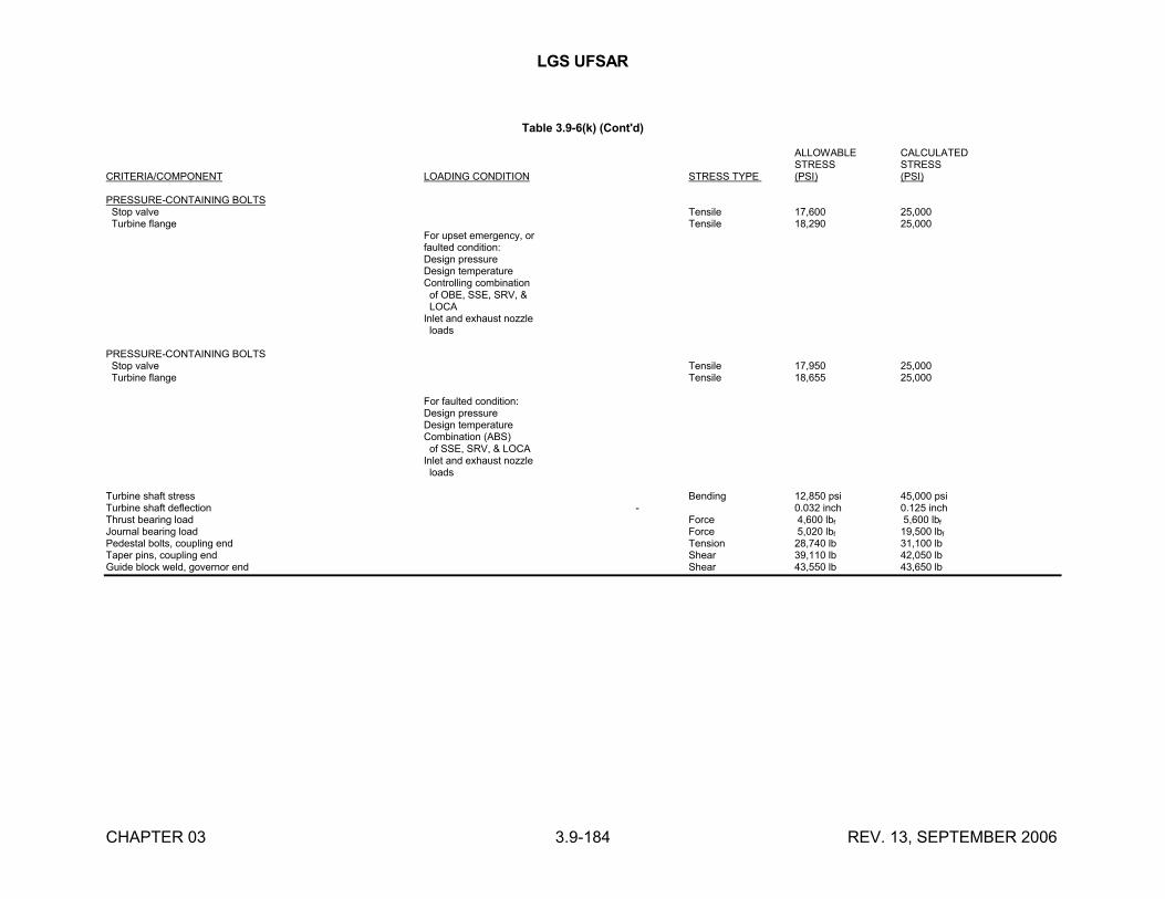
LGS UFSAR
CHAPTER 03 3.9-184 REV. 13, SEPTEMBER 2006
Table 3.9-6(k) (Cont'd)
ALLOWABLE CALCULATEDSTRESS STRESS
CRITERIA/COMPONENT LOADING CONDITION STRESS TYPE (PSI) (PSI)
PRESSURE-CONTAINING BOLTS Stop valve Tensile 17,600 25,000 Turbine flange Tensile 18,290 25,000
For upset emergency, orfaulted condition:Design pressureDesign temperatureControlling combination of OBE, SSE, SRV, & LOCAInlet and exhaust nozzle loads
PRESSURE-CONTAINING BOLTS Stop valve Tensile 17,950 25,000 Turbine flange Tensile 18,655 25,000
For faulted condition:Design pressureDesign temperatureCombination (ABS) of SSE, SRV, & LOCAInlet and exhaust nozzle loads
Turbine shaft stress Bending 12,850 psi 45,000 psiTurbine shaft deflection - 0.032 inch 0.125 inchThrust bearing load Force 4,600 lbf 5,600 lbf
Journal bearing load Force 5,020 lbf 19,500 lbf
Pedestal bolts, coupling end Tension 28,740 lb 31,100 lbTaper pins, coupling end Shear 39,110 lb 42,050 lbGuide block weld, governor end Shear 43,550 lb 43,650 lb
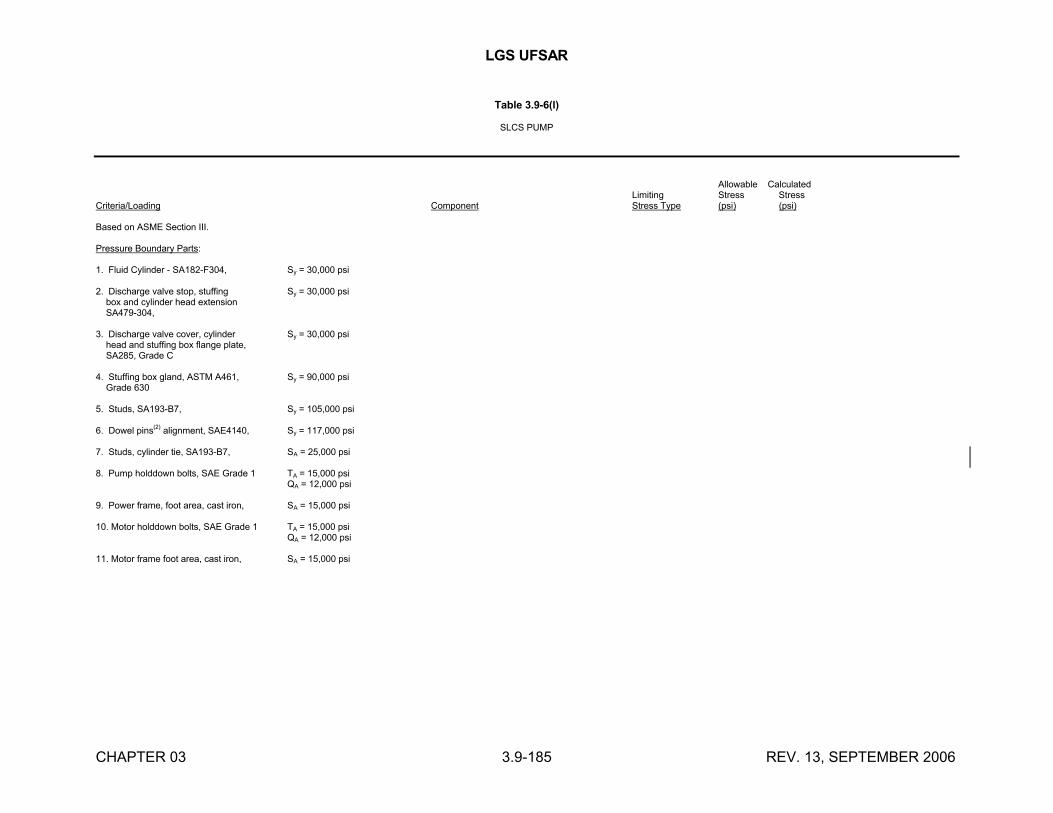
LGS UFSAR
CHAPTER 03 3.9-185 REV. 13, SEPTEMBER 2006
Table 3.9-6(l)
SLCS PUMP
Allowable CalculatedLimiting Stress Stress
Criteria/Loading Component Stress Type (psi) (psi)
Based on ASME Section III.
Pressure Boundary Parts:
1. Fluid Cylinder - SA182-F304, Sy = 30,000 psi
2. Discharge valve stop, stuffing Sy = 30,000 psi box and cylinder head extension SA479-304,
3. Discharge valve cover, cylinder Sy = 30,000 psi head and stuffing box flange plate, SA285, Grade C
4. Stuffing box gland, ASTM A461, Sy = 90,000 psi Grade 630
5. Studs, SA193-B7, Sy = 105,000 psi
6. Dowel pins(2) alignment, SAE4140, Sy = 117,000 psi
7. Studs, cylinder tie, SA193-B7, SA = 25,000 psi
8. Pump holddown bolts, SAE Grade 1 TA = 15,000 psiQA = 12,000 psi
9. Power frame, foot area, cast iron, SA = 15,000 psi
10. Motor holddown bolts, SAE Grade 1 TA = 15,000 psiQA = 12,000 psi
11. Motor frame foot area, cast iron, SA = 15,000 psi
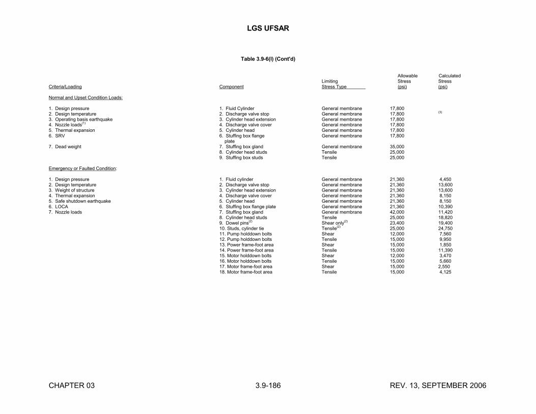
LGS UFSAR
CHAPTER 03 3.9-186 REV. 13, SEPTEMBER 2006
Table 3.9-6(l) (Cont'd)
Allowable CalculatedLimiting Stress Stress
Criteria/Loading Component Stress Type (psi) (psi)
Normal and Upset Condition Loads:
1. Design pressure 1. Fluid Cylinder General membrane 17,8002. Design temperature 2. Discharge valve stop General membrane 17,800 (3)
3. Operating basis earthquake 3. Cylinder head extension General membrane 17,8004. Nozzle loads
(1)4. Discharge valve cover General membrane 17,800
5. Thermal expansion 5. Cylinder head General membrane 17,8006. SRV 6. Stuffing box flange General membrane 17,800
plate7. Dead weight 7. Stuffing box gland General membrane 35,000
8. Cylinder head studs Tensile 25,0009. Stuffing box studs Tensile 25,000
Emergency or Faulted Condition:
1. Design pressure 1. Fluid cylinder General membrane 21,360 4,4502. Design temperature 2. Discharge valve stop General membrane 21,360 13,6003. Weight of structure 3. Cylinder head extension General membrane 21,360 13,6004. Thermal expansion 4. Discharge valve cover General membrane 21,360 8,1505. Safe shutdown earthquake 5. Cylinder head General membrane 21,360 8,1506. LOCA 6. Stuffing box flange plate General membrane 21,360 10,3907. Nozzle loads 7. Stuffing box gland General membrane 42,000 11,420
8. Cylinder head studs Tensile 25,000 18,8209. Dowel pins(2) Shear only(2) 23,400 19,40010. Studs, cylinder tie Tensile(2) 25,000 24,75011. Pump holddown bolts Shear 12,000 7,56012. Pump holddown bolts Tensile 15,000 9,95013. Power frame-foot area Shear 15,000 1,85014. Power frame-foot area Tensile 15,000 11,39015. Motor holddown bolts Shear 12,000 3,47016. Motor holddown bolts Tensile 15,000 5,66017. Motor frame-foot area Shear 15,000 2,55018. Motor frame-foot area Tensile 15,000 4,125
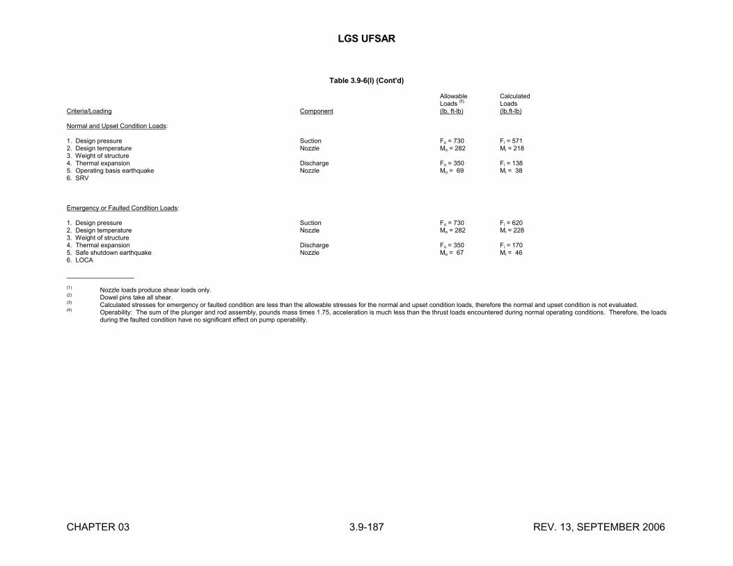
LGS UFSAR
CHAPTER 03 3.9-187 REV. 13, SEPTEMBER 2006
Table 3.9-6(l) (Cont'd)
Allowable CalculatedLoads (5) Loads
Criteria/Loading Component (lb, ft-lb) (lb,ft-lb)
Normal and Upset Condition Loads:
1. Design pressure Suction Fo = 730 Fi = 5712. Design temperature Nozzle Mo = 282 Mi = 2183. Weight of structure4. Thermal expansion Discharge Fo = 350 Fi = 1385. Operating basis earthquake Nozzle Mo = 69 Mi = 386. SRV
Emergency or Faulted Condition Loads:
1. Design pressure Suction Fo = 730 Fi = 6202. Design temperature Nozzle Mo = 282 Mi = 2283. Weight of structure4. Thermal expansion Discharge Fo = 350 Fi = 1705. Safe shutdown earthquake Nozzle Mo = 67 Mi = 466. LOCA
___________________
(1) Nozzle loads produce shear loads only.(2) Dowel pins take all shear.(3) Calculated stresses for emergency or faulted condition are less than the allowable stresses for the normal and upset condition loads, therefore the normal and upset condition is not evaluated.(4) Operability: The sum of the plunger and rod assembly, pounds mass times 1.75, acceleration is much less than the thrust loads encountered during normal operating conditions. Therefore, the loads
during the faulted condition have no significant effect on pump operability.
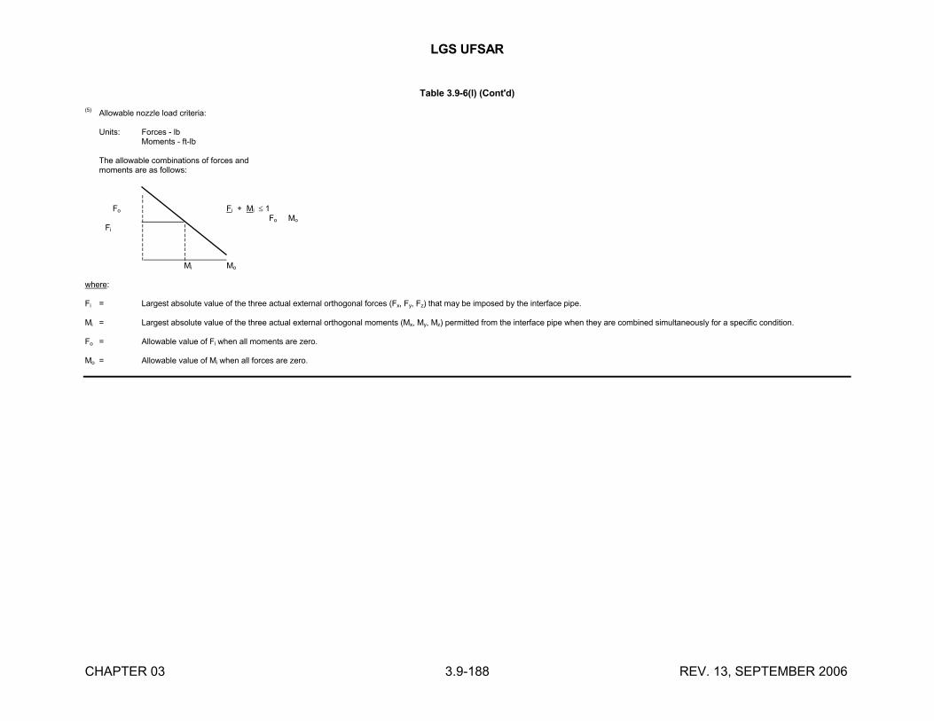
LGS UFSAR
CHAPTER 03 3.9-188 REV. 13, SEPTEMBER 2006
Table 3.9-6(l) (Cont'd)
(5) Allowable nozzle load criteria:
Units: Forces - lbMoments - ft-lb
The allowable combinations of forces andmoments are as follows:
¦ Fo ¦ Fi + Mi 1 ¦ Fo Mo
Fi ¦ ¦¦ ¦¦ ¦¦ ¦
Mi Mo
where: Fi = Largest absolute value of the three actual external orthogonal forces (Fx, Fy, Fz) that may be imposed by the interface pipe.
Mi = Largest absolute value of the three actual external orthogonal moments (Mx, My, Mz) permitted from the interface pipe when they are combined simultaneously for a specific condition.
Fo = Allowable value of Fi when all moments are zero.
Mo = Allowable value of Mi when all forces are zero.
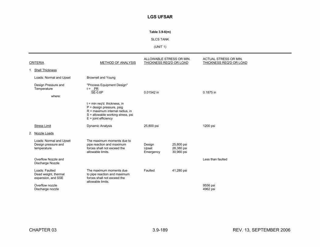
LGS UFSAR
CHAPTER 03 3.9-189 REV. 13, SEPTEMBER 2006
Table 3.9-6(m)
SLCS TANK
(UNIT 1)
ALLOWABLE STRESS OR MIN. ACTUAL STRESS OR MIN.CRITERIA METHOD OF ANALYSIS THICKNESS REQ'D OR LOAD THICKNESS REQ'D OR LOAD
1. Shell Thickness
Loads: Normal and Upset Brownell and Young
Design Pressure and "Process Equipment Design"Temperature t = PR
SE-0.6P 0.01542 in 0.1875 in where:
t = min req'd. thickness, inP = design pressure, psigR = maximum internal radius, inS = allowable working stress, psiE = joint efficiency
Stress Limit Dynamic Analysis 25,800 psi 1200 psi
2. Nozzle Loads
Loads: Normal and Upset The maximum moments due toDesign pressure and pipe reaction and maximum Design 25,800 psitemperature forces shall not exceed the Upset 28,380 psi
allowable limits. Emergency 30,960 psi
Overflow Nozzle and Less than faultedDischarge Nozzle
Loads: Faulted The maximum moments due Faulted 41,280 psiDead weight, thermal to pipe reaction and maximumexpansion, and SSE forces shall not exceed the
allowable limits.Overflow nozzle 9556 psiDischarge nozzle 4962 psi
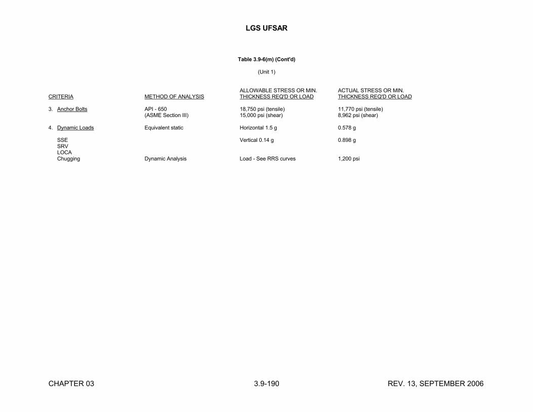
LGS UFSAR
CHAPTER 03 3.9-190 REV. 13, SEPTEMBER 2006
Table 3.9-6(m) (Cont'd)
(Unit 1)
ALLOWABLE STRESS OR MIN. ACTUAL STRESS OR MIN.CRITERIA METHOD OF ANALYSIS THICKNESS REQ'D OR LOAD THICKNESS REQ'D OR LOAD
3. Anchor Bolts API - 650 18,750 psi (tensile) 11,770 psi (tensile)(ASME Section III) 15,000 psi (shear) 8,962 psi (shear)
4. Dynamic Loads Equivalent static Horizontal 1.5 g 0.578 g
SSE Vertical 0.14 g 0.898 gSRVLOCAChugging Dynamic Analysis Load - See RRS curves 1,200 psi
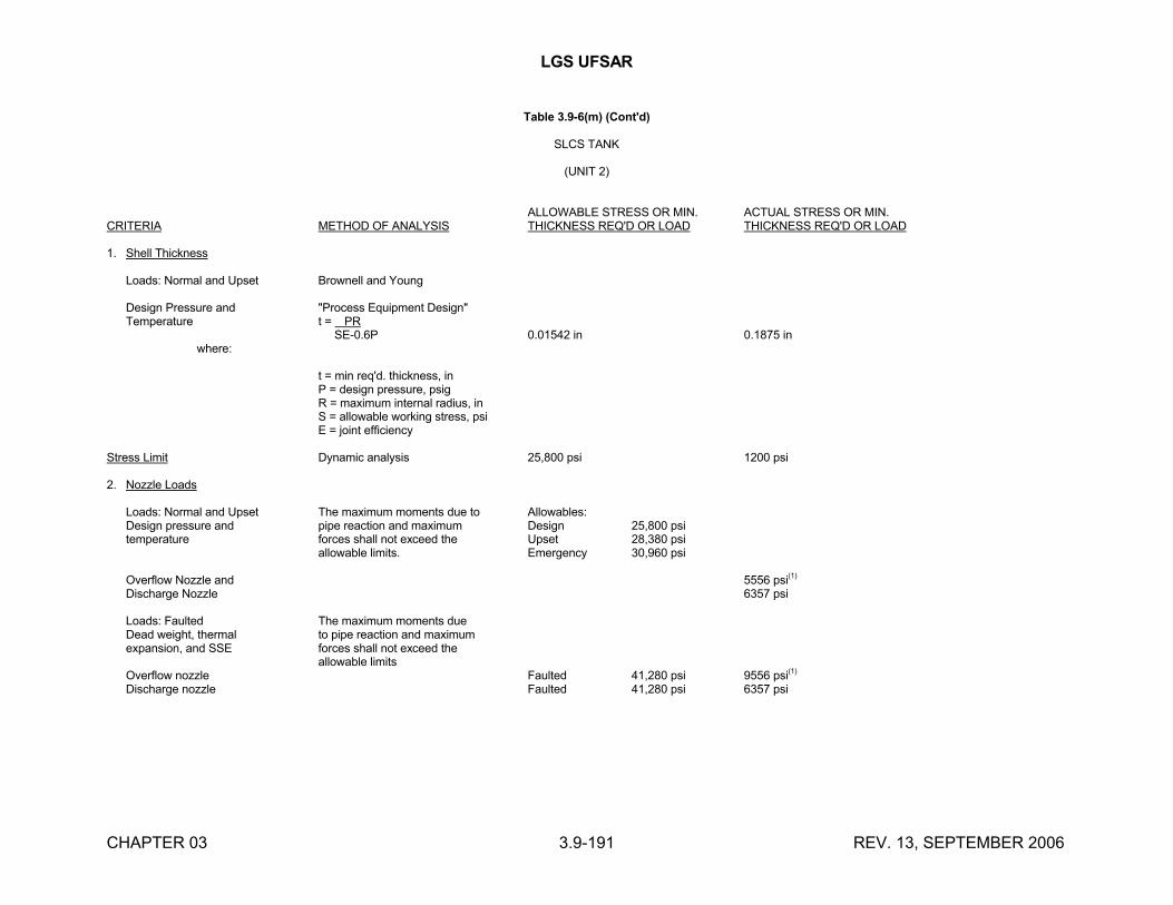
LGS UFSAR
CHAPTER 03 3.9-191 REV. 13, SEPTEMBER 2006
Table 3.9-6(m) (Cont'd)
SLCS TANK
(UNIT 2)
ALLOWABLE STRESS OR MIN. ACTUAL STRESS OR MIN.CRITERIA METHOD OF ANALYSIS THICKNESS REQ'D OR LOAD THICKNESS REQ'D OR LOAD
1. Shell Thickness
Loads: Normal and Upset Brownell and Young
Design Pressure and "Process Equipment Design"Temperature t = PR
SE-0.6P 0.01542 in 0.1875 in where:
t = min req'd. thickness, inP = design pressure, psigR = maximum internal radius, inS = allowable working stress, psiE = joint efficiency
Stress Limit Dynamic analysis 25,800 psi 1200 psi
2. Nozzle Loads
Loads: Normal and Upset The maximum moments due to Allowables:Design pressure and pipe reaction and maximum Design 25,800 psitemperature forces shall not exceed the Upset 28,380 psi
allowable limits. Emergency 30,960 psi
Overflow Nozzle and 5556 psi(1)
Discharge Nozzle 6357 psi
Loads: Faulted The maximum moments dueDead weight, thermal to pipe reaction and maximumexpansion, and SSE forces shall not exceed the
allowable limitsOverflow nozzle Faulted 41,280 psi 9556 psi(1)
Discharge nozzle Faulted 41,280 psi 6357 psi
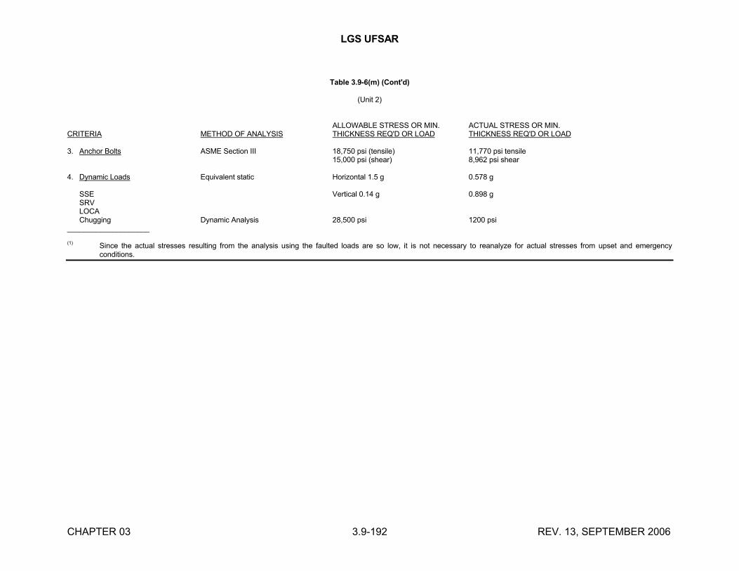
LGS UFSAR
CHAPTER 03 3.9-192 REV. 13, SEPTEMBER 2006
Table 3.9-6(m) (Cont'd)
(Unit 2)
ALLOWABLE STRESS OR MIN. ACTUAL STRESS OR MIN.CRITERIA METHOD OF ANALYSIS THICKNESS REQ'D OR LOAD THICKNESS REQ'D OR LOAD
3. Anchor Bolts ASME Section III 18,750 psi (tensile) 11,770 psi tensile15,000 psi (shear) 8,962 psi shear
4. Dynamic Loads Equivalent static Horizontal 1.5 g 0.578 g
SSE Vertical 0.14 g 0.898 gSRVLOCAChugging Dynamic Analysis 28,500 psi 1200 psi
____________________
(1) Since the actual stresses resulting from the analysis using the faulted loads are so low, it is not necessary to reanalyze for actual stresses from upset and emergency conditions.
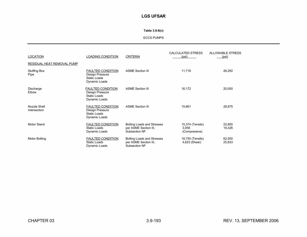
LGS UFSAR
CHAPTER 03 3.9-193 REV. 13, SEPTEMBER 2006
Table 3.9-6(n)
ECCS PUMPS
CALCULATED STRESS ALLOWABLE STRESSLOCATION LOADING CONDITION CRITERIA (psi) (psi)
RESIDUAL HEAT REMOVAL PUMP
Stuffing Box FAULTED CONDITION ASME Section III 11,718 26,250Pipe Design Pressure
Static Loads Dynamic Loads
Discharge FAULTED CONDITION ASME Section III 16,172 20,000Elbow Design Pressure
Static Loads Dynamic Loads
Nozzle Shell FAULTED CONDITION ASME Section III 15,661 28,875Intersection Design Pressure
Static Loads Dynamic Loads
Motor Stand FAULTED CONDITION Bolting Loads and Stresses 15,374 (Tensile) 22,800 Static Loads per ASME Section III, 3,058 19,326 Dynamic Loads Subsection NF (Compressive)
Motor Bolting FAULTED CONDITION Bolting Loads and Stresses 18,755 (Tensile) 62,500 Static Loads per ASME Section III, 4,623 (Shear) 25,833 Dynamic Loads Subsection NF
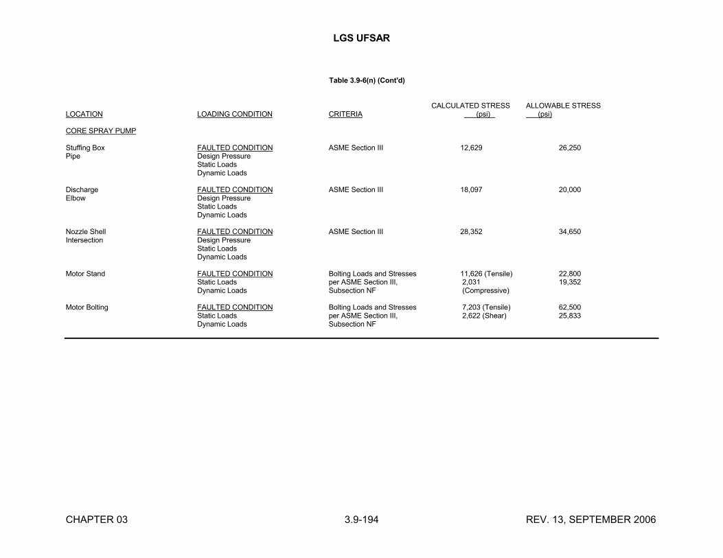
LGS UFSAR
CHAPTER 03 3.9-194 REV. 13, SEPTEMBER 2006
Table 3.9-6(n) (Cont'd)
CALCULATED STRESS ALLOWABLE STRESSLOCATION LOADING CONDITION CRITERIA (psi) (psi)
CORE SPRAY PUMP
Stuffing Box FAULTED CONDITION ASME Section III 12,629 26,250Pipe Design Pressure
Static LoadsDynamic Loads
Discharge FAULTED CONDITION ASME Section III 18,097 20,000Elbow Design Pressure
Static LoadsDynamic Loads
Nozzle Shell FAULTED CONDITION ASME Section III 28,352 34,650Intersection Design Pressure
Static LoadsDynamic Loads
Motor Stand FAULTED CONDITION Bolting Loads and Stresses 11,626 (Tensile) 22,800Static Loads per ASME Section III, 2,031 19,352Dynamic Loads Subsection NF (Compressive)
Motor Bolting FAULTED CONDITION Bolting Loads and Stresses 7,203 (Tensile) 62,500Static Loads per ASME Section III, 2,622 (Shear) 25,833Dynamic Loads Subsection NF
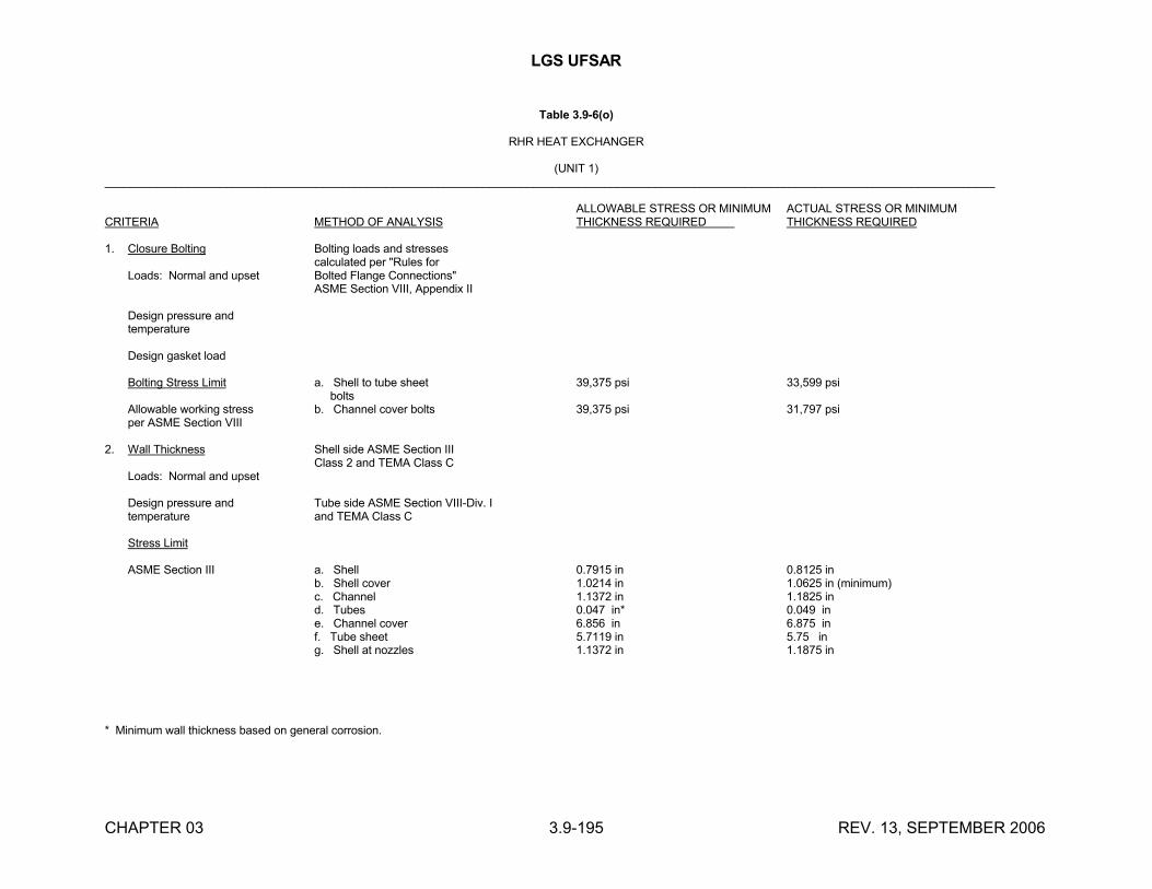
LGS UFSAR
CHAPTER 03 3.9-195 REV. 13, SEPTEMBER 2006
Table 3.9-6(o)
RHR HEAT EXCHANGER
(UNIT 1)___________________________________________________________________________________________________________________________________________
ALLOWABLE STRESS OR MINIMUM ACTUAL STRESS OR MINIMUMCRITERIA METHOD OF ANALYSIS THICKNESS REQUIRED THICKNESS REQUIRED
1. Closure Bolting Bolting loads and stressescalculated per "Rules for
Loads: Normal and upset Bolted Flange Connections"ASME Section VIII, Appendix II
Design pressure andtemperature
Design gasket load
Bolting Stress Limit a. Shell to tube sheet 39,375 psi 33,599 psi bolts
Allowable working stress b. Channel cover bolts 39,375 psi 31,797 psiper ASME Section VIII
2. Wall Thickness Shell side ASME Section IIIClass 2 and TEMA Class C
Loads: Normal and upset
Design pressure and Tube side ASME Section VIII-Div. Itemperature and TEMA Class C
Stress Limit
ASME Section III a. Shell 0.7915 in 0.8125 inb. Shell cover 1.0214 in 1.0625 in (minimum)c. Channel 1.1372 in 1.1825 ind. Tubes 0.047 in* 0.049 ine. Channel cover 6.856 in 6.875 inf. Tube sheet 5.7119 in 5.75 ing. Shell at nozzles 1.1372 in 1.1875 in
* Minimum wall thickness based on general corrosion.

LGS UFSAR
CHAPTER 03 3.9-196 REV. 13, SEPTEMBER 2006
Table 3.9-6(o) (Cont'd)
(Unit 1)
ALLOWABLE STRESS OR MINIMUM ACTUAL STRESS OR MINIMUMCRITERIA METHOD OF ANALYSIS THICKNESS REQUIRED THICKNESS REQUIRED
3. Nozzle Loads See (a) and (b) below See (c) below
Design pressure andtemperature
Dead weight, thermal Primary local membrane stressexpansion and SSE less than 1.8 ASME Section VIII
allowable.
a) Maximum allowable piping loads for faulted conditions (including SSE) shall not exceed the following relationship for each nozzle:
Fix + Fiy + Fiz 1 and Mix + Miy + Miz 1Fox Foy Foz Mox Moy Moz
where Fi (lbs) is the maximum piping load imposed on each nozzle in the x, y and z direction and Mi (lb-ft) is the maximum moment imposed on each nozzle in the x, y and z directions.
b) Allowable design basis limits (forces Fox, Foy, Foz and Moments Mox, Moy, Moz) for nozzles N1, N2, N3, and N4:
N1 N2 N3 N4(Channel inlet) (Channel outlet) (Shell inlet) (Shell outlet)
Fox 11,395 lb 11,395 lb 44,143 lb 26,692 lb
Foy 25,621 lb 25,621 lb 19,630 lb 26,692 lb
Foz 25,621 lb 25,621 lb 44,143 lb 11,871 lb
Mox 65,926 lb-ft 65,926 lb-ft 21,839 lb-ft 12,230 lb-ft
Moy 8,537 lb-ft 8,537 lb-ft 113,596 lb-ft 12,230 lb-ft
Moz 8,537 lb-ft 8,537 lb-ft 21,839 lb-ft 68,680 lb-ft
Note: The calculated loads in (c) below that exceed these allowable loads have been evaluated and are acceptable.
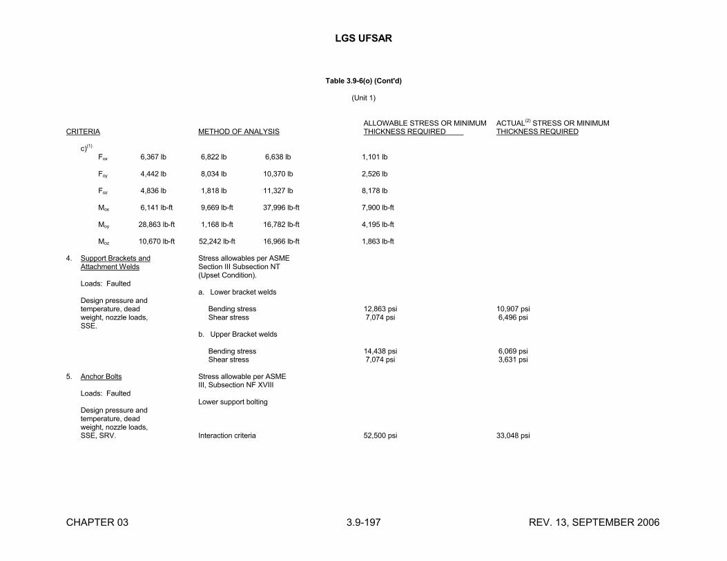
LGS UFSAR
CHAPTER 03 3.9-197 REV. 13, SEPTEMBER 2006
Table 3.9-6(o) (Cont'd)
(Unit 1)
ALLOWABLE STRESS OR MINIMUM ACTUAL(2) STRESS OR MINIMUMCRITERIA METHOD OF ANALYSIS THICKNESS REQUIRED THICKNESS REQUIRED
c)(1)
Fox 6,367 lb 6,822 lb 6,638 lb 1,101 lb
Foy 4,442 lb 8,034 lb 10,370 lb 2,526 lb
Foz 4,836 lb 1,818 lb 11,327 lb 8,178 lb
Mox 6,141 lb-ft 9,669 lb-ft 37,996 lb-ft 7,900 lb-ft
Moy 28,863 lb-ft 1,168 lb-ft 16,782 lb-ft 4,195 lb-ft
Moz 10,670 lb-ft 52,242 lb-ft 16,966 lb-ft 1,863 lb-ft
4. Support Brackets and Stress allowables per ASMEAttachment Welds Section III Subsection NT
(Upset Condition).Loads: Faulted
a. Lower bracket weldsDesign pressure andtemperature, dead Bending stress 12,863 psi 10,907 psiweight, nozzle loads, Shear stress 7,074 psi 6,496 psiSSE.
b. Upper Bracket welds
Bending stress 14,438 psi 6,069 psi Shear stress 7,074 psi 3,631 psi
5. Anchor Bolts Stress allowable per ASMEIII, Subsection NF XVIII
Loads: FaultedLower support bolting
Design pressure andtemperature, deadweight, nozzle loads,SSE, SRV. Interaction criteria 52,500 psi 33,048 psi
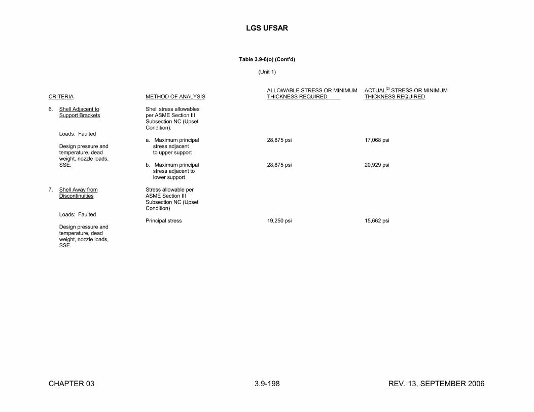
LGS UFSAR
CHAPTER 03 3.9-198 REV. 13, SEPTEMBER 2006
Table 3.9-6(o) (Cont'd)
(Unit 1)
ALLOWABLE STRESS OR MINIMUM ACTUAL(2) STRESS OR MINIMUMCRITERIA METHOD OF ANALYSIS THICKNESS REQUIRED THICKNESS REQUIRED
6. Shell Adjacent to Shell stress allowablesSupport Brackets per ASME Section III
Subsection NC (UpsetCondition).
Loads: Faulteda. Maximum principal 28,875 psi 17,068 psi
Design pressure and stress adjacenttemperature, dead to upper supportweight, nozzle loads,SSE. b. Maximum principal 28,875 psi 20,929 psi
stress adjacent to lower support
7. Shell Away from Stress allowable perDiscontinuities ASME Section III
Subsection NC (UpsetCondition)
Loads: FaultedPrincipal stress 19,250 psi 15,662 psi
Design pressure andtemperature, deadweight, nozzle loads,SSE.
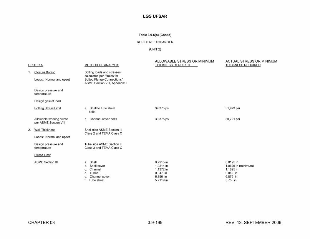
LGS UFSAR
CHAPTER 03 3.9-199 REV. 13, SEPTEMBER 2006
Table 3.9-6(o) (Cont'd)
RHR HEAT EXCHANGER
(UNIT 2)
ALLOWABLE STRESS OR MINIMUM ACTUAL STRESS OR MINIMUMCRITERIA METHOD OF ANALYSIS THICKNESS REQUIRED THICKNESS REQUIRED
1. Closure Bolting Bolting loads and stressescalculated per "Rules for
Loads: Normal and upset Bolted Flange Connections"ASME Section VIII, Appendix II
Design pressure andtemperature
Design gasket load
Bolting Stress Limit a. Shell to tube sheet 39,375 psi 31,973 psi bolts
Allowable working stress b. Channel cover bolts 39,375 psi 30,721 psiper ASME Section VIII
2. Wall Thickness Shell side ASME Section IIIClass 2 and TEMA Class C
Loads: Normal and upset
Design pressure and Tube side ASME Section IIItemperature Class 3 and TEMA Class C
Stress Limit
ASME Section III a. Shell 0.7915 in 0.8125 inb. Shell cover 1.0214 in 1.0625 in (minimum)c. Channel 1.1372 in 1.1825 ind. Tubes 0.047 in 0.049 ine. Channel cover 6.856 in 6.875 inf. Tube sheet 5.7119 in 5.75 in
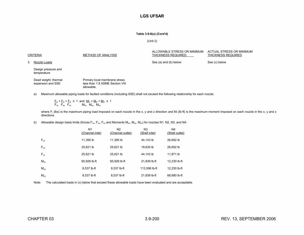
LGS UFSAR
CHAPTER 03 3.9-200 REV. 13, SEPTEMBER 2006
Table 3.9-6(o) (Cont'd)
(Unit 2)
ALLOWABLE STRESS OR MINIMUM ACTUAL STRESS OR MINIMUMCRITERIA METHOD OF ANALYSIS THICKNESS REQUIRED THICKNESS REQUIRED
3. Nozzle Loads See (a) and (b) below See (c) below
Design pressure andtemperature
Dead weight, thermal Primary local membrane stressexpansion and SSE less than 1.8 ASME Section VIII
allowable.
a) Maximum allowable piping loads for faulted conditions (including SSE) shall not exceed the following relationship for each nozzle:
Fix + Fiy + Fiz ≤ 1 and Mix + Miy + Miz ≤ 1Fox Foy Foz Mox Moy Moz
where Fi (lbs) is the maximum piping load imposed on each nozzle in the x, y and z direction and Mi (lb-ft) is the maximum moment imposed on each nozzle in the x, y and z directions.
b) Allowable design basis limits (forces Fox, Foy, Foz and Moments Mox, Moy, Moz) for nozzles N1, N2, N3, and N4:
N1 N2 N3 N4(Channel inlet) (Channel outlet) (Shell inlet) (Shell outlet)
Fox 11,395 lb 11,395 lb 44,143 lb 26,692 lb
Foy 25,621 lb 25,621 lb 19,630 lb 26,692 lb
Foz 25,621 lb 25,621 lb 44,143 lb 11,871 lb
Mox 65,926 lb-ft 65,926 lb-ft 21,839 lb-ft 12,230 lb-ft
Moy 8,537 lb-ft 8,537 lb-ft 113,596 lb-ft 12,230 lb-ft
Moz 8,537 lb-ft 8,537 lb-ft 21,839 lb-ft 68,680 lb-ft
Note: The calculated loads in (c) below that exceed these allowable loads have been evaluated and are acceptable.
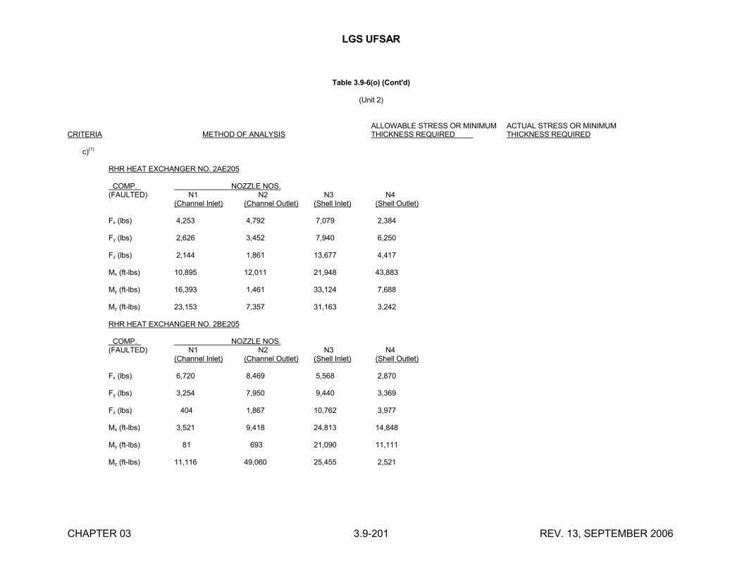
LGS UFSAR
CHAPTER 03 3.9-201 REV. 13, SEPTEMBER 2006
Table 3.9-6(o) (Cont'd)
(Unit 2)
ALLOWABLE STRESS OR MINIMUM ACTUAL STRESS OR MINIMUMCRITERIA METHOD OF ANALYSIS THICKNESS REQUIRED THICKNESS REQUIRED
c)(1)
RHR HEAT EXCHANGER NO. 2AE205
COMP. NOZZLE NOS. (FAULTED) N1 N2 N3 N4
(Channel Inlet) (Channel Outlet) (Shell Inlet) (Shell Outlet)
Fx (lbs) 4,253 4,792 7,079 2,384
Fy (lbs) 2,626 3,452 7,940 6,250
Fz (lbs) 2,144 1,861 13,677 4,417
Mx (ft-lbs) 10,895 12,011 21,948 43,883
My (ft-lbs) 16,393 1,461 33,124 7,688
Mz (ft-lbs) 23,153 7,357 31,163 3,242
RHR HEAT EXCHANGER NO. 2BE205
COMP. NOZZLE NOS. (FAULTED) N1 N2 N3 N4
(Channel Inlet) (Channel Outlet) (Shell Inlet) (Shell Outlet)
Fx (lbs) 6,720 8,469 5,568 2,870
Fy (lbs) 3,254 7,950 9,440 3,369
Fz (lbs) 404 1,867 10,762 3,977
Mx (ft-lbs) 3,521 9,418 24,813 14,848
My (ft-lbs) 81 693 21,090 11,111
Mz (ft-lbs) 11,116 49,060 25,455 2,521
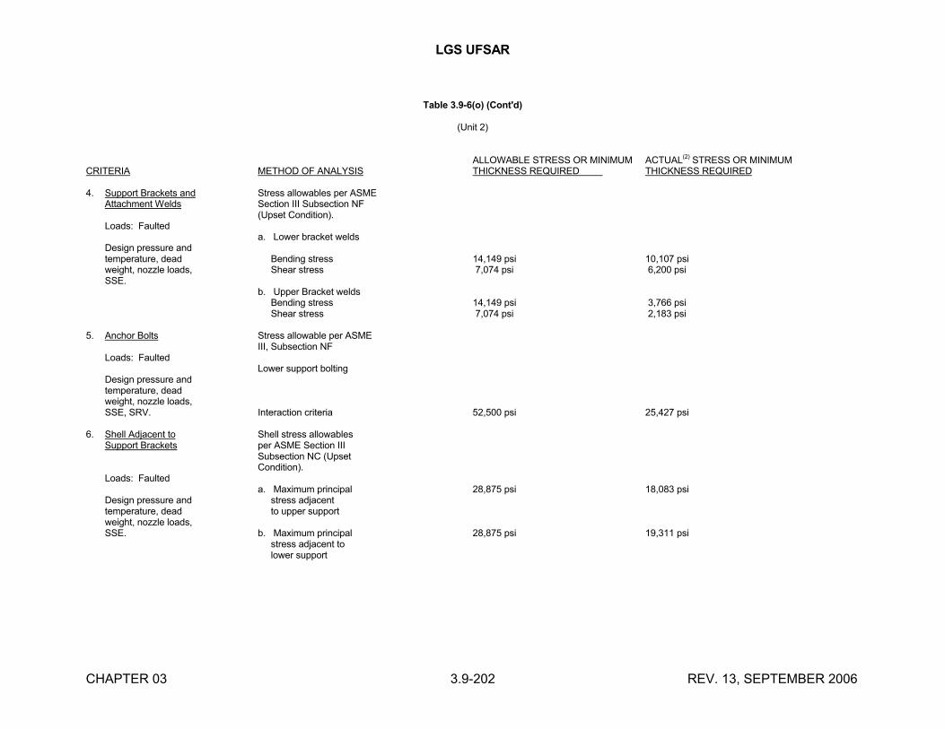
LGS UFSAR
CHAPTER 03 3.9-202 REV. 13, SEPTEMBER 2006
Table 3.9-6(o) (Cont'd)
(Unit 2)
ALLOWABLE STRESS OR MINIMUM ACTUAL(2) STRESS OR MINIMUMCRITERIA METHOD OF ANALYSIS THICKNESS REQUIRED THICKNESS REQUIRED
4. Support Brackets and Stress allowables per ASMEAttachment Welds Section III Subsection NF
(Upset Condition).Loads: Faulted
a. Lower bracket weldsDesign pressure andtemperature, dead Bending stress 14,149 psi 10,107 psiweight, nozzle loads, Shear stress 7,074 psi 6,200 psiSSE.
b. Upper Bracket welds Bending stress 14,149 psi 3,766 psi Shear stress 7,074 psi 2,183 psi
5. Anchor Bolts Stress allowable per ASMEIII, Subsection NF
Loads: FaultedLower support bolting
Design pressure andtemperature, deadweight, nozzle loads,SSE, SRV. Interaction criteria 52,500 psi 25,427 psi
6. Shell Adjacent to Shell stress allowablesSupport Brackets per ASME Section III
Subsection NC (UpsetCondition).
Loads: Faulteda. Maximum principal 28,875 psi 18,083 psi
Design pressure and stress adjacenttemperature, dead to upper supportweight, nozzle loads,SSE. b. Maximum principal 28,875 psi 19,311 psi
stress adjacent to lower support
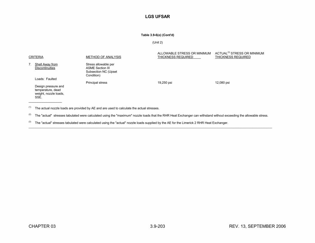
LGS UFSAR
CHAPTER 03 3.9-203 REV. 13, SEPTEMBER 2006
Table 3.9-6(o) (Cont'd)
(Unit 2)
ALLOWABLE STRESS OR MINIMUM ACTUAL(3) STRESS OR MINIMUMCRITERIA METHOD OF ANALYSIS THICKNESS REQUIRED THICKNESS REQUIRED
7. Shell Away from Stress allowable perDiscontinuities ASME Section III
Subsection NC (UpsetCondition)
Loads: FaultedPrincipal stress 19,250 psi 12,080 psi
Design pressure andtemperature, deadweight, nozzle loads,SSE.
___________________
(1) The actual nozzle loads are provided by AE and are used to calculate the actual stresses.
(2) The "actual" stresses tabulated were calculated using the "maximum" nozzle loads that the RHR Heat Exchanger can withstand without exceeding the allowable stress.
(3) The "actual" stresses tabulated were calculated using the "actual" nozzle loads supplied by the AE for the Limerick 2 RHR Heat Exchanger.___________________________________________________________________________________________________________________________________________
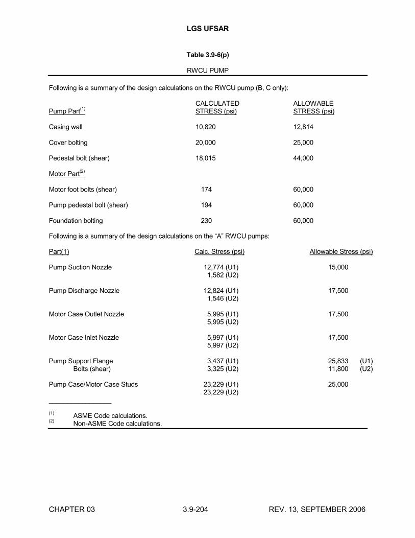
LGS UFSAR
CHAPTER 03 3.9-204 REV. 13, SEPTEMBER 2006
Table 3.9-6(p)
RWCU PUMP
Following is a summary of the design calculations on the RWCU pump (B, C only):
CALCULATED ALLOWABLEPump Part
(1)STRESS (psi) STRESS (psi)
Casing wall 10,820 12,814
Cover bolting 20,000 25,000
Pedestal bolt (shear) 18,015 44,000
Motor Part(2)
Motor foot bolts (shear) 174 60,000
Pump pedestal bolt (shear) 194 60,000
Foundation bolting 230 60,000
Following is a summary of the design calculations on the “A” RWCU pumps:
Part(1) Calc. Stress (psi) Allowable Stress (psi)
Pump Suction Nozzle 12,774 (U1) 15,0001,582 (U2)
Pump Discharge Nozzle 12,824 (U1) 17,5001,546 (U2)
Motor Case Outlet Nozzle 5,995 (U1) 17,5005,995 (U2)
Motor Case Inlet Nozzle 5,997 (U1) 17,5005,997 (U2)
Pump Support Flange 3,437 (U1) 25,833 (U1)Bolts (shear) 3,325 (U2) 11,800 (U2)
Pump Case/Motor Case Studs 23,229 (U1) 25,00023,229 (U2)
_________________
(1)ASME Code calculations.
(2)Non-ASME Code calculations.
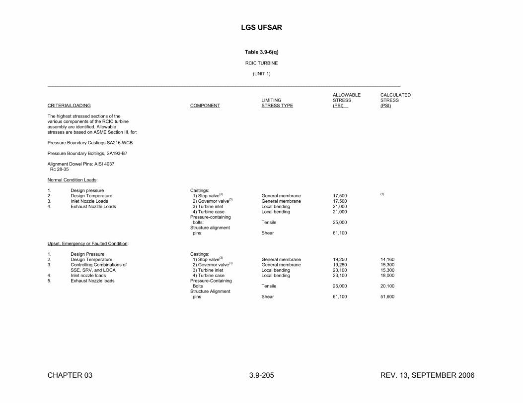
LGS UFSAR
CHAPTER 03 3.9-205 REV. 13, SEPTEMBER 2006
Table 3.9-6(q)
RCIC TURBINE
(UNIT 1)
___________________________________________________________________________________________________________________________________________
ALLOWABLE CALCULATEDLIMITING STRESS STRESS
CRITERIA/LOADING COMPONENT STRESS TYPE (PSI) (PSI)
The highest stressed sections of thevarious components of the RCIC turbineassembly are identified. Allowablestresses are based on ASME Section III, for:
Pressure Boundary Castings SA216-WCB
Pressure Boundary Boltings, SA193-B7
Alignment Dowel Pins: AISI 4037, Rc 28-35
Normal Condition Loads:
1. Design pressure Castings:2. Design Temperature 1) Stop valve(3) General membrane 17,500 (1)
3. Inlet Nozzle Loads 2) Governor valve(3) General membrane 17,5004. Exhaust Nozzle Loads 3) Turbine inlet Local bending 21,000
4) Turbine case Local bending 21,000Pressure-containing bolts: Tensile 25,000Structure alignment pins: Shear 61,100
Upset, Emergency or Faulted Condition:
1. Design Pressure Castings:2. Design Temperature 1) Stop valve(3) General membrane 19,250 14,1603. Controlling Combinations of 2) Governor valve(3) General membrane 19,250 15,300
SSE, SRV, and LOCA 3) Turbine inlet Local bending 23,100 15,3004. Inlet nozzle loads 4) Turbine case Local bending 23,100 18,0005. Exhaust Nozzle loads Pressure-Containing
Bolts Tensile 25,000 20,100Structure Alignment pins Shear 61,100 51,600
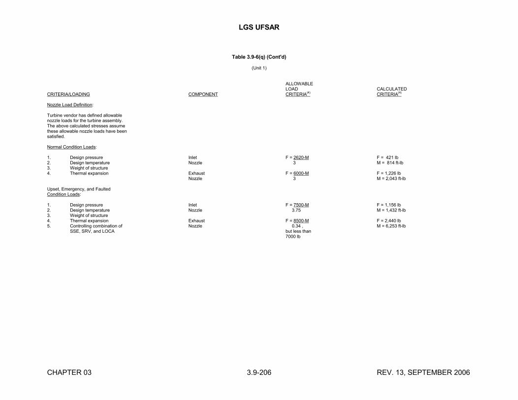
LGS UFSAR
CHAPTER 03 3.9-206 REV. 13, SEPTEMBER 2006
Table 3.9-6(q) (Cont'd)
(Unit 1)
ALLOWABLELOAD CALCULATED
CRITERIA/LOADING COMPONENT CRITERIA(4) CRITERIA(4)
Nozzle Load Definition:
Turbine vendor has defined allowablenozzle loads for the turbine assembly.The above calculated stresses assumethese allowable nozzle loads have beensatisfied.
Normal Condition Loads:
1. Design pressure Inlet F = 2620-M F = 421 lb2. Design temperature Nozzle 3 M = 814 ft-lb3. Weight of structure4. Thermal expansion Exhaust F = 6000-M F = 1,226 lb
Nozzle 3 M = 2,043 ft-lb
Upset, Emergency, and FaultedCondition Loads:
1. Design pressure Inlet F = 7500-M F = 1,156 lb2. Design temperature Nozzle 3.75 M = 1,432 ft-lb3. Weight of structure4. Thermal expansion Exhaust F = 8500-M F = 2,440 lb5. Controlling combination of Nozzle 0.34 , M = 6,253 ft-lb
SSE, SRV, and LOCA but less than7000 lb
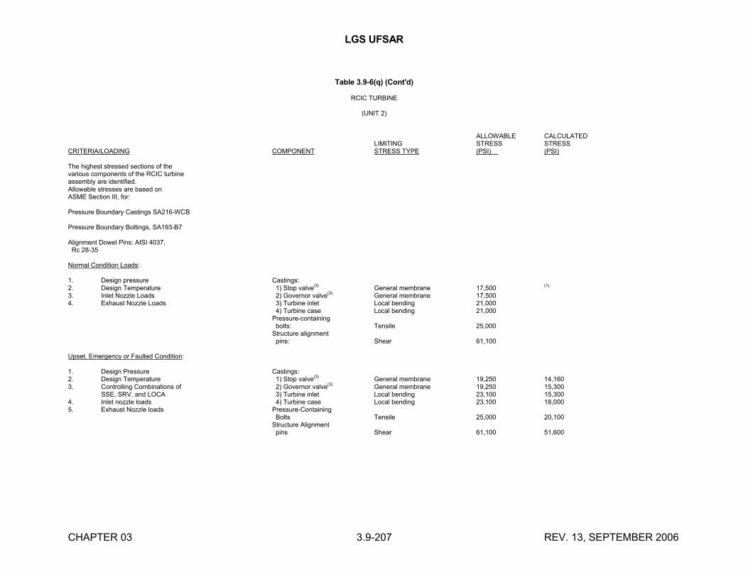
LGS UFSAR
CHAPTER 03 3.9-207 REV. 13, SEPTEMBER 2006
Table 3.9-6(q) (Cont'd)
RCIC TURBINE
(UNIT 2)
ALLOWABLE CALCULATEDLIMITING STRESS STRESS
CRITERIA/LOADING COMPONENT STRESS TYPE (PSI) (PSI)
The highest stressed sections of thevarious components of the RCIC turbineassembly are identified.Allowable stresses are based onASME Section III, for:
Pressure Boundary Castings SA216-WCB
Pressure Boundary Boltings, SA193-B7
Alignment Dowel Pins: AISI 4037, Rc 28-35
Normal Condition Loads:
1. Design pressure Castings:2. Design Temperature 1) Stop valve(3) General membrane 17,500 (1)
3. Inlet Nozzle Loads 2) Governor valve(3) General membrane 17,5004. Exhaust Nozzle Loads 3) Turbine inlet Local bending 21,000
4) Turbine case Local bending 21,000Pressure-containing bolts: Tensile 25,000Structure alignment pins: Shear 61,100
Upset, Emergency or Faulted Condition:
1. Design Pressure Castings:2. Design Temperature 1) Stop valve(3) General membrane 19,250 14,1603. Controlling Combinations of 2) Governor valve(3) General membrane 19,250 15,300
SSE, SRV, and LOCA 3) Turbine inlet Local bending 23,100 15,3004. Inlet nozzle loads 4) Turbine case Local bending 23,100 18,0005. Exhaust Nozzle loads Pressure-Containing
Bolts Tensile 25,000 20,100Structure Alignment pins Shear 61,100 51,600
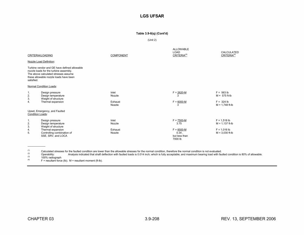
LGS UFSAR
CHAPTER 03 3.9-208 REV. 13, SEPTEMBER 2006
Table 3.9-6(q) (Cont'd)
(Unit 2)
ALLOWABLELOAD CALCULATED
CRITERIA/LOADING COMPONENT CRITERIA(4) CRITERIA(4)
Nozzle Load Definition:
Turbine vendor and GE have defined allowablenozzle loads for the turbine assembly.The above calculated stresses assumethese allowable nozzle loads have beensatisfied.
Normal Condition Loads:
1. Design pressure Inlet F = 2620-M F = 563 lb2. Design temperature Nozzle 3 M = 575 ft-lb3. Weight of structure4. Thermal expansion Exhaust F = 6000-M F = 324 lb
Nozzle 3 M = 1,748 ft-lb
Upset, Emergency, and FaultedCondition Loads:
1. Design pressure Inlet F = 7500-M F = 1,518 lb2. Design temperature Nozzle 3.75 M = 1,137 ft-lb3. Weight of structure4. Thermal expansion Exhaust F = 8500-M F = 1,016 lb5. Controlling combination of Nozzle 0.34 , M = 3,030 ft-lb
SSE, SRV, and LOCA but less than7000 lb
____________
(1) Calculated stresses for the faulted condition are lower than the allowable stresses for the normal condition, therefore the normal condition is not evaluated.(2) Operability: Analysis indicated that shaft deflection with faulted loads is 0.014 inch; which is fully acceptable; and maximum bearing load with faulted condition is 80% of allowable.(3) 100% radiograph(4) F = resultant force (lb); M = resultant moment (ft-lb).
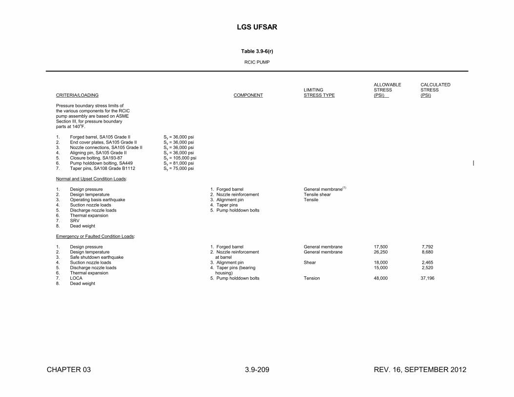
LGS UFSAR
CHAPTER 03 3.9-209 REV. 16, SEPTEMBER 2012
Table 3.9-6(r)
RCIC PUMP
ALLOWABLE CALCULATEDLIMITING STRESS STRESS
CRITERIA/LOADING COMPONENT STRESS TYPE (PSI) (PSI)
Pressure boundary stress limits ofthe various components for the RCICpump assembly are based on ASMESection III, for pressure boundaryparts at 140
oF.
1. Forged barrel, SA105 Grade II Sy = 36,000 psi2. End cover plates, SA105 Grade II Sy = 36,000 psi3. Nozzle connections, SA105 Grade II Sy = 36,000 psi4. Aligning pin, SA105 Grade II Sy = 36,000 psi5. Closure bolting, SA193-87 Sy = 105,000 psi6. Pump holddown bolting, SA449 Sy = 81,000 psi7. Taper pins, SA108 Grade B1112 Sy = 75,000 psi
Normal and Upset Condition Loads:
1. Design pressure 1. Forged barrel General membrane(1)
2. Design temperature 2. Nozzle reinforcement Tensile shear3. Operating basis earthquake 3. Alignment pin Tensile4. Suction nozzle loads 4. Taper pins5. Discharge nozzle loads 5. Pump holddown bolts6. Thermal expansion7. SRV8. Dead weight
Emergency or Faulted Condition Loads:
1. Design pressure 1. Forged barrel General membrane 17,500 7,7922. Design temperature 2. Nozzle reinforcement General membrane 26,250 8,6803. Safe shutdown earthquake at barrel4. Suction nozzle loads 3. Alignment pin Shear 18,000 2,4655. Discharge nozzle loads 4. Taper pins (bearing 15,000 2,5206. Thermal expansion housing)7. LOCA 5. Pump holddown bolts Tension 48,000 37,1968. Dead weight
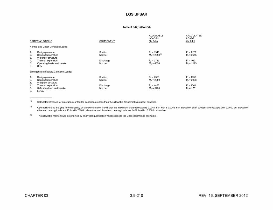
LGS UFSAR
CHAPTER 03 3.9-210 REV. 16, SEPTEMBER 2012
Table 3.9-6(r) (Cont'd)
ALLOWABLE CALCULATEDLOADS(4) LOADS
CRITERIA/LOADING COMPONENT (lb, ft-lb) (lb, ft-lb)
Normal and Upset Condition Loads:
1. Design pressure Suction Fo = 1940 Fi = 11732. Design temperature Nozzle Mo = 2950
(3)Mi = 2555
3. Weight of structure4. Thermal expansion Discharge Fo = 3715 Fi = 9135. Operating basis earthquake Nozzle Mo = 4330 Mi = 11936. SRV
Emergency or Faulted Condition Loads:
1. Design pressure Suction Fo = 2325 Fi = 10332. Design temperature Nozzle Mo = 2950 Mi = 24383. Weight of structure4. Thermal expansion Discharge Fo = 4450 Fi = 10615. Safe shutdown earthquake Nozzle Mo = 5200 Mi = 17516. LOCA
_________________
(1) Calculated stresses for emergency or faulted condition are less than the allowable for normal plus upset condition.
(2) Operability static analysis for emergency or faulted condition shows that the maximum shaft deflection is 0.0044 inch with a 0.0055 inch allowable, shaft stresses are 5602 psi with 32,000 psi allowable, drive end bearing loads are 45 lb with 7670 lb allowable, and thrust end bearing loads are 1462 lb with 17,200 lb allowable.
(3) This allowable moment was determined by analytical qualification which exceeds the Code-determined allowable.
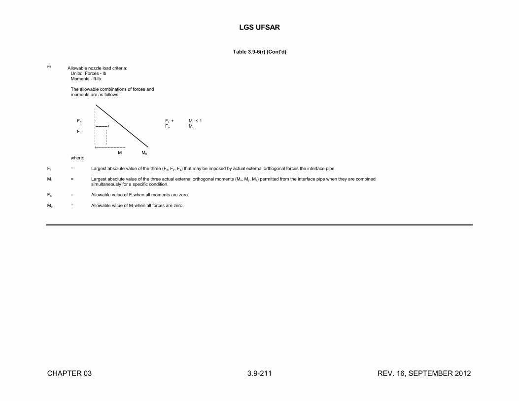
LGS UFSAR
CHAPTER 03 3.9-211 REV. 16, SEPTEMBER 2012
Table 3.9-6(r) (Cont'd)
(4)Allowable nozzle load criteria:
Units: Forces - lbMoments - ft-lb
The allowable combinations of forces andmoments are as follows:
¦¦
Fo ¦ Fi + Mi ≤ 1¦--------+ Fo Mo
Fi ¦ ¦ ¦ ¦ ¦ ¦ +-------------------
Mi Mo
where:
Fi = Largest absolute value of the three (Fx, Fy, Fz) that may be imposed by actual external orthogonal forces the interface pipe.
Mi = Largest absolute value of the three actual external orthogonal moments (Mx, My, Mz) permitted from the interface pipe when they are combined simultaneously for a specific condition.
Fo = Allowable value of Fi when all moments are zero.
Mo = Allowable value of Mi when all forces are zero.
LGS UFSAR
CHAPTER 03 3.9-212 REV. 15, SEPTEMBER 2010
Table 3.9-6(s)
REACTOR REFUELING AND SERVICING EQUIPMENT
The information on this page has been deleted.
LGS UFSAR
CHAPTER 03 3.9-213 REV. 15, SEPTEMBER 2010
Table 3.9-6(s) (Cont'd)
The information on this page has been deleted.
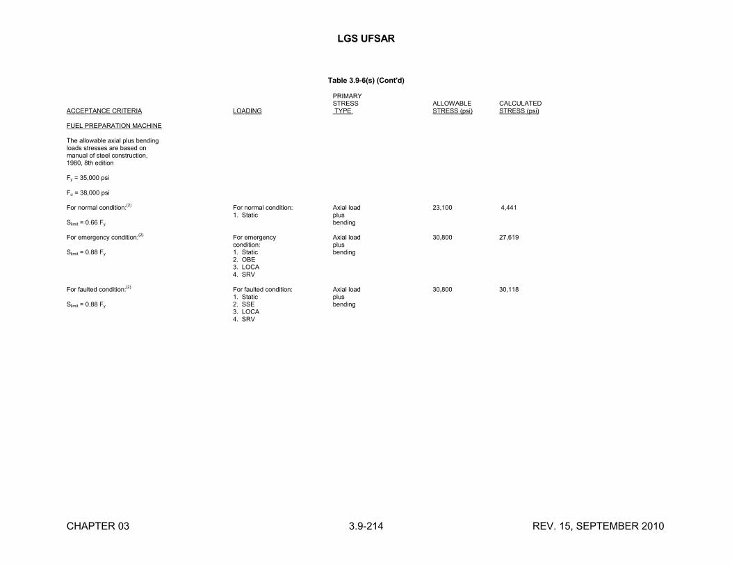
LGS UFSAR
CHAPTER 03 3.9-214 REV. 15, SEPTEMBER 2010
Table 3.9-6(s) (Cont'd)
PRIMARYSTRESS ALLOWABLE CALCULATED
ACCEPTANCE CRITERIA LOADING TYPE STRESS (psi) STRESS (psi)
FUEL PREPARATION MACHINE
The allowable axial plus bendingloads stresses are based onmanual of steel construction,1980, 8th edition
Fy = 35,000 psi
Fu = 38,000 psi
For normal condition:(2)
For normal condition: Axial load 23,100 4,4411. Static plus
Slimit = 0.66 Fy bending
For emergency condition:(2) For emergency Axial load 30,800 27,619condition: plus
Slimit = 0.88 Fy 1. Static bending2. OBE3. LOCA4. SRV
For faulted condition:(2) For faulted condition: Axial load 30,800 30,1181. Static plus
Slimit = 0.88 Fy 2. SSE bending3. LOCA4. SRV
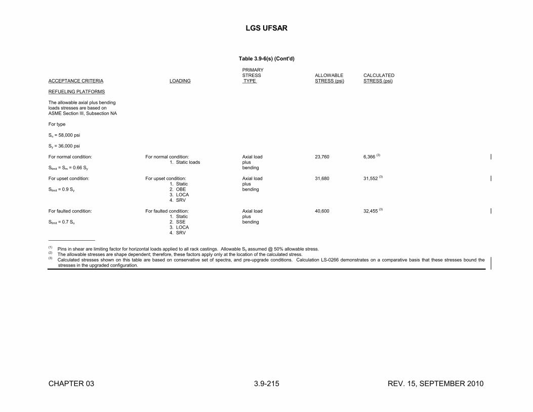
LGS UFSAR
CHAPTER 03 3.9-215 REV. 15, SEPTEMBER 2010
Table 3.9-6(s) (Cont'd)
PRIMARYSTRESS ALLOWABLE CALCULATED
ACCEPTANCE CRITERIA LOADING TYPE STRESS (psi) STRESS (psi)
REFUELING PLATFORMS
The allowable axial plus bendingloads stresses are based onASME Section III, Subsection NA
For type
Su = 58,000 psi
Sy = 36,000 psi
For normal condition: For normal condition: Axial load 23,760 6,366 (3)
1. Static loads plusSlimit = Sm = 0.66 Sy bending
For upset condition: For upset condition: Axial load 31,680 31,552 (3)
1. Static plusSlimit = 0.9 Sy 2. OBE bending
3. LOCA4. SRV
For faulted condition: For faulted condition: Axial load 40,600 32,455 (3)
1. Static plusSlimit = 0.7 Su 2. SSE bending
3. LOCA4. SRV
__________________
(1) Pins in shear are limiting factor for horizontal loads applied to all rack castings. Allowable Ss assumed @ 50% allowable stress.(2)
The allowable stresses are shape dependent; therefore, these factors apply only at the location of the calculated stress.(3) Calculated stresses shown on this table are based on conservative set of spectra, and pre-upgrade conditions. Calculation LS-0266 demonstrates on a comparative basis that these stresses bound the
stresses in the upgraded configuration.
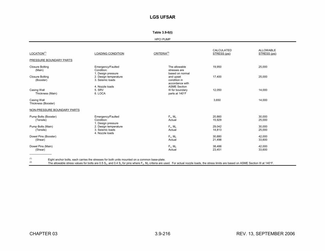
LGS UFSAR
CHAPTER 03 3.9-216 REV. 13, SEPTEMBER 2006
Table 3.9-6(t)
HPCI PUMP
CALCULATED ALLOWABLELOCATION
(1)LOADING CONDITION CRITERIA
(2)STRESS (psi) STRESS (psi)
PRESSURE BOUNDARY PARTS
Closure Bolting Emergency/Faulted The allowable 19,950 25,000(Main) Condition: stresses are
1. Design pressure based on normalClosure Bolting 2. Design temperature and upset 17,400 25,000
(Booster) 3. Seismic loads condition inaccordance with
4. Nozzle loads ASME SectionCasing Wall 5. SRV III for boundary 12,050 14,000
Thickness (Main) 6. LOCA parts at 140F
Casing Wall 3,650 14,000Thickness (Booster)
NON-PRESSURE BOUNDARY PARTS
Pump Bolts (Booster) Emergency/Faulted Fo, Mo 20,860 30,000(Tensile) Condition: Actual 15,929 25,000
1. Design pressurePump Bolts (Main) 2. Design temperature Fo, Mo 29,042 30,000
(Tensile) 3. Seismic loads Actual 14,813 25,0004. Nozzle loads
Dowel Pins (Booster) Fo, Mo 30,880 42,000(Shear) Actual 21,498 33,600
Dowel Pins (Main) Fo, Mo 38,488 42,000(Shear) Actual 23,451 33,600
______________
(1) Eight anchor bolts, each carries the stresses for both units mounted on a common base-plate.(2) The allowable stress values for bolts are 0.5 Su, and 0.4 Su for pins where Fo, Mo criteria are used. For actual nozzle loads, the stress limits are based on ASME Section III at 140F.
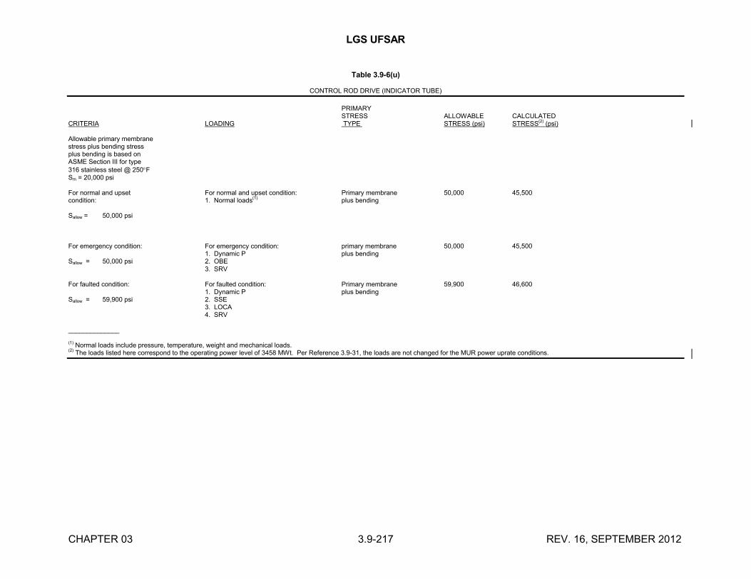
LGS UFSAR
CHAPTER 03 3.9-217 REV. 16, SEPTEMBER 2012
Table 3.9-6(u)
CONTROL ROD DRIVE (INDICATOR TUBE)
PRIMARYSTRESS ALLOWABLE CALCULATED
CRITERIA LOADING TYPE STRESS (psi) STRESS(2)
(psi)
Allowable primary membranestress plus bending stressplus bending is based onASME Section III for type316 stainless steel @ 250FSm = 20,000 psi
For normal and upset For normal and upset condition: Primary membrane 50,000 45,500condition: 1. Normal loads
(1)plus bending
Sallow = 50,000 psi
For emergency condition: For emergency condition: primary membrane 50,000 45,5001. Dynamic P plus bending
Sallow = 50,000 psi 2. OBE
3. SRV
For faulted condition: For faulted condition: Primary membrane 59,900 46,6001. Dynamic P plus bending
Sallow = 59,900 psi 2. SSE
3. LOCA
4. SRV
______________
(1) Normal loads include pressure, temperature, weight and mechanical loads.(2) The loads listed here correspond to the operating power level of 3458 MWt. Per Reference 3.9-31, the loads are not changed for the MUR power uprate conditions.
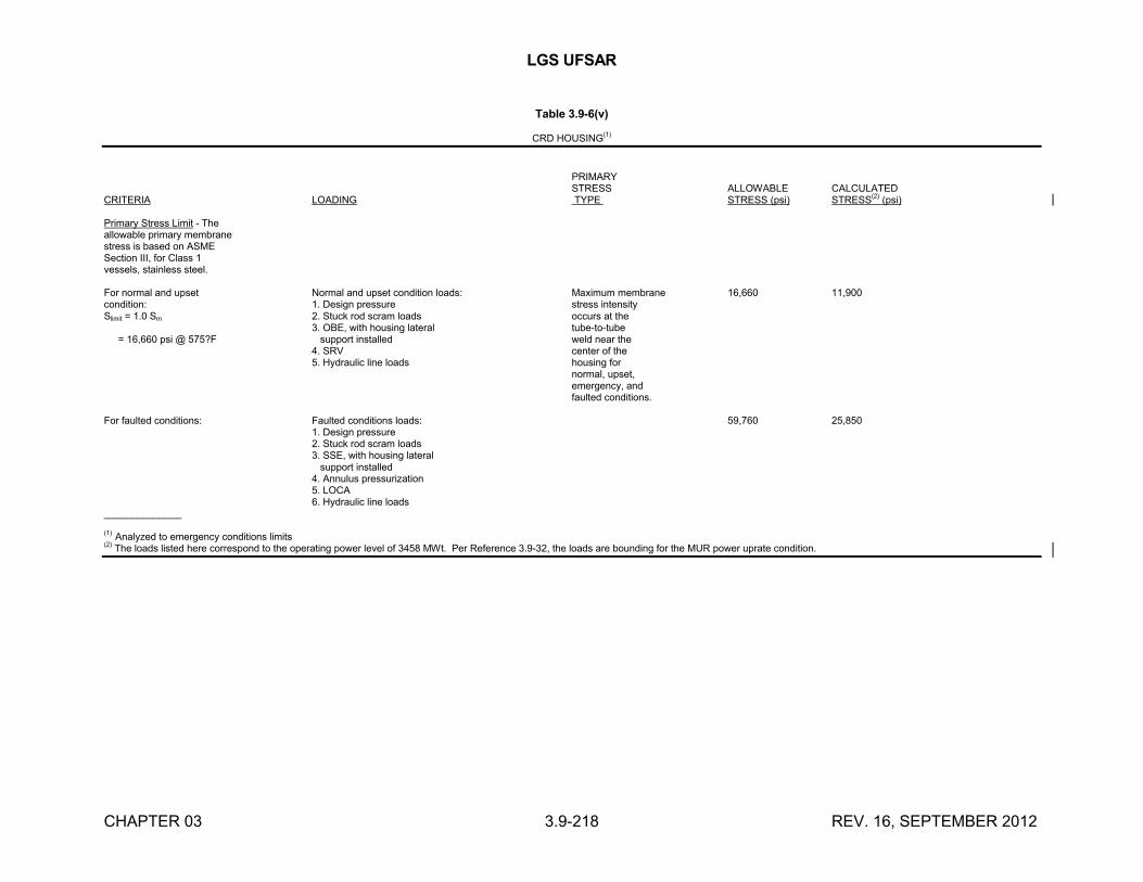
LGS UFSAR
CHAPTER 03 3.9-218 REV. 16, SEPTEMBER 2012
Table 3.9-6(v)
CRD HOUSING(1)
PRIMARYSTRESS ALLOWABLE CALCULATED
CRITERIA LOADING TYPE STRESS (psi) STRESS(2)
(psi)
Primary Stress Limit - Theallowable primary membranestress is based on ASMESection III, for Class 1vessels, stainless steel.
For normal and upset Normal and upset condition loads: Maximum membrane 16,660 11,900condition: 1. Design pressure stress intensitySlimit = 1.0 Sm 2. Stuck rod scram loads occurs at the
3. OBE, with housing lateral tube-to-tube
= 16,660 psi @ 575?F support installed weld near the4. SRV center of the5. Hydraulic line loads housing for
normal, upset,emergency, andfaulted conditions.
For faulted conditions: Faulted conditions loads: 59,760 25,8501. Design pressure2. Stuck rod scram loads
3. SSE, with housing lateral support installed4. Annulus pressurization5. LOCA6. Hydraulic line loads
______________
(1) Analyzed to emergency conditions limits(2) The loads listed here correspond to the operating power level of 3458 MWt. Per Reference 3.9-32, the loads are bounding for the MUR power uprate condition.
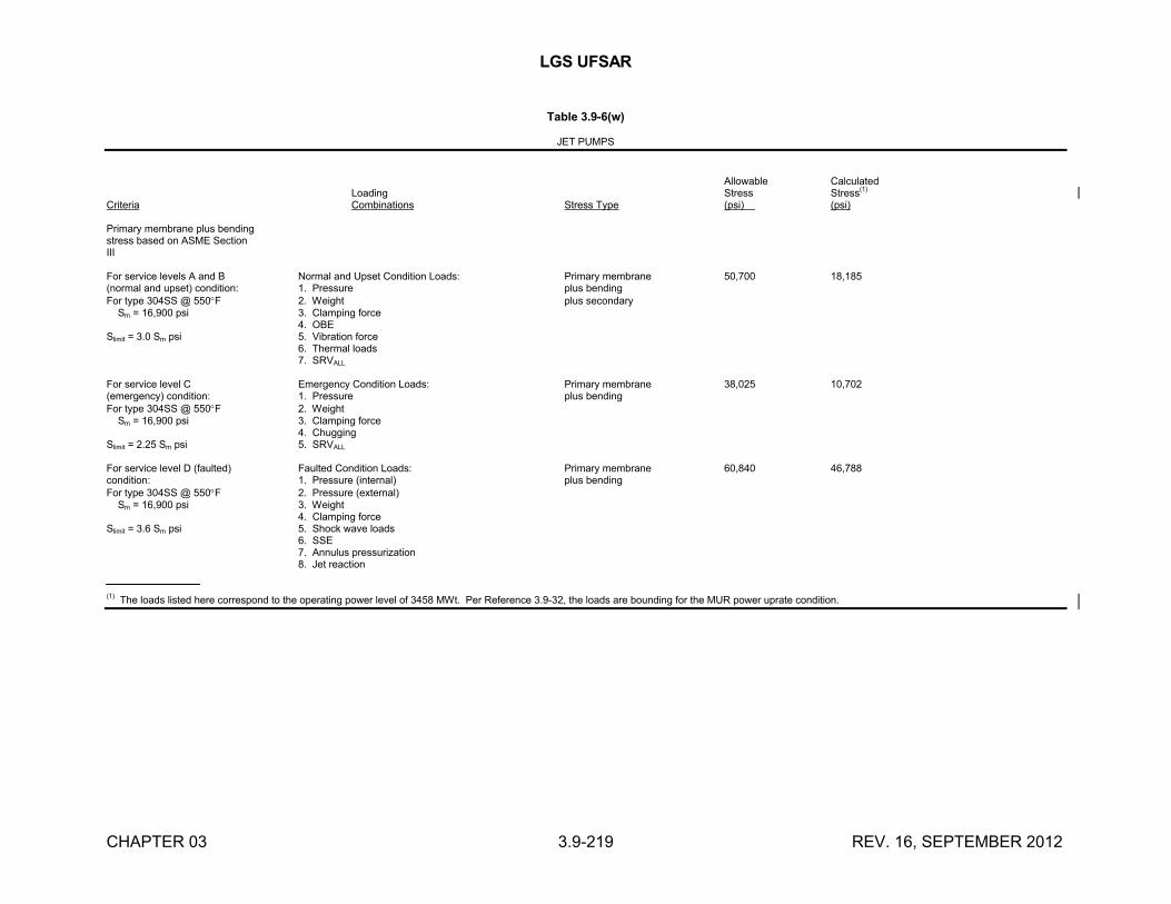
LGS UFSAR
CHAPTER 03 3.9-219 REV. 16, SEPTEMBER 2012
Table 3.9-6(w)
JET PUMPS
Allowable CalculatedLoading Stress Stress
(1)
Criteria Combinations Stress Type (psi) (psi)
Primary membrane plus bendingstress based on ASME SectionIII
For service levels A and B Normal and Upset Condition Loads: Primary membrane 50,700 18,185(normal and upset) condition: 1. Pressure plus bendingFor type 304SS @ 550F 2. Weight plus secondary Sm = 16,900 psi 3. Clamping force
4. OBESlimit = 3.0 Sm psi 5. Vibration force
6. Thermal loads7. SRVALL
For service level C Emergency Condition Loads: Primary membrane 38,025 10,702(emergency) condition: 1. Pressure plus bendingFor type 304SS @ 550F 2. Weight Sm = 16,900 psi 3. Clamping force
4. ChuggingSlimit = 2.25 Sm psi 5. SRVALL
For service level D (faulted) Faulted Condition Loads: Primary membrane 60,840 46,788condition: 1. Pressure (internal) plus bendingFor type 304SS @ 550F 2. Pressure (external) Sm = 16,900 psi 3. Weight
4. Clamping forceSlimit = 3.6 Sm psi 5. Shock wave loads
6. SSE7. Annulus pressurization8. Jet reaction
(1) The loads listed here correspond to the operating power level of 3458 MWt. Per Reference 3.9-32, the loads are bounding for the MUR power uprate condition.
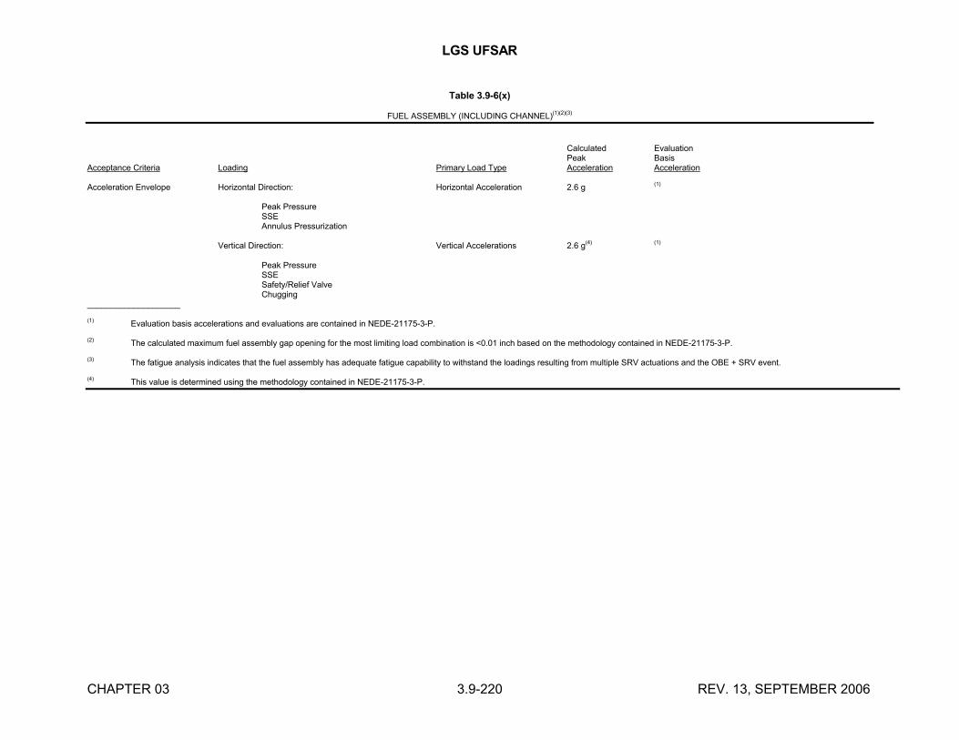
LGS UFSAR
CHAPTER 03 3.9-220 REV. 13, SEPTEMBER 2006
Table 3.9-6(x)
FUEL ASSEMBLY (INCLUDING CHANNEL)(1)(2)(3)
Calculated EvaluationPeak Basis
Acceptance Criteria Loading Primary Load Type Acceleration Acceleration
Acceleration Envelope Horizontal Direction: Horizontal Acceleration 2.6 g (1)
Peak PressureSSEAnnulus Pressurization
Vertical Direction: Vertical Accelerations 2.6 g(4) (1)
Peak PressureSSESafety/Relief ValveChugging
____________________
(1) Evaluation basis accelerations and evaluations are contained in NEDE-21175-3-P.
(2) The calculated maximum fuel assembly gap opening for the most limiting load combination is <0.01 inch based on the methodology contained in NEDE-21175-3-P.
(3) The fatigue analysis indicates that the fuel assembly has adequate fatigue capability to withstand the loadings resulting from multiple SRV actuations and the OBE + SRV event.
(4) This value is determined using the methodology contained in NEDE-21175-3-P.
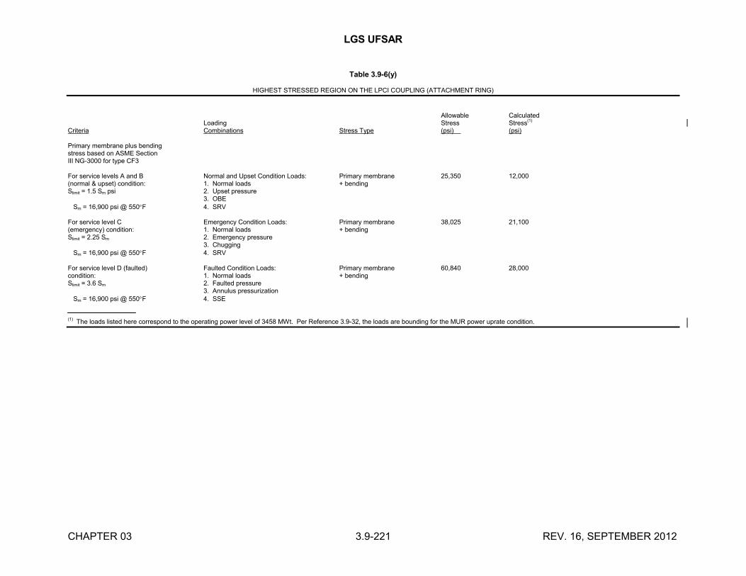
LGS UFSAR
CHAPTER 03 3.9-221 REV. 16, SEPTEMBER 2012
Table 3.9-6(y)
HIGHEST STRESSED REGION ON THE LPCI COUPLING (ATTACHMENT RING)
Allowable CalculatedLoading Stress Stress
(1)
Criteria Combinations Stress Type (psi) (psi)
Primary membrane plus bendingstress based on ASME SectionIII NG-3000 for type CF3
For service levels A and B Normal and Upset Condition Loads: Primary membrane 25,350 12,000(normal & upset) condition: 1. Normal loads + bendingSlimit = 1.5 Sm psi 2. Upset pressure
3. OBE Sm = 16,900 psi @ 550F 4. SRV
For service level C Emergency Condition Loads: Primary membrane 38,025 21,100(emergency) condition: 1. Normal loads + bendingSlimit = 2.25 Sm 2. Emergency pressure
3. Chugging Sm = 16,900 psi @ 550F 4. SRV
For service level D (faulted) Faulted Condition Loads: Primary membrane 60,840 28,000condition: 1. Normal loads + bendingSlimit = 3.6 Sm 2. Faulted pressure
3. Annulus pressurization Sm = 16,900 psi @ 550F 4. SSE
(1) The loads listed here correspond to the operating power level of 3458 MWt. Per Reference 3.9-32, the loads are bounding for the MUR power uprate condition.
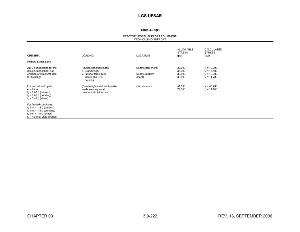
LGS UFSAR
CHAPTER 03 3.9-222 REV. 13, SEPTEMBER 2006
Table 3.9-6(z)
REACTOR VESSEL SUPPORT EQUIPMENT:CRD HOUSING SUPPORT
ALLOWABLE CALCULATEDSTRESS STRESS
CRITERIA LOADING LOCATION (psi) (psi)
Primary Stress Limit
AISC specification for the Faulted condition loads Beams (top chord) 33,000 fa = 12,200design, fabrication, and 1. Deadweight 33,000 fb = 16,500erection of structural steel 2. Impact force from Beams (bottom 33,000 fa = 10,300for buildings failure of a CRD chord) 33,000 fb = 11,700
housing
For normal and upset (Deadweights and earthquake Grid structure 41,500 fb = 40,700condition: loads are very small 27,500 fv = 11,100fa = 0.60 fy (tension) compared to jet forces.)fb = 0.60 fy (bending)fv = 0.40 fy (shear)
For faulted conditions:fa limit = 1.5 fa (tension)fb limit = 1.5 fb (bonding)fv limit = 1.5 fv (shear)fy = material yield strength
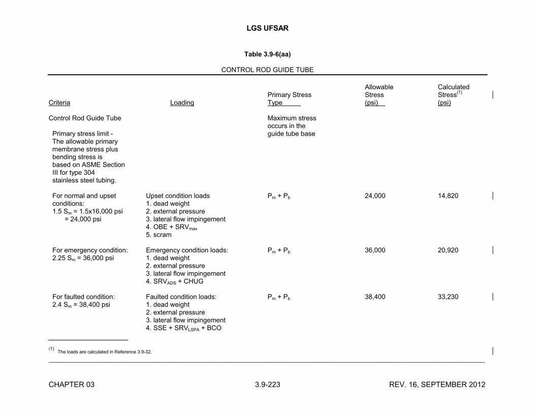
LGS UFSAR
CHAPTER 03 3.9-223 REV. 16, SEPTEMBER 2012
Table 3.9-6(aa)
CONTROL ROD GUIDE TUBE
Allowable CalculatedPrimary Stress Stress Stress
(1)
Criteria Loading Type (psi) (psi)
Control Rod Guide Tube Maximum stressoccurs in the
Primary stress limit - guide tube base The allowable primary membrane stress plus bending stress is based on ASME Section III for type 304 stainless steel tubing.
For normal and upset Upset condition loads Pm + Pb 24,000 14,820 conditions: 1. dead weight 1.5 Sm = 1.5x16,000 psi 2. external pressure = 24,000 psi 3. lateral flow impingement
4. OBE + SRVmax
5. scram
For emergency condition: Emergency condition loads: Pm + Pb 36,000 20,920 2.25 Sm = 36,000 psi 1. dead weight
2. external pressure3. lateral flow impingement4. SRVADS + CHUG
For faulted condition: Faulted condition loads: Pm + Pb 38,400 33,230 2.4 Sm = 38,400 psi 1. dead weight
2. external pressure3. lateral flow impingement4. SSE + SRVLSPA + BCO
(1) The loads are calculated in Reference 3.9-32.
_____________________________________________________________________________________________________________________
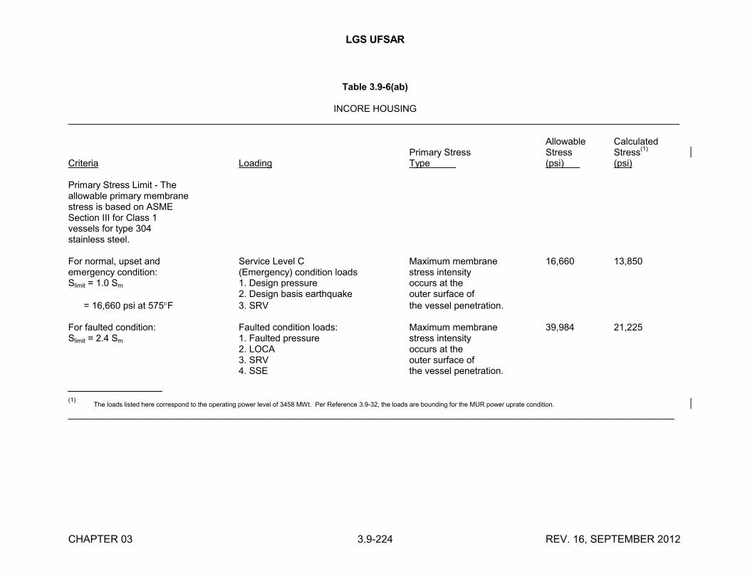
LGS UFSAR
CHAPTER 03 3.9-224 REV. 16, SEPTEMBER 2012
Table 3.9-6(ab)
INCORE HOUSING_____________________________________________________________________________________________________________________
Allowable CalculatedPrimary Stress Stress Stress
(1)
Criteria Loading Type (psi) (psi)
Primary Stress Limit - Theallowable primary membranestress is based on ASMESection III for Class 1vessels for type 304stainless steel.
For normal, upset and Service Level C Maximum membrane 16,660 13,850emergency condition: (Emergency) condition loads stress intensitySlimit = 1.0 Sm 1. Design pressure occurs at the
2. Design basis earthquake outer surface of = 16,660 psi at 575F 3. SRV the vessel penetration.
For faulted condition: Faulted condition loads: Maximum membrane 39,984 21,225Slimit = 2.4 Sm 1. Faulted pressure stress intensity
2. LOCA occurs at the3. SRV outer surface of4. SSE the vessel penetration.
(1)The loads listed here correspond to the operating power level of 3458 MWt. Per Reference 3.9-32, the loads are bounding for the MUR power uprate condition.
____________________________________________________________________________________________________________________
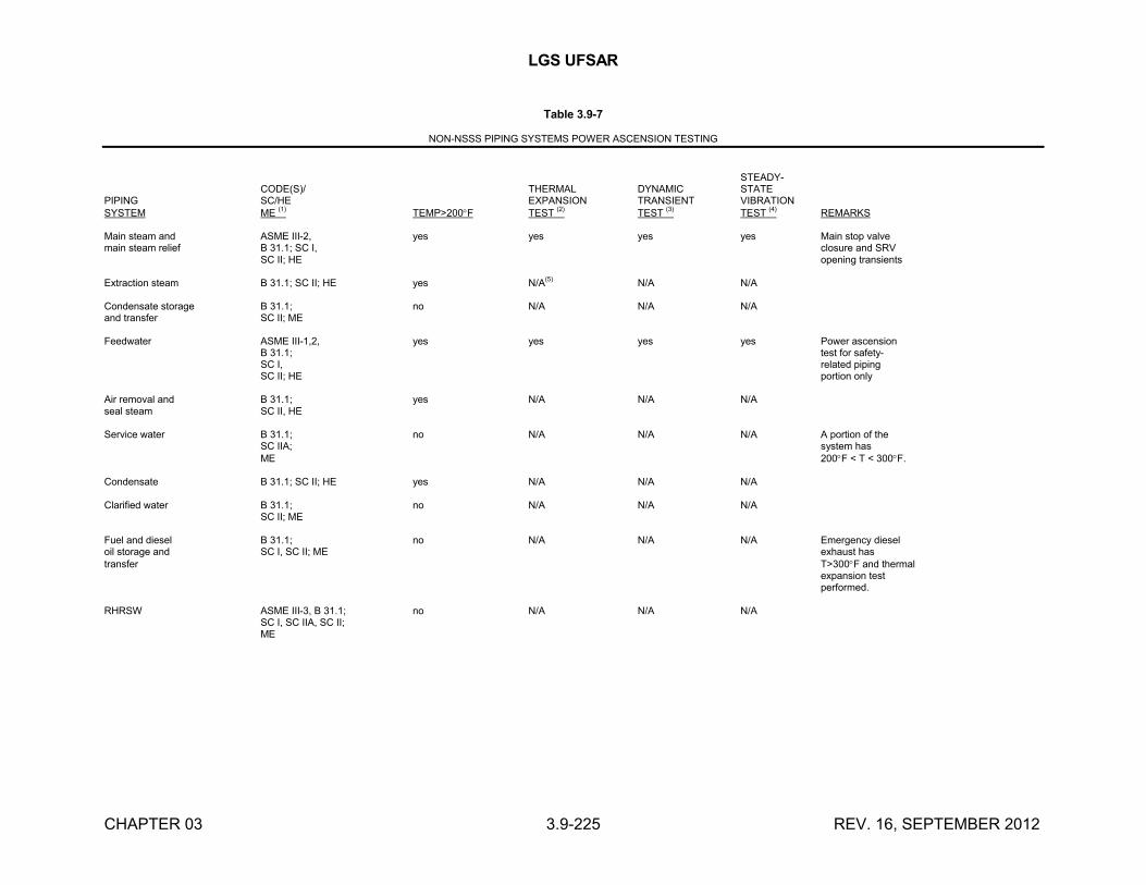
LGS UFSAR
CHAPTER 03 3.9-225 REV. 16, SEPTEMBER 2012
Table 3.9-7
NON-NSSS PIPING SYSTEMS POWER ASCENSION TESTING
STEADY-CODE(S)/ THERMAL DYNAMIC STATE
PIPING SC/HE EXPANSION TRANSIENT VIBRATIONSYSTEM ME (1) TEMP>200F TEST (2) TEST (3) TEST (4) REMARKS
Main steam and ASME III-2, yes yes yes yes Main stop valvemain steam relief B 31.1; SC I, closure and SRV
SC II; HE opening transients
Extraction steam B 31.1; SC II; HE yes N/A(5)
N/A N/A
Condensate storage B 31.1; no N/A N/A N/Aand transfer SC II; ME
Feedwater ASME III-1,2, yes yes yes yes Power ascensionB 31.1; test for safety-SC I, related pipingSC II; HE portion only
Air removal and B 31.1; yes N/A N/A N/Aseal steam SC II, HE
Service water B 31.1; no N/A N/A N/A A portion of theSC IIA; system hasME 200F < T < 300F.
Condensate B 31.1; SC II; HE yes N/A N/A N/A
Clarified water B 31.1; no N/A N/A N/ASC II; ME
Fuel and diesel B 31.1; no N/A N/A N/A Emergency dieseloil storage and SC I, SC II; ME exhaust hastransfer T>300F and thermal
expansion testperformed.
RHRSW ASME III-3, B 31.1; no N/A N/A N/ASC I, SC IIA, SC II;ME
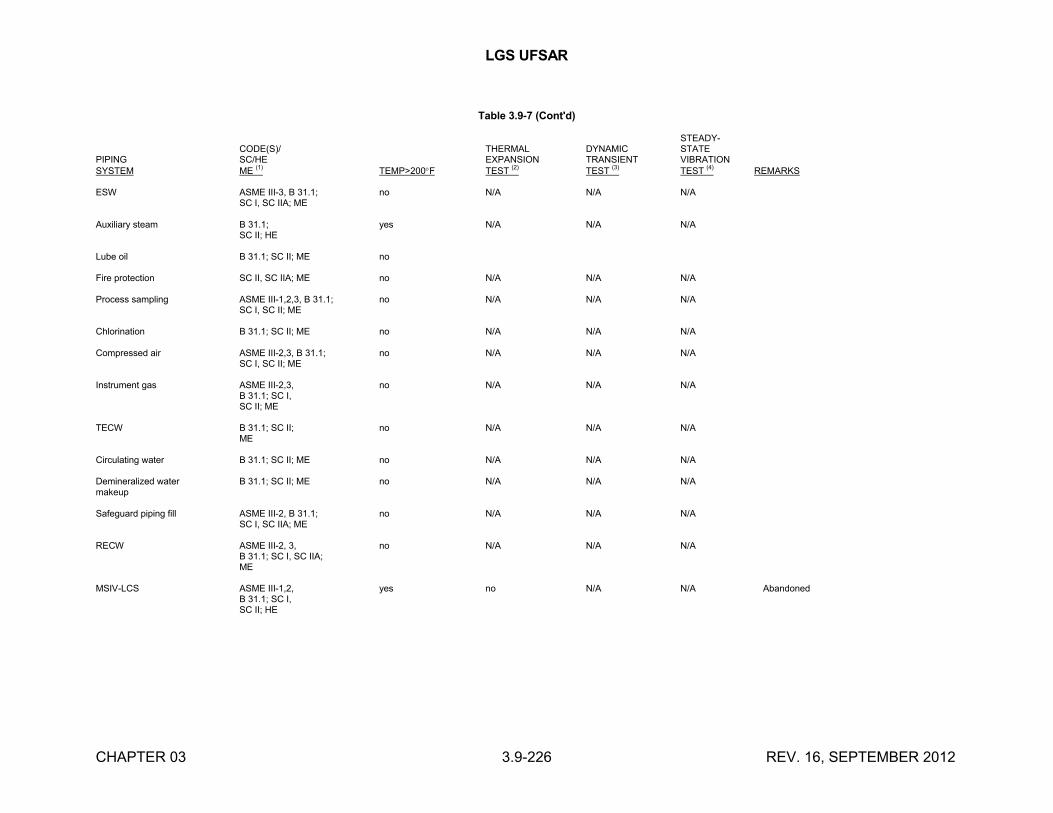
LGS UFSAR
CHAPTER 03 3.9-226 REV. 16, SEPTEMBER 2012
Table 3.9-7 (Cont'd)
STEADY-CODE(S)/ THERMAL DYNAMIC STATE
PIPING SC/HE EXPANSION TRANSIENT VIBRATIONSYSTEM ME (1) TEMP>200F TEST (2) TEST (3) TEST (4) REMARKS
ESW ASME III-3, B 31.1; no N/A N/A N/ASC I, SC IIA; ME
Auxiliary steam B 31.1; yes N/A N/A N/ASC II; HE
Lube oil B 31.1; SC II; ME no
Fire protection SC II, SC IIA; ME no N/A N/A N/A
Process sampling ASME III-1,2,3, B 31.1; no N/A N/A N/ASC I, SC II; ME
Chlorination B 31.1; SC II; ME no N/A N/A N/A
Compressed air ASME III-2,3, B 31.1; no N/A N/A N/ASC I, SC II; ME
Instrument gas ASME III-2,3, no N/A N/A N/AB 31.1; SC I,SC II; ME
TECW B 31.1; SC II; no N/A N/A N/AME
Circulating water B 31.1; SC II; ME no N/A N/A N/A
Demineralized water B 31.1; SC II; ME no N/A N/A N/Amakeup
Safeguard piping fill ASME III-2, B 31.1; no N/A N/A N/ASC I, SC IIA; ME
RECW ASME III-2, 3, no N/A N/A N/AB 31.1; SC I, SC IIA;ME
MSIV-LCS ASME III-1,2, yes no N/A N/A AbandonedB 31.1; SC I,SC II; HE
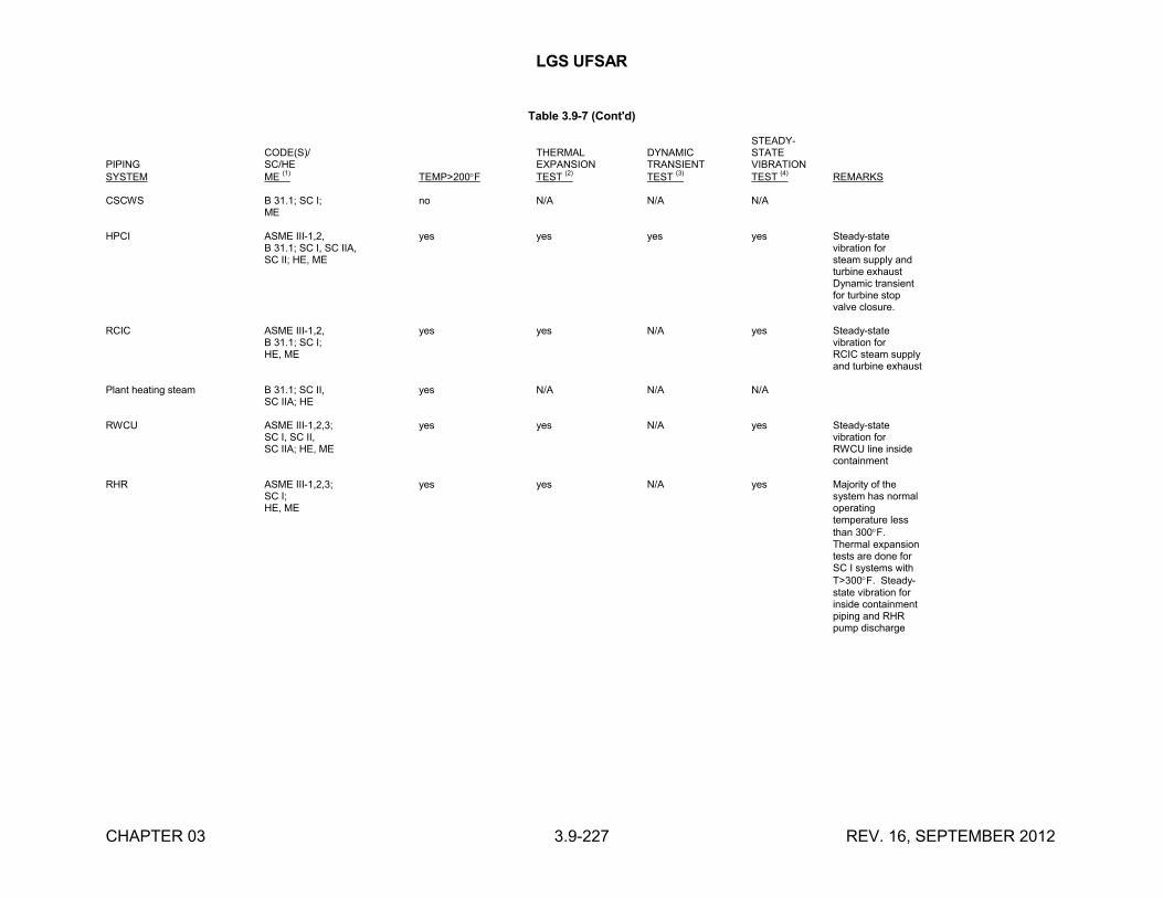
LGS UFSAR
CHAPTER 03 3.9-227 REV. 16, SEPTEMBER 2012
Table 3.9-7 (Cont'd)
STEADY-CODE(S)/ THERMAL DYNAMIC STATE
PIPING SC/HE EXPANSION TRANSIENT VIBRATIONSYSTEM ME
(1)TEMP>200F TEST
(2)TEST
(3)TEST
(4)REMARKS
CSCWS B 31.1; SC I; no N/A N/A N/AME
HPCI ASME III-1,2, yes yes yes yes Steady-stateB 31.1; SC I, SC IIA, vibration forSC II; HE, ME steam supply and
turbine exhaustDynamic transient for turbine stopvalve closure.
RCIC ASME III-1,2, yes yes N/A yes Steady-stateB 31.1; SC I; vibration forHE, ME RCIC steam supply
and turbine exhaust
Plant heating steam B 31.1; SC II, yes N/A N/A N/ASC IIA; HE
RWCU ASME III-1,2,3; yes yes N/A yes Steady-stateSC I, SC II, vibration forSC IIA; HE, ME RWCU line inside
containment
RHR ASME III-1,2,3; yes yes N/A yes Majority of theSC I; system has normalHE, ME operating
temperature less than 300F.Thermal expansiontests are done forSC I systems withT>300F. Steady-state vibration forinside containment piping and RHRpump discharge
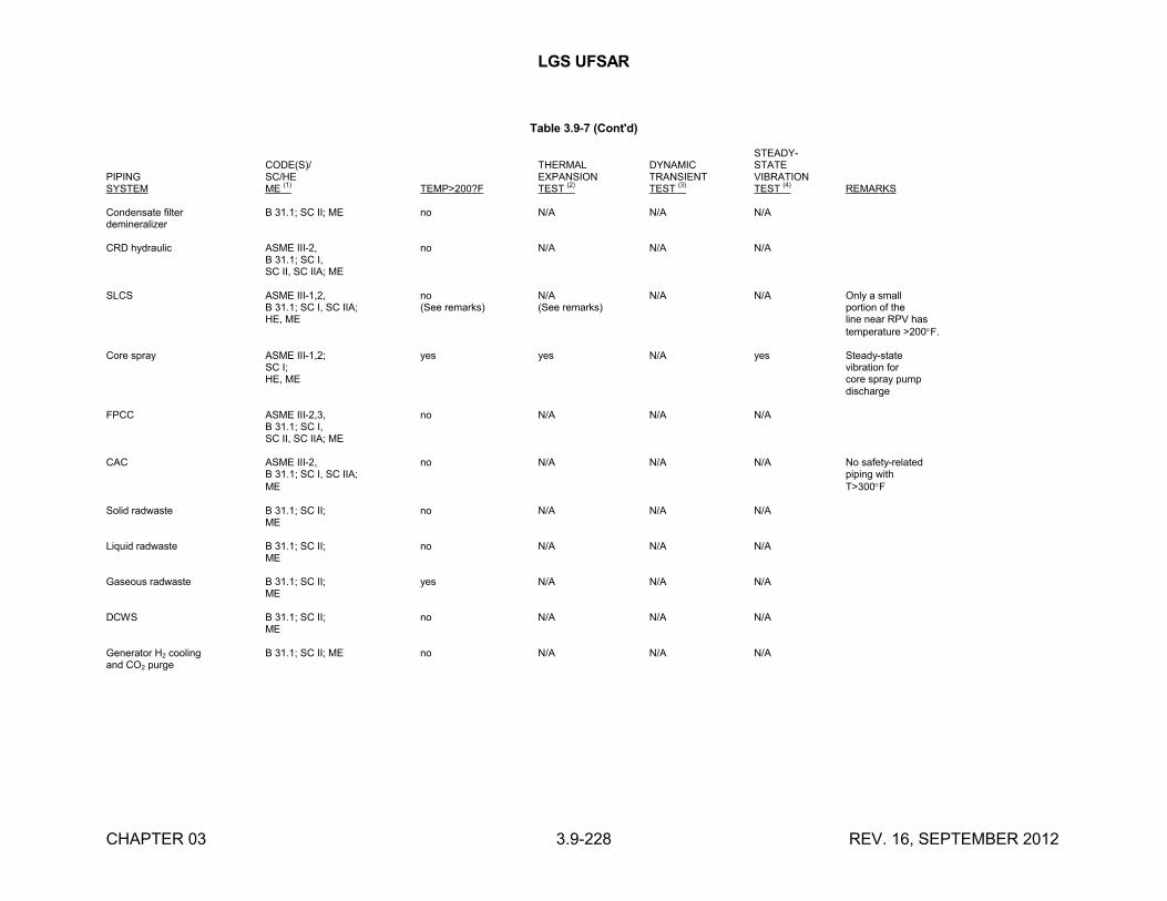
LGS UFSAR
CHAPTER 03 3.9-228 REV. 16, SEPTEMBER 2012
Table 3.9-7 (Cont'd)
STEADY-CODE(S)/ THERMAL DYNAMIC STATE
PIPING SC/HE EXPANSION TRANSIENT VIBRATIONSYSTEM ME
(1)TEMP>200?F TEST
(2)TEST
(3)TEST
(4)REMARKS
Condensate filter B 31.1; SC II; ME no N/A N/A N/Ademineralizer
CRD hydraulic ASME III-2, no N/A N/A N/AB 31.1; SC I,SC II, SC IIA; ME
SLCS ASME III-1,2, no N/A N/A N/A Only a smallB 31.1; SC I, SC IIA; (See remarks) (See remarks) portion of theHE, ME line near RPV has
temperature >200F.
Core spray ASME III-1,2; yes yes N/A yes Steady-stateSC I; vibration forHE, ME core spray pump
discharge
FPCC ASME III-2,3, no N/A N/A N/AB 31.1; SC I,SC II, SC IIA; ME
CAC ASME III-2, no N/A N/A N/A No safety-relatedB 31.1; SC I, SC IIA; piping withME T>300F
Solid radwaste B 31.1; SC II; no N/A N/A N/AME
Liquid radwaste B 31.1; SC II; no N/A N/A N/AME
Gaseous radwaste B 31.1; SC II; yes N/A N/A N/AME
DCWS B 31.1; SC II; no N/A N/A N/AME
Generator H2 cooling B 31.1; SC II; ME no N/A N/A N/Aand CO2 purge
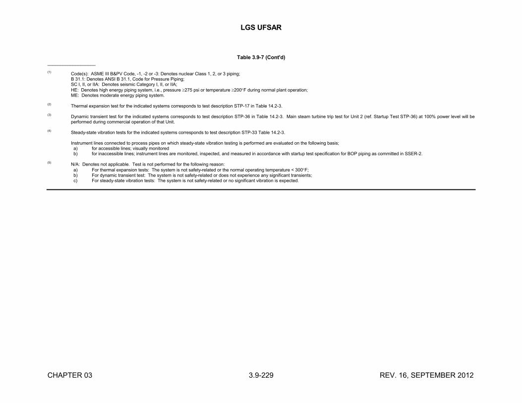
LGS UFSAR
CHAPTER 03 3.9-229 REV. 16, SEPTEMBER 2012
Table 3.9-7 (Cont'd)___________________
(1) Code(s): ASME III B&PV Code, -1, -2 or -3: Denotes nuclear Class 1, 2, or 3 piping;B 31.1: Denotes ANSI B 31.1, Code for Pressure Piping;SC I, II, or IIA: Denotes seismic Category I, II, or IIA;HE: Denotes high energy piping system, i.e., pressure 275 psi or temperature 200F during normal plant operation;ME: Denotes moderate energy piping system.
(2) Thermal expansion test for the indicated systems corresponds to test description STP-17 in Table 14.2-3.
(3)Dynamic transient test for the indicated systems corresponds to test description STP-36 in Table 14.2-3. Main steam turbine trip test for Unit 2 (ref. Startup Test STP-36) at 100% power level will be performed during commercial operation of that Unit.
(4)Steady-state vibration tests for the indicated systems corresponds to test description STP-33 Table 14.2-3.
Instrument lines connected to process pipes on which steady-state vibration testing is performed are evaluated on the following basis; a) for accessible lines; visually monitored b) for inaccessible lines; instrument lines are monitored, inspected, and measured in accordance with startup test specification for BOP piping as committed in SSER-2.
(5) N/A: Denotes not applicable. Test is not performed for the following reason: a) For thermal expansion tests: The system is not safety-related or the normal operating temperature < 300F; b) For dynamic transient test: The system is not safety-related or does not experience any significant transients; c) For steady-state vibration tests: The system is not safety-related or no significant vibration is expected.
LGS UFSAR
CHAPTER 03 3.9-230 REV. 13, SEPTEMBER 2006
Table 3.9-8
INTENTIONALLY LEFT BLANK
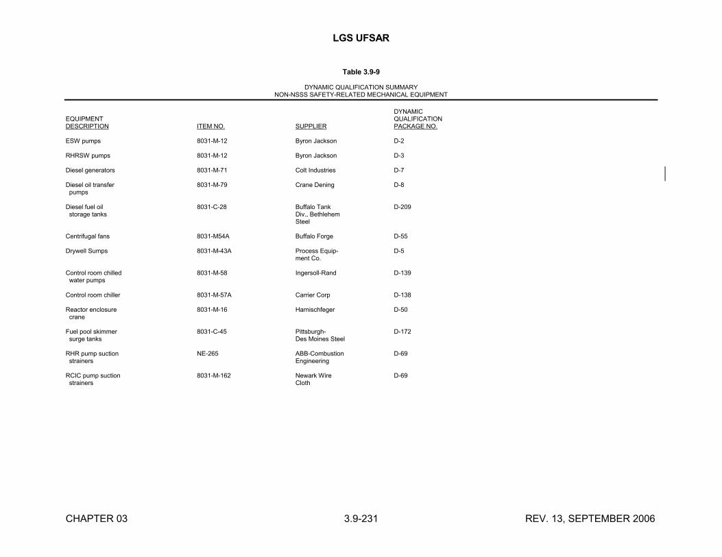
LGS UFSAR
CHAPTER 03 3.9-231 REV. 13, SEPTEMBER 2006
Table 3.9-9
DYNAMIC QUALIFICATION SUMMARYNON-NSSS SAFETY-RELATED MECHANICAL EQUIPMENT
DYNAMICEQUIPMENT QUALIFICATIONDESCRIPTION ITEM NO. SUPPLIER PACKAGE NO.
ESW pumps 8031-M-12 Byron Jackson D-2
RHRSW pumps 8031-M-12 Byron Jackson D-3
Diesel generators 8031-M-71 Colt Industries D-7
Diesel oil transfer 8031-M-79 Crane Dening D-8 pumps
Diesel fuel oil 8031-C-28 Buffalo Tank D-209 storage tanks Div., Bethlehem
Steel
Centrifugal fans 8031-M54A Buffalo Forge D-55
Drywell Sumps 8031-M-43A Process Equip- D-5ment Co.
Control room chilled 8031-M-58 Ingersoll-Rand D-139 water pumps
Control room chiller 8031-M-57A Carrier Corp D-138
Reactor enclosure 8031-M-16 Harnischfeger D-50 crane
Fuel pool skimmer 8031-C-45 Pittsburgh- D-172 surge tanks Des Moines Steel
RHR pump suction NE-265 ABB-Combustion D-69 strainers Engineering
RCIC pump suction 8031-M-162 Newark Wire D-69 strainers Cloth
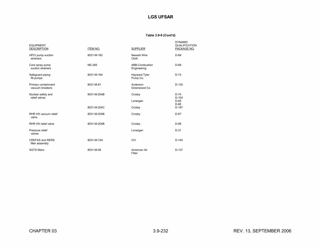
LGS UFSAR
CHAPTER 03 3.9-232 REV. 13, SEPTEMBER 2006
Table 3.9-9 (Cont'd)
DYNAMICEQUIPMENT QUALIFICATIONDESCRIPTION ITEM NO. SUPPLIER PACKAGE NO.
HPCI pump suction 8031-M-162 Newark Wire D-69 strainers Cloth
Core spray pump NE-265 ABB-Combustion D-69 suction strainers Engineering
Safeguard piping 8031-M-164 Hayward Tyler D-73 fill pumps Pump Co.
Primary containment 8031-M-81 Anderson D-135 vacuum breakers Greenwood Co.
Nuclear safety and 8031-M-204B Crosby D-74 relief valves D-154
Lonergan D-65D-66
8031-M-204C Crosby D-197
RHR HX vacuum relief 8031-M-204B Crosby D-67 valve
RHR HX relief valve 8031-M-204B Crosby D-68
Pressure relief Lonergan D-31 valves
CREFAS and RERS 8031-M-72A CIV D-140 filter assembly
SGTS filters 8031-M-56 American Air D-137Filter
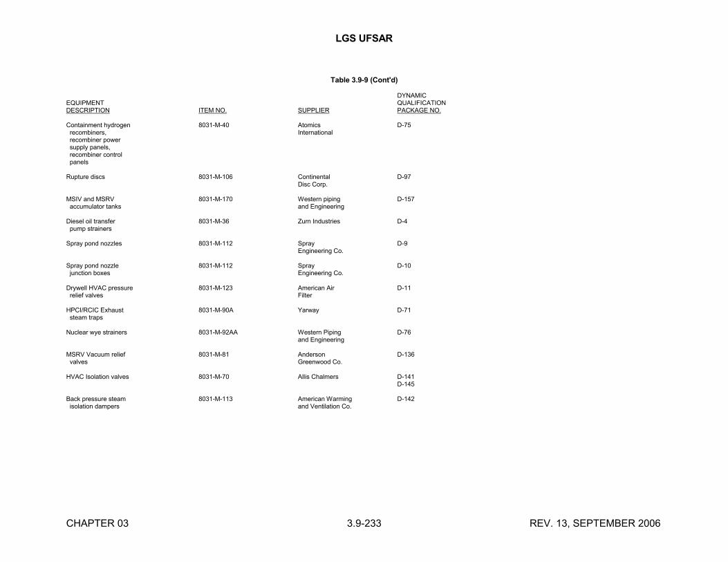
LGS UFSAR
CHAPTER 03 3.9-233 REV. 13, SEPTEMBER 2006
Table 3.9-9 (Cont'd)
DYNAMICEQUIPMENT QUALIFICATIONDESCRIPTION ITEM NO. SUPPLIER PACKAGE NO.
Containment hydrogen 8031-M-40 Atomics D-75 recombiners, International recombiner power supply panels, recombiner control panels
Rupture discs 8031-M-106 Continental D-97Disc Corp.
MSIV and MSRV 8031-M-170 Western piping D-157 accumulator tanks and Engineering
Diesel oil transfer 8031-M-36 Zurn Industries D-4 pump strainers
Spray pond nozzles 8031-M-112 Spray D-9Engineering Co.
Spray pond nozzle 8031-M-112 Spray D-10 junction boxes Engineering Co.
Drywell HVAC pressure 8031-M-123 American Air D-11 relief valves Filter
HPCI/RCIC Exhaust 8031-M-90A Yarway D-71 steam traps
Nuclear wye strainers 8031-M-92AA Western Piping D-76and Engineering
MSRV Vacuum relief 8031-M-81 Anderson D-136 valves Greenwood Co.
HVAC Isolation valves 8031-M-70 Allis Chalmers D-141D-145
Back pressure steam 8031-M-113 American Warming D-142 isolation dampers and Ventilation Co.
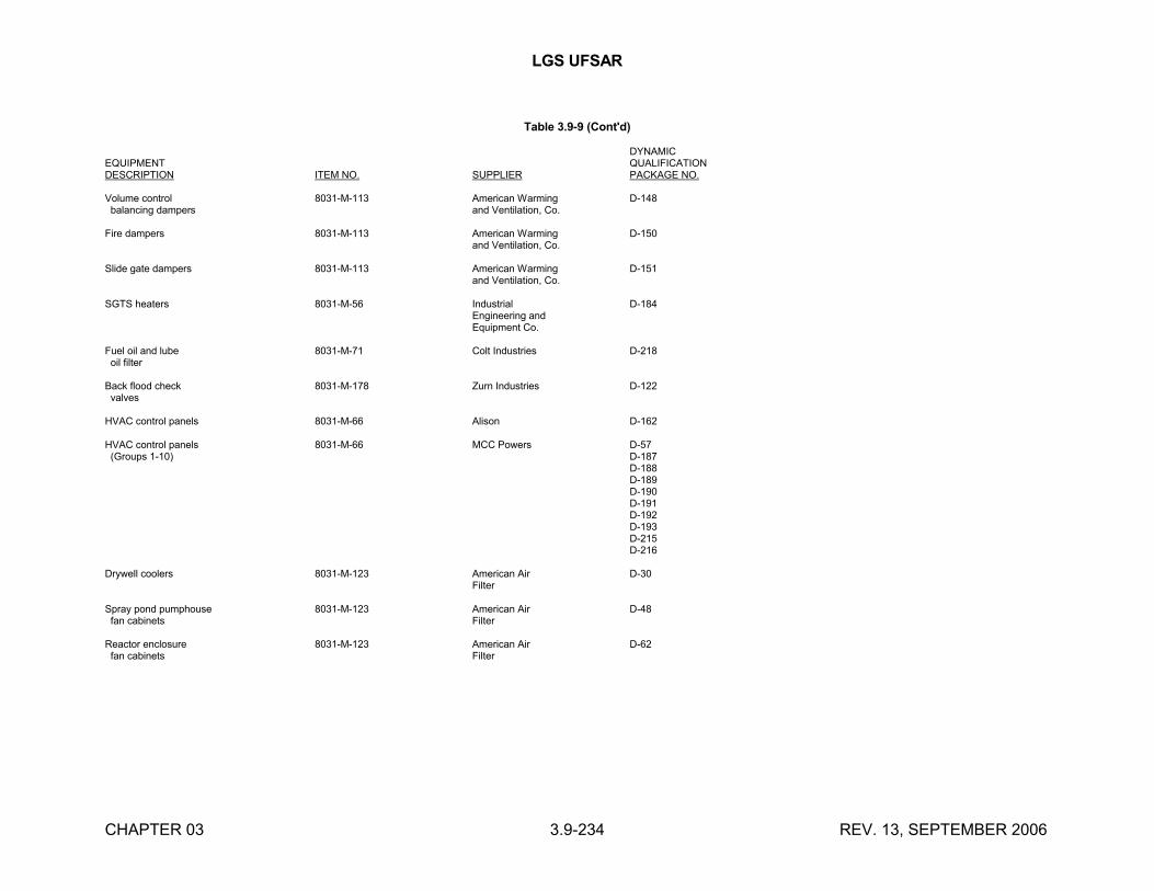
LGS UFSAR
CHAPTER 03 3.9-234 REV. 13, SEPTEMBER 2006
Table 3.9-9 (Cont'd)
DYNAMICEQUIPMENT QUALIFICATIONDESCRIPTION ITEM NO. SUPPLIER PACKAGE NO.
Volume control 8031-M-113 American Warming D-148 balancing dampers and Ventilation, Co.
Fire dampers 8031-M-113 American Warming D-150and Ventilation, Co.
Slide gate dampers 8031-M-113 American Warming D-151and Ventilation, Co.
SGTS heaters 8031-M-56 Industrial D-184Engineering andEquipment Co.
Fuel oil and lube 8031-M-71 Colt Industries D-218 oil filter
Back flood check 8031-M-178 Zurn Industries D-122 valves
HVAC control panels 8031-M-66 Alison D-162
HVAC control panels 8031-M-66 MCC Powers D-57 (Groups 1-10) D-187
D-188D-189D-190D-191D-192D-193D-215D-216
Drywell coolers 8031-M-123 American Air D-30Filter
Spray pond pumphouse 8031-M-123 American Air D-48 fan cabinets Filter
Reactor enclosure 8031-M-123 American Air D-62 fan cabinets Filter
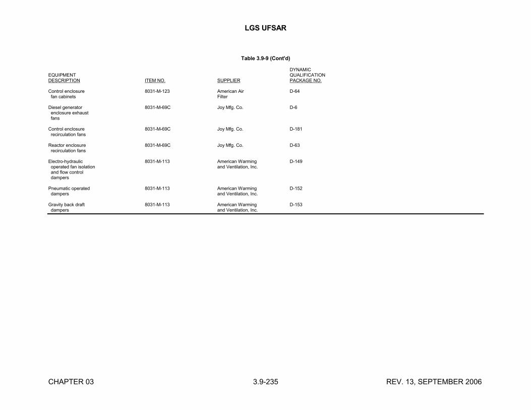
LGS UFSAR
CHAPTER 03 3.9-235 REV. 13, SEPTEMBER 2006
Table 3.9-9 (Cont'd)
DYNAMICEQUIPMENT QUALIFICATIONDESCRIPTION ITEM NO. SUPPLIER PACKAGE NO.
Control enclosure 8031-M-123 American Air D-64 fan cabinets Filter
Diesel generator 8031-M-69C Joy Mfg. Co. D-6 enclosure exhaust fans
Control enclosure 8031-M-69C Joy Mfg. Co. D-181 recirculation fans
Reactor enclosure 8031-M-69C Joy Mfg. Co. D-63 recirculation fans
Electro-hydraulic 8031-M-113 American Warming D-149 operated fan isolation and Ventilation, Inc. and flow control dampers
Pneumatic operated 8031-M-113 American Warming D-152 dampers and Ventilation, Inc.
Gravity back draft 8031-M-113 American Warming D-153 dampers and Ventilation, Inc.
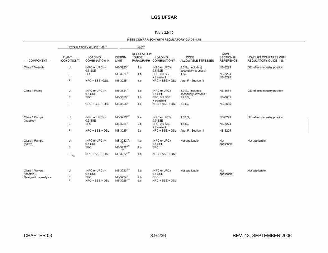
LGS UFSAR
CHAPTER 03 3.9-236 REV. 13, SEPTEMBER 2006
Table 3.9-10
NSSS COMPARISON WITH REGULATORY GUIDE 1.48
REGULATORY GUIDE 1.48(1)
LGS(1)
REGULATORY ASME PLANT LOADING DESIGN GUIDE LOADING CODE SECTION III HOW LGS COMPARES WITH
COMPONENT CONDITION(2)
COMBINATION 1/ LIMIT PARAGRAPH COMBINATION(c)
ALLOWABLE STRESSES REFERENCE REGULATORY GUIDE 1.48
Class 1 Vessels U (NPC or UPC) + NB-32232/
1.a (NPC or UPC), 3.0 Sm (includes) NB-3223 GE reflects industry position0.5 SSE 0.5 SSE secondary stresses)
E EPC NB-32242/ 1.b EPC, 0.5 SSE 1.8m NB-3224+ transient NB-3225
F NPC + SSE +DSL NB-32252/
1.c NPC + SSE + DSL App. F - Section III
Class 1 Piping U (NPC or UPC) + NB-36542/ 1.a (NPC or UPC), 3.0 Sm (includes NB-3654 GE reflects industry position0.5 SSE 0.5 SSE secondary stresses
E EPC NB-36552/
1.b EPC, 0.5 SSE 2.25 Sm NB-3655+ transient
F NPC + SSE + DSL NB-36562/
1.c NPC + SSE + DSL 3.0 Sm NB-3656
Class 1 Pumps U (NPC or UPC) + NB-32235/1/ 2.a (NPC or UPC), 1.63 Sm NB-3223 GE reflects industry position(inactive) 0.5 SSE 0.5 SSE
E EPC NB-32241/ 2.b EPC, 0.5 SSE 1.8 Sm NB-3224+ transient
F NPC + SSE + DSL NB-32251/ 2.c NPC + SSE + DSL App. F - Section III NB-3225
Class 1 Pumps U (NPC or UPC) + NB-32225/6/ 4.a (NPC or UPC), Not applicable Not Not applicable(active) 0.5 SSE 7 8 0.5 SSE applicable
E EPC NB-32225/6/ 4.a EPC 7/8/
F NPC + SSE + DSL NB-32225/6/ 4.a NPC + SSE + DSL 7/8/
Class 1 Valves U (NPC or UPC) + NB-32235/4/ 2.a (NPC or UPC), Not applicable Not Not applicable(inactive) 0.5 SSE 0.5 SSE applicableDesigned by analysis. E EPC NB-32244/ 2.b EPC
F NPC + SSE + DSL NB-32252/4/ 2.c NPC + SSE + DSL
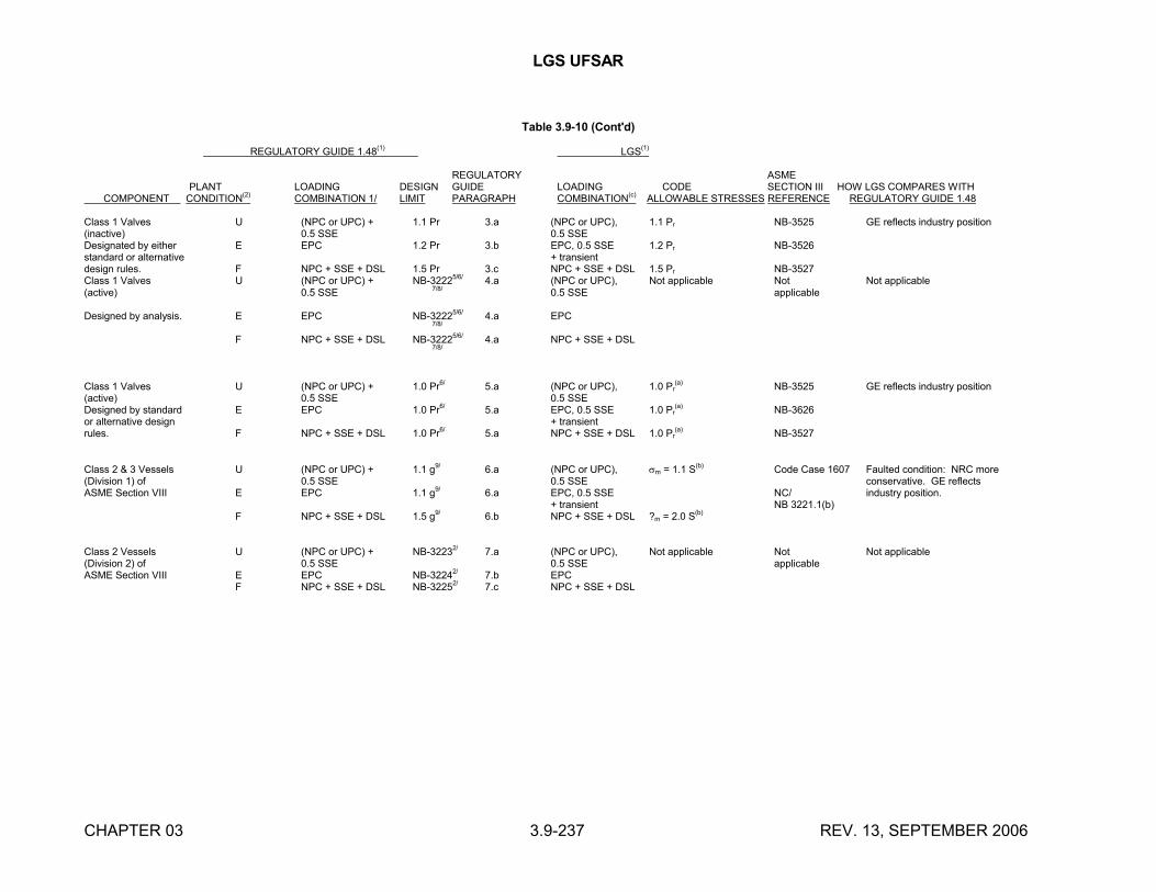
LGS UFSAR
CHAPTER 03 3.9-237 REV. 13, SEPTEMBER 2006
Table 3.9-10 (Cont'd)
REGULATORY GUIDE 1.48(1)
LGS(1)
REGULATORY ASME PLANT LOADING DESIGN GUIDE LOADING CODE SECTION III HOW LGS COMPARES WITH COMPONENT CONDITION(2) COMBINATION 1/ LIMIT PARAGRAPH COMBINATION(c) ALLOWABLE STRESSES REFERENCE REGULATORY GUIDE 1.48
Class 1 Valves U (NPC or UPC) + 1.1 Pr
3.a (NPC or UPC), 1.1 Pr NB-3525 GE reflects industry position(inactive) 0.5 SSE 0.5 SSEDesignated by either E EPC 1.2 Pr 3.b EPC, 0.5 SSE 1.2 Pr NB-3526standard or alternative + transientdesign rules. F NPC + SSE + DSL 1.5 Pr
3.c NPC + SSE + DSL 1.5 Pr NB-3527
Class 1 Valves U (NPC or UPC) + NB-32225/6/ 4.a (NPC or UPC), Not applicable Not Not applicable(active) 0.5 SSE 7/8/ 0.5 SSE applicable
Designed by analysis. E EPC NB-32225/6/
4.a EPC
7/8/
F NPC + SSE + DSL NB-32225/6/ 4.a NPC + SSE + DSL
7/8/
Class 1 Valves U (NPC or UPC) + 1.0 Pr6/ 5.a (NPC or UPC), 1.0 Pr(a) NB-3525 GE reflects industry position
(active) 0.5 SSE 0.5 SSEDesigned by standard E EPC 1.0 Pr6/ 5.a EPC, 0.5 SSE 1.0 Pr
(a) NB-3626or alternative design + transientrules. F NPC + SSE + DSL 1.0 Pr6/ 5.a NPC + SSE + DSL 1.0 Pr
(a) NB-3527
Class 2 & 3 Vessels U (NPC or UPC) + 1.1 g9/ 6.a (NPC or UPC), m = 1.1 S(b) Code Case 1607 Faulted condition: NRC more(Division 1) of 0.5 SSE 0.5 SSE conservative. GE reflectsASME Section VIII E EPC 1.1 g9/ 6.a EPC, 0.5 SSE NC/ industry position.
+ transient NB 3221.1(b)F NPC + SSE + DSL 1.5 g9/ 6.b NPC + SSE + DSL ?m = 2.0 S(b)
Class 2 Vessels U (NPC or UPC) + NB-32232/ 7.a (NPC or UPC), Not applicable Not Not applicable(Division 2) of 0.5 SSE 0.5 SSE applicableASME Section VIII E EPC NB-32242/ 7.b EPC
F NPC + SSE + DSL NB-32252/ 7.c NPC + SSE + DSL
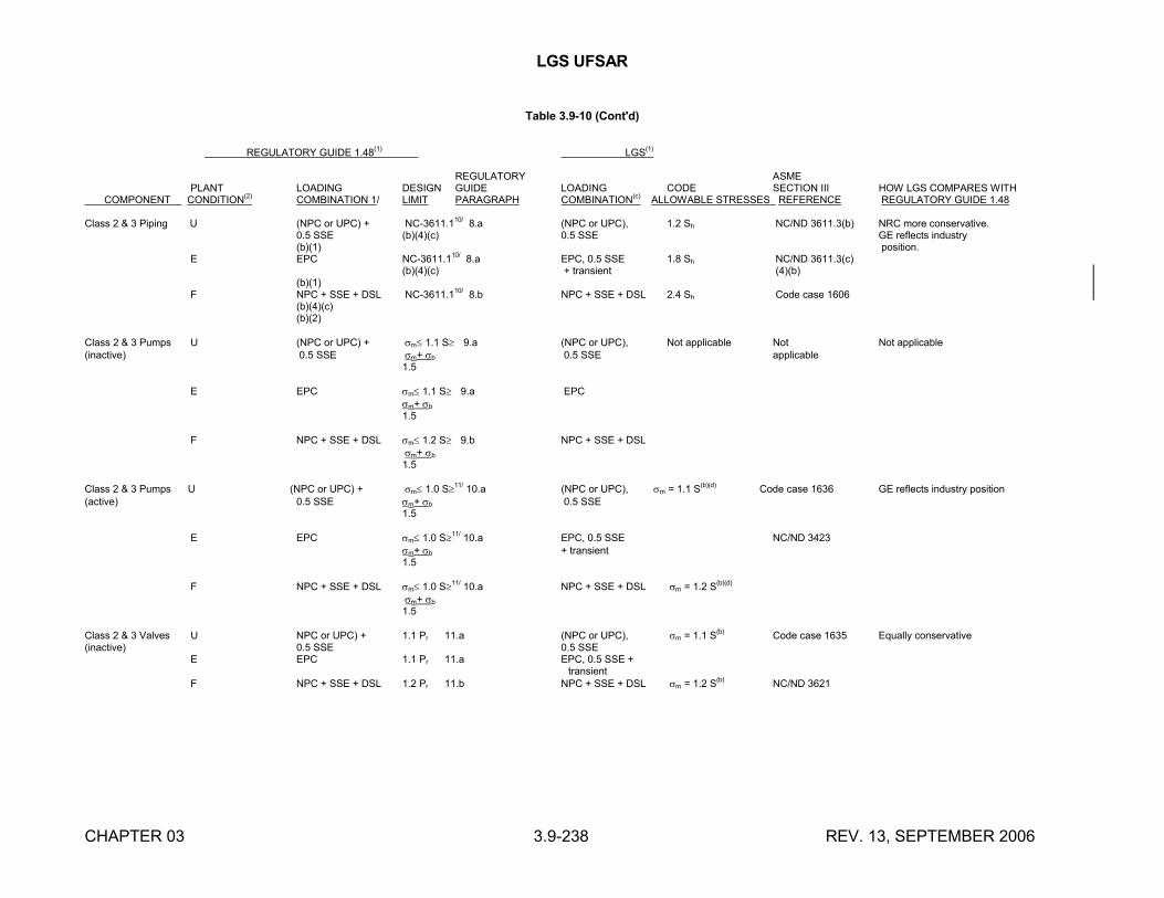
LGS UFSAR
CHAPTER 03 3.9-238 REV. 13, SEPTEMBER 2006
Table 3.9-10 (Cont'd)
REGULATORY GUIDE 1.48(1)
LGS(1)
REGULATORY ASMEPLANT LOADING DESIGN GUIDE LOADING CODE SECTION III HOW LGS COMPARES WITH
COMPONENT CONDITION(2) COMBINATION 1/ LIMIT PARAGRAPH COMBINATION(c) ALLOWABLE STRESSES REFERENCE REGULATORY GUIDE 1.48
Class 2 & 3 Piping U (NPC or UPC) + NC-3611.110/
8.a (NPC or UPC), 1.2 Sh NC/ND 3611.3(b) NRC more conservative.0.5 SSE (b)(4)(c)
0.5 SSE GE reflects industry
(b)(1) position.E EPC NC-3611.1
10/ 8.a EPC, 0.5 SSE 1.8 Sh NC/ND 3611.3(c)
(b)(4)(c)
+ transient (4)(b)(b)(1)
F NPC + SSE + DSL NC-3611.110/ 8.b NPC + SSE + DSL 2.4 Sh Code case 1606(b)(4)(c)(b)(2)
Class 2 & 3 Pumps U (NPC or UPC) + m 1.1 S 9.a (NPC or UPC), Not applicable Not Not applicable
(inactive) 0.5 SSE m+ b 0.5 SSE applicable1.5
E EPC m 1.1 S 9.a EPCm+ b
1.5
F NPC + SSE + DSL m 1.2 S 9.b NPC + SSE + DSLm+ b
1.5
Class 2 & 3 Pumps U (NPC or UPC) + m 1.0 S11/ 10.a (NPC or UPC), m = 1.1 S(b)(d) Code case 1636 GE reflects industry position(active) 0.5 SSE m+ b 0.5 SSE
1.5
E EPC m 1.0 S11/ 10.a EPC, 0.5 SSE NC/ND 3423m+ b + transient 1.5
F NPC + SSE + DSL m 1.0 S11/ 10.a NPC + SSE + DSL m = 1.2 S(b)(d)
m+ b
1.5
Class 2 & 3 Valves U NPC or UPC) + 1.1 Pr 11.a (NPC or UPC), m = 1.1 S(b) Code case 1635 Equally conservative
(inactive) 0.5 SSE 0.5 SSE E EPC 1.1 Pr
11.a EPC, 0.5 SSE + transient
F NPC + SSE + DSL 1.2 Pr 11.b NPC + SSE + DSL m = 1.2 S(b) NC/ND 3621
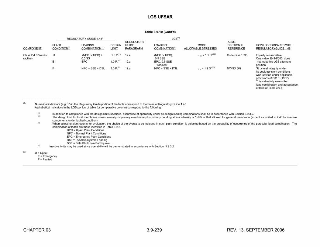
LGS UFSAR
CHAPTER 03 3.9-239 REV. 13, SEPTEMBER 2006
Table 3.9-10 (Cont'd)
REGULATORY GUIDE 1.48(1) LGS(1) REGULATORY ASME
PLANT LOADING DESIGN GUIDE LOADING CODE SECTION III HOWLGSCOMPARES WITHCOMPONENT CONDITION
(2)COMBINATION 1/ LIMIT PARAGRAPH COMBINATION
(c) ALLOWABLE STRESSES REFERENCE REGULATORYGUIDE 1.48
Class 2 & 3 Valves U (NPC or UPC) + 1.0 Pr11/
12.a (NPC or UPC), m = 1.1 S(a)(b)
Code case 1635 Equally conservative.(active) 0.5 SS 0.5 SSE One valve, E41-F005, does
E EPC 1.0 Pr11/
12.a EPC, 0.5 SSE not meet this LGS alternate+ transient position.
F NPC + SSE + DSL 1.0 Pr11/
12.a NPC + SSE + DSL m = 1.2 S(a)(b)
NC/ND 362 Structural integrity under its peak transient conditions was justified under applicable
provisions of B31.1 (1967).This valve fully meets theload combination and acceptancecriteria of Table 3.9-6.
_________________________
(1) Numerical indicators (e.g. 1/) in the Regulatory Guide portion of the table correspond to footnotes of Regulatory Guide 1.48.Alphabetical indicators in the LGS portion of table (or comparative column) correspond to the following:
(a) In addition to compliance with the design limits specified, assurance of operability under all design loading combinations shall be in accordance with Section 3.9.3.2.(b) The design limit for local membrane stress intensity or primary membrane plus primary bending stress intensity is 150% of that allowed for general membrane (except as limited to 2.45 for inactive
components under faulted condition).(c) When selecting plant events for evaluation, the choice of the events to be included in each plant condition is selected based on the probability of occurrence of the particular load combination. The
combination of loads are those identified in Table 3.9-2.UPC = Upset Plant ConditionsNPC = Normal Plant ConditionsEPC = Emergency Plant ConditionsDSL = Dynamic System LoadingSSE = Safe Shutdown Earthquake
(d)Inactive limits may be used since operability will be demonstrated in accordance with Section 3.9.3.2.
(2) U = UpsetE = EmergencyF = Faulted
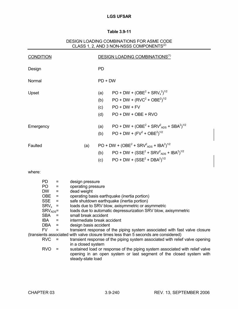
LGS UFSAR
CHAPTER 03 3.9-240 REV. 13, SEPTEMBER 2006
Table 3.9-11
DESIGN LOADING COMBINATIONS FOR ASME CODECLASS 1, 2, AND 3 NON-NSSS COMPONENTS(2)
CONDITION DESIGN LOADING COMBINATIONS(1)
Design PD
Normal PD + DW
Upset (a) PO + DW + (OBE2 + SRVx2)1/2
(b) PO + DW + (RVC2 + OBE2)1/2
(c) PO + DW + FV
(d) PO + DW + OBE + RVO
Emergency (a) PO + DW + (OBE2 + SRV2ADS + SBA2)1/2
(b) PO + DW + (FV2 + OBE2)1/2
Faulted (a) PO + DW + (OBE2 + SRV2ADS + IBA2)1/2
(b) PO + DW + (SSE2 + SRV2ADS + IBA2)1/2
(c) PO + DW + (SSE2 + DBA2)1/2
where:
PD = design pressurePO = operating pressureDW = dead weightOBE = operating basis earthquake (inertia portion)SSE = safe shutdown earthquake (inertia portion)SRVx = loads due to SRV blow, axisymmetric or asymmetricSRVADS= loads due to automatic depressurization SRV blow, axisymmetricSBA = small break accidentIBA = intermediate break accidentDBA = design basis accidentFV = transient response of the piping system associated with fast valve closure
(transients associated with valve closure times less than 5 seconds are considered)RVC = transient response of the piping system associated with relief valve opening
in a closed systemRVO = sustained load or response of the piping system associated with relief valve
opening in an open system or last segment of the closed system with steady-state load
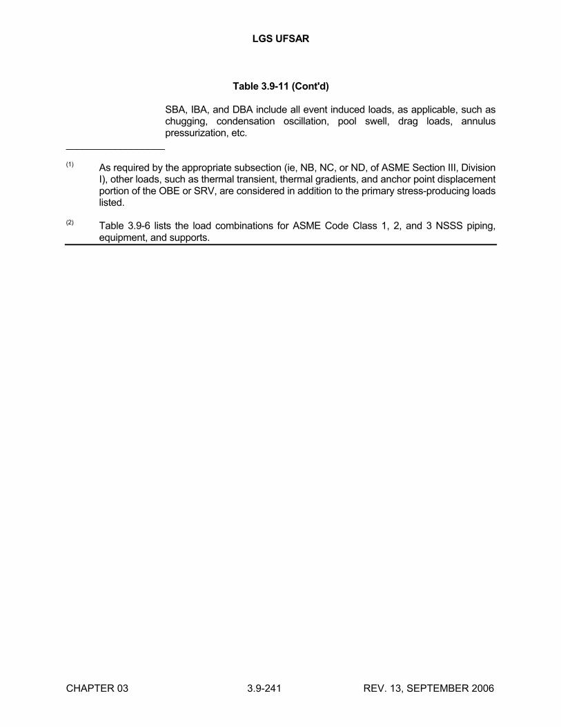
LGS UFSAR
CHAPTER 03 3.9-241 REV. 13, SEPTEMBER 2006
Table 3.9-11 (Cont'd)
SBA, IBA, and DBA include all event induced loads, as applicable, such as chugging, condensation oscillation, pool swell, drag loads, annulus pressurization, etc.
__________________
(1) As required by the appropriate subsection (ie, NB, NC, or ND, of ASME Section III, Division I), other loads, such as thermal transient, thermal gradients, and anchor point displacement portion of the OBE or SRV, are considered in addition to the primary stress-producing loads listed.
(2) Table 3.9-6 lists the load combinations for ASME Code Class 1, 2, and 3 NSSS piping, equipment, and supports.
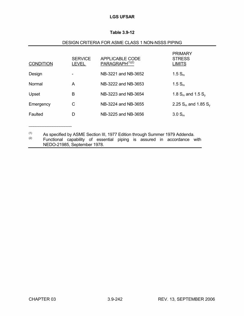
LGS UFSAR
CHAPTER 03 3.9-242 REV. 13, SEPTEMBER 2006
Table 3.9-12
DESIGN CRITERIA FOR ASME CLASS 1 NON-NSSS PIPING
PRIMARYSERVICE APPLICABLE CODE STRESS
CONDITION LEVEL PARAGRAPH(1)(2) LIMITS
Design - NB-3221 and NB-3652 1.5 Sm
Normal A NB-3222 and NB-3653 1.5 Sm
Upset B NB-3223 and NB-3654 1.8 Sm and 1.5 Sy
Emergency C NB-3224 and NB-3655 2.25 Sm and 1.85 Sy
Faulted D NB-3225 and NB-3656 3.0 Sm
__________________
(1) As specified by ASME Section III, 1977 Edition through Summer 1979 Addenda.(2) Functional capability of essential piping is assured in accordance with
NEDO-21985, September 1978.
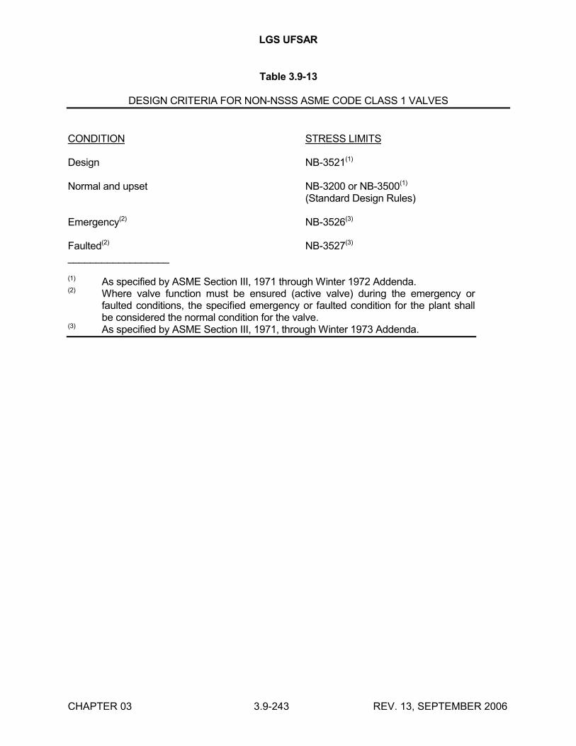
LGS UFSAR
CHAPTER 03 3.9-243 REV. 13, SEPTEMBER 2006
Table 3.9-13
DESIGN CRITERIA FOR NON-NSSS ASME CODE CLASS 1 VALVES
CONDITION STRESS LIMITS
Design NB-3521(1)
Normal and upset NB-3200 or NB-3500(1)
(Standard Design Rules)
Emergency(2) NB-3526(3)
Faulted(2) NB-3527(3)
__________________
(1) As specified by ASME Section III, 1971 through Winter 1972 Addenda.(2) Where valve function must be ensured (active valve) during the emergency or
faulted conditions, the specified emergency or faulted condition for the plant shall be considered the normal condition for the valve.
(3) As specified by ASME Section III, 1971, through Winter 1973 Addenda.
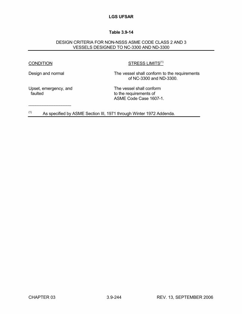
LGS UFSAR
CHAPTER 03 3.9-244 REV. 13, SEPTEMBER 2006
Table 3.9-14
DESIGN CRITERIA FOR NON-NSSS ASME CODE CLASS 2 AND 3VESSELS DESIGNED TO NC-3300 AND ND-3300
CONDITION STRESS LIMITS(1)
Design and normal The vessel shall conform to the requirements of NC-3300 and ND-3300.
Upset, emergency, and The vessel shall conform faulted to the requirements of
ASME Code Case 1607-1.__________________
(1) As specified by ASME Section III, 1971 through Winter 1972 Addenda.
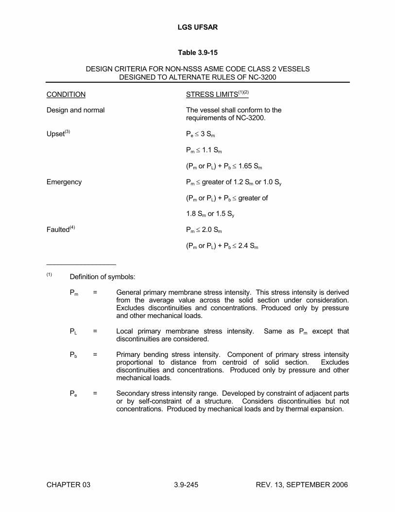
LGS UFSAR
CHAPTER 03 3.9-245 REV. 13, SEPTEMBER 2006
Table 3.9-15
DESIGN CRITERIA FOR NON-NSSS ASME CODE CLASS 2 VESSELSDESIGNED TO ALTERNATE RULES OF NC-3200
CONDITION STRESS LIMITS(1)(2)
Design and normal The vessel shall conform to therequirements of NC-3200.
Upset(3) Pe 3 Sm
Pm 1.1 Sm
(Pm or PL) + Pb 1.65 Sm
Emergency Pm greater of 1.2 Sm or 1.0 Sy
(Pm or PL) + Pb greater of
1.8 Sm or 1.5 Sy
Faulted(4) Pm 2.0 Sm
(Pm or PL) + Pb 2.4 Sm
__________________
(1) Definition of symbols:
Pm = General primary membrane stress intensity. This stress intensity is derived from the average value across the solid section under consideration. Excludes discontinuities and concentrations. Produced only by pressure and other mechanical loads.
PL = Local primary membrane stress intensity. Same as Pm except that discontinuities are considered.
Pb = Primary bending stress intensity. Component of primary stress intensity proportional to distance from centroid of solid section. Excludes discontinuities and concentrations. Produced only by pressure and other mechanical loads.
Pe = Secondary stress intensity range. Developed by constraint of adjacent parts or by self-constraint of a structure. Considers discontinuities but not concentrations. Produced by mechanical loads and by thermal expansion.
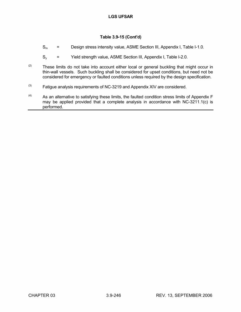
LGS UFSAR
CHAPTER 03 3.9-246 REV. 13, SEPTEMBER 2006
Table 3.9-15 (Cont'd)
Sm = Design stress intensity value, ASME Section III, Appendix I, Table I-1.0.
Sy = Yield strength value, ASME Section III, Appendix I, Table I-2.0.
(2) These limits do not take into account either local or general buckling that might occur in thin-wall vessels. Such buckling shall be considered for upset conditions, but need not be considered for emergency or faulted conditions unless required by the design specification.
(3) Fatigue analysis requirements of NC-3219 and Appendix XIV are considered.
(4) As an alternative to satisfying these limits, the faulted condition stress limits of Appendix F may be applied provided that a complete analysis in accordance with NC-3211.1(c) is performed.
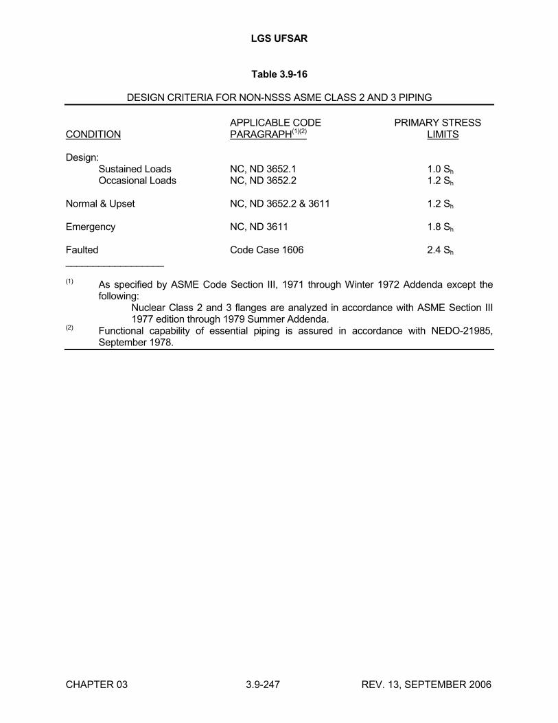
LGS UFSAR
CHAPTER 03 3.9-247 REV. 13, SEPTEMBER 2006
Table 3.9-16
DESIGN CRITERIA FOR NON-NSSS ASME CLASS 2 AND 3 PIPING
APPLICABLE CODE PRIMARY STRESSCONDITION PARAGRAPH(1)(2) LIMITS
Design:Sustained Loads NC, ND 3652.1 1.0 Sh
Occasional Loads NC, ND 3652.2 1.2 Sh
Normal & Upset NC, ND 3652.2 & 3611 1.2 Sh
Emergency NC, ND 3611 1.8 Sh
Faulted Code Case 1606 2.4 Sh
__________________
(1) As specified by ASME Code Section III, 1971 through Winter 1972 Addenda except the following:
Nuclear Class 2 and 3 flanges are analyzed in accordance with ASME Section III 1977 edition through 1979 Summer Addenda.
(2) Functional capability of essential piping is assured in accordance with NEDO-21985, September 1978.
LGS UFSAR
CHAPTER 03 3.9-248 REV. 13, SEPTEMBER 2006
Table 3.9-17
Intentionally Left Blank(Deleted)
Table 3.9-18
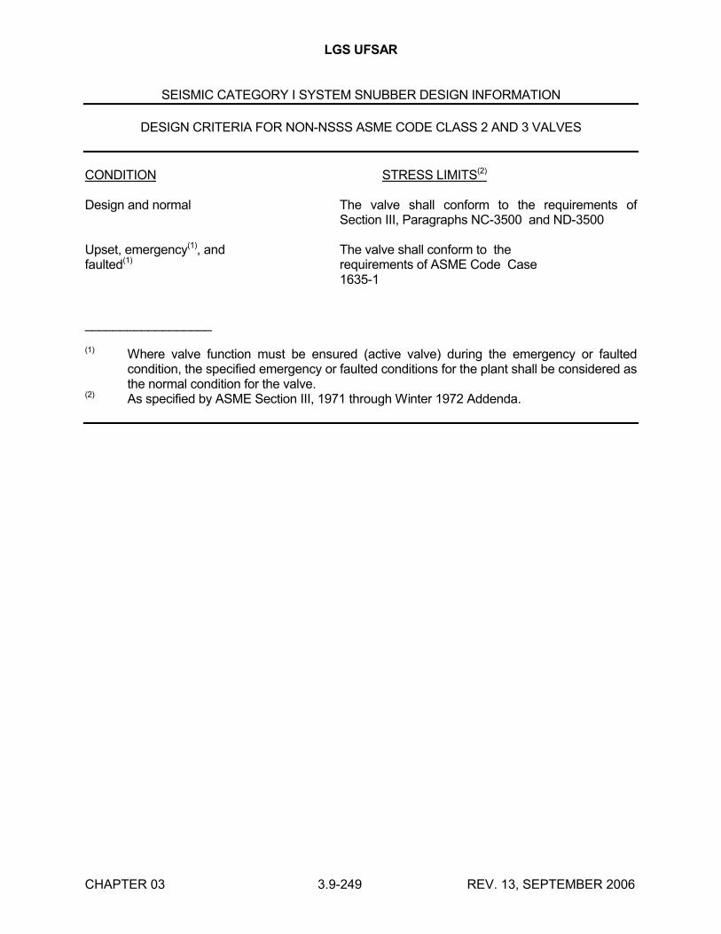
LGS UFSAR
CHAPTER 03 3.9-249 REV. 13, SEPTEMBER 2006
SEISMIC CATEGORY I SYSTEM SNUBBER DESIGN INFORMATION
DESIGN CRITERIA FOR NON-NSSS ASME CODE CLASS 2 AND 3 VALVES
CONDITION STRESS LIMITS(2)
Design and normal The valve shall conform to the requirements of Section III, Paragraphs NC-3500 and ND-3500
Upset, emergency(1), and The valve shall conform to thefaulted(1) requirements of ASME Code Case
1635-1
__________________
(1) Where valve function must be ensured (active valve) during the emergency or faulted condition, the specified emergency or faulted conditions for the plant shall be considered as the normal condition for the valve.
(2) As specified by ASME Section III, 1971 through Winter 1972 Addenda.
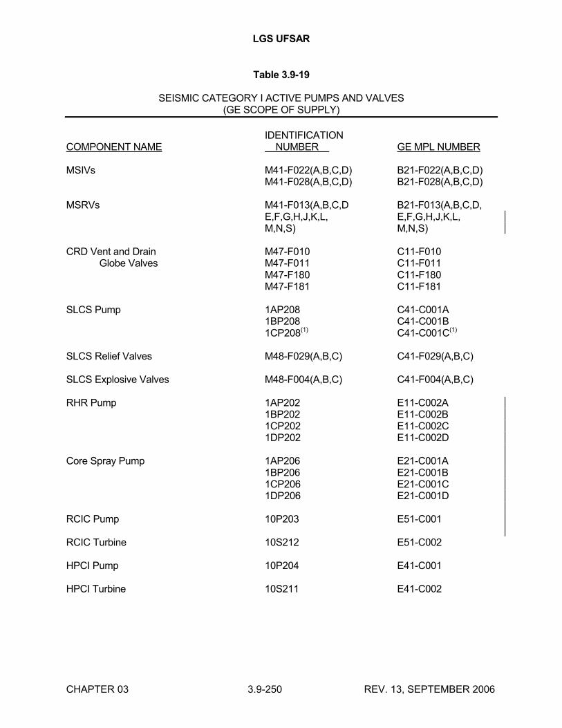
LGS UFSAR
CHAPTER 03 3.9-250 REV. 13, SEPTEMBER 2006
Table 3.9-19
SEISMIC CATEGORY I ACTIVE PUMPS AND VALVES(GE SCOPE OF SUPPLY)
IDENTIFICATIONCOMPONENT NAME NUMBER GE MPL NUMBER
MSIVs M41-F022(A,B,C,D) B21-F022(A,B,C,D)M41-F028(A,B,C,D) B21-F028(A,B,C,D)
MSRVs M41-F013(A,B,C,D B21-F013(A,B,C,D,E,F,G,H,J,K,L, E,F,G,H,J,K,L,M,N,S) M,N,S)
CRD Vent and Drain M47-F010 C11-F010Globe Valves M47-F011 C11-F011
M47-F180 C11-F180M47-F181 C11-F181
SLCS Pump 1AP208 C41-C001A1BP208 C41-C001B1CP208(1) C41-C001C(1)
SLCS Relief Valves M48-F029(A,B,C) C41-F029(A,B,C)
SLCS Explosive Valves M48-F004(A,B,C) C41-F004(A,B,C)
RHR Pump 1AP202 E11-C002A1BP202 E11-C002B1CP202 E11-C002C1DP202 E11-C002D
Core Spray Pump 1AP206 E21-C001A1BP206 E21-C001B1CP206 E21-C001C1DP206 E21-C001D
RCIC Pump 10P203 E51-C001
RCIC Turbine 10S212 E51-C002
HPCI Pump 10P204 E41-C001
HPCI Turbine 10S211 E41-C002
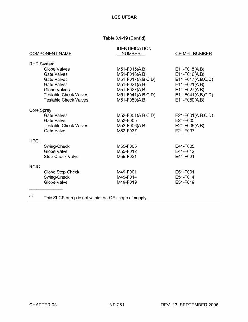
LGS UFSAR
CHAPTER 03 3.9-251 REV. 13, SEPTEMBER 2006
Table 3.9-19 (Cont'd)
IDENTIFICATIONCOMPONENT NAME NUMBER GE MPL NUMBER
RHR SystemGlobe Valves M51-F015(A,B) E11-F015(A,B)Gate Valves M51-F016(A,B) E11-F016(A,B)Gate Valves M51-F017(A,B,C,D) E11-F017(A,B,C,D)Gate Valves M51-F021(A,B) E11-F021(A,B)Globe Valves M51-F027(A,B) E11-F027(A,B)Testable Check Valves M51-F041(A,B,C,D) E11-F041(A,B,C,D)Testable Check Valves M51-F050(A,B) E11-F050(A,B)
Core SprayGate Valves M52-F001(A,B,C,D) E21-F001(A,B,C,D)Gate Valve M52-F005 E21-F005Testable Check Valves M52-F006(A,B) E21-F006(A,B)Gate Valve M52-F037 E21-F037
HPCISwing-Check M55-F005 E41-F005Globe Valve M55-F012 E41-F012Stop-Check Valve M55-F021 E41-F021
RCICGlobe Stop-Check M49-F001 E51-F001Swing-Check M49-F014 E51-F014Globe Valve M49-F019 E51-F019
______________
(1) This SLCS pump is not within the GE scope of supply.
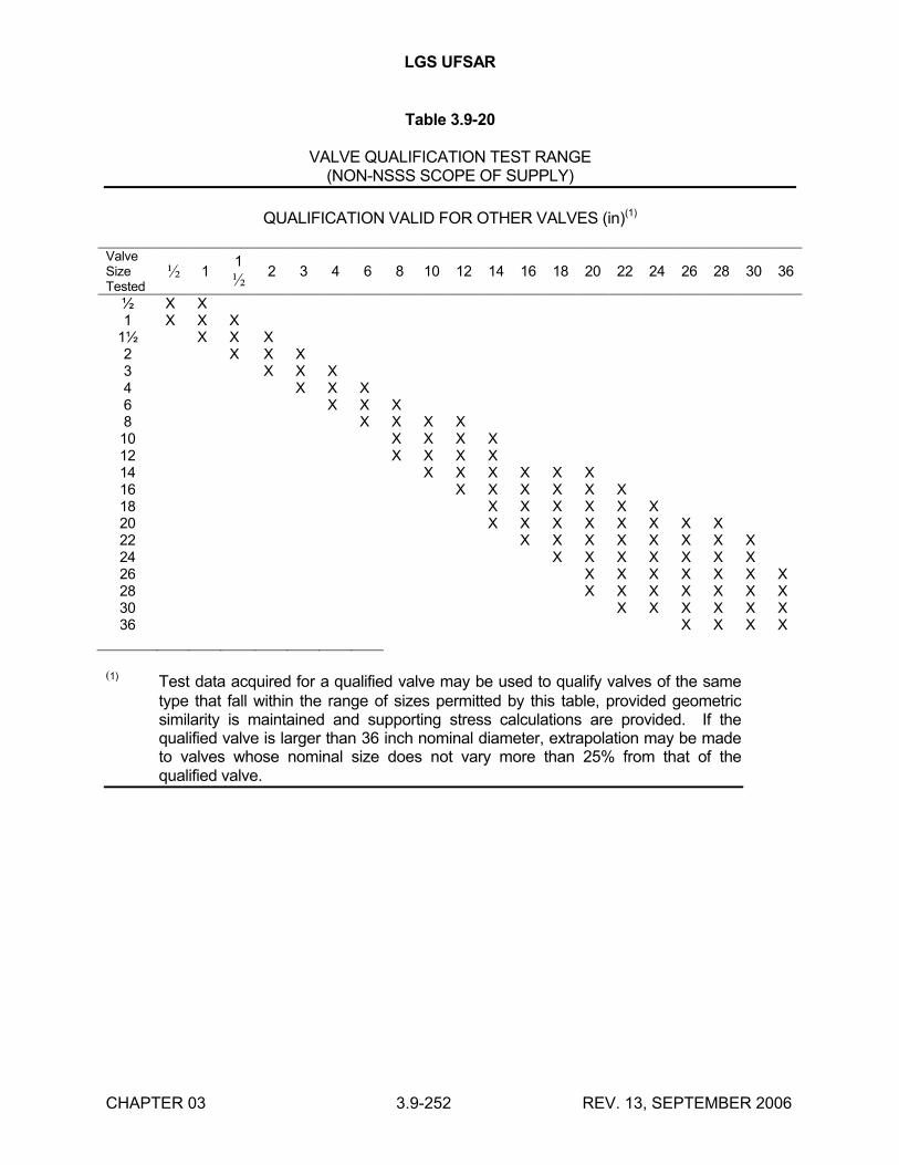
LGS UFSAR
CHAPTER 03 3.9-252 REV. 13, SEPTEMBER 2006
Table 3.9-20
VALVE QUALIFICATION TEST RANGE(NON-NSSS SCOPE OF SUPPLY)
QUALIFICATION VALID FOR OTHER VALVES (in)(1)
Valve Size Tested
½ 11
½2 3 4 6 8 10 12 14 16 18 20 22 24 26 28 30 36
½ X X1 X X X
1½ X X X2 X X X3 X X X4 X X X6 X X X8 X X X X10 X X X X12 X X X X14 X X X X X X16 X X X X X X18 X X X X X X20 X X X X X X X X22 X X X X X X X X24 X X X X X X X26 X X X X X X X28 X X X X X X X30 X X X X X X36 X X X X
(1) Test data acquired for a qualified valve may be used to qualify valves of the same type that fall within the range of sizes permitted by this table, provided geometric similarity is maintained and supporting stress calculations are provided. If the qualified valve is larger than 36 inch nominal diameter, extrapolation may be made to valves whose nominal size does not vary more than 25% from that of the qualified valve.
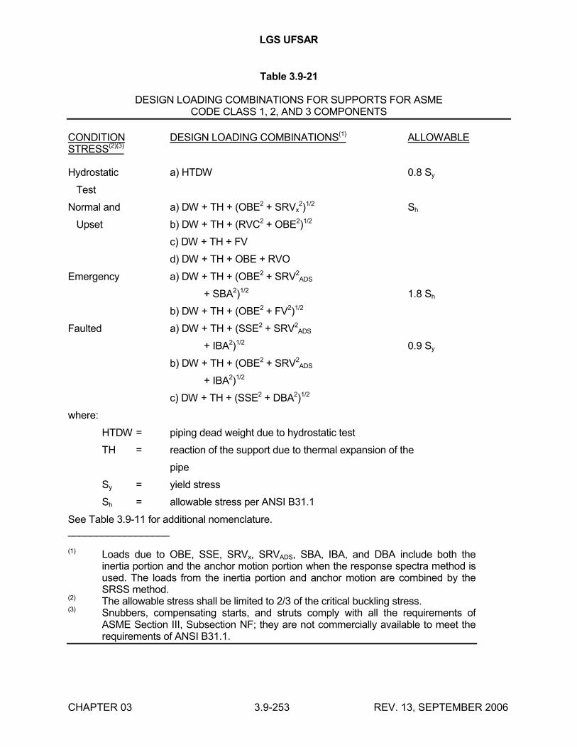
LGS UFSAR
CHAPTER 03 3.9-253 REV. 13, SEPTEMBER 2006
Table 3.9-21
DESIGN LOADING COMBINATIONS FOR SUPPORTS FOR ASMECODE CLASS 1, 2, AND 3 COMPONENTS
CONDITION DESIGN LOADING COMBINATIONS(1) ALLOWABLE STRESS(2)(3)
Hydrostatic a) HTDW 0.8 Sy
Test
Normal and a) DW + TH + (OBE2 + SRVx2)1/2 Sh
Upset b) DW + TH + (RVC2 + OBE2)1/2
c) DW + TH + FV
d) DW + TH + OBE + RVO
Emergency a) DW + TH + (OBE2 + SRV2ADS
+ SBA2)1/2 1.8 Sh
b) DW + TH + (OBE2 + FV2)1/2
Faulted a) DW + TH + (SSE2 + SRV2ADS
+ IBA2)1/2 0.9 Sy
b) DW + TH + (OBE2 + SRV2ADS
+ IBA2)1/2
c) DW + TH + (SSE2 + DBA2)1/2
where:
HTDW = piping dead weight due to hydrostatic test
TH = reaction of the support due to thermal expansion of the
pipe
Sy = yield stress
Sh = allowable stress per ANSI B31.1
See Table 3.9-11 for additional nomenclature.__________________
(1) Loads due to OBE, SSE, SRVx, SRVADS, SBA, IBA, and DBA include both the inertia portion and the anchor motion portion when the response spectra method is used. The loads from the inertia portion and anchor motion are combined by the SRSS method.
(2) The allowable stress shall be limited to 2/3 of the critical buckling stress.(3) Snubbers, compensating starts, and struts comply with all the requirements of
ASME Section III, Subsection NF; they are not commercially available to meet the requirements of ANSI B31.1.
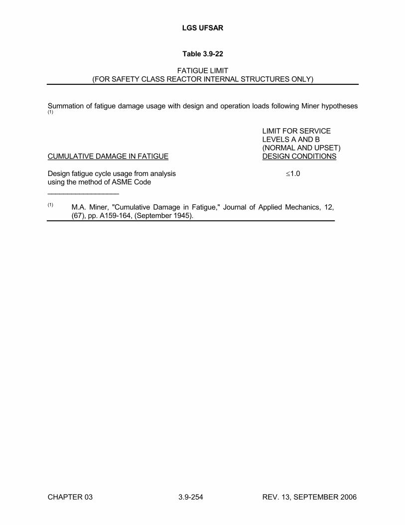
LGS UFSAR
CHAPTER 03 3.9-254 REV. 13, SEPTEMBER 2006
Table 3.9-22
FATIGUE LIMIT(FOR SAFETY CLASS REACTOR INTERNAL STRUCTURES ONLY)
Summation of fatigue damage usage with design and operation loads following Miner hypotheses (1)
LIMIT FOR SERVICELEVELS A AND B(NORMAL AND UPSET)
CUMULATIVE DAMAGE IN FATIGUE DESIGN CONDITIONS
Design fatigue cycle usage from analysis 1.0using the method of ASME Code__________________
(1) M.A. Miner, "Cumulative Damage in Fatigue," Journal of Applied Mechanics, 12, (67), pp. A159-164, (September 1945).
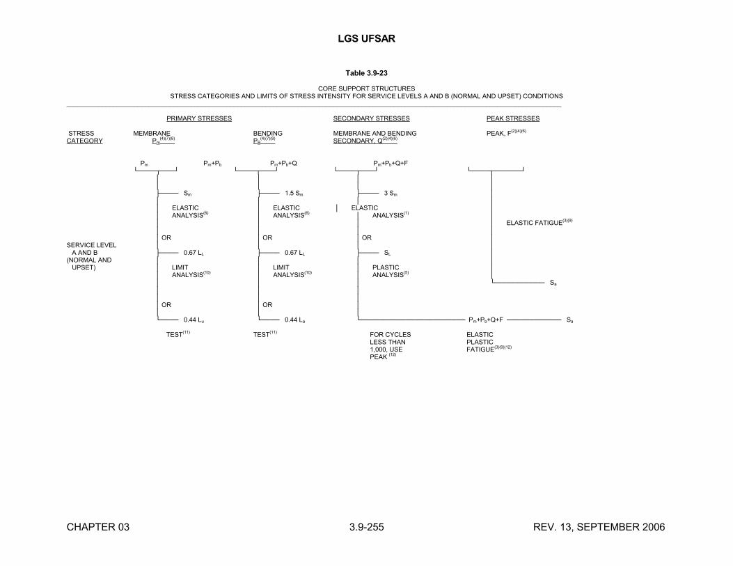
LGS UFSAR
CHAPTER 03 3.9-255 REV. 13, SEPTEMBER 2006
Table 3.9-23
CORE SUPPORT STRUCTURESSTRESS CATEGORIES AND LIMITS OF STRESS INTENSITY FOR SERVICE LEVELS A AND B (NORMAL AND UPSET) CONDITIONS
___________________________________________________________________________________________________________________________________________
PRIMARY STRESSES SECONDARY STRESSES PEAK STRESSES
STRESS MEMBRANE BENDING MEMBRANE AND BENDING PEAK, F(2)(4)(6)
CATEGORY Pm(4)(7)(8)
PB(4)(7)(8)
SECONDARY, Q(2)(4)(6)
Pm Pm+Pb Pm+Pb+Q Pm+Pb+Q+F└────┬───┘ └────┬───┘ └────┬───┘ └────┬──────┘
│ │ │ │ │ │ │ │ ├──── Sm ├──── 1.5 Sm ├──── 3 Sm │ │ │ │ │ │ ELASTIC │ ELASTIC │ ELASTIC │ │ ANALYSIS(6) │ ANALYSIS(6) │ ANALYSIS(1) │ │ │ │ │ ELASTIC FATIGUE
(3)(9)
│ │ │ │ │ OR │ OR │ OR │
SERVICE LEVEL │ │ │ │ A AND B ├──── 0.67 LL ├──── 0.67 LL ├──── SL │(NORMAL AND │ │ │ │ UPSET) │ LIMIT │ LIMIT │ PLASTIC │
│ ANALYSIS(10) │ ANALYSIS(10) │ ANALYSIS(5) │ │ │ │ └─────────── Sa
│ │ │ │ │ │ │ OR │ OR │ │ │ │ └──── 0.44 Lu └──── 0.44 La └─────────────────────── Pm+Pb+Q+F ──────────── Sa
TEST(11) TEST(11) FOR CYCLES ELASTICLESS THAN PLASTIC1,000, USE FATIGUE
(3)(9)(12)
PEAK (12)
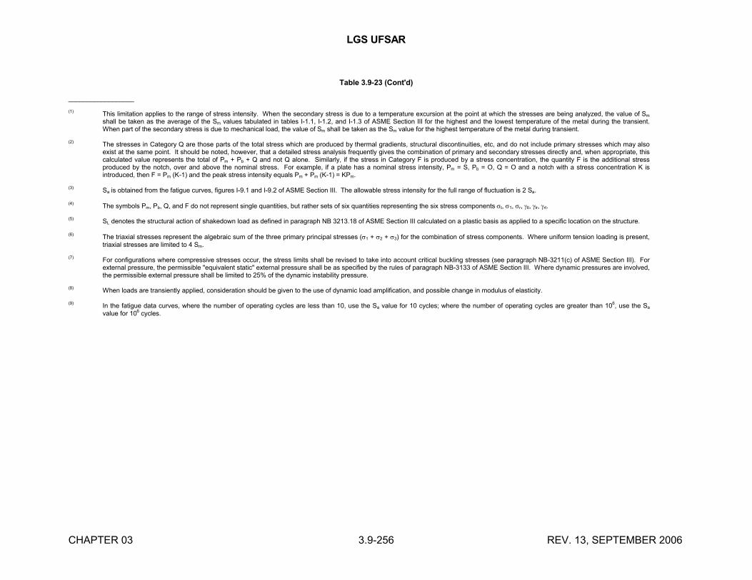
LGS UFSAR
CHAPTER 03 3.9-256 REV. 13, SEPTEMBER 2006
Table 3.9-23 (Cont'd)
__________________
(1)This limitation applies to the range of stress intensity. When the secondary stress is due to a temperature excursion at the point at which the stresses are being analyzed, the value of Sm
shall be taken as the average of the Sm values tabulated in tables I-1.1, I-1.2, and I-1.3 of ASME Section III for the highest and the lowest temperature of the metal during the transient. When part of the secondary stress is due to mechanical load, the value of Sm shall be taken as the Sm value for the highest temperature of the metal during transient.
(2)The stresses in Category Q are those parts of the total stress which are produced by thermal gradients, structural discontinuities, etc, and do not include primary stresses which may also exist at the same point. It should be noted, however, that a detailed stress analysis frequently gives the combination of primary and secondary stresses directly and, when appropriate, this calculated value represents the total of Pm + Pb + Q and not Q alone. Similarly, if the stress in Category F is produced by a stress concentration, the quantity F is the additional stress produced by the notch, over and above the nominal stress. For example, if a plate has a nominal stress intensity, Pm = S, Pb = O, Q = O and a notch with a stress concentration K is introduced, then F = Pm (K-1) and the peak stress intensity equals Pm + Pm (K-1) = KPm.
(3) Sa is obtained from the fatigue curves, figures I-9.1 and I-9.2 of ASME Section III. The allowable stress intensity for the full range of fluctuation is 2 Sa.
(4) The symbols Pm, Pb, Q, and F do not represent single quantities, but rather sets of six quantities representing the six stress components t, 1, r, tl, lr, rt.
(5)SL denotes the structural action of shakedown load as defined in paragraph NB 3213.18 of ASME Section III calculated on a plastic basis as applied to a specific location on the structure.
(6)The triaxial stresses represent the algebraic sum of the three primary principal stresses (1 + 2 + 3) for the combination of stress components. Where uniform tension loading is present, triaxial stresses are limited to 4 Sm.
(7) For configurations where compressive stresses occur, the stress limits shall be revised to take into account critical buckling stresses (see paragraph NB-3211(c) of ASME Section III). For external pressure, the permissible "equivalent static" external pressure shall be as specified by the rules of paragraph NB-3133 of ASME Section III. Where dynamic pressures are involved, the permissible external pressure shall be limited to 25% of the dynamic instability pressure.
(8) When loads are transiently applied, consideration should be given to the use of dynamic load amplification, and possible change in modulus of elasticity.
(9) In the fatigue data curves, where the number of operating cycles are less than 10, use the Sa value for 10 cycles; where the number of operating cycles are greater than 106, use the Sa
value for 106 cycles.
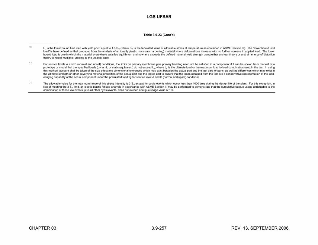
LGS UFSAR
CHAPTER 03 3.9-257 REV. 13, SEPTEMBER 2006
Table 3.9-23 (Cont'd)
__________________
(10)LL is the lower bound limit load with yield point equal to 1.5 Sm (where Sm is the tabulated value of allowable stress at temperature as contained in ASME Section III). The "lower bound limit load" is here defined as that produced from the analysis of an ideally plastic (nonstrain hardening) material where deformations increase with no further increase in applied load. The lower bound load is one in which the material everywhere satisfies equilibrium and nowhere exceeds the defined material yield strength using either a shear theory or a strain energy of distortion theory to relate multiaxial yielding to the uniaxial case.
(11)For service levels A and B (normal and upset) conditions, the limits on primary membrane plus primary bending need not be satisfied in a component if it can be shown from the test of a prototype or model that the specified loads (dynamic or static-equivalent) do not exceed Lu, where Lu is the ultimate load or the maximum load to load combination used in the test. In using this method, account shall be taken of the size effect and dimensional tolerances which may exist between the actual part and the test part, or parts, as well as differences which may exist in the ultimate strength or other governing material properties of the actual part and the tested part to assure that the loads obtained from the test are a conservative representation of the load-carrying capability of the actual component under the postulated loading for service level A and B (normal and upset) conditions.
(12)The allowable value for the maximum range of this stress intensity is 3 Sm except for cyclic events which occur less than 1000 time during the design life of the plant. For this exception, in lieu of meeting the 3 Sm limit, an elastic-plastic fatigue analysis in accordance with ASME Section III may be performed to demonstrate that the cumulative fatigue usage attributable to the combination of these low events, plus all other cyclic events, does not exceed a fatigue usage value of 1.0.
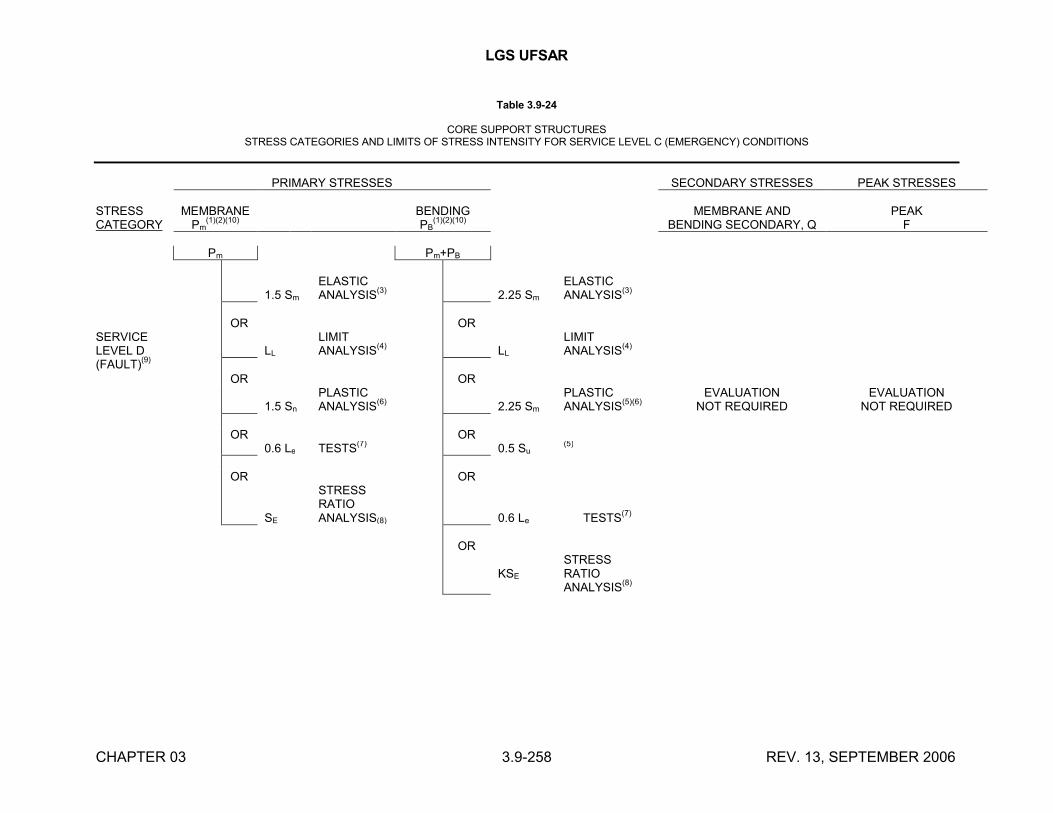
LGS UFSAR
CHAPTER 03 3.9-258 REV. 13, SEPTEMBER 2006
Table 3.9-24
CORE SUPPORT STRUCTURESSTRESS CATEGORIES AND LIMITS OF STRESS INTENSITY FOR SERVICE LEVEL C (EMERGENCY) CONDITIONS
PRIMARY STRESSES SECONDARY STRESSES PEAK STRESSES
STRESS CATEGORY
MEMBRANEPm
(1)(2)(10)BENDINGPB
(1)(2)(10)MEMBRANE AND
BENDING SECONDARY, QPEAK
F
Pm Pm+PB
1.5 Sm
ELASTICANALYSIS
(3) 2.25 Sm
ELASTICANALYSIS
(3)
OR ORSERVICELEVEL D (FAULT)
(9)LL
LIMIT ANALYSIS
(4)LL
LIMIT ANALYSIS
(4)
OR OR
1.5 Sn
PLASTIC ANALYSIS
(6)2.25 Sm
PLASTIC ANALYSIS
(5)(6)EVALUATION
NOT REQUIREDEVALUATION
NOT REQUIRED
OR OR0.6 Le TESTS
(7)0.5 Su
(5)
OR OR
SE
STRESS RATIOANALYSIS(8) 0.6 Le TESTS
(7)
OR
KSE
STRESS RATIOANALYSIS
(8)
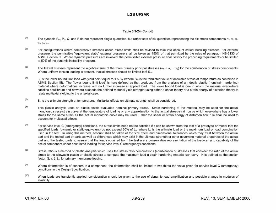
LGS UFSAR
CHAPTER 03 3.9-259 REV. 13, SEPTEMBER 2006
Table 3.9-24 (Cont'd)
(1)The symbols Pm, Pb, Q, and F do not represent single quantities, but rather sets of six quantities representing the six stress components t, l, r, tl, lr, rt.
(2)For configurations where compressive stresses occur, stress limits shall be revised to take into account critical buckling stresses. For external pressure, the permissible "equivalent static" external pressure shall be taken as 150% of that permitted by the rules of paragraph NB-3133 of ASME Section III. Where dynamic pressures are involved, the permissible external pressure shall satisfy the preceding requirements or be limited to 50% of the dynamic instability pressure.
(3)The triaxial stresses represent the algebraic sum of the three primary principal stresses (1 + 2 + 3) for the combination of stress components. Where uniform tension loading is present, triaxial stresses should be limited to 6 Sm.
(4)LL is the lower bound limit load with yield point equal to 1.5 Sm (where Sm is the tabulated value of allowable stress at temperature as contained in ASME Section III). The "lower bound limit load" is here defined as that produced from the analysis of an ideally plastic (nonstrain hardening) material where deformations increase with no further increase in applied load. The lower bound load is one in which the material everywhere satisfies equilibrium and nowhere exceeds the defined material yield strength using either a shear theory or a strain energy of distortion theory to relate multiaxial yielding to the uniaxial case.
(5)Su is the ultimate strength at temperature. Multiaxial effects on ultimate strength shall be considered.
(6)This plastic analysis uses an elastic-plastic evaluated nominal primary stress. Strain hardening of the material may be used for the actual monotonic stress-strain curve at the temperature of loading or any approximation to the actual stress-strain curve which everywhere has a lower stress for the same strain as the actual monotonic curve may be used. Either the shear or strain energy of distortion flow rule shall be used to account for multiaxial effects.
(7)For service level C (emergency) conditions, the stress limits need not be satisfied if it can be shown from the test of a prototype or model that the specified loads (dynamic or static-equivalent) do not exceed 60% of Le, where Le is the ultimate load or the maximum load or load combination used in the test. In using this method, account shall be taken of the size effect and dimensional tolerances which may exist between the actual part and the tested part or parts as well as differences which may exist in the ultimate strength or other governing material properties of the actual part and the tested parts to assure that the loads obtained from the test are a conservative representation of the load-carrying capability of the actual component under postulated loading for service level C (emergency) conditions.
(8)Stress ratio is a method of plastic analysis which uses the stress ratio combinations (combination of stresses that consider the ratio of the actual stress to the allowable plastic or elastic stress) to compute the maximum load a strain hardening material can carry. K is defined as the section factor; Se 2 Sm for primary membrane loading.
(9)Where deformation is of concern in a component, the deformation shall be limited to two-thirds the value given for service level C (emergency) conditions in the Design Specification.
(10)When loads are transiently applied, consideration should be given to the use of dynamic load amplification and possible change in modulus of elasticity.
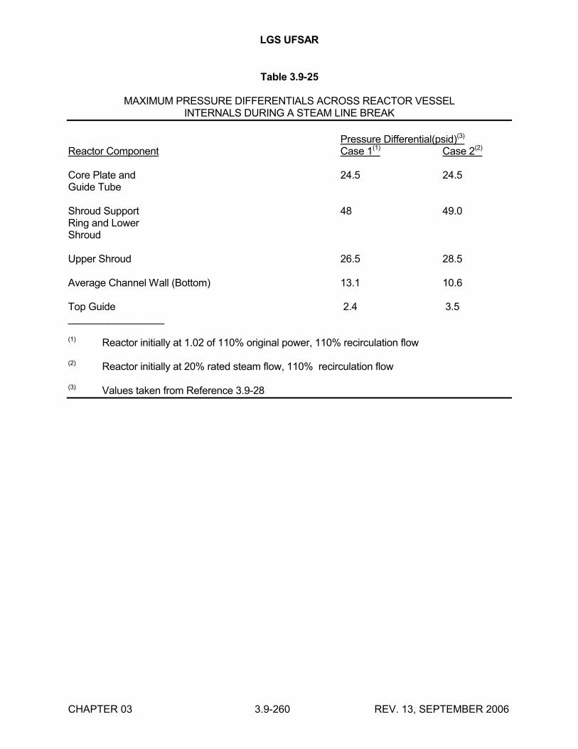
LGS UFSAR
CHAPTER 03 3.9-260 REV. 13, SEPTEMBER 2006
Table 3.9-25
MAXIMUM PRESSURE DIFFERENTIALS ACROSS REACTOR VESSELINTERNALS DURING A STEAM LINE BREAK
Pressure Differential(psid)(3)
Reactor Component Case 1(1) Case 2(2)
Core Plate and 24.5 24.5Guide Tube
Shroud Support 48 49.0Ring and LowerShroud
Upper Shroud 26.5 28.5
Average Channel Wall (Bottom) 13.1 10.6
Top Guide 2.4 3.5_________________
(1) Reactor initially at 1.02 of 110% original power, 110% recirculation flow
(2) Reactor initially at 20% rated steam flow, 110% recirculation flow
(3) Values taken from Reference 3.9-28
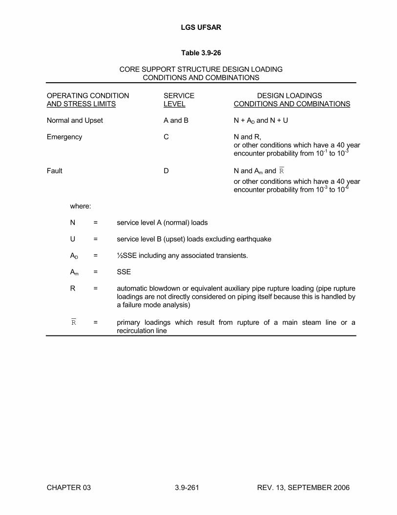
LGS UFSAR
CHAPTER 03 3.9-261 REV. 13, SEPTEMBER 2006
Table 3.9-26
CORE SUPPORT STRUCTURE DESIGN LOADINGCONDITIONS AND COMBINATIONS
OPERATING CONDITION SERVICE DESIGN LOADINGSAND STRESS LIMITS LEVEL CONDITIONS AND COMBINATIONS
Normal and Upset A and B N + AD and N + U
Emergency C N and R,or other conditions which have a 40 year encounter probability from 10-1 to 10-3
Fault D N and Am and R
or other conditions which have a 40 year encounter probability from 10-3 to 10-6
where:
N = service level A (normal) loads
U = service level B (upset) loads excluding earthquake
AD = ½SSE including any associated transients.
Am = SSE
R = automatic blowdown or equivalent auxiliary pipe rupture loading (pipe rupture loadings are not directly considered on piping itself because this is handled by a failure mode analysis)
R = primary loadings which result from rupture of a main steam line or a recirculation line
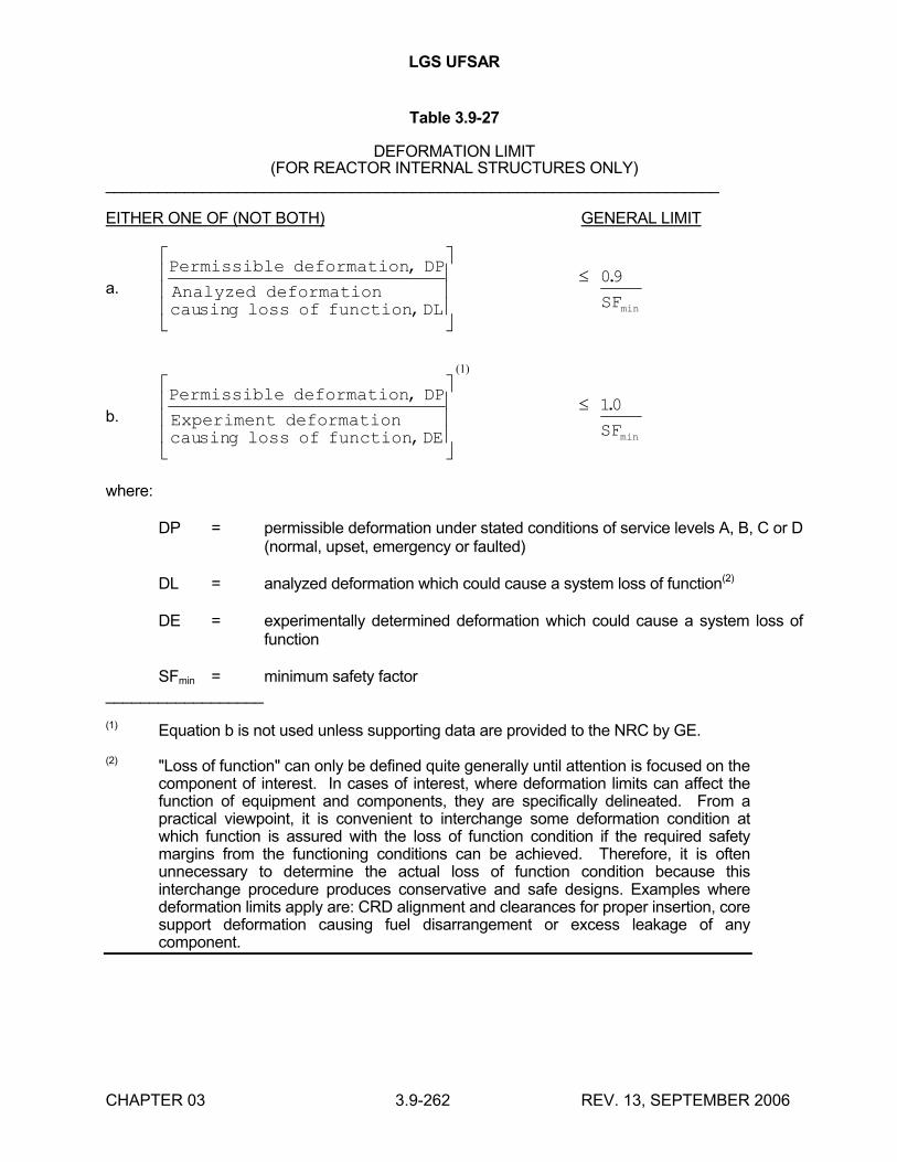
LGS UFSAR
CHAPTER 03 3.9-262 REV. 13, SEPTEMBER 2006
Table 3.9-27
DEFORMATION LIMIT(FOR REACTOR INTERNAL STRUCTURES ONLY)
______________________________________________________________________
EITHER ONE OF (NOT BOTH) GENERAL LIMIT
a.
Permissible deformation DP
Analyzed deformationcau g loss of function DL SF
,
sin ,
.
min
09
b.
Permissible deformation DP
Experiment deformationcau g loss of function DE SF
,
sin ,
.
min
10
where:
DP = permissible deformation under stated conditions of service levels A, B, C or D (normal, upset, emergency or faulted)
DL = analyzed deformation which could cause a system loss of function(2)
DE = experimentally determined deformation which could cause a system loss of function
SFmin = minimum safety factor __________________
(1) Equation b is not used unless supporting data are provided to the NRC by GE.
(2) "Loss of function" can only be defined quite generally until attention is focused on the component of interest. In cases of interest, where deformation limits can affect the function of equipment and components, they are specifically delineated. From a practical viewpoint, it is convenient to interchange some deformation condition at which function is assured with the loss of function condition if the required safety margins from the functioning conditions can be achieved. Therefore, it is often unnecessary to determine the actual loss of function condition because this interchange procedure produces conservative and safe designs. Examples where deformation limits apply are: CRD alignment and clearances for proper insertion, core support deformation causing fuel disarrangement or excess leakage of any component.
(1)
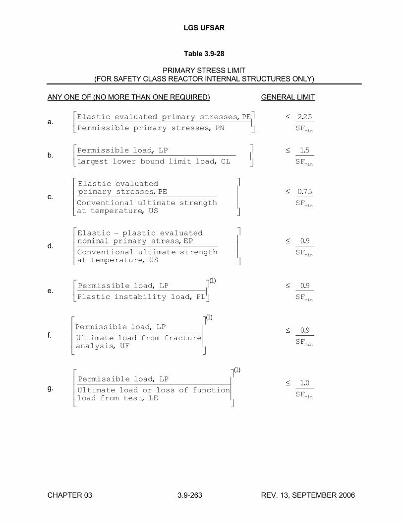
LGS UFSAR
CHAPTER 03 3.9-263 REV. 13, SEPTEMBER 2006
Table 3.9-28
PRIMARY STRESS LIMIT(FOR SAFETY CLASS REACTOR INTERNAL STRUCTURES ONLY)
ANY ONE OF (NO MORE THAN ONE REQUIRED) GENERAL LIMIT
a.Elastic evaluated primary stresses PE
Permissible primary stresses PN
,
,
225.
minSF
b.Permissible load LP
L est lower bound it load CL
,
arg lim ,
15.
minSF
c.
Elastic evaluatedprimary stresses PE
Conventional ultimate strengthat temperature US
,
,
075.
minSF
d.
Elastic plastic evaluatedno al primary stress EP
Conventional ultimate strengthat temperature US
min ,
,
09.
minSF
e.Permissible load LP
Plastic instability load PL
,
,
()
1 09.
minSF
f.Permissible load LP
Ultimate load from fractureanalysis UF
,
,
()
1
09.
minSF
g.Permissible load LP
Ultimate load or loss of functionload from test LE
,
,
()
1
10.
minSF
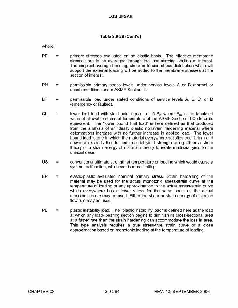
LGS UFSAR
CHAPTER 03 3.9-264 REV. 13, SEPTEMBER 2006
Table 3.9-28 (Cont'd)
where:
PE = primary stresses evaluated on an elastic basis. The effective membrane stresses are to be averaged through the load-carrying section of interest. The simplest average bending, shear or torsion stress distribution which will support the external loading will be added to the membrane stresses at the section of interest.
PN = permissible primary stress levels under service levels A or B (normal or upset) conditions under ASME Section III.
LP = permissible load under stated conditions of service levels A, B, C, or D (emergency or faulted).
CL = lower limit load with yield point equal to 1.5 Sm where Sm is the tabulated value of allowable stress at temperature of the ASME Section III Code or its equivalent. The "lower bound limit load" is here defined as that produced from the analysis of an ideally plastic nonstrain hardening material where deformations increase with no further increase in applied load. The lower bound load is one in which the material everywhere satisfies equilibrium and nowhere exceeds the defined material yield strength using either a shear theory or a strain energy of distortion theory to relate multiaxial yield to the uniaxial case.
US = conventional ultimate strength at temperature or loading which would cause a system malfunction, whichever is more limiting.
EP = elastic-plastic evaluated nominal primary stress. Strain hardening of the material may be used for the actual monotonic stress-strain curve at the temperature of loading or any approximation to the actual stress-strain curve which everywhere has a lower stress for the same strain as the actual monotonic curve may be used. Either the shear or strain energy of distortion flow rule may be used.
PL = plastic instability load. The "plastic instability load" is defined here as the load at which any load- bearing section begins to diminish its cross-sectional area at a faster rate than the strain hardening can accommodate the loss in area. This type analysis requires a true stress-true strain curve or a close approximation based on monotonic loading at the temperature of loading.
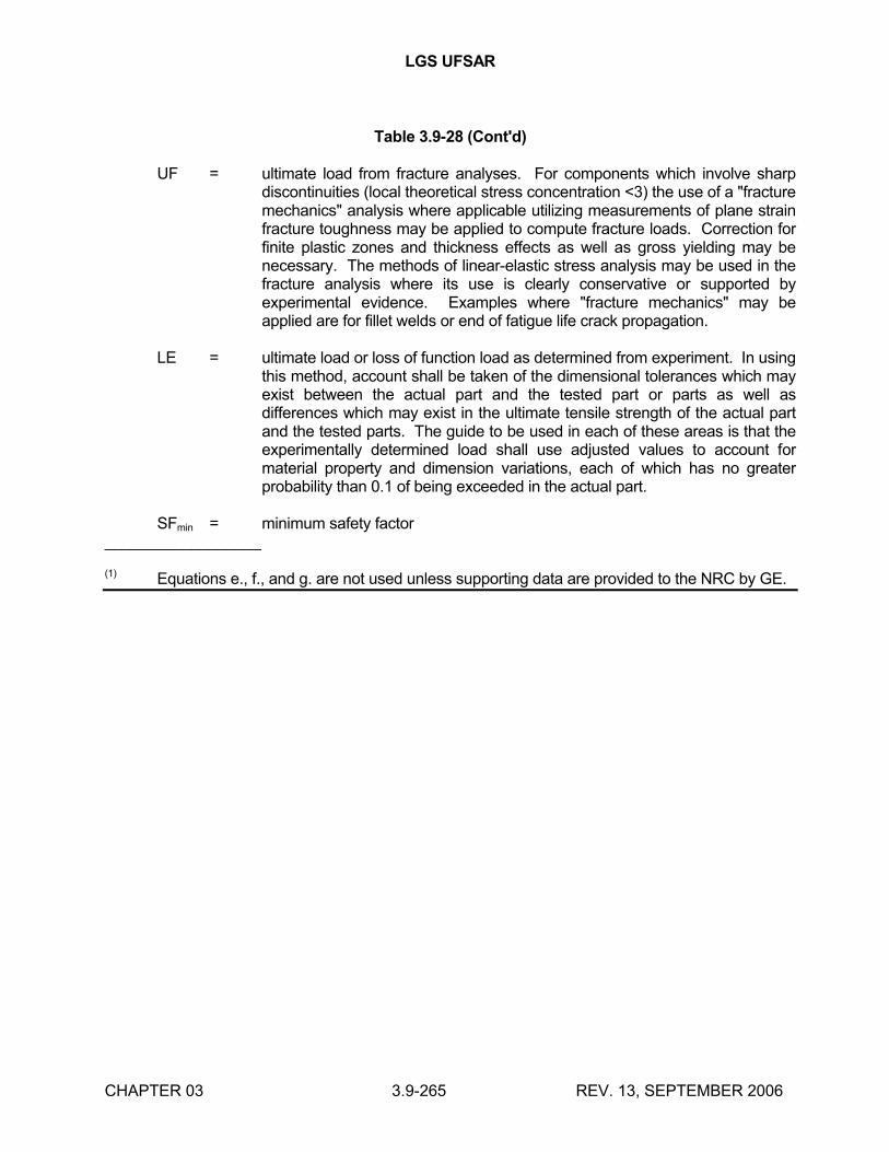
LGS UFSAR
CHAPTER 03 3.9-265 REV. 13, SEPTEMBER 2006
Table 3.9-28 (Cont'd)
UF = ultimate load from fracture analyses. For components which involve sharp discontinuities (local theoretical stress concentration <3) the use of a "fracture mechanics" analysis where applicable utilizing measurements of plane strain fracture toughness may be applied to compute fracture loads. Correction for finite plastic zones and thickness effects as well as gross yielding may be necessary. The methods of linear-elastic stress analysis may be used in the fracture analysis where its use is clearly conservative or supported by experimental evidence. Examples where "fracture mechanics" may be applied are for fillet welds or end of fatigue life crack propagation.
LE = ultimate load or loss of function load as determined from experiment. In using this method, account shall be taken of the dimensional tolerances which may exist between the actual part and the tested part or parts as well as differences which may exist in the ultimate tensile strength of the actual part and the tested parts. The guide to be used in each of these areas is that the experimentally determined load shall use adjusted values to account for material property and dimension variations, each of which has no greater probability than 0.1 of being exceeded in the actual part.
SFmin = minimum safety factor __________________
(1) Equations e., f., and g. are not used unless supporting data are provided to the NRC by GE.
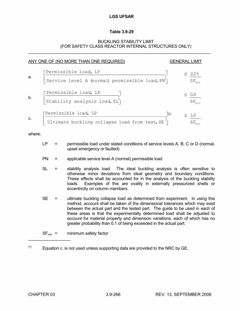
LGS UFSAR
CHAPTER 03 3.9-266 REV. 13, SEPTEMBER 2006
Table 3.9-29
BUCKLING STABILITY LIMIT(FOR SAFETY CLASS REACTOR INTERNAL STRUCTURES ONLY)
_______________________________________________________________________
ANY ONE OF (NO MORE THAN ONE REQUIRED) GENERAL LIMIT
a.Permissible load LP
Service level A normal permissible load PN
,
( ) ,
225.
minSF
b.Permissible load LP
Stability analysis load SL
,
,
09.
minSF
c.Permissible load LP
Ultimate buckling collapse load from test SE
,
,
()
1 10.
minSF
where:
LP = permissible load under stated conditions of service levels A, B, C or D (normal, upset emergency or faulted)
PN = applicable service level A (normal) permissible load
SL = stability analysis load. The ideal buckling analysis is often sensitive to otherwise minor deviations from ideal geometry and boundary conditions. These effects shall be accounted for in the analysis of the buckling stability loads. Examples of this are ovality in externally pressurized shells or eccentricity on column members.
SE = ultimate buckling collapse load as determined from experiment. In using this method, account shall be taken of the dimensional tolerances which may exist between the actual part and the tested part. The guide to be used in each of these areas is that the experimentally determined load shall be adjusted to account for material property and dimension variations, each of which has no greater probability than 0.1 of being exceeded in the actual part.
SFmin = minimum safety factor __________________
(1) Equation c. is not used unless supporting data are provided to the NRC by GE.
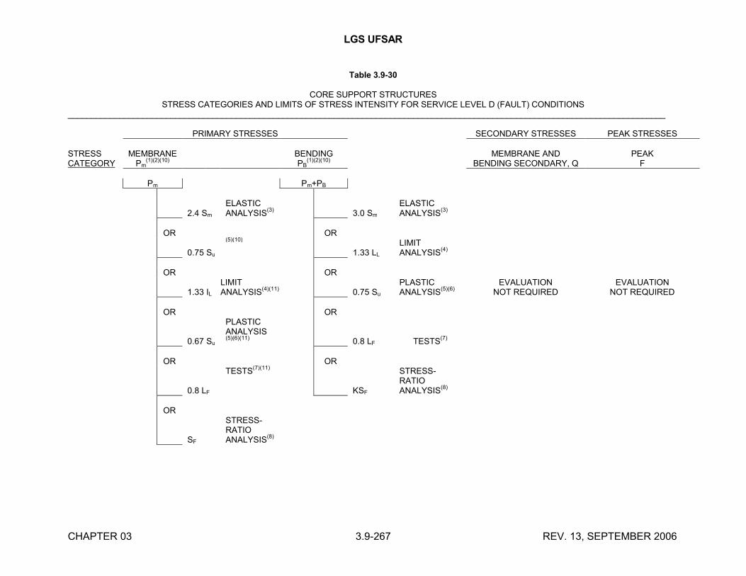
LGS UFSAR
CHAPTER 03 3.9-267 REV. 13, SEPTEMBER 2006
Table 3.9-30
CORE SUPPORT STRUCTURESSTRESS CATEGORIES AND LIMITS OF STRESS INTENSITY FOR SERVICE LEVEL D (FAULT) CONDITIONS
________________________________________________________________________________________________________________________________
PRIMARY STRESSES SECONDARY STRESSES PEAK STRESSES
STRESS CATEGORY
MEMBRANEPm
(1)(2)(10)BENDINGPB
(1)(2)(10)MEMBRANE AND
BENDING SECONDARY, QPEAK
F
Pm Pm+PB
2.4 Sm
ELASTICANALYSIS
(3) 3.0 Sm
ELASTICANALYSIS
(3)
OR OR
0.75 Su
(5)(10)
1.33 LL
LIMIT ANALYSIS
(4)
OR OR
1.33 IL
LIMIT ANALYSIS
(4)(11)0.75 Su
PLASTIC ANALYSIS
(5)(6)EVALUATION
NOT REQUIREDEVALUATION
NOT REQUIRED
OR OR
0.67 Su
PLASTIC ANALYSIS (5)(6)(11)
0.8 LF TESTS(7)
OR OR
0.8 LF
TESTS(7)(11)
KSF
STRESS-RATIOANALYSIS
(8)
OR
SF
STRESS-RATIOANALYSIS
(8)
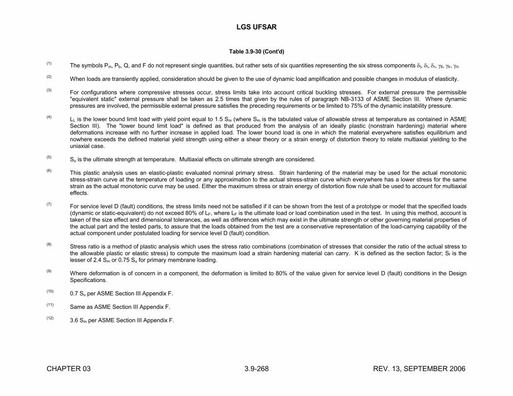
LGS UFSAR
CHAPTER 03 3.9-268 REV. 13, SEPTEMBER 2006
Table 3.9-30 (Cont'd)
(1)The symbols Pm, Pb, Q, and F do not represent single quantities, but rather sets of six quantities representing the six stress components t, l, r, tl, tr, rl.
(2)When loads are transiently applied, consideration should be given to the use of dynamic load amplification and possible changes in modulus of elasticity.
(3)For configurations where compressive stresses occur, stress limits take into account critical buckling stresses. For external pressure the permissible "equivalent static" external pressure shall be taken as 2.5 times that given by the rules of paragraph NB-3133 of ASME Section III. Where dynamic pressures are involved, the permissible external pressure satisfies the preceding requirements or be limited to 75% of the dynamic instability pressure.
(4)LL is the lower bound limit load with yield point equal to 1.5 Sm (where Sm is the tabulated value of allowable stress at temperature as contained in ASME Section III). The "lower bound limit load" is defined as that produced from the analysis of an ideally plastic (nonstrain hardening) material where deformations increase with no further increase in applied load. The lower bound load is one in which the material everywhere satisfies equilibrium and nowhere exceeds the defined material yield strength using either a shear theory or a strain energy of distortion theory to relate multiaxial yielding to the uniaxial case.
(5)Su is the ultimate strength at temperature. Multiaxial effects on ultimate strength are considered.
(6)This plastic analysis uses an elastic-plastic evaluated nominal primary stress. Strain hardening of the material may be used for the actual monotonicstress-strain curve at the temperature of loading or any approximation to the actual stress-strain curve which everywhere has a lower stress for the same strain as the actual monotonic curve may be used. Either the maximum stress or strain energy of distortion flow rule shall be used to account for multiaxial effects.
(7)For service level D (fault) conditions, the stress limits need not be satisfied if it can be shown from the test of a prototype or model that the specified loads (dynamic or static-equivalent) do not exceed 80% of LF, where LF is the ultimate load or load combination used in the test. In using this method, account is taken of the size effect and dimensional tolerances, as well as differences which may exist in the ultimate strength or other governing material properties of the actual part and the tested parts, to assure that the loads obtained from the test are a conservative representation of the load-carrying capability of the actual component under postulated loading for service level D (fault) condition.
(8)Stress ratio is a method of plastic analysis which uses the stress ratio combinations (combination of stresses that consider the ratio of the actual stress to the allowable plastic or elastic stress) to compute the maximum load a strain hardening material can carry. K is defined as the section factor; Sf is the lesser of 2.4 Sm or 0.75 Su for primary membrane loading.
(9)Where deformation is of concern in a component, the deformation is limited to 80% of the value given for service level D (fault) conditions in the Design Specifications.
(10)0.7 Su per ASME Section III Appendix F.
(11)Same as ASME Section III Appendix F.
(12)3.6 Sm per ASME Section III Appendix F.

LGS UFSAR
CHAPTER 03 3.9-269 REV. 13, SEPTEMBER 2006
Table 3.9-31
INTENTIONALLY LEFT BLANK
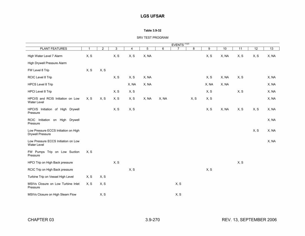
LGS UFSAR
CHAPTER 03 3.9-270 REV. 13, SEPTEMBER 2006
Table 3.9-32
SRV TEST PROGRAM
EVENTS (1)(2)
PLANT FEATURES 1 2 3 4 5 6 7 8 9 10 11 12 13
High Water Level 7 Alarm X, S X, S X, S X, NA X, S X, NA X, S X, S X, NA
High Drywell Pressure Alarm
FW Level 8 Trip X, S X, S
RCIC Level 8 Trip X, S X, S X, NA X, S X, NA X, S X, NA
HPCS Level 8 Trip X, NA X, NA X, NA X, NA X, NA
HPCI Level 8 Trip X, S X, S X, S X, S X, NA
HPCI/S and RCIS Initiation on Low Water Level
X, S X, S X, S X, S X, NA X, NA X, S X, S X, NA
HPCI/S Initiation of High Drywell Pressure
X, S X, S X, S X, NA X, S X, S X, NA
RCIC Initiation on High Drywell Pressure
X, NA
Low Pressure ECCS Initiation on High Drywell Pressure
X, S X, NA
Low Pressure ECCS Initiation on Low Water Level
X, NA
FW Pumps Trip on Low Suction Pressure
X, S
HPCI Trip on High Back pressure X, S X, S
RCIC Trip on High Back pressure X, S X, S
Turbine Trip on Vessel High Level X, S X, S
MSIVs Closure on Low Turbine Inlet Pressure
X, S X, S X, S
MSIVs Closure on High Steam Flow X, S X, S
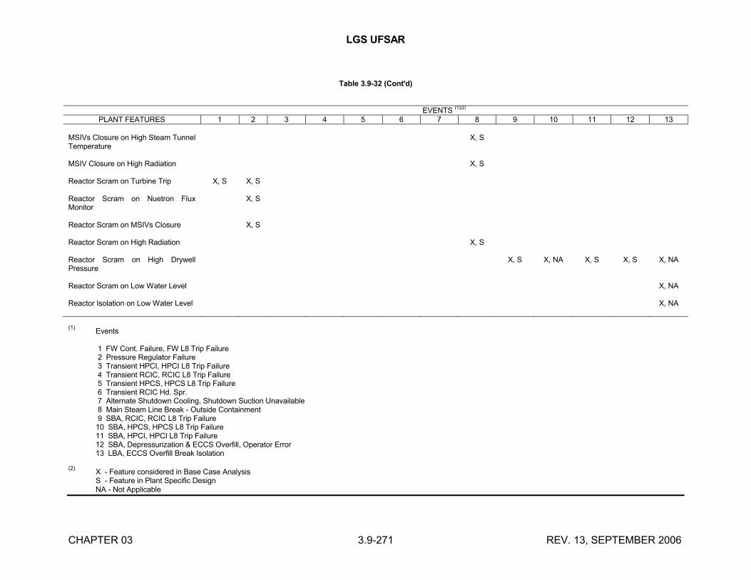
LGS UFSAR
CHAPTER 03 3.9-271 REV. 13, SEPTEMBER 2006
Table 3.9-32 (Cont'd)
EVENTS (1)(2)
PLANT FEATURES 1 2 3 4 5 6 7 8 9 10 11 12 13
MSIVs Closure on High Steam Tunnel Temperature
X, S
MSIV Closure on High Radiation X, S
Reactor Scram on Turbine Trip X, S X, S
Reactor Scram on Nuetron Flux Monitor
X, S
Reactor Scram on MSIVs Closure X, S
Reactor Scram on High Radiation X, S
Reactor Scram on High Drywell Pressure
X, S X, NA X, S X, S X, NA
Reactor Scram on Low Water Level X, NA
Reactor Isolation on Low Water Level X, NA
(1)Events
1 FW Cont. Failure, FW L8 Trip Failure2 Pressure Regulator Failure3 Transient HPCI, HPCI L8 Trip Failure4 Transient RCIC, RCIC L8 Trip Failure5 Transient HPCS, HPCS L8 Trip Failure6 Transient RCIC Hd. Spr.7 Alternate Shutdown Cooling, Shutdown Suction Unavailable8 Main Steam Line Break - Outside Containment9 SBA, RCIC, RCIC L8 Trip Failure
10 SBA, HPCS, HPCS L8 Trip Failure11 SBA, HPCI, HPCI L8 Trip Failure12 SBA, Depressurization & ECCS Overfill, Operator Error13 LBA, ECCS Overfill Break Isolation
(2)X - Feature considered in Base Case AnalysisS - Feature in Plant Specific DesignNA - Not Applicable
LGS UFSAR
CHAPTER 03 3.10-1 REV. 13, SEPTEMBER 2006
3.10 QUALIFICATION OF SEISMIC CATEGORY I INSTRUMENTATION AND ELECTRICAL EQUIPMENT
The dynamic qualification criteria applicable to the seismic Category I instruments, electrical equipment, and their supports are provided in this section. The methods and procedures used to qualify them are also discussed. Seismic Category I instruments, equipment, and supporting structures are identified in Table 3.2-1.
3.10.1 DYNAMIC QUALIFICATION CRITERIA
The seismic Category I instruments and electrical equipment are designed to withstand the effects of the SSE defined in Section 3.7 and the hydrodynamic loads discussed in Section 3.9 and Appendix 3A.4 through 3A.7 without functional impairment.
The qualification discussion covered in the following sections is generally divided into two types of equipment: NSSS equipment and non-NSSS equipment.
The following design criteria and qualification procedures for NSSS equipment include the effects of both seismic and hydrodynamic loads. The non-NSSS equipment qualification discussions include only seismic design criteria and procedures. Refer to Appendix 3A.6.8 and 3A.7.1.7 for non-NSSS equipment subjected to hydrodynamic loads. Appendix 3A.6.7 and 3A.7.1.6 contain further discussion of NSSS equipment qualification.
3.10.1.1 Dynamic Loading Design Criteria (NSSS Equipment)
The criterion used in the design and subsequent qualification of all Class 1E instruments and electrical equipment supplied by GE is as follows: "The Class 1E equipment shall be capable of performing all safety-related functions during (1) normal plant operation, (2) anticipated transients, (3) DBAs, and (4) postaccident operation while being subjected to, and after the cessation of, the accelerations resulting from the SSE and hydrodynamic loads at the point of attachment of the equipment to the building or supporting structure."
The criteria for each of the devices used in the Class 1E systems depend on the use in a given system; for example, a relay in one system may have as its safety function to de-energize and open its contacts within a certain time, while in another system it must energize and close its contacts. Since GE supplies many devices for many applications, the approach taken was to test the device in the worst case configuration. In this way, the capability of protective action initiation and the proper operation of safety-related circuits is assured.
From the basic input ground motion data, a series of response curves at various structure elevations is developed after the building layout is completed. Standard requirement levels that meet or exceed the maximum expected unique plant information are included in the purchase specifications for seismic Category I equipment. Suppliers of equipment such as batteries and racks, instrument racks, control consoles, etc., are required to submit test data, operating experience and/or calculations to substantiate that their components, systems, etc will not suffer loss of function during or after dynamic loadings. The magnitude and frequency content of the loadings which each component will experience are determined by its specific location within the plant. All Class 1E equipment will be evaluated for the capability of performing its safety function during and after dynamic loading combinations given in Table 3.9-6.
LGS UFSAR
CHAPTER 03 3.10-2 REV. 13, SEPTEMBER 2006
3.10.1.2 Dynamic Loading Design Criteria (Non-NSSS Equipment)
The seismic Category I instruments and electrical equipment is the equipment that is designed to maintain its functional capability and/or to maintain the pressure boundary integrity during and after an SSE and at least 5 OBEs. (Refer to Appendix 3A.6.8 for criteria for equipment subjected to hydrodynamic loads.)
Seismic Category I equipment is designed to withstand the more severe of the following load combinations:
a. OBE Conditions:
The load combinations include gravity loads and operation loads (or LOCA loads, if applicable) including associated temperatures and pressures, combined with the seismic loading of an OBE.
Stresses in the structural steel portions may be increased to 125% of the allowable working stress limits accepted as good practice as set forth in the appropriate design standards; that is, AISC Manual of Steel Construction, ASME B&PV Code, ANSI B31.1 and B31.7 codes for pressure piping, or other equivalent industrial codes. The resulting deflections do not prevent continuous normal operation of the equipment during and after the seismic disturbance.
b. SSE Conditions:
The load combinations include gravity loads and operating loads (or LOCA loads, if applicable) including associated temperatures and pressures combined with the seismic loading of the SSE. Stresses in the structural portions may be increased to 150% of code allowable working stress limits but are not to exceed 0.9 Fy in bending, 0.85 Fy for tension, and 0.5 Fy in shear, where (Fy) equals the material yield stress at the design temperature. The resulting deflections will not prevent the operation of the equipment during and after the seismic disturbance.
The performance requirements of the seismic Category I items and their respective supports are structural as well as functional. Where applicable, the structural requirements are in accordance with AISC "Specifications for the Design, Fabrication, and Erection of Structural Steel for Buildings," adopted February 12, 1969, or similar codes applicable for other construction materials.
The structural requirements for electrical and instrumentation equipment and systems that are required to maintain pressure boundary integrity are in accordance with the ASME Section III.
3.10.2 METHODS AND PROCEDURES FOR QUALIFYING ELECTRICAL EQUIPMENT AND INSTRUMENTATION
Seismic Category I instruments and electrical equipment are qualified according to the criteria discussed in Section 3.10.1 by the methods and procedures described in this section. The qualification methods and procedures are discussed in two parts: NSSS and non-NSSS equipment; both of which were re-assessed to SRP 3.10 Seismic Qualification Review Team (SQRT) requirements including IEEE 344-1975, and Reg. Guides 1.10 and 1.92. The SQRT re-assessment concluded that the seismic and dynamic qualification program meets the intent of IEEE 344-1975 and Reg. Guides 1.100 and 1.92.
LGS UFSAR
CHAPTER 03 3.10-3 REV. 13, SEPTEMBER 2006
3.10.2.1 Methods and Procedures for Qualifying NSSS Electrical Equipment and Instruments (Excluding Motors and Valve-Mounted Equipment)
3.10.2.1.1 Methods of Showing NSSS Equipment Compliance with IEEE 344 (1975) and Regulatory Guide 1.100
Originally, NSSS equipment were qualified to IEEE 344 (1971), which was the plant commitment, and as such did not demonstrate compliance with Regulatory Guide 1.100 and other SQRT criteria. However, a re-assessment of all NSSS equipment qualifications to NEDE-24788 "SQRT Technical Approach" ensures an adequate degree of equipment conformance to IEEE 344-1975 and Regulatory Guides 1.100 and 1.92 requirements which represents an acceptable basis for qualifying the equipment.
GE-supplied Class 1E equipment meets the requirement that the dynamic qualification should demonstrate the capability to perform the required function during and after the dynamic event. Both analysis and testing were used, but most equipment was tested. Analysis was primarily used to determine the adequacy of mechanical strength (mounting bolts, etc) after operating capability was established by testing.
a. Analysis
GE-supplied Class 1E equipment performing primarily a mechanical safety function (pressure boundary devices, etc) was analyzed, since the passive nature of its critical safety role usually made testing impractical. Analytical methods sanctioned by IEEE 344 (1971) were used in such cases and were re-evaluated to IEEE 334 (1975) criteria with satisfactory results. Table 3.10-1 shows which items were qualified by analysis.
b. Testing
GE-supplied Class 1E equipment having primarily an active electrical safety function was tested in compliance with IEEE 344 (1971), section 3.2 and were re-evaluated to IEEE 344 (1975) criteria with satisfactory results.
Available documentation verifies that the dynamic qualification of GE-supplied Class 1E equipment is in accordance with the requirements of IEEE 344 (1975).
3.10.2.1.2 Testing Procedures for Qualifying NSSS Electrical Equipment and Instruments (Excluding Motors and Valve-Mounted Equipment)
The test procedure requires that the device be mounted on the table of the vibration machine in a manner similar to how it is normally installed. The device is tested in the operating states as if it were performing its Class 1E functions and these states are monitored before, during, and after the test to assure proper function and absence of spurious function. In the example of a relay, both energized and de-energized states and normally open and normally closed contact configurations are tested if the relay is used in those configurations in its Class 1E functions.
The dynamic excitation is a single-frequency test in which the applied vibration is a sinusoidal table motion at a fixed peak acceleration and a discrete frequency at any given time. The vibratory excitation is applied in three orthogonal axes individually, with the axes chosen as those coincident with the most probable mounting configuration.
LGS UFSAR
CHAPTER 03 3.10-4 REV. 13, SEPTEMBER 2006
The first step is to search for resonances in each axis. This is done because resonances cause amplification of the input vibration and are the most likely cause of malfunction. The resonance search is usually run at low acceleration levels (0.2 g) to avoid damaging the test sample in case a severe resonance is encountered. The resonance search is run in accordance with IEEE 344; if the device is large enough, the vibrations are monitored by accelerometers placed at critical locations, from which resonances are determined by comparing the acceleration level with that at the table of the vibration machine. If the devices are either too small for an accelerometer, have their critical parts in an inaccessible location, or have critical parts that would be adversely affected by the mounting of an accelerometer, the vibrations are monitored at the closest location.
Following the frequency scan and resonance determination, the devices are tested to determine their malfunction limit. This test is a necessary adjunct to the assembly test, as shown later. The malfunction limit test is run at each resonant frequency as determined by the frequency scan. In this test, the acceleration level is gradually increased until either the device malfunctions or the limit of the vibration machine is reached. If no resonances are detected (as is usually the case), the device is considered to be rigid (all parts move in unison), and the malfunction limit is therefore independent of frequency. To achieve maximum acceleration from the vibration machine, rigid devices are malfunction tested at the upper test frequency because that allows the maximum acceleration to be obtained from deflection-limited machines.
The summary of the tests on the devices used in Class 1E applications given in Table 3.10-1 includes the "qualification" limit for each device tested.
The above procedures are required of purchased devices, as well as of those made by GE. Vendor test results are reviewed, and, if unacceptable, the tests are repeated either by GE or by the vendor. If the vendor tests are adequate, the device is considered qualified to the limits of the test.
3.10.2.1.3 Qualification of Valve-Mounted Equipment
The piping analysis establishes the response spectra, the power spectral density function or time history characteristics, and develops horizontal and vertical accelerations for the pipe-mounted equipment. Class 1E MOV actuators are qualified in accordance with IEEE 382 (1972).
The SRV, including the electrical components mounted on the valve, is subjected to a dynamic test. This testing is described in Sections 3.9.2.2a.2.14 and 3.9.3.1.13.
3.10.2.1.4 Qualification of NSSS Motors
The seismic qualification of the ECCS motors is discussed in Section 3.9.2.2a.2.7 in conjunction with the ECCS pump and motor assembly. The seismic qualification of the SLCS pump motor isdiscussed in Section 3.9.2.2a.2.10 in conjunction with the SLC pump motor assembly.
3.10.2.2 Methods and Procedures for Qualifying Non-NSSS Instruments and Electrical Equipment
In regard to compliance with Regulatory Guide 1.100, the analysis and testing for the seismic qualification of non-NSSS Class 1E instruments and electrical equipment required to function during and after an SSE are in compliance with IEEE 344 (1971) for components purchased before issuance of IEEE 344 (1975) and are in compliance with IEEE 344 (1975) for components
LGS UFSAR
CHAPTER 03 3.10-5 REV. 13, SEPTEMBER 2006
purchased after its issuance. In addition, all non-NSSS instruments and controls were re-evaluated to IEEE 344 (1975) and Reg. Guide 1.100 requirements (SQRT requirements) and found satisfactory.
Pipe-mounted instrumentation is qualified by analysis and/or testing to the acceleration levels allowed for piping systems. These levels include gravity and operation loading, as well as loading that is due to seismic excitation. Passive instruments that must only maintain mechanical and pressure boundary integrity are tested to the acceleration levels of the response spectra for the area in which they are to be installed.
Seismic Category I equipment is shown to be capable of withstanding the horizontal and vertical accelerations of five OBEs and one SSE by one of the following methods: dynamic analysis; dynamic testing; or a combination of dynamic analysis and testing. (Refer to Appendix 3A.7.1.7 for qualification methods for equipment subjected to hydrodynamic loads.)
3.10.2.2.1 Dynamic Analysis
For the analysis, equipment is idealized as a system of lumped masses and springs for which frequencies and mode shapes are determined for vibration in the vertical direction and two orthogonal horizontal directions. For each direction of vibration, the spectral accelerations per mode are obtained from the appropriate spectrum response curve corresponding to the location and damping of the equipment. Seismic loading in terms of inertia forces, moments, and shears is determined for each direction using the spectrum response method summing the absolute values per mode. If the orientation of the equipment is not designated, the horizontal seismic loading is taken as the maximum loading (worst case) obtained using each horizontal direction of vibration and the appropriate horizontal spectrum response curve(s). If the frequencies of all equipment modes (determined by either analysis or testing) are greater than the frequency of the appropriate spectrum response curve at which the acceleration is constant in the rigid (high frequency) range, the seismic loading consists of the static loading corresponding to that acceleration level.
If the equipment damping is unknown, the following values shall be used:
a. OBE - ½% damping
b. SSE - 1% damping
In lieu of determining the vibrational frequencies of equipment, the seismic loading of structurally simple equipment (that can be adequately represented as a single mass and spring) consists of a static load corresponding to 1.5 times the peak acceleration of the appropriate response spectrum curve. Total seismic loading consists of both the vertical seismic loading and the maximum horizontal seismic loading applied to the equipment simultaneously.
Where equipment must meet IEEE 344 (1975), the dynamic analysis is in accordance with section 5 of IEEE 344 (1975). Equipment qualified by analysis to IEEE 344 (1971) were re-evaluated to IEEE 344 (1975) criteria and found satisfactory.
3.10.2.2.2 Dynamic Tests
In lieu of performing a dynamic analysis, seismic adequacy is established by providing dynamic test or previous dynamic environmental (performance) data that demonstrate that the equipment
LGS UFSAR
CHAPTER 03 3.10-6 REV. 13, SEPTEMBER 2006
meets the seismic design criteria as defined in this section. The previous data include at least one of the following:
a. Recent test data acquired from dynamic tests of equipment
b. Dynamic test data from previously tested comparable equipment
c. Performance data from equipment that, during normal operating conditions, is subjected to dynamic loads equal to or greater than those defined in this section
3.10.3 METHODS AND PROCEDURES OF ANALYSIS OR TESTING OF SUPPORTS OF ELECTRICAL EQUIPMENT AND INSTRUMENTATION
3.10.3.1 Dynamic Analysis Testing Procedures And Restraint Measures For NSSS Equipment Supports (Other Than Motors And Valve-Mounted Equipment)
Some GE-supplied Class 1E devices are qualified by analysis only (Table 3.10-1). Analysis is used for passive mechanical devices and sometimes is used in combination with testing for largerassemblies containing safeguard devices. For instance, a test may be run to determine if there are natural frequencies in the equipment within the critical frequency range. If the equipment is determined to be free of natural frequencies, then it is assumed to be rigid and a static analysis is performed. If the equipment has natural frequencies in the critical frequency range, then calculations of transmissibility are performed and responses to varying input accelerations are determined to see whether Class 1E devices mounted in the assembly would operate without malfunctioning. In general, the testing of Class 1E equipment is accomplished using the following procedure.
Assemblies (i.e., control panels) containing devices that have had dynamic loading malfunction limits established are tested by mounting the assembly on the table of a vibration machine, in a manner similar to that in which it is to be mounted when in use, and vibration testing the assembly by running a low level resonance search. As with the devices, the assemblies are tested in the three major orthogonal axes. The resonance search is run in the same manner as described for devices. If resonances are present, the transmissibility between the input and the locations of each Class 1E device is determined by measuring the accelerations at each device location and calculating the magnification between it and the input. Once known, the transmissibilities could be used analytically to determine the response at any Class 1E device location for any given input. It is assumed that the transmissibilities are linear as a function of acceleration, even though they actually decrease as acceleration is increased; therefore, this is a conservative assumption. As long as the device input accelerations are determined to be below their malfunction limits, the assembly is considered a rigid body with a transmissibility equal to 1, so that a device mounted on it is limited directly by the assembly input acceleration.
Since control panels and racks constitute the majority of seismic Category I electric assemblies supplied by GE, the qualification testing of these is discussed in more detail. There are basically four generic panel types: vertical board; instrument rack; local rack; and NEMA-12 enclosures. One or more of each type is tested using the above procedures.
Figures 3.10-1 through 3.10-4 illustrate the four basic panel types referenced above and show typical accelerometer locations. The status of the dynamic tests on the Class 1E panels suppliedby GE for LGS is summarized in Table 3.10-2.
LGS UFSAR
CHAPTER 03 3.10-7 REV. 13, SEPTEMBER 2006
The full acceleration level tests described above disclose that most of the panel types have more than adequate mechanical strength and that a given panel design acceptability is just a function of its amplification factor and the malfunction levels of the devices mounted in it. Subsequent panels are therefore tested at lower acceleration levels, and the transmissibilities are measured to the various devices as described above. By dividing the devices' malfunction levels by the panel transmissibility between the device and the panel input, the panel qualification level can be determined. Several high level tests have been run on selected generic panel designs to assure the conservatism in using the transmissibility analysis described.
3.10.3.2 Non-NSSS Equipment Supports
Analyses or tests are performed for all supports of electrical equipment and instruments, such as switchgear, battery racks, instrument racks, control consoles, cabinets, and panels to ensure their structural capability to withstand seismic excitation.
The following bases are used in the seismic design and analysis of seismic Category I instrument tubing supports:
a. All instrument tubing supports are qualified by analysis, using the response spectrum method described in Section 3.10.2.2.1.
b. Analysis and design of seismic restraint measures for instrument tubing supports are based on combined limiting values for static load, span length, and computed seismic response.
c. Maximum stress is limited to 90% of minimum yield stress.
d. The seismic Category I instrument tubing systems are supported so that the allowable stresses permitted by ASME Section III are not exceeded when the tubing is subjected to the loads specified in Section 3.9 for Class 2 and 3 piping.
For field-mounted instruments, the following are applicable. (Refer to Appendix 3A.7.1.7 for instrument supports subjected to hydrodynamic loads.)
a. The mounting structures for seismic Category I instruments have a fundamental frequency of 33 Hz or higher (rigid range), which corresponds to the maximum floor acceleration. Therefore the ZPA for the installation is applicable.
b. The stress level in the mounting structure does not exceed the material allowable stress when the mounting structure is subjected to the maximum acceleration level for its location, in combination with other design loads.
3.10.4 OPERATING LICENSE REVIEW
3.10.4.1 NSSS Equipment
3.10.4.1.1 NSSS Control and Electrical Equipment (Other Than Motors and Valve-Mounted Equipment)
The qualification test plans and results for safety-related panels and control equipment within the NSSS scope of supply are maintained as follows:
LGS UFSAR
CHAPTER 03 3.10-8 REV. 13, SEPTEMBER 2006
a. Proprietary documents will be maintained by GE in a centrally located, readily auditable, permanent file.
b. Nonproprietary summary documents will be maintained by the licensee in a centrally located, readily auditable, permanent file.
If equipment fails to pass the tests, it is rejected. In some cases, equipment that fails one test is modified or repaired to meet the performance requirements and is retested. If the retested equipment passes the latter test, it may be used in a Class 1E application.
Table 3.10-1 lists the NSSS control devices by item number and vendor. The table also gives the corresponding acceleration levels for the devices used in Class 1E applications. The acceleration level shown in the right columns of Table 3.10-1 is the acceleration at which either the device malfunctioned or the limit of the vibration machine was reached.
3.10.4.1.2 NSSS Motors
Qualification test results for the ECCS motors are discussed in Section 3.9.2.2a.2.7 in conjunction with the ECCS pump and motor assembly. Qualification test results for the SLCS motor are discussed in Section 3.9.2.2a.2.10 in conjunction with the SLCS pump motor assembly.
3.10.4.1.3 Valve-Mounted Equipment
The SRVs, including the electrical components mounted on the valves, are subjected to dynamic tests. The results of these tests are discussed in Sections 3.9.2.2a.2.14 and 3.9.3.1.13, and are maintained in the same manner as discussed in Section 3.10.4.1.1.
3.10.4.2 Non-NSSS Equipment
A list of dynamic qualification packages for non-NSSS safety-related instruments and electrical equipment is given in Table 3.10-3. The qualification packages will be maintained by the licensee in a centrally located, readily auditable permanent file.
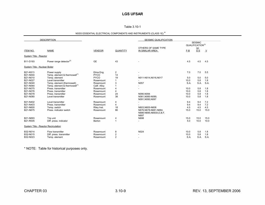
LGS UFSAR
CHAPTER 03 3.10-9 REV. 13, SEPTEMBER 2006
Table 3.10-1
NSSS ESSENTIAL ELECTRICAL COMPONENTS AND INSTRUMENTS (CLASS 1E) *
DESCRIPTION SEISMIC QUALIFICATION SEISMIC
QUALIFICATION(3)
OTHERS OF SAME TYPE (g)ITEM NO. NAME VENDOR QUANTITY IN SIMILAR AREA F-B S-S V
System Title - Reactor
B11-D193 Power range detector(2) GE 43 - 4.5 4.5 4.5
System Title - Nuclear Boiler
B21-K613 Power supply Elma Eng. 2 - 7.0 7.0 5.5B21-N004 Temp. element & thermowell(1) PYCO 14 -B21-N010 Temp. element PYCO 19 N011-N014,N016,N017 5.0 5.0 5.0B21-N027 Level transmitter Rosemount 1 - 10.0 5.8 1.8B21-N040 Temp. element (thermowell) Rosemount 3 N057 S.A. S.A. S.A.B21-N064 Temp. element & thermowell
(1)Calif. Alloy 1 -
B21-N075 Press. transmitter Rosemount 4 - 10.0 5.8 1.8B21-N076 Press. transmitter Rosemount 4 10.0 5.8 1.8B21-N078 Press. transmitter Rosemount 24 N090,N094 10.0 5.8 1.8B21-N080 Level transmitter Rosemount 38 N081,N085-N089, 10.0 5.8 1.8
N091,N095,N097B21-N402 Level transmitter Rosemount 4 - 9.4 9.4 7.2B21-N403 Press. transmitter Rosemount 4 - 9.4 9.4 7.2B21-N600 Temp. switch Riley Inst. 18 N603,N605-N608 4.5 4.5 4.5B21-N675 Press. indicator switch Rosemount 86 N676,N678-N681,N684, 15.0 15.0 15.0
N686-N695,N693A,E,B,F,N697
B21-N693 Trip unit Rosemount 4 N698 15.0 15.0 15.0B21-R005 Diff. press. indicator Barton 1 - 5.0 10.0 10.0
System Title - Reactor Recirculation
B32-N014 Flow transmitter Rosemount 8 N024 10.0 5.8 1.8B32-N015 Diff. press. transmitter Rosemount 2 - 10.0 5.8 1.8B32-N023 Temp. element Rosemount 2 - S.A. S.A. S.A.
* NOTE: Table for historical purposes only.
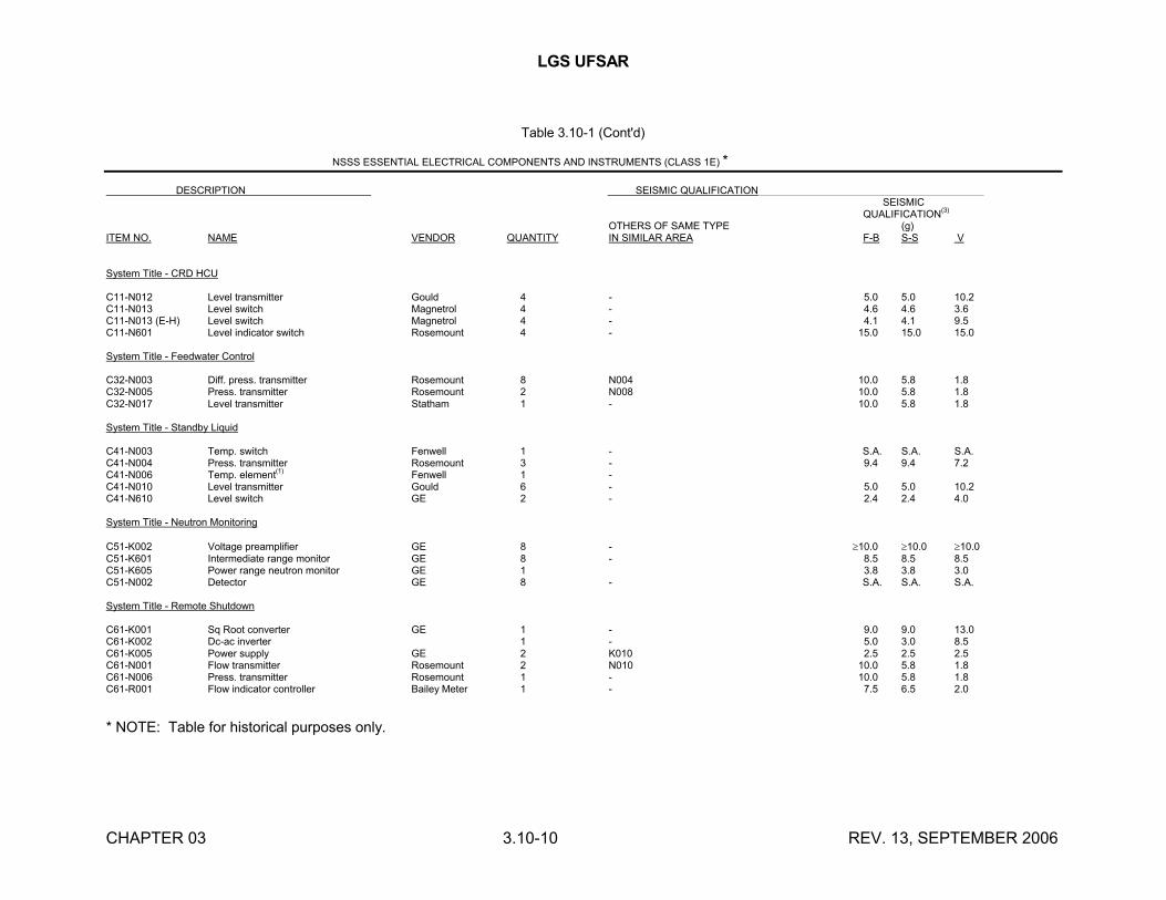
LGS UFSAR
CHAPTER 03 3.10-10 REV. 13, SEPTEMBER 2006
Table 3.10-1 (Cont'd)
NSSS ESSENTIAL ELECTRICAL COMPONENTS AND INSTRUMENTS (CLASS 1E) *
DESCRIPTION SEISMIC QUALIFICATION SEISMIC
QUALIFICATION(3)
OTHERS OF SAME TYPE (g)ITEM NO. NAME VENDOR QUANTITY IN SIMILAR AREA F-B S-S V
System Title - CRD HCU
C11-N012 Level transmitter Gould 4 - 5.0 5.0 10.2C11-N013 Level switch Magnetrol 4 - 4.6 4.6 3.6C11-N013 (E-H) Level switch Magnetrol 4 - 4.1 4.1 9.5C11-N601 Level indicator switch Rosemount 4 - 15.0 15.0 15.0
System Title - Feedwater Control
C32-N003 Diff. press. transmitter Rosemount 8 N004 10.0 5.8 1.8C32-N005 Press. transmitter Rosemount 2 N008 10.0 5.8 1.8C32-N017 Level transmitter Statham 1 - 10.0 5.8 1.8
System Title - Standby Liquid
C41-N003 Temp. switch Fenwell 1 - S.A. S.A. S.A.C41-N004 Press. transmitter Rosemount 3 - 9.4 9.4 7.2C41-N006 Temp. element(1) Fenwell 1 -C41-N010 Level transmitter Gould 6 - 5.0 5.0 10.2C41-N610 Level switch GE 2 - 2.4 2.4 4.0
System Title - Neutron Monitoring
C51-K002 Voltage preamplifier GE 8 - 10.0 10.0 10.0C51-K601 Intermediate range monitor GE 8 - 8.5 8.5 8.5C51-K605 Power range neutron monitor GE 1 3.8 3.8 3.0C51-N002 Detector GE 8 - S.A. S.A. S.A.
System Title - Remote Shutdown
C61-K001 Sq Root converter GE 1 - 9.0 9.0 13.0C61-K002 Dc-ac inverter 1 - 5.0 3.0 8.5C61-K005 Power supply GE 2 K010 2.5 2.5 2.5C61-N001 Flow transmitter Rosemount 2 N010 10.0 5.8 1.8C61-N006 Press. transmitter Rosemount 1 - 10.0 5.8 1.8C61-R001 Flow indicator controller Bailey Meter 1 - 7.5 6.5 2.0
* NOTE: Table for historical purposes only.
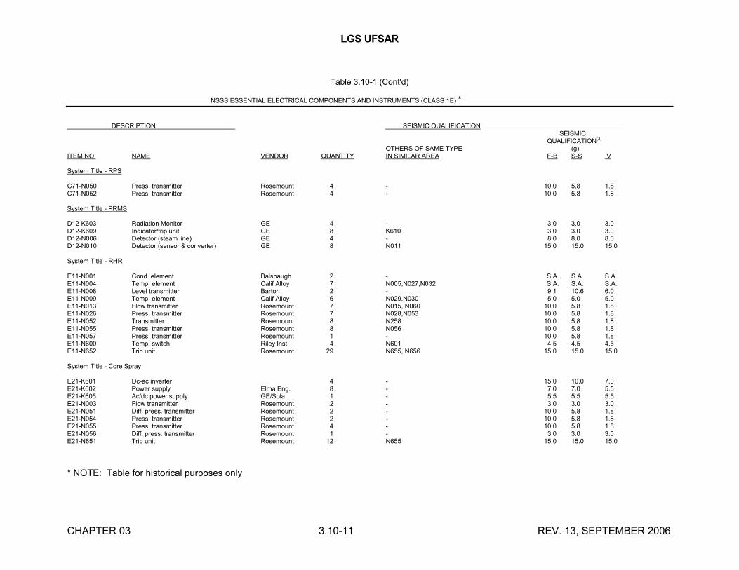
LGS UFSAR
CHAPTER 03 3.10-11 REV. 13, SEPTEMBER 2006
Table 3.10-1 (Cont'd)
NSSS ESSENTIAL ELECTRICAL COMPONENTS AND INSTRUMENTS (CLASS 1E) *
DESCRIPTION SEISMIC QUALIFICATION SEISMIC
QUALIFICATION(3)
OTHERS OF SAME TYPE (g)ITEM NO. NAME VENDOR QUANTITY IN SIMILAR AREA F-B S-S V
System Title - RPS
C71-N050 Press. transmitter Rosemount 4 - 10.0 5.8 1.8C71-N052 Press. transmitter Rosemount 4 - 10.0 5.8 1.8
System Title - PRMS
D12-K603 Radiation Monitor GE 4 - 3.0 3.0 3.0D12-K609 Indicator/trip unit GE 8 K610 3.0 3.0 3.0D12-N006 Detector (steam line) GE 4 - 8.0 8.0 8.0D12-N010 Detector (sensor & converter) GE 8 N011 15.0 15.0 15.0
System Title - RHR
E11-N001 Cond. element Balsbaugh 2 - S.A. S.A. S.A.E11-N004 Temp. element Calif Alloy 7 N005,N027,N032 S.A. S.A. S.A.E11-N008 Level transmitter Barton 2 - 9.1 10.6 6.0E11-N009 Temp. element Calif Alloy 6 N029,N030 5.0 5.0 5.0E11-N013 Flow transmitter Rosemount 7 N015, N060 10.0 5.8 1.8E11-N026 Press. transmitter Rosemount 7 N028,N053 10.0 5.8 1.8E11-N052 Transmitter Rosemount 8 N258 10.0 5.8 1.8E11-N055 Press. transmitter Rosemount 8 N056 10.0 5.8 1.8E11-N057 Press. transmitter Rosemount 1 - 10.0 5.8 1.8E11-N600 Temp. switch Riley Inst. 4 N601 4.5 4.5 4.5E11-N652 Trip unit Rosemount 29 N655, N656 15.0 15.0 15.0
System Title - Core Spray
E21-K601 Dc-ac inverter 4 - 15.0 10.0 7.0E21-K602 Power supply Elma Eng. 8 - 7.0 7.0 5.5E21-K605 Ac/dc power supply GE/Sola 1 - 5.5 5.5 5.5E21-N003 Flow transmitter Rosemount 2 - 3.0 3.0 3.0E21-N051 Diff. press. transmitter Rosemount 2 - 10.0 5.8 1.8E21-N054 Press. transmitter Rosemount 2 - 10.0 5.8 1.8E21-N055 Press. transmitter Rosemount 4 - 10.0 5.8 1.8E21-N056 Diff. press. transmitter Rosemount 1 - 3.0 3.0 3.0E21-N651 Trip unit Rosemount 12 N655 15.0 15.0 15.0
* NOTE: Table for historical purposes only
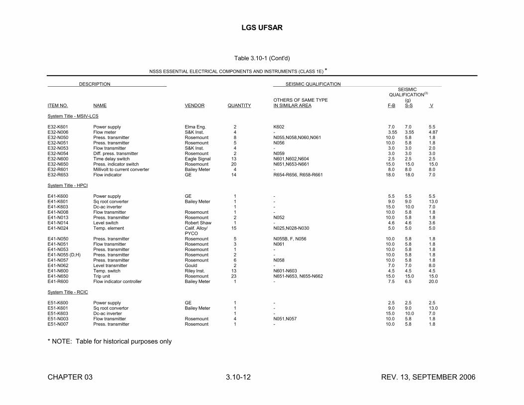
LGS UFSAR
CHAPTER 03 3.10-12 REV. 13, SEPTEMBER 2006
Table 3.10-1 (Cont'd)
NSSS ESSENTIAL ELECTRICAL COMPONENTS AND INSTRUMENTS (CLASS 1E) *
DESCRIPTION SEISMIC QUALIFICATION SEISMIC
QUALIFICATION(3)
OTHERS OF SAME TYPE (g)ITEM NO. NAME VENDOR QUANTITY IN SIMILAR AREA F-B S-S V
System Title - MSIV-LCS
E32-K601 Power supply Elma Eng. 2 K602 7.0 7.0 5.5E32-N006 Flow meter S&K Inst. 4 - 3.55 3.55 4.87E32-N050 Press. transmitter Rosemount 8 N055,N058,N060,N061 10.0 5.8 1.8E32-N051 Press. transmitter Rosemount 5 N056 10.0 5.8 1.8E32-N053 Flow transmitter S&K Inst. 4 - 3.0 3.0 2.0E32-N054 Diff. press. transmitter Rosemount 2 N059 3.0 3.0 3.0E32-N600 Time delay switch Eagle Signal 13 N601,N602,N604 2.5 2.5 2.5E32-N650 Press. indicator switch Rosemount 20 N651,N653-N661 15.0 15.0 15.0E32-R601 Millivolt to current converter Bailey Meter 4 - 8.0 8.0 8.0E32-R653 Flow indicator GE 14 R654-R656, R658-R661 18.0 18.0 7.0
System Title - HPCI
E41-K600 Power supply GE 1 - 5.5 5.5 5.5E41-K601 Sq root converter Bailey Meter 1 - 9.0 9.0 13.0E41-K603 Dc-ac inverter 1 - 15.0 10.0 7.0E41-N008 Flow transmitter Rosemount 1 - 10.0 5.8 1.8E41-N013 Press. transmitter Rosemount 2 N052 10.0 5.8 1.8E41-N014 Level switch Robert Shaw 1 - 4.6 4.6 3.6E41-N024 Temp. element Calif. Alloy/ 15 N025,N028-N030 5.0 5.0 5.0
PYCOE41-N050 Press. transmitter Rosemount 5 N055B, F, N056 10.0 5.8 1.8E41-N051 Flow transmitter Rosemount 3 N061 10.0 5.8 1.8E41-N053 Press. transmitter Rosemount 1 - 10.0 5.8 1.8E41-N055 (D,H) Press. transmitter Rosemount 2 - 10.0 5.8 1.8E41-N057 Press. transmitter Rosemount 6 N058 10.0 5.8 1.8E41-N062 Level transmitter Gould 2 - 7.0 7.0 8.0E41-N600 Temp. switch Riley Inst. 13 N601-N603 4.5 4.5 4.5E41-N650 Trip unit Rosemount 23 N651-N653, N655-N662 15.0 15.0 15.0E41-R600 Flow indicator controller Bailey Meter 1 - 7.5 6.5 20.0
System Title - RCIC
E51-K600 Power supply GE 1 - 2.5 2.5 2.5E51-K601 Sq root convertor Bailey Meter 1 - 9.0 9.0 13.0E51-K603 Dc-ac inverter 1 - 15.0 10.0 7.0E51-N003 Flow transmitter Rosemount 4 N051,N057 10.0 5.8 1.8E51-N007 Press. transmitter Rosemount 1 - 10.0 5.8 1.8
* NOTE: Table for historical purposes only

LGS UFSAR
CHAPTER 03 3.10-13 REV. 13, SEPTEMBER 2006
Table 3.10-1 (Cont'd) *
DESCRIPTION SEISMIC QUALIFICATION SEISMIC
QUALIFICATION(3)
OTHERS OF SAME TYPE (g)ITEM NO. NAME VENDOR QUANTITY IN SIMILAR AREA F-B S-S V
E51-N010 Level switch Magnetrol 1 - 4.6 4.6 3.6E51-N011 Temp. element Calif. Alloy 15 N021-N023,N025 5.0 5.0 5.0E51-N035 Level transmitter Rosemount 2 - 3.0 3.0 3.0E51-N050 Press. transmitter Rosemount 2 N052 3.0 3.0 3.0E51-N053 Press. transmitter Rosemount 1 - 10.0 5.8 1.8E51-N055 Press. transmitter Rosemount 10 N056,N058 10.0 5.8 1.8E51-N600 Temp. switch Riley Inst. 11 N603 4.5 4.5 4.5E51-N650 Press. indicator switch Rosemount 21 N635,N651-N653,N655-N660 15.0 15.0 15.0E51-R600 Flow indicator controller Bailey Meter 1 - 7.5 6.5 20.0
System Title - RWCU
G31-K602 Sq root converter Bailey Meter 6 K603,K605 9.0 9.0 13.0G31-K604 Five input summer Bailey Meter 2 - 9.0 9.0 13.0G31-N012 Flow transmitter Rosemount 6 N036,N041 10.0 5.8 1.8G31-N016 Temp. element Calif Alloy 36 N022,N023 5.0 5.0 5.0G31-N600 Temp. switch Riley Inst. 24 N602 4.5 4.5 4.5G31-N603 Diff. flow switch Bailey Meter 2 - 7.5 8.5 20.0G31-R616 Cycle timer Eagle Signal 2 - 2.5 2.5 2.5
___________________
(1) Classified as pressure integrity or passive instrument(2) Qualified by analysis(3) S.A. = Stress Analysis
* NOTE: Table for historical purposes only
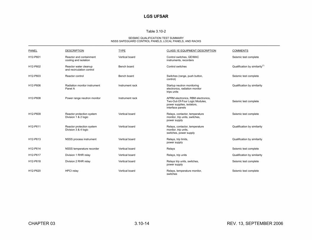
LGS UFSAR
CHAPTER 03 3.10-14 REV. 13, SEPTEMBER 2006
Table 3.10-2
SEISMIC QUALIFICATION TEST SUMMARYNSSS SAFEGUARD CONTROL PANELS, LOCAL PANELS, AND RACKS
______________________________________________________________________________________________________________________________________________________________________
PANEL DESCRIPTION TYPE CLASS 1E EQUIPMENT DESCRIPTION COMMENTS
H12-P601 Reactor and containment Vertical board Control switches, GE/MAC Seismic test completecooling and isolation instruments, recorders
H12-P602 Reactor water cleanup Bench board Control switches Qualification by similarity(1)
and recirculation control
H12-P603 Reactor control Bench board Switches (range, push button, Seismic test completecontrol)
H12-P606 Radiation monitor instrument Instrument rack Startup neutron monitoring Qualification by similarityPanel A electronics, radiation monitor
trips units
H12-P608 Power range neutron monitor Instrument rack APRM electronics, RBM electronics,Two-Out-Of-Four Logic Modules, Seismic test completepower supplies, isolators,interface panels
H12-P609 Reactor protection system Vertical board Relays, contactor, temperature Seismic test completeDivision 1 & 2 logic monitor, trip units, switches,
power supply
H12-P611 Reactor protection system Vertical board Relays, contactor, temperature Qualification by similarityDivision 3 & 4 logic monitor, trip units,
switches, power supply
H12-P613 NSSS process instrument Vertical board Relays, trip limits, Qualification by similaritypower supply
H12-P614 NSSS temperature recorder Vertical board Relays Seismic test complete
H12-P617 Division 1 RHR relay Vertical board Relays, trip units Qualification by similarity
H12-P618 Division 2 RHR relay Vertical board Relays trip units, switches, Seismic test completepower supply
H12-P620 HPCI relay Vertical board Relays, temperature monitor, Seismic test completeswitches
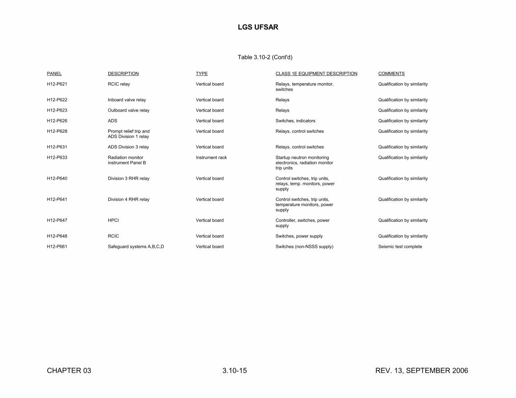
LGS UFSAR
CHAPTER 03 3.10-15 REV. 13, SEPTEMBER 2006
Table 3.10-2 (Cont'd)
PANEL DESCRIPTION TYPE CLASS 1E EQUIPMENT DESCRIPTION COMMENTS
H12-P621 RCIC relay Vertical board Relays, temperature monitor, Qualification by similarityswitches
H12-P622 Inboard valve relay Vertical board Relays Qualification by similarity
H12-P623 Outboard valve relay Vertical board Relays Qualification by similarity
H12-P626 ADS Vertical board Switches, indicators Qualification by similarity
H12-P628 Prompt relief trip and Vertical board Relays, control switches Qualification by similarityADS Division 1 relay
H12-P631 ADS Division 3 relay Vertical board Relays, control switches Qualification by similarity
H12-P633 Radiation monitor Instrument rack Startup neutron monitoring Qualification by similarityinstrument Panel B electronics, radiation monitor
trip units
H12-P640 Division 3 RHR relay Vertical board Control switches, trip units, Qualification by similarityrelays, temp. monitors, powersupply
H12-P641 Division 4 RHR relay Vertical board Control switches, trip units, Qualification by similaritytemperature monitors, powersupply
H12-P647 HPCI Vertical board Controller, switches, power Qualification by similaritysupply
H12-P648 RCIC Vertical board Switches, power supply Qualification by similarity
H12-P661 Safeguard systems A,B,C,D Vertical board Switches (non-NSSS supply) Seismic test complete

LGS UFSAR
CHAPTER 03 3.10-16 REV. 13, SEPTEMBER 2006
Table 3.10-2 (Cont'd)
PANEL DESCRIPTION TYPE CLASS 1E EQUIPMENT DESCRIPTION COMMENTS
H12-P787 Termination cabinet Cabinet Cables Qualification by similarity
H12-P788 Termination cabinet Cabinet Cables Qualification by similarity
H12-P789 Termination cabinet Cabinet Cables Qualification by similarity
H12-P790 Termination cabinet Cabinet Cables Qualification by similarity
H12-P791 Termination cabinet 2 Bay cabinet Cables Qualification by similarity
H12-P792 Termination cabinet 2 bay cabinet Cables Qualification by similarity
H12-P793 Termination cabinet 2 bay cabinet Cables Qualification by similarity
H23-P001 Core spray system, Panel A Local panel Pressure transmitters Seismic test complete
H23-P002 Reactor water cleanup Local panel Pressure transmitters, Seismic test completeindicators, temperature control
H23-P004 Reactor vessel level Local panel Pressure transmitters and Qualification by similarity& pressure, Panel A indicators, level indicator,
switches
H23-P005 Reactor vessel level Local panel Pressure transmitters Qualification by similarity& pressure, Panel B
H23-P006 Recirc pump, Panel A Local panel Pressure transmitters Qualification by similarity
H23-P009 Jet pump, Panel A Local panel Pressure transmitters Seismic test complete
H23-P010 Jet pump, Panel B Local panel Pressure transmitters Qualification by similarity
H23-P014 HPCI system, Panel B Local panel Pressure transmitters, Qualification by similarityindicators
H23-P015 Main steam flow, Panel B Local panel Pressure transmitters Qualification by similarity
H23-P016 HPCI leak detection, Panel A Local panel Pressure transmitters Qualification by similarity
H23-P017 RCIC, Panel A Local panel Pressure transmitters Qualification by similarity
H23-P018 RHR System, Panel A Local panel Pressure transmitters Qualification by similarity
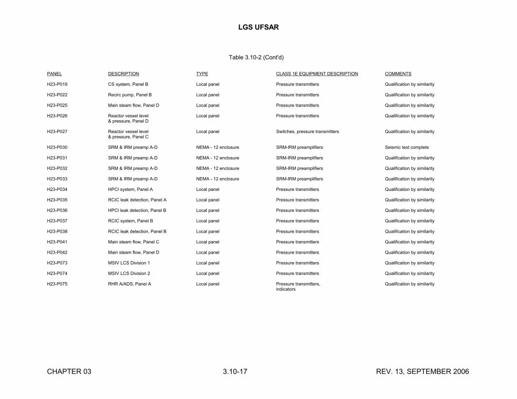
LGS UFSAR
CHAPTER 03 3.10-17 REV. 13, SEPTEMBER 2006
Table 3.10-2 (Cont'd)
PANEL DESCRIPTION TYPE CLASS 1E EQUIPMENT DESCRIPTION COMMENTS
H23-P019 CS system, Panel B Local panel Pressure transmitters Qualification by similarity
H23-P022 Recirc pump, Panel B Local panel Pressure transmitters Qualification by similarity
H23-P025 Main steam flow, Panel D Local panel Pressure transmitters Qualification by similarity
H23-P026 Reactor vessel level Local panel Pressure transmitters Qualification by similarity& pressure, Panel D
H23-P027 Reactor vessel level Local panel Switches, pressure transmitters Qualification by similarity& pressure, Panel C
H23-P030 SRM & IRM preamp A-D NEMA - 12 enclosure SRM-IRM preamplifiers Seismic test complete
H23-P031 SRM & IRM preamp A-D NEMA - 12 enclosure SRM-IRM preamplifiers Qualification by similarity
H23-P032 SRM & IRM preamp A-D NEMA - 12 enclosure SRM-IRM preamplifiers Qualification by similarity
H23-P033 SRM & IRM preamp A-D NEMA - 12 enclosure SRM-IRM preamplifiers Qualification by similarity
H23-P034 HPCI system, Panel A Local panel Pressure transmitters Qualification by similarity
H23-P035 RCIC leak detection, Panel A Local panel Pressure transmitters Qualification by similarity
H23-P036 HPCI leak detection, Panel B Local panel Pressure transmitters Qualification by similarity
H23-P037 RCIC system, Panel B Local panel Pressure transmitters Qualification by similarity
H23-P038 RCIC leak detection, Panel B Local panel Pressure transmitters Qualification by similarity
H23-P041 Main steam flow, Panel C Local panel Pressure transmitters Qualification by similarity
H23-P042 Main steam flow, Panel D Local panel Pressure transmitters Qualification by similarity
H23-P073 MSIV LCS Division 1 Local panel Pressure transmitters Qualification by similarity
H23-P074 MSIV LCS Division 2 Local panel Pressure transmitters Qualification by similarity
H23-P075 RHR A/ADS, Panel A Local panel Pressure transmitters, Qualification by similarityindicators
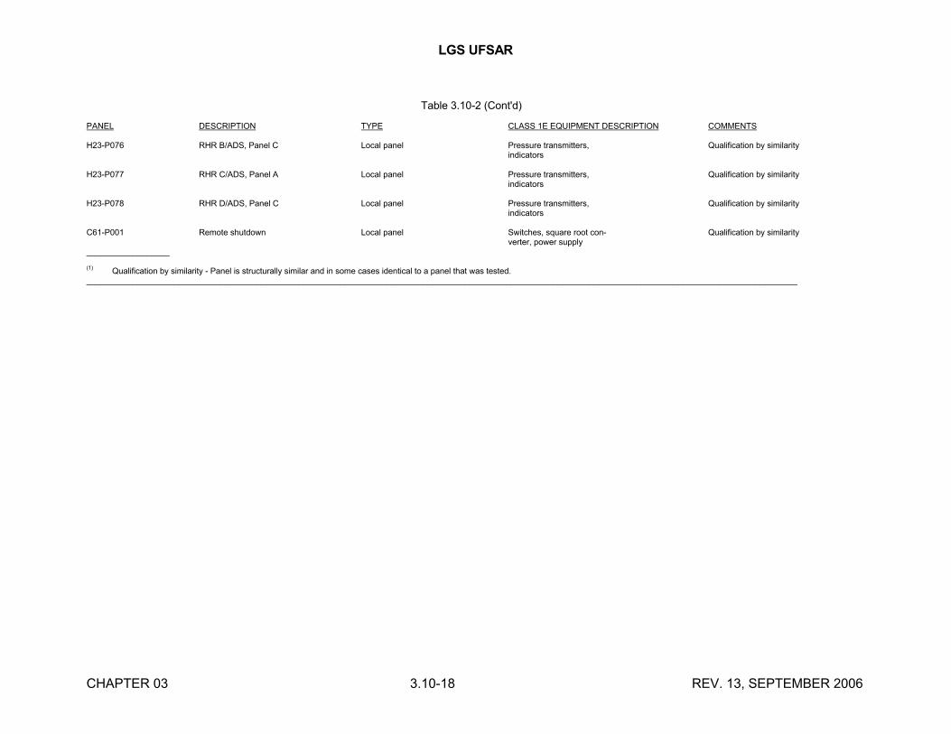
LGS UFSAR
CHAPTER 03 3.10-18 REV. 13, SEPTEMBER 2006
Table 3.10-2 (Cont'd)
PANEL DESCRIPTION TYPE CLASS 1E EQUIPMENT DESCRIPTION COMMENTS
H23-P076 RHR B/ADS, Panel C Local panel Pressure transmitters, Qualification by similarityindicators
H23-P077 RHR C/ADS, Panel A Local panel Pressure transmitters, Qualification by similarityindicators
H23-P078 RHR D/ADS, Panel C Local panel Pressure transmitters, Qualification by similarityindicators
C61-P001 Remote shutdown Local panel Switches, square root con- Qualification by similarityverter, power supply
__________________
(1)Qualification by similarity - Panel is structurally similar and in some cases identical to a panel that was tested.
__________________________________________________________________________________________________________________________________________________________
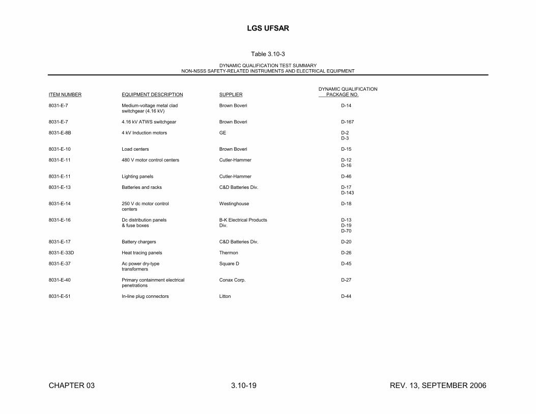
LGS UFSAR
CHAPTER 03 3.10-19 REV. 13, SEPTEMBER 2006
Table 3.10-3
DYNAMIC QUALIFICATION TEST SUMMARYNON-NSSS SAFETY-RELATED INSTRUMENTS AND ELECTRICAL EQUIPMENT
DYNAMIC QUALIFICATIONITEM NUMBER EQUIPMENT DESCRIPTION SUPPLIER PACKAGE NO.
8031-E-7 Medium-voltage metal clad Brown Boveri D-14switchgear (4.16 kV)
8031-E-7 4.16 kV ATWS switchgear Brown Boveri D-167
8031-E-8B 4 kV Induction motors GE D-2D-3
8031-E-10 Load centers Brown Boveri D-15
8031-E-11 480 V motor control centers Cutler-Hammer D-12D-16
8031-E-11 Lighting panels Cutler-Hammer D-46
8031-E-13 Batteries and racks C&D Batteries Div. D-17D-143
8031-E-14 250 V dc motor control Westinghouse D-18centers
8031-E-16 Dc distribution panels B-K Electrical Products D-13& fuse boxes Div. D-19
D-70
8031-E-17 Battery chargers C&D Batteries Div. D-20
8031-E-33D Heat tracing panels Thermon D-26
8031-E-37 Ac power dry-type Square D D-45transformers
8031-E-40 Primary containment electrical Conax Corp. D-27penetrations
8031-E-51 In-line plug connectors Litton D-44
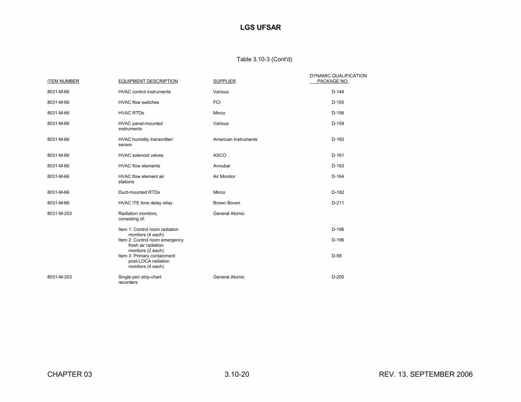
LGS UFSAR
CHAPTER 03 3.10-20 REV. 13, SEPTEMBER 2006
Table 3.10-3 (Cont'd)
DYNAMIC QUALIFICATIONITEM NUMBER EQUIPMENT DESCRIPTION SUPPLIER PACKAGE NO.
8031-M-66 HVAC control instruments Various D-144
8031-M-66 HVAC flow switches FCI D-155
8031-M-66 HVAC RTDs Minco D-156
8031-M-66 HVAC panel-mounted Various D-159instruments
8031-M-66 HVAC humidity transmitter/ American Instruments D-160sensor
8031-M-66 HVAC solenoid valves ASCO D-161
8031-M-66 HVAC flow elements Annubar D-163
8031-M-66 HVAC flow element air Air Monitor D-164stations
8031-M-66 Duct-mounted RTDs Minco D-182
8031-M-66 HVAC ITE time delay relay Brown Boveri D-211
8031-M-203 Radiation monitors, General Atomicconsisting of:
Item 1: Control room radiation D-196 monitors (4 each)Item 2: Control room emergency D-196 fresh air radiation monitors (2 each)Item 3: Primary containment D-58 post-LOCA radiation monitors (4 each)
8031-M-203 Single pen strip-chart General Atomic D-200recorders
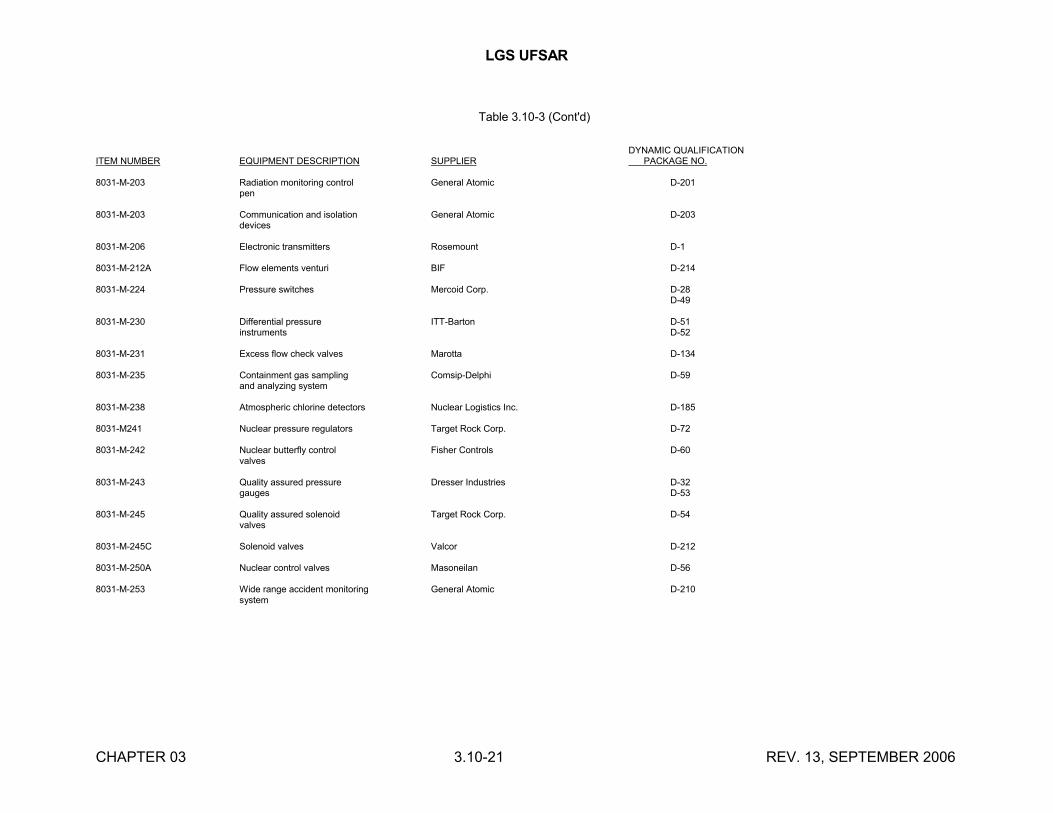
LGS UFSAR
CHAPTER 03 3.10-21 REV. 13, SEPTEMBER 2006
Table 3.10-3 (Cont'd)
DYNAMIC QUALIFICATIONITEM NUMBER EQUIPMENT DESCRIPTION SUPPLIER PACKAGE NO.
8031-M-203 Radiation monitoring control General Atomic D-201pen
8031-M-203 Communication and isolation General Atomic D-203devices
8031-M-206 Electronic transmitters Rosemount D-1
8031-M-212A Flow elements venturi BIF D-214
8031-M-224 Pressure switches Mercoid Corp. D-28D-49
8031-M-230 Differential pressure ITT-Barton D-51instruments D-52
8031-M-231 Excess flow check valves Marotta D-134
8031-M-235 Containment gas sampling Comsip-Delphi D-59and analyzing system
8031-M-238 Atmospheric chlorine detectors Nuclear Logistics Inc. D-185
8031-M241 Nuclear pressure regulators Target Rock Corp. D-72
8031-M-242 Nuclear butterfly control Fisher Controls D-60valves
8031-M-243 Quality assured pressure Dresser Industries D-32gauges D-53
8031-M-245 Quality assured solenoid Target Rock Corp. D-54valves
8031-M-245C Solenoid valves Valcor D-212
8031-M-250A Nuclear control valves Masoneilan D-56
8031-M-253 Wide range accident monitoring General Atomic D-210system
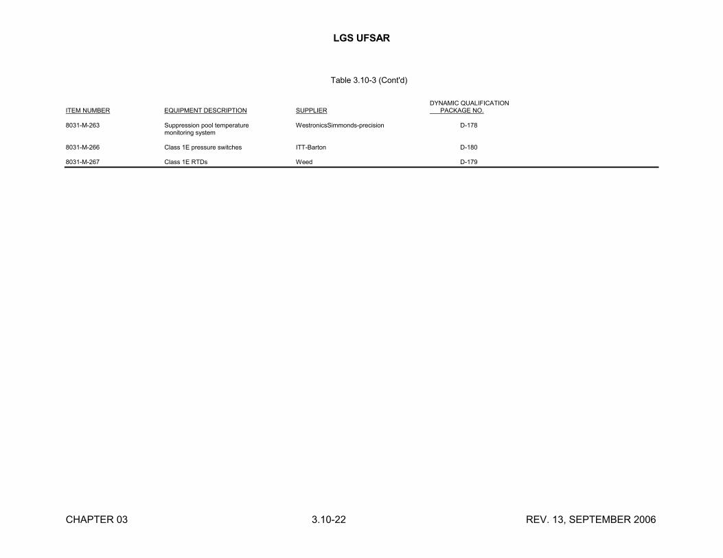
LGS UFSAR
CHAPTER 03 3.10-22 REV. 13, SEPTEMBER 2006
Table 3.10-3 (Cont'd)
DYNAMIC QUALIFICATIONITEM NUMBER EQUIPMENT DESCRIPTION SUPPLIER PACKAGE NO.
8031-M-263 Suppression pool temperature WestronicsSimmonds-precision D-178monitoring system
8031-M-266 Class 1E pressure switches ITT-Barton D-180
8031-M-267 Class 1E RTDs Weed D-179
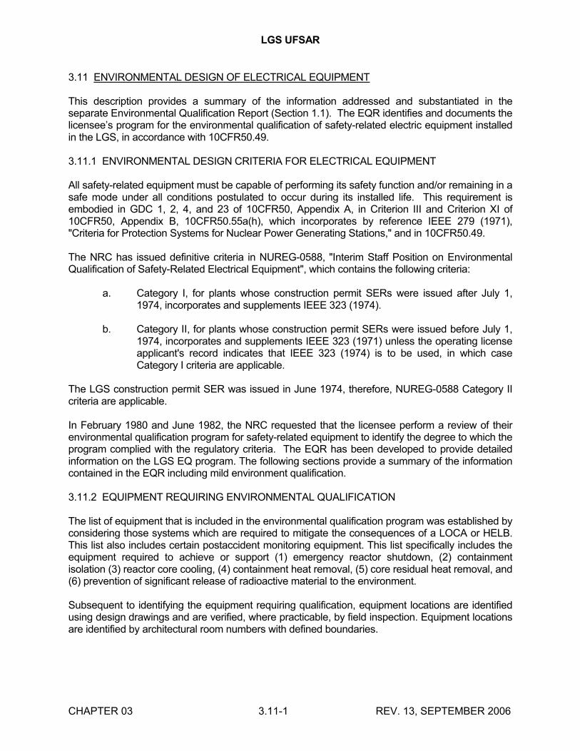
LGS UFSAR
CHAPTER 03 3.11-1 REV. 13, SEPTEMBER 2006
3.11 ENVIRONMENTAL DESIGN OF ELECTRICAL EQUIPMENT
This description provides a summary of the information addressed and substantiated in the separate Environmental Qualification Report (Section 1.1). The EQR identifies and documents the licensee’s program for the environmental qualification of safety-related electric equipment installed in the LGS, in accordance with 10CFR50.49.
3.11.1 ENVIRONMENTAL DESIGN CRITERIA FOR ELECTRICAL EQUIPMENT
All safety-related equipment must be capable of performing its safety function and/or remaining in a safe mode under all conditions postulated to occur during its installed life. This requirement is embodied in GDC 1, 2, 4, and 23 of 10CFR50, Appendix A, in Criterion III and Criterion XI of 10CFR50, Appendix B, 10CFR50.55a(h), which incorporates by reference IEEE 279 (1971), "Criteria for Protection Systems for Nuclear Power Generating Stations," and in 10CFR50.49.
The NRC has issued definitive criteria in NUREG-0588, "Interim Staff Position on Environmental Qualification of Safety-Related Electrical Equipment", which contains the following criteria:
a. Category I, for plants whose construction permit SERs were issued after July 1, 1974, incorporates and supplements IEEE 323 (1974).
b. Category II, for plants whose construction permit SERs were issued before July 1, 1974, incorporates and supplements IEEE 323 (1971) unless the operating license applicant's record indicates that IEEE 323 (1974) is to be used, in which case Category I criteria are applicable.
The LGS construction permit SER was issued in June 1974, therefore, NUREG-0588 Category II criteria are applicable.
In February 1980 and June 1982, the NRC requested that the licensee perform a review of their environmental qualification program for safety-related equipment to identify the degree to which the program complied with the regulatory criteria. The EQR has been developed to provide detailed information on the LGS EQ program. The following sections provide a summary of the information contained in the EQR including mild environment qualification.
3.11.2 EQUIPMENT REQUIRING ENVIRONMENTAL QUALIFICATION
The list of equipment that is included in the environmental qualification program was established by considering those systems which are required to mitigate the consequences of a LOCA or HELB. This list also includes certain postaccident monitoring equipment. This list specifically includes the equipment required to achieve or support (1) emergency reactor shutdown, (2) containment isolation (3) reactor core cooling, (4) containment heat removal, (5) core residual heat removal, and (6) prevention of significant release of radioactive material to the environment.
Subsequent to identifying the equipment requiring qualification, equipment locations are identified using design drawings and are verified, where practicable, by field inspection. Equipment locations are identified by architectural room numbers with defined boundaries.
LGS UFSAR
CHAPTER 03 3.11-2 REV. 13, SEPTEMBER 2006
3.11.3 ENVIRONMENTAL SERVICE CONDITIONS
Environmental conditions have been determined for normal, abnormal, and accident conditions.
All areas inside containment and rooms containing high energy lines or post-LOCA recirculatory fluid lines outside of containment are considered to be harsh environments.
3.11.3.1 Environmental Conditions During Normal Plant Operation
Redundant plant HVAC systems are designed to maintain the temperature and humidity within the normal limits which are shown in the EQR. Section 9.4 describes the HVAC system.
The TID for normal operation for 40 years of equipment life have been calculated assuming a 100% load factor and rated power. The doses are based on the design radiation source terms of the radiation sources within each plant area.
Aging effects on all equipment are considered in the qualification program to conform to the requirements of section 4 of NUREG-0588. Components susceptible to aging effects are identified, and refurbishment and/or replacement is incorporated into the LGS Preventive Maintenance/Surveillance Program. Known susceptibility to aging degradation, results of inspections and manufacturer's recommendations are factored into the Maintenance/Surveillance Program.
Effects of known normal vibratory loads on equipment are considered in the EQ program when significant.
3.11.3.2 Accident Environmental Conditions
Operability duration requirements have been determined based on the length of time the equipment must maintain its ability to perform its safety function.
The primary containment time-dependent pressure and temperature profiles for the spectrum of postulated LOCAs and main steam line breaks have been generated using NRC approved methodology.
Temperature and pressure conditions resulting from a HELB outside containment have been determined using plant specific profiles. These profiles bound accident environments caused by other events. Sections 3.6 and 9.4 describe the analyses used in generating these profiles. Additional information is contained in the EQR.
Post-LOCA radiation doses inside primary and secondary containments were calculated in accordance with NUREG-0737, item II.B.2. The source terms are consistent with those specified in NUREG-0588 and NUREG-0737. Additional information is contained in Section 1.13.
Dynamic qualification of equipment due to seismic and hydrodynamic loads from SRV and LOCA is addressed in Section 3.10 and Appendix 3A.7.1.7.
The potential for submergence of equipment inside and outside containment is identified. Identified equipment is either qualified for submergence or analyzed to ensure both that it completes its
LGS UFSAR
CHAPTER 03 3.11-3 REV. 13, SEPTEMBER 2006
function prior to submergence and that failure after submergence is acceptable. If these conditions cannot be met, the equipment will be relocated above flood level.
LGS has the capability of water spray actuation to mitigate the effects of a LOCA. Although no credit for spray actuation has been taken in determining temperature/pressure conditions inside containment, equipment inside containment is evaluated for the effects of spray.
Synergistic effects, where known, are considered. Specifically, where a supplier has identified synergisms or where the licensee is aware of synergistic effects for a particular component, it has been addressed. Appropriate documentation is included in the qualification file.
Margins appropriate to account for unquantified uncertainties in the effects of production variations and/or inaccuracies in test instruments are included in the qualification program.
3.11.4 QUALIFICATION TESTING AND ANALYSIS OF EQUIPMENT
All qualification testing and analysis of safety-related electrical equipment is performed according to the appropriate NUREG-0588 guidelines. Sequential testing and analysis or a combination thereof is performed for all electrical equipment. Analyses, performed on a case-by-case basis, have been conducted using approved methodologies to provide adequate justification.
3.11.5 METHODOLOGY FOR EVALUATING ENVIRONMENTAL QUALIFICATION TO SERVICE CONDITIONS
A comparison of environmental qualification to equipment service conditions is performed for all equipment located in harsh environmental zones. The equipment is evaluated for the 40 year normal environment and accident environments resulting from the spectrum of LOCAs and HELBs inside and outside containment. A point-by-point comparison is made between service condition parameters and qualified levels.
In addition, reviews and analyses were completed to ensure that the equipment tested was either identical or similar to the installed plant equipment.
3.11.6 MAINTENANCE/SURVEILLANCE PROGRAM
A Maintenance/Surveillance Program has been developed to encompass vendor prescribed maintenance procedures and periodic inspections of equipment to ensure that degradation is not occurring sooner than predicted. The program requires replacement of subcomponents (e.g., seals, gaskets, etc) at predetermined intervals to maintain the designated life. In addition, the program encompasses procedures to ensure that the environment is maintained relatively clean to avoid the possible adverse effects of dust.
3.11.7 REPLACEMENT PARTS PROGRAM
Safety-related equipment and spare and replacement parts are being ordered to meet or exceed the original specifications. For replacement parts being procured from the original specification and which are identical to the originally supplied equipment, a certificate of conformance is considered sufficient documentation to support qualification. However, if identical replacement parts are not available, environmental qualification for the new replacement parts will be demonstrated.
LGS UFSAR
CHAPTER 03 3.11-4 REV. 13, SEPTEMBER 2006
3.11.8 MILD ENVIRONMENT QUALIFICATION
Mild environment qualification is not included in the EQ program. A mild environment is an environment that would at no time be significantly more severe than the environment that would occur during normal plant operation, including anticipated operational occurrences.
LGS UFSAR
CHAPTER 03 3.12-1 REV. 16, SEPTEMBER 2012
3.12 CONTROL OF HEAVY LOADS
3.12.1 Introduction/Licensing Background
Site Licensing documentation is discussed in Section 1.12 (Subsection A-36) of the LGSUFSAR. Section 1.12 states "requirements for heavy loads, NUREG-0612, were addressed in the initial operating license review." Section 1.12 mentions a submittal dated August 13, 1984,which includes Bechtel Revision 3 of the LGS Overhead Handling Systems Review Final Report. Limerick Generating Station, Limerick Units 1 and 2, Overhead Handling Systems Review Final Report, Bechtel Revision 6/PECO Revision 1 (SDOC M-038-00008), August 1989 is incorporated in the LGS UFSAR as reference 9.1-1. The report summarizes the site correspondence to and from the NRC with respect to GL 81-07 and GL 85-11. Licensee submittal dated May 10, 1996, in response to NRC Bulletin 96-02 determines that at the time, NUREG-0612, Phase I commitments were being effectively implemented at LGS.
3.12.2 Safety Basis
UFSAR Section 1.12 (Subsection A-36) provides documentation of the site's compliance with Phase I of NUREG-0612 and Overhead Handling Systems Review Final Report (Reference 9.1-1) provides documentation that the site utilizes a single failure proof crane for RPVH/specified lifts and performed load drop analysis that demonstrates the fuel in the RPV will not be damaged and by providing electrical or mechanical interlocks on the crane to prevent travel of crane over spent fuel pool.
3.12.3 Scope of Heavy Load Handling Systems
The scope of load handling systems is documented in tabular form in M-038-00008 (Reference 9.1-1).
3.12.4 Control of Heavy Loads Program
3.12.4.1 Commitments in Response to NUREG-0612, Phase I Elements
The station is committed to NUREG-0612, Phase I elements as summarized in section 1.12 (Subsection A-36) of the LGS UFSAR. Detailed information is documented in M-038-00008 (Reference 9.1-1).
3.12.4.2 Reactor Pressure Vessel Head (RPVH) Lifting Procedures
The LGS UFSAR documents a single failure proof crane to be utilized to perform RPV head lifts in UFSAR Section 9.1.5 and is also documented further in reference 9.1- 1 (SDOC M-038-00008). In addition, the strong back/carousel used as a special Iifting device for this evolution is single failure proof per UFSAR Section 9.1.4.2.5.8.
This safety basis (single failure proof Iift for RPVH) is reflected in procedures M-041-200(Reactor Pressure Vessel Disassembly) and M-041-400 (Reactor Pressure VesselReassembly).
3.12.4.3 Single Failure Proof Cranes for Spent Fuel Casks
LGS UFSAR
CHAPTER 03 3.12-2 REV. 16, SEPTEMBER 2012
The spent fuel cask will be equipped with lifting lugs and yoke(s) which are single failure proof and compatible with the single failure proof reactor enclosure crane and main hook, thus precluding a cask-drop due to a single failure (UFSAR section 15.7.5). Refer to Section 9.1.5 for a description of the reactor enclosure crane and the interlocks that prevent moving the crane over the fuel pool in the absence of specific action by the crane operator to allow such movement.
3.12.5 Safety Evaluation
The basis for the site's conclusion that the existing heavy loads program is compliant with the NUREG-0612, Phase 1 requirements is documented in UFSAR Section 1.12 under the heading of "Implementation and Status Summary." This section states, "the requirements for heavy loads, NUREG-0612, were addressed in the initial operating license submittal and Unit I Operating License NPF-27 License Condition 2.C( 19)." This demonstrates that the LGS heavy loads program is compliant with the appropriate regulations, codes, and standards.
Reference 9.1 1 documents, that in the event of postulated load drops, the consequences are acceptable, as demonstrated by load drop analyses. Restrictions on load height, weight, medium under the load and safe paths are reflected in plant procedures.
Reference 9.1-1 documents that when using single failure proof cranes or equivalent to perform heavy loads lifts, the risk of a load drop is extremely unlikely and acceptably low.
Detailed review of load handling systems as documented in Reference 9.1-1 (SDOC M-038-00008) provides sufficient documentation (along with controls required by station rigging procedures) that heavy load lifts are done safely.


