Embed Size (px)
Citation preview
LiFi and Hybrid WiFi/LiFi Indoor Networking: FromTheory to PracticeMohammad Reza Ghaderi ( [email protected] )
Islamic Azad University South Tehran Branch
Research Article
Keywords: LiFi, hybrid WiFi/LiFi, optical communications, visible light communications
Posted Date: February 18th, 2022
DOI: https://doi.org/10.21203/rs.3.rs-1227840/v1
License: This work is licensed under a Creative Commons Attribution 4.0 International License. Read Full License
LiFi and Hybrid WiFi/LiFi Indoor Networking: From Theory to Practice
Mohammad Reza Ghaderi
Department of Electrical Engineering, Islamic Azad University South Tehran Branch, Tehran, Iran
[email protected] ORCID: 0000-0003-0033-4898
Abstract
Today, researchers and manufacturers consider light fidelity (LiFi) technology as an essential solution for
fast data transfer in networks. In addition, one of the essential solutions to meet the traffic restriction
challenge caused by the growing demand of Internet users is the integration of various communication
technologies. Combining LiFi and wireless fidelity (WiFi) technologies is an effective solution to overcome
this challenge. Hybrid WiFi/LiFi network uses fast data transfer from LiFi and wide coverage from WiFi.
Therefore, their integration can complement the shortcomings of each of these technologies and increases
the network performance. In this work, while presenting theoretical concepts of LiFi and hybrid WiFi/LiFi
networks, issues such as network structure, cell deployment, modulation techniques, multiple access
schemes, and criteria for measuring network performance are discussed. We present practical concepts for
implementing LiFi-based networks in detail.
Keywords: LiFi, hybrid WiFi/LiFi, optical communications, visible light communications
1. Introduction
Studies show that at the end of 2020, mobile data transmission accounted for 71% of Internet traffic, which
more than 80% of this data transmission being in indoor ereas, such as offices and homes. Due to the limited
resources of the radio frequency (RF) spectrum and the dense establishment of WiFi hubs, radio systems
will have difficulty meeting the growing demand for mobile Internet, especially in the fifth and higher
generations of cellular networks. To deal with the shortage of RF spectrum, the use of LiFi technology is
recommended [1].
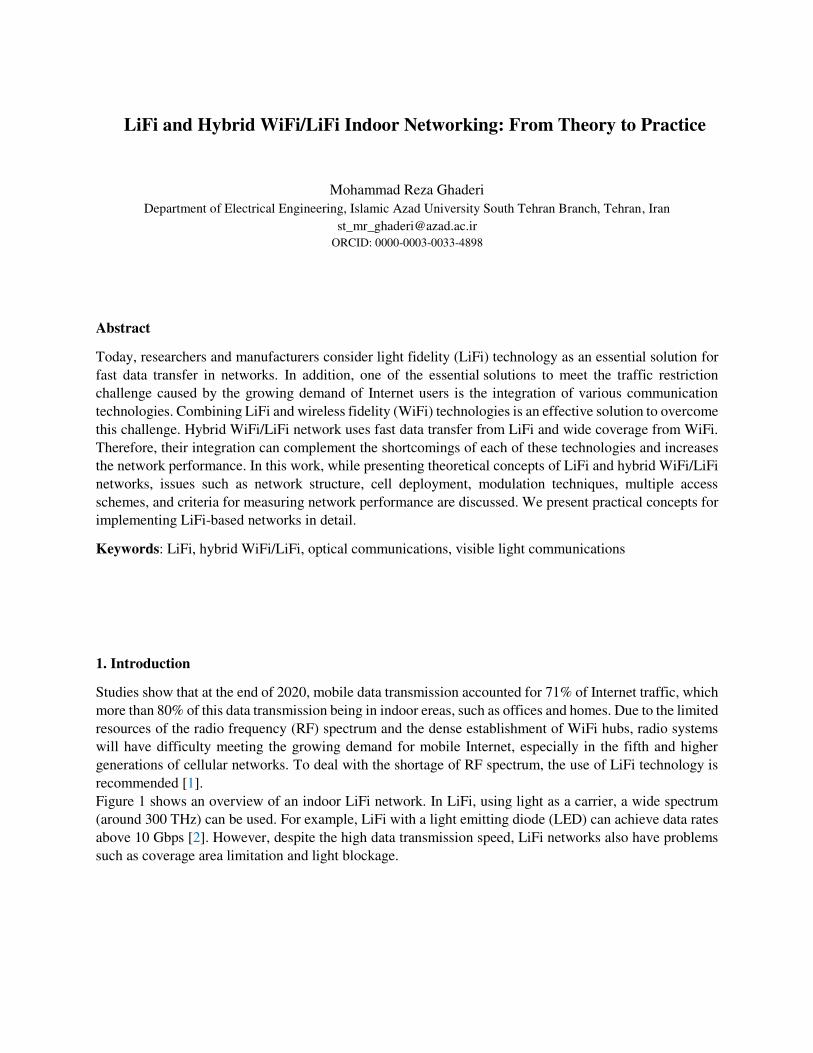
Figure 1 shows an overview of an indoor LiFi network. In LiFi, using light as a carrier, a wide spectrum
(around 300 THz) can be used. For example, LiFi with a light emitting diode (LED) can achieve data rates
above 10 Gbps [2]. However, despite the high data transmission speed, LiFi networks also have problems
such as coverage area limitation and light blockage.
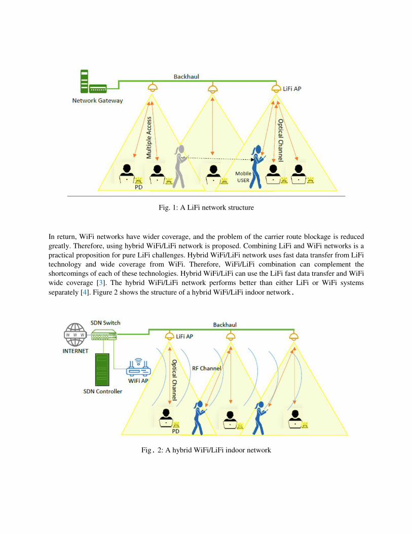
Fig. 1: A LiFi network structure
In return, WiFi networks have wider coverage, and the problem of the carrier route blockage is reduced
greatly. Therefore, using hybrid WiFi/LiFi network is proposed. Combining LiFi and WiFi networks is a
practical proposition for pure LiFi challenges. Hybrid WiFi/LiFi network uses fast data transfer from LiFi
technology and wide coverage from WiFi. Therefore, WiFi/LiFi combination can complement the
shortcomings of each of these technologies. Hybrid WiFi/LiFi can use the LiFi fast data transfer and WiFi
wide coverage [3]. The hybrid WiFi/LiFi network performs better than either LiFi or WiFi systems
separately [4]. Figure 2 shows the structure of a hybrid WiFi/LiFi indoor network.
Fig. 2: A hybrid WiFi/LiFi indoor network
In this paper, we present the issues related to the implementation of LiFi and hybrid WiFi/LiFi networks
for practical purposes. Matters include; 1) design of LiFi and hybrid WiFi/LiFi networks to determine the
location of LiFi and WiFi access points (APs), 2) allocation of resources to balance the load on the network,
3) mobility and challenges such as user path, light path blockage, and handover, and 4) network
performance improvement in terms of efficiency will be discussed in detail. In the following, we show how
to implement a LiFi-based indoor network.
The rest of the article is as follows: The second section describes the topics related to LiFi and hybrid
WiFi/LiFi networks. In the third section, the attributes of LiFi and hybrid WiFi/LiFi networks are presented.
In the fourth section, the performance of the LiFi and hybrid WiFi/LiFi networks is evaluated. In the fifth
section, we present how to implement a LiFi indoor network and finally, in the last section, we summarize
and conclude the article.
2. Background and Related Works
In this section, we introduce LiFi and hybrid WiFi/LiFi networks and related topics. In general, any LiFi or
hybrid WiFi/LiFi network consists of six main components including; 1) network structure, 2) cell
deployment model, 3) multiple access method, 4) modulation technique, 5) illumination (if required), and
6) backhaul [5]. Each of these components includes subsets as shown in Figure 3.
2.1. Network Structure According to the general structure of LiFi or hybrid WiFi/LiFi networks, as shown in Figs. 1 and 2,
respectively, to achieve flexible communication and resource allocation for the users, it is necessary to
manage users and network resources. In a hybrid network, as shown in Fig. 2, management is provid by
software-defined networking (SDN) server.
2.2. Cell Deployment Model
LiFi networks can be designed as cellular networks. Cellular networks can be provided with different types
of cell deployment models. Cell deployment can be deployed in one or two dimensions. In one-dimensional
cell deployment, the transmitter/receiver (T/R) points are arranged in a linear array [6]. This cell
deployment model is commonly used for LiFi outdoor network scenarios along a street, highway, or railroad
[7]. In the indoor networks, it is preferable to develop the cells in two dimensions, because this model can
provide a general form of coverage in the desired location. LED or infrared (IR) transmitters, used as LiFi
transmitters, are usually mounted permanently on the ceiling of an indoor area. In the two-dimensional
deployment, four models include; 1) Lattice, 2) Hexagonal, 3) Poisson point process (PPP), and 4) Hardcore
point process (HCPP) are used [8]. Figure 4 shows the cell deployment models. The lattice model is the
most practical and standard method used for LiFi and hybrid WiFi/LiFi networks due to the topological
location of the optical T/Rs (LED or IR). This deployment model has been widely used in many studies of
LiFi and hybrid WiFi/LiFi networks [9]. The hexagonal deployment model provides the best possible
Signal-to-Interference & Noise Ratio (SINR) coverage in the LiFi network. In the PPP deployment model,
instead of regular and definite cell deployment, cell deployment is performed randomely. This model is
unusual and impractical. In addition, the PPP model offers the worst probability of SINR coverage among
the three mentioned models [10]. The HCPP model is a pessimistic practical approximation model in which
two light sources might be placed side by side. This condition can only occur in rare cases. To compensate
the lack of cell deployment in the homogeneous PPP model, point processes such as the hardcore point
process (HCPP), suggest a better approximation in the real world. Therefore, this model has recently been
considered in the analysis of cellular systems.
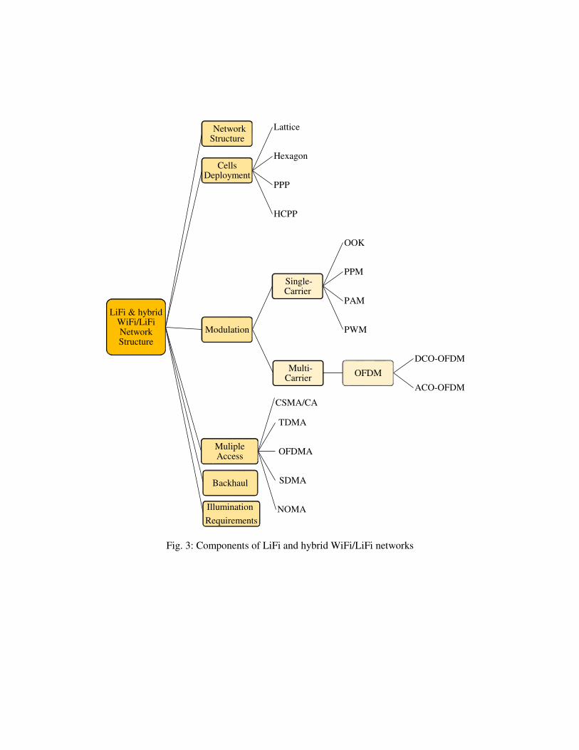
Fig. 3: Components of LiFi and hybrid WiFi/LiFi networks
LiFi & hybrid WiFi/LiFiNetwork Structure
Network Structure
Cells Deployment
Lattice
Hexagon
PPP
HCPP
Modulation
Single-Carrier
OOK
PPM
PAM
PWM
Multi-Carrier
OFDM
DCO-OFDM
ACO-OFDM
Muliple Access
CSMA/CA
TDMA
OFDMA
SDMA
NOMA
Backhaul
Illumination
Requirements
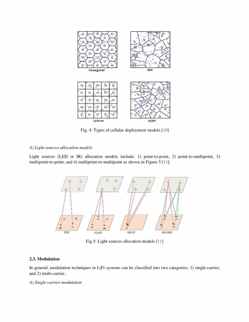
Fig. 4: Types of cellular deployment models [10]
A) Light sources allocation models
Light sources (LED or IR) allocation models include; 1) point-to-point, 2) point-to-multipoint, 3)
multipoint-to-point, and 4) multipoint-to-multipoint as shown in Figure 5 [11].
Fig.5: Light sources allocation models [11]
2.3. Modulation
In general, modulation techniques in LiFi systems can be classified into two categories; 1) single-carrier,
and 2) multi-carrier. A) Single-carrier modulation
On-off keying (OOK), pulse position modulation (PPM), unipolar pulse amplitude modulation (PAM),
pulse width modulation (PWM), and "multi-ton discrete modulation" PAM are standard single-carrier
modulation techniques. Single-carrier modulation methods are easier to implement and more suitable for
low-rate applications. Among these modulation schemes, OOK modulation is more prevalent in medium-
speed data transmission due to its less complexity. Using OOK, bit “1” is indicated by the presence of a
light pulse, while a bit "0" is indicated by the absence of a light pulse. Return to zero (RZ), and non-return
to zero (NRZ) schemes are different forms of the OOK method. In the NRZ, the “0” bit duration is the same
as the pulse duration sent to indicate “1”, while in the RZ scheme, durations are not equal. The low
complexity of OOK has led to use it in commercial wireless optical systems such as fast IR links at the less
than 4 Mbps applications. Single-carrier modulation schemes are prone to inter-symbol interference (ISI)
[1]. Therefore, as the amount of data required increases, the implementing of these modulation techniques
requires more sophisticated equalizers in the receiver to deal with ISI through the dispersive channel.
B) Multi-carrier modulation
Compared to single-carrier modulation schemes, multi-carrier modulation techniques are more spectrally
practical and can provide higher data rates. Orthogonal frequency division multiplexing (OFDM) is one of
the most common and widespread methods of multi-carrier modulation. OFDM is one of the effective
solutions to deal with the impact of ISI in LiFi systems [12]. In LiFi systems, the ISI is limited due to the
signal passing through a dispersive optical channel in high-speed data transmission mode [12]. In addition,
in the LiFi systems that use LEDs as light carriers in the downlink, bandwidth is limited due to off-the-shelf
LEDs. OFDM uses fast Fourier transform (FFT) and inverse FFT (IFFT) techniques. In LiFi systems, a
modulated signal is used. Therefore, this signal must have a positive and real value. So, a typical OFDM
modulator that generates complex and bipolar signals cannot be compatible with a direct
Intensity Modulation/Direct Detection (IM/DD) scheme [13]. Optical OFDM (O-OFDM) is a unipolar
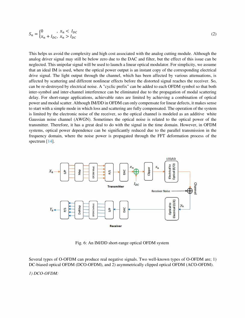
solution that can be used based on IM/DD. Figure 6 shows an overview of an IM/DD short-range O-OFDM
system. In the transmitter, the high-speed data is first to split into a large number of low-speed datasets by
the serial-to-parallel converter. Serial to parallel conversion occurs before encoding in quadrature amplitude
modulation (QAM) symbols. Then, it is applied to N sub-channels with equal distance. These symbols are
converted to time signals through the inverse fast Fourier transform (IFFT). The nth symbol in the IQ
modulator (modulating with both in-phase (I) and quadrature (Q) inputs) is obtained from the following
equation [14]:
x𝑛 = 1N ∑ (𝑋𝑘𝐼N−1k=0 + 𝑗𝑋𝑘𝑄) exp (j 2πN 𝑘𝑛) (1)
where (𝑋𝑘𝐼 + 𝑗𝑋𝑘𝑄 ) is the mixed value of the symbol modulated on the kth subcarrier. Since the OFDM
signal is the sum of a group of independent and uniformly distributed components, the number of
subchannels or alphabetic size x𝑛, is approximately Gaussian due to the central limit theorem. The output
of the OFDM modulator is converted to a digital data sequence via a parallel to serial converter. A digital-
to-analog converter (DAC) is used to convert this sequence into an analog waveform, generally bipolar. A
biasing and cutting process can then deliver this signal through the IM/DD unipolar system. If we consider
the bias voltage as IDC, the asymmetric cut samples in the time domain that represent the output distorted
signal sequence are shown as follows:
𝑆𝑛 = {0 , 𝑥𝑛 < 𝐼𝐷𝐶 𝑥𝑛 + 𝐼𝐷𝐶 , 𝑥𝑛 > 𝐼𝐷𝐶 (2)
This helps us avoid the complexity and high cost associated with the analog cutting module. Although the
analog driver signal may still be below zero due to the DAC and filter, but the effect of this issue can be
neglected. This unipolar signal will be used to launch a linear optical modulator. For simplicity, we assume
that an ideal IM is used, where the optical power output is an instant copy of the corresponding electrical
drive signal. The light output through the channel, which has been affected by various attenuations, is
affected by scattering and different nonlinear effects before the distorted signal reaches the receiver. So,
can be re-destroyed by electrical noise. A "cyclic prefix" can be added to each OFDM symbol so that both
inter-symbol and inter-channel interference can be eliminated due to the propagation of modal scattering
delay. For short-range applications, achievable rates are limited by achieving a combination of optical
power and modal scatter. Although IM/DD in OFDM can only compensate for linear defects, it makes sense
to start with a simple mode in which loss and scattering are fully compensated. The operation of the system
is limited by the electronic noise of the receiver, so the optical channel is modeled as an additive white
Gaussian noise channel (AWGN). Sometimes the optical noise is related to the optical power of the
transmitter. Therefore, it has a great deal to do with the signal in the time domain. However, in OFDM
systems, optical power dependence can be significantly reduced due to the parallel transmission in the
frequency domain, where the noise power is propagated through the FFT deformation process of the
spectrum [14].
Fig. 6: An IM/DD short-range optical OFDM system
Several types of O-OFDM can produce real negative signals. Two well-known types of O-OFDM are; 1)
DC-biased optical OFDM (DCO-OFDM), and 2) asymmetrically clipped optical OFDM (ACO-OFDM).
1) DCO-OFDM:
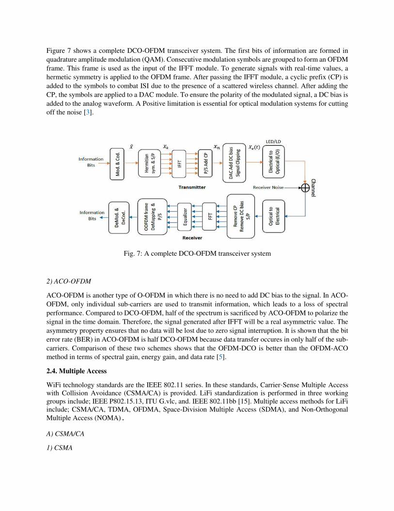
Figure 7 shows a complete DCO-OFDM transceiver system. The first bits of information are formed in
quadrature amplitude modulation (QAM). Consecutive modulation symbols are grouped to form an OFDM
frame. This frame is used as the input of the IFFT module. To generate signals with real-time values, a
hermetic symmetry is applied to the OFDM frame. After passing the IFFT module, a cyclic prefix (CP) is
added to the symbols to combat ISI due to the presence of a scattered wireless channel. After adding the
CP, the symbols are applied to a DAC module. To ensure the polarity of the modulated signal, a DC bias is
added to the analog waveform. A Positive limitation is essential for optical modulation systems for cutting
off the noise [3].
Fig. 7: A complete DCO-OFDM transceiver system
2) ACO-OFDM
ACO-OFDM is another type of O-OFDM in which there is no need to add DC bias to the signal. In ACO-
OFDM, only individual sub-carriers are used to transmit information, which leads to a loss of spectral
performance. Compared to DCO-OFDM, half of the spectrum is sacrificed by ACO-OFDM to polarize the
signal in the time domain. Therefore, the signal generated after IFFT will be a real asymmetric value. The
asymmetry property ensures that no data will be lost due to zero signal interruption. It is shown that the bit
error rate (BER) in ACO-OFDM is half DCO-OFDM because data transfer occures in only half of the sub-
carriers. Comparison of these two schemes shows that the OFDM-DCO is better than the OFDM-ACO
method in terms of spectral gain, energy gain, and data rate [5].
2.4. Multiple Access
WiFi technology standards are the IEEE 802.11 series. In these standards, Carrier-Sense Multiple Access
with Collision Avoidance (CSMA/CA) is provided. LiFi standardization is performed in three working
groups include; IEEE P802.15.13, ITU G.vlc, and. IEEE 802.11bb [15]. Multiple access methods for LiFi
include; CSMA/CA, TDMA, OFDMA, Space-Division Multiple Access (SDMA), and Non-Orthogonal
Multiple Access (NOMA).
A) CSMA/CA
1) CSMA
The CSMA technique is proposed to reduce the probability of a collision when two or more stations start
sending their signals through the data link layer. Multiple access based on the "carrier-sense" method
requires each station to check the channel status before sending data. Persistence methods can assist the
station during channel busy/idle. 2) CSMA/CD
In the Carrier Sense Multiple Access with Collision Detection (CSMA/CD) technique, a station monitors
the environment after sending a frame to see if it will be successful. If the transmission is successful, the
transmission process is completed by the station; otherwise, the frame will be resent. 3) CSMA/CA
CSMA/CA can benefit from the Request to Send (RTS) and the Clear to Send (CTS) methods between the
transmitter and receiver [16]. When a node can access the channel, it can use the total bandwidth.
CSMA/CA uses a scheme called slotted Binary Exponential Backoff (BEB) to reduce collisions caused by
simultaneous sending in nodes. Hence, the nodes listen to the channel for a period known as Distributed
Inter-Frame Space (DIFS) before sending. Then, if the channel is idle, the nodes generate random backups.
The node with the least amount of backup is the first to send, and before the other nodes, it sends the RTS
frame to the AP. If the RTS frame is successfully received in the AP, the AP responds with the CTS frame
after a Short Interframe Space (SIFS). Once the node gets the CTS packet, it starts sending data after being
specified by SIFS. Finally, an ACK packet is sent by the AP after SIFS to notify the successful receipt of
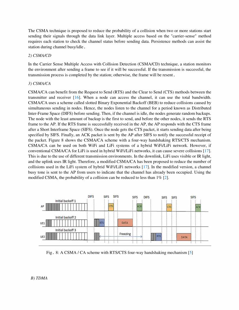
the packet. Figure 8 shows the CSMA/CA scheme with a four-way handshaking RTS/CTS mechanism.
CSMA/CA can be used on both WiFi and LiFi systems of a hybrid WiFi/LiFi network. However, if
conventional CSMA/CA for LiFi is used in hybrid WiFi/LiFi networks, it can cause severe collisions [17].
This is due to the use of different transmission environments. In the downlink, LiFi uses visible or IR light,
and the uplink uses IR light. Therefore, a modified CSMA/CA has been proposed to reduce the number of
collisions used in the LiFi system of hybrid WiFi/LiFi networks [17]. In the modified version, a channel
busy tone is sent to the AP from users to indicate that the channel has already been occupied. Using the
modified CSMA, the probability of a collision can be reduced to less than 1% [2].
Fig. 8: A CSMA / CA scheme with RTS/CTS four-way handshaking mechanism [5]
B) TDMA
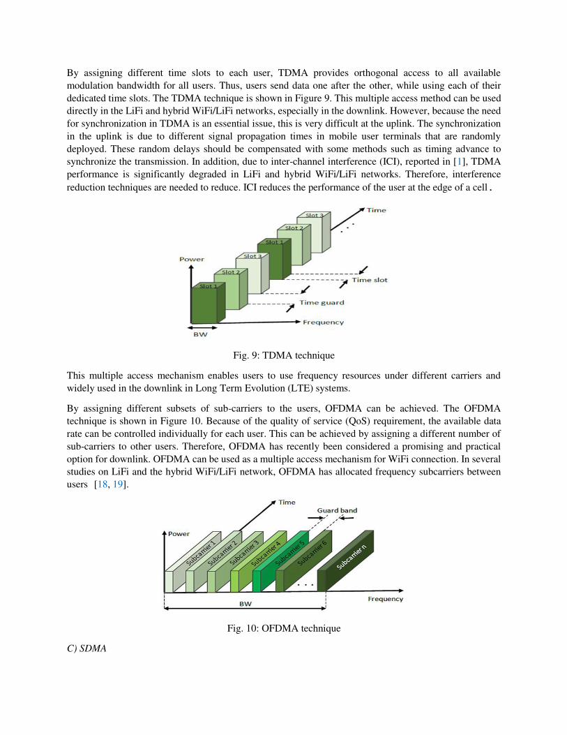
By assigning different time slots to each user, TDMA provides orthogonal access to all available
modulation bandwidth for all users. Thus, users send data one after the other, while using each of their
dedicated time slots. The TDMA technique is shown in Figure 9. This multiple access method can be used
directly in the LiFi and hybrid WiFi/LiFi networks, especially in the downlink. However, because the need
for synchronization in TDMA is an essential issue, this is very difficult at the uplink. The synchronization
in the uplink is due to different signal propagation times in mobile user terminals that are randomly
deployed. These random delays should be compensated with some methods such as timing advance to
synchronize the transmission. In addition, due to inter-channel interference (ICI), reported in [1], TDMA
performance is significantly degraded in LiFi and hybrid WiFi/LiFi networks. Therefore, interference
reduction techniques are needed to reduce. ICI reduces the performance of the user at the edge of a cell.
Fig. 9: TDMA technique
This multiple access mechanism enables users to use frequency resources under different carriers and
widely used in the downlink in Long Term Evolution (LTE) systems.
By assigning different subsets of sub-carriers to the users, OFDMA can be achieved. The OFDMA
technique is shown in Figure 10. Because of the quality of service (QoS) requirement, the available data
rate can be controlled individually for each user. This can be achieved by assigning a different number of
sub-carriers to other users. Therefore, OFDMA has recently been considered a promising and practical
option for downlink. OFDMA can be used as a multiple access mechanism for WiFi connection. In several
studies on LiFi and the hybrid WiFi/LiFi network, OFDMA has allocated frequency subcarriers between
users [18, 19].
Fig. 10: OFDMA technique
C) SDMA
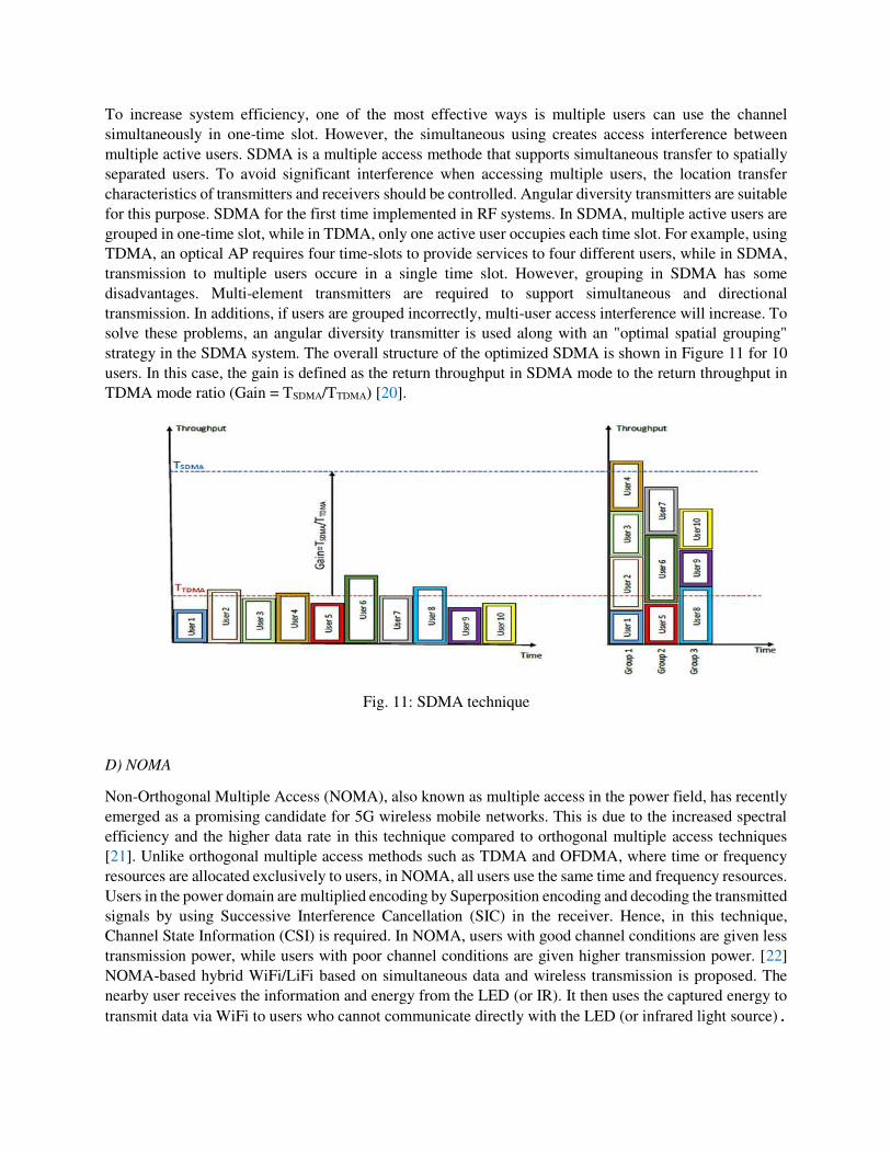
To increase system efficiency, one of the most effective ways is multiple users can use the channel
simultaneously in one-time slot. However, the simultaneous using creates access interference between
multiple active users. SDMA is a multiple access methode that supports simultaneous transfer to spatially
separated users. To avoid significant interference when accessing multiple users, the location transfer
characteristics of transmitters and receivers should be controlled. Angular diversity transmitters are suitable
for this purpose. SDMA for the first time implemented in RF systems. In SDMA, multiple active users are
grouped in one-time slot, while in TDMA, only one active user occupies each time slot. For example, using
TDMA, an optical AP requires four time-slots to provide services to four different users, while in SDMA,
transmission to multiple users occure in a single time slot. However, grouping in SDMA has some
disadvantages. Multi-element transmitters are required to support simultaneous and directional
transmission. In additions, if users are grouped incorrectly, multi-user access interference will increase. To
solve these problems, an angular diversity transmitter is used along with an "optimal spatial grouping"
strategy in the SDMA system. The overall structure of the optimized SDMA is shown in Figure 11 for 10
users. In this case, the gain is defined as the return throughput in SDMA mode to the return throughput in
TDMA mode ratio (Gain = TSDMA/TTDMA) [20].
Fig. 11: SDMA technique
D) NOMA
Non-Orthogonal Multiple Access (NOMA), also known as multiple access in the power field, has recently
emerged as a promising candidate for 5G wireless mobile networks. This is due to the increased spectral
efficiency and the higher data rate in this technique compared to orthogonal multiple access techniques
[21]. Unlike orthogonal multiple access methods such as TDMA and OFDMA, where time or frequency
resources are allocated exclusively to users, in NOMA, all users use the same time and frequency resources.
Users in the power domain are multiplied encoding by Superposition encoding and decoding the transmitted
signals by using Successive Interference Cancellation (SIC) in the receiver. Hence, in this technique,
Channel State Information (CSI) is required. In NOMA, users with good channel conditions are given less
transmission power, while users with poor channel conditions are given higher transmission power. [22]
NOMA-based hybrid WiFi/LiFi based on simultaneous data and wireless transmission is proposed. The
nearby user receives the information and energy from the LED (or IR). It then uses the captured energy to
transmit data via WiFi to users who cannot communicate directly with the LED (or infrared light source).
2.5. Backhaul
In mobile networks, the links that connect the light source points (LED or IR) to the central unit are called
backhaul links. With the rapid growth of mobile users, backhaul links should also grow accordingly. Radio
interfaces have long been a bottleneck for mobile networks due to their low performance. However, this
bottleneck has shifted to backend networks in recent years, along with improved radio interfaces and
demand for high-speed data service and data generation. Hybrid WiFi/LiFi networks should have separate
or shared backhaul for LiFi and WiFi networks that can ensure availability, scalability, and visibility on
hybrid networks. LiFi networks are made up of several small cells known as femtocells [23]. Using modern
interference management techniques, the spectrum can be fully utilized in each LiFi cell [24]. Therefore,
LiFi APs can provide data rates of several gigabits per second. Hence, backhaul links should transmit
hundreds of gigabits per second over LiFi networks. Various technologies, including wireless optical
technologies such as visible or infrared light, have been studied as possible solutions for connecting
backhauls. The wired backhaul option is fiber optics that provide a wide bandwidth of several gigabits per
second. Optical wireless communication is another possible solution that will be able to manage high-speed
networks in backups for future networks. In [25], a wireless solution based on visible light communication
is proposed for indoor auto cell LiFi networks. In [26], frequency reuse is provided for access and backhaul
links. Both visible and infrared light bands are evaluated as backhaul solutions for LiFi networks. The
effects of "between backhaul" and "backhaul-to-access" interference on the SINR have also been analyzed.
To achieve re-realization with visible light, the authors evaluated both full reuse and in-bandwidth
allocation methods. In hybrid networks where LiFi and WiFi systems are provided by the same backlink
[27]. 2.6 . Illumination Requirement
In LiFi or hybrid LiFi/WiFi systems that use visible light produced by LEDs as a downlink carrier, one of
the most effective ways to improve energy efficiency is to properly design the placement or arrangement
of the LEDs inside the building. By optimizing the location of the LEDs and controlling their output power
level, the minimum energy consumption is achieved, and at the same time, a desirable lighting pattern is
achieved. It is important to consider room lighting limits when designing a LiFi network that uses LEDs as
a downlink carrier. the illumination requirement for an indoor environment should be in the range of 300
to 1500 Lux [28]. Typically, the light is low in the corners of the room while it is high in the center of the
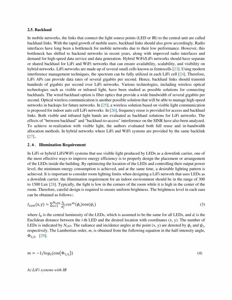
room. Therefore, careful design is required to ensure uniform brightness. The brightness level in each eara
can be obtained as follows: 𝐼𝐿𝑢𝑚(x, y) = ∑ 𝐼0𝑑𝑖2𝑁𝐿𝐸𝐷𝑖=1 𝑐𝑜𝑠𝑚(𝜙𝑖)cos (𝜓𝑖) (3)
where 𝐼0 is the central luminosity of the LEDs, which is assumed to be the same for all LEDs, and di is the
Euclidean distance between the i-th LED and the desired location with coordinates (x, y). The number of
LEDs is indicated by NLED. The radiance and incidence angles at the point (x, y) are denoted by 𝜙𝑖 and 𝜓𝑖, respectively. The Lambertian order, m, is obtained from the following equation in the half-intensity angle, Φ1/2 [29].
𝑚 = −1/𝑙𝑜𝑔2(cos(Φ1/2)) (4)
A) LiFi systems with IR
Some LiFi systems use IR transmitter/receiver instead of LED in up and downlinks. In this case, ambient
illumination should be provided through other illuminating equipments (the IR transmitter/receiver only is
used for sending and receiving data, and ambient illumination is not provided in this way).
3. Attributes of LiFi and Hybrid WiFi/LiFi Systems
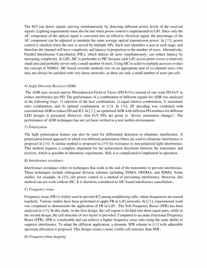
A LiFi or hybrid WiFi/LiFi system has essential attributes include; 1) interference, 2) user behavior model,
3) handover, and 4) load balancing. Figure 12 shows the essential characteristics of LiFi and hybrid
WiFi/LiFi systems.
3.1. Interference
Increasing the number of light sources (LED or IR) is one of the essential aspects of network density, which
will be recognized as the primary mechanism of wireless evolution in the next decade. However,
interference management is crucial. LiFi and WiFi do not interfere due to operating in different spectrums.
In addition, CSMA/CA with WiFi can minimize co-channel interference (CCI). Hence, hybrid WiFi/LiFi
networks focus more on LiFi interference management techniques. These techniques are listed in Figure
11[5].
A) Interference cancellation
Interference cancellation refers to techniques that decode the information and use this information along
with channel estimation to cancel or reduce interference in the received signal [29]. These types of
techniques are used at the end of the receiver, where receiving an interference signal. These techniques can
be summarized as follows: 1) Precoding
Precoding techniques including zero forcing (ZF), block diagonalization (BD), and dirty paper coding
(DPC), are widely used to eliminate interference signals in downlink. The basic principle in these
techniques is to intelligently create orthogonal channels by breaking them down into individual units.
Because optical signals are not negative, conventional Precoding techniques need to be modified by LiFi;
for example adding DC bias is one of these methods [30]. Depending on the type of interference, Precoding
techniques can be divided into two categories; multi-user detection (MUD) and coordinated multi-point
transmission (CoMP). The purpose of the MUD is to eliminate interference between channels within the
same APs. CoMP is designed to eliminate ICI by coordinating APs to exchange CSI knowledge.
Encryption-based methods for override encoding require Channel State Information at the Transmitter
(CSIT) for all subscriber channels. If no illumination is needed, WiFi typically uses IR and forms a
Frequency Division Duplex (FDD) system. Therefore, implementing precoding techniques in LiFi is costly.
CSI also disrupts precoding performance. This is more pronounced in LiFi because rapid device oriantation
create high-speed channels.
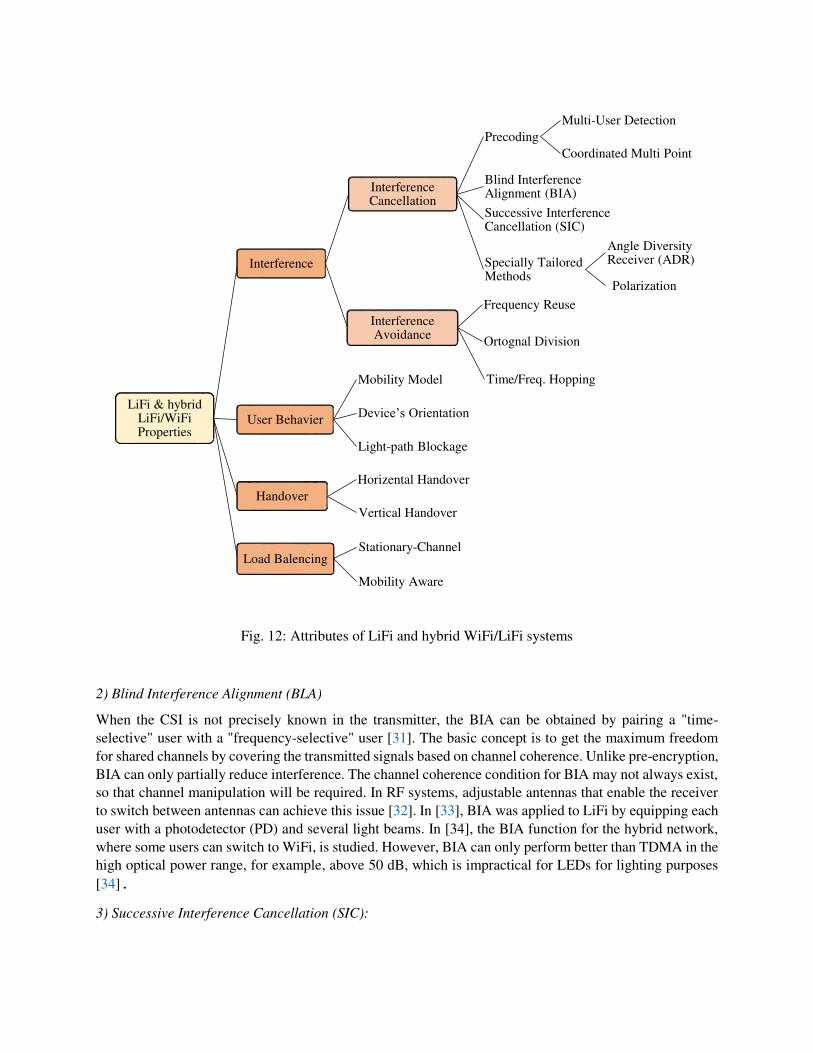
Fig. 12: Attributes of LiFi and hybrid WiFi/LiFi systems
2) Blind Interference Alignment (BLA)
When the CSI is not precisely known in the transmitter, the BIA can be obtained by pairing a "time-
selective" user with a "frequency-selective" user [31]. The basic concept is to get the maximum freedom
for shared channels by covering the transmitted signals based on channel coherence. Unlike pre-encryption,
BIA can only partially reduce interference. The channel coherence condition for BIA may not always exist,
so that channel manipulation will be required. In RF systems, adjustable antennas that enable the receiver
to switch between antennas can achieve this issue [32]. In [33], BIA was applied to LiFi by equipping each
user with a photodetector (PD) and several light beams. In [34], the BIA function for the hybrid network,
where some users can switch to WiFi, is studied. However, BIA can only perform better than TDMA in the
high optical power range, for example, above 50 dB, which is impractical for LEDs for lighting purposes
[34]. 3) Successive Interference Cancellation (SIC):
LiFi & hybrid LiFi/WiFi Properties
Interference
Interference Cancellation
Precoding
Multi-User Detection
Coordinated Multi Point
Blind Interference Alignment (BIA)
Successive Interference Cancellation (SIC)
Specially Tailored Methods
Angle Diversity Receiver (ADR)
Polarization
Interference Avoidance
Frequency Reuse
Ortognal Division
Time/Freq. Hopping
User Behavier
Mobility Model
Device’s Orientation
Light-path Blockage
Handover
Horizental Handover
Vertical Handover
Load BalencingStationary-Channel
Mobility Aware
The SCI can detect signals arriving simultaneously by detecting different power levels of the received
signals. Lighting requirements must also be met when power control is implemented in LiFi. Since only the
AC component of the optical signal is converted into an effective electrical signal, the percentage of the
AC component can be adjusted to maintain the same average optical transmission power. In [35], power
control is checked when the user is served by multiple APs. Each user identifies a user at each stage, and
therefore the channel will have complexity and latency in proportion to the number of users. Alternatively,
Parallel Interference Cancellation (PIC), which detects all users simultaneously, can reduce latency by
increasing complexity. In LiFi, SIC is preferable to PIC because each LiFi access point covers a relatively
small area and probably serves only a small number of users. Using SIC to achieve multiple accesses evokes
the concept of NOMA. SIC-based override methods rely on an appropriate pair of co-channel users who
may not always be satisfied with very dense networks, as there are only a small number of users per cell.
4) Angle Diversity Receiver (ADR)
The ADR uses several narrow Photodetector-Field of Views (PD-FoVs) instead of one wide PD-FoV to
reduce interference per PD. The performance of a combination of different signals for ADR was analyzed
in the following ways: 1) selection of the best combination, 2) equal interest combination, 3) maximum
ratio combination, and 4) optimal combination, in [24]. In [36], ZF decoding was combined with
conventional ADR to reduce ISI and ICI. In [37], an optimized ADR with different PD numbers for different
LED designs is presented. However, slim FoV PDs are prone to "device orientation changes". The
performance of ADR techniques has not yet been verified in a real mobile environment. 5) Polarization
The light polarization feature can also be used for differential detection to eliminate interference. A
polarization-based approuch in which two different polarization filters are used to eliminate interference is
proposed in [38]. A similar method is proposed in [39] for resistance to non-polarized light interference.
This method requires a complete alignment for the polarization directions between the transmitter and
receiver, which is possible in laboratory experiments. Still, it is complicated to implement in operation.
B) Interference avoidance
Interference avoidance refers to techniques that work at the end of the transmitter to prevent interference.
These techniques include orthogonal division schemes including TDMA, OFDMA, and SDMA. Some
studies, for example, in [40], cite power control as a method of preventing interference. However, this
method can not work without SIC. It is therefore considered as SIC-based interference cancellation.
C) Frequency reuse
Frequency reuse (FR) is widely used to prevent ICI among neighboring cells, where frequencies are reused
regularly. Various studies have been performed to apply FR in LiFi networks. In [41], experimental work
was completed to demonstrate the application of FR in LiFi. The Soft Frequency Reuse (SFR) has been
analyzed in [42]. In this study, in the first design, the cell region is divided into three equal parts, while in
the second design, the cell structure of two layers is provided. Compared to accurate Fractional Frequency
Reuse (FFR), SFR is visualizable and can achieve a higher frequency reuse ratio using the same ability to
suppress interference. To adapt the different application, a dynamic SFR scheme in [43] with adjustable
spectrum allocation is proposed. This design creates a more visible cell structure than SFR. D) Frequency/time hopping
Frequency/time hopping methods, using a quasi-random sequence known to both transmitter and receiver,
quickly move a carrier across many frequency channels or time slots. A time hopping method for LiFi was
reported in [44], where the duty cycle of the optical carrier is different in a quasi-random manner. This
method reduces the likelihood of two users occupying the time-frequency block but requires careful
coordination between the AP and the user. 3.2. User Behavior
In LiFi cellular network and subsequently in hybrid WiFi/LiFi network, efficiency and Quality of Service
(QoS) depends on various factors such as user mobility, random orientation of the user's device and link
blocking. Many mobility models are presented in the articles [45]. The Random Waypoint (RWP) model is
one of the simplest and most well-known models designed to simulate user mobility indoors or outdoors.
Device orientation and link blocking are two other essential factors that affecting user performance on LiFi
networks.
A) Mobility
Various models have been proposed to demonstrate indoor mobility. In [46], user mobility is considered in
rectangular microcells in which users may either move at a constant speed or remain stationary during a
call. In this model, users tend to move in straight lines to the point where they change direction, according
to the Poisson process model. In [47] a mobility model based on a new rule is proposed inside a multi-room
building in which users move in specific paths from one room to another. In [48] a mobility model is defined
in which nodes move along the edges of the graph. The edges represent authentic paths inside the room.
Each node randomly selects a destination chart from the vertex subset and moves along the edge. A 3D
mobility model inside the building considering boundary conditions is presented in [49]. In this model,
horizontal and vertical movement are modeled. In [50] the same idea is extended to a 3D mobility model
in high-rise building environments where vertical movement is performed by elevator. A new and more
realistic three-dimensional internal mobility model based on actual building data is presented in the
reference [51]. To model the building, various factors such as walls, floor, and ceiling are considered, and
then, a diagram-based model is introduced in which users move along the edges between nodes in valid
paths. A simple and widely used mobility model is the RWP model. In recent studies, they have considered
the RWP mobility model in their simulations. Therefore, this internal mobility model is usually used. The
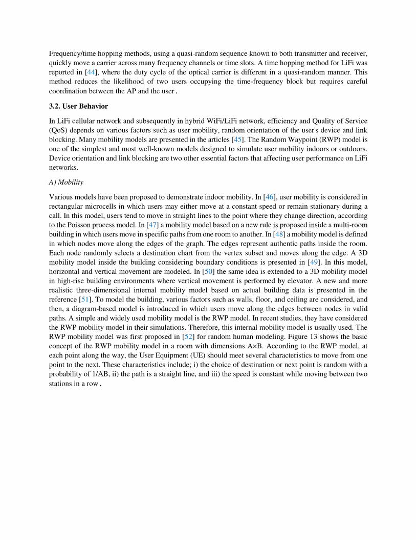
RWP mobility model was first proposed in [52] for random human modeling. Figure 13 shows the basic
concept of the RWP mobility model in a room with dimensions A×B. According to the RWP model, at
each point along the way, the User Equipment (UE) should meet several characteristics to move from one
point to the next. These characteristics include; i) the choice of destination or next point is random with a
probability of 1/AB, ii) the path is a straight line, and iii) the speed is constant while moving between two
stations in a row.
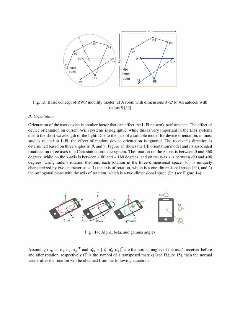
Fig. 13: Basic concept of RWP mobility model: a) A room with dimensions A×B b) An autocell with
radius R [52]
B) Orientation
Orientation of the user device is another factor that can affect the LiFi network performance. The effect of
device orientation on current WiFi systems is negligible, while this is very important in the LiFi systems
due to the short wavelength of the light. Due to the lack of a suitable model for device orientation, in most
studies related to LiFi, the effect of random device orientation is ignored. The receiver’s direction is
determined based on three angles 𝛼, 𝛽, and 𝛾. Figure 13 shows the UE orientation model and its associated
rotations on three axes in a Cartesian coordinate system. The rotation on the z-axis is between 0 and 360
degrees, while on the x-axis is between -180 and + 180 degrees, and on the y-axis is between -90 and +90
degrees. Using Euler's rotation theorem, each rotation in the three-dimensional space (ℝ3) is uniquely
characterized by two characteristics: 1) the axis of rotation, which is a one-dimensional space (ℝ1), and 2)
the orthogonal plane with the axis of rotation, which is a two-dimensional space (ℝ2) (see Figure 14).
Fig. 14: Alpha, beta, and gamma angles
Assuming nrx = [n1 n2 n3]T and nrx′ = [n1′ n2′ n3′ ]T are the normal angles of the user's receiver before
and after rotation, respectively (T is the symbol of a transposed matrix) (see Figure 15), then the normal
vector after the rotation will be obtained from the following equation:
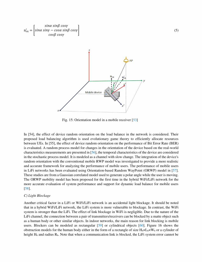
nrx′ = [ 𝑠𝑖𝑛𝛼 𝑠𝑖𝑛𝛽 𝑐𝑜𝑠𝛾𝑠𝑖𝑛𝛼 𝑠𝑖𝑛𝛾 − 𝑐𝑜𝑠𝛼 𝑠𝑖𝑛𝛽 𝑐𝑜𝑠𝛾𝑐𝑜𝑠𝛽 𝑐𝑜𝑠𝛾 ] (5)
Fig. 15: Orientation model in a mobile receiver [53]
In [54], the effect of device random orientation on the load balance in the network is considered. Their
proposed load balancing algorithm is used evolutionary game theory to efficiently allocate resources
between UEs. In [55], the effect of device random orientation on the performance of Bit Error Rate (BER)
is evaluated. A random process model for changes in the orientation of the device based on the real-world
characteristics measurements are presented in [56], the temporal characteristics of the device are considered
in the stochastic process model. It is modeled as a channel with slow change. The integration of the device's
random orientation with the conventional mobile RWP model was investigated to provide a more realistic
and accurate framework for analyzing the performance of mobile users. The performance of mobile users
in LiFi networks has been evaluated using Orientation-based Random WayPoint (ORWP) model in [57].
These studies are from a Gaussian correlated model used to generate a polar angle while the user is moving.
The ORWP mobility model has been proposed for the first time in the hybrid WiFi/LiFi network for the
more accurate evaluation of system performance and support for dynamic load balance for mobile users
[58].
C) Light Blockage
Another critical factor in a LiFi or WiFi/LiFi network is an accidental light blockage. It should be noted
that in a hybrid WiFi/LiFi network, the LiFi system is more vulnerable to blockage. In contrast, the WiFi
system is stronger than the LiFi. The effect of link blockage in WiFi is negligible. Due to the nature of the
LiFi channel, the connection between a pair of transmitters/receivers can be blocked by a matte object such
as a human body or other similar objects. In indoor networks, the main reason for link blocking is mobile
users. Blockers can be modeled as rectangular [59] or cylindrical objects [60]. Figure 16 shows the
obstruction models for the human body either in the form of a rectangle of size Hb×Lb×Wb or a cylinder of
height Hb and radius Rb. Note that when a communication link is blocked, the LiFi system error cannot be
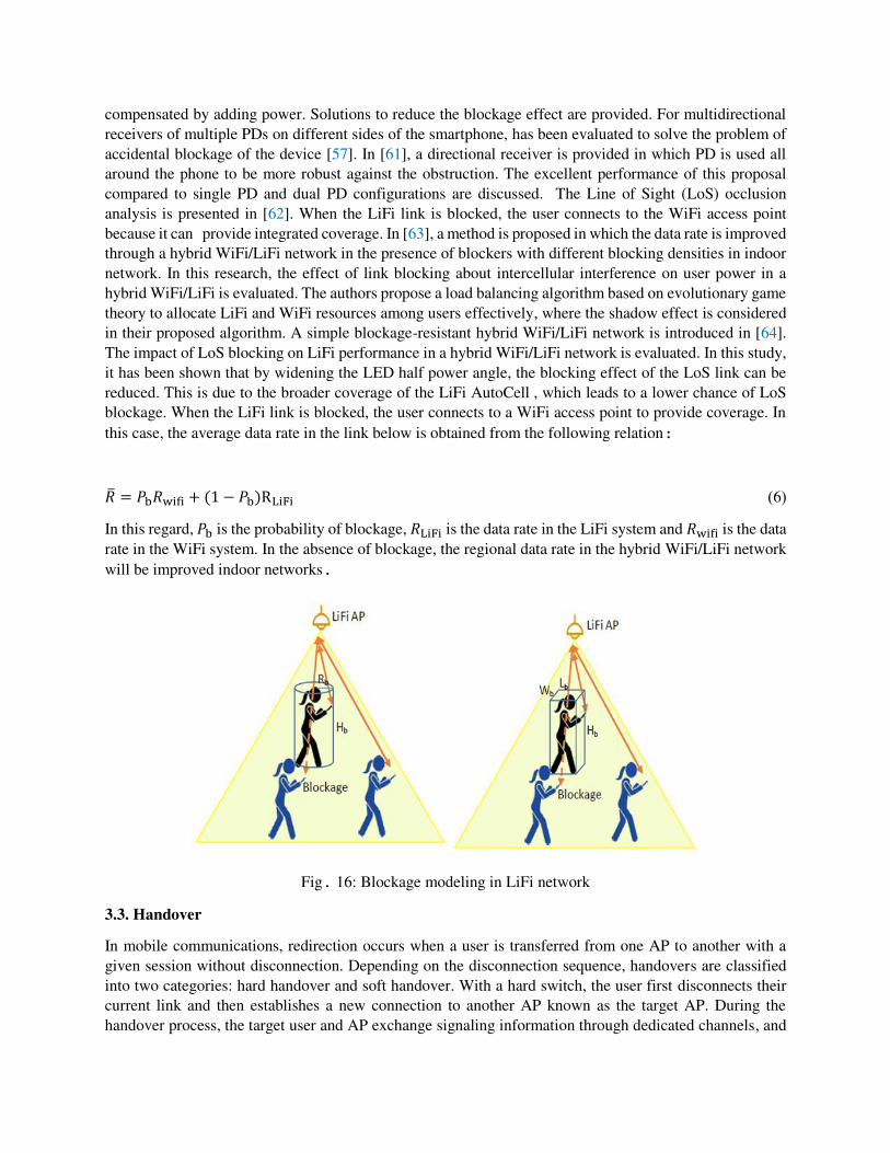
compensated by adding power. Solutions to reduce the blockage effect are provided. For multidirectional
receivers of multiple PDs on different sides of the smartphone, has been evaluated to solve the problem of
accidental blockage of the device [57]. In [61], a directional receiver is provided in which PD is used all
around the phone to be more robust against the obstruction. The excellent performance of this proposal
compared to single PD and dual PD configurations are discussed. The Line of Sight (LoS) occlusion
analysis is presented in [62]. When the LiFi link is blocked, the user connects to the WiFi access point
because it can provide integrated coverage. In [63], a method is proposed in which the data rate is improved
through a hybrid WiFi/LiFi network in the presence of blockers with different blocking densities in indoor
network. In this research, the effect of link blocking about intercellular interference on user power in a
hybrid WiFi/LiFi is evaluated. The authors propose a load balancing algorithm based on evolutionary game
theory to allocate LiFi and WiFi resources among users effectively, where the shadow effect is considered
in their proposed algorithm. A simple blockage-resistant hybrid WiFi/LiFi network is introduced in [64].
The impact of LoS blocking on LiFi performance in a hybrid WiFi/LiFi network is evaluated. In this study,
it has been shown that by widening the LED half power angle, the blocking effect of the LoS link can be
reduced. This is due to the broader coverage of the LiFi AutoCell , which leads to a lower chance of LoS
blockage. When the LiFi link is blocked, the user connects to a WiFi access point to provide coverage. In
this case, the average data rate in the link below is obtained from the following relation: �̅� = 𝑃b𝑅wifi + (1 − 𝑃b)RLiFi )6(
In this regard, 𝑃b is the probability of blockage, 𝑅LiFi is the data rate in the LiFi system and 𝑅wifi is the data
rate in the WiFi system. In the absence of blockage, the regional data rate in the hybrid WiFi/LiFi network
will be improved indoor networks.
Fig. 16: Blockage modeling in LiFi network
3.3. Handover
In mobile communications, redirection occurs when a user is transferred from one AP to another with a
given session without disconnection. Depending on the disconnection sequence, handovers are classified
into two categories: hard handover and soft handover. With a hard switch, the user first disconnects their
current link and then establishes a new connection to another AP known as the target AP. During the
handover process, the target user and AP exchange signaling information through dedicated channels, and
no data transfer will be available. In the case of soft switching, a new connection is established before the
user disconnects from the host AP. This allows data to be transferred in parallel with the handover process.
Soft switching can typically be used when the host and target APs are operate at the same carrier frequency.
Conversely a handover that requires a change in the carrier frequency is called a hard handover. Therefore,
it is necessary to examine the effect of how the handover process on the performance of the hybrid network.
In general, the transfer process in a hybrid network is divided into two categories include horizontal
handover (HHO), and vertical handover (VHO). Horizontal handover occurs within a single wireless access
technology, while VHO occurs between different accesses technologies. With VHO, the air interface
changes, but the routing to the destination remains the same. In some studies, a third category called
diagonal handover has been introduced, in which both the air interface and the destination change direction.
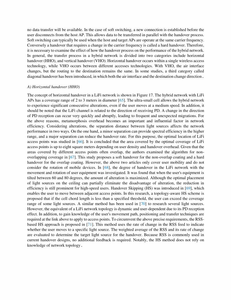
A) Horizontal handover (HHO)
The concept of horizontal handover in a LiFi network is shown in Figure 17. The hybrid network with LiFi
APs has a coverage range of 2 to 3 meters in diameter [65]. The ultra-small cell allows the hybrid network
to experience significant consecutive alterations, even if the user moves at a medium speed. In addition, it
should be noted that the LiFi channel is related to the direction of receiving PD. A change in the direction
of PD reception can occur very quickly and abruptly, leading to frequent and unexpected migrations. For
the above reasons, metamorphosis overhead becomes an important and influential factor in network
efficiency. Considering alterations, the separation distance between light sources affects the network
performance in two ways. On the one hand, a minor separation can provide spectral efficiency in the higher
range, and a major separation can reduce the handover rate. For this purpose, the optimal location of LiFi
access points was studied in [66]. It is concluded that the area covered by the optimal coverage of LiFi
access points is up to eight square meters depending on user density and handover overhead. Given that the
areas covered by different access points often overlap, the authors examined the algorithm for non-
overlapping coverage in [67]. This study proposes a soft handover for the non-overlap coating and a hard
handover for the overlap coating. However, the above two articles only cover user mobility and do not
consider the rotation of mobile devices. In [68], the degree of handover in the LiFi network with the
movement and rotation of user equipment was investigated. It was found that when the user's equipment is
tilted between 60 and 80 degrees, the amount of alteration is maximized. Although the optimal placement
of light sources on the ceiling can partially eliminate the disadvantage of alteration, the reduction in
efficiency is still prominent for high-speed users. Handover Skipping (HS) was introduced in [69], which
enables the user to move between adjacent access points. In this research, a topology-aware HS scheme is
proposed that if the cell chord length is less than a specified threshold, the user can exceed the coverage
range of some light sources. A similar method has been used in [70] to research several light sources.
However, the equivalent of a LiFi network topology is dynamic and user-dependent due to its PD reception
effect. In addition, to gain knowledge of the user's movement path, positioning and transfer techniques are
required at the link above to apply to access points. To circumvent the above precise requirements, the RSS-
based HS approach is proposed in [71]. This method uses the rate of change in the RSS feed to indicate
whether the user moves to a specific light source. The weighted average of the RSS and its rate of change
are evaluated to determine the target light source for the handover. Because RSS is commonly used in
current handover designs, no additional feedback is required. Notably, the HS method does not rely on
knowledge of network topology.
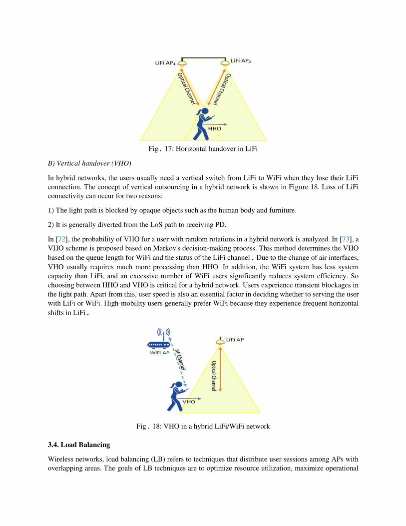
Fig. 17: Horizontal handover in LiFi
B) Vertical handover (VHO)
In hybrid networks, the users usually need a vertical switch from LiFi to WiFi when they lose their LiFi
connection. The concept of vertical outsourcing in a hybrid network is shown in Figure 18. Loss of LiFi
connectivity can occur for two reasons:
1) The light path is blocked by opaque objects such as the human body and furniture.
2) It is generally diverted from the LoS path to receiving PD.
In [72], the probability of VHO for a user with random rotations in a hybrid network is analyzed. In [73], a
VHO scheme is proposed based on Markov's decision-making process. This method determines the VHO
based on the queue length for WiFi and the status of the LiFi channel. Due to the change of air interfaces,
VHO usually requires much more processing than HHO. In addition, the WiFi system has less system
capacity than LiFi, and an excessive number of WiFi users significantly reduces system efficiency. So
choosing between HHO and VHO is critical for a hybrid network. Users experience transient blockages in
the light path. Apart from this, user speed is also an essential factor in deciding whether to serving the user
with LiFi or WiFi. High-mobility users generally prefer WiFi because they experience frequent horizontal
shifts in LiFi.
Fig. 18: VHO in a hybrid LiFi/WiFi network
3.4. Load Balancing
Wireless networks, load balancing (LB) refers to techniques that distribute user sessions among APs with
overlapping areas. The goals of LB techniques are to optimize resource utilization, maximize operational
efficiency, minimize response time, and reduce network congestion. In homogeneous networks, coverage
overlap is limited to minimize ICI among access points. As a result, LB only applies to cell edge users who
enter unusual loads at different access points. In other words, LB is not needed when users' requests for
data rates are evenly distributed over an area. In [67], the authors reviewed the LB techniques related to
WiFi and classified these techniques into two categories: user-centric and based on the coverage area of
the light source. Using user-based methods, each user according to their interest, with optimal network
performance is difficult to achieve. In contrast, light source coverage area-based methods are implemented
at the network level but require a central unit to coordinate applications. Unlike homogeneous networks,
LB becomes necessary and challenging in combined WiFi/LiFi networks. This is because the areas covered
by LiFi and WiFi overlap entirely. WiFi hotspots also have more coverage but less system capacity than
LiFi hotspots. This makes WiFi prone to over-transmission, even if user demand for data rates is evenly
distributed geographically. The proposed LB algorithms for LiFi and WiFi/LiFi hybrid networks can be
classified into two categories: 1) static channel and 2) mobility awareness.
A) Stationary channel
An LB method in the form of centralized and distributed resource allocation algorithms for achieving
Proportional Fairness (PF) among users is presented in [62]. To improve service quality (QoS), the LB
problem is considered a problem that combines the correct value and formulated nonlinear programming
that addresses different data needs among users. The above methods both create NP-hard problems, in
which case the problem solving is faced with a computational complexity that increases exponentially with
the number of access points. To reduce the processing power required, an iterative algorithm based on
evolutionary game theory is reported in [54], in which multiple justice functions (MFF) are considered. In
this research, the obstruction of the light path, the desired orientation of the receiver and the need for data
speed to model a practical communication scenario are identified. The authors in [19] introduced an
iterative algorithm but focused on force allocation. The algorithm consists of two modes: i) finding the
optimal energy allocation of each AP to maximize its output power, and ii) searching for another access
point for the user with the lowest data rate to increase overall efficiency and increase system equity. The
above iterative algorithms, which require several iterations to achieve a steady-state, can be considered
autonomous optimization. As mentioned, general optimization and autonomous optimization have their
limitations, thus leading to a significant amount of processing time being spent. In LiFi and WiFi/LiFi
hybrid networks, CSI can change quickly for mobile users, even at medium speeds. This limits processing
time and therefore challenges the practicality of the above methods. Alternatively, direct decision methods
are implemented that significantly reduce processing time. In other words, it first identifies the users who
should be served by WiFi and then determines the other users as a standalone LiFi network. This method,
based on fuzzy logic, relying on statistical knowledge of data rate needs and CSI, can have optimal
performance in terms of power consumption and fairness and reduces processing time by more than ten
times.
B) Movement awareness
The methods mentioned in the previous section have this feature in common, in all of which there is CSI
awareness. Given that the CSI value changes due to user movements or environmental changes, in such
cases, these methods must recalculate their solutions. The impact of alterations should also be considered
when new solutions change the way users interact (which may change very quickly in LiFi and WiFi/LiFi
hybrid networks). For example, users at the edges of LiFi access point cells prefer WiFi, and users at the
center of LiFi access points prefer LiFi. Using fixed channel load balancing methods, users are frequently
switched between LiFi and WiFi as they move across LiFi access points. To solve the above problem, user
mobility must be considered along with LB. This idea is referred to as the balance of motion-aware load
[74]. Such an approach was proposed as a model of university admission. In this method, the achievable
data rate and the user's direction are used to measure the user preference for route selection. The total user
data rate in this case is used to calculate AP preferences. These two preferences are then calculated
iteratively to arrive at a fixed solution. A dynamic LB scheme is proposed in [75], which also uses an
iterative algorithm. In each iteration, resources are allocated to improve the effective data rate that does not
include additional metamorphosis costs. In [76], a similar method is developed but with a joint
implementation to allocate light sources and their budget. The results show that a joint implementation can
be 50% more efficient than a separate implementation, with higher computational complexity costs. In all
the proposed methods in this field, it is always tried to compromise between the instantaneous data rate and
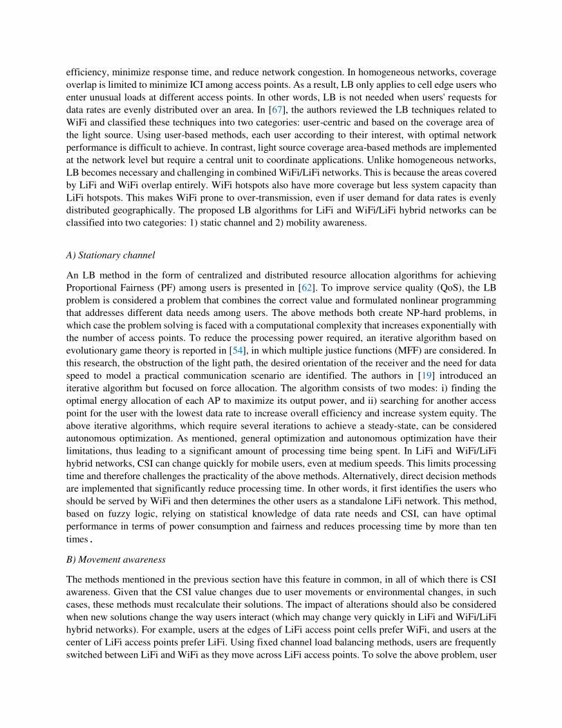
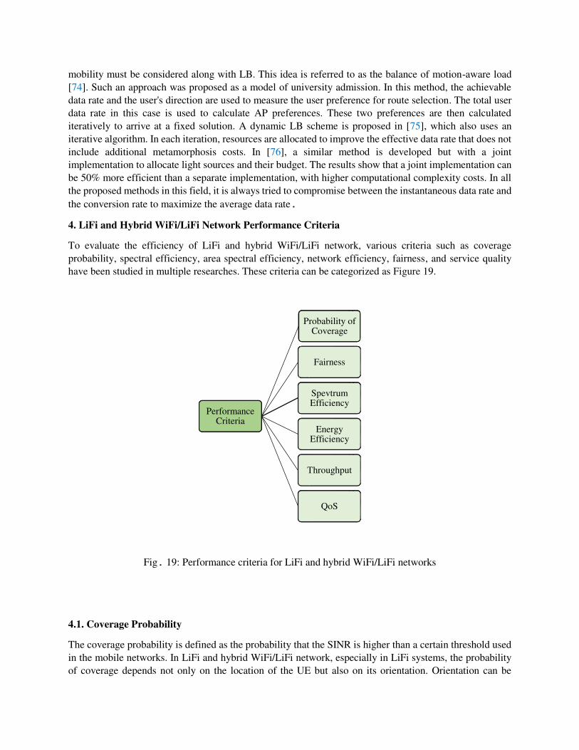
the conversion rate to maximize the average data rate. 4. LiFi and Hybrid WiFi/LiFi Network Performance Criteria
To evaluate the efficiency of LiFi and hybrid WiFi/LiFi network, various criteria such as coverage
probability, spectral efficiency, area spectral efficiency, network efficiency, fairness, and service quality
have been studied in multiple researches. These criteria can be categorized as Figure 19.
Fig. 19: Performance criteria for LiFi and hybrid WiFi/LiFi networks
4.1. Coverage Probability
The coverage probability is defined as the probability that the SINR is higher than a certain threshold used
in the mobile networks. In LiFi and hybrid WiFi/LiFi network, especially in LiFi systems, the probability
of coverage depends not only on the location of the UE but also on its orientation. Orientation can be
Performance Criteria
Probability of Coverage
Fairness
Spevtrum Efficiency
Energy Efficiency
Throughput
QoS
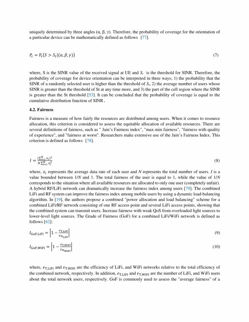
uniquely determined by three angles (α, β, γ). Therefore, the probability of coverage for the orientation of
a particular device can be mathematically defined as follows [77].
𝑃𝑐 = Pr{𝑆 > 𝑆𝑡|(𝛼, 𝛽, 𝛾)} (7)
where, S is the SINR value of the received signal at UE and St is the threshold for SINR. Therefore, the
probability of coverage for device orientation can be interpreted in three ways; 1) the probability that the
SINR of a randomly selected user is higher than the threshold of St, 2) the average number of users whose
SINR is greater than the threshold of St at any time more, and 3) the part of the cell region where the SINR
is greater than the St threshold [53]. It can be concluded that the probability of coverage is equal to the
cumulative distribution function of SINR. 4.2. Fairness
Fairness is a measure of how fairly the resources are distributed among users. When it comes to resource
allocation, this criterion is considered to assess the equitable allocation of available resources. There are
several definitions of fairness, such as " Jain’s Fairness index", "max-min fairness", "fairness with quality
of experience", and "fairness at worst". Researchers make extensive use of the Jain’s Fairness Index. This
criterion is defined as follows [78].
𝐼 = (∑ 𝑥𝑖𝑁𝑖=1 )2𝑁 ∑ 𝑥𝑖2𝑁𝑖=1 (8)
where, 𝑥𝑖 represents the average data rate of each user and N represents the total number of users. I is a
value bounded between 1/N and 1. The total fairness of the user is equal to 1, while the value of 1/N
corresponds to the situation where all available resources are allocated to only one user (completely unfair).
A hybrid RF/LiFi network can dramatically increase the fairness index among users [79]. The combined
LiFi and RF system can improve the fairness index among mobile users by using a dynamic load-balancing
algorithm. In [19], the authors propose a combined "power allocation and load balancing" scheme for a
combined LiFi/RF network consisting of one RF access point and several LiFi access points, showing that
the combined system can transmit users. Increase fairness with weak QoS from overloaded light sources to
lower-level light sources. The Grade of Fairness (GoF) for a combined LiFi/WiFi network is defined as
follows [62]: 𝐼GoF,LiFi = |1 − 𝜖T,LiFi𝜖𝑁LiFi| (9)
𝐼GoF,WiFi = |1 − 𝜖T,WiFi𝜖𝑁WiFi| (10)
where, 𝜖T,LiFi and 𝜖T,WiFi are the efficiency of LiFi, and WiFi networks relative to the total efficiency of
the combined network, respectively. In addition, 𝜖T,LiFi and 𝜖T,WiFi are the number of LiFi, and WiFi users
about the total network users, respectively. GoF is commonly used to assess the "average fairness" of a
network. A hybrid network can generate a higher GoF, especially when the distance between the percentage
of LiFi (WiFi) efficiency and the fraction of users connected to LiFi (WiFi) is small. 4.3. Spectral Efficiency
Spectral efficiency is one of the most common criteria for measuring the effectiveness of a link. Many
studies on hybrid RF/ Visible light communication (VLC) networks have repeatedly confirmed that the
spectral gain of a hybrid network is much higher than that of stand-alone RF or VLC networks. Some
research through Monte Carlo simulations has shown that the hybrid RF/VLC system can provide higher
spectral performance and data speed compared to a pure RF network. In [79], a hybrid internal network is
proposed that solves the problem of dynamic load balance for mobile phone users. The idea was developed
by optimizing AP allocation and resource allocation in a combined LiFi/RF network, which shows that the
spectral effect is doubled compared to the conventional signal strength strategy. Because the AP in a LiFi
network covers a specific area known as the autocell, the bandwidth source can be widely used in space.
To compare the throughput in a hybrid network with a standalone LiFi or WiFi network, Area Spectrum
Efficiency (ASE) studies have been considered in several studies on LiFi/WiFi hybrid networks. The ASE
represents the user spectral performance for a given density [80]. Mathematically, the ASE can be expressed
as follows: ζ = 𝑅𝐴𝑟 (11)
where, R is the data rate, and 𝐴𝑟 is the internal area. LiFi networks can offer higher ASE compared to
standalone RF cellular networks. It has been shown that a LiFi network, due to the reuse of bandwidth, can
achieve ASE several hundred times that of a femtocell. Therefore, the integration of LiFi and RF networks
can ensure comprehensive coverage and higher ASE. The authors in [80] proposed a combined RF system
with LiFi and Femtocell, which increases the average ASE by at least twice as much as an independent RF
network. In [62], a load balancing mechanism is proposed that can achieve proportional fairness and higher
ASE compared to a stand-alone LiFi network. Both distributed and centralized resource allocation schemes
have been developed and shown that a higher ASE can be achieved through the hybrid RF/LiFi system. 4.4. Energy Efficiency
Energy demand is also proliferating as requests for high-data-rate communications proliferate. In wireless
communication, energy gain is defined as the ratio of data transfer rate to power consumption in terms of
bits per joule [81]: 𝜂 = 𝑅𝑃 (12)
where, R is the available data rate in bit per second and P is the total power sent in watts. Research shows
that hybrid RF/VLC networks have significantly more energy gain than stand-alone RF or VLC networks.
In [81], energy in integrated VLC systems with RF networks has been studied. The authors formulated the
problem of bandwidth optimization and power allocation to maximize the energy efficiency of the RF/VLC
hybrid network. The effect of various parameters such as the number of users, direct emission (LoS), and
number of LEDs on energy efficiency has been investigated. This study demonstrates the superior
performance of an RF/VLC hybrid network compared to an RF system. In [19], a combined optimization
of power allocation and load balancing for VLC/RF hybrid networks is proposed. The authors have
proposed an iterative algorithm for power distribution among users. By submitting an optimization problem,
their proposed design can guarantee the maximum amount of data available and thus the energy reliability
of the VLC/RF hybrid network. It has been shown that the new algorithm converges quickly and can provide
better performance compared to conventional methods. In [82], with optimal energy allocation, the overall
energy efficiency of the RF/VLC hybrid network is improved. It has been shown that the energy efficiency
of a three-bit hybrid grid is higher than that of an independent RF system. 4.5. Network Throughput
One of the main goals of hybrid networks is to improve the efficiency of users and the network. Almost all
studies on a hybrid WiFi/LiFi network compared to a pure LiFi or WiFi network have confirmed the
potential. In [18], a simple RF deployment is introduced to increase data interrupt rate performance per user
of standalone LiFi systems and improve overall network efficiency. It has been shown that the probability
of disconnection via a combined LiFi/RF network is halved compared to a standalone LiFi system for an
operating efficiency of 30 Mbps. The effect of Field of View (FoV) on the average user rate in a hybrid
LiFi/RF is evaluated and compared with an independent LiFi and RF system. It turns out that a hybrid
network can improve user performance of more than 30 Mbps and more than 40 Mbps, respectively,
compared to a pure LiFi and RF network. In [62], a typical load balance scheme for hybrid WiFi/LiFi
networks is proposed. The hybrid system is able to increase the average user efficiency for both
conventional and integrated cell structures. In [76], the authors propose a dynamic load balancing
mechanism by considering metamorphosis for LiFi and WiFi hybrid networks. The beneficial performance
of the load balancing algorithm in this proposal also believes the system efficiency. It shows that the hybrid
network can significantly serve the user power by serving mobile users via WiFi access points and semi-
static users through LiFi access points. Improve. The combined RF and LiFi network can to solve better
the problem of link blocking and increase system efficiency compared to the independent LiFi network
[54], [63].
4.6. Quality of Service (QoS)
Another essential metric is QoS, which can be used in hybrid RF and VLC networks. In essence, QoS
measures the service performance met by users on a network. To evaluate, and quantify the network QoS,
various criteria such as bit rate, transmission delay, operational efficiency and link availability can be used.
In addition, given the growing demand for latency-sensitive applications, including video streaming and
games, it will be necessary to consider other QoS evaluations in the data link layer. Mainly when QoS
constraints are needed, many researchers perform layer-by-layer assessments related to physical layers and
data links. Hybrid WiFi/LiFi systems serve as a promising potential for meeting QoS constraints and needs
in the future. Are considered. Using numerical results, the LiFi system has been shown to improve latency
in hybrid LiFi/RF networks. 5. Scenario-Based Architecture
5.1. Implementing A LiFi-based Indoor Network
Step 1) Coverage and cell deployment model
A) Coverage
The first essential issue in implementing a LiFi-based network is providing the complete coverage of the
desired area. For achieving complete coverage, the position of the light sources (LEDs or IRs) on the ceiling
with respect to the position of UEs (such as computers or laptops) should be considered. Figure 20 shows
the coverage area on the surface of the user's desk and on the floor. In figure 20, (H) is the vertical distance
from the the light source on the ceiling to the user's desk, (r) and (R) indicate the diameter of coverage areas
on the desk and on the floor, respectively.
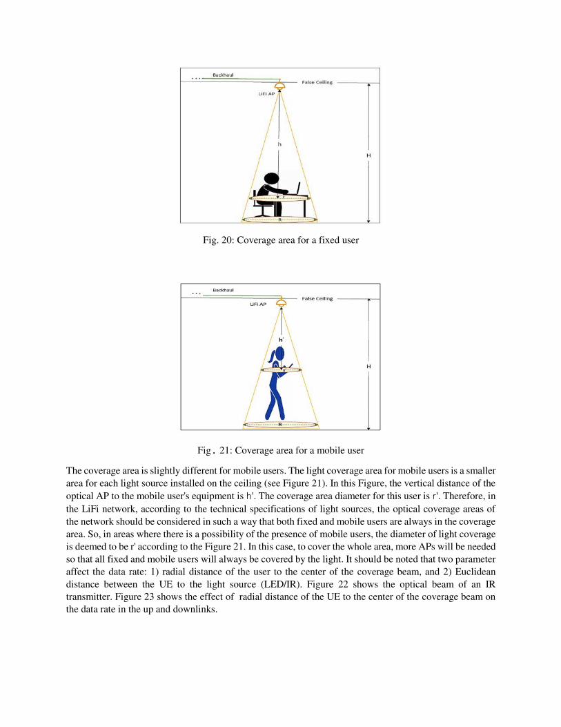
Fig. 20: Coverage area for a fixed user
Fig. 21: Coverage area for a mobile user
The coverage area is slightly different for mobile users. The light coverage area for mobile users is a smaller
area for each light source installed on the ceiling (see Figure 21). In this Figure, the vertical distance of the
optical AP to the mobile user's equipment is h'. The coverage area diameter for this user is r'. Therefore, in
the LiFi network, according to the technical specifications of light sources, the optical coverage areas of
the network should be considered in such a way that both fixed and mobile users are always in the coverage
area. So, in areas where there is a possibility of the presence of mobile users, the diameter of light coverage
is deemed to be r' according to the Figure 21. In this case, to cover the whole area, more APs will be needed
so that all fixed and mobile users will always be covered by the light. It should be noted that two parameter
affect the data rate: 1) radial distance of the user to the center of the coverage beam, and 2) Euclidean
distance between the UE to the light source (LED/IR). Figure 22 shows the optical beam of an IR
transmitter. Figure 23 shows the effect of radial distance of the UE to the center of the coverage beam on
the data rate in the up and downlinks.
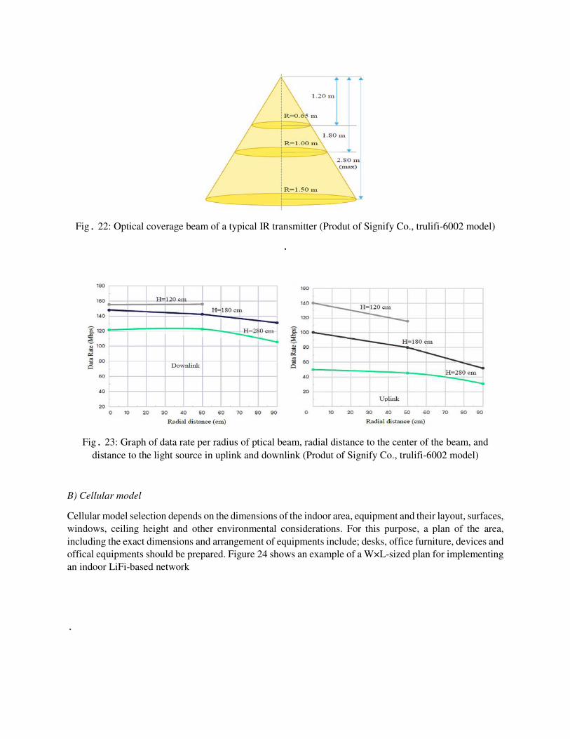
Fig. 22: Optical coverage beam of a typical IR transmitter (Produt of Signify Co., trulifi-6002 model)
.
Fig. 23: Graph of data rate per radius of ptical beam, radial distance to the center of the beam, and
distance to the light source in uplink and downlink (Produt of Signify Co., trulifi-6002 model)
B) Cellular model
Cellular model selection depends on the dimensions of the indoor area, equipment and their layout, surfaces,
windows, ceiling height and other environmental considerations. For this purpose, a plan of the area,
including the exact dimensions and arrangement of equipments include; desks, office furniture, devices and
offical equipments should be prepared. Figure 24 shows an example of a W×L-sized plan for implementing
an indoor LiFi-based network
.
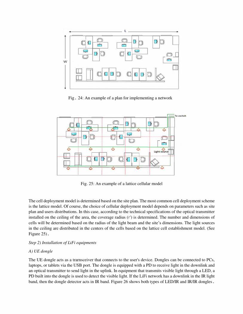
Fig. 24: An example of a plan for implementing a network
Fig. 25: An example of a lattice cellular model
The cell deployment model is determined based on the site plan. The most common cell deployment scheme
is the lattice model. Of course, the choice of cellular deployment model depends on parameters such as site
plan and users distributions. In this case, according to the technical specifications of the optical transmitter
installed on the ceiling of the area, the coverage radius (r') is determined. The number and dimensions of
cells will be determined based on the radius of the light beam and the site’s dimensions. The light sources
in the ceiling are distributed in the centers of the cells based on the lattice cell establishment model. (See
Figure 25). Step 2) Installation of LiFi equipments
A) UE dongle
The UE dongle acts as a trarnsceiver that connects to the user's device. Dongles can be connected to PCs,
laptops, or tablets via the USB port. The dongle is equipped with a PD to receive light in the downlink and
an optical transmitter to send light in the uplink. In equipment that transmits visible light through a LED, a
PD built into the dongle is used to detect the visible light. If the LiFi network has a downlink in the IR light
band, then the dongle detector acts in IR band. Figure 26 shows both types of LED/IR and IR/IR dongles.
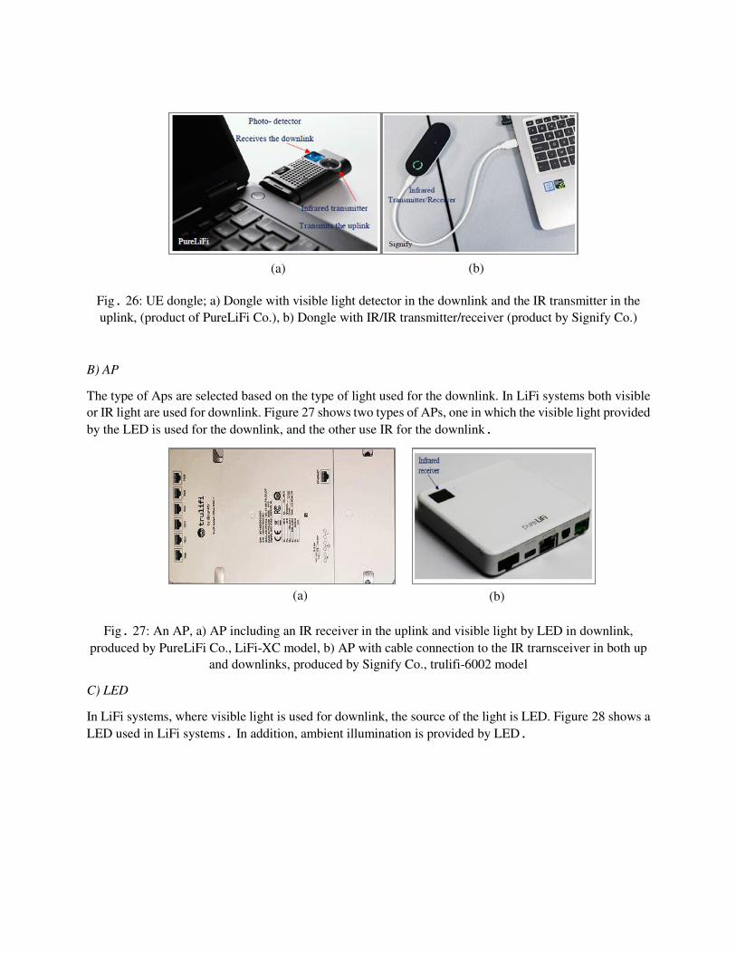
Fig. 26: UE dongle; a) Dongle with visible light detector in the downlink and the IR transmitter in the
uplink, (product of PureLiFi Co.), b) Dongle with IR/IR transmitter/receiver (product by Signify Co.)
B) AP
The type of Aps are selected based on the type of light used for the downlink. In LiFi systems both visible
or IR light are used for downlink. Figure 27 shows two types of APs, one in which the visible light provided
by the LED is used for the downlink, and the other use IR for the downlink.
Fig. 27: An AP, a) AP including an IR receiver in the uplink and visible light by LED in downlink,
produced by PureLiFi Co., LiFi-XC model, b) AP with cable connection to the IR trarnsceiver in both up
and downlinks, produced by Signify Co., trulifi-6002 model
C) LED
In LiFi systems, where visible light is used for downlink, the source of the light is LED. Figure 28 shows a
LED used in LiFi systems. In addition, ambient illumination is provided by LED.
(a) (b)
(a) (b)
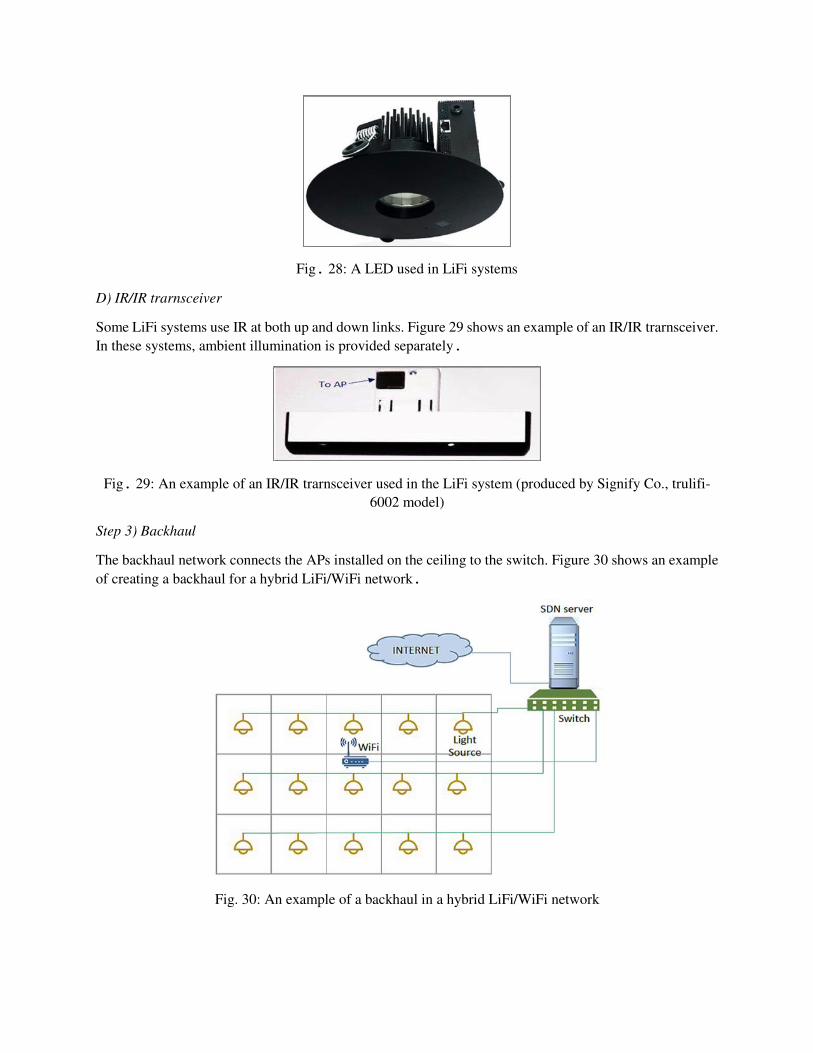
Fig. 28: A LED used in LiFi systems
D) IR/IR trarnsceiver
Some LiFi systems use IR at both up and down links. Figure 29 shows an example of an IR/IR trarnsceiver.
In these systems, ambient illumination is provided separately.
Fig. 29: An example of an IR/IR trarnsceiver used in the LiFi system (produced by Signify Co., trulifi-
6002 model)
Step 3) Backhaul
The backhaul network connects the APs installed on the ceiling to the switch. Figure 30 shows an example
of creating a backhaul for a hybrid LiFi/WiFi network.
Fig. 30: An example of a backhaul in a hybrid LiFi/WiFi network
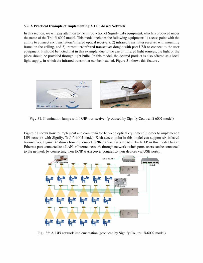
5.2. A Practical Example of Implementing A LiFi-based Network
In this section, we will pay attention to the introduction of Signify LiFi equipment, which is produced under
the name of the Trulifi-6002 model. This model includes the following equipment: 1) access point with the
ability to connect six transmitters/infrared optical receivers, 2) infrared transmitter receiver with mounting
frame on the ceiling, and 3) transmitter/infrared transceiver dongle with port USB to connect to the user
equipment. It should be noted that in this example, due to the use of infrared light sources, the light of the
place should be provided through light bulbs. In this model, the desired product is also offered as a local
light supply, in which the infrared transmitter can be installed. Figure 31 shows this feature.
Fig. 31: Illumination lamps with IR/IR trarnsceiver (produced by Signify Co., trulifi-6002 model)
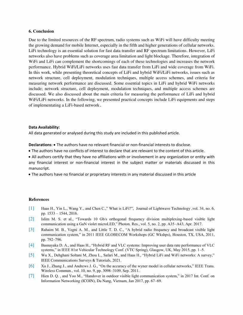
Figure 31 shows how to implement and communicate between optical equipment in order to implement a
LiFi network with Signify, Trulifi-6002 model. Each access point in this model can support six infrared
trarnsceiver. Figure 32 shows how to connect IR/IR trarnsceivers to APs. Each AP in this model has an
Ethernet port connected to a LAN or Internet network through network switch ports. users can be connected
to the network by connecting their IR/IR trarnsceiver dongles to their devices via USB ports.
Fig. 32: A LiFi network implementation (produced by Signify Co., trulifi-6002 model)
6. Conclusion
Due to the limited resources of the RF spectrum, radio systems such as WiFi will have difficulty meeting
the growing demand for mobile Internet, especially in the fifth and higher generations of cellular networks.
LiFi technology is an essential solution for fast data transfer and RF spectrum limitations. However, LiFi
networks also have problems such as coverage area limitation and light blockage. Therefore, integration of
WiFi and LiFi can complement the shortcomings of each of these technologies and increases the network
performance. Hybrid WiFi/LiFi networks uses fast data transfer from LiFi and wide coverage from WiFi.
In this work, while presenting theoretical concepts of LiFi and hybrid WiFi/LiFi networks, issues such as
network structure, cell deployment, modulation techniques, multiple access schemes, and criteria for
measuring network performance are discussed. Some essential topics in LiFi and hybrid WiFi networks
include; network structure, cell deployment, modulation techniques, and multiple access schemes are
discussed. We also discussed about the main criteria for measuring the performance of LiFi and hybrid
WiFi/LiFi networks. In the following, we presented practical concepts include LiFi equipments and steps
of implementating a LiFi-based network.
Data Availability:
All data generated or analysed during this study are included in this published article.
Declarations: The authors have no relevant financial or non-financial interests to disclose.
The authors have no conflicts of interest to declare that are relevant to the content of this article.
All authors certify that they have no affiliations with or involvement in any organization or entity with
any financial interest or non-financial interest in the subject matter or materials discussed in this
manuscript.
The authors have no financial or proprietary interests in any material discussed in this article
References
[1] Haas H., Yin L., Wang Y., and Chen C.,” What is LiFi?”, Journal of Lightwave Technology ,vol. 34, no. 6,
pp. 1533 – 1544, 2016.
[2] Islim M. S. et al., “Towards 10 Gb/s orthogonal frequency division multiplexing-based visible light
communication using a GaN violet microLED,” Photon. Res., vol. 5, no. 2, pp. A35–A43, Apr. 2017.
[3] Rahaim M. B., Vegni A. M., and Little T. D. C., “A hybrid radio frequency and broadcast visible light communication system,” in 2011 IEEE GLOBECOM Workshops (GC Wkshps), Houston, TX, USA, 2011,
pp. 792–796.
[4] Basnayaka D. A., and Haas H., “Hybrid RF and VLC systems: Improving user data rate performance of VLC systems,” in IEEE 81st Vehicular Technology Conf. (VTC Spring), Glasgow, UK, May 2015, pp. 1–5.
[5] Wu X., Dehghani Soltani M, Zhou L., Safari M., and Haas H., “Hybrid LiFi and WiFi networks: A survey,” IEEE Communications Surveys & Tutorials, 2021.
[6] Xu J., Zhang J., and Andrews J. G., “On the accuracy of the wyner model in cellular networks,” IEEE Trans. Wireless Commun., vol. 10, no. 9, pp. 3098–3109, Sep. 2011.
[7] Hien D. Q. , and Yoo M., “Handover in outdoor visible light communication system,” in 2017 Int. Conf. on Information Networking (ICOIN), Da Nang, Vietnam, Jan 2017, pp. 67–69.
[8] Haas H., Chen C., O'Brien D.,” A guide to wireless networking by light”, Progress in Quantum Electronics, vol. 55, pp. 88- 111, 2017.
[9] Wang J., Jiang C., Zhang H., Zhang X., Leung V. C. M., and Hanzo L., “Learning-aided network association
for hybrid indoor lifi wifi systems,”IEEE Trans.Veh.Technol.,vol. 67,no.4, pp.3561–3574, April 2018.
[10] Chen C., Basnayaka D. A., and Haas H., “Downlink performance of optical attocell networks,” Journal of Lightwave Technology, vol. 34, no. 1, pp. 137– 156, Jan. 2016.
[11] Abdalla I., Rahaim M. B., and Little T.D.C., “Interferenceinmulti-user opticalwireless
communicationssystems,” Philosophical Transactions A, 2020. [12] Afgani M. Z, Haas H., Elgala H., and Knipp D., “Visible light communication using ofdm,” in 2nd
International Conference on Testbeds and Research Infrastructures for the Development of Networks and
Communities, 2006. TRIDENTCOM 2006, 2006.
[13] Tsonev, D., Chun H., Rajbhandari S., McKendry J. J. D., Videv S., Gu E., Haji M., Watson S., Kelly A. E.,
Faulkner G., Dawson M. D., Haas H., and Brien D. O’, “A 3-gb/s single-led OFDM -based wireless vlc link
using a gallium nitride µled,” IEEE Photon. Technol. Lett., vol. 26, no. 7, pp. 637–640, April 2014.
[14] Chen L., Krongold B., and Evans J., “Performance analysis for optical OFDM transmission in short-range
IM/DD systems,” vol. 3, no. 7, pp. 974-983, 2012.
[15] IEEE 802.11bb Standard for Information Technology Telecommunications and Information Exchange
between Systems Local and Metropolitan Area Networks-Specific Requirements, Part 11: Wireless LAN Medium Access Control (MAC) and Physical Layer (PHY) Specifications Amendment: Light Communications, IEEE-SA Std., Jul. 2018.
[16] IEEE 802.11: Wireless LAN Medium Access Control (MAC) and Physical Layer (PHY) Specifications, IEEE-
SA Std., Rev. 2012.
[17] Soltani M. D., Wu X., Safari M., and Haas H., “Bidirectional user throughput maximization based on feedback reduction in lifi networks,” IEEE Trans. Commun., vol. 66, no. 7, pp. 3172–3186, July 2018.
[18] Basnayaka D. A., and Haas H., “Design and analysis of a hybrid radio frequency and visible light communication system,” IEEE Trans. Commun., vol. 65, no. 10, pp. 4334–4347, Oct. 2017.
[19] Obeed M., Salhab A. M., Zummo S. A., and Alouini M., “Joint optimization of power allocation and load
balancing for hybrid VLC/RF networks,” IEEE/OSA J. Opt. Commun. Netw. vol. 10, no. 5, pp. 553– 562,
May 2018.
[20] Chen Z. , and H. Haas, “Space division multiple access in visible light communications,” in 2015 IEEE Int. Conf. on Communications (ICC), London, UK, 2015, pp. 5115–5119.
[21] Ding Z., Lei X., Karagiannidis G. K., Schober R., Yuan J., and Bhargava V. K., “A survey on non-orthogonal
multiple access for 5g networks: Research challenges and future trends,” IEEE Journal on Selected Areas in
Communications, vol. 35, no. 10, pp. 2181–2195, Oct 2017.
[22] Papanikolaou V. K., Diamantoulakis P. D., Ding Z., Muhaidat S., and Karagiannidis G. K., “Hybrid vlc/rf networks with non-orthogonal multiple access,” in 2018 IEEE Global Communications Conference
(GLOBECOM), Abu Dhabi, United Arab Emirates, 2018, pp. 1–6.
[23] Haas H., “High-speed wireless networking using visible light,” SPIE Newsroom, Apr. 2013. [24] Chen Z., Basnayaka D. A., Wu X., and Haas H., “Interference Mitigation for Indoor Optical Attocell Networks
Using an Angle Diversity Receiver,” J. Lightw. Technol., vol. 36, no. 18, pp. 3866–3881, Sep. 2018.
[25] Kazemi H., Safari M., and Haas H., “A wireless backhaul solution using visible light communication for indoor Li-Fi attocell networks,” in 2017 IEEE Int. Conf. on Communications (ICC),Paris,France,2017, pp. 1–7.
[26] Kazemi H., Safari M., Haas H., “A wireless optical backhaul solution for optical attocell networks,” IEEE Trans. Wireless Commun., vol. 18, no. 2, pp. 807– 823, Feb 2019.
[27] Papanikolaou V. K., Bamidis P. P., Diamantoulakis P. D., and Karagiannidis G. K., “Li-fi and wi-fi with common backhaul: Coordination and resource allocation,” in 2018 IEEE Wireless Communications and Networking Conference (WCNC), 2018, pp. 1–6.
[28] Komine T., and Nakagawa M., “Fundamental analysis for visiblelight communication system using led lights,” IEEE Trans. Consum. Electron. vol. 50, no. 1, pp. 100–107, Feb 2004.
[29] Andrews J. G., “Interference cancellation for cellular systems: a contemporary overview,” IEEE Wireless
Commun., vol. 12, no. 2, pp. 19–29, Apr. 2005.
[30] Ying K., Qian H., Baxley R. J., and Yao S., “Joint optimization of precoder and equalizer in MIMO VLC systems,” IEEE J. Sel. Areas Commun., vol. 33, no. 9, pp. 1949–1958, Sep. 2015.
[31] Jafar S. A., “Blind interference alignment,” IEEE J. Sel. Topics Signal Process., vol. 6, no. 3, pp. 216–227,
Jun. 2012.
[32] Gou T., Wang C., and Jafar S. A., “Aiming perfectly in the dark-blind interference alignment through
staggered antenna switching,” IEEE Trans. Signal Process., vol. 59, no. 6, pp. 2734–2744, Jun. 2011.
[33] Wu L., Zhang Z., Dang J., and Liu H., “Blind interference alignment for multiuser MISO indoor visible light communications,” IEEE Commun. Lett. vol. 21, no. 5, pp. 1039–1042, May 2017.
[34] Qidan A. A., Morales-Cespedes M., and Armada A. G., “The role of WiFi in LiFi hybrid networks based on blind interference alignment,” in IEEE 87th Vehicular Technology Conf. (VTC Spring), Porto, Portugal, 2018, pp. 1–5.
[35] Eroğlu Y. S., Güvenç I., Şahin A., Yapıcı Y., Pala N., Yüksel M., “Multi element VLC networks: LED assignment, power control, and optimum combining,” IEEE J. Sel. Areas Commun., vol. 36, no. 1, pp. 121–135, Jan. 2018.
[36] Eldeeb H. B., Selmy H. A. I., Elsayed H. M., and R. I. Badr R. I., “Interference mitigation and capacity enhancement using constraint field of view ADR in downlink VLC channel,” IET Commun., vol. 12, no. 16, pp. 1968–1978, 2018.
[37] Chen C., Zhong W., Yang H., Zhang S., and Du P., “Reduction of SINR fluctuation in indoor multi-cell VLC
systems using optimized angle diversity receiver,” J. Lightw. Technol., vol. 36, no. 17, pp. 3603–3610, Sep.
2018.
[38] Ryoo H., Kwon D., Yang S., and Han S., “Differential optical detection in VLC for inter-cell interference
reduced flexible cell planning,” IEEE Photonics Technol. Lett., vol. 28, no. 23, pp. 2728–2731, Dec. 2016.
[39] Atta M. A., and Bermak A., “A polarization-based interference-tolerant VLC link for low data rate
applications,” IEEE Photon. J., vol. 10, no. 2, pp. 1–11, Apr. 2018.
[40] Zahir T., Arshad K., Nakata A., and Moessner K., “Interference management in femtocells,” IEEE Commun. Surveys Tuts. vol. 15, no. 1, pp. 293–311, 1st Quart. 2013.
[41] Kim H., Kim D., Yang S., Son Y., and Han S., “Mitigation of inter-cell interference utilizing carrier allocation
in visible light communication system,” IEEE Commun. Lett. vol. 16, no. 4, pp. 526–529, Apr. 2012.
[42] Chen C., Videv S., Tsonev D., and Haas H., “Fractional frequency reuse in DCO-OFDM-based optical attocell
networks,” J. Lightw. Technol., vol. 33, no. 19, pp. 3986–4000, Oct. 2015.
[43] Zhou K., Gong C., and Xu Z., “Color planning and intercell interference coordination for multicolor visible
light communication networks,” J. Lightw. Technol., vol. 35, no. 22, pp. 4980–4993, Nov. 2017.
[44] Quintana C., Rabadan J., Rufo J., Delgado F., and Perez-Jimenez R., “Time-hopping spread-spectrum system
for wireless optical communications,”IEEE Trans.Consum. Electron. vol.55, no.3, pp.1083–1088, Aug. 2009.
[45] Bai F., and Helmy A., “A survey of mobility models,” Wireless Adhoc Networks. University of Southern California, USA, vol. 206, p. 147, 2004.
[46] Kim T. S., and Sung D. K., “The effects of handoffs on microcell based pcn networks,” in 1994 IEEE Global Communications Conf. GLOBECOM), vol.3, SanFrancisco, CA, USA, USA, 1994, pp.1316– 1320.
[47] Aschenbruck N., Ernst R., and Martini P., “Indoor mobility modelling,” in 2010 IEEE GLOBECOM
Workshops (GC Wkshps), Miami, FL, USA, Dec 2010, pp. 1264–1269.
[48] Cavilla A. L., Baron G., Hart T. E., Litty L., and de Lara E., “Simplified simulation models for indoor manet evaluation are not robust,” in 2004 First Annual IEEE Communications Society Conference on Sensor and Ad
Hoc Communications and Networks, 2004. IEEE SECON 2004, Santa Clara, CA, USA, 2004, pp. 610–620.
[49] Kim T. S., Chung M. Y., Sung D. K., and Sengoku M., “Mobility modeling and traffic analysis in three-
dimensional indoor environments,” IEEE Trans. Veh. Technol., vol. 47, no. 2, pp. 546–557, May 1998.
[50] Kim T. S., Kwon J. K., and Sung D. K., “Mobility modeling and traffic analysis in three-dimensional high-
rise building environments,” IEEE Trans. Veh. Technol., vol. 49, no. 5, pp. 1633–1640, Sep. 2000.
[51] Rose D. M., Jansen T., Hahn S., and Krner T., “Impact of realistic indoor mobility modelling in the context of propagation modelling on the user and network experience,” in 2013 7th European Conf. on Antennas and Propagation (EuCAP), Gothenburg, Sweden, 2013, pp. 3979–3983.
[52] Broch J., Maltz D. A., Johnson D. B., Hu Y.-C., and Jetcheva J., “A Performance Comparison of Multi-hop
Wireless Ad Hoc Network Routing Protocols,” in Proc. of the 4th Annual ACM/IEEE Int. Conf. on Mobile Computing and Networking, ser. MobiCom ’98. Dallas
[53] Soltani M.D., Kazemi H, , Safari M., and Haas H., “Handover modeling for indoor Li-Fi cellular networks:
The effects of receiver mobility and rotation,” in 2017 IEEE Wireless Communications and Networking Conf. (WCNC), San Francisco, CA, USA, 2017, pp. 1–6.
[54] Wang Y., Wu X., and Haas H., “Load balancing game with shadowing effect for indoor hybrid LiFi/RF networks,” IEEE Trans. Wireless Commun., vol. 16, no. 4, pp. 2366–2378, Apr. 2017.
[55] Soltani M. D., Purwita A. A., Tavakkolnia I., Haas H., and Safari M., “Impact of device orientation on error performance of LiFi systems,” IEEE Access, vol. 7, pp. 41690–41701, 2019.
[56] Purwita A. A., Soltani M. D., Safari M., and Haas H., “Terminal orientation in OFDM-based LiFi systems,”
IEEE Transactions on Wireless Communications, vol. 18, no. 8, pp. 4003–4016, Aug 2019.
[57] Tavakkolnia I., Soltani M. D., Arfaoui M. A., Ghrayeb A., Assi C., Safari M., and Haas H.,“MIMO system
with multi-directional receiver in optical wireless communications,” in 2019 IEEE Int. Conf. on Communications Workshops (ICC Workshops), Shanghai, China, May 2019, pp. 1–6.
[58] Zeng Z., Soltani M. D., Wang Y., Wu X., and Haas H., “Realistic indoor hybrid WiFi and OFDMA-based
LiFi networks,” Submitted to IEEE Trans. Commun., 2019.
[59] Hoang T. B., Kandukuri S., Sahuguede S., and Julien-Vergonjanne A., “Infrared mobile transmissions for smart indoor applications,” in 2018 11th Int. Symp. on Communication Systems, Networks Digital Signal Processing (CSNDSP), Budapest, Hungary, 2018, pp. 1–6.
[60] Dong K., Liao X., and Zhu S., “Link blockage analysis for indoor 60ghz radio systems,” Electronics Letters, vol. 48, no. 23, pp. 1506– 1508, November 2012.
[61] Chen C., Soltani M. D., Safari M., Purwita A. A., Wu X., and Haas H., “An omnidirectional user equipment
configuration to support mobility in LiFi networks,” in 2019 IEEE Int. Conf. on Communications Workshops (ICC Workshops), Shanghai, China, May 2019, pp. 1–6.
[62] Li X., Zhang R., and Hanzo L., “Cooperative load balancing in hybrid visible light communications and WiFi,” IEEE Trans. Commun., vol. 63, no. 4, pp. 1319–1329, Apr. 2015.
[63] Wang Y., Wu X., and Haas H., “Analysis of area data rate with shadowing effects in li-fi and rf hybrid network,” in 2016 IEEE Int, Conf. on Communications (ICC), Kuala Lumpur,
[64] Hammouda M., Akin S., Vegni A. M., Haas H., and Peissig J., “Hybrid RF/LC Systems under QoS Constraints,” in 25th Int. Conf. on Telecommunications (ICT), St. Malo, France, 2018, pp. 312–318.
[65] Haas H., “Visible light communication,”in 2015 Optical Fiber Communications Conf. and Exhibition (OFC),
Los Angeles, CA, USA, 2015, pp. 1–72.
[66] Pergoloni S., Biagi M., Colonnese S., Cusani R., and Scarano G., “Optimized LEDs footprinting for indoor visible light communication networks,” IEEE Photonics Technol. Lett., vol. 28, no. 4, pp. 532–535, Feb. 2016.
[67] Vegni A. M., and Little T. D. C., “Handover in VLC systems with cooperating mobile devices,” in 2012 Int. Conf. on Computing, Networking and Communications (ICNC), Maui, HI, USA, 2012, pp. 126–130.
[68] Yen L., Yeh T., and Chi K., “Load balancing in IEEE 802.11 networks,” IEEE Internet Comput., vol. 13, no. 1, pp. 56–64, Jan. 2009.
[69] Arshad R., Elsawy H., Sorour S., Al-Naffouri T. Y., and Alouini M., “Handover management in 5G and beyond: A topology aware skipping approach,” IEEE Access, vol. 4, pp. 9073–9081, 2016.
[70] Demarchou E., Psomas C., and Krikidis I., “Mobility management in ultra-dense networks: handover skipping
techniques,” IEEE Access, vol. 6, pp. 11921–11930, 2018.
[71] Wu X., and Haas H., “Handover skipping for LiFi,” IEEE Access, vol. 7, pp. 38369–38378, 2019.
[72] Purwita A. A., Soltani M. D., Safari M., and Haas H., “Handover probability of hybrid LiFi/RF-based
networks with randomly-oriented devices,” in IEEE 87th Vehicular Technology Conf. (VTC Spring), Porto,
Portugal, 2018, pp. 1–5.
[73] Wang F., Wang Z., Qian C., Dai L., and Yang Z., “Efficient vertical handover scheme for heterogeneous VLC-
RF systems,” IEEE/OSA J. Opt. Commun. Netw., vol. 7, no. 12, pp. 1172–1180, Dec. 2015.
[74] Li L., Zhang Y., Fan B., and Tian H., “Mobility-aware load balancing scheme in hybrid VLC-LTE networks,” IEEE Commun. Lett. vol. 20, no. 11, pp. 2276–2279, Nov. 2016.
[75] Wang Y., and Haas H., “Dynamic load balancing with handover in hybrid Li-Fi and Wi-Fi networks,” J. Lightw. Technol., vol. 33, no. 22, pp. 4671–4682, Nov. 2015.
[76] Wang Y., Basnayaka D. A., Wu X., and Haas H., “Optimization of load balancing in hybrid LiFi/RF networks,” IEEE Trans. Commun., vol. 65, no. 4, pp. 1708–1720, Apr. 2017.
[77] Andrews J. G., Baccelli F., and Ganti R. K., “A tractable approach to coverage and rate in cellular networks,” IEEE Trans. on Commun., vol. 59, no. 11, pp. 3122–3134, November 2011.
[78] Jain R. K., Chiu D.-M. W., and Hawe W. R., “A quantitative measure of fairness and discrimination,” Eastern Research Laboratory, Digital Equipment Corporation: Hudson, MA, USA, pp. 2–7, 1984.
[79] Wang Y., Basnayaka D. A., and Haas H., “Dynamic load balancing for hybrid Li-Fi and rf indoor networks,” in 2015 IEEE Int. Conf. on Communication Workshop (ICCW),London,UK,2015,pp.1422–1427.
[80] Stefan I., and Haas H., “Hybrid visible light and radio frequency communication systems,” in IEEE 80th Vehicular Technology Conf. (VTC Fall), Vancouver, Canada, 2014, pp. 1–5.
[81] Kashef M., Ismail M., Abdallah M., Qaraqe K. A., and Serpedin E., “Energy efficient resource allocation for mixed rf/vlc heterogeneous wireless networks,” IEEE J. Sel. Areas Commun., vol. 34, no. 4, pp. 883–893,
April 2016.
[82] Kashef M., Ismail M., Abdallah M., Qaraqe K., and Serpedin E., “Power allocation for maximizing energy efficiency of mixed rf/vlc wireless networks,” in 2015 23rd European Signal Processing Conf. (EUSIPCO), Nice, France, 2015, pp. 1441–1445.


