Embed Size (px)
Citation preview
Combustion Controls
Global Siemens Headquarters Siemens AG Berliner Ring 23 76437 Rastatt Germany
SCC, Inc. 1250 Lunt Avenue Elk Grove Village, IL 60007 USA Telephone: 1-224-366-8445
www.scccombustion.com
Printed in USA
© Siemens Industry, Inc. • (05/2015)
LMV5... Linkageless Burner Management System

Intentionally Left Blank

Section 1 Overview
Section 2 Wiring
Section 3 Parameters
Section 4 Commissioning
Section 5 VSD
Section 6 O2 Trim
Section 7 Troubleshooting
Section 8 Modbus
Section 9 ACS450
Section 10 Revision History
Appendix A Application Guide
Appendix B* Complimentary Products Guide
*Can be found at www.scccombustion.com.
LMV Series Technical Instructions
Document No. LV5-1000
SCC Inc. Page 1 Section 1
1-1: Introduction
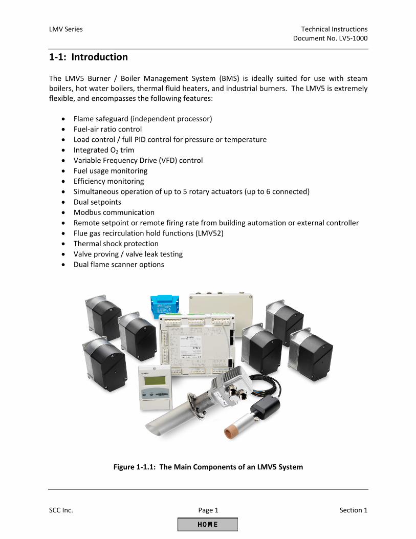
The LMV5 Burner / Boiler Management System (BMS) is ideally suited for use with steam
boilers, hot water boilers, thermal fluid heaters, and industrial burners. The LMV5 is extremely
flexible, and encompasses the following features:
• Flame safeguard (independent processor)
• Fuel-air ratio control
• Load control / full PID control for pressure or temperature
• Integrated O2 trim
• Variable Frequency Drive (VFD) control
• Fuel usage monitoring
• Efficiency monitoring
• Simultaneous operation of up to 5 rotary actuators (up to 6 connected)
• Dual setpoints
• Modbus communication
• Remote setpoint or remote firing rate from building automation or external controller
• Flue gas recirculation hold functions (LMV52)
• Thermal shock protection
• Valve proving / valve leak testing
• Dual flame scanner options
Figure 1-1.1: The Main Components of an LMV5 System
Technical Instructions LMV Series
Document No. LV5-1000
Section 1 Page 2 SCC Inc.
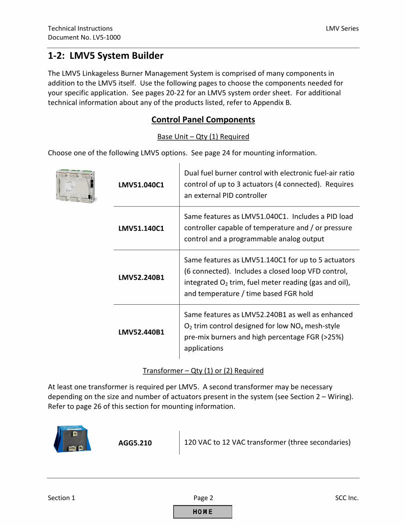
1-2: LMV5 System Builder
The LMV5 Linkageless Burner Management System is comprised of many components in
addition to the LMV5 itself. Use the following pages to choose the components needed for
your specific application. See pages 20-22 for an LMV5 system order sheet. For additional
technical information about any of the products listed, refer to Appendix B.
Control Panel Components
Base Unit – Qty (1) Required
Choose one of the following LMV5 options. See page 24 for mounting information.
LMV51.040C1
Dual fuel burner control with electronic fuel-air ratio
control of up to 3 actuators (4 connected). Requires
an external PID controller
LMV51.140C1
Same features as LMV51.040C1. Includes a PID load
controller capable of temperature and / or pressure
control and a programmable analog output
LMV52.240B1
Same features as LMV51.140C1 for up to 5 actuators
(6 connected). Includes a closed loop VFD control,
integrated O2 trim, fuel meter reading (gas and oil),
and temperature / time based FGR hold
LMV52.440B1
Same features as LMV52.240B1 as well as enhanced
O2 trim control designed for low NOx mesh-style
pre-mix burners and high percentage FGR (>25%)
applications
Transformer – Qty (1) or (2) Required
At least one transformer is required per LMV5. A second transformer may be necessary
depending on the size and number of actuators present in the system (see Section 2 – Wiring).
Refer to page 26 of this section for mounting information.
AGG5.210 120 VAC to 12 VAC transformer (three secondaries)
LMV Series Technical Instructions
Document No. LV5-1000
SCC Inc. Page 3 Section 1
Control Panel Components (continued)
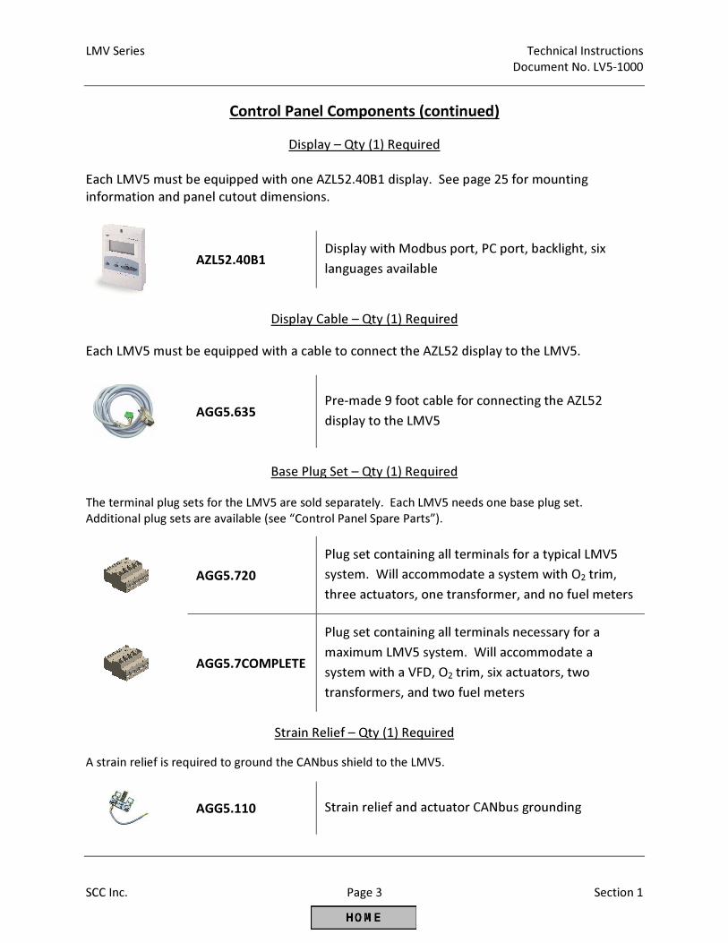
Display – Qty (1) Required
Each LMV5 must be equipped with one AZL52.40B1 display. See page 25 for mounting
information and panel cutout dimensions.
AZL52.40B1 Display with Modbus port, PC port, backlight, six
languages available
Display Cable – Qty (1) Required
Each LMV5 must be equipped with a cable to connect the AZL52 display to the LMV5.
AGG5.635 Pre-made 9 foot cable for connecting the AZL52
display to the LMV5
Base Plug Set – Qty (1) Required
The terminal plug sets for the LMV5 are sold separately. Each LMV5 needs one base plug set.
Additional plug sets are available (see “Control Panel Spare Parts”).
AGG5.720
Plug set containing all terminals for a typical LMV5
system. Will accommodate a system with O2 trim,
three actuators, one transformer, and no fuel meters
AGG5.7COMPLETE
Plug set containing all terminals necessary for a
maximum LMV5 system. Will accommodate a
system with a VFD, O2 trim, six actuators, two
transformers, and two fuel meters
Strain Relief – Qty (1) Required
A strain relief is required to ground the CANbus shield to the LMV5.
AGG5.110 Strain relief and actuator CANbus grounding
Technical Instructions LMV Series
Document No. LV5-1000
Section 1 Page 4 SCC Inc.
Control Panel Components (continued)
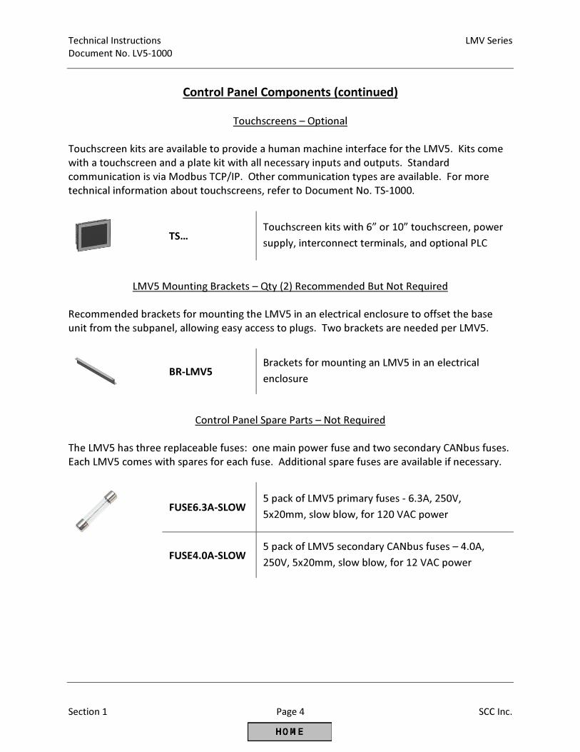
Touchscreens – Optional
Touchscreen kits are available to provide a human machine interface for the LMV5. Kits come
with a touchscreen and a plate kit with all necessary inputs and outputs. Standard
communication is via Modbus TCP/IP. Other communication types are available. For more
technical information about touchscreens, refer to Document No. TS-1000.
TS… Touchscreen kits with 6” or 10” touchscreen, power
supply, interconnect terminals, and optional PLC
LMV5 Mounting Brackets – Qty (2) Recommended But Not Required
Recommended brackets for mounting the LMV5 in an electrical enclosure to offset the base
unit from the subpanel, allowing easy access to plugs. Two brackets are needed per LMV5.
BR-LMV5
Brackets for mounting an LMV5 in an electrical
enclosure
Control Panel Spare Parts – Not Required
The LMV5 has three replaceable fuses: one main power fuse and two secondary CANbus fuses.
Each LMV5 comes with spares for each fuse. Additional spare fuses are available if necessary.
FUSE6.3A-SLOW 5 pack of LMV5 primary fuses - 6.3A, 250V,
5x20mm, slow blow, for 120 VAC power
FUSE4.0A-SLOW 5 pack of LMV5 secondary CANbus fuses – 4.0A,
250V, 5x20mm, slow blow, for 12 VAC power
LMV Series Technical Instructions
Document No. LV5-1000
SCC Inc. Page 5 Section 1
Control Panel Components (continued)
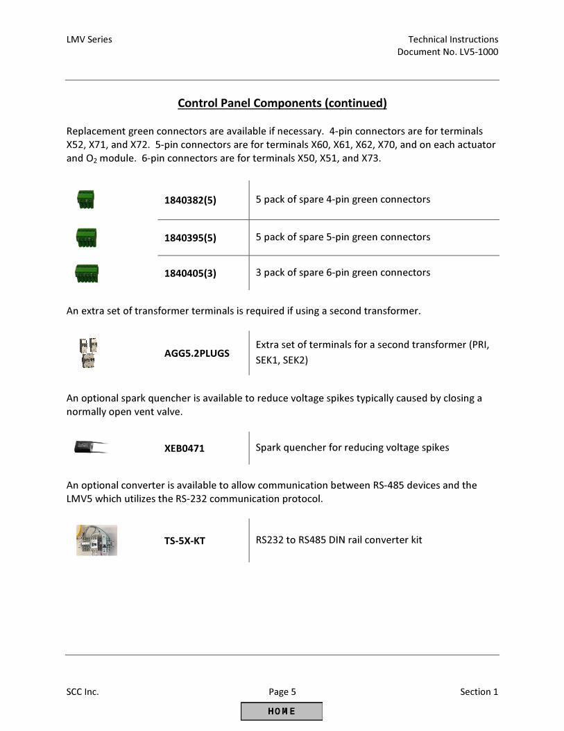
Replacement green connectors are available if necessary. 4-pin connectors are for terminals
X52, X71, and X72. 5-pin connectors are for terminals X60, X61, X62, X70, and on each actuator
and O2 module. 6-pin connectors are for terminals X50, X51, and X73.
1840382(5) 5 pack of spare 4-pin green connectors
1840395(5) 5 pack of spare 5-pin green connectors
1840405(3) 3 pack of spare 6-pin green connectors
An extra set of transformer terminals is required if using a second transformer.
AGG5.2PLUGS
Extra set of terminals for a second transformer (PRI,
SEK1, SEK2)
An optional spark quencher is available to reduce voltage spikes typically caused by closing a
normally open vent valve.
XEB0471 Spark quencher for reducing voltage spikes
An optional converter is available to allow communication between RS-485 devices and the
LMV5 which utilizes the RS-232 communication protocol.
TS-5X-KT RS232 to RS485 DIN rail converter kit
Technical Instructions LMV Series
Document No. LV5-1000
Section 1 Page 6 SCC Inc.
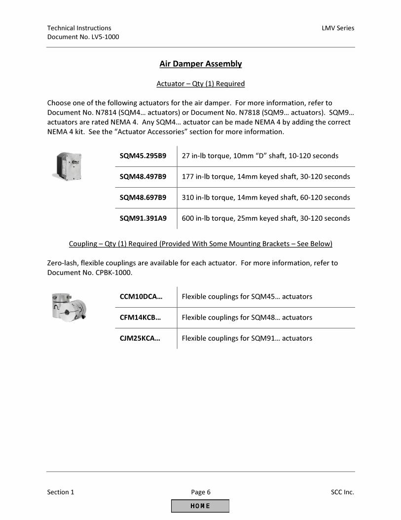
Air Damper Assembly
Actuator – Qty (1) Required
Choose one of the following actuators for the air damper. For more information, refer to
Document No. N7814 (SQM4… actuators) or Document No. N7818 (SQM9… actuators). SQM9…
actuators are rated NEMA 4. Any SQM4… actuator can be made NEMA 4 by adding the correct
NEMA 4 kit. See the “Actuator Accessories” section for more information.
SQM45.295B9 27 in-lb torque, 10mm “D” shaft, 10-120 seconds
SQM48.497B9 177 in-lb torque, 14mm keyed shaft, 30-120 seconds
SQM48.697B9 310 in-lb torque, 14mm keyed shaft, 60-120 seconds
SQM91.391A9 600 in-lb torque, 25mm keyed shaft, 30-120 seconds
Coupling – Qty (1) Required (Provided With Some Mounting Brackets – See Below)
Zero-lash, flexible couplings are available for each actuator. For more information, refer to
Document No. CPBK-1000.
CCM10DCA… Flexible couplings for SQM45… actuators
CFM14KCB… Flexible couplings for SQM48… actuators
CJM25KCA… Flexible couplings for SQM91… actuators
LMV Series Technical Instructions
Document No. LV5-1000
SCC Inc. Page 7 Section 1
Air Damper Assembly (continued)
Mounting Bracket Kits - Optional
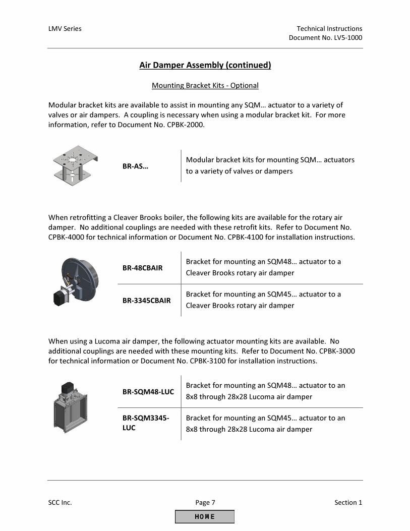
Modular bracket kits are available to assist in mounting any SQM… actuator to a variety of
valves or air dampers. A coupling is necessary when using a modular bracket kit. For more
information, refer to Document No. CPBK-2000.
BR-AS… Modular bracket kits for mounting SQM… actuators
to a variety of valves or dampers
When retrofitting a Cleaver Brooks boiler, the following kits are available for the rotary air
damper. No additional couplings are needed with these retrofit kits. Refer to Document No.
CPBK-4000 for technical information or Document No. CPBK-4100 for installation instructions.
BR-48CBAIR Bracket for mounting an SQM48… actuator to a
Cleaver Brooks rotary air damper
BR-3345CBAIR Bracket for mounting an SQM45… actuator to a
Cleaver Brooks rotary air damper
When using a Lucoma air damper, the following actuator mounting kits are available. No
additional couplings are needed with these mounting kits. Refer to Document No. CPBK-3000
for technical information or Document No. CPBK-3100 for installation instructions.
BR-SQM48-LUC Bracket for mounting an SQM48… actuator to an
8x8 through 28x28 Lucoma air damper
BR-SQM3345-
LUC
Bracket for mounting an SQM45… actuator to an
8x8 through 28x28 Lucoma air damper
Technical Instructions LMV Series
Document No. LV5-1000
Section 1 Page 8 SCC Inc.
Gas Firing Rate Control Valve
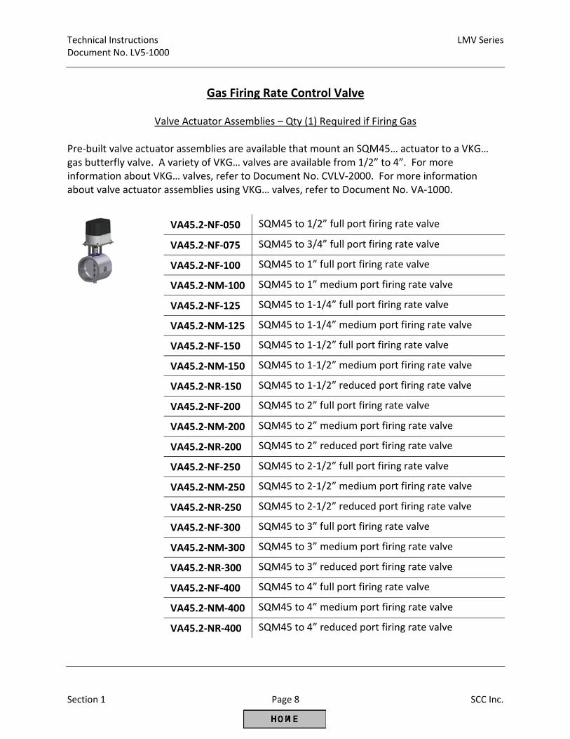
Valve Actuator Assemblies – Qty (1) Required if Firing Gas
Pre-built valve actuator assemblies are available that mount an SQM45… actuator to a VKG…
gas butterfly valve. A variety of VKG… valves are available from 1/2” to 4”. For more
information about VKG… valves, refer to Document No. CVLV-2000. For more information
about valve actuator assemblies using VKG… valves, refer to Document No. VA-1000.
VA45.2-NF-050 SQM45 to 1/2” full port firing rate valve
VA45.2-NF-075 SQM45 to 3/4” full port firing rate valve
VA45.2-NF-100 SQM45 to 1” full port firing rate valve
VA45.2-NM-100 SQM45 to 1” medium port firing rate valve
VA45.2-NF-125 SQM45 to 1-1/4” full port firing rate valve
VA45.2-NM-125 SQM45 to 1-1/4” medium port firing rate valve
VA45.2-NF-150 SQM45 to 1-1/2” full port firing rate valve
VA45.2-NM-150 SQM45 to 1-1/2” medium port firing rate valve
VA45.2-NR-150 SQM45 to 1-1/2” reduced port firing rate valve
VA45.2-NF-200 SQM45 to 2” full port firing rate valve
VA45.2-NM-200 SQM45 to 2” medium port firing rate valve
VA45.2-NR-200 SQM45 to 2” reduced port firing rate valve
VA45.2-NF-250 SQM45 to 2-1/2” full port firing rate valve
VA45.2-NM-250 SQM45 to 2-1/2” medium port firing rate valve
VA45.2-NR-250 SQM45 to 2-1/2” reduced port firing rate valve
VA45.2-NF-300 SQM45 to 3” full port firing rate valve
VA45.2-NM-300 SQM45 to 3” medium port firing rate valve
VA45.2-NR-300 SQM45 to 3” reduced port firing rate valve
VA45.2-NF-400 SQM45 to 4” full port firing rate valve
VA45.2-NM-400 SQM45 to 4” medium port firing rate valve
VA45.2-NR-400 SQM45 to 4” reduced port firing rate valve
LMV Series Technical Instructions
Document No. LV5-1000
SCC Inc. Page 9 Section 1
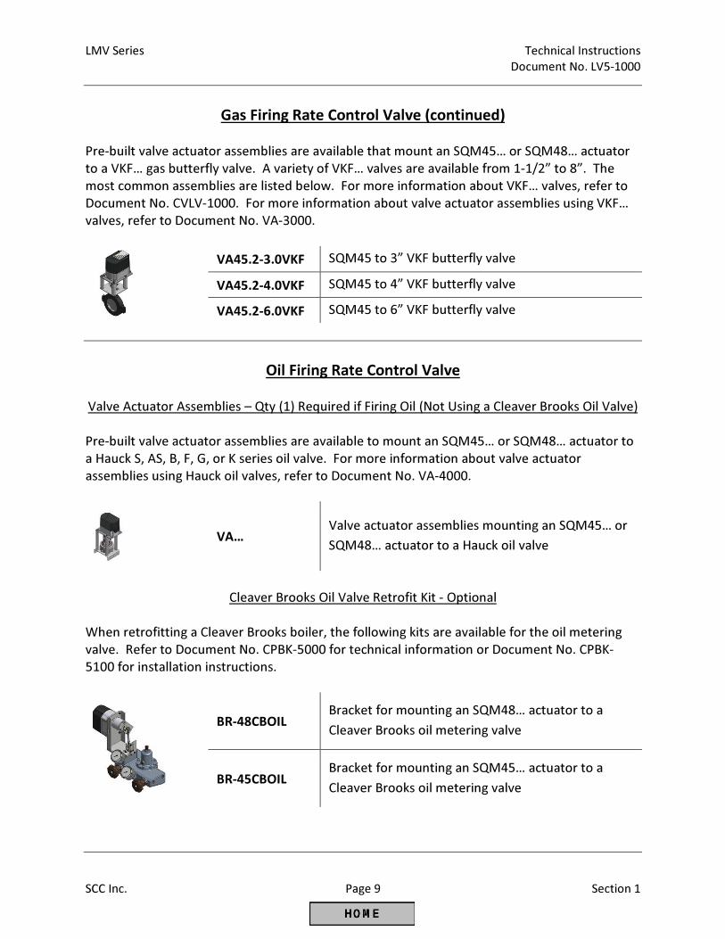
Gas Firing Rate Control Valve (continued)
Pre-built valve actuator assemblies are available that mount an SQM45… or SQM48… actuator
to a VKF… gas butterfly valve. A variety of VKF… valves are available from 1-1/2” to 8”. The
most common assemblies are listed below. For more information about VKF… valves, refer to
Document No. CVLV-1000. For more information about valve actuator assemblies using VKF…
valves, refer to Document No. VA-3000.
VA45.2-3.0VKF SQM45 to 3” VKF butterfly valve
VA45.2-4.0VKF SQM45 to 4” VKF butterfly valve
VA45.2-6.0VKF SQM45 to 6” VKF butterfly valve
Oil Firing Rate Control Valve
Valve Actuator Assemblies – Qty (1) Required if Firing Oil (Not Using a Cleaver Brooks Oil Valve)
Pre-built valve actuator assemblies are available to mount an SQM45… or SQM48… actuator to
a Hauck S, AS, B, F, G, or K series oil valve. For more information about valve actuator
assemblies using Hauck oil valves, refer to Document No. VA-4000.
VA… Valve actuator assemblies mounting an SQM45… or
SQM48… actuator to a Hauck oil valve
Cleaver Brooks Oil Valve Retrofit Kit - Optional
When retrofitting a Cleaver Brooks boiler, the following kits are available for the oil metering
valve. Refer to Document No. CPBK-5000 for technical information or Document No. CPBK-
5100 for installation instructions.
BR-48CBOIL Bracket for mounting an SQM48… actuator to a
Cleaver Brooks oil metering valve
BR-45CBOIL Bracket for mounting an SQM45… actuator to a
Cleaver Brooks oil metering valve
Technical Instructions LMV Series
Document No. LV5-1000
Section 1 Page 10 SCC Inc.
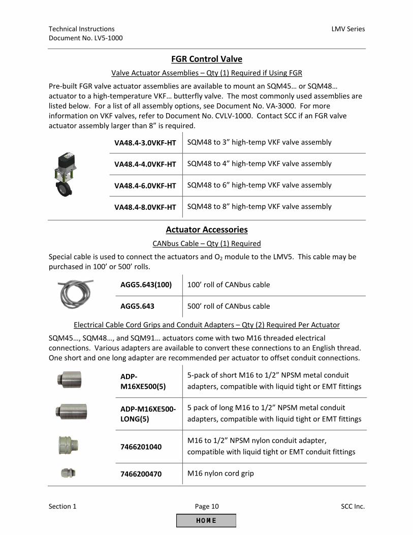
FGR Control Valve
Valve Actuator Assemblies – Qty (1) Required if Using FGR
Pre-built FGR valve actuator assemblies are available to mount an SQM45… or SQM48…
actuator to a high-temperature VKF… butterfly valve. The most commonly used assemblies are
listed below. For a list of all assembly options, see Document No. VA-3000. For more
information on VKF valves, refer to Document No. CVLV-1000. Contact SCC if an FGR valve
actuator assembly larger than 8” is required.
VA48.4-3.0VKF-HT SQM48 to 3” high-temp VKF valve assembly
VA48.4-4.0VKF-HT SQM48 to 4” high-temp VKF valve assembly
VA48.4-6.0VKF-HT SQM48 to 6” high-temp VKF valve assembly
VA48.4-8.0VKF-HT SQM48 to 8” high-temp VKF valve assembly
Actuator Accessories
CANbus Cable – Qty (1) Required
Special cable is used to connect the actuators and O2 module to the LMV5. This cable may be
purchased in 100’ or 500’ rolls.
AGG5.643(100) 100’ roll of CANbus cable
AGG5.643 500’ roll of CANbus cable
Electrical Cable Cord Grips and Conduit Adapters – Qty (2) Required Per Actuator
SQM45…, SQM48…, and SQM91… actuators come with two M16 threaded electrical
connections. Various adapters are available to convert these connections to an English thread.
One short and one long adapter are recommended per actuator to offset conduit connections.
ADP-
M16XE500(5)
5-pack of short M16 to 1/2” NPSM metal conduit
adapters, compatible with liquid tight or EMT fittings
ADP-M16XE500-
LONG(5)
5 pack of long M16 to 1/2” NPSM metal conduit
adapters, compatible with liquid tight or EMT fittings
7466201040
M16 to 1/2” NPSM nylon conduit adapter,
compatible with liquid tight or EMT conduit fittings
7466200470 M16 nylon cord grip
LMV Series Technical Instructions
Document No. LV5-1000
SCC Inc. Page 11 Section 1
Actuator Accessories (continued)
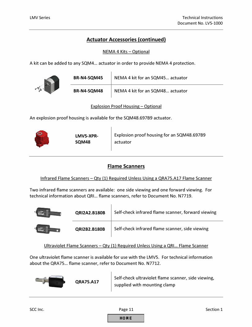
NEMA 4 Kits – Optional
A kit can be added to any SQM4… actuator in order to provide NEMA 4 protection.
BR-N4-SQM45 NEMA 4 kit for an SQM45… actuator
BR-N4-SQM48 NEMA 4 kit for an SQM48… actuator
Explosion Proof Housing – Optional
An explosion proof housing is available for the SQM48.697B9 actuator.
LMV5-XPR-
SQM48
Explosion proof housing for an SQM48.697B9
actuator
Flame Scanners
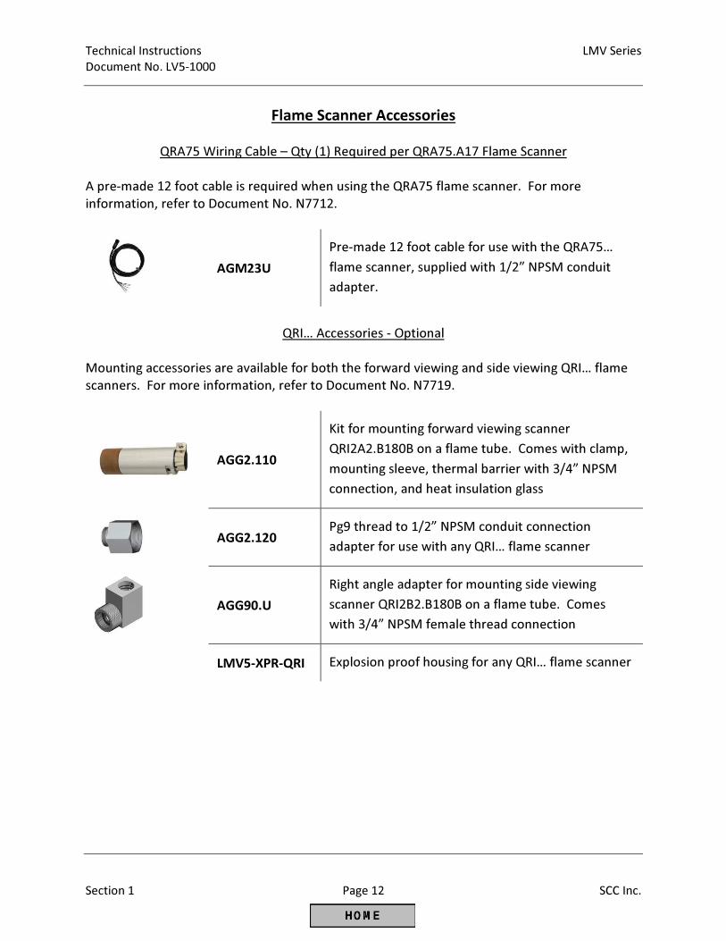
Infrared Flame Scanners – Qty (1) Required Unless Using a QRA75.A17 Flame Scanner
Two infrared flame scanners are available: one side viewing and one forward viewing. For
technical information about QRI… flame scanners, refer to Document No. N7719.
QRI2A2.B180B Self-check infrared flame scanner, forward viewing
QRI2B2.B180B Self-check infrared flame scanner, side viewing
Ultraviolet Flame Scanners – Qty (1) Required Unless Using a QRI… Flame Scanner
One ultraviolet flame scanner is available for use with the LMV5. For technical information
about the QRA75… flame scanner, refer to Document No. N7712.
QRA75.A17
Self-check ultraviolet flame scanner, side viewing,
supplied with mounting clamp
Technical Instructions LMV Series
Document No. LV5-1000
Section 1 Page 12 SCC Inc.
Flame Scanner Accessories
QRA75 Wiring Cable – Qty (1) Required per QRA75.A17 Flame Scanner
A pre-made 12 foot cable is required when using the QRA75 flame scanner. For more
information, refer to Document No. N7712.
AGM23U
Pre-made 12 foot cable for use with the QRA75…
flame scanner, supplied with 1/2” NPSM conduit
adapter.
QRI… Accessories - Optional
Mounting accessories are available for both the forward viewing and side viewing QRI… flame
scanners. For more information, refer to Document No. N7719.
AGG2.110
Kit for mounting forward viewing scanner
QRI2A2.B180B on a flame tube. Comes with clamp,
mounting sleeve, thermal barrier with 3/4” NPSM
connection, and heat insulation glass
AGG2.120
Pg9 thread to 1/2” NPSM conduit connection
adapter for use with any QRI… flame scanner
AGG90.U
Right angle adapter for mounting side viewing
scanner QRI2B2.B180B on a flame tube. Comes
with 3/4” NPSM female thread connection
LMV5-XPR-QRI Explosion proof housing for any QRI… flame scanner
LMV Series Technical Instructions
Document No. LV5-1000
SCC Inc. Page 13 Section 1
Flame Scanner Accessories (continued)
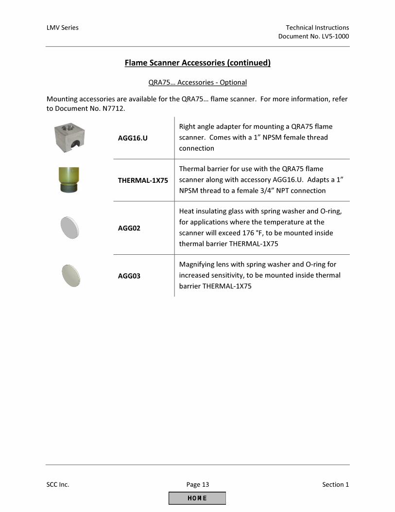
QRA75… Accessories - Optional
Mounting accessories are available for the QRA75… flame scanner. For more information, refer
to Document No. N7712.
AGG16.U
Right angle adapter for mounting a QRA75 flame
scanner. Comes with a 1” NPSM female thread
connection
THERMAL-1X75
Thermal barrier for use with the QRA75 flame
scanner along with accessory AGG16.U. Adapts a 1”
NPSM thread to a female 3/4” NPT connection
AGG02
Heat insulating glass with spring washer and O-ring,
for applications where the temperature at the
scanner will exceed 176 °F, to be mounted inside
thermal barrier THERMAL-1X75
AGG03
Magnifying lens with spring washer and O-ring for
increased sensitivity, to be mounted inside thermal
barrier THERMAL-1X75
Technical Instructions LMV Series
Document No. LV5-1000
Section 1 Page 14 SCC Inc.
Sensors
Pressure Sensors – Qty (1) Required for Steam Boilers
A wide range of pressure sensors is available for steam boilers. All sensors have a 1/4” NPT
process connection and a 1/2” NPT conduit connection. Sensors are available with either a 4-
20 mA or 0-10 Vdc output signal. All available 4-20 mA sensors are listed below. To order a 0-
10 Vdc sensor, change the underlined digit to a 1. The 0-100 PSI sensor is only available with a
4-20 mA signal. For more information on 7MF pressure sensors, refer to Document No. SEN-
2000.
7MF1565-4BB00-5EA1 0-15 PSI range, 4-20 mA signal
7MF1565-4BE00-5EA1 0-30 PSI range, 4-20 mA signal
7MF1565-4BF00-5EA1 0-60 PSI range, 4-20 mA signal
7MF1565-4BG00-5EA1 0-100 PSI range, 4-20 mA signal
7MF1565-4CA00-5EA1 0-150 PSI range, 4-20 mA signal
7MF1565-4CB00-5EA1
0-200 PSI range, 4-20 mA signal
7MF1565-4CD00-5EA1 0-300 PSI range, 4-20 mA signal
7MF1565-4CE00-5EA1 0-500 PSI range, 4-20 mA signal
7MF1565-4CF00-5EA1 0-750 PSI range, 4-20 mA signal
LMV Series Technical Instructions
Document No. LV5-1000
SCC Inc. Page 15 Section 1
Sensors (continued)
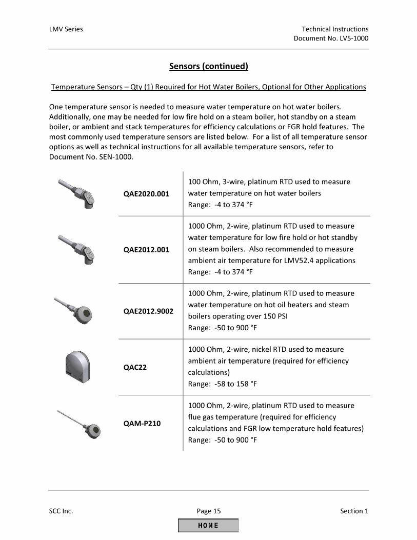
Temperature Sensors – Qty (1) Required for Hot Water Boilers, Optional for Other Applications
One temperature sensor is needed to measure water temperature on hot water boilers.
Additionally, one may be needed for low fire hold on a steam boiler, hot standby on a steam
boiler, or ambient and stack temperatures for efficiency calculations or FGR hold features. The
most commonly used temperature sensors are listed below. For a list of all temperature sensor
options as well as technical instructions for all available temperature sensors, refer to
Document No. SEN-1000.
QAE2020.001
100 Ohm, 3-wire, platinum RTD used to measure
water temperature on hot water boilers
Range: -4 to 374 °F
QAE2012.001
1000 Ohm, 2-wire, platinum RTD used to measure
water temperature for low fire hold or hot standby
on steam boilers. Also recommended to measure
ambient air temperature for LMV52.4 applications
Range: -4 to 374 °F
QAE2012.9002
1000 Ohm, 2-wire, platinum RTD used to measure
water temperature on hot oil heaters and steam
boilers operating over 150 PSI
Range: -50 to 900 °F
QAC22
1000 Ohm, 2-wire, nickel RTD used to measure
ambient air temperature (required for efficiency
calculations)
Range: -58 to 158 °F
QAM-P210
1000 Ohm, 2-wire, platinum RTD used to measure
flue gas temperature (required for efficiency
calculations and FGR low temperature hold features)
Range: -50 to 900 °F
Technical Instructions LMV Series
Document No. LV5-1000
Section 1 Page 16 SCC Inc.
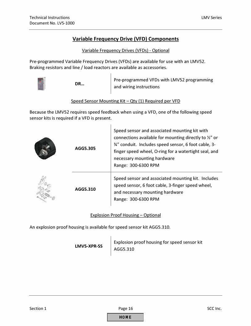
Variable Frequency Drive (VFD) Components
Variable Frequency Drives (VFDs) - Optional
Pre-programmed Variable Frequency Drives (VFDs) are available for use with an LMV52.
Braking resistors and line / load reactors are available as accessories.
DR…
Pre-programmed VFDs with LMV52 programming
and wiring instructions
Speed Sensor Mounting Kit – Qty (1) Required per VFD
Because the LMV52 requires speed feedback when using a VFD, one of the following speed
sensor kits is required if a VFD is present.
AGG5.305
Speed sensor and associated mounting kit with
connections available for mounting directly to ½” or
¾” conduit. Includes speed sensor, 6 foot cable, 3-
finger speed wheel, O-ring for a watertight seal, and
necessary mounting hardware
Range: 300-6300 RPM
AGG5.310
Speed sensor and associated mounting kit. Includes
speed sensor, 6 foot cable, 3-finger speed wheel,
and necessary mounting hardware
Range: 300-6300 RPM
Explosion Proof Housing – Optional
An explosion proof housing is available for speed sensor kit AGG5.310.
LMV5-XPR-SS
Explosion proof housing for speed sensor kit
AGG5.310
LMV Series Technical Instructions
Document No. LV5-1000
SCC Inc. Page 17 Section 1
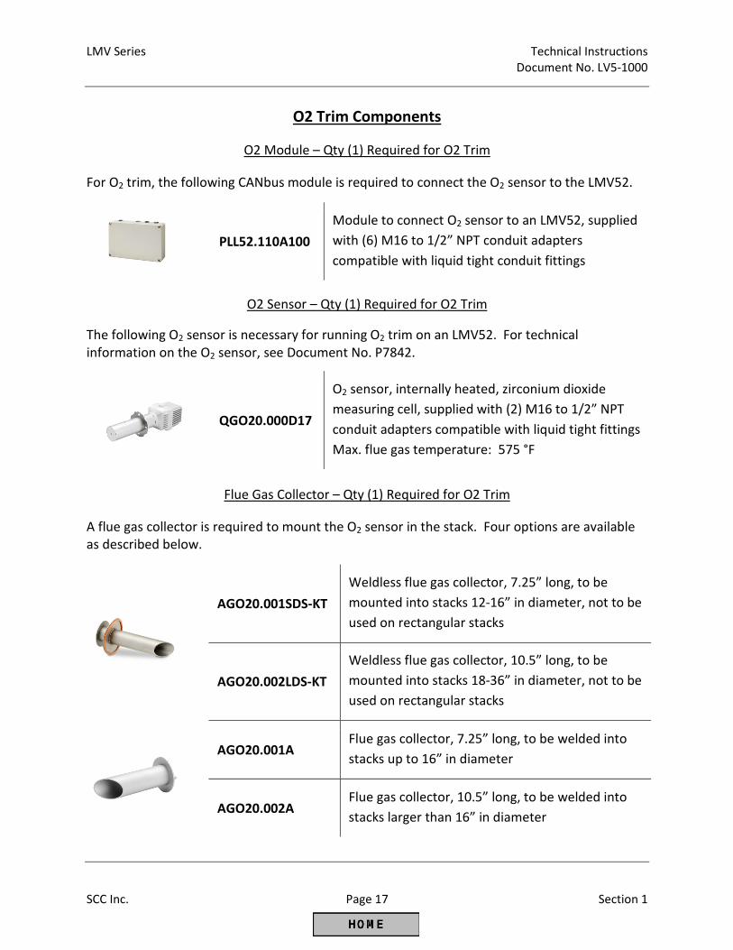
O2 Trim Components
O2 Module – Qty (1) Required for O2 Trim
For O2 trim, the following CANbus module is required to connect the O2 sensor to the LMV52.
PLL52.110A100
Module to connect O2 sensor to an LMV52, supplied
with (6) M16 to 1/2” NPT conduit adapters
compatible with liquid tight conduit fittings
O2 Sensor – Qty (1) Required for O2 Trim
The following O2 sensor is necessary for running O2 trim on an LMV52. For technical
information on the O2 sensor, see Document No. P7842.
QGO20.000D17
O2 sensor, internally heated, zirconium dioxide
measuring cell, supplied with (2) M16 to 1/2” NPT
conduit adapters compatible with liquid tight fittings
Max. flue gas temperature: 575 °F
Flue Gas Collector – Qty (1) Required for O2 Trim
A flue gas collector is required to mount the O2 sensor in the stack. Four options are available
as described below.
AGO20.001SDS-KT
Weldless flue gas collector, 7.25” long, to be
mounted into stacks 12-16” in diameter, not to be
used on rectangular stacks
AGO20.002LDS-KT
Weldless flue gas collector, 10.5” long, to be
mounted into stacks 18-36” in diameter, not to be
used on rectangular stacks
AGO20.001A Flue gas collector, 7.25” long, to be welded into
stacks up to 16” in diameter
AGO20.002A Flue gas collector, 10.5” long, to be welded into
stacks larger than 16” in diameter
Technical Instructions LMV Series
Document No. LV5-1000
Section 1 Page 18 SCC Inc.
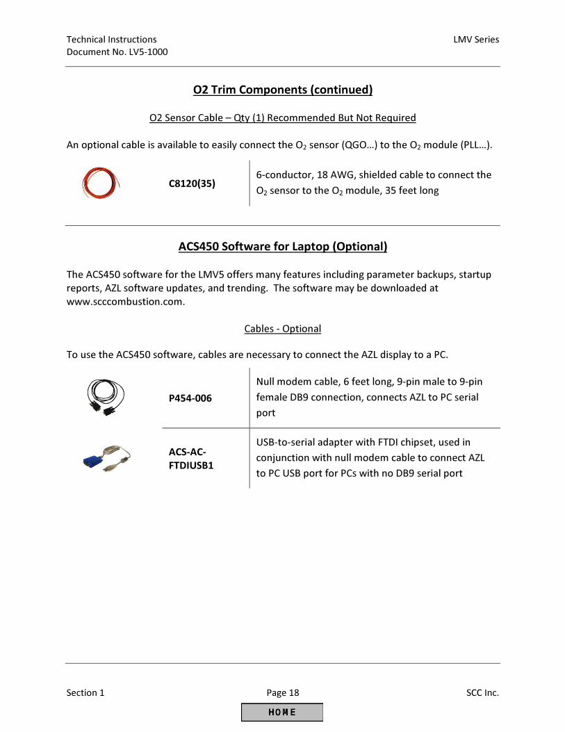
O2 Trim Components (continued)
O2 Sensor Cable – Qty (1) Recommended But Not Required
An optional cable is available to easily connect the O2 sensor (QGO…) to the O2 module (PLL…).
C8120(35)
6-conductor, 18 AWG, shielded cable to connect the
O2 sensor to the O2 module, 35 feet long
ACS450 Software for Laptop (Optional)
The ACS450 software for the LMV5 offers many features including parameter backups, startup
reports, AZL software updates, and trending. The software may be downloaded at
www.scccombustion.com.
Cables - Optional
To use the ACS450 software, cables are necessary to connect the AZL display to a PC.
P454-006
Null modem cable, 6 feet long, 9-pin male to 9-pin
female DB9 connection, connects AZL to PC serial
port
ACS-AC-
FTDIUSB1
USB-to-serial adapter with FTDI chipset, used in
conjunction with null modem cable to connect AZL
to PC USB port for PCs with no DB9 serial port
LMV Series Technical Instructions
Document No. LV5-1000
SCC Inc. Page 19 Section 1
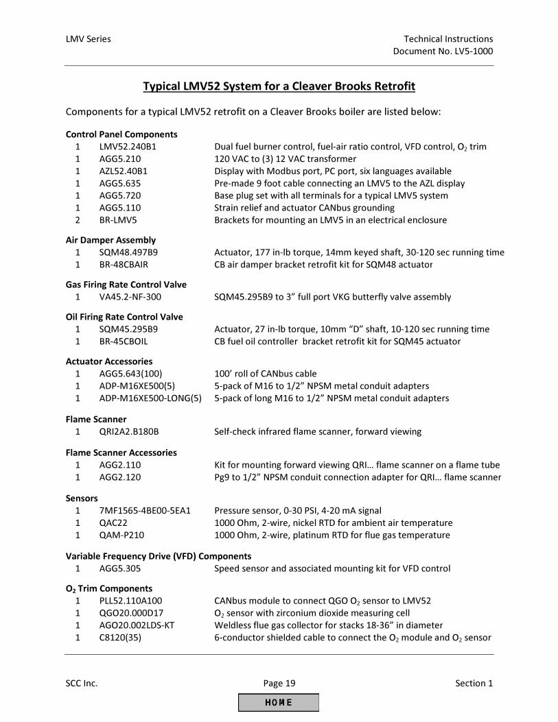
Typical LMV52 System for a Cleaver Brooks Retrofit
Components for a typical LMV52 retrofit on a Cleaver Brooks boiler are listed below:
Control Panel Components
1 LMV52.240B1 Dual fuel burner control, fuel-air ratio control, VFD control, O2 trim
1 AGG5.210 120 VAC to (3) 12 VAC transformer
1 AZL52.40B1 Display with Modbus port, PC port, six languages available
1 AGG5.635 Pre-made 9 foot cable connecting an LMV5 to the AZL display
1 AGG5.720 Base plug set with all terminals for a typical LMV5 system
1 AGG5.110 Strain relief and actuator CANbus grounding
2 BR-LMV5 Brackets for mounting an LMV5 in an electrical enclosure
Air Damper Assembly
1 SQM48.497B9 Actuator, 177 in-lb torque, 14mm keyed shaft, 30-120 sec running time
1 BR-48CBAIR CB air damper bracket retrofit kit for SQM48 actuator
Gas Firing Rate Control Valve
1 VA45.2-NF-300 SQM45.295B9 to 3” full port VKG butterfly valve assembly
Oil Firing Rate Control Valve
1 SQM45.295B9 Actuator, 27 in-lb torque, 10mm “D” shaft, 10-120 sec running time
1 BR-45CBOIL CB fuel oil controller bracket retrofit kit for SQM45 actuator
Actuator Accessories
1 AGG5.643(100) 100’ roll of CANbus cable
1
1
ADP-M16XE500(5)
ADP-M16XE500-LONG(5)
5-pack of M16 to 1/2” NPSM metal conduit adapters
5-pack of long M16 to 1/2” NPSM metal conduit adapters
Flame Scanner
1 QRI2A2.B180B Self-check infrared flame scanner, forward viewing
Flame Scanner Accessories
1 AGG2.110 Kit for mounting forward viewing QRI… flame scanner on a flame tube
1 AGG2.120 Pg9 to 1/2” NPSM conduit connection adapter for QRI… flame scanner
Sensors
1 7MF1565-4BE00-5EA1 Pressure sensor, 0-30 PSI, 4-20 mA signal
1 QAC22 1000 Ohm, 2-wire, nickel RTD for ambient air temperature
1 QAM-P210 1000 Ohm, 2-wire, platinum RTD for flue gas temperature
Variable Frequency Drive (VFD) Components
1 AGG5.305 Speed sensor and associated mounting kit for VFD control
O2 Trim Components
1 PLL52.110A100 CANbus module to connect QGO O2 sensor to LMV52
1 QGO20.000D17 O2 sensor with zirconium dioxide measuring cell
1 AGO20.002LDS-KT Weldless flue gas collector for stacks 18-36” in diameter
1 C8120(35) 6-conductor shielded cable to connect the O2 module and O2 sensor
Technical Instructions LMV Series
Document No. LV5-1000
Section 1 Page 20 SCC Inc.
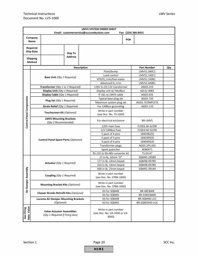
LMV5 SYSTEM ORDER SHEET
Email: [email protected] Fax: (224) 366-8455
Company
Name PO#
Required
Ship Date
Ship To
Address
Shipping
Method
Description Part Number Qty
Co
ntr
ol
Pa
ne
l C
om
po
ne
nts
Base Unit (Qty 1 Required)
Float/bump LMV51.040C1
Load control LMV51.140C1
VFD/O2 trim/fuel meter LMV52.240B1
Advanced O2 trim LMV52.440B1
Transformer (Qty 1 or 2 Required) 120V to (3) 12V transformer AGG5.210
Display Unit (Qty 1 Required) Display unit w/ Modbus AZL52.40B1
Display Cable (Qty 1 Required) 9' AZL to LMV5 cable AGG5.635
Plug Set (Qty 1 Required) Typical base plug set AGG5.720
Maximum system plug set AGG5.7COMPLETE
Strain Relief (Qty 1 Required) For CANbus grounding AGG5.110
Touchscreen Kit (Optional) Write in part number
(see Doc. No. TS-1000)
LMV5 Mounting Brackets
(Qty 2 Recommended) For electrical enclosure BR-LMV5
Control Panel Spare Parts (Optional)
120V main fuse FUSE6.3A-SLOW
12V CANbus fuse FUSE4.0A-SLOW
5 pack of 4-pins 1840382(5)
5 pack of 5-pins 1840395(5)
3 pack of 6-pins 1840405(3)
Transformer plugs AGG5.2PLUGS
Spark quencher XEB0471
RS-232 to RS-485 converter kit TS-5X-KT
Air
Da
mp
er
Ass
em
bly
Actuator (Qty 1 Required)
27 in-lb, 10mm "D" SQM45.295B9
177 in-lb, 14mm keyed SQM48.497B9
310 in-lb, 14mm keyed SQM48.697B9
600 in-lb, 25mm keyed SQM91.391A9
Coupling (Qty 1 Required) Write in part number
(see Doc. No. CPBK-1000)
Mounting Bracket Kits (Optional) Write in part number
(see Doc. No. CPBK-2000)
Cleaver Brooks Retrofit Kits (Optional) Kit for SQM48 BR-48CBAIR
Kit for SQM45 BR-3345CBAIR
Lucoma Air Damper Mounting Brackets
(Optional)
Kit for SQM48 BR-SQM48-LUC
Kit for SQM45 BR-SQM3345-LUC
Ga
s Fir
ing
Ra
te V
alv
e
Valve Actuator Assemblies
(Qty 1 Required if Firing Gas)
Write in part number
(see Doc. No. VA-1000 or VA-
3000)

LMV Series Technical Instructions
Document No. LV5-1000
SCC Inc. Page 21 Section 1
Intentionally Left Blank
Technical Instructions LMV Series
Document No. LV5-1000
Section 1 Page 22 SCC Inc.
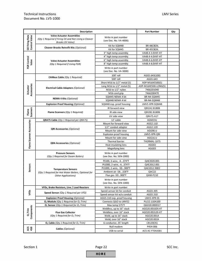
Description Part Number Qty
Oil
Fir
ing
Ra
te
Co
ntr
ol
Va
lve
Valve Actuator Assemblies
(Qty 1 Required if Firing Oil and Not Using a Cleaver
Brooks Oil Valve)
Write in part number
(see Doc. No. VA-4000)
Cleaver Brooks Retrofit Kits (Optional) Kit for SQM48 BR-48CBOIL
Kit for SQM45 BR-45CBOIL
FG
R C
on
tro
l
Va
lve
Valve Actuator Assemblies
(Qty 1 Required if Using FGR)
3" high temp assembly VA48.4-3.0VKF-HT
4" high temp assembly VA48.4-4.0VKF-HT
6" high temp assembly VA48.4-6.0VKF-HT
8" high temp assembly VA48.4-8.0VKF-HT
Write in part number
(see Doc. No. VA-3000)
Act
ua
tor
Acc
ess
ori
es
CANbus Cable (Qty 1 Required) 100' roll AGG5.643(100)
500' roll AGG5.643
Electrical Cable Adapters (Optional)
Short M16 to 1/2" metal (5) ADP-M16XE500(5)
Long M16 to 1/2” metal (5) ADP-M16XE500-LONG(5)
M16 to 1/2" nylon 7466201040
M16 cord grip 7466200470
NEMA 4 Kits (Optional) SQM45 NEMA 4 kit BR-N4-SQM45
SQM48 NEMA 4 kit BR-N4-SQM48
Explosion Proof Housing (Optional) SQM48 exp. proof housing LMV5-XPR-SQM48
Fla
me
Sca
nn
ers
Flame Scanners (Qty 1 Required)
IR forward view QRI2A2.B180B
IR side view QRI2B2.B180B
UV side view QRA75.A17
Fla
me
Sca
nn
er
Acc
ess
ori
es QRA75 Cable (Qty 1 Required per QRA75) 12' cable AGM23U
QRI Accessories (Optional)
Mount for forward view AGG2.110
1/2" conduit adapter AGG2.120
Mount for side view AGG90.U
Explosion proof housing LMV5-XPR-QRI
QRA Accessories (Optional)
Mount for side view AGG16.U
Thermal barrier THERMAL-1X75
Heat insulating lens AGG02
Magnifying lens AGG03
Se
nso
rs
Pressure Sensors
(Qty 1 Required for Steam Boilers)
Write in part number
(see Doc. No. SEN-2000)
Temperature Sensors
(Qty 1 Required for Hot Water Boilers, Optional for
Other Applications)
Pt100, 3-wire, -4...374°F QAE2020.001
Pt1000, 2-wire, -4...374°F QAE2012.001
Pt1000, 2-wire, -50...900°F QAE2012.9002
Ambient air -58...158°F QAC22
Flue gas -50...900°F QAM-P210
Write in part number
(see Doc. No. SEN-1000)
VF
Ds
VFDs, Brake Resistors, Line / Load Reactors Write in part number
Speed Sensor (Qty 1 Required per VFD) Speed sensor kit for conduit AGG5.305
Speed sensor kit w/o conduit AGG5.310
Explosion Proof Housing (Optional) AGG5.310 exp. proof housing LMV5-XPR-SS
O2
Tri
m
Co
mp
on
en
ts
O2 Module (Qty 1 Required for O2 Trim) Connects QGO to LMV52 PLL52.110A100
O2 Sensor (Qty 1 Required for O2 Trim) Max temp 575°F QGO20.000D17
Flue Gas Collector
(Qty 1 Required for O2 Trim)
Weldless, up to 16" stack AGO20.001SDS-KT
Weldless, over 16" stack AGO20.002LDS-KT
Weld, up to 16" stack AGO20.001A
Weld, over 16" stack AGO20.002A
O2 Cable (Qty 1 Required for O2 Trim) 6-conductor, 35' length C8120(35)
AC
S
45
0
Cables (Optional) Null modem P454-006
USB-to-serial ACS-AC-FTDIUSB1

LMV Series Technical Instructions
Document No. LV5-1000
SCC Inc. Page 23 Section 1
Intentionally Left Blank
Technical Instructions LMV Series
Document No. LV5-1000
Section 1 Page 24 SCC Inc.
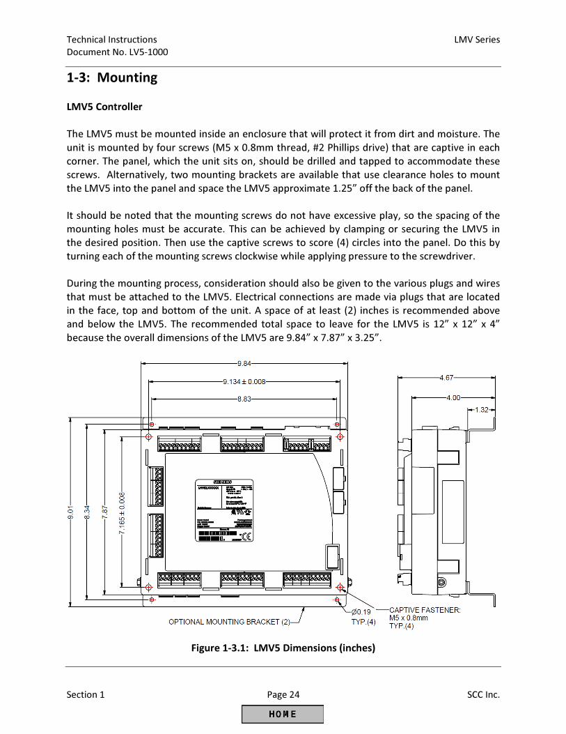
1-3: Mounting
LMV5 Controller
The LMV5 must be mounted inside an enclosure that will protect it from dirt and moisture. The
unit is mounted by four screws (M5 x 0.8mm thread, #2 Phillips drive) that are captive in each
corner. The panel, which the unit sits on, should be drilled and tapped to accommodate these
screws. Alternatively, two mounting brackets are available that use clearance holes to mount
the LMV5 into the panel and space the LMV5 approximate 1.25” off the back of the panel.
It should be noted that the mounting screws do not have excessive play, so the spacing of the
mounting holes must be accurate. This can be achieved by clamping or securing the LMV5 in
the desired position. Then use the captive screws to score (4) circles into the panel. Do this by
turning each of the mounting screws clockwise while applying pressure to the screwdriver.
During the mounting process, consideration should also be given to the various plugs and wires
that must be attached to the LMV5. Electrical connections are made via plugs that are located
in the face, top and bottom of the unit. A space of at least (2) inches is recommended above
and below the LMV5. The recommended total space to leave for the LMV5 is 12” x 12” x 4”
because the overall dimensions of the LMV5 are 9.84” x 7.87” x 3.25”.
Figure 1-3.1: LMV5 Dimensions (inches)
LMV Series Technical Instructions
Document No. LV5-1000
SCC Inc. Page 25 Section 1
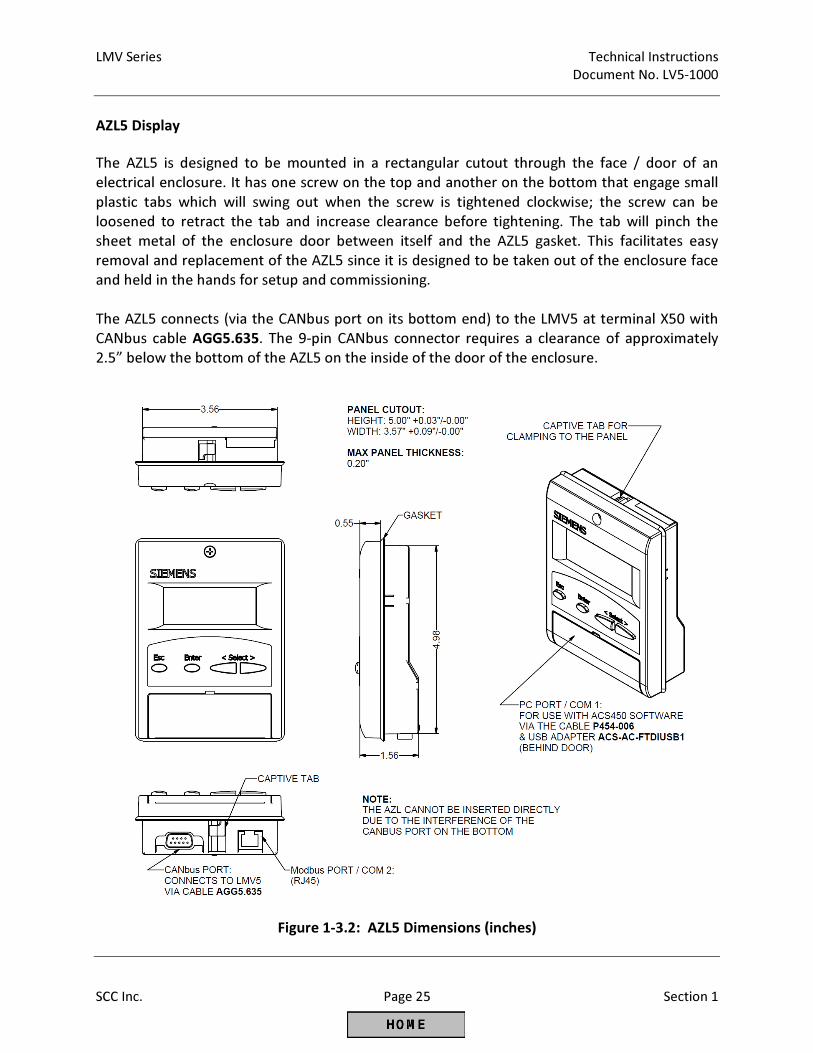
AZL5 Display
The AZL5 is designed to be mounted in a rectangular cutout through the face / door of an
electrical enclosure. It has one screw on the top and another on the bottom that engage small
plastic tabs which will swing out when the screw is tightened clockwise; the screw can be
loosened to retract the tab and increase clearance before tightening. The tab will pinch the
sheet metal of the enclosure door between itself and the AZL5 gasket. This facilitates easy
removal and replacement of the AZL5 since it is designed to be taken out of the enclosure face
and held in the hands for setup and commissioning.
The AZL5 connects (via the CANbus port on its bottom end) to the LMV5 at terminal X50 with
CANbus cable AGG5.635. The 9-pin CANbus connector requires a clearance of approximately
2.5” below the bottom of the AZL5 on the inside of the door of the enclosure.
Figure 1-3.2: AZL5 Dimensions (inches)
Technical Instructions LMV Series
Document No. LV5-1000
Section 1 Page 26 SCC Inc.
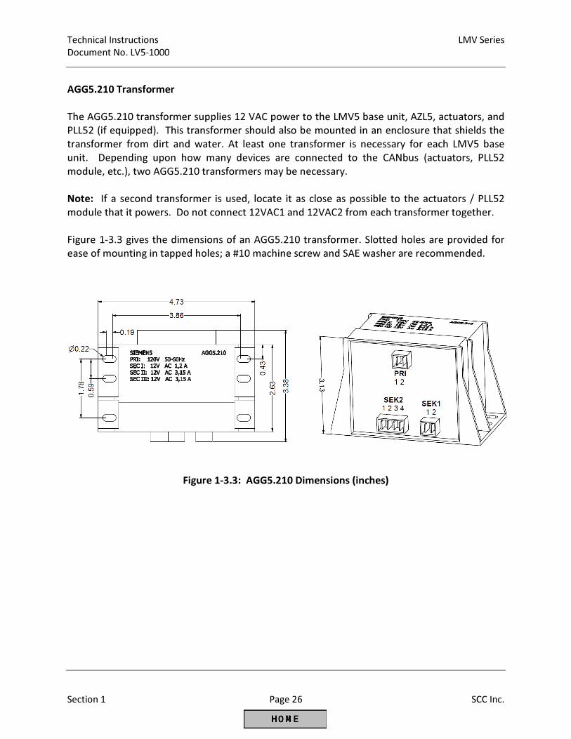
AGG5.210 Transformer
The AGG5.210 transformer supplies 12 VAC power to the LMV5 base unit, AZL5, actuators, and
PLL52 (if equipped). This transformer should also be mounted in an enclosure that shields the
transformer from dirt and water. At least one transformer is necessary for each LMV5 base
unit. Depending upon how many devices are connected to the CANbus (actuators, PLL52
module, etc.), two AGG5.210 transformers may be necessary.
Note: If a second transformer is used, locate it as close as possible to the actuators / PLL52
module that it powers. Do not connect 12VAC1 and 12VAC2 from each transformer together.
Figure 1-3.3 gives the dimensions of an AGG5.210 transformer. Slotted holes are provided for
ease of mounting in tapped holes; a #10 machine screw and SAE washer are recommended.
Figure 1-3.3: AGG5.210 Dimensions (inches)
LMV Series Technical Instructions
Document No. LV5-1000
SCC Inc. Page 27 Section 1
1-4: Important Safety Notes
• The LMV5 is a safety device. Under no circumstances should the unit be modified or
opened. SCC Inc. will not assume responsibility for damage resulting from unauthorized
modification of the unit.
• After commissioning, and after each service visit, the flue gas values should be checked
across the firing range.
• All activities (mounting, installation, service work, etc.) must be performed by qualified
staff.
• Before performing any work in the connection area of the LMV5, disconnect the unit
from the main supply (all-polar disconnection).
• Protection against electrical shock hazard on the LMV5 and all other connected
electrical components must be ensured through good wiring and grounding practices.
• Fall or shock can adversely affect the safety functions of an LMV5. Such units must not
be put into operation, even if they do not exhibit any apparent damage.
• The coupling that is used between the actuator and the driven valve / damper is safety
related, and must be of a robust and flexible design. Should this coupling fail during
operation, the LMV5 will no longer have control of the burner’s combustion, bringing
about a hazardous condition.
• Condensation and the entry of water into the unit must be avoided.
Technical Instructions LMV Series
Document No. LV5-1000
Section 1 Page 28 SCC Inc.
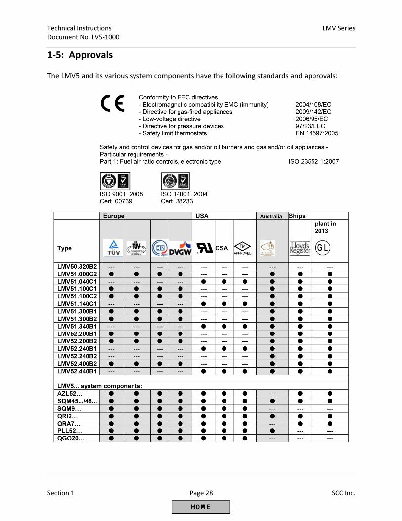
1-5: Approvals
The LMV5 and its various system components have the following standards and approvals:
Section 1 Overview
Section 2 Wiring
Section 3 Parameters
Section 4 Commissioning
Section 5 VSD
Section 6 O2 Trim
Section 7 Troubleshooting
Section 8 Modbus
Section 9 ACS450
Section 10 Revision History
Appendix A Application Guide
Appendix B* Complimentary Products Guide
*Can be found at www.scccombustion.com.
LMV Series Technical Instructions
Document No. LV5-1000
SCC Inc. Page 1 Section 2
2-1: Wiring Introduction
The LMV5 is a very flexible burner control. As such, there are many different ways to wire it. The
specific application will dictate the wiring required. This section details the most common applications.
The parameter settings outlined in Section 3 can enable, disable or change the functionality of many
terminals on the LMV5. Thus, wiring and parameter settings work together to make the LMV5 an
extremely versatile BMS.
This section includes terminal descriptions (Section 2-2) and extensive wiring diagrams (Section 2-3) that
detail the many applications of the LMV5.
Terminals
The connection terminals of the LMV5 are RAST 5 and RAST 2.5 connectors (plugs). Line voltage plugs
are keyed so that they will only fit into one socket of the LMV5, eliminating the possibility of inserting a
plug into an incorrect socket.
Each plug is designed to connect one external device or a small group of external devices, such as gas
valves, to the LMV5. Each group of plugs on the front of the LMV5 provides line voltage and grounds so
that an additional terminal strip is not necessary.
Note: All protective earth grounds (PE), neutrals (N) and lines (L) are common inside the LMV5.
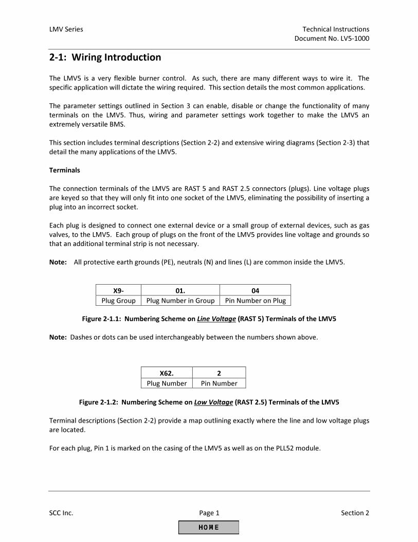
X9- 01. 04
Plug Group Plug Number in Group Pin Number on Plug
Figure 2-1.1: Numbering Scheme on Line Voltage (RAST 5) Terminals of the LMV5
Note: Dashes or dots can be used interchangeably between the numbers shown above.
X62. 2
Plug Number Pin Number
Figure 2-1.2: Numbering Scheme on Low Voltage (RAST 2.5) Terminals of the LMV5
Terminal descriptions (Section 2-2) provide a map outlining exactly where the line and low voltage plugs
are located.
For each plug, Pin 1 is marked on the casing of the LMV5 as well as on the PLL52 module.
Technical Instructions LMV Series
Document No. LV5-1000
Section 2 Page 2 SCC Inc.
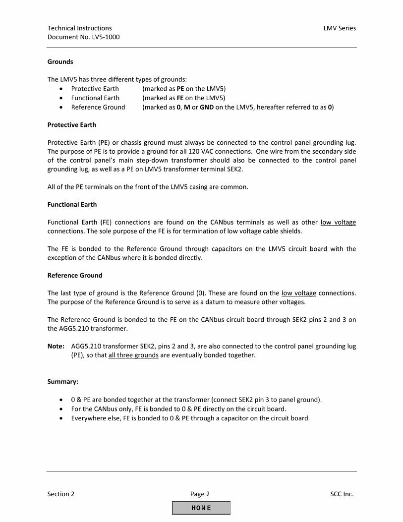
Grounds
The LMV5 has three different types of grounds:
• Protective Earth (marked as PE on the LMV5)
• Functional Earth (marked as FE on the LMV5)
• Reference Ground (marked as 0, M or GND on the LMV5, hereafter referred to as 0)
Protective Earth
Protective Earth (PE) or chassis ground must always be connected to the control panel grounding lug.
The purpose of PE is to provide a ground for all 120 VAC connections. One wire from the secondary side
of the control panel’s main step-down transformer should also be connected to the control panel
grounding lug, as well as a PE on LMV5 transformer terminal SEK2.
All of the PE terminals on the front of the LMV5 casing are common.
Functional Earth
Functional Earth (FE) connections are found on the CANbus terminals as well as other low voltage
connections. The sole purpose of the FE is for termination of low voltage cable shields.
The FE is bonded to the Reference Ground through capacitors on the LMV5 circuit board with the
exception of the CANbus where it is bonded directly.
Reference Ground
The last type of ground is the Reference Ground (0). These are found on the low voltage connections.
The purpose of the Reference Ground is to serve as a datum to measure other voltages.
The Reference Ground is bonded to the FE on the CANbus circuit board through SEK2 pins 2 and 3 on
the AGG5.210 transformer.
Note: AGG5.210 transformer SEK2, pins 2 and 3, are also connected to the control panel grounding lug
(PE), so that all three grounds are eventually bonded together.
Summary:
• 0 & PE are bonded together at the transformer (connect SEK2 pin 3 to panel ground).
• For the CANbus only, FE is bonded to 0 & PE directly on the circuit board.
• Everywhere else, FE is bonded to 0 & PE through a capacitor on the circuit board.
LMV Series Technical Instructions
Document No. LV5-1000
SCC Inc. Page 3 Section 2
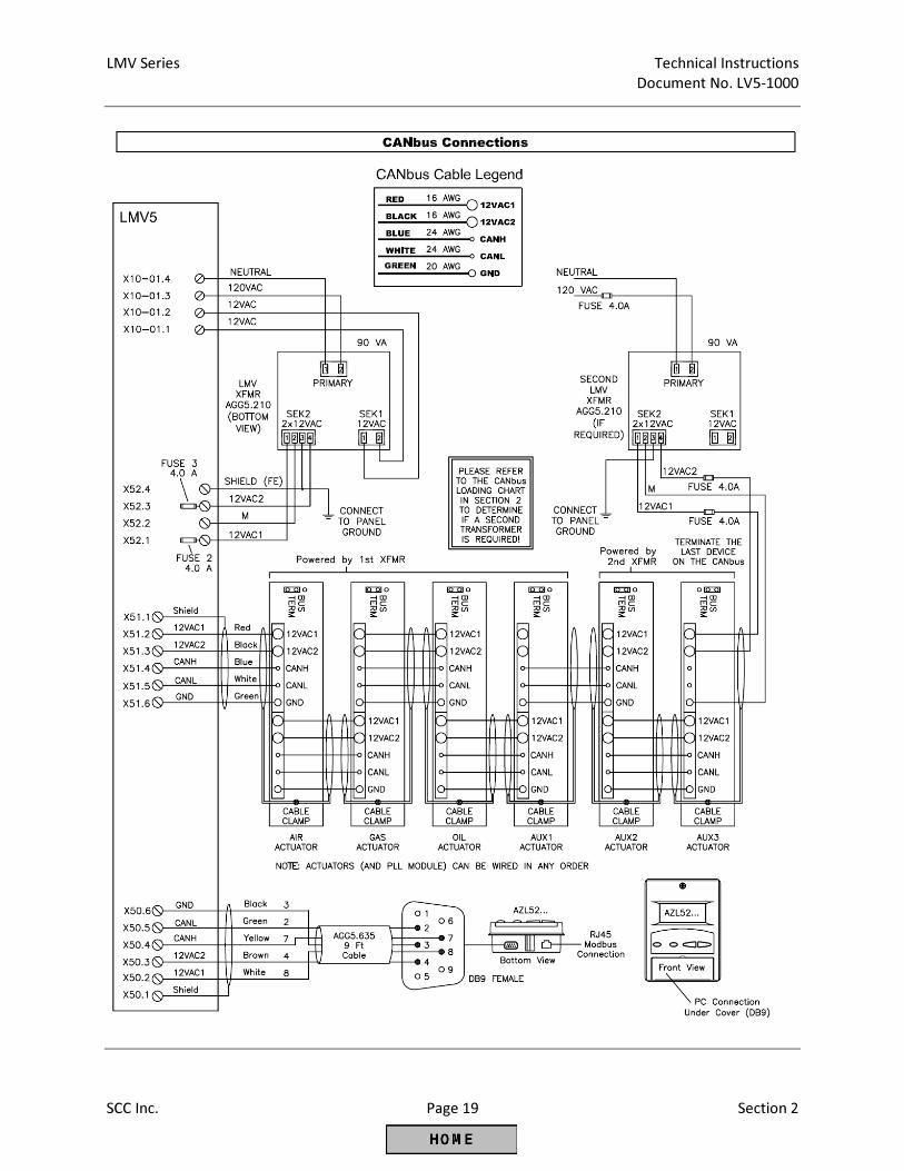
CANbus
The CANbus is a data bus similar to a computer network. The CANbus is used to connect the actuators,
AZL5, and PLL52 module to the LMV5 base unit. Special shielded cable is used to connect all devices on
the CANbus to the LMV5 base unit. This cable carries five wires and a braided shield that is located
underneath the plastic cable sheathing.
The two heavier gauge wires (16 AWG) are used for power transmission to the connected devices. These
power wires are labeled 12VAC1 and 12VAC2, and carry 12 VAC each. These wires are powered by SEK2
Pin 1 and Pin 4 of the AGG5.210 transformer’s 4-pin plug, and are fused by FU2 and FU3. These fuses
are located under black covers on the right hand side of the LMV5. If measured, 12VAC1 and 12VAC2
should have a potential of approximately 12 VAC to reference ground and 24 VAC between 12VAC1 and
12VAC2.
The two lighter gauge (24 AWG) wires are a shielded, twisted pair to help reduce noise on the line. They
carry the digital CANbus data signals and are labeled CANL and CANH. The signal on these wires consists
of 5 VDC pulses.
Note: These data wires should never contact the 12VAC wires when the system is powered. LMV5
damage may result.
The termination jumper located on each actuator and PLL52 module is used to terminate CANH and
CANL and should be moved to the bus termination position on the last CANbus device.
The last wire in the cable is the reference ground and is marked GND. This is also connected to each
device on the CANbus so that the LMV5 can monitor for voltage drops that might affect actuator
operation.
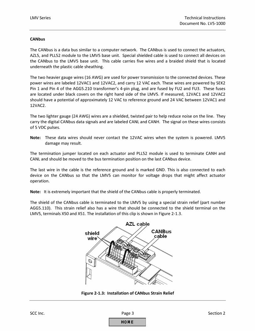
Note: It is extremely important that the shield of the CANbus cable is properly terminated.
The shield of the CANbus cable is terminated to the LMV5 by using a special strain relief (part number
AGG5.110). This strain relief also has a wire that should be connected to the shield terminal on the
LMV5, terminals X50 and X51. The installation of this clip is shown in Figure 2-1.3.
Figure 2-1.3: Installation of CANbus Strain Relief
Technical Instructions LMV Series
Document No. LV5-1000
Section 2 Page 4 SCC Inc.
CANbus (continued)
The shield of the CANbus cable must be connected on each cable segment (between the LMV5 and the
actuators or PLL52 module) so that the entire shield has continuity with terminal X51.1 which is the
shield connection on the LMV5. This is achieved by clamping the shield on both cable segments with the
metal clamps provided on the cable entry of each actuator. Clamps for the CANbus shield are also
provided on the PLL52 module.
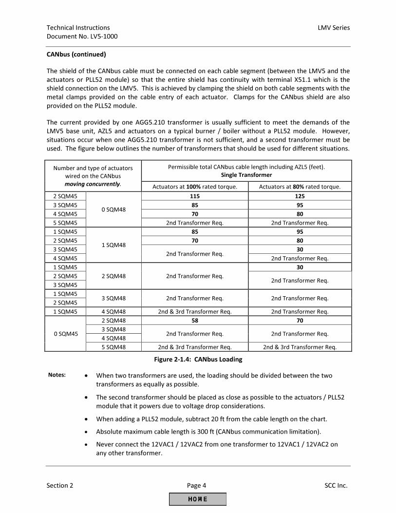
The current provided by one AGG5.210 transformer is usually sufficient to meet the demands of the
LMV5 base unit, AZL5 and actuators on a typical burner / boiler without a PLL52 module. However,
situations occur when one AGG5.210 transformer is not sufficient, and a second transformer must be
used. The figure below outlines the number of transformers that should be used for different situations.
Number and type of actuators
wired on the CANbus
moving concurrently.
Permissible total CANbus cable length including AZL5 (feet).
Single Transformer
Actuators at 100% rated torque. Actuators at 80% rated torque.
2 SQM45
0 SQM48
115 125
3 SQM45 85 95
4 SQM45 70 80
5 SQM45 2nd Transformer Req. 2nd Transformer Req.
1 SQM45
1 SQM48
85 95
2 SQM45 70 80
3 SQM45 2nd Transformer Req.
30
4 SQM45 2nd Transformer Req.
1 SQM45
2 SQM48 2nd Transformer Req.
30
2 SQM45 2nd Transformer Req.
3 SQM45
1 SQM45 3 SQM48 2nd Transformer Req. 2nd Transformer Req.
2 SQM45
1 SQM45 4 SQM48 2nd & 3rd Transformer Req. 2nd Transformer Req.
0 SQM45
2 SQM48 58 70
3 SQM48 2nd Transformer Req. 2nd Transformer Req.
4 SQM48
5 SQM48 2nd & 3rd Transformer Req. 2nd & 3rd Transformer Req.
Figure 2-1.4: CANbus Loading
Notes: • When two transformers are used, the loading should be divided between the two
transformers as equally as possible.
• The second transformer should be placed as close as possible to the actuators / PLL52
module that it powers due to voltage drop considerations.
• When adding a PLL52 module, subtract 20 ft from the cable length on the chart.
• Absolute maximum cable length is 300 ft (CANbus communication limitation).
• Never connect the 12VAC1 / 12VAC2 from one transformer to 12VAC1 / 12VAC2 on
any other transformer.
LMV Series Technical Instructions
Document No. LV5-1000
SCC Inc. Page 5 Section 2
Load Controller
The LMV51.1 and all LMV52 are equipped with a load controller. The load controller is very flexible and
can read multiple sensors simultaneously. Typically, either a temperature sensor or pressure sensor is
connected for burner modulation. Both a pressure and a temperature sensor can be used in
conjunction for certain applications such as cold start (thermal shock protection).
The load controller has six different operational modes that can be changed by opening or closing a
connection on X62. These six different modes of operation are outlined in Section 4. By using a dry
contact, or switch, between terminals X62.1 and X62.2, the mode and / or setpoint of the internal load
controller can be changed.
If the load controller is in “IntLC” (internal load controller), setpoint W1 will be used if X62.1 / X62.2 is
open and setpoint W2 will be used if X62.1 / X62.2 is closed. If the load controller is in any other mode
and X62.1 / X62.2 is closed, the LMV5 will revert back to “IntLC” and will use setpoint W1. See Section 4
for more information about load controller modes.
This feature is commonly used when switching the LMV5 from “ExtLC X62” (remote modulation via a 4-
20mA source wired into terminals X62.3 and X62.4) back to “IntLC” (local, using LMV5 load controller for
modulation of the burner).
The load controller also provides power for 4-20 mA or 0-10 VDC sensors, or 4-20 mA or 0-10 VDC
externally powered sensors. The wiring of these sensors is covered in Section 2-3.
Floating / Bumping and Multistage Oil
Terminals X5-03.2 and X5-03.3 can be used for floating / bumping control or multistage oil control, also
called 3-position control. This option can be done on all models of LMV5, and is required on the
LMV51.0 models.
Through the use of floating / bumping, the LMV5 can be driven to a higher firing rate by placing line
voltage on terminal X5-03.2 and to a lower firing rate by removing line voltage from X5-03.2 and placing
line voltage on X5-03.3. No voltage on X5-03.2 or X5-03.3 keeps the current firing rate. By alternating
voltage on these terminals, the firing rate of the LMV5 can be increased, decreased, or kept the same.
The floating / bumping type of modulation is typically done with an RWF40/50/55.
A relay can be placed in the line connected to X5-03.2 if a low fire hold is desired.
If externally controlled multistage oil is selected, terminal X5-03.1 is energized for stage 1. Terminal X5-
03.2 can be energized to put the burner in stage 2, and terminal X5-03.3 can be energized to put the
burner in stage 3. De-energizing these terminals takes the burner out of stage 2 or 3.
Technical Instructions LMV Series
Document No. LV5-1000
Section 2 Page 6 SCC Inc.
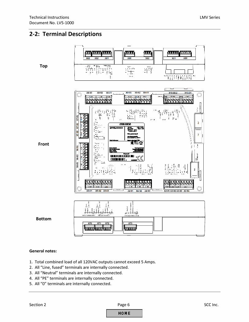
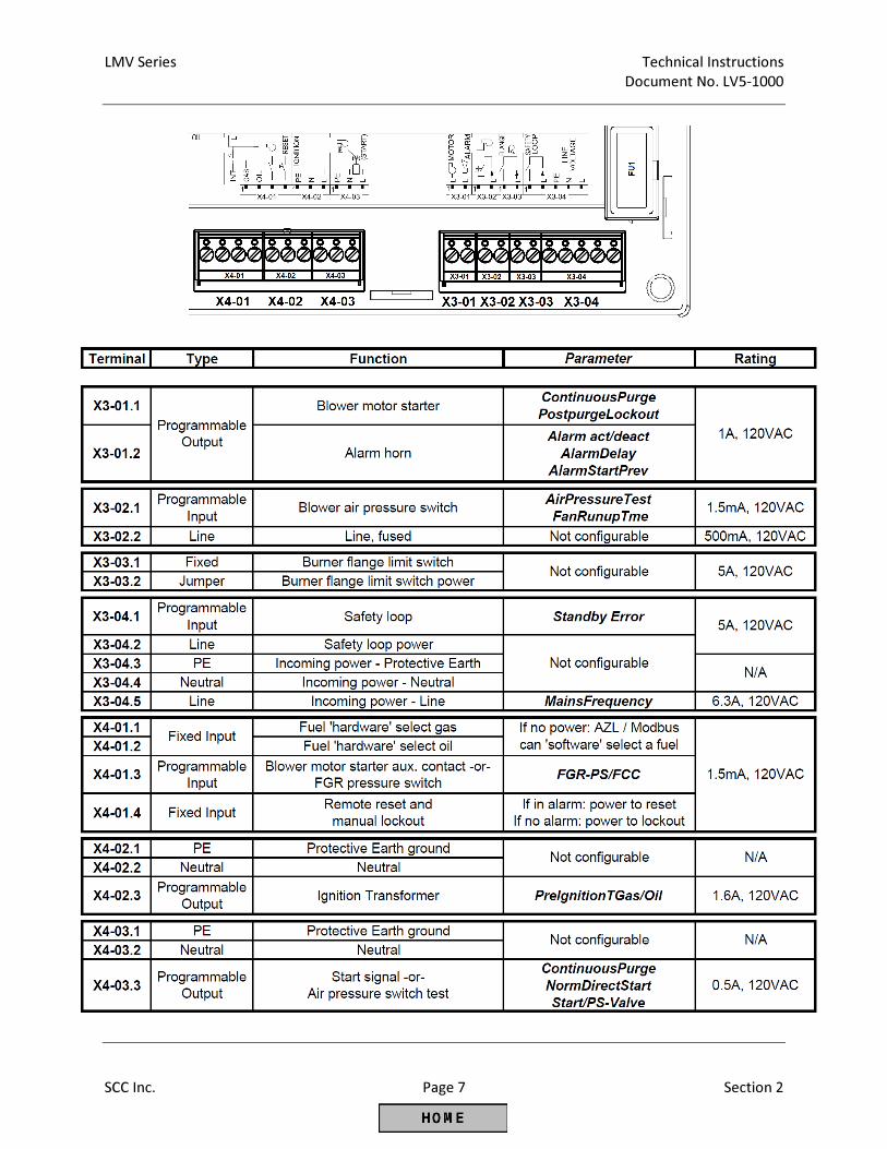
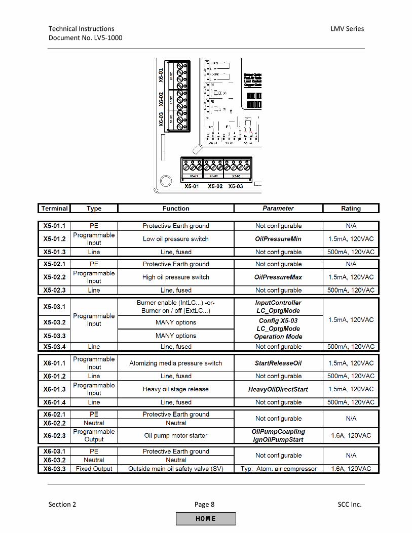
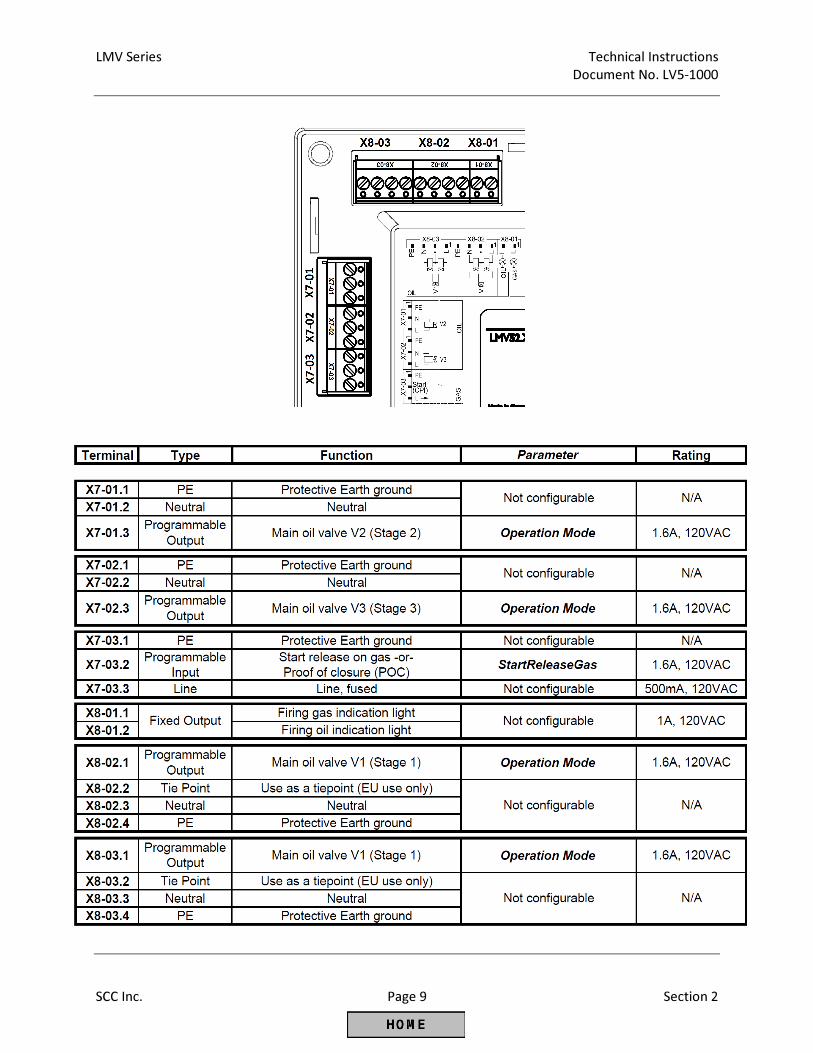
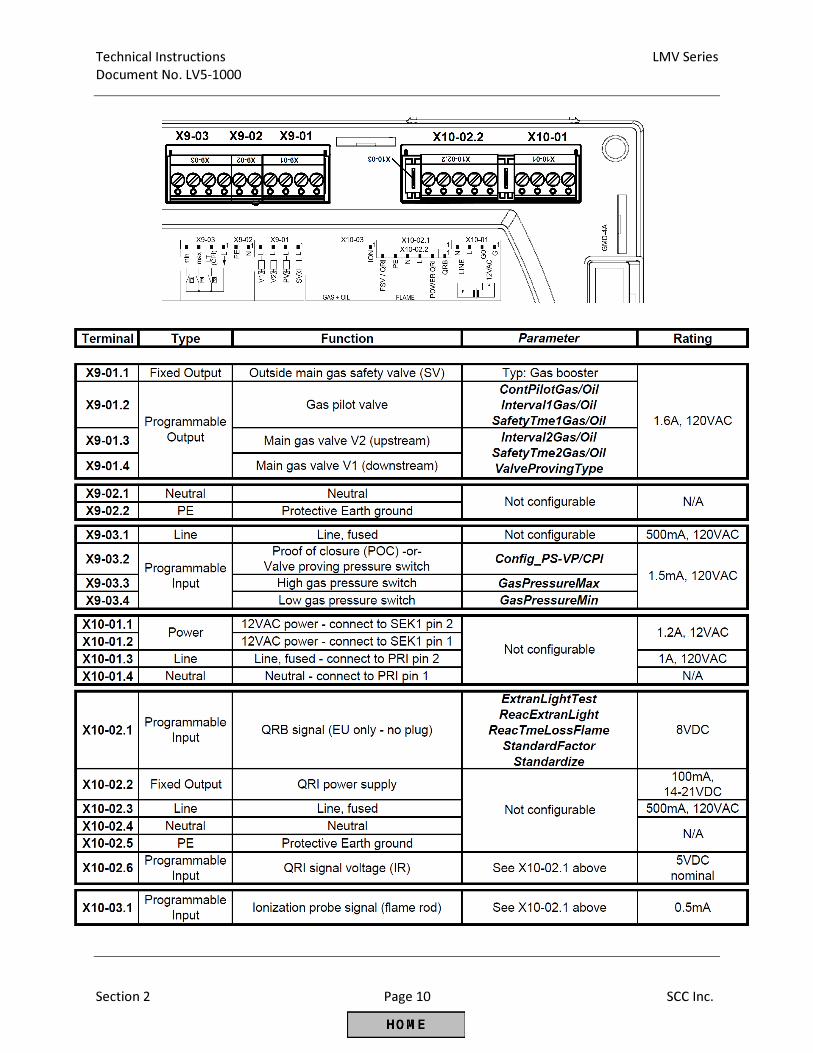
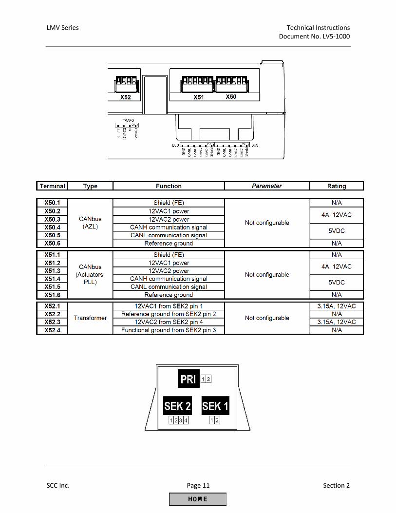
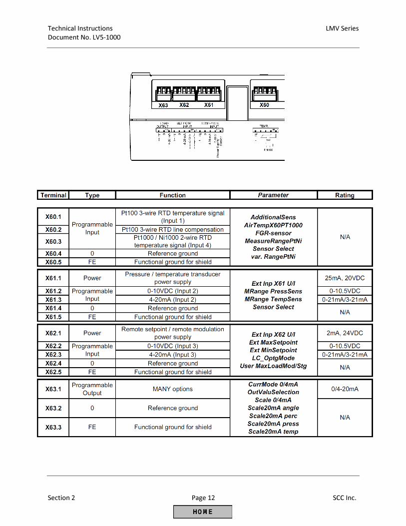
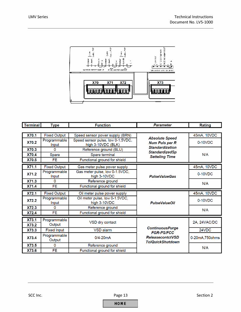
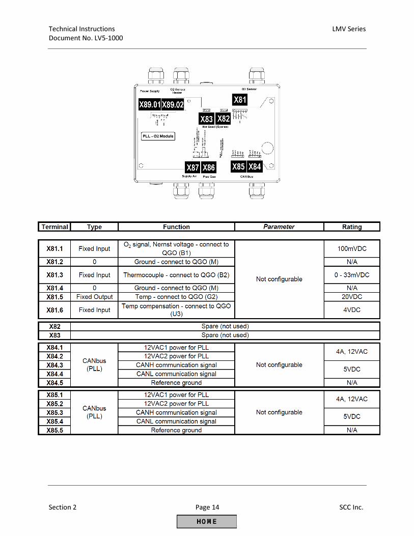
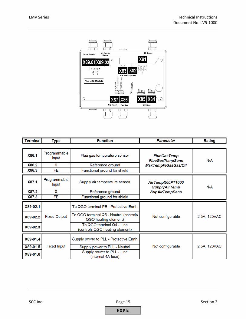
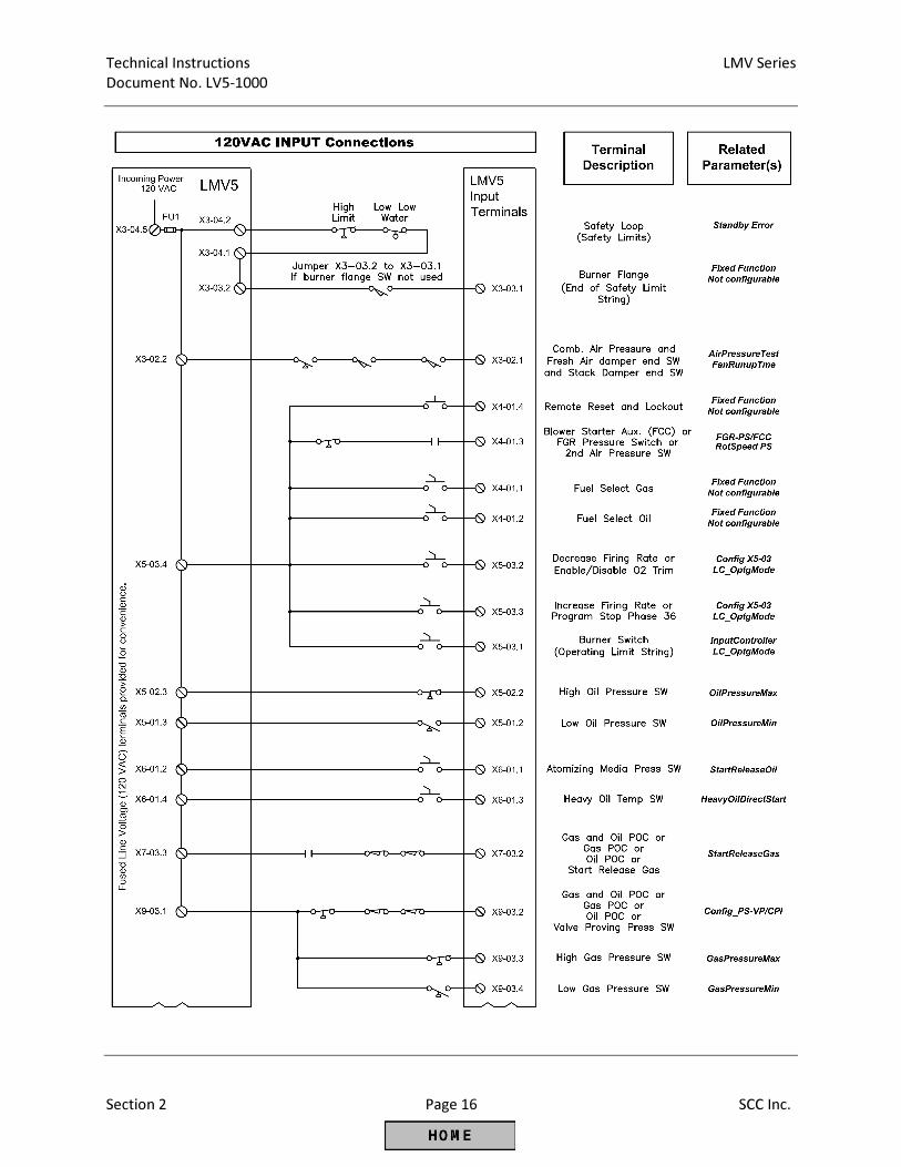
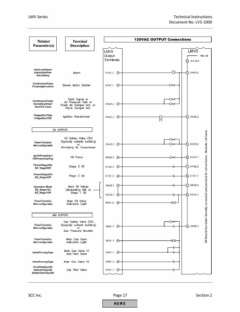
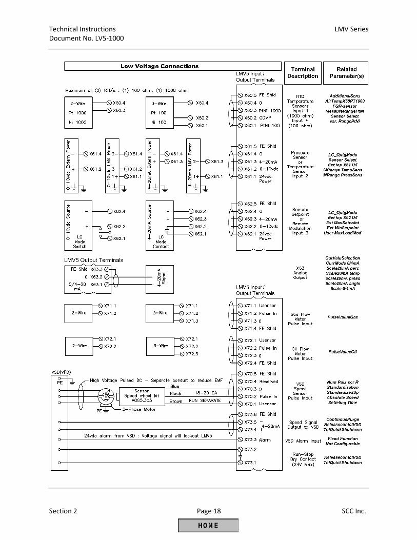
2-2: Terminal Descriptions
Top
Front
Bottom
General notes:
1. Total combined load of all 120VAC outputs cannot exceed 5 Amps.
2. All “Line, fused” terminals are internally connected.
3. All “Neutral” terminals are internally connected.
4. All “PE” terminals are internally connected.
5. All “0” terminals are internally connected.
LMV Series Technical Instructions
Document No. LV5-1000
SCC Inc. Page 7 Section 2
Technical Instructions LMV Series
Document No. LV5-1000
Section 2 Page 8 SCC Inc.
LMV Series Technical Instructions
Document No. LV5-1000
SCC Inc. Page 9 Section 2
Technical Instructions LMV Series
Document No. LV5-1000
Section 2 Page 10 SCC Inc.
LMV Series Technical Instructions
Document No. LV5-1000
SCC Inc. Page 11 Section 2
Technical Instructions LMV Series
Document No. LV5-1000
Section 2 Page 12 SCC Inc.
LMV Series Technical Instructions
Document No. LV5-1000
SCC Inc. Page 13 Section 2
Technical Instructions LMV Series
Document No. LV5-1000
Section 2 Page 14 SCC Inc.
LMV Series Technical Instructions
Document No. LV5-1000
SCC Inc. Page 15 Section 2
Technical Instructions LMV Series
Document No. LV5-1000
Section 2 Page 16 SCC Inc.
LMV Series Technical Instructions
Document No. LV5-1000
SCC Inc. Page 17 Section 2
Technical Instructions LMV Series
Document No. LV5-1000
Section 2 Page 18 SCC Inc.
LMV Series Technical Instructions
Document No. LV5-1000
SCC Inc. Page 19 Section 2
Technical Instructions LMV Series
Document No. LV5-1000
Section 2 Page 20 SCC Inc.
LMV Series Technical Instructions
Document No. LV5-1000
SCC Inc. Page 21 Section 2

Technical Instructions LMV Series
Document No. LV5-1000
Section 2 Page 22 SCC Inc.
Intentionally Left Blank

Section 1 Overview
Section 2 Wiring
Section 3 Parameters
Section 4 Commissioning
Section 5 VSD
Section 6 O2 Trim
Section 7 Troubleshooting
Section 8 Modbus
Section 9 ACS450
Section 10 Revision History
Appendix A Application Guide
Appendix B* Complimentary Products Guide
*Can be found at www.scccombustion.com.
LMV Series Technical Instructions Document No. LV5‐1000
SCC Inc. Page 1 Section 3
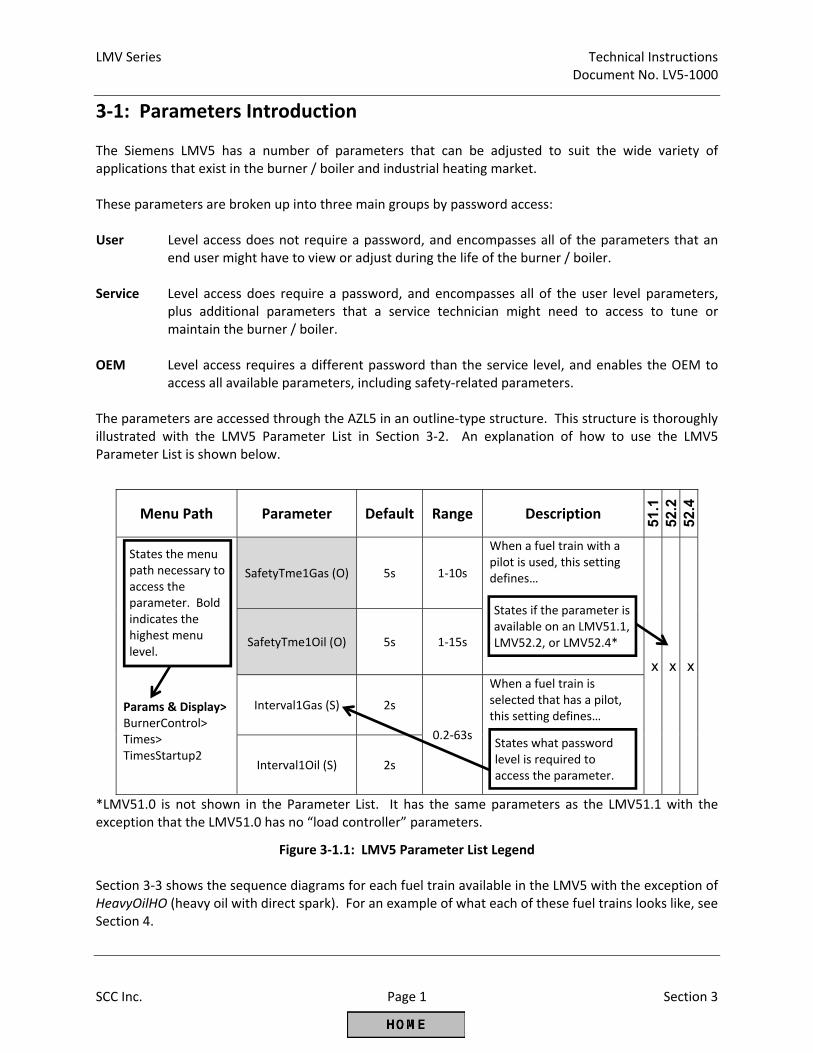
3‐1: Parameters Introduction The Siemens LMV5 has a number of parameters that can be adjusted to suit the wide variety of applications that exist in the burner / boiler and industrial heating market. These parameters are broken up into three main groups by password access: User Level access does not require a password, and encompasses all of the parameters that an
end user might have to view or adjust during the life of the burner / boiler. Service Level access does require a password, and encompasses all of the user level parameters,
plus additional parameters that a service technician might need to access to tune or maintain the burner / boiler.
OEM Level access requires a different password than the service level, and enables the OEM to
access all available parameters, including safety‐related parameters. The parameters are accessed through the AZL5 in an outline‐type structure. This structure is thoroughly illustrated with the LMV5 Parameter List in Section 3‐2. An explanation of how to use the LMV5 Parameter List is shown below.
*LMV51.0 is not shown in the Parameter List. It has the same parameters as the LMV51.1 with the exception that the LMV51.0 has no “load controller” parameters.
Figure 3‐1.1: LMV5 Parameter List Legend Section 3‐3 shows the sequence diagrams for each fuel train available in the LMV5 with the exception of HeavyOilHO (heavy oil with direct spark). For an example of what each of these fuel trains looks like, see Section 4.
Menu Path Parameter Default Range Description
51.1
52
.2
52.4
Params & Display> BurnerControl> Times> TimesStartup2
SafetyTme1Gas (O) 5s 1‐10s
When a fuel train with a pilot is used, this setting defines…
x x x
SafetyTme1Oil (O) 5s 1‐15s
Interval1Gas (S) 2s
0.2‐63s
When a fuel train is selected that has a pilot, this setting defines…
Interval1Oil (S) 2s
States what password level is required to access the parameter.
States the menu path necessary to access the parameter. Bold indicates the highest menu level.
States if the parameter is available on an LMV51.1, LMV52.2, or LMV52.4*
LMV Series Technical Instructions
LV5-1000
SCC Inc. Page 2 Section 3
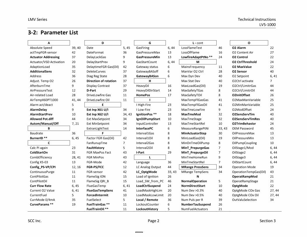
3-2: Parameter List
A
D
G
L - cont
O
Absolute Speed 39, 40 Date 5, 45 GasFiring 6, 44 LossFlameTest 46 O2 Alarm 22
actTmpFGR-sensor 42 DateFormat 36 GasPressureMax 13 LossOfFlame 16 O2 Content Air 27
Actuator Addressing 37 DelayLackGas 9 GasPressureMin 13 LowfireAdaptPtNo ** 24 O2 Control 22
Actuator/VSD Activation 20 DelayStartPrev 9 GasStartCount 6, 44 M
O2 CtrlThreshold 24
AdaptionLoad 35 DelaytimeFGR Gas(Oil) 42 Gateway status 6 MainsFrequency 11 O2 MaxValue 22
AdditionalSens 32 DeleteCurves 37 GatewayBASoff 6 ManVar O2 Ctrl 28 O2 Sensor 40
Address 36 Diag Reg State 28 GatewayBASon 6 Max Dyn Dev 40 O2 Setpoint 6, 41
Adjust. Temp O2 26 Direction of rotation 37 H
Max Stat Dev 40 O2Ctrl activate 7
AfterburnTme 9 Display Contrast 37 HeavyOil 16 MaxLoadGas(Oil) 19 O2Ctrl/LimitrGas 44
AirPressureTest 12 D-Part 29 HeavyOilDirStart 14 MaxSafetyTGas 8 O2Ctrl/LimitrOil 44
Air-related Load 28 DriveLowfire Gas 11 HomePos 17 MaxSafetyTOil 8 O2InitOffset 26
AirTempX60PT1000 41, 44 DriveLowfire Oil 11 I
MaxTempFlGasGas 41 O2MaxManVariable 25
Alarm act/deact 5 E
I High-Fire 23 MaxTempFlGasOil 41 O2MinManVariable 25
AlarmDelay 9 Ext Inp X61 U/I 34 I Low-Fire 23 MaxTmeLowFire 9 O2ModOffset 24
AlarmStartPrev 10 Ext Inp X62 U/I 34, 43 IgnitionPos ** 18 MaxTmeMod 32 O2SensServTim 40
Allowed Pot.diff 44 Ext MaxSetpoint 34 IgnOilPumpStart 10 MaxTmeStage 32 O2SensServTimRes 40
Autom/Manual/Off 7, 21 Ext MinSetpoint 34 InputController 13 MaxTmeStartRel 10 O2TrimBehavior 24
B
ExtranLightTest 14 InterfacePC 6 MeasureRangePtNi 33, 43 OEM Password 45
Baudrate 36 F
Interval1Gas 8 MinActuatorStep 30 OilPressureMax 13
BurnerID ** 6, 45 Factor FGR Gas(Oil) 42 Interval1Oil 8 MinLoadGas(Oil) 19 OilPressureMin 13
C
FanRunupTme 7 Interval2Gas 8 MinOnTmeOilPump 8 OilPumpCoupling 10
Calc PI again 23 FaultHistory 5 Interval2Oil 8 MinT_PrepurgeGas 7 OilStage1/Mod 6, 44
ColdStartOn 31 FGR MaxPos Fact 43 I-Part 29 MinT_PrepurgeOil 7 OilStage2 6, 44
CombEfficiency 28, 41 FGR MinPos 43 L
MinTmeHomeRun 9 OilStage3 6, 44
Config X5-03 13 FGR-Mode 42 Language 36 MinTmeStartRel 7 OilStartCount 6, 44
Config_PS-VP/CPI 12, 16 FGR-PS/FCC 12 LC Analog Output 44 MRange PressSens 34 Operation Mode 19
ContinuousPurge 11 FGR-sensor 42 LC_OptgMode 33, 43 MRange TempSens 34 OperationTempGas(Oil) 43
ContPilotGas 11 FlameSig ION 15 Load of Ignition 26 N
OperatRampMod 21
ContPilotOil 11 FlameSig QRI_B 15 Load_SW_from_PC 46 NormalOperation 5 OperatRampStage 21
Curr Flow Rate 6, 45 FlueGasTemp 6, 41 LoadCtrlSuspend 24 NormDirectStart 10 OptgMode 22
Current O2 Value 6, 41 FlueGasTempSens 41 LoadMaskHighLim 20 Num Dev >0.3% 40 OptgMode COx Gas 27, 44
CurrentFuel 5 ForcedIntermit 10 LoadMaskLowLimit 20 Num Dev >0.5% 40 OptgMode COx Oil 27, 44
CurrMode 0/4mA 35 FuelSelect 5 Local / Remote 36 Num Puls per R 39 OutValuSelection 34
CurveParams ** 19 FuelTrainGas ** 11 LockoutCounter 6 NumberTauSuspend 26
FuelTrainOil ** 11 LockoutHistory 5 NumFuelActuators 21
LMV Series Technical Instructions
LV5-1000
SCC Inc. Page 3 Section 3
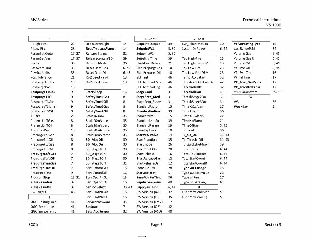
P
R
S - cont
S - cont
V
P High-Fire 23 ReacExtranLight 14 Setpoint Output 39 SW_FilterTmeCon 30 ValveProvingType 16
P Low-Fire 23 ReacTmeLossFlame 14 SetpointW1 5, 30 SystemOnPower 6, 44 var. RangePtNi 34
ParamSet Code 17, 37 Release Stages 32 SetpointW2 5, 30 T
Volume Gas 6, 45
ParamSet Vers 17, 37 ReleasecontctVSD 39 Setteling Time 39 Tau High-Fire 23 Volume Gas R 6, 45
Parity 36 Remote Mode 36 ShutdownBehav 21 Tau High-FireOEM 23 Volume Oil 6, 45
PasswordTime 36 Reset Date Gas 6, 45 Skip PrepurgeGas 10 Tau Low-Fire 23 Volume Oil R 6, 45
PhysicalUnits 36 Reset Date Oil 6, 45 Skip PrepurgeOil 10 Tau Low-Fire OEM 23 VP_EvacTme 16
Pos. Tolerance 21 RotSpeed PS off 13 SLT Test 46 Temp. ColdStart 32 VP_FillTme 17
PostpurgeLockout 10 RotSpeed PS on 13 SLT-Testload Mod 46 ThresholdFGR Gas(Oil) 42 VP_Tme_GasPress 17
PostpurgePos 18 S
SLT-Testload Stg 46 ThresholdOff 32 VP_TmeAtmPress 17
PostpurgeT1Gas 9 SafetyLoop 16 StageLoad 31 ThresholdOn 31 VSD Parameters 39, 40
PostpurgeT1Oil 9 SafetyTme1Gas 8 StageSetp_Mod 31 ThreshStage2On 31 W
PostpurgeT3Gas 9 SafetyTme1Oil 8 StageSetp_Stage 31 ThreshStage3On 31 W3 36
PostpurgeT3long 9 SafetyTme2Gas 8 StandardFactor 15 Time COx Alarm 27 Weekday 5
PostpurgeT3Oil 9 SafetyTme2Oil 8 Standardization 39 Time EU/US 36
P-Part 29 Scale 0/4mA 35 Standardize 15 Time O2 Alarm 22
PreIgnitionTGas 8 Scale20mA angle 35 StandardizedSp 39 TimeNoFlame 21
PreIgnitionTOil 8 Scale20mA perc 35 StandardParam 29 TimeOfDay 5, 45
PrepurgePos 18 Scale20mA press 35 Standby Error 10 Timeout 36
PrepurgePt1Gas 8 Scale20mA temp 35 Start/PS-Valve 14 TL_SD_On 31, 43
PrepurgePt1Oil 8 SD_ModOff 30 StartAdaption 35 TL_Thresh_Off 31, 43
PrepurgePt3Gas 8 SD_ModOn 30 Startmode 26 TolQuickShutdown 39
PrepurgePt3Oil 8 SD_Stage1Off 30 StartPoint Op 20 TotalHours 6, 44
PrepurgeSafeGas 7 SD_Stage1On 30 StartRelease 16 TotalHoursReset 6, 44
PrepurgeSafeOil 7 SD_Stage2Off 30 StartReleaseGas 12 TotalStartCount 6, 44
PrepurgeTmeGas 7 SD_Stage3Off 31 StartReleaseOil 12 TotalStartCountR 6, 44
PrepurgeTmeOil 7 SensExtranlGas 15 State O2 Ctrl 28 Type Air Change 25
PressReacTme 9 SensExtranlOil 16 Status/Reset 5 Type O2 MaxValue 22
ProgramStop 19, 21 SensOperPhGas 15 Sum/WinterTime 36 Type of Fuel 27
PulseValueGas 39 SensOperPhOil 16 SupAirTempSens 40 Type of Gateway 6
PulseValueOil 39 Sensor Select 33, 43 SupplyAirTemp 6, 41 U
PW Logout 46 SensPilotPhGas 15 SW Version (AZL) 37 User MaxLoadMod 5
Q
SensPilotPhOil 16 SW Version (LC) 35 User MaxLoadStg 5
QGO HeatingLoad 41 ServicePassword 45 SW Version (LMV) 17
QGO Resistance 41 SetLoad 7 SW Version (O2) 42
QGO SensorTemp 41 Setp AddSensor 32 SW Version (VSD) 40
LMV Series Technical Instructions
LV5-1000
SCC Inc. Page 4 Section 3
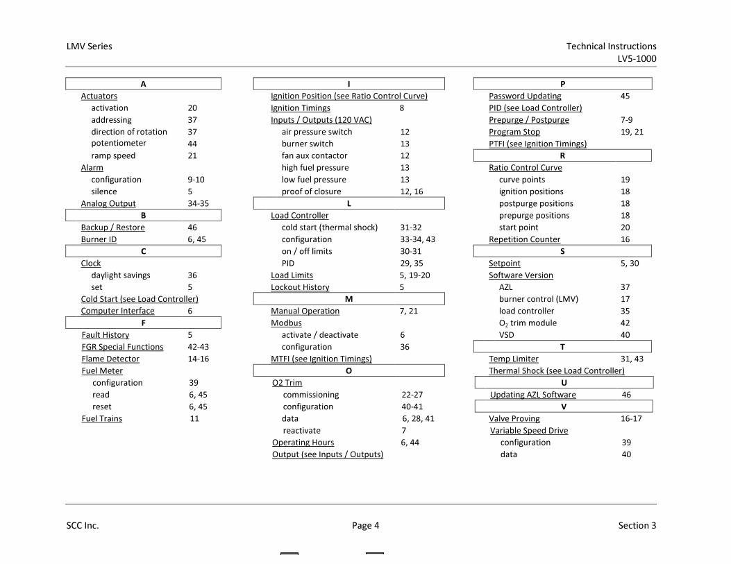
A I P
Actuators Ignition Position (see Ratio Control Curve) Password Updating 45
activation 20 Ignition Timings 8 PID (see Load Controller)
addressing 37 Inputs / Outputs (120 VAC) Prepurge / Postpurge 7-9
direction of rotation 37 air pressure switch 12 Program Stop 19, 21
potentiometer
tolerance
44 burner switch 13 PTFI (see Ignition Timings)
ramp speed 21 fan aux contactor 12 R
Alarm high fuel pressure 13 Ratio Control Curve
configuration 9-10 low fuel pressure 13 curve points 19
silence 5 proof of closure 12, 16 ignition positions 18
Analog Output 34-35 L postpurge positions 18
B Load Controller prepurge positions 18
Backup / Restore 46 cold start (thermal shock) 31-32 start point 20
Burner ID 6, 45 configuration 33-34, 43 Repetition Counter 16
C on / off limits 30-31 S
Clock PID 29, 35 Setpoint 5, 30
daylight savings 36 Load Limits 5, 19-20 Software Version
set 5 Lockout History 5 AZL 37
Cold Start (see Load Controller) M burner control (LMV) 17
Computer Interface
(ACS450)
6 Manual Operation 7, 21 load controller 35
F Modbus O2 trim module 42
Fault History 5 activate / deactivate 6 VSD 40
FGR Special Functions 42-43 configuration 36 T
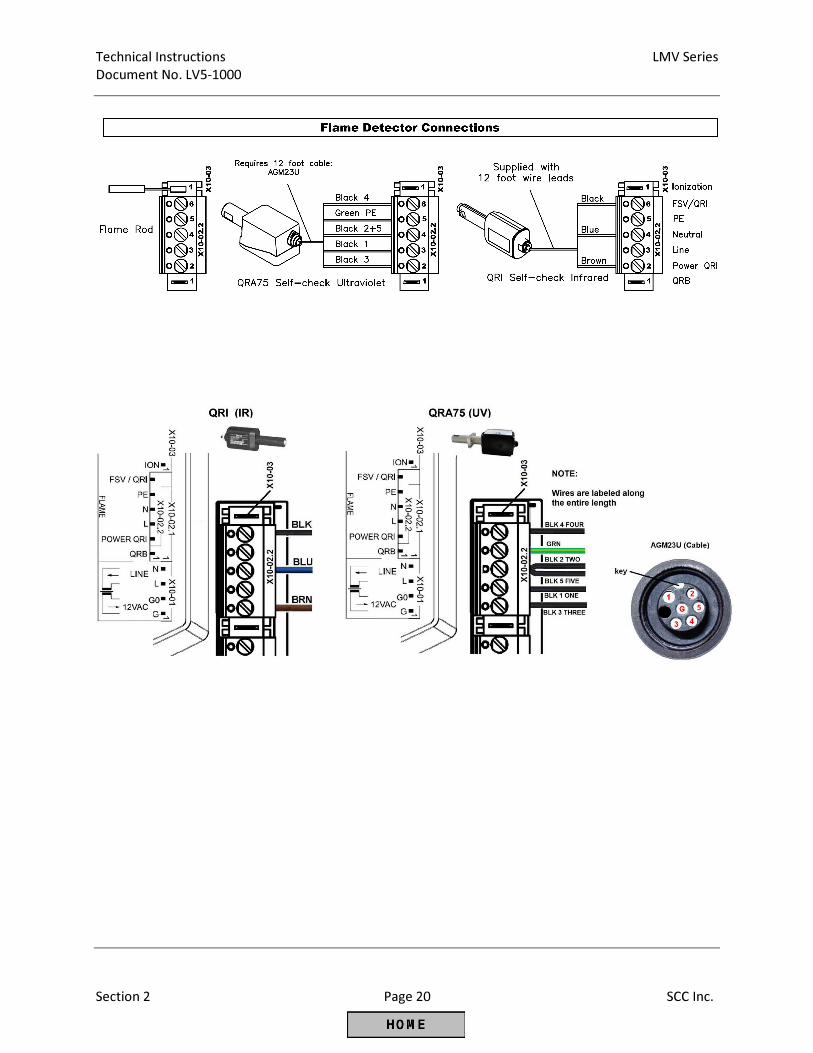
Flame Detector 14-16 MTFI (see Ignition Timings) Temp Limiter 31, 43
Fuel Meter O Thermal Shock (see Load Controller)
configuration 39 O2 Trim U
read 6, 45 commissioning 22-27 Updating AZL Software 46
reset 6, 45 configuration 40-41 V
Fuel Trains 11 data 6, 28, 41 Valve Proving 16-17
reactivate 7 Variable Speed Drive
Operating Hours 6, 44 configuration 39
Output (see Inputs / Outputs) data 40
LMV Series Technical Instructions
LV5-1000
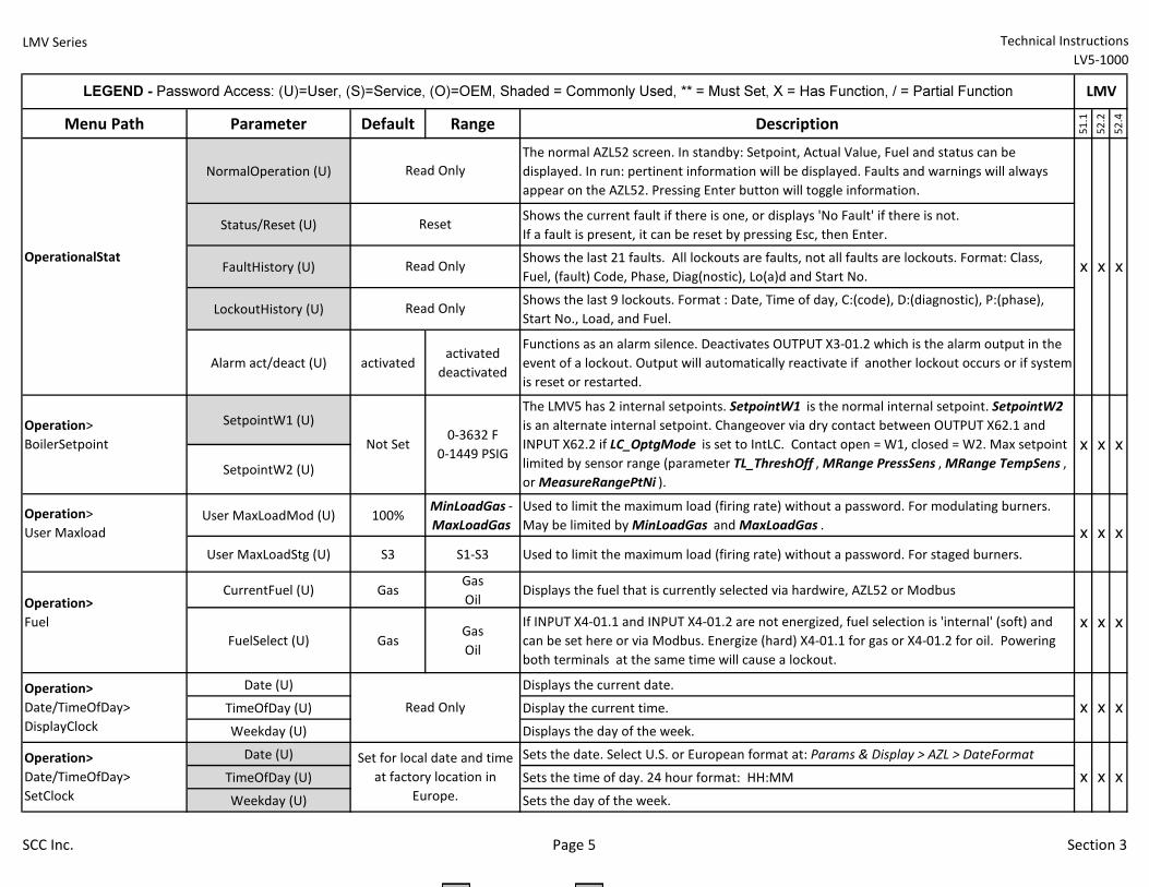
Menu Path Parameter Default Range Description
51.1
52.2
52.4
NormalOperation (U)
The normal AZL52 screen. In standby: Setpoint, Actual Value, Fuel and status can be
displayed. In run: pertinent information will be displayed. Faults and warnings will always
appear on the AZL52. Pressing Enter button will toggle information.
Status/Reset (U)Shows the current fault if there is one, or displays 'No Fault' if there is not.
If a fault is present, it can be reset by pressing Esc, then Enter.
FaultHistory (U)Shows the last 21 faults. All lockouts are faults, not all faults are lockouts. Format: Class,
Fuel, (fault) Code, Phase, Diag(nostic), Lo(a)d and Start No.
LockoutHistory (U)Shows the last 9 lockouts. Format : Date, Time of day, C:(code), D:(diagnostic), P:(phase),
Start No., Load, and Fuel.
Alarm act/deact (U) activatedactivated
deactivated
Functions as an alarm silence. Deactivates OUTPUT X3-01.2 which is the alarm output in the
event of a lockout. Output will automatically reactivate if another lockout occurs or if system
is reset or restarted.
SetpointW1 (U)
SetpointW2 (U)
User MaxLoadMod (U) 100%MinLoadGas -
MaxLoadGas
Used to limit the maximum load (firing rate) without a password. For modulating burners.
May be limited by MinLoadGas and MaxLoadGas .
User MaxLoadStg (U) S3 S1-S3 Used to limit the maximum load (firing rate) without a password. For staged burners.
CurrentFuel (U) GasGas
OilDisplays the fuel that is currently selected via hardwire, AZL52 or Modbus
FuelSelect (U) GasGas
Oil
If INPUT X4-01.1 and INPUT X4-01.2 are not energized, fuel selection is 'internal' (soft) and
can be set here or via Modbus. Energize (hard) X4-01.1 for gas or X4-01.2 for oil. Powering
both terminals at the same time will cause a lockout.
Date (U) Displays the current date.
TimeOfDay (U) Display the current time.
Weekday (U) Displays the day of the week.
Date (U) Sets the date. Select U.S. or European format at: Params & Display > AZL > DateFormat
TimeOfDay (U) Sets the time of day. 24 hour format: HH:MM
Weekday (U) Sets the day of the week.
Operation>
Date/TimeOfDay>
SetClock
Read Only
Read Only
Reset
LEGEND - Password Access: (U)=User, (S)=Service, (O)=OEM, Shaded = Commonly Used, ** = Must Set, X = Has Function, / = Partial Function LMV
OperationalStat
Operation>
BoilerSetpoint
The LMV5 has 2 internal setpoints. SetpointW1 is the normal internal setpoint. SetpointW2
is an alternate internal setpoint. Changeover via dry contact between OUTPUT X62.1 and
INPUT X62.2 if LC_OptgMode is set to IntLC. Contact open = W1, closed = W2. Max setpoint
limited by sensor range (parameter TL_ThreshOff , MRange PressSens , MRange TempSens ,
or MeasureRangePtNi ).
Operation>
User Maxload
Operation>
Fuel
Operation>
Date/TimeOfDay>
DisplayClock
x x x
Read Only
Not Set0-3632 F
0-1449 PSIG
xxx
x x x
x
Read Only
x
x
Set for local date and time
at factory location in
Europe.
x x
x x x
x
SCC Inc. Page 5 Section 3
LMV Series Technical Instructions
LV5-1000
Menu Path Parameter Default Range Description
51.1
52.2
52.4
LEGEND - Password Access: (U)=User, (S)=Service, (O)=OEM, Shaded = Commonly Used, ** = Must Set, X = Has Function, / = Partial Function LMV
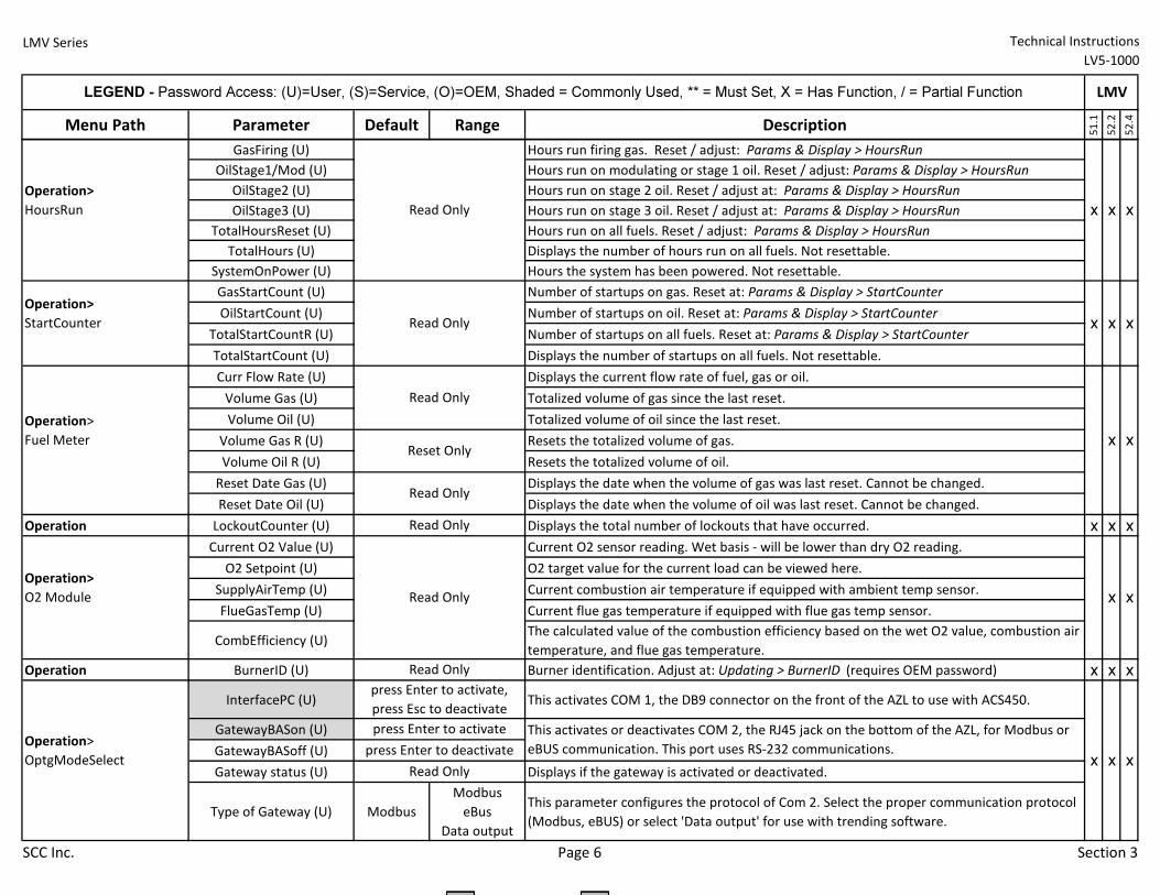
GasFiring (U) Hours run firing gas. Reset / adjust: Params & Display > HoursRun
OilStage1/Mod (U) Hours run on modulating or stage 1 oil. Reset / adjust: Params & Display > HoursRun
OilStage2 (U) Hours run on stage 2 oil. Reset / adjust at: Params & Display > HoursRun
OilStage3 (U) Hours run on stage 3 oil. Reset / adjust at: Params & Display > HoursRun
TotalHoursReset (U) Hours run on all fuels. Reset / adjust: Params & Display > HoursRun
TotalHours (U) Displays the number of hours run on all fuels. Not resettable.
SystemOnPower (U) Hours the system has been powered. Not resettable.
GasStartCount (U) Number of startups on gas. Reset at: Params & Display > StartCounter
OilStartCount (U) Number of startups on oil. Reset at: Params & Display > StartCounter
TotalStartCountR (U) Number of startups on all fuels. Reset at: Params & Display > StartCounter
TotalStartCount (U) Displays the number of startups on all fuels. Not resettable.
Curr Flow Rate (U) Displays the current flow rate of fuel, gas or oil.
Volume Gas (U) Totalized volume of gas since the last reset.
Volume Oil (U) Totalized volume of oil since the last reset.
Volume Gas R (U) Resets the totalized volume of gas.
Volume Oil R (U) Resets the totalized volume of oil.
Reset Date Gas (U) Displays the date when the volume of gas was last reset. Cannot be changed.
Reset Date Oil (U) Displays the date when the volume of oil was last reset. Cannot be changed.
Operation LockoutCounter (U) Displays the total number of lockouts that have occurred. x x x
Current O2 Value (U) Current O2 sensor reading. Wet basis - will be lower than dry O2 reading.
O2 Setpoint (U) O2 target value for the current load can be viewed here.
SupplyAirTemp (U) Current combustion air temperature if equipped with ambient temp sensor.
FlueGasTemp (U) Current flue gas temperature if equipped with flue gas temp sensor.
CombEfficiency (U)The calculated value of the combustion efficiency based on the wet O2 value, combustion air
temperature, and flue gas temperature.
Operation BurnerID (U) Burner identification. Adjust at: Updating > BurnerID (requires OEM password) x x x
InterfacePC (U) This activates COM 1, the DB9 connector on the front of the AZL to use with ACS450.
GatewayBASon (U)
GatewayBASoff (U)
Gateway status (U) Displays if the gateway is activated or deactivated.
Type of Gateway (U) Modbus
Modbus
eBus
Data output
This parameter configures the protocol of Com 2. Select the proper communication protocol
(Modbus, eBUS) or select 'Data output' for use with trending software.
Operation>
HoursRun
Operation>
StartCounter
Operation>
Fuel Meter
Operation>
O2 Module
Operation>
OptgModeSelect
Read Only x x x
Read Only x x x
Read Only
Reset Onlyx x
x x
press Enter to activate
Read Only
Read Only
Read Only
Read Only
Read Only
press Enter to activate,
press Esc to deactivate
This activates or deactivates COM 2, the RJ45 jack on the bottom of the AZL, for Modbus or
eBUS communication. This port uses RS-232 communications.press Enter to deactivatex x x
SCC Inc. Page 6 Section 3
LMV Series Technical Instructions
LV5-1000
Menu Path Parameter Default Range Description
51.1
52.2
52.4
LEGEND - Password Access: (U)=User, (S)=Service, (O)=OEM, Shaded = Commonly Used, ** = Must Set, X = Has Function, / = Partial Function LMV
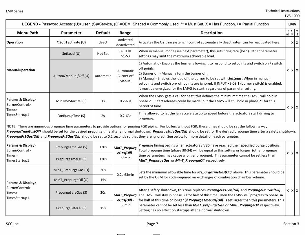
Operation O2Ctrl activate (U) deactactivated
deactivatedActivates the O2 trim system. If control automatically deactivates, can be reactivated here. x x
SetLoad (U) Not Set0-100%
S1-S3
When in manual mode (see next parameter), this sets firing rate (load). Other parameter
settings may limit the maximum achievable load.
Autom/Manual/Off (U) Automatic
Automatic
Burner off
Manual
1) Automatic - Enables the burner allowing it to respond to setpoints and switch on / switch
off points.
2) Burner off - Manually turn the burner off.
3) Manual - Enables the load of the burner to be set with SetLoad . When in manual,
setpoints and switch on/ off points are ignored. If INPUT X5-03.1 (burner switch) is enabled,
it must be energized for the LMV5 to start, regardless of parameter setting.
MinTmeStartRel (S) 1s 0.2-63s
When the LMV5 gets a call for heat, this defines the minimum time the LMV5 will hold in
phase 21. Start releases could be made, but the LMV5 will still hold in phase 21 for this
period of time.
FanRunupTme (S) 2s 0.2-63sTime allowed to let the fan accelerate up to speed before the actuators start driving to
prepurge.
PrepurgeTmeGas (S) 120s
PrepurgeTmeOil (S) 120s
MinT_PrepurgeGas (O) 20s
MinT_PrepurgeOil (O) 15s
PrepurgeSafeGas (S) 20s
PrepurgeSafeOil (S) 15s
Params & Display>
BurnerControl>
Times>
TimesStartup1
NOTE: There are numerous prepurge time parameters to provide options for purging FGR piping. For boilers without FGR, these times should be set the following way.
PrepurgeTmeGas(Oil) should be set for the desired prepurge time after a normal shutdown. PrepurgeSafeGas(Oil) should be set for the desired prepurge time after a safety shutdown.
PrepurgePt1Gas(Oil) and PrepurgePt3Gas(Oil) should be set to 0.2 seconds so that they are ignored. See below for more detail on each parameter.
x x x
ManualOperation
Prepurge timing begins when actuators / VSD have reached their specified purge positions.
Total prepurge time (phase 30-34) will be equal to this setting or longer (other prepurge
time parameters may cause a longer prepurge). This parameter cannot be set less than
MinT_PrepurgeGas or MinT_PrepurgeOil respectively.
Sets the minimum allowable time for PrepurgeTmeGas(Oil) above. This parameter should be
set by the OEM for code-required air exchanges of combustion chamber volume.
After a safety shutdown, this time replaces PrepurgePt1Gas(Oil) and PrepurgePt3Gas(Oil) .
The LMV5 will stay in phase 30 for half of this time. Then the LMV5 will progress to phase 34
for half of this time or longer (if PrepurgeTmeGas(Oil) is set larger than this parameter). This
parameter cannot be set less than MinT_PrepurgeGas or MinT_PrepurgeOil respectively.
Setting has no effect on startups after a normal shutdown.
0.2s-63min
MinT_Prepurg
eGas(Oil) -
63min
MinT_Prepurg
eGas(Oil) -
63min
Params & Display>
BurnerControl>
Times>
TimesStartup1
Params & Display>
BurnerControl>
Times>
TimesStartup1
x x x
x x x
x x x
SCC Inc. Page 7 Section 3
LMV Series Technical Instructions
LV5-1000
Menu Path Parameter Default Range Description
51.1
52.2
52.4
LEGEND - Password Access: (U)=User, (S)=Service, (O)=OEM, Shaded = Commonly Used, ** = Must Set, X = Has Function, / = Partial Function LMV
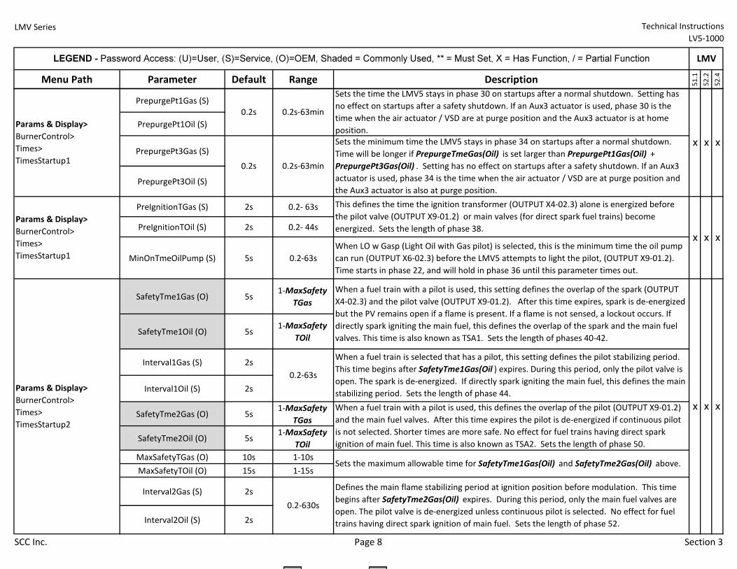
PrepurgePt1Gas (S)
PrepurgePt1Oil (S)
PrepurgePt3Gas (S)
PrepurgePt3Oil (S)
PreIgnitionTGas (S) 2s 0.2- 63s
PreIgnitionTOil (S) 2s 0.2- 44s
MinOnTmeOilPump (S) 5s 0.2-63s
When LO w Gasp (Light Oil with Gas pilot) is selected, this is the minimum time the oil pump
can run (OUTPUT X6-02.3) before the LMV5 attempts to light the pilot, (OUTPUT X9-01.2).
Time starts in phase 22, and will hold in phase 36 until this parameter times out.
SafetyTme1Gas (O) 5s1-MaxSafety
TGas
SafetyTme1Oil (O) 5s1-MaxSafety
TOil
Interval1Gas (S) 2s
Interval1Oil (S) 2s
SafetyTme2Gas (O) 5s1-MaxSafety
TGas
SafetyTme2Oil (O) 5s1-MaxSafety
TOil
MaxSafetyTGas (O) 10s 1-10s
MaxSafetyTOil (O) 15s 1-15s
Interval2Gas (S) 2s
Interval2Oil (S) 2s
x x
x x x
xSets the minimum time the LMV5 stays in phase 34 on startups after a normal shutdown.
Time will be longer if PrepurgeTmeGas(Oil) is set larger than PrepurgePt1Gas(Oil) +
PrepurgePt3Gas(Oil) . Setting has no effect on startups after a safety shutdown. If an Aux3
actuator is used, phase 34 is the time when the air actuator / VSD are at purge position and
the Aux3 actuator is also at purge position.
This defines the time the ignition transformer (OUTPUT X4-02.3) alone is energized before
the pilot valve (OUTPUT X9-01.2) or main valves (for direct spark fuel trains) become
energized. Sets the length of phase 38.
0.2s-63min
0.2s-63min
0.2s
0.2s
Params & Display>
BurnerControl>
Times>
TimesStartup1
Params & Display>
BurnerControl>
Times>
TimesStartup1
0.2-63s
0.2-630s
Params & Display>
BurnerControl>
Times>
TimesStartup2
Sets the maximum allowable time for SafetyTme1Gas(Oil) and SafetyTme2Gas(Oil) above.
xWhen a fuel train with a pilot is used, this defines the overlap of the pilot (OUTPUT X9-01.2)
and the main fuel valves. After this time expires the pilot is de-energized if continuous pilot
is not selected. Shorter times are more safe. No effect for fuel trains having direct spark
ignition of main fuel. This time is also known as TSA2. Sets the length of phase 50.
Defines the main flame stabilizing period at ignition position before modulation. This time
begins after SafetyTme2Gas(Oil) expires. During this period, only the main fuel valves are
open. The pilot valve is de-energized unless continuous pilot is selected. No effect for fuel
trains having direct spark ignition of main fuel. Sets the length of phase 52.
Sets the time the LMV5 stays in phase 30 on startups after a normal shutdown. Setting has
no effect on startups after a safety shutdown. If an Aux3 actuator is used, phase 30 is the
time when the air actuator / VSD are at purge position and the Aux3 actuator is at home
position.
When a fuel train with a pilot is used, this setting defines the overlap of the spark (OUTPUT
X4-02.3) and the pilot valve (OUTPUT X9-01.2). After this time expires, spark is de-energized
but the PV remains open if a flame is present. If a flame is not sensed, a lockout occurs. If
directly spark igniting the main fuel, this defines the overlap of the spark and the main fuel
valves. This time is also known as TSA1. Sets the length of phases 40-42.
When a fuel train is selected that has a pilot, this setting defines the pilot stabilizing period.
This time begins after SafetyTme1Gas(Oil ) expires. During this period, only the pilot valve is
open. The spark is de-energized. If directly spark igniting the main fuel, this defines the main
stabilizing period. Sets the length of phase 44.
x x
SCC Inc. Page 8 Section 3
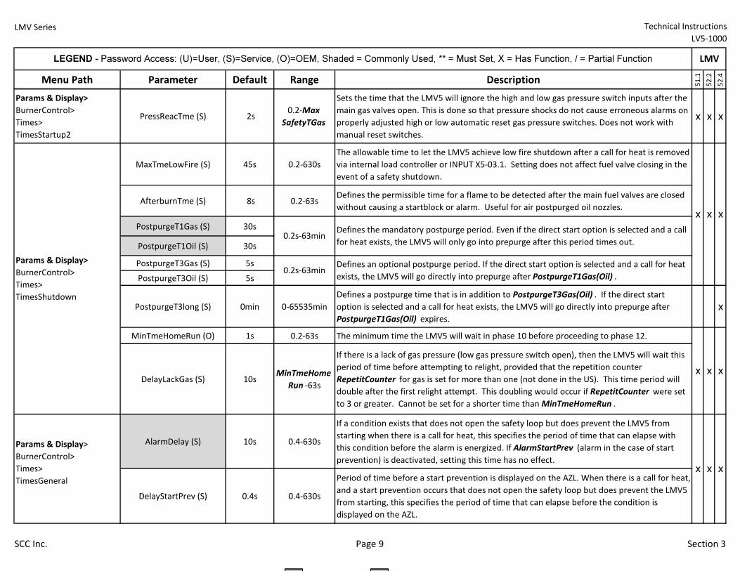
LMV Series Technical Instructions
LV5-1000
Menu Path Parameter Default Range Description
51.1
52.2
52.4
LEGEND - Password Access: (U)=User, (S)=Service, (O)=OEM, Shaded = Commonly Used, ** = Must Set, X = Has Function, / = Partial Function LMV
Params & Display>
BurnerControl>
Times>
TimesStartup2
PressReacTme (S) 2s 0.2-Max
SafetyTGas
Sets the time that the LMV5 will ignore the high and low gas pressure switch inputs after the
main gas valves open. This is done so that pressure shocks do not cause erroneous alarms on
properly adjusted high or low automatic reset gas pressure switches. Does not work with
manual reset switches.
x x x
MaxTmeLowFire (S) 45s 0.2-630s
The allowable time to let the LMV5 achieve low fire shutdown after a call for heat is removed
via internal load controller or INPUT X5-03.1. Setting does not affect fuel valve closing in the
event of a safety shutdown.
AfterburnTme (S) 8s 0.2-63sDefines the permissible time for a flame to be detected after the main fuel valves are closed
without causing a startblock or alarm. Useful for air postpurged oil nozzles.
PostpurgeT1Gas (S) 30s
PostpurgeT1Oil (S) 30s
PostpurgeT3Gas (S) 5s
PostpurgeT3Oil (S) 5s
PostpurgeT3long (S) 0min 0-65535min
Defines a postpurge time that is in addition to PostpurgeT3Gas(Oil) . If the direct start
option is selected and a call for heat exists, the LMV5 will go directly into prepurge after
PostpurgeT1Gas(Oil) expires.
x
MinTmeHomeRun (O) 1s 0.2-63s The minimum time the LMV5 will wait in phase 10 before proceeding to phase 12.
DelayLackGas (S) 10sMinTmeHome
Run -63s
If there is a lack of gas pressure (low gas pressure switch open), then the LMV5 will wait this
period of time before attempting to relight, provided that the repetition counter
RepetitCounter for gas is set for more than one (not done in the US). This time period will
double after the first relight attempt. This doubling would occur if RepetitCounter were set
to 3 or greater. Cannot be set for a shorter time than MinTmeHomeRun .
AlarmDelay (S) 10s 0.4-630s
If a condition exists that does not open the safety loop but does prevent the LMV5 from
starting when there is a call for heat, this specifies the period of time that can elapse with
this condition before the alarm is energized. If AlarmStartPrev (alarm in the case of start
prevention) is deactivated, setting this time has no effect.
DelayStartPrev (S) 0.4s 0.4-630s
Period of time before a start prevention is displayed on the AZL. When there is a call for heat,
and a start prevention occurs that does not open the safety loop but does prevent the LMV5
from starting, this specifies the period of time that can elapse before the condition is
displayed on the AZL.
Params & Display>
BurnerControl>
Times>
TimesGeneral
0.2s-63min
0.2s-63minParams & Display>
BurnerControl>
Times>
TimesShutdown
x xx
x x x
x x x
Defines the mandatory postpurge period. Even if the direct start option is selected and a call
for heat exists, the LMV5 will only go into prepurge after this period times out.
Defines an optional postpurge period. If the direct start option is selected and a call for heat
exists, the LMV5 will go directly into prepurge after PostpurgeT1Gas(Oil) .
SCC Inc. Page 9 Section 3
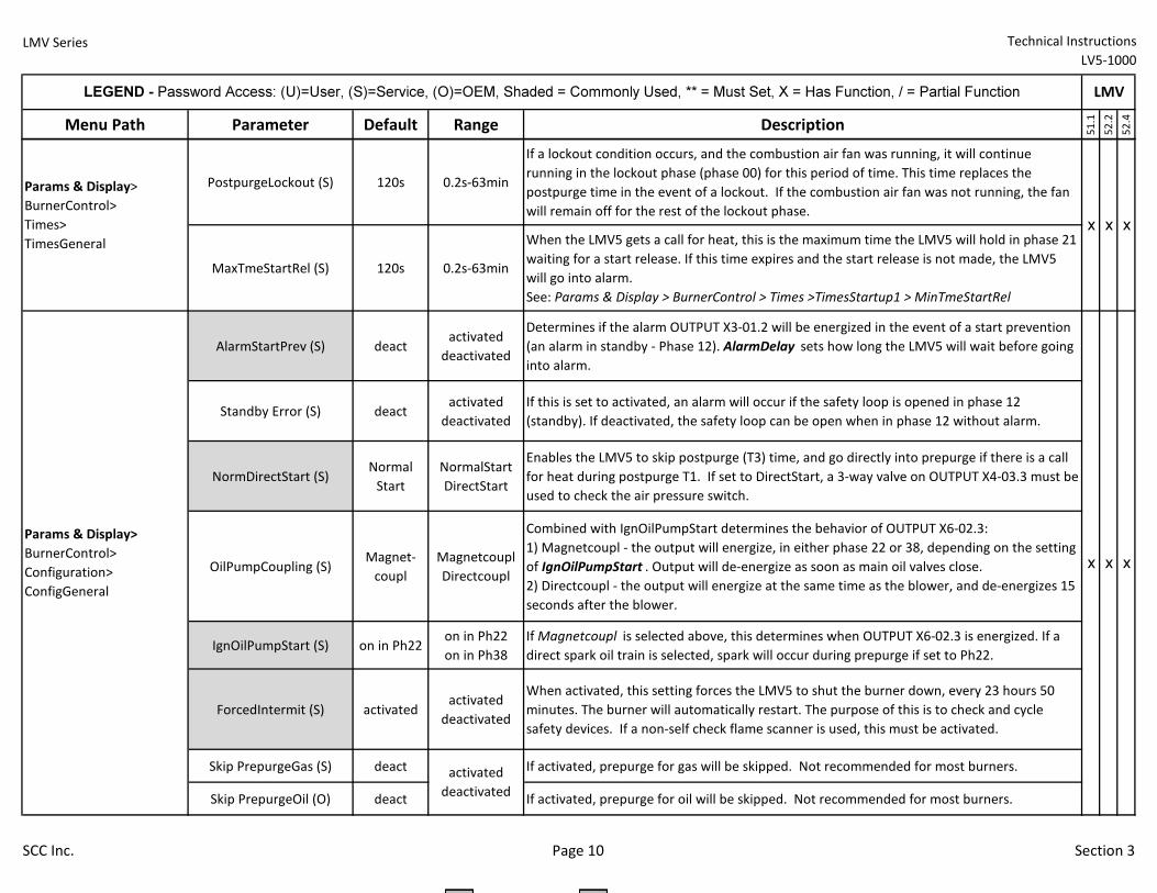
LMV Series Technical Instructions
LV5-1000
Menu Path Parameter Default Range Description
51.1
52.2
52.4
LEGEND - Password Access: (U)=User, (S)=Service, (O)=OEM, Shaded = Commonly Used, ** = Must Set, X = Has Function, / = Partial Function LMV
PostpurgeLockout (S) 120s 0.2s-63min
If a lockout condition occurs, and the combustion air fan was running, it will continue
running in the lockout phase (phase 00) for this period of time. This time replaces the
postpurge time in the event of a lockout. If the combustion air fan was not running, the fan
will remain off for the rest of the lockout phase.
MaxTmeStartRel (S) 120s 0.2s-63min
When the LMV5 gets a call for heat, this is the maximum time the LMV5 will hold in phase 21
waiting for a start release. If this time expires and the start release is not made, the LMV5
will go into alarm.
See: Params & Display > BurnerControl > Times >TimesStartup1 > MinTmeStartRel
AlarmStartPrev (S) deactactivated
deactivated
Determines if the alarm OUTPUT X3-01.2 will be energized in the event of a start prevention
(an alarm in standby - Phase 12). AlarmDelay sets how long the LMV5 will wait before going
into alarm.
Standby Error (S) deactactivated
deactivated
If this is set to activated, an alarm will occur if the safety loop is opened in phase 12
(standby). If deactivated, the safety loop can be open when in phase 12 without alarm.
NormDirectStart (S)Normal
Start
NormalStart
DirectStart
Enables the LMV5 to skip postpurge (T3) time, and go directly into prepurge if there is a call
for heat during postpurge T1. If set to DirectStart, a 3-way valve on OUTPUT X4-03.3 must be
used to check the air pressure switch.
OilPumpCoupling (S)Magnet-
coupl
Magnetcoupl
Directcoupl
Combined with IgnOilPumpStart determines the behavior of OUTPUT X6-02.3:
1) Magnetcoupl - the output will energize, in either phase 22 or 38, depending on the setting
of IgnOilPumpStart . Output will de-energize as soon as main oil valves close.
2) Directcoupl - the output will energize at the same time as the blower, and de-energizes 15
seconds after the blower.
IgnOilPumpStart (S) on in Ph22on in Ph22
on in Ph38
If Magnetcoupl is selected above, this determines when OUTPUT X6-02.3 is energized. If a
direct spark oil train is selected, spark will occur during prepurge if set to Ph22.
ForcedIntermit (S) activatedactivated
deactivated
When activated, this setting forces the LMV5 to shut the burner down, every 23 hours 50
minutes. The burner will automatically restart. The purpose of this is to check and cycle
safety devices. If a non-self check flame scanner is used, this must be activated.
Skip PrepurgeGas (S) deact If activated, prepurge for gas will be skipped. Not recommended for most burners.
Skip PrepurgeOil (O) deact If activated, prepurge for oil will be skipped. Not recommended for most burners.
Params & Display>
BurnerControl>
Times>
TimesGeneral
Params & Display>
BurnerControl>
Configuration>
ConfigGeneral
activated
deactivated
x
x x x
x x
SCC Inc. Page 10 Section 3
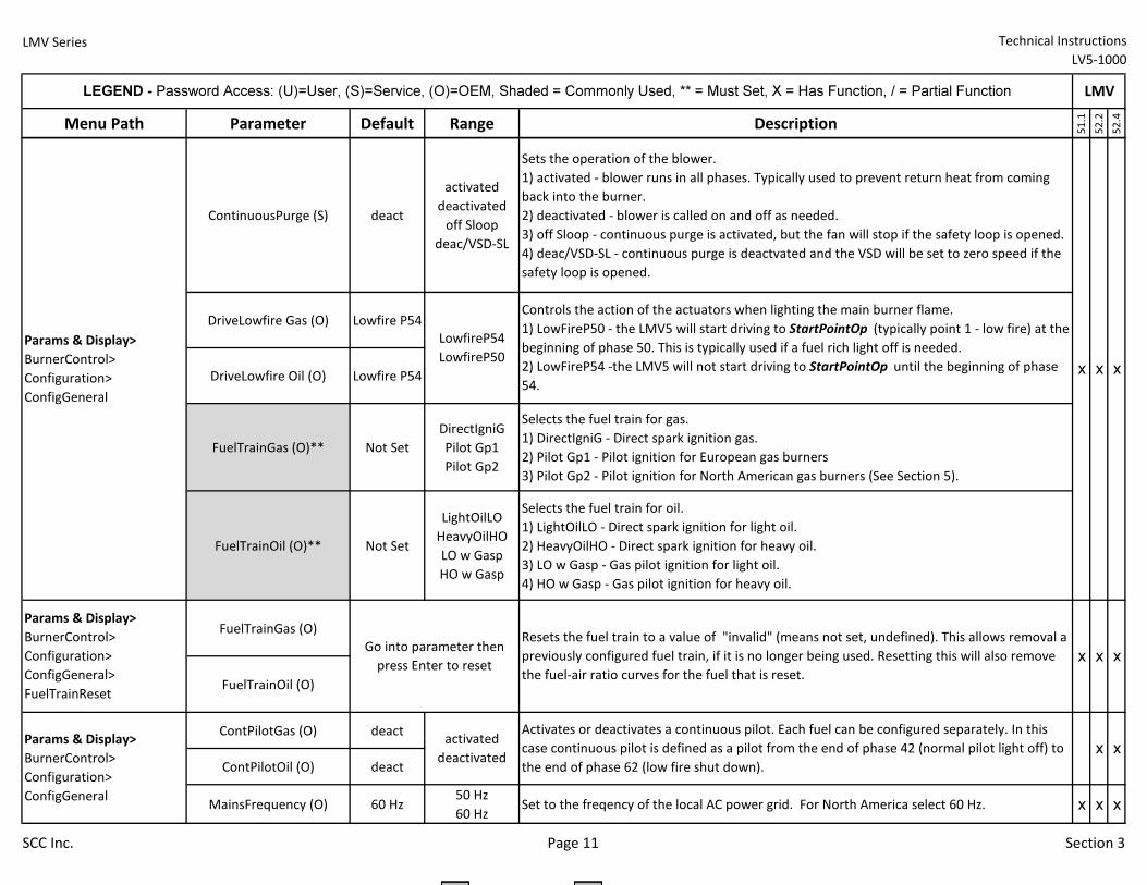
LMV Series Technical Instructions
LV5-1000
Menu Path Parameter Default Range Description
51.1
52.2
52.4
LEGEND - Password Access: (U)=User, (S)=Service, (O)=OEM, Shaded = Commonly Used, ** = Must Set, X = Has Function, / = Partial Function LMV
ContinuousPurge (S) deact
activated
deactivated
off Sloop
deac/VSD-SL
Sets the operation of the blower.
1) activated - blower runs in all phases. Typically used to prevent return heat from coming
back into the burner.
2) deactivated - blower is called on and off as needed.
3) off Sloop - continuous purge is activated, but the fan will stop if the safety loop is opened.
4) deac/VSD-SL - continuous purge is deactvated and the VSD will be set to zero speed if the
safety loop is opened.
DriveLowfire Gas (O) Lowfire P54
DriveLowfire Oil (O) Lowfire P54
FuelTrainGas (O)** Not Set
DirectIgniG
Pilot Gp1
Pilot Gp2
Selects the fuel train for gas.
1) DirectIgniG - Direct spark ignition gas.
2) Pilot Gp1 - Pilot ignition for European gas burners
3) Pilot Gp2 - Pilot ignition for North American gas burners (See Section 5).
FuelTrainOil (O)** Not Set
LightOilLO
HeavyOilHO
LO w Gasp
HO w Gasp
Selects the fuel train for oil.
1) LightOilLO - Direct spark ignition for light oil.
2) HeavyOilHO - Direct spark ignition for heavy oil.
3) LO w Gasp - Gas pilot ignition for light oil.
4) HO w Gasp - Gas pilot ignition for heavy oil.
FuelTrainGas (O)
FuelTrainOil (O)
ContPilotGas (O) deact
ContPilotOil (O) deact
MainsFrequency (O) 60 Hz50 Hz
60 HzSet to the freqency of the local AC power grid. For North America select 60 Hz. x x x
x
Params & Display>
BurnerControl>
Configuration>
ConfigGeneral
LowfireP54
LowfireP50
Params & Display>
BurnerControl>
Configuration>
ConfigGeneral>
FuelTrainReset
Resets the fuel train to a value of "invalid" (means not set, undefined). This allows removal a
previously configured fuel train, if it is no longer being used. Resetting this will also remove
the fuel-air ratio curves for the fuel that is reset.
Params & Display>
BurnerControl>
Configuration>
ConfigGeneral
Activates or deactivates a continuous pilot. Each fuel can be configured separately. In this
case continuous pilot is defined as a pilot from the end of phase 42 (normal pilot light off) to
the end of phase 62 (low fire shut down).
Go into parameter then
press Enter to reset
activated
deactivated
x x
x x x
x x
Controls the action of the actuators when lighting the main burner flame.
1) LowFireP50 - the LMV5 will start driving to StartPointOp (typically point 1 - low fire) at the
beginning of phase 50. This is typically used if a fuel rich light off is needed.
2) LowFireP54 -the LMV5 will not start driving to StartPointOp until the beginning of phase
54.
SCC Inc. Page 11 Section 3
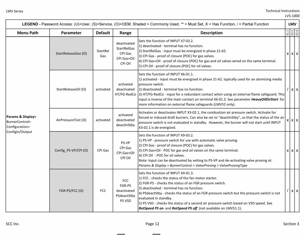
LMV Series Technical Instructions
LV5-1000
Menu Path Parameter Default Range Description
51.1
52.2
52.4
LEGEND - Password Access: (U)=User, (S)=Service, (O)=OEM, Shaded = Commonly Used, ** = Must Set, X = Has Function, / = Partial Function LMV
StartReleaseGas (O)StartRel
Gas
deactivated
StartRelGas
CPI Gas
CPI Gas+Oil
CPI Oil
Sets the function of INPUT X7-03.2.
1) deactivated - terminal has no function.
2) StartRelGas - input must be energized in phase 21-62.
3) CPI Gas - proof of closure (POC) for gas valves.
4) CPI Gas+Oil - proof of closure (POC) for gas and oil valves wired on the same terminal.
5) CPI Oil - proof of closure (POC) for oil valves.
x x x
StartReleaseOil (O) activated
activated
deactivated
HT/FG-RedCo
Sets the function of INPUT X6-01.1.
1) activated - input must be energized in phase 21-62, typically used for an atomizing media
pressure switch.
2) deactivated - terminal has no function.
3) HT/FG-RedCo - input for a redundant contact when using an external flame safeguard. This
input is inverse of the main contact on terminal X6-01.3. See parameter HeavyOilDirStart for
more information on external flame safeguards (LMV52 only).
/ x x
AirPressureTest (O) activated
activated
deactivated
deactInStby
Activates or deactivates INPUT X3-02.1, the combustion air pressure switch. Activate for
forced or induced draft burners. Can also be set to "deactInStby", so that the status of the air
pressure switch is not evaluated in standby. However, the burner will not start until INPUT
X3-02.1 is de-energized.
x x x
Config_PS-VP/CPI (O) CPI Gas
PS-VP
CPI Gas
CPI Gas+Oil
CPI Oil
Sets the function of INPUT X9-03.2.
1) PS-VP - pressure switch for use with automatic valve proving.
2) CPI Gas - proof of closure (POC) for gas valves.
3) CPI Gas+Oil - POC for gas and oil valves on the same terminal.
4) CPI Oil - POC for oil valves.
Note: Input can be deactivated by setting to PS-VP and de-activating valve proving at:
Params & Display > BurnerControl > ValveProving > ValveProvingType
x x x
FGR-PS/FCC (O) FCC
FCC
FGR-PS
deactivated
PSdeactStby
PS VSD
Sets the function of INPUT X4-01.3.
1) FCC - checks the status of the fan motor starter.
2) FGR-PS - checks the status of an FGR pressure switch.
3) deactivated - terminal has no function.
4) PSdeactStby - checks the status of an FGR pressure switch but the pressure switch is not
evaluated in standby.
5) PS VSD - checks the status of a second air pressure switch based on VSD speed. See
RotSpeed PS on and RotSpeed PS off (not available on LMV51.1).
/ x x
Params & Display>
BurnerControl>
Configuration>
ConfigIn/Output
SCC Inc. Page 12 Section 3
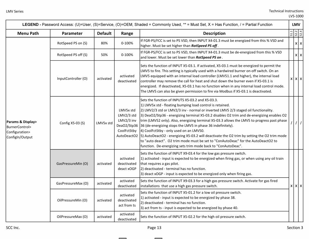
LMV Series Technical Instructions
LV5-1000
Menu Path Parameter Default Range Description
51.1
52.2
52.4
LEGEND - Password Access: (U)=User, (S)=Service, (O)=OEM, Shaded = Commonly Used, ** = Must Set, X = Has Function, / = Partial Function LMV
RotSpeed PS on (S) 80% 0-100%If FGR-PS/FCC is set to PS VSD, then INPUT X4-01.3 must be energized from this % VSD and
higher. Must be set higher than RotSpeed PS off .x x
RotSpeed PS off (S) 50% 0-100%If FGR-PS/FCC is set to PS VSD, then INPUT X4-01.3 must be de-energized from this % VSD
and lower. Must be set lower than RotSpeed PS on .x x
InputController (O) activatedactivated
deactivated
Sets the function of INPUT X5-03.1. If activated, X5-03.1 must be energized to permit the
LMV5 to fire. This setting is typically used with a hardwired burner on-off switch. On an
LMV5 equipped with an internal load controller (LMV51.1 and higher), the internal load
controller may remove the call for heat and shut down the burner even if X5-03.1 is
energized. If deactivated, X5-03.1 has no function when in any internal load control mode.
The LMV5 can also be given permission to fire via Modbus if X5-03.1 is deactivated.
x x x
Config X5-03 (S) LMV5x std
LMV5x std
LMV2/3 std
LMV2/3 inv
DeaO2/Stp36
CoolFctStby
AutoDeactO2
Sets the function of INPUTS X5-03.2 and X5-03.3.
1) LMV5x std - floating bumping load control is retained.
2) LMV2/3 std or LMV2/3 inv - normal or inverted LMV5 2/3 staged oil functionality.
3) DeaO2/Stp36 - energizing terminal X5-03.2 disables O2 trim and de-energizing enables O2
trim (LMV52 only). Also, energizing terminal X5-03.3 allows the LMV5 to progress past phase
36 (de-energizing stops the LMV5 in phase 36 indefinitely).
4) CoolFctStby - only used on an LMV50.
5) AutoDeactO2 - energizing X5-03.2 will deactivate the O2 trim by setting the O2 trim mode
to "auto deact". O2 trim mode must be set to "ConAutoDeac" for the AutoDeactO2 to
function. De-energizing sets trim mode back to "ConAutoDeac".
/ / /
GasPressureMin (O) activated
activated
deactivated
deact xOGP
Sets the function of INPUT X9-03.4 for the low gas pressure switch.
1) activated - input is expected to be energized when firing gas, or when using any oil train
that requires a gas pilot.
2) deactivated - terminal has no function.
3) deact xOGP - input is expected to be energized only when firing gas.
GasPressureMax (O) activatedactivated
deactivated
Sets the function of INPUT X9-03.3 for a high gas pressure switch. Activate for gas fired
installations that use a high gas pressure switch.
OilPressureMin (O) activated
activated
deactivated
act from ts
Sets the function of INPUT X5-01.2 for a low oil pressure switch.
1) activated - input is expected to be energized by phase 38.
2) deactivated - terminal has no function.
3) act from ts - input is expected to be energized by phase 40.
OilPressureMax (O) activatedactivated
deactivatedSets the function of INPUT X5-02.2 for the high oil pressure switch.
x
Params & Display>
BurnerControl>
Configuration>
ConfigIn/Output
x x
SCC Inc. Page 13 Section 3
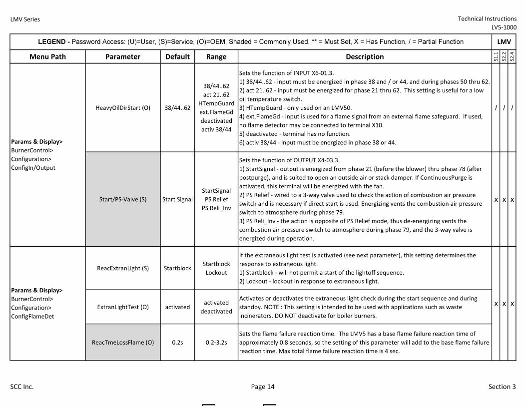
LMV Series Technical Instructions
LV5-1000
Menu Path Parameter Default Range Description
51.1
52.2
52.4
LEGEND - Password Access: (U)=User, (S)=Service, (O)=OEM, Shaded = Commonly Used, ** = Must Set, X = Has Function, / = Partial Function LMV
HeavyOilDirStart (O) 38/44..62
38/44..62
act 21..62
HTempGuard
ext.FlameGd
deactivated
activ 38/44
Sets the function of INPUT X6-01.3.
1) 38/44..62 - input must be energized in phase 38 and / or 44, and during phases 50 thru 62.
2) act 21..62 - input must be energized for phase 21 thru 62. This setting is useful for a low
oil temperature switch.
3) HTempGuard - only used on an LMV50.
4) ext.FlameGd - input is used for a flame signal from an external flame safeguard. If used,
no flame detector may be connected to terminal X10.
5) deactivated - terminal has no function.
6) activ 38/44 - input must be energized in phase 38 or 44.
/ / /
Start/PS-Valve (S) Start Signal
StartSignal
PS Relief
PS Reli_Inv
Sets the function of OUTPUT X4-03.3.
1) StartSignal - output is energized from phase 21 (before the blower) thru phase 78 (after
postpurge), and is suited to open an outside air or stack damper. If ContinuousPurge is
activated, this terminal will be energized with the fan.
2) PS Relief - wired to a 3-way valve used to check the action of combustion air pressure
switch and is necessary if direct start is used. Energizing vents the combustion air pressure
switch to atmosphere during phase 79.
3) PS Reli_Inv - the action is opposite of PS Relief mode, thus de-energizing vents the
combustion air pressure switch to atmosphere during phase 79, and the 3-way valve is
energized during operation.
x x x
ReacExtranLight (S) StartblockStartblock
Lockout
If the extraneous light test is activated (see next parameter), this setting determines the
response to extraneous light.
1) Startblock - will not permit a start of the lightoff sequence.
2) Lockout - lockout in response to extraneous light.
ExtranLightTest (O) activatedactivated
deactivated
Activates or deactivates the extraneous light check during the start sequence and during
standby. NOTE : This setting is intended to be used with applications such as waste
incinerators. DO NOT deactivate for boiler burners.
ReacTmeLossFlame (O) 0.2s 0.2-3.2s
Sets the flame failure reaction time. The LMV5 has a base flame failure reaction time of
approximately 0.8 seconds, so the setting of this parameter will add to the base flame failure
reaction time. Max total flame failure reaction time is 4 sec.
x x x
Params & Display>
BurnerControl>
Configuration>
ConfigIn/Output
Params & Display>
BurnerControl>
Configuration>
ConfigFlameDet
SCC Inc. Page 14 Section 3
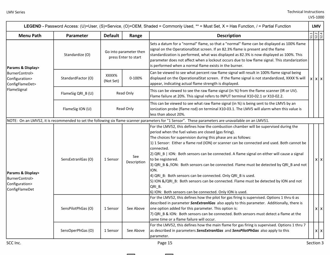
LMV Series Technical Instructions
LV5-1000
Menu Path Parameter Default Range Description
51.1
52.2
52.4
LEGEND - Password Access: (U)=User, (S)=Service, (O)=OEM, Shaded = Commonly Used, ** = Must Set, X = Has Function, / = Partial Function LMV
Standardize (O)
Sets a datum for a "normal" flame, so that a "normal" flame can be displayed as 100% flame
signal on the OperationalStat screen. If an 82.3% flame is present and the flame
standardization is performed, what was displayed as 82.3% is now displayed as 100%. This
parameter does not affect when a lockout occurs due to low flame signal. This standarization
is performed when a normal flame exists in the burner.
StandardFactor (O)XXXX%
(Not Set)0-100%
Can be viewed to see what percent raw flame signal will result in 100% flame signal being
displayed on the OperationalStat screen. If the flame signal is not standardized, XXXX % will
appear, indicating actual flame strength is displayed.
FlameSig QRI_B (U)This can be viewed to see the raw flame signal (in %) from the flame scanner (IR or UV).
Flame failure at 20%. This signal refers to INPUT terminal X10-02.1 or X10-02.2.
FlameSig ION (U)
This can be viewed to see what raw flame signal (in %) is being sent to the LMV5 by an
ionization probe (flame rod) on terminal X10-03.1. The LMV5 will alarm when this value is
less than about 20%.
SensExtranlGas (O) 1 SensorSee
Description
For the LMV52, this defines how the combustion chamber will be supervised during the
period when the fuel valves are closed (gas firing).
The choices for supervision during this phase are as follows:
1) 1 Sensor: Either a flame rod (ION) or scanner can be connected and used. Both cannot be
connected.
2) QRI_B | ION: Both sensors can be connected. A flame signal on either will cause a signal
to be registered.
3) QRI_B & /ION: Both sensors can be connected. Flame must be detected by QRI_B and not
ION.
4) QRI_B: Both sensors can be connected. Only QRI_B is used.
5) ION &/QRI_B: Both sensors can be connected. Flame must be detected by ION and not
QRI_B.
6) ION: Both sensors can be connected. Only ION is used.
x x
SensPilotPhGas (O) 1 Sensor See Above
For the LMV52, this defines how the pilot for gas firing is supervised. Options 1 thru 6 as
described in parameter SenExtranlGas also apply to this parameter. Additionally, there is
one option added for this parameter. This option is:
7) QRI_B & ION: Both sensors can be connected. Both sensors must detect a flame at the
same time or a flame failure will occur.
x x
SensOperPhGas (O) 1 Sensor See Above
For the LMV52, this defines how the main flame for gas firing is supervised. Options 1 thru 7
as described in parameters SensExtranlGas and SensPilotPhGas also apply to this
parameter.
x x
x x x
Params & Display>
BurnerControl>
Configuration>
ConfigFlameDet
Params & Display>
BurnerControl>
Configuration>
ConfigFlameDet>
FlameSignal
Go into parameter then
press Enter to start
Read Only
Read Only
NOTE: On an LMV52, it is recommended to set the following six flame scanner parameters for "1 Sensor". These parameters are unavailable on an LMV51.
SCC Inc. Page 15 Section 3
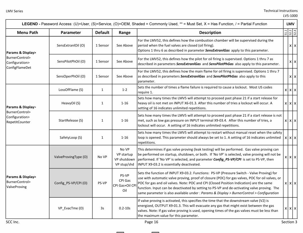
LMV Series Technical Instructions
LV5-1000
Menu Path Parameter Default Range Description
51.1
52.2
52.4
LEGEND - Password Access: (U)=User, (S)=Service, (O)=OEM, Shaded = Commonly Used, ** = Must Set, X = Has Function, / = Partial Function LMV
SensExtranlOil (O) 1 Sensor See Above
For the LMV52, this defines how the combustion chamber will be supervised during the
period when the fuel valves are closed (oil firing).
Options 1 thru 6 as described in parameter SensExtranlGas apply to this parameter.
x x
SensPilotPhOil (O) 1 Sensor See AboveFor the LMV52, this defines how the pilot for oil firing is supervised. Options 1 thru 7 as
described in parameters SensExtranlGas and SensPilotPhGas also apply to this parameter.x x
SensOperPhOil (O) 1 Sensor See Above
For the LMV52, this defines how the main flame for oil firing is supervised. Options 1 thru 7
as described in parameters SensExtranlGas and SensPilotPhGas also apply to this
parameter.
x x
LossOfFlame (S) 1 1-2Sets the number of times a flame failure is required to cause a lockout. Most US codes
require 1.x x x
HeavyOil (S) 1 1-16
Sets how many times the LMV5 will attempt to proceed past phase 21 if a start release for
heavy oil is not met on INPUT X6-01.3. After this number of tries a lockout will occur. A
setting of 16 indicates unlimited repetitions.
x x x
StartRelease (S) 1 1-16
Sets how many times the LMV5 will attempt to proceed past phase 21 if a start release is not
met, such as low gas pressure on INPUT terminal X9-03.4. After this number of tries, a
lockout will occur. A setting of 16 indicates unlimited repetitions.
x x x
SafetyLoop (S) 1 1-16
Sets how many times the LMV5 will attempt to restart without manual reset when the safety
loop is opened. This parameter should always be set to 1. A setting of 16 indicates unlimited
repetitions.
x x x
ValveProvingType (O) No VP
No VP
VP startup
VP shutdown
VP stup/shd
This determines if gas valve proving (leak testing) will be performed. Gas valve proving can
be performed on startup, shutdown, or both. If 'No VP' is selected, valve proving will not be
performed. If 'No VP' is selected, and parameter Config_PS-VP/CPI is set to PS-VP, then
INPUT X9-03.2 is essentially deactivated.
x x x
Config_PS-VP/CPI (O) PS-VP
PS-VP
CPI Gas
CPI Gas+Oil CPI
Oil
Sets the function of INPUT X9-03.2. Functions: PS-VP (Pressure Switch - Valve Proving) for
use with automatic valve proving, proof of closure (POC) for gas valves, POC for oil valves, or
POC for gas and oil valves. Note: POC and CPI (Closed Position Indication) are the same
function. Input can be deactivated by setting to PS-VP and de-activating valve proving. The
same parameter is also available under : Params & Display > BurnerControl > Configuration
x x x
VP_EvacTme (O) 3s 0.2-10s
If valve proving is activated, this specifies the time that the downstream valve (V2) is
energized, OUTPUT X9-01.3. This will evacuate any gas that might exist between the gas
valves. Note: If gas valve proving is used, opening times of the gas valves must be less than
the maximum value for this parameter.
x x x
Params & Display>
BurnerControl>
Configuration>
ConfigFlameDet
Params & Display>
BurnerControl>
ValveProving
Params & Display>
BurnerControl>
Configuration>
RepetitCounter
SCC Inc. Page 16 Section 3
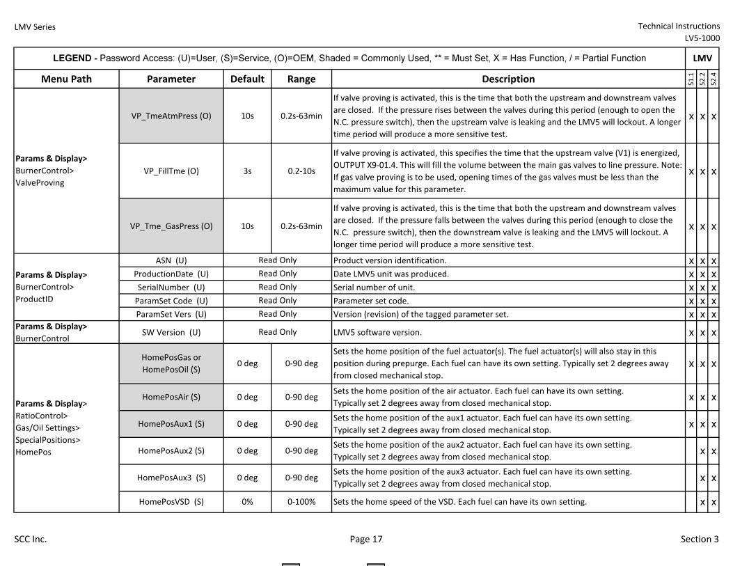
LMV Series Technical Instructions
LV5-1000
Menu Path Parameter Default Range Description
51.1
52.2
52.4
LEGEND - Password Access: (U)=User, (S)=Service, (O)=OEM, Shaded = Commonly Used, ** = Must Set, X = Has Function, / = Partial Function LMV
VP_TmeAtmPress (O) 10s 0.2s-63min
If valve proving is activated, this is the time that both the upstream and downstream valves
are closed. If the pressure rises between the valves during this period (enough to open the
N.C. pressure switch), then the upstream valve is leaking and the LMV5 will lockout. A longer
time period will produce a more sensitive test.
x x x
VP_FillTme (O) 3s 0.2-10s
If valve proving is activated, this specifies the time that the upstream valve (V1) is energized,
OUTPUT X9-01.4. This will fill the volume between the main gas valves to line pressure. Note:
If gas valve proving is to be used, opening times of the gas valves must be less than the
maximum value for this parameter.
x x x
VP_Tme_GasPress (O) 10s 0.2s-63min
If valve proving is activated, this is the time that both the upstream and downstream valves
are closed. If the pressure falls between the valves during this period (enough to close the
N.C. pressure switch), then the downstream valve is leaking and the LMV5 will lockout. A
longer time period will produce a more sensitive test.
x x x
ASN (U) Product version identification. x x x
ProductionDate (U) Date LMV5 unit was produced. x x x
SerialNumber (U) Serial number of unit. x x x
ParamSet Code (U) Parameter set code. x x x
ParamSet Vers (U) Version (revision) of the tagged parameter set. x x x
Params & Display>
BurnerControlSW Version (U) LMV5 software version. x x x
Read Only
Read Only
Read Only
0 deg 0-90 deg
0-90 deg
0% 0-100%
Params & Display>
BurnerControl>
ProductID
Params & Display>
RatioControl>
Gas/Oil Settings>
SpecialPositions>
HomePos
HomePosGas or
HomePosOil (S)
Read Only
Read Only
Read Only
Params & Display>
BurnerControl>
ValveProving
HomePosAux1 (S)Sets the home position of the aux1 actuator. Each fuel can have its own setting.
Typically set 2 degrees away from closed mechanical stop.
HomePosAux2 (S)Sets the home position of the aux2 actuator. Each fuel can have its own setting.
Typically set 2 degrees away from closed mechanical stop.
HomePosAux3 (S)Sets the home position of the aux3 actuator. Each fuel can have its own setting.
Typically set 2 degrees away from closed mechanical stop.
HomePosVSD (S) Sets the home speed of the VSD. Each fuel can have its own setting.
0 deg 0-90 deg
0 deg 0-90 deg
0 deg 0-90 deg
0 deg
HomePosAir (S)
x x
x
x x x
Sets the home position of the air actuator. Each fuel can have its own setting.
Typically set 2 degrees away from closed mechanical stop.
x x
x
x x
x
x
x x
Sets the home position of the fuel actuator(s). The fuel actuator(s) will also stay in this
position during prepurge. Each fuel can have its own setting. Typically set 2 degrees away
from closed mechanical stop.
SCC Inc. Page 17 Section 3
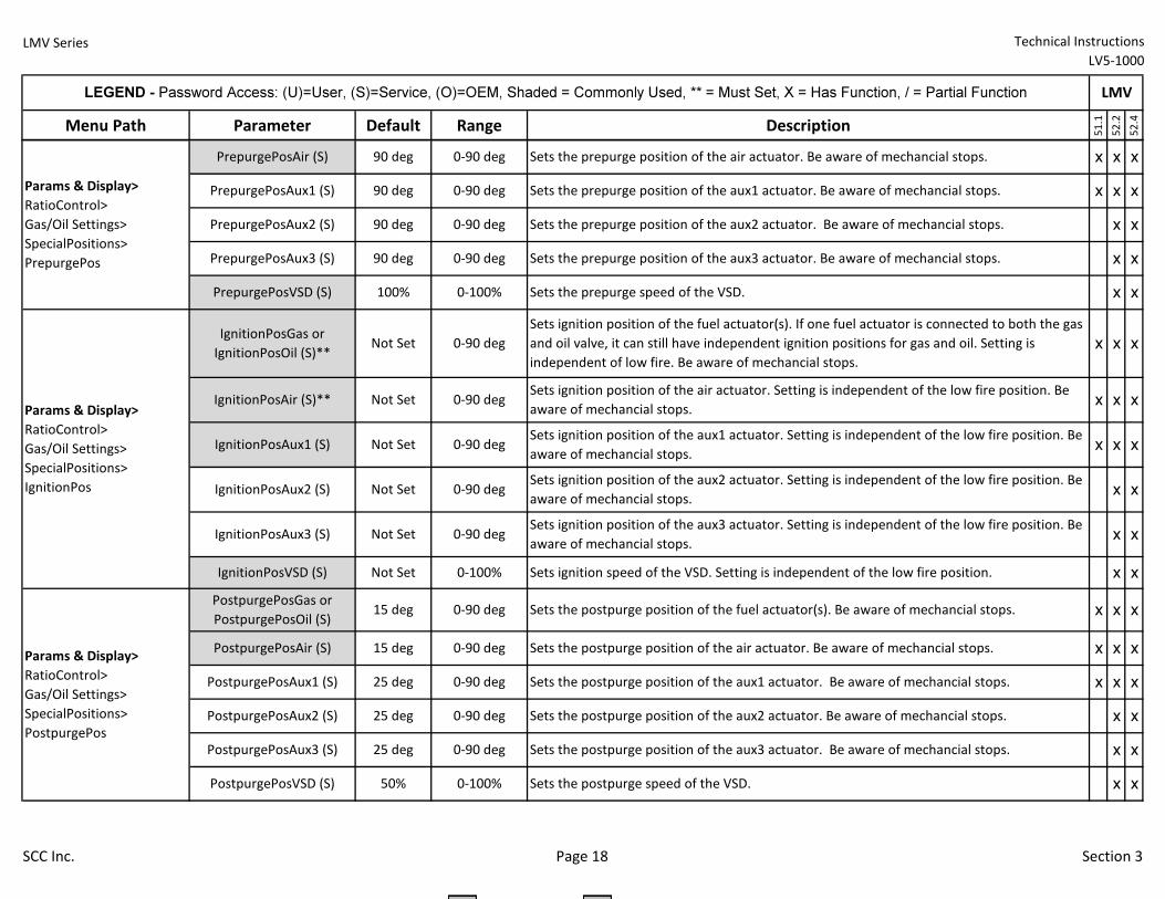
LMV Series Technical Instructions
LV5-1000
Menu Path Parameter Default Range Description
51.1
52.2
52.4
LEGEND - Password Access: (U)=User, (S)=Service, (O)=OEM, Shaded = Commonly Used, ** = Must Set, X = Has Function, / = Partial Function LMV
0-90 deg15 deg
IgnitionPosVSD (S)
Sets the postpurge position of the aux2 actuator. Be aware of mechancial stops.
90 deg 0-90 deg
PrepurgePosAux3 (S)
PrepurgePosVSD (S)
Params & Display>
RatioControl>
Gas/Oil Settings>
SpecialPositions>
IgnitionPos
IgnitionPosGas or
IgnitionPosOil (S)**
0-90 deg
Not Set 0-90 deg
Not Set 0-100%
100% 0-100%
Not Set
90 deg
PrepurgePosAux1 (S)
IgnitionPosAux2 (S)
PrepurgePosAux2 (S) Sets the prepurge position of the aux2 actuator. Be aware of mechancial stops.
Params & Display>
RatioControl>
Gas/Oil Settings>
SpecialPositions>
PostpurgePos
PostpurgePosGas or
PostpurgePosOil (S)Sets the postpurge position of the fuel actuator(s). Be aware of mechancial stops.
Params & Display>
RatioControl>
Gas/Oil Settings>
SpecialPositions>
PrepurgePos
PrepurgePosAir (S) Sets the prepurge position of the air actuator. Be aware of mechancial stops.
PostpurgePosAux3 (S) Sets the postpurge position of the aux3 actuator. Be aware of mechancial stops.
PostpurgePosVSD (S)
IgnitionPosAir (S)**Sets ignition position of the air actuator. Setting is independent of the low fire position. Be
aware of mechancial stops.
IgnitionPosAux1 (S)
Sets the postpurge position of the air actuator. Be aware of mechancial stops.
PostpurgePosAux1 (S)
Sets ignition position of the aux1 actuator. Setting is independent of the low fire position. Be
aware of mechancial stops.
PostpurgePosAir (S)
0-90 deg
Sets ignition position of the aux2 actuator. Setting is independent of the low fire position. Be
aware of mechancial stops.
IgnitionPosAux3 (S)Sets ignition position of the aux3 actuator. Setting is independent of the low fire position. Be
aware of mechancial stops.
Sets the postpurge position of the aux1 actuator. Be aware of mechancial stops.
PostpurgePosAux2 (S)
Sets the prepurge position of the aux3 actuator. Be aware of mechancial stops.
Sets the prepurge position of the aux1 actuator. Be aware of mechancial stops.
Sets the postpurge speed of the VSD.
0-90 deg
0-90 deg
0-90 deg
0-100%
25 deg
25 deg
25 deg
50%
x
Sets the prepurge speed of the VSD.
90 deg 0-90 deg
Not Set 0-90 deg
Not Set
Sets ignition position of the fuel actuator(s). If one fuel actuator is connected to both the gas
and oil valve, it can still have independent ignition positions for gas and oil. Setting is
independent of low fire. Be aware of mechancial stops.
Sets ignition speed of the VSD. Setting is independent of the low fire position.
90 deg 0-90 deg
0-90 deg
Not Set 0-90 deg
0-90 deg15 deg
x x
x x
x
x
x x x
x
x x
x x
x x x
x x x
x
x x x
x x
x
x
x x x
x
x x x
x x x
x
x x
SCC Inc. Page 18 Section 3
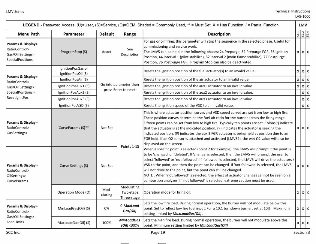
LMV Series Technical Instructions
LV5-1000
Menu Path Parameter Default Range Description
51.1
52.2
52.4
LEGEND - Password Access: (U)=User, (S)=Service, (O)=OEM, Shaded = Commonly Used, ** = Must Set, X = Has Function, / = Partial Function LMV
IgnitionPosGas or
IgnitionPosOil (S)Resets the ignition position of the fuel actuator(s) to an invalid value. x x x
IgnitionPosAir (S) Resets the ignition position of the air actuator to an invalid value. x x x
IgnitionPosAux1 (S) Resets the ignition position of the aux1 actuator to an invalid value. x x x
IgnitionPosAux2 (S) Resets the ignition position of the aux2 actuator to an invalid value. x x
IgnitionPosAux3 (S) Resets the ignition position of the aux3 actuator to an invalid value. x x
IgnitionPosVSD (S) Resets the ignition speed of the VSD to an invalid value. x x
Params & Display>
RatioControl>
GasSettings>
CurveParams (S)** Not Set x x x
Curve Settings (S) Not Set x x x
Operation Mode (O)Mod-
ulating
Modulating
Two-stage
Three-stage
Operation mode for firing oil. x x x
MinLoadGas(Oil) (S) 0%0-MaxLoad
Gas(Oil)
Sets the low fire load. During normal operation, the burner will not modulate below this
point. Set to reflect low fire fuel input. For a 10:1 turndown burner, set at 10%. Maximum
setting limited by MaxLoadGas(Oil) .
x x x
MaxLoadGas(Oil) (S) 100%MinLoadGas
(Oil) -100%
Sets the high fire load. During normal operation, the burner will not modulate above this
point. Minimum setting limited by MinLoadGas(Oil) .x x x
Params & Display>
RatioControl>
Gas/Oil Settings>
SpecialPositions
ProgramStop (S)
Params & Display>
RatioControl>
Gas/Oil Settings>
LoadLimits
Params & Display>
RatioControl>
OilSettings>
CurveParams
Go into parameter then
press Enter to reset
Params & Display>
RatioControl>
Gas/Oil Settings>
SpecialPositions>
ResetlgnitPos
deactSee
Description
For gas or oil firing, this parameter will stop the sequence in the selected phase. Useful for
commissioning and service work.
The LMV5 can be held in the following phases: 24 Prepurge, 32 Prepurge FGR, 36 Ignition
Position, 44 Interval 1 (pilot stabilize), 52 Interval 2 (main flame stabilize), 72 Postpurge
Position, 76 Postpurge FGR. Program Stop can also be deactivated.
This is where actuator position curves and VSD speed curves are set from low to high fire.
These position curves determine the fuel-air ratio for the burner across the firing range.
Fifteen points can be set from low to high fire. Typically ten points are set. Colons(:) indicate
that the actuator is at the indicated position, (>) indicates the actuator is seeking the
indicated position, (#) indicates the aux 3 FGR actuator is being held at position due to an
FGR hold. If an O2 sensor is attached and activated (LMV52), the wet O2 value will also be
displayed on the screen.
When a specific point is selected (point 2 for example), the LMV5 will prompt if the point is
to be 'changed' or 'deleted'. If 'change' is selected, then the LMV5 will prompt the user to
select 'followed' or 'not followed'. If 'followed' is selected, the LMV5 will drive the actuators /
VSD to the point, and then the point can be changed. If 'not followed' is selected, the LMV5
will not drive to the point, but the point can still be changed.
NOTE : When 'not followed' is selected, the effect of actuator changes cannot be seen on a
combustion analyzer. If 'not followed' is selected, extreme caution must be used.
Points 1-15
x x x
SCC Inc. Page 19 Section 3
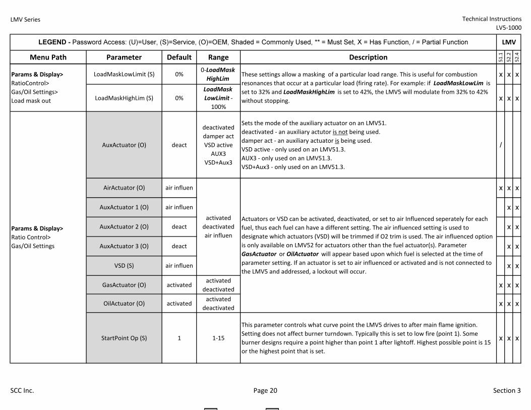
LMV Series Technical Instructions
LV5-1000
Menu Path Parameter Default Range Description
51.1
52.2
52.4
LEGEND - Password Access: (U)=User, (S)=Service, (O)=OEM, Shaded = Commonly Used, ** = Must Set, X = Has Function, / = Partial Function LMV
LoadMaskLowLimit (S) 0%0-LoadMask
HighLimx x x
LoadMaskHighLim (S) 0%
LoadMask
LowLimit -
100%
x x x
AuxActuator (O) deact
deactivated
damper act
VSD active
AUX3
VSD+Aux3
Sets the mode of the auxiliary actuator on an LMV51.
deactivated - an auxiliary actutor is not being used.
damper act - an auxiliary actuator is being used.
VSD active - only used on an LMV51.3.
AUX3 - only used on an LMV51.3.
VSD+Aux3 - only used on an LMV51.3.
/
GasActuator (O) activatedactivated
deactivatedx x x
OilActuator (O) activatedactivated
deactivatedx x x
StartPoint Op (S) 1 1-15
This parameter controls what curve point the LMV5 drives to after main flame ignition.
Setting does not affect burner turndown. Typically this is set to low fire (point 1). Some
burner designs require a point higher than point 1 after lightoff. Highest possible point is 15
or the highest point that is set.
x x x
Params & Display>
RatioControl>
Gas/Oil Settings>
Load mask out
VSD (S)
AuxActuator 1 (O)
AuxActuator 2 (O)
AuxActuator 3 (O)
These settings allow a masking of a particular load range. This is useful for combustion
resonances that occur at a particular load (firing rate). For example: if LoadMaskLowLim is
set to 32% and LoadMaskHighLim is set to 42%, the LMV5 will modulate from 32% to 42%
without stopping.
AirActuator (O)
Actuators or VSD can be activated, deactivated, or set to air Influenced seperately for each
fuel, thus each fuel can have a different setting. The air influenced setting is used to
designate which actuators (VSD) will be trimmed if O2 trim is used. The air influenced option
is only available on LMV52 for actuators other than the fuel actuator(s). Parameter
GasActuator or OilActuator will appear based upon which fuel is selected at the time of
parameter setting. If an actuator is set to air influenced or activated and is not connected to
the LMV5 and addressed, a lockout will occur.
Params & Display>
Ratio Control>
Gas/Oil Settings
air influen
air influen
deact
deact
air influen
activated
deactivated
air influen
x
x x
x x
x x
x x
x
x
SCC Inc. Page 20 Section 3
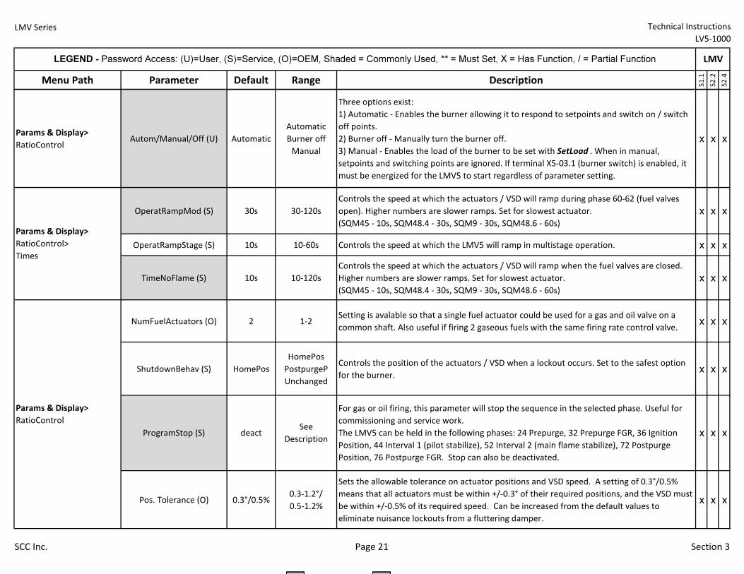
LMV Series Technical Instructions
LV5-1000
Menu Path Parameter Default Range Description
51.1
52.2
52.4
LEGEND - Password Access: (U)=User, (S)=Service, (O)=OEM, Shaded = Commonly Used, ** = Must Set, X = Has Function, / = Partial Function LMV
Params & Display>
RatioControlAutom/Manual/Off (U) Automatic
Automatic
Burner off
Manual
Three options exist:
1) Automatic - Enables the burner allowing it to respond to setpoints and switch on / switch
off points.
2) Burner off - Manually turn the burner off.
3) Manual - Enables the load of the burner to be set with SetLoad . When in manual,
setpoints and switching points are ignored. If terminal X5-03.1 (burner switch) is enabled, it
must be energized for the LMV5 to start regardless of parameter setting.
x x x
OperatRampMod (S) 30s 30-120s
Controls the speed at which the actuators / VSD will ramp during phase 60-62 (fuel valves
open). Higher numbers are slower ramps. Set for slowest actuator.
(SQM45 - 10s, SQM48.4 - 30s, SQM9 - 30s, SQM48.6 - 60s)
x x x
OperatRampStage (S) 10s 10-60s Controls the speed at which the LMV5 will ramp in multistage operation. x x x
TimeNoFlame (S) 10s 10-120s
Controls the speed at which the actuators / VSD will ramp when the fuel valves are closed.
Higher numbers are slower ramps. Set for slowest actuator.
(SQM45 - 10s, SQM48.4 - 30s, SQM9 - 30s, SQM48.6 - 60s)
x x x
NumFuelActuators (O) 2 1-2Setting is avalable so that a single fuel actuator could be used for a gas and oil valve on a
common shaft. Also useful if firing 2 gaseous fuels with the same firing rate control valve.x x x
ShutdownBehav (S) HomePos
HomePos
PostpurgeP
Unchanged
Controls the position of the actuators / VSD when a lockout occurs. Set to the safest option
for the burner.x x x
Pos. Tolerance (O) 0.3°/0.5%0.3-1.2°/
0.5-1.2%
Sets the allowable tolerance on actuator positions and VSD speed. A setting of 0.3°/0.5%
means that all actuators must be within +/-0.3° of their required positions, and the VSD must
be within +/-0.5% of its required speed. Can be increased from the default values to
eliminate nuisance lockouts from a fluttering damper.
x x x
Params & Display>
RatioControl
Params & Display>
RatioControl>
Times
ProgramStop (S) deactSee
Descriptionx x x
For gas or oil firing, this parameter will stop the sequence in the selected phase. Useful for
commissioning and service work.
The LMV5 can be held in the following phases: 24 Prepurge, 32 Prepurge FGR, 36 Ignition
Position, 44 Interval 1 (pilot stabilize), 52 Interval 2 (main flame stabilize), 72 Postpurge
Position, 76 Postpurge FGR. Stop can also be deactivated.
SCC Inc. Page 21 Section 3
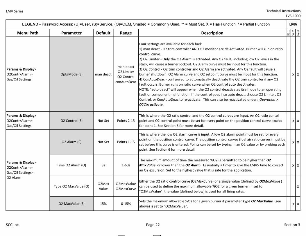
LMV Series Technical Instructions
LV5-1000
Menu Path Parameter Default Range Description
51.1
52.2
52.4
LEGEND - Password Access: (U)=User, (S)=Service, (O)=OEM, Shaded = Commonly Used, ** = Must Set, X = Has Function, / = Partial Function LMV
Params & Display>
O2Contr/Alarm>
Gas/Oil Settings
OptgMode (S) man deact
man deact
O2 Limiter
O2 Control
conAutoDeac
Four settings are available for each fuel:
1) man deact - O2 trim controller AND O2 monitor are de-activated. Burner will run on ratio
control curve.
2) O2 Limiter - Only the O2 Alarm is activated. Any O2 fault, including low O2 levels in the
stack, will cause a burner lockout. O2 Alarm curve must be input for this function.
3) O2 Control - O2 trim controller and O2 Alarm are activated. Any O2 fault will cause a
burner shutdown. O2 Alarm curve and O2 setpoint curve must be input for this function.
4) ConAutoDeac - configured to automatically deactivate the O2 trim controller if any O2
fault occurs. Burner runs on ratio curve when O2 control auto deactivates.
NOTE: "auto deact" will appear when the O2 control deactivates itself, due to an operating
fault or component malfunction. If the control goes into auto deact, choose O2 Limiter, O2
Control, or ConAutoDeac to re-activate. This can also be reactivated under: Operation >
O2Ctrl activate .
x x
Params & Display>
O2Contr/Alarm>
Gas/Oil Settings
O2 Control (S) Not Set Points 2-15
This is where the O2 ratio control and the O2 control curves are input. An O2 ratio contol
point and O2 control point must be set for every point on the position control curve except
for point 1. See Section 6 for more detail.
x x
O2 Alarm (S) Not Set Points 1-15
This is where the low O2 alarm curve is input. A low O2 alarm point must be set for every
point on the position control curve. The position control curves (fuel air ratio curves) must be
set before this curve is entered. Points can be set by typing in an O2 value or by probing each
point. See Section 6 for more detail.
x x
Time O2 Alarm (O) 3s 1-60s
The maximum amount of time the measured %O2 is permitted to be higher than O2
MaxValue or lower than the O2 Alarm . Essentially a timer to give the LMV5 time to correct
an O2 excursion. Set to the highest value that is safe for the application.
x x
Type O2 MaxValue (O)O2Max
Value
O2MaxValue
O2MaxCurve
Either the O2 ratio control curve (O2MaxCurve) or a single value (defined by O2MaxValue )
can be used to define the maximum allowable %O2 for a given burner. If set to
"O2MaxValue", the value (defined below) is used for all firing rates.
x
O2 MaxValue (S) 15% 0-15%Sets the maximum allowable %O2 for a given burner if parameter Type O2 MaxValue (see
above) is set to "O2MaxValue".x x
Params & Display>
O2Contr/Alarm>
Gas/Oil Settings>
O2 Alarm
SCC Inc. Page 22 Section 3
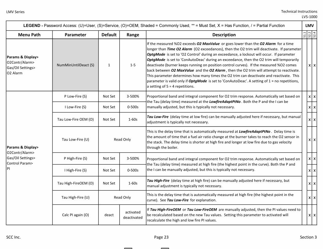
LMV Series Technical Instructions
LV5-1000
Menu Path Parameter Default Range Description
51.1
52.2
52.4
LEGEND - Password Access: (U)=User, (S)=Service, (O)=OEM, Shaded = Commonly Used, ** = Must Set, X = Has Function, / = Partial Function LMV
Params & Display>
O2Contr/Alarm>
Gas/Oil Settings>
O2 Alarm
NumMinUntilDeact (S) 1 1-5
If the measured %O2 exceeds O2 MaxValue or goes lower than the O2 Alarm for a time
longer than Time O2 Alarm (O2 exceedances), then the O2 trim will deactivate. If parameter
OptgMode is set to 'O2 Control' during an exceedance, a lockout will occur. If parameter
OptgMode is set to 'ConAutoDeac' during an exceedance, then the O2 trim will temporarily
deactivate (burner keeps running on position control curves). If the measured %O2 comes
back between O2 MaxValue and the O2 Alarm , then the O2 trim will attempt to reactivate.
This parameter determines how many times the O2 trim can deactivate and reactivate. This
parameter is valid only if OptgMode is set to 'ConAutoDeac'. A setting of 1 = no repetitions,
a setting of 5 = 4 repetitions.
x x
Calc PI again (O) deactactivated
deactivated
If Tau High-FireOEM or Tau Low-FireOEM are manually adjusted, then the PI values need to
be recalculated based on the new Tau values. Setting this parameter to activated will
recalculate the high and low fire PI values.
x x
Proportional band and integral component for O2 trim response. Automatically set based on
the Tau (delay time) measured at the LowfireAdaptPtNo . Both the P and the I can be
manually adjusted, but this is typically not necessary.
This is the delay time that is automatically measured at LowfireAdaptPtNo . Delay time is
the amount of time that a fuel air ratio change at the burner takes to reach the O2 sensor in
the stack. The delay time is shorter at high fire and longer at low fire due to gas velocity
through the boiler.
x x
Tau Low-Fire (delay time at low fire) can be manually adjusted here if necessary, but manual
adjustment is typically not necessary.
x x
x x
x xRead Only
Not Set
I Low-Fire (S)
Tau Low-Fire OEM (O)
Tau Low-Fire (U)
P High-Fire (S)
Params & Display>
O2Contr/Alarm>
Gas/Oil Settings>
Control Param>
PI
P Low-Fire (S)
Tau High-Fire (U)
0-500s
Not Set 1-60s
Not Set
3-500% x x
x x
x x
x x
Tau High-Fire (delay time at high fire) can be manually adjusted here if necessary, but
manual adjustment is typically not necessary.
This is the delay time that is automatically measured at high fire (the highest point in the
curve). See Tau Low-Fire for explanation.
Proportional band and integral component for O2 trim response. Automatically set based on
the Tau (delay time) measured at high fire (the highest point in the curve). Both the P and
the I can be manually adjusted, but this is typically not necessary.Not Set
3-500%
Not Set 0-500s
Not Set 1-60s
I High-Fire (S)
Tau High-FireOEM (O)
Read Only
SCC Inc. Page 23 Section 3
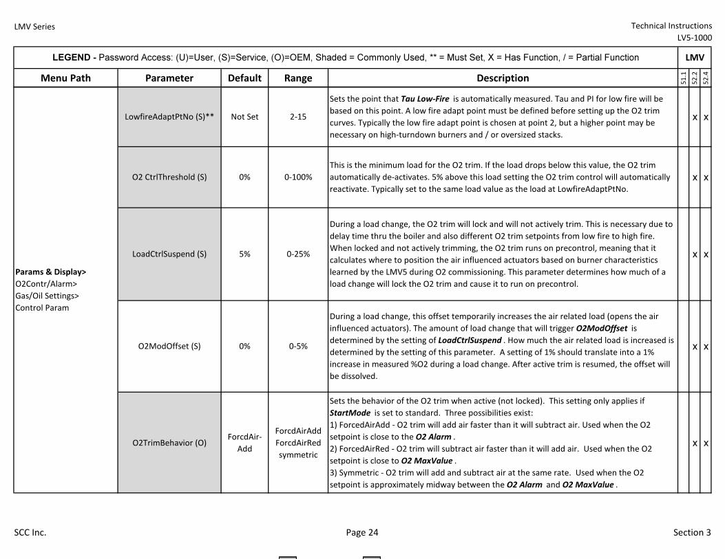
LMV Series Technical Instructions
LV5-1000
Menu Path Parameter Default Range Description
51.1
52.2
52.4
LEGEND - Password Access: (U)=User, (S)=Service, (O)=OEM, Shaded = Commonly Used, ** = Must Set, X = Has Function, / = Partial Function LMV
O2TrimBehavior (O)ForcdAir-
Add
ForcdAirAdd
ForcdAirRed
symmetric
Sets the behavior of the O2 trim when active (not locked). This setting only applies if
StartMode is set to standard. Three possibilities exist:
1) ForcedAirAdd - O2 trim will add air faster than it will subtract air. Used when the O2
setpoint is close to the O2 Alarm .
2) ForcedAirRed - O2 trim will subtract air faster than it will add air. Used when the O2
setpoint is close to O2 MaxValue .
3) Symmetric - O2 trim will add and subtract air at the same rate. Used when the O2
setpoint is approximately midway between the O2 Alarm and O2 MaxValue .
x x
x x
x x
x x
During a load change, this offset temporarily increases the air related load (opens the air
influenced actuators). The amount of load change that will trigger O2ModOffset is
determined by the setting of LoadCtrlSuspend . How much the air related load is increased is
determined by the setting of this parameter. A setting of 1% should translate into a 1%
increase in measured %O2 during a load change. After active trim is resumed, the offset will
be dissolved.
O2ModOffset (S) 0-5%
0-25%
LowfireAdaptPtNo (S)**
O2 CtrlThreshold (S)
2-15
0%
0%
0-100%
5%
x x
Sets the point that Tau Low-Fire is automatically measured. Tau and PI for low fire will be
based on this point. A low fire adapt point must be defined before setting up the O2 trim
curves. Typically the low fire adapt point is chosen at point 2, but a higher point may be
necessary on high-turndown burners and / or oversized stacks.
This is the minimum load for the O2 trim. If the load drops below this value, the O2 trim
automatically de-activates. 5% above this load setting the O2 trim control will automatically
reactivate. Typically set to the same load value as the load at LowfireAdaptPtNo.
During a load change, the O2 trim will lock and will not actively trim. This is necessary due to
delay time thru the boiler and also different O2 trim setpoints from low fire to high fire.
When locked and not actively trimming, the O2 trim runs on precontrol, meaning that it
calculates where to position the air influenced actuators based on burner characteristics
learned by the LMV5 during O2 commissioning. This parameter determines how much of a
load change will lock the O2 trim and cause it to run on precontrol.
Not Set
Params & Display>
O2Contr/Alarm>
Gas/Oil Settings>
Control Param
LoadCtrlSuspend (S)
SCC Inc. Page 24 Section 3
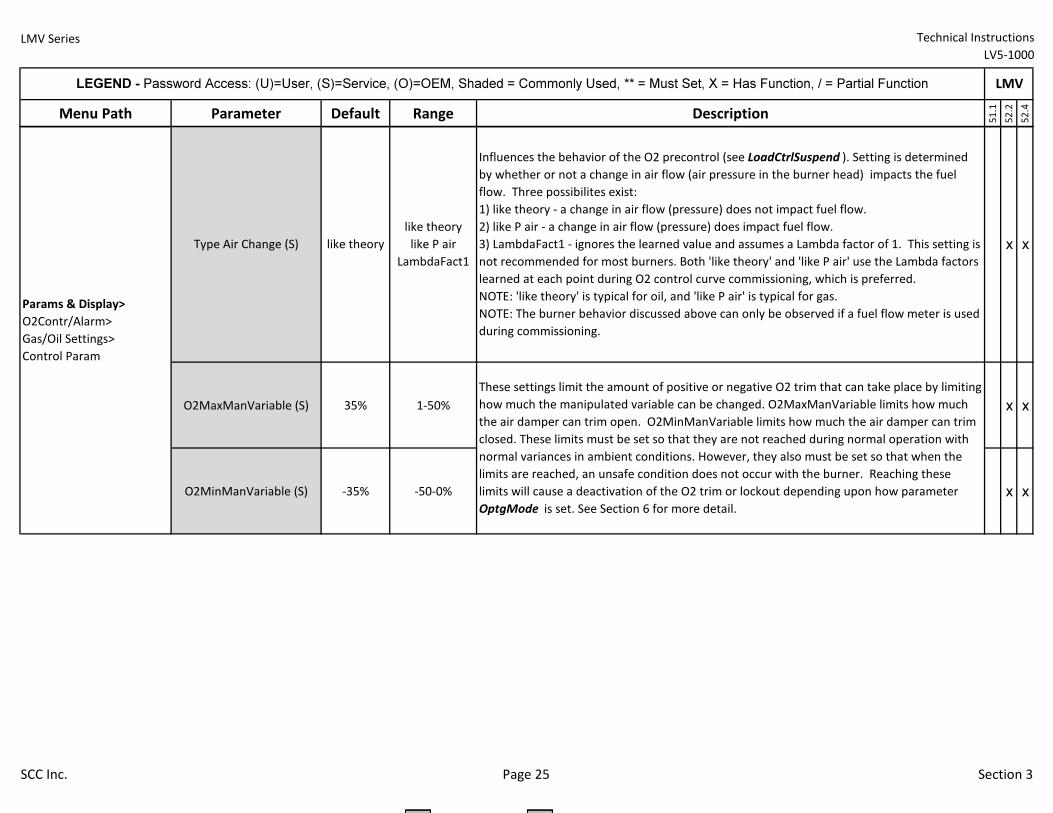
LMV Series Technical Instructions
LV5-1000
Menu Path Parameter Default Range Description
51.1
52.2
52.4
LEGEND - Password Access: (U)=User, (S)=Service, (O)=OEM, Shaded = Commonly Used, ** = Must Set, X = Has Function, / = Partial Function LMV
O2MaxManVariable (S) 35% 1-50% x x
O2MinManVariable (S) -35% -50-0% x x
x x
Influences the behavior of the O2 precontrol (see LoadCtrlSuspend ). Setting is determined
by whether or not a change in air flow (air pressure in the burner head) impacts the fuel
flow. Three possibilites exist:
1) like theory - a change in air flow (pressure) does not impact fuel flow.
2) like P air - a change in air flow (pressure) does impact fuel flow.
3) LambdaFact1 - ignores the learned value and assumes a Lambda factor of 1. This setting is
not recommended for most burners. Both 'like theory' and 'like P air' use the Lambda factors
learned at each point during O2 control curve commissioning, which is preferred.
NOTE: 'like theory' is typical for oil, and 'like P air' is typical for gas.
NOTE: The burner behavior discussed above can only be observed if a fuel flow meter is used
during commissioning.
These settings limit the amount of positive or negative O2 trim that can take place by limiting
how much the manipulated variable can be changed. O2MaxManVariable limits how much
the air damper can trim open. O2MinManVariable limits how much the air damper can trim
closed. These limits must be set so that they are not reached during normal operation with
normal variances in ambient conditions. However, they also must be set so that when the
limits are reached, an unsafe condition does not occur with the burner. Reaching these
limits will cause a deactivation of the O2 trim or lockout depending upon how parameter
OptgMode is set. See Section 6 for more detail.
Type Air Change (S) like theory
like theory
like P air
LambdaFact1
Params & Display>
O2Contr/Alarm>
Gas/Oil Settings>
Control Param
SCC Inc. Page 25 Section 3
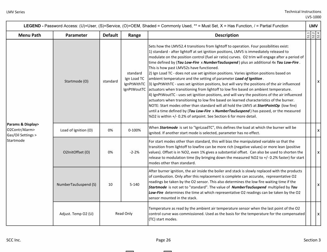
LMV Series Technical Instructions
LV5-1000
Menu Path Parameter Default Range Description
51.1
52.2
52.4
LEGEND - Password Access: (U)=User, (S)=Service, (O)=OEM, Shaded = Commonly Used, ** = Must Set, X = Has Function, / = Partial Function LMV
Startmode (O) standard
standard
Ign Load TC
IgnPtWithTC
IgnPtWoutTC
Sets how the LMV52.4 transitions from lightoff to operation. Four possibilities exist:
1) standard - after lightoff at set ignition positions, LMV5 is immediately released to
modulate on the position control (fuel air ratio) curves. O2 trim will engage after a period of
time defined by (Tau Low-Fire x NumberTauSuspend ) plus an additional 4x Tau Low-Fire .
This is how past LMV52s have functioned.
2) Ign Load TC - does not use set ignition positions. Varies ignition positions based on
ambient temperature and the setting of parameter Load of Ignition .
3) IgnPtWithTC - uses set ignition positions, but will vary the positions of the air influenced
actuators when transitioning from lightoff to low fire based on ambient temperature.
4) IgnPtWoutTC - uses set ignition positions, and will vary the positions of the air influenced
actuators when transitioning to low fire based on learned characteristics of the burner.
NOTE: Start modes other than standard will all hold the LMV5 at StartPointOp (low fire)
until a time defined by (Tau Low-Fire x NumberTauSuspend ) has passed, or the measured
%O2 is within +/- 0.2% of setpoint. See Section 6 for more detail.
x
Load of Ignition (O) 0% 0-100%When Startmode is set to "IgnLoadTC", this defines the load at which the burner will be
ignited. If another start mode is selected, parameter has no effect.x
O2InitOffset (O) 0% -2-2%
For start modes other than standard, this will bias the manipulated variable so that the
transition from lightoff to lowfire can be more rich (negative values) or more lean (positive
values). Offset is in %O2, even 1% gives a substantial offset. Can also be used to shorten the
release to modulation time (by bringing down the measured %O2 to +/- 0.2% faster) for start
modes other than standard.
x
NumberTauSuspend (S) 10 5-140
After burner ignition, the air inside the boiler and stack is slowly replaced with the products
of combustion. Only after this replacement is complete can accurate, representative O2
readings be taken by the O2 sensor. This also determines the low fire waiting time if the
Startmode is not set to "standard". The value of NumberTauSuspend multiplied by Tau
Low-Fire determines the time at which representative O2 readings can be taken by the O2
sensor mounted in the stack.
x
Adjust. Temp O2 (U)
Temperature as read by the ambient air temperature sensor when the last point of the O2
control curve was commissioned. Used as the basis for the temperature for the compensated
(TC) start modes.
xRead Only
Params & Display>
O2Contr/Alarm>
Gas/Oil Settings >
Startmode
SCC Inc. Page 26 Section 3
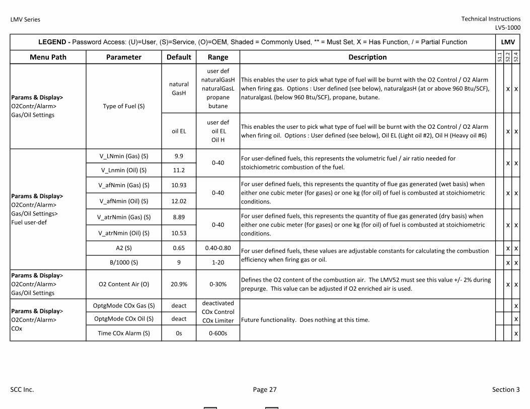
LMV Series Technical Instructions
LV5-1000
Menu Path Parameter Default Range Description
51.1
52.2
52.4
LEGEND - Password Access: (U)=User, (S)=Service, (O)=OEM, Shaded = Commonly Used, ** = Must Set, X = Has Function, / = Partial Function LMV
natural
GasH
user def
naturalGasH
naturalGasL
propane
butane
This enables the user to pick what type of fuel will be burnt with the O2 Control / O2 Alarm
when firing gas. Options : User defined (see below), naturalgasH (at or above 960 Btu/SCF),
naturalgasL (below 960 Btu/SCF), propane, butane.
x x
oil EL
user def
oil EL
Oil H
This enables the user to pick what type of fuel will be burnt with the O2 Control / O2 Alarm
when firing oil. Options : User defined (see below), Oil EL (Light oil #2), Oil H (Heavy oil #6)x x
V_LNmin (Gas) (S) 9.9
V_Lnmin (Oil) (S) 11.2
V_afNmin (Gas) (S) 10.93
V_afNmin (Oil) (S) 12.02
V_atrNmin (Gas) (S) 8.89
V_atrNmin (Oil) (S) 10.53
OptgMode COx Gas (S) deact x
OptgMode COx Oil (S) deact x
Time COx Alarm (S) 0s 0-600s x
Params & Display>
O2Contr/Alarm>
COx
deactivated
COx Control
COx Limiter Future functionality. Does nothing at this time.
9 1-20
x x
x x
x x
x x
x x
x xDefines the O2 content of the combustion air. The LMV52 must see this value +/- 2% during
prepurge. This value can be adjusted if O2 enriched air is used.
For user-defined fuels, this represents the volumetric fuel / air ratio needed for
stoichiometric combustion of the fuel.
For user defined fuels, this represents the quantity of flue gas generated (wet basis) when
either one cubic meter (for gases) or one kg (for oil) of fuel is combusted at stoichiometric
conditions.
For user defined fuels, this represents the quantity of flue gas generated (dry basis) when
either one cubic meter (for gases) or one kg (for oil) of fuel is combusted at stoichiometric
conditions.
A2 (S) For user defined fuels, these values are adjustable constants for calculating the combustion
efficiency when firing gas or oil.
0-40
0-40
0-40
0.65 0.40-0.80
Type of Fuel (S)
O2 Content Air (O) 20.9% 0-30%
B/1000 (S)
Params & Display>
O2Contr/Alarm>
Gas/Oil Settings>
Fuel user-def
Params & Display>
O2Contr/Alarm>
Gas/Oil Settings
Params & Display>
O2Contr/Alarm>
Gas/Oil Settings
SCC Inc. Page 27 Section 3
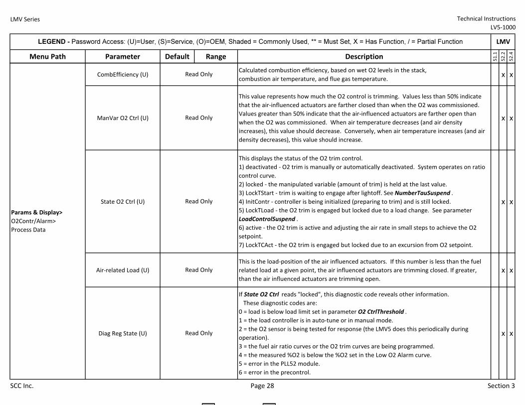
LMV Series Technical Instructions
LV5-1000
Menu Path Parameter Default Range Description
51.1
52.2
52.4
LEGEND - Password Access: (U)=User, (S)=Service, (O)=OEM, Shaded = Commonly Used, ** = Must Set, X = Has Function, / = Partial Function LMV
CombEfficiency (U)Calculated combustion efficiency, based on wet O2 levels in the stack,
combustion air temperature, and flue gas temperature.x x
ManVar O2 Ctrl (U)
This value represents how much the O2 control is trimming. Values less than 50% indicate
that the air-influenced actuators are farther closed than when the O2 was commissioned.
Values greater than 50% indicate that the air-influenced actuators are farther open than
when the O2 was commissioned. When air temperature decreases (and air density
increases), this value should decrease. Conversely, when air temperature increases (and air
density decreases), this value should increase.
x x
State O2 Ctrl (U)
This displays the status of the O2 trim control.
1) deactivated - O2 trim is manually or automatically deactivated. System operates on ratio
control curve.
2) locked - the manipulated variable (amount of trim) is held at the last value.
3) LockTStart - trim is waiting to engage after lightoff. See NumberTauSuspend .
4) InitContr - controller is being initialized (preparing to trim) and is still locked.
5) LockTLoad - the O2 trim is engaged but locked due to a load change. See parameter
LoadControlSuspend .
6) active - the O2 trim is active and adjusting the air rate in small steps to achieve the O2
setpoint.
7) LockTCAct - the O2 trim is engaged but locked due to an excursion from O2 setpoint.
x x
Air-related Load (U)
This is the load-position of the air influenced actuators. If this number is less than the fuel
related load at a given point, the air influenced actuators are trimming closed. If greater,
than the air influenced actuators are trimming open.
x x
Diag Reg State (U)
If State O2 Ctrl reads "locked", this diagnostic code reveals other information.
These diagnostic codes are:
0 = load is below load limit set in parameter O2 CtrlThreshold .
1 = the load controller is in auto-tune or in manual mode.
2 = the O2 sensor is being tested for response (the LMV5 does this periodically during
operation).
3 = the fuel air ratio curves or the O2 trim curves are being programmed.
4 = the measured %O2 is below the %O2 set in the Low O2 Alarm curve.
5 = error in the PLL52 module.
6 = error in the precontrol.
x x
Read Only
Read Only
Params & Display>
O2Contr/Alarm>
Process Data
Read Only
Read Only
Read Only
SCC Inc. Page 28 Section 3
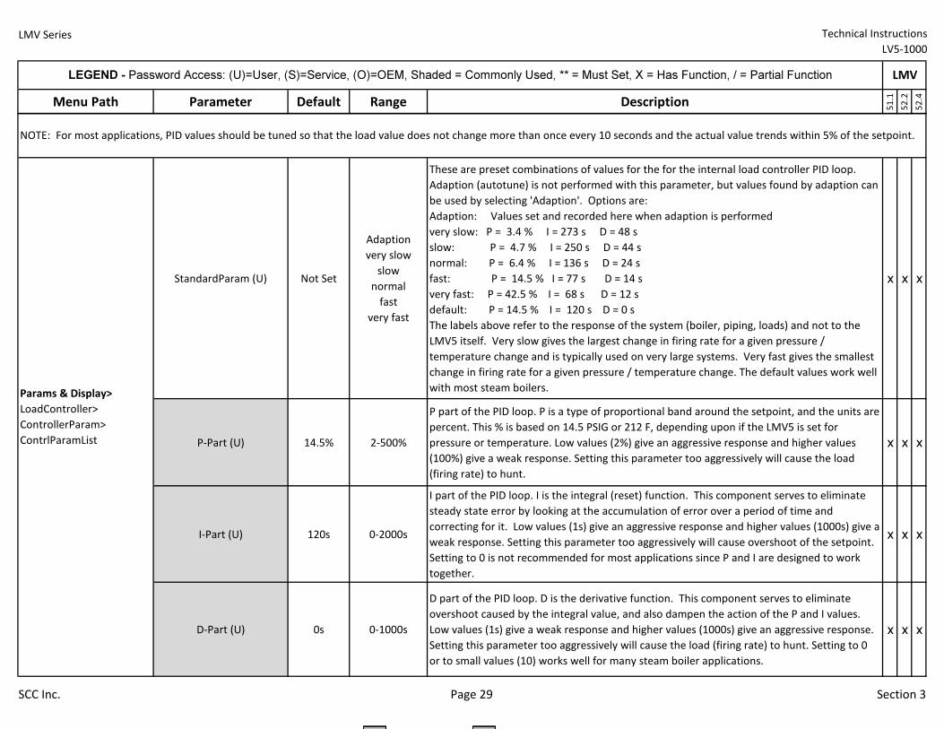
LMV Series Technical Instructions
LV5-1000
Menu Path Parameter Default Range Description
51.1
52.2
52.4
LEGEND - Password Access: (U)=User, (S)=Service, (O)=OEM, Shaded = Commonly Used, ** = Must Set, X = Has Function, / = Partial Function LMV
StandardParam (U) Not Set
Adaption
very slow
slow
normal
fast
very fast
These are preset combinations of values for the for the internal load controller PID loop.
Adaption (autotune) is not performed with this parameter, but values found by adaption can
be used by selecting 'Adaption'. Options are:
Adaption: Values set and recorded here when adaption is performed
very slow: P = 3.4 % I = 273 s D = 48 s
slow: P = 4.7 % I = 250 s D = 44 s
normal: P = 6.4 % I = 136 s D = 24 s
fast: P = 14.5 % I = 77 s D = 14 s
very fast: P = 42.5 % I = 68 s D = 12 s
default: P = 14.5 % I = 120 s D = 0 s
The labels above refer to the response of the system (boiler, piping, loads) and not to the
LMV5 itself. Very slow gives the largest change in firing rate for a given pressure /
temperature change and is typically used on very large systems. Very fast gives the smallest
change in firing rate for a given pressure / temperature change. The default values work well
with most steam boilers.
x x x
P-Part (U) 14.5% 2-500%
P part of the PID loop. P is a type of proportional band around the setpoint, and the units are
percent. This % is based on 14.5 PSIG or 212 F, depending upon if the LMV5 is set for
pressure or temperature. Low values (2%) give an aggressive response and higher values
(100%) give a weak response. Setting this parameter too aggressively will cause the load
(firing rate) to hunt.
x x x
I-Part (U) 120s 0-2000s
I part of the PID loop. I is the integral (reset) function. This component serves to eliminate
steady state error by looking at the accumulation of error over a period of time and
correcting for it. Low values (1s) give an aggressive response and higher values (1000s) give a
weak response. Setting this parameter too aggressively will cause overshoot of the setpoint.
Setting to 0 is not recommended for most applications since P and I are designed to work
together.
x x x
D-Part (U) 0s 0-1000s
D part of the PID loop. D is the derivative function. This component serves to eliminate
overshoot caused by the integral value, and also dampen the action of the P and I values.
Low values (1s) give a weak response and higher values (1000s) give an aggressive response.
Setting this parameter too aggressively will cause the load (firing rate) to hunt. Setting to 0
or to small values (10) works well for many steam boiler applications.
x x x
Params & Display>
LoadController>
ControllerParam>
ContrlParamList
NOTE: For most applications, PID values should be tuned so that the load value does not change more than once every 10 seconds and the actual value trends within 5% of the setpoint.
SCC Inc. Page 29 Section 3
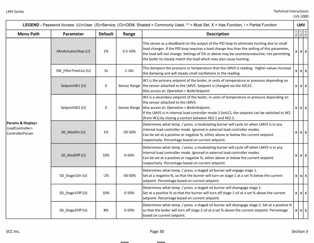
LMV Series Technical Instructions
LV5-1000
Menu Path Parameter Default Range Description
51.1
52.2
52.4
LEGEND - Password Access: (U)=User, (S)=Service, (O)=OEM, Shaded = Commonly Used, ** = Must Set, X = Has Function, / = Partial Function LMV
MinActuatorStep (U) 1% 0.5-10%
This serves as a deadband on the output of the PID loop to eliminate hunting due to small
load changes. If the PID loop requires a load change less than the setting of this parameter,
the load will not change. Settings of 5% or above may be counterproductive, not permitting
the boiler to closely match the load which may also cause hunting.
x x x
SW_FilterTmeCon (U) 3s 1-10sThis dampens the pressure or temperature that the LMV5 is reading. Higher values increase
the damping and will steady small oscillations in the reading.x x x
SetpointW1 (U) 0 Sensor Range
W1 is the primary setpoint of the boiler, in units of temperature or pressure depending on
the sensor attached to the LMV5. Setpoint is changed via the AZL52.
Also access at: Operation > BoilerSetpoint .
x x x
SetpointW2 (U) 0 Sensor Range
W2 is a secondary setpoint of the boiler, in units of temperature or pressure depending on
the sensor attached to the LMV5.
Also access at: Operation > BoilerSetpoint .
If the LMV5 is in internal load controller mode 2 (IntLC), the setpoint can be switched to W2
(from W1) by closing a contact between X62.1 and X62.2.
x x x
SD_ModOn (U) 1% -50-50%
Determines what temp. / press. a modulating burner will cycle on when LMV5 is in any
internal load controller mode. Ignored in external load controller modes.
Can be set at a positive or negative %, either above or below the current setpoint
respectively. Percentage based on current setpoint.
x x x
SD_ModOff (U) 10% 0-50%
Determines what temp. / press. a modulating burner will cycle off when LMV5 is in any
internal load controller mode. Ignored in external load controller modes.
Can be set at a positive or negative %, either above or below the current setpoint
respectively. Percentage based on current setpoint.
x x x
SD_Stage1On (U) -2% -50-50%
Determines what temp. / press. a staged oil burner will engage stage 1.
Set at a negative %, so that the burner will turn on stage 1 at a set % below the current
setpoint. Percentage based on current setpoint.
x x x
SD_Stage1Off (U) 10% 0-50%
Determines what temp. / press. a staged oil burner will disengage stage 1.
Set at a positive % so that the burner will turn off stage 1 oil at a set % above the current
setpoint. Percentage based on current setpoint.
x x x
SD_Stage2Off (U) 8% 0-50%
Determines what temp. / press. a staged oil burner will disengage stage 2. Set at a positive %
so that the boiler will turn off stage 2 oil at a set % above the current setpoint. Percentage
based on current setpoint.
x x x
Params & Display>
LoadController>
ControllerParam
SCC Inc. Page 30 Section 3
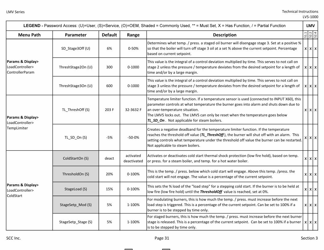
LMV Series Technical Instructions
LV5-1000
Menu Path Parameter Default Range Description
51.1
52.2
52.4
LEGEND - Password Access: (U)=User, (S)=Service, (O)=OEM, Shaded = Commonly Used, ** = Must Set, X = Has Function, / = Partial Function LMV
SD_Stage3Off (U) 6% 0-50%
Determines what temp. / press. a staged oil burner will disengage stage 3. Set at a positive %
so that the boiler will turn off stage 3 oil at a set % above the current setpoint. Percentage
based on current setpoint.
x x x
ThreshStage2On (U) 300 0-1000
This value is the integral of a control deviation multiplied by time. This serves to not call on
stage 2 unless the pressure / temperature deviates from the desired setpoint for a length of
time and/or by a large margin.
x x x
ThreshStage3On (U) 600 0-1000
This value is the integral of a control deviation multiplied by time. This serves to not call on
stage 3 unless the pressure / temperature deviates from the desired setpoint for a length of
time and/or by a large margin.
x x x
TL_ThreshOff (S) 203 F 32-3632 F
Temperature limiter function. If a temperature sensor is used (connected to INPUT X60), this
parameter controls at what temperature the burner goes into alarm and shuts down due to
an over-temperature situation.
The LMV5 locks out. The LMV5 can only be reset when the temperature goes below
TL_SD_On . Not applicable for steam boilers.
x x x
TL_SD_On (S) -5% -50-0%
Creates a negative deadband for the temperature limiter function. If the temperature
reaches the threshold off value (TL_ThreshOff ), the burner will shut off with an alarm. This
setting controls what temperature under the threshold off value the burner can be restarted.
Not applicable to steam boilers.
x x x
ColdStartOn (S) deactactivated
deactivated
Activates or deactivates cold start thermal shock protection (low fire hold), based on temp.
or press. for a steam boiler, and temp. for a hot water boiler.x x x
ThresholdOn (S) 20% 0-100%This is the temp. / press. below which cold start will engage. Above this temp. /press. the
cold start will not engage. The value is a percentage of the current setpoint.x x x
StageLoad (S) 15% 0-100%This sets the % load of the "load step" for a stepping cold start. If the burner is to be held at
low fire (low fire hold) until the ThresholdOff value is reached, set at 0%.x x x
StageSetp_Mod (S) 5% 1-100%
For modulating burners, this is how much the temp. / press. must increase before the next
load step is triggered. This is a percentage of the current setpoint. Can be set to 100% if a
burner is to be stepped by time only.
x x x
StageSetp_Stage (S) 5% 1-100%
For staged burners, this is how much the temp. / press. must increase before the next burner
stage is released. This is a percentage of the current setpoint. Can be set to 100% if a burner
is to be stepped by time only.
x x x
Params & Display>
LoadController>
TempLimiter
Params & Display>
LoadController>
ColdStart
Params & Display>
LoadController>
ControllerParam
SCC Inc. Page 31 Section 3
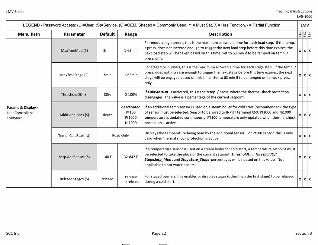
LMV Series Technical Instructions
LV5-1000
Menu Path Parameter Default Range Description
51.1
52.2
52.4
LEGEND - Password Access: (U)=User, (S)=Service, (O)=OEM, Shaded = Commonly Used, ** = Must Set, X = Has Function, / = Partial Function LMV
MaxTmeMod (S) 3min 1-63min
For modulating burners, this is the maximum allowable time for each load step. If the temp.
/ press. does not increase enough to trigger the next load step before this time expires, the
next load step will be taken based on this time. Set to 63 min if to be ramped on temp. /
press. only.
x x x
MaxTmeStage (S) 3min 1-63min
For staged oil burners, this is the maximum allowable time for each stage step. If the temp. /
press. does not increase enough to trigger the next stage before this time expires, the next
stage will be engaged based on this time. Set to 63 min if to be ramped on temp. / press.
only.
x x x
ThresholdOff (S) 80% 0-100%If ColdStartOn is activated, this is the temp. / press. where the thermal shock protection
disengages. The value is a percentage of the current setpoint.x x x
AdditionalSens (S) deact
deactivated
Pt100
Pt1000
Ni1000
If an additional temp sensor is used on a steam boiler for cold start (recommended), the type
of sensor must be selected. Sensor to be wired to INPUT terminal X60. Pt1000 and Ni1000
temperature is updated continuously, PT100 temperature only updated when thermal shock
protection is active.
x x x
Temp. ColdStart (U)Displays the temperature being read by the additional sensor. For Pt100 sensor, this is only
valid when thermal shock protection is active.x x x
Setp AddSensor (S) 140 F 32-842 F
If a temperature sensor is used on a steam boiler for cold start, a temperature setpoint must
be selected to take the place of the current setpoint. ThresholdOn , ThresholdOff ,
StageSetp_Mod , and StageSetp_Stage percentages will be based on this value. Not
applicable to hot water boilers.
x x x
Release Stages (S) releaserelease
no release
For staged burners, this enables or disables stages (other than the first stage) to be released
during a cold start.x x x
Read Only
Params & Display>
LoadController>
ColdStart
SCC Inc. Page 32 Section 3
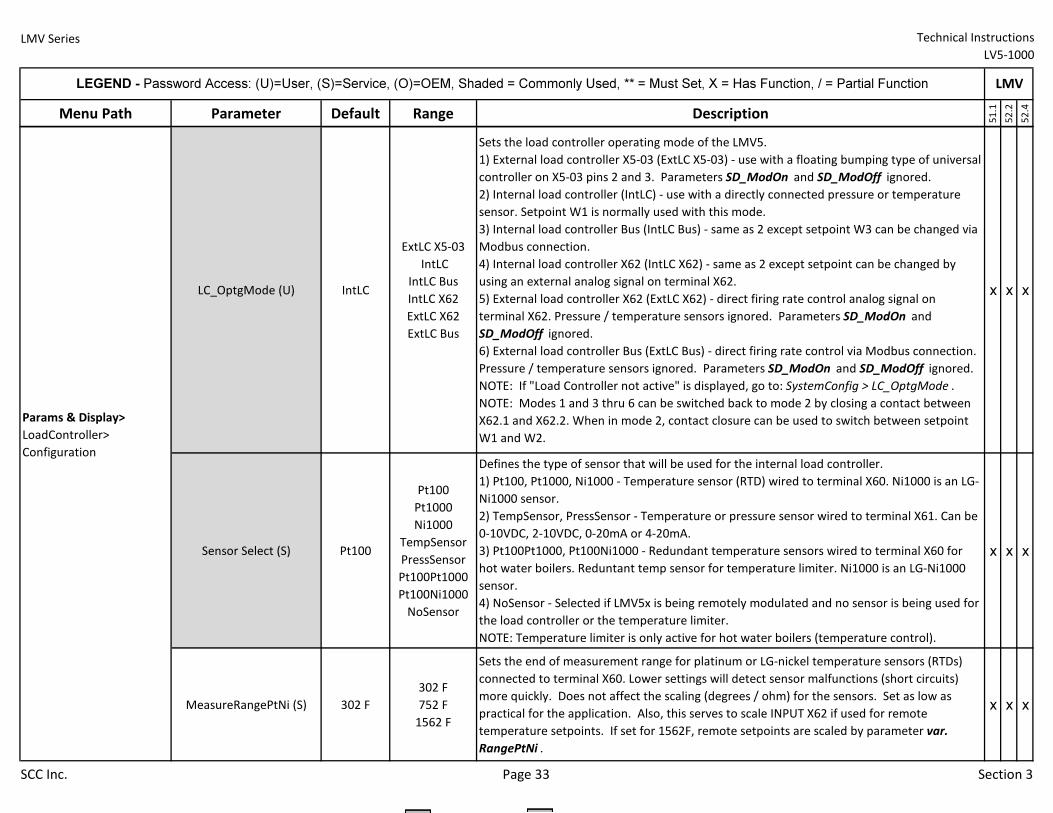
LMV Series Technical Instructions
LV5-1000
Menu Path Parameter Default Range Description
51.1
52.2
52.4
LEGEND - Password Access: (U)=User, (S)=Service, (O)=OEM, Shaded = Commonly Used, ** = Must Set, X = Has Function, / = Partial Function LMV
LC_OptgMode (U) IntLC
ExtLC X5-03
IntLC
IntLC Bus
IntLC X62
ExtLC X62
ExtLC Bus
Sets the load controller operating mode of the LMV5.
1) External load controller X5-03 (ExtLC X5-03) - use with a floating bumping type of universal
controller on X5-03 pins 2 and 3. Parameters SD_ModOn and SD_ModOff ignored.
2) Internal load controller (IntLC) - use with a directly connected pressure or temperature
sensor. Setpoint W1 is normally used with this mode.
3) Internal load controller Bus (IntLC Bus) - same as 2 except setpoint W3 can be changed via
Modbus connection.
4) Internal load controller X62 (IntLC X62) - same as 2 except setpoint can be changed by
using an external analog signal on terminal X62.
5) External load controller X62 (ExtLC X62) - direct firing rate control analog signal on
terminal X62. Pressure / temperature sensors ignored. Parameters SD_ModOn and
SD_ModOff ignored.
6) External load controller Bus (ExtLC Bus) - direct firing rate control via Modbus connection.
Pressure / temperature sensors ignored. Parameters SD_ModOn and SD_ModOff ignored.
NOTE: If "Load Controller not active" is displayed, go to: SystemConfig > LC_OptgMode .
NOTE: Modes 1 and 3 thru 6 can be switched back to mode 2 by closing a contact between
X62.1 and X62.2. When in mode 2, contact closure can be used to switch between setpoint
W1 and W2.
x x x
Sensor Select (S) Pt100
Pt100
Pt1000
Ni1000
TempSensor
PressSensor
Pt100Pt1000
Pt100Ni1000
NoSensor
Defines the type of sensor that will be used for the internal load controller.
1) Pt100, Pt1000, Ni1000 - Temperature sensor (RTD) wired to terminal X60. Ni1000 is an LG-
Ni1000 sensor.
2) TempSensor, PressSensor - Temperature or pressure sensor wired to terminal X61. Can be
0-10VDC, 2-10VDC, 0-20mA or 4-20mA.
3) Pt100Pt1000, Pt100Ni1000 - Redundant temperature sensors wired to terminal X60 for
hot water boilers. Reduntant temp sensor for temperature limiter. Ni1000 is an LG-Ni1000
sensor.
4) NoSensor - Selected if LMV5x is being remotely modulated and no sensor is being used for
the load controller or the temperature limiter.
NOTE: Temperature limiter is only active for hot water boilers (temperature control).
x x x
MeasureRangePtNi (S) 302 F
302 F
752 F
1562 F
Sets the end of measurement range for platinum or LG-nickel temperature sensors (RTDs)
connected to terminal X60. Lower settings will detect sensor malfunctions (short circuits)
more quickly. Does not affect the scaling (degrees / ohm) for the sensors. Set as low as
practical for the application. Also, this serves to scale INPUT X62 if used for remote
temperature setpoints. If set for 1562F, remote setpoints are scaled by parameter var.
RangePtNi .
x x x
Params & Display>
LoadController>
Configuration
SCC Inc. Page 33 Section 3
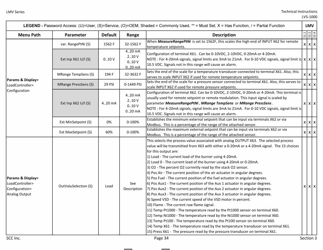
LMV Series Technical Instructions
LV5-1000
Menu Path Parameter Default Range Description
51.1
52.2
52.4
LEGEND - Password Access: (U)=User, (S)=Service, (O)=OEM, Shaded = Commonly Used, ** = Must Set, X = Has Function, / = Partial Function LMV
var. RangePtNi (S) 1562 F 32-1562 FWhen MeasureRangePtNi is set to 1562F, this scales the high end of INPUT X62 for remote
temperature setpoints.x x x
Ext Inp X61 U/I (S) 0..10 V
4..20 mA
2..10 V
0..10 V
0..20 mA
Configuration of terminal X61. Can be 0-10VDC, 2-10VDC, 0-20mA or 4-20mA.
NOTE : For 4-20mA signals, signal limits are 3mA to 21mA. For 0-10 VDC signals, signal limit is
10.5 VDC. Signals not in this range will cause an alarm.
x x x
MRange TempSens (S) 194 F 32-3632 FSets the end of the scale for a temperature transducer connected to terminal X61. Also, this
serves to scale INPUT X62 if used for remote temperature setpoints.x x x
MRange PressSens (S) 29 PSI 0-1449 PSISets the end of the scale for a pressure sensor connected to terminal X61. Also, this serves to
scale INPUT X62 if used for remote pressure setpoints. x x x
Ext Inp X62 U/I (S) 4..20 mA
4..20 mA
2..10 V
0..10 V
0..20 mA
Configuration of terminal X62. Can be 0-10VDC, 2-10VDC, 0-20mA or 4-20mA. This terminal is
usually used for remote setpoint or remote modulation. This input signal is scaled by
parameter MeasureRangePtNi , MRange TempSens or MRange PressSens .
NOTE : For 4-20mA signals, signal limits are 3mA to 21mA. For 0-10 VDC signals, signal limit is
10.5 VDC. Signals not in this range will cause an alarm.
x x x
Ext MinSetpoint (S) 0% 0-100%Establishes the minimum external setpoint that can be input via terminals X62 or via
Modbus. This is a percentage of the range of the attached sensor.x x x
Ext MaxSetpoint (S) 60% 0-100%Establishes the maximum external setpoint that can be input via terminals X62 or via
Modbus. This is a percentage of the range of the attached sensor.x x x
Params & Display>
LoadController>
Configuration>
Analog Output
OutValuSelection (S) LoadSee
Description
This selects the process value associated with analog OUTPUT X63. The selected process
value will be transmitted from X63 with either a 0-20mA or a 4-20mA signal. The 15 choices
for this output are:
1) Load - The current load of the burner using 4-20mA.
2) Load 0 - The current load of the burner using 4-20mA or 0-20mA.
3) O2 - The percent O2 currently read by the stack O2 sensor.
4) Pos Air - The current position of the air actuator in angular degrees.
5) Pos Fuel - The current position of the fuel actuator in angular degrees.
6) Pos Aux1 - The current position of the Aux 1 actuator in angular degrees.
7) Pos Aux2 - The current position of the Aux 2 actuator in angular degrees.
8) Pos Aux3 - The current position of the Aux 3 actuator in angular degrees.
9) Speed VSD - The current speed of the VSD motor in percent.
10) Flame - The current raw flame signal.
11) Temp Pt1000 - The temperature read by the Pt1000 sensor on terminal X60.
12) Temp Ni1000 - The temperature read by the Ni1000 sensor on terminal X60.
13) Temp Pt100 - The temperature read by the Pt100 sensor on terminal X60.
14) Temp X61 - The temperature read by the temperature transducer on terminal X61.
15) Press X61 - The pressure read by the pressure transducer on terminal X61.
x x x
Params & Display>
LoadController>
Configuration
SCC Inc. Page 34 Section 3
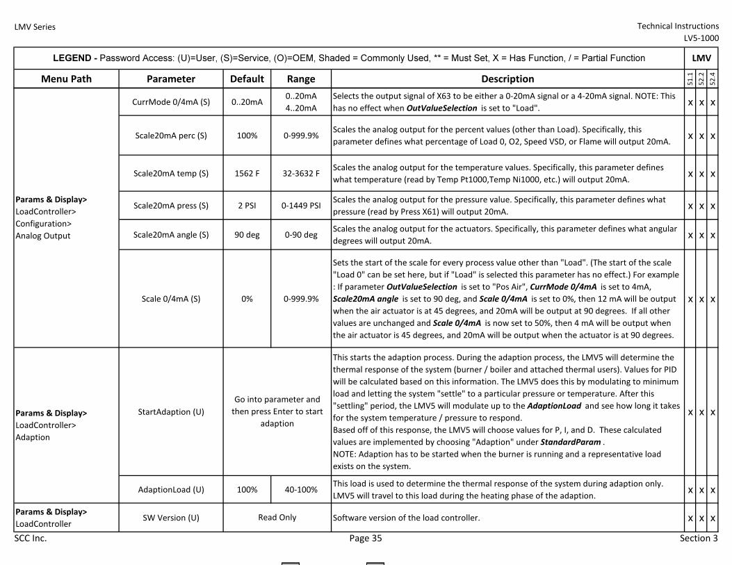
LMV Series Technical Instructions
LV5-1000
Menu Path Parameter Default Range Description
51.1
52.2
52.4
LEGEND - Password Access: (U)=User, (S)=Service, (O)=OEM, Shaded = Commonly Used, ** = Must Set, X = Has Function, / = Partial Function LMV
CurrMode 0/4mA (S) 0..20mA0..20mA
4..20mA
Selects the output signal of X63 to be either a 0-20mA signal or a 4-20mA signal. NOTE: This
has no effect when OutValueSelection is set to "Load".x x x
Scale20mA perc (S) 100% 0-999.9%Scales the analog output for the percent values (other than Load). Specifically, this
parameter defines what percentage of Load 0, O2, Speed VSD, or Flame will output 20mA.x x x
Scale20mA temp (S) 1562 F 32-3632 FScales the analog output for the temperature values. Specifically, this parameter defines
what temperature (read by Temp Pt1000,Temp Ni1000, etc.) will output 20mA.x x x
Scale20mA press (S) 2 PSI 0-1449 PSIScales the analog output for the pressure value. Specifically, this parameter defines what
pressure (read by Press X61) will output 20mA.x x x
Scale20mA angle (S) 90 deg 0-90 degScales the analog output for the actuators. Specifically, this parameter defines what angular
degrees will output 20mA.x x x
Scale 0/4mA (S) 0% 0-999.9%
Sets the start of the scale for every process value other than "Load". (The start of the scale
"Load 0" can be set here, but if "Load" is selected this parameter has no effect.) For example
: If parameter OutValueSelection is set to "Pos Air", CurrMode 0/4mA is set to 4mA,
Scale20mA angle is set to 90 deg, and Scale 0/4mA is set to 0%, then 12 mA will be output
when the air actuator is at 45 degrees, and 20mA will be output at 90 degrees. If all other
values are unchanged and Scale 0/4mA is now set to 50%, then 4 mA will be output when
the air actuator is 45 degrees, and 20mA will be output when the actuator is at 90 degrees.
x x x
StartAdaption (U)
This starts the adaption process. During the adaption process, the LMV5 will determine the
thermal response of the system (burner / boiler and attached thermal users). Values for PID
will be calculated based on this information. The LMV5 does this by modulating to minimum
load and letting the system "settle" to a particular pressure or temperature. After this
"settling" period, the LMV5 will modulate up to the AdaptionLoad and see how long it takes
for the system temperature / pressure to respond.
Based off of this response, the LMV5 will choose values for P, I, and D. These calculated
values are implemented by choosing "Adaption" under StandardParam .
NOTE: Adaption has to be started when the burner is running and a representative load
exists on the system.
x x x
AdaptionLoad (U) 100% 40-100%This load is used to determine the thermal response of the system during adaption only.
LMV5 will travel to this load during the heating phase of the adaption. x x x
Params & Display>
LoadController SW Version (U) Software version of the load controller. x x x
Params & Display>
LoadController>
Configuration>
Analog Output
Go into parameter and
then press Enter to start
adaption
Read Only
Params & Display>
LoadController>
Adaption
SCC Inc. Page 35 Section 3
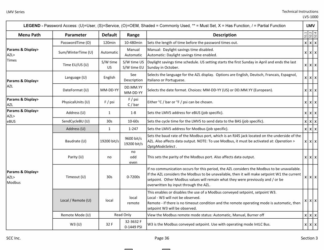
LMV Series Technical Instructions
LV5-1000
Menu Path Parameter Default Range Description
51.1
52.2
52.4
LEGEND - Password Access: (U)=User, (S)=Service, (O)=OEM, Shaded = Commonly Used, ** = Must Set, X = Has Function, / = Partial Function LMV
PasswordTime (O) 120min 10-480min Sets the length of time before the password times out. x x x
Sum/WinterTime (U) Automatic Manual
Automatic
Manual: Daylight savings time disabled.
Automatic: Daylight savings time enabled.x x x
Time EU/US (U)S/W time
US
S/W time US
S/W time EU
Daylight savings time schedule. US setting starts the first Sunday in April and ends the last
Sunday in October.x x x
Language (U) EnglishSee
Description
Selects the language for the AZL display. Options are English, Deutsch, Francais, Espagnol,
Italiano or Portuguese.x x x
DateFormat (U) MM-DD-YYDD.MM.YY
MM-DD-YYSelects the date format. Choices: MM-DD-YY (US) or DD.MM.YY (European). x x x
Params & Display>
AZLPhysicalUnits (U) F / psi
F / psi
C / barEither °C / bar or °F / psi can be chosen. x x x
Address (U) 1 1-8 Sets the LMV5 address for eBUS (job specific). x x x
SendCycleBU (U) 30s 10-60s Sets the cycle time for the LMV5 to send data to the BAS (job specific). x x x
Address (U) 1 1-247 Sets the LMV5 address for Modbus (job specific). x x x
Baudrate (U) 19200 bit/s9600 bit/s
19200 bit/s
Sets the baud rate of the Modbus port, which is an RJ45 jack located on the underside of the
AZL. Also affects data output. NOTE: To use Modbus, it must be activated at: Operation >
OptgModeSelect .
x x x
Parity (U) no
no
odd
even
This sets the parity of the Modbus port. Also affects data output. x x x
Timeout (U) 30s 0-7200s
If no communication occurs for this period, the AZL considers the Modbus to be unavailable.
If the AZL considers the Modbus to be unavailable, then it will make setpoint W1 the current
setpoint. Other Modbus values will remain what they were previously and / or be
overwritten by input through the AZL.
x x x
Local / Remote (U) locallocal
remote
This enables or disables the use of a Modbus conveyed setpoint, setpoint W3.
Local - W3 will not be observed.
Remote - if there is no timeout condition and the remote operating mode is automatic, then
setpoint W3 will be observed.
x x x
Remote Mode (U) View the Modbus remote mode status: Automatic, Manual, Burner off x x x
W3 (U) 32 F32-3632 F
0-1449 PSIW3 is the Modbus conveyed setpoint. Use with operating mode IntLC Bus. x x x
Read Only
Params & Display>
AZL>
Times
Params & Display>
AZL
Params & Display>
AZL>
eBUS
Params & Display>
AZL>
Modbus
SCC Inc. Page 36 Section 3
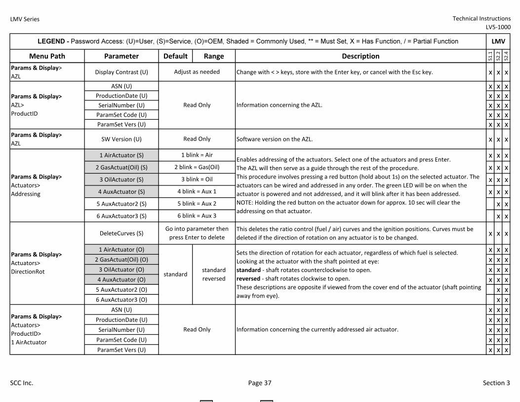
LMV Series Technical Instructions
LV5-1000
Menu Path Parameter Default Range Description
51.1
52.2
52.4
LEGEND - Password Access: (U)=User, (S)=Service, (O)=OEM, Shaded = Commonly Used, ** = Must Set, X = Has Function, / = Partial Function LMV
Params & Display>
AZLDisplay Contrast (U) Change with < > keys, store with the Enter key, or cancel with the Esc key. x x x
ASN (U) x x x
ProductionDate (U) x x x
SerialNumber (U) x x x
ParamSet Code (U) x x x
ParamSet Vers (U) x x x
Params & Display>
AZLSW Version (U) Software version on the AZL. x x x
1 AirActuator (S) x x x
2 GasActuat(Oil) (S) x x x
3 OilActuator (S) x x x
4 AuxActuator (S) x x x
5 AuxActuator2 (S) x x
6 AuxActuator3 (S) x x
DeleteCurves (S)This deletes the ratio control (fuel / air) curves and the ignition positions. Curves must be
deleted if the direction of rotation on any actuator is to be changed.x x x
1 AirActuator (O) x x x
2 GasActuat(Oil) (O) x x x
3 OilActuator (O) x x x
4 AuxActuator (O) x x x
5 AuxActuator2 (O) x x
6 AuxActuator3 (O) x x
ASN (U) x x x
ProductionDate (U) x x x
SerialNumber (U) x x x
ParamSet Code (U) x x x
ParamSet Vers (U) x x x
Information concerning the AZL.
Enables addressing of the actuators. Select one of the actuators and press Enter.
The AZL will then serve as a guide through the rest of the procedure.
This procedure involves pressing a red button (hold about 1s) on the selected actuator. The
actuators can be wired and addressed in any order. The green LED will be on when the
actuator is powered and not addressed, and it will blink after it has been addressed.
NOTE: Holding the red button on the actuator down for approx. 10 sec will clear the
addressing on that actuator.
Adjust as needed
Read Only
Read Only
1 blink = Air
2 blink = Gas(Oil)
3 blink = Oil
4 blink = Aux 1
5 blink = Aux 2
6 blink = Aux 3
Params & Display>
Actuators>
Addressing
Sets the direction of rotation for each actuator, regardless of which fuel is selected.
Looking at the actuator with the shaft pointed at eye:
standard - shaft rotates counterclockwise to open.
reversed - shaft rotates clockwise to open.
These descriptions are opposite if viewed from the cover end of the actuator (shaft pointing
away from eye).
Params & Display>
Actuators>
ProductID>
1 AirActuator
Information concerning the currently addressed air actuator.
Params & Display>
Actuators>
DirectionRot
Go into parameter then
press Enter to delete
standardstandard
reversed
Read Only
Params & Display>
AZL>
ProductID
SCC Inc. Page 37 Section 3
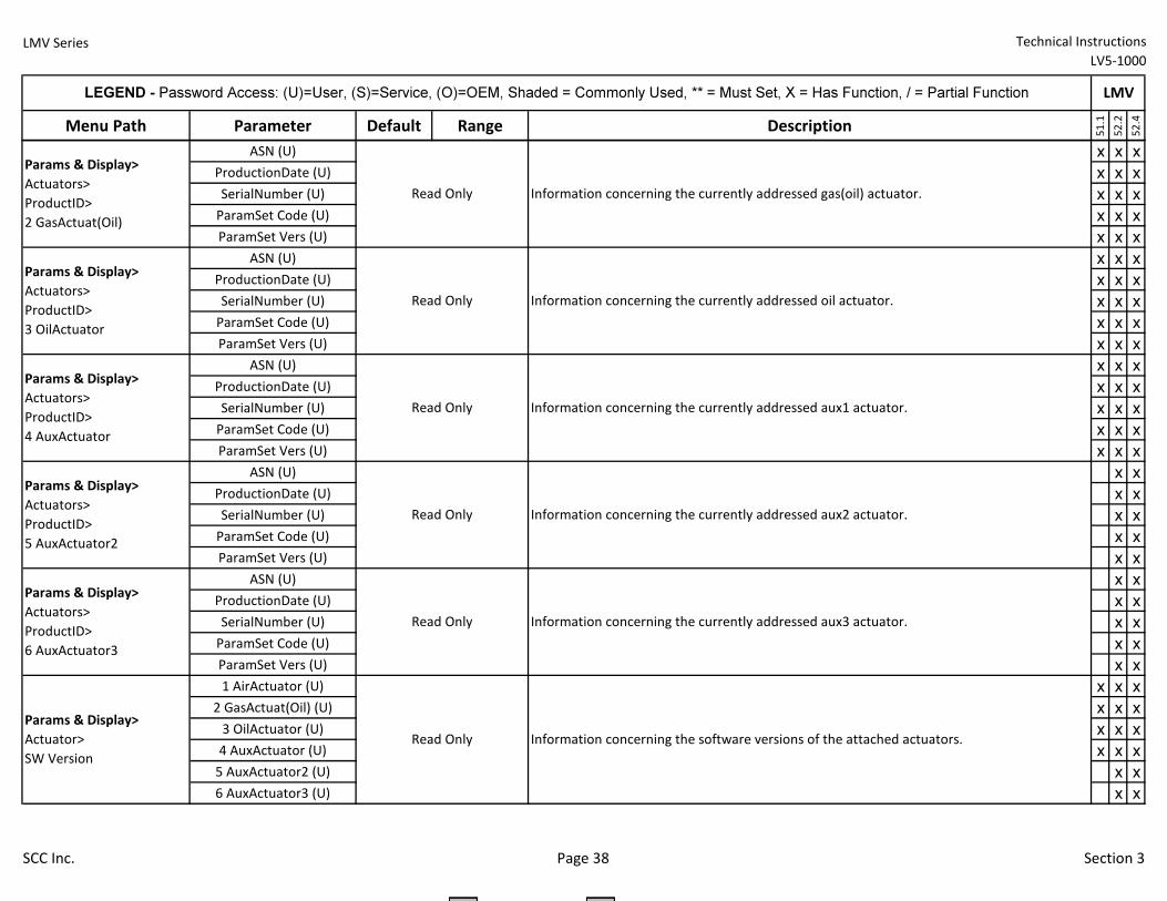
LMV Series Technical Instructions
LV5-1000
Menu Path Parameter Default Range Description
51.1
52.2
52.4
LEGEND - Password Access: (U)=User, (S)=Service, (O)=OEM, Shaded = Commonly Used, ** = Must Set, X = Has Function, / = Partial Function LMV
ASN (U) x x x
ProductionDate (U) x x x
SerialNumber (U) x x x
ParamSet Code (U) x x x
ParamSet Vers (U) x x x
ASN (U) x x x
ProductionDate (U) x x x
SerialNumber (U) x x x
ParamSet Code (U) x x x
ParamSet Vers (U) x x x
ASN (U) x x x
ProductionDate (U) x x x
SerialNumber (U) x x x
ParamSet Code (U) x x x
ParamSet Vers (U) x x x
ASN (U) x x
ProductionDate (U) x x
SerialNumber (U) x x
ParamSet Code (U) x x
ParamSet Vers (U) x x
ASN (U) x x
ProductionDate (U) x x
SerialNumber (U) x x
ParamSet Code (U) x x
ParamSet Vers (U) x x
1 AirActuator (U) x x x
2 GasActuat(Oil) (U) x x x
3 OilActuator (U) x x x
4 AuxActuator (U) x x x
5 AuxActuator2 (U) x x
6 AuxActuator3 (U) x x
Information concerning the currently addressed aux1 actuator.
Read Only
Params & Display>
Actuators>
ProductID>
5 AuxActuator2
Information concerning the currently addressed aux2 actuator.
Params & Display>
Actuators>
ProductID>
6 AuxActuator3
Information concerning the currently addressed aux3 actuator.
Params & Display>
Actuators>
ProductID>
2 GasActuat(Oil)
Information concerning the currently addressed gas(oil) actuator.
Params & Display>
Actuators>
ProductID>
3 OilActuator
Information concerning the currently addressed oil actuator.
Params & Display>
Actuators>
ProductID>
4 AuxActuator
Read Only
Read Only
Read Only
Read Only
Information concerning the software versions of the attached actuators.Read Only
Params & Display>
Actuator>
SW Version
SCC Inc. Page 38 Section 3
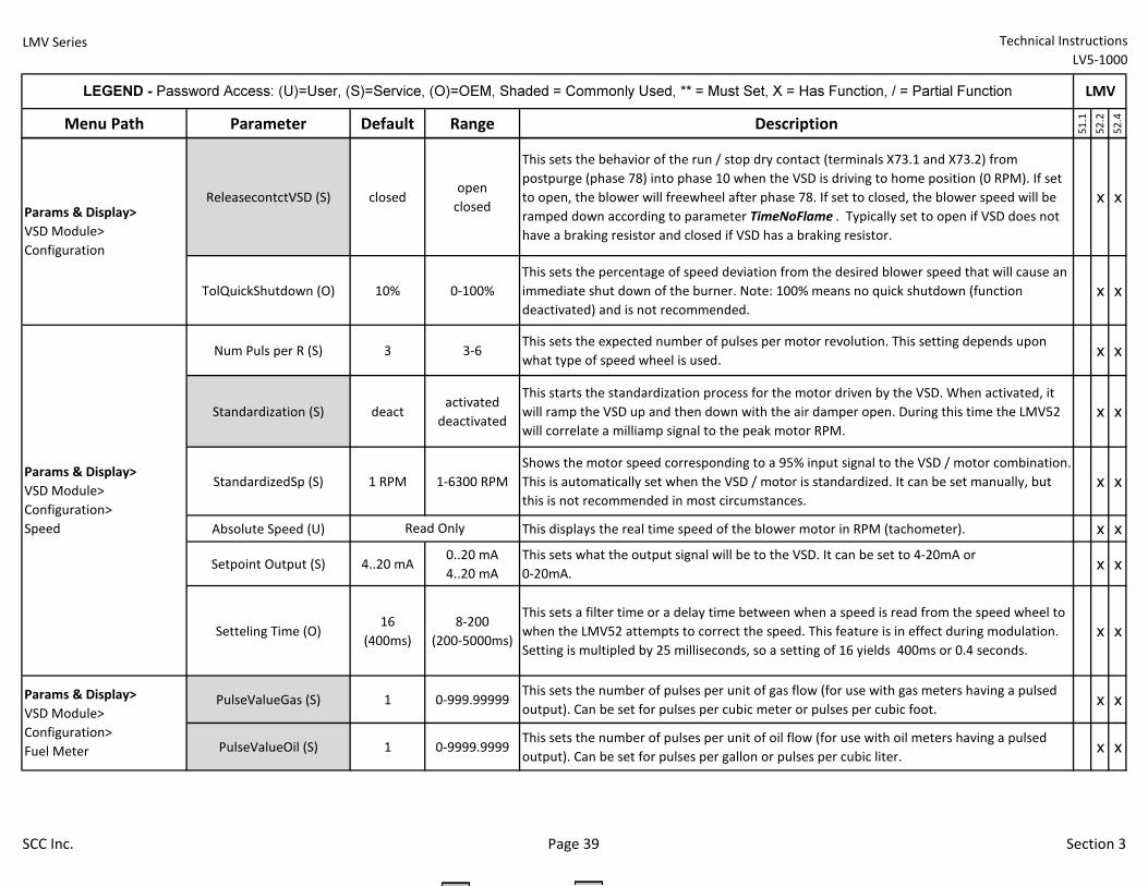
LMV Series Technical Instructions
LV5-1000
Menu Path Parameter Default Range Description
51.1
52.2
52.4
LEGEND - Password Access: (U)=User, (S)=Service, (O)=OEM, Shaded = Commonly Used, ** = Must Set, X = Has Function, / = Partial Function LMV
ReleasecontctVSD (S) closedopen
closed
This sets the behavior of the run / stop dry contact (terminals X73.1 and X73.2) from
postpurge (phase 78) into phase 10 when the VSD is driving to home position (0 RPM). If set
to open, the blower will freewheel after phase 78. If set to closed, the blower speed will be
ramped down according to parameter TimeNoFlame . Typically set to open if VSD does not
have a braking resistor and closed if VSD has a braking resistor.
x x
TolQuickShutdown (O) 10% 0-100%
This sets the percentage of speed deviation from the desired blower speed that will cause an
immediate shut down of the burner. Note: 100% means no quick shutdown (function
deactivated) and is not recommended.
x x
Num Puls per R (S) 3 3-6This sets the expected number of pulses per motor revolution. This setting depends upon
what type of speed wheel is used.x x
Standardization (S) deactactivated
deactivated
This starts the standardization process for the motor driven by the VSD. When activated, it
will ramp the VSD up and then down with the air damper open. During this time the LMV52
will correlate a milliamp signal to the peak motor RPM.
x x
StandardizedSp (S) 1 RPM 1-6300 RPM
Shows the motor speed corresponding to a 95% input signal to the VSD / motor combination.
This is automatically set when the VSD / motor is standardized. It can be set manually, but
this is not recommended in most circumstances.
x x
Absolute Speed (U) This displays the real time speed of the blower motor in RPM (tachometer). x x
Setpoint Output (S) 4..20 mA0..20 mA
4..20 mA
This sets what the output signal will be to the VSD. It can be set to 4-20mA or
0-20mA.x x
Setteling Time (O)16
(400ms)
8-200
(200-5000ms)
This sets a filter time or a delay time between when a speed is read from the speed wheel to
when the LMV52 attempts to correct the speed. This feature is in effect during modulation.
Setting is multipled by 25 milliseconds, so a setting of 16 yields 400ms or 0.4 seconds.
x x
PulseValueGas (S) 1 0-999.99999This sets the number of pulses per unit of gas flow (for use with gas meters having a pulsed
output). Can be set for pulses per cubic meter or pulses per cubic foot.x x
PulseValueOil (S) 1 0-9999.9999This sets the number of pulses per unit of oil flow (for use with oil meters having a pulsed
output). Can be set for pulses per gallon or pulses per cubic liter.x x
Params & Display>
VSD Module>
Configuration
Params & Display>
VSD Module>
Configuration>
Speed Read Only
Params & Display>
VSD Module>
Configuration>
Fuel Meter
SCC Inc. Page 39 Section 3
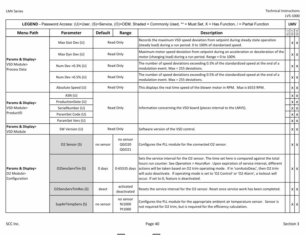
LMV Series Technical Instructions
LV5-1000
Menu Path Parameter Default Range Description
51.1
52.2
52.4
LEGEND - Password Access: (U)=User, (S)=Service, (O)=OEM, Shaded = Commonly Used, ** = Must Set, X = Has Function, / = Partial Function LMV
Max Stat Dev (U)Records the maximum VSD speed deviation from setpoint during steady state operation
(steady load) during a run period. 0 to 100% of standarized speed.x x
Max Dyn Dev (U)Maximum motor speed deviation from setpoint during an acceleration or deceleration of the
motor (changing load) during a run period. Range = 0 to 100%x x
Num Dev >0.3% (U)The number of speed deviations exceeding 0.3% of the standardized speed at the end of a
modulation event. Max = 255 deviations.x x
Num Dev >0.5% (U)The number of speed deviations exceeding 0.5% of the standardized speed at the end of a
modulation event. Max = 255 deviations.x x
Absolute Speed (U) This displays the real time speed of the blower motor in RPM. Max is 6553 RPM. x x
ASN (U) x x
ProductionDate (U) x x
SerialNumber (U) x x
ParamSet Code (U) x x
ParamSet Vers (U) x x
Params & Display>
VSD ModuleSW Version (U) Software version of the VSD control. x x
O2 Sensor (S) no sensor
no sensor
QGO20
QGO21
Configures the PLL module for the connected O2 sensor. x x
O2SensServTim (S) 0 days 0-65535 days
Sets the service interval for the O2 sensor. The time set here is compared against the total
hours run counter. See Operation > HoursRun . Upon expiration of service interval, different
actions will be taken based on O2 trim operating mode. If in 'conAutoDeac', then O2 trim
will auto deactivate. If operating mode is set to 'O2 Control' or 'O2 Alarm', a lockout will
occur. If set to 0, feature is deactivated.
x x
O2SensServTimRes (S) deactactivated
deactivatedResets the service interval for the O2 sensor. Reset once service work has been completed. x x
SupAirTempSens (S) no sensor
no sensor
Ni1000
Pt1000
Configures the PLL module for the appropriate ambient air temperature sensor. Sensor is
not required for O2 trim, but is required for the efficiency calculation.x x
Information concerning the VSD board (pieces internal to the LMV5).
Read Only
Read Only
Read Only
Read Only
Read Only
Read Only
Read Only
Params & Display>
VSD Module>
Process Data
Params & Display>
VSD Module>
ProductID
Params & Display>
O2 Module>
Configuration
SCC Inc. Page 40 Section 3
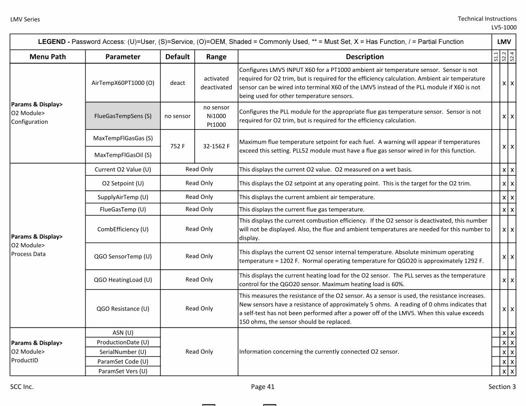
LMV Series Technical Instructions
LV5-1000
Menu Path Parameter Default Range Description
51.1
52.2
52.4
LEGEND - Password Access: (U)=User, (S)=Service, (O)=OEM, Shaded = Commonly Used, ** = Must Set, X = Has Function, / = Partial Function LMV
AirTempX60PT1000 (O) deactactivated
deactivated
Configures LMV5 INPUT X60 for a PT1000 ambient air temperature sensor. Sensor is not
required for O2 trim, but is required for the efficiency calculation. Ambient air temperature
sensor can be wired into terminal X60 of the LMV5 instead of the PLL module if X60 is not
being used for other temperature sensors.
x x
FlueGasTempSens (S) no sensor
no sensor
Ni1000
Pt1000
Configures the PLL module for the appropriate flue gas temperature sensor. Sensor is not
required for O2 trim, but is required for the efficiency calculation.x x
MaxTempFlGasGas (S)
MaxTempFlGasOil (S)
Current O2 Value (U) This displays the current O2 value. O2 measured on a wet basis. x x
O2 Setpoint (U) This displays the O2 setpoint at any operating point. This is the target for the O2 trim. x x
SupplyAirTemp (U) This displays the current ambient air temperature. x x
FlueGasTemp (U) This displays the current flue gas temperature. x x
CombEfficiency (U)
This displays the current combustion efficiency. If the O2 sensor is deactivated, this number
will not be displayed. Also, the flue and ambient temperatures are needed for this number to
display.
x x
QGO SensorTemp (U)This displays the current O2 sensor internal temperature. Absolute minimum operating
temperature = 1202 F. Normal operating temperature for QGO20 is approximately 1292 F.x x
QGO HeatingLoad (U)This displays the current heating load for the O2 sensor. The PLL serves as the temperature
control for the QGO20 sensor. Maximum heating load is 60%.x x
QGO Resistance (U)
This measures the resistance of the O2 sensor. As a sensor is used, the resistance increases.
New sensors have a resistance of approximately 5 ohms. A reading of 0 ohms indicates that
a self-test has not been performed after a power off of the LMV5. When this value exceeds
150 ohms, the sensor should be replaced.
x x
ASN (U) x x
ProductionDate (U) x x
SerialNumber (U) x x
ParamSet Code (U) x x
ParamSet Vers (U) x x
Read Only
Read Only
Read Only
Read Only
x x
Params & Display>
O2 Module>
ProductID
Information concerning the currently connected O2 sensor.
Maximum flue temperature setpoint for each fuel. A warning will appear if temperatures
exceed this setting. PLL52 module must have a flue gas sensor wired in for this function.
Params & Display>
O2 Module>
Configuration
752 F 32-1562 F
Params & Display>
O2 Module>
Process Data Read Only
Read Only
Read Only
Read Only
Read Only
SCC Inc. Page 41 Section 3
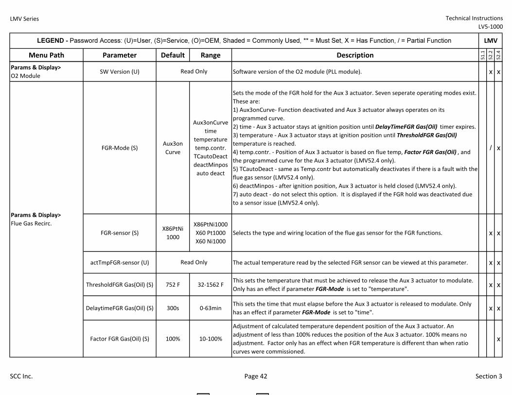
LMV Series Technical Instructions
LV5-1000
Menu Path Parameter Default Range Description
51.1
52.2
52.4
LEGEND - Password Access: (U)=User, (S)=Service, (O)=OEM, Shaded = Commonly Used, ** = Must Set, X = Has Function, / = Partial Function LMV
Params & Display>
O2 ModuleSW Version (U) Software version of the O2 module (PLL module). x x
FGR-Mode (S)Aux3on
Curve
Aux3onCurve
time
temperature
temp.contr.
TCautoDeact
deactMinpos
auto deact
Sets the mode of the FGR hold for the Aux 3 actuator. Seven seperate operating modes exist.
These are:
1) Aux3onCurve- Function deactivated and Aux 3 actuator always operates on its
programmed curve.
2) time - Aux 3 actuator stays at ignition position until DelayTimeFGR Gas(Oil) timer expires.
3) temperature - Aux 3 actuator stays at ignition position until ThresholdFGR Gas(Oil)
temperature is reached.
4) temp.contr. - Position of Aux 3 actuator is based on flue temp, Factor FGR Gas(Oil) , and
the programmed curve for the Aux 3 actuator (LMV52.4 only).
5) TCautoDeact - same as Temp.contr but automatically deactivates if there is a fault with the
flue gas sensor (LMV52.4 only).
6) deactMinpos - after ignition position, Aux 3 actuator is held closed (LMV52.4 only).
7) auto deact - do not select this option. It is displayed if the FGR hold was deactivated due
to a sensor issue (LMV52.4 only).
/ x
FGR-sensor (S)X86PtNi
1000
X86PtNi1000
X60 Pt1000
X60 Ni1000
Selects the type and wiring location of the flue gas sensor for the FGR functions. x x
actTmpFGR-sensor (U) The actual temperature read by the selected FGR sensor can be viewed at this parameter. x x
ThresholdFGR Gas(Oil) (S) 752 F 32-1562 FThis sets the temperature that must be achieved to release the Aux 3 actuator to modulate.
Only has an effect if parameter FGR-Mode is set to "temperature".x x
DelaytimeFGR Gas(Oil) (S) 300s 0-63minThis sets the time that must elapse before the Aux 3 actuator is released to modulate. Only
has an effect if parameter FGR-Mode is set to "time". x x
Factor FGR Gas(Oil) (S) 100% 10-100%
Adjustment of calculated temperature dependent position of the Aux 3 actuator. An
adjustment of less than 100% reduces the position of the Aux 3 actuator. 100% means no
adjustment. Factor only has an effect when FGR temperature is different than when ratio
curves were commissioned.
x
Read Only
Read Only
Params & Display>
Flue Gas Recirc.
SCC Inc. Page 42 Section 3
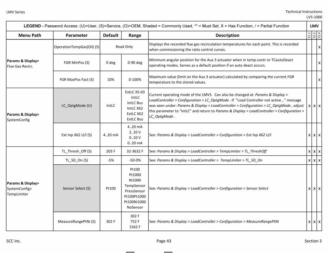
LMV Series Technical Instructions
LV5-1000
Menu Path Parameter Default Range Description
51.1
52.2
52.4
LEGEND - Password Access: (U)=User, (S)=Service, (O)=OEM, Shaded = Commonly Used, ** = Must Set, X = Has Function, / = Partial Function LMV
OperationTempGas(Oil) (S)Displays the recorded flue gas recirculation temperatures for each point. This is recorded
when commissioning the ratio control curves.x
FGR MinPos (S) 0 deg 0-90 degMinimum angular position for the Aux 3 actuator when in temp.contr or TCautoDeact
operating modes. Serves as a default position if an auto deact occurs.x
FGR MaxPos Fact (S) 10% 0-100%Maximum value (limit on the Aux 3 actuator) calculated by comparing the current FGR
temperature to the stored values.x
LC_OptgMode (U) IntLC
ExtLC X5-03
IntLC
IntLC Bus
IntLC X62
ExtLC X62
ExtLC Bus
Current operating mode of the LMV5. Can also be changed at: Params & Display >
LoadController > Configuration > LC_OptgMode . If "Load Controller not active..." message
was seen under: Params & Display > LoadController > Configuration > LC_OptgMode , adjust
this parameter to "IntLC" and return to Params & Display > LoadController > Configuration >
LC_OptgMode .
x x x
Ext Inp X62 U/I (S) 4..20 mA
4..20 mA
2..10 V
0..10 V
0..20 mA
See: Params & Display > LoadController > Configuration > Ext Inp X62 U/I x x x
TL_Thresh_Off (S) 203 F 32-3632 F See: Params & Display > LoadController > TempLimiter > TL_ThreshOff x x x
TL_SD_On (S) -5% -50-0% See: Params & Display > LoadController > TempLimiter > TL_SD_On x x x
Sensor Select (S) Pt100
Pt100
Pt1000
Ni1000
TempSensor
PressSensor
Pt100Pt1000
Pt100Ni1000
NoSensor
See: Params & Display > LoadController > Configuration > Sensor Select x x x
MeasureRangePtNi (S) 302 F
302 F
752 F
1562 F
See: Params & Display > LoadController > Configuration > MeasureRangePtNi x x x
Params & Display>
SystemConfig
Read Only
Params & Display>
SystemConfig>
TempLimiter
Params & Display>
Flue Gas Recirc.
SCC Inc. Page 43 Section 3
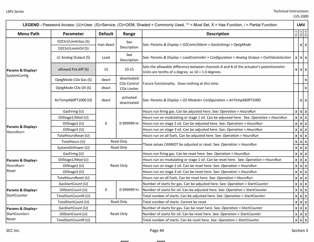
LMV Series Technical Instructions
LV5-1000
Menu Path Parameter Default Range Description
51.1
52.2
52.4
LEGEND - Password Access: (U)=User, (S)=Service, (O)=OEM, Shaded = Commonly Used, ** = Must Set, X = Has Function, / = Partial Function LMV
O2Ctrl/LimitrGas (S)
O2Ctrl/LimitrOil (S)
LC Analog Output (S) LoadSee
DescriptionSee: Params & Display > LoadController > Configuration > Analog Output > OutValuSelection x x x
allowed Pot.diff (S) 15 10-15Sets the allowable difference between channels A and B of the actuator's potentiometer.
Units are tenths of a degree, so 10 = 1.0 degrees.x x x
OptgMode COx Gas (S) deact x
OptgMode COx Oil (S) deact x
AirTempX60PT1000 (O) deactactivated
deactivatedSee: Params & Display > O2 Module> Configuration > AirTempX60PT1000 x x
GasFiring (U) Hours run firing gas. Can be adjusted here. See: Operation > HoursRun x x x
OilStage1/Mod (U) Hours run on modulating or stage 1 oil. Can be adjusted here. See: Operation > HoursRun x x x
OilStage2 (U) Hours run on stage 2 oil. Can be adjusted here. See: Operation > HoursRun x x x
OilStage3 (U) Hours run on stage 3 oil. Can be adjusted here. See: Operation > HoursRun x x x
TotalHoursReset (U) Hours run on all fuels. Can be adjusted here. See: Operation > HoursRun x x x
TotalHours (U) x x x
SystemOnPower (U) x x x
GasFiring (U) Hours run firing gas. Can be reset here. See: Operation > HoursRun x x x
OilStage1/Mod (U) Hours run on modulating or stage 1 oil. Can be reset here. See: Operation > HoursRun x x x
OilStage2 (U) Hours run on stage 2 oil. Can be reset here. See: Operation > HoursRun x x x
OilStage3 (U) Hours run on stage 3 oil. Can be reset here. See: Operation > HoursRun x x x
TotalHoursReset (U) Hours run on all fuels. Can be reset here. See: Operation > HoursRun x x x
GasStartCount (U) Number of starts for gas. Can be adjusted here. See: Operation > StartCounter x x x
OilStartCount (U) Number of starts for oil. Can be adjusted here. See: Operation > StartCounter x x x
TotalStartCountR (U) Total number of starts. Can be adjusted here. See: Operation > StartCounter x x x
TotalStartCount (U) Total number of starts. Cannot be reset. x x x
GasStartCount (U) Number of starts for gas. Can be reset here. See: Operation > StartCounter x x x
OilStartCount (U) Number of starts for oil. Can be reset here. See: Operation > StartCounter x x x
TotalStartCountR (U) Total number of starts. Can be reset here. See: Operation > StartCounter x x x
x x
Params & Display>
HoursRun>
These values CANNOT be adjusted or reset. See: Operation > HoursRun
Params & Display>
HoursRun>
Reset
Params & Display>
StartCounter
Read Only
0 0-999999 hr
deactivated
COx Control
COx Limiter
Future functionality. Does nothing at this time.
Reset Only
Reset Only
Params & Display>
SystemConfig
Read Only
See: Params & Display > O2Contr/Alarm > GasSettings > OptgModeman deactSee
Description
Read Only
Params & Display>
StartCounter>
Reset
0 0-999999 hr
SCC Inc. Page 44 Section 3
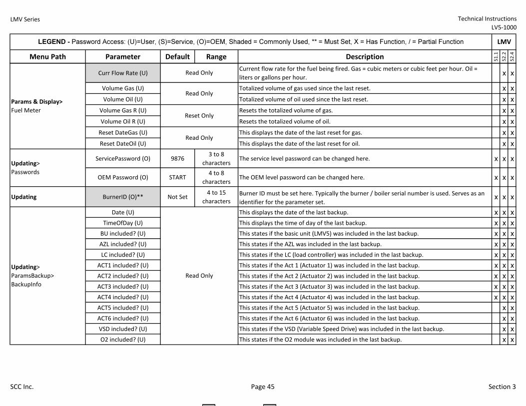
LMV Series Technical Instructions
LV5-1000
Menu Path Parameter Default Range Description
51.1
52.2
52.4
LEGEND - Password Access: (U)=User, (S)=Service, (O)=OEM, Shaded = Commonly Used, ** = Must Set, X = Has Function, / = Partial Function LMV
Curr Flow Rate (U)Current flow rate for the fuel being fired. Gas = cubic meters or cubic feet per hour. Oil =
liters or gallons per hour.x x
Volume Gas (U) Totalized volume of gas used since the last reset. x x
Volume Oil (U) Totalized volume of oil used since the last reset. x x
Volume Gas R (U) Resets the totalized volume of gas. x x
Volume Oil R (U) Resets the totalized volume of oil. x x
Reset DateGas (U) This displays the date of the last reset for gas. x x
Reset DateOil (U) This displays the date of the last reset for oil. x x
ServicePassword (O) 98763 to 8
charactersThe service level password can be changed here. x x x
OEM Password (O) START4 to 8
charactersThe OEM level password can be changed here. x x x
Updating BurnerID (O)** Not Set4 to 15
characters
Burner ID must be set here. Typically the burner / boiler serial number is used. Serves as an
identifier for the parameter set.x x x
Date (U) This displays the date of the last backup. x x x
TimeOfDay (U) This displays the time of day of the last backup. x x x
BU included? (U) This states if the basic unit (LMV5) was included in the last backup. x x x
AZL included? (U) This states if the AZL was included in the last backup. x x x
LC included? (U) This states if the LC (load controller) was included in the last backup. x x x
ACT1 included? (U) This states if the Act 1 (Actuator 1) was included in the last backup. x x x
ACT2 included? (U) This states if the Act 2 (Actuator 2) was included in the last backup. x x x
ACT3 included? (U) This states if the Act 3 (Actuator 3) was included in the last backup. x x x
ACT4 included? (U) This states if the Act 4 (Actuator 4) was included in the last backup. x x x
ACT5 included? (U) This states if the Act 5 (Actuator 5) was included in the last backup. x x
ACT6 included? (U) This states if the Act 6 (Actuator 6) was included in the last backup. x x
VSD included? (U) This states if the VSD (Variable Speed Drive) was included in the last backup. x x
O2 included? (U) This states if the O2 module was included in the last backup. x x
Read Only
Reset Only
Read Only
Updating>
Passwords
Updating>
ParamsBackup>
BackupInfo
Read Only
Params & Display>
Fuel Meter
Read Only
SCC Inc. Page 45 Section 3
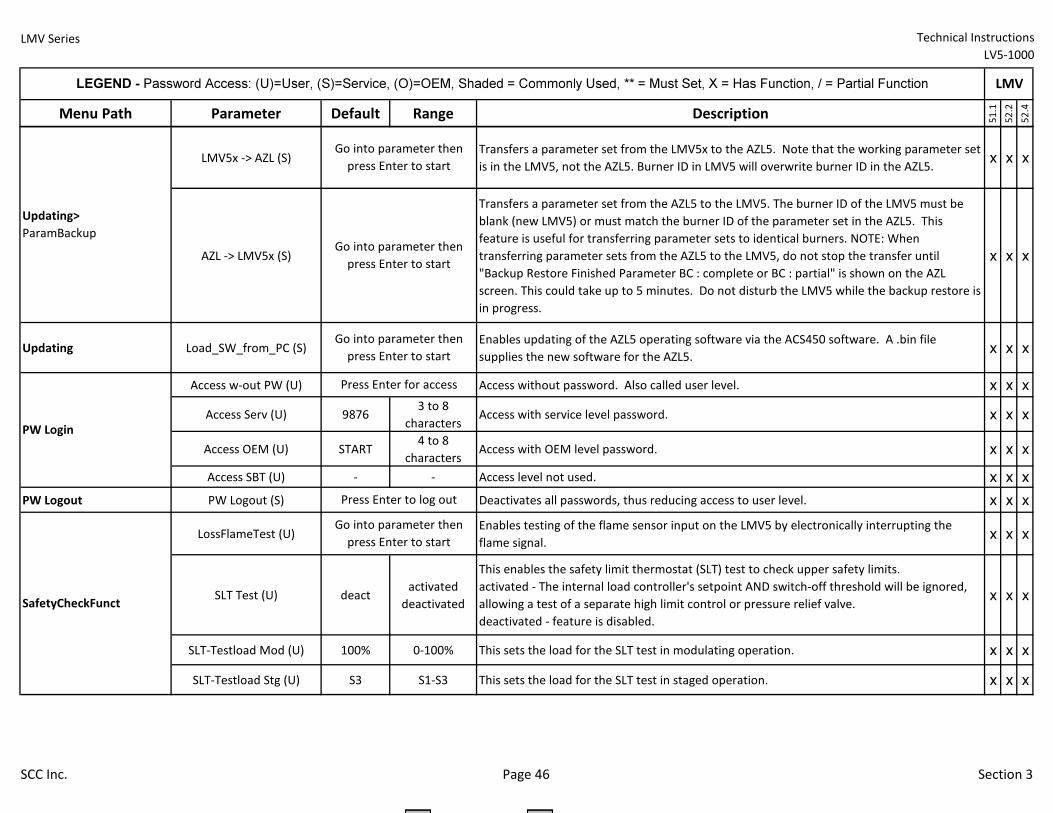
LMV Series Technical Instructions
LV5-1000
Menu Path Parameter Default Range Description
51.1
52.2
52.4
LEGEND - Password Access: (U)=User, (S)=Service, (O)=OEM, Shaded = Commonly Used, ** = Must Set, X = Has Function, / = Partial Function LMV
LMV5x -> AZL (S)Transfers a parameter set from the LMV5x to the AZL5. Note that the working parameter set
is in the LMV5, not the AZL5. Burner ID in LMV5 will overwrite burner ID in the AZL5.x x x
AZL -> LMV5x (S)
Transfers a parameter set from the AZL5 to the LMV5. The burner ID of the LMV5 must be
blank (new LMV5) or must match the burner ID of the parameter set in the AZL5. This
feature is useful for transferring parameter sets to identical burners. NOTE: When
transferring parameter sets from the AZL5 to the LMV5, do not stop the transfer until
"Backup Restore Finished Parameter BC : complete or BC : partial" is shown on the AZL
screen. This could take up to 5 minutes. Do not disturb the LMV5 while the backup restore is
in progress.
x x x
Updating Load_SW_from_PC (S)Enables updating of the AZL5 operating software via the ACS450 software. A .bin file
supplies the new software for the AZL5.x x x
Access w-out PW (U) Access without password. Also called user level. x x x
Access Serv (U) 98763 to 8
charactersAccess with service level password. x x x
Access OEM (U) START4 to 8
charactersAccess with OEM level password. x x x
Access SBT (U) - - Access level not used. x x x
PW Logout PW Logout (S) Deactivates all passwords, thus reducing access to user level. x x x
LossFlameTest (U)Enables testing of the flame sensor input on the LMV5 by electronically interrupting the
flame signal.x x x
SLT Test (U) deactactivated
deactivated
This enables the safety limit thermostat (SLT) test to check upper safety limits.
activated - The internal load controller's setpoint AND switch-off threshold will be ignored,
allowing a test of a separate high limit control or pressure relief valve.
deactivated - feature is disabled.
x x x
SLT-Testload Mod (U) 100% 0-100% This sets the load for the SLT test in modulating operation. x x x
SLT-Testload Stg (U) S3 S1-S3 This sets the load for the SLT test in staged operation. x x x
SafetyCheckFunct
Press Enter to log out
Go into parameter then
press Enter to start
Updating>
ParamBackup
Press Enter for access
Go into parameter then
press Enter to start
Go into parameter then
press Enter to start
Go into parameter then
press Enter to start
PW Login
SCC Inc. Page 46 Section 3
LMV Series Technical Instructions LV5‐1000
SCC Inc. Page 47 Section 3
3‐3: Sequence Diagrams
The Siemens LMV5 BMS can perform a number of different burner sequences based upon how certain parameters are set. Although there are a number of parameters that affect small aspects of the burner sequence, the main parameters that affect the sequence are parameters FuelTrainGas and FuelTrainOil.
These parameters set the framework of the sequence and are based upon the fuel train diagrams in Section 4. The OEM has the option of selecting one of three different gas trains with their associated sequence diagrams, and one of four different oil trains with their associated sequence diagrams (the sequence diagrams and fuel train diagrams for direct spark ignition with heavy oil have been omitted).
The sequence diagrams in Section 3‐3 illustrate when input and output terminals are expected to be energized or de‐energized. A legend on the bottom of each page describes the various symbols used in the diagrams. The last diagram describes what positions the attached actuators are expected to achieve at each phase and outlines the method that is used to check the actuators position.
Notes:
1) Only one fuel select terminal can be energized at a time. If both terminals are energized, the LMV5 will go into lockout. If neither terminal is energized, fuel selection is internal through the AZL5 (FuelSelect) or via Modbus.
2) The external burner on / off switch can be disabled with parameter InputController. If activated, this terminal needs to be energized to have the LMV5 start its sequence. The function of terminal X5‐03.1 becomes “burner on / off” when any external load control mode is selected.
3) The alarm can be silenced through the AZL (Alarm act/deact). This alarm silence resets when the LMV5 is reset or restarted.
4) When using an LMV52, continuous pilot is possible (ContPilotGas / ContPilotOil). If continuous pilot is activated, the pilot valve will remain energized through phase 62.
5) If parameter GasPressureMin is set to activated, the low gas pressure switch is expected to remain closed during phases 21‐50 of LO w Gasp and HO w Gasp, ensuring adequate gas pressure for the pilot. If GasPressureMin is set to Deact xOGP, the low gas pressure switch is expected to remain closed only when firing gas and is not checked when firing oil.
LMV Series Technical Instructions LV5‐1000
SCC Inc. Page 48 Section 3
6) If parameter OilPumpCoupling is set to Magnetcoupl, the output for the oil pump can be energized in Phase 22 or in Phase 38, depending upon how parameter IgnOilPumpStart is set. If parameter OilPumpCoupling is set to DirectCoupl, the output will energize with the blower and de‐energize 15 seconds after the blower de‐energizes.
7) If gas valve proving is performed on startup (immediately after phase 30), the actuators will be in prepurge position. If gas valve proving is performed on shutdown (immediately after phase 62), the actuators will be in the same position as they were in phase 62. The actuators will not move during valve proving.
8) If parameter AirPressureTest is set to activated, the air pressure switch must open after postpurge is complete, causing input terminal X3‐02.1 to de‐energize. The LMV5 will wait about 30 seconds in phase 10 (driving to home position) for the switch to open before the LMV5 goes into alarm. This is done to check for welded contacts in the air pressure switch. If air pressure switch alarms are encountered in phase 10, increasing the setpoint of the air pressure switch typically cures this problem. If AirPressureTest is set to deactInStby, the air pressure switch is not checked in phase 10 or 12, but the switch must be open or the LMV5 will not start when it receives a call for heat.
9) The LMV5 can be configured for different reactions to extraneous light (a flame signal when there should not be one). Depending on how parameters ReacExtranLight and ExtranLightTest are configured, the LMV5 can lockout, block the startup sequence, or ignore it altogether. The extraneous light test should always be enabled for gas / oil fired boilers. The only time parameter ExtranLightTest should be set to deactivated is for applications such as waste incineration.
10) If direct start is enabled and there is a call for heat after phase 62, the LMV5 will omit phase 78 and will go to phase 79. In phase 79, the LMV5 will check the blower air pressure switch with the blower still running by using a three‐way solenoid valve (APS checking). If the switch checks out, the LMV5 will then proceed directly to phase 24 (driving to prepurge position).
11) Safety Time 1 is defined as the overlap of the ignition spark and pilot valve. Safety Time 2 is defined as the overlap of the pilot valve and the main fuel valves. Interval 1 and Interval 2 are stabilization times for the pilot and main flames, respectively.
12) If parameter ContinuousPurge is set to activated, fan output X3‐01.1 will be energized in all phases. Typically this is used in burner applications where return heat may be a problem.
LMV Series Technical Instructions LV5‐1000
SCC Inc. Page 49 Section 3
13) Actuator position is checked by using one of three methods. The method used depends upon the phase of the sequence.
Position Required to Proceed means that the actuators must achieve and hold a certain position for the sequence to proceed. Dynamic Position Checking means that the actuator is evaluated by a “time and distance from target” algorithm. The further the actuator is away from its target position, the less time the actuator is permitted to be in that position. Run‐Time Position Checking means that the actuator is expected to be at a certain point in a certain amount of time (based off of the run‐time of the actuator).
14) For direct spark oil fuel trains, spark (ignition) will occur during prepurge if parameter OilPumpCoupling is set to Magnetcoupl and parameter IgnOilPumpStart is set to on in Ph22.
15) If parameter FGR‐PS/FCC is set for PSdeactStby, the status of the FGR pressure switch is not checked in phase 10 or 12. The rest of the sequence is the same as setting this parameter to FGR‐PS. If parameter FGR‐PS/FCC is set for PS VSD, input X4‐01.3 must be energized anytime the VSD speed is higher than RotSpeed PS on and de‐energized anytime the VSD speed is lower than RotSpeed PS off.
16) Depending on how parameter HeavyOilDirStart is set, input X6‐01.3 has varying sequences. If this parameter is set for activ 38/44, input X6‐01.3 must be energized in phase 44. If this parameter is set for 38/44..62, input X6‐01.3 must be energized in phases 44‐62. If this parameter is set for act 21..62, input X6‐01.3 must be energized in phases 21‐62. If this parameter is set for deactivated, energizing input X6‐01.3 has no effect.
17) Inputs X5‐03.2 and X5‐03.3 have many functions depending on how parameter Config X5‐03 is set. The settings are as follows:
LMV5x std – If parameter LC_OptgMode is set to ExtLC X5‐03, energizing X5‐03.2 will decrease the firing rate, while energizing X5‐03.3 will increase the firing rate.
LMV2/3 std – If parameter LC_OptgMode is set to ExtLC X5‐03, energizing X5‐03.3 will achieve stage 2 oil, while energizing X5‐03.2 will achieve stage 3 oil.
LMV2/3 inv – If parameter LC_OptgMode is set to ExtLC X5‐03, energizing X5‐03.2 will achieve stage 2 oil, while energizing X5‐03.3 will achieve stage 3 oil.
LMV Series Technical Instructions LV5‐1000
SCC Inc. Page 50 Section 3
DeaO2/Stp36 – Energizing input X5‐03.2 disables O2 trim, while de‐energizing X5‐03.2 enables O2 trim (LMV52 only).
Energizing input X5‐03.3 allows the LMV5 to progress past phase 36. If X5‐03.3 is de‐energized, the LMV5 will remain in phase 36 indefinitely.
CoolFctStby – This setting has no effect (LMV50 only). AutoDeactO2 – Energizing input X5‐03.3 will deactivate O2 trim by setting O2 trim OptgMode to auto deact. O2 trim
OptgMode must be set to ConAutoDeac for this function to work. De‐energizing X5‐03.3 sets the O2 trim OptgMode back to ConAutoDeac. Terminal X5‐03.2 has no function with this setting.
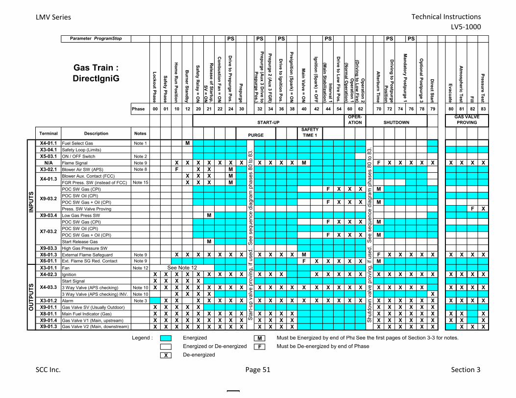
LMV Series Technical InstructionsLV5‐1000
Parameter ProgramStop PS PS PS PS PS PS
Gas Train : DirectIgniG
Lockout Phase
Safety Phase
Hom
e Run Position
Burner Standby
Safety Relay = O
N
Release of Startup,
SV = ON
Com
bustion Fan = ON
Drive to Prepurge Pos.
Prepurge
Prepurge (Aux 3 D
rive to Pre purge Pos.)
Prepurge 2 (Aux 3 FG
R)
Drive to Ignition Pos.
Preignition (Spark) = ON
Main Valve = O
N
Ignition (Spark) = OFF
Interval 1(M
ain Stabilization)
Drive to Low
Fire Pos.
Operation 1
(Norm
al Operation)
Operation 2
(Driving to Low
Fire)
Afterburn Tim
e
Driving to Postpurge
Position
Optional Postpurge 3
Direct Start
Evacuate
Atm
ospheric Test
Fill
Pressure Test
Phase 00 01 10 12 20 21 22 24 30 32 34 36 38 40 42 44 54 60 62 70 72 74 76 78 79 80 81 82 83
Terminal Description Notes
X4-01.1 Fuel Select Gas Note 1 MX3-04.1 Safety Loop (Limits)X5-03.1 ON / OFF Switch Note 2
N/A Flame Signal Note 9 X X X X X X X X X X X M F X X X X X X X X XX3-02.1 Blower Air SW (APS) Note 8 F X X M
Blower Aux. Contact (FCC) X X X MFGR Press. SW (instead of FCC) Note 15 X X X MPOC SW Gas (CPI) F X X X MPOC SW Oil (CPI)POC SW Gas + Oil (CPI) F X X X MPress. SW Valve Proving F X
X9-03.4 Low Gas Press SW MPOC SW Gas (CPI) F X X X MPOC SW Oil (CPI)POC SW Gas + Oil (CPI) F X X X MStart Release Gas M
X9-03.3 High Gas Pressure SW X6-01.3 External Flame Safeguard Note 9 X X X X X X X X X X X M F X X X X X X X X XX6-01.1 Ext. Flame SG Red. Contact Note 9 F X X X X X MX3-01.1 Fan Note 12X4-02.3 Ignition X X X X X X X X X X X X X X X X X X X X X X X X X X X
Start Signal X X X X X3 Way Valve (APS checking) Note 10 X X X X X X X X X X X X X X X X X X X X X X X X X X X X3 Way Valve (APS checking) INV. Note 10 X X X X X
X3-01.2 Alarm Note 3 X X X X X X X X X X X X X X X X X X X X X X X X X X XX9-01.1 Gas Valve SV (Usually Outdoor) X X X X X X X X X X XX8-01.1 Main Fuel Indicator (Gas) X X X X X X X X X X X X X X X X X X X X X XX9-01.4 Gas Valve V1 (Main, upstream) X X X X X X X X X X X X X X X X X X X X X XX9-01.3 Gas Valve V2 (Main, downstream) X X X X X X X X X X X X X X X X X X X X X X
Legend : Energized M Must be Energized by end of PhaSee the first pages of Section 3-3 for notes.Energized or De-energized F Must be De-energized by end of Phase
X De-energized
INPU
TS
Shut
dow
n va
lve
prov
ing,
if u
sed.
See
seq
uenc
e di
agra
m p
hase
s 80
to 8
3.
GAS VALVE PROVING
Mandatory Postpurge 1
START-UP SHUTDOWNOPER- ATION
OU
TPU
TS
PURGESAFETY TIME 1
X4-01.3
X9-03.2
X7-03.2
X4-03.3
See Note 12
Star
t-up
valv
e pr
ovin
g, if
use
d. S
ee s
eque
nce
diag
ram
pha
ses
80 to
83.
SCC Inc. Page 51 Section 3
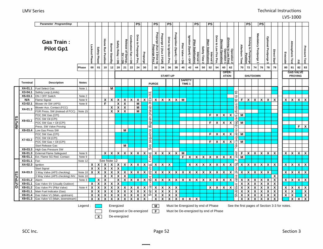
LMV Series Technical InstructionsLV5‐1000
Parameter ProgramStop PS PS PS PS PS PS PS
Gas Train : Pilot Gp1
Lockout Phase
Safety Phase
Hom
e Run Position
Burner Standby
Safety Relay = O
N
Release of Startup,
SV = ON
Com
bustion Fan = ON
Drive to Prepurge Pos.
Prepurge
Prepurge (Aux 3 D
rive toPre purge Pos.)
Prepurge 2 (Aux 3 FG
R)
Drive to Ignition Pos.
Preignition (Spark) = ON
Pilot Valve = ON
Ignition (Spark) = OFF
Interval 1(Pilot Stabilization)
Safety Time 2
Interval 2(M
ain Stabilization)
Drive to Low
Fire Pos.
Operation 1
(Norm
al Operation)
Operation 2
(Driving to Low
Fire)
Afterburn Tim
e
Driving to Postpurge
Position
Optional Postpurge 3
Direct Start
Evacuate
Atm
ospheric Test
Fill
Pressure Test
Phase 00 01 10 12 20 21 22 24 30 32 34 36 38 40 42 44 50 52 54 60 62 70 72 74 76 78 79 80 81 82 83
Terminal Description Notes
X4-01.1 Fuel Select Gas Note 1 MX3-04.1 Safety Loop (Limits)
X5-03.1 ON / OFF Switch Note 2
N/A Flame Signal Note 9 X X X X X X X X X X X M F X X X X X X X X XX3-02.1 Blower Air SW (APS) Note 8 F X X M
Blower Aux. Contact (FCC) X X X MFGR Press. SW (instead of FCC) Note 15 X X X MPOC SW Gas (CPI) F X X X MPOC SW Oil (CPI) `POC SW Gas + Oil (CPI) F X X X MPress. SW Valve Proving F X
X9-03.4 Low Gas Press SW MPOC SW Gas (CPI) F X X X MPOC SW Oil (CPI)
POC SW Gas + Oil (CPI) F X X X MStart Release Gas M
X9-03.3 High Gas Pressure SW
X6-01.3 External Flame Safeguard Note 9 X X X X X X X X X X X M F X X X X X X X X XX6-01.1 Ext. Flame SG Red. Contact Note 9 F X X X X X X X MX3-01.1 Fan Note 12
X4-02.3 Ignition X X X X X X X X X X X X X X X X X X X X X X X X X X X X XStart Signal X X X X X3 Way Valve (APS checking) Note 10 X X X X X X X X X X X X X X X X X X X X X X X X X X X X X X3 Way Valve (APS checking) INV. Note 10 X X X X X
X3-01.2 Alarm Note 3 X X X X X X X X X X X X X X X X X X X X X X X X X X X X XX9-01.1 Gas Valve SV (Usually Outdoor) X X X X X X X X X X XX9-01.2 Gas Valve PV (Pilot Valve) Note 4 X X X X X X X X X X X X X X X X X X X X X X X X X X XX8-01.1 Main Fuel Indicator (Gas) X X X X X X X X X X X X X X X X X X X X X XX9-01.4 Gas Valve V1 (Main, upstream) X X X X X X X X X X X X X X X X X X X X X XX9-01.3 Gas Valve V2 (Main, downstream) X X X X X X X X X X X X X X X X X X X X X X X X X
Legend : Energized M Must be Energized by end of Phase See the first pages of Section 3-3 for notes.
Energized or De-energized F Must be De-energized by end of Phase
X De-energized
GAS VALVE PROVING
Mandatory Postpurge 1
SHUTDOWN
Shu
tdow
n va
lve
prov
ing,
if u
sed.
S
ee s
eque
nce
diag
ram
pha
ses
80 t
o 83
.
START-UP
Sta
rt-u
p va
lve
prov
ing,
if u
sed.
S
ee s
eque
nce
diag
ram
pha
ses
80 t
o 83
.
OPER- ATION
OU
TPU
TS
PURGESAFETY TIME 1
X4-01.3
X9-03.2
X7-03.2
X4-03.3
See Note 12
INPU
TS
SCC Inc. Page 52 Section 3
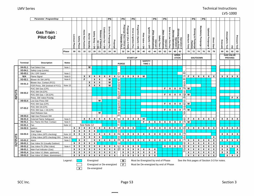
LMV Series Technical InstructionsLV5‐1000
Parameter ProgramStop PS PS PS PS PS PS PS
Gas Train : Pilot Gp2
Lockout Phase
Safety Phase
Hom
e Run Position
Burner Standby
Safety Relay = O
N
Release of Startup,
SV = ON
Com
bustion Fan = ON
Drive to Prepurge Pos.
Prepurge
Prepurge (Aux 3 D
rive toPrepurge Pos.)
Prepurge 2 (Aux 3 FG
R)
Drive to Ignition Pos.
Preignition (Spark) = ON
Pilot Valve = ON
Ignition (Spark) = OFF
Interval 1(Pilot Stabilization)
Safety Time 2
Interval 2(M
ain Stabilization)
Drive to Low
Fire Pos.
Operation 1
(Norm
al Operation)
Operation 2
(Driving to Low
Fire)
Afterburn Tim
e
Driving to Postpurge
Position
Optional Postpurge 3
Direct Start
Evacuate
Atm
ospheric Test
Fill
Pressure Test
Phase 00 01 10 12 20 21 22 24 30 32 34 36 38 40 42 44 50 52 54 60 62 70 72 74 76 78 79 80 81 82 83
Terminal Description Notes
X4-01.1 Fuel Select Gas Note 1 MX3-04.1 Safety Loop (Limits)
X5-03.1 ON / OFF Switch Note 2
N/A Flame Signal Note 9 X X X X X X X X X X X M F X X X X X X X X XX3-02.1 Blower Air SW (APS) Note 8 F X X M
Blower Aux. Contact (FCC) X X X MFGR Press. SW (instead of FCC) Note 15 X X X MPOC SW Gas (CPI) F X X X MPOC SW Oil (CPI) `POC SW Gas + Oil (CPI) F X X X MPress. SW Valve Proving F X
X9-03.4 Low Gas Press SW MPOC SW Gas (CPI) F X X X MPOC SW Oil (CPI)
POC SW Gas + Oil (CPI) F X X X MStart Release Gas M
X9-03.3 High Gas Pressure SW
X6-01.3 External Flame Safeguard Note 9 X X X X X X X X X X X M F X X X X X X X X XX6-01.1 Ext. Flame SG Red. Contact Note 9 F X X X X X X X MX3-01.1 Fan Note 12
X4-02.3 Ignition X X X X X X X X X X X X X X X X X X X X X X X X X X X X XStart Signal X X X X X3 Way Valve (APS checking) Note 10 X X X X X X X X X X X X X X X X X X X X X X X X X3 Way Valve (APS checking) INV. Note 10 X X X X X
X3-01.2 Alarm Note 3 X X X X X X X X X X X X X X X X X X X X X X X X X X X X XX9-01.1 Gas Valve SV (Usually Outdoor) X X X X X X X X X X XX9-01.2 Gas Valve PV (Pilot Valve) Note 4 X X X X X X X X X X X X X X X X X X X X X X X X X X XX8-01.1 Main Fuel Indicator (Gas) X X X X X X X X X X X X X X X X X X X X X X X X XX9-01.4 Gas Valve V1 (Main, upstream) X X X X X X X X X X X X X X X X X X X X X X X X XX9-01.3 Gas Valve V2 (Main, downstream) X X X X X X X X X X X X X X X X X X X X X X X X X
Legend : Energized M Must be Energized by end of Phase See the first pages of Section 3-3 for notes.
Energized or De-energized F Must be De-energized by end of Phase
X De-energized
INPU
TSO
UTP
UTS
PURGESAFETY TIME 1
X4-01.3
X9-03.2
X7-03.2
X4-03.3
GAS VALVE PROVING
Mandatory Postpurge 1
START-UP SHUTDOWNOPER- ATION
Sta
rt-u
p v
alv
e p
rovi
ng
, if
use
d.
Se
e s
eq
ue
nce
dia
gra
m p
ha
ses
80
to
83
.
Sh
utd
ow
n v
alv
e p
rovi
ng
, if
use
d.
Se
e s
eq
ue
nce
dia
gra
m p
ha
ses
80
to
83
.
See Note 12
SCC Inc. Page 53 Section 3
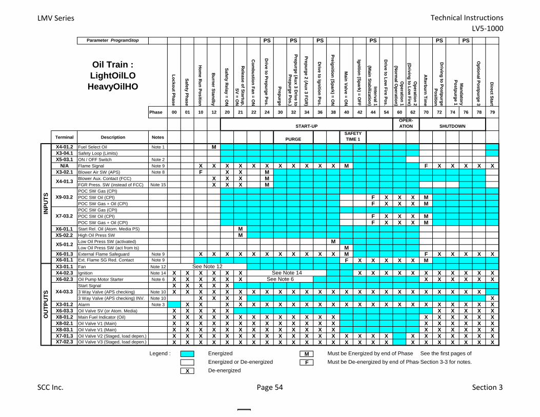
LMV Series Technical InstructionsLV5‐1000
Parameter ProgramStop PS PS PS PS PS PS
Oil Train : LightOilLO
HeavyOilHO
Lockout Phase
Safety Phase
Hom
e Run Position
Burner Standby
Safety Relay = O
N
Release of Startup,
SV = ON
Com
bustion Fan = ON
Drive to Prepurge Pos.
Prepurge
Prepurge (Aux 3 D
rive to Prepurge Pos.)
Prepurge 2 (Aux 3 FG
R)
Drive to Ignition Pos.
Preignition (Spark) = ON
Main Valve = O
N
Ignition (Spark) = OFF
Interval 1(M
ain Stabilization)
Drive to Low
Fire Pos.
Operation 1
(Norm
al Operation)
Operation 2
(Driving to Low
Fire)
Afterburn Tim
e
Driving to Postpurge
Position
Optional Postpurge 3
Direct Start
Phase 00 01 10 12 20 21 22 24 30 32 34 36 38 40 42 44 54 60 62 70 72 74 76 78 79
Terminal Description Notes
X4-01.2 Fuel Select Oil Note 1 MX3-04.1 Safety Loop (Limits)
X5-03.1 ON / OFF Switch Note 2
N/A Flame Signal Note 9 X X X X X X X X X X X M F X X X X XX3-02.1 Blower Air SW (APS) Note 8 F X X M
Blower Aux. Contact (FCC) X X X MFGR Press. SW (instead of FCC) Note 15 X X X MPOC SW Gas (CPI)
POC SW Oil (CPI) F X X X MPOC SW Gas + Oil (CPI) F X X X MPOC SW Gas (CPI)
POC SW Oil (CPI) F X X X MPOC SW Gas + Oil (CPI) F X X X M
X6-01.1 Start Rel. Oil (Atom. Media PS) MX5-02.2 High Oil Press SW M
Low Oil Press SW (activated) MLow Oil Press SW (act from ts) M
X6-01.3 External Flame Safeguard Note 9 X X X X X X X X X X X M F X X X X XX6-01.1 Ext. Flame SG Red. Contact Note 9 F X X X X X MX3-01.1 Fan Note 12
X4-02.3 Ignition Note 14 X X X X X X X X X X X X X X X X XX6-02.3 Oil Pump Motor Starter Note 6 X X X X X X X X X X X X
Start Signal X X X X X3 Way Valve (APS checking) Note 10 X X X X X X X X X X X X X X X X X X X X X X X X3 Way Valve (APS checking) INV. Note 10 X X X X X
X3-01.2 Alarm Note 3 X X X X X X X X X X X X X X X X X X X X X X XX6-03.3 Oil Valve SV (or Atom. Media) X X X X X X X X X XX8-01.2 Main Fuel Indicator (Oil) X X X X X X X X X X X X X X X X X X XX8-02.1 Oil Valve V1 (Main) X X X X X X X X X X X X X X X X X X XX8-03.1 Oil Valve V1 (Main) X X X X X X X X X X X X X X X X X X XX7-01.3 Oil Valve V2 (Staged, load depen.) X X X X X X X X X X X X X X X X X X X X X X X XX7-02.3 Oil Valve V3 (Staged, load depen.) X X X X X X X X X X X X X X X X X X X X X X X X
Legend : Energized M Must be Energized by end of Phase See the first pages of
Energized or De-energized F Must be De-energized by end of PhaseSection 3-3 for notes.
X De-energized
INPU
TS
OPER- ATION SHUTDOWN
Mandatory
Postpurge 1
START-UP
OU
TPU
TS
PURGESAFETY TIME 1
X4-01.3
X5-01.2
X9-03.2
X4-03.3
See Note 12
X7-03.2
See Note 6See Note 14
SCC Inc. Page 54 Section 3
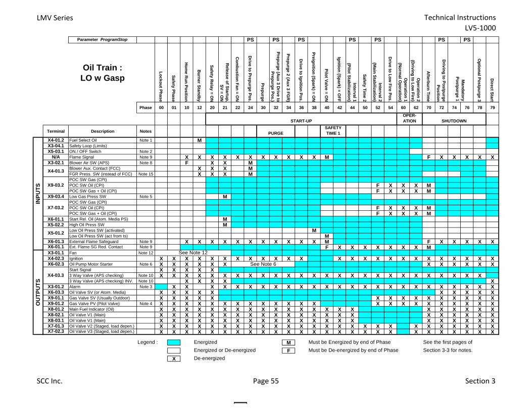
LMV Series Technical InstructionsLV5‐1000
Parameter ProgramStop PS PS PS PS PS PS PS
Oil Train : LO w Gasp
Lockout Phase
Safety Phase
Hom
e Run Position
Burner Standby
Safety Relay = O
N
Release of Startup,
SV = ON
Com
bustion Fan = ON
Drive to Prepurge Pos.
Prepurge
Prepurge (Aux 3 D
rive toPrepurge Pos.)
Prepurge 2 (Aux 3 FG
R)
Drive to Ignition Pos.
Preignition (Spark) = ON
Pilot Valve = ON
Ignition (Spark) = OFF
Interval 1(Pilot Stabilization)
Safety Time 2
Interval 2(M
ain Stabilization)
Drive to Low
Fire Pos.
Operation 1
(Norm
al Operation)
Operation 2
(Driving to Low
Fire)
Afterburn Tim
e
Driving to Postpurge
Position
Optional Postpurge 3
Direct Start
Phase 00 01 10 12 20 21 22 24 30 32 34 36 38 40 42 44 50 52 54 60 62 70 72 74 76 78 79
Terminal Description Notes
X4-01.2 Fuel Select Oil Note 1 MX3-04.1 Safety Loop (Limits)X5-03.1 ON / OFF Switch Note 2
N/A Flame Signal Note 9 X X X X X X X X X X X M F X X X X XX3-02.1 Blower Air SW (APS) Note 8 F X X M
Blower Aux. Contact (FCC) X X X MFGR Press. SW (instead of FCC) Note 15 X X X MPOC SW Gas (CPI)POC SW Oil (CPI) F X X X MPOC SW Gas + Oil (CPI) F X X X M
X9-03.4 Low Gas Press SW Note 5 MPOC SW Gas (CPI)POC SW Oil (CPI) F X X X MPOC SW Gas + Oil (CPI) F X X X M
X6-01.1 Start Rel. Oil (Atom. Media PS) MX5-02.2 High Oil Press SW M
Low Oil Press SW (activated) MLow Oil Press SW (act from ts) M
X6-01.3 External Flame Safeguard Note 9 X X X X X X X X X X X M F X X X X XX6-01.1 Ext. Flame SG Red. Contact Note 9 F X X X X X X X MX3-01.1 Fan Note 12X4-02.3 Ignition X X X X X X X X X X X X X X X X X X X X X X X X XX6-02.3 Oil Pump Motor Starter Note 6 X X X X X X X X X X X X
Start Signal X X X X X3 Way Valve (APS checking) Note 10 X X X X X X X X X X X X X X X X X X X X X X X X X X3 Way Valve (APS checking) INV. Note 10 X X X X X
X3-01.2 Alarm Note 3 X X X X X X X X X X X X X X X X X X X X X X X X XX6-03.3 Oil Valve SV (or Atom. Media) X X X X X X X X X XX9-01.1 Gas Valve SV (Usually Outdoor) X X X X X X X X X X X X X X XX9-01.2 Gas Valve PV (Pilot Valve) Note 4 X X X X X X X X X X X X X X X X X X X X X X XX8-01.2 Main Fuel Indicator (Oil) X X X X X X X X X X X X X X X X X X X X X XX8-02.1 Oil Valve V1 (Main) X X X X X X X X X X X X X X X X X X X X X XX8-03.1 Oil Valve V1 (Main) X X X X X X X X X X X X X X X X X X X X X XX7-01.3 Oil Valve V2 (Staged, load depen.) X X X X X X X X X X X X X X X X X X X X X X X X X XX7-02.3 Oil Valve V3 (Staged, load depen.) X X X X X X X X X X X X X X X X X X X X X X X X X X
Legend : Energized M Must be Energized by end of Phase See the first pages of
Energized or De-energized F Must be De-energized by end of Phase Section 3-3 for notes.
X De-energized
X9-03.2
X4-03.3
See Note 12
X7-03.2
X5-01.2
Mandatory
Postpurge 1
START-UPOPER- ATION SHUTDOWN
INPU
TSO
UTP
UTS
X4-01.3
See Note 6
PURGESAFETY TIME 1
SCC Inc. Page 55 Section 3
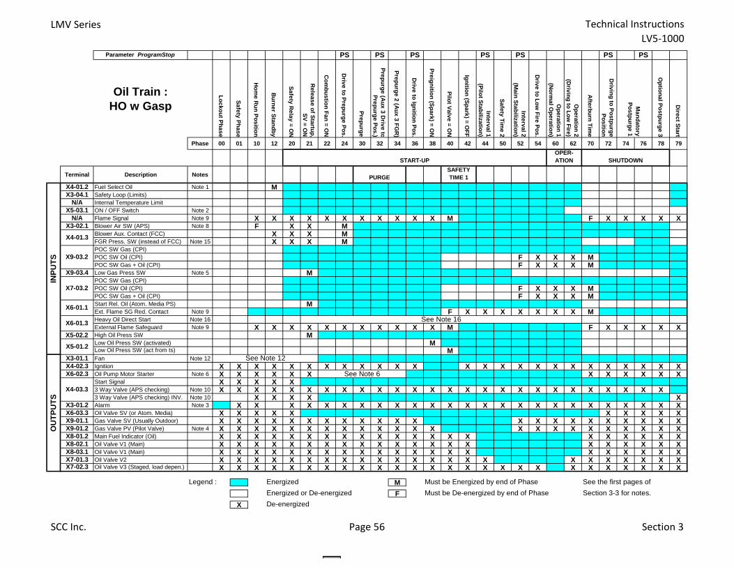
LMV Series Technical InstructionsLV5‐1000
Parameter ProgramStop PS PS PS PS PS PS PS
Oil Train : HO w Gasp
Lockout Phase
Safety Phase
Hom
e Run Position
Burner Standby
Safety Relay = O
N
Release of Startup,
SV = ON
Com
bustion Fan = ON
Drive to Prepurge Pos.
Prepurge
Prepurge (Aux 3 D
rive toPrepurge Pos.)
Prepurge 2 (Aux 3 FG
R)
Drive to Ignition Pos.
Preignition (Spark) = ON
Pilot Valve = ON
Ignition (Spark) = OFF
Interval 1(Pilot Stabilization)
Safety Time 2
Interval 2(M
ain Stabilization)
Drive to Low
Fire Pos.
Operation 1
(Norm
al Operation)
Operation 2
(Driving to Low
Fire)
Afterburn Tim
e
Driving to Postpurge
Position
Optional Postpurge 3
Direct Start
Phase 00 01 10 12 20 21 22 24 30 32 34 36 38 40 42 44 50 52 54 60 62 70 72 74 76 78 79
Terminal Description Notes
X4-01.2 Fuel Select Oil Note 1 MX3-04.1 Safety Loop (Limits)
N/A Internal Temperature LimitX5-03.1 ON / OFF Switch Note 2
N/A Flame Signal Note 9 X X X X X X X X X X X M F X X X X XX3-02.1 Blower Air SW (APS) Note 8 F X X M
Blower Aux. Contact (FCC) X X X MFGR Press. SW (instead of FCC) Note 15 X X X MPOC SW Gas (CPI)POC SW Oil (CPI) F X X X MPOC SW Gas + Oil (CPI) F X X X M
X9-03.4 Low Gas Press SW Note 5 MPOC SW Gas (CPI)POC SW Oil (CPI) F X X X MPOC SW Gas + Oil (CPI) F X X X MStart Rel. Oil (Atom. Media PS) MExt. Flame SG Red. Contact Note 9 F X X X X X X X MHeavy Oil Direct Start Note 16External Flame Safeguard Note 9 X X X X X X X X X X X M F X X X X X
X5-02.2 High Oil Press SW MLow Oil Press SW (activated) MLow Oil Press SW (act from ts) M
X3-01.1 Fan Note 12X4-02.3 Ignition X X X X X X X X X X X X X X X X X X X X X X X X XX6-02.3 Oil Pump Motor Starter Note 6 X X X X X X X X X X X X
Start Signal X X X X X3 Way Valve (APS checking) Note 10 X X X X X X X X X X X X X X X X X X X X X X X X X X3 Way Valve (APS checking) INV. Note 10 X X X X X
X3-01.2 Alarm Note 3 X X X X X X X X X X X X X X X X X X X X X X X X XX6-03.3 Oil Valve SV (or Atom. Media) X X X X X X X X X XX9-01.1 Gas Valve SV (Usually Outdoor) X X X X X X X X X X X X X X X X X X X X X XX9-01.2 Gas Valve PV (Pilot Valve) Note 4 X X X X X X X X X X X X X X X X X X X X X X XX8-01.2 Main Fuel Indicator (Oil) X X X X X X X X X X X X X X X X X X X X XX8-02.1 Oil Valve V1 (Main) X X X X X X X X X X X X X X X X X X X X XX8-03.1 Oil Valve V1 (Main) X X X X X X X X X X X X X X X X X X X X XX7-01.3 Oil Valve V2 X X X X X X X X X X X X X X X X X X X X X X XX7-02.3 Oil Valve V3 (Staged, load depen.) X X X X X X X X X X X X X X X X X X X X X X X X X X
Legend : Energized M Must be Energized by end of Phase See the first pages of
Energized or De-energized F Must be De-energized by end of Phase Section 3-3 for notes.
X De-energized
X7-03.2
See Note 6
X5-01.2
Mandatory
Postpurge 1
START-UP
See Note 16X6-01.3
X6-01.1
INPU
TS
OPER- ATION SHUTDOWN
OU
TPU
TS
PURGESAFETY TIME 1
X4-01.3
X9-03.2
X4-03.3
See Note 12
SCC Inc. Page 56 Section 3
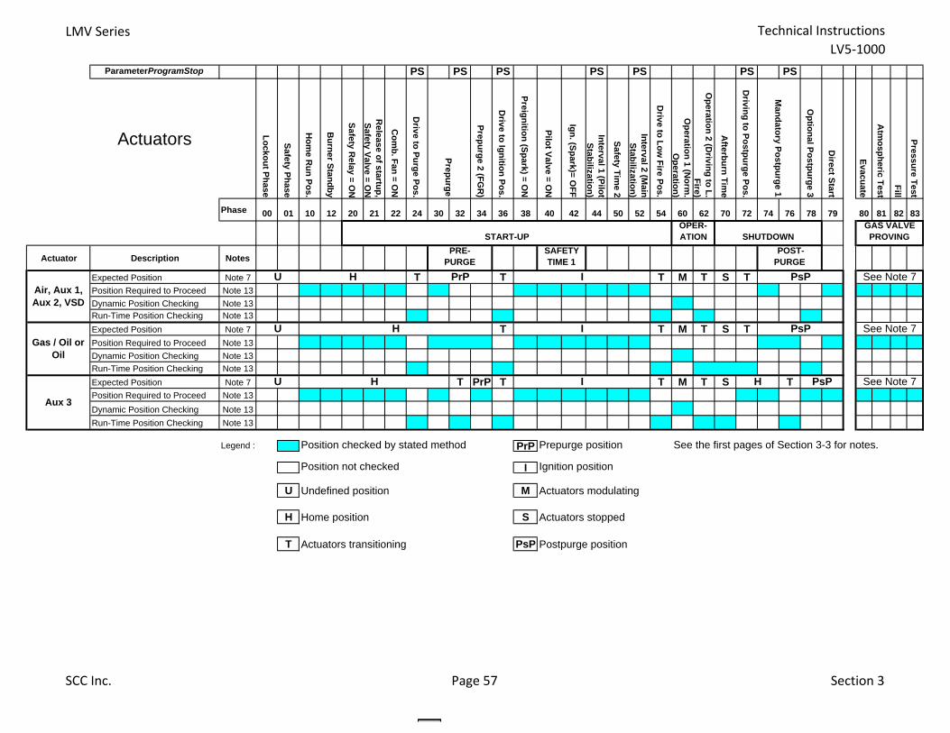
LMV Series Technical InstructionsLV5‐1000
ParameterProgramStop PS PS PS PS PS PS PS
Actuators Lockout Phase
Safety Phase
Hom
e Run Pos.
Burner Standby
Safety Relay = O
N
Release of startup,
Safety Valve = ON
Com
b. Fan = ON
Drive to Purge Pos.
Prepurge 2 (FGR
)
Drive to Ignition Pos.
Preignition (Spark) = ON
Pilot Valve = ON
Ign. (Spark)= OFF
Interval 1 (Pilot Stabilization)
Safety Time 2
Interval 2 (Main
Stabilization)
Drive to Low
Fire Pos.
Operation 1 (N
orm.
Operation)
Operation 2 (D
riving to L. Fire)
Afterburn Tim
e
Driving to Postpurge Pos.
Optional Postpurge 3
Direct Start
Evacuate
Atm
ospheric Test
Fill
Pressure Test
Phase 00 01 10 12 20 21 22 24 30 32 34 36 38 40 42 44 50 52 54 60 62 70 72 74 76 78 79 80 81 82 83
Actuator Description Notes
Expected Position Note 7 T T T M T S TPosition Required to Proceed Note 13
Dynamic Position Checking Note 13Run-Time Position Checking Note 13
Expected Position Note 7 T T M T S TPosition Required to Proceed Note 13
Dynamic Position Checking Note 13
Run-Time Position Checking Note 13
Expected Position Note 7 T PrP T T M T S TPosition Required to Proceed Note 13
Dynamic Position Checking Note 13
Run-Time Position Checking Note 13
Legend : Position checked by stated method PrP Prepurge position See the first pages of Section 3-3 for notes.
Position not checked I Ignition position
U Undefined position M Actuators modulating
H Home position S Actuators stopped
T Actuators transitioning PsP Postpurge position
See Note 7PsP
I PsP
H
See Note 7H
Aux 3
U IH
Gas / Oil or Oil
U
Air, Aux 1, Aux 2, VSD
OPER- ATION SHUTDOWN
GAS VALVE PROVING
See Note 7
Mandatory Postpurge 1
I PsP
POST- PURGE
Prepurge
H PrPU
START-UPPRE-
PURGESAFETY TIME 1
SCC Inc. Page 57 Section 3

Technical Instructions LMV Series Document No. LV5‐1000
Section 3 Page 58 SCC Inc.
Intentionally Left Blank
Section 1 Overview
Section 2 Wiring
Section 3 Parameters
Section 4 Commissioning
Section 5 VSD
Section 6 O2 Trim
Section 7 Troubleshooting
Section 8 Modbus
Section 9 ACS450
Section 10 Revision History
Appendix A Application Guide
Appendix B* Complimentary Products Guide
*Can be found at www.scccombustion.com.
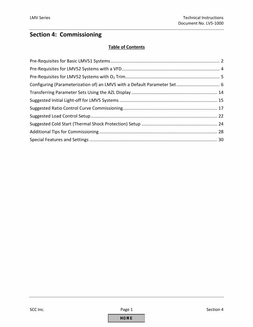
LMV Series Technical Instructions Document No. LV5‐1000
SCC Inc. Page 1 Section 4
Section 4: Commissioning
Table of Contents
Pre‐Requisites for Basic LMV51 Systems ........................................................................................ 2
Pre‐Requisites for LMV52 Systems with a VFD ............................................................................... 4
Pre‐Requisites for LMV52 Systems with O2 Trim ............................................................................ 5
Configuring (Parameterization of) an LMV5 with a Default Parameter Set ................................... 6
Transferring Parameter Sets Using the AZL Display ..................................................................... 14
Suggested Initial Light‐off for LMV5 Systems ............................................................................... 15
Suggested Ratio Control Curve Commissioning............................................................................ 17
Suggested Load Control Setup ...................................................................................................... 22
Suggested Cold Start (Thermal Shock Protection) Setup ............................................................. 24
Additional Tips for Commissioning ............................................................................................... 28
Special Features and Settings ....................................................................................................... 30
Technical Instructions LMV Series Document No. LV5‐1000
Section 4 Page 2 SCC Inc.
Before the LMV5 can be commissioned, certain pre‐requisites must be met for the LMV5 control, the burner, the boiler, and the boiler room. Experience has shown that if the points below are addressed properly, commissioning will be safe, timely, and trouble‐free. Pre‐Requisites for Basic LMV51 Systems
1. Burner / boiler must be in "good" condition. Burner firing head must be correct for the boiler and the firing head must not be cracked, melted, or otherwise damaged. Other items to check include:
a. Flame scanner tube must sight pilot and main flame correctly.
b. Refractory should not interfere with the flame scanner sighting or the flame path of the burner.
c. For fire tube boilers, the flame should not impinge on the Morrison tube.
2. All LMV5 components (base unit, actuators, flame scanners, etc.) are mounted properly. Please see Section 1 (Overview) and Appendix B (LMV5 Accessories Guide) for mounting details. Particular attention should be paid to the following:
a. Actuator shaft couplings must accomplish the following:
i. Compensate for both angular and parallel shaft misalignment generated by the mounting bracket.
ii. Have little or no backlash.
iii. Be robust enough to absorb the stall torque of the actuator without damage. Solid (rigid) shaft couplings are not acceptable in most applications. Clamp‐type couplings that have a D‐shape or keyway are preferred since these will not damage the actuator shaft and do provide positive engagement. In linkage‐less applications, actuator couplings should be considered to be safety‐related components. NOTE: Do not couple actuator to valve / damper shaft until actuator is addressed, the direction of rotation for the actuator is set, and the LMV5 alarm is reset. This is outlined later in the commissioning section.
b. Actuator brackets must be rigid enough so that they do not amplify burner vibration
(diving board effect) or distort significantly when the actuator is applying maximum torque to the valve / damper shaft.
LMV Series Technical Instructions Document No. LV5‐1000
SCC Inc. Page 3 Section 4
c. When actuator is installed and coupled, ensure that all mounting hardware is tightened
adequately, and some method of thread locking is employed on the mounting hardware (except for the coupling hardware).
d. Ensure environmental conditions (temperature, vibration, moisture, etc.) are not exceeded.
3. Ensure that all wiring is per the applicable wiring diagram and also meets applicable local and
national codes. Particular attention should be paid to the following:
e. If a step‐down control transformer is the source of 120 VAC power for the LMV5, the ground and neutral should be bonded (connected) on the transformer.
f. Voltage supply to a 120 VAC LMV5 must be between 102 and 132 VAC, 47‐63 Hz. Waveform must be a full sine wave.
g. The small transformer(s) used for the LMV5 (AGG5.210, typically blue or black) must be wired and grounded. See Section 2 (Wiring) for more details. Pay attention to pins 3 and 4 on terminal SEK2 and proper grounding. If more than two SQM48 and one SQM45 actuators are modulated at the same time, a second transformer (AGG5.210) will be required.
h. CANbus wire (AGG5.643) must be used to wire between actuators. Plain, shielded cable is not adequate and is not permitted.
i. Ensure that the last device and only the last device on the CANbus has the termination jumper in the “Bus Termination” position. See Section 2 (Wiring) for more details. The AZL has built‐in termination.
4. Fuel (gas) supply must be adequate to support high fire operation and fuel (gas) train must be
sized correctly.
j. Fuel (gas) pressure before the firing rate control valve must be correct, stable and repeatable at all firing rates and must not vary when other fuel (gas) burning appliances (other boilers in the building) are being operated.
k. The fuel (gas) pressure regulator on the burner being commissioned should not be fully open at high fire and should not be bouncing off the seat at low fire. Fuel regulator must be sized properly, and have adequate turndown capability.
5. A temporary stack gas analyzer that has been calibrated and at a minimum reads O2 (%) and CO
(ppm) must be used for setting combustion.
6. Knowledge of what fuel flow represents high fire of the burner / boiler combination and also the turndown of the burner / boiler combination. This can typically be found on the burner / boiler nameplate.
Technical Instructions LMV Series Document No. LV5‐1000
Section 4 Page 4 SCC Inc.
7. A method of determining firing rate (fuel flow within +/‐ 5%) should be used. This, in
combination with knowledge of high fire and turndown, is used to set the load numbers on each curve point. An Excel spreadsheet is available for this purpose.
8. For steam boilers, the feedwater supply must be adequate to support high fire operation. Feedwater controls must be working properly.
9. The load on the boiler must be adequate so that a burner / boiler combination can be run at high fire for a minimum of 5 minutes.
Pre‐Requisites for LMV52 Systems with a VFD
1. All pre‐requisites of the Basic LMV51 system apply.
2. Blower motor speed sensor and speed wheel must be installed correctly. See Appendix B (LMV5 Accessories Guide) for more details.
3. Vector‐type VFDs are highly recommended due to their inherently more precise motor speed control. Volt / Hz VFDs are not recommended due to less precise speed control.
4. Proper grounding between the LMV5, the VFD, and the motor must be installed. See Section 2 (Wiring) for more details.
5. VFD parameters must be set correctly to be compatible with both the LMV52 and the blower
motor. See Section 5 (VSD) for more details. Particular attention should be paid to the following:
a. Analog signal configuration. Both the LMV52 and VFD must be configured for a 4‐20mA signal.
b. Ramp rates between the LMV52 and the VFD must be compatible. In general, ramp rates of the VFD should be 10 seconds less than the LMV52.
c. VFD must be set up as a slave unit for a 4‐20mA signal. Damping, dead band, and PID functions must be disabled.
d. The frequency (Hz) output of the drive must be directly proportional to the analog input
signal.
e. Acceleration / deceleration curves must be linear instead of “S‐shaped”.
f. Ramp settings must be ramp up / ramp down instead of ramp up / coast down.
g. Any type of damping or stall prevention in the VFD should be deactivated.
LMV Series Technical Instructions Document No. LV5‐1000
SCC Inc. Page 5 Section 4
6. LMV52 / VFD combination must be “Standardized” before operation. See Section 5 (VSD) for
more details.
a. Verify that the air damper opens to pre‐purge position before the blower is energized for standardization.
Pre‐Requisites for LMV52 Systems with O2 Trim
1. All prerequisites of the Basic LMV51 system apply.
2. The O2 sensor must be mounted correctly. See Appendix B (LMV5 Accessories Guide) for more details. Particular attention should be paid to the following:
a. If the O2 sensor cannot be installed per Appendix B (LMV5 Accessories Guide), contact SCC for assistance.
b. The QGO20 O2 sensor is not suited for most types of biogas or fuels that produce ash, such as #6 oil. Contact SCC for advice on the compatibility of uncommon fuels.
3. The O2 sensor must be wired to the PLL52 correctly. See Section 2 (Wiring) for more details. Particular attention should be paid to the following:
a. The PLL52 module must be within 30 feet of the O2 sensor.
b. Two conduits must be run between the QGO20 O2 sensor and the PLL52 module. One conduit must contain the low voltage signals while the other conduit must contain the high voltage for the sensor heater.
4. The furnace pressure of the boiler being commissioned must be repeatable at a given firing rate.
Repeatability of +/‐ 0.2 in WC at each firing rate is adequate.
5. A fuel flow meter or some means of determining the load (firing rate) to +/‐ 3% is required. A more accurate load number (+/‐ 3%) for each curve point is necessary for reliable O2 trim functionality.
6. The LMV52 must be powered and configured for the QGO20 O2 sensor for two hours prior to commissioning. This is done to let the QGO20 sensor heat up thoroughly.
7. The boiler must be up to normal operating temperature / pressure for at least one hour before commissioning the O2 trim.
Technical Instructions LMV Series Document No. LV5‐1000
Section 4 Page 6 SCC Inc.
Configuring (Parameterization of) an LMV5 with a Default Parameter Set The procedure below assumes an LMV5 with a default parameter set. If the LMV5 is mounted to a burner / boiler, the OEM(s) may have already changed the parameters from the default setting and parameterized the LMV5 for the application.
Section 3 (Parameters) gives a detailed explanation of all of the parameters in the LMV5, as well as highlights which parameters must be set (marked with a double asterisk **) and which parameters are frequently used (shaded).
This procedure gives a general guideline of what parameters need to be set to get an LMV5 running on a typical burner/ boiler. Every burner is different, so it is likely that every burner will need a somewhat unique parameter set to run correctly.
When an LMV5 with a default parameter set is powered up and wired correctly, it will go into alarm and state that "no fuel train is defined". During the parameterization, the alarm does not need to be reset. Moreover, the alarm will come back immediately until at least a few key parameters are set. The recommendation is to silence the alarm horn, and leave the LMV5 in a state of alarm until the key parameters are set.
1. Log in at the OEM password level. From the factory, the OEM password for the LMV5 is "START".
2. Set the Burner ID. This can be found in the main menu under Updating. The OEM password will be required when the Updating menu is entered. The Burner ID is a unique number which matches the burner to the parameter set in the LMV5. Typically, the serial number of the burner is used as the Burner ID.
3. Configure the load controller sensor (except LMV51.0…) using the following menu path:
Params & Display > LoadController > Configuration
The default configuration is for a hot water boiler (temperature control) with a PT100 RTD temperature sensor. For a steam boiler (pressure control), set the following parameters to the following settings:
Sensor Select = PressSensor Ext Inp X61 U/I = 0..10V or 4..20mA (sensor dependent) MRangePressSens = High range of pressure sensor
4. Set the fuel train(s). If only gas is to be fired, only a gas fuel train must be selected. If only oil is to be fired, only an oil fuel train must be selected. For dual fuel burners, both a gas and oil fuel train must be selected. Fuel trains can be set using the following menu path:
Params & Display > BurnerControl > Configuration > ConfigGeneral
See the following pages for fuel train information. “Pilot Gp2” is typical for gas piloted gas burners and “LO w Gasp” is typical for gas piloted oil burners.
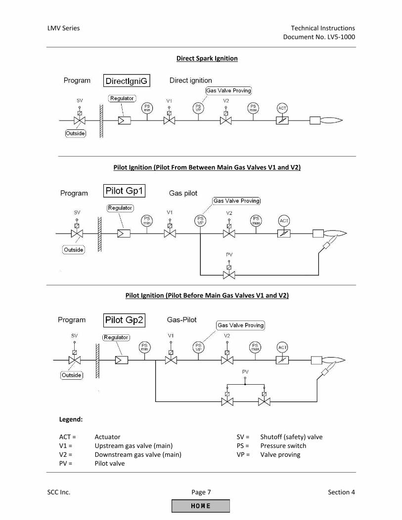
LMV Series Technical Instructions Document No. LV5‐1000
SCC Inc. Page 7 Section 4
Direct Spark Ignition
Pilot Ignition (Pilot From Between Main Gas Valves V1 and V2)
Pilot Ignition (Pilot Before Main Gas Valves V1 and V2)
Legend: ACT = Actuator SV = Shutoff (safety) valve V1 = Upstream gas valve (main) PS = Pressure switch V2 = Downstream gas valve (main) VP = Valve proving PV = Pilot valve
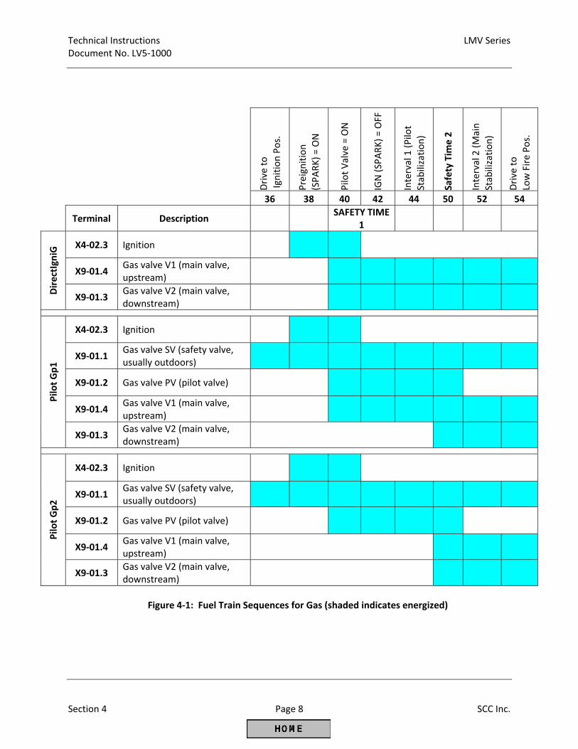
Technical Instructions LMV Series Document No. LV5‐1000
Section 4 Page 8 SCC Inc.
Drive to
Ignition Pos.
Preignition
(SPARK) = ON
Pilot Valve = ON
IGN (SPARK) = OFF
Interval 1 (Pilot
Stabilization)
Safety Tim
e 2
Interval 2 (Main
Stabilization)
Drive to
Low Fire Pos.
36 38 40 42 44 50 52 54
Terminal Description
SAFETY TIME 1
DirectIgniG X4‐02.3 Ignition
X9‐01.4 Gas valve V1 (main valve, upstream)
X9‐01.3 Gas valve V2 (main valve, downstream)
Pilo
t Gp1
X4‐02.3 Ignition
X9‐01.1 Gas valve SV (safety valve, usually outdoors)
X9‐01.2 Gas valve PV (pilot valve)
X9‐01.4 Gas valve V1 (main valve, upstream)
X9‐01.3 Gas valve V2 (main valve, downstream)
Pilo
t Gp2
X4‐02.3 Ignition
X9‐01.1 Gas valve SV (safety valve, usually outdoors)
X9‐01.2 Gas valve PV (pilot valve)
X9‐01.4 Gas valve V1 (main valve, upstream)
X9‐01.3 Gas valve V2 (main valve, downstream)
Figure 4‐1: Fuel Train Sequences for Gas (shaded indicates energized)
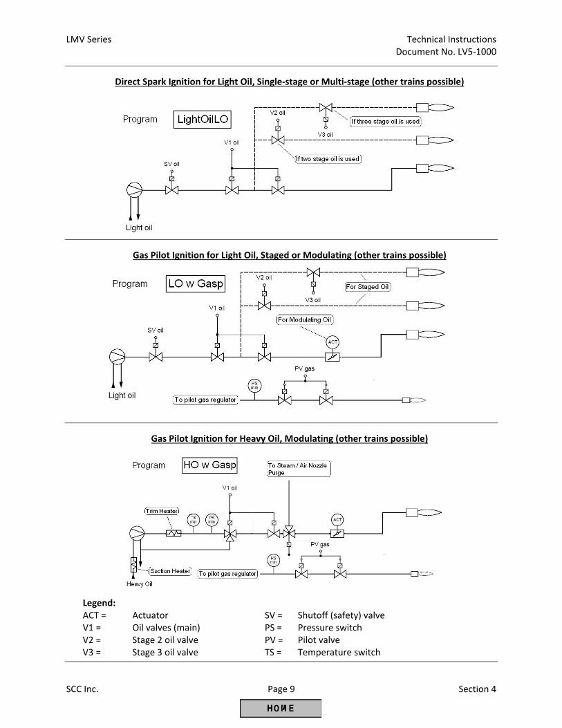
LMV Series Technical Instructions Document No. LV5‐1000
SCC Inc. Page 9 Section 4
Direct Spark Ignition for Light Oil, Single‐stage or Multi‐stage (other trains possible)
Gas Pilot Ignition for Light Oil, Staged or Modulating (other trains possible)
Gas Pilot Ignition for Heavy Oil, Modulating (other trains possible)
Legend: ACT = Actuator SV = Shutoff (safety) valve V1 = Oil valves (main) PS = Pressure switch V2 = Stage 2 oil valve PV = Pilot valve V3 = Stage 3 oil valve TS = Temperature switch

Technical Instructions LMV Series Document No. LV5‐1000
Section 4 Page 10 SCC Inc.
Drive to
Ignition Pos.
Preignition
(SPARK) = ON
Pilot Valve = ON
IGN (SPARK) = OFF
Interval 1
Safety Tim
e 2
Interval 2 (Main
Stabilization)
Drive to
Low Fire Pos.
36 38 40 42 44 50 52 54
Terminal Description SAFETY TIME 1
LightO
ilLO X4‐02.3 Ignition
X8‐02.1 Oil valve V1 (main valve)
X8‐03.1 Oil valve V1 (main valve)
LO w Gasp
X4‐02.3 Ignition
X9‐01.1 Gas valve SV (safety valve, usually outdoors)
X9‐01.2 Gas valve PV (pilot valve)
X8‐02.1 Oil valve V1 (main valve)
X8‐03.1 Oil valve V1 (main valve)
Safety Time 2 HO ONLY
HO w Gasp
X4‐02.3 Ignition
X9‐01.1 Gas valve SV (safety valve, usually outdoors)
X9‐01.2 Gas valve PV (pilot valve)
X8‐02.1 Oil valve V1 (main valve)
X8‐03.1 Oil valve V1 (main valve)
Figure 4‐2: Fuel Train Sequences for Oil (shaded indicates energized)
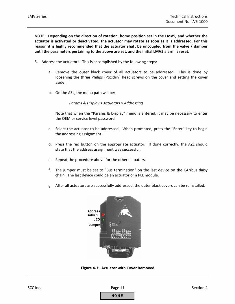
LMV Series Technical Instructions Document No. LV5‐1000
SCC Inc. Page 11 Section 4
NOTE: Depending on the direction of rotation, home position set in the LMV5, and whether the actuator is activated or deactivated, the actuator may rotate as soon as it is addressed. For this reason it is highly recommended that the actuator shaft be uncoupled from the valve / damper until the parameters pertaining to the above are set, and the initial LMV5 alarm is reset.
5. Address the actuators. This is accomplished by the following steps:
a. Remove the outer black cover of all actuators to be addressed. This is done by
loosening the three Philips (Pozidriv) head screws on the cover and setting the cover aside.
b. On the AZL, the menu path will be:
Params & Display > Actuators > Addressing Note that when the “Params & Display” menu is entered, it may be necessary to enter the OEM or service level password.
c. Select the actuator to be addressed. When prompted, press the “Enter” key to begin the addressing assignment.
d. Press the red button on the appropriate actuator. If done correctly, the AZL should state that the address assignment was successful.
e. Repeat the procedure above for the other actuators.
f. The jumper must be set to "Bus termination" on the last device on the CANbus daisy chain. The last device could be an actuator or a PLL module.
g. After all actuators are successfully addressed, the outer black covers can be reinstalled.
Figure 4‐3: Actuator with Cover Removed
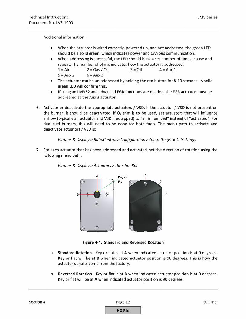
Technical Documen
Section 4
A
6. Athaidd
7. Fofo
Instructions t No. LV5‐100
dditional info
When should
When repeat1 = Air5 = Au
The acgreen
If usingaddres
ctivate or dehe burner, it irflow (typicaual fuel burneactivate act
Param
or each actuaollowing men
Param
a. StandaKey oractuat
b. ReversKey or
00
ormation:
the actuator d be a solid gr
addressing ist. The number 2 =x 2 6 =
ctuator can beLED will conf
g an LMV52 assed as the A
eactivate the should be delly air actuatoners, this wiluators / VSD
ms & Display >
ator that has u path:
ms & Display >
Figure
ard Rotation r flat will be ator's shafts co
sed Rotationr flat will be a
is wired corrreen, which in
s successful, tr of blinks ind= Gas / Oil= Aux 3
e un‐addressefirm this.
and advancedux 3 actuator
appropriate eactivated. Ifor and VSD if l need to beis:
> RatioContro
been address
> Actuators >
e 4‐4: Standa
‐ Key or flat at B when inome from the
‐ Key or flat t A when ind
Page 12
rectly, powerendicates pow
the LED shouldicates how t 3 = O
ed by holding
d FGR functior.
actuators / Vf O2 trim is toequipped) toe done for b
ol > Configura
sed and activ
DirectionRot
ard and Reve
is at A whendicated actuae factory.
is at B whenicated actuat
ed up, and nower and CANb
ld blink a set the actuator iOil 4
g the red butt
ns are neede
VSD. If the aco be used, seo “air influencboth fuels. Th
tion > GasSet
vated, set the
ersed Rotatio
indicated acator position
indicated actor position is
ot addressed,us communic
number of tiis addressed: 4 = Aux 1
ton for 8‐10 s
d, the FGR ac
ctuator / VSDet actuators ced” instead he menu pat
ttings or OilSe
e direction of
on
ctuator positin is 90 degree
ctuator positis 90 degrees.
LMV S
SC
, the green LEcation.
mes, pause a
seconds. A so
ctuator must
D is not presethat will influof “activatedth to activate
ettings
rotation usin
on is at 0 deges. This is how
on is at 0 deg
Series
CC Inc.
ED
nd
olid
be
ent on uence d”. For e and
ng the
grees. w the
grees.
LMV Series Technical Instructions Document No. LV5‐1000
SCC Inc. Page 13 Section 4
NOTE: Make sure that the direction of rotation is set correctly for all actuators at this time, including the oil actuator. If the direction of rotation must be changed later, the fuel‐air ratio control curves must be deleted.
8. At this point, the LMV5 alarm can be reset, provided that there is not a call for heat present (burner switch is off / X5‐03.1 is not energized). Older LMV5 units also require the safety loop to be closed before the alarm can be reset. The reset can be accomplished via a remote reset button (if wired) or via the menu path:
OperationalStat > Status/Reset > Press “ESC” then “ENTER” to reset
9. Set actuator home (standby) positions if necessary. Defaults are 0 degrees and 0% VSD. For dual fuel burners this will need to be done for both fuels. The menu path is:
Params & Display > RatioControl > GasSettings or OilSettings > SpecialPositions > HomePos
10. Couple actuators to the valves / dampers. Actuators must not torque against mechanical stops on the valve / damper when at home position. Adjust home positions if necessary.
NOTE: Actuator shaft couplings must compensate for both angular and parallel shaft misalignment due to the mounting bracket. Solid (rigid) shaft couplings are not acceptable in most applications, especially when formed or welded mounting brackets are used. Couplings should have little to no backlash, and are a safety relevant part of a linkage‐less system.
NOTE: Make absolutely certain that when the actuators are at or near 0 degrees (as indicated on the AZL display) that the valve / damper the actuator is coupled to is in the CLOSED (minimum flow) position. An exception to this is some back‐flow type oil burners, where a wide open oil valve will result in minimal flow thru the oil nozzle.
11. With the burner off, stroke each valve / damper through its intended range of motion using the SQM… actuator that is now coupled to the valve / damper. The menu path to do this is:
Params & Display > RatioControl > GasSettings or OilSettings > CurveParams (For oil, also go into Curve Settings)
In the Curve Parameters screen, all of the activated actuators for the selected fuel can be stroked through their intended range of motion. An arrow (>) indicates the actuator is driving to the set position and a colon (:) indicates that the actuator is at the set position. Verify that no binding will occur through the intended range of motion. Also note valves / dampers where wide open is less than 90 degrees.
12. Set special positions for all activated actuators. This will define where the actuators / VSD go for ignition, pre‐purge, and post‐purge. For dual fuel burners this will need to be done for both fuels. Special positions can be set using the following menu path:
Params & Display > RatioControl > GasSettings or OilSettings > SpecialPositions
Technical Instructions LMV Series Document No. LV5‐1000
Section 4 Page 14 SCC Inc.
13. At this point, all other LMV5 parameters under the “BurnerControl” and “RatioControl”
headings should be reviewed and set accordingly for the individual burner requirements.
Params & Display > BurnerControl Params & Display > RatioControl
Section 3 of this literature explains every parameter in detail, and the most commonly used parameters are shaded for easy reference.
14. If the burner has a Variable Speed Drive (VSD) on the blower, it must be standardized. In most cases, the VSD is a Variable Frequency Drive (VFD). See Section 5 in this literature if the VFD parameters are not already set, and for a more detailed standardization procedure. If the VFD parameters are set, standardize the VFD using the following menu path:
Params & Display > VSD Module > Configuration > Speed Once Standardization is set to “activated”, the air damper should open to its pre‐purge position, and the blower should ramp up, pause, and then ramp back down. If this does not occur, make sure that the VSD is set to “air influenced” and the safety loop is closed.
Transferring Parameter Sets Using the AZL Display This procedure will detail how to transfer a parameter set from one burner to another burner. In this example, the parameter set will originate from Burner #1 (B1) and will be copied to Burner #2 (B2). Naturally, using a similar procedure, the parameter set from Burner #1 can be copied to Burners #3, #4, #5, etc. The ACS450 PC software can also be used for this purpose (see Section 9). Note: Passwords are transferred with the parameter sets. Manual operation settings are not transferred with parameter sets.
1. Obtain the OEM or service level passwords for B1 and B2.
2. On B1, upload all of the current parameters from the LMV5 to the AZL flash memory using the
following menu path:
Updating > ParamBackup > LMV5x ‐> AZL
The OEM or service level password for B1 will be necessary to access this. This will upload all of the current LMV5 parameters to the AZL flash memory. This process is complete when the AZL states "Parameters have been stored". If the LMV5 on B2 is known to have a blank burner ID, then power off B1 LMV5, remove the AZL, and skip to step 5. Otherwise, go to the next step.
3. Write down B1 burner ID. This can be found at the following menu path:
Operation > Burner ID
After this step, B1 LMV5 can be powered off. After B1 is powered off, remove the AZL.
LMV Series Technical Instructions Document No. LV5‐1000
SCC Inc. Page 15 Section 4
4. On B2, write down the burner ID if it is not blank. If the burner ID on B2 is not the same as B1,
change the burner ID on B2 to match B1. Changing the burner ID can be done using the following menu path:
Updating > BurnerID
The OEM level password will be required to change the burner ID.
5. Power off B2 LMV5. After B2 LMV5 is powered off, remove the AZL from B2 and replace with the AZL from B1. Power B2 LMV5 back on.
6. Now that the burner IDs match or the B2 burner ID is blank, the B1 parameter set can be downloaded into B2 using the following menu path:
Updating > ParamBackup > AZL ‐> LMV5x
The OEM or service level password for B2 will be necessary to access this. This will download all of the parameters from B1 AZL into the LMV5 on B2. This process may take up to 5 minutes. This process is complete when the AZL states "Backup Restore finished Parameter BC : Complete" or “Backup Restore finished Parameter BC : Partial". Do not interrupt this process once it is started. Also, the alarm output will be energized when the new parameter set is downloaded to B2 LMV5.
7. After this is complete, B2 can be powered down. The AZL from B1 can be returned to B1 and the AZL from B2 can be reconnected to B2. Power B2 LMV5 back on.
8. If the burner ID on B2 was changed to allow the backup, then return the burner ID to what it was previously. If the burner ID was blank before the download, change the burner ID on B2 to a unique value different than B1. Typically, the burner serial number is used. NOTE: An exact copy of all parameters is transferred when the above procedure is executed, including light‐off positions, Fuel Air Ratio Control Curves and O2 Curves. Typically, even "identical" burners and boilers need unique light‐off positions, Fuel Air Ratio Control Curves and O2 curves. Since this is typically the case, curves and ignition positions are typically deleted after the parameter set is downloaded into a new burner.
Suggested Initial Light‐off for LMV5 Systems
1. The following procedure assumes the following:
a. Fuel train "Pilot GP2" was selected for a gas pilot burner. b. Pre‐requisites for Basic LMV51 systems or LMV52 systems (from above) are met. c. Procedure for Configuring (Parameterization of) an LMV5 has been done (from above). d. This is a first‐time commissioning of the LMV5 and the combustion control curve is blank
(no points are entered).
2. Close manual main fuel (gas) valve that is downstream of the pilot take‐off.
Technical Instructions LMV Series Document No. LV5‐1000
Section 4 Page 16 SCC Inc.
3. Ensure burner switch is off. If the LMV5 is not yet powered, turn on the power to the LMV5.
4. At this point, all safety interlocks that can be checked should be checked in a safe manner. This
includes but is not limited to: low water cut offs, high temperature switches, high gas pressure switch, low gas pressure switch, proof of closure (POC), etc.
5. Later in the procedure when the burner is running, the rest of the safety interlocks must be checked in a safe manner. This includes but is not limited to: Air pressure switches, high steam pressure limits, draft switches, etc.
6. Set parameter ProgramStop to Interval 1, Phase 44. This will stop the burner from progressing past lighting the pilot. This parameter can be found under the following menu path:
Params & Display > RatioControl > ProgramStop
7. Turn on the burner switch. The burner should drive to pre‐purge (Phase 24), drive to ignition (Phase 38), light the pilot, and stop in pilot stabilization (Phase 44). If the pilot does not light on a new installation, there could be air in the gas line. Bleed the air in a safe manner if necessary and attempt to re‐light the pilot.
8. Once the pilot is lit, tune the pilot by adjusting the ignition position of the air actuator and / or adjusting the pilot gas pressure regulator, if necessary. Pilot flame should be stable and return a flame signal of 85% or greater. Ignition positions can be adjusted at this time using the following menu path:
Params & Display > RatioControl > GasSettings > SpecialPositions > IgnitionPos
9. Once a satisfactory pilot flame is established, set ProgramStop to Interval 2, Phase 52. The burner should open the main fuel (gas) valves and attempt to light the main flame. The LMV5 should show a flame failure since the manual main fuel (gas) valve is closed.
10. If a flame failure does occur, proceed to reset the LMV5 and open the manual main fuel (gas) valve. The burner should once again proceed through the startup sequence, light the pilot and then attempt to light the main flame.
11. If the main flame lights, adjust the ignition position of the gas valve to achieve a safe main flame. At this time, a calibrated stack gas analyzer should be inserted into the stack and used to evaluate combustion. If the main flame fails to light, the ignition position of the firing rate control valve and / or the gas pressure regulator may need to be adjusted to achieve a combustible mixture at the ignition position. After the combustion has been verified to be safe with an analyzer, ProgramStop can be left at Interval 2, Phase 52 for boil out or boiler warming if required.
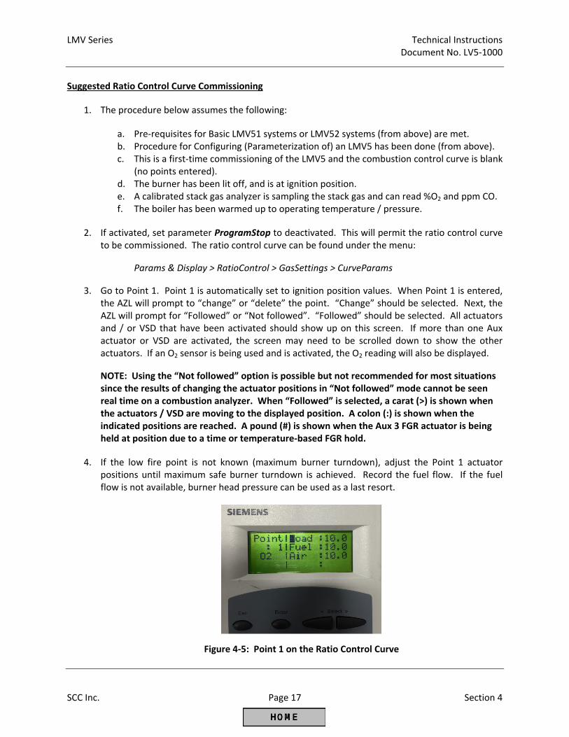
LMV Series Technical Instructions Document No. LV5‐1000
SCC Inc. Page 17 Section 4
Suggested Ratio Control Curve Commissioning
1. The procedure below assumes the following:
a. Pre‐requisites for Basic LMV51 systems or LMV52 systems (from above) are met. b. Procedure for Configuring (Parameterization of) an LMV5 has been done (from above). c. This is a first‐time commissioning of the LMV5 and the combustion control curve is blank
(no points entered). d. The burner has been lit off, and is at ignition position. e. A calibrated stack gas analyzer is sampling the stack gas and can read %O2 and ppm CO. f. The boiler has been warmed up to operating temperature / pressure.
2. If activated, set parameter ProgramStop to deactivated. This will permit the ratio control curve to be commissioned. The ratio control curve can be found under the menu:
Params & Display > RatioControl > GasSettings > CurveParams
3. Go to Point 1. Point 1 is automatically set to ignition position values. When Point 1 is entered, the AZL will prompt to “change” or “delete” the point. “Change” should be selected. Next, the AZL will prompt for “Followed” or “Not followed”. “Followed” should be selected. All actuators and / or VSD that have been activated should show up on this screen. If more than one Aux actuator or VSD are activated, the screen may need to be scrolled down to show the other actuators. If an O2 sensor is being used and is activated, the O2 reading will also be displayed.
NOTE: Using the “Not followed” option is possible but not recommended for most situations since the results of changing the actuator positions in “Not followed” mode cannot be seen real time on a combustion analyzer. When “Followed” is selected, a carat (>) is shown when the actuators / VSD are moving to the displayed position. A colon (:) is shown when the indicated positions are reached. A pound (#) is shown when the Aux 3 FGR actuator is being held at position due to a time or temperature‐based FGR hold.
4. If the low fire point is not known (maximum burner turndown), adjust the Point 1 actuator positions until maximum safe burner turndown is achieved. Record the fuel flow. If the fuel flow is not available, burner head pressure can be used as a last resort.
Figure 4‐5: Point 1 on the Ratio Control Curve
Technical Instructions LMV Series Document No. LV5‐1000
Section 4 Page 18 SCC Inc.
NOTE: While commissioning the Ratio Control Curves, it is the responsibility of the technician to ensure that safe fuel / air ratios are being maintained. If an AZL5 arrow key is held down when adjusting an actuator position, the position will be changed at a progressively faster rate.
5. Set the load number to 100%. Increase the effective firing rate of the burner by increasing the
actuator and / or VSD positions in a way that maintains a safe fuel / air ratio. This is typically accomplished by increasing air, fuel and VSD (if equipped) in a stepwise rotation. Keep increasing the firing rate in this manner until high fire positions of the actuators / VSD are reached.
NOTE: Typically, the gas pressure regulator immediately upstream of the firing rate control valve will need to be adjusted on a new installation. Adjust the regulator such that the firing rate control valve is between 60‐80 degrees open at high fire.
6. Once high fire actuator / VSD positions and gas pressure regulator(s) are set, record actuator / VSD positions, burner head pressure, high fire fuel flow, and gas pressure upstream of the firing rate control valve. After this is recorded, the burner can be shut down.
7. With the burner off, go back to Point 1. When Point 1 is entered, the AZL will prompt to “change” or “delete” the point. “Delete” should be selected, and Point 1 should be deleted.
8. Now that low fire and high fire fuel flows have been established and the gas pressure regulator has been set, the Ratio Control Curves can be laid out using fuel flow. If fuel flow is not available, burner head pressure can be used as a last resort. The curves can be laid out using paper and a calculator, or a free excel spreadsheet is available for this purpose. This spreadsheet, called the “LMVx Curves Spreadsheet”, can be found at www.scccombustion.com. The next page shows how the “LMVx Curves Spreadsheet” used to set up a 600 BHP steam boiler with FGR (Aux 3 actuator) and a VSD. This is an example to illustrate what a typical setup might look like, and is not intended to be copied verbatim to an LMV5 in the field. NOTE: Up to 15 curve points can be entered; however, 10 points are recommended for most applications.
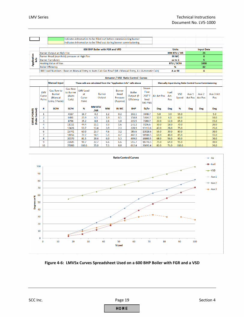
LMV Series Technical Instructions Document No. LV5‐1000
SCC Inc. Page 19 Section 4
Figure 4‐6: LMV5x Curves Spreadsheet Used on a 600 BHP Boiler with FGR and a VSD
Technical Instructions LMV Series Document No. LV5‐1000
Section 4 Page 20 SCC Inc.
NOTE: When in a curve point on the right‐hand side of the AZL screen, pressing “Esc” will bring the cursor back to the left, off of the numbers. Pressing “Esc” again while off of the numbers will bring up a prompt to ask if the point is to be stored (press “Enter”) or the changes canceled (press “Esc”). If store is selected, a bar will rotate on the left‐hand side of the AZL5 display while the point is being stored.
NOTE: When putting in a new point that is not yet defined (XXXX shown for the positions and load), pressing “Enter” will put in values for the positions and load from the previous point based on load number. These values serve as a place to start for the new point.
9. With the Ratio Control Curves laid out on paper or with the spreadsheet, begin setting the curve points from low fire (Point 1) to high fire (Point 10). The general procedure for each point is to match the load number to the fuel flow while maintaining safe combustion. After this is complete, adjust the air and / or FGR as necessary to achieve safe, efficient combustion and emissions compliance on each point.
10. The following is a summary of what should be achieved for each point on the Ratio Control Curve:
For standard burners (LMV51, or LMV52 without O2 trim):
a. Safe, efficient combustion as verified by a calibrated stack gas analyzer b. The % load matching the fuel flow within +/‐ 5% c. Emissions compliance d. Smooth Ratio Control Curves (no sharp peaks and valleys)
For standard nozzle mixing burners (no or low % FGR) and O2 trim (LMV52):
e. All points a thru d above f. VSD speed should increase with load in a linear fashion (if equipped) g. The % load matching the fuel flow within +/‐ 3% h. Find and record the %O2 wet corresponding to the fuel rich limit (O2 Alarm value) for
each point by probing* i. Find and record the %O2 wet corresponding to the fuel lean limit (O2 MaxValue) for
Point 1 and Point 10 by probing* j. Last but not least, leave the curve points so that the %O2 wet is 2% higher than the fuel
rich limit (O2 Alarm value). Record this as the saved value for each curve point.
For pre‐mix mesh burners and nozzle mixing burners (high % FGR) and O2 trim (LMV52):
k. All points a thru d above l. VSD speed should increase with load in a linear fashion (if equipped) m. The % load matching the fuel flow within +/‐ 3% n. Determine the %O2 wet corresponding to the fuel rich limit (O2 Alarm Value) for each
point. Probing may or may not be possible depending on the burner design. Also, follow burner OEM recommendations. Most mesh burner elements can be damaged if run too fuel rich.*
LMV Series Technical Instructions Document No. LV5‐1000
SCC Inc. Page 21 Section 4
o. Find and record the %O2 wet corresponding to the fuel lean limit (O2 MaxValue) for
Point 1 and Point 10 by probing or according to burner OEM recommendations.* p. Find the target %O2. For these burners, the target %O2 for each point will be the %O2
wet corresponding to emissions compliance (typically CO, NOx). After the target %O2 is found, increase the %O2 and leave the point at least 0.5% O2 leaner than the target %O2. Record this as the saved value for each curve point.
* NOTE: This information will be needed to commission the O2 trim, and it is convenient to obtain this information when commissioning the Ratio Control Curve. When probing the fuel rich limit, it is not recommended to exceed 200 ppm CO (dry basis) or less than 1.0% O2 (wet or dry basis) for any point. When probing the fuel lean limit, it is not recommended to exceed 200 ppm CO or adversely affect flame stability for any point. The LMV52 with the QGO20 O2 sensor reads %O2 on a wet basis, while most external exhaust gas analyzers read %O2 on a dry basis.
11. After Point 10 values have been saved, press “Esc” to exit CurveParams.
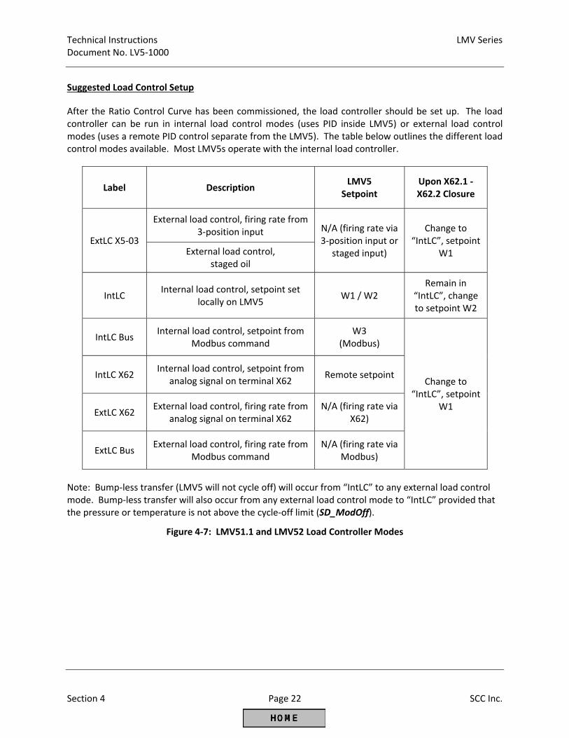
Technical Instructions LMV Series Document No. LV5‐1000
Section 4 Page 22 SCC Inc.
Suggested Load Control Setup
After the Ratio Control Curve has been commissioned, the load controller should be set up. The load controller can be run in internal load control modes (uses PID inside LMV5) or external load control modes (uses a remote PID control separate from the LMV5). The table below outlines the different load control modes available. Most LMV5s operate with the internal load controller.
Label Description LMV5
Setpoint Upon X62.1 ‐ X62.2 Closure
ExtLC X5‐03
External load control, firing rate from 3‐position input N/A (firing rate via
3‐position input or staged input)
Change to “IntLC”, setpoint
W1 External load control, staged oil
IntLC Internal load control, setpoint set
locally on LMV5 W1 / W2
Remain in “IntLC”, change to setpoint W2
IntLC Bus Internal load control, setpoint from
Modbus command W3
(Modbus)
Change to “IntLC”, setpoint
W1
IntLC X62 Internal load control, setpoint from
analog signal on terminal X62 Remote setpoint
ExtLC X62 External load control, firing rate from
analog signal on terminal X62 N/A (firing rate via
X62)
ExtLC Bus External load control, firing rate from
Modbus command N/A (firing rate via
Modbus)
Note: Bump‐less transfer (LMV5 will not cycle off) will occur from “IntLC” to any external load control mode. Bump‐less transfer will also occur from any external load control mode to “IntLC” provided that the pressure or temperature is not above the cycle‐off limit (SD_ModOff).
Figure 4‐7: LMV51.1 and LMV52 Load Controller Modes
LMV Series Technical Instructions Document No. LV5‐1000
SCC Inc. Page 23 Section 4
Most boilers use load controller mode "IntLC" which utilizes the local temperature / pressure sensor and a local setpoint entered through the AZL display. The following procedure outlines how to set up this mode:
1. If possible, shut off the burner switch. Let the burner get back to Phase 12 (standby).
2. Verify that the load controller is in the correct mode through the following menu path:
Params & Display > LoadController > Configuration Set parameter LC_OptgMode to "IntLC". Next, verify that the connected pressure or temperature sensor is configured correctly. In the same menu, set Sensor Select to “PressSensor” for a steam boiler or to the appropriate temperature sensor for a hot water boiler.
3. If a pressure sensor was selected, two additional parameters must be set in the same menu. Set parameter Ext Inp X61 U/I to match the pressure sensor wired into the X61 terminal. Typically this will be 0‐10VDC or 4‐20mA and will be printed on the side of the sensor. Next, set parameter MRange PressSens to the high range of the pressure sensor. This is typically printed on the side of the pressure sensor.
4. Configure setpoint W1 (the local setpoint) through the following menu path:
Operation > BoilerSetpoint
5. Set the turn‐on point (SD_ModOn) and the turn‐off point (SD_ModOff) for the boiler. These are percentages based on the current setpoint (W1). The menu path for these parameters is: Params & Display > LoadController > ControllerParam Typically, the burner is shut off 10% over setpoint and turned back on 1% above setpoint.
NOTE: Other pressure / temperature controls or limits on the boiler must be set above the SD_ModOff pressure / temperature.
NOTE: SD_ModOff and SD_ModOn are only valid for internal load controller modes. If the LMV5 is in an external load controller mode, SD_ModOff and SD_ModOn are ignored.
6. If it is safe to do so, turn on the burner switch. If thermal shock is a concern, allow the boiler to warm. The burner can be put in manual and held at low fire if necessary through the Manual Operation menu.
7. Once the boiler is up to pressure / temperature, is modulating, and is carrying normal load, adjust the PID values through the following menu path:
Params & Display > LoadController > ControllerParam > ContrlParamList
Technical Instructions LMV Series Document No. LV5‐1000
Section 4 Page 24 SCC Inc.
Properly adjusted PID values will result in the pressure / temperature staying within +/‐ 3% of setpoint without constantly changing the load and modulating the actuators. P‐Part (Proportional Band) ‐ Increases firing rate based on how far below setpoint the temperature / pressure is. Smaller values cause a more aggressive P response to a drop in pressure / temperature relative to setpoint. Values that are too small will cause hunting. Typical setting: 10% to 30%. I‐Part (Integral) ‐ Serves to eliminate steady state "droop" caused by the proportional band setting. Thus, this works hand in hand with P‐Part to bring the pressure / temperature up to setpoint. Smaller values cause a more aggressive I response (a setting of 1 is most aggressive). Values that are too small will cause overshoot. Typical setting: 80 sec to 300 sec. A setting of 0 deactivates the feature, but this is not recommended. D‐Part (Derivative) ‐ Serves to eliminate overshoot, and allows a more aggressive integral setting. Larger values cause a more aggressive D response. D‐Part is not needed on many steam boilers. If needed, small values of less than 20 typically work well. A setting of 0 deactivates the feature. Large values will typically cause hunting.
8. After the PID loop has been adjusted, it is possible that the load will still move up and down by a
small amount (1‐2% load). If this is the case, adjusting parameter MinActuatorStep may help eliminate this "micro‐hunting". This parameter can be found in the following menu:
Params & Display > LoadController > ControllerParam MinActuatorStep is basically a dead band for the output of the PID loop. Typical setting: 1% to 4%. Values above 5% could cause hunting issues in some applications.
Suggested Cold Start (Thermal Shock Protection) Setup The LMV51.1 and LMV52 have an internal load control and therefore have the ability to perform thermal shock protection. Thermal shock protection only functions when the LMV5 is in an internal load controller mode, namely IntLC, IntLC X62, or IntLC Bus (see chart on previous pages). The cold start feature requires that the temperature or pressure of the boiler is measured by a sensor connected to the LMV5. For a hot water boiler (temperature‐based modulation), the same temperature sensor that is used for modulation must be used for the cold start feature. For a steam boiler (pressure‐based modulation), a temperature sensor is also highly recommended for cold start. Temperature sensors are highly recommended since pressure does not always represent temperature in a non‐firing steam boiler, especially when multiple steam boilers are piped to the same steam header. The paragraphs below will only mention temperature‐based cold start, but the same ideas also apply to pressure‐based cold start.
LMV Series Technical Instructions Document No. LV5‐1000
SCC Inc. Page 25 Section 4
1. If possible, shut off the burner switch. Let the burner get back to Phase 12 (standby).
2. Access the cold start parameters through the following menu path:
Params & Display > LoadController > ColdStart
Set parameter ThresholdOn to the minimum permissible temperature where the burner can be released to modulate. Below this temperature, cold start will engage on initial startup (not during normal operation). Set ThresholdOff to a temperature higher than ThresholdOn. If already engaged, cold start will disengage at the ThresholdOff temperature. Setting ThresholdOn and ThresholdOff is required for cold start.
NOTE: Parameters ThresholdOn and ThresholdOff are percentages based on the current setpoint (W1). If an additional temperature sensor is used on a steam boiler, ThresholdOn and ThresholdOff will be based on parameter Setp AddSensor.
3. For a steam boiler that is on a common header with other steam boilers, an additional temperature sensor is required for cold start. This will typically be a Pt1000 or Ni1000 RTD wired to terminal X60. Pt100 is possible but not recommended. Choose the appropriate sensor via parameter AdditionalSens.
4. There are four basic ways that the cold start can be set. These are:
a. Basic Low Fire Hold
The LMV5 will be held at low fire until the ThresholdOff temperature is reached, and then the LMV5 will be released to modulate. This “hold” will re‐engage when the temperature falls below the ThresholdOn value. Parameter StageLoad must be set to 0.
b. Temperature‐based Stepping Start The LMV5 will be held at low fire until a certain temperature change is detected, and then a step up in burner output (load) will be taken. This continues until the ThresholdOff temperature is reached. This will achieve the ThresholdOff temperature faster than a basic low fire hold. Parameter StageLoad must be set to a value greater than 0, since the step‐up in load is determined by this parameter. Parameter StageSetp_Mod must also be set to determine the amount of temperature change that will trigger a step‐up in load. Parameter MaxTmeMod should be set to a high number (30 min) so that it has no effect.
c. Time‐based Stepping Start The LMV5 will be held at low fire until a certain time elapses, and then a step‐up in load will be taken. This continues until the ThresholdOff value is reached. StageLoad must be set to a value greater than 0, since the step‐up in load is determined by this parameter. Parameter StageSetp_Mod should be set to a high number (80%) so that it has no effect. Parameter MaxTmeMod is set to determine how much time should elapse before the next load step is triggered.
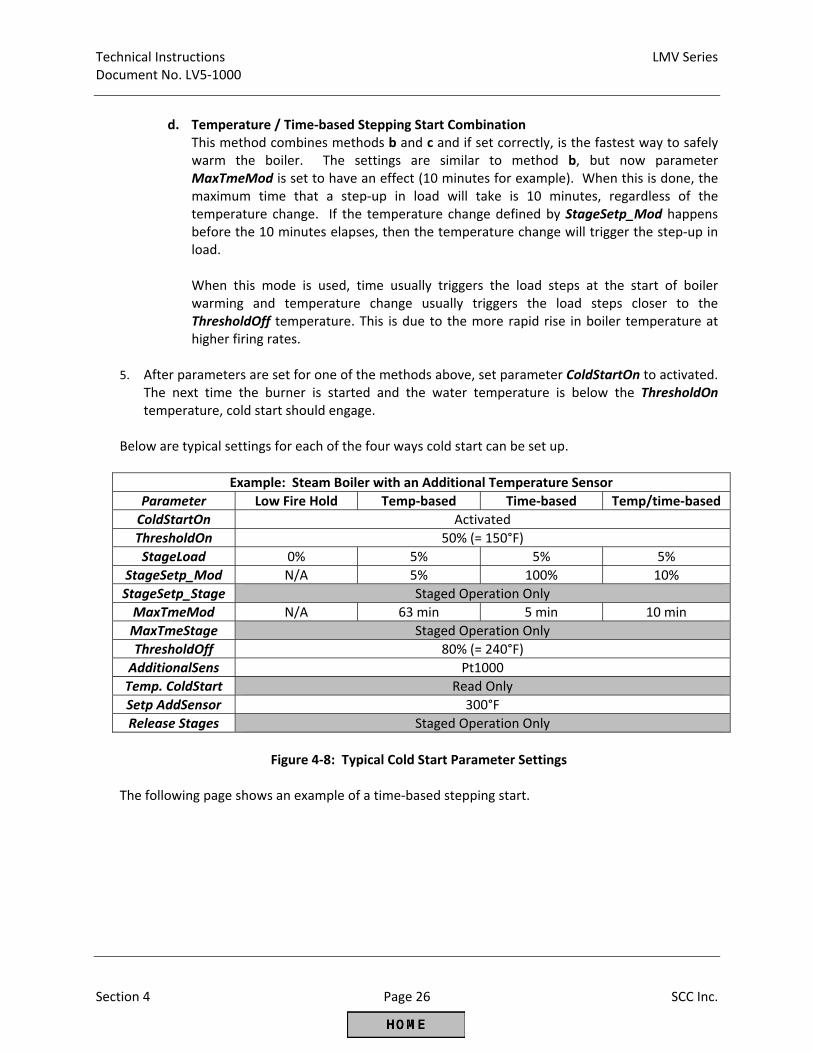
Technical Instructions LMV Series Document No. LV5‐1000
Section 4 Page 26 SCC Inc.
d. Temperature / Time‐based Stepping Start Combination
This method combines methods b and c and if set correctly, is the fastest way to safely warm the boiler. The settings are similar to method b, but now parameter MaxTmeMod is set to have an effect (10 minutes for example). When this is done, the maximum time that a step‐up in load will take is 10 minutes, regardless of the temperature change. If the temperature change defined by StageSetp_Mod happens before the 10 minutes elapses, then the temperature change will trigger the step‐up in load. When this mode is used, time usually triggers the load steps at the start of boiler warming and temperature change usually triggers the load steps closer to the ThresholdOff temperature. This is due to the more rapid rise in boiler temperature at higher firing rates.
5. After parameters are set for one of the methods above, set parameter ColdStartOn to activated. The next time the burner is started and the water temperature is below the ThresholdOn temperature, cold start should engage.
Below are typical settings for each of the four ways cold start can be set up.
Example: Steam Boiler with an Additional Temperature Sensor
Parameter Low Fire Hold Temp‐based Time‐based Temp/time‐based
ColdStartOn Activated
ThresholdOn 50% (= 150°F)
StageLoad 0% 5% 5% 5%
StageSetp_Mod N/A 5% 100% 10%
StageSetp_Stage Staged Operation Only
MaxTmeMod N/A 63 min 5 min 10 min
MaxTmeStage Staged Operation Only
ThresholdOff 80% (= 240°F)
AdditionalSens Pt1000
Temp. ColdStart Read Only
Setp AddSensor 300°F
Release Stages Staged Operation Only
Figure 4‐8: Typical Cold Start Parameter Settings
The following page shows an example of a time‐based stepping start.
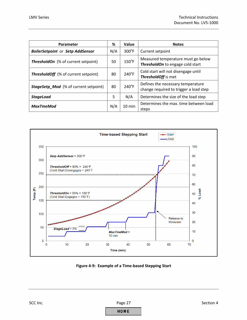
LMV Series Technical Instructions Document No. LV5‐1000
SCC Inc. Page 27 Section 4
Parameter % Value Notes
BoilerSetpoint or Setp AddSensor N/A 300oF Current setpoint
ThresholdOn (% of current setpoint) 50 150oF Measured temperature must go below ThresholdOn to engage cold start
ThresholdOff (% of current setpoint) 80 240oF Cold start will not disengage until ThresholdOff is met
StageSetp_Mod (% of current setpoint) 80 240oF Defines the necessary temperature change required to trigger a load step
StageLoad 5 N/A Determines the size of the load step
MaxTmeMod N/A 10 min Determines the max. time between load steps
Figure 4‐9: Example of a Time‐based Stepping Start
Technical Instructions LMV Series Document No. LV5‐1000
Section 4 Page 28 SCC Inc.
Additional Tips for Commissioning
If an LMV52 is being commissioned, activate the O2 sensor as soon as possible. Once the O2 sensor is heated, this will show a fast responding O2 value on the AZL screen during Ratio Control Curve commissioning. This sensor reads %O2 wet so the value will be somewhat lower than an external flue gas analyzer.
Using a fuel flow meter (temporary or permanent) for commissioning is always a good idea even for LMV51’s without O2 trim. If the fuel input (heat output) increases linearly with firing rate, the PID loop in any load control will work much better. A temporary, insertion type of flow meter is available from SCC Inc. for this purpose.
If burner head pressure must be used as a last resort to estimate firing rate, bear in mind that head pressure does not increase with gas flow in a linear manner. There is a square root relationship between the differential pressure across the burner head and the gas flow. This relationship is very similar to how the pressure varies across a fixed orifice with an increase or decrease in flow. Also, furnace pressure must be accounted for by hooking up both sides of the manometer, one side to the burner head pressure and one side to the furnace pressure.
Carbon Monoxide (CO) is produced when combustion is incomplete, typically due to the flame being too rich or too lean. CO is potentially explosive when mixed with air in the right proportions. For CO to be explosive in air, it must reach a concentration of at least 12.5% (125,000 ppm) with an ignition source present.
If a burner is commissioned properly, actuator curves should increase smoothly with increasing load (firing rate). One exception to this would be the FGR actuator (Aux1 or Aux3) which commonly decreases (closes) as firing rate increases. Curves should always be smooth, with no sharp corners.
The best and fastest method to commission a burner with an LMV5 is to set up a small table where the technician can have his laptop, AZL, fuel flow meter and external flue gas analyzer all within arm's reach. This allows the curve points to be input rapidly and accurately. If the information is entered in the laptop point by point, a very nice start‐up report will also be generated.
The ACS450 software is not as fast as using the AZL to commission the LMV5. Since this is the case, the ACS450 is typically not used to commission the LMV5. However, the ACS450 is very valuable when used to download an .mdb file (all parameter settings, fault and lockout history, in English) and also when used to download .par files (the machine‐language parameter set from the LMV5). It is recommended to download both of these files after commissioning, so that there is a backup record of all parameter and curve settings.
To go back out of the menu and check burner operation, press the < and > buttons at the same time. This will take the cursor to Normal Operation, so the normal operation screen can be viewed by pressing Enter. This can be done anywhere in the menu as long as a single parameter is not currently displayed. Pressing Esc will take the cursor back in to where it was in the menu.
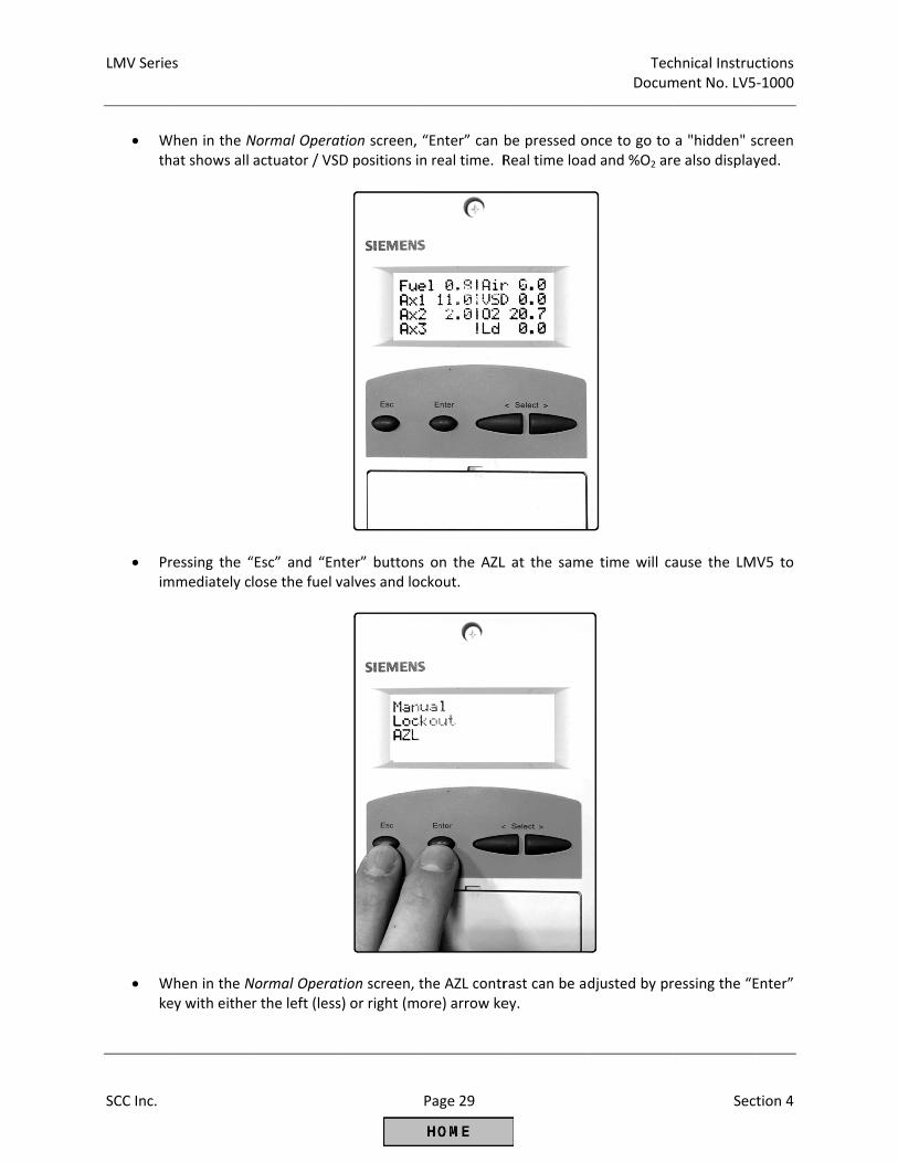
LMV Serie
SCC Inc.
W
th
Pim
Wke
es
When in the Nhat shows all
ressing the “mmediately c
When in the Ney with eithe
Normal Operaactuator / VS
“Esc” and “Enlose the fuel v
Normal Operar the left (less
ation screen, SD positions i
nter” buttonsvalves and lo
ation screen, ts) or right (m
Page 29
“Enter” can n real time. R
s on the AZLckout.
the AZL controre) arrow ke
be pressed oReal time loa
L at the same
rast can be adey.
TecDocum
once to go to d and %O2 ar
e time will c
djusted by pr
chnical Instrucment No. LV5
Sec
a "hidden" sre also display
ause the LM
ressing the “E
ctions ‐1000
tion 4
screen yed.
V5 to
Enter”
Technical Instructions LMV Series Document No. LV5‐1000
Section 4 Page 30 SCC Inc.
Special Features and Settings
The LMV5 has special features and settings that are very useful in some situations. Some of these features are detailed below.
Alarm act/deact An internal alarm silence. Alarm silence will reset when the LMV5 alarm is reset. MinTmeStartRel Permits the LMV5 to hold in phase 21 for a specified period of time with the start
signal terminal energized. This can be used as a delay to let stack and/or fresh air dampers open.
PressReacTme Allows the LMV5 to disregard the high and low gas / oil pressure switches for a
settable time period after the main gas / oil valves open. This is used with automatic reset pressure switches so that pressure spikes due to the main valves opening will be ignored. This also allows for a reduced delta between switch setpoints and normal operating pressures. This time can also be reduced to 0.2 seconds, deactivating the feature. Not used with manual reset switches.
NormDirectStart Permits the LMV5 to go from post‐purge directly into pre‐purge without turning
the blower off. The blower air pressure switch must be checked by using a 3‐way solenoid valve. The solenoid valve is configured under parameter StartSignal.
ForcedIntermit Shuts the burner down once every 24 hours to cycle and check flame scanner, air
pressure switch, POC, and other safety devices. DriveLowFire Starts driving to low fire (StartPointOp) immediately after main fuel valves open.
Enables less air to be put on the pilot for ignition, and enables a fuel rich light off without creating excessive CO. Also called "Golden Start" functionality.
StartReleaseGas Configures terminal X7‐03.2 as a start release for gas, CPI gas, CPI oil, or CPI gas +
oil. Gas and oil POCs can be wired here, freeing up terminal X9‐03.2 for gas valve proving. CPI stands for Closed Position Indication, which is essentially the same as Proof of Closure (POC).
Config_PS‐VP/CPI Configures terminal X9‐03.2 for PS‐VP (Pressure Switch ‐ Valve Proving), CPI gas,
CPI oil, or CPI gas + oil. CPI stands for Closed Position Indication, which is essentially the same as Proof of Closure (POC).
Config X5‐03 Terminal X5‐03.3 can be configured to hold the LMV5 in phase 36 (ignition
position). Terminal X5‐03.2 can be configured to disable O2 trim. HeavyOilDirStart Terminal X6‐01.3 can be used as an input for an external flame relay. ReacTmeLossFlame Adjustable flame failure response time (FFRT).
LMV Series Technical Instructions Document No. LV5‐1000
SCC Inc. Page 31 Section 4
SensOperPhGas Enables two flame detectors to be used on one burner (LMV52 only). ValveProvingType Enables gas valve proving on start‐up or shutdown or both. This type of testing
ensures that the gas valves are closed, and that the valve seats are in good condition.
StartPointOp Can adjust which curve point the LMV5 will drive to after light off. This setting
does not affect turndown. NumFuelActuators Permits the LMV5 to run dual fuel with a single actuator ‐ two fuel valves on one
actuator. ProgramStop Stops the LMV5 at a particular phase in the start‐up or shutdown sequence. This
is particularly useful when set to Phase 44 for tuning the pilot. FGR‐Mode On an LMV52, this setting enables only the Aux 3 actuator to be held from
modulating until a certain temperature or time after light off is met. This is usually used to delay the use of FGR until a certain time or until a stack temperature is met.
ReleasecontctVSD If a VSD is being used, this enables the blower to coast down after post‐purge is
complete. O2SensServTim This sets a service interval for the O2 sensor.

Technical Instructions LMV Series Document No. LV5‐1000
Section 4 Page 32 SCC Inc.
Intentionally Left Blank

Section 1 Overview
Section 2 Wiring
Section 3 Parameters
Section 4 Commissioning
Section 5 VSD
Section 6 O2 Trim
Section 7 Troubleshooting
Section 8 Modbus
Section 9 ACS450
Section 10 Revision History
Appendix A Application Guide
Appendix B* Complimentary Products Guide
*Can be found at www.scccombustion.com.
LMV Series Technical Instructions Document No. LV5‐1000
SCC Inc. Page 1 Section 5
Section 5 ‐ Variable Speed Drive Control
Table of Contents Introduction .................................................................................................................................... 2
VFD and AC Induction Motor Fundamentals .................................................................................. 2
Line Reactors ................................................................................................................................... 3
Output Wiring / Load Reactors ....................................................................................................... 4
Shaft Current ................................................................................................................................... 5
Braking Resistors ............................................................................................................................. 5
Types of VFDs: Vector and Volt/Hz ................................................................................................ 7
Centrifugal Blower Fundamentals .................................................................................................. 7
Configuring VFDs for use with the LMV52 ...................................................................................... 8
Standardizing the LMV52 ................................................................................................................ 9
Blower Speed Monitoring ............................................................................................................. 13
Suggested Setup Procedure for the VFD Control ......................................................................... 15
Additional Tips for Burners with VFD Control .............................................................................. 16
Technical Instructions LMV Series Document No. LV5‐1000
Section 5 Page 2 SCC Inc.
Introduction The LMV52 features an integrated, closed‐loop Variable Speed Drive (VSD) control that is typically used to ramp the speed of the combustion air blower with firing rate. This is accomplished by transmitting a 4‐20 mA signal from the LMV52 to the VSD, and then reading the speed of the motor via a motor‐mounted, safety‐rated encoder wheel (speed wheel) and speed sensor. By using the speed wheel and sensor, the LMV52 can positively verify both the speed and direction of the blower, thus ensuring proper VSD operation. Blower speed and direction of rotation have a large impact on the airflow delivered to the burner, and thus the fuel‐air ratio. The most common type of VSD, a Variable Frequency Drive (VFD), is typically not safety‐rated and will typically not fail in a safe manner (a VFD failure will typically cause the combustion air blower to slow down or stop, causing the burner to go rich). The combustion air pressure switch offers only a small amount of protection in a VFD application, since the switch must be set to allow low fire operation when the blower is spinning slowly and the blower output pressure is low. The motor or blower shaft‐mounted, safety‐rated speed wheel and sensor ensure that a VFD failure will be quickly detected and the burner will shut down in a safe way.
VFD and AC Induction Motor Fundamentals VFDs are typically connected to a three‐phase alternating current (AC) induction motor that is used to power the combustion air blower. Modern VFDs operate by taking single‐ or three‐phase AC and rectifying this power to high voltage direct current (DC) for the DC bus. The AC power is typically rectified to DC with banks of diodes. The DC bus feeds a bank of Insulated Gate Bipolar Transistors (IGBTs), and a microprocessor is used to fire the IGBTs in a way that the voltage and frequency of the modified sine waves can be controlled. This is done for each of the three phases on the VFD output. The microprocessor varies the voltage and frequency of the modified sine waves in response to a signal; in this case, the 4‐20mA input. By design, a three‐phase AC induction motor will attempt to approximately synchronize its speed with the frequency of three‐phase power that it is being fed. Thus, if the frequency can be adjusted, so can the speed of the motor. As their name suggests, three‐phase induction motors generate magnetic fields in the rotor of the motor by using induction rather than by using slip rings or brushes. The advantage of this type of construction is very low maintenance, and a small disadvantage is a phenomenon called slip. Slip is defined as the difference between the theoretical speed at a given AC frequency and the actual speed at a given AC frequency. Slip increases as the load on the motor (torque output) increases. Three‐phase AC motors that do not have slip are referred to as synchronous motors, since these motors exactly synchronize their speed to the frequency of the incoming AC power. This type of motor is not typically used on blowers, but is mentioned as a comparison to the AC induction motor. A truly synchronous 2‐pole motor will spin at exactly 3600 RPM if it is fed exactly 60 Hz. A truly synchronous 4‐pole motor will spin at exactly 1800 RPM if it is fed exactly 60 Hz. In contrast, a 2‐pole, three‐phase AC induction motor fed 60 Hz will spin less than 3600 RPM, and how much less is determined by how heavily the motor is loaded and how much slip that loading causes.
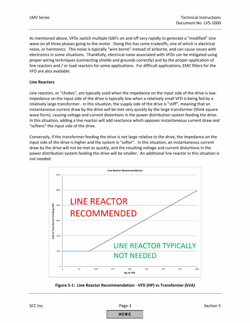
LMV Series Technical Instructions Document No. LV5‐1000
SCC Inc. Page 3 Section 5
As mentioned above, VFDs switch multiple IGBTs on and off very rapidly to generate a "modified" sine wave on all three phases going to the motor. Doing this has some tradeoffs, one of which is electrical noise, or harmonics. This noise is typically "wire borne" instead of airborne, and can cause issues with electronics in some situations. Thankfully, electrical noise associated with VFDs can be mitigated using proper wiring techniques (connecting shields and grounds correctly) and by the proper application of line reactors and / or load reactors for some applications. For difficult applications, EMC filters for the VFD are also available. Line Reactors Line reactors, or "chokes", are typically used when the impedance on the input side of the drive is low. Impedance on the input side of the drive is typically low when a relatively small VFD is being fed by a relatively large transformer. In this situation, the supply side of the drive is "stiff", meaning that an instantaneous current draw by the drive will be met very quickly by the large transformer (think square wave form), causing voltage and current distortions in the power distribution system feeding the drive. In this situation, adding a line reactor will add reactance which opposes instantaneous current draw and "softens" the input side of the drive. Conversely, if the transformer feeding the drive is not large relative to the drive, the impedance on the input side of the drive is higher and the system is "softer". In this situation, an instantaneous current draw by the drive will not be met as quickly, and the resulting voltage and current distortions in the power distribution system feeding the drive will be smaller. An additional line reactor in this situation is not needed.
Figure 5‐1: Line Reactor Recommendation ‐ VFD (HP) vs Transformer (kVA)
Technical Instructions LMV Series Document No. LV5‐1000
Section 5 Page 4 SCC Inc.
In general, a line reactor is recommended if the supply capacity (kVA) of the transformer feeding the drive is greater than or equal to 10 times the capacity (kVA) of the drive for transformers 600 kVA and larger. Figure 5‐1 notes: 1. Drive power is shown in HP rather than kVA. This conversion can be done assuming a power factor
of unity (1) and negligible losses due to efficiency. 2. Transformers less than 600 kVA have high enough impedance (“soft” enough) so that line reactors
are typically not necessary. Example 1: A 25 HP drive is being fed by an 800 kVA transformer. Is a line reactor required? Assumptions: The power factor is unity (power factor =1) Losses due to efficiency and wiring are negligible
1. Convert horsepower to kilowatts: 25 HP x 0.745 HP/kW = 18.63 kW 2. Convert kilowatts to kVA: kW = kVA * Pf (Pf is power factor, which is assumed to be 1 in this
example) Thus, a 25 HP drive is 18.63 kVA.
3. Calculate the kVA ratio: 800 kVA / 18.63 kVA = 42.94
Since a ratio of 42.94 is greater than 10, and the transformer is larger than 600 kVA, a line reactor will be necessary for this application. The same conclusion can also be arrived at by using Figure 5‐1.
Example 2: A 10 HP drive is fed by a 400 kVA transformer. Is a line reactor required? Using the same assumptions and calculation as example 1, the kVA ratio is 53.7, but the transformer is smaller than 600 kVA, so a line reactor is not necessary. The same conclusion can also be arrived at by using Figure 5‐1. Output Wiring / Load Reactors When the VFD / motor are running, high levels of electrical noise are produced on the wiring between the VFD and the motor. This is due to the fact that modified sine waves produced by the drive IGBTs are basically high frequency / high voltage DC pulses. These output wires must be enclosed in some type of shielding (metallic conduit or metal‐shielded cable) to mitigate radiated electrical noise. Wire length between the VFD and the motor should be kept to less than 150 feet if possible due to the reflected wave / standing wave phenomenon and voltage overshoot phenomenon. Both of these phenomena are rather complex, and are a function of the wire length from the VFD to the motor. The reflected wave / standing wave phenomenon and voltage overshoot phenomenon can damage non‐inverter duty motor windings over time due to the high peak voltages that these phenomena can produce.
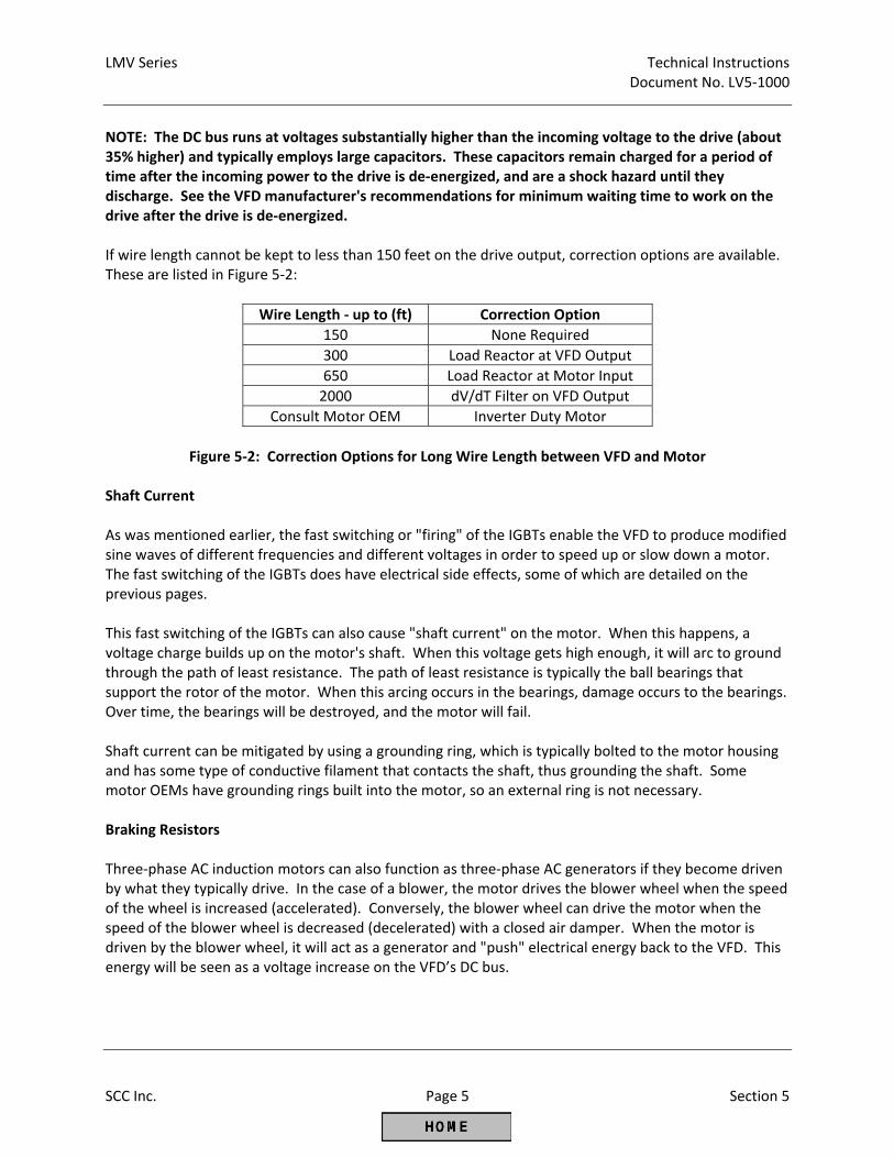
LMV Series Technical Instructions Document No. LV5‐1000
SCC Inc. Page 5 Section 5
NOTE: The DC bus runs at voltages substantially higher than the incoming voltage to the drive (about 35% higher) and typically employs large capacitors. These capacitors remain charged for a period of time after the incoming power to the drive is de‐energized, and are a shock hazard until they discharge. See the VFD manufacturer's recommendations for minimum waiting time to work on the drive after the drive is de‐energized. If wire length cannot be kept to less than 150 feet on the drive output, correction options are available. These are listed in Figure 5‐2:
Wire Length ‐ up to (ft) Correction Option
150 None Required
300 Load Reactor at VFD Output
650 Load Reactor at Motor Input
2000 dV/dT Filter on VFD Output
Consult Motor OEM Inverter Duty Motor
Figure 5‐2: Correction Options for Long Wire Length between VFD and Motor
Shaft Current As was mentioned earlier, the fast switching or "firing" of the IGBTs enable the VFD to produce modified sine waves of different frequencies and different voltages in order to speed up or slow down a motor. The fast switching of the IGBTs does have electrical side effects, some of which are detailed on the previous pages. This fast switching of the IGBTs can also cause "shaft current" on the motor. When this happens, a voltage charge builds up on the motor's shaft. When this voltage gets high enough, it will arc to ground through the path of least resistance. The path of least resistance is typically the ball bearings that support the rotor of the motor. When this arcing occurs in the bearings, damage occurs to the bearings. Over time, the bearings will be destroyed, and the motor will fail. Shaft current can be mitigated by using a grounding ring, which is typically bolted to the motor housing and has some type of conductive filament that contacts the shaft, thus grounding the shaft. Some motor OEMs have grounding rings built into the motor, so an external ring is not necessary. Braking Resistors Three‐phase AC induction motors can also function as three‐phase AC generators if they become driven by what they typically drive. In the case of a blower, the motor drives the blower wheel when the speed of the wheel is increased (accelerated). Conversely, the blower wheel can drive the motor when the speed of the blower wheel is decreased (decelerated) with a closed air damper. When the motor is driven by the blower wheel, it will act as a generator and "push" electrical energy back to the VFD. This energy will be seen as a voltage increase on the VFD’s DC bus.
Technical Instructions LMV Series Document No. LV5‐1000
Section 5 Page 6 SCC Inc.
The DC bus can absorb a small amount of energy in the DC bus capacitors. However, if the motor generates more than what these capacitors can absorb, the DC bus voltage will rise to critical levels and one of two actions will be taken by the VFD. Depending on the parameter setting of the VFD, the VFD will either stop decelerating (stall prevention) or the VFD will alarm and shut down. Either one of the actions is not a desirable result on a combustion air application. To avoid DC bus overvoltage issues, a braking resistor can be added to the VFD so that the excess electrical energy generated by decelerating the blower wheel can be turned to heat. This process happens seamlessly so that the VFD can decelerate the blower smoothly. Due to a number of variables, it is difficult to determine if a braking resistor will be needed on a particular application unless that application has been tested. The only disadvantage of having a braking resistor and not needing it is cost and possibly the space for the resistor. Burners having the following characteristics will typically need a braking resistor: 1. A heavy blower wheel ‐ Kinetic energy is stored in a spinning wheel. The heavier the blower wheel,
the greater the stored energy. When this wheel is slowed down, the kinetic energy must go somewhere, and it is usually "pushed" back to the VFD as electrical energy.
2. Fast ramp times ‐ The faster the ramp times, the faster the blower wheel must be accelerated and
decelerated. Just like a car, more energy is required to accelerate quickly (bigger engine) and more energy is required to be dissipated when decelerating quickly (bigger brakes). Decelerating a given blower wheel more quickly will push more electrical energy back to the VFD.
3. Mostly closed air damper ‐ A motor spinning at 3600 RPM draws fewer amps with a closed or nearly
closed air damper as compared to a wide open air damper. Thus, the horsepower used by the motor and the drag (braking) on the blower wheel will be much less with a closed or nearly closed air damper. Decelerating a given blower wheel with reduced drag will also push more electrical energy back to the VFD.
As one might expect, the above points compound one another. Decelerating a heavy blower wheel with a fast ramp time and a mostly closed air damper will push a large amount of electrical energy back at the VFD and will likely cause DC bus overvoltage issues if a braking resistor is not installed. In contrast, a light blower wheel (sheet metal instead of cast iron), a slower ramp time (90 seconds instead of 30 seconds), and slowing the blower down on a more open air damper are characteristics that will greatly reduce the amount of electrical energy pushed back to the VFD and should allow the braking resistor to be omitted in most cases. On some models of VFDs, braking resistors can be added after the VFD is installed if necessary. This is a point to consider when installing VFDs for combustion air applications.
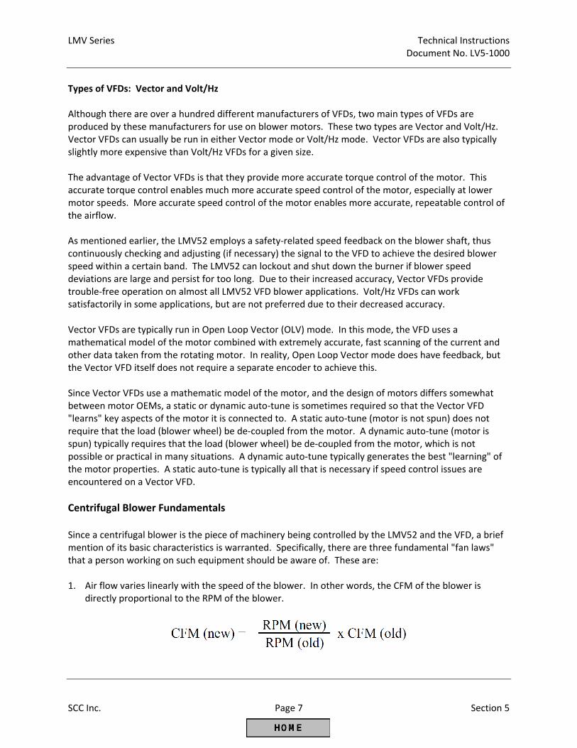
LMV Series Technical Instructions Document No. LV5‐1000
SCC Inc. Page 7 Section 5
Types of VFDs: Vector and Volt/Hz Although there are over a hundred different manufacturers of VFDs, two main types of VFDs are produced by these manufacturers for use on blower motors. These two types are Vector and Volt/Hz. Vector VFDs can usually be run in either Vector mode or Volt/Hz mode. Vector VFDs are also typically slightly more expensive than Volt/Hz VFDs for a given size. The advantage of Vector VFDs is that they provide more accurate torque control of the motor. This accurate torque control enables much more accurate speed control of the motor, especially at lower motor speeds. More accurate speed control of the motor enables more accurate, repeatable control of the airflow. As mentioned earlier, the LMV52 employs a safety‐related speed feedback on the blower shaft, thus continuously checking and adjusting (if necessary) the signal to the VFD to achieve the desired blower speed within a certain band. The LMV52 can lockout and shut down the burner if blower speed deviations are large and persist for too long. Due to their increased accuracy, Vector VFDs provide trouble‐free operation on almost all LMV52 VFD blower applications. Volt/Hz VFDs can work satisfactorily in some applications, but are not preferred due to their decreased accuracy. Vector VFDs are typically run in Open Loop Vector (OLV) mode. In this mode, the VFD uses a mathematical model of the motor combined with extremely accurate, fast scanning of the current and other data taken from the rotating motor. In reality, Open Loop Vector mode does have feedback, but the Vector VFD itself does not require a separate encoder to achieve this. Since Vector VFDs use a mathematic model of the motor, and the design of motors differs somewhat between motor OEMs, a static or dynamic auto‐tune is sometimes required so that the Vector VFD "learns" key aspects of the motor it is connected to. A static auto‐tune (motor is not spun) does not require that the load (blower wheel) be de‐coupled from the motor. A dynamic auto‐tune (motor is spun) typically requires that the load (blower wheel) be de‐coupled from the motor, which is not possible or practical in many situations. A dynamic auto‐tune typically generates the best "learning" of the motor properties. A static auto‐tune is typically all that is necessary if speed control issues are encountered on a Vector VFD.
Centrifugal Blower Fundamentals Since a centrifugal blower is the piece of machinery being controlled by the LMV52 and the VFD, a brief mention of its basic characteristics is warranted. Specifically, there are three fundamental "fan laws" that a person working on such equipment should be aware of. These are: 1. Air flow varies linearly with the speed of the blower. In other words, the CFM of the blower is
directly proportional to the RPM of the blower.
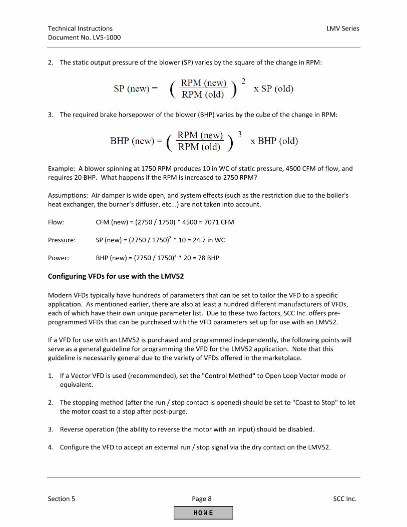
Technical Instructions LMV Series Document No. LV5‐1000
Section 5 Page 8 SCC Inc.
2. The static output pressure of the blower (SP) varies by the square of the change in RPM:
3. The required brake horsepower of the blower (BHP) varies by the cube of the change in RPM:
Example: A blower spinning at 1750 RPM produces 10 in WC of static pressure, 4500 CFM of flow, and requires 20 BHP. What happens if the RPM is increased to 2750 RPM? Assumptions: Air damper is wide open, and system effects (such as the restriction due to the boiler's heat exchanger, the burner’s diffuser, etc...) are not taken into account. Flow: CFM (new) = (2750 / 1750) * 4500 = 7071 CFM Pressure: SP (new) = (2750 / 1750)2 * 10 = 24.7 in WC Power: BHP (new) = (2750 / 1750)3 * 20 = 78 BHP
Configuring VFDs for use with the LMV52 Modern VFDs typically have hundreds of parameters that can be set to tailor the VFD to a specific application. As mentioned earlier, there are also at least a hundred different manufacturers of VFDs, each of which have their own unique parameter list. Due to these two factors, SCC Inc. offers pre‐programmed VFDs that can be purchased with the VFD parameters set up for use with an LMV52. If a VFD for use with an LMV52 is purchased and programmed independently, the following points will serve as a general guideline for programming the VFD for the LMV52 application. Note that this guideline is necessarily general due to the variety of VFDs offered in the marketplace. 1. If a Vector VFD is used (recommended), set the "Control Method" to Open Loop Vector mode or
equivalent. 2. The stopping method (after the run / stop contact is opened) should be set to "Coast to Stop" to let
the motor coast to a stop after post‐purge. 3. Reverse operation (the ability to reverse the motor with an input) should be disabled. 4. Configure the VFD to accept an external run / stop signal via the dry contact on the LMV52.
LMV Series Technical Instructions Document No. LV5‐1000
SCC Inc. Page 9 Section 5
5. The VFD should be able to do a "flying start" so that the VFD will not try to stop a free‐wheeling
blower wheel before starting the wheel spinning again. Blower wheels frequently free‐wheel due to draft and other factors.
6. Ramp times ‐ the VFD should be set to slightly faster ramp times compared to the LMV52 ramp
times (LMV52 parameters TimeNoFlame and OperatRampMod). If the shorter LMV52 ramp time is set to 60 seconds, the ramp up and ramp down times in the VFD should be set no longer than 55 seconds. In general, a 5 second differential will work well in most situations.
Note: If short ramp times are necessary with large blowers (heavy blower wheels), a braking resistor may be necessary. See the braking resistor explanation on the previous pages.
7. Ramps must be linear with the 4‐20mA signal. S‐shaped ramps and PID / filtering on the 4‐20mA
signal will cause speed faults on the LMV52. 8. The analog signal should be configured for a 4‐20mA signal and it should be spanned so that 4mA =
0Hz and 20mA = 62Hz (for blowers designed for 60 Hz power). The additional 2Hz is to make sure that full blower speed is achievable even with a 19.5 mA standardization (see standardization section below).
9. The motor nameplate data must be entered for the motor that the VFD is connected to. 10. Some VFDs have a feature that will stop ramping the drive if a critical limit in the drive is
approached. On some VFDs, this feature is referred to as "stall prevention". Two common limits are the maximum amperage drawn and the DC bus voltage. Stall prevention, while protecting the drive, can cause speed faults with the LMV52 due to the drive ceasing to ramp in concert with the LMV52. If a braking resistor is used, stall prevention can typically be deactivated.
11. For Vector VFDs, perform at least a static auto‐tune so that the VFD "learns" the characteristics of
the motor it is connected to. A static auto‐tune does not require that the load (blower wheel) be disconnected since the load is not spun. Some dynamic auto‐tunes require that the load is disconnected.
12. If a braking resistor is being used, the braking resistor will typically have a high temperature switch.
The drive should be programmed and wired so that a braking resistor over temperature will cause the drive to shut down.
Standardizing the LMV52 After the LMV52, VFD, blower, and speed sensor are installed and wired correctly (see Section 2), and the VFD parameters are set correctly, the LMV52 must be standardized. This only needs to be done once, as long as there are not changes to the VFD and / or blower. If any changes are made (including VFD programming), it is recommended to re‐standardize so that the LMV52 can "learn" the change that was made.
Technical Instructions LMV Series Document No. LV5‐1000
Section 5 Page 10 SCC Inc.
The purpose of the standardization (calibration) procedure is to establish the relationship between the LMV52 analog output signal (4‐20mA) and the blower speed, as read by the speed sensor connected to the LMV52. This is done by recording a blower speed with 19.5 mA applied to the VFD. Once started, basic steps in the standardization are as follows: 1. The air damper is opened to pre‐purge position. 2. The run / stop dry contact in the LMV52 is closed. 3. An analog signal of 19.5 mA is applied to the VFD. 4. The VFD / blower ramp up to speed. After the speed has stabilized, the actual peak RPM is recorded
by the LMV52. 5. The analog signal is returned to minimum (typically 4 mA). 6. The run / stop dry contact in the LMV52 is opened. 7. The air damper is returned to home position. A typical standardization process for a 2‐pole (~3600 RPM) blower is shown graphically in Figure 5‐3. If a standardization was performed on a 4‐pole (~1800 RPM) blower, the procedure would be similar but the blower speed achieved at 19.5 mA would be approximately 1750 RPM.
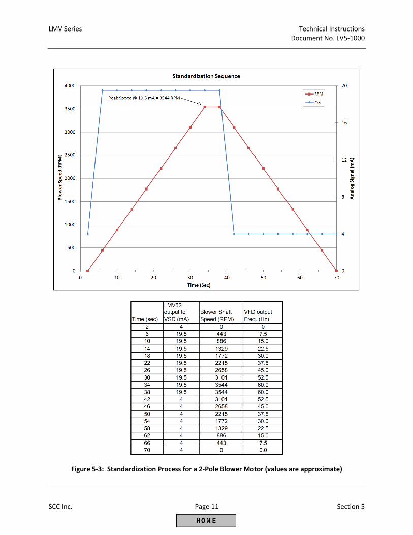
LMV Series Technical Instructions Document No. LV5‐1000
SCC Inc. Page 11 Section 5
Figure 5‐3: Standardization Process for a 2‐Pole Blower Motor (values are approximate)
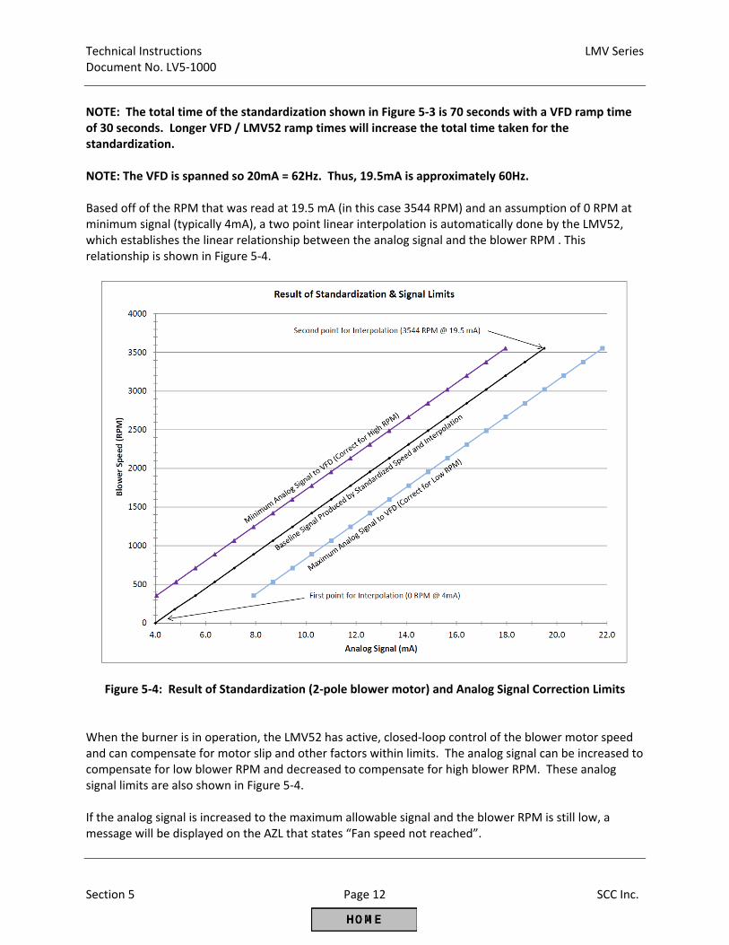
Technical Instructions LMV Series Document No. LV5‐1000
Section 5 Page 12 SCC Inc.
NOTE: The total time of the standardization shown in Figure 5‐3 is 70 seconds with a VFD ramp time of 30 seconds. Longer VFD / LMV52 ramp times will increase the total time taken for the standardization. NOTE: The VFD is spanned so 20mA = 62Hz. Thus, 19.5mA is approximately 60Hz. Based off of the RPM that was read at 19.5 mA (in this case 3544 RPM) and an assumption of 0 RPM at minimum signal (typically 4mA), a two point linear interpolation is automatically done by the LMV52, which establishes the linear relationship between the analog signal and the blower RPM . This relationship is shown in Figure 5‐4.
Figure 5‐4: Result of Standardization (2‐pole blower motor) and Analog Signal Correction Limits When the burner is in operation, the LMV52 has active, closed‐loop control of the blower motor speed and can compensate for motor slip and other factors within limits. The analog signal can be increased to compensate for low blower RPM and decreased to compensate for high blower RPM. These analog signal limits are also shown in Figure 5‐4. If the analog signal is increased to the maximum allowable signal and the blower RPM is still low, a message will be displayed on the AZL that states “Fan speed not reached”.
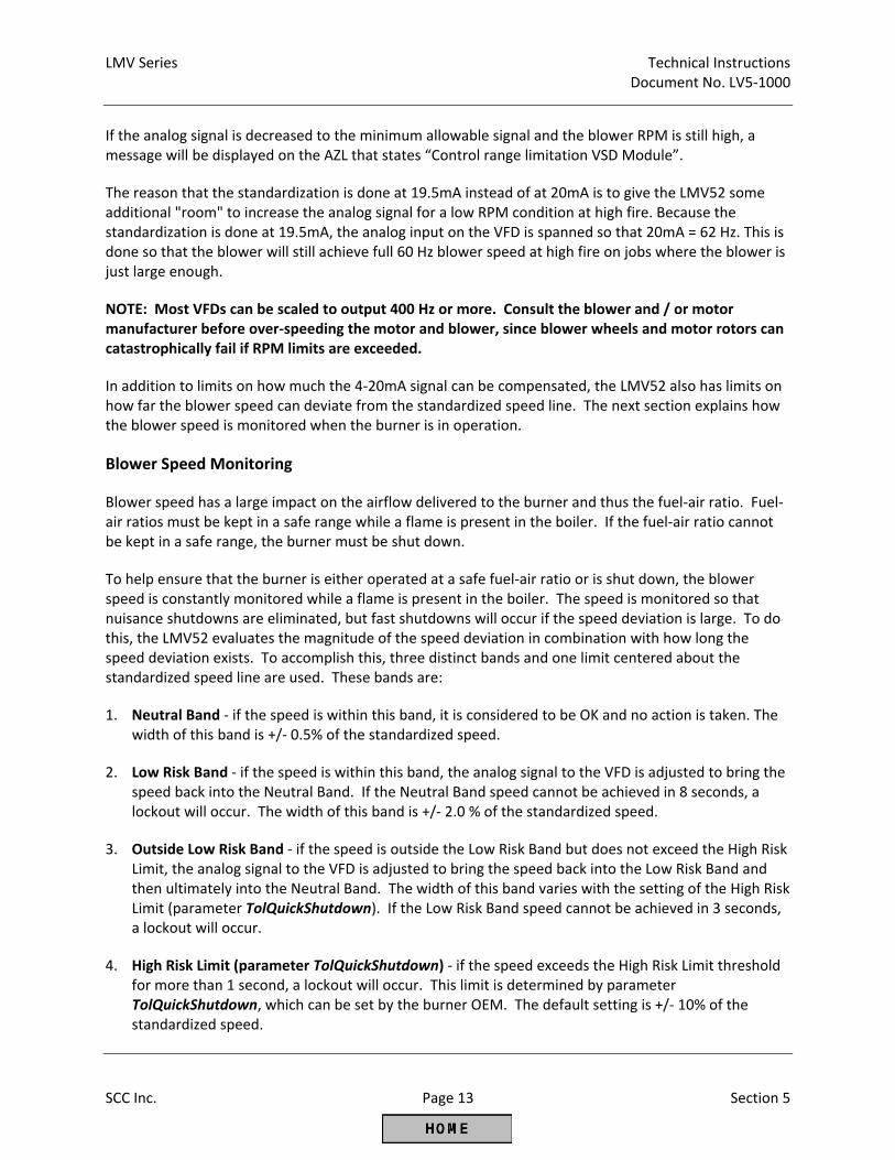
LMV Series Technical Instructions Document No. LV5‐1000
SCC Inc. Page 13 Section 5
If the analog signal is decreased to the minimum allowable signal and the blower RPM is still high, a message will be displayed on the AZL that states “Control range limitation VSD Module”.
The reason that the standardization is done at 19.5mA instead of at 20mA is to give the LMV52 some additional "room" to increase the analog signal for a low RPM condition at high fire. Because the standardization is done at 19.5mA, the analog input on the VFD is spanned so that 20mA = 62 Hz. This is done so that the blower will still achieve full 60 Hz blower speed at high fire on jobs where the blower is just large enough.
NOTE: Most VFDs can be scaled to output 400 Hz or more. Consult the blower and / or motor manufacturer before over‐speeding the motor and blower, since blower wheels and motor rotors can catastrophically fail if RPM limits are exceeded.
In addition to limits on how much the 4‐20mA signal can be compensated, the LMV52 also has limits on how far the blower speed can deviate from the standardized speed line. The next section explains how the blower speed is monitored when the burner is in operation.
Blower Speed Monitoring
Blower speed has a large impact on the airflow delivered to the burner and thus the fuel‐air ratio. Fuel‐air ratios must be kept in a safe range while a flame is present in the boiler. If the fuel‐air ratio cannot be kept in a safe range, the burner must be shut down.
To help ensure that the burner is either operated at a safe fuel‐air ratio or is shut down, the blower speed is constantly monitored while a flame is present in the boiler. The speed is monitored so that nuisance shutdowns are eliminated, but fast shutdowns will occur if the speed deviation is large. To do this, the LMV52 evaluates the magnitude of the speed deviation in combination with how long the speed deviation exists. To accomplish this, three distinct bands and one limit centered about the standardized speed line are used. These bands are:
1. Neutral Band ‐ if the speed is within this band, it is considered to be OK and no action is taken. The width of this band is +/‐ 0.5% of the standardized speed.
2. Low Risk Band ‐ if the speed is within this band, the analog signal to the VFD is adjusted to bring the speed back into the Neutral Band. If the Neutral Band speed cannot be achieved in 8 seconds, a lockout will occur. The width of this band is +/‐ 2.0 % of the standardized speed.
3. Outside Low Risk Band ‐ if the speed is outside the Low Risk Band but does not exceed the High Risk Limit, the analog signal to the VFD is adjusted to bring the speed back into the Low Risk Band and then ultimately into the Neutral Band. The width of this band varies with the setting of the High Risk Limit (parameter TolQuickShutdown). If the Low Risk Band speed cannot be achieved in 3 seconds, a lockout will occur.
4. High Risk Limit (parameter TolQuickShutdown) ‐ if the speed exceeds the High Risk Limit threshold for more than 1 second, a lockout will occur. This limit is determined by parameter TolQuickShutdown, which can be set by the burner OEM. The default setting is +/‐ 10% of the standardized speed.
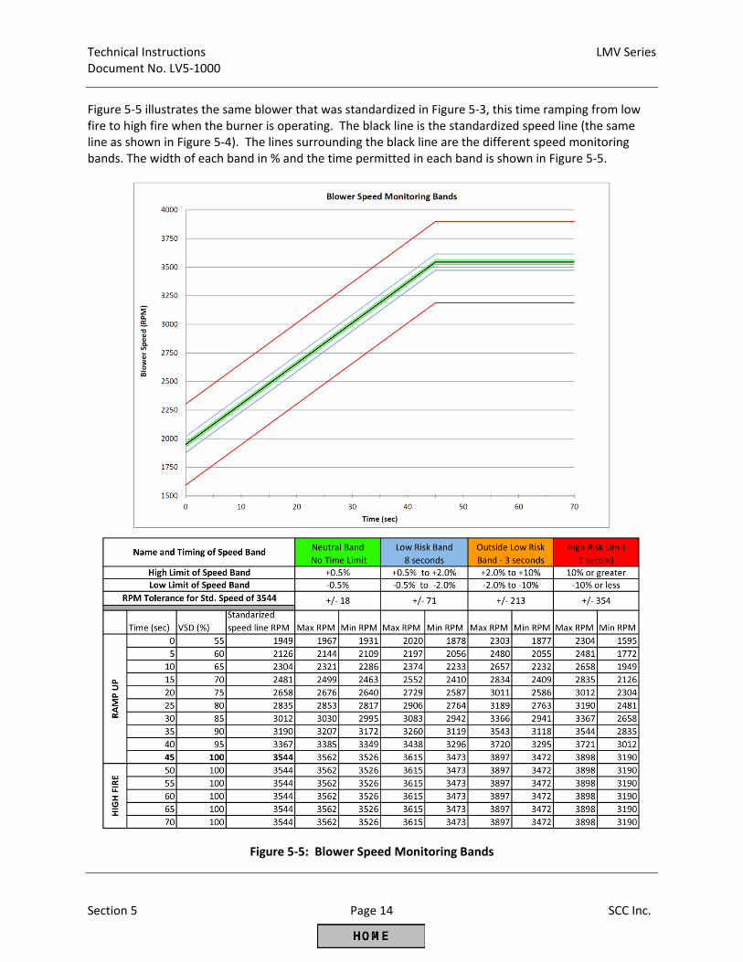
Technical Instructions LMV Series Document No. LV5‐1000
Section 5 Page 14 SCC Inc.
Figure 5‐5 illustrates the same blower that was standardized in Figure 5‐3, this time ramping from low fire to high fire when the burner is operating. The black line is the standardized speed line (the same line as shown in Figure 5‐4). The lines surrounding the black line are the different speed monitoring bands. The width of each band in % and the time permitted in each band is shown in Figure 5‐5.
Figure 5‐5: Blower Speed Monitoring Bands
LMV Series Technical Instructions Document No. LV5‐1000
SCC Inc. Page 15 Section 5
Suggested Setup Procedure for the VFD Control After verifying that all VFD related components are installed and wired correctly, the VFD control can be set up. Naturally, if the burner has a VFD, this must be done before the Ratio Control Curves are commissioned. Particular attention should be paid to the following points: 1. The arrow on the speed wheel points in the same direction as the correct blower rotation. 2. The gap between the inductive sensor and the speed wheel finger is correct (approx. 1/16"). 3. The VFD, motor, and LMV52 share a common ground. 4. The analog signal from the LMV52 to the VFD must be in shielded cable with one end of the shield
grounded. After these points are double‐checked, the LMV52 parameters can be set. 1. Activate the VFD. The VFD control can be activated / deactivated for either fuel in a dual fuel
burner. Typically, if a burner has a VFD, it will be activated on each fuel. The VFD can be activated using the following menu path:
Params & Display > RatioControl > Gas/Oil Setting > VSD 2. Set the air actuator to be “air influenced”. This is done so that the air damper will open to pre‐purge
position when the LMV52 is standardized. This can be done using the following menu path:
Params & Display > RatioControl > Gas/Oil Settings > AirActuator = air influen 3. Set or check the LMV52 ramp times. Both of these must be at least 5 seconds longer than the ramp
times set in the VFD. The ramp times can be checked using the following menu path:
Params & Display > RatioControl > Times > OperatRampMod Params & Display > RatioControl > Times > TimeNoFlame
4. If using a 6‐finger speed wheel (rarely necessary ‐ only if the VFD will be operated under 300 RPM),
change the number of pulses per revolution from 3 to 6 using the following menu path:
Params & Display > VSD Module > Configuration > Speed > Num Puls per R 5. Configure the analog output of the LMV52 to match the analog input of the VFD. Typically, a 4‐
20mA signal is used. The analog output signal can be set using the following menu path:
Params & Display > VSD Module > Configuration > Speed > Setpoint Output 6. If the VFD was not purchased pre‐programmed for an LMV52, set the relevant VFD parameters. See
section on previous pages titled "Configuring VFDs for use with the LMV52".
Technical Instructions LMV Series Document No. LV5‐1000
Section 5 Page 16 SCC Inc.
7. If working on an un‐configured LMV52, parameters unrelated to the VFD must be set before the VFD
can be standardized. These are thoroughly outlined in Section 4 under "Configuring (Parameterization of) an LMV5 with a Default Parameter Set". To summarize, the following must be set: burner ID, fuel train, actuator addresses, actuator directions of rotation, and actuator special positions.
8. The LMV52 safety loop must be closed (high limit, low water, burner flange, etc...) or the
standardization will not occur even if the LMV52 is not in alarm. 9. The burner switch must be off (LMV52 input X5‐03.1 must be de‐energized). 10. The VFD must be in remote mode so that it will respect the run‐stop contact and the analog signal
from the LMV52. 11. The LMV52 / VFD / blower are now ready to be standardized. The standardization process can be
initiated using the following menu path: Params & Display > VSD Module > Configuration > Speed > Standardization
Set parameter Standardization to “activated”. The air damper should then drive to the pre‐purge position and the VFD / blower should ramp up to approximately 60 Hz (100% VFD). After a few seconds at 60 Hz, the VFD / blower should ramp back down to 0 Hz. The air damper should also drive back to home position.
12. Check the standardized speed, which is the product of the standardization, using the following menu
path:
Params & Display > VSD Module > Configuration > Speed > StandardizedSp
For 2‐pole blowers, the standardized speed should be 3500 RPM, +/‐ 100 RPM. If the speed is out of this range, the drive was most likely not spanned so that 20mA = 62Hz, or the motor is heavily loaded (a lot of slip). The same logic applies to 4‐pole motors, except the speed should be 1700 +/‐ 100 RPM.
13. If the LMV52 does not have O2 trim, the air damper actuator can be set back to “activated” instead
of “air influen” using the following menu path:
Params & Display > RatioControl > Gas/Oil Settings > AirActuator = activated
Additional Tips for Burners with VFD Control Most of the time, speed faults that are seen on the LMV52 are caused by the VFD not being able to
decelerate the blower when the blower is being ramped down. If fast ramp times are not critical for the application, ramp times can be increased and this should correct the issue. If fast ramp times are necessary, a braking resistor may also be required to achieve the fast ramp down times.
LMV Series Technical Instructions Document No. LV5‐1000
SCC Inc. Page 17 Section 5
The LMV52 / VFD / blower response can be watched to check for proper operation. This can be done in standby Phase 12 (burner off) by using the following menu path:
Params & Display > RatioControl > Gas/Oil Settings > CurveParams or Curve Settings When the blower is at a speed other than what is displayed, an arrow (>) is displayed on the AZL next to the VFD position. When the blower is at the displayed speed, a colon (:) is displayed on the AZL next to the VFD position. By ramping the VFD up and down, the response of the VFD can be observed. Transitioning back and forth between a colon (:) and a (>) after ramping the VFD up or down indicates a speed control issue.
The LMV52's closed loop speed control is based on PI (proportional‐integral) logic. The response of this loop can be tuned using the following menu path:
Params & Display > VSD Module > Configuration > Speed > Setteling Time
In most cases, this does not need to be tuned. See Section 3 (Parameters) for a full explanation.
The absolute speed as read in real time by the speed wheel can be watched at any point in time. When the LMV52 is not modulating or when it is at a fixed VFD speed (pre‐purge, post‐purge, ignition, etc.), the speed should be steady, not deviating by more than +/‐ 10 RPM. This can be viewed at:
Params & Display > VSD Module > Configuration > Speed > Absolute Speed
The combustion air pressure switch should be set by taking the VFD to 10% below the lowest anticipated low fire speed (if low fire is 50%, take the VFD to 40%) and setting the switch to open at that point. This should maximize the safety potential of the combustion air pressure switch and minimize nuisance trips. This can be done in standby by setting the home position of the VFD to 40% and setting the switch.
In most applications with an air damper, there is little reason to decrease blower speed below about 50% VFD (30 Hz). Power consumption decreases by the cube of the RPM even without the additional restriction of an air damper. Referencing information from the "Centrifugal Blower Fundamentals" section on the previous pages, decreasing the speed of a 25 HP (18.62 kW) motor from 3600 RPM (60 Hz) to 1800 RPM (30 Hz) will cause the power consumption to be reduced from 18.62 kW down to 2.32 kW, an electrical savings of over 800%.
A VFD alone without an air damper or sliding head offers limited accuracy and repeatability for the airflow at higher burner turndowns. For most boiler burners, modulating the VFD alone without an air damper is okay for turndowns of 4‐to‐1 or less. Using only a VFD for airflow regulation at higher turndowns may lead to airflow repeatability issues.

Technical Instructions LMV Series Document No. LV5‐1000
Section 5 Page 18 SCC Inc.
Intentionally Left Blank
Section 1 Overview
Section 2 Wiring
Section 3 Parameters
Section 4 Commissioning
Section 5 VSD
Section 6 O2 Trim
Section 7 Troubleshooting
Section 8 Modbus
Section 9 ACS450
Section 10 Revision History
Appendix A Application Guide
Appendix B* Complimentary Products Guide
*Can be found at www.scccombustion.com.
LMV Series Technical Instructions Document No. LV5‐1000
SCC Inc. Page 1 Section 6
Section 6: Oxygen Trim
Table of Contents Introduction .................................................................................................................................... 2 O2 Trim (O2 Control) Fundamentals ................................................................................................ 2 Pre‐control ...................................................................................................................................... 4 O2 Trim Terminology ....................................................................................................................... 4 O2 Control and O2 Alarm Curves ..................................................................................................... 6 O2 Trim Configuration (Parameterization) Before Commissioning ................................................ 7 Suggested O2 Trim Commissioning – Traditional Nozzle Mixing Burner with No or Low
Percentage FGR (Typically LMV52.240) .................................................................................... 9 Suggested O2 Trim Commissioning – Premix Mesh Burner or Nozzle Mixing Burner with High
Percentage of FGR (Typically LMV52.440) .............................................................................. 14 Post Commissioning Tuning .......................................................................................................... 20 Observing the Behavior of the O2 Trim ......................................................................................... 24 Using the O2 Alarm Functionality without O2 Trim ....................................................................... 25 How the O2 is Measured with the QGO20 Sensor and PLL52 Module ......................................... 26 Considerations when Using O2 Trim with FGR .............................................................................. 29 Additional Tips for O2 Trim Commissioning and Tuning ............................................................... 33
Technical Instructions LMV Series Document No. LV5‐1000
Section 6 Page 2 SCC Inc.
Introduction The LMV52.240 and the LMV52.440 both have O2 (oxygen) trim and O2 alarm (previously called “monitor”) capability. In addition, the LMV52.440 offers advanced features such as temperature compensated light‐off and more dynamic O2 trim capabilities. In general, the LMV52.440 is recommended for more difficult applications such as low and ultra‐low NOx burners where the burner stability band is much smaller than a traditional nozzle mixing burner. Some features in the LMV52.440 were specifically designed for ultra‐low NOx mesh burners. The O2 trim functions by using an in‐situ O2 sensor installed in the boiler stack, and then adjusting actuators and / or VSD to maintain a % O2 setpoint. Only air‐related (air influenced) actuators are adjusted, thus the O2 trim does not adjust the firing rate (fuel‐related load). Only the air rate (air‐related load) is adjusted. Each Ratio Control Curve Point that is entered (see Section 4) will have a corresponding O2 trim setpoint, rich limit (O2 alarm) and lean limit (O2 max value). The exception to this rule is that O2 trim cannot be performed on Point 1. If 10 points are entered on the Ratio Control Curve, there will be 9 trim points and 10 rich limit (O2 alarm) points. Having 10 points on the Ratio Control Curve is recommended. As is the case with advanced systems such as O2 trim, the fundamental systems that lie underneath the advanced system must be in place and working correctly to enable the advanced system to work correctly. For example, if the gas pressure supply is not repeatable upstream of the firing rate control valve (fundamental system), then the O2 trim (advanced system) is likely to deactivate. The fundamental systems on the burner / boiler that must be working correctly are outlined in detail in the Pre‐Requisites listed in Section 4. The Pre‐Requisites for LMV52 systems with O2 trim must be met before O2 trim commissioning is attempted. If the Pre‐Requisites are satisfied, then reliable operation of the O2 trim depends on correct parameter settings for the application and correct commissioning of the O2 trim. This section will outline the basics behind how the O2 trim system operates, and will outline the typical commissioning procedure for a traditional nozzle mixing burner (standard emissions) and a pre‐mix mesh burner (low or ultra‐low NOx). Nozzle mixing burners that use a high percentage of FGR to achieve low NOx typically behave in a way that is similar to a pre‐mix mesh burner, so the commissioning procedure for these types of burners is similar to a pre‐mix mesh burner. O2 Trim (O2 Control) Fundamentals By definition, an O2 trim (O2 control) system monitors the level of O2 in the exhaust gases of the boiler and adjusts the fuel or air flow to maintain an O2 setpoint. The LMV52 accomplishes this task by reading the %O2 (wet basis) with an in‐situ O2 sensor and by adjusting the angular position of air flow influencing actuators. If the burner is equipped with a VSD (variable speed drive) for the blower, the O2 trim can also adjust the blower speed to influence the burner airflow.
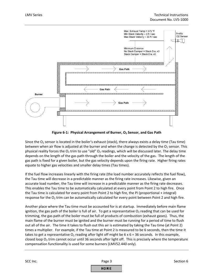
LMV Series Technical Instructions Document No. LV5‐1000
SCC Inc. Page 3 Section 6
Figure 6‐1: Physical Arrangement of Burner, O2 Sensor, and Gas Path Since the O2 sensor is located in the boiler's exhaust (stack), there always exists a delay time (Tau time) between when air flow is adjusted at the burner and when the change is detected by the O2 sensor. This physical reality forces the O2 trim to use "old" O2 readings, which will be discussed later. The delay time depends on the length of the gas path through the boiler and the velocity of the gas. The length of the gas path is fixed for a given boiler, but the gas velocity depends upon the firing rate. Higher firing rates equate to higher gas velocities and smaller delay times (Tau times). If the fuel flow increases linearly with the firing rate (the load number accurately reflects the fuel flow), the Tau time will decrease in a predictable manner as the firing rate increases. Likewise, given an accurate load number, the Tau time will increase in a predictable manner as the firing rate decreases. This enables the Tau time to be automatically calculated at every point from Point 2 to high fire. Once the Tau time is calculated for every point from Point 2 to high fire, the PI (proportional + integral) response for the O2 trim can be automatically calculated for every point between Point 2 and high fire. Another place where the Tau time must be accounted for is at startup. Immediately before main flame ignition, the gas path of the boiler is full of air. To get a representative O2 reading that can be used for trimming, the gas path of the boiler must be full of products of combustion (exhaust gases). Thus, the main flame of the burner must be ignited and the burner must be running for a period of time to flush out all of the air. The time it takes to flush out this air is estimated by taking the Tau time (at Point 2) times a multiplier. For example, if the Tau time at Point 2 is measured to be 6 seconds, then the time it takes to get a representative O2 reading after light off might be 6 x 6 = 36 seconds. In this example, closed loop O2 trim cannot occur until 36 seconds after light off. This is precisely where the temperature compensation functionality is used for some burners (LMV52.440 only).
Technical Instructions LMV Series Document No. LV5‐1000
Section 6 Page 4 SCC Inc.
For many nozzle mixing burners (traditional boiler burners), the O2 setpoint will be a higher value at low fire and a lower value at high fire. This is true since most nozzle mixing burners need more excess air (higher O2) at low fire to achieve complete combustion. For this type of burner an O2 setpoint of 5% O2 (wet) at low fire and an O2 setpoint of 2% O2 (wet) at high fire is not uncommon. Pre‐control As mentioned above, all O2 trim systems with an O2 sensor in the boiler's exhaust must use "old" O2 readings due to physical realities of the boiler. This fact, combined with an O2 setpoint that typically varies from low fire to high fire means that the O2 trim system cannot actively trim when the burner makes a large change in firing rate. This begs the question of what happens to the O2 trim when the burner transitions from 20% firing rate to, say, 80% firing rate. The answer is the O2 trim changes modes from active trim to what is referred to as "pre‐control". Pre‐control is possible because the LMV52 learns the characteristic of the burner at each point on the curve during the O2 trim commissioning. The specific characteristic that the LMV52 learns is how much of a change in airflow (air rate) is necessary to achieve a certain change in the %O2. This specific characteristic is known as the Lambda Factor, and is essentially the burner's signature from an O2 trim standpoint. Just like the delay time (Tau time) that was mentioned earlier, it is necessary for the fuel flow to match the load number so that the Lambda Factor is correct and accurate for each point. Pre‐control uses the Lambda Factor so that the burner can be modulated while keeping the %O2 close to the O2 setpoint, even though the setpoint changes with the firing rate and the O2 trim is using "old" O2 readings. Once the burner stops modulating or only modulates a small amount (+/‐ 5%), the O2 trim will change modes back to "active" and perform active O2 trim once again. A properly commissioned O2 trim system will typically maintain the %O2 setpoint with a deviation of +/‐ 0.1% O2 when the burner is not modulating a significant amount (+/‐ 5% load change). With this small load change, the O2 trim will stay in the "active" mode. When significant modulation is encountered (+/‐ 15% load change), the pre‐control will engage and the deviation from setpoint will increase. Deviations of +/‐ 0.3% or less are typical during modulation when the pre‐control is engaged. O2 Trim Terminology 1. %O2 Wet – In‐situ O2 sensors, like the QGO20 sensor that is used with the LMV52, read the %O2 on a
wet basis. This is in contrast to the vast majority of portable combustion analyzers that read %O2 on a dry basis. %O2 wet should always be a lower value than %O2 dry. Figure 6‐11 (located later in this section) gives the approximate relationship between %O2 wet and %O2 dry.
2. Tau Time ‐ This is the delay time between when an adjustment is made at the burner (moving the
air damper, etc.) and when that adjustment is read at the O2 sensor. For a given burner / boiler, this time will be shorter at high fire and longer at low fire.
3. O2 Ratio Control ‐ This is the measured %O2 wet when the actuators / VSD are on the Fuel‐Air Ratio
Control Curve and are not being trimmed. This is recorded for each point on the curve except Point 1. This is also commonly referred to as the “lean curve”.
LMV Series Technical Instructions Document No. LV5‐1000
SCC Inc. Page 5 Section 6
4. O2 Control ‐ This is the setpoint of the O2 trim system for each point on the curve except Point 1.
This is also commonly referred to as the “trim curve”. 5. O2 Alarm ‐ This is the rich O2 limit for each point. Every Fuel‐Air Ratio Curve point including Point 1
must have a corresponding O2 alarm point. This is also commonly referred to as the “rich curve” or “rich alarm”.
6. O2 Max Value ‐ This is the lean O2 limit, and is a single value for all points. This is also referred to as
the “lean alarm”. 7. Lambda Factor ‐ A value that is learned by the LMV52 for each point on the curve except Point 1.
This value is learned when the O2 control curve is being set, and is based on how the measured %O2 responds when the burner is being transitioned from an O2 Ratio Control point to the O2 Control point during O2 Control commissioning. This value represents how much the air flow needs to be changed to get a change in the measured %O2, and is essentially the "signature" of the burner from an O2 trim perspective.
8. Fuel Rate – This is the percentage of high fire fuel flow and is also referred to as the firing rate. This
is also the same as the "Load" number seen during Ratio Control Curve commissioning. For a 10‐to‐1 turndown burner, high fire would be 100% and low fire would be 10%. For a 4‐to‐1 turndown burner, high fire would be 100% and low fire would be 25%. For O2 trim systems, it is very important that the fuel rate (load number) matches the actual fuel flow to the burner within +/‐ 3%.
9. Air Rate ‐ When no O2 trim is taking place (running on Ratio Control Curve), the air rate is the same
as the fuel rate. This is also known as the air flow. For example, a 10‐to‐1 turndown burner running at Point 5 on the Ratio Control Curve will have a fuel rate of 50% and an air rate of 50%. If the O2 trim is engaged and the O2 sensor reads values higher than setpoint, the air rate will be reduced relative to the fuel rate until the setpoint is achieved.
10. Standardized Value ‐ This is a percentage reduction of the air rate and is used when the O2 Control
Curve is being set. For example, if the air rate is 50%, and a Standardized Value of 10% is entered, the air rate will be reduced to 45%. The math would be: (50% * 10% = 5%), then (50% ‐5%) = 45%.
11. Pre‐Control ‐ When large load changes occur during modulation, this will engage and temporarily
disable the closed‐loop O2 trim. This temporary "open‐loop" trim is based on using a correct Lambda Factor to predict how the burner will react when modulating. Pre‐control is necessary for burners where the O2 setpoint is not constant from low fire to high fire.
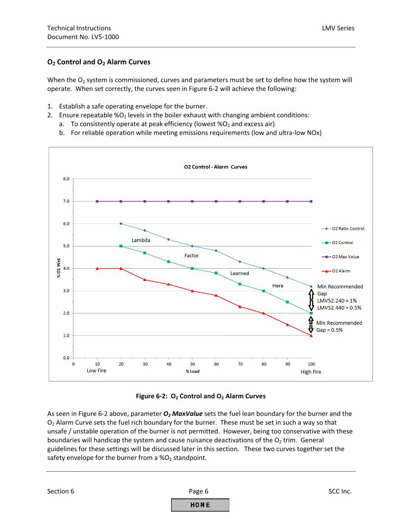
Technical Documen
Section 6
O2 Contr When theoperate. 1. Estab2. Ensur
a. Tob. Fo
As seen inO2 Alarm unsafe / uboundarieguidelinessafety env
Instructions t No. LV5‐100
ol and O2 Al
e O2 system isWhen set cor
lish a safe opre repeatable o consistentlyor reliable op
n Figure 6‐2 aCurve sets thunstable operes will handics for these sevelope for the
00
larm Curves
s commissionrrectly, the cu
perating enve%O2 levels iny operate at pperation while
Figur
bove, paramehe fuel rich boration of the bcap the systemettings will bee burner from
s
ed, curves anurves seen in
lope for the bn the boiler expeak efficience meeting em
re 6‐2: O2 Co
eter O2 MaxVoundary for thburner is not m and cause n discussed latm a %O2 stand
Page 6
nd parameterFigure 6‐2 w
burner. xhaust with ccy (lowest %Omissions requi
ntrol and O2
Value sets thehe burner. Thpermitted. Hnuisance deater in this secdpoint.
rs must be setwill achieve the
changing ambO2 and excessrements (low
Alarm Curve
e fuel lean bohese must beHowever, beictivations of ction. These
t to define hoe following:
bient conditios air) w and ultra‐lo
s
oundary for the set in such ang too consethe O2 trim. two curves to
LMV S
SCC
ow the system
ons:
w NOx)
he burner anda way so that rvative with tGeneral ogether set t
Series
C Inc.
m will
d the
these
he
LMV Series Technical Instructions Document No. LV5‐1000
SCC Inc. Page 7 Section 6
The O2 Ratio Control Curve reflects the %O2 that resulted from setting the Fuel‐Air Ratio Control Curve. The O2 Control Curve is the target for the O2 trim system when it is activated. When the burner is transitioned from the O2 Ratio Control Curve to the O2 Control Curve by increasing the Standardized Value, the Lambda Factor will be learned and recorded at that specific point. A larger gap between the O2 Ratio Control Curve and the O2 Control Curve will give the LMV52 the best opportunity to learn the Lambda Factor of the burner, and thus yield the best pre‐control when the burner is modulating. A gap of 1% O2 or more is ideal, and it is typically achievable on nozzle mixing burners with no or low percentages of FGR. A 1% gap is typically not achievable on premix mesh burners or on nozzle mixing burners that use a high percentage of FGR. This gap also sets the available quantity of "lean" trim for an LMV52.240, and that is why the minimum recommended gap for an LMV52.240 is 1%. The LMV52.440 uses a different O2 trim algorithm for premix, mesh and high percentage FGR burners and can deal with a minimum gap of 0.5%. O2 Trim Configuration (Parameterization) Before Commissioning The procedure below assumes an LMV52 with default parameters for the O2 Contr/Alarm menu and the O2 Module menu. If the LMV52 is mounted to a burner / boiler, the burner / boiler OEM may have already changed the parameters from the default setting and parameterized the LMV52 for the application. This procedure also assumes that all O2 trim components are installed and wired correctly, and that the O2 trim will be commissioned on natural gas. Section 3 gives a detailed explanation of all of the parameters in the LMV52 as well as highlights which parameters must be set (marked with a double asterisk **) and which parameters are frequently used (shaded). This procedure gives a general guideline of what parameters need to be set on both a traditional nozzle mixing burner with little to no FGR, and also for low and ultra‐low NOx burners that are pre‐mix mesh type or high percentage FGR. Every burner is different, so it is likely that every burner will need a somewhat unique parameter set to run correctly. 1. Log in at the OEM password level. From the factory, the OEM password for the LMV5 is "START". 2. If not done so already, activate the O2 sensor using the following menu path:
Params & Display > O2 Module > Configuration > O2 Sensor = QGO20
3. If being used, configure the appropriate temperature sensors for blower inlet air temperature and
stack temperature. This is done through the following menu path:
Params & Display > O2 Module > Configuration > SupAirTempSens Params & Display > O2 Module > Configuration > FlueGasTempSens
Parameter SupAirTempSens activates and configures the blower inlet air temperature sensor. Parameter FlueGasTempSens activates and configures the stack temperature sensor. Options are Ni1000 or Pt1000 2‐wire sensors for both inputs.
Technical Instructions LMV Series Document No. LV5‐1000
Section 6 Page 8 SCC Inc.
NOTE: Both sensors are required to do a boiler efficiency calculation. The boiler efficiency calculation is not required for O2 trim operation. If sensors are activated but not reading correctly or not wired correctly, the O2 trim will not activate. Burner inlet temperature must be read to perform a temperature‐compensated startup on the LMV52.440.
4. Set the appropriate actuators to “air influen” (air influenced). These are typically only the actuators
/ VSD that will directly influence the burner air rate. The menu path for these parameters is: Params & Display > RatioControl > Gas Settings Typically, only the air actuator and the VSD (if used) are set to air influenced. If used, the FGR actuator is usually not set to air influenced.
5. Set the operating mode of the O2 system to “man deact” (manually deactivated). This is necessary for the O2 system curves to be commissioned. The menu path for this parameter is:
Params & Display > O2Contr/Alarm > Gas Settings > OptgMode = man deact 6. Set the curve point at which the low fire delay time will be measured. This is typically set to Point 2,
unless oversized exhaust stacks with high turndown burners are encountered, which may make gas velocity in the stack too low at low fire. For these applications, setting this parameter to a higher point than Point 2 will increase the gas velocity past the O2 sensor and yield a more responsive O2 reading. This can be set through the following menu path:
Params & Display > O2Contr/Alarm> Gas Settings > Control Param > LowfireAdaptPtNo 7. Set the load value at which the O2 trim will disengage. Typically, this is set to the load value for
Point 2 on the Fuel‐Air Ratio Control Curve. The exception to this is if parameter LowfireAdaptPtNo is set to a point other than Point 2. If this is the case, set this for the load value that corresponds to the point set by LowfireAdaptPtNo. This can be set through the following menu path:
Params & Display > O2Contr/Alarm > Gas Settings > Control Param > O2 CtrlThreshold 8. Set the desired type of pre‐control. For most natural gas burners where the gap between O2 curves
is large enough that the Lambda Factor can be learned (see O2 Control and O2 Alarm Curves in Figure 6‐2), this should be set to "like P air". The "like theory" setting is typically used for oil burners, and "LambdaFact1" should only be used as a last resort. The menu path for setting the type of pre‐control is:
Params & Display > O2Contr/Alarm > Gas Settings > Control Param > Type Air Change
LMV Series Technical Instructions Document No. LV5‐1000
SCC Inc. Page 9 Section 6
Suggested O2 Trim Commissioning ‐ Traditional Nozzle Mixing Burner with No or Low Percentage FGR (Typically LMV52.240) 1. The commissioning procedure assumes the following:
a. All Pre‐Requisites for an LMV52 system with O2 trim (and VSD if equipped) have been met according to Section 4 of this literature.
b. The Ratio Control Curves have been commissioned according to Section 4 of this literature. c. Section 6 of this literature has been read and understood up to this point.
2. As was the case for the Ratio Control Curves in Section 4, the same free spreadsheet can also be
used to assist in the commissioning of the O2 trim. This spreadsheet graphically illustrates the O2 curves as well as provides an orderly way to record the details of how the burner was set up.
Figure 6‐3: LMVx Curves Spreadsheet
3. The key to commissioning the O2 curves quickly and easily is contained in the Ratio Control Curves.
Specifically, the following must be achieved for each point on the Ratio Control Curves (as paraphrased from Section 4 of this literature):
a. Safe, efficient combustion as verified by a calibrated stack gas analyzer b. The % load matching the fuel flow within +/‐ 3% c. Emissions compliance d. Smooth Ratio Control Curves (no sharp peaks or valleys) e. VSD speed should increase with load in a linear fashion (if equipped) f. Find and record the %O2 wet corresponding to the fuel rich limit (O2 Alarm value) for each point
by probing.* g. Find and record the %O2 wet corresponding to the fuel lean limit (O2 MaxValue) for Point 1 and
Point 10 by probing.* h. Last but not least, leave the curve points so that the %O2 wet is 2% higher than the fuel rich limit
(O2 Alarm value). Record this as the "saved" value for each curve point.
* NOTE: When probing the fuel rich limit, it is not recommended to exceed 200 PPM CO (dry basis) or less than 1.0% O2 (wet or dry basis) for any point. When probing the fuel lean limit, it is not recommended to exceed 200 PPM CO or adversely affect flame stability for any point.
Technical Instructions LMV Series Document No. LV5‐1000
Section 6 Page 10 SCC Inc.
NOTE: The %O2 values read and displayed by the LMV52 system are always on a wet basis (%O2 wet). Most if not all external exhaust gas analyzers read and display %O2 and other gases on a dry basis (%O2 dry). All O2 curves must be commissioned using %O2 wet values as read by the LMV52. The external exhaust gas analyzer is used to read CO, NOx, and also serves as a way to double check the %O2 wet values. Figure 6‐11 gives the approximate relationship between %O2 wet and %O2 dry.
4. Make sure that the QGO20 O2 sensor has been activated for at least 2 hours and is up to temperature. This gives the Zirconium cell time to heat‐soak and also to burn off any contaminants. The temperature of the cell can be checked if desired through the following menu path:
Params & Display > O2 Module > Process Data > QGO SensorTemp 5. With the burner off (Phase 12), set the fuel rich limit (O2 Alarm value) for each point. This can be
done with the burner off since these values have already been found and recorded during Ratio Control Curve commissioning (see above). Once into the O2 Alarm curve, simply enter in the recorded value for each point and save each point. To access the O2 Alarm curve, use the following menu path:
Params & Display > O2 Contr/Alarm > Gas Settings > O2 Alarm > O2 Alarm 6. With the burner off (Phase 12), set the fuel lean limit (O2 MaxValue) based on the values that have
already been found and recorded for Point 1 and Point 10 during Ratio Control Curve commissioning (see above). To set the fuel lean limit, use the following menu path:
Params & Display > O2 Contr/Alarm > Gas Settings > O2 Alarm > O2 MaxValue 7. If the LMVx Curves spreadsheet is not being used, take the recorded O2 Alarm values and add 0.5%
for each point. Take the "saved" %O2 from the Ratio Control Curve and subtract 1.0% for each point. This will provide a target band for setting the O2 Control Curve points. Example: The O2 Alarm value is 2%. The Ratio Control Curve point "saved" is 4%. Add 0.5% to the O2 Alarm = 2.5%. Subtract 1% from the Ratio Control = 3%. For this point, the target for the O2 Control is between 2.5% and 3%.
8. When it is safe to do so and when there is adequate load available, start the burner / boiler and let it
warm up to operating temperature. 9. Access the O2 Ratio Control Curve and the O2 Control Curve using the following menu path:
Params & Display > O2 Contr/Alarm > Gas Settings > O2 Control
10. Once the O2 Control Curve is entered, Point 2 should be displayed. Pressing Enter again should drive
the burner to Point 2 if it is not already there. When the burner is driving to Point 2, a carat (>) will be displayed. Once the burner is at Point 2, a colon (:) will be displayed. If the aux 3 actuator is used for FGR and FGR‐Mode is not set for “Aux3onCurve”, a pound (#) indicates the aux 3 actuator has not released to the curve.
LMV Series Technical Instructions Document No. LV5‐1000
SCC Inc. Page 11 Section 6
11. The AZL52 will then prompt "when value stable, continue with ENTER”. After the burner is at Point
2, wait at least an additional 30 seconds to make sure that the O2 value being read is representative of Point 2, then press Enter. Pressing Enter stores the O2 Ratio Control Curve point. The value that is stored should be close (+/‐ 0.2%) to the "saved" value that was recorded for Point 2 during Ratio Control Curve commissioning.
NOTE: It is important to wait long enough to get a steady‐state O2 value before Enter is pressed. If in doubt, wait longer for the value to stabilize. Waiting longer than necessary has no ill effects for the O2 trim commissioning. NOTE: If the O2 value displayed on the AZL52 is not steady (oscillating more than +/‐ 0.1% O2), it is likely that the O2 sensor is not mounted correctly, or there are other issues with the burner / boiler that are affecting the fuel / air ratio. These issues must be corrected before proceeding.
12. Next, slowly increase the StandardVal number, which reduces the air flow into the burner. The
reading beside O2 Control should start to drop as StandardVal is increased. Note that the Tau time of the boiler comes into play here, so it may take 10‐15 seconds or more for a change in the StandardVal number to be seen in the O2 reading.
13. Once the StandardVal number has been increased enough to get the %O2 into the target band (at least 0.5% O2 above the O2 Alarm and 1% below the O2 Ratio Control Curve point), the point can be stored. This is done by pressing Enter, Escape, and then Enter again.
14. After the point is stored, the delay time at Point 2 (Tau Low‐Fire) will be measured. This should occur and the AZL52 should state "Measurement Successful, Control Parameters Stored".
15. The rest of the Points (3 thru 10) can now be done in a similar manner. The delay time (Tau High‐Fire) will also be measured at the high fire point, in this case Point 10.
16. After the delay time is successfully measured at Point 10, escape out of the O2 Control Curve. See Figures 6‐4 and 6‐5 below for an example of what typical O2 trim curves and Lambda Factor curves might look like for this application.
17. The O2 trim can now be activated in one of two modes. Mode “conAutoDeac” allows the O2 trim to work as long as the measured %O2 does not exceed the rich limit (O2 Alarm) or the lean limit (O2 MaxValue). If either of these limits is exceeded, the O2 trim will deactivate and the burner will run on the normal Ratio Control Curves. Mode “O2 Control” also allows the O2 trim to work, except that if the limits are exceeded a lockout will occur. Mode “conAutoDeac” is typically used. To set the O2 control operating mode, use the following menu path:
Params & Display > O2Contr/Alarm > Gas Settings > OptgMode
18. The O2 trim is now commissioned and activated. Some additional tuning may be required
depending on the application. See "Post Commissioning Tuning" later in this section for more information.
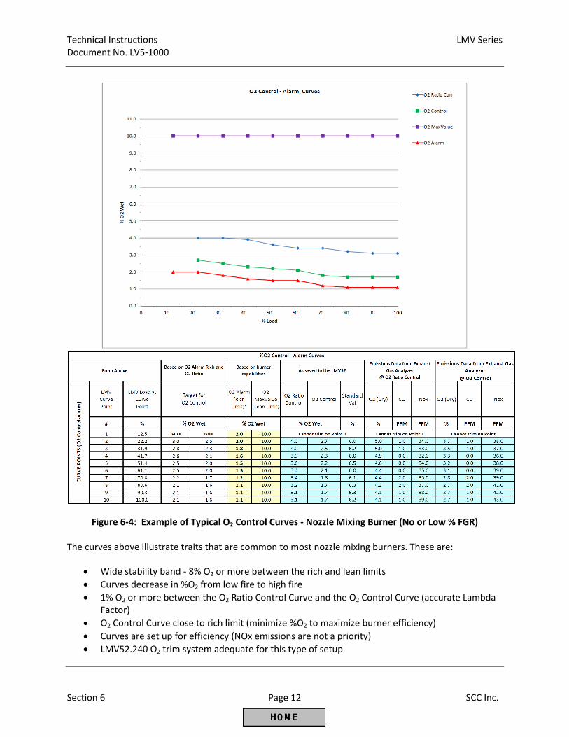
Technical Instructions LMV Series Document No. LV5‐1000
Section 6 Page 12 SCC Inc.
Figure 6‐4: Example of Typical O2 Control Curves ‐ Nozzle Mixing Burner (No or Low % FGR) The curves above illustrate traits that are common to most nozzle mixing burners. These are:
Wide stability band ‐ 8% O2 or more between the rich and lean limits Curves decrease in %O2 from low fire to high fire 1% O2 or more between the O2 Ratio Control Curve and the O2 Control Curve (accurate Lambda
Factor) O2 Control Curve close to rich limit (minimize %O2 to maximize burner efficiency) Curves are set up for efficiency (NOx emissions are not a priority) LMV52.240 O2 trim system adequate for this type of setup
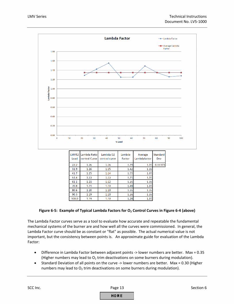
LMV Series Technical Instructions Document No. LV5‐1000
SCC Inc. Page 13 Section 6
Figure 6‐5: Example of Typical Lambda Factors for O2 Control Curves in Figure 6‐4 (above)
The Lambda Factor curves serve as a tool to evaluate how accurate and repeatable the fundamental mechanical systems of the burner are and how well all the curves were commissioned. In general, the Lambda Factor curve should be as constant or "flat" as possible. The actual numerical value is not important, but the consistency between points is. An approximate guide for evaluation of the Lambda Factor:
Difference in Lambda Factor between adjacent points ‐> lower numbers are better. Max = 0.35 (Higher numbers may lead to O2 trim deactivations on some burners during modulation).
Standard Deviation of all points on the curve ‐> lower numbers are better. Max = 0.30 (Higher numbers may lead to O2 trim deactivations on some burners during modulation).
Technical Instructions LMV Series Document No. LV5‐1000
Section 6 Page 14 SCC Inc.
Suggested O2 Trim Commissioning ‐ Premix Mesh Burner or Nozzle Mixing Burner with High Percentage of FGR (Typically LMV52.440) 1. The commissioning procedure assumes the following:
a. All Pre‐Requisites for an LMV52 system with O2 trim (and VSD if equipped) have been met according to Section 4 of this literature.
b. The Ratio Control Curves have been commissioned according to Section 4 of this literature. c. Section 6 of this literature has been read and understood up to this point. d. If a start mode with combustion air temperature compensation will be used, the air
temperature sensor must be installed and activated. 2. As was the case for the Ratio Control Curves in Section 4, the same free spreadsheet can also be
used to assist in the commissioning of the O2 trim. This spreadsheet graphically illustrates the O2 curves as well as provides an orderly way to record the details of how the burner was set up.
Figure 6‐3: LMVx Curves Spreadsheet
3. The key to commissioning the O2 curves quickly and easily is contained in the Ratio Control Curves.
Specifically, the following must be achieved for each point on the Ratio Control Curves (as paraphrased from Section 4 of this literature):
a. Safe combustion as verified by a calibrated stack gas analyzer b. The % load matching the fuel flow within +/‐ 3% c. Emissions compliance d. Smooth Ratio Control Curves (no sharp peaks or valleys) e. VSD speed should increase with load in a linear fashion (if equipped) f. Determine the %O2 wet corresponding to the fuel rich limit (O2 Alarm value) for each point.
Probing may or may not be possible depending on the burner design. Also, follow burner OEM recommendations. Most mesh burner elements can be damaged if run too fuel rich.*
g. Find and record the %O2 wet corresponding to the fuel lean limit (O2 MaxValue) for Point 1 and Point 10 by probing or according to burner OEM recommendations.*
h. Find the target %O2. For these burners the target %O2 for each point will be the %O2 wet corresponding to emissions compliance (typically CO, NOx). After the target %O2 is found, increase the %O2 and leave the point at least 0.5% O2 leaner than the target %O2. Record this as the "saved" value for each curve point.
LMV Series Technical Instructions Document No. LV5‐1000
SCC Inc. Page 15 Section 6
* NOTE: When probing the fuel rich limit, it is not recommended to exceed 200 PPM CO (dry basis) or less than 1.0% O2 (wet or dry basis) for any point. When probing the fuel lean limit, it is not recommended to exceed 200 PPM CO or adversely affect flame stability for any point.
NOTE: The %O2 values read and displayed by the LMV52 system are always on a wet basis (%O2 wet). Most if not all external exhaust gas analyzers read and display %O2 and other gases on a dry basis (%O2 dry). All O2 curves must be commissioned using %O2 wet values as read by the LMV52. The external exhaust gas analyzer is used to read CO, NOx, and also serves as a way to double check the %O2 wet values. Figure 6‐11 gives the approximate relationship between %O2 wet and %O2 dry.
4. Make sure that the QGO20 O2 sensor has been activated for at least 2 hours and is up to
temperature. This gives the Zirconium cell time to heat‐soak and also to burn off any contaminants. The temperature of the cell can be checked if desired through the following menu path:
Params & Display > O2 Module > Process Data > QGO SensorTemp
5. With the burner off (Phase 12), set the fuel rich limit (O2 Alarm value) for each point. This can
be done with the burner off since these values have already been found and recorded during Ratio Control Curve commissioning (see above). Once into the O2 Alarm curve, simply enter in the recorded value for each point and save each point. To access the O2 Alarm curve, use the following menu path:
Params & Display > O2 Contr/Alarm > Gas Settings > O2 Alarm > O2 Alarm
6. With the burner off (Phase 12), set the fuel lean limit (O2 MaxValue) based on the values that
have already been found and recorded for Point 1 and Point 10 during Ratio Control Curve commissioning (see above). To set the fuel lean limit, use the following menu path:
Params & Display > O2 Contr/Alarm > Gas Settings > O2 Alarm > O2 MaxValue
7. The target %O2 (recorded above) will be used for the O2 Control Curve. The O2 Control Curve
points should be set to the target %O2 within a band of (+0.2 / ‐0.0).
8. When it is safe to do so and when there is adequate load available, start the burner / boiler and let it warm up to operating temperature.
9. Access the O2 Ratio Control Curve and the O2 Control Curve using the following menu path:
Params & Display > O2 Contr/Alarm > Gas Settings > O2 Control
10. Once the O2 Control Curve is entered, Point 2 should be displayed. Pressing Enter again should drive the burner to Point 2 if it is not already there. When the burner is driving to Point 2, a carat (>) will be displayed. Once the burner is at Point 2, a colon (:) will be displayed. If the aux 3 actuator is used for FGR and FGR‐Mode is not set for “Aux3onCurve”, a pound (#) indicates the aux 3 actuator has not released to the curve.
Technical Instructions LMV Series Document No. LV5‐1000
Section 6 Page 16 SCC Inc.
11. The AZL52 will then prompt "when value stable, continue with ENTER”. After the burner is at
Point 2, wait at least an additional 30 seconds to make sure that the O2 value being read is representative of Point 2, then press Enter. Pressing Enter stores the O2 Ratio Control Curve point. The value that is stored should be close (+/‐ 0.2%) to the "saved" value that was recorded for Point 2 during Ratio Control Curve commissioning.
NOTE: It is important to wait long enough to get a steady‐state O2 value before Enter is pressed. If in doubt, wait longer for the value to stabilize. Waiting longer than necessary has no ill effects for the O2 trim commissioning. NOTE: If the O2 value displayed on the AZL52 is not steady (oscillating more than +/‐ 0.1% O2), it is likely that the O2 sensor is not mounted correctly, or there are other issues with the burner / boiler that are affecting the fuel / air ratio. These issues must be corrected before proceeding.
12. Next, slowly increase the StandardVal number, which reduces the air flow into the burner. The reading beside O2 Control should start to drop as StandardVal is increased. Note that the Tau time of the boiler comes into play here, so it may take 10‐15 seconds or more for a change in the StandardVal number to be seen in the O2 reading.
13. Once the StandardVal number has been increased enough to get the %O2 at least 0.5% below
the O2 Ratio Control Curve, the point can be stored. This is done by pressing Enter, Escape, and then Enter again.
NOTE: If the Ratio Control Curve point was saved 0.5% O2 above the target %O2 (see step 3 above), then lowering the %O2 by 0.5% using the StandardVal should put the O2 Control Curve point on or very close to the target %O2.
14. After the point is stored, the delay time at Point 2 (Tau Low‐Fire) will be measured. This should
occur and the AZL52 should state "Measurement Successful, Control Parameters Stored". 15. The rest of the Points (3 thru 10) can now be done in a similar manner. The delay time (Tau
High‐Fire) will also be measured at the high fire point, in this case Point 10.
16. After the delay time is successfully measured at Point 10, escape out of the O2 control curve. See Figures 6‐6 and 6‐7 below for an example of what typical O2 trim curves and Lambda Factor curves might look like for this application.
17. If the burner must always be run with either temperature compensation or O2 trim (most ultra‐
low NOx mesh burners): a. Limit the low fire to the load number at Point 2. This can be done by setting parameter
MinLoadGas to the load number of Point 2 using the following menu path:
Params & Display > RatioControl > Gas Settings > LoadLimits > MinLoadGas
LMV Series Technical Instructions Document No. LV5‐1000
SCC Inc. Page 17 Section 6
b. Make the burner drive to Point 2 immediately after light off. This can be done by setting
parameter StartPointOp to 2 using the following menu path:
Params & Display > RatioControl > Gas Settings > StartPointOp = 2
18. If the burner needs air temperature compensation after light off (most ultra‐low NOx mesh burners), activate air temperature compensation. Multiple modes of temperature compensation are available; the most often used mode is “IgnPtWithTC”. This mode will enable temperature compensation after light off and at Point 2 before the O2 trim engages. Temperature compensated light off can be activated using the following menu path:
Params & Display > O2Contr/Alarm > Gas Settings > Startmode > Startmode
NOTE: Air temperature compensation requires an air temperature sensor wired to the
LMV52.440. See “O2 Trim Configuration (Parameterization) Before Commissioning” above for more information.
19. The O2 trim can now be activated in one of two modes. Mode “conAutoDeac” allows the O2
trim to work as long as the measured %O2 does not exceed the rich limit (O2 Alarm) or the lean limit (O2 MaxValue). If either of these limits is exceeded, the O2 trim will deactivate and the burner will run on the normal Ratio Control Curves. Mode “O2 Control” also allows the O2 trim to work, except that if the limits are exceeded a lockout will occur. Mode “conAutoDeac” is typically used. To set the O2 control operating mode, use the following menu path:
Params & Display > O2Contr/Alarm > Gas Settings > OptgMode
20. The O2 trim is now commissioned and activated. Some additional tuning may be required
depending on the application. See "Post Commissioning Tuning" later in this section for more information.
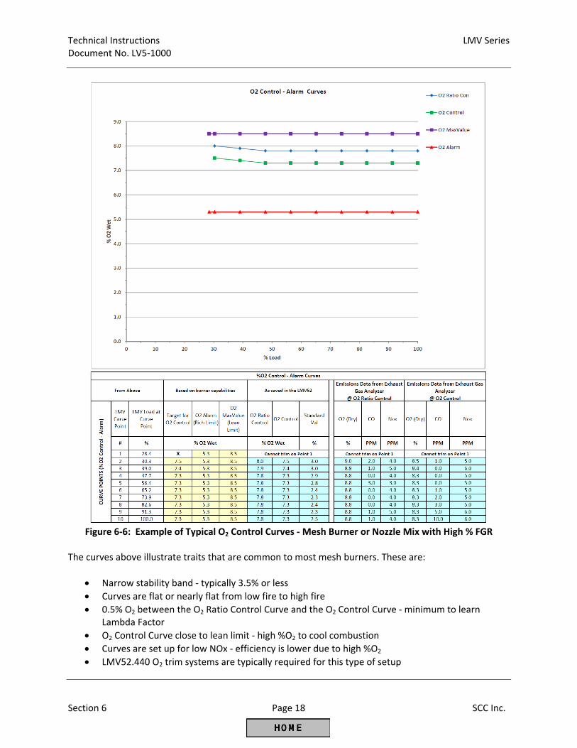
Technical Instructions LMV Series Document No. LV5‐1000
Section 6 Page 18 SCC Inc.
Figure 6‐6: Example of Typical O2 Control Curves ‐ Mesh Burner or Nozzle Mix with High % FGR
The curves above illustrate traits that are common to most mesh burners. These are:
Narrow stability band ‐ typically 3.5% or less Curves are flat or nearly flat from low fire to high fire 0.5% O2 between the O2 Ratio Control Curve and the O2 Control Curve ‐ minimum to learn
Lambda Factor O2 Control Curve close to lean limit ‐ high %O2 to cool combustion Curves are set up for low NOx ‐ efficiency is lower due to high %O2 LMV52.440 O2 trim systems are typically required for this type of setup
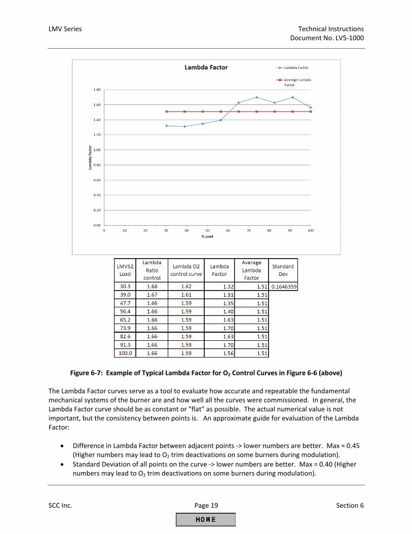
LMV Series Technical Instructions Document No. LV5‐1000
SCC Inc. Page 19 Section 6
Figure 6‐7: Example of Typical Lambda Factor for O2 Control Curves in Figure 6‐6 (above) The Lambda Factor curves serve as a tool to evaluate how accurate and repeatable the fundamental mechanical systems of the burner are and how well all the curves were commissioned. In general, the Lambda Factor curve should be as constant or "flat" as possible. The actual numerical value is not important, but the consistency between points is. An approximate guide for evaluation of the Lambda Factor:
Difference in Lambda Factor between adjacent points ‐> lower numbers are better. Max = 0.45 (Higher numbers may lead to O2 trim deactivations on some burners during modulation).
Standard Deviation of all points on the curve ‐> lower numbers are better. Max = 0.40 (Higher numbers may lead to O2 trim deactivations on some burners during modulation).
Technical Instructions LMV Series Document No. LV5‐1000
Section 6 Page 20 SCC Inc.
Post Commissioning Tuning After the O2 curves have been set up according to the procedures above, some additional burner / boiler specific tuning may be necessary to keep the O2 trim operating properly. When and how to use these tuning parameters is discussed below. LoadCtrlSuspend ‐ This sets the load change that is necessary to make the O2 trim transition from active O2 trim to pre‐control. Many factors influence the setting of this parameter. Menu path: Params & Display > O2Contr/Alarm > Gas Settings > Control Param Higher settings (more active trim, less pre‐control) can help the O2 trim stay close to setpoint in the following situations: 1. The O2 Control Curve is relatively flat from low fire to high fire (varies less than 0.5% O2) 2. The modulation ramp time is slow (OperatRampMod is set to 60 seconds or more) 3. The delay time (Tau time) of the boiler is relatively fast (Tau Low‐Fire is set to 7 seconds or less) Lower settings (less active trim, more pre‐control) can help the O2 trim stay close to setpoint in the following situations: 1. The O2 Control Curve slopes from low fire to high fire (varies more than 0.5% O2) 2. The modulation ramp time is fast (OperatRampMod is set to 30 seconds) 3. The delay time (Tau time) of the boiler is slow (Tau Low‐Fire is set for more than 7 seconds) O2TrimBehavior ‐ If parameter Startmode is set to “standard”, this setting controls how the O2 trim responds if the measured O2 value starts to move away from the O2 setpoint significantly. Menu path: Params & Display > O2Contr/Alarm > Gas Settings > Control Param 1. A setting of “ForcedAirAdd” will help if deactivations are due to the rich limit (O2 alarm) since air will
be added more aggressively. 2. A setting of “ForcedAirRed” will help if deactivations are due to the lean limit (O2 MaxValue) since
air will be subtracted more aggressively. 3. A setting of “symmetric” is used when the rich limit (O2 alarm) and the lean limit (O2 MaxValue) are
relatively close together, and an aggressive correction in one direction might cause a deactivation due to the other limit.
NOTE: On an LMV52.440 with the StartMode set to something other than “standard”, the setting of O2TrimBehavior has no effect. O2ModOffset ‐ During a load change when the pre‐control becomes active (see LoadCtrlSuspend), this will temporarily add more air beyond what is prescribed by the Lambda Factor. Increasing this setting can help with rich limit (O2 alarm) deactivations during modulation, but this parameter should not be used as a substitute for proper O2 trim commissioning procedures. Menu path: Params & Display > O2Contr/Alarm > Gas Settings > Control Param
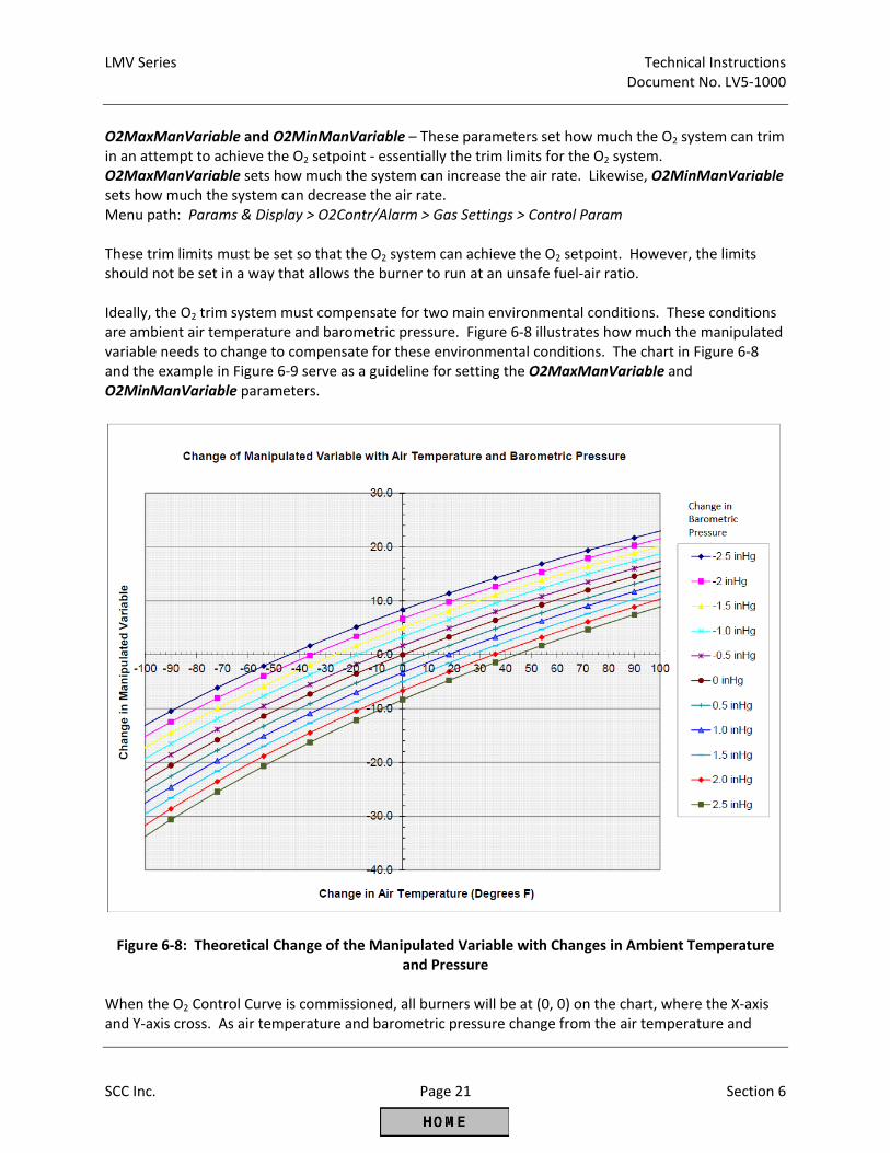
LMV Series Technical Instructions Document No. LV5‐1000
SCC Inc. Page 21 Section 6
O2MaxManVariable and O2MinManVariable – These parameters set how much the O2 system can trim in an attempt to achieve the O2 setpoint ‐ essentially the trim limits for the O2 system. O2MaxManVariable sets how much the system can increase the air rate. Likewise, O2MinManVariable sets how much the system can decrease the air rate. Menu path: Params & Display > O2Contr/Alarm > Gas Settings > Control Param These trim limits must be set so that the O2 system can achieve the O2 setpoint. However, the limits should not be set in a way that allows the burner to run at an unsafe fuel‐air ratio. Ideally, the O2 trim system must compensate for two main environmental conditions. These conditions are ambient air temperature and barometric pressure. Figure 6‐8 illustrates how much the manipulated variable needs to change to compensate for these environmental conditions. The chart in Figure 6‐8 and the example in Figure 6‐9 serve as a guideline for setting the O2MaxManVariable and O2MinManVariable parameters.
Figure 6‐8: Theoretical Change of the Manipulated Variable with Changes in Ambient Temperature
and Pressure When the O2 Control Curve is commissioned, all burners will be at (0, 0) on the chart, where the X‐axis and Y‐axis cross. As air temperature and barometric pressure change from the air temperature and
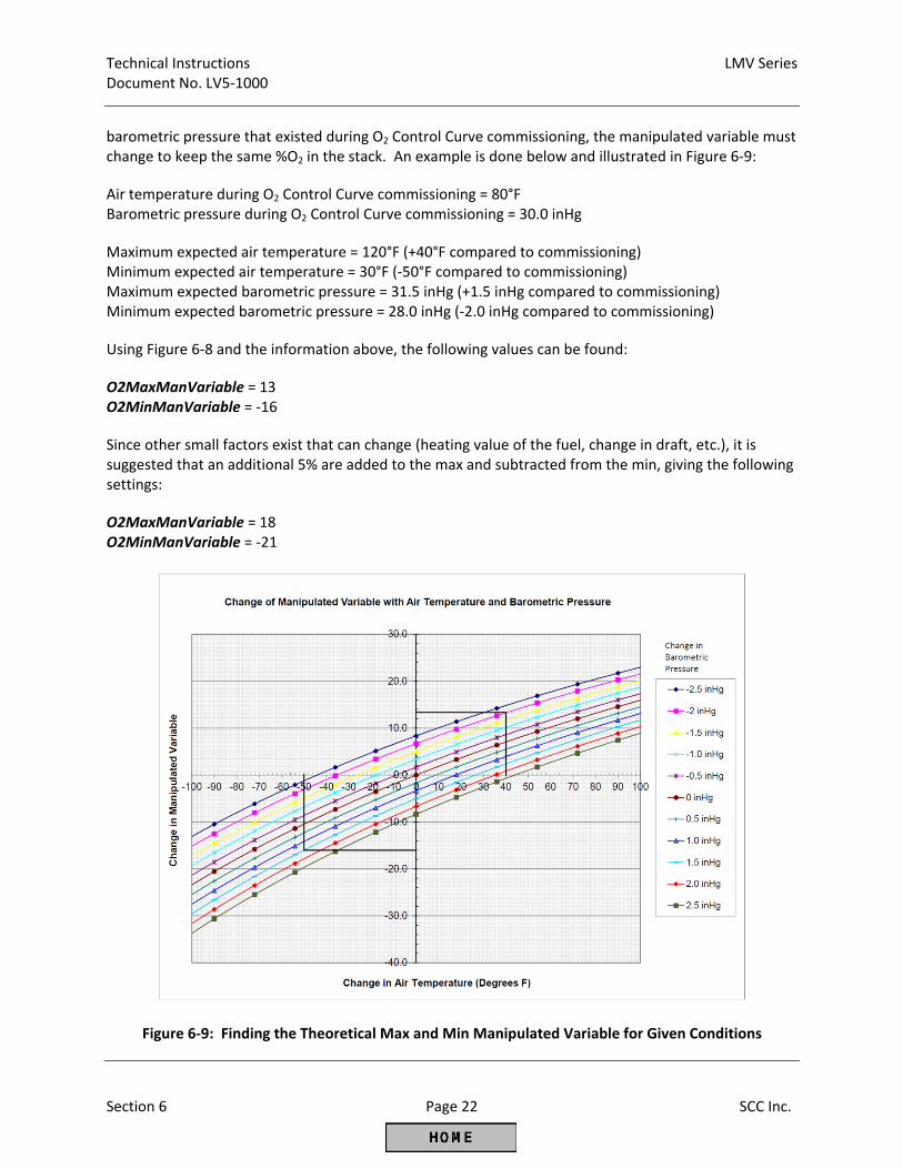
Technical Instructions LMV Series Document No. LV5‐1000
Section 6 Page 22 SCC Inc.
barometric pressure that existed during O2 Control Curve commissioning, the manipulated variable must change to keep the same %O2 in the stack. An example is done below and illustrated in Figure 6‐9: Air temperature during O2 Control Curve commissioning = 80°F Barometric pressure during O2 Control Curve commissioning = 30.0 inHg Maximum expected air temperature = 120°F (+40°F compared to commissioning) Minimum expected air temperature = 30°F (‐50°F compared to commissioning) Maximum expected barometric pressure = 31.5 inHg (+1.5 inHg compared to commissioning) Minimum expected barometric pressure = 28.0 inHg (‐2.0 inHg compared to commissioning) Using Figure 6‐8 and the information above, the following values can be found: O2MaxManVariable = 13 O2MinManVariable = ‐16 Since other small factors exist that can change (heating value of the fuel, change in draft, etc.), it is suggested that an additional 5% are added to the max and subtracted from the min, giving the following settings: O2MaxManVariable = 18 O2MinManVariable = ‐21
Figure 6‐9: Finding the Theoretical Max and Min Manipulated Variable for Given Conditions
LMV Series Technical Instructions Document No. LV5‐1000
SCC Inc. Page 23 Section 6
NumberTauSuspend ‐ The length of time after main flame light‐off that is required until an accurate, representative O2 value is read by the O2 sensor. Basically, the time it takes to replace all of the air in the boiler with products of combustion. This parameter is a multiplier that is taken times the delay time at low fire (Tau Low‐Fire) to determine the length of waiting time before a representative O2 value is measured and the O2 trim can engage. If Tau Low‐Fire was read to be 5 seconds during O2 Control Curve commissioning, and NumberTauSuspend is set to 10, then the O2 trim would engage 50 seconds after main flame light‐off. A setting of 10 will work for almost all applications, and will be conservative for most. Higher numbers (more waiting time) are more conservative and lower numbers are less conservative. Menu path: Params & Display > O2Contr/Alarm > Gas Settings > Startmode
Startmode ‐ This determines how the burner transitions from light‐off to engaging the O2 trim. Two of the modes, “Ign Load TC” and “IgnPtWithTC”, require a combustion air temperature sensor. Immediately after main flame light‐off, the O2 sensor does not have a valid reading since the gas path of the boiler is full of air. Some burner designs, most notably ultra‐low NOx mesh burners, require some type of compensation at light‐off to ensure flame stability before the O2 sensor has a valid reading. Four options are available: 1. Standard ‐ Burner will modulate right after light‐off, not waiting for the O2 trim to engage. O2 trim
will engage after the time defined by NumberTauSuspend expires at the burner’s current load. 2. Ign Load TC ‐ This will vary the ignition positions (special positions) of the actuators based on the
combustion air temperature and also based on a defined load number (parameter Load of Ignition). This also will drive the "temperature compensated" actuators to Point 2 (or whichever point is defined by parameter StartPointOp). The burner will be held in Phase 60 at Point 2 (or whichever point is defined by parameter StartPointOp) until the time defined by NumberTauSuspend expires. The burner will then be released to modulate with the O2 trim active.
3. IgnPtWithTC ‐ This will not vary the ignition positions (special positions) of the actuators based on the combustion air temperature. It will drive the actuators from the temperature‐compensated set ignition positions to Point 2 (or whichever point is defined by parameter StartPointOp). The burner will be held in Phase 60 at Point 2 (or whichever point is defined by parameter StartPointOp) until the time defined by NumberTauSuspend expires. The burner will then be released to modulate with the O2 trim active.
4. IgnPtWoutTC ‐ Similar to “IgnPtWithTC”, but less accuracy due to the lack of a combustion air sensor.
On burners with a wide flame stability band, such as traditional nozzle mixing burners with little or no FGR, a StartMode setting of “standard” typically works well. On burners with a more narrow flame stability band (low and ultra‐low NOx mesh burners), “IgnPtWithTC” typically works well. Menu path: Params & Display > O2Contr/Alarm > Gas Settings > Startmode
Technical Instructions LMV Series Document No. LV5‐1000
Section 6 Page 24 SCC Inc.
O2InitOffset ‐ For the other three start modes other than "standard", this is a rich or lean bias that is applied to the temperature compensation. Negative values (‐2 to ‐0.1) will bias the temperature compensation more rich, and positive values (0.1 to 2) will bias the temperature compensation more lean. Note that the units on this are %O2, so a setting of ‐2 will offset the O2 approximately 2% more rich. This offset is dissolved after the O2 trim becomes active (NumberTauSuspend expires). Menu path: Params & Display > O2Contr/Alarm > Gas Settings > Startmode Observing the Behavior of the O2 Trim After the O2 curves are commissioned and post commissioning tuning is done, the behavior of the O2 trim can be observed and evaluated to determine if further tuning is necessary. Current O2 Value and O2 Setpoint Menu path: Operation > O2 Module Parameters can be toggled between to see how well the O2 setpoint is being followed at different firing rates and when transitioning between firing rates. Expected behavior: the difference between the O2 setpoint and actual value should be slightly more when the burner is transitioning between firing rates and less when not transitioning. As a guideline, the difference should be less than +/‐ 0.2% O2 when not transitioning and less than +/‐0.4% O2 when transitioning. ManVar O2 Ctrl Menu path: Params & Display > O2 Contr/Alarm > Process Data This parameter shows the amount of trim. The value shown is defined below: 1. A value of 50% indicates no trimming. 2. Values greater than 50% ‐ more air is needed to achieve O2 setpoint compared to when the O2
Control Curve was commissioned. 3. Values less than 50% ‐ less air is needed to achieve O2 setpoint compared to when O2 Control Curve
was commissioned. Expected behavior: should stay relatively consistent from low fire to high fire. Should change with external changes such as combustion air temperature, barometric pressure, draft, heating value of fuel, air filters becoming dirty, etc. State O2 Ctrl Menu path: Params & Display > O2 Contr/Alarm > Process Data This parameters identifies the state of the O2 control. Possible values are: 1. Deactivated – the O2 control was either manually or automatically deactivated 2. Locked – the manipulated variable (amount of trim) is being held at the last value 3. LockTStart – O2 control is waiting to engage after light‐off (waiting for NumberTauSuspend to
expire)
LMV Series Technical Instructions Document No. LV5‐1000
SCC Inc. Page 25 Section 6
4. InitContr – O2 control is preparing to engage but is still locked 5. LockTLoad – O2 control is engaged but locked (in pre‐control) due to a load change 6. Active – O2 control is actively trimming based on setpoint and measured O2 value 7. LockTCAct ‐ O2 control is engaged but locked due to an excursion from setpoint If the state of the O2 control is shown as "locked", parameter Diag Reg State will show the reason why. Diag Reg State Menu path: Params & Display > O2 Contr/Alarm > Process Data This parameter shows the reason that the O2 control is locked. Possible values are: 0 – The load is below the load limit set by parameter O2 CtrlThreshold 1 – The load controller is in auto tune 2 – The O2 sensor is being tested for response (self‐check of O2 sensor) 3 – The fuel‐air ratio or O2 trim curves are being programmed 4 – The measured % O2 is above the lean limit or below the rich limit 5 – There is an error in the PLL52 module 6 – There is an error in the pre‐control Using the O2 Alarm Functionality without O2 Trim As was previously mentioned, the O2 system can be run in different modes. The modes are set using parameter OptgMode, which can be found using the following menu path: Menu path: Params & Display > O2 Contr/Alarm > Gas/Oil Settings The available operating modes are: 1. Man deact ‐ deactivates all O2 trim and O2 alarm functionality. %O2 value can still be viewed. 2. O2 Limiter ‐ Only the O2 alarm is active. This means that a lockout will occur if the lean limit (O2
MaxValue) is exceeded for a time longer than what is set for parameter Time O2 Alarm. Likewise, a lockout will occur if the rich limit (O2 alarm curve) is exceeded for a time longer than what is set for parameter Time O2 Alarm. No trim functionality is active.
3. O2 Control ‐ The same as O2 Limiter, except O2 trim is now enabled. Exceeding rich or lean limits will cause a lockout in the same way as the O2 Limiter mode.
4. ConAutoDeac – In this mode, exceeding the rich or lean limits will not cause an immediate lockout. Exceeding the rich or lean limits will cause the O2 trim to be temporarily deactivated. After a waiting time of 3 times Tau, the measured %O2 will be re‐evaluated. If the %O2 is higher than the rich alarm, the O2 trim will be deactivated. If the %O2 is lower than the rich alarm, a lockout will occur. The O2 trim can be automatically deactivated and reactivated the number of times allowed by parameter NumMinUntilDeact. The maximum setting is 5. If more than 5 deactivations and reactivations occur, then the O2 trim mode will be changed to “auto deact” until the O2 trim control is manually re‐activated.
5. Auto deact ‐ indicates that the O2 trim has been automatically deactivated for some reason. See error codes in Section 7. Do not select this mode.
Technical Instructions LMV Series Document No. LV5‐1000
Section 6 Page 26 SCC Inc.
If only the O2 alarm function is to be used and the O2 trim has not been commissioned, a few key parameters must be set. These are: 1. O2 MaxValue ‐ set to the maximum safe %O2 (wet) for all points. 2. O2 Alarm curve ‐ enter the minimum safe %O2 (wet) for each point. 3. Tau Low‐FireOEM ‐ the delay time of the burner / boiler at low fire 4. Tau High‐FireOEM ‐ the delay time of the burner / boiler at high fire 5. OptgMode ‐ set to O2 Limiter If the O2 trim has not been commissioned, it will be necessary to manually enter Tau Low‐FireOEM and Tau High‐FireOEM. These Tau times do not have to be as accurate as if the O2 trim was being used. These can be manually timed by using the O2 reading on the AZL (recommended), or typical values can be used. Higher turndown burners will produce longer low fire Tau times. Typically, for a 5‐to‐1 turndown burner, Tau Low‐FireOEM is between 10‐20 seconds. Tau High‐FireOEM is typically 4 seconds or less. How the O2 is Measured with the QGO20 Sensor and PLL52 Module
The QGO20 is a Zirconium type sensor that is heated to approximately 1292°F. The high temperatures allow oxygen to diffuse through the Zirconium cell and produce a milli‐volt signal. This milli‐volt signal is referred to as the Nernst Voltage. The Nernst Voltage that is produced for a given %O2 is dependent on the concentration of oxygen and the temperature of the Zirconium cell. The PLL52 module reads both the Nernst Voltage and the temperature of the Zirconium cell. With this information, the %O2 can be accurately determined and sent back to the LMV52 over CANbus. As well as taking the milli‐volt signals and converting these to CANbus data, the PLL52 also serves as the controller for the Zirconium cell's heating element. The PLL52 is also a place to connect the combustion air temperature sensor and the stack gas temperature sensor. Three milli‐volt signals originate in the QGO20: 1. Nernst Voltage from the Zirconium oxide O2 cell terminals B1 and M 2. O2 cell thermocouple signal terminals B2 and M 3. Cold junction thermocouple compensation terminals G2 and U3 These three milli‐volt signals between the QGO20 and the PLL52 must be run in a separate conduit and / or a shielded cable. See Section 2 for complete details on wiring the QGO20 to the PLL52. High voltage wires are also connected from the PLL52 to the QGO20 for the heater. It is very important that these wires are run in a separate conduit away from the milli‐volt signals. NOTE: Never connect the QGO20 heater directly to line voltage! Permanent damage will result to the heating element and the sensor. High voltage wires for the heater to the QGO20 must come from the PLL52 module. See Section 2 for more information.
Also, due to possible interference on the milli‐volt signals, the PLL52 must be installed within 30 feet of the QGO20.
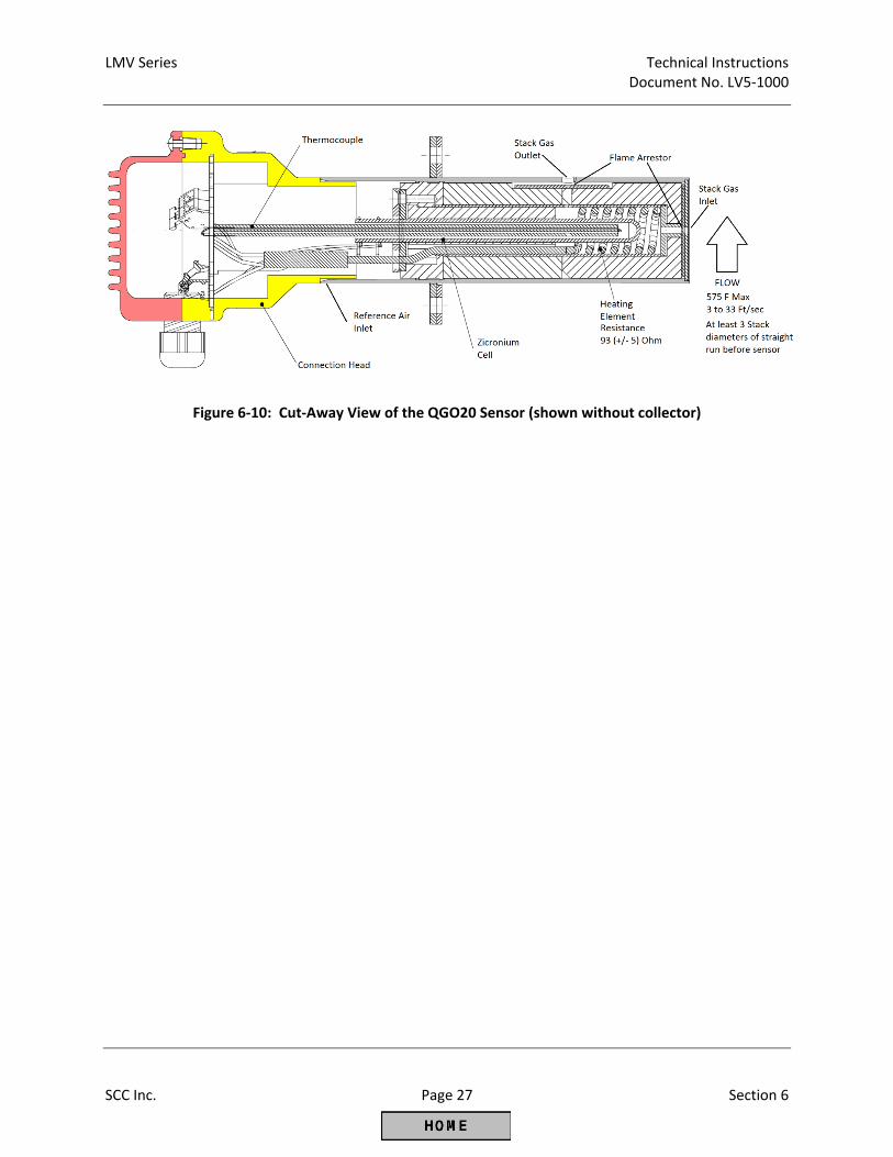
LMV Series Technical Instructions Document No. LV5‐1000
SCC Inc. Page 27 Section 6
Figure 6‐10: Cut‐Away View of the QGO20 Sensor (shown without collector)
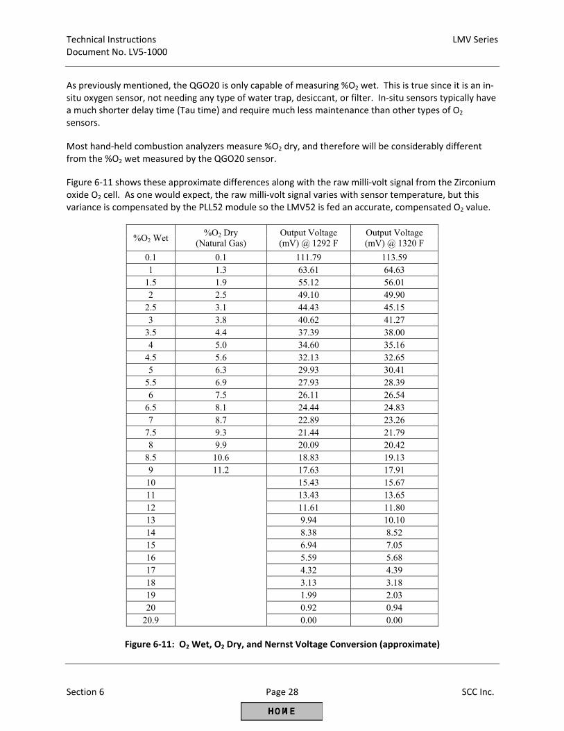
Technical Instructions LMV Series Document No. LV5‐1000
Section 6 Page 28 SCC Inc.
As previously mentioned, the QGO20 is only capable of measuring %O2 wet. This is true since it is an in‐situ oxygen sensor, not needing any type of water trap, desiccant, or filter. In‐situ sensors typically have a much shorter delay time (Tau time) and require much less maintenance than other types of O2 sensors. Most hand‐held combustion analyzers measure %O2 dry, and therefore will be considerably different from the %O2 wet measured by the QGO20 sensor. Figure 6‐11 shows these approximate differences along with the raw milli‐volt signal from the Zirconium oxide O2 cell. As one would expect, the raw milli‐volt signal varies with sensor temperature, but this variance is compensated by the PLL52 module so the LMV52 is fed an accurate, compensated O2 value.
%O2 Wet %O2 Dry
(Natural Gas) Output Voltage (mV) @ 1292 F
Output Voltage (mV) @ 1320 F
0.1 0.1 111.79 113.59 1 1.3 63.61 64.63
1.5 1.9 55.12 56.01 2 2.5 49.10 49.90
2.5 3.1 44.43 45.15 3 3.8 40.62 41.27
3.5 4.4 37.39 38.00 4 5.0 34.60 35.16
4.5 5.6 32.13 32.65 5 6.3 29.93 30.41
5.5 6.9 27.93 28.39 6 7.5 26.11 26.54
6.5 8.1 24.44 24.83 7 8.7 22.89 23.26
7.5 9.3 21.44 21.79 8 9.9 20.09 20.42
8.5 10.6 18.83 19.13 9 11.2 17.63 17.91
10
15.43 15.67 11 13.43 13.65 12 11.61 11.80 13 9.94 10.10 14 8.38 8.52 15 6.94 7.05 16 5.59 5.68 17 4.32 4.39 18 3.13 3.18 19 1.99 2.03 20 0.92 0.94
20.9 0.00 0.00
Figure 6‐11: O2 Wet, O2 Dry, and Nernst Voltage Conversion (approximate)
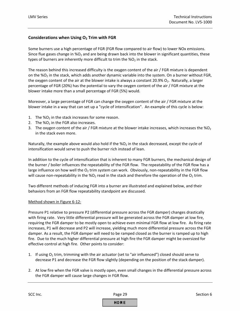
LMV Series Technical Instructions Document No. LV5‐1000
SCC Inc. Page 29 Section 6
Considerations when Using O2 Trim with FGR Some burners use a high percentage of FGR (FGR flow compared to air flow) to lower NOx emissions. Since flue gases change in %O2 and are being drawn back into the blower in significant quantities, these types of burners are inherently more difficult to trim the %O2 in the stack. The reason behind this increased difficulty is the oxygen content of the air / FGR mixture is dependent on the %O2 in the stack, which adds another dynamic variable into the system. On a burner without FGR, the oxygen content of the air at the blower intake is always a constant 20.9% O2. Naturally, a larger percentage of FGR (20%) has the potential to vary the oxygen content of the air / FGR mixture at the blower intake more than a small percentage of FGR (5%) would. Moreover, a large percentage of FGR can change the oxygen content of the air / FGR mixture at the blower intake in a way that can set up a "cycle of intensification". An example of this cycle is below: 1. The %O2 in the stack increases for some reason. 2. The %O2 in the FGR also increases. 3. The oxygen content of the air / FGR mixture at the blower intake increases, which increases the %O2
in the stack even more. Naturally, the example above would also hold if the %O2 in the stack decreased, except the cycle of intensification would serve to push the burner rich instead of lean. In addition to the cycle of intensification that is inherent to many FGR burners, the mechanical design of the burner / boiler influences the repeatability of the FGR flow. The repeatability of the FGR flow has a large influence on how well the O2 trim system can work. Obviously, non‐repeatability in the FGR flow will cause non‐repeatability in the %O2 read in the stack and therefore the operation of the O2 trim. Two different methods of inducing FGR into a burner are illustrated and explained below, and their behaviors from an FGR flow repeatability standpoint are discussed. Method shown in Figure 6‐12: Pressure P1 relative to pressure P2 (differential pressure across the FGR damper) changes drastically with firing rate. Very little differential pressure will be generated across the FGR damper at low fire, requiring the FGR damper to be mostly open to achieve even minimal FGR flow at low fire. As firing rate increases, P1 will decrease and P2 will increase, yielding much more differential pressure across the FGR damper. As a result, the FGR damper will need to be ramped closed as the burner is ramped up to high fire. Due to the much higher differential pressure at high fire the FGR damper might be oversized for effective control at high fire. Other points to consider: 1. If using O2 trim, trimming with the air actuator (set to "air influenced") closed should serve to
decrease P1 and decrease the FGR flow slightly (depending on the position of the stack damper). 2. At low fire when the FGR valve is mostly open, even small changes in the differential pressure across
the FGR damper will cause large changes in FGR flow.
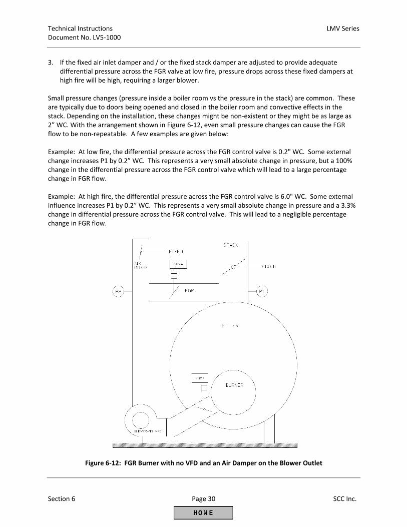
Technical Instructions LMV Series Document No. LV5‐1000
Section 6 Page 30 SCC Inc.
3. If the fixed air inlet damper and / or the fixed stack damper are adjusted to provide adequate
differential pressure across the FGR valve at low fire, pressure drops across these fixed dampers at high fire will be high, requiring a larger blower.
Small pressure changes (pressure inside a boiler room vs the pressure in the stack) are common. These are typically due to doors being opened and closed in the boiler room and convective effects in the stack. Depending on the installation, these changes might be non‐existent or they might be as large as 2” WC. With the arrangement shown in Figure 6‐12, even small pressure changes can cause the FGR flow to be non‐repeatable. A few examples are given below: Example: At low fire, the differential pressure across the FGR control valve is 0.2" WC. Some external change increases P1 by 0.2” WC. This represents a very small absolute change in pressure, but a 100% change in the differential pressure across the FGR control valve which will lead to a large percentage change in FGR flow. Example: At high fire, the differential pressure across the FGR control valve is 6.0" WC. Some external influence increases P1 by 0.2” WC. This represents a very small absolute change in pressure and a 3.3% change in differential pressure across the FGR control valve. This will lead to a negligible percentage change in FGR flow.
Figure 6‐12: FGR Burner with no VFD and an Air Damper on the Blower Outlet
LMV Series Technical Instructions Document No. LV5‐1000
SCC Inc. Page 31 Section 6
Method shown in Figure 6‐13: Pressure P1 relative to pressure P2 (differential pressure across the FGR damper) is more constant with firing rate. Differential pressure will be generated across the FGR damper at low fire by using the suction of the blower against the air damper. The differential pressure across the FGR damper can also be adjusted with the speed of the VFD. As firing rate increases, P2 will increase (less vacuum) and P1 will increase due to increased pressure behind the stack damper, yielding a more consistent differential pressure. As a result, the FGR damper can be sized more appropriately and should offer better control. Other points to consider: 1. If using O2 trim, the effect that the trim has on FGR flow can be adjusted. Three possibilities:
a. If only the air damper is trimmed (set to “air influenced”), trimming closed and reducing air flow will increase the vacuum at P2 and increase FGR flow relative to air flow.
b. If only the VFD is trimmed (set to “air influenced”), trimming slower and reducing air rate will
reduce the vacuum at P2 and reduce the FGR flow relative to the air flow. c. If both the air damper and VFD are trimmed (set to “air influenced”), trimming closed should
keep the vacuum at P2 relatively constant and keep the FGR flow constant relative to the air flow.
2. Differential pressure across the FGR damper is significant even at low fire due to the vacuum
provided by the blower. Small changes in the differential pressure across the FGR damper will cause small changes in FGR flow. FGR flow will be more repeatable as compared to the method in Figure 6‐12, especially at low to mid fire.
3. No fixed air dampers exist for the blower intake, and the fixed damper in the stack may be able to
be opened further, reducing the blower pressure requirements.
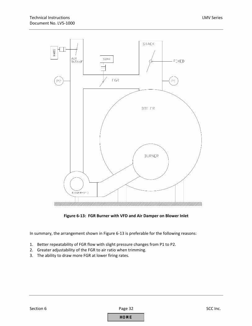
Technical Instructions LMV Series Document No. LV5‐1000
Section 6 Page 32 SCC Inc.
Figure 6‐13: FGR Burner with VFD and Air Damper on Blower Inlet
In summary, the arrangement shown in Figure 6‐13 is preferable for the following reasons: 1. Better repeatability of FGR flow with slight pressure changes from P1 to P2. 2. Greater adjustability of the FGR to air ratio when trimming. 3. The ability to draw more FGR at lower firing rates.
LMV Series Technical Instructions Document No. LV5‐1000
SCC Inc. Page 33 Section 6
Additional Tips for O2 Trim Commissioning and Tuning If the AZL52 displays that the O2 trim has been automatically deactivated, it can be re‐activated
under the following menu path:
Operation > O2Ctrl activate Repeated deactivations can be caused by many different problems, including inaccurate load numbers.
All of the points on the O2 Control Curve should be completed in one session, and the session should
be less than an hour. This is preferable, since ambient conditions (air temperature and barometric pressure) typically do not change a significant amount in one hour.
Every point on the O2 Ratio Control Curve must have a corresponding point on the rich limit (O2
alarm) curve. For Point 2 and above, every point on the O2 Ratio Control Curve must also have a corresponding point on the O2 Control Curve. If this is not done, an immediate O2 trim deactivation will occur.
If a point on the O2 Ratio Control Curve is changed (actuator positions), the corresponding point on
the O2 Control Curve will be deleted. The O2 trim will automatically deactivate and cannot be re‐activated if points are missing on any of the curves (O2 Ratio Control, O2 Control, O2 Alarm).
Considering the items above, if one point is changed on the O2 Ratio Control Curve, then the O2
Ratio Control Curve and the O2 Control Curve should be redone so that the Lambda Factor at each point is known to be based on the same ambient conditions. Setting the O2 Ratio Control Curve and the O2 Control Curve in a piecemeal fashion typically does not yield reliable O2 trim operation.
The LMV52.240 can only decrease the air influencing actuator positions below their settings on the
O2 Ratio Control Curve. This is typically not an issue if the gap between the O2 Ratio Control Curve and the O2 Control Curve is large enough (1%). The LMV52.440 can increase or decrease the air influencing actuator positions, so the gap between the O2 Ratio Control Curve and the O2 Control Curve can be smaller (0.5%). This also gives the LMV52.440 the ability to deal with more challenging applications such as FGR and low NOx mesh burners.
Most burners will flame fail in a safe way if operated too lean. However, overly lean operation may
be hazardous for some burner designs. If one of these burners is encountered, the O2 Ratio Control Curve can be set to function as the lean limit using the following menu path:
Params & Display > O2Contr/Alarm > Gas/Oil Settings > O2 Alarm > Type O2 MaxValue
Set this to “O2MaxCurve”. For this type of burner it is also recommended to set the operating mode of the O2 trim to “O2 Control”, so a lockout will occur if the lean limit is reached.
Params & Display > O2Contr/Alarm > Gas/Oil Settings > OptgMode = O2 Control
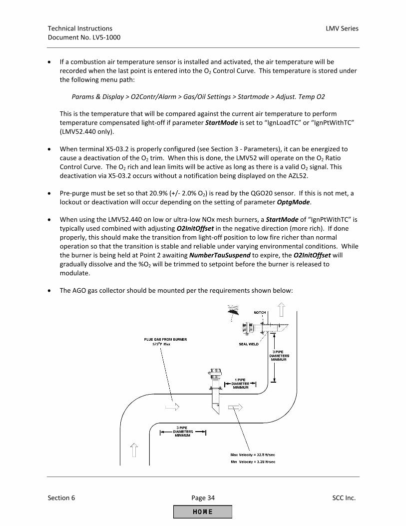
Technical Instructions LMV Series Document No. LV5‐1000
Section 6 Page 34 SCC Inc.
If a combustion air temperature sensor is installed and activated, the air temperature will be
recorded when the last point is entered into the O2 Control Curve. This temperature is stored under the following menu path:
Params & Display > O2Contr/Alarm > Gas/Oil Settings > Startmode > Adjust. Temp O2
This is the temperature that will be compared against the current air temperature to perform temperature compensated light‐off if parameter StartMode is set to “IgnLoadTC” or “IgnPtWithTC” (LMV52.440 only).
When terminal X5‐03.2 is properly configured (see Section 3 ‐ Parameters), it can be energized to
cause a deactivation of the O2 trim. When this is done, the LMV52 will operate on the O2 Ratio Control Curve. The O2 rich and lean limits will be active as long as there is a valid O2 signal. This deactivation via X5‐03.2 occurs without a notification being displayed on the AZL52.
Pre‐purge must be set so that 20.9% (+/‐ 2.0% O2) is read by the QGO20 sensor. If this is not met, a
lockout or deactivation will occur depending on the setting of parameter OptgMode. When using the LMV52.440 on low or ultra‐low NOx mesh burners, a StartMode of “IgnPtWithTC” is
typically used combined with adjusting O2InitOffset in the negative direction (more rich). If done properly, this should make the transition from light‐off position to low fire richer than normal operation so that the transition is stable and reliable under varying environmental conditions. While the burner is being held at Point 2 awaiting NumberTauSuspend to expire, the O2InitOffset will gradually dissolve and the %O2 will be trimmed to setpoint before the burner is released to modulate.
The AGO gas collector should be mounted per the requirements shown below:
Section 1 Overview
Section 2 Wiring
Section 3 Parameters
Section 4 Commissioning
Section 5 VSD
Section 6 O2 Trim
Section 7 Troubleshooting
Section 8 Modbus
Section 9 ACS450
Section 10 Revision History
Appendix A Application Guide
Appendix B* Complimentary Products Guide
*Can be found at www.scccombustion.com.
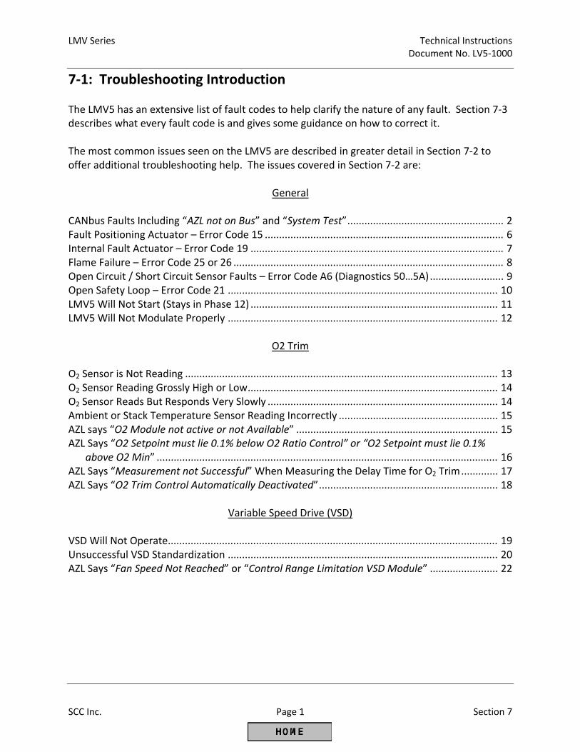
LMV Series Technical Instructions Document No. LV5‐1000
SCC Inc. Page 1 Section 7
7‐1: Troubleshooting Introduction The LMV5 has an extensive list of fault codes to help clarify the nature of any fault. Section 7‐3 describes what every fault code is and gives some guidance on how to correct it. The most common issues seen on the LMV5 are described in greater detail in Section 7‐2 to offer additional troubleshooting help. The issues covered in Section 7‐2 are:
General
CANbus Faults Including “AZL not on Bus” and “System Test” ....................................................... 2 Fault Positioning Actuator – Error Code 15 .................................................................................... 6 Internal Fault Actuator – Error Code 19 ......................................................................................... 7 Flame Failure – Error Code 25 or 26 ............................................................................................... 8 Open Circuit / Short Circuit Sensor Faults – Error Code A6 (Diagnostics 50…5A) .......................... 9 Open Safety Loop – Error Code 21 ............................................................................................... 10 LMV5 Will Not Start (Stays in Phase 12) ....................................................................................... 11 LMV5 Will Not Modulate Properly ............................................................................................... 12
O2 Trim
O2 Sensor is Not Reading .............................................................................................................. 13 O2 Sensor Reading Grossly High or Low ........................................................................................ 14 O2 Sensor Reads But Responds Very Slowly ................................................................................. 14 Ambient or Stack Temperature Sensor Reading Incorrectly ........................................................ 15 AZL says “O2 Module not active or not Available” ....................................................................... 15 AZL Says “O2 Setpoint must lie 0.1% below O2 Ratio Control” or “O2 Setpoint must lie 0.1%
above O2 Min” ........................................................................................................................ 16 AZL Says “Measurement not Successful” When Measuring the Delay Time for O2 Trim ............. 17 AZL Says “O2 Trim Control Automatically Deactivated” ............................................................... 18
Variable Speed Drive (VSD)
VSD Will Not Operate.................................................................................................................... 19 Unsuccessful VSD Standardization ............................................................................................... 20 AZL Says “Fan Speed Not Reached” or “Control Range Limitation VSD Module” ........................ 22
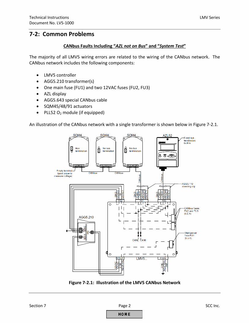
Technical Instructions LMV Series Document No. LV5‐1000
Section 7 Page 2 SCC Inc.
7‐2: Common Problems
CANbus Faults Including “AZL not on Bus” and “System Test”
The majority of all LMV5 wiring errors are related to the wiring of the CANbus network. The CANbus network includes the following components:
LMV5 controller
AGG5.210 transformer(s)
One main fuse (FU1) and two 12VAC fuses (FU2, FU3)
AZL display
AGG5.643 special CANbus cable
SQM45/48/91 actuators
PLL52 O2 module (if equipped) An illustration of the CANbus network with a single transformer is shown below in Figure 7‐2.1.
Figure 7‐2.1: Illustration of the LMV5 CANbus Network
LMV Series Technical Instructions Document No. LV5‐1000
SCC Inc. Page 3 Section 7
CANbus Faults Including “AZL not on Bus” and “System Test” (continued)
The most common CANbus errors are:
“AZL not on Bus”
Stuck in “System Test”
Error code 99
Error code A7, diagnostic 17 However, there are many additional error codes that can also be caused by an issue with the CANbus network. The following procedure can be used to diagnose any CANbus related error: 1. Take the cover off of the last actuator (or PLL52 O2 module) on the CANbus network wired
to terminal X51 on the LMV5. This should have only one 5‐pin green connector plugged into it. The other CANbus terminals should be empty, and is a perfect place to measure voltage. Ensure that the following voltages are present on the pins of the empty CANbus terminal:
12 VAC between pins 12VAC1 and GND
12 VAC between pins 12VAC2 and GND
24 VAC between pins 12VAC1 and 12VAC2 When measuring to ground (GND), it is ok to have anywhere from 10.2‐13.2 VAC as long as both measurements are the same. For example, it is okay to have 11 VAC between pins 12VAC1 and GND as long as there is also 11 VAC between pins 12VAC2 and GND. In addition, the voltage between pins 12VAC1 and 12VAC2 must be exactly double the other two measurements. If these three voltage measurements are correct, skip to step 3.
2. If one or more of the voltage measurements is incorrect, check the following:
CANbus fuses FU2 and FU3 are located on the right hand side of the LMV5. Check that these fuses are not blown. If either one is blown, check the LMV5 wiring for incorrect terminations. Once any wiring errors have been fixed, replace the blown fuse.
The most common wiring error has to do with pins 3 and 4 on transformer terminal SEK2. Pin 3 on terminal SEK2 should be wired to terminal X52, pin 4 on the LMV5. Pin 4 on terminal SEK2 should be wired to terminal X52, pin 3 on the LMV5.
Make sure pin 3 on terminal SEK2 of the transformer is grounded properly.
Make sure the rest of the CANbus network is wired properly. See Section 2 for additional wiring assistance.
Technical Instructions LMV Series Document No. LV5‐1000
Section 7 Page 4 SCC Inc.
CANbus Faults Including “AZL not on Bus” and “System Test” (continued) 3. Check the LMV5 fault history. If the faults always occur in phase 38, the CANbus errors are
being caused by noise from the ignition transformer. Make sure the ignition transformer is grounded properly and has a good neutral. Also, make sure any CANbus wires that run close to the ignition transformer are in proper conduit. It may be necessary to either relocate the ignition transformer or add a shield between the ignition transformer and any nearby CANbus wires.
4. Unplug the 6‐pin green connector plugged into terminal X51 on the top of the LMV5. This leaves the AZL, the LMV5, and the cable between them as the only CANbus components still plugged in. Reset the fault on the LMV5. At this point, two things can happen:
If the AZL faults with “Fault Feedback Air Actuator”, then the AZL, the LMV5, and the cable between them are all working properly. This means that there is likely an issue with the wiring of the actuators or O2 module. Go to step 5.
If the same CANbus fault recurs, then there is a problem with the AZL, the LMV5, or the cable between them. Check the wiring and terminations on the cable. Though unlikely, the AZL or the LMV5 might be damaged and need to be replaced. If a spare AZL is available, try it. If no spare AZL is present, check for any noticeable damage to either the AZL or the LMV5 to determine which component to replace.
5. To find the wiring issue with the actuators or O2 module, plug components back in one at a
time to terminal X51 on the LMV5 to determine which component is causing the CANbus errors. First, plug in just the cable (unplugged from the actuator) that connects the first actuator to terminal X51 on the LMV5. Reset the fault on the LMV5. If “Fault Feedback Air Actuator” shows up again, the cable itself is okay. Next, plug in just the first actuator (unplugged from the cable running to the second actuator). Reset the fault on the LMV5. As long as actuator feedback faults continue to show up after each component is plugged in and the LMV5 is reset, continue to plug in another component. At some point, plugging in a component should cause the CANbus fault to recur.
6. Once the component causing the CANbus errors has been found, check the following to correct the problem:
Make sure all terminations to the actuator are done properly and no wire strands from adjacent pins are touching one another and causing a short.
LMV Series Technical Instructions Document No. LV5‐1000
SCC Inc. Page 5 Section 7
CANbus Faults Including “AZL not on Bus” and “System Test” (continued)
Make sure the shielding of the CANbus cable is grounded properly. The shielding of the CANbus cable is immediately under the plastic sheathing and encircles all five conductors. The shielding on all segments of the CANbus cable must have continuity with terminal X51.1. This can be checked with a multi‐meter by connecting one probe on the AGG5.110 shielding clip attached to terminal X51.1, and the other probe on the last actuator (or O2 module) on the CANbus network.
If everything else checks out, and every time one of the actuators is plugged in it immediately causes a CANbus fault, replace the appropriate actuator.
Technical Instructions LMV Series Document No. LV5‐1000
Section 7 Page 6 SCC Inc.
Fault Positioning Actuator – Error Code 15
An error code 15 essentially means that an actuator has not reached the position it is being told to drive to by the LMV5. The diagnostic code will detail which actuator is having the problem. If an error code 15 is encountered, check for the following causes: 1. Binding. At full torque output, the actuator cannot move the valve or damper it is trying to
move. This is typically due to the actuator pushing against mechanical stops on the valve or damper. Check that the actuator was properly coupled. This may also be caused by a valve or damper that requires more torque than the actuator is capable of.
2. Temperature. All SQM… actuators are rated for a maximum operating temperature of 140°F. However, when operating temperatures exceed 120°F, the torque output of the actuator is decreased by 15%. If this is the case, reduce the heat to the actuator.
3. Duty Cycle. All SQM… actuators are rated for a 50% duty cycle, meaning that the actuator can only be moving half of the time. Duty cycles over 50% can cause the actuator to overheat which reduces the torque output severely. If the actuator is constantly moving, improve the PID settings and / or adjust parameter MinActuatorStep.
4. Flutter. This typically occurs on air or FGR dampers. Highly turbulent flow across a damper blade can cause an alternating torque to be applied to the damper shaft. This in turn puts an alternating torque on the actuator shaft. For example, let’s say that the LMV5 is commanding the air actuator to drive to 50.0° which is a highly turbulent spot on the air damper. The following action may be seen:
LMV5 sees actuator at 50.3° and repositions it counterclockwise
LMV5 sees actuator at 49.7° and repositions it clockwise
LMV5 sees actuator at 50.3° and repositions it counterclockwise
LMV5 sees actuator at 49.7° and repositions it clockwise In this scenario, eventually the LMV5 determines that the actuator cannot reach the 50.0° position and faults with an error code 15. If a flutter is present on the air damper, a constant torque can be applied to the air damper assembly to eliminate the effects of the flutter.
5. Power. All of the actuators for the LMV5 run off of 24 VAC power. Measure between
terminals 12VAC1 and 12VAC2 on the actuator to ensure there are approximately 24 VAC provided to the actuator throughout the firing range. If there are not, see Section 2 for help on CANbus wiring. Depending on the load requirements of the system, a second transformer may be necessary.
LMV Series Technical Instructions Document No. LV5‐1000
SCC Inc. Page 7 Section 7
Fault Positioning Actuator – Error Code 15 (continued)
6. If everything else checks out okay, replace the actuator.
Internal Fault Actuator – Error Code 19
SQM45 and SQM48 actuators have dual potentiometers that provide feedback to the LMV5 to verify actuator position. When these two potentiometers disagree, the LMV5 faults with an error code 19. The diagnostic code will detail which actuator is having the problem. If an error code 19 is encountered, check the following: 1. Ensure that parameter allowed Pot.diff is set to 15. This allows a maximum disagreement
of 1.5° between the two potentiometers.
2. If allowed Pot.diff is set to 15 and the LMV5 continues to receive error code 19, the actuator must be replaced. The likely cause of the damaged actuator is excessive side load on the actuator shaft or excessive vibration. Over time, excessive side load on the actuator shaft can wear down the shaft bearings of the actuator. Since the potentiometers are mounted directly onto the back of the shaft, they will disagree more and more as the shaft bearings wear. Excessive vibration can also cause potentiometer wear and lead to an error code 19.
3. It is imperative that proper couplings are used when mounting actuators. It is highly recommended to use an SCC flexible coupling on all actuators. SCC couplings eliminate excessive side load due to their design. Furthermore, SCC couplings allow up to 1/16” of parallel misalignment and 3° of angular misalignment between the actuator and valve shafts. See Document No. CPBK‐1000 for more information on available flexible couplings.
4. It is also important to use a rigid mounting bracket when mounting any actuator. Excessive vibration over time can wear the potentiometer tracks. If the wear is too severe, error code 19 can result. Rigid mounting brackets help to minimize the effects of vibration. SCC offers a wide variety of brackets and fully assembled valve actuator assemblies to ensure proper mounting of actuators. See Section 1 for more details.
Technical Instructions LMV Series Document No. LV5‐1000
Section 7 Page 8 SCC Inc.
Flame Failure – Error Code 25 or 26
If either an error code 25 or error code 26 is encountered, a flame failure has occurred. An error code 25 means that a flame failure occurred during pilot, while an error code 26 means that a flame failure occurred during operation. To remedy either fault, check the following: 1. Increase the flame failure response time through the following menu path:
Params & Display > BurnerControl > Configuration > ConfigFlameDet > ReacTmeLossFlame
The LMV5 has a base flame failure response time of 0.8 seconds. The setting of parameter ReacTmeLossFlame adds an additional 0.2 – 3.2 seconds for a maximum of a 4 second flame failure response time (FFRT).
2. Use a flame source to check if the flame scanner is defective. The flame signal can be
viewed using the following menu path: Params & Display > BurnerControl > Configuration > ConfigFlameDet > FlameSignal
Parameter FlameSig QRI_B can be used to view the flame signal when using an infrared scanner (QRI2…) or an ultraviolet scanner (QRA7…). Parameter FlameSig ION can be used to view the flame signal when using a flame rod. A flame failure occurs below a 20% flame signal. If the flame signal reads 0% when using a flame source, check the wiring of the scanner. See Section 2 for wiring assistance. If the wiring is correct, replace the defective scanner.
3. If an error code 25 occurred, check the wiring of the ignition transformer and pilot valve. Also, check to make sure any manual shutoff valves are open on the pilot line.
4. If an error code 25 occurred, check the position of the air damper during ignition. This can be viewed using the following menu path: Params & Display > RatioControl > Gas Settings > SpecialPositions > IgnitionPos > IgnitionPosAir
Decrease this position if the pilot flame is being blown out.
5. If an error code 26 occurred, there could be flame signal decay due to glowing refractory inside the boiler. If this is the case, replace the QRI2… infrared scanner with a QRA7… ultraviolet scanner.
LMV Series Technical Instructions Document No. LV5‐1000
SCC Inc. Page 9 Section 7
Open Circuit / Short Circuit Sensor Faults – Error Code A6 (Diagnostics 50…5A)
An error code A6 (diagnostic code 50…5A) means that the LMV5 is configured for a certain type of sensor, but it is not detecting that the sensor is connected. This means that a parameter in the LMV5 is set incorrectly, the wiring of the sensor is incorrect, or the sensor has failed. Note: Some of the fault code messages refer to Input 2 or Input 3. Input 2 is terminal X61 which is used for pressure sensors. Input 3 is terminal X62 which is used for remote setpoint and modulation signals. Check the following: 1. Ensure that the parameters used to program the analog inputs are set correctly:
LC_OptgMode Sensor Select
Ext Inp X61 U/I Ext Inp X62 U/I
See Section 3 for information on how these parameters should be set.
2. If all of the above parameters are set correctly, check the wiring of the attached sensors.
See Section 2 for information on how to wire sensors to the LMV5. 3. On a steam boiler, a temperature sensor can be used in addition to the pressure sensor for
the cold start function. If this is the case, check the setting of parameter AdditionalSens. See Section 3 for more information on how to set this parameter.
4. An additional FGR temperature sensor can be installed to perform an FGR hold function. If
parameter FGR‐Mode is set to “temperature”, “temp.contr.”, or “TCautoDeact”, an FGR sensor is expected to be wired into terminal X60 or X86, depending on the setting of FGR‐sensor. If this parameter is set to X60, check that the sensor is wired correctly.
5. If O2 trim is being used, an ambient air temperature sensor can be wired into terminal X60.
Check the setting of parameter AirTempX60PT1000. If this is set to activated, a Pt1000 temperature sensor is expected to be wired into terminal X60.
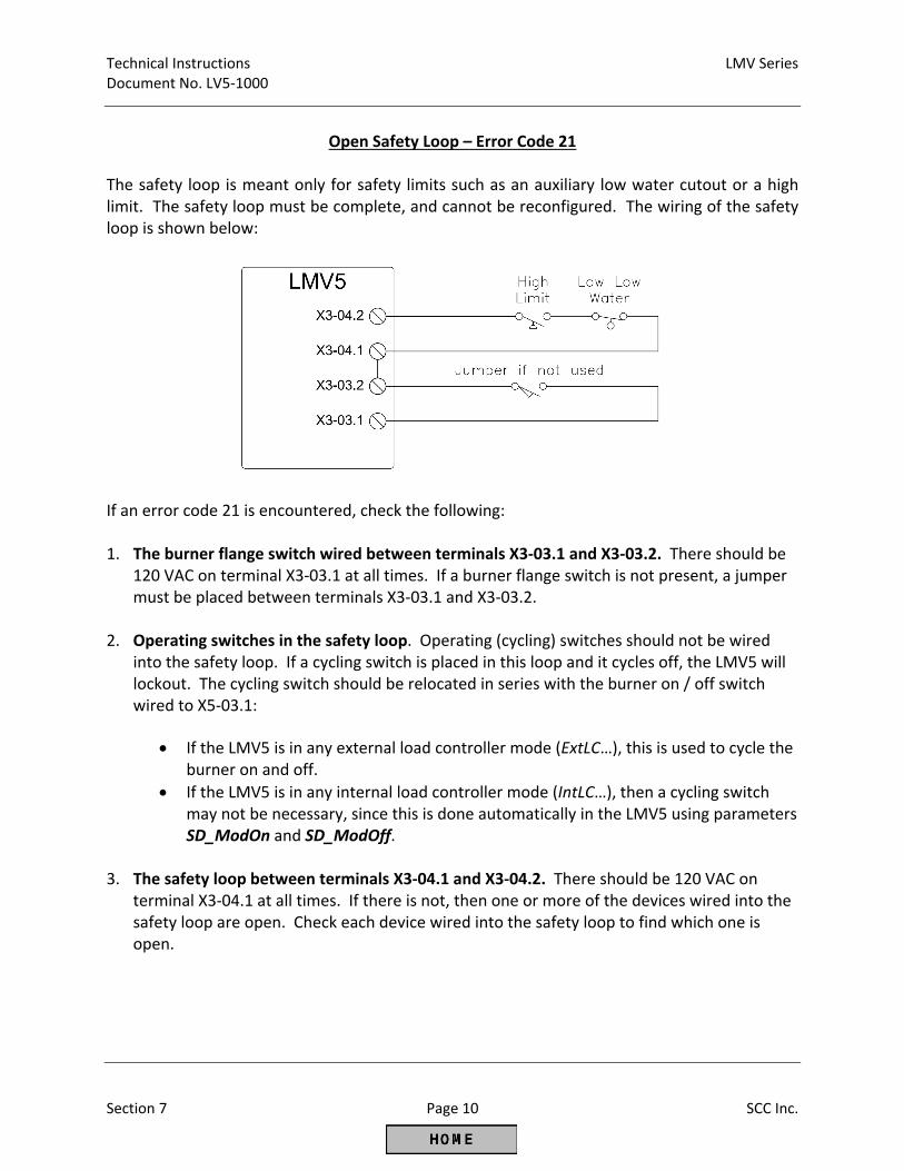
Technical Instructions LMV Series Document No. LV5‐1000
Section 7 Page 10 SCC Inc.
Open Safety Loop – Error Code 21
The safety loop is meant only for safety limits such as an auxiliary low water cutout or a high limit. The safety loop must be complete, and cannot be reconfigured. The wiring of the safety loop is shown below:
If an error code 21 is encountered, check the following: 1. The burner flange switch wired between terminals X3‐03.1 and X3‐03.2. There should be
120 VAC on terminal X3‐03.1 at all times. If a burner flange switch is not present, a jumper must be placed between terminals X3‐03.1 and X3‐03.2.
2. Operating switches in the safety loop. Operating (cycling) switches should not be wired into the safety loop. If a cycling switch is placed in this loop and it cycles off, the LMV5 will lockout. The cycling switch should be relocated in series with the burner on / off switch wired to X5‐03.1:
If the LMV5 is in any external load controller mode (ExtLC…), this is used to cycle the burner on and off.
If the LMV5 is in any internal load controller mode (IntLC…), then a cycling switch may not be necessary, since this is done automatically in the LMV5 using parameters SD_ModOn and SD_ModOff.
3. The safety loop between terminals X3‐04.1 and X3‐04.2. There should be 120 VAC on
terminal X3‐04.1 at all times. If there is not, then one or more of the devices wired into the safety loop are open. Check each device wired into the safety loop to find which one is open.
LMV Series Technical Instructions Document No. LV5‐1000
SCC Inc. Page 11 Section 7
LMV5 Will Not Start (Stays in Phase 12)
1. Ensure that the LMV5 is in automatic mode through the following menu path:
ManualOperation > Autom/Manual/Off = Automatic 2. The burner will not start if the safety loop is open. Verify that there is 120 VAC on both
terminals X3‐03.1 and X3‐04.1. 3. Verify that there is 120 VAC at burner switch input terminal X5‐03.1.
4. Verify that the LMV5 is not in alarm. If so, correct the issue causing the alarm and reset the
fault. 5. Verify that ignition positions are defined for all activated actuators, including the VSD. This
can be done through the following menu path:
Params & Display > RatioControl > Gas/Oil Settings > SpecialPositions > IgnitionPos
6. Verify that the actual value of the boiler is less than the switch on threshold of the burner (setpoint + SD_ModOn).
Technical Instructions LMV Series Document No. LV5‐1000
Section 7 Page 12 SCC Inc.
LMV5 Will Not Modulate Properly
1. Ensure that the LMV5 is in automatic mode through the following menu path: ManualOperation > Autom/Manual/Off = Automatic
2. Check the PID settings and make sure that they are set for the application. P‐Part – This is the proportional band. The proportional band increases firing rate based on how far below setpoint the temperature / pressure is. Smaller values cause a more aggressive response to a drop in pressure / temperature relative to setpoint. Values that are too small will cause hunting. Typical setting: 10% to 30%. I‐Part – This is the integral part, which serves to eliminate steady state "droop" caused by the proportional band setting. Thus, this works hand in hand with P‐Part to bring the pressure / temperature up to setpoint. Smaller values cause a more aggressive response (a setting of 1 is most aggressive). Values that are too small will cause overshoot. Typical setting: 80 sec to 300 sec. A setting of 0 deactivates the feature, but this is not recommended. D‐Part – This is the derivative part, which serves to eliminate overshoot, and allows a more aggressive integral setting. Larger values cause a more aggressive response. D‐Part is not needed on many steam boilers. If needed, small values of less than 20 typically work well. A setting of 0 deactivates the feature. Large values will typically cause hunting.
3. Check the load limit parameters (UserMaxLoad, MinLoad, MaxLoad) to verify that they are
not limiting modulation.
4. Check the load mask parameters under each fuel and verify that they are not preventing modulation. These can be checked using the following menu path: Params & Display > RatioControl > Gas/Oil Settings > LoadLimits
Default values are: LoadMaskLowLimit = 0%, LoadMaskHighLimit = 0%. 5. If the LMV5 goes to high fire in phase 52, check parameter StartPointOp under each fuel.
This should typically be set to 1 (low fire).
Note: If PID values are set properly, the load should change no more than once every 8 seconds on most installations. If PID values are set improperly, the duty cycle of the SQM… actuator can be exceeded.
LMV Series Technical Instructions Document No. LV5‐1000
SCC Inc. Page 13 Section 7
O2 Sensor is Not Reading
If the O2 value on the main screen is displayed as “XXXX”, check the following: 1. Ensure that the QGO20 O2 sensor is activated through the following menu path:
Params & Display > O2 Module > Configuration > O2 Sensor = QGO20
2. The PLL52 O2 module controls the QGO20 O2 sensor’s heater to achieve a sensor
temperature of approximately 1292 oF. The sensor cannot read %O2 if the sensor is below 1202 oF. Check the temperature of the QGO20 sensor through the following menu path: Params & Display > O2 Module > Process Data > QGO SensorTemp If the temperature is below 1202 °F, check the heating load to the O2 sensor: Params & Display > O2 Module > Process Data > QGO HeatingLoad The maximum QGO heating load is 60%. If the heating load is at or near 60%, the QGO20 sensor temperature should be increasing. If it is, the O2 sensor will begin reading once the temperature is over 1202 °F. If the temperature is not increasing, check the following:
The stack velocity may be too high, thus cooling the sensor. The maximum stack velocity is 33 ft / second.
The wiring between the O2 sensor and the PLL52 O2 module may be incorrect. Refer to Section 2 to check the wiring between the two devices.
The heating element in the QGO20 O2 sensor may be damaged. Measure the resistance between terminals Q4 and Q5 on the QGO20 O2 sensor. There should be between 5 and 150 Ohms between these terminals. If there is an open circuit between these two terminals, the heating element has been damaged and the QGO20 O2 sensor needs to be replaced.
Note: The QGO20 sensor can take up to two hours to achieve operating temperature on the
initial startup.
Technical Instructions LMV Series Document No. LV5‐1000
Section 7 Page 14 SCC Inc.
O2 Sensor Reading Grossly High or Low
If the O2 readings from the O2 sensor are grossly high or low, check the following:
1. The milli‐volt signals from the QGO20 to the PLL52 could have interference. Ensure that the
high and low voltage wires that run from the QGO20 to the PLL52 are in a separate conduit. 2. The QGO20 sensor reads %O2 wet. Most combustion analyzers read %O2 dry, so the O2
number shown on the AZL52 is typically at least 1% O2 lower than the combustion analyzer. 3. The QGO20 sensor may be mounted incorrectly, and the sensor is not picking up a
representative reading of the %O2 in the stack.
O2 Sensor Reads But Responds Very Slowly If the %O2 being displayed is responding slowly to combustion changes, check the following: 1. Ensure that the QGO20 sensor is clean. This can be done by shutting off the power to the
LMV52, and removing the QGO20 from the stack. Be careful as the sensor is likely to be very hot. After the QGO20 is removed from the stack, let it cool for at least an hour.
After the sensor has cooled, it can be blown out using low pressure compressed air (less
than 15 PSIG) through the top of the sensor and out the front. If this is done when the QGO20 sensor is hot, the ceramics inside the sensor will most likely be cracked and the sensor will need to be replaced.
2. Check the orientation of the QGO20 sensor and the AGO20 collector. The one notch on the
AGO20 collector’s flange should be between the two notches on the QGO20 sensor’s flange. Also, ensure that the bevel of the collector is pointed into the flow of the stack gas.
3. Check the internal resistance of the QGO20 sensor using the following menu path: Params & Display > O2 Module > Process Data > QGO Resistance This value increases as the sensor ages. As the internal resistance increases, the response
time of the sensor also increases. A new sensor has 0 Ohms, while the maximum resistance is 150 Ohms, indicating replacement of the sensor is necessary.
LMV Series Technical Instructions Document No. LV5‐1000
SCC Inc. Page 15 Section 7
Ambient or Stack Temperature Sensor Reading Incorrectly
If the ambient or stack temperature sensor wired into the PLL52 are not reading (displayed as “XXXX” on the AZL screen), or the sensors are reading incorrectly, check the following:
1. Ensure that the sensors are wired into the PLL52 module correctly. See Section 2 to verify proper wiring.
2. Both sensors must be a 2‐wire, 1000 Ohm, platinum or nickel RTD. Check to see that the sensors are activated and properly configured under the following menu paths:
Params & Display > O2 Module > Configuration > SupAirTempSens Params & Display > O2 Module > Configuration > FlueGasTempSens
Note: The ambient and stack temperature sensors are not necessary for O2 trim. However, if one or both inputs are configured for a sensor and either sensor is not reading, the O2 trim will not activate.
AZL Says “O2 Module not active or not Available”
If the AZL displays the message “O2 Module not active or not Available” when trying to access one of the following menus, the LMV52 has lost communication with the PLL52 O2 module.
Params & Display > O2Contr/Alarm ‐or‐ Params & Display > O2 Module
Check the CANbus wiring between the LMV52 and the PLL52. See Section 2 for wiring assistance. Once communications have been re‐established, access to the O2 menus will be allowed. To deactivate the O2 module entirely, use the following menu path: Params & Display > SystemConfig > O2Ctrl/LimitrGas(Oil) = man deact
Technical Instructions LMV Series Document No. LV5‐1000
Section 7 Page 16 SCC Inc.
During O2 Commissioning, AZL Says “O2 Setpoint must lie 0.1% below O2 Ratio Control” or
“O2 Setpoint must lie 0.1% above O2 Min”
When setting the O2 control curve, one of the following messages appears:
“O2 Setpoint must lie 0.1% below O2 Ratio Control” “O2 Setpoint must lie 0.1% above O2 Min”.
If this is the case, check the following:
1. Ensure that there is an absolute minimum of 0.2 %O2 between the O2 alarm curve and the O2 ratio control curve at every point on these curves.
2. Also ensure that the %O2 that is to be set on the O2 control curve is at least 0.1% O2 above
the O2 alarm curve and 0.1% O2 below the O2 ratio control curve. Note 1: In most cases, the %O2 gap between the curves should be larger than the absolute
minimum. Depending on the burner characteristic, doing this may also lead to more trouble‐free operation. See Section 6 for more information on these curves.
It is preferable to have a 1 to 1.5% gap between the O2 alarm curve and the O2 control curve.
It is preferable to have a 1.5% gap between the O2 ratio control curve and the O2 control curve.
Note 2: When setting up the three O2 curves, these curves are set using the %O2 values
displayed on the AZL5. These values are given on a wet basis.
A separate combustion analyzer (which typically measures dry %O2) is required for reference and to monitor CO and NOx production.
LMV Series Technical Instructions Document No. LV5‐1000
SCC Inc. Page 17 Section 7
AZL Says “Measurement not Successful” When Measuring the Delay Time for O2 Trim
When setting the low fire point or the high fire point on the O2 control curve, the AZL measures what is called the “delay time” (Tau time). The delay time is defined as the length of time it takes a change in the air damper position to be detected by the O2 sensor. This time is longer at low fire and shorter at high fire due to gas velocity. If an error occurs while trying to measure this delay time, the AZL says “Measurement not Successful”.
To troubleshoot this, check the following:
1) Verify that OptgMode is set to “man deact” using the following menu path:
Params & Display > O2Contr/Alarm > Gas/Oil Settings > OptgMode 2) Verify that LowfireAdaptPtNo is set to 2 (combustion curve point 2) or higher if desired. By
default, this parameter is set to “X” (undefined). The menu path for this parameter is:
Params & Display > O2Contr/Alarm > Gas/Oil Settings > Control Param > LowfireAdaptPtNo
3) If both of the above parameters are set correctly, then it is possible that the O2 readings on
the ratio control curve were set incorrectly. When setting each point on the O2 control curve, the LMV5 will prompt with the message “When value stable continue w ENTER”. Pressing ENTER then sets the %O2 for the ratio control curve. If ENTER is pressed too early before the O2 value has stabilized, a non‐representative O2 value will be entered for the ratio control curve. If this is the case, go back into the O2 control curve and at each point wait to get a stable reading before pressing ENTER to ensure that the O2 reading is representative of the current air damper position. 30‐60 seconds is not too long to wait once the arrow (>) turns into a colon (:) indicating that the actuators have stopped moving.
Technical Instructions LMV Series Document No. LV5‐1000
Section 7 Page 18 SCC Inc.
AZL Says “O2 Trim Control Automatically Deactivated”
Many different problems can cause the O2 trim control to automatically deactivate. When this happens, check the fault history. The most recent fault will likely be error code BF, diagnostic 00. This is the error code for an automatic deactivation of the O2 trim. Check the previous error code in the fault history to see what actually caused the automatic deactivation. The most common are:
1. Error code B5, diagnostic code 01. This means that the current O2 value went below the O2
alarm curve for more than 3 seconds, which caused the O2 trim to deactivate.
a. Make sure the load numbers on the Ratio Control Curve match the actual fuel flow. Use a fuel flow meter if possible.
b. Increase the %O2 gap between the O2 Control Curve and the O2 Alarm Curve at and around the point where the fault occurred (can be determined by the load listed in the fault history).
Also, parameter O2ModOffset can be increased in 0.5% increments. Parameter LoadCtrlSuspend can be decreased in 1% increments. See Section 3 for more information on these parameters.
2. Error code AB, diagnostic code 15 or 16. Check the configuration of the ambient and stack
temperature sensors. If these sensors are activated and are not wired in or are not functioning correctly, the O2 trim will automatically deactivate immediately after it is reactivated.
3. Error code AB, diagnostic code 20. Check the temperature of the QGO20 sensor using the
following menu path:
Params & Display > O2 Module > Process Data > QGO SensorTemp
The temperature should be at least 1202 oF. If the temperature falls below this value during prepurge or anytime during operation, the %O2 cannot be read and the O2 trim will automatically deactivate. If this is the case, the QGO20 sensor may be mounted improperly or the gas velocity may be too high.
LMV Series Technical Instructions Document No. LV5‐1000
SCC Inc. Page 19 Section 7
VSD Will Not Operate If the VSD will not operate the blower (blower will not spin) when the LMV52 standardization is activated, check the following: 1. Ensure that the VSD is activated through the following menu path in the LMV52:
Params & Display > RatioControl > Gas/Oil Settings > VSD = activated
2. The VSD cannot standardize if the safety loop is open. Check that the safety loop is closed
by making sure there is 120 VAC on terminal X3‐03.1. If there is not, check the limits in the safety loop and the burner flange to see which limit is open.
3. Ensure that the LMV52 is not in alarm. If so, reset the fault and attempt to standardize again.
4. Verify that the 0/4‐20 mA signal and the run/stop contact wired between the VSD and the LMV52 are wired correctly. See Section 2 for more information on wiring.
5. Verify that the three‐phase motor wiring between the VSD and the motor is correct. 6. Verify that the VSD is set up properly for the motor it is driving. Specifically, check the
following:
The VSD should be spanned so that 0/4mA equals 0Hz and 20mA = 62Hz (on a 60 Hz grid frequency). See Section 5 for more information.
The VSD is in remote mode so that it looks for a 0/4‐20mA signal and a run/stop contact. Closing the run/stop contact should cause the VSD to operate the motor.
7. Disconnect the analog signal and run/stop contact wires between the VSD and the LMV52.
Use a handheld 0/4‐20mA source and a toggle switch to verify that the VSD responds to a contact closure and a varying 0/4‐20mA signal.
If the VSD does not respond, correct the configuration of the VSD.
If the VSD responds to the contact closure and the varying 0/4‐20mA signal,
then go to the next step.
8. With the wires between the LMV52 and VSD still disconnected, use a multi‐meter to verify that the LMV52 outputs about 19.5mA during the standardization (see note below). Also verify that the run/stop contact in the LMV52 closes and remains closed during the standardization.
Technical Instructions LMV Series Document No. LV5‐1000
Section 7 Page 20 SCC Inc.
Unsuccessful VSD Standardization
For information on what VSD standardizing is or how to perform standardization, see Section 5. The standardized speed can be viewed using the following menu path:
Params & Display > VSD Module > Configuration > Speed > StandardizedSp
For a 3600 RPM motor, the standardized speed is typically 3500 +/‐ 100 RPM. If this is the case, the standardization was successful. If the VSD does not standardize successfully, check the following: 1. The VSD cannot standardize if the safety loop is open. Check that the safety loop is closed
by making sure there is 120 VAC on terminal X3‐03.1. If there is not, check the limits in the safety loop and the burner flange to see which limit is open.
2. Ensure that the LMV52 is not in alarm. If so, reset the fault and attempt to standardize
again. 3. Verify the speed wheel is installed on the blower motor correctly and the gap between the
speed sensor and the speed wheel is correct (about 1/16”). Also, use Section 2 to verify that the wiring from the speed sensor to the LMV52 is correct. The yellow LED on the back of the speed sensor should blink every time a speed wheel “finger” passes by the nose of the sensor. If it does not blink, the sensor is wired incorrectly, the sensor is mounted too far from the speed wheel, or the sensor is defective.
4. Check to ensure that the air damper opens when the standardization is activated. If this does not happen, set the air actuator to “air influenced” using the following menu
path: Params & Display > RatioControl > Gas/Oil Settings > AirActuator 5. Check the ramp times on the LMV52 and the VSD. The ramp times on the VSD must be faster (shorter) than the ramp times on the LMV52.
The LMV52 ramp times can be found using the following menu paths: Params & Display > RatioControl > Times > OperatRampMod Params & Display > RatioControl > Times > TimeNoFlame In general, the VSD ramp times should be set about 5 seconds faster (shorter) than the
LMV52 ramp times.
LMV Series Technical Instructions Document No. LV5‐1000
SCC Inc. Page 21 Section 7
Unsuccessful VSD Standardization (continued)
6. Monitor the speed of the blower motor during the standardization process. After
standardization is activated, the real time speed can be read using the following menu path: Params & Display > VSD Module > Speed > Absolute Speed During standardization, the absolute speed should rise up to a peak value and hold steady
at that value for a few seconds. Then, the value should drop back down to zero (or near zero).
The peak value that is seen should be recorded as the standardized speed. If this doesn’t
happen, it’s likely that there’s a problem with the VSD or the speed sensor.
Technical Instructions LMV Series Document No. LV5‐1000
Section 7 Page 22 SCC Inc.
AZL Says “Fan Speed Not Reached” or “Control Range Limitation VSD Module”
During burner operation, the LMV52 sends a 0/4‐20 mA signal to the VSD to control the speed of the blower. The speed sensor sends feedback to the LMV52 to let it know the actual speed of the blower. If the speed is too high or too low, the LMV52 will increase or decrease the signal to the VSD accordingly. However, there are limits on how much the LMV52 can increase or decrease the signal. If these limits are met, the LMV52 will lockout with one of the following messages:
“Fan Speed Not Reached” – Error code 15, diagnostic 10 or 40
“Control Range Limitation VSD Module” – Error code A9, diagnostic 0D “Fan Speed Not Reached” indicates that the blower speed is still too low even though the LMV52 has increased the 0/4‐20mA signal as far as possible. “Control Range Limitation VSD Module” indicates that the blower speed is too high even though the LMV52 has decreased the 0/4‐20mA signal as far as possible. If either of these messages appears, do the following: 1. Increase the ramp times of both the VSD and LMV52. Shorter ramp times on the VSD and
LMV52 create a more demanding application for the VSD. Simply put, a shorter ramp time will cause the VSD to draw or absorb much more amperage for a given change in blower speed since the change in speed occurs more quickly. To adjust the ramp times of the LMV52, use the following menu paths:
Params & Display > RatioControl > Times > OperatRampMod Params & Display > RatioControl > Times > TimeNoFlame
2. Large blower motors connected to large, heavy blower wheels have high rotating inertia.
As the inertia of the blower wheel increases, the power needed to accelerate and decelerate the blower increases. If increasing the ramp times does not help, a braking resistor may need to be installed on the VSD to help decrease the speed of the blower motor more quickly.
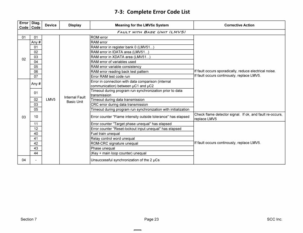
7-3: Complete Error Code List
Error
Code
Diag.
CodeDevice Display Meaning for the LMV5x System Corrective Action
01 01 ROM error
Any # RAM error
01 RAM error in register bank 0 (LMV51...)
02 RAM error in IDATA area (LMV51...)
03 RAM error in XDATA area (LMV51...)
04 RAM error of variables used
05 RAM error variable consistency
06 RAM error reading back test pattern
07 Error RAM test code run
Any #Error in connection with data comparison (internal
communication) between µC1 and µC2
01Timeout during program run synchronization prior to data
transmission
02 Timeout during data transmission
03 CRC error during data transmission
05 Timeout during program run synchronization with initialization
10 Error counter "Flame intensity outside tolerance" has elapsedCheck flame detector signal. If ok, and fault re-occurs,
replace LMV5
11 Error counter "Target phase unequal" has elapsed
12 Error counter "Reset-lockout input unequal" has elapsed
40 Fuel train unequal
41 Relay control word unequal
42 ROM-CRC signature unequal
43 Phase unequal
44 (Key + main loop counter) unequal
04 - Unsuccessful synchronization of the 2 µCs
Fault with Base Unit (LMV5)
02
If fault occurs continously, replace LMV5.
03
LMV5Internal Fault
Basic Unit
If fault occurs sporadically, reduce electrical noise.
If fault occurs continously, replace LMV5.
Section 7 Page 23 SCC Inc.
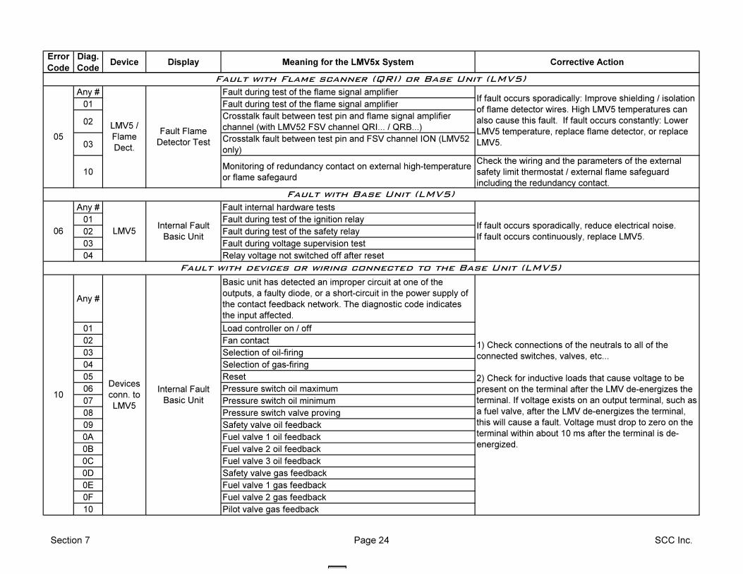
Error
Code
Diag.
CodeDevice Display Meaning for the LMV5x System Corrective Action
Any # Fault during test of the flame signal amplifier
01 Fault during test of the flame signal amplifier
02Crosstalk fault between test pin and flame signal amplifier
channel (with LMV52 FSV channel QRI... / QRB...)
03Crosstalk fault between test pin and FSV channel ION (LMV52
only)
10Monitoring of redundancy contact on external high-temperature
or flame safegaurd
Check the wiring and the parameters of the external
safety limit thermostat / external flame safeguard
including the redundancy contact.
Any # Fault internal hardware tests
01 Fault during test of the ignition relay
02 Fault during test of the safety relay
03 Fault during voltage supervision test
04 Relay voltage not switched off after reset
Any #
Basic unit has detected an improper circuit at one of the
outputs, a faulty diode, or a short-circuit in the power supply of
the contact feedback network. The diagnostic code indicates
the input affected.
01 Load controller on / off
02 Fan contact
03 Selection of oil-firing
04 Selection of gas-firing
05 Reset
06 Pressure switch oil maximum
07 Pressure switch oil minimum
08 Pressure switch valve proving
09 Safety valve oil feedback
0A Fuel valve 1 oil feedback
0B Fuel valve 2 oil feedback
0C Fuel valve 3 oil feedback
0D Safety valve gas feedback
0E Fuel valve 1 gas feedback
0F Fuel valve 2 gas feedback
10 Pilot valve gas feedback
Fault with Base Unit (LMV5)
Internal Fault
Basic Unit
1) Check connections of the neutrals to all of the
connected switches, valves, etc...
2) Check for inductive loads that cause voltage to be
present on the terminal after the LMV de-energizes the
terminal. If voltage exists on an output terminal, such as
a fuel valve, after the LMV de-energizes the terminal,
this will cause a fault. Voltage must drop to zero on the
terminal within about 10 ms after the terminal is de-
energized.
If fault occurs sporadically, reduce electrical noise.
If fault occurs continuously, replace LMV5.06 LMV5
Internal Fault
Basic Unit
Fault with devices or wiring connected to the Base Unit (LMV5)
LMV5 /
Flame
Dect.
Fault Flame
Detector Test05
Fault with Flame scanner (QRI) or Base Unit (LMV5)
10
If fault occurs sporadically: Improve shielding / isolation
of flame detector wires. High LMV5 temperatures can
also cause this fault. If fault occurs constantly: Lower
LMV5 temperature, replace flame detector, or replace
LMV5.
Devices
conn. to
LMV5
Section 7 Page 24 SCC Inc.
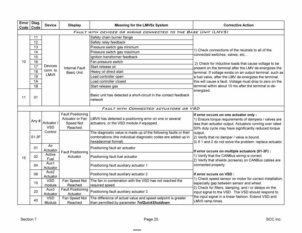
Error
Code
Diag.
CodeDevice Display Meaning for the LMV5x System Corrective Action
11 Safety chain burner flange
12 Safety relay feedback
13 Pressure switch gas minimum
14 Pressure switch gas maximum
15 Ignition transformer feedback
16 Fan pressure switch
17 Start release oil
18 Heavy oil direct start
19 Load controller open
1A Load controller closed
1B Start release gas
11 01Basic unit has detected a short-circuit in the contact feedback
network
Any #
Fault Positioning
Actuator or Fan
Speed Not
Reached
LMV5 has detected a positioning error on one or several
actuators, or the VSD module if equipped.
01-3F
The diagnostic value is made up of the following faults or their
combinations (the individual diagnostic codes are added up in
hexadecimal format)
01Air
ActuatorPositioning fault air actuator
02Active
Fuel Positioning fault fuel actuator
04Aux1
ActuatorPositioning fault auxiliary actuator 1
08Aux2
ActuatorPositioning fault auxiliary actuator 2
10VSD
module
Fan Speed Not
Reached
The fan in combination with the VSD has not reached the
required speed
20Aux3
Actuator
Fault Positioning
Actuator Positioning fault auxiliary actuator 3
40VSD
Module
Fan Speed Not
Reached
The difference of actual value and speed setpoint is greater
than permitted by parameter TolQuickShutdown
If error occurs on one actuator only :
1) Ensure torque requirements of dampers / valves are
less than actuator output. Actuators running over rated
50% duty cycle may have significantly reduced torque
output.
2) Verify that no damper / valve is bound.
3) If 1 and 2 do not solve the problem: replace actuator.
If error occurs on multiple actuators (01-3F) :
1) Verify that the CANBus wiring is correct.
2) Verify that shields (screens) on CANBus cables are
connected properly.
If error occurs on VSD :
1) Check speed sensor on motor for correct installation,
especially gap between sensor and wheel.
2) Check for filters, damping, and / or delays on the
input signal to the VSD. The VSD should respond to
the input signal in a linear fashion. Extend VSD and
LMV5 ramp times.
15
Fault Positioning
Actuator
Fault with Connected actuators or VSD
Actuator /
VSD
Control
10Devices
conn. to
LMV5
Internal Fault
Basic Unit
1) Check connections of the neutrals to all of the
connected switches, valves, etc...
2) Check for inductive loads that cause voltage to be
present on the terminal after the LMV de-energizes the
terminal. If voltage exists on an output terminal, such as
a fuel valve, after the LMV de-energizes the terminal,
this will cause a fault. Voltage must drop to zero on the
terminal within about 10 ms after the terminal is de-
energized.
Fault with devices or wiring connected to the Base Unit (LMV5)
Section 7 Page 25 SCC Inc.
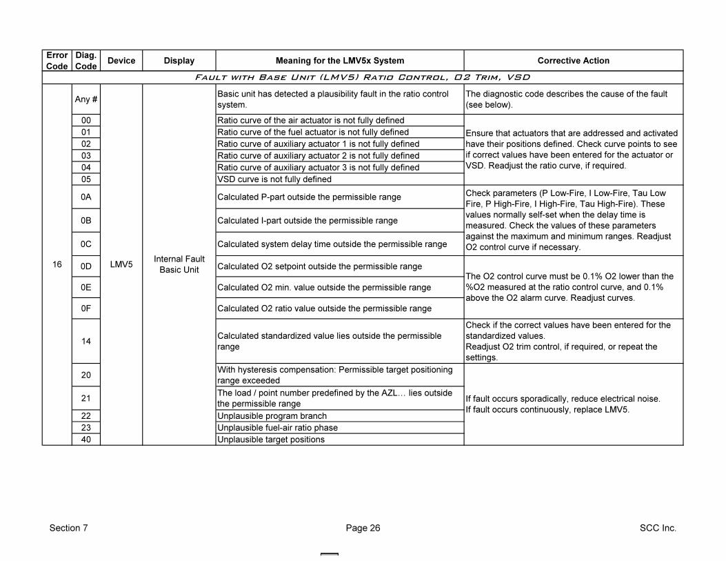
Error
Code
Diag.
CodeDevice Display Meaning for the LMV5x System Corrective Action
Any #Basic unit has detected a plausibility fault in the ratio control
system.
The diagnostic code describes the cause of the fault
(see below).
00 Ratio curve of the air actuator is not fully defined
01 Ratio curve of the fuel actuator is not fully defined
02 Ratio curve of auxiliary actuator 1 is not fully defined
03 Ratio curve of auxiliary actuator 2 is not fully defined
04 Ratio curve of auxiliary actuator 3 is not fully defined
05 VSD curve is not fully defined
0A Calculated P-part outside the permissible range
0B Calculated I-part outside the permissible range
0C Calculated system delay time outside the permissible range
0D Calculated O2 setpoint outside the permissible range
0E Calculated O2 min. value outside the permissible range
0F Calculated O2 ratio value outside the permissible range
14Calculated standardized value lies outside the permissible
range
Check if the correct values have been entered for the
standardized values.
Readjust O2 trim control, if required, or repeat the
settings.
20With hysteresis compensation: Permissible target positioning
range exceeded
21The load / point number predefined by the AZLI lies outside
the permissible range
22 Unplausible program branch
23 Unplausible fuel-air ratio phase
40 Unplausible target positions
16 LMV5
If fault occurs sporadically, reduce electrical noise.
If fault occurs continuously, replace LMV5.
Internal Fault
Basic Unit
Check parameters (P Low-Fire, I Low-Fire, Tau Low
Fire, P High-Fire, I High-Fire, Tau High-Fire). These
values normally self-set when the delay time is
measured. Check the values of these parameters
against the maximum and minimum ranges. Readjust
O2 control curve if necessary.
The O2 control curve must be 0.1% O2 lower than the
%O2 measured at the ratio control curve, and 0.1%
above the O2 alarm curve. Readjust curves.
Ensure that actuators that are addressed and activated
have their positions defined. Check curve points to see
if correct values have been entered for the actuator or
VSD. Readjust the ratio curve, if required.
Fault with Base Unit (LMV5) Ratio Control, O2 Trim, VSD
Section 7 Page 26 SCC Inc.
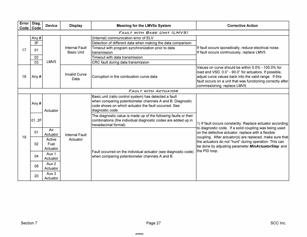
Error
Code
Diag.
CodeDevice Display Meaning for the LMV5x System Corrective Action
Any # (Internal) communication error of ELV
3F Detection of different data when making the data comparison
01Timeout with program synchronization prior to data
transmission
02 Timeout with data transmission
03 CRC fault during data transmission
18 Any #Invalid Curve
DataCorruption in the combustion curve data
Values on curve should be within 0.0% - 100.0% for
load and VSD, 0.0° - 90.0° for actuators. If possible,
adjust curve values back into the valid range. If this
fault occurs on a unit that was functioning correctly after
commissioning, replace LMV5.
Any #
Basic unit (ratio control system) has detected a fault
when comparing potentiometer channels A and B. Diagnostic
code shows on which actuator the fault occurred. See
diagnostic code.
01..2F
The diagnostic value is made up of the following faults or their
combinations (the individual diagnostic codes are added up in
hexadecimal format)
01Air
Actuator
02
Active
Fuel
Actuator
04Aux 1
Actuator
08Aux 2
Actuator
20Aux 3
Actuator
Fault with Actuator
Internal Fault
Actuator
If fault occurs sporadically, reduce electrical noise.
If fault occurs continuously, replace LMV5.17
Internal Fault
Basic Unit
LMV5
Actuator
19
1) If fault occurs constantly: Replace actuator according
to diagnostic code. If a solid coupling was being used
on the defective actuator, replace with a flexible
coupling. After actuator(s) are replaced, make sure that
the actuators do not "hunt" during operation. This can
be done by adjusting parameter MinActuatorStep and
the PID loop.
Fault with Base Unit (LMV5)
Fault occurred on the individual actuator (see diagnostic code)
when comparing potentiometer channels A and B
Section 7 Page 27 SCC Inc.
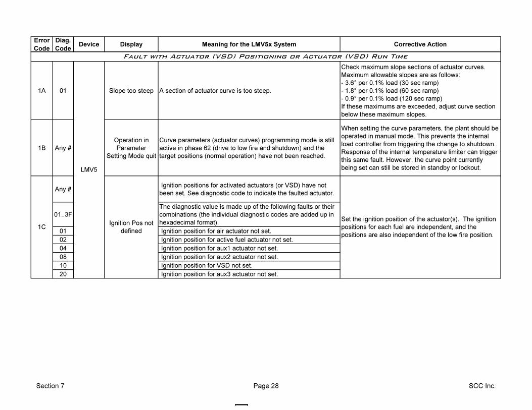
Error
Code
Diag.
CodeDevice Display Meaning for the LMV5x System Corrective Action
1A 01 Slope too steep A section of actuator curve is too steep.
Check maximum slope sections of actuator curves.
Maximum allowable slopes are as follows:
- 3.6° per 0.1% load (30 sec ramp)
- 1.8° per 0.1% load (60 sec ramp)
- 0.9° per 0.1% load (120 sec ramp)
If these maximums are exceeded, adjust curve section
below these maximum slopes.
1B Any #
Operation in
Parameter
Setting Mode quit
Curve parameters (actuator curves) programming mode is still
active in phase 62 (drive to low fire and shutdown) and the
target positions (normal operation) have not been reached.
When setting the curve parameters, the plant should be
operated in manual mode. This prevents the internal
load controller from triggering the change to shutdown.
Response of the internal temperature limiter can trigger
this same fault. However, the curve point currently
being set can still be stored in standby or lockout.
Any # Ignition positions for activated actuators (or VSD) have not
been set. See diagnostic code to indicate the faulted actuator.
01..3F
The diagnostic value is made up of the following faults or their
combinations (the individual diagnostic codes are added up in
hexadecimal format).
01 Ignition position for air actuator not set.
02 Ignition position for active fuel actuator not set.
04 Ignition position for aux1 actuator not set.
08 Ignition position for aux2 actuator not set.
10 Ignition position for VSD not set.
20 Ignition position for aux3 actuator not set.
Fault with Actuator (VSD) Positioning or Actuator (VSD) Run Time
Set the ignition position of the actuator(s). The ignition
positions for each fuel are independent, and the
positions are also independent of the low fire position.
1C
LMV5
Ignition Pos not
defined
Section 7 Page 28 SCC Inc.
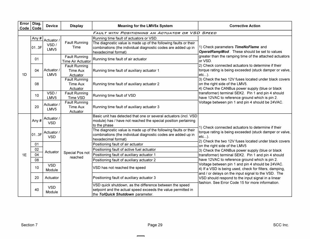
Error
Code
Diag.
CodeDevice Display Meaning for the LMV5x System Corrective Action
Any # Running time fault of actuators or VSD.
01..3F
The diagnostic value is made up of the following faults or their
combinations (the individual diagnostic codes are added up in
hexadecimal format)
01Fault Running
Time Air ActuatorRunning time fault of air actuator
04
Fault Running
Time Aux
Actuator
Running time fault of auxiliary actuator 1
08
Fault Running
Time Aux
Actuator
Running time fault of auxiliary actuator 2
10VSD /
LMV5
Fault Running
Time VSDRunning time fault of VSD
20Actuator /
LMV5
Fault Running
Time Aux
Actuator
Running time fault of auxiliary actuator 3
Any #Actuator /
VSD
Basic unit has detected that one or several actuators (incl. VSD
module) has / have not reached the special position pertaining
to the phase
01..3FActuator /
VSD
The diagnostic value is made up of the following faults or their
combinations (the individual diagnostic codes are added up in
hexadecimal format)
01 Positioning fault of air actuator
02 Positioning fault of active fuel actuator
04 Positioning fault of auxiliary actuator 1
08 Positioning fault of auxiliary actuator 2
10VSD
ModuleVSD has not reached the speed
20 Actuator Positioning fault of auxiliary actuator 3
40VSD
Module
VSD quick shutdown, as the difference between the speed
setpoint and the actual speed exceeds the value permitted in
the TolQuick Shutdown parameter.
Fault with Positioning an Actuator or VSD Speed
Actuator /
VSD /
LMV5
Fault Running
Time
1D
1E
1) Check parameters TimeNoFlame and
OperatRampMod . These should be set to values
greater than the ramping time of the attached actuators
or VSD.
2) Check connected actuators to determine if their
torque rating is being exceeded (stuck damper or valve,
etc...).
3) Check the two 12V fuses located under black covers
on the right side of the LMV5.
4) Check the CANBus power supply (blue or black
transformer) terminal SEK2. Pin 1 and pin 4 should
have 12VAC to reference ground which is pin 2.
Voltage between pin 1 and pin 4 should be 24VAC.
Actuator
1) Check connected actuators to determine if their
torque rating is being exceeded (stuck damper or valve,
etc...).
2) Check the two 12V fuses located under black covers
on the right side of the LMV5
3) Check the CANBus power supply (blue or black
transformer) terminal SEK2. Pin 1 and pin 4 should
have 12VAC to reference ground which is pin 2.
Voltage between pin 1 and pin 4 should be 24VAC.
4) If a VSD is being used, check for filters, damping,
and / or delays on the input signal to the VSD. The
VSD should respond to the input signal in a linear
fashion. See Error Code 15 for more information.
Special Pos not
reached
Actuator /
LMV5
Section 7 Page 29 SCC Inc.
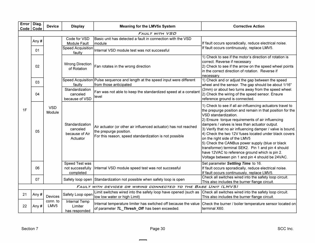
Error
Code
Diag.
CodeDevice Display Meaning for the LMV5x System Corrective Action
Any #Code for VSD
Module Fault
Basic unit has detected a fault in connection with the VSD
module
01Speed Acquisition
faultyInternal VSD module test was not successful
02Wrong Direction
of RotationFan rotates in the wrong direction
1) Check to see if the motor’s direction of rotation is
correct. Reverse if necessary
2) Check to see if the arrow on the speed wheel points
in the correct direction of rotation. Reverse if
necessary.
03Speed Acquisition
faulty
Pulse sequence and length at the speed input were different
from those anticipated
04
Standardization
canceled
because of VSD
Fan was not able to keep the standardized speed at a constant
level
05
Standardization
canceled
because of Air
Actuator
Air actuator (or other air influenced actuator) has not reached
the prepurge position.
For this reason, speed standardization is not possible
1) Check to see if all air-influencing actuators travel to
the prepurge position and remain in that position for the
VSD standardization.
2) Ensure torque requirements of air influencing
dampers / valves is less than actuator output.
3) Verify that no air influencing damper / valve is bound.
4) Check the two 12V fuses located under black covers
on the right side of the LMV5
5) Check the CANBus power supply (blue or black
transformer) terminal SEK2. Pin 1 and pin 4 should
have 12VAC to reference ground which is pin 2.
Voltage between pin 1 and pin 4 should be 24VAC.
06
Speed Test was
not successfully
completed
Internal VSD module speed test was not successful
Set parameter Settling Time to 16.
If fault occurs sporadically, reduce electrical noise.
If fault occurs continuously, replace LMV5.
07 Safety loop open Standardization not possible when safety loop is openCheck all switches wired into the safety loop circuit.
This also includes the burner flange circuit.
21 Any # Safety Loop openLimit switches wired into the safety loop have opened (such as
low low water or high Limit)
Check all switches wired into the safety loop circuit.
This also includes the burner flange circuit.
22 Any #
Internal Temp
Limiter
has responded
Internal temperature limiter has switched off because the value
of parameter TL_Thresh_Off has been exceeded.
Check the burner / boiler temperature sensor located on
terminal X60.
If fault occurs sporadically, reduce electrical noise.
If fault occurs continuously, replace LMV5.
VSD
Module
1) Check and or adjust the gap between the speed
wheel and the sensor. The gap should be about 1/16"
(2mm) or about two turns away from the speed wheel.
2) Check the wiring of the speed sensor. Ensure
reference ground is connected.
1F
Fault with VSD
Devices
conn. to
LMV5
Fault with devices or wiring connected to the Base Unit (LMV5)
Section 7 Page 30 SCC Inc.
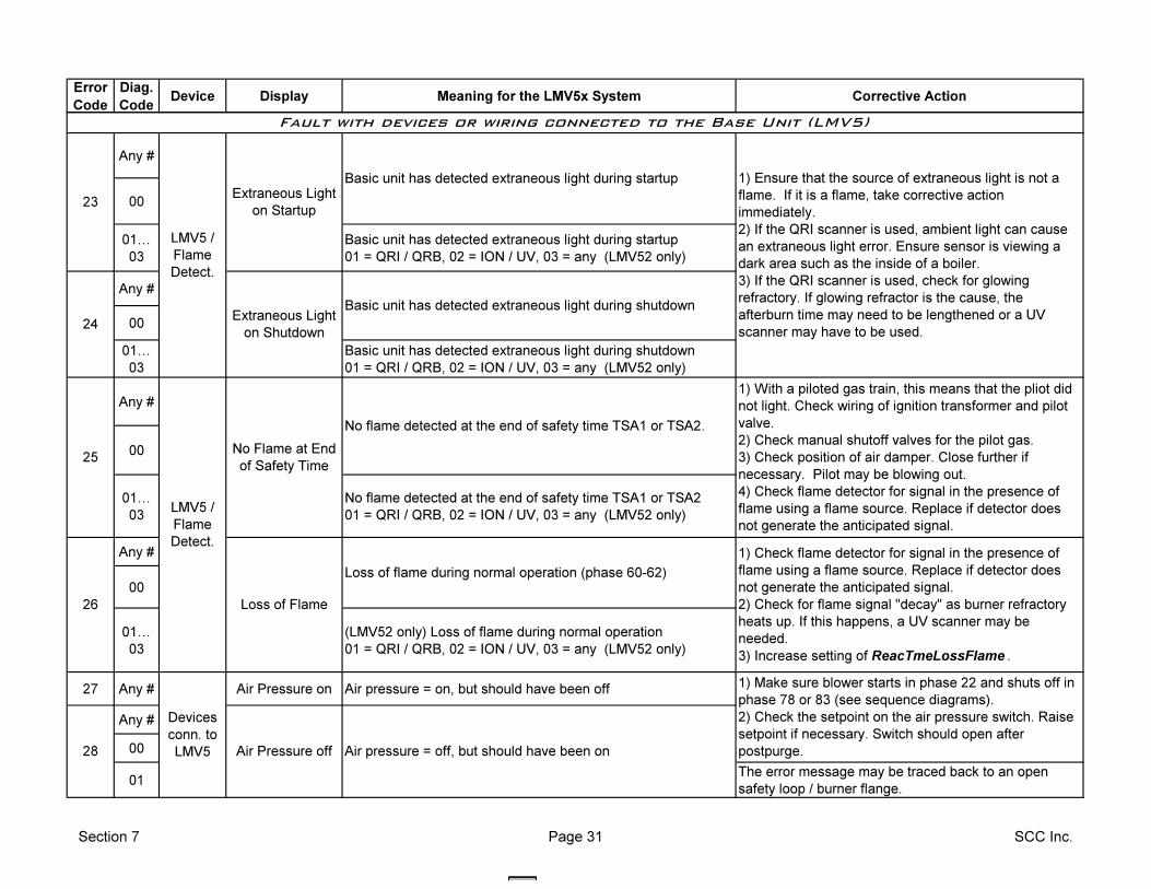
Error
Code
Diag.
CodeDevice Display Meaning for the LMV5x System Corrective Action
Any #
00
01I
03
Basic unit has detected extraneous light during startup
01 = QRI / QRB, 02 = ION / UV, 03 = any (LMV52 only)
Any #
00
01I
03
Basic unit has detected extraneous light during shutdown
01 = QRI / QRB, 02 = ION / UV, 03 = any (LMV52 only)
Any #
00
01I
03
No flame detected at the end of safety time TSA1 or TSA2
01 = QRI / QRB, 02 = ION / UV, 03 = any (LMV52 only)
Any #
00
01I
03
(LMV52 only) Loss of flame during normal operation
01 = QRI / QRB, 02 = ION / UV, 03 = any (LMV52 only)
27 Any # Air Pressure on Air pressure = on, but should have been off
Any #
00
01The error message may be traced back to an open
safety loop / burner flange.
1) Make sure blower starts in phase 22 and shuts off in
phase 78 or 83 (see sequence diagrams).
2) Check the setpoint on the air pressure switch. Raise
setpoint if necessary. Switch should open after
postpurge.
No flame detected at the end of safety time TSA1 or TSA2.
Loss of flame during normal operation (phase 60-62)
Air pressure = off, but should have been on
1) Check flame detector for signal in the presence of
flame using a flame source. Replace if detector does
not generate the anticipated signal.
2) Check for flame signal "decay" as burner refractory
heats up. If this happens, a UV scanner may be
needed.
3) Increase setting of ReacTmeLossFlame .
Basic unit has detected extraneous light during shutdown
1) Ensure that the source of extraneous light is not a
flame. If it is a flame, take corrective action
immediately.
2) If the QRI scanner is used, ambient light can cause
an extraneous light error. Ensure sensor is viewing a
dark area such as the inside of a boiler.
3) If the QRI scanner is used, check for glowing
refractory. If glowing refractor is the cause, the
afterburn time may need to be lengthened or a UV
scanner may have to be used.
Basic unit has detected extraneous light during startup
1) With a piloted gas train, this means that the pliot did
not light. Check wiring of ignition transformer and pilot
valve.
2) Check manual shutoff valves for the pilot gas.
3) Check position of air damper. Close further if
necessary. Pilot may be blowing out.
4) Check flame detector for signal in the presence of
flame using a flame source. Replace if detector does
not generate the anticipated signal.
LMV5 /
Flame
Detect.
Loss of Flame
Extraneous Light
on Shutdown
No Flame at End
of Safety Time
Fault with devices or wiring connected to the Base Unit (LMV5)
28 Air Pressure off
Devices
conn. to
LMV5
Extraneous Light
on Startup
25
26
23
24
LMV5 /
Flame
Detect.
Section 7 Page 31 SCC Inc.
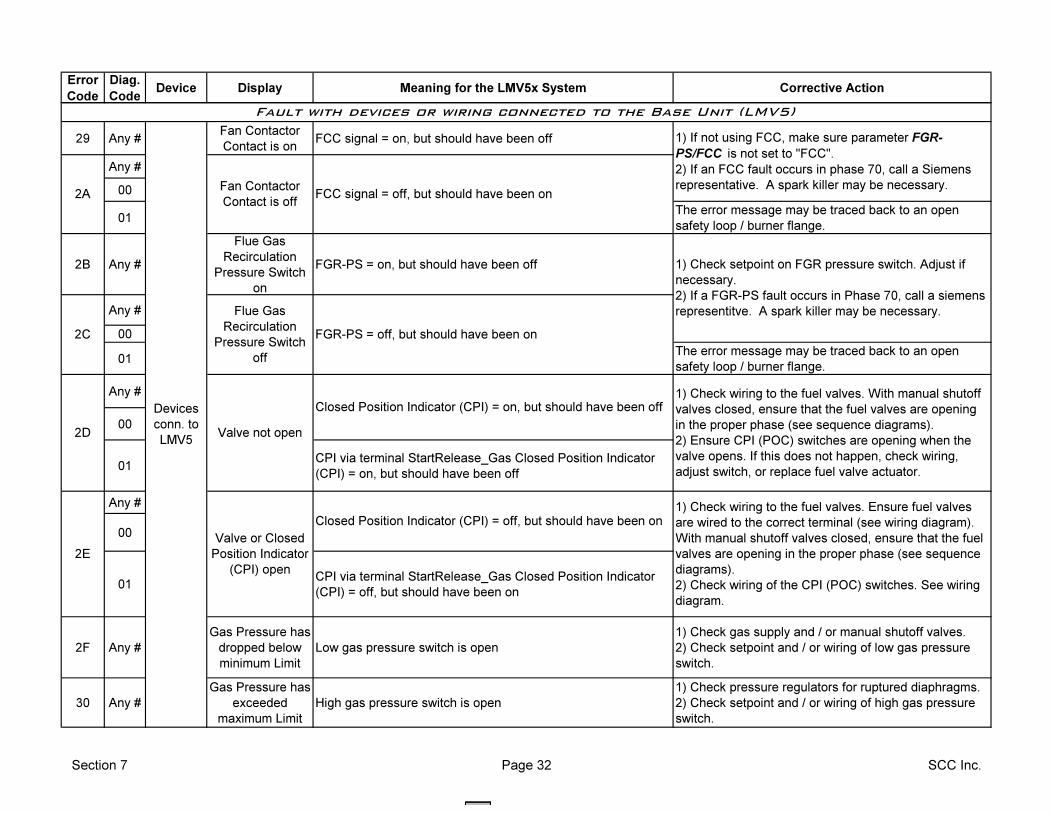
Error
Code
Diag.
CodeDevice Display Meaning for the LMV5x System Corrective Action
29 Any #Fan Contactor
Contact is onFCC signal = on, but should have been off
Any #
00
01The error message may be traced back to an open
safety loop / burner flange.
2B Any #
Flue Gas
Recirculation
Pressure Switch
on
FGR-PS = on, but should have been off
Any #
00
01The error message may be traced back to an open
safety loop / burner flange.
Any #
00
01CPI via terminal StartRelease_Gas Closed Position Indicator
(CPI) = on, but should have been off
Any #
00
01CPI via terminal StartRelease_Gas Closed Position Indicator
(CPI) = off, but should have been on
2F Any #
Gas Pressure has
dropped below
minimum Limit
Low gas pressure switch is open
1) Check gas supply and / or manual shutoff valves.
2) Check setpoint and / or wiring of low gas pressure
switch.
30 Any #
Gas Pressure has
exceeded
maximum Limit
High gas pressure switch is open
1) Check pressure regulators for ruptured diaphragms.
2) Check setpoint and / or wiring of high gas pressure
switch.
Fault with devices or wiring connected to the Base Unit (LMV5)
FCC signal = off, but should have been on
1) Check setpoint on FGR pressure switch. Adjust if
necessary.
2) If a FGR-PS fault occurs in Phase 70, call a siemens
representitve. A spark killer may be necessary.
Valve not open
Closed Position Indicator (CPI) = off, but should have been on1) Check wiring to the fuel valves. Ensure fuel valves
are wired to the correct terminal (see wiring diagram).
With manual shutoff valves closed, ensure that the fuel
valves are opening in the proper phase (see sequence
diagrams).
2) Check wiring of the CPI (POC) switches. See wiring
diagram.
1) Check wiring to the fuel valves. With manual shutoff
valves closed, ensure that the fuel valves are opening
in the proper phase (see sequence diagrams).
2) Ensure CPI (POC) switches are opening when the
valve opens. If this does not happen, check wiring,
adjust switch, or replace fuel valve actuator.
2D
2E
Closed Position Indicator (CPI) = on, but should have been off
Valve or Closed
Position Indicator
(CPI) open
2AFan Contactor
Contact is off
1) If not using FCC, make sure parameter FGR-
PS/FCC is not set to "FCC".
2) If an FCC fault occurs in phase 70, call a Siemens
representative. A spark killer may be necessary.
Devices
conn. to
LMV5
2C
Flue Gas
Recirculation
Pressure Switch
off
FGR-PS = off, but should have been on
Section 7 Page 32 SCC Inc.
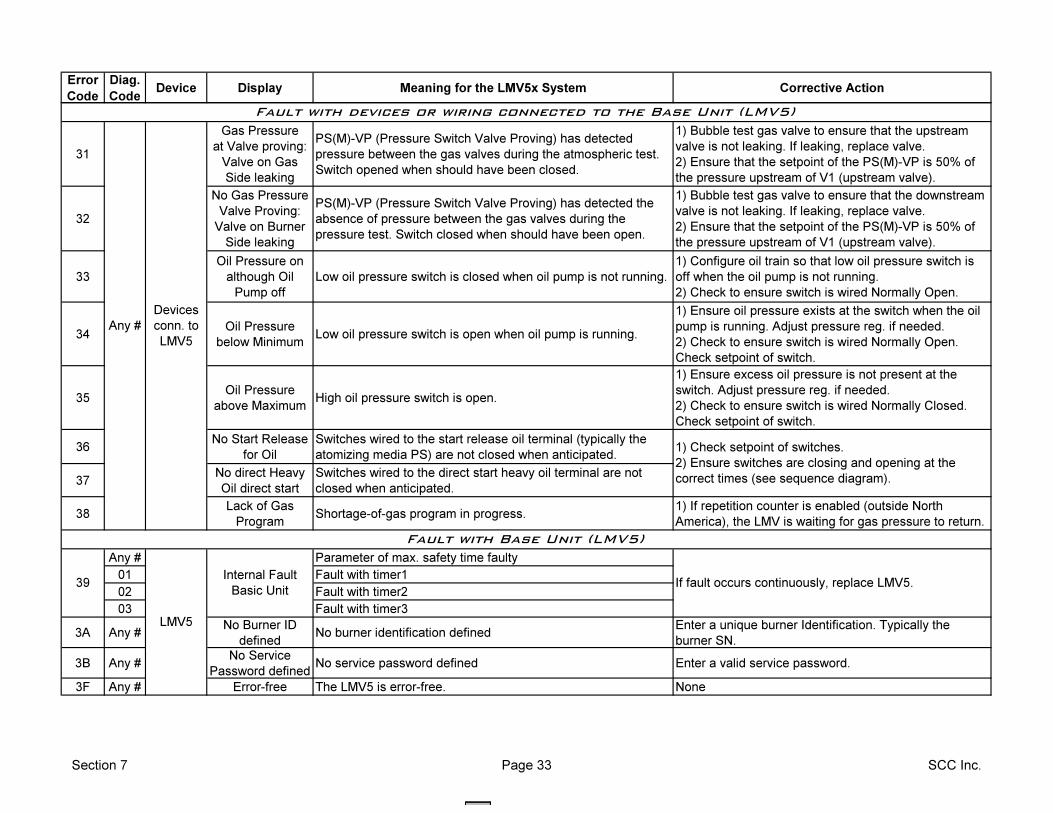
Error
Code
Diag.
CodeDevice Display Meaning for the LMV5x System Corrective Action
31
Gas Pressure
at Valve proving:
Valve on Gas
Side leaking
PS(M)-VP (Pressure Switch Valve Proving) has detected
pressure between the gas valves during the atmospheric test.
Switch opened when should have been closed.
1) Bubble test gas valve to ensure that the upstream
valve is not leaking. If leaking, replace valve.
2) Ensure that the setpoint of the PS(M)-VP is 50% of
the pressure upstream of V1 (upstream valve).
32
No Gas Pressure
Valve Proving:
Valve on Burner
Side leaking
PS(M)-VP (Pressure Switch Valve Proving) has detected the
absence of pressure between the gas valves during the
pressure test. Switch closed when should have been open.
1) Bubble test gas valve to ensure that the downstream
valve is not leaking. If leaking, replace valve.
2) Ensure that the setpoint of the PS(M)-VP is 50% of
the pressure upstream of V1 (upstream valve).
33
Oil Pressure on
although Oil
Pump off
Low oil pressure switch is closed when oil pump is not running.
1) Configure oil train so that low oil pressure switch is
off when the oil pump is not running.
2) Check to ensure switch is wired Normally Open.
34Oil Pressure
below MinimumLow oil pressure switch is open when oil pump is running.
1) Ensure oil pressure exists at the switch when the oil
pump is running. Adjust pressure reg. if needed.
2) Check to ensure switch is wired Normally Open.
Check setpoint of switch.
35Oil Pressure
above MaximumHigh oil pressure switch is open.
1) Ensure excess oil pressure is not present at the
switch. Adjust pressure reg. if needed.
2) Check to ensure switch is wired Normally Closed.
Check setpoint of switch.
36No Start Release
for Oil
Switches wired to the start release oil terminal (typically the
atomizing media PS) are not closed when anticipated.
37No direct Heavy
Oil direct start
Switches wired to the direct start heavy oil terminal are not
closed when anticipated.
38Lack of Gas
ProgramShortage-of-gas program in progress.
1) If repetition counter is enabled (outside North
America), the LMV is waiting for gas pressure to return.
Any # Parameter of max. safety time faulty
01 Fault with timer1
02 Fault with timer2
03 Fault with timer3
3A Any #No Burner ID
definedNo burner identification defined
Enter a unique burner Identification. Typically the
burner SN.
3B Any #No Service
Password definedNo service password defined Enter a valid service password.
3F Any # Error-free The LMV5 is error-free. None
If fault occurs continuously, replace LMV5.
Fault with Base Unit (LMV5)
Any #
Internal Fault
Basic Unit
1) Check setpoint of switches.
2) Ensure switches are closing and opening at the
correct times (see sequence diagram).
39
Devices
conn. to
LMV5
Fault with devices or wiring connected to the Base Unit (LMV5)
LMV5
Section 7 Page 33 SCC Inc.
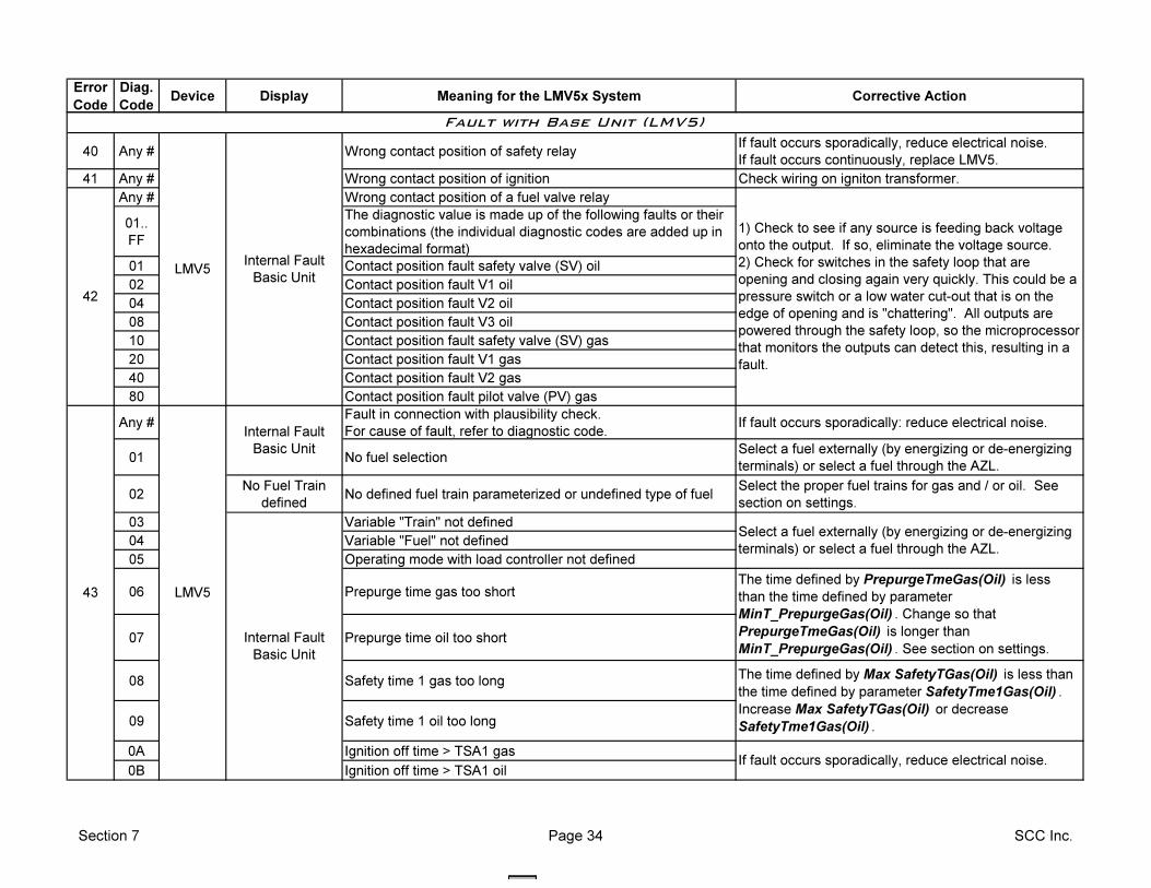
Error
Code
Diag.
CodeDevice Display Meaning for the LMV5x System Corrective Action
40 Any # Wrong contact position of safety relayIf fault occurs sporadically, reduce electrical noise.
If fault occurs continuously, replace LMV5.
41 Any # Wrong contact position of ignition Check wiring on igniton transformer.
Any # Wrong contact position of a fuel valve relay
01..
FF
The diagnostic value is made up of the following faults or their
combinations (the individual diagnostic codes are added up in
hexadecimal format)
01 Contact position fault safety valve (SV) oil
02 Contact position fault V1 oil
04 Contact position fault V2 oil
08 Contact position fault V3 oil
10 Contact position fault safety valve (SV) gas
20 Contact position fault V1 gas
40 Contact position fault V2 gas
80 Contact position fault pilot valve (PV) gas
Any #Fault in connection with plausibility check.
For cause of fault, refer to diagnostic code.If fault occurs sporadically: reduce electrical noise.
01 No fuel selectionSelect a fuel externally (by energizing or de-energizing
terminals) or select a fuel through the AZL.
02No Fuel Train
definedNo defined fuel train parameterized or undefined type of fuel
Select the proper fuel trains for gas and / or oil. See
section on settings.
03 Variable "Train" not defined
04 Variable "Fuel" not defined
05 Operating mode with load controller not defined
06 Prepurge time gas too short
07 Prepurge time oil too short
08 Safety time 1 gas too long
09 Safety time 1 oil too long
0A Ignition off time > TSA1 gas
0B Ignition off time > TSA1 oil
LMV5
42
1) Check to see if any source is feeding back voltage
onto the output. If so, eliminate the voltage source.
2) Check for switches in the safety loop that are
opening and closing again very quickly. This could be a
pressure switch or a low water cut-out that is on the
edge of opening and is "chattering". All outputs are
powered through the safety loop, so the microprocessor
that monitors the outputs can detect this, resulting in a
fault.
Internal Fault
Basic Unit
Internal Fault
Basic Unit
Fault with Base Unit (LMV5)
LMV5
Select a fuel externally (by energizing or de-energizing
terminals) or select a fuel through the AZL.
The time defined by PrepurgeTmeGas(Oil) is less
than the time defined by parameter
MinT_PrepurgeGas(Oil) . Change so that
PrepurgeTmeGas(Oil) is longer than
MinT_PrepurgeGas(Oil) . See section on settings.
The time defined by Max SafetyTGas(Oil) is less than
the time defined by parameter SafetyTme1Gas(Oil) .
Increase Max SafetyTGas(Oil) or decrease
SafetyTme1Gas(Oil) .
If fault occurs sporadically, reduce electrical noise.
Internal Fault
Basic Unit
43
Section 7 Page 34 SCC Inc.
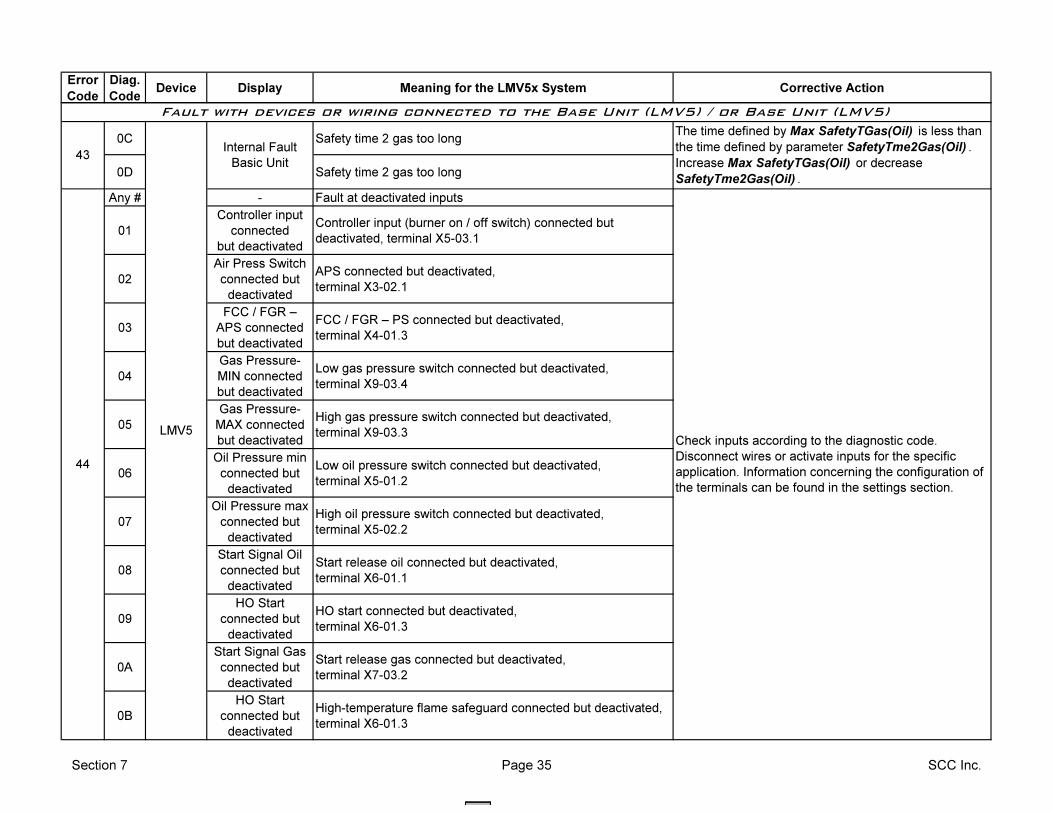
Error
Code
Diag.
CodeDevice Display Meaning for the LMV5x System Corrective Action
0C Safety time 2 gas too long
0D Safety time 2 gas too long
Any # - Fault at deactivated inputs
01
Controller input
connected
but deactivated
Controller input (burner on / off switch) connected but
deactivated, terminal X5-03.1
02
Air Press Switch
connected but
deactivated
APS connected but deactivated,
terminal X3-02.1
03
FCC / FGR –
APS connected
but deactivated
FCC / FGR – PS connected but deactivated,
terminal X4-01.3
04
Gas Pressure-
MIN connected
but deactivated
Low gas pressure switch connected but deactivated,
terminal X9-03.4
05
Gas Pressure-
MAX connected
but deactivated
High gas pressure switch connected but deactivated,
terminal X9-03.3
06
Oil Pressure min
connected but
deactivated
Low oil pressure switch connected but deactivated,
terminal X5-01.2
07
Oil Pressure max
connected but
deactivated
High oil pressure switch connected but deactivated,
terminal X5-02.2
08
Start Signal Oil
connected but
deactivated
Start release oil connected but deactivated,
terminal X6-01.1
09
HO Start
connected but
deactivated
HO start connected but deactivated,
terminal X6-01.3
0A
Start Signal Gas
connected but
deactivated
Start release gas connected but deactivated,
terminal X7-03.2
0B
HO Start
connected but
deactivated
High-temperature flame safeguard connected but deactivated,
terminal X6-01.3
Internal Fault
Basic Unit43
Fault with devices or wiring connected to the Base Unit (LMV5) / or Base Unit (LMV5)
44
Check inputs according to the diagnostic code.
Disconnect wires or activate inputs for the specific
application. Information concerning the configuration of
the terminals can be found in the settings section.
LMV5
The time defined by Max SafetyTGas(Oil) is less than
the time defined by parameter SafetyTme2Gas(Oil) .
Increase Max SafetyTGas(Oil) or decrease
SafetyTme2Gas(Oil) .
Section 7 Page 35 SCC Inc.
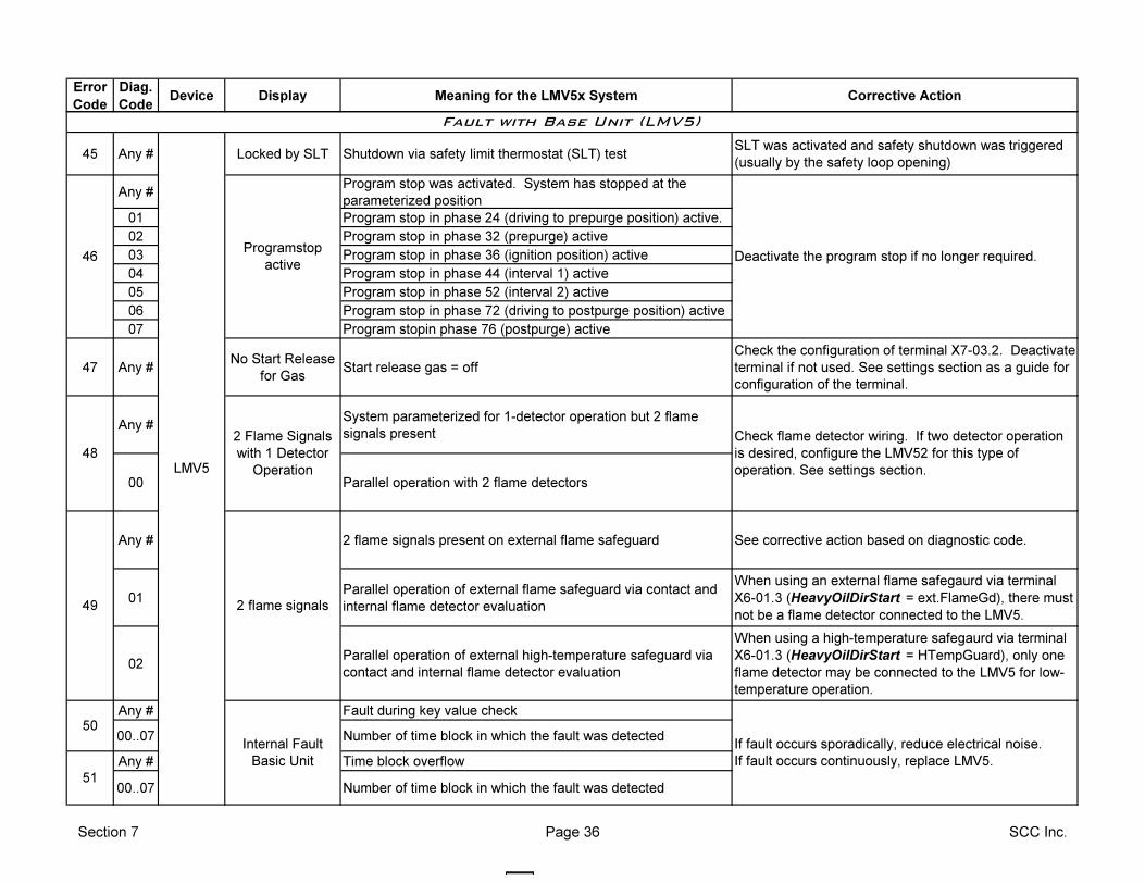
Error
Code
Diag.
CodeDevice Display Meaning for the LMV5x System Corrective Action
45 Any # Locked by SLT Shutdown via safety limit thermostat (SLT) testSLT was activated and safety shutdown was triggered
(usually by the safety loop opening)
Any #Program stop was activated. System has stopped at the
parameterized position
01 Program stop in phase 24 (driving to prepurge position) active.
02 Program stop in phase 32 (prepurge) active
03 Program stop in phase 36 (ignition position) active
04 Program stop in phase 44 (interval 1) active
05 Program stop in phase 52 (interval 2) active
06 Program stop in phase 72 (driving to postpurge position) active
07 Program stopin phase 76 (postpurge) active
47 Any #No Start Release
for GasStart release gas = off
Check the configuration of terminal X7-03.2. Deactivate
terminal if not used. See settings section as a guide for
configuration of the terminal.
Any #System parameterized for 1-detector operation but 2 flame
signals present
00 Parallel operation with 2 flame detectors
Any # 2 flame signals present on external flame safeguard See corrective action based on diagnostic code.
01Parallel operation of external flame safeguard via contact and
internal flame detector evaluation
When using an external flame safegaurd via terminal
X6-01.3 (HeavyOilDirStart = ext.FlameGd), there must
not be a flame detector connected to the LMV5.
02Parallel operation of external high-temperature safeguard via
contact and internal flame detector evaluation
When using a high-temperature safegaurd via terminal
X6-01.3 (HeavyOilDirStart = HTempGuard), only one
flame detector may be connected to the LMV5 for low-
temperature operation.
Any # Fault during key value check
00..07 Number of time block in which the fault was detected
Any # Time block overflow
00..07 Number of time block in which the fault was detected51
Internal Fault
Basic Unit
If fault occurs sporadically, reduce electrical noise.
If fault occurs continuously, replace LMV5.
LMV5
Programstop
active
Fault with Base Unit (LMV5)
2 flame signals
46
50
48
2 Flame Signals
with 1 Detector
Operation
Check flame detector wiring. If two detector operation
is desired, configure the LMV52 for this type of
operation. See settings section.
49
Deactivate the program stop if no longer required.
Section 7 Page 36 SCC Inc.
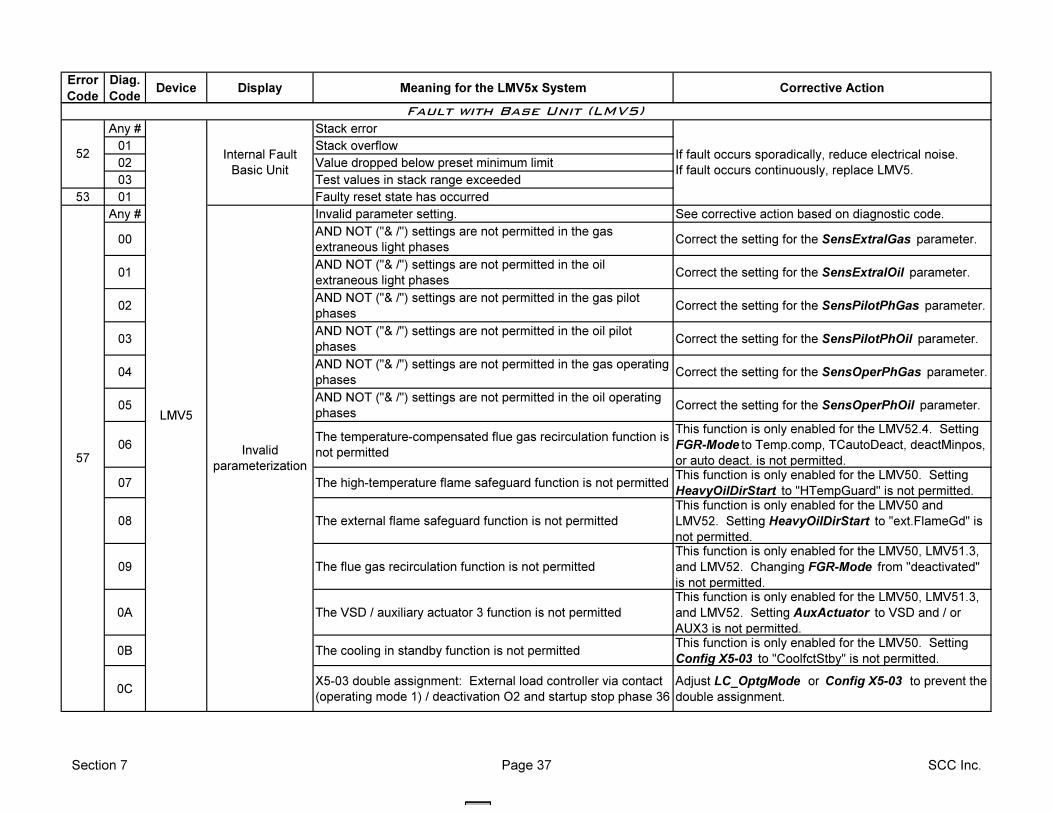
Error
Code
Diag.
CodeDevice Display Meaning for the LMV5x System Corrective Action
Any # Stack error
01 Stack overflow
02 Value dropped below preset minimum limit
03 Test values in stack range exceeded
53 01 Faulty reset state has occurred
Any # Invalid parameter setting. See corrective action based on diagnostic code.
00AND NOT ("& /") settings are not permitted in the gas
extraneous light phasesCorrect the setting for the SensExtralGas parameter.
01AND NOT ("& /") settings are not permitted in the oil
extraneous light phasesCorrect the setting for the SensExtralOil parameter.
02AND NOT ("& /") settings are not permitted in the gas pilot
phasesCorrect the setting for the SensPilotPhGas parameter.
03AND NOT ("& /") settings are not permitted in the oil pilot
phasesCorrect the setting for the SensPilotPhOil parameter.
04AND NOT ("& /") settings are not permitted in the gas operating
phasesCorrect the setting for the SensOperPhGas parameter.
05AND NOT ("& /") settings are not permitted in the oil operating
phasesCorrect the setting for the SensOperPhOil parameter.
06The temperature-compensated flue gas recirculation function is
not permitted
This function is only enabled for the LMV52.4. Setting
FGR-Mode to Temp.comp, TCautoDeact, deactMinpos,
or auto deact. is not permitted.
07 The high-temperature flame safeguard function is not permittedThis function is only enabled for the LMV50. Setting
HeavyOilDirStart to "HTempGuard" is not permitted.
08 The external flame safeguard function is not permitted
This function is only enabled for the LMV50 and
LMV52. Setting HeavyOilDirStart to "ext.FlameGd" is
not permitted.
09 The flue gas recirculation function is not permitted
This function is only enabled for the LMV50, LMV51.3,
and LMV52. Changing FGR-Mode from "deactivated"
is not permitted.
0A The VSD / auxiliary actuator 3 function is not permitted
This function is only enabled for the LMV50, LMV51.3,
and LMV52. Setting AuxActuator to VSD and / or
AUX3 is not permitted.
0B The cooling in standby function is not permittedThis function is only enabled for the LMV50. Setting
Config X5-03 to "CoolfctStby" is not permitted.
0CX5-03 double assignment: External load controller via contact
(operating mode 1) / deactivation O2 and startup stop phase 36
Adjust LC_OptgMode or Config X5-03 to prevent the
double assignment.
Fault with Base Unit (LMV5)
52 If fault occurs sporadically, reduce electrical noise.
If fault occurs continuously, replace LMV5.
LMV5
Internal Fault
Basic Unit
Invalid
parameterization57
Section 7 Page 37 SCC Inc.
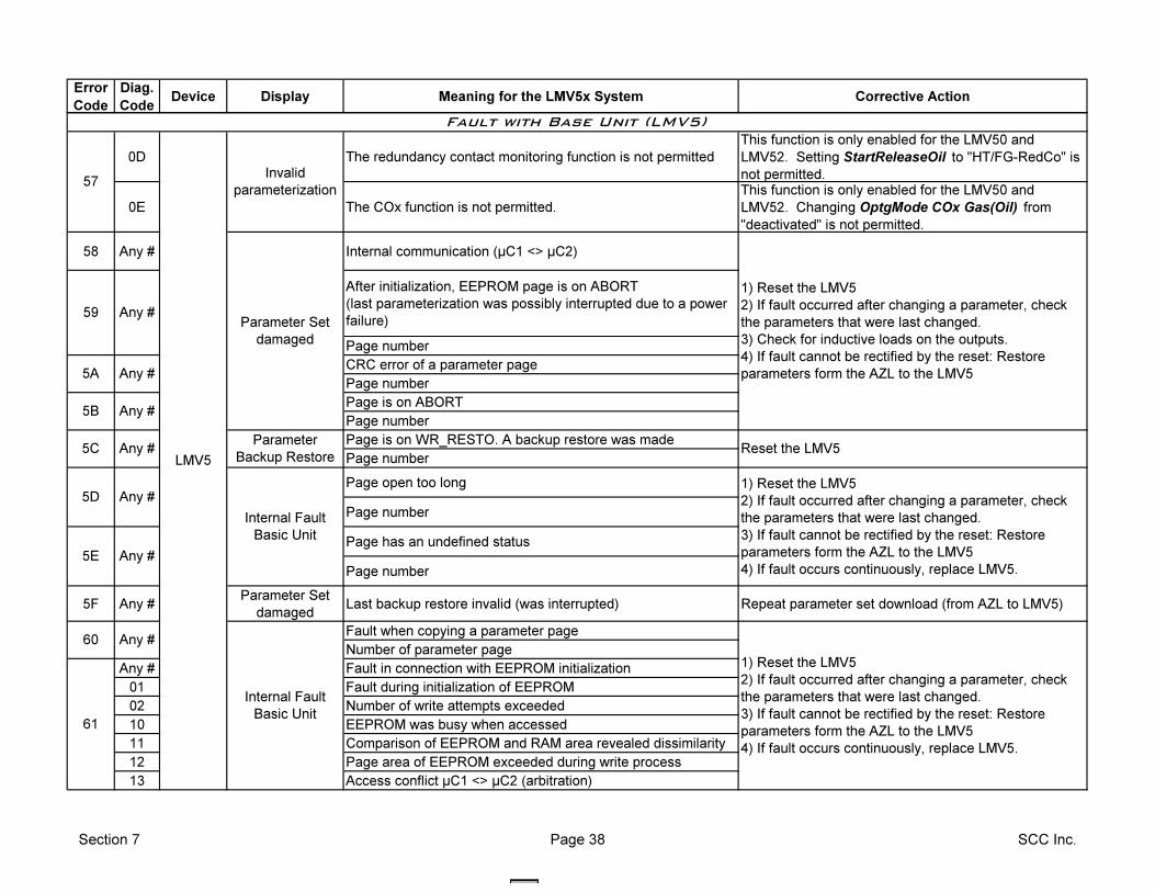
Error
Code
Diag.
CodeDevice Display Meaning for the LMV5x System Corrective Action
0D The redundancy contact monitoring function is not permitted
This function is only enabled for the LMV50 and
LMV52. Setting StartReleaseOil to "HT/FG-RedCo" is
not permitted.
0E The COx function is not permitted.
This function is only enabled for the LMV50 and
LMV52. Changing OptgMode COx Gas(Oil) from
"deactivated" is not permitted.
58 Any # Internal communication (µC1 <> µC2)
After initialization, EEPROM page is on ABORT
(last parameterization was possibly interrupted due to a power
failure)
Page number
CRC error of a parameter page
Page number
Page is on ABORT
Page number
Page is on WR_RESTO. A backup restore was made
Page number
Page open too long
Page number
Page has an undefined status
Page number
5F Any #Parameter Set
damagedLast backup restore invalid (was interrupted) Repeat parameter set download (from AZL to LMV5)
Fault when copying a parameter page
Number of parameter page
Any # Fault in connection with EEPROM initialization
01 Fault during initialization of EEPROM
02 Number of write attempts exceeded
10 EEPROM was busy when accessed
11 Comparison of EEPROM and RAM area revealed dissimilarity
12 Page area of EEPROM exceeded during write process
13 Access conflict µC1 <> µC2 (arbitration)
Any #
Any #
Internal Fault
Basic Unit
Any #
5B
1) Reset the LMV5
2) If fault occurred after changing a parameter, check
the parameters that were last changed.
3) If fault cannot be rectified by the reset: Restore
parameters form the AZL to the LMV5
4) If fault occurs continuously, replace LMV5.
5C
5D
5E
Any #
Any #
5A
1) Reset the LMV5
2) If fault occurred after changing a parameter, check
the parameters that were last changed.
3) Check for inductive loads on the outputs.
4) If fault cannot be rectified by the reset: Restore
parameters form the AZL to the LMV5
Any #
LMV5
60
1) Reset the LMV5
2) If fault occurred after changing a parameter, check
the parameters that were last changed.
3) If fault cannot be rectified by the reset: Restore
parameters form the AZL to the LMV5
4) If fault occurs continuously, replace LMV5.
Reset the LMV5
Parameter Set
damaged
59 Any #
Fault with Base Unit (LMV5)
57Invalid
parameterization
Internal Fault
Basic Unit61
Parameter
Backup Restore
Section 7 Page 38 SCC Inc.
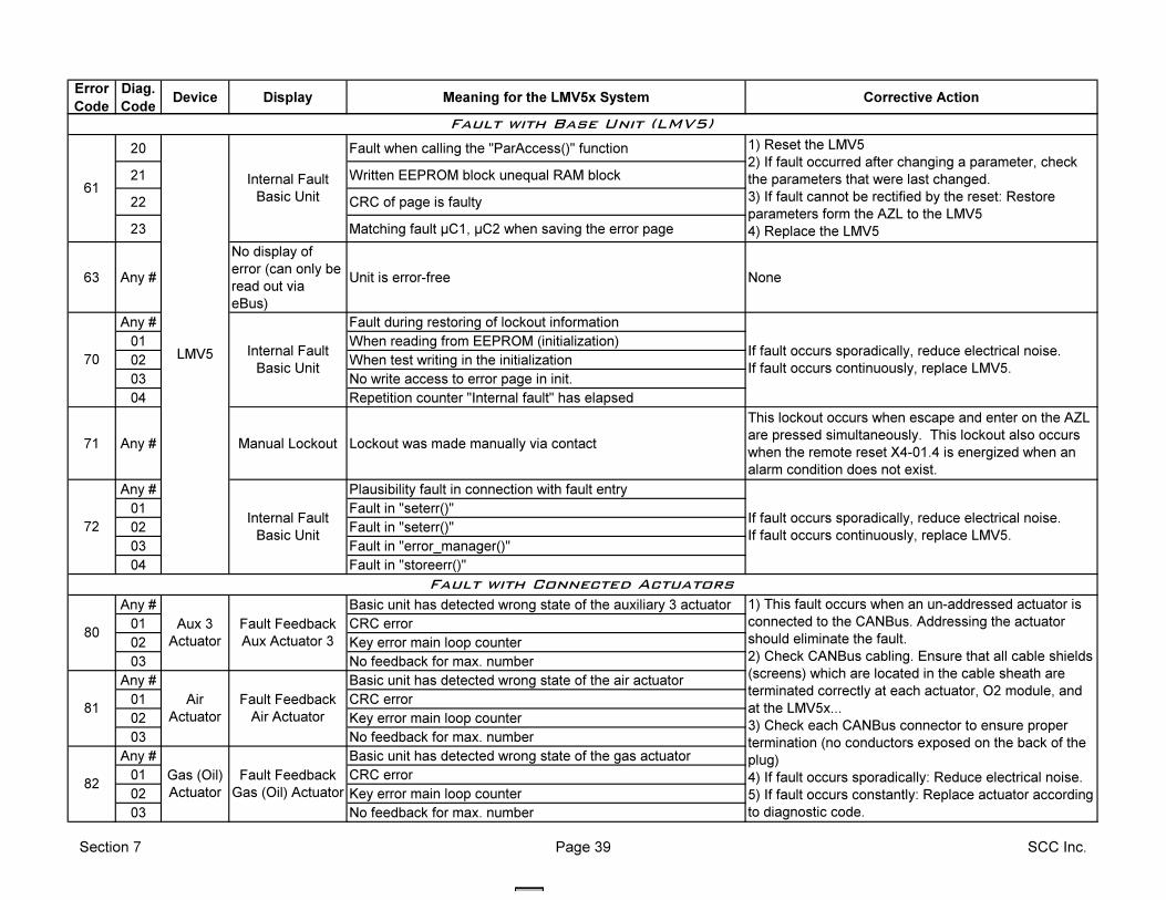
Error
Code
Diag.
CodeDevice Display Meaning for the LMV5x System Corrective Action
20 Fault when calling the "ParAccess()" function
21 Written EEPROM block unequal RAM block
22 CRC of page is faulty
23 Matching fault µC1, µC2 when saving the error page
63 Any #
No display of
error (can only be
read out via
eBus)
Unit is error-free None
Any # Fault during restoring of lockout information
01 When reading from EEPROM (initialization)
02 When test writing in the initialization
03 No write access to error page in init.
04 Repetition counter "Internal fault" has elapsed
71 Any # Manual Lockout Lockout was made manually via contact
This lockout occurs when escape and enter on the AZL
are pressed simultaneously. This lockout also occurs
when the remote reset X4-01.4 is energized when an
alarm condition does not exist.
Any # Plausibility fault in connection with fault entry
01 Fault in "seterr()"
02 Fault in "seterr()"
03 Fault in "error_manager()"
04 Fault in "storeerr()"
Any # Basic unit has detected wrong state of the auxiliary 3 actuator
01 CRC error
02 Key error main loop counter
03 No feedback for max. number
Any # Basic unit has detected wrong state of the air actuator
01 CRC error
02 Key error main loop counter
03 No feedback for max. number
Any # Basic unit has detected wrong state of the gas actuator
01 CRC error
02 Key error main loop counter
03 No feedback for max. number
80
81
82
1) This fault occurs when an un-addressed actuator is
connected to the CANBus. Addressing the actuator
should eliminate the fault.
2) Check CANBus cabling. Ensure that all cable shields
(screens) which are located in the cable sheath are
terminated correctly at each actuator, O2 module, and
at the LMV5x...
3) Check each CANBus connector to ensure proper
termination (no conductors exposed on the back of the
plug)
4) If fault occurs sporadically: Reduce electrical noise.
5) If fault occurs constantly: Replace actuator according
to diagnostic code.
Internal Fault
Basic Unit
Aux 3
Actuator
72
Fault with Base Unit (LMV5)
Internal Fault
Basic Unit
If fault occurs sporadically, reduce electrical noise.
If fault occurs continuously, replace LMV5.
Fault with Connected Actuators
LMV5 70
61
1) Reset the LMV5
2) If fault occurred after changing a parameter, check
the parameters that were last changed.
3) If fault cannot be rectified by the reset: Restore
parameters form the AZL to the LMV5
4) Replace the LMV5
Internal Fault
Basic Unit
If fault occurs sporadically, reduce electrical noise.
If fault occurs continuously, replace LMV5.
Fault Feedback
Aux Actuator 3
Fault Feedback
Air Actuator
Fault Feedback
Gas (Oil) Actuator
Air
Actuator
Gas (Oil)
Actuator
Section 7 Page 39 SCC Inc.
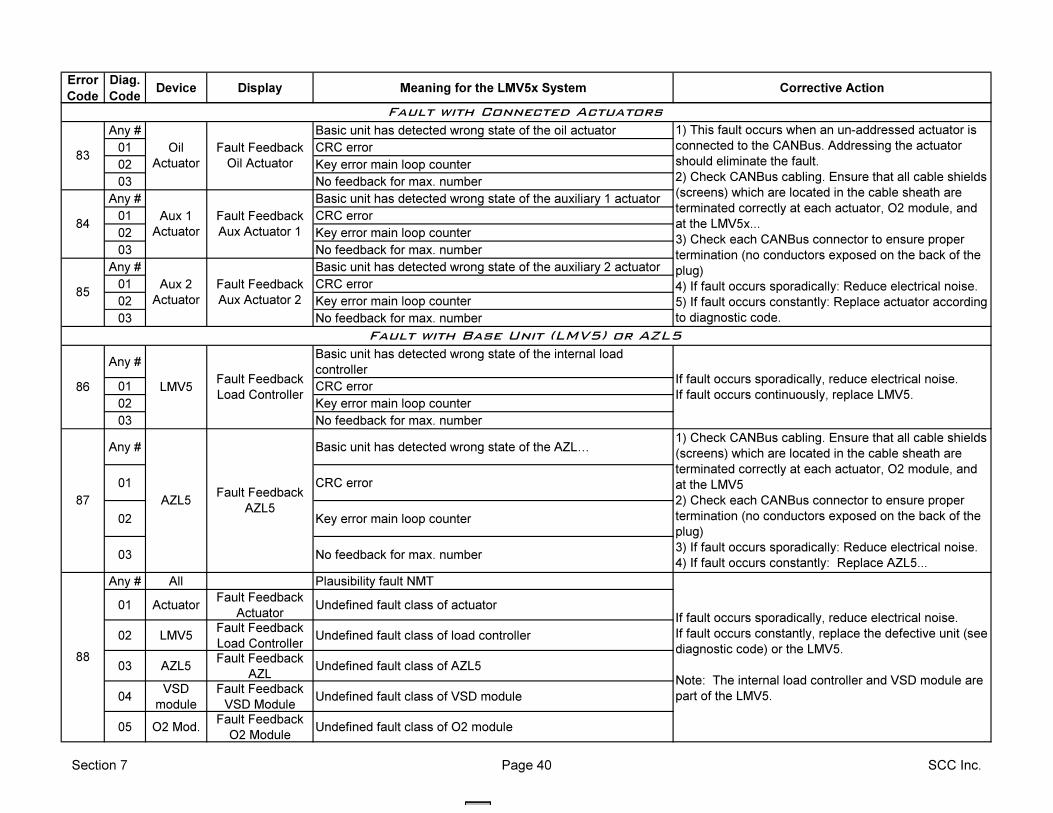
Error
Code
Diag.
CodeDevice Display Meaning for the LMV5x System Corrective Action
Any # Basic unit has detected wrong state of the oil actuator
01 CRC error
02 Key error main loop counter
03 No feedback for max. number
Any # Basic unit has detected wrong state of the auxiliary 1 actuator
01 CRC error
02 Key error main loop counter
03 No feedback for max. number
Any # Basic unit has detected wrong state of the auxiliary 2 actuator
01 CRC error
02 Key error main loop counter
03 No feedback for max. number
Any #Basic unit has detected wrong state of the internal load
controller
01 CRC error
02 Key error main loop counter
03 No feedback for max. number
Any # Basic unit has detected wrong state of the AZLI
01 CRC error
02 Key error main loop counter
03 No feedback for max. number
Any # All Plausibility fault NMT
01 ActuatorFault Feedback
ActuatorUndefined fault class of actuator
02 LMV5 Fault Feedback
Load ControllerUndefined fault class of load controller
03 AZL5Fault Feedback
AZLUndefined fault class of AZL5
04VSD
module
Fault Feedback
VSD ModuleUndefined fault class of VSD module
05 O2 Mod.Fault Feedback
O2 ModuleUndefined fault class of O2 module
If fault occurs sporadically, reduce electrical noise.
If fault occurs constantly, replace the defective unit (see
diagnostic code) or the LMV5.
Note: The internal load controller and VSD module are
part of the LMV5.
Oil
Actuator83
84
Aux 2
Actuator
87
Fault with Connected Actuators
85
1) This fault occurs when an un-addressed actuator is
connected to the CANBus. Addressing the actuator
should eliminate the fault.
2) Check CANBus cabling. Ensure that all cable shields
(screens) which are located in the cable sheath are
terminated correctly at each actuator, O2 module, and
at the LMV5x...
3) Check each CANBus connector to ensure proper
termination (no conductors exposed on the back of the
plug)
4) If fault occurs sporadically: Reduce electrical noise.
5) If fault occurs constantly: Replace actuator according
to diagnostic code.
Fault Feedback
Oil Actuator
Aux 1
Actuator
Fault Feedback
Aux Actuator 1
If fault occurs sporadically, reduce electrical noise.
If fault occurs continuously, replace LMV5.
Fault Feedback
AZL5
1) Check CANBus cabling. Ensure that all cable shields
(screens) which are located in the cable sheath are
terminated correctly at each actuator, O2 module, and
at the LMV5
2) Check each CANBus connector to ensure proper
termination (no conductors exposed on the back of the
plug)
3) If fault occurs sporadically: Reduce electrical noise.
4) If fault occurs constantly: Replace AZL5...
Fault Feedback
Aux Actuator 2
Fault with Base Unit (LMV5) or AZL5
LMV5
AZL5
88
Fault Feedback
Load Controller86
Section 7 Page 40 SCC Inc.
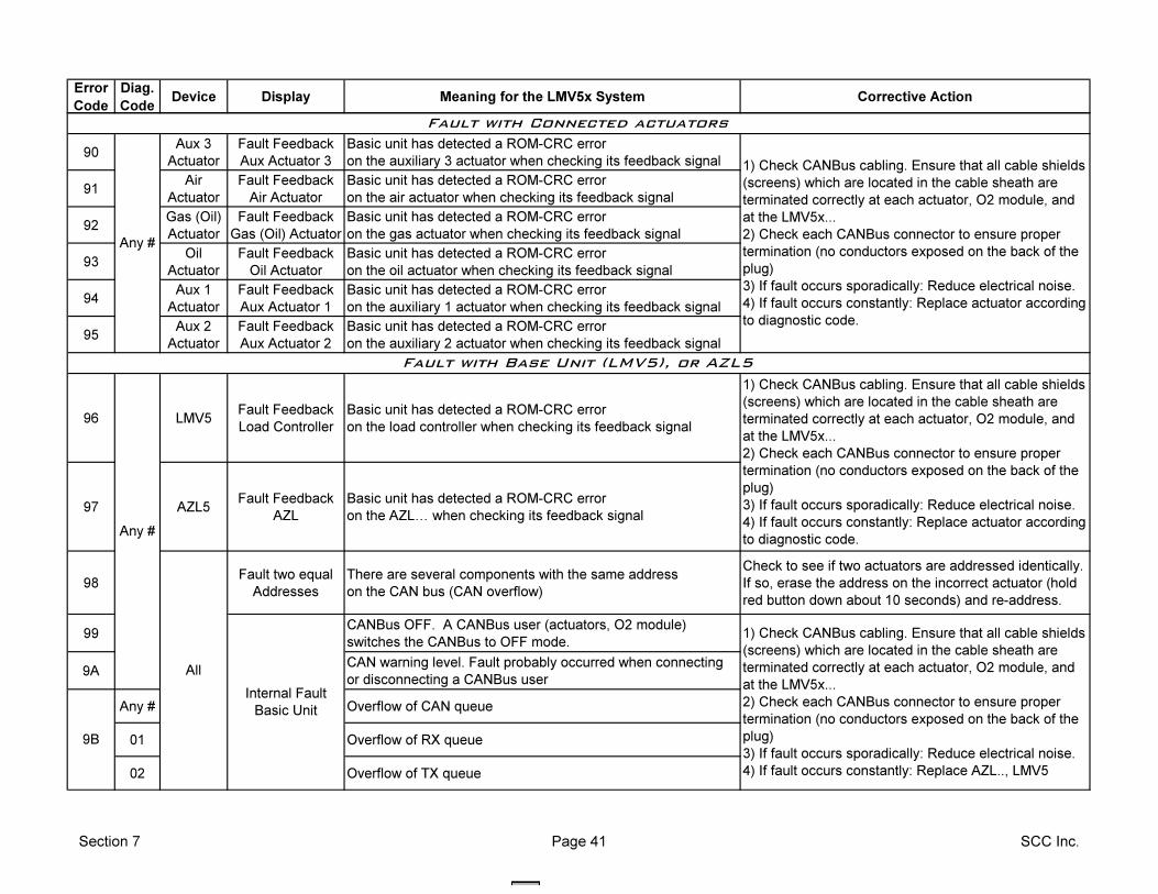
Error
Code
Diag.
CodeDevice Display Meaning for the LMV5x System Corrective Action
90Aux 3
Actuator
Fault Feedback
Aux Actuator 3
Basic unit has detected a ROM-CRC error
on the auxiliary 3 actuator when checking its feedback signal
91Air
Actuator
Fault Feedback
Air Actuator
Basic unit has detected a ROM-CRC error
on the air actuator when checking its feedback signal
92Gas (Oil)
Actuator
Fault Feedback
Gas (Oil) Actuator
Basic unit has detected a ROM-CRC error
on the gas actuator when checking its feedback signal
93Oil
Actuator
Fault Feedback
Oil Actuator
Basic unit has detected a ROM-CRC error
on the oil actuator when checking its feedback signal
94Aux 1
Actuator
Fault Feedback
Aux Actuator 1
Basic unit has detected a ROM-CRC error
on the auxiliary 1 actuator when checking its feedback signal
95Aux 2
Actuator
Fault Feedback
Aux Actuator 2
Basic unit has detected a ROM-CRC error
on the auxiliary 2 actuator when checking its feedback signal
96 LMV5 Fault Feedback
Load Controller
Basic unit has detected a ROM-CRC error
on the load controller when checking its feedback signal
97 AZL5Fault Feedback
AZL
Basic unit has detected a ROM-CRC error
on the AZLI when checking its feedback signal
98Fault two equal
Addresses
There are several components with the same address
on the CAN bus (CAN overflow)
Check to see if two actuators are addressed identically.
If so, erase the address on the incorrect actuator (hold
red button down about 10 seconds) and re-address.
99CANBus OFF. A CANBus user (actuators, O2 module)
switches the CANBus to OFF mode.
9ACAN warning level. Fault probably occurred when connecting
or disconnecting a CANBus user
Any # Overflow of CAN queue
01 Overflow of RX queue
02 Overflow of TX queue
Fault with Base Unit (LMV5), or AZL5
9B
Internal Fault
Basic Unit
1) Check CANBus cabling. Ensure that all cable shields
(screens) which are located in the cable sheath are
terminated correctly at each actuator, O2 module, and
at the LMV5x...
2) Check each CANBus connector to ensure proper
termination (no conductors exposed on the back of the
plug)
3) If fault occurs sporadically: Reduce electrical noise.
4) If fault occurs constantly: Replace AZL.., LMV5
Fault with Connected actuators
1) Check CANBus cabling. Ensure that all cable shields
(screens) which are located in the cable sheath are
terminated correctly at each actuator, O2 module, and
at the LMV5x...
2) Check each CANBus connector to ensure proper
termination (no conductors exposed on the back of the
plug)
3) If fault occurs sporadically: Reduce electrical noise.
4) If fault occurs constantly: Replace actuator according
to diagnostic code.
Any #
All
Section 7 Page 41 SCC Inc.
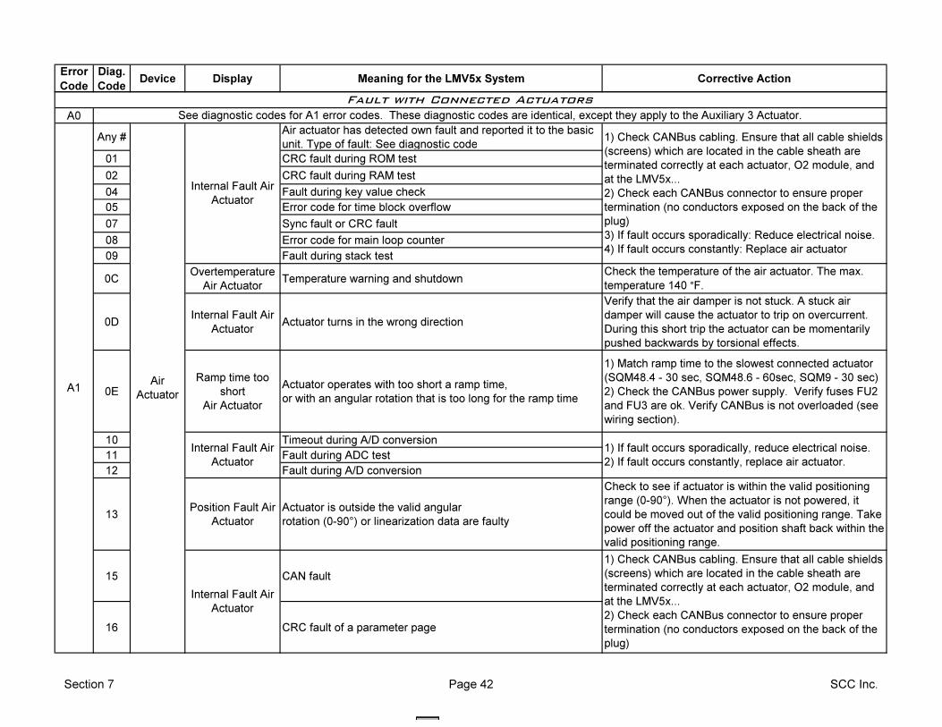
Error
Code
Diag.
CodeDevice Display Meaning for the LMV5x System Corrective Action
A0
Any #Air actuator has detected own fault and reported it to the basic
unit. Type of fault: See diagnostic code
01 CRC fault during ROM test
02 CRC fault during RAM test
04 Fault during key value check
05 Error code for time block overflow
07 Sync fault or CRC fault
08 Error code for main loop counter
09 Fault during stack test
0COvertemperature
Air ActuatorTemperature warning and shutdown
Check the temperature of the air actuator. The max.
temperature 140 °F.
0DInternal Fault Air
ActuatorActuator turns in the wrong direction
Verify that the air damper is not stuck. A stuck air
damper will cause the actuator to trip on overcurrent.
During this short trip the actuator can be momentarily
pushed backwards by torsional effects.
0E
Ramp time too
short
Air Actuator
Actuator operates with too short a ramp time,
or with an angular rotation that is too long for the ramp time
1) Match ramp time to the slowest connected actuator
(SQM48.4 - 30 sec, SQM48.6 - 60sec, SQM9 - 30 sec)
2) Check the CANBus power supply. Verify fuses FU2
and FU3 are ok. Verify CANBus is not overloaded (see
wiring section).
10 Timeout during A/D conversion
11 Fault during ADC test
12 Fault during A/D conversion
13Position Fault Air
Actuator
Actuator is outside the valid angular
rotation (0-90°) or linearization data are faulty
Check to see if actuator is within the valid positioning
range (0-90°). When the actuator is not powered, it
could be moved out of the valid positioning range. Take
power off the actuator and position shaft back within the
valid positioning range.
15 CAN fault
16 CRC fault of a parameter page
Fault with Connected Actuators
Air
Actuator
Internal Fault Air
Actuator
A1
1) Check CANBus cabling. Ensure that all cable shields
(screens) which are located in the cable sheath are
terminated correctly at each actuator, O2 module, and
at the LMV5x...
2) Check each CANBus connector to ensure proper
termination (no conductors exposed on the back of the
plug)
3) If fault occurs sporadically: Reduce electrical noise.
4) If fault occurs constantly: Replace air actuator
See diagnostic codes for A1 error codes. These diagnostic codes are identical, except they apply to the Auxiliary 3 Actuator.
1) Check CANBus cabling. Ensure that all cable shields
(screens) which are located in the cable sheath are
terminated correctly at each actuator, O2 module, and
at the LMV5x...
2) Check each CANBus connector to ensure proper
termination (no conductors exposed on the back of the
plug)
1) If fault occurs sporadically, reduce electrical noise.
2) If fault occurs constantly, replace air actuator.
Internal Fault Air
Actuator
Internal Fault Air
Actuator
Section 7 Page 42 SCC Inc.
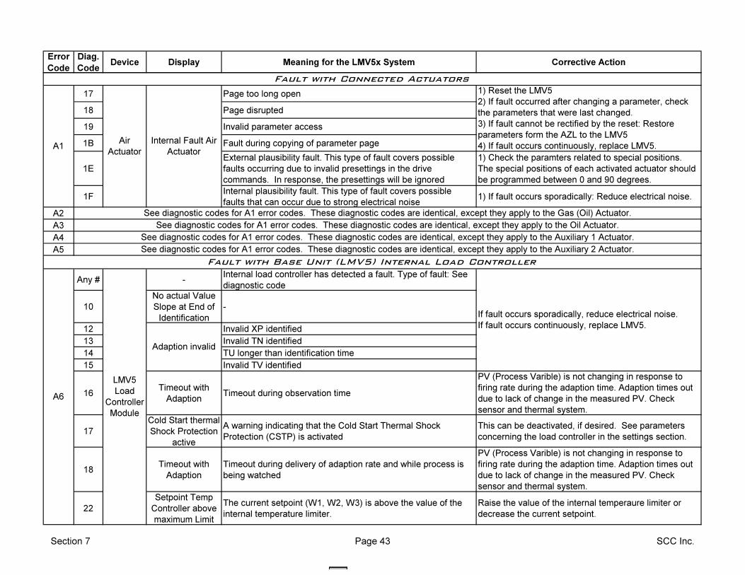
Error
Code
Diag.
CodeDevice Display Meaning for the LMV5x System Corrective Action
17 Page too long open
18 Page disrupted
19 Invalid parameter access
1B Fault during copying of parameter page
1E
External plausibility fault. This type of fault covers possible
faults occurring due to invalid presettings in the drive
commands. In response, the presettings will be ignored
1) Check the paramters related to special positions.
The special positions of each activated actuator should
be programmed between 0 and 90 degrees.
1FInternal plausibility fault. This type of fault covers possible
faults that can occur due to strong electrical noise1) If fault occurs sporadically: Reduce electrical noise.
A2
A3
A4
A5
Any # -Internal load controller has detected a fault. Type of fault: See
diagnostic code
10
No actual Value
Slope at End of
Identification
-
12 Invalid XP identified
13 Invalid TN identified
14 TU longer than identification time
15 Invalid TV identified
16Timeout with
AdaptionTimeout during observation time
PV (Process Varible) is not changing in response to
firing rate during the adaption time. Adaption times out
due to lack of change in the measured PV. Check
sensor and thermal system.
17
Cold Start thermal
Shock Protection
active
A warning indicating that the Cold Start Thermal Shock
Protection (CSTP) is activated
This can be deactivated, if desired. See parameters
concerning the load controller in the settings section.
18Timeout with
Adaption
Timeout during delivery of adaption rate and while process is
being watched
PV (Process Varible) is not changing in response to
firing rate during the adaption time. Adaption times out
due to lack of change in the measured PV. Check
sensor and thermal system.
22
Setpoint Temp
Controller above
maximum Limit
The current setpoint (W1, W2, W3) is above the value of the
internal temperature limiter.
Raise the value of the internal temperaure limiter or
decrease the current setpoint.
See diagnostic codes for A1 error codes. These diagnostic codes are identical, except they apply to the Gas (Oil) Actuator.
See diagnostic codes for A1 error codes. These diagnostic codes are identical, except they apply to the Auxiliary 2 Actuator.
Fault with Base Unit (LMV5) Internal Load Controller
1) Reset the LMV5
2) If fault occurred after changing a parameter, check
the parameters that were last changed.
3) If fault cannot be rectified by the reset: Restore
parameters form the AZL to the LMV5
4) If fault occurs continuously, replace LMV5.A1
If fault occurs sporadically, reduce electrical noise.
If fault occurs continuously, replace LMV5.
A6
LMV5
Load
Controller
Module
See diagnostic codes for A1 error codes. These diagnostic codes are identical, except they apply to the Oil Actuator.
See diagnostic codes for A1 error codes. These diagnostic codes are identical, except they apply to the Auxiliary 1 Actuator.
Adaption invalid
Fault with Connected Actuators
Internal Fault Air
Actuator
Air
Actuator
Section 7 Page 43 SCC Inc.
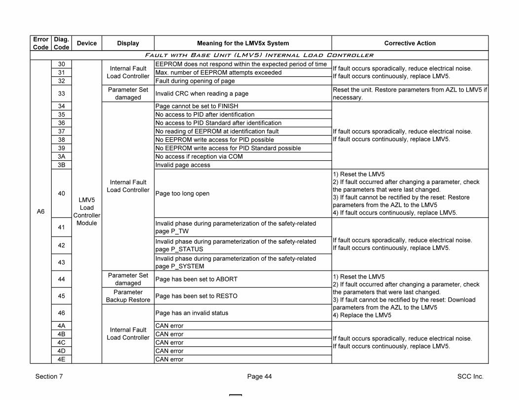
Error
Code
Diag.
CodeDevice Display Meaning for the LMV5x System Corrective Action
30 EEPROM does not respond within the expected period of time
31 Max. number of EEPROM attempts exceeded
32 Fault during opening of page
33Parameter Set
damagedInvalid CRC when reading a page
Reset the unit. Restore parameters from AZL to LMV5 if
necessary.
34 Page cannot be set to FINISH
35 No access to PID after identification
36 No access to PID Standard after identification
37 No reading of EEPROM at identification fault
38 No EEPROM write access for PID possible
39 No EEPROM write access for PID Standard possible
3A No access if reception via COM
3B Invalid page access
40 Page too long open
1) Reset the LMV5
2) If fault occurred after changing a parameter, check
the parameters that were last changed.
3) If fault cannot be rectified by the reset: Restore
parameters from the AZL to the LMV5
4) If fault occurs continuously, replace LMV5.
41Invalid phase during parameterization of the safety-related
page P_TW
42Invalid phase during parameterization of the safety-related
page P_STATUS
43Invalid phase during parameterization of the safety-related
page P_SYSTEM
44Parameter Set
damagedPage has been set to ABORT
45Parameter
Backup RestorePage has been set to RESTO
46 Page has an invalid status
4A CAN error
4B CAN error
4C CAN error
4D CAN error
4E CAN error
1) Reset the LMV5
2) If fault occurred after changing a parameter, check
the parameters that were last changed.
3) If fault cannot be rectified by the reset: Download
parameters from the AZL to the LMV5
4) Replace the LMV5
Internal Fault
Load Controller
Fault with Base Unit (LMV5) Internal Load Controller
A6
LMV5
Load
Controller
Module
Internal Fault
Load Controller
If fault occurs sporadically, reduce electrical noise.
If fault occurs continuously, replace LMV5.
If fault occurs sporadically, reduce electrical noise.
If fault occurs continuously, replace LMV5.
Internal Fault
Load Controller
If fault occurs sporadically, reduce electrical noise.
If fault occurs continuously, replace LMV5.
If fault occurs sporadically, reduce electrical noise.
If fault occurs continuously, replace LMV5.
Section 7 Page 44 SCC Inc.
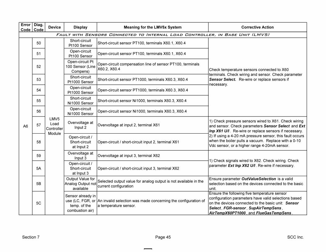
Error
Code
Diag.
CodeDevice Display Meaning for the LMV5x System Corrective Action
50Short-circuit
Pt100 SensorShort-circuit sensor PT100, terminals X60.1, X60.4
51Open-circuit
Pt100 SensorOpen-circuit sensor PT100, terminals X60.1, X60.4
52
Open-circuit Pt
100 Sensor (Line
Compens)
Open-circuit compensation line of sensor PT100, terminals
X60.2, X60.4
53Short-circuit
Pt1000 SensorShort-circuit sensor PT1000, terminals X60.3, X60.4
54Open-circuit
Pt1000 SensorOpen-circuit sensor PT1000, terminals X60.3, X60.4
55Short-circuit
Ni1000 SensorShort-circuit sensor Ni1000, terminals X60.3, X60.4
56Open-circuit
Ni1000 SensorOpen-circuit sensor Ni1000, terminals X60.3, X60.4
57Overvoltage at
Input 2Overvoltage at input 2, terminal X61
58
Open-circuit /
Short-circuit
at Input 2
Open-circuit / short-circuit input 2, terminal X61
59Overvoltage at
Input 3Overvoltage at input 3, terminal X62
5A
Open-circuit /
Short-circuit
at Input 3
Open-circuit / short-circuit input 3, terminal X62
5B
Output Value for
Analog Output not
available
Selected output value for analog output is not available in the
current configuration
Ensure parameter OutValueSelection is a valid
selection based on the devices connected to the basic
unit.
5C
Sensor already in
use (LC, FGR, or
temp. of the
combustion air)
An invalid selection was made concerning the configuration of
a temperature sensor.
Ensure the following five temperature sensor
configuration parameters have valid selections based
on the devices connected to the basic unit: Sensor
Select , FGR-sensor , SupAirTempSens ,
AirTempX60PT1000 , and FlueGasTempSens .
1) Check signals wired to X62. Check wiring. Check
parameter Ext Inp X62 U/I . Re-wire if necessary.
Fault with Sensors Connected to Internal Load Controller, in Base Unit (LMV5)
A6
LMV5
Load
Controller
Module
1) Check pressure sensors wired to X61. Check wiring
and sensor. Check parameters Sensor Select and Ext
Inp X61 U/I . Re-wire or replace sensors if necessary.
2) If using a 4-20 mA pressure sensor, this fault occurs
when the boiler pulls a vacuum. Replace with a 0-10
Vdc sensor, or a higher range 4-20mA sensor.
Check temperature sensors connected to X60
terminals. Check wiring and sensor. Check parameter
Sensor Select. Re-wire or replace sensors if
necessary.
Section 7 Page 45 SCC Inc.
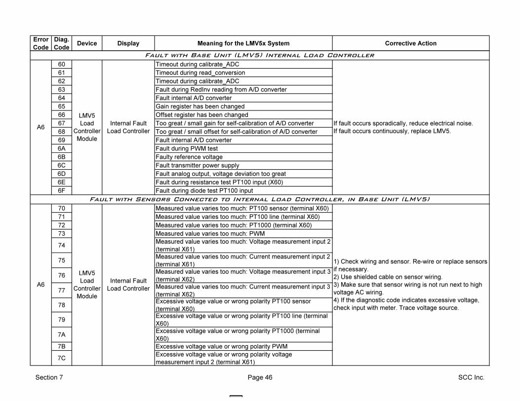
Error
Code
Diag.
CodeDevice Display Meaning for the LMV5x System Corrective Action
60 Timeout during calibrate_ADC
61 Timeout during read_conversion
62 Timeout during calibrate_ADC
63 Fault during RedInv reading from A/D converter
64 Fault internal A/D converter
65 Gain register has been changed
66 Offset register has been changed
67 Too great / small gain for self-calibration of A/D converter
68 Too great / small offset for self-calibration of A/D converter
69 Fault internal A/D converter
6A Fault during PWM test
6B Faulty reference voltage
6C Fault transmitter power supply
6D Fault analog output, voltage deviation too great
6E Fault during resistance test PT100 input (X60)
6F Fault during diode test PT100 input
70 Measured value varies too much: PT100 sensor (terminal X60)
71 Measured value varies too much: PT100 line (terminal X60)
72 Measured value varies too much: PT1000 (terminal X60)
73 Measured value varies too much: PWM
74Measured value varies too much: Voltage measurement input 2
(terminal X61)
75Measured value varies too much: Current measurement input 2
(terminal X61)
76Measured value varies too much: Voltage measurement input 3
(terminal X62)
77Measured value varies too much: Current measurement input 3
(terminal X62)
78Excessive voltage value or wrong polarity PT100 sensor
(terminal X60)
79Excessive voltage value or wrong polarity PT100 line (terminal
X60)
7AExcessive voltage value or wrong polarity PT1000 (terminal
X60)
7B Excessive voltage value or wrong polarity PWM
7CExcessive voltage value or wrong polarity voltage
measurement input 2 (terminal X61)
Fault with Base Unit (LMV5) Internal Load Controller
Fault with Sensors Connected to Internal Load Controller, in Base Unit (LMV5)
LMV5
Load
Controller
Module
Internal Fault
Load Controller
If fault occurs sporadically, reduce electrical noise.
If fault occurs continuously, replace LMV5.A6
A6
LMV5
Load
Controller
Module
Internal Fault
Load Controller
1) Check wiring and sensor. Re-wire or replace sensors
if necessary.
2) Use shielded cable on sensor wiring.
3) Make sure that sensor wiring is not run next to high
voltage AC wiring.
4) If the diagnostic code indicates excessive voltage,
check input with meter. Trace voltage source.
Section 7 Page 46 SCC Inc.
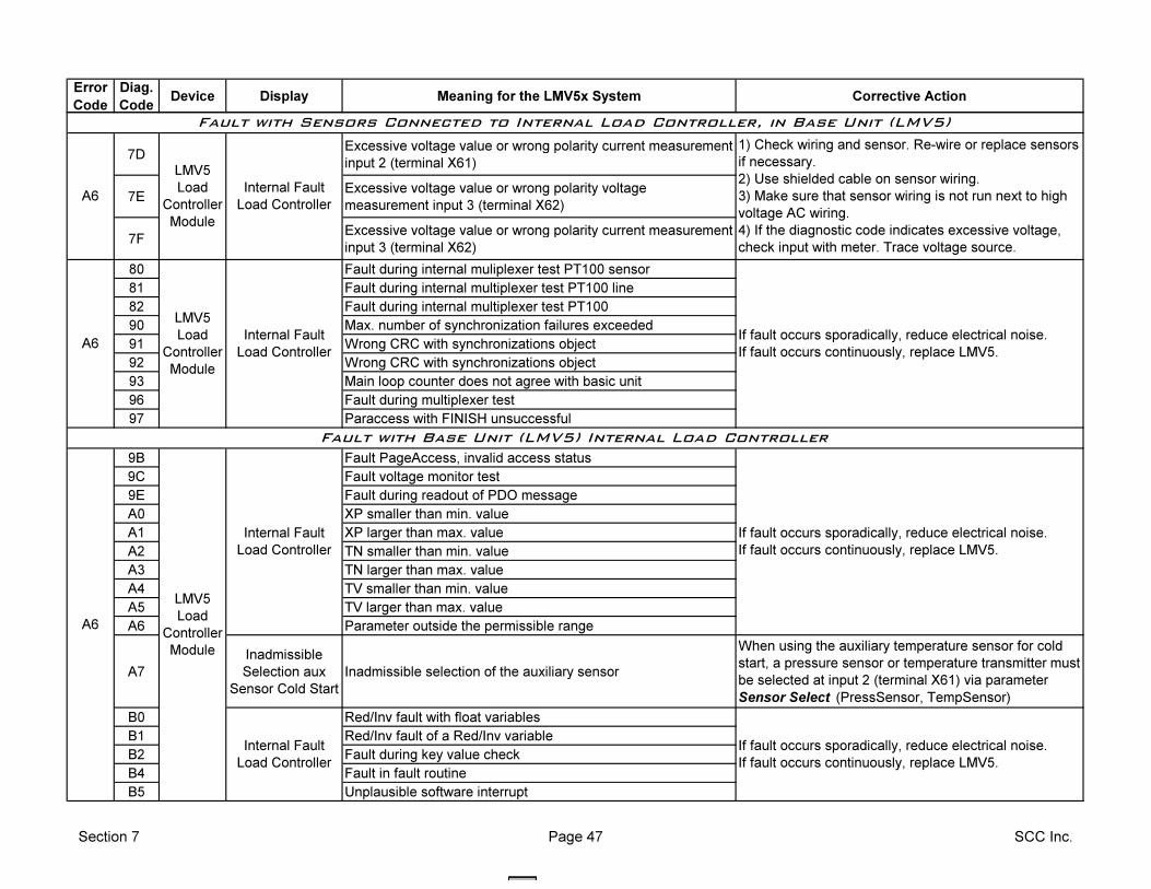
Error
Code
Diag.
CodeDevice Display Meaning for the LMV5x System Corrective Action
7DExcessive voltage value or wrong polarity current measurement
input 2 (terminal X61)
7EExcessive voltage value or wrong polarity voltage
measurement input 3 (terminal X62)
7FExcessive voltage value or wrong polarity current measurement
input 3 (terminal X62)
80 Fault during internal muliplexer test PT100 sensor
81 Fault during internal multiplexer test PT100 line
82 Fault during internal multiplexer test PT100
90 Max. number of synchronization failures exceeded
91 Wrong CRC with synchronizations object
92 Wrong CRC with synchronizations object
93 Main loop counter does not agree with basic unit
96 Fault during multiplexer test
97 Paraccess with FINISH unsuccessful
9B Fault PageAccess, invalid access status
9C Fault voltage monitor test
9E Fault during readout of PDO message
A0 XP smaller than min. value
A1 XP larger than max. value
A2 TN smaller than min. value
A3 TN larger than max. value
A4 TV smaller than min. value
A5 TV larger than max. value
A6 Parameter outside the permissible range
A7
Inadmissible
Selection aux
Sensor Cold Start
Inadmissible selection of the auxiliary sensor
When using the auxiliary temperature sensor for cold
start, a pressure sensor or temperature transmitter must
be selected at input 2 (terminal X61) via parameter
Sensor Select (PressSensor, TempSensor)
B0 Red/Inv fault with float variables
B1 Red/Inv fault of a Red/Inv variable
B2 Fault during key value check
B4 Fault in fault routine
B5 Unplausible software interrupt
LMV5
Load
Controller
Module
Internal Fault
Load Controller
If fault occurs sporadically, reduce electrical noise.
If fault occurs continuously, replace LMV5.
If fault occurs sporadically, reduce electrical noise.
If fault occurs continuously, replace LMV5.
Internal Fault
Load Controller
Internal Fault
Load Controller
Fault with Base Unit (LMV5) Internal Load Controller
A6
LMV5
Load
Controller
Module
If fault occurs sporadically, reduce electrical noise.
If fault occurs continuously, replace LMV5.
A6
A6
LMV5
Load
Controller
Module
Internal Fault
Load Controller
1) Check wiring and sensor. Re-wire or replace sensors
if necessary.
2) Use shielded cable on sensor wiring.
3) Make sure that sensor wiring is not run next to high
voltage AC wiring.
4) If the diagnostic code indicates excessive voltage,
check input with meter. Trace voltage source.
Fault with Sensors Connected to Internal Load Controller, in Base Unit (LMV5)
Section 7 Page 47 SCC Inc.
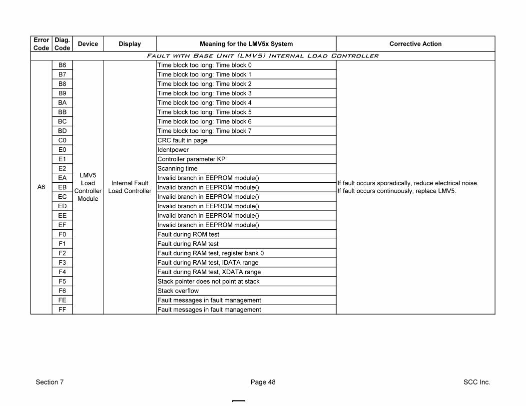
Error
Code
Diag.
CodeDevice Display Meaning for the LMV5x System Corrective Action
B6 Time block too long: Time block 0
B7 Time block too long: Time block 1
B8 Time block too long: Time block 2
B9 Time block too long: Time block 3
BA Time block too long: Time block 4
BB Time block too long: Time block 5
BC Time block too long: Time block 6
BD Time block too long: Time block 7
C0 CRC fault in page
E0 Identpower
E1 Controller parameter KP
E2 Scanning time
EA Invalid branch in EEPROM module()
EB Invalid branch in EEPROM module()
EC Invalid branch in EEPROM module()
ED Invalid branch in EEPROM module()
EE Invalid branch in EEPROM module()
EF Invalid branch in EEPROM module()
F0 Fault during ROM test
F1 Fault during RAM test
F2 Fault during RAM test, register bank 0
F3 Fault during RAM test, IDATA range
F4 Fault during RAM test, XDATA range
F5 Stack pointer does not point at stack
F6 Stack overflow
FE Fault messages in fault management
FF Fault messages in fault management
Fault with Base Unit (LMV5) Internal Load Controller
A6
LMV5
Load
Controller
Module
Internal Fault
Load Controller
If fault occurs sporadically, reduce electrical noise.
If fault occurs continuously, replace LMV5.
Section 7 Page 48 SCC Inc.
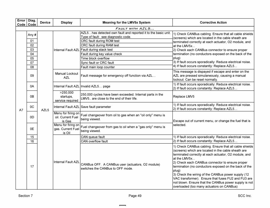
Error
Code
Diag.
CodeDevice Display Meaning for the LMV5x System Corrective Action
Any #AZL5Ihas detected own fault and reported it to the basic unit.
Type of fault: see diagnostic code.
01 CRC fault during ROM test
02 CRC fault during RAM test
03 Fault during stack test
04 Fault during key value check
05 Time block overflow
07 Sync fault or CRC fault
08 Fault main loop counter
09Manual Lockout
AZLFault message for emergency off function via AZLI
This message is dispayed if escape and enter on the
AZL are pressed simulaneously, causing a manual
lockout. Can be reset normally.
0A Internal Fault AZL Invalid AZL5I page1) If fault occurs sporadically: Reduce electrical noise.
2) If fault occurs constantly: Replace AZL5I
0B
>250,000
startups,
service required
250,000 cycles have been exceeded. Internal parts in the
LMV5.. are close to the end of their life.Replace LMV5
0C Internal Fault AZL Save fault parameter1) If fault occurs sporadically: Reduce electrical noise.
2) If fault occurs constantly: Replace AZL5I
0D
Menu for firing on
oil. Current Fuel
is Gas
Fuel changeover from oil to gas when an "oil only" menu is
being viewed.
0E
Menu for firing on
gas. Current Fuel
is Oil
Fuel changeover from gas to oil when a "gas only" menu is
being viewed.
15 CAN queue fault
16 CAN overflow fault
17CANBus OFF. A CANBus user (actuators, O2 module)
switches the CANBus to OFF mode.
1) Check CANBus cabling. Ensure that all cable shields
(screens) which are located in the cable sheath are
terminated correctly at each actuator, O2 module, and
at the LMV5x...
2) Check each CANBus connector to ensure proper
termination (no conductors exposed on the back of the
plug)
3) Check the wiring of the CANBus power supply (12
VAC transformer). Ensure that fuses FU2 and FU3 are
not blown. Ensure that the CANBus power supply is not
overloaded (too many actuators on CANBus)
Fault with AZL5…
Internal Fault AZL
Escape out of current menu, or change the fuel that is
selected.
1) If fault occurs sporadically: Reduce electrical noise.
2) If fault occurs constantly: Replace AZL5I
A7 AZL5
Internal Fault AZL
1) Check CANBus cabling. Ensure that all cable shields
(screens) which are located in the cable sheath are
terminated correctly at each actuator, O2 module, and
at the LMV5x...
2) Check each CANBus connector to ensure proper
termination (no conductors exposed on the back of the
plug)
3) If fault occurs sporadically: Reduce electrical noise.
4) If fault occurs constantly: Replace AZL5...
Section 7 Page 49 SCC Inc.
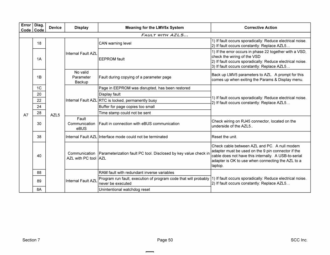
Error
Code
Diag.
CodeDevice Display Meaning for the LMV5x System Corrective Action
18 CAN warning level1) If fault occurs sporadically: Reduce electrical noise.
2) If fault occurs constantly: Replace AZL5I
1A EEPROM fault
1) If the error occurs in phase 22 together with a VSD,
check the wiring of the VSD
2) If fault occurs sporadically: Reduce electrical noise.
3) If fault occurs constantly: Replace AZL5I
1B
No valid
Parameter
Backup
Fault during copying of a parameter pageBack up LMV5 parameters to AZL. A prompt for this
comes up when exiting the Params & Display menu.
1C Page in EEPROM was disrupted, has been restored
20 Display fault
22 RTC is locked, permanently busy
24 Buffer for page copies too small
28 Time stamp could not be sent
30
Fault
Communication
eBUS
Fault in connection with eBUS communicationCheck wiring on RJ45 connector, located on the
underside of the AZL5..
38 Internal Fault AZL Interface mode could not be terminated Reset the unit.
40Communication
AZL with PC tool
Parameterization fault PC tool. Disclosed by key value check in
AZL
Check cable between AZL and PC. A null modem
adapter must be used on the 9 pin connector if the
cable does not have this internally. A USB-to-serial
adapter is OK to use when connecting the AZL to a
laptop.
88 RAM fault with redundant inverse variables
89Program run fault, execution of program code that will probably
never be executed
8A Unintentional watchdog reset
Internal Fault AZL
Internal Fault AZL1) If fault occurs sporadically: Reduce electrical noise.
2) If fault occurs constantly: Replace AZL5I
1) If fault occurs sporadically: Reduce electrical noise.
2) If fault occurs constantly: Replace AZL5I
Fault with AZL5…
A7 AZL5
Internal Fault AZL
Section 7 Page 50 SCC Inc.
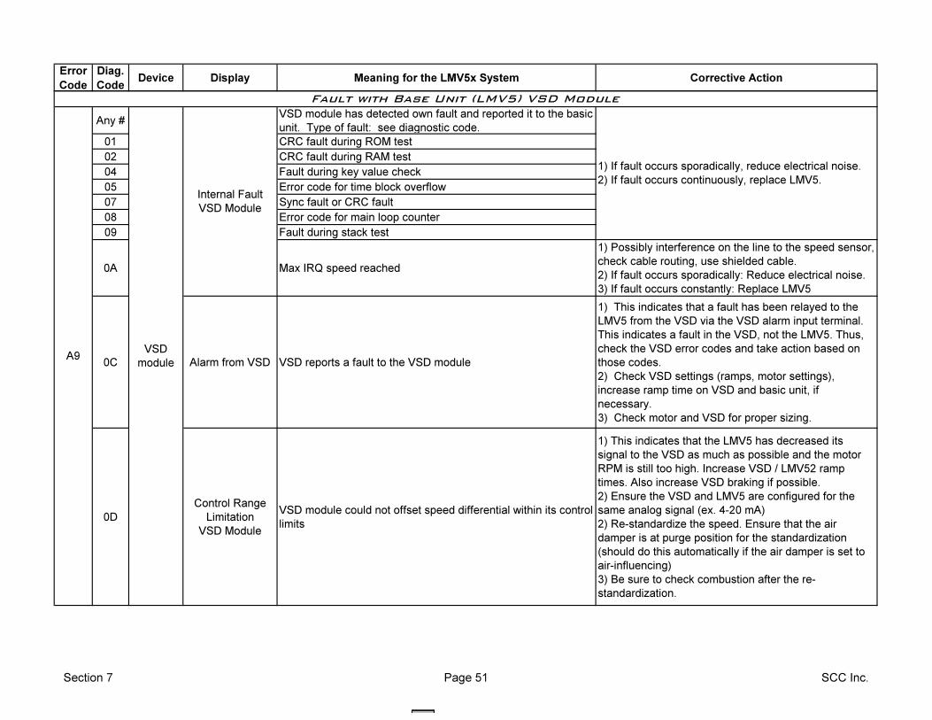
Error
Code
Diag.
CodeDevice Display Meaning for the LMV5x System Corrective Action
Any #VSD module has detected own fault and reported it to the basic
unit. Type of fault: see diagnostic code.
01 CRC fault during ROM test
02 CRC fault during RAM test
04 Fault during key value check
05 Error code for time block overflow
07 Sync fault or CRC fault
08 Error code for main loop counter
09 Fault during stack test
0A Max IRQ speed reached
1) Possibly interference on the line to the speed sensor,
check cable routing, use shielded cable.
2) If fault occurs sporadically: Reduce electrical noise.
3) If fault occurs constantly: Replace LMV5
0C Alarm from VSD VSD reports a fault to the VSD module
1) This indicates that a fault has been relayed to the
LMV5 from the VSD via the VSD alarm input terminal.
This indicates a fault in the VSD, not the LMV5. Thus,
check the VSD error codes and take action based on
those codes.
2) Check VSD settings (ramps, motor settings),
increase ramp time on VSD and basic unit, if
necessary.
3) Check motor and VSD for proper sizing.
0D
Control Range
Limitation
VSD Module
VSD module could not offset speed differential within its control
limits
1) This indicates that the LMV5 has decreased its
signal to the VSD as much as possible and the motor
RPM is still too high. Increase VSD / LMV52 ramp
times. Also increase VSD braking if possible.
2) Ensure the VSD and LMV5 are configured for the
same analog signal (ex. 4-20 mA)
2) Re-standardize the speed. Ensure that the air
damper is at purge position for the standardization
(should do this automatically if the air damper is set to
air-influencing)
3) Be sure to check combustion after the re-
standardization.
Fault with Base Unit (LMV5) VSD Module
A9VSD
module
1) If fault occurs sporadically, reduce electrical noise.
2) If fault occurs continuously, replace LMV5.
Internal Fault
VSD Module
Section 7 Page 51 SCC Inc.
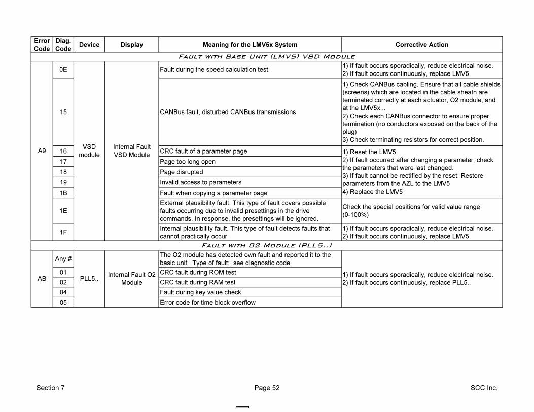
Error
Code
Diag.
CodeDevice Display Meaning for the LMV5x System Corrective Action
0E Fault during the speed calculation test1) If fault occurs sporadically, reduce electrical noise.
2) If fault occurs continuously, replace LMV5.
15 CANBus fault, disturbed CANBus transmissions
1) Check CANBus cabling. Ensure that all cable shields
(screens) which are located in the cable sheath are
terminated correctly at each actuator, O2 module, and
at the LMV5x...
2) Check each CANBus connector to ensure proper
termination (no conductors exposed on the back of the
plug)
3) Check terminating resistors for correct position.
16 CRC fault of a parameter page
17 Page too long open
18 Page disrupted
19 Invalid access to parameters
1B Fault when copying a parameter page
1E
External plausibility fault. This type of fault covers possible
faults occurring due to invalid presettings in the drive
commands. In response, the presettings will be ignored.
Check the special positions for valid value range
(0-100%)
1FInternal plausibility fault. This type of fault detects faults that
cannot practically occur.
1) If fault occurs sporadically, reduce electrical noise.
2) If fault occurs continuously, replace LMV5.
Any #The O2 module has detected own fault and reported it to the
basic unit. Type of fault: see diagnostic code
01 CRC fault during ROM test
02 CRC fault during RAM test
04 Fault during key value check
05 Error code for time block overflow
Internal Fault
VSD Module 1) Reset the LMV5
2) If fault occurred after changing a parameter, check
the parameters that were last changed.
3) If fault cannot be rectified by the reset: Restore
parameters from the AZL to the LMV5
4) Replace the LMV5
Fault with 02 Module (PLL5..)
PLL5..ABInternal Fault O2
Module
1) If fault occurs sporadically, reduce electrical noise.
2) If fault occurs continuously, replace PLL5..
A9VSD
module
Fault with Base Unit (LMV5) VSD Module
Section 7 Page 52 SCC Inc.
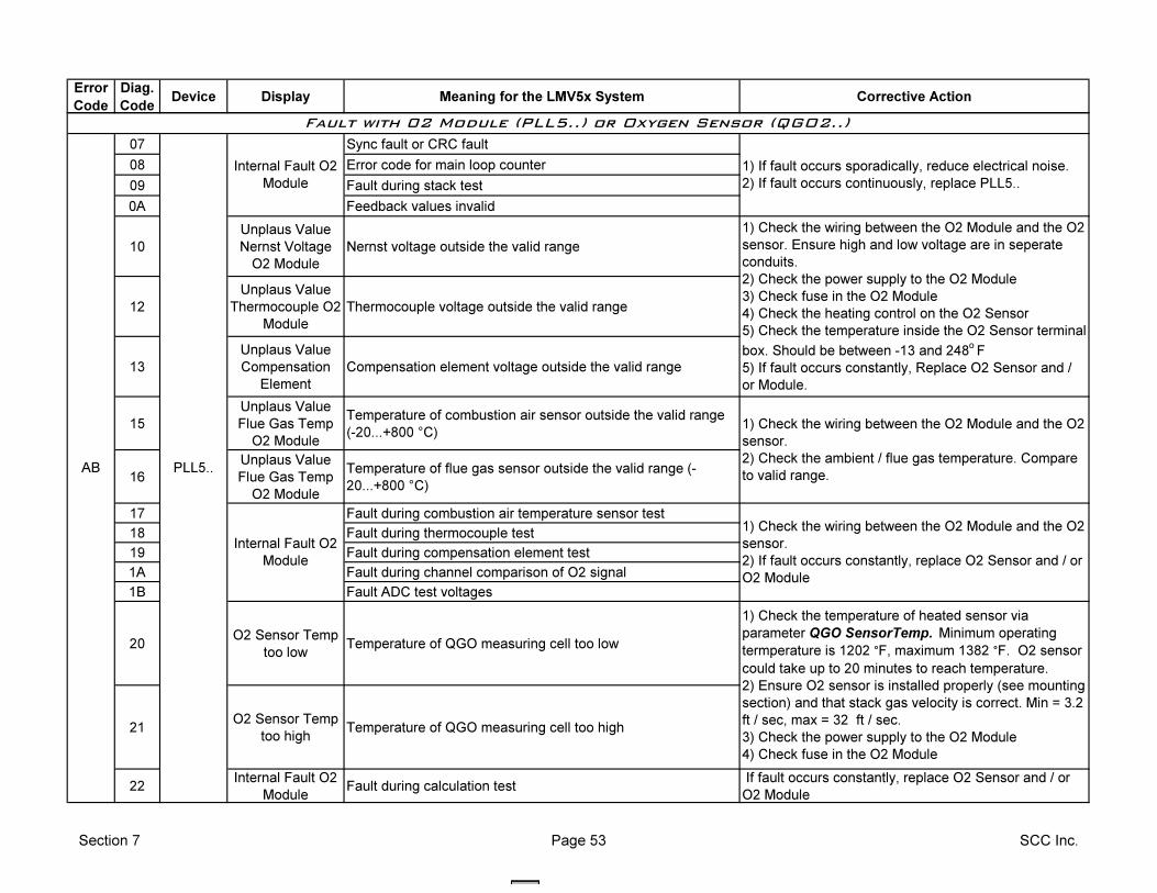
Error
Code
Diag.
CodeDevice Display Meaning for the LMV5x System Corrective Action
07 Sync fault or CRC fault
08 Error code for main loop counter
09 Fault during stack test
0A Feedback values invalid
10
Unplaus Value
Nernst Voltage
O2 Module
Nernst voltage outside the valid range
12
Unplaus Value
Thermocouple O2
Module
Thermocouple voltage outside the valid range
13
Unplaus Value
Compensation
Element
Compensation element voltage outside the valid range
15
Unplaus Value
Flue Gas Temp
O2 Module
Temperature of combustion air sensor outside the valid range
(-20...+800 °C)
16
Unplaus Value
Flue Gas Temp
O2 Module
Temperature of flue gas sensor outside the valid range (-
20...+800 °C)
17 Fault during combustion air temperature sensor test
18 Fault during thermocouple test
19 Fault during compensation element test
1A Fault during channel comparison of O2 signal
1B Fault ADC test voltages
20O2 Sensor Temp
too lowTemperature of QGO measuring cell too low
21O2 Sensor Temp
too highTemperature of QGO measuring cell too high
22Internal Fault O2
ModuleFault during calculation test
If fault occurs constantly, replace O2 Sensor and / or
O2 Module
1) If fault occurs sporadically, reduce electrical noise.
2) If fault occurs continuously, replace PLL5..
Internal Fault O2
Module
1) Check the wiring between the O2 Module and the O2
sensor. Ensure high and low voltage are in seperate
conduits.
2) Check the power supply to the O2 Module
3) Check fuse in the O2 Module
4) Check the heating control on the O2 Sensor
5) Check the temperature inside the O2 Sensor terminal
box. Should be between -13 and 248o
F
5) If fault occurs constantly, Replace O2 Sensor and /
or Module.
Fault with 02 Module (PLL5..) or Oxygen Sensor (QGO2..)
1) Check the wiring between the O2 Module and the O2
sensor.
2) Check the ambient / flue gas temperature. Compare
to valid range.
1) Check the wiring between the O2 Module and the O2
sensor.
2) If fault occurs constantly, replace O2 Sensor and / or
O2 Module
Internal Fault O2
Module
1) Check the temperature of heated sensor via
parameter QGO SensorTemp. Minimum operating
termperature is 1202 °F, maximum 1382 °F. O2 sensor
could take up to 20 minutes to reach temperature.
2) Ensure O2 sensor is installed properly (see mounting
section) and that stack gas velocity is correct. Min = 3.2
ft / sec, max = 32 ft / sec.
3) Check the power supply to the O2 Module
4) Check fuse in the O2 Module
PLL5..AB
Section 7 Page 53 SCC Inc.
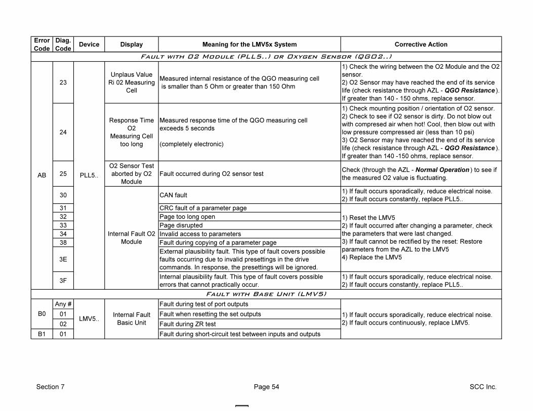
Error
Code
Diag.
CodeDevice Display Meaning for the LMV5x System Corrective Action
23
Unplaus Value
Ri 02 Measuring
Cell
Measured internal resistance of the QGO measuring cell
is smaller than 5 Ohm or greater than 150 Ohm
1) Check the wiring between the O2 Module and the O2
sensor.
2) O2 Sensor may have reached the end of its service
life (check resistance through AZL - QGO Resistance ).
If greater than 140 - 150 ohms, replace sensor.
24
Response Time
O2
Measuring Cell
too long
Measured response time of the QGO measuring cell
exceeds 5 seconds
(completely electronic)
1) Check mounting position / orientation of O2 sensor.
2) Check to see if O2 sensor is dirty. Do not blow out
with compresed air when hot! Cool, then blow out with
low pressure compressed air (less than 10 psi)
3) O2 Sensor may have reached the end of its service
life (check resistance through AZL - QGO Resistance ).
If greater than 140 -150 ohms, replace sensor.
25
O2 Sensor Test
aborted by O2
Module
Fault occurred during O2 sensor testCheck (through the AZL - Normal Operation ) to see if
the measured O2 value is fluctuating.
30 CAN fault1) If fault occurs sporadically, reduce electrical noise.
2) If fault occurs constantly, replace PLL5..
31 CRC fault of a parameter page
32 Page too long open
33 Page disrupted
34 Invalid access to parameters
38 Fault during copying of a parameter page
3E
External plausibility fault. This type of fault covers possible
faults occurring due to invalid presettings in the drive
commands. In response, the presettings will be ignored.
3FInternal plausibility fault. This type of fault covers possible
errors that cannot practically occur.
1) If fault occurs sporadically, reduce electrical noise.
2) If fault occurs constantly, replace PLL5..
Any # Fault during test of port outputs
01 Fault when resetting the set outputs
02 Fault during ZR test
B1 01 Fault during short-circuit test between inputs and outputs
Fault with 02 Module (PLL5..) or Oxygen Sensor (QGO2..)
Fault with Base Unit (LMV5)
B0
1) Reset the LMV5
2) If fault occurred after changing a parameter, check
the parameters that were last changed.
3) If fault cannot be rectified by the reset: Restore
parameters from the AZL to the LMV5
4) Replace the LMV5
PLL5..
1) If fault occurs sporadically, reduce electrical noise.
2) If fault occurs continuously, replace LMV5.
AB
Internal Fault O2
Module
LMV5..Internal Fault
Basic Unit
Section 7 Page 54 SCC Inc.
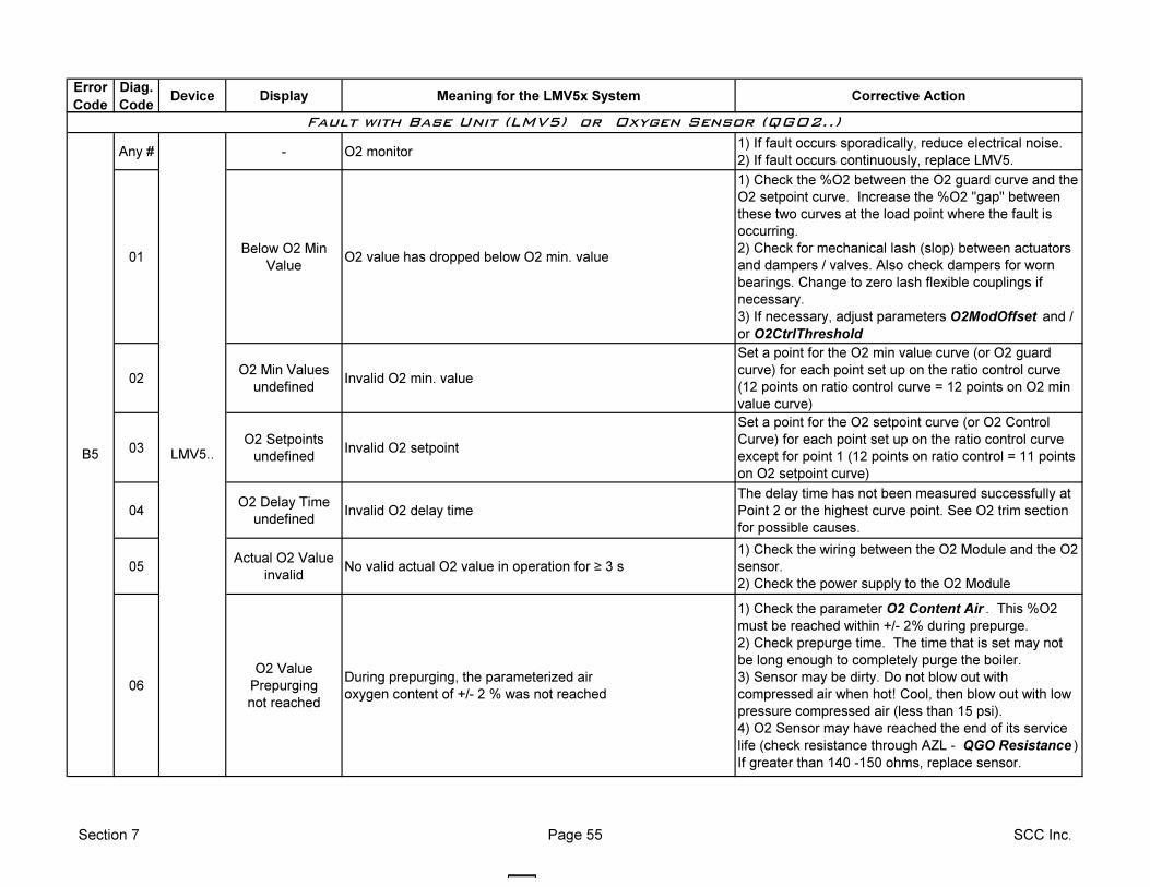
Error
Code
Diag.
CodeDevice Display Meaning for the LMV5x System Corrective Action
Any # - O2 monitor1) If fault occurs sporadically, reduce electrical noise.
2) If fault occurs continuously, replace LMV5.
01Below O2 Min
ValueO2 value has dropped below O2 min. value
1) Check the %O2 between the O2 guard curve and the
O2 setpoint curve. Increase the %O2 "gap" between
these two curves at the load point where the fault is
occurring.
2) Check for mechanical lash (slop) between actuators
and dampers / valves. Also check dampers for worn
bearings. Change to zero lash flexible couplings if
necessary.
3) If necessary, adjust parameters O2ModOffset and /
or O2CtrlThreshold
02O2 Min Values
undefinedInvalid O2 min. value
Set a point for the O2 min value curve (or O2 guard
curve) for each point set up on the ratio control curve
(12 points on ratio control curve = 12 points on O2 min
value curve)
03O2 Setpoints
undefinedInvalid O2 setpoint
Set a point for the O2 setpoint curve (or O2 Control
Curve) for each point set up on the ratio control curve
except for point 1 (12 points on ratio control = 11 points
on O2 setpoint curve)
04O2 Delay Time
undefinedInvalid O2 delay time
The delay time has not been measured successfully at
Point 2 or the highest curve point. See O2 trim section
for possible causes.
05Actual O2 Value
invalidNo valid actual O2 value in operation for ≥ 3 s
1) Check the wiring between the O2 Module and the O2
sensor.
2) Check the power supply to the O2 Module
06
O2 Value
Prepurging
not reached
During prepurging, the parameterized air
oxygen content of +/- 2 % was not reached
1) Check the parameter O2 Content Air . This %O2
must be reached within +/- 2% during prepurge.
2) Check prepurge time. The time that is set may not
be long enough to completely purge the boiler.
3) Sensor may be dirty. Do not blow out with
compressed air when hot! Cool, then blow out with low
pressure compressed air (less than 15 psi).
4) O2 Sensor may have reached the end of its service
life (check resistance through AZL - QGO Resistance )
If greater than 140 -150 ohms, replace sensor.
B5 LMV5..
Fault with Base Unit (LMV5) or Oxygen Sensor (QGO2..)
Section 7 Page 55 SCC Inc.
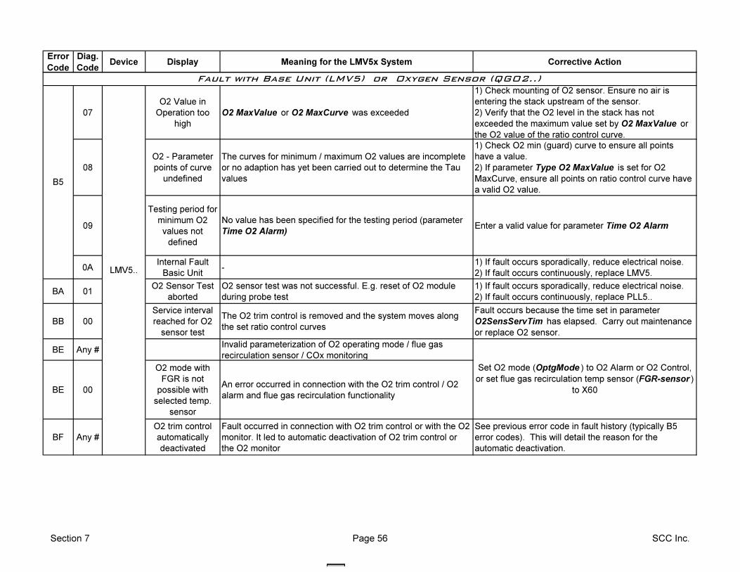
Error
Code
Diag.
CodeDevice Display Meaning for the LMV5x System Corrective Action
07
O2 Value in
Operation too
high
O2 MaxValue or O2 MaxCurve was exceeded
1) Check mounting of O2 sensor. Ensure no air is
entering the stack upstream of the sensor.
2) Verify that the O2 level in the stack has not
exceeded the maximum value set by O2 MaxValue or
the O2 value of the ratio control curve.
08
O2 - Parameter
points of curve
undefined
The curves for minimum / maximum O2 values are incomplete
or no adaption has yet been carried out to determine the Tau
values
1) Check O2 min (guard) curve to ensure all points
have a value.
2) If parameter Type O2 MaxValue is set for O2
MaxCurve, ensure all points on ratio control curve have
a valid O2 value.
09
Testing period for
minimum O2
values not
defined
No value has been specified for the testing period (parameter
Time O2 Alarm)Enter a valid value for parameter Time O2 Alarm
0AInternal Fault
Basic Unit-
1) If fault occurs sporadically, reduce electrical noise.
2) If fault occurs continuously, replace LMV5.
BA 01O2 Sensor Test
aborted
O2 sensor test was not successful. E.g. reset of O2 module
during probe test
1) If fault occurs sporadically, reduce electrical noise.
2) If fault occurs continuously, replace PLL5..
BB 00
Service interval
reached for O2
sensor test
The O2 trim control is removed and the system moves along
the set ratio control curves
Fault occurs because the time set in parameter
O2SensServTim has elapsed. Carry out maintenance
or replace O2 sensor.
BE Any #Invalid parameterization of O2 operating mode / flue gas
recirculation sensor / COx monitoring
BE 00
O2 mode with
FGR is not
possible with
selected temp.
sensor
An error occurred in connection with the O2 trim control / O2
alarm and flue gas recirculation functionality
BF Any #
O2 trim control
automatically
deactivated
Fault occurred in connection with O2 trim control or with the O2
monitor. It led to automatic deactivation of O2 trim control or
the O2 monitor
See previous error code in fault history (typically B5
error codes). This will detail the reason for the
automatic deactivation.
Fault with Base Unit (LMV5) or Oxygen Sensor (QGO2..)
B5
Set O2 mode (OptgMode ) to O2 Alarm or O2 Control,
or set flue gas recirculation temp sensor (FGR-sensor )
to X60
LMV5..
Section 7 Page 56 SCC Inc.
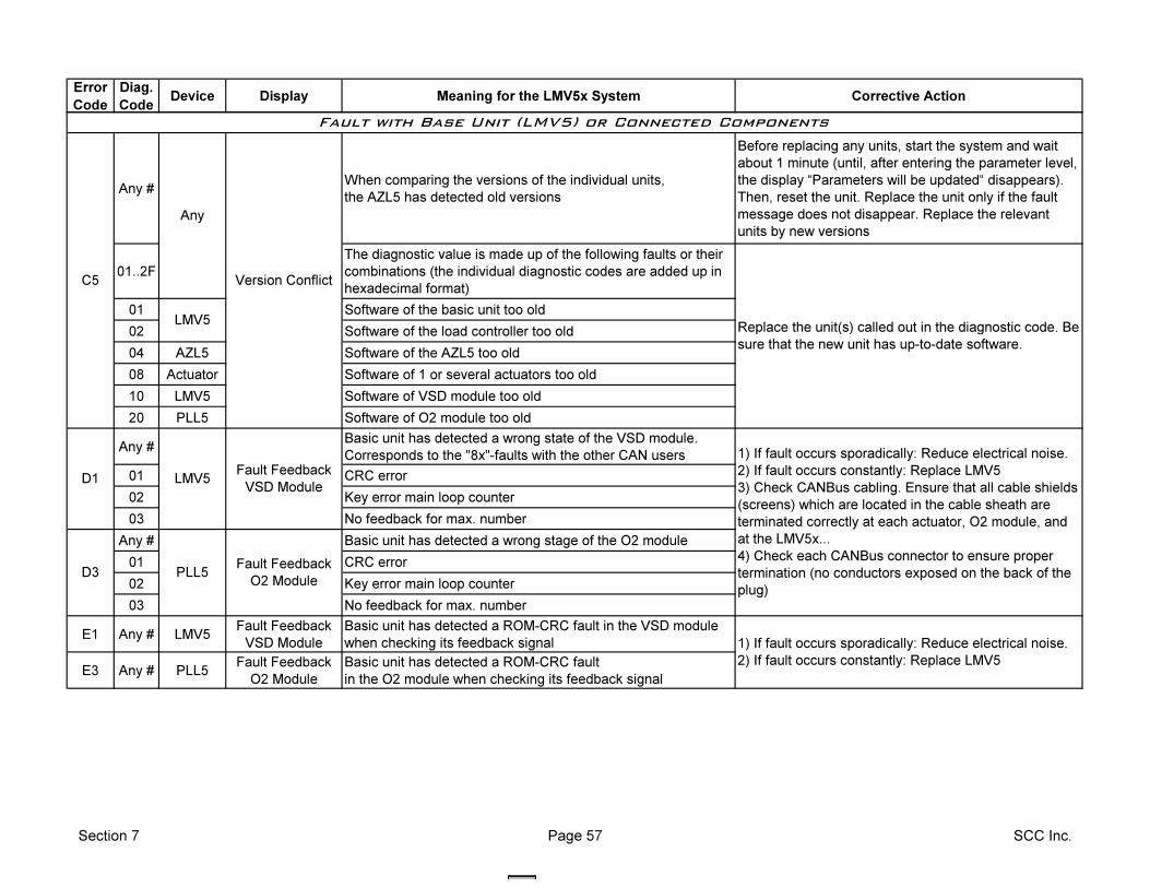
Error
Code
Diag.
CodeDevice Display Meaning for the LMV5x System Corrective Action
Any #When comparing the versions of the individual units,
the AZL5 has detected old versions
Before replacing any units, start the system and wait
about 1 minute (until, after entering the parameter level,
the display “Parameters will be updated“ disappears).
Then, reset the unit. Replace the unit only if the fault
message does not disappear. Replace the relevant
units by new versions
01..2F
The diagnostic value is made up of the following faults or their
combinations (the individual diagnostic codes are added up in
hexadecimal format)
01 Software of the basic unit too old
02 Software of the load controller too old
04 AZL5 Software of the AZL5 too old
08 Actuator Software of 1 or several actuators too old
10 LMV5 Software of VSD module too old
20 PLL5 Software of O2 module too old
Any #Basic unit has detected a wrong state of the VSD module.
Corresponds to the "8x"-faults with the other CAN users
01 CRC error
02 Key error main loop counter
03 No feedback for max. number
Any # Basic unit has detected a wrong stage of the O2 module
01 CRC error
02 Key error main loop counter
03 No feedback for max. number
E1 Any # LMV5Fault Feedback
VSD Module
Basic unit has detected a ROM-CRC fault in the VSD module
when checking its feedback signal
E3 Any # PLL5Fault Feedback
O2 Module
Basic unit has detected a ROM-CRC fault
in the O2 module when checking its feedback signal
PLL5
Fault Feedback
VSD ModuleLMV5
Any
1) If fault occurs sporadically: Reduce electrical noise.
2) If fault occurs constantly: Replace LMV5
3) Check CANBus cabling. Ensure that all cable shields
(screens) which are located in the cable sheath are
terminated correctly at each actuator, O2 module, and
at the LMV5x...
4) Check each CANBus connector to ensure proper
termination (no conductors exposed on the back of the
plug)
Fault Feedback
O2 Module
D1
D3
Version Conflict
LMV5
C5
Replace the unit(s) called out in the diagnostic code. Be
sure that the new unit has up-to-date software.
Fault with Base Unit (LMV5) or Connected Components
1) If fault occurs sporadically: Reduce electrical noise.
2) If fault occurs constantly: Replace LMV5
Section 7 Page 57 SCC Inc.
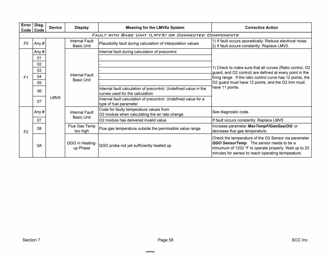
Error
Code
Diag.
CodeDevice Display Meaning for the LMV5x System Corrective Action
F0 Any #Internal Fault
Basic UnitPlausibility fault during calculation of interpolation values
1) If fault occurs sporadically: Reduce electrical noise.
2) If fault occurs constantly: Replace LMV5.
Any # Internal fault during calculation of precontrol
01 -
02 -
03 -
04 -
05 -
06Internal fault calculation of precontrol. Undefined value in the
curves used for the calculation
07Internal fault calculation of precontrol. Undefined value for a
type of fuel parameter
Any #Code for faulty temperature values from
O2 module when calculating the air rate changeSee diagnostic code.
07 O2 module has delivered invalid value If fault occurs constantly: Replace LMV5
08Flue Gas Temp
too highFlue gas temperature outside the permissible value range
Increase parameter MaxTempFlGasGas(Oil) or
decrease flue gas temperature.
0AQGO in Heating-
up PhaseQGO probe not yet sufficiently heated up
Check the temperature of the O2 Sensor via parameter
QGO SensorTemp . The sensor needs to be a
minumum of 1202 °F to operate properly. Wait up to 20
minutes for sensor to reach operating termpeature.
Fault with Base Unit (LMV5) or Connected Components
F1Internal Fault
Basic Unit
1) Check to make sure that all curves (Ratio control, O2
guard, and O2 control) are defined at every point in the
firing range. If the ratio control curve has 12 points, the
O2 guard must have 12 points, and the O2 trim must
have 11 points.
LMV5
F2
Internal Fault
Basic Unit
Section 7 Page 58 SCC Inc.
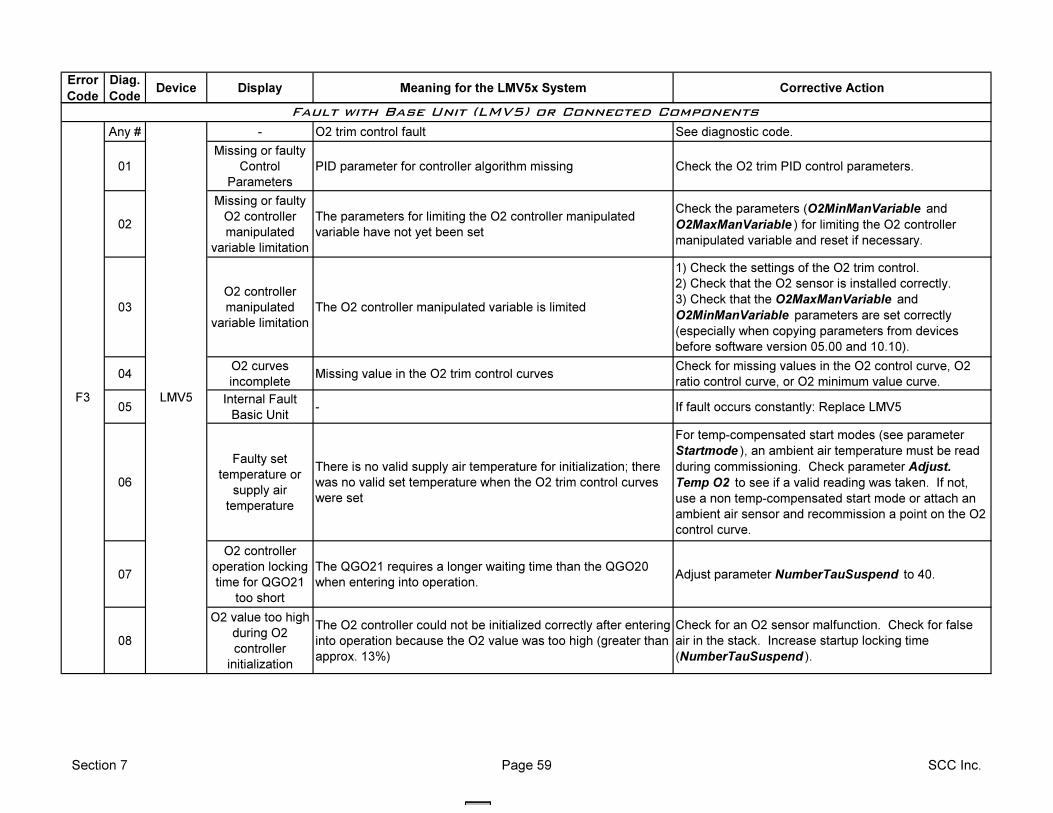
Error
Code
Diag.
CodeDevice Display Meaning for the LMV5x System Corrective Action
Any # - O2 trim control fault See diagnostic code.
01
Missing or faulty
Control
Parameters
PID parameter for controller algorithm missing Check the O2 trim PID control parameters.
02
Missing or faulty
O2 controller
manipulated
variable limitation
The parameters for limiting the O2 controller manipulated
variable have not yet been set
Check the parameters (O2MinManVariable and
O2MaxManVariable ) for limiting the O2 controller
manipulated variable and reset if necessary.
03
O2 controller
manipulated
variable limitation
The O2 controller manipulated variable is limited
1) Check the settings of the O2 trim control.
2) Check that the O2 sensor is installed correctly.
3) Check that the O2MaxManVariable and
O2MinManVariable parameters are set correctly
(especially when copying parameters from devices
before software version 05.00 and 10.10).
04O2 curves
incompleteMissing value in the O2 trim control curves
Check for missing values in the O2 control curve, O2
ratio control curve, or O2 minimum value curve.
05Internal Fault
Basic Unit- If fault occurs constantly: Replace LMV5
06
Faulty set
temperature or
supply air
temperature
There is no valid supply air temperature for initialization; there
was no valid set temperature when the O2 trim control curves
were set
For temp-compensated start modes (see parameter
Startmode ), an ambient air temperature must be read
during commissioning. Check parameter Adjust.
Temp O2 to see if a valid reading was taken. If not,
use a non temp-compensated start mode or attach an
ambient air sensor and recommission a point on the O2
control curve.
07
O2 controller
operation locking
time for QGO21
too short
The QGO21 requires a longer waiting time than the QGO20
when entering into operation.Adjust parameter NumberTauSuspend to 40.
08
O2 value too high
during O2
controller
initialization
The O2 controller could not be initialized correctly after entering
into operation because the O2 value was too high (greater than
approx. 13%)
Check for an O2 sensor malfunction. Check for false
air in the stack. Increase startup locking time
(NumberTauSuspend ).
Fault with Base Unit (LMV5) or Connected Components
F3 LMV5
Section 7 Page 59 SCC Inc.
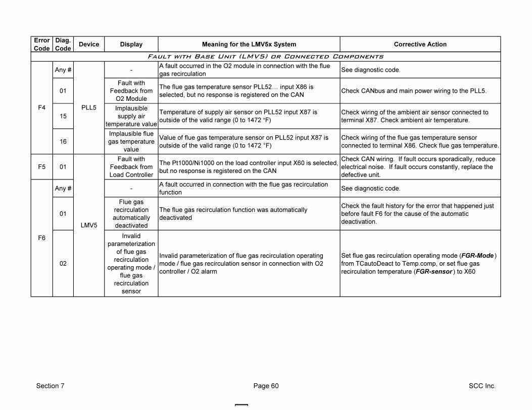
Error
Code
Diag.
CodeDevice Display Meaning for the LMV5x System Corrective Action
Any # -A fault occurred in the O2 module in connection with the flue
gas recirculationSee diagnostic code.
01
Fault with
Feedback from
O2 Module
The flue gas temperature sensor PLL52I input X86 is
selected, but no response is registered on the CANCheck CANbus and main power wiring to the PLL5.
15
Implausible
supply air
temperature value
Temperature of supply air sensor on PLL52 input X87 is
outside of the valid range (0 to 1472 °F)
Check wiring of the ambient air sensor connected to
terminal X87. Check ambient air temperature.
16
Implausible flue
gas temperature
value
Value of flue gas temperature sensor on PLL52 input X87 is
outside of the valid range (0 to 1472 °F)
Check wiring of the flue gas temperature sensor
connected to terminal X86. Check flue gas temperature.
F5 01
Fault with
Feedback from
Load Controller
The Pt1000/Ni1000 on the load controller input X60 is selected,
but no response is registered on the CAN
Check CAN wiring. If fault occurs sporadically, reduce
electrical noise. If fault occurs constantly, replace the
defective unit.
Any # -A fault occurred in connection with the flue gas recirculation
functionSee diagnostic code.
01
Flue gas
recirculation
automatically
deactivated
The flue gas recirculation function was automatically
deactivated
Check the fault history for the error that happened just
before fault F6 for the cause of the automatic
deactivation.
02
Invalid
parameterization
of flue gas
recirculation
operating mode /
flue gas
recirculation
sensor
Invalid parameterization of flue gas recirculation operating
mode / flue gas recirculation sensor in connection with O2
controller / O2 alarm
Set flue gas recirculation operating mode (FGR-Mode )
from TCautoDeact to Temp.comp, or set flue gas
recirculation temperature (FGR-sensor ) to X60
F4 PLL5
F6
LMV5
Fault with Base Unit (LMV5) or Connected Components
Section 7 Page 60 SCC Inc.

Section 1 Overview
Section 2 Wiring
Section 3 Parameters
Section 4 Commissioning
Section 5 VSD
Section 6 O2 Trim
Section 7 Troubleshooting
Section 8 Modbus
Section 9 ACS450
Section 10 Revision History
Appendix A Application Guide
Appendix B* Complimentary Products Guide
*Can be found at www.scccombustion.com.
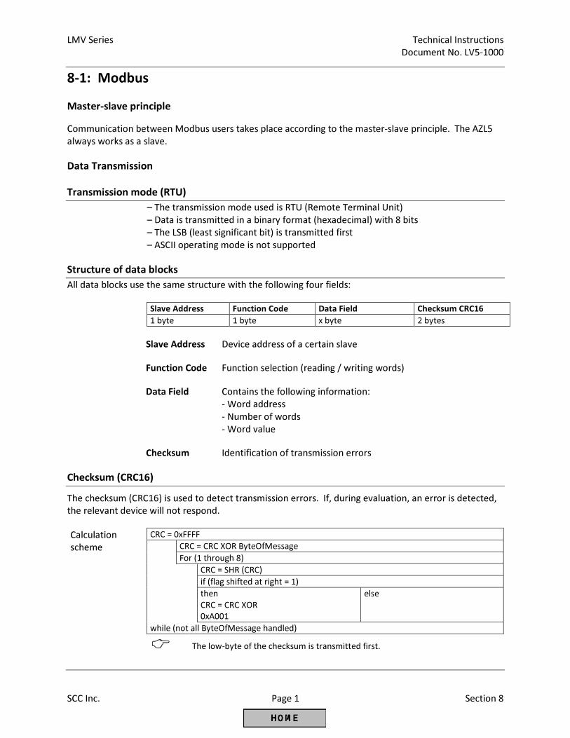
LMV Series Technical Instructions
Document No. LV5-1000
SCC Inc. Page 1 Section 8
8-1: Modbus
Master-slave principle
Communication between Modbus users takes place according to the master-slave principle. The AZL5
always works as a slave.
Data Transmission
Transmission mode (RTU)
– The transmission mode used is RTU (Remote Terminal Unit)
– Data is transmitted in a binary format (hexadecimal) with 8 bits
– The LSB (least significant bit) is transmitted first
– ASCII operating mode is not supported
Structure of data blocks
All data blocks use the same structure with the following four fields:
Slave Address Function Code Data Field Checksum CRC16
1 byte 1 byte x byte 2 bytes
Slave Address Device address of a certain slave
Function Code Function selection (reading / writing words)
Data Field Contains the following information: - Word address - Number of words - Word value
Checksum Identification of transmission errors
Checksum (CRC16)
The checksum (CRC16) is used to detect transmission errors. If, during evaluation, an error is detected,
the relevant device will not respond.
Calculation
scheme CRC = 0xFFFF
CRC = CRC XOR ByteOfMessage
For (1 through 8)
CRC = SHR (CRC)
if (flag shifted at right = 1)
then
CRC = CRC XOR
0xA001
else
while (not all ByteOfMessage handled)
� The low-byte of the checksum is transmitted first.
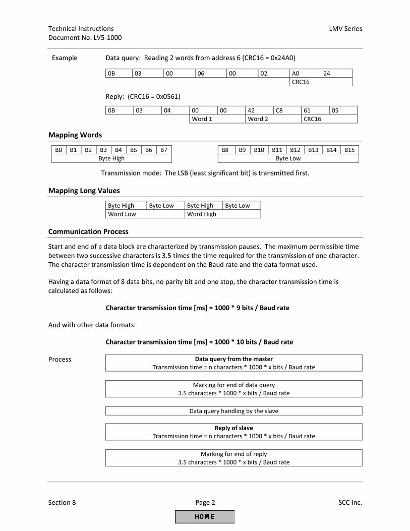
Technical Instructions LMV Series
Document No. LV5-1000
Section 8 Page 2 SCC Inc.
Example Data query: Reading 2 words from address 6 (CRC16 = 0x24A0)
0B 03 00 06 00 02 A0 24
CRC16
Reply: (CRC16 = 0x0561)
0B 03 04 00 00 42 C8 61 05
Word 1 Word 2 CRC16
Mapping Words
B0 B1 B2 B3 B4 B5 B6 B7 B8 B9 B10 B11 B12 B13 B14 B15
Byte High Byte Low
Transmission mode: The LSB (least significant bit) is transmitted first.
Mapping Long Values
Byte High Byte Low Byte High Byte Low
Word Low Word High
Communication Process
Start and end of a data block are characterized by transmission pauses. The maximum permissible time
between two successive characters is 3.5 times the time required for the transmission of one character.
The character transmission time is dependent on the Baud rate and the data format used.
Having a data format of 8 data bits, no parity bit and one stop, the character transmission time is
calculated as follows:
Character transmission time [ms] = 1000 * 9 bits / Baud rate
And with other data formats:
Character transmission time [ms] = 1000 * 10 bits / Baud rate
Process Data query from the master
Transmission time = n characters * 1000 * x bits / Baud rate
Marking for end of data query
3.5 characters * 1000 * x bits / Baud rate
Data query handling by the slave
Reply of slave
Transmission time = n characters * 1000 * x bits / Baud rate
Marking for end of reply
3.5 characters * 1000 * x bits / Baud rate
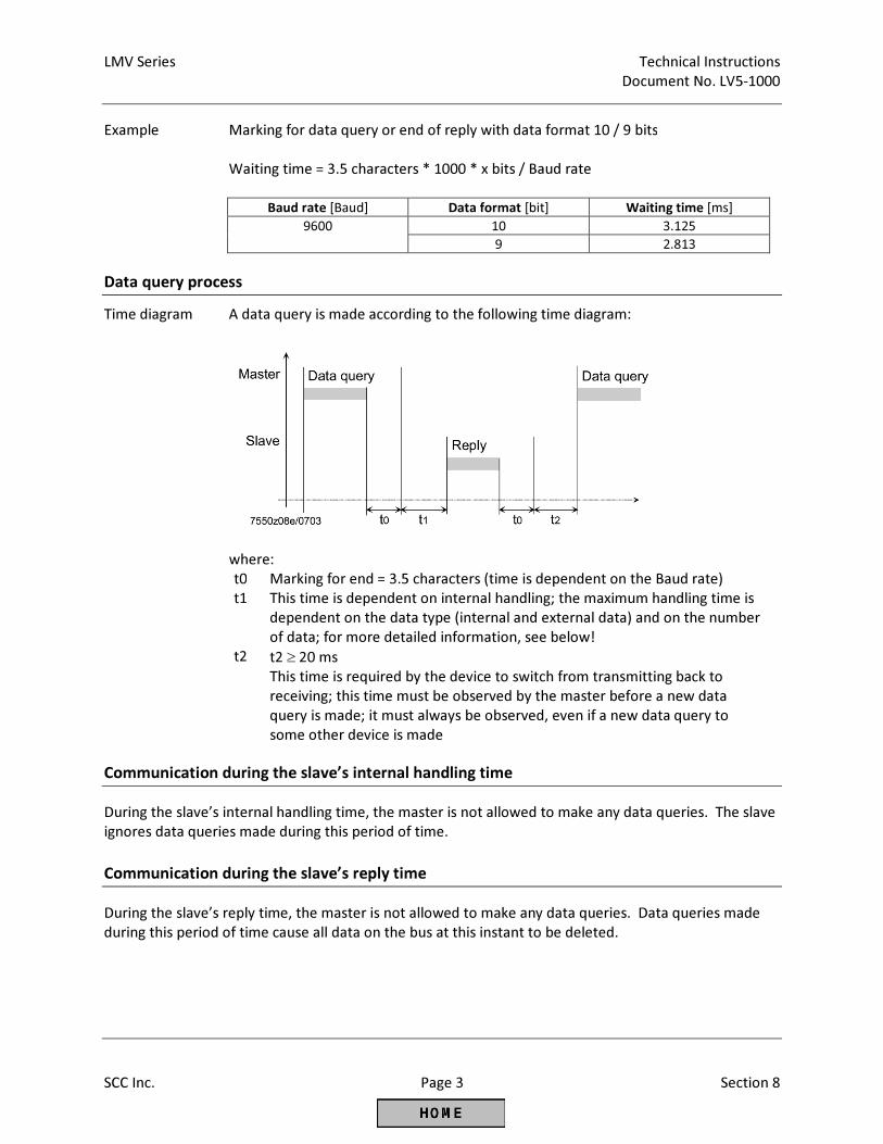
LMV Series Technical Instructions
Document No. LV5-1000
SCC Inc. Page 3 Section 8
Example Marking for data query or end of reply with data format 10 / 9 bits
Waiting time = 3.5 characters * 1000 * x bits / Baud rate
Baud rate [Baud] Data format [bit] Waiting time [ms]
9600 10 3.125
9 2.813
Data query process
Time diagram A data query is made according to the following time diagram:
where:
t0 Marking for end = 3.5 characters (time is dependent on the Baud rate) t1 This time is dependent on internal handling; the maximum handling time is
dependent on the data type (internal and external data) and on the number
of data; for more detailed information, see below! t2 t2 ≥ 20 ms
This time is required by the device to switch from transmitting back to
receiving; this time must be observed by the master before a new data
query is made; it must always be observed, even if a new data query to
some other device is made
Communication during the slave’s internal handling time
During the slave’s internal handling time, the master is not allowed to make any data queries. The slave
ignores data queries made during this period of time.
Communication during the slave’s reply time
During the slave’s reply time, the master is not allowed to make any data queries. Data queries made
during this period of time cause all data on the bus at this instant to be deleted.
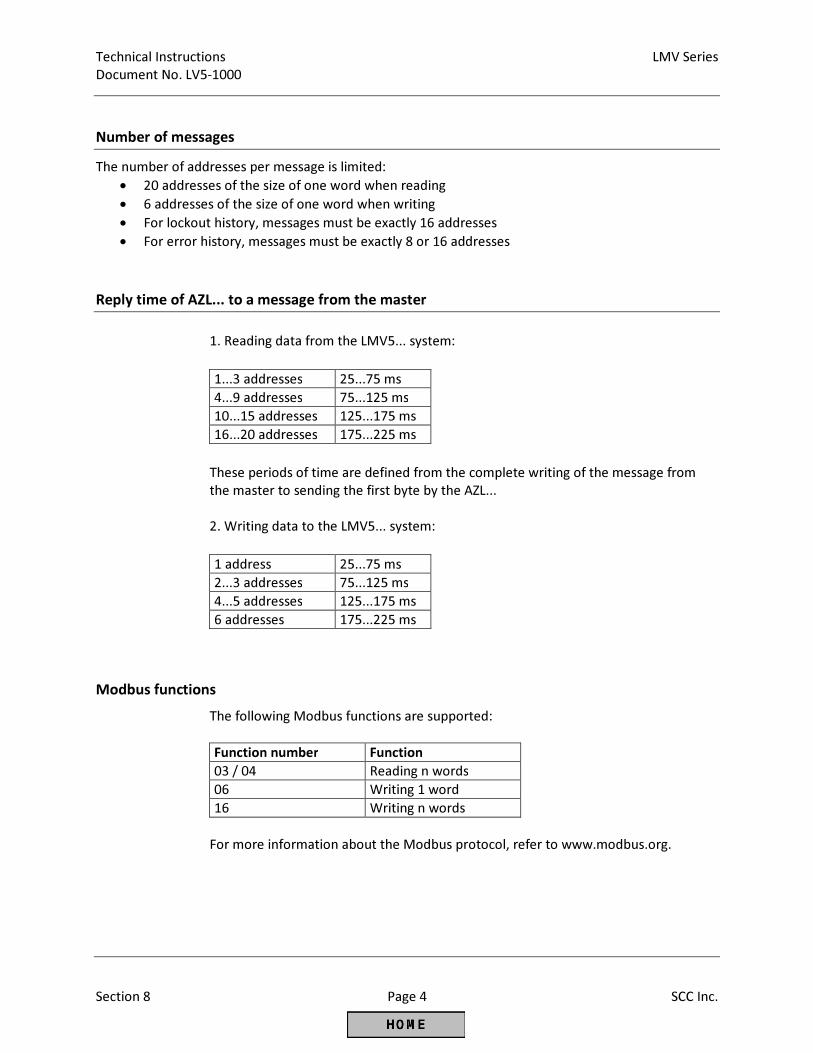
Technical Instructions LMV Series
Document No. LV5-1000
Section 8 Page 4 SCC Inc.
Number of messages
The number of addresses per message is limited:
• 20 addresses of the size of one word when reading
• 6 addresses of the size of one word when writing
• For lockout history, messages must be exactly 16 addresses
• For error history, messages must be exactly 8 or 16 addresses
Reply time of AZL... to a message from the master
1. Reading data from the LMV5... system:
1...3 addresses 25...75 ms 4...9 addresses 75...125 ms 10...15 addresses 125...175 ms 16...20 addresses 175...225 ms
These periods of time are defined from the complete writing of the message from
the master to sending the first byte by the AZL...
2. Writing data to the LMV5... system:
1 address 25...75 ms 2...3 addresses 75...125 ms 4...5 addresses 125...175 ms 6 addresses 175...225 ms
Modbus functions
The following Modbus functions are supported:
Function number Function
03 / 04 Reading n words 06 Writing 1 word 16 Writing n words
For more information about the Modbus protocol, refer to www.modbus.org.
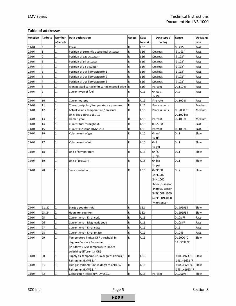
LMV Series Technical Instructions
Document No. LV5-1000
SCC Inc. Page 5 Section 8
Table of addresses Function Address Number
of words
Data designation Access Data
format
Data type /
coding
Range Updating
rate
03/04 0 1 Phase R U16 0...255 Fast
03/04 1 1 Position of currently active fuel actuator R S16 Degrees -3... 93° Fast
03/04 2 1 Position of gas actuator R S16 Degrees -3...93° Fast
03/04 3 1 Position of oil actuator R S16 Degrees -3...93° Fast
03/04 4 1 Position of air actuator R S16 Degrees -3...93° Fast
03/04 5 1 Position of auxiliary actuator 1 R S16 Degrees -3...93° Fast
03/04 6 1 Position of auxiliary actuator 2 R S16 Degrees -3...93° Fast
03/04 7 1 Position of auxiliary actuator 3 R S16 Degrees -3...93° Fast
03/04 8 1 Manipulated variable for variable speed drive R S16 Percent 0…110 % Fast
03/04 9 1 Current type of fuel R U16 0= Gas
1= Oil
0...1 Fast
03/04 10 1 Current output R U16 Fire rate 0…100 % Fast
03/04 11 1 Current setpoint / temperature / pressure R U16 Process units Medium
03/04 12 1 Actual value / temperature / pressure
Unit: See address 18 / 19
R U16 Process units 0…2000 °C
0…100 bar
Medium
03/04 13 1 Flame signal R U16 Percent 0…100 % Medium
03/04 14 1 Current fuel throughput R U16 0..65534 Fast
03/04 15 1 Current O2 value (LMV52...) R U16 Percent 0…100 % Fast
03/04 16 1 Volume unit of gas R U16 0= m³
1= ft³
0…1 Slow
03/04 17 1 Volume unit of oil R U16 0= l
1= gal
0…1 Slow
03/04 18 1 Unit of temperature R U16 0= °C
1= °F
0…1 Slow
03/04 19 1 Unit of pressure R U16 0= bar
1= psi
0…1 Slow
03/04 20 1 Sensor selection R U16 0=Pt100
1=Pt1000
2=Ni1000
3=temp. sensor
4=press. sensor
5=Pt100Pt1000
6=Pt100Ni1000
7=no sensor
0…7 Slow
03/04 21, 22 2 Startup counter total R S32 0…999999 Slow
03/04 23, 24 2 Hours run counter R S32 0…999999 Slow
03/04 25 1 Current error: Error code R U16 0...0x FF Fast
03/04 26 1 Current error: Diagnostic code R U16 0…0x FF Fast
03/04 27 1 Current error: Error class R U16 0...5 Fast
03/04 28 1 Current error: Error phase R U16 0...255 Fast
03/04 29 1 Temperature limiter OFF threshold, in
degrees Celsius / Fahrenheit
(in address 129: Temperature limiter
switching differential ON)
R U16 0…2000 °C
32…3632 °F
Slow
03/04 30 1 Supply air temperature, in degrees Celsius /
Fahrenheit (LMV52...)
R U16 -100…+923 °C
-148..+1693 °F
Slow
03/04 31 1 Flue gas temperature, in degrees Celsius /
Fahrenheit (LMV52...)
R U16 -100...+923 °C
-148...+1693 °F
Slow
03/04 32 1 Combustion efficiency (LMV52...) R U16 Percent 0...200 % Slow
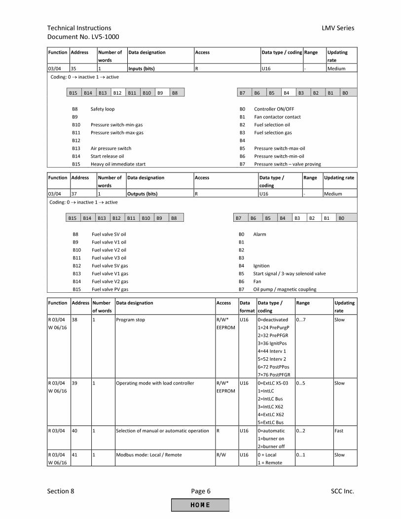
Technical Instructions LMV Series
Document No. LV5-1000
Section 8 Page 6 SCC Inc.
Function Address Number of
words
Data designation Access Data type / coding Range Updating
rate
03/04 35 1 Inputs (bits) R U16 - Medium
Coding: 0 → inactive 1 → active
B15 B14 B13 B12 B11 B10 B9 B8 B7 B6 B5 B4 B3 B2 B1 B0
B8
B9
B10
Safety loop
Pressure switch-min-gas
B0
B1
B2
Controller ON/OFF
Fan contactor contact
Fuel selection oil
B11 Pressure switch-max-gas B3 Fuel selection gas
B12 B4
B13 Air pressure switch B5 Pressure switch-max-oil
B14 Start release oil B6 Pressure switch-min-oil
B15 Heavy oil immediate start B7 Pressure switch – valve proving
Function Address Number of
words
Data designation Access Data type /
coding
Range Updating rate
03/04 37 1 Outputs (bits) R U16 - Medium
Coding: 0 → inactive 1 → active
B15 B14 B13 B12 B11 B10 B9 B8 B7 B6 B5 B4 B3 B2 B1 B0
B8 Fuel valve SV oil B0 Alarm
B9 Fuel valve V1 oil B1
B10 Fuel valve V2 oil B2
B11 Fuel valve V3 oil B3
B12 Fuel valve SV gas B4 Ignition
B13 Fuel valve V1 gas B5 Start signal / 3-way solenoid valve
B14 Fuel valve V2 gas B6 Fan
B15 Fuel valve PV gas B7 Oil pump / magnetic coupling
Function Address Number
of words
Data designation Access Data
format
Data type /
coding
Range Updating
rate
R 03/04
W 06/16
38 1 Program stop R/W*
EEPROM
U16 0=deactivated
1=24 PrePurgP
2=32 PrePFGR
3=36 IgnitPos
4=44 Interv 1
5=52 Interv 2
6=72 PostPPos
7=76 PostPFGR
0...7 Slow
R 03/04
W 06/16
39 1 Operating mode with load controller R/W*
EEPROM
U16 0=ExtLC X5-03
1=IntLC
2=IntLC Bus
3=IntLC X62
4=ExtLC X62
5=ExtLC Bus
0…5 Slow
R 03/04
40 1 Selection of manual or automatic operation R U16 0=automatic
1=burner on
2=burner off
0…2 Fast
R 03/04
W 06/16
41 1 Modbus mode: Local / Remote R/W U16 0 = Local
1 = Remote
0…1 Slow
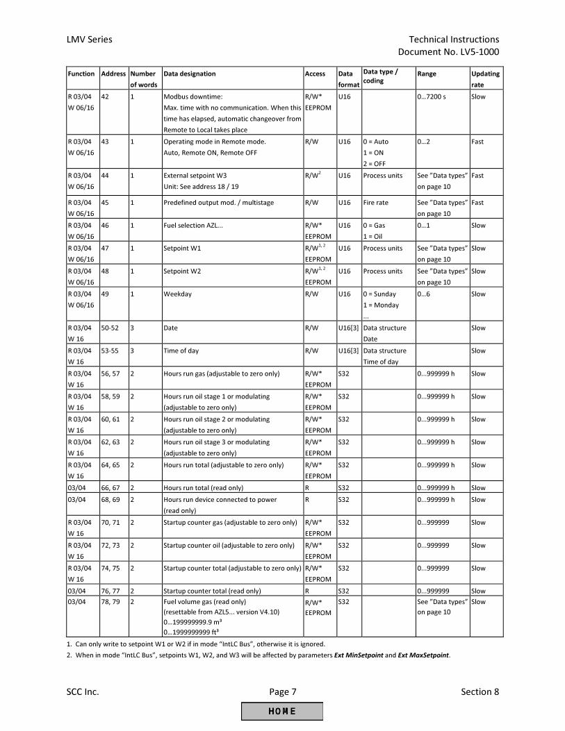
LMV Series Technical Instructions
Document No. LV5-1000
SCC Inc. Page 7 Section 8
Function Address Number
of words
Data designation Access Data
format
Data type /
coding Range Updating
rate
R 03/04
W 06/16
42 1 Modbus downtime:
Max. time with no communication. When this
time has elapsed, automatic changeover from
Remote to Local takes place
R/W*
EEPROM
U16 0…7200 s Slow
R 03/04
W 06/16
43 1 Operating mode in Remote mode.
Auto, Remote ON, Remote OFF
R/W U16 0 = Auto
1 = ON
2 = OFF
0…2 Fast
R 03/04
W 06/16
44 1 External setpoint W3
Unit: See address 18 / 19
R/W2 U16 Process units See ”Data types”
on page 10
Fast
R 03/04
W 06/16
45 1 Predefined output mod. / multistage R/W U16 Fire rate See ”Data types”
on page 10
Fast
R 03/04
W 06/16
46 1 Fuel selection AZL... R/W*
EEPROM
U16 0 = Gas
1 = Oil
0…1 Slow
R 03/04
W 06/16
47 1 Setpoint W1 R/W1, 2
EEPROM
U16 Process units See ”Data types”
on page 10
Slow
R 03/04
W 06/16
48 1 Setpoint W2 R/W1, 2
EEPROM
U16 Process units See ”Data types”
on page 10
Slow
R 03/04
W 06/16
49 1 Weekday R/W U16 0 = Sunday
1 = Monday
...
0…6 Slow
R 03/04
W 16
50-52 3 Date
R/W U16[3]
Data structure
Date
Slow
R 03/04
W 16
53-55 3 Time of day
R/W U16[3] Data structure
Time of day
Slow
R 03/04
W 16
56, 57 2 Hours run gas (adjustable to zero only) R/W*
EEPROM
S32 0...999999 h Slow
R 03/04
W 16
58, 59 2 Hours run oil stage 1 or modulating
(adjustable to zero only)
R/W*
EEPROM
S32 0...999999 h Slow
R 03/04
W 16
60, 61 2 Hours run oil stage 2 or modulating
(adjustable to zero only)
R/W*
EEPROM
S32 0...999999 h Slow
R 03/04
W 16
62, 63 2 Hours run oil stage 3 or modulating
(adjustable to zero only)
R/W*
EEPROM
S32 0...999999 h Slow
R 03/04
W 16
64, 65 2 Hours run total (adjustable to zero only) R/W*
EEPROM
S32 0...999999 h Slow
03/04 66, 67 2 Hours run total (read only) R S32 0...999999 h Slow
03/04 68, 69 2 Hours run device connected to power
(read only)
R S32 0...999999 h Slow
R 03/04
W 16
70, 71 2 Startup counter gas (adjustable to zero only) R/W*
EEPROM
S32 0...999999 Slow
R 03/04
W 16
72, 73 2 Startup counter oil (adjustable to zero only) R/W*
EEPROM
S32 0...999999 Slow
R 03/04
W 16
74, 75 2 Startup counter total (adjustable to zero only) R/W*
EEPROM
S32 0...999999 Slow
03/04 76, 77 2 Startup counter total (read only) R S32 0...999999 Slow
03/04 78, 79 2 Fuel volume gas (read only)
(resettable from AZL5... version V4.10)
0…199999999.9 m³
0…1999999999 ft³
R/W*
EEPROM
S32 See ”Data types”
on page 10
Slow
1. Can only write to setpoint W1 or W2 if in mode “IntLC Bus”, otherwise it is ignored.
2. When in mode “IntLC Bus”, setpoints W1, W2, and W3 will be affected by parameters Ext MinSetpoint and Ext MaxSetpoint.
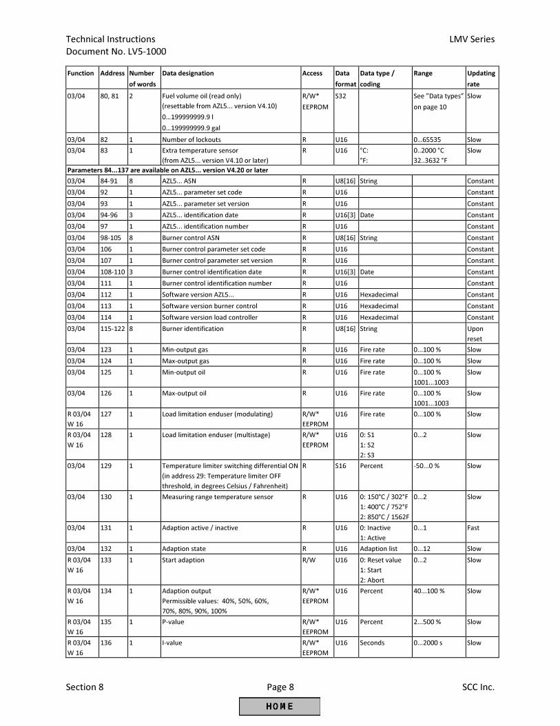
Technical Instructions LMV Series
Document No. LV5-1000
Section 8 Page 8 SCC Inc.
Function Address Number
of words
Data designation Access Data
format
Data type /
coding
Range Updating
rate
03/04 80, 81 2 Fuel volume oil (read only)
(resettable from AZL5... version V4.10)
0…199999999.9 l
0…199999999.9 gal
R/W*
EEPROM
S32 See ”Data types”
on page 10
Slow
03/04 82 1 Number of lockouts R U16 0…65535 Slow
03/04 83 1 Extra temperature sensor
(from AZL5... version V4.10 or later)
R U16 °C:
°F:
0..2000 °C
32..3632 °F
Slow
Parameters 84...137 are available on AZL5... version V4.20 or later
03/04 84-91 8 AZL5... ASN R U8[16] String Constant
03/04 92 1 AZL5... parameter set code R U16 Constant
03/04 93 1 AZL5... parameter set version R U16 Constant
03/04 94-96 3 AZL5... identification date R U16[3] Date Constant
03/04 97 1 AZL5... identification number R U16 Constant
03/04 98-105 8 Burner control ASN R U8[16] String Constant
03/04 106 1 Burner control parameter set code R U16 Constant
03/04 107 1 Burner control parameter set version R U16 Constant
03/04 108-110 3 Burner control identification date R U16[3] Date Constant
03/04 111 1 Burner control identification number R U16 Constant
03/04 112 1 Software version AZL5... R U16 Hexadecimal Constant
03/04 113 1 Software version burner control R U16 Hexadecimal Constant
03/04 114 1 Software version load controller R U16 Hexadecimal Constant
03/04 115-122 8 Burner identification R U8[16] String Upon
reset
03/04 123 1 Min-output gas R U16 Fire rate 0...100 % Slow
03/04 124 1 Max-output gas R U16 Fire rate 0...100 % Slow
03/04 125 1 Min-output oil R U16 Fire rate 0...100 %
1001...1003
Slow
03/04 126 1 Max-output oil R U16 Fire rate 0...100 %
1001...1003
Slow
R 03/04
W 16
127 1 Load limitation enduser (modulating) R/W*
EEPROM
U16 Fire rate 0...100 % Slow
R 03/04
W 16
128 1 Load limitation enduser (multistage) R/W*
EEPROM
U16 0: S1
1: S2
2: S3
0...2 Slow
03/04 129 1 Temperature limiter switching differential ON
(in address 29: Temperature limiter OFF
threshold, in degrees Celsius / Fahrenheit)
R S16 Percent -50...0 % Slow
03/04 130 1 Measuring range temperature sensor R U16 0: 150°C / 302°F
1: 400°C / 752°F
2: 850°C / 1562F
0...2 Slow
03/04 131 1 Adaption active / inactive R U16 0: Inactive
1: Active
0...1 Fast
03/04 132 1 Adaption state R U16 Adaption list 0...12 Slow
R 03/04
W 16
133 1 Start adaption R/W U16 0: Reset value
1: Start
2: Abort
0...2 Slow
R 03/04
W 16
134 1 Adaption output
Permissible values: 40%, 50%, 60%,
70%, 80%, 90%, 100%
R/W*
EEPROM
U16 Percent 40...100 % Slow
R 03/04
W 16
135 1 P-value R/W*
EEPROM
U16 Percent 2...500 % Slow
R 03/04
W 16
136 1 I-value R/W*
EEPROM
U16 Seconds 0...2000 s Slow
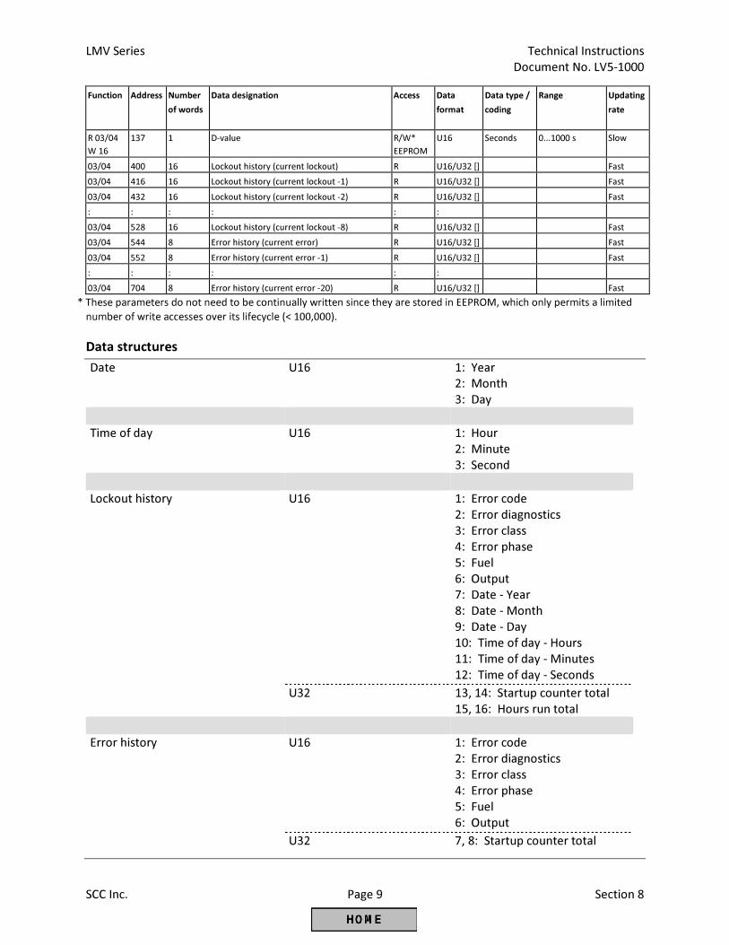
LMV Series Technical Instructions
Document No. LV5-1000
SCC Inc. Page 9 Section 8
Function Address Number
of words
Data designation Access Data
format
Data type /
coding
Range Updating
rate
R 03/04
W 16
137 1 D-value R/W*
EEPROM
U16 Seconds 0...1000 s Slow
03/04 400 16 Lockout history (current lockout) R U16/U32 [] Fast
03/04 416 16 Lockout history (current lockout -1) R U16/U32 [] Fast
03/04 432 16 Lockout history (current lockout -2) R U16/U32 [] Fast
: : : : : :
03/04 528 16 Lockout history (current lockout -8) R U16/U32 [] Fast
03/04 544 8 Error history (current error) R U16/U32 [] Fast
03/04 552 8 Error history (current error -1) R U16/U32 [] Fast
: : : : : :
03/04 704 8 Error history (current error -20) R U16/U32 [] Fast
* These parameters do not need to be continually written since they are stored in EEPROM, which only permits a limited
number of write accesses over its lifecycle (< 100,000).
Data structures
Date U16 1: Year 2: Month 3: Day
Time of day U16 1: Hour
2: Minute 3: Second
Lockout history U16 1: Error code
2: Error diagnostics 3: Error class 4: Error phase 5: Fuel 6: Output 7: Date - Year 8: Date - Month 9: Date - Day 10: Time of day - Hours 11: Time of day - Minutes 12: Time of day - Seconds
U32 13, 14: Startup counter total 15, 16: Hours run total
Error history U16 1: Error code
2: Error diagnostics 3: Error class 4: Error phase 5: Fuel 6: Output
U32 7, 8: Startup counter total
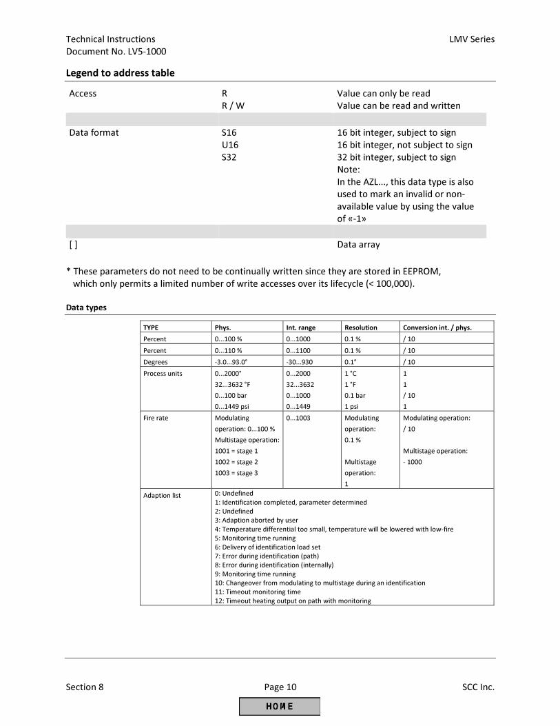
Technical Instructions LMV Series
Document No. LV5-1000
Section 8 Page 10 SCC Inc.
Legend to address table
Access R Value can only be read R / W Value can be read and written
Data format S16
U16 16 bit integer, subject to sign 16 bit integer, not subject to sign
S32 32 bit integer, subject to sign Note: In the AZL..., this data type is also
used to mark an invalid or non-
available value by using the value
of «-1» [ ] Data array
* These parameters do not need to be continually written since they are stored in EEPROM,
which only permits a limited number of write accesses over its lifecycle (< 100,000).
Data types
TYPE Phys. Int. range Resolution Conversion int. / phys.
Percent 0...100 % 0...1000 0.1 % / 10
Percent 0...110 % 0...1100 0.1 % / 10
Degrees -3.0...93.0° -30...930 0.1° / 10
Process units 0...2000°
32...3632 °F
0...100 bar
0...1449 psi
0...2000
32...3632
0...1000
0...1449
1 °C
1 °F
0.1 bar
1 psi
1
1
/ 10
1
Fire rate Modulating
operation: 0...100 %
Multistage operation:
1001 = stage 1
1002 = stage 2
1003 = stage 3
0...1003 Modulating
operation:
0.1 %
Multistage
operation:
1
Modulating operation:
/ 10
Multistage operation:
- 1000
Adaption list 0: Undefined
1: Identification completed, parameter determined
2: Undefined
3: Adaption aborted by user
4: Temperature differential too small, temperature will be lowered with low-fire
5: Monitoring time running
6: Delivery of identification load set
7: Error during identification (path)
8: Error during identification (internally)
9: Monitoring time running
10: Changeover from modulating to multistage during an identification
11: Timeout monitoring time
12: Timeout heating output on path with monitoring
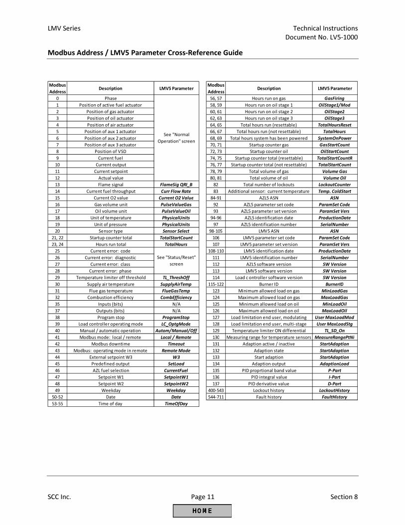
LMV Series Technical Instructions
Document No. LV5-1000
SCC Inc. Page 11 Section 8
Modbus Address / LMV5 Parameter Cross-Reference Guide
Modbus
AddressDescription LMV5 Parameter
Modbus
AddressDescription LMV5 Parameter
0 Phase 56, 57 Hours run on gas GasFiring
1 Position of active fuel actuator 58, 59 Hours run on oil stage 1 OilStage1/Mod
2 Position of gas actuator 60, 61 Hours run on oil stage 2 OilStage2
3 Position of oil actuator 62, 63 Hours run on oil stage 3 OilStage3
4 Position of air actuator 64, 65 Total hours run (resettable) TotalHoursReset
5 Position of aux 1 actuator 66, 67 Total hours run (not resettable) TotalHours
6 Position of aux 2 actuator 68, 69 Total hours system has been powered SystemOnPower
7 Position of aux 3 actuator 70, 71 Startup counter gas GasStartCount
8 Position of VSD 72, 73 Startup counter oil OilStartCount
9 Current fuel 74, 75 Startup counter total (resettable) TotalStartCountR
10 Current output 76, 77 Startup counter total (not resettable) TotalStartCount
11 Current setpoint 78, 79 Total volume of gas Volume Gas
12 Actual value 80, 81 Total volume of oil Volume Oil
13 Flame signal FlameSig QRI_B 82 Total number of lockouts LockoutCounter
14 Current fuel throughput Curr Flow Rate 83 Additional sensor: current temperature Temp. ColdStart
15 Current O2 value Current O2 Value 84-91 AZL5 ASN ASN
16 Gas volume unit PulseValueGas 92 AZL5 parameter set code ParamSet Code
17 Oil volume unit PulseValueOil 93 AZL5 parameter set version ParamSet Vers
18 Unit of temperature PhysicalUnits 94-96 AZL5 identification date ProductionDate
19 Unit of pressure PhysicalUnits 97 AZL5 identification number SerialNumber
20 Sensor type Sensor Select 98-105 LMV5 ASN ASN
21, 22 Startup counter total TotalStartCount 106 LMV5 parameter set code ParamSet Code
23, 24 Hours run total TotalHours 107 LMV5 parameter set version ParamSet Vers
25 Current error: code 108-110 LMV5 identification date ProductionDate
26 Current error: diagnostic 111 LMV5 identification number SerialNumber
27 Current error: class 112 AZL5 software version SW Version
28 Current error: phase 113 LMV5 software version SW Version
29 Temperature limiter off threshold TL_ThreshOff 114 Load c ontroller software version SW Version
30 Supply air temperature SupplyAirTemp 115-122 Burner ID BurnerID
31 Flue gas temperature FlueGasTemp 123 Minimum allowed load on gas MinLoadGas
32 Combustion efficiency CombEfficiency 124 Maximum allowed load on gas MaxLoadGas
35 Inputs (bits) N/A 125 Minimum allowed load on oil MinLoadOil
37 Outputs (bits) N/A 126 Maximum allowed load on oil MaxLoadOil
38 Program stop ProgramStop 127 Load limitation end user, modulating User MaxLoadMod
39 Load controller operating mode LC_OptgMode 128 Load limitation end user, multi-stage User MaxLoadStg
40 Manual / automatic operation Autom/Manual/Off 129 Temperature limiter ON differential TL_SD_On
41 Modbus mode: local / remote Local / Remote 130 Measuring range for temperature sensors MeasureRangePtNi
42 Modbus downtime Timeout 131 Adaption active / inactive StartAdaption
43 Modbus: operating mode in remote Remote Mode 132 Adaption state StartAdaption
44 External setpoint W3 W3 133 Start adaption StartAdaption
45 Predefined output SetLoad 134 Adaption output AdaptionLoad
46 AZL fuel selection CurrentFuel 135 PID proprtional band value P-Part
47 Setpoint W1 SetpointW1 136 PID integral value I-Part
48 Setpoint W2 SetpointW2 137 PID derivative value D-Part
49 Weekday Weekday 400-543 Lockout history LockoutHistory
50-52 Date Date 544-711 Fault history FaultHistory
53-55 Time of day TimeOfDay
See "Status/Reset"
screen
See "Normal
Operation" screen
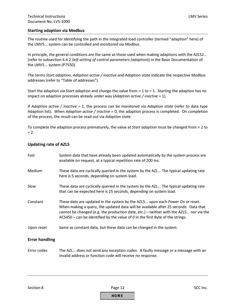
Technical Instructions LMV Series
Document No. LV5-1000
Section 8 Page 12 SCC Inc.
Starting adaption via Modbus
The routine used for identifying the path in the integrated load controller (termed “adaption” here) of
the LMV5... system can be controlled and monitored via Modbus.
In principle, the general conditions are the same as those used when making adaptions with the AZL52...
(refer to subsection 6.4.2 Self-setting of control parameters (adaption)) in the Basic Documentation of
the LMV5... system (P7550).
The terms Start adaption, Adaption active / inactive and Adaption state indicate the respective Modbus
addresses (refer to “Table of addresses”).
Start the adaption via Start adaption and change the value from ≠ 1 to = 1. Starting the adaption has no
impact on adaption processes already under way (Adaption active / inactive = 1).
If Adaption active / inactive = 1, the process can be monitored via Adaption state (refer to data type
Adaption list). When Adaption active / inactive = 0, the adaption process is completed. On completion
of the process, the result can be read out via Adaption state.
To complete the adaption process prematurely, the value at Start adaption must be changed from ≠ 2 to
= 2.
Updating rate of AZL5
Fast System data that have already been updated automatically by the system process are
available on request, at a typical repetition rate of 200 ms.
Medium These data are cyclically queried in the system by the AZL... The typical updating rate
here is 5 seconds, depending on system load.
Slow These data are cyclically queried in the system by the AZL... The typical updating rate
that can be expected here is 25 seconds, depending on system load.
Constant These data are updated in the system by the AZL5... upon each Power On or reset.
When making a query, the updated data will be available after 25 seconds. Data that
cannot be changed (e.g. the production date, etc.) – neither with the AZL5... nor via the
ACS450 – can be identified by the value of 0 in the first Byte of the strings.
Upon reset Same as constant data, but these data can be changed in the system.
Error handling
Error codes The AZL… does not send any exception codes. A faulty message or a message with an
invalid address or function code will receive no response.
LMV Series Technical Instructions
Document No. LV5-1000
SCC Inc. Page 13 Section 8
Selection menus in the AZL5
Activation of Modbus operation
Ensure the gateway mode is set to Modbus:
Operation > OptgModeSelect > Type of Gateway
Activation takes place via menu:
Operation > OptgModeSelect > GatewayBASon
Having made the selection, the menu item can be quit via ESC.The setting is retained until Operation >
OptgModeSelect > GatewayBASoff is selected via the AZL… menu.
When GatewayBASon is activated, plant operation and diagnostics via the AZL... are still possible.
Deactivation takes place via menu:
Operation > OptgModeSelect > GatewayBASoff
Slave address
Selection is made via menu:
Params & Display > AZL > Modbus > Address
According to Modicon specifications, addresses between 1...247 can be selected. The slave address is
filed in nonvolatile memory of the AZL...
Transmission parameters
Transmission rate The setting is made via menu:
Params & Display > AZL > Modbus > Baudrate.
There is a choice of 9600 bit/s or 19200 bit/s.
Parity Using the AZL... menu:
Params & Display > AZL > Modbus > Parity,
parity can be set to none, even or odd.
Timeout communication failure
When there is no Modbus communication, this timeout defines the period of time on completion of
which the AZL… changes automatically from Remote to Local.
The setting is made via menu Params & Display > AZL > Modbus > Timeout.
Local «-» Remote mode
This setting defines whether the AZL… shall work in Local or Remote mode.
Remote mode
Display of Remote Auto, Remote On, Remote Off mode. A change can only be made via Modbus.
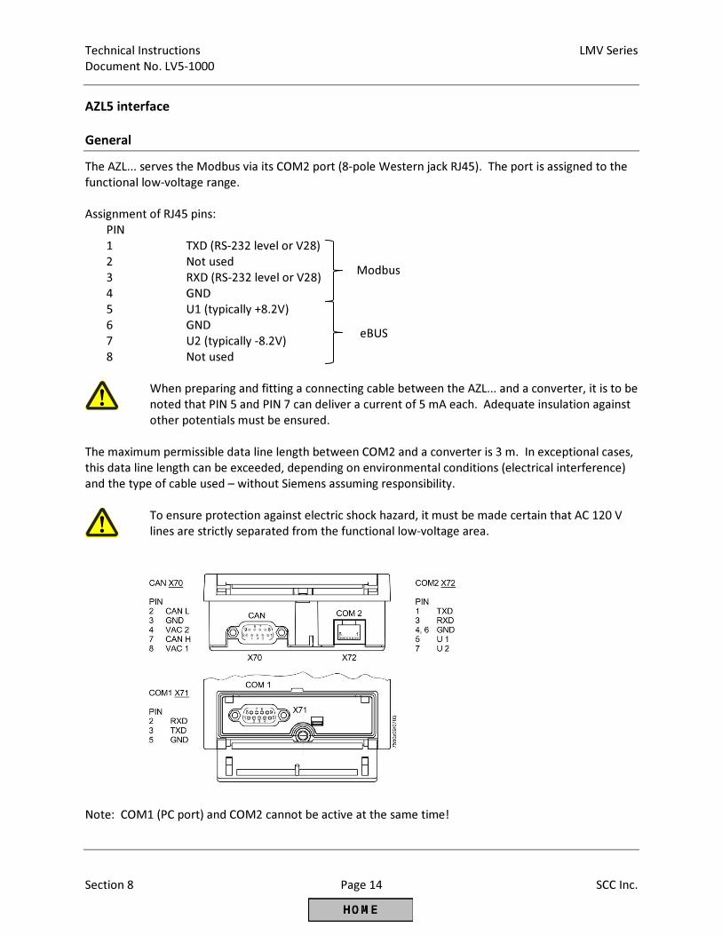
Technical Instructions LMV Series
Document No. LV5-1000
Section 8 Page 14 SCC Inc.
AZL5 interface
General
The AZL... serves the Modbus via its COM2 port (8-pole Western jack RJ45). The port is assigned to the
functional low-voltage range.
Assignment of RJ45 pins:
PIN
1 TXD (RS-232 level or V28)
2 Not used
3 RXD (RS-232 level or V28)
4 GND
5 U1 (typically +8.2V)
6 GND
7 U2 (typically -8.2V)
8 Not used
When preparing and fitting a connecting cable between the AZL... and a converter, it is to be
noted that PIN 5 and PIN 7 can deliver a current of 5 mA each. Adequate insulation against
other potentials must be ensured.
The maximum permissible data line length between COM2 and a converter is 3 m. In exceptional cases,
this data line length can be exceeded, depending on environmental conditions (electrical interference)
and the type of cable used – without Siemens assuming responsibility.
To ensure protection against electric shock hazard, it must be made certain that AC 120 V
lines are strictly separated from the functional low-voltage area.
Note: COM1 (PC port) and COM2 cannot be active at the same time!
Modbus
eBUS
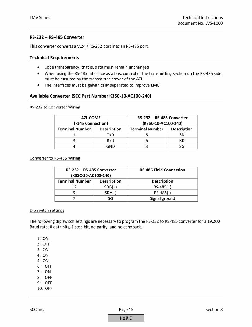
LMV Series Technical Instructions
Document No. LV5-1000
SCC Inc. Page 15 Section 8
RS-232 – RS-485 Converter
This converter converts a V.24 / RS-232 port into an RS-485 port.
Technical Requirements
• Code transparency, that is, data must remain unchanged
• When using the RS-485 interface as a bus, control of the transmitting section on the RS-485 side
must be ensured by the transmitter power of the AZL…
• The interfaces must be galvanically separated to improve EMC
Available Converter (SCC Part Number K3SC-10-AC100-240)
RS-232 to Converter Wiring
AZL COM2
(RJ45 Connection)
RS-232 – RS-485 Converter
(K3SC-10-AC100-240)
Terminal Number Description Terminal Number Description
1 TxD 5 SD
3 RxD 6 RD
4 GND 3 SG
Converter to RS-485 Wiring
RS-232 – RS-485 Converter
(K3SC-10-AC100-240)
RS-485 Field Connection
Terminal Number Description Description
12 SDB(+) RS-485(+)
9 SDA(-) RS-485(-)
7 SG Signal ground
Dip switch settings
The following dip switch settings are necessary to program the RS-232 to RS-485 converter for a 19,200
Baud rate, 8 data bits, 1 stop bit, no parity, and no echoback.
1: ON
2: OFF
3: ON
4: ON
5: ON
6: OFF
7: ON
8: OFF
9: OFF
10: OFF
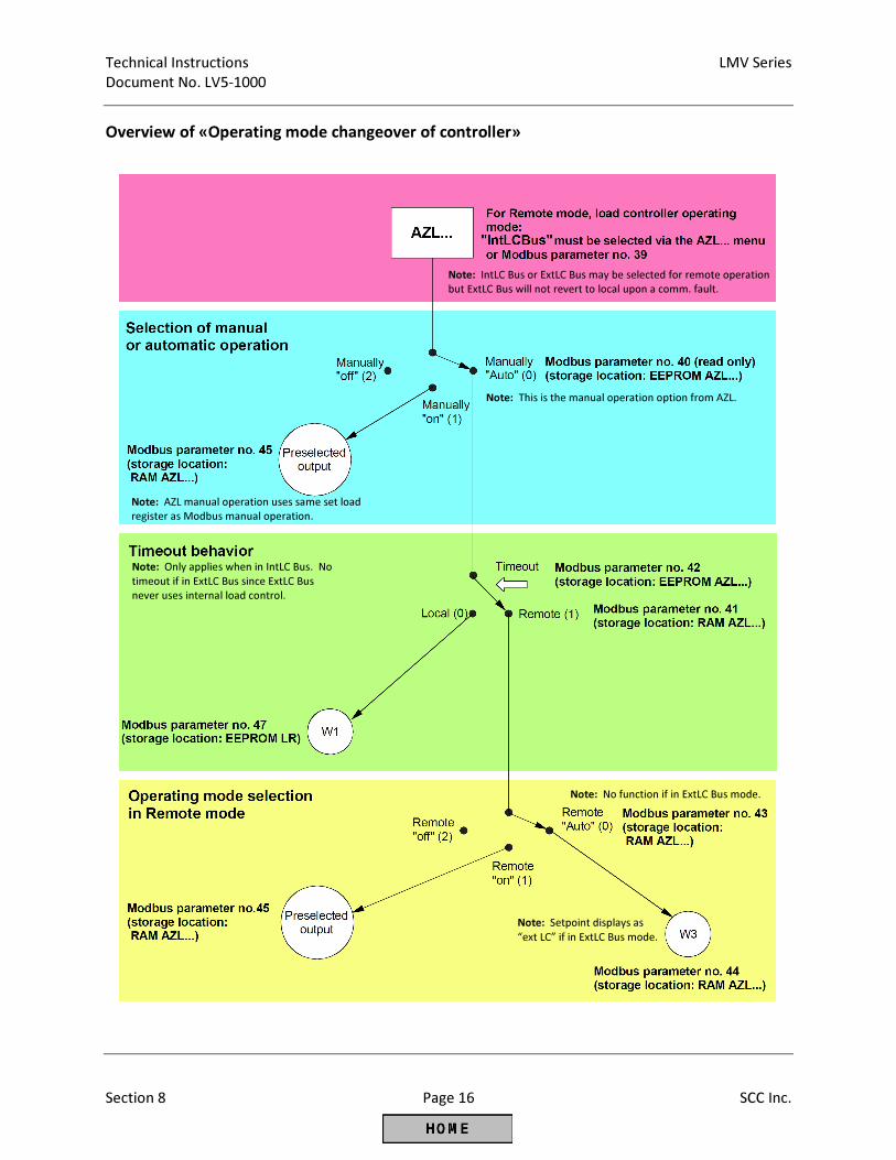
Technical Instructions LMV Series
Document No. LV5-1000
Section 8 Page 16 SCC Inc.
Overview of «Operating mode changeover of controller»
Note: Only applies when in IntLC Bus. No
timeout if in ExtLC Bus since ExtLC Bus
never uses internal load control.
Note: AZL manual operation uses same set load
register as Modbus manual operation.
Note: This is the manual operation option from AZL.
Note: IntLC Bus or ExtLC Bus may be selected for remote operation
but ExtLC Bus will not revert to local upon a comm. fault.
Note: No function if in ExtLC Bus mode.
Note: Setpoint displays as
“ext LC” if in ExtLC Bus mode.
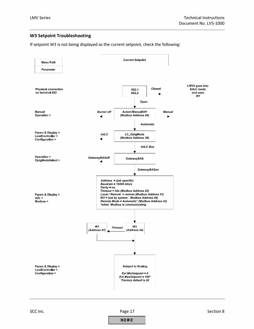
LMV Series Technical Instructions
Document No. LV5-1000
SCC Inc. Page 17 Section 8
W3 Setpoint Troubleshooting
If setpoint W3 is not being displayed as the current setpoint, check the following:
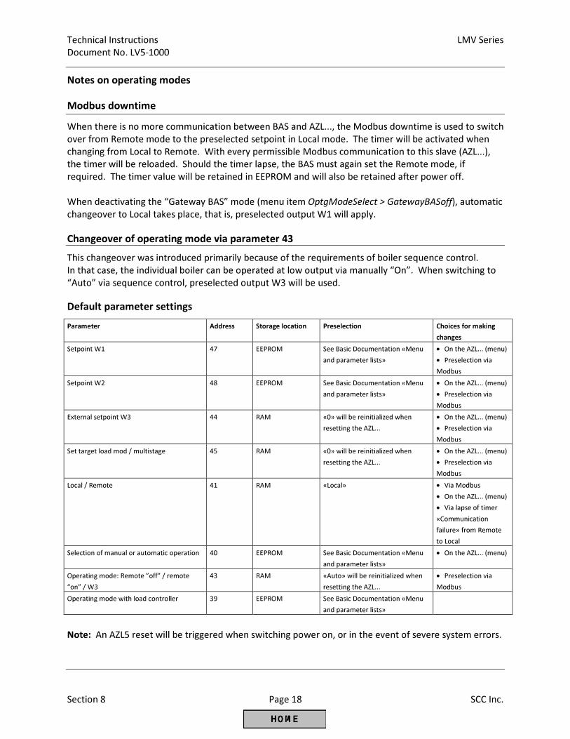
Technical Instructions LMV Series
Document No. LV5-1000
Section 8 Page 18 SCC Inc.
Notes on operating modes
Modbus downtime
When there is no more communication between BAS and AZL..., the Modbus downtime is used to switch
over from Remote mode to the preselected setpoint in Local mode. The timer will be activated when
changing from Local to Remote. With every permissible Modbus communication to this slave (AZL...),
the timer will be reloaded. Should the timer lapse, the BAS must again set the Remote mode, if
required. The timer value will be retained in EEPROM and will also be retained after power off.
When deactivating the “Gateway BAS” mode (menu item OptgModeSelect > GatewayBASoff), automatic
changeover to Local takes place, that is, preselected output W1 will apply.
Changeover of operating mode via parameter 43
This changeover was introduced primarily because of the requirements of boiler sequence control.
In that case, the individual boiler can be operated at low output via manually “On”. When switching to
“Auto” via sequence control, preselected output W3 will be used.
Default parameter settings
Parameter Address Storage location Preselection Choices for making
changes
Setpoint W1 47 EEPROM See Basic Documentation «Menu
and parameter lists»
• On the AZL... (menu)
• Preselection via
Modbus
Setpoint W2 48 EEPROM See Basic Documentation «Menu
and parameter lists»
• On the AZL... (menu)
• Preselection via
Modbus
External setpoint W3 44 RAM «0» will be reinitialized when
resetting the AZL...
• On the AZL... (menu)
• Preselection via
Modbus
Set target load mod / multistage 45 RAM «0» will be reinitialized when
resetting the AZL...
• On the AZL... (menu)
• Preselection via
Modbus
Local / Remote 41 RAM «Local» • Via Modbus
• On the AZL... (menu)
• Via lapse of timer
«Communication
failure» from Remote
to Local
Selection of manual or automatic operation 40 EEPROM See Basic Documentation «Menu
and parameter lists»
• On the AZL... (menu)
Operating mode: Remote ”off” / remote
“on” / W3
43 RAM «Auto» will be reinitialized when
resetting the AZL...
• Preselection via
Modbus
Operating mode with load controller 39 EEPROM See Basic Documentation «Menu
and parameter lists»
Note: An AZL5 reset will be triggered when switching power on, or in the event of severe system errors.
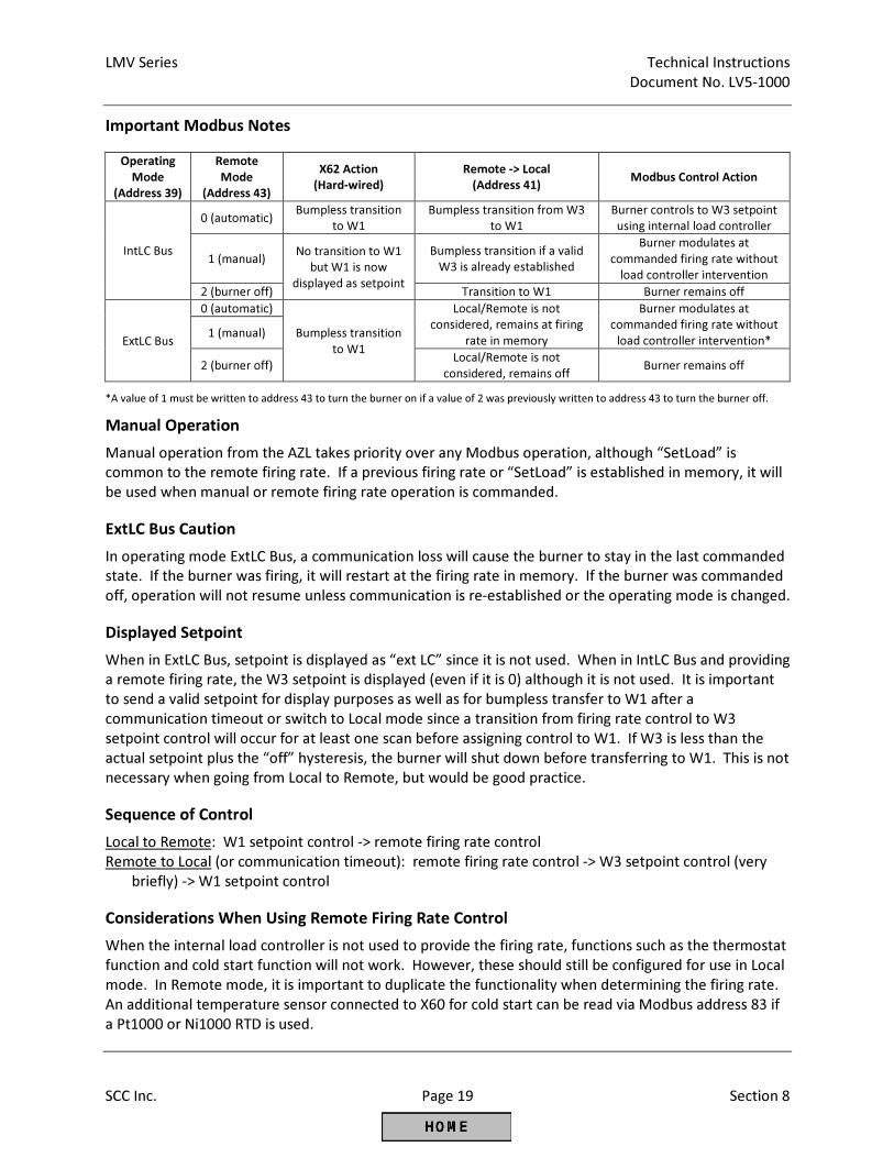
LMV Series Technical Instructions
Document No. LV5-1000
SCC Inc. Page 19 Section 8
Important Modbus Notes
Operating
Mode
(Address 39)
Remote
Mode
(Address 43)
X62 Action
(Hard-wired)
Remote -> Local
(Address 41) Modbus Control Action
IntLC Bus
0 (automatic) Bumpless transition
to W1
Bumpless transition from W3
to W1
Burner controls to W3 setpoint
using internal load controller
1 (manual) No transition to W1
but W1 is now
displayed as setpoint
Bumpless transition if a valid
W3 is already established
Burner modulates at
commanded firing rate without
load controller intervention
2 (burner off) Transition to W1 Burner remains off
ExtLC Bus
0 (automatic)
Bumpless transition
to W1
Local/Remote is not
considered, remains at firing
rate in memory
Burner modulates at
commanded firing rate without
load controller intervention* 1 (manual)
2 (burner off) Local/Remote is not
considered, remains off Burner remains off
*A value of 1 must be written to address 43 to turn the burner on if a value of 2 was previously written to address 43 to turn the burner off.
Manual Operation
Manual operation from the AZL takes priority over any Modbus operation, although “SetLoad” is
common to the remote firing rate. If a previous firing rate or “SetLoad” is established in memory, it will
be used when manual or remote firing rate operation is commanded.
ExtLC Bus Caution
In operating mode ExtLC Bus, a communication loss will cause the burner to stay in the last commanded
state. If the burner was firing, it will restart at the firing rate in memory. If the burner was commanded
off, operation will not resume unless communication is re-established or the operating mode is changed.
Displayed Setpoint
When in ExtLC Bus, setpoint is displayed as “ext LC” since it is not used. When in IntLC Bus and providing
a remote firing rate, the W3 setpoint is displayed (even if it is 0) although it is not used. It is important
to send a valid setpoint for display purposes as well as for bumpless transfer to W1 after a
communication timeout or switch to Local mode since a transition from firing rate control to W3
setpoint control will occur for at least one scan before assigning control to W1. If W3 is less than the
actual setpoint plus the “off” hysteresis, the burner will shut down before transferring to W1. This is not
necessary when going from Local to Remote, but would be good practice.
Sequence of Control
Local to Remote: W1 setpoint control -> remote firing rate control
Remote to Local (or communication timeout): remote firing rate control -> W3 setpoint control (very
briefly) -> W1 setpoint control
Considerations When Using Remote Firing Rate Control
When the internal load controller is not used to provide the firing rate, functions such as the thermostat
function and cold start function will not work. However, these should still be configured for use in Local
mode. In Remote mode, it is important to duplicate the functionality when determining the firing rate.
An additional temperature sensor connected to X60 for cold start can be read via Modbus address 83 if
a Pt1000 or Ni1000 RTD is used.

Technical Instructions LMV Series
Document No. LV5-1000
Section 8 Page 20 SCC Inc.
Intentionally Left Blank
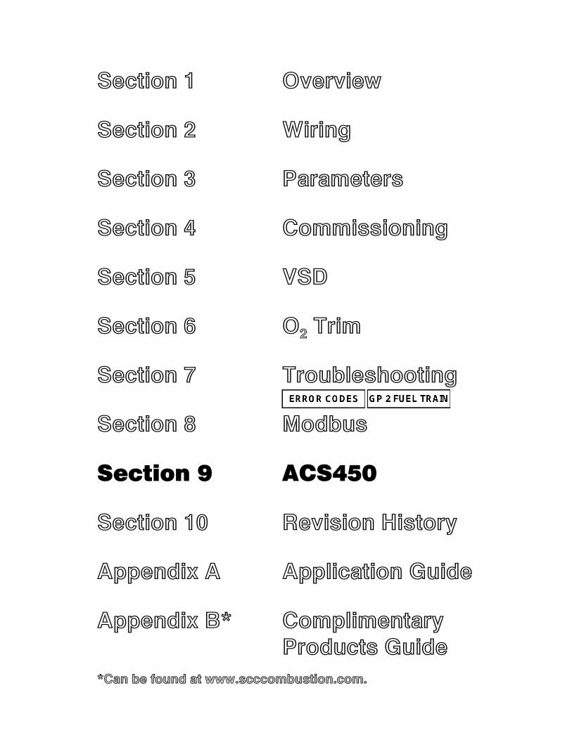
Section 1 Overview
Section 2 Wiring
Section 3 Parameters
Section 4 Commissioning
Section 5 VSD
Section 6 O2 Trim
Section 7 Troubleshooting
Section 8 Modbus
Section 9 ACS450
Section 10 Revision History
Appendix A Application Guide
Appendix B* Complimentary Products Guide
*Can be found at www.scccombustion.com.
LMV Series Technical Instructions
Document No. LV5-1000
SCC Inc. Page 1 Section 9
Section 9-1: ACS450 Introduction
The LMV5 system can be completely programmed using either the AZL5 or a PC with the
ACS450 software. Most people find that using the AZL5 is more convenient than the ACS450 for
a “manual” setup of the LMV5 parameters. However, the ACS450 has additional capabilities
that are not available with the AZL5 / LMV5 alone. These additional, valuable capabilities are:
1. Saving and printing all LMV5 settings, combustion curves, and information in a report
format. This provides a convenient, comprehensive startup report.
2. Saving and uploading entire LMV5 parameter sets to or from a PC.
3. Updating AZL5 software.
4. Viewing and saving trends (particularly useful for tuning PID loops).
5. Viewing a “dashboard” of the LMV5 inputs and outputs as well as the LMV5 operating state.
Sections 9-2 through 9-4 will cover the software installation, communication setup, and AZL5
software updates. Sections 9-5 through 9-8 will explain how to utilize the basic capabilities of
the ACS450 software, including startup reports, parameter sets, trending, and the “dashboard”.
Since most people prefer to use the AZL5 to set parameters and combustions curves in the
LMV5, the procedure to do this with ACS450 will not be covered in this guide. For technical
information about how to program the LMV5 through the ACS450 software, email
The ACS450 software can be used with the following PC operating systems:
• Windows 98 (ACS450 version 3.4 or older only)
• Windows 2000 (ACS450 version 3.4 or older only)
• Windows XP (ACS450 version 3.4 or older only)
• Windows 7
• Windows 8
• Windows 10
ACS450 cannot be used with the following PC operating systems:
• Windows Vista
• Windows ME
Technical Instructions LMV Series
Document No. LV5-1000
Section 9 Page 2 SCC Inc.
9-2: ACS450 Software Installation
The following steps outline the procedure for installing the ACS450 software on a PC:
1. The ACS450 software can be acquired in a couple of ways:
a. Download it from the SCC website: www.scccombustion.com/acs450_form.htm
• After filling out a short form, you will receive an e-mail containing the Username and
Password required to download the software. Once the Username and Password
are acquired, use the “click here” link on the same webpage in order to start the
download.
b. Download it from SCC’s Combustion CD.
c. Acquire it via an e-mail attachment.
2. The files shown below must reside in the same folder on the PC or on the CD before
proceeding.
• acs450.msi • InstMsiA.exe • InstMsiW.exe • setup.exe • setup.ini
Double-click on the setup.exe file. This should start the installation. Pick the desired options as
the installation prompts.
3. Once installed, the files will be located on the computer’s hard drive at one of the following
locations:
C:\Program Files (x86)\ACS450
C:\Program Files (x86)\Siemens AG\ACS450
4. Open these folders and check to make sure that all of the .cod files listed below are there.
These are necessary for the AZL5 to communicate properly with the ACS450 software.
• Para_Nr_0400.cod • Para_Nr_0410.cod • Para_Nr_0420.cod
• Para_Nr_0450.cod • Para_Nr_0460.cod • Para_Nr_0470.cod
• Para_Nr_0480.cod • Para_Nr_0490.cod • Para_Nr_0500.cod
• Para_Nr_0510.cod
Any missing .cod files can be acquired from the SCC Combustion CD or by emailing
5. At this point, the ACS450 is ready to run. The first time ACS450 is started it will prompt for a
license code. When prompted, type the following license code: 041028000703GH.
LMV Series Technical Instructions
Document No. LV5-1000
SCC Inc. Page 3 Section 9
9-3: AZL5 Communication Setup
The following steps summarize the procedure for establishing communication between the
AZL5 and a PC.
1. The table below outlines the cables necessary for connecting the PC to the AZL5. These
cables will vary depending on whether or not the PC has a serial port to connect to.
Table 9-3.1: Necessary Cables to Connect PC to AZL5
Type of PC
Null
modem
cable
USB-to-serial
converter w/
FTDI chipset
PC with serial port X
PC without serial port X X
For convenience, SCC stocks both the null modem cable and the USB-to-serial cable with the
FTDI chipset. See Section 1 for part numbers and technical information for these cables.
2. Once the correct connection cables are acquired, the PC can be connected to the AZL5.
Plug one end of the connection cable into the 9-pin RS-232 port on the front of the AZL5 (under
the front cover). Plug the other end of the connection cable into the PC.
3. In order to connect, the AZL5 must be put into InterfacePC mode. This selection is found
using the following menu path in the AZL5:
Operation > OptgModeSelect > InterfacePC
4. Once the AZL5 is in InterfacePC mode, attempt to connect with the ACS450 on the user
level. This is done by going to the “System LMV5x” dropdown menu and selecting “Connect”.
When the dialog box appears, select “User” and press OK. If the connection is successful,
proceed to step 5.
If the connection is not successful, check the com port settings. To check which com port the
connection cord is plugged into, open the computer’s Device Manager. Once open, expand the
“Ports (COM & LPT)” tab and check which com port is called “USB Serial Port”. This port must
match the port that the ACS450 software is reading. The com port being read by the ACS450
can be changed by going to the “System LMV5x” dropdown menu and selecting “Options”.
Note: The ACS450 software only recognizes com ports 1 through 8. If the port that the
connection cord is plugged into is higher than 8, it needs to be changed. This is done by right-
clicking on “USB Serial Port” and selecting “Properties”. Go to the “Port Settings” tab and click
“Advanced”. From here, the com port number can be changed to any number that is not
currently being used by another device.
Technical Instructions LMV Series
Document No. LV5-1000
Section 9 Page 4 SCC Inc.
5. After the connection at the user level is successful, disconnect from the AZL5 and then
reconnect at the service or OEM level, if desired. This is done by going to the “System LMV5x”
dropdown menu and selecting “Disconnect”. Remember that a password will be necessary to
access the LMV5 on the service or OEM level and that the password is case-sensitive.
Note: If a fault window appears, it is not necessary to close the fault window. It can be moved
to the side and temporarily ignored. Most tasks can be performed with the fault window open.
If the fault window is closed and the fault is not cleared, the fault window will reappear in a few
seconds.
LMV Series Technical Instructions
Document No. LV5-1000
SCC Inc. Page 5 Section 9
9-4: AZL5 Software Updates
The AZL5 software package is frequently updated with new parameters and features. The
software of any AZL5 can be updated using the ACS450 software. If the AZL5 ever states that
there is a “Version Conflict” when it is connected to the LMV5, the AZL5 software needs to be
updated via the ACS450 software.
The current software version of the AZL5 can be checked via the following menu path on the
AZL5:
Params & Display > Access w-out PW > AZL > SW Version
At the time of publication, the latest software version is 5.10, which will display as “0510” on
the AZL5.
The following steps outline the procedure for updating the software version of the AZL5.
1. Ensure that ACS450 is installed on the computer being used to update the AZL5 software.
See Section 9-2 if necessary.
Note: Prior to attempting an AZL5 software update, deactivate the Modbus port (RJ45) on the
bottom of the AZL5 if it is being used. The port can be deactivated under:
Operation > OptgModeSelect > GatewayBASoff
2. Locate the correct .bin file. The ACS450 will prompt for the file later in this procedure. The
.bin file that is necessary for the update is shown below. If the .bin file cannot be located, it can
be acquired from the SCC Combustion CD or by emailing [email protected].
• AZL52.00_V0510.BIN
3. Connect the PC to the AZL5 using the necessary cables. The requirements of this
connection are outlined in Section 9-3.
Technical Instructions LMV Series
Document No. LV5-1000
Section 9 Page 6 SCC Inc.
4. On the main menu in the AZL5, scroll down to “Updating”. When “Enter” is pressed, a
password prompt will appear. Either the service or OEM level password will be necessary. After
access is gained, scroll down to “Load_SW_from_PC” and press “Enter”. This screen will state
“Start Process with ENTER”. Do not press “Enter” at this time.
Note: If the AZL5 displays “Version Conflict”, press “Esc” on the AZL5 in order to get to the
main menu. When the AZL5 is in a “Version Conflict”, only the service password will grant
access to the “Load_SW_from_PC” option.
5. Open up the ACS450 on the computer, go to the “System LMV5x” dropdown menu, and
select “Update AZL Flash”. The ACS450 will then ask for the .bin file. Locate and open the
correct .bin file. Once the .bin file is opened, press “Enter” on the AZL5 to begin the update.
Note: It is important that steps 4 and 5 are completed as specified above. Make sure to press
“Enter” on the AZL5 immediately after opening the .bin file on the computer. If these steps are
performed too far apart, the update process could take a long time, or not happen altogether.
6. The AZL5 screen should say “SW-Update” on the top. If everything is working properly, the
AZL5 should say “clearing flash” and then it should say “programming”. During the process,
there should be a horizontal bar on the AZL5 screen and also on the computer screen that
slowly fills in from the left to the right. The update procedure takes at least 5 minutes. When
everything is finished, the ACS450 should say “Transfer finished, press cancel” and the AZL
should say “SW-Update OK, FLASH : V05.00, cancel : left key”.
7. Press “Esc” on the AZL5. It will go into “System Test” and then come up normally. The AZL5
flash update is now complete.
LMV Series Technical Instructions
Document No. LV5-1000
SCC Inc. Page 7 Section 9
9-5: Creating an LMV5 Startup Report
The following steps outline the procedure for saving, viewing and printing a startup report to a
PC. The LMV5 must be in standby or lockout and have a burner ID to create a backup report.
Saving the .mdb file
1. Ensure that the ACS450 software is open, and the PC is connected to the AZL5 at the user,
service, or OEM level. See Sections 9-2 or 9-3 if necessary. A full report will be saved at any
password level. The report can be filtered later by password level when it is viewed.
2. Go to the ACS450 “System LMV5x” dropdown menu, and select “Backup for offline mode”.
3. The ACS450 will then read the parameters on the LMV5 and compose a report. The status
of the backup will be indicated on the backup window. The backup process may take up to 10
minutes. This report will be automatically saved in C:\Program Files (x86)\ACS450\daten. The
file name is automatically saved as the burner ID of the LMV5.
4. After the backup process is complete, go to the ACS450 “System LMV5x” dropdown menu,
and select “Disconnect”. A window will appear that asks “Do you want to store parameters for
offline mode?” Since this was just done in Step 3, it is not necessary to repeat. Click “No”.
5. The ACS450 is now disconnected from the LMV5, and the .mdb file is saved. Once
disconnected, the .mdb file can be viewed or printed with the ACS450 software.
Viewing and printing the .mdb file contents
6. Ensure that the ACS450 software is open, and not connected to the LMV5. Go to the “File”
dropdown menu, and select “Show Parameters”. When this is selected, a dialogue window will
appear. Select the .mdb file to be opened. The default location for the .mdb files is C:\Program
Files (x86)\ACS450\daten.
7. Once the file is selected, another window will appear for the access level. Any level can be
chosen to view and print the parameter list without needing a password. The level chosen will
affect what parameters appear, so selecting the OEM level will show all parameters available.
Once the access level is selected, a list of the parameters and their settings should appear.
8. Once the parameter list is visible on the screen, it can be viewed and / or printed. The fault
and lockout history can also be viewed and / or printed. To access the fault and lockout history,
go to the “Parameters” dropdown menu and slide the cursor to “Operating State”. The options
of “Fault History” and “Lockout History” should appear. Click on either to view.
Note: Many people prefer to create the startup report in a more universal document format,
such as a .pdf file type. This can be done with Adobe ® software that has a writer function. To
create the .pdf files, simply print the desired pieces of the .mdb file to the .pdf writer instead of
an actual paper and toner printer. Most people prefer to have a .pdf file of the parameter list,
fault history, and lockout history. These pieces provide a very inclusive LMV5 startup report.
Technical Instructions LMV Series
Document No. LV5-1000
Section 9 Page 8 SCC Inc.
9-6: Saving and Uploading Parameter Sets
The following steps outline the procedure for saving parameter sets (.par files) to a PC and also
uploading parameter sets from a PC to an LMV5.
Saving a .par file to the PC
1. Ensure that the ACS450 software is open, and the PC is connected to the AZL5 at the service
or OEM level. See Sections 9-2 or 9-3 if necessary.
2. To save an LMV5 parameter set to a PC, go to the ACS450 “System LMV5x” dropdown
menu, and select “Backup LMV > PC”.
3. A window will appear titled “Backup LMV > PC” and will have a message at the bottom
stating the “Status”. The “Status” will start as “1” and will proceed to saying “Input file name”.
From the time the window appears to when the message states “Input file name” could take up
to three minutes, but is usually less.
4. A comment can be typed in if desired. If not, click on “Save in File” and another window will
come up. In this window, type the file name (a name containing the burner ID is recommended)
and select an appropriate folder to save the file. The default location for .par file storage is
C:\Program files (x86)\ACS450\daten. Click on “Save”.
5. When being saved, the message on the “Backup LMV > PC” window should state “Reading
Parameters”. When saving is completed successfully, the message should say “Success, press
Close”. Click “Close”. The .par file is now stored on the PC in the specified location.
Note: The .par file is stored in machine language, so it is not useful as a startup report.
Uploading a .par file to the LMV5
6. Ensure that the ACS450 software is open, and the PC is connected to the AZL5 at the service
or OEM level. See Sections 9-2 or 9-3 if necessary.
7. To upload a parameter set from a PC to an LMV5, go to the ACS450 “System LMV5x”
dropdown menu, and select “Restore PC > LMV”.
8. A prompt will appear, asking for the desired .par file. Select the desired .par file and click on
“Open”. This .par file will overwrite the parameter set on the LMV5 and will determine the
behavior of the LMV5. Be sure that the correct .par file is selected.
LMV Series Technical Instructions
Document No. LV5-1000
SCC Inc. Page 9 Section 9
9. A window will appear titled “Restore PC > LMV”. If the message on the bottom of the
window states “Burner ID is ok” or “New base unit”, then proceed to Step 11. If the message
states “Burner ID is different”, proceed to the next step.
10. If the burner ID contained in the .par file is different than the burner ID on the LMV5, the
ACS450 software will not permit the .par file to be uploaded to the LMV5. The exception to this
is if the burner ID on the LMV5 is blank. If the burner ID is blank, then the upload is permitted.
If the burner ID is different, two options are available (perform either option A or B below):
A. Change the burner ID on the LMV5 to match the burner ID contained in the .par file. This
can be done via the ACS450 software or through the AZL5 directly. The OEM password is
required to do this with either method.
i. If using ACS450 – Once connected at the OEM level, go to the “Parameters”
dropdown menu. The path to change the burner ID is Operation > Burner ID.
Change the Burner ID in the dropdown menu.
ii. If using the AZL5 - Disconnect the PC. Once disconnected, the path through the
AZL5 is Updating > Burner ID. A prompt will appear for the password when
“Updating” is selected on the AZL5.
B. Reset and then initialize the LMV5 using the ACS450.
i. Connect to the LMV5 with the ACS450 at the Service or OEM level. After
connecting successfully, go to the “System LMV5x” dropdown menu and select
“Reset BU”. A reset window will appear that states the burner ID and fuel train
will be deleted.
ii. Click “Reset”, and the LMV5 will be reset (burner ID and fuel train). An alarm
window will immediately appear that states “No Fuel Train Defined”. This alarm
window does not need to be closed. The alarm window can be moved out of the
way. Click on “Close” to close the reset window.
iii. The burner ID and fuel train are now erased. Go under the “System LMV5x”
dropdown menu and select “Disconnect”. A window will appear that asks “Do
you want to store parameters for offline mode?” Click “No” if a backup (.mdb
file) file is not necessary. If “Yes” is clicked, the ACS450 will create an .mdb file.
The .mdb file creation can take up to 10 minutes. Creating an .mdb file is
discussed in Section 9-5.
Technical Instructions LMV Series
Document No. LV5-1000
Section 9 Page 10 SCC Inc.
iv. Next, go to the “System LMV5x” dropdown menu and select “Init BU”. A window
will appear and the ACS450 will begin reading the parameters. This will take a
few minutes. After this is complete, a window will appear that asks for a .par file.
Select the .par file that contains the parameter set to be uploaded. This
parameter set (.par) will overwrite the parameter set on the LMV5 and will
determine the behavior of the LMV5. Be sure that the correct .par file is
selected.
11. Click on “Store in LMV”. This will start the upload process.
12. The following messages should appear on the “Restore PC > LMV” window. These
messages are (in order): “Function Succeeded”, “Transferring Parameters”, “Status = 1”, “Status
= 2”, “Status = 3”, and “Parameter Transfer Succeeded”. The upload process may take up to five
minutes to complete. Also, an alarm may occur during the upload. This alarm is normal, and is
to alert the technician that the new parameter set has been uploaded to the LMV5.
13. Once the “Parameter Transfer Succeeded” message is shown on the “Restore PC > LMV”
window, click on “Close”. The alarm resulting from the upload can also be reset at this time.
The upload is now complete.
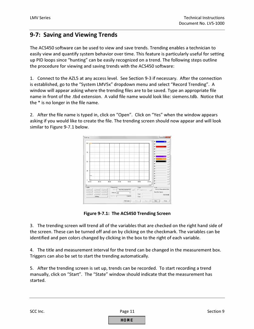
LMV Series Technical Instructions
Document No. LV5-1000
SCC Inc. Page 11 Section 9
9-7: Saving and Viewing Trends
The ACS450 software can be used to view and save trends. Trending enables a technician to
easily view and quantify system behavior over time. This feature is particularly useful for setting
up PID loops since “hunting” can be easily recognized on a trend. The following steps outline
the procedure for viewing and saving trends with the ACS450 software:
1. Connect to the AZL5 at any access level. See Section 9-3 if necessary. After the connection
is established, go to the “System LMV5x” dropdown menu and select “Record Trending”. A
window will appear asking where the trending files are to be saved. Type an appropriate file
name in front of the .tbd extension. A valid file name would look like: siemens.tdb. Notice that
the * is no longer in the file name.
2. After the file name is typed in, click on “Open”. Click on “Yes” when the window appears
asking if you would like to create the file. The trending screen should now appear and will look
similar to Figure 9-7.1 below.
Figure 9-7.1: The ACS450 Trending Screen
3. The trending screen will trend all of the variables that are checked on the right hand side of
the screen. These can be turned off and on by clicking on the checkmark. The variables can be
identified and pen colors changed by clicking in the box to the right of each variable.
4. The title and measurement interval for the trend can be changed in the measurement box.
Triggers can also be set to start the trending automatically.
5. After the trending screen is set up, trends can be recorded. To start recording a trend
manually, click on “Start”. The “State” window should indicate that the measurement has
started.
Technical Instructions LMV Series
Document No. LV5-1000
Section 9 Page 12 SCC Inc.
6. Trends will be buffered until “Stop” is clicked. When “Stop” is clicked, the trends will be
saved under the previously defined .tbd file.
7. Trends can be viewed when the ACS450 is disconnected from the AZL5. To view trends, go
to the “File” dropdown menu and select “Show Trending”. A window will appear prompting for
the correct .tbd file.
8. Select the trend to be viewed or exported. If “Ok” is clicked, the trend can be seen in
ACS450. If “Export” is clicked, a .csv file can be created that can be opened with Microsoft
Excel.
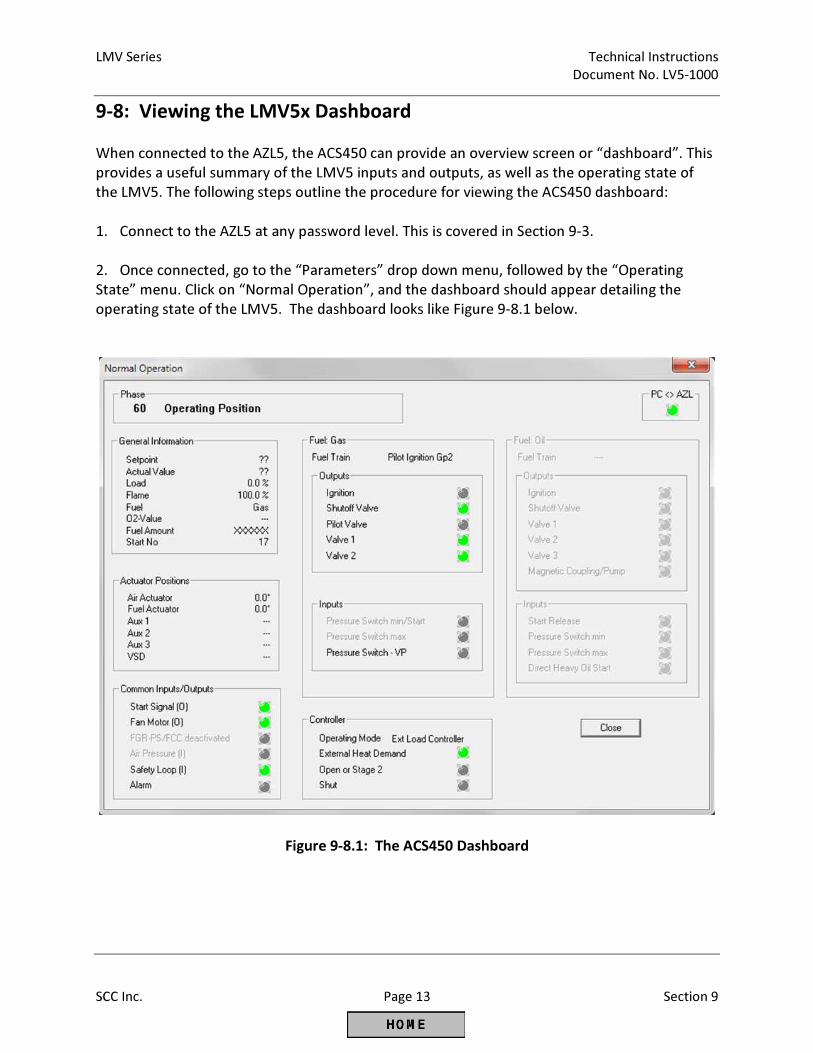
LMV Series Technical Instructions
Document No. LV5-1000
SCC Inc. Page 13 Section 9
9-8: Viewing the LMV5x Dashboard
When connected to the AZL5, the ACS450 can provide an overview screen or “dashboard”. This
provides a useful summary of the LMV5 inputs and outputs, as well as the operating state of
the LMV5. The following steps outline the procedure for viewing the ACS450 dashboard:
1. Connect to the AZL5 at any password level. This is covered in Section 9-3.
2. Once connected, go to the “Parameters” drop down menu, followed by the “Operating
State” menu. Click on “Normal Operation”, and the dashboard should appear detailing the
operating state of the LMV5. The dashboard looks like Figure 9-8.1 below.
Figure 9-8.1: The ACS450 Dashboard
Technical Instructions LMV Series
Document No. LV5-1000
Section 9 Page 14 SCC Inc.
Intentionally Left Blank

Section 1 Overview
Section 2 Wiring
Section 3 Parameters
Section 4 Commissioning
Section 5 VSD
Section 6 O2 Trim
Section 7 Troubleshooting
Section 8 Modbus
Section 9 ACS450
Section 10 Revision History
Appendix A Application Guide
Appendix B* Complimentary Products Guide
*Can be found at www.scccombustion.com.
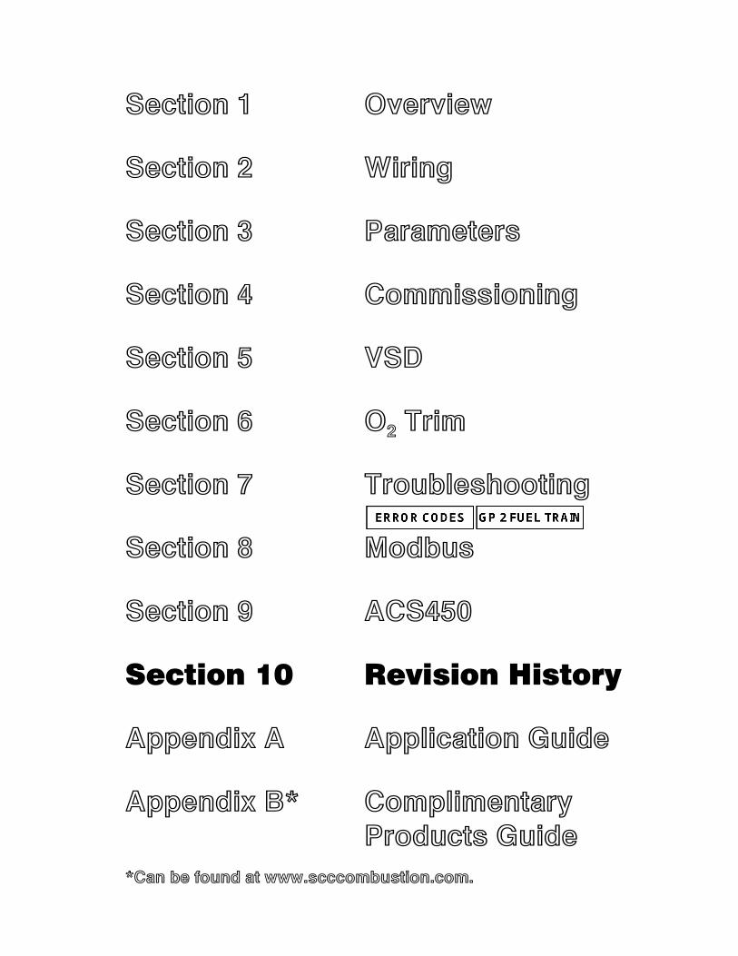
Section 1 Overview
Section 2 Wiring
Section 3 Parameters
Section 4 Commissioning
Section 5 VSD
Section 6 O2 Trim
Section 7 Troubleshooting
Section 8 Modbus
Section 9 ACS450
Section 10 Revision History
Appendix A Application Guide
Appendix B* Complimentary Products Guide
*Can be found at www.scccombustion.com.
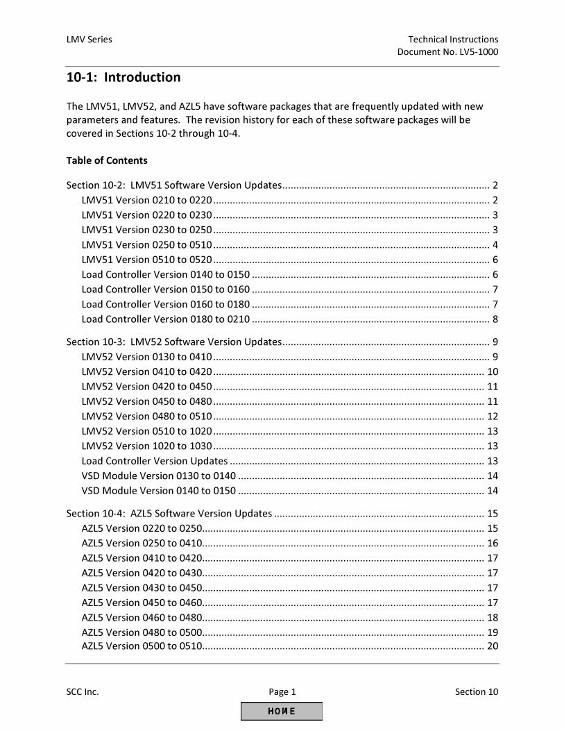
LMV Series Technical Instructions
Document No. LV5-1000
SCC Inc. Page 1 Section 10
10-1: Introduction
The LMV51, LMV52, and AZL5 have software packages that are frequently updated with new
parameters and features. The revision history for each of these software packages will be
covered in Sections 10-2 through 10-4.
Table of Contents
Section 10-2: LMV51 Software Version Updates ........................................................................... 2
LMV51 Version 0210 to 0220 .................................................................................................... 2
LMV51 Version 0220 to 0230 .................................................................................................... 3
LMV51 Version 0230 to 0250 .................................................................................................... 3
LMV51 Version 0250 to 0510 .................................................................................................... 4
LMV51 Version 0510 to 0520 .................................................................................................... 6
Load Controller Version 0140 to 0150 ...................................................................................... 6
Load Controller Version 0150 to 0160 ...................................................................................... 7
Load Controller Version 0160 to 0180 ...................................................................................... 7
Load Controller Version 0180 to 0210 ...................................................................................... 8
Section 10-3: LMV52 Software Version Updates ........................................................................... 9
LMV52 Version 0130 to 0410 .................................................................................................... 9
LMV52 Version 0410 to 0420 .................................................................................................. 10
LMV52 Version 0420 to 0450 .................................................................................................. 11
LMV52 Version 0450 to 0480 .................................................................................................. 11
LMV52 Version 0480 to 0510 .................................................................................................. 12
LMV52 Version 0510 to 1020 .................................................................................................. 13
LMV52 Version 1020 to 1030 .................................................................................................. 13
Load Controller Version Updates ............................................................................................ 13
VSD Module Version 0130 to 0140 ......................................................................................... 14
VSD Module Version 0140 to 0150 ......................................................................................... 14
Section 10-4: AZL5 Software Version Updates ............................................................................ 15
AZL5 Version 0220 to 0250 ...................................................................................................... 15
AZL5 Version 0250 to 0410 ...................................................................................................... 16
AZL5 Version 0410 to 0420 ...................................................................................................... 17
AZL5 Version 0420 to 0430 ...................................................................................................... 17
AZL5 Version 0430 to 0450 ...................................................................................................... 17
AZL5 Version 0450 to 0460 ...................................................................................................... 17
AZL5 Version 0460 to 0480 ...................................................................................................... 18
AZL5 Version 0480 to 0500 ...................................................................................................... 19
AZL5 Version 0500 to 0510 ...................................................................................................... 20
Technical Instructions LMV Series
Document No. LV5-1000
Section 10 Page 2 SCC Inc.
10-2: LMV51 Software Version Updates
This section covers all of the revisions that were made to the LMV51 controller with each new
software release. The software version of any LMV51 controller can be found using the
following menu path:
Params & Display > BurnerControl > SW Version
The LMV51.1 also has a load controller with its own unique software version. The software
version for the load controller can be found using the following menu path:
Params & Display > LoadController > SW Version
LMV51 Software Update: Version 0210 to 0220
The following updates were made with LMV51 software version 0220:
1. When the unit reaches the Program stop position, the AZL5 displays “Programstop active”.
2. Alarm output X3-02.1 can be deactivated via parameter Alarm act/deact. The current fault
or lockout is still maintained on the AZL, but the 120V output is de-energized. Deactivation of
the output remains active until a reset is made, another fault occurs, or a startup occurs.
3. A low oil pressure switch can now be activated when firing oil.
4. When firing oil, the oil safety valve output X6-03.3 de-energizes on completion of the
afterburn time (end of phase 70). The fan output de-energizes after phase 79. Using
parameter OilPumpCoupling, it is now possible to choose between the described above (when
using the magnetic clutch) or direct coupling of the oil pump. In the case of direct coupling, the
oil safety valve must be connected to the output for the oil pump (X6-02.3). The oil safety is
will always be controlled when the fan runs, plus another 15 seconds.
5. The evaluation of input DWminOil when using oil train “Heavy oil with gas pilot” has been
moved from phase 38 to phase 44. DWminOil is only valued during the safety time after a delay
time has elapsed.
6. The output signal to the air pressure switch test valve can be inverted using parameter
Start/PS-Valve. This output is only active when the fan operates.
7. If the burner operation is set to “Manually on”, the burner on / off contact (X5-03.1) acts as
a shutoff device should an over-temperature situation occur. With the exception of operating
mode 1 (ExtLC X5-03), the burner on / off contact can be deactivated if not being used as a
shutoff device.
LMV Series Technical Instructions
Document No. LV5-1000
SCC Inc. Page 3 Section 10
LMV51 Software Update: Version 0210 to 0220 (continued)
8. After a safety shutdown, the longer prepurge time PrepurgeSafeGas/Oil becomes active.
LMV51 Software Update: Version 0220 to 0230
The following update was made with LMV51 software version 0230:
1. After ignition, the actuators will drive to curve point 1 independent of whether or not the
minimum load has been set to a higher value than the load of point 1. Once the actuators have
reached point 1, they will then drive to the set minimum load.
LMV51 Software Update: Version 0230 to 0250
The following updates were made with LMV51 software version 0250:
The product numbers of the LMV5 changed as follows:
LMV51.0x0Bx → LMV51.0x0Cx
LMV51.1x0Bx → LMV51.1x0Cx
LMV51.200Ax → no modification
To operate an LMV5 with the software versions listed above, it is necessary to have AZL5
software version 0410 or higher installed. Using this software, all AZL5s can now be updated.
The passwords are now encoded. The following other changes were made to the LMV5 basic
units:
1. Introduction of a preset load for testing the safety limit thermostat (SLT-Testload Mod, SLT
Testload Stg).
2. Introduction of a burner startup without prepurging (Skip Prepurge Gas, Skip Prepurge Oil).
3. Prepurge times 1 (t30) and 3 (t34) can be set at the OEM level.
4. Introduction of a repetition counter at the OEM level for loss of flame during operation
(LossOfFlame).
5. Alarm in the event of start prevention in standby mode (ShutdwnStbyOnErr). In the case of
a start prevention with no call for heat, it has previously not been possible to set off an alarm.
Now an alarm can also be triggered in standby mode.
6. The inputs for oil are no longer checked when firing on gas. Likewise, the inputs for gas are
no longer checked when firing on oil.
Technical Instructions LMV Series
Document No. LV5-1000
Section 10 Page 4 SCC Inc.
LMV51 Software Update: Version 0230 to 0250 (continued)
7. The maximum filling and evacuation times for gas valve proving are now limited by the
maximum permissible safety time for startup. In particular, this affects the burner control
versions that use the American standard parameter set.
8. Introduction of max. load limitation at the user level (UserMaxLoadMod, UserMaxLoadStg).
9. Hiding an adjustable load range aimed at reducing resonance phenomena in the
burner/boiler/stack system (LoadMaskLowLimit, LoadMaskHighLimit).
10. The fuel actuator can be deactivated (only with an LMV52).
11. A new flue gas recirculation (FGR) function (only with an LMV52). Actuator AUX3 can be
employed for controlling the damper used for flue gas recirculation (FGR). To improve the
burner’s startup characteristics, only this actuator can be driven from its ignition position to the
adjusted curve, either time-delayed or depending on the flue gas temperature.
12. A new option for no prepurge for gas burners (Skip Prepurge Gas). As per EN 676, the
prepurge time can be skipped if a valve proving system is installed.
13. Changing the extraneous light test for OEMs. Now the OEM is able to skip the extraneous
light test in the start sequence (ExtranLightTest).
14. The curve points can now be adjusted without actually running the actuators to the
adjusted positions.
15. When running heavy oil, the high oil pressure switch can now be opened in phases 38 and
44 for the pressure switch reaction time.
LMV51 Software Update: Version 0250 to 0510
The microcomputer PCB was converted to the same microcomputer PCB as in the LMV52
(known as platform conversion). This means that from the date of the switchover, these
variants will also have the additional hardware input X7-03.2 (start release gas or POC), which
was previously only available for the LMV52.
Additionally, the assignment of the software functions in the LMV5 has also been rearranged,
meaning that the release upgrade includes functions from higher LMV5 variants as well as
completely new functions.
The following updates were made with LMV51 software version 0510:
1. Configuration of new input X7-03.2 for start release gas or for various POC via parameter
StartReleaseGas.
LMV Series Technical Instructions
Document No. LV5-1000
SCC Inc. Page 5 Section 10
LMV51 Software Update: Version 0250 to 0510 (continued)
2. The flue gas recirculation (FGR) pressure switch input X4-01.3 can be parameterized to not
care in standby mode.
3. New configuration of load controller inputs X5-03.2 and X5-03.3 to act like an LMV3 via
parameter Config X5-03.
4. Connection of a pressure switch for valve proving (PS-VP) or POC.
5. Configuration of input X9-03.4 via parameter GasPressureMin can be set to “deact xOGP” to
deactivate the input when firing oil.
6. Heavy oil direct start input X6-01.3 with more minimum temperature supervision options
(phases 21-62, phases 38-62).
7. Air pressure supervision can be deactivated in standby mode by setting parameter
AirPressureTest to “deactInStby”.
8. Option to adjust the reaction time for loss of flame and the safety time in operation via
parameter ReacTmeLossFlame.
9. Configuration of input X5-03.3 via parameter Config X5-03 to stop the startup sequence in
phase 36 (driving to ignition position).
10. Using an air actuator and gas control valve, all modulating gas fuel trains can now also be
used for burners with pneumatic or mechanical fuel air ratio control.
11. Parameter StartPoint Op available for setting which curve point the LMV5 drives to after
lighting off.
12. Using parameter DriveLowfire Gas(Oil), drive to low fire may now start in phase 50.
13. Phases 50 and 52 are skipped if a non-pilot fuel train has been selected.
14. Manual output is unaffected by the load setting when programming the curve parameters,
both via the AZL5 and Modbus.
15. With an external load controller at input X5-03, the integration time of the input signals is
now established as a function of the ramp time.
Examples:
• For a 30-second ramp time, there will be a load increase of approx. 0.6% per cycle
• For a 60-second ramp time, there will be a load increase of approx. 0.3% per cycle
16. The minimum actuator step also applies when operating via Modbus or eBus remotely in
order to protect the actuators.
17. Quick shutdown in multistage operation with a variable speed drive (VSD) is only
performed if speed deviations are present that are above the parameterized threshold
TolQuickShutdown.
Technical Instructions LMV Series
Document No. LV5-1000
Section 10 Page 6 SCC Inc.
LMV51 Software Update: Version 0250 to 0510 (continued)
18. When using gas with the flue gas recirculation function (FGR) and oil without the FGR
function, switchover to oil will not occur until the FGR actuator is closed.
19. When the air rate is adjusted, the message Ramp time too fast "actuator name" now
appears.
20. The setting range for the valve proving test times (phases 81 and 83) were increased from
63 seconds to 63 minutes.
21. Only on LMV51.1 – Other values other than the load are now available from analog output
X63.
LMV51 Software Update: Version 0510 to 0520
The following update was made with LMV52 software version 0520:
1. Expansion for SQM45 / SQM48 actuators with new parameter Pos. tolerance for changing
the tolerance of the actuator position and VSD speed.
Load Controller Software Update: Version 0140 to 0150
The following updates were made with LMV5 load controller software version 0150:
1. An auxiliary sensor can be added for cold start thermal shock protection.
2. Straightforward changeover of operation to internal load controller mode (IntLC). Using a
potential-free contact at terminals X62.1 and X62.2, it is now possible to switch from other load
controller modes to the internal load controller mode. The following operating modes can be
switched over:
• IntLC X62 (mode 4) → IntLC (mode 2)
• ExtLC X62 (mode 5) → IntLC (mode 2)
• IntLC Bus (mode 3) → IntLC (mode 2)
• ExtLC Bus (mode 6) → IntLC (mode 2)
• ExtLC X5-03 (mode 1) → IntLC (mode 2)
3. Pt100 sensors in operating mode ExtLC Bus (mode 6) are now permitted.
4. New load controller functions for analog input and load output:
Manipulated variable input, modulating
• < 3 mA: Line interruption
• 4 mA / 2 Vdc: Low fire (minimum load)
• 20 mA / 10 Vdc: Nominal load (maximum load)
LMV Series Technical Instructions
Document No. LV5-1000
SCC Inc. Page 7 Section 10
Load Controller Software Update: Version 0140 to 0150 (continued)
Load output, modulating
• < 3 mA: Line interruption
• 4 mA: 0% load
• xx mA: Low fire (minimum load)
• xx mA: Nominal load (maximum load)
• 20 mA: 100% load
• Shutting the burner down = no impact on signal.
Manipulated variable input, multistage burner
• Stage 1: 5 mA or 2.5 Vdc
• Stage 2: 10 mA or 5 Vdc
• Stage 3: 15 mA or 7.5 Vdc
Switching thresholds at:
• 7.5 mA and 12 mA with 0.5 mA hysteresis
• 3.75 Vdc and 6.25 Vdc with 0.25 Vdc hysteresis
Load output, multistage
• Burner off: 4 mA
• Stage 1: 5 mA
• Stage 2: 10 mA
• Stage 3: 15 mA
Load Controller Software Update: Version 0150 to 0160
The following updates were made with LMV5 load controller software version 0160:
1. The plausibility check at inputs X61 and X62 is not made anymore. This means that fast value
changes at these inputs will no longer result in a safety shutdown.
Load Controller Software Update: Version 0160 to 0180
The following updates were made with LMV5 load controller software version 0180:
1. Analog inputs 2 and 3 (X61, X62) have two additional ranges added: 0-10 Vdc and 0-20 mA.
Technical Instructions LMV Series
Document No. LV5-1000
Section 10 Page 8 SCC Inc.
Load Controller Software Update: Version 0160 to 0180 (continued)
2. Analog output X63 has one additional range added: 0-20 mA.
3. The value of the analog output (e.g. load, temperatures, O2, etc.) can now be selected.
4. The measuring range for temperature input X60 added an additional option for Pt100,
Pt1000, and Ni1000 sensors: 1562 °F [850 °C].
5. A new variable temperature range was added via parameter var. RangePtNi.
6. Parameter MinActuatorStep also becomes active for external load controller modes.
Load Controller Software Update: Version 0180 to 0210
The following updates were made with LMV5 load controller software version 0210:
1. The starting point for ThermalShockProtection was increased from 0% output to minimum
output. At the deactivation of ThermalShockProtection, the load controller is initiated with the
current output. Previously, the LMV5 moved to low fire and then to the current load.
2. At the end of the thermal shock protection program, the current temperature acquired by
the Ni/Pt1000 sensor programmed as an additional sensor is now updated. The change only
applies to a Ni/Pt1000 sensor, not to a Ni/Pt100 sensor. The temperature is displayed by the
AZL52/ Modbus.
3. When using flue gas recirculation (FGR) mode “TCautoDeact”, in the event of an error of the
Pt/Ni1000 sensor, a lockout is not triggered.
LMV Series Technical Instructions
Document No. LV5-1000
SCC Inc. Page 9 Section 10
10-3: LMV52 Software Version Updates
This section covers all of the revisions that were made to the LMV52 controller with each new
software release. The software version of any LMV52 controller can be found using the
following menu path:
Params & Display > BurnerControl > SW Version
The LMV52 also has a load controller with its own unique software version. The software
version for the load controller can be found using the following menu path:
Params & Display > LoadController > SW Version
Finally, the LMV52 has a VSD module with its own unique software version. The software
version for the VSD module can be found using the following menu path:
Params & Display > VSD Module > SW Version
LMV52 Software Update: Version 0130 to 0410
The following updates were made with LMV52 software version 0410:
The product numbers of the LMV5 changed as follows:
LMV52.2x0Ax → LMV52.2x0Bx
To operate an LMV5 with the software versions listed above, it is necessary to have AZL5
software version 0410 or higher installed. Using this software, all AZL5s can now be updated.
The passwords are now encoded. The following other changes were made to the LMV5 basic
units:
1. Introduction of a preset load for testing the safety limit thermostat (SLT-Testload Mod, SLT
Testload Stg).
2. Introduction of a burner startup without prepurging (Skip Prepurge Gas, Skip Prepurge Oil).
3. Prepurge times 1 (t30) and 3 (t34) can be set at the OEM level.
4. Introduction of a repetition counter at the OEM level for loss of flame during operation
(LossOfFlame).
5. Alarm in the event of start prevention in standby mode (ShutdwnStbyOnErr). In the case of
a start prevention with no call for heat, it has previously not been possible to set off an alarm.
Now an alarm can also be triggered in standby mode.
Technical Instructions LMV Series
Document No. LV5-1000
Section 10 Page 10 SCC Inc.
LMV52 Software Update: Version 0130 to 0410 (continued)
6. The inputs for oil are no longer checked when firing on gas. Likewise, the inputs for gas are
no longer checked when firing on oil.
7. The maximum filling and evacuation times for gas valve proving are now limited by the
maximum permissible safety time for startup. In particular, this affects the burner control
versions that use the American standard parameter set.
8. Introduction of max. load limitation at the user level (UserMaxLoadMod, UserMaxLoadStg).
9. Hiding an adjustable load range aimed at reducing resonance phenomena in the
burner/boiler/stack system (LoadMaskLowLimit, LoadMaskHighLimit).
10. The fuel actuator can be deactivated (only with an LMV52).
11. A new flue gas recirculation (FGR) function (only with an LMV52). Actuator AUX3 can be
employed for controlling the damper used for flue gas recirculation (FGR). To improve the
burner’s startup characteristics, only this actuator can be driven from its ignition position to the
adjusted curve, either time-delayed or depending on the flue gas temperature.
12. A new option for no prepurge for gas burners (Skip Prepurge Gas). As per EN 676, the
prepurge time can be skipped if a valve proving system is installed.
13. Changing the extraneous light test for OEMs. Now the OEM is able to skip the extraneous
light test in the start sequence (ExtranLightTest).
14. The curve points can now be adjusted without actually running the actuators to the
adjusted positions.
15. When running heavy oil, the high oil pressure switch can now be opened in phases 38 and
44 for the pressure switch reaction time.
LMV52 Software Update: Version 0410 to 0420
The following updates were made with LMV52 software version 0420:
1. Check of AZL5 software version changed to version 0360 or higher.
2. Handling of open / closed release contact changed.
3. O2 sensor test delayed until test conditions are reached.
4. Plausibility check of run time test rectified.
5. Timing problem in connection with flying start of VSD rectified.
LMV Series Technical Instructions
Document No. LV5-1000
SCC Inc. Page 11 Section 10
LMV52 Software Update: Version 0420 to 0450
The following updates were made with LMV52 software version 0450:
1. Abortion of speed test during operation by leaving the left operating position with controlled
shutdown.
2. Implementation of functionality to reach the operating position after ignition via a curve
point other than point 1 (StartPoint Op).
3. No more writing of diagnostic data in the ignition phases (not yet implemented with the VSD
module).
4. Position evaluation of actuators and VSD in phases 20-22 removed.
5. Introduction of a timeout (ramp time) for opening the release contact when speed is not
reached in standby and home run.
6. Evaluation of extraneous light during shutdown in phase 76 (second part of afterburn time)
shifted.
7. Implementation of load adjustment with ExtR-X5 and the fuel actuator is deactivated.
8. Response of start prevention changed when alarms are activated in standby and the QGO20
is not up to temperature.
LMV52 Software Update: Version 0450 to 0480
The following updates were made with LMV52 software version 0480:
1. Flame failure during safety time 2 (TSA2).
2. Message for flame failure during safety time 2 (TSA2) changed from “Loss of flame during
operation” to “No flame at the end of the safety time”.
3. In the case of fuel trains with direct ignition (G, LO, HO), phases 50 (TSA2) and 52 (interval 2)
are skipped.
4. Introduction of a minimum test time of 5 seconds for extraneous light during startup in
phase 36 (driving to ignition position).
5. In the case of a flying start, the VSD test is skipped.
6. Parameter MinLoadGas at the service level is valued higher than parameter
UserMaxLoadMod at the user level.
7. When deleting the curve parameters, StartPoint Operation, the value used for overwriting
parameters was too high. This has been rectified with version 4.80.
Technical Instructions LMV Series
Document No. LV5-1000
Section 10 Page 12 SCC Inc.
LMV52 Software Update: Version 0450 to 0480 (continued)
8. A parasitic effect in the QRI2 flame scanner during the reset phase leads to a short signal
pulse. Thus, flame evaluation during the reset is now delayed so the signal is ignored.
LMV52 Software Update: Version 0480 to 0510
The following updates were made with LMV52 software version 0510:
1. A new option for flame supervision via an external, safety-related flame safeguard.
2. Continuous pilot is available for fuel trains using a pilot. If activated, the pilot valve remains
open through phase 62.
3. A new calculation process is available for O2 pre-control. The Type ofAirChange parameter
was enhanced to include the “LambdaFact1” setting option.
4. When setting the O2 setpoint curve, the minimum intervals accepted by the LMV52 have
been reduced as follows:
• Interval between O2 ratio control curve and O2 setpoint curve: from 1% to 0.1%
• Interval between O2 setpoint curve and O2 alarm curve: from 0.5% to 0.1%
5. In O2 operating mode “conAutoDeac”, when the O2 falls below the O2 alarm value, the LMV5
initially operates along the ratio control curves. O2 trim control is only deactivated
automatically once the NumMinUntilDeact repetition counter has elapsed. The minimum O2
alarm remains active even once O2 trim control has been deactivated.
6. Omission of the waiting time following interruptions to the power supply if the QGO20 cell
temperature is greater than 1274 °F [690 °C] on startup.
7. O2 trim control behavior can be altered using the O2TrimBehavior parameter.
8. Limitations of the O2 controller manipulated variable are now available via new parameters
O2MinManVariable and O2MaxManVariable.
9. Activation / deactivation of O2 trim control via an external contact can be configured at input
X5-03.3 using parameter Config X5-03.
10. The status of the O2 controller can be displayed via data point State O2 Ctrl.
11. The O2 maximum value alarm has been revised. It can now be the O2 ratio control curve or
a set value. This is programmed via parameters Type O2 MaxValue and O2 MaxValue.
12. A new service timer for the O2 sensor is now available. This can be adjusted via parameter
O2SensServTim and reset via parameter O2SensServTimRes.
13. In order to calculate the combustion efficiency, the supply air temperature sensor can now
be connected to input X60 as well as to input X87 on the PLL52 which was already available.
LMV Series Technical Instructions
Document No. LV5-1000
SCC Inc. Page 13 Section 10
LMV52 Software Update: Version 0510 to 1020
The following updates were made with LMV52 software version 1020:
1. New function: Temperature-compensated flue gas recirculation (FGR).
2. Driving to the low fire position from phase 50 is adjustable (DriveLowfire Gas, DriveLowfire
Oil).
3. Extended monitoring of the air pressure switch with new mode “deactInStby”. When using
this setting, the signal of the air pressure switch in standby is not evaluated. In case of
continuous purging, only a start prevention is triggered and a message appears in place of a
shutdown.
4. Extended monitoring of the air pressure switch for flue gas recirculation (FGR) with two new
modes:
deactInStby - When using this setting, the signal of the air pressure switch for flue gas
recirculation (FGR) in standby is not evaluated. In case of continuous purging, only a start
prevention is triggered and a message appears in place of a shutdown.
PS VSD - When using this setting, the pressure switch for flue gas recirculation (FGR) must
deliver an ON signal if the VSD speed lies above the speed set via parameter SP VSD PS on.
If the VSD speed lies below the speed set via parameter SP VSD PS off, the pressure switch for
flue gas recirculation (FGR) must deliver an OFF signal.
1. Specially designed for fiber mesh burners, various new start options have now been included
for O2 control and can be set via the Startmode parameter.
2. Long postpurge time (tn3) can be set up to 65,535 minutes via parameter PostpurgeT3Long.
LMV52 Software Update: Version 1020 to 1030
The following update was made with LMV52 software version 1030:
1. Expansion for SQM45 / SQM48 actuators with new parameter Pos. tolerance for changing
the tolerance of the actuator position and VSD speed.
Load Controller Version Updates
All load controller version updates to the LMV52 were the same as the updates for the LMV51.
See pages 6-8 in this section for details on the load controller software updates.
Technical Instructions LMV Series
Document No. LV5-1000
Section 10 Page 14 SCC Inc.
VSD Module Software Update: Version 0130 to 0140
The following updates were made with LMV52 VSD module software version 0140:
1. Opening of the release contact during shutdown can be set via parameter
ReleaseContctVSD. This enables the VSD module to use a DC break.
2. Quick shutdown of the burner when speed deviation exceeds parameter TolQuickShutdown.
VSD Module Software Update: Version 0140 to 0150
The following updates were made with LMV5 VSD module software version 0150:
1. To avoid error code A9, diagnostic 18 (Page disrupted), statistics data are now only stored in
standby and operation.
2. In some cases, the correction offset for the speed setpoint was not reset after a safety
shutdown. This could lead to error messages. The new version eliminates this effect.
3. Internal system tests have been modified, allowing the VSD test initialized by the LMV5 to be
dropped.
4. Quick shutdown of the VSD is also affected in programming mode.
LMV Series Technical Instructions
Document No. LV5-1000
SCC Inc. Page 15 Section 10
10-4: AZL5 Software Version Updates
This section covers all of the revisions that were made to the AZL5 with each new software
release. The software version of any AZL5 module can be found using the following menu path:
Params & Display > AZL > SW Version
AZL5 Software Update: Version 0220 to 0250
The following updates were made with AZL5 software version 0250:
1. The software version of the flash memory has been changed from V02.20 to V02.50.
2. For the load controller inputs 1 / 2 / 4, the following new parameter names have been
assigned:
• Inp1/2/4Selection → Sensor Select
• Inp1/4BerEnd → MeasureRangePtNi
• Inp2TempBerEnd → MRange TempSens
• Inp2PressBerEnd → MRange PressSens
• Inp3Config_I/U → Ext Inp X62 U/I
• Inp3MinSetpoint → Ext MinSetpoint
• Inp3MaxSetpoint → Ext MaxSetpoint
3. When reading fuel usage in liters, a blank has been introduced between the value and the
unit.
4. The transfer of parameter copies from new LMV5 controllers to the backup memory of the
AZL5 is prevented. Copying is not possible and a message is delivered.
5. The default settings of the following parameters have been changed:
• PrepurgeTmeGas: 15 seconds
• MaxTmeLowFire: 45 seconds
• PostpurgePosAir: 15°
• PostpurgePosAux1: 25°
• PostpurgePosAux3: 25°
• PostpurgePosAux3: 25°
• SD_Stage1On: -2%
Technical Instructions LMV Series
Document No. LV5-1000
Section 10 Page 16 SCC Inc.
AZL5 Software Update: Version 0220 to 0250 (continued)
6. The following name changes were made to the load controller operating modes:
• extLR → ExtLC X5-03
• intLR → IntLC
• intLR via BACS → IntLC Bus
• intLR BACS to → IntLC X62
• extLRanalg → ExtLC X62
• extLR via BACS → ExtLC Bus
7. New display text for actuator faults has been added. The AZL5 indicates a new fault carrying
code 0x0E (too short ramp time):
• Too short ramp time, air actuator
• Too short ramp time, gas actuator
• Too short ramp time, oil actuator
• Too short ramp time, auxiliary actuator 1
• Too short ramp time, auxiliary actuator 2 (LMV52 only)
• Too short ramp time, auxiliary actuator 3 (LMV52 only)
AZL5 Software Update: Version 0250 to 0410
The following updates were made with AZL5 software version 0410:
1. In the case of error code 16 and very flat or steep curves, tolerances can occur in connection
with the family of curves of the LMV5. This effect was eliminated from LMV52 controllers with
software version 0120 and higher. This effect was eliminated from LMV52 controllers with
software version 0250 and higher.
2. Monitoring of the microprocessor’s power supply is now more tolerant.
3. Error code 1E, diagnostic code 10 would appear after standardization of the VSD when ramp
times were set above 35 seconds. The problem has been eliminated.
4. Change of load controller mode 6 to 2: The output can now be changed.
5. Smallest adjustable prepurge value for VSD has been changed to 10%
6. VSD correction with speed deviations has been changed.
7. Using the PC tool, a parameter set can now be stored in a new LMV5.
8. Modbus setpoint W3 (writing after reset) has been corrected.
LMV Series Technical Instructions
Document No. LV5-1000
SCC Inc. Page 17 Section 10
AZL5 Software Update: Version 0410 to 0420
The following updates were made with AZL5 software version 0420:
1. Display of additional temperature for steam boilers with thermal shock protection.
2. The system is now capable of handling imperial and metric units.
3. The Siemens AZL52 is supplied with English settings.
4. Over Modbus, the non-resettable fuel meters have been replaced by resettable ones.
The following new parameters are now available:
• Temperature acquired by the extra temperature sensor for over-temperature
protection
• Flame signal (LMV51) / flame signal channel A (LMV52)
• Flame signal channel B (LMV52)
AZL5 Software Update: Version 0420 to 0430
The following updates were made with AZL5 software version 0430:
1. Introduction of the Cyrillic character set.
AZL5 Software Update: Version 0430 to 0450
The following updates were made with AZL5 software version 0450:
1. The load controller’s switching thresholds now display absolute values as well, but the
setting values are still relative values.
2. User MaxLoadMod is now limited by MinLoad and MaxLoad.
3. Correction of Italian translation.
4. Transmission of pressure values via eBus has been corrected.
5. Access level to activate for the flame detector test has been changed to user-level.
6. Introduction of parameter StartPoint Op.
AZL5 Software Update: Version 0450 to 0460
The following update was made with AZL5 software version 0460:
1. The effect of error message 3163 in communication with ACS450 has been rectified.
Technical Instructions LMV Series
Document No. LV5-1000
Section 10 Page 18 SCC Inc.
AZL5 Software Update: Version 0460 to 0480
The following updates were made with AZL5 software version 0480:
1. In connection with the new LMV52.4, only AZL5 units with software version 0480 and higher
can be used. The AZL5 can also be used with all other types of LMV5. Due to the new
parameters, the initially reserved storage space in the AZL5 had been exceeded. For this
reason, specific product numbers had to be introduced for the LMV52.4.
2. Change to function Modulating curve parameterization. The temperature currently acquired
by the flue gas recirculation (FGR) sensor is displayed if the flue gas recirculation (FGR) function
is activated and the auxiliary 3 actuator has been selected for FGR.
3. New parameters OperationTempGas and OperationTempOil are available for reading and
displaying the recorded flue gas recirculation (FGR) temperatures during commissioning.
4. Reading and display of the temperature currently acquired by the flue gas recirculation (FGR)
sensor when the AZL5 is in interface mode. This is provided because the value is not displayed
by the PC tool ACS450.
5. Support of the new flue gas recirculation (FGR) parameters.
6. The AZL5 accepts backup data from older software versions (both AZL5 and ACS450
backups).
7. To avoid misunderstandings, two names have been changed for the FGR operating mode:
• Aux3onCurve - When this operating mode is selected, the flue gas recirculation (FGR)
function is deactivated and the auxiliary 3 actuator is driven to the ratio control curve.
This means that if the auxiliary 3 actuator is used as a flue gas feedback actuator, flue
gas would be recirculated.
• deactMinpos - Since the word deact was replaced by Aux3oncurve, the word deact is
added here. This denotes that the auxiliary 3 actuator is driven to the minimum position
so that no flue gas is recirculated (or only very small amounts).
8. The cold start thermal shock ON and OFF values are now also displayed as absolute values –
in addition to the relative values.
LMV Series Technical Instructions
Document No. LV5-1000
SCC Inc. Page 19 Section 10
AZL5 Software Update: Version 0480 to 0500
The following updates were made with AZL5 software version 0500:
1. Three new languages are available for the AZL52.09 (Cyrillic): Bulgarian, Romanian, and
Turkish.
2. The display when cold start thermal shock protection is active has been enhanced. The
display no longer alternates between “Coldstart is activated” and “Warning”. Now instead of
“Warning”, a display showing the actual values (temperature / pressure) appears.
3. During interface mode, the actual values for pressure or temperature and flue gas
recirculation (FGR) temperature are now displayed.
4. A message appears when speed standardization is started and the safety loop is open.
5. Display of the raw flame signals even for LMV51 controllers.
6. The combustion efficiency is transmitted via Modbus or eBus as the value “0” if a valid value
cannot be calculated.
7. Support of the new functions for the LMV52.4 for fiber mesh burners.
8. The absolute values of the SD_ModOn and SD_ModOff activation / deactivation values for
the load controller with the units °F / PSI are now displayed correctly.
9. The text displayed on the AZL5 when parameters are being uploaded from the LMV5 to the
AZL5 has been changed from “Backup is made” to “Backup is being made” in order to avoid
misunderstandings.
10. The text displayed on the AZL5 when parameters are being downloaded from the AZL5 to
the LMV5 has been changed from “Backup restore is carried out” to “Backup restore is being
carried out” in order to avoid misunderstandings.
11. Display text has been corrected for the O2 trim control delay time. “Delay Time…” is now
shown instead of “Dela Time…”.
12. Italian display text for backup corrected from eseguio (incorrect) in eseguito.
13. Designation for O2 guard (O2 limiter, O2 monitor) changed to O2 alarm for English.
14. Support of all new and enhanced parameters.
15. On software version 0500 of the AZL5, the restoring of backup data from LMV5 devices
with a larger scope of functions and with more parameters into LMV5 devices with a smaller
scope of functions and fewer parameters is prevented.
Example:
• Backup file from an LMV52 cannot be restored into an LMV51
• Backup file from an LMV51 can be restored into an LMV52
Technical Instructions LMV Series
Document No. LV5-1000
Section 10 Page 20 SCC Inc.
AZL5 Software Update: Version 0500 to 0510
The following updates were made with AZL5 software version 0510:
1. The AZL52 normal operation indicator is switched between the internal and external
setpoint depending on the switch position X62.
2. For parameters SD_ModOn and SD_ModOff, larger values are permitted for the
switch-off hysteresis.
3. Parameter name corrections Dutch 1.
4. Parameter name corrections Dutch 2.
5. Parameter name corrections French.
6. Additional display value Fahrenheit / Temperature, is calculated correctly / displayed for the
load controller from V02.20.
7. The maximum value of the safety times can be changed on the OEM access level.
8. New parameter Pos. tolerance for variable tolerance specification of the actuators and the
VSD.
9. Parameter name correction German Handbetrieb replaced with Manueller Betrieb.

Section 1 Overview
Section 2 Wiring
Section 3 Parameters
Section 4 Commissioning
Section 5 VSD
Section 6 O2 Trim
Section 7 Troubleshooting
Section 8 Modbus
Section 9 ACS450
Section 10 Revision History
Appendix A Application Guide
Appendix B* Complimentary Products Guide
*Can be found at www.scccombustion.com.
LMV Series Technical Instructions
Document No. LV5-8000
SCC Inc. Page 1 Appendix A
Appendix A:
LMV5 Application Guide
Description
The LMV5 Application Guide includes programming, wiring, and operation examples of the
control system for the most common applications.
Technical Instructions LMV Series
Document No. LV5-8000
Appendix A Page 2 SCC Inc.
Table of Contents
Direct Start
Introduction ............................................................................................................................... 4
Procedure .................................................................................................................................. 4
Operation ................................................................................................................................... 6
Hot Standby on a Steam Boiler with an RWF50 or RWF55
Introduction ............................................................................................................................... 7
LMV5 with an RWF5x for Hot Standby Only ............................................................................. 8
Procedure ............................................................................................................................. 8
Operation ............................................................................................................................. 9
Important Notes ................................................................................................................... 9
LMV5 with an RWF55 for Hot Standby and Load Control ....................................................... 10
Procedure ........................................................................................................................... 10
Operation ........................................................................................................................... 11
Important Notes ................................................................................................................. 11
Hot Standby with a Temperature Switch
Introduction ............................................................................................................................. 12
Procedure ................................................................................................................................ 13
Operation ................................................................................................................................. 13
Low Fire Hold with an RWF55
Introduction ............................................................................................................................. 14
Procedure ................................................................................................................................ 15
Steam Boiler with an RWF55 with Analog Output ............................................................. 15
Hot Water Boiler with an RWF55 with Analog Output ...................................................... 16
Steam Boiler with an RWF55 with 3-position Output ....................................................... 17
Hot Water Boiler with an RWF55 with 3-position Output ................................................. 18
Operation ................................................................................................................................. 19
Example ................................................................................................................................... 19
LMV Series Technical Instructions
Document No. LV5-8000
SCC Inc. Page 3 Appendix A
Table of Contents (continued)
Pilot Valve Proving
Introduction ............................................................................................................................. 20
Procedure ................................................................................................................................ 20
Option 1: On Startup with SKP25’s on both the Pilot and Main Gas Trains........................... 22
Sequence of Operation ...................................................................................................... 23
Important Notes ................................................................................................................. 23
Option 2: On Startup, SKP25 on the Main Gas Train, Solenoid Valves on the Pilot Train ..... 24
Sequence of Operation ...................................................................................................... 25
Important Notes ................................................................................................................. 25
Option 3: Pilot Valve Proving on Startup and Main Valve Proving on Shutdown .................. 26
Sequence of Operation ...................................................................................................... 27
Important Notes ................................................................................................................. 27
Purge Proving
Introduction ............................................................................................................................. 28
Procedure ................................................................................................................................ 28
Operation ................................................................................................................................. 29
Remote Setpoint
Introduction ............................................................................................................................. 30
Procedure ................................................................................................................................ 30
Example: Pressure Sensor Wired to Terminal X61 ................................................................. 32
Example: Temperature Sensor Wired to Terminal X60 .......................................................... 33
Example: Temperature Transmitter Wired to Terminal X61.................................................. 34
Valve Proving with Two Pressure Switches
Introduction ............................................................................................................................. 35
Sequence of Operation ............................................................................................................ 36
Important Notes ...................................................................................................................... 36
VFD Bypass
Introduction ............................................................................................................................. 37
Single Fuel Procedure .............................................................................................................. 38
Single Fuel Operation .............................................................................................................. 40
Dual Fuel Procedure ................................................................................................................ 41
Dual Fuel Operation................................................................................................................. 42
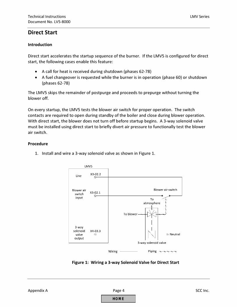
Technical Instructions LMV Series
Document No. LV5-8000
Appendix A Page 4 SCC Inc.
Direct Start
Introduction
Direct start accelerates the startup sequence of the burner. If the LMV5 is configured for direct
start, the following cases enable this feature:
• A call for heat is received during shutdown (phases 62-78)
• A fuel changeover is requested while the burner is in operation (phase 60) or shutdown
(phases 62-78)
The LMV5 skips the remainder of postpurge and proceeds to prepurge without turning the
blower off.
On every startup, the LMV5 tests the blower air switch for proper operation. The switch
contacts are required to open during standby of the boiler and close during blower operation.
With direct start, the blower does not turn off before startup begins. A 3-way solenoid valve
must be installed using direct start to briefly divert air pressure to functionally test the blower
air switch.
Procedure
1. Install and wire a 3-way solenoid valve as shown in Figure 1.
Figure 1: Wiring a 3-way Solenoid Valve for Direct Start
LMV Series Technical Instructions
Document No. LV5-8000
SCC Inc. Page 5 Appendix A
Direct Start (continued)
2. Program the LMV5 to utilize direct start through the following menu path:
Params & Display > BurnerControl > Configuration > ConfigGeneral >
NormDirectStart = DirectStart
3. Configure “Start/PS-Valve” (output terminal X4-03.3) to energize the 3-way solenoid
valve that diverts air pressure away from the blower air switch. This can be
programmed two different ways:
PS Relief – The solenoid valve is energized to divert air pressure away from the
blower air switch in phase 79.
PS Relief_inv – The solenoid valve is energized to expose the blower air switch to
air pressure in every phase except phase 79.
Program the “Start/PS-Valve” parameter through the following menu path:
Params & Display > BurnerControl > Configuration > ConfigIn/Output >
Start/PS-Valve
4. When using direct start, the postpurge time of the boiler is split into two stages:
PostpurgeT1Gas(Oil) – Defines the mandatory postpurge time (phase 74). If the
direct start option is selected and a call for heat exists, the LMV5 will postpurge
for this minimum amount of time.
PostpurgeT3Gas(Oil) – Defines the optional postpurge time (phase 78). If the
direct start option is selected and a call for heat exists, the LMV5 will skip this
postpurge time and go directly into prepurge after the functional test of the
blower air switch.
By minimizing the mandatory postpurge time, PostpurgeT1Gas(Oil), the full benefits of
direct start are achieved. Even with direct start enabled, the LMV5 retains a full
prepurge before opening the fuel valves and starting up. The optional postpurge time,
PostpurgeT3Gas(Oil), is the time required for the proper amount of air exchanges on a
normal shutdown. Both of these postpurge times can be set through the following
menu path:
Params & Display > BurnerControl > Times > Times Shutdown
Technical Instructions LMV Series
Document No. LV5-8000
Appendix A Page 6 SCC Inc.
Direct Start (continued)
Operation
Direct start accelerates the startup sequence in the following instances:
• The LMV5 loses the call for heat (terminal X5-03.1), and regains it before or during
postpurge (phase 62-78)
• The LMV5 receives a fuel changeover request (terminal X4-01.1 or X4-01.2) during
burner operation (phase 60) or shutdown (phases 62-78)
If either of these situations occurs, the LMV5:
1. Drives to low fire (phase 62) and shuts the fuel valves.
2. Ensures the flame signal drops out during the afterburn time (phase 70).
3. Drives to postpurge position (phase 72) and performs its mandatory postpurge
(PostpurgeT1Gas(Oil), phase 74).
4. Proceeds to phase 79 and either powers on or off the 3-way solenoid valve dependent
upon the setting of parameter “Start/PS-Valve”. The LMV5 verifies the operation of the
blower air switch via input terminal X3-02.1 during phase 79.
5. Drives directly to prepurge position (phase 24) and proceeds to startup as normal.
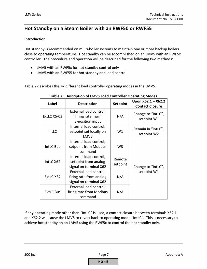
LMV Series Technical Instructions
Document No. LV5-8000
SCC Inc. Page 7 Appendix A
Hot Standby on a Steam Boiler with an RWF50 or RWF55
Introduction
Hot standby is recommended on multi-boiler systems to maintain one or more backup boilers
close to operating temperature. Hot standby can be accomplished on an LMV5 with an RWF5x
controller. The procedure and operation will be described for the following two methods:
• LMV5 with an RWF5x for hot standby control only
• LMV5 with an RWF55 for hot standby and load control
Table 2 describes the six different load controller operating modes in the LMV5.
Table 2: Description of LMV5 Load Controller Operating Modes
Label Description Setpoint Upon X62.1 – X62.2
Contact Closure
ExtLC X5-03
External load control,
firing rate from
3-position input
N/A Change to “IntLC”,
setpoint W1
IntLC
Internal load control,
setpoint set locally on
LMV5
W1 Remain in “IntLC”,
setpoint W2
IntLC Bus
Internal load control,
setpoint from Modbus
command
W3
Change to “IntLC”,
setpoint W1
IntLC X62
Internal load control,
setpoint from analog
signal on terminal X62
Remote
setpoint
ExtLC X62
External load control,
firing rate from analog
signal on terminal X62
N/A
ExtLC Bus
External load control,
firing rate from Modbus
command
N/A
If any operating mode other than “IntLC” is used, a contact closure between terminals X62.1
and X62.2 will cause the LMV5 to revert back to operating mode “IntLC”. This is necessary to
achieve hot standby on an LMV5 using the RWF5x to control the hot standby only.
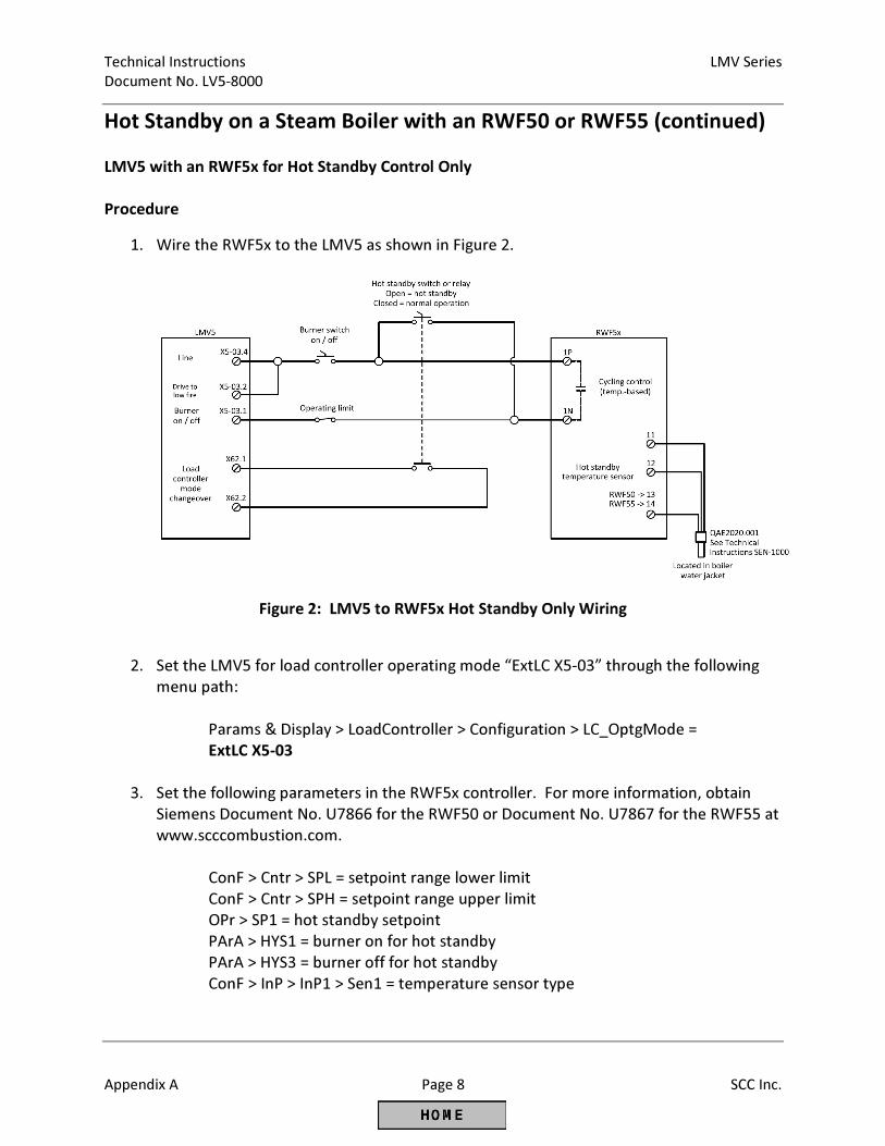
Technical Instructions LMV Series
Document No. LV5-8000
Appendix A Page 8 SCC Inc.
Hot Standby on a Steam Boiler with an RWF50 or RWF55 (continued)
LMV5 with an RWF5x for Hot Standby Control Only
Procedure
1. Wire the RWF5x to the LMV5 as shown in Figure 2.
Figure 2: LMV5 to RWF5x Hot Standby Only Wiring
2. Set the LMV5 for load controller operating mode “ExtLC X5-03” through the following
menu path:
Params & Display > LoadController > Configuration > LC_OptgMode =
ExtLC X5-03
3. Set the following parameters in the RWF5x controller. For more information, obtain
Siemens Document No. U7866 for the RWF50 or Document No. U7867 for the RWF55 at
www.scccombustion.com.
ConF > Cntr > SPL = setpoint range lower limit
ConF > Cntr > SPH = setpoint range upper limit
OPr > SP1 = hot standby setpoint
PArA > HYS1 = burner on for hot standby
PArA > HYS3 = burner off for hot standby
ConF > InP > InP1 > Sen1 = temperature sensor type
LMV Series Technical Instructions
Document No. LV5-8000
SCC Inc. Page 9 Appendix A
Hot Standby on a Steam Boiler with an RWF50 or RWF55 (continued)
Operation
1. When the hot standby switch is open, the LMV5 system is in hot standby mode. The
burner will turn on and off based on the limits set in the RWF5x controller. The contact
between X62.1 and X62.2 will be open. The LMV5 will be in operating mode “ExtLC X5-
03” and looking for a 3-position input for its firing rate command. Since line power from
terminal X5-03.4 has been directly connected to the terminal that decreases the firing
rate (X5-03.2), the LMV5 will stay at low fire until the burner turns off based on the
burner off point set in the RWF5x (PArA > HYS3).
2. When the hot standby switch is closed, the system is in normal operation and not in hot
standby. The contact between X62.1 and X62.2 will close, causing the LMV5 to change
to operating mode “IntLC”. The burner will be controlled based on the limits set in the
LMV5.
Important Notes
1. Any RWF5x controller model will suffice for this hot standby option.
2. The RWF5x is operating only during hot standby mode.
3. The internal load controller of the LMV5 is used during normal operation.
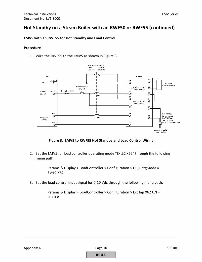
Technical Instructions LMV Series
Document No. LV5-8000
Appendix A Page 10 SCC Inc.
Hot Standby on a Steam Boiler with an RWF50 or RWF55 (continued)
LMV5 with an RWF55 for Hot Standby and Load Control
Procedure
1. Wire the RWF55 to the LMV5 as shown in Figure 3.
Figure 3: LMV5 to RWF55 Hot Standby and Load Control Wiring
2. Set the LMV5 for load controller operating mode “ExtLC X62” through the following
menu path:
Params & Display > LoadController > Configuration > LC_OptgMode =
ExtLC X62
3. Set the load control input signal for 0-10 Vdc through the following menu path:
Params & Display > LoadController > Configuration > Ext Inp X62 U/I =
0..10 V
LMV Series Technical Instructions
Document No. LV5-8000
SCC Inc. Page 11 Appendix A
Hot Standby on a Steam Boiler with an RWF50 or RWF55 (continued)
4. Set the following parameters in the RWF55 controller. For more information, obtain
Siemens Document No. U7867 for the RWF55 at www.scccombustion.com.
ConF > Cntr > CtYP = 2
ConF > Cntr > SPL = setpoint range lower limit
ConF > Cntr > SPH = setpoint range upper limit
OPr > SP1 = normal operation setpoint
PArA > HYS1 = burner on for normal operation
PArA > HYS3 = burner off for normal operation
ConF > InP > InP1 > Sen1 = pressure sensor type
ConF > InP > lnP1 > SCL1 = 0
ConF > InP > InP1 > SCH1 = high end of the range of the pressure sensor
ConF > InP > InP3 > Sen3 = temperature sensor type
ConF > AF > FnCt = 12
ConF > AF > AL = hot standby setpoint
ConF > AF > HYSt = burner on / off for hot standby
ConF > OutP > SiGn = 2
Operation
1. When the hot standby switch is set for hot standby, the LMV5 system is in hot standby
mode. The burner will turn on and off based on the temperature limits set in the
RWF55 controller for hot standby (ConF > AF). Since the signal to LMV5 terminal X62 is
broken by the hot standby switch, the LMV5 stays at low fire until the burner turns off
based on the burner off point set in the RWF55.
2. When the hot standby switch is set for normal operation, the system is in normal
operation mode and not in hot standby. The burner will turn on and off based on the
pressure limits set in the RWF55 controller for normal operation (PArA > HYS1 and PArA
> HYS3). The signal to LMV5 terminal X62 determines the firing rate of the burner.
Important Notes
1. An RWF55 controller must be used for this hot standby option (not RWF50).
2. The RWF55 is operating as the load controller during normal operation as well as
controlling the hot standby.
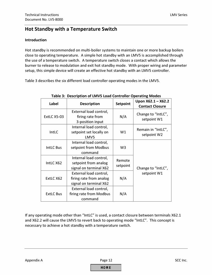
Technical Instructions LMV Series
Document No. LV5-8000
Appendix A Page 12 SCC Inc.
Hot Standby with a Temperature Switch
Introduction
Hot standby is recommended on multi-boiler systems to maintain one or more backup boilers
close to operating temperature. A simple hot standby with an LMV5 is accomplished through
the use of a temperature switch. A temperature switch closes a contact which allows the
burner to release to modulation and exit hot standby mode. With proper wiring and parameter
setup, this simple device will create an effective hot standby with an LMV5 controller.
Table 3 describes the six different load controller operating modes in the LMV5.
Table 3: Description of LMV5 Load Controller Operating Modes
Label Description Setpoint Upon X62.1 – X62.2
Contact Closure
ExtLC X5-03
External load control,
firing rate from
3-position input
N/A Change to “IntLC”,
setpoint W1
IntLC
Internal load control,
setpoint set locally on
LMV5
W1 Remain in “IntLC”,
setpoint W2
IntLC Bus
Internal load control,
setpoint from Modbus
command
W3
Change to “IntLC”,
setpoint W1
IntLC X62
Internal load control,
setpoint from analog
signal on terminal X62
Remote
setpoint
ExtLC X62
External load control,
firing rate from analog
signal on terminal X62
N/A
ExtLC Bus
External load control,
firing rate from Modbus
command
N/A
If any operating mode other than “IntLC” is used, a contact closure between terminals X62.1
and X62.2 will cause the LMV5 to revert back to operating mode “IntLC”. This concept is
necessary to achieve a hot standby with a temperature switch.
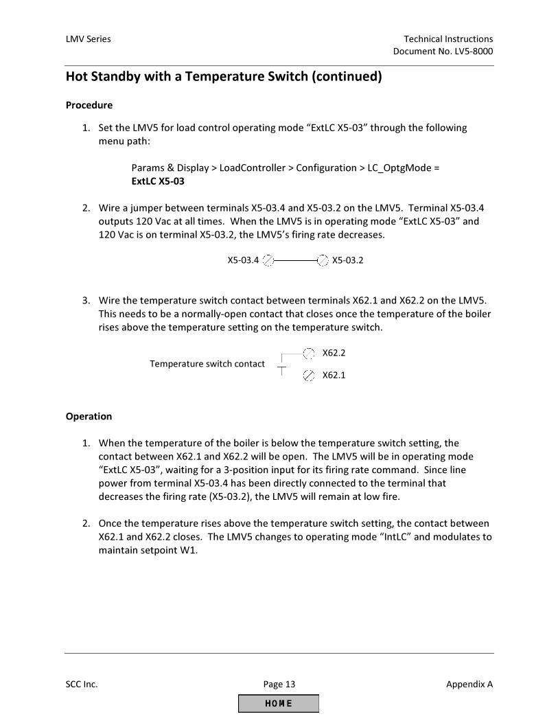
LMV Series Technical Instructions
Document No. LV5-8000
SCC Inc. Page 13 Appendix A
Hot Standby with a Temperature Switch (continued)
Procedure
1. Set the LMV5 for load control operating mode “ExtLC X5-03” through the following
menu path:
Params & Display > LoadController > Configuration > LC_OptgMode =
ExtLC X5-03
2. Wire a jumper between terminals X5-03.4 and X5-03.2 on the LMV5. Terminal X5-03.4
outputs 120 Vac at all times. When the LMV5 is in operating mode “ExtLC X5-03” and
120 Vac is on terminal X5-03.2, the LMV5’s firing rate decreases.
3. Wire the temperature switch contact between terminals X62.1 and X62.2 on the LMV5.
This needs to be a normally-open contact that closes once the temperature of the boiler
rises above the temperature setting on the temperature switch.
Operation
1. When the temperature of the boiler is below the temperature switch setting, the
contact between X62.1 and X62.2 will be open. The LMV5 will be in operating mode
“ExtLC X5-03”, waiting for a 3-position input for its firing rate command. Since line
power from terminal X5-03.4 has been directly connected to the terminal that
decreases the firing rate (X5-03.2), the LMV5 will remain at low fire.
2. Once the temperature rises above the temperature switch setting, the contact between
X62.1 and X62.2 closes. The LMV5 changes to operating mode “IntLC” and modulates to
maintain setpoint W1.
X5-03.4 X5-03.2
Temperature switch contact X62.2
X62.1
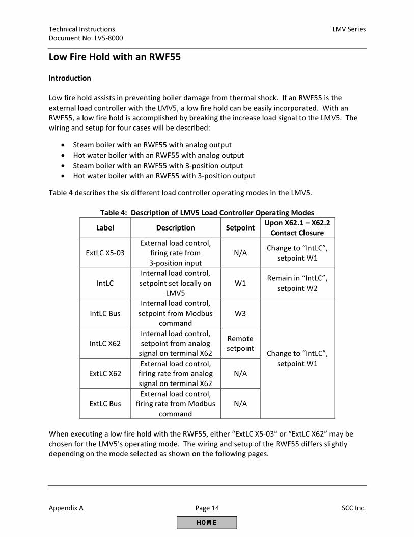
Technical Instructions LMV Series
Document No. LV5-8000
Appendix A Page 14 SCC Inc.
Low Fire Hold with an RWF55
Introduction
Low fire hold assists in preventing boiler damage from thermal shock. If an RWF55 is the
external load controller with the LMV5, a low fire hold can be easily incorporated. With an
RWF55, a low fire hold is accomplished by breaking the increase load signal to the LMV5. The
wiring and setup for four cases will be described:
• Steam boiler with an RWF55 with analog output
• Hot water boiler with an RWF55 with analog output
• Steam boiler with an RWF55 with 3-position output
• Hot water boiler with an RWF55 with 3-position output
Table 4 describes the six different load controller operating modes in the LMV5.
Table 4: Description of LMV5 Load Controller Operating Modes
Label Description Setpoint Upon X62.1 – X62.2
Contact Closure
ExtLC X5-03
External load control,
firing rate from
3-position input
N/A Change to “IntLC”,
setpoint W1
IntLC
Internal load control,
setpoint set locally on
LMV5
W1 Remain in “IntLC”,
setpoint W2
IntLC Bus
Internal load control,
setpoint from Modbus
command
W3
Change to “IntLC”,
setpoint W1
IntLC X62
Internal load control,
setpoint from analog
signal on terminal X62
Remote
setpoint
ExtLC X62
External load control,
firing rate from analog
signal on terminal X62
N/A
ExtLC Bus
External load control,
firing rate from Modbus
command
N/A
When executing a low fire hold with the RWF55, either “ExtLC X5-03” or “ExtLC X62” may be
chosen for the LMV5’s operating mode. The wiring and setup of the RWF55 differs slightly
depending on the mode selected as shown on the following pages.
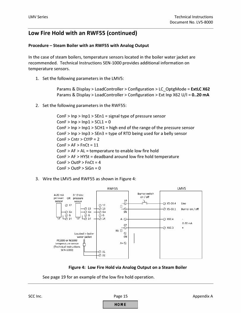
LMV Series Technical Instructions
Document No. LV5-8000
SCC Inc. Page 15 Appendix A
Low Fire Hold with an RWF55 (continued)
Procedure – Steam Boiler with an RWF55 with Analog Output
In the case of steam boilers, temperature sensors located in the boiler water jacket are
recommended. Technical Instructions SEN-1000 provides additional information on
temperature sensors.
1. Set the following parameters in the LMV5:
Params & Display > LoadController > Configuration > LC_OptgMode = ExtLC X62
Params & Display > LoadController > Configuration > Ext Inp X62 U/I = 0..20 mA
2. Set the following parameters in the RWF55:
ConF > Inp > Inp1 > SEn1 = signal type of pressure sensor
ConF > Inp > Inp1 > SCL1 = 0
ConF > Inp > Inp1 > SCH1 = high end of the range of the pressure sensor
ConF > Inp > Inp3 > SEn3 = type of RTD being used for a belly sensor
ConF > Cntr > CtYP = 2
ConF > AF > FnCt = 11
ConF > AF > AL = temperature to enable low fire hold
ConF > AF > HYSt = deadband around low fire hold temperature
ConF > OutP > FnCt = 4
ConF > OutP > SiGn = 0
3. Wire the LMV5 and RWF55 as shown in Figure 4:
Figure 4: Low Fire Hold via Analog Output on a Steam Boiler
See page 19 for an example of the low fire hold operation.
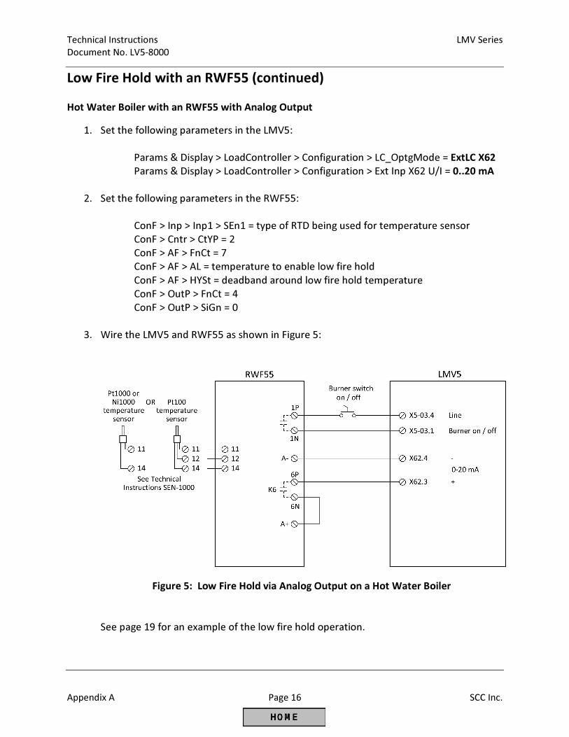
Technical Instructions LMV Series
Document No. LV5-8000
Appendix A Page 16 SCC Inc.
Low Fire Hold with an RWF55 (continued)
Hot Water Boiler with an RWF55 with Analog Output
1. Set the following parameters in the LMV5:
Params & Display > LoadController > Configuration > LC_OptgMode = ExtLC X62
Params & Display > LoadController > Configuration > Ext Inp X62 U/I = 0..20 mA
2. Set the following parameters in the RWF55:
ConF > Inp > Inp1 > SEn1 = type of RTD being used for temperature sensor
ConF > Cntr > CtYP = 2
ConF > AF > FnCt = 7
ConF > AF > AL = temperature to enable low fire hold
ConF > AF > HYSt = deadband around low fire hold temperature
ConF > OutP > FnCt = 4
ConF > OutP > SiGn = 0
3. Wire the LMV5 and RWF55 as shown in Figure 5:
Figure 5: Low Fire Hold via Analog Output on a Hot Water Boiler
See page 19 for an example of the low fire hold operation.
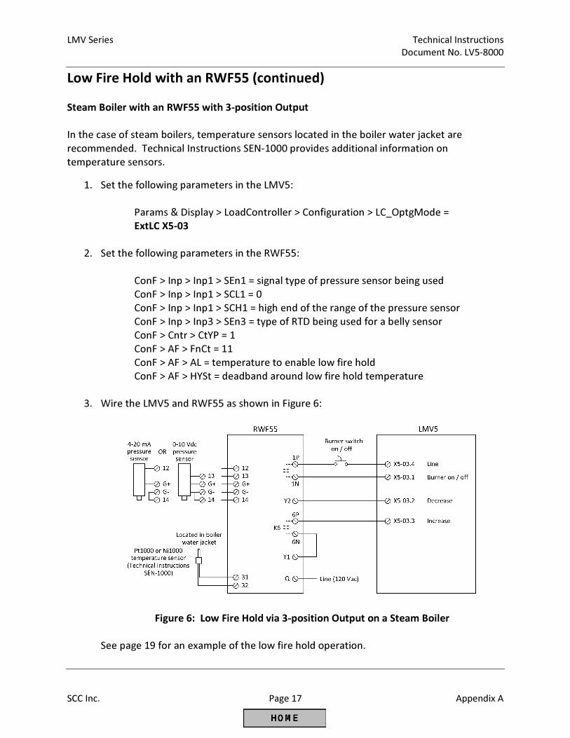
LMV Series Technical Instructions
Document No. LV5-8000
SCC Inc. Page 17 Appendix A
Low Fire Hold with an RWF55 (continued)
Steam Boiler with an RWF55 with 3-position Output
In the case of steam boilers, temperature sensors located in the boiler water jacket are
recommended. Technical Instructions SEN-1000 provides additional information on
temperature sensors.
1. Set the following parameters in the LMV5:
Params & Display > LoadController > Configuration > LC_OptgMode =
ExtLC X5-03
2. Set the following parameters in the RWF55:
ConF > Inp > Inp1 > SEn1 = signal type of pressure sensor being used
ConF > Inp > Inp1 > SCL1 = 0
ConF > Inp > Inp1 > SCH1 = high end of the range of the pressure sensor
ConF > Inp > Inp3 > SEn3 = type of RTD being used for a belly sensor
ConF > Cntr > CtYP = 1
ConF > AF > FnCt = 11
ConF > AF > AL = temperature to enable low fire hold
ConF > AF > HYSt = deadband around low fire hold temperature
3. Wire the LMV5 and RWF55 as shown in Figure 6:
Figure 6: Low Fire Hold via 3-position Output on a Steam Boiler
See page 19 for an example of the low fire hold operation.
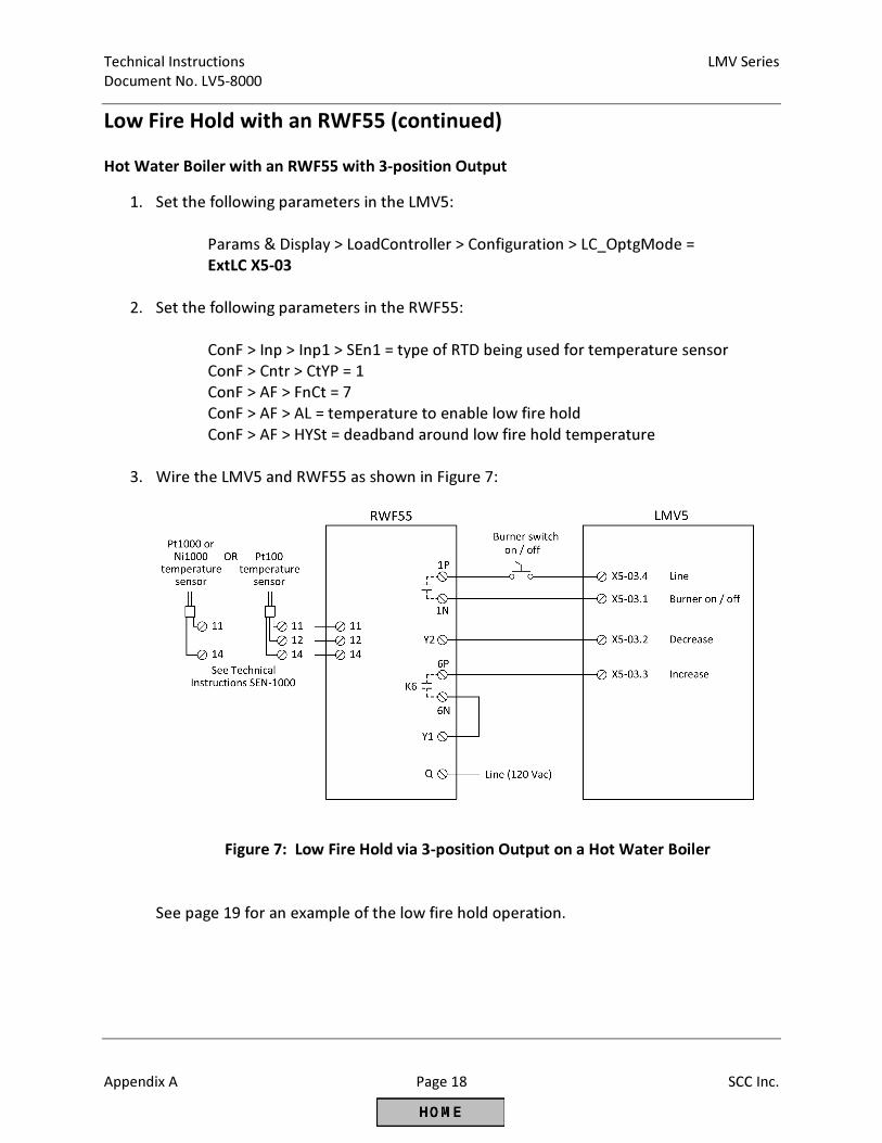
Technical Instructions LMV Series
Document No. LV5-8000
Appendix A Page 18 SCC Inc.
Low Fire Hold with an RWF55 (continued)
Hot Water Boiler with an RWF55 with 3-position Output
1. Set the following parameters in the LMV5:
Params & Display > LoadController > Configuration > LC_OptgMode =
ExtLC X5-03
2. Set the following parameters in the RWF55:
ConF > Inp > Inp1 > SEn1 = type of RTD being used for temperature sensor
ConF > Cntr > CtYP = 1
ConF > AF > FnCt = 7
ConF > AF > AL = temperature to enable low fire hold
ConF > AF > HYSt = deadband around low fire hold temperature
3. Wire the LMV5 and RWF55 as shown in Figure 7:
Figure 7: Low Fire Hold via 3-position Output on a Hot Water Boiler
See page 19 for an example of the low fire hold operation.
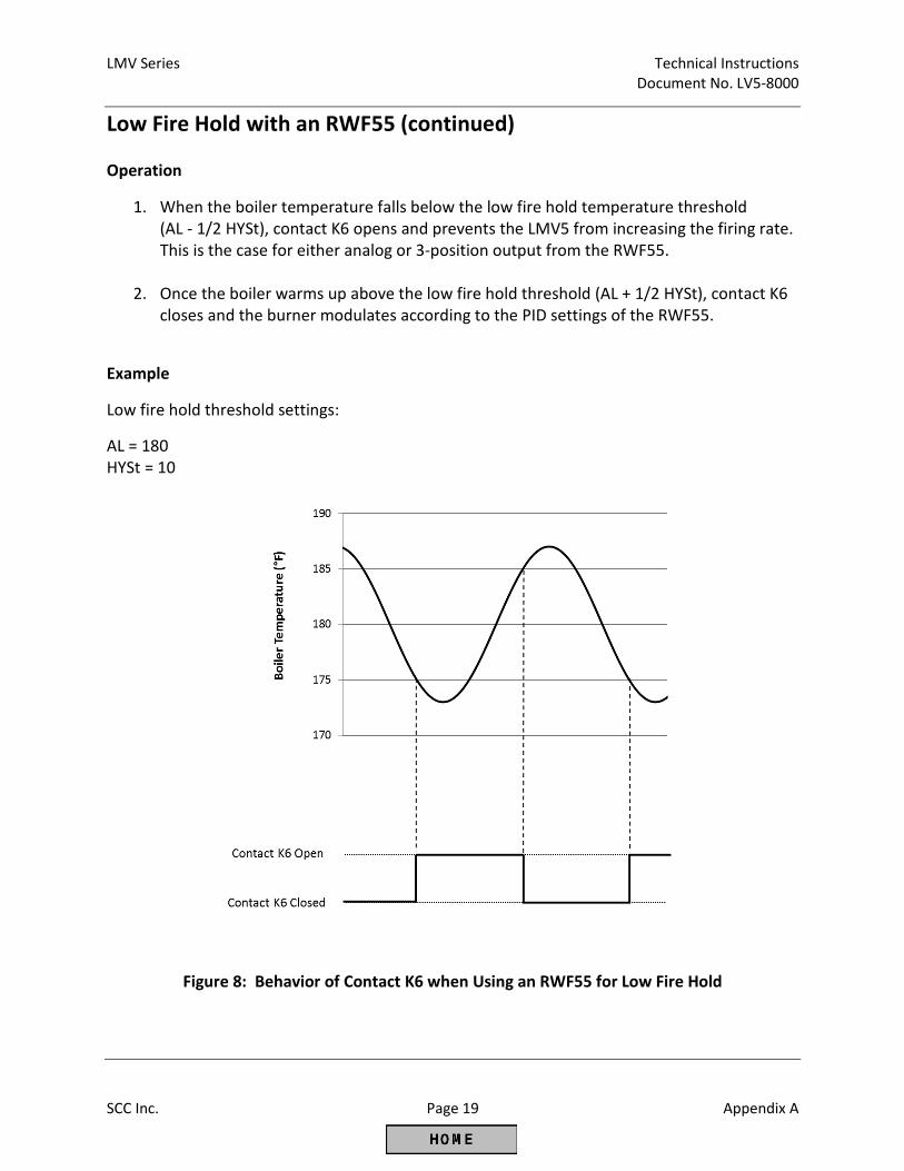
LMV Series Technical Instructions
Document No. LV5-8000
SCC Inc. Page 19 Appendix A
Low Fire Hold with an RWF55 (continued)
Operation
1. When the boiler temperature falls below the low fire hold temperature threshold
(AL - 1/2 HYSt), contact K6 opens and prevents the LMV5 from increasing the firing rate.
This is the case for either analog or 3-position output from the RWF55.
2. Once the boiler warms up above the low fire hold threshold (AL + 1/2 HYSt), contact K6
closes and the burner modulates according to the PID settings of the RWF55.
Example
Low fire hold threshold settings:
AL = 180
HYSt = 10
Figure 8: Behavior of Contact K6 when Using an RWF55 for Low Fire Hold
Technical Instructions LMV Series
Document No. LV5-8000
Appendix A Page 20 SCC Inc.
Pilot Valve Proving
Introduction
Valve proving detects if the main gas valves in a gas train are leaking. In addition to checking
the main gas valves, the pilot valves may be tested for leakage as well. There are three options
for performing pilot valve proving:
• Option 1: On Startup with SKP25’s on both the Pilot and Main Gas Trains
• Option 2: On Startup, SKP25 on the Main Gas Train, Solenoid Valves on the Pilot Train
• Option 3: Pilot Valve Proving on Startup and Main Valve Proving on Shutdown
On the LMV5, valve proving of the main gas valves can be performed during startup, during
shutdown, or during both startup and shutdown of the boiler. If pilot valve proving is added
using Option 1 or Option 2, valve proving must be performed during startup of the boiler only.
If pilot valve proving is added using Option 3, valve proving must be performed during both
startup and shutdown of the boiler.
Pilot valve proving can be performed on any LMV52. Pilot valve proving can be performed on
any LMV51 with a date code of 140131xxxx (Jan 31, 2014) or later.
Procedure
1. The valve proving type can be set in the LMV5 through the following menu path:
Params & Display > BurnerControl > ValveProving > ValveProvingType
For Option 1 or Option 2, this must be set for “VP startup”. For Option 3, this must be
set for “VP stup/shd”.
2. In addition to setting the valve proving type, input terminal X9-03.2 must be set for a
valve proving pressure switch input. This can be done through the following menu path:
Params & Display > BurnerControl > ValveProving > Config_PS-VP/CPI = PS-VP
LMV Series Technical Instructions
Document No. LV5-8000
SCC Inc. Page 21 Appendix A
Pilot Valve Proving (continued)
3. The times for each of the four stages of valve proving need to be set. To do so, use the
following menu paths in the LMV5:
Params & Display > BurnerControl > ValveProving > VP_EvacTme
Params & Display > BurnerControl > ValveProving > VP_TmeAtmPress
Params & Display > BurnerControl > ValveProving > VP_FillTme
Params & Display > BurnerControl > ValveProving > VP_Tme_GasPress
“VP_EvacTme” is the time that the downstream valve is energized in order to evacuate
the chamber between the upstream and downstream valves (phase 80). This is typically
set to 3 seconds, but should not be set any less than the opening time of the valves.
“VP_FillTme” is the time that the upstream valve is energized in order to pressurize the
chamber between the upstream and downstream valves (phase 82). This is typically set
to 3 seconds, but should not be set any less than the opening time of the valves.
“VP_TmeAtmPress” is the time that both the upstream and downstream valves are
closed to test the leakage rate of the upstream valve (phase 81). “VP_Tme_GasPress” is
the time that both the upstream and downstream valves are closed to test the leakage
rate of the downstream valve (phase 83). Both of these times should be set to the same
value. These times can be calculated using the following equation:
����� =��� − �����× � × 3600
���� × �����
ttest = Time for setting parameters “VP_TmeAtmPress” and “VP_Tme_GasPress” in
seconds
Pi = Inlet gas pressure (pressure upstream of both valves) in PSIG
Pset = Gas pressure setting on pressure switch in PSIG (should be set for half of Pi)
Patm = Atmospheric pressure downstream of both valves in PSIA (typically
14.7 PSI)
V = Volume between the gas valves to be tested in ft3
Qleak = Allowable leakage rate in ft3/hr
For Option 3, these times should be calculated independently for the pilot and main
valves, and the larger of the calculated times should be used as the parameter setting.
4. Parameter “PreIgnitionTGas” should be set for its default of 2 seconds. This parameter
can be found at the following menu path in the LMV5:
Params & Display > BurnerControl > Times > TimesStartup1 > PreIgnitionTGas
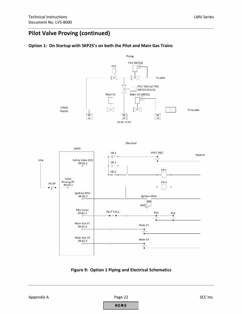
Technical Instructions LMV Series
Document No. LV5-8000
Appendix A Page 22 SCC Inc.
Pilot Valve Proving (continued)
Option 1: On Startup with SKP25’s on both the Pilot and Main Gas Trains
Figure 9: Option 1 Piping and Electrical Schematics
LMV Series Technical Instructions
Document No. LV5-8000
SCC Inc. Page 23 Appendix A
Pilot Valve Proving (continued)
Option 1 Sequence of Operation
1. The LMV5 is in standby. All valves are closed and all relay contacts are as shown in the
electrical schematic.
2. The LMV5 receives a call for heat. The SV terminal (X9-01.1) energizes before the
blower, energizing the PVLT (Pilot Valve Leak Test). The PVLT opens, and connects the
volumes between the pilot valves and main valves. The PVLT POC switch also opens,
preventing the operation of the pilot valves.
3. During prepurge, the main valve proving sequence takes place as normal. The PS-VP
(Pressure Switch - Valve Proving) is wired to terminal X9-03.2 as normal. The setpoint of
the PS-VP should be set for half of the inlet pressure.
4. The LMV5 drives to ignition position. The ignition transformer output (X4-02.3)
energizes, thereby energizing the CR-2 coil, and latching the CR-1 coil from the power
supplied from X9-01.1. At the same time, one of the CR-1 contacts opens, thereby
closing the PVLT valve and closing the PVLT POC switch. Note that the PVLT POC switch
must be closed before the pilot valves open.
5. The LMV5 continues light off and runs as normal, with the CR-1 coil latched in and the
PVLT valve closed.
6. Upon shutdown, the SV terminal (X9-01.1) de-energizes, which un-latches the circuit.
The PVLT valve remains closed until the next start up.
Option 1 Important Notes
1. The proof of closure switch on the PVLT ensures that gas is unable to flow between the
pilot and main valves before the pilot attempts to light.
2. All four valves are tested at the inlet pressure, which is the pressure that they normally
operate at. The PS-VP should be set for half of the inlet pressure which provides a valid
test for all four valves.
3. Valve proving must be done on startup only.
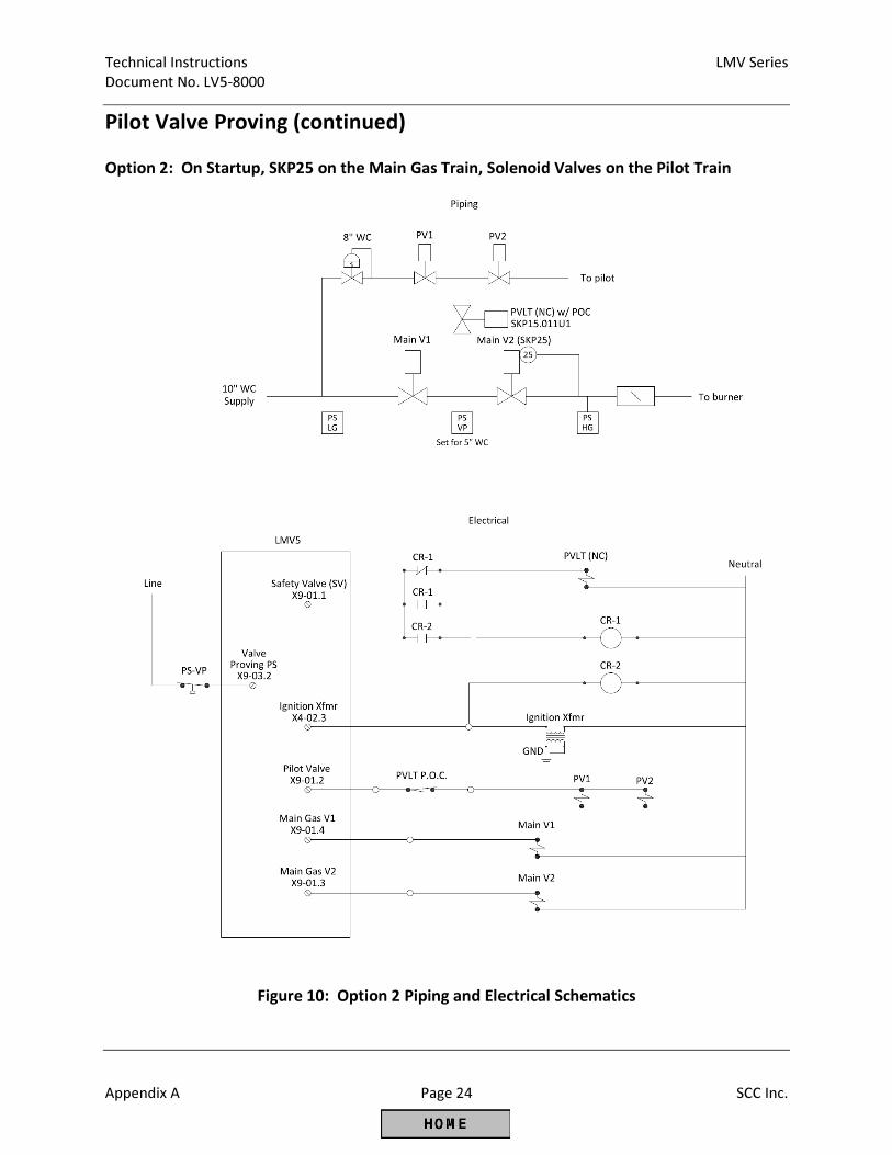
Technical Instructions LMV Series
Document No. LV5-8000
Appendix A Page 24 SCC Inc.
Pilot Valve Proving (continued)
Option 2: On Startup, SKP25 on the Main Gas Train, Solenoid Valves on the Pilot Train
Figure 10: Option 2 Piping and Electrical Schematics
LMV Series Technical Instructions
Document No. LV5-8000
SCC Inc. Page 25 Appendix A
Pilot Valve Proving (continued)
Option 2 Sequence of Operation
1. The LMV5 is in standby. All valves are closed and all relay contacts are as shown in the
electrical schematic.
2. The LMV5 receives a call for heat. The SV terminal (X9-01.1) energizes before the
blower, energizing the PVLT (Pilot Valve Leak Test). The PVLT opens, and connects the
volumes between the pilot valves and main valves. The PVLT POC switch also opens,
preventing the operation of the pilot valves.
3. During prepurge, the main valve proving sequence takes place as normal. The PS-VP
(Pressure Switch - Valve Proving) is wired to terminal X9-03.2 as normal. The setpoint of
the PS-VP should be set for half of the inlet pressure.
4. The LMV5 drives to ignition position. The ignition transformer output (X4-02.3)
energizes, thereby energizing the CR-2 coil, and latching the CR-1 coil from the power
supplied from X9-01.1. At the same time, one of the CR-1 contacts opens, thereby
closing the PVLT valve and closing the PVLT POC switch. Note that the PVLT POC switch
must be closed before the pilot valves open.
5. The LMV5 continues light off and runs as normal, with the CR-1 coil latched in and the
PVLT valve closed.
6. Upon shutdown, the SV terminal (X9-01.1) de-energizes, which un-latches the circuit.
The PVLT valve remains closed until the next start up.
Option 2 Important Notes
1. The proof of closure switch on the PVLT ensures that gas is unable to flow between the
pilot and main valves before the pilot attempts to light.
2. Inlet pressure and pilot pressure must be similar (within ~30%) to have a valid test for all
four valves.
3. Valve proving must be done on startup only.
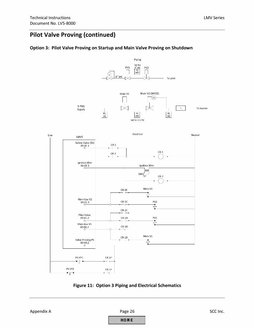
Technical Instructions LMV Series
Document No. LV5-8000
Appendix A Page 26 SCC Inc.
Pilot Valve Proving (continued)
Option 3: Pilot Valve Proving on Startup and Main Valve Proving on Shutdown
Figure 11: Option 3 Piping and Electrical Schematics
LMV Series Technical Instructions
Document No. LV5-8000
SCC Inc. Page 27 Appendix A
Pilot Valve Proving (continued)
Option 3 Sequence of Operation
1. The LMV5 is in standby. All valves are closed and all relay contacts are as shown in the
electrical schematic. Main gas valve V1 terminal X9-01.4 is effectively connected to PV1,
and main gas valve V2 terminal X9-01.3 is effectively connected to PV2.
2. The LMV5 receives a call for heat. The SV terminal (X9-01.1) energizes before the
blower, which has no effect. The LMV5 drives to prepurge position.
3. During prepurge, the valve proving sequence takes place on the pilot valves only. PS-
VP2 (the Pressure Switch Valve Proving between the pilots) is effectively connected to
the valve proving terminal (X9-03.2). The setpoint of PS-VP2 should be set for half of
the inlet pressure to the pilot valves.
4. The LMV5 drives to ignition position. The ignition transformer output (X4-02.3)
energizes, thereby energizing the CR-2 coil, and latching the CR-1 coil from the power
supplied from X9-01.1. The main gas valve V1 terminal (X9-01.4) is connected to main
gas valve V1, and the main gas valve V2 terminal (X9-01.3) is connected to main gas
valve V2. The pilot valve terminal (X9-01.2) is connected to both PV1 and PV2. Also, PS-
VP1 is now connected to the valve proving terminal (X9-03.2).
5. The LMV5 continues to light off and runs as normal, with the CR-1 coil latched in.
6. Upon shutdown, the LMV5 proceeds directly into valve proving on shutdown. The SV
terminal (X9-01.1) is still energized, so the main valves will go through valve proving
using PS-VP1. The setpoint of PS-VP1 should be set for half of the main inlet pressure.
7. After valve proving on shutdown is complete, the SV terminal (X9-01.1) de-energizes
and the CR-1 circuit unlatches.
Option 3 Important Notes
1. Separate pressure switches for the pilot valves and main valves are required.
2. All four valves are tested independently.
3. Valve proving must be done on both startup and shutdown of the boiler.
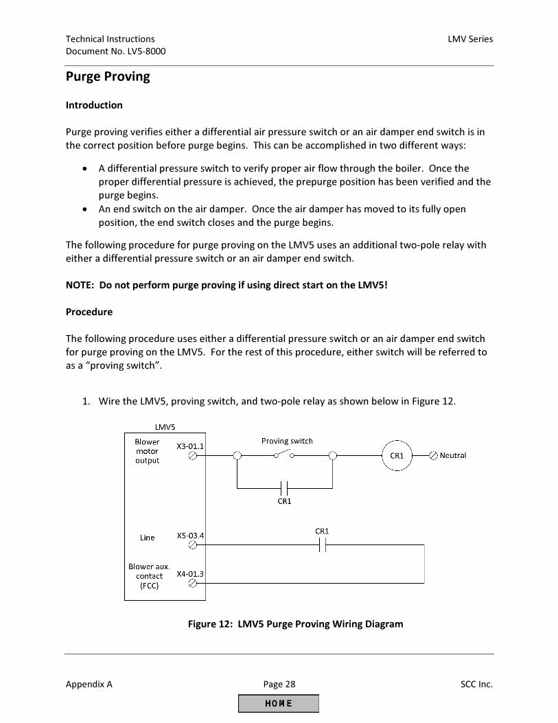
Technical Instructions LMV Series
Document No. LV5-8000
Appendix A Page 28 SCC Inc.
Purge Proving
Introduction
Purge proving verifies either a differential air pressure switch or an air damper end switch is in
the correct position before purge begins. This can be accomplished in two different ways:
• A differential pressure switch to verify proper air flow through the boiler. Once the
proper differential pressure is achieved, the prepurge position has been verified and the
purge begins.
• An end switch on the air damper. Once the air damper has moved to its fully open
position, the end switch closes and the purge begins.
The following procedure for purge proving on the LMV5 uses an additional two-pole relay with
either a differential pressure switch or an air damper end switch.
NOTE: Do not perform purge proving if using direct start on the LMV5!
Procedure
The following procedure uses either a differential pressure switch or an air damper end switch
for purge proving on the LMV5. For the rest of this procedure, either switch will be referred to
as a “proving switch”.
1. Wire the LMV5, proving switch, and two-pole relay as shown below in Figure 12.
Figure 12: LMV5 Purge Proving Wiring Diagram
LMV Series Technical Instructions
Document No. LV5-8000
SCC Inc. Page 29 Appendix A
Purge Proving
2. Input X4-01.3 on the LMV5 must be configured for a blower auxiliary contact. This can
be set through the following menu path in the LMV5:
Params & Display > BurnerControl > Configuration > ConfigIn/Output >
FGR-PS/FCC = FCC
Operation
1. In phase 22, the blower motor output (X3-01.1) energizes, powering the common side of
the proving switch. Note: Since the blower motor may never turn off when using
direct start, purge proving cannot be used in conjunction with direct start on the
LMV5.
2. By the end of phase 24, the blower auxiliary contact input (X4-01.3) must be energized
or the LMV5 will lockout on a “fan contactor contact” (FCC) fault.
3. Once the proving switch makes, relay CR1 energizes and the two normally-open
contacts close.
4. The contact wired in parallel with the proving switch latches power to relay CR1 as long
as the blower is on.
5. The other contact wired off of line terminal X5-03.4 completes the circuit to the blower
auxiliary contact input (X4-01.3). At this point, the purge proving is complete and the
LMV5 will progress to phase 30 (prepurge).
Technical Instructions LMV Series
Document No. LV5-8000
Appendix A Page 30 SCC Inc.
Remote Setpoint
Introduction
The LMV5 can be configured to accept either a local setpoint or a remote setpoint. A remote
setpoint takes an analog input and converts it into a setpoint. On the LMV5, terminal X62 can
be wired and configured to accept a variety of signals for a remote setpoint. The following
steps describe the procedure for setting up a remote setpoint on the LMV5.
Procedure
1. Log in to the LMV5 with either the service or OEM level password.
2. The LMV5 must be set for a load controller operating mode of “IntLC X62”. The LMV5
will utilize the internal PID loop, but will also respond to a remote setpoint from an
analog signal on terminal X62. To set the load controller operating mode to “IntLC X62”,
use the following menu path:
Params & Display > LoadController > Configuration > LC_OptgMode = IntLC X62
3. Configure the type of analog signal which will be input to terminal X62. Four options are
available: 0-10 Vdc, 2-10 Vdc, 0-20 mA, or 4-20 mA. Use the following menu path to set
the input type for terminal X62:
Params & Display > LoadController > Configuration > Ext Inp X62 U/I
NOTE: For the remainder of this section, all examples will use a 4-20 mA signal.
4. The analog input must be scaled appropriately depending on the desired setpoint limits
for the remote setpoint. The LMV5 predefines what setpoint a 4 mA signal indicates.
Conversely, the LMV5 must be programmed with the desired setpoint for a 20 mA
signal. Then, the setpoint will be scaled linearly for any signal between 4 and 20 mA.
Low Setpoint Scaling
When operating on pressure, a 4 mA signal always translates to a 0 psi setpoint.
When operating on temperature, a 4 mA signal always translates to a 32°F setpoint.
High Setpoint Scaling
The high end of the setpoint scaling depends on the sensor type wired to terminals X60
or X61. There are three possibilities for sensor type: a pressure sensor wired to
terminal X61, a temperature sensor wired to terminal X60, or a temperature transmitter
wired to terminal X61.
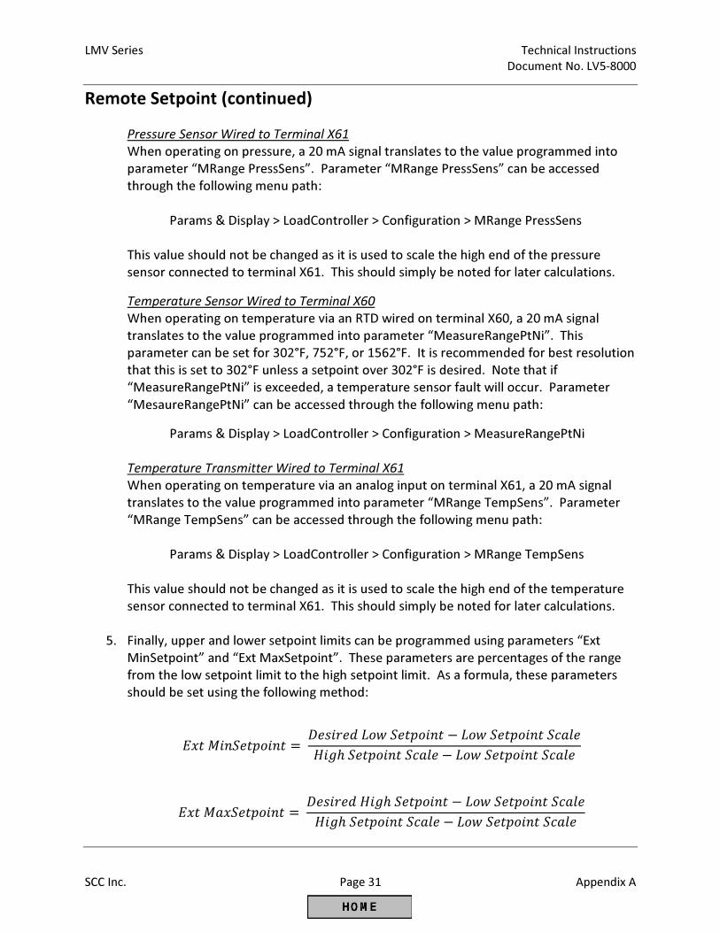
LMV Series Technical Instructions
Document No. LV5-8000
SCC Inc. Page 31 Appendix A
Remote Setpoint (continued)
Pressure Sensor Wired to Terminal X61
When operating on pressure, a 20 mA signal translates to the value programmed into
parameter “MRange PressSens”. Parameter “MRange PressSens” can be accessed
through the following menu path:
Params & Display > LoadController > Configuration > MRange PressSens
This value should not be changed as it is used to scale the high end of the pressure
sensor connected to terminal X61. This should simply be noted for later calculations.
Temperature Sensor Wired to Terminal X60
When operating on temperature via an RTD wired on terminal X60, a 20 mA signal
translates to the value programmed into parameter “MeasureRangePtNi”. This
parameter can be set for 302°F, 752°F, or 1562°F. It is recommended for best resolution
that this is set to 302°F unless a setpoint over 302°F is desired. Note that if
“MeasureRangePtNi” is exceeded, a temperature sensor fault will occur. Parameter
“MesaureRangePtNi” can be accessed through the following menu path:
Params & Display > LoadController > Configuration > MeasureRangePtNi
Temperature Transmitter Wired to Terminal X61
When operating on temperature via an analog input on terminal X61, a 20 mA signal
translates to the value programmed into parameter “MRange TempSens”. Parameter
“MRange TempSens” can be accessed through the following menu path:
Params & Display > LoadController > Configuration > MRange TempSens
This value should not be changed as it is used to scale the high end of the temperature
sensor connected to terminal X61. This should simply be noted for later calculations.
5. Finally, upper and lower setpoint limits can be programmed using parameters “Ext
MinSetpoint” and “Ext MaxSetpoint”. These parameters are percentages of the range
from the low setpoint limit to the high setpoint limit. As a formula, these parameters
should be set using the following method:
���� ������� = ���������� ������� − ��� ������� ����
���ℎ ������� ���� − ��� ������� ����
��� ������� = ����������ℎ ������� − ��� ������� ����
���ℎ ������� ���� − ��� ������� ����
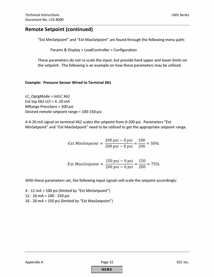
Technical Instructions LMV Series
Document No. LV5-8000
Appendix A Page 32 SCC Inc.
Remote Setpoint (continued)
“Ext MinSetpoint” and “Ext MaxSetpoint” are found through the following menu path:
Params & Display > LoadController > Configuration
These parameters do not re-scale the input, but provide hard upper and lower limits on
the setpoint. The following is an example on how these parameters may be utilized.
Example: Pressure Sensor Wired to Terminal X61
LC_OptgMode = IntLC X62
Ext Inp X62 U/I = 4..20 mA
MRange PressSens = 200 psi
Desired remote setpoint range = 100-150 psi
A 4-20 mA signal on terminal X62 scales the setpoint from 0-200 psi. Parameters “Ext
MinSetpoint” and “Ext MaxSetpoint” need to be utilized to get the appropriate setpoint range.
���� ������� = 100��� − 0���
200��� − 0���=
100
200= 50%
��� ������� = 150��� − 0���
200��� − 0���=
150
200= 75%
With these parameters set, the following input signals will scale the setpoint accordingly:
4 - 12 mA = 100 psi (limited by “Ext MinSetpoint”)
12 - 16 mA = 100 - 150 psi
16 - 20 mA = 150 psi (limited by “Ext MaxSetpoint”)
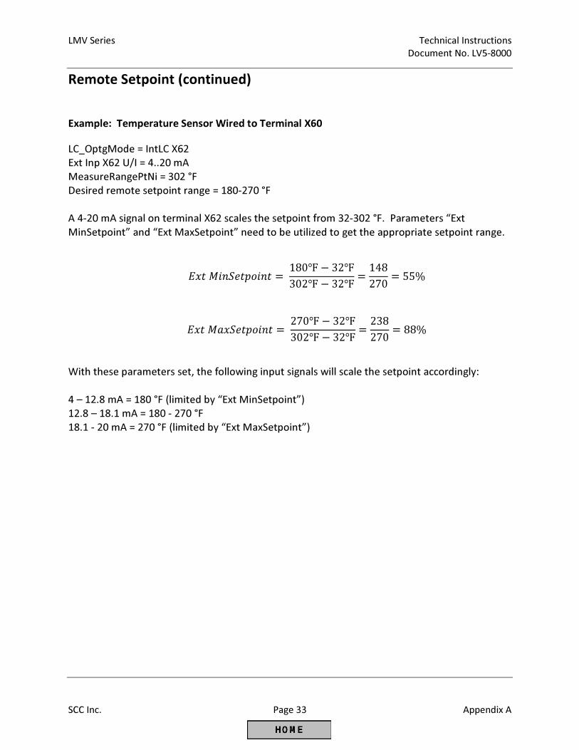
LMV Series Technical Instructions
Document No. LV5-8000
SCC Inc. Page 33 Appendix A
Remote Setpoint (continued)
Example: Temperature Sensor Wired to Terminal X60
LC_OptgMode = IntLC X62
Ext Inp X62 U/I = 4..20 mA
MeasureRangePtNi = 302 °F
Desired remote setpoint range = 180-270 °F
A 4-20 mA signal on terminal X62 scales the setpoint from 32-302 °F. Parameters “Ext
MinSetpoint” and “Ext MaxSetpoint” need to be utilized to get the appropriate setpoint range.
���� ������� = 180℉ − 32℉
302℉ − 32℉=
148
270= 55%
��� ������� = 270℉ − 32℉
302℉ − 32℉=
238
270= 88%
With these parameters set, the following input signals will scale the setpoint accordingly:
4 – 12.8 mA = 180 °F (limited by “Ext MinSetpoint”)
12.8 – 18.1 mA = 180 - 270 °F
18.1 - 20 mA = 270 °F (limited by “Ext MaxSetpoint”)
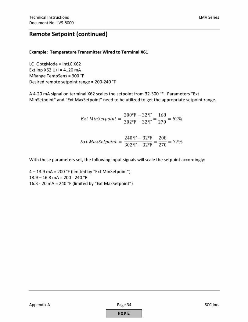
Technical Instructions LMV Series
Document No. LV5-8000
Appendix A Page 34 SCC Inc.
Remote Setpoint (continued)
Example: Temperature Transmitter Wired to Terminal X61
LC_OptgMode = IntLC X62
Ext Inp X62 U/I = 4..20 mA
MRange TempSens = 300 °F
Desired remote setpoint range = 200-240 °F
A 4-20 mA signal on terminal X62 scales the setpoint from 32-300 °F. Parameters “Ext
MinSetpoint” and “Ext MaxSetpoint” need to be utilized to get the appropriate setpoint range.
���� ������� = 200℉ − 32℉
302℉ − 32℉=
168
270= 62%
��� ������� = 240℉ − 32℉
302℉ − 32℉=
208
270= 77%
With these parameters set, the following input signals will scale the setpoint accordingly:
4 – 13.9 mA = 200 °F (limited by “Ext MinSetpoint”)
13.9 – 16.3 mA = 200 - 240 °F
16.3 - 20 mA = 240 °F (limited by “Ext MaxSetpoint”)
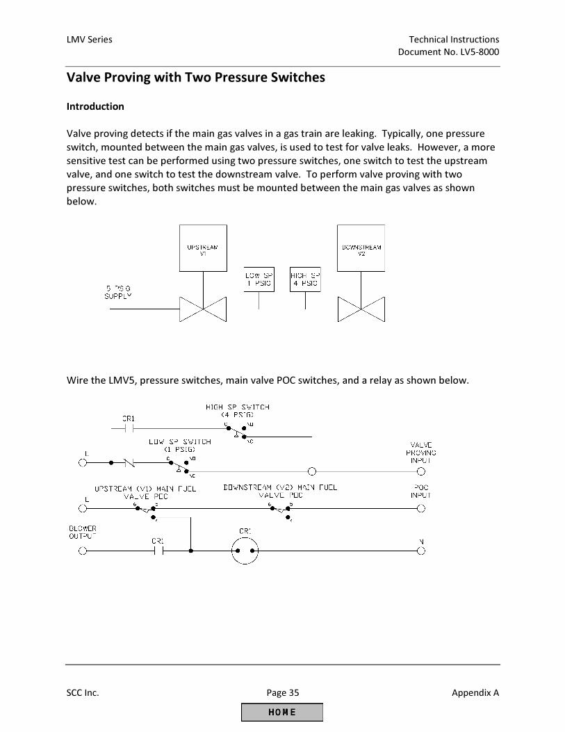
LMV Series Technical Instructions
Document No. LV5-8000
SCC Inc. Page 35 Appendix A
Valve Proving with Two Pressure Switches
Introduction
Valve proving detects if the main gas valves in a gas train are leaking. Typically, one pressure
switch, mounted between the main gas valves, is used to test for valve leaks. However, a more
sensitive test can be performed using two pressure switches, one switch to test the upstream
valve, and one switch to test the downstream valve. To perform valve proving with two
pressure switches, both switches must be mounted between the main gas valves as shown
below.
Wire the LMV5, pressure switches, main valve POC switches, and a relay as shown below.
Technical Instructions LMV Series
Document No. LV5-8000
Appendix A Page 36 SCC Inc.
Valve Proving with Two Pressure Switches (continued)
Sequence of Operation
1. The blower energizes, but nothing happens as CR1 remains open.
2. V2 opens, evacuating the space between the main valves.
a. The V2 POC switch changes state, but this has no effect on CR1.
3. V2 closes, and the waiting time begins.
a. If V1 leaks by, the low SP switch will open (NO), and the valve proving input will de-
energize (test fail).
b. The high SP switch is essentially not in the circuit at this point (CR1 open)
4. If V1 passes the test, V1 is opened, pressurizing the space between the main valves.
a. Normally open contact (4) on the V1 POC switch latches CR1 coil, all CR1 contacts
change state.
b. The high SP switch will be open (NO). The low SP switch is essentially removed from the
circuit.
5. V1 closes, and the waiting time begins.
a. If V2 leaks by, the high SP switch will close and the valve proving input will energize (test
fail).
b. CR1 coil is still latched at this point.
6. The burner lights off, V1 and V2 are energized, both POC switches open.
a. This has no effect on the CR1 coil, which remains latched.
7. After post purge, the blower output de-energizes and un-latches the circuit.
Important Notes
1. The valve proving input X9-03.2 must be energized for the V1 leak test, and de-energized for the
V2 leak test.
2. Valve proving must be done on startup only.
3. If the relay were to fail (stick one way or the other), a less-sensitive valve proving test would
result. A POC switch could never be jumpered by a failed relay.
LMV Series Technical Instructions
Document No. LV5-8000
SCC Inc. Page 37 Appendix A
VFD Bypass
Introduction
When using an LMV52 with a variable frequency drive (VFD), it may be beneficial to bypass the
VFD and run the motor at full speed. There are typically two reasons for doing this:
• On a single fuel system, it is desired to have the ability to run without the VFD, typically
in the event of a VFD malfunction.
• On a dual fuel system, it is desired to use the VFD with one fuel (typically gas) but not
the other fuel (typically oil).
The following pages provide the information to apply a VFD bypass on either a single or dual
fuel system. For the single fuel system, the fuel is assumed to be gas. For the dual fuel system,
it will be assumed that the main fuel is gas and the secondary fuel is oil.
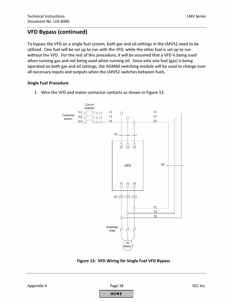
Technical Instructions LMV Series
Document No. LV5-8000
Appendix A Page 38 SCC Inc.
VFD Bypass (continued)
To bypass the VFD on a single fuel system, both gas and oil settings in the LMV52 need to be
utilized. One fuel will be set up to run with the VFD, while the other fuel is set up to run
without the VFD. For the rest of this procedure, it will be assumed that a VFD is being used
when running gas and not being used when running oil. Since only one fuel (gas) is being
operated on both gas and oil settings, the AGM60 switching module will be used to change over
all necessary inputs and outputs when the LMV52 switches between fuels.
Single Fuel Procedure
1. Wire the VFD and motor contactor contacts as shown in Figure 13.
Figure 13: VFD Wiring for Single Fuel VFD Bypass
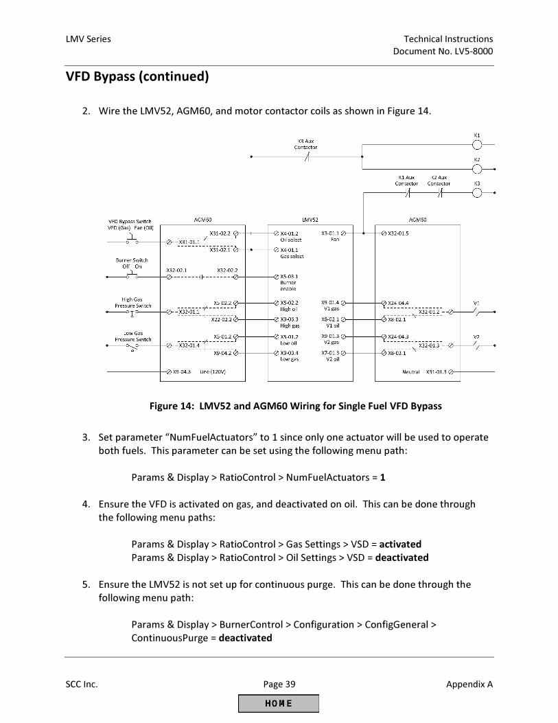
LMV Series Technical Instructions
Document No. LV5-8000
SCC Inc. Page 39 Appendix A
VFD Bypass (continued)
2. Wire the LMV52, AGM60, and motor contactor coils as shown in Figure 14.
Figure 14: LMV52 and AGM60 Wiring for Single Fuel VFD Bypass
3. Set parameter “NumFuelActuators” to 1 since only one actuator will be used to operate
both fuels. This parameter can be set using the following menu path:
Params & Display > RatioControl > NumFuelActuators = 1
4. Ensure the VFD is activated on gas, and deactivated on oil. This can be done through
the following menu paths:
Params & Display > RatioControl > Gas Settings > VSD = activated
Params & Display > RatioControl > Oil Settings > VSD = deactivated
5. Ensure the LMV52 is not set up for continuous purge. This can be done through the
following menu path:
Params & Display > BurnerControl > Configuration > ConfigGeneral >
ContinuousPurge = deactivated
Technical Instructions LMV Series
Document No. LV5-8000
Appendix A Page 40 SCC Inc.
VFD Bypass (continued)
Single Fuel Operation
1. When the “VFD Bypass Switch” is in VFD mode, motor contactors K1 and K2 are
energized. Power flows through the VFD to the motor. Bypass contactor K3 remains
de-energized. The fuel select terminal (X31-01.1) on the AGM60 is de-energized, so the
LMV52 runs gas. All inputs and outputs are connected through the AGM60 to the
LMV52 gas terminals.
2. When the “VFD Bypass Switch” is in Fan mode, motor contactors K1 and K2 are de-
energized and no power flows to the VFD. Power runs directly to the motor through
bypass contactor K3 once the fan output (X3-01.1) is energized in phase 22. The fuel
select terminal (X31-01.1) on the AGM60 is energized, so the LMV52 runs oil. All inputs
and outputs are connected through the AGM60 to the LMV52 oil terminals.
3. If the “VFD Bypass Switch” is switched during operation, the LMV52 immediately loses
its call for heat and goes through its shutdown sequence. When the fan output (X3-
01.1) de-energizes after phase 78, terminal X32-01.5 on the AGM60 becomes de-
energized, causing the switchover of all inputs and outputs connected through the
AGM60 and the motor contactors.
Note: Even though this is a single fuel system running gas, the LMV52 display will state
it is running oil when the “VFD Bypass Switch” is in Fan mode.
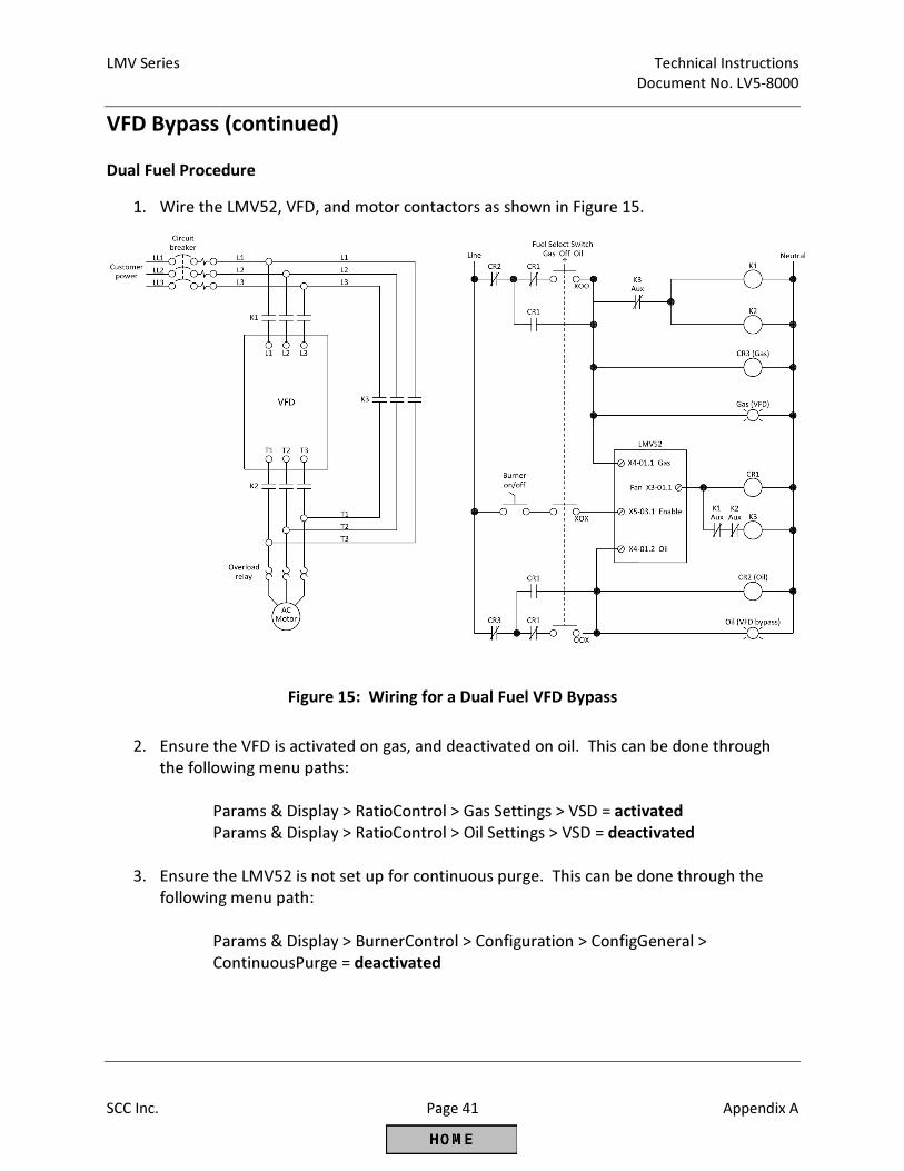
LMV Series Technical Instructions
Document No. LV5-8000
SCC Inc. Page 41 Appendix A
VFD Bypass (continued)
Dual Fuel Procedure
1. Wire the LMV52, VFD, and motor contactors as shown in Figure 15.
Figure 15: Wiring for a Dual Fuel VFD Bypass
2. Ensure the VFD is activated on gas, and deactivated on oil. This can be done through
the following menu paths:
Params & Display > RatioControl > Gas Settings > VSD = activated
Params & Display > RatioControl > Oil Settings > VSD = deactivated
3. Ensure the LMV52 is not set up for continuous purge. This can be done through the
following menu path:
Params & Display > BurnerControl > Configuration > ConfigGeneral >
ContinuousPurge = deactivated
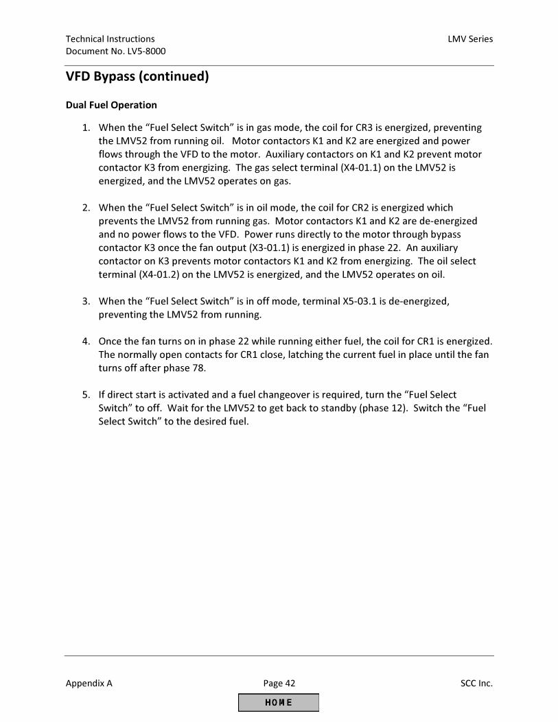
Technical Instructions LMV Series
Document No. LV5-8000
Appendix A Page 42 SCC Inc.
VFD Bypass (continued)
Dual Fuel Operation
1. When the “Fuel Select Switch” is in gas mode, the coil for CR3 is energized, preventing
the LMV52 from running oil. Motor contactors K1 and K2 are energized and power
flows through the VFD to the motor. Auxiliary contactors on K1 and K2 prevent motor
contactor K3 from energizing. The gas select terminal (X4-01.1) on the LMV52 is
energized, and the LMV52 operates on gas.
2. When the “Fuel Select Switch” is in oil mode, the coil for CR2 is energized which
prevents the LMV52 from running gas. Motor contactors K1 and K2 are de-energized
and no power flows to the VFD. Power runs directly to the motor through bypass
contactor K3 once the fan output (X3-01.1) is energized in phase 22. An auxiliary
contactor on K3 prevents motor contactors K1 and K2 from energizing. The oil select
terminal (X4-01.2) on the LMV52 is energized, and the LMV52 operates on oil.
3. When the “Fuel Select Switch” is in off mode, terminal X5-03.1 is de-energized,
preventing the LMV52 from running.
4. Once the fan turns on in phase 22 while running either fuel, the coil for CR1 is energized.
The normally open contacts for CR1 close, latching the current fuel in place until the fan
turns off after phase 78.
5. If direct start is activated and a fuel changeover is required, turn the “Fuel Select
Switch” to off. Wait for the LMV52 to get back to standby (phase 12). Switch the “Fuel
Select Switch” to the desired fuel.

Intentionally Left Blank
Global Siemens Headquarters Siemens AG Berliner Ring 23 76437 Rastatt Germany
SCC, Inc. 1250 Lunt Avenue Elk Grove Village, IL 60007 USA Telephone: 1-224-366-8445
www.scccombustion.com
Printed in USA
© Siemens Industry, Inc. • (05/2015)
Technical Instructions Document No. LV5-1000 July 10, 2015