Embed Size (px)
Citation preview

�������
������� �����
������������� �������� ��
��������������������������� �!�
© Siemens Milltronics Process Instruments Inc. 2010
Safety Guidelines: Warning notices must be observed to ensure personal safety as well as that of others, and to protect the product and the connected equipment. These warning notices are accompanied by a clarification of the level of caution to be observed.
Qualified Personnel: This device/system may only be set up and operated in conjunction with this manual. Qualified personnel are only authorized to install and operate this equipment in accordance with established safety practices and standards.
Unit Repair and Excluded Liability:
• The user is responsible for all changes and repairs made to the device by the user or the user’s agent.
• All new components are to be provided by Siemens Milltronics Process Instruments Inc. • Restrict repair to faulty components only. • Do not reuse faulty components.
Warning: Cardboard shipping package provides limited humidity and moisture protection. This product can only function properly and safely if it is correctly transported, stored, installed, set up, operated, and maintained. This product is intended for use in industrial areas. Operation of this equipment in a residential area may cause interference to several frequency based communications.
Note: Always use product in accordance with specifications.
Copyright Siemens Milltronics Process Instruments Inc. 2010. All Rights Reserved
Disclaimer of Liability
This document is available in bound version and in electronic version. We encourage users to purchase authorized bound manuals, or to view electronic versions as designed and authored by Siemens Milltronics Process Instruments Inc. Siemens Milltronics Process Instruments Inc. will not be responsible for the contents of partial or whole reproductions of either bound or electronic versions.
While we have verified the contents of this manual for agreement with the instrumentation described, variations remain possible. Thus we cannot guarantee full agreement. The contents of this manual are regularly reviewed and corrections are included in subsequent editions. Please check the website shown below for the latest manual revisions. We welcome all suggestions for improvement. Technical data subject to change.
MILLTRONICS®is a registered trademark of Siemens Milltronics Process Instruments Inc. Contact SMPI Technical Publications European Authorized Representative at the following address: Technical Publications Siemens AG Siemens Milltronics Process Instruments Inc. Industry Sector 1954 Technology Drive, P.O. Box 4225 76181 Karlsruhe Peterborough, Ontario, Canada, K9J 7B1 Deutschland Email: [email protected] • For a selection of Siemens Milltronics level measurement manuals, go to:
www. siemens.com/level. Choose Instructions and Manuals under the More Info list. • For a selection of Siemens Milltronics weighing manuals, go to:
www. siemens.com/weighing. Choose Support, and then Manuals / Operating Instructions.
mm
mm
m
Table of Contents
Table of Contents
Table of Contents .................................................................................................................iSafety Notes .............................................................................................................................................1
Safety marking symbols ..............................................................................................................1FCC Conformity ........................................................................................................................................1
CE Electromagnetic Compatibility (EMC) Conformity ..........................................................2The Manual ...............................................................................................................................................2
Application Examples ...................................................................................................................3Technical Support ....................................................................................................................................3Abbreviations and Identifications .......................................................................................................3
SITRANS LR200 Overview ................................................................................................. 5
Specifications ...................................................................................................................... 6Power............................................................................................................................................. 6Performance................................................................................................................................. 6Interface ........................................................................................................................................ 7Mechanical ................................................................................................................................... 7Environmental .............................................................................................................................. 9Process.......................................................................................................................................... 9Approvals ...................................................................................................................................... 9Programmer (infrared keypad) .............................................................................................. 10
Installation ......................................................................................................................... 13Pressure Equipment Directive, PED, 97/23/EC ...............................................................................14Mounting location .................................................................................................................................14
Nozzle design ...............................................................................................................................14Nozzle location .............................................................................................................................14Orientation in a vessel with obstructions .............................................................................16Mounting on a Stillpipe or Bypass Pipe ................................................................................16
Installation Instructions .......................................................................................................................17
Wiring .................................................................................................................................. 19Power .......................................................................................................................................................19Connecting SITRANS LR200 ...............................................................................................................19
Basic PLC configuration with PROFIBUS PA ........................................................................20Wiring Setups for hazardous area installations ............................................................................21
PLC configuration with PROFIBUS PA for hazardous areas ............................................21Instructions specific to hazardous area installations ..................................................................24
Operating via the handheld programmer .....................................................................25Activating SITRANS LR200 .................................................................................................................25
The LCD Display ...........................................................................................................................25Handheld Programmer ...............................................................................................................26Programming SITRANS LR200 .................................................................................................27
Quick Start Wizard via the handheld programmer .......................................................................30Auto False Echo Suppression ............................................................................................................32Requesting an Echo Profile ................................................................................................................32Device Address ......................................................................................................................................33
i
mm
mm
m
Tabl
e of
Cot
ents
Level application example ...................................................................................................................33
Operating via SIMATIC PDM ..........................................................................................34Functions in SIMATIC PDM ................................................................................................................34
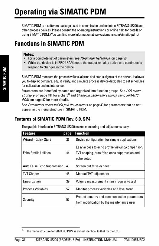
Features of SIMATIC PDM Rev. 6.0, SP4 ...............................................................................34Features of SIMATIC PDM Rev. 5.2, SP1 ...............................................................................35Electronic Device Description (EDD) ......................................................................................35Configuring a new device .........................................................................................................35
Quick Start Wizard via SIMATIC PDM .............................................................................................36Wizard - Quick Start ...................................................................................................................36Linearization .................................................................................................................................39Configuring a stillpipe application ...........................................................................................42
Changing parameter settings using SIMATIC PDM .....................................................................42Parameters accessed via pull-down menus ........................................................................43Diagnostics ...................................................................................................................................52Security ..........................................................................................................................................56
Operating via FDT (Field Device Tool) ...........................................................................57Device Type Manager (DTM) .............................................................................................................57SITRANS DTM .......................................................................................................................................57The instrument EDD ..............................................................................................................................57Configuring a new device via FDT ....................................................................................................57
Parameter Reference .......................................................................................................59Quick Start .................................................................................................................................. 59Setup ............................................................................................................................................ 60
Identification..................................................................................................................... 60Device ................................................................................................................................ 60Sensor ................................................................................................................................ 60Linearization ..................................................................................................................... 65Signal Processing............................................................................................................ 69AIFB1 .................................................................................................................................. 77AIFB2 .................................................................................................................................. 81Measured Values ............................................................................................................ 81
Diagnostics ................................................................................................................................. 81Echo Profile....................................................................................................................... 81Fault Reset ........................................................................................................................ 82Electronics Temperature ............................................................................................... 82Condensed Status ........................................................................................................... 82Allocation .......................................................................................................................... 83Peak Values ...................................................................................................................... 86
Service ........................................................................................................................................ 86Master Reset.................................................................................................................... 86Remaining Device Lifetime ........................................................................................... 87Remaining Sensor Lifetime ........................................................................................... 90Service Schedule ............................................................................................................ 93Calibration Schedule ...................................................................................................... 96Manufacture Date........................................................................................................... 99Powered Hours................................................................................................................ 99Power-on Resets............................................................................................................. 99LCD Fast Mode................................................................................................................. 99
ii
mm
mm
m
Table of Contents
LCD Contrast.................................................................................................................. 100Communication....................................................................................................................... 100Device Address ............................................................................................................ 100PROFIBUS Ident Number ........................................................................................... 100
Security..................................................................................................................................... 101Remote Access............................................................................................................. 101Local Access ................................................................................................................. 101
Language.................................................................................................................................. 101
Appendix A: Alphabetical Parameter List .................................................................. 103
Appendix B: Troubleshooting ....................................................................................... 106Communication Troubleshooting ................................................................................................... 106Device Status Icons ........................................................................................................................... 107General Fault Codes .......................................................................................................................... 109Operation Troubleshooting ...............................................................................................................113
Appendix C: Maintenance ............................................................................................ 115Unit Repair and Excluded Liability ..................................................................................................115
Replacing the antenna .............................................................................................................115
Appendix D: Technical Reference ............................................................................... 116Principles of Operation ......................................................................................................................116Echo Processing ..................................................................................................................................116
Process Intelligence .................................................................................................................116Echo Selection ...........................................................................................................................117Measurement Range ................................................................................................................121
Measurement Response ...................................................................................................................121Damping .................................................................................................................................................122Loss of Echo (LOE) ...............................................................................................................................122
LOE Timer ....................................................................................................................................122Fail-safe Behavior .....................................................................................................................123
Maximum Process Temperature Chart ..........................................................................................124Process Pressure/Temperature derating curves .........................................................................125Pressure Equipment Directive, PED, 97/23/EC .............................................................................125
Appendix E: Application Examples ............................................................................. 130Liquid resin in storage vessel, level measurement ..................................................................130Horizontal vessel with volume measurement ............................................................................131Application with Stillpipe ................................................................................................................132
Propagation Factor/Stillpipe Diameter ................................................................................133
Appendix F: PROFIBUS PA Profile Structure ............................................................. 134PROFIBUS Level Device Design ......................................................................................................134Block Model ..........................................................................................................................................134
Description of the blocks .........................................................................................................135
Appendix G: Communications via PROFIBUS PA ..................................................... 140Device Configuration tool ..................................................................................................................140
SIMATIC PDM ............................................................................................................................140Network Configuration ......................................................................................................................140
The GSD file ................................................................................................................................140
iii
mm
mm
m
Tabl
e of
Cot
ents
Bus Termination ...................................................................................................................................141Power Demands ..................................................................................................................................141PROFIBUS address .............................................................................................................................141Operating as a Profile Device ...........................................................................................................141
Configuring a device .................................................................................................................142Configuring PROFIBUS PA with an S7-300/ 400 PLC ........................................................142
Cyclic versus Acyclic Data ................................................................................................................142Cyclic Data ..................................................................................................................................142
Status Byte ...........................................................................................................................................143Condensed Status ...............................................................................................................................144Diagnostics ...........................................................................................................................................146
Diagnosis reply (available cyclically) ....................................................................................146Diagnosis Object (available cyclically or acyclically) .......................................................147Condensed Mode Diagnosis ..................................................................................................148Acyclic Extended Diagnostics (General Fault Codes) ......................................................149
Acyclic Data ..........................................................................................................................................152
Appendix H: Flange Adapter Versions ........................................................................ 154Dimensions: ..........................................................................................................................................154
Threaded connection, PTFE Rod ..........................................................................................154PTFE Rod Antenna, Flat-Face Flange ...................................................................................155Threaded Connection, PTFE Rod, external shield .............................................................156Flat-Face Flange with Horn Antenna and Waveguide extension .................................157Flanged Horn dimensions .......................................................................................................158Raised Face or Flat-Face Flange with Waveguide ...........................................................159Sliding Waveguide Configuration ..........................................................................................160Sanitary connection, Rod Antenna, PTFE or HDPE ..........................................................161
Raised Face Flange per EN 1092-1 .................................................................................................162Raised Face Flange Dimensions ...........................................................................................163
Flat-Face Flange (constant thickness series) ..............................................................................164Flat-Face Flange Dimensions .................................................................................................165
Flange Mounting Instructions ..........................................................................................................167Rod Assembly .............................................................................................................................168Rod Extension Requirements .................................................................................................168
Mounting Guidelines ..........................................................................................................................169
Appendix J: Firmware Revision History ..................................................................... 171
Glossary ............................................................................................................................ 173
Index .................................................................................................................................. 177
LCD menu structure ....................................................................................................... 181
iv
mm
mm
m
SITRAN
S LR200
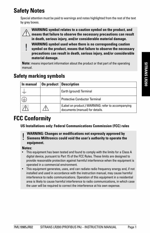
Safety NotesSpecial attention must be paid to warnings and notes highlighted from the rest of the text by grey boxes.
Safety marking symbols
FCC ConformityUS Installations only: Federal Communications Commission (FCC) rules
WARNING symbol relates to a caution symbol on the product, and means that failure to observe the necessary precautions can result in death, serious injury, and/or considerable material damage.WARNING symbol used when there is no corresponding caution symbol on the product, means that failure to observe the necessary precautions can result in death, serious injury, and/or considerable material damage.
Note: means important information about the product or that part of the operating manual.
In manual On product Description
Earth (ground) Terminal
Protective Conductor Terminal
(Label on product.) WARNING: refer to accompanying documents (manual) for details.
WARNING: Changes or modifications not expressly approved by Siemens Milltronics could void the user’s authority to operate the equipment.
Notes:• This equipment has been tested and found to comply with the limits for a Class A
digital device, pursuant to Part 15 of the FCC Rules. These limits are designed to provide reasonable protection against harmful interference when the equipment is operated in a commercial environment.
• This equipment generates, uses, and can radiate radio frequency energy and, if not installed and used in accordance with the instruction manual, may cause harmful interference to radio communications. Operation of this equipment in a residential area is likely to cause harmful interference to radio communications, in which case the user will be required to correct the interference at his own expense.
7ML19985JR02 SITRANS LR200 (PROFIBUS PA) – INSTRUCTION MANUAL Page 1
mm
mm
m
SITR
AN
S LR
200
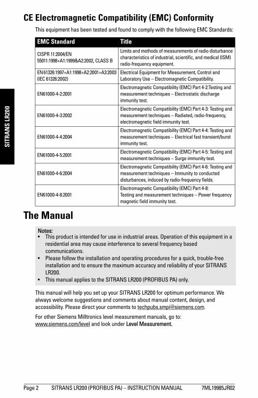
CE Electromagnetic Compatibility (EMC) ConformityThis equipment has been tested and found to comply with the following EMC Standards:
The Manual
This manual will help you set up your SITRANS LR200 for optimum performance. We always welcome suggestions and comments about manual content, design, and accessibility. Please direct your comments to [email protected].
For other Siemens Milltronics level measurement manuals, go to:www.siemens.com/level and look under Level Measurement.
EMC Standard Title
CISPR 11:2004/EN 55011:1998+A1:1999&A2:2002, CLASS B
Limits and methods of measurements of radio disturbance characteristics of industrial, scientific, and medical (ISM) radio-frequency equipment.
EN 61326:1997+A1:1998+A2:2001+A3:2003 (IEC 61326:2002)
Electrical Equipment for Measurement, Control and Laboratory Use – Electromagnetic Compatibility.
EN61000-4-2:2001 Electromagnetic Compatibility (EMC) Part 4-2:Testing and measurement techniques – Electrostatic discharge immunity test.
EN61000-4-3:2002 Electromagnetic Compatibility (EMC) Part 4-3: Testing and measurement techniques – Radiated, radio-frequency, electromagnetic field immunity test.
EN61000-4-4:2004 Electromagnetic Compatibility (EMC) Part 4-4: Testing and measurement techniques – Electrical fast transient/burst immunity test.
EN61000-4-5:2001 Electromagnetic Compatibility (EMC) Part 4-5: Testing and measurement techniques – Surge immunity test.
EN61000-4-6:2004 Electromagnetic Compatibility (EMC) Part 4-6: Testing and measurement techniques – Immunity to conducted disturbances, induced by radio-frequency fields.
EN61000-4-8:2001 Electromagnetic Compatibility (EMC) Part 4-8:Testing and measurement techniques – Power frequency magnetic field immunity test.
Notes:• This product is intended for use in industrial areas. Operation of this equipment in a
residential area may cause interference to several frequency based communications.
• Please follow the installation and operating procedures for a quick, trouble-free installation and to ensure the maximum accuracy and reliability of your SITRANS LR200.
• This manual applies to the SITRANS LR200 (PROFIBUS PA) only.
Page 2 SITRANS LR200 (PROFIBUS PA) – INSTRUCTION MANUAL 7ML19985JR02
mm
mm
m
SITRAN
S LR200
JR02.2-Introduction.fm Page 3 Wednesday, June 23, 2010 3:45 PM
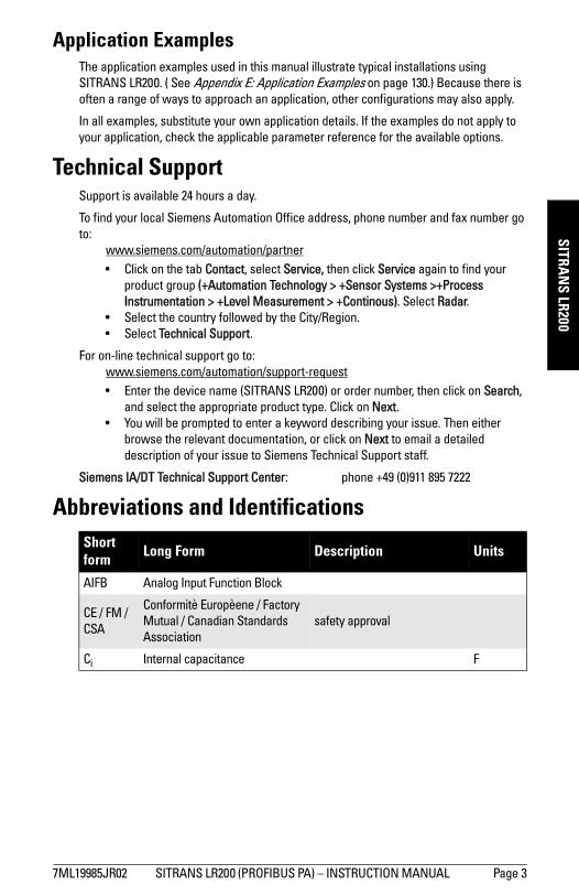
Application ExamplesThe application examples used in this manual illustrate typical installations using SITRANS LR200. ( See Appendix E: Application Examples on page 130.) Because there is often a range of ways to approach an application, other configurations may also apply.
In all examples, substitute your own application details. If the examples do not apply to your application, check the applicable parameter reference for the available options.
Technical SupportSupport is available 24 hours a day.
To find your local Siemens Automation Office address, phone number and fax number go to:
www.siemens.com/automation/partner• Click on the tab Contact, select Service, then click Service again to find your
product group (+Automation Technology > +Sensor Systems >+Process Instrumentation > +Level Measurement > +Continous). Select Radar.
• Select the country followed by the City/Region. • Select Technical Support.
For on-line technical support go to:www.siemens.com/automation/support-request • Enter the device name (SITRANS LR200) or order number, then click on Search,
and select the appropriate product type. Click on Next.• You will be prompted to enter a keyword describing your issue. Then either
browse the relevant documentation, or click on Next to email a detailed description of your issue to Siemens Technical Support staff.
Siemens IA/DT Technical Support Center: phone +49 (0)911 895 7222
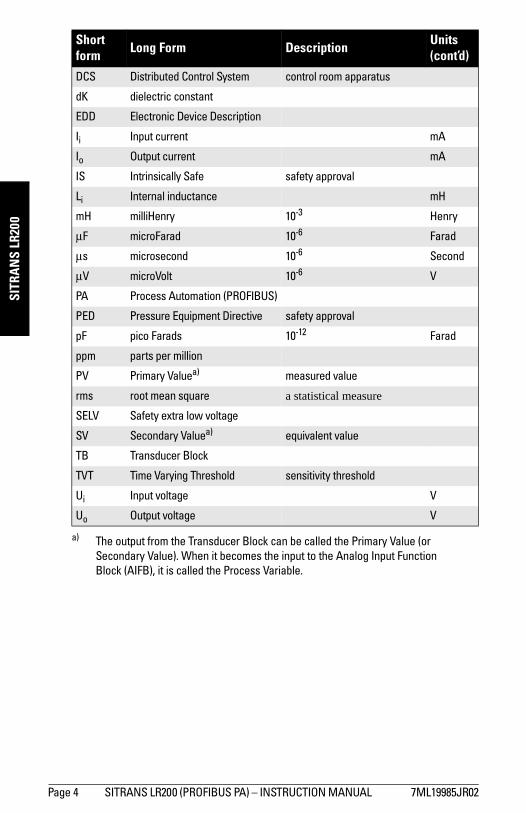
Abbreviations and IdentificationsShort form Long Form Description Units
AIFB Analog Input Function Block
CE / FM / CSA
Conformitè Europèene / Factory Mutual / Canadian Standards Association
safety approval
Ci Internal capacitance F
7ML19985JR02 SITRANS LR200 (PROFIBUS PA) – INSTRUCTION MANUAL Page 3
mm
mm
m
SITR
AN
S LR
200
DCS Distributed Control System control room apparatus
dK dielectric constant
EDD Electronic Device Description
Ii Input current mA
Io Output current mA
IS Intrinsically Safe safety approval
Li Internal inductance mH
mH milliHenry 10-3 Henry
μF microFarad 10-6 Farad
μs microsecond 10-6 Second
μV microVolt 10-6 V
PA Process Automation (PROFIBUS)
PED Pressure Equipment Directive safety approval
pF pico Farads 10-12 Farad
ppm parts per million
PV Primary Valuea) measured value
rms root mean square a statistical measure
SELV Safety extra low voltage
SV Secondary Valuea) equivalent value
TB Transducer Block
TVT Time Varying Threshold sensitivity threshold
Ui Input voltage V
Uo Output voltage V
a) The output from the Transducer Block can be called the Primary Value (or Secondary Value). When it becomes the input to the Analog Input Function Block (AIFB), it is called the Process Variable.
Short form Long Form Description Units
(cont’d)
Page 4 SITRANS LR200 (PROFIBUS PA) – INSTRUCTION MANUAL 7ML19985JR02
mm
mm
m
SITRAN
S LR200
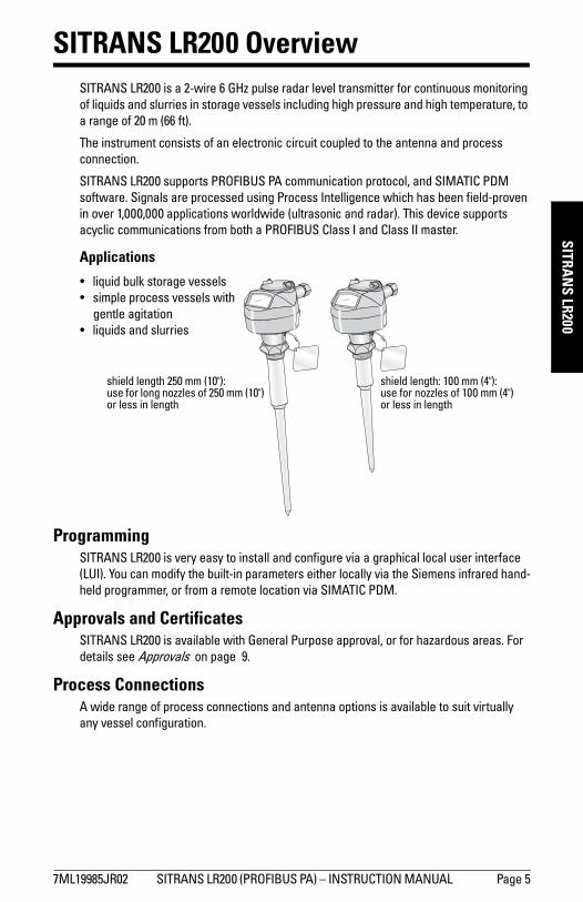
SITRANS LR200 OverviewSITRANS LR200 is a 2-wire 6 GHz pulse radar level transmitter for continuous monitoring of liquids and slurries in storage vessels including high pressure and high temperature, to a range of 20 m (66 ft).
The instrument consists of an electronic circuit coupled to the antenna and process connection.
SITRANS LR200 supports PROFIBUS PA communication protocol, and SIMATIC PDM software. Signals are processed using Process Intelligence which has been field-proven in over 1,000,000 applications worldwide (ultrasonic and radar). This device supports acyclic communications from both a PROFIBUS Class I and Class II master.
Applications
ProgrammingSITRANS LR200 is very easy to install and configure via a graphical local user interface (LUI). You can modify the built-in parameters either locally via the Siemens infrared hand-held programmer, or from a remote location via SIMATIC PDM.
Approvals and CertificatesSITRANS LR200 is available with General Purpose approval, or for hazardous areas. For details see Approvals on page 9.
Process ConnectionsA wide range of process connections and antenna options is available to suit virtually any vessel configuration.
shield length: 100 mm (4"): use for nozzles of 100 mm (4") or less in length
shield length 250 mm (10"): use for long nozzles of 250 mm (10") or less in length
• liquid bulk storage vessels• simple process vessels with
gentle agitation• liquids and slurries
7ML19985JR02 SITRANS LR200 (PROFIBUS PA) – INSTRUCTION MANUAL Page 5
mm
mm
m
Spec
ifica
tions
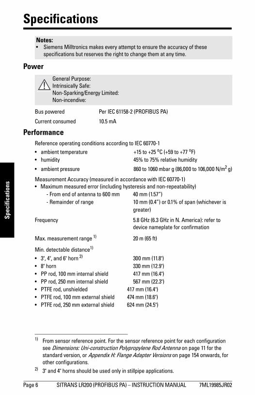
Specifications
Power
Bus powered Per IEC 61158-2 (PROFIBUS PA)
Current consumed 10.5 mA
PerformanceReference operating conditions according to IEC 60770-1
• ambient temperature +15 to +25 oC (+59 to +77 oF)• humidity 45% to 75% relative humidity
• ambient pressure 860 to 1060 mbar g (86,000 to 106,000 N/m2 g)
Measurement Accuracy (measured in accordance with IEC 60770-1)• Maximum measured error (including hysteresis and non-repeatability)
- From end of antenna to 600 mm 40 mm (1.57”) - Remainder of range 10 mm (0.4”) or 0.1% of span (whichever is
greater)
Frequency 5.8 GHz (6.3 GHz in N. America): refer to device nameplate for confirmation
Max. measurement range 1) 20 m (65 ft)
Min. detectable distance1)
• 3", 4", and 6" horn 2) 300 mm (11.8")• 8" horn 330 mm (12.9")• PP rod, 100 mm internal shield 417 mm (16.4")• PP rod, 250 mm internal shield 567 mm (22.3")• PTFE rod, unshielded 417 mm (16.4")• PTFE rod, 100 mm external shield 474 mm (18.6")• PTFE rod, 250 mm external shield 624 mm (24.5")
Notes:• Siemens Milltronics makes every attempt to ensure the accuracy of these
specifications but reserves the right to change them at any time.
General Purpose:Intrinsically Safe:Non-Sparking/Energy Limited:Non-incendive:
1) From sensor reference point. For the sensor reference point for each configuration see Dimensions: Uni-construction Polypropylene Rod Antenna on page 11 for the standard version, or Appendix H: Flange Adapter Versions on page 154 onwards, for other configurations.
2) 3" and 4" horns should be used only in stillpipe applications.
Page 6 SITRANS LR200 (PROFIBUS PA) – INSTRUCTION MANUAL 7ML19985JR02
mm
mm
m
Specifications
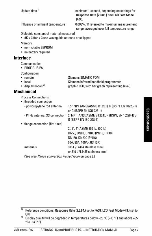
Update time 1) minimum 1 second, depending on settings for Response Rate (2.3.8.1.) and LCD Fast Mode (4.9.).
Influence of ambient temperature 0.003% / K referred to maximum measurement range, averaged over full temperature range
Dielectric constant of material measured• dK > 3 (for < 3 use waveguide antenna or stillpipe)
Memory• non-volatile EEPROM• no battery required.
InterfaceCommunication• PROFIBUS PA
Configuration• remote Siemens SIMATIC PDM • local Siemens infrared handheld programmer• display (local) 2) graphic LCD, with bar graph representing level)
MechanicalProcess Connections: • threaded connection - polypropylene rod antenna 1.5” NPT (ANSI/ASME B1.20.1), R (BSPT, EN 10226-1)
or G (BSPP, EN ISO 228-1) - PTFE antenna, SS connection 2" NPT (ANSI/ASME B1.20.1), R (BSPT, EN 10226-1) or
G (BSPP, EN ISO 228-1) • flange connection (flat-face) 2", 3", 4" (ASME 150 lb, 300 lb) DN50, DN80, DN100 (PN16, PN40) DN150, DN200 (PN16) 50A, 80A, 100A (JIS 10K) materials 316 L /1.4404 stainless steel or 316 L /1.4435 stainless steel (See also flange connection (raised face) on page 8.)
1) Reference conditions: Response Rate (2.3.8.1.) set to FAST, LCD Fast Mode (4.9.) set to ON.
2) Display quality will be degraded in temperatures below –25 °C (–13 °F) and above +65 °C (+149 °F).
7ML19985JR02 SITRANS LR200 (PROFIBUS PA) – INSTRUCTION MANUAL Page 7
mm
mm
m
Spec
ifica
tions
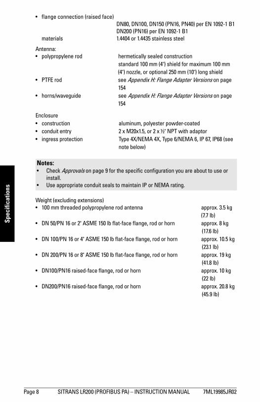
• flange connection (raised face) DN80, DN100, DN150 (PN16, PN40) per EN 1092-1 B1 DN200 (PN16) per EN 1092-1 B1 materials 1.4404 or 1.4435 stainless steel
Antenna:• polypropylene rod hermetically sealed construction standard 100 mm (4") shield for maximum 100 mm
(4") nozzle, or optional 250 mm (10") long shield• PTFE rod see Appendix H: Flange Adapter Versions on page
154• horns/waveguide see Appendix H: Flange Adapter Versions on page
154
Enclosure • construction aluminum, polyester powder-coated• conduit entry 2 x M20x1.5, or 2 x ½" NPT with adaptor• ingress protection Type 4X/NEMA 4X, Type 6/NEMA 6, IP 67, IP68 (see
note below)
Weight (excluding extensions)• 100 mm threaded polypropylene rod antenna approx. 3.5 kg
(7.7 lb)• DN 50/PN 16 or 2" ASME 150 lb flat-face flange, rod or horn approx. 8 kg
(17.6 lb)• DN 100/PN 16 or 4" ASME 150 lb flat-face flange, rod or horn approx. 10.5 kg
(23.1 lb)• DN 200/PN 16 or 8" ASME 150 lb flat-face flange, rod or horn approx. 19 kg
(41.8 lb)• DN100/PN16 raised-face flange, rod or horn approx. 10 kg
(22 lb)• DN200/PN16 raised-face flange, rod or horn approx. 20.8 kg
(45.9 lb)
Notes: • Check Approvals on page 9 for the specific configuration you are about to use or
install.• Use appropriate conduit seals to maintain IP or NEMA rating.
Page 8 SITRANS LR200 (PROFIBUS PA) – INSTRUCTION MANUAL 7ML19985JR02
mm
mm
m
Specifications
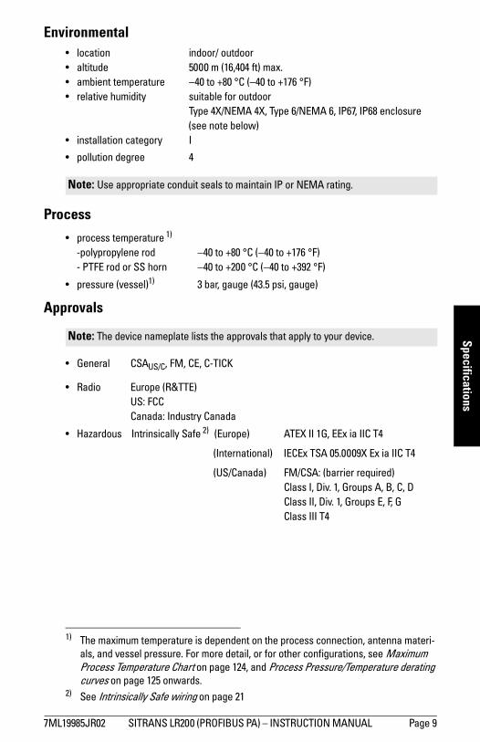
Environmental• location indoor/ outdoor• altitude 5000 m (16,404 ft) max.• ambient temperature −40 to +80 °C (−40 to +176 °F)• relative humidity suitable for outdoor Type 4X/NEMA 4X, Type 6/NEMA 6, IP67, IP68 enclosure
(see note below)• installation category I
• pollution degree 4
Process
• process temperature 1) -polypropylene rod −40 to +80 °C (−40 to +176 °F) - PTFE rod or SS horn −40 to +200 °C (−40 to +392 °F)
• pressure (vessel)1) 3 bar, gauge (43.5 psi, gauge)
Approvals
• General CSAUS/C, FM, CE, C-TICK
• Radio Europe (R&TTE) US: FCC Canada: Industry Canada
• Hazardous Intrinsically Safe 2) (Europe) ATEX II 1G, EEx ia IIC T4
(International) IECEx TSA 05.0009X Ex ia IIC T4
(US/Canada) FM/CSA: (barrier required) Class I, Div. 1, Groups A, B, C, D Class II, Div. 1, Groups E, F, G Class III T4
Note: Use appropriate conduit seals to maintain IP or NEMA rating.
1) The maximum temperature is dependent on the process connection, antenna materi-als, and vessel pressure. For more detail, or for other configurations, see Maximum Process Temperature Chart on page 124, and Process Pressure/Temperature derating curves on page 125 onwards.
Note: The device nameplate lists the approvals that apply to your device.
2) See Intrinsically Safe wiring on page 21
7ML19985JR02 SITRANS LR200 (PROFIBUS PA) – INSTRUCTION MANUAL Page 9
mm
mm
m
Spec
ifica
tions
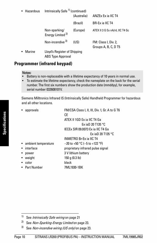
• Hazardous Intrinsically Safe 1) (continued) (Australia) ANZEx Ex ia IIC T4
(Brazil) BR-Ex ia IIC T4
Non-sparking/ (Europe) ATEX II 3 G Ex nA/nL IIC T4 Gc Energy Limited 2)
Non-incendive 3) (US) FM: Class I, Div. 2, Groups A, B, C, D T5
• Marine Lloyd’s Register of Shipping ABS Type Approval
Programmer (infrared keypad)
Siemens Milltronics Infrared IS (Intrinsically Safe) Handheld Programmer for hazardous and all other locations.
• approvals FM/CSA Class I, II, III, Div. 1, Gr. A to G T6CEATEX II 1GD Ex ia IIC T4 Ga
Ex iaD 20 T135 °C IECEx SIR 09.0073 Ex ia IIC T4 Ga Ex iaD 20 T135 °C INMETRO Br-Ex ia IIC T4• ambient temperature −20 to +50 °C (−5 to +122 °F)• interface proprietary infrared pulse signal• power 3 V lithium battery • weight 150 g (0.3 lb)• color black• Part Number 7ML1930-1BK
1) See Intrinsically Safe wiring on page 212) See Non-Sparking-Energy Limited on page 23.3) See Non-incendive wiring (US only) on page 23.
Notes: • Battery is non-replaceable with a lifetime expectancy of 10 years in normal use. • To estimate the lifetime expectancy, check the nameplate on the back for the serial
number. The first six numbers show the production date (mmddyy), for example, serial number 032608101V.
Page 10 SITRANS LR200 (PROFIBUS PA) – INSTRUCTION MANUAL 7ML19985JR02
mm
mm
m
Specifications
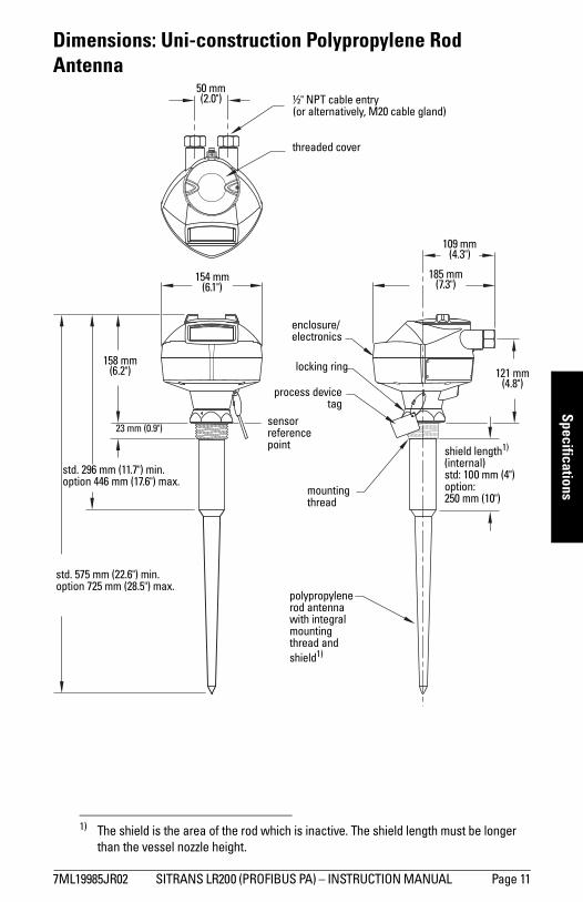
Dimensions: Uni-construction Polypropylene Rod Antenna
1)
1) The shield is the area of the rod which is inactive. The shield length must be longer than the vessel nozzle height.
sensor reference point
threaded cover
enclosure/electronics
polypropylene rod antenna with integral mounting thread and shield1)
shield length1) (internal)std: 100 mm (4")option: 250 mm (10")
std. 296 mm (11.7") min.option 446 mm (17.6") max.
158 mm (6.2")
154 mm (6.1")
185 mm (7.3")
mounting thread
½" NPT cable entry (or alternatively, M20 cable gland)
process devicetag
locking ring
109 mm (4.3")
121 mm (4.8")
50 mm (2.0")
std. 575 mm (22.6") min.option 725 mm (28.5") max.
23 mm (0.9")
7ML19985JR02 SITRANS LR200 (PROFIBUS PA) – INSTRUCTION MANUAL Page 11
mm
mm
m
Spec
ifica
tions
Threaded Connection MarkingsThreaded connection markings are found on the flat face/faces of the process connection.
Serial number:a unique number allotted to each process connection, including the date of manufacture (MMDDYY) followed by a number from 001 to 999.
Page 12 SITRANS LR200 (PROFIBUS PA) – INSTRUCTION MANUAL 7ML19985JR02
mm
mm
m
Installation
Installation
1)
WARNINGS: • Handle the device using the enclosure, not the antenna or the device
tag, to avoid damage.• Installation shall be performed only by qualified personnel and in
accordance with local governing regulations.• SITRANS LR200 is to be used only in the manner outlined in this man-
ual, otherwise protection provided by the device may be impaired.• Never attempt to loosen, remove, or disassemble process connection
or instrument housing while vessel contents are under pressure.• Materials of construction are chosen based on their chemical compati-
bility (or inertness) for general purposes. For exposure to specific envi-ronments, check with chemical compatibility charts before installing.
• The user is responsible for the selection of bolting and gasket materials which will fall within the limits of the flange and its intended use and which are suitable for the service conditions.
• Improper installation may result in loss of process pressure.Notes:• Refer to the device nameplate for approval information.• The Process Device Tag shall remain with the process pressure boundary
assembly1). In the event the instrument package is replaced, the Process Device Tag shall be transferred to the replacement unit.
• SITRANS LR200 units are hydrostatically tested, meeting or exceeding the require-ments of the ASME Boiler and Pressure Vessel Code and the European Pressure Equipment Directive.
• The serial numbers stamped in each process connection body provide a unique identification number indicating date of manufacture.Example: MMDDYY – XXX (where MM = month, DD = day, YY = year, and
XXX= sequential unit produced) Further markings (space permitting) indicate flange configuration, size, pressure class, material, and material heat code.
1) The process pressure boundary assembly comprises the components that act as a barrier against pressure loss from the process vessel: that is, the combination of pro-cess connection body and emitter, but normally excluding the electrical enclosure.
7ML19985JR02 SITRANS LR200 (PROFIBUS PA) – INSTRUCTION MANUAL Page 13
mm
mm
m
Inst
alla
tion
Pressure Equipment Directive, PED, 97/23/ECSiemens Level Transmitters with flanged, threaded, or sanitary clamp type process mounts have no pressure-bearing housing of their own and, therefore, do not come under the Pressure Equipment Directive as pressure or safety accessories, (see EU Commission Guidelines 1/8 and 1/20).
Mounting location
Nozzle design
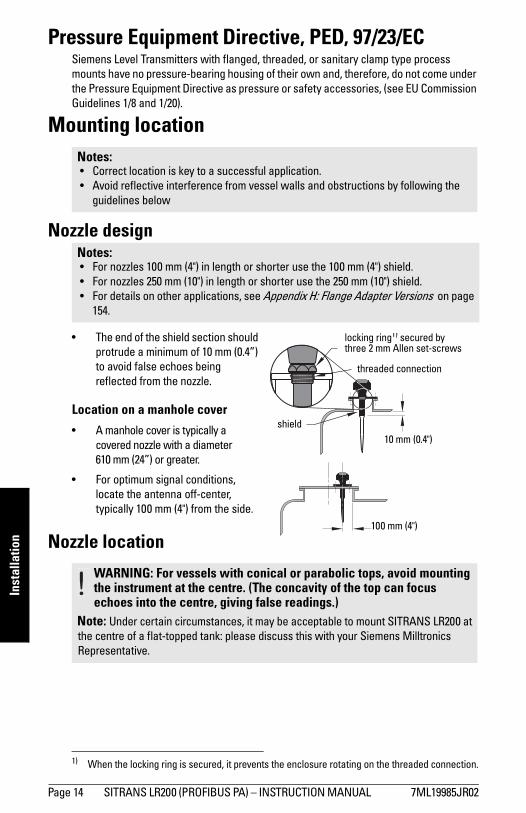
• The end of the shield section should protrude a minimum of 10 mm (0.4”) to avoid false echoes being reflected from the nozzle.1)
Location on a manhole cover
• A manhole cover is typically a covered nozzle with a diameter 610 mm (24”) or greater.
• For optimum signal conditions, locate the antenna off-center, typically 100 mm (4") from the side.
Nozzle location
Notes: • Correct location is key to a successful application.• Avoid reflective interference from vessel walls and obstructions by following the
guidelines below
Notes: • For nozzles 100 mm (4") in length or shorter use the 100 mm (4") shield.• For nozzles 250 mm (10") in length or shorter use the 250 mm (10") shield.• For details on other applications, see Appendix H: Flange Adapter Versions on page
154.
1) When the locking ring is secured, it prevents the enclosure rotating on the threaded connection.
WARNING: For vessels with conical or parabolic tops, avoid mounting the instrument at the centre. (The concavity of the top can focus echoes into the centre, giving false readings.)
Note: Under certain circumstances, it may be acceptable to mount SITRANS LR200 at the centre of a flat-topped tank: please discuss this with your Siemens Milltronics Representative.
10 mm (0.4")
locking ring1) secured by three 2 mm Allen set-screws
threaded connection
shield
100 mm (4")
Page 14 SITRANS LR200 (PROFIBUS PA) – INSTRUCTION MANUAL 7ML19985JR02
mm
mm
m
Installation
Nozzle location (continued)
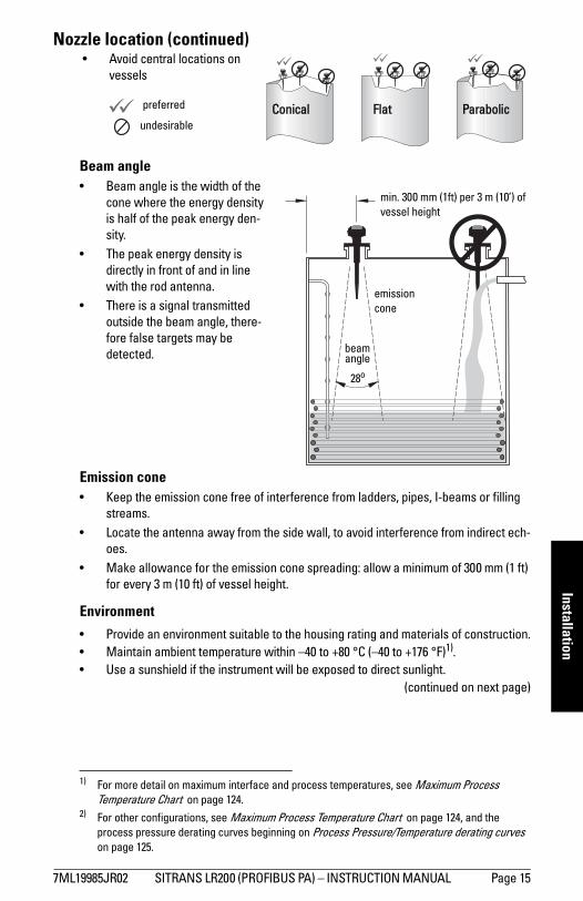
Beam angle• Beam angle is the width of the
cone where the energy density is half of the peak energy den-sity.
• The peak energy density is directly in front of and in line with the rod antenna.
• There is a signal transmitted outside the beam angle, there-fore false targets may be detected.
Emission cone• Keep the emission cone free of interference from ladders, pipes, I-beams or filling
streams. • Locate the antenna away from the side wall, to avoid interference from indirect ech-
oes.• Make allowance for the emission cone spreading: allow a minimum of 300 mm (1 ft)
for every 3 m (10 ft) of vessel height.
Environment
• Provide an environment suitable to the housing rating and materials of construction.• Maintain ambient temperature within –40 to +80 °C (–40 to +176 °F)1).• Use a sunshield if the instrument will be exposed to direct sunlight.2)
(continued on next page)
1) For more detail on maximum interface and process temperatures, see Maximum Process Temperature Chart on page 124.
2) For other configurations, see Maximum Process Temperature Chart on page 124, and the process pressure derating curves beginning on Process Pressure/Temperature derating curves on page 125.
Coni
Fl at
Flat Parabolic Conicalpreferred
undesirable
• Avoid central locations on vessels
min. 300 mm (1ft) per 3 m (10’) of vessel height
beam angle
28o
emission cone
7ML19985JR02 SITRANS LR200 (PROFIBUS PA) – INSTRUCTION MANUAL Page 15
mm
mm
m
Inst
alla
tion
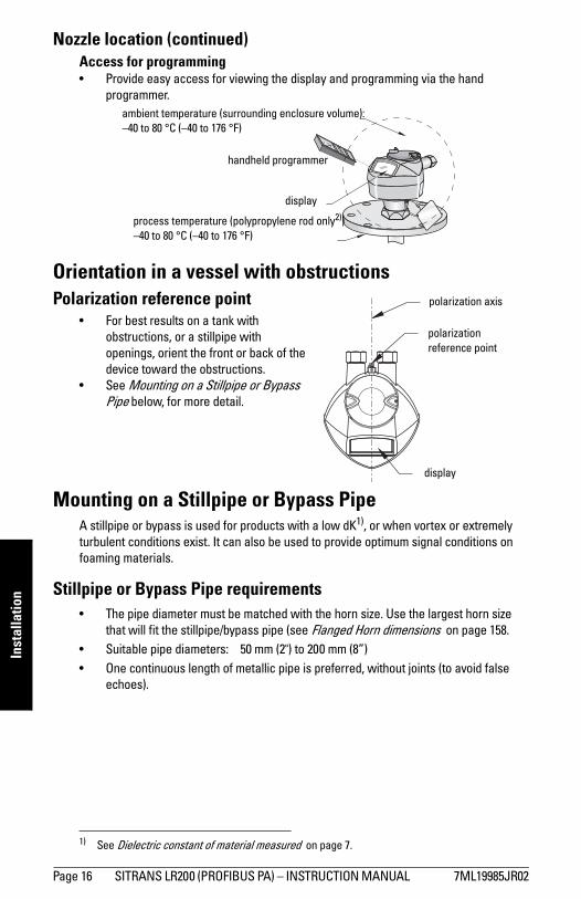
Nozzle location (continued)Access for programming• Provide easy access for viewing the display and programming via the hand
programmer.
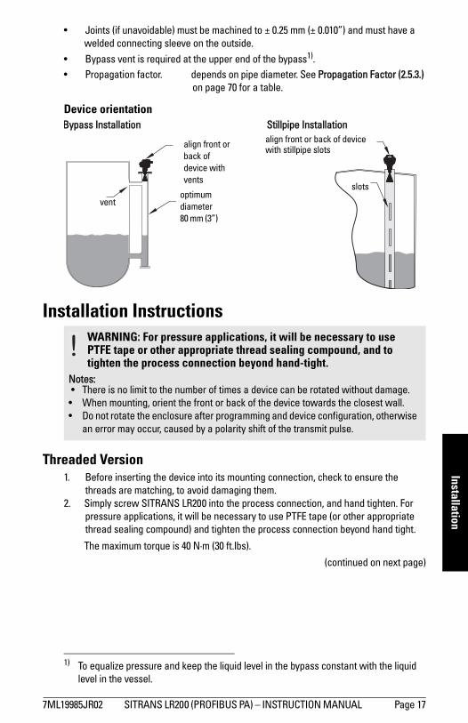
Orientation in a vessel with obstructionsPolarization reference point
• For best results on a tank with obstructions, or a stillpipe with openings, orient the front or back of the device toward the obstructions.
• See Mounting on a Stillpipe or Bypass Pipe below, for more detail.
Mounting on a Stillpipe or Bypass PipeA stillpipe or bypass is used for products with a low dK1), or when vortex or extremely turbulent conditions exist. It can also be used to provide optimum signal conditions on foaming materials.
Stillpipe or Bypass Pipe requirements• The pipe diameter must be matched with the horn size. Use the largest horn size
that will fit the stillpipe/bypass pipe (see Flanged Horn dimensions on page 158.• Suitable pipe diameters: 50 mm (2") to 200 mm (8”) • One continuous length of metallic pipe is preferred, without joints (to avoid false
echoes).
1) See Dielectric constant of material measured on page 7.
ambient temperature (surrounding enclosure volume):–40 to 80 °C (–40 to 176 °F)
process temperature (polypropylene rod only2))–40 to 80 °C (–40 to 176 °F)
handheld programmer
display
polarization reference point
display
polarization axis
Page 16 SITRANS LR200 (PROFIBUS PA) – INSTRUCTION MANUAL 7ML19985JR02
mm
mm
m
Installation
• Joints (if unavoidable) must be machined to ± 0.25 mm (± 0.010”) and must have awelded connecting sleeve on the outside.• Bypass vent is required at the upper end of the bypass1).• Propagation factor. depends on pipe diameter. See Propagation Factor (2.5.3.)
on page 70 for a table.
Device orientation
Installation Instructions
Threaded Version1. Before inserting the device into its mounting connection, check to ensure the
threads are matching, to avoid damaging them. 2. Simply screw SITRANS LR200 into the process connection, and hand tighten. For
pressure applications, it will be necessary to use PTFE tape (or other appropriate thread sealing compound) and tighten the process connection beyond hand tight.
The maximum torque is 40 N·m (30 ft.lbs).
(continued on next page)
1) To equalize pressure and keep the liquid level in the bypass constant with the liquid level in the vessel.
WARNING: For pressure applications, it will be necessary to use PTFE tape or other appropriate thread sealing compound, and to tighten the process connection beyond hand-tight.
Notes: • There is no limit to the number of times a device can be rotated without damage.
• When mounting, orient the front or back of the device towards the closest wall.• Do not rotate the enclosure after programming and device configuration, otherwise
an error may occur, caused by a polarity shift of the transmit pulse.
align front or back of device with vents
align front or back of device with stillpipe slots
Stillpipe Installation
slots
Bypass Installation
ventoptimum diameter80 mm (3”)
7ML19985JR02 SITRANS LR200 (PROFIBUS PA) – INSTRUCTION MANUAL Page 17
mm
mm
m
Inst
alla
tion
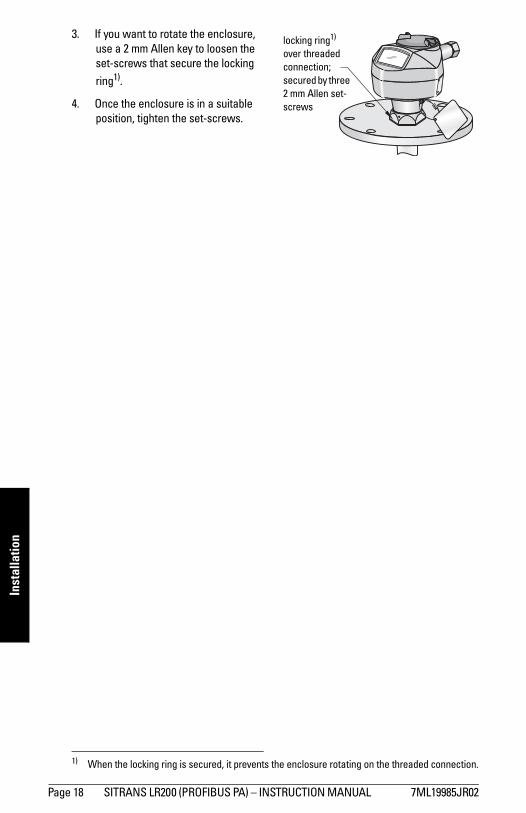
3. If you want to rotate the enclosure, use a 2 mm Allen key to loosen the set-screws that secure the locking ring1).
4. Once the enclosure is in a suitable position, tighten the set-screws.
1) When the locking ring is secured, it prevents the enclosure rotating on the threaded connection.
locking ring1) over threaded connection; secured by three 2 mm Allen set-screws
Page 18 SITRANS LR200 (PROFIBUS PA) – INSTRUCTION MANUAL 7ML19985JR02
mm
mm
m
Wiring
Wiring
Power
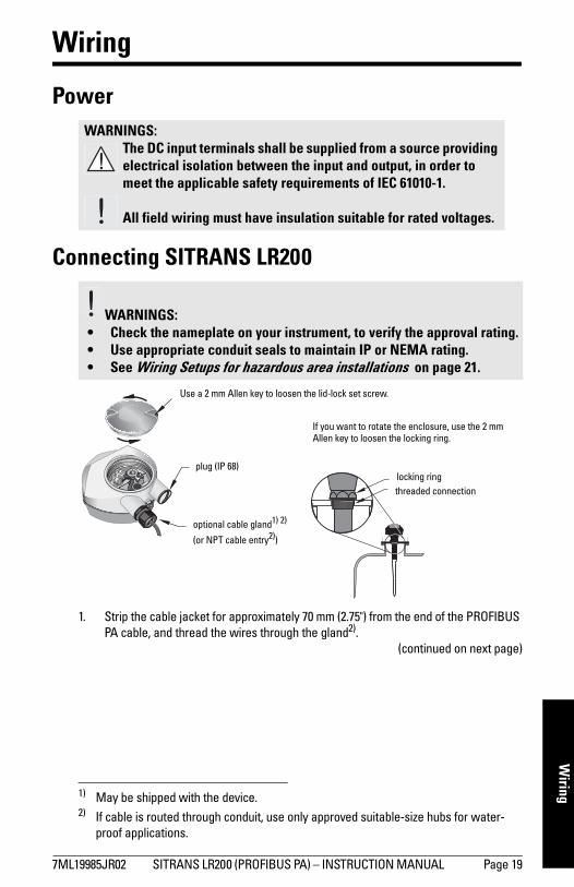
Connecting SITRANS LR200
1)
1. Strip the cable jacket for approximately 70 mm (2.75") from the end of the PROFIBUS PA cable, and thread the wires through the gland2).
(continued on next page)
WARNINGS:The DC input terminals shall be supplied from a source providing electrical isolation between the input and output, in order to meet the applicable safety requirements of IEC 61010-1.
All field wiring must have insulation suitable for rated voltages.
WARNINGS: • Check the nameplate on your instrument, to verify the approval rating.• Use appropriate conduit seals to maintain IP or NEMA rating.• See Wiring Setups for hazardous area installations on page 21.
1) May be shipped with the device.2) If cable is routed through conduit, use only approved suitable-size hubs for water-
proof applications.
Use a 2 mm Allen key to loosen the lid-lock set screw.
optional cable gland1) 2)
(or NPT cable entry2))
plug (IP 68)
If you want to rotate the enclosure, use the 2 mm Allen key to loosen the locking ring.
locking ringthreaded connection
7ML19985JR02 SITRANS LR200 (PROFIBUS PA) – INSTRUCTION MANUAL Page 19
mm
mm
m
Wiri
ng
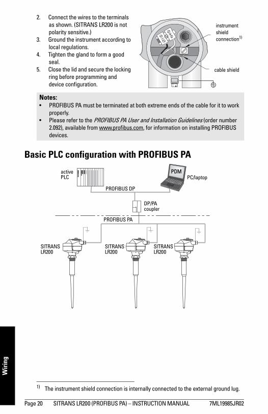
2. Connect the wires to the terminals as shown. (SITRANS LR200 is not polarity sensitive.)
3. Ground the instrument according to local regulations. 1)
4. Tighten the gland to form a good seal.
5. Close the lid and secure the locking ring before programming and device configuration.
Basic PLC configuration with PROFIBUS PA
1) The instrument shield connection is internally connected to the external ground lug.
Notes: • PROFIBUS PA must be terminated at both extreme ends of the cable for it to work
properly.• Please refer to the PROFIBUS PA User and Installation Guidelines (order number
2.092), available from www.profibus.com, for information on installing PROFIBUS devices.
instrument shield connection1)
cable shield
PROFIBUS PA
PROFIBUS DP
DP/PA coupler
active PLC PC/laptop
PDM
SITRANS LR200
SITRANS LR200
SITRANS LR200
Page 20 SITRANS LR200 (PROFIBUS PA) – INSTRUCTION MANUAL 7ML19985JR02
mm
mm
m
Wiring
Wiring Setups for hazardous area installationsThere are three wiring options for hazardous area installations:
• Intrinsically Safe wiring on page 21• Non-Sparking-Energy Limited on page 23• Non-incendive wiring (US only) on page 23
In all cases, check the nameplate on your instrument, and confirm the approval rating.
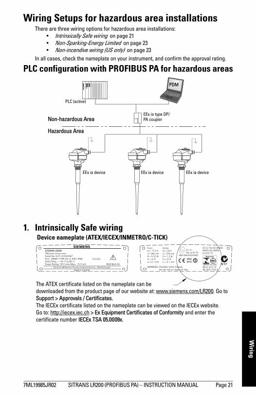
PLC configuration with PROFIBUS PA for hazardous areas
1. Intrinsically Safe wiring
Hazardous Area
Non-hazardous Area
PLC (active)
EEx ia type DP/PA coupler
PDM
EEx ia device EEx ia device EEx ia device
The ATEX certificate listed on the nameplate can be downloaded from the product page of our website at: www.siemens.com/LR200. Go to Support > Approvals / Certificates. The IECEx certificate listed on the nameplate can be viewed on the IECEx website. Go to: http://iecex.iec.ch > Ex Equipment Certificates of Conformity and enter the certificate number IECEx TSA 05.0009x.
Device nameplate (ATEX/IECEX/INMETRO/C-TICK)
7ML19985JR02 SITRANS LR200 (PROFIBUS PA) – INSTRUCTION MANUAL Page 21
mm
mm
m
Wiri
ng
• For wiring requirements: follow local regulations. • Approved dust-tight and water-tight conduit seals are required for outdoor
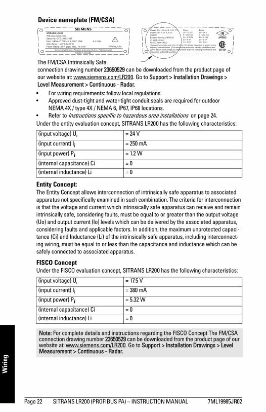
NEMA 4X / type 4X / NEMA 6, IP67, IP68 locations.• Refer to Instructions specific to hazardous area installations on page 24.Under the entity evaluation concept, SITRANS LR200 has the following characteristics:
Entity Concept: The Entity Concept allows interconnection of intrinsically safe apparatus to associated apparatus not specifically examined in such combination. The criteria for interconnection is that the voltage and current which intrinsically safe apparatus can receive and remain intrinsically safe, considering faults, must be equal to or greater than the output voltage (Uo) and output current (Io) levels which can be delivered by the associated apparatus, considering faults and applicable factors. In addition, the maximum unprotected capaci-tance (Ci) and Inductance (Li) of the intrinsically safe apparatus, including interconnect-ing wiring, must be equal to or less than the capacitance and inductance which can be safely connected to associated apparatus.
FISCO ConceptUnder the FISCO evaluation concept, SITRANS LR200 has the following characteristics:
(input voltage) Ui = 24 V
(input current) Ii = 250 mA
(input power) Pi = 1.2 W
(internal capacitance) Ci = 0(internal inductance) Li = 0
(input voltage) Ui = 17.5 V
(input current) Ii = 380 mA
(input power) Pi = 5.32 W
(internal capacitance) Ci = 0 (internal inductance) Li = 0
Note: For complete details and instructions regarding the FISCO Concept The FM/CSA connection drawing number 23650529 can be downloaded from the product page of our website at: www.siemens.com/LR200. Go to Support > Installation Drawings > Level Measurement > Continuous - Radar.
The FM/CSA Intrinsically Safe connection drawing number 23650529 can be downloaded from the product page of our website at: www.siemens.com/LR200. Go to Support > Installation Drawings > Level Measurement > Continuous - Radar.
Device nameplate (FM/CSA)
Page 22 SITRANS LR200 (PROFIBUS PA) – INSTRUCTION MANUAL 7ML19985JR02
mm
mm
m
Wiring
The FISCO Concept allows interconnection of intrinsically safe apparatus to associated apparatus not specifically examined in such combination. The criteria for interconnection is that the voltage (Ui or Vmax), the current (Ii, or Imax) and the power (Pi, or Pmax) which intrinsically safe apparatus can receive and remain intrinsically safe, considering faults, must be equal to or greater than the voltage (Uo or Voc or Vi), the current (lo or Isc or li), and the power (Po or Pmax) levels which can be delivered by the associated apparatus, considering faults and applicable factors. In addition, the maximum unprotected capacitance (Ci) and inductance (Li) of each apparatus (other than the termination) connected to the fieldbus must be less than or equal to 5 nF and 10 μH respectively.
In each segment only one active device, normally the associated apparatus, is allowed to provide the necessary energy for the fieldbus system. The allowed voltage Uo (or Voc or Vt) of the associated apparatus is limited to the range of 14V dc to 24V dc. All other equipment connected to the bus cable has to be passive, meaning that they are not allowed to provide energy to the system, except for a leakage current of 50 μA for each connected device. Separately powered equipment needs a galvanic isolation to assure that the intrinsically safe fieldbus circuit remains passive.
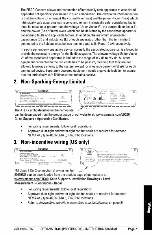
2. Non-Sparking-Energy Limited
• For wiring requirements: follow local regulations. • Approved dust-tight and water-tight conduit seals are required for outdoor
NEMA 4X / type 4X / NEMA 6, IP67, IP68 locations.
3. Non-incendive wiring (US only)
• For wiring requirements: follow local regulations. • Approved dust-tight and water-tight conduit seals are required for outdoor
NEMA 4X / type 4X / NEMA 6, IP67, IP68 locations.• Refer to Instructions specific to hazardous area installations on page 24
The ATEX certificate listed on the nameplate can be downloaded from the product page of our website at: www.siemens.com/LR200.Go to: Support > Approvals / Certificates.
FM Class 1, Div 2 connection drawing number23650537 can be downloaded from the product page of our website at: www.siemens.com/LR200. Go to Support > Installation Drawings > Level Measurement > Continuous - Radar.
7ML19985JR02 SITRANS LR200 (PROFIBUS PA) – INSTRUCTION MANUAL Page 23

mm
mm
m
Wiri
ng
Instructions specific to hazardous area installations
(Reference European ATEX Directive 94/9/EC, Annex II, 1/0/6)
The following instructions apply to equipment covered by certificate number SIRA 06ATEX2356X and SIRA 09ATEX4152X:
1. For use and assembly, refer to the main instructions.
2. The equipment is certified for use as Category 1G equipment per SIRA 06ATEX2356X, and Category 3G equipment per SIRA 09ATEX4152X.
3. The equipment may be used with flammable gases and vapors with apparatus groups IIC, IIB, and IIA, and temperature classes T1, T2, T3, and T4.
4. The equipment is certified for use in an ambient temperature range of –40 °C to +80 °C.
5. The equipment has not been assessed as a safety related device (as referred to by Directive 94/9/EC Annex II, clause 1.5).
6. Installation and inspection of this equipment shall be carried out by suitably trained personnel in accordance with the applicable code of practice (EN 60079-14 and EN 60079-17 in Europe).
7. The equipment is non-repairable.8. The certificate numbers have an ‘X’ suffix, which indicates that special conditions
for safe use apply. Those installing or inspecting this equipment must have access to the certificates.
9. If the equipment is likely to come into contact with aggressive substances, then it is the responsibility of the user to take suitable precautions that prevent it from being adversely affected, thus ensuring that the type of protection is not compromised.
Aggressive substances:e.g. acidic liquids or gases that may attack metals, or solvents that may affect polymeric materials.
Suitable precautions: e.g. regular checks as part of routine inspections or establishing from the material’s data sheet that it is resistant to specific chemicals.
Page 24 SITRANS LR200 (PROFIBUS PA) – INSTRUCTION MANUAL 7ML19985JR02
mm
mm
m
Quick Start: local
Operating via the handheld programmer
SITRANS LR200 carries out its level measurement tasks according to settings made via parameters. The settings can be modified locally via the Local User Interface (LUI) which consists of an LCD display and a handheld programmer.
A Quick Start Wizard provides an easy 5-step procedure to help you configure the device for a simple application. There are two ways to access the wizard:
• locally (see Quick Start Wizard via the handheld programmer on page 30)• from a remote location (see Quick Start Wizard via SIMATIC PDM on page 36)
For more complex setups see Appendix E: Application Examples on page 130, and for the complete range of parameters see Parameter Reference on page 59.
Activating SITRANS LR200Power up the instrument. SITRANS LR200 automatically starts up in Measurement mode. A transition screen showing the current firmware revision and an incrementing line of stars is displayed while the first measurement is being processed.
Press Mode to toggle between Measurement and Program Mode.1) 2)
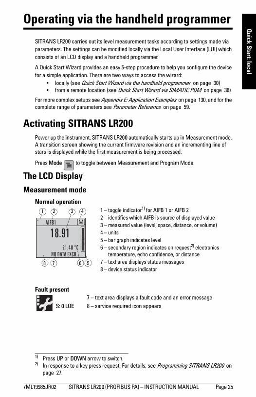
The LCD DisplayMeasurement mode
Normal operation
Fault present
1) Press UP or DOWN arrow to switch.2) In response to a key press request. For details, see Programming SITRANS LR200 on
page 27.
1 – toggle indicator1) for AIFB 1 or AIFB 22 – identifies which AIFB is source of displayed value3 – measured value (level, space, distance, or volume)4 – units5 – bar graph indicates level6 – secondary region indicates on request2) electronics
temperature, echo confidence, or distance7 – text area displays status messages 8 – device status indicator
678
1 3 42
5
S: 0 LOE7 – text area displays a fault code and an error message8 – service required icon appears
7ML19985JR02 SITRANS LR200 (PROFIBUS PA) – INSTRUCTION MANUAL Page 25
mm
mm
m
Qui
ck S
tart
: loc
al
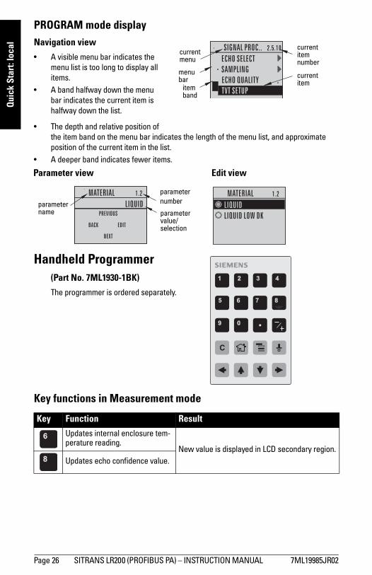
PROGRAM mode displayNavigation view
• A visible menu bar indicates the menu list is too long to display all items.
• A band halfway down the menu bar indicates the current item is halfway down the list.
• The depth and relative position of the item band on the menu bar indicates the length of the menu list, and approximate position of the current item in the list.
• A deeper band indicates fewer items.
Handheld Programmer(Part No. 7ML1930-1BK)
The programmer is ordered separately.
Key functions in Measurement mode
Key Function Result
Updates internal enclosure tem-perature reading.
New value is displayed in LCD secondary region.Updates echo confidence value.
current item number
current item
current menu
item band
menu bar
parameter value/selection
parameter numberparameter
name
Edit viewParameter view
C
Page 26 SITRANS LR200 (PROFIBUS PA) – INSTRUCTION MANUAL 7ML19985JR02
mm
mm
m
Quick Start: local
Programming SITRANS LR200
Change parameter settings and set operating conditions to suit your specific application. (For remote operation see Operating via SIMATIC PDM on page 34.)
Parameter menus
Parameters are identified by name and organized into function groups (seeLCD menu structure on page 181).
Updates distance measurement. New value is displayed in LCD secondary region
Mode opens PROGRAM mode.
Opens the menu level last displayed in this power cycle, unless power has been cycled since exit-ing PROGRAM mode or more than 10 minutes have elapsed since PROGRAM mode was used. Then top level menu will be displayed.
RIGHT arrowopens PROGRAM mode. Opens the top level menu.
UP or DOWN arrowtoggles between AIFB 1 and AIFB 2.
Identifies which AIFB is the source of the dis-played value.
Notes: • While the device is in PROGRAM mode the output remains active and continues to
respond to changes in the device.• SITRANS LR200 automatically returns to Measurement mode after a period of
inactivity in PROGRAM mode (between 15 seconds and 10 minutes, depending on the menu level).
Note: For the complete list of parameters with instructions, see Parameter Reference on page 59
Key Function Result (cont’d)
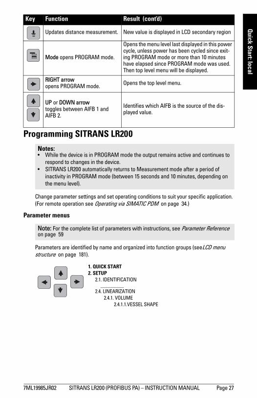
1. QUICK START2. SETUP
2.1. IDENTIFICATION......................
2.4. LINEARIZATION2.4.1. VOLUME
2.4.1.1.VESSEL SHAPE
7ML19985JR02 SITRANS LR200 (PROFIBUS PA) – INSTRUCTION MANUAL Page 27
mm
mm
m
Qui
ck S
tart
: loc
al
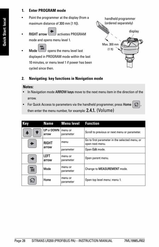
1. Enter PROGRAM mode
• Point the programmer at the display (from a
maximum distance of 300 mm [1 ft]).
• RIGHT arrow activates PROGRAM
mode and opens menu level 1.
• Mode opens the menu level last
displayed in PROGRAM mode within the last
10 minutes, or menu level 1 if power has been
cycled since then.
2. Navigating: key functions in Navigation mode
Notes: • In Navigation mode ARROW keys move to the next menu item in the direction of the
arrow.
• For Quick Access to parameters via the handheld programmer, press Home ,
then enter the menu number, for example: 2.4.1. (Volume)
Key Name Menu level Function
UP or DOWN arrow
menu or parameter Scroll to previous or next menu or parameter.
RIGHT arrow
menu Go to first parameter in the selected menu, or open next menu.
parameter Open Edit mode.
LEFTarrow
menu or parameter Open parent menu.
Mode menu or parameter Change to MEASUREMENT mode.
Home menu or parameter Open top level menu: menu 1.
display
handheld programmer (ordered separately)
Max. 300 mm
(1 ft)
Page 28 SITRANS LR200 (PROFIBUS PA) – INSTRUCTION MANUAL 7ML19985JR02
mm
mm
m
Quick Start: local
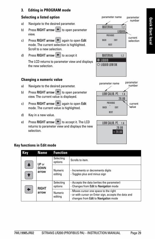
3. Editing in PROGRAM mode
Selecting a listed option
a) Navigate to the desired parameter.
b) Press RIGHT arrow to open parameter view.
c) Press RIGHT arrow again to open Edit mode. The current selection is highlighted.
Scroll to a new selection.
d) Press RIGHT arrow to accept it
The LCD returns to parameter view and displays the new selection.
Changing a numeric value
a) Navigate to the desired parameter.
b) Press RIGHT arrow to open parameter view. The current value is displayed.
c) Press RIGHT arrow again to open Edit mode. The current value is highlighted.
d) Key in a new value.
e) Press RIGHT arrow to accept it. The LCD returns to parameter view and displays the new selection.
Key functions in Edit mode
Key Name Function
UP or DOWN arrow
Selecting options Scrolls to item.
Numeric editing
- Increments or decrements digits- Toggles plus and minus sign
RIGHT arrow
Selecting options
- Accepts the data (writes the parameter)- Changes from Edit to Navigation mode
Numeric editing
- Moves cursor one space to the right- or with cursor on Enter sign, accepts the data and
changes from Edit to Navigation mode
parameter name parameternumber
current selection
current value
parameternumber
parameter name
7ML19985JR02 SITRANS LR200 (PROFIBUS PA) – INSTRUCTION MANUAL Page 29

mm
mm
m
Qui
ck S
tart
: loc
al
Quick Start Wizard via the handheld programmer
1. Quick Starta. Point the programmer at the display (from a maximum distance of 300 mm [1 ft]),
then press RIGHT arrow to activate PROGRAM mode and open menu level 1.
b. Press RIGHT arrow twice to navigate to menu item 1.1 and open parameter view.
c. Press RIGHT arrow to open Edit mode or DOWN arrow to accept default values and move directly to the next item.
d. To change a setting, scroll to the desired item or key in a new value.
e. After modifying a value, press RIGHT arrow to accept it and press DOWN arrow
to move to the next item.
1.1. LanguageSelects the language to be used on the LCD and takes effect immediately.
LEFT arrow
Selecting options Cancels Edit mode without changing the parameter
Numeric editing
- Moves cursor to plus/minus sign if this is the first key pressed
- or moves cursor one space to the left.
Clear Numeric editing Erases the display.
Decimal point
Numeric editing
Enters a decimal point.
Plus or minus sign
Numeric editing
Changes the sign of the entered value.
to Numeral Numeric
editing Enters the corresponding character.
Notes: • The Quick Start wizard settings are inter-related and changes apply only after you
select YES in Apply? (Apply changes) (1.8.)• Do not use the Quick Start wizard to modify individual parameters: see instead
Parameter Reference on page 59. (Perform customization only after the Quick Start has been completed.)
Options English, Deutsch, Français, Español
Key Name Function (cont’d)
C
Page 30 SITRANS LR200 (PROFIBUS PA) – INSTRUCTION MANUAL 7ML19985JR02
mm
mm
m
Quick Start: local
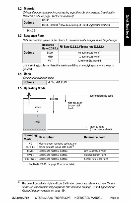
1.2. MaterialSelects the appropriate echo processing algorithms for the material (see Position Detect (2.5.7.2.) on page 117 for more detail).
1.3. Response RateSets the reaction speed of the device to measurement changes in the target range.
Use a setting just faster than the maximum filling or emptying rate (whichever is greater).
1.4. UnitsSensor measurement units.
1.5. Operating Mode 1)
OptionsLIQUID
LIQUID LOW DK1) (low dielectric liquid – CLEF algorithm enabled)
1) dK < 3.0
Options
Response Rate (2.3.8.1.)
Fill Rate (2.3.8.2.)/Empty rate (2.3.8.3.)
SLOW 0.1 m/min (0.32 ft/min)
MED 1.0 m/min (3.28 ft/min)
FAST 10.0 m/min (32.8 ft/min)
Options M, CM, MM, FT, IN
Operating Mode Description Reference point
NOSERVICE
Measurement not being updated. the device defaults to Fail-safe mode1).
1) See Mode (2.6.9.1.) on page 80 for more detail.
LEVEL Distance to material surface Low Calibration Point
SPACE Distance to material surface High Calibration Point
DISTANCE Distance to material surface Sensor Reference Point
1) The point from which High and Low Calibration points are referenced: see Dimen-sions: Uni-construction Polypropylene Rod Antenna on page 11 and Appendix H: Flange Adapter Versions on page 154.
high cal. point (process full level)
low cal. point (process empty level)
level
space
distancesensor reference point1)
7ML19985JR02 SITRANS LR200 (PROFIBUS PA) – INSTRUCTION MANUAL Page 31
mm
mm
m
Qui
ck S
tart
: loc
al
1.6. Low Calibration PointDistance from Sensor Reference to Low Calibration Point: usually process empty level. (See Operating Mode (1.5.) for an illustration.)
1.7. High Calibration PointDistance from Sensor Reference to High Calibration Point: usually process full level. (See Operating Mode (1.5.) for an illustration.)
1.8. Apply? (Apply changes)In order to save the Quick Start settings it is necessary to select Yes to apply changes.
Press Mode to return to Measurement mode. SITRANS LR200 is now ready to operate.
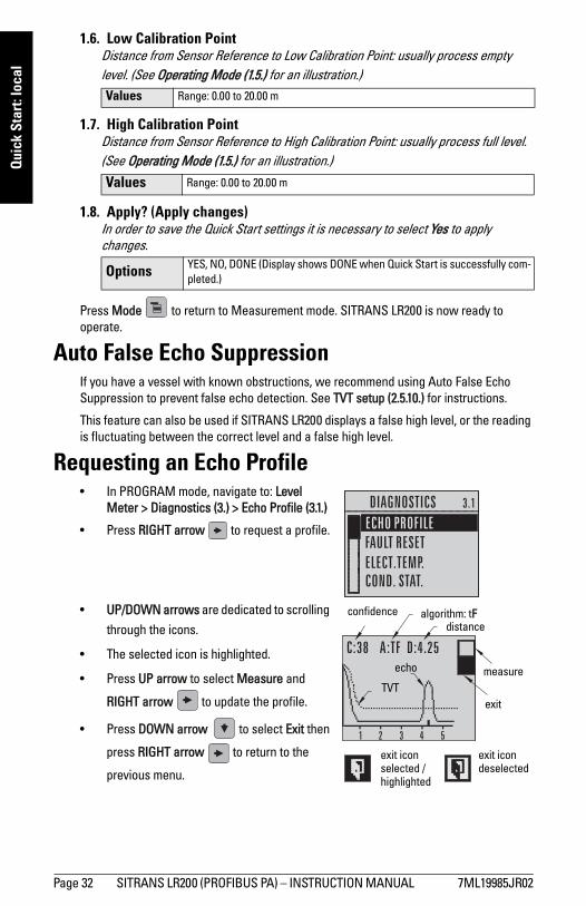
Auto False Echo SuppressionIf you have a vessel with known obstructions, we recommend using Auto False Echo Suppression to prevent false echo detection. See TVT setup (2.5.10.) for instructions.
This feature can also be used if SITRANS LR200 displays a false high level, or the reading is fluctuating between the correct level and a false high level.
Requesting an Echo Profile• In PROGRAM mode, navigate to: Level
Meter > Diagnostics (3.) > Echo Profile (3.1.)
• Press RIGHT arrow to request a profile.
• UP/DOWN arrows are dedicated to scrolling
through the icons.
• The selected icon is highlighted.
• Press UP arrow to select Measure and
RIGHT arrow to update the profile.
• Press DOWN arrow to select Exit then
press RIGHT arrow to return to the
previous menu.
Values Range: 0.00 to 20.00 m
Values Range: 0.00 to 20.00 m
Options YES, NO, DONE (Display shows DONE when Quick Start is successfully com-pleted.)
algorithm: tFconfidence distance
TVT
echo
exit icon selected /highlighted
exit icon deselected
exit
measure
Page 32 SITRANS LR200 (PROFIBUS PA) – INSTRUCTION MANUAL 7ML19985JR02
mm
mm
m
Quick Start: local
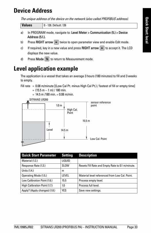
Device AddressThe unique address of the device on the network (also called PROFIBUS address).
a) In PROGRAM mode, navigate to: Level Meter > Communication (5.) > Device Address (5.1.).
b) Press RIGHT arrow twice to open parameter view and enable Edit mode.
c) If required, key in a new value and press RIGHT arrow to accept it. The LCD
displays the new value.
d) Press Mode to return to Measurement mode.
Level application exampleThe application is a vessel that takes an average 3 hours (180 minutes) to fill and 3 weeks to empty.
Fill rate = 0.08 m/minute [(Low Cal Pt. minus High Cal Pt.) / fastest of fill or empty time]= (15.5 m – 1 m) / 180 min. = 14.5 m /180 min. = 0.08 m/min.
Values 0 - 126. Default: 126
Quick Start Parameter Setting Description Material (1.2.) LIQUID
Response Rate (1.3.) SLOW Resets Fill Rate and Empty Rate to 0.1 m/minute.
Units (1.4.) m
Operating Mode (1.5.) LEVEL Material level referenced from Low Cal. Point.
Low Calibration Point (1.6.) 15.5 Process empty level.
High Calibration Point (1.7.) 1.0 Process full level.
Apply? (Apply changes) (1.8.) YES Save new settings.
sensor reference point
Level
Low Cal. Point
High Cal. Point
15.5 m
1.0 m
SITRANS LR200
14.5 m
7ML19985JR02 SITRANS LR200 (PROFIBUS PA) – INSTRUCTION MANUAL Page 33
mm
mm
m
SIM
ATIC
PD
M
Operating via SIMATIC PDM
SIMATIC PDM is a software package used to commission and maintain SITRANS LR200 and other process devices. Please consult the operating instructions or online help for details on using SIMATIC PDM. (You can find more information at www.siemens.com/simatic-pdm.)
Functions in SIMATIC PDM
SIMATIC PDM monitors the process values, alarms and status signals of the device. It allows you to display, compare, adjust, verify, and simulate process device data; also to set schedules for calibration and maintenance.Parameters are identified by name and organized into function groups. See LCD menu structure on page 181 for a chart1) and Changing parameter settings using SIMATIC PDM on page 42 for more details. See Parameters accessed via pull-down menus on page 43 for parameters that do not appear in the menu structure in SIMATIC PDM.
Features of SIMATIC PDM Rev. 6.0, SP4The graphic interface in SITRANS LR200 makes monitoring and adjustments easy:
Notes: • For a complete list of parameters see Parameter Reference on page 59.• While the device is in PROGRAM mode the output remains active and continues to
respond to changes in the device.
1) The menu structure for SIMATIC PDM is almost identical to that for the LCD.
Feature page Function
Wizard - Quick Start 36 Device configuration for simple applications
Echo Profile Utilities 44
Easy access to echo profile viewing/comparison,
TVT shaping, auto false echo suppression and
echo setup
Auto False Echo Suppression 46 Screen out false echoes
TVT Shaper 45 Manual TVT adjustment
Linearization 39 Volume measurement in an irregular vessel
Process Variables 52 Monitor process variables and level trend
Security 56Protect security and communication parameters
from modification by the maintenance user
Page 34 SITRANS LR200 (PROFIBUS PA) – INSTRUCTION MANUAL 7ML19985JR02
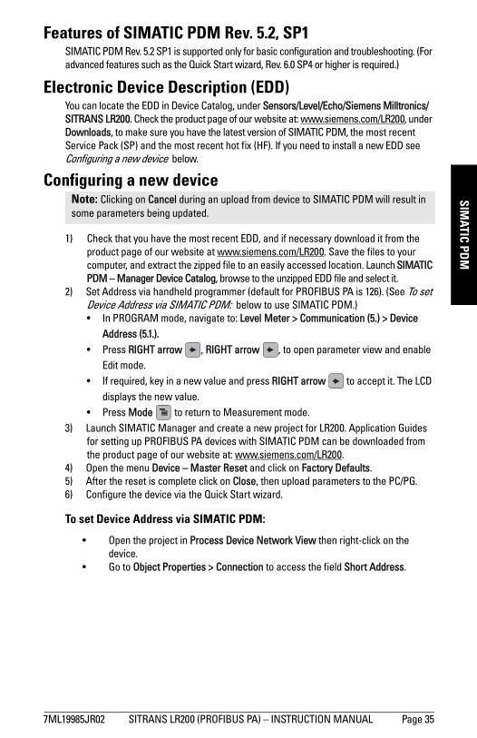
mm
mm
m
SIMATIC PD
M
Features of SIMATIC PDM Rev. 5.2, SP1 SIMATIC PDM Rev. 5.2 SP1 is supported only for basic configuration and troubleshooting. (For advanced features such as the Quick Start wizard, Rev. 6.0 SP4 or higher is required.)
Electronic Device Description (EDD)You can locate the EDD in Device Catalog, under Sensors/Level/Echo/Siemens Milltronics/SITRANS LR200. Check the product page of our website at: www.siemens.com/LR200, under Downloads, to make sure you have the latest version of SIMATIC PDM, the most recent Service Pack (SP) and the most recent hot fix (HF). If you need to install a new EDD see Configuring a new device below.
Configuring a new device
1) Check that you have the most recent EDD, and if necessary download it from the product page of our website at www.siemens.com/LR200. Save the files to your computer, and extract the zipped file to an easily accessed location. Launch SIMATIC PDM – Manager Device Catalog, browse to the unzipped EDD file and select it.
2) Set Address via handheld programmer (default for PROFIBUS PA is 126). (See To set Device Address via SIMATIC PDM: below to use SIMATIC PDM.)• In PROGRAM mode, navigate to: Level Meter > Communication (5.) > Device
Address (5.1.).• Press RIGHT arrow , RIGHT arrow , to open parameter view and enable
Edit mode.• If required, key in a new value and press RIGHT arrow to accept it. The LCD
displays the new value.• Press Mode to return to Measurement mode.
3) Launch SIMATIC Manager and create a new project for LR200. Application Guides for setting up PROFIBUS PA devices with SIMATIC PDM can be downloaded from the product page of our website at: www.siemens.com/LR200.
4) Open the menu Device – Master Reset and click on Factory Defaults.5) After the reset is complete click on Close, then upload parameters to the PC/PG.6) Configure the device via the Quick Start wizard.
To set Device Address via SIMATIC PDM:
• Open the project in Process Device Network View then right-click on the device.
• Go to Object Properties > Connection to access the field Short Address.
Note: Clicking on Cancel during an upload from device to SIMATIC PDM will result in some parameters being updated.
7ML19985JR02 SITRANS LR200 (PROFIBUS PA) – INSTRUCTION MANUAL Page 35
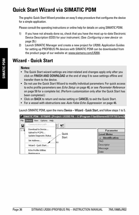
mm
mm
m
SIM
ATIC
PD
M
Quick Start Wizard via SIMATIC PDMThe graphic Quick Start Wizard provides an easy 5-step procedure that configures the device for a simple application.
Please consult the operating instructions or online help for details on using SIMATIC PDM.
1) If you have not already done so, check that you have the most up-to-date Electronic Device Description (EDD) for your instrument. (See Configuring a new device on page 35.)
2) Launch SIMATIC Manager and create a new project for LR200. Application Guides for setting up PROFIBUS PA devices with SIMATIC PDM can be downloaded from the product page of our website at: www.siemens.com/LR200.
Wizard - Quick Start
Launch SIMATIC PDM, open the menu Device – Wizard - Quick Start, and follow steps 1 to 5.
Notes: • The Quick Start wizard settings are inter-related and changes apply only after you
click on FINISH AND DOWNLOAD at the end of step 5 to save settings offline and transfer them to the device.
• Do not use the Quick Start Wizard to modify individual parameters: For quick access to echo profile parameters see Echo Setup on page 48, or see Parameter Reference on page 59 for a complete list. (Perform customization only after the Quick Start has been completed.)
• Click on BACK to return and revise setting or CANCEL to exit the Quick Start. • For a vessel with obstructions see Auto False Echo Suppression on page 46.
Quick Start
Page 36 SITRANS LR200 (PROFIBUS PA) – INSTRUCTION MANUAL 7ML19985JR02
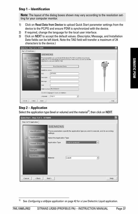
mm
mm
m
SIMATIC PD
M
Step 1 – Identification
1) Click on Read Data from Device to upload Quick Start parameter settings from the device to the PC/PG and ensure PDM is synchronized with the device.
2) If required, change the language for the local user interface.3) Click on NEXT to accept the default values. (Descriptor, Message, and Installation
Date fields can be left blank. Note the TAG field will transfer a maximum of 24 characters to the device.)
Step 2 – ApplicationSelect the application type (level or volume) and the material1), then click on NEXT.
Note: The layout of the dialog boxes shown may vary according to the resolution set-ting for your computer monitor.
1) See Configuring a stillpipe application on page 42 for a Low Dielectric Liquid application.
7ML19985JR02 SITRANS LR200 (PROFIBUS PA) – INSTRUCTION MANUAL Page 37
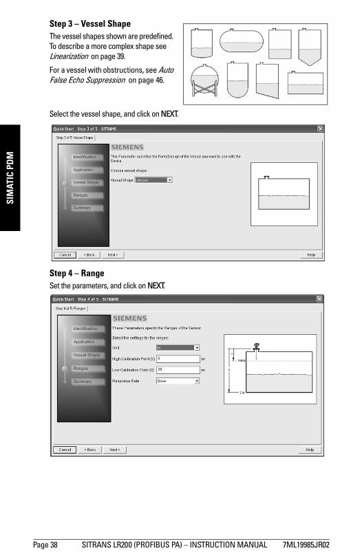
mm
mm
m
SIM
ATIC
PD
M
Step 3 – Vessel ShapeThe vessel shapes shown are predefined. To describe a more complex shape see Linearization on page 39.
For a vessel with obstructions, see Auto False Echo Suppression on page 46.
Select the vessel shape, and click on NEXT.
Step 4 – RangeSet the parameters, and click on NEXT.
Page 38 SITRANS LR200 (PROFIBUS PA) – INSTRUCTION MANUAL 7ML19985JR02
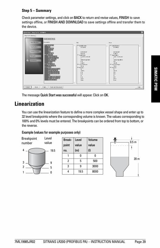
mm
mm
m
SIMATIC PD
M
Step 5 – Summary
Check parameter settings, and click on BACK to return and revise values, FINISH to save settings offline, or FINISH AND DOWNLOAD to save settings offline and transfer them to the device.
The message Quick Start was successful will appear. Click on OK.
Linearization You can use the linearization feature to define a more complex vessel shape and enter up to 32 level breakpoints where the corresponding volume is known. The values corresponding to 100% and 0% levels must be entered. The breakpoints can be ordered from top to bottom, or the reverse.
Example (values for example purposes only)
4
Breakpoint number
32
1
Break-
point
no.
Level
value
(m)
Volume
value
(l)
1 0 0
2 5 500
3 9 3000
4 19.5 8000
Level value
95
0
20 m
0.5 m
19.5
7ML19985JR02 SITRANS LR200 (PROFIBUS PA) – INSTRUCTION MANUAL Page 39
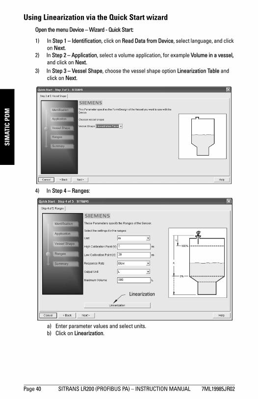
mm
mm
m
SIM
ATIC
PD
M
Using Linearization via the Quick Start wizardOpen the menu Device – Wizard - Quick Start:
1) In Step 1 – Identification, click on Read Data from Device, select language, and click on Next.
2) In Step 2 – Application, select a volume application, for example Volume in a vessel, and click on Next.
3) In Step 3 – Vessel Shape, choose the vessel shape option Linearization Table and click on Next.
4) In Step 4 – Ranges:
a) Enter parameter values and select units.b) Click on Linearization.
Linearization
Page 40 SITRANS LR200 (PROFIBUS PA) – INSTRUCTION MANUAL 7ML19985JR02
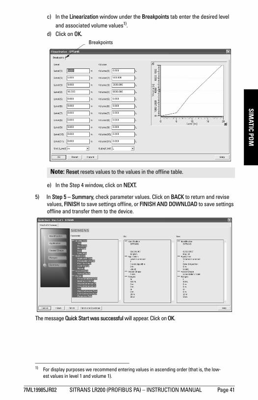
mm
mm
m
SIMATIC PD
M
c) In the Linearization window under the Breakpoints tab enter the desired leveland associated volume values1).d) Click on OK.
e) In the Step 4 window, click on NEXT.
5) In Step 5 – Summary, check parameter values. Click on BACK to return and revise values, FINISH to save settings offline, or FINISH AND DOWNLOAD to save settings offline and transfer them to the device.
The message Quick Start was successful will appear. Click on OK.
1) For display purposes we recommend entering values in ascending order (that is, the low-est values in level 1 and volume 1).
Note: Reset resets values to the values in the offline table.
Breakpoints
7ML19985JR02 SITRANS LR200 (PROFIBUS PA) – INSTRUCTION MANUAL Page 41
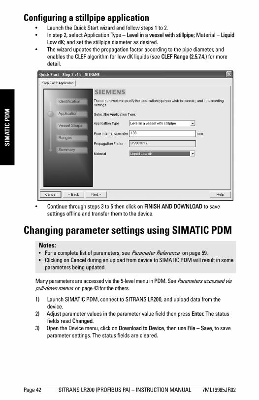
mm
mm
m
SIM
ATIC
PD
M
Configuring a stillpipe application• Launch the Quick Start wizard and follow steps 1 to 2. • In step 2, select Application Type – Level in a vessel with stillpipe; Material – Liquid
Low dK; and set the stillpipe diameter as desired. • The wizard updates the propagation factor according to the pipe diameter, and
enables the CLEF algorithm for low dK liquids (see CLEF Range (2.5.7.4.) for more detail.
• Continue through steps 3 to 5 then click on FINISH AND DOWNLOAD to save settings offline and transfer them to the device.
Changing parameter settings using SIMATIC PDM
Many parameters are accessed via the 5-level menu in PDM. See Parameters accessed via pull-down menus on page 43 for the others.
1) Launch SIMATIC PDM, connect to SITRANS LR200, and upload data from the device.
2) Adjust parameter values in the parameter value field then press Enter. The status fields read Changed.
3) Open the Device menu, click on Download to Device, then use File – Save, to save parameter settings. The status fields are cleared.
Notes: • For a complete list of parameters, see Parameter Reference on page 59. • Clicking on Cancel during an upload from device to SIMATIC PDM will result in some
parameters being updated.
Page 42 SITRANS LR200 (PROFIBUS PA) – INSTRUCTION MANUAL 7ML19985JR02
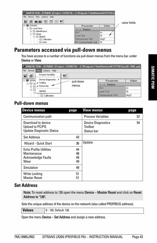
mm
mm
m
SIMATIC PD
M
Parameters accessed via pull-down menusYou have access to a number of functions via pull-down menus from the menu bar. under Device or View.
Pull-down menus
Set Address
Sets the unique address of the device on the network (also called PROFIBUS address).
Open the menu Device – Set Address and assign a new address.
Device menus page View menus page
Communication path Process Variables 52
Download to deviceUpload to PC/PGUpdate Diagnostic Status
Device Diagnostics 54ToolbarStatus bar
Set Address 43
Wizard - Quick Start 36 Update
Echo Profile Utilities 44Maintenance 48Acknowledge Faults 49Wear 49
Simulation 49
Write Locking 51Master Reset 51
Note: To reset address to 126 open the menu Device – Master Reset and click on Reset Address to "126".
Values 0 - 126. Default: 126
value fields
pull-down menus
7ML19985JR02 SITRANS LR200 (PROFIBUS PA) – INSTRUCTION MANUAL Page 43
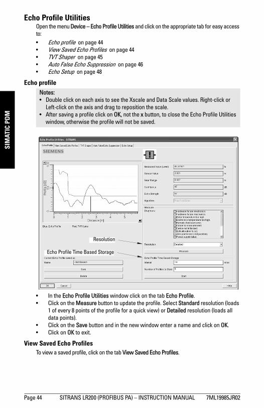
mm
mm
m
SIM
ATIC
PD
M
Echo Profile UtilitiesOpen the menu Device – Echo Profile Utilities and click on the appropriate tab for easy access to: • Echo profile on page 44• View Saved Echo Profiles on page 44• TVT Shaper on page 45• Auto False Echo Suppression on page 46• Echo Setup on page 48
Echo profile
• In the Echo Profile Utilities window click on the tab Echo Profile. • Click on the Measure button to update the profile. Select Standard resolution (loads
1 of every 8 points of the profile for a quick view) or Detailed resolution (loads all data points).
• Click on the Save button and in the new window enter a name and click on OK.• Click on OK to exit.
View Saved Echo ProfilesTo view a saved profile, click on the tab View Saved Echo Profiles.
Notes: • Double click on each axis to see the Xscale and Data Scale values. Right-click or
Left-click on the axis and drag to reposition the scale.• After saving a profile click on OK, not the x button, to close the Echo Profile Utilities
window, otherwise the profile will not be saved.
Echo Profile Time Based Storage
Resolution
Page 44 SITRANS LR200 (PROFIBUS PA) – INSTRUCTION MANUAL 7ML19985JR02
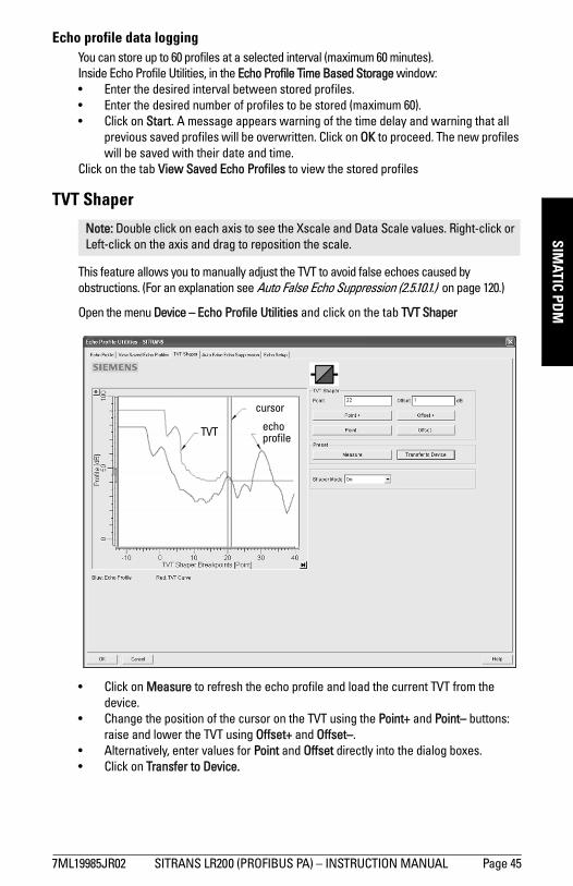
mm
mm
m
SIMATIC PD
M
Echo profile data loggingYou can store up to 60 profiles at a selected interval (maximum 60 minutes). Inside Echo Profile Utilities, in the Echo Profile Time Based Storage window:• Enter the desired interval between stored profiles.• Enter the desired number of profiles to be stored (maximum 60).• Click on Start. A message appears warning of the time delay and warning that all
previous saved profiles will be overwritten. Click on OK to proceed. The new profiles will be saved with their date and time.
Click on the tab View Saved Echo Profiles to view the stored profiles
TVT Shaper
This feature allows you to manually adjust the TVT to avoid false echoes caused by obstructions. (For an explanation see Auto False Echo Suppression (2.5.10.1.) on page 120.)
Open the menu Device – Echo Profile Utilities and click on the tab TVT Shaper
• Click on Measure to refresh the echo profile and load the current TVT from the device.
• Change the position of the cursor on the TVT using the Point+ and Point– buttons: raise and lower the TVT using Offset+ and Offset–.
• Alternatively, enter values for Point and Offset directly into the dialog boxes. • Click on Transfer to Device.
Note: Double click on each axis to see the Xscale and Data Scale values. Right-click or Left-click on the axis and drag to reposition the scale.
TVT
cursor
echo profile
7ML19985JR02 SITRANS LR200 (PROFIBUS PA) – INSTRUCTION MANUAL Page 45
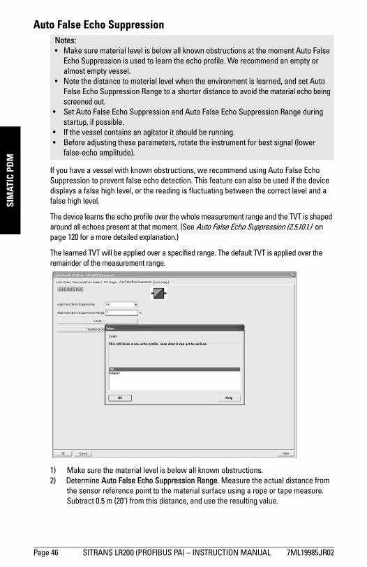
mm
mm
m
SIM
ATIC
PD
M
Auto False Echo Suppression
If you have a vessel with known obstructions, we recommend using Auto False Echo Suppression to prevent false echo detection. This feature can also be used if the device displays a false high level, or the reading is fluctuating between the correct level and a false high level.
The device learns the echo profile over the whole measurement range and the TVT is shaped around all echoes present at that moment. (See Auto False Echo Suppression (2.5.10.1.) on page 120 for a more detailed explanation.)
The learned TVT will be applied over a specified range. The default TVT is applied over the remainder of the measurement range.
1) Make sure the material level is below all known obstructions. 2) Determine Auto False Echo Suppression Range. Measure the actual distance from
the sensor reference point to the material surface using a rope or tape measure. Subtract 0.5 m (20") from this distance, and use the resulting value.
Notes: • Make sure material level is below all known obstructions at the moment Auto False
Echo Suppression is used to learn the echo profile. We recommend an empty or almost empty vessel.
• Note the distance to material level when the environment is learned, and set Auto False Echo Suppression Range to a shorter distance to avoid the material echo being screened out.
• Set Auto False Echo Suppression and Auto False Echo Suppression Range during startup, if possible.
• If the vessel contains an agitator it should be running. • Before adjusting these parameters, rotate the instrument for best signal (lower
false-echo amplitude).
Page 46 SITRANS LR200 (PROFIBUS PA) – INSTRUCTION MANUAL 7ML19985JR02
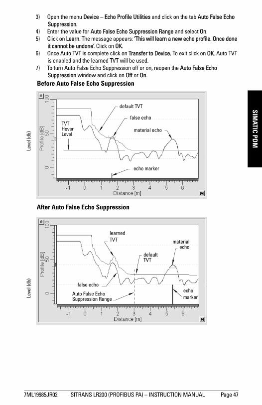
mm
mm
m
SIMATIC PD
M
3) Open the menu Device – Echo Profile Utilities and click on the tab Auto False EchoSuppression.4) Enter the value for Auto False Echo Suppression Range and select On. 5) Click on Learn. The message appears: ’This will learn a new echo profile. Once done
it cannot be undone’. Click on OK.6) Once Auto TVT is complete click on Transfer to Device. To exit click on OK. Auto TVT
is enabled and the learned TVT will be used.7) To turn Auto False Echo Suppression off or on, reopen the Auto False Echo
Suppression window and click on Off or On.Before Auto False Echo Suppression
default TVT
TVT Hover Level
Leve
l (db
)
echo marker
After Auto False Echo Suppression
materialecho
false echo
Auto False Echo Suppression Range
echo markerLe
vel (
db)
default TVT
material echo
false echo
learned TVT
7ML19985JR02 SITRANS LR200 (PROFIBUS PA) – INSTRUCTION MANUAL Page 47
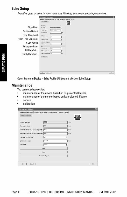
mm
mm
m
SIM
ATIC
PD
M
Echo SetupProvides quick access to echo selection, filtering, and response rate parameters.
Open the menu Device – Echo Profile Utilities and click on Echo Setup.
MaintenanceYou can set schedules for: • maintenance of the device based on its projected lifetime • maintenance of the sensor based on its projected lifetime• service• calibration
AlgorithmPosition DetectEcho Threshold
Filter Time ConstantCLEF Range
Response Rate Fill Rate/min.
Empty Rate/min.
Page 48 SITRANS LR200 (PROFIBUS PA) – INSTRUCTION MANUAL 7ML19985JR02
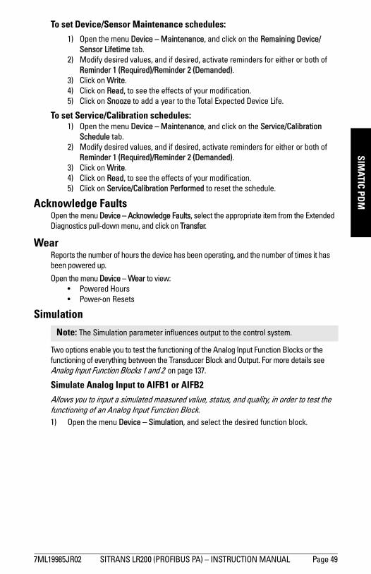
mm
mm
m
SIMATIC PD
M
To set Device/Sensor Maintenance schedules:
1) Open the menu Device – Maintenance, and click on the Remaining Device/Sensor Lifetime tab.
2) Modify desired values, and if desired, activate reminders for either or both of Reminder 1 (Required)/Reminder 2 (Demanded).
3) Click on Write.4) Click on Read, to see the effects of your modification.5) Click on Snooze to add a year to the Total Expected Device Life.
To set Service/Calibration schedules:1) Open the menu Device – Maintenance, and click on the Service/Calibration
Schedule tab. 2) Modify desired values, and if desired, activate reminders for either or both of
Reminder 1 (Required)/Reminder 2 (Demanded).3) Click on Write.4) Click on Read, to see the effects of your modification.5) Click on Service/Calibration Performed to reset the schedule.
Acknowledge FaultsOpen the menu Device – Acknowledge Faults, select the appropriate item from the Extended Diagnostics pull-down menu, and click on Transfer.
WearReports the number of hours the device has been operating, and the number of times it has been powered up.
Open the menu Device – Wear to view:• Powered Hours• Power-on Resets
Simulation
Two options enable you to test the functioning of the Analog Input Function Blocks or the functioning of everything between the Transducer Block and Output. For more details see Analog Input Function Blocks 1 and 2 on page 137.
Simulate Analog Input to AIFB1 or AIFB2
Allows you to input a simulated measured value, status, and quality, in order to test the functioning of an Analog Input Function Block.1) Open the menu Device – Simulation, and select the desired function block.
Note: The Simulation parameter influences output to the control system.
7ML19985JR02 SITRANS LR200 (PROFIBUS PA) – INSTRUCTION MANUAL Page 49
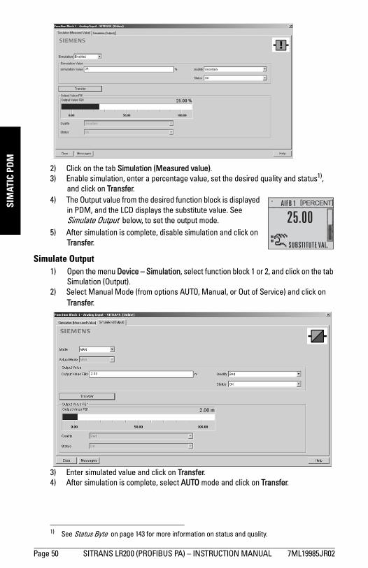
mm
mm
m
SIM
ATIC
PD
M
2) Click on the tab Simulation (Measured value). 3) Enable simulation, enter a percentage value, set the desired quality and status1),
and click on Transfer. 4) The Output value from the desired function block is displayed
in PDM, and the LCD displays the substitute value. See Simulate Output below, to set the output mode.
5) After simulation is complete, disable simulation and click on Transfer.
Simulate Output1) Open the menu Device – Simulation, select function block 1 or 2, and click on the tab
Simulation (Output).2) Select Manual Mode (from options AUTO, Manual, or Out of Service) and click on
Transfer.
3) Enter simulated value and click on Transfer.4) After simulation is complete, select AUTO mode and click on Transfer.
1) See Status Byte on page 143 for more information on status and quality.
Page 50 SITRANS LR200 (PROFIBUS PA) – INSTRUCTION MANUAL 7ML19985JR02
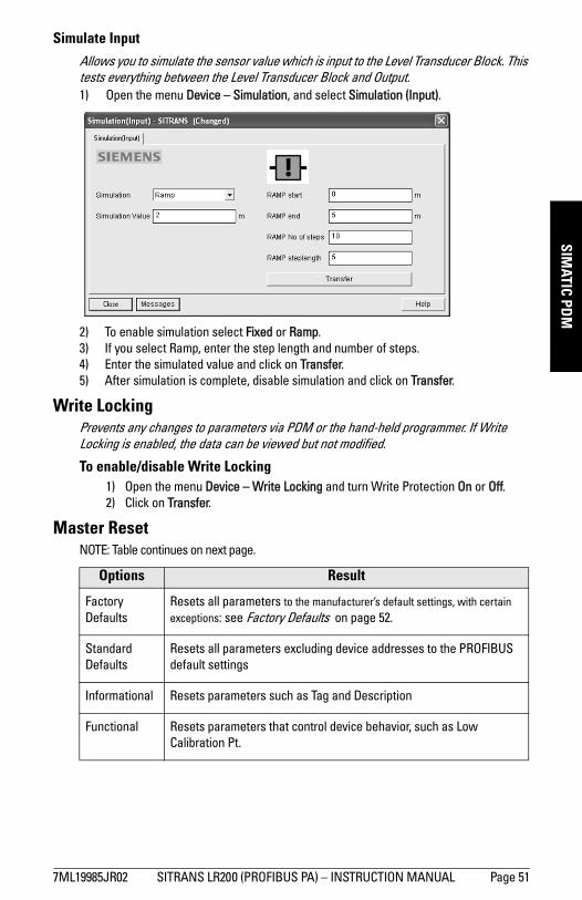
mm
mm
m
SIMATIC PD
M
Simulate Input
Allows you to simulate the sensor value which is input to the Level Transducer Block. This tests everything between the Level Transducer Block and Output.1) Open the menu Device – Simulation, and select Simulation (Input).
2) To enable simulation select Fixed or Ramp.3) If you select Ramp, enter the step length and number of steps. 4) Enter the simulated value and click on Transfer.5) After simulation is complete, disable simulation and click on Transfer.
Write LockingPrevents any changes to parameters via PDM or the hand-held programmer. If Write Locking is enabled, the data can be viewed but not modified.
To enable/disable Write Locking1) Open the menu Device – Write Locking and turn Write Protection On or Off. 2) Click on Transfer.
Master ResetNOTE: Table continues on next page.
Options Result
Factory Defaults
Resets all parameters to the manufacturer’s default settings, with certain exceptions: see Factory Defaults on page 52.
Standard Defaults
Resets all parameters excluding device addresses to the PROFIBUS default settings
Informational Resets parameters such as Tag and Description
Functional Resets parameters that control device behavior, such as Low Calibration Pt.
7ML19985JR02 SITRANS LR200 (PROFIBUS PA) – INSTRUCTION MANUAL Page 51
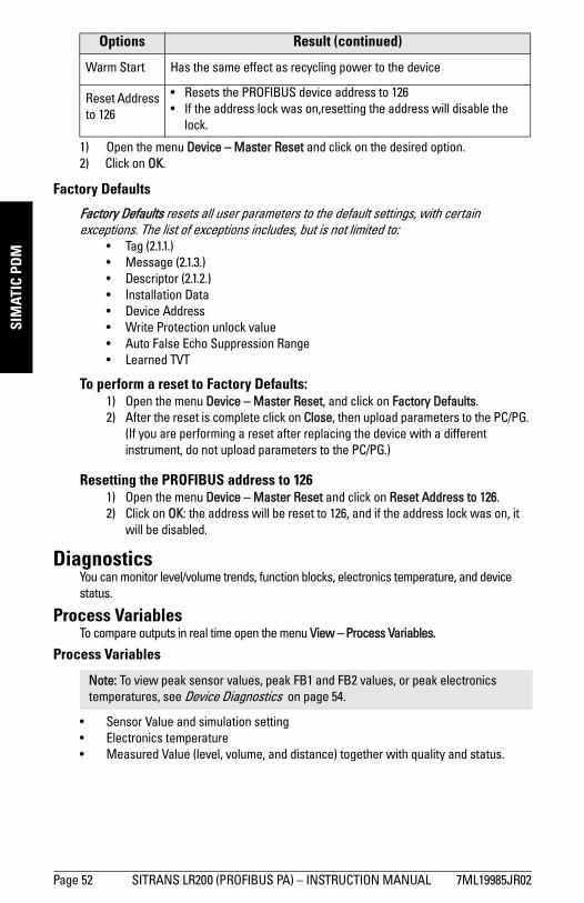
mm
mm
m
SIM
ATIC
PD
M
1) Open the menu Device – Master Reset and click on the desired option.2) Click on OK.
Factory Defaults
Factory Defaults resets all user parameters to the default settings, with certain exceptions. The list of exceptions includes, but is not limited to:
• Tag (2.1.1.)• Message (2.1.3.)• Descriptor (2.1.2.)• Installation Data• Device Address • Write Protection unlock value• Auto False Echo Suppression Range • Learned TVT
To perform a reset to Factory Defaults:1) Open the menu Device – Master Reset, and click on Factory Defaults.2) After the reset is complete click on Close, then upload parameters to the PC/PG.
(If you are performing a reset after replacing the device with a different instrument, do not upload parameters to the PC/PG.)
Resetting the PROFIBUS address to 1261) Open the menu Device – Master Reset and click on Reset Address to 126.2) Click on OK: the address will be reset to 126, and if the address lock was on, it
will be disabled.
DiagnosticsYou can monitor level/volume trends, function blocks, electronics temperature, and device status.
Process VariablesTo compare outputs in real time open the menu View – Process Variables.
Process Variables
• Sensor Value and simulation setting• Electronics temperature• Measured Value (level, volume, and distance) together with quality and status.
Warm Start Has the same effect as recycling power to the device
Reset Address to 126
• Resets the PROFIBUS device address to 126 • If the address lock was on,resetting the address will disable the
lock.
Note: To view peak sensor values, peak FB1 and FB2 values, or peak electronics temperatures, see Device Diagnostics on page 54.
Options Result (continued)
Page 52 SITRANS LR200 (PROFIBUS PA) – INSTRUCTION MANUAL 7ML19985JR02
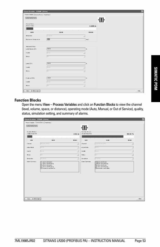
mm
mm
m
SIMATIC PD
M
Function BlocksOpen the menu View – Process Variables and click on Function Blocks to view the channel (level, volume, space, or distance), operating mode (Auto, Manual, or Out of Service), quality, status, simulation setting, and summary of alarms.
7ML19985JR02 SITRANS LR200 (PROFIBUS PA) – INSTRUCTION MANUAL Page 53
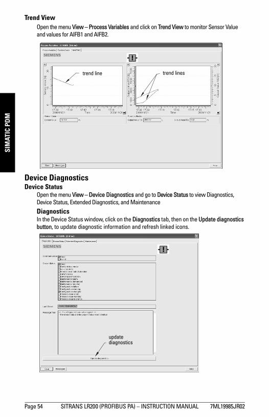
mm
mm
m
SIM
ATIC
PD
M
Trend ViewOpen the menu View – Process Variables and click on Trend View to monitor Sensor Value and values for AIFB1 and AIFB2.
Device DiagnosticsDevice Status
Open the menu View – Device Diagnostics and go to Device Status to view Diagnostics, Device Status, Extended Diagnostics, and Maintenance
DiagnosticsIn the Device Status window, click on the Diagnostics tab, then on the Update diagnostics button, to update diagnostic information and refresh linked icons.
trend line trend lines
update diagnostics
Page 54 SITRANS LR200 (PROFIBUS PA) – INSTRUCTION MANUAL 7ML19985JR02
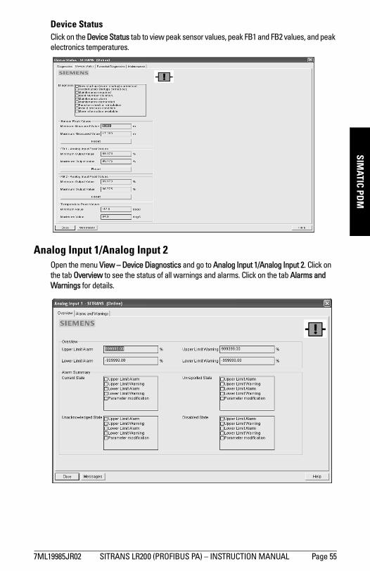
mm
mm
m
SIMATIC PD
M
Device StatusClick on the Device Status tab to view peak sensor values, peak FB1 and FB2 values, and peak electronics temperatures.
Analog Input 1/Analog Input 2Open the menu View – Device Diagnostics and go to Analog Input 1/Analog Input 2. Click on the tab Overview to see the status of all warnings and alarms. Click on the tab Alarms and Warnings for details.
7ML19985JR02 SITRANS LR200 (PROFIBUS PA) – INSTRUCTION MANUAL Page 55
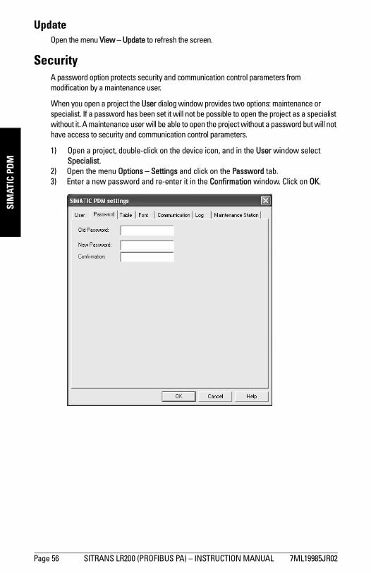
mm
mm
m
SIM
ATIC
PD
M
UpdateOpen the menu View – Update to refresh the screen.
SecurityA password option protects security and communication control parameters from modification by a maintenance user.
When you open a project the User dialog window provides two options: maintenance or specialist. If a password has been set it will not be possible to open the project as a specialist without it. A maintenance user will be able to open the project without a password but will not have access to security and communication control parameters.
1) Open a project, double-click on the device icon, and in the User window select Specialist.
2) Open the menu Options – Settings and click on the Password tab.3) Enter a new password and re-enter it in the Confirmation window. Click on OK.
Page 56 SITRANS LR200 (PROFIBUS PA) – INSTRUCTION MANUAL 7ML19985JR02
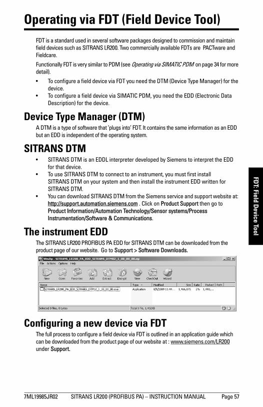
mm
mm
m
FDT: Field Device Tool
Operating via FDT (Field Device Tool)FDT is a standard used in several software packages designed to commission and maintain field devices such as SITRANS LR200. Two commercially available FDTs are PACTware and Fieldcare.
Functionally FDT is very similar to PDM (see Operating via SIMATIC PDM on page 34 for more detail).
• To configure a field device via FDT you need the DTM (Device Type Manager) for the device.
• To configure a field device via SIMATIC PDM, you need the EDD (Electronic Data Description) for the device.
Device Type Manager (DTM)A DTM is a type of software that ’plugs into’ FDT. It contains the same information as an EDD but an EDD is independent of the operating system.
SITRANS DTM• SITRANS DTM is an EDDL interpreter developed by Siemens to interpret the EDD
for that device. • To use SITRANS DTM to connect to an instrument, you must first install
SITRANS DTM on your system and then install the instrument EDD written for SITRANS DTM.
• You can download SITRANS DTM from the Siemens service and support website at: http://support.automation.siemens.com . Click on Product Support then go to Product Information/Automation Technology/Sensor systems/Process Instrumentation/Software & Communications.
The instrument EDDThe SITRANS LR200 PROFIBUS PA EDD for SITRANS DTM can be downloaded from the product page of our website. Go to Support > Software Downloads.
Configuring a new device via FDTThe full process to configure a field device via FDT is outlined in an application guide which can be downloaded from the product page of our website at : www.siemens.com/LR200 under Support.
7ML19985JR02 SITRANS LR200 (PROFIBUS PA) – INSTRUCTION MANUAL Page 57

mm
mm
m
FDT:
Fie
ld D
evic
e To
ol
Notes
Page 58 SITRANS LR200 (PROFIBUS PA) – INSTRUCTION MANUAL 7ML19985JR02
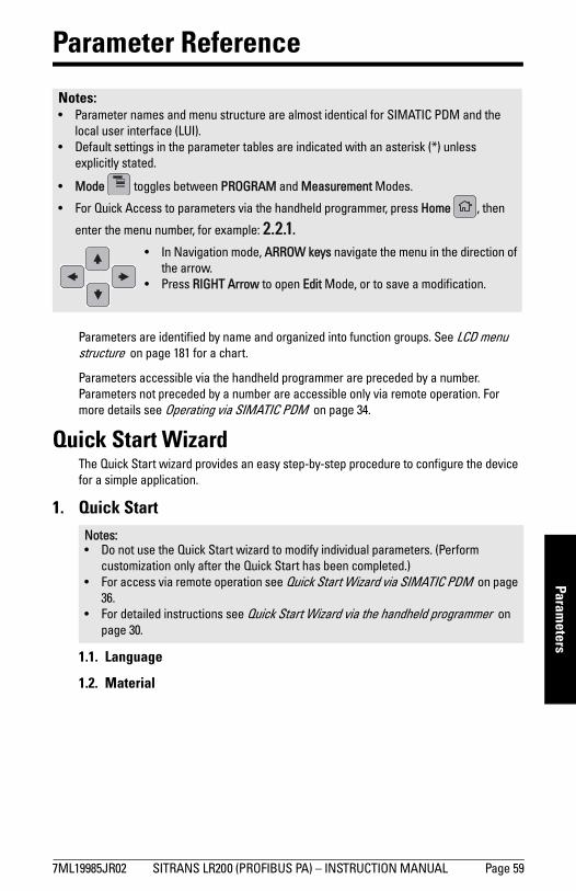
mm
mm
m
Parameters
Parameter Reference
Parameters are identified by name and organized into function groups. See LCD menu structure on page 181 for a chart.
Parameters accessible via the handheld programmer are preceded by a number. Parameters not preceded by a number are accessible only via remote operation. For more details see Operating via SIMATIC PDM on page 34.
Quick Start WizardThe Quick Start wizard provides an easy step-by-step procedure to configure the device for a simple application.
1. Quick Start
1.1. Language
1.2. Material
Notes: • Parameter names and menu structure are almost identical for SIMATIC PDM and the
local user interface (LUI). • Default settings in the parameter tables are indicated with an asterisk (*) unless
explicitly stated.
• Mode toggles between PROGRAM and Measurement Modes.
• For Quick Access to parameters via the handheld programmer, press Home , then
enter the menu number, for example: 2.2.1.
Notes: • Do not use the Quick Start wizard to modify individual parameters. (Perform
customization only after the Quick Start has been completed.)• For access via remote operation see Quick Start Wizard via SIMATIC PDM on page
36.• For detailed instructions see Quick Start Wizard via the handheld programmer on
page 30.
• In Navigation mode, ARROW keys navigate the menu in the direction of the arrow.
• Press RIGHT Arrow to open Edit Mode, or to save a modification.
7ML19985JR02 SITRANS LR200 (PROFIBUS PA) – INSTRUCTION MANUAL Page 59
mm
mm
m
Para
met
ers
1.3. Response Rate1.4. Units1.5. Operating Mode1.6. Low Calibration Point1.7. High Calibration Point1.8. Apply? (Apply changes)
2. Setup
2.1. Identification2.1.1. Tag
Text that can be used in any way. A recommended use is as a unique label for a field device in a plant. Limited to 32 ASCII characters.
2.1.2. DescriptorText that can be used in any way. Limited to 32 ASCII characters. No specific recommended use.
2.1.3. MessageText that can be used in any way. Limited to 32 ASCII characters. No specific recommended use.
2.2. Device2.2.1. Hardware Revision
Read only. Corresponds to the electronics hardware of the Field Device. 2.2.2. Firmware Revision
Read only. Corresponds to the software or firmware that is embedded in the Field Device.
2.2.3. Loader RevisionRead only. Corresponds to the software used to update the Field Device.
2.2.4. Order OptionRead only. Displays the device type.
2.3. Sensor2.3.1. Unit
Sensor measurement unit.
Notes: • Default settings in the parameter tables are indicated with an asterisk (*) unless
explicitly stated.• Values shown in the following tables can be entered via the handheld programmer.
Note: SITRANS PDM limits the TAG field to a maximum of 24 characters.
Valuesm, cm, mm, ft, in
Default: m
Page 60 SITRANS LR200 (PROFIBUS PA) – INSTRUCTION MANUAL 7ML19985JR02
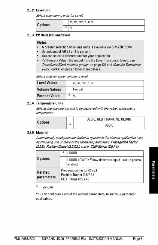
mm
mm
m
Parameters
2.3.2. Level UnitSelect engineering units for Level.
2.3.3. PV Units (volume/level)
Select units for either volume or level.
2.3.4. Temperature UnitsSelects the engineering unit to be displayed with the value representing temperature.
2.3.5. MaterialAutomatically configures the device to operate in the chosen application type, by changing one or more of the following parameters: Propagation Factor (2.5.3.), Position Detect (2.5.7.2.), and/or CLEF Range (2.5.7.4.).
You can configure each of the related parameters, to suit your particular application.
Optionsm, cm, mm, ft, in, %
* %
Notes: • A greater selection of volume units is available via SIMATIC PDM.• Default unit of AIFB1 or 2 is percent.• You can select a different unit for your application.• PV (Primary Value): the output from the Level Transducer Block. See
Transducer Block function groups on page 135 and How the Transducer Block works: on page 135 for more details.
Level Values m, cm, mm, ft, in
Volume Values liter, gal
Percent Value * %
OptionsDEG C, DEG F, RANKINE, KELVIN
* DEG C
Options* LIQUID
LIQUID LOW DKa) (low dielectric liquid – CLEF algorithm enabled)
a) dK < 3.0
Related parameters
Propagation Factor (2.5.3.)Position Detect (2.5.7.2.)CLEF Range (2.5.7.4.)
7ML19985JR02 SITRANS LR200 (PROFIBUS PA) – INSTRUCTION MANUAL Page 61
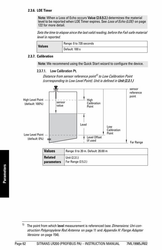
mm
mm
m
Para
met
ers
2.3.6. LOE Timer
Sets the time to elapse since the last valid reading, before the Fail-safe material level is reported.
2.3.7. Calibration
2.3.7.1. Low Calibration Pt. Distance from sensor reference point1) to Low Calibration Point (corresponding to Low Level Point). Unit is defined in Unit (2.3.1.)
Note: When a Loss of Echo occurs Value (2.6.9.2.) determines the material level to be reported when LOE Timer expires. See Loss of Echo (LOE) on page 122 for more detail.
ValuesRange: 0 to 720 seconds
Default: 100 s
Note: We recommend using the Quick Start wizard to configure the device.
1) The point from which level measurement is referenced (see Dimensions: Uni-con-struction Polypropylene Rod Antenna on page 11 and Appendix H: Flange Adapter Versions on page 154).
Values Range: 0 to 20 m. Default: 20.00 m
Related parameters
Unit (2.3.1.)Far Range (2.5.2.)
High Level Point(default: 100%)
sensor reference point
Low Level Point(default: 0%)
LevelLow Calibration Point
High Calibration Point
Level Offset (if used
sensor value
Far Range
Page 62 SITRANS LR200 (PROFIBUS PA) – INSTRUCTION MANUAL 7ML19985JR02
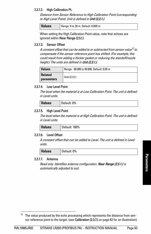
mm
mm
m
Parameters
2.3.7.2. High Calibration Pt. Distance from Sensor Reference to High Calibration Point (corresponding to High Level Point). Unit is defined in Unit (2.3.1.).
When setting the High Calibration Point value, note that echoes are ignored within Near Range (2.5.1.)
2.3.7.3. Sensor Offset A constant offset that can be added to or subtracted from sensor value1) to compensate if the sensor reference point has shifted. (For example, this could result from adding a thicker gasket or reducing the standoff/nozzle height.) The units are defined in Unit (2.3.1.).
2.3.7.4. Low Level Point The level when the material is at Low Calibration Point. The unit is defined in Level units.
2.3.7.5. High Level Point The level when the material is at High Calibration Point. The unit is defined in Level units.
2.3.7.6. Level Offset A constant offset that can be added to Level. The unit is defined in Level units.
2.3.7.7. AntennaRead only. Identifies antenna configuration. Near Range (2.5.1.) is automatically adjusted to suit.
Values Range: 0 to 20 m. Default: 0.000 m
1) The value produced by the echo processing which represents the distance from sen-sor reference point to the target. (see Calibration (2.3.7.) on page 62 for an illustration).
Values Range: -99.999 to 99.999. Default: 0.00 m
Related parameters
Unit (2.3.1.)
Values Default: 0%
Values Default: 100%
Values Default: 0%
7ML19985JR02 SITRANS LR200 (PROFIBUS PA) – INSTRUCTION MANUAL Page 63
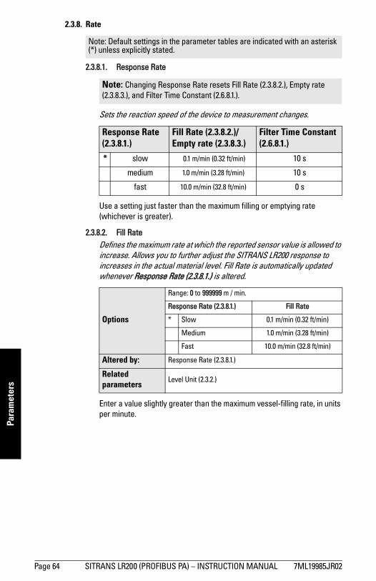
mm
mm
m
Para
met
ers
2.3.8. Rate
2.3.8.1. Response Rate
Sets the reaction speed of the device to measurement changes..
Use a setting just faster than the maximum filling or emptying rate (whichever is greater).
2.3.8.2. Fill RateDefines the maximum rate at which the reported sensor value is allowed to increase. Allows you to further adjust the SITRANS LR200 response to increases in the actual material level. Fill Rate is automatically updated whenever Response Rate (2.3.8.1.) is altered.
Enter a value slightly greater than the maximum vessel-filling rate, in units per minute.
Note: Default settings in the parameter tables are indicated with an asterisk (*) unless explicitly stated.
Note: Changing Response Rate resets Fill Rate (2.3.8.2.), Empty rate (2.3.8.3.), and Filter Time Constant (2.6.8.1.).
Response Rate (2.3.8.1.)
Fill Rate (2.3.8.2.)/Empty rate (2.3.8.3.)
Filter Time Constant (2.6.8.1.)
* slow 0.1 m/min (0.32 ft/min) 10 s
medium 1.0 m/min (3.28 ft/min) 10 s
fast 10.0 m/min (32.8 ft/min) 0 s
Options
Range: 0 to 999999 m / min.
Response Rate (2.3.8.1.) Fill Rate
* Slow 0.1 m/min (0.32 ft/min)
Medium 1.0 m/min (3.28 ft/min)
Fast 10.0 m/min (32.8 ft/min)
Altered by: Response Rate (2.3.8.1.)
Related parameters
Level Unit (2.3.2.)
Page 64 SITRANS LR200 (PROFIBUS PA) – INSTRUCTION MANUAL 7ML19985JR02
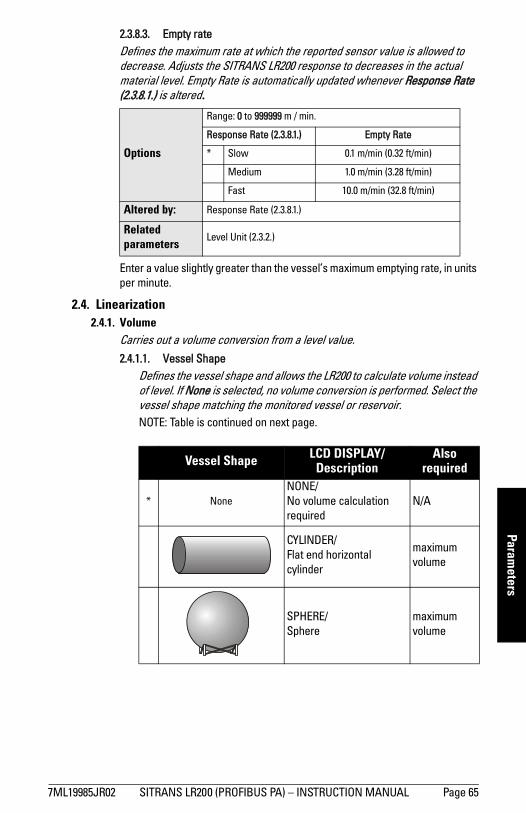
mm
mm
m
Parameters
2.3.8.3. Empty rateDefines the maximum rate at which the reported sensor value is allowed to decrease. Adjusts the SITRANS LR200 response to decreases in the actual material level. Empty Rate is automatically updated whenever Response Rate (2.3.8.1.) is altered.
Enter a value slightly greater than the vessel’s maximum emptying rate, in units per minute.
2.4. Linearization2.4.1. Volume
Carries out a volume conversion from a level value. 2.4.1.1. Vessel Shape
Defines the vessel shape and allows the LR200 to calculate volume instead of level. If None is selected, no volume conversion is performed. Select the vessel shape matching the monitored vessel or reservoir.NOTE: Table is continued on next page.
Options
Range: 0 to 999999 m / min.
Response Rate (2.3.8.1.) Empty Rate
* Slow 0.1 m/min (0.32 ft/min)
Medium 1.0 m/min (3.28 ft/min)
Fast 10.0 m/min (32.8 ft/min)
Altered by: Response Rate (2.3.8.1.)
Related parameters
Level Unit (2.3.2.)
Vessel Shape LCD DISPLAY/Description
Also required
* NoneNONE/No volume calculation required
N/A
CYLINDER/Flat end horizontal cylinder
maximum volume
SPHERE/Sphere
maximum volume
7ML19985JR02 SITRANS LR200 (PROFIBUS PA) – INSTRUCTION MANUAL Page 65
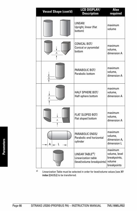
mm
mm
m
Para
met
ers
LINEAR/Upright, linear (flat bottom)
maximum volume
CONICAL BOT/Conical or pyramidal bottom
maximum volume, dimension A
PARABOLIC BOT/Parabolic bottom
maximum volume, dimension A
HALF SPHERE BOT/Half-sphere bottom
maximum volume, dimension A
FLAT SLOPED BOT/Flat sloped bottom
maximum volume, dimension A
PARABOLIC ENDS/Parabolic end horizontal cylinder
maximum volume, dimension A, dimension L
LINEAR TABLEa)/Linearization table(level/volume breakpoints)
maximum volume, level breakpoints, volume breakpoints
a) Linearization Table must be selected in order for level/volume values [see XY index (2.4.1.5.)] to be transferred.
Vessel Shape (cont’d) LCD DISPLAY/Description
Also required
A
A
A
A
A L
Page 66 SITRANS LR200 (PROFIBUS PA) – INSTRUCTION MANUAL 7ML19985JR02
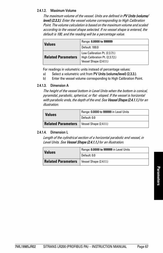
mm
mm
m
Parameters
2.4.1.2. Maximum VolumeThe maximum volume of the vessel. Units are defined in PV Units (volume/level) (2.3.3.). Enter the vessel volume corresponding to High Calibration Point. The volume calculation is based on the maximum volume and scaled according to the vessel shape selected. If no vessel shape is entered, the default is 100, and the reading will be a percentage value.
For readings in volumetric units instead of percentage values:a) Select a volumetric unit from PV Units (volume/level) (2.3.3.).b) Enter the vessel volume corresponding to High Calibration Point.
2.4.1.3. Dimension AThe height of the vessel bottom in Level Units when the bottom is conical, pyramidal, parabolic, spherical, or flat -sloped. If the vessel is horizontal with parabolic ends, the depth of the end. See Vessel Shape (2.4.1.1.) for an illustration.
2.4.1.4. Dimension LLength of the cylindrical section of a horizontal parabolic end vessel, in Level Units. See Vessel Shape (2.4.1.1.) for an illustration.
ValuesRange: 0.0000 to 999999
Default: 100.0
Related ParametersLow Calibration Pt. (2.3.7.1.)High Calibration Pt. (2.3.7.2.)Vessel Shape (2.4.1.1.)
ValuesRange: 0.0000 to 999999 in Level Units
Default: 0.0
Related Parameters Vessel Shape (2.4.1.1.)
ValuesRange: 0.0000 to 999999 in Level Units
Default: 0.0
Related Parameters Vessel Shape (2.4.1.1.)
7ML19985JR02 SITRANS LR200 (PROFIBUS PA) – INSTRUCTION MANUAL Page 67
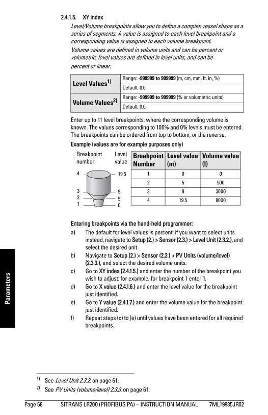
mm
mm
m
Para
met
ers
2.4.1.5. XY index Level/Volume breakpoints allow you to define a complex vessel shape as a series of segments. A value is assigned to each level breakpoint and a corresponding value is assigned to each volume breakpoint. Volume values are defined in volume units and can be percent or volumetric; level values are defined in level units, and can be percent or linear.1) 2)
Enter up to 11 level breakpoints, where the corresponding volume is known. The values corresponding to 100% and 0% levels must be entered. The breakpoints can be ordered from top to bottom, or the reverse.
Example (values are for example purposes only)
Entering breakpoints via the hand-held programmer:a) The default for level values is percent: if you want to select units
instead, navigate to Setup (2.) > Sensor (2.3.) > Level Unit (2.3.2.), and select the desired unit
b) Navigate to Setup (2.) > Sensor (2.3.) > PV Units (volume/level) (2.3.3.), and select the desired volume units.
c) Go to XY index (2.4.1.5.) and enter the number of the breakpoint you wish to adjust: for example, for breakpoint 1 enter 1.
d) Go to X value (2.4.1.6.) and enter the level value for the breakpoint just identified.
e) Go to Y value (2.4.1.7.) and enter the volume value for the breakpoint just identified.
f) Repeat steps (c) to (e) until values have been entered for all required breakpoints.
Level Values1) Range: -999999 to 999999 (m, cm, mm, ft, in, %)
Default: 0.0
Volume Values2) Range: -999999 to 999999 (% or volumetric units)
Default: 0.0
1) See Level Unit 2.3.2. on page 61.2) See PV Units (volume/level) 2.3.3. on page 61.
19.5
950
Breakpoint number
Breakpoint Number
Level value(m)
Volume value(l)
1 0 0
2 5 500
3 9 3000
4 19.5 8000
Level value
4
321
Page 68 SITRANS LR200 (PROFIBUS PA) – INSTRUCTION MANUAL 7ML19985JR02
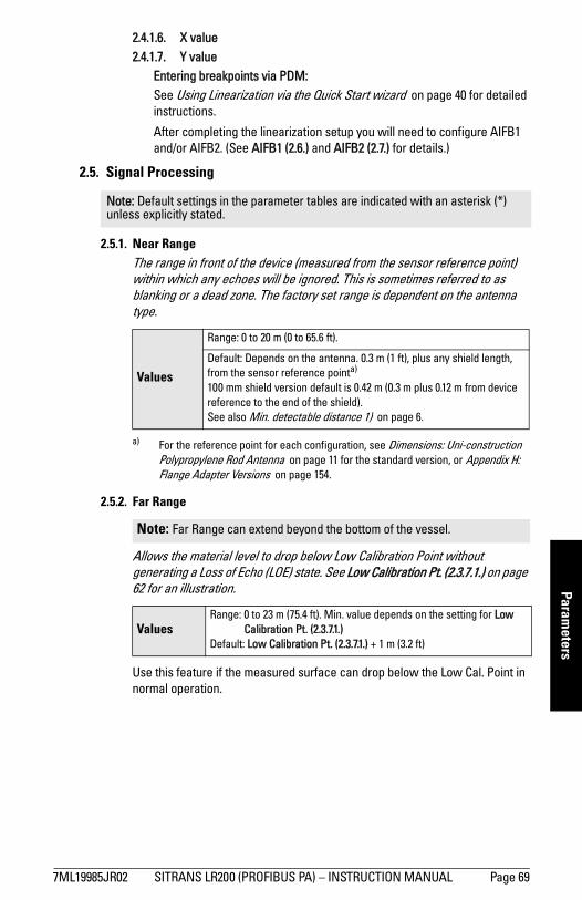
mm
mm
m
Parameters
2.4.1.6. X value2.4.1.7. Y value
Entering breakpoints via PDM:See Using Linearization via the Quick Start wizard on page 40 for detailed instructions.
After completing the linearization setup you will need to configure AIFB1 and/or AIFB2. (See AIFB1 (2.6.) and AIFB2 (2.7.) for details.)
2.5. Signal Processing
2.5.1. Near Range The range in front of the device (measured from the sensor reference point) within which any echoes will be ignored. This is sometimes referred to as blanking or a dead zone. The factory set range is dependent on the antenna type.
2.5.2. Far Range
Allows the material level to drop below Low Calibration Point without generating a Loss of Echo (LOE) state. See Low Calibration Pt. (2.3.7.1.) on page 62 for an illustration.
Use this feature if the measured surface can drop below the Low Cal. Point in normal operation.
Note: Default settings in the parameter tables are indicated with an asterisk (*) unless explicitly stated.
Values
Range: 0 to 20 m (0 to 65.6 ft).
Default: Depends on the antenna. 0.3 m (1 ft), plus any shield length, from the sensor reference pointa)
100 mm shield version default is 0.42 m (0.3 m plus 0.12 m from device reference to the end of the shield).See also Min. detectable distance 1) on page 6.
a) For the reference point for each configuration, see Dimensions: Uni-construction Polypropylene Rod Antenna on page 11 for the standard version, or Appendix H: Flange Adapter Versions on page 154.
Note: Far Range can extend beyond the bottom of the vessel.
ValuesRange: 0 to 23 m (75.4 ft). Min. value depends on the setting for Low
Calibration Pt. (2.3.7.1.)Default: Low Calibration Pt. (2.3.7.1.) + 1 m (3.2 ft)
7ML19985JR02 SITRANS LR200 (PROFIBUS PA) – INSTRUCTION MANUAL Page 69
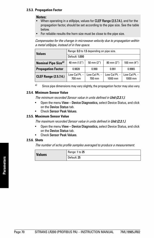
mm
mm
m
Para
met
ers
2.5.3. Propagation Factor
Compensates for the change in microwave velocity due to propagation within a metal stillpipe, instead of in free space.
2.5.4. Minimum Sensor ValueThe minimum recorded Sensor value in units defined in Unit (2.3.1.).• Open the menu View – Device Diagnostics, select Device Status, and click
on the Device Status tab.• Check Sensor Peak Values.
2.5.5. Maximum Sensor ValueThe maximum recorded Sensor value in units defined in Unit (2.3.1.).• Open the menu View – Device Diagnostics, select Device Status, and click
on the Device Status tab.• Check Sensor Peak Values.
2.5.6. ShotsThe number of echo profile samples averaged to produce a measurement.
Notes: • When operating in a stillpipe, values for CLEF Range (2.5.7.4.), and for the
propagation factor, should be set according to the pipe size. See the table below.
• For reliable results the horn size must be close to the pipe size.
Values Range: 0.3 to 1.5 depending on pipe size.
Default: 1.000
Nominal Pipe Sizea)
a) Since pipe dimensions may vary slightly, the propagation factor may also vary.
40 mm (1.5”) 50 mm (2”) 80 mm (3”) 100 mm (4”)
Propagation Factor 0.9828 0.990 0.991 0.9965
CLEF Range (2.5.7.4.) Low Cal Pt. – 700 mm
Low Cal Pt. – 700 mm
Low Cal Pt. – 1000 mm
Low Cal Pt. – 1000 mm
Values Range: 1 to 25
Default: 25
Page 70 SITRANS LR200 (PROFIBUS PA) – INSTRUCTION MANUAL 7ML19985JR02
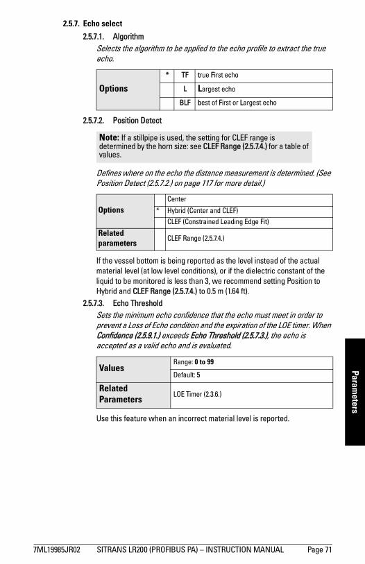
mm
mm
m
Parameters
2.5.7. Echo select
2.5.7.1. AlgorithmSelects the algorithm to be applied to the echo profile to extract the true echo.
2.5.7.2. Position Detect
Defines where on the echo the distance measurement is determined. (See Position Detect (2.5.7.2.) on page 117 for more detail.)
If the vessel bottom is being reported as the level instead of the actual material level (at low level conditions), or if the dielectric constant of the liquid to be monitored is less than 3, we recommend setting Position to Hybrid and CLEF Range (2.5.7.4.) to 0.5 m (1.64 ft).
2.5.7.3. Echo Threshold Sets the minimum echo confidence that the echo must meet in order to prevent a Loss of Echo condition and the expiration of the LOE timer. When Confidence (2.5.9.1.) exceeds Echo Threshold (2.5.7.3.), the echo is accepted as a valid echo and is evaluated.
Use this feature when an incorrect material level is reported.
Options
* TF true First echo
L Largest echo
BLF best of First or Largest echo
Note: If a stillpipe is used, the setting for CLEF range is determined by the horn size: see CLEF Range (2.5.7.4.) for a table of values.
OptionsCenter
* Hybrid (Center and CLEF)
CLEF (Constrained Leading Edge Fit)
Related parameters
CLEF Range (2.5.7.4.)
ValuesRange: 0 to 99
Default: 5
Related Parameters
LOE Timer (2.3.6.)
7ML19985JR02 SITRANS LR200 (PROFIBUS PA) – INSTRUCTION MANUAL Page 71
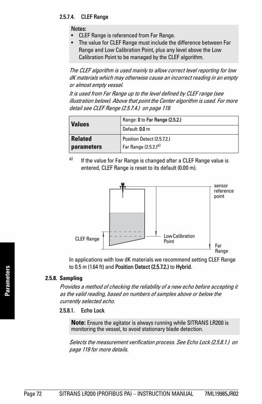
mm
mm
m
Para
met
ers
2.5.7.4. CLEF Range
The CLEF algorithm is used mainly to allow correct level reporting for low dK materials which may otherwise cause an incorrect reading in an empty or almost empty vessel.It is used from Far Range up to the level defined by CLEF range (see illustration below). Above that point the Center algorithm is used. For more detail see CLEF Range (2.5.7.4.) on page 119.
In applications with low dK materials we recommend setting CLEF Range to 0.5 m (1.64 ft) and Position Detect (2.5.7.2.) to Hybrid.
2.5.8. SamplingProvides a method of checking the reliability of a new echo before accepting it as the valid reading, based on numbers of samples above or below the currently selected echo.2.5.8.1. Echo Lock
Selects the measurement verification process. See Echo Lock (2.5.8.1.) on page 119 for more details.
Notes: • CLEF Range is referenced from Far Range.• The value for CLEF Range must include the difference between Far
Range and Low Calibration Point, plus any level above the Low Calibration Point to be managed by the CLEF algorithm.
Values Range: 0 to Far Range (2.5.2.)
Default: 0.0 m
Related parameters
Position Detect (2.5.7.2.)
Far Range (2.5.2.)a)
a) If the value for Far Range is changed after a CLEF Range value is entered, CLEF Range is reset to its default (0.00 m).
Note: Ensure the agitator is always running while SITRANS LR200 is monitoring the vessel, to avoid stationary blade detection.
sensor reference point
CLEF Range Low Calibration Point
Far Range
Page 72 SITRANS LR200 (PROFIBUS PA) – INSTRUCTION MANUAL 7ML19985JR02
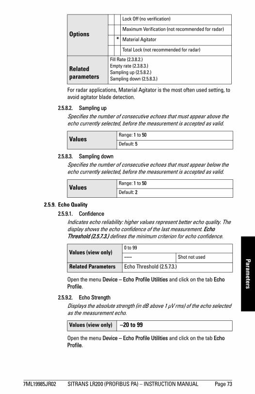
mm
mm
m
Parameters
For radar applications, Material Agitator is the most often used setting, to avoid agitator blade detection.
2.5.8.2. Sampling up Specifies the number of consecutive echoes that must appear above the echo currently selected, before the measurement is accepted as valid.
2.5.8.3. Sampling downSpecifies the number of consecutive echoes that must appear below the echo currently selected, before the measurement is accepted as valid.
2.5.9. Echo Quality
2.5.9.1. Confidence Indicates echo reliability: higher values represent better echo quality. The display shows the echo confidence of the last measurement. Echo Threshold (2.5.7.3.) defines the minimum criterion for echo confidence.
Open the menu Device – Echo Profile Utilities and click on the tab Echo Profile.
2.5.9.2. Echo StrengthDisplays the absolute strength (in dB above 1 μV rms) of the echo selected as the measurement echo.
Open the menu Device – Echo Profile Utilities and click on the tab Echo Profile.
Options
Lock Off (no verification)
Maximum Verification (not recommended for radar)
* Material Agitator
Total Lock (not recommended for radar)
Related parameters
Fill Rate (2.3.8.2.)Empty rate (2.3.8.3.)Sampling up (2.5.8.2.)Sampling down (2.5.8.3.)
Values Range: 1 to 50
Default: 5
Values Range: 1 to 50
Default: 2
Values (view only)0 to 99
---- Shot not used
Related Parameters Echo Threshold (2.5.7.3.)
Values (view only) –20 to 99
7ML19985JR02 SITRANS LR200 (PROFIBUS PA) – INSTRUCTION MANUAL Page 73
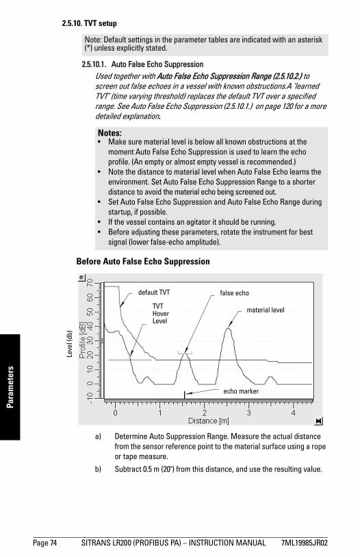
mm
mm
m
Para
met
ers
2.5.10. TVT setup
2.5.10.1. Auto False Echo SuppressionUsed together with Auto False Echo Suppression Range (2.5.10.2.) to screen out false echoes in a vessel with known obstructions.A ’learned TVT’ (time varying threshold) replaces the default TVT over a specified range. See Auto False Echo Suppression (2.5.10.1.) on page 120 for a more detailed explanation.
a) Determine Auto Suppression Range. Measure the actual distance from the sensor reference point to the material surface using a rope or tape measure.
b) Subtract 0.5 m (20") from this distance, and use the resulting value.
Note: Default settings in the parameter tables are indicated with an asterisk (*) unless explicitly stated.
Notes: • Make sure material level is below all known obstructions at the
moment Auto False Echo Suppression is used to learn the echo profile. (An empty or almost empty vessel is recommended.)
• Note the distance to material level when Auto False Echo learns the environment. Set Auto False Echo Suppression Range to a shorter distance to avoid the material echo being screened out.
• Set Auto False Echo Suppression and Auto False Echo Range during startup, if possible.
• If the vessel contains an agitator it should be running. • Before adjusting these parameters, rotate the instrument for best
signal (lower false-echo amplitude).
Before Auto False Echo Suppression
default TVT
TVT Hover Level
Leve
l (db
)
echo marker
material level
false echo
Page 74 SITRANS LR200 (PROFIBUS PA) – INSTRUCTION MANUAL 7ML19985JR02
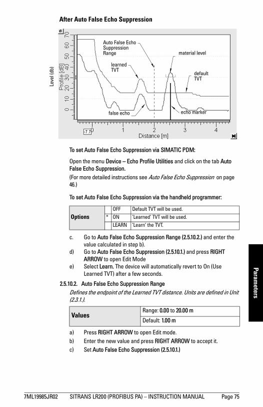
mm
mm
m
Parameters
To set Auto False Echo Suppression via SIMATIC PDM:
Open the menu Device – Echo Profile Utilities and click on the tab Auto False Echo Suppression. (For more detailed instructions see Auto False Echo Suppression on page 46.)
To set Auto False Echo Suppression via the handheld programmer:
c. Go to Auto False Echo Suppression Range (2.5.10.2.) and enter the value calculated in step b).
d) Go to Auto False Echo Suppression (2.5.10.1.) and press RIGHT ARROW to open Edit Mode
e) Select Learn. The device will automatically revert to On (Use Learned TVT) after a few seconds.
2.5.10.2. Auto False Echo Suppression RangeDefines the endpoint of the Learned TVT distance. Units are defined in Unit (2.3.1.).
a) Press RIGHT ARROW to open Edit mode.b) Enter the new value and press RIGHT ARROW to accept it.c) Set Auto False Echo Suppression (2.5.10.1.)
OptionsOFF Default TVT will be used.
* ON ’Learned’ TVT will be used.
LEARN ’Learn’ the TVT.
Values Range: 0.00 to 20.00 m
Default: 1.00 m
After Auto False Echo Suppression
learned TVT
material level
false echo
Auto False Echo Suppression Range
echo marker
Leve
l (db
)
default TVT
7ML19985JR02 SITRANS LR200 (PROFIBUS PA) – INSTRUCTION MANUAL Page 75
mm
mm
m
Para
met
ers
2.5.10.3. Hover Level1) Defines how high the TVT (Time Varying Threshold) is placed above the noise floor of the echo profile, as a percentage of the difference between the peak of the largest echo in the profile and the noise floor. See Before Auto False Echo Suppression on page 74 for an illustration.)
When the device is located in the center of the vessel, the TVT hover level may be lowered to increase the confidence level of the largest echo.
2.5.10.4. Shaper ModeEnables/disables TVT shaper (2.5.11.).
2.5.11. TVT shaper
Adjusts the TVT (Time Varying Threshold) at a specified range (breakpoint on the TVT). This allows you to reshape the TVT curve to avoid unwanted echoes. There are 40 breakpoints arranged in 5 groups. (We recommend using SIMATIC PDM to access this feature.)
To use TVT shaper via SIMATIC PDM: a) Go to Level Meter > Setup > Signal Processing > TVT setup > Shaper
Mode and select On.b) Open the menu Device – Echo Profile Utilities and click on TVT Shaper. For
more detail see TVT Shaper on page 45.
To use TVT shaper via LUI (local user interface):a) Go to Shaper Mode (2.5.10.4.) and select option ON.b) In TVT shaper, go to Breakpoint 1-9 (2.5.11.1.).c) Open Breakpoint 1 and enter the TVT Offset value (between –50 and 50).d) Go to the next Breakpoint and repeat step (c) till all desired breakpoint
values have been entered.
2.5.11.1. Breakpoint 1-9
2)
1) For an illustration, see Before Auto False Echo Suppression and After Auto False Echo Suppression on page 75.
Values Range: 0 to 100%
Default: 40%
Options * OFF
ON
Note: Shaper Mode (2.5.10.4.) must be turned ON in order for TVT shaper points to be transferred.
Values Range2): – 50 to 50 dB
Default: 0 dB
2) The range is –100 to 100 bits. With 2 bits per dB this gives a range of –50 to 50 dB.
Page 76 SITRANS LR200 (PROFIBUS PA) – INSTRUCTION MANUAL 7ML19985JR02
mm
mm
m
Parameters
2.5.11.2. Breakpoint 10-18
1)2.5.11.3. Breakpoint 19-27
2.5.11.4. Breakpoint 28-36
2.5.11.5. Breakpoint 37 - 40
2.6. AIFB1
2.6.1. Static Revision No.The revision level of the static data associated with Analog Input Function Block 1. The Static Revision No. is updated whenever a configuration parameter is changed.
2.6.2. ModeUsed to request an operating mode from the Analog Input Function Block.
Allows you to put the SITRANS LR200 into Out of Service Mode and then reset it to Automatic Mode. Manual Mode is used in conjunction with Simulation. See Simulation on page 49. It should be used only with SIMATIC PDM in order to benefit from all the features available.
Values Range1): – 50 to 50 dB
Default: 0 dB
1) The range is –100 to 100 bits. With 2 bits per dB this gives a range of –50 to 50 dB.
Values Range1): – 50 to 50 dB
Default: 0 dB
Values Range1): – 50 to 50 dB
Default: 0 dB
Values Range1): – 50 to 50 dB
Default: 0 dB
Note: Default settings in the parameter tables are indicated with an asterisk (*) unless explicitly stated.
OptionsAutomatic Mode (AUTO)
Manual Mode (MAN)
Out of Service (O/S)
7ML19985JR02 SITRANS LR200 (PROFIBUS PA) – INSTRUCTION MANUAL Page 77
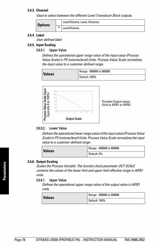
mm
mm
m
Para
met
ers
2.6.3. ChannelUsed to select between the different Level Transducer Block outputs.
2.6.4. LabelUser defined label
2.6.5. Input Scaling2.6.5.1. Upper Value
Defines the operational upper range value of the input value (Process Value Scale) in PV (volume/level) Units. Process Value Scale normalizes the input value to a customer-defined range.
2.6.5.2. Lower Value Defines the operational lower range value of the input value (Process Value Scale) in PV (volume/level) Units. Process Value Scale normalizes the input value to a customer-defined range.
2.6.6. Output ScalingScales the Process Variable. The function block parameter OUT SCALE contains the values of the lower limit and upper limit effective range in AIFB1 units.2.6.6.1. Upper Value
Defines the operational upper range value of the output value in AIFB1 units.
OptionsLevel/Volume, Level, Distance
* Level/Volume
Values Range: -999999 to 999999
Default: 100%
Values Range: -999999 to 999999
Default: 0%
Values Range: -999999 to 999999
Default: 100%
Proc
ess
Valu
e Sc
ale
Inpu
t(ty
pica
lly 0
to 1
00%
)
Output Scale
Provides Output values (Out) to AIFB1 or AIFB2
Page 78 SITRANS LR200 (PROFIBUS PA) – INSTRUCTION MANUAL 7ML19985JR02
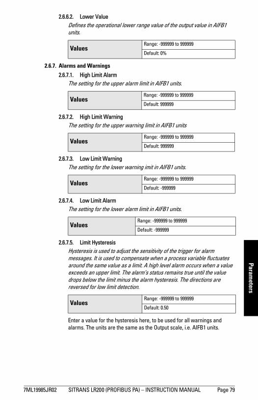
mm
mm
m
Parameters
2.6.6.2. Lower Value Defines the operational lower range value of the output value in AIFB1 units.
2.6.7. Alarms and Warnings
2.6.7.1. High Limit AlarmThe setting for the upper alarm limit in AIFB1 units.
2.6.7.2. High Limit WarningThe setting for the upper warning limit in AIFB1 units
2.6.7.3. Low Limit WarningThe setting for the lower warning imit in AIFB1 units.
2.6.7.4. Low Limit AlarmThe setting for the lower alarm limit in AIFB1 units.
2.6.7.5. Limit HysteresisHysteresis is used to adjust the sensitivity of the trigger for alarm messages. It is used to compensate when a process variable fluctuates around the same value as a limit. A high level alarm occurs when a value exceeds an upper limit. The alarm’s status remains true until the value drops below the limit minus the alarm hysteresis. The directions are reversed for low limit detection.
Enter a value for the hysteresis here, to be used for all warnings and alarms. The units are the same as the Output scale, i.e. AIFB1 units.
Values Range: -999999 to 999999
Default: 0%
Values Range: -999999 to 999999
Default: 999999
Values Range: -999999 to 999999
Default: 999999
Values Range: -999999 to 999999
Default: -999999
Values Range: -999999 to 999999
Default: -999999
Values Range: -999999 to 999999
Default: 0.50
7ML19985JR02 SITRANS LR200 (PROFIBUS PA) – INSTRUCTION MANUAL Page 79
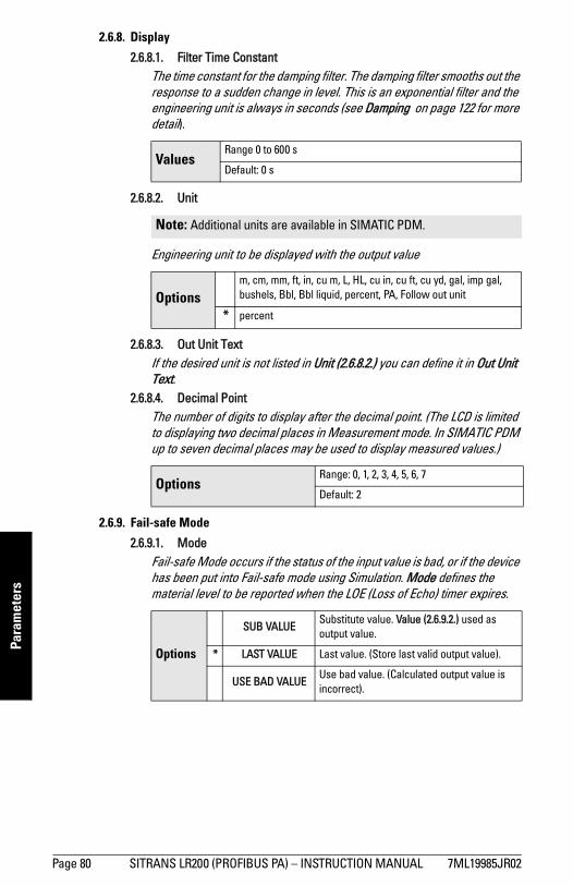
mm
mm
m
Para
met
ers
2.6.8. Display
2.6.8.1. Filter Time ConstantThe time constant for the damping filter. The damping filter smooths out the response to a sudden change in level. This is an exponential filter and the engineering unit is always in seconds (see Damping on page 122 for more detail).
2.6.8.2. Unit
Engineering unit to be displayed with the output value
2.6.8.3. Out Unit TextIf the desired unit is not listed in Unit (2.6.8.2.) you can define it in Out Unit Text.
2.6.8.4. Decimal PointThe number of digits to display after the decimal point. (The LCD is limited to displaying two decimal places in Measurement mode. In SIMATIC PDM up to seven decimal places may be used to display measured values.)
2.6.9. Fail-safe Mode
2.6.9.1. Mode Fail-safe Mode occurs if the status of the input value is bad, or if the device has been put into Fail-safe mode using Simulation. Mode defines the material level to be reported when the LOE (Loss of Echo) timer expires.
ValuesRange 0 to 600 s
Default: 0 s
Note: Additional units are available in SIMATIC PDM.
Optionsm, cm, mm, ft, in, cu m, L, HL, cu in, cu ft, cu yd, gal, imp gal, bushels, Bbl, Bbl liquid, percent, PA, Follow out unit
* percent
Options Range: 0, 1, 2, 3, 4, 5, 6, 7
Default: 2
Options
SUB VALUESubstitute value. Value (2.6.9.2.) used as output value.
* LAST VALUE Last value. (Store last valid output value).
USE BAD VALUEUse bad value. (Calculated output value is incorrect).
Page 80 SITRANS LR200 (PROFIBUS PA) – INSTRUCTION MANUAL 7ML19985JR02
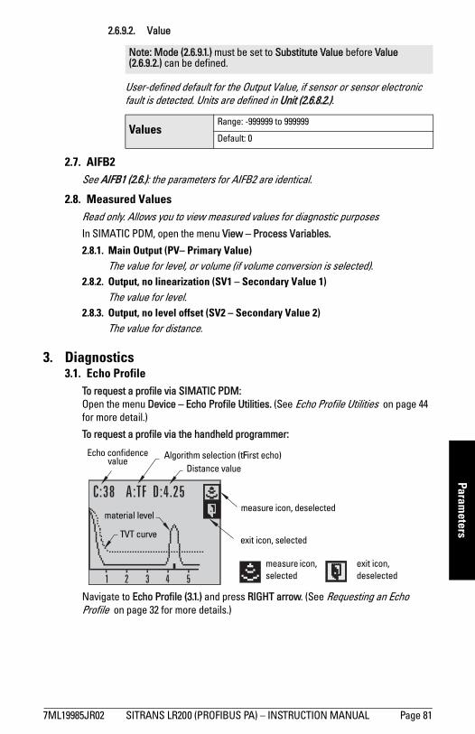
mm
mm
m
Parameters
2.6.9.2. Value
User-defined default for the Output Value, if sensor or sensor electronic fault is detected. Units are defined in Unit (2.6.8.2.).
2.7. AIFB2See AIFB1 (2.6.): the parameters for AIFB2 are identical.
2.8. Measured ValuesRead only. Allows you to view measured values for diagnostic purposes In SIMATIC PDM, open the menu View – Process Variables.
2.8.1. Main Output (PV– Primary Value)The value for level, or volume (if volume conversion is selected).
2.8.2. Output, no linearization (SV1 – Secondary Value 1)The value for level.
2.8.3. Output, no level offset (SV2 – Secondary Value 2)The value for distance.
3. Diagnostics3.1. Echo Profile
To request a profile via SIMATIC PDM: Open the menu Device – Echo Profile Utilities. (See Echo Profile Utilities on page 44 for more detail.)
To request a profile via the handheld programmer:
Navigate to Echo Profile (3.1.) and press RIGHT arrow. (See Requesting an Echo Profile on page 32 for more details.)
Note: Mode (2.6.9.1.) must be set to Substitute Value before Value (2.6.9.2.) can be defined.
Values Range: -999999 to 999999
Default: 0
measure icon, selected
exit icon, deselected
exit icon, selected
measure icon, deselected
Distance valueAlgorithm selection (tFirst echo)
TVT curve
material level
Echo confidence value
7ML19985JR02 SITRANS LR200 (PROFIBUS PA) – INSTRUCTION MANUAL Page 81
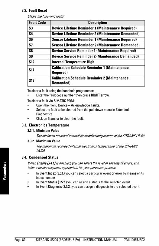
mm
mm
m
Para
met
ers
3.2. Fault ResetClears the following faults:
To clear a fault using the handheld programmer:• Enter the fault code number then press RIGHT arrow.
To clear a fault via SIMATIC PDM:• Open the menu Device – Acknowledge Faults.• Select the fault to be cleared from the pull-down menu in Extended
Diagnostics.• Click on Transfer to clear the fault.
3.3. Electronics Temperature3.3.1. Minimum Value
The minimum recorded internal electronics temperature of the SITRANS LR200.3.3.2. Maximum Value
The maximum recorded internal electronics temperature of the SITRANS LR200.
3.4. Condensed Status When Enable (3.4.1.) is enabled, you can select the level of severity of errors, and tailor a device response appropriate for your particular process. • In Event Index (3.5.1.) you can select a particular event or error by means of its
index number. • In Event Status (3.5.2.) you can assign a status to the selected event. • In Event Diagnosis (3.5.3.) you can assign a diagnosis to the selected event.
Fault Code Description S3 Device Lifetime Reminder 1 (Maintenance Required)S4 Device Lifetime Reminder 2 (Maintenance Demanded)S6 Sensor Lifetime Reminder 1 (Maintenance Required)S7 Sensor Lifetime Reminder 2 (Maintenance Demanded)S8 Device Service Reminder 1 (Maintenance Required)S9 Device Service Reminder 2 (Maintenance Demanded)S12 Internal Temperature High
S17 Calibration Schedule Reminder 1 (Maintenance Required)
S18 Calibration Schedule Reminder 2 (Maintenance Demanded)
Page 82 SITRANS LR200 (PROFIBUS PA) – INSTRUCTION MANUAL 7ML19985JR02
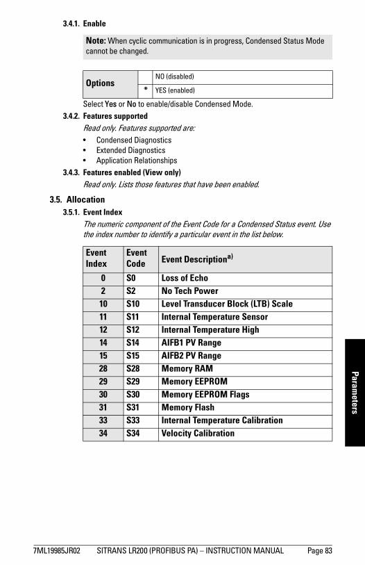
mm
mm
m
Parameters
3.4.1. Enable
Select Yes or No to enable/disable Condensed Mode.3.4.2. Features supported
Read only. Features supported are: • Condensed Diagnostics• Extended Diagnostics• Application Relationships
3.4.3. Features enabled (View only)Read only. Lists those features that have been enabled.
3.5. Allocation3.5.1. Event Index
The numeric component of the Event Code for a Condensed Status event. Use the index number to identify a particular event in the list below.
Note: When cyclic communication is in progress, Condensed Status Mode cannot be changed.
OptionsNO (disabled)
* YES (enabled)
Event Index
Event Code Event Descriptiona)
0 S0 Loss of Echo2 S2 No Tech Power10 S10 Level Transducer Block (LTB) Scale11 S11 Internal Temperature Sensor12 S12 Internal Temperature High14 S14 AIFB1 PV Range15 S15 AIFB2 PV Range28 S28 Memory RAM29 S29 Memory EEPROM30 S30 Memory EEPROM Flags31 S31 Memory Flash33 S33 Internal Temperature Calibration34 S34 Velocity Calibration
7ML19985JR02 SITRANS LR200 (PROFIBUS PA) – INSTRUCTION MANUAL Page 83
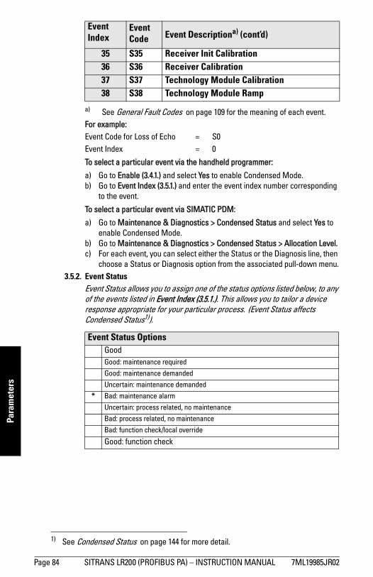
mm
mm
m
Para
met
ers
For example:Event Code for Loss of Echo = S0Event Index = 0
To select a particular event via the handheld programmer:
a) Go to Enable (3.4.1.) and select Yes to enable Condensed Mode.b) Go to Event Index (3.5.1.) and enter the event index number corresponding
to the event.
To select a particular event via SIMATIC PDM:
a) Go to Maintenance & Diagnostics > Condensed Status and select Yes to enable Condensed Mode.
b) Go to Maintenance & Diagnostics > Condensed Status > Allocation Level. c) For each event, you can select either the Status or the Diagnosis line, then
choose a Status or Diagnosis option from the associated pull-down menu.3.5.2. Event Status
Event Status allows you to assign one of the status options listed below, to any of the events listed in Event Index (3.5.1.). This allows you to tailor a device response appropriate for your particular process. (Event Status affects Condensed Status1)).
35 S35 Receiver Init Calibration36 S36 Receiver Calibration37 S37 Technology Module Calibration38 S38 Technology Module Ramp
a) See General Fault Codes on page 109 for the meaning of each event.
Event Status OptionsGoodGood: maintenance required
Good: maintenance demanded
Uncertain: maintenance demanded
* Bad: maintenance alarm
Uncertain: process related, no maintenance
Bad: process related, no maintenance
Bad: function check/local override
Good: function check
1) See Condensed Status on page 144 for more detail.
Event Index
Event Code Event Descriptiona) (cont’d)
Page 84 SITRANS LR200 (PROFIBUS PA) – INSTRUCTION MANUAL 7ML19985JR02
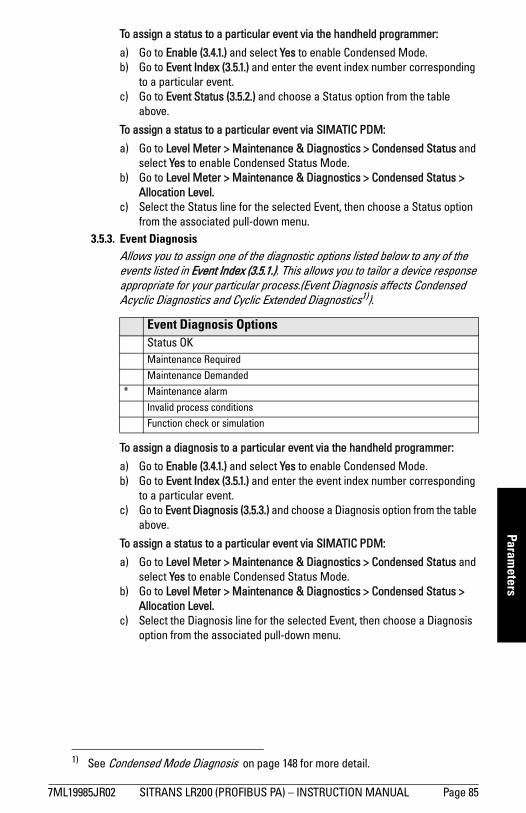
mm
mm
m
Parameters
To assign a status to a particular event via the handheld programmer:
a) Go to Enable (3.4.1.) and select Yes to enable Condensed Mode.b) Go to Event Index (3.5.1.) and enter the event index number corresponding
to a particular event.c) Go to Event Status (3.5.2.) and choose a Status option from the table
above.
To assign a status to a particular event via SIMATIC PDM:
a) Go to Level Meter > Maintenance & Diagnostics > Condensed Status and select Yes to enable Condensed Status Mode.
b) Go to Level Meter > Maintenance & Diagnostics > Condensed Status > Allocation Level.
c) Select the Status line for the selected Event, then choose a Status option from the associated pull-down menu.
3.5.3. Event DiagnosisAllows you to assign one of the diagnostic options listed below to any of the events listed in Event Index (3.5.1.). This allows you to tailor a device response appropriate for your particular process.(Event Diagnosis affects Condensed Acyclic Diagnostics and Cyclic Extended Diagnostics1)).
To assign a diagnosis to a particular event via the handheld programmer:
a) Go to Enable (3.4.1.) and select Yes to enable Condensed Mode.b) Go to Event Index (3.5.1.) and enter the event index number corresponding
to a particular event.c) Go to Event Diagnosis (3.5.3.) and choose a Diagnosis option from the table
above.
To assign a status to a particular event via SIMATIC PDM:
a) Go to Level Meter > Maintenance & Diagnostics > Condensed Status and select Yes to enable Condensed Status Mode.
b) Go to Level Meter > Maintenance & Diagnostics > Condensed Status > Allocation Level.
c) Select the Diagnosis line for the selected Event, then choose a Diagnosis option from the associated pull-down menu.
Event Diagnosis OptionsStatus OKMaintenance Required
Maintenance Demanded
* Maintenance alarm
Invalid process conditions
Function check or simulation
1) See Condensed Mode Diagnosis on page 148 for more detail.
7ML19985JR02 SITRANS LR200 (PROFIBUS PA) – INSTRUCTION MANUAL Page 85
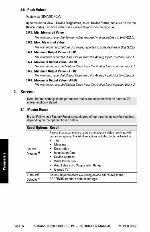
mm
mm
m
Para
met
ers
3.6. Peak Values
To view via SIMATIC PDM:
Open the menu View – Device Diagnostics, select Device Status, and click on the tab Device Status. For more details see Device Diagnostics on page 54.
3.6.1. Min. Measured ValueThe minimum recorded Sensor value, reported in units defined in Unit (2.3.1.).
3.6.2. Max. Measured ValueThe maximum recorded Sensor value, reported in units defined in Unit (2.3.1.).
3.6.3. Minimum Output Value - AIFB1The minimum recorded Output Value from the Analog Input Function Block 1.
3.6.4. Maximum Output Value - AIFB1The maximum recorded Output Value from the Analog Input Function Block 1.
3.6.5. Minimum Output Value - AIFB2The minimum recorded Output Value from the Analog Input Function Block 2.
3.6.6. Maximum Output Value - AIFB2The maximum recorded Output Value from the Analog Input Function Block 2.
4. Service
4.1. Master Reset
Note: Default settings in the parameter tables are indicated with an asterisk (*) unless explicitly stated.
Note: Following a Factory Reset, some degree of reprogramming may be required, depending on the option chosen below.
Reset Options Result
Factory
Defaultsa)
Resets all user parameters to the manufacturer’s default settings, with certain exceptions. The list of exceptions includes, but is not limited to: • Tag• Message• Description• Installation Data• Device Address • Write Protection• Auto False Echo Suppression Range• learned TVT
Standard Defaultsa)
Resets all parameters excluding device addresses to the PROFIBUS standard default settings.
Page 86 SITRANS LR200 (PROFIBUS PA) – INSTRUCTION MANUAL 7ML19985JR02
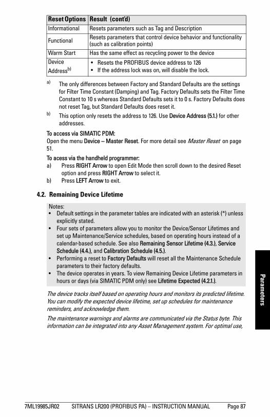
mm
mm
m
Parameters
To access via SIMATIC PDM:Open the menu Device – Master Reset. For more detail see Master Reset on page 51.
To acess via the handheld programmer:a) Press RIGHT Arrow to open Edit Mode then scroll down to the desired Reset
option and press RIGHT Arrow to select it. b) Press LEFT Arrow to exit.
4.2. Remaining Device Lifetime
The device tracks itself based on operating hours and monitors its predicted lifetime. You can modify the expected device lifetime, set up schedules for maintenance reminders, and acknowledge them.The maintenance warnings and alarms are communicated via the Status byte. This information can be integrated into any Asset Management system. For optimal use,
Informational Resets parameters such as Tag and Description
Functional Resets parameters that control device behavior and functionality (such as calibration points)
Warm Start Has the same effect as recycling power to the deviceDevice Addressb)
• Resets the PROFIBUS device address to 126 • If the address lock was on, will disable the lock.
a) The only differences between Factory and Standard Defaults are the settings for Filter Time Constant (Damping) and Tag. Factory Defaults sets the Filter Time Constant to 10 s whereas Standard Defaults sets it to 0 s. Factory Defaults does not reset Tag, but Standard Defaults does reset it.
b) This option only resets the address to 126. Use Device Address (5.1.) for other addresses.
Notes: • Default settings in the parameter tables are indicated with an asterisk (*) unless
explicitly stated.• Four sets of parameters allow you to monitor the Device/Sensor Lifetimes and
set up Maintenance/Service schedules, based on operating hours instead of a calendar-based schedule. See also Remaining Sensor Lifetime (4.3.), Service Schedule (4.4.), and Calibration Schedule (4.5.).
• Performing a reset to Factory Defaults will reset all the Maintenance Schedule parameters to their factory defaults.
• The device operates in years. To view Remaining Device Lifetime parameters in hours or days (via SIMATIC PDM only) see Lifetime Expected (4.2.1.).
Reset Options Result (cont’d)
7ML19985JR02 SITRANS LR200 (PROFIBUS PA) – INSTRUCTION MANUAL Page 87
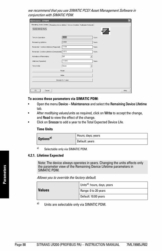
mm
mm
m
Para
met
ers
we recommend that you use SIMATIC PCS7 Asset Management Software in conjunction with SIMATIC PDM.
To access these parameters via SIMATIC PDM:• Open the menu Device – Maintenance and select the Remaining Device Lifetime
tab.• After modifying values/units as required, click on Write to accept the change,
and Read to view the effect of the change.• Click on Snooze to add a year to the Total Expected Device Life.
Time Units
4.2.1. Lifetime Expected
Allows you to override the factory default.
Optionsa)
a) Selectable only via SIMATIC PDM.
Hours; days; years
Default: years
Note: The device always operates in years. Changing the units affects only the parameter view of the Remaining Device Lifetime parameters in SIMATIC PDM.
ValuesUnitsa): hours, days, years
a) Units are selectable only via SIMATIC PDM.
Range: 0 to 20 years
Default: 10.00 years
Page 88 SITRANS LR200 (PROFIBUS PA) – INSTRUCTION MANUAL 7ML19985JR02
mm
mm
m
Parameters
4.2.2. Time in OperationRead only. The amount of time the device has been operating in years.
4.2.3. Remaining LifetimeRead only. Lifetime Expected (4.2.1.) less Time in Operation (4.2.2.).
4.2.4. Reminder Activation
Allows you to enable a maintenance reminder.
a) First set the values in Reminder 1 (Required) (4.2.5.)/Reminder 2 (Demanded) (4.2.6.).
b) Select the desired Reminder Activation option.4.2.5. Reminder 1 (Required)
If Remaining Lifetime (4.2.3.) is equal to or less than this value, the device generates a Maintenance Required reminder.
a) Modify values as required. b) Set Reminder Activation (4.2.4.) to the desired option.
4.2.6. Reminder 2 (Demanded) If Remaining Lifetime (4.2.3.) is equal to or less than this value, the device generates a Maintenance Demanded reminder.
a) Modify limit values as required. b) Set Reminder Activation (4.2.4.) to the desired option.
4.2.7. Maintenance StatusIndicates which level of maintenance reminder is active.In SIMATIC PDM, open the menu View – Device Diagnostics, select Device Status, click on the Maintenance tab, and check the Device Lifetime Status window.
Note: To modify this parameter via SIMATIC PDM it must be accessed via the pull-down menu Device – Maintenance.
Values
Reminder 1 (Maintenance Required)
Reminder 2 (Maintenance Demanded)
Reminders 1 and 2
* OFF
ValuesRange: 0 to 20 years
Default: 0.164 years
ValuesRange: 0 to 20 years
Default: 0.019 years
7ML19985JR02 SITRANS LR200 (PROFIBUS PA) – INSTRUCTION MANUAL Page 89
mm
mm
m
Para
met
ers
4.2.8. Acknowledge StatusIndicates which level of maintenance reminder has been acknowledged.In SIMATIC PDM, open the menu View – Device Diagnostics, select Device Status, click on the Maintenance tab, and check the Device Lifetime Status window.
4.2.9. Acknowledge Acknowledges the current maintenance reminder.To acknowledge a reminder via SIMATIC PDM: a) Open the menu View – Device Diagnostics, select Device Status, and click
on the Maintenance tab.b) In the Device Lifetime section, click on Acknowledge Warnings.
To acknowledge a reminder via the handheld programmer:
a) Press RIGHT arrow twice to open parameter view and activate Edit
Mode.
b) Press RIGHT arrow to acknowledge the reminder.
4.3. Remaining Sensor Lifetime
The device monitors the predicted lifetime of the sensor (the components exposed to the vessel environment). You can modify the expected sensor lifetime, set up schedules for maintenance reminders, and acknowledge them. To access these parameters via SIMATIC PDM:• Open the menu Device – Maintenance and select the Remaining Sensor
Lifetime tab.• After modifying values/units as required, click on Write to accept the change,
and Read to view the effect of the change.• Click on Snooze to add a year to the Total Expected Sensor Life.• Click on Sensor Replaced to restart the timer and clear any fault messages.
Notes: • Default settings in the parameter tables are indicated with an asterisk (*) unless
explicitly stated.• Four sets of parameters allow you to monitor the Device/Sensor Lifetimes and
set up Maintenance/Service schedules, based on operating hours instead of a calendar-based schedule. See also Remaining Device Lifetime (4.2.), Service Schedule (4.4.), and Calibration Schedule (4.5.).
• Performing a reset to Factory Defaults will reset all the Maintenance Schedule parameters to their factory defaults.
• The device operates in years. To view Remaining Sensor Lifetime parameters in hours or days (via SIMATIC PDM only) see Lifetime Expected (4.3.1.).
Page 90 SITRANS LR200 (PROFIBUS PA) – INSTRUCTION MANUAL 7ML19985JR02
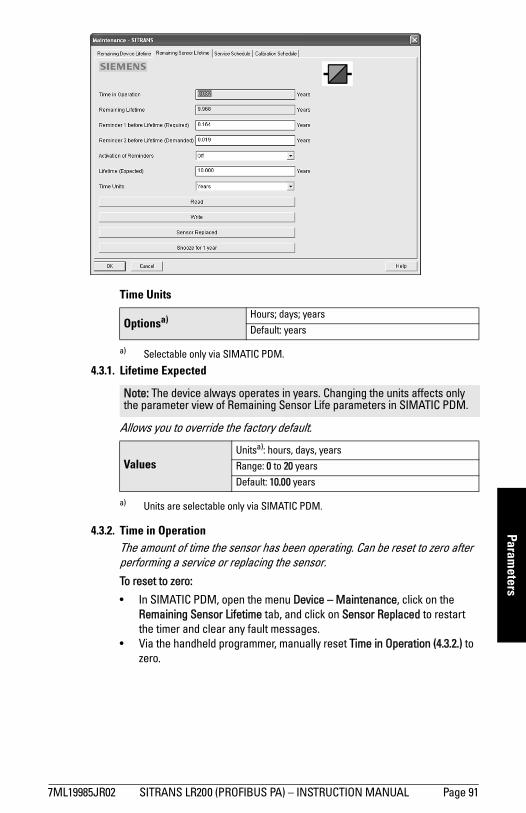
mm
mm
m
Parameters
Time Units
4.3.1. Lifetime Expected
Allows you to override the factory default.
4.3.2. Time in OperationThe amount of time the sensor has been operating. Can be reset to zero after performing a service or replacing the sensor.To reset to zero:
• In SIMATIC PDM, open the menu Device – Maintenance, click on the Remaining Sensor Lifetime tab, and click on Sensor Replaced to restart the timer and clear any fault messages.
• Via the handheld programmer, manually reset Time in Operation (4.3.2.) to zero.
Optionsa)
a) Selectable only via SIMATIC PDM.
Hours; days; years
Default: years
Note: The device always operates in years. Changing the units affects only the parameter view of Remaining Sensor Life parameters in SIMATIC PDM.
ValuesUnitsa): hours, days, years
a) Units are selectable only via SIMATIC PDM.
Range: 0 to 20 years
Default: 10.00 years
7ML19985JR02 SITRANS LR200 (PROFIBUS PA) – INSTRUCTION MANUAL Page 91
mm
mm
m
Para
met
ers
4.3.3. Remaining LifetimeRead only. Lifetime Expected (4.3.1.) less Time in Operation (4.3.2.).
4.3.4. Reminder Activation
Allows you to enable a maintenance reminder.
a) First set the values in Reminder 1 (Required) (4.3.5.)/Reminder 2 (Demanded) (4.3.6.).
b) Select the desired Reminder Activation option.4.3.5. Reminder 1 (Required)
If Remaining Lifetime (4.3.3.) is equal to or less than this value, the device generates a Maintenance Required reminder.
a) Modify values as required.b) Set Reminder Activation (4.3.4.) to the desired option.
4.3.6. Reminder 2 (Demanded)If Remaining Lifetime (4.3.3.) is equal to or less than this value, the device generates a Maintenance Demanded reminder.
a) Modify values as requiredb) Set Reminder Activation (4.3.4.) to the desired option.
4.3.7. Maintenance StatusIndicates which level of maintenance reminder is active.In SIMATIC PDM, open the menu View – Device Diagnostics, select Device Status, click on the Maintenance tab, and check the Sensor Lifetime Status window.
4.3.8. Acknowledge StatusIndicates which level of maintenance reminder has been acknowledged.In SIMATIC PDM, open the menu View – Device Diagnostics, select Device Status, click on the Maintenance tab, and check the Sensor Lifetime Status window.
Note: To modify this parameter via SIMATIC PDM it must be accessed via the pull-down menu Device – Maintenance.
Options
Reminder 1 (Maintenance Required)
Reminder 2 (Maintenance Demanded)
Reminders 1 and 2
* OFF
ValuesRange: 0 to 20 years
Default: 0.164 years
ValuesRange: 0 to 20 years
Default: 0.019 years
Page 92 SITRANS LR200 (PROFIBUS PA) – INSTRUCTION MANUAL 7ML19985JR02
mm
mm
m
Parameters
4.3.9. Acknowledge Acknowledges the current maintenance reminder.To acknowledge a reminder via SIMATIC PDM: a) Open the menu View – Device Diagnostics, select Device Status, and click
on the Maintenance tab.b) In the Sensor Lifetime section click on Acknowledge Warnings.
To acknowledge a reminder via the handheld programmer:
a) Press RIGHT arrow twice to open parameter view and activate Edit
Mode.
b) Press RIGHT arrow to acknowledge the reminder
4.4. Service Schedule
The device tracks service intervals based on operating hours and monitors the predicted lifetime to the next service. You can modify the Total Service Interval, set schedules for Maintenance Alerts, and acknowledge them.The maintenance warnings and alarms are communicated via the Status byte. This information can be integrated into any Asset Management system. For optimal use, we recommend that you use SIMATIC PCS7 Asset Management Software in conjunction with SIMATIC PDM.To access these parameters via SIMATIC PDM:• Open the menu Device – Maintenance and select the Service Schedule tab.• After modifying values/units as required, click on Write to accept the change,
and Read to view the effect of the change.• Click on Service Performed to restart the timer and clear any fault messages.
Notes: • Four sets of parameters allow you to monitor the Device/Sensor Lifetimes and
set up Maintenance/Service schedules, based on operating hours instead of a calendar-based schedule. See also Remaining Device Lifetime (4.2.), Remaining Sensor Lifetime (4.3.), and Calibration Schedule (4.5.).
• Performing a reset to Factory Defaults will reset all the Maintenance Schedule parameters to their factory defaults.
• The device operates in years. To view Service Interval parameters in hours or days (via SIMATIC PDM only) see Service Interval (4.4.1.).
7ML19985JR02 SITRANS LR200 (PROFIBUS PA) – INSTRUCTION MANUAL Page 93
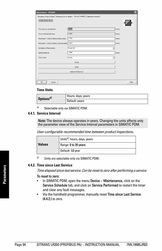
mm
mm
m
Para
met
ers
Time Units
4.4.1. Service Interval
User-configurable recommended time between product inspections.
4.4.2. Time since Last ServiceTime elapsed since last service. Can be reset to zero after performing a service. To reset to zero:• In SIMATIC PDM, open the menu Device – Maintenance, click on the
Service Schedule tab, and click on Service Performed to restart the timer and clear any fault messages.
• Via the handheld programmer, manually reset Time since Last Service (4.4.2.) to zero.
Optionsa)
a) Selectable only via SIMATIC PDM.
Hours; days; years
Default: years
Note: The device always operates in years. Changing the units affects only the parameter view of the Service Interval parameters in SIMATIC PDM.
ValuesUnitsa): hours, days, years
a) Units are selectable only via SIMATIC PDM.
Range: 0 to 20 years
Default: 1.0 year
Page 94 SITRANS LR200 (PROFIBUS PA) – INSTRUCTION MANUAL 7ML19985JR02
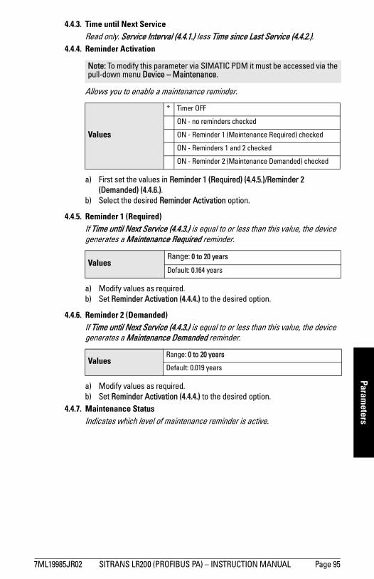
mm
mm
m
Parameters
4.4.3. Time until Next ServiceRead only. Service Interval (4.4.1.) less Time since Last Service (4.4.2.).
4.4.4. Reminder Activation
Allows you to enable a maintenance reminder.
a) First set the values in Reminder 1 (Required) (4.4.5.)/Reminder 2 (Demanded) (4.4.6.).
b) Select the desired Reminder Activation option.
4.4.5. Reminder 1 (Required)If Time until Next Service (4.4.3.) is equal to or less than this value, the device generates a Maintenance Required reminder.
a) Modify values as required.b) Set Reminder Activation (4.4.4.) to the desired option.
4.4.6. Reminder 2 (Demanded)If Time until Next Service (4.4.3.) is equal to or less than this value, the device generates a Maintenance Demanded reminder.
a) Modify values as required.b) Set Reminder Activation (4.4.4.) to the desired option.
4.4.7. Maintenance StatusIndicates which level of maintenance reminder is active.
Note: To modify this parameter via SIMATIC PDM it must be accessed via the pull-down menu Device – Maintenance.
Values
* Timer OFF
ON - no reminders checked
ON - Reminder 1 (Maintenance Required) checked
ON - Reminders 1 and 2 checked
ON - Reminder 2 (Maintenance Demanded) checked
ValuesRange: 0 to 20 years
Default: 0.164 years
ValuesRange: 0 to 20 years
Default: 0.019 years
7ML19985JR02 SITRANS LR200 (PROFIBUS PA) – INSTRUCTION MANUAL Page 95
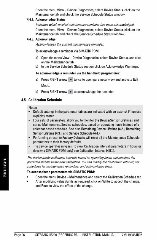
mm
mm
m
Para
met
ers
Open the menu View – Device Diagnostics, select Device Status, click on the Maintenance tab and check the Service Schedule Status window.
4.4.8. Acknowledge StatusIndicates which level of maintenance reminder has been acknowledged.Open the menu View – Device Diagnostics, select Device Status, click on the Maintenance tab and check the Service Schedule Status window.
4.4.9. AcknowledgeAcknowledges the current maintenance reminder.
To acknowledge a reminder via SIMATIC PDM:
a) Open the menu View – Device Diagnostics, select Device Status, and click on the Maintenance tab.
b) In the Service Schedule Status section click on Acknowledge Warnings.
To acknowledge a reminder via the handheld programmer:
a) Press RIGHT arrow twice to open parameter view and activate Edit
Mode.
b) Press RIGHT arrow to acknowledge the reminder.
4.5. Calibration Schedule
The device tracks calibration intervals based on operating hours and monitors the predicted lifetime to the next calibration. You can modify the Calibration Interval, set schedules for maintenance reminders, and acknowledge them.To access these parameters via SIMATIC PDM:• Open the menu Device – Maintenance and select the Calibration Schedule tab.• After modifying values/units as required, click on Write to accept the change,
and Read to view the effect of the change.
Notes: • Default settings in the parameter tables are indicated with an asterisk (*) unless
explicitly stated.• Four sets of parameters allow you to monitor the Device/Sensor Lifetimes and
set up Maintenance/Service schedules, based on operating hours instead of a calendar-based schedule. See also Remaining Device Lifetime (4.2.), Remaining Sensor Lifetime (4.3.), and Service Schedule (4.4.).
• Performing a reset to Factory Defaults will reset all the Maintenance Schedule parameters to their factory defaults.
• The device operates in years. To view Calibration Interval parameters in hours or days (via SIMATIC PDM only) see Calibration Interval (4.5.1.).
Page 96 SITRANS LR200 (PROFIBUS PA) – INSTRUCTION MANUAL 7ML19985JR02
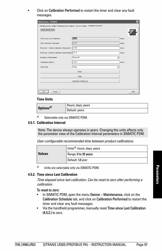
mm
mm
m
Parameters
• Click on Calibration Performed to restart the timer and clear any fault messages.
Time Units
4.5.1. Calibration Interval
User-configurable recommended time between product calibrations.
4.5.2. Time since Last CalibrationTime elapsed since last calibration. Can be reset to zero after performing a calibration.To reset to zero:• In SIMATIC PDM, open the menu Device – Maintenance, click on the
Calibration Schedule tab, and click on Calibration Performed to restart the timer and clear any fault messages.
• Via the handheld programmer, manually reset Time since Last Calibration (4.5.2.) to zero.
Optionsa)
a) Selectable only via SIMATIC PDM.
Hours; days; years
Default: years
Note: The device always operates in years. Changing the units affects only the parameter view of the Calibration Interval parameters in SIMATIC PDM.
ValuesUnitsa): hours, days, years
a) Units are selectable only via SIMATIC PDM.
Range: 0 to 20 years
Default: 1.0 year
7ML19985JR02 SITRANS LR200 (PROFIBUS PA) – INSTRUCTION MANUAL Page 97
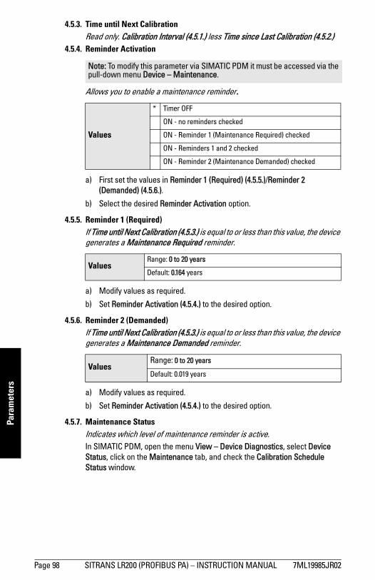
mm
mm
m
Para
met
ers
4.5.3. Time until Next CalibrationRead only. Calibration Interval (4.5.1.) less Time since Last Calibration (4.5.2.)
4.5.4. Reminder Activation
Allows you to enable a maintenance reminder.
a) First set the values in Reminder 1 (Required) (4.5.5.)/Reminder 2 (Demanded) (4.5.6.).
b) Select the desired Reminder Activation option.
4.5.5. Reminder 1 (Required)If Time until Next Calibration (4.5.3.) is equal to or less than this value, the device generates a Maintenance Required reminder.
a) Modify values as required.
b) Set Reminder Activation (4.5.4.) to the desired option.
4.5.6. Reminder 2 (Demanded)If Time until Next Calibration (4.5.3.) is equal to or less than this value, the device generates a Maintenance Demanded reminder.
a) Modify values as required.
b) Set Reminder Activation (4.5.4.) to the desired option.
4.5.7. Maintenance StatusIndicates which level of maintenance reminder is active.In SIMATIC PDM, open the menu View – Device Diagnostics, select Device Status, click on the Maintenance tab, and check the Calibration Schedule Status window.
Note: To modify this parameter via SIMATIC PDM it must be accessed via the pull-down menu Device – Maintenance.
Values
* Timer OFF
ON - no reminders checked
ON - Reminder 1 (Maintenance Required) checked
ON - Reminders 1 and 2 checked
ON - Reminder 2 (Maintenance Demanded) checked
ValuesRange: 0 to 20 years
Default: 0.164 years
ValuesRange: 0 to 20 years
Default: 0.019 years
Page 98 SITRANS LR200 (PROFIBUS PA) – INSTRUCTION MANUAL 7ML19985JR02
mm
mm
m
Parameters
4.5.8. Acknowledge StatusIndicates which level of maintenance reminder has been acknowledged.In SIMATIC PDM, open the menu View – Device Diagnostics, select Device Status, click on the Maintenance tab, and check the Calibration Schedule Status window.
4.5.9. AcknowledgeAcknowledges the current maintenance reminder.
To acknowledge a reminder via SIMATIC PDM:
a) Open the menu View – Device Diagnostics, select Device Status, and click on the Maintenance tab.
b) In the Calibration Schedule Status section click on Acknowledge Warnings.
To acknowledge a reminder via the handheld programmer:
a) Press RIGHT arrow twice to open parameter view and activate Edit
Mode.
b) Press RIGHT arrow to acknowledge the reminder.
4.6. Manufacture DateThe date of manufacture of the SITRANS LR200 (yy mm dd).
4.7. Powered HoursDisplays the number of hours the unit has been powered up since manufacture.To view via SIMATIC PDM, open the menu Device – Wear.
4.8. Power-on ResetsThe number of power cycles that have occurred since manufacture.To view via SIMATIC PDM, open the menu Device – Wear.
4.9. LCD Fast Mode
Enables a faster rate of measurement from the device by disabling most of the display area. Only the bar graph will be refreshed when LCD Fast Mode is set to ON.
Notes: • LCD Fast Mode takes effect only after 30 minutes of inactivity. (Each time the
device is powered up, a further 30 minutes of inactivity is required.)• LCD Fast Mode affects Measurement mode only; it has no effect on Navigation
mode.
ValuesON
* OFF
7ML19985JR02 SITRANS LR200 (PROFIBUS PA) – INSTRUCTION MANUAL Page 99
mm
mm
m
Para
met
ers
4.10. LCD Contrast The factory setting is for optimum visibility at room temperature and in average light conditions. Extremes of temperature will lessen the contrast.
Adjust the value to improve visibility in different temperatures and light conditions. Change the value in small steps to ensure you can continue to read the display.
5. Communication
5.1. Device Address
Sets the unique address of the device on the network (also called PROFIBUS address).
To set Device Address via the handheld programmer: See Device Address on page 33 for details.
To set Device Address via SIMATIC PDM:See Set Address on page 43 for details.
5.2. PROFIBUS Ident NumberIdentifies the device on the network. The Ident Number must match that in the GSD file (the GSD file provides information on the device to the master).
Values Range: 0 (High contrast) to 20 (Low contrast). Default: 10
Note: Default settings in the parameter tables are indicated with an asterisk (*) unless explicitly stated.
Note: The address can be changed and locked from a remote master. See PROFIBUS address on page 141 for details on disabling the address lock and Master Reset (4.1.) on page 86 to reset Device Address to 126.
Values 0 - 126. Default: 126
Options
STD PROFILEStandard Profile (uses generic GSD for 2 AIFB [ident # = 0x9701]
* MANUFACTURERManufacturer-specific (uses Siemens EDD and GSD file, which identifies the LR200 [PROFIBUS PA]) [ident # = 0x8150]
STD – AIFB 1 ONL.
Standard Profile AIFB 1 only (uses generic GSD for 1 AIFB) [ident # = 0x9700]
Page 100 SITRANS LR200 (PROFIBUS PA) – INSTRUCTION MANUAL 7ML19985JR02
mm
mm
m
Parameters
6. Security
6.1. Remote Access6.1.1. Remote Lockout
Enables or disables programming via the network and PDM.
6.2. Local Access6.2.1. Write Protection
Prevents any changes to parameters via PDM or the hand-held programmer.
6.2.2. Local OperationEnables or disables programming via the hand-held programmer.
In SIMATIC PDM, open the menu Device – Write Locking, select On or Off, and click on Transfer.
7. LanguageSelects the language to be used on the LCD.
Note: Default settings in the parameter tables are indicated with an asterisk (*) unless explicitly stated.
Note: If access control is changed to limit remote access, it can be reset only via the handheld programmer.
Options* OFF (Remote operation enabled)
ON (Remote operation disabled)
Note: Do not lose this number value.
Hand-held programmer Values
Range: 0 to 99999
2457 (unlock value) Off (enables programming)
any other value On (disables programming)
Options* ENABLED
DISABLED
Options
* ENGLISH
DEUTSCH
FRANÇAIS
ESPAÑOL
7ML19985JR02 SITRANS LR200 (PROFIBUS PA) – INSTRUCTION MANUAL Page 101

mm
mm
m
Para
met
ers
Notes
Page 102 SITRANS LR200 (PROFIBUS PA) – INSTRUCTION MANUAL 7ML19985JR02
mm
mm
m
A: Param
eter List
Appendix A: Alphabetical Parameter List
Parameter Name (Parameter Number) Page Number
AIFB1 (2.6.) 77AIFB2 (2.7.) 81Alarms and Warnings (2.6.7.) 79Algorithm (2.5.7.1.) 71Allocation (3.5.) 83Antenna (2.3.7.7.) 63Auto False Echo Suppression (2.5.10.1.) 74Auto False Echo Suppression Range (2.5.10.2.) 75Calibration (2.3.7.) 62Calibration Schedule (4.5.) 96Channel (2.6.3.) 78CLEF Range (2.5.7.4.) 72Condensed Status (3.4.) 82Confidence (2.5.9.1.) 73Descriptor (2.1.2.) 60Device Address (5.1.) 100Dimension A (2.4.1.3.) 67Dimension L (2.4.1.4.) 67Display (2.6.8.) 80Echo Lock (2.5.8.1.) 72Echo Profile (3.1.) 81Echo Quality (2.5.9.) 73Echo select (2.5.7.) 71Echo Strength (2.5.9.2.) 73Echo Strength (2.5.9.2.) 73Electronics Temperature (3.3.) 82Empty rate (2.3.8.3.) 65Event Index (3.5.1.) 83Event Status (3.5.2.) 84Event Diagnosis (3.5.3.) 85Fail-safe Mode (2.6.9.) 80Far Range (2.5.2.) 69Fault Reset (3.2.) 82Fill Rate (2.3.8.2.) 64Filter Time Constant (2.6.8.1.) 80Firmware Revision (2.2.2.) 60Hardware Revision (2.2.1.) 60
7ML19985JR02 SITRANS LR200 (PROFIBUS PA) – INSTRUCTION MANUAL Page 103
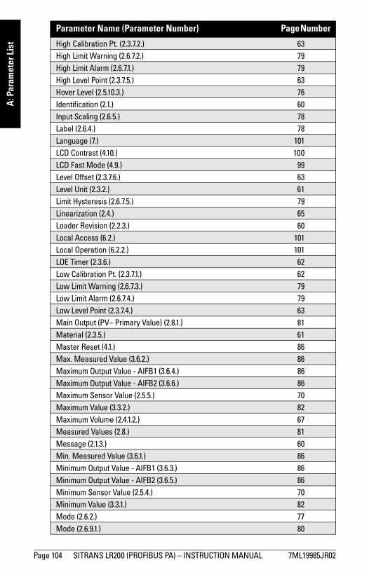
mm
mm
m
A: P
aram
eter
Lis
t
High Calibration Pt. (2.3.7.2.) 63High Limit Warning (2.6.7.2.) 79High Limit Alarm (2.6.7.1.) 79High Level Point (2.3.7.5.) 63Hover Level (2.5.10.3.) 76Identification (2.1.) 60Input Scaling (2.6.5.) 78Label (2.6.4.) 78Language (7.) 101LCD Contrast (4.10.) 100LCD Fast Mode (4.9.) 99Level Offset (2.3.7.6.) 63Level Unit (2.3.2.) 61Limit Hysteresis (2.6.7.5.) 79Linearization (2.4.) 65Loader Revision (2.2.3.) 60Local Access (6.2.) 101Local Operation (6.2.2.) 101LOE Timer (2.3.6.) 62Low Calibration Pt. (2.3.7.1.) 62Low Limit Warning (2.6.7.3.) 79Low Limit Alarm (2.6.7.4.) 79Low Level Point (2.3.7.4.) 63Main Output (PV– Primary Value) (2.8.1.) 81Material (2.3.5.) 61Master Reset (4.1.) 86Max. Measured Value (3.6.2.) 86Maximum Output Value - AIFB1 (3.6.4.) 86Maximum Output Value - AIFB2 (3.6.6.) 86Maximum Sensor Value (2.5.5.) 70Maximum Value (3.3.2.) 82Maximum Volume (2.4.1.2.) 67Measured Values (2.8.) 81Message (2.1.3.) 60Min. Measured Value (3.6.1.) 86Minimum Output Value - AIFB1 (3.6.3.) 86Minimum Output Value - AIFB2 (3.6.5.) 86Minimum Sensor Value (2.5.4.) 70Minimum Value (3.3.1.) 82Mode (2.6.2.) 77Mode (2.6.9.1.) 80Parameter Name (Parameter Number) Page Number
Page 104 SITRANS LR200 (PROFIBUS PA) – INSTRUCTION MANUAL 7ML19985JR02
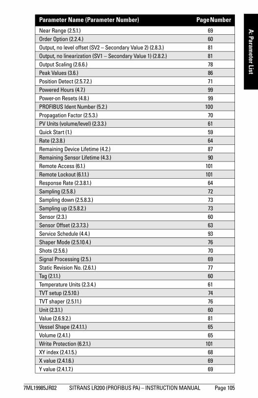
mm
mm
m
A: Param
eter List
Near Range (2.5.1.) 69Order Option (2.2.4.) 60Output, no level offset (SV2 – Secondary Value 2) (2.8.3.) 81Output, no linearization (SV1 – Secondary Value 1) (2.8.2.) 81Output Scaling (2.6.6.) 78Peak Values (3.6.) 86Position Detect (2.5.7.2.) 71Powered Hours (4.7.) 99Power-on Resets (4.8.) 99PROFIBUS Ident Number (5.2.) 100Propagation Factor (2.5.3.) 70PV Units (volume/level) (2.3.3.) 61Quick Start (1.) 59Rate (2.3.8.) 64Remaining Device Lifetime (4.2.) 87Remaining Sensor Lifetime (4.3.) 90Remote Access (6.1.) 101Remote Lockout (6.1.1.) 101Response Rate (2.3.8.1.) 64Sampling (2.5.8.) 72Sampling down (2.5.8.3.) 73Sampling up (2.5.8.2.) 73Sensor (2.3.) 60Sensor Offset (2.3.7.3.) 63Service Schedule (4.4.) 93Shaper Mode (2.5.10.4.) 76Shots (2.5.6.) 70Signal Processing (2.5.) 69Static Revision No. (2.6.1.) 77Tag (2.1.1.) 60Temperature Units (2.3.4.) 61TVT setup (2.5.10.) 74TVT shaper (2.5.11.) 76Unit (2.3.1.) 60Value (2.6.9.2.) 81Vessel Shape (2.4.1.1.) 65Volume (2.4.1.) 65Write Protection (6.2.1.) 101XY index (2.4.1.5.) 68X value (2.4.1.6.) 69Y value (2.4.1.7.) 69
Parameter Name (Parameter Number) Page Number
7ML19985JR02 SITRANS LR200 (PROFIBUS PA) – INSTRUCTION MANUAL Page 105
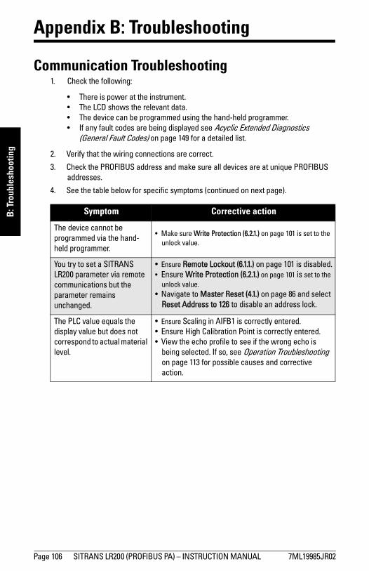
mm
mm
m
B: T
roub
lesh
ootin
g
Appendix B: Troubleshooting
Communication Troubleshooting1. Check the following:
• There is power at the instrument.• The LCD shows the relevant data.• The device can be programmed using the hand-held programmer.• If any fault codes are being displayed see Acyclic Extended Diagnostics
(General Fault Codes) on page 149 for a detailed list.
2. Verify that the wiring connections are correct.
3. Check the PROFIBUS address and make sure all devices are at unique PROFIBUS addresses.
4. See the table below for specific symptoms (continued on next page).
Symptom Corrective action
The device cannot be programmed via the hand-held programmer.
• Make sure Write Protection (6.2.1.) on page 101 is set to the unlock value.
You try to set a SITRANS LR200 parameter via remote communications but the parameter remains unchanged.
• Ensure Remote Lockout (6.1.1.) on page 101 is disabled.• Ensure Write Protection (6.2.1.) on page 101 is set to the
unlock value.• Navigate to Master Reset (4.1.) on page 86 and select
Reset Address to 126 to disable an address lock.
The PLC value equals the display value but does not correspond to actual material level.
• Ensure Scaling in AIFB1 is correctly entered.• Ensure High Calibration Point is correctly entered.• View the echo profile to see if the wrong echo is
being selected. If so, see Operation Troubleshooting on page 113 for possible causes and corrective action.
Page 106 SITRANS LR200 (PROFIBUS PA) – INSTRUCTION MANUAL 7ML19985JR02
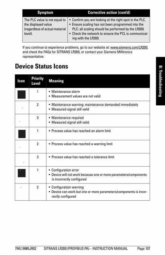
mm
mm
m
B: Troubleshooting
If you continue to experience problems, go to our website at: www.siemens.com/LR200, and check the FAQs for SITRANS LR200, or contact your Siemens Milltronics representative.
Device Status Icons
The PLC value is not equal to the displayed value (regardless of actual material level).
• Confirm you are looking at the right spot in the PLC.• Ensure scaling has not been programmed into the
PLC: all scaling should be performed by the LR200.• Check the network to ensure the PCL is communicat-
ing with the LR200.
Icon PriorityLevel Meaning
1 • Maintenance alarm • Measurement values are not valid
2 • Maintenance warning: maintenance demanded immediately• Measured signal still valid
3 • Maintenance required• Measured signal still valid
1 • Process value has reached an alarm limit
2 • Process value has reached a warning limit
3 • Process value has reached a tolerance limit
1 • Configuration error• Device will not work because one or more parameters/components
is incorrectly configured
2 • Configuration warning• Device can work but one or more parameters/components is incor-
rectly configured
Symptom Corrective action (cont’d)
7ML19985JR02 SITRANS LR200 (PROFIBUS PA) – INSTRUCTION MANUAL Page 107
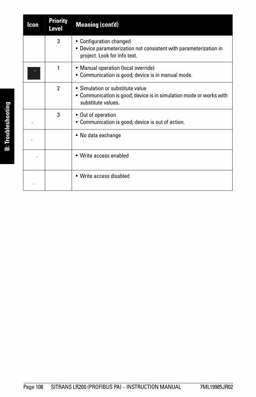
mm
mm
m
B: T
roub
lesh
ootin
g
3 • Configuration changed• Device parameterization not consistent with parameterization in
project. Look for info text.
1 • Manual operation (local override)• Communication is good; device is in manual mode.
2 • Simulation or substitute value• Communication is good; device is in simulation mode or works with
substitute values.
3 • Out of operation• Communication is good; device is out of action.
• No data exchange
• Write access enabled
• Write access disabled
Icon PriorityLevel Meaning (cont’d)
Page 108 SITRANS LR200 (PROFIBUS PA) – INSTRUCTION MANUAL 7ML19985JR02
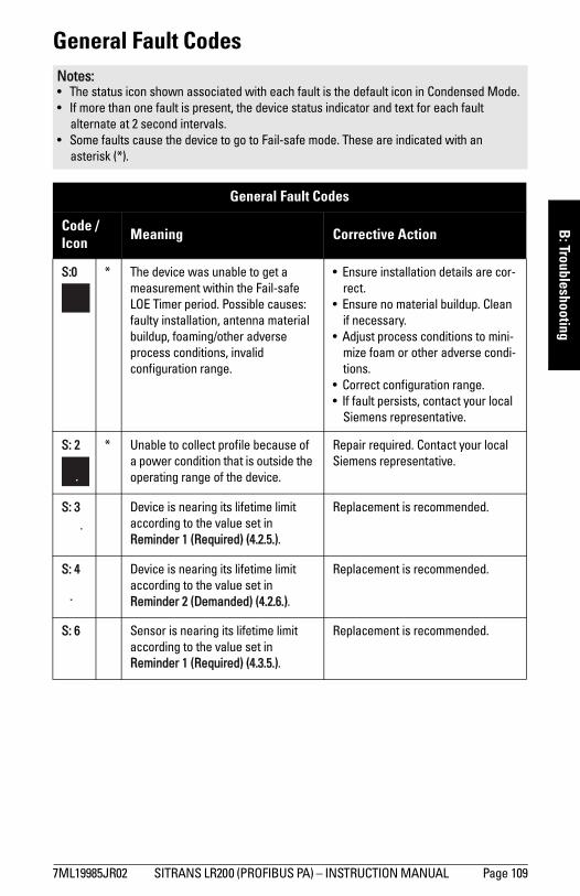
mm
mm
m
B: Troubleshooting
General Fault CodesNotes:• The status icon shown associated with each fault is the default icon in Condensed Mode.• If more than one fault is present, the device status indicator and text for each fault
alternate at 2 second intervals.• Some faults cause the device to go to Fail-safe mode. These are indicated with an
asterisk (*).
General Fault Codes
Code /Icon Meaning Corrective Action
S:0 * The device was unable to get a measurement within the Fail-safe LOE Timer period. Possible causes: faulty installation, antenna material buildup, foaming/other adverse process conditions, invalid configuration range.
• Ensure installation details are cor-rect.
• Ensure no material buildup. Clean if necessary.
• Adjust process conditions to mini-mize foam or other adverse condi-tions.
• Correct configuration range.• If fault persists, contact your local
Siemens representative.
S: 2 * Unable to collect profile because of a power condition that is outside the operating range of the device.
Repair required. Contact your local Siemens representative.
S: 3 Device is nearing its lifetime limit according to the value set in Reminder 1 (Required) (4.2.5.).
Replacement is recommended.
S: 4 Device is nearing its lifetime limit according to the value set in Reminder 2 (Demanded) (4.2.6.).
Replacement is recommended.
S: 6 Sensor is nearing its lifetime limit according to the value set in Reminder 1 (Required) (4.3.5.).
Replacement is recommended.
7ML19985JR02 SITRANS LR200 (PROFIBUS PA) – INSTRUCTION MANUAL Page 109
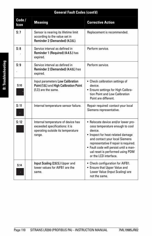
mm
mm
m
B: T
roub
lesh
ootin
g
S: 7 Sensor is nearing its lifetime limit according to the value set in Reminder 2 (Demanded) (4.3.6.).
Replacement is recommended.
S: 8 Service interval as defined in Reminder 1 (Required) (4.4.5.) has expired.
Perform service.
S: 9 Service interval as defined in Reminder 2 (Demanded) (4.4.6.) has expired.
Perform service.
S:10Input parameters Low Calibration Point (1.6.) and High Calibration Point (1.7.) are the same.
• Check calibration settings of device.
• Ensure settings for High Calibra-tion Point and Low Calibration Point are different.
S: 11 Internal temperature sensor failure. Repair required: contact your local Siemens representative.
S: 12 Internal temperature of device has exceeded specifications: it is operating outside its temperature range.
• Relocate device and/or lower pro-cess temperature enough to cool device.
• Inspect for heat-related damage and contact your local Siemens representative if repair is required.
• Fault code will persist until a man-ual reset is performed using PDM or the LCD interface.
S:14 Input Scaling (2.6.5.) Upper and lower values for AIFB1 are the same.
• Check configuration for AIFB1.• Ensure that Upper Value and
Lower Value (Input Scaling) are not the same.
General Fault Codes (cont’d)
Code /Icon Meaning Corrective Action
Page 110 SITRANS LR200 (PROFIBUS PA) – INSTRUCTION MANUAL 7ML19985JR02
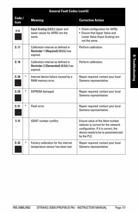
mm
mm
m
B: Troubleshooting
S:15 Input Scaling (2.6.5.) Upper and lower values for AIFB2 are the same.
• Check configuration for AIFB2.• Ensure that Upper Value and
Lower Value (Input Scaling) are not the same.
S: 17 Calibration interval as defined in Reminder 1 (Required) (4.5.5.) has expired.
Perform calibration.
S: 18 Calibration interval as defined in Reminder 2 (Demanded) (4.5.6.) has expired.
Perform calibration.
S: 28 * Internal device failure caused by a RAM memory error.
Repair required: contact your local Siemens representative.
S: 29 * EEPROM damaged. Repair required: contact your local Siemens representative.
S: 31 * Flash error. Repair required: contact your local Siemens representative.
S: 32 IDENT number conflict. Ensure value of the Ident number selector is correct for the network configuration. If it is correct, the device needs to be re-parameterized by the PLC.
S: 33 * Factory calibration for the internal temperature sensor has been lost.
Repair required: contact your local Siemens representative.
General Fault Codes (cont’d)
Code /Icon Meaning Corrective Action
7ML19985JR02 SITRANS LR200 (PROFIBUS PA) – INSTRUCTION MANUAL Page 111
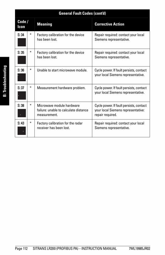
mm
mm
m
B: T
roub
lesh
ootin
g
S: 34 * Factory calibration for the device has been lost.
Repair required: contact your local Siemens representative.
S: 35 * Factory calibration for the device has been lost.
Repair required: contact your local Siemens representative.
S: 36 * Unable to start microwave module. Cycle power. If fault persists, contact your local Siemens representative.
S: 37 * Measurement hardware problem. Cycle power. If fault persists, contact your local Siemens representative.
S: 38 * Microwave module hardware failure: unable to calculate distance measurement.
Cycle power. If fault persists, contact your local Siemens representative: repair required.
S: 43 * Factory calibration for the radar receiver has been lost.
Repair required: contact your local Siemens representative.
General Fault Codes (cont’d)
Code /Icon Meaning Corrective Action
Page 112 SITRANS LR200 (PROFIBUS PA) – INSTRUCTION MANUAL 7ML19985JR02
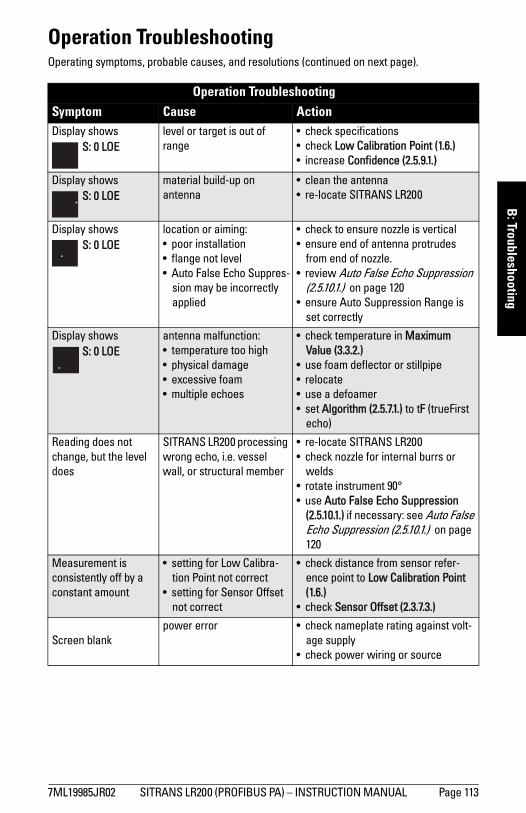
mm
mm
m
B: Troubleshooting
Operation TroubleshootingOperating symptoms, probable causes, and resolutions (continued on next page).
Operation Troubleshooting Symptom Cause ActionDisplay shows
S: 0 LOElevel or target is out of range
• check specifications• check Low Calibration Point (1.6.)• increase Confidence (2.5.9.1.)
Display shows S: 0 LOE
material build-up on antenna
• clean the antenna• re-locate SITRANS LR200
Display shows S: 0 LOE
location or aiming:• poor installation• flange not level• Auto False Echo Suppres-
sion may be incorrectly applied
• check to ensure nozzle is vertical• ensure end of antenna protrudes
from end of nozzle.• review Auto False Echo Suppression
(2.5.10.1.) on page 120• ensure Auto Suppression Range is
set correctly
Display shows S: 0 LOE
antenna malfunction:• temperature too high• physical damage• excessive foam• multiple echoes
• check temperature in Maximum Value (3.3.2.)
• use foam deflector or stillpipe• relocate• use a defoamer• set Algorithm (2.5.7.1.) to tF (trueFirst
echo)
Reading does not change, but the level does
SITRANS LR200 processing wrong echo, i.e. vessel wall, or structural member
• re-locate SITRANS LR200• check nozzle for internal burrs or
welds• rotate instrument 90°• use Auto False Echo Suppression
(2.5.10.1.) if necessary: see Auto False Echo Suppression (2.5.10.1.) on page 120
Measurement is consistently off by a constant amount
• setting for Low Calibra-tion Point not correct
• setting for Sensor Offset not correct
• check distance from sensor refer-ence point to Low Calibration Point (1.6.)
• check Sensor Offset (2.3.7.3.)
Screen blankpower error • check nameplate rating against volt-
age supply• check power wiring or source
7ML19985JR02 SITRANS LR200 (PROFIBUS PA) – INSTRUCTION MANUAL Page 113
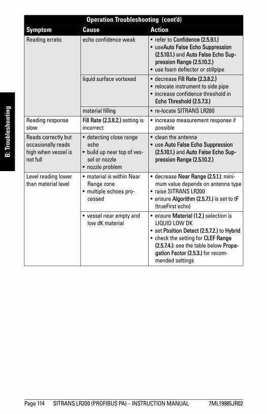
mm
mm
m
B: T
roub
lesh
ootin
g
Reading erratic echo confidence weak • refer to Confidence (2.5.9.1.)• useAuto False Echo Suppression
(2.5.10.1.) and Auto False Echo Sup-pression Range (2.5.10.2.)
• use foam deflector or stillpipe
liquid surface vortexed • decrease Fill Rate (2.3.8.2.) • relocate instrument to side pipe• increase confidence threshold in
Echo Threshold (2.5.7.3.)
material filling • re-locate SITRANS LR200
Reading response slow
Fill Rate (2.3.8.2.) setting is incorrect
• increase measurement response if possible
Reads correctly but occasionally reads high when vessel is not full
• detecting close range echo
• build up near top of ves-sel or nozzle
• nozzle problem
• clean the antenna• use Auto False Echo Suppression
(2.5.10.1.) and Auto False Echo Sup-pression Range (2.5.10.2.)
Level reading lower than material level
• material is within Near Range zone
• multiple echoes pro-cessed
• decrease Near Range (2.5.1.): mini-mum value depends on antenna type
• raise SITRANS LR200• ensure Algorithm (2.5.7.1.) is set to tF
(trueFirst echo)
• vessel near empty and low dK material
• ensure Material (1.2.) selection is LIQUID LOW DK
• set Position Detect (2.5.7.2.) to Hybrid• check the setting for CLEF Range
(2.5.7.4.): see the table below Propa-gation Factor (2.5.3.) for recom-mended settings
Operation Troubleshooting (cont’d)Symptom Cause Action
Page 114 SITRANS LR200 (PROFIBUS PA) – INSTRUCTION MANUAL 7ML19985JR02

7ML19985JR02 SITRANS LR200 (PROFIBUS PA) – INSTRUCTION MANUAL Page 115
mm
mm
m
C: Maintenance
Appendix C: Maintenance
SITRANS LR200 requires no maintenance or cleaning under normal operating conditions.
Under severe operating conditions, the antenna may require periodic cleaning. If cleaning becomes necessary:
• Note the antenna material and the process medium, and select a cleaning solution that will not react adversely with either.
• Remove the instrument from service and wipe the antenna clean using a cloth and suitable cleaning solution.
Unit Repair and Excluded LiabilityAll changes and repairs must be done by qualified personnel, and applicable safety regulations must be followed. Please note the following:
• The user is responsible for all changes and repairs made to the device.• All new components must be provided by Siemens Milltronics Process Instruments
Inc.• Restrict repair to faulty components only.• Do not re-use faulty components.
Replacing the antenna• When a new antenna is installed the propagation factor will not change.• After replacing the antenna check the material level reported by the device against
the actual material level, and if necessary use Sensor Offset (2.3.7.3.) to compensate.
mm
mm
m
D: T
echn
ical
Ref
eren
ce
Appendix D: Technical Reference
Principles of Operation SITRANS LR200 is a 2-wire 6 GHz pulse radar level transmitter for continuous monitoring of liquids and slurries1). Radar level measurement uses the time of flight principle to determine distance to a material surface. The device transmits a signal and waits for the return echo. The transit time is directly proportional to the distance from the material.
Pulse radar uses polarized electromagnetic waves. Microwave pulses are emitted from the antenna at a fixed repetition rate, and reflect off the interface between two materials with different dielectric constants (the atmosphere and the material being monitored).
Electromagnetic wave propagation is virtually unaffected by temperature or pressure changes, or by changes in the vapor levels inside a vessel. Electromagnetic waves are not attenuated by dust.
SITRANS LR200 consists of an enclosed electronic circuit coupled to an antenna and process connection. The electronic circuit generates a radar signal (6.3 GHz in North America, 5.8 GHz elsewhere) that is directed to the antenna.
The signal is emitted from the antenna, and the reflected echoes are digitally converted to an echo profile. The profile is analyzed to determine the distance from the material surface to the sensor reference point2). This distance is used as a basis for the display of material level.
Echo Processing
Process IntelligenceThe signal processing technology embedded in Siemens radar level devices is known as Process Intelligence.
Process intelligence provides high measurement reliability regardless of the dynamically changing conditions within the vessel being monitored. The embedded Process Intelligence dynamically adjusts to the constantly changing material surfaces within these vessels.
Note: Where a number follows the parameter name, for example, Algorithm (2.5.7.1.) this is the parameter access number via the handheld programmer. See Parameter Reference on page 59 for a complete list of parameters.
1) The microwave output level is significantly less than that emitted from cellular phones.2) See Dimensions: Uni-construction Polypropylene Rod Antenna on page 11 and Appendix H:
Flange Adapter Versions on page 154.
Page 116 SITRANS LR200 (PROFIBUS PA) – INSTRUCTION MANUAL 7ML19985JR02
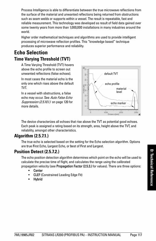
mm
mm
m
D: Technical Reference
Process Intelligence is able to differentiate between the true microwave reflections from the surface of the material and unwanted reflections being returned from obstructions such as seam welds or supports within a vessel. The result is repeatable, fast and reliable measurement. This technology was developed as result of field data gained over some twenty years from more than 1,000,000 installations in many industries around the world.
Higher order mathematical techniques and algorithms are used to provide intelligent processing of microwave reflection profiles. This “knowledge based” technique produces superior performance and reliability.
Echo SelectionTime Varying Threshold (TVT)
A Time Varying Threshold (TVT) hovers above the echo profile to screen out unwanted reflections (false echoes).
In most cases the material echo is the only one which rises above the default TVT.
In a vessel with obstructions, a false echo may occur. See Auto False Echo Suppression (2.5.10.1.) on page 120 for more details.
The device characterizes all echoes that rise above the TVT as potential good echoes. Each peak is assigned a rating based on its strength, area, height above the TVT, and reliability, amongst other characteristics.
Algorithm (2.5.7.1.)The true echo is selected based on the setting for the Echo selection algorithm. Options are true First Echo, Largest Echo, or best of First and Largest.
Position Detect (2.5.7.2.) The echo position detection algorithm determines which point on the echo will be used to calculate the precise time of flight, and calculates the range using the calibrated propagation velocity (see Propagation Factor (2.5.3.) for values). There are three options:
• Center • CLEF (Constrained Leading Edge Fit)• Hybrid
default TVT
material level
echo marker
echo profile
7ML19985JR02 SITRANS LR200 (PROFIBUS PA) – INSTRUCTION MANUAL Page 117
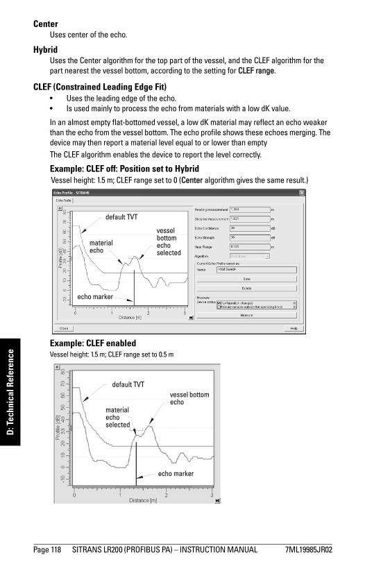
mm
mm
m
D: T
echn
ical
Ref
eren
ce
CenterUses center of the echo.
Hybrid Uses the Center algorithm for the top part of the vessel, and the CLEF algorithm for the part nearest the vessel bottom, according to the setting for CLEF range.
CLEF (Constrained Leading Edge Fit) • Uses the leading edge of the echo.• Is used mainly to process the echo from materials with a low dK value.
In an almost empty flat-bottomed vessel, a low dK material may reflect an echo weaker than the echo from the vessel bottom. The echo profile shows these echoes merging. The device may then report a material level equal to or lower than emptyThe CLEF algorithm enables the device to report the level correctly.
Example: CLEF off: Position set to Hybrid
Example: CLEF enabled
default TVT
vessel bottom echo selected
material echo
echo marker
Vessel height: 1.5 m; CLEF range set to 0 (Center algorithm gives the same result.)
default TVTvessel bottom echo
material echoselected
echo marker
Vessel height: 1.5 m; CLEF range set to 0.5 m
Page 118 SITRANS LR200 (PROFIBUS PA) – INSTRUCTION MANUAL 7ML19985JR02
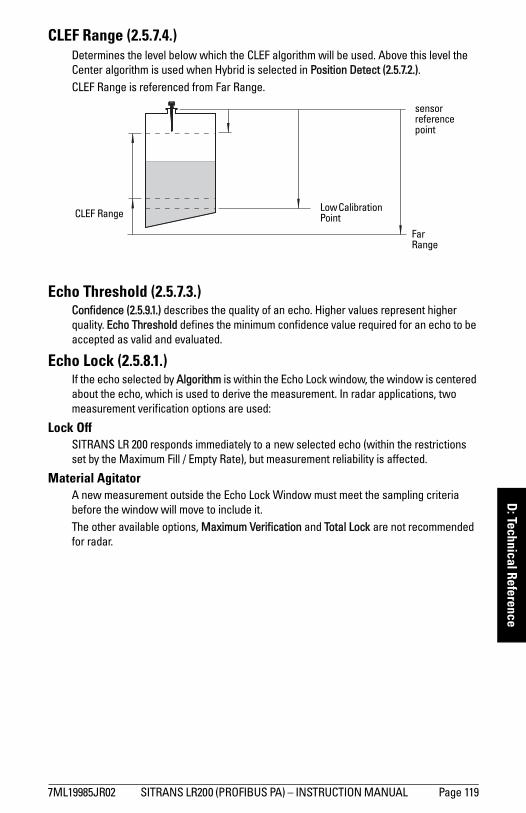
mm
mm
m
D: Technical Reference
CLEF Range (2.5.7.4.) Determines the level below which the CLEF algorithm will be used. Above this level the Center algorithm is used when Hybrid is selected in Position Detect (2.5.7.2.).CLEF Range is referenced from Far Range.
Echo Threshold (2.5.7.3.)Confidence (2.5.9.1.) describes the quality of an echo. Higher values represent higher quality. Echo Threshold defines the minimum confidence value required for an echo to be accepted as valid and evaluated.
Echo Lock (2.5.8.1.)If the echo selected by Algorithm is within the Echo Lock window, the window is centered about the echo, which is used to derive the measurement. In radar applications, two measurement verification options are used:
Lock Off SITRANS LR 200 responds immediately to a new selected echo (within the restrictions set by the Maximum Fill / Empty Rate), but measurement reliability is affected.
Material AgitatorA new measurement outside the Echo Lock Window must meet the sampling criteria before the window will move to include it. The other available options, Maximum Verification and Total Lock are not recommended for radar.
sensor reference point
CLEF Range Low Calibration Point
Far Range
7ML19985JR02 SITRANS LR200 (PROFIBUS PA) – INSTRUCTION MANUAL Page 119
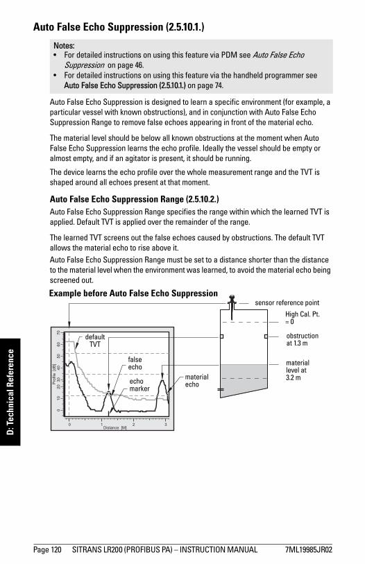
mm
mm
m
D: T
echn
ical
Ref
eren
ce
Auto False Echo Suppression (2.5.10.1.)
Auto False Echo Suppression is designed to learn a specific environment (for example, a particular vessel with known obstructions), and in conjunction with Auto False Echo Suppression Range to remove false echoes appearing in front of the material echo.
The material level should be below all known obstructions at the moment when Auto False Echo Suppression learns the echo profile. Ideally the vessel should be empty or almost empty, and if an agitator is present, it should be running.
The device learns the echo profile over the whole measurement range and the TVT is shaped around all echoes present at that moment.
Auto False Echo Suppression Range (2.5.10.2.)Auto False Echo Suppression Range specifies the range within which the learned TVT is applied. Default TVT is applied over the remainder of the range.
The learned TVT screens out the false echoes caused by obstructions. The default TVT allows the material echo to rise above it.Auto False Echo Suppression Range must be set to a distance shorter than the distance to the material level when the environment was learned, to avoid the material echo being screened out.
Notes: • For detailed instructions on using this feature via PDM see Auto False Echo
Suppression on page 46. • For detailed instructions on using this feature via the handheld programmer see
Auto False Echo Suppression (2.5.10.1.) on page 74.
High Cal. Pt.= 0
obstruction at 1.3 m
material level at 3.2 m
false echo
material echo
default TVT
sensor reference pointExample before Auto False Echo Suppression
echo marker
Page 120 SITRANS LR200 (PROFIBUS PA) – INSTRUCTION MANUAL 7ML19985JR02
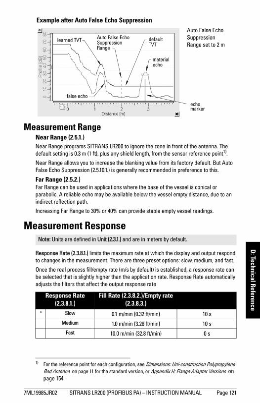
mm
mm
m
D: Technical Reference
Measurement RangeNear Range (2.5.1.)Near Range programs SITRANS LR200 to ignore the zone in front of the antenna. The default setting is 0.3 m (1 ft), plus any shield length, from the sensor reference point1).
Near Range allows you to increase the blanking value from its factory default. But Auto False Echo Suppression (2.5.10.1.) is generally recommended in preference to this.
Far Range (2.5.2.) Far Range can be used in applications where the base of the vessel is conical or parabolic. A reliable echo may be available below the vessel empty distance, due to an indirect reflection path.
Increasing Far Range to 30% or 40% can provide stable empty vessel readings.
Measurement Response
Response Rate (2.3.8.1.) limits the maximum rate at which the display and output respond to changes in the measurement. There are three preset options: slow, medium, and fast.
Once the real process fill/empty rate (m/s by default) is established, a response rate can be selected that is slightly higher than the application rate. Response Rate automatically adjusts the filters that affect the output response rate
1) For the reference point for each configuration, see Dimensions: Uni-construction Polypropylene Rod Antenna on page 11 for the standard version, or Appendix H: Flange Adapter Versions on page 154.
Note: Units are defined in Unit (2.3.1.) and are in meters by default.
Response Rate (2.3.8.1.)
Fill Rate (2.3.8.2.)/Empty rate (2.3.8.3.)
Filter Time Constant (2.6.8.1.)
* Slow 0.1 m/min (0.32 ft/min) 10 sMedium 1.0 m/min (3.28 ft/min) 10 s
Fast 10.0 m/min (32.8 ft/min) 0 s
Example after Auto False Echo Suppression
learned TVT
material echo
false echo
echo marker
Auto False Echo Suppression Range set to 2 m
Auto False Echo Suppression Range
default TVT
7ML19985JR02 SITRANS LR200 (PROFIBUS PA) – INSTRUCTION MANUAL Page 121
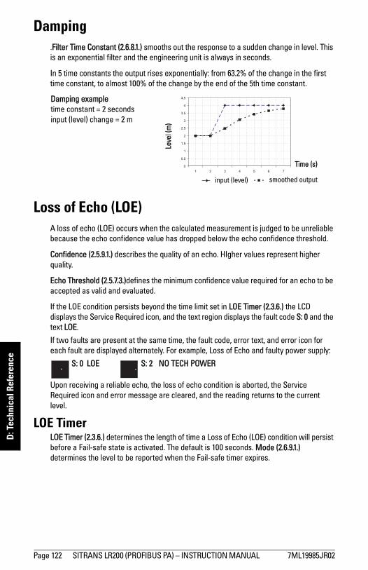
mm
mm
m
D: T
echn
ical
Ref
eren
ce
Damping.Filter Time Constant (2.6.8.1.) smooths out the response to a sudden change in level. This is an exponential filter and the engineering unit is always in seconds.
In 5 time constants the output rises exponentially: from 63.2% of the change in the first time constant, to almost 100% of the change by the end of the 5th time constant.
Loss of Echo (LOE)A loss of echo (LOE) occurs when the calculated measurement is judged to be unreliable because the echo confidence value has dropped below the echo confidence threshold.
Confidence (2.5.9.1.) describes the quality of an echo. HIgher values represent higher quality.
Echo Threshold (2.5.7.3.)defines the minimum confidence value required for an echo to be accepted as valid and evaluated.
If the LOE condition persists beyond the time limit set in LOE Timer (2.3.6.) the LCD displays the Service Required icon, and the text region displays the fault code S: 0 and the text LOE.
If two faults are present at the same time, the fault code, error text, and error icon for each fault are displayed alternately. For example, Loss of Echo and faulty power supply:
S: 0 LOE S: 2 NO TECH POWER
Upon receiving a reliable echo, the loss of echo condition is aborted, the Service Required icon and error message are cleared, and the reading returns to the current level.
LOE TimerLOE Timer (2.3.6.) determines the length of time a Loss of Echo (LOE) condition will persist before a Fail-safe state is activated. The default is 100 seconds. Mode (2.6.9.1.) determines the level to be reported when the Fail-safe timer expires.
Leve
l (m
)Time (s)
smoothed outputinput (level)
Damping exampletime constant = 2 secondsinput (level) change = 2 m
Page 122 SITRANS LR200 (PROFIBUS PA) – INSTRUCTION MANUAL 7ML19985JR02
mm
mm
m
D: Technical Reference
Fail-safe BehaviorThe purpose of the Fail-safe setting is to put the process into a safe mode of operation in the event of a fault or failure. The value to be reported in the event of a fault is selected so that a loss of power or loss of signal triggers the same response as an unsafe level.
Fail-safe mode may be triggered by a loss of echo, a bad configuration, or certain device faults. You can select one of three possible values to be reported when a Fail-safe mode is activated.
Mode (2.6.9.1.)Mode determines the material level to be reported when LOE Timer (2.3.6.) expires.
Value (2.6.9.2.)Value defines the material level to be reported if the option Use substitute value is selected in Mode (2.6.9.1.).
The two Analog Input Function blocks are set separately.
To set a user-defined value• Navigate to Level Meter > Setup > Analog Input (1 or 2).• Set Mode (2.6.9.1.) to Use substitute value.• Go to Value (2.6.9.2.) and enter the desired value.
Mode (2.6.9.1.)SUB VALUE Use substitute value. Value (2.6.9.2.) used as output value.
LAST VALUE * Last value (Store last valid output value).
USE BAD VALUE Use bad value (Calculated output value is incorrect).
7ML19985JR02 SITRANS LR200 (PROFIBUS PA) – INSTRUCTION MANUAL Page 123
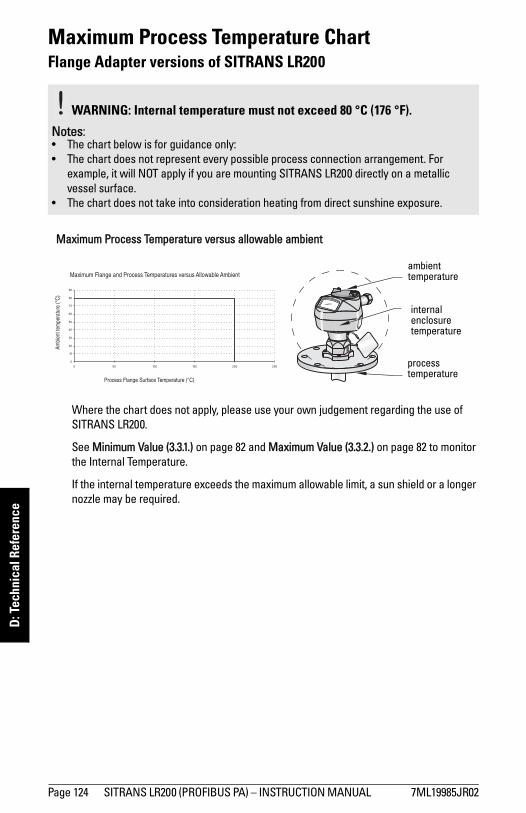
mm
mm
m
D: T
echn
ical
Ref
eren
ce
Maximum Process Temperature ChartFlange Adapter versions of SITRANS LR200
.
Where the chart does not apply, please use your own judgement regarding the use of SITRANS LR200.
See Minimum Value (3.3.1.) on page 82 and Maximum Value (3.3.2.) on page 82 to monitor the Internal Temperature.
If the internal temperature exceeds the maximum allowable limit, a sun shield or a longer nozzle may be required.
WARNING: Internal temperature must not exceed 80 °C (176 °F).
Notes: • The chart below is for guidance only: • The chart does not represent every possible process connection arrangement. For
example, it will NOT apply if you are mounting SITRANS LR200 directly on a metallic vessel surface.
• The chart does not take into consideration heating from direct sunshine exposure.
internal enclosure temperature
process temperature
ambient temperature
Maximum Process Temperature versus allowable ambient
Page 124 SITRANS LR200 (PROFIBUS PA) – INSTRUCTION MANUAL 7ML19985JR02

mm
mm
m
D: Technical Reference
Process Pressure/Temperature derating curves
Pressure Equipment Directive, PED, 97/23/ECSiemens Level Transmitters with flanged, threaded, or sanitary clamp type process mounts have no pressure-bearing housing of their own and, therefore, do not come under the Pressure Equipment Directive as pressure or safety accessories, (see EU Commission Guidelines 1/8 and 1/20). 1)
WARNINGS: • Never attempt to loosen, remove or disassemble process connection or
instrument housing while vessel contents are under pressure.• Materials of construction are chosen based on their chemical
compatibility (or inertness) for general purposes. For exposure to specific environments, check with chemical compatibility charts before installing.
• The user is responsible for the selection of bolting and gasket materials which will fall within the limits of the flange and its intended use and which are suitable for the service conditions.
• Improper installation may result in loss of process pressure and/or release of process fluids and/or gases.
Notes: • The Process Device Tag shall remain with the process pressure boundary
assembly1). In the event the instrument package is replaced, the Process Device Tag shall be transferred to the replacement unit.
• SITRANS LR200 units are hydrostatically tested, meeting or exceeding the requirements of the ASME Boiler and Pressure Vessel Code and the European Pressure Equipment Directive.
• The serial numbers stamped in each process connection body, (flange, threaded, or sanitary), provide a unique identification number indicating date of manufacture.Example: MMDDYY – XXX (where MM = month, DD = day, YY = year, and
XXX= sequential unit produced) Further markings (space permitting) indicate flange configuration, size, pressure class, material, and material heat code.
1) The process pressure boundary assembly comprises the components that act as a barrier against pressure loss from the process vessel: that is, the combination of process connec-tion body and emitter, but normally excluding the electrical enclosure.
7ML19985JR02 SITRANS LR200 (PROFIBUS PA) – INSTRUCTION MANUAL Page 125
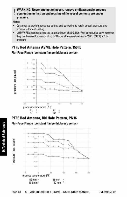
mm
mm
m
D: T
echn
ical
Ref
eren
ce
PTFE Rod Antenna ASME Hole Pattern, 150 lbFlat-Face Flange (constant flange thickness series)
PTFE Rod Antenna, DN Hole Pattern, PN16Flat-Face Flange (constant flange thickness series)
WARNING: Never attempt to loosen, remove or disassemble process connection or instrument housing while vessel contents are under pressure.
Notes: • Customer to provide adequate bolting and gasketing to retain vessel pressure and
provide sufficient sealing.• UHMW-PE antennas are rated to a maximum of 80°C (176°F) of continuous duty, however,
they can be used for periods of up to 3 hours at temperatures up to 120°C (248°F) at 1 bar pressure.
2” 3”4” 6”
process temperature (°C)
pres
sure
(bar
, gau
ge)
pres
sure
(ba
r, g
auge
)
100 mm50 mm
150 mm80 mm
process temperature (°C)
Page 126 SITRANS LR200 (PROFIBUS PA) – INSTRUCTION MANUAL 7ML19985JR02
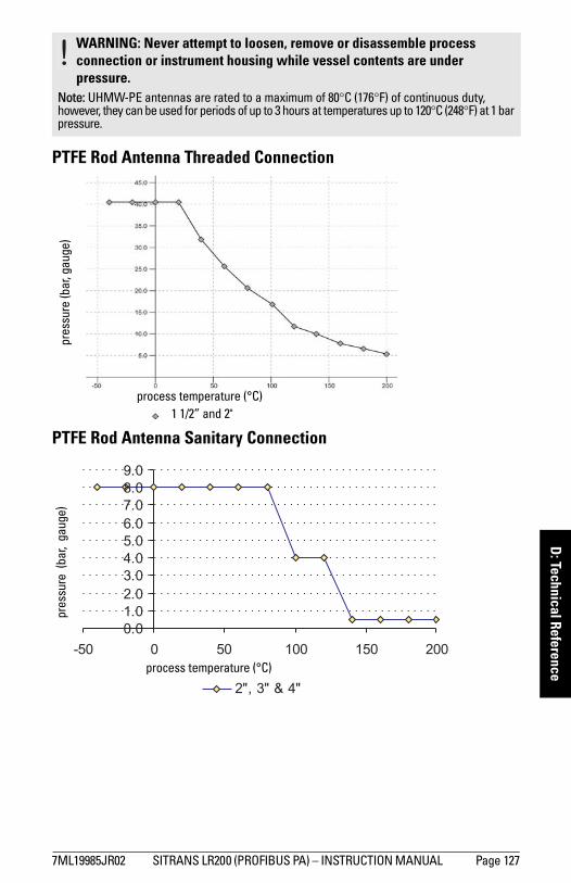
mm
mm
m
D: Technical Reference
PTFE Rod Antenna Threaded Connection
PTFE Rod Antenna Sanitary Connection
WARNING: Never attempt to loosen, remove or disassemble process connection or instrument housing while vessel contents are under pressure.
Note: UHMW-PE antennas are rated to a maximum of 80°C (176°F) of continuous duty, however, they can be used for periods of up to 3 hours at temperatures up to 120°C (248°F) at 1 bar pressure.
1 1/2” and 2"
pres
sure
(bar
, gau
ge)
process temperature (°C)
pres
sure
(ba
r, g
auge
)
process temperature (°C)
7ML19985JR02 SITRANS LR200 (PROFIBUS PA) – INSTRUCTION MANUAL Page 127
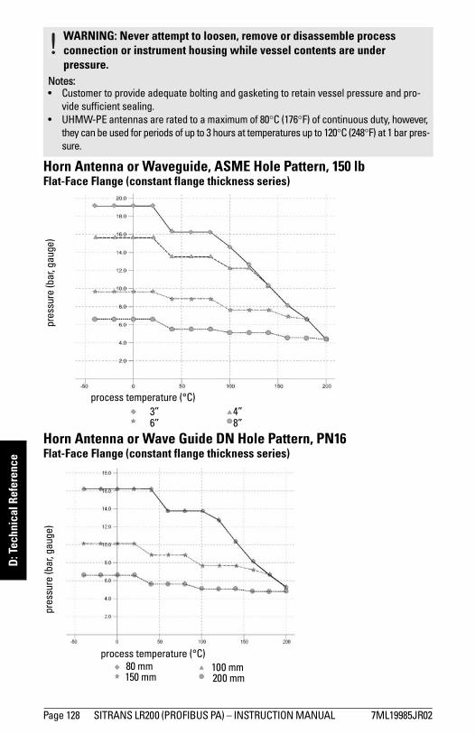
mm
mm
m
D: T
echn
ical
Ref
eren
ce
Horn Antenna or Waveguide, ASME Hole Pattern, 150 lbFlat-Face Flange (constant flange thickness series)
Horn Antenna or Wave Guide DN Hole Pattern, PN16Flat-Face Flange (constant flange thickness series)
WARNING: Never attempt to loosen, remove or disassemble process connection or instrument housing while vessel contents are under pressure.
Notes: • Customer to provide adequate bolting and gasketing to retain vessel pressure and pro-
vide sufficient sealing.• UHMW-PE antennas are rated to a maximum of 80°C (176°F) of continuous duty, however,
they can be used for periods of up to 3 hours at temperatures up to 120°C (248°F) at 1 bar pres-sure.
process temperature (°C)
pres
sure
(bar
, gau
ge)
4”6”3”
8”
process temperature (°C)100 mm
150 mm 200 mm80 mm
pres
sure
(bar
, gau
ge)
Page 128 SITRANS LR200 (PROFIBUS PA) – INSTRUCTION MANUAL 7ML19985JR02
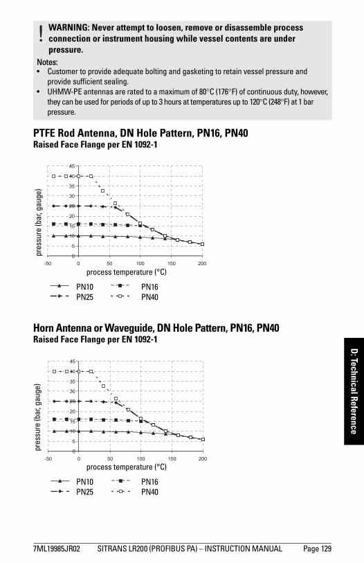
mm
mm
m
D: Technical Reference
PTFE Rod Antenna, DN Hole Pattern, PN16, PN40 Raised Face Flange per EN 1092-1
Horn Antenna or Waveguide, DN Hole Pattern, PN16, PN40 Raised Face Flange per EN 1092-1
WARNING: Never attempt to loosen, remove or disassemble process connection or instrument housing while vessel contents are under pressure.
Notes: • Customer to provide adequate bolting and gasketing to retain vessel pressure and
provide sufficient sealing.• UHMW-PE antennas are rated to a maximum of 80°C (176°F) of continuous duty, however,
they can be used for periods of up to 3 hours at temperatures up to 120°C (248°F) at 1 bar pressure.
process temperature (°C)
pres
sure
(bar
, gau
ge)
PN16PN25PN10
PN40
process temperature (°C)
pres
sure
(bar
, gau
ge)
PN16PN25PN10
PN40
7ML19985JR02 SITRANS LR200 (PROFIBUS PA) – INSTRUCTION MANUAL Page 129
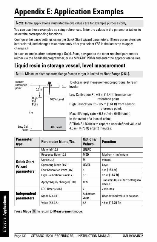
mm
mm
m
E: S
peci
al A
pplic
atio
ns
Appendix E: Application Examples
You can use these examples as setup references. Enter the values in the parameter tables to select the corresponding functions.
Configure the basic settings using the Quick Start wizard parameters. (These parameters are inter-related, and changes take effect only after you select YES in the last step to apply changes.)
In each example, after performing a Quick Start, navigate to the other required parameters (either via the handheld programmer, or via SIMATIC PDM) and enter the appropriate values.
Liquid resin in storage vessel, level measurement
Press Mode to return to Measurement mode.
Note: In the applications illustrated below, values are for example purposes only.
Note: Minimum distance from flange face to target is limited by Near Range (2.5.1.).
Parameter type Parameter Name/No. Options/
Values Function
Quick Start Wizard parameters
Material (1.2.) LIQUID
Response Rate (1.3.) MED Medium =1 m/minute
Units (1.4.) M meters
Operating Mode (1.5.) LEVEL Level
Low Calibration Point (1.6.) 5 5 m (16.4 ft) High Calibration Point (1.7.) 0.5 0.5 m (1.64 ft)
Apply? (Apply changes) (1.8.) YESTransfers Quick Start settings to device.
Independent parameters
LOE Timer (2.3.6.) 2 2 minutes
Mode (2.6.9.1.)Substitute value
User-defined value to be used.
Value (2.6.9.2.) 4.5 4.5 m (14.76 ft)
To obtain level measurement proportional to resin levels:
Low Calibration Pt. = 5 m (16.4 ft) from sensor reference point
High Calibration Pt.= 0.5 m (1.64 ft) from sensor reference point.
Max.fill/empty rate = 0.2 m/min. (0.65 ft/min) In the event of a loss of echo: SITRANS LR200 is to report a user-defined value of 4.5 m (14.76 ft) after 2 minutes.
0.5 m
Low CalPoint
5 m
100% Level
0% Level
High Cal Point
sensor reference point
Page 130 SITRANS LR200 (PROFIBUS PA) – INSTRUCTION MANUAL 7ML19985JR02
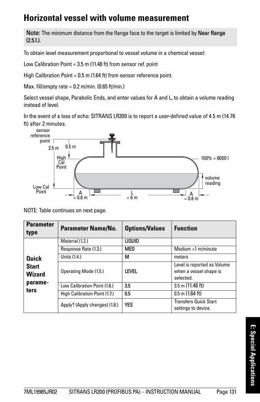
mm
mm
m
E: Special Applications
Horizontal vessel with volume measurement
To obtain level measurement proportional to vessel volume in a chemical vessel:
Low Calibration Point = 3.5 m (11.48 ft) from sensor ref. point
High Calibration Point = 0.5 m (1.64 ft) from sensor reference point.
Max. fill/empty rate = 0.2 m/min. (0.65 ft/min.)
Select vessel shape, Parabolic Ends, and enter values for A and L, to obtain a volume reading instead of level.
In the event of a loss of echo: SITRANS LR200 is to report a user-defined value of 4.5 m (14.76 ft) after 2 minutes.
NOTE: Table continues on next page.
Note: The minimum distance from the flange face to the target is limited by Near Range (2.5.1.).
Parameter type Parameter Name/No. Options/Values Function
Quick Start Wizard parame-ters
Material (1.2.) LIQUID
Response Rate (1.3.) MED Medium =1 m/minute
Units (1.4.) M meters
Operating Mode (1.5.) LEVELLevel is reported as Volume when a vessel shape is selected.
Low Calibration Point (1.6.) 3.5 3.5 m (11.48 ft) High Calibration Point (1.7.) 0.5 0.5 m (1.64 ft)
Apply? (Apply changes) (1.8.) YESTransfers Quick Start settings to device.
volume reading
3.5 m
A= 0.8 m
L= 6 m
Low Cal Point
100% = 8000 l
sensorreference
point
A= 0.8 m
0.5 m
High Cal
Point
7ML19985JR02 SITRANS LR200 (PROFIBUS PA) – INSTRUCTION MANUAL Page 131
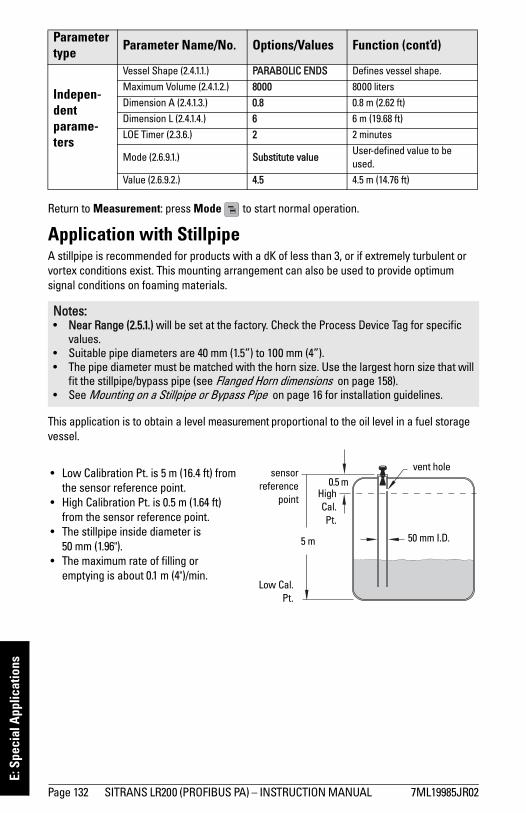
mm
mm
m
E: S
peci
al A
pplic
atio
ns
Return to Measurement: press Mode to start normal operation.
Application with StillpipeA stillpipe is recommended for products with a dK of less than 3, or if extremely turbulent or vortex conditions exist. This mounting arrangement can also be used to provide optimum signal conditions on foaming materials.
This application is to obtain a level measurement proportional to the oil level in a fuel storage vessel.
Indepen-dent parame-ters
Vessel Shape (2.4.1.1.) PARABOLIC ENDS Defines vessel shape.
Maximum Volume (2.4.1.2.) 8000 8000 liters
Dimension A (2.4.1.3.) 0.8 0.8 m (2.62 ft)
Dimension L (2.4.1.4.) 6 6 m (19.68 ft)
LOE Timer (2.3.6.) 2 2 minutes
Mode (2.6.9.1.) Substitute valueUser-defined value to be used.
Value (2.6.9.2.) 4.5 4.5 m (14.76 ft)
Notes: • Near Range (2.5.1.) will be set at the factory. Check the Process Device Tag for specific
values.• Suitable pipe diameters are 40 mm (1.5”) to 100 mm (4”). • The pipe diameter must be matched with the horn size. Use the largest horn size that will
fit the stillpipe/bypass pipe (see Flanged Horn dimensions on page 158).• See Mounting on a Stillpipe or Bypass Pipe on page 16 for installation guidelines.
Parameter type Parameter Name/No. Options/Values Function (cont’d)
• Low Calibration Pt. is 5 m (16.4 ft) from the sensor reference point.
• High Calibration Pt. is 0.5 m (1.64 ft) from the sensor reference point.
• The stillpipe inside diameter is 50 mm (1.96").
• The maximum rate of filling or emptying is about 0.1 m (4")/min.
5 m
0.5 msensor
referencepoint
Low Cal.Pt.
HighCal.Pt.
50 mm I.D.
vent hole
Page 132 SITRANS LR200 (PROFIBUS PA) – INSTRUCTION MANUAL 7ML19985JR02
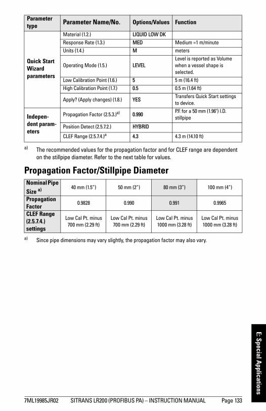
mm
mm
m
E: Special Applications
Propagation Factor/Stillpipe Diameter
Parameter type Parameter Name/No. Options/Values Function
Quick Start Wizard parameters
Material (1.2.) LIQUID LOW DK
Response Rate (1.3.) MED Medium =1 m/minute
Units (1.4.) M meters
Operating Mode (1.5.) LEVELLevel is reported as Volume when a vessel shape is selected.
Low Calibration Point (1.6.) 5 5 m (16.4 ft)
High Calibration Point (1.7.) 0.5 0.5 m (1.64 ft)
Apply? (Apply changes) (1.8.) YESTransfers Quick Start settings to device.
Indepen-dent param-eters
Propagation Factor (2.5.3.)a) 0.990P.F. for a 50 mm (1.96") I.D. stillpipe
Position Detect (2.5.7.2.) HYBRID
CLEF Range (2.5.7.4.)a 4.3 4.3 m (14.10 ft)
a) The recommended values for the propagation factor and for CLEF range are dependent on the stillpipe diameter. Refer to the next table for values.
Nominal Pipe Size a)
a) Since pipe dimensions may vary slightly, the propagation factor may also vary.
40 mm (1.5”) 50 mm (2”) 80 mm (3”) 100 mm (4”)
Propagation Factor
0.9828 0.990 0.991 0.9965
CLEF Range (2.5.7.4.) settings
Low Cal Pt. minus 700 mm (2.29 ft)
Low Cal Pt. minus 700 mm (2.29 ft)
Low Cal Pt. minus 1000 mm (3.28 ft)
Low Cal Pt. minus 1000 mm (3.28 ft)
7ML19985JR02 SITRANS LR200 (PROFIBUS PA) – INSTRUCTION MANUAL Page 133
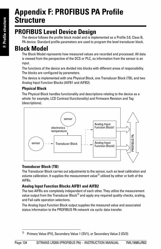
mm
mm
m
F: P
rofil
e st
ruct
ure
Appendix F: PROFIBUS PA Profile StructurePROFIBUS Level Device Design
The device follows the profile block model and is implemented as a Profile 3.0, Class B, PA device. Standard profile parameters are used to program the level transducer block.
Block ModelThe Block Model represents how measured values are recorded and processed. All data is viewed from the perspective of the DCS or PLC, so information from the sensor is an input.The functions of the device are divided into blocks with different areas of responsibility. The blocks are configured by parameters.The device is implemented with one Physical Block, one Transducer Block (TB), and two Analog Input Function Blocks (AIFB1 and AIFB2).
Physical BlockThe Physical Block handles functionality and descriptions relating to the device as a whole: for example, LCD Contrast (functionality) and Firmware Revision and Tag (descriptions).
Transducer Block (TB)The Transducer Block carries out adjustments to the sensor, such as level calibration and volume calibration. It supplies the measurement value1) utilized by either or both of the AIFBs.
Analog Input Function Blocks AIFB1 and AIFB2The two AIFBs are completely independent of each other. They utilize the measurement value output from the Transducer Block1) and apply any required quality checks, scaling, and Fail-safe operation selections. The Analog Input Function Block output supplies the measured value and associated status information to the PROFIBUS PA network via cyclic data transfer.
1) Primary Value (PV), Secondary Value 1 (SV1), or Secondary Value 2 (SV2)
sensor
sensor
Transducer Block
electronics temperature
Analog Input Function Block2
Analog Input Function Block1
PROF
IBUS
PA
Page 134 SITRANS LR200 (PROFIBUS PA) – INSTRUCTION MANUAL 7ML19985JR02
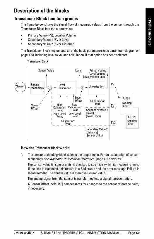
mm
mm
m
F: Profile structure
Description of the blocksTransducer Block function groups
The figure below shows the signal flow of measured values from the sensor through the Transducer Block into the output value:
• Primary Value (PV): Level or Volume• Secondary Value 1 (SV1): Level • Secondary Value 2 (SV2): Distance
The Transducer Block implements all of the basic parameters (see parameter diagram on page 136), including level to volume calculation, if that option has been selected.
How the Transducer Block works:
1. The sensor technology block selects the proper echo. For an explanation of sensor technology, see Appendix D: Technical Reference , page 116 onwards.
The sensor value (in sensor units) is checked to see if it is within its measuring limits. If the limit is exceeded, this results in a Bad status and the error message Failure in measurement. The sensor value is stored in Sensor Value.
The analog signal from the sensor is transformed into a digital representation.
A Sensor Offset (default 0) compensates for changes to the sensor reference point, if necessary.
Transducer Block
Sensor Value
Sensor Sensor technology
Level calibration Linearization
Level Primary Value[Level/Volume]
(level/volume units)
(Analog Input)
AIFB1
Secondary Value 1 [Level](Level Units)
Secondary Value 2 [Distance](Sensor Units)
Sensor Offset
Level Offset
High Calibration
PointHigh Level
Point
Low Calibration
Point Low Level
Point
Calibration Type
Linearization Type
PV
SV1
SV2
AIFB2(Analog Input)
7ML19985JR02 SITRANS LR200 (PROFIBUS PA) – INSTRUCTION MANUAL Page 135
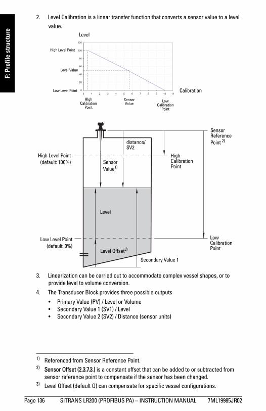
mm
mm
m
F: P
rofil
e st
ruct
ure
2. Level Calibration is a linear transfer function that converts a sensor value to a level
value. 1)2)3)
3. Linearization can be carried out to accommodate complex vessel shapes, or to provide level to volume conversion.
4. The Transducer Block provides three possible outputs
• Primary Value (PV) / Level or Volume• Secondary Value 1 (SV1) / Level• Secondary Value 2 (SV2) / Distance (sensor units)
1) Referenced from Sensor Reference Point.2) Sensor Offset (2.3.7.3.) is a constant offset that can be added to or subtracted from
sensor reference point to compensate if the sensor has been changed. 3) Level Offset (default O) can compensate for specific vessel configurations.
Level
High Level Point
Low Level Point Calibration
Level Value
Low Calibration
Point
HIghCalibration
Point
Sensor Value
High Level Point(default: 100%)
Sensor Reference Point 2)
Sensor Value1)
Low Level Point(default: 0%)
Level
Level Offset3)
Secondary Value 1
Low Calibration Point
High Calibration Point
distance/SV2
Page 136 SITRANS LR200 (PROFIBUS PA) – INSTRUCTION MANUAL 7ML19985JR02
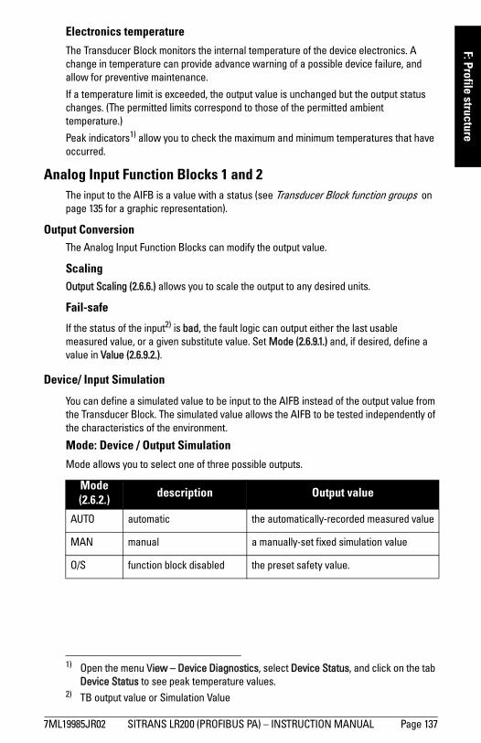
mm
mm
m
F: Profile structure
Electronics temperature
The Transducer Block monitors the internal temperature of the device electronics. A change in temperature can provide advance warning of a possible device failure, and allow for preventive maintenance.
If a temperature limit is exceeded, the output value is unchanged but the output status changes. (The permitted limits correspond to those of the permitted ambient temperature.)
Peak indicators1) allow you to check the maximum and minimum temperatures that have occurred.
Analog Input Function Blocks 1 and 2The input to the AIFB is a value with a status (see Transducer Block function groups on page 135 for a graphic representation).
Output ConversionThe Analog Input Function Blocks can modify the output value.
ScalingOutput Scaling (2.6.6.) allows you to scale the output to any desired units.
Fail-safe
If the status of the input2) is bad, the fault logic can output either the last usable measured value, or a given substitute value. Set Mode (2.6.9.1.) and, if desired, define a value in Value (2.6.9.2.).
Device/ Input Simulation
You can define a simulated value to be input to the AIFB instead of the output value from the Transducer Block. The simulated value allows the AIFB to be tested independently of the characteristics of the environment.
Mode: Device / Output Simulation
Mode allows you to select one of three possible outputs.
1) Open the menu View – Device Diagnostics, select Device Status, and click on the tab Device Status to see peak temperature values.
2) TB output value or Simulation Value
Mode (2.6.2.) description Output value
AUTO automatic the automatically-recorded measured value
MAN manual a manually-set fixed simulation value
O/S function block disabled the preset safety value.
7ML19985JR02 SITRANS LR200 (PROFIBUS PA) – INSTRUCTION MANUAL Page 137
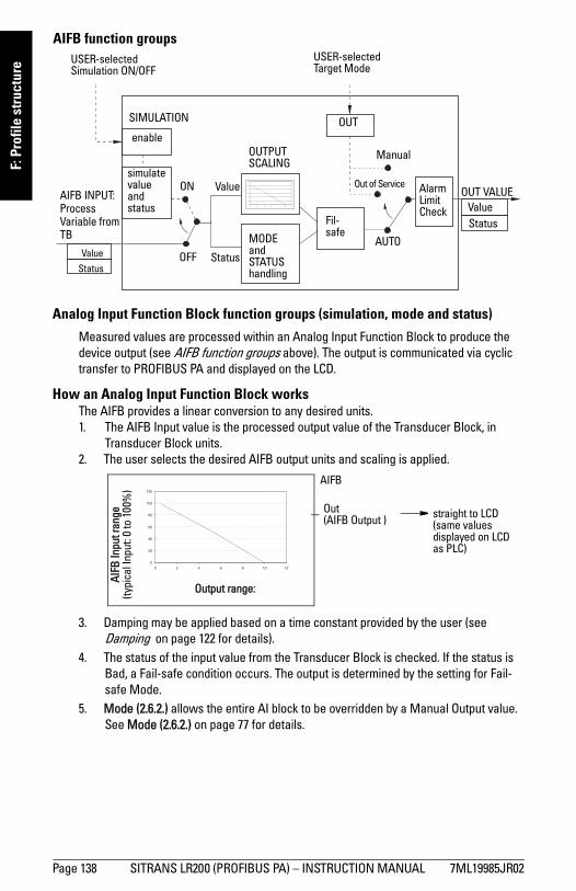
mm
mm
m
F: P
rofil
e st
ruct
ure
Analog Input Function Block function groups (simulation, mode and status)
Measured values are processed within an Analog Input Function Block to produce the device output (see AIFB function groups above). The output is communicated via cyclic transfer to PROFIBUS PA and displayed on the LCD.
How an Analog Input Function Block worksThe AIFB provides a linear conversion to any desired units.1. The AIFB Input value is the processed output value of the Transducer Block, in
Transducer Block units. 2. The user selects the desired AIFB output units and scaling is applied.
3. Damping may be applied based on a time constant provided by the user (see Damping on page 122 for details).
4. The status of the input value from the Transducer Block is checked. If the status is Bad, a Fail-safe condition occurs. The output is determined by the setting for Fail-safe Mode.
5. Mode (2.6.2.) allows the entire AI block to be overridden by a Manual Output value. See Mode (2.6.2.) on page 77 for details.
enable
Status
OUT VALUE
AUTOMODE and STATUS handling
AIFB INPUT:Process Variable from TB
Value Status
Alarm Limit Check
Out of Service
OUT
Manual
Value simulate value and status
Value
Status
USER-selectedSimulation ON/OFF
USER-selectedTarget Mode
OFF
SIMULATION
Fil-safe
ON
OUTPUT SCALING
AIFB function groups
AIFB
AIFB
Inpu
t ran
ge(ty
pica
l Inp
ut: 0
to 1
00%
)
Output range:
Out (AIFB Output ) straight to LCD
(same values displayed on LCD as PLC)
Page 138 SITRANS LR200 (PROFIBUS PA) – INSTRUCTION MANUAL 7ML19985JR02
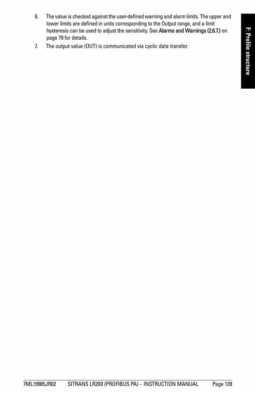
mm
mm
m
F: Profile structure
6. The value is checked against the user-defined warning and alarm limits. The upper andlower limits are defined in units corresponding to the Output range, and a limit hysteresis can be used to adjust the sensitivity. See Alarms and Warnings (2.6.7.) on page 79 for details.
7. The output value (OUT) is communicated via cyclic data transfer.
7ML19985JR02 SITRANS LR200 (PROFIBUS PA) – INSTRUCTION MANUAL Page 139
mm
mm
m
G: C
omm
unic
atio
ns P
A
Appendix G: Communications via PROFIBUS PA
SITRANS LR200 (PROFIBUS PA) is a Profile Version 3.01, Class B, PA device. It supports Class 1 Master for cyclic and acyclic data exchange, and Class 2 for acyclic services. The full range of SITRANS LR200 functions is available only over a PROFIBUS PA network.
PROFIBUS PA is an open industrial protocol. Full details about PROFIBUS PA can be obtained from PROFIBUS International at www.profibus.com.
Device Configuration toolTo use PROFIBUS PA, you will need a PC configuration tool: we recommend SIMATIC PDM. Please consult the operating instructions or online help for details on using SIMATIC PDM. (You can find more information at www.siemens.com/simatic-pdm.)
SIMATIC PDMSIMATIC PDM is a software package used to commission and maintain SITRANS LR200 and other process devices. For more detail see Functions in SIMATIC PDM on page 34.
Electronic Device Description (EDD)
In order to use Process Device Manager (PDM) with PROFIBUS PA, you will need the Electronic Device Description for SITRANS LR200. For details see Electronic Device Description (EDD) on page 35.
Enhanced EDD (Electronic Device Description)
The Enhanced EDD has improved usability features: for example, see Wizard - Quick Start on page 36 and Echo Profile Utilities on page 44.
Network ConfigurationTo configure a PROFIBUS PA Class 1 Master (for example, a PLC), you will need a GSD file.
The GSD fileThe GSD file SIEM810F.gsd is available from the SITRANS LR200 product page on our web site. Go to www.siemens.com/LR200 and click Downloads.
Note: SITRANS LR200 requires the EDD for SIMATIC PDM Rev. 6.0 with SP4.
Page 140 SITRANS LR200 (PROFIBUS PA) – INSTRUCTION MANUAL 7ML19985JR02
mm
mm
m
G: Com
munications PA
Bus Termination
Power DemandsTo determine how many devices can be connected to a bus line, calculate the combined maximum current consumption of all the connected devices: 10.5 mA for each SITRANS LR200. Allow a current reserve for safety.
PROFIBUS address
A unique PROFIBUS address identifies each device on the network.
• To set the PROFIBUS address see Device Address (5.1.) on page 100.• To reset the PROFIBUS address to 126 see Master Reset (4.1.) on page 86.
Operating as a Profile DeviceEvery manufactured PROFIBUS product has a unique PROFIBUS identification number which identifies it to the system. PROFIBUS Profile Standard version 3.01 also defines a Profile Model which can identify a product as a generic profile device on the network.
SITRANS LR200 can be identified in one of three ways:
Defining the device as Profile-specific as opposed to Manufacturer-specific makes it possible to exchange the device for any other device of the same profile type without changing the GSD file.
To set up SITRANS LR200 as a profile device see PROFIBUS Ident Number (5.2.) on page 100.
Note: PROFIBUS PA MUST be terminated at both extreme ends of the cable for it to work properly. Please refer to the PROFIBUS PA User and Installation Guidelines (order number 2.092), available from www.profibus.com.
Notes:• It is possible to change the device address via a Class 1 master (for example, a PLC)
and lock the device address to prevent further changes.• If this Address Lock is on, the PA address cannot be changed. This lock can be
disabled only by performing an Address Reset.
Device Identification Profile Model
STD PROFILEStandard Profile (uses generic GSD for 2 AIFB [ident # = 0x9701]
* MANUFACTURERManufacturer-specific (uses Siemens EDD and GSD file, which identifies the LR200 [PROFIBUS PA]) [ident # = 0x8150]
STD – AIFB 1 ONLYStandard Profile AIFB 1 only (uses generic GSD for 1 AIFB) [ident # = 0x9700]
7ML19985JR02 SITRANS LR200 (PROFIBUS PA) – INSTRUCTION MANUAL Page 141
mm
mm
m
G: C
omm
unic
atio
ns P
A
Configuring a deviceSee Configuring a new device on page 35.
Configuring PROFIBUS PA with an S7-300/ 400 PLC1. If SITRANS LR200 is not listed in the STEP 7 device catalog, you can download the
DeviceInstall file from the Siemens Web site and run it from your computer. Go to www.siemens.com/LR200 and click Downloads.
2. Add the SITRANS LR200 "rack": click and drag the SITRANS LR200 folder from the hardware catalog.
3. Fill the rack with desired modules, by dragging and dropping them from the hardware catalog.
4. After configuring PROFIBUS PA in steps 2 and 3, download it to the PLC.
5. Add code to the PLC program to read data consistently using the SFC14.
Cyclic versus Acyclic DataWhen you request data from a device via PROFIBUS PA, you have two choices. Cyclic data is provided at every bus scan: acyclic data is requested and provided as needed.
Input information is always requested at every bus scan and is set up as cyclic data. Configuration information is only needed periodically and is set up as acyclic data.
Cyclic DataWhen you configure SITRANS LR200 on the PROFIBUS PA bus, there are two slots available for modules.
Slot 0 always transmits AIFB1 information1); slot 1 defaults to Free Place, but can be changed to AIFB2 information. If you do not wish to have data transmitted, then you must use a Free Place module in that slot.
Each of the two Analog Input Function Blocks can be set up to return Level, Distance, or Volume. Within the function blocks, the values are scaled according to the user requirements (please see Analog Input Function Blocks 1 and 2 on page 137 for details).
Note: Each of the slots has to have a module defined in it.
1) For more information, please see Analog Input Function Blocks 1 and 2 on page 137.
Page 142 SITRANS LR200 (PROFIBUS PA) – INSTRUCTION MANUAL 7ML19985JR02
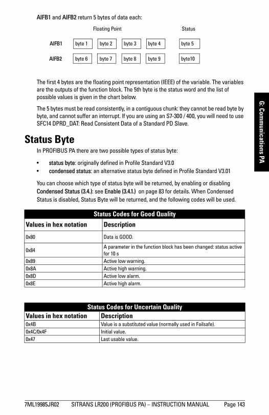
mm
mm
m
G: Com
munications PA
AIFB1 and AIFB2 return 5 bytes of data each:
The first 4 bytes are the floating point representation (IEEE) of the variable. The variables are the outputs of the function block. The 5th byte is the status word and the list of possible values is given in the chart below.
The 5 bytes must be read consistently, in a contiguous chunk: they cannot be read byte by byte, and cannot suffer an interrupt. If you are using an S7-300 / 400, you will need to use SFC14 DPRD_DAT: Read Consistent Data of a Standard PD Slave.
Status ByteIn PROFIBUS PA there are two possible types of status byte:
• status byte: originally defined in Profile Standard V3.0• condensed status: an alternative status byte defined in Profile Standard V3.01
You can choose which type of status byte will be returned, by enabling or disabling Condensed Status (3.4.): see Enable (3.4.1.) on page 83 for details. When Condensed Status is disabled, Status Byte will be returned, and the following codes will be used.
Status Codes for Good Quality
Values in hex notation Description
0x80 Data is GOOD.
0x84A parameter in the function block has been changed: status active for 10 s
0x89 Active low warning.0x8A Active high warning.0x8D Active low alarm.0x8E Active high alarm.
Status Codes for Uncertain QualityValues in hex notation Description 0x4B Value is a substituted value (normally used in Failsafe).0x4C/0x4F Initial value.0x47 Last usable value.
Floating Point Status
AIFB2
AIFB1 byte 1 byte 2 byte 3 byte 4 byte 5
byte 6 byte 7 byte 8 byte 9 byte10byte10
7ML19985JR02 SITRANS LR200 (PROFIBUS PA) – INSTRUCTION MANUAL Page 143
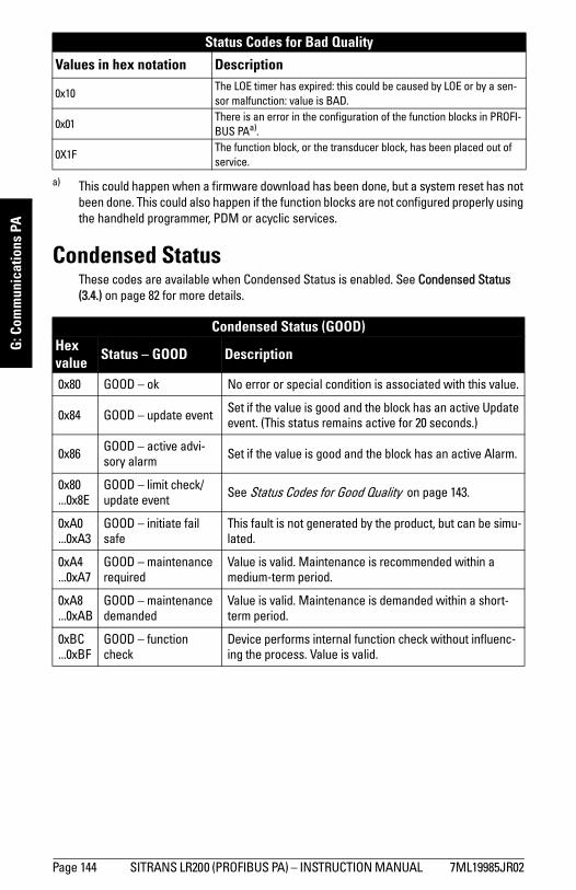
mm
mm
m
G: C
omm
unic
atio
ns P
A
Condensed StatusThese codes are available when Condensed Status is enabled. See Condensed Status (3.4.) on page 82 for more details.
Status Codes for Bad Quality
Values in hex notation Description
0x10The LOE timer has expired: this could be caused by LOE or by a sen-sor malfunction: value is BAD.
0x01There is an error in the configuration of the function blocks in PROFI-BUS PAa).
0X1FThe function block, or the transducer block, has been placed out of service.
a) This could happen when a firmware download has been done, but a system reset has not been done. This could also happen if the function blocks are not configured properly using the handheld programmer, PDM or acyclic services.
Condensed Status (GOOD)Hex value Status – GOOD Description
0x80 GOOD – ok No error or special condition is associated with this value.
0x84 GOOD – update event Set if the value is good and the block has an active Update event. (This status remains active for 20 seconds.)
0x86 GOOD – active advi-sory alarm Set if the value is good and the block has an active Alarm.
0x80 ...0x8E
GOOD – limit check/update event See Status Codes for Good Quality on page 143.
0xA0 ...0xA3
GOOD – initiate fail safe
This fault is not generated by the product, but can be simu-lated.
0xA4 ...0xA7
GOOD – maintenance required
Value is valid. Maintenance is recommended within a medium-term period.
0xA8 ...0xAB
GOOD – maintenance demanded
Value is valid. Maintenance is demanded within a short-term period.
0xBC ...0xBF
GOOD – function check
Device performs internal function check without influenc-ing the process. Value is valid.
Page 144 SITRANS LR200 (PROFIBUS PA) – INSTRUCTION MANUAL 7ML19985JR02
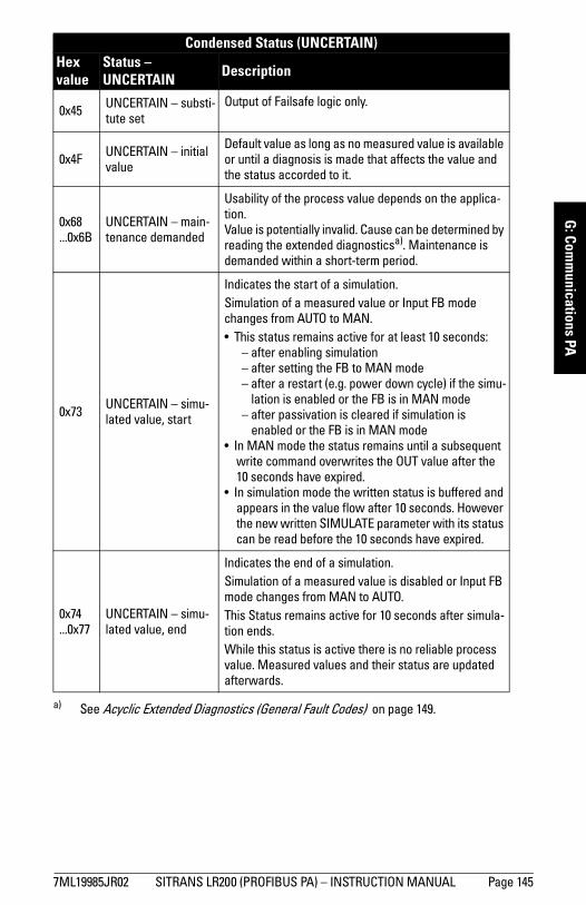
mm
mm
m
G: Com
munications PA
Condensed Status (UNCERTAIN) Hex value
Status – UNCERTAIN Description
0x45 UNCERTAIN – substi-tute set
Output of Failsafe logic only.
0x4F UNCERTAIN – initial value
Default value as long as no measured value is available or until a diagnosis is made that affects the value and the status accorded to it.
0x68 ...0x6B
UNCERTAIN – main-tenance demanded
Usability of the process value depends on the applica-tion. Value is potentially invalid. Cause can be determined by reading the extended diagnosticsa). Maintenance is demanded within a short-term period.
0x73 UNCERTAIN – simu-lated value, start
Indicates the start of a simulation. Simulation of a measured value or Input FB mode changes from AUTO to MAN. • This status remains active for at least 10 seconds:
– after enabling simulation– after setting the FB to MAN mode– after a restart (e.g. power down cycle) if the simu-
lation is enabled or the FB is in MAN mode– after passivation is cleared if simulation is
enabled or the FB is in MAN mode• In MAN mode the status remains until a subsequent
write command overwrites the OUT value after the 10 seconds have expired.
• In simulation mode the written status is buffered and appears in the value flow after 10 seconds. However the new written SIMULATE parameter with its status can be read before the 10 seconds have expired.
0x74 ...0x77
UNCERTAIN – simu-lated value, end
Indicates the end of a simulation.Simulation of a measured value is disabled or Input FB mode changes from MAN to AUTO. This Status remains active for 10 seconds after simula-tion ends. While this status is active there is no reliable process value. Measured values and their status are updated afterwards.
a) See Acyclic Extended Diagnostics (General Fault Codes) on page 149.
7ML19985JR02 SITRANS LR200 (PROFIBUS PA) – INSTRUCTION MANUAL Page 145
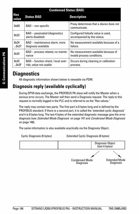
mm
mm
m
G: C
omm
unic
atio
ns P
A
DiagnosticsAll diagnostic information shown below is viewable via PDM.
Diagnosis reply (available cyclically)During DPV0 data exchange, the PROFIBUS PA slave will notify the Master when a serious error occurs. The Master will then send a Diagnosis request. The reply to this request is normally logged in the PLC and is referred to as the "Hex values."
The reply may contain two parts. The first part is 6 bytes long and is defined by the PROFIBUS standard. If there is a second part, it is called the ’extended cyclic diagnosis’ and it is 8 bytes long. The last 4 bytes of the extended diagnostic message give the error diagnosis (see Extended Mode Diagnosis on page 147 and Condensed Mode Diagnosis on page 148).
The same information is also available acyclically via the Diagnosis Object.
Condensed Status (BAD)Hex value Status BAD Description
0x00 BAD – non specific Proxy determines that a device does not communicate.
0x23 BAD – passivated (diagnostics alerts disabled)
Configured failsafe value is used, accompanied by this status.
0x24 ...0x27
BAD – maintenance alarm, more diagnosis available
No measurement available because of a failure.
0x25 BAD – process related, no mainte-nance
No measurement available because of invalid process conditions.
0x3C ...0x3F
BAD – function check / local over-ride, value not usable
Occurs during cleaning or calibration process.
Cyclic Diagnosis (6 bytes) Extended Cyclic Diagnosis (8 bytes)
Diagnosis Object(last 4 bytes)
Condensed Mode Diagnosis
Extended Mode Diagnosis
Page 146 SITRANS LR200 (PROFIBUS PA) – INSTRUCTION MANUAL 7ML19985JR02
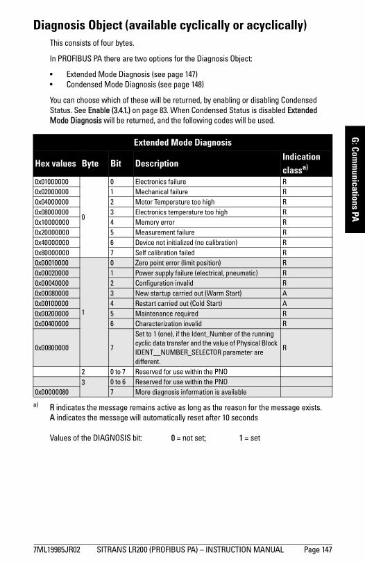
mm
mm
m
G: Com
munications PA
Diagnosis Object (available cyclically or acyclically)This consists of four bytes.
In PROFIBUS PA there are two options for the Diagnosis Object:
• Extended Mode Diagnosis (see page 147)• Condensed Mode Diagnosis (see page 148)
You can choose which of these will be returned, by enabling or disabling Condensed Status. See Enable (3.4.1.) on page 83. When Condensed Status is disabled Extended Mode Diagnosis will be returned, and the following codes will be used.
Values of the DIAGNOSIS bit: 0 = not set; 1 = set
Extended Mode Diagnosis
Hex values Byte Bit DescriptionIndication classa)
a) R indicates the message remains active as long as the reason for the message exists.A indicates the message will automatically reset after 10 seconds
0x01000000
0
0 Electronics failure R0x02000000 1 Mechanical failure R0x04000000 2 Motor Temperature too high R0x08000000 3 Electronics temperature too high R0x10000000 4 Memory error R0x20000000 5 Measurement failure R0x40000000 6 Device not initialized (no calibration) R0x80000000 7 Self calibration failed R0x00010000
1
0 Zero point error (limit position) R0x00020000 1 Power supply failure (electrical, pneumatic) R0x00040000 2 Configuration invalid R0x00080000 3 New startup carried out (Warm Start) A0x00100000 4 Restart carried out (Cold Start) A0x00200000 5 Maintenance required R0x00400000 6 Characterization invalid R
0x00800000 7
Set to 1 (one), if the Ident_Number of the running cyclic data transfer and the value of Physical Block IDENT__NUMBER_SELECTOR parameter are different.
R
2 0 to 7 Reserved for use within the PNO3 0 to 6 Reserved for use within the PNO
0x00000080 7 More diagnosis information is available
7ML19985JR02 SITRANS LR200 (PROFIBUS PA) – INSTRUCTION MANUAL Page 147
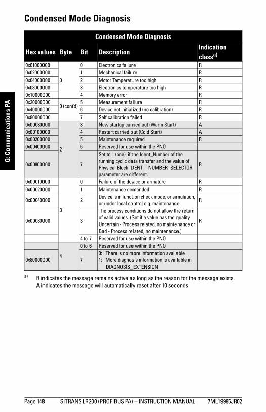
mm
mm
m
G: C
omm
unic
atio
ns P
A
Condensed Mode Diagnosis
Condensed Mode Diagnosis
Hex values Byte Bit DescriptionIndication classa)
a) R indicates the message remains active as long as the reason for the message exists.A indicates the message will automatically reset after 10 seconds
0x01000000
0
0 Electronics failure R0x02000000 1 Mechanical failure R0x04000000 2 Motor Temperature too high R0x08000000 3 Electronics temperature too high R0x10000000 4 Memory error R0x20000000
0 (cont’d)5 Measurement failure R
0x40000000 6 Device not initialized (no calibration) R0x80000000 7 Self calibration failed R0x00080000
2
3 New startup carried out (Warm Start) A0x00100000 4 Restart carried out (Cold Start) A0x00200000 5 Maintenance required R0x00400000 6 Reserved for use within the PNO
0x00800000 7
Set to 1 (one), if the Ident_Number of the running cyclic data transfer and the value of Physical Block IDENT__NUMBER_SELECTOR parameter are different.
R
0x00010000
3
0 Failure of the device or armature R0x00020000 1 Maintenance demanded R
0x00040000 2Device is in function check mode, or simulation, or under local control e.g. maintenance
R
0x00080000 3
The process conditions do not allow the return of valid values. (Set if a value has the quality Uncertain - Process related, no maintenance or Bad - Process related, no maintenance.)
R
4 to 7 Reserved for use within the PNO
4
0 to 6 Reserved for use within the PNO
0x80000000 70: There is no more information available1: More diagnosis information is available in
DIAGNOSIS_EXTENSION
Page 148 SITRANS LR200 (PROFIBUS PA) – INSTRUCTION MANUAL 7ML19985JR02
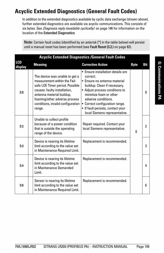
mm
mm
m
G: Com
munications PA
Acyclic Extended Diagnostics (General Fault Codes)In addition to the extended diagnostics available by cyclic data exchange (shown above), further extended diagnostics are available via acyclic communications. This consists of six bytes. See Diagnosis reply (available cyclically) on page 146 for information on the location of the Extended Diagnostics
Note: Certain fault codes (identified by an asterisk [*] in the table below) will persist until a manual reset has been performed (see Fault Reset (3.2.) on page 82).
Acyclic Extended Diagnostics /General Fault Codes LCD display
Meaning Corrective Action Byte Bit
S:0
The device was unable to get a measurement within the Fail-safe LOE Timer period. Possible causes: faulty installation, antenna material buildup, foaming/other adverse process conditions, invalid configuration range.
• Ensure installation details are correct.
• Ensure no antenna material buildup. Clean if necessary.
• Adjust process conditions to minimize foam or other adverse conditions.
• Correct configuration range.• If fault persists, contact your
local Siemens representative.
0
0
S:2
Unable to collect profile because of a power condition that is outside the operating range of the device.
Repair required. Contact your local Siemens representative.
2
S:3Device is nearing its lifetime limit according to the value set in Maintenance Required Limit.
Replacement is recommended.3
S:4
Device is nearing its lifetime limit according to the value set in Maintenance Demanded Limit.
Replacement is recommended.
4
S:6Sensor is nearing its lifetime limit according to the value set in Maintenance Required Limit.
Replacement is recommended.6
7ML19985JR02 SITRANS LR200 (PROFIBUS PA) – INSTRUCTION MANUAL Page 149
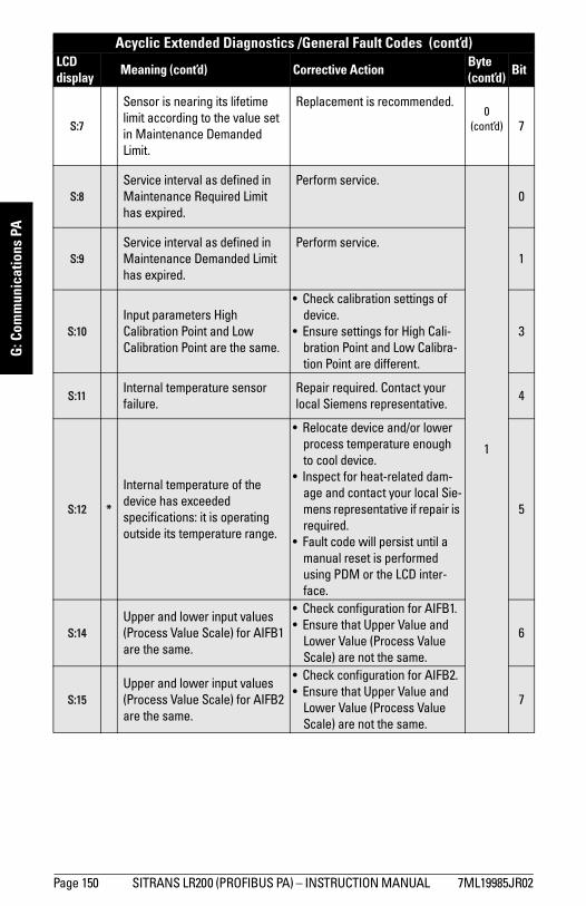
mm
mm
m
G: C
omm
unic
atio
ns P
A
S:7
Sensor is nearing its lifetime limit according to the value set in Maintenance Demanded Limit.
Replacement is recommended.0
(cont’d) 7
S:8Service interval as defined in Maintenance Required Limit has expired.
Perform service.
1
0
S:9Service interval as defined in Maintenance Demanded Limit has expired.
Perform service.1
S:10Input parameters High Calibration Point and Low Calibration Point are the same.
• Check calibration settings of device.
• Ensure settings for High Cali-bration Point and Low Calibra-tion Point are different.
3
S:11Internal temperature sensor failure.
Repair required. Contact your local Siemens representative.
4
S:12 *
Internal temperature of the device has exceeded specifications: it is operating outside its temperature range.
• Relocate device and/or lower process temperature enough to cool device.
• Inspect for heat-related dam-age and contact your local Sie-mens representative if repair is required.
• Fault code will persist until a manual reset is performed using PDM or the LCD inter-face.
5
S:14Upper and lower input values (Process Value Scale) for AIFB1 are the same.
• Check configuration for AIFB1.• Ensure that Upper Value and
Lower Value (Process Value Scale) are not the same.
6
S:15Upper and lower input values (Process Value Scale) for AIFB2 are the same.
• Check configuration for AIFB2.• Ensure that Upper Value and
Lower Value (Process Value Scale) are not the same.
7
Acyclic Extended Diagnostics /General Fault Codes (cont’d)LCD display
Meaning (cont’d) Corrective ActionByte (cont’d)
Bit
Page 150 SITRANS LR200 (PROFIBUS PA) – INSTRUCTION MANUAL 7ML19985JR02
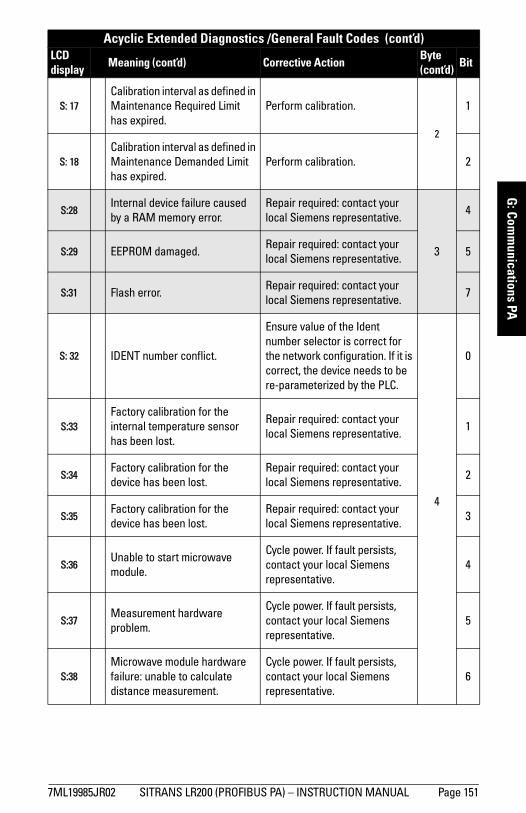
mm
mm
m
G: Com
munications PA
S: 17Calibration interval as defined in Maintenance Required Limit has expired.
Perform calibration.
2
1
S: 18Calibration interval as defined in Maintenance Demanded Limit has expired.
Perform calibration. 2
S:28Internal device failure caused by a RAM memory error.
Repair required: contact your local Siemens representative.
3
4
S:29 EEPROM damaged.Repair required: contact your local Siemens representative.
5
S:31 Flash error.Repair required: contact your local Siemens representative.
7
S: 32 IDENT number conflict.
Ensure value of the Ident number selector is correct for the network configuration. If it is correct, the device needs to be re-parameterized by the PLC.
4
0
S:33Factory calibration for the internal temperature sensor has been lost.
Repair required: contact your local Siemens representative.
1
S:34Factory calibration for the device has been lost.
Repair required: contact your local Siemens representative.
2
S:35Factory calibration for the device has been lost.
Repair required: contact your local Siemens representative.
3
S:36Unable to start microwave module.
Cycle power. If fault persists, contact your local Siemens representative.
4
S:37Measurement hardware problem.
Cycle power. If fault persists, contact your local Siemens representative.
5
S:38Microwave module hardware failure: unable to calculate distance measurement.
Cycle power. If fault persists, contact your local Siemens representative.
6
Acyclic Extended Diagnostics /General Fault Codes (cont’d)LCD display
Meaning (cont’d) Corrective ActionByte (cont’d)
Bit
7ML19985JR02 SITRANS LR200 (PROFIBUS PA) – INSTRUCTION MANUAL Page 151
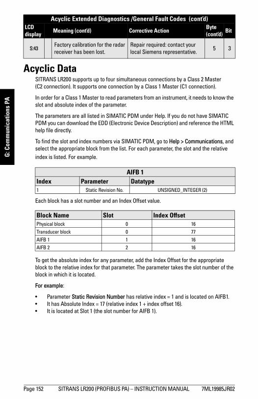
mm
mm
m
G: C
omm
unic
atio
ns P
A
Acyclic DataSITRANS LR200 supports up to four simultaneous connections by a Class 2 Master (C2 connection). It supports one connection by a Class 1 Master (C1 connection).
In order for a Class 1 Master to read parameters from an instrument, it needs to know the slot and absolute index of the parameter.
The parameters are all listed in SIMATIC PDM under Help. If you do not have SIMATIC PDM you can download the EDD (Electronic Device Description) and reference the HTML help file directly.
To find the slot and index numbers via SIMATIC PDM, go to Help > Communications, and select the appropriate block from the list. For each parameter, the slot and the relative index is listed. For example.
Each block has a slot number and an Index Offset value.
To get the absolute index for any parameter, add the Index Offset for the appropriate block to the relative index for that parameter. The parameter takes the slot number of the block in which it is located.
For example:
• Parameter Static Revision Number has relative index = 1 and is located on AIFB1.• It has Absolute Index = 17 (relative index 1 + index offset 16).• It is located at Slot 1 (the slot number for AIFB 1).
S:43Factory calibration for the radar receiver has been lost.
Repair required: contact your local Siemens representative.
5 3
AIFB 1Index Parameter Datatype1 Static Revision No. UNSIGNED_INTEGER (2)
Block Name Slot Index OffsetPhysical block 0 16
Transducer block 0 77
AIFB 1 1 16
AIFB 2 2 16
Acyclic Extended Diagnostics /General Fault Codes (cont’d)LCD display
Meaning (cont’d) Corrective ActionByte (cont’d)
Bit
Page 152 SITRANS LR200 (PROFIBUS PA) – INSTRUCTION MANUAL 7ML19985JR02

mm
mm
m
G: Com
munications PA
Notes
7ML19985JR02 SITRANS LR200 (PROFIBUS PA) – INSTRUCTION MANUAL Page 153
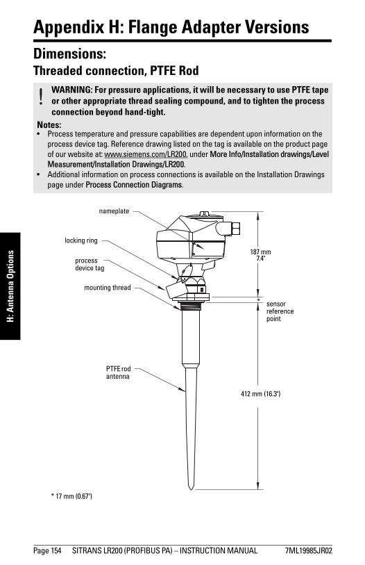
mm
mm
m
H: A
nten
na O
ptio
ns
Appendix H: Flange Adapter Versions Dimensions: Threaded connection, PTFE Rod
WARNING: For pressure applications, it will be necessary to use PTFE tape or other appropriate thread sealing compound, and to tighten the process connection beyond hand-tight.
Notes: • Process temperature and pressure capabilities are dependent upon information on the
process device tag. Reference drawing listed on the tag is available on the product page of our website at: www.siemens.com/LR200, under More Info/Installation drawings/Level Measurement/Installation Drawings/LR200.
• Additional information on process connections is available on the Installation Drawings page under Process Connection Diagrams.
412 mm (16.3")
sensor reference point
187 mm 7.4"
nameplate
locking ring
process device tag
mounting thread
PTFE rod antenna
*
* 17 mm (0.67")
Page 154 SITRANS LR200 (PROFIBUS PA) – INSTRUCTION MANUAL 7ML19985JR02
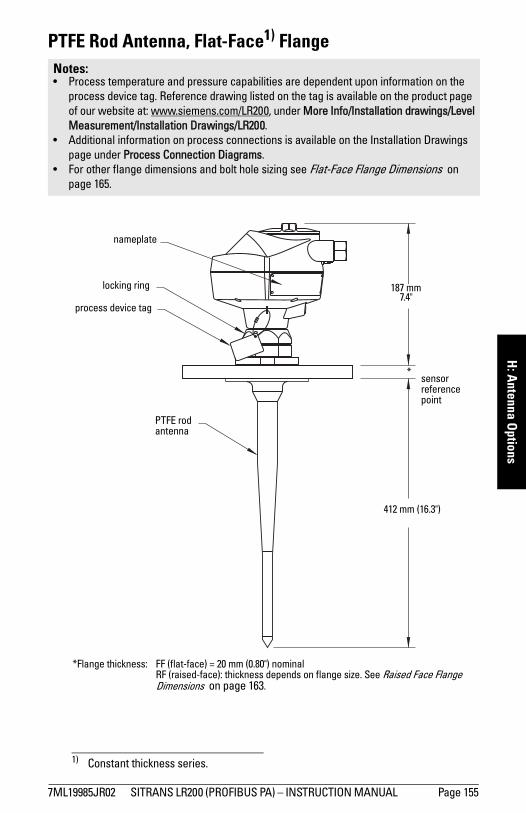
mm
mm
m
H: A
ntenna Options
PTFE Rod Antenna, Flat-Face1) Flange Notes: • Process temperature and pressure capabilities are dependent upon information on the
process device tag. Reference drawing listed on the tag is available on the product page of our website at: www.siemens.com/LR200, under More Info/Installation drawings/Level Measurement/Installation Drawings/LR200.
• Additional information on process connections is available on the Installation Drawings page under Process Connection Diagrams.
• For other flange dimensions and bolt hole sizing see Flat-Face Flange Dimensions on page 165.
1) Constant thickness series.
PTFE rod antenna
sensor reference point
nameplate
locking ring
process device tag
187 mm 7.4"
*
412 mm (16.3")
*Flange thickness: FF (flat-face) = 20 mm (0.80") nominalRF (raised-face): thickness depends on flange size. See Raised Face Flange Dimensions on page 163.
7ML19985JR02 SITRANS LR200 (PROFIBUS PA) – INSTRUCTION MANUAL Page 155
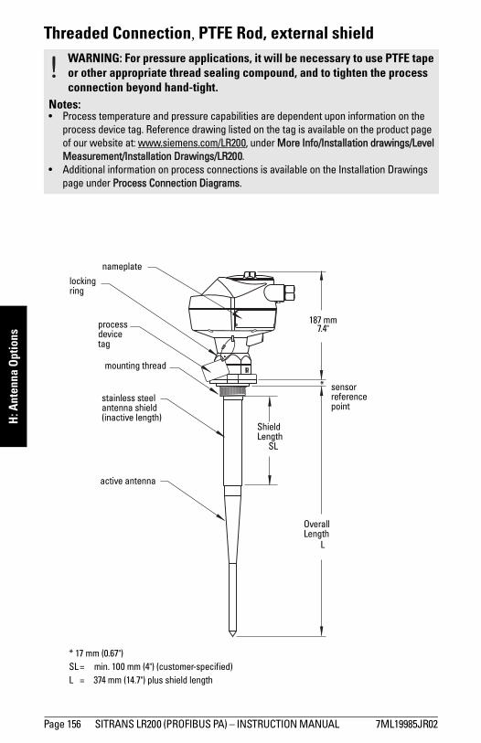
mm
mm
m
H: A
nten
na O
ptio
ns
Threaded Connection, PTFE Rod, external shieldWARNING: For pressure applications, it will be necessary to use PTFE tape or other appropriate thread sealing compound, and to tighten the process connection beyond hand-tight.
Notes: • Process temperature and pressure capabilities are dependent upon information on the
process device tag. Reference drawing listed on the tag is available on the product page of our website at: www.siemens.com/LR200, under More Info/Installation drawings/Level Measurement/Installation Drawings/LR200.
• Additional information on process connections is available on the Installation Drawings page under Process Connection Diagrams.
stainless steel antenna shield (inactive length)
active antenna
Shield Length
SL
OverallLength
L
sensor reference point
nameplate
locking ring
process device tag
187 mm 7.4"
*
mounting thread
* 17 mm (0.67")SL = min. 100 mm (4") (customer-specified)L = 374 mm (14.7") plus shield length
Page 156 SITRANS LR200 (PROFIBUS PA) – INSTRUCTION MANUAL 7ML19985JR02
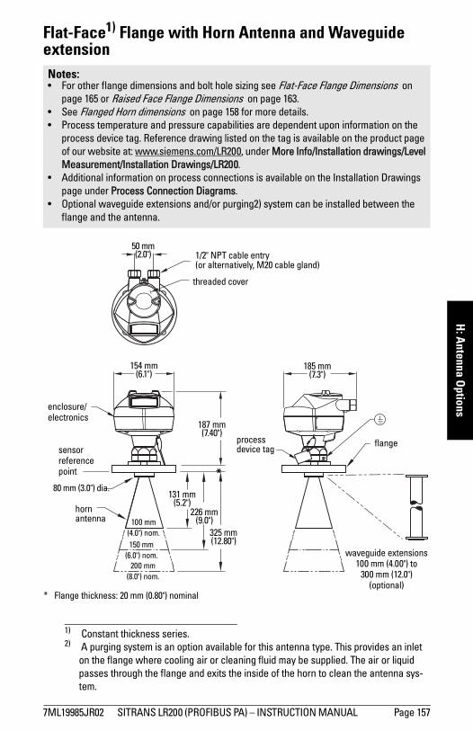
mm
mm
m
H: A
ntenna Options
Flat-Face1) Flange with Horn Antenna and Waveguide extension2)
1) Constant thickness series.
Notes: • For other flange dimensions and bolt hole sizing see Flat-Face Flange Dimensions on
page 165 or Raised Face Flange Dimensions on page 163.• See Flanged Horn dimensions on page 158 for more details.• Process temperature and pressure capabilities are dependent upon information on the
process device tag. Reference drawing listed on the tag is available on the product page of our website at: www.siemens.com/LR200, under More Info/Installation drawings/Level Measurement/Installation Drawings/LR200.
• Additional information on process connections is available on the Installation Drawings page under Process Connection Diagrams.
• Optional waveguide extensions and/or purging2) system can be installed between the flange and the antenna.
2) A purging system is an option available for this antenna type. This provides an inlet on the flange where cooling air or cleaning fluid may be supplied. The air or liquid passes through the flange and exits the inside of the horn to clean the antenna sys-tem.
threaded cover
enclosure/electronics
187 mm (7.40")
154 mm (6.1")
185 mm (7.3")
1/2" NPT cable entry (or alternatively, M20 cable gland)
sensor referencepoint
131 mm (5.2")
100 mm (4.0") nom.
50 mm (2.0")
flange
80 mm (3.0") dia.
waveguide extensions 100 mm (4.00") to
300 mm (12.0")(optional)
hornantenna
process device tag
* Flange thickness: 20 mm (0.80") nominal
*
325 mm (12.80")
226 mm (9.0")
150 mm (6.0") nom.
200 mm (8.0") nom.
7ML19985JR02 SITRANS LR200 (PROFIBUS PA) – INSTRUCTION MANUAL Page 157
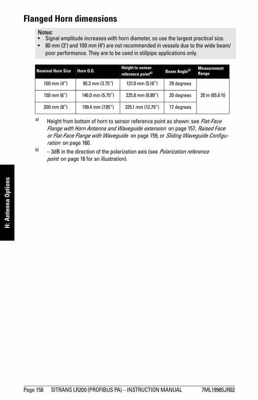
mm
mm
m
H: A
nten
na O
ptio
ns
Flanged Horn dimensionsNotes:• Signal amplitude increases with horn diameter, so use the largest practical size.• 80 mm (3") and 100 mm (4") are not recommended in vessels due to the wide beam/
poor performance. They are to be used in stillpipe applications only.
Nominal Horn Size Horn O.D.Height to sensor reference pointa)
a) Height from bottom of horn to sensor reference point as shown: see Flat-Face Flange with Horn Antenna and Waveguide extension on page 157, Raised Face or Flat-Face Flange with Waveguide on page 159, or Sliding Waveguide Configu-ration on page 160.
Beam Angleb)
b) – 3dB in the direction of the polarization axis (see Polarization reference point on page 16 for an illustration).
Measurement Range
100 mm (4”) 95.3 mm (3.75”) 131.0 mm (5.16”) 29 degrees
20 m (65.6 ft)150 mm (6”) 146.0 mm (5.75”) 225.8 mm (8.89”) 20 degrees
200 mm (8”) 199.4 mm (7.85”) 325.1 mm (12.79”) 17 degrees
Page 158 SITRANS LR200 (PROFIBUS PA) – INSTRUCTION MANUAL 7ML19985JR02
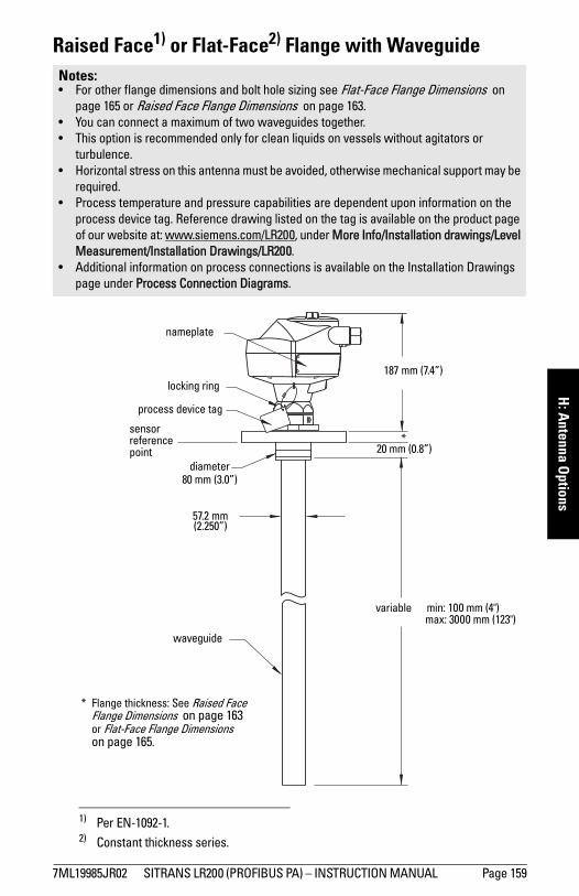
mm
mm
m
H: A
ntenna Options
Raised Face1) or Flat-Face2) Flange with WaveguideNotes:• For other flange dimensions and bolt hole sizing see Flat-Face Flange Dimensions on
page 165 or Raised Face Flange Dimensions on page 163.• You can connect a maximum of two waveguides together.• This option is recommended only for clean liquids on vessels without agitators or
turbulence. • Horizontal stress on this antenna must be avoided, otherwise mechanical support may be
required. • Process temperature and pressure capabilities are dependent upon information on the
process device tag. Reference drawing listed on the tag is available on the product page of our website at: www.siemens.com/LR200, under More Info/Installation drawings/Level Measurement/Installation Drawings/LR200.
• Additional information on process connections is available on the Installation Drawings page under Process Connection Diagrams.
1) Per EN-1092-1.2) Constant thickness series.
nameplate
variable min: 100 mm (4")max: 3000 mm (123")
waveguide
57.2 mm(2.250”)
sensor reference point
locking ring
process device tag
187 mm (7.4”)
20 mm (0.8”)
diameter 80 mm (3.0”)
*
* Flange thickness: See Raised Face Flange Dimensions on page 163 or Flat-Face Flange Dimensions on page 165.
7ML19985JR02 SITRANS LR200 (PROFIBUS PA) – INSTRUCTION MANUAL Page 159
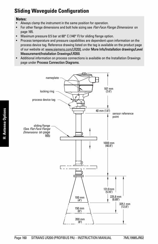
mm
mm
m
H: A
nten
na O
ptio
ns
Sliding Waveguide ConfigurationNotes:• Always clamp the instrument in the same position for operation.• For other flange dimensions and bolt hole sizing see Flat-Face Flange Dimensions on
page 165.• Maximum pressure 0.5 bar at 60° C (140° F) for sliding flange option.• Process temperature and pressure capabilities are dependent upon information on the
process device tag. Reference drawing listed on the tag is available on the product page of our website at: www.siemens.com/LR200, under More Info/Installation drawings/Level Measurement/Installation Drawings/LR200.
• Additional information on process connections is available on the Installation Drawings page under Process Connection Diagrams.
sliding flange(See Flat-Face FlangeDimensions on page
165)
nameplate
1000 mm (40.8")
131.0 mm (5.16")
225.8 mm (8.89")
325.1 mm (12.8")150 mm
(6")
200 mm (8")
100 mm (4")
sensor reference point
locking ring
process device tag
187 mm (7.4")
40 mm (1.6")
Page 160 SITRANS LR200 (PROFIBUS PA) – INSTRUCTION MANUAL 7ML19985JR02
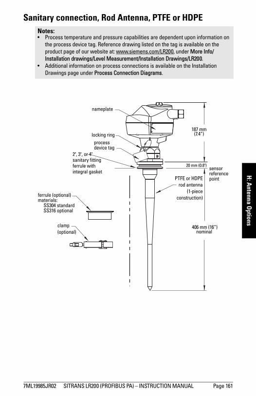
mm
mm
m
H: A
ntenna Options
Sanitary connection, Rod Antenna, PTFE or HDPENotes: • Process temperature and pressure capabilities are dependent upon information on
the process device tag. Reference drawing listed on the tag is available on the product page of our website at: www.siemens.com/LR200, under More Info/Installation drawings/Level Measurement/Installation Drawings/LR200.
• Additional information on process connections is available on the Installation Drawings page under Process Connection Diagrams.
ferrule (optional)materials:
SS304 standardSS316 optional
2", 3", or 4" sanitary fitting ferrule with integral gasket
clamp(optional)
406 mm (16”) nominal
nameplate
sensor reference point
locking ringprocess device tag
187 mm (7.4”)
20 mm (0.8")
PTFE or HDPErod antenna
(1-piececonstruction)
7ML19985JR02 SITRANS LR200 (PROFIBUS PA) – INSTRUCTION MANUAL Page 161
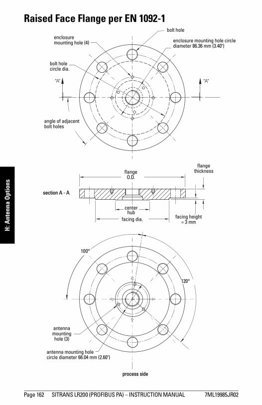
mm
mm
m
H: A
nten
na O
ptio
ns
Raised Face Flange per EN 1092-1
process side
bolt hole
flange O.D.
bolt hole circle dia.
flange thickness
facing height= 3 mmfacing dia.
center hub
angle of adjacent bolt holes
section A - A
antenna mounting hole (3)
enclosure mounting hole circle diameter 86.36 mm (3.40")
enclosure mounting hole (4)
antenna mounting holecircle diameter 66.04 mm (2.60")
120°
100°
Page 162 SITRANS LR200 (PROFIBUS PA) – INSTRUCTION MANUAL 7ML19985JR02
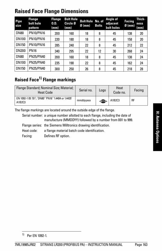
mm
mm
m
H: A
ntenna Options
Raised Face Flange Dimensions
Raised Face1) Flange markings
The flange markings are located around the outside edge of the flange.Serial number: a unique number allotted to each flange, including the date of
manufacture (MMDDYY) followed by a number from 001 to 999.Flange series: the Siemens Milltronics drawing identification.Heat code: a flange material batch code identification.Facing: Defines RF option.
Pipe size
Flange bolt hole pattern
Flange O.D. (mm)
Bolt Hole Circle Ø (mm)
Bolt Hole Ø (mm)
No. of Bolts
Angle of adjacent bolt holes
FacingØ (mm)
Thick-ness (mm)
DN80 PN10/PN16 200 160 18 8 45 138 20DN100 PN10/PN16 220 180 18 8 45 158 20DN150 PN10/PN16 285 240 22 8 45 212 22DN200 PN16 340 295 22 12 30 268 24DN80 PN25/PN40 200 160 18 8 45 138 24DN100 PN25/PN40 235 190 22 8 45 162 24DN150 PN25/PN40 300 250 26 8 45 218 28
Flange Standard; Nominal Size; Material; Heat Code
Serial no. LogoHeat
Code no. Facing
EN 1092-1 05 ’B1’; ’DN80’ ’PN16’ ’1.4404 or 1.4435’ A1B2C3
mmddyyxxx A1B2C3 RF
1) Per EN 1092-1.
7ML19985JR02 SITRANS LR200 (PROFIBUS PA) – INSTRUCTION MANUAL Page 163
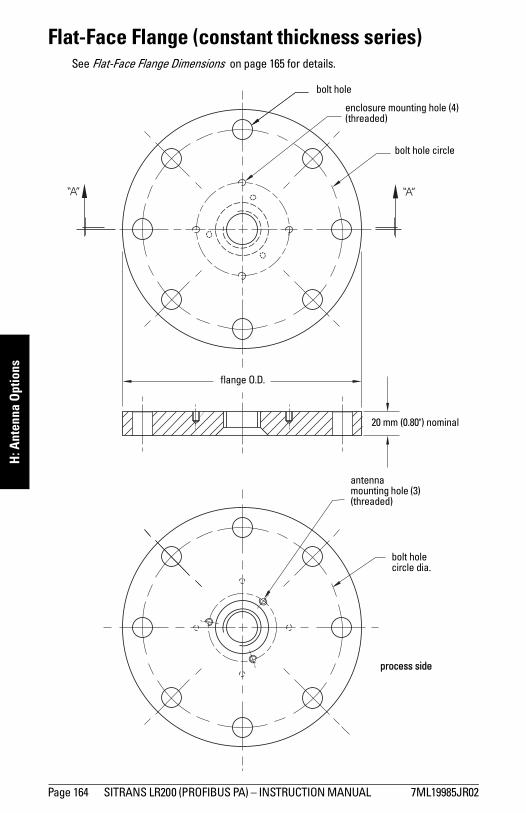
mm
mm
m
H: A
nten
na O
ptio
ns
Flat-Face Flange (constant thickness series)See Flat-Face Flange Dimensions on page 165 for details.
process side
enclosure mounting hole (4) (threaded)
bolt hole
flange O.D.
bolt hole circle
20 mm (0.80") nominal
antenna mounting hole (3) (threaded)
bolt hole circle dia.
Page 164 SITRANS LR200 (PROFIBUS PA) – INSTRUCTION MANUAL 7ML19985JR02
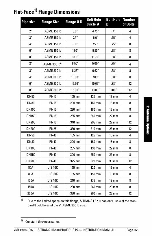
mm
mm
m
H: A
ntenna Options
Flat-Face1) Flange Dimensions
Pipe size Flange Size Flange O.D. Bolt Hole Circle Ø
Bolt Hole Ø
Number of Bolts
2” ASME 150 lb 6.0” 4.75” .7” 4
3” ASME 150 lb 7.5” 6.0” .75” 4
4” ASME 150 lb 9.0” 7.50” .75” 8
6” ASME 150 lb 11.0” 9.50” .88” 8
8” ASME 150 lb 13.5” 11.75” .88” 8
2” ASME 300 lba)
a) Due to the limited space on this flange, SITRANS LR200 can only use 4 of the stan-dard 8 bolt holes of the 2” ASME 300 lb size.
6.50” 5.00” .75” 4
3” ASME 300 lb 8.25” 6.62” .88” 8
4” ASME 300 lb 10.00” 7.88” .88” 8
6” ASME 300 lb 12.50” 10.62” .88” 12
8” ASME 300 lb 15.00” 13.00” 1.00” 12
DN50 PN16 165 mm 125 mm 18 mm 4
DN80 PN16 200 mm 160 mm 18 mm 8
DN100 PN16 220 mm 180 mm 18 mm 8
DN150 PN16 285 mm 240 mm 22 mm 8
DN200 PN16 340 mm 295 mm 22 mm 12
DN200 PN25 360 mm 310 mm 26 mm 12
DN50 PN40 165 mm 125 mm 18 mm 4
DN80 PN40 200 mm 160 mm 18 mm 8
DN100 PN40 235 mm 190 mm 22 mm 8
DN150 PN40 300 mm 250 mm 26 mm 8
DN200 PN40 375 mm 320 mm 30 mm 12
50A JIS 10K 155 mm 120 mm 19 mm 4
80A JIS 10K 185 mm 150 mm 19 mm 8
100A JIS 10K 210 mm 175 mm 19 mm 8
150A JIS 10K 280 mm 240 mm 23 mm 8
200A JIS 10K 330 mm 290 mm 23 mm 12
1) Constant thickness series.
7ML19985JR02 SITRANS LR200 (PROFIBUS PA) – INSTRUCTION MANUAL Page 165
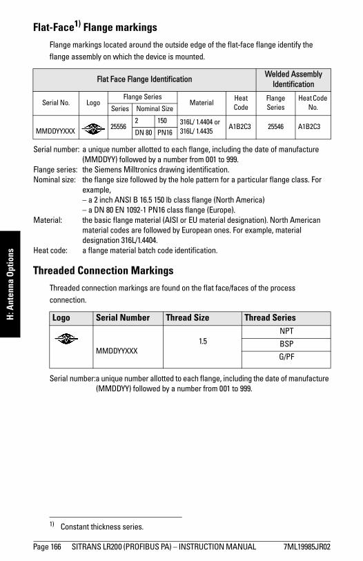
mm
mm
m
H: A
nten
na O
ptio
ns
Flat-Face1) Flange markingsFlange markings located around the outside edge of the flat-face flange identify the flange assembly on which the device is mounted.
Serial number: a unique number allotted to each flange, including the date of manufacture (MMDDYY) followed by a number from 001 to 999.
Flange series: the Siemens Milltronics drawing identification.Nominal size: the flange size followed by the hole pattern for a particular flange class. For
example,– a 2 inch ANSI B 16.5 150 lb class flange (North America)– a DN 80 EN 1092-1 PN16 class flange (Europe).
Material: the basic flange material (AISI or EU material designation). North American material codes are followed by European ones. For example, material designation 316L/1.4404.
Heat code: a flange material batch code identification.
Threaded Connection MarkingsThreaded connection markings are found on the flat face/faces of the process connection.
Serial number:a unique number allotted to each flange, including the date of manufacture (MMDDYY) followed by a number from 001 to 999.
1) Constant thickness series.
Flat Face Flange IdentificationWelded Assembly
Identification
Serial No. LogoFlange Series
MaterialHeat Code
Flange Series
Heat Code No. Series Nominal Size
MMDDYYXXX25556
2 150 316L/ 1.4404 or 316L/ 1.4435
A1B2C3 25546 A1B2C3DN 80 PN16
Logo Serial Number Thread Size Thread Series
MMDDYYXXX1.5
NPT
BSP
G/PF
Page 166 SITRANS LR200 (PROFIBUS PA) – INSTRUCTION MANUAL 7ML19985JR02
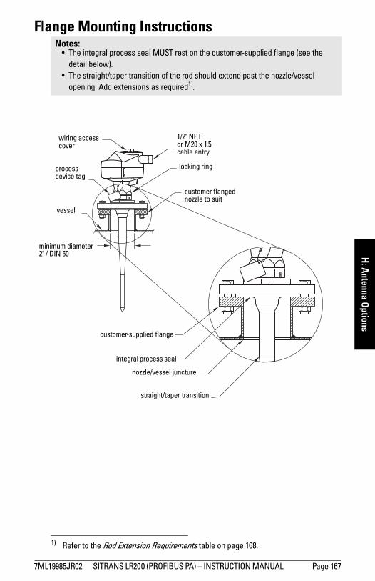
mm
mm
m
H: A
ntenna Options
Flange Mounting Instructions
1)
Notes:• The integral process seal MUST rest on the customer-supplied flange (see the
detail below). • The straight/taper transition of the rod should extend past the nozzle/vessel
opening. Add extensions as required1).
1) Refer to the Rod Extension Requirements table on page 168.
1/2" NPT or M20 x 1.5cable entry
straight/taper transition
nozzle/vessel juncture
integral process seal
customer-supplied flange
customer-flanged nozzle to suit
wiring access cover
minimum diameter 2" / DIN 50
vessel
locking ringprocess device tag
7ML19985JR02 SITRANS LR200 (PROFIBUS PA) – INSTRUCTION MANUAL Page 167
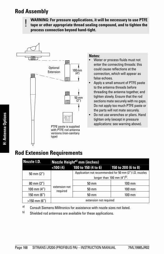
mm
mm
m
H: A
nten
na O
ptio
ns
Rod Assembly
Rod Extension Requirements
WARNING: For pressure applications, it will be necessary to use PTFE tape or other appropriate thread sealing compound, and to tighten the process connection beyond hand-tight.
Nozzle I.D. Nozzle Heighta) mm (inches)
a) Consult Siemens Milltronics for assistance with nozzle sizes not listed.
<100 (4) 100 to 150 (4 to 6) 150 to 200 (6 to 8)50 mm (2”)
extension not required
Application not recommended for 50 mm (2”) I.D. nozzles
longer than 100 mm (4”)b).
b) Shielded rod antennas are available for these applications.
80 mm (3”) 50 mm 100 mm
100 mm (4”) 50 mm 100 mm
150 mm (6”) 50 mm 100 mm
>150 mm (6”) extension not required
50 mm(2”)
PTFE paste is supplied with PTFE rod antenna versions (non-sanitary type)
OptionalExtension 100 mm
(4")
Notes:• Water or process fluids must not
enter the connecting threads: this could cause reflections at the connection, which will appear as false echoes.
• Apply a small amount of PTFE paste to the antenna threads before threading the antenna together, and tighten slowly. Ensure that the rod sections mate securely with no gaps. Do not apply too much PTFE paste or the parts will not mate securely.
• Do not use wrenches or pliers. Hand tighten only (except in pressure applications: see warning above).
Page 168 SITRANS LR200 (PROFIBUS PA) – INSTRUCTION MANUAL 7ML19985JR02
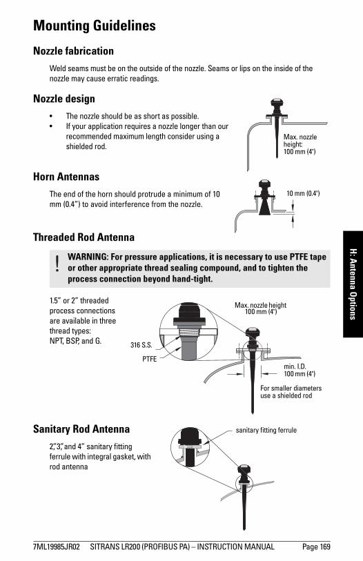
mm
mm
m
H: A
ntenna Options
Mounting Guidelines
Nozzle fabricationWeld seams must be on the outside of the nozzle. Seams or lips on the inside of the nozzle may cause erratic readings.
Nozzle design• The nozzle should be as short as possible. • If your application requires a nozzle longer than our
recommended maximum length consider using a shielded rod.
Horn AntennasThe end of the horn should protrude a minimum of 10 mm (0.4”) to avoid interference from the nozzle.
Threaded Rod Antenna
1.5” or 2” threaded process connections are available in three thread types: NPT, BSP, and G.
Sanitary Rod Antenna2”, 3”, and 4” sanitary fitting ferrule with integral gasket, with rod antenna
WARNING: For pressure applications, it is necessary to use PTFE tape or other appropriate thread sealing compound, and to tighten the process connection beyond hand-tight.
Max. nozzle height: 100 mm (4")
10 mm (0.4")
min. I.D. 100 mm (4")
For smaller diameters use a shielded rod
316 S.S.
PTFE
Max. nozzle height 100 mm (4")
sanitary fitting ferrule
7ML19985JR02 SITRANS LR200 (PROFIBUS PA) – INSTRUCTION MANUAL Page 169
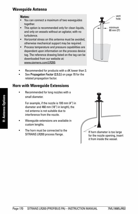
mm
mm
m
H: A
nten
na O
ptio
ns
Waveguide Antenna
• Recommended for products with a dK lower than 3.• See Propagation Factor (2.5.3.) on page 70 for the
related propagation factor.
Horn with Waveguide Extensions• Recommended for long nozzles with a
small diameter.
For example, if the nozzle is 100 mm (4”) in diameter and 460 mm (18”) in length), the rod antenna is not suitable due to interference from the nozzle.
• Waveguide extensions are available in custom lengths.
• The horn must be connected to the SITRANS LR200 process flange.
Notes: • You can connect a maximum of two waveguides
together.• This option is recommended only for clean liquids,
and only on vessels without an agitator, with no turbulence.
• Horizontal stress on this antenna must be avoided, otherwise mechanical support may be required.
• Process temperature and pressure capabilities are dependent upon information on the process device tag. The reference drawing listed on the tag can be downloaded from our website at: www.siemens.com/LR200.
vent hole
minimum 80 mm (3")
If horn diameter is too large for the nozzle opening, insert it from inside the vessel.
Page 170 SITRANS LR200 (PROFIBUS PA) – INSTRUCTION MANUAL 7ML19985JR02
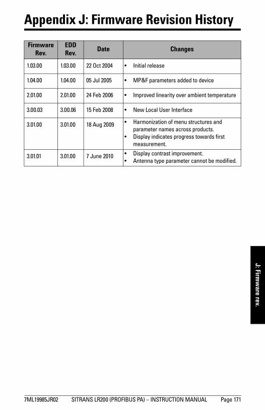
mm
mm
m
J: Firmw
are rev.
Appendix J: Firmware Revision History
Firmware Rev.
EDD Rev. Date Changes
1.03.00 1.03.00 22 Oct 2004 • Initial release
1.04.00 1.04.00 05 Jul 2005 • MP&F parameters added to device
2.01.00 2.01.00 24 Feb 2006 • Improved linearity over ambient temperature
3.00.03 3.00.06 15 Feb 2008 • New Local User Interface
3.01.00 3.01.00 18 Aug 2009 • Harmonization of menu structures and parameter names across products.
• Display indicates progress towards first measurement.
3.01.01 3.01.00 7 June 2010 • Display contrast improvement.• Antenna type parameter cannot be modified.
7ML19985JR02 SITRANS LR200 (PROFIBUS PA) – INSTRUCTION MANUAL Page 171

mm
mm
m
J: F
irmw
are
rev.
Notes
Page 172 SITRANS LR200 (PROFIBUS PA) – INSTRUCTION MANUAL 7ML19985JR02
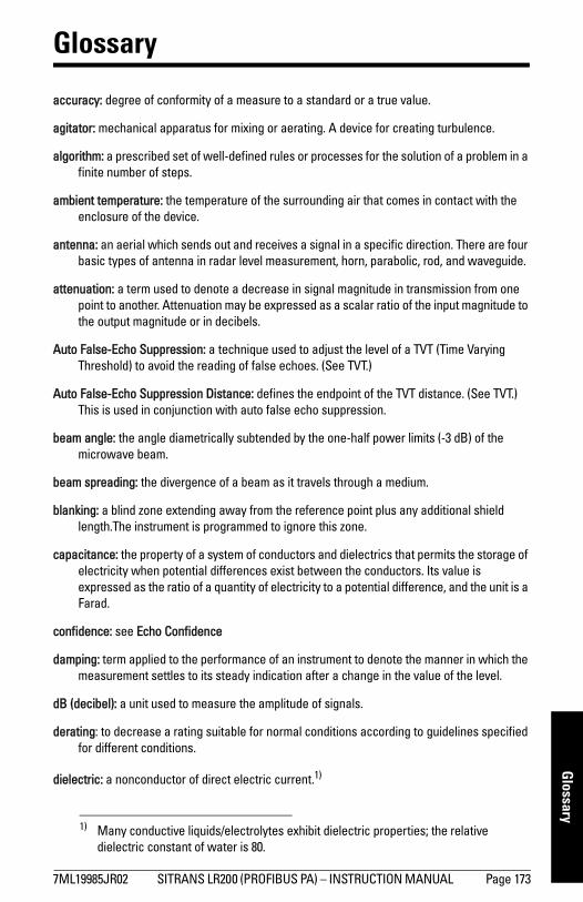
mm
mm
m
Glossary
Glossary
accuracy: degree of conformity of a measure to a standard or a true value.
agitator: mechanical apparatus for mixing or aerating. A device for creating turbulence.
algorithm: a prescribed set of well-defined rules or processes for the solution of a problem in a finite number of steps.
ambient temperature: the temperature of the surrounding air that comes in contact with the enclosure of the device.
antenna: an aerial which sends out and receives a signal in a specific direction. There are four basic types of antenna in radar level measurement, horn, parabolic, rod, and waveguide.
attenuation: a term used to denote a decrease in signal magnitude in transmission from one point to another. Attenuation may be expressed as a scalar ratio of the input magnitude to the output magnitude or in decibels.
Auto False-Echo Suppression: a technique used to adjust the level of a TVT (Time Varying Threshold) to avoid the reading of false echoes. (See TVT.)
Auto False-Echo Suppression Distance: defines the endpoint of the TVT distance. (See TVT.) This is used in conjunction with auto false echo suppression.
beam angle: the angle diametrically subtended by the one-half power limits (-3 dB) of the microwave beam.
beam spreading: the divergence of a beam as it travels through a medium.
blanking: a blind zone extending away from the reference point plus any additional shield length.The instrument is programmed to ignore this zone.
capacitance: the property of a system of conductors and dielectrics that permits the storage of electricity when potential differences exist between the conductors. Its value is expressed as the ratio of a quantity of electricity to a potential difference, and the unit is a Farad.
confidence: see Echo Confidence
damping: term applied to the performance of an instrument to denote the manner in which the measurement settles to its steady indication after a change in the value of the level.
dB (decibel): a unit used to measure the amplitude of signals.
derating: to decrease a rating suitable for normal conditions according to guidelines specified for different conditions.
dielectric: a nonconductor of direct electric current.1)
1) Many conductive liquids/electrolytes exhibit dielectric properties; the relative dielectric constant of water is 80.
7ML19985JR02 SITRANS LR200 (PROFIBUS PA) – INSTRUCTION MANUAL Page 173
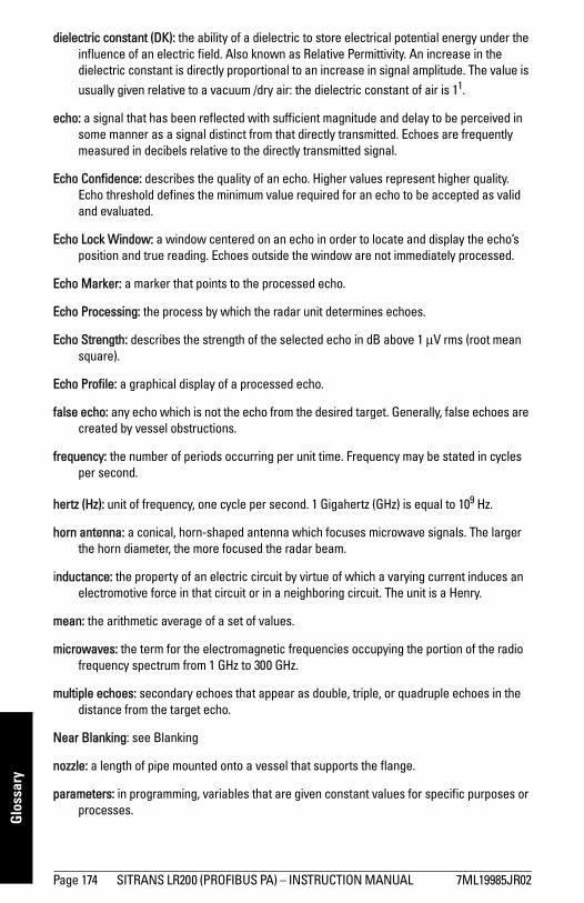
mm
mm
m
Glo
ssar
y
dielectric constant (DK): the ability of a dielectric to store electrical potential energy under theinfluence of an electric field. Also known as Relative Permittivity. An increase in the dielectric constant is directly proportional to an increase in signal amplitude. The value is usually given relative to a vacuum /dry air: the dielectric constant of air is 11.
echo: a signal that has been reflected with sufficient magnitude and delay to be perceived in some manner as a signal distinct from that directly transmitted. Echoes are frequently measured in decibels relative to the directly transmitted signal.
Echo Confidence: describes the quality of an echo. Higher values represent higher quality. Echo threshold defines the minimum value required for an echo to be accepted as valid and evaluated.
Echo Lock Window: a window centered on an echo in order to locate and display the echo’s position and true reading. Echoes outside the window are not immediately processed.
Echo Marker: a marker that points to the processed echo.
Echo Processing: the process by which the radar unit determines echoes.
Echo Strength: describes the strength of the selected echo in dB above 1 μV rms (root mean square).
Echo Profile: a graphical display of a processed echo.
false echo: any echo which is not the echo from the desired target. Generally, false echoes are created by vessel obstructions.
frequency: the number of periods occurring per unit time. Frequency may be stated in cycles per second.
hertz (Hz): unit of frequency, one cycle per second. 1 Gigahertz (GHz) is equal to 109 Hz.
horn antenna: a conical, horn-shaped antenna which focuses microwave signals. The larger the horn diameter, the more focused the radar beam.
inductance: the property of an electric circuit by virtue of which a varying current induces an electromotive force in that circuit or in a neighboring circuit. The unit is a Henry.
mean: the arithmetic average of a set of values.
microwaves: the term for the electromagnetic frequencies occupying the portion of the radio frequency spectrum from 1 GHz to 300 GHz.
multiple echoes: secondary echoes that appear as double, triple, or quadruple echoes in the distance from the target echo.
Near Blanking: see Blanking
nozzle: a length of pipe mounted onto a vessel that supports the flange.
parameters: in programming, variables that are given constant values for specific purposes or processes.
Page 174 SITRANS LR200 (PROFIBUS PA) – INSTRUCTION MANUAL 7ML19985JR02
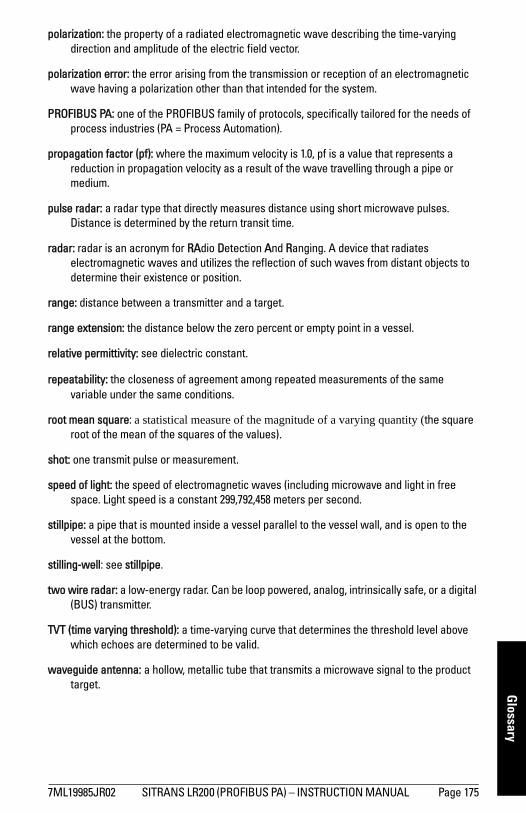
mm
mm
m
Glossary
polarization: the property of a radiated electromagnetic wave describing the time-varying direction and amplitude of the electric field vector.
polarization error: the error arising from the transmission or reception of an electromagnetic wave having a polarization other than that intended for the system.
PROFIBUS PA: one of the PROFIBUS family of protocols, specifically tailored for the needs of process industries (PA = Process Automation).
propagation factor (pf): where the maximum velocity is 1.0, pf is a value that represents a reduction in propagation velocity as a result of the wave travelling through a pipe or medium.
pulse radar: a radar type that directly measures distance using short microwave pulses. Distance is determined by the return transit time.
radar: radar is an acronym for RAdio Detection And Ranging. A device that radiates electromagnetic waves and utilizes the reflection of such waves from distant objects to determine their existence or position.
range: distance between a transmitter and a target.
range extension: the distance below the zero percent or empty point in a vessel.
relative permittivity: see dielectric constant.
repeatability: the closeness of agreement among repeated measurements of the same variable under the same conditions.
root mean square: a statistical measure of the magnitude of a varying quantity (the square root of the mean of the squares of the values).
shot: one transmit pulse or measurement.
speed of light: the speed of electromagnetic waves (including microwave and light in free space. Light speed is a constant 299,792,458 meters per second.
stillpipe: a pipe that is mounted inside a vessel parallel to the vessel wall, and is open to the vessel at the bottom.
stilling-well: see stillpipe.
two wire radar: a low-energy radar. Can be loop powered, analog, intrinsically safe, or a digital (BUS) transmitter.
TVT (time varying threshold): a time-varying curve that determines the threshold level above which echoes are determined to be valid.
waveguide antenna: a hollow, metallic tube that transmits a microwave signal to the product target.
7ML19985JR02 SITRANS LR200 (PROFIBUS PA) – INSTRUCTION MANUAL Page 175

mm
mm
m
Glo
ssar
y
Notes
Page 176 SITRANS LR200 (PROFIBUS PA) – INSTRUCTION MANUAL 7ML19985JR02
mm
mm
m
Index
Index
Aabbreviations
list 3access control
local access 101remote access 101
Acknowledge Faultsvia PDM 49
activating SITRANS LR200 25acyclic diagnostics
fault codes 147address lock
disable 86antenna replacement 115application examples
level measurement in storage vessel 130
level measurement with stillpipe 132volume in horizontal vessel 131
approvals 9Auto False Echo Suppression
explanation 120setup 74setup via LUI 75TVT shaper adjustment 45via PDM 44, 46
Bbeam angle
values 158beam angle spread 15blanking (see Near Range) 121bus address (device address)
resetting to 126 141bus termination 141bypass pipe
installation 16CCalibration Interval 96cleaning
instructions 115CLEF (Constrained Leading Edge Fit)
explanation 118CLEF Range
setup 72Condensed Status
explanation 144
configurationnetwork 140new device via PDM 35PLC with PROFIBUS PA 20Quick Start via LUI 30stillpipe via PDM 42
cyclic data 142versus acyclic 142
Ddamping
explanation 122Filter Time Constant setup 80
data loggingtime-based echo profile storage 45
DDsee Electronic Device Description 140
Device Address 100resetting to 126 141set via LUI 33set via PDM 35
device descriptionsee Electronic Device Description 140
device nameplateFM/CSA Class 1 Div. 2 23
Device Statusview via PDM 54
device statusicons 107
diagnosis reply 146Diagnostics
maintenance settings 81update diagnostics 54via PDM 52
dimensionsFlat-Face flange 164horn antenna 159PTFE threaded rod antenna 154Raise Face flange 162sanitary rod antenna 161uni-construction PP rod 11waveguide 159
displaysee LCD display 25
Eecho confidence
explanation 119view 73
Echo Processing 116Process Intelligence 116
Echo Profile
Note: Parameter names are capitalized.
7ML19985JR02 SITRANS LR200 (PROFIBUS PA) – INSTRUCTION MANUAL Page 177
mm
mm
m
Inde
x
data logging 45view via LUI 32view via PDM 44Echo Profile UtilitiesEcho Profile, TVT Shaper, Auto False
Echo Suppression 44echo selection
Algorithm 117CLEF (Constrained Leading Edge Fit)
118Position Detect 117Time Varying Threshold (TVT) 117
Echo Setupquick access via PDM 48
EDDsee Electronic Device Description 35
edit modehandheld programmer 29
Electronic Device Description (EDD)required for PROFIBUS PA 140updating 35
emission coneillustration 15
Empty ratesetup 65
enclosureopening 19
FFactory Defaults
reset via PDM 52factory defaults 86Fail-safe
Behavior explanation 123Mode explanation 123Value explanation 123
Fail-safe Mode FB1setup 80
Far Rangeexplanation 121setup 69
fault codesacyclic diagnostics 147acyclic extended diagnostics 149general fault codes 109icons 109
Fill Ratesetup 64
Filter Time Constantexplanation 122
flange dimensions
Flat-Face 164Raised Face 163
flange markingsFlat-Face 166Raised Face 163
Function BlocksAnalog Input Function Blocks 137Transducer Block (TB) 135view process variables via PDM 53
function keysedit mode 29measurement mode 26navigation mode 28
GGSD file 140Hhandheld programmer
edit mode 29measurement mode 26navigation 28programming 27
hazardous area installationsinstructions 24wiring 21
hysteresissetup 79
Iicons
device status 107fault codes 109
identifications and abbreviationslist 3
installationenclosure rotating 18hazardous area wiring 21requirements 13temperature guidelines 15vessel shape notes 14warnings and notes 13
internal temperaturemonitoring 124
Kkey functions
measurement mode 26navigation mode 28
LLanguage 101LCD display
Contrast 100echo profile viewing 32
Page 178 SITRANS LR200 (PROFIBUS PA) – INSTRUCTION MANUAL 7ML19985JR02
mm
mm
m
Index
Fast Mode 99measurement mode 25PROGRAM mode 26lid-lock set screw 19Limit Hysteresis
setup 79linearization
via PDM 39local access
write protection 101Local Operation
enable/disable 101lock
address lock, disable 86local operation enable/disable 101Remote Lockout 101Write Locking via PDM 51write protection 101
locking ring 18LOE Timer
explanation 122setup 62
Loss of Echo (LOE)explanation 122
LUI (local user interface)local user interface (LUI) 25
Mmaintenance 115
antenna replacement 115calibration schedules 48cleaning 115repairs 115service schedules 48
maintenance settingssee Diagnostics 81
markingsthreaded connection 12
Master Resetfactory defaults 86reset PROFIBUS address to 126 86standard defaults 86
measurement rangeblanking (Near Range) 69extension (Far Range) 69maximum 6
mountingflange mounting instructions 167flange-mounted options 169nozzle design 14, 125nozzle location 14, 125
on vessel with obstructions 16NNear Range
explanation 121setup 69
OOperating Mode
level, distance, space 31operating principles 116orientation
in vessel with obstructions 16Output Limits
setup 79Output Scale
setup 78Pparameters
reset via PDM 42password protection
via PDM 56PDM
see SIMATIC PDM 34peak values
electronics temperature 55sensor peak values
FB1 and FB2 55performance
specifications 6pipe sizes
FF flange mounting 165RF flange mounting 163
polarization reference point 16power consumption 141power source
requirements 19Process Intelligence 116process temperature
maximum 124Process Variables
view via PDM 52PROFIBUS
address 141address reset to 126 86address reset to 126 via PDM 52address set via LUI 33address set via PDM 35device design 134Ident Number 100
programmerhandheld 26
7ML19985JR02 SITRANS LR200 (PROFIBUS PA) – INSTRUCTION MANUAL Page 179
mm
mm
m
Inde
x
programming LR200enter program mode 28via handheld programmer 27
Propagation Factor 70QQuick Start wizard
via LUI 30via PDM 36
Rreading erratic 114reading incorrect 113reading response slow 114Remote Lockout 101remote operation
enable/disable 101repair
antenna replacement 115cautions 115excluded liability 115
resetsMaster Reset 86
Response Rateexplanation 121setup 64
rod assembly 168rod extension requirements 168Ssafety notes 1security
access control 101password protection via PDM 56
Service Interval 93settings
adjust parameters via LUI 27, 29adjust parameters via PDM 42
SIMATIC PDMfeatures of rev. 6.0 SP4 34overview 34, 140Rev. 5.2, SP1 35
Simulate Analog Inputvia PDM 49
Simulate Inputvia PDM 51
Simulate Outputvia PDM 50
Simulationvia PDM 49
SITRANS LR200operating principles 116overview 5
startuptransition screen 25
statusupdate diagnostics 54
status bytestatus codes 143
status codes 143stillpipe
installation 16stillpipe application
configuring via PDM 42Support
contact information 3TTechnical Support 3temperature de-Rating
curves 125terminal access 19threaded connection markings 166trend view
via PDM 54troubleshooting
communications 106operation 113
TVT (time varying threshold)explanation 117
TVT Shapermanual adjustment via PDM 45via PDM 44
Vvessel shape
installation notes 14selection 65
WWear
powered hours, poweron resets 49wiring
connecting LR200 19hazardous area installations 21terminal access 19
Write Lockingvia PDM 51
Write Protection 101
Page 180 SITRANS LR200 (PROFIBUS PA) – INSTRUCTION MANUAL 7ML19985JR02
SITRANS L S LR200 (PROFIBUS PA) – INSTRUCTION MANUAL 7ML19985JR02
App
endi
x C:
men
u ch
art
R200 (PROFIBUS PA) – INSTRUCTION MANUAL Page 181 SITRAN
LCD menu structure
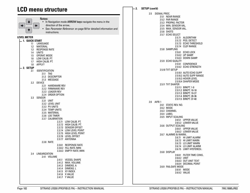
Page 182 SIT ITRANS LR200 (PROFIBUS PA) – INSTRUCTION MANUAL 7ML19985JR02
App
endi
x C:
men
u ch
art LCD menu structure
LEVEL METER1. QUICK START
1.1 LANG1.2 MATE1.3 RESPO1.4 UNITS1.5 OPERA1.6 LOW C1.7 HIGH C1.8 APPLY
2. SETUP2.1 IDENT
222
2.2 DEVIC2222
2.3 SENSO2222222
2
2.4 LINEA2
2.5 SIGNAL PROC.2.5.1 NEAR RANGE2.5.2 FAR RANGE2.5.3 PROPAG. FACTOR2.5.4 MIN. SENSOR VAL.2.5.5 MAX. SENSOR VAL.2.5.6 SHOTS2.5.7 ECHO SELECT
2.5.7.1 ALGORITHM2.5.7.2 POS. DETECT2.5.7.3 ECHO THRESHOLD2.5.7.4 CLEF RANGE
2.5.8 SAMPLING2.5.8.1 ECHO LOCK2.5.8.2 UP SAMP.2.5.8.3 DOWN SAMP.
2.5.9 ECHO QUALITY2.5.9.1 CONFIDENCE2.5.9.2 ECHO STRENGTH
2.5.10 TVT SETUP2.5.10.1 AUTO ECHO SUPP2.5.10.2 AUTO SUPP RANGE2.5.10.3 HOVER LEVEL2.5.10.4 SHAPER MODE
2.5.11 TVT SHAPER2.5.11.1 BRKPT. 1-92.5.11.2 BRKPT. 10-182.5.11.3 BRKPT. 19-272.5.11.4 BRKPT. 28-362.5.11.5 BRKPT. 37-40
6 AIFB 12.6.1 STATIC REV. NO.2.6.2 MODE2.6.3 CHANNEL2.6.4 LABEL2.6.5 INPUT SCALING
2.6.5.1 UPPER VALUE2.6.5.2 LOWER VALUE
2.6.6 OUTPUT SCALING2.6.6.1 UPPER VALUE2.6.6.2 LOWER VALUE
2.6.7 ALARMS & WARNI..2.6.7.1 HI LIMIT ALARM2.6.7.2 HI LIMIT WARN2.6.7.3 LO LIMIT WARN2.6.7.4 LO LIMIT ALARM2.6.7.5 LIMIT HYSTERESI..
2.6.8 DISPLAY2.6.8.1 FILTER TIME CONS..2.6.8.2 UNIT2.6.8.3 OUT UNIT TEXT2.6.8.4 DECIMAL POINT
2.6.9 FAIL-SAFE MODE2.6.9.1 MODE2.6.9.2 VALUE
Notes: • In Navigation mode ARROW keys navigate the menu in the
direction of the arrow.. • See Parameter Reference on page 59 for detailed information and
2. SETUP (cont’d)
RANS LR200 (PROFIBUS PA) – INSTRUCTION MANUAL S
UAGERIALNSE RATE
T. MODEALIB. PT.ALIB. PT.
?
IFICATION.1.1 TAG.1.2 DESCRIPTOR.1.3 MESSAGEE.2.1 HARDWARE REV.2.2 FIRMWARE REV.2.3 LOADER REV.2.4 ORDER OPTIONR
.3.1 UNIT
.3.2 LEVEL UNIT
.3.3 PV UNITS
.3.4 TEMP UNITS
.3.5 MATERIAL
.3.6 LOE TIMER
.3.7 CALIBRATION2.3.7.1 LOW CALIB. PT.2.3.7.2 HIGH CALIB. PT.2.3.7.3 SENSOR OFFSET2.3.7.4 LOW LEVEL POINT2.3.7.5 HIGH LEVEL POINT2.3.7.6 LEVEL OFFSET2.3.7.7 ANTENNA
.3.8 RATE2.3.8.1 RESPONSE RATE2.3.8.2 FILL RATE /MIN2.3.8.3 EMPTY RATE /MIN
RIZATION.4.1 VOLUME
2.4.1.1 VESSEL SHAPE2.4.1.2 MAX. VOLUME2.4.1.3 DIMENS. A2.4.1.4 DIMENS. L2.4.1.5 XY INDEX2.4.1.6 X VALUE2.4.1.7 Y VALUE
2.
instructions.
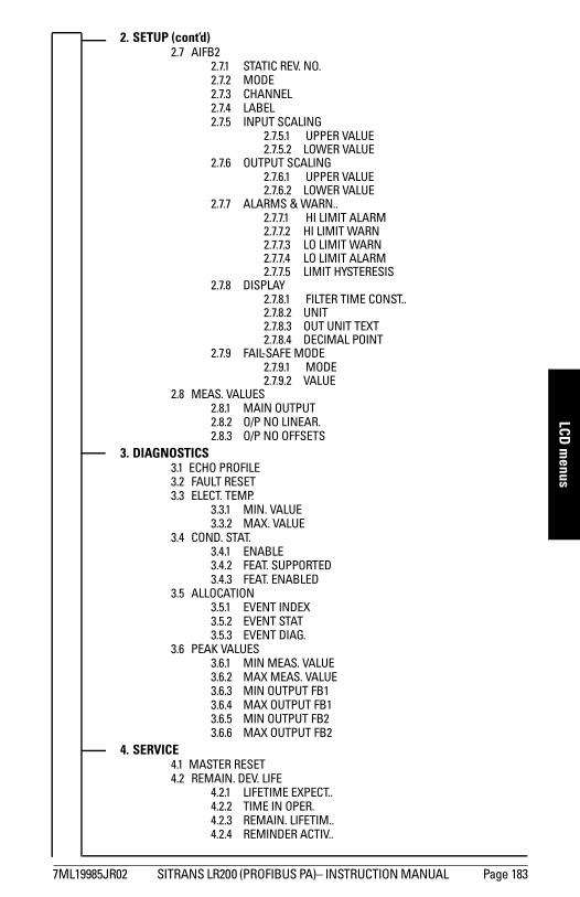
mm
mm
m
LCD m
enus
2. SETUP (cont’d)2.7 AIFB22.7.1 STATIC REV. NO.2.7.2 MODE2.7.3 CHANNEL2.7.4 LABEL2.7.5 INPUT SCALING
2.7.5.1 UPPER VALUE2.7.5.2 LOWER VALUE
2.7.6 OUTPUT SCALING2.7.6.1 UPPER VALUE2.7.6.2 LOWER VALUE
2.7.7 ALARMS & WARN..2.7.7.1 HI LIMIT ALARM2.7.7.2 HI LIMIT WARN2.7.7.3 LO LIMIT WARN2.7.7.4 LO LIMIT ALARM2.7.7.5 LIMIT HYSTERESIS
2.7.8 DISPLAY2.7.8.1 FILTER TIME CONST..2.7.8.2 UNIT2.7.8.3 OUT UNIT TEXT2.7.8.4 DECIMAL POINT
2.7.9 FAIL-SAFE MODE2.7.9.1 MODE2.7.9.2 VALUE
2.8 MEAS. VALUES2.8.1 MAIN OUTPUT2.8.2 O/P NO LINEAR.2.8.3 O/P NO OFFSETS
3. DIAGNOSTICS3.1 ECHO PROFILE3.2 FAULT RESET3.3 ELECT. TEMP.
3.3.1 MIN. VALUE3.3.2 MAX. VALUE
3.4 COND. STAT.3.4.1 ENABLE3.4.2 FEAT. SUPPORTED3.4.3 FEAT. ENABLED
3.5 ALLOCATION3.5.1 EVENT INDEX3.5.2 EVENT STAT3.5.3 EVENT DIAG.
3.6 PEAK VALUES3.6.1 MIN MEAS. VALUE3.6.2 MAX MEAS. VALUE3.6.3 MIN OUTPUT FB13.6.4 MAX OUTPUT FB13.6.5 MIN OUTPUT FB23.6.6 MAX OUTPUT FB2
4. SERVICE4.1 MASTER RESET4.2 REMAIN. DEV. LIFE
4.2.1 LIFETIME EXPECT..4.2.2 TIME IN OPER.4.2.3 REMAIN. LIFETIM..4.2.4 REMINDER ACTIV..
7ML19985JR02 SITRANS LR200 (PROFIBUS PA)– INSTRUCTION MANUAL Page 183
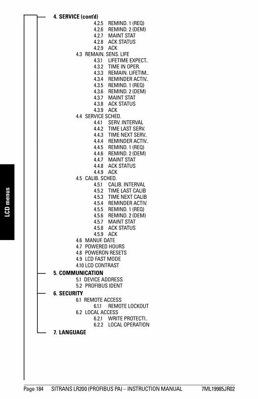
mm
mm
m
LCD
men
us
4. SERVICE (cont’d)4.2.5 REMIND. 1 (REQ)4.2.6 REMIND. 2 (DEM)4.2.7 MAINT STAT4.2.8 ACK STATUS4.2.9 ACK
4.3 REMAIN. SENS. LIFE4.3.1 LIFETIME EXPECT..4.3.2 TIME IN OPER.4.3.3 REMAIN. LIFETIM..4.3.4 REMINDER ACTIV..4.3.5 REMIND. 1 (REQ)4.3.6 REMIND. 2 (DEM)4.3.7 MAINT STAT4.3.8 ACK STATUS4.3.9 ACK
4.4 SERVICE SCHED. 4.4.1 SERV. INTERVAL4.4.2 TIME LAST SERV.4.4.3 TIME NEXT SERV..4.4.4 REMINDER ACTIV..4.4.5 REMIND. 1 (REQ)4.4.6 REMIND. 2 (DEM)4.4.7 MAINT STAT4.4.8 ACK STATUS4.4.9 ACK
4.5 CALIB. SCHED. 4.5.1 CALIB. INTERVAL4.5.2 TIME LAST CALIB4.5.3 TIME NEXT CALIB4.5.4 REMINDER ACTIV.4.5.5 REMIND. 1 (REQ)4.5.6 REMIND. 2 (DEM)4.5.7 MAINT STAT4.5.8 ACK STATUS4.5.9 ACK
4.6 MANUF. DATE4.7 POWERED HOURS4.8 POWERON RESETS4.9 LCD FAST MODE4.10 LCD CONTRAST
5. COMMUNICATION5.1 DEVICE ADDRESS5.2 PROFIBUS IDENT
6. SECURITY6.1 REMOTE ACCESS
6.1.1 REMOTE LOCKOUT6.2 LOCAL ACCESS
6.2.1 WRITE PROTECTI.. 6.2.2 LOCAL OPERATION
7. LANGUAGE
Page 184 SITRANS LR200 (PROFIBUS PA) – INSTRUCTION MANUAL 7ML19985JR02

www.siemens.com/processautomation
Printed in Canada
"""#���$���#��$ ����������%"���&���
"""#���$���#��$ '�(�'
����$������)��$�����
"""#���$���#��$ �����������$�����
����������� ������� ��������������������������������� ���� ���������������� ��� ��!���"��# $��%%������& � ���'�"()������*�+�,#�
��&-����� ��������.��� ���/�� ��� ����0�!��%�%
����1�����/�&����/�2��������� �
3������������ ������� ����������������������%4�4 *7ml19985JR02*


