Embed Size (px)
Citation preview

Seediscussions,stats,andauthorprofilesforthispublicationat:https://www.researchgate.net/publication/228913185
Lunarsciencewithaffordablesmallspacecrafttechnologies:MoonLITEandMoonraker
ARTICLEinPLANETARYANDSPACESCIENCE·MARCH2008
ImpactFactor:1.88·DOI:10.1016/j.pss.2007.11.005
CITATIONS
26
READS
81
15AUTHORS,INCLUDING:
IanACrawford
Birkbeck,UniversityofLondon
313PUBLICATIONS2,214CITATIONS
SEEPROFILE
AlexDaSilvaCuriel
SurreySatelliteTechnologyLimited
62PUBLICATIONS287CITATIONS
SEEPROFILE
AlanSmith
UniversityCollegeLondon
686PUBLICATIONS10,028CITATIONS
SEEPROFILE
Availablefrom:IanACrawford
Retrievedon:04February2016

ARTICLE IN PRESS
0032-0633/$ - se
doi:10.1016/j.ps
�CorrespondE-mail addr
1Recent Eart
Planetary and Space Science 56 (2008) 368–377
www.elsevier.com/locate/pss
Lunar science with affordable small spacecraft technologies:MoonLITE and Moonraker
Yang Gaoa,�, Andy Phippsb, Mark Taylorb, Ian A. Crawfordd, Andrew J. Balle,Lionel Wilsonf, Dave Parkerc, Martin Sweetinga,b, Alex da Silva Curielb, Phil Daviesb,
Adam Bakerb, W.Thomas Pikeg, Alan Smithh, Rob Gowenh
aSurrey Space Centre, University of Surrey, Guildford GU2 7XH, UKbSurrey Satellite Technology Limited, Surrey Space Centre, Guildford GU2 7YE, UK
cBritish National Space Centre, London SW1W 9SS, UKdSchool of Earth Sciences, Birkbeck College, London WC1E 7HX, UK
ePlanetary and Space Sciences Research Institute, Centre for Earth, Planetary, Space and Astronomical Research, The Open University,
Walton Hall, Milton Keynes MK7 6AA, UKfEnvironmental Science Department, Lancaster University, Lancaster LA1 4YQ, UK
gDepartment of Electrical and Electronic Engineering, Imperial College London, London SW7 2AZ, UKhMullard Space Science Laboratory, University College London, Dorking RH5 6NT, UK
Received 13 June 2007; received in revised form 6 November 2007; accepted 9 November 2007
Available online 22 November 2007
Abstract
Returning to the Moon has been advocated by a large number of international planetary scientists in order to answer several key
scientific questions. The UK also has an active lunar science community keen to support (robotic) lunar exploration missions. However,
for several years these interests have been eclipsed by the drive to Mars. Recently there is a renewed global interest in the Moon
demonstrated by the Vision for Space Exploration in the USA, the evolving Global Exploration Partnership, and new lunar missions
from Europe, Japan, China, India and the USA. The ESA Aurora programme may also broaden its focus to embrace the Moon as well
as Mars—realizing that the risks associated with many of the major technical challenges that are faced by Mars missions could be
reduced by relatively inexpensive and timely lunar technology tests. Surrey Satellite Technology Ltd. (SSTL) and Surrey Space Centre
(SSC) have been preparing a ‘smallsat’ approach [Sweeting, M.N., Underwood, C.I., 2003. Small-satellite engineering and applications.
In: Fortescue, P., Stark, J., Swinerd, G., (Eds.), Spacecraft Systems Engineering, third edition. Wiley, New York, pp. 581–612] to
achieving a low-cost lunar mission for more than a decade—including various activities, such as the earlier LunarSat study funded by
ESA and a current hardware contribution to the Chandrayaan-1 mission. With the recent successes in GIOVE-A, TOPSAT and
BEIJING-1,1 alongside participation in Aurora and Chandrayaan-1, Surrey have developed capabilities for providing affordable
engineering solutions to space exploration. Recently, SSTL/SSC was funded by the UK Particle Physics and Astronomy Research
Council (PPARC) (now subsumed into the UK Science and Technology Facilities Council) to undertake a study on low-cost lunar
mission concepts that could address key scientific questions. This paper presents some major results from this study [Phipps and Gao,
2006. Lunar mission options study. UK Particle Physics and Astronomy Research Council Report Reference No. 118537, pp. 1–104] and
provides preliminary definitions of two mission proposals.
r 2007 Elsevier Ltd. All rights reserved.
Keywords: The moon; Mission definition; Lunar science; Spacecraft design
e front matter r 2007 Elsevier Ltd. All rights reserved.
s.2007.11.005
ing author. Tel.: +441483 683446.
ess: [email protected] (Y. Gao).
h satellite missions built and launched by SSTL.
1. Introduction
Since the last Apollo landing on the Moon in 1972, ourknowledge of the Solar System has expanded immeasurably,

ARTICLE IN PRESSY. Gao et al. / Planetary and Space Science 56 (2008) 368–377 369
raising questions that cannot be answered from Earth(Phipps and Gao, 2006). There is now a global renewedinterest in returning to the Moon, driven both by thedemands of science and as a stepping-stone for humanexploration of the Solar System (Crawford, 2004; ESA,1992; Jolliff et al., 2006). In terms of science, the Moonprovides a unique record of processes affecting evolution ofterrestrial planets during the first Giga-year or so ofSolar System history. This includes internal processesof geological evolution (e.g. differentiation and crustformation) and external processes caused by the environ-ment (e.g. meteoroid and asteroid flux, interplanetarydust density, solar wind flux and composition, galacticcosmic ray flux) that are not as easily examined anywhereelse in our Solar System (Ball and Crawford, 2006;National Research Council, 2007; Spudis, 1996; Stern,2005). So far, all the in situ measurements of the lunarsurface have been obtained by soft landings on the nearside of the Moon, from Apollo, Luna and Surveyormissions. Actual samples have been returned from only 9locations from mid- to low-latitudes on the near side, the 6Apollo and 3 Luna landing sites, although the samplecollection has been supplemented by the discovery of 40+lunar meteorites (see http://meteorites.wustl.edu/lunar/moon_meteorites_list_alumina.htm and http://curator.jsc.nasa.gov/antmet/lmc/index.cfm for details). There is littledoubt that returning to the Moon could, with sustainedeffort, vastly enhance our knowledge of the Solar Systemand of our own planet. The UK for instance already playsa significant role in lunar science research by participatingin the Clementine, SMART-1, Chandrayaan-1 and LROmissions, as well as through geological studies using remotesensing and lunar meteorite data as inputs to theoreticalmodelling.
During 2006, PPARC funded SSTL to carry out a pre-phase-A study of a UK-led small-scale lunar mission.A fundamental driver in the study was that anyUK-led mission must (1) be affordable2; (2) satisfy keyscience objectives not yet addressed; (3) offer the oppor-tunity for educational outreach; and (4) stimulate UKindustrial capability in space exploration. Initially, thestudy assessed the scientific and technological requirementsof three mission options, namely orbiter, lander andsample-return. The design and cost drivers in termsof science performance and required technology wereidentified. First-level system design and trade-offs wereperformed. Finally, two mission proposals were estab-lished, namely MoonLITE and Moonraker. This paperpresents a preliminary mission definition, including thescience and technology, of the two mission concepts, aswell as a science comparison with forthcoming approvedmissions.
2The low-cost concept is basically reflected in low launch mass. The
ROM cost estimate of MoonLITE is 100 million pounds. Such a costing
exercise is not yet done for Moonraker but it is deemed more expensive
due to higher development cost.
2. MoonLITE (Moon Lightweight Interior and Telecom
Experiment)
2.1. Mission rationale
The MoonLITE mission concept comprises a smallorbiter and four penetrators (see Fig. 1). The orbiter willdemonstrate communications and navigation technologiesaimed at supporting future exploration missions, whilst theprimary scientific goal is to investigate the seismicenvironment and deep structure of the Moon includingthe nature of the core, by placing a network ofseismometers via penetrators on the lunar surface. Thefour penetrators would be widely spaced over the surface,with a pair on the near side (a preference for one being inthe same area as one of the Apollo seismic stations forcalibration purposes) and the other pair on the far side. Inaddition, heat flow experiments will be conducted. Ifpossible, one penetrator would be targeted at a polar coldtrap and equipped with an experiment to detect water andother volatiles. The surface mission is proposed to last 1year at least, driven by the maximum life expectancy of theseismic network constrained by power source likely to beavailable. Other science experiments do not require so long(a few lunar diurnal cycles for heat flow, and much less forvolatiles). Provision for penetrator descent imagery wouldbe desirable for both science context and outreachpurposes.The demonstration of instrumented penetrators for the
Moon, using non-aerodynamic attitude stabilization,would prove a technology relevant to the scientificexploration of other destinations such as Mercury, Europaand Enceladus. The basic technology for penetrators has
Fig. 1. MoonLITE orbiter carrying four penetrators.
ARTICLE IN PRESS
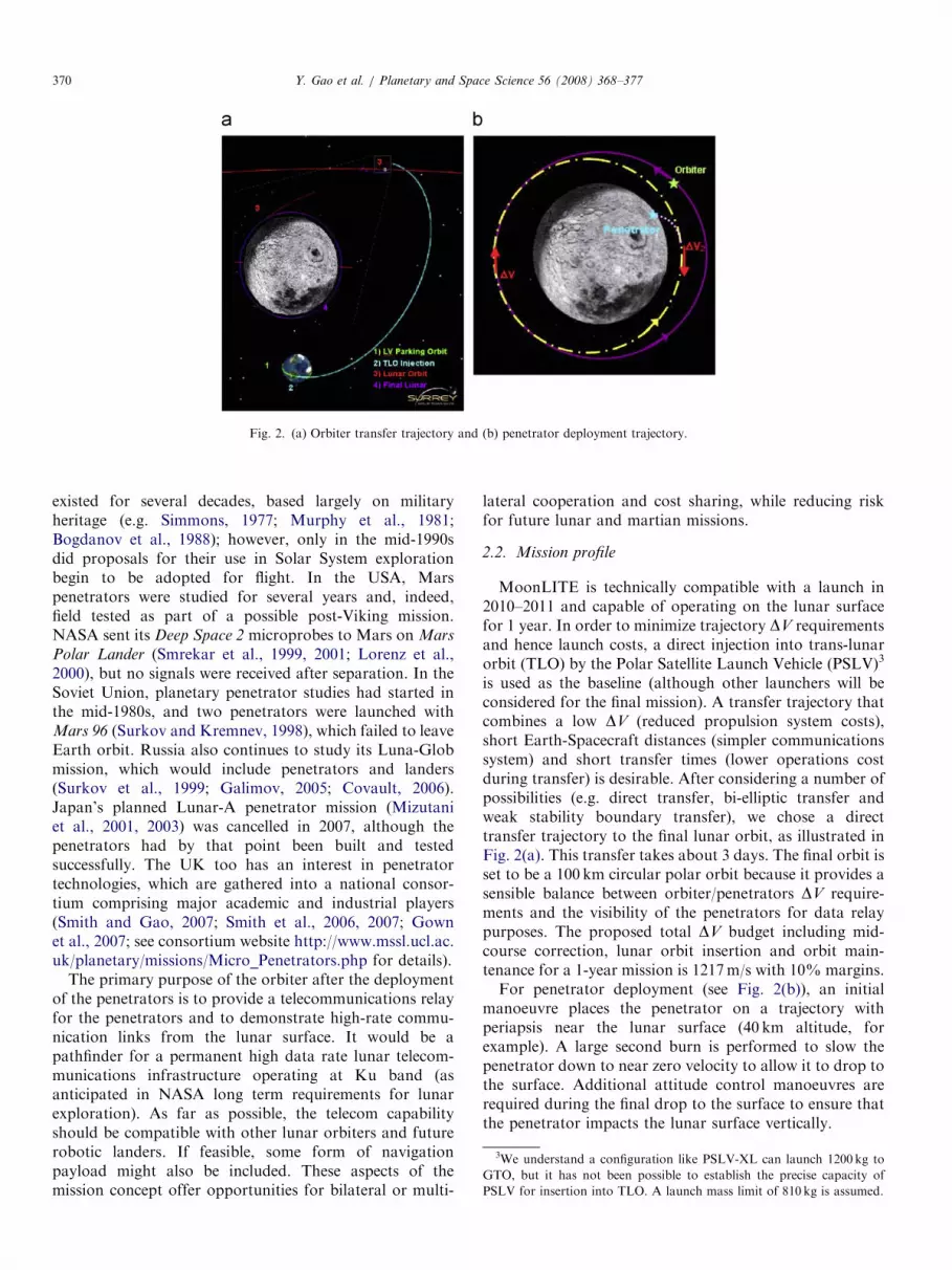
Fig. 2. (a) Orbiter transfer trajectory and (b) penetrator deployment trajectory.
3We understand a configuration like PSLV-XL can launch 1200 kg to
GTO, but it has not been possible to establish the precise capacity of
PSLV for insertion into TLO. A launch mass limit of 810 kg is assumed.
Y. Gao et al. / Planetary and Space Science 56 (2008) 368–377370
existed for several decades, based largely on militaryheritage (e.g. Simmons, 1977; Murphy et al., 1981;Bogdanov et al., 1988); however, only in the mid-1990sdid proposals for their use in Solar System explorationbegin to be adopted for flight. In the USA, Marspenetrators were studied for several years and, indeed,field tested as part of a possible post-Viking mission.NASA sent its Deep Space 2 microprobes to Mars on Mars
Polar Lander (Smrekar et al., 1999, 2001; Lorenz et al.,2000), but no signals were received after separation. In theSoviet Union, planetary penetrator studies had started inthe mid-1980s, and two penetrators were launched withMars 96 (Surkov and Kremnev, 1998), which failed to leaveEarth orbit. Russia also continues to study its Luna-Globmission, which would include penetrators and landers(Surkov et al., 1999; Galimov, 2005; Covault, 2006).Japan’s planned Lunar-A penetrator mission (Mizutaniet al., 2001, 2003) was cancelled in 2007, although thepenetrators had by that point been built and testedsuccessfully. The UK too has an interest in penetratortechnologies, which are gathered into a national consor-tium comprising major academic and industrial players(Smith and Gao, 2007; Smith et al., 2006, 2007; Gownet al., 2007; see consortium website http://www.mssl.ucl.ac.uk/planetary/missions/Micro_Penetrators.php for details).
The primary purpose of the orbiter after the deploymentof the penetrators is to provide a telecommunications relayfor the penetrators and to demonstrate high-rate commu-nication links from the lunar surface. It would be apathfinder for a permanent high data rate lunar telecom-munications infrastructure operating at Ku band (asanticipated in NASA long term requirements for lunarexploration). As far as possible, the telecom capabilityshould be compatible with other lunar orbiters and futurerobotic landers. If feasible, some form of navigationpayload might also be included. These aspects of themission concept offer opportunities for bilateral or multi-
lateral cooperation and cost sharing, while reducing riskfor future lunar and martian missions.
2.2. Mission profile
MoonLITE is technically compatible with a launch in2010–2011 and capable of operating on the lunar surfacefor 1 year. In order to minimize trajectory DV requirementsand hence launch costs, a direct injection into trans-lunarorbit (TLO) by the Polar Satellite Launch Vehicle (PSLV)3
is used as the baseline (although other launchers will beconsidered for the final mission). A transfer trajectory thatcombines a low DV (reduced propulsion system costs),short Earth-Spacecraft distances (simpler communicationssystem) and short transfer times (lower operations costduring transfer) is desirable. After considering a number ofpossibilities (e.g. direct transfer, bi-elliptic transfer andweak stability boundary transfer), we chose a directtransfer trajectory to the final lunar orbit, as illustrated inFig. 2(a). This transfer takes about 3 days. The final orbit isset to be a 100 km circular polar orbit because it provides asensible balance between orbiter/penetrators DV require-ments and the visibility of the penetrators for data relaypurposes. The proposed total DV budget including mid-course correction, lunar orbit insertion and orbit main-tenance for a 1-year mission is 1217m/s with 10% margins.For penetrator deployment (see Fig. 2(b)), an initial
manoeuvre places the penetrator on a trajectory withperiapsis near the lunar surface (40 km altitude, forexample). A large second burn is performed to slow thepenetrator down to near zero velocity to allow it to drop tothe surface. Additional attitude control manoeuvres arerequired during the final drop to the surface to ensure thatthe penetrator impacts the lunar surface vertically.

ARTICLE IN PRESSY. Gao et al. / Planetary and Space Science 56 (2008) 368–377 371
2.3. MoonLITE spacecraft
The basic configuration of the MoonLITE spacecraft isshown in Fig. 3. The concept is based on the GIOVE-Aspacecraft (Benedicto et al., 2006) but only one solar arrayis required, which remains stowed until after penetratordeployment and then rotates. Penetrators for payloaddelivery are bullet-shaped vehicles designed to penetrate asurface and emplace experiments at some depth. The fourpenetrators of the MoonLITE are attached in two pairs onopposite sides of the orbiter body. Each cylindricalpenetrator is to carry and deliver a science payloadpackage to the lunar surface. Table 1 gives specificationsof a strawman payload such as the seismometer and heatflow probe for the primary science objectives of themission. For example, the 3-axis microseismometer isproposed by members of the UK Penetrator Consortiumfrom Imperial College London using novel micromachinedtechnologies (Pike et al., 2004, 2006; Pike and Standley,2005). Performance of such a micro-instrument is com-pared to Apollo, Viking and terrestrial seismometers in
Fig. 3. MoonLITE spac
Table 1
MoonLITE penetrator strawman payload
Science instrument Mass
(g)
Volume
(cm3)
Power
(mW)
Micro-seismometer (3-axis) 300 200 112
Heat flow package 300 20 25 (Normal) 300
(peak)
Water/volatiles detector 750 1000 3000
Geochemistry package (XRS) 260 160 4000
Accelerometer (8 sensors) 56 �8 o500
Tilt-meter (2-axis) 10 25 o100
Descent imager 10 3 160
Fig. 5. The proposed heat flow package will measure thetemperature gradient and thermal conductivity of the lunarregolith. This may, for example, include a number ofsensors located on the outside of the penetrator, such as asuite of 8 relative temperature sensor or thermocouples, 4absolute temperature sensors (Pt-100 or NTC thermistors),and 4 miniature thermal conductivity sensors (e.g. heaterplate with thermocouple, or miniaturized needle probe).More descriptions of the proposed payload can be foundin an ESA Cosmic Vision proposal called LunarEX (seehttp://www.mssl.ucl.ac.uk/planetary/missions/LunarEX_CV_bid-Modified_Dec07.pdf for full report).A conceptual design for the MoonLITE penetrators is
shown in Fig. 4. Each is assumed to have a total massbudget of 36 kg-including 23 kg of propulsion and 13 kg ofactual penetrator carrying a science payload mass of �2 kg.The penetrator is expected to impact the lunar surface ataround 300m/s. The data rate from the penetrator to theorbiter is assumed to be 30 kbits/day. Because of theinfrequent communication contacts with the orbiter (e.g.every 15 days), each penetrator will need to operate
ecraft configuration.
OBDH Telemetry
10 samples/s/axis and 24 bit each; Total
data rate of 720 bits/s
6Mbits (corresponding to
�0.5% time during
events)
Temperature measurement at 1/h at
418 bit resolution;
o0.1Mbit for
temperature;
Thermal measurement at 50Hz at 12 bit
resolution
o0.5Mbit for thermal
50Mbits of data in series of operations o2Mbits
No special requirement 50 kbit per spectrum (two
spectra)
100 kHz sampling (equivalent to 3mm
spatial) with 12-bit resolution for 8 axes
0.1Mbit in total
1Hz sampling with 12-bit resolution for
each of 2 axes
1 kbit in total
Offline� 10 data compression on 21
images (32Mbits each)
2Mbits over 28 days;
some over descent (TBD)

ARTICLE IN PRESS
Fig. 4. Concept for lunar kinetic micro-penetrator.
Table 2
MoonLITE mission mass budgets (kg)
Structure 131.0
Communications 8.4
Power 28.7
Solar panels 15.3
AOCS 44.1
Propulsion 66.1
OBDH 6.5
Environmental 16.6
Harness 30.0
Payload (penetrators) 144
System margin 49.1
Total (dry) 539.7
Propellant (transfer, LOI, OM) 296.4
AOCS propellant 10
Propellant (total) 306.4
Total (launch) 846.1
5SSTL is developing a bipropellant engine using high test peroxide
(HTP) and kerosene that would potentially reduce the recurring costs
further (Coxhill, 2002).6
Y. Gao et al. / Planetary and Space Science 56 (2008) 368–377372
autonomously, collecting, compressing, and storing datauntil each uplink opportunity. A small commandingcapability is necessary to allow optimization of seismicdata selection and data volume reduction. Because of thelow radiation environment an FPGA, small micro-con-troller and/or micro-processor solution will be strongcandidates for this mission with relatively high densitymemory. Each penetrator is buried beneath the lunarregolith, and the communication relies on transmissionthrough the regolith (as for Lunar-A penetrators). How-ever, a detailed study will be made of regolith communica-tion transparency properties, and the possibility of atrailing antenna especially for the case of immersion intoregolith containing a significant proportion of ice. Thebaseline design is a body antenna mounted at the aft(trailing) end of the penetrator. The antenna would beconformed to the surface of the penetrator, to ensure asmooth, projection free surface. As the body diameter isquite small for a UHF antenna, a helical or similar antennamay be needed; alternatively dielectric loading could beemployed at the expense of mass. The dielectric propertiesof the regolith would need to be taken into account indesigning the antenna in order to optimize performancewhen buried. The UK penetrator consortium is currentlyinvestigating the key design issues and penetrator sub-systems including AOCS, material, communication, power,payload operations, etc. The LunarEX proposal outlinesthe recent progress.
The spacecraft contains low and medium gain antennas(10 and 15 cm patch) on all faces to provide omni-directional communication coverage. The orbiter has twoS-band ranging receivers (0.5–4 kbps using a 10 cm patchantenna) and transmitters (0.4–2 kbps using a 15 cm patchantenna) for communication with Earth ground stations4
and penetrators. To provide uplink at high speed for othersurface activities on the Moon, the orbiter is also equippedwith one Ku-band receiver (10Mbps using an omni-directional antenna).
A chemical propulsion system is adopted based on abipropellant solution using monomethyl-hydrazine(MMH) and nitrogen tetroxide (NTO) that gives the most
4The Earth ground station baseline is the Rutherford Appleton
Laboratory (RAL) 12m aperture antenna.
mass-efficient solution.5 A single centrally mounted 400 or500N thrust engine (see Fig. 3) is used to perform the mainDV manoeuvres. Four 10N thrusters, located at thecorners of the same panel, are used for attitude controlduring the orbit manoeuvre firings. Together with twoothers on the side, all thrusters would be used for the fullrange of attitude control functions during the mission.Attitude determination is performed using sun sensors
and star cameras, combined with 3-axis gyros utilizedduring manoeuvres. Three-axis attitude control is executedusing four orthogonal reaction wheels and a set of 12redundant thrusters. The on-board propulsion systemmentioned above is used for control during orbit man-oeuvres and wheel de-saturation.6
2.4. Mass budget
The mass budget of MoonLITE is shown in Table 2. Thetotal launch mass is 846 kg including an overall averagemargin of 10%. Further mass reduction trades are beingexplored to reduce the orbiter mass to match theperformance of the PSLV, such as reduced redundancy ofsub-systems (currently everything is dual redundant) andmass minimization of SSTL sub-systems, etc.
3. Moonraker
3.1. Mission rationale
The Moonraker mission consists of a single propulsivesoft-lander (see Figs. 6 and 8) aiming to provide a low-cost
De-saturation is the process of unloading angular momentum from the
reaction wheels (i.e. when the wheels have reached maximum speed). The
wheels are slowed down and the corresponding rotation of the spacecraft
is cancelled out by thrusters to maintain 3-axis pointing.

ARTICLE IN PRESS
Fig. 6. Moonraker lander jettisoning solid motor.
Fig. 7. Lander
Fig. 5. Comparison of microseismometer, Apollo, Viking and terrestrial
(STS-2) seismometers (after Lognonne and Mosser, 1993).
Y. Gao et al. / Planetary and Space Science 56 (2008) 368–377 373
European lander capability for robotic exploration of thelunar surface in preparation for subsequent humanexpeditions. The first mission is targeted to the lunar nearside, which allows direct-to-Earth communications. Theprimary science goal is in situ dating of the young basalts atnorthern Oceanus Procellarum, both for understandinglunar evolution and for better calibrating the lunarcratering rate that is used with assumptions for datingsolid surfaces throughout the whole Solar System (Craw-ford et al., 2007). The envisaged in situ method involves aK–Ar dating technique being investigated at the Universityof Leicester and the Open University, building uponprevious work (Swindle, 2001; Swindle et al., 2001). Thiscombines data from both an X-ray spectrometer and amass spectrometer derived from Beagle 2 and Rosettaheritage. The in situ dating is at present un-proven and hasbeen met with scepticism in some quarters (Taylor et al.,2006), but if successful, it could be of general use at otherrocky planets, and could be used to help select samples forreturn-type missions (e.g. Mars Sample Return (MSR)).Even if in situ dating proves not to be feasible, the X-rayspectrometer derived from Beagle 2 (Sims et al., 1999)would still be suitable for general geochemistry work,which would also be scientifically very valuable ifperformed at sites from which samples have not yet beenreturned.Technologically, the robotic lander could embody great-
er intelligence than ExoMars (e.g. vision-based guidancefor the terminal phase) to allow landing autonomously onthe ejecta blanket of a suitable crater such as Lichtenburgat Oceanus Procellarum. This capability would be novel butis essential for future precision robotic landers (Mars,asteroids, Europa, etc.). Surface sample acquisition mayinvolve robotic arms, miniaturized drills, possibly includinga ‘rake’ to extract small rock fragments of interest from theregolith, giving rise to the mission name, ‘Moonraker’. Themission concept could be implemented driven by the need
trajectory.

ARTICLE IN PRESS
Table 4
Moonraker mission mass budgets (kg)
Science payload 23.6
Y. Gao et al. / Planetary and Space Science 56 (2008) 368–377374
to test vision-based precision terminal guidance usingactive hazard avoidance.
3.2. Mission profile
Moonraker is proposed to launch in 2013. The space-craft is placed directly into a TLO by the PSLV launcher.A direct hyperbolic approach is used to land on thenorthern region of Oceanus Procellarum, which has directvisibility to the Earth. This transfer duration is approxi-mately 5 days. The entire transfer trajectory is shown inFig. 7 illustrating the direct interplanetary transfer,hyperbolic arrival and final descent to the surface. Thedescent phase starts with a spin-stabilized solid motor
Table 3
Moonraker lander strawman payload
Science
instrument
Mass (kg) Power
(W)
Data rate/volume
Gas analysis
package (incl.
sample ovens and
electronics)
8 (excl. sample
acquisition)
Idle:
5–10
Peak:
30–50
1Mbyte/sample;
Min. 10 samples
X-ray
Spectrometer
0.14 per detector (2
off) plus 0.2
electronics (excl.
sample acquisition)
2.7 32 kbits per
measurement
NIR Vis/NIR
imaging
spectrometry
microscope
1 (excl. sample
acquisition)
2 �10Mbit per
measurement
(data cube);
assume 30 samples
Infrared spec
(IRS)
0.5 (excl. sample
acquisition)
1.5 �32 kbits per
measurement;
assume 30 samples
LAMS (laser
ablation mass
spec)
0.5 (excl. sample
acquisition)
3 �32 kbits per
measurement;
assume 30 samples
RAMAN/LIBS 1.5 (excl. sample
acquisition)
3 �32 kbits per
measurement;
assume 30 samples
Seismometers-
short period and
broadband
2.3 (for broadband
plus short period)
0.6 2.5Mb/day
Heat flow
package
2 10
peak
o1 kbps mean
Fig. 8. Moonraker spacecraft configuration: cruise (left) and on-surface
(right).
firing to decelerate the approach velocity from 2.5 km/swhen the lander is about 70 km above the surface. It takesless than 1min for the lander to reach 10 km above thesurface and its velocity to be reduced to about 80m/s. Thelander then jettisons the solid motor, fires the liquid motorand continues to decelerate. From this point until landing,the target duration is 4min. The lander subsequently entersdespin and transitions to a 3-axis stabilization mode,followed by a 3-axis controlled descent mode, a free fall for
Duration Science objectives
Per sample: 30min per step�min. 10
steps, Min. 10 samples
Age dating
Min. 3 h (for arm-mounted head) but
could be up to 2wks during lunar night
(for lander-based head examining sample
to be dated)
Age dating/geochemistry
Seconds per measurement; Assume 30
samples
Geochemistry (would
duplicate some of the
capabilities of the XRS and
volatiles detection)
Seconds per measurement; Assume 30
samples
Seconds per measurement; Assume 30
samples
Seconds per measurement; Assume 30
samples
�1 yr continuous buffered and filtered for
downlink
Seismology
Periodical data generation Heat flow
TTC comms 19.1
Structure 45.1
ADCS 14.7
OBDH 4.3
Power 9.4
Propulsion (hydrazine) 30.8
Harness 9.9
Thermal control 3.1
Landing gear 16.2
System margin 17.6
Lander (dry) 193.8
Descent liquid propellant 58.0
Lander (total) 251.8
Solid motor stage 493.3
Liquid propellant during cruise transfer 28.1
Propellant (total) 521.4
Total (launch) 773.2
ARTICLE IN PRESS
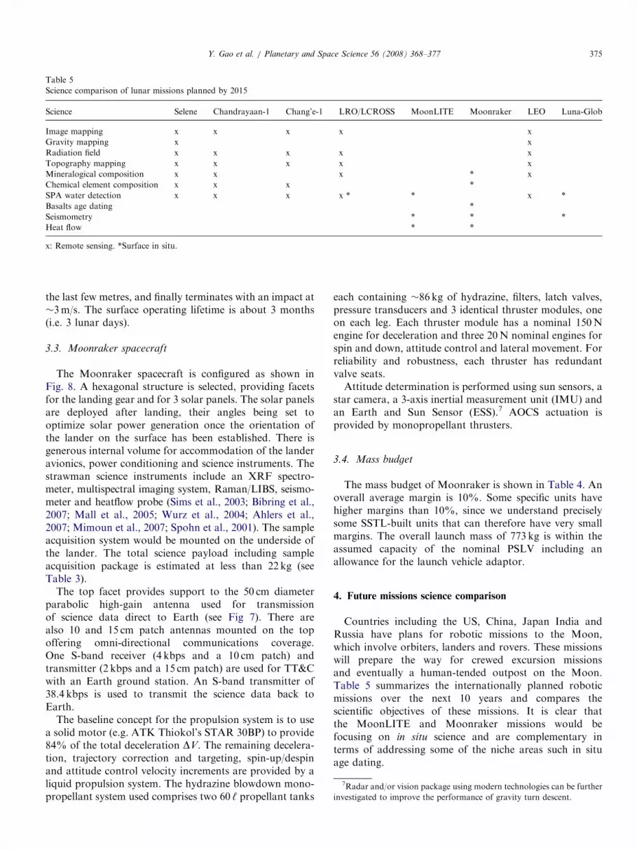
Table 5
Science comparison of lunar missions planned by 2015
Science Selene Chandrayaan-1 Chang’e-1 LRO/LCROSS MoonLITE Moonraker LEO Luna-Glob
Image mapping x x x x x
Gravity mapping x x
Radiation field x x x x x
Topography mapping x x x x x
Mineralogical composition x x x * x
Chemical element composition x x x *
SPA water detection x x x x * * x *
Basalts age dating *
Seismometry * * *
Heat flow * *
x: Remote sensing. *Surface in situ.
7Radar and/or vision package using modern technologies can be further
investigated to improve the performance of gravity turn descent.
Y. Gao et al. / Planetary and Space Science 56 (2008) 368–377 375
the last few metres, and finally terminates with an impact at�3m/s. The surface operating lifetime is about 3 months(i.e. 3 lunar days).
3.3. Moonraker spacecraft
The Moonraker spacecraft is configured as shown inFig. 8. A hexagonal structure is selected, providing facetsfor the landing gear and for 3 solar panels. The solar panelsare deployed after landing, their angles being set tooptimize solar power generation once the orientation ofthe lander on the surface has been established. There isgenerous internal volume for accommodation of the landeravionics, power conditioning and science instruments. Thestrawman science instruments include an XRF spectro-meter, multispectral imaging system, Raman/LIBS, seismo-meter and heatflow probe (Sims et al., 2003; Bibring et al.,2007; Mall et al., 2005; Wurz et al., 2004; Ahlers et al.,2007; Mimoun et al., 2007; Spohn et al., 2001). The sampleacquisition system would be mounted on the underside ofthe lander. The total science payload including sampleacquisition package is estimated at less than 22 kg (seeTable 3).
The top facet provides support to the 50 cm diameterparabolic high-gain antenna used for transmissionof science data direct to Earth (see Fig 7). There arealso 10 and 15 cm patch antennas mounted on the topoffering omni-directional communications coverage.One S-band receiver (4 kbps and a 10 cm patch) andtransmitter (2 kbps and a 15 cm patch) are used for TT&Cwith an Earth ground station. An S-band transmitter of38.4 kbps is used to transmit the science data back toEarth.
The baseline concept for the propulsion system is to usea solid motor (e.g. ATK Thiokol’s STAR 30BP) to provide84% of the total deceleration DV. The remaining decelera-tion, trajectory correction and targeting, spin-up/despinand attitude control velocity increments are provided by aliquid propulsion system. The hydrazine blowdown mono-propellant system used comprises two 60 ‘ propellant tanks
each containing �86 kg of hydrazine, filters, latch valves,pressure transducers and 3 identical thruster modules, oneon each leg. Each thruster module has a nominal 150Nengine for deceleration and three 20N nominal engines forspin and down, attitude control and lateral movement. Forreliability and robustness, each thruster has redundantvalve seats.Attitude determination is performed using sun sensors, a
star camera, a 3-axis inertial measurement unit (IMU) andan Earth and Sun Sensor (ESS).7 AOCS actuation isprovided by monopropellant thrusters.
3.4. Mass budget
The mass budget of Moonraker is shown in Table 4. Anoverall average margin is 10%. Some specific units havehigher margins than 10%, since we understand preciselysome SSTL-built units that can therefore have very smallmargins. The overall launch mass of 773 kg is within theassumed capacity of the nominal PSLV including anallowance for the launch vehicle adaptor.
4. Future missions science comparison
Countries including the US, China, Japan India andRussia have plans for robotic missions to the Moon,which involve orbiters, landers and rovers. These missionswill prepare the way for crewed excursion missionsand eventually a human-tended outpost on the Moon.Table 5 summarizes the internationally planned roboticmissions over the next 10 years and compares thescientific objectives of these missions. It is clear thatthe MoonLITE and Moonraker missions would befocusing on in situ science and are complementary interms of addressing some of the niche areas such in situage dating.

ARTICLE IN PRESSY. Gao et al. / Planetary and Space Science 56 (2008) 368–377376
5. Conclusion
The Moon remains scientifically appealing and hasgenerated revived interest in recent years (e.g. Jolliffet al., 2006). Despite the large number of planned missions,there still remain significant gaps in science that can beaddressed by low-cost lunar missions. Small, low costmissions have become highly successful in recent years,with outstanding results and many scientific and commer-cial users. The capabilities of small satellites have also seendrastic improvements, and have matured to the pointwhere such missions offer huge potential within spaceexploration. The MoonLITE and Moonraker missionsprovide a stepwise approach to space exploration, using theMoon as a proving ground for technology that is essentialfor robotic exploration of Mars and reducing risk for de-risking larger programmes such as ExoMars and MSR.
Acknowledgments
Thanks to UK Particle Physics and Astronomy ResearchCouncil for funding this study. Special thanks to BobParkinson for being an external reviewer of the study.
References
Ahlers, B., Courreges-Lacoste, G.B., Perez, F.R., 2007. The Raman LIBS
instrument on ExoMars. Presented at the European Geosciences
Union, Vienna. Abstr. Geophys. Res. Abstr. 9, 11112.
Ball, A.J., Crawford, I.A., 2006. Which way to the moon? Astron.
Geophys. 47, 4.17–4.19.
Benedicto, J., Gatti, G., Garutti, A., Paffet, J., Bradford, A., Jackson, C.,
Rooney, E., 2006. The triumph of GIOVE-A. ESA Bull. 127, 62–69.
Bibring, J-P., Berthe, M., the MicrOmega team, 2007. MicrOmega: a NIR
hyperspectral microscope for in situ compositional analyses on board
ESA/ExoMars. Presented at the European Geosciences Union,
Vienna. Abstr. Geophys. Res. Abstr. 9, 10715.
Bogdanov, A.V., Nikolaev, A.V., Serbin, V.I., Skuridin, G.A., Khavrosh-
kin, O.B., Tsyplakov, V.V., 1988. Method for analysing terrestrial
planets, Kosmich. Issled. Transl. Cosmic Res. 26 (4), 505–515, 26(4),
591–603 (in Russian).
Covault, C., 2006. Russia’s lunar return. Av. Week .Space Technol. 5,
20–22.
Coxhill, I., Richardson, G., Sweeting M., 2002. An investigation of a low
cost HTP/KEROSENE 40 N thruster for small satellites. In:
Proceedings of the 38th AIAA/ASME/SAE/ASEE Joint Propulsion
Conference and Exhibit, IN, USA, July, pp. 1–9.
Crawford, I.A., 2004. The scientific case for renewed human activities on
the moon. Space Pol. 20, 91–97.
Crawford, I.A., Fagents, S.A., Joy, K.H., 2007. Full moon exploration:
exploring the basaltic lava flows of Oceanus Procellarum. Astron.
Geophys. 48, 3.18–3.21.
ESA, 1992. Mission to the Moon, ESA SP-1150.
Galimov, E.M., 2005. Luna-Glob project in the context of the past and
present lunar exploration in Russia. J. Earth System Sci. 114 (6),
801–806.
Gowen, R., Smith, A., Griffiths, A., Coates, A., Ball, A., Barber, S.,
Hagermann, A., Sheridan, S., Crawford, I., Church, P., Wells, N.,
Gao, Y., Phipps, A., Talboys, D., Pike, W.T., 2007. Kinetic
penetrators for exploration of solar system bodies. Presented at the
Fifth International Planetary Probes Workshop (IPPW-5), Bordeaux,
France, 23–29 June 2007 to be published by ESA in Special Publication
Sp-650.
Jolliff, B.L., Wieczorek, M.A., Shearer, C.K., Neal, C.R. (Eds.), 2006.
New views of the moon, Rev. Min. Geochem. 60.
Lognonne, P., Mosser, B., 1993. Planetary seismology. Surv. Geophys. 14,
239–302.
Lorenz, R.D., Moersch, J.E., Stone, J.A., Morgan, A.R., Smrekar, S.E.,
2000. Penetration tests on the DS-2 Mars microprobes: penetration
depth and impact accelerometry. Planet. Space Sci. 48 (5), 419–436.
Mall, U., Nathues, A., Keller, H.U., 2005. SIR-2: The NIR spectrometer
for the Chandrayaan-1 mission. Proc. 37th AAS division for planetary
sciences meeting, session 57, Cambridge, UK. Bull. Am. Astronom.
Soc. 37, 749 September 4–9, 2005, paper: 57–09.
Mimoun, D., Lognonne, P., Giardini, D., Pike, W.T., 2007. Ulrich
Christensen, Arie van den Berg, Schibler, P. and the SEIS team, The
SEIS experiment: a planetary seismometer for Mars and the moon.
Lunar Planet. Sci. XXXVIII Abstract 2204.
Mizutani, H., Fujimura, A., Hayakawa, M., Tanaka, S., Shiraishi, H., 2001.
Lunar-A penetrator: its science and instruments. In: Komle, N.I., Kargl,
G., Ball, A.J., Lorenz, R.D. (Eds.), Penetrometry in the Solar System.
Austrian Academy of Sciences Press, Vienna, pp. 125–136.
Mizutani, H., Fujimura, A., Tanaka, S., Shiraishi, H., Nakajima, T., 2003.
Lunar-A mission: goals and status. Adv. Space Res. 31 (11),
2315–2321.
Murphy, J.P., Reynolds, R.T., Blanchard, M.B., Clanton, U.S., 1981.
Surface Penetrators for Planetary Exploration: Science Rationale and
Development Program, NASA TM-81251, Ames Research Center.
National Research Council, 2007. The Scientific Context for Exploration
of the Moon-Final Report. The National Academies Press, Washing-
ton, DC.
Phipps, A., Gao, Y., 2006. Lunar mission options study. UK Particle
Physics and Astronomy Research Council Report Reference No.
#118537, pp. 1–104.
Pike, W.T., Standley, I.M., 2005. Determination of the dynamics of
micromachined lateral suspensions in the scanning electron micro-
scope. J. Micromech. Microeng. 15, S82–S88.
Pike, W.T., Karl, W., Kumar, S., Vijendran, S., Semple, T., 2004. Analysis
of sidewall quality in through-wafer deep reactive-ion etching.
Microelectr. Eng. 73–74, 340.
Pike, W.T., Standley, I.M., Syms, R.R.A., 2006. Micromachined
Accelerometer. U.S. Patent 7, 036, 374.
Simmons, G.J., 1977. Surface penetrators—a promising new type of
planetary lander. J. British Interplanet. Soc. 30 (7), 243–256.
Sims, M.R., et al., 1999. Beagle 2: a proposed exobiology lander for ESA’s
2003 mars express mission. Adv. Space. Res. 23, 1925–1928.
Sims, M.R., et al., 2003. Performance characteristic1s of the PAW
instrumentation on Beagle 2 (the astrobiology lander on ESA’s Mars
Express Mission), instruments, methods, and missions for Astrobiol-
ogy V. In: Hoover, Richard B., Rozanov, Alexei Yu., Paepe, Roland
R. (Eds.), Proceeding of the SPIE, vol. 4859, pp. 32–44.
Smith, A., Gao, Y., 2007. Concepts and instruments for low-cost lunar
surface missions. Presented at the European Geosciences Union, Vienna,
9, 2007, 07927, 15–20 April. Abstract in Geophysical Research Abstracts.
Smith, A., Gowen, R., Coates, A., Crawford, I., Scott, R., Church, P.,
Ellery, A., Gao, Y., Pike, T., 2007. Lunar exploration with
penetrators. J. Astron. 28 (Suppl. April).
Smith, A., Gowen, R., Coates, A., Crawford, I., Scott, R., Church, P.,
Gao, Y., Pike, T., Flanagann, J., 2006. Development of kinetic
penetrators for exploration of airless solar system bodies. Presented at
the Second Workshop on Penetrometry in the Solar System, Space
Research Institute, Graz, Austria: 25–28 September 2006.
Smrekar, S., Catling, D., Lorenz, R., et al., 1999. Deep space 2: the Mars
microprobe mission. J. Geophys. Res. 104 (E11), 27013–27030.
Smrekar, S., Lorenz, R.D., Urquhart, M., 2001. The Deep-space-2
penetrator design and its use for accelerometry and estimation of
thermal conductivity. In: Komle, N.I., Kargl, G., Ball, A.J., Lorenz,
R.D. (Eds.), Penetrometry in the Solar System. Austrian Academy of
Sciences Press, Vienna, pp. 109–123.
Spohn, T., Ball, A.J., Seiferlin, K., Conzelmann, V., Hagermann, A.,
Komle, N.I., Kargl, G., 2001. A heat flow and physical properties
ARTICLE IN PRESSY. Gao et al. / Planetary and Space Science 56 (2008) 368–377 377
package for the surface of Mercury. Planet. Space Sci. 49 (14/15),
1571–1577.
Spudis, P.D., 1996. The Once and Future Moon. Smithsonian Institution
Press.
Stern, S.A., 2005. Ex luna, scientia. The Space Rev., 3 October.
Surkov, Y.A., Kremnev, R.S., 1998. Mars-96 mission: Mars exploration
with the use of penetrators. Planet. Space Sci. 46 (11/12), 1689–1696.
Surkov, Y.A., Moskaleva, L.P., Shcheglov, O.P., Sheretov, E.P.,
Kremnev, R.S., Pichkhadze, K.M., Akulov, Y.P., Dolgopolov, V.P.,
1999. Lander and scientific equipment for exploring of volatiles on the
moon. Planet. Space Sci. 47 (8–9), 1051–1060.
Sweeting, M.N., Underwood, C.I., 2003. Small-satellite engineering and
applications. In: Fortescue, P., Stark, J., Swinerd, G., (Ed.), Spacecraft
Systems Engineering, third edition. Wiley, New York, pp. 581–612.
Swindle, T.D., 2001. Could in situ dating work on Mars? In: 32nd Annual
Lunar and Planetary Science Conference, March 12–16, Houston, TX.
Abstract no. 1492.
Swindle, T.D., Brown, R., Greenberg, R., Lunine, J., McEwen, A., 2001.
In situ chronology in the outer solar system. In: Forum on Innovative
Approaches to Outer Planetary Exploration, 2001, 83.
Taylor, S.R., Pieters, C.M., MacPherson, G.J., 2006. Earth-Moon system,
planetary science and lessons learned. In: Jolliff, B.L., et al. (Eds.),
New Views of the Moon, Revn. Min. & Geochem, vol. 60,
pp. 657–704.
Wurz, P., Rohner, U., Whitby, J.A., 2004. A highly miniaturised laser
ablation time-of-flight mass spectrometer for planetary exploration. In:
Workshop on Europa’s Icy Shell: Past Present and Future, Houston,
6–8 February, Abstract #7003.


