Embed Size (px)
Citation preview

NUREGIC'R 3746, Vol. 3'
--
HEDL-TME 84-31
LWR PRESSURE VESSEL SURVEILLANCE
DOSIMETRY IMPROVEMENT PROGRAM
1984 ANNUAL REPORT(OCTOBER 1,1983 - SEPTEMBER 30, 1984)
Hanford Engineering Development LaboratoryPrepared by
W.N. McElroy (HEDL)
F.B.K. Kam (ORNL)J.A. Grundi and E.D. McGarry (NBS)
A. Fabry (CENISCK)
ag so g eso43o Prepared for the U.S. Nuclear Regulatory Commission
CR-3746 R PDR
- - - - - _ _ _ _ _ _ _ _ _
j

* *'
'
)7 ',
NOTICE
This report was ptepared as an account of work sponsored by an agency of the United StatesGovernment. Neither the United States Government nor any agency thereof, or any of theiremployees, makes any warranty, expressed or imphed, or assumes any legal liability of re-sponsibility for any third party's use, or the results of such use, of any information, apparatus,product or process disclosed in this report, or represents that its use by such third party wouldnot infringe privately owned rights.
NOTICE
Availability of Reference Materials Cited in NRC Publications
Most documents cited in N RC publications will be available from one of the following sources:
1. The NRC Public Document Room,1717 H Street, N.W.Washington, DC 20555
2. The NRC/GPO Sales Program, U.S. Nuclear Regulatory Commission,Washington, DC 20555
3. The National Technical information Service, Springfield, VA 22161
Although the listing that follows represents the majority of documents cited in NRC publications,it is not intended to be exhaustive.
Referenced documents available for inspection and copying for a fee from the NRC Public Docu-ment Room include NRC correspondence and internal NRC memoranda; NRC Of fice of Inspectionand Enforcement bulletins, circulars, information notices, inspection and investigation notices;Licensee Event Reports; vendor reports and correspondence; Commission papers; and applicant andlicensee documents and correspondence.
The following documents in the NUREG series are available for purchase from the NRC/GPO SalesProgram: formal NRC staff and contractor reports NRC sponsored conference proceedings, andNRC booklets and brochures. Also available are Regulatory Guides, NRC regulations in the Code ofFederal Regulations, and Nuclear Regulatory Commission Issuances.
Documents available from the National Technical Information Service include NUREG seriesreports and technical reports prepared by other federal agencies and reports prepared by the AtomicEnergy Commission, forerunner agency to the Nuclear Regulatory Commission.
Documents available from pubhc and special technical libraries include all open literature items,such as books, journal and periodical articles, and transactions. Federal Register notices, federal andstate legislation, and congressional reports can usually be obtained from these libraries.
Documents such as theses, dissertations, foreign reports and translations, and non-NRC conferenceproceedings are available for purchase from the organization sponsoring the publication cited.
Single copies of NRC draf t reports are avadable free, to the extent of supply, upon written requestto the Division of Technical Inforrnation and Document Control, U S. Nuclear Regulatory Commission. Washington, DC 20555.
Copies of industry codes and standards used in a substantive manner in the NRC regulatory processare maintained at the NRC Library, 7920 Norfolk Avenue, Bethesda, Maryland, and are availablethere for. reference use by the public. Codes and standards are usually copyrighted and may be
|
purchased from the originating organization or, if they are American National Standards, from theAmerican National Standards Institute,1430 Broadway, New York, NY 10018.
_
GPO Ponted con once .$4.75 .- |

-
: NUREGICR-3746, Vol. 3
HEDL-TME 84 31{ R5i
!iI
L LWR PRESSURE VESSEL SURVEILLANCE
DOSIMETRY IMPROVEMENT PROGRAMi
,
!
f1984 ANNUAL REPORT
(OCTOBER 1,1983 - SEPTEMBER 30,1984):
.
!i
t
| Hanford Engineering Development l.aboratoryOperated by Westinghouse Hanford Company
P.O. Box 1970 R;chland, WA 99352
A Subsidiary of Westinghouse Electric Corporation
Prepared by
W.N. McElroy (HEDU|
| F.B.K. Kam (ORNUJ.A. Grundi and ED. McGarry (NBS)
,
A. Fabry (CEN/SCK)
Manuscript Completed: December 1984Date Published: April 1985
.
Prepared for Division of Engineering TechnologyOffice of Nuclear Regulatory Research
U.S. Nuclear Regulatory Commission
Washington, DC 20555.
NRC FIN No. B5988
_ _ , _ _
_ _ . _ _ . __

FOREWORD
The Light Water Reactor Pressure Vessel Surveillance Dosimetry ImprovementProgram (LWR-PV-SDIP) has been established by NRC to improve, test, verify,and standardize the physics-dosimetry-metallurgy, damage correlation, andassociated reactor analysis methods, procedures and data used to predictthe integrated effect of neutron exposure to LWR pressure vessels and theirsupport structures. A vigorous research effort attacking the same measure-ment and analysis problems exists worldwide, and strong cooperative linksbetween the US NRC-supported activities at HEDL, ORNL, NBS, and MEA and thosesupported by CEN/SCK (Mol, Belgium), EPRI (Palo Alto, USA), KFA (Jdlich,Germany), and several UK laboratories have been extended to a number of othercountries and laboratories. These cooperative links are strengthened by theactive membership of the scientific staff from many participating countriesand laboratories in the ASTM E10 Committee on Nuclear Technology and Appli-cations. Several subcommittees of ASTM E10 are responsible for the prepara-
tion of LWR surveillance standards.
The primary objective of this multilaboratory program is to prepare an updatedand improved set of physics-dosimetry-metallurgy, damage correlation, and
I associated reactor analysis ASTM standards for LWR pressure vessel and supportstructure irradiation surveillance programs. Supporting this objective are aseries of analytical and experimental validation and calibration studies in" Standard, Reference, and Controlled Environment Benchmark Fields," research;
reactor " Test Regions," and operating power reactor " Surveillance Positions."
These studies will establish and certify the precision and accuracy of themeasurement and predictive methods recommended in the ASTM Standards and usedfor the assessment and control of the present and end-of-life (E0L) conditionof pressure vessel and support structure steels. Consistent and accuratemeasurement and data analysis techniques and methods, therefore, will bedeveloped, tested and verified along with guidelines for required neutronfield calculations used to correlate changes in material propertics with thecharacteristics of the neutron radiation field. Application of establishedASTM standards is expected to permit the reporting of measured materials
i property changes and neutron exposures to an accuracy and precision withinbounds of 10 to 30%, depending on the measured metallurgical variable andt
neutron environment.
! The assessment of the radiation-induced degradation of material propertiesin a power reactor requires accurate definition of the neutron field fromthe outer region of the reactor core to the outer boundaries of the pressurevessel. The accuracy of measurements on neutron flux and spectrum is asso-ciated with two distinct components of LWR irradiation surveillance proce-dures 1) proper application of calculational estimates of the neutronexposure at in- and ex-vessel surveillance positions, various locations inthe vessel wall.and ex-vessel: support structures, and 2) understanding the
support struct'
erty changes in reactor vessels and theirrelationship;betwee terigical test specimens irradiated in test
reactors and.. lux positions in operating powerreactors.
.
b
' - __ ._ _.

. .. .
.
. _ _ _ - _ _ _ .
PREVIOUS REPORTS IN LWR-PV-SDIP SERIES
NUREG/CR-0038 HEDL-TME 78-4 July 1977 - September 1977NUREG/CR-0127 HEDL-TME 78-5 October 1977 - December 1977
NUREG/CR-0285 HEDL-TME 78-6 January 1978 - March 1978 |NUREG/CR-0050 HEDL-TME 78-7 April 1978 - June 1978NUREG/CR-0551 HEDL-TME 78-8 July 1978 - September 1978NUREG/CR-0720 HEDL-TME 79-18 October 1978 - December 1978
NUREG/CR-1240, Vol. 1 HEDL-TME 79-41 January 1979 - March 1979NUREG/CR-1240, Vol. 2 HEDL-TME 80-1 April 1979 - June 1979NUREG/CR-1240, Vol. 3 HEDL-TME 80-2 July 1979 - September 1979NUREG/CR-1240, Vol. 4 HEDL-TME 80-3 October 1979 - December 1979 !
NUREG/CR-1291 HEDL-SA-1949 October 1978 - December 1979*
NUREG/CR-1241, Vol. 1 HEDL-TME 80-4 January 1980 - March 1980NUREG/CR-1241, Vol. 2 HEDL-TME 80-5 April 1980 - June 1980NUREG/CR-1747 HEDL-TME 80-73 October 1979 - December 1980*NUREG/CR-1241, Vol . 3 HEDL-TME 80-6 October 1980 - December 1980
NUREG/CR-2345, Vol. 1 HEDL-TME 81-33 January 1981 - March 1981NUREG/CR-2345, Vol. 2 HEDL-TME 81-34 April 1981 - June 1981NUREG/CP-0029 HEDL-SA-2546 October 1980 - September 1981*NUREG/CR-2345, Vol. 4 HEDL-TME 81-36 October 1981 - December 1981
NUREG/CR-2805, Vol. 1 HEDL-TME 82-18 January 1982 - March 1982NUREG/CR-2805, Vol . 2 HEDL-TME 82-19 April 1982 - June 1982NUREG/CR-2805, Vol. 3 HEDL-TME 82-20 October 1981 - September 1982*NUREG/CR-2805, Vol. 4 HEDL-TME 82-21 October 1982 - December 1982
NUREG/CR-3391, Vol. 1 HEDL-TME 83-21 January 1983 - March 1983NUREG/CR-3391, Vol. 2 HEDL-TME 83-22 April 1983 - June 1983NUREG/CR-3391, Vol. 3 HEDL-TME 83-23 October 1982 - September 1983*NUREG/CR-3391, Vol. 4 ** October 1983 - December 1983
NUREG/CR-3746, Vol. 1 HEDL-THE 84-20 October 1983 - March 1984NUREG/CR-3746, Vol. 2 HEDL-TME 84-21 April 1984 - September 1984
* Annual Reports.**No HEDL-TME number assigned because this progress report contains only an NBS
contribution on " Compendium of Benchmark Neutron Fields for Pressure VesselSurveillance Dosimetry."
ii
___ _____- _ _ ___

--____ - _ _ _ _ - _ _ _ _ _ _ _ _ .
FOREWORD
The Light Water Reactor Pressure Vessel Surveillance Dosimetry ImprovementProgram (LWR-PV-SDIP) has been established by NRC to improve, test, verify,and standardize the physics-dosimetry-metallurgy, damage correlation, andassociated reactor analysis methods, procedures and data used to predictthe integrated effect of neutron exposure to LWR pressure vessels and theirsupport structures. A vigorous research effort attacking the same measure-ment and analysis problems exists worldwide, and strong cooperative linksbetween the US NRC-supported activities at HEDL, ORNL, NBS, and MEA and thosesupported by CEN/SCK (Mol, Belgium), EPRI (Palo Alto, USA), KFA (Julich,Germany), and several UK laboratories have been extended to a number of othercountries and laboratories. These ccoperative links are strengthened by the
'active membership of the scientific staff from many participating countriesand laboratories in the ASTM E10 Committee on Nuclear Technology and Appli-cations. Several subcommittees of ASTM E10 are responsible for the prepara-tion of LWR surveillance standards.
The primary objective of this multilaboratory program is to prepare an updatedand improved set of physics-dosimetry-metallurgy, damage correlation, andassociated reactor analysis ASTM standards for LWR pressure vessel and supportstructure irradiation surveillance programs. Supporting this objective are aseries of analytical and experimental validation and calibration studies in" Standard, Reference, and Controlled Environment Benchmark Fields," researchreactor " Test Regions," and operating power reactor " Surveillance Positions."
These studies will establish and certify the precision and accuracy of themeasurement and predictive methods recommended in the ASTM Standards and usedfor the assessment and control of % e present and end-of-life (E0L) conditionof pressure vessel and support structure steels. Consistent and accuratemeasurement and data analysis techniques and methods, therefore, will bedeveloped, tested and verified along with guidelines for required neutronfield calculations used to correlate changes in material properties with thecharacteristics of the neutron radiation field. Application of establishedASTM standards is expected to permit the reporting of measured materialsproperty changes and neutron exposures to an accuracy and precision withinbounds of 10 to 30%, depending on the measured metallurgical variable andneutron environment.
The assessment of the radiation-induced degradation of material propertiesin a power reactor requires accurate definition of the neutron field fromthe outer region of the reactor core to the outer boundaries of the pressurevessel. The accuracy of measurements on neutron flux and spectrum is asso-ciated with two distinct components of LWR irradiation surveillance proce-dures 1) proper application of calculational estimates of the neutronexposure at in- and ex-vessel surveillance positions, various locations inthe vessel wall and ex-vessel support structures, and 2) understanding therelationship between material property changes in reactor vessels and theirsupport structures, and in metallurgical test specimens irradiated in testreactors and at accelerated neutron flux positions in operating powerreactors.
iii
|
| __

.__ _ _ _ _ _ _ _ - - _ _ _ _ _ _ _ _ _ _ _ _ _ _ _ _ _ _ - - - - - - _ _ _ _ _ _ _ _ _ _ _ _ _ _ _ _ _ _ _ _ _ _ _ _ _ _ _ _ _ _ _ _ _ . _ _ _ _ _ _ _ _ _
The first component requires verification and calibration experiments in avariet', of neutron irradiation test facilities including LWR-PV mockups,power .'eactor surveillance positions, and related benchmark neutron fields.The benchmarks serve as a permanent reference measurement for neutron fluxand fluence detection techniques, which are continually under developmentand widely applied by laboratories with different levels of capability. Thesecond component requires a serious extrapolation of an observed neutron-induced mechanical property change from research reactor " Test Regions" andoperating power reactor " Surveillance Positions" to locations inside thebody of the pressure vessel wall and to ex-vessel support structures. Theneutron flux at the vessel inner wall is up to one order of magnitude lowerthan at surveillance specimen positions and up to two orders of magnitudelower than for test reactor positions. At the vessel outer wall, the neu-tron flux is one order of magnitude or more lower than at the vessel innerwall. Further, the neutron spectra at, within, and leaving the vessel aresubstantially different.
To meet reactor pressure vessel radiation monitoring requirements, a varietyof neutron flux and fluence detectors are employed, most of which are pas-sive. Each detector must be validated for application to the higher fluxand harder neutron spectrum of the research reactor " Test Region" and tothe lower flux and degraded neutron spectrum at " Surveillance Positions."Required detectors must respond to neutrons of various energies so thatmultigroup spectra can be determined with accuracy sufficient for adequatedamage response estimates. Detectors being used, developed, and tested forthe program include radiometric (RM) sensors, helium accumulation fluencemonitor (HAFM) sensors, solid state track recorder (SSTR) sensors, anddamage monitor (DM) sensors.
The neassity for pressure vessel mockup facilities for physics-dosimetryinvestigations and for irradiation of metallurgical specimens was recognizedearly in the formation of the NRC program. Experimental studies associatedwith high- and low-flux versions of a pressurized water reactor (PWR) pres-sure vessel mockup are in progress in the US, Belgium, France, and UnitedKingdom. The US low-flux version is known as the ORNL Poolside CriticalAssembly (PCA) and the high-flux version is known as the Oak Ridge ResearchReactor (ORR) Poolside Facility (PSF), both located at Oak Ridge, Tennessee.
I As specialized benchmarks, these facilities provide well-characterizedj neutron environments where active and passive neutron dosimetry, various
types of LWR-PV and support structure neutron field calculations, andtemperature-controlled metallurgical specimen exposures are brought together.
The two key low-flux pressure vessel mockups in Europe are known as theMol-Belgium-VENUS and Winfrith-United Kingdom-NESDIP facilities. The VENUSFacility is being used for PWR core source and azimuthal lead factor studies,while NESDIP is being used for PWR cavity and azimuthal lead factor studies.A third and important low-fluence pressure vessel mockup in Europe is iden-tified with a French PV-simulator at the periphery of the Triton reactor.It served as the irradiation facility for the DOMPAC dosimetry experimentfor studying surveillance capsule perturbations and through-PV-wall radialfluence and damage profiles (gradients) for PWRs of the Fessenheim 1 type.
1' v
|
|
_ _ . _ _ _ __________ - _ .___ _ _ _

_ _ _ _ _ _ _ .__ ___ _ _ _ __ ______-_ _
,
1,
The first component requires verification and calibration experiments in avariet of neutron irradiation test facilities including LWR-PV mockups,,
power .eactor surveillance positions, and related benchmark neutron fields. *
The benchmarks serve as a permanent reference measurement for neutron fluxand fluence detection techniques, which are continually under developmentand widely applied by laboratories with different levels of capability. Thesecond component requires a serious extrapolation of an observed neutron-induced mechanical property change from research reactor " Test Regions" andoperating power reactor " Surveillance Positions" to locations inside thebody of the pressure vessel wall and to ex-vessel support structures. The,
' neutron flux at the vessel inner wall is up to one order of magnitude lowerthan at surveillance specimen positions and up to two orders of magnitudelower than for test reactor positions. At the vessel outer wall, the neu-tron flux is one order of magnitude or more lower than at the vessel innerwall. Further, the neutron spectra at, within, and leaving the vessel are '
substantially different.I
'To meet reactor pressure vessel radiation monitoring requirements, a varietyof neutron flux and fluence detectors are employed, most of which are pas-sive. Each detector must be validated for application to the higher flux-
and harder neutron spectrum of the research reactor " Test Region" and tothe lower flux and degraded neutron spectrum at " Surveillance Positions."
' Required detectors must respond to neutrons of various energies so thatmultigroup spectra can be determined with accuracy sufficient for adequatedamage response estimates. Detectors being used, developed, and tested for
: the program include radiometric (RM) sensors, helium accumulation fluencemonitor (HAFM) sensors, solid state track recorder (SSTR) sensors, and ,
,
damage monitor (DM) sensors.
The necessity for pressure vessel mockup facilities for physics-dosimetryinvestigations and for irradiation of metallurgical specimens was recognized
;early in the formation of the NRC program. Experimental studies associatedwith high- and low-flux versions of a pressurized water reactor (PWR) pres-sure vessel mockup are in progress in the US, Belgium, France, and UnitedKingdom. The US low-flux version is known as the ORNL Poolside CriticalAssembly (PCA) and the high-flux version is known as the Oak Ridge Research ;'
Reactor (0RR) Poolside Facility (PSF), both located at Oak Ridge, Tennessee. I
As specialized benchmarks, these facilities provide well-characterizedneutron environments where active and passive neutron dosimetry, varioustypes of LWR-PV and support structure neutron field calculations, andtemperature-controlled metallurgical specimen exposures are brought together.
The two key low-flux pressure vessel mockups in Europe are known as theMol-Belgium-VENUS and Winfrith-United Kingdom-NESDIP facilities. The VENUSFacility is being used for PWR core source and azimuthal lead f actor studies,while NESDIP is being used for PWR cavity and azimuthal lead factor studies.A third and important low-fluence pressure ve.ssel mockup in Europe is iden-tified with a French PV-simulator at the periphery of the Triton reactor.It served as the irradiation facility for the 00MPAC dosimetry experiment
i for studying surveillance capsule perturbations and through-PV-wall radialfluence and damage profiles (gradients) for PWRs of the Fessenheim 1 type.
I.
iv'
,
1
. _ - - - - . _ _ . - --- _ _ - - -~ - - .

, _ .__ _ _ _ _ _ _ _ _ - _ _ _ ._. . _ _ _ _ . _ _ _ - _ _ _ _ - _
Results of measurement and calculational strategies outlined here will bemade available for use by the nuclear industry as ASTM standards. FederalRegulations 10 CFR 50 (Cf83) already requires adherence to several ASTMstandards that establish a surveillance program for each power reactor andincorporate metallurgical specimens, physics-dosimetry flux-fluence monitors,and neutron field evaluation. Revised and new standards in preparation willbe carefully updated, flexible, and, above all, consistent.
v
i'l
L

|
CONTRIBUTORS LWR-PV-SDIP 1984 ANNUAL REPORT I1
Prepared by W. N. McElroy, F. B. K. Kam, J. A. Grundl, E. D. McGarry, and.
A. Fabry with reference to and/or use of selected contributions from the !
following participants and laboratories.j
W. N. McElroy, L. D. Blackburn, R. Gold, G. L. Guthrie, $L. S. Kellogg, E. P. Lippincott, W. Y. Matsumoto,
J. P. McNeese, C. C. Preston, J. H. Roberts, F. H. Ruddy,J. M. Ruggles, and R. L. Simons
Hanford Engineering Development Laboratory (HEDL), USA
. E. D. McGarry, C. M. Eisenhauer, D. M. Gilliam,J. A. Grundl, and G. P. Lamaze,
National Bureau of Standards (NBS), USA,
F. B. K. Kam, C. A. Baldwin, R. E. Maerker, F. W. Stallmann, and M. Williams;
Oak Ridge National Laboratory (0RNL), USA '
A. Fabry, J. Debrue, G. Deleeuw, S. Deleeuw, P. J. D'Hondt, J. Lacroix,G. Minsart, J. Pelsmaekers, H. Tourwe, and Ph. Van Asbroeck
.
Centre d' Etudes de.l'Energie Nucleaire,Studiecentrum voor Kernenergie (CEN/SCK), Mol, Belgium
| W. Schneider, D. Packur, and L. WeiseKernforschungsanlage (KFA) Julich, Federal Republic of Germany
f M. Austin, A. F. Thomas, R. Squires, and:T. J. WilliamsRolls-Royce & Associates Limited (RR&A), Derby, UK '
! :
( A..J. Fudge (Harwell) and J. Butler, I. J. Curl, P. C. Miller,,
and A. Packwood (Winfrith)Atomic Energy Research Establishment (AERE), UK '
A. A. Alberman, J. Bollen, J. P. Genthon, and P. Soulat (Saclay)and P. Mas (Grenoble).
Commissariat a l'Energie Atomique,Centre d' Etudes Nucleaires (CEA/CEN), France )
H. Farrar IV and B. L. OliverRockwell International (RI), USA
G. R. Odette and G. LucasUniversity of California at Santa Barbara (UCSB), USA
P. D. HedgecockAPTECH Engineering Services, USA i
lJ. S. Perrin and R. A. Wullaert j
Fracture Control Corporation (FCC), USA
vi

, _ _ _ _ _ _ _ _ _
B. A. Magurno and J. F. CarewBrookhaven National Laboratory (BNL), USA
T. U. Marston, T. Griesbach, O. 0zer, T. Passell, and R. ShawElectric Power Research Institute (EPRI), USA
C. O. Cogburn, L. West, and J. WilliamsUniversity of Arkansas (UA), USA
W. C. HopkinsBechtel Power Corporation, USA
M. HaasEngineering Services Associates (ENSA), USA
J. R. HawthorneMaterials Engineering Associates (MEA), US A
E. B. NorrisSouthwest Research Institute (SwRI), USA
M. P. Manahan-
Battelle Memorial Institute (BMI) Columbus Laboratory, USA
S. L. Anderson, T. R. Mager, and S. E. YanichkoWestinghcuse Electric Corporation (W), USA
A. A. Lowe Jr, Q. King, R. H. Lewis, and C. L. WhitmarshBabcock & Wilcox Company (B&W), USA
G. C. Martin JrGeneral Electric Company (GE), USA
G. P. Cavanaugh, S T. Byrnes, and J. J. KoziolCombustion EngE eering, Inc. (CE), USAl
N. Tsoulfanidis and D. R. EdwardsUniversity of Missouri, Rolla (UMR), USA
S. GrantCarolina Power and Light Company, USA
J. B. SunFlorida Power and Light Company, USA
H. F. JonesMaine Yankee Atomic Power Company, USA
F. HegedusSwiss Federal Institute for Reactor Research (EIR),
Wuerenlingen, Switzerland
vii1
f.
~ _ ~

__
,
i
flVREG/CR-3746, Vol. 3HEDL-TME 84-31
,
LWR PRESSURE VESSEL SURVEILLANCE 00SIMETRY IMPROVEMENT PROGRAM
1984 ANNUAL REPORT>
1
' 3'r. W. N. McElroy (HEDL)
*S g
?
ABSTRACT>
9P
This report describes progress made in the Light WaterReactor Pressure Vessel Surveillance Dosimetry improve-ment Program (LWR-PV-SDIP) during FY 1984 The primaryconcern of this program is to improve, test, verify, andstandardize the physics-dosimetry-metallurgy and theassociated reactor and damage analysis procedures anddata used for predicting the integrated effects ofneutron exposure to LWR pressure vessels and support; s tructures. .These procedures and data are being recom-mended in a new and updated set of AS211 standards beingprepared, tested, and verified by program participants.1these standards, together with parts of the US Code ofFederal Regulations and ASME codes, are needed and usedfor the assessment and control of the condition of LHRpressure vessels and support structures during the 30-to 60-year lifetime of a nuclear power plant.
>
3
'a,* \_ 5:
.t
, , ')'
.isv:.
r
i1 .
1x,
| t.;, > ;$ 7
h N. ,~
5 -
- - - - - - - - -

__ . __ _
. .
ACKNOWLEDGMENTS
The success of the LWR Pressure Vessel Surveillance Dosimetry Improvement '
Program (LWR-PV-SDIP) continues to depend on the efforts and the freeexchange of ideas and views by representatives of a large number of research,'
service,-regulatory, vendor, architect / engineer, and utility organizations.The information reported herein could not have been developed without the
-
continuing support of the respective funding organizations and their manage-ment and technical. staffs.'
Special acknowledgment is due to C. Z. Serpan of- NRC for having . identified the need for an international program such as theLWR-PV-SDIP and for making it possible by taking a strong overall. support; ;
and management lead.
Additional acknowledgment is due to 8. R. Hayward .R. L. Knecht, W. F. Sheely,and H. H. Yoshikawa of HEDL for their constructive comments and help in the
>
preparation and review of program documentation. Very special acknowledgment '
is given to N. E. Kenny who edited this document; to D. C. Smith of the HEOLIrradiation Environment Group; and to the HEDL Technical Publications, WordProcessing, Graphics, and Duplicating personnel who contributed to its"preparation.
,
t
4
1
!,
X
*_ . _ _ ___ _ _ _ _ _ -- - - - - - - - - - - - - - - - - - - - - - - - - - - - - - - - - - - - -

$
CONTENTS
.
Previous Reports in LWR-PV-SDIP' Series 11-
iiiForeword
Contributors'to LWR-PV-SDIP 1984 Annual Report- vi
ixAbstractxAcknowledgments
I
xvF.i gures --
xviiTables.
xixAcronyms
11.0 INTRODUCTION
. 2.0 SUMMARY 0F FY 1984 RESEARCH PROGRESS 3
2.1 ASTM STANDARDS AND PROGRAM DOCUMENTATION6
2.1.1 ASTM Standards 6112.1. 2 Program Documentation
2.2 LWR PHYSICS-DOSIMETRY TESTING IN THE ORNL P0OLCRITICAL ASSEMBLY PRESSURE VESSEL BENCHMARKFACILITY (0RNL-PCA) .13
2.2.1 Experimental Program 13
2.2.1.1 PCA Passive Dosimetry Measurements 13
2.2.1.2 Gamma-Ray Spectrometry 15
2.2.2 Neutron and Gamma Program 16
2.2.2.1 PCA Neutron Calculations' 16
2.2.2.2 PCA Gamma Calculations 17
2.3 ' LWR STEEL PHYSICS-DOSIMETRY-METALLURGY TESTING 18
2.3.1 Experimental Dosimetry Program 18
'
2.3.1.1 PSF Physics-Dosimetry-Metallurgy' Experiments 19
;r
2.3.1.2 PSF Experimental and Blind Test- 19
'l
4 xi?
i
,

CONTENTS (Cont'd)
Page
2.3.1.3 ORR-SDMF 242.3.1.4 BSR-HSST 252. 3.1. 5 SUNY-NSTF 252.3.1.6 LWR Power and Test Reactor
Advanced SSTR Dosimetry 26
2.3.2 Neutron Calculations 27
2.3.2.1 PSF Neutron Calculations 272.3.2.2 PV Wall Neutron Fluence
Attenuation Predictions 272.3.2.3 ORR-SDMF 282.3.2.4 BSR-HSST 282.3.2.5 SUNY-NSTF 28
2.4 ANALYSIS AND INTERPRETATION OF POWER REACTORSURVEILLANCE AND RESEARCH REACTOR TEST RESULTS 29
2.4.1 Surveillance Capsule Data Development' andTesting 29
2.4.1.1 Trend Curve Data Development 29
2.4.2 Research Reactor Data Development andTesting 32
2.4.3 Benchmark Referencing Programs 322.4.4 VENUS, NESDIP, and DOMPAC Benchmark
Experiments 32
2.4.4.1 Mol, Belgium VENUS PWR Core-Baffel-Barrel-Thermal-ShieldBenchmark 32
2.4.4.2 United Kingdom NESDIP Power-Reactor Ex-Vessel CavityBenchmark 34
2.4.4.3 French DOMPAC PWR PressureVessel and Surveillance CapsuleBenchmark 34
2.4.5 Fifth ASTM-EURATOM InternationalSymposium on Reactor Dosimetry andLondon LWR-PV-SDIP Meeting 35
xii
<_
CONTENTS (Cont'd)
Page.
3.0 BENCHMARK REFERENCING AND 00SIMETRY CALIBRATION FORRESEARCH AND POWER REACTOR TEST AND SURVEILLANCE
37PROGRAMS
3.1 CERTIFIED FLUENCE STANDARDS 37
3.1.1; Benchmarking 4th SDMF Dosimetry andRound-Robin Support for Developmentof a Special Research Material (SRM) 37
3.1.2 Certified Fluence Standards for Evalu-ating '8'Cs-Radiometric Analysis 38
3.2 EVALUATIONS OF POWER REACTOR SURVEILLANCEPHYSICS-DOSIMETRY EFFORTS 38
3.2.1 Maine Yankee 38
'3.2.2 H. B. Robinson 38
3.2.3 McGuire-1 39
3.2.4 Turkey Point 3 39' 3.2.5 Arkansas Nuclear One - Unit II 39
3.3 COOPERATIVE RESEARCH BETWEEN r AND SCK/CENRELATED TO THE NRC LWR-PV-SDIP 39
3.3.1 ~NBS Participation in the VENUS Experiment 39
3.3.2 intercalibration of the Belgian and U.S.Standard 885U Fission Spectrum-Irradia-tion Facilities 40
3.3.2.1 U.S. 885U Cavity Fission Source 40
3.3.2.2 Belgian 85U Cavity FissionSource 40
3.3.2.3 Verification of Certified Flu-ences in the Belgian 28SUStandard Field 40
3.3.2.4 Recalibration of the NBS 285U,
Standard Fission SpectrumAgainst the Belgian 288U Fis-sion Spectrum 41-
3.4 NBS INTERACTIONS WITH PSF /SDMF AND PCA BENCH-MARK IRRADIATION EXPERIMENTS 41
3.4.1 Certified Fluence Standards 41
3.4.2 ORR-SDMF 42
3.4.3 Special Standard Neutron FieldIrradiation -42
:
xiiis-
r-1
_ _ _ _

. _ . .
.
!
CONTENTS ~(Cont'd)
Page
3.5' COMPENDIUM 0F BENCHMARK AND TEST REGION NEUTRONFIELDS AND RELATED RESEARCH 42
3.5.1 Compendium ,4 2 -3.5.2 Related Research 423.5.3 Scattering in the Cavity Fission Source 43
3.6 = QUALITY ASSURANCE OF AN INVENTORY OF SENSORMATERIALS FOR SURVEILLANCE 00SIMETRY .43,
3.6.1 New Supply of NBS 2 8'O RadiometricDosimeters 43
3.6.2 Cobalt-in-Copper Analyses 44
3.7 ASTM STANDARD GUIDE E706(IIE) FOR BENCHMARKTESTING 0F REACTOR-VESSEL NEUTRON 00SIMETRY 44
3.7.1 Status 44_ 3.7.2 Error Assessment. 44
4.0 BIBLIOGRAPHY 45
'
,
|
|,
o l
I!
xiv
- - . . - - - - . . . - - _ . . - . .. . .. -.. .- . - . Y

!:
l
FIGURES i
Figure Page
1 -ASTM Standards for Surveillance of LWR Nuclear ReactorPressure Vessels and Their Support Structures 51
2 Preparation, Validation, and Calibration Schedule forLWR-PV and Support Structure Surveillance Standards 52
3 Axial Distributions of the 887Np and :seu FissionRates in the PCA 4/12 SSC Configuration 53
4 Low-Energy Gamma-Ray Continuum for the 1/4-T Locationof the 12/13 Configuration as Compared with CEN/SCKand ORNL-Calculational Results 53
5 Low-Energy Gamma-Ray Continuum for the 3/4-T Locationof the 12/13 Configuration as Compared with CEN/SCK'
and ORNL Calculational Results 53
6 View of Hanfora Optical Track Scanning (HOTS) Systemfor SSTRs Showing Scanning Stage and Optics 54
7 ORR-PSF Irradiation Facility 55
8- Illustration of a Typical Dosimeter and MetallurgicalSpecimen Assembly in the Irradiation Capsules 56
9 Venus Irradiation Locati,ns of Selected NRE That HaveBeen Scanned in the Intetral Mode 57
'10 Gamma Spectrum from an Iron Foil Irradiated for30 hours in the NBS 888U Cavity Fission Source 58
1
11 Record of On-Site Changes to CE 0* Ex-Vessel FluxMonitor Capsule Assembly 59
.
.12 Bare Dosimetry Package for Maine Yankee 0* Dosimeters 60
13 Shielded Dosimetry Package for Maine Yankee 0*Dosimeters 61
14 NBS Cavity Fission Source 62
15a BR-1 Cavity Fission Spectrum Standard Neutron FieldFacility 63
|-15b Fission Spectrum Neutron Source and Detector 63
|\
XV
;
__

.
FIGURES (Cont'd)
| Figure Page
16 Present and Former Procedures for Calibration of>
the Neutron Fluence Rate in the NBS 8 85U CavityFission _ Source 64
17 EffectsofScatteringon'theNeuthonEnergySpectrumin the NBS' Cavity Fission Source 65
18 Monte Carlo Estimates of Trends in Effects onThreshold-Type Nuclear Reactions Caused by Scatter-
~ing in the Cavity Fission Source 65
xvi

TABLES
Table Page
1 LWR-PV Benchmark Field Facilities 67
2 Power Reactors Being Used by LWR-PV-SDIP Participantsto Benchmark Physics-Dosimetry Methods, Proceduresand Data for Pressure Vessel and Support StructureSurveillance 68
3 Integral- I- and J-Reaction Rates for the 1/4-TLocation of the 12/13 Configuration in the PCA 70
4 Infinite Medium Dose Rates Observed in the 1981 PCAExperiments 70
5 Gamma-Ray Dose Rates for the 4/12 SSC Configuration 70
6 Comparison Between Experimentally Determined CharpyShift and Blind Test Predictions 71
7 List of Materials and Chemical Compositions 72
8 Summary of Radiation Damage Determinations for theCharpy Specimen 73
9 Re-Evaluated Exposure Values and Their Uncertaintiesfor LWR-Pressure Vessel Surveillance Capsules 74
10 Comparison of HEDL Trend Curve Formula Calculationsof Charpy 41-J Temperature Shift and Values Determined
76by Hawthorne
11 Integral I- and J- Reaction Rates for the VI (CoreCenter) location in Venus 77
12 Integral I- and J- Reaction Rates for the 24 Locationof the Outer Baffle in Venus 77
13 Integral I- and J- Reaction Rates for the 42 Locationof the Outer Baffle in Venus 78
14 Integral I- and J- Reaction Rates for the 21 Locationof the Barrel in Venus 78
15 Integral I- and J- Reaction Rates for the 41 Locationof the Barrel in Venus 79
16 Integra? I- and J- Reaction Rates for the 21 Locationof the Pad in Venus 79
xvii

_ _ . _ . _ . _ _ _ _ . _ _ _ _ _ . _ _ _ _ _ _ _ _ _ _ . _ _ _ _ _ . ,___ . . . _ _ . _ _ _ _ _ _ _ _ _ _ _ . _ _ _ _ _ . _ _ _ _ _ _ _ _ _ _ _ _ _ _ _ _ _ . _ _ _ _ _ _ . _ _ _ _ _ _ - - _ _ _ _
|
TABLES (Cont'd),
Table ' Page
17_: Recapitulation of the Certified 8 880 ' Fluence Stan-.
dards Issued by NBS in.FY83 and FY84~to Benchmark..
Reference Radiometric Dosimetry for the LWR-PV-SDIP 80.
.18 ~ Dosimeter Types and Reactions 82
_19 Ratio of Measured Reaction Cross Section in the 888Uand 888Cf Fission Neutron Fields'and Comparisons
-with Ratios Calculated =from ENDF/V-V Cross Sectionsand Various.assU Spectra 82
20 Fully Corrected Experimental Results f rom VariousExperimental Configurations 83
i-
,
l,
,
''
xviii!
!.',
.m.- .-m_ . - _ - _ _ _ . _ . . . _ _ . ._ _ _ _ _ _ . . . _ . _ . _ _ _ _ _ . _ _ . _ _ _ _ _ _ - _ _ .

.< _ - -. .
ACRONYMS-
: ASTM American Society for Testing and MaterialsBSR Bulk-Shielding Reactor
. BWR Boiling Water Reactor'
CFS- ~ Cavity Fission Source'
DM Damage Monitor
IEOL End-of-Life"
''
HAFM ~ Helium Accumulation Fluence Monitor
HOTS Hanford Optical Track ScannerHSST Heavy-Section Steel Technology (Program)
-ISNF. Intermediate-Energy Standard Neutron Field~
LWR Light Water Reactor
NDTT Nil Ductility Transition Temperaturet
NESDIP Nestor Shielding and Dosimetry Improvement Program
4 . NRC Nuclear Regulatory Commission
NRE -- Nuclear Research Emulsion);- NSTF Nuclear Science and Technology Facilities
ORR 0ak Ridge Research Reactor (ORNL)
PCA Poolside Critical Assembly (0RNL),
PF Perturbation FactorPSF Poolside Facility-(0RNL)'
PTS Pressurized Thermal Shock-pud ~ Paired-Uranium Detectors
PV Pressure Vessel'
PWR Pressurized Water ReactorRM Radiometric Monitor- -
~ SDIP- ; Surveillance Dosimetry Improvement Program
SDMF Simulated Dosimetry Measurement Facility
SPVC . Simulated Pressure Vessel Capsule
SRM Special Research Material
SSC- Simulated Surveillance Capsule
SSTR. . Solid-State Track Recorder.
SUNY State University of New York.
xix,
4)A - . .- . - . . _ . . _ - - , _ . . , - . . . - _ - - - _ - _ , - _. - , - - _ -

ACRONYMS * (Cont'd)
SV8C Simulated Void Box Capsule
T/F Thermal-to-Fast (Ratio)TLD Thermoluminescent Dosimeterdpa Displacement per Atom
TS Thermal ShieldUK United Kingdom
VENUS Low-Flux Pressure Vessel Mockup, Mol, BelguimWRSR Water Reactor Safety Research
1
XX
__

LIGHT WATER REACTOR PRESSURE VESSEL
SURVEILLANCE 00SIMETRY IMPROVEMENT PROGRAMs
ANNUAL REPORT
1.0 ' INTRODUCTION
The objective ~of this program is to make measurements in neutron fields:(" Benchmark" and' reactor " Test and Surveillance Regions") for the subsequentvalidation / calibration of available state-of-the-art physics-dosimetry-metallurgy, damage correlation, and the associated reactor analysis proce-dures and data. These procedures _ and data are in -turn used for predictingthe integrated effects of neutron exposure to Light Water Reactor (LWR)Pressure Vessel (PV) and support structure steels from results of researchreactor tests and power reactor surveillance programs. The program work'
-includes: .1) selection of the neutron fields, 2) validation / calibration of-
physics-dosimetry-metallurgy, damage correlation, and the associated reactoranalysis procedures and data using these fields, 3) preparation and editingof a series of 22 supporting NUREG reports, and 4) preparation and establish-ment of a set:of 21 ASTM-recommended standard Practices, Guides, and Methods(see Figures 1 and 2).
*
_
d
4
4
1
>
1

_
2.0 SUMMARY OF FY 1984 RESEARCH PROGRESS
To account for neutron radiation damage in setting pressure-temperaturelimits and making fracture analysis (see appropriate references in Sec-tion 4.0), neutron-induced changes in reactor PV steel fracture toughness andembrittlement must be predicted, then checked by extrapolation of surveil-lance program data during the vessel's service life. Uncertainties in thepredicting methodology can be significant. The main variables of concernare associated with:
Steel chemical composition and microstructure.
Steel irradiation temperature.
Power plant configurations and dimensions - core edge to.
surveillance to vessel wall to support structure positionsCore power distribution.
Reactor operating history.
Reactor physics computations.
Selection of neutron exposure units.
Dosimetry measurements.
Neutron spectral effects.
Neutron dose rate effects..
Variables associated with the physical measurements of PV steel propertychanges are not considered here and are addressed separately in Appendices Gand H of 10 CFR Part 50 (Cf83), in ASTM Standards, and appropriate referencesin Section 4.0.
The US NRC has estimated that without remedial action, there are a number ofoperating early-generation US pressurized water reactors (PWR) that couldhave beltline materials with marginal toughness, relative to the existingrequirements of Appendices G and H and Regulatory Guide 1.99 (Re77), sometimewithin their presently licensed service life (Nr80,Ra83,Ra84); i.e., in therange up to about 32 years. This is of particular concern for safety,licensing, and regulatory issues related to pressurized thermal shock (PTS)(D182).
As older vessels become more highly irradiated, the predictive capabilityfor changes in fracture toughness and embrittlement must improve, particu-
: larly for plants operated beyond their current design service life; i.e., inthe range above about 32 years. Since during the vessel's service life an
| increasing amount of information will be available from research reactortests and power reactor surveillance programs, better procedures to evaluateand use this information can and must be developed. The most appropriateway to make information available on these procedures is through voluntaryconsensus standards, such as those now being developed by ASTM Committee E10on Nuclear Technology and Applications (As84,He82,Mc84).
Important summary highlights of FY 1984 research activities of this multi-laboratory program are:
!
.
|
3
N_ . . _ . _ . _ _ _ _ . - _

The compittion of the first draft and/or revisions of eight (Figures 1oand 2) of the 21 ASTM standards that focus on the physics-dosimetry-metallurgy, damage correlation, and the associated reactor analysis andinterpretation aspects of the problem of guaranteeing the safety andintegrity of the PV boundary and its support structures for LWR power,
reactors (As84,Mc84).
The initiation and completion of important supporting verification and.
calibration benchmark studies, reviews, as well as neutron and gammafield experimental and calculational work (Table 1), which demonstrate ,
and verify the direct applicability of the recommended methods, proce-dures, and data in the 21 ASTM standards (1 " master matrix," 9 "prac-tices," 6 " guides," and 5 " methods"). Of particular interest here wasthe continuation of studies on: 1) the effect of the use of differentneutron exposure parameters, 2) flux level and other variables effects,and 3) their separate and combined impact relative to the assessment andcontrol of the present and end-of-life (E0L) condition of PV and supportstructure steels (Au83,Ch82,Ch83,Di82,Gu82,Gu82a,Gu84b,Gu84c,Gu84d,Mc84,Mc84h,Nr82,Ra83,Ra84,Si84). Of further interest was the continuedplanning and implementation of verification tests in H. B. Robinson,Maine Yankee, Crystal River (or Davis Besse), Arkansas-1 and Arkansas-2,see Figure 6, Table 2, and Ref (Mc84).
The completion of the analysis of key experimental physics-dosimetry.
studies associated with the ORNL-Poolside Critical Assembly (PCA)low-flux version of a PWR PV mockup (Tables 3, 4 and 5 and. Figures 3through 5) and the continuation of work associated with the VENUS
'
(Fa83,Fa83a), NESDIP (Au82,Au82a,Au83), and DOMPAC (A183) mockups-(Table 1), in Belgium, the UK, and France, respectively (Fe84,Go84,Mc84,Mc84h,Ru84).
The successful completion of the preliminary analyses for the Oak Ridge.
Research (ORR) Reactor simulated surveillance capsule (SSC), simulatedpressure vessel capsule (SPVC) and simulated void box capsule (SVBC)LWR power plant physics-dosimetry-metallurgy experiments. Associatedwith this was the successful implementation and preliminary documenta-tion of the results of an international physics-dosimetry-metallurgy"Poolside Facility (PSF) Blind Test," see Figures 7 and 8, Tables 6through 8, and Table 10 (Gu84b,Gu84d,Li81,Mc84,St84,St84b,St84c).
The completion of required studies associated with the evaluation and.
reevaluation of exposure units and values for existing and new metal-'lurgical data bases (NRC, MPC, EPRI, ASTM, and others), Table 9 (Si84).The initial power reactor studies have involved the reanalysis of datafrom 47 PWR and BWR surveillance capsule reports for the W-NTD, B&W,CE, and GE power plants. Using a consistent set of aux 11Tary data anddosimetry-adjusted reactor physics results, the revised fluence valuesfor E > 1 MeV averaged 25% higher than the originally reported values.The range of fluence values (new/old) was from a low of 0.80 to a highof 2.38, see also Ref (5182a,Mc84). The research reactor studies havecontinued to involve the reanalysis of data originally reported by NRLand HEDL, see Ref (Mc82a), and the physics-dosimetry analysis (L184) ofthe results of new test reactor (SUNY-NSTF) experiments by MEA-ENSA andHEOL(Ha83).
I'
i
4
l._ - - . _ _ _ , _ _ _ - - _

The completion of required documentation of studies associated with the.
data development and testing of new trend curves for the ART nT shif tNversus neutron exposure (fluence E > 1.0 MeV and dpa) for an HRCselected power reactor surveillance capsule data base of up to 177points; see Ref (Gu82b,Gu82c,Gu83,Gu83a,Gu83b,Gu83c,Gu84c,Mc84,Mc84h,Ra84). The status of EPRI-supported program work related to physics-dosimetry-metallurgy data development and testing is provided in Ref(Mc82c,0d78,0d79,0d83,Pe84,Va81,Va82,Va83).
Relative to the above, and of particular interest here, has been the.
establishment and application of new ARTNDT versus fluence and dpacurves for use by NRC for PTS studies (0182,Nr80,Nr81,Nr82) and byR. Randall of NRC in the preparation of a 1984 Revision of RegulatoryGuide 1.99 (Ra83,Ra84,Re77). Separate and more recent developments arethe study of trend curves, based on PSF, PWR, and BWR data, that containterms to account for possible thermal neutron, spectral and flux leveleffects (Mc84,Mc84h,Gu84b).
The completion of the preparation and presentation of papers for the.
Fifth ASTM-EURATOM International Symposium on Reactor Dosimetry held atGeesthacht, Federal Republic of Germany, September 24-28, 1984, and thepreparation and presentation of a paper at the NRC 12th Water ReactorSafety Research (WRSR) Information Meeting in October 1984, related tothe PSF Experiments and Blind Test (St84c).
<
5
i
-_

.
2.1 ASTM STANDARDS AND PROGRAM DOCUMENTATION
2.1.1 ASTM Standards
Figures 1 and 2 provide information on the interrelationships and currentschedule for the preparation and acceptance of the set of 21 ASTM standards.Results of ASTM balloting for these standards were discussed at theJune 1984, Williamsburg, VA and the January 1985,= Reno, NV ASTM E10meetings. Figures 1 and 2 will be updated next at the June 1985 Toronto,Canada meeting 'and will be reviewed by the ASTM E10.05 Nuclear RadiationMetrology and E10.02 Metallurgy Subcommittee members to coordinate thepreparation, balloting, testing, and acceptance of the entire set ofstandards. Refs (As84,Mc84) provide additional information related to thescope, content, and preparation of most of these standards.
E706(0) Master Matrix Guide
Lead Authors W. McElroy (10.05)* and P. Hedgecock (E10.02)*Participants Lead authors of all Practices (I), Guides (II), and
Methods (III)Status This standard will be in place in the 1985 ASTM Annual
Book of Standards as E706-84. The entire standard,scope, and discussion sections were reviewed and updated.
E706(IA) Analysis and Interpretation of Reactor Surveillance Results
Lead Authors S. Anderson and W. McElroy (E10.05)Status This standard will be in placed in the 1985 ASTM Annual
Book of Standards as E853-84. The entire standard wasreviewed and updated.
E706(IB) Effects of High-Energy Neutron Radiation on the MechanicalProperties of Metallic Materials
Lead Authors J. Beeston (E10.02); E. Norris, and H. Farrar (E10.05)Status E184-79 is on the books. E. Norris and W. McElroy
updated the physics-dosimetry parts of the standard forthe January 1984 San Diego meeting. A title change forthe standard to " Recommended Physics-Dosimetry-Metallurgy Interface Standard for LWR, FBR, and MFRDevelopment Programs," as well as some revisions to thetext were balloted at the E10.02 and E10.05 levels. Asa result of this ballot and discussions at San Diego, itwas reballoted for removal; the ballot results indicated
' the standard should not be removed. Actions on plansfor revision were taken at the Reno meeting.
,
*P. D. Hedgecock-and W. N. McElroy are the current chairmen of the E10.02and E10.05 Subcommittees, respectively, of the ASTM E10 Committee. Thecurrent chairman of the ASTM E10 Committee is J. Perrin.
6
- - . _ _ __

E706(IC) Surveillance Test Results Extrapolation
Lead Authors G. Guthrie and W. McElroy (10.05); S. Byrne (10.02)Status This standard will be in place in the 1985 ASTM Annual
Book of Standards as E560-84. The entire contents ofthe standard were revised, reviewed, and updated.
E706(ID) Displaced Atom (dpa) Exposure Unit
Lead Authors D. Doran, E. Lippincott, and W. McElroy (E10.05)Status This standard will appear in the 1985 ASTM Annual Book
of Standards as E693-79. The need exists to update the' basic nuclear data, i.e., using ENDF/8-V data and com-
paring the results with those obtained using ENDF/B-IVdata. More complete and detailed information on thetesting and application of the dpa exposure unit isprovided in a Research Information Letter (RIL) on "AnImproved Damage Exposure Unit, dpa, for LWR PressureVessel and Support Structure Surveillance," which wasprepared for NRC in August 1982 (Mc82a). An ASTM newsrelease on the results of an MPC ad hoc task groupmeeting on the use of dpa as an exposure unit for PVsurveillance stated: " Task group members have concludedthat both fluence (E > 1.0 MeV) and dpa can and shouldbe used for the foreseeable future, until such time as
ithe fluence (E > 1.0 MeV) is totally outmoded and nolonger necessary because of appropriate standards fordpa."
E706(IE) Damage Correlation for Reactor Vessel Surveillance
Lead Authors G. Guthrie and W. McElroy (E10.05); P. Hedgecock (E10.02)Status A draft of this standard has been prepared and requires
further revision, which is dependent on the analysis ofphysics-dosimetry-metallurgy results from test and powerreactor benchmarking studies in progress.
E706(IF) Surveillance Tests for Nuclear Reactor Vessels
Lead Authors T. Mager (E10.02) and S. Anderson (E10.05)Status This standard will appear in the 1985 ASTM Annual Book
of Standards as E185-82. An update on physics-dosimetry-metallurgy is needed in 1985-1986, particularly toaddress required changes associated with the use by thenuclear industry of new low-leakage core fuel managementschemes. The reader is referred to the ASTM StandardE853-84 for information on needed changes in this keyASTM standard, which is used for establishing a physics-dosimetry-metallurgy surveillance program for eachoperating LWR nuclear power plant.
>
7
- .. . - - . - .__ - -. -. - - . _ .

, _ - . . _ _ _ _ - _ _ _ _ _ _ _ _ _ _ _ _ _ _ _ _ _ _ _ _ _ _ _ _ . __ _ _ _ _ _ _ _ _ _ _ _
l
E706(IG) Determining Radiation Exposure for Nuclear Reactor SupportStructures
Lead Authors W. Hopkins (E10.05) and P. Hedgecock (E10.02)Status A draft of the standard was distributed for discussion
at the San Diego meeting. Appropriate revisions weremade, and the standard was successfully balloted at theE10.05, E10.2, E10, and Society levels. It will be inplace in the 1985 ASTM Annual Book of Standards asE1035-84.
E706(IH) Supplemental Test Methods for Reactor Vessel Surveillance
Lead Authors R. Hawthorne (E10.02) and E. Norris (E10.05)Status This standard will appear in the 1985 ASTM Annual Book
of Standards as E636-83.
E706(II) Analysis and Interpretation of Physics Dosimetry Results for TestReactors
Lead Authors F. Kam, F. Stallmann and M. Williams (E10.05)Status This standard will appear in the 1985 ASTM Annual Book
of Standards as E1006-84.
E706(IIA) Application of Spectrum Adjustment Methods
Lead Authors F. Stallmann (E10.05)Status This standard will appear in the 1985 ASTM Annual Book
of Standards as E944-83.
E706(IIB) Application of ENDF/A Cross-Section and Uncertainty File
Lead Authors E. Lippincott and W. McElroy (E10.05)Status This standard was successfully balloted, with
appropriate editorial changes, at the E10 and Societylevels. It will appear in the 1985 ASTM Annual Book ofSta,ndards as E1018-84. It is anticipated that the first
version of the ENDF/A file will be issued in 1986.
A paper on the ENDF/A file and ASTM Standard waspresentedfortheFourthASTM-EURATOMSymposium(Li82);another paper (Sc83) discusses the benefits andlimitations of using adjusted (or benchmarked) crosssections in neutron spectrum unfolding; and Reference(As84) provides additional information on the scope ofthe E706(IIB) Standard.
E706(IIC) Sensor Set Design and Irradiation for Reactor Surveillance
Lead Authors G. Martin and E. Lippincott (E10.05)Status This standard will appear in the 1985 ASTM Annual Book
of Standards as E844-81.
t
8

._ _ _ _ - _ _ _ _ - _ _ _ _ _ . - _ .-___ ___-_ _ __ _ _ _ _ _ _ - _-_ _ _
.
E706(IID) Application of Neutron Transport Methods for Reactor VesselSurveillance
Lead Authors L. Miller and R. Maerker (E10.05)Status This standard will appear in the 1985 Annual Book of
Standards as E482-82.
- E706(IIE) Benchmark Testing of Reactor Vessel Dosimetry
Lead Authors E. McGarry and G. Grundl (E10.05)Status A first draft of this standard is to be submitted at the
June 1985, Toronto, Canada ASTM meeting. The 1984addition of the NBS Compendium of Benchmark NeutronFields for Reactor Dosimetry was completed by J. Grundlof NBS and is to be distributed as an NBS publication(see Section 3.5 and Gr84a).
E706(IIF) Predicting Neutron Radiation Damage to Reactor Vessel Materials
Lead Authors P. Hedgecock and S. Byrne (E10.02); G. Guthrie (E10.05)Status This standard will appear in the 1985 ASTM Annual Book
of Standards as E900-83. This standard will be revisedto provide trend curves based on power plant surveillanceresults; i.e., only power reactor data will be used toestablish the curves that will be recommended forassessing and controlling the condition of pressurevessels for BWR and PWR nuclear power plants. The*
recent work of P. Randall (Ra84), which incorporates theresults of recent studies by G. Guthrie (Gu84,Gu84c) andG. Odette (Od83,0d83a,Pe84), will form the basis for therevision of this standard. -
E706(IIIA) Analysis of Radiometric Monitors for Reactor Vessel Surveillance
Lead Authors L. Kellogg, F. Ruddy, W. Matsumoto and F. Hegedus(E10.05) e
Status This standard was successfully balloted at the E10levels and it has been issued by ASTM as E1005-84 andwill appear in the 1985 ASTM Annual Book of Standards. ,
It makes reference to a series of other ASTM standardsfor the measurement of individual fission and non-
!- fission reaction rates. The EURATOM Working Group onReactor 00simetry (EWGRD) is preparing a new ASTMstandard for the measurement of reaction rates for the'8Nb(n.n')'8Nbm sensor.
4
i.
9
1. - - - _ - - - - - . . . . _ .- - - _ _ ___ _ . _ - . - - __- _ . . _ -

E706(IIIB) Application and Analysis of Solid State Track Recorder (SSTR)Monitors for Reactor Vessel Surveillance
Lead Authors R. Gold, F. Ruddy and J. Roberts (E10.05)Status This standard will appear in the 1985 ASTM Annual Book
of Standards as E854-81. The increased application ofSSTR, RM, HAFM, and DM sensors for in- and ex-vesselphysics-dosimetry surveillance programs (in support ofthe determination of the effects of old and new fuelmanagement schemes on the present and E0L condition ofpressure vessels and their support structures) isdiscussed elsewhere (Mc82a,Mc84,Ru84,Ru84a).
E706(IIIC) Application and Analysis of Helium Accumulation Fluence Monitors(HAFM) for Reactor Vessel Surveillance
Lead Authors H. Farrar and B. Oliver (E10.05)Status This standard will appear in the 1985 ASTM Annual book
of Standards as E910-82.
E706(IIID) Application and Analysis of Damage Monitors (DM) for ReactorVessel Surveillance
Lead Authors A. Fudge, A. Fabry and G. Guthrie (E10.05)Status A draft outline was submitted. The first draf t of this
standard has yet to be prepared, and it is expected toconcentrate on the initial use of sapphire and, possibly '
surveillance capsule steel corr ation menitor materials.This and other candidate sense materials for test andpower reactor applications ar jiscussed in References
( A182, Au82a, De82, Fa82,Ma82t' d2).
E706(IIIE) Application and Analysis of Tempt cure Monitors for ReactorVessel Surveillance
Lead Authors B. Seidel (E10.02) and G. Guthrie (E10.05)Status A revised draf t of this standard has been prepared and
is being reballoted at the E10.02 and E10 levels. It
concentrates on the use of melt wires for PWR and BWRsurveillance capsules.
Comments Related to the Preparation of E706(IIIE)
S. Grant -- Improvement in the measurement of.
temperature in surveillance capsules is desirableto obtain second-order improvement in vessel steelradiation damage trend curves. If sufficient !improvement is achieved, it becomes meaningful toalso add the contribution of gamma heating. Second-order improvements are essential to projections
10
|

_ - _ _ - _ - _ _ _ _ - _ _ _ _ _ _ _ _ _
<
that will be accurate in the 4 x 10'' or greaterfast neutron range, as well as the <1 x 10⁸'range.-
J. Mason -- Microcalorimetry may be employed to.
determine gamma-ray energy deposition rites inreactor enviornments. Information on recentdevelopments that might be relevant to thepreparation of this standard are contained inSection 8.4 of the Minutes of the 13th LWR-PV-SDIP.
A. Lowe -- The sensitivity of melt wires, or normal.
thermal monitors, to the actual temperature towhich they are exposed means that for selectedreactor operations, the monitors will recordtemperatures that are not indicative of normaloperation. -Therefore, any evaluation of thermalmonitors must be done in coordination with a reviewof reactor history and related thermal responses.
2.1. 2 Program Documentation
The following list of 22 planned NRC NUREG reports is provided for reference. purposes. Each document will have Light Water Reactor Pressurt.-VesselSurveillance Dosimetry Improvement Program (LWR-PV-SDIP) as the main titlefollowed by individual subtitles. The NUREG report number ano the antici-pated issue date for each document are given; some subsequent annualupdating of the loose-leaf documents will be required. More information anda brief statement on the contents of each document are provided elsewhere(Mc84,Mc841). '
,
i
11
.}a

g.- - - - -
!
!
PROGRAM DOCUMENTATION:
LWR-PV-SDIPNRC Report No. Vol No. Lab Report No. Procram No.* Issue Date Editors ,
NUREG/CR-1861 HEDL-TME 80-87~ NUREG 1-1 July 1981 WN McElroy
(PCA Physics-Dosimetry)
NUREG/CR-3295' Vol 1 MEA-2017 Vol 1 NUREG 13-1 April 1984 JR Hawthorne(PSF Metallurgy)Vol 2 MEA-2017, Vol 2 NUREG 13-2 April 1984 JR Hawthorne
HEDL-TME 85-2 NUREG 1-2 September 1984 WN McElroyNUREG/CR-3318** --
(PCAPhysics-Dosimetry) (Revision 9/85)
HEDL-TME 85-3 NUREG 4 March 1985 WN McElroyNUREG/CR-3319** --
(Power Reactor Physics-Dosimetry)
NUREG/CR-3320 Vol 1** HEDL-TME 85-4 NUREG 3 September 1985 WN McElroy
(PSF SSC/SPVC Vol 2** HEDL-TME 85-5 NUREG'2 January 1986 WN McElroy
Experiments & Vol 3** HEDL-TME 86-X NUREG S April 1986 WN McElroy
Blind Test)- Vol 4** HEDL-TME 86-X NUREG 6-1 July 1986 WN McElroy
Experiments)-
NUREG 6-4 June 1985 JS Perrin(PSF SV8C . Vol 5 EPRI/FCC/W-NTDTU Marston
NUREG/CR-3320 Vol 6 CEN/SCK-XX NUREG 6-2 December 1984 Ph VanAsbroeck(PSF SSC/SPVC Experiments & Blind Test) JR Hawthorne
A. Fabry
HEDL-TME 86-XX NUREG 7 September 1986 'WN McElroy'.NUREG/CR-3321** --
(SDMF Physics-Dosimetry) FBK KamJA Grundl
,ED McGarry,
HEDL-TME 87-XX NUREG 8 September 1987 WN McElroyNUREG/CR-3322** --
(Test Reactor Physics-Dosimetry) FBK Kam'
NUREG/CR-3323 Vol 1 CEN/SCK-XX NUREG 9-1 April 1986 A. Fabry(VENUSPhysics-Dosimetry) WN McElroy
Vol 2 CEN/SCK-XX NUREG 9-2 September 1987 ED McGarry: :
NUREG/CR-3324 Vol 1 AEEW-R 1736 NUREG 10-1 January 1984 J. Butler(NESDIP Vol 2 AEEW-R XXXX NUREG 10-2 September 1985 M. AustinPhysics- Vol 3 AEEW-R XXXX NUREG 10-3 September 1986 WN McElroy
Dosimetry) Vol 4 AEEW-R XXXX NUREG 10-4 September 1987 - -
Vol 5 AEEW-R XXXX NUREG 10-5 September 1988'
NUREG/CR-3325- HEDL-TME 87-XX NUREG 11-1 September 1987 WM McElroy(Gundremmingen Physics-Dosimetry-Metallurgy) |
I
NUREG/CR-3326** HEDL-TME 88-XX NUREG 12 September 1988 WN McElroy |
(Test Reactor Metallurgy) FBK Kam IE
)|
*These program numbers are not to be used on final reports.** Loose-leaf document. .
|
!
12
.__. . - _ - - _ _ _ _ _ _ - _ _ _ _ _ _ _ _ _ _ - - _ _ - _ _ _ _ _ __ __ _ ___ - ___ ____-___-_--__-____- - _-____-_- ______

2.2 LWR PHYSICS-DOSIMETRY TESTING IN THE ORNL P0OL CRITICAL ASSEMBLYPRES 5URE VE5SEL BENCHMARK FACILITY (ORNL-PCA)
The pressure vessel benchmark facility at the PCA (Ka83) has afforded inves-tigation of the following variables: 1) plant dimensions - core edge tosurveillance to vessel wall to support structures positions, 2) core powerdistribution, 3) reactor physics computations, 4) selection of neutron
p exposure units, 5) neutron spectral effects, and 6) dosimetry measurements.
! Results of studies completed to date indicate that routine LWR power plant| calculations of flux, fluence, and spectrum, using current Sn transporti methods, can be as accurate as +15% (la) for a criterion of E > 1.0 MeV
if properly modeled and subjected to benchmark neutron field validation.Otherwise, errors can be a factor of two or more (Mc81). Summary informa-tion on the status of PCA program work is provided in Sections 2.2.1 and2.2.2.
2.2.1 Experimental Program
.Analys s of available passive dosimetry data has gone forward. These passiveidosimetry analyses have emphasized: 1) HEDL nuclear research emulsion (NRE)measurements in the 8/7 and .12/13 configurations; 2) HEDL solid-state track
recorder (SSTR)(and radiometric monitor (RM) measurements to fill in and sup-plement former 1979-1980) measurements in the 8/7 and 12/13 configurations;3) HEDL active gamma spectrometry measurements with the Janus probe in the9/7,12/13, and 4/12 SSC configurations, as well as measurements of theperturbation effects of the probe with a miniature HEDL ionization chamber;and 4) comparison of SSTR and fission chamber fission rates.
2.2.1.1 PCA Passive Dosimetry Measurements
NRE Measurements
Results of integral mode scanning of NRE irradiated in the 1981 PCA experi-ments have already been reported in the Minutes of the 12th LWR-PV-SDIPMeeting. An example of the comparison of these NRE data with ORNL calcula-tions is given in Table 3 for the 1/4-T location of the 12/13 configuration.These NRE results are consistently high by almost a factor of two. Similar
'inconsistancies arise at the 1/2-T and 3/4-T locations of the 12/13 con-figuration. A detailed step-by-step examination of the emulsion techniquehas failed to uncover any systematic factor or effect that could account forthis discrepancy. Results from the NRE experiments in the PWR engineering
- mockup at VENUS imply that integral mode neutron dosimetry with NRE is onfirm ground. See Section 2.4.4.1 in this regard. The 1981 NRE irradiationsin the PCA are now under review to determine whether any irradiationconditions could be responsible.
This disagreement could well be one of scale, since incorporation of hREdata in least-squares analyses together with RM dosimetry and calculationsproduces a substantial decrease in the uncertainty of the adjusted neutronspectra. More details on these least-squares analyses can be found in Ref(Mc841), which has been issued in loose-leaf form, see Section 2.1.2. Thisformat will permit follow-on contributions and analyses for the PCA to beincluded as they arise.
13
4

. .~ - . _- .. .-. . . . . . _ ~ . _ _ _
;
4
i
SSTR Measurements<
.- PCA 12/13 Configuration,
4 .
A comparison of measurements made in the PCA 12/13 configuration in: separatesets of experiments carried out in October and November of 1981 is given in ;
Ref(Mc841). In general, the agreement between the two _ sets of data is'.
excellent, indicating that the measurements are reproducible within the| quoted experimental uncertainties.14 PCA 4/12 SSC Configuration.
f'8"Np and * * *U fission rates were measured in the SSC, 'l/4-T,1/2-T and
. 3/4-T locations in the PCA 4/12 SSC configuration during January 1981. These! data are sumarized in (Mc841). The relative fission rates are plotted as a
function of axial location in Figure 3. All data were normalized to the! midplane location. The solid line plotted for comparison is the result of
Mol fission chamber traverses. The agreement of the relative SSTR fission. rates with the shape of the axial distribution indicated by the fissionL chamber is consistent within the experimental uncertainties of the data.'
Fission rates as a function of radial location are provided for 8"Np and1 : for 8"U in Ref (Mc841). Data from the 8/7 and 12/13 configurations are
also given for comparison in Ref (Mc841) with relative uncertainties. Toi obtain the absolute uncertainties from relative uncertainties, the 4.1%
uncertainty in the absolute power normalization must be combined in quadra-i ture with the tabulated values. The absolute uncertainties in these dataare generally $5% (lo). !
'*
. General Data Trendsi
The data given in Ref (Mc841) show that the slopes of 8"U and 8'Np fissionrates (attenuation) in the PV block appear to be independent of configura-,
'
tion. As an additional check on the consistency of the SSTR fission rates,fission rate ratios were taken for equivalent locations in the different con-
i figurations. For the PV block, these ratios are all independent of location.j - Further, the relative fission rate data indicate that all the PCA SSTR fis-
sion rate measurements are selfconsistent on a relative basis and that.theL measurements are reproducible within the stated experimental uncertainties-!. on an absolute basis.!~
Comparison of SSTR and Fission Chamber PCA Fission Rates< .4
At present, pending the result of benchmark irradiations of the SSTR fission-able deposits, the SSTR results are reported as absolute fission rates. Thefission chamber results, on the other hand, have been benchmark ~ referenced,
! and the fission chamber results are reported as fissio.n equivalent fluxes. 1
! In order to make direct comparisons between the SSTR and the National Bureau: of Standards (NBS) fission chamber results, the fission chamber data werej converted into the corresponding reaction rates. ,
i
:!
:
| 14,
i'
- - - - . - - --- _ .- - _.._- - . _- _ . _ .

These data, reported in Ref (Mc84i), indicate that the NBS fission chamberresults are consistently about 10% higher than the SSTR results. The meanof all of the 8"Np ratios is 0.906 + 0.026, the mean of the '''U ratiosis 0.890 + 0.023, and the overall mean of all 22 ratios is 0.897 + 0.025. Apossible explanation for the 10% bias is the fact that the void iitroducedby the NBS fission chamber creates a perturbation. Measurements have beenconducted at PCA to compare SSTRs, RMs, and the NBS fission chamberdirectly. The results of these comparisons are presently being analyzed.
Direct comparisons between the SSTRs and CEN/SCK chamber can be made only attwo locations in the 12/13 configuration. No detectable bias exists betweenthe SSTR and CEN/SCK chamber measurements at these two locations, which areboth external to the PV block.
RM Measurements.
The recommended non-fission sensor [888Rh(n,n'),885In(n n'),5'Ni(n,p), and2 * Al(n p)] PCA integral reaction rates for the different configurations aregiven in Ref (Mc841). A number of HEDL RM sensors were exposed at the PCA in1981 in selected positions for the 12/13 and other configurations to completethe matrix of available RM data from the PCA experiments. The final RM,together with the NRE and SSTR results have been documented in Ref (Mc841).
2.2.1.2 Gamma-Ray Spectrometry
To meet the needs of the LWR-PV-SDIP program, gamma-ray spectrometry hasbeen conducted in the three low-power mockups, namely the Pool CriticalAssembly (PCA) in Oak Ridge National Laboratory (ORNL) (USA), VENUS inCEN/SCK (Belgium), and NESDIP in Atomic Energy Establishment Winfrith (AEEW)(UK). A significant outgrowth of these collaborative efforts was the recog-nition and subsequent quantification of the perturbation factor (PF) createdby the Janus probe. It was conjectured that the PF arises from the void orsemi-voided regions introduced by the Janus probe into the gamma-ray inten-sity gradient that exists in the PV block. Initial analysis of the 1981 workperformed in the 4/12 SSC configuration at the PCA had already confirmed theexistence of such PF. Since the significance of this PF was clearly estab-lished, recent follow-on PF measurements at NESDIP are used here to correctthe PCA measurements.
Gamma-Ray Spectra and Dose Rates in the PCA.
The PFs provided in Ref (Mc841) have been used to correct both gamma-rayspectra and dose rates measured with the Janus probe in LWR-PV configurationsstudied in the PCA. However, from a rigorous viewpoint, the PF consideredhere are dose PF. Consequently, use of dose PF for spectral adjustmentsmust obviously be justified. Such a justification can be made by examiningspectral ratios obtained from Janus probe spectral measurements conducted atdifferent locations of the same LWR-PV configuration. On this basis, it canbe shown that the dose PF can be used for spectral adjustment without compro-mising experimental accuracy. This justification cannot be fully delineatedhere because of space restrictions, but can be found in Ref (Mc841).
15

Figures 4 and 5 compare Janus probe spectral measurements with calculationsfor the 1/4-T and 3/4-T locations of the 12/13 configuration, respectively.All measured gamma-ray spectra have been corrected for background as well asfor the perturbation introduced by the Janus probe. Calculations for the12/13 configuration have been performed by ORNL and CEN/SCK. These spectralcomparisons are absolute and possess conventional units, i.e., gamma-rays(cm2-MeV-s), at I watt of PCA power.
For the 12/13 configuration, the ORNL calculations are roughly a factor oftwo lower than experimental gamma-ray spectra, whereas CEN/SCK calculationsoccupy an intermediate position. Comparisons between theory and experimentsfor the 4/12 SSC configuration exhibit the same general trends. It is sur-prising to see that comparisons between theory and experiment generallyimprove with increasing penetration into the PV. However, calculationsgenerally decrease more rapidly than experimental results with increasinggamma-ray energy.
Infinite medium dose rates IM observed with the Janus probe in the 1981PCA experiments are enumerated in Table 4. These results have been corrected -
for the Janus probe field perturbation, which varies with both configurationand location. These dose rates can be taken as infinite medium dose rates insteel. It has already been shown that the difference between infinite mediumdose rates for silicon and iron is negligible.
Table 5 presents a comparison of experimental and calculated gamma-ray doserates for the 4/12 SSC configuration. In addition to the DIM results fromthe 1981 Janus probe experiments, this table presents results obtained bythe CEN/SCK group, who performed both thermoluminescent dosimeter (TLD)measurements and calculations.
Some work has continued on extending the Janus probe response matrix tohigher energy. Measurements have been completed with the gamma-rays from5*C* (s4.4 MeV) and 550 (s6.1 MeV). Analysis of these data are still under-way with the goal of providing PCA experimental gamma-ray spectra up toroughly 6 MeV.
UsingtheresultsfromaJlfourlocationsofthe4/12SSCconfigurationgivenin Table 5, one finds a DIM /TLD average ratio of 0.92. Consequently, theSi(L1) and TLD methods agree within experimental uncertainty. Comparison ofthese experimental results with calculations does not show consistent agree-ment. The extremely low calculational result at the V8 location might bedue to inadequate modeling of the actual geometric configuration used in thePCA. More details on these comparisons can be found in Ref (Mc841).
2.2.2 Neutron and Gamma Calculations
2.2.2.1 PCA Neutron Calculations
Neutron transport calculations for the PCA 4/12 and the PCA 4/12 SSC con-figurations have been completed in support of the PSF metallurgical irra-diation experiment. All neutronics calculations are performed with the 00T
16
_ _ _ _ _ _ _ _ _

,
(Rh79) computer program and the VITAMIN-C (Ro82) cross-section library. TheORNL methodology utilizes a flux density synthesis technique described byMaerker and Williams (Ma82e). The purpose of these calculations is toverify that the calculations can predict the perturbation effect resulting; from the insertion of a surveillance capsule. The perturbation effect is'
defined here to be the ratio of the 8'Np reaction rate with the SSC to; the 8 8'Np reaction rate without the SSC. The calculations predict well
the axial shape and the perturbation effect for the 28'Np reaction. Onlyrelative measurements are available so that absolute comparisons car.not bemade.
| A paper by Lippincott (L184a) on the evaluation of neutron flux in the PCA! was presented at the Fifth ASTM-EURATOM Symposium. More detailed informa-
tion on this work, and similar work by Stallman and Thomas, is provided in;
Ref (Mc841).
2.2.2.2 PCA Gamma Calculations
Significant discrepancies exist in the gamma calculations between ORNL andCEN/SCK. The source of these discrepancies has been identified to be in the
! cross-section input. The CEN/SCK set included the gamma contributions fromfission product gammas while the ORNL set did not. However, significant'
discrepancies between calculations and measurements still exist as discussedin Section 2.2.1.2 and shown in Figures 4 and 5.i
!
|
;
i
:
i
:
1
J i
=)
3 17
|
h~ _ . . _ . . _ , _ . - ~ . - _ _ . . . . _ . . _ _ . . . _ _ _ _ _ . . . , _ . . . . . . _ _ - _ _ . _ . . _ .__ _ _..._._._ __ _- ,_. _ _ _ . .-

_ _ _ . _ _ _ _ _ _ _ _ _ _
~
..
t-
2.3 LWR STEEL PHYSICS-DOSIMETRY-METALLURGY TESTING
Higher flux / fluence physics-dosimetry-metallurgy benchmark fields haveafforded study of the following variables: 1)steelchemicalcompositionand microstructure, 2) steel irradiation temperature, 3) reactor operatinghistory, 4) reactor physics computations, 5) selection of neutron exposureunits, 6) dosimetry measurements, and 7) neutron spectral and dose rateeffects.
A number of metallurgical programs and studies have been established todetermine the fracture toughness and Charpy properties of irradiated mater-ials as a function of chemistry, microstructure, and irradiation conditions.TheORR-PSF (Ka83)multilaboratoryphysics-dosimetry-metallurgyprogramisexpected to provide key irradiation effects data, under well-controlledconditions, to help in: 1) the verification and calibration of exposureunits and values and 2) the analysis and correlation of property change dataobtained from this and other program work. Summary information on the
I status of the ORR-PSF and other program work is provided in Sections 2.3.1e and 2.3.2.
2.3.1 Experimental Dosimetry Program,
For neutron dosimetry in these higher flux / fluence benchmark fields, just asfor commercial LWR power plants, it is extremely advantageous to use time-integrating in addition to RM dosimeters; such as very long half-life RM,SSTR, helium accumulation fluence monitors (HAFM), and damage monitors(DM). This advantage is underscored by recent PSF calculations that show as
, much as 40% cycle-to-cycle variation in the saturated activities of RM| dosimeters.s
[
|- In addition to time-integration, another advantage in using SSTR rather than;RPi fission monitors is because the SSTRs make use of 8 "U, 8"U, 8'N , ando8"Pu deposits on a nickel backing disk that are of such small mass that the.
| dosimeters can be handled as if they were just an unirradiated nickel foil;; i.e., the as-received commercially available nickel backing must first be
cleaned to remove the naturally occurring 1 w rface contamination.of 888U (withs0.7% 8 8 8U content). For SSTR monitors prepared for high fluence (108 8 to,
14 10" n/cm8) applications, therefore, the actual amount of 8 8 8U, 8'U, 8'Np,>
| . or 8"Pu that is electrochemically deposited-on the nickel backing is less! '
than the initial natural uranium surface contamination.
Testing' and confirmation of the accuracy of RM, SSTR, HAFM, and DM sensorsfor LWR surveillance programs is being accomplished in PSF and SOMF physics-dosimetry-metallurgy experiments. Application of SSTR, HAFM, and DM forneutron dosimetry in higher flux / fluence LWR-PV environments entails verifi-cation, and/or extension of the overall existing experimental techniques.
| -For. instance, the need for automated SSTR track scanning systems of highquantitative accuracy has been recognized for some time. The availabilityof such systems is an overriding factor in cost-effective SSTR applications,
|- at high flux / fluence in support of the PSF, SDMF, and PWR and BWR benchmarktests, as well as commercial applications, see Figure 6.
18
2.3.1.1 PSF Physics-Dosimetry-Metallurgy Experiments
The 2-year physics-dosimetry-metallurgy irradiation experiment in the ORR-PSF was completed June 22, 1982. The SPVC and the SVBC were disassembled,and the dosimetry sensors and metallurgical specimens were shipped to the
The preliminary physics-dosimetry-metallurgy,appropriate participants.irradiation and temperature distribution data, and the reactor power time-history data for these LWR-PV steel simulation experiments have been docu-mented; the results were made available to participants of the PSF BlindTest Workshop held in April 1984, at Richland, WA.
The preliminary HEDL and ORNL physics-dosimetry results have been comparedwith those obtained by other participants (Belgium, UK, Germany, and US) andno significant discrepancies exist. Final exposure parameter values(fluence-total, thermal E > 1.0 MeV; and dpa maps) for SSC-1, SSC-2,SPVC, and SVBC must still have the concurrence of all program participantsdoing physics-dosimetry analysis.
The final MEA metallurgy results and analysis for SSC and SPVC have beendocumented and reported in NUREG/CR-3295, Volumes 1 and 2, by R. Hawthorneet al, (see Section 2.1.2) (Ha84,Ha84a). Copies of these reports were madeavailable to the participants of the PSF Blind Test Workshop in April 1984.
The program documentation plan and schedule for all of the PSF Experimentand PSF Blind Test HUREG reports (six volumes) are given in Section 2.1.2.
2.3.1.2 PSF Experimental and Blind Test
The ORR-PSF experiment was specifically designed to simulate the surveillancecapsule-PV configuration in power reactors and to test the validity of proce-dures that determine the radiation damage in the vessel from test results of
Emphasis was on radiation embrittlement of reactorsurveillance capsules.vessel steels and damage correlation in order to test current embrittlementprediction methodologies. For this purpose, a PSF metallurgical Blind Testwas initiated (Mc83d). Experimental results were withheld from the partici-pants; only the type of information normally contained in surveillancereports was given. The goal was to predict from this limited informationthe metallurgical test results in the PV wall capsule. Of particularinterest was the question: What effects, if any, the differences in fluencerate and fluence spectrum in the surveillance capsule and in the PV wall mayhave on embrittlement predictions?
To serve as a benchmark, a very careful characterization of the ORR-PSFexperiment was necessary, both in terms of neutron fluence spectra and ofmetallurgical test results. Statistically determined uncertainties must begiven in terms of variances and covariances to make the comparisons betweenpredictions and experimental results meaningful. A more detailed descriptionof the PSF experiment characterization program and the preliminary resultsof the PSF Blind Test are given in Ref (St84c). Here, only preliminaryresults of the Blind Test and its implications will be highlighted.
19
- _ _ _ _ _ _ _ _ _-___

__
Description of the PSF Experiment.
The ORR-PSF (Figure 7) consists of the ORR reactor core and the ex-core com-ponents that are used to mock up PV surveillance configurations for LWRs.The ex-core components are the thermal shield (TS), the SSC, the SPVC, andthe SV8C. The aluminum window is part of the ORR PV that separates the core
|from the ex-core components. The PSF metallurgical Blind Test is concerned|with the SSC and the SPVC. Five metallurgical specimen assemblies were
prepared for the irradiation experiment. Each assembly (Figure 8) contains ,
the same mix of plate, forging, and weld material specimens (Ha84,Ha84a).Dosimeters are distributed throughout each assembly to monitor the neutronexposure received by the specimens. Two capsules were fabricated forirradiation in sequence at the simulated surveillance locations (SSC-1 andSSC-2) to fluences (E > l.0 MeV) of $2 x 10⁵' and $4 x 10⁸' neutrons /cm8,respectively. Each SSC contained one of the metallurgical specimen assem-blies. The SPVC contained the other three assemblies, which were positionedat locations corresponding to the inner surface (0-T), the quarter thickness(1/4 T), and the half thickness (1/2 T) of a PV. The fluences for SSC-1 andSSC-2 are approximately equal to the 1/4-T and 0-T positions, respectively.The total irradiation times for SSC-1 and SSC-2 are approximately 46 daysand 92 days, respectively, while the irradiation time for the SPVC is$600 days. The temperature of the specimens was tightly controlled to288*C + 7*C during the irradiation (M181).
Neutron Transport Calculations.
Flux, fluence, and reaction rate calculations were performed for each of thethree exposures (two surveillance capsules and a PV capsule) performedduring the two-year metallurgical Blind Test experiment at the ORR-PSF.Motivation for these calculations was prompted by differences of up to 25%between dosimetry measurements performed in the earlier startup scopingexperiment and the two-year experiment.
Following the same simplified calculational methods used in a re-analysis ofthe startup experiment, fission source distributions were obtained from thethree-dimensional (30) diffusion theory for most of the 52 cycles activeduring the course of the complete experiment, combined in small groups, andthe resultant ex-core group fluxes calculated by the two-dimensional (20)discrete ordinate transport theory. MoredetailscanbefoundinRef(Ma84a)and (Ma84b).
Comparisons of the ORNL-calculated dosimeter end-of-irradiation activitieswith HEDL measurements indicate agreement generally within 15% for the firstsurveillance capsule, 5% for the second, and 10% for three locations in thePV capsule, which are as good as, if not somewhat better than, comparisonsin the startup experiment. The calculations thus validate the trend of the
|
measurements in both the startup and the two-year experiments and confirmthe presence of a significant cycle-to-cycle variation in the core leakage.
20

,
The tape containing the unadjusted spectral fluences for each of the threeexposures that can be used in the metallurgical analysis is thus consideredto be accurate to within about 10%.
Dosimetry and Adjustment Procedures.
A 10% accuracy, as quoted in the preceeding section, for the damage parametervalues of the metallurgical specimens is quite sufficient for most metal-lurgical damage correlation studies. However, since the ORR-PSF experimentis intended to be a benchmark, higher accuracies and a more thorough studyof the uncertainties is required. Thus, comprehensive statistical analyseswith the use of adjustment procedures are being made by program participantsto obtain complete three-dimensional fluence-spectrum maps. These maps willinclude not only the damage parameter values et > 1.0 MeV, et > 0.1 MeV(et = fluence), and dpa, but also reaction rate values for all major thresh-old reactions. These reaction rate values are included to test dosimetrymeasurements from a variety of laboratories and some experimental dosimetry(e.g., damage monitors) which were not used in the adjustment procedure.
Details of the dosimetry sensors in the ORR-PSF experiment are given in Ref -'(Li81). Summary information on the analysis of physics-dosimetry for theORR-PSF experiment by Blind Test participants is given in Ref (Gu84d). The
measurements, which are available to date, can be found in the two refer-Both the LSL-M2 and FERRET adjustment procedures (St84a,5c79) haveences.
been used for the evaluation. The ORNL results are discussed in Ref (St84)and the HEDL and combined HEDL/0RNL results have yet to be documented; ingeneral, exposure parameter value uncertainties are in the 5 to 15% (lo)range.
Statistical Evaluation of the Metallurgical Tests.
The need for rigorous statistical evaluation of the experimental results isnot restricted to dosimetry and neutron fluence determination. The highstandard for accuracy and reliable determination of uncertainties appliesalso to the metallurgical test results. The primary source for the BlindTest comparisons is the Charpy test results. The raw Charpy data (Ha84) arefitted to continuous curves, impact energy vs test temperature, in order todetermine the shift of nil-ductility temperature (aNDT) and upper-shelfenergy (aOSE) with increasing damage fluence. Hand-drawn fits are used inRefs (Ha84) and (Ha84a) but without assigned uncertainties. The HEDL evalua-tion makes use of hand-drawn and least-squares fit (Gu84b). In the ORNLevaluation (St84b,St84c), a computer fit CV81* was used. This fitting proce-dure uses separate curves for aNDT and aVSE and is, therefore, more flexiblethan hyperbolic tangent or error function approximations, which are commonlyused for computer fits. (These fits were used by some Blind Test partici-pants.) There are no obvious differences between the CV81 evaluations and
*CV81 is a linear least-squares procedure, ilthough linear combinations ofnon-linear functions can be used.
I
21
_-_____________ __ ___ _ . _ _ _ _ _ _ _ _ _ _ _ _ _ _ _ _ _ _ _ _ _ _ _ _ _ _ _ _ _ _ _ _ _ _ _ _ _ _ _ _ _ _ _
the hand-drawn fits in Ref (Ha84), as can be seen in Table 6, but the statis-tical computer fit allows the calculation of uncertainties. Table 7 liststhe different materials used in the metallurgical irradiation and theirchemical composition. A summary of the CV81 results is given in Table 8.Details of the procedure are given in Refs (St84b,St84c).
Discussion of the Blind Test Results.
The participants of the Blind Test received the following information(Mc83d):*
1) Calculated 102-group flux-spectrum, exposure rate parameters, anddosimeter reaction rates for the SSC-1, SSC-2, and SPVC 0-T PV surface,1/4-T wall,1/2-T wall, 3/4-T wall, and SVBC positions.
2) The SSC-1 measured in-situ dosimetry as-built information, exposuretime history, and post-irradiation sensor results.
3) The SSC-1, SSC-2, and SPVC 0-T,1/4-T, and 1/2-T measured in-situ Co-Alalloy bare and gadolinium-covered sensor results used to determine twoadditional low-energy group flux-spectral values for the thermal andthermal to 9.8 x 10⁻² MeV energy ranges.
4) The SSC-1, SSC-2, and SPVC measured metallurgical specimen exposuretime histories.
5) The SSC-1, SSC-2, and SPVC measured metallurgical specimen temperaturetime histories.
6) The SSC-1, SSC-2, and SPVC as-built metallurgical specimen dimensionaland placement information.
7) The SSC-1 metallurgical specimen heat treatment, chemistry, and measuredunirradiated and irradiated properties for different steels.
Participants were asked to predict both the damage parameter values and themetallurgical test results in the SSC-2 and SPVC capsules.
To determine damage parameter values, most participants used the calculatedfluences normalized with measurements at the SSC-1. Adjustment proceduresand cosine-exponential fits were also used by some participants. Uncertain-ties were quoted by some participants and were all on the optimistic side.None of the quoted figures for damage parameter values differed by more than30% in either direction from the ORNL evaluation, and 65% of the values were
*This information will be made available to those who have an interest inmaking their own analysis, predictions, and contributions to the PSFexperiment studies.
22

within +10 of ORNL. Differences in tM damage parameter determinations hadvery little impact on the determination of radiation damage. That is, someparticipants who predicted low parameter values quoted high embrittlementvalues and vice versa.
The prediction of materials property changes, primarily NDT and USE forCharpy vs fluence, were all based on one of the two formulas
(!)AM = C (+t)a , or
aM = C (+t)[a-b log (+t)] (2)
with AM materials change and +t fluence > 1.0 MeV (or some other damageparameter such as dpa). C is a " chemistry factor" that is either determinedexplicitly from the chemical composition and a data base or used as a scalefactor based on the SSC-1 results. Formula (1) with a = 0.5 is used in NRCReg. Guide 1.99 (Re77). Other (usually smaller) values of a are used by someparticipants as obtained from their data bases. The "Guthrie formula" (Gu84)replaces the straight line in a log-log plot by a parabola, taking intoaccount that damage " saturates" faster than a single exponent would indicate.The parameters a and b were either the ones originally obtained by Guthrieor modifications obtained from their own data bases.
The NEA and ORNL 41J-aRTNDT results were compared with Blind Test predic-tions and summarized in Table 6. Lowest and highest predictions are strik-ingly close to each other and mostly symmetrically distributed relative tothe experimental values. The largest deviation, between measurements andprediction, is for the weld (Code R) in the SPVC capsules. The high nickelcontent places this material outside the data bases from which the predictionformulas were obtained. Aside from this material, no consistent biases normajor deviations between predictions and experimental values were found.Also, none of the prediction formulas was consistently superior. The explan-ation for this outcome is discussed in Ref (St84c).
To explain the differences in trend curves for different materials quanti-tatively, much more needs to be known about the physical processes that leadto radiation embrittlement. This can be obtained only with more detailedstudies of the microstructure. The current information from this experiment(
i
and other metallurgical data bases is purely phenomenological. Any attemptto fit such data to some simple model results in fairly large data scatter,which is not likely to improve by adding more parameters to the model. In,
l
the Blind Test predictions, a lo uncertainty of approximately +20*C for aNDTwas observed, and this uncertainty was about the same for different predic-tion formulas. The uncertainty is likely to be somewhat larger for predic-tions based on surveillance specimens in commercial power reactors. Morework is needed to establish reliable safety margins in these cases (Gu84c).
The reader is referred to Ref (St84c) for more information on the comparisonof the metallurgical results from the ORR-PSF experiment with the predictionsof Reg. Guide 1.99, Revision 1, (Re77), which is based on formula (1) and the
23
.

. _ ___ __ __ . _ _ _ _ _ _ _ _ _ _ _. _ _ _ _ _ _ _ _ _ _ _ . _. _ _ _ _ _ _ _ _ _ _ _ _ _ _ _ _ _ _ _ _ _ _ _ _ _ _ _ _ _ _ _ _ _ _ _ _ _
,
proposed Revision 2 (Ra84), which is based on the Guthrie formula (Eq. 2)(Gu84). Additional information on the effects of irradiation temperature,fluence rate, neutron spectrum, and thermal neutrons are provided in Ref(Gu84b, Mc84h, and/or St84c).
Application to PV Surveillance and Regulatory Procedures.
These preliminary PSF metallurgical Blind Test comparisons show that thevarious embrittlement prediction formulas are adequate as rough approxima-tions, but that none captures the complex and not-well-understood correlationbetween radiation embrittlement and fluence, fluence rate, neutron spectrum,chemistry, heat treatment and, perhaps, other factors. None of the currentprediction formulas appears clearly superior, but the Guthrie formula cap-tures somewhat better the saturation effect at higher fluences, since thequadratic term adds more flexibility. Improvements are possible in thefollowing areas:
1) Realistic uncertainties need to be established in conjunction withprediction formulas. The Blind Test comparison gives some clues forthe size of uncertainties (Table 6). Larger data bases aad statisticalevaluations, which are more specifically directed towards uncertainties,are needed for more definite results, see Ref (Gu84c).
2) Prediction formulas, which are derived from a data base, may not bevalid for materials whose composition is outside the range of the database. Substantially higher safety margins must be applied to suchmaterials and/or test irradiations must be performed to establish trendcurves for the particular material.
Recommendations for Future Research.
The PSF experiment has essentially confirmed the broad trends for radiationdamage which had been determined from existing data collections. Underneaththese general trends lies, however, a bewildering variety of detailed struc-tures that 1) reflect the complexity of the damage mechanisms and 2) contri-buted to substantial uncertainties in predicting radiation damage. Anyimprovements in prediction will come only from a better understanding of theeffects of radiation to the microstructure of the material and from a precisequantification of these effects. Future research planning should considerexperiments that are directed to a better understanding of the embrittlementmechanisms and the combined (and separate) effects of the involved variables.
2.3.1.3 ORR-SDMF
In addition to verification of surveillance capsule perturbation effects,the ORR-SDMF (Ka83) tests provide benchmark referencing of the primaryneutron sensors used for irradiation surveillance of pressure vessels andtheir support structures. The SDMF tests are conducted in the high-fluxenvironment of the PSF adjacent to the ORR. These tests and the SDMFFacility are an outgrowth of the LWR-PV-SDIP. They are a result of the need
|
1
24
. _ _
1) to benchmark calculations and QA dosimetry sensor materials in fluxenvironments more intense than are available in pure standard fields and2) to acquire data to validate and substantiate methods, p ocedures, anddata recommended for use in the ASTM standards.
Results of the Westinghouse-Combustion Engineering Surve ' w ce v APerturbation Experiment (2nd SDMF test) were reported in ne 1982 Anr'..'Report (Mc82a). Experimental results from the B&W Surveillance CapsulePerturbation Experiment (3rd SDMF Test) are not yet available. HEDL ar .other program participants are still in the process of completing the" RMsensor and physics-dosimetry analysis for the 3rd test.
Work continued in FY84 on the physics-dosimetry analysis for the November 19834th SDMF test; a nominal 18-day irradiation of selected RM (HEDL, NBS, KFA),SSTR (HEDL), HAFM (RI) and DM (Harwell-RR&A) sensors in the 4/12 configura-tion with an SSC attached to the back of the TS. Ref (Mc84) providesadditional information on the RM, SSTR, HAFM, and/or DM sensors selected forirradiation in the 4th test.Preliminary results of the UK analysis of the sapphire DMs for the PSF and4th SDMF test were discussed by A. Fudge in a poster session and a workshopat the 5th ASTM-EURATOM Symposium. These PSF and 4th SDMF-DM monitor resultscorrelated well with other test reactor physics-dosimetry results whenplotted versus measured "Nb(n,n') reactions.
A special " tungsten photo-fraction gauge experiment" was placed at the backof the 4th SDMF void box to obtain some information about photofission cor-rections to RM and SSTR fission reaction rates in a cavity-like environment.Ref (Ve80) provides more information on photofission corrections.
NBS-certified neutron fluence standards were sent to HEDL and KFA for RMsensor counting with dosimeters from the 4th SDMF irradiation. The nuclearreactions involved are: 8 'U(dep)(n,f)FP(Ba-La), 5 'Ni(n,p)'Co, and" Fe (n ,p )" Mn .
2.3.1.4 BSR-HSST
The Bulk Shielding Reactor (BSR) metallurgical results of the 61W to 67Wseries for the Heavy-Section Steel Technology (HSST) Program have beenreported in Refs (St82d,St82e) by ORNL. The original computer program forthe statistical analysis has been modified and generalized to includenonlinear fitting. Additional information is provided in Refs(Fa80a,Ka82,Ka82a,Ka82b).
2.3.1.5 SUNY-NSTF
A joint MEA-ENSA-HEDL metallurgical irradiation study is underway withmetallurgical specimens being irradiated at the State University of NY(SUNY) Nuclear Science and Technology Facilities (NSTF) at Buffalo, NY.
The purpose of the experiments is to determine the effect of variations ofchemical composition on the irradiation embrittlement sensitivity of alloys
25
.__ - __ - -

.. .. -. - _ - _ -. . .
+
; having a composition typical of reactor PV steels. To determine the effects!
of the variations of the individual elements, a base composition has beenselected and extra concentrations of particular elements have been added,one, two or three elements at a time.
.
MEA is responsible for melts, experiment design, construction, irradiation,,
and Charpy/ tensile tests. HEDL is responsible for small specimen compres-'
sion and hardness tests, fractography a J computer analysis data / interactionsand the physics dosimetry characterization program.
To date, 7 main melts have been prepared and split into 4 chemically dif-!
i ferent ingots in each main melt for a total of 28 separate ingot composi-t
; tions. Specimens from 16 of the 28 ingots have been irradiated and tested(Charpy), and specimens from an additional 8 ingots have been irradiated butare at present untested. The results of the initial tests are available in'
Ref(Ha83). The results identify phosphorous as a detrimental element. Aphosphorous saturation phenomenon was observed.
4
Analysis of the Buffalo dosimetry test has been completed and fluxes havebeen derived using the dosimetry results and the HEDL-0RNL calculated flux
;
spectrum. A paper on this work was presented at the 5th ASTM-EURATOMSymposium (L184). Good agreement between the dosimetry results and the cal-
a culation was obtained. Further details on the calculated and measured1 results will be reported in the next LWR-PV-SDIP semiannual progress report,) including axial profiles and estimated gradients through the speciment assembly.
Two dosimetry capsules from irradiation U8R-51 have been analysed. Ther'::ults will be correlated with the dosimetry test results and calculatedflux spectrum and reported in a semiannual progress report for FY85.
Three additional capsules have been supplied by HEDL to MEA for inclusion ina metallurgy experiment. Schedule for recovery and analysis of these cap-'
.sules is not known at this time. It is also expected that HEDL dosimetry,
i. results for the MEA irradiation will be correlated with independent dosimetrymeasurements made by J. W. Rogers (EG&G, Idaho).
-2.3.1.6 LWR Power and Test Reactor Advanced SSTR Dosimetry
HEDL is in the process of completing the preliminary analysis of SSTRs (8"U,' 8"Np, etc.) irradiated in the PSF Experiments to verify their applicabilityfor use in very high fluence (10" to 10' n/cm2) test and power reactormetallurgical specimen irradiation capsules.
WHC and NBS through NRC and subcontracts to W-NTD and B&W is now providingstate-of-the-art advanced cavity dosimetry for commercial LWR operations
_
(Ru84,Ru84a). This dosimetry provides improved measurement of neutronfluence for reactor specific evaluations related to PV embrittlement. SSTRs4
are one of the key dosimeters, and their effective economic use requires ani"
automated system for counting tracks up to and beyond 107 tracks /cm8, see
!
i26
:-
-_ _. __. . , . _ . . _ - __ - -- - -__ , _-_ _ . _ _ . - _ _ ~ --

Figure 6. Recent attempts to scan such high density SSTRs have been quitepromising and indicate that accuracies of better than 5% (lo) may beattainable at these very high track densities.
The development of advanced SSTR scanning (counting) systems for routine LWRpower and test reactor dosimetry applications is particularly significantbecause, as stated previously, the SSTRs make use of 8 8 8U, 8'U, 8 8'Np, and8"Pu deposits that are of such small mass that the un-irradiated dosime-ters can be handled as if they were just un-irradiated nickel foils.
2.3.2 Neutron Calculations
2.3.2.1 PSF Neutron Calculations
Flux, fluence, and dosimetry calculations were made of the two-year metallur-gical Blind Test irradiation experiment performed at the ORR-PSF during theperiod from April 1980 to June 1982.
Early in the calculations, it became apparent that significant cycle-to-cycle variations (up to 40%) could exist in the ORR core neutron leakagesamong the 52 cycles active in the irradiation. In order to compare dosim-etry calculations with measurements, few short cuts could be employed.Nothing short of a complete analysis, taking into considerr. tion the sourcedistribution of each of the 52 cycles as well as their leakages, wouldsuffice if an accurate comparison were desired. Initial comparisons ofcalculated results with HEDL dosimetry measurements have been performed forthe experiment. It is to be observed that the variation is as much as 40%,with cycle groups 158C + 158D and 161C representing the extremes. Thespectrum remains unaltered from cycle to cycle.
2.3.2.2 PV Wall Neutron Fluence Attenuation Predictions
The preliminary results of PSF comparisons lie within 10%, but reaffirmslight deficiencies in the iron cross sections first brought to light by thePCA and PSF Startup experiment comparisons (Mc81,Wi83), which show increas-ing disagreement the further into the PV one goes.
In the planned Revision 2 of Reg. Guide 1.99 (Ra84), the equation used for|i
PV wall fluence attenuation by Randall is1
Fluence (X) = Fluence (Surface) e (3)*
,
where X is the depth in the wall in inches, measured from the inside surface..This equation is based on transport calculations by Guthrie et al. (Gu82,Gu82a) for the dpa attenuation through an 8.0-inch vessel wall. These cal-culations did not account for the deficiencies in the iron cross sectionsmentioned above.
It has been recently noted by Fabry that the 'Li(n.a) spectrometry data(Deleeuw) (Mc81) in PCA are consistent with gas proton recoil spectrometry
,
| (Rogers) (Mc81) and silicon damage measurements (Deleeuw) (Mc81), and they
|indicate larger proportions of neutrons below 1.0 MeV than predicted by
27
| |
- _ _ _ _ _ __ _ _ __

|
ENDF/BIV; the discrepancy is of the order of 20%, in the same direction asNRE results reported by Roberts, Gold, and Preston in Section 2.2.1.1 - NREMeasurements. This confirmed result does affect the dpa/4>l MeV trans-verse predictions through the reactor PV planned for use in Reg. Guide 1.99,Revision 2 (Ra84), and may adversely impinge upon eventual crack-arrestconsiderations in the safety analysis of ASME-III designed vessels. It isrecommended, therefore, that:
1) A new simultaneous evaluation of all experimental data in PCA, theNESDIP replica, and the Mol Iron Shell Benchmarks should be performed,including the French DM results obtained during the PSF start-upprogram,
2) Integral measurements using NRE as well as higher threshold-energysensors [such as "Ni(n,p) or "Zn(n,p), 8'Al(n,a)] should be performedin the Mol Iron Shell Benchmarks, and
3) Continuous gamma-ray spectrometry experiments be conducted in theNESDIP benchmark, Phase 3, to resolve inelastic gamma-rays produced byfast neutron interactions in iron and thereby test the inelasticneutron transport cross section of iron.
2.3.2.3 ORR-SDMF
Westinghouse plans to complete the transport calculations and analysis forthe W and CE surveillance capsule perturbation experiment by July 1985.
The calculational program to determine the energy-dependent flux distribu-tion throughout the test region for the B&W surveillance capsule perturba-tion experiment was started by C. Whitmarsh of B&W. The cross-sectionlibrary to be used by ORNL to compute the source distribution for the B&Wperturbation experiment was completed and the results were made available toB&W.
2.3.2.4 BSR-HSST
The BSR-HSST irradiation experiments have been completed and the resultshave been documented (Be83,St83).
2.3.2.5 SUNY-NSTF
HEDL has the lead responsibility for modeling, completing, and documentingthe results for the transport calculations for the SUNY-NSTF (Buffalo, NY)MEA-ENSA-HEDL chemistry-metallurgical tests. ORNL has provided technicalassistance in the use of the D0T transport code and offered suggestions as tothe modeling of the core and experiment. MEA-ENSA have provided detailedinformation on the Buffalo irradiation rigs and their operation (i.e., mater-tals, geometries, dimensions, tolerances, water, and air gaps changes result-ing from temperature control, thermocouple lead gaps, etc.). These HEDL-0RNLcalculations were completed in FY 1984. HEDL has used the FERRET code toobtain preliminary dosimetry adjusted neutron exposure parameters for thisimportant series of metallurgical irradiations. A paper on the physics-dosimetry was prepared and presented at the 5th ASTM-EURATOM Symposium by
| Lippincott et al. (Li84).
28

..
.
2.4 ANALYSIS AND INTERPRETATION OF POWER REACTION SURVEILLANCE ANDRE5EARCH REACTOR: TEST RESULTS.
,
Summary information'is presented in the 1983 Annual'R'eport (Mc84) on theresults of previous LWR-PV-SDIP. studies associated with physics-dosimetry-metallurgy data development.and testing for power reactor surveillance andresearch reactor. irradiation effects programs. Updated information isprovided in the following Sections.
2.4.1 Surveillance Capsule Data Development and Testing
.2.4.1.1 Trend Curve Data Development
As discussed in .the 1983 Annual Report, and as a part of the LWR-PV-SDIPProgram, statistically based' data correlation studies have been made by HEDLand other program. participants using existing PWR and BWR physics-dosimetry-metallurgical data in anticipation of the analysis of new fracture toughnessand embrittlement data from the BSR-HSST, SUNY-NSTF, ORR-PSF and other exper-.iments. The reader is referred to Ref (Mc84) for additional summary typeinformation and. appropriate references.
'In Ref (S184), Simons presents results of evaluation and reevaluation ofexposure units and values for 47 PWR and BWR surveillance capsule reportsfor W,' B&W, CE, and GE power plants. Using a consistent set of auxiliarydata and dosimetry-adjusted reactor physics results, the revised fluence-
--values-(Table 9).for E > 1 MeV averaged 25% higher than the originallyreported values. The range of fluence values (new/old) was from a low of .0.80.to a high of 2.38, see'also Ref (Si82a,Mc84). These HEDL-derivedFERRET-SANDII exposure parameter values have been used for the HEDL PWR andBWR trend curve. data development and testing studies discussed in subsequent.. sections of this report.
In'Ref.(Ra84), Randall discusses the basis for his Revision 2 of Reg.Guide 1.99. As stated, the Guide is being updated to reflect recent studiesof the physical basis for neutron radiation damage and efforts to correlate
edamage to chemical composition and fluence. Revision 2 contains severalsignificant changes.- Welds and base metal are treated separately. Nickelcontent is added as'a variable and phosphorus is removed. The exponent in
. the fluence factor is reduced, especially-at high fluences; and guidance isgiven for calculating attenuation of damage through the vessel wall [seeEquation (3), Section 2.3.2.2].
,
In'Refs (Gu84b) and (Mc84h), the effects of changes in different variables-and use of different exposure parameter models for predicting the Charpyshift for the 30-point PhF weld, plate, and forging data base and a 30-point
.PWR weld data base are discussed in considerable detail.
The main comments and conclusions of Guthrie's study (which is based on theus'e of PSF and. test reactor data) are:
29
. _. . 1
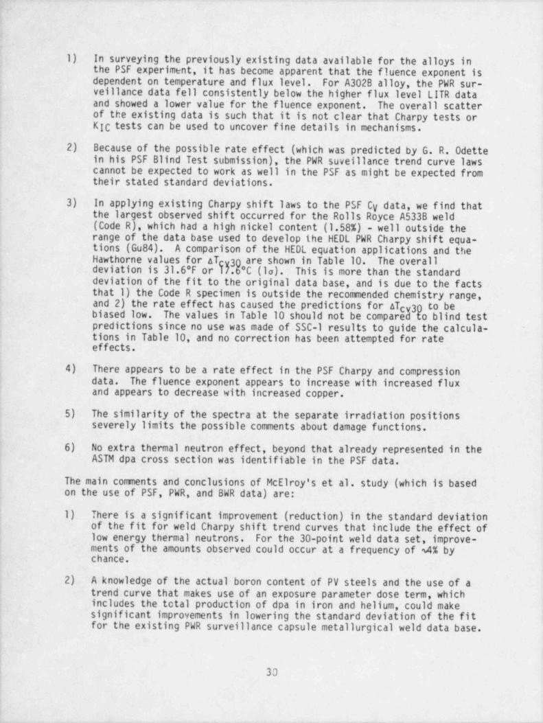
1) In surveying the previously existing data available for the alloys inthe PSF experiment, it has become apparent that the fluence exponent is
~
dependent on temperature and flux level. For A3028 alloy, the PWR sur-veillance data fell consistently below the higher flux level LITR dataand showed a lower value for the fluence exponent. The overall scatterof the existing data is such that it is not clear that Charpy tests orKIC tests can be used to uncover fine details in mechanisms.
2) Because of the possible rate effect (which was predicted by G. R. Odettein his PSF Blind Test submission), the PWR suveillance trend curve lawscannot be expected to work as well in the PSF as might be expected fromtheir stated standard deviations.
3) In applying existing Charpy shift laws to the PSF Cy data, we find thatthe largest observed shift occurred for the Rolls Royce A533B weld(Code R), which had a high nickel content (1.58%) - well outside therange of the data base used to develop the HEDL PWR Charpy shift equa-tions (Gu84). A comparison of the HEDL equation applications and theHawthorne values for aTcv30 are shown in Table 10. The overalldeviation is 31.6 F or T7.6*C (la). ' This is more than the standarddeviation of the fit to the original data base, and is due to the factsthat 1) the Code R specimen is outside the recommended chemistry range,and 2) the rate effect has caused the predictions for ATcv30 to bebiased low. The values in Table 10 should not be compared to blind testpredictions since no use was made of SSC-l results to guide the calcula-tions in Table 10, and no correction has been attempted for rateeffects.
4) There appears to be a rate effect in the PSF Charpy and compressiondata. The fluence exponent appears to increase with increased fluxand appears to decrease with increased copper.
5) The similarity of the spectra at the separate irradiation positionsseverely limits the possible comments about damage functions.
6) No extra thermal neutron effect, beyond that already represented in theASTM dpa cross section was identifiable in the PSF data.
The main comments and conclusions of McElroy's et al. study (which is basedon the use of PSF, PWR, and BWR data) are:
1) There is a significant improvement (reduction) in the standard deviationof the fit for weld Charpy shift trend curves that include the effect oflow energy thermal neutrons. For the 30-point weld data set, improve-ments of the amounts observed could occur at a frequency of 4% bychance.
2) A knowledge of the actual boron content of PV steels and the use of atrend curve that makes use of an exposure parameter dose term, whichincludes the total production of dpa in iron and helium, could makesignificant improvements in lowering the standard deviation of the fitfor the existing PWR surveillance capsule metallurgical weld data base.
Ii 30
__ _ _ _ _ . _ _ _ _ _ _ _ _ _ . _ _ _ _ _
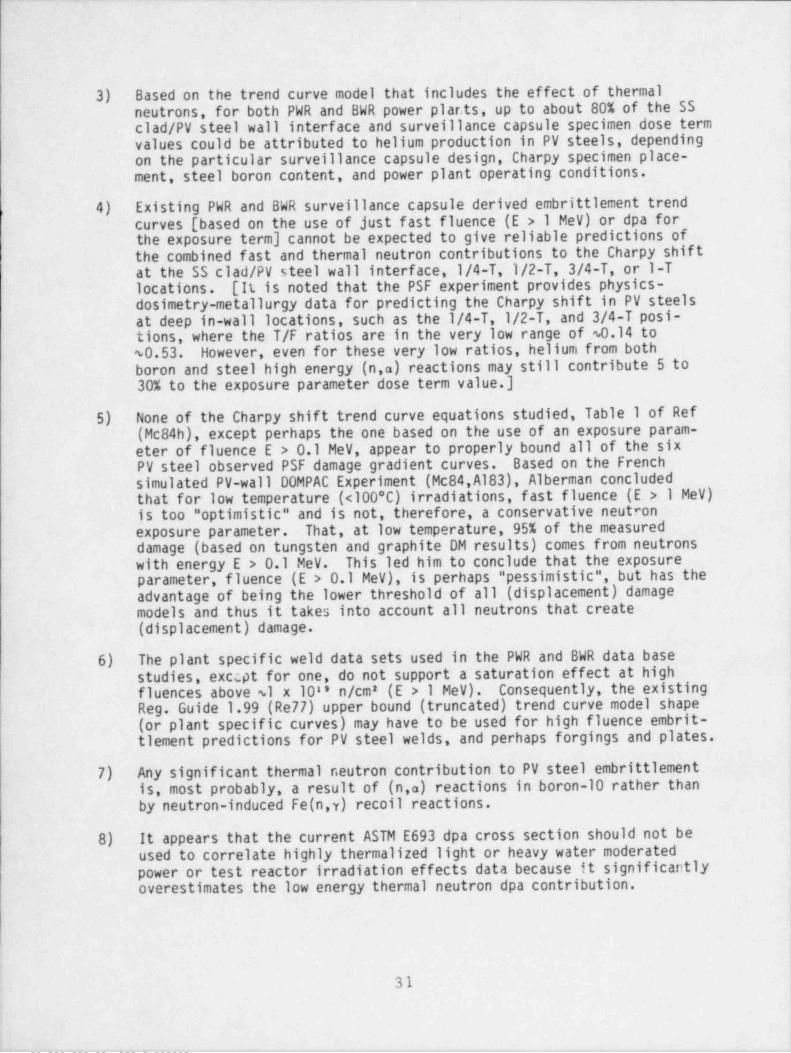
.
3) Based.on the trend curve model that includes the effect of thermal |neutrons, for both PWR and BWR power plar,ts, up to about 80% of the SS |
'clad /PV steel wall interface and surveillance capsule specimen dose termvalues could be attributed to helium production in PV steels, dependingon the particular surveillance capsule design, Charpy specimen place-ment, steel boron content, and power plant operating conditions.
.
'4) Existing PWR and BWR surveillance capsule derived embrittlement trendcurves [ based on the use of just fast fluence (E > 1 MeV) or dpa forthe exposure-term] cannot be expected to give reliable predictions of.the combined fast and thermal neutron contributions to the Charpy shiftat the SS clad /PV steel wall interface,1/4-T,1/2-T, 3/4-T, or 1-Tlocations. [It is noted that the PSF experiment provides physics-dosimetry-metallurgy data for predicting the Charpy shift in PV steelsat deep in-wall locations, such as the 1/4-T, 1/2-T, and 3/4-T posi- '
tions, where the T/F ratios are in the very low range of $0.14 toS0.53. However, even for these very low ratios, helium from bothboron and_ steel high energy (n,'a) reactions may still contribute 5 to
~30% to the exposure parameter dose term value.]
-5) None of the Charpy shift trend curve equations studied, Table 1 of Ref(Mc84h), except perhaps the one based on the use of an exposure param- '
eter of fluence E > 0.1 MeV, appear to properly bound all of the sixPV steel observed PSF damage gradient curves. Based on the Frenchsimulated PV-wall DOMPAC Experiment (Mc84, A183), Alberman concludedthat for low. temperature (<100*C) irradiations, fast fluence (E > 1 MeV)is too " optimistic" and is not, therefore, a conservative neutronexposure parameter. That, at low temperature, 95% of the measureddamage (based on tungsten and graphite DM results) comes from neutrons
'with energy E > 0.1 MeV. This led him to conclude that the exposureparameter, fluence (E .> 0.1 MeV), is perhaps " pessimistic", but has theadvantage of being the lower threshold of all (displacement) damagemodels and thus it takes into account all neutrons that create(displacement) damage.
6). The plant specific weld data sets used in the-PWR and BWR data base'
studies, exccpt.'for one, do not support a saturation effect at highfluences above $1 x 10 " n/cm' (E > 1 MeV). Consequently, the existingReg. Guide 1.99 (Re77) upper bound (truncated) trend curve model shape(or plant specific curves) may have to be used for high fluence embrit-tiement predictions for PV steel welds, and perhaps forgings and plates.
7) Any significant thermal neutron contribution to PV steel embrittlementis, most probably, a result of (n a) reactions in boron-10 rather thanby neutron-induced Fe(n,y) recoil reactions.
t
8). .It appears that the current ASTM E693 dpa cross section should not beused to correlate highly thermalized light or heavy water moderated '
. power or test reactor irradiation effects data because it significantlyoverestimates the low energy thermal neutron dpa contribution.
; i
|- 31
i.
. _ _ . _ _ _ . _ _ _ . _ _ . - _ _ _ . _ . _ _ _ _ _ _ _

9) The PV-wall SS clad /PV steel interface surface T/F ratio for PWR and |BWR power plants is expected to be in the range of 2 to 6 on the basisof surveillance capsule measurements, Westinghouse transport calcula-tions, GE measurements, and the PSF experiment physics-dosimetryresults.
10) Individual Charpy specimens (with natural boron content of @.4 up toperhaps 5 wt ppm) in PWR and BWR surveillance capsules will be subjectto C neutron exposures with T/F ratios in the range of @.5 to 5,Ldepending on the surveillance capsule design, its placement and thereactor operating conditions. The T/F variation for individual Charpyspecimens, therefore, could be an important parameter for the correla-tion of a set of Charpy specimen results and derived ARTNDT values.
11) From this study, that of Grant and Earp (Gr84), and others discussed inRef (Mc84h), a final conclusion is: the PSF experiment and PWR and BWRsurveillance program results clearly show that comparison of the effectsof radiation damage on yield strength, hardness, RTNDT and USE will beneeded to aid in improving and refining our knowledge of trend curvesand PV wall damage gradients. Implicit in this are the current observa-tions that the establishment of separate trend curves for welds, forg-ings, and plates will give increased understanding and accuracy in pro-
~ jections of the present and future metallurgical condition of PV steels.'
2.4.2 Research Reactor Data Development and Testing
As discussed in previous annual reports and as a part of the LWR-PV-SDIPProgram, statistically based (as well as other) physics-dosimetry-metallurgydata analysis and correlation studies using research reactor data are beingmade by ORNL, MEA, HEDL, UCSB and other program participants. The reader isreferred to Sections 2.3.1 and 2.3.2 and the proceeding of the 5th ASTM-EURATOM Symposium for more information on the ORNL, MEA, HEDL, UCSB, andother studies.
2.4.3 Benchmark Referencing Program
Benchmark referencing studies on both the experimental and calculationalaspects of the LWR-PV-SDIP are important program elements. The results ofsuch studies are discussed and referenced throughout Sections 1.0 and 2.0.Section 3.0 provides additional information about FY84 accomplishments byNBS and other LWR-PV-SDIP participants related to benchmark referencing anddosimetry calibration activities for research and power reactor test andsurveillance programs. More complete information is given in Ref (Mc84) andin the proceedings of the Fifth ASTM-EURATOM Symposium.
2.4.4 VENUS, NESDIP, and 00MPAC Benchmark Experiments
2.4.4.1 Mol, Belgium VENUS PWR Core-Baffel-Barrel-Thermal Shield Benchmark
Dosimetry experiments in the PWR engineering mockup at the VENUS criticalfacility were carried out in the first half of 1983. A detailed description
,
32
, - . . -._ -

of the VENUS facility at CEN/SCK, Mol, Belgium, can be found in Ref (Fa83,Fa83a,Mc84). This mockup was established to provide a relevant and practicalreactor physics link between PCA/ PSF tests and actual environments of LWRpower plants. Indeed for actual power plants, the azimuthal and verticalvariation of the surveillance capsule lead factors can not be ignored.These variations, together with the core boundary fuel power distributionmust be treated in detail, otherwise undetected biases may be entailed incalculations. Such biases will be further exacerbated by the use ofadvanced fuel and core management (low leakage) schemes, where the effectsof fuel burnup and plutonium build-in must be handled properly to obtain
i reliable reactor transport calculational results. A CEN/SCK paper on theresults of the VENUS program work was presented at the Fifth ASTM-EURATOMSymposium (Fa84).
Work is in progress to complete the analysis of the measurements performed*
in VENUS in 1983. A second series of 'Li neutron spectrometry measurementsand irradiations of SSTRs were further performed in April-May 1984. Draftsections of NUREG/CR-3323, see Section 2.1.2, on the VENUS experiments havebeen completed and have been distributed to program participants.
Results of transport theory calculations by CEN/SCK (Fa84), ORNL (Wi84b) andWestinghouse (Fe84) were presented at the Fifth ASTM-EURATOM Symposium onReactor Dosimetry. Present predictions of fast neutron propagation from the'
core to the barrel and the neutron pad are that C/E lies between 0.85 and1.10 in most cases, with a tendency for low values at great distance fromthe core and at high neutron energies.
The integral mode NRE results for VENUS, which are generally more sensitiveto lower energy neutrons, reveal a more complex pattern. Integral mode scan-ning has been completed on six NREs irradiated in VENUS. Figure 9 shows thelocations of these NRE in the VENUS mockup. Actual integral mode scanningresults are given in Tables 11-16, which include C/E ratios obtained rela-tive to MOL calculations. There is excellant agreement at core center, butserious disagreement outside the core proper.
A comparison of these results with the irradiation locations of these NRE inVENUS (see Figure 9) discloses that these discrepancies are correlated with
| distance for the sharp corner at the boundary of the core fuel at roughly| 27'. The NRE closest to this corner, namely the NRE irradiated in the outer
baffle at 24*, passes the highest C/E ratios (see Table 12). The nextnearest NRE to this corner is the one located in the barrel at 21 ; Table 14shows that these C/E ratios are also high, although the J-values are somewhatimproved over those of Table IC. The C/E ratios generally improve as the NRElocation becomes more distant from this fuel corner. In fact, the C/E valuesobtained in the pad at 21 (see Table 16) agree with the above mentionedtendency for C/E values to be low at great distance from the core. Sincethe NRE experimental technique obviously does not change from location-to-location and excellant agreement is obtained at core center (see Table 11),one can conclude that calculations of these lower energy groups become moredifficult as this fuel corner is approached. Comparison between measuredand calculated gamma-energy-deposition values is still preliminary; furtheractions are needed to produce final experimental results.
33
. - _ _ - - .- .-.

___ ____
Cross section measurements in the 8"U fission spectrum neutron field atthe BR1 reactor were also reported (Gi84). Microcalorimetry work in the BR1gamma standard field has also been accomplished by J. Mason. These facili-ties are used as benchmark referencing fields for the VENUS measurements.
2.4.4.2 United Kingdom NESDIP Power-Reactor Ex-Vessel Cavity Benchmark
The Nestor Shielding and Dosimetry Improvement Program (NESDIP) was success- )fully lauched in 1983. A detailed description of the NESDIP facility atAEEW can be found in Ref (Au82,Au82a,Au83,Mc84). NESDIP efforts have been '
divided into three formally scheduled phases that are discussed below.Phase I (the PCA 12/13 Replica Experiments) of the program has now beencompleted, and an AEEW report fully detailing the experiments has beenpublished, see Section 2.1.2. The reader is referred to this UK/NRC report,
and Refs (Mc84,Mc841) for discussion of the results and conclusions.
Phase II of NESDIP, the lateral extension of PCA replica to 2-m8 shieldsbegan in November 1983. This phase will be an AEEW responsibility in orderto verify the extension of the original LWR-PV simulator assembly to thismuch larger size PV simulator.
Phase III of NESDIP, which involves the simulations of actual commercialLWR cavity configurat. ions tailored to the requirements of the NRC and USutilities and vendors, is now scheduled to begin in the fall of 1985. Thiswill be the subject of a formal agreement between NRC and AEEW since con-siderable US participation is entailed. In addition, timely exchange of AEEWdata and analyis will be essential to meet NRC schedules. In return, AEEWhas asked NRC to supply sufficient technical data including source terms to |enable AEEW to calculate the y and neutron fields within an actual PWRcavity (probably at H. B. Robinson, a Westinghouse plant operated by CarolinaPower and Light Co.). Until this agreement is signed, specifics of thePhase III experiments can not be further detailed. I
2.4.4.3 French DOMPAC PWR Pressure Vessel and Surveillance Capsule,
Benchmark '
The 00MPAC dosimetry experiment is an irradiated PWR-PV and surveillancecapsule sumilation performed in the pool of the TRITON reactor (Fortenay-aux-Roses). It was designed for radiation damage characterization insidethe vessel (neutron spectrum variation) and a surveillance capsule locatedbehind a simulated " thermal shield" of a reference PWR of the Fessenheim 1(900-MW) type. A detailed description of the DOMPAC test facility can be
-found in Ref (A183).
Passive "Ni(n,p),"Fe(n,p) and '8Cu(n,a) RM and graphite (GAMIN) andtungsten (W) DM dosimetry measurements were performed in 00MPAC at ambienttemperatures (50 to 100*C). ANISN (100-group) transport and SABINE (26-group) computations were performed for the design of 00MPAC, and the methodof spectral indices was used to readjust the DOMPAC design to represent theactual water and steel configuration of Fessenheim,
i*
.
34

4
1
The experimental RM-Ni derived flux level results were found, generally,to be in good agreement with calculated gradients inside the vessel. A 3DMonte-Carlo (TRIP 0LI-code) computation has provided validation of theexperimental GAMIN and W damage fluences. It also indicates a lower effec-tive damage threshold (0.3 MeV) than expected from the theoretical irondisplacement model (0.45 MeV), which also implies weaker neutron damageattenuation inside the vessel. The damage gradient in the PV wall, evalu-ated experimentelly by tungsten DM dosimetry, is however entirely consistentwith that computed using steel damage models (iron dpa or probable zones).
2.4.5 Fifth ASTM-EURATOM International Symposium on Reactor Dosimetryand London LWR-PV-SDIP Meeting
The EURATOM and ASTM program committees successfully completed all of thenecessary activities associated with implementation of the Fifth ASTM-EURATOMSymposium held in Geesthacht, Federal Republic of Germany, September 24-28,1984. An ASTM-EURATOM program committee meeting was held in conjunction withthe Reno, NV, ASTM meeting in January 1985, to initiate planning for thenext symposium, tentatively scheduled to be held in San Antonio, TX, inApril 1987. The symposium is scheduled to be hosted by SwRI, withE. D. Norris as the principal contact. Minutes of the 14th LWR-PV-SDIPmeeting, which was hosted by RR&A and held at the Institute of Civil Engi-neering, London, England, October 1-5, 1984, were completed and distributedto LWR-PV-SIDP participants in December 1984.
!
!
!
,
,
35
I1

3.0 BENCHMARK REFERENCING AND DOSIMETRY CALIBRATION FOR RESEARCH ANDPOWER REACTOR TEST AND SURVEILLANCE PROGRAMS
The following sections update and provide new information about NBS and otherLWR-PV-SDIP work related to benchmark referencing and dosimetry calibrationactivities for research, test, and power reactor studies.
3.1 CERTIFIED FLUENCE STANDARDS
A chief objective of the NBS effort is to achieve benchmark referencing ofRM dosimetry measurements through the distribution and evaluation of Certi-fied Fluence Standards. These standards are threshold and fission-type
neutron sensors irradiated in a standard neutron field to a well-definedfluence.
Table 17 identifies 56 certified fluence standards prepared in the NBS 285UStandard Neutron Fission Spectrum for the LWR-PV-SDIP during FY83 and FY84.The FY83 information is included because many of the standards are not evalu-ated for 9 to 12 months after their distribution, so FY83 information is
current information on this time scale. Previous fluence standards wereissued to cover PCA irradiation measurements, as reported in NUREG/CR-1861(Mc81b) and NUREG/CR-3318 (Mc84a), and to round-robin test the 'Ni(n,p)'Coreaction; 25 irradiated nickel fluence standards were distributed and theresults were reported in (Mc84j) at the 5th ASTM / EURATOM Symposium inGeesthacht, Germany, September 1984. The current (Table 17) fluence stan-dards have been issued to cover experiments dealing with the development ofpower-reactor, surveillance-dosimetry benchmarks (e.g., PSF /SDMF, NESDIP andVENUS) and to support the cooperative efforts with nuclear reactor vendorsto develop generic operating power reactors as combined dosimetry and metal-lurgy benchmarks (e.g., Maine Yankee [ Combustion Engineering Designed Plant],H. B. Robinson [ Westinghouse Designed Plant], and Davis Besse - Unit I(BabcockandWilcoxDesignedPlant]aswellasArkansasNuclearOne-UnitI, Babcock and Wilcox Designed Plant] and Arkansas Nuclear One - Unit IILCombustion Engineering Designed Plant].
3.1.1 Benchmarking 4th SDMF Dosimetry and Round-Robin Support for Devel-opment of a Special Research Material (SRM)
As indicated in Section 2.3.1.3, NBS-certified neutron fluence standards havebeen sent to HEDL, KFA, Julich, and W-NTD to benchmark reference RM sensorcounting with dosimeters from the 4tW SDMF irradiation. The nuclear reac-tions involved are 8 8 'U(n,f)FP, 'Ni(n,p)"Co, * *Ti(n,p) * *Sc, and "Fe(n,p)'Mn.The latter two reactions were induced in pure iron and nickel foils as well
as in a nickel-iron alloy containing 33.6% nickel. This alloy, with itscertified nickel content, is NBS-SRM-ll58. It will also be distributed,with a different number, as a Certified Fluence Standard SRM in the nearfuture. The unirradiated alloy may be used as both a slow and fast neutronfluence monitor. The radioactive fluence standard (alloy) may be used tocalibrate dosimetry methods and to determine the sensitivity of analyticalmethods to nickel " contamination" radiations in iron and steel samples fromreactors. The gama spectrum from an irradiated SRM alloy foil is shown in
37

- . .-- .
Figure 10. Even with a relatively high-resolution GeLi detector, properbackground substraction for the iron 835-kev gamma peak, in the oresence ofthe cobalt 811-kev peak, can be a problem.
3.1.2 Certified Fluence Standards for Evaluating 8 8 'Cs RadiometricAnalysis
The last irradiation in Table 17 is seen to be for 150 hours for a fluenceof 108 ' n/cm > 1 MeV to produce the first, ever, certified fluence standardscontaining conventionally measurable amounts of 8 8'Cs. This isotope withits 30-year half-life is the fission product most used to determine the num-ber of fissions in any fissionable isotope. Three such 88'Cs standards'
were produced and initially distributed to HEDL, EG&G-Idaho (and NBS), whowill measure radioactivity from a number of other fission products as wellas 88'Cs. Subsequently, the 88'Cs fluence standards will be circulatedinternationally, but first to laboratories with direct interests in the NRCLWR-PV-SDIP effort.
3.2 EVALUATIONS OF POWER REACTOR SURVEILLANCE PHYSICS-DOSIMETRY EFFORTS
3.2.1 Maine Yankee
The Maine Yankee cavity dosimetry for the first, low-enrichment peripheral-,
' fuel cycle has been removed. D. McGarry of NBS was on site inWiscasset, Maine from 18 to 26 of May 1984 to assist H. Jones of MaineYankee Atomic Power Company (who is responsible for the Plant's PV surveil-lance program) in the dosimeter recovery and a re-installation. All dosime-ters were separated and re-identified to confirm loading information. HEDLdosimeters were shipped to HEDL and the remaining dosimeters (from CombustionEngineering) were repackaged for shipmenat to W-NTD (S. Anderson).-
_
Figures 11, 12 and 13 give details of the CE dosimetry removed from the 0 ,ex-vessel monitor position. Note.that the aluminum wire wraps were installed(by Jones and McGarry) at Maine Yankee before installation to ensure adequateseparation of the bare and cadmium-covered dosimetry packages (see Figure 12and Figure 13).
Additional CE dosimeters, but in rectangular-alu'minum HEDL-type packages,were re-installed on the original CE holder (central) rod and remounted at0* for irradiation during the current cycle.,
3.2.2 H. B. Robinson
Radiometric analyses of the ex-vessel dosimetry irradiated in Cycle 9 hasbeen accomplished by HEDL. HEDL SSTR analysis is in progress. The internal,advanced replacement surveillance capsule dosimetry has been returned to HEDL '
for analyses. Correlation of internal and ex-vessel, or cavity, measurementswill provide valuable information regarding verification of calculationaltechniques for low leakage PWR cores. There were no NBS dosimeters in eitherof the above-mentioned sets. Fluence standards have been supplied to HEDLfor benchmarking the RM counting. All of this work is being coordinated by
.
S. Grant of Caroline Power and Light, the utility representative responsiblefor the plant's PV surveillance program.
,
|
38
;
- _ . _ _ _ _ _. , ,._ _ _ __ _ _ _ _ __.

.
3.2.3 McGuire-1
Preliminary results from the McGuire-1 cavity experiments have been reportedat the 5th ASTM-EURATOM Symposium. These were obtained from a string of RMholders removed in 1982. Four additional strings, from cavity locationsboth within and between azimuthal regions covered by the reactor neutronpads and covering a range of 2 m in elevation, were retrieved in 1984 andshipped to the University of Arkansas. At the same time, an in-vessel sur-veillance capsule was retrieved for analysis by W-NTD (S. Anderson). NBSfluence standards have been prepared for exchange between the two countinglaboratories together with the dosimetry materials. Calculations by Univer-sity of Missouri-Rolla, W-NTD and ORNL are expected to provide a similar
_
test of the in- and ex-vessel physics-dosimetry, which has been completed inAN0-2.
3.2.4 Turkey Point 3
Advanced cavity dosimetry was installed by W-NTD in the reactor cavity ofTurkey Point Unit-3 in December 1983. The Installed cavity dosimetryincludes both radiometric monitors (HEDL-ILRR foils and NBS paired uraniumdetectors). J. Sun of Florida Power and Light is responsible for the coor-dination of this joint NRC-HEDL-NBS-W-NTD physics-dosimetry surveillanceprogram verification effort.
_
3.2.5 Arkansas Nuclear One - Unit II
Experiments similar to those in ANO-1 commenced in 1979. Four detectorwells have been used for cavity dosimetry, with radiometric monitors at sev-eral elevations and axial profiles covering the core region and beyond thenozzles, above the installed cavity shield. Seven cavity experiments atvarious stages of three fuel cycles have been completed and, as in Unit I,cavity measurements are to be continued. An internal surveillance capsulewas removed in 1982, from which dosimetry materials have been analyzed byBattelle Columbus Laboratories and by the University of Arkansas. Both ofthese laboratories have also counted neutron fluence standards supplied bythe NBS.
3.3 COOPERATIVE RESEARCH BETWEEN NBS AND SCK/CEN RELATED TO THE NRCLWR-PV-SDIP
3.3.1 NBS Participation in the VENUS Experiment
Extensive dosimetry measurements have been completed for the Belgian VENUSProgram for core source to PV wall fluence verification. J. Grundl,D. Gilliam and D. McGarry of NBS were on site in Mol, Belgium (in 1983 and1984) to assist with the subject experiment and to verify benchmark fieldcalibrations of all the active neutron dosimetry used therein (see Sec-tion 3.3.2.3). In VENUS, prototype experimental data were obtained fortesting calculational methods and models in the vicinity of nuclear reactorfuel corners and core edges, see Section 2.4.4.1.
39

_ _ _ _ _ _ _ _____ - _________ __ _ _ _ _ _ _ _ _ _ _ _ _ _ _ _ _ _
1
Significant analytical effort was required during 1984, some of which iscarried into FY85, to digest the experimental information described in thefollowing sections.
3.3.2 Intercalibration of the Belgian and U.S. Standard 8 8 5U FissionSpectrum Irradiation Facilities
3.3.2.1 U.S. 8 8 5 Cavity Fission Source
The U.S. Standard 8 8 5U Fission Neutron Spectrum is at the National Bureauof Standards in Gaithersburg, MD. It operates in the center of a 30-cmdiameter spherical cavity located in the graphite thermal column of the NBSResearch Reactor. For this reason, the facility is frequently called theCavity Fission Source (CFS). The upper view in Figure 14 shows, in detail,the CFS assembly containing neutron sensors and the lower view shows theCFS's location within the thermal column cavity. The CFS consists of twodisks of 8850 metal (16 mm diam x 0.13 mm thick) placed above and below acylindrical cadmium pill box 0.076 cm thick. This assembly encloses, forirradiation, approximately six passive neutron sensors (nominally 1.27 cmdiam x 0.025 cm thick). The neutron sensors are held in the center of theassembly by light-weight aluminum pieces.
3.3.2.2 Belgian 885U Cavity Fission Source
Figure 15 shows the 8 8 8U CFS assembly at the SCK/CEN Laboratory, Mol,Belgium. This assembly incorporates a 100-cm diam cavity as opposed to the30-cm diam cavity for the NBS 888U field. The significance of the largercavity is that there are substantially fewer low-energy (wall returned)neutrons in the Belgian field. Also, the larger source permits the exposureof an NBS fission chamber. This chamber cannot be used in the smaller volume
-NBS CFS. The Belgian 888U Standard Field operates in the graphite thermalcolumn of the BR-1 reactor at the SCK/CEN Laboratories.
3.3.2.3 Verification of Certified Fluences in the Belgian 8 8 8U StandardField
The absolute source strength, and therefore the fluence rate, in any CFS isdependent on the reactor power level. Consequently, a fluence monitor thatis independently calibrated against both an absolute source strength and thereactor power level is required for each irradiation. The independent cali-bration of the Belgian 88 5U neutron field was confirmed by NBS. The fis-sion rate, per watt of reactor power, in the Belgian field was compared with
i the fission rate of 8 8'Pu during a certified flux-density irradiation inthe NBS 8**Cf Standard Fission Spectrum.
The source for the NBS 8 58Cf (spontaneous fission) neutron field is a pointsource bead of 8'8CfP2 in a light-weight aluminum and stainless steel cap-sule. The source is suspended 1.6 m from the nearest reflectin'g surface ina low-scatter environment. The free-field fluence rate for such a 858Cfsource is then just a function of source strength, distance, time and a fewsmall geometry-dependent scattering corrections.
!
40
'_. _ ._ _ _ _ _ _ _

Since the ratio of the 8 8'Pu(n,f) spectrum-averaged cross sections in the885U and 858Cf fission spectra is unity, to within several tenths of a per-cent, the fission rate per monitored watt of reactor power in the Belgian8 8 5U spectrum is measured with the same 8 5'Pu deposit, in an NBS fissionchamber, as was used in the NBS 858Cf measurement.
3.3.2.4 Recalibration of the NBS "85U Standard Fission Spectrum Againstthe Belgian 8''U Fission Spectrum
It should be noted that if it were not for the fact that the NBS 8 8 5U CFS istoo small to accept an NBS fission chamber, calibration of its flux densitycould be accomplished with a a n'Pu deposit in a fission chamber in the samemanner that Belgian 885U field was calibrated. However, such is not thecase. The method of calibration is to utilize a radiometric dosimeter suf-ficiently small in size to fit into the NBS CFS but with a reaction proba-bility large enough to provide radioactivity sufficient for counting after afew days of irradiation in the standard neutron field.
Historically, the reaction selected was the 225(In(n,n')tismIn reaction andthe flux-density calibration for the NBS 2 85U field was transferred from theNBS 258Cf field. In 1983-1984, the transfer was accomplished from theMol 8 8 5U field by the 5'Ni(n,p) 5'Co reaction. The change was made becausethe 4.5-hour half-life of the indium reaction is too short to transfer fromBelgium, while the reaction rate probability of the nickel reaction is toolow for efficient transfer from the 258Cf field. Figure 16 summarizes thedetails of both the "old" and "new" calibrations. At present, there is abouta 1.5% discrepancy between the two methods. This is, of course, not a prob-lem for bencmkark referencing LWR-PV-SDIP dosimetry.
All of the above activities as related to standard neutron fields have beendocumented and reported in the proceedings from the 5th ASTM / EURATOM Sympo-sium held in Geesthacht, Germany, September 1984. The information, and its
~
significance as a bases of reference for dosimetry accomplished under theNRC LWR-PV-SDIP, was presented at Geesthacht in a poster paper.
3.4 NBS INTERACTIONS WITH PSF /SDMF AND PCA BENCHMARK IRRADIATIONEXPERIMENTS
3.4.1 Certified Fluence Standards
| As indicated in Table 17, during FY83, FY84 and so far in FY85, approximately' 20 certified fluence standards have been distributed to HEDL, CEN/SCK, ORNL,
}{-NTD, and KFA (dillich) to assist in benchmark referencing radiometric dosim-etry for the various PSF /SDMF experiments. Table 18 gives an accounting bydosimeter types and reactions.
!
| 41
| |
II
i

3.4.2 ORR-SDMF'
NBS assisted HEDL and ORNL in dosimeter logistics, planning and coordinatingthe November 1983 4th SDMF: a nominal 18-day irradiation of selected radio-metric (RM) dosimetry (from HEDL, NBS and KFA), SSTRs (HEDL), HAFMs (RI) anddamage monitors (DM) (Harwell, RR&A) in the 4/12 SSC configuration. Fluencestandards (already identified in Table 18) were sent to HEDL and KFA. TheNBS paired-uranium detectors (Puds) have been shipped to HEDL for radiometricanalyses. Significant heat plus water damage (apparently) was suffered bythe pud in the SSC location. Probably no data will be available from thatdosimeter.
3.4.3 Special Standard Neutroni Field Irradiation
Several 8 52Cf.and ' 8 5U standard neutron field irradiations were conducted toexamine various aspects of SSTR and HAFM methodology. Except for the very(ultra) light-weight SSTR fissionable deposits, these irradiations have con-firmed assigned masses for the HEDL deposits and have demonstrated that in
-free fields, such as found in the vicinity of a 858Cf source, both NBS fis-sion chambers and SSTRs yield the same fission rates to within +1% (la).
NBS is actively engaged in the present controversy where HAFM measurementsin a variety of benchmark and test region neutron fields suggest discrepan-cies with the ''8 and 'Li(n,a) cross sections.<
3.5 COMPENDIUM 0F BENCHMARK AND TEST-REGICN NEUTRON FIELDS AND RELATEDRESEARCH
3.5.1 Compendium
The subject compendium was updated and published in FY84 in NUREG/CR-3391,Vol 4 (Mc84k). Since then, an additional entry has been completed for theIntermediate-Energy Standard Neutron Field (ISNF) at NBS, and the updatewill be published in FY85.
In addition to the ISNF, work is progressing toward an entry for the PCAExperiments. Neutron energy spectra and physical description have beenreceived from ORNL for the PCA 12/13 and 4/12 SSC configurations. Spectruminformation for the 8/7 configuration is still required.
3.5.2 Related Research*
In the Belgian Cavity Fission *85U spectrum at the BR-1 Reactor at Mol,Belgium SCK/CEN Laboratories, a series of neutron cross section measurementswas made in which the neutron fluence rate was determined by a transfer
*This research is not funded by the NRC but is of interest because it has adirect bearing on the accuracy of benchmark referenced LWR-PV dosimetry andstandard neutron field data in the subject compendium.
42
. - . . - . - - _ _ _ - . . .. . _ - - . _ - - _ - . _

from the NBS 858Cf fission Spectrum. The mentioned flux-density transfer hadbeen accomplished in support of calibration measurements for the Belgian /NRCVENUS program (see Section 3.3.2.3). This provided an opportunity to verifyintegral cross-section measurements for important dosimetry isotopes. Fis-sion cross sections were reported for 88'U, 285U, a: 3g, a "Pu, 8 8 'Np and8 88 Th, as well as threshold reaction cross sections for '8 5In(n,n') and the**Ni(n,p) reactions. The data were reported at the 5th ASTM / EURATOM symposiumby D. Gilliam et al. (Gi84). The results are summarized in Tables 19 and 20.
Both the US (NBS Laboratory) and the FRG (PTB Laboratory) have completecross-section measurements in the 8 8 50 fission spectrum at Mol, Belgium.The PTB results were presented by W. Mannhart at the 5th ASTM / EURATOM Sympo-sium. Agreement for common isotopes is very good. Furthermore, within theexperimental uncertainties, the results still agree with the measurements
'made at Mol, by CEN/SCK, NBS, and PTB.' ,
3.5.3 Scattering in the Cavity Fission Source
The 8 85U spectrum of the NBS CFS is created inside of a small volume betweentwo fission disks. Compared to the complexity of nuclear power reactors,the CFS is a relatively simple structure. As such, it can be mathematicallymodeled in Monte Carlo calculations and can be examined for effects of inter-actions on the purity of the fission spectrum.
The Monte Carlo investigations, carried out for NBS by P. Sorenson (LANL),reveal net spectral perturbations on the order of 5%; primarily, because ofinelastic scattering in uranium and aluminum. The energy shift in the fis-sion spectrum is shown in Figure 17. This figure is the spectrum calculated
i at a particular fluence-monitor sensor within the CFS. By integrating theperturbed spectrum over the cross section of the pertinent neutron sensormaterial, one determines the effect on a particular isotopic reaction rate.'
Such an effect may be negative or positive. For example, a negative resultwill be obtained whenever inelastic scattering decreases the neutron energybelow the threshold of a reaction. Figure 18 graphically represents thetrends in such perturbations as a function of the approximate low-energythresholds. The five data points (open circles) are, from lef t to right, forthe reactions 8 8 'Np(n,f), I S sin (n,n'), s eNi(n,p), 8 'Al(n,a) and 5 8Cu(n,a).
3.6 QUALITY ASSURANCE OF AN INVENTORY OF SENSOR MATERIALS FORSURVEILLANCE DOSIMETRY
3.6.1 New Supply of NBS 8 8'O Radiometric Dosimeters
Negotiations are underway with the Belgian, Geel Laboratory (Van Audenhoven)to fabricate, from NBS-SRM-002 uranium oxide powder (U 0 ), a supply of38quality controlled 88'U dosimeters. The mentione.' SRM material has a 0.01755at.% 8880 content. The final form, pressed powder or metal foil, on thematerial for encapsulation has not yet been decided. Dosimeter geometry.willbe a disk nominally 13 mm diam by 0.15 to 0.40 mm thick. Specificationsi
require elemental weight of uranium in each dosimeter be known and that anyresidual oxide or other impurities that would affect the gravimetric analysisat the 0.5% accuracy level should also be known..
43
___ __ -. __ __ _ _ ._
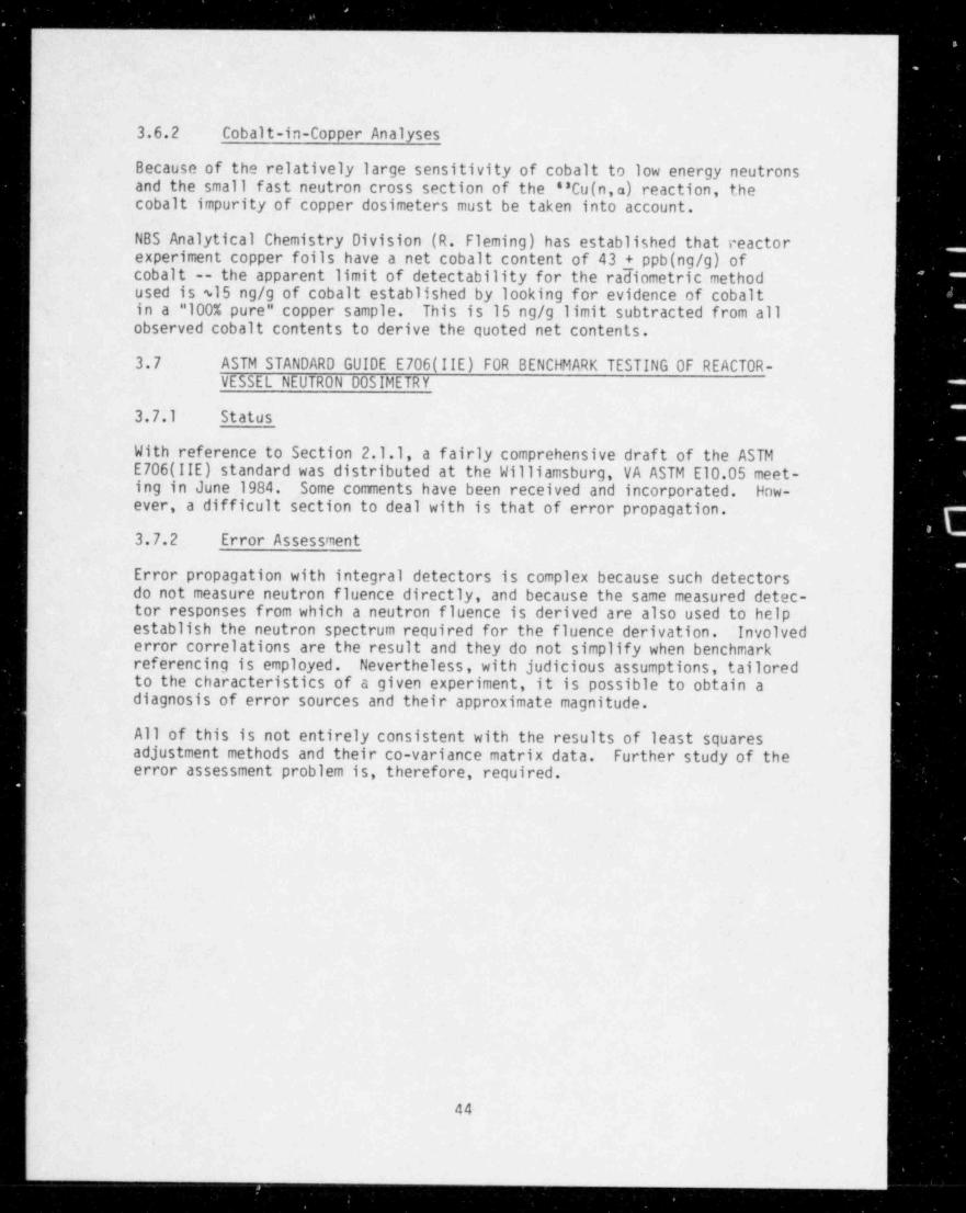
_ . _ _ . _ . . _ _ _.-
-
3.6.2 Cobalt-in-Copper Analyses
Because of the relatively large sensitivity of cobalt to low energy neutronsand the small fast neutron cross section of the '8Cu(n,a) reaction, thecobalt impurity of copper dosimeters must be taken into account.
NBS Analytical Chemistry Division (R. Fleming) has established that reactorexperiment copper foils have a net cobalt content of 43 + ppb (ng/g) ofcobalt -- the apparent limit of detectability for the radiometric methodused is $15 ng/g of cobalt established by looking for evidence of cobaltin a "100% pure" copper sample. This is 15 ng/g limit subtracted from allobserved cobalt contents to derive the quoted net contents.
3.7 ASTM STANDARD GUIDE E706(IIE) FOR BENCHMARK TESTING OF REACTOR-VESSEL NEUTRON 00SIMETRY
3.7.1 Status
With reference to Section 2.1.1, a fairly comprehensive draft of the ASTME706(IIE) standard was distributed at the Williamsburg, VA ASTM E10.05 meet-ing in June 1984. Some comments have been received and incorporated. How-ever, a difficult section to deal with is that of error propagation.
3.7.2 Error Assessment
Error propagation with integral detectors is complex because such detectorsdo not measure neutron fluence directly, and because the same measured detec-tor responses from which a neutron fluence is derived are also used to helpestablish the neutron spectrum required for the fluence derivation. Involvederror correlations are the result and they do not simplify when benchmarkreferencing is employed. Nevertheless, with judicious assumptions, tailoredto the characteristics of a given experiment, it is possible to obtain adiagnosis of error sources and their approximate magnitude.
All of this is not entirely consistent with the results of least squaresadjustment methods and their co-variance matrix data. Further study of theerror assessment problem is, therefore, required.
44
, . . _ . -

.
.
..
./.
4.0 BIBLIOGRAPHYi
(A182) A. A. Alberman et al., " Nouveaux Developpments de la Dosimetriedes Dommages par Technique Tungstene," Proc. 4th ASTM- EURATOMSymposium on Reactor Dosimetry, Gaithersburg, MD, March 22-26, . J
1982, NUREG/CP-0029, NRC, Washington, DC, Vol .1, pp. 321-329,July 1982. ..
(A183) A. A. Alberman et al., DOMPAC Dosimetry Experiment Neutron Simula-tion of the Pressure Vessel of a Pressurized-Water Reactor, Charac-
terization of Irradiation Damage, CEA-R-5217, Centr,e d' Etudes -
Nucleaires de Saclay, France, May 1983.
(As84) " Nuclear (II), Solar, and Geothermal Energy," Sec.12, Vcl 12.02,1984 Annual Book of ASTM Standards, 1984.
(Au82) M. Austin,.' Description and Status of the NESTOR Dosimetry Icprove-'
ment Programme (NESDIP)," Proc.10th WRSR Information Meeting, 1
Gaithersburg, MD, October 12-15, 1992, NUREG/CF-0041, Vol. 4, NRC,Washington, DC, pp. 228-231, January 1983. .
(Au82a) M. Austin, " Sense of Direction: An Observation of Trends in Mate-rials Dosimetry in the United Kingdom," Proc. 4th ASTM-EURATOMSymposium on Reactor Dosimetry, Gaithersburg, MD, March 22- p26, 1982, NUREG/CP-0029, NRC, Washington, DC,.Vol. 1, p. 461-469, L
July 1982.
(Au83) M. Austin et al., "The NESTOR Shielding and Dosimetry ImprovementProgramme (NESDIP): The Replica Experiment (Phase 1)," Proc. lithWRSR Information Meeting, National Bureau of Standards,Washington, DC, October 1983.
(Be83) R. G. Berggren and F. W. Stallmann, " Statistical Analysis of Pres-sure Vessel Steel Embrittlement Data," from the ANS Special Sessionon Correlations and Implications of Neutron Irradiation Embrittle- '
ment of Pressure Vessel Steels, Detroit, MI, June -12-16,1983,Trans. Am. Nucl. Soc. 44_, p. 225, 1983. -
(Cf83) Code of Federal Resulations,10CFR50, " Domestic Licensing ofProduction and Uti'ization Facilities," " General Design Criteriafor Nuclear Power Plants," Appendix A; " Fracture ToughnessRequirements," Appendix G; " Reactor Vessel Material Surveillance - 1
, _
Program Requirements." Appendix H; US Government Printing Office,.
Washington, DC, current edition. -
~ 2c(Ch82) R. D. Cheverton, "A'Brief Account of the Effect of Overcooling "
Accidents on the Integrity of PWR Pressure Vessels," Proc. 4th t
ASTM-EURATOM Symposium on Reactor Dosimetry, NUREG/CP-0029, NRC,- .I -
. .
Washington, DC, Vol. 2, pp.1061-1070, July 1982.
!-a
..
45-+
Ie' I, i. "4 #t g _ - + e , ,j -- g ,. -[ - *- , '- .. . _ _
,-

.
.
| ,.
.: ' ~
.,'
_
(Ch83) R. D. Cheverton, S. K. Iskander and G. D. Whitman, "The Integrityp- of PWR Pressure Vessels During Overcooling Accidents," Proc. 10thj WRSR Information Meeting, Gaitnersbu g, MD, October 12-15, 1982,
NURFG/CP-0041, Vol. 4, NRC, Washincton, DC, pp. 232-241,<
Jar vary 1983..
'
( De8? ) S. Le Leeuw and R. Menil, " Silicon P.I.N. Diode Neutron DamageSonitors," Proc. 4th ASTM-EURATOM Symposium on Reactor Dosimetry,Gai nersburg, MD, March 22-26, 1982, NUREG/CP-0029, NRC,
; Washlagton, DC, Vol. 1, pp. 387-412, Jul y 1982.
(dis 2) W. J. Dircks, Pressurized Thermal Shetk (PTS), and Enclosure A,"NRC Staff Evaluation of PTS," SECY-8F795, NRC, Washington, DC,November 1982. --
(Fa80a) A. Fabry et al., "Results and Implications of the Initial NeutronicCharacterization of Two HSST Irradiat ion Capsules 6nd the PSF Simu- -
lated LWR Pressure Vessel Irradiation Facility," Proc. 8th WRSRInformation Meeting, Gaithersburg, MD, October 27-31, 1980, _NUREG/CP-0023, NRC, W3shinaton, DC, March 1982. '
' (Fa82) A. Fabry et al., " Improvement of LWR Pressure Vessel Steel Embrit-tlement Surveillance: Progress Report on Belgian Activities in
i: Cooperation with the USNRC and other R&D Programs," Proc. 4th -
ASTM-EURATOM Symposium on Reactor Dosime,t_rt, Ga ithersburg, MD,'
. ch 22-26, 1982, NUREG/rP -0029, NR Washir gton . DC, Vol .1,m,
45-77, July 1982. 13 .
.
L (Fa83) A. Fabry et al., " VENUS Dosimetry Program," Paper or< ented; at the 10th PRSR Information Meetina, Gaithersburg, MD,
October 12-15, 1982, prepr.1t available._ ;
(Fa83a} A. Fabry et al ., "The Belgium Characterizat ion Progran 6nd the: Venus Program for Core Source to PV Wall Fl~ence Verificatio" "
Proc. llth WRSR Information Meeting, National Bureau cf Stardards,
[ Washington, DC, October 19D3.
7 (Fa84) A. Fabry et al., " VENUS PWR Enlineering Mockup: Core Qualifica-' ; tion, Neutron and Gamma Field Characterization," Proc. 5th
i ASTN-EURATOM Synposium on Reactor Dosimetry, September 2f-28, 1984.1
(Fe84) A. H. Fero, " Neutron and Gamma-Ray Flux Calculations for the VENUSPWk Engineering Mockup," Proc. Sth ASTM-EURATOM Symposium onD caClor Dosimetrr, Snptember 24-28, 1984. . ,
(GiS4 / b. M. Gilliam et al., " Cross-Section Measurements in the 255U
I Fission Spectrum NeuL on Field," Proc. of the ;to ASTP-EURATOM - ~
iC. Symposium on Rec ~ tor losimetry, Geesthacht, FRG, September 24 28. ~
~
- T1984.
.-
( Go84 ) R. bold et al.. '' Nondestructive Determination of Reactor PV NeutronExposure by Cortinuous Gamma-Ray Spectrum," HOL-SA-3064, Proc. 5th fASTM-EURATOM Synposium on Reactor Dosimetry, Seulember 24-28, 1984 -
-s ._2:
%
;..
. . . . . . . . . _ . . _ _ _ _ _
-

(Gr84) S. P. Grant and S. L. Earp, " Methods for Extending Life of a PWRReactor Vessel After Long-Term Exposure to Fast Neutron Radiation,"Proc.12th ASTM Symposium on Ef fects of Radiation on Materials,ASTM STP 870, June 1984.
(Gr84a) J. A. Grundl, C. M. Eisenhauer and E. D. McGarry, " Compendium ofBenchmark Neutron Fields for Pressure Vessel Surveillance,"LWR-PV-SDIP Quarterly Progress Report October - December 1983,NUREG/CR-3391, Vol . 4, NRC, Washington, DC, May 1984.
(Gu82) G. L. Guthrie, W. N. McElroy and S. L. Anderson, "A PreliminaryStudy of the Use of Fuel Management Techniques for Slowing PressureVessel Embrittlement," Proc. 4th ASTM-EURATOM Symposium on ReactorDosimetry, Gaithersburg, MD, March 22-26, 1982, N'JREG/ CP-0029,NRC, Washington, DC, Vol.1, pp.111-120, July 1982.
(Gu82a) G. L. Guthrie, W. N. McElroy and S. L. Anderson, " Investigationsof Effects of Reactor Core Loadings on PV Neutron Exposure,"LWR-PV-SDIP Quarterly Progress Report, October 1981 - December1981, NUREG/CR-2345, Vol. 4, HEDL-TME 81-36, Section E andAppendix, pp. HEDL-35 - HEDL-36 and HEDL-Al - HEDL-A46, HanfordEngineering Development Laboratory, Richland, WA, October 1982.
(Gu82b) G. L. Guthrie, " Development of Trend Curve Formulas Using Surveil-lance Data," LWR-PV-SDIP Quarterly Progress Report, January 1982 -March 1982, NUREG/CR-2805, Vol.1, HEDL-TME 82-18, Hanford Engi-neering Development Laboratory, Richland , WA, pp. HEDL-3 - HEDt-18,December 1982.
(Gu82c) G. L. Guthrie, " Development of Trend Curve Formulas Using Surveil-lance Data-II," LWR-PV-SDIP Quarterly Progress Report , April -
| June 1982, NUREG/CR-2805, Vol. 2, HEDL-TME 82-19, Hanford Engi-neering Development Laboratory, Richland, WA, pp. HEDL-3 - HEDL-13,December 1982.
(Gu83) G. L. Guthrie, "Charpy Trend Curve Formulas Derived from anExpanded Surveillance Data Base," LWR-PV-SDIP Quarterly Progress
I Report, October 1982 - December 1982, NUREG/CR-2805, Vol. 4,i HEDL-TME 82-21, Hanford Engineering Development Laboratory,
Richland, WA, pp. HEDL-3 - HEDL-13, July 1983.e
(Gu83a) G. L. Guthrie, " Pressure Vessel Steel Irradiation EmbrittlementFormulas Derived from PWR Surveillance Data," from the ANS Spe-cial Session on Correlations and Implications of Neutron Irradia-tion Embrittlement of Pressure Vessel Steels, Detroit, MI,June 12-!6,1983, Trans. Am. Nucl . Soc. 44, p. 222, January 1983.
(Gu83b) G. L. Guthrie, " Error Estimations in Applications of Charpy TrendCurve Formulas," LWR-PV-SDIP Quarterly Progress Report,January 1983 - March 1983, NUREG/CR-3391, Vol.1, HEDL-TME 83-21,
[Hanford Engineering Development Laboratory, Richland, WA,pp. HEDL-3 - HEDL-13, November 1983.:
.
,47
,\
n:. - - - - - --sem- -

.
b
(Gu83c) G. L. Guthrie, "Charpy Trend-Curve Development Based on PWRSurveillance Data," Proc. lith WRSR Information' Meeting,
| Gaithersburg, MD,-October 24-28, 1983, NUREG/CP-0048, NRC,Washington, DC.
,
'
(Gu84) .G. L. Guthrie, "Charpy Trend Curves Based on 177 PWR Data Points,".
LWR-PV-SDIP Quarterly Progress Report, April 1983 - June 1983,NUREG/CR-3391, Vol. 2, HEDL-TME 83-22, Hanford Engineering Devel-
1
opment Laboratory, Richland,-WA, HEDL-3 - HEDL-15, April 1984.
|(Gu84b) G. L. Guthrie, "HEDL Analysis of the PSF Experiment," see Minutes $?4th LWR-PV-SDIP Meeting, HEDL-7511, October 1-5, 1984.
(Gu84c) G. L. Guthrie,." Uncertainty Considerations in Development andApplication of Charpy Trend-Curve Formulas," HEDL-SA-3205, 5thASTM-EURATOM Symposium on Reactor Dosimetry, September 24-2E71984.
(Gu84d) G. L. Guthrie, E. P. Lipp'ncott and E. D. McGarry, LWR-PV-SDIP:iPSF Blind Test Workshop Minutes, HEDL-7467, April 9-10, 1984.
(Ha83) J. R. Hawthorne, " Evaluation of Reimbrittlement' Rate FollowingAnnealing-and Related Investigations on RPV Steels," MEA-2032,Materials Engineering Associates, Inc., 0xen Hill, MD, and Proc.lith WRSR Information Meeting, Gaithersburg, MD,October 24-28, 1983, NUREG/CP-0048, NRC, Washington, DC.
(Ha84), J. R. Hawthorne, B. H. Menke and A. L. Hiser, LWR-PV-SDIP: NotchDuctility and Fracture Toughness Degradation of A302-B and A533-BReference Plates from PSF Simulated Surveillance and Through-WallIrradiation Capsules, NUREG/CR-3295, MEA-2017, Vol .1, April 1984.
- (Ha84a) J.:R. Hawthorne and B. H. Menke, LWR-PV-SDIP: Postirradiation.
. Notch Ductility and Tensile Strength Determinations for PSF~
Simulated Surveillance and Through-Wall Specimen Capsules,NUREG/CR-3295, MEA-2017, Vol. 2, NRC, Washington, DC, April 1984.
(He82) P.~ D. Hedgecock and J. S. Perrin, " Standards for Materials BehaviorUnder Neutron Irradiation," Proc. 4th ASTM-EURATOM Symposium onReactor Dosimetry, Gaithersburg, MD, March 22-26, 1982,NUREG/CP-0029, p. 829, NRC, Washington, DC, July 1982. .
(Ka82) F. B. K. Kam, Ed., Proc. 4th ASTM-EURATOM Symposium on ReactorDosimetry, Gaithersburg, MD, March 22-26, 1982, NUREG/CP-0029,NRC, Washington, DC, Vols.1 and 2, July 1982.
.(Ka82a) F. B. K. Kam, " Characterization of the Fourth HSST Series ofNeutron Spectral Metallurgical Irradiation Capsules," Paper
' presented at the 4th ASTM-EURATOM Symposium on Reactor Dosimetry,Gaithersburg, MD, March 22-26, 1982, preprints available.
>
48
- _ _ _ _ _ _ _ - _ _ _ _ _ _

(Ka82b) ~ F. B. K. Kam et al., " Neutron Exposure Parameters for the FourthHSST Series of Metallurgical Irradiation Capsules," Proc. 4th
' ASTM-EURATOM Symposium on Reactor Dosimetry, Gaithersburg, MD,March 22-26,-1982, NUREG/CP-0029, NRC,. Washington, DC, Vol . 2,pp.=1023-1033, July 1982.
(Ka83) F. B. K. Kam, F. W. Stallmann, R. E. Maerker and M. L. Williams," Light Water Reactor Pressure Vessel (LWR-PV) Benchmark Facilities(PCA, ORR-PSF, ORR-SDMF) at ORNL," LWR-PV-SDIP Quarterly ProgressReport, April 1982 - June 1987, HEDL-TME 82-19, Hanford EngineeringDevelopment Laboratory, Richland, WA, pp. ORNL-l - ORNL-19,January 1983.
( L181) E. P. Lippincott et al., Fabrication' Data Package for HEDLDosimetry in the ORNL Poolside Facility LWR Pressure VesselMock-Up Irradiation, HEDL-TC-2065, Hanford Engineering DevelopmentLaboratory, Richland, WA, September 1981.
(Li82) E. P. Lippincott and W. N. McElroy, " ASTM Standard RecommendedGuide on Application of ENDF/A Cross-Section and UncertaintyFile: Establishment of the File," Proc. 4th ASTM-EURATOMSymposium on Reactor Dosimetry, Gaithersburg, MD, March 22-26,1982, NUREG/CP-0029, NRC, Washington, DC, Vol . 2, pp. 705-710,July 1982.
-(lib 4) E. P. Lippincott, " Evaluation of Neutron Exposure Conditions forthe Buffalo Reactor," HEDL-SA-3101, Proc. 5th ASTM-EURATOMSymposium on Reactor Dosimetry, September 24-28, 1984.
(Li84a) E. ' P. Lippincott, " Evaluation of Neutron Flux in the PCA,"HEDL-SA-3102, Proc. 5th ASTM-EURATOM Symposium on ReactorDosimetry, September 24-28, 1984.
(Ma82b) P.~ Mas and R. Perdreau, "Caracterisation d' Emplacements d'Irra-diation en Spectres Neutroniques et en Dommages," Proc. 4thASTM-EURATOM Symposium on Reactor Dosimetry, Gaithersburg, MD,March 22-26, 1982, NUREG/CP-0029, NRC, Washington, DC, Vol . 2,pp. 847-854, July 1982.
-(Ma82e) R. E. Maerker and M. L. Williams, " Calculations of the WestinghousePerturbation Experiment at the Poolside Facility," Proc. 4thASTM-EURATOM Symposium on Reactor Dosimetry, Gaithersburg, MD,March 22-26, 1982, NUREG/CP-0029, NRC, Washington, DC, Vol. 1,pp.131-141, July 1982.'
(Ma84a) R. E. Maerker and B. A. Worley, Activity and Fluence Calculations _for the Startup and Two-Year Irradiation Experiments Performed atthe PSF, NUREG/ CR-3886, ORNL/TM-9265, October 1984.
(Ma84b) R. E. Maerker and B. A. Worley, " Calculated Spectral Fluences andDosimeter Activities for the Metallurgical Blind Test Irradiationsat the ORR-PSF," 5th ASTM-EURATOM Symposium on Reactor Dosimetry,September 24-28, 1984.
(Mc81) W. N. McElroy, Ed., LWR-PV-SDIP: PCA Experiments and Blind Test,NUREG/CR-1861, HEDL-TME 80-87, NRC, Washington, DC, July 1981.
49

. . . . . . . _ _ . . - _ . _ . - _. - - __
s
.f
'
(Mc81b) E. D. McGarry- and A. Fabry, " Fission Chamber Measurements," LWR-~
.
PV-SDIP: PCA Experiments and Blind Test, W. N. McElroy, Ed.,'
NUREG/CR-1861, HEDL-TME 80-87, NRC, Washington, DC, pp. 2.3-1 -2.3-38, July 1981.
(Mc82a) _W.N.McEIroyetal., LWR-PV-SDIP: 1982 Annual Report,,
-
NUREG/CR-2805, Vol . 3, HEDL-TME 82-20, NRC, Washington, DC.. |.
December 1982. 1;
-(Mc82c) P. McConnell'et al., Irradiated Nuclear Pressure Vessel Steel Datai
Base, EPRI NP-2428, Electric Power Research Institute, Palo Alto,.
' IA, June 1982.
' (Mc83d)- -W.~ N. McElroy and F. B. K. Kam, PSF Blind Test Instructions andData Packages, HEDL-7448, April 1983.
.
(Mc84) W. N.'McElroy et al., LWR-PV-SDIP 1983 Annual Report,t.
NUREG/CR-3391, Vol . 3, HEDL-TME 83-23, NRC, Washington, DC,.
E - January 1984. _1
! (Mc84a) L . D. McGarry et al., " Gamma-Ray Response of Integral NeutronE
Dosimeters and Review of Measured 88 80 Fission Rates," LWR-PV .-
, SDIP: PCA Dosimetry in Sua) ort of the PSF Physics-Dosimetry-''
Metallurgy Experiments, NUREG/CR-3318, HEDL-TME 84-1, Section 4.5,.NRC, Washington, DC, 1984.
,
'- (Mc84h) W. N. McElroy et al., " Trend Curve Exposure Parameter Data Devel-
opment and Testing," HEDL-SA-3126, Proc. 5th ASTM-EURATOM,
; . Symposium on Reactor Dosimetry, September 24-28, 1984.'
(Mc841) W. N. McElroy, LWR-PV-SDIP: PCA Experiments Blind Test andPhysics-Dosimetry Support for the PSF Experiments, NUREG/CR-3318,
i' HEDL-TME 84-1, September 1984.
| .(Mc84j) E. D. McGarry et al., "The U.S. 8 8 8U Fission Spectrum Standard' Neutron Field Revisited,"-Proc 5th ASTM-EURATOM Symposium on
; Reactor Dosimetry,' Geesthacht, FRG, September 24-28, 1984,
f - (Mc841) W. N. McElroy et al., Minutes of the 14th LWR-PV-SDIP Meeting,f
London, UK, October 1-5, 1984, HEDL-7511, Hanford Engineering*
Development Laboratory, Richland, WA.,
1
(Mi81) L. F. Miller, Analysis of the Temperature Data from the ORR-PSFIrradiation' Experiment: - Methodology and Computer Software,
'
NUREG/CR-2273, ORNL/ TM-7766, November 1981.~
(Nr80) NRC Staff, Presentation to Advisory Committee on Reactor Safe-guards, Metal Components' Subcommittee, Transcribed Proceedings of4
i Meeting, Washington, DC, January 24, 1980.
| (Nr81) NRC, Task Action Plan A-ll Report: Resolution of the Reactor'Vessel Materials -Toughness Safety Issue, NUREG-0744,
. September 1981.,
&
1
50
.
N
4-e e vw w4+e1 6"-r- rw- ww-ww .- +w - s- -vs - -wr-- - -- ---r--w-it-*----w-v---v .-,-ww---v-y = - - ' *-1s*-'=-*-'e=-e yy-e-*.'-- -w -e- -1y y - - - ----v* - -

.--
%
9
9 9
na 5 mese man asLW W UI-
amnium ame .
unemarum gammeggm usemu mmie
~~"8 IFEM IN(g --e em
EW M,,, ..a.
li , . i . i . .. i . . i . - i .. i . i . .
" " ," ,,,",*E" ",, ss - . - seuce ams ,,,
sar'a==''=us,maisumam, , , , , , -
- , , , , , , _ -| ._ _- - .- ;, J., - _=- u- - - - -- , . _
- -- , , , , , , , , , , , _
E s6e su ma'ama. nasas an eenre in ,,,,,, is aimsse inspessu'e snaruesom e su sienes ineussen sun. sus me n anum mesearmsese venctus __ == reactus
E.ma.in. m | |.
I I. - .-.. . .a i . . i .
am=== am == se iais. == a==.us e' " ' " -
amnium e amsniumemen esamme = =ue== n-insium meene -
, , " , , , , " " _ " " '_anasies= = ness
_, ammsciusam man- === - - encum === - -" muass senesseman.er,,um
' " ~ ' " w. wi.e. m unes sa
STATUS CODE em.ar in enea u en s eises in
-|-
|== ens == emme
cn tu accrrno as asTu stasonno; two osits utta 3 I
sinunano NuanSEn IUDecaTE TEAR of acctPlaalct |"
,, , s. .m acetrito as asim sianonne sus comuuny
UNoEnCoNIG nWon nEVIElot mammmen uma semerumaa stanoano courtino ano a satiot enoctss e macun ase mamaram-w onut cowttito ano us nrvuw enoctss - === =ar- -
PB onaff aIID911 o0TLIIIE raRTlattT colnPt TEo-- --
l .
l l. . . ._ ..
_ :--"m"-. :"s::'. . -' ,,,;-". ,::n-. m. ---- --- . .-,, ., e - . - - --- -.a,,,,_
--as_
(#_ - -,88 .I.It.s.a.t.16 (4 (W
.E.t.4 82
ASTM STANDARDS FOR SURVEILLANCE OF LWR NUCLEAR REACTOR PRESSURE VESSELS AND SUPPORT STRUCTURES.= = . ,
FIGURE 1. ASTM Standards for Surveillance of LWR Nuclear Reactor Pressure Vessels and Their SupportStructures.
. . . .

asCOMMtNOSO Sit AarM STANOAAOS NO. m n as Si Se a u as SS ST se.. i si . .i i ... .. ... ii. ... is i i si sii
8 MASrsa asAf aim ou oS r0 t m. M, y%ga ye 3
e ME.tMoOS Oe SunvEnLANCE AND CommeLAh0sePa AC TiCa S
^ ; '=^"; "'''u"|,""a"*" *' ""*"^a "^*'*a =,C ES w-o>-c 1 o-w- XS 579tCTS Of MeOM ENE AGV NiufRON AADsAfsoal ON
MtCMANaCAL PaOPtAnte 8 1 MNC. Su.v..uANC. n8, AESuoe m.A,OmnON .o -e O o-o. .e i x---
0 DISPLACED Af0M10PallAPOSuRG uMIT4 (r' $MOl' N
E. DAMAOS COAAILAfsofs POR AEACTOA veSSSL '
SuavleuaNCE 8 0 0-4>-C O-C 1p. SuavssuaNCa ilSTS pOR NuCttAn RSACTOa
vtaetLSE9 7 [ M MM^
O. DETERM48e4NG AADeADON taPOSuRE POR NuCLEAAREACTOn avPPonf ernuCTuntS S C: 0--O-4>--C i X
M SUPPLEMENTAL ts8r MATH 000 POR REACTOn vaSaltSunvliuANCtes S 5 0 >- C i
1. ANALVess ANO sasTERP4E'ATION Of PMVS4CS DOSitetTATmISuLTS EOR TsSr nEACTOne it O 3-<>--C i X
N. SUPPORTING METHOOOLOOT OuiDES
A. APPUCAflOss Of astuTRON SPECTRUM ADJUSTMENTMETHOOS 19 O ,; Q-@{ 1 M '
S APPUCAftose OF 4sesi, A CAOSS StCTION ANOussCE A TA8NTY P6L18 12 O MOM i N
C. 584804 StT 088604 4401AAADIAfl0N FOA REACTORSvRvieuANCE is aW )----0--C 1 O-<
0. APPUCADON Of NEUTRON TRA8sSPORT METM000 PORREACTOR vtSSEL SunwesuaNCE uO O--O-C i O--6-----0-
"
f. StasCMMAAN ftSTiseQ Of REACTOR VESSEL OostMETPV 10 : O S Ci $=F. PAf DeCTHs0 NEuTR08e RADeATION DAMA04 TO REACTOR
vtS84L MATERIALS 19 14 OS M M'd D-^
en. 884804 MEA 8uRIMtNTS MtTHOOSAPPUCADON AND ANALYSIS 07.
A RADIOMETR#C MONITORS FOR REACTOR vtSSELSuavteuANCE 1T | * O Q [email protected] i $.4 '
B 60u0 STATE TRACK ARCOADER MOeslTOAS FORREACTOR vt4SEL SURvleuAluCE 18 | , O )--(i %
C. MauuM ACCuMuun0N etutNCE MOsuTOa8 PORREACTOa vaSSEL SuavEsuANCE u :: Wy i $e
O DAMAGE MONsfonsNG FOR REACTOR vtSSELSuRva.uANC4 at y; y4;
I TEMPinATunt amNsTOnS pon ASACTOa vtSSELSuRvinLLANC419 31 %f V^
f fI if I I f I t ff ifI ff I ff I ff f f f f fff fffO J A J O J A J O J A J O J A J O J A J O J AJ OJ AJ OJ AJ OJ AJ OJ AJ OJ AJ O
3 DAAFT OuTusst Out 70 ASTM EIS Su0 COMMITTEE TASK onOuPS| O Ist DRAFT TO APPRORIATE ASTM EIS SuSCOMMITTER TASE OR0vPS'
Q AEvsSED DRAFT POR ASTM EIS SuSCOMMITTite. ASTM EIS COMMITTit. AND/04 ASTM SOCitTY SAuCTINOPtI
| g ACCEPTANCE A8 ASTM STANDARD) AtvisiON AND ACCEPTAfeCI AS ASTM STANDAROj PaaMARV flMt INit Av&L 70m ROUNO ROSese WAu0ATION AseO CAUS AATION TESTS
( t'asse01Caits TMAt TM4 LEAO RESPOastiSIUTV 18 WITH SuSCOMMITTtt EIS SIINSTRAD OF WTTM SuSCOMMITTER E10.88.
Nott An ASTM STANDAAOS MUST St AEvifWED. UPDATIO AS RIOusMEO. AND REGALLOTED fvtRY S YEARS.;
NEOL S311-1117
i.
i
| FIGURE 2. Preparation, Validation, and Calibration Schedule for LWR-PV andSupport Structure Surveillance Standards,
i
t
!52t
i
!
|
|
. _ .
1.1
J'
te - eei
.
. &S - A
k 7
$ s.s- fI:::
-. s.:PcA 4/12 ISsQ
e 2m t..n sacuA239t n T/4e N es..a sSc%0.6 -
c M es..n tio4
el .agg . tag e . 100 + 200
ot3TANCS To usoPLAN4 D. cat ==
FIGURE 3. Axial Distributions of the 237Np and 238U Fission Rates in thePCA 4/12 SSC Configuration.
. 'd,v
$ - mot cALcutAficens* -o at cAtcuunoas 1
? F it Is >
k bis, \ r Amanaunom.g
mAosAnon,' V.'
1. $g6P..
' ' " * ' ' I,
-~'. ..i , , , , , , ,
* d wN ,g ._,,
.
I V.,d,,______
| ,z e.
. . ,,e m e n en en i i. is is in in zu zu an a.n-------------
oAu.A'.aAv emenav e ev,.
FIGURE 4. Low-Energy Ganna-Ray Continuum for the 1/4-T Location of the 12/13Configuration as Compared with CEN/SCK and ORNL Calculational Results.
sio , i . , , .
5j k uot cAtcutAfions
.- --on=t cAccuunoms a
i : $I
ANfte6MLAnoss.108 AAceAnog
-
+-+ :g t - g ,- ~ ...,a
, _ , . . . , .
__# - 4 -
g -
____
! ,q _____ 'O. . g -_ -_ _ _ _ _ _
. . _ _ _ _ _ _ _ _ _ _ ,. _ _
; . . ..
. . _
3 ,,, , . . .
93 eN 9 72 9 33 1 14 t5 1M in SW 2 17 2D 2p tDGAMMA AAT 14tRG,IMovl . . . .
FIGURE 5. Low-Energy Gamma-Ray Continuum for the 3/4-T Location of the 12/13Configuration as Compared with CEN/SCK and ORNL Calculational Results.
53
i

.- _ _
,
pj;pv ~;'
'[k $
Q % ')',
. ,.w ,,. m .a :,
7-,
+ r
+|_ & s,J [*!;.
~ . . .
[ )se}~2: 'I g n, ,
~.- ;. .
,';
~ ~ ~ *n ,.
.
7-
-| p\ - .g ,;7--
~^
._ ._ _,
j. . , , , ,
mi -.............
:Iif
,
f,
|t a
!.
'
.
hA.J
e
. .|6 fh'
,.
'f ,
- <-, ,~4:'*
W *s ;
'. ~. e.
|
FIGURE 6. View of Hanford Optical Track Scanning (HOTS) System for SSTRsShowing Scanning Stage and Optics. Neg 8102282-4
54
- - - - - - - - - - . - - - - _ _ - _ _ _ _ - . _ _ _

'
'
W| ;
)?
,.. e y
s)4^/p,
~\
's -
\s ** f~ b.-#
D' of .,#p .6 N,&,#-Q
. ,,
.- .. K .. :x, s.
~ '
. q.' :
|- s|r ' Qf'-'
',_
A' ,.
*?'S' W,-
I
8W47'}s,
i
tDUM (z.y77
i
! Ficygg ,* ORR~ psp yYradfggg% Facility.
55
.

weet ss
4. eSs'i$r..ui,AAAg ,,My,4
N - ;t. u;. ++pjw as -a N N. 3.
Nwa eo -A N N" " * * ~ ' N N }g nrA cs%> 2 se 'V nsa. csc, m a.ssuoi. cc -c- sa N N aN N vg \ , RLs.ur. esw)o
g e*
'
y"Yotcc-0
kk 's/j'NN S N kQ3<. yaja es
o N N g34 / ssN NNo> a N MI t * ee"' ,
"!REE:E N N % o D' N N/wm
cn
k \ N M/m es-p d)% kQ$*
sou mIR \ %x x\ _t-%" $/ /N N I o, s g x,
/gN P
-o-uca 5 _,ja en, _c- m e/ ssN N % o3 Ne
_ aca. enN ,< e-wa u '*
C '
.%"gykis33 /
_I_uem u 4TNs1N jg e n -t - - a ~'y N h
/
i p r-uca CC
C- - * '>
gJ g5 fig"-
gggg%gav5"gp<Heta. B Bma 96 / mmee
g.3sw go4
as
FIGURE 8. Illustration of a Typica1 Dos 1 meter and Metallurgical Specimen Assembly in the Irradiation- - -
Capsules.
_ _ _ _ _ _ _ _ _ _ -_ _- - _. _ _ _ - _ _ _ _ _ _

NRE Locations*
v2 RADrus = 56 5,5 Cuv3 RADeus 216. Cu
IGRID PITCo, e ,5 GmiO COOADrNaTESga,vi amE vt=v
n Cu
o SS 255 CM
'E I } -jE a ,_ , ,,,,,c,O O o e g 4,
O 3 $ 9.O- a /
O r s. srs O O P
\O ,2. .u, gP NE S' 072 Cu
e .3,o, c,O
o p*JwaftnGAPt CoaE O
g saamat
OUTE A sarFLt O
**$ O,p/ =suTaO=PAD
n .sa,0 g Ogy on . .,
en. .n,0 Of
/tMElt-3,. mel O44 Futt
Osd2......i en ..r,
p #,,Od.'. ., 0 ''#
2$, . , , , , , gw,0/ e O O '+ -ai o0
-----,,.,,,,i e...., en,.., e.n..>. e
t-m asi1 O * *''' ,. .es. . . . . . . . ,
i II O <-n .ru
,==ta i4 s 4 s> | o,o n5*earr6: o
1 i- a r. .s,e8 $ '*
|.nia c,a. .g ;,,,,
n,>O 2 ,.uit i ..evet
| i 3r. 7,
v.000 -
, ,-
p' ~.-n 1, n .n . . . . , ,
~.? R I E I I E
. . . . , - . :- a a e a
e
FIGURE 9. Venus Irradiation Locations of Selected NRE That Have Been Scannedin the Integral Mode.
57
-. - -. -. _

' 0 000i i i i i i i i
_ GAMMA SPECTRUM |
FROM AN IRON F0ll~
IRRADIATED FOR g 312.5 Day
30 HOURS IN THE y as4.83 kay ;
i0,000 - NBS U-235 CAVITY / "'' ' ' "' I -
I'' '
FISSION SOURCE u,, g ,', , u ,,*
. - 70.78 day_
,
g 810.75 kev;
**o, (99.45 7.)$ from
E 1,000 - "Ni(n,p)"Co_
" Rate ~ 0.04 cps
! /y' !-
-
.
8 ./g. ./ b. d \\i
.
-
.
--
,00 , . . . . .. . . . . . ..... ..-. . .
k... W* *
--
' ' ' ' ' ' ' '10710 720 730 740 750 760 770 780
CHANNELOF 1024
FIGURE 10. Gamma Spectrum from an Iron Foil Irradiated for 30 Hours in theNBS assU Cavity Fission Source.
58
. - - - - . . . _ _ . _ _ - - _ . - _ - _ _ - - . , - _ .

_ _ _ _ _ - _ - _ _ _ . _ _ . . -_ . _ _ , _ _ _ _ _ . _ _
BCT- SC-T BC-M SC-M BC-B - SC B
'*: 67 7116" :-
32-3/16" :- 32-4/16" :
7 ToTop
'2 11/ 416"' 4 '2 11/16"'~212/16"' '
'
z i e ..i .c|{g (=" " ' ~ g =" y{ggo"e n v=.
''
g | | I |
Measurements are Accurate NOTE:- 7 7/16" : 32 3/16' :
to Slightly Less Than 1116" Aluminum Wire$ 2 70-3116" : Wraps Added toSeparate Bare and
: 99-10/16" - Cadmium-CoveredDosametry.
: 102 4/16" E.D M 11112/82: 131 14/16" :
2 1 4 9116" :
Ref.: C.E. Drawing E 4781165 201(01)
NOTE: Slight Discrepancies (21/16") Exist in Redundant Measurements. Principal Cause was inability to Reproduce TopReference Position.
i
FIGURE 11. Record of On Site (Maine Yankee) Changes to Combustion Engineering's 0 Ex-Vessel FluxMonitor Capsule Assembly. Dimensions shown are "as recorded" measurements. Spring-like,aluminum-wire wraps were added on site.
I

a
-
: 1.625" ;
bgo.0.13647|8" Deep {||||||||||||
''
;,/ vzM/M #Ag ,
i s -
;- L$ )777777773 3--------------
0.375R <i
>
Combustion Engineering +--- 0. 7 50" r
Q / Dosimeter Locations
l I I
NTR
[[[[[[[[[[[ / ARRANGEMENT!
At Uranium (238) Foil'
A2 Co-Al Wire
| A3 Titanium Wire
[[[[[[[[I A4 fron Wire' N HEDL Bare A5 HEDL Bare Dosimeters, , , ,
Dosimetry
'
a
Ref.: Combustion Engineering Dwg. E-4781-165 201(R01)
|
| FIGURE 12. Bare Dosimetry Package for Maine Yankee 0* Dosimeters.
|
. _ _ _ _ - _ _ _ _ _ _ _ _ _ _ _ _ _ _ _ _ _ _ _

__
40* 80* I: 1.625"l
01369 WHHHH/Hi="o~o '0593R g_ _ _ _ _ g,, ,
,L 7////////// /ABe t,
,' ~
~ ,85
. . ~
N' | 0 22r-,,,,,,,,,,,,,,,,,,,,,,
'/0 377" Through Ho:e80' Sol'd Aluminum Combustion Engineering
Center Rod Dosimeter Locations
M NOTE: This Capsule Looks Just Like a35mm Film Can.1116"--+ -
Can is Marked with aRed Line Indicating4 020" ~ *-
*
$ ", I 'Which Side is to Face Reactor Core
7/HH/HHHDOSIMETER
.[[[[[[[[[[[ / MONITORARRANGEMENT
B1 Uranium (238) Fool en CadmiumB2 Co Al Wire in CadmiumB3 Nickel Wire in CadmiumB4 Copper Wire in Cadmium
.r/sssssssssssssssssssssB5 Np-237 Wiro in Cadmium
g yg 4B6 HEDL Dosimeters in Cadmium
. 86" HEDL Dosimeter*' * HELD " Coin Shapped,"*
Top Screws On -*- 2 ,
Cadmium-Covered Dosimeters<
Ref.: Combustion Engineering Dw0. E 4781165-201 (RO1)
NOTE: The Cadmium Covers are on the Dosimeters. The Above Parts are all Aluminum.
FIGURE 13. Shielded (Cadmium) Dosimetry Package for Maine Yankee 0* Dosimeters.

i
a
1s
: :/ < ;.
235u SOURCES - s 's
- :s
DETECTOR STACK ' N
l ' ' /; 'p
caoMlUM ENCLOSURE [-'
-
!
NNNM'n\.Nx'N NNxxxxxY///////)
xxx-
!
ke= 'N''\x'?'S's ___
N'N\ \\\\
FIGURE 14. NBS Cavity Fission Source.
62

.-
: PERSONNEL SHIELD' .
i
{/ETER CAVITYN!////N N''/,/[ W/
DIAM CHANNEL
^5"'kYM[ ) "o ' ' a,
.
/ h(/ '
. | -30 CM / f'
YLINDRICAL p
/ FOIL /.
+
" OFISSION CHAMBER $ !CHA BER
'
{ AT CENTER POSITION
l' ///// 1 9i NEUTRONS FROM BR1 COR /
/t / /t / /t / /t / /t / /t/i G R A P HIT E THERMAL COLUMN ;
FIGURE 15a. BR-1 Cavity Fission Spectrum Standard Neutron Field Facility.0.1 CM THICK
!/ CADMlUM TUBEi
ALUMINUM
.[ CLADAR -.. 1-
- -
U 235 FOIL DIMENSIONS* SOURCE 2 Z, 2 R. AR
ASSEMBLY NO. (CM) (CM) (CM)
MARKll 7.7 3.3 0.01
MARK llA 7.96 3.44 0.02p ,
CHAMBER ., M ARK lli 7.95 5.25 0.04
\-. -_ CYLINDRICAL
U 235 FOIL,
2 R, --*=
FIGURE 15b. Fission Spectrum Neutron Source and Detector.
63

--
'
N851 Ra-Se (r. ni C ,,e,,re MnSO. Bath 0*'e'*"aeNeutron Source With a 252Cf Spontaneouswa50, - Source Strengtn | gge~ Fession SourcesCaiterated 8ac*rrSource Strength Cal.braten
proeuce F,ewsWorn Known Fussoon
heutron Fouence
NSS Fission '"* $ ' n 'arreo.are so 0 I*A'U" F*'iChamoer 06'8'* * 252Cf Fission U*""d,'r*o# [ * *WithMPu Fess s ence Neutron Field ru Fixed GeometryDepositnun,o,n.a,; ",M n Counter
'i
, , , ,
,_. ,,.ns_er7 % (Seefe ifi
Nicket and wreenereIndium Foets Cerse Coun# ,%*s: 9etosan !)uence TransreroFruence
2350 Fassion Neutron DF "hn Onfy(See fe (21/g - ner.os o
,,y' /*,Q',8,,'er,ons F etdFined Geometry '
(in 1-Meter Dia. Cavity)Counter
,_e ,,.ns,er nka anewNo
IS** to @ *ne le r4
NBS Cavity Fission Source235U Fission Neutron
Field(n 30cm Dia Cavity)
~ ~
~- Pu 239', Pu-239 , O c,SCKrCEN - cf
,-U 235 gPu 239 U 235 - Pu-239
. cf Oe U 235. .
~ ~
~- i n.Old NBS ,,, hcf O c,115 ~ |
* R+n.115ih 23 * eU 235
-
R c,,f, ,
, . , , ,
, g,,,235 ,. , , ,
U
~ SCK/CEN"New N8S h U 235 Nr58
R U 235 iNsS)E ciU 235 Nr58,q U 235(SCK,
~ SCK/CEN ~New
b BSN
R '".-235U
* R in 115"U.235,N S, <**U 235 ,,s
, U-235 (SCK;
FIGURE 16. Present and Former Procedures for Calibration of the NeutronFluence Rate in the NBS 888U Cavity Fission Source.
l!
|
|
| 64,
t

._ _ _ _ _ _ _
12 i i i i, _
~
(Spectrum at the Bottom Indium Foll)*
, 3-
,
' 2a .-
A w-2 8 - ~
1 u.u. 3 .
I*,IE 4 - v
-
2 .
-
""tt .
l= 0 - a |c ISo
~
, , , ,
0 2 4 6 8 10
Energy (MeV)
Effects of Scattering on the Neutron Energy Spectrum in the NBSFIGURE 17.
Cavity Fission Source.i i i i
n A Poeltive Effect Means that the Obeefvedb \" Reaction Rete Must be Reduced to Aeree with anE t unportwtad spectrum.
k +2 - g
-
a. se ..t
t-
8= s _
0 - \.
e \E "By Eye" Trend
Curve Onlyti s.* s
~
5 -2 -\ '
swc s
3 N ~ , - o-s _ _ ' 'm ,"
'i i
, _
100 2 4 6 8 9
1.ower (95%) Energy Threshold in MeV
Monte Carlo Estimates of Trends in Effects on Threshold-TypeFIGURE 18. Nuclear Reactions Caused by Scattering in the Cavity FissionSource.
65

1
TABLE 1
LWR-PV BENCHMARK FIELD FACILITIES *
Benchmark Anticipated
Field OperationFacility locatioc Schedule _ Main Purpose
8 " Cf /" 'U NBS US 1975-Open Standard fields for cross-section testing and validation; emphasis is onequivalent fission flux calibrations and RM fluence counting standards.
PCA-PV ORNL,US 1978-84 Data base for the "PCA Pnysics-Dosimetry Blind Test": Low-powerexperimental / calculational benchmark for different LWR-PV configurations;emphasis is on verification of radial neutron exposure gradients and leadfactors; i.e., confirmation of radial through-wall fracture toughness andembrittlement predictions.
PSF-PV ORNL,US 1980-84 Data base for the " PSF Physics-Dosimetry-Metallurgy Blind Test": High-power LWR-PV physics-dosimetry-metallurgical test; emphasis is on high-temperature and high-fluence simulation of PWR environmental conditionsand verification of neutron damage gradients; 1.e., confirmation of radialthrough-wall fracture toughness and embrittlement predictions.
PSF-SDMF ORNL,US 1979-Open High-power LWR-PV benchmark: Emphasis is on verification of surveillancecapsule perturbations; specific RM, SSTR, HAFM, and DM verification tests,and quality assurance evaluations of commercial dosimetry materials andservices; 1.e., confirmation of the physics-dosimetry methods, procedures,and data recomended for in-situ in- and ex-vessel surv1111ance programs.
VENUS CEN/SCK, 1982-Open Low-power LWR-PV core source boundary benchmark: Emphasis is on verifi-Moi, cation of effects of new and old fuel management schemes and accuracy ofBelgium azimuthal lead factors; f.e., confirmation of azimuthal PV wall fracture
toughness and embrittlement predictions.
NESDIP AEEW, 1982-Open Low-power LWR-PV cavity benchmark: Emphasis is on different PWR configura.Winfrith, tions and nrification, via cavity measurements, of neutron exposure gra-UK dients and lead factors; 1.e., confirmation of radial through-wall fracture
toughness and embrittlement predictions.
DOMPAC CEA, 1980-1983 Low-fluence experimental / calculational benchmark for a specific PWR con-Fontenay, figuration: Emphasis is on verification of surveillance capsule pertur-France, bations and PV-wall neutron exposure and damage gradients; 1.e confirmation
of radial PV-wall fracture toughness and embrittlement predictions.
(Acronyms:AEEW - Atomic Energy Establishment (Winfrith, UK)CEA - Commissariat a l' Energie Atomique (France)CEN/SCK - Centre d' Etude de l'Energie Nucleaire-Studiecentrum voor Kernernergie (Moi, Belgium)DOMPAC -TritonReactorThermalShieldandPressureVesselMockup(Fontenay-aux-Roses)UK - United KingdomNBS - National Bureau of Standards, USPCA-PV - Pool Critical Assembly Physics-Dosimetry Pressure Vessel Mockup (ORNL)ORNL - Oak Ridge National LaboratoryPSF-PV - Oak Ridge Research (ORR) Reactor Pool Side Facility Physics-Dosimetry-Metallurgy Pressure Vessel
MockupPSF-SDMF - PSF Simulated Dosimetry Measurement Facility at the ORRVENUS - Critical Facility (Mol, Belgium)NESDIP - NESTOR Reactor Surveillance Dosimetry Improvement Program Facility (Winfrith, UK)PWR - Pressurized Water Reactor
67

_ , . _ _ _ _ . _ _ _._._.______,___ _ _.______ _
*taed ares se 4tsges taxa ses sataeseos set,
d d d 4 A A s t **35 M4304 d A (1) A 9*8NIIId d A A '*8 870t V 35480 t*0-d d A ase tsdeeg
W d A A~
A* iego ,,, ,3es Wdet te m *d .,
A A e i a,,*.) .1,<0., ,e i ~ w)0 -
. n,d dd d A ItYld se (su s) 3a
(A) d d A
mit J}Je) le (an*e)e)W14 W (su*elg
4 4 &
d 4 A lju W {ase**)g 5p estW# et 'O.d d A Sqd se gag *,gg(4) d 4 A A t el8* H (an*ejagd dAll u (aw ejei
f(A) N N d N A N A A (N) A R N N N gg*gtelas u jan*ejagiAi 3 4 A N 4 4 A A le) A E N 4 W glelse te gaH*sjajI A I e a 4 s A e A A (m) A e a a ms tel8e 1e (g*M*elle, seia= u an e):v e.11'- (A) (A) d Idl A (A) A A (Al 4 (A)
u (d) u (d) e a tu) e a a a e 6t-v3 se (d**)u Etd d 4
dAls[viad( ** *)s3,i4 4 d
** *) l'O'd d 4 A W 6'#III
A 4 d J A A A A A A 430's)ng gd d d A A A A A Agg(3 *wjdu gg ,mq vd d 4 A A
g
di{ s *=)eAny tvd d d A A A A A A dj(#**)n gA d d d A A A A A A A (A) (A) (s'ajn
t)fgg$3''IOA d d d A A A A A A A (A) (A)ggg
44-JI56 W2& 4 4 4 A A A A A A A (A) (A)ei %es p(s*w=))nggg(3 ngg ,g O(s) (e) (m) (s) (s) (s) (s) (u) (a) (s) (s) (s) A A (a) A (e) A *
enoA A Ad d d A A A A A A A A A
e, ,g ( a *s))$g, g Of 8 5 *A A A Ad A d A A A A A A A A A A A og (a'en s& A 4 4 d A A A A A A A A A A g5 voo * * *)'s fA A A Ad a d A A A A A A A A A A A A A o ( a*ojea 3A d d d & A A ge t4I ''''I'"t 6A A d a d A A A A A 4 4 A A A (A) 4 (A) 11s
& A A A d & A A A A A A A (1) (A) A ja) que-' g g.s 'ajdugg g56'8 *'Id" f tA A d A d A A A A A A A A (A) (Al A 14) adgg s'elduj(g inte l'O'to) (e) (el (e) 4 (s) (u) (s) (m) (s) (e) (a) (e) A A tu) 4 (a) A e i-ec , s **)d"stid d 4 & 5),ogg'# *eleigg gd 4 1 A
tur-J756'8''I93tt 2(s) (n) (s) (s) (e) (s) (e) (a) (e) (e) (a) (n) (e) (e) (a) (up (m) e t-es pi s **)=ggoi A A d A 4 A A A A A A A A A .A) A A) 13 # *wfogg gA A A 4 A d A A A A A A A A (Al i A) 4 A) tes afg #*s)pgg gA A 4 d A J A A A A A A A A (1) iAl & Alg
(a) (n) (u) (e) (a) (n) (n) (al (e) (n) (a) (n) (a) (e) A A (el A to) Aauf 0lI# IOei-es g(s*e)(ioA A A Ad A d A A A A A A A A & 4 A A & poi, td**)teigg %*teA A A Ad & 4 4 1 A A A A A A A A A A A (d**) 8 4tesa 4 g14 4 d & A A A A A A A A As (d' ele g,gA A d A d A A A A A A A A A A A Ag g,g ( ** el a h
A 3 4 3 A 3 %. _ . 2.maed aimeij aaed 2:=eiv nes) s naed ais muaw unieA sesi s naed iWeieuaq so +8ds a6aa
A 3 A 3 A 3 & 3 A 3 A 3 sea :M*e Et*** tatt dit***W ( AN)sai6:*e aaea osas pos/ sad aaed avao esivensa w weA eviou est tem) **tsesaA uswis, usein A6 2= 1m/and aveiend es es s) 3am/sms 3 W und n/ sad 3 W end W ene n/ mad ate / Wt-se riz* t === i esm t-gwas assos nwe1 wiew essereen e n t-demJ s.vasse z-me men wg t"U "*t)'4s
(.iwn ne .. ined =>.ina, ( As ion -ei ew (3) Au=> iesaa-a taipa*e ain" * *.d'a'/**As a* *" '"" '"id!
.33NVTil3ABOS 380130 BIS lb0ddOS ONV 73SS3A 380SS3Bd 803 VIVO ONV S3800330Bd '500H13WAB13HIS00-S31SAHd NUVHH3N38 01 SINVdI311HVd dIOS-Ad-BM1 A8 0350 DNI38 SB013V3H B3M0d
2 318V1
-. _ _ _ _ _ _ . _ _ _

. - -_ _. .- - ,_ _ ._ .__ _. __ _ . _ .
FOOTNOTES * for Table 2:
Power Reactors-Being Used by LWR-PV-SDIP Participants-~
1
aEnergy ranges for the solid state track recorders.(SSTRs) are the same as those given for thefissionable radiometric sensors.i
b enerally these reactions are used with cadmium, cadmium-oxide or gadolinium filters to eliminateGtheir sensitivity to neutrons having energies less than 0.5 eV. The cavity measurements in theArkansas Power & Light reactors have also included intermediate-energy measurements using thick(1.65 g/cm*) boron-10 filters (shells) for.the 2 8 5U, * * *U and 8 8'NP fission sensors.
|
cDM means d_amage m_onitors (damage to the sensor crystal lattice, such as- A3028 and A5338 orother steels with high copper content and high sensitivity to damage).
|
dHAFM means helium accumulation _f,luence m_onitors.
eGenerally cobalt and silver are included as dilute alloys with aluminum. Scandium is normally Sc02$ and more recently as a 4.1% Sc0 -Mg0 ceramic wire.2
f requently when there is no specific HAFM dosimetry package, some of the radiometric sensorsFand some of the steel damage monitors serve as HAFMs after they have been analyzed for theirprincipal function.
]9Ni and/or Fe gradient disks were also included in the SSTR capsule, as required.
h ron from RM sensors or.Charpy specimens.I
i ote that power plant CR is Crystal River-3 (Florida Power Corp.) and DB is Davis Besse-1N
(Toledo Edison Co.).
JThe Y following-the P refers to a previous Oconee 2 test.
k urveillance capsule reference correlation material (ASTM reference steel plates).S
IThe determination (or feasibility) of using any of the Oconee plants for future benchmark studies hasyet to be made.

. _ .
TABLE 3
INTEGRAL I- AND J-REACTION RATES (PER WATT OF PCA POWER) FOR THE1/4-T LOCATION OF THE 12/13 CONFIGURATION IN THE PCA
Reaction Energy (MeV) Calculation Experiment C/EI (protons /MeV s) 0.4467 3.23 (-20) 4.58 (-20) 0.71I 0.5198 2.64 (-20) 4.18 (-20) 0.63I 0.5877 2.08 (-20) 3.63 (-20) 0.57I 0.6515 1.66 (-20) 2.96 (-20) 0.56I 0.7119 1.26 (-20) 2.19 (-20) 0.58J(protons /s) 0.4073 1.26 (-20) 2.15 (-20) 0.58J 0.4837 1.02(-20) 1.78 (-20) 0.57J 0.5540 0.846 (-20) 1.47(-20) 0. MJ 0.6197 0.717 (-20) 1.27 (-20) 0. %
TABLE 4
INFINITE MEDIUM DOSE RATES * OBSERVED IN THE 1981 PCA EXPERIMENTS
ConfigurationLocation _4/12SSC 12/13 4/121/4 T 220 152 490***1/2 T 65.4 35.6 ---
3/4 T 19.1 9.24 ---
VB 11.0** 2.56
*0ose rates in mrad /h at 1-watt PCA power were corrected for Janus probefield perturbation.**A perturbation factor of 0.9 has been applied corresponding to that
obtained at the VB location in the 12/13 configuration.***A perturbation factor of 1.16 has been applied corresponding to that
obtained at the 1/4-T location in the 4/12 SCC configuration.
TABLF 5'
GA41A-RAY DOSE RATES * FOR THE 4/12 SSC CONFIGURATION
Experiment CalculationLocation TLD U CEN/5CK Dgg/R0 Dig / N
. .
gg
1/4 T 255 220 210 0.86 1.051/2 T 68 65.4 52 0.96 1.263/4 T 21.5 19.1 19.1 0.89 1.00VB 11.5 11.0 2.2 0.96 5.05
* Dose rates in mrad /h at 1-watt PCA power.
70
._- __ _

-
,
TABLE 6
COMPARISON BETWEEN EXPERIMENTALLY DETERMINEDCHARPY SHIFT AND BLIND TEST PREDICTIONS
Smallest and LargestDetermined From Values Predicted by Difference-
, Charpy Curves Blind Test Participants Blind Test - CV81GV84" 5td. MEA ** Min. Max. Min. Max.
('C) (*C) ('C) (*C) ('C) (*C) (*C)
A302-8 Plate
SSC-1 78 +12 82 71 . 98 -7 +20
SSC-2 94 Ill 94 75 112 -19 +18
0-T 77 T10 . 81 71 96 -6 +19
1/4 T 65 T18 67 65- 81 0 +16
1/2 T 52 110 50 45 66 -7 +14
A533-8 Plate
SSC-1 71 +11 61 45 69 -24 -2
SSC-2 84 T10 81 62 99 -22 +15
0-T 71 T13 75 60 87 -11 +16
~9 69 54 63 -15 -61/4 T 69 +
1/2 T 52 +To 53 26 52 -26 0,
A508 22NiMcCr37 Forging
-SSC-1 52 +16 61 57 77 -5 +25
SSC-2 109 T14 94 65 110 -44 +1
0-T 81 T16 72 63 97 -18 +16
1/4 T 66 718 78 52 76 -14 +10
1/2 T 66 113 56 45 64 -21 -2
A508-3 Forging
SSC-1 15 +7 20 6 43 -9 +18
SSC-2 39 T7 39 11 53 -28 +14
0-T 27 T7 25 10 49 -17 +22
1/4 T 23 76 20 8 42 -15 +19
1/2 T 22 17 14 6 35 -16 +13
A533-B Submerged Arc Weld (EC)
SSC-1 112 +33 108 99 118 -13 +6
SSC-2 123 T60 119 130 153 -7 +30
0-T 125 TSO 124 121 135 -4 +10
1/4 T 96 T18 94 91 115 -5 +19
1/2 T 94 120 89 63 103 -31 +9
A533-8 Submerged Arc Weld (R)
SSC-1 230 +12 222 218 227 -12 -3
SSC-2 309 T38 289 246 319 -63 +10
0-T 294 715 286 239 288 -55 -6
1/4 T 270 725 256 180 218 -90 -52
1/2 T 242 144 239 143 189 -99 -53
*0RNL Evaluation.**EvaluationinRef(Ha84andHa84a).
71

_ - - - , _ _ _ _ _ - - - - _ - _ - - _ - - - - - - - - -__ - - - - - - - - - - - - - - _ -
%
TABLE 7
LIST OF MATERIALS AND CHEMICAL COMPOSITIONS (wt%)
i: Material _ Heat Code Supplier P Ni Cu {' '
A302-B(ASTMReference F23 NRL 0.011 0.18 0.20 iPlate)4
) - A533-B (HSST Plate 03) 3PS, 3PT, NRL 0.011 0.56 0.123PU
.
A508 22NiMoCr37 Forging K KFA 0.009 0.96 0.121
j A508-3 Forging M0 M0L .0.008 0.75 0.05A533-B Submerged Arc Weld EC EPRI 0.007 0.64 0.24(Single Vee. Type
A533-B Base Plate).
| A533-8 Submerged Arc Weld R RR&A 0.009 1.58 0*23(Single Vee Type.
#
A533-8 Base Plate)
:i
!
.
h
|.
; -
.
l
'72,
<_ __ __- _ _._ . _ - _ _ , - - , - _ . , . - , _ . , _ _ _ . _ _ _ _ . _ . _ . _ _ _ _ _ _ _ .___ _ _ __ _ ___,

.__ . , , - , ._.
t
' TA8LE 8 -
StM9ARY OF RADIATION DAMAGE DETERMINATIONS FOR THE CHARPY SPECIMEN
ANDT 5td. ANOT 5td. aNDT . Std. Upper Shelf Std.6 Dev. 0.89 un , Dev. . Drop Dev.(.8Jc} ' y (ec} g (a} g-et > 1.0 Mev et > 0.1 MeV . dpa- 41J Oev.
- (n/ca" .10") * (n /cm* *10") (10-s) yyA302-8 Plate
55C-1 2.59 7.46 3.86 78 +12 84 +17 86 +10 23 +8
55C-2 5.38 15.35 7.% 94 Til (101 ** T15 92 710' 33 T6
0-T 3.95 11.44 6.06 77 T10 (87 720 (77) 736 25 T7,
1/4 T 2.16 8.13 3.70 - 65' T18 (109 783 (72) IIS 29 T6
.1/2 T 1.03 5.27 2.11 52 310 (57) }l7 56 })0 26 }7
A533-8 Plate28 +11
-55C-1 '2.32 6.61 3.44 71 +11 71 +12 85 +9u 40 T13
55C-2 4.83 13.63 7.11 84 T10 86 +11 91 77
0-T 3.59 10.20- 5.46 71 T13 (92) . T25 91 +TO 42 ' T13~6 40 T13~7 74~9 65 ++
1/4 T .1.95 7.13 - 3.28 69 +
1/2 T 0.94 4.60' 1.87 52 +TO 52 18 57 17 . 22 113_
A508 22NiMOCr37 Forging]
55C-1 1.75 5.69 2.77 (52) +16 57 +11 78 +7 47 +16
55C-2 3.64 11.70 5.72 109 T14 114 TIO 117 T8 69 Tl6
0-T ' 2.71 8.70 4.40 81 T16 90 710 97 T7 43 T16
1/4 T 1.47 6.11 2.64 66 T18 82 Til 93 T8 . 48 Il69 74 }8 40 115
1/2 T 0.71. 3.97 1.51 66 113 71 +
A508-3 Forging
55C-1 1.93 6.32 3.07 15 +7 13 +5 18 -+5 32 +14
55C-2 4.02 13.02 6.34 39 T7 38 T5 38 75 37 Il40-T 2.95 9.65 4.80 27 77 24 75 26 75 . 29 Til1/4 7 1.60 . 6.84 2.92 23 T6 20 T5 23 T5 7 T14
1/2 T 0.77 4.45 1.67 22 17 24 16 21 76 26 114 -
A553-8 Submerged Arc Weld (EC)
55C-1 1.87 6.11 2.97 112 +33 (166) -+120 (142) +35 33 +14
55C-2 3.90 12.59 6.14 123 T60 (157) - 138 T20 33 T14- - (171) 766. 34 Til
0-T -2.88 9.45 4.11 125 ISO,
1/4 T 1.60 6.82 2.92 96 T18 - - (118) 722 31 T14 ~
1/2 T 0.77 4.48 1.68 94 120 (136) +65 (129) 742 26 114
A553-8 Submerged Arc Weld (R)
' 17 98 +1555C-1 2.46 7.07 3.66 230 +12 259 +21 260 +
~64 123 +1555C-2 5.13 14.56 7.57 309 T38 % 352 +-
- - 364) T56 ' 110 T15
1/4 T 2.12 7.95 - 3.62 270 T25 - - ((321)0-T 3.18 10.97 5.83 294 ' IIST58 108 T14
- - 210 322 98 })41/2 T 1.02 5.21 2.09 242 144
* neutrons /ca' *10".** Values in parentheses are obtained by extrapolation and may be unreliable.
___-_- --.- -

. _ 1
TABLE'9
RE-EVALUATED EXPOSURE VALUES AND THEIR UNCERTAINTIES FOR LWR PRESSURE VESSEL. SURVEILLANCE CAPSULES
FluenceService Fluence (et > 1 MeV? (n/cm ) '(E < 0.414 eV) Exposure **Plant Unit Capsule Lab * Old New [1 (15 i] New/Old' (n/cm ) dpa [1 (la)] New dpa/et dpa/s hpa (appb)t Time (s)
Westinghouse***
Conn. Yankee A BMI 2.08 E+18 ' 3.16 E+18 (12) 1.53 2.54 E+18 f18) 0.00482(12) 1.52 E-21 9.06 E-11 - 6 5.233 E+07Conn. Yankee F- BMI 4.04 E+18 6.06 E+18 (24) 1.50 5.43 E+18 i 32) 0.00949 (27) 1.56 E-21 1.24 E-10 13 7.651 E+07 -Conn. Yankee H W 1.79 E+19 2.00E+19(24) 1.12 2.33 E+19119) 0.0324 (27) 1.62 E-21 1.36 E-10 52 2.390 E+08San Onofre A SwRI 1.20 E+19 2.86E+19(22) 2.38 2.05 E+19 (23) 0.0486 ' (27) 1.70 E-21 8.35 E-10 43 5.824 E+07San Onofre D !wRI 2.36 E+19 5.62E+19(26) 2.38 3.76 E+19 (23) 0.0944 (29) 1.68 E-21 1.06 E-09 80 8.881 E+07San Onofre F W 5.14 E+19 5.73E+19(14) 1.11 2.99E+19(28) 0.0955 (20) 1.67 E-21 ' 3.92 E-10 73 2.438 E+08
'
Turkey Point 3 S SwRI 1.41 E+19 1.62 E+19 (24) 1.15 1.34 E+19 L243 0.0255 f27Turkey Point 3 T W 5.68 E+18 7.01 E+18 (10) 1.23 5.12 E+18 ||58 l 0.0109 C12)11.57 E-21 2.33 E-10 33 1.095 E+081.55 E-21 4.73 E-10 14 2.302 E+07Turkey Point 4 5 SIsNI 1.25 E+19 1.31E+19(25p 1.05 1.31 E+19 I 25? 0.0213 I 27? 1.63 E-21 1.97 E-10 37 1.079 E+08Turkey Point 4 T SwRI 6.05 E+18 7.54 E+18 (13 i 1.25 8.40 E+18 f211 0.0130 (131 1.72 E-21 3.48 E-10 20 3.728 E+07H. 8. Robinson 2 $ W 3.02 E+18 3.91 E+18 (24) 1.29 8.81 E+18 i 18? 0.00615 1 27[ 1.57 E-21 1.06 E-10 19 4.209 E+0?H. 8. Robinson 2 V SirRI 4.51 E+18 7.42 E+18 (22 1 1.61 8.% E+18 f20 t 0.0119 (25 | 1.59 E-21 1.09 E-10 21 1.050 E+08Surry 1 T BMI 2.50 E+18 2.86 E+18 L9? 1.14 3.57 E+18 iy
20)20 0.00449 L12) 1.57 E-21 1.33 E-10 8 3.378 E+07= Surry 2 X BMI 3.02 E+18 3.03 E+18 Lil i 1.00 3.64 E+18 L 1 0.00473 L13 | 1.56 E-21 1.28 E-10 9 3.687 E+07North Anna 1 V B&W 2.49 E+18 2.72 E+18 i 9; I 1.09 5.80 E+18 | 14? 0.00411(11) 1.51 E-21 1.15 E-10 11 3.570 E+07Bernau 2 R EIFR 1.70 E+19 1.34 E+19 [ 9) 1.27 2.27 E+19 (21? 0.0198 (11J' 1.48 E-21 1.16 E-10 49 1.714 E+08
Pr. Island 1 V W 5.21 E+186.74E+18L10)l6.03 E+18 fil 1.16 9.21 E+18 f211 0.0102 (16p 1.69 E-21 2.41 E-10 20 4.248 E+07Pr. Island 2 V U 5.49 E+18 1.23 9.75 E+18 1:26h 0.0117 (13 1 1.74 E-21 2.67 E-10 21 4.394 E+07R. E. Ginna 1 R U 7.60 E+18 1.17 E+19 fl0) 1.54 1.84 E+19 i 25) 0.0215 f14? 1.83 E-21 2.59 E-10 38 8.328 E+07R. E. Ginna 1 V U 4.90 E+18 5.93 E+18 f141 1.21 1.37 E+19 f59 I 0.0102 L22) 1.72 E-21 2.20 E-10 29 4.612 E+07Kewaunee V U 5.59 E+18 ' 6.41 E+18 (10? 1.15 1.23 E+19 L23? 0.0114 i 13; I 1.78 E-21 2.82 E-10 26 4.057 E+07Point Beach 1 S U 7.05 E+18 8.45 E+18 (10? 1.20 1.20 E+19 1:191 0.0146 L131 1.73 E-21 1.25 E-10 27 1.163 E+08Point Beach 1 R U 2.22 E+19 - 2.29 E+19 f10 1.37 2.85 E+19 i 22j 0.0408 1 135 1.78 E-21 2.50 E-10 61 1.632 E+08
'
Point Beach 2 V BRI 4.74 E+18 7.28 E+18 Lil I 1.54 - 1.09 E+19 L18 i 0.0121 (13h 1.66 E-21 2.52 E-10 23 4.805 E+07Point Beach 2 T W 9.45 E+18 9.40 E+18 fl0) 0.99 1.48 E+19 L21; 0.0157 (12[ 1.67 E-21 1.44 E-10 32 1.087 E+08i
Point Beach 2 R R 2.01 E+19 2.52 E+19 L10J 1.25 4.71 E+19 L26J 0.0460 [14J 1.83 E-21 2.81 E-10 93 1.640 E+080. C. Cook 1 T SwRI 1.80 E+18 2.71 E+18 L22i 1.51 3.26 E+19 fl9'l 0.00445 25[ 1.64 E-21 1.12 E-10 77 3.991 E+07Indian Point 2 T SwRI 2.02 E+18 3.28 E+18 L221 1.62 4.01 E+18 f44) 0.00537 27 l 1.64 E-21 1.20 E-10 91 4.473 E+07Indian Point 3 T W 2.92 E+18 3.23 E+18 | 22) 1.11 3.13 E+18 i 21
)10.00520 25? 1.61 E-21 1.23 E-10 74 4.211 E+07Zton 1 i BRI 1.80 E+18 3.04 E+18 C101 1.69 3.17 E+18 (21 0.00488(12) 1.61 E-21 1.29 E-10 82 3.789 E+07Zion i U W 8.92 E+18 1.01 E+19 (10? 1.13 8.87 E+18 (24 1 0.0166 (13) 1.64 E-21 1.47 E-10 21 1.123 E+08Zion 2 U BRI 2.00 E+18 2.80 E+18 ( 9J 1.40 3.80 E+18 (15J 0.00446 (12) 1.59 E-21 1.11 E-10 10 4.007 E+07Salem 1 T W 2.56 E+18 2.84 E+18 (22) 1.11 3.26 E+18 (19) 0.00460 (25) 1.62 E-21 1.34 E-10 7 3.426 E+07
*8MI = Battelle Memorial Institute;i. EIFR Eidg. Institute fur Reaktorforschung.W = Westinghouse; SwRI = Southwest Research Institute; CE = Combustion Engineering; ET = EffectsTechnology; B&W = Babcock and Wilco** Equivalent constant power level exposure time.
***3.16 E+18 (12) means 3.16 x 10¹⁸ with a 125 (le) uncertainty.tCalculated for A3028 steel with a nominal concentration of 0.55 appm boron present.
- - _ - . - - ~

- - . .,
,
}'
TABLE 9 (Cont'd)
Fluence.Service Fluence (et > 1 Mev) (n/cm ) (E < 0.414 ev) Exposure **
Plant Unit Capsule Lab * old new [1 (15)] New/Old (n/cm ) dpa [1 (le)] New dea /et dpa/s hpa (appb)t Time (s)
Combustion Engineering
Palisades A240 BMI 4.40 E+19 6.06 E+19 (23) 1.38 7.26 E+19 L61) 0.0972 (28' 1.60 E-21 1.36 E-09 170 7.130 E+07Fort Calhoun W225 CE 5.10 E+18 5.83 E+18 (14? 1.14 3.09 E+19 f60) 0.00879 (18l' 1.51 E-21 1.07 E-10 63 8.191 E+07,
1.62 E-21 1.03 E-09 62 . 2.777 E+07Maine Yankee 1 ET 1.30 E+19 1.76 E+19 (191 1.35 3.00 E+19 ||29J 0.0285 (23| |
Maine Yankee 2 W 8.84 E+19 7.73E+19(13;' O.87 1.20E+20L23; 0.121 (18) 1.57 E-21 8.38 E-10 230 1.446 E+08i.
Maine Yankee W263 BRI 7.10 E+18 5.67 E+18 (12J 0.82 2.67 E+19 121J 0.00843 (14) 1.49 E-21 5.83 E-11 55 1.446 E+08
' Babcock & Wilcox
Oconee 1 F B&W ' 8.70 E+17 6.98E+17(21) 0.80 1.00 E+18 (13) 0.000959L19).1.37E-21 3.65 E-11 3 2.629 E+07i 0.00208 f10) 1.39 E-21 4.01 E-11 7 5.186 E+07
2.61E+18LIS'hOconee 1 E B&W 1.50 E+18 1.50E+18(101 1.001.55 E+18 L15 0.00148 Lil) 1.47 E-21 3.88 E-11 4 3.802 E+07Oconee 2 C B&W 9.43 E+17 1.01 E+18 (10'l 1.07
1.09 1.34 E+18 fil? 0.00113 fil) 1.40 E-21 3.79 E-11 3 2.983 E+07Oconee 3 A B&W 7.39 E+17 8.05 E+17 (10|*|
Three Mile Is. 1 E B&W 1.07 E+18 1.09 E+18 ( 9 l 1.02 1.90 E+18 Lilj 0.00151 ; 9) 1.39 E-21 3.75 E-11 5 4.036 E+07
Arkansas Nuclear 1 E B&W 7.27 E+17 8.18 E+17 ( 8) 1.13 6.32 E+17 ( 9) 0.00117 L 8) 1.43 E-21 3.92 E-11 2 2.981 E+07,
General Electric
! # -2.06 E+19 1.86 E+19 (17) 1.51 E+20 62) 0.0285 (17 l 1.53 E-21 3.35 E-10 290 8.483 E+07 -" Dresden 3 4G14 W
4G15 1.50 E+19 1.35 E+19 f17 1.19 E+20 62) 0.0209 (17? 1.55 E-21 2.46 E-10 240 8.483 E+074G16 1.20 E+19 1.08 E+19 1 17 0.89 9.70 E+19 62J 0.0168 (17J 1.55 E-21 1.98 E-10 200 8.483 E-07
i 4G17 5.16 E+18 4.51 E+18 ; 17 5.20 E+19 (62) 0.00733 (18) 1.63 E-21 8.64 E-11 120 8.438 E+07
i Quad Cities 2 3G14~
4.14 E+19 4.28 E+19 |165 2.45 E+20 f 625 0.0611 L17) 1.43 E-21 4.29 E-10 400 1.422 E+08W
3G15 3.48 E+19 3.60 E+19 L16| 2.13 E+20 ||621 0.0516 f17? 1.43 E-21 3.63 E-10 370 1.422 E+08
3G16 2.43 E+19 2.52 E+19 LI63 1.03 1.55 E+20 L62) 0.0362 L17J 1.44 E-21 2.54 E-10 290 1.422 E+08
3G17 2.32 E+19 2.37 E+19 ||17] 1.49E+201;62J 0.0342 i17? 1.44 E-21 2.41 E-10 290 1.422 E+08
I 3G6~
4.04 E+19 4.23E+19(17L 2.41E+20(62) 0.0604 (17 1.43 E-21 4.85 E-10 400 1.243 E+08Quad Cities 1 3G5 W
3.08 E+19 3.12 E+19 (171 1.92 E+20 (62) 0.0450 (17 1.44 E-21 3.62 E-10 340 1.243 E+08
3G7 2.37 E+19 2.47 E+19 (17j 1.01 1.54E+20(62) 0.0356 (17 1.44 E-21 2.86 E-10 290 1.253 E+08
3G8 1.24 E+19 1.17 E+19 (17) 1.03E+20(62) 0.0180 (17 1.54 E-21 1.45 E-10 210 1.243 E+08]
I|
Avg 1.25
j *BMI = Battelle Memorial Institute; W = Westinghouse; SwRI = Southwest Research Institute; CE = Combustion Engineering; ET = Effects,
Technology; B&W = Babcock and Wilcox, EIFR Eidg. Institute fur Reaktorforschung.** Equivalent constant power leve exposure time.
***3.16 E+18 (12) means 3.16 x 10|8 with a 121 (lo) uncertainty.;
tCalculated for A3028 steel with a nominal concentration of 0.55 appe boron present.
.

__ _ _ _ _ _ _ _ _ _ _ _ _ _ _ _ _ __ . _ _ . _ _ _ .__ _ _ _ _ _ _ _ _ - _ _ _ _-_-- __ . _ _ _ . _ _ . ._
I
TABLE 10
00MPARIS0N OF HEDL TREND CURVE FORMULA CALCULATIONS OF CHARPY 41-J TEMPERATURE SHIFTAND VALUES DETERMINED BY HAWTHORNE (*C)
F 3P R EC M0 KPosition JRH* CALC ** JRH CALC JRH CALC JRH CALC JRH CALC JRH CALC
SI S SC-1 82 69.8 61 54.9 222 232.2 108 115.0 20 8.6 61 54
SSC-2 94 78.1 81 61.8 289 266.2 119 134.2 39 9.8 94 61.9OT 81 74.9 75 59.0 286 253.8 114 129.7 25 9.5 72 59.71/4 T 67 69.2 69 54.2 256 232.2 94 117 20 8.7 78 54.11/2 T 50 61.8 53 48.1 239 205.5 89 102.2 14 7.6 56 47.3
* Hawthorne, Ref (Ha84,Ha84a).**Guthrie, Ref (Gu84b).
- _-____. _ _ _ _ - .

--
..
TABLE 11
INTEGRAL I- AND J-REACTION RATES * FOR THE VI (CORE CENTER)'LOCATION IN VENUS
REACTION (ENERGY. MeV) CALCULATION EXPERIMENT M
1** (0.4467). 6.35 (-15) 5.07 (-15) 1.25
1 (0.5198) 5.00 (-15) 4.62 (-15) 1.08
I. (0.5877) 4.05 (-15) 4.10 (-15) 0.99
I (0.6515) 3.50 (-15) 3.55 (-15) 0.99
I (0.7119) 3.02 (-15) 3.01 (-15) 1.01
J'** (0.4073) 3.04 (-15) 3.04 (-15) 1.00
'J (0.4837) 2.59 (-15) 2.65 (-15) 0.98
J (0.5540) 2.25 <-15) 2.33 (-15) 0.97
J (0.61973 1.995 (-15) 2.06 (-15) 0.97
* REACTION RATES NORMALIZED TO 1004 POWER" UNITS OF PROTONS /(MeV.5).
'" UNITS OF PROTONS /S.
TABLE 12
INTEGRAL I- AND J-REACTION RATES * FOR THE 24' LOCATIONOF THE OUTER BAFFLE IN VENUS
REACTION (ENERGY. PeV) CALCULATION EXPERIMENT M
I" (0.4467) 2.20 (-15) 1.76 (-15) 1.25
I (0.5198) 1.70 (-15) 1.13 (-15) 1.50
I (0.5877) 1.35 (-15) 0.870 (-151 1.55
1 (0.6515) - 1.16 (-15) 0.783 (-15) 1.48
I (0.7119) 0.987 (-15) 0.711 (-15) 1.39
J'** (0.4073) 0.964 (-15) 0.671 (-15) 1.44
J (0.4837) 0.806 (-15) 0.537 (-15) 1.50
J (0.5540) 0.693 (-15) 0.458 (-15) 1.51
J (0.6197) 0.607 (-15) 0.401 (-15) 1.52
* REACTION RATES NORMALI2ED TO 1004 POWER
* * UNITS OF PROTONS /(MeV.$).'
* " UNITS OF FR010NS/S.
77

.. - .
TABLE 13
INTEGRAL I- AND J-REACTION RATES * FOR THE 42* LOCATIONOF THE OUTER BAFFLE IN VENUS
.
REACTION (ENERGY. MeV) CALCULATION EXPERIMENT C/E
1** '(0.4467) 6.98 (-15) 4.31 (-15) 1.62I (0.5198) 5.43 (-15) 3.95 (-15) 1.37
~I (0.5877) 4.32 (-15) 3.54 (-15) 1.22I (0.6515) 3.71 (-15) 3.09 (-15) 1.191 (0.7119) 3.17 (-15) 2.64 (-15) 1.20
J"* (0.4073) 3.09 (-15) 2.56 (-15) 1.21'J (0.4837) 2.59 (-15) 2.23 (-15) 1.16J (0.5540) 2.23 (-15) 1.95 (-15) ~ 1.14J (0.6197) 1.95 (-15) 1.72 (-15) 1.14
* REACTION RATES NORMALIZED TO 1004 POWER~" UN!iS OF PR0 IONS /(MeV 5).'" UNITS OF PROTONS /S.
,
TABLE 14-
INTEGRAL I- AND J-REACTION RATES * FOR THE 21' LOCATIONOF THE BARREL IN VENUS
REACTION (ENERGY. MeV) CALCULATION. EXPERIMENT CZE
I** (0.4467) 5.13 (-16) 3.46 (-16) 1.48I (0.5198)~ 3.91 (-16) 2.66 (-16) 1,47I (0.5877) 3.08 (-16) 2.05 (-16) 1.51I (0.6515) 2.62 (-16) 1.63 (-16) 1.61I (0.7119) 2.23 (-16) 1.38 (-16) 1.62
J'" (0.4073) 2.18 (-16) 1.76 (-16) 1.24J (0.4837) 1.82 (-16) 1.37 (-16) 1.33J (0.5540) 1.56 (-16) 1.18 (-16) 1.32J (0.6197) 1.36 (-16) 1.05 (-16) 1.30 a
'
* REACTION RATES NORMALIZED TO 100% POWER
** UN!iS OF PROTONS /(MeV.5)."* UNITS OF PROTONS /S.
78
i
!
- - . . .-..e - - - . , . . - . - - . r--.. ---- ,. , - -- r,.. --. , ,_ ,.

..
TABLE 15
INTEGRAL I- AND J-REACTION RATES * FOR THE 41' LOCATION0F THE BARREL IN VENUS
REACTION (ENERGY. MeV) CALCULATION EXPERIMENT Cfg
- !** (0.4467) 2.39 (-16) 1.58 (-16) 1.51
1 (0.5198) 1.84 (-16) 1.43 (-16) 1.29
I (0.5877) 1.47 (-16) 1.25 (-16) 1.17
'
I (0.6515) 1.26 (-16) 1.08 (-16) 1.16
I (0.7119) 1.08 (-16) 0.927 (-16) 1.16
J"* (0.4073) 1.08 (-16) 1.07 (-16) 1.01
J (0.4837) 0.912 (-16) 0.949 (-16) 0.96
J (0.5540) 0.789 (-16) 0.848 (-16) 0.93
J (0.6197) 0.696 (-16) 0.766 (-16) 0.91
* REACTION RATES NORMAL 11ED TO 1006 POWER
** UNITS OF PROTONS /(MeV 5).UNITS OF PROTONS /S."*
TABLE 16
INTEGRAL I- AND J-REACTION RATES * FOR THE 21' LOCATIONOF THE PAD IN VENUS
REACTION (ENERGY. MeV) CALCULATION EXPERIMENT Cf_[
1** (0.4467) 5.07 (-17) 4.31 (-17) 1.18
I (0.5198) 3.85 (-17) 3.95 (-17) 0.98
I (0.5877) 3.00 (-17) 3.50 (-17) 0.86s
I (0.6515) 2.53 (-171 2.92 (-17) 0.87
I (0.7119) 2.13 (-17) 2.31 (-17) 0.93
J"* (0.4073) 2.07 (-17) 2.26 (-17) 0.92
J (0.4837) 1.71 (-17) 1.93 (-17) 0.88
J (0.5540) 1.45 (-17) 1.65 (-17) 0.88
J (0.6197) 1.26 (-17) 1.42 (-17) 0.88
* REACTION RATES NORMAL 11ED TO 100% POWER
** UNITS OF PROTONS /(MeV.5).
*" UNIIS OF PROTONS /S.
79
..

. _ _ _ _ _ ._ _ _ _ _ _ - _ _ - _ _ _ _ _ _ _ _ _ _ _ - _ _ - - _ _ _ _ _ _ _ _
TABLE 17
RECAPITULATION OF THE CERTIFIED 2850 FLUENCE STANDARDSISSUED BY NBS IN FY83 AND FY84 TO BENCHMARK-REFERENCE
RADIOMETRIC 00SIMETRY FOR THE LWR-PV-SDIP
Irrad. End of Exposure Standard Prepared Approx dateNo. Ident. Irrad. Time (hr) I.D. fort supplied
1 Fx-1 -10/82 10/4/82 69.4 N1-A (1) Williams /Cogburn;2 " " =" Fe-FN Univ. of Arkansas
Nov 823 " " " U28-FX-1 | (2) Failey/Lowry:Battele-Columbus
4' T1/Ni-1 1/25/83 96.9 N1-B' Kellogg HEDL Mar 835 - "" " Ni-U Baldwin/Kam ORNL Aug 836 * " " T1-11 Univ. of Ark &
Battelle-Columbus Mar 837 ~" " " T1-14 Kellogg HEDL Mar 83
8 Fe/N1-1 2/6/83 72 3 Fe-GA Schneider KFA,Julich Dec 83
9 . "" " Fe-CB Kellogg HEDL Mar 8310 " " " Ni-P Schneiders KFA,Julich Dec 83
11 " " " N1-R Kellogg HEDL Jan 84-
12' Ti/Fe-1 3/1/83 95.0 Fe-GC Tourwei Mol May 8313 " " " Fe-GD Kellogg HEDL Jan 8414 * " " T1-15 Tourwei Mol May 8315 " " " T1-16 Baldwin/Kam ORNL Aug 8316 " " " Ti-17 (NBS: Internal Use)17 " " " Ni-S Tourwei Mol May 83
18 Rh/Al-1 4/6/83 2.0 Rh-I'
19 " " " Rh-IIRh-III h All for Kellogg: Apr 8320 " " "
21 " " " Al-11-1 I HEDL (On site, at22 * " " 'Al-11-2 NBS, calibration of
the portable Ge-Ligamma counter used,
23 Al/Fe/Ti-1 4/8/83 16/8 Fe-FE at VENUS and NESDIP)24 " " " Fe-FC j25 " " " Al-11-3 Apr 83i
26 " " " Al-11-427 " " " Ti-7
IAlso Ni-BG from standard irradiation which ended on 12/6/81
80,
-- - . . - - -.- .. . _ -

g-
TABLE 17 (Cont'd)
Irrad. End of Exposure Standard- Prepared Approx date
l No. Ident. Irrad. Time (hr) I.D. fort supplied
28 T1/Fe-2 8/26/83 94.2 Fe/N1-A Rogers : EG&G-Idaho Jun 84T1-46A Tourwei Mols special29 * " "
8'E 0330 - T1-46B enriched T1-46" " "
" " " T1-A (NBSt. Internal Use)! 31
32 U-Fe-1 11/14/63 94.6 Fe/N1-B Schneider KFA-Julich Dec 83" " " Ti-B Rogers: EG&G-Idaho Jun 8433" " " Ni-C Rogers: EG&G-Idaho Jun 8434" " " Ni-D (NBS: Internal Use)35
U8-5-21 Schneiders KFA-Julich Dec 83" " "36
37 U/Fe-2 11/20/83 97.8 Ni-E (NBS: Internal Use)" " " Ti-C (NBS: Internal Use)38
Fe/Ni-C Kellogg s . HEDL Jan 84" " "39
Fe/N1-D (NBS: Internal Use)40 " " "
US-5-27 Kellogg HEDL Jan 8441 " " "
42 Ti-Fe-3 8/6/84 95.0 T1-2 Blackburn/ Anderson Jan 85WEC-Nucl. Tech. Div.
T1-3 Available" " "4344 " " " Fe-GH Blackburn/ Anderson: Jan 85
WEC-Nucl. Tech. Div.Fe-GK Available" " "
45Ni-G Blackburn/ Anderson: Jan 85" " "46
WEC-Nucl. Tech. Div.
47 U/ORNL 8/15/84 1.7 Cu-1 NBS/HEDL" " " Cu-2 Calibration of 1984 Aug 8448
U8-6 PCA Irradiations" " "49
,
50 U/Fe-3 8/30/84 149 U8(Nat)-50 NBS: Cs-137 Flu. Std.U8(Nat)-51 Rogers: EG&G-Idaho" " *
51U8(Nat)-52 Matsamoto HEDL" " "52NB-1 Williamson - Sep 84" " "
53Univ, of Vir.
Fe/N1-150 NBS: Iron-nickel" " "54
alloy std.
Ni-U Schima NBS Nov 84" " "55
Ni-T Fabry: Mol Oct 84" " "56
i
l
!
81
. - . -- . . - . - _ _ _- - . -. _ - . - - _ _ - . - --

TABLE 18
00SIMETER TYPES AND REACTIONSe-
Fluence Standard NumberType Reaction nIdentification DistributedNickel ''Ni(n,p)seCo Nib,G,P,R,S,T,V 7Iron ' 'Fe (n .p) ' Hn Fe-GA, GB, GC, GD, GH 5Titanium ' 'Ti (n , p )"Sc Ti-2, 14. 15, 16 4U-238 88'U(n,f)Ba-La V8-5-21, 5-27 2*U-238 88'U(n,f)Cs-137 08-Nat-52 1**Fe/Ni alloy (both ''Co & *Hn) Fe/Ni-8, C 2
*Not all laboratories interested in short half-life Ba-La decay.**Just distributed; to be sent to all laboratories interested.
TABLE 19-
RATIO 0F MEASURED REACTION CROSS SECTIONS IN THE 88 5U AND 8 88CfFISSION NEUTRON FIELDS AND COMPARISONS WITH RATIOS CALCULATED FROM
ENDF/B-V CROSS SECTIONS AND VARIOUS 888U SPECTRA
is in 235u Calculated Ratio / Experimental Resulte in 252Cf
Isotope and ENDF/8-V Madl and-Nix N8$. Reaction Experimental Watt " Exact" -Evaluation
Result for 2350 for 2350 for 235g
23'Pu (n,f) (0.997) 1.002 1.004 1.*
2350(n.f) 0.987 2 1.91 1.013 1.012 1.013
23eu(n.f) 0.957 2 2.21 1.017 1.023 0.982
237Np (n.f) 0.995 2 2.11 1.001 1.001 0.983
2*oPu (n.f) 0.996 2 2.71 1.001 1.001 0.982
2330 (n.f) 1.030 2 3.11 0.972 0.972 0.915
232Th (n.f) 0.928 2 2.71 1.035 1.039 0.999
115 n (n.n') 0.969 2 2.11 1.016 1.021 0.984!
5sMi (n.p) 0.917 2 2.71 1.006 0.997 0.968
* Exactly 1. due to flux transfer normalization.
'The htBS evaluation of the 252 f fission neutron spectrum is usedC
for all the calculated values.!
t'
82
- - . - - -.- -- _- . -. . -. - - - - _ - _ - - - ,

TABLE 20
FULLY CORRECTED EXPERIMENTAL RESULTS FROM VARIOUS EXPERIMENTAL CONFIGURATIONS
Nucipar Reacd ont Unts d"Isotope and Cross SectionReaction (nuclei)(monitor) of( 239Pu) by Flux Transfer
(10- 21) (mb)
MARK IIA CENTER *
~
239Pu (n,f) 21.65 + 0.9% 1.0 (1818 1.9%)#2350 (n.f) 14.28 1.0% 0.660 1.1% 1199 t 1.9%238U (n,f) 3.727 1.8% 0.172 + 1.8% 313 t 2.4%237Np (n,f) 16.26 1.3% 0.751 + 1.4% 1366 2.1%28.opu (n,f) 15.86 t 1.3% 0.733 t 1.4% 1332 t 2.1%233U(n,f) 23.21 2 2.5% 1.072 2.6% 1949 3.1%232Th (n,f) 0.988 t 2.6% 0.0456 t 2.6% 83 3.1%11stn (n,n') 2.258 1.2% 0.1043 t 1.4% 190 2.1%58 1 (n.p) 1.325 t 1.7% 0.0612 t 1.8% 111 2.4%N
*MARK III Center
239 u (n f) 24.57 1.4% 1.0 (1818 t 1.9%)tP
235U (n,f) 16.04 t 1.7% 0.653 2.0% 1190 t 2.6%238U (n,f) 4.201 t 1.8% 0.171 2.1% 312 t 2.6%237Np (n,f) 18.26 ! 1.3% 0.743 ! 1.8% 1355 2.4%
*MARK II Center
239Pu (n,f) 15.64 t 0.8% 1.0 (1818 t 1.9%)t235U (n,f) 10.39 1.0% 0.664 1.0% 1211 t 1.9%2380 (n,f) 2.675 1.6% 0.171 t 1.6% 312 2.3%237Np (n f) 11.67 t 1.2% 0.746 t 1.4% 1360 t 2.1%
*These results apply to a 0.5-inch (1.27 cm) diameter foilpositioned as shown in Figure 1. These results have not beencorrected to correspond to a point detector at the facilitycenter.
tThis value is taken from NBS measurements in the 252Cf spectrumand a calculated ratio, based on ENOF/B-V cross section data andthe NBS evaluation of the 252Cf and 2350 neutron spectra.
,
83
. - _ . _ . .- . _ . . . _ _ . . _ _ _ - . . - _ _ _

i
i
NUREG/CR-3746, Vol. 3HEDL-TME 84-31
~RS
DISTRIBUTION
R5 Argonne National Laboratory (2)9700 South Cass Avenue
00E-HQ/0ffice of Converter Argonne, IL 60439Reactor DeplomantNuclear RegulatT66 & Safety Division RJ ArmaniNE-12 RR Heinrich, Bldg 316Washington, DC 20545
Babcock & Wilcox Co<
JD Griffith, Deputy Director- Lynchburg Research Center _ ( 5)*
P.O. Box 1260.00E-HQ/0ffice of Breeder Lynchburg, VA 24505'
Technology Projects (8)NE-53 LB Gross AA Lowe JrWashington, DC 20545 RH Lewis CL Whitmarsh
SQ KingH. Alter, Asst Director, Safety-
DF Bunch, Director, Office of BattelleBreeder Technology Projects Pacific Northwest Laboratory
PB Hemmig, Asst Director, P.O. Box 999Reactor Physics Technology Richland, WA 99352
,
JW Lewellen, Manager,2
Core Analysis Technology EP Simonen
,
DK Magnus, Director,' - Fuels & Core Materials Battelle Memorial Institute (2)
RJ Neuhold, Director, 505 King AvenueSafety.& Physics Columbus, OH 43201
_
CM Purdy, Asst Director,Materials & Structures Tech MP Manahan
A. Van Echo, Manager, Metallurgy, JS Perrin, ONWI4
Absorbers & StandardsBechtel Power Corporation15740 Shady Grove Road00E-RL/AME
.
Gaithersburg, MD 207604
Breeder Technology DivisionTechnology Development BranchP.O. Box 550, FED /210 WC HopkinsRichland, WA 99352
; Brookhaven National Laboratory (3)KR Absher, Chief National Neutron Cross-Section Center
*
Arizona State Universit-l (2)College of Eng & Appl Sciences JF Carew BA MagurnoTempe, AZ 85287 S. Pearlstein, B1dg T-197
JW McKiveen Burns & Roe IncB. Stewart 633 Industrial Avenue
Paramus, NJ 07672'
J. Celnik'
Distr-14
_ _ _ _ _ _ _ _ _ _ _ _ _ _ _ _ .

, - -
.
NUREG/CR-3746, Vol. 3HEDL-TME 84-31
R5
DISTRIBUTION (Cont'd),
Carolina Power & Light Co Commonwealth Edison~
| P.O. Box 1551 P.O. Box 767Raleigh, SC 27602 Chicago, IL 60690
SP Grant E. Steeve,
|
Centre d' Etude de l'Energie Nucidaire EG&G Idaho Inc (3)Studiecentrum voor Kernenergie (7) P.O. Box 1625,
| Boeretang 200 Idaho Falls, ID 83415.B-2400 Mol, Belgium'
iRC Greenwood JW Rogers
J. Debrue A. Fabry Y. HarkerG. Deleeuw G. MinsartS. Deleeuw Ph Van Asbroeck Electric Power Research Institute (8)
: P. O'Hondt 3412 Hillview Avenuei P.O. Box 10412i Combustion Engineering Inc (5) Palo Alto, CA 94304
1000 Prospect Hill RoadWindsor,'CT 06095 T. Griesbach A0 Rossin
, TU Marston R. Shaw! S. Byrne RG Shimko 0. Ozer K. Stahlkopf
G. Cavanaugh D. Stephen T. Passell JJ TaylorJJ Koziol
; Energieonderzoek Centrum NederlandComitato Nazional per Energia Nucidare Westerdionweg 3Centro di Studi Nucleari della Casaccia Postfach 1Casella Postale 2400 NL-1755 ZG Petten, The NetherlandsSanta Maria di Galeria'
i I-00060 Rome, Italy WL Zijp
i U. Farinelli Engineering Services Associates3320 Bailey
Commissariat a l'Energie Atomique Buffalo, NY 14215-Centre d' Etudes Nucleaires de Saclay (6)Boite Postale 2 M. Haas91190 Gif-sur-Yvette, France
! EURATOM :
AA Alberman JP Genthon Joint Research Center Ispra (2)C. Buchalet . P. Mas I-21020 Ispra, Varese, Italy
(Framatome) (Grenoble) '
JM Cerles P. Petrequin R. Dierckx >
H. Rief! '
|,
Distr-2
, .. . -, _ . . . _ _ ___ _ _ _ _ - , _ - . . _ _ - _ _ . _ . . - _ _ . . . _ . - _ .-

I
NUREG/CR-3746, Vol. 3HEDL-TME 84-31
R5-
DISTRIBUTION (Cont'd)
Flerida Power & Light Co Italian Atomic Power Authority9250 W. Flager Street National Electric Energy Agency (2)
-P.O. Box 52100 Viale Regina Margherita 137Miami, FL 33152 Rome, Italy
JB Sun' M. GallianiF. Remondino
Fracture Control Corporation5951 Encina Road, No. 105 Japan Atomic Energy Research Institute (2)Golsta, CA 93117 Tokai Research Establishment
Tokai-mura, Naka-gunP. McConnell Ibaraki-ken, Japan
Gin:ral Electric Co S. MizazonoVallecitos Nuclear Center K. SakuraiP.O. Box 460 ,
Pleasanton, CA 94566 Kernforschungsanlage Julich GmbH (3)Postfach 1913
GC Martin 0-517 Julich 1,-
Federal Republic of GermanyIKE-Stuttgart (2)Institut fur Kernenergetik D. Pachur L. Weiseund Energiesysteme W. SchneiderPfaffenwaldring 31, Postfach 8011400-7000,Stuttgart80(Vaihingen)Fed:ral Republic of Germany Kraftwerk Union Aktiengesellschaft (5)
Postfach 3220G. Hehn 0-8520 Erlangen,G. Prillinger Federal Republic of Germany
International Atomic Energy Agency (2) A. Gerscha J. KobanWagramerstrasse 5 U. Groschel C. LeitzPostfach 100 W. HofmannA-1400 Vienna, Austria
Los Alamos National Laboratory (2)A. Sinev P.O. Box 1663
'JJ Schmidt Los Alamos, NM 87545
IRT Corporation (3) GE Hansen, Group N-2P.O. Box 80817 L. StewartSan Diego, CA 92183
Maine Yankee Atomic Power CoNA Lurie WE Selph Edison DriveC. Preskitt Augusta, MA 04336
HF Jones Jr
Distr-3

. _ _ _ _ _ _ _ _ _ _ - _ _ _ _ _ _ _ _ _ _ _ _ _ _ . _ _ _ _ _ _ _ _
s
NUREG/CR-3746, Vol. 3HEDL-TME 84-31
R5 .
. DISTRIBUTION (Cont'd)
Materials Engineering Associates Inc Oak Ridge National Laboratory (8)111 Mel-Mara Drive P.O. Box X0xen Hill, MD 20021 Oak Ridge TN 37830
JR Hawthorne CA Baldwin, Bldg 3001 'RE MaerkerRG Berggren LS Miller
Max-Planck-Institut- FBK Kam R. Nanstadfur Plasma Physik AL Lotts FW StallmannThe NET TeamD-8046 Garching bei Munchen, Radiation Research Associates (2)Federal Republic of Germany 3550 Hulen Street
Fort Worth, TX 76107DR Harries, Technology
RM RubinNational Bureau of Standards MB WellsCenter of Radiation Research (6)Washington, DC 20234 Rockwell International
i Rocketdyne Division (2)RS Caswell JA Grundl 6633 Canoga AvenueCM Eisenhauer G. Lamaze Canoga Park, CA 91304DM Gilliam ED McGarry
H. Farrar IVNaval Research Laboratory BM OliverEngineering Materials Division
,
Thermostructural Materials Branch-- Rolls-Royce & Associates Ltd (5)Code 6390 P.O. Box 31Washington, DC 20375 Derby DE2 8BJ, UK
LE Steele M. Austin AF Thomas,
P. Burch TJ WilliamsNuclear Regulatory Commission (17) R. SquiresOffice of Nuclear Regulatory ResearchDivision of Engineering Technology S.A. Cockerill-OugreeMaterials Engineering Branch Recherches et DevelopmentsNL-5650 Division de la Construction MecaniqueGaithersburg, MD 20555 B-4100 seraing, Belgium
Chief L. Lois J. Widarti
Public Doc Rm (3) 5. Pawlicki >
M. Bolotski PN Randall Science Applications Inc (3)M. Dunenseld CZ Serpan P.O. Box 2325R. Gamble D. Sieno La Jolla, CA 92037W. Hazelton A. TaboadaKG Hoge M. Vagin W. Hagan VV VerbinskiRE Johnson GL Simons
Distr-4

. _ _ _ _ - _ - _ _ _ _ _ _ _ _ _ _ _ _ _ _ _ ,
, - .,
% r
.
:
NUREG/CR-3746,.Vol. 3HEDL-TME 84-31
R5,
/ DISTRIBUTION (Cont'd) ,
i
| Ship Research Institute University of Californiai Tokai Branch Office. -at Santa Barbara (2)'
Tokai-mura, Naka-gun Dept of Chem & Nucl Engineering|i
'
Ibaraki-ken, Japan Santa Barbara, CA '93106'
K. Takeuchi G. Lucas<
GR Odette1
Southwest Research InstituteI 8500 Calebra Road Univ of London Reactor Center
P.O. Box 28510 511 wood Park, Sunnyh111,;.
| San Antonio, TX 78284 Ascot, Berkshire SL5 7PY, UK
. EB Norris .
1 JA Mason i
Swiss Federal Institute| for Reactor Research University of Tokyo (2)
CH-5303 WUrenlingen, Switzerland Oept of Nuclear Engineering,
7-3-1, Hongoj F. Hegedus Bunkyo-ku, Tokyo, 113 Japan1~ United Kingdom Atomic Energy Authority M. Nakazawa
Atomic Energy Research Establishment (3) J. Sekiguchi' Harwell,.0xon OX11 ORA, UK
WestinghouseJ LM Davies Nuclear Energy Systems (5).
AJ Fudge P.O. Box 355Pittsburgh, PA 15230*
"
United Kingdom Atomic Energy Authority-'
Atomic Energy Establishment (3) SL Anderson TR Magerj. Winfrith, Dorchester, Dorset, UK A. Fero SE Yanichkoi FL Lau! J. Butler A. Packwood
AK McCracken Westinghouse,
Research and Development Center _'
University of Arkansas (2) 1310 Beulah RoadDept of Mechanical Engineering Pittsburgh, PA 15235 ,.
,' Fayetteville, AR 72701: JA Spitznagel [
C0 Cogburn2
; L. West University of Missouri at Rolla (2) -
; Dept of Nucl Engineering i
Building C ;
Rolla, MO 65401:
! OR Edwards ;
L N. Tsoulfanidis t
i :
||. Distr-5,
! )
- . . . . . - , - . , . , - - _ - - _ - , . - , , _ - . - . - - . - _ . . . , _ , - - _ , . - - _ , , . _ - - , , . , . - - - - , , -

,.
1
L
NUREG/CR-3746, Vol. 3
- -'~
HEDL-TME'84-31R5
DISTRIBUTION (Cont'd)
'
HEDL (47)| c/o Supervisor, Documentation 1
P.O.' Box 1970, W/C-123 4-
1Richland, WA 99352;
| HJ Anderson W/C-28 WN McElroy (2) W/C-39| RA Bennett W/D-3 JP McNeece W/A-56| .LD Blackburn W/A-40 JE Nolan W/8-65L DG Doran W/A-57 RE Peterson W/8-66| EA Evans .W/C-23 CC Preston W/C-39; DS'Gelles W/A-65 JH Roberts W/C-39| 'R. Gold W/C-39 FH Ruddy W/C-39| GL Guthrie W/A-40 JM Ruggles W/C-33
BR Hayward W/C-44 RE Schenter W/A-58LA James W/A-40 FA Schmittroth W/A-58
'
LS Kellogg W/C-39 WF Sheely W/C-441NE Kenny. W/C-ll5 FR Shober W/E-3
| RL Knecht. W/A-40 RL Simons W/A-65M K Korenko W/C-27 HH Yoshikawa W/C-44
'
. JJ Laidler W/B-107 Program Files (10) W/C-39'
EP Lippincott (2) W/C-39 Central Files W/C-110WY Matsumoto W/C-33 Documentation W/C-123
!
i
* U.S. 00VENNNENT PRINTING OFFICE 198 $.461 721 s 20067
'
f-
..
, .
i
..
Distr-6,
l.1_____ - - _ _ _ _ _ - - _ - _ _ - _ _ - - - - - _ - - - - - - _ - - - - - - - _ _ _ - - _ - -

.. _
u u,ucuaneauarou co .u.oM i . oa r w . . , A- r,oc v., N. , -.,
3ac .o= = flVREG/CR-3746, Vol. 3E',*d? BIBUOGRAPHIC DATA SHEET HEDL-TME 84-31us .Nir.uctioNs oN r-. ..vi.u ,
3 u A, . .u N.a riru .No iu r,ra .
LWR Pressure Vessel Surveillance DosimetryImprovement Program
.oAre eoarcov ario1984 Annual Report|
*"aa'o'r-(October 1, 1983 - September 30, 1984) December 1984. .o r o. ,,,
* " " " ' ' " ' ' " ' 'W. N. McElroy
IvtARwQN r es
1985April. Pmoster,r A580* ORE uNir Nuwste
7 SEASQAMeNG ORGANajaraQN NAWS ANO WAILING AOOmt5S nwN le ce ,
Hanford Engineering Development Laboratory , , , , , , , , , , , , , , , ,
P.O. Box 1970Richland, L'A 99352 B5988
I t. rvetOF8tPomr'O SFONSomiNG OaGAN+4 4rsON Naws aNO WaikiNG A00At55 ow,v t o Case,
^"""#IDivision of Engineering TechnologyOffice of fluclear Regulatory Research . ..a.oo cov e so u~N.. ,
U.S. fluclear Rejulatory Commission October 1983 - September 1984Washington, DC 20555
,3 luMLEUtNr AM f Nort3
.s..sr.cr,m - .,
This report describes progress made in the Light Water Reactor Pressure VesselSurveillance Dosimetry Improvement Program (LWR-PV-SDIP) during FY 1984 The
primary concern of this program is to improve, test, verify, and standardizethe physics-dosimetry-metallurgy and the associated reactor and damage analysisprocedures and data used for predicting the integrated effects of neutron exposureto LWR-PVs and support structures. These procedures and data are being recommendedin a new and updated set of ASTM standards being prepared, tested, and verifiedby program participants. These standards, together with parts of the US Code ofFederal Regulations and ASME codes, are needed and used for the assessment andcontrol of the condition of LWR-PVs and support structures during the 30- to60-year lifetime of a nuclear power plant.
,. occuo.Nr.N.s..... ....c.o.c..c. ,,o.. , , , . . . , , . . , , , ,ir.riviNr
Light Water Reactor Pressure Vessel Surveillance UnlimitedDosimetry improvement Program (LUR-PV-SDIP)
,. iscu.,r, et.u...c.e,oN
, r e, ,.,,,
..e Ne,....io. NiNo S"""' Unclassified, r . .,
Unclassifiedo w....u...aii
.
'O #4 48

, . . .
UNITED STATES -|,ov2rs ctus .2,tNUCLEAR REGULATORY COMMISSION **S W *'nsPrio 8
WASHINGTON, D.C. 20555wfs'.*.7 c
PERMIT No G 47
OFFICIAL BUSINESSPENALTY FOR PRIVATE USE. $300
.;
F.1
||
,
;
-
)- a
( )-
!
!
.
|
| ' ' , ,$
~
4 f
sf
. ' i
g 1
w 1
|||
L.


