Embed Size (px)
Citation preview
JC-NRLF
MACHINE SHOPMATHEMATICS
m
THE LIST
IN MEMOR1AMFLOR1AN CAJORI
*-/ .

MACHINE-SHOPMATHEMATICS
BY
GEOKGE WENTWORTHt
DAVID EUGENE SMITHAND
HERBERT DRUERY HARPER
GINN AND COMPANYBOSTON NEW YORK CHICAGO LONDON
ATLANTA DALLAS COLUMBUS SAN FRANCISCO
COPYRIGHT, 1922, BY GINN AND COMPANYENTERED AT STATIONERS' HALL
ALL RIGHTS RESERVED
422.4
Tgfte gtfrenatumGINN AND COMPANY PRO-PRIETORS BOSTON U.S.A.
PEEFACE
Purpose of the Work. This work has been prepared to meet
the needs of students who expect to become machinists, either
in the special line of automobile construction or in the more
general lines of the machine shop. It is therefore strictly limited
in scope to the needs of those who are entering upon this kind of
work, and it treats only of such topics as experience has shown
are demanded by the practical machinist who is determined to
advance in his vocation.
Work Presupposed. The student is supposed to have covered
the work laid down in the authors' " Fundamentals of Practical
Mathematics," or its equivalent, and therefore to be familiar
with the use of whole numbers, common fractions, decimals, per
cents, proportion, and the common tables of measure as appliedto practical problems. While it is not an absolute essential
that the student should have mastered the slide rule or should
be thoroughly acquainted with the elements of trigonometryand with the metric system, it is desirable that he should have
at least a fair working knowledge of these subjects.
Topics Considered. A glance at the Contents will show the
topics considered, the relative amount of attention given to
each, and the sequence in which they are taken up. In generalit may be said that the choice of topics and the time allotted to
each are conditioned by the actual needs of the student, while
the sequence is based chiefly upon the question of relative diffi-
culty, although due attention has been given to the dependenceof one topic upon another. The first thing that is needed is a
knowledge of the measuring instruments actually used in the
iii
iv PREFACE
machine shop, since without this knowledge the rest of the work
is meaningless ;the second topic relates to speeds and feeds, this
being the first thing that the student meets in the use of a
machine;the third topic, tapers and taper turning, follows natu-
rally, and so on throughout the book.
The authors believe that they have succeeded here, as in their
earlier book in this field, in eliminating nonessentials, in empha-
sizing the great principles, and in presenting the matter in a new
but perfectly natural form, with definite and valuable applica-
tions which initiate the student into the actual work of the shop.
They hope that their efforts will meet with the approval of teachers
and students alike.
Acknowledgment. The authors wish to express their thanks
to the following manufacturers who have given permission to use
the illustrations shown on the pages mentioned: South Bend
Lathe Works, South Bend, Ind., p. 8;K. K. LeBlond Machine
Tool Co., Cincinnati, Ohio, p. 62;Cincinnati Milling Machine Co.,
Cincinnati, Ohio, p. 63;Brown and Sharpe Manufacturing Co.,
Providence, K. L, pp. 70, 81, 91, 99, 105, and 115;Meisel Press
Manufacturing Co., Boston, Mass., pp. 97, 103, and 112;Niles-
Bement-Pond Co., New York, N.Y., p. 110; Hoeffer Manufactur-
ing Co., Freeport, 111., p. 118;Ohio Machine Tool Co., Kenton,
Ohio, p. 124; Lynd-Farquhar Co., Boston, Mass., p. 126
;Garvin
Machine Co., New York, N.Y., p. 128; and the Putnam Machine
Works, Fitchburg, Mass., p. 132. Other well-known manufacturers
supply similar machines of a high degree of precision, and they
would, no doubt, have been equally willing to give permission to
use their illustrations had it been requested.
CONTENTSCHAPTER PAGE
I. MEASURING INSTRUMENTS 1
II. SPEEDS AND FEEDS . . . . 9
III. TAPERS AND TAPER TURNING 21
IV. SCREW THREADS 35
V. INDEXING AND SPIRAL CUTTING 61
VI. GEARS . 85
VII. REVIEW PROBLEMS 117
TABLES FOR REFERENCE 137
INDEX 159

MACHINE-SHOP MATHEMATICS
CHAPTER I
MEASURING INSTRUMENTS
Measuring Lengths. In measuring short distances we take
each distance with a pair of dividers, transfer it to a steel
ruler, and then read off the length. Since, however, rulers
are seldom graduated beyond g1
^", this method is not accu-
rate enough for fine work.
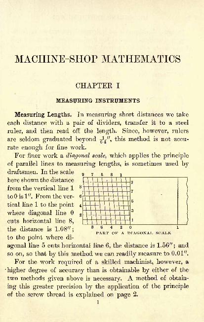
For finer work a diagonal scale, which applies the principle
of parallel lines to measuring lengths, is sometimes used bydraftsmen. In the scale
here shown the distance
from the vertical line 1
to is 1". From the ver-
tical line 1 to the point
where diagonal line
cuts horizontal line 8,
the distance is 1.08";
8 6 4 2 1
/ PART OF A DIAGONAL SCALEto the point where di-
agonal line 5 cuts horizontal line 6, the distance is 1.56"; and
so on, so that by this method we can readily measure to 0.01".
For the work required of a skilled machinist, however, a
higher degree of accuracy than is obtainable by either of the
two methods given above is necessary. A method of obtain-
ing this greater precision by the application of the principle
of the screw thread is explained on page 2.
1
MEASURING INSTRUMENTS
Caliper. A caliper is an instrument for measuring thick-
ness or diameters. One of the most common forms is a pair
of compasses with legs curved inward for measuring outside
diameters and the thickness of plates. The legs may also
curve outward for measuring inside diameters.
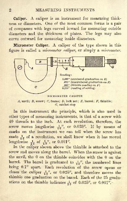
Micrometer Caliper. A caliper of the type shown in this
figure is called a micrometer caliper, or simply a micrometer.
Reading :
0.300" (numbered graduation on E).025" (unnumbered graduation on E).003" (thimble reading on F)
0.328" (reading of setting)
MICROMETER CALIPER
A, anvil; B, screw
; (7, frame ; D, lock nut; E, barrel
; F, thimble;
G, ratchet stop
In this instrument the principle, which is also used in
other types of measuring instruments, is that of a screw with
40 threads to the inch. At each revolution, therefore, the
screw moves lengthwise -fa",or 0.025". If by means of
marks on the instrument we can tell when the screw has
made ^ of a revolution, we shall know when it has moved
lengthwise ^ of-fa",
or 0.001".
In the caliper shown above the thimble is attached to the
screw and moves along the barrel. When the screw is againstthe anvil, the on the thimble coincides with the on the
barrel. The barrel is graduated to-fa", the numbered lines
being 0.1" apart. Each revolution of the screw opens or
closes the caliper ?y, or 0.025", and therefore moves the
thimble one graduation on the barrel. Each of the 25 gradu-ations on the thimble indicates of 0.025", or 0.001".-
MICROMETER CALIPER 3
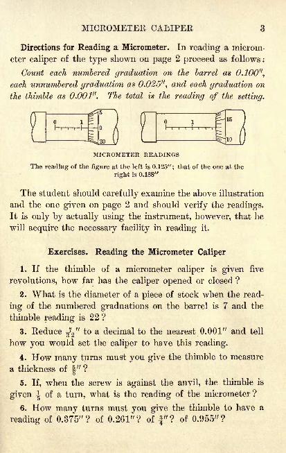
Directions for Reading a Micrometer. In reading a microm-
eter caliper of the type shown on page 2 proceed as follows :
Count each numbered graduation on the barrel as 0.100",
each unnumbered graduation as 0.026", and each graduation on
the thimble as 0.001". The total is the reading of the setting.
MICROMETER READINGS
The reading of the figure at the left is 0.125"; that of the one at the
right is 0.188"
The student should carefully examine the above illustration
and the one given on page 2 and should verify the readings.
It is only by actually using the instrument, however, that he
will acquire the necessary facility in reading it.
Exercises. Reading the Micrometer Caliper
1. If the thimble of a micrometer caliper is given five
revolutions, how far has the caliper opened or closed ?
2. What is the diameter of a piece of stock when the read-
ing of the numbered graduations on the barrel is 7 and the
thimble reading is 22 ?
3. Reduce ^'f to a decimal to the nearest 0.001" and tell
how you would set the caliper to have this reading.
4. How many turns must you give the thimble to measure
a thickness of 4" ?o
5. If, when the screw is against the anvil, the thimble is
given | of a turn, what is the reading of the micrometer?
6. How many turns must you give the thimble to have a
reading of 0.375"? of 0.261"? of "? of 0.955"?
4 MEASURING INSTRUMENTS
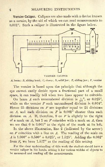
Vernier Caliper. Calipers are also made with a device known
as a vernier, by the aid of which we can read measurements to
0.001". Such a caliper is illustrated in the figure below.
VERNIER CALIPER
A, beam; B, sliding head
; C, clamp ; D, solid jaw ; E, sliding jaw ; F, vernier
The vernier is based upon the principle that although the
eye cannot easily decide upon a fractional part of a small
space, it can readily tell when two lines appear to coincide.
On beam A each unnumbered division is-fa",
or 0.025",
while on the vernier F each unnumbered division is 0.024".
Hence 25 divisions on F are together equal to 24 divisions
on A, and each division on F is 0.001" shorter than each
division on A. If, therefore, on F is slightly to the right
of a mark on A, but 1 on F coincides with a mark on A, then
we see that is 0.001" to the right of the mark at its left.
In the above illustration, line 2 (indicated by the arrow)on F coincides with a hue on A. The reading of the scale on
A is 1.000" + 0.500" 4- 0.025", or 1.525". Adding the 0.002"
from F, we have 1.527" as the reading of this setting.
For the clear understanding of this work the student should have a
vernier caliper in his hands, setting it for various widths of objects to
be measured and reading off the measurements.
VERNIER CALIPER
12345
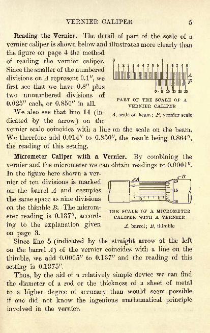
Reading the Vernier. The detail of part of the scale of a
vernier caliper is shown below and illustrates more clearly than
the figure on page 4 the method
of reading the vernier caliper.
Since the smaller of the numbered
divisions on A represent 0.1", wefirst see that we have 0.8" plustwo unnumbered divisions of
~~~,, T ^ r^r-^i, . PART OF THE SCALE OF A0.020" each, or 0.850" in all. VERNIER CALIPERWe also see that line 14 (in- A> scale on beam; F% vernier scale
dicated by the arrow) on the
vernier scale coincides with a line on the scale on the beam.
We therefore add 0.014" to 0.850", the result being 0.864",
the reading of this setting.
Micrometer Caliper with a Vernier. By combining the
vernier and the micrometer we can obtain readings to 0.0001".
In the figure here shown a ver-
nier of ten divisions is marked
on the barrel A and occupies
the same space as nine divisions
on the thimble B. The microm-
eter reading is 0.137", accord-
ing to the explanation givenon page 3.
Since line 5 (indicated by the straight arrow at the left
on the barrel A) of the vernier coincides with a line on the
thimble, we add 0.0005" to 0.137" and the reading of this
setting is 0.1375".
Thus, by the aid of a relatively simple device we can find
the diameter of a rod or the thickness of a sheet of metal
to a higher degree of accuracy than would seem possible
if one did not know the ingenious mathematical principle
involved in the vernier.
p A MICROMETERCALIPER WITH A VERNIER
j, barrel ;#, thimble
6 MEASURING INSTRUMENTS
Exercises. Verniers and Micrometers
1. How would you set the vernier micrometer in the
second figure on page 5 to read 0.4843"?
2. What part of 1" is indicated by the sixteenth line
from the zero mark on the beam of a vernier caliper?
3. What are the readings on the beam scale and on the
vernier scale of a vernier caliper for a thickness of J"?
4. How would you set a vernier micrometer to read
0.5781"? to read 0.8704"?
5. What are the readings on the barrel, the thimble, and
the vernier of a ten-thousandths micrometer for a setting of
0.1093"? for a setting of 0.2789"?
6. How far does the screw of a micrometer move at each
revolution of the thimble ?
7. How would you set a vernier micrometer to read ^" ?
8. A machinist takes a micrometer caliper which is fully
closed and gives the thimble three revolutions. What is the
opening of the caliper?
9. How would you set a ten-thousandths micrometer to
read 0.1878" ? to read 0.6593" ?
10. Through what part of a revolution must the thimble
be turned to move the screw of a micrometer caliper 0.004" ?
to move the screw 0.017"?
11. Which, if either, gives the more accurate measurement,a vernier caliper or a micrometer caliper? State fully the
reason for your answer.
12. Find the distance between the anvil and the screw
of a vernier micrometer when the reading of the numbered
graduations on the barrel is 4, the thimble reading is 6, and
the vernier reading is 3.
VERNIERS AND MICROMETERS
13. Find the distance as in Ex. 12 when the reading of
the numbered graduations on the barrel is 7, that of the un-
numbered graduations is 3, the thimble reading is 4, and the
vernier reading is 6.
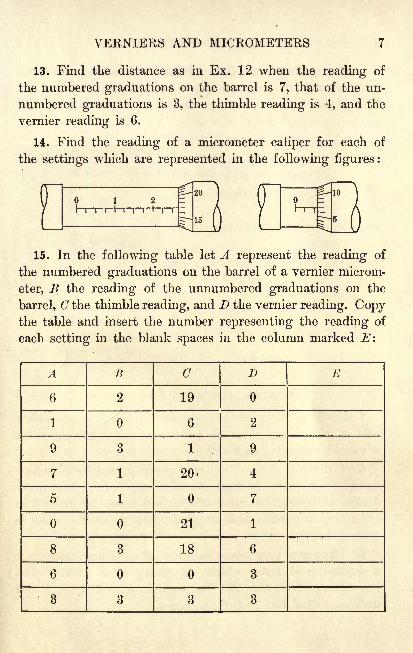
14. Find the reading of a micrometer caliper for each of
the settings which are represented in the following figures:
15. In the following table let A represent the reading of
the numbered graduations on the barrel of a vernier microm-
eter, B the reading of the unnumbered graduations on the
barrel, C the thimble reading, and D the vernier reading. Copythe table and insert the number representing the reading of
each setting in the blank spaces in the column marked E\
A
8 MEASURING INSTRUMENTS
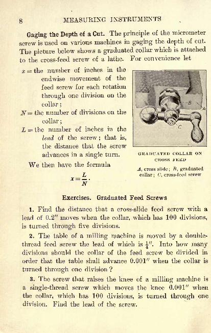
Gaging the Depth of a Cut. The principle of the micrometer
screw is used on various machines in gaging the depth of cut.
The picture below shows a graduated collar which is attached
to the cross-feed screw of a lathe. For convenience let
x = the number of inches in the
endwise movement of the
feed screw for each rotation
through one division on the
collar ;
N= the number of divisions on the
collar ;
L = the number of inches in the
lead of the screw ; that is,
the distance that the screw
advances in a single turn.
We then have the formula
L
GRADUATED COLLAR ONCROSS FEED
A, cross slide; B, graduated
collar; C', cross-feed screw
Exercises. Graduated Feed Screws
1. Find the distance that a cross-slide feed screw with a
lead of 0.2" moves when the collar, which has 100 divisions,
is turned through five divisions.
2. The table of a milling machine is moved by a double-
thread feed screw the lead of which is ". Into how manydivisions should the collar of the feed screw be divided in
order that the table shall advance 0.001" when the collar is
turned through one division ?
3. The screw that raises the knee of a milling machine is
a single-thread screw which moves the knee 0.001" whenthe collar, which has 100 divisions, is turned through one
division. Find the lead of the screw.
CHAPTER II
SPEEDS AND FEEDS
Cutting Speed. The cutting speed of a machine is always
given in feet per minute (F. P.M.), but the expression has
somewhat different meanings for different machines.
In turning work on a lathe it means the number of linear
feet, measured on the surface of the work, which passes the
edge of the cutting tool in one minute.
On a planer it means the rate in F.P.M. at which the
work passes the tool.
On a shaper it means the rate in F.P.M. at which the
tool passes the work.
On a milling machine it means the surface speed of the
cutter ; that is, the speed of a point on the rim of the cutter.
The cutting speed is not always the same, even on the
same machine, but depends upon the following conditions:
1. The kind and quality of the material.
2. The kind and quality of the cutting tool.
3. The depth of the cut.
4. The feed of the tool, that is, the distance traveled side-
ways by the tool in one revolution of the work on a lathe, or
a similar distance in other types of machines.
5. The lubrication.
Thus, on a milling machine the cutting speed may be 30 F.P.M.
for steel, 50 F.P.M. for cast iron, and 90 F.P.M. for brass. On such a
machine a heavy flow of oil is necessary on the cutter when milling
steel, and a failure to provide for it not only changes the speed but
materially affects the life of the cutter.
9
10 SPEEDS AND FEEDS
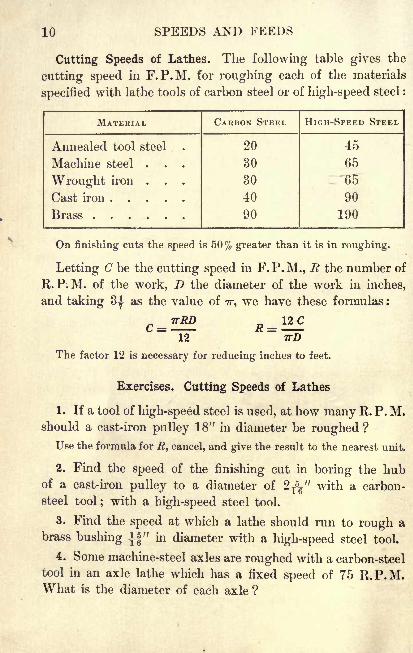
Cutting Speeds of Lathes. The following table gives the
cutting speed in F.P.M. for roughing each of the materials
specified with lathe tools of carbon steel or of high-speed steel :
MATERIAL
PLANERS 11
Cutting Speeds of Planers. Planers are usually so belted
as to give only one cutting speed. This speed is usually
about 25 F.P.M. and is used for brass, cast iron, and steel.
Only the direct stroke is a cutting stroke, the return stroke
being more rapid, usually two or three times as rapid as the
cutting stroke. It is customary to say that the return stroke
is then 2 to 1 or 3 to 1 ; and to speak of the planer as a
2-to-l, or a 3-to-l, planer.
In setting up the work on a planer a distance of V is
always allowed at each end of the work for the tool to clear.
Exercises. Cutting Speeds of Planers
1. How long will it take to make one cut the length of a
cast-iron block 14' 10" long, the cutting speed of the planer
being 25 F.P.M. and the return stroke being 3 to 1 ?
Allowing V at each end of the work for the tool to clear, the total
forward movement is 15'. Hence the forward movement will take ^,or |, of a minute. How long will it take to make the cut?
2. A planer to be used for planing cast iron is belted to
give a cutting speed of 45 F.P.M. If the return speed is
90 F.P.M., how many strokes per minute will the planermake when the length of the stroke is 2' 6"? when it is 6' ?
when it is 8' 9" ? when it is 12' 6" ?
3. If a 2-to-l planer makes six strokes per minute and
the length of each stroke is 3' 4", what is the cutting speed ?
4. How long will it take to make 36 cuts on an iron cast-
ing 43" long, the cutting speed ,of the planer being 45 F. P. M.
and the return stroke being 2 to 1 ?
5. On a casting 1' 7fr
long a 3-to-l planer is making 12
strokes per minute. What is the cutting speed ?
6. In Ex. 5 how many strokes per minute would be re-
quired to have the same cutting speed on a 2-to-l planer?
12 SPEEDS AND FEEDS
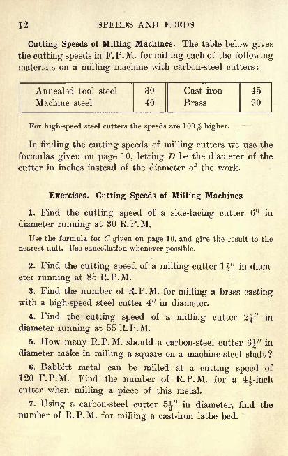
Cutting Speeds of Milling Machines. The table below gives
the cutting speeds in F.P.M. for milling each of the following
materials on a milling machine with carbon-steel cutters :
Annealed tool steel
Machine steel
DRILLS 13
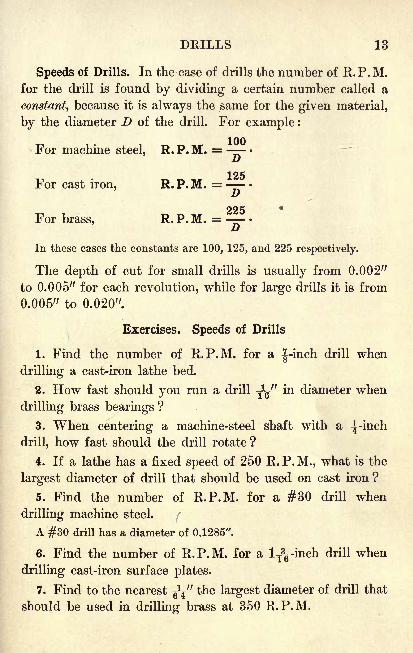
Speeds of Drills. In the case of drills the number of R.P.M.for the drill is found by dividing a certain number called a
constant, because it is always the same for the given material,
by the diameter D of the drill. For example :
For machine steel, R. P. M. =
125For cast iron, R. P. M. =
For brass, R.P.M. =---
In these cases the constants are 100, 125, and 225 respectively.
The depth of cut for small drills is usually from 0.002"
to 0.005" for each revolution, while for large drills it is from
0.005" to 0.020".
Exercises. Speeds of Drills
1. Find the number of R.P.M. for a J-inch drill when
drilling a cast-iron lathe bed.
2. How fast should you run a drill J^" in diameter when
drilling brass bearings ?
3. When centering a machine-steel shaft with a ^-inch
drill, how fast should the drill rotate ?
4. If a lathe has a fixed speed of 250 R.P.M., what is the
largest diameter of drill that should be used on cast iron ?
5. Find the number of R.P.M. for a #30 drill when
drilling machine steel. f
A #30 drill has a diameter of 0.1285".
6. Find the number of R.P.M. for a lT3g-inch drill when
drilling cast-iron surface plates.
7. Find to the nearest g\" the largest diameter of drill that
should be used in drilling brass at 350 R.P.M.
14 SPEEDS AND FEEDS
Exercises. Review
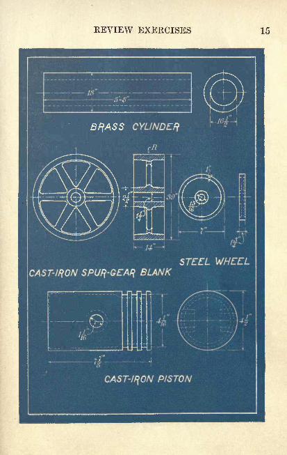
1. Find the number of R.P.M. of a lathe for roughing
the outside of the brass cylinder, which is shown in the
blueprint on page 15, with a tool of carbon steel.
2. Find the speed of the finishing cut in boring the hole
in the same cylinder with a high-speed tool.
3. Find the number of R.P.M. for drilling the center
hole in the spur-gear blank.
4. Using a carbon-steel tool, find the number of R.P.M.
for roughing the face R of the spur-gear blank.
5. If the spur-gear blank in Ex. 4 were made of machine
steel instead of cast iron and if the tool were of high-speed
steel, should the speed of the lathe be increased or should
it be decreased when making the cut? How much should
be the increase or decrease?
6. What should be the number of R.P.M. for drilling the
hole in the machine-steel wheel shown in the blueprint ?
7. Find the number of R.P.M. for a finishing cut over
the outside of the steel wheel with a tool of carbon steel.
8. Find the number of R.P.M. for drilling the l^g-inchhole in the cast-iron piston.
9. Using a high-speed tool, find the. number of R.P.M. for
roughing the outside of the piston.
10. Using a carbon-steel tool, find the number of R.P.M.for finishing the piston-ring grooves shown in the blueprint.
11. Find the number of R.P.M. for milling a brass castingwith a high-speed cutter 7J" in diameter.
12. If a drill press is belted to make 365 R.P.M., find to
the nearest fa" the largest diameter of drill that can be used
when drilling cast iron.
REVIEW EXERCISES 15
16 SPEEDS AND FEEDS
Cutting Speed of Shapers. There are two leading kinds of
shapers, namely, geared shapers and crank shapers.
The cutting speed of a geared shaper is found in the same
way as that of a planer, as explained on page 11.
In the case of a crank shaper, however, the number of
strokes per minute depends upon the speed of the cone
pulley which drives the shaper. In this kind of shaper the
return stroke has about twice the speed of the forward
stroke ; that is, it is said to be about 2 to 1.
For example, if a crank shaper is making 50 R. P. M., if the lengthof the stroke is I/, and if the return stroke is twice as rapid as the
forward stroke, what is the cutting speed of the shaper ?
Since the return stroke is twice as fast as the forward one, it takes
half as long to make it. Hence the forward stroke takes and the re-
turn stroke takes ^ of the time required for one revolution.
In 1 min. there are 50 forward strokes of V each and 50 return
strokes of the same length, the 50 forward strokes taking of a
minute and the 50 return strokes taking ^ of a minute.
Hence the cutting speed is 50' in min., or f of 50' in 1 min.
That is, the cutting speed is 75 F.P.M.
Exercises. Cutting Speeds of Shapers
1. The ram of a crank shaper makes 85 strokes per minute,
and the length of the cut is 2". Find the cutting speed.
In problems dealing with shapers take the ratio of speeds as 2 to 1,
as given above, unless otherwise stated.
2. A crank shaper is cutting at the rate of 40 F.P.M. on a
14-inch cut. Find the number of R.P.M.
3. If a crank shaper makes 18 R.P.'M. and the length of
the cut is 9", what is the cutting speed ?
4. If a crank shaper is cutting a 4-inch casting at the
rate of 50 F.P.M., what is the number of R.P.M.?
5. Solve Ex. 4 for a cutting speed of 40 F.P.M.
FEEDS 17
Expression of Feeds. Feeds can be expressed in several
different ways, the following being the most common:
1. By the number of revolutions which the work makeswhile the tool is advancing 1".
That is, we may speak of a feed as 75 revolutions to the inch.
2. By the number of inches that the tool advances alongthe work at each revolution or stroke.
In the above case we may express the feed as J^" per revolution.
Standard Feeds. The following are certain standard feeds
in common use, each being expressed in inches per revolution :
MATERIAL
18 SPEEDS AND FEEDS
Exercises. Review
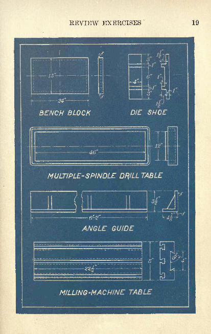
1. The bench block shown in the blueprint on page 19 is
made of cast iron and fy1
! was left on the surfaces marked
/ for finishing to the dimensions given. If a roughing cut
is taken with a 1-inch feed and a finishing cut with a ^-inch
feed, how long will it take to plane the top of the casting
on a 3-to-l planer with a cutting speed of 25 F.P.M.?
In such problems find the results to minutes, calling any fraction a
whole minute, unless otherwise directed.
2. The die-shoe dimensions given in the blueprint are
for the rough machine-steel casting. Taking one cut with a
0.015-inch feed and using a carbon-steel side-milling cutter
having a 3-inch face and a diameter of 4", how long will it
take to machine the entire surface of the shoe ?
It will require six cuts on the top of the shoe, five on the bottom,
one at each end, and one on each long side.
3. The multiple-spindle drill table is made of cast iron.
Find the time required to plane the top on a 2-to-l planerwith a cutting speed of 25 F. P. M., giving it one roughing cut
with a ^g-inch feed and one finishing cut with a j^-inch feed.
4. Using a 2-to-l planer with a cutting speed of 25 F.P.M.and a ^g-inch feed, how long will it take to make one cut over
the two surfaces marked/ on the machine-steel angle guide ?
5. How many R.P.M. should be made by a carbon-steel
T-slot cutter1-J."
in diameter when milling the T-slots in the
cast-iron milling-machine table ?
6. What should be the speed of a 4-inch high-speed cutter
when milling the 4-inch groove in the milling-machine table ?
7. Calculate the time required to take a single cut over
the top of the milling-machine table, using a ^V-kich feed
on a 3-to-l planer with a cutting speed of 25 F.P.M.
REVIEW EXERCISES 19
20 SPEEDS AND FEEDS
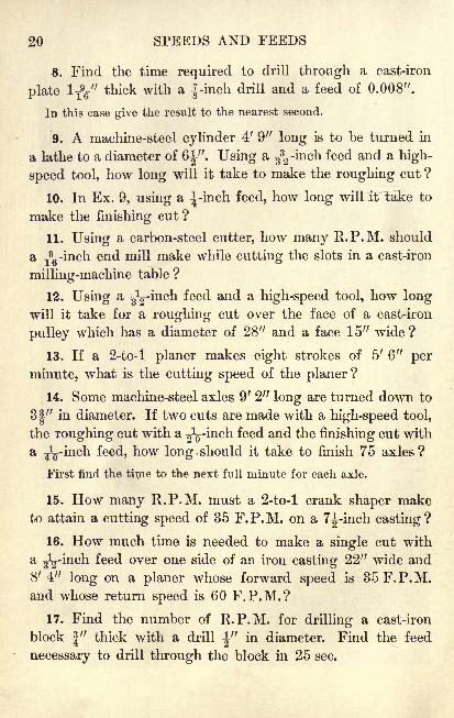
8. Find the time required to drill through a cast-iron
plate l Ty thick with a {-inch drill and a feed of 0.008".
In this case give the result to the nearest second.
9. A machine-steel cylinder 4' 9" long is to be turned in
a lathe to a diameter of 6|". Using a ^-inch feed and a high-
speed tool, how long will it take to make the roughing cut ?
10. In Ex. 9, using a ^-inch feed, how long will it take to
make the finishing cut?
11. Using a carbon-steel cutter, how many R.P.M. should
a y9g-inch end mill make while cutting the slots in a cast-iron
milling-machine table ?
12. Using a J^-inch feed and a high-speed tool, how longwill it take for a roughing cut over the face of a cast-iron
pulley which has a diameter of 28" and a face 15" wide ?
13. If a 2-to-l planer makes eight strokes of 5' 6" per
minute, what is the cutting speed of the planer ?
14. Some machine-steel axles 9' 2" long are turned down to
31" in diameter. If two cuts are made with a high-speed tool,
the roughing cut with a J^-inch feed and the finishing cut with
a ^L-inch feed, how long.should it take to finish 75 axles?
First find the time to the next full minute for each axle.
15. How many R.P.M. must a 2-to-l crank shaper maketo attain a cutting speed of 35 F.P.M. on a 7J-inch casting?
16. How much time is needed to make a single cut with
a J^-inch feed over one side of an iron casting 22" wide and
8' 4" long on a planer whose forward speed is 35 F.P.M.and whose return speed is 60 F.P.M.?
17. Find the number of R.P.M. for drilling a cast-iron
block |" thick with a drill J" in diameter. Find the feed
necessary to drill through the block in 25 sec.
CHAPTER III
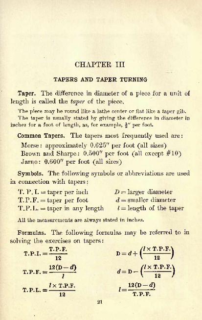
TAPERS AND TAPER TURNING
Taper. The difference in diameter of a piece for a unit of
length is called the taper of the piece.
The piece may be round like a lathe center or flat like a taper gib.
The taper is usually stated by giving the difference in diameter in
inches for a foot of length, as, for example, \" per foot.
Common Tapers. The tapers most frequently used are:
Morse : approximately 0.625" per foot (all sizes)
Brown and Sharpe: 0.500" per foot (all except #10)Jarno : 0.600" per foot (all sizes)
Symbols. The following symbols or abbreviations are used
in connection with tapers:
T.P.I. = taper per inch D = larger diameter
T.P.F. = taper per foot d = smaller diameter
T.P.L. = taper in any length 1 = length of the taper
All the measurements are always stated in inches.
Formulas. The following formulas may be referred to in
solving the exercises on tapers:
T.P.F. //XT. P.FT.P.I. =_ D
12(D-d) //XT.P.FA
V 12 /T.P.F. = ^- d
7xT.P.F. 12(D-d)T.P. L . =___ '=TRFT
21
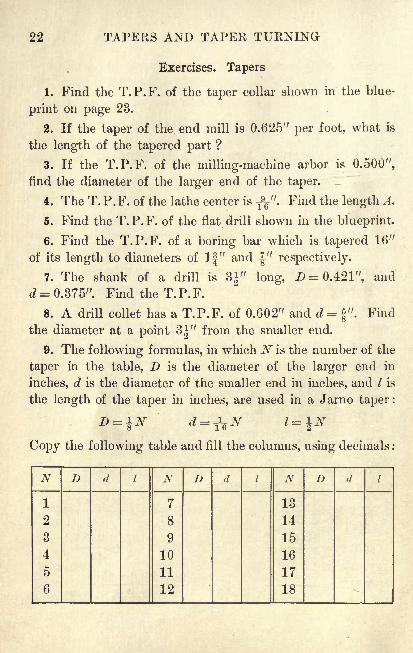
22 TAPERS AND TAPER TURNING
Exercises. Tapers
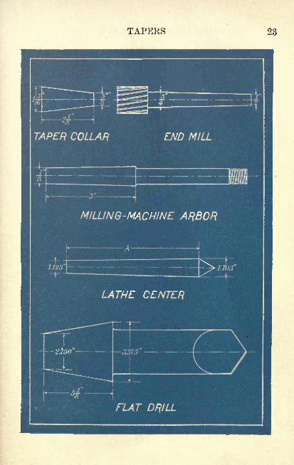
1. Find the T.P.F. of the taper collar shown in the blue-
print on page 23.
2. If the taper of the end mill is 0.625" per foot, what is
the length of the tapered part ?
3. If the T.P.F. of the milling-machine arbor is 0.500",
find the diameter of the larger end of the taper.
4. The T.P.F. of the lathe center is T9g".
Find the length A.
5. Find the T.P.F. of the flat drill shown in the blueprint.
6. Find the T.P.F. of a boring bar which is tapered 16"
of its length to diameters of 1|" and J" respectively.
7. The shank of a drill is 31" long, D= 0.421", and
d = 0.375". Find the T.P.F.
8. A drill collet has a T.P.F. of 0.602" and d = 4". Findo
the diameter at a point 3|" from the smaller end.
9. The following formulas, in which N is the number of the
taper in the table, D is the diameter of the larger end in
inches, d is the diameter of the smaller end in inches, and I is
the length of the taper in inches, are used in a J arno taper :
Copy the following table and fill the columns, using decimals
N
TAPERS 23
24 TAPEKS AND TAPER TURNING
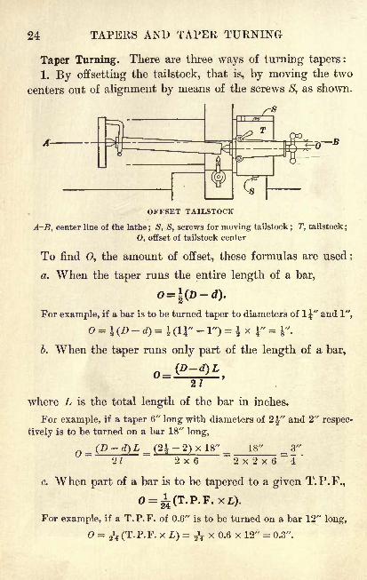
Taper Turning. There are three ways of turning tapers:
1. By offsetting the tailstock, that is, by moving the two
centers out of alignment by means of the screws S, as shown.
OFFSET TAILSTOCK
A-B, center line of the lathe; S, S, screws for moving tailstock
; T, tailstock;
O, offset of tailstock center
To find 0, the amount of offset, these formulas are used*
a. When the taper runs the entire length of a bar,
=\(D-d).
For example, if a bar is to be turned taper to diameters of 1^" and 1",
o = KD -d)= iar -
1") = i x r =i".
b. When the taper runs only part of the length of a bar,
21
where L is the total length of the bar in inches.
For example, if a taper 6" long with diameters of 2^" and 2" respec-
tively is to be turned on a bar 18" long,
= (D ~ O L - (2 ?~ 2) x 18// = 18" = 3"
21 2x6 ~2x2x6~4*
c. When part of a bar is to be tapered to a given T.P.F.,
For example, if a T.P.F. of 0.6" is to be turned on a bar 12" long,
= 2^ (T.P.F. x L) = ^ x 0.6 x 12" = 0.3".
,-' 'VrUTTT>XFTArr
26 TAPERS AND TAPER TURNING
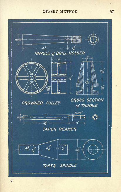
Exercises. Offset Method
1. Find the T.P.F. of the drill-holder handle shown in
the blueprint on page 27.
2. In Ex. 1 how far should the tailstock center be offset
in order to turn the handle to the required taper ?
3. The crowned pulley is to be turned on a 10-inch arbor.
What distance should the tailstock center be offset?
4. Find the T.P.F. of the crowned pulley.
5. If the thimble is to be turned on a 6J-inch mandrel,
find the T.P.F. and the distance which the tailstock center
should be offset in turning the taper.
6. In turning the taper reamer, what should be the offset
of the tailstock center? What is the T.P.F.?
7. In turning the taper spindle, what should be the offset
of the tailstock center?
8. A taper 15" long with diameters of 1.234" and 0.984"
respectively is to be turned on a shaft 17" long. Find the
offset for the tailstock center.
9. Copy the following table of measurements of Morse stand-
ard taper reamers and supply the missing numbers :
No.
OFFSET METHOD 27
28 TAPERS AND TAPER TURNING
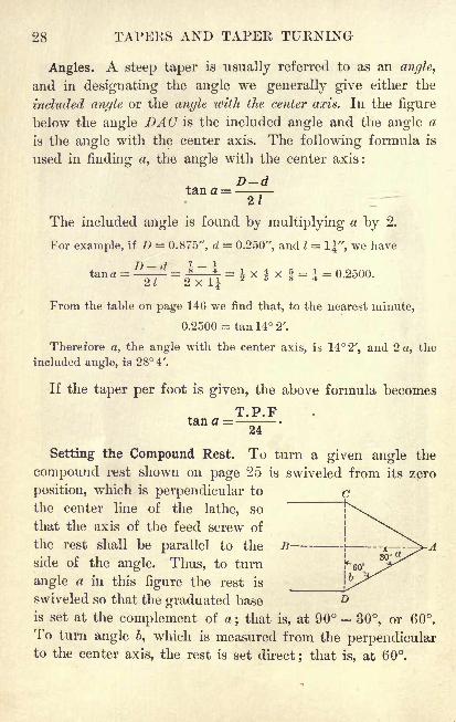
Angles. A steep taper is usually referred to as an angle,
and in designating the angle we generally give either the
included angle or the angle with the center axis. In the figure
below the angle DAC is the included angle and the angle a
is the angle with the center axis. The following formula is
used in finding a, the angle with the center axis :
D-d---
The included angle is found by multiplying a by 2.
For example, if D = O.S75", d = 0.250", and I = 1", we have
tana =^7 =|-=1
=J x x = 1 = 0.2500.
From the table on page 146 we find that, to the nearest minute,
0.2500 = tan 14 2'.
Therefore a, the angle with the center axis, is 14 2', and 2 a, the
included angle, is 28 4'.
If the taper per foot is given, the above formula becomes
T.P.Ftan a =
24
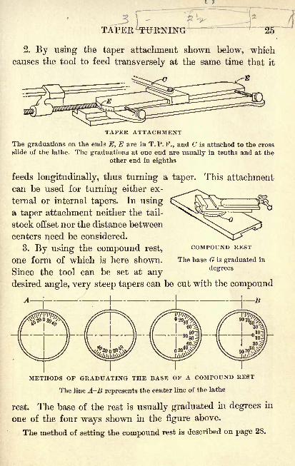
Setting the Compound Rest. To turn a given angle the
compound rest shown on page 25 is swiveled from its zero
position, which is perpendicular to
the center line of the lathe, so
that the axis of the feed screw of
the rest shall be parallel to the
side of the angle. Thus, to turn
angle a in this figure the rest is
swiveled so that the graduated base D
is set at the complement of a; that is, at 90 30, or 60.
To turn angle >, which is measured from the perpendicularto the center axis, the rest is set direct ; that is, at 60.
COMPOUND REST 29
Exercises. Use of the Compound Rest
Find the included angles for the following tapers per foot :
1. 0.500". 2. 0.602". 3. T9g". 4. 0.750".
5. A drill collet is to be bored taper by the aid of a
compound rest. If it is required that D 1Jg ", d = 1|", and
I = 4J", find the angle made with the center axis.
Find the angles made with the center axis in these tapers :
6T) Ql" /7 11" 7 1 H T) 91 It fl 11^7 Q". JJ
t>2 , a ^ , t i . o. JL* = z>, a = ig- ,
6 = o .
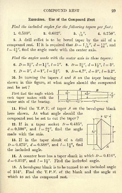
10. In turning the tapers A and B on the taper bearingshown in this figure, at what angles should the compoundrest be set?
BFirst find the angle which _
each taper makes with the
center axis of the bearing.
11. Find the T. P.F. of taper A on the bevel-gear blank
here shown. At what angle should theL, 1 1// J
compound rest be set to cut the taper?
12. If in a taper socket D = 0.435",
d = 0.300", and I = 2f", find the anglemade with the axis.
13. If in the taper shank of a drill
D = 0.475", d= 0.388", and Z=lf", find
the included angle.
14. A counter bore has a taper shank in which D = 0.416",
d = 0.312", and Z = lf". Find the included angle.
15. A bevel-gear blank is to be turned to an included angleof 134. Find the T.P.F. of the blank and the angle at
which to set the compound rest.
53""T3"
1
30 TAPERS AND TAPER TURNING
Exercises. Review
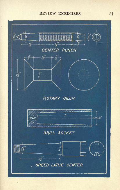
1. The center punch shown in the blueprint on page 31
is to be turned in a chuck with the aid of a compound rest.
Find the angle which each taper makes with the axis.
2. The rotary oiler shown in the blueprint is used to oil
the ways of a planer. Find the included angle.
3. In the drill socket shown in the blueprint find the
T.P.F. and the angle made with the axis.
4. In the speed-lathe center shown in the blueprint find
the T.P.F. and the included angle.
5. A milling-machine arbor 18" long is to be tapered 4"on one end to 0.500" per foot. Find the offset of the tail-
stock center for turning the required taper.
6. A reamer has a T.P.F. of 0.625" and its diameters are
0.500" and 0.750" respectively. Find I
7. If the maximum offset of the tailstock center of a lathe
is iy, what is the greatest T.P.F. that can be cut on a
shaft 6" long ? on a shaft 2' 3" long ? on a shaft 3' 6" long ?
8. A taper bushing has diameters of 2|" and 1|", respec-
tively, and a T.P.F. of 0.500". Find I
9. In the taper shank of a cutter which has a T.P.F. of
0.600", d = If" and I = 3|". Find 2).
In each of the following find the angle made with the axis :
10. D = 0.354", d = 0.279", and 1= 3f".
11. D = 1.125", d= 0.900", and Z = 4i".
12. /> = 1.231", d = 1.020", and Z = 4Ty.13. I>= 2.494", d= 2.116", and l = l\".
14. D= 1.2888", d = 1.0446", and /=5jJ".15. D = 3.976", d = 2.165", and I = 3|".
REVIEW EXERCISES 31
32 TAPERS AND TAPER TURNING
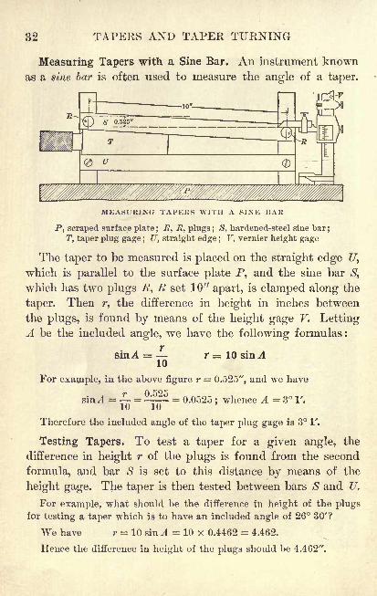
Measuring Tapers with a Sine Bar. An instrument knownas a sine bar is often used to measure the angle of a taper.
MEASURING TAPERS WITH A SINE BAR
P, scraped surface plate ; 7?, R, plugs ; S, hardened-steel sine bar;
T, taper plug gage ; U, straight edge ; V, vernier height gage
The taper to be measured is placed on the straight edge U,
which is parallel to the surface plate P, and the sine bar S,
which has two plugs .#, R set 10" apart, is clamped along the
taper. Then r, the difference in height in inches between
the plugs, is found by means of the height gage F. LettingA be the included angle, we have the following formulas:
sinA =10
r = 10 sin A
For example, in the above figure r = 0.525", and we have
v r 9'i
sin .4 = = ^- = 0.0525;whence A = 3 V.
Therefore the included angle of the taper plug gage is 3 1'.
Testing Tapers. To test a taper for a given angle, the
difference in height r of the plugs is found from the second
formula, and bar S is set to this distance by means of the
height gage. The taper is then tested between bars S and U.
For example, what should be the difference in height of the plugsfor testing a taper which is to have an included angle of 26 30'?
We have r = 10 sin A = 10 x 0.4462 = 4.462.
Hence the difference in height of the plugs should be 4.462".
MEASURING TAPERS 33
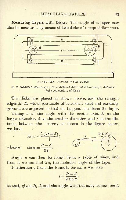
Measuring Tapers with Disks. The angle of a taper mayalso be measured by means of two disks of unequal diameters.
1
MEASURING TAPERS WITH DISKS
7?, J?, hardened-steel edges ; D, d, disks of different diameters; I, distance
between centers of disks
The disks are placed as shown above, and the straight
edges R, R, which are made of hardened steel and carefully
ground, are adjusted so that the tangent lines form the taper.
Taking a as the angle with the center axis, D as the
larger diameter, d as the smaller diameter, and I as the dis-
tance between the centers, as shown in the figure below,
we have
sin a =
whence sin a =
I
D-d21
Angle a can then be found from a table of sines, and
from it we can find 2 a, the included angle of the taper.
Furthermore, from the formula for sin a we have
so that, given D, d, and the angle with the axis, we can find L
34 TAPERS AND TAPER TURNING
Exercises. Measuring Tapers
Find the difference in height of the plugs for setting a sine
bar to test each of the following tapers per foot :
1. 0.600". 3. 0.623". 5.f".
7. 1^". 9. 2".
2. 0.602". 4. 0.630". 6. ". 8. If". 10. 2|".
11. If the disk diameters are 1" and 2" respectively and
if Z, the center distance, is 4", what is the included angle
of the taper?
12. If the disk diameters are 1" and 1.5" respectively and
if Z = 4", what is the T.P.F.? the included angle? the
angle formed with the axis ?
13. If the taper is 0.5" per foot and the disk diameters are
0.75" and 1" respectively, what is I?
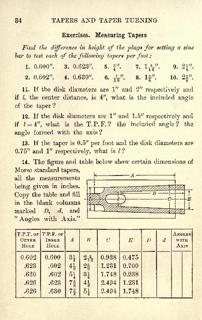
14. The figure and table below show certain dimensions of
Morse standard tapers,
all the measurements
being given in inches.
Copy the table and fill
in the blank columns
marked Z>, c?, and"Angles with Axis."
T.P.F. OF
OUTERHOLE
CHAPTER IV
SCREW THREADS
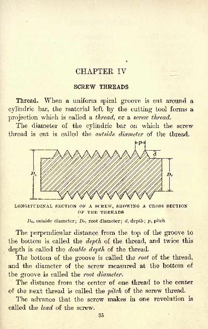
Thread. When a uniform spiral groove is cut around a
cylindric bar, the material left by the cutting tool forms a
projection which is called a thread, or a screw thread.
The diameter of the cylindric bar on which the screw
thread is cut is called the outside diameter of the thread.
1*1
LONGITUDINAL SECTION OF A SCREW, SHOWING A CROSS SECTIONOF THE THREADS
Do, outside diameter; Dr ,root diameter; d, depth; p, pitch
The perpendicular distance from the top of the groove to
the bottom is called the depth of the thread, and twice this
depth is called the double depth of the thread.
The bottom of the groove is called the root of the thread,
and the diameter of the screw measured at the bottom of
the groove is called the root diameter.
The distance from the center of one thread to the center
of the next thread is called the pitch of the screw thread.
The advance that the screw makes in one revolution is
called the lead of the screw.
35
36 SCREW THREADS
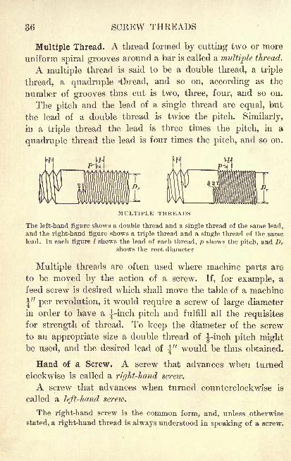
Multiple Thread. A thread formed by cutting two or more
uniform spiral grooves around a bar is called a multiple thread.
A multiple thread is said to be a double thread, a triple
thread, a quadruple -thread, and so on, according as the
number of grooves thus cut is two, three, four, and so on.
The pitch and the lead of a single thread are equal, but
the lead of a double thread is twice the pitch. Similarly,
in a triple thread the lead is three times the pitch, in a
quadruple thread the lead is four times the pitch, and so on.
MULTIPLE THREADS
The left-hand figure shows a double thread and a single thread of the same lead,
and the right-hand figure shows a triple thread and a single thread of the samelead. In each figure I shows the lead of each thread, p shows the pitch, and Dr
shows the root diameter
Multiple threads are often used where machine parts are
to be moved by the action of a screw. If, for example, a
feed screw is desired which shall move the table of a machine
\" per revolution, it would require a screw of large diameter
in order to have a |-inch pitch and fulfill all the requisitesfor strength of thread. To keep the diameter of the screw
to an appropriate size a double thread of ^-inch pitch mightbe used, and the desired lead of \" would be thus obtained.
Hand of a Screw. A screw that advances when turned
clockwise is called a right-hand screw.
A screw that advances when turned counterclockwise is
called a left-hand screw.
The right-hand screw is the common form, and, unless otherwise
stated, a right-hand thread is always understood in speaking of a screw.
MULTIPLE THREAD 37
Exercises. Threads
1. A screw has 18 single threads to the inch. Find the
pitch and the lead of the screw.
2. In the single-thread screw shown on page 35 supposethat the outside diameter is lyg" and that the depth of the
thread is-f^
ff. Find the root diameter.
It is evident from the figure that the root diameter is equal to the
outside diameter minus the double depth of the thread.
3. In the double-thread screw shown on page 36 supposethat there are 16 threads to the inch ; that is, 8 double
threads. Find the pitch and the lead of the screw.
4. If the root diameter of a double-thread screw is 1-|"
and the depth of the thread is ^", find the outside diam-
eter of the screw.
5. In the triple-thread screw shown on page 36 supposethat the pitch is
-Jg-".What is the lead of the screw ?
6. The cross slide on a lathe is moved by a screw that
has 16 threads per inch, and one revolution of the screw
moves the slide \". How would you designate the thread?
7. A lead screw has a triple thread with 18 threads to the
inch. Find the pitch and the lead.
8. When the feed screw on a milling machine makes one
revolution it moves the table ^".If the screw has 8 threads
to the inch, how would you designate the thread ?
9. How many revolutions must be made by a triple-thread
feed screw of i-inch pitch in order to move the table which
it controls a distance of 11" ?
10. When the screw that raises the knee on a milling
machine makes one revolution it moves the knee 0.200". If
the screw has 5 threads to the inch, how should the thread
be designated ?
SCREW THREADS
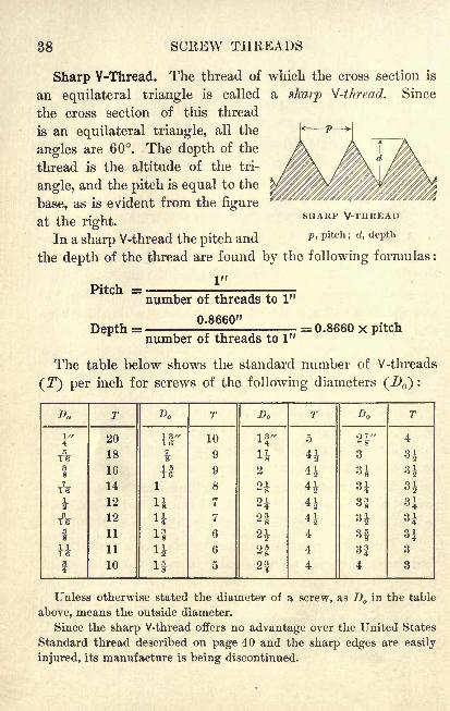
Sharp V-Thread. The thread of which the cross section is
an equilateral triangle is called a sharp V-thread. Since
the cross section of this thread
is an equilateral triangle, all the
angles are 60. The depth of the
thread is the altitude of the tri-
angle, and the pitch is equal to the
base, as is evident from the figure
at the right.
In a sharp V-thread the pitch and* Pitch '>
d>dePth
the depth of the thread are found by the following formulas :
SHARP
Pitch =
Depth =
1"
number of threads to 1"
0.8660"
number of threads to 1"= 0.8660 x pitch
The table below shows the standard number of V-threads
( T) per inch for screws of the following diameters (^ ) :
Da
SHAKP V-THREADS 39
Exercises. Sharp V -Threads
1. Find the depth of a sharp V-thread with a pitch of J".
In the following problems use the table and the formulas on page 38.
Carry all computations involving decimals to four decimal places, but
in the final result discard the fourth place, giving the dimension correct
to the nearest 0.001".
2. Find the double depth of a sharp V-thread with 9 threads
to the inch; with 11 threads to the inch.
3. Find the depth of a sharp V-thread with 3J threads to
the inch; with 4J threads to the inch.
4. Find the tap-drill size of a sharp V-thread tap which
has an outside diameter of J".
A tap is a tool for cutting internal threads, and the tap-drill size is the
size of the drill for boring the hole to be tapped. In actual practice, to
avoid breaking taps, the tap-drill size for ordinary work is generallytaken a little larger than the root diameter of the thread on the tap,
but in all problems in this book the tap^drill size is to be taken as equalto the root diameter.
5. A screw having 5 sharp V-threads to the inch has a
root diameter of 1.4036". Find the outside diameter.
6. Find the tap-drill size for a sharp V-thread tap which
has an outside diameter of1|-".
7. If the root diameter of a sharp V-thread screw is
4.3072" and the outside diameter is 5", what is the depthof the thread and the number of threads per inch ?
Find the double depth of a sharp V-thread, given that the pitch
of each thread is as follows :
s. Ty. 9. ^". 10. i". 11. Ty. 12. i".
13. Find the tap-drill size for a tap If" in diameter with
6 double sharp V-threads to the inch.
40 SCREW THREADS
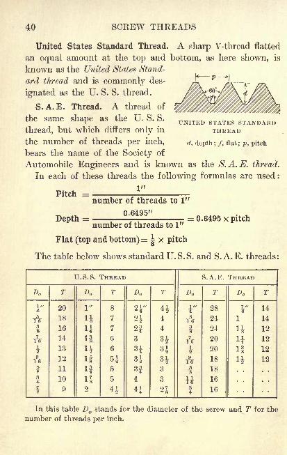
United States Standard Thread. A sharp V-thread flatted
an equal amount at the top and bottom, as here shown, is
known as the United States Stand-
ard thread and is commonly des-
ignated as the U. S. S. thread.
S.A.E. Thread. A thread of
the same shape as the U. S. S.
thread, but which differs only in
the number of threads per inch,
bears the name of the Society of
Automobile Engineers and is known as the S.A.E. thread.
In each of these threads the following formulas are used:
UNITED STATES STANDARDTHREAD
d, depth; /, flat; p, pitch
Pitch =
Depth =
number of threads to 1"
0.6495" = 0.6495 x pitchnumber of threads to 1"
Flat (top and bottom)= |x pitch
The table below shows standard U.S.S. and S.A.E. threads:
U.S.S. THREAD
U.S.S. AND S.A.E. THREADS 41
Exercises. U.S.S. and S.A.E. Threads
1. Find from the formula on page 40 the depth of a
U.S.S. thread with 8 threads to the inch.
The U. S. S. thread was devised by William Sellers in 1869. It is also
known as the Sellers thread and as the Franklin Institute thread.
2. Find the tap-drill size for a l|-inch S.A.E. thread.
3. Find the double depth of a U.S.S. thread of Jy-inch
pitch; of y1^-inch pitch.
4. If the root diameter of a U.S.S. thread is 4.2551"
and there are 2| threads to the inch, what is the outside
diameter of the screw?
5. What is the root diameter of an S.A.E. thread ^" in
diameter? |" in diameter?
6. Find the tap-drill size of a 31-inch U.S.S. thread.
7. If the root diameter of an S.A.E. thread of -J^-inch
pitch is 0.9072", what is the outside diameter?
Find the width of the point of a thread tool for cutting each
of the following numbers of U. 8. S. threads to the inch :
8. 3. 9. 4|, 10. 7. 11. 13. 12. 18. 13. 20.
The width of the point of the cutting tool is the same as the width
of the flat at the bottom of the groove.
14. If the root diameter of a U.S.S. thread is 1.7113" and
the outside diameter is 2", what is the depth of the thread ?
15. Find to the nearest ^" the proper size of drill for
boring a hole which is to be tapped with a full 11-inch
U.S.S. thread; with a full f-inch S.A.E. thread.
A full thread is a thread cut to the depth given by the formula. For
ordinary work a tap drill which will give about 75% of a full thread is
generally used, and tables of tap drills often list the drill sizes in sixty-
fourths of an inch which will give such a thread.
42 SCREW THREADS
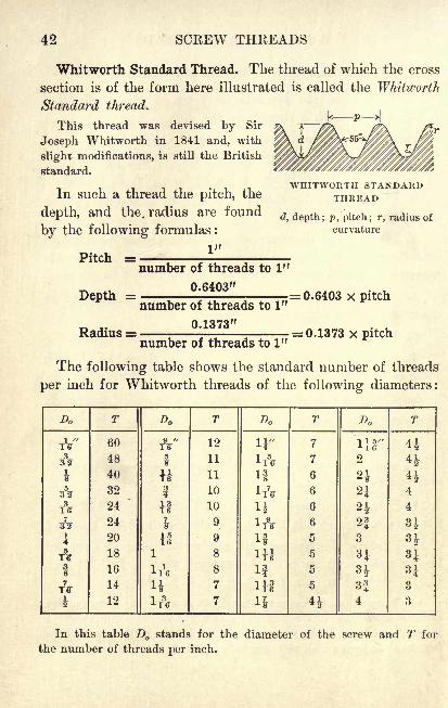
Whitworth Standard Thread. The thread of which the cross
section is of the form here illustrated is called the Whitworth
Standard thread.
This thread was devised by Sir
Joseph Whitworth in 1841 and, with
slight modifications, is still the British
standard.
In such a thread the pitch, the
depth, and the. radius are found
by the following formulas :
1"
WHITWORTH STANDARDTHREAD
(7, depth; p, pitch; r, radius of
curvature
Pitch =
Depth =
Radius =
number of threads to 1"
0.6403"
number of threads to 1"
0.1373"
number of threads to 1"
= 0.6403 x pitch
= 0.1373 x pitch
The following table shows the standard number of threads
per inch for Whitworth threads of the following diameters:
Do
WHITWOETH STANDARD THREADS 43
Exercises. Whitworth Threads
1. Find the depth of a Whitworth thread of ^-inch pitch.
2. Find the double depth of a Whitworth thread with
7 threads to the inch.
Find the radius for the point of the tool for cutting a Whit-
worth thread of which the pitch in each case is as follows :
3. 0.4". 4. i". 5. i". 6. i". 7.-s\"' 8. &"
9. Find the tap-drill size for a Whitworth thread of whichthe outside diameter is 4".
o
10. If the root diameter of a Whitworth thread is 3.3231"
and there are 3 threads to the inch, what is the outside
diameter of the screw ?
11. If the root diameter of a Whitworth thread is 5.2377"
and there are 2J threads to the inch, what is the outside
diameter of the screw ?
12. Find the root diameter of a Whitworth thread with an
outside diameter of Jg".
13. If the outside diameter of a Whitworth thread is 41"
and the root diameter is 4.0546", what is the pitch ?
14. find the root diameter of a Whitworth thread with an
outside diameter of 3".
15. If the diameter of a Whitworth screw is ^", how manythreads are there to the inch ? What is the pitch ? the depthof thread ? the root diameter ?
16. If the root diameter of a Whitworth thread with 8
threads to the inch is 0.9024", what is the outside diameter?
17. If the diameter of a Whitworth screw is 3", how manythreads are there to the inch ? What is the pitch ? the depthof thread ? the root diameter ?
44 SCREW THREADS
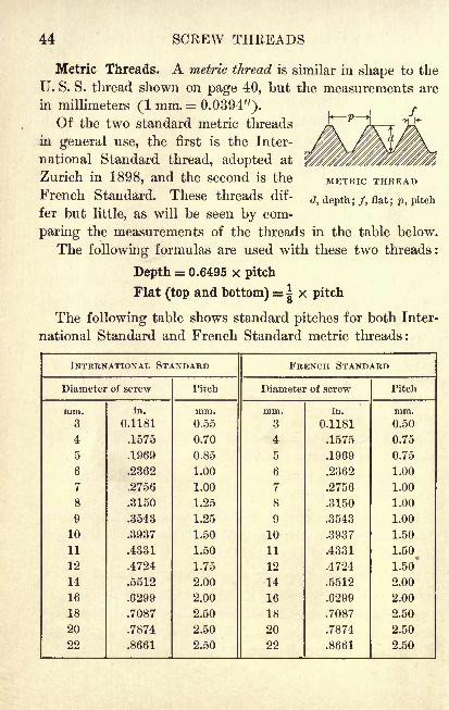
Metric Threads. A metric thread is similar in shape to the
U. S. S. thread shown on page 40, but the measurements are
in millimeters (1 mm.= 0.0394").Of the two standard metric threads
in general use, the first is the Inter-
national Standard thread, adopted at
Zurich in 1898, and the second is the
French Standard. These threads dif-
fer but little, as will be seen by com-
paring the measurements of the threads in the table below.
The following formulas are used with these two threads:
Depth = 0.6495 x pitch
Flat (top and bottom) = |x pitch
The following table shows standard pitches for both Inter-
national Standard and French Standard metric threads:
METRIC THREAD
d, depth ; /, flat; p, pitch
INTERNATIONAL STANDARD
METRIC THREADS 45
Exercises. Metric Threads
1. Find from the formula on page 44 the depth of a
French Standard thread of 1-millimeter pitch.
The introduction of French and Italian automobiles into this countryand our recent expansion of foreign trade render computation in metric
units necessary as well as desirable.
In problems dealing with metric threads give the final results to the
nearest 0.1 mm., unless otherwise specified.
2. Find the double depth of a French Standard thread of
3-millimeter pitch.
3. Find the root diameter of a 10-millimeter International
Standard thread.
4. Find the pitch of an International Standard thread of
which the outside diameter is 27 mm. and the root diameter
is 23.10 mm.
5. Find the outside diameter of a French Standard thread
of which the root diameter is 48.86 mm. and the pitchis 5.50 mm.
6. For particularly accurate work the formula for the
depth of an International Standard thread is as follows:
depth = 0.64952 X pitch. If the pitch is 4.500 mm., find the
depth to the nearest 0.01 mm., using this formula.
7. In Ex. 6 if the depth is 0.974 mm., what is the pitch?
8. Find the width of the flat of an International Standard
thread with an outside diameter of 11 mm.
9. If the root diameter of a French Standard thread is
23.10 mm. and the pitch is 3 mm., what is the outside diam-
eter of the screw ?
10. If the outside diameter of a French Standard thread
is 36 mm. and the root diameter is 30.80 mm., what is the
pitch of the thread?
46 SCREW THREADS
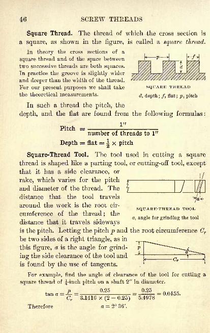
Square Thread. The thread of which the cross section is
a square, as shown in the figure, is called a square thread.
In theory the cross sections of a
square thread and of the space between
two successive threads are both squares.
In practice the groove is slightly wider
and deeper than the width of the thread.
For our present purposes we shall take SQUARE THREAD
the theoretical measurements.a, depth; /, flat; p, pitch
In such a thread the pitch, the
depth, and the flat are found from the following formulas:
1""number of threads to 1"
Depth = flat =Ix pitch
Square-Thread Tool. The tool used in cutting a square
thread is shaped like a parting tool, or cutting-off tool, exceptthat it has a side clearance, or
( /
rake, which varies for the pitch
and diameter of the thread. The
distance that the tool travels
around the work is the root cir-
cumference of the thread ; the
distance that it travels sidewaysis the pitch. Letting the pitch p and the root circumference Cr
be two sides of a right triangle, as in
this figure, a is the angle for grind-
ing the side clearance of the tool and
is found by the use of tangents.
For example, find the angle of clearance of the tool for cutting a
square thread of ^-inch pitch on a shaft 2" in diameter.
0.25 0.25tan a = = = = 0.0455.
Cr 3.1416 x (2-
0.25) 5.4978
Therefore a = 2 36'.
^SQUARE-THREAD TOOL
a, angle for grinding the tool
SQUARE THREADS 47
Exercises. Square Threads
1. From the formulas on page 46 find the pitch, the
depth, the double depth, and the flat of a square thread with
8 threads to the inch.
2. If the outside diameter of a screw with square threads
is 2|", and there are 8 threads to the inch, what is the root
diameter of the screw ?
3. At what angle should the tool be ground for cuttingthe thread referred to in Ex. 2?
4. If a double square thread has a diameter of iy and
a lead of J", what is the root diameter?
5. In cutting a square thread with 2 threads to the inch
on a shaft 41" in diameter, what angle of side clearance
should be' allowed for the tool?
6. If the double depth of a square thread is 0.0417", what
is the number of threads to the inch ?
7. Find the angle for grinding the side clearance of the
tool used in cutting a square thread having an outside
diameter of 1|" and a pitch of-^g".
8. A triple square-thread screw of outside diameter 1|"has a lead of \". Find the root diameter of the thread.
9. Find the angle for grinding the side clearance of the
tool for cutting the thread in Ex. 8.
10. Find the outside diameter of a square thread which
has a root diameter of 3T5g-"
and a pitch of-J".
11. Find the angle for grinding the tool used in cutting
the thread described in Ex. 10. What would be the angle
if the thread were a double thread of the same lead?
12. If the root circumference of a square thread is 2.3562"
and the pitch is J", what is the outside diameter?
48 SCKEW THREADS
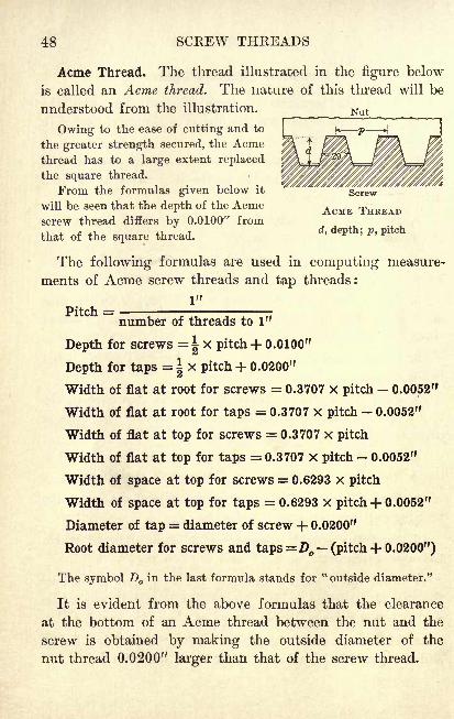
Acme Thread. The thread illustrated in the figure below
is called an Acme thread. The nature of this thread will be
understood from the illustration. Nut
Owing to the ease of cutting and to
the greater strength secured, the Acmethread has to a large extent replaced
the square thread.
From the formulas given below it
will be seen that the depth of the Acme ACME THREADscrew thread differs by 0.0100" from
that of the square thread.d
' depth; p ' pit(
The following formulas are used in computing measure-
ments of Acme screw threads and tap threads:
number of threads to 1"
Depth for screws =| x pitch + 0.0100"
Depth for taps = |x pitch + 0.0200"
Width of flat at root for screws = 0.3707 X pitch 0.0052"
Width of flat at root for taps = 0.3707 x pitch- 0.0052"
Width of flat at top for screws = 0.3707 x pitch
Width of flat at top for taps = 0.3707 x pitch 0.0052"
Width of space at top for screws = 0.6293 x pitch
Width of space at top for taps = 0.6293 x pitch + 0.0052"
Diameter of tap = diameter of screw + 0.0200"
Root diameter for screws and taps =D (pitch + 0.0200")
The symbol D in the last formula stands for"outside diameter."
It is evident from the above formulas that the clearance
at the bottom of an Acme thread between the nut and the
screw is obtained by making the outside diameter of the
nut thread 0.0200" larger than that of the screw thread.
ACME THREADS 49
Exercises. Acme Threads
1. Find from the formula on page 48 the width of the
flat at the root of an Acme screw thread having 2J- threads
to the inch.
2. Find the depth of an Acme tap thread of ^-inch pitch.
3. Find the width of the flat at the top of an Acme screw
thread having 12 threads to the inch.
4. Find the root diameter of an Acme tap thread having4 threads to the inch and an outside diameter of 2J".
5. Find the outside diameter of an Acme screw thread
having a root diameter of 3.4443" and 3J threads to the inch.
6. A boring bar with a diameter of 3|" is threaded with
an Acme screw thread which has a double depth of 0.2422".
Find the pitch of the thread.
7. In Ex. 6 find the width of the flat at the root.
8. Find the width of the flat at the top and also at the
root of an Acme screw thread of |-inch pitch.
9. Find the root diameter of an Acme tap thread which
has an outside diameter of 1-jV and 7 threads to the inch.
10. In an Acme screw thread of-j
3g-inch pitch find the
width of the flat at the top, the width of the flat at the root,
and the width of the space at the top.
11. If the outside diameter of an Acme screw thread hav-
ing 3 threads to the inch is ij", what is the root diameter ?
the outside diameter of the corresponding tap thread ?
12. If the root diameter of an Acme screw thread is
3.2982" and the outside diameter is 4J", what is the pitch
of the thread ?
13. Find the outside diameter of an Acme screw thread
with 12 threads to the inch and a root diameter of 1.1467".
50 SCREW THREADS
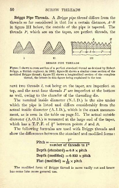
Briggs Pipe Threads. A Briggs pipe thread differs from the
threads so far considered in that for a certain distance, A~Bin figure III below, the outside of the pipe is tapered. The
threads P, which are on the taper, are perfect threads, the
in
BRIGGS PIPE THREADS
Figure I shows a cross section of a perfect standard thread as devised by Robert
Briggs, a British engineer, in 1882; figure II shows a similar cross section of the
modified Briggs thread; figure III shows a longitudinal section of the complete
thread, the letters in this figure being explained in the text
next two threads /, not being on the taper, are imperfect on
top, and the next four threads I' are imperfect at the bottom
as well, owing to the chamfer of the threading die.
The nominal inside diameter (N.I. D.) is the size under
which the pipe is listed and differs considerably from the
actual inside diameter (A.I.D.), which is the exact measure-
ment, as is seen in the table on page 51. The actual outside
diameter (A. O.D.) is measured at the large end of the taper,
which has a T.P.F. of |" between points A and B.
The following formulas are used with Briggs threads and
show the differences between the standard and modified forms :
1"Pitch
number of threads to 1"
Depth (standard) = 0.8 x pitch
Depth (modified) = 0.833 x pitch
Flat (modified) =i x pitch
The modified form of Briggs thread is more easily cut and hence
has come into more general use.
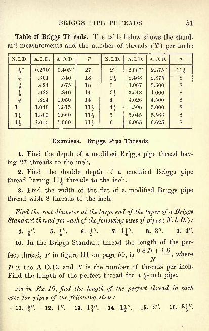
BRIGGS PIPE THREADS 51
Table of Briggs Threads. The table below shows the stand-
ard measurements and the number of threads (T7
) per inch:
N.I.D.
52 SCREW THREADS
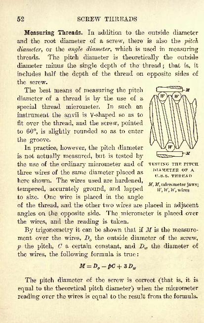
Measuring Threads. In addition to the outside diameter
and the root diameter of a screw, there is also the pitch
diameter, or the angle diameter, which is used in measuringthreads. The pitch diameter is theoretically the outside
diameter minus the single depth of the' thread; that is, it
includes half the depth of the thread on opposite sides of
the screw.
The best means of measuring the pitch
diameter of a thread is by the use of a
special thread micrometer. In such an
instrument the anvil is V-shaped so as to
fit over the thread, and the screw, pointed
to 60, is slightly rounded so as to enter
the groove.
In practice, however, the pitch diameter
is not actually measured, but is tested bythe use of the ordinary micrometer and of TESTING THE PITCH
three wires of the same diameter placed asDIAMETER OF ATJ S S THREAD
here shown. The wires used are hardened,M, M, micrometer jaws;
tempered, accurately ground, and lapped w, w, w, wires
to size. One wire is placed in the angleof the thread, and the other two wires are placed in adjacent
angles on the opposite side. The micrometer is placed over
the wires, and the reading is taken.
By trigonometry it can be shown that if M is the measure-
ment over the wires, D the outside diameter of the screw,
p the pitch, C a certain constant, and Dw the diameter of
the wires, the following formula is true :
The pitch diameter of the screw is correct (that is, it is
equal to the theoretical pitch diameter) when the micrometer
reading over the wires is equal to the result from the formula.
MEASURING THEEADS 53
Illustrative Problems. 1. Find the correct measurementsover wires of a -inch U. S. S. thread, the diameter of the
measuring wires being 0.05773" and the constant, which is
used for all U. S. S. threads, being 1.5155.
We first refer to the table of U. S. S. threads on page 40, and find that
when the outside diameter of the thread is"there are 10 threads to
the inch. The pitch, therefore, is ^".Using the formula given on page 52, we find M, the measurement
over the wires, as follows :
M= D -pC+ 3 Dw = 0.75 - 1.5155
10+ 3 x 0.05773 = 0.77164
Since a vernier micrometer gives readings only to 0.0001" we givethe above result as 0.7716". If the reading of the caliper agrees with
this result, the pitch diameter is correct.
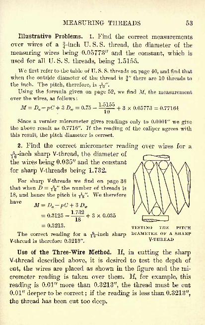
2. Find the correct micrometer reading over wires for a
T5g-inch sharp V-thread, the diameter of
the wires being 0.035" and the constant
for sharp V-threads being 1.732.
For sharp V-threads we find on page 38
that when D =T5^" the number of threads is
18, and hence the pitch is TV- We therefore
have
+ 3 x 0.035= 0.3125 -
= 0.3213. TESTING THE PITCH
The correct reading for a ^-inch sharp DIAMETER OF A SHARP
V-thread is therefore 0.3213". V-THREAD
Use of the Three-Wire Method. If, in cutting the sharpV-thread described above, it is desired to test the depth of
cut, the wires are placed as shown in the figure and the mi-
crometer reading is taken over them. If, for example, this
reading is 0.01" more than 0.3213", the thread must be cut
0.01" deeper to be correct ; if the reading is less than 0.3213",
the thread has been cut too deep.
54 SCKEW THREADS
Exercises. Measuring Threads
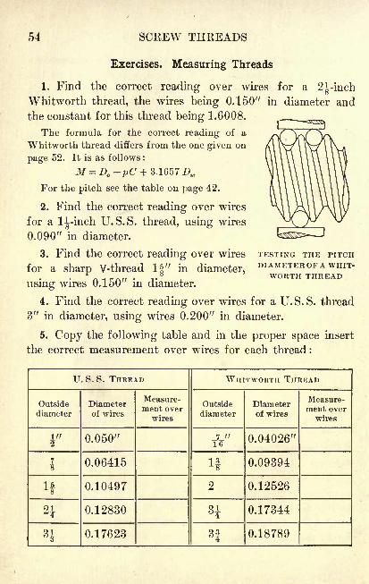
1. Find the correct reading over wires for a 21-inch
Whitworth thread, the wires being 0.150" in diameter and
the constant for this thread being 1.6008.
The formula for the correct reading of a
Whitworth thread differs from the one given on
page 52. It is as follows :
M = D -pC + 3.1657 Dw
For the pitch see the table on page 42.
2. Find the correct reading over wires
for a 1^-inch U.S.S. thread, using wires
0.090" in diameter.
3. Find the correct reading over wires TESTING THE PITCH
for a sharp V-thread If" in diameter,DIAMKTEBOFA WHIT-
r- WORTH THREAD
using wires 0.150" in diameter.
4. Find the correct reading over wires for a U.S.S. thread
3" in diameter, using wires 0.200" in diameter.
5. Copy the following table and in the proper space insert
the correct measurement over wires for each thread :
U. S. S. THREAD
REVIEW EXERCISES 55
Exercises. Review
1. Find the lead of a double-thread screw which has
12 threads to the inch; which has 20 threads to the inch.
2. Find the root diameter of an S.A.E. thread that is
11" in diameter.
3. Find the double depth of a Briggs Standard pipethread for a 4
1-inch pipe.
4. In an Acme screw thread with a pitch of Ty find the
width of the flat at the top, the width of the flat at the root,
and the width of the space at the top.
5. What is the pitch of a square thread when the double
depth is 0.2222"? How many threads are there to I" ?
6. If the root diameter of an International Standard
thread is 5.70 mm. and the pitch is 1 mm., what is the outside
diameter ? the width of the flat ?
7. At what angle should the thread tool be ground to
cut a square thread with 6 threads to the inch and an out-
side diameter of 1^"?8. Find the tap-drill size of a l|-inch U.S.S. tap.
9. Find the root diameter of an Acme tap thread2-|"
in
outside diameter with 5 threads to the inch.
10. Find the correct reading over wires for a sharp V-thread
11" in diameter, the diameter of the wires being 0.070".
11. The root diameter of a U.S.S. thread with 3J threads
to the inch is 2.6288". Find the outside diameter.
12. The root diameter of a Whitworth Standard thread
is 4.5343" and the outside diameter is 5". Find the pitch
of the thread.
13. If the outside diameter of an Acme screw thread hav-
ing 11 threads to the inch is 31", what is the root diameter ?
56 SCEEW THREADS
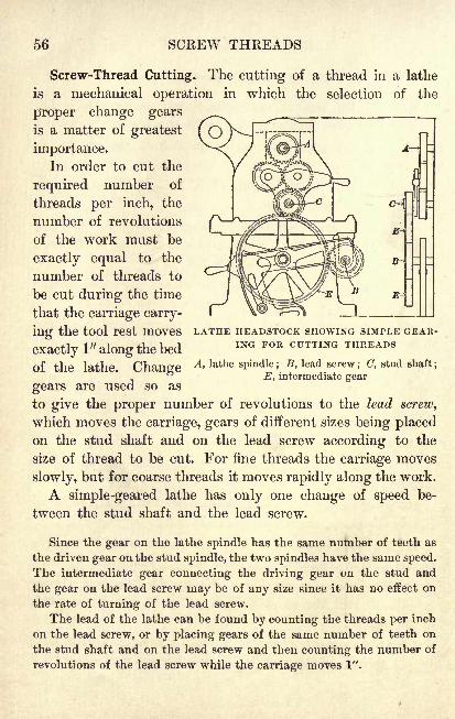
Screw-Thread Cutting. The cutting of a thread in a lathe
is a mechanical operation in which the selection of the
proper change gears
is a matter of greatest
importance.In order to cut the
required number of
threads per inch, the
number of revolutions
of the work must be
exactly equal to the
number of threads to
be cut during the time
that the carriage carry-
ing the tool rest moves LATHE HEADSTOCK SHOWING SIMPLE GEAR-
exactly 1" along the bed ING FOR CUTTING THREA S
of the lathe. Change A> lathe sPindle ;
B>lead screw; c, stud shaft;
E, intermediate gear
gears are used so as
to give the proper number of revolutions to the lead screw,
which moves the carriage, gears of different sizes being placedon the stud shaft and on the lead screw according to the
size of thread to be cut. For fine threads the carriage moves
slowly, but for coarse threads it moves rapidly along the work.
A simple-geared lathe has only one change of speed be-
tween the stud shaft and the lead screw.
Since the gear on the lathe spindle has the same number of teeth as
the driven gear on the stud spindle, the two spindles have the same speed.
The intermediate gear connecting the driving gear on the stud and
the gear on the lead screw may be of any size since it has no effect on
the rate of turning of the lead screw.
The lead of the lathe can be found by counting the threads per inch
on the lead screw, or by placing gears of the same number of teeth on
the stud shaft and on the lead screw and then counting the number of
revolutions of the lead screw while the carriage moves 1".
SCKEW-THKEAD CUTTING 57
Illustrative Problem. If the lead screw of a lathe has
6 threads per inch and it is desired to cut 12 threads perinch on a screw, what change gears are required ?
In this case, since the lead screw will revolve 6 times while the car-
riage advances 1", and the work must revolve 12 times during the same
period, change gears with a ratio of 6 to 12, or of 1 to 2, should be
placed on the stud shaft and the lead screw. That is, expressed as a
general proportion, which may be used in any problem requiring the
use of simple gearing, we have the following :
Number of teeth on outside stud gearNumber of teeth on lead-screw gear
_ number of threads per inch on lead screw
number of threads per inch on work
Each term of the ratio of the gears is multiplied by a number such
that the result is a ratio whose terms correspond to the numbers of
teeth on two of the gears with which the lathe is equipped.
4x6 24In this case we have =
4 x 12 48
That is, a gear with 24 teeth should be placed on the end of the stud
shaft, and a gear with 48 teeth on the lead screw. An intermediate gearof the proper size is used to connect the two gears.
Variation of Lathes. The number of threads per inch on
the lead screw varies on different makes of lathes, and this
makes it necessary to have different sets of change gears.
In our problems we shall use the following sets of gears :
For a lead screw with 5 threads per inch : 25, 25, 30, 35,
40, 45, 50, 55, 60, 65, 69, 70, 80, 90, 100, 110, 120.
FoY a lead screw with 6 threads per inch : 24, 24, 32, 40,
44, 48, 52, 56, 60, 64, 72, 110.
For a lead screw with 8 threads per inch : 24, 24, 28, 32,
36, 40, 44, 48, 52, 56, 64, 69, 72, 80, 96.
In the exercises use only gears which are shown above as belongingto the set for the lead screw specified in each problem.
58 SCREW THREADS
Exercises. Screw-Thread Cutting
1. What change gears are required on a lathe with a lead
screw of 1-inch pitch in cutting a screw thread of -Jg-inch
pitch ? in cutting a thread with a pitch of 0.125" ?
Find the change gears required on a lathe with a lead screw
of A-inch pitch for cutting each of the following numbers of
threads per inch:
2. 12. 3. 7. 4. 13. 5. 18. 6. 111.
Find the change gears required on a lathe having a lead screw
with 8 threads per inch for cutting each of the following num-
bers of threads per inch :
7. 4. 9. 9. 11. 12. 13. 18. 15. 10.
8. 5. 10. 16. 12. 7. 14. 6. 16. 20.
17. What is the pitch of the thread that is cut on a lathe
with a lead screw of J-inch pitch when there is a 25-tooth
gear on the stud and a 40-tooth gear on the lead screw ?
Find the change gears required on a lathe having a lead screw
with 6 threads per inch for cutting each of the following num-
bers of threads per inch :
18. 6. 19. 10. 20. 13. 21. 18. 22. 271.
23. Find the largest number of threads per inch that can
be cut with simple gearing on a lathe which has a lead screw
of ^-inch pitch ; of 1-inch pitch ;of ^-inch pitch.
24. Find the smallest number of threads per inch that can
be cut with simple gearing on a lathe which has a lead screw
of ^-inch pitch ;of 1-inch pitch ; of ^-inch pitch.
25. Find the change gears necessary to cut a thread with
a lead of f"
if the lead screw of the lathe has 5 threads perinch ;
if the lead screw has 8 threads per inch.
COMPOUND GEAKING 59
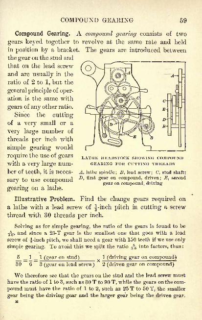
Compound Gearing. A compound gearing consists of two
gears keyed together to revolve at the same rate and held
in position by a bracket. The gears are introduced between
the gear on the stud and
that on the lead screw
and are usually in the
ratio of 2 to 1, but the
general principle of oper-
ation is the same with
gears of any other ratio.
Since the cuttingof a very small or a
very large number of
threads per inch with
simple gearing would
require the use of gearswith a very large num-
ber of teeth, it is neces-
sary to use compound
gearing on a lathe.
Illustrative Problem. Find the change gears required on
a lathe with a lead screw of -^-inch pitch in cutting a screw
thread with 30 threads per inch.
Solving as for simple gearing, the ratio of the gears is found to be
3%-, and since a 25-T gear is the smallest one that goes with a lead
screw of ^-inch pitch, we shall need a gear with 150 teeth if we use only
simple gearing. To avoid this we split the ratio ^o into factors, thus :
5 _ 1 _ 1 (gear on stud) 1 (driving gear on compound)30 6 3 (gear on lead screw) 2 (driven gear on compound)
We therefore see that the gears on the stud and the lead screw must
have the ratio of 1 to 3, such as 30 T to 90 T, while the gears on the com-
pound must have the ratio of 1 to 2, such as 25 T to 50 T, the smaller
gear being the driving gear and the larger gea'r being the driven gear.
LATHE HEADSTOCK SHOWING COMPOUNDGEARING FOR CUTTING THREADS
A, lathe spindle; B, lead screw; C, stud shaft;
D, first gear on compound, driven; E, second
gear on compound, driving
60 SCREW THREADS
Exercises. Screw-Thread Cutting
1. Find the change gears required on a lathe with a lead
screw of i-inch pitch in cutting 25 threads to the inch.
This example shows that the gears on the compound are not neces-
sarily in the ratio of 2 to 1, the principle being the same for any ratio.
Find the change gears required on a lathe with a lead screw
of -inch pitch in cutting a thread with each of the following
numbers of threads to the inch :
2. 28. 3. 7|. 4.3|.
5. 32. 6. 42.
Similarly, for a lead screw of ^-inch pitch,the numbers being :
7. 1. 8. 11. 9. 22. 10. 36. 11. 28.
Similarly, for a lead screw of ^-inch pitch, the numbers being :
12. 2. 13. 23. 14. T5r 15.
f.16. 1^.
Find the change gears required on a lathe having a lead
screw with 5 threads to the inch in cutting a thread with each
of the following leads :
17. Ty. is. f". 19. f". 20. f. 21. Ty.22. Find the change gears required on a lathe having a
lead screw with 6 threads to the inch in cutting a metric
screw with a lead of 2 mm.
First find the number of threads to the inch (1" = 25.4 mm.) corre-
sponding to the given lead in millimeters. It will be found that a gearwith 127 teeth is required to cut a metric thread on a lathe which has
an English lead screw. In Exs. 22 and 23 assume that the lathe is
equipped with such a gear in addition to those listed on page 57.
23. On a lathe having a lead screw with 6 threads to the
inch, find the change gears required for cutting a metric
thread with a lead of 3 mm.; with a lead of 3.5 mm.
CHAPTER V
INDEXING AND SPIRAL CUTTING
Indexing. The process of dividing a circumference into
equal parts is called indexing.
Indexing is done by the aid of a milling-machine fixture
known as the dividing head, spiral head, or index head, and
which is described on page 63. The dividing head is ordinarily
employed in obtaining equal divisions on a circumference, but
may be used to obtain equal divisions of various kinds on
other types of work.
There are various kinds of indexing, direct, simple,
angular, compound, and differential. These will be considered
and explained in the following pages.
Among the cases in which the machinist will make use of
indexing are the following : in cutting spur, bevel, and spiral
gears ;in cutting worm wheels ;
in cutting plate and cylin-
dric cams; and in making milling-machine cutters, counter
bores, reamers, and twist drills.
The dividing-head spindle may be set at any angle from about 5
below the horizontal to about 10 beyond the vertical. The swiveling
block is usually graduated about its circumference in fourths of a
degree, but some machines have a vernier that reads to ^.Work is held in a dividing head in a manner similar to that used on
an engine lathe, the three following general methods being used : (1) by
mounting it on centers, (2) by holding it on an arbor, and (3) by secur-
ing it in a chuck.
When the work is held on an arbor or mounted on centers it is
necessary to use the dividing-head tailstock, which has an adjustable
center capable of being raised or lowered.
61
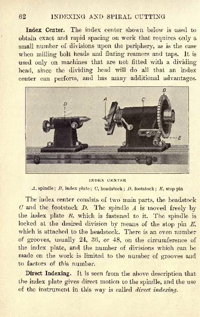
62 INDEXING AND SPIRAL CUTTING
Index Center. The index center shown below is used to
obtain exact and rapid spacing on work that requires only a
small number of divisions upon the periphery, as is the case
when milling bolt heads and fluting reamers and taps. It is
used only on machines that are not fitted with a dividing
head, since the dividing head will do all that an index
center can perform, and has many additional advantages.
INDEX CENTER
A, spindle ; B, index plate ; C, headstock; D, footstock
; E, stop pin
The index center consists of two main parts, the headstock
C and the footstock D. The spindle A is moved freely bythe index plate B, which is fastened to it. The spindle is
locked at the desired division by means of the stop pin E,
which is attached to the headstock. There is an even numberof grooves, usually 24, 36, or 48, on the circumference of
the index plate, and the number of divisions which can be
made on the work is limited to the number of grooves and
to factors of this number.
Direct Indexing. It is seen from the above description that
the index plate gives direct motion to the spindle, and the use
of the instrument in this way is called direct indexing.
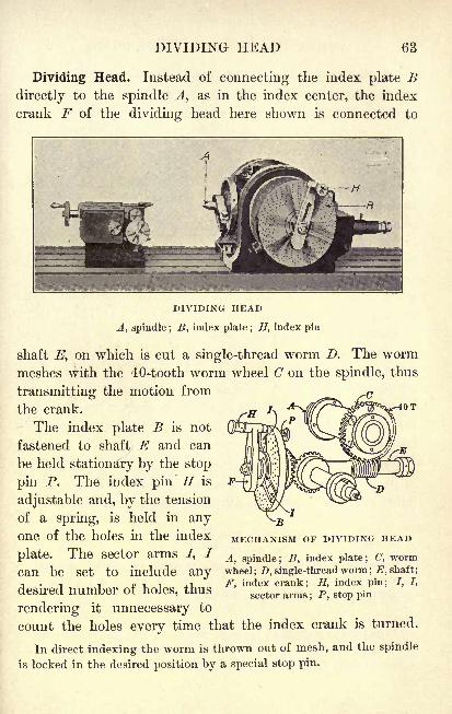
DIVIDING HEAD 63
Dividing Head. Instead of connecting the index plate Bdirectly to the spindle A, as in the index center, the index
crank F of the dividing head here shown is connected to
DIVIDING HEAD
A, spindle ; B, index plate ; H, index pin
shaft E, on which is cut a single-thread worm D. The wormmeshes with the 40-tooth worm wheel C on the spindle, thus
transmitting the motion from
the crank.
The index plate B is not
fastened to shaft E and can
be held stationary by the stop
pin P. The index pin H is
adjustable and, by the tension
of a spring, is held in anyone of the holes in the index
plate. The sector arms /, /
can be set to include any
MECHANISM OF DIVIDING HEAD
A, spindle; B, index plate; C, wormwheel
; D, single-thread worm ; E, shaft;
F, index crank; H, index pin; J, /,
sector arms ; P, stop pindesired number of holes, thus
rendering it unnecessary to
count the holes every time that the index crank is turned.
In direct indexing the worm is thrown out of mesh, and the spindle
is locked in the desired position by a special stop pin.
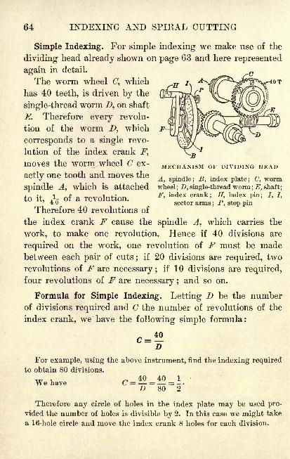
64 INDEXING AND SPIRAL CUTTING
Simple Indexing. For simple indexing we make use of the
dividing head already shown on page 63 and here represented
again in detail.
The worm wheel (7, which
has 40 teeth, is driven by the
single-thread worm Z>, on shaft
E. Therefore every revolu-
tion of the worm D, which
corresponds to a single revo-
lution of the index crank F,
moves the worm wheel C ex-
actly one tooth and moves the
MECHANISM OF DIVIDING HEAD
A, spindle ; B, index plate ; (7, worm
Spindle A1 which is attached wheel; D, single-thread worm; E, shaft;
fn if 1 nf a rpvnlntinn F' index Crank5H
>index Pin 5
7 *tO It, 7 01 a revolution.
sector arms; P, stop pinTherefore 40 revolutions of
the index crank F cause the spindle A, which carries the
work, to make one revolution. Hence if 40 divisions are
required on the work, one revolution of F must be madebetween each pair of cuts; if 20 divisions are required, two
revolutions of F are necessary ; if 10 divisions are required,
four revolutions of F are necessary ; and so on.
Formula for Simple Indexing. Letting D be the number
of divisions required and C the number of revolutions of the
index crank, we have the following simple formula:
For example, using the above instrument, find the indexing required
to obtain 80 divisions.
C = = = -D 80 2*
We have
Therefore any circle of holes in the index plate may be used pro-
vided the number of holes is divisible by 2. In this case we might take
a 16-hole circle and move the index crank 8 holes for each division.
SIMPLE INDEXING 65
Index Plates. Different makes of dividing heads have dif-
ferent sets of index plates. In our exercises we shall use
plates which have circles with the number of holes as follows :
BROWN AND SHARPE
Plate 1 : 15, 16, 17, 18, 19, 20
Plate 2 : 21, 23, 27, 29, 31, 33
Plate 3: 37, 39, 41, 43, 47, 49
CINCINNATI MILLING MACHINE CO.
One plate drilled on both sides, as follows:
First side: 24, 25, 28, 30, 34, 37, 38, 39, 41, 42, 43
Second side: 46, 47, 49, 51, 53, 54, 57, 58, 59, 62, 66
Exercises. Simple Indexing
1. If a spur gear is to have 36 teeth, find the indexing
required on a Cincinnati dividing head.
Since C = f = 1^, we must have a circle with the number of holes
divisible by 9, in this case 54. The indexing required is therefore one
revolution of the index crank plus 6 holes on the 54-hole circle.
2. Find the indexing required on a B. & S. (Brown and
Sharpe) dividing head for 7 divisions.
Find the indexing on a B. $ S. dividing head for each of
the following divisions :
3. 3. 5. 45. 7. 98. 9. 145. 11. 205.
4. 26. 6. 68. 8. 116. '
10. 164. 12. 312.
Find the indexing on a Cincinnati dividing head for each of
the following divisions :
13. 5. 15. 17. 17. 44. 19. 70. 21. 92.
14. 9. 16. 23. 18. 55. 20. 85. 22. 110.
66 INDEXING AND SPIRAL CUTTING
Angular Indexing. If the dividing head requires 40 turns
of the index crank for one revolution of the spindle, that is,
to turn the work through 360, one turn of the crank will
produce a turning of -^ of 360, or 9. The process of
indexing work by angles is known as angular indexing.
Therefore, if one revolution of the index crank gives an
angle of 9, two holes on the 18-hole circle or three holes on
the 27-hole circle of a B. & S. dividing head will correspondto 1. Halves and thirds of a degree are indexed by takingone hole on the 18-hole circle or one hole on the 27-hole
circle respectively. On a Cincinnati dividing head the 54-hole
circle is used, six holes corresponding to 1, and so on.
For example, using a B. & S. dividing head, find the indexing for an
angle of 25.
Since one turn of the index crank gives an angle of 9, the numberof turns of the crank will be -^
5-, or 2. The indexing required is, there-
fore, two revolutions of the crank plus 14 holes on the 18-hole circle.
Exercises. Angular Indexing
1. Find the indexing on a B. & S. head for an angle of 11.
2. Find the indexing on a Cincinnati dividing head for
an angle of
Using a B. $ S. dividing head, find the indexing for each
of the following angles :
3. 1. 5. 4J. 7. 13. 9. 33. 11. 44f.4. 2J. 6. 8f. 8. 17i. 10. 40i. 12. 451.
Using a Cincinnati dividing head, find the indexing for each
of the following angles :
13. 3. 15. 11. 17. 23. 19. 56^. 21. 79|.14. 51. 16. 19|. 18. 31J. 20. 75. 22. 82 '.
ANGULAR AND COMPOUND INDEXING 67
Compound Indexing. To obtain divisions which are beyondthe range of simple indexing a device known as compoundindexing is sometimes employed.
In this method the index crank is first turned a definite
amount in the regular way, and then the stop pin holdingthe index plate is disengaged and the index plate is turned
either in the same direction or in the opposite direction. The
indexing is thus compounded of two separate movementswhich are, in reality, two simple-indexing operations.
Compound indexing should be used only when there is no other con-
venient way of obtaining the division. This is because of the chances of
error due to the fact that the holes must be counted when moving the
index plate, as will be seen in the example below. The method has been
largely superseded by the differential method explained on page 70.
If, for example, the index crank of a B. & S. dividing head
is turned 40 holes on the 18-hole circle, that is, two revo-
lutions plus four holes, and then, the stop pin being disen-
gaged, the index plate is turned 40 holes on the 19-hole circle,
that is, two revolutions plus two holes, in the same direction,
the two movements will cause the spindle holding the work
to make ^ + Jg, or -f^ of a revolution.
If, however, the index plate is turned in the opposite
direction from the index crank, the spindle will make y1
^ Jg,
or g^, of a revolution. Since the two revolutions of the
index crank and the index plate are in opposite directions,
they offset each other, and the same result is obtained by
moving the index crank four holes on the 18-hole circle in
one direction and the index plate two holes on the 19-hole
circle in the opposite direction.
Thus, by combining the two movements we can obtain
342 divisions with the index plates listed on page 65. With
simple indexing we should have required a plate with a
circle of 171 holes.
68 INDEXING AND SPIRAL CUTTING
Illustration of Compound Indexing. For example, to find
the indexing required on a B. & S. dividing head to obtain
147 divisions, we proceed as follows:
1. Find two factors of 147.
That is, 147 = 3 x 49.
2. Try to find two circles on the same plate, one with 49
holes and the other with perhaps ten holes less. In this case
let us try the 49-hole and 39-hole circles.
3. Factor the difference between the numbers of holes in
the two circles.
That is, 49 - 39 - 10 = 2 x 5.
4. Take the indicated product of these two sets of factors
as the numerator of a fraction.
That is, the numerator is (3 x 49) x (2 x 5).
5. Take for the denominator of this fraction (1) the fac-
tors of 40, that is, of the number of turns of the index crank
to one turn of the dividing-head spindle ; (2) the factors of
the larger circle ; (3) the factors of the smaller circle.
That is, (1) 40 = 2 x 2 x 2 x 5,
(2) 49 = 7 x 7,
(3) 39 = 3 x 13,
and hence the denominator is (2 X 2 X 2 X 5) X (7 X 7) x (3 x 13).
6. Now cancel, and if all the factors in the numerator
cancel out, the correct circles have been chosen.
7_
, . , (48 x 3") X (2 X 0)In this case we have ^- E2? M -
,
(2 x 2 x x 0) x (/ x 7) x(JJ
x 13)
and therefore the correct circles have been chosen.
If all the factors in the numerator do not cancel out, other numbers
representing the numbers of holes in the circles of the index plates must
be chosen until two circles are found that will permit the cancellation
of all these factors.
COMPOUND INDEXING 69
7. Take the product of the uncanceled factors in the
denominator as the numerator of each of two fractions, called
the indexing fractions, in which the numerator is the number
of holes to be turned, and the denominator is the number of
holes in the circle on which the number turned is counted.
In this case the numerator of the indexing fractions is 2 x 2 x 13,
or 52, and the fractions which give the desired divisions are + ^fand |, the signs + and being used to show that the two move-
ments are to be made in opposite directions.
That is, by turning 52 holes on the 39-hole circle in one direction
and 52 holes on the 49-hole circle in the other direction, we shall have
the proper movement of the spindle.
This is seen from the fact that
If any whole number is subtracted from each of two fractions, the
difference of the fractions is not affected. In this case, therefore, we
may subtract 1 from each fraction, and we have
-l=49, and -!=&Hence we give the indexing fractions required to obtain 147 divisions
by compound indexing as + ^f and ^.
Exercises. Compound Indexing
Using compound indexing on a B. $ S. dividing head, findthe indexing fractions for each of the following divisions :
1. 69. 2. 51. 3. 99. 4. 217. 5. 294.
6. By the compound method, find the indexing fractions
for cutting a spur gear 'with 77 teeth on a milling machine
which is equipped with a B. & S. dividing head.
7. Find the fractions in Ex. 6 for a gear with 87 teeth.
8. Find the indexing fractions for cutting 129 teeth on
the rim of a ratchet wheel, using compound indexing on a
B. & S. dividing head.
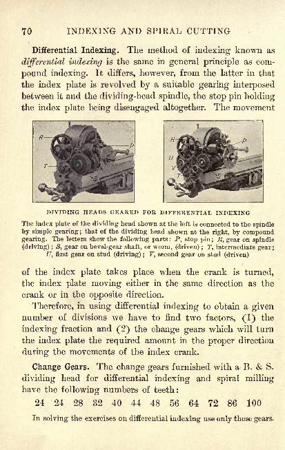
70 INDEXING AND SPIRAL CUTTING
Differential Indexing. The method of indexing known as
differential indexing is the same in general principle as com-
pound indexing. It differs, however, from the latter in that
the index plate is revolved by a suitable gearing interposed
between it and the dividing-head spindle, the stop pin holdingthe index plate being disengaged altogether. The movement
DIVIDING HEADS GEARED FOR DIFFERENTIAL INDEXING
The index plate of the dividing head shown at the left is connected to the spindle
by simple gearing ;that of the dividing head shown at the right, by compound
gearing. The letters show the following parts : P, stop pin ; R, gear on spindle
(driving) ; S, gear on bevel-gear shaft, or worm, (driven) ; T, intermediate gear ;
U, first gear on stud (driving) ; V, second gear on stud (driven)
of the index plate takes place when the crank is turned,
the index plate moving either in the same direction as the
crank or in the opposite direction.
Therefore, in using differential indexing to obtain a givennumber of divisions we have to find two factors, (1) the
indexing fraction and (2) the change gears which will turn
the index plate the required amount in the proper direction
during the movements of the index crank.
Change Gears. The change gears furnished with a B. & S.
dividing head for differential indexing and spiral milling
have the following numbers of teeth:
24 24 28 32 40 44 48 56 64 72 86 100
In solving the exercises on differential indexing use only these gears.
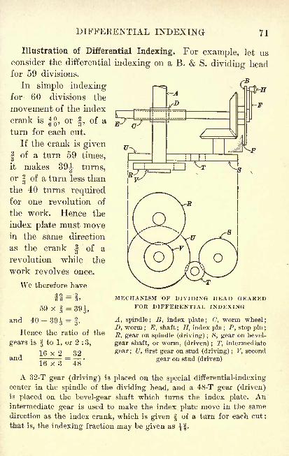
DIFFERENTIAL INDEXING 71
Illustration of Differential Indexing. For example, let usconsider the differential indexing on a B. & S. dividing headfor 59 divisions.
In simple indexing p^= Cj
for 60 divisions the
movement of the index
crank is |$, orJ,
of a
turn for each cut.
If the crank is given
| of a turn 59 times,
it makes 391 turns,
or | of a turn less than
the 40 turns requiredfor one revolution of
the work. Hence the
index plate must movein the same direction
as the crank ^ of aB
revolution while the
work revolves once.
We therefore have
59 x = 39^,
and 40-39J =f.
Hence the ratio of the
gears is to 1, or 2 : 3,
16 x 2 ^ 32
16 x 3 ~48'and
MECHANISM OF DIVIDING HEAD GEAREDFOR DIFFERENTIAL INDEXING
A, spindle; B, index plate; C, worm wheel;D, worm ; E, shaft
; H, index pin ; P, stop pin ;
ft, gear on spindle (driving) ; S, gear on bevel-
gear shaft, or worm, (driven) ; !T, intermediate
gear ; U, first gear on stud (driving) ; V, second
gear on stud (driven)
A 32-T gear (driving) is placed on the special differential-indexing
center in the spindle of the dividing head, and a 48-T gear (driven)is placed on the bevel-gear shaft which turns the index plate. Anintermediate gear is used to make the index plate move in the same
direction as the index crank, which is given of a turn for each cut ;
that is, the indexing fraction may be given as -^f.
72 INDEXING AND SPIRAL CUTTING
Exercises. Review
1. Find the differential indexing on a B. & S. dividing
head for 175 divisions.
For 180 divisions, T4g o-
=
Then 175 x f = 38f , and 40-38f = l^.
Hence the required gearing must be in the ratio of 1 to 1, or 10 : 9.
Since no two gears will give this ratio, we have
JQ. 40 S y 5D US' 54"
Gears in the ratio of 8 (driving) to 9 (driven) are used on the spindle
and bevel-gear shaft, and gears in the ratio of 5 (driving) to 4 (driven)
are used on the stud. We therefore have
8_x_8 = 64 8 x 5 _ 40
8 x 9~
72'
8 x 4~
32'
The arrangement of the gears is as follows : spindle, 64 T;bevel-
gear shaft, 72 T; first gear on stud, 40 T; second gear on stud, 32 T.
With compound gearing an intermediate gear is not needed to make
the index plate turn in the same direction as the index crank. The in-
dexing fraction may be given as T4? ,which is equivalent to f of a turn.
Find the differential indexing on a B. $ S. dividing head
for each of the following divisions :
2. 53. 4. 107. 6. 161. 8. 199. 10. 271.
3. 67. 5. 112. 7. 173. 9. 214. 11. 321.
Using a Cincinnati dividing head, find the simple indexing
movement for each of the following divisions :
12. 116. 13. 145. 14. 205. 15. 245. 16. 392.
Using a B. $ S. dividing head, find the indexing movement
for each of the following angles :
17. 12. 18. 211. 19. 291. 20. 53|. 21. 66.
22. Using compound indexing on a B. &. S. head, find the
indexing fractions for milling 273 slots on a feed disk.
SPIRALS 73
Spirals. A winding cut made by a tool moving around
a cone and at the same time advancing along its slant line
at a uniform rate is called a spiral cut.
Since the method of feeding the work is the same in the case of a
straight reamer as in that of a taper reamer, it is customary to give the
name "spiral cut "
to the helical flutes of straight drills and reamers andalso to the spiral teeth in mills, gears, and cutters.
The dividing head is used not only for indexing but also
for the milling of spirals. When a spiral is being milled the
work is turned slowly by the dividing head, while the table
of the milling machine feeds lengthwise.
The lead of a spiral is figured in much the same way as
the lead of a screw thread ; that is, it is the distance that the
spiral advances in making one turn around the work. The
spiral, however, is spoken of as having so many inches to
one turn instead of as having so many threads to one inch,
as is the case with a screw thread.
In the process of milling a spiral, change gears are used to
connect the dividing head with the feed screw on the table
of the milling machine, so that the spindle of the dividinghead rotates a definite amount in proportion to the distance
that the table travels. The action of this gearing is similar to
that used in cutting a thread in a lathe.
Spirals are always cut on a universal milling machine,
the table of which can be set at any desired angle to the
spindle holding the milling cutter. The table is set at such
an angle as will bring the milling cutter in line with the cut
to be made on the work, as is explained on page 78. The
angle at which the table is set has no effect on the lead of
the spiral, which is determined by the change gears used.
If the table were left in its normal position at right angles
to the cutter spindle, a spiral of the same lead would be
obtained, but the shape of the cut would be changed.
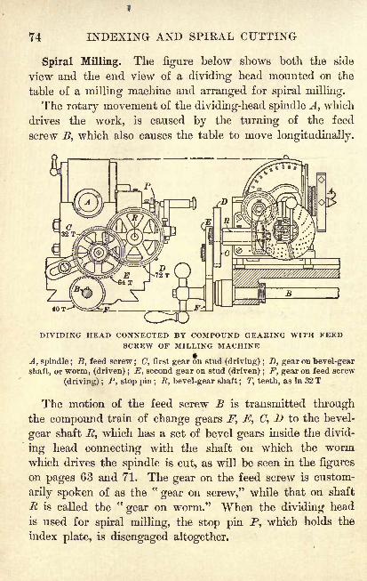
74 INDEXING AND SPIRAL CUTTING
Spiral Milling. The figure below shows both the side
view and the end view of a dividing head mounted on the
table of a milling machine and arranged for spiral milling.
The rotary movement of the dividing-head spindle A, which
drives the work, is caused by the turning of the feed
screw B, which also causes the table to move longitudinally.
40
DIVIDING HEAD CONNECTED BY COMPOUND GEARING WITH FEEDSCREW OF MILLING MACHINE
A, spindle ; B, feed screw; (7, first gear on stud (driving) ; D, gear on bevel-gear
shaft, or worm, (driven) ; E, second gear on stud (driven) ; F, gear on feed screw
(driving) ; P, stop pin; R, bevel-gear shaft; T, teeth, as in 32 T
The motion of the feed screw B is transmitted throughthe compound train of change gears F, E, (7, D to the bevel-
gear shaft R, which has a set of bevel gears inside the divid-
ing head connecting with the shaft on which the wormwhich drives the spindle is cut, as will be seen in the figures
on pages 63 and 71. The gear on the feed screw is custom-
arily spoken of as the"gear on screw," while that on shaft
R is called the"gear on worm." When the dividing head
is used for spiral milling, the stop pin P, which holds the
index plate, is disengaged altogether.
SPIKAL MILLING 75
Lead of a Milling Machine. If the change gears are in the
ratio of 1 to 1 (that is, if gear D revolves once for each revo-
lution of F), the lead of the milling machine is the distance that
the table travels while the spindle revolves once.
This distance is a constant used in figuring change gears and varies
with different makes of machines.
If R is the number of revolutions of the feed screw for
one revolution of the spindle with 1-to-l gearing and F is
the lead of the feed screw, Jf, the lead of the milling machine,
is found as follows :
M = RFFor example, if with 1-to-l gearing R = 40 on a milling machine
which has F = ", we have
3/^/^ = 40 x 4" = 10".
Change Gears. Letting L be the lead of the spiral to be
cut and M the lead of the milling machine, the ratio of
driven to driving gears is found from the following formula :
Gears driven L
Gears driving~~ M
Letting Tw represent the gear on worm (driven), Ts the
gear on screw (driving), Slthe first gear on stud (driving),
and S2the second gear on stud (driven), the above ratio is
split into two factors as follows:
Gears driven _ T
Gears driving~~
Ts
The terms of each of the ratios Tw : T8 and S2
: Slare multiplied by
a number which will give numbers in the list of gears on page 70.
To find the lead of a spiral which will be cut with a given
combination of change gears we have the following formula :
_ M x product of driven gears
product of driving gears
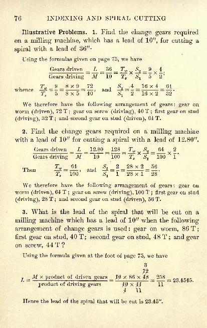
76 INDEXING AND SPIKAL CUTTING
Illustrative Problems. 1. Find the change gears requiredon a milling machine, which has a lead of 10", for cutting a
spiral with a lead of 36"-
Using the formulas given on page 75, we have
Gears driven _ L _ 36 _ Tw ^ 2 _ 9^
4
Gears driving
~ M ~10
~~
T8
*S
l
~5X
2'
Tw 9 8 x 9 72 , 524 16 x 4 64
whence _^- =_ = _, and -2 = - =__ = _.
We therefore have the following arrangement of gears : gear on
worm (driven), 72 T; gear on screw (driving), 40 T
;first gear on stud
(driving), 32 T;and second gear on stud (driven), 64 T.
2. Find the change gears required on a milling machine
with a lead of 10" for cutting a spiral with a lead of 12.80".
Gears driven = L = 12.80 _ 128 = Tw S^ _ _62
Gears driving M ~10
~100
~T8
*^
~~
100X
1'
Tw 64 5 2 28 x 2 56Then - = > and - = = =
T8 100 Sl
1 28 x 1 28
We therefore have the following arrangement of gears: gear on
worm (driven), 64 T; gear on screw (driving), 100 T
;first gear on stud
(driving), 28 T;and second gear on stud (driven), 56 T.
3. What is the lead of the spiral that will be cut on a
milling machine which has a lead of 10" when the following
arrangement of change gears is used : gear on worm, 86 T;
first gear on stud, 40 T; second gear on stud, 48 T ; and gearon screw, 44 T ?
Using the formula given at the foot of page 75, we have
3
T _M X product of driven gears _ ffl x 86 x $fi _ 258 _ _
product of driving gears x 11
t 11
Hence the lead of the spiral that will be cut is 23.45".
CUTTING SPIRALS 77
Exercises. Cutting Spirals
1. If a milling machine has a lead of 10", what change
gears are needed to cut a spiral with a lead of 16" ?
2. If a milling machine has a lead of 10", what change
gears are needed to cut a spiral with a lead of 22.50" ?
3. For milling a spiral the change gears on a millingmachine which has a lead of 10" were placed as follows: a
64-T gear as the gear on worm, a 40-T gear as the gear on
screw, a 32-T gear as the first gear on stud, "and a 56-T gearas the second gear on stud. What is the lead of the spiral
which was cut with this arrangement of gears ?
Find the change gears required on a milling machine with a
lead of 10" for milling each of the following spiral leads :
4. 0.80". 7. 4.125". 10. 18.75". 13. 31.50".
5. 2.20". 8. 12.60". 11. 21.00". 14. 37.50".
6. 3.50". 9. 17.20". 12. 25.80". 15. 52.50".
16. Find the change gears required on a milling machine
with a lead of 10" in cutting a spiral of one turn in 13J".
17. In milling a spiral the following arrangement of change
gears was used : gear on worm, 86 T ; gear on screw, 56 T ;
first gear on stud, 28 T ; second gear on stud, 48 T. If the
lead of the milling machine was 20", what was the lead of
the spiral which was milled ?
18. What is the lead of the spiral which will be cut on a
milling machine with a lead of 10" when there is a 64-T
gear on the bevel-gear shaft, or worm, a 32-T gear as the first
gear on the stud, a 48-T gear as the second gear on the stud,
and a 56-T gear on the feed screw ?
19. What would be the lead of the spiral in Ex. 18 if the
gears on the stud were reversed?
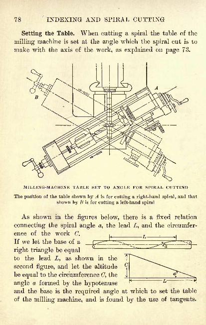
78 INDEXING AND SPIRAL CUTTING
Setting the Table. When cutting a spiral the table of the
milling machine is set at the angle which the spiral cut is to
make with the axis of the work, as explained on page 73.
MILLING-MACHINE TABLE SET TO ANGLE FOR SPIRAL CUTTING
The position of the table shown by A is for cutting a right-hand spiral, and that
shown by B is for cutting a left-hand spiral
As shown in the figures below, there is a fixed relation
connecting the spiral angle #, the lead Z, and the circumfer-
ence of the work C.i *1
If we let the base of a
right triangle be equalto the lead , as shown in the
second figure, and let the altitude
be equal to the circumference C, the
angle a formed by the hypotenuseand the base is the required angle at which to set the table
of the milling machine, and is found by the use of tangents.
SETTING THE TABLE 79
Illustrative Problem. Find the angle at which to set the
table of a milling machine when cutting a spiral with a lead
of 28.00" on a 3i-inch blank.
Referring to the lower figures on page 78, in which C represents the
circumference of the work and L the lead of the spiral, we see that
tan a =L
C 3.1416 x 31Then tan a - = = 0.3647,
and hence a = 20 2'.
Since the scale by which angle a is set is usually graduated only to
fourths of a degree, we give the above result as 20.
Exercises. Setting the Table
Find the angle at which to set the table of a milling machine
to cut each of the following :
1. A spiral with a lead of 13.12" on a spiral-gear blank
which is 2|" in diameter.
In all problems dealing with setting the table of a milling machine
give the results to the nearest J.
2. A spiral of 8.95-inch lead on a 1-inch twist drill.
3. A spiral with a lead of 15.75" on a milling cutter which
is to be 4" in diameter.o
4. A spiral with a lead of 0.67" on a |-inch spindle.
5. A spiral with a lead of 67.45" on a spiral-gear blank
which has a diameter of 5|".
6. If the angle of the spiral on a twist drill \\n in diameter
is 191, what is the lead?
7. If the table of a milling machine is set at an angle of
10^ for cutting a spiral with a lead of 68.57", what is the
diameter of the work ?
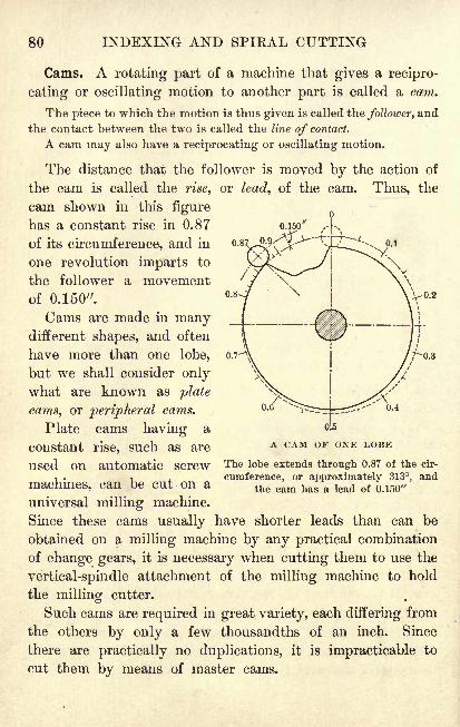
80 INDEXING AND SPIRAL CUTTING
0.87
Cams. A rotating part of a machine that gives a recipro-
cating or oscillating motion to another part is called a cam.
The piece to which the motion is thus given is called the follower, and
the contact between the two is called the line of contact.
A cam may also have a reciprocating or oscillating motion.
The distance that the follower is moved by the action of
the cam is called the rise, or lead, of the cam. Thus, the
cam shown in this figure
has a constant rise in 0.87
of its circumference, and in
one revolution imparts to
the follower a movement
of 0.150".
Cams are made in manydifferent shapes, and often
have more than one lobe,
but we shall consider onlywhat are known as plate
cams, or peripheral cams.
Plate cams having a
constant rise, such as are
used on automatic screw
machines, can be cut on a
universal milling machine.
Since these cams usually have shorter leads than can be
obtained on a milling machine by any practical combination
of change gears, it is necessary when cutting them to use the
vertical-spindle attachment of the milling machine to hold
the milling cutter.
Such cams are required in great variety, each differing from
the others by only a few thousandths of an inch. Since
there are practically no duplications, it is impracticable to
cut them by means of master cams.
0.6 0.4
A CAM OF ONE LOBE
The lobe extends through 0.87 of the cir-
cumference, or approximately 313, andthe cam has a lead of 0.150"
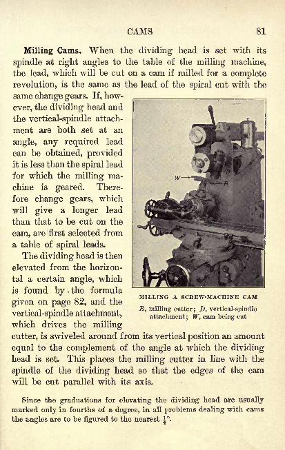
CAMS 81
Milling Cams. When the dividing head is set with its
spindle at right angles to the table of the milling machine,
the lead, which will be cut on a cam if milled for a complete
revolution, is the same as the lead of the spiral cut with the
same change gears. If, how-
ever, the dividing head and
the vertical-spindle attach-
ment are both set at an
angle, any required lead
can be obtained, providedit is less than the spiral lead
for which the milling ma-
chine is geared. There-
fore change gears, which
will give a longer lead
than that to be cut on the
cam, are first selected from
a table of spiral leads.
The dividing head is then
elevated from the horizon-
tal a certain angle, which
is found by the formula
given on page 82, and the
vertical-spindle attachment,
which drives the milling
cutter, is swiveled around from its vertical position an amount
equal to the complement of the angle at which the dividinghead is set. This places the milling cutter in line with the
spindle of the dividing head so that the edges of the cam
will be cut parallel with its axis.
Since the graduations for elevating the dividing head are usually
marked only in fourths of a degree, in all problems dealing with cams
the angles are to be figured to the nearest ^.
MILLING A SCREW-MACHINE CAM
, milling cutter; D, vertical-spindle
attachment; W, cam being cut
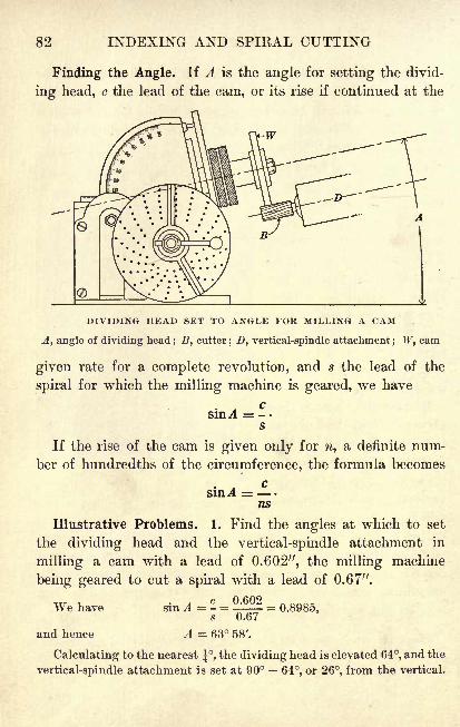
82 INDEXING AND SPIRAL CUTTING
Finding the Angle. If A is the angle for setting the divid-
ing head, c the lead of the cam, or its rise if continued at the
DIVIDING HEAD SET TO ANGLE FOR MILLING A CAM
A, angle of dividing head; B, cutter
; D, vertical-spindle attachment; W, cam
given rate for a complete revolution, and s the lead of the
spiral for which the milling machine is geared, we have
sin^ = -.s
If the rise of the cam is given only for n, a definite num-
ber of hundredths of the circumference, the formula becomes
c~
ns
Illustrative Problems. 1. Find the angles at which to set
the dividing head and the vertical-spindle attachment in
milling a cam with a lead of 0.602", the milling machine
being geared to cut a spiral with a lead of 0.67".
We have
and hence A = 63 58'.
Calculating to the nearest , the dividing head is elevated 64, and the
vertical-spindle attachment is set at 90 64, or 26, from the vertical.
CUTTING PLATE CAMS 83
2. In Ex. 1 find the angles if the cam were to have a lead
of 0.150" in 300, or in 0.83 of the circumference.
We have sin A = = 5lL52 = 0.2697,ns 0.83 x 0.67
and hence A = 15 39'.
The dividing head is elevated 15f and the vertical-spindle attach-
ment is swiveled around 90 15f ,or 74^, from the vertical.
Exercises. Cutting Plate Cams
1. Find the angle at which to elevate the dividing head
when cutting a cam with a lead of 1.249", the millingmachine being geared to cut a spiral with a lead of 1.333".
2. A milling machine is geared to cut a spiral with a lead
of 1.860". At what angles should the dividing head and
the vertical-spindle attachment be set for milling a cam
with a lead of 1.801" ?
3. A cam having a rise of 0.634" in 0.75 of its circum-
ference is to be milled on a milling machine geared to cut
a spiral with a lead of 0.930". Find the angle at which to
elevate the dividing head.
4. In Ex. 3 find the angle at which to set the vertical-
spindle attachment if the given rise were to be obtained in
0.83 of the circumference of the cam.
A milling machine being geared to cut a spiral with a lead
of 0.916", find the angle at which to elevate the dividing head
for milling a cam with each of the following leads :
5. 0.669". 8. 0.789". 11. 0.733". 14. 0.898".
6. 0.691". 9. 0.712". 12. 0.859". 15. 0.771".
7. 0.701". 10. 0.853". 13. 0.751". 16. 0.904".
84 INDEXING AND SPIRAL CUTTING
Exercises. Review
1. If the feed screw on the table of a milling machine
has a lead of 0.4" and it requires 40 revolutions of the feed
screw with 1-to-l gearing to turn the dividing-head spindle
once, what is the lead of the machine ?
2. Find the change gears required on a milling machine
with a lead of 10" for milling a cutter with spiral teeth of
9.60-inch lead.
3. Find the angle at which to elevate the dividing head
when milling a cam with a rise of 0.150" in 0.75 of the
circumference, the machine being geared to cut a spiral
with a lead of 0.67".
Find the angle at which to set the table to cut a spiral with
a lead of 13.760", given the diameter of each piece as follows :
4. 1". 6. \". 8. f".10. 1". 12. |".
5. If". 7. If". 9. 21". 11. IJ". 13. 31".
14. Find the lead of the spiral which is cut on a milling
machine with a lead of 10" when there is a 100-T gear on
the worm, a 24-T gear as the first and a 64-T gear as the
second gear on the stud, and a 28-T gear on the screw.
15. Find the angles at which to set the dividing head and
the vertical-spindle attachment when milling a cam with a
rise of 0.136" in 0.85 of the circumference, the milling
machine being geared to cut a spiral with a lead of 0.67".
Find the change gears required on a milling machine with a
lead of 10" for milling each of the following spiral leads :
16. 0.90". 19. 3.75". 22. 12.375". 25. 27.50".
17. 1.44". 20. 6.60". 23. 13.125". 26. 31.25".
18. 2.45". 21. 8.25". 24. 16.875". 27. 42.00".
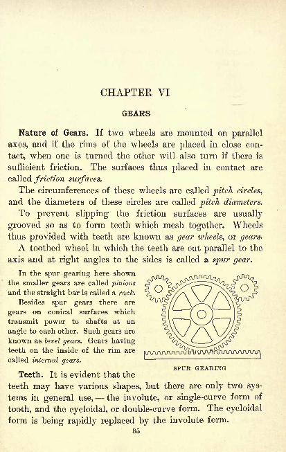
CHAPTER VI
GEARS
Nature of Gears. If two wheels are mounted on parallel
axes, and if the rims of the wheels are placed in close con-
tact, when one is turned the other will also turn if there is
sufficient friction. The surfaces thus placed in contact are
called friction surfaces.
The circumferences of these wheels are called pitch circles,
and the diameters of these circles are called pitch diameters.
To prevent slipping the friction surfaces are usually
grooved so as to form teeth which mesh together. Wheels
thus provided with teeth are known as gear wheels, or gears-
A toothed wheel in which the teeth are cut parallel to the
axis and at right angles to the sides is called a spur gear.
In the spur gearing here shownthe smaller gears are called pinions
and the straight bar is called a rack.
Besides spur gears there are
gears on conical surfaces which
transmit power to shafts at an
angle to each other. Such gears are
known as bevel gears. Gears havingteeth on the inside of the rim are
called internal gears.
Teeth. It is evident that the
teeth may have various shapes, but there are only two sys-
tems in general use, the involute, or single-curve form of
tooth, and the cycloidal, or double-curve form. The cycloidal
form is being rapidly replaced by the involute form.
85
SPUR GEARING
86 GEARS
Terms Used. The figure on page 87 illustrates the defini-
tions of the following terms, which we shall use in connection
with the work on spur gearing:
Addendum. The height (a) of a tooth above the pitch circle.
Center distance. The distance (^)c) between the centers of
the shafts to which the gears are fastened.
Chordal pitch. The distance from the center of one tooth
to the center of the next tooth, measured on a straight line;
that is, on the chord of the pitch circle.
Circular pitch. The distance (Pc) between the centers of
two adjacent teeth, measured on the pitch circle.
It includes the equivalent of one space and one tooth.
Clearance. The distance (c) from the working-depth circle
to the whole-depth circle to allow freer action of the gears.
Dedendum. The depth (d) of a tooth between the pitch
circle and the working-depth circle.
Diametral pitch. The number of teeth per unit of the pitch
diameter of the gear.
Thus, if there are 48 teeth on a gear with a pitch diameter of 12",
the diametral pitch of the gear is T f, or 4.
Unless otherwise stated, the "pitch" ofa gear means the"diametral pitch ."
Face of a tooth. The working surface (Fa) outside the pitch
circle and extending the width of the tooth.
Flank of a tooth. The working surface (FF) inside the pitch
circle and extending the width of the tooth.
Outside circle. The circumference ( F) of the gear blank.
Outside diameter. The diameter (I> ) of the outside circle.
Pitch circle. The circumference of the friction cylinder.
Pitch diameter. The diameter (Dp) of the pitch circle.
Pitch line. The circumference line (X) of the pitch circle.
Root. The total depth of a tooth inside the pitch circle,
equivalent to the dedendum plus the clearance.
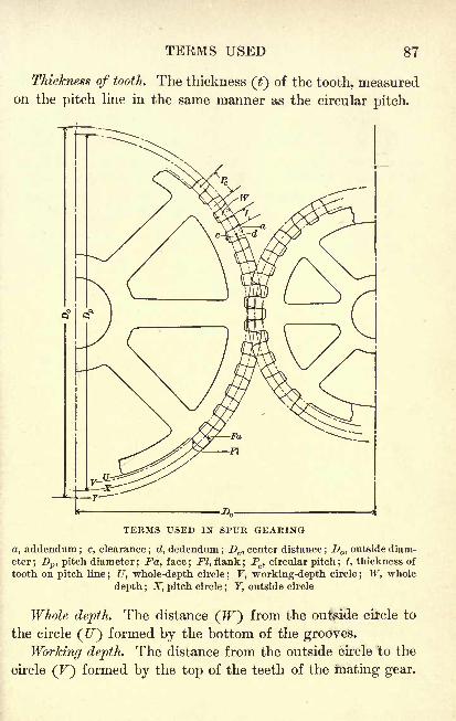
TERMS USED 87
Thickness of tooth. The thickness () of the tooth, measuredon the pitch line in the same manner as the circular pitch.
TERMS USED IN SPUR GEARING
, addendum ; c, clearance; d, dedendum ;
Dc , center distance;D ,
outside diam-
eter; Dp , pitch diameter; Fa, face; Fl, flank; Pc ,circular pitch ; t, thickness of
tooth on pitch line; U, whole-depth circle
; F, working-depth circle; W, whole
depth ; X, pitch circle; F, outside circle
Whole depth. The distance (JF) from the outside circle to
the circle (U) formed by the bottom of the grooves.
Working depth. The distance from the outside circle to the
circle (F) formed by the top of the teeth of the mating gear.
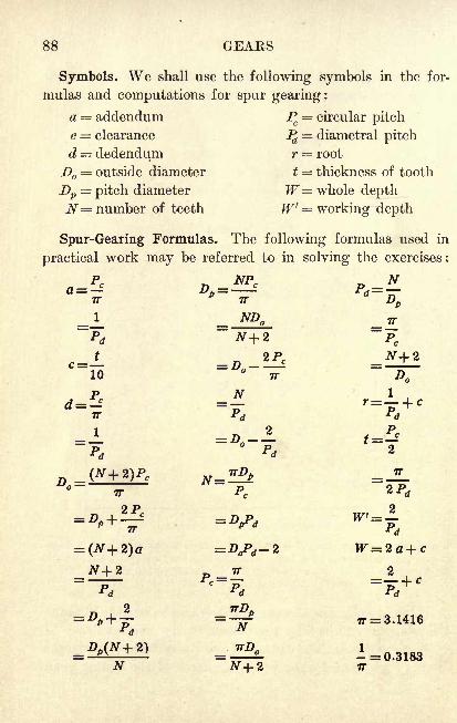
88 GEARS
Symbols. We shall use the following symbols in the for-
mulas and computations for spur gearing:
a = addendum Pc
circular pitch
c = clearance Pd = diametral pitch
d = dedendum r = root
D = outside diameter t = thickness of tooth
Dv= pitch diameter W= whole depth
N= number of teeth W'' = working depth
Spur-Gearing Formulas. The following formulas used in
practical work may be referred to in solving the exercises :
10 TT D
Pd P* 2
7
~7T
(N+2)a =Z>aP<f-2 W=2a+c
N+2 TT 2
= 3.1416
N N+2 TT
SPUR-GEARING FORMULAS 89
Exercises. Spur Gears
1. A gear has a circular pitch of 0.7854". Find the pitch.
Remember that the word "pitch
" when used alone always refers to
the diametral pitch, and use the second formula for Pd on page 88.
The difference in the use of the term "pitch
"as applied to gears and
to screw threads should be noted. Thus, we speak of a screw with
4 threads to the inch as a screw of -inch pitch, while a gear which
has 4 teeth to each inch of the pitch diameter is a 4-pitch gear.
2. What is the circular pitch of a gear which has a
pitch of 26?
Carry all computations for dimensions of gears to four decimal places,
but in the final result discard the fourth place, giving the dimensions
correct to the nearest 0.001".
3. Find the outside diameter of a gear having 70 teeth
and a pitch of 8.
4. Find the thickness of tooth on the pitch line of a gearwith a pitch of 16.
5. A gear has a pitch of 12 and an outside diameter of
5". Find the number of teeth.
6. If Pc= 2.5133", what is the value of Pd ? Write a state-
ment of the meaning of the problem, not using the symbols.
The value of Pd should be given as 1^.
7. If Pd = 9, what is the value of Pc? Write a statement
as in Ex. 6.
8. If the outside diameter of a gear is 18" and the pitch
is 6, what is the number of teeth?
9. If a gear has 24 teeth and a pitch of 18, what is the
outside diameter?
10. What should be the diameter of the gear blank for a
gear which is to have 46 teeth and the circular pitch of
which is to be 0.1309"?
90 GEAKS
11. Find the whole depth of a tooth on a gear having"
a pitch of 10.
It will be seen from the formulas on page 88 that to find the whole
2depth W we must use the formula W = - + c> in which we find c from
the formula c - and t from the formula t = 5-^- Since TT = 3.1416,
1 5708we have = 1.5708, and hence t = - . If we substitute this value
for t in the formula c = -, we shall then have c = '
, or c = -^ --10 r& -frf
Using this value for c, we have
Such a formula when once developed may be used in finding the
whole depth of tooth for any given pitch.
12. How many teeth should there be on a gear having a
pitch of 12 and an outside diameter of 3|"?
13. If_ZJ=
1|, what is the value of Pc? Write a statement
of the meaning of the problem, not using the symbols.
14. If the outside diameter of a gear is 4" and the numberof teeth is 46, what is the pitch ?
15. Find the number of teeth for a gear having a pitch of
14 and an outside diameter of 7f".
16. Find the thickness of a tooth on an 8-pitch gear.
17. Find the whole depth of a tooth on an 11-pitch gear.
18. Find the pitch of a 75-tooth gear having an outside
diameter of 19J".
19. The pitch diameter of a gear is 1.8182" and the pitchis 22. Find the number of teeth and the outside diameter.
20. The circular pitch of a gear is If". Find the workingdepth of a tooth.
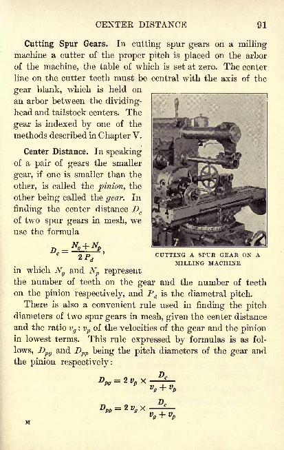
CENTER DISTANCE 91
Cutting Spur Gears. In cutting spur gears on a millingmachine a cutter of the proper pitch is placed on the arbor
of the machine, the table of which is set at zero. The center
line on the cutter teeth must be central with the axis of the
gear blank, which is held on
an arbor between the dividing-
head and tailstock centers. The
gear is indexed by one of the
methods described in Chapter V.
Center Distance. In speakingof a pair of gears the smaller
gear, if one is smaller than the
other, is called the pinion, the
other being called the gear. In
finding the center distance Dc
of two spur gears in mesh, weuse the formula
CUTTING A SPUR GEAR ON AMILLING MACHINE
in which Ngand Np represent
the number of teeth on the gear and the number of teeth
on the pinion respectively, and Pd is the diametral pitch.
There is also a convenient rule used in finding the pitchdiameters of two spur gears in mesh, given the center distance
and the ratio vg
: vp of the velocities of the gear and the pinionin lowest terms. This rule expressed by formulas is as fol-
lows, Dpg and Dpp being the pitch diameters of the gear and
the pinion respectively:
Dpg = 2vh x
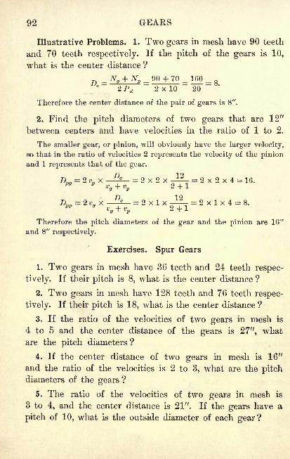
92 GEARS
Illustrative Problems. 1. Two gears in mesh have 90 teeth
and 70 teeth respectively. If the pitch of the gears is 10,
what is the center distance?
90 + 70 = 160 =2 x 10 20
Therefore the center distance of the pair of gears is 8".
2. Find the pitch diameters of two gears that are 12"
between centers and have velocities hi the ratio of 1 to 2.
The smaller gear, or pinion, will obviously have the larger velocity,
so that in the ratio of velocities 2 represents the velocity of the pinionand 1 represents that of the gear.
D = 2 x 2 x -I?- = 2 x 2 x 4 = 16.
Therefore the pitch diameters of the gear and the pinion are 16"
and 8" respectively.
Exercises. Spur Gears
1. Two gears in mesh have 36 teeth and 24 teeth respec-
tively. If their pitch is 8, what is the center distance ?
2. Two gears in mesh have 128 teeth and 76 teeth respec-
tively. If their pitch is 18, what is the center distance ?
3. If the ratio of the velocities of two gears in mesh is
4 to 5 and the center distance of the gears is 27", what
are the pitch diameters?
4. If the center distance of two gears in mesh is 16"
and the ratio of the velocities is 2 to 3, what are the pitchdiameters of the gears ?
5. The ratio of the velocities of two gears in mesh is
3 to 4, and the center distance is 21". If the gears have a
pitch of 10, what is the outside diameter of each gear?
SPUE GEAKS 93
6. In Ex. 5 find the number of teeth on each of the gears.
7. If two 6-pitch gears in mesh have 132 teeth and
66 teeth respectively, what is the center distance ?
8. If the velocity ratio of two gears in mesh is 5 to 6
and the distance between the centers is 33", what are the
pitch diameters of the gears ?
9. If the pitch in Ex. 8 is 6, find the outside diameters.
10. Find the number of teeth on each of the gears in Ex. 8.
11. If two 3-pitch gears in mesh have 182 teeth and 96 teeth
respectively, what is the center distance ?
12. If the velocity ratio of two gears in mesh is 3 to 1
and the distance between the centers of the gears is 48",
what are the pitch diameters?
13. If the pitch in Ex. 12 is 4, find the outside diameters.
14. Find the number of teeth on each of the gears in Ex. 12.
15. The center distance of two gears in mesh is 6". One
gear has 48 teeth and its pitch is 16. Find the number of
teeth and the outside diameter of the other gear.
16. If the center distance of two gears in mesh is 12", and
the gears have a velocity ratio of 4 to 6, find the pitch diam-
eters. If the pitch of the gears is 10, find the number of
teeth on each gear and also find the outside diameters.
17. If the gears in Ex. 16 are cut on a milling machine
which is equipped with a Cincinnati dividing head, find the
indexing required in cutting each gear.
18. If the pitch diameters of two gears in mesh are 41"
and 13J" respectively, find the velocity ratio and the dis-
tance between the centers of the gears.
19. Two gears mesh together, one having 76 teeth and an
outside diameter of 5", and the other 49 teeth and an outside
diameter of 3". Find the center distance of the gears.
94 GEARS
Comparative Sizes of Gear Teeth. In order that the student
may have an idea of the comparative sizes of the gear teeth
that he is using, several figures are shown on page 95. In
some of these cases both Pd and Pcare given, but either may
be found from the other by the formulas on page 88.
Exercises. Gear Teeth
Find the circular pitch of a gear when the diametral pitch in
each case is as follows :
1.f.
3. 14. 5. 18. 7. 22. 9. 28. 11. 38.
2. 1J. 4. 16. 6. 20. 8. 24. 10. 32. 12. 46.
Find the diametral pitch of a gear when the circular pitch in
each case is as follows :
13. 0.0628". 15. 0.0873". 17. 0.1047". 19. 0.2856".
14. 0.0714". 16. 0.0924". 18. 0.1208". 20. 0.8976".
21. Find the thickness on the pitch line of a \-Pd gear
tooth; of a 1|-^J gear tooth.
A \-Pd gear tooth is a tooth on a gear which has a pitch of \.
22. Find the addendum of a 4-inch-^ gear tooth.
A 4-inch-Pc gear tooth is a tooth on a gear in which Pc= 4".
23. Find the whole depth of a %\-Pd gear tooth.
24. Find the thickness on the pitch line of a i|-inch-JJ
gear tooth; of a lT3g-inch-P gear tooth.
25. If the pitch diameter of a spur gear is 2.8571" and
there are 40 teeth, what is the pitch of the gear ?
26. Find the addendum of a1J--ZJ gear tooth.
27. Find the clearance of a Jg-inch-p; gear tooth.
28. Find the whole depth of a 38-P, gear tooth.
29. Find the working depth of a |-inch-^ gear tooth.
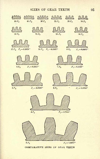
SIZES OF GEAR TEETH 95
36 Pd 32 Pd 28 Pd 24 Pd
20 P 16 P 14 P
2 Pd Pc= 0.2618" 10 /Jd />c = 0.3142'' 9 Pd 7% -0.3491'
3 Pd Pc= 1.0472"
COMPARATIVE SIZES OF GEAR TEETH
96 GEAKS
Exercises. Review
1. Find the number of teeth on a spur gear having an
outside diameter of 4.4" and a pitch of 10.
2. Find the pitch diameter of a spur gear that has 32
teeth and a pitch of 10.
3. In Ex. 2 find the outside diameter.
4. Find the pitch of a gear in which ^ = 6.2832".
5. Find the center distance of two 12-JJ gears in mesh
that have 66 teeth and 54 teeth respectively.
6. Find the circular pitch of a gear that has a pitch of 34.
7. Find the whole depth of a tooth on a rack that has a
linear pitch of 0.1745".
When referring to a rack the term **linear pitch
"is used in place
of the term "circular pitch."
8. Find the pitch diameter of a gear with 42 teeth and a
circular pitch of 0.2618".
9. The velocity ratio of two gears in mesh is 3 to 5 and
the center distance is 24". Find the pitch diameters.
10. If the pitch of the gears in Ex. 9 is 4, what is the
number of teeth on each gear?
11. In Ex. 10 what is the outside diameter of each gear?
12. Find the pitch of a spur gear that has 80 teeth and
an outside diameter of 16.4".
13. If a spur gear has a pitch of 36, what is the working
depth of a tooth?
14. If the circular pitch of a gear is 0.1653", what is the
addendum ? the thickness of tooth on the pitch line ?
15. If a gear has 140 teeth and an outside diameter of
10}", what is the pitch ?
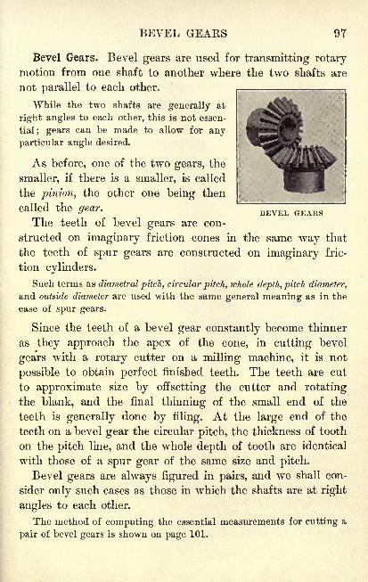
BEVEL GEARS 97
BEVEL GEARS
Bevel Gears. Bevel gears are used for transmitting rotarymotion from one shaft to another where the two shafts are
not parallel to each other.
While the two shafts are generally at
right angles to each other, this is not essen-
tial; gears can be made to allow for any
particular angle desired.
As before, one of the two gears, the
smaller, if there is a smaller, is called
the pinion, the other one being then
called the gear.
The teeth of bevel gears are con-
structed on imaginary friction cones in the same way that
the teeth of spur gears are constructed on imaginary fric-
tion cylinders.
Such terms as diametral pitch, circular pitch, whole depth, pitch diameter,
and outside diameter are used with the same general meaning as in the
case of spur gears.
Since the teeth of a bevel gear constantly become thinner
as they approach the apex of the cone, in cutting bevel
gears with a rotary cutter on a milling machine, it is not
possible to obtain perfect finished teeth. The teeth are cut
to approximate size by offsetting the cutter and rotating
the blank, and the final thinning of the small end of the
teeth is generally done by filing. At the large end of the
teeth on a bevel gear the circular pitch, the thickness of tooth
on the pitch line, and the whole depth of tooth are identical
with those of a spur gear of the same size and pitch.
Bevel gears are always figured in pairs, and we shall con-
sider only such cases as those in which the shafts are at right
angles to each other.
The method of computing the essential measurements for cutting a
pair of bevel gears is shown on page 101.
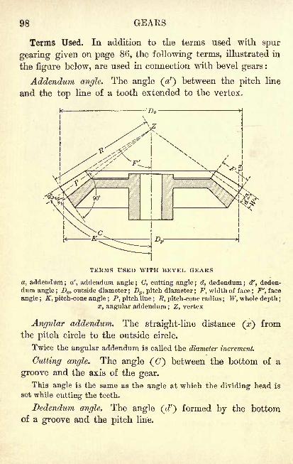
98 GEARS
Terms Used. In addition to the terms used with spur
gearing given on page 86, the following terms, illustrated in
the figure below, are used in connection with bevel gears :
Addendum angle. The angle (V) between the pitch line
and the top line of a tooth extended to the vertex.
TERMS USED WITH BEVEL GEARS
a, addendum; a', addendum angle ; (7, cutting angle ; d, dedendum ; d', deden-
dum angle ;D
,outside diameter
;Dp , pitch diameter; F, width of face
; F', face
angle ; K, pitch-cone angle ; P, pitch line; /?, pitch-cone radius
; W, whole depth ;
x, angular addendum ; Z, vertex
Angular addendum. The straight-line distance (x) from
the pitch circle to the outside circle.
Twice the angular addendum is called the diameter increment.
Cutting angle. The angle (C) between the bottom of a
groove and the axis of the gear.
This angle is the same as the angle at which the dividing head is
set while cutting the teeth.
Dedendum angle. The angle (d1
) formed by the bottomof a groove and the pitch line.
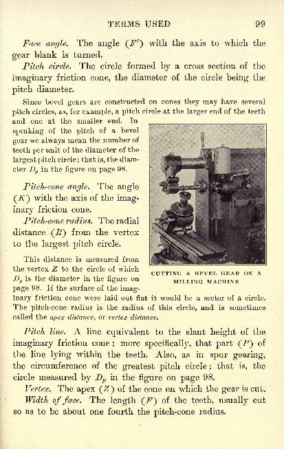
TERMS USED 99
Face angle. The angle (/'7
') with the axis to which the
gear blank is turned.
Pitch circle. The circle formed by a cross section of the
imaginary friction cone, the diameter of the circle being the
pitch diameter.
Since bevel gears are constructed on cones they may have several
pitch circles, as, for example, a pitch circle at the larger end of the teeth
and one at the smaller end. In
speaking of the pitch of a bevel
gear we always mean the number of
teeth per unit of the diameter of the
largest pitch circle;that is, the diam-
eter Dp in the figure on page 98.
Pitch-cone angle. The angle
(7f) with the axis of the imag-
inary friction cone.
Pitch-cone radius. The radial
distance (J) from the vertex
to the largest pitch circle.
This distance is measured from
the vertex Z to the circle of which
Dp is the diameter in the figure on
page 98. If the surface of the imag-
inary friction cone were laid out flat it would be a sector of a circle.
The pitch-cone radius is the radius of this circle, and is sometimes
called the apex distance, or vertex distance.
Pitch line. A line equivalent to the slant height of the
imaginary friction cone ; more specifically, that part (P) of
the line lying within the teeth. Also, as in spur gearing,
the circumference of the greatest pitch circle ; that is, the
circle measured by Dp in the figure on page 98.
Vertex. The apex (Z) of the cone on which the gear is cut.
Width of face. The length (.F) of the teeth, usually cut
so as to be about one fourth the pitch-cone radius.
CUTTING A BEVEL GEAR ON AMILLING MACHINE
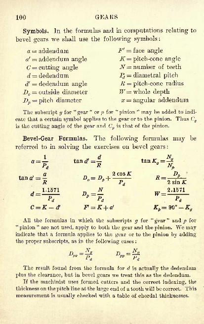
100 GEARS
Symbols. In the formulas and in computations relating to
bevel gears we shall use the following symbols :
a = addendum F 1 = face angle
a' = addendum angle K= pitch-cone angle
C = cutting angle N= number of teeth
d = dedendum Pd = diametral pitch
d' = dedendum angle R = pitch-cone radius
D = outside diameter W= whole depthDp = pitch diameter x = angular addendum
The subscript g for"gear
"or p for
"pinion
"may be added to indi-
cate that a certain symbol applies to the gear or to the pinion. Thus Cg
is the cutting angle of the gear and Cp is that of the pinion.
Bevel-Gear Formulas. The following formulas may be
referred to in solving the exercises on bevel gears :
All the formulas in which the subscripts g for"gear
" and p for"pinion
"are not used, apply to both the gear and the pinion. We may
indicate that a formula applies to the gear or to the pinion by addingthe proper subscripts, as in the following cases :
D=j? D =
T?^d rd
The result found from the formula for d is actually the dedendum
plus the clearance, but in bevel gears we treat this as the dedendum.If the machinist uses formed cutters and the correct indexing, the
thickness on the pitch line at the large end of a tooth will be correct. This
measurement is usually checked with a table of chordal thicknesses.
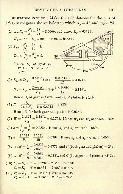
BEVEL-GEAR FORMULAS 101
Illustrative Problem. Make the calculations for the pair of
-7J bevel gears shown below in which Ng= 48 and Np
= 24.
(1) tan Kg= a. = = 2.0000, and hence K
g= 63 26'.
JNp 24
Kp= 90 - K
g= 90 -63 26' = 26 34'.
Hence Dp of gear is
4" and Z)p of pinionis 2".
= 4
> v 8Q44
Hence D of gear is 4.075" and D of pinion is 2.149".
Dp 4~2 sinKy
~2 x 0.8945
5 '
Hence R for both gear and pinion is 2.236".
= 0.1798. Hence Wgand Wp are each 0.180".(5) W = =
(6) a = = = 0.0833. Hence agand ap are each 0.083".
(7) d = = 0.0964. Hence dgand dp are each 0.096".
(8) tan a' = - = ' = 0.0373, and a' (both gear and pinion)= 2 8'.'''
(9) tan d' = = ' = 0.0431, and ef (both gear and pinion)= 2 28
7.
-R 2.23o9
(10) Cg= K
g-d' = 63 26' - 2 28' = 60 58'.
Cp = Kp -d' = 26 34' - 2 28' = 24 6'.
(11) F'g= K
g + a' = 63 26' + 2 8' = 6534 X.
F' = K + a' = 2634' + 28/ = 2842 /.
102 GEAKS
Exercises. Bevel Gears
For a pair of level gears, if it is required that Pd 9, Ng
= 36,
and Np = 18, find each of the following :
1. The pitch diameters of both the gear and the pinion.
2. The pitch-cone angles of both the gear and the pinion.
3. The outside diameters of both the gear and the pinion.
4. The pitch-cone radius.
5. The whole depth of the teeth.
6. The addendum and the dedendum.
7. The addendum angle and the dedendum angle.
8. The cutting angles of both the gear and the pinion.
9. The face angles of both the gear and the pinion.
10. The thickness of tooth on the pitch line.
This measurement at the large end of the teeth may be calculated
from one of the spur-gearing formulas for t given on page 88, but it
is not an essential measurement when the gear is cut with formed
cutters. As a check, however, the thickness of tooth is usually measured
with a special gear-tooth vernier caliper and compared with a table of
chordal thicknesses of gear teeth, since the caliper measures the chordal
thickness and not the thickness of tooth along the pitch circle.
Make all the necessary calculations for cutting each of the
following pairs of bevel gears :
11. Gear, 52 teeth; pinion, 36 teeth; pitch, 14.
12. Gear, 45 teeth ; pinion, 15 teeth ; pitch, 10.
13. Gear, 56 teeth ; pinion, 32 teeth ; pitch, 8.
14. Gear, 48 teeth; pinion, 12 teeth; pitch, 14.
15. Gear, 60 teeth; pinion, 18 teeth; pitch, 12.
The elements required in making the calculations for cutting a pairof bevel gears are shown on page 101.
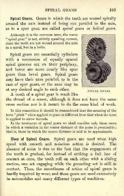
SPIRAL GEARS 103
SPIRAL GEARS
Spiral Gears. Gears in which the teeth are wound spirally
around the axis instead of being cut parallel to the axis,
as in a spur gear, are called spiral gears or helical gears.
Although it is the common term, the name"spiral gear
"is not, strictly speaking, correct,
since the teeth are not wound around the axis
in a spiral, but in a helix.
Spiral gears are essentially cylinders
with a succession of equally spaced
spiral grooves cut on their periphery,
and hence are more nearly like spur
gears than bevel gears. Spiral gears
may have their axes parallel, as in the
case of spur gears, or the axes may be
at any desired angle to each other.
A tooth of a spiral gear is much like
the thread of a screw, although it does not have the same
cross section nor is it meant to do the same kind of work.
In this connection it should be remembered that the meaning of the
term "pitch
" when applied to gears is different from that when the term
is applied to screw threads.
In the treatment of spiral gears we shall consider only those cases
in which a variation in the center distance of the gears is permissible ;
that is, those in which the center distance is said to be approximate.
Uses of Spiral Gears. Spiral gears are used when high
speed with smooth and noiseless action is desired. Theabsence of noise is due to the fact that the engagement of
the teeth is gradual, for instead of striking a full line of
contact at once, the teeth roll on each other with a sliding
motion, one set engaging while the preceding set is still in
contact. Thus, the smoothness of action of spiral gears is
hardly impaired by wear, and these gears are used extensivelyin automobiles and many different types of machines.
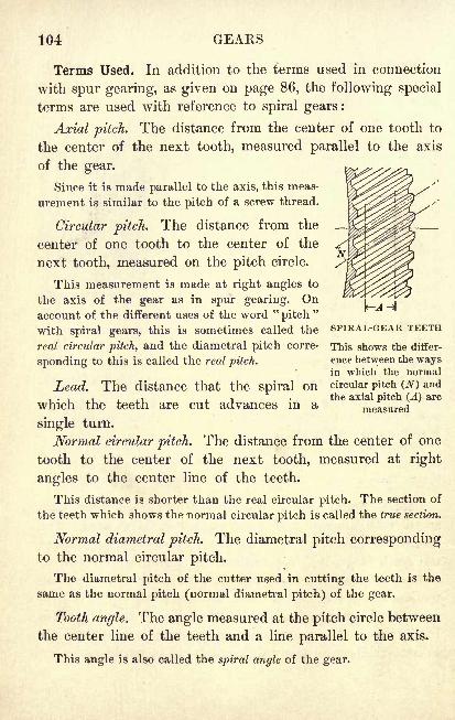
104 GEARS
Terms Used. In addition to the terms used in connection
with spur gearing, as given on page 86, the following special
terms are used with reference to spiral gears :
Axial pitch. The distance from the center of one tooth to
the center of the next tooth, measured parallel to the axis
of the gear.
Since it is made parallel to the axis, this meas-
urement is similar to the pitch of a screw thread.
Circular pitch. The distance from the
center of one tooth to the center of the
next tooth, measured on the pitch circle.
This measurement is made at right angles to
the axis of the gear as in spur gearing. Onaccount of the different uses of the word "
pitch"
with spiral gears, this is sometimes called the SPIRAL-GEAR TEETH
real circular pitch, and the diametral pitch corre- This shows the differ-
sponding to this is called the real pitch.ence between the waysin which the normal
Lead. The distance that the spiral on circular pitch (N) and
, . , ., ., , . the axial pitch (A) arewhich the teeth are cut advances in a measured
single turn.
Normal circular pitch. The distance from the center of one
tooth to the center of the next tooth, measured at right
angles to the center line of the teeth.
This distance is shorter than the real circular pitch. The section of
the teeth which shows the normal circular pitch is called the true section.
Normal diametral pitch. The diametral pitch correspondingto the normal circular pitch.
The diametral pitch of the cutter used in cutting the teeth is the
same as the normal pitch (normal diametral pitch) of the gear.
Tooth angle. The angle measured at the pitch circle between
the center line of the teeth and a line parallel to the axis.
This angle is also called the spiral angle of the gear.
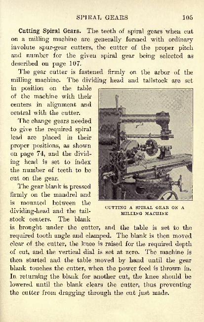
SPIRAL GEARS 105
Cutting Spiral Gears. The teeth of spiral gears when cut
on a milling machine are generally formed with ordinaryinvolute spur-gear cutters, the cutter of the proper pitchand number for the given spiral gear being selected as
described on page 107.
The gear cutter is fastened firmly on the arbor of the
milling machine. The dividing head and tailstock are set
in position on the table
of the machine with their
centers in alignment and
central with the cutter.
The change gears needed
to give the required spiral
lead are placed in their
proper positions, as shown
on page 74, and the divid-
ing head is set to index
the number of teeth to be
cut on the gear.
The gear blank is pressed
firmly on the mandrel and
is mounted between the
dividing-head and the tail-
stock centers. The blank
is brought under the cutter, and the table is set to the
required tooth angle and clamped. The blank is then movedclear of the cutter, the knee is raised for the required depthof cut, and the vertical dial is set at zero. The machine is
then started and the table moved by hand until the gearblank touches the cutter, when the power feed is thrown in.
In returning the blank for another cut, the knee should be
lowered until the blank clears the cutter, thus preventingthe cutter from dragging through the cut just made.
CUTTING A SPIRAL GEAR ON AMILLING MACHINE
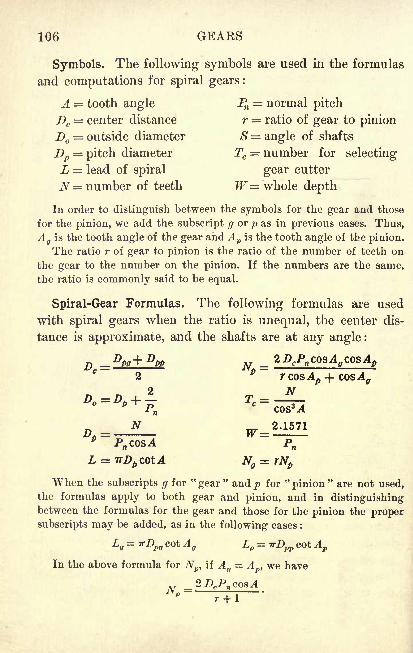
106 GEARS
Symbols. The following symbols are used in the formulas
and computations for spiral gears:
A = tooth angle Pn = normal pitch
Dc= center distance r = ratio of gear to pinion
D = outside diameter S = angle of shafts
Dp= pitch diameter Tc
= number for selecting
L = lead of spiral gear cutter
N= number of teeth W= whole depth
In order to distinguish between the symbols for the gear and those
for the pinion, we add the subscript g or p as in previous cases. Thus,A
gis the tooth angle of the gear and Ap is the tooth angle of the pinion.
The ratio r of gear to pinion is the ratio of the number of teeth on
the gear to the number on the pinion. If the numbers are the same,
the ratio is commonly said to be equal.
Spiral-Gear Formulas. The following formulas are used
with spiral gears when the ratio is unequal, the center dis-
tance is approximate, and the shafts are at any angle :
When the subscripts g for "gear" and/> for "pinion" are not used,
the formulas apply to both gear and pinion, and in distinguishingbetween the formulas for the gear and those for the pinion the proper
subscripts may be added, as in the following cases :
Lg= '
Tfl)pg cot A g Lp = irDpp cot ApIn the above formula for N
ptif A
g= Ap , we have
, T _2DcPn cosA
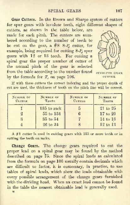
SPIRAL GEARS 107
Gear Cutters. In the Brown and Sharpe system of cutters
for spur gears with involute teeth, eight different shapes of
cutters, as shown in the table below, are
made for each pitch. The cutters are num-
bered according to the number of teeth to
be cut on the gear, a #8 %-Pd cutter, for
example, being required for cutting 8-Pz spur
gears with 12 or 13 teeth. For cutting a
spiral gear the proper number of cutter of
the normal pitch of the gear is selected
from the table according to the number found INVOLUTE GEAR
by the formula for Tc on page 106. CUTTER
If with these cutters the correct indexing and the proper depth of
cut are used, the thickness of tooth on the pitch line will be correct.
NUMBER OF
CUTTER
108 GEARS
Illustrative Problem. Make the calculations for cutting a
pair of spiral gears in which it is required that r = 4, Pn = 6,
Dc (approximate)= 12", Ag
= 30, Ap= 20, and S= 50.
r2DcPn cosA ff
cosA p _ 2 x 12 x 6 x 0.8660 x 0.9397 _ 25 op = rcoaAp + coaA
ff4 x 0.9397 + 0.8660
Such a result is taken to the nearest whole number, in this case 25.
Ng= rNp = 4 x 25 = 100.
The gear and pinion have 100 teeth and 25 teeth respectively.
no 9456=
p 6 x 0.9397
The pitch diameters of gear and pinion are 19.246" and 4.434".
(3) Dog= Dpg +^ = 19.2456 + | = 19.5789.
* n
DoP= Dpp + - = 4.4340 + | = 4.7673.
* n
The outside diameters of gear and pinion are 19.579" and 4.767".
(4) Lg= irDpg cotA g
= 3.1416 x 19.2456 x 1.7321 = 104.7262.
Lp = irDpp coiAp = 3.1416 x 4.4340 x 2.7475 = 38.2724.
The leads of the spirals on gear and pinion are 104.73" and 38.27".
1QO _ 154 n~
301cos3Ap 0.9397 3
"0.8298
"
From the table on page 107 we see that a #1 Q-P(lcutter is required
for the gear and a #4 6-Prfcutter for the pinion.
The whole depth of tooth on both gear and pinion is 0.360''.
(7) Dc=
J (Dpg + Dpp)=
$ (19.2456 + 4.4340) - 11.8398.
The "exact" center distance of the gears is 11.840".
SPIRAL GEARS 109
Exercises. Spiral Gears at Any Angle
For a pair of spiral gears, if it is required that r = 2, Pn = 10,
Dc (approximate) = 10", Ag=30, A
p= 20, and S= 50, find
each of the following :
1. The number of teeth on the gear and on the pinion.
2. The pitch diameters of both the gear and the pinion.
3. The outside diameters of both the gear and the pinion.
4. The leads of the spirals on both the gear and the pinion.
5. The numbers of the two cutters required.
6. The whole depth of the teeth.
7. The exact center distance of the gears.
For a pair of spiral gears, if it is required that r = 3, J^=4,Dc (approximate) = 16' f
, Ag=40, Ap=20, and S = 60, find
each of the following :
8. The number of teeth on the gear and on the pinion.
9. The pitch diameters of both the gear and the pinion.
10. The outside diameters of both the gear and the pinion.
11. The leads of the spirals on both the gear and the pinion.
12. The numbers of the two cutters required.
13. The whole depth of the teeth.
14. The exact center distance of the gears.
15. Make the necessary calculations for cutting a pair of
spiral gears, it being required that Dc (approximate) = 1",
r = l^, Pn =S, Ag=25, 4,= 15, and S=40.
16. Make the necessary calculations for cutting a pair of
spiral gears, it being required that Dc (approximate)= 1 2",
r = 4, %=$, 4,= 30, 4,= 30, and S=60.
In finding Np use the formula given at the foot of page 106.
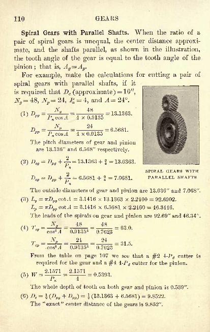
110 GEARS
Spiral Gears with Parallel Shafts. When the ratio of a
pair of spiral gears is unequal, the center distance approxi-
mate, and the shafts parallel, as shown in the illustration,
the tooth angle of the gear is equal to the tooth angle of the
pinion ; that is, Ag=Ap.
For example, make the calculations for cutting a pair of
spiral gears with parallel shafts, if it
is required that Dc (approximate) = 10",
Ng= 48, Np= 24, % = 4, and A= 24.
CD ft,"
99 Pn cosA
4 x 0.9135
24
= 13.1363.
= 6.5681.4 x 0.9135
The pitch diameters of gear and pinionare 13.136" and 6.568" respectively.
(2) Dog= = 13.1363 + f = 13.6363.
= 6.5681*
= 7.0681.
SPIRAL GEARS WITHPARALLEL SHAFTS
The outside diameters of gear and pinion are 13.636" and 7.068".
(3) Lg= TrD
pg cotA = 3.1416 x 13.1363 x 2.2460 = 92.6902.
Lp = irDpp cotA = 3.1416 x 6.5681 x 2.2460 = 46.3446.
The leads of the spirals on gear and pinion are 92.69" and 46.34".
Ng 48 48
cos3 .!
~
Nn
(4) Tcg=
TCP
0.913530.762.3
24 24
= 63.0.
= 31.5.ooeM 0.91353 0.7623
From the table on page 107 we see that a #2 4-Pd cutter is
required for the gear and a #4 4-Pd cutter for the pinion.
(5) W =-*
= 0.5393.
The whole depth of tooth on both gear and pinion is 0.539".
(6) Dc= $ (Dpg + Dpp) = $ (13.1363 + 6.5681)
= 9.8522.
The "exact" center distance of the gears is 9.852".
SPIRAL GEARS 111
Exercises. Spiral Gears with Parallel Shafts
1. For a certain pair of spiral gears it is required that the
shafts be parallel at an approximate center distance of 2^",that JV^=32, Np =20, Pn =l2, and ^=18. Find the pitchdiameters of both the gear and the pinion.
2. In Ex. 1 find the outside diameters of both the gearand the pinion.
3. In Ex. 1 find the leads of the spirals on both the gearand the pinion.
4. In Ex. 1 find the number of the cutter to be used for
cutting the gear and the same for the pinion.
5. In Ex. 1 find the whole depth of the teeth.
6. In Ex. 1 find the exact center distance.
For a pair of spiral gears, if it is required that the shafts
be parallel, that Dc (approximate) = 12-j-",r =
1-j,Pn = 6, and
A = 20, find each of the following :
7. The number of teeth on the gear and on the pinion.
In finding Np use the formula given at the foot of page 108.
8. The pitch diameters of both the gear and the pinion.
9. The outside diameters of both the gear and the pinion.
10. The leads of the spirals on both the gear and the pinion.
11. The number of the cutter to be used for cutting the
gear and the same for the pinion.
12. The whole depth of the teeth.
13. The exact center distance of the gears.
14. A spiral gear with a pitch diameter of 6.2121" has a
spiral lead of 72.83". Find the angle at which the milling-
machine table was set in cutting the gear.
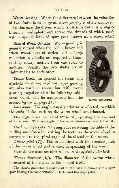
112 GEAES
Worm Gearing. When the difference between the velocities
of two shafts is to be great, worm gearing is often employed.
In this case the driver, which is called a worm, is a single-
thread or multiple-thread screw, the threads of which mesh
with a special form of spur gear known as a worm wheel.
Uses of Worm Gearing. Worm gearing is
generally used when the load is heavy and
when smoothness of action and a large
reduction in velocity are required in trans-
mitting rotary motion from one shaft to
another. Usually the two shafts are at
right angles to each other.
Terms Used. In general the terms and
symbols which are used with spur gearingare also used in connection with worm
gearing, together with the following addi-
tions, which will be understood from the
second figure on page 113:
Face angle. The angle, usually arbitrarily selected, to which
the ends of the teeth on the worm wheel are trimmed.
This angle varies from about 55 to 65, depending upon the kind
of worm used. The face angle of the wheel shown on page 113 is 60.
Gashing angle (). The angle for swiveling the table of the
milling machine when cutting the teeth on the worm wheel to
correspond to the spiral angle of the thread on the worm.
Linear pitch (JJ). This is identical with the circular pitch
of the worm wheel and is used in speaking of the worm.
Since the two terms are identical, we use the symbol Pc for both.
Throat diameter (!><). The diameter of the worm wheel
measured at the center of the curved teeth.
The throat diameter is equivalent to the outside diameter of a spur
gear having the same number of teeth and the same pitch.
WORM GEARING
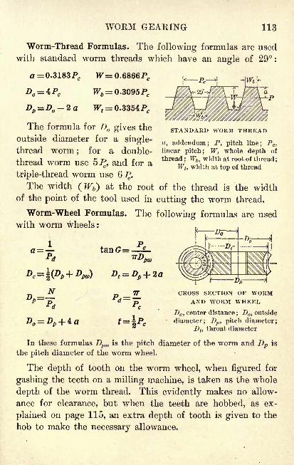
WORM GEARING 113
Worm-Thread Formulas. The following formulas are used
with standard worm threads which have an angle of 29 :
a = 0.3183PC W- 0.6866PC
Dp =D -2a Wt= 0.3354Pc
The formula for D gives the
outside diameter for a single-
thread worm; for a double-
thread worm use 5^, and for a
triple-thread worm use
The width (JF6) at the root
of the point of the tool used in
Worm-Wheel Formulas. Thewith worm wheels:
STANDARD WORM THREAD
a, addendum; P, pitch line; Pc ,
linear pitch; W, whole depth of
thread;Wb , width at root of thread
;
Wt ,width at top of thread
of the thread is the width
cutting the worm thread.
following formulas are used
tanG= PC
TTD'pw
n _J^ p _ IT CROSS SECTION OF WORMP~~~p~ **=
|Br AND WORM WHEEL* d * c
Dc ,center distance
;D
, outside
DQ= Dp -J- 4 a t= \Pc
'
diameter; Dp , pitch diameter;Dt ,
throat diameter
In these formulas Dpw is the pitch diameter of the worm and Dp is
the pitch diameter of the worm wheel.
The depth of tooth on the worm wheel, when figured for
gashing the teeth on a milling machine, is taken as the whole
depth of the worm thread. This evidently makes no allow-
ance for clearance, but when the teeth are hobbed, as ex-
plained on page 115, an extra depth of tooth is given to the
hob to make the necessary allowance.
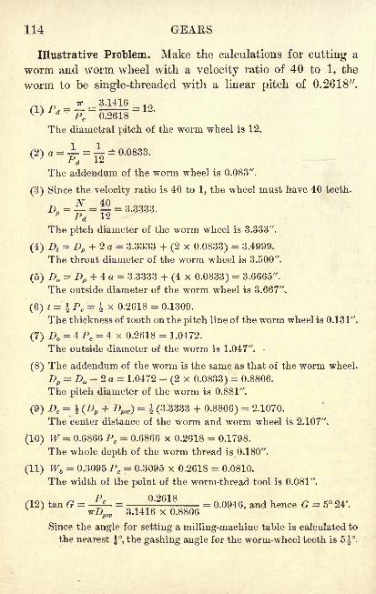
114 GEARS
Illustrative Problem. Make the calculations for cutting a
worm and worm wheel with a velocity ratio of 40 to 1, the
worm to be single-threaded with a linear pitch of 0.2618".
_ TT _ 3.1416 _(1)Pd -Fc ~2618-
The diametral pitch of the worm wheel is 12.
(2) a = -L = =0.0833.
The addendum of the worm wheel is 0.083".
(3) Since the velocity ratio is 40 to 1, the wheel must have 40 teeth.
_^_40p~
~P~d
~12~
The pitch diameter of the worm wheel is 3.333".
(4) Dt= Dp + 2 a = 3.3333 + (2 x 0.0833) = 3.4999.
The throat diameter of the worm wheel is 3.500".
(5) D = Dp + 4 a = 3.3333 + (4 x 0.0833) = 3.6665".
The outside diameter of the worm wheel is 3.667".
(6) t = \PC= % x 0.2618 = 0.1309.
The thickness of tooth on the pitch line of the worm wheel is 0.131".
(7) D = 4 Pc= 4 x 0.2618 = 1.0472.
The outside diameter of the worm is 1.047".
(8) The addendum of the worm is the same as that of the worm wheel.
Dp= D -2a = 1.0472 - (2 x 0.0833) = 0.8806.
The pitch diameter of the worm is 0.881".
(9) Dc= } (Dp + Dpw)
= i(3.3333 + 0.8806) = 2.1070.
The center distance of the worm and worm wheel is 2.107".
(10) W = 0.6866 Pc= 0.6866 x 0.2618 = 0.1798.
The whole depth of the worm thread is 0.180".
(11) Wb= 0.3095 Pc
= 0.3095 x 0.2618 = 0.0810.
The width of the point of the worm-thread tool is 0.081".
-p A Oftl Q
(12) tan G =^- =3 1416 x .8806
= 0.0946, and hence G = 5 24'.
Since the angle for setting a milling-machine table is calculated to
the nearest \, the gashing angle for the worm-wheel teeth is 5 \.
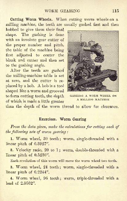
WORM GEARING 115
Cutting Worm Wheels. When cutting worm wheels on a
milling machine, the teeth are usually gashed first and then
hobbed to give them their final
shape. The gashing is done
with an involute gear cutter of
the proper number and pitch,
the table of the machine beingfirst adjusted to center the
blank and cutter and then set
to the gashing angle.
After the teeth are gashedthe milling-machine table is set
at zero, and the cutter is re-
placed by a hob. A hob is a tool
shaped like a worm and groovedto form cutting teeth, the depth
GASHING A WORM WHEEL ON,. i
. T . T T.^T A MILLING MACHINEof which is made a little greaterthan the depth of the worm thread to allow for clearance.
Exercises. Worm Gearing
From the data given, make the calculations for cutting each ofthe following sets of worm gearing :
1. Worm wheel, 30 teeth; worm, single-threaded with a
linear pitch of 0.3927".
2. Velocity ratio, 20 to 1 ; worm, double-threaded with a
linear pitch of 0.5236".
Each revolution of this worm will move the worm wheel two teeth.
3. Worm wheel, 24 teeth; worm, single-threaded with a
linear pitch of 0.2244".
4. Worm wheel, 96 teeth; worm, triple-threaded with a
lead of 2.3562".
116 GEAKS
Exercises. Gears
1. If, in a spur gear, D = 2.228" and Pc = ^", what is
the number of teeth?
2. If an 8-Pd spur gear has 203 teeth, what is D ?
3. Find the whole depth of tooth for a |-JJ spur gear.
4. Find the circular pitch for a 32-T spur gear in which
it is required that Dp 16.55".
5. Two 8-JJ bevel gears are to have 80 teeth and 20 teeth
respectively. Make the calculations for cutting the gears.
6. If a 20-inch spur gear has 198 teeth, what is the pitch ?
7. If the circular pitch of a spur gear is 2|", what is the
addendum? the whole depth of tooth?
8. If it is required that a worm wheel is to have 20 teeth
and the worm a single thread with a linear pitch of 0.3142",
make the calculations for cutting the gearing.
9. If a 39-T spur gear has a pitch of 31, what is D ?
10. Make the necessary calculations for cutting a pair of
spiral gears, it being required that Dc (approximate) = 12",
Pn =6, ^=30, ^=30, =60, andr=3.
11. A lf-^J spur gear has a pitch diameter of 97.14".
Find the outside diameter and the number of teeth.
12. Make the calculations for cutting a pair of bevel gears,
it being required that the pitch be 5, the number of teeth on
the pinion 17, and the velocity ratio 3 to 1.
13. A worm wheel is to have 60 teeth and is to mesh with a
double-thread worm having a linear pitch of 1.0472". Makeall the calculations for cutting the gearing.
14. Find the pitch diameters of two spur gears in mesh if
the center distance between the gears is 12", and one gearhas 40 teeth and the other 20 teeth.
CHAPTER VII
REVIEW PROBLEMS
Exercises. General Applications
Change the following tapers per inch to tapers per foot :
1. 0.0762". 2. 0.08175". 3. 0.0162". 4. 0.0542".
5. If the outside diameter of a spur gear is 4J" and the
pitch is 18, what is the number of teeth ?
6. Find the tap-drill size of a l|-inch U. S. S. thread.
7. If a quadruple-thread screw has 16 threads per inch,
what is the pitch and what is the lead ?
8. Find the change gears required on a lathe, which has
a lead screw with 5 threads to the inch,when cutting a metric
thread with a lead of 1.5 mm.
Assume that the lathe is equipped with a 127-T gear.
9. Two 12-7J spur gears in mesh have 66 teeth and 40
teeth respectively. Find the center distance.
10. Find the pitch diameter of a spur gear having 37 teeth
and a pitch of 10.
11. If a spiral lead of 27" is to be cut on a J-inch drill,
to what angle should the milling-machine table be set ?
12. Find the indexing required on a B. & S. dividing head
for milling a ratchet wheel with grooves 13J apart.
13. Find the outside diameter of a 96-T spur gear which
has a pitch of 14.
117
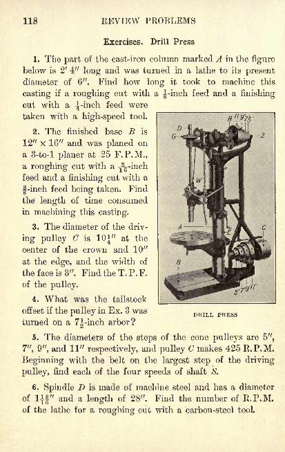
118 REVIEW PROBLEMS
Exercises. Drill Press
1. The part of the cast-iron column marked A in the figure
below is 2' 4" long and was turned in a lathe to its present
diameter of 6". Find how long it took to machine this
casting if a roughing cut with a |-inch feed and a finishing
cut with a ^-inch feed were
taken with a high-speed tool.
2. The finished base B is
12" x 16" and was planed on
a 3-to-l planer at 25 F.P.M.,a roughing cut with a y^-inchfeed and a finishing cut with a
|-inch feed being taken. Find
the length of time consumed
in machining this casting.
3. The diameter of the driv-
ing pulley C is 10 J" at the
center of the crown and 10"
at the edge, and the width of
the face is 3". Find the T. P. F.
of the pulley.
4. What was the tailstock
offset if the pulley in Ex. 3 was
turned on a 7J-inch arbor?
5. The diameters of the steps of the cone pulleys are 5",
7", 9", and 11" respectively, and pulley C makes 425 R.P.M.
Beginning with the belt on the largest step of the driving
pulley, find each of the four speeds of shaft S.
6. Spindle D is made of machine steel and has a diameter
of llf" and a length of 28". Find the number of R.P.M.of the lathe for a roughing cut with a carbon-steel tool.
DRILL PRESS
DKILL PEESS 119
7. The spindle in Ex. 6 was turned from round stock,
a roughing cut with a Tl
g-inch feed and a finishing cut with
a 0.01 5-inch feed being taken with a high-speed steel tool.
Find the time taken in machining the spindle.
8. If the adjusting screw E has a U. S. S. thread of
Jg-inch pitch, what is the root diameter of the screw ?
9. Find the change gears required on a lathe, which has
a lead screw with 5 threads per inch, in cutting screw E.
10. Bevel gear G is a 14-JJ gear with 51 teeth, and the
pinion meshing with it has 17 teeth. Make all the necessarycalculations for cutting this pair of gears.
11. If spur gear E has 71 teeth and a circular pitch of
0.3491", what is its outside diameter?
12. In Ex. 11 find the addendum and the whole depthof tooth of gear R.
13. Find the indexing required on a B. & S. dividing head
in cutting gear E.
14. Worm W is a single-thread screw with a linear pitch
of 0.2244", and meshes with a worm wheel having 25 teeth.
Make the calculations for cutting the worm and wheel.
15. If the adjusting screw E has an Acme screw thread
with a pitch of 0.1111", find the depth, the width at the
top of the thread, and the number of threads per inch.
16. The circular table of the drill press is made of cast
iron and has a diameter of 27" and a thickness of 14".o
Find the time required for machining the circumference, a
roughing cut with a feed of 0.05" and a finishing cut with
a feed of 0.125" being taken with a high-speed steel tool.
17. Find the number of R.P.M. for boring the center hole
in the circular table in Ex. 16 to a diameter of 1^" with a
carbon-steel tool.
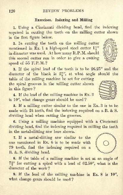
120 EEVIEW PROBLEMS
Exercises. Indexing and Milling
1. Using a Cincinnati dividing head, find the indexing
required in cutting the teeth on the milling cutter shown
in the first figure below.
2. In cutting the teeth on -the milling cutter
mentioned in Ex. 1 a high-speed steel cutter 1J"in diameter was used. At how many R. P. M. should
this second cutter run in order to give a cutting
speed of 55 F.P.M.?
3. If the spiral lead of the teeth is to be 26.25" and the
diameter of the blank is 2J", at what angle should the
table of the milling machine be set for cutting
the spiral grooves in the milling cutter shown
in this figure ?
4. If the lead of the milling machine in Ex. 3
is 10'-, what change gears should be used ?
5. If a milling cutter similar to the one in Ex. 3 is to be
made with 24 teeth, find the indexing required on a B. & S.
dividing head when cutting the grooves.
6. Using a milling machine equipped with a Cincinnati
dividing head, find the indexing required in milling the teeth
in the metal-slitting saw here shown.
7. If a metal-slitting saw similar to the
one mentioned in Ex. 6 is to be made with
79 teeth, find the indexing required on a
B. &. S. dividing head.
8. If the table of a milling machine is set at an angle of
7| for cutting a spiral with a lead of 62.50", what is the
diameter of the work ?
9. If the lead of the milling machine in Ex. 8 is 10",
what change gears should be used ?
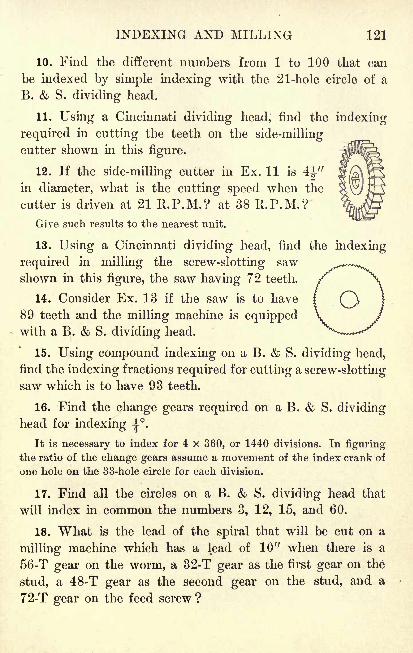
INDEXING AND MILLING 121
10. Find the different numbers from 1 to 100 that can
be indexed by simple indexing with the 21-hole circle of a
B. & S. dividing head.
11. Using a Cincinnati dividing head, find the indexing
required in cutting the teeth on the side-milling
cutter shown in this figure.
12. If the side-milling cutter in Ex. 11 is 4|"in diameter, what is the cutting speed when the
cutter is driven at 21 R.P.M.? at 38 R.P.M.?
Give such results to the nearest unit.
13. Using a Cincinnati dividing head, find the indexing
required in milling the screw-slotting saw
shown in this figure, the saw having 72 teeth.
14. Consider Ex. 13 if the saw is to have
89 teeth and the milling machine is equippedwith a B. & S. dividing head.
15. Using compound indexing on a B. & S. dividing head,
find the indexing fractions required for cutting a screw-slottingsaw which is to have 93 teeth.
16. Find the change gears required on a B. & S. dividinghead for indexing ^.
It is necessary to index for 4 x 360, or 1440 divisions. In figuring
the ratio of the change gears assume a movement of the index crank of
one hole on the 33-hole circle for each division.
17. Find all the circles on a B. & S. dividing head that
will index in common the numbers 3, 12, 15, and 60.
18. What is the lead of the spiral that will be cut on a
milling machine which has a lead of 10" when there is a
56-T gear on the worm, a 32-T gear as the first gear on the
stud, a 48-T gear as the second gear on the stud, and a
72-T gear on the feed screw ?
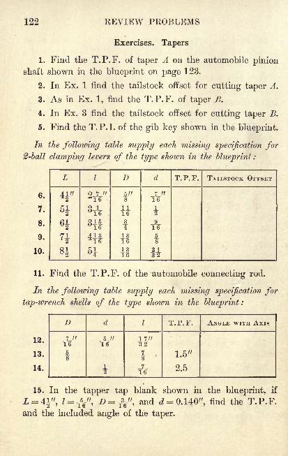
122 EEVIEW PROBLEMS
Exercises. Tapers
1. Find the T.P.F. of taper A on the automobile pinionshaft shown in the blueprint on page 123.
2. In Ex. 1 find the tailstock offset for cutting taper A.
3. As in Ex. 1, find the T.P.F. of taper B.
4. In Ex. 3 find the tailstock offset for cutting taper B.
5. Find the T.P.I, of the gib key shown in the blueprint.
In the following table supply each missing specification for2-ball clamping levers of the type shown in the blueprint :
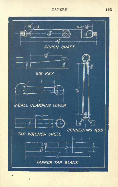
TAPERS 123
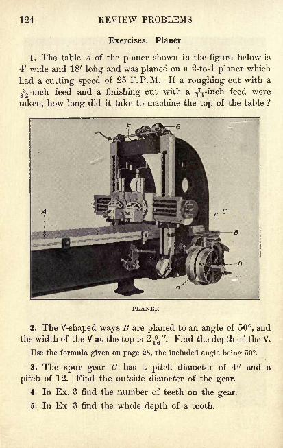
124 REVIEW PROBLEMS
Exercises. Planer
1. The table A of the planer shown in the figure below is
4' wide and 18' long and was planed on a 2-to-l planer which
had a cutting speed of 25 F.P.M. If a roughing cut with a
^32-inch feed and a finishing cut with a T
7g-mch feed were
taken, how long did it take to machine the top of the table ?
PLANER
2. The V-shaped ways B are planed to an angle of 50, and
the width of the V at the top is 2yy. Find the depth of the V.
Use the formula given on page 28, the included angle being 50.
3. The spur gear C has a pitch diameter of 4" and a
pitch of 12. Find the outside diameter of the gear.
4. In Ex. 3 find the number of teeth on the gear.
5. In Ex. 3 find the whole depth of a tooth.
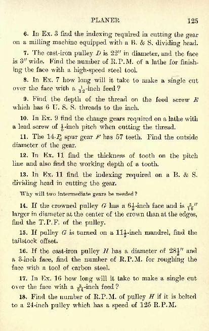
PLANER 125
6. In Ex. 3 find the indexing required in cutting the gearon a milling machine equipped with a B. & S. dividing head.
7. The cast-iron pulley D is 22" in diameter, and the face
is 3" wide. Find the number of R.P.M. of a lathe for finish-
ing the face with a high-speed steel tool.
8. In Ex. 7 how long will it take to make a single cut
over the face with a ^-inch feed ?
9. Find the depth of the thread on the feed screw Ewhich has 6 U. S. S. threads to the inch.
10. In Ex. 9 find the change gears required on a lathe with
a lead screw of ^-inch pitch when cutting the thread.
11. The 14-^ spur gear F has 57 teeth. Find the outside
diameter of the gear.
12. In Ex. 11 find the thickness of tooth on the pitchline and also find the working depth of a tooth.
13. In Ex. 11 find the indexing required on a B. & S.
dividing head in cutting the gear.
Why will two intermediate gears be needed ?
14. If the crowned pulley G has a 6i-inch face and isT5g"
larger in diameter at the center of the crown than at the edges,find the T.P.F. of the pulley.
15. If pulley G is turned on a Ill-inch mandrel, find the
tailstock offset.
16. If the cast-iron pulley H has a diameter of 28|-"
and
a 3-inch face, find the number of R.P.M. for roughing the
face with a tool of carbon steel.
17. In Ex. 16 how long will it take to make a single cut
over the face with a ^-inch feed ?
18. Find the number of R.P.M. of pulley H if it is belted
to a 24-inch pulley which has a speed of 125 R.P.M.
126 REVIEW PROBLEMS
Exercises. Drilling Machine
1. If motor A in the figure below makes 750 R.P.M., if
gear 1 on the motor has 24 teeth, and if gear 2 has 56 teeth,
what is the speed of the shaft to which gear 2 is fastened?
WALL RADIAL-DRILLING MACHINE
2. If the gears in Ex. 1 were spur gears with a pitch of 14,
what would be the respective outside diameters ?
3. What would be the center distance if gears 1 and 2
were spur gears which meshed together instead of being con-
nected by the endless chain ?
4. Find the indexing required on a Cincinnati dividing
head for cutting the gears in Ex. 3.
5. The 6-7J bevel gears B have 48 teeth and 16 teeth
respectively. Make the calculations for cutting these gears.
DRILLING MACHINE 127
6. The socket in spindle C is bored to a #4 Morse taper,which has a T.P.F. of 0.623". To what angle should a
compound rest be set to bore this taper?
7. Shaft Z>, which is made of machine steel, is 10' 6" longand has a diameter of If". Find the number of R.P.M. of
a* lathe for roughing the shaft with a high-speed steel tool.
8. In Ex. 7 find how long it will take to make a singlecut over the shaft with a feed of 0.015".
9. The worm wheel G has 60 teeth and it meshes with
a single-thread worm, the linear pitch of which is 0.1963".
Make the calculations for cutting the worm and wheel.
10. If the weight H is made of cast iron and is approxi-
mately 2|-" x 5|" x 8^-", find its approximate weight.
The weight of cast iron may be taken as 450 Ib. per cubic foot.
11. If the diameter at the middle of the l|-inch face of
the cast-iron wheel J is 4||" and that at the edge is 4|", what
is the T.P.F. of the wheel?
12. Using the smaller diameter in Ex. 11, at what speedshould the face be finished with a high-speed tool ?
13. In Ex. 11 find the time required for finishing 25 wheels
of this type, making a single cut with a gL-mch feed over the
face of each wheel.
14. Shaft D makes an angle of 22 with brace E and is
perpendicular to shaft F. If the distance between the axis
of shaft F and the vertex of the angle formed by Z> and Eis 9' 8", find to the nearest 0.1" the length of E between
the vertices of the angles formed by E with D and F.
The ratio D : E is what function of the angle between them ? This
example and Exs. 3-22 on page 134 may be omitted by those students
who have not had the equivalent of Chapter IV (Trigonometry) in" Fundamentals of Practical Mathematics "
in this series.
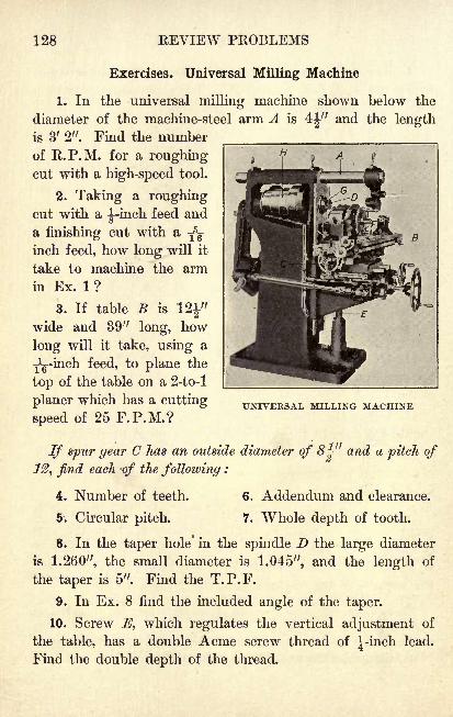
128 REVIEW PROBLEMS
Exercises. Universal Milling Machine
1. In the universal milling machine shown below the
diameter of the machine-steel arm A is 4J" and the lengthis 3' 2". Find the number
of R.P.M. for a roughingcut with a high-speed tool.
2. Taking a roughingcut with a ^-inch feed and
a finishing cut with a-j
5^
inch feed, how long will it
take to machine the arm
in Ex. 1 ?
3. If table B is
wide and 39" long, how
long will it take, using a
Jg-inch feed, to plane the
top of the table on a 2-to-l
planer which has a cutting
speed of 25 F.P.M.?UNIVERSAL MILLING MACHINE
If spur gear C has an outside diameter of 8j" and a pitch of
12, find each -of the following :
4. Number of teeth. 6. Addendum and clearance.
5 1
. Circular pitch. 7. Whole depth of tooth.
8. In the taper hole* in the spindle D the large diameter
is 1.260", the small diameter is 1.045", and the length of
the taper is 5". Find the T.P.F.
9. In Ex. 8 find the included angle of the taper.
10. Screw E, which regulates the vertical adjustment of
the table, has a double Acme screw thread of ^-inch lead.
Find the double depth of the thread.
UNIVERSAL MILLING MACHINE 129
11. In Ex. 10 find the change gears required on a lathe
with a lead screw of 1-inch pitch when cutting the thread.
In cutting a double thread the gears are figured as if for a single
thread of the required lead. One groove is cut to the double-thread
depth, the work is given a half turn, and then the other groove is cut.
12. If gear F has 44 teeth, find the indexing required on
a B. & S. dividing head in cutting the gear.
13. If the diameters of the steps of the cone pulley H are
7", 8-f", 101", and 12" respectively, and the pulley is madeof cast iron, find the number of R.P.M. needed in roughingthe face of each step with a tool of carbon steel.
14. If each step of the cone pulley in Ex. 13 has a 21-inch
face, find the time taken in making a roughing cut over the
four faces with a -jL-inch feed..
15. Beginning with the smallest step, a finishing cut was
taken over the faces of the steps of the cone pulley in
Ex. 13, the speeds of the lathe being as follows: 70 R.P.M.,60 R.P.M., 50 R.P.M., 45 R.P.M. Find the average cut-
ting speed used in finishing the pulley.
16. If the diameter at the center of each step of the cone
pulley in Ex. 13 is-fa
11
greater than that at the edge, find
the T.P.F. of the face.
17. The cone pulley in Ex. 13 is driven by a similar cone
pulley on a countershaft which makes 98 R.P.M., the 7^-inch
steps being opposite the 12-inch steps. Beginning with the
lowest speed, find the speed of the shaft to which cone pulley
H is fastened for each position of the belt on the steps.
18. If the outside diameter of the nose of the spindle D is
2^-" and the nose is threaded with a sharp V-thread of ^-inch
pitch, to what diameter should the collar G be bored?
19. If the lead of the milling machine is 10", what change
gears are needed in cutting a spiral with a lead of 2.24"?
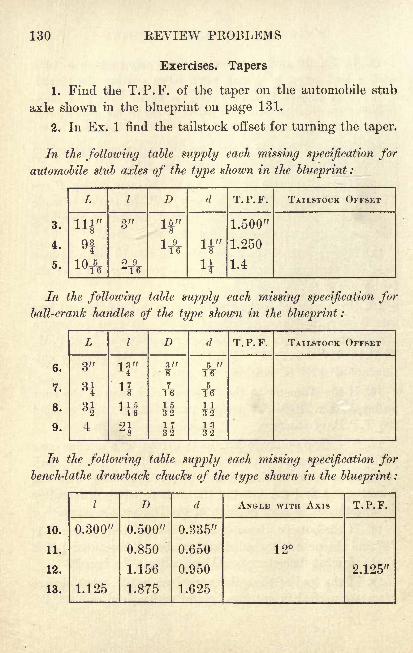
130 REVIEW PROBLEMS
Exercises. Tapers
1. Find the T.P.F. of the taper on the automobile stub
axle shown in the blueprint on page 131.
2. In Ex. 1 find the tailstock offset for turning the taper.
In the following table supply each missing specification for
automobile stub axles of the type shown in the blueprint :
3.
4.
5.
L

TAPERS 131
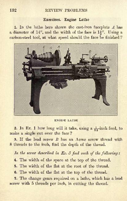
132 KEVIEW PROBLEMS
Exercises. Engine Lathe
1. In the lathe here shown the cast-iron faceplate A has
a diameter of 14", and the width of the face is 1|". Using a
carbon-steel tool, at what speed should the face be finished ?
ENGINE LATHE
2. In Ex. 1 how long will it take, using a gL-inch feed, to
make a single cut over the face ?
3. If the lead screw B has an Acme screw thread with
8 threads to the inch, find the depth of the thread.
In the screw described in Ex. 3 find each of the following :
4. The width of the space at the top of the thread.
5. The width of the flat at the root of the thread.
6. The width of the flat at the top of the thread.
7. The change gears required on a lathe, which has a lead
screw with 5 threads per inch, in cutting the thread.
ENGINE LATHE 133
8. Spur gear C is a 12-J^ gear with 96 teeth. Find the
pitch diameter of the gear.
9. In Ex. 8 find the outside diameter of the gear.
10. In Ex. 8 find the whole depth of tooth.
11. The dead center D is 1.475" in diameter at its small
end, 1.790" in diameter at its large end, and the length of
the taper is 6". Find the T.P.F.
12. In Ex. 11 find the included angle of the taper.
13. In the cast-iron cone pulley E the diameters of the
steps are 61", 7T\", 8|", 91f", and 11" respectively, and the
width of each face is 1|". Beginning with the smallest step,
find the number of R.P.M. for finishing each face with a
high-speed steel tool.
14. If the diameters at the centers of the steps of the
pulley in Ex. 13 are ^V greater than those at the edges, find
the angle which the faces make with the axis of the pulley.
15. If the cone pulley in Ex. 13 is turned on a 7^-inch
arbor, find the offset of the tailstock center.
16. If the machine-steel feed rod F is {" *n diameter and
5' 8" in length, what is the number of R.P.M. needed in
roughing the rod with a tool of carbon steel?
17. In Ex. 16 how long will it take to make a single cut
over the rod with a I-inch feed ?o
18. If the spur gear G has 117 teeth and the pitch is 8,
what is the outside diameter?
19. In Ex. 18 find the circular pitch and the thickness of
tooth on the pitch line.
20. Using a B. & S. dividing head, find the indexing
required in cutting the gear in Ex. 18.
21. A piece of cast iron 1^" in diameter is turned in
the lathe at 175 R.P.M. Find the cutting speed used.
134 REVIEW PROBLEMS
Exercises. General Applications
1. Find the angle a in the lathe center shown in the
blueprint on page 135.
2. In Ex. 1 find the length L of the pointed end.
3. The three holes J, B, C are to be drilled on a milling
machine in the jig plate shown in the blueprint. Find to the
nearest 0.001" the vertical movement from A for drilling
hole C. Find the lateral movement from C for drilling hole B.
In connection with Exs. 3-22 see the note at the foot of page 127.
4. The holes in the cylinder head shown in the blueprint
are equally spaced on the circle. Find the straight-line dis-
tance between the centers of the holes.
5. Consider Ex. 4 if there are 9 holes on a 12-inch circle ;
13 holes on an 18-inch circle ;21 holes on a 16-inch circle.
6. In the pulleys and belting shown in the blueprintfind the angle a and also find the distance D between the
centers of the pulleys.
7. Find the diameter of the round stock required for
making hexagonal heads which are to be |" across the flats.
Consider Ex. 7 for each of the following measurements across
the flats :
8. If". 9. lTy. 10. 1J". 11. 111". 12. 2T3/.
Find in each case the largest square that can be milled on
a round shaft in which the diameter is as follows :
13. Ty. 14. ||". 15. lTy. 16. lif ". 17. 25y.
Find in each case the diameter of the round stock required in
milling a square in which the length of side is as follows :
18. f". 19. 11". 20. lTy. 21. If". 22. 2|".
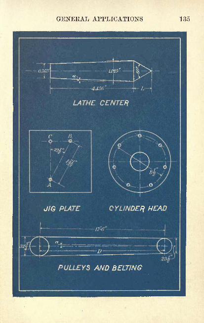
GEKEKAL APPLICATIONS 135
136 REVIEW PROBLEMS
Exercises. Miscellaneous Problems
1. A plug gage T9g" in diameter enters a hole with un-
known taper a distance of 3^", and another plug gage 11"
in diameter enters the same hole a distance of 2J". Find
the T.P.F. of the hole.
2. Find the change gears required on a milling machine
with a lead of 10" in cutting a spiral with a lead of 12.90".
3. Make the necessary calculations for cutting a pair of
16-^ bevel gears if the velocity ratio of the gears is to be
3 to 4, if the shafts are to be at right angles to each other,
and if the pinion is to have 48 teeth.
4. If a milling machine is geared to cut a spiral with a
lead of 0.67", find the angle at which the dividing head
should be elevated in milling a cam which is to have a rise
of 0.310" in 0.47 of the circumference.
5. The center of a 12-7J spur gear with 54 teeth is 8|"from the center of a mating gear. Find the number of teeth
and the outside diameter of the second gear.
6. Make all the necessary calculations for cutting a pair
of spiral gears if it is required that Dc (approximate) = 12",
r = 2, Ag= 33, Ap
= 27, Pn = 8, and S = 60.
7. Two spur gears are to mesh with a distance of 27"
between centers, and the velocity ratio is to be 1 to 2. If
the gears are to be cut 10 pitch, what should be the outside
diameter and the number of teeth on each gear?
8. If an Acme screw thread with 3 threads per inch is cut
on a 2^-inch shaft, what is the root diameter of the thread ?
9. The tailstock center of a certain lathe can be offset a
maximum distance of 21" from the center line of the lathe.
What is the greatest T.P.F. that can be cut on a piece of
work 9" long? on a piece of work 17" long?
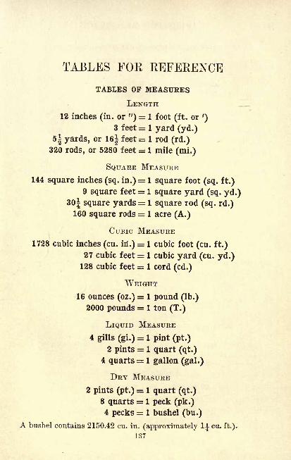
TABLES FOR REFERENCE
TABLES OF MEASURES
LENGTH
12 inches (in. or ") = 1 foot (ft. or')
3 feet = 1 yard (yd.)
5| yards, or 16| feet = 1 rod (rd.)320 rods, or 5280 feet = 1 mile (mi.)
SQUARE MEASURE
144 square inches (sq. in.)= 1 square foot (sq. ft.)
9 square feet = 1 square yard (sq. yd.)
30| square yards = 1 square rod (sq. rd.)160 square rods = 1 acre (A.)
CUBIC MEASURE
1728 cubic inches (cu. in*.)= 1 cubic foot (cu. ft.)
27 cubic feet = 1 cubic yard (cu. yd.)128 cubic feet = 1 cord (cd.)
WEIGHT
16 ounces (oz.)= 1 pound (Ib.)
2000 pounds = 1 ton (T.)
LIQUID MEASURE
4 gills (gi.)= 1 pint (pt.)
2 pints = 1 quart (qt.)
4 quarts = 1 gallon (gal.)
DRY MEASURE
2 pints (pt.) = 1 quart (qt.)
8 quarts = 1 peck (pk.)4 pecks = 1 bushel (bu.)
A bushel contains 2150.42 cu. in. (approximately l cu. ft.).
137
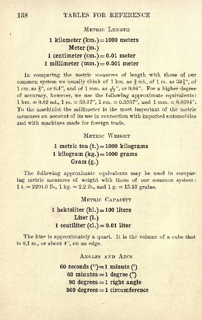
138 TABLES FOB REFERENCE
METRIC LENGTH
1 kilometer (km.)= 1000 meters
Meter (m.)1 centimeter (cm.) =0.01 meter
1 millimeter (mm.) =0.001 meter
In comparing the metric measures of length with those of our
common system we usually think of 1 km. as 2 mi., of 1 m. as 39^", of
1 cm. as f", or 0.4", and of 1 mm. as ^V >or 0.04". For a higher degree
of accuracy, however, we use the following approximate equivalents :
1 km. = 0.62 mi., 1 m. = 39.37", 1 cm. = 0.3937", and 1 mm. = 0.0394".
To the machinist the millimeter is the most important of the metric
measures on account of its use in connection with imported automobiles
and with machines made for foreign trade.
METRIC WEIGHT
1 metric ton (t.)= 1000 kilograms
1 kilogram (kg.)= 1000 gramsGram (g.)
The following approximate equivalents may be used in compar-
ing metric measures of weight with those of our common system :
1 1. = 2204.6 lb., 1 kg. = 2.2 lb., and 1 g.= 15.43 grains.
METRIC CAPACITY
1 hektoliter (hi.)= 100 liters
Liter (1.)
1 centiliter (cl.)= 0.01 liter
The liter is approximately a quart. It is the volume of a cube that
is 0.1 m., or about 4", on an edge.
ANGLES AND ARCS
60 seconds (")= 1 minute (')
60 minutes = 1 degree ()90 degrees = 1 right angle
360 degrees = 1 circumference
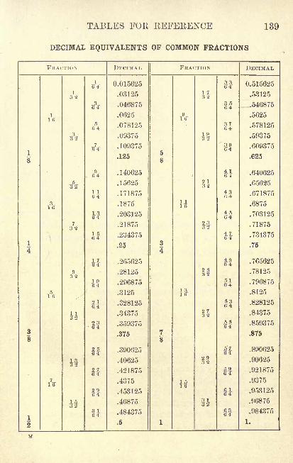
TABLES FOE, REFERENCE 139
DECIMAL EQUIVALENTS OF COMMON FRACTIONS
FRACTION
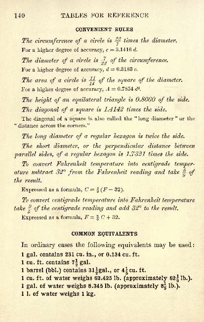
140 TABLES FOR REFERENCE
CONVENIENT RULES
The circumference of a circle is ^ times the diameter.
For a higher degree of accuracy, c = 3.1416 d.
The diameter of a circle is-j^ of the circumference.
For a higher degree of accuracy, d = 0.3183 c.
The area of a circle isj^ of the square of the diameter.
For a higher degree of accuracy, A = 0.7854 cP.
The height of an equilateral triangle is 0.8660 of the side.
The diagonal of a square is 1.4142 times the side.
The diagonal of a square is also called the"long diameter "
or the"distance across the corners."
The long diameter of a regular hexagon is twice the side.
The short diameter, or the perpendicular distance between
parallel sides, of a regular hexagon is 1.7321 times the side.
To convert Fahrenheit temperature into centigrade temper-
ature subtract 32 from the Fahrenheit reading and take ^ of
the result.
Expressed as a formula, C = f (F 32).
To convert centigrade temperature into Fahrenheit temperature
takej? of the centigrade reading and add 32 to the result.
Expressed as a formula, F = f C + 32.
COMMON EQUIVALENTS
In ordinary cases the following equivalents may be used:
1 gal. contains 231 cu. in., or 0.134 cu. ft.
1 cu. ft. contains 7| gal.
1 barrel (bbl.) contains 3l|gal., or 4|cu. ft.
1 cu. ft. of water weighs 62.425 Ib. (approximately 62 1 lb.).
1 gal. of water weighs 8.345 lb. (approximately s| lb.).
1 1. of water weighs 1 kg.
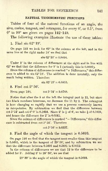
TABLES FOE BEFEKENCE 141
NATURAL TRIGONOMETRIC FUNCTIONS
Tables of four of the natural functions of an angle, the
sine, cosine, tangent, and cotangent, for every 6', or 0.1, fromto 90 are given on pages 142-149.
The following examples illustrate the use of these tables :
1. Find sin 62 19'.
On page 143 we look for 62 in the column at the left, and in the
same line at the right under 18' we find that
sin 62 18' = 0.8854.
Under V in the column of differences at the right and in line with62 we find that the difference for 1' is 1 (actually this is 0.0001).
Since the column of differences is marked "+ Differences," this differ-
ence is added to sin 62 18'. The addition is done mentally, only the
result being written. Therefore
sin 62 19' = 0.8855.
2. Find cot 5 56'.
From page 148, cot 5 54' = 9.6768.
Notice that after the 5 at the left the integral part is 11, but since
two black numbers intervene, we decrease the 11 by 2. The cotangentis here changing so rapidly that we use a process commonly knownas interpolation. By subtraction we find that the difference between
cot 5 54' and cot 6 0' is 0.1624. Since 2' is ^ of 6', we take of 0.1624,
and hence the difference for 2' is 0.0541.
Since the column of differences is marked te
Differences," this differ-
ence is subtracted from cot 5 54'. Therefore
cot 5 56'= 9.6227.
3. Find the angle of which the tangent is 0.5693.
On page 146 we find that the tangent next smaller than this tangentis 0.5681, which is the tangent of 29 36', and by subtraction we see
that the difference between 0.5693 and 0.5681 is 0.0012.
In the column of differences we see that 12 is the difference to be
added for 3'. Adding 3' to 29 36', we see that
29 39' is the angle of which the tangent is 0.5693.
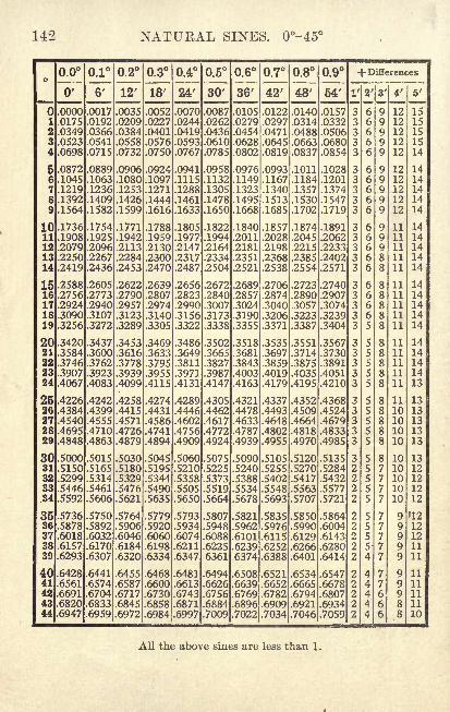
142 NATURAL SINES. 0-45
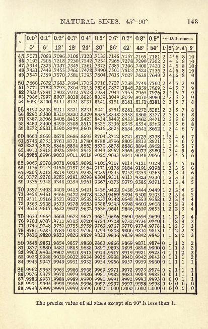
NATURAL SINES. 45-90 143
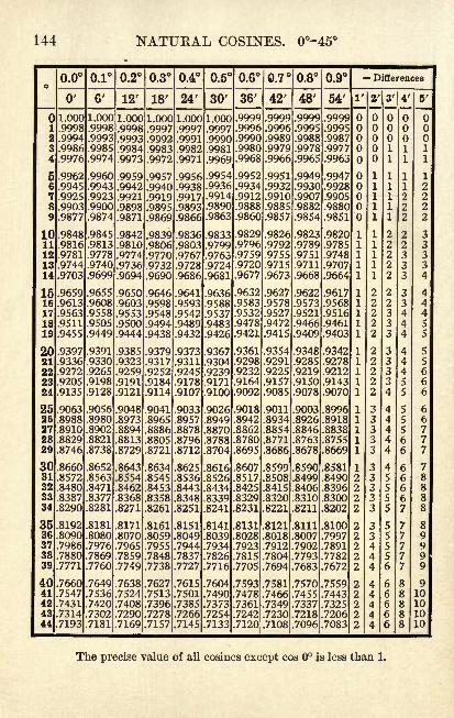
144 NATUKAL COSINES. 0-45
o
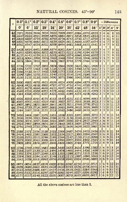
NATURAL COSINES. 45-90 145
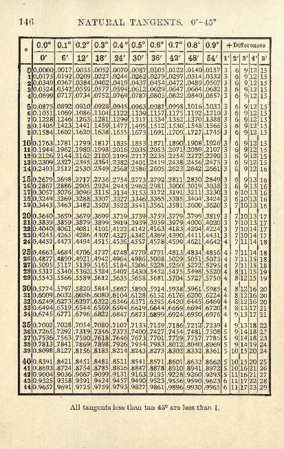
146 NATURAL TA^GEXTS. 0-45 e
o
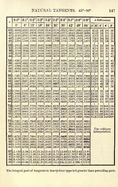
NATURAL TANGENTS. 45- 90 147
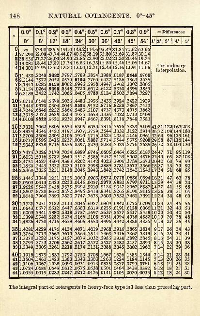
148 NATUKAL COTANGENTS. 0-45
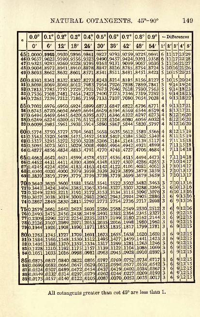
NATUKAL COTANGENTS. 45-90 149
o
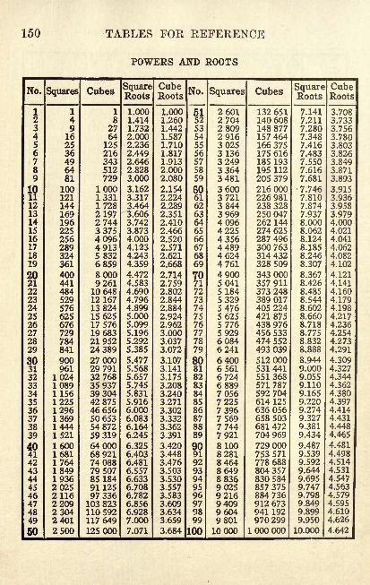
150 TABLES FOE REFERENCE
POWERS AND ROOTS
No.
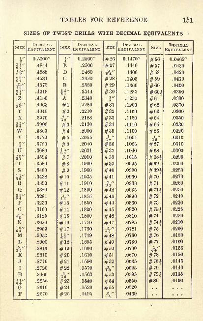
TABLES FOR REFERENCE 151
SIZES OF TWIST DRILLS WITH DECIMAL EQUIVALENTS
SIZE
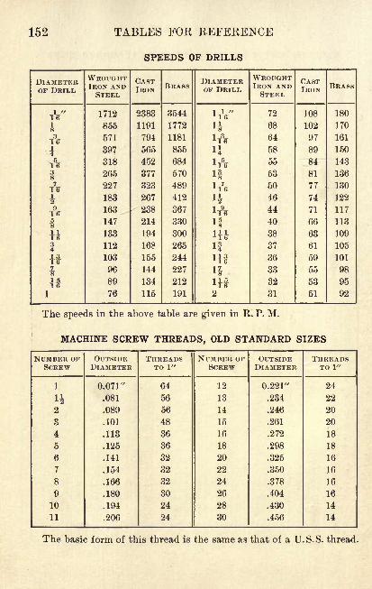
152 TABLES FOR REFERENCE
SPEEDS OF DRILLS
DIAMETEROF DRILL
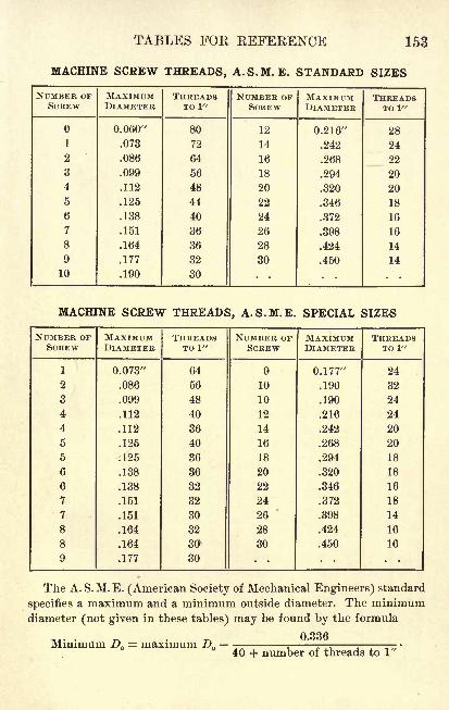
TABLES FOR REFERENCE 153
MACHINE SCREW THREADS, A.S.M. E. STANDARD SIZES
NUMBEK OFSCREW
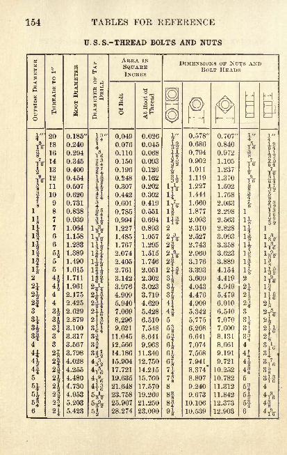
154 TABLES FOR REFERENCE
U.S.S.-THREAD BOLTS AND NUTS
M
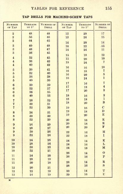
TABLES FOR REFERENCE 155
TAP DRILLS FOR MACHINE-SCREW TAPS
NUMBEROF TAP
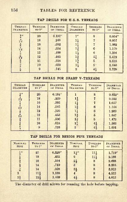
156 TABLES FOR REFERENCE
TAP DRILLS FOR U.S.S. THREADS
THREAD
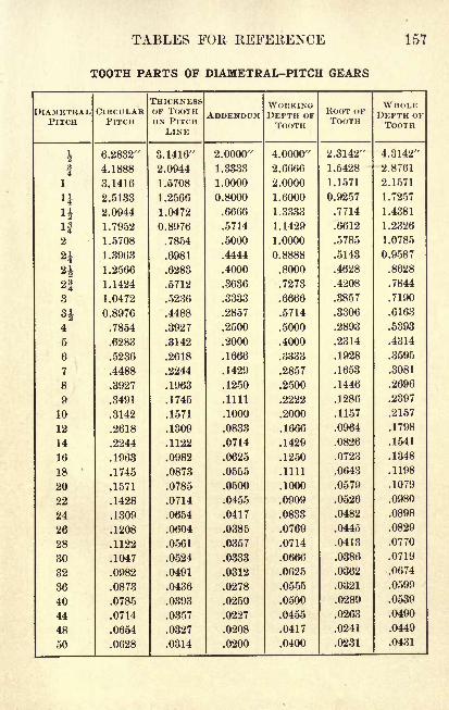
TABLES FOR REFERENCE 157
TOOTH PARTS OF DIAMETRAL-PITCH GEARS
DIAMETRALPITCH
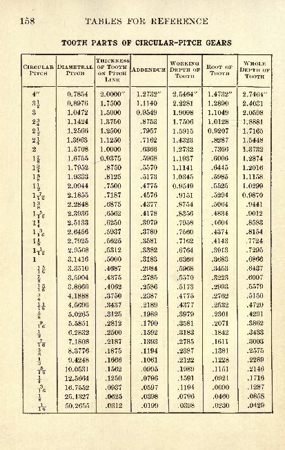
158 TABLES FOR REFERENCE
TOOTH PARTS OF CIRCULAR-PITCH GEARS
CIRCULARPITCH
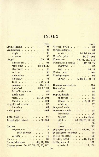
INDEXPAGE
Acme thread 48
Addendum 86
angle 98
angular 98
Angle 28, 138
addendum 98
with axis 28, 32, 33
clearance 46
cutting 98
dedendum 98
diameter 52
face 98, 112
gashing 112, 115
included 28, 32, 33
for milling cams .... 82
pitch-cone 99
spiral 73, 78, 104
tooth 104
Angular addendum 98
indexing 66
Axial pitch 104
Bevel gear . . .
Briggs pipe thread
. . 97
. 50, 156
Caliper
micrometer . .
with vernier
vernier ....Cam .
. . 2
. . 2
. . 5
4
80
Center distance . . . 86, 91, 103
Change gears 56, 57, 70, 73, 75, 107
PAGEChordal pitch 86
Circle, outside 86
pitch 85, 86, 98, 99
Circular pitch .... 86, 97, 104
Clearance .... 46, 86, 113, 115
Compound gearing . . .59, 72, 75
indexing 67
rest 25, 28
Cutter, gear 107
Cutting angle 98
speeds ... 9, 10, 11, 12, 16
Decimal equivalents .... 139
Dedendum 86
angle 98
Depth, double 35
of thread 35
whole 87, 90, 97
working 87
Diagonal scale 1
Diameter, angle 52
increment 98
outside 35, 86, 97
pitch .... 52, 85, 86, 97, 99
root 35
throat ........ 112
Diametral pitch ... 86, 97, 104
Differential indexing .... 70
Direct indexing 62
Dividing head 61, 63, 73
Drills, sizes of . 151
speeds of 13, 152
159
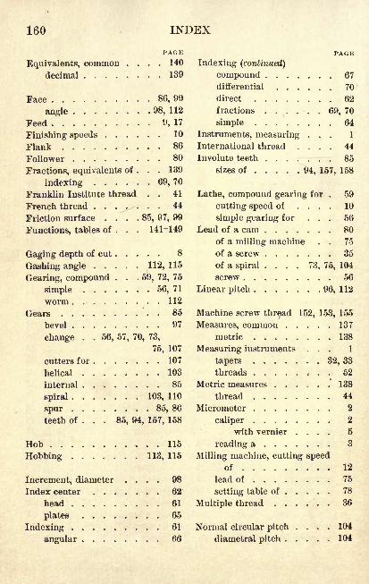
160 INDEX
Equivalents, commondecimal .
PACK140
139
Face 86, 99
angle 98, 112
Feed 9, 17
Finishing speeds 10
Flank 86
Follower 80
Fractions, equivalents of ... 139
indexing 69,70
Franklin Institute thread . . 41
French thread 44
Friction surface . . . .85, 97, 99
Functions, tables of ... 141-149
Gaging depth of cut 8
Gashing angle 112, 115
Gearing, compound . . . 59, 72, 75
simple 56, 71
worm 112
Gears . 85
bevel 97
change . . 56, 57, 70, 73,
75, 107
cutters for 107
helical 103
internal 85
spiral 103, 110
spur 85, 86
teeth of ... 85, 94, 157, 158
Hob 115
Robbing 113, 115
Increment, diameter .... 98
Index center 62
head 61
plates 65
Indexing 61
angular 66
PAGE
Indexing (continued)
compound 67
differential 70
direct 62
fractions . . . . . . 69, 70
simple 64
Instruments, measuring ... 1
International thread .... 44
Involute teeth . . . ;-- ;- r . 85
sizes of . . ... . .94, 157, 158
Lathe, compound gearing for . 59
cutting speed of .... 10
simple gearing for ... 56
Lead of a cam 80
of a milling machine . . 75
of a screw 35
of a spiral .... 73, 75, 104
screw 56
Linear pitch 96, 112
Machine screw thread 152, 153, 155
Measures, common 137
metric .., ,. 138
Measuring instruments ... 1
tapers . . 32, 33
threads 52
Metric measures 138
thread 44
Micrometer . 2
caliper $/with vernier .... 5
reading a 8
Milling machine, cutting speedof 12
lead of 75
setting table of 78
Multiple thread 36
Normal circular pitch .... 104
diametral pitch 104
INDEX 161
PAGE
Offset for tapers 24
Outside circle 86
diameter 35, 86, 97
Pitch 35, 86, 103
axial 104
chordal 86
circle 85, 86, 98, 99
circular 86, 97, 104
-cone alible 99
radius 99
diameter of a gear 85, 86, 97, 99
of a thread 52
diametral .... 86, 97, 104
line 86, 98, 99
linear 96, 112
normal 104
Pinion 85, 91, 97
Pipe thread 50, 156
Planer, cutting speed of ... 11
Problem material
bevel gears .... 102, 116
calipers 3, 6
cams ........ 83, 84
cutting speeds 10, 11, 12,
14, 16, 18, 20
drill press 118
drilling machine .... 126
drills, speeds of . . 13, 14, 20
feeds 17, 18
gaging cuts 8
general applications .117,
134, 136
indexing . 65, 66, 69, 72, 120
lathes .... 10, 14, 20, 132
milling . . 12, 14, 18, 120, 128
planers 11, 18, 124
review 14, 18, 30, 55, 72,
84, 96, 117-136
shapers 16, 20
spiral gears . . 109, 111, 116
PAGEProblem material (continued)
spirals '. 77, 79, 84
spur gears . 89, 92, 94, 96, 116
tapers . . 22, 26, 29, 30,
34, 122, 130
threads 37, 39, 41, 43, 45,
47, 49, 51, 54, 56, 58, 60
worm gearing . . . 115, 116
Rack 85, 96
Radius, pitch-cone 99
Ratio, velocity 91, 106
Rest, compound 25, 28
Review problems . 14, 18, 30,
55, 72, 84, 96, 117-136
Rise 80
Root 35, 86
diameter 35
Roughing speeds 10
Rules, convenient 140
S. A. E. thread 40
Scale, diagonal 1
Screw, hand of 36
lead of 35
thread 35
Sellers thread 41
Shaper, cutting speed of ... 16
Sharp V-thread 38
Simple gearing 56, 71
indexing 64
Sine bar 33
Speeds, cutting . 9, 10, 11, 12, 16
of drills 13, 152
surface 9
Spiral 73
angle 73, 78, 104
gears 103
with parallel shafts . 110
head 61
lead of 73, 75, 104
162 INDEX
PAGE
Spur gears 85, 86
Square thread 46
tool 46
Stud ! 56, 59
Symbols . . 21, 88, 100, 106, 112
Tables
angles and arcs 138
Briggs pipe threads . . 51, 156
common fractions .... 139
measures 137
cosines 144
cotangents 148
cutting speeds . . . . 10, 12
decimal equivalents . . . 139
drills, sizes of 151
speeds of 152
feeds 17
machine screw threads 152,
153, 155
metric measures .... 138
threads 44
powers and roots .... 150
S. A. E. thread 40
sines 142
tangents 146
tap drills ..... 155, 156
tooth parts .... 157, 158
U. S. S. thread .... 40, 156
bolts and nuts . . . 154
V-thread 38, 156
Whitworth thread ... 42
Tailstock, offsetting the ... 24
Tap 39
-drill size . . 39, 41, 155, 156
Taper 21
attachment 25
measuring a 32, 33
testing a 32
turning a ...'.-... 24
PAGE
Teeth, cycloidal 85
involute 85, 95
sizes of ... 94, 157, 158
Thread 35
Acme j . 48
cutting 56, 59
machine screw . 152, 153, 155
measuring 52
metric 44
multiple . .. 36
pipe ........ 50, 156
S. A. E 40
screw 35
square 46
U. S. S. . . . 40, 52, 154, 156
V- 38, 53, 156
Whitworth 42, 54
Throat diameter 112
Tooth angle 104
thickness of . 87, 100, 102, 107
Trigonometric functions ... 141
U. S. S. thread 40, 52, 154, 156
V-thread, sharp ... 38, 53, 156
Velocity ratio 91, 106
Vernier 4
caliper 4
micrometer caliper with . 5
reading a 5
Vertex of a bevel gear .... 99
Wheel, gear 85
worm ....... 63, 64, 112
Whitworth thread .... 42, 54
Whole depth 87, 90, 97
Working depth 87
Worm 63, 64, 73, 112
gearing 112
wheel 63, 64, 112
PRINTKD IN THE UNITED STATES OF AMERICA

UNIVERSITY OF CALIFORNIA LIBRARYBERKELEY
Return to desk from which borrowed.
This book is DUE on the last date stamped below.
2lMar'50B6
LIBRARY USE
BRARY USE
mo
LIBRARY USE
SEP 8 1960
SEP 15 1960
NP
;*D LpREC'D Lp- MAK1H ) -1LD 21-100m-ll,'49(B7146sl6)476
..
O f ) * -f
M306017TI
THE UNIVERSITY OF CALIFORNIA LIBRARY