Embed Size (px)
Citation preview
Page 1 © 2003 Lennox Industries Inc.
Corp. 0308−L6
G61MPService Literature Revised 11−2006
G61MP SERIES UNITSG61MP series units are high−efficiency multi−position (up-
flow, downflow, horizontal right and left) gas furnaces
manufactured with Lennox Duralok Plus� heat exchang-
ers formed of aluminized steel. G61MP units are available
in heating capacities of 44,000 to 132,000 Btuh (13.0.0 to
38.6 kW) and cooling applications from 2 to 5 tons (7.0 kW
to 17.5 kW)) up to 5 tons. Refer to Engineering Handbook
for proper sizing.
Units are factory equipped for use with natural gas. Kits are
available for conversion to LPG operation. G61MP model
units are equipped with the Two−Stage Integrated SureLight
control. All G61MP units meet the California Nitrogen Ox-
ides (NOx) Standards and California Seasonal Efficiency re-
quirements. All units use a redundant gas valve to assure
safety shut−off as required by C.S.A.
All specifications in this manual are subject to change. Pro-
cedures outlined in this manual are presented as a recom-
mendation only and do not supersede or replace local or
state codes. In the absence of local or state codes, the
guidelines and procedures outlined in this manual (except
where noted) are recommendations only and do not consti-
tute code.
TABLE OF CONTENTS
Specifications Page 2. . . . . . . . . . . . . . . . . . . . . . . . . . . . .
Blower Data Page 4. . . . . . . . . . . . . . . . . . . . . . . . . . . . . .
Parts Identification Page 7. . . . . . . . . . . . . . . . . . . . . . . . .
I Unit Components Page 8. . . . . . . . . . . . . . . . . . . . . . . .
II Installation Page 21. . . . . . . . . . . . . . . . . . . . . . . . . . . .
III Start Up Page 35. . . . . . . . . . . . . . . . . . . . . . . . . . . . . . .
IV Heating System Service Checks Page 36. . . . . . . . .
V Typical Operating Characteristics Page 39. . . . . . . . .
VI Maintenance Page 40. . . . . . . . . . . . . . . . . . . . . . . . . .
VII Wiring and Sequence of Operation Page 43. . . . . .
VIII Field Wiring and Jumper Setting Page 59. . . . . . . .
IX Control Board Troubleshooting Page 63. . . . . . . . . .
IMPORTANTImproper installation, adjustment, alteration, serviceor maintenance can cause property damage, person-al injury or loss of life. Installation and service mustbe performed by a qualified installer, service agencyor the gas supplier.
WARNINGElectric shock hazard. Can cause injuryor death. Before attempting to performany service or maintenance, turn theelectrical power to unit OFF at discon-nect switch(es). Unit may have multiplepower supplies.
WARNINGSharp edges.Be careful when servicing unit to avoid sharp edgeswhich may result in personal injury.
Page 2
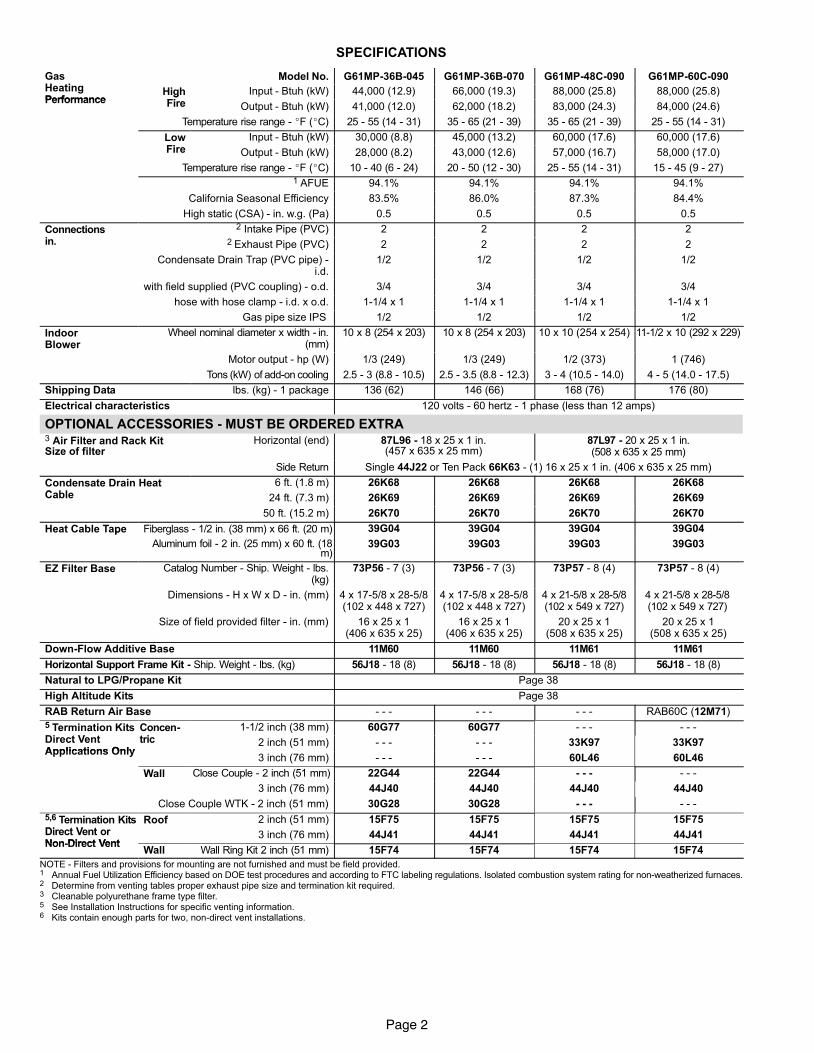
SPECIFICATIONS
GasH ti
Model�No. G61MP−36B−045 G61MP−36B−070 G61MP−48C−090 G61MP−60C−090HeatingPerformance
HighFi
Input�− Btuh (kW) 44,000 (12.9) 66,000 (19.3) 88,000 (25.8) 88,000 (25.8)Performance
gFire Output�− Btuh (kW) 41,000 (12.0) 62,000 (18.2) 83,000 (24.3) 84,000 (24.6)
Temperature rise range − �F (�C) 25 − 55 (14 − 31) 35 − 65 (21 − 39) 35 − 65 (21 − 39) 25 − 55 (14 − 31)
LowFi
Input�− Btuh (kW) 30,000 (8.8) 45,000 (13.2) 60,000 (17.6) 60,000 (17.6)Fire Output�− Btuh (kW) 28,000 (8.2) 43,000 (12.6) 57,000 (16.7) 58,000 (17.0)
Temperature rise range − �F (�C) 10 − 40 (6 − 24) 20 − 50 (12 − 30) 25 − 55 (14 − 31) 15 − 45 (9 − 27)1 AFUE 94.1% 94.1% 94.1% 94.1%
California Seasonal Efficiency 83.5% 86.0% 87.3% 84.4%
High�static�(CSA)�− in.�w.g. (Pa) 0.5 0.5 0.5 0.5
Connectionsi
2 Intake Pipe (PVC) 2 2 2 2in. 2 Exhaust Pipe (PVC) 2 2 2 2
Condensate Drain Trap (PVC pipe) −i.d.
1/2 1/2 1/2 1/2
with field supplied (PVC coupling) − o.d. 3/4 3/4 3/4 3/4
hose with hose clamp − i.d. x o.d. 1−1/4 x 1 1−1/4 x 1 1−1/4 x 1 1−1/4 x 1
Gas�pipe�size�IPS� 1/2 1/2 1/2 1/2
IndoorBlower
Wheel nominal diameter x width −�in.(mm)
10 x 8 (254 x 203) 10 x 8 (254 x 203) 10 x 10 (254 x 254) 11−1/2 x 10 (292 x 229)o e
Motor�output − hp (W) 1/3 (249) 1/3 (249) 1/2 (373) 1 (746)
Tons�(kW) of�add-on�cooling 2.5 − 3 (8.8 − 10.5) 2.5 − 3.5 (8.8 − 12.3) 3 − 4 (10.5 − 14.0) 4 − 5 (14.0 − 17.5)
Shipping�Data lbs. (kg) − 1 package 136 (62) 146 (66) 168 (76) 176 (80)
Electrical�characteristics 120 volts − 60 hertz − 1 phase (less than 12 amps)
OPTIONAL ACCESSORIES − MUST BE ORDERED EXTRA3 Air Filter and Rack KitSize of filter
Horizontal (end) 87L96 − 18 x 25 x 1 in.(457 x 635 x 25 mm)
87L97 − 20 x 25 x 1 in.(508 x 635 x 25 mm)
Side Return Single 44J22 or Ten Pack 66K63 − (1) 16 x 25 x 1 in. (406 x 635 x 25 mm)
Condensate Drain HeatC bl
6 ft. (1.8 m) 26K68 26K68 26K68 26K68Cable 24 ft. (7.3 m) 26K69 26K69 26K69 26K69
50 ft. (15.2 m) 26K70 26K70 26K70 26K70
Heat Cable Tape Fiberglass − 1/2 in. (38 mm) x 66 ft. (20 m) 39G04 39G04 39G04 39G04p
Aluminum foil − 2 in. (25 mm) x 60 ft. (18m)
39G03 39G03 39G03 39G03
EZ Filter Base Catalog Number − Ship. Weight − lbs.(kg)
73P56 − 7 (3) 73P56 − 7 (3) 73P57 − 8 (4) 73P57 − 8 (4)
Dimensions − H x W x D − in. (mm) 4 x 17−5/8 x 28−5/8(102 x 448 x 727)
4 x 17−5/8 x 28−5/8(102 x 448 x 727)
4 x 21−5/8 x 28−5/8(102 x 549 x 727)
4 x 21−5/8 x 28−5/8(102 x 549 x 727)
Size of field provided filter − in. (mm) 16 x 25 x 1(406 x 635 x 25)
16 x 25 x 1(406 x 635 x 25)
20 x 25 x 1(508 x 635 x 25)
20 x 25 x 1(508 x 635 x 25)
Down−Flow Additive Base 11M60 11M60 11M61 11M61
Horizontal Support Frame Kit − Ship. Weight − lbs. (kg) 56J18 − 18 (8) 56J18 − 18 (8) 56J18 − 18 (8) 56J18 − 18 (8)
Natural to LPG/Propane Kit Page 38
High Altitude Kits Page 38
RAB Return Air Base − − − − − − − − − RAB60C (12M71)
5 Termination KitsDi t V t
Concen-t i
1−1/2 inch (38 mm) 60G77 60G77 − − − − − −Direct VentApplications Only
tric 2 inch (51 mm) − − − − − − 33K97 33K97Applications Only
3 inch (76 mm) − − − − − − 60L46 60L46
Wall Close Couple − 2 inch (51 mm) 22G44 22G44 − − − − − −
3 inch (76 mm) 44J40 44J40 44J40 44J40
Close Couple WTK − 2 inch (51 mm) 30G28 30G28 − − − − − −
5,6 Termination KitsDi t V t
Roof 2 inch (51 mm) 15F75 15F75 15F75 15F75Direct Vent orNon−Direct Vent
3 inch (76 mm) 44J41 44J41 44J41 44J41Non−Direct Vent
Wall Wall Ring Kit 2 inch (51 mm) 15F74 15F74 15F74 15F74
NOTE − Filters and provisions for mounting are not furnished and must be field provided.1 Annual Fuel Utilization Efficiency based on DOE test procedures and according to FTC labeling regulations. Isolated combustion system rating for non-weatherized furnaces.2 Determine from venting tables proper exhaust pipe size and termination kit required.3 Cleanable polyurethane frame type filter.5 See Installation Instructions for specific venting information.6 Kits contain enough parts for two, non−direct vent installations.
Page 3
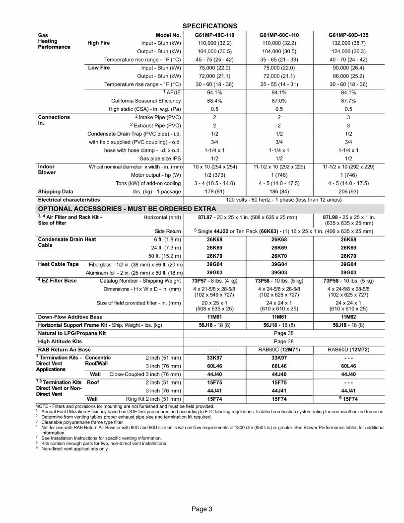
SPECIFICATIONS
GasH ti
Model�No. G61MP−48C−110 G61MP−60C−110 G61MP−60D−135HeatingPerformance
High Fire Input�− Btuh (kW) 110,000 (32.2) 110,000 (32.2) 132,000 (38.7)Performance
g
Output�− Btuh (kW) 104,000 (30.5) 104,000 (30.5) 124,000 (36.3)
Temperature rise range − �F (�C) 45 − 75 (25 − 42) 35 − 65 (21 − 39) 40 − 70 (24 − 42)
Low Fire Input�− Btuh (kW) 75,000 (22.0) 75,000 (22.0) 90,000 (26.4)
Output�− Btuh (kW) 72,000 (21.1) 72,000 (21.1) 86,000 (25.2)
Temperature rise range − �F (�C) 30 − 60 (18 − 36) 25 − 55 (14 − 31) 30 − 60 (18 − 36)
1 AFUE 94.1% 94.1% 94.1%
California Seasonal Efficiency 88.4% 87.0% 87.7%
High�static�(CSA)�− in.�w.g. (Pa) 0.5 0.5 0.5
Connectionsi
2 Intake Pipe (PVC) 2 2 3in. 2 Exhaust Pipe (PVC) 2 2 3
Condensate Drain Trap (PVC pipe) − i.d. 1/2 1/2 1/2
with field supplied (PVC coupling) − o.d. 3/4 3/4 3/4
hose with hose clamp − i.d. x o.d. 1−1/4 x 1 1−1/4 x 1 1−1/4 x 1
Gas�pipe�size�IPS 1/2 1/2 1/2
IndoorBlo er
Wheel�nominal�diameter �x�width −�in. (mm) 10 x 10 (254 x 254) 11−1/2 x 10 (292 x 229) 11−1/2 x 10 (292 x 229)Blower
Motor�output − hp (W) 1/2 (373) 1 (746) 1 (746)
Tons�(kW) of�add-on�cooling 3 − 4 (10.5 − 14.0) 4 − 5 (14.0 − 17.5) 4 − 5 (14.0 − 17.5)
Shipping�Data lbs. (kg) − 1 package 178 (81) 186 (84) 206 (93)
Electrical�characteristics 120 volts − 60 hertz − 1 phase (less than 12 amps)
OPTIONAL ACCESSORIES − MUST BE ORDERED EXTRA3, 4 Air Filter and Rack Kit −Size of filter
Horizontal (end) 87L97 − 20 x 25 x 1 in. (508 x 635 x 25 mm) 87L98 − 25 x 25 x 1 in.(635 x 635 x 25 mm)
Side Return 5 Single 44J22 or Ten Pack (66K63) − (1) 16 x 25 x 1 in. (406 x 635 x 25 mm)
Condensate Drain HeatC bl
6 ft. (1.8 m) 26K68 26K68 26K68Cable
24 ft. (7.3 m) 26K69 26K69 26K69
50 ft. (15.2 m) 26K70 26K70 26K70
Heat Cable Tape Fiberglass − 1/2 in. (38 mm) x 66 ft. (20 m) 39G04 39G04 39G04p
Aluminum foil − 2 in. (25 mm) x 60 ft. (18 m) 39G03 39G03 39G03
4 EZ Filter Base Catalog Number − Shipping Weight 73P57 − 8 lbs. (4 kg) 73P58 − 10 lbs. (5 kg) 73P58 − 10 lbs. (5 kg)
Dimensions − H x W x D − in. (mm) 4 x 21−5/8 x 28−5/8(102 x 549 x 727)
4 x 24−5/8 x 28−5/8(102 x 625 x 727)
4 x 24−5/8 x 28−5/8(102 x 625 x 727)
Size of field provided filter − in. (mm) 20 x 25 x 1(508 x 635 x 25)
24 x 24 x 1(610 x 610 x 25)
24 x 24 x 1(610 x 610 x 25)
Down−Flow Additive Base 11M61 11M61 11M62
Horizontal Support Frame Kit − Ship. Weight − lbs. (kg) 56J18 − 18 (8) 56J18 − 18 (8) 56J18 − 18 (8)
Natural to LPG/Propane Kit Page 38
High Altitude Kits Page 38
RAB Return Air Base − − − − RAB60C (12M71) RAB60D (12M72)
7 Termination Kits −Di t V t
ConcentricR f/W ll
2 inch (51 mm) 33K97 33K97 − − −Direct VentApplications
Roof/Wall3 inch (76 mm) 60L46 60L46 60L46
ApplicationsWall Close−Coupled 3 inch (76 mm) 44J40 44J40 44J40
7,8 Termination KitsDi t V t N
Roof 2 inch (51 mm) 15F75 15F75 − − −Direct Vent or Non−Direct Vent
3 inch (76 mm) 44J41 44J41 44J41Direct Vent
Wall Ring Kit 2 inch (51 mm) 15F74 15F74 9 15F74
NOTE − Filters and provisions for mounting are not furnished and must be field provided.1 Annual Fuel Utilization Efficiency based on DOE test procedures and according to FTC labeling regulations. Isolated combustion system rating for non-weatherized furnaces.2 Determine from venting tables proper exhaust pipe size and termination kit required.3 Cleanable polyurethane frame type filter.4 Not for use with RAB Return Air Base or with 60C and 60D size units with air flow requirements of 1800 cfm (850 L/s) or greater. See Blower Performance tables for additional
information.7 See Installation Instructions for specific venting information.8 Kits contain enough parts for two, non−direct vent installations.9 Non−direct vent applications only.
Page 4
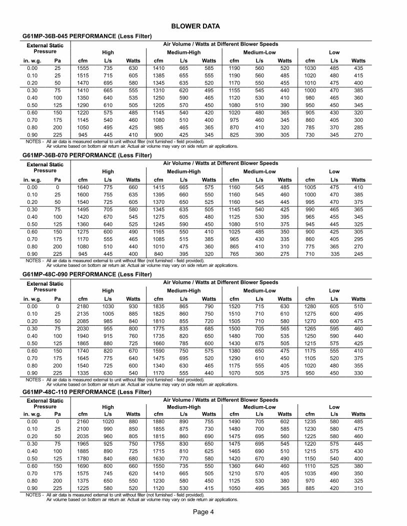
BLOWER DATA
G61MP−36B−045 PERFORMANCE (Less Filter)
External Static Air Volume / Watts at Different Blower SpeedsExternal StaticPressure High Medium−High Medium−Low Low
in. w.g. Pa cfm L/s Watts cfm L/s Watts cfm L/s Watts cfm L/s Watts
0.00 25 1555 735 630 1410 665 585 1190 560 520 1030 485 435
0.10 25 1515 715 605 1385 655 555 1190 560 485 1020 480 415
0.20 50 1470 695 580 1345 635 520 1170 550 455 1010 475 400
0.30 75 1410 665 555 1310 620 495 1155 545 440 1000 470 385
0.40 100 1350 640 535 1250 590 465 1120 530 410 980 465 360
0.50 125 1290 610 505 1205 570 450 1080 510 390 950 450 345
0.60 150 1220 575 485 1145 540 420 1020 480 365 905 430 320
0.70 175 1145 540 460 1080 510 400 975 460 345 860 405 300
0.80 200 1050 495 425 985 465 365 870 410 320 785 370 285
0.90 225 945 445 410 900 425 345 825 390 305 730 345 270
NOTES − All air data is measured external to unit without filter (not furnished − field provided).Air volume based on bottom air return air. Actual air volume may vary on side return air applications.
G61MP−36B−070 PERFORMANCE (Less Filter)
External Static Air Volume / Watts at Different Blower SpeedsExternal StaticPressure High Medium−High Medium−Low Low
in. w.g. Pa cfm L/s Watts cfm L/s Watts cfm L/s Watts cfm L/s Watts
0.00 0 1640 775 660 1415 665 575 1160 545 485 1005 475 410
0.10 25 1600 755 635 1395 660 550 1160 545 460 1000 470 385
0.20 50 1540 725 605 1370 650 525 1160 545 445 995 470 375
0.30 75 1495 705 580 1345 635 505 1145 540 425 990 465 365
0.40 100 1420 670 545 1275 605 480 1125 530 395 965 455 345
0.50 125 1360 640 525 1245 590 450 1080 510 375 945 445 325
0.60 150 1275 600 490 1165 550 410 1025 485 350 900 425 305
0.70 175 1170 555 465 1085 515 385 965 430 335 860 405 295
0.80 200 1080 510 440 1010 475 360 865 410 310 775 365 270
0.90 225 945 445 400 840 395 320 765 360 275 710 335 245
NOTES − All air data is measured external to unit without filter (not furnished − field provided).Air volume based on bottom air return air. Actual air volume may vary on side return air applications.
G61MP−48C−090 PERFORMANCE (Less Filter)
External Static Air Volume / Watts at Different Blower SpeedsExternal StaticPressure High Medium−High Medium−Low Low
in. w.g. Pa cfm L/s Watts cfm L/s Watts cfm L/s Watts cfm L/s Watts
0.00 0 2180 1030 930 1835 865 790 1520 715 630 1280 605 510
0.10 25 2135 1005 885 1825 860 750 1510 710 610 1275 600 495
0.20 50 2085 985 840 1810 855 720 1505 710 580 1270 600 475
0.30 75 2030 955 800 1775 835 685 1500 705 565 1265 595 460
0.40 100 1940 915 760 1735 820 650 1480 700 535 1250 590 440
0.50 125 1865 880 725 1660 785 600 1430 675 505 1215 575 425
0.60 150 1740 820 670 1590 750 575 1380 650 475 1175 555 410
0.70 175 1645 775 640 1475 695 520 1290 610 450 1105 520 375
0.80 200 1540 725 600 1340 630 465 1175 555 405 1020 480 355
0.90 225 1335 630 540 1170 555 440 1070 505 375 950 450 330
NOTES − All air data is measured external to unit without filter (not furnished − field provided).Air volume based on bottom air return air. Actual air volume may vary on side return air applications.
G61MP−48C−110 PERFORMANCE (Less Filter)
External Static Air Volume / Watts at Different Blower SpeedsExternal StaticPressure High Medium−High Medium−Low Low
in. w.g. Pa cfm L/s Watts cfm L/s Watts cfm L/s Watts cfm L/s Watts
0.00 0 2160 1020 880 1880 890 755 1490 705 602 1235 580 485
0.10 25 2100 990 850 1855 875 730 1480 700 585 1230 580 475
0.20 50 2035 960 805 1815 860 690 1475 695 560 1225 580 460
0.30 75 1965 925 750 1755 830 650 1475 695 545 1220 575 445
0.40 100 1885 890 725 1715 810 625 1465 690 510 1215 575 430
0.50 125 1780 840 680 1630 770 580 1420 670 490 1150 540 400
0.60 150 1690 800 660 1550 735 550 1360 640 460 1110 525 380
0.70 175 1575 745 620 1410 665 505 1210 570 405 1035 490 350
0.80 200 1375 650 550 1230 580 450 1125 530 380 970 460 325
0.90 225 1225 580 520 1120 530 415 1050 495 365 885 420 310
NOTES − All air data is measured external to unit without filter (not furnished − field provided).Air volume based on bottom air return air. Actual air volume may vary on side return air applications.
Page 5
BLOWER DATA
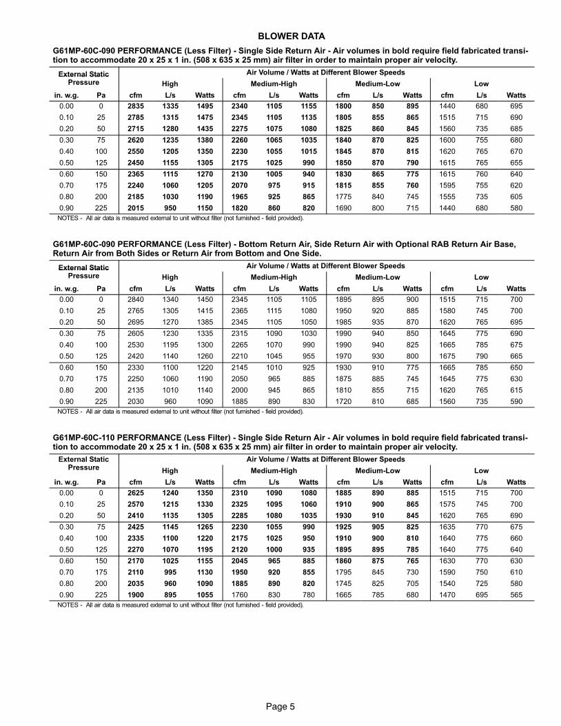
G61MP−60C−090 PERFORMANCE (Less Filter) − Single Side Return Air − Air volumes in bold require field fabricated transi-tion to accommodate 20 x 25 x 1 in. (508 x 635 x 25 mm) air filter in order to maintain proper air velocity.
External Static Air Volume / Watts at Different Blower SpeedsExternal StaticPressure High Medium−High Medium−Low Low
in. w.g. Pa cfm L/s Watts cfm L/s Watts cfm L/s Watts cfm L/s Watts
0.00 0 2835 1335 1495 2340 1105 1155 1800 850 895 1440 680 695
0.10 25 2785 1315 1475 2345 1105 1135 1805 855 865 1515 715 690
0.20 50 2715 1280 1435 2275 1075 1080 1825 860 845 1560 735 685
0.30 75 2620 1235 1380 2260 1065 1035 1840 870 825 1600 755 680
0.40 100 2550 1205 1350 2230 1055 1015 1845 870 815 1620 765 670
0.50 125 2450 1155 1305 2175 1025 990 1850 870 790 1615 765 655
0.60 150 2365 1115 1270 2130 1005 940 1830 865 775 1615 760 640
0.70 175 2240 1060 1205 2070 975 915 1815 855 760 1595 755 620
0.80 200 2185 1030 1190 1965 925 865 1775 840 745 1555 735 605
0.90 225 2015 950 1150 1820 860 820 1690 800 715 1440 680 580
NOTES − All air data is measured external to unit without filter (not furnished − field provided).
G61MP−60C−090 PERFORMANCE (Less Filter) − Bottom Return Air, Side Return Air with Optional RAB Return Air Base,Return Air from Both Sides or Return Air from Bottom and One Side.
External Static Air Volume / Watts at Different Blower SpeedsExternal StaticPressure High Medium−High Medium−Low Low
in. w.g. Pa cfm L/s Watts cfm L/s Watts cfm L/s Watts cfm L/s Watts
0.00 0 2840 1340 1450 2345 1105 1105 1895 895 900 1515 715 700
0.10 25 2765 1305 1415 2365 1115 1080 1950 920 885 1580 745 700
0.20 50 2695 1270 1385 2345 1105 1050 1985 935 870 1620 765 695
0.30 75 2605 1230 1335 2315 1090 1030 1990 940 850 1645 775 690
0.40 100 2530 1195 1300 2265 1070 990 1990 940 825 1665 785 675
0.50 125 2420 1140 1260 2210 1045 955 1970 930 800 1675 790 665
0.60 150 2330 1100 1220 2145 1010 925 1930 910 775 1665 785 650
0.70 175 2250 1060 1190 2050 965 885 1875 885 745 1645 775 630
0.80 200 2135 1010 1140 2000 945 865 1810 855 715 1620 765 615
0.90 225 2030 960 1090 1885 890 830 1720 810 685 1560 735 590
NOTES − All air data is measured external to unit without filter (not furnished − field provided).
G61MP−60C−110 PERFORMANCE (Less Filter) − Single Side Return Air − Air volumes in bold require field fabricated transi-tion to accommodate 20 x 25 x 1 in. (508 x 635 x 25 mm) air filter in order to maintain proper air velocity.
External StaticP
Air Volume / Watts at Different Blower SpeedsPressure High Medium−High Medium−Low Low
in. w.g. Pa cfm L/s Watts cfm L/s Watts cfm L/s Watts cfm L/s Watts
0.00 0 2625 1240 1350 2310 1090 1080 1885 890 885 1515 715 700
0.10 25 2570 1215 1330 2325 1095 1060 1910 900 865 1575 745 700
0.20 50 2410 1135 1305 2285 1080 1035 1930 910 845 1620 765 690
0.30 75 2425 1145 1265 2230 1055 990 1925 905 825 1635 770 675
0.40 100 2335 1100 1220 2175 1025 950 1910 900 810 1640 775 660
0.50 125 2270 1070 1195 2120 1000 935 1895 895 785 1640 775 640
0.60 150 2170 1025 1155 2045 965 885 1860 875 765 1630 770 630
0.70 175 2110 995 1130 1950 920 855 1795 845 730 1590 750 610
0.80 200 2035 960 1090 1885 890 820 1745 825 705 1540 725 580
0.90 225 1900 895 1055 1760 830 780 1665 785 680 1470 695 565
NOTES − All air data is measured external to unit without filter (not furnished − field provided).
Page 6
BLOWER DATA
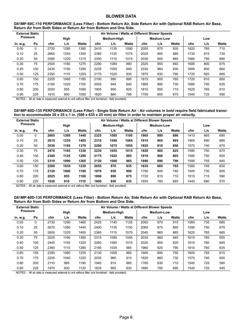
G61MP−60C−110 PERFORMANCE (Less Filter) − Bottom Return Air, Side Return Air with Optional RAB Return Air Base,Return Air from Both Sides or Return Air from Bottom and One Side.
External StaticP
Air Volume / Watts at Different Blower SpeedsPressure High Medium−High Medium−Low Low
in. w.g. Pa cfm L/s Watts cfm L/s Watts cfm L/s Watts cfm L/s Watts
0.00 0 2720 1285 1385 2410 1135 1090 2055 970 935 1620 765 710
0.10 25 2665 1255 1355 2385 1125 1075 2025 955 885 1730 815 735
0.20 50 2585 1220 1315 2350 1110 1015 2030 955 865 1680 795 690
0.30 75 2505 1180 1275 2290 1080 990 2025 955 840 1695 800 675
0.40 100 2435 1150 1250 2235 1055 940 2030 960 830 1695 800 660
0.50 125 2350 1110 1205 2170 1025 930 1975 930 790 1735 820 665
0.60 150 2255 1065 1185 2100 990 895 1915 905 765 1720 810 650
0.70 175 2160 1020 1150 2005 945 840 1865 880 730 1680 795 635
0.80 200 2020 955 1090 1905 900 825 1810 855 710 1625 765 610
0.90 225 1910 900 1050 1820 860 795 1705 805 675 1540 725 590
NOTES − All air data is measured external to unit without filter (not furnished − field provided).
G61MP−60D−135 PERFORMANCE (Less Filter) − Single Side Return Air − Air volumes in bold require field fabricated transi-tion to accommodate 20 x 25 x 1 in. (508 x 635 x 25 mm) air filter in order to maintain proper air velocity.
External StaticP
Air Volume / Watts at Different Blower SpeedsPressure High Medium−High Medium−Low Low
in. w.g. Pa cfm L/s Watts cfm L/s Watts cfm L/s Watts cfm L/s Watts
0.00 0 2665 1260 1440 2325 1095 1100 1865 880 890 1410 665 690
0.10 25 2615 1235 1405 2310 1090 1065 1915 905 865 1465 690 685
0.20 50 2530 1195 1370 2280 1075 1055 1925 910 850 1570 740 675
0.30 75 2470 1165 1330 2235 1055 1015 1920 905 825 1590 750 670
0.40 100 2380 1125 1290 2175 1025 985 1910 900 805 1590 750 655
0.50 125 2310 1090 1265 2120 1000 965 1890 890 790 1595 755 645
0.60 150 2200 1035 1230 2055 970 935 1835 865 765 1580 745 630
0.70 175 2120 1000 1190 1970 930 900 1790 845 740 1545 730 605
0.80 200 2025 955 1160 1890 890 875 1720 810 710 1515 715 590
0.90 225 1930 910 1110 1800 850 835 1655 780 685 1440 680 570
NOTES − All air data is measured external to unit without filter (not furnished − field provided).
G61MP−60D−135 PERFORMANCE (Less Filter) − Bottom Return Air, Side Return Air with Optional RAB Return Air Base,Return Air from Both Sides or Return Air from Bottom and One Side.
External StaticP
Air Volume / Watts at Different Blower SpeedsPressure High Medium−High Medium−Low Low
in. w.g. Pa cfm L/s Watts cfm L/s Watts cfm L/s Watts cfm L/s Watts
0.00 0 2730 1290 1465 2425 1145 1125 2055 970 915 1560 735 680
0.10 25 2670 1260 1440 2400 1135 1100 2065 975 890 1590 750 675
0.20 50 2600 1225 1400 2365 1115 1070 2045 965 865 1620 765 665
0.30 75 2525 1190 1360 2315 1095 1045 2035 960 845 1615 760 655
0.40 100 2445 1155 1325 2260 1065 1015 2020 955 820 1615 760 645
0.50 125 2360 1115 1280 2195 1035 985 1960 925 790 1610 760 635
0.60 150 2290 1080 1255 2130 1005 965 1900 895 755 1600 755 615
0.70 175 2205 1040 1220 2035 960 910 1825 860 730 1570 740 600
0.80 200 2110 995 1195 1945 915 880 1765 830 710 1540 725 580
0.90 225 1970 930 1120 1835 865 830 1680 795 690 1540 725 545
NOTES − All air data is measured external to unit without filter (not furnished − field provided).
Page 7
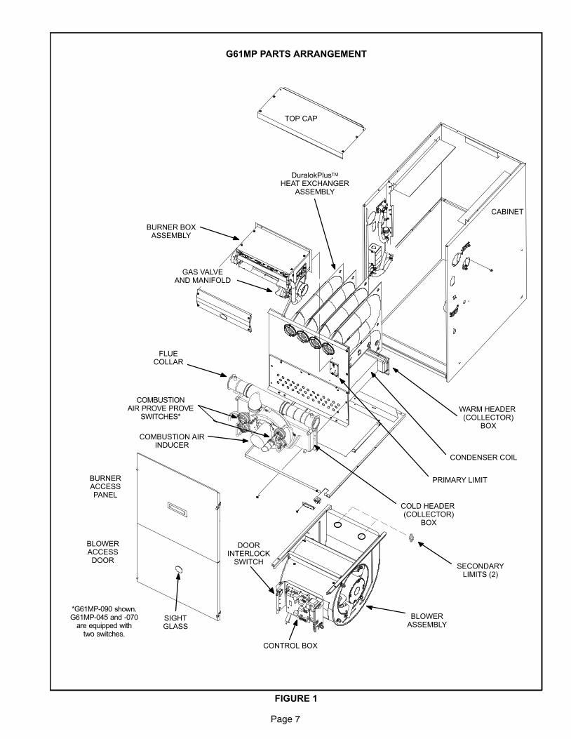
G61MP PARTS ARRANGEMENT
FIGURE 1
TOP CAP
CABINET
BURNER BOXASSEMBLY
SIGHTGLASS
DuralokPlusTM
HEAT EXCHANGERASSEMBLY
CONDENSER COIL
CONTROL BOX
DOORINTERLOCK
SWITCH
COLD HEADER (COLLECTOR)
BOX
COMBUSTION AIRINDUCER
BLOWERACCESSDOOR
BURNERACCESSPANEL
FLUECOLLAR
COMBUSTIONAIR PROVE PROVE
SWITCHES*
PRIMARY LIMIT
WARM HEADER (COLLECTOR)
BOX
GAS VALVEAND MANIFOLD
SECONDARYLIMITS (2)
BLOWERASSEMBLY
*G61MP−090 shown.G61MP−045 and −070
are equipped withtwo switches.
Page 8
I−UNIT COMPONENTS
G61MP unit components are shown in figure 1. The gas
valve, combustion air inducer and burners can be ac-
cessed by removing the burner access panel. Electrical
components are in the control box (figure 2) found in the
blower section.
G61MP units are factory equipped with a bottom return air
panel in place. The panel is designed to be field removed as
required for bottom air return. Markings are provided for side
return air and may be cut out in the field.
CAUTIONElectrostatic discharge can affect electroniccomponents. Take precautions during furnaceinstallation and service to protect the furnace’selectronic controls. Precautions will help to avoidcontrol exposure to electrostatic discharge byputting the furnace, the control and the techni-cian at the same electrostatic potential. Neutral-ize electrostatic charge by touching hand and alltools on an unpainted unit surface, such as thegas valve or blower deck, before performing anyservice procedure.
ELECTROSTATIC DISCHARGE (ESD)
Precautions and Procedures
A−Control Box
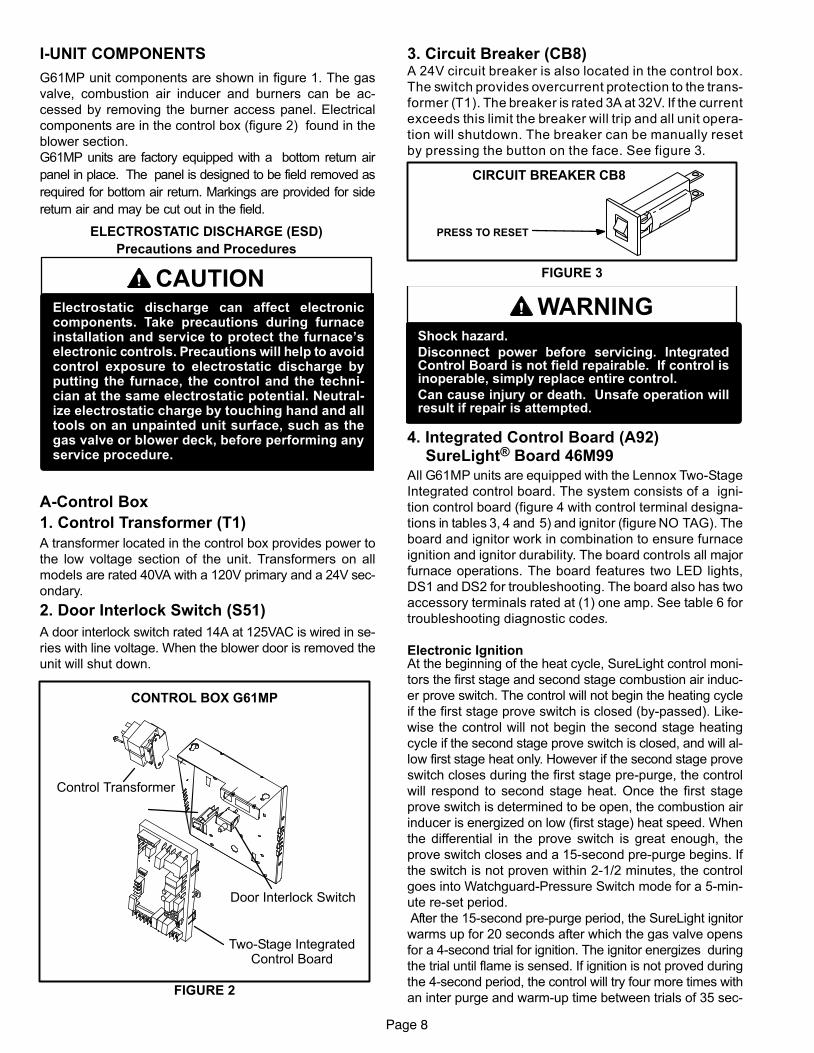
1. Control Transformer (T1)
A transformer located in the control box provides power to
the low voltage section of the unit. Transformers on all
models are rated 40VA with a 120V primary and a 24V sec-
ondary.
2. Door Interlock Switch (S51)
A door interlock switch rated 14A at 125VAC is wired in se-
ries with line voltage. When the blower door is removed the
unit will shut down.
FIGURE 2
CONTROL BOX G61MP
Door Interlock Switch
Two−Stage IntegratedControl Board
Control Transformer
3. Circuit Breaker (CB8)A 24V circuit breaker is also located in the control box.
The switch provides overcurrent protection to the trans-
former (T1). The breaker is rated 3A at 32V. If the current
exceeds this limit the breaker will trip and all unit opera-
tion will shutdown. The breaker can be manually reset
by pressing the button on the face. See figure 3.
FIGURE 3
CIRCUIT BREAKER CB8
PRESS TO RESET
WARNINGShock hazard.
Disconnect power before servicing. IntegratedControl Board is not field repairable. If control isinoperable, simply replace entire control.
Can cause injury or death. Unsafe operation willresult if repair is attempted.
4. Integrated Control Board (A92)SureLight® Board 46M99
All G61MP units are equipped with the Lennox Two−Stage
Integrated control board. The system consists of a igni-
tion control board (figure 4 with control terminal designa-
tions in tables 3, 4 and 5) and ignitor (figure NO TAG). The
board and ignitor work in combination to ensure furnace
ignition and ignitor durability. The board controls all major
furnace operations. The board features two LED lights,
DS1 and DS2 for troubleshooting. The board also has two
accessory terminals rated at (1) one amp. See table 6 for
troubleshooting diagnostic codes.
Electronic IgnitionAt the beginning of the heat cycle, SureLight control moni-
tors the first stage and second stage combustion air induc-
er prove switch. The control will not begin the heating cycle
if the first stage prove switch is closed (by−passed). Like-
wise the control will not begin the second stage heating
cycle if the second stage prove switch is closed, and will al-
low first stage heat only. However if the second stage prove
switch closes during the first stage pre−purge, the control
will respond to second stage heat. Once the first stage
prove switch is determined to be open, the combustion air
inducer is energized on low (first stage) heat speed. When
the differential in the prove switch is great enough, the
prove switch closes and a 15−second pre−purge begins. If
the switch is not proven within 2−1/2 minutes, the control
goes into Watchguard−Pressure Switch mode for a 5−min-
ute re−set period.
After the 15−second pre−purge period, the SureLight ignitor
warms up for 20 seconds after which the gas valve opens
for a 4−second trial for ignition. The ignitor energizes during
the trial until flame is sensed. If ignition is not proved during
the 4−second period, the control will try four more times with
an inter purge and warm−up time between trials of 35 sec-
Page 9
onds. After a total of five trials for ignition (including the ini-
tial trial), the control goes into Watchguard−Flame Failure
mode. After a 60−minute reset period, the control will begin
the ignition sequence again.
The SureLight control board has an added feature that pro-
longs the life of the ignitor. After a successful ignition, the
SureLight control utilizes less power to energize the ignitor
on successive calls for heat. The control continues to ramp
down the voltage to the ignitor until it finds the lowest
amount of power that will provide a successful ignition. This
amount of power is used for 255 cycles. On the 256th call
for heat, the control will again ramp down until the lowest
power is determined and the cycle begins again.
Two Stage Operation / Thermostat Selection Jumper
The control can be utilized in two modes: SINGLE−STAGE
thermostat or TWO−STAGE thermostat. The thermostat
selection jumper E20, located just below dip switches 1
through 4 (figure 4), must be positioned for the particular
application. The jumper is factory set on �TWO" for use
with a two−stage thermostat with two stage heat. Re−posi-
tion jumper to �SINGLE" for use with a single stage thermo-
stat with two stage heat.
While in the single−stage thermostat mode (single jumper
setting), the burners will always fire on first−stage heat. The
combustion air inducer will operate on low speed and in-
door blower will operate on low heat speed. After a 10 min-
ute recognition period, the unit will switch to second stage
heat. While in the two−stage thermostat mode (two jumper
setting) the burners will fire on first−stage heat. The com-
bustion air inducer will operate on low speed and indoor
blower will operate on low heat speed. The unit will switch
to second−stage heat on call from the indoor thermostat. If
there is a simultaneous call for first and second stage heat,
the unit will fire on first stage heat and switch to second
stage heat after 30 seconds of operation. See Sequence of
Operation flow charts in the back of this manual for more
detail.
Dip Switch Settings
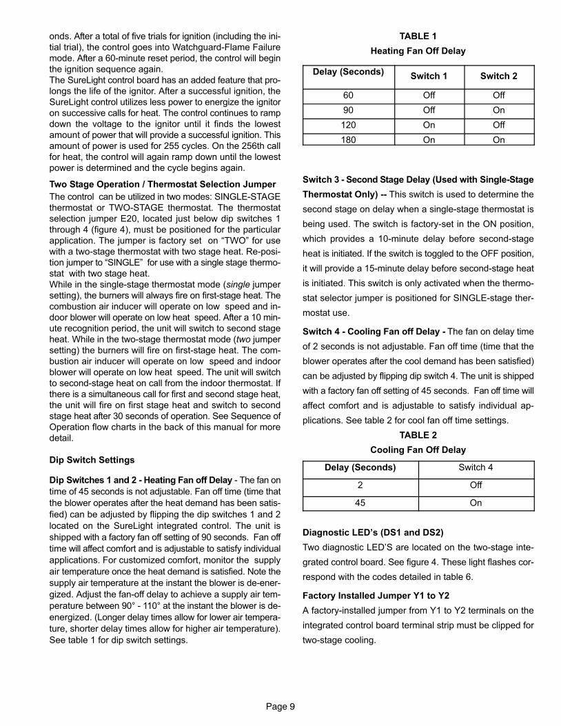
Dip Switches 1 and 2 − Heating Fan off Delay − The fan on
time of 45 seconds is not adjustable. Fan off time (time that
the blower operates after the heat demand has been satis-
fied) can be adjusted by flipping the dip switches 1 and 2
located on the SureLight integrated control. The unit is
shipped with a factory fan off setting of 90 seconds. Fan off
time will affect comfort and is adjustable to satisfy individual
applications. For customized comfort, monitor the supply
air temperature once the heat demand is satisfied. Note the
supply air temperature at the instant the blower is de−ener-
gized. Adjust the fan−off delay to achieve a supply air tem-
perature between 90° − 110° at the instant the blower is de−
energized. (Longer delay times allow for lower air tempera-
ture, shorter delay times allow for higher air temperature).
See table 1 for dip switch settings.
TABLE 1
Heating Fan Off Delay
Delay (Seconds)Switch 1 Switch 2
60 Off Off
90 Off On
120 On Off
180 On On
Switch 3 − Second Stage Delay (Used with Single−Stage
Thermostat Only) −− This switch is used to determine the
second stage on delay when a single−stage thermostat is
being used. The switch is factory−set in the ON position,
which provides a 10−minute delay before second−stage
heat is initiated. If the switch is toggled to the OFF position,
it will provide a 15−minute delay before second−stage heat
is initiated. This switch is only activated when the thermo-
stat selector jumper is positioned for SINGLE−stage ther-
mostat use.
Switch 4 − Cooling Fan off Delay − The fan on delay time
of 2 seconds is not adjustable. Fan off time (time that the
blower operates after the cool demand has been satisfied)
can be adjusted by flipping dip switch 4. The unit is shipped
with a factory fan off setting of 45 seconds. Fan off time will
affect comfort and is adjustable to satisfy individual ap-
plications. See table 2 for cool fan off time settings.
TABLE 2
Cooling Fan Off Delay
Delay (Seconds) Switch 4
2 Off
45 On
Diagnostic LED’s (DS1 and DS2)
Two diagnostic LED’S are located on the two−stage inte-
grated control board. See figure 4. These light flashes cor-
respond with the codes detailed in table 6.
Factory Installed Jumper Y1 to Y2
A factory−installed jumper from Y1 to Y2 terminals on the
integrated control board terminal strip must be clipped for
two−stage cooling.
Page 10
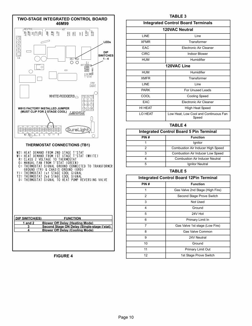
TWO−STAGE INTEGRATED CONTROL BOARD46M99
FIGURE 4
THERMOSTAT CONNECTIONS (TB1)
DIPSWITCHES
1 − 4
LEDs
W915 FACTORY INSTALLED JUMPER(MUST CLIP FOR 2 STAGE COOL)
DIP SWITCH(ES) FUNCTION
1 and 2 Blower Off Delay (Heating Mode)3 Second Stage ON Delay (Single−stage t’stat)4 Blower Off Delay (Cooling Mode)
TABLE 3
Integrated Control Board Terminals
120VAC Neutral
LINE Line
XFMR Transformer
EAC Electronic Air Cleaner
CIRC Indoor Blower
HUM Humidifier
120VAC Line
HUM Humidifier
XMFR Transformer
LINE Line
PARK For Unused Leads
COOL Cooling Speed
EAC Electronic Air Cleaner
HI HEAT HIigh Heat Speed
LO HEAT Low Heat, Low Cool and Continuous FanSpeed
TABLE 4
Integrated Control Board 5 Pin Terminal
PIN # Function
1 Ignitor
2 Combustion Air Inducer High Speed
3 Combustion Air Inducer Low Speed
4 Combustion Air Inducer Neutral
5 Ignitor Neutral
TABLE 5
Integrated Control Board 12Pin Terminal
PIN # Function
1 Gas Valve 2nd Stage (High Fire)
2 Second Stage Prove Switch
3 Not Used
4 Ground
5 24V Hot
6 Primary Limit In
7 Gas Valve 1st stage (Low Fire)
8 Gas Valve Common
9 24V Neutral
10 Ground
11 Primary Limit Out
12 1st Stage Prove Switch
Page 11
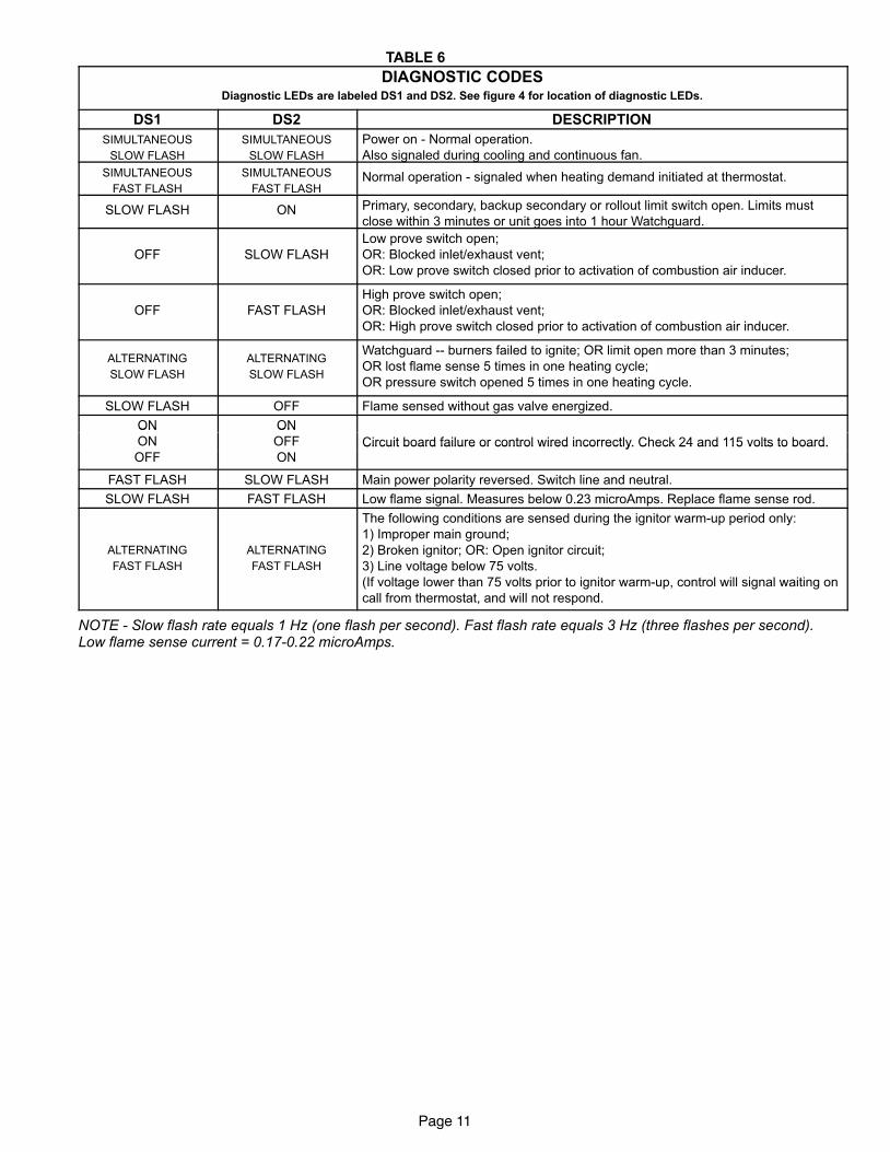
TABLE 6
DIAGNOSTIC CODESDiagnostic LEDs are labeled DS1 and DS2. See figure 4 for location of diagnostic LEDs.
DS1 DS2 DESCRIPTION
SIMULTANEOUS
SLOW FLASH
SIMULTANEOUS
SLOW FLASH
Power on − Normal operation.
Also signaled during cooling and continuous fan.
SIMULTANEOUS
FAST FLASH
SIMULTANEOUS
FAST FLASHNormal operation − signaled when heating demand initiated at thermostat.
SLOW FLASH ON Primary, secondary, backup secondary or rollout limit switch open. Limits must
close within 3 minutes or unit goes into 1 hour Watchguard.
OFF SLOW FLASH
Low prove switch open;
OR: Blocked inlet/exhaust vent;
OR: Low prove switch closed prior to activation of combustion air inducer.
OFF FAST FLASH
High prove switch open;
OR: Blocked inlet/exhaust vent;
OR: High prove switch closed prior to activation of combustion air inducer.
ALTERNATING
SLOW FLASH
ALTERNATING
SLOW FLASH
Watchguard −− burners failed to ignite; OR limit open more than 3 minutes;
OR lost flame sense 5 times in one heating cycle;
OR pressure switch opened 5 times in one heating cycle.
SLOW FLASH OFF Flame sensed without gas valve energized.
ON ONON
ON
ON
OFF Circuit board failure or control wired incorrectly. Check 24 and 115 volts to board.OFF ON
Circuit board failure or control wired incorrectly. Check 24 and 115 volts to board.
FAST FLASH SLOW FLASH Main power polarity reversed. Switch line and neutral.
SLOW FLASH FAST FLASH Low flame signal. Measures below 0.23 microAmps. Replace flame sense rod.
ALTERNATING
FAST FLASH
ALTERNATING
FAST FLASH
The following conditions are sensed during the ignitor warm−up period only:
1) Improper main ground;
2) Broken ignitor; OR: Open ignitor circuit;
3) Line voltage below 75 volts.
(If voltage lower than 75 volts prior to ignitor warm-up, control will signal waiting on
call from thermostat, and will not respond.
NOTE − Slow flash rate equals 1 Hz (one flash per second). Fast flash rate equals 3 Hz (three flashes per second).Low flame sense current = 0.17−0.22 microAmps.
Page 12
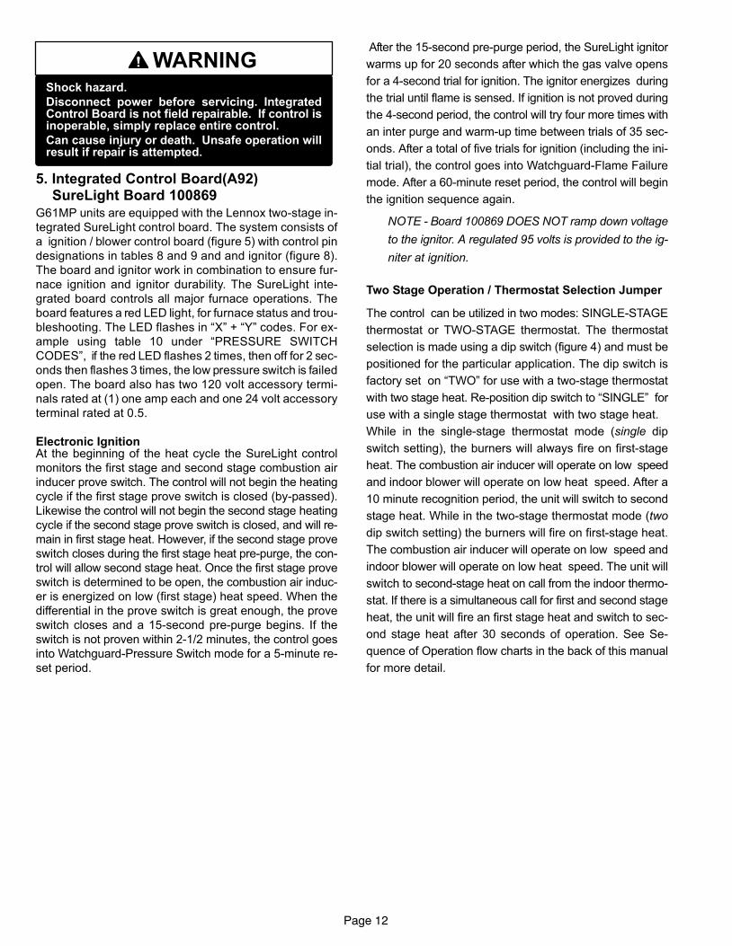
WARNINGShock hazard.
Disconnect power before servicing. IntegratedControl Board is not field repairable. If control isinoperable, simply replace entire control.
Can cause injury or death. Unsafe operation willresult if repair is attempted.
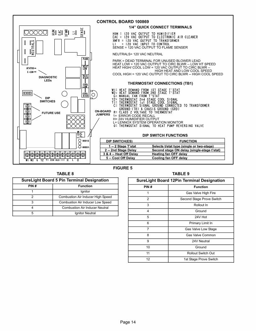
5. Integrated Control Board(A92)SureLight Board 100869
G61MP units are equipped with the Lennox two−stage in-
tegrated SureLight control board. The system consists of
a ignition / blower control board (figure 5) with control pin
designations in tables 8 and 9 and and ignitor (figure 8).
The board and ignitor work in combination to ensure fur-
nace ignition and ignitor durability. The SureLight inte-
grated board controls all major furnace operations. The
board features a red LED light, for furnace status and trou-
bleshooting. The LED flashes in �X" + �Y" codes. For ex-
ample using table 10 under �PRESSURE SWITCH
CODES", if the red LED flashes 2 times, then off for 2 sec-
onds then flashes 3 times, the low pressure switch is failed
open. The board also has two 120 volt accessory termi-
nals rated at (1) one amp each and one 24 volt accessory
terminal rated at 0.5.
Electronic IgnitionAt the beginning of the heat cycle the SureLight control
monitors the first stage and second stage combustion air
inducer prove switch. The control will not begin the heating
cycle if the first stage prove switch is closed (by−passed).
Likewise the control will not begin the second stage heating
cycle if the second stage prove switch is closed, and will re-
main in first stage heat. However, if the second stage prove
switch closes during the first stage heat pre−purge, the con-
trol will allow second stage heat. Once the first stage prove
switch is determined to be open, the combustion air induc-
er is energized on low (first stage) heat speed. When the
differential in the prove switch is great enough, the prove
switch closes and a 15−second pre−purge begins. If the
switch is not proven within 2−1/2 minutes, the control goes
into Watchguard−Pressure Switch mode for a 5−minute re−
set period.
After the 15−second pre−purge period, the SureLight ignitor
warms up for 20 seconds after which the gas valve opens
for a 4−second trial for ignition. The ignitor energizes during
the trial until flame is sensed. If ignition is not proved during
the 4−second period, the control will try four more times with
an inter purge and warm−up time between trials of 35 sec-
onds. After a total of five trials for ignition (including the ini-
tial trial), the control goes into Watchguard−Flame Failure
mode. After a 60−minute reset period, the control will begin
the ignition sequence again.
NOTE − Board 100869 DOES NOT ramp down voltage
to the ignitor. A regulated 95 volts is provided to the ig-
niter at ignition.
Two Stage Operation / Thermostat Selection Jumper
The control can be utilized in two modes: SINGLE−STAGE
thermostat or TWO−STAGE thermostat. The thermostat
selection is made using a dip switch (figure 4) and must be
positioned for the particular application. The dip switch is
factory set on �TWO" for use with a two−stage thermostat
with two stage heat. Re−position dip switch to �SINGLE" for
use with a single stage thermostat with two stage heat.
While in the single−stage thermostat mode (single dip
switch setting), the burners will always fire on first−stage
heat. The combustion air inducer will operate on low speed
and indoor blower will operate on low heat speed. After a
10 minute recognition period, the unit will switch to second
stage heat. While in the two−stage thermostat mode (two
dip switch setting) the burners will fire on first−stage heat.
The combustion air inducer will operate on low speed and
indoor blower will operate on low heat speed. The unit will
switch to second−stage heat on call from the indoor thermo-
stat. If there is a simultaneous call for first and second stage
heat, the unit will fire an first stage heat and switch to sec-
ond stage heat after 30 seconds of operation. See Se-
quence of Operation flow charts in the back of this manual
for more detail.
Page 13
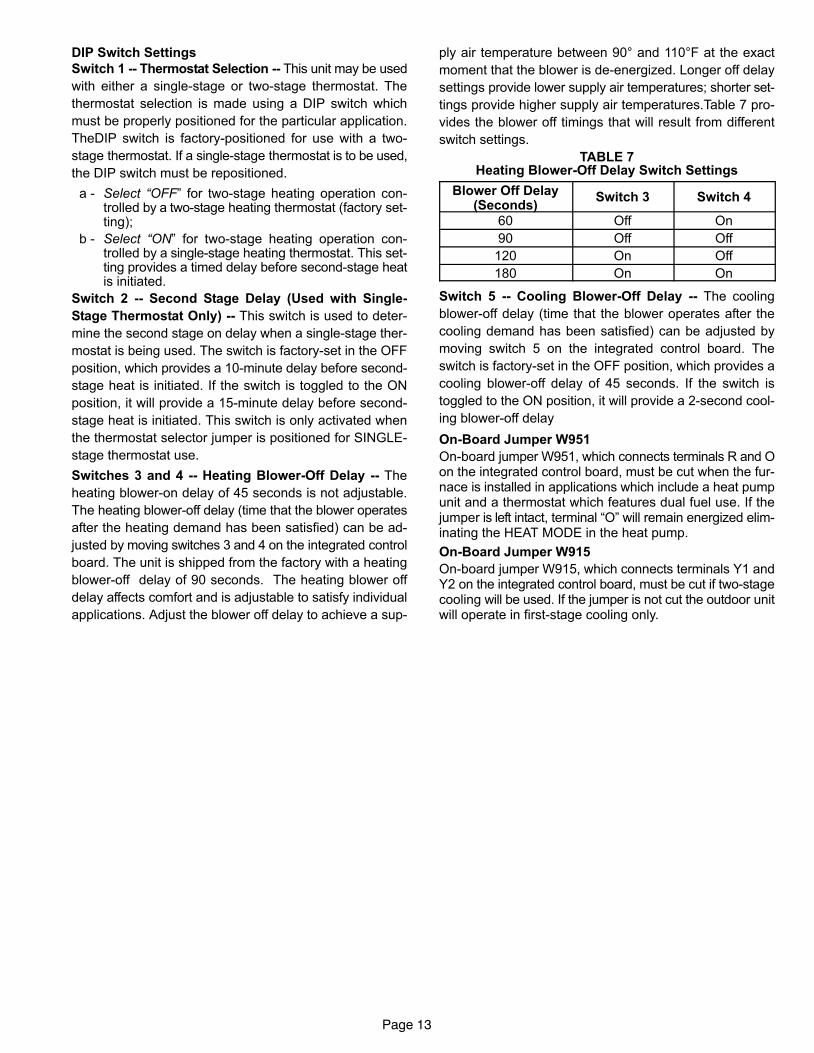
DIP Switch Settings
Switch 1 −− Thermostat Selection −− This unit may be used
with either a single−stage or two−stage thermostat. The
thermostat selection is made using a DIP switch which
must be properly positioned for the particular application.
TheDIP switch is factory−positioned for use with a two−
stage thermostat. If a single−stage thermostat is to be used,
the DIP switch must be repositioned.
a − Select �OFF" for two−stage heating operation con-trolled by a two−stage heating thermostat (factory set-ting);
b − Select �ON" for two−stage heating operation con-trolled by a single−stage heating thermostat. This set-ting provides a timed delay before second−stage heatis initiated.
Switch 2 −− Second Stage Delay (Used with Single−
Stage Thermostat Only) −− This switch is used to deter-
mine the second stage on delay when a single−stage ther-
mostat is being used. The switch is factory−set in the OFF
position, which provides a 10−minute delay before second−
stage heat is initiated. If the switch is toggled to the ON
position, it will provide a 15−minute delay before second−
stage heat is initiated. This switch is only activated when
the thermostat selector jumper is positioned for SINGLE−
stage thermostat use.
Switches 3 and 4 −− Heating Blower−Off Delay −− The
heating blower−on delay of 45 seconds is not adjustable.
The heating blower−off delay (time that the blower operates
after the heating demand has been satisfied) can be ad-
justed by moving switches 3 and 4 on the integrated control
board. The unit is shipped from the factory with a heating
blower−off delay of 90 seconds. The heating blower off
delay affects comfort and is adjustable to satisfy individual
applications. Adjust the blower off delay to achieve a sup-
ply air temperature between 90° and 110°F at the exact
moment that the blower is de−energized. Longer off delay
settings provide lower supply air temperatures; shorter set-
tings provide higher supply air temperatures.Table 7 pro-
vides the blower off timings that will result from different
switch settings.
TABLE 7Heating Blower−Off Delay Switch Settings
Blower Off Delay(Seconds)
Switch 3 Switch 4
60 Off On
90 Off Off
120 On Off
180 On On
Switch 5 −− Cooling Blower−Off Delay −− The cooling
blower−off delay (time that the blower operates after the
cooling demand has been satisfied) can be adjusted by
moving switch 5 on the integrated control board. The
switch is factory−set in the OFF position, which provides a
cooling blower−off delay of 45 seconds. If the switch is
toggled to the ON position, it will provide a 2−second cool-
ing blower−off delay
On−Board Jumper W951
On−board jumper W951, which connects terminals R and Oon the integrated control board, must be cut when the fur-nace is installed in applications which include a heat pumpunit and a thermostat which features dual fuel use. If thejumper is left intact, terminal �O" will remain energized elim-inating the HEAT MODE in the heat pump.
On−Board Jumper W915
On−board jumper W915, which connects terminals Y1 andY2 on the integrated control board, must be cut if two−stagecooling will be used. If the jumper is not cut the outdoor unitwill operate in first−stage cooling only.
Page 14
CONTROL BOARD 100869
FIGURE 5
THERMOSTAT CONNECTIONS (TB1)
1/4" QUICK CONNECT TERMINALS
DIP SWITCH FUNCTIONS
DIPSWITCHES
DIAGNOSTICLEDs
ON−BOARDJUMPERS 1= ERROR CODE RECALL
H= 24V HUMIDIFIER OUTPUTL= LENNOX SYSTEM OPERATION MONITOR
SENSE = 120 VAC OUTPUT TO FLAME SENSER
NEUTRALS= 120 VAC NEUTRAL
PARK = DEAD TERMINAL FOR UNUSED BLOWER LEADHEAT LOW = 120 VAC OUTPUT TO CIRC BLWR −− LOW HT SPEEDHEAT HIGH/ COOL LOW = 120 VAC OUTPUT TO CIRC BLWR −−
HIGH HEAT AND LOW COOL SPEEDCOOL HIGH = 120 VAC OUTPUT TO CIRC BLWR −− HIGH COOL SPEED
DIP SWITCH(ES) FUNCTION
1 −− 2 Stage T’stat Selects t/stat type (single or two−stage)2 −− 2nd Stage Delay Second stage ON delay (single−stage t’stat)
3 & 4 −− Heat Off Delay Heating fan OFF delay
5 −− Cool Off Delay Cooling fan OFF delay
W915
W951
FUTURE USE
TABLE 8
SureLight Board 5 Pin Terminal Designation
PIN # Function
1 Ignitor
2 Combustion Air Inducer High Speed
3 Combustion Air Inducer Low Speed
4 Combustion Air Inducer Neutral
5 Ignitor Neutral
TABLE 9
SureLight Board 12Pin Terminal Designation
PIN # Function
1 Gas Valve High Fire
2 Second Stage Prove Switch
3 Rollout In
4 Ground
5 24V Hot
6 Primary Limit In
7 Gas Valve Low Stage
8 Gas Valve Common
9 24V Neutral
10 Ground
11 Rollout Switch Out
12 1st Stage Prove Switch
Page 15
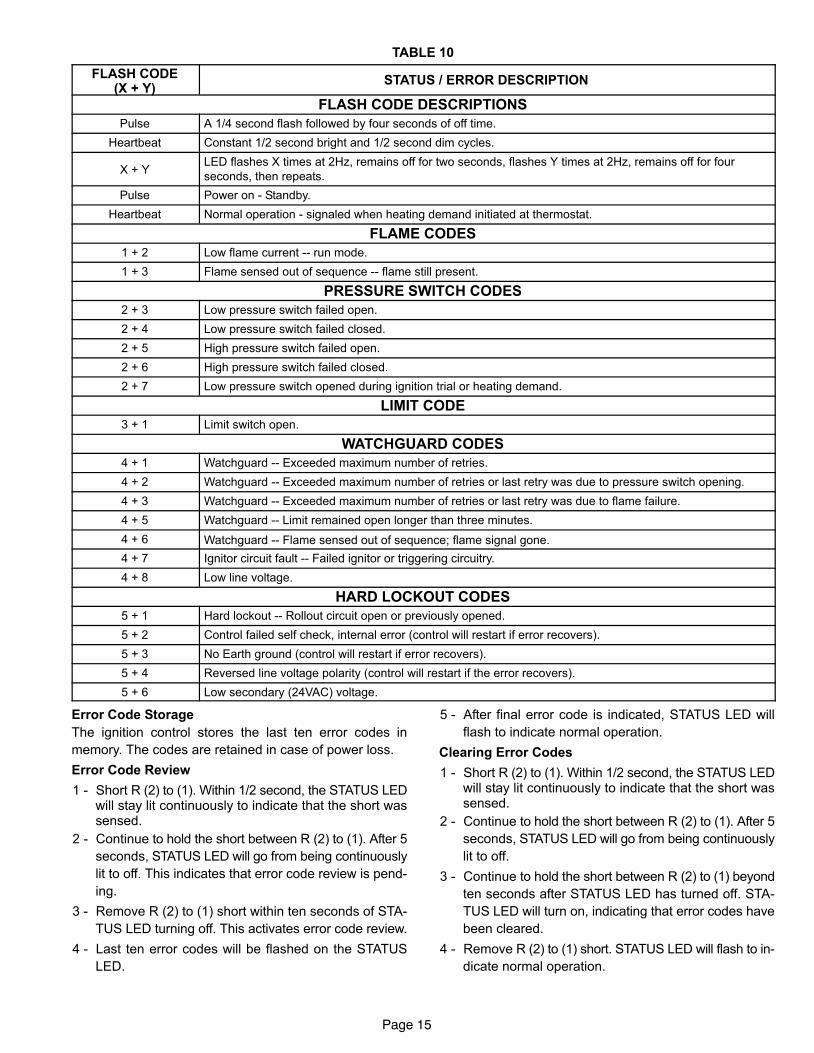
TABLE 10
FLASH CODE(X + Y)
STATUS / ERROR DESCRIPTION
FLASH CODE DESCRIPTIONS
Pulse A 1/4 second flash followed by four seconds of off time.
Heartbeat Constant 1/2 second bright and 1/2 second dim cycles.
X + YLED flashes X times at 2Hz, remains off for two seconds, flashes Y times at 2Hz, remains off for four
seconds, then repeats.
Pulse Power on − Standby.
Heartbeat Normal operation − signaled when heating demand initiated at thermostat.
FLAME CODES
1 + 2 Low flame current −− run mode.
1 + 3 Flame sensed out of sequence −− flame still present.
PRESSURE SWITCH CODES
2 + 3 Low pressure switch failed open.
2 + 4 Low pressure switch failed closed.
2 + 5 High pressure switch failed open.
2 + 6 High pressure switch failed closed.
2 + 7 Low pressure switch opened during ignition trial or heating demand.
LIMIT CODE
3 + 1 Limit switch open.
WATCHGUARD CODES
4 + 1 Watchguard −− Exceeded maximum number of retries.
4 + 2 Watchguard −− Exceeded maximum number of retries or last retry was due to pressure switch opening.
4 + 3 Watchguard −− Exceeded maximum number of retries or last retry was due to flame failure.
4 + 5 Watchguard −− Limit remained open longer than three minutes.
4 + 6 Watchguard −− Flame sensed out of sequence; flame signal gone.
4 + 7 Ignitor circuit fault −− Failed ignitor or triggering circuitry.
4 + 8 Low line voltage.
HARD LOCKOUT CODES
5 + 1 Hard lockout −− Rollout circuit open or previously opened.
5 + 2 Control failed self check, internal error (control will restart if error recovers).
5 + 3 No Earth ground (control will restart if error recovers).
5 + 4 Reversed line voltage polarity (control will restart if the error recovers).
5 + 6 Low secondary (24VAC) voltage.
Error Code Storage
The ignition control stores the last ten error codes in
memory. The codes are retained in case of power loss.
Error Code Review
1 − Short R (2) to (1). Within 1/2 second, the STATUS LEDwill stay lit continuously to indicate that the short wassensed.
2 − Continue to hold the short between R (2) to (1). After 5
seconds, STATUS LED will go from being continuously
lit to off. This indicates that error code review is pend-
ing.
3 − Remove R (2) to (1) short within ten seconds of STA-
TUS LED turning off. This activates error code review.
4 − Last ten error codes will be flashed on the STATUS
LED.
5 − After final error code is indicated, STATUS LED will
flash to indicate normal operation.
Clearing Error Codes
1 − Short R (2) to (1). Within 1/2 second, the STATUS LEDwill stay lit continuously to indicate that the short wassensed.
2 − Continue to hold the short between R (2) to (1). After 5
seconds, STATUS LED will go from being continuously
lit to off.
3 − Continue to hold the short between R (2) to (1) beyond
ten seconds after STATUS LED has turned off. STA-
TUS LED will turn on, indicating that error codes have
been cleared.
4 − Remove R (2) to (1) short. STATUS LED will flash to in-
dicate normal operation.
Page 16
B−Blower Compartment
1. Blower Motor (B3) and Capacitor (C4)
All G61MP units use direct drive blower motors. All motors
are 120V permanent split capacitor motors to ensure maxi-
mum efficiency. Ratings for capacitors will be on motor
nameplate. See SPECIFICATIONS section for motor speci-
fications.
NOTE − Shafts on 1 HP motors have 2 flat sides and arematched with blower wheels with 2 set screws.
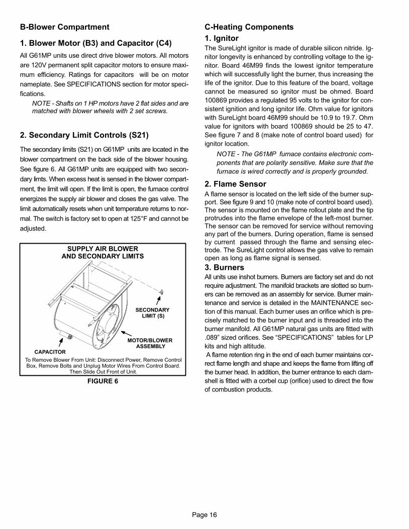
2. Secondary Limit Controls (S21)
The secondary limits (S21) on G61MP units are located in the
blower compartment on the back side of the blower housing.
See figure 6. All G61MP units are equipped with two secon-
dary limts. When excess heat is sensed in the blower compart-
ment, the limit will open. If the limit is open, the furnace control
energizes the supply air blower and closes the gas valve. The
limit automatically resets when unit temperature returns to nor-
mal. The switch is factory set to open at 125°F and cannot be
adjusted.
FIGURE 6
SUPPLY AIR BLOWERAND SECONDARY LIMITS
SECONDARY LIMIT (S)
CAPACITOR
MOTOR/BLOWER ASSEMBLY
To Remove Blower From Unit: Disconnect Power, Remove ControlBox, Remove Bolts and Unplug Motor Wires From Control Board.
Then Slide Out Front of Unit.
C−Heating Components
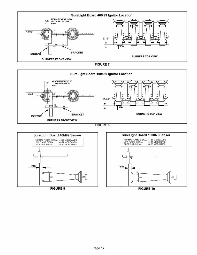
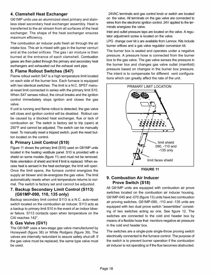
1. Ignitor
The SureLight ignitor is made of durable silicon nitride. Ig-
nitor longevity is enhanced by controlling voltage to the ig-
nitor. Board 46M99 finds the lowest ignitor temperature
which will successfully light the burner, thus increasing the
life of the ignitor. Due to this feature of the board, voltage
cannot be measured so ignitor must be ohmed. Board
100869 provides a regulated 95 volts to the ignitor for con-
sistent ignition and long ignitor life. Ohm value for ignitors
with SureLight board 46M99 should be 10.9 to 19.7. Ohm
value for ignitors with board 100869 should be 25 to 47.
See figure 7 and 8 (make note of control board used) for
ignitor location.
NOTE − The G61MP furnace contains electronic com-
ponents that are polarity sensitive. Make sure that the
furnace is wired correctly and is properly grounded.
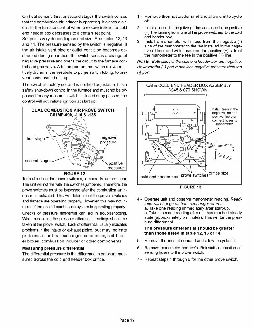
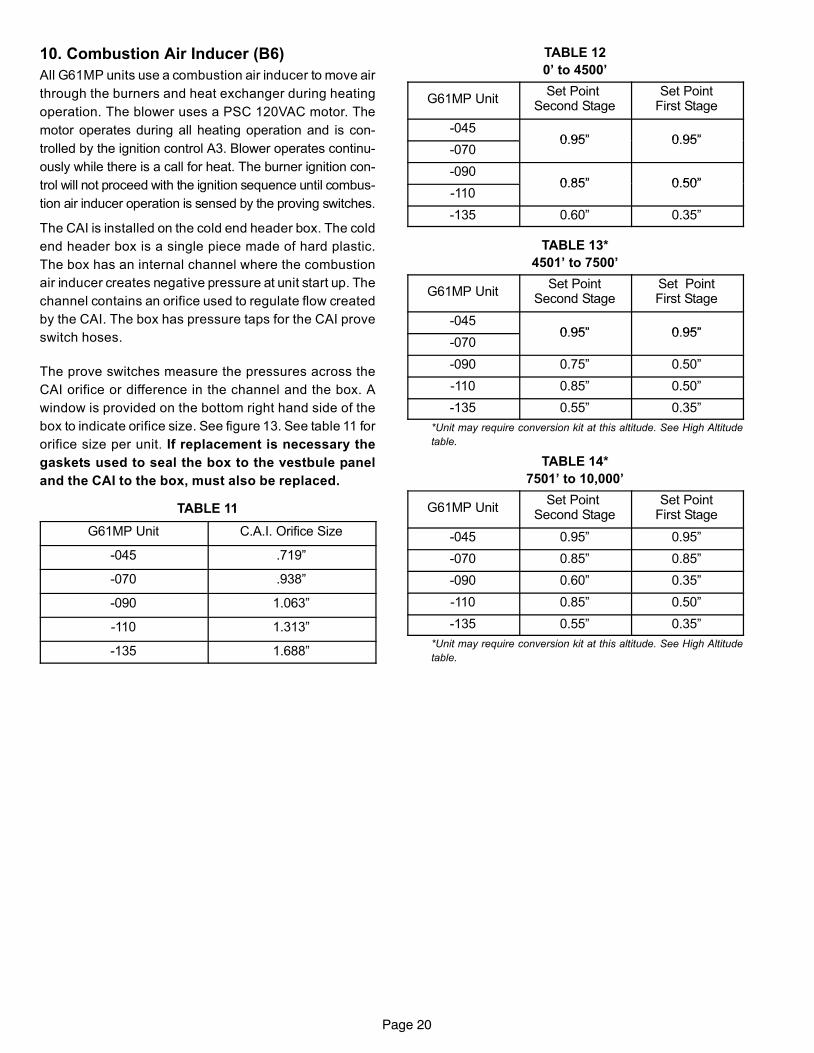
2. Flame Sensor
A flame sensor is located on the left side of the burner sup-
port. See figure 9 and 10 (make note of control board used).
The sensor is mounted on the flame rollout plate and the tip
protrudes into the flame envelope of the left−most burner.
The sensor can be removed for service without removing
any part of the burners. During operation, flame is sensed
by current passed through the flame and sensing elec-
trode. The SureLight control allows the gas valve to remain
open as long as flame signal is sensed.
3. BurnersAll units use inshot burners. Burners are factory set and do not
require adjustment. The manifold brackets are slotted so burn-
ers can be removed as an assembly for service. Burner main-
tenance and service is detailed in the MAINTENANCE sec-
tion of this manual. Each burner uses an orifice which is pre-
cisely matched to the burner input and is threaded into the
burner manifold. All G61MP natural gas units are fitted with
.089" sized orifices. See �SPECIFICATIONS" tables for LP
kits and high altitude.
A flame retention ring in the end of each burner maintains cor-
rect flame length and shape and keeps the flame from lifting off
the burner head. In addition, the burner entrance to each clam-
shell is fitted with a corbel cup (orifice) used to direct the flow
of combustion products.
Page 17
FIGURE 7
5/16"
13/32’
5/8"
SureLight Board 46M99 Ignitor Location
BURNERS TOP VIEWBURNERS FRONT VIEW
MEASUREMENT IS TOI.D. OF RETENTIONRING
IGNITORBRACKET
FIGURE 8
21/64"
7/32’
5/8"
SureLight Board 100869 Ignitor Location
BURNERS TOP VIEW
BURNERS FRONT VIEW
MEASUREMENT IS TOI.D. OF RETENTIONRING
IGNITORBRACKET
FIGURE 9
NORMAL FLAME SIGNAL > 0.23 MICROAMPSLOW FLAME SIGNAL < 0.22 MICROAMPSDROP OUT SIGNAL = 0.16 MICROAMPS
5/16"
SureLight Board 46M99 Sensor
FIGURE 10
NORMAL FLAME SIGNAL > 1.50 MICROAMPSLOW FLAME SIGNAL < 1.40 MICROAMPSDROP OUT SIGNAL = 0.20 MICROAMPS
5/16"
SureLight Board 100869 Sensor
Page 18
4. Clamshell Heat Exchanger
G61MP units use an aluminized steel primary and stain-
less steel secondary heat exchanger assembly. Heat is
transferred to the air stream from all surfaces of the heat
exchanger. The shape of the heat exchanger ensures
maximum efficiency.
The combustion air inducer pulls fresh air through the air
intake box. This air is mixed with gas in the burner venturi
and at the corbel orifices. The gas / air mixture is then
burned at the entrance of each clamshell. Combustion
gases are then pulled through the primary and secondary heat
exchangers and exhausted out the exhaust vent pipe.
5. Flame Rollout Switches (S47)Flame rollout switch S47 is a high temperature limit located
on each side of the burner box. Each furnace is equipped
with two identical switches. The limit is a N.C. SPST manu-
al-reset limit connected in series with the primary limit S10.
When S47 senses rollout, the circuit breaks and the ignition
control immediately stops ignition and closes the gas
valve.
If unit is running and flame rollout is detected, the gas valve
will close and ignition control will be disabled. Rollout can
be caused by a blocked heat exchanger, flue or lack of
combustion air. The switch is factory set to trip (open) at
250°F and cannot be adjusted. The switch can be manually
reset. To manually reset a tripped switch, push the reset but-
ton located on the control.
6. Primary Limit Control (S10)
Figure 11 shows the primary limit (S10) used on G61MP units
located in the heating vestibule panel. S10 is provided with a
shield on some models (figure 11) and must not be removed.
Note orientation of shield and limit if limit is replaced. When ex-
cess heat is sensed in the heat exchanger, the limit will open.
Once the limit opens, the furnace control energizes the
supply air blower and de−energizes the gas valve. The limit
automatically resets when unit temperature returns to nor-
mal. The switch is factory set and cannot be adjusted.
7. Backup Secondary Limit Control (S113)(G61MP−090, 110, 135 only)
Backup secondary limit control S113 is a N.C. auto−reset
switch located on the combustion air inducer. S113 acts as
a backup to primary limit S10 in the event of an indoor blow-
er failure. S113 contacts open when temperature on the
CAI reaches 142°.
8. Gas Valve (GV1)The G61MP uses a two−stage gas valve manufactured by
Honeywell (figure 38) or White Rodgers (figure 39). The
valves are internally redundant to assure safety shut−off. If
the gas valve must be replaced, the same type valve must
be used.
24VAC terminals and gas control knob or switch are located
on the valve. All terminals on the gas valve are connected to
wires from the electronic ignition control. 24V applied to the ter-
minals energizes the valve.
Inlet and outlet pressure taps are located on the valve. A regu-
lator adjustment screw is located on the valve.
LPG change over kit s are available from Lennox. Kits include
burner orifices and a gas valve regulator conversion kit.
The burner box is sealed and operates under a negative
pressure. A pressure hose is connected from the burner
box to the gas valve. The gas valve senses the pressure in
the burner box and changes gas valve outlet (manifold)
pressure based on changes in the burner box pressure.
The intent is to compensate for different vent configura-
tions which can greatly affect the rate of the unit.
FIGURE 11
PRIMARY LIMIT LOCATION
limit faces shield
limit shield090, −110 and
−135 only
9. Combustion Air Inducer Prove Switch (S18)
All G61MP units are equipped with combustion air prove
switches located on the combustion air inducer housing.
G61MP−045 and −070 (figure 13) units have two combustion
air proving switches. G61MP−090, −110 and −135 units are
equipped with two dual prove switch �assemblies" consist-
ing of two switches acting as one. See figure 12. The
switches are connected to the cold end header box by
means of a flexible hose that monitors negative air pressure
in the cold end header box.
The switches are a single-pole single-throw proving switch
electrically connected to the furnace control. The purpose of
the switch is to prevent burner operation if the combustion
air inducer is not operating or if the flue becomes obstructed.
Page 19
On heat demand (first or second stage) the switch senses
that the combustion air inducer is operating. It closes a cir-
cuit to the furnace control when pressure inside the cold
end header box decreases to a certain set point.
Set points vary depending on unit size. See tables 12, 13
and 14. The pressure sensed by the switch is negative. If
the air intake vent pipe or outlet vent pipe becomes ob-
structed during operation, the switch senses a change of
negative pressure and opens the circuit to the furnace con-
trol and gas valve. A bleed port on the switch allows rela-
tively dry air in the vestibule to purge switch tubing, to pre-
vent condensate build up.
The switch is factory set and is not field adjustable. It is a
safety shut-down control in the furnace and must not be by−
passed for any reason. If switch is closed or by−passed, the
control will not initiate ignition at start up.
FIGURE 12
DUAL COMBUSTION AIR PROVE SWITCHG61MP−090, −110 & −135
first stage
second stagepositivepressure
negativepressure
To troubleshoot the prove switches, temporarily jumper them.
The unit will not fire with the switches jumpered. Therefore, the
prove switches must be bypassed after the combustion air in-
ducer is activated. This will determine if the prove switches
and furnace are operating properly. However, this may not in-
dicate if the sealed combustion system is operating properly.
Checks of pressure differential can aid in troubleshooting.
When measuring the pressure differential, readings should be
taken at the prove switch. Lack of differential usually indicates
problems in the intake or exhaust piping, but may indicate
problems in the heat exchanger, condensing coil, head-
er boxes, combustion inducer or other components.
Measuring pressure differential
The differential pressure is the difference in pressure mea-
sured across the cold end header box orifice.
1 − Remove thermostat demand and allow unit to cycleoff.
2 − Install a tee in the negative (−) line and a tee in the positive(+) line running from one of the prove switches to the coldend header box.
3 − Install a manometer with hose from the negative (−)side of the manometer to the tee installed in the nega-tive (−) line and with hose from the positive (+) side ofthe manometer to the tee in the positive (+) line.
NOTE − Both sides of the cold end header box are negative.
However the (+) port reads less negative pressure than the
(−) port.
FIGURE 13
Install tee’s in thenegative line andpositive line thenconnect hoses to
manometer.
prove switchesorifice size
CAI & COLD END HEADER BOX ASSEMBLY(−045 & 070 SHOWN)
cold end header box
++ __
4 − Operate unit and observe manometer reading. Read-ings will change as heat exchanger warms.a. Take one reading immediately after start-up.b. Take a second reading after unit has reached steadystate (approximately 5 minutes). This will be the pres-sure differential.
The pressure differential should be greater
than those listed in table 12, 13 or 14.
5 − Remove thermostat demand and allow to cycle off.
6 − Remove manometer and tee’s. Reinstall combustion airsensing hoses to the prove switch.
7 − Repeat steps 1 through 6 for the other prove switch.
Page 20
10. Combustion Air Inducer (B6)
All G61MP units use a combustion air inducer to move air
through the burners and heat exchanger during heating
operation. The blower uses a PSC 120VAC motor. The
motor operates during all heating operation and is con-
trolled by the ignition control A3. Blower operates continu-
ously while there is a call for heat. The burner ignition con-
trol will not proceed with the ignition sequence until combus-
tion air inducer operation is sensed by the proving switches.
The CAI is installed on the cold end header box. The cold
end header box is a single piece made of hard plastic.
The box has an internal channel where the combustion
air inducer creates negative pressure at unit start up. The
channel contains an orifice used to regulate flow created
by the CAI. The box has pressure taps for the CAI prove
switch hoses.
The prove switches measure the pressures across the
CAI orifice or difference in the channel and the box. A
window is provided on the bottom right hand side of the
box to indicate orifice size. See figure 13. See table 11 for
orifice size per unit. If replacement is necessary the
gaskets used to seal the box to the vestbule panel
and the CAI to the box, must also be replaced.
TABLE 11
G61MP Unit C.A.I. Orifice Size
−045 .719"
−070 .938"
−090 1.063"
−110 1.313"
−135 1.688"
TABLE 12
0’ to 4500’
G61MP UnitSet Point
Second StageSet Point
First Stage
−0450 95" 0 95"
−0700.95" 0.95"
−0900 85" 0 50"
−1100.85" 0.50"
−135 0.60" 0.35"
TABLE 13*
4501’ to 7500’
G61MP UnitSet Point
Second StageSet PointFirst Stage
−0450 95" 0 95"
−0700.95" 0.95"
−090 0.75" 0.50"
−110 0.85" 0.50"
−135 0.55" 0.35"
*Unit may require conversion kit at this altitude. See High Altitude
table.
TABLE 14*
7501’ to 10,000’
G61MP UnitSet Point
Second StageSet Point
First Stage
−045 0.95" 0.95"
−070 0.85" 0.85"
−090 0.60" 0.35"
−110 0.85" 0.50"
−135 0.55" 0.35"
*Unit may require conversion kit at this altitude. See High Altitude
table.
Page 21
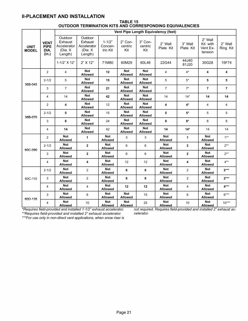
II−PLACEMENT AND INSTALLATIONTABLE 15
OUTDOOR TERMINATION KITS AND CORRESPONDING EQUIVALENCIES
Vent Pipe Length Equivalency (feet)
UNITMODEL
VENTPIPEDIA.(in.)
OutdoorExhaust
Accelerator(Dia. XLength)
OutdoorExhaust
Accelerator(Dia. XLength)
1−1/2"Concen-tric Kit
2" Con-centric
Kit
3" Con-centric
Kit
2" WallPlate Kit
3" WallPlate Kit
2" WallKit withVent Ex-tension
2" WallRing Kit
1−1/2" X 12" 2" X 12" 71M80 60M29 60L46 22G4444J4081J20
30G28 15F74
2 4 NotAllowed
12 NotAllowed
NotAllowed
4 4* 4 4
36B−045
2−1/2 5 NotAllowed
15 NotAllowed
NotAllowed
5 5* 5 5
36B−045
3 7 NotAllowed
21 NotAllowed
NotAllowed
7 7* 7 7
4 14 NotAllowed
42 NotAllowed
NotAllowed
14 14* 14 14
2 4 NotAllowed
12 NotAllowed
NotAllowed
4 4* 4 4
36B−070
2−1/2 5 NotAllowed
15 NotAllowed
NotAllowed
5 5* 5 5
36B−070
3 8 NotAllowed
24 NotAllowed
NotAllowed
8 8* 8 8
4 14 NotAllowed
42 NotAllowed
NotAllowed
14 14* 14 14
2 NotAllowed
1 NotAllowed
3 3 NotAllowed
1 NotAllowed
1**
60C−090
2−1/2 NotAllowed
2 NotAllowed
6 6 NotAllowed
2 NotAllowed
2**
60C−090
3 NotAllowed
2 NotAllowed
6 6 NotAllowed
2 NotAllowed
2**
4 NotAllowed
4 NotAllowed
12 12 NotAllowed
4 NotAllowed
4**
2−1/2 NotAllowed
2 NotAllowed
6 6 NotAllowed
2 NotAllowed
2***
60C−110 3 NotAllowed
2 NotAllowed
6 6 NotAllowed
2 NotAllowed
2***
4 NotAllowed
4 NotAllowed
12 12 NotAllowed
4 NotAllowed
4***
60D−135
3 NotAllowed
6 NotAllowed
NotAllowed
15 NotAllowed
6 NotAllowed
6***
60D−135
4 NotAllowed
10 NotAllowed
NotAllowed
25 NotAllowed
10 NotAllowed
10***
*Requires field−provided and installed 1−1/2" exhaust accelerator.**Requires field−provided and installed 2" exhaust accelerator.***For use only in non−direct vent applications, when snow riser is
not required. Requires field−provided and installed 2" exhaust ac-celerator.
Page 22
A−Vent Piping Guidelines
The G61MP can be installed as either a Non−Direct Vent
or a Direct Vent gas central furnace.
NOTE − In Non-Direct Vent installations, combustion air is
taken from indoors and flue gases are discharged outdoors.
In Direct Vent installations, combustion air is taken from out-
doors and flue gases are discharged outdoors.
Intake and exhaust pipe sizing in Direct Vent applications
and exhaust pipe sizing in Non-Direct Vent applications −−
Size pipe according to tables 16 and 17. Table 16 lists the
minimum equivalent vent pipe lengths permitted. Table 17
lists the maximum equivalent pipe lengths permitted.
Maximum vent length is defined as:
Total length (linear feet) of pipe,
Plus Equivalent length (feet) of fittings,
Plus Equivalent length (feet) of termination.
NOTE − Include ALL pipe and ALL fittings, both in
doors and outdoors.
Regardless of the diameter of pipe used, the standard roof
and wall terminations described in section Exhaust Piping
Terminations should be used. Exhaust vent termination
pipe is sized to optimize the velocity of the exhaust gas as
it exits the termination. Refer to table 18.
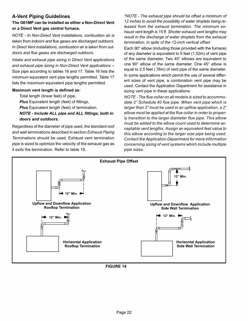
*NOTE − The exhaust pipe should be offset a minimum of
12 inches to avoid the possibility of water droplets being re-
leased from the exhaust termination. The minimum ex-
haust vent length is 15 ft. Shorter exhaust vent lengths may
result in the discharge of water droplets from the exhaust
termination, in spite of the 12−inch vertical offset.
Each 90° elbow (including those provided with the furnace)
of any diameter is equivalent to 5 feet (1.52m) of vent pipe
of the same diameter. Two 45° elbows are equivalent to
one 90° elbow of the same diameter. One 45° elbow is
equal to 2.5 feet (.76m) of vent pipe of the same diameter.
In some applications which permit the use of several differ-
ent sizes of vent pipe, a combination vent pipe may be
used. Contact the Application Department for assistance in
sizing vent pipe in these applications.
NOTE − The flue collar on all models is sized to accommo-
date 2" Schedule 40 flue pipe. When vent pipe which is
larger than 2" must be used in an upflow application, a 2"
elbow must be applied at the flue collar in order to proper-
ly transition to the larger diameter flue pipe. This elbow
must be added to the elbow count used to determine ac-
ceptable vent lengths. Assign an equivalent feet value to
this elbow according to the larger size pipe being used.
Contact the Application Department for more information
concerning sizing of vent systems which include multiple
pipe sizes.
FIGURE 14
Exhaust Pipe Offset
12" Min.
12" Min.12" Min.
12" Min.
Upflow and Downflow ApplicationRooftop Termination
Upflow and Downflow ApplicationSide Wall Termination
Horizontal ApplicationRooftop Termination
Horizontal ApplicationSide Wall Termination
Page 23
Use the following steps to correctly size vent pipe diameter.
1 − Determine the vent termination and its corresponding
equivalent feet value according to table 15.
2 − Determine the number of 90° elbows required for both
indoor and outdoor (e.g. snow riser) use. Calculate the
corresponding equivalent feet of vent pipe.
3 − Determine the number of 45° elbows required for both
indoor and outdoor use. Calculate the corresponding
equivalent feet of vent pipe.
4 − Determine the length of straight pipe required.
5 − Add the total equivalent feet calculated in steps 1
through 4 and compare that length to the maximum
values given in table 16 for the proposed vent pipe di-
ameter. If the total equivalent length required exceeds
the maximum equivalent length listed in the appropri-
ate table, evaluate the next larger size pipe.
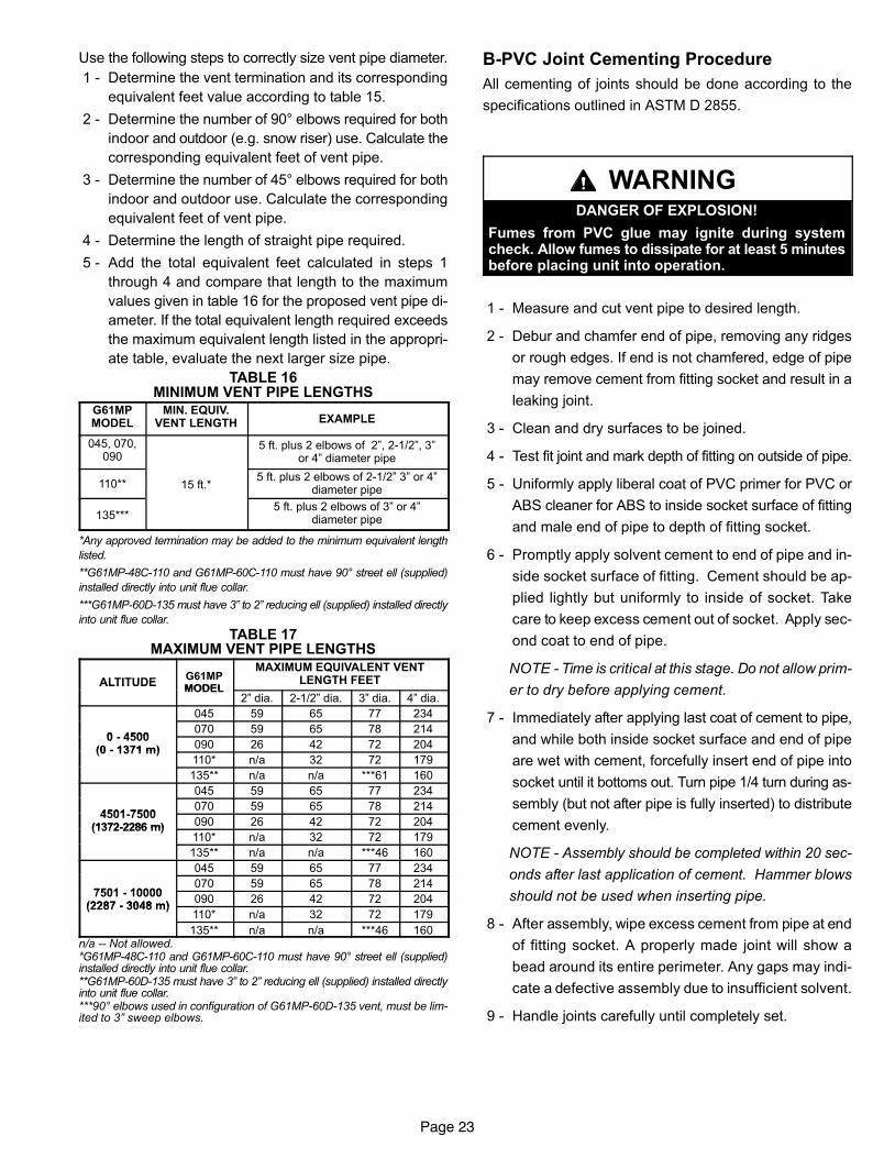
TABLE 16MINIMUM VENT PIPE LENGTHS
G61MPMODEL
MIN. EQUIV.VENT LENGTH EXAMPLE
045, 070,090
5 ft. plus 2 elbows of 2", 2−1/2", 3"or 4" diameter pipe
110** 15 ft.*5 ft. plus 2 elbows of 2−1/2" 3" or 4"
diameter pipe
135***5 ft. plus 2 elbows of 3" or 4"
diameter pipe
*Any approved termination may be added to the minimum equivalent length
listed.
**G61MP−48C−110 and G61MP−60C−110 must have 90° street ell (supplied)
installed directly into unit flue collar.
***G61MP−60D−135 must have 3" to 2" reducing ell (supplied) installed directly
into unit flue collar.
TABLE 17MAXIMUM VENT PIPE LENGTHS
ALTITUDEG61MPMODEL
MAXIMUM EQUIVALENT VENTLENGTH FEETALTITUDE
MODEL2" dia. 2−1/2" dia. 3" dia. 4" dia.
045 59 65 77 234
0 4500070 59 65 78 214
0 − 4500(0 − 1371 m) 090 26 42 72 204(0 − 1371 m)
110* n/a 32 72 179
135** n/a n/a ***61 160
045 59 65 77 234
4501 7500070 59 65 78 214
4501−7500(1372−2286 m) 090 26 42 72 204(1372−2286 m)
110* n/a 32 72 179
135** n/a n/a ***46 160
045 59 65 77 234
7501 10000070 59 65 78 214
7501 − 10000(2287 − 3048 m)
090 26 42 72 204(2287 − 3048 m)
110* n/a 32 72 179
135** n/a n/a ***46 160n/a −− Not allowed.*G61MP−48C−110 and G61MP−60C−110 must have 90° street ell (supplied)installed directly into unit flue collar.**G61MP−60D−135 must have 3" to 2" reducing ell (supplied) installed directlyinto unit flue collar.***90° elbows used in configuration of G61MP−60D−135 vent, must be lim-ited to 3" sweep elbows.
B−PVC Joint Cementing Procedure
All cementing of joints should be done according to the
specifications outlined in ASTM D 2855.
WARNINGDANGER OF EXPLOSION!
Fumes from PVC glue may ignite during systemcheck. Allow fumes to dissipate for at least 5 minutesbefore placing unit into operation.
1 − Measure and cut vent pipe to desired length.
2 − Debur and chamfer end of pipe, removing any ridges
or rough edges. If end is not chamfered, edge of pipe
may remove cement from fitting socket and result in a
leaking joint.
3 − Clean and dry surfaces to be joined.
4 − Test fit joint and mark depth of fitting on outside of pipe.
5 − Uniformly apply liberal coat of PVC primer for PVC or
ABS cleaner for ABS to inside socket surface of fitting
and male end of pipe to depth of fitting socket.
6 − Promptly apply solvent cement to end of pipe and in-
side socket surface of fitting. Cement should be ap-
plied lightly but uniformly to inside of socket. Take
care to keep excess cement out of socket. Apply sec-
ond coat to end of pipe.
NOTE − Time is critical at this stage. Do not allow prim-
er to dry before applying cement.
7 − Immediately after applying last coat of cement to pipe,
and while both inside socket surface and end of pipe
are wet with cement, forcefully insert end of pipe into
socket until it bottoms out. Turn pipe 1/4 turn during as-
sembly (but not after pipe is fully inserted) to distribute
cement evenly.
NOTE − Assembly should be completed within 20 sec-
onds after last application of cement. Hammer blows
should not be used when inserting pipe.
8 − After assembly, wipe excess cement from pipe at end
of fitting socket. A properly made joint will show a
bead around its entire perimeter. Any gaps may indi-
cate a defective assembly due to insufficient solvent.
9 − Handle joints carefully until completely set.
Page 24
C− Venting Practices
The thickness of construction through which vent pipes
may be installed is 24" (610mm) maximum and 3" (76mm)
minimum. If a G61MP furnace replaces a furnace which
was commonly vented with another gas appliance, the size
of the existing vent pipe for that gas appliance must be
checked. Without the heat of the original furnace flue prod-
ucts, the existing vent pipe is probably oversized for the
single water heater or other appliance. The vent should be
checked for proper draw with the remaining appliance.
1. Use recommended piping materials for exhaust pip-
ing.
2. Secure all joints so that they are gas-tight using ap-
proved cement.
Suspend piping using hangers at a minimum of every 5
feet (1.52m) for schedule
40 PVC and every 3 feet
(.91m) for ABS−DWV, PVC−
DWV, SPR−21 PVC, and
SDR−26 PVC piping. A suit-
able hanger can be fabri-
cated by using metal or
plastic strapping or a large
wire tie.
3. In areas where piping penetrates joists or interior
walls, hole must be large enough to allow clearance on
all sides of pipe through center of hole using a hanger.
4. Isolate piping at the point where it exits the outside wall
or roof in order to prevent transmission of vibration to
the structure.
5. When furnace is installed in a residence where unit is
shut down for an extended period of time, such as a
vacation home, make provisions for draining conden-
sate collection trap and lines.
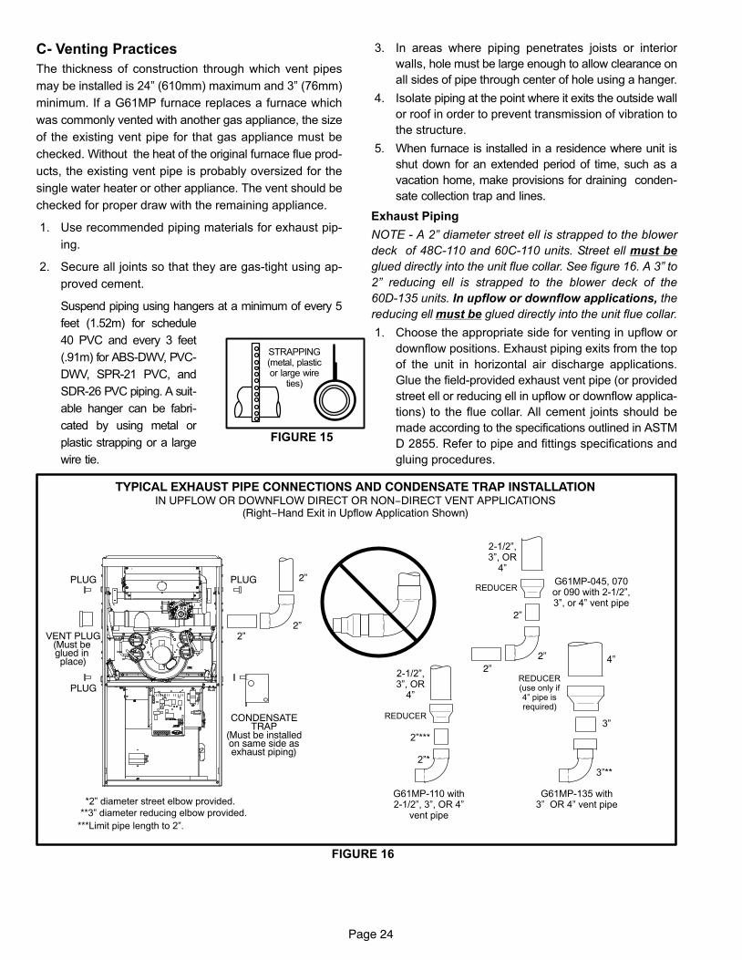
Exhaust Piping
NOTE − A 2" diameter street ell is strapped to the blower
deck of 48C−110 and 60C−110 units. Street ell must be
glued directly into the unit flue collar. See figure 16. A 3" to
2" reducing ell is strapped to the blower deck of the
60D−135 units. In upflow or downflow applications, the
reducing ell must be glued directly into the unit flue collar.
1. Choose the appropriate side for venting in upflow or
downflow positions. Exhaust piping exits from the top
of the unit in horizontal air discharge applications.
Glue the field−provided exhaust vent pipe (or provided
street ell or reducing ell in upflow or downflow applica-
tions) to the flue collar. All cement joints should be
made according to the specifications outlined in ASTM
D 2855. Refer to pipe and fittings specifications and
gluing procedures.
CONDENSATETRAP
(Must be installedon same side asexhaust piping)
VENT PLUG(Must be glued in place)
PLUG
PLUG PLUG
TYPICAL EXHAUST PIPE CONNECTIONS AND CONDENSATE TRAP INSTALLATIONIN UPFLOW OR DOWNFLOW DIRECT OR NON−DIRECT VENT APPLICATIONS
(Right−Hand Exit in Upflow Application Shown)
FIGURE 16
*2" diameter street elbow provided.
**3" diameter reducing elbow provided.
G61MP−110 with2−1/2", 3", OR 4"
vent pipe
G61MP−135 with3" OR 4" vent pipe
2"*
3"**
2"***
2"
REDUCER
G61MP−045, 070or 090 with 2−1/2",3", or 4" vent pipe
2−1/2",3", OR
4"
3"
REDUCER(use only if4" pipe isrequired)
4"
***Limit pipe length to 2".
2”
2”
2−1/2",3", OR
4"
REDUCER
2”
2”
2”
FIGURE 15
STRAPPING(metal, plasticor large wire
ties)
Page 25
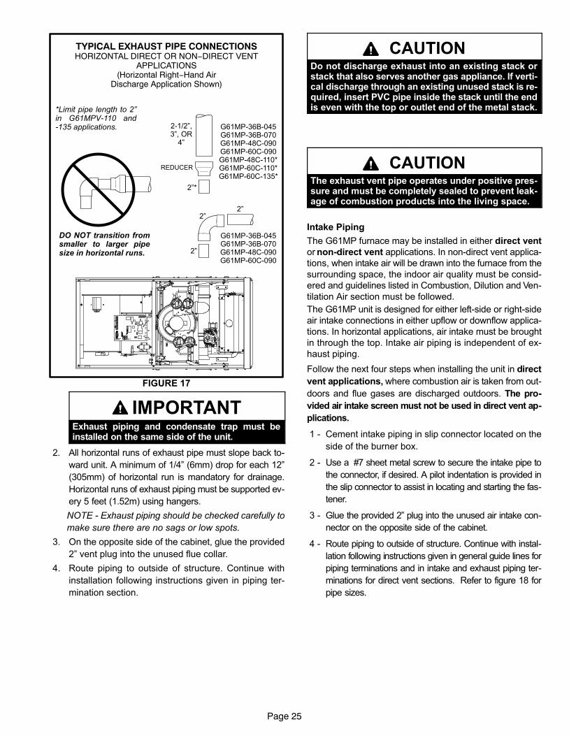
FIGURE 17
TYPICAL EXHAUST PIPE CONNECTIONSHORIZONTAL DIRECT OR NON−DIRECT VENT
APPLICATIONS(Horizontal Right−Hand Air
Discharge Application Shown)
G61MP−36B−045G61MP−36B−070G61MP−48C−090G61MP−60C−090G61MP−48C−110*G61MP−60C−110*G61MP−60C−135*
G61MP−36B−045G61MP−36B−070G61MP−48C−090G61MP−60C−090
*Limit pipe length to 2"in G61MPV−110 and−135 applications.
DO NOT transition fromsmaller to larger pipesize in horizontal runs. 2"
2"2"
2"*
2−1/2",3", OR
4"
REDUCER
IMPORTANTExhaust piping and condensate trap must beinstalled on the same side of the unit.
2. All horizontal runs of exhaust pipe must slope back to-
ward unit. A minimum of 1/4" (6mm) drop for each 12"
(305mm) of horizontal run is mandatory for drainage.
Horizontal runs of exhaust piping must be supported ev-
ery 5 feet (1.52m) using hangers.
NOTE − Exhaust piping should be checked carefully to
make sure there are no sags or low spots.
3. On the opposite side of the cabinet, glue the provided
2" vent plug into the unused flue collar.
4. Route piping to outside of structure. Continue with
installation following instructions given in piping ter-
mination section.
CAUTIONDo not discharge exhaust into an existing stack orstack that also serves another gas appliance. If verti-cal discharge through an existing unused stack is re-quired, insert PVC pipe inside the stack until the endis even with the top or outlet end of the metal stack.
CAUTIONThe exhaust vent pipe operates under positive pres-sure and must be completely sealed to prevent leak-age of combustion products into the living space.
Intake Piping
The G61MP furnace may be installed in either direct vent
or non−direct vent applications. In non−direct vent applica-
tions, when intake air will be drawn into the furnace from the
surrounding space, the indoor air quality must be consid-
ered and guidelines listed in Combustion, Dilution and Ven-
tilation Air section must be followed.
The G61MP unit is designed for either left−side or right−side
air intake connections in either upflow or downflow applica-
tions. In horizontal applications, air intake must be brought
in through the top. Intake air piping is independent of ex-
haust piping.
Follow the next four steps when installing the unit in direct
vent applications, where combustion air is taken from out-
doors and flue gases are discharged outdoors. The pro-
vided air intake screen must not be used in direct vent ap-
plications.
1 − Cement intake piping in slip connector located on the
side of the burner box.
2 − Use a #7 sheet metal screw to secure the intake pipe to
the connector, if desired. A pilot indentation is provided in
the slip connector to assist in locating and starting the fas-
tener.
3 − Glue the provided 2" plug into the unused air intake con-
nector on the opposite side of the cabinet.
4 − Route piping to outside of structure. Continue with instal-
lation following instructions given in general guide lines for
piping terminations and in intake and exhaust piping ter-
minations for direct vent sections. Refer to figure 18 for
pipe sizes.
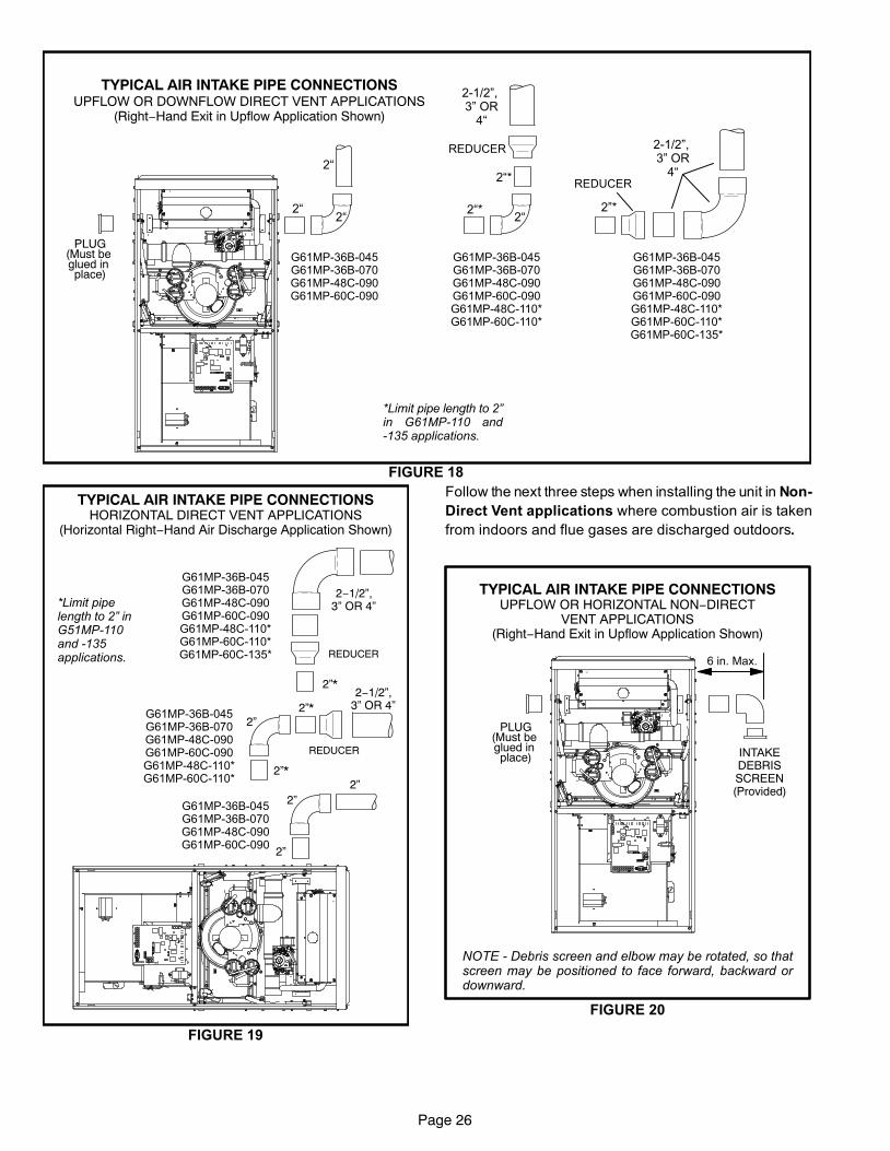
Page 26
TYPICAL AIR INTAKE PIPE CONNECTIONSUPFLOW OR DOWNFLOW DIRECT VENT APPLICATIONS
(Right−Hand Exit in Upflow Application Shown)
FIGURE 18
PLUG(Must be glued in place)
G61MP−36B−045G61MP−36B−070G61MP−48C−090G61MP−60C−090G61MP−48C−110*G61MP−60C−110*G61MP−60C−135*
G61MP−36B−045G61MP−36B−070G61MP−48C−090G61MP−60C−090G61MP−48C−110*G61MP−60C−110*
G61MP−36B−045G61MP−36B−070G61MP−48C−090G61MP−60C−090
2�
2�2�
2�*
2�2�*
2−1/2", 3" OR
4�
REDUCER
2"*
REDUCER
2−1/2", 3" OR
4�
*Limit pipe length to 2"in G61MP−110 and−135 applications.
FIGURE 19
TYPICAL AIR INTAKE PIPE CONNECTIONSHORIZONTAL DIRECT VENT APPLICATIONS
(Horizontal Right−Hand Air Discharge Application Shown)
G61MP−36B−045G61MP−36B−070G61MP−48C−090G61MP−60C−090G61MP−48C−110*G61MP−60C−110*G61MP−60C−135*
G61MP−36B−045G61MP−36B−070G61MP−48C−090G61MP−60C−090G61MP−48C−110*G61MP−60C−110*
2”*
2”
2”*
2”
2”
REDUCER
REDUCER
2”*
2−1/2”,3” OR 4”
2−1/2”,3” OR 4”*Limit pipe
length to 2" inG51MP−110and −135 applications.
2”
G61MP−36B−045G61MP−36B−070G61MP−48C−090G61MP−60C−090
Follow the next three steps when installing the unit in Non-
Direct Vent applications where combustion air is taken
from indoors and flue gases are discharged outdoors.
FIGURE 20
PLUG(Must be glued in place)
TYPICAL AIR INTAKE PIPE CONNECTIONSUPFLOW OR HORIZONTAL NON−DIRECT
VENT APPLICATIONS(Right−Hand Exit in Upflow Application Shown)
6 in. Max.
INTAKEDEBRISSCREEN(Provided)
NOTE − Debris screen and elbow may be rotated, so thatscreen may be positioned to face forward, backward ordownward.
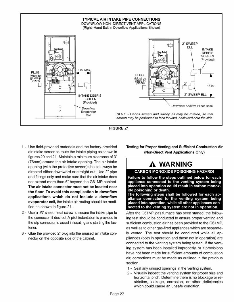
Page 27
TYPICAL AIR INTAKE PIPE CONNECTIONSDOWNFLOW NON−DIRECT VENT APPLICATIONS(Right−Hand Exit in Downflow Applications Shown)
FIGURE 21
PLUG(Must be glued in place)
6 in. Max.
PLUG(Must be glued in place)
Downflow Additive Flloor Base
18 in.
DownflowEvaporator
Coil
2"
2" SWEEPELL
2" SWEEP ELLINTAKE DEBRISSCREEN(Provided)
INTAKEDEBRISSCREEN(Provided)
NOTE − Debris screen and sweep ell may be rotated, so thatscreen may be positioned to face forward, backward or to the side.
1 − Use field−provided materials and the factory−provided
air intake screen to route the intake piping as shown in
figures 20 and 21. Maintain a minimum clearance of 3"
(76mm) around the air intake opening. The air intake
opening (with the protective screen) should always be
directed either downward or straight out. Use 2" pipe
and fittings only and make sure that the air intake does
not extend more than 6" beyond the G61MP cabinet.
The air intake connector must not be located near
the floor. To avoid this complication in downflow
applications which do not include a downflow
evaporator coil, the intake air routing should be modi-
fied as shown in figure 21.
2 − Use a #7 sheet metal screw to secure the intake pipe to
the connector, if desired. A pilot indentation is provided in
the slip connector to assist in locating and starting the fas-
tener.
3 − Glue the provided 2" plug into the unused air intake con-
nector on the opposite side of the cabinet.
Testing for Proper Venting and Sufficient Combustion Air
(Non−Direct Vent Applications Only)
WARNINGCARBON MONOXIDE POISONING HAZARD!
Failure to follow the steps outlined below for eachappliance connected to the venting system beingplaced into operation could result in carbon monox-ide poisoning or death.The following steps shall be followed for each ap-pliance connected to the venting system beingplaced into operation, while all other appliances con-nected to the venting system are not in operation.
After the G61MP gas furnace has been started, the follow-
ing test should be conducted to ensure proper venting and
sufficient combustion air has been provided to the G61MP,
as well as to other gas-fired appliances which are separate-
ly vented. The test should be conducted while all ap-
pliances (both in operation and those not in operation) are
connected to the venting system being tested. If the vent-
ing system has been installed improperly, or if provisions
have not been made for sufficient amounts of combustion
air, corrections must be made as outlined in the previous
section.
1 − Seal any unused openings in the venting system.
2 − Visually inspect the venting system for proper size andhorizontal pitch. Determine there is no blockage or re-striction, leakage, corrosion, or other deficiencieswhich could cause an unsafe condition.
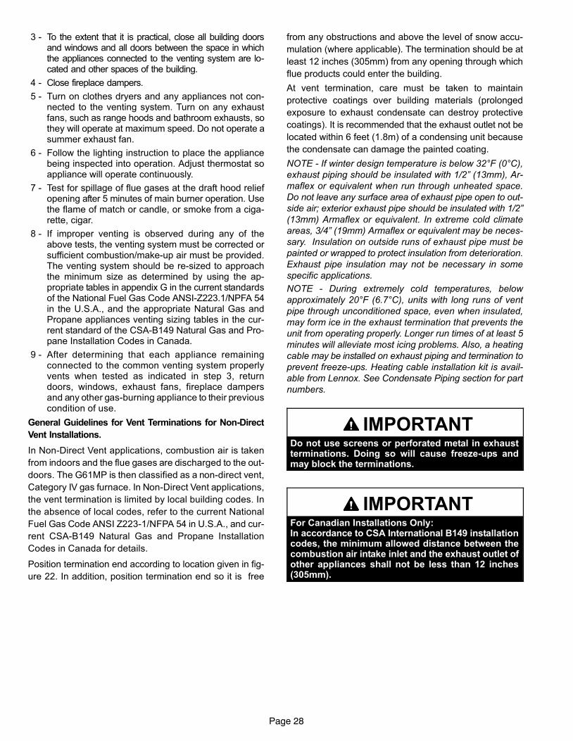
Page 28
3 − To the extent that it is practical, close all building doorsand windows and all doors between the space in whichthe appliances connected to the venting system are lo-cated and other spaces of the building.
4 − Close fireplace dampers.
5 − Turn on clothes dryers and any appliances not con-nected to the venting system. Turn on any exhaustfans, such as range hoods and bathroom exhausts, sothey will operate at maximum speed. Do not operate asummer exhaust fan.
6 − Follow the lighting instruction to place the appliancebeing inspected into operation. Adjust thermostat soappliance will operate continuously.
7 − Test for spillage of flue gases at the draft hood reliefopening after 5 minutes of main burner operation. Usethe flame of match or candle, or smoke from a ciga-rette, cigar.
8 − If improper venting is observed during any of theabove tests, the venting system must be corrected orsufficient combustion/make-up air must be provided.The venting system should be re-sized to approachthe minimum size as determined by using the ap-propriate tables in appendix G in the current standardsof the National Fuel Gas Code ANSI−Z223.1/NPFA 54in the U.S.A., and the appropriate Natural Gas andPropane appliances venting sizing tables in the cur-rent standard of the CSA−B149 Natural Gas and Pro-pane Installation Codes in Canada.
9 − After determining that each appliance remainingconnected to the common venting system properlyvents when tested as indicated in step 3, returndoors, windows, exhaust fans, fireplace dampersand any other gas-burning appliance to their previouscondition of use.
General Guidelines for Vent Terminations for Non-Direct
Vent Installations.
In Non-Direct Vent applications, combustion air is taken
from indoors and the flue gases are discharged to the out-
doors. The G61MP is then classified as a non-direct vent,
Category IV gas furnace. In Non-Direct Vent applications,
the vent termination is limited by local building codes. In
the absence of local codes, refer to the current National
Fuel Gas Code ANSI Z223−1/NFPA 54 in U.S.A., and cur-
rent CSA−B149 Natural Gas and Propane Installation
Codes in Canada for details.
Position termination end according to location given in fig-
ure 22. In addition, position termination end so it is free
from any obstructions and above the level of snow accu-
mulation (where applicable). The termination should be at
least 12 inches (305mm) from any opening through which
flue products could enter the building.
At vent termination, care must be taken to maintain
protective coatings over building materials (prolonged
exposure to exhaust condensate can destroy protective
coatings). It is recommended that the exhaust outlet not be
located within 6 feet (1.8m) of a condensing unit because
the condensate can damage the painted coating.
NOTE − If winter design temperature is below 32°F (0°C),
exhaust piping should be insulated with 1/2" (13mm), Ar-
maflex or equivalent when run through unheated space.
Do not leave any surface area of exhaust pipe open to out-
side air; exterior exhaust pipe should be insulated with 1/2"
(13mm) Armaflex or equivalent. In extreme cold climate
areas, 3/4" (19mm) Armaflex or equivalent may be neces-
sary. Insulation on outside runs of exhaust pipe must be
painted or wrapped to protect insulation from deterioration.
Exhaust pipe insulation may not be necessary in some
specific applications.
NOTE − During extremely cold temperatures, below
approximately 20°F (6.7°C), units with long runs of vent
pipe through unconditioned space, even when insulated,
may form ice in the exhaust termination that prevents the
unit from operating properly. Longer run times of at least 5
minutes will alleviate most icing problems. Also, a heating
cable may be installed on exhaust piping and termination to
prevent freeze−ups. Heating cable installation kit is avail-
able from Lennox. See Condensate Piping section for part
numbers.
IMPORTANTDo not use screens or perforated metal in exhaustterminations. Doing so will cause freeze−ups andmay block the terminations.
IMPORTANTFor Canadian Installations Only:In accordance to CSA International B149 installationcodes, the minimum allowed distance between thecombustion air intake inlet and the exhaust outlet ofother appliances shall not be less than 12 inches(305mm).
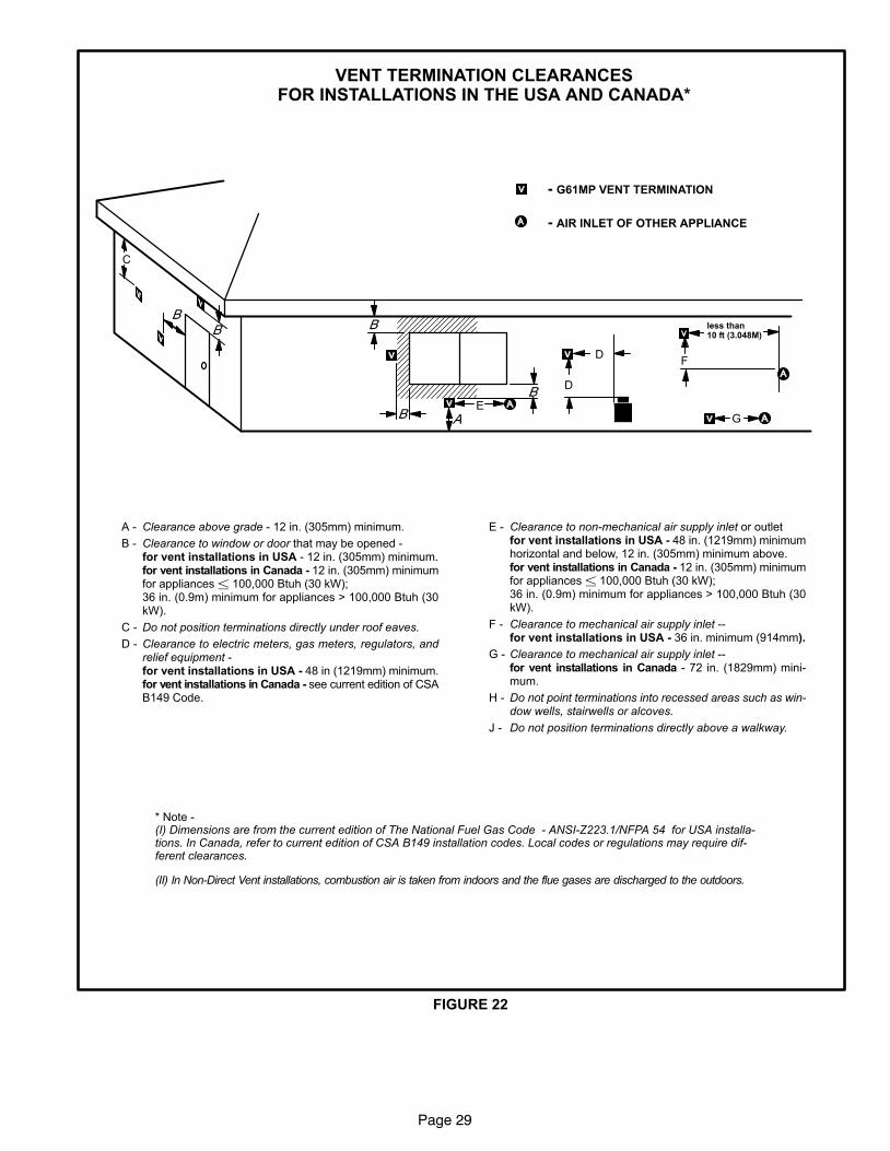
Page 29
FIGURE 22
VENT TERMINATION CLEARANCESFOR INSTALLATIONS IN THE USA AND CANADA*
A − Clearance above grade − 12 in. (305mm) minimum.
B − Clearance to window or door that may be opened − for vent installations in USA − 12 in. (305mm) minimum.for vent installations in Canada − 12 in. (305mm) minimumfor appliances � 100,000 Btuh (30 kW);36 in. (0.9m) minimum for appliances > 100,000 Btuh (30kW).
C − Do not position terminations directly under roof eaves.
D − Clearance to electric meters, gas meters, regulators, andrelief equipment − for vent installations in USA − 48 in (1219mm) minimum.for vent installations in Canada − see current edition of CSAB149 Code.
E − Clearance to non−mechanical air supply inlet or outlet for vent installations in USA − 48 in. (1219mm) minimumhorizontal and below, 12 in. (305mm) minimum above.for vent installations in Canada − 12 in. (305mm) minimumfor appliances � 100,000 Btuh (30 kW);36 in. (0.9m) minimum for appliances > 100,000 Btuh (30kW).
F − Clearance to mechanical air supply inlet −− for vent installations in USA − 36 in. minimum (914mm).
G − Clearance to mechanical air supply inlet −− for vent installations in Canada − 72 in. (1829mm) mini-mum.
H − Do not point terminations into recessed areas such as win-dow wells, stairwells or alcoves.
J − Do not position terminations directly above a walkway.
* Note − (I) Dimensions are from the current edition of The National Fuel Gas Code − ANSI-Z223.1/NFPA 54 for USA installa-tions. In Canada, refer to current edition of CSA B149 installation codes. Local codes or regulations may require dif-ferent clearances.
less than 10 ft (3.048M)
C
D
D
E
F
G
(II) In Non-Direct Vent installations, combustion air is taken from indoors and the flue gases are discharged to the outdoors.
− G61MP VENT TERMINATION
− AIR INLET OF OTHER APPLIANCE
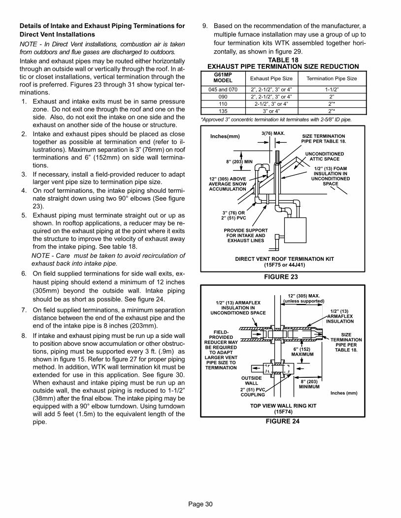
Page 30
Details of Intake and Exhaust Piping Terminations for
Direct Vent Installations
NOTE − In Direct Vent installations, combustion air is taken
from outdoors and flue gases are discharged to outdoors.
Intake and exhaust pipes may be routed either horizontally
through an outside wall or vertically through the roof. In at-
tic or closet installations, vertical termination through the
roof is preferred. Figures 23 through 31 show typical ter-
minations.
1. Exhaust and intake exits must be in same pressure
zone. Do not exit one through the roof and one on the
side. Also, do not exit the intake on one side and the
exhaust on another side of the house or structure.
2. Intake and exhaust pipes should be placed as close
together as possible at termination end (refer to il-
lustrations). Maximum separation is 3" (76mm) on roof
terminations and 6" (152mm) on side wall termina-
tions.
3. If necessary, install a field−provided reducer to adaptlarger vent pipe size to termination pipe size.
4. On roof terminations, the intake piping should termi-
nate straight down using two 90° elbows (See figure
23).
5. Exhaust piping must terminate straight out or up as
shown. In rooftop applications, a reducer may be re-
quired on the exhaust piping at the point where it exits
the structure to improve the velocity of exhaust away
from the intake piping. See table 18.
NOTE − Care must be taken to avoid recirculation of
exhaust back into intake pipe.
6. On field supplied terminations for side wall exits, ex-
haust piping should extend a minimum of 12 inches
(305mm) beyond the outside wall. Intake piping
should be as short as possible. See figure 24.
7. On field supplied terminations, a minimum separation
distance between the end of the exhaust pipe and the
end of the intake pipe is 8 inches (203mm).
8. If intake and exhaust piping must be run up a side wall
to position above snow accumulation or other obstruc-
tions, piping must be supported every 3 ft. (.9m) as
shown in figure 15. Refer to figure 27 for proper piping
method. In addition, WTK wall termination kit must be
extended for use in this application. See figure 30.
When exhaust and intake piping must be run up an
outside wall, the exhaust piping is reduced to 1−1/2"
(38mm) after the final elbow. The intake piping may be
equipped with a 90° elbow turndown. Using turndown
will add 5 feet (1.5m) to the equivalent length of the
pipe.
9. Based on the recommendation of the manufacturer, a
multiple furnace installation may use a group of up to
four termination kits WTK assembled together hori-
zontally, as shown in figure 29.
TABLE 18EXHAUST PIPE TERMINATION SIZE REDUCTION
G61MPMODEL Exhaust Pipe Size Termination Pipe Size
045 and 070 2", 2−1/2", 3" or 4" 1−1/2"
090 2", 2−1/2", 3" or 4" 2"
110 2−1/2", 3" or 4" 2"*
135 3" or 4" 2"*
*Approved 3" concentric termination kit terminates with 2−5/8" ID pipe.
FIGURE 23
DIRECT VENT ROOF TERMINATION KIT(15F75 or 44J41)
UNCONDITIONEDATTIC SPACE
1/2" (13) FOAMINSULATION IN
UNCONDITIONEDSPACE
SIZE TERMINATIONPIPE PER TABLE 18.
3(76) MAX.
12" (305) ABOVEAVERAGE SNOWACCUMULATION
3" (76) OR2" (51) PVC
PROVIDE SUPPORTFOR INTAKE ANDEXHAUST LINES
8" (203) MIN
Inches(mm)
FIGURE 24
8" (203)MINIMUM
1/2" (13) ARMAFLEXINSULATION IN
UNCONDITIONED SPACE
12" (305) MAX.(unless supported)
1/2" (13) ARMAFLEXINSULATION
6" (152) MAXIMUM
2" (51) PVCCOUPLING
OUTSIDEWALL
Inches (mm)
TOP VIEW WALL RING KIT(15F74)
SIZETERMINATION
PIPE PERTABLE 18.
FIELD−PROVIDED
REDUCER MAYBE REQUIRED
TO ADAPTLARGER VENTPIPE SIZE TOTERMINATION
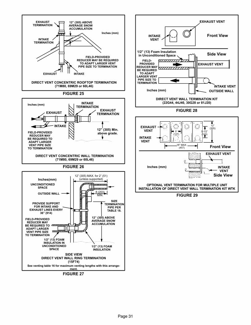
Page 31
FIGURE 25
12" (305) ABOVEAVERAGE SNOWACCUMULATION
EXHAUST
EXHAUSTTERMINATION
INTAKETERMINATION
INTAKE
Inches (mm)
DIRECT VENT CONCENTRIC ROOFTOP TERMINATION(71M80, 69M29 or 60L46)
FIELD−PROVIDEDREDUCER MAY BE REQUIRED
TO ADAPT LARGER VENTPIPE SIZE TO TERMINATION
FIGURE 26
EXHAUSTEXHAUST
TERMINATION
INTAKETERMINATION
INTAKE12" (305) Min.above grade.
Inches (mm)
DIRECT VENT CONCENTRIC WALL TERMINATION(71M80, 69M29 or 60L46)
FIELD−PROVIDEDREDUCER MAY
BE REQUIRED TOADAPT LARGERVENT PIPE SIZE
TO TERMINATION
FIGURE 27
See venting table 16 for maximum venting lengths with this arrange-ment.
12" (305) ABOVEAVERAGE SNOWACCUMULATION
UNCONDITIONEDSPACE
12" (305) MAX. for 2" (51)(unless supported)
8 (203)MIN.
1/2" (13) FOAMINSULATION
1/2" (13) FOAMINSULATION IN
UNCONDITIONEDSPACE
PROVIDE SUPPORTFOR INTAKE AND
EXHAUST LINES EVERY36" (914)
OUTSIDE WALL
Inches(mm)
SIDE VIEWDIRECT VENT WALL RING TERMINATION
(15F74)
SIZETERMINATION
PIPE PERTABLE 18.
FIELD−PROVIDEDREDUCER MAY
BE REQUIRED TOADAPT LARGERVENT PIPE SIZE
TO TERMINATION
FIGURE 28
1/2" (13) Foam Insulation in Unconditioned Space
EXHAUST VENT
INTAKE VENT
OUTSIDE WALL
EXHAUST VENT
INTAKEVENT
Front View
Side View
Inches (mm)
FIELD−PROVIDED
REDUCER MAYBE REQUIRED
TO ADAPTLARGER VENTPIPE SIZE TOTERMINATION
DIRECT VENT WALL TERMINATION KIT(22G44, 44J40, 30G28 or 81J20)
FIGURE 29
EXHAUSTVENT
INTAKEVENT
5−1/2"(140)
Front View
12"(305)
5"(127)
18" MAX.(457)
EXHAUST VENT
INTAKEVENT
OPTIONAL VENT TERMINATION FOR MULTIPLE UNITINSTALLATION OF DIRECT VENT WALL TERMINATION KIT WTK
Inches (mm)
Side View
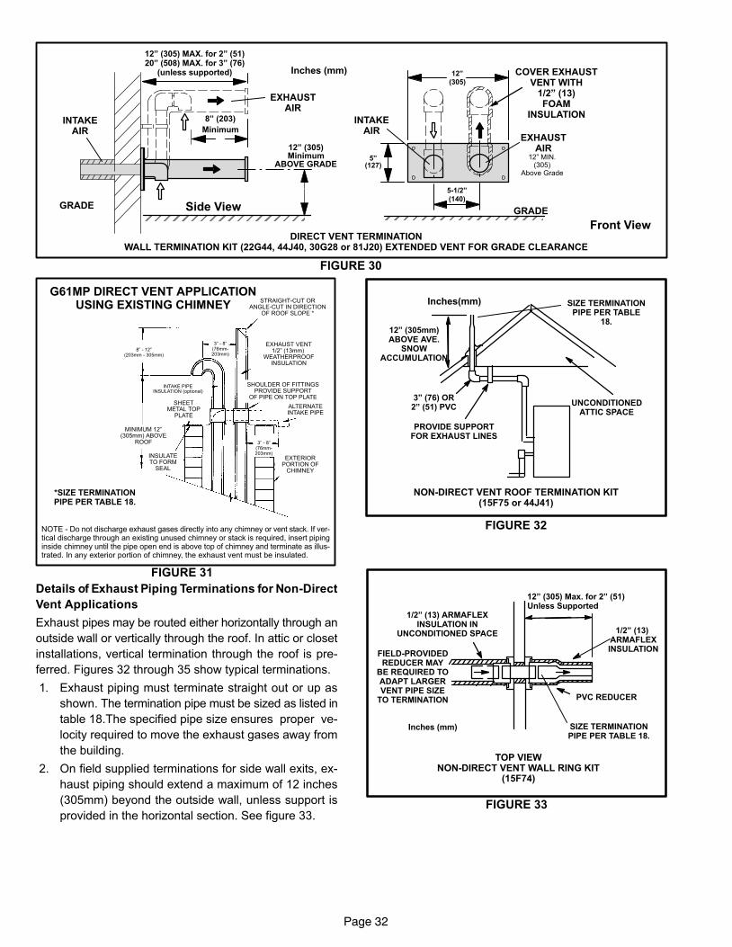
Page 32
FIGURE 30
12" MIN.(305)
Above Grade
COVER EXHAUSTVENT WITH
1/2" (13)FOAM
INSULATION
Front View
Side View
DIRECT VENT TERMINATIONWALL TERMINATION KIT (22G44, 44J40, 30G28 or 81J20) EXTENDED VENT FOR GRADE CLEARANCE
Inches (mm)
ÉÉÉÉÉÉÉÉÉÉÉÉÉÉÉÉÉÉÉÉ
5"(127)
5-1/2"
(140)
EXHAUSTAIR
INTAKEAIR
GRADE
12"
(305)
8" (203)
Minimum
12" (305)Minimum
ABOVE GRADE
INTAKEAIR
EXHAUSTAIR
GRADEÉÉÉÉÉÉÉÉÉÉÉÉÉÉÉÉÉÉÉÉ
12" (305) MAX. for 2" (51)20" (508) MAX. for 3" (76)
(unless supported)
G61MP DIRECT VENT APPLICATIONUSING EXISTING CHIMNEY
NOTE − Do not discharge exhaust gases directly into any chimney or vent stack. If ver-tical discharge through an existing unused chimney or stack is required, insert pipinginside chimney until the pipe open end is above top of chimney and terminate as illus-trated. In any exterior portion of chimney, the exhaust vent must be insulated.
FIGURE 31
8" − 12"(203mm − 305mm)
3" − 8"(76mm−203mm)
3" − 8"(76mm−203mm)
STRAIGHT−CUT ORANGLE−CUT IN DIRECTION
OF ROOF SLOPE *
EXHAUST VENT1/2" (13mm)
WEATHERPROOFINSULATION
SHOULDER OF FITTINGSPROVIDE SUPPORT
OF PIPE ON TOP PLATE
ALTERNATEINTAKE PIPE
INTAKE PIPEINSULATION (optional)
EXTERIORPORTION OF
CHIMNEY
INSULATETO FORM
SEAL
SHEETMETAL TOP
PLATE
MINIMUM 12"(305mm) ABOVE
ROOF
*SIZE TERMINATIONPIPE PER TABLE 18.
Details of Exhaust Piping Terminations for Non-Direct
Vent Applications
Exhaust pipes may be routed either horizontally through an
outside wall or vertically through the roof. In attic or closet
installations, vertical termination through the roof is pre-
ferred. Figures 32 through 35 show typical terminations.
1. Exhaust piping must terminate straight out or up as
shown. The termination pipe must be sized as listed in
table 18.The specified pipe size ensures proper ve-
locity required to move the exhaust gases away from
the building.
2. On field supplied terminations for side wall exits, ex-
haust piping should extend a maximum of 12 inches
(305mm) beyond the outside wall, unless support is
provided in the horizontal section. See figure 33.
FIGURE 32
NON−DIRECT VENT ROOF TERMINATION KIT(15F75 or 44J41)
UNCONDITIONEDATTIC SPACE
3" (76) OR2" (51) PVC
PROVIDE SUPPORTFOR EXHAUST LINES
Inches(mm)
12" (305mm)ABOVE AVE.
SNOWACCUMULATION
SIZE TERMINATIONPIPE PER TABLE
18.
FIGURE 33
1/2" (13) ARMAFLEXINSULATION IN
UNCONDITIONED SPACE
12" (305) Max. for 2" (51)Unless Supported
PVC REDUCER
1/2" (13) ARMAFLEXINSULATION
Inches (mm)
TOP VIEWNON−DIRECT VENT WALL RING KIT
(15F74)
SIZE TERMINATIONPIPE PER TABLE 18.
FIELD−PROVIDEDREDUCER MAY
BE REQUIRED TOADAPT LARGERVENT PIPE SIZE
TO TERMINATION
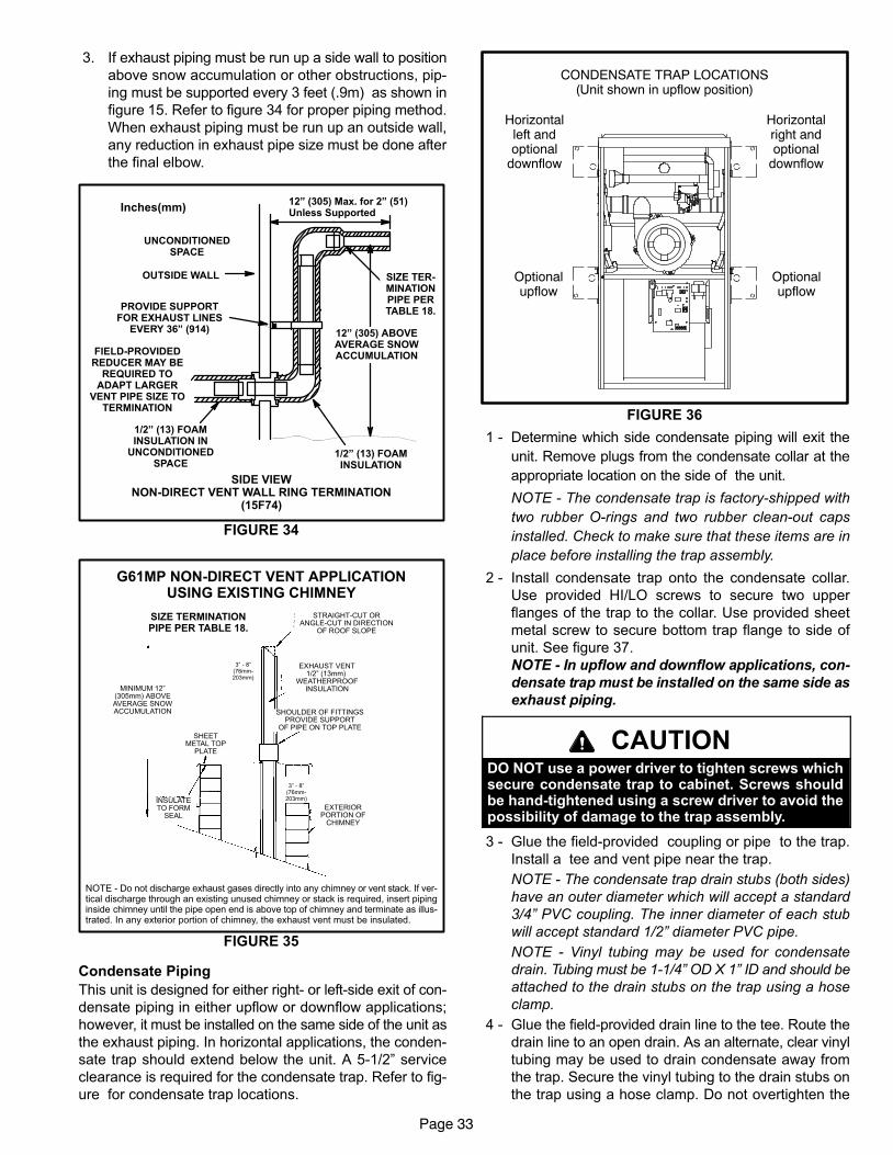
Page 33
3. If exhaust piping must be run up a side wall to position
above snow accumulation or other obstructions, pip-
ing must be supported every 3 feet (.9m) as shown in
figure 15. Refer to figure 34 for proper piping method.
When exhaust piping must be run up an outside wall,
any reduction in exhaust pipe size must be done after
the final elbow.
FIGURE 34
12" (305) ABOVEAVERAGE SNOWACCUMULATION
UNCONDITIONEDSPACE
1/2" (13) FOAMINSULATION
1/2" (13) FOAMINSULATION IN
UNCONDITIONEDSPACE
PROVIDE SUPPORTFOR EXHAUST LINES
EVERY 36" (914)
OUTSIDE WALL
Inches(mm)
SIDE VIEWNON−DIRECT VENT WALL RING TERMINATION
(15F74)
12" (305) Max. for 2" (51)Unless Supported
SIZE TER-MINATIONPIPE PERTABLE 18.
FIELD−PROVIDEDREDUCER MAY BE
REQUIRED TOADAPT LARGER
VENT PIPE SIZE TOTERMINATION
NOTE − Do not discharge exhaust gases directly into any chimney or vent stack. If ver-tical discharge through an existing unused chimney or stack is required, insert pipinginside chimney until the pipe open end is above top of chimney and terminate as illus-trated. In any exterior portion of chimney, the exhaust vent must be insulated.
FIGURE 35
3" − 8"(76mm−203mm)
3" − 8"(76mm−203mm)
MINIMUM12" (304mm)
ABOVE AVERAGESNOW ACCUMULATION
STRAIGHT−CUT ORANGLE−CUT IN DIRECTION
OF ROOF SLOPE
EXHAUST VENT1/2" (13mm)
WEATHERPROOFINSULATION
SHOULDER OF FITTINGSPROVIDE SUPPORT
OF PIPE ON TOP PLATE
EXTERIORPORTION OF
CHIMNEY
INSULATETO FORM
SEAL
SHEETMETAL TOP
PLATE
MINIMUM 12"(305mm) ABOVEAVERAGE SNOWACCUMULATION
SIZE TERMINATIONPIPE PER TABLE 18.
G61MP NON−DIRECT VENT APPLICATIONUSING EXISTING CHIMNEY
Condensate Piping
This unit is designed for either right- or left-side exit of con-
densate piping in either upflow or downflow applications;
however, it must be installed on the same side of the unit as
the exhaust piping. In horizontal applications, the conden-
sate trap should extend below the unit. A 5−1/2" service
clearance is required for the condensate trap. Refer to fig-
ure for condensate trap locations.
FIGURE 36
CONDENSATE TRAP LOCATIONS(Unit shown in upflow position)
Horizontalleft andoptional
downflow
Horizontalright andoptional
downflow
Optionalupflow
Optionalupflow
1 − Determine which side condensate piping will exit the
unit. Remove plugs from the condensate collar at the
appropriate location on the side of the unit.
NOTE − The condensate trap is factory−shipped with
two rubber O−rings and two rubber clean−out caps
installed. Check to make sure that these items are in
place before installing the trap assembly.
2 − Install condensate trap onto the condensate collar.
Use provided HI/LO screws to secure two upper
flanges of the trap to the collar. Use provided sheet
metal screw to secure bottom trap flange to side of
unit. See figure 37.
NOTE − In upflow and downflow applications, con-
densate trap must be installed on the same side as
exhaust piping.
CAUTIONDO NOT use a power driver to tighten screws whichsecure condensate trap to cabinet. Screws shouldbe hand−tightened using a screw driver to avoid thepossibility of damage to the trap assembly.
3 − Glue the field−provided coupling or pipe to the trap.
Install a tee and vent pipe near the trap.
NOTE − The condensate trap drain stubs (both sides)
have an outer diameter which will accept a standard
3/4" PVC coupling. The inner diameter of each stub
will accept standard 1/2" diameter PVC pipe.
NOTE − Vinyl tubing may be used for condensate
drain. Tubing must be 1−1/4" OD X 1" ID and should be
attached to the drain stubs on the trap using a hose
clamp.
4 − Glue the field−provided drain line to the tee. Route the
drain line to an open drain. As an alternate, clear vinyl
tubing may be used to drain condensate away from
the trap. Secure the vinyl tubing to the drain stubs on
the trap using a hose clamp. Do not overtighten the
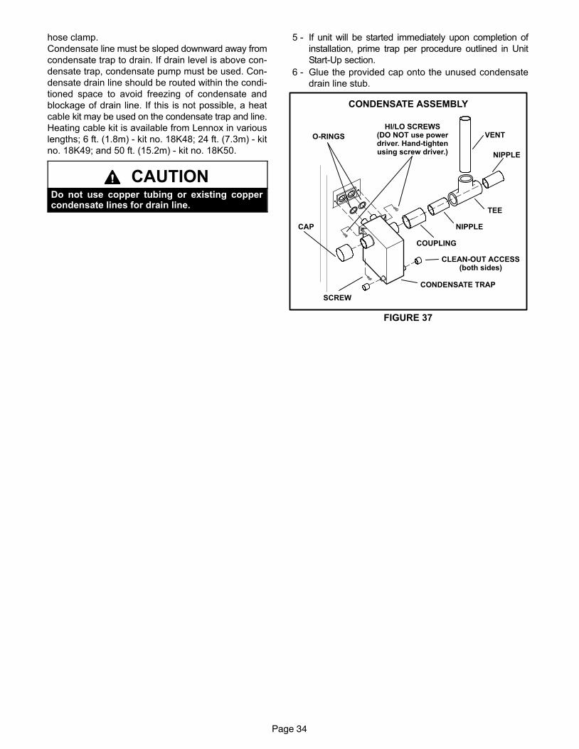
Page 34
hose clamp.
Condensate line must be sloped downward away from
condensate trap to drain. If drain level is above con-
densate trap, condensate pump must be used. Con-
densate drain line should be routed within the condi-
tioned space to avoid freezing of condensate and
blockage of drain line. If this is not possible, a heat
cable kit may be used on the condensate trap and line.
Heating cable kit is available from Lennox in various
lengths; 6 ft. (1.8m) − kit no. 18K48; 24 ft. (7.3m) − kit
no. 18K49; and 50 ft. (15.2m) − kit no. 18K50.
CAUTIONDo not use copper tubing or existing coppercondensate lines for drain line.
5 − If unit will be started immediately upon completion of
installation, prime trap per procedure outlined in Unit
Start−Up section.
6 − Glue the provided cap onto the unused condensate
drain line stub.
CONDENSATE ASSEMBLY
FIGURE 37
COUPLING
CAP
CONDENSATE TRAP
NIPPLE
NIPPLE
TEE
VENT
CLEAN−OUT ACCESS(both sides)
HI/LO SCREWS(DO NOT use powerdriver. Hand−tightenusing screw driver.)
SCREW
O−RINGS
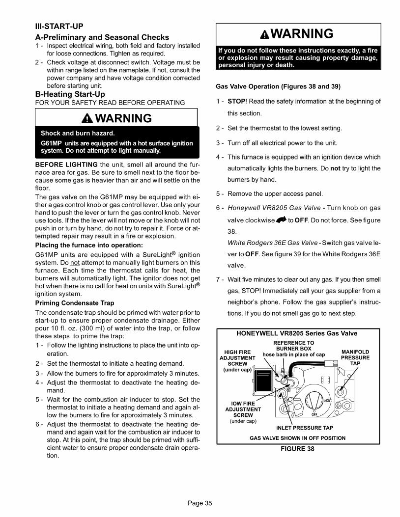
Page 35
III−START-UP
A−Preliminary and Seasonal Checks1 − Inspect electrical wiring, both field and factory installed
for loose connections. Tighten as required.
2 − Check voltage at disconnect switch. Voltage must be
within range listed on the nameplate. If not, consult the
power company and have voltage condition corrected
before starting unit.
B−Heating Start-UpFOR YOUR SAFETY READ BEFORE OPERATING
WARNINGShock and burn hazard.
G61MP units are equipped with a hot surface ignitionsystem. Do not attempt to light manually.
BEFORE LIGHTING the unit, smell all around the fur-
nace area for gas. Be sure to smell next to the floor be-
cause some gas is heavier than air and will settle on the
floor.
The gas valve on the G61MP may be equipped with ei-
ther a gas control knob or gas control lever. Use only your
hand to push the lever or turn the gas control knob. Never
use tools. If the the lever will not move or the knob will not
push in or turn by hand, do not try to repair it. Force or at-
tempted repair may result in a fire or explosion.
Placing the furnace into operation:
G61MP units are equipped with a SureLight® ignition
system. Do not attempt to manually light burners on this
furnace. Each time the thermostat calls for heat, the
burners will automatically light. The ignitor does not get
hot when there is no call for heat on units with SureLight®
ignition system.
Priming Condensate Trap
The condensate trap should be primed with water prior to
start−up to ensure proper condensate drainage. Either
pour 10 fl. oz. (300 ml) of water into the trap, or follow
these steps to prime the trap:
1 − Follow the lighting instructions to place the unit into op-
eration.
2 − Set the thermostat to initiate a heating demand.
3 − Allow the burners to fire for approximately 3 minutes.
4 − Adjust the thermostat to deactivate the heating de-
mand.
5 − Wait for the combustion air inducer to stop. Set the
thermostat to initiate a heating demand and again al-
low the burners to fire for approximately 3 minutes.
6 − Adjust the thermostat to deactivate the heating de-
mand and again wait for the combustion air inducer to
stop. At this point, the trap should be primed with suffi-
cient water to ensure proper condensate drain opera-
tion.
WARNINGIf you do not follow these instructions exactly, a fireor explosion may result causing property damage,personal injury or death.
Gas Valve Operation (Figures 38 and 39)
1 − STOP! Read the safety information at the beginning of
this section.
2 − Set the thermostat to the lowest setting.
3 − Turn off all electrical power to the unit.
4 − This furnace is equipped with an ignition device which
automatically lights the burners. Do not try to light the
burners by hand.
5 − Remove the upper access panel.
6 − Honeywell VR8205 Gas Valve − Turn knob on gas
valve clockwise to OFF. Do not force. See figure
38.
White Rodgers 36E Gas Valve − Switch gas valve le-
ver to OFF. See figure 39 for the White Rodgers 36E
valve.
7 − Wait five minutes to clear out any gas. If you then smell
gas, STOP! Immediately call your gas supplier from a
neighbor’s phone. Follow the gas supplier’s instruc-
tions. If you do not smell gas go to next step.
HONEYWELL VR8205 Series Gas Valve
GAS VALVE SHOWN IN OFF POSITION
MANIFOLDPRESSURE
TAP
lOW FIREADJUSTMENT
SCREW(under cap)
iNLET PRESSURE TAP
HIGH FIREADJUSTMENT
SCREW(under cap)
REFERENCE TOBURNER BOX
hose barb in place of cap
FIGURE 38
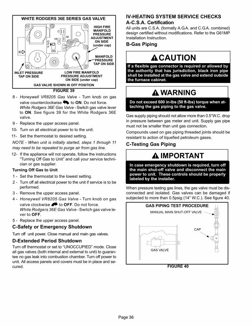
Page 36
WHITE RODGERS 36E SERIES GAS VALVE
GAS VALVE SHOWN IN OFF POSITION
HIGH FIREMANIFOLDPRESSURE
ADJUSTMENTON SIDE
(under cap)
MANIFOLDPRESSURE
TAP ON SIDE
INLET PRESSURETAP ON SIDE
LOW FIRE MANIFOLDPRESSURE ADJUSTMENT
ON SIDE (under cap)
FIGURE 39
8 − Honeywell VR8205 Gas Valve − Turn knob on gas
valve counterclockwise to ON. Do not force.
White Rodgers 36E Gas Valve − Switch gas valve lever
to ON. See figure 39 for the White Rodgers 36E
valve.
9 − Replace the upper access panel.
10− Turn on all electrical power to to the unit.
11− Set the thermostat to desired setting.
NOTE − When unit is initially started, steps 1 through 11
may need to be repeated to purge air from gas line.
12− If the appliance will not operate, follow the instructions
�Turning Off Gas to Unit" and call your service techni-
cian or gas supplier.
Turning Off Gas to Unit
1 − Set the thermostat to the lowest setting.
2 − Turn off all electrical power to the unit if service is to be
performed.
3 − Remove the upper access panel.
4 − Honeywell VR8205 Gas Valve − Turn knob on gas
valve clockwise to OFF. Do not force.
White Rodgers 36E Gas Valve − Switch gas valve le-
ver to OFF.
5 − Replace the upper access panel.
C−Safety or Emergency Shutdown
Turn off unit power. Close manual and main gas valves.
D−Extended Period Shutdown
Turn off thermostat or set to �UNOCCUPIED" mode. Close
all gas valves (both internal and external to unit) to guaran-
tee no gas leak into combustion chamber. Turn off power to
unit. All access panels and covers must be in place and se-
cured.
IV−HEATING SYSTEM SERVICE CHECKS
A−C.S.A. CertificationAll units are C.S.A. (formally A.G.A. and C.G.A. combined)
design certified without modifications. Refer to the G61MP
Installation Instruction.
B−Gas Piping
CAUTIONIf a flexible gas connector is required or allowed bythe authority that has jurisdiction, black iron pipeshall be installed at the gas valve and extend outsidethe furnace cabinet.
WARNINGDo not exceed 600 in−lbs (50 ft−lbs) torque when at-taching the gas piping to the gas valve.
Gas supply piping should not allow more than 0.5"W.C. drop
in pressure between gas meter and unit. Supply gas pipe
must not be smaller than unit gas connection.
Compounds used on gas piping threaded joints should be
resistant to action of liquefied petroleum gases.
C−Testing Gas Piping
IMPORTANTIn case emergency shutdown is required, turn offthe main shut-off valve and disconnect the mainpower to unit. These controls should be properlylabeled by the installer.
When pressure testing gas lines, the gas valve must be dis-
connected and isolated. Gas valves can be damaged if
subjected to more than 0.5psig (14" W.C.). See figure 40.
FIGURE 40
MANUAL MAIN SHUT−OFF VALVE
GAS VALVE
CAP
GAS PIPING TEST PROCEDURE
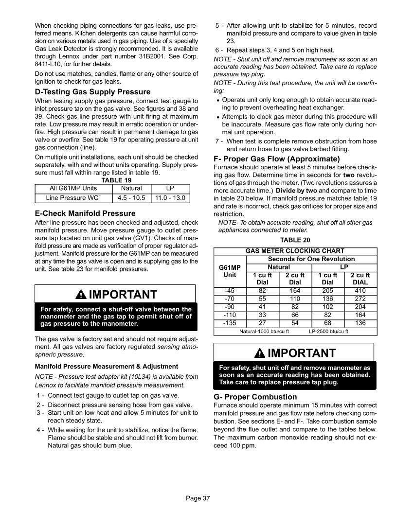
Page 37
When checking piping connections for gas leaks, use pre-
ferred means. Kitchen detergents can cause harmful corro-
sion on various metals used in gas piping. Use of a specialty
Gas Leak Detector is strongly recommended. It is available
through Lennox under part number 31B2001. See Corp.
8411−L10, for further details.
Do not use matches, candles, flame or any other source of
ignition to check for gas leaks.
D−Testing Gas Supply PressureWhen testing supply gas pressure, connect test gauge to
inlet pressure tap on the gas valve. See figures and 38 and
39. Check gas line pressure with unit firing at maximum
rate. Low pressure may result in erratic operation or under-
fire. High pressure can result in permanent damage to gas
valve or overfire. See table 19 for operating pressure at unit
gas connection (line).
On multiple unit installations, each unit should be checked
separately, with and without units operating. Supply pres-
sure must fall within range listed in table 19.
TABLE 19
All G61MP Units Natural LP
Line Pressure WC" 4.5 − 10.5 11.0 − 13.0
E−Check Manifold PressureAfter line pressure has been checked and adjusted, check
manifold pressure. Move pressure gauge to outlet pres-
sure tap located on unit gas valve (GV1). Checks of man-
ifold pressure are made as verification of proper regulator ad-
justment. Manifold pressure for the G61MP can be measured
at any time the gas valve is open and is supplying gas to the
unit. See table 23 for manifold pressures.
IMPORTANTFor safety, connect a shut-off valve between themanometer and the gas tap to permit shut off ofgas pressure to the manometer.
The gas valve is factory set and should not require adjust-
ment. All gas valves are factory regulated sensing atmo-
spheric pressure.
Manifold Pressure Measurement & Adjustment
NOTE − Pressure test adapter kit (10L34) is available from
Lennox to facilitate manifold pressure measurement.
1 − Connect test gauge to outlet tap on gas valve.
2 − Disconnect pressure sensing hose from gas valve.
3 − Start unit on low heat and allow 5 minutes for unit to
reach steady state.
4 − While waiting for the unit to stabilize, notice the flame.
Flame should be stable and should not lift from burner.
Natural gas should burn blue.
5 − After allowing unit to stabilize for 5 minutes, record
manifold pressure and compare to value given in table
23.
6 − Repeat steps 3, 4 and 5 on high heat.
NOTE − Shut unit off and remove manometer as soon as anaccurate reading has been obtained. Take care to replacepressure tap plug.
NOTE − During this test procedure, the unit will be overfir-
ing:
� Operate unit only long enough to obtain accurate read-
ing to prevent overheating heat exchanger.
� Attempts to clock gas meter during this procedure will
be inaccurate. Measure gas flow rate only during nor-
mal unit operation.
7 − When test is complete remove obstruction from hose
and return hose to gas valve barbed fitting.
F− Proper Gas Flow (Approximate)Furnace should operate at least 5 minutes before check-
ing gas flow. Determine time in seconds for two revolu-
tions of gas through the meter. (Two revolutions assures a
more accurate time.) Divide by two and compare to time
in table 20 below. If manifold pressure matches table 19
and rate is incorrect, check gas orifices for proper size and
restriction.
NOTE− To obtain accurate reading, shut off all other gasappliances connected to meter.
TABLE 20
GAS METER CLOCKING CHART
Seconds for One Revolution
G61MP Natural LPG61MPUnit 1 cu ft
Dial2 cu ftDial
1 cu ftDial
2 cu ftDIAL
−45 82 164 205 410
−70 55 110 136 272
−90 41 82 102 204
−110 33 66 82 164
−135 27 54 68 136
Natural−1000 btu/cu ft LP−2500 btu/cu ft
IMPORTANTFor safety, shut unit off and remove manometer assoon as an accurate reading has been obtained.Take care to replace pressure tap plug.
G− Proper CombustionFurnace should operate minimum 15 minutes with correct
manifold pressure and gas flow rate before checking com-
bustion. See sections E− and F−. Take combustion sample
beyond the flue outlet and compare to the tables below.
The maximum carbon monoxide reading should not ex-
ceed 100 ppm.
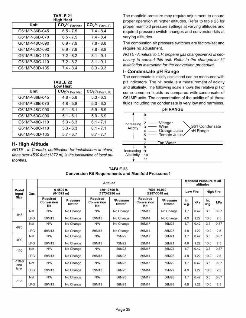
Page 38
TABLE 21High Heat
Unit CO2% For Nat CO2% For L.P.
G61MP−36B−045 6.5 − 7.5 7.4 − 8.4
G61MP−36B−070 6.5 − 7.5 7.4 − 8.4
G61MP−48C−090 6.9 − 7.9 7.8 − 8.8
G61MP−60C−090 6.9 − 7.9 7.8 − 8.8
G61MP−48C−110 7.2 − 8.2 8.1 − 9.1
G61MP−60C−110 7.2 − 8.2 8.1 − 9.1
G61MP−60D−135 7.4 − 8.4 8.3 − 9.3
TABLE 22Low Heat
Unit CO2% For Nat CO2% For L.P.
G61MP−36B−045 4.8 − 5.8 5.3 − 6.3
G61MP−36B−070 4.8 − 5.8 5.3 − 6.3
G61MP−48C−090 5.1 − 6.1 5.9 − 6.9
G61MP−60C−090 5.1 − 6.1 5.9 − 6.9
G61MP−48C−110 5.3 − 6.3 6.1 − 7.1
G61MP−60C−110 5.3 − 6.3 6.1 − 7.1
G61MP−60D−135 5.7 − 6.7 6.7 − 7.7
H− High AltitudeNOTE − In Canada, certification for installations at eleva-
tions over 4500 feet (1372 m) is the jurisdiction of local au-
thorities.
The manifold pressure may require adjustment to ensure
proper operation at higher altitudes. Refer to table 23 for
proper manifold pressure settings at varying altitudes and
required pressure switch changes and conversion kits at
varying altitudes.
The combustion air pressure switches are factory−set and
require no adjustment.
NOTE − A natural to L.P. propane gas changeover kit is nec-
essary to convert this unit. Refer to the changeover kit
installation instruction for the conversion procedure.
I− Condensate pH RangeThe condensate is mildly acidic and can be measured with
pH indicators. The pH scale is a measurement of acidity
and alkalinity. The following scale shows the relative pH of
some common liquids as compared with condensate of
G61MP units. The concentration of the acidity of all these
fluids including the condensate is very low and harmless.
pH RANGE
01234567891011
VinegarWineOrange JuiceTomato Juice
Tap Water
G61 CondensatepH Range
IncreasingAcidity
IncreasingAlkalinity
TABLE 23Conversion Kit Requirements and Manifold Pressures1
AltitudeManifold Pressure at all
altitudes
ModelInputSi
Gas
0−4500 ft.(0−1372 m)
4501−7500 ft.(1373−2286 m)
7501−10,000(2287−3048 m)
Low Fire High Firep
Size RequiredConversion
Kit
PressureSwitch
RequiredConversion
Kit
1PressureSwitch
RequiredConversion
Kit
1PressureSwitch
in.w.g.
kPain.
w.g.kPa
−045Nat
LPG
N/A
59M13
No Change
No Change
N/A
59M13
No Change
No Change
59M17
59M14
No Change
No Change
1.7
4.9
0.42
1.22
3.5
10.0
0.87
2.5
−070Nat
LPG
N/A
59M13
No Change
No Change
N/A
59M13
No Change
No Change
59M17
59M14
56M23
56M23
1.7
4.9
0.42
1.22
3.5
10.0
0.87
2.5
−090Nat
LPG
N/A
59M13
No Change
No Change
N/A
59M13
75M22
75M22
59M17
59M14
56M21
56M21
1.7
4.9
0.42
1.22
3.5
10.0
0.87
2.5
−110Nat
LPG
N/A
59M13
No Change
No Change
N/A
59M13
56M23
56M23
59M17
59M14
56M23
56M23
1.7
4.9
0.42
1.22
3.5
10.0
0.87
2.5
−110−6andlater
Nat
LPG
N/A
59M13
No Change
No Change
N/A
59M13
56M23
56M23
59M17
59M14
75M22
75M22
1.7
4.9
0.42
1.22
3.5
10.0
0.87
2.5
−135Nat
LPG
N/A
59M13
No Change
No Change
N/A
59M13
56M93
56M93
59M17
59M14
56M93
56M93
1.7
4.9
0.42
1.22
3.5
10.0
0.87
2.5
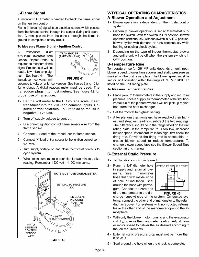
FIGURE 41
TRANSDUCER (PART #78H5401)
FIGURE 43
STATIC PRESSURE TEST
Page 39
J−Flame Signal
A microamp DC meter is needed to check the flame signal
on the ignition control.
Flame (microamp) signal is an electrical current which passes
from the furnace control through the sensor during unit opera-
tion. Current passes from the sensor through the flame to
ground to complete a safety circuit.
To Measure Flame Signal − Ignition Control:
A transducer (Part
#78H5401 available from
Lennox Repair Parts) is
required to measure flame
signal if meter used will not
read a low micro amp sig-
nal. �See�figure�41. The
transducer converts mi-
croamps to volts on a 1:1 conversion. See figures 9 and 10 for
flame signal. A digital readout meter must be used. The
transducer plugs into most meters. See figure 42 for
proper use of transducer.
1 − Set the volt meter to the DC voltage scale. Insert
transducer into the VDC and common inputs. Ob-
serve correct polarities. Failure to do so results in
negative (−) values.
2 − Turn off supply voltage to control.
3 − Disconnect ignition control flame sensor wire from the
flame sensor.
4 − Connect (−) lead of the transducer to flame sensor.
5 − Connect (+) lead of transducer to the ignition control sen-
sor wire.
6 − Turn supply voltage on and close thermostat contacts to
cycle system.
7 − When main burners are in operation for two minutes, take
reading. Remember 1 DC volt = 1 DC microamp.
SET DIAL TO MEASUREVDC
(+)
(−) TOFLAME SENSOR
NOTE−MUST USE DIGITAL METER
RED COLLARINDICATESPOSITIVE
LEAD
(+) TOIGNITIONCONTROLSENSOR
WIRE
FIGURE 42
(−)
V−TYPICAL OPERATING CHARACTERISTICS
A−Blower Operation and Adjustment1 − Blower operation is dependent on thermostat control
system.
2 − Generally, blower operation is set at thermostat sub-
base fan switch. With fan switch in ON position, blower
operates continuously. With fan switch in AUTO position,
blower cycles with demand or runs continuously while
heating or cooling circuit cycles.
3 − Depending on the type of indoor thermostat, blower
and entire unit will be off when the system switch is in
OFF position.
B−Temperature RiseTemperature rise for G61MP units depends on unit input,
blower speed, blower horsepower and static pressure as
marked on the unit rating plate. The blower speed must be
set for unit operation within the range of �TEMP. RISE °F"
listed on the unit rating plate.
To Measure Temperature Rise:
1 − Place plenum thermometers in the supply and return air
plenums. Locate supply air thermometer in the first hori-
zontal run of the plenum where it will not pick up radiant
heat from the heat exchanger.
2 − Set thermostat to highest setting.
3 − After plenum thermometers have reached their high-
est and steadiest readings, subtract the two readings.
The difference should be in the range listed on the unit
rating plate. If the temperature is too low, decrease
blower speed. If temperature is too high, first check the
firing rate. Provided the firing rate is acceptable, in-
crease blower speed to reduce temperature. To
change blower speed taps see the Blower Speed Taps
section in this manual.
C−External Static Pressure
1 − Tap locations shown in figure 43.
2 − Punch a 1/4" diameter hole
in supply and return air ple-
nums. Insert manometer
hose flush with inside edge
of hole or insulation. Seal
around the hose with perma-
gum. Connect the zero end
of the manometer to the dis-
charge (supply) side of the system. On ducted sys-
tems, connect the other end of manometer to the return
duct as above. For systems with non−ducted returns,
leave the other end of the manometer open to the at-
mosphere.
3 − With only the blower motor running and the evaporator
coil dry, observe the manometer reading. Adjust blow-
er motor speed to deliver the air desired according to
the job requirements.
4 − External static pressure drop must not be more than
0.8" W.C.
5 − Seal around the hole when the check is complete.
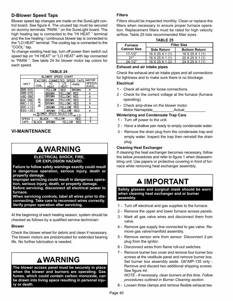
Page 40
D−Blower Speed Taps
Blower speed tap changes are made on the SureLight con-trol board. See figure 4. The unused tap must be securedon dummy terminals "PARK " on the SureLight board. Thehigh heating tap is connected to the "HI HEAT " terminaland the low heating / continuous blower tap is connected tothe "LO HEAT" terminal. The cooling tap is connected to the�COOL" tap.To change existing heat tap, turn off power then switch out
speed tap on "HI HEAT" or �LO HEAT" with tap connected
to "PARK ". See table 24 for blower motor tap colors for
each speed.
TABLE 24
VI−MAINTENANCE
WARNINGELECTRICAL SHOCK, FIRE,OR EXPLOSION HAZARD.
Failure to follow safety warnings exactly could resultin dangerous operation, serious injury, death orproperty damage.Improper servicing could result in dangerous opera-tion, serious injury, death, or property damage.Before servicing, disconnect all electrical power tofurnace.When servicing controls, label all wires prior to dis-connecting. Take care to reconnect wires correctly.Verify proper operation after servicing.
At the beginning of each heating season, system should be
checked as follows by a qualified service technician:
Blower
Check the blower wheel for debris and clean if necessary.
The blower motors are prelubricated for extended bearing
life. No further lubrication is needed.
WARNINGThe blower access panel must be securely in placewhen the blower and burners are operating. Gasfumes, which could contain carbon monoxide, canbe drawn into living space resulting in personal inju-ry or death.
Filters
Filters should be inspected monthly. Clean or replace the
filters when necessary to ensure proper furnace opera-
tion. Replacement filters must be rated for high velocity
airflow. Table 25 lists recommended filter sizes.
TABLE 25
Furnace Filter SizeFurnaceCabinet Size Side Return Bottom Return
17−1/2" 16 X 25 X 1 (1) 16 X 25 X 1 (1)21" 16 X 25 X 1 (1) 20 X 25 X 1 (1)
24−1/2" 16 X 25 X 1 (2) 24 X 25 X 1 (1)
Exhaust and air intake pipes
Check the exhaust and air intake pipes and all connections
for tightness and to make sure there is no blockage.
Electrical
1 − Check all wiring for loose connections.
2 − Check for the correct voltage at the furnace (furnace
operating).
3 − Check amp−draw on the blower motor.Motor Nameplate__________Actual__________
Winterizing and Condensate Trap Care
1 − Turn off power to the unit.
2 − Have a shallow pan ready to empty condensate water.
3 − Remove the drain plug from the condensate trap and
empty water. Inspect the trap then reinstall the drain
plug.
Cleaning Heat Exchanger
If cleaning the heat exchanger becomes necessary, follow
the below procedures and refer to figure 1 when disassem-
bling unit. Use papers or protective covering in front of fur-
nace while removing heat exchanger assembly.
IMPORTANTSafety glasses and surgical mask should be wornwhen cleaning heat exchanger and or burnerassembly.
1 − Turn off electrical and gas supplies to the furnace.
2 − Remove the upper and lower furnace access panels.
3 − Mark all gas valve wires and disconnect them from
valve.
4 − Remove gas supply line connected to gas valve. Re-
move gas valve/manifold assembly.
5 − Remove sensor wire from sensor. Disconnect 2-pin
plug from the ignitor.
6 − Disconnect wires from flame roll−out switches.
7 − Remove burner box cover and remove four burner box
screws at the vestibule panel and remove burner box.
Set burner box assembly aside. G61MP−135 only −
Remove and discard two additional shipping screws.
See figure 44.
NOTE − If necessary, clean burners at this time. Follow
procedures outlined in Burner Cleaning section.
8 − Loosen three clamps and remove flexible exhaust tee.
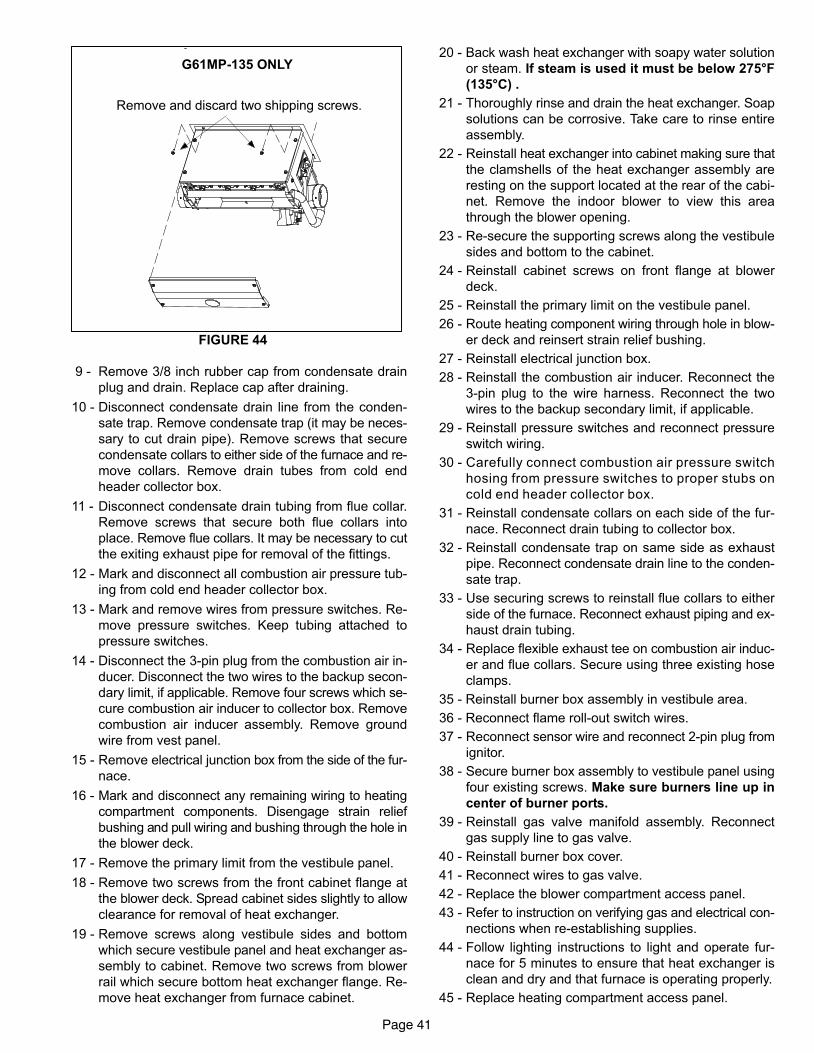
Page 41
FIGURE 44
Remove and discard two shipping screws.
G61MP−135 ONLY
9 − Remove 3/8 inch rubber cap from condensate drain
plug and drain. Replace cap after draining.
10 − Disconnect condensate drain line from the conden-
sate trap. Remove condensate trap (it may be neces-
sary to cut drain pipe). Remove screws that secure
condensate collars to either side of the furnace and re-
move collars. Remove drain tubes from cold end
header collector box.
11 − Disconnect condensate drain tubing from flue collar.
Remove screws that secure both flue collars into
place. Remove flue collars. It may be necessary to cut
the exiting exhaust pipe for removal of the fittings.
12 − Mark and disconnect all combustion air pressure tub-
ing from cold end header collector box.
13 − Mark and remove wires from pressure switches. Re-
move pressure switches. Keep tubing attached to
pressure switches.
14 − Disconnect the 3-pin plug from the combustion air in-
ducer. Disconnect the two wires to the backup secon-
dary limit, if applicable. Remove four screws which se-
cure combustion air inducer to collector box. Remove
combustion air inducer assembly. Remove ground
wire from vest panel.
15 − Remove electrical junction box from the side of the fur-
nace.
16 − Mark and disconnect any remaining wiring to heating
compartment components. Disengage strain relief
bushing and pull wiring and bushing through the hole in
the blower deck.
17 − Remove the primary limit from the vestibule panel.
18 − Remove two screws from the front cabinet flange at
the blower deck. Spread cabinet sides slightly to allow
clearance for removal of heat exchanger.
19 − Remove screws along vestibule sides and bottom
which secure vestibule panel and heat exchanger as-
sembly to cabinet. Remove two screws from blower
rail which secure bottom heat exchanger flange. Re-
move heat exchanger from furnace cabinet.
20 − Back wash heat exchanger with soapy water solution
or steam. If steam is used it must be below 275°F
(135°C) .
21 − Thoroughly rinse and drain the heat exchanger. Soap
solutions can be corrosive. Take care to rinse entire
assembly.
22 − Reinstall heat exchanger into cabinet making sure that
the clamshells of the heat exchanger assembly are
resting on the support located at the rear of the cabi-
net. Remove the indoor blower to view this area
through the blower opening.
23 − Re-secure the supporting screws along the vestibule
sides and bottom to the cabinet.
24 − Reinstall cabinet screws on front flange at blower
deck.
25 − Reinstall the primary limit on the vestibule panel.
26 − Route heating component wiring through hole in blow-
er deck and reinsert strain relief bushing.
27 − Reinstall electrical junction box.
28 − Reinstall the combustion air inducer. Reconnect the
3−pin plug to the wire harness. Reconnect the two
wires to the backup secondary limit, if applicable.
29 − Reinstall pressure switches and reconnect pressure
switch wiring.
30 − Carefully connect combustion air pressure switch
hosing from pressure switches to proper stubs on
cold end header collector box.
31 − Reinstall condensate collars on each side of the fur-
nace. Reconnect drain tubing to collector box.
32 − Reinstall condensate trap on same side as exhaust
pipe. Reconnect condensate drain line to the conden-
sate trap.
33 − Use securing screws to reinstall flue collars to either
side of the furnace. Reconnect exhaust piping and ex-
haust drain tubing.
34 − Replace flexible exhaust tee on combustion air induc-
er and flue collars. Secure using three existing hose
clamps.
35 − Reinstall burner box assembly in vestibule area.
36 − Reconnect flame roll−out switch wires.
37 − Reconnect sensor wire and reconnect 2−pin plug from
ignitor.
38 − Secure burner box assembly to vestibule panel using
four existing screws. Make sure burners line up in
center of burner ports.
39 − Reinstall gas valve manifold assembly. Reconnect
gas supply line to gas valve.
40 − Reinstall burner box cover.
41 − Reconnect wires to gas valve.
42 − Replace the blower compartment access panel.
43 − Refer to instruction on verifying gas and electrical con-
nections when re−establishing supplies.
44 − Follow lighting instructions to light and operate fur-
nace for 5 minutes to ensure that heat exchanger is
clean and dry and that furnace is operating properly.
45 − Replace heating compartment access panel.
Page 42
Cleaning the Burner Assembly
1 − Turn off electrical and gas power supplies to furnace.
Remove upper and lower furnace access panels.
2 − Mark all gas valve wires and disconnect them from the
valve.
3 − Disconnect the gas supply line from the gas valve. Re-
move gas valve/manifold assembly.
4 − Mark and disconnect sensor wire from the sensor. Dis-
connect 2-pin plug from the ignitor at the burner box.
5 − Remove burner box cover and remove four screws
which secure burner box assembly to vest panel. Re-
move burner box from the unit. G61MP−135 only − Re-
move and discard two additional shipping screws.
See figure 44.
6 − Use the soft brush attachment on a vacuum cleaner to
gently clean the face of the burners. Visually inspect
the inside of the burners and crossovers for any block-
age caused by foreign matter. Remove any blockage.
7 − Reconnect the sensor wire and reconnect the 2−pin
plug to the ignitor wiring harness.
8 − Reinstall the burner box assembly using the existing
four screws. Make sure that the burners line up in the
center of the burner ports.
9 − Reinstall the gas valve manifold assembly. Reconnect
the gas supply line to the gas valve. Reinstall the burn-
er box cover.
10 − Reconnect the gas valve wires to the gas valve.
11 − Replace the blower compartment access panel.
12 − Refer to instruction on verifying gas and electrical con-
nections when re−establishing supplies.
13 − Follow lighting instructions to light and operate fur-
nace for 5 minutes to ensure that heat exchanger is
clean and dry and that furnace is operating properly.
14 − Replace heating compartment access panel.
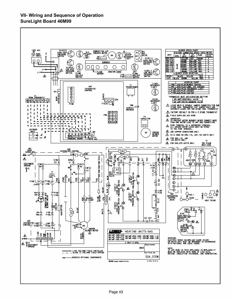
Page 43
VII− Wiring and Sequence of Operation
SureLight Board 46M99
Page 44
SureLight Board 46M99
Sequence depends on type thermostat used. G61MP
units are applicable for single stage or two stage ther-
mostats. Both type thermostats are described below.
Thermostat jumper E20 dictates which mode unit will
operate in. See flow chart for more sequence detail.
SureLight Control Self Check
When there is a call for heat, the SureLight integrated con-
trol runs a self check. The control checks for S10 primary
limit, S21 secondary limit (s) and S47 rollout switch nor-
mally closed contacts. The control also checks for S102
high heat and S128 low heat prove switch normally open
contacts. Once self check is complete and all safety
switches are operational, heat call can continue.
Two−Stage Thermostat, Two Stage Heat. Jumper E20set at �TWO".
1− SureLight control energizes combustion air inducer B6
on low heat speed. Combustion air inducer runs until
S128 low heat prove switch contacts close (switch
must close within 2 1/2 minutes or control goes into
Watchguard Pressure Switch mode. High heat prove
switch S102 may also close). A 15 second pre−purge
follows once S128 closes.
2− SureLight control begins 20 second ignitor warm up
period.
3− Gas valve opens on first stage for a 4 second trial for
ignition. Ignitor stays energized during the trial or until
flame sensed.
4− Flame is sensed, gas valve remains on first stage heat,
ignitor de−energizes.
5− After 45 second delay, indoor blower B3 is energized
on low heat speed.
The furnace will stay in this mode until first stage de-
mand is satified OR a second stage heat demand is
initiated.
6− Second stage heat demand initiated. A 30 second sec-
ond stage recognition period begins.
7− The combustion air inducer ramps up to high heat
speed.
8− S102 high heat prove switch closes and the gas valve
energizes second stage heat.
9− B3 indoor blower energizes on high heat speed.
Single−Stage Thermostat, Two Stage Heat. JumperE20 set at �SINGLE"
1− SureLight control energizes combustion air inducer B6
on low heat speed. Combustion air inducer runs until
S128 low heat prove switch contacts close (switch
must close within 2 1/2 minutes or control goes into
Watchguard Pressure Switch mode High heat prove
switch S102 may also close). A 15 second pre−purge
follows once S128 closes.
2− SureLight control begins 20 second ignitor warm up
period.
3− Gas valve opens on first stage for a 4 second trial for
ignition. Ignitor stays energized during the trial or until
flame sensed.
4− Flame is sensed, gas valve remains on first stage heat,
ignitor de−energizes.
5− After 45 second delay, indoor blower B3 is energized
on low heat speed.
6− A 10 minute (factory set) or 15 minute (field set) second
stage heat delay period begins.
7− After the delay the combustion air inducer ramps up to
high heat speed.
8− S102 high heat prove switch closes and the gas valve
energizes second stage heat.
9− B3 indoor blower energizes on high heat speed.
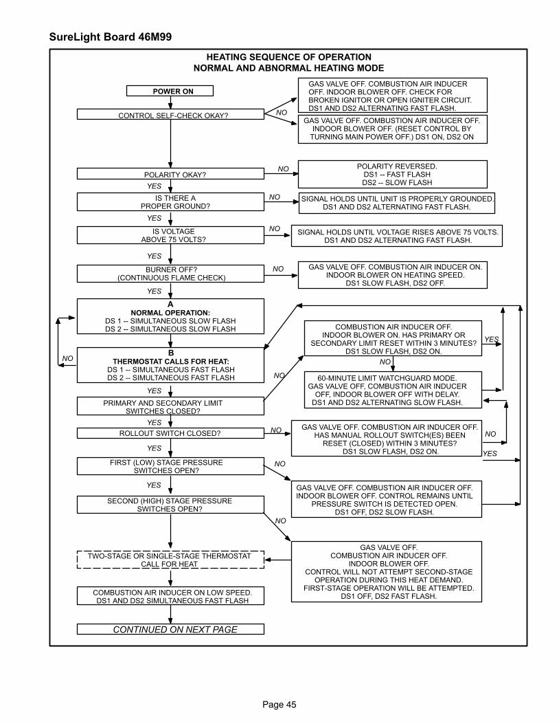
Page 45
SureLight Board 46M99
HEATING SEQUENCE OF OPERATION
NORMAL AND ABNORMAL HEATING MODE
CONTROL SELF−CHECK OKAY?
YES
GAS VALVE OFF. COMBUSTION AIR INDUCER OFF.INDOOR BLOWER OFF. (RESET CONTROL BY
TURNING MAIN POWER OFF.) DS1 ON, DS2 ON
NO POLARITY REVERSED.DS1 −− FAST FLASHDS2 −− SLOW FLASH
POWER ON
POLARITY OKAY?
NO
SIGNAL HOLDS UNTIL UNIT IS PROPERLY GROUNDED.DS1 AND DS2 ALTERNATING FAST FLASH.
IS THERE APROPER GROUND?
IS VOLTAGEABOVE 75 VOLTS?
SIGNAL HOLDS UNTIL VOLTAGE RISES ABOVE 75 VOLTS.DS1 AND DS2 ALTERNATING FAST FLASH.
NO
YES
NO
YES
GAS VALVE OFF. COMBUSTION AIR INDUCEROFF. INDOOR BLOWER OFF. CHECK FORBROKEN IGNITOR OR OPEN IGNITER CIRCUIT.DS1 AND DS2 ALTERNATING FAST FLASH.
BURNER OFF?(CONTINUOUS FLAME CHECK)
YES
NO GAS VALVE OFF. COMBUSTION AIR INDUCER ON.INDOOR BLOWER ON HEATING SPEED.
DS1 SLOW FLASH, DS2 OFF.
ANORMAL OPERATION:
DS 1 −− SIMULTANEOUS SLOW FLASHDS 2 −− SIMULTANEOUS SLOW FLASH
BTHERMOSTAT CALLS FOR HEAT:
DS 1 −− SIMULTANEOUS FAST FLASHDS 2 −− SIMULTANEOUS FAST FLASH
YES
PRIMARY AND SECONDARY LIMITSWITCHES CLOSED?
YES
NO
COMBUSTION AIR INDUCER OFF.INDOOR BLOWER ON. HAS PRIMARY OR
SECONDARY LIMIT RESET WITHIN 3 MINUTES?DS1 SLOW FLASH, DS2 ON.
ROLLOUT SWITCH CLOSED?GAS VALVE OFF. COMBUSTION AIR INDUCER OFF.
HAS MANUAL ROLLOUT SWITCH(ES) BEENRESET (CLOSED) WITHIN 3 MINUTES?
DS1 SLOW FLASH, DS2 ON.
NO
YES
FIRST (LOW) STAGE PRESSURESWITCHES OPEN?
NO
GAS VALVE OFF. COMBUSTION AIR INDUCER OFF.INDOOR BLOWER OFF. CONTROL REMAINS UNTIL
PRESSURE SWITCH IS DETECTED OPEN.DS1 OFF, DS2 SLOW FLASH.
YES
GAS VALVE OFF.COMBUSTION AIR INDUCER OFF.
INDOOR BLOWER OFF.CONTROL WILL NOT ATTEMPT SECOND−STAGE
OPERATION DURING THIS HEAT DEMAND.FIRST−STAGE OPERATION WILL BE ATTEMPTED.
DS1 OFF, DS2 FAST FLASH.
NO
TWO−STAGE OR SINGLE−STAGE THERMOSTATCALL FOR HEAT
COMBUSTION AIR INDUCER ON LOW SPEED.DS1 AND DS2 SIMULTANEOUS FAST FLASH
CONTINUED ON NEXT PAGE
NO NO
60−MINUTE LIMIT WATCHGUARD MODE.GAS VALVE OFF, COMBUSTION AIR INDUCER
OFF, INDOOR BLOWER OFF WITH DELAY.DS1 AND DS2 ALTERNATING SLOW FLASH.
YES
NO
YES
SECOND (HIGH) STAGE PRESSURESWITCHES OPEN?
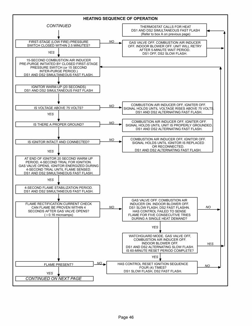
Page 46
HEATING SEQUENCE OF OPERATION
FIRST−STAGE (LOW FIRE) PRESSURESWITCH CLOSED WITHIN 2.5 MINUTES?
GAS VALVE OFF. COMBUSTION AIR INDUCEROFF. INDOOR BLOWER OFF. UNIT WILL RETRY
AFTER 5−MINUTE WAIT PERIOD.DS1 OFF, DS2 SLOW FLASH.YES
NO
15−SECOND COMBUSTION AIR INDUCERPRE−PURGE INITIATED BY CLOSED FIRST−STAGE
PRESSURE SWITCH (or 15 SECONDINTER−PURGE PERIOD.)
DS1 AND DS2 SIMULTANEOUS FAST FLASH.
IGNITOR WARM−UP (20 SECONDS)DS1 AND DS2 SIMULTANEOUS FAST FLASH
IS VOLTAGE ABOVE 75 VOLTS?NO COMBUSTION AIR INDUCER OFF, IGNITER OFF.
SIGNAL HOLDS UNTIL VOLTAGE RISES ABOVE 75 VOLTS.DS1 AND DS2 ALTERNATING FAST FLASH.
YES
IS THERE A PROPER GROUND?NO COMBUSTION AIR INDUCER OFF, IGNITER OFF.
SIGNAL HOLDS UNTIL UNIT IS PROPERLY GROUNDED.DS1 AND DS2 ALTERNATING FAST FLASH.
NO COMBUSTION AIR INDUCER OFF, IGNITOR OFF.SIGNAL HOLDS UNTIL IGNITOR IS REPLACED
OR RECONNECTED.DS1 AND DS2 ALTERNATING FAST FLASH.YES
AT END OF IGNITOR 20 SECOND WARM UPPERIOD, 4−SECOND TRIAL FOR IGNITION.
GAS VALVE OPENS, IGNITOR ENERGIZED DURING4−SECOND TRIAL UNTIL FLAME SENSED.
DS1 AND DS2 SIMULTANEOUS FAST FLASH.
YES
4−SECOND FLAME STABILIZATION PERIOD.DS1 AND DS2 SIMULTANEOUS FAST FLASH.
FLAME RECTIFICATION CURRENT CHECKCAN FLAME BE PROVEN WITHIN 4
SECONDS AFTER GAS VALVE OPENS?(�0.16 microamps)
NO
GAS VALVE OFF. COMBUSTION AIRINDUCER ON. INDOOR BLOWER OFF.DS1 SLOW FLASH, DS2 FAST FLASHN.
HAS CONTROL FAILED TO SENSEFLAME FOR FIVE CONSECUTIVE TRIES
DURING A SINGLE HEAT DEMAND?
YES
THERMOSTAT CALLS FOR HEATDS1 AND DS2 SIMULTANEOUS FAST FLASH
(Refer to box A on previous page)
YES
FLAME PRESENT? NO HAS CONTROL RESET IGNITION SEQUENCEFOUR (4) TIMES?
DS1 SLOW FLASH, DS2 FAST FLASH.
YES
CONTINUED ON NEXT PAGE
YES
NO
NO
CONTINUED
IS IGNITOR INTACT AND CONNECTED?
WATCHGUARD MODE. GAS VALVE OFF,COMBUSTION AIR INDUCER OFF.
INDOOR BLOWER OFF.DS1 AND DS2 ALTERNATING SLOW FLASH.IS 60−MINUTE RESET PERIOD COMPLETE?
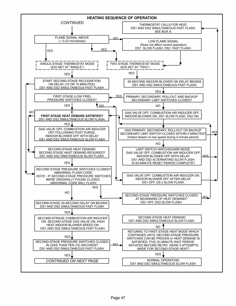
Page 47
HEATING SEQUENCE OF OPERATION
LOW FLAME SIGNAL(Does not affect control operation)
DS1 SLOW FLASH, DS2 FAST FLASH.
FLAME SIGNAL ABOVE(�0.22 microamps)
NO
YES
CONTINUED ON NEXT PAGE
YES
SINGLE−STAGE THERMOSTAT MODE(E20 SET AT �SINGLE")
TWO STAGE THERMOSTAT MODE(E20 SET AT �TWO")
YES
YES
START SECOND−STAGE RECOGNITION ON DELAY (10 OR 15 MINUTES).
DS1 AND DS2 SIMULTANEOUS FAST FLASH.
45−SECOND INDOOR BLOWER ON DELAY BEGINS.DS1 AND DS2 SIMULTANEOUS FAST FLASH.
YES
YES
PRIMARY, SECONDARY, ROLLOUT AND BACKUPSECONDARY LIMIT SWITCHES CLOSED?
NO
GAS VALVE OFF, COMBUSTION AIR INDUCER OFF,INDOOR BLOWER ON. DS1 SLOW FLASH, DS2 ON.
HAS PRIMARY, SECONDARY, ROLLOUT OR BACKUPSECONDARY LIMIT SWITCH CLOSED WITHIN 3 MINUTES?
(Indoor blower on low speed during 3−minute period)
YESFIRST−STAGE (LOW FIRE)PRESSURE SWITCHES CLOSED?
LIMIT SWITCH WATCHGUARD MODE.GAS VALVE OFF, COMBUSTION AIR INDUCER OFF,
INDOOR BLOWER OFF WITH DELAY.DS1 AND DS2 ALTERNATING SLOW FLASH.IS 60−MINUTE RESET PERIOD COMPLETE?
THERMOSTAT CALLS FOR HEAT.DS1 AND DS2 SIMULTANEOUS FAST FLASH.
SEE BOX A.
NO
YES
GAS VALVE OFF. COMBUSTION AIR INDUCER ON.INDOOR BLOWER OFF AFTER DELAY.
DS1 OFF, DS 2 SLOW FLASH.
NOYES
CFIRST−STAGE HEAT DEMAND SATISFIED?
DS1 AND DS2 SIMULTANEOUS SLOW FLASH.
GAS VALVE OFF, COMBUSTION AIR INDUCEROFF FOLLOWING POST PURGE.
INDOOR BLOWER OFF WITH DELAYDS1 AND DS2 SIMULTANEOUS SLOW FLASH
YES
SECOND−STAGE HEAT DEMAND.SECOND−STAGE HEAT DEMAND REQUIRED?DS1 AND DS2 SIMUTANEOUS SLOW FLASH.
NO
SECOND STAGE PRESSURE SWITCHES CLOSED?ABNORMAL FLASH CODE.
NOTE − IF SECOND−STAGE PRESSURE SWITCHESWERE ORIGINALLY FOUND CLOSED,
ABNORMAL CODE WILL FLASH.
SECOND−STAGE PRESSURE SWITCHES CLOSEDAT BEGINNING OF HEAT DEMAND?
DS1 OFF, DS2 SLOW FLASH.
YES
NO
SECOND−STAGE 30−SECOND DELAY ON BEGINS.DS1 AND DS2 SIMULTANEOUS FAST FLASH
SECOND−STRAGE COMBUSTION AIR INDUCER ON. SECOND−STAGE GAS VALVE ON. HIGH
HEAT INDOOR BLOWER SPEED ON.DS1 AND DS2 SIMULTANEOUS FAST FLASH.
YES
SECOND−STAGE PRESSURE SWITCHES CLOSEDIN LESS THAN TEN (10) SECONDS?
DS1 AND DS2 SIMULTANEOUS FAST FLASH.
YES
NO
RETURNS TO FIRST−STAGE HEAT MODE WHICHCONTINUES UNTIL SECOND−STAGE PRESSURE
SWITCHES CAN BE PROVEN or HEAT DEMAND ISSATISFIED. FIVE (5) MINUTE WAIT PERIOD
INITIATED BEFORE RETRY. WERE 5 ATTEMPTSMADE FOR SECOND−STAGE HEAT?
YES
NORMAL OPERATION.DS1 AND DS2 SIMULTANEOUS SLOW FLASH.
SECOND STAGE HEAT DEMANDDS1 AND DS2 SIMULTANEOUS SLOW FLASH.
NO
YES
NO
YES
CONTINUED
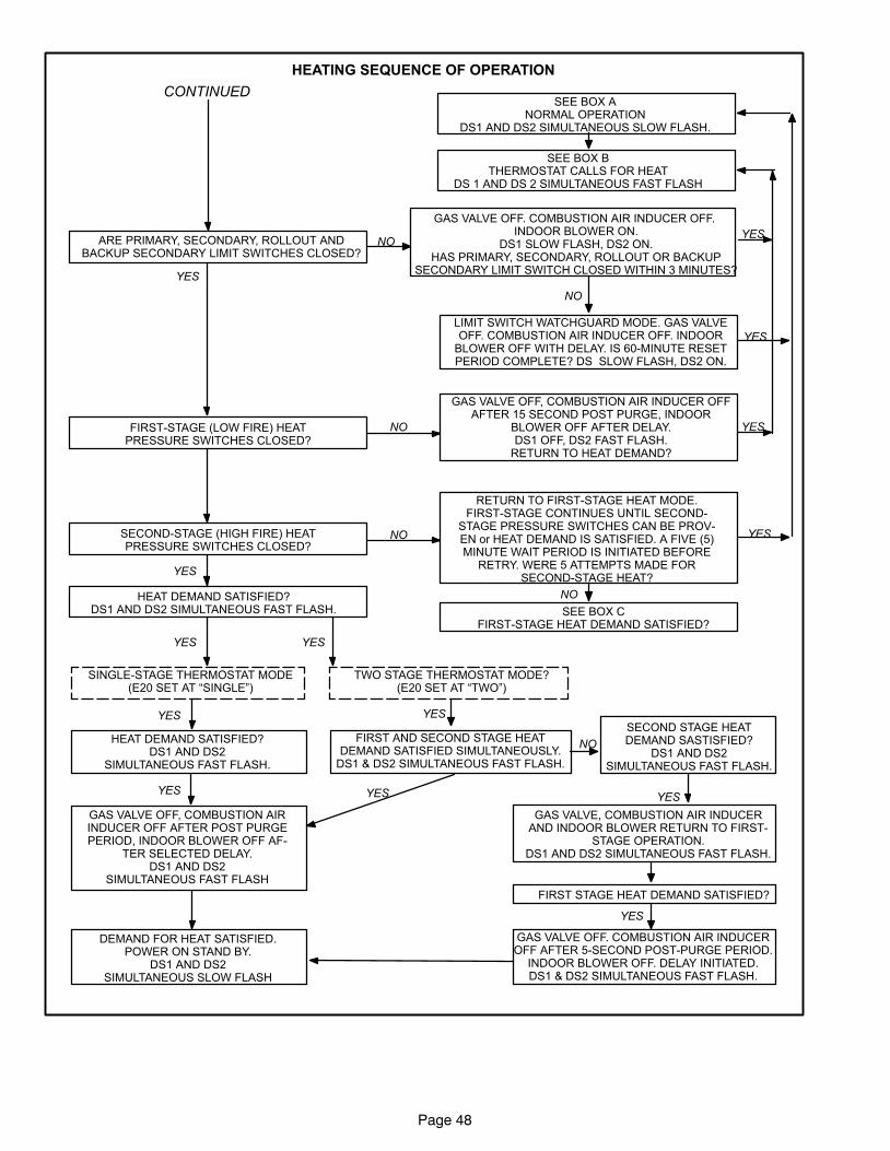
Page 48
HEATING SEQUENCE OF OPERATION
ARE PRIMARY, SECONDARY, ROLLOUT ANDBACKUP SECONDARY LIMIT SWITCHES CLOSED?
NO
GAS VALVE OFF. COMBUSTION AIR INDUCER OFF. INDOOR BLOWER ON.
DS1 SLOW FLASH, DS2 ON.HAS PRIMARY, SECONDARY, ROLLOUT OR BACKUP
SECONDARY LIMIT SWITCH CLOSED WITHIN 3 MINUTES?
NO
LIMIT SWITCH WATCHGUARD MODE. GAS VALVEOFF. COMBUSTION AIR INDUCER OFF. INDOOR
BLOWER OFF WITH DELAY. IS 60−MINUTE RESETPERIOD COMPLETE? DS SLOW FLASH, DS2 ON.
SEE BOX BTHERMOSTAT CALLS FOR HEAT
DS 1 AND DS 2 SIMULTANEOUS FAST FLASH
YES
FIRST−STAGE (LOW FIRE) HEATPRESSURE SWITCHES CLOSED?
NO
SEE BOX ANORMAL OPERATION
DS1 AND DS2 SIMULTANEOUS SLOW FLASH.
YES
YES
GAS VALVE OFF, COMBUSTION AIR INDUCER OFFAFTER 15 SECOND POST PURGE, INDOOR
BLOWER OFF AFTER DELAY.DS1 OFF, DS2 FAST FLASH.
RETURN TO HEAT DEMAND?
YES
YES
NO
RETURN TO FIRST−STAGE HEAT MODE.FIRST−STAGE CONTINUES UNTIL SECOND−
STAGE PRESSURE SWITCHES CAN BE PROV-EN or HEAT DEMAND IS SATISFIED. A FIVE (5)MINUTE WAIT PERIOD IS INITIATED BEFORE
RETRY. WERE 5 ATTEMPTS MADE FORSECOND−STAGE HEAT?
YES
NO
SEE BOX CFIRST−STAGE HEAT DEMAND SATISFIED?
HEAT DEMAND SATISFIED?DS1 AND DS2 SIMULTANEOUS FAST FLASH.
YES
TWO STAGE THERMOSTAT MODE?(E20 SET AT �TWO")
SINGLE−STAGE THERMOSTAT MODE(E20 SET AT �SINGLE")
YES
YES
HEAT DEMAND SATISFIED?DS1 AND DS2
SIMULTANEOUS FAST FLASH.
FIRST AND SECOND STAGE HEATDEMAND SATISFIED SIMULTANEOUSLY.
DS1 & DS2 SIMULTANEOUS FAST FLASH.
YES
YES
GAS VALVE OFF, COMBUSTION AIRINDUCER OFF AFTER POST PURGEPERIOD, INDOOR BLOWER OFF AF-
TER SELECTED DELAY.DS1 AND DS2
SIMULTANEOUS FAST FLASH
DEMAND FOR HEAT SATISFIED.POWER ON STAND BY.
DS1 AND DS2SIMULTANEOUS SLOW FLASH
YES
SECOND STAGE HEATDEMAND SASTISFIED?
DS1 AND DS2SIMULTANEOUS FAST FLASH.
NO
GAS VALVE, COMBUSTION AIR INDUCERAND INDOOR BLOWER RETURN TO FIRST−
STAGE OPERATION.DS1 AND DS2 SIMULTANEOUS FAST FLASH.
YES
FIRST STAGE HEAT DEMAND SATISFIED?
YES
GAS VALVE OFF. COMBUSTION AIR INDUCEROFF AFTER 5−SECOND POST−PURGE PERIOD.
INDOOR BLOWER OFF. DELAY INITIATED.DS1 & DS2 SIMULTANEOUS FAST FLASH.
CONTINUED
SECOND−STAGE (HIGH FIRE) HEATPRESSURE SWITCHES CLOSED?
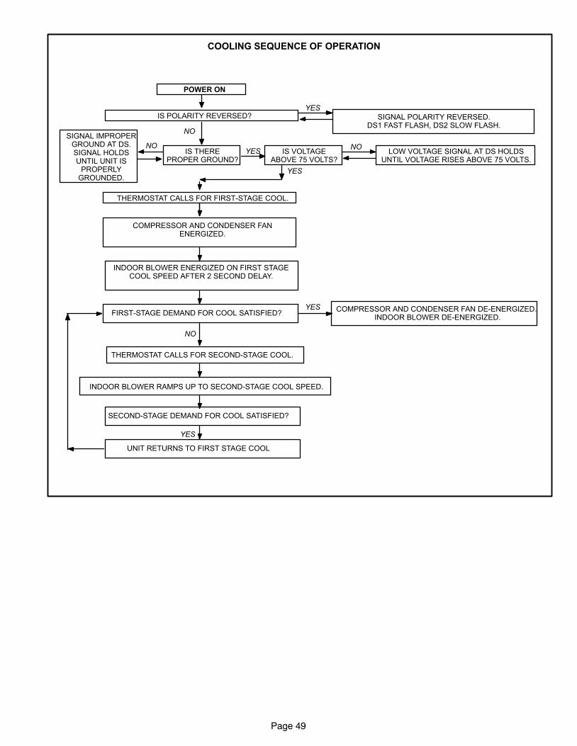
Page 49
COOLING SEQUENCE OF OPERATION
SIGNAL POLARITY REVERSED.DS1 FAST FLASH, DS2 SLOW FLASH.
POWER ON
YESIS POLARITY REVERSED?
THERMOSTAT CALLS FOR FIRST−STAGE COOL.
COMPRESSOR AND CONDENSER FANENERGIZED.
NO
IS THEREPROPER GROUND?
IS VOLTAGEABOVE 75 VOLTS?
LOW VOLTAGE SIGNAL AT DS HOLDSUNTIL VOLTAGE RISES ABOVE 75 VOLTS.
NOYES
NO
SIGNAL IMPROPERGROUND AT DS.SIGNAL HOLDSUNTIL UNIT IS
PROPERLYGROUNDED.
INDOOR BLOWER ENERGIZED ON FIRST STAGECOOL SPEED AFTER 2 SECOND DELAY.
FIRST−STAGE DEMAND FOR COOL SATISFIED?
NO
THERMOSTAT CALLS FOR SECOND−STAGE COOL.
YES
COMPRESSOR AND CONDENSER FAN DE−ENERGIZED. INDOOR BLOWER DE−ENERGIZED.
YES
INDOOR BLOWER RAMPS UP TO SECOND−STAGE COOL SPEED.
SECOND−STAGE DEMAND FOR COOL SATISFIED?
YES
UNIT RETURNS TO FIRST STAGE COOL
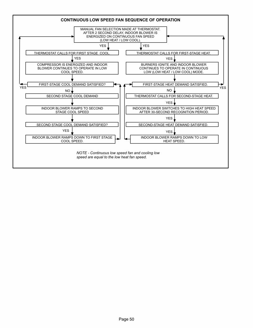
Page 50
CONTINUOUS LOW SPEED FAN SEQUENCE OF OPERATION
MANUAL FAN SELECTION MADE AT THERMOSTAT.AFTER 2 SECOND DELAY, INDOOR BLOWER IS
ENERGIZED ON CONTINUOUS FAN SPEED(LOW HEAT / LOW COOL).
THERMOSTAT CALLS FOR FIRST−STAGE HEAT.THERMOSTAT CALLS FOR FIRST STAGE COOL.
YESYES
BURNERS IGNITE AND INDOOR BLOWERCONTINUES TO OPERATE IN CONTINUOUS
LOW (LOW HEAT / LOW COOL) MODE.
FIRST−STAGE HEAT DEMAND SATISFIED.YES
NO
THERMOSTAT CALLS FOR SECOND−STAGE HEAT.
YES
INDOOR BLOWER SWITCHES TO HIGH HEAT SPEEDAFTER 30−SECOND RECOGNITION PERIOD.
SECOND−STAGE HEAT DEMAND SATISFIED.
YES
YES
INDOOR BLOWER RAMPS DOWN TO LOWHEAT SPEED.
COMPRESSOR IS ENERGIZED AND INDOORBLOWER CONTINUES TO OPERATE IN LOW
COOL SPEED.
FIRST−STAGE COOL DEMAND SATISFIED?YES
NO
SECOND STAGE COOL DEMAND SATISFIED?
INDOOR BLOWER RAMPS TO SECONDSTAGE COOL SPEED
YES
SECOND STAGE COOL DEMAND
INDOOR BLOWER RAMPS DOWN TO FIRST STAGECOOL SPEED.
YES YES
NOTE − Continuous low speed fan and cooling lowspeed are equal to the low heat fan speed.
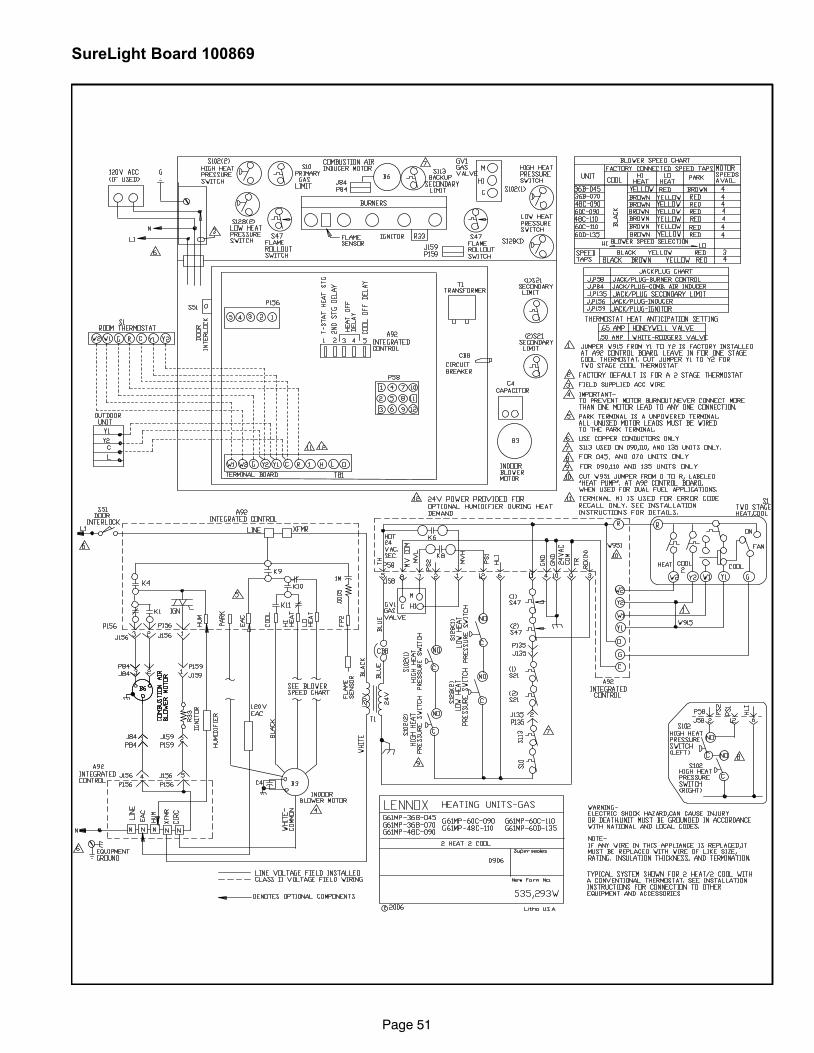
Page 51
SureLight Board 100869
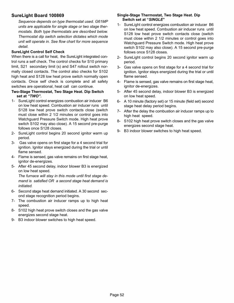
Page 52
SureLight Board 100869
Sequence depends on type thermostat used. G61MP
units are applicable for single stage or two stage ther-
mostats. Both type thermostats are described below.
Thermostat dip switch selection dictates which mode
unit will operate in. See flow chart for more sequence
detail.
SureLight Control Self Check
When there is a call for heat, the SureLight integrated con-
trol runs a self check. The control checks for S10 primary
limit, S21 secondary limit (s) and S47 rollout switch nor-
mally closed contacts. The control also checks for S102
high heat and S128 low heat prove switch normally open
contacts. Once self check is complete and all safety
switches are operational, heat call can continue.
Two−Stage Thermostat, Two Stage Heat. Dip Switchset at �TWO".
1− SureLight control energizes combustion air inducer B6
on low heat speed. Combustion air inducer runs until
S128 low heat prove switch contacts close (switch
must close within 2 1/2 minutes or control goes into
Watchguard Pressure Switch mode. High heat prove
switch S102 may also close). A 15 second pre−purge
follows once S128 closes.
2− SureLight control begins 20 second ignitor warm up
period.
3− Gas valve opens on first stage for a 4 second trial for
ignition. Ignitor stays energized during the trial or until
flame sensed.
4− Flame is sensed, gas valve remains on first stage heat,
ignitor de−energizes.
5− After 45 second delay, indoor blower B3 is energized
on low heat speed.
The furnace will stay in this mode until first stage de-
mand is satisfied OR a second stage heat demand is
initiated.
6− Second stage heat demand initiated. A 30 second sec-
ond stage recognition period begins.
7− The combustion air inducer ramps up to high heat
speed.
8− S102 high heat prove switch closes and the gas valve
energizes second stage heat.
9− B3 indoor blower switches to high heat speed.
Single−Stage Thermostat, Two Stage Heat. DipSwitch set at �SINGLE"
1− SureLight control energizes combustion air inducer B6
on low heat speed. Combustion air inducer runs until
S128 low heat prove switch contacts close (switch
must close within 2 1/2 minutes or control goes into
Watchguard Pressure Switch mode. High heat prove
switch S102 may also close). A 15 second pre−purge
follows once S128 closes.
2− SureLight control begins 20 second ignitor warm up
period.
3− Gas valve opens on first stage for a 4 second trial for
ignition. Ignitor stays energized during the trial or until
flame sensed.
4− Flame is sensed, gas valve remains on first stage heat,
ignitor de−energizes.
5− After 45 second delay, indoor blower B3 is energized
on low heat speed.
6− A 10 minute (factory set) or 15 minute (field set) second
stage heat delay period begins.
7− After the delay the combustion air inducer ramps up to
high heat speed.
8− S102 high heat prove switch closes and the gas valve
energizes second stage heat.
9− B3 indoor blower switches to high heat speed.
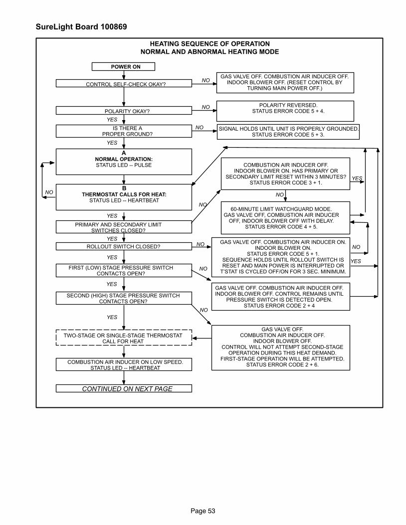
Page 53
SureLight Board 100869
HEATING SEQUENCE OF OPERATION
NORMAL AND ABNORMAL HEATING MODE
CONTROL SELF−CHECK OKAY?
YES
GAS VALVE OFF. COMBUSTION AIR INDUCER OFF.INDOOR BLOWER OFF. (RESET CONTROL BY
TURNING MAIN POWER OFF.)
NO POLARITY REVERSED.STATUS ERROR CODE 5 + 4.
POWER ON
POLARITY OKAY?
SIGNAL HOLDS UNTIL UNIT IS PROPERLY GROUNDED.STATUS ERROR CODE 5 + 3.
IS THERE APROPER GROUND?
NO
YES
ANORMAL OPERATION:STATUS LED −− PULSE
BTHERMOSTAT CALLS FOR HEAT:
STATUS LED −− HEARTBEAT
YES
PRIMARY AND SECONDARY LIMITSWITCHES CLOSED?
YES
NO
COMBUSTION AIR INDUCER OFF.INDOOR BLOWER ON. HAS PRIMARY OR
SECONDARY LIMIT RESET WITHIN 3 MINUTES?STATUS ERROR CODE 3 + 1.
ROLLOUT SWITCH CLOSED?GAS VALVE OFF. COMBUSTION AIR INDUCER ON.
INDOOR BLOWER ON.STATUS ERROR CODE 5 + 1.
SEQUENCE HOLDS UNTIL ROLLOUT SWITCH ISRESET AND MAIN POWER IS INTERRUPTED OR
T’STAT IS CYCLED OFF/ON FOR 3 SEC. MINIMUM.
NO
YES
FIRST (LOW) STAGE PRESSURE SWITCHCONTACTS OPEN?
NO
GAS VALVE OFF. COMBUSTION AIR INDUCER OFF.INDOOR BLOWER OFF. CONTROL REMAINS UNTIL
PRESSURE SWITCH IS DETECTED OPEN.STATUS ERROR CODE 2 + 4
YES
GAS VALVE OFF.COMBUSTION AIR INDUCER OFF.
INDOOR BLOWER OFF.CONTROL WILL NOT ATTEMPT SECOND−STAGE
OPERATION DURING THIS HEAT DEMAND.FIRST−STAGE OPERATION WILL BE ATTEMPTED.
STATUS ERROR CODE 2 + 6.
NO
TWO−STAGE OR SINGLE−STAGE THERMOSTATCALL FOR HEAT
COMBUSTION AIR INDUCER ON LOW SPEED.STATUS LED −− HEARTBEAT
CONTINUED ON NEXT PAGE
NO NO
60−MINUTE LIMIT WATCHGUARD MODE.GAS VALVE OFF, COMBUSTION AIR INDUCER
OFF, INDOOR BLOWER OFF WITH DELAY.STATUS ERROR CODE 4 + 5.
YES
NO
YES
SECOND (HIGH) STAGE PRESSURE SWITCHCONTACTS OPEN?
NO
YES
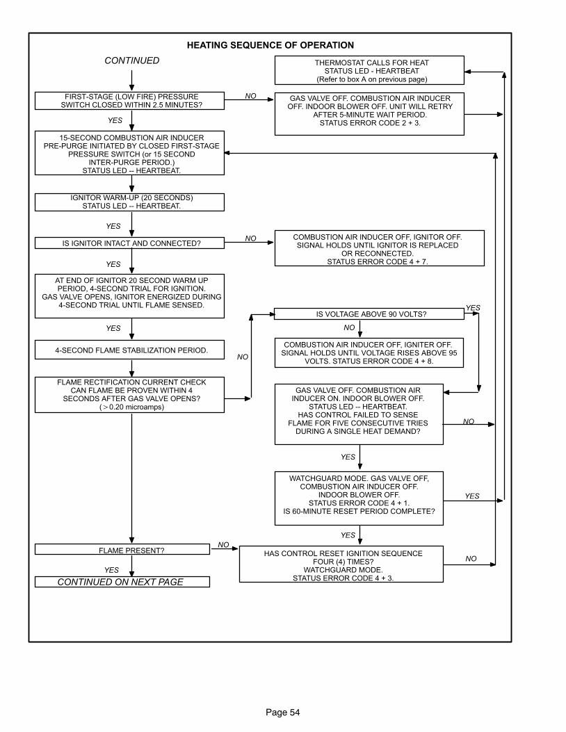
Page 54
HEATING SEQUENCE OF OPERATION
FIRST−STAGE (LOW FIRE) PRESSURESWITCH CLOSED WITHIN 2.5 MINUTES?
GAS VALVE OFF. COMBUSTION AIR INDUCEROFF. INDOOR BLOWER OFF. UNIT WILL RETRY
AFTER 5−MINUTE WAIT PERIOD.STATUS ERROR CODE 2 + 3.YES
NO
15−SECOND COMBUSTION AIR INDUCERPRE−PURGE INITIATED BY CLOSED FIRST−STAGE
PRESSURE SWITCH (or 15 SECONDINTER−PURGE PERIOD.)
STATUS LED −− HEARTBEAT.
IGNITOR WARM−UP (20 SECONDS)STATUS LED −− HEARTBEAT.
IS VOLTAGE ABOVE 90 VOLTS?
NO
COMBUSTION AIR INDUCER OFF, IGNITER OFF. SIGNAL HOLDS UNTIL VOLTAGE RISES ABOVE 95
VOLTS. STATUS ERROR CODE 4 + 8.
YES
NO COMBUSTION AIR INDUCER OFF, IGNITOR OFF.SIGNAL HOLDS UNTIL IGNITOR IS REPLACED
OR RECONNECTED.STATUS ERROR CODE 4 + 7.YES
AT END OF IGNITOR 20 SECOND WARM UPPERIOD, 4−SECOND TRIAL FOR IGNITION.
GAS VALVE OPENS, IGNITOR ENERGIZED DURING4−SECOND TRIAL UNTIL FLAME SENSED.
YES
4−SECOND FLAME STABILIZATION PERIOD.
FLAME RECTIFICATION CURRENT CHECKCAN FLAME BE PROVEN WITHIN 4
SECONDS AFTER GAS VALVE OPENS?(�0.20 microamps)
GAS VALVE OFF. COMBUSTION AIRINDUCER ON. INDOOR BLOWER OFF.
STATUS LED −− HEARTBEAT.HAS CONTROL FAILED TO SENSE
FLAME FOR FIVE CONSECUTIVE TRIESDURING A SINGLE HEAT DEMAND?
YES
THERMOSTAT CALLS FOR HEATSTATUS LED − HEARTBEAT
(Refer to box A on previous page)
YES
FLAME PRESENT?NO
HAS CONTROL RESET IGNITION SEQUENCEFOUR (4) TIMES?
WATCHGUARD MODE.STATUS ERROR CODE 4 + 3.
YES
CONTINUED ON NEXT PAGE
YES
NO
NO
CONTINUED
IS IGNITOR INTACT AND CONNECTED?
WATCHGUARD MODE. GAS VALVE OFF,COMBUSTION AIR INDUCER OFF.
INDOOR BLOWER OFF.STATUS ERROR CODE 4 + 1.
IS 60−MINUTE RESET PERIOD COMPLETE?
NO
YES
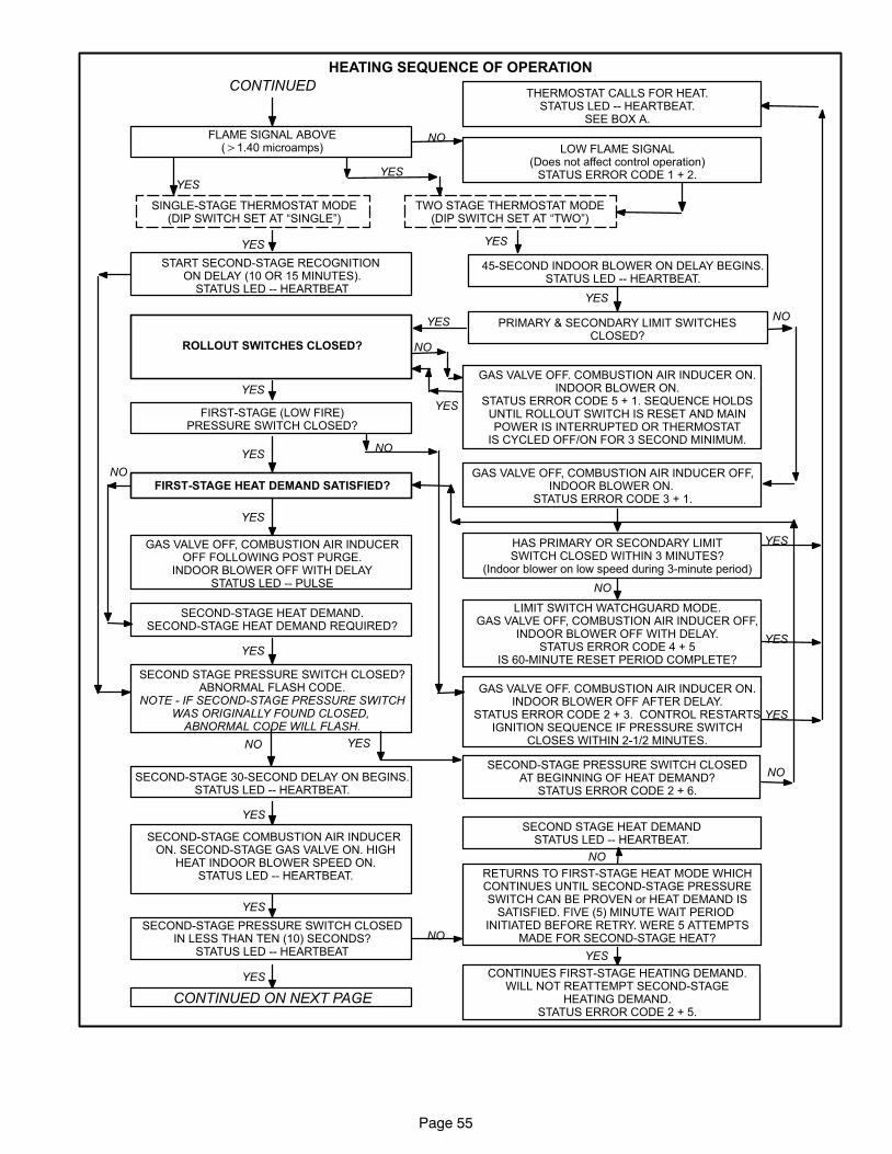
Page 55
HEATING SEQUENCE OF OPERATION
LOW FLAME SIGNAL(Does not affect control operation)
STATUS ERROR CODE 1 + 2.
FLAME SIGNAL ABOVE(�1.40 microamps)
NO
YES
CONTINUED ON NEXT PAGE
YES
SINGLE−STAGE THERMOSTAT MODE(DIP SWITCH SET AT �SINGLE")
TWO STAGE THERMOSTAT MODE(DIP SWITCH SET AT �TWO")
YES
YES
START SECOND−STAGE RECOGNITION ON DELAY (10 OR 15 MINUTES).
STATUS LED −− HEARTBEAT
45−SECOND INDOOR BLOWER ON DELAY BEGINS.STATUS LED −− HEARTBEAT.
YES
YES
PRIMARY & SECONDARY LIMIT SWITCHESCLOSED?
GAS VALVE OFF, COMBUSTION AIR INDUCER OFF,INDOOR BLOWER ON.
STATUS ERROR CODE 3 + 1.
HAS PRIMARY OR SECONDARY LIMITSWITCH CLOSED WITHIN 3 MINUTES?
(Indoor blower on low speed during 3−minute period)
FIRST−STAGE (LOW FIRE)PRESSURE SWITCH CLOSED?
LIMIT SWITCH WATCHGUARD MODE.GAS VALVE OFF, COMBUSTION AIR INDUCER OFF,
INDOOR BLOWER OFF WITH DELAY.STATUS ERROR CODE 4 + 5
IS 60−MINUTE RESET PERIOD COMPLETE?
THERMOSTAT CALLS FOR HEAT.STATUS LED −− HEARTBEAT.
SEE BOX A.
NO
YES
GAS VALVE OFF. COMBUSTION AIR INDUCER ON.INDOOR BLOWER OFF AFTER DELAY.
STATUS ERROR CODE 2 + 3. CONTROL RESTARTSIGNITION SEQUENCE IF PRESSURE SWITCH
CLOSES WITHIN 2−1/2 MINUTES.
NO
YES
FIRST−STAGE HEAT DEMAND SATISFIED?
GAS VALVE OFF, COMBUSTION AIR INDUCEROFF FOLLOWING POST PURGE.
INDOOR BLOWER OFF WITH DELAYSTATUS LED −− PULSE
YES
SECOND−STAGE HEAT DEMAND.SECOND−STAGE HEAT DEMAND REQUIRED?
NO
SECOND STAGE PRESSURE SWITCH CLOSED?ABNORMAL FLASH CODE.
NOTE − IF SECOND−STAGE PRESSURE SWITCHWAS ORIGINALLY FOUND CLOSED,
ABNORMAL CODE WILL FLASH.
SECOND−STAGE PRESSURE SWITCH CLOSEDAT BEGINNING OF HEAT DEMAND?
STATUS ERROR CODE 2 + 6.
YESNO
SECOND−STAGE 30−SECOND DELAY ON BEGINS.STATUS LED −− HEARTBEAT.
SECOND−STAGE COMBUSTION AIR INDUCER ON. SECOND−STAGE GAS VALVE ON. HIGH
HEAT INDOOR BLOWER SPEED ON.STATUS LED −− HEARTBEAT.
YES
SECOND−STAGE PRESSURE SWITCH CLOSEDIN LESS THAN TEN (10) SECONDS?
STATUS LED −− HEARTBEAT
YES
NO
RETURNS TO FIRST−STAGE HEAT MODE WHICHCONTINUES UNTIL SECOND−STAGE PRESSURESWITCH CAN BE PROVEN or HEAT DEMAND IS
SATISFIED. FIVE (5) MINUTE WAIT PERIOD INITIATED BEFORE RETRY. WERE 5 ATTEMPTS
MADE FOR SECOND−STAGE HEAT?
YES
CONTINUES FIRST−STAGE HEATING DEMAND.WILL NOT REATTEMPT SECOND−STAGE
HEATING DEMAND.STATUS ERROR CODE 2 + 5.
SECOND STAGE HEAT DEMANDSTATUS LED −− HEARTBEAT.
NO
YES
NO
YES
CONTINUED
GAS VALVE OFF. COMBUSTION AIR INDUCER ON.INDOOR BLOWER ON.
STATUS ERROR CODE 5 + 1. SEQUENCE HOLDSUNTIL ROLLOUT SWITCH IS RESET AND MAINPOWER IS INTERRUPTED OR THERMOSTAT
IS CYCLED OFF/ON FOR 3 SECOND MINIMUM.
ROLLOUT SWITCHES CLOSED? NO
YES
YES
NO
YES
YES
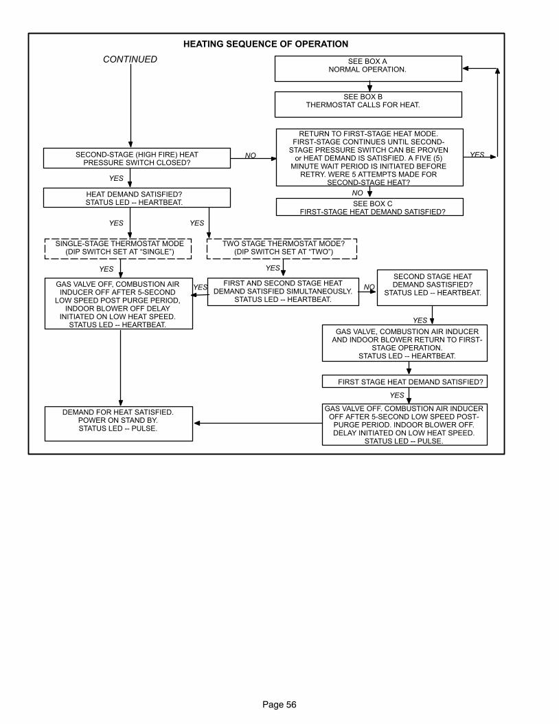
Page 56
HEATING SEQUENCE OF OPERATION
SEE BOX BTHERMOSTAT CALLS FOR HEAT.
SEE BOX ANORMAL OPERATION.
YES
NO
RETURN TO FIRST−STAGE HEAT MODE.FIRST−STAGE CONTINUES UNTIL SECOND−
STAGE PRESSURE SWITCH CAN BE PROVENor HEAT DEMAND IS SATISFIED. A FIVE (5)
MINUTE WAIT PERIOD IS INITIATED BEFORERETRY. WERE 5 ATTEMPTS MADE FOR
SECOND−STAGE HEAT?
YES
NO
SEE BOX CFIRST−STAGE HEAT DEMAND SATISFIED?
HEAT DEMAND SATISFIED?STATUS LED −− HEARTBEAT.
YES
TWO STAGE THERMOSTAT MODE?(DIP SWITCH SET AT �TWO")
SINGLE−STAGE THERMOSTAT MODE(DIP SWITCH SET AT �SINGLE")
YES
YES
FIRST AND SECOND STAGE HEATDEMAND SATISFIED SIMULTANEOUSLY.
STATUS LED −− HEARTBEAT.
YES
GAS VALVE OFF, COMBUSTION AIRINDUCER OFF AFTER 5−SECOND
LOW SPEED POST PURGE PERIOD,INDOOR BLOWER OFF DELAY
INITIATED ON LOW HEAT SPEED.STATUS LED −− HEARTBEAT.
DEMAND FOR HEAT SATISFIED.POWER ON STAND BY.STATUS LED −− PULSE.
YES
SECOND STAGE HEATDEMAND SASTISFIED?
STATUS LED −− HEARTBEAT.NO
GAS VALVE, COMBUSTION AIR INDUCERAND INDOOR BLOWER RETURN TO FIRST−
STAGE OPERATION.STATUS LED −− HEARTBEAT.
YES
FIRST STAGE HEAT DEMAND SATISFIED?
YES
GAS VALVE OFF. COMBUSTION AIR INDUCEROFF AFTER 5−SECOND LOW SPEED POST−
PURGE PERIOD. INDOOR BLOWER OFF.DELAY INITIATED ON LOW HEAT SPEED.
STATUS LED −− PULSE.
CONTINUED
SECOND−STAGE (HIGH FIRE) HEATPRESSURE SWITCH CLOSED?
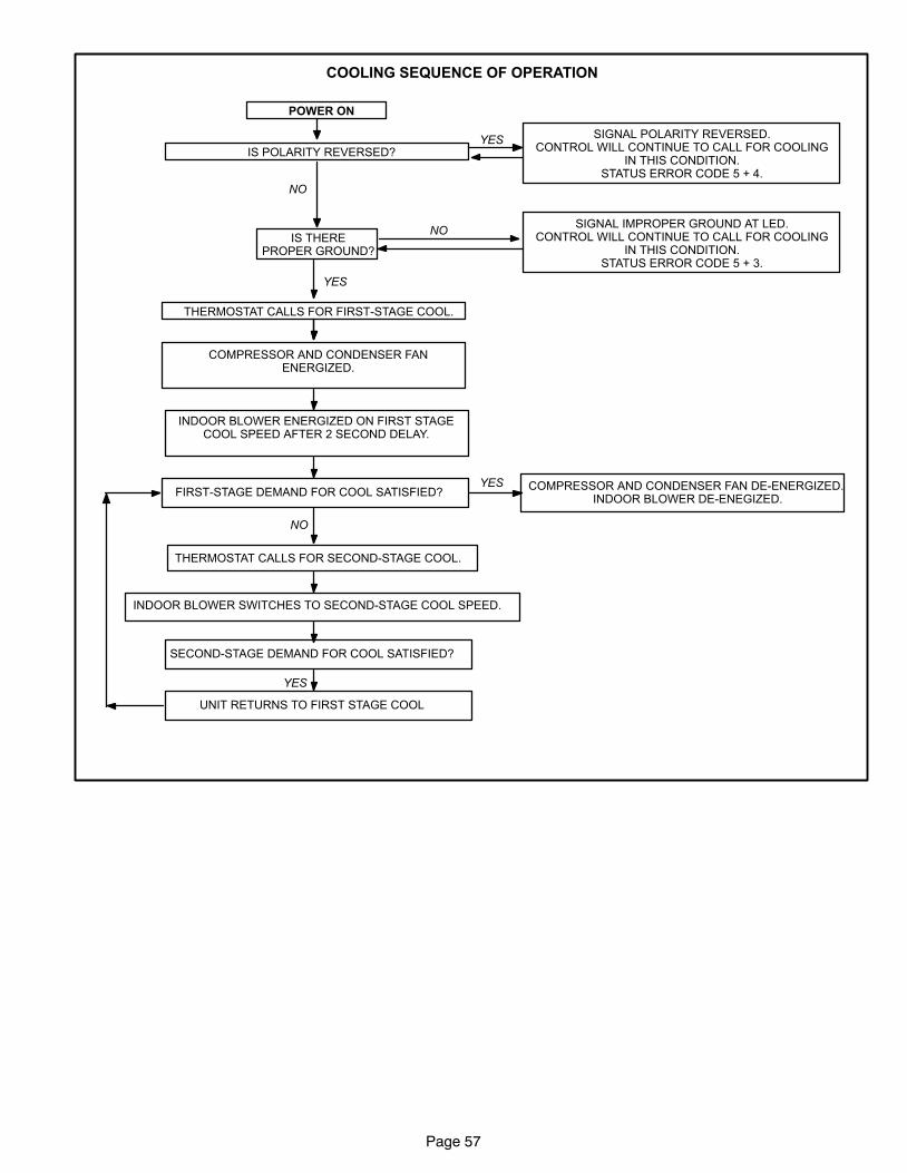
Page 57
COOLING SEQUENCE OF OPERATION
SIGNAL POLARITY REVERSED.CONTROL WILL CONTINUE TO CALL FOR COOLING
IN THIS CONDITION.STATUS ERROR CODE 5 + 4.
POWER ON
YESIS POLARITY REVERSED?
THERMOSTAT CALLS FOR FIRST−STAGE COOL.
COMPRESSOR AND CONDENSER FANENERGIZED.
NO
IS THEREPROPER GROUND?
YES
NO
INDOOR BLOWER ENERGIZED ON FIRST STAGECOOL SPEED AFTER 2 SECOND DELAY.
FIRST−STAGE DEMAND FOR COOL SATISFIED?
NO
THERMOSTAT CALLS FOR SECOND−STAGE COOL.
COMPRESSOR AND CONDENSER FAN DE−ENERGIZED. INDOOR BLOWER DE−ENEGIZED.
YES
INDOOR BLOWER SWITCHES TO SECOND−STAGE COOL SPEED.
SECOND−STAGE DEMAND FOR COOL SATISFIED?
YES
UNIT RETURNS TO FIRST STAGE COOL
SIGNAL IMPROPER GROUND AT LED.CONTROL WILL CONTINUE TO CALL FOR COOLING
IN THIS CONDITION.STATUS ERROR CODE 5 + 3.
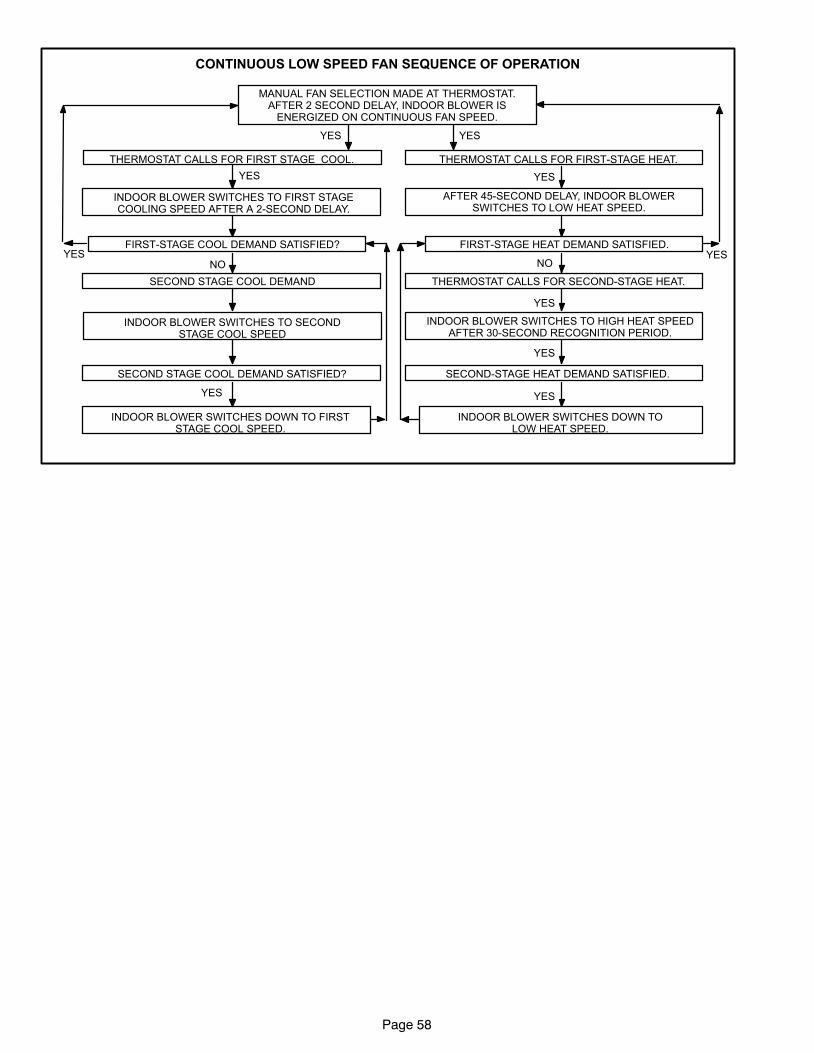
Page 58
CONTINUOUS LOW SPEED FAN SEQUENCE OF OPERATION
MANUAL FAN SELECTION MADE AT THERMOSTAT.AFTER 2 SECOND DELAY, INDOOR BLOWER IS
ENERGIZED ON CONTINUOUS FAN SPEED.
THERMOSTAT CALLS FOR FIRST−STAGE HEAT.THERMOSTAT CALLS FOR FIRST STAGE COOL.
YESYES
AFTER 45−SECOND DELAY, INDOOR BLOWERSWITCHES TO LOW HEAT SPEED.
FIRST−STAGE HEAT DEMAND SATISFIED.YES
NO
THERMOSTAT CALLS FOR SECOND−STAGE HEAT.
YES
INDOOR BLOWER SWITCHES TO HIGH HEAT SPEEDAFTER 30−SECOND RECOGNITION PERIOD.
SECOND−STAGE HEAT DEMAND SATISFIED.
YES
YES
INDOOR BLOWER SWITCHES DOWN TOLOW HEAT SPEED.
INDOOR BLOWER SWITCHES TO FIRST STAGECOOLING SPEED AFTER A 2−SECOND DELAY.
FIRST−STAGE COOL DEMAND SATISFIED?YES
NO
SECOND STAGE COOL DEMAND SATISFIED?
INDOOR BLOWER SWITCHES TO SECONDSTAGE COOL SPEED
YES
SECOND STAGE COOL DEMAND
INDOOR BLOWER SWITCHES DOWN TO FIRSTSTAGE COOL SPEED.
YES YES
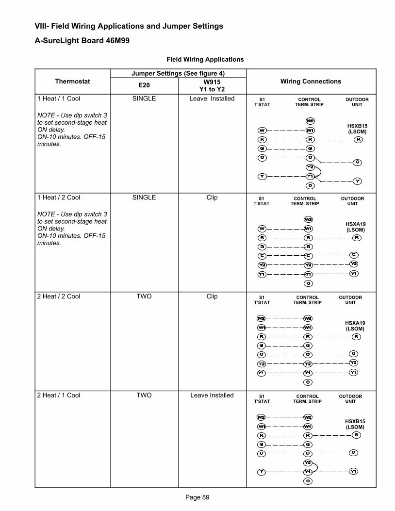
Page 59
VIII− Field Wiring Applications and Jumper Settings
A−SureLight Board 46M99
Field Wiring Applications
Jumper Settings (See figure 4)
ThermostatE20
W915Y1 to Y2
Wiring Connections
1 Heat / 1 Cool
NOTE − Use dip switch 3to set second−stage heatON delay.ON−10 minutes. OFF−15minutes.
SINGLE Leave Installed S1T’STAT
CONTROLTERM. STRIP
OUTDOORUNIT
HSXB15(LSOM)
1 Heat / 2 Cool
NOTE − Use dip switch 3to set second−stage heatON delay.ON−10 minutes. OFF−15minutes.
SINGLE Clip S1T’STAT
CONTROLTERM. STRIP
OUTDOORUNIT
HSXA19(LSOM)
2 Heat / 2 Cool TWO Clip S1T’STAT
CONTROLTERM. STRIP
OUTDOORUNIT
HSXA19(LSOM)
2 Heat / 1 Cool TWO Leave Installed S1T’STAT
CONTROLTERM. STRIP
OUTDOORUNIT
HSXB15(LSOM)
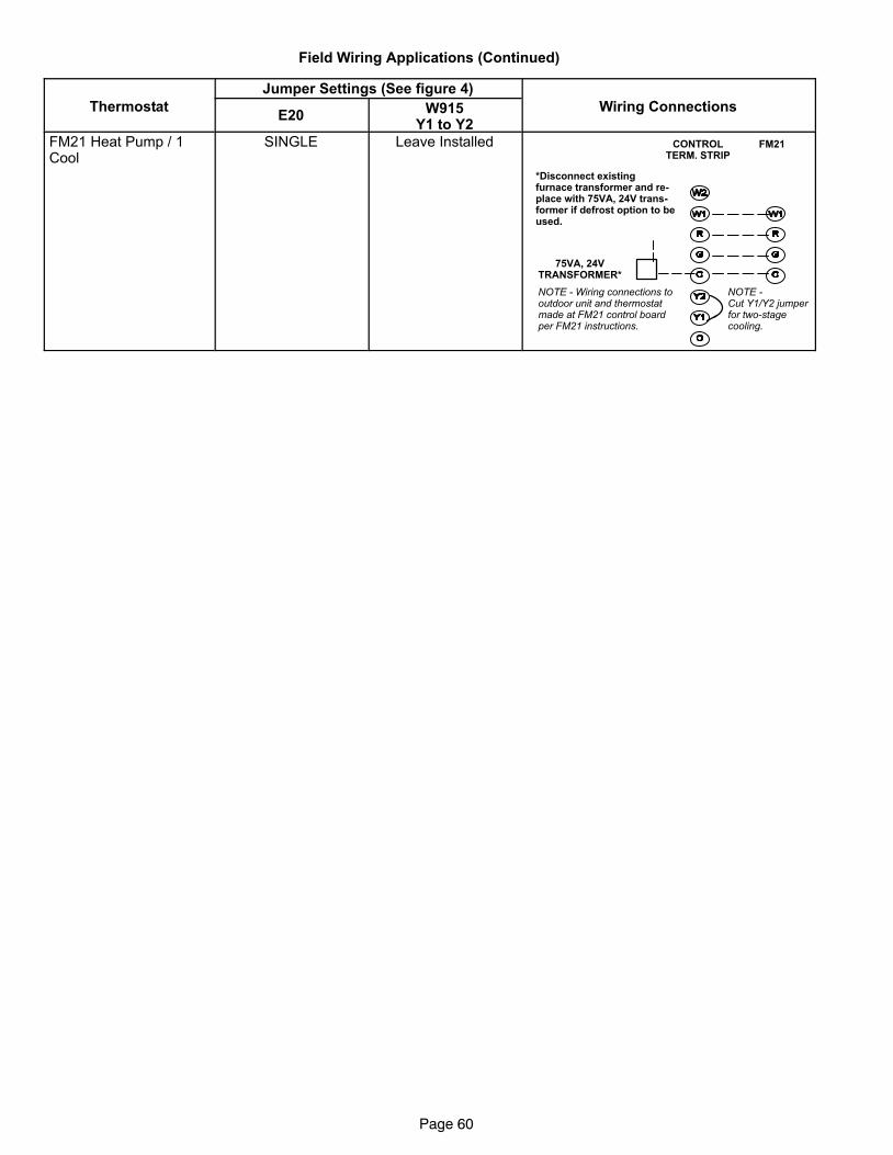
Page 60
Field Wiring Applications (Continued)
Jumper Settings (See figure 4)
ThermostatE20
W915Y1 to Y2
Wiring Connections
FM21 Heat Pump / 1Cool
SINGLE Leave Installed CONTROLTERM. STRIP
FM21
75VA, 24VTRANSFORMER*
*Disconnect existingfurnace transformer and re-place with 75VA, 24V trans-former if defrost option to beused.
NOTE − Wiring connections tooutdoor unit and thermostatmade at FM21 control boardper FM21 instructions.
NOTE − Cut Y1/Y2 jumperfor two−stagecooling.
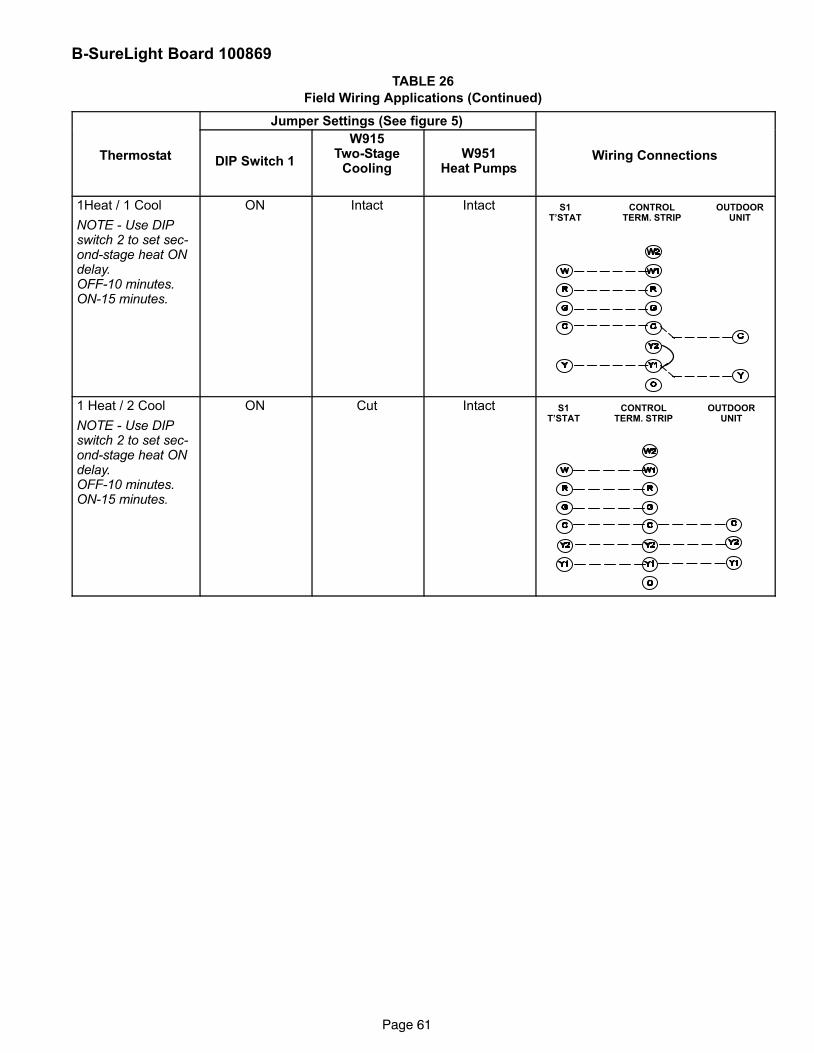
Page 61
B−SureLight Board 100869
TABLE 26
Field Wiring Applications (Continued)
Jumper Settings (See figure 5)
Thermostat DIP Switch 1
W915Two−Stage
CoolingW951
Heat PumpsWiring Connections
1Heat / 1 Cool
NOTE − Use DIPswitch 2 to set sec-ond−stage heat ONdelay.OFF−10 minutes.ON−15 minutes.
ON Intact Intact S1T’STAT
CONTROLTERM. STRIP
OUTDOORUNIT
1 Heat / 2 Cool
NOTE − Use DIPswitch 2 to set sec-ond−stage heat ONdelay.OFF−10 minutes.ON−15 minutes.
ON Cut Intact S1T’STAT
CONTROLTERM. STRIP
OUTDOORUNIT
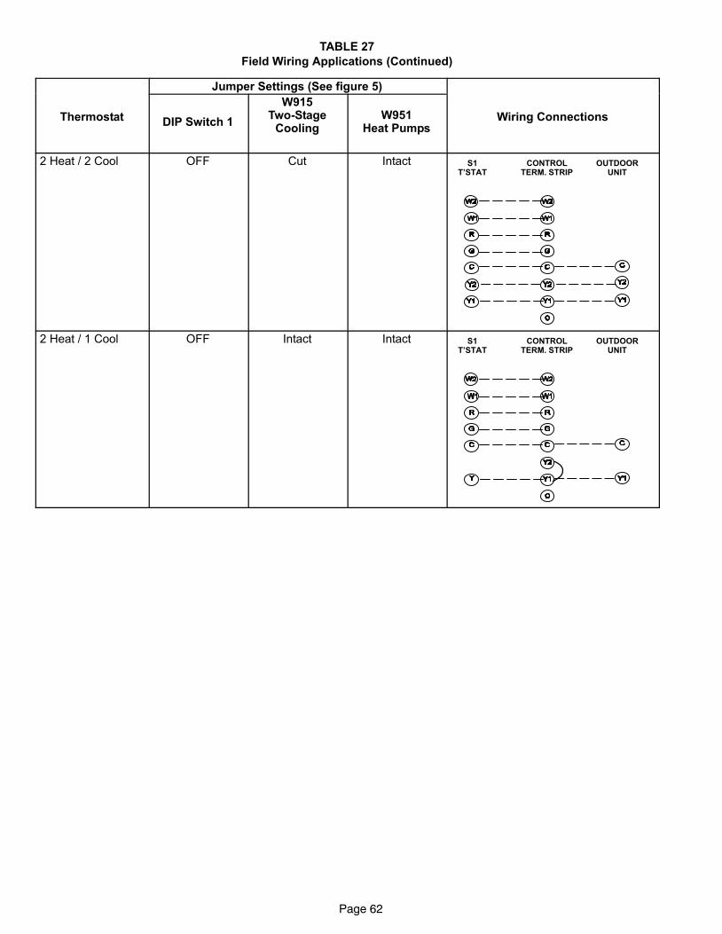
Page 62
TABLE 27
Field Wiring Applications (Continued)
Jumper Settings (See figure 5)
Thermostat DIP Switch 1
W915Two−Stage
CoolingW951
Heat PumpsWiring Connections
2 Heat / 2 Cool OFF Cut Intact S1T’STAT
CONTROLTERM. STRIP
OUTDOORUNIT
2 Heat / 1 Cool OFF Intact Intact S1T’STAT
CONTROLTERM. STRIP
OUTDOORUNIT
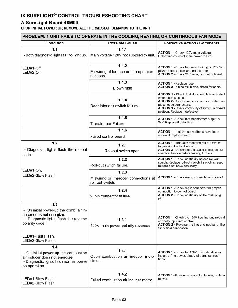
Page 63
IX−SURELIGHT® CONTROL TROUBLESHOOTING CHART
A−SureLight Board 46M99UPON INITIAL POWER UP, REMOVE ALL THERMOSTAT DEMANDS TO THE UNIT
PROBLEM: 1 UNIT FAILS TO OPERATE IN THE COOLING, HEATING, OR CONTINUOUS FAN MODE
Condition Possible Cause Corrective Action / Comments
1.1
− Both diagnostic lights fail to light up.
1.1.1
Main voltage 120V not supplied to unit.ACTION 1 − Check 120V main voltage.Determine cause of main power failure.
LED#1−OffLED#2−Off
1.1.2
Miswiring of furnace or improper con-nections.
ACTION 1 − Check for correct wiring of 120V topower make up box and transformer.ACTION 2 − Check 24V wiring to control board.
1.1.3
Blown fuse
ACTION 1 − Replace fuse.ACTION 2 − If fuse still blows, check for short.
1.1.4
Door interlock switch failure.
ACTION 1 − Check that door switch is activatedwhen door is closed.ACTION 2 − Check wire connections to switch, re-place loose connectors.ACTION 3 − Check continuity of switch in closedposition. Replace if defective.
1.1.5
Transformer Failure.
ACTION 1 − Check that transformer output is24V. Replace if defective.
1.1.6
Failed control board.
ACTION 1 − If all the above items have beenchecked, replace board.
1.2
− Diagnostic lights flash the roll−out
code.
1.2.1
Roll−out switch open.
ACTION 1 − Manually reset the roll−out switchby pushing the top button.ACTION 2 − Determine the cause of the roll−outswitch activation before leaving furnace.code.
LED#1 O
1.2.2
Roll−out switch failure.
ACTION 1 − Check continuity across roll−outswitch. Replace roll−out switch if switch is resetbut does not have continuity.
LED#1−On,
LED#2−Slow Flash1.2.3
Mis iring or improper connections at ACTION 1 − Check wiring connections to switchLED#2 Slow Flash
Miswiring or improper connections atroll−out switch.
ACTION 1 − Check wiring connections to switch.
1.2.4
9 pin connector failure
ACTION 1 − Check 9−pin connector for properconnection to control board.ACTION 2 − Check continuity of the multi plugpin.
1.3
− On initial power−up the comb. air in-ducer does not energize.ducer does not energize. − Diagnostic lights flash the reversepolarity code.
1.3.1
120V main power polarity reversed.
ACTION 1 − Check the 120V has line and neutralcorrectly input into control.ACTION 2 − Reverse the line and neutral at the120V field connection.
LED#1−Fast Flash,LED#2−Slow Flash.
120V field connection.
1.4
− On initial power up the combustionair inducer does not energize. − Diagnostic lights flash normal poweron operation.
1.4.1
Open combustion air inducer motorcircuit.
ACTION 1 − Check for 120V to combustion airinducer. If no power, check wire and connec-tions.
on operation.
LED#1−Slow FlashLED#2−Slow Flash
1.4.2
Failed combustion air inducer motor.
ACTION 1 − If power is present at blower, replaceblower.
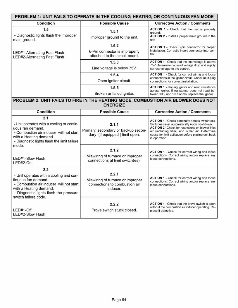
Page 64
PROBLEM 1: UNIT FAILS TO OPERATE IN THE COOLING, HEATING, OR CONTINUOUS FAN MODE
Condition Possible Cause Corrective Action / Comments
1.5
− Diagnostic lights flash the impropermain ground.
1.5.1
Improper ground to the unit.
ACTION 1 − Check that the unit is properlyground.ACTION 2 − Install a proper main ground to theunitg
LED#1−Alternating Fast FlashLED#2−Alternating Fast Flash
1.5.2
6−Pin connector is improperlyattached to the circuit board.
ACTION 1 − Check 6−pin connector for properinstallation. Correctly insert connector into con-trol.
LED#2 Alternating Fast Flash
1.5.3
Line voltage is below 75V.
ACTION 1 − Check that the line voltage is above75V. Determine cause of voltage drop and supplycorrect voltage to the control.
1.5.4
Open ignitor circuit.
ACTION 1 − Check for correct wiring and looseconnections in the ignitor circuit. Check mult−plugconnections for correct installation.
1.5.5
Broken or failed ignitor.
ACTION 1 − Unplug ignitor and read resistanceacross ignitor. If resistance does not read be-tween 10.9 and 19.7 ohms, replace the ignitor.
PROBLEM 2: UNIT FAILS TO FIRE IN THE HEATING MODE, COMBUSTION AIR BLOWER DOES NOTENERGIZE
Condition Possible Cause Corrective Action / Comments
2.1
− Unit operates with a cooling or contin-uous fan demand. − Combustion air inducer will not startwith a Heating demand. − Diagnostic lights flash the limit failure
d
2.1.1
Primary, secondary or backup secon-dary (if equipped ) limit open.
ACTION 1 − Check continuity across switch(es).Switches reset automatically upon cool down.ACTION 2 − Check for restrictions on blower inletair (including filter) and outlet air. Determinecause for limit activation before placing unit backin operation.
g gmode.
LED#1−Slow Flash,LED#2−On
2.1.2
Miswiring of furnace or improperconnections at limit switch(es).
ACTION 1 − Check for correct wiring and looseconnections. Correct wiring and/or replace anyloose connections.
2.2
− Unit operates with a cooling and con-tinuous fan demand. − Combustion air inducer will not startwith a Heating demand. − Diagnostic lights flash the pressureswitch failure code
2.2.1
Miswiring of furnace or improperconnections to combustion air
inducer.
ACTION 1 − Check for correct wiring and looseconnections. Correct wiring and/or replace anyloose connections.
switch failure code.
LED#1−Off,LED#2−Slow Flash
2.2.2
Prove switch stuck closed.
ACTION 1 − Check that the prove switch is openwithout the combustion air inducer operating. Re-place if defective.
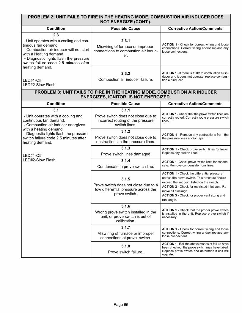
Page 65
PROBLEM 2: UNIT FAILS TO FIRE IN THE HEATING MODE, COMBUSTION AIR INDUCER DOESNOT ENERGIZE (CONT.).
Condition Possible Cause Corrective Action/Comments
2.3
− Unit operates with a cooling and con-tinuous fan demand. − Combustion air inducer will not startwith a Heating demand. − Diagnostic lights flash the pressureswitch failure code 2.5 minutes after
2.3.1
Miswiring of furnace or improper connections to combustion air induc-
er.
ACTION 1 − Check for correct wiring and looseconnections. Correct wiring and/or replace anyloose connections.
switch failure code 2.5 minutes afterheating demand.
LED#1−Off, LED#2−Slow Flash
2.3.2
Combustion air inducer failure.
ACTION 1 − If there is 120V to combustion air in-ducer and it does not operate, replace combus-tion air inducer.
PROBLEM 3: UNIT FAILS TO FIRE IN THE HEATING MODE, COMBUSTION AIR INDUCERENERGIZES, IGNITOR IS NOT ENERGIZED.
Condition Possible Cause Corrective Action/Comments
3.1
− Unit operates with a cooling andcontinuous fan demand. − Combustion air inducer energizeswith a heating demand
3.1.1
Prove switch does not close due toincorrect routing of the pressure
switch lines.
ACTION 1 − Check that the prove switch lines arecorrectly routed. Correctly route pressure switchlines.
with a heating demand. − Diagnostic lights flash the pressureswitch failure code 2.5 minutes afterheating demand.
3.1.2
Prove switch does not close due toobstructions in the pressure lines.
ACTION 1 − Remove any obstructions from thethe pressure lines and/or taps.
g
LED#1−Off
3.1.3
Prove switch lines damaged
ACTION 1 − Check prove switch lines for leaks.Replace any broken lines.
LED#1 OffLED#2−Slow Flash 3.1.4
Condensate in prove switch line.
ACTION 1 − Check prove switch lines for conden-sate. Remove condensate from lines.
3.1.5
Prove switch does not close due to alow differential pressure across the
prove switch.
ACTION 1 − Check the differential pressure
across the prove switch. This pressure should
exceed the set point listed on the switch.
ACTION 2 − Check for restricted inlet vent. Re-
move all blockage.
ACTION 3 − Check for proper vent sizing and
run length.
3.1.6
Wrong prove switch installed in theunit, or prove switch is out of
calibration.
ACTION 1 − Check that the proper prove switchis installed in the unit. Replace prove switch ifnecessary.
3.1.7
Miswiring of furnace or improperconnections at prove switch.
ACTION 1 − Check for correct wiring and looseconnections. Correct wiring and/or replace anyloose connections.
3.1.8
Prove switch failure.
ACTION 1 − If all the above modes of failure havebeen checked, the prove switch may have failed.Replace prove switch and determine if unit willoperate.
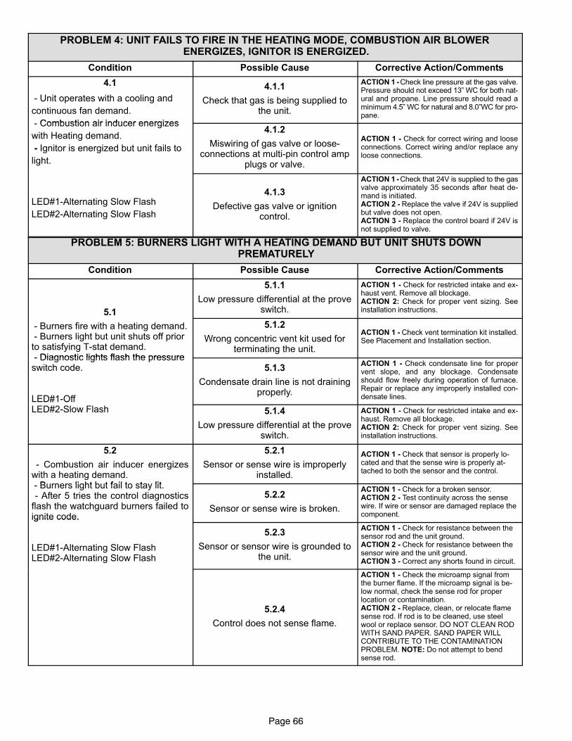
Page 66
PROBLEM 4: UNIT FAILS TO FIRE IN THE HEATING MODE, COMBUSTION AIR BLOWER ENERGIZES, IGNITOR IS ENERGIZED.
Condition Possible Cause Corrective Action/Comments
4.1
− Unit operates with a cooling and
continuous fan demand.
Combustion air inducer energizes
4.1.1
Check that gas is being supplied tothe unit.
ACTION 1 − Check line pressure at the gas valve.Pressure should not exceed 13" WC for both nat-ural and propane. Line pressure should read aminimum 4.5" WC for natural and 8.0"WC for pro-pane.
− Combustion air inducer energizes
with Heating demand.
− Ignitor is energized but unit fails to
light.
4.1.2
Miswiring of gas valve or loose-connections at multi−pin control amp
plugs or valve.
ACTION 1 − Check for correct wiring and looseconnections. Correct wiring and/or replace anyloose connections.
LED#1−Alternating Slow Flash
LED#2−Alternating Slow Flash
4.1.3
Defective gas valve or ignitioncontrol.
ACTION 1 − Check that 24V is supplied to the gasvalve approximately 35 seconds after heat de-mand is initiated.ACTION 2 − Replace the valve if 24V is suppliedbut valve does not open.ACTION 3 − Replace the control board if 24V isnot supplied to valve.
PROBLEM 5: BURNERS LIGHT WITH A HEATING DEMAND BUT UNIT SHUTS DOWN PREMATURELY
Condition Possible Cause Corrective Action/Comments
5.1
5.1.1
Low pressure differential at the proveswitch.
ACTION 1 − Check for restricted intake and ex-haust vent. Remove all blockage.ACTION 2: Check for proper vent sizing. Seeinstallation instructions.5.1
− Burners fire with a heating demand. − Burners light but unit shuts off priorto satisfying T−stat demand.− Diagnostic lights flash the pressure
5.1.2
Wrong concentric vent kit used forterminating the unit.
ACTION 1 − Check vent termination kit installed.See Placement and Installation section.
− Diagnostic lights flash the pressureswitch code.
LED#1−Off
5.1.3
Condensate drain line is not drainingproperly.
ACTION 1 − Check condensate line for propervent slope, and any blockage. Condensateshould flow freely during operation of furnace.Repair or replace any improperly installed con-densate lines.LED#1 Off
LED#2−Slow Flash 5.1.4
Low pressure differential at the proveswitch.
ACTION 1 − Check for restricted intake and ex-haust. Remove all blockage.ACTION 2: Check for proper vent sizing. Seeinstallation instructions.
5.2
− Combustion air inducer energizeswith a heating demand.
B rners light b t fail to sta lit
5.2.1
Sensor or sense wire is improperlyinstalled.
ACTION 1 − Check that sensor is properly lo-cated and that the sense wire is properly at-tached to both the sensor and the control.
− Burners light but fail to stay lit. − After 5 tries the control diagnosticsflash the watchguard burners failed toignite code.
5.2.2
Sensor or sense wire is broken.
ACTION 1 − Check for a broken sensor.ACTION 2 − Test continuity across the sensewire. If wire or sensor are damaged replace thecomponent.ignite code.
LED#1−Alternating Slow FlashLED#2−Alternating Slow Flash
5.2.3
Sensor or sensor wire is grounded tothe unit.
ACTION 1 − Check for resistance between thesensor rod and the unit ground.ACTION 2 − Check for resistance between thesensor wire and the unit ground.ACTION 3 − Correct any shorts found in circuit.
5.2.4
Control does not sense flame.
ACTION 1 − Check the microamp signal fromthe burner flame. If the microamp signal is be-low normal, check the sense rod for properlocation or contamination.ACTION 2 − Replace, clean, or relocate flamesense rod. If rod is to be cleaned, use steelwool or replace sensor. DO NOT CLEAN RODWITH SAND PAPER. SAND PAPER WILLCONTRIBUTE TO THE CONTAMINATIONPROBLEM. NOTE: Do not attempt to bendsense rod.
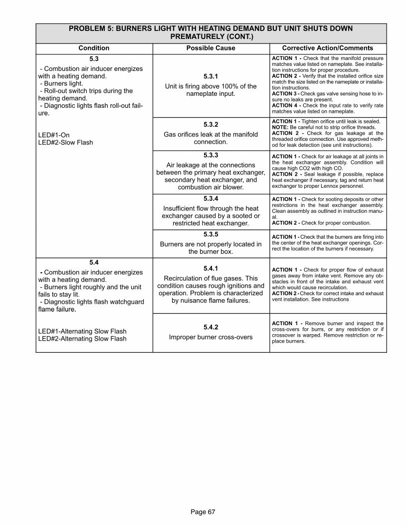
Page 67
PROBLEM 5: BURNERS LIGHT WITH HEATING DEMAND BUT UNIT SHUTS DOWN PREMATURELY (CONT.)
Condition Possible Cause Corrective Action/Comments
5.3
− Combustion air inducer energizeswith a heating demand. − Burners light. − Roll−out switch trips during theheating demand. − Diagnostic lights flash roll−out fail-ure.
5.3.1
Unit is firing above 100% of thenameplate input.
ACTION 1 − Check that the manifold pressurematches value listed on nameplate. See installa-tion instructions for proper procedure.ACTION 2 − Verify that the installed orifice sizematch the size listed on the nameplate or installa-tion instructions.ACTION 3 − Check gas valve sensing hose to in-sure no leaks are present.ACTION 4 − Check the input rate to verify ratematches value listed on nameplate.ure.
LED#1−OnLED#2−Slow Flash
5.3.2
Gas orifices leak at the manifoldconnection.
ACTION 1 − Tighten orifice until leak is sealed.NOTE: Be careful not to strip orifice threads.ACTION 2 − Check for gas leakage at thethreaded orifice connection. Use approved meth-od for leak detection (see unit instructions).
5.3.3
Air leakage at the connectionsbetween the primary heat exchanger,
secondary heat exchanger, andcombustion air blower.
ACTION 1 − Check for air leakage at all joints inthe heat exchanger assembly. Condition willcause high CO2 with high CO.ACTION 2 − Seal leakage if possible, replaceheat exchanger if necessary, tag and return heatexchanger to proper Lennox personnel.
5.3.4
Insufficient flow through the heatexchanger caused by a sooted or
restricted heat exchanger.
ACTION 1 − Check for sooting deposits or otherrestrictions in the heat exchanger assembly.Clean assembly as outlined in instruction manu-al.ACTION 2 − Check for proper combustion.
5.3.5
Burners are not properly located inthe burner box.
ACTION 1 − Check that the burners are firing intothe center of the heat exchanger openings. Cor-rect the location of the burners if necessary.
5.4
− Combustion air inducer energizeswith a heating demand. − Burners light roughly and the unitfails to stay lit. − Diagnostic lights flash watchguardflame failure.
5.4.1
Recirculation of flue gases. Thiscondition causes rough ignitions andoperation. Problem is characterized
by nuisance flame failures.
ACTION 1 − Check for proper flow of exhaustgases away from intake vent. Remove any ob-stacles in front of the intake and exhaust ventwhich would cause recirculation.ACTION 2 − Check for correct intake and exhaustvent installation. See instructions
flame failure.
LED#1−Alternating Slow FlashLED#2−Alternating Slow Flash
5.4.2
Improper burner cross−overs
ACTION 1 − Remove burner and inspect thecross−overs for burrs, or any restriction or ifcrossover is warped. Remove restriction or re-place burners.
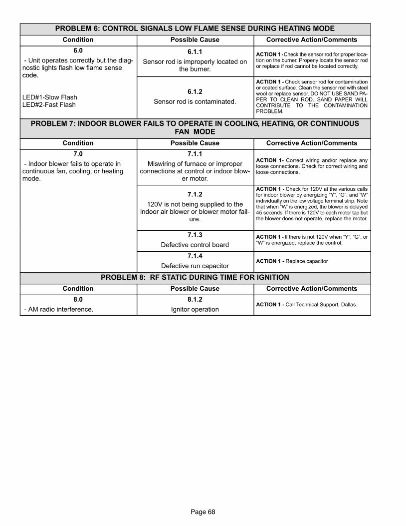
Page 68
PROBLEM 6: CONTROL SIGNALS LOW FLAME SENSE DURING HEATING MODE
Condition Possible Cause Corrective Action/Comments
6.0
− Unit operates correctly but the diag-nostic lights flash low flame sensecode
6.1.1
Sensor rod is improperly located onthe burner.
ACTION 1 − Check the sensor rod for proper loca-tion on the burner. Properly locate the sensor rodor replace if rod cannot be located correctly.
code.
LED#1−Slow FlashLED#2−Fast Flash
6.1.2
Sensor rod is contaminated.
ACTION 1 − Check sensor rod for contaminationor coated surface. Clean the sensor rod with steelwool or replace sensor. DO NOT USE SAND PA-PER TO CLEAN ROD. SAND PAPER WILLCONTRIBUTE TO THE CONTAMINATIONPROBLEM.
PROBLEM 7: INDOOR BLOWER FAILS TO OPERATE IN COOLING, HEATING, OR CONTINUOUSFAN MODE
Condition Possible Cause Corrective Action/Comments
7.0
− Indoor blower fails to operate incontinuous fan, cooling, or heatingmode.
7.1.1
Miswiring of furnace or improperconnections at control or indoor blow-
er motor.
ACTION 1− Correct wiring and/or replace anyloose connections. Check for correct wiring andloose connections.
7.1.2
120V is not being supplied to theindoor air blower or blower motor fail-
ure.
ACTION 1 − Check for 120V at the various callsfor indoor blower by energizing "Y", "G", and "W"individually on the low voltage terminal strip. Notethat when "W’ is energized, the blower is delayed45 seconds. If there is 120V to each motor tap butthe blower does not operate, replace the motor.
7.1.3
Defective control board
ACTION 1 − If there is not 120V when "Y", "G", or"W" is energized, replace the control.
7.1.4
Defective run capacitorACTION 1 − Replace capacitor
PROBLEM 8: RF STATIC DURING TIME FOR IGNITION
Condition Possible Cause Corrective Action/Comments
8.0
− AM radio interference.
8.1.2
Ignitor operationACTION 1 − Call Technical Support, Dallas.
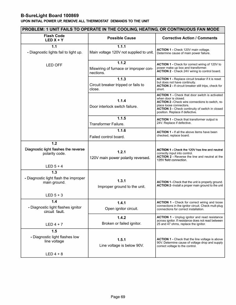
Page 69
B−SureLight Board 100869UPON INITIAL POWER UP, REMOVE ALL THERMOSTAT DEMANDS TO THE UNIT
PROBLEM: 1 UNIT FAILS TO OPERATE IN THE COOLING, HEATING, OR CONTINUOUS FAN MODE
Flash CodeLED X + Y
Possible Cause Corrective Action / Comments
1.1
− Diagnostic lights fail to light up.
1.1.1
Main voltage 120V not supplied to unit.ACTION 1 − Check 120V main voltage.Determine cause of main power failure.
LED OFF1.1.2
Miswiring of furnace or improper con-nections.
ACTION 1 − Check for correct wiring of 120V topower make up box and transformer.ACTION 2 − Check 24V wiring to control board.
1.1.3
Circuit breaker tripped or fails toclose.
ACTION 1 − Replace circuit breaker if it is resetbut does not have continuity.ACTION 2 − If circuit breaker still trips, check forshort.
1.1.4
Door interlock switch failure.
ACTION 1 − Check that door switch is activatedwhen door is closed.ACTION 2 − Check wire connections to switch, re-place loose connectors.ACTION 3 − Check continuity of switch in closedposition. Replace if defective.
1.1.5
Transformer Failure.
ACTION 1 − Check that transformer output is24V. Replace if defective.
1.1.6
Failed control board.
ACTION 1 − If all the above items have beenchecked, replace board.
1.2
Diagnostic light flashes the reverse ACTION 1 − Check the 120V has line and neutral Diagnostic light flashes the reversepolarity code. 1.2.1
120V main power polarity reversed.
ACTION 1 − Check the 120V has line and neutralcorrectly input into control.ACTION 2 − Reverse the line and neutral at the120V field connection
LED 5 + 4
120V main power polarity reversed.120V field connection.
1.3
− Diagnostic light flash the impropermain ground.
LED 5 + 3
1.3.1
Improper ground to the unit.
ACTION 1 − Check that the unit is properly ground.ACTION 2 − Install a proper main ground to the unit
1.4
− Diagnostic light flashes ignitorcircuit fault.
1.4.1
Open ignitor circuit.
ACTION 1 − Check for correct wiring and looseconnections in the ignitor circuit. Check mult−plugconnections for correct installation.
circuit fault.
LED 4 + 7
1.4.2
Broken or failed ignitor.
ACTION 1 − Unplug ignitor and read resistanceacross ignitor. If resistance does not read between25 and 47 ohms, replace the ignitor.
1.5
− Diagnostic light flashes lowline voltage
LED 4 + 8
1.5.1
Line voltage is below 90V.
ACTION 1 − Check that the line voltage is above90V. Determine cause of voltage drop and supplycorrect voltage to the control.
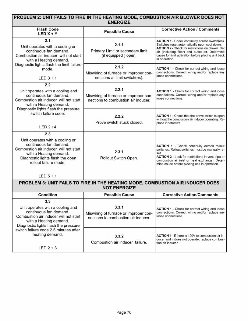
Page 70
PROBLEM 2: UNIT FAILS TO FIRE IN THE HEATING MODE, COMBUSTION AIR BLOWER DOES NOTENERGIZE
Flash CodeLED X + Y
Possible CauseCorrective Action / Comments
2.1
Unit operates with a cooling orcontinuous fan demand.
Combustion air inducer will not startwith a Heating demand.
Di ti li ht fl h th li it f il
2.1.1
Primary Limit or secondary limit(if equipped ) open.
ACTION 1 − Check continuity across switch(es).Switches reset automatically upon cool down.ACTION 2 − Check for restrictions on blower inletair (including filter) and outlet air. Determinecause for limit activation before placing unit backin operation.g
Diagnostic lights flash the limit failuremode.
LED 3 + 1
2.1.2
Miswiring of furnace or improper con-nections at limit switch(es).
ACTION 1 − Check for correct wiring and looseconnections. Correct wiring and/or replace anyloose connections.
2.2
Unit operates with a cooling andcontinuous fan demand.
Combustion air inducer will not startwith a Heating demand.
Diagnostic lights flash the pressure
2.2.1
Miswiring of furnace or improper con-nections to combustion air inducer.
ACTION 1 − Check for correct wiring and looseconnections. Correct wiring and/or replace anyloose connections.
Diagnostic lights flash the pressureswitch failure code.
LED 2 +4
2.2.2
Prove switch stuck closed.
ACTION 1 − Check that the prove switch is openwithout the combustion air inducer operating. Re-place if defective.
2.3
Unit operates with a cooling orcontinuous fan demand.
Combustion air inducer will not startwith a Heating demand.
Diagnostic lights flash the openrollout failure mode.
LED 5 + 1
2.3.1
Rollout Switch Open.
ACTION 1 − Check continuity across rolloutswitches. Rollout switches must be manually re-set.ACTION 2 − Look for restrictions in vent pipe orcombustion air inlet or heat exchanger. Deter-mine cause before placing unit in operation.
PROBLEM 3: UNIT FAILS TO FIRE IN THE HEATING MODE, COMBUSTION AIR INDUCER DOESNOT ENERGIZE
Condition Possible Cause Corrective Action/Comments
3.3
Unit operates with a cooling andcontinuous fan demand.
Combustion air inducer will not startwith a Heating demand.
Diagnostic lights flash the pressure
3.3.1
Miswiring of furnace or improper con-nections to combustion air inducer.
ACTION 1 − Check for correct wiring and looseconnections. Correct wiring and/or replace anyloose connections.
Diagnostic lights flash the pressureswitch failure code 2.5 minutes after
heating demand.
LED 2 + 3
3.3.2
Combustion air inducer failure.
ACTION 1 − If there is 120V to combustion air in-ducer and it does not operate, replace combus-tion air inducer.
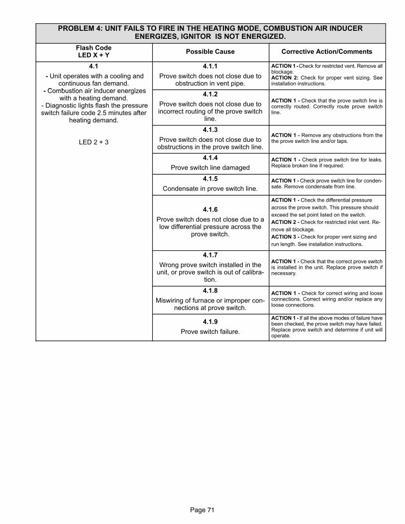
Page 71
PROBLEM 4: UNIT FAILS TO FIRE IN THE HEATING MODE, COMBUSTION AIR INDUCERENERGIZES, IGNITOR IS NOT ENERGIZED.
Flash CodeLED X + Y
Possible Cause Corrective Action/Comments
4.1
− Unit operates with a cooling andcontinuous fan demand.
Comb stion air ind cer energi es
4.1.1
Prove switch does not close due toobstruction in vent pipe.
ACTION 1 − Check for restricted vent. Remove allblockage.ACTION 2: Check for proper vent sizing. Seeinstallation instructions.
− Combustion air inducer energizeswith a heating demand.
− Diagnostic lights flash the pressureswitch failure code 2.5 minutes after
heating demand.
4.1.2
Prove switch does not close due toincorrect routing of the prove switch
line.
ACTION 1 − Check that the prove switch line iscorrectly routed. Correctly route prove switchline.
g
LED 2 + 3
4.1.3
Prove switch does not close due toobstructions in the prove switch line.
ACTION 1 − Remove any obstructions from thethe prove switch line and/or taps.
4.1.4
Prove switch line damaged
ACTION 1 − Check prove switch line for leaks.Replace broken line if required.
4.1.5
Condensate in prove switch line.
ACTION 1 − Check prove switch line for conden-sate. Remove condensate from line.
4.1.6
Prove switch does not close due to alow differential pressure across the
prove switch.
ACTION 1 − Check the differential pressure
across the prove switch. This pressure should
exceed the set point listed on the switch.
ACTION 2 − Check for restricted inlet vent. Re-
move all blockage.
ACTION 3 − Check for proper vent sizing and
run length. See installation instructions.
4.1.7
Wrong prove switch installed in theunit, or prove switch is out of calibra-
tion.
ACTION 1 − Check that the correct prove switchis installed in the unit. Replace prove switch ifnecessary.
4.1.8
Miswiring of furnace or improper con-nections at prove switch.
ACTION 1 − Check for correct wiring and looseconnections. Correct wiring and/or replace anyloose connections.
4.1.9
Prove switch failure.
ACTION 1 − If all the above modes of failure havebeen checked, the prove switch may have failed.Replace prove switch and determine if unit willoperate.
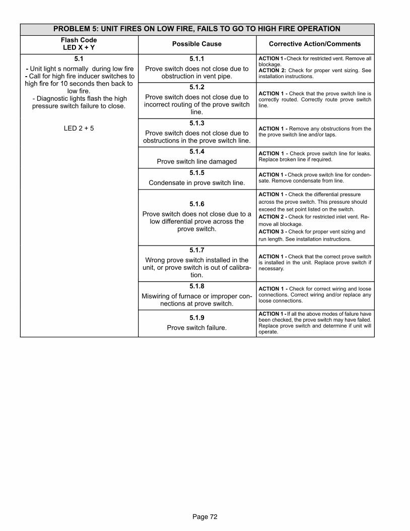
Page 72
PROBLEM 5: UNIT FIRES ON LOW FIRE, FAILS TO GO TO HIGH FIRE OPERATION
Flash CodeLED X + Y
Possible Cause Corrective Action/Comments
5.1
− Unit light s normally during low fire − Call for high fire inducer switches tohi h fi f 10 d th b k t
5.1.1
Prove switch does not close due toobstruction in vent pipe.
ACTION 1 − Check for restricted vent. Remove allblockage.ACTION 2: Check for proper vent sizing. Seeinstallation instructions.
high fire for 10 seconds then back tolow fire.
− Diagnostic lights flash the highpressure switch failure to close.
5.1.2
Prove switch does not close due toincorrect routing of the prove switch
line.
ACTION 1 − Check that the prove switch line iscorrectly routed. Correctly route prove switchline.
LED 2 + 55.1.3
Prove switch does not close due toobstructions in the prove switch line.
ACTION 1 − Remove any obstructions from thethe prove switch line and/or taps.
5.1.4
Prove switch line damaged
ACTION 1 − Check prove switch line for leaks.Replace broken line if required.
5.1.5
Condensate in prove switch line.
ACTION 1 − Check prove switch line for conden-sate. Remove condensate from line.
5.1.6
Prove switch does not close due to alow differential prove across the
prove switch.
ACTION 1 − Check the differential pressure
across the prove switch. This pressure should
exceed the set point listed on the switch.
ACTION 2 − Check for restricted inlet vent. Re-
move all blockage.
ACTION 3 − Check for proper vent sizing and
run length. See installation instructions.
5.1.7
Wrong prove switch installed in theunit, or prove switch is out of calibra-
tion.
ACTION 1 − Check that the correct prove switchis installed in the unit. Replace prove switch ifnecessary.
5.1.8
Miswiring of furnace or improper con-nections at prove switch.
ACTION 1 − Check for correct wiring and looseconnections. Correct wiring and/or replace anyloose connections.
5.1.9
Prove switch failure.
ACTION 1 − If all the above modes of failure havebeen checked, the prove switch may have failed.Replace prove switch and determine if unit willoperate.
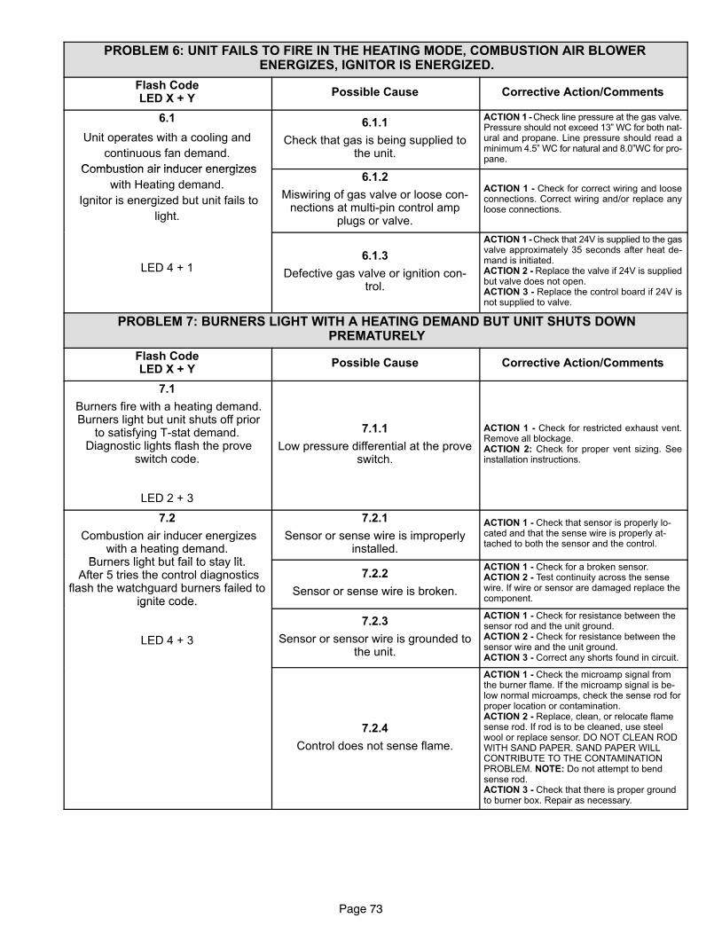
Page 73
PROBLEM 6: UNIT FAILS TO FIRE IN THE HEATING MODE, COMBUSTION AIR BLOWER ENERGIZES, IGNITOR IS ENERGIZED.
Flash CodeLED X + Y
Possible Cause Corrective Action/Comments
6.1
Unit operates with a cooling and
continuous fan demand.
Combustion air inducer energizes
6.1.1
Check that gas is being supplied tothe unit.
ACTION 1 − Check line pressure at the gas valve.Pressure should not exceed 13" WC for both nat-ural and propane. Line pressure should read aminimum 4.5" WC for natural and 8.0"WC for pro-pane.
Combustion air inducer energizes
with Heating demand.
Ignitor is energized but unit fails to
light.
6.1.2
Miswiring of gas valve or loose con-nections at multi−pin control amp
plugs or valve.
ACTION 1 − Check for correct wiring and looseconnections. Correct wiring and/or replace anyloose connections.
LED 4 + 16.1.3
Defective gas valve or ignition con-trol.
ACTION 1 − Check that 24V is supplied to the gasvalve approximately 35 seconds after heat de-mand is initiated.ACTION 2 − Replace the valve if 24V is suppliedbut valve does not open.ACTION 3 − Replace the control board if 24V isnot supplied to valve.
PROBLEM 7: BURNERS LIGHT WITH A HEATING DEMAND BUT UNIT SHUTS DOWN PREMATURELY
Flash CodeLED X + Y
Possible Cause Corrective Action/Comments
7.1
Burners fire with a heating demand. Burners light but unit shuts off prior
to satisfying T−stat demand. Diagnostic lights flash the prove
switch code.
LED 2 + 3
7.1.1
Low pressure differential at the proveswitch.
ACTION 1 − Check for restricted exhaust vent.Remove all blockage.ACTION 2: Check for proper vent sizing. Seeinstallation instructions.
7.2
Combustion air inducer energizeswith a heating demand.
B li ht b t f il t t lit
7.2.1
Sensor or sense wire is improperlyinstalled.
ACTION 1 − Check that sensor is properly lo-cated and that the sense wire is properly at-tached to both the sensor and the control.
Burners light but fail to stay lit. After 5 tries the control diagnostics
flash the watchguard burners failed toignite code.
7.2.2
Sensor or sense wire is broken.
ACTION 1 − Check for a broken sensor.ACTION 2 − Test continuity across the sensewire. If wire or sensor are damaged replace thecomponent.ignite code.
LED 4 + 3
7.2.3
Sensor or sensor wire is grounded tothe unit.
ACTION 1 − Check for resistance between thesensor rod and the unit ground.ACTION 2 − Check for resistance between thesensor wire and the unit ground.ACTION 3 − Correct any shorts found in circuit.
7.2.4
Control does not sense flame.
ACTION 1 − Check the microamp signal fromthe burner flame. If the microamp signal is be-low normal microamps, check the sense rod forproper location or contamination.ACTION 2 − Replace, clean, or relocate flamesense rod. If rod is to be cleaned, use steelwool or replace sensor. DO NOT CLEAN RODWITH SAND PAPER. SAND PAPER WILLCONTRIBUTE TO THE CONTAMINATIONPROBLEM. NOTE: Do not attempt to bendsense rod.ACTION 3 − Check that there is proper groundto burner box. Repair as necessary.
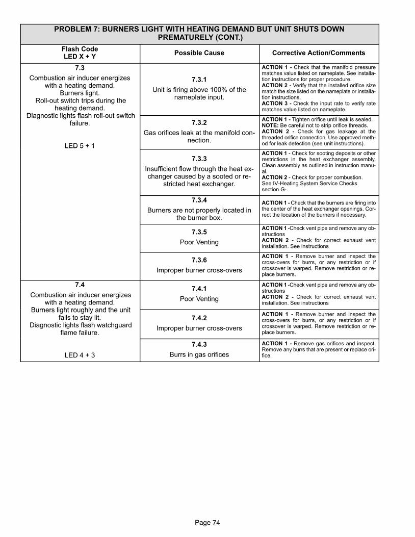
Page 74
PROBLEM 7: BURNERS LIGHT WITH HEATING DEMAND BUT UNIT SHUTS DOWN PREMATURELY (CONT.)
Flash CodeLED X + Y
Possible Cause Corrective Action/Comments
7.3
Combustion air inducer energizeswith a heating demand.
Burners light. Roll−out switch trips during the
heating demand.Diagnostic lights flash roll out switch
7.3.1
Unit is firing above 100% of thenameplate input.
ACTION 1 − Check that the manifold pressurematches value listed on nameplate. See installa-tion instructions for proper procedure.ACTION 2 − Verify that the installed orifice sizematch the size listed on the nameplate or installa-tion instructions.ACTION 3 − Check the input rate to verify ratematches value listed on nameplate.
Diagnostic lights flash roll−out switchfailure.
LED 5 + 1
7.3.2
Gas orifices leak at the manifold con-nection.
ACTION 1 − Tighten orifice until leak is sealed.NOTE: Be careful not to strip orifice threads.ACTION 2 − Check for gas leakage at thethreaded orifice connection. Use approved meth-od for leak detection (see unit instructions).LED 5 + 1
7.3.3
Insufficient flow through the heat ex-changer caused by a sooted or re-
stricted heat exchanger.
ACTION 1 − Check for sooting deposits or otherrestrictions in the heat exchanger assembly.Clean assembly as outlined in instruction manu-al.ACTION 2 − Check for proper combustion.See IV−Heating System Service Checkssection G−.
7.3.4
Burners are not properly located inthe burner box.
ACTION 1 − Check that the burners are firing intothe center of the heat exchanger openings. Cor-rect the location of the burners if necessary.
7.3.5
Poor Venting
ACTION 1 −Check vent pipe and remove any ob-structionsACTION 2 − Check for correct exhaust ventinstallation. See instructions
7.3.6
Improper burner cross−overs
ACTION 1 − Remove burner and inspect thecross−overs for burrs, or any restriction or ifcrossover is warped. Remove restriction or re-place burners.
7.4
Combustion air inducer energizeswith a heating demand.
Burners light roughly and the unit
7.4.1
Poor Venting
ACTION 1 −Check vent pipe and remove any ob-structionsACTION 2 − Check for correct exhaust ventinstallation. See instructions
Burners light roughly and the unitfails to stay lit.
Diagnostic lights flash watchguardflame failure.
7.4.2
Improper burner cross−overs
ACTION 1 − Remove burner and inspect thecross−overs for burrs, or any restriction or ifcrossover is warped. Remove restriction or re-place burners.
LED 4 + 3
7.4.3
Burrs in gas orifices
ACTION 1 − Remove gas orifices and inspect.Remove any burrs that are present or replace ori-fice.
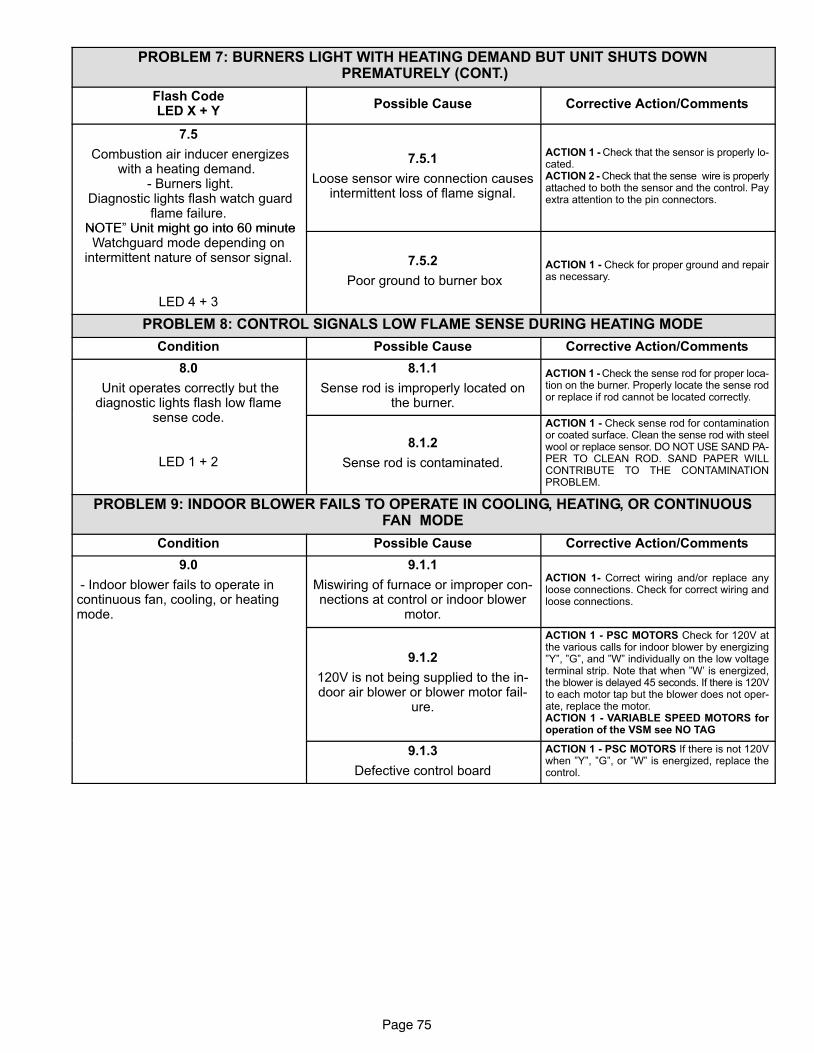
Page 75
PROBLEM 7: BURNERS LIGHT WITH HEATING DEMAND BUT UNIT SHUTS DOWN PREMATURELY (CONT.)
Flash CodeLED X + Y
Possible Cause Corrective Action/Comments
7.5
Combustion air inducer energizeswith a heating demand.
− Burners light. Diagnostic lights flash watch guard
flame failure.NOTE" Unit might go into 60 minute
7.5.1
Loose sensor wire connection causesintermittent loss of flame signal.
ACTION 1 − Check that the sensor is properly lo-cated.ACTION 2 − Check that the sense wire is properlyattached to both the sensor and the control. Payextra attention to the pin connectors.
NOTE Unit might go into 60 minuteWatchguard mode depending on
intermittent nature of sensor signal.
LED 4 + 3
7.5.2
Poor ground to burner box
ACTION 1 − Check for proper ground and repairas necessary.
PROBLEM 8: CONTROL SIGNALS LOW FLAME SENSE DURING HEATING MODE
Condition Possible Cause Corrective Action/Comments
8.0
Unit operates correctly but thediagnostic lights flash low flame
d
8.1.1
Sense rod is improperly located onthe burner.
ACTION 1 − Check the sense rod for proper loca-tion on the burner. Properly locate the sense rodor replace if rod cannot be located correctly.
sense code.
LED 1 + 2
8.1.2
Sense rod is contaminated.
ACTION 1 − Check sense rod for contaminationor coated surface. Clean the sense rod with steelwool or replace sensor. DO NOT USE SAND PA-PER TO CLEAN ROD. SAND PAPER WILLCONTRIBUTE TO THE CONTAMINATIONPROBLEM.
PROBLEM 9: INDOOR BLOWER FAILS TO OPERATE IN COOLING, HEATING, OR CONTINUOUSFAN MODE
Condition Possible Cause Corrective Action/Comments
9.0
− Indoor blower fails to operate incontinuous fan, cooling, or heatingmode.
9.1.1
Miswiring of furnace or improper con-nections at control or indoor blower
motor.
ACTION 1− Correct wiring and/or replace anyloose connections. Check for correct wiring andloose connections.
9.1.2
120V is not being supplied to the in-door air blower or blower motor fail-
ure.
ACTION 1 − PSC MOTORS Check for 120V atthe various calls for indoor blower by energizing"Y", "G", and "W" individually on the low voltageterminal strip. Note that when "W’ is energized,the blower is delayed 45 seconds. If there is 120Vto each motor tap but the blower does not oper-ate, replace the motor.ACTION 1 − VARIABLE SPEED MOTORS foroperation of the VSM see NO TAG
9.1.3
Defective control board
ACTION 1 − PSC MOTORS If there is not 120Vwhen "Y", "G", or "W" is energized, replace thecontrol.
Page 76
SERVICE NOTES


