Embed Size (px)
Citation preview
www.siemens.com/healthineers
MAMMOMAT RevelationOperator Manual – Tomosynthesis (Option)VC10 or higher


MAMMOMAT RevelationOperator Manual – Tomosynthesis (Option)VC10 or higher
Indicates a hintIs used to provide information on how to avoid operating errors or information emphasizingimportant details
Indicates the solution of a problemIs used to provide troubleshooting information or answers to frequently asked questions
Indicates a list item
Indicates a prerequisiteIs used for a condition that has to be fulfilled before starting a particular operation
Indicates a one-step operation
Indicates steps within operating sequences
Is used for references and for table or figure titles
Is used to identify a link to related information as well as previous or next steps
Is used to identify window titles, menu items, function names, buttons, and keys, for example,the Save button
Is used to emphasize particularly important sections of the text
Is used for on-screen output of the system including code-related elements or commands
Is used to identify inputs you need to provide
Is used for the navigation to a certain submenu entry
CAUTIONUsed with the safety alert symbol, indicates a hazardous situation which, if not avoided, couldresult in minor or moderate injury or material damage.CAUTION consists of the following elements:◾ Information about the nature of a hazardous situation
◾ Consequences of not avoiding a hazardous situation
◾ Methods of avoiding a hazardous situation
WARNINGIndicates a hazardous situation which, if not avoided, could result in death or serious injury.WARNING consists of the following elements:◾ Information about the nature of a hazardous situation
◾ Consequences of not avoiding a hazardous situation
◾ Methods of avoiding a hazardous situation
Italic
Bold
BlueUI text
User textMenu > Menu Item
Legend
4 Tomosynthesis (Option) | Operator ManualPrint No. XPW7-340G.621.05.02.02
1 System overview 71.1 Intended use for Canada 71.2 System description 7
1.2.1 Acquisition principle 81.2.2 Tomo scan 81.2.3 Raw projections 81.2.4 Processed projections 91.2.5 First view 91.2.6 Slices 91.2.7 Insight 2D (Option) 91.2.8 Insight 3D (Option) 91.2.9 Empire technology (Option) 101.2.10 Bounding box 101.2.11 Reconstruction 101.2.12 Reprocessing 101.2.13 Automatic movement of the swivel arm 101.2.14 Compression plate 111.2.15 Tomo face shield 12
1.3 System setting 131.3.1 Type of calibration 131.3.2 Calibration intervals 131.3.3 Performing detector calibration 141.3.4 Ending detector calibration 16
2 Tomosynthesis examination 192.1 Layout of the Examination task card 192.2 Preparations 20
2.2.1 General preparations 202.2.2 Registering a patient 202.2.3 Performing the examination settings 202.2.4 Positioning the patient 222.2.5 Compressing the breast 22
2.3 Acquiring exposures 232.3.1 Acquiring tomo images 242.3.2 Modifying the bounding box 262.3.3 Status bar and image text 27
2.4 Displaying/processing tomo examination images 292.4.1 Display of reconstructions 302.4.2 Displaying tomo images 312.4.3 Reconstructing tomo images 322.4.4 Playing back motion images (movie/cine) 35
2.5 Additional notes on the tomo examination 372.5.1 Correcting projection views 372.5.2 Adding projection views 382.5.3 Creating a 2D + 3D exposure 392.5.4 Post-processing examination images 40
2.6 Ending the examination 42
3 Configuration 433.1 Configuring a tomo examination 43
3.1.1 Configuring procedures 433.1.2 Details of the projection views 433.1.3 Image selection for autotransfer destinations 443.1.4 Configuring the image impression (IP Set) 46
Table of contents
MAMMOMAT Revelation | VC10 or higher 5Print No. XPW7-340G.621.05.02.02

4 Glossary 49
Index 51
Table of contents
6 Tomosynthesis (Option) | Operator ManualPrint No. XPW7-340G.621.05.02.02
System overview
Please be aware that this Operator Manual Tomosynthesis is just oneoption.Only the complete manual is valid:
◾ Operator Manual - MAMMOMAT Revelation system◾ Quality control manual◾ Safety Hints - syngo VI10A◾ Tomosynthesis Option
Intended use for CanadaThe MAMMOMAT Revelation system with the option Tomosynthesis is indicatedfor acquisition of 2D as well as 3D digital mammography to be used in screeningand diagnosis.The screening examination may consist of a 2D FFDM image set with or withoutthe 3D image set. The views included in the image set will be determined by thescreening protocol and/or the requirements of the diagnostic indication.
System descriptionMAMMOMAT Revelation is supporting the Tomosynthesis Option.With tomosynthesis, three-dimensional information can be obtained by takingexposures from different angles. This significantly reduces the tissue overlapproblem which limits diagnosis in conventional mammography. Tomosynthesisis displayed and controlled at the workstation.In tomosynthesis, the X-ray tube rotates in a defined angular range. During theacquisition, several X-rays are taken from different directions. Each of thesesingle exposures is taken with a very low dose. Due to the different acquisitiondirections, the set of 2-dimensional X-ray images contains the 3D information ofthe object, allowing the volume of the breast to be reconstructed by appropriatesoftware algorithms and visualized in the form of slice images.During tomosynthesis acquisition, the swivel arm of the MAMMOMATRevelation covers an angular range from +25° to -25° while 25 views areacquired.
Inform the patient in detail about the examination procedure, in particularabout the time required and the automatic movement of the swivel arm.
1
1.1
1.2
System overview 1
MAMMOMAT Revelation | VC10 or higher 7Print No. XPW7-340G.621.05.02.02
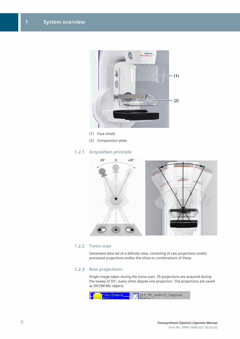
(1) Face shield(2) Compression plate
Acquisition principle
Tomo scanGenerated data set of a definite view, consisting of raw projections and/orprocessed projections and/or the slices or combinations of these.
Raw projectionsSingle image taken during the tomo scan. 25 projections are acquired duringthe sweep of 50°, every other degree one projection. The projections are savedas DICOM MG objects.
1.2.1
1.2.2
1.2.3
1 System overview
8 Tomosynthesis (Option) | Operator ManualPrint No. XPW7-340G.621.05.02.02
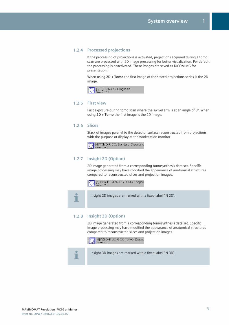
Processed projectionsIf the processing of projections is activated, projections acquired during a tomoscan are processed with 2D image processing for better visualization. Per defaultthe processing is deactivated. These images are saved as DICOM MG forpresentation.When using 2D + Tomo the first image of the stored projections series is the 2Dimage.
First viewFirst exposure during tomo scan where the swivel arm is at an angle of 0°. Whenusing 2D + Tomo the first image is the 2D image.
SlicesStack of images parallel to the detector surface reconstructed from projectionswith the purpose of display at the workstation monitor.
Insight 2D (Option)2D image generated from a corresponding tomosynthesis data set. Specificimage processing may have modified the appearance of anatomical structurescompared to reconstructed slices and projection images.
Insight 2D images are marked with a fixed label “IN 2D”.
Insight 3D (Option)3D image generated from a corresponding tomosynthesis data set. Specificimage processing may have modified the appearance of anatomical structurescompared to reconstructed slices and projection images.
Insight 3D images are marked with a fixed label “IN 3D”.
1.2.4
1.2.5
1.2.6
1.2.7
1.2.8
System overview 1
MAMMOMAT Revelation | VC10 or higher 9Print No. XPW7-340G.621.05.02.02
CAUTION
Insight 2D or Insight 3D images are derived from tomosynthesis acquisitiondata. Image processing may have modified the appearance of anatomicalstructures compared to FFDM.Risk of incorrect diagnosis!◆ Insight 2D or Insight 3D images should only be reviewed together with
tomosynthesis slices.
Empire technology (Option)Unique, multiple algorithms, providing superior image quality in both contrastand detail.
Bounding boxRegion of interest, describing the area that will be reconstructed. Using thehandles you can adjust the bounding box to the breast tissue area to bereconstructed for slices.
ReconstructionThe calculation of the stack of slices (3D volume) from the projections using areconstruction algorithm.
ReprocessingProcessing of the projections and 2D image with new image processing orreconstruction parameter set.
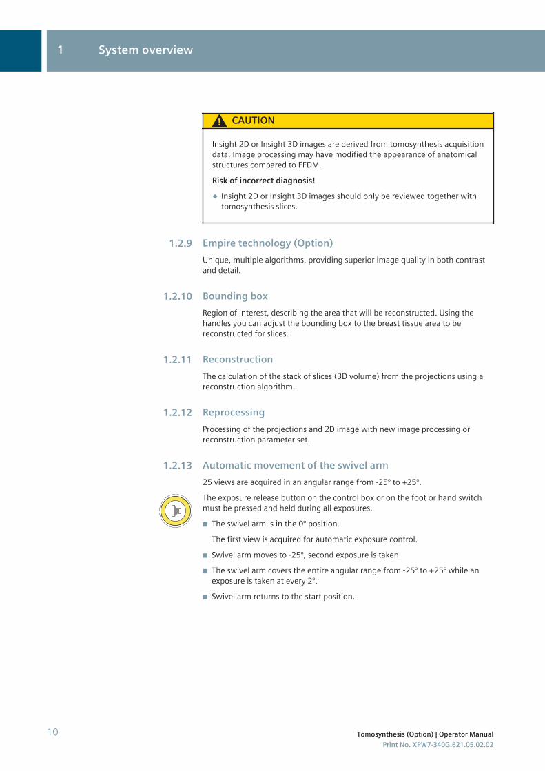
Automatic movement of the swivel arm25 views are acquired in an angular range from -25° to +25°.The exposure release button on the control box or on the foot or hand switchmust be pressed and held during all exposures.◾ The swivel arm is in the 0° position.
The first view is acquired for automatic exposure control.◾ Swivel arm moves to -25°, second exposure is taken.◾ The swivel arm covers the entire angular range from -25° to +25° while an
exposure is taken at every 2°.◾ Swivel arm returns to the start position.
1.2.9
1.2.10
1.2.11
1.2.12
1.2.13
1 System overview
10 Tomosynthesis (Option) | Operator ManualPrint No. XPW7-340G.621.05.02.02
◾ Release the exposure button.◾ The first view is displayed.◾ The slices are automatically reconstructed and then displayed.◾ The projections are processed and displayed if activated (by default
deactivated).
Inform the patient in detail about the examination procedure, in particularabout the time required and the automatic movement of the swivel arm.
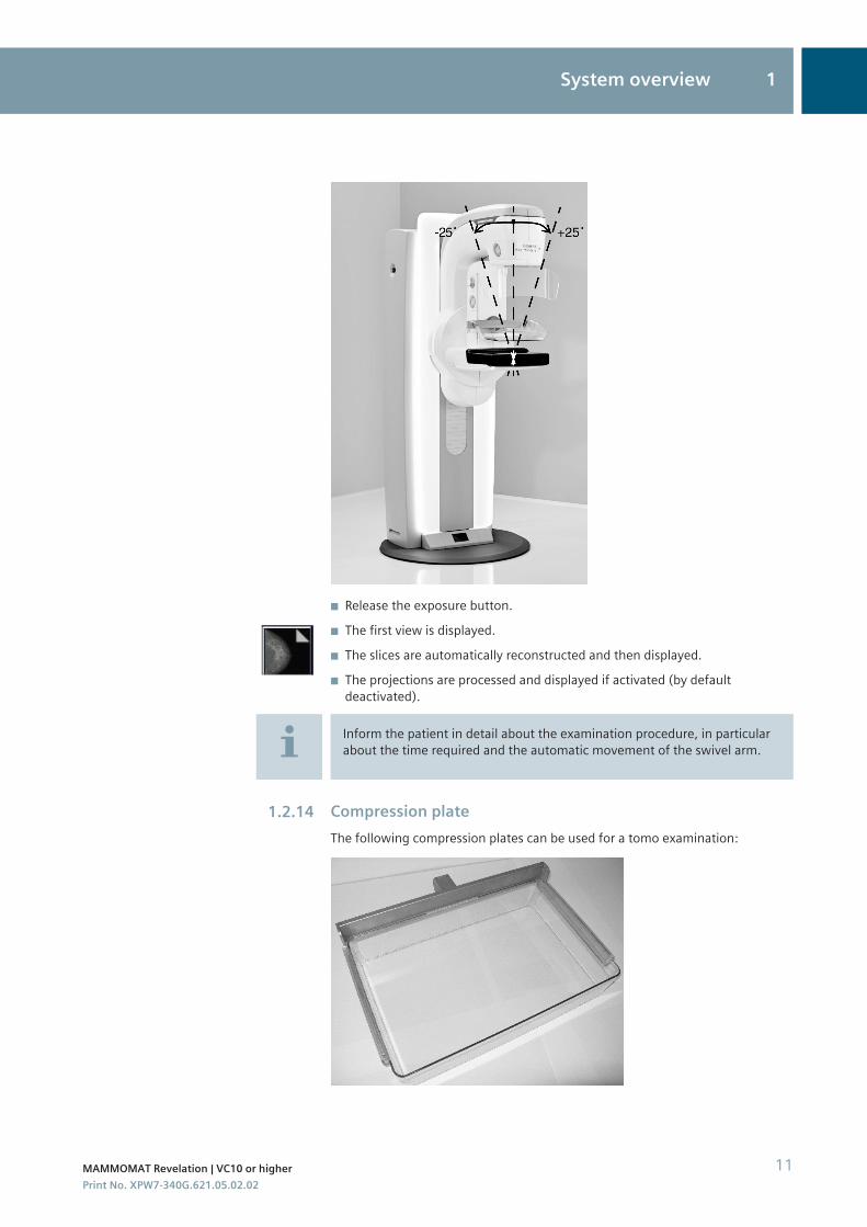
Compression plateThe following compression plates can be used for a tomo examination:
1.2.14
System overview 1
MAMMOMAT Revelation | VC10 or higher 11Print No. XPW7-340G.621.05.02.02
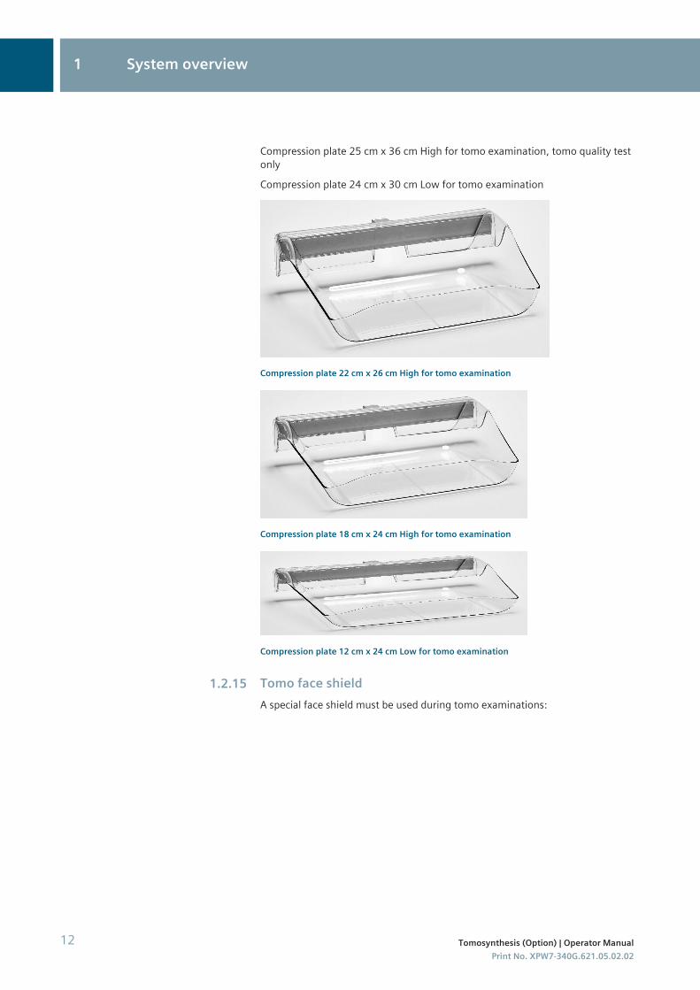
Compression plate 25 cm x 36 cm High for tomo examination, tomo quality testonlyCompression plate 24 cm x 30 cm Low for tomo examination
Compression plate 22 cm x 26 cm High for tomo examination
Compression plate 18 cm x 24 cm High for tomo examination
Compression plate 12 cm x 24 cm Low for tomo examination
Tomo face shieldA special face shield must be used during tomo examinations:
1.2.15
1 System overview
12 Tomosynthesis (Option) | Operator ManualPrint No. XPW7-340G.621.05.02.02
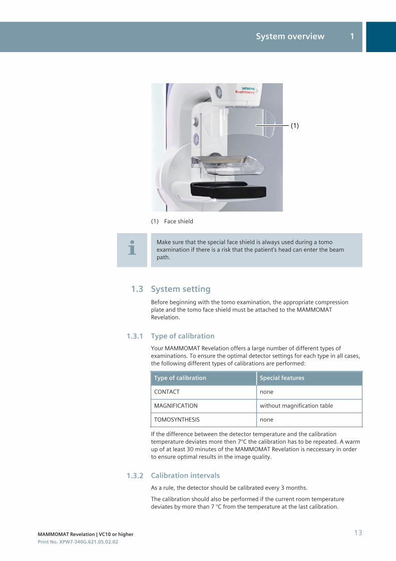
(1) Face shield
Make sure that the special face shield is always used during a tomoexamination if there is a risk that the patient's head can enter the beampath.
System settingBefore beginning with the tomo examination, the appropriate compressionplate and the tomo face shield must be attached to the MAMMOMATRevelation.
Type of calibrationYour MAMMOMAT Revelation offers a large number of different types ofexaminations. To ensure the optimal detector settings for each type in all cases,the following different types of calibrations are performed:
Type of calibration Special features
CONTACT none
MAGNIFICATION without magnification table
TOMOSYNTHESIS none
If the difference between the detector temperature and the calibrationtemperature deviates more then 7°C the calibration has to be repeated. A warmup of at least 30 minutes of the MAMMOMAT Revelation is neccessary in orderto ensure optimal results in the image quality.
Calibration intervalsAs a rule, the detector should be calibrated every 3 months.The calibration should also be performed if the current room temperaturedeviates by more than 7 °C from the temperature at the last calibration.
1.3
1.3.1
1.3.2
System overview 1
MAMMOMAT Revelation | VC10 or higher 13Print No. XPW7-340G.621.05.02.02
Calibration is performed without a compression plate. It is recommend thatthe tomosynthesis calibration be performed after contact calibration.
Performing detector calibration
Before you begin calibration, you have to set the swivel arm up for thecalibration.1 Install the 40 mm Plexiglass plate on the swivel arm so that the entire image
area is covered.
2 Move the swivel arm to the 0° position.
3 Remove the compression plate.
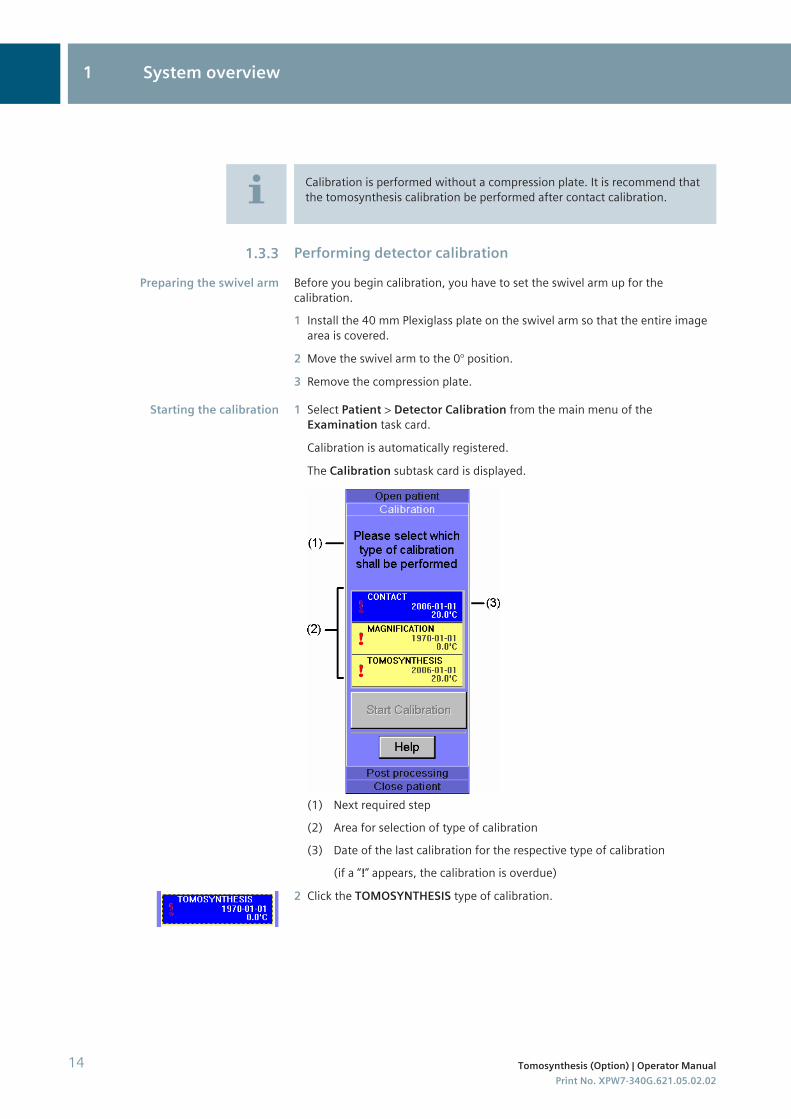
1 Select Patient > Detector Calibration from the main menu of theExamination task card.
Calibration is automatically registered.
The Calibration subtask card is displayed.
(1) Next required step(2) Area for selection of type of calibration(3) Date of the last calibration for the respective type of calibration
(if a “!” appears, the calibration is overdue)
2 Click the TOMOSYNTHESIS type of calibration.
1.3.3
Preparing the swivel arm
Starting the calibration
1 System overview
14 Tomosynthesis (Option) | Operator ManualPrint No. XPW7-340G.621.05.02.02
When the calibration subtask is selected, the exposure parameters areautomatically correctly set and displayed in the generator control field foreach anode/filter combination.See register: Examination, section Generator control field
Please note that for the TOMOSYNTHESIS calibration type, the calibrationcan only be repeated five times. After that the system has to be restarted.
3 Click Start Calibration.
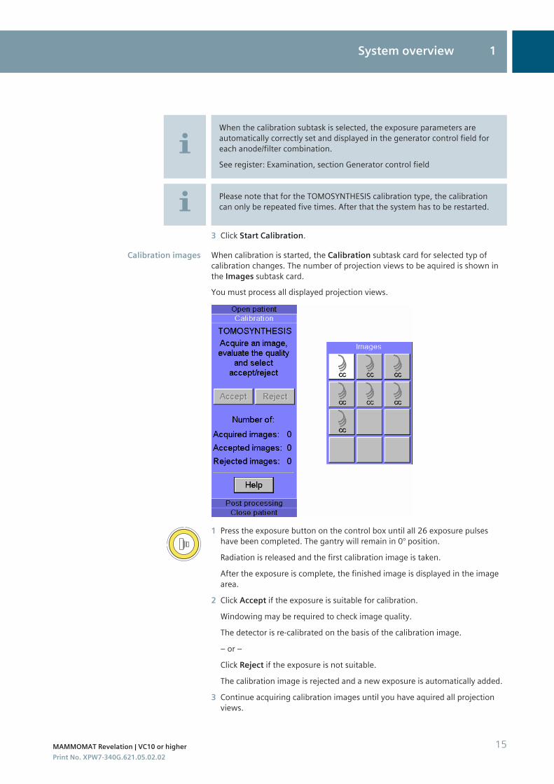
When calibration is started, the Calibration subtask card for selected typ ofcalibration changes. The number of projection views to be aquired is shown inthe Images subtask card.You must process all displayed projection views.
1 Press the exposure button on the control box until all 26 exposure pulseshave been completed. The gantry will remain in 0° position.
Radiation is released and the first calibration image is taken.
After the exposure is complete, the finished image is displayed in the imagearea.
2 Click Accept if the exposure is suitable for calibration.
Windowing may be required to check image quality.
The detector is re-calibrated on the basis of the calibration image.
– or –
Click Reject if the exposure is not suitable.
The calibration image is rejected and a new exposure is automatically added.
3 Continue acquiring calibration images until you have aquired all projectionviews.
Calibration images
System overview 1
MAMMOMAT Revelation | VC10 or higher 15Print No. XPW7-340G.621.05.02.02
The number of accepted and rejected exposures is counted in the Calibrationsubtask card.
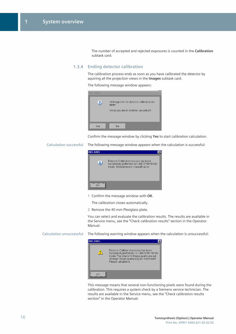
Ending detector calibrationThe calibration process ends as soon as you have calibrated the detector byaquiring all the projection views in the Images subtask card.The following message window appears:
Confirm the message window by clicking Yes to start calibration calculation.
The following message window appears when the calculation is successful:
1 Confirm the message window with OK.
The calibration closes automatically.
2 Remove the 40 mm Plexiglass plate.
You can select and evaluate the calibration results. The results are available inthe Service menu, see the “Check calibration results” section in the OperatorManual.
The following warning window appears when the calculation is unsuccessful:
This message means that several non-functioning pixels were found during thecalibration. This requires a system check by a Siemens service technician. Theresults are available in the Service menu, see the “Check calibration resultssection” in the Operator Manual.
1.3.4
Calculation successful
Calculation unsuccessful
1 System overview
16 Tomosynthesis (Option) | Operator ManualPrint No. XPW7-340G.621.05.02.02
◆ Call a Siemens service technician or a technician trained by Siemens.
Until the analysis by the service technician, clinical operation may continueif:
◾ the daily checks run without errors◾ there are no visible artifacts◾ the quality authorities have no objections
System overview 1
MAMMOMAT Revelation | VC10 or higher 17Print No. XPW7-340G.621.05.02.02

1 System overview
18 Tomosynthesis (Option) | Operator ManualPrint No. XPW7-340G.621.05.02.02
Tomosynthesis examination
This chapter describes a standard tomo examination. The examination iscontrolled at the workstation with preset examination parameters.For information about the control and display elements of the tomoexamination see ( Page 13 System setting).For further information on performing the examination at the workstation andchanging examination settings, see the MAMMOMAT Revelation OperatorManual.
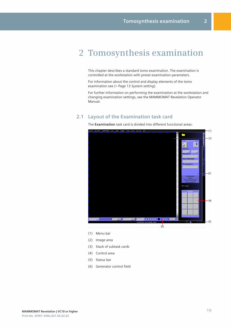
Layout of the Examination task cardThe Examination task card is divided into different functional areas:
(1) Menu bar(2) Image area(3) Stack of subtask cards(4) Control area(5) Status bar(6) Generator control field
2
2.1
Tomosynthesis examination 2
MAMMOMAT Revelation | VC10 or higher 19Print No. XPW7-340G.621.05.02.02
Preparations
General preparations✓ It is assumed that the MAMMOMAT has been correctly installed and started
up.
1 Prepare the MAMMOMAT for tomo mode.
2 Inform the patient about the examination procedure.
Registering a patientAt the beginning of an examination the patient must be registered via the RIS/Scheduler or manually.1 To open the Patient Registration window, click this button.
2 Enter the required examination data in the Patient Registration window.
3 Click the Exam button.
The Examination task card is opened.
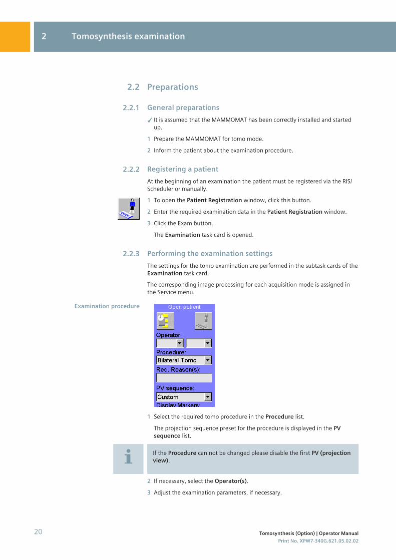
Performing the examination settingsThe settings for the tomo examination are performed in the subtask cards of theExamination task card.The corresponding image processing for each acquisition mode is assigned inthe Service menu.
1 Select the required tomo procedure in the Procedure list.
The projection sequence preset for the procedure is displayed in the PVsequence list.
If the Procedure can not be changed please disable the first PV (projectionview).
2 If necessary, select the Operator(s).3 Adjust the examination parameters, if necessary.
2.2
2.2.1
2.2.2
2.2.3
Examination procedure
2 Tomosynthesis examination
20 Tomosynthesis (Option) | Operator ManualPrint No. XPW7-340G.621.05.02.02
CAUTION
The use of the PRIME + Tomo acquisition mode for breasts withimplants.Repeated image!◆ Don't use PRIME + Tomo acquisition mode for breasts with implants.
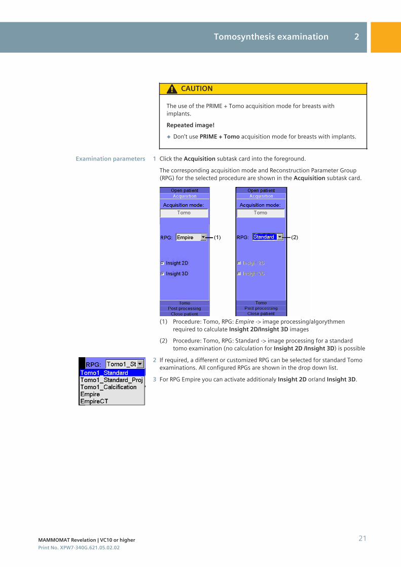
1 Click the Acquisition subtask card into the foreground.
The corresponding acquisition mode and Reconstruction Parameter Group(RPG) for the selected procedure are shown in the Acquisition subtask card.
(1) Procedure: Tomo, RPG: Empire -> image processing/algorythmenrequired to calculate Insight 2D/Insight 3D images
(2) Procedure: Tomo, RPG: Standard -> image processing for a standardtomo examination (no calculation for Insight 2D /Insight 3D) is possible
2 If required, a different or customized RPG can be selected for standard Tomoexaminations. All configured RPGs are shown in the drop down list.
3 For RPG Empire you can activate additionaly Insight 2D or/and Insight 3D.
Examination parameters
Tomosynthesis examination 2
MAMMOMAT Revelation | VC10 or higher 21Print No. XPW7-340G.621.05.02.02
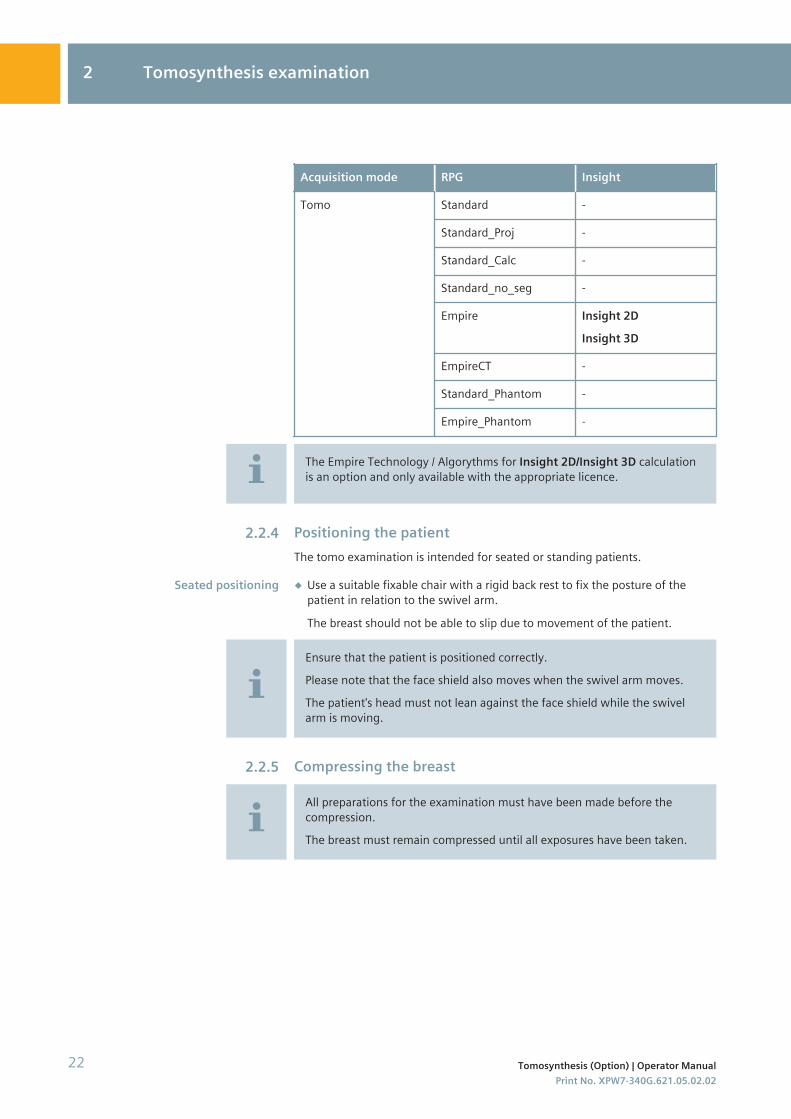
Acquisition mode RPG Insight
Tomo Standard -
Standard_Proj -
Standard_Calc -
Standard_no_seg -
Empire Insight 2DInsight 3D
EmpireCT -
Standard_Phantom -
Empire_Phantom -
The Empire Technology / Algorythms for Insight 2D/Insight 3D calculationis an option and only available with the appropriate licence.
Positioning the patientThe tomo examination is intended for seated or standing patients.
◆ Use a suitable fixable chair with a rigid back rest to fix the posture of thepatient in relation to the swivel arm.
The breast should not be able to slip due to movement of the patient.
Ensure that the patient is positioned correctly.Please note that the face shield also moves when the swivel arm moves.The patient's head must not lean against the face shield while the swivelarm is moving.
Compressing the breast
All preparations for the examination must have been made before thecompression.The breast must remain compressed until all exposures have been taken.
2.2.4
Seated positioning
2.2.5
2 Tomosynthesis examination
22 Tomosynthesis (Option) | Operator ManualPrint No. XPW7-340G.621.05.02.02
CAUTION
If breast implants are not taken into consideration, this will lead to errorsin treatment and incorrect settings during the examination.Risk of injury during compression and tomo examination!◆ Ask the patient about existing implants prior to the examination. Inform
the patient about the risks of providing false information.
◆ Adjust the preparation and examination of the patient accordingly (e.g.,performing compression, system parameter settings).
1 Lower the compression plate with the control knob or foot switch andcompress the breast with a force of at least 30 N to prevent the breast frommoving.
2 Patients with implants, or patients who recently have had breast surgery,must not be exposed to "optimized compression" OPCOMP.
CAUTION
Unintended decompression during procedureRepetition of examination necessary!◆ Move the foot switches outside the reach of the patient and
personnel as soon as the patient's breast is compressed.
Please note that a message box is displayed if the thickness of thecompressed breast is between 80 and 100 mm:
◾ The image quality is limited.Please note that a message box is displayed if the thickness of thecompressed breast is > 100 mm:
◾ Only slice images from 1 to 100 mm will be reconstructed.◾ No slice images of more than 100 mm will be calculated.
Acquiring exposuresThe exposure to be taken is shown in the Images subtask card of theExamination task card.
Performing compression
2.3
Tomosynthesis examination 2
MAMMOMAT Revelation | VC10 or higher 23Print No. XPW7-340G.621.05.02.02
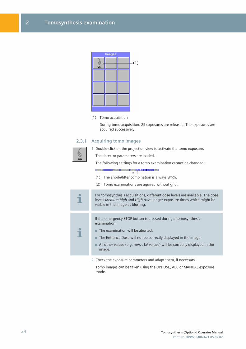
(1) Tomo acquisitionDuring tomo acquisition, 25 exposures are released. The exposures areacquired successively.
Acquiring tomo images1 Double-click on the projection view to activate the tomo exposure.
The detector parameters are loaded.
The following settings for a tomo examination cannot be changed:
(1) The anode/filter combination is always W/Rh.(2) Tomo examinations are aquired without grid.
For tomosynthesis acquisitions, different dose levels are available. The doselevels Medium high and High have longer exposure times which might bevisible in the image as blurring.
If the emergency STOP button is pressed during a tomosynthesisexamination:
◾ The examination will be aborted.◾ The Entrance Dose will not be correctly displayed in the image.◾ All other values (e.g. mAs-, kV values) will be correctly displayed in the
image.
2 Check the exposure parameters and adapt them, if necessary.
Tomo images can be taken using the OPDOSE, AEC or MANUAL exposuremode.
2.3.1
2 Tomosynthesis examination
24 Tomosynthesis (Option) | Operator ManualPrint No. XPW7-340G.621.05.02.02
The following message appears as soon as the mAs is too high or too low:Calculated mAs outside valid range.Please change to AEC mode.At low compression thickness < 20 mm, reduce the kV in 1 kVincrements. For larger compression thicknesses > 50 mm increase thekV in 1 kV increments.To switch to AEC mode, select the AEC acquisition mode on the generatorcontrol panel.The AEC value set previously is retained and the kV can be increased in 1 kVincrements.
3 Press and hold the exposure button on the control box as long as the signal isaudible.
The button will light up yellow during the exposure.
Radiation is released and tomo images are acquired.
CAUTION
Collision with swivel arm during acquisition.Injury to patient or operator by pinching!◆ Ensure that there is no risk of collision within the tube arm swivel
range (±25°) during tomo acquisition.
CAUTION
Tube arm stops or object table moves unintentionally during acquisition.Patient or operator is squeezed!◆ If the tube arm suddenly stops before reaching end position or object
table moves during tomo or stereo acquisition, release the exposurebutton and decompress. Call service for system check-up.
Exposure parameters for 3D implant exposures
The parameters for the Tomo Implant and 2D+Tomo Implant acquisitionmodes are shown in the EXPOSURE Programs tab card in the ProcedureHandling Configuration window.
Projection view statusIn the Images subtask card, the individual projection views up to thereconstructed tomo data set are shown as follows:
Tomosynthesis examination 2
MAMMOMAT Revelation | VC10 or higher 25Print No. XPW7-340G.621.05.02.02
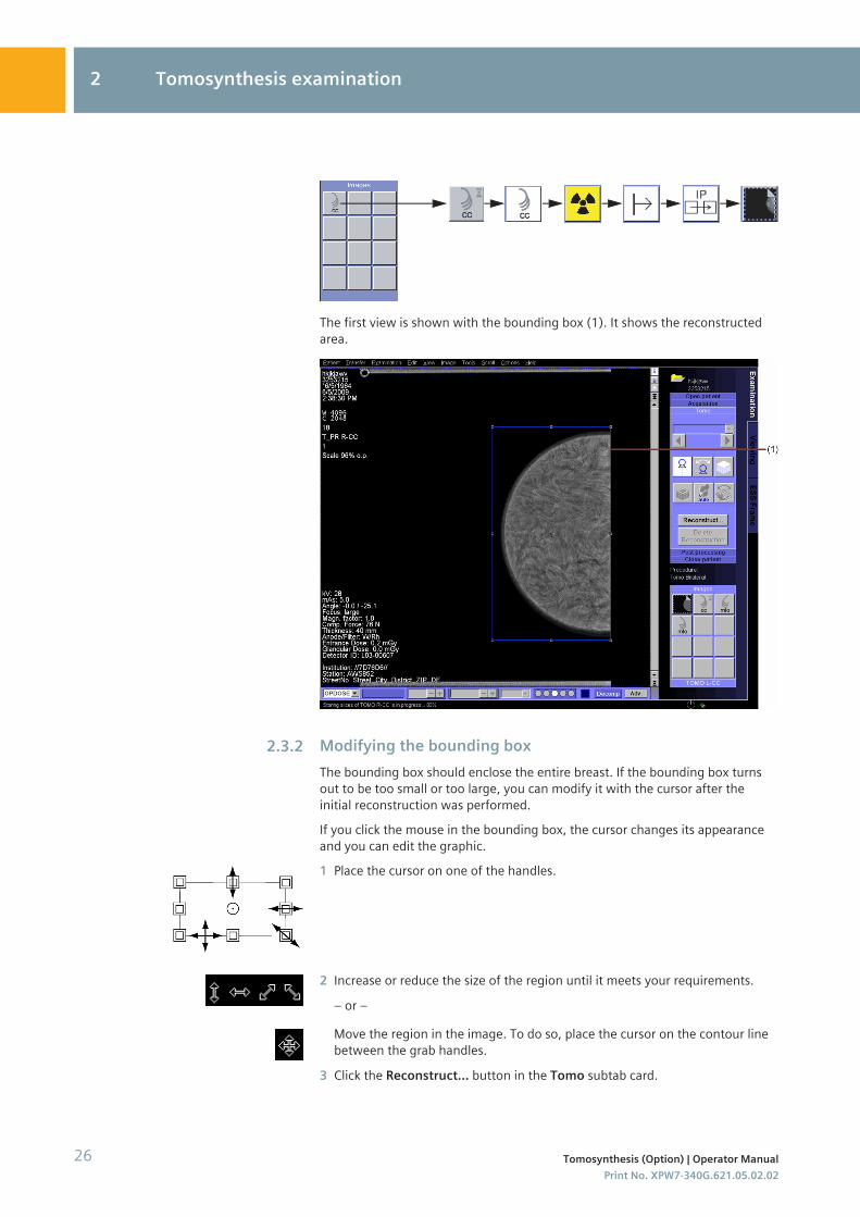
The first view is shown with the bounding box (1). It shows the reconstructedarea.
Modifying the bounding boxThe bounding box should enclose the entire breast. If the bounding box turnsout to be too small or too large, you can modify it with the cursor after theinitial reconstruction was performed.If you click the mouse in the bounding box, the cursor changes its appearanceand you can edit the graphic.1 Place the cursor on one of the handles.
2 Increase or reduce the size of the region until it meets your requirements.
– or –
Move the region in the image. To do so, place the cursor on the contour linebetween the grab handles.
3 Click the Reconstruct... button in the Tomo subtab card.
2.3.2
2 Tomosynthesis examination
26 Tomosynthesis (Option) | Operator ManualPrint No. XPW7-340G.621.05.02.02
The tomo images will be reconstructed, see ( Page 32 Reconstructing tomoimages).
Please note that each parameter set from the Reconstruction parametergroup name list has different reconstruction properties:
◾ Standard is used for all standard tomo examinations.◾ Standard_Proj is used for all standard tomo examinations. Additionals
the processed projections are available.◾ Standard_Calc is used in cases where an additional tomo reconstruction
is required with a particular focus on micro calcifications.◾ Standard_no_seg is used for special tomo examinations where the
background should be not set black.◾ Empire is used for all standard tomo examinations.◾ EmpireCT is used for all standard tomo examinations.◾ Standard_Phantom is used for phantom tomo examinations.◾ Empire_Phantom is used for phantom tomo examinations.
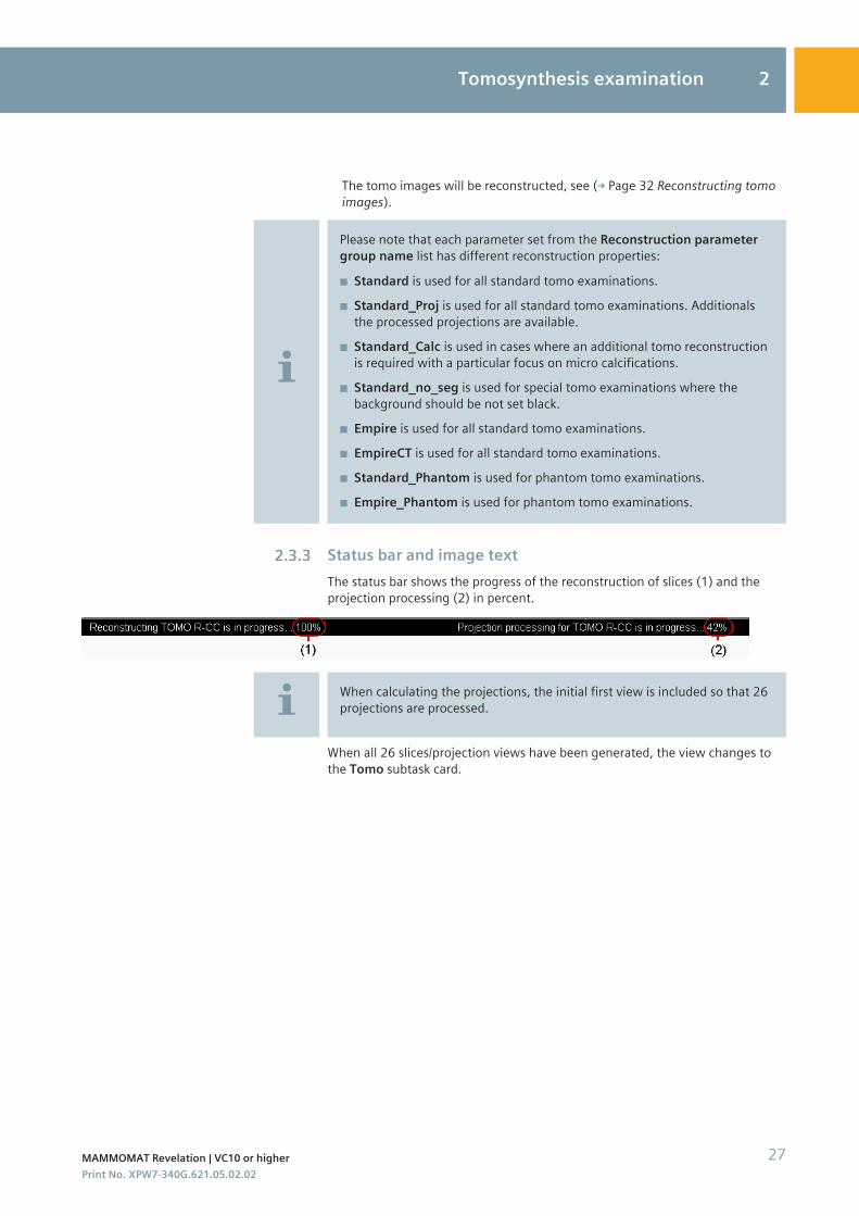
Status bar and image textThe status bar shows the progress of the reconstruction of slices (1) and theprojection processing (2) in percent.
When calculating the projections, the initial first view is included so that 26projections are processed.
When all 26 slices/projection views have been generated, the view changes tothe Tomo subtask card.
2.3.3
Tomosynthesis examination 2
MAMMOMAT Revelation | VC10 or higher 27Print No. XPW7-340G.621.05.02.02
(1)(2)(3)(4)(5)(6)(7)(8)(9)(10)(11)
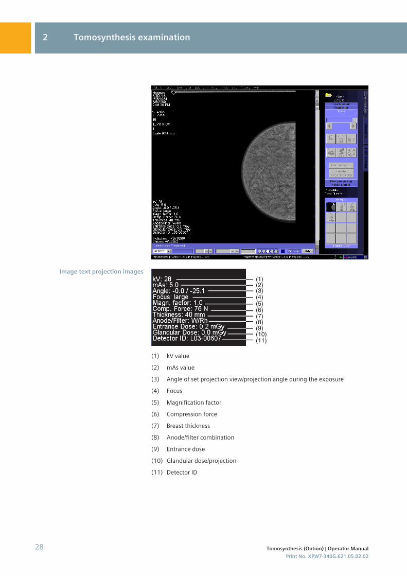
(1) kV value(2) mAs value(3) Angle of set projection view/projection angle during the exposure(4) Focus(5) Magnification factor(6) Compression force(7) Breast thickness(8) Anode/filter combination(9) Entrance dose(10) Glandular dose/projection(11) Detector ID
Image text projection images
2 Tomosynthesis examination
28 Tomosynthesis (Option) | Operator ManualPrint No. XPW7-340G.621.05.02.02
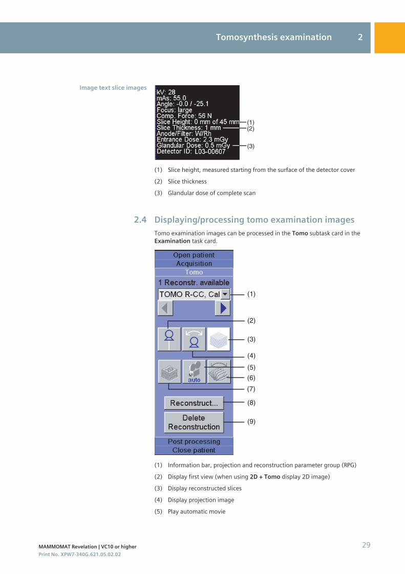
(1)(2)
(3)
(1) Slice height, measured starting from the surface of the detector cover(2) Slice thickness(3) Glandular dose of complete scan
Displaying/processing tomo examination imagesTomo examination images can be processed in the Tomo subtask card in theExamination task card.
(1)
(2)
(3)
(4)
(5)
(8)
(9)
(6)
(7)
(1) Information bar, projection and reconstruction parameter group (RPG)(2) Display first view (when using 2D + Tomo display 2D image)(3) Display reconstructed slices(4) Display projection image(5) Play automatic movie
Image text slice images
2.4
Tomosynthesis examination 2
MAMMOMAT Revelation | VC10 or higher 29Print No. XPW7-340G.621.05.02.02
(6) Display Insight 2D images(7) Display Insight 3D images(8) Reconstruct tomo images(9) Delete selected reconstructed tomo images
Subsequent acquisition must be deactivated in order to process tomoexamination images.
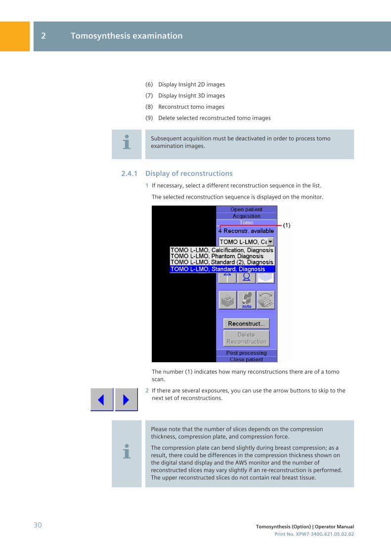
Display of reconstructions1 If necessary, select a different reconstruction sequence in the list.
The selected reconstruction sequence is displayed on the monitor.
The number (1) indicates how many reconstructions there are of a tomoscan.
2 If there are several exposures, you can use the arrow buttons to skip to thenext set of reconstructions.
Please note that the number of slices depends on the compressionthickness, compression plate, and compression force.The compression plate can bend slightly during breast compression; as aresult, there could be differences in the compression thickness shown onthe digital stand display and the AWS monitor and the number ofreconstructed slices may vary slightly if an re-reconstruction is performed.The upper reconstructed slices do not contain real breast tissue.
2.4.1
2 Tomosynthesis examination
30 Tomosynthesis (Option) | Operator ManualPrint No. XPW7-340G.621.05.02.02
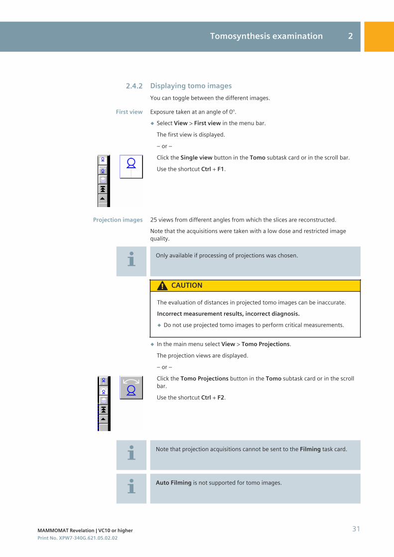
Displaying tomo imagesYou can toggle between the different images.
Exposure taken at an angle of 0°.◆ Select View > First view in the menu bar.
The first view is displayed.
– or –
Click the Single view button in the Tomo subtask card or in the scroll bar.
Use the shortcut Ctrl + F1.
25 views from different angles from which the slices are reconstructed.Note that the acquisitions were taken with a low dose and restricted imagequality.
Only available if processing of projections was chosen.
CAUTION
The evaluation of distances in projected tomo images can be inaccurate.Incorrect measurement results, incorrect diagnosis.◆ Do not use projected tomo images to perform critical measurements.
◆ In the main menu select View > Tomo Projections.
The projection views are displayed.
– or –
Click the Tomo Projections button in the Tomo subtask card or in the scrollbar.
Use the shortcut Ctrl + F2.
Note that projection acquisitions cannot be sent to the Filming task card.
Auto Filming is not supported for tomo images.
2.4.2
First view
Projection images
Tomosynthesis examination 2
MAMMOMAT Revelation | VC10 or higher 31Print No. XPW7-340G.621.05.02.02
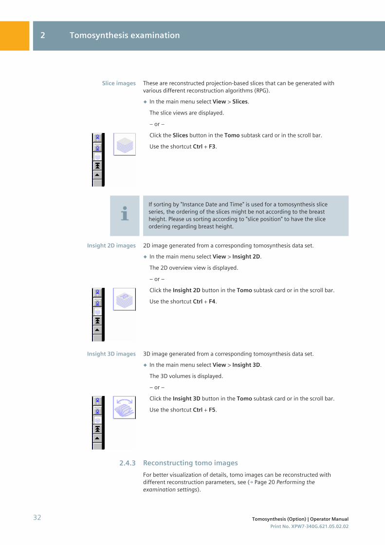
These are reconstructed projection-based slices that can be generated withvarious different reconstruction algorithms (RPG).◆ In the main menu select View > Slices.
The slice views are displayed.
– or –
Click the Slices button in the Tomo subtask card or in the scroll bar.
Use the shortcut Ctrl + F3.
If sorting by "Instance Date and Time" is used for a tomosynthesis sliceseries, the ordering of the slices might be not according to the breastheight. Please us sorting according to "slice position" to have the sliceordering regarding breast height.
2D image generated from a corresponding tomosynthesis data set.◆ In the main menu select View > Insight 2D.
The 2D overview view is displayed.
– or –
Click the Insight 2D button in the Tomo subtask card or in the scroll bar.
Use the shortcut Ctrl + F4.
3D image generated from a corresponding tomosynthesis data set.◆ In the main menu select View > Insight 3D.
The 3D volumes is displayed.
– or –
Click the Insight 3D button in the Tomo subtask card or in the scroll bar.
Use the shortcut Ctrl + F5.
Reconstructing tomo imagesFor better visualization of details, tomo images can be reconstructed withdifferent reconstruction parameters, see ( Page 20 Performing theexamination settings).
Slice images
Insight 2D images
Insight 3D images
2.4.3
2 Tomosynthesis examination
32 Tomosynthesis (Option) | Operator ManualPrint No. XPW7-340G.621.05.02.02
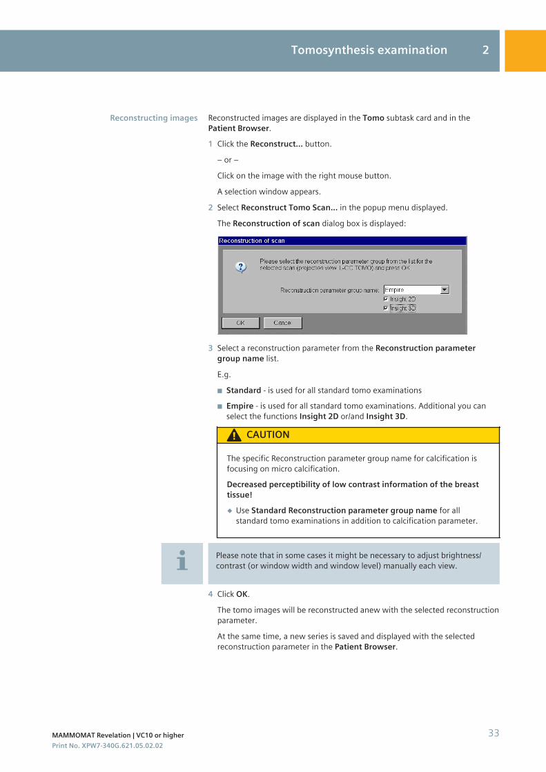
Reconstructed images are displayed in the Tomo subtask card and in thePatient Browser.1 Click the Reconstruct... button.
– or –
Click on the image with the right mouse button.
A selection window appears.
2 Select Reconstruct Tomo Scan... in the popup menu displayed.
The Reconstruction of scan dialog box is displayed:
3 Select a reconstruction parameter from the Reconstruction parametergroup name list.
E.g.
◾ Standard - is used for all standard tomo examinations◾ Empire - is used for all standard tomo examinations. Additional you can
select the functions Insight 2D or/and Insight 3D.
CAUTION
The specific Reconstruction parameter group name for calcification isfocusing on micro calcification.Decreased perceptibility of low contrast information of the breasttissue!◆ Use Standard Reconstruction parameter group name for all
standard tomo examinations in addition to calcification parameter.
Please note that in some cases it might be necessary to adjust brightness/contrast (or window width and window level) manually each view.
4 Click OK.
The tomo images will be reconstructed anew with the selected reconstructionparameter.
At the same time, a new series is saved and displayed with the selectedreconstruction parameter in the Patient Browser.
Reconstructing images
Tomosynthesis examination 2
MAMMOMAT Revelation | VC10 or higher 33Print No. XPW7-340G.621.05.02.02
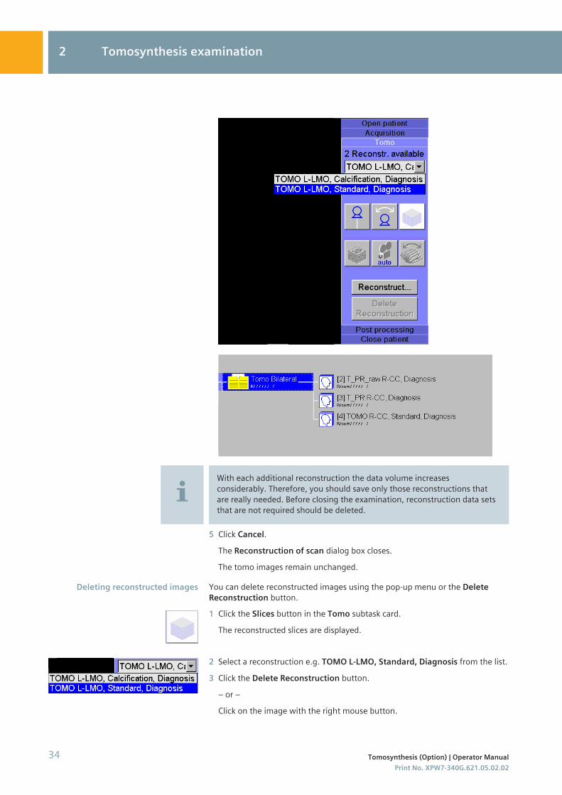
With each additional reconstruction the data volume increasesconsiderably. Therefore, you should save only those reconstructions thatare really needed. Before closing the examination, reconstruction data setsthat are not required should be deleted.
5 Click Cancel.The Reconstruction of scan dialog box closes.
The tomo images remain unchanged.
You can delete reconstructed images using the pop-up menu or the DeleteReconstruction button.1 Click the Slices button in the Tomo subtask card.
The reconstructed slices are displayed.
2 Select a reconstruction e.g. TOMO L-LMO, Standard, Diagnosis from the list.
3 Click the Delete Reconstruction button.
– or –
Click on the image with the right mouse button.
Deleting reconstructed images
2 Tomosynthesis examination
34 Tomosynthesis (Option) | Operator ManualPrint No. XPW7-340G.621.05.02.02
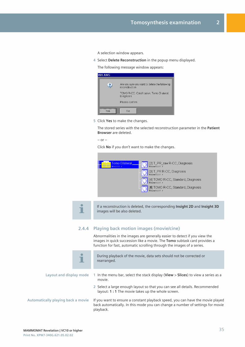
A selection window appears.
4 Select Delete Reconstruction in the popup menu displayed.
The following message window appears:
5 Click Yes to make the changes.
The stored series with the selected reconstruction parameter in the PatientBrowser are deleted.
– or –
Click No if you don't want to make the changes.
If a reconstruction is deleted, the corresponding Insight 2D and Insight 3Dimages will be also deleted.
Playing back motion images (movie/cine)Abnormalities in the images are generally easier to detect if you view theimages in quick succession like a movie. The Tomo subtask card provides afunction for fast, automatic scrolling through the images of a series.
During playback of the movie, data sets should not be corrected orrearranged.
1 In the menu bar, select the stack display (View > Slices) to view a series as amovie.
2 Select a large enough layout so that you can see all details. Recommendedlayout: 1 : 1 The movie takes up the whole screen.
If you want to ensure a constant playback speed, you can have the movie playedback automatically. In this mode you can change a number of settings for movieplayback.
2.4.4
Layout and display mode
Automatically playing back a movie
Tomosynthesis examination 2
MAMMOMAT Revelation | VC10 or higher 35Print No. XPW7-340G.621.05.02.02
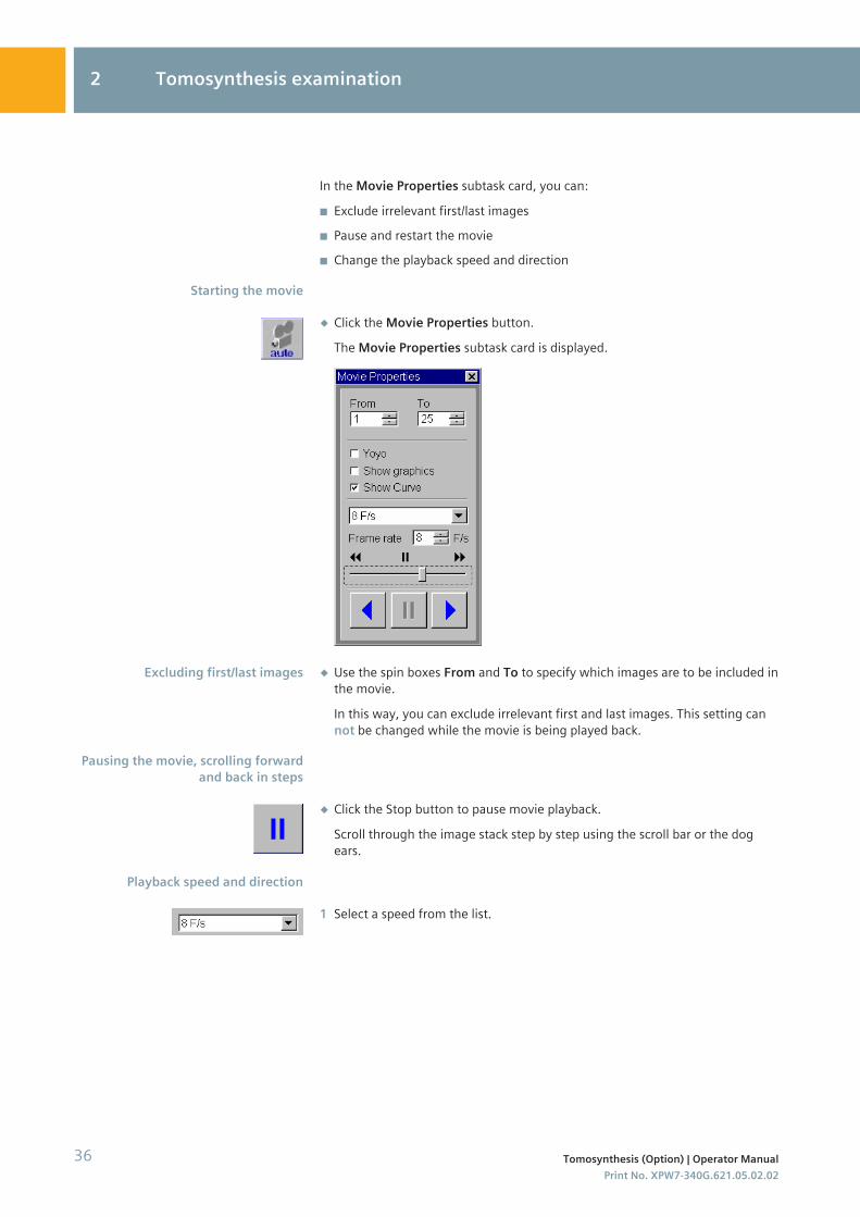
In the Movie Properties subtask card, you can:
◾ Exclude irrelevant first/last images◾ Pause and restart the movie◾ Change the playback speed and direction
◆ Click the Movie Properties button.
The Movie Properties subtask card is displayed.
◆ Use the spin boxes From and To to specify which images are to be included inthe movie.
In this way, you can exclude irrelevant first and last images. This setting cannot be changed while the movie is being played back.
◆ Click the Stop button to pause movie playback.
Scroll through the image stack step by step using the scroll bar or the dogears.
1 Select a speed from the list.
Starting the movie
Excluding first/last images
Pausing the movie, scrolling forwardand back in steps
Playback speed and direction
2 Tomosynthesis examination
36 Tomosynthesis (Option) | Operator ManualPrint No. XPW7-340G.621.05.02.02
– or –
Enter a playback speed using the spin box next to Frame rate.
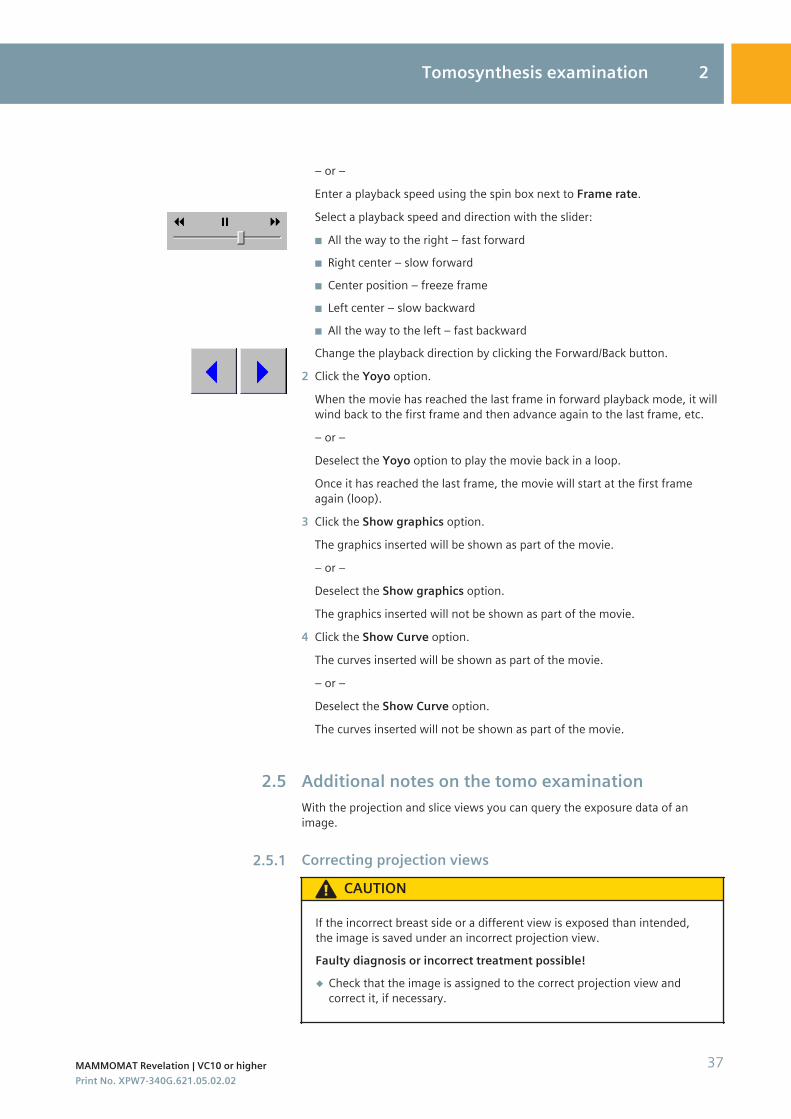
Select a playback speed and direction with the slider:
◾ All the way to the right – fast forward◾ Right center – slow forward◾ Center position – freeze frame◾ Left center – slow backward◾ All the way to the left – fast backwardChange the playback direction by clicking the Forward/Back button.
2 Click the Yoyo option.
When the movie has reached the last frame in forward playback mode, it willwind back to the first frame and then advance again to the last frame, etc.
– or –
Deselect the Yoyo option to play the movie back in a loop.
Once it has reached the last frame, the movie will start at the first frameagain (loop).
3 Click the Show graphics option.
The graphics inserted will be shown as part of the movie.
– or –
Deselect the Show graphics option.
The graphics inserted will not be shown as part of the movie.
4 Click the Show Curve option.
The curves inserted will be shown as part of the movie.
– or –
Deselect the Show Curve option.
The curves inserted will not be shown as part of the movie.
Additional notes on the tomo examinationWith the projection and slice views you can query the exposure data of animage.
Correcting projection views
CAUTION
If the incorrect breast side or a different view is exposed than intended,the image is saved under an incorrect projection view.Faulty diagnosis or incorrect treatment possible!◆ Check that the image is assigned to the correct projection view and
correct it, if necessary.
2.5
2.5.1
Tomosynthesis examination 2
MAMMOMAT Revelation | VC10 or higher 37Print No. XPW7-340G.621.05.02.02
1 Right-click the relevant image in the Images subtask card.
A popup menu is displayed.
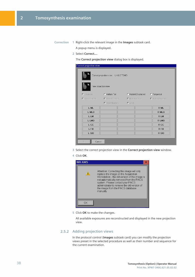
2 Select Correct....The Correct projection view dialog box is displayed.
3 Select the correct projection view in the Correct projection view window.
4 Click OK.
5 Click OK to make the changes.
All available exposures are reconstructed and displayed in the new projectionview.
Adding projection viewsIn the protocol control (Images subtask card) you can modify the projectionviews preset in the selected procedure as well as their number and sequence forthe current examination.
Correction
2.5.2
2 Tomosynthesis examination
38 Tomosynthesis (Option) | Operator ManualPrint No. XPW7-340G.621.05.02.02
Depending on the selected projection view the projection views can bemodified, added, inserted or deleted.For all these functions the window Modified Views appears where you canoperate on.
1 With the right mouse button, click on the Images subtask card of theprojection view.
2 Select Add.
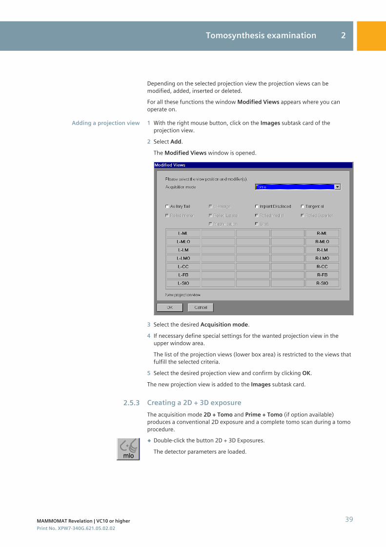
The Modified Views window is opened.
3 Select the desired Acquisition mode.
4 If necessary define special settings for the wanted projection view in theupper window area.
The list of the projection views (lower box area) is restricted to the views thatfulfill the selected criteria.
5 Select the desired projection view and confirm by clicking OK.
The new projection view is added to the Images subtask card.
Creating a 2D + 3D exposureThe acquisition mode 2D + Tomo and Prime + Tomo (if option available)produces a conventional 2D exposure and a complete tomo scan during a tomoprocedure.◆ Double-click the button 2D + 3D Exposures.
The detector parameters are loaded.
Adding a projection view
2.5.3
Tomosynthesis examination 2
MAMMOMAT Revelation | VC10 or higher 39Print No. XPW7-340G.621.05.02.02
The following images/slices are created:
◾ 2D exposure (single image)◾ Projections◾ Reconstructed slices
The 2D image is part of the projection series.
In the acquisition mode 2D + Tomo and Prime + Tomo (if option available)the indicated glandular dose corresponds to
◾ the dose applied during the 2D exposure, in the case of a 2D exposure◾ the dose applied during the entire scan, in the case of tomo slices◾ the dose applied during the single projection, in the case of projection
views◾ in the case of manual 2D + Tomo mode:
– the set mAs value corresponds to the mAs value during the 2Dexposure
– the mAs value for a Tomo scan is twice a 2D FFDM image
When using the 2D + Tomo the 2D exposure is always done with the GridPosition In, even if the user has selected the option Grid Position Out inAdvanced dialog box.Avoid interrupting the radiation release during a tomosynthesisexamination when using the 2D + Tomo function between the 2D exposureand the 3D scan.
If, during a tomosynthesis examination using the function 2D + Tomo, anerror message appears for the following setting:
◾ kV value: 32 kV◾ mAs value: > 280 mAsReduce the mAs value (≤ 280 mAs) in order to continue the examination.Please note the following settings in order to avoid error messages:
◾ 23 - 28 kV: < 300 mAs◾ 29 - 32 kV: < 280 mAs◾ 33 - 35 kV: < 250 mAs
Post-processing examination imagesYou can process the examination images directly in the Examination task card.Some of the post-processing tools are also available in the Viewing tabcard andcan be Saved as. Click on the tool again to deactivate it.
2.5.4
2 Tomosynthesis examination
40 Tomosynthesis (Option) | Operator ManualPrint No. XPW7-340G.621.05.02.02
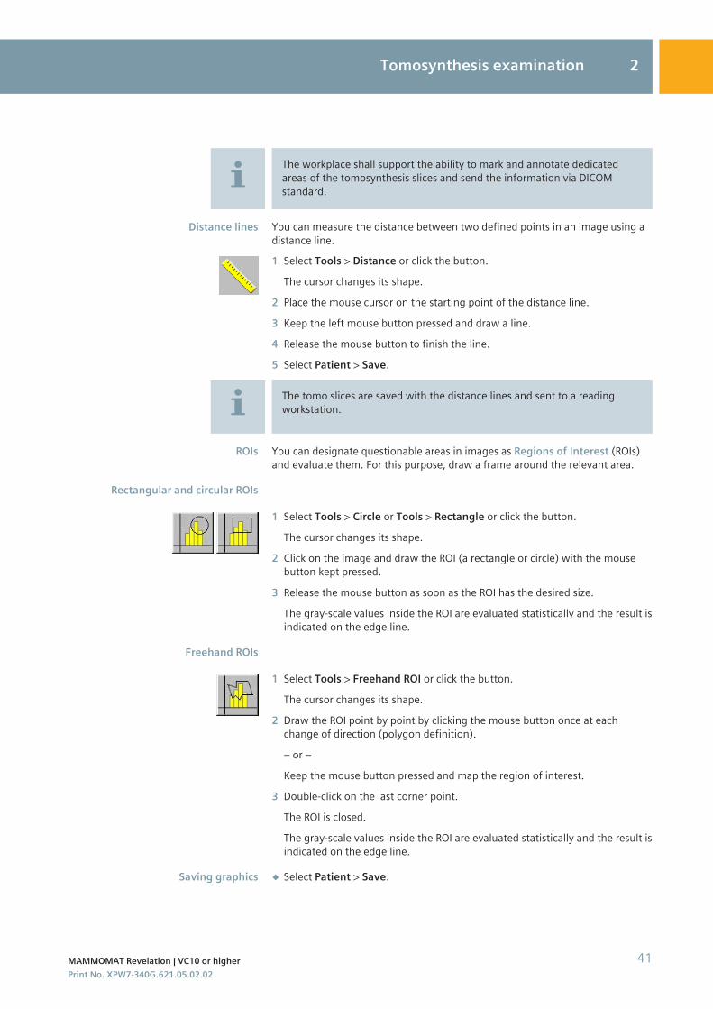
The workplace shall support the ability to mark and annotate dedicatedareas of the tomosynthesis slices and send the information via DICOMstandard.
You can measure the distance between two defined points in an image using adistance line.1 Select Tools > Distance or click the button.
The cursor changes its shape.
2 Place the mouse cursor on the starting point of the distance line.
3 Keep the left mouse button pressed and draw a line.
4 Release the mouse button to finish the line.
5 Select Patient > Save.
The tomo slices are saved with the distance lines and sent to a readingworkstation.
You can designate questionable areas in images as Regions of Interest (ROIs)and evaluate them. For this purpose, draw a frame around the relevant area.
1 Select Tools > Circle or Tools > Rectangle or click the button.
The cursor changes its shape.
2 Click on the image and draw the ROI (a rectangle or circle) with the mousebutton kept pressed.
3 Release the mouse button as soon as the ROI has the desired size.
The gray-scale values inside the ROI are evaluated statistically and the result isindicated on the edge line.
1 Select Tools > Freehand ROI or click the button.
The cursor changes its shape.
2 Draw the ROI point by point by clicking the mouse button once at eachchange of direction (polygon definition).
– or –
Keep the mouse button pressed and map the region of interest.
3 Double-click on the last corner point.
The ROI is closed.
The gray-scale values inside the ROI are evaluated statistically and the result isindicated on the edge line.
◆ Select Patient > Save.
Distance lines
ROIs
Rectangular and circular ROIs
Freehand ROIs
Saving graphics
Tomosynthesis examination 2
MAMMOMAT Revelation | VC10 or higher 41Print No. XPW7-340G.621.05.02.02
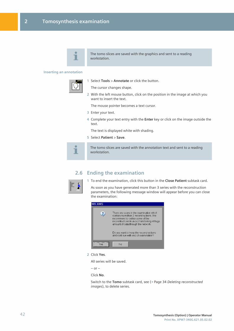
The tomo slices are saved with the graphics and sent to a readingworkstation.
1 Select Tools > Annotate or click the button.
The cursor changes shape.
2 With the left mouse button, click on the position in the image at which youwant to insert the text.
The mouse pointer becomes a text cursor.
3 Enter your text.
4 Complete your text entry with the Enter key or click on the image outside thetext.
The text is displayed white with shading.
5 Select Patient > Save.
The tomo slices are saved with the annotation text and sent to a readingworkstation.
Ending the examination1 To end the examination, click this button in the Close Patient subtask card.
As soon as you have generated more than 3 series with the reconstructionparameters, the following message window will appear before you can closethe examination:
2 Click Yes.
All series will be saved.
– or –
Click No.
Switch to the Tomo subtask card, see ( Page 34 Deleting reconstructedimages), to delete series.
Inserting an annotation
2.6
2 Tomosynthesis examination
42 Tomosynthesis (Option) | Operator ManualPrint No. XPW7-340G.621.05.02.02
Configuration
Configuring a tomo examinationOnly the changes regarding the tomo examination are described here. For theconfiguration of the Examination task card see register Configuration, chapterConfiguring examination.
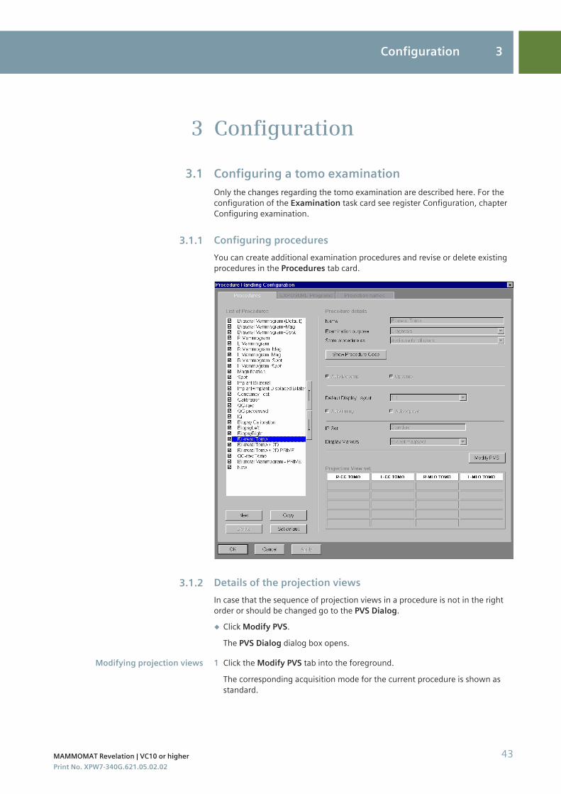
Configuring proceduresYou can create additional examination procedures and revise or delete existingprocedures in the Procedures tab card.
Details of the projection viewsIn case that the sequence of projection views in a procedure is not in the rightorder or should be changed go to the PVS Dialog.◆ Click Modify PVS.
The PVS Dialog dialog box opens.
1 Click the Modify PVS tab into the foreground.
The corresponding acquisition mode for the current procedure is shown asstandard.
3
3.1
3.1.1
3.1.2
Modifying projection views
Configuration 3
MAMMOMAT Revelation | VC10 or higher 43Print No. XPW7-340G.621.05.02.02
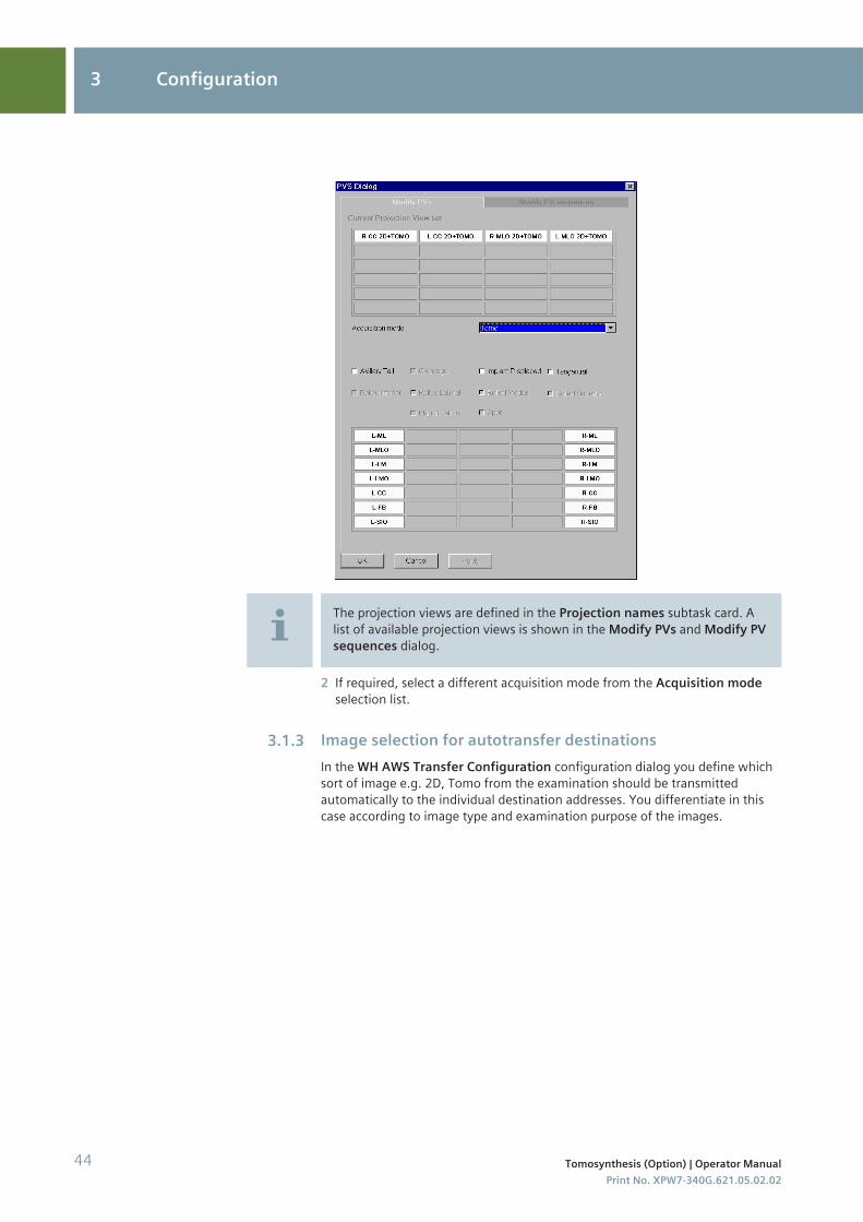
The projection views are defined in the Projection names subtask card. Alist of available projection views is shown in the Modify PVs and Modify PVsequences dialog.
2 If required, select a different acquisition mode from the Acquisition modeselection list.
Image selection for autotransfer destinationsIn the WH AWS Transfer Configuration configuration dialog you define whichsort of image e.g. 2D, Tomo from the examination should be transmittedautomatically to the individual destination addresses. You differentiate in thiscase according to image type and examination purpose of the images.
3.1.3
3 Configuration
44 Tomosynthesis (Option) | Operator ManualPrint No. XPW7-340G.621.05.02.02
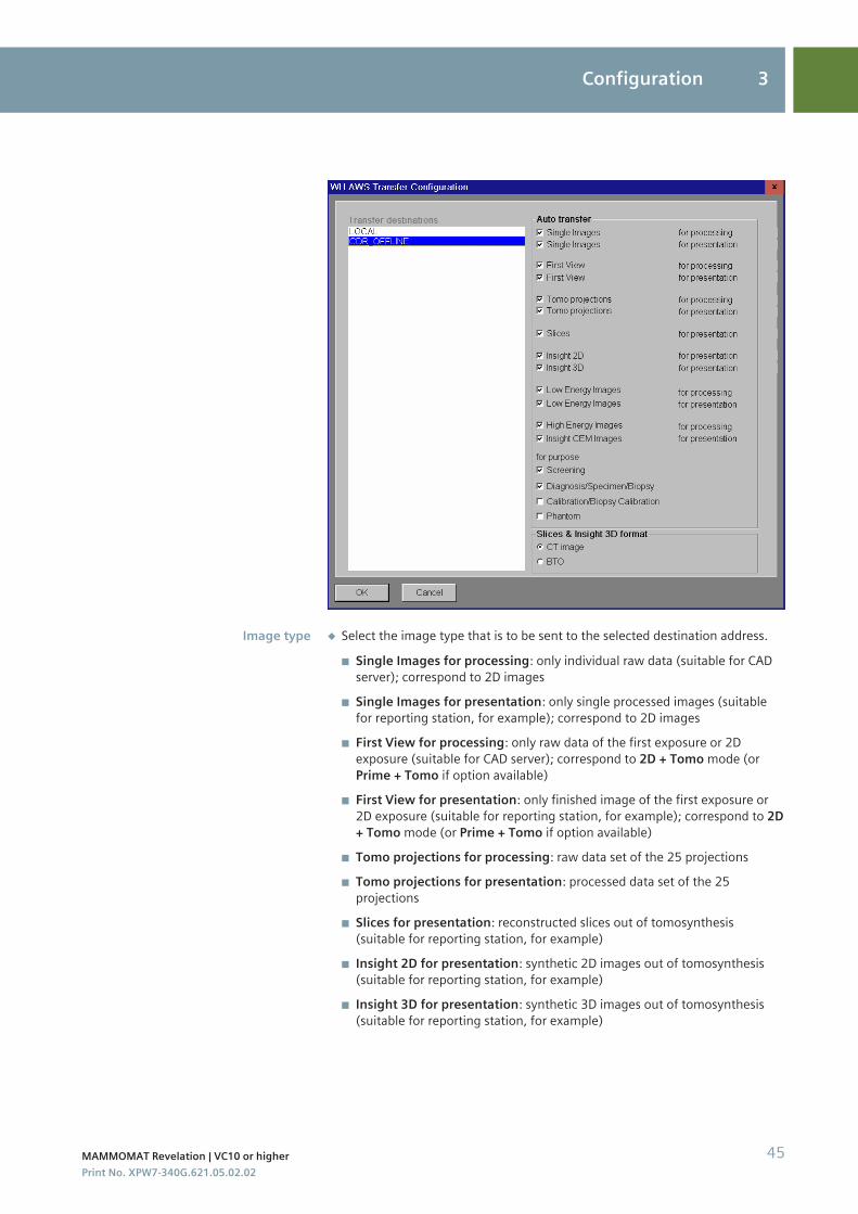
◆ Select the image type that is to be sent to the selected destination address.
◾ Single Images for processing: only individual raw data (suitable for CADserver); correspond to 2D images
◾ Single Images for presentation: only single processed images (suitablefor reporting station, for example); correspond to 2D images
◾ First View for processing: only raw data of the first exposure or 2Dexposure (suitable for CAD server); correspond to 2D + Tomo mode (orPrime + Tomo if option available)
◾ First View for presentation: only finished image of the first exposure or2D exposure (suitable for reporting station, for example); correspond to 2D+ Tomo mode (or Prime + Tomo if option available)
◾ Tomo projections for processing: raw data set of the 25 projections◾ Tomo projections for presentation: processed data set of the 25
projections◾ Slices for presentation: reconstructed slices out of tomosynthesis
(suitable for reporting station, for example)◾ Insight 2D for presentation: synthetic 2D images out of tomosynthesis
(suitable for reporting station, for example)◾ Insight 3D for presentation: synthetic 3D images out of tomosynthesis
(suitable for reporting station, for example)
Image type
Configuration 3
MAMMOMAT Revelation | VC10 or higher 45Print No. XPW7-340G.621.05.02.02
◆ Select BTO or CT image to transfer tomosynthesis slices to the definedDICOM note.
◾ BTO: DICOM modality Breast Tomosynthesis ObjectThe saved graphics, distance lines and annotation in one tomo slice aresent.
◾ CT image: DICOM modality CT image
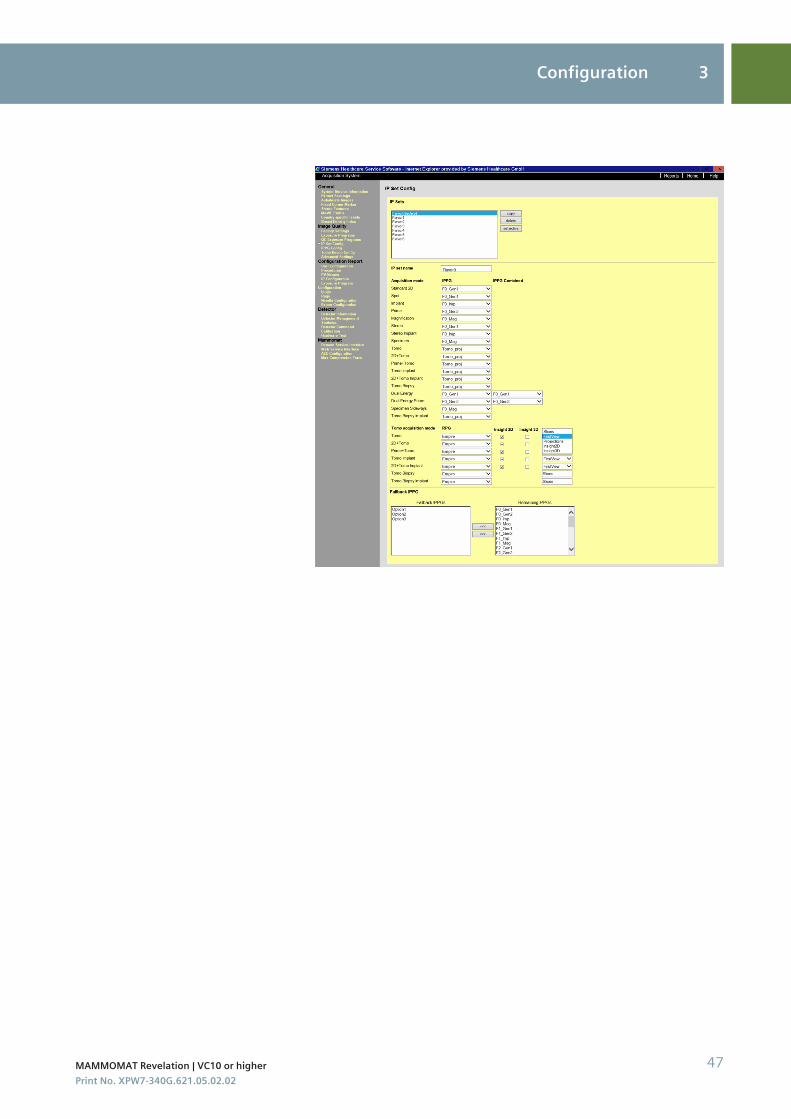
Configuring the image impression (IP Set)The IP Set Config can only be configured by the application specialist in theService menu.
The workplace shall have the ability to configure which series of thetomosynthesis results will be displayed directly after the exposure:◾ raw data of the projection views◾ processed projections views◾ reconstructed slices◾ 2D images of the 2D + tomosynthesis scan◾ MIP view◾ synthetic 2D view◾ raw projection views for quality assurance
◆ Select Service > ... in the main menu.
Change the First View to Insight 2D if required.
Slices & Insight 3D format
3.1.4
3 Configuration
46 Tomosynthesis (Option) | Operator ManualPrint No. XPW7-340G.621.05.02.02
Configuration 3
MAMMOMAT Revelation | VC10 or higher 47Print No. XPW7-340G.621.05.02.02

3 Configuration
48 Tomosynthesis (Option) | Operator ManualPrint No. XPW7-340G.621.05.02.02
Glossary
Region of interest, describing the area that will be reconstructed. Using thehandles you can adjust the bounding box to the breast tissue area to bereconstructed for slices.
Unique, multiple algorithms, providing superior image quality in both contrastand detail.
First exposure during tomo scan where the swivel arm is at an angle of 0°.Whenusing 2D + Tomo the first image is the 2D image.
2D image generated from a corresponding tomosynthesis data set. Specificimage processing may have modified the appearance of anatomical structurescompared to reconstructed slices and projection images.
3D image generated from a corresponding tomosynthesis data set. Specificimage processing may have modified the appearance of anatomical structurescompared to reconstructed slices and projection images.
If the processing of projections is activated, projections acquired during a tomoscan are processed with OpView 2D image processing for better visualization.Per default the processing is deactivated. These images are saved as DICOM MGfor presentation.When using 2D + Tomo the first image of the stored projections series is the 2Dimage.
Single image taken during the tomo scan. 25 projections are acquired duringthe sweep of 50°, every other degree one projection. The projections are savedas DICOM MG objects.
The calculation of the stack of slices (3D volume) from the projections using areconstruction algorithm.
Processing of the projections and 2D image with new image processing orreconstruction parameter set.
Stack of images parallel to the detector surface reconstructed from projectionswith the purpose of display at the workstation monitor.
Generated data set of a definite view, consisting of raw projections and/orprocessed projections and/or the slices or combinations of these.
4
Bounding box
Empire technology
First view
Insight 2D
Insight 3D
Processed projections
Raw projections
Reconstruction
Reprocessing
Slices
Tomo scan
Glossary 4
MAMMOMAT Revelation | VC10 or higher 49Print No. XPW7-340G.621.05.02.02

4 Glossary
50 Tomosynthesis (Option) | Operator ManualPrint No. XPW7-340G.621.05.02.02
1,2,3 …2D + 3D exposure
creating 39
AAcquisition principle 7Automatic movement
of the swivel arm 7
BBounding box 7
modifying 23Breast
compressing 22
CCalibration
ending 16performing 14type 13
Calibration images 14Calibration intervals 13Cine 35Compressing
the breast 22Compression plate 11Configuration
tomosynthesis 43Configuring
image selection for autotransfer 44procedures for tomosynthesis 43projection views for tomosynthesis 43
Correctingprojection views 37tomo image information 37
DDetector calibration
ending 16performing 14
Distance line 41
EEmpire technology 7Examination
ending 42tomosynthesis 19
Examination parameterstomosynthesis 20
Examination proceduretomosynthesis 20
Examination settingstomosynthesis 20
Examination task cardlayout 19
Exposurestomosynthesis 23
FFirst view 7
IImage selection for autotransfer
configuring for tomosynthesis 44Image text
tomosynthesis 27Image text projection images 27Images
displaying 31post-processing 40reconstructing 32
Insight 2D 7Insight 3D 7Intervals
for calibration 13
LLegend 4
MMotion images
playing back 35Movie 35
PPatient
positioning 22Playing back
motion images (movie/cine) 35Positioning the patient 22Post-processing 40Preparations
tomosynthesis 20Procedures
configuring for tomosynthesis 43Processed projections 7Projection images
image text 27Projection view
adding 38Projection views
configuring for tomosynthesis 43correcting 37
RRaw projections 7Reconstruction 7Reprocessing 7
SSlice images
image text 27Slices 7
Status bartomosynthesis 27
TTomo face shield 12Tomo image information
correcting 37Tomo scan 7Tomosynthesis
configuration 43description 7displaying images 31examination 19examination settings 20exposures 23image text 27preparations 20reconstructing images 32status bar 27
Type of calibration 13
Index
MAMMOMAT Revelation | VC10 or higher 51Print No. XPW7-340G.621.05.02.02

This page has been intentionally left blank.
52 Tomosynthesis (Option) | Operator ManualPrint No. XPW7-340G.621.05.02.02

This page has been intentionally left blank.
MAMMOMAT Revelation | VC10 or higher 53Print No. XPW7-340G.621.05.02.02

This page has been intentionally left blank.
54 Tomosynthesis (Option) | Operator ManualPrint No. XPW7-340G.621.05.02.02


This device bears a CE mark in accordance with the provisions of CouncilDirective 93/42/EEC of June 14, 1993 concerning medical devices andthe Council Directive 2011/65/EU of June 08, 2011 on the restriction ofthe use of certain hazardous substances in electrical and electronicequipment.
The CE marking applies only to Medical Devices which have been put onthe market according to the above-mentioned EC Directive.
Unauthorized changes to this product are not covered by the CE markand the related Declaration of Conformity.
Original language: English
Legal ManufacturerSiemens Healthcare GmbHHenkestr. 12791052 ErlangenGermany
Siemens Healthcare HeadquartersSiemens Healthcare GmbHHenkestr. 12791052 ErlangenGermanyPhone: +49 9131 84-0siemens.com/healthcare
Print No. XPW7-340G.621.05.02.02 | © Siemens Healthcare GmbH, 2018
www.siemens.com/healthineers


