Embed Size (px)
Citation preview
Code. MD-XXX-09 Rev. 0 Date 22/06/15 pg 1 / 133
MANUAL OPERATOR
HASSI MESSAOUD
MD-XXX-09
0 22/06/15 ISSUE Massimo Piga
Rev Date Description Written Controlled Approved

Code. MD-XXX-09 Rev. 0 Date 22/06/15 pg 2 / 133

Code. MD-XXX-09 Rev. 0 Date 22/06/15 pg 3 / 133
SUMMARY:
1 REFERENCE DOCUMENTS ................................................................................................................................. 6
2 LEGEND ................................................................................................................................................................. 7
3 INTRODUCTION .................................................................................................................................................... 8
4 DESCRIPTION OF THE CONTROL SYSTEM ...................................................................................................... 9 4.1 LIST OF ITEMS DESCRIBED IN THE MANUAL .................................................................................................................. 9 4.2 DESCRIPTION OF ARCHITECTURE .................................................................................................................................. 9
5 DESCRIPTION HMI SYSTEM .............................................................................................................................. 12 5.1 INTRODUCTION ................................................................................................................................................................ 12 5.2 HMI SYSTEM ARCHITECTURE......................................................................................................................................... 12 5.3 DESCRIPTION OF CONTROL AND VIEWING AREAS ..................................................................................................... 14 5.3.1 OBJECT FOR "ANALOG SIGNALS" ............................................................................................................................... 14 5.3.2 OBJECT FOR B "DIGITAL SIGNALS" ............................................................................................................................. 16 5.3.3 C OBJECT FOR "ELECTRICAL EQUIPMENT" ............................................................................................................... 17 5.3.4 OBJECT FOR "RUN COUNTER HOURS" ...................................................................................................................... 19 5.3.5 OBJECT FOR E "VALVES ALL OR NOTHING" .............................................................................................................. 19 5.3.6 OBJECT FOR F "REGULATOR PID" .............................................................................................................................. 22 5.4 ALARM MANAGEMENT ..................................................................................................................................................... 26 5.4.1 CHARACTERIZING PHASE ALARMS ............................................................................................................................ 27 5.4.2 ACTIONS TO BE PERFORMED IN CASE OF OCCURRENCE OF AN ALARM ............................................................ 29 5.5 OVERVIEW SCREEN PAGES ........................................................................................................................................... 30 5.5.1 MAIN MENU .................................................................................................................................................................... 30 5.5.2 P&ID: GAS DISCHARGE ................................................................................................................................................. 30 5.5.3 P & ID: SYSTEM LUBRICATING OIL AND MOUTH ....................................................................................................... 31 5.5.4 P & ID: AIR INSTRUMENTS ............................................................................................................................................ 31 5.5.5 P & ID: CONTROL PAGE ................................................................................................................................................ 32 5.5.6 P & ID: 1st STAGE COMPRESSOR ................................................................................................................................ 32 5.5.7 P & ID: 2nd STAGE COMPRESSOR ................................................................................................................................ 33 5.5.8 P & ID: A GEAR BOX ...................................................................................................................................................... 34 5.5.9 CONTROLLER: TURBINE ............................................................................................................................................... 34 5.5.10 CONTROLLER: ANTISURGE CONTROL ..................................................................................................................... 35 5.5.11 MOS: MANUAL BYPASS LOCKS ................................................................................................................................. 35 5.5.12 DIAGNOSTIC................................................................................................................................................................. 36 5.5.13 DIGITAL INPUTS TABLE .............................................................................................................................................. 37 5.5.14 INPUT SIGNALS TABLE MCC ...................................................................................................................................... 37 5.5.15 SIMILAR THRESHOLD ................................................................................................................................................. 38 5.5.16 PRINT DATA LOGGING ................................................................................................................................................ 40 5.5.17 ADMINISTRATION ........................................................................................................................................................ 42
6 FUNCTIONAL DESCRIPTION ............................................................................................................................. 43 6.1 INTRODUCTION ................................................................................................................................................................ 43 6.2 GAS CIRCUIT ..................................................................................................................................................................... 43 6.2.1 COMPONENTS ............................................................................................................................................................... 43 6.2.2 OPERATION .................................................................................................................................................................... 44 6.3 OIL SYSTEMS .................................................................................................................................................................... 45 6.3.1 COMPONENTS ............................................................................................................................................................... 45 6.3.2 PRIOR ............................................................................................................................................................................. 46 6.3.3 OPERATION .................................................................................................................................................................... 46 6.4 CIRCUIT AIR INSTRUMENTS ........................................................................................................................................... 48 6.4.1 COMPONENTS ............................................................................................................................................................... 48 6.5 CIRCUIT COMBUSTION AIR AND BURNING ................................................................................................................... 49 6.5.1 COMPONENTS ............................................................................................................................................................... 49 6.5.2 PRIOR ............................................................................................................................................................................. 50 6.5.3 OPERATION .................................................................................................................................................................... 50 6.6 TURBINE CONTROL .......................................................................................................................................................... 52 6.6.1 COMPONENTS ............................................................................................................................................................... 53 6.6.2 PRIOR ............................................................................................................................................................................. 53
Code. MD-XXX-09 Rev. 0 Date 22/06/15 pg 4 / 133
6.6.3 OPERATION .................................................................................................................................................................... 55 6.6.3.1 RESET OF TRIGGERS ................................................................................................................................................ 55 6.6.3.2 STARTING THE TURBINE ........................................................................................................................................... 56 6.6.3.3 CONTROL AND SAFETY ............................................................................................................................................. 58 6.6.3.4 STOP PLANNED .......................................................................................................................................................... 59 6.6.3.5 MONITORING OF MEASURES .................................................................................................................................... 59 6.6.3.5.1 TABLE STARTS ........................................................................................................................................................ 62 6.6.3.6 PARAMETERS CONFIGURETION CONTROL ............................................................................................................ 62 6.7 COMPRESSOR .................................................................................................................................................................. 63 6.7.1 COMPONENTS ............................................................................................................................................................... 63 6.7.2 PRIOR ............................................................................................................................................................................. 64 6.7.3 OPERATION .................................................................................................................................................................... 65
7 FUNCTIONAL DESCRIPTION AUXILIARY COMPONENTS ............................................................................. 65 7.1 ELECTRICAL EQUIPMENT ............................................................................................................................................... 65 7.1.1 AUXILIARY OIL PUMP: PMOA........................................................................................................................................ 65 7.1.1.1 MANAGEMENT MANUAL ............................................................................................................................................ 65 7.1.1.2 AUTOMATIC MANAGEMENT ...................................................................................................................................... 65 7.1.1.3 PRESENCE OF PRIORITY CONTROL (OVERRIDE) .................................................................................................. 66 7.1.1.4 FAULTS ........................................................................................................................................................................ 66 7.1.2 OIL PUMP RELIEF: PMOE .............................................................................................................................................. 68 7.1.2.1 MANAGEMENT MANUAL ............................................................................................................................................ 68 7.1.2.2 AUTOMATIC MANAGEMENT ...................................................................................................................................... 68 7.1.2.3 PRESENCE OF PRIORITY CONTROL (OVERRIDE) .................................................................................................. 69 7.1.2.4 FAULTS ........................................................................................................................................................................ 69 7.1.3 OIL COOLER: EH1 .......................................................................................................................................................... 70 7.1.3.1 MANAGEMENT MANUAL ............................................................................................................................................ 70 7.1.3.2 AUTOMATIC MANAGEMENT ...................................................................................................................................... 70 7.1.3.3 PRESENCE OF PRIORITY CONTROL (OVERRIDE) .................................................................................................. 71 7.1.3.4 FAULTS ........................................................................................................................................................................ 71 7.1.4 EXTRACTION OF OIL FUMES: OIL STEAM EXTR ........................................................................................................ 73 7.1.4.1 MANAGEMENT MANUAL ............................................................................................................................................ 73 7.1.4.2 AUTOMATIC MANAGEMENT ...................................................................................................................................... 73 7.1.4.3 PRESENCE OF PRIORITY CONTROL (OVERRIDE) .................................................................................................. 74 7.1.4.4 FAULTS ........................................................................................................................................................................ 75 7.1.5 FAN OIL COOLER: T2AB ................................................................................................................................................ 76 7.1.5.1 MANAGEMENT MANUAL OBJECT E1 ........................................................................................................................ 76 7.1.5.2 AUTOMATIC MANAGEMENT OBJECT E1 .................................................................................................................. 76 7.1.5.3 PRESENCE OF PRIORITY CONTROL (OVERRIDE) .................................................................................................. 78 7.1.5.4 MANAGEMENT MANUAL OBJECT "E1 INV" .............................................................................................................. 78 7.1.5.5 AUTOMATIC MANAGEMENT OF THE OBJECT "E1 INV" .......................................................................................... 78 7.1.5.6 FAULTS ........................................................................................................................................................................ 79 7.1.6 FAN OIL COOLER: T2BB ................................................................................................................................................ 81 7.1.6.1 MANAGEMENT MANUAL OBJECT E2 ........................................................................................................................ 81 7.1.6.2 AUTOMATIC MANAGEMENT OBJECT E2 .................................................................................................................. 81 7.1.6.3 PRESENCE OF PRIORITY CONTROL (OVERRIDE) .................................................................................................. 83 7.1.6.4 MANAGEMENT MANUAL OBJECT "E2 INV" .............................................................................................................. 83 7.1.6.5 AUTOMATIC MANAGEMENT OF THE OBJECT "E2 INV" .......................................................................................... 83 7.1.6.6 FAULTS ........................................................................................................................................................................ 84 7.1.7 TURNING GEAR: VIR ..................................................................................................................................................... 86 7.1.7.1 MANAGEMENT MANUAL ............................................................................................................................................ 86 7.1.7.2 AUTOMATIC MANAGEMENT ...................................................................................................................................... 86 7.1.7.3 PRESENCE OF PRIORITY CONTROL (OVERRIDE) .................................................................................................. 87 7.1.7.4 FAULTS ........................................................................................................................................................................ 87 7.1.8 AIR TREATMENT SYSTEM INSTRUMENTS: DRY-COOLER ........................................................................................ 88 7.1.8.1 MANAGEMENT MANUAL ............................................................................................................................................ 88 7.1.8.2 FAULTS ........................................................................................................................................................................ 88 7.1.9 EXTRACTION OF SAND: S-EM1 .................................................................................................................................... 90 7.1.9.1 MANAGEMENT MANUAL ............................................................................................................................................ 90 7.1.9.2 AUTOMATIC MANAGEMENT ...................................................................................................................................... 90 7.1.9.3 PRESENCE OF PRIORITY CONTROL (OVERRIDE) .................................................................................................. 91 7.1.9.4 FAULTS ........................................................................................................................................................................ 91 7.1.10 Cleaning system (PULSE JET): SQZ1 ........................................................................................................................... 93 7.1.10.1 MANAGEMENT MANUAL .......................................................................................................................................... 93 7.1.10.2 AUTOMATIC MANAGEMENT .................................................................................................................................... 93 7.1.10.3 PRESENCE OF PRIORITY CONTROL (OVERRIDE) ................................................................................................ 94

Code. MD-XXX-09 Rev. 0 Date 22/06/15 pg 5 / 133
7.1.10.4 FAULTS ...................................................................................................................................................................... 95 7.1.11 INTERSTAGE AIR COOLER FAN EL. MOTOR ............................................................................................................ 96 7.1.11.1 MANAGEMENT MANUAL .......................................................................................................................................... 96 7.1.11.2 AUTOMATIC MANAGEMENT .................................................................................................................................... 96 7.1.11.3 FAULTS ...................................................................................................................................................................... 97 7.1.12 COMPRESSOR SEAL/LUBE OIL MAIN & AUX EL. MOTOR ....................................................................................... 98 7.1.12.1 MANAGEMENT MANUAL .......................................................................................................................................... 98 7.1.12.2 AUTOMATIC MANAGEMENT .................................................................................................................................... 98 7.1.12.3 FAULTS ...................................................................................................................................................................... 99 7.1.13 COMPRESSOR SEAL/LUBE OIL EMERGENCY EL. MOTOR ................................................................................... 100 7.1.13.1 MANAGEMENT MANUAL ........................................................................................................................................ 100 7.1.13.2 AUTOMATIC MANAGEMENT .................................................................................................................................. 100 7.1.13.3 FAULTS .................................................................................................................................................................... 101 7.2 VALVES ALL OR NOTHING ............................................................................................................................................. 102 7.2.1 STOP GAS FUEL VALVE: FGV1................................................................................................................................... 102 7.2.1.1 MANAGEMENT MANUAL .......................................................................................................................................... 102 7.2.1.2 AUTOMATIC MANAGEMENT .................................................................................................................................... 102 7.2.1.3 PRESENCE OF PRIORITY CONTROL (OVERRIDE) ................................................................................................ 103 7.2.1.4 FAULTS ...................................................................................................................................................................... 103 7.2.2 PURGE VALVE FUEL GAS: FGV6 ................................................................................................................................ 104 7.2.2.1 MANAGEMENT MANUAL .......................................................................................................................................... 104 7.2.2.2 AUTOMATIC MANAGEMENT .................................................................................................................................... 104 7.2.2.3 PRESENCE OF PRIORITY CONTROL (OVERRIDE) ................................................................................................ 105 7.2.2.4 FAULTS ...................................................................................................................................................................... 105 7.2.3 ISOLATION VALVE FUEL GAS: FGV4 ......................................................................................................................... 106 7.2.3.1 MANAGEMENT MANUAL .......................................................................................................................................... 106 7.2.3.2 AUTOMATIC MANAGEMENT .................................................................................................................................... 106 7.2.3.3 PRESENCE OF PRIORITY CONTROL (OVERRIDE) ................................................................................................ 107 7.2.3.4 FAULTS ...................................................................................................................................................................... 107 7.2.4 VALVE ANTIMPOMPAGE: VBY .................................................................................................................................... 107 7.2.4.1 MANAGEMENT MANUAL .......................................................................................................................................... 108 7.2.4.2 AUTOMATIC MANAGEMENT .................................................................................................................................... 108 7.2.4.3 PRESENCE OF PRIORITY CONTROL (OVERRIDE) ................................................................................................ 108 7.2.4.4 FAULTS ...................................................................................................................................................................... 108
8 SCHEDULES ...................................................................................................................................................... 120 8.1 DISPLAY HISTORICAL DATA (HISTORIAN VIEWER) .................................................................................................... 121 8.1.1 MAIN WINDOW OF THE HISTORIAN VIEWER ............................................................................................................ 121 8.1.2 VIEW TREND (TREND DISPLAY) ................................................................................................................................. 122 8.1.3 DISPLAY OF LEGENDS ................................................................................................................................................ 123 8.1.4 SAVE / LOAD SETTING TRACKS ................................................................................................................................. 126 8.1.4.1 CSV EXPORT TO DATA ............................................................................................................................................ 128

Code. MD-XXX-09 Rev. 0 Date 22/06/15 pg 6 / 133
1 REFERENCE DOCUMENTS ID No. DESCRIPTION REV 1 MD-222-09 Diagram piping and instrumentation 6 2 3 8 4 5 6 7

Code. MD-XXX-09 Rev. 0 Date 22/06/15 pg 7 / 133
2 LEGEND DCS : Distributed control system ESM : Motor launch FGV : Gas Valve HMI : Operator interface (screen pages) MOS : Minimum operating speed SOV : Solenoid VIR : Rotator

Code. MD-XXX-09 Rev. 0 Date 22/06/15 pg 8 / 133
3 INTRODUCTION The purpose of this document is to provide the central Sonatrach Hassi Messaoud operators the information needed to drive the gas turbine through the interfaces to the table UCP (group control panel) and the MCC chart (control station engines).

Code. MD-XXX-09 Rev. 0 Date 22/06/15 pg 9 / 133
4 DESCRIPTION OF THE CONTROL SYSTEM 4.1 LIST OF ITEMS DESCRIBED IN THE MANUAL
The elements that are part of the control system, the operation is the subject of this manual listed below: • UCP: Unit Control Panel; • MCC switchboard for supplying electrical equipment and alternating voltage; • HMI: Human-Machine Interface; • E1, E2: UPS units for lube oil fans;
The Figure 4-1 below shows a map with the spatial arrangement of the control system tables.
UCPUPS MCC ECC INV
DC110
E1 E2
FIRE & GAS (CONTROL ROOM)
Figure 4-1
4.2 DESCRIPTION OF ARCHITECTURE The schema Figure 4-2 Architecture of the system & co Figure 4-2 illustrates the architecture of the control system.

Code. MD-XXX-09 Rev. 0 Date 22/06/15 pg 10 / 133
Figure 4-2 : Control System Architecture

Code. MD-XXX-09 Rev. 0 Date 22/06/15 pg 11 / 133
Referring to the Figure 4-2, Hereinafter lists the various subsystems with a brief description of the function they perform:
• UCP, Control panel. He understands: o Redundant system CPU:
CPU 1; CPU 2;
o Rack I / O cards for controlling the turbine: RACK / O A;
o Monitoring and protection system and turbine vibration generator: ENTEK A; ENTEK B; ENTEK C;
o Rack I / O cards for control of auxiliary components: RACK E/S B;
o HUB-SWITCH (switching node) for the interconnection of devices ETHERNET: ETHERNET;
o Industrial OP for historical data logging and serial communications management: o Security API (Safety PLC) for contact management from:
Emergency pushbuttons; • Interface, Interface system between operators and the control system, consisting of the following
units that communicate with the PCU via Ethernet: o HMI: Desktop that performs the human-machine interface function to act on the control
system; o TURBINE Industrial OP without keyboard, with touch screen interface type for the
conFiguretion of the turbine control parameters; o ENGINEER: Laptop that performs the engineering station function, which includes among
others the display client software from HISTORIAN historical data; • Main valve of the turbine fuel (FGV3). This is a valve type fuel metering ("Fuel Metering"), she
received the PCU a 4-20 mA signal type and interprets it as a debit reference: a high performance control system Built in the same valve modulates the opening of the valve so that the flow rate is equal to that requested by the PCU.
• Inverters for control of the oil cooler fans (E1 and E2). They receive signal of 4-20mA PCU and based on this signal, modulating the speed of the powered engines.
• MCC, Motor Control Centre (motor control center). He understands: o System Remote I / O connected to the CPUs of the PCU:
RACK A MCC RACK B MCC
o MCC drawers type A characterized by: Contactor controlled by a digital output of the RACK OF MCC; Disconnect coil controlled by a digital output of the RACK OF MCC; Feedback "switch activated" to a digital input of the RACK OF MCC;
o MCC drawers type B characterized by: Disconnect coil controlled by a digital output of the RACK OF MCC; Feedback "switch activated" to a digital input of the RACK OF MCC;
o Device for starting the understeer (VIR); o Device for the start of the backup pump (i.e. PMOE);

Code. MD-XXX-09 Rev. 0 Date 22/06/15 pg 12 / 133
5 DESCRIPTION HMI SYSTEM
5.1 INTRODUCTION The purpose of this chapter is to describe the structure and operation of the video interface system to the operator, also called HMI.
5.2 HMI SYSTEM ARCHITECTURE Each screen page is divided into five sections.
Figure 5-5-1Structure HMI

Code. MD-XXX-09 Rev. 0 Date 22/06/15 pg 13 / 133
• SECTION 1 The upper band contains the following information:
o Names and logos of companies MESIT and Sonatrach;
o Title screen page;
• SECTION 2
This area contains buttons to display the different screen pages.
• SECTION 3 This area contains important information such as:
o State of the turbine;
o Speed;
o Temperature to the combustion chambers;
o Discharge pressure axial compressor;
o Exhaust temperatures;
o Load;
o Temperature at the chimney;
o Opening of the main valve;
o Opening the starting valve.
• SECTION 4
Alarm Banner. Top thereof the most recent messages are display.
• SECTION 5
Area that depends on the applied specific screen-page.

Code. MD-XXX-09 Rev. 0 Date 22/06/15 pg 14 / 133
5.3 DESCRIPTION OF CONTROL AND VIEWING AREAS The pages contain multiple objects with monitoring function or command. Below is provide an explanation of these objects.
5.3.1 OBJECT FOR "ANALOG SIGNALS"
Figure 5-5-2: Main view
Figure 5-5-3: Specific Changes
Figure 5-5-4: View the type display
Details display:
Label;
Activity Indicator:
a. : Device in maintenance mode;
b. : Out of order;
c. : Alarm Inhibition;

Code. MD-XXX-09 Rev. 0 Date 22/06/15 pg 15 / 133
d. : Device in Operator mode;
e. : Communication failure;
f. : Invalid conFiguretion;
g. : An interview muting is active;
h. : Enter or PV (operating variable) uncertain;
View B;
Value;
Intervention thresholds:
i. : HH the intervention threshold;
j. : Action Level H;
k. : The action level;
l. : LL action level;
Alarm Presence:
m. Blanc: The alarm cause is no longer present, necessary acquittal;
n. Light Blue: Information Alarm;
o. Yellow: Warning;
p. Red: Exception;
q. Magenta: Fault;
Indication unit of measurement.

Code. MD-XXX-09 Rev. 0 Date 22/06/15 pg 16 / 133
5.3.2 OBJECT FOR B "DIGITAL SIGNALS"
Figure 5-5-5: Main view
Figure 5-5-6: View the type display
Details display:
A. Label;
B. Status indicator:
a. : Alternate PV in use;
b. : Alarm Inhibition (removed or disabled);
c. : Invalid conFiguretion
C. Mnemonic indicator associated with the value of the digital input;
D. : Fault Indicator / O
E. Alarm Presence:
a. White: The alarm cause is no longer present, necessary acknowledge;
b. Light Blue: Information Alarm;

Code. MD-XXX-09 Rev. 0 Date 22/06/15 pg 17 / 133
c. Yellow: Warning;
d. Red: Exception;
e. Magenta: Fault;
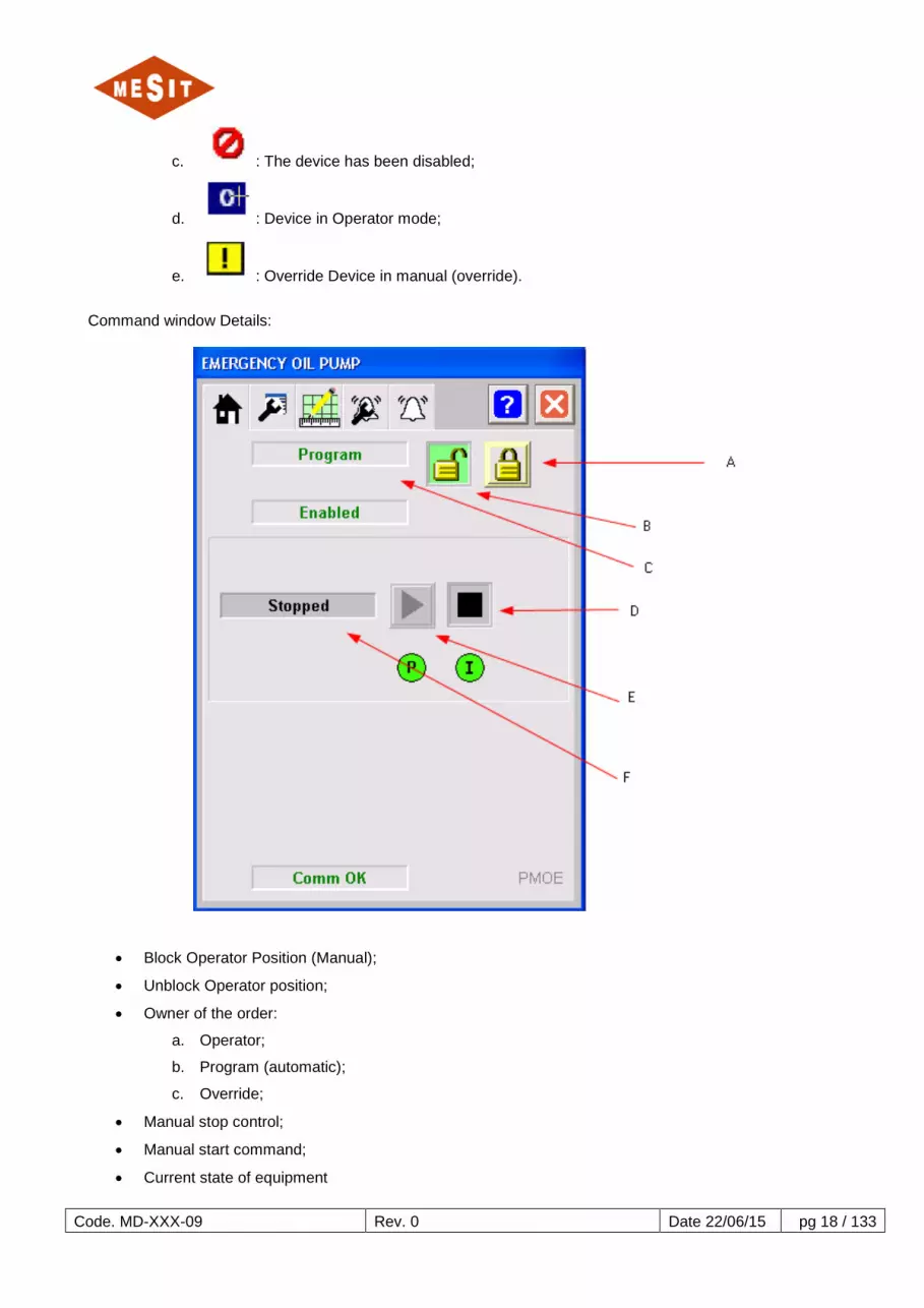
5.3.3 C OBJECT FOR "ELECTRICAL EQUIPMENT"
Figure 5-5-7: Main view
Figure 5-5-8: View the type display
Details display:
A. State Equipment:
a. Blue: By train to stop;
b. Grey: Stopped;
c. Blue: starting up;
d. Dark Green: Running
B. Status indicator:
a. : Device in maintenance mode;
b. : Device in Manual mode (local);
Code. MD-XXX-09 Rev. 0 Date 22/06/15 pg 18 / 133
c. : The device has been disabled;
d. : Device in Operator mode;
e. : Override Device in manual (override).
Command window Details:
• Block Operator Position (Manual);
• Unblock Operator position;
• Owner of the order:
a. Operator;
b. Program (automatic);
c. Override;
• Manual stop control;
• Manual start command;
• Current state of equipment

Code. MD-XXX-09 Rev. 0 Date 22/06/15 pg 19 / 133
5.3.4 OBJECT FOR "RUN COUNTER HOURS"
Figure 5-5-9. Main View
5.3.5 OBJECT FOR E "VALVES ALL OR NOTHING"
Figure 5-5-10: Main view

Code. MD-XXX-09 Rev. 0 Date 22/06/15 pg 20 / 133
Details display:
A. : State solenoid coils:
a. Gray: No line reel;
b. Turquoise powered reel;
B. State of the valve:
a. Blue: In the process of closing;
b. Grey: Closed;
c. Blue: In the process of opening;
d. Dark green: Open;
C. Status Indicators:
a. : Device in maintenance mode;
b. : Device in Manual mode (local);
c. : The device has been disabled;
d. : Device in Operator mode;
e. : Override Device in manual (override);
f. : Alarm Inhibition (removed or disabled);
g. : Communication Failure (outdated);
h. : Invalid conFiguretion;
D. See C;
E. Label of the valve;

Code. MD-XXX-09 Rev. 0 Date 22/06/15 pg 21 / 133
F. Alarm indicator:
a. Blanc: The alarm cause is no longer present, necessary acquittal;
b. Light Blue: Information Alarm;
c. Yellow: Warning;
d. Red: Exception;
e. Magenta: Fault;
Command window Details:
A. Block Operator Position (Manual);
B. Unblock Operator position;
C. Owner of the order:
a. Operator;
b. Program (automatic);
c. Override;
D. Manual closing command;
E. Manual opening command;
F. Current state of the valve

Code. MD-XXX-09 Rev. 0 Date 22/06/15 pg 22 / 133
5.3.6 OBJECT FOR F "REGULATOR PID"
Figure 5-5-11: View the type display
Figure 5-5-12: Main view

Code. MD-XXX-09 Rev. 0 Date 22/06/15 pg 23 / 133
Figure 5-5-13: View changes
Figure 5-5-14: Window view settings

Code. MD-XXX-09 Rev. 0 Date 22/06/15 pg 24 / 133
Main control Details:
A. PID label;
B. Value of the reference (SP = setpoint);
C. Value of the operating variable (PV);
D. Auto Selector;
E. Manual mode selector;
F. Value of the controller output (Control Variable = CV);
G. Desired setpoint value;
H. The set rate of change;
I. Instant Mode setpoint change (H point rate has no effect);
L. Push button and indicator for the presence of an anomaly;
M. Push button to access the window changes

Code. MD-XXX-09 Rev. 0 Date 22/06/15 pg 25 / 133
Details window changes:
A. Push button to access the adjustment window controls;
B. Legend PV (operating variables);
C. Legend SP (instructions);
D. Legend CV (control variables)

Code. MD-XXX-09 Rev. 0 Date 22/06/15 pg 26 / 133
Details window setting control parameters:
A. Desired value of the proportional gain;
B. The proportional gain variation rate;
C. Fashion instantaneous change of the proportional gain (rate B has no effect);
D. Integration time;
5.4 ALARM MANAGEMENT Alarm management is accomplished through a list always in the foreground located at the foot of the screen page (ref. Figure 5-5-15), With a set of indicators and controls always right foreground on the page (ref. Figure 5-5-16) And with a specialized window (ref. Figure 5-5-17).
Figure 5-5-15: Alarm list at bottom of page
Figure 5-5-16 Signaling and controls for alarm management

Code. MD-XXX-09 Rev. 0 Date 22/06/15 pg 27 / 133
Figure 5-5-17: Window dedicated to alarms
5.4.1 CHARACTERIZING PHASE ALARMS When an alarm occurs, it is present as a first array element of Figure 5-5-15. This condition is represented with the symbol indicating not yet acknowledged by the operator alarms.
When this event occurs, the siren starts to ring (if it is not already ringing) and symbol appears in the region of Figure 5-5-16. The event that caused the alarm is stored on a specialized element, which must be reset to remove the alarm from the list, once the cause is no longer present. The reset action of alarm and siren deactivation is accomplished by means of the RESET push-button located in the Figure 5-5-16. The area shown in the Figure 5-5-16 has two leds that are lit in case of:
• Presence of at least one alarm: CUMULATIVE ALARM; • Presence of at least one trigger: TRIGGER CUMULATIVE;
To access the full list of existing alarms must press which provides access to the window Figure 5-5-17.

Code. MD-XXX-09 Rev. 0 Date 22/06/15 pg 28 / 133
Figure 5-5-18: Details of the window dedicated to alarms
Compared to the Figure 5-5-18 :
A. All commands: a. : Acknowledgement of selected alarms; b. : Acknowledgement of alarms selected with the addition of a comment; c. : Acknowledge all alarms displayed on the page; d. : Acknowledge all alarms contained in the list;
e. : Shows details for the selected alarms; f. : Prints the alarm list; g. Defines alarm visualization of the order; h. : Run a search in the alarm list;
B. Bar containing the titles of the displayed fields: If you select the title you force the order of the list based on the corresponding field;
C. Alarm status: a. : Unacknowledged alarm; b. : Alarm paid;
D. Auxiliary information:
a. : Led indicating the correct operation of the alarm monitoring system;
b. : Number of events present in the list; c. : Number of unacknowledged alarms; d. : Number of non-rearmed but acknowledged alarms;

Code. MD-XXX-09 Rev. 0 Date 22/06/15 pg 29 / 133
5.4.2 ACTIONS TO BE PERFORMED IN CASE OF OCCURRENCE OF AN ALARM The actions to be taken in case of occurrence of an alarm are:
• Turn off the siren; • Understand what it is alarm; • Check the option to remove the cause that caused it, see 8.1 ; • Acknowledge the alarm; • Repeat the above actions for all alarms.

Code. MD-XXX-09 Rev. 0 Date 22/06/15 pg 30 / 133
5.5 OVERVIEW SCREEN PAGES 5.5.1 MAIN MENU This page is a summary of all the screen pages. Through pushbuttons is possible to access the corresponding screen page.
5.5.2 P&ID: GAS DISCHARGE View 6.2

Code. MD-XXX-09 Rev. 0 Date 22/06/15 pg 31 / 133
5.5.3 P & ID: SYSTEM LUBRICATING OIL AND MOUTH View 6.3
5.5.4 P & ID: AIR INSTRUMENTS View 6.4

Code. MD-XXX-09 Rev. 0 Date 22/06/15 pg 32 / 133
5.5.5 P & ID: CONTROL PAGE View 6.5 and 6.6
5.5.6 P & ID: 1st STAGE COMPRESSOR

Code. MD-XXX-09 Rev. 0 Date 22/06/15 pg 33 / 133
5.5.7 P & ID: 2nd STAGE COMPRESSOR
Code. MD-XXX-09 Rev. 0 Date 22/06/15 pg 34 / 133
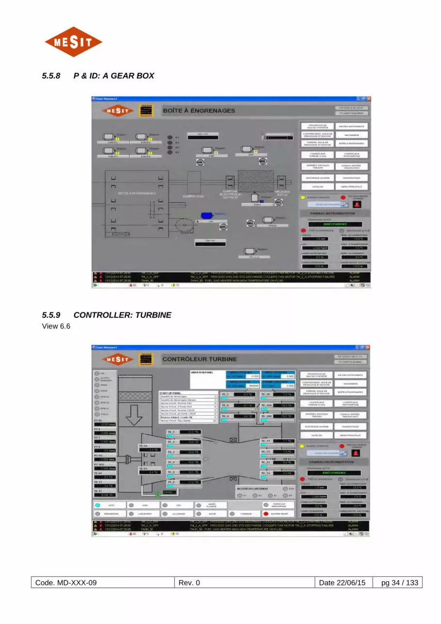
5.5.8 P & ID: A GEAR BOX
5.5.9 CONTROLLER: TURBINE View 6.6

Code. MD-XXX-09 Rev. 0 Date 22/06/15 pg 35 / 133
5.5.10 CONTROLLER: ANTISURGE CONTROL View 6.6
5.5.11 MOS: MANUAL BYPASS LOCKS

Code. MD-XXX-09 Rev. 0 Date 22/06/15 pg 36 / 133
Pages (2 in total) make available a selector; called MOS (Manual Override Switch) for certain causes trigger to avoid certain conditions that otherwise would cause the outbreak of the machine. In the displayed page, the MOS refers to the trigger caused by the intervention of the high temperature threshold for the TE-1 instrument. Activation of a MOS because the occurrence of an alarm.
5.5.12 DIAGNOSTIC The page shows colorful animations by the presence of faults in the PLC system.

Code. MD-XXX-09 Rev. 0 Date 22/06/15 pg 37 / 133
5.5.13 DIGITAL INPUTS TABLE The pages list the digital inputs managed by the internal board cards UCP.
5.5.14 INPUT SIGNALS TABLE MCC The pages list the digital inputs managed by internal boards MCC chart.

Code. MD-XXX-09 Rev. 0 Date 22/06/15 pg 38 / 133
5.5.15 SIMILAR THRESHOLD Pages (3 total) reported the thresholds associated with the analog instrumentation with an explanation of their effect.

Code. MD-XXX-09 Rev. 0 Date 22/06/15 pg 39 / 133

Code. MD-XXX-09 Rev. 0 Date 22/06/15 pg 40 / 133
5.5.16 PRINT DATA LOGGING If you press this push-button printing is started from the state in that time some "critical" variables for regulating the turbine. The following reports a copy of possible impressions.

Code. MD-XXX-09 Rev. 0 Date 22/06/15 pg 41 / 133

Code. MD-XXX-09 Rev. 0 Date 22/06/15 pg 42 / 133
5.5.17 ADMINISTRATION The figure below shows the administration page of the HMI system.
The carrier selection function allows the user to select the system with the corresponding authorizations. Access is protected by a password. The table below shows the rights of different users: User Password Operator Mode /
Program Threshold Description,
etc. Maintenance
operator **** X - - - engineer **** X X X - supervisor **** X X X X An order in this page also allows the passage of the English language to the French language.

Code. MD-XXX-09 Rev. 0 Date 22/06/15 pg 43 / 133
6 FUNCTIONAL DESCRIPTION 6.1 INTRODUCTION
The purpose of this chapter is to describe the operating logic of the control system.
6.2 GAS CIRCUIT The gas system is shown schematically in the document MD-222-09 page 3.
6.2.1 COMPONENTS The components parts of the gas circuit, which also applies to the control system, is reported below:
• Gas Heater:
o PSLL 202/3: Alarm;
• Gas filtration skid:
o LSHH 205/4: Triggered by the separator too high;
o LSHH 205/3: high level alarm of the separator;
o PDT 205/1, differential pressure at the ends of the filter:
Alarm per intervention threshold H;
Actuation by interference threshold HH;
• Transmitters:
o TE 33, the fuel gas temperature:
Actuation by interference threshold HH, set @ 60 ° C;
Actuation by interference threshold LL, set @ 10 ° C;
Startup permission to temperatures above 15 ° C
o PT 9G, fuel gas pressure at the entrance:
The action level alarm, set @ 9.5 bar;
Actuation by interference threshold LL, set @ 3 bar;
o PT 16G, gas pressure at the exit of skid;
• Vannes ALL OUT THERE:
o FGV 1 Stop valve of fuel gas:
Operated by FGV SOV 1
ZSH 1: Sw. open end of race
ZSL 1: Sw. closed limit
o FGV 6, purge valve fuel gas:
Driven by SOV V2G
ZSH 6: interr. open end of race
ZSL 6: interr. closed limit
o FGV 4, isolation valve fuel gas:
Powered by SOV V1G
ZSH 6: interr. open end of race
ZSL 6: interr. closed limit
• Control valves:

Code. MD-XXX-09 Rev. 0 Date 22/06/15 pg 44 / 133
o FGV 2 starter valve fuel gas:
Actuated by a 4-20 mA signal from the table, acting through an electro converter and
positioner
ZSH 2: interr. open end of race
ZSL 2: interr. closed limit
o FGV 3 Main valve fuel gas:
Electrically actuated by the control signal types 4-20mA from Table
ZSH 3: interr. open end of race
ZSL 3: interr. closed limit
6.2.2 OPERATION The gas from the battery input is processed by the heating system, the operation of which is indicated by the PSLL 202/3 state that should not be in alarm. The gas is processed by the system which has the functions of separation and filtration. During normal operation, the following alarms should NOT be present:
• LAH 205/3 • LAHH 205/4 • PDAH 205/1 • PDAHH 205/1
After passing the separation-filtration system, the gas arrives at the input of the skid of the turbine gas valves. Abnormal pressure values and gas temperature cause the following events:
• TE 33, the fuel gas temperature:
o Actuation by interference threshold HH, set @ 60 ° C;
o Actuation by interference threshold LL, set @ 10 ° C;
o Startup permission to temperatures above 15 ° C
• PT 9G, fuel gas pressure at the entrance:
o The action level alarm, set @ 9.5 bar;
o Actuation by interference threshold LL, set @ 3 bar;

Code. MD-XXX-09 Rev. 0 Date 22/06/15 pg 45 / 133
6.3 OIL SYSTEMS The oil circuit is shown schematically in the document MD-222-09 page 5.
6.3.1 COMPONENTS The components parts of the oil circuit, which also applies to the control system, is reported below:
• Oil pumps:
o Main pump driven by the accessory gearbox
o Auxiliary pump: PMOA;
o Emergency pump: PMOE;
• Fans of the oil cooler:
o T2AB
o T2BB
• Oil Cooler: EH1
• Oil vapor extractor: PRESS
• Transmitters / thermocouples:
o PT 1, oil pressure to the collector:
Low pressure alarm @ 0.85 bar
Threshold L @ 0.58 bar as permission for the march to tacking
Triggered by pressure too low @ 0.59 bar
o PT 3 oil discharge pressure of the mechanical pump:
Low pressure threshold @ 5 bar to start PMOA;
High pressure threshold @ 6.37 bar to start PMOA;
o PT 7, the mechanical system pressure overspeed:
Low pressure threshold @ 0.85 bar as start permission;
Triggered by pressure too low @ 0.75 bar
o LS 10: oil tank level status;
o TE 201: bottom oil temperature reservoir
o TE 205: tank top oil temperature:
Threshold L @ 30 ° C for management EH1 (ref. 0)
o TE 17: upstream oil temperature of the radiator;
o TE 17 °: downstream oil temperature of the radiator;
o PDT 11: pressure at the ends of the filter:
o High pressure alarm @ 1000 mbar
o TE 200: oil temperature downstream of the filter:
High temperature alarm @ 60 ° C
Triggered by too high temperature @ 70 ° C
o TE 1A discharge oil temperature exhaust side turbine bearing:
High temperature alarm @ 75 ° C
Triggered by too high temperature 100 ° C @
o TE 203: Discharge oil temperature thrust bearing axial turbine compressor side:
High temperature alarm @ 70 ° C

Code. MD-XXX-09 Rev. 0 Date 22/06/15 pg 46 / 133
Triggered by too high temperature 100 ° C @
o TE 204: Discharge oil temperature thrust bearing axial turbine compressor side:
High temperature alarm @ 70 ° C
Triggered by too high temperature 100 ° C @
o TE 12: white metal temperature thrust bearing axial turbine compressor side:
High temperature alarm @ 95 ° C
Triggered by too high temperature 115 ° C @
o TE 13 white metal temperature thrust bearing axial turbine compressor side:
High temperature alarm @ 95 ° C
Triggered by too high temperature 115 ° C @
o TE 6A discharge oil temperature bearing gearbox, turbine side:
High temperature alarm @ 70 ° C
o TE 6B discharge oil temperature bearing gearbox, turbine side:
Triggered by too high temperature 100 ° C @
o TE 110: white metal bearing temperature turbine compressor side:
High temperature alarm @ 95 ° C
Triggered by too high temperature 105 ° C @
o TE 111: white metal bearing temperature compressor side:
High temperature alarm @ 95 ° C
Triggered by too high temperature 105 ° C @
6.3.2 PRIOR All equipment listed below should be left in automatic mode:
• Oil pumps:
o Auxiliary pump: PMOA;
o Emergency pump: PMOE;
o Emergency pump: RPM-3C
o Auxiliary pump: RPM-3B
o Main pump: RPM-3A
• Fans oil cooler:
o T2AB o T2BB
• Oil Cooler: EH1
• Oil vapor extractor: PRESS
6.3.3 OPERATION During operation of the turbine lubrication is guaranteed by the main pump. During the start-up and shutdown, lubrication is guaranteed by PMOA, which starts automatically if the pressure measured by PT 3 is low. At very low manifold pressure PT 1, the standby pump starts, PMOE. The main causes of the low pressure manifold (PT 1) are:
• Failure of the PMOA
If the oil tank is unsuitable temperatures, the radiator is on EH 1, provided that the oil is going to flow, ref. 0.

Code. MD-XXX-09 Rev. 0 Date 22/06/15 pg 47 / 133
The oil circulating through the cooling radiator, where T2AB fans, T2BB, powered by the corresponding inverters, eliminate excess heat to keep the temperature measured by TE 205-50 ° C, The regulator used is 17A ICT set with reference to 50 ° C. If the mechanical system overspeed occurs, the pressure measured by PT 7 downward and thus causes the activation of the system.

Code. MD-XXX-09 Rev. 0 Date 22/06/15 pg 48 / 133
6.4 CIRCUIT AIR INSTRUMENTS The instrument air system is shown schematically in the document MD-222-09 page 9.
6.4.1 COMPONENTS The components parts of the air circuit instruments, which also applies to the control system, is reported below:
• Air treatment system DRY-COOLER
• Solenoid:
o SOV 10 for controlling the anti-surge valve VBY axial compressor
o SOV V2G, for controlling the FGV6 valve
o SOV V1G for control of FGV4 valve
• Transmitters:
o PT A, discharge pressure of the air compressor:
Low pressure alarm @ 2 bar
o PT 11, pressure to the compressed air manifold
Low pressure alarm @ 2.8 bar
o PT 8, pressure compensating cylinder
Low pressure alarm @ 0.6 bar
o PT 6, axial compressor discharge pressure
• Digital Instruments:
o HSP 6, axial compressor discharge pressure switch:
Set @ 0.4 bar
o ZSH VBY: limit switch anti-surge valve opening;
o ZSL VBY: end of anti-surge valve closing stroke;

Code. MD-XXX-09 Rev. 0 Date 22/06/15 pg 49 / 133
6.5 CIRCUIT COMBUSTION AIR AND BURNING The combustion air circuit and the combustion is shown schematically in document MD-222-09 on page 7. For specific descriptions of the operation of turbine regulator, see 6.6.
6.5.1 COMPONENTS The list of the component parts of the combustion air system and combustion, which also applies to the control system, is reported below:
• Electrical equipment:
o S-EM1, sand extractor
o SQZ1, cleaning system filter room:
35 PSL: low air pressure to the hallway of the cleaning system (pulse-jet);
PDAH 32: high differential pressure at the ends of the filter chamber;
o VIR, rotator:
Protecting the motor shaft turning gear mounted properly: ZSH 100;
o ESM Starting electric motor:
During torque transfer clutch (engaged): ZSH 101;
o Spark plugs ÷ TR6 TR1;
• Transmitters / thermocouples:
o TE 202, filter room air temperature;
o TE 14, turbine inlet air temperature;
o PT 05 turbine inlet air pressure:
Low pressure alarm per intervention threshold;
Actuation by interference too low pressure threshold;
o TE-11, air temperature at the outlet of the axial compressor;
o TE-1, 1-temperature combustion chamber:
Triggered by too high temperature at start @ 700 ° C;
Triggered by too high temperature load condition @ 950 ° C;
o TE-2, combustion chamber temperature 2:
Triggered by too high temperature at start @ 700 ° C;
Triggered by too high temperature load condition @ 950 ° C;
o TE-3, combustion chamber temperature 3:
Triggered by too high temperature at start @ 700 ° C;
Triggered by too high temperature load condition @ 950 ° C;
o TE-4, combustion chamber temperature 4:
Triggered by too high temperature at start @ 700 ° C;
Triggered by too high temperature load condition @ 950 ° C;
o TE-5, 5 combustion chamber temperature:
Triggered by too high temperature at start @ 700 ° C;
Triggered by too high temperature load condition @ 950 ° C;
o TE-6, 6-temperature combustion chamber:
Triggered by too high temperature at start @ 700 ° C;

Code. MD-XXX-09 Rev. 0 Date 22/06/15 pg 50 / 133
Triggered by too high temperature load condition @ 950 ° C;
o TE-T1, turbine exhaust temperature;
o TE-T2, turbine exhaust temperature;
o TE-T3, turbine exhaust temperature;
o TE-T4, turbine exhaust temperature;
o TE-7, temperature exhaust chimney pipe:
High temperature alarm @ 430 ° C;
o TE-8, temperature exhaust chimney pipe:
Triggered by too high temperature @ 450 ° C;
o TE-9-temperature exhaust chimney pipe:
Triggered by too high temperature @ 450 ° C;
o TE-10 temperature exhaust chimney pipe;
o TE-10A-temperature exhaust chimney pipe;
o TE-10B-temperature exhaust chimney pipe;
• VT-1. Turbine Vibration:
o High vibration alarm threshold during startup @ 6 fps;
o High vibration alarm threshold during start @ 8 fps;
o High vibration alarm threshold for the charging plug @ 3 fps;
o High vibration alarm threshold for the charging plug @ 4 fps;
6.5.2 PRIOR All attachments listed below should be left in automatic mode:
• S-EM1, sand extractor;
• SQZ1, cleaning system filter room;
• VIR, rotator
6.5.3 OPERATION The incoming air to the intake of the turbine axial compressor goes through the room S-EM1 filters and extracted from the chamber the sand collected on the bottom of the space upstream of the filters. When S-EM1 is running one of the following conditions happen:
• DPA-32; • Manual Request for operator pushbutton: HSSEM_1_STR;
Automatic sequence of cleaning system (pulse-jet) is started. When the filter status is compromised, the pressure measured by PT-5 will tend to assume still lower values, reaching the threshold value too low causes the turbine trip. The ZSH-100 signal strength stop tacking VIR in order to prevent accidents during the manual shift operations. The ZSH-101 signal indicates whether the clutch by which the starter motor provides torque to the turbine is engaged or not. The management of these signals:
• PT-6; • HSP-6; • TE-TE-1 ÷ 6; • TE-TE-T1 ÷ T4; • TE-TE-7 ÷ 10B;
And management of the following electrical equipment: • ESM;

Code. MD-XXX-09 Rev. 0 Date 22/06/15 pg 51 / 133
• VIR; • SP1 ÷ SP6;
Code. MD-XXX-09 Rev. 0 Date 22/06/15 pg 52 / 133
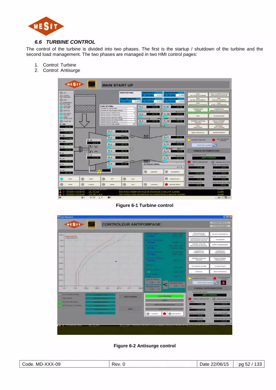
6.6 TURBINE CONTROL The control of the turbine is divided into two phases. The first is the startup / shutdown of the turbine and the second load management. The two phases are managed in two HMI control pages:
1. Control: Turbine 2. Control: Antisurge
Figure 6-1 Turbine control
Figure 6-2 Antisurge control

Code. MD-XXX-09 Rev. 0 Date 22/06/15 pg 53 / 133
6.6.1 COMPONENTS The instruments involved in the control of the turbine are many and below we offer a list:
• Speed Sensors (ST-SR1,2) • Temperatures combustion chambers (TE-1..6) • Turbine exhaust temperatures (TE_T1..T4) • Temperatures exhaust pipe - chimney (TE-7..10B) • Barometric pressure (PT-05) • Axial compressor discharge pressure switch (PSH-6) • Axial compressor discharge pressure (PT-6) • Rotator (VIR) • Starter motor (ESM) • Gas line valves Overspeed FGV1 by SOV-solenoid FGV1 FGV6 evacuation by the SOV-V2G solenoid Isolation solenoid FGV4 SOV-V1G • Start gas valve (FGV2) • Valve control gas (FGV3) • Anti-surge valve (bypass) by VBY solenoid valve (SOV-10).
6.6.2 PRIOR Pre turbine control are basically three:
• Mode selection of the turbine start sequence • elimination of triggers • Startup permissions
The modes of the starting sequence of the turbine can only be changed by triggering the same condition and turbine are:
1. Automatic 2. Semi-Automatic 3. Stop (Off)
Figure 6-3 Operating Modes
Automatic startup executes the beginning of the startup sequence at the end, without need for intervention from the operator. The Semi-Automatic Boot runs the startup sequence with two breaks for the launch sequence and the flame outlet of the turbine. This mode requires commands by the operator to perform the following sequence. Off Mode (off) does not allow the turbine to start. Triggers are eliminated, after resetting all alarms and after performing the RESET MASTER (main reset) control, using the push button only present in the screen page dedicated to turbine control, as shown in first figure of paragraph 6.6. The turbine control needs a permission to be available at startup. Permission is the result of a set of conditions necessary to consider the subsidiary system ready to start. The state of the permission is available in the turbine control page, highlighted in the corresponding screen page in the section 6.6.3.1 (Figure 6-6).

Code. MD-XXX-09 Rev. 0 Date 22/06/15 pg 54 / 133
The table below shows all the necessary conditions for the start permission. The list is split into two blocks as shown on the next page:
Block permissions 1: description Bypass Automatic auxiliary oil pump (PMOA) NO Automatic emergency oil pump (PMOE) NO PT 9G> State BAS NO Gas heater according NO Ready to launch engine start NO ****************** *** ******************* *** Fan 1 oil cooling (E1) in automatic YES Oil cooling fan 2 (E2) Automatic YES Automatic management candles NO PT 1> State BAS NO
Table 6-1 First block permissions
Block permissions 2: description Bypass *************************** ** *************************** ** Overspeed (SOV-V2) Automatic NO ************************** ** ************************** ** Anti-surge valve open NO PT 7> Status BAS NO Closed gas control valve NO Speed <DOWN State YES Automatic engine start NO Automatic turbine inlet oil temperature control NO Inhibition turbine startup after shutdown NO
Table 6-2 Second permissions block
For completeness we must add that during the interview, not enabled the operator user, it is possible to avoid certain permissions, and some not, as indicated in the table indication. If all listed states are active, permission is available (green led); While some states are avoided (bypass), but permission is still available (green led), the derivation is highlighted with all avoided by (yellow) alarm. The following figures show the situation just described.

Code. MD-XXX-09 Rev. 0 Date 22/06/15 pg 55 / 133
Figure 6-4 Signalling permissions
Figure 6-5 Permissions window
6.6.3 OPERATION The operation of the turbine control is mainly divided into two phases shown in the screen-pages dedicated to:
• Control: turbine takes care of startup / shutdown of the turbine and monitoring of the main variables involved in the regulation and can be further subdivided as follows:
a. Reset triggers b. Starting the turbine c. Control and safety devices d. Planned shutdown e. Surveillance
In the following paragraphs are reported in the order that we will describe the turbine control functions.
6.6.3.1 RESET OF TRIGGERS The triggers reset operation is a delicate and main phase to turn the turbine, therefore we provide a careful description below.
General led permissions OK NO OK

Code. MD-XXX-09 Rev. 0 Date 22/06/15 pg 56 / 133
Figure 6-6 Reset triggers
1. Keep pressed the alarm reset push button, to remove the current alarm. 2. Wait a few seconds to give time to the visual rearmament. 3. Keep pressed the push-button Master Reset to eliminate the triggers of the currently active turbine. 4. The led triggers turns green. 5. Repeat the first two points. 6. The led of the cumulative trigger turns green. 7. Manual reset of the launch engine, to perform on the local table. 8. Manual reset of the launch engine, to perform on the local table. 9. Repeat step 3 of the sequence. 10. The led permissions turns green, if there are no causes that inhibit the release.
6.6.3.2 STARTING THE TURBINE
The start sequence is divided into three sequences:
1. Start-up 2. Launching 3. Ignition
Note: the control takes into account the expected inconsistency between control and feedback, and in such a case by means of its activation is protected turbine. The following illustrates the automatic sequence. The semi-automatic mode is strictly identical to the automatic mode, but requires an order by the operator to complete the sub-sequences listed above. If necessary we mentionera the command for the semi-automatic mode. Once you meet the requirements shown in the above paragraph, the turbine is ready to start, unless it is stopped (off). The startup sequence begins with the start command by the operator.
Master Reset Signal
Reset alarms
Permissive Signal
Common shutdowns

Code. MD-XXX-09 Rev. 0 Date 22/06/15 pg 57 / 133
Figure 6-6-7 Commands and signals starting phase
1. Start: The current control instantly completes the start-up phase and automatically switches to that launch, while in semi-automatic mode the operator must press the push button to begin the sequence LAUNCH.
2. Launch: The control automatically switches to the launch phase, while in semi-automatic mode the operator must press the push button to begin the sequence LAUNCH. The launch sequence produces the following:
a1. Launch engine ignition. a2. Increased launch engine speed reference a3. Stopping the VIR a4. Cleaning the turbine with compressor air. a5. Opening of the overspeed valve (SOV-FGV1) triggering HSP-6 (Table 6-3Point 13). a6. Opening the gas discharge valve (SOV-V2G). a7. Closing the gas discharge valve (SOV-V2G) Timed (Table 6-3Point 14). a8. Locking the launch engine speed reference.
3. Ignition:
The control automatically switches to the ignition phase, while in semi-automatic mode the operator must press the push button to start the sequence IGNITE. The ignition sequence produces the following:
i1. Lighting the candles combustion chambers (Table 6-3Point 15). i2. Opening the isolation valve (SOV-V1G) after an adjustable delay to the previous point (Table 6-3Point 16). i3. Taken flame if the median temperature of the combustion chamber (GT_PRV_COMBUSTOR) exceeds the
flame confirmation threshold. It is important to note that the gas-start valve has a pre-calibrated mechanical opening to provide just the input gas with compressed air, ensuring the ignition of the combustion chambers (Table 6-3Point 17).
i4. From that time, if a temperature of the combustion chamber (TE-1..6) Or the median falls below the flame failure threshold, the turbine is protected by a trigger (Table 6-3Point 18).
i5. After the flame outlet, the launch engine speed reference starts to rise again. i6. Beginning of the control action on the valve start-up and regulation of the gas when the discharge pressure
of the axial compressor (PT-6) meet the threshold (Table 6-3Point 19). i7. Launch engine shutdown. When the speed reaches the maximum speed threshold of the launch engine
(Table 6-3Point 20), an adjustable timer is started, during which the starter motor speed is kept constant and equal to its maximum. At the end of the delay (Table 6-3Point 21) the starter motor is actually stopped. It is important to note that the turbine is already able to support themselves before this, but to avoid any thermal control problem and make the smoothest possible start is delayed engine shutdown to continue to benefit from its contribution.
i8. Closing the anti-surge valve (SOV-10 bypass) obtained when a compressor discharge pressure threshold is reached or exceeded the corresponding speed threshold (Table 6-3Point 22).
i9. Phase stabilization or preheating of the turbine, after reaching the reference speed and its maximum speed without load, now coincide with the timing of the turbine speed (Table 6-3Point 23).
i10. At the end of the stabilization phase, the boot sequence is completed. The figure below shows a generic temporal sequence of starting the turbine.
Start command
Turbine signaling Ready to start (green) Started sequence (blue)
Launch control Ignition control
During ignition turbine signaling
Signalling turbine being launched

Code. MD-XXX-09 Rev. 0 Date 22/06/15 pg 58 / 133
Figure 6-6-8 Starting Sequence
6.6.3.3 CONTROL AND SAFETY
During operation of the turbine he controllers, limitations and active safety (ves) for the major variables in play. In particular controls, limitations and following parameters listed in the Table 6-3 are active:
1. Limiting speed for starting the turbine (Table 6-3Point 24). 2. Active cruise control when the target speed is reached (speed according to the active ramp that ends with
the target Table 6-3Point 25). 3. Limitation temperature combustion chambers (Table 6-3Point 1). 4. Limitation temperature exhaust pipe - chimney (temperature depending on the compressor discharge
pressure and barometric pressure).
Code. MD-XXX-09 Rev. 0 Date 22/06/15 pg 59 / 133
5. Limitation of acceleration (Table 6-3Point 9). The always active safety in the control are:
1. Temperature combustion chambers: alarm and trip to the median of six temperatures (Table 6-3Point 2 and 3).
2. Exhaust turbine temperature: alarm and trip to the median of four temperatures (Table 6-3Point 4 and 5). 3. Temperature exhaust pipe - chimney: alarm and trip to the median of six temperatures (Table 6-3Point 7
and 8). 4. Lack of flame, valid for each sensor and the combustion chamber center (Table 6-3Point 18). 5. Electronic overspeed alarm and trip (Table 6-3Point 10 and 11). 6. Congruence control / valve response. 7. Disagreement redundant combustion temperature signals, exhaust turbine and exhaust pipe (Table
6-3Point 6)
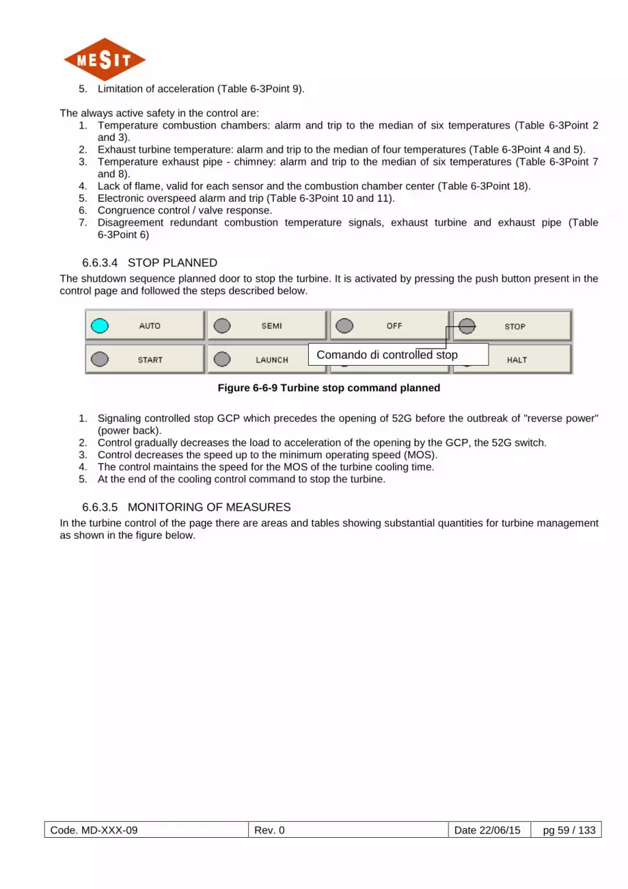
6.6.3.4 STOP PLANNED The shutdown sequence planned door to stop the turbine. It is activated by pressing the push button present in the control page and followed the steps described below.
Figure 6-6-9 Turbine stop command planned
1. Signaling controlled stop GCP which precedes the opening of 52G before the outbreak of "reverse power"
(power back). 2. Control gradually decreases the load to acceleration of the opening by the GCP, the 52G switch. 3. Control decreases the speed up to the minimum operating speed (MOS). 4. The control maintains the speed for the MOS of the turbine cooling time. 5. At the end of the cooling control command to stop the turbine.
6.6.3.5 MONITORING OF MEASURES
In the turbine control of the page there are areas and tables showing substantial quantities for turbine management as shown in the figure below.
Comando di controlled stop

Code. MD-XXX-09 Rev. 0 Date 22/06/15 pg 60 / 133
Figure 6-6-10 Boxes monitoring
On the main control is monitored temperatures:
• combustion chambers, • turbine exhaust, • exhaust pipe - chimney,
but also monitors the main values on control in the table on the left (0) And vibration (0). In the center of the page there is the table of starts (6.6.3.6.2) And below, in addition to push buttons with the main controls of the turbine, the anti-surge valve (bypass) with its state is displayed.
Temperatures: Exhaust pipe Exhaust turbine Combustion chambers
Bypass
Vibrations
Table start
Settings Generals

Code. MD-XXX-09 Rev. 0 Date 22/06/15 pg 61 / 133
Figure 6-6-11 Parameter Description
Beside the table also indicates the metal temperatures of the thrust bearing.

Code. MD-XXX-09 Rev. 0 Date 22/06/15 pg 62 / 133
6.6.3.5.1 TABLE STARTS The table starts indicates the number of starts as well as non-successful starts. Set to start it indicates the hours of operation of the turbine in the different possible conFiguretions fuel, as gas, liquid and crude oil. The operation is divided into normal and crest.
Figure 6-6-12 Table start
Among the parameters, the most important parameter is the equivalent operating hours, fundamental for the maintenance scheduling of the turbine.
6.6.3.6 PARAMETERS CONFIGURETION CONTROL The main parameters of turbine control conFiguretion are listed in the table below:
Description threshold
unit
1. Combustion chamber temperatures: Reference 630 ° C
2. Temperatures combustion chamber: alarm (start / load) 600/855 ° C
3. Temperatures combustion chamber: Trigger (start / load) 700/950 ° C
4. Turbine exhaust temperatures: Alarm 450 ° C
5. Turbine exhaust temperatures: Trigger 460 ° C
6. Disagreement redundant signals (start / load) 80/120 ° C
7. Temperatures exhaust pipe: Alarm 430 ° C
8. Temperatures exhaust pipe: Trigger 440 ° C
9. Acceleration: Reference 10 turn / s
10. Overspeed: Alarm 3200 rev / min
11. Overspeed: Trigger 3250 rev / min
12. Threshold VIR stop 300 rev / min
13. Threshold HSP-6 indication *: PT-6 Pressure speed
~ 0045 600 ~
barg rev / min

Code. MD-XXX-09 Rev. 0 Date 22/06/15 pg 63 / 133
14. Relief valve delay SOV-V2G 10 dry
15. Delay of TR1..3 spark plug 3 min
16. Delay opening isolation valve SOV-V1G- 20 dry
17. Flame temperature confirmation 250 ° C
18. Release temperatures flame failure 200 ° C
19. Threshold control gas valves, axial compressor discharge pressure PT-6 0.22 barg
20. Threshold motor stop launching turbine speed 1790 rev / min
21. Delay launching engine stop 10 min
22. Threshold bypass closure: PT-6 Pressure speed
3.3 2700
barg rev / min
23. Turbine preheating delay 2 min
24. Speed limit during startup MOS 2940 rev / min
25. Target speed 3000 rev / min
Table 6-3 Control parameters
* Note: The values are indicative because it is a pressure switch.
6.7 COMPRESSOR The compressor is shown schematically in the document MD-222-09 page 3-4.
6.7.1 COMPONENTS The components parts of the compressor, which also applies to the control system, is reported below:
• Transmitters:
o LT-2101, Scrubber M2 level:
Low threshold Alarm @ (To be decided on site);
o PT-4002A, Scrubber M2 pressure:

Code. MD-XXX-09 Rev. 0 Date 22/06/15 pg 64 / 133
Low threshold Alarm @ (To be decided on site);
o PT-4702, Scrubber M2 pressure:
Low Low threshold Alarm @ (To be decided on site);
o TE-3002, Scrubber M24 inlet temperature:
High threshold Alarm @ 80°C
o TE-3702, Scrubber M24 inlet temperature:
High High threshold Alarm @ 90°C
o LT-2101, Scrubber M24 level:
Low threshold Alarm @ (To be decided on site);
o LT-2820, OIL BUFFER TANK level:
High threshold Alarm @ (To be decided on site);
High High threshold Alarm @ (To be decided on site);
Low Low threshold Alarm @ (To be decided on site);
Low threshold Alarm @ (To be decided on site);
o PDT-41021, SEAL OIL inlet delivery line differential pressure:
Low threshold Alarm @ (To be decided on site);
o PT-4820, SEAL OIL inlet supply line pressure (From lube oil):
Low Low threshold Alarm @ (To be decided on site);
6.7.2 PRIOR All equipment listed below should be left in automatic mode:
• RPM-3C, Seal oil emergency pump:
• RPM-3B, Seal oil auxiliary pump:
• RPM-3A, Seal oil main pump:
• LCV-2820
• TM-2-E
• TM-2-F
• ROV-5011
• ROV-5004
• LCV-2104
• ROV-5010
• ROV-5005
• ROV-5008
• FCV-1003
• ROV-5006
• ROV-5003
• LCV-2102
• SOV-1001A
• FCV-1001A
• ROV-5009
Code. MD-XXX-09 Rev. 0 Date 22/06/15 pg 65 / 133
6.7.3 OPERATION Make sure all Antisurge parameters settings are inserted and antisurge vale is in AUTO by relevant indicator on Antisurge dashboard page:
When you ready to export gas push relevant push button on Antisurge dashboard page:
7 FUNCTIONAL DESCRIPTION AUXILIARY COMPONENTS 7.1 ELECTRICAL EQUIPMENT
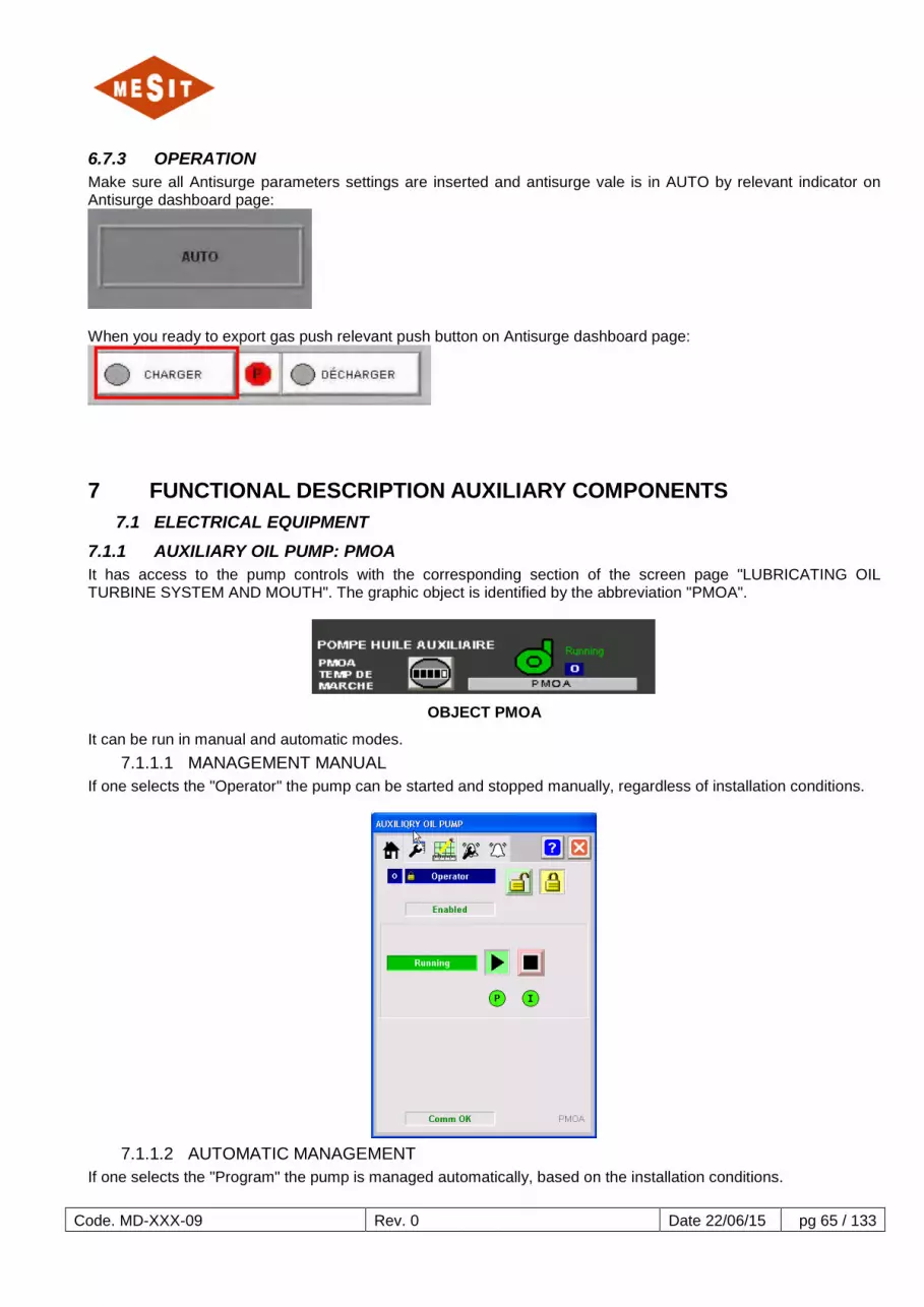
7.1.1 AUXILIARY OIL PUMP: PMOA It has access to the pump controls with the corresponding section of the screen page "LUBRICATING OIL TURBINE SYSTEM AND MOUTH". The graphic object is identified by the abbreviation "PMOA".
OBJECT PMOA
It can be run in manual and automatic modes. 7.1.1.1 MANAGEMENT MANUAL
If one selects the "Operator" the pump can be started and stopped manually, regardless of installation conditions.
7.1.1.2 AUTOMATIC MANAGEMENT
If one selects the "Program" the pump is managed automatically, based on the installation conditions.

Code. MD-XXX-09 Rev. 0 Date 22/06/15 pg 66 / 133
The following conditions cause the automatic start of the pump:
• Low pressure PT_3;
The following conditions cause the automatic pump stop: • High pressure PT_3;
7.1.1.3 PRESENCE OF PRIORITY CONTROL (OVERRIDE)
Regardless of the mode "Auto" or "Manual" in the presence of an override the pump is off. For PMOA causes override are: Open main switch: MS_IN001_FINE_IN_ALM;
Presence Override (Override)
7.1.1.4 FAULTS The following causes may cause the non-starting the pump:
1. Non-activated Drawer:
o Display:
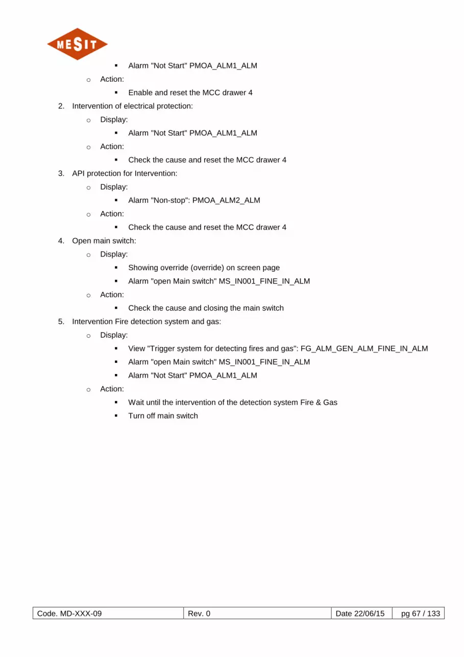
Code. MD-XXX-09 Rev. 0 Date 22/06/15 pg 67 / 133
Alarm "Not Start" PMOA_ALM1_ALM
o Action:
Enable and reset the MCC drawer 4
2. Intervention of electrical protection:
o Display:
Alarm "Not Start" PMOA_ALM1_ALM
o Action:
Check the cause and reset the MCC drawer 4
3. API protection for Intervention:
o Display:
Alarm "Non-stop": PMOA_ALM2_ALM
o Action:
Check the cause and reset the MCC drawer 4
4. Open main switch:
o Display:
Showing override (override) on screen page
Alarm "open Main switch" MS_IN001_FINE_IN_ALM
o Action:
Check the cause and closing the main switch
5. Intervention Fire detection system and gas:
o Display:
View "Trigger system for detecting fires and gas": FG_ALM_GEN_ALM_FINE_IN_ALM
Alarm "open Main switch" MS_IN001_FINE_IN_ALM
Alarm "Not Start" PMOA_ALM1_ALM
o Action:
Wait until the intervention of the detection system Fire & Gas
Turn off main switch

Code. MD-XXX-09 Rev. 0 Date 22/06/15 pg 68 / 133
7.1.2 OIL PUMP RELIEF: PMOE It has access to the pump controls with the corresponding section in the screen page "SYSTEM LUBRICATING OIL AND MOUTH TURBINE". The corresponding graphic object is identified by the initials "PMOE."
PMOE OBJECT
It can be run in manual and automatic modes.
7.1.2.1 MANAGEMENT MANUAL If you select the "Operator" mode the pump can be started and stopped manually, regardless of installation conditions.
7.1.2.2 AUTOMATIC MANAGEMENT If you select the "Program" mode the pump is managed automatically, based on the installation conditions.

Code. MD-XXX-09 Rev. 0 Date 22/06/15 pg 69 / 133
The following conditions cause the automatic start of the pump:
• Very low pressure PT_1;
The following conditions cause the automatic pump stop: • NO PT_1 low pressure;
•
7.1.2.3 PRESENCE OF PRIORITY CONTROL (OVERRIDE) The PMOE pump provides no way of Override.
7.1.2.4 FAULTS The following causes may cause the non-starting the pump:
1 Intervention of electrical protection (HQ-DC): • Signalling:
o Switch open alarm HQ-DC MS_IN043_FINE_IN_ALM o Alarm "Not Start" PMOE_ALM1_ALM
• Action: o Check the cause of the intervention and close HQ-DC
2 Anomaly starter CC: • Signalling:
o Alarm Fault start system KF-GTH75: MS_IN133_FINE_IN_ALM o Alarm "Not Start" PMOE_ALM1_ALM
• Action: o Check the cause and reset the alarm "Fault start system KF-GTH75"
3 Intervention Fire detection system and gas: • Signalling:
o View "Trigger system for detecting fires and gas": FG_ALM_GEN_ALM_FINE_IN_ALM o Alarm "Not Start" PMOE_ALM1_ALM
• Action: o Wait until the intervention of the detection system Fire & Gas

Code. MD-XXX-09 Rev. 0 Date 22/06/15 pg 70 / 133
7.1.3 OIL COOLER: EH1 It has access to the radiator controls by the relevant section in the screen page "SYSTEM LUBRICATING OIL AND MOUTH TURBINE". The corresponding graphic object is identified by the abbreviation "EH1."
EH1 OBJECT
It can be run in manual and automatic modes.
7.1.3.1 MANAGEMENT MANUAL If you select the "Operator" mode, the heater can be started and stopped manually, regardless of installation conditions.
7.1.3.2 AUTOMATIC MANAGEMENT If one selects the "Program" the radiator is handled automatically, based on the installation conditions.

Code. MD-XXX-09 Rev. 0 Date 22/06/15 pg 71 / 133
The following conditions cause the automatic start of the radiator:
• Low temperature TE_205 NOT Intervention LSL_10;
The following conditions cause the automatic shutdown of the radiator: • Low temperature or NO response TE_205 LSL_10;
7.1.3.3 PRESENCE OF PRIORITY CONTROL (OVERRIDE) Regardless of the mode "Auto" or "Manual" in the presence of an override control the heater is turned off. For EH1 causes override are:
• Open main switch: MS_IN001_FINE_IN_ALM; • Very low pressure PT_1; • LSL_10 response;
Presence Override (Override)
7.1.3.4 FAULTS The following causes may cause the non-start of the radiator:

Code. MD-XXX-09 Rev. 0 Date 22/06/15 pg 72 / 133
1. Non-activated Drawer:
o Signalling:
Alarm "Not Start" EH1_ALM1_ALM
o Action:
Enable and reset the MCC drawer 3
2. Intervention of electrical protection:
o Signalling:
Alarm "Not Start" EH1_ALM1_ALM
o Action:
Check the cause and reset the MCC drawer 3
3. API protection for Intervention:
o Signalling:
Alarm "Non-stop" EH1_ALM2_ALM
o Action:
Check the cause and reset the MCC drawer 3
4. Open main switch:
o Signalling:
Showing override (override) on screen page
Alarm "open Main switch" MS_IN001_FINE_IN_ALM
o Action:
Check the cause and closing the main switch
5. Intervention Fire detection system and gas:
o Signalling:
Display "Trigger system for detecting fires and Gas": FG_ALM_GEN_ALM_FINE_IN_ALM
Alarm "open Main switch" MS_IN001_FINE_IN_ALM
Alarm "Not Start" EH1_ALM1_ALM
o Action:
Wait until the intervention of the detection system Fire & Gas
Turn off main switch

Code. MD-XXX-09 Rev. 0 Date 22/06/15 pg 73 / 133
7.1.4 EXTRACTION OF OIL FUMES: OIL STEAM EXTR It has access to the extractor orders the corresponding section in the screen page "LUBRICATING OIL TURBINE SYSTEM AND MOUTH". The corresponding graphic object is identified by the acronym "OIL VAPOUR EXTR".
OBJECT OIL EXTR VAPOEUR
It can be operated in manual and automatic modes.
7.1.4.1 MANAGEMENT MANUAL If you select the "Operator" extractor mode can be started and stopped manually, regardless of installation conditions.
7.1.4.2 AUTOMATIC MANAGEMENT If you select the mode "Programme" extractor is handled automatically, based on the installation conditions.

Code. MD-XXX-09 Rev. 0 Date 22/06/15 pg 74 / 133
The following conditions cause the automatic start of the extractor: • Virateur running or speed of the turbine is not zero;
The following conditions cause the automatic shutdown of the extractor: • None of the conditions that cause automatic operation;
7.1.4.3 PRESENCE OF PRIORITY CONTROL (OVERRIDE) Regardless of the mode "Auto" or "Manual" in the presence of an override control the extractor is turned off. For "EXTR OIL VAPOR" the causes of priority order are:
• Open main switch: MS_IN001_FINE_IN_ALM;
Presence Override (Override)

Code. MD-XXX-09 Rev. 0 Date 22/06/15 pg 75 / 133
7.1.4.4 FAULTS The following causes may cause the non-start of the extractor:
1. Non-activated Drawer:
o Signalling:
Alarm "Not Start" PRESS_ALM1_ALM
o Action:
Enable and reset the MCC drawer 11
2. Intervention of electrical protection:
o Signalling:
Alarm "Not Start" PRESS_ALM1_ALM
o Action:
Check the cause and reset the MCC drawer 11
3. API protection for Intervention:
o Signalling:
Alarm "Non-stop": PRESS_ALM1_ALM
o Action:
Check the cause and reset the MCC drawer 11
4. Main switch
5. Display open:
o Signalling:
Override on screen page
Alarm "open Main switch" MS_IN001_FINE_IN_ALM
o Action:
Check the cause and closing the main switch
6. Intervention Fire detection system and gas:
o Signalling:
View "Trigger system for detecting fires and gas": FG_ALM_GEN_ALM_FINE_IN_ALM
Alarm "open Main switch"
Alarm "open Main switch" MS_IN001_FINE_IN_ALM
o Action:
Wait until the intervention of the detection system Fire & Gas
Turn off main switch

Code. MD-XXX-09 Rev. 0 Date 22/06/15 pg 76 / 133
7.1.5 FAN OIL COOLER: T2AB Fans commands you have access to the relevant section in the screen page "LUBRICATING OIL TURBINE SYSTEM AND MOUTH". The electric fan control is performed by MCC drawer and a case containing an inverter. The graphic object is identified by the corresponding "E1" acronym for MCC drawer, and "E1 INV" to the inverter.
E1 Purpose
E1 INV OBJECT
It can be operated in manual and automatic modes. 7.1.5.1 MANAGEMENT MANUAL OBJECT E1
If you select the "Operator" mode the fan can be started and stopped manually, regardless of installation conditions.
7.1.5.2 AUTOMATIC MANAGEMENT OBJECT E1 If you select the "Program" mode the fan is automatically controlled, based on the installation conditions.
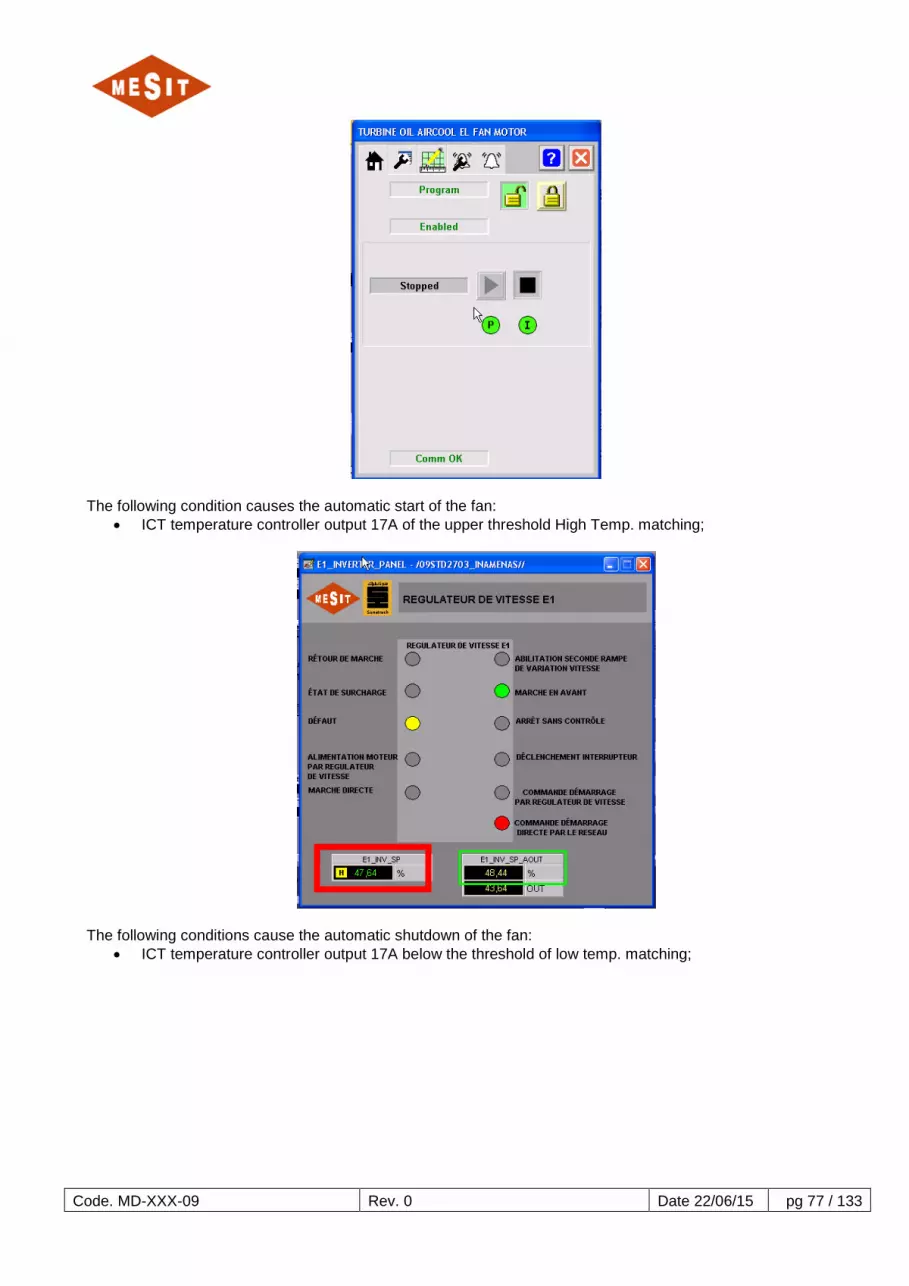
Code. MD-XXX-09 Rev. 0 Date 22/06/15 pg 77 / 133
The following condition causes the automatic start of the fan: • ICT temperature controller output 17A of the upper threshold High Temp. matching;
The following conditions cause the automatic shutdown of the fan: • ICT temperature controller output 17A below the threshold of low temp. matching;

Code. MD-XXX-09 Rev. 0 Date 22/06/15 pg 78 / 133
7.1.5.3 PRESENCE OF PRIORITY CONTROL (OVERRIDE)
No override mode is provided. 7.1.5.4 MANAGEMENT MANUAL OBJECT "E1 INV"
If the "Operator" mode is selected in the graphic object "AO TO INVERTER E1" fan speed can be adjusted manually, regardless of installation conditions.
7.1.5.5 AUTOMATIC MANAGEMENT OF THE OBJECT "E1 INV" If you select the "Operator" mode in the graphic object "AO TO INVERTER E1" fan speed tracks the value requested by the PIC 17A.

Code. MD-XXX-09 Rev. 0 Date 22/06/15 pg 79 / 133
7.1.5.6 FAULTS The following causes may cause the non-fan start:
1. Non-activated Drawer:
o Signalling:
Alarm "Not Start" E1_ALM1_ALM
o Action:
Enable and reset the MCC drawer 1
2. Intervention electrical protection MCC drawer 1:
o Signalling:
Alarm "Not Start" E1_ALM1_ALM
o Action:
Check the cause and reset the MCC drawer 1
3. UPS not available Table E1:
o Signalling:
Alarm "Not Start" E1_ALM1_ALM
o Action:
Reset the MCC drawer 1
4. Intervention Table E1 electrical inverter protections:
o Signalling:
Alarm "Not Start" E1_ALM1_ALM
o Action:
Check cause and reset Table E1 UPS
5. Intervention of specific protections E1 UPS:
o Signalling:

Code. MD-XXX-09 Rev. 0 Date 22/06/15 pg 80 / 133
Display on screen page E1 INV object colored yellow
Alarm not available Inverter: E1_INV_FAULT_FINE_IN_ALM
o Actions:
Check cause
Rearm E1 UPS by pressing the push button corresponding
Feed Table E2 UPS
6. API protection for Intervention:
o Signalling:
Alarm "Non-stop" E1_ALM2_ALM
o Action:
Check the cause and reset the MCC drawer 1
7. Open main switch:
o Signalling:
Showing override (override) on screen page
Alarm "open Main switch" MS_IN001_FINE_IN_ALM
o Action:
Check the cause and closing the main switch
8. Intervention Fire detection system and gas:
o Signalling:
View "Trigger system for detecting fires and gas": FG_ALM_GEN_ALM_FINE_IN_ALM
Alarm "open Main switch" MS_IN001_FINE_IN_ALM
Alarm "Not Start" E1_ALM1_ALM
o Action:
Wait until the intervention of the detection system Fire & Gas
Turn off main switch
Push Button Reset

Code. MD-XXX-09 Rev. 0 Date 22/06/15 pg 81 / 133
7.1.6 FAN OIL COOLER: T2BB Fans commands you have access to the relevant section in the screen page "LUBRICATING OIL TURBINE SYSTEM AND MOUTH". The electric fan control is performed by MCC drawer and a case containing an inverter. The graphic object is identified by the corresponding "E2" acronym for MCC drawer, and "E2 INV" to the inverter.
OBJECT E2
E2 INV OBJECT
It can be operated in manual and automatic modes. 7.1.6.1 MANAGEMENT MANUAL OBJECT E2
If you select the "Operator" mode the fan can be started and stopped manually, regardless of installation conditions.
7.1.6.2 AUTOMATIC MANAGEMENT OBJECT E2 If you select the "Program" mode the fan is automatically controlled, based on the installation conditions.

Code. MD-XXX-09 Rev. 0 Date 22/06/15 pg 82 / 133
The following condition causes the automatic start of the fan: • ICT temperature controller output 17A of the upper threshold High Temp. matching;
The following conditions provocano automatic shutdown della fan:
• ICT temperature controller output 17A below the threshold of low temp. matching;

Code. MD-XXX-09 Rev. 0 Date 22/06/15 pg 83 / 133
7.1.6.3 PRESENCE OF PRIORITY CONTROL (OVERRIDE) No override mode is provided.
7.1.6.4 MANAGEMENT MANUAL OBJECT "E2 INV" If the "Operator" mode is selected in the graphic object "AO TO INVERTER E1" fan speed can be adjusted manually, regardless of installation conditions.
7.1.6.5 AUTOMATIC MANAGEMENT OF THE OBJECT "E2 INV" If you select the "operator" mode in the graphic object "AO TO INVERTER E1" fan speed tracks the value requested by the PIC 17A.

Code. MD-XXX-09 Rev. 0 Date 22/06/15 pg 84 / 133
7.1.6.6 FAULTS
The following causes may cause the non-fan start: 1. Non-activated Drawer:
o Signalling:
Alarm "Not Start" E2_ALM1_ALM
o Action:
Enable and reset the MCC drawer 1
2. Intervention electrical protection MCC drawer 1:
o Signalling:
Alarm "Not Start" E2_ALM1_ALM
o Action:
Check the cause and reset the MCC drawer 1
3. UPS not available Table E2:
o Signalling:
Alarm "Not Start" E2_ALM1_ALM
o Action:
Reset the MCC drawer 1
4. Intervention Table E2 electrical inverter protections:
o Signalling:
Alarm "Not Start" E2_ALM1_ALM
o Action:
Check cause and reset Table E2 UPS
5. Intervention of specific protections UPS E2:
o Signalling:

Code. MD-XXX-09 Rev. 0 Date 22/06/15 pg 85 / 133
Display on screen page E2 INV object colored yellow
Alarm not available Inverter: E2_INV_FAULT_FINE_IN_ALM
o Actions:
Check cause
Reset E2 UPS by pressing the push button corresponding
Feed Table E2 UPS
6. API protection for Intervention:
o Signalling:
Alarm "Non-stop": E2_ALM2_ALM
o Action:
Check the cause and reset the MCC drawer 1
7. Open main switch:
o Signalling:
Showing override (override) on screen page
Alarm "open Main switch" MS_IN001_FINE_IN_ALM
o Action:
Check the cause and closing the main switch
8. Intervention Fire detection system and gas:
o Signalling:
View "Trigger system for detecting fires and gas": FG_ALM_GEN_ALM_FINE_IN_ALM
Alarm "open Main switch" MS_IN001_FINE_IN_ALM
Alarm "Not Start" E2_ALM1_ALM
o Action:
Wait until the intervention of the detection system Fire & Gas
Turn off main switch
Push Button Reset

Code. MD-XXX-09 Rev. 0 Date 22/06/15 pg 86 / 133
7.1.7 TURNING GEAR: VIR Tacking the commands you have access to the relevant section in the screen page "GEAR BOX WARDROBE." The corresponding graphic object is identified by the abbreviation "VIR."
VIR OBJECT
It can be operated in manual and automatic modes.
7.1.7.1 MANAGEMENT MANUAL If you select the "Operator" mode the understeer can be started and stopped manually, regardless of installation conditions.
7.1.7.2 AUTOMATIC MANAGEMENT If you select the "Program" mode the turning gear is handled automatically, based on the installation conditions.

Code. MD-XXX-09 Rev. 0 Date 22/06/15 pg 87 / 133
The following conditions cause the automatic start of tacking: • Very low pressure PT_1;
The following conditions cause the automatic shutdown of tacking: • NO PT_1 low pressure;
7.1.7.3 PRESENCE OF PRIORITY CONTROL (OVERRIDE)
VIR provides no way of Override.
7.1.7.4 FAULTS The following causes may cause the non-start tacking:
1. Intervention of electrical protection (HQ-DC):
o Signalling:
Switch open alarm HQ-DC MS_IN043_FINE_IN_ALM
Alarm "Not Start" VIR_ALM1_ALM
o Action:
Check the cause of the intervention and close HQ-DC
2. Anomaly starter CC:
o Signalling:
Alarm Fault start system KF-GTH50: MS_IN143_FINE_IN_ALM
Alarm "Not Start" VIR_ALM1_ALM
o Action:
Check the cause and reset the alarm "Malfunction KF-GTH50"
3. Intervention Fire detection system and gas:
o Signalling:
View "Trigger system for detecting fires and gas": FG_ALM_GEN_ALM_FINE_IN_ALM
Alarm "Not Start" VIR_ALM1_ALM
o Action:
Wait until the intervention of the detection system Fire & Gas

Code. MD-XXX-09 Rev. 0 Date 22/06/15 pg 88 / 133
7.1.8 AIR TREATMENT SYSTEM INSTRUMENTS: DRY-COOLER It has access to the controls of the air treatment system instruments by the relevant section in the screen page "AIR TURBINE INSTRUMENTATION". The corresponding graphic object is identified by the abbreviation "DRY".
OBJECT DRY
It can only be managed manually.
7.1.8.1 MANAGEMENT MANUAL The air drying system must be started manually using the selector in the corresponding MCC drawer 15. The video interface only allows to stop the device, by using the disconnect coil: after operation the drawer must be manually reset.
7.1.8.2 FAULTS The following causes may cause the non-starting the dryer:
1. Non-powered equipment: o Signalling:
Feedback walk NOT present;
o Action:
Powering the device via the switch on the MCC drawer 15
2. Non-activated Drawer:
o Signalling:
Feedback walk NOT present;
o Action:
Activate the drawer and power the unit using the switch on the MCC drawer 15

Code. MD-XXX-09 Rev. 0 Date 22/06/15 pg 89 / 133
3. Intervention of electrical protection:
o Signalling:
Feedback walk NOT present;
o Action:
Check the cause and power the unit using the switch on the MCC drawer 15
4. Open main switch:
o Signalling:
Feedback walk NOT present;
Alarm "open Main switch" MS_IN001_FINE_IN_ALM
o Action:
Check the cause and closing the main switch
5. Intervention Fire detection system and gas:
o Signalling:
View "Trigger system for detecting fires and gas": FG_ALM_GEN_ALM_FINE_IN_ALM
Alarm "open Main switch" MS_IN001_FINE_IN_ALM
Feedback walk NOT present;
o Action:
Wait until the intervention of the detection system Fire & Gas
Turn off main switch

Code. MD-XXX-09 Rev. 0 Date 22/06/15 pg 90 / 133
7.1.9 EXTRACTION OF SAND: S-EM1 It controls access to the extractor by the corresponding section in the screen page "PAGE CONTROL TURBINE". The corresponding graphic object is identified by the initials "S-EM1".
OBJECT S-EM1
It can be operated in manual and automatic modes.
7.1.9.1 MANAGEMENT MANUAL If you select the "Operator" extractor mode can be started and stopped manually, regardless of installation conditions.
7.1.9.2 AUTOMATIC MANAGEMENT If you select the mode "Programme" extractor is handled automatically, based on the installation conditions.

Code. MD-XXX-09 Rev. 0 Date 22/06/15 pg 91 / 133
The following conditions cause the automatic start of the extractor: • VIR on, or Turbine running;
The following conditions cause the automatic shutdown of the extractor: • None of the conditions that cause automatic operation;
7.1.9.3 PRESENCE OF PRIORITY CONTROL (OVERRIDE)
Regardless of the mode "Auto" or "Manual" in the presence of an override the extractor is turned off. For S-EM1 causes override are: Open main switch: MS_IN001_FINE_IN_ALM;
Presence Override (Override)
7.1.9.4 FAULTS The following causes may cause the non-start of the extractor:
1. Non-activated Drawer:
o Signalling:

Code. MD-XXX-09 Rev. 0 Date 22/06/15 pg 92 / 133
Alarm "Not Start" S_EM1_ALM1_ALM
o Action:
Enable and reset the MCC drawer 17
2. Intervention of electrical protection:
o Signalling:
Alarm "Not Start" S_EM1_ALM1_ALM
o Action:
Check the cause and reset the MCC drawer 17
3. API protection for Intervention:
o Signalling:
Alarm "Non-stop": S_EM1_ALM1_ALM
o Action:
Check the cause and reset the MCC drawer 17
4. Open main switch:
o Signalling:
Showing override (override) on screen page
Alarm "open Main switch" MS_IN001_FINE_IN_ALM
o Action:
Check the cause and closing the main switch
5. Intervention Fire detection system and gas:
o Signalling:
View "Trigger system for detecting fires and gas": FG_ALM_GEN_ALM_FINE_IN_ALM
Alarm "open Main switch" MS_IN001_FINE_IN_ALM
Alarm "Not Start" S_EM1_ALM1_ALM
o Action:
Wait until the intervention of the detection system Fire & Gas
Turn off main switch

Code. MD-XXX-09 Rev. 0 Date 22/06/15 pg 93 / 133
7.1.10 Cleaning system (PULSE JET): SQZ1 It has access to the commands of the cleaning system (Pulse Jet) by the corresponding section in the screen page "PAGE CONTROL TURBINE". The corresponding graphic object is identified by the abbreviation "SQZ1".
OBJECT SQZ1
It can be operated in manual and automatic modes.
7.1.10.1 MANAGEMENT MANUAL If one selects the "Operator" the cleaning system (Pulse Jet) can be started and stopped manually, regardless of installation conditions.
7.1.10.2 AUTOMATIC MANAGEMENT If one selects the "Program" the cleaning system (Pulse Jet) is handled automatically, based on the installation conditions.

Code. MD-XXX-09 Rev. 0 Date 22/06/15 pg 94 / 133
The following conditions cause the automatic start of the cleaning system: • PDH_32 response; • Manual control by HSSEM_1 local operator;
The following conditions cause the automatic shutdown of the cleaning system: • None of the conditions that cause automatic operation;
Automatic running condition lasts until at least one cycle of the cleaning system is completed.
7.1.10.3 PRESENCE OF PRIORITY CONTROL (OVERRIDE) Regardless of the mode "Auto" or "Manual" in the presence of an override the cleaning system is off. For SQZ1 causes override are:
• Open main switch: MS_IN001_FINE_IN_ALM; • S-EM1 not running;
Presence Override (Override)

Code. MD-XXX-09 Rev. 0 Date 22/06/15 pg 95 / 133
7.1.10.4 FAULTS The following causes may cause the non-starting the cleaning system (Pulse Jet):
1. Non-activated Drawer:
o Signalling:
Alarm "Not Start" SQZ1_ALM1_ALM
o Action:
Enable and reset the MCC drawer 19
2. Intervention of electrical protection:
o Signalling:
Alarm "Not Start" SQZ1_ALM1_ALM
o Action:
Check the cause and reset the MCC drawer 19
3. API protection for Intervention:
o Signalling:
Alarm "Non-stop": SQZ1_ALM2_ALM
o Action:
Check the cause and reset the MCC drawer 19
4. Open main switch:
o Signalling:
Showing override (override) on screen page
Alarm "open Main switch" MS_IN001_FINE_IN_ALM
o Action:
Check the cause and closing the main switch
5. Intervention Fire detection system and gas:
o Signalling:
View "Trigger system for detecting fires and gas": FG_ALM_GEN_ALM_FINE_IN_ALM
Alarm "open Main switch" MS_IN001_FINE_IN_ALM
Alarm "Not Start" SQZ1_ALM1_ALM
o Action:
Wait until the intervention of the detection system Fire & Gas
Turn off main switch

Code. MD-XXX-09 Rev. 0 Date 22/06/15 pg 96 / 133
7.1.11 INTERSTAGE AIR COOLER FAN EL. MOTOR It can be operated in manual and automatic modes.
7.1.11.1 MANAGEMENT MANUAL If you select the "Operator" mode the fan can be started and stopped manually, regardless of installation conditions.
7.1.11.2 AUTOMATIC MANAGEMENT If you select the "Program" mode the fan is automatically controlled, based on the installation conditions.
The following conditions cause the automatic start of the fan: Turbine ready to service;

Code. MD-XXX-09 Rev. 0 Date 22/06/15 pg 97 / 133
• High threshold reached for TE_3002; • Low threshold reached for TE_3002;
The following conditions cause the automatic shutdown of the fan: • None of the conditions that cause automatic operation;
7.1.11.3 FAULTS
The following causes may cause the cooler start: 1. Non-activated Drawer:
o Signalling: • Alarm "Not Start"
o Action: • Enable and reset the MCC drawer 5
1. Intervention of electrical protection:
o Signalling: • Alarm "Not Start"
o Action: • Check the cause and reset the MCC drawer 5
2. API protection for Intervention:
o Signalling: • Alarm "Non-stop"
o Action: • Check the cause and reset the MCC drawer 5
3. Open main switch:
o Signalling: • Showing override (override) on screen page • Alarm "open Main switch"
o Action: • Check the cause and closing the main switch
4. Intervention Fire detection system and gas:
o Signalling: • View "from Trigger Fires and Gas detection system" • Alarm "open Main switch" • Alarm "Not Start"
o Action: • Wait until the intervention of the detection system Fire & Gas • Turn off main switch

Code. MD-XXX-09 Rev. 0 Date 22/06/15 pg 98 / 133
7.1.12 COMPRESSOR SEAL/LUBE OIL MAIN & AUX EL. MOTOR It can be operated in manual and automatic modes.
7.1.12.1 MANAGEMENT MANUAL If you select the "Operator" mode the pump can be started and stopped manually, regardless of installation conditions.
7.1.12.2 AUTOMATIC MANAGEMENT If you select the "Program" mode the pump is handled automatically, based on the installation conditions.
The following conditions cause the automatic start of the pump:

Code. MD-XXX-09 Rev. 0 Date 22/06/15 pg 99 / 133
• Speed > 0; • PT_4308 Low Low threshold • PT_4308 Low threshold
7.1.12.3 FAULTS
The following causes may cause the non-starting of the pump: 1. Non-activated Drawer:
o Signalling:
Alarm "Not Start"
o Action:
Enable and reset the MCC drawer 6
2. Intervention of electrical protection:
o Signalling:
Alarm "Not Start"
o Action:
Check the cause and reset the MCC drawer 6
3. API protection for Intervention:
o Signalling:
Alarm "Non-stop"
o Action:
Check the cause and reset the MCC drawer 6
4. Open main switch:
o Signalling:
Showing override (override) on screen page
Alarm "open Main switch"
o Action:
Check the cause and closing the main switch
5. Intervention Fire detection system and gas:
o Signalling:
View "from Trigger Fires and Gas detection system"
Alarm "open Main switch"
Alarm "Not Start"
o Action:
Wait until the intervention of the detection system Fire & Gas
Turn off main switch

Code. MD-XXX-09 Rev. 0 Date 22/06/15 pg 100 / 133
7.1.13 COMPRESSOR SEAL/LUBE OIL EMERGENCY EL. MOTOR It can be operated in manual and automatic modes.
7.1.13.1 MANAGEMENT MANUAL If you select the "Operator" mode the pump can be started and stopped manually, regardless of installation conditions.
7.1.13.2 AUTOMATIC MANAGEMENT If you select the "Program" mode the pump is handled automatically, based on the installation conditions.
The following conditions (together) cause the automatic start of the pump:

Code. MD-XXX-09 Rev. 0 Date 22/06/15 pg 101 / 133
• LY_2820 STS_L or PT_1_STS_LL; • Not PT_03_L; • PT_4305 > 0.2
7.1.13.3 FAULTS
The following causes may cause the non-starting of the pump: 1. Non-activated Drawer:
o Signalling:
Alarm "Not Start"
o Action:
Enable and reset the MCC drawer 7
2. Intervention of electrical protection:
o Signalling:
Alarm "Not Start"
o Action:
Check the cause and reset the MCC drawer 7
3. API protection for Intervention:
o Signalling:
Alarm "Non-stop"
o Action:
Check the cause and reset the MCC drawer 7
4. Open main switch:
o Signalling:
Showing override (override) on screen page
Alarm "open Main switch"
o Action:
Check the cause and closing the main switch
5. Intervention Fire detection system and gas:
o Signalling:
View "from Trigger Fires and Gas detection system"
Alarm "open Main switch"
Alarm "Not Start"
o Action:
Wait until the intervention of the detection system Fire & Gas
Turn off main switch

Code. MD-XXX-09 Rev. 0 Date 22/06/15 pg 102 / 133
7.2 VALVES
7.2.1 STOP GAS FUEL VALVE: FGV1 The valve is shown in the "GAS VALVE TURBINE POWER". Next to it we find the signs of the states of:
• ZSH-1 opening limit; • ZSL-1 closing limit;
FGV1
The valve is controlled by means of air instruments, by the use of the solenoid valve "SOV-FGV-1" which is the "AIR TURBINE INSTRUMENTATION" page.
SOV-FGV-1
7.2.1.1 MANAGEMENT MANUAL Manual management of the valve is not possible
7.2.1.2 AUTOMATIC MANAGEMENT Automatic management of the valve is performed by the SOV-FGV-1.
Automatic opening: • The automatic opening is described in the chapter 6.6.3.2

Code. MD-XXX-09 Rev. 0 Date 22/06/15 pg 103 / 133
Automatic closing: • When triggered.
7.2.1.3 PRESENCE OF PRIORITY CONTROL (OVERRIDE)
In the presence of the master control valve is closed. The causes of priority order are: Triggering non-reset
Presence Override (Override)
7.2.1.4 FAULTS The following causes can cause erroneous operation of the valve:
1. Blown fuse: o Signalling:
• Alarm FGV_1_ALM1_ALM o Action:
• Find the cause and replace the fuse 2. End of non-infringement opening race:
o Signalling: • Alarm FGV_1_ALM1_ALM
o Action: • Check the travel of the valve and the acquisition of the limit switch
3. Plea of infringement closing stroke: o Signalling:
• Alarm FGV_1_ALM1_ALM o Action:
• Check the travel of the valve and the acquisition of the limit switch 4. Simultaneous reading of the closing limit switches and openness:
o Signalling: • Alarm FGV_1_ALM1_ALM
o Action: • Check the position of limit switches and their acquisition

Code. MD-XXX-09 Rev. 0 Date 22/06/15 pg 104 / 133
7.2.2 PURGE VALVE FUEL GAS: FGV6 The valve is shown in the "GAS VALVE TURBINE POWER". Next to it we find the signs of the states of:
• ZSH-6 opening limit; • ZSL-6: closing limit;
FGV6
The valve is controlled by means of air instruments, the use of SOV-V2G solenoid valve, which is the "AIR TURBINE INSTRUMENTATION"
SOV-V2G
7.2.2.1 MANAGEMENT MANUAL Manual management of the valve is not possible
7.2.2.2 AUTOMATIC MANAGEMENT Automatic management of the valve is performed by the SOV-V2G.
Automatic opening:
• The automatic opening is described in the chapter 6.6.3.2 Automatic closing:
• When triggered.

Code. MD-XXX-09 Rev. 0 Date 22/06/15 pg 105 / 133
7.2.2.3 PRESENCE OF PRIORITY CONTROL (OVERRIDE) In the presence of the master control valve is closed. The causes of priority order are:
• Triggering non-reset
Presence Override (Override)
7.2.2.4 FAULTS The following causes can cause erroneous operation of the valve:
1. Blown fuse: o Signalling:
• Alarm FGV_6_ALM1_ALM o Action:
• Find the cause and replace the fuse 2. End of non-infringement opening race:
o Signalling: • Alarm FGV_6_ALM1_ALM
o Action: • Check the travel of the valve and the acquisition of the limit switch
3. Plea of infringement closing stroke: o Signalling:
• Alarm FGV_6_ALM1_ALM o Action:
• Check the travel of the valve and the acquisition of the limit switch 4. Simultaneous reading of the closing limit switches and openness:
o Signalling: • Alarm FGV_6_ALM1_ALM
o Action: • Check the position of limit switches and their acquisition

Code. MD-XXX-09 Rev. 0 Date 22/06/15 pg 106 / 133
7.2.3 ISOLATION VALVE FUEL GAS: FGV4 The valve is shown in the "GAS VALVE TURBINE POWER". On his side are the indications of the states of:
• ZSH-4: opening limit; • ZSL-4: closing limit;
FGV4
The valve is controlled by means of air instruments, the use of SOV-V1G solenoid valve, which is the "AIR TURBINE INSTRUMENTATION"
SOV-V1G
7.2.3.1 MANAGEMENT MANUAL Manual management of the valve is not possible
7.2.3.2 AUTOMATIC MANAGEMENT Automatic management of the valve is performed by the SOV-V1G.
Automatic opening: • The automatic opening is described in the chapter 6.6.3.2
Automatic closing:

Code. MD-XXX-09 Rev. 0 Date 22/06/15 pg 107 / 133
• When triggered.
7.2.3.3 PRESENCE OF PRIORITY CONTROL (OVERRIDE) In the presence of the master control valve is closed. The causes of priority order are:
• Triggering non-reset
Presence Override (Override)
7.2.3.4 FAULTS The following causes can cause erroneous operation of the valve:
1. Blown fuse: o Signalling:
• Alarm FGV_4_ALM1_ALM o Action:
• Find the cause and replace the fuse 2. End of non-infringement opening race:
o Signalling: • Alarm FGV_4_ALM1_ALM
o Action: • Check the travel of the valve and the acquisition of the limit switch
3. Plea of infringement closing stroke: o Signalling:
• Alarm FGV_4_ALM1_ALM o Action:
• Check the travel of the valve and the acquisition of the limit switch 4. Simultaneous reading of the closing limit switches and openness:
o Signalling: • Alarm FGV_4_ALM1_ALM
o Action: • Check the position of limit switches and their acquisition
7.2.4 VALVE ANTISURGE: VBY The valve is shown in the "AIR TURBINE INSTRUMENTATION". Next to it we find the signs of the states of:
• ZSH-VBY: opening limit;

Code. MD-XXX-09 Rev. 0 Date 22/06/15 pg 108 / 133
• ZSL-VBY: closing limit;
VBY
The valve is controlled by means of air instruments, by the use of the SOV-10 solenoid valve, which is on the same page.
SOV-10
7.2.4.1 MANAGEMENT MANUAL Manual management of the valve is not possible
7.2.4.2 AUTOMATIC MANAGEMENT Automatic management of the valve is performed by the SOV-10.
Automatic opening:
• The automatic opening is described in the chapter 6.6.3.2 Automatic closing:
• In the absence of the opening control. 7.2.4.3 PRESENCE OF PRIORITY CONTROL (OVERRIDE)
For this valve management override is NOT intended. 7.2.4.4 FAULTS
The following causes can cause erroneous operation of the valve: 1. Blown fuse:
o Signalling:
Code. MD-XXX-09 Rev. 0 Date 22/06/15 pg 109 / 133
Alarm SOV_10_EVB_ALM1_ALM
o Action:
Find the cause and replace the fuse
2. End of non-infringement opening race:
o Signalling:
Alarm SOV_10_EVB_ALM1_ALM
o Action:
Check the travel of the valve and the acquisition of the limit switch
3. Plea of infringement closing stroke:
o Signalling:
Alarm SOV_10_EVB_ALM1_ALM
o Action:
Check the travel of the valve and the acquisition of the limit switch
4. Simultaneous reading of the closing limit switches and openness:
o Signalling:
Alarm SOV_10_EVB_ALM1_ALM
o Action:
5. Check the position of limit switches and their acquisition
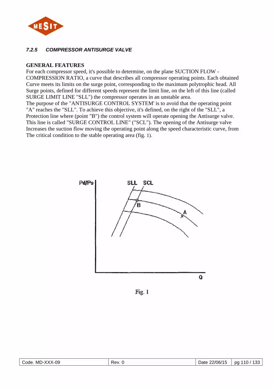
Code. MD-XXX-09 Rev. 0 Date 22/06/15 pg 110 / 133
7.2.5 COMPRESSOR ANTISURGE VALVE
GENERAL FEATURES For each compressor speed, it's possible to determine, on the plane SUCTION FLOW - COMPRESSION RATIO, a curve that describes all compressor operating points. Each obtained Curve meets its limits on the surge point, corresponding to the maximum polytrophic head. All Surge points, defined for different speeds represent the limit line, on the left of this line (called SURGE LIMIT LINE "SLL") the compressor operates in an unstable area. The purpose of the "ANTISURGE CONTROL SYSTEM' is to avoid that the operating point "A" reaches the "SLL". To achieve this objective, it's defined, on the right of the "SLL", a Protection line where (point "B") the control system will operate opening the Antisurge valve. This line is called "SURGE CONTROL LINE" ("SCL"). The opening of the Antisurge valve Increases the suction flow moving the operating point along the speed characteristic curve, from The critical condition to the stable operating area (fig. 1).

Code. MD-XXX-09 Rev. 0 Date 22/06/15 pg 111 / 133
SYMBOLS LEGEND N = compressor speed KI, K2, K3, K4 = constant Qs = volumetric flow Hp = polytrophic head Pd = discharge pressure Ps = suction pressure Z = compressibility factor R = gas constant T = gas absolute temperature n = polytrophic head exponent f3 = characteristic orifice constant hs = dp across the orifice ]'S = suction gas density PSA = absolute suction pressure PDA = absolute discharge pressure PSD = design suction pressure K = deviation margin Sl1 = surge limit line Scl = surge control line Pv = process variable (compressor operating point) ANTISURGE CONTROL LAW Considering a monostage centrifugal compressor, it is possible to verify the followings relations, varing the compressor speed, for each surge point:

Code. MD-XXX-09 Rev. 0 Date 22/06/15 pg 112 / 133

Code. MD-XXX-09 Rev. 0 Date 22/06/15 pg 113 / 133

Code. MD-XXX-09 Rev. 0 Date 22/06/15 pg 114 / 133

Code. MD-XXX-09 Rev. 0 Date 22/06/15 pg 115 / 133

Code. MD-XXX-09 Rev. 0 Date 22/06/15 pg 116 / 133

Code. MD-XXX-09 Rev. 0 Date 22/06/15 pg 117 / 133

Code. MD-XXX-09 Rev. 0 Date 22/06/15 pg 118 / 133

Code. MD-XXX-09 Rev. 0 Date 22/06/15 pg 119 / 133

Code. MD-XXX-09 Rev. 0 Date 22/06/15 pg 120 / 133
8 SCHEDULES

Code. MD-XXX-09 Rev. 0 Date 22/06/15 pg 121 / 133
8.1 DISPLAY HISTORICAL DATA (HISTORIAN VIEWER) 8.1.1 MAIN WINDOW OF THE HISTORIAN VIEWER All functions are executed in this window (Figure 8-1)
Figure 8-1
Open New Trend (open new trend):
Click on the push button "New Trend" (new trend) Trends to open a window and add the push button on the window bar. New Open Table (open new table):
"New Table" (new table) , Application is not available in this project. Open Trend RealTime (open real-time trend, only if the function is installed):
"Open RealTime Trend" , Application is not available in this project. Auto Point Open Search (open automatic search points):
Click on the push button "Open Point Auto Search" to open the search window automatically points (Point Auto Search). Historian Viewer Setting (Setting the display of historical data):
Click on the push button "Setting" to select from "User Setting" (user settings), "Function Level Setting" (function level setting) and "Database Connection Setting" (connection settings database) (Figure 8-2)
Figure 8-2
Change User (switch user):
Click on the pushbutton "Change User" to change the current user.

Code. MD-XXX-09 Rev. 0 Date 22/06/15 pg 122 / 133
Application Exit (exit the application):
Click on the push-button Release Historian Viewer to exit. Selecting windows to open: Any trend window or table can be selected Historian Viewer using the Windows Menu (Figure 8-3)
Figure 8-3
Click with the left mouse button on the name of the desired window to open. Click with the left mouse button on "Close All Windows" (close all windows) to close all open windows.
8.1.2 VIEW TREND (TREND DISPLAY)
Figure 8-4
Add New Plots (add new plots):
Click on the push button "Insert Point" (enter point) (Figure 8-4) To open the window below that allows the user to select the data set table. (Figure 8-5).

Code. MD-XXX-09 Rev. 0 Date 22/06/15 pg 123 / 133
Figure 8-5
Select Table Source in the first list box (listBox). In the second list box, the data points (data points) existing appear. Select the item in the second list box (multiple selections Points allowed). Select or délectionner the "From Data" filter (data) and "To Data" (up given). Select the font color. (Only if the user selects only one item, the multiple points are colored randomly).
Click the acceptance push button to draw the point.
Click on the push-button Release to close the window. Plots Delete (delete points):
Click on the push-button to open the list of Points (fig.8).
Figure 8-6
Select the item in the listbox (multiple selections are allowed).
Click the acceptance push button to delete the selected points of the trend.
Click on the push-button release to close the window.
8.1.3 DISPLAY OF LEGENDS

Code. MD-XXX-09 Rev. 0 Date 22/06/15 pg 124 / 133
Figure 8-7
A list of tracks (Plots) loaded is shown in the bottom of the trend, and allows the user to know the current path for each color, the name e the value by using the Cursor Mode (Cursor Mode). Zoom Mode (Zoom mode)
Click on the pushbutton "Zoom enable mode" (activate zoom mode) (Fig. 6) to zoom in on the plot area. Scroll Mode (Scroll mode):
Click on the pushbutton "Scroll enable mode" (enable scroll mode) (Fig. 6) to move the display patterns on the X axis and on the Y axis Cursor mode (cursor mode):
Click on the pushbutton "Cursor enable mode" (enable cursor mode) (Fig. 6) to review the plot area with a cross cursor and display the value of the X axis and Y axis The slider allows the user to see the current value for each line of the trend by the display of captions (Fig.9). Y Axis Reset (resetting Y axis status): Click on the push button "reset Y" (resetting state Y) to resize the Y axis according to the current points range.

Code. MD-XXX-09 Rev. 0 Date 22/06/15 pg 125 / 133
Reset X Axis (resetting state X-axis): Click on the push button "reset X" (resetting state X) to resize the Y axis as the selected range of time from the scroll bar. ScrollBar (scroll bar): The scroll bar resizes the axis X visibility range of 1 minute minimum up to a maximum of 3 days. Trend ConFiguretion (conFiguretion of the trend) Click with the right mouse button on the pushbutton Plots Area (plot area) to open the popup to display menu with multiple functionality. Configuring Points
Figure 8-8
Click "Select" (select) to set the current range of the Y axis with the selected item. Click on "Visible" to enable or disable the visibility of the item selected. Click "Change Line Color" (change the line color) to set a new color for the selected item. Grid conFiguretion
Figure 8-9
Check "Enable Grid" (enable grid) to enable or disable the grid line on the Path area. Click on "Set Y Axis Grid Division" (set Y axis grid division) to select the number of divisions of the grid on the Y axis Click on "Set X Axis Grid Division" (set X axis grid division) to select the number of divisions of the grid on the X axis

Code. MD-XXX-09 Rev. 0 Date 22/06/15 pg 126 / 133
Plot ConFiguretion
Figure 8-10
Click on "Auto Update Enable" (enable automatic updates) to activate the update in real time from the plots with the databases that do not have a maximum time limit. Click "Only Real Plot Points" (draw only real points) to draw, for each plot, only Actual Points. Click on "Set Line width" (adjust line width) to set the width of the line of the route. Colour Settings
Figure 8-11
Click on "Background Color" (background color) to change the background color of the plot area. Click on "Cursor Color" (cursor color) to change the color of the cross cursor.
8.1.4 SAVE / LOAD SETTING TRACKS This tool allows the user to record Historian Viewer in a set of selected paths with a name. The entire conFiguretion is always available for reloading.
Figure 8-12
Save settings
Click on the recording-button (Fig.14) to open a new dialog box in which the user can enter the name of the ConFiguretion and choose whether to share settings with other users or not (fig.15)

Code. MD-XXX-09 Rev. 0 Date 22/06/15 pg 127 / 133
Figure 8-13
Enter the name, choose a private or public use and click on the Accept button to save the conFiguretion (if the conFiguretion name already exists, the Utilsiateur can overwrite or not).
Click on the push-button Release to close the window without saving. Load settings
Click on the loading pushbutton (Fig.14) to open a new dialog box in which the user can select the settings to load. (Fig.16)
Figure 8-14
Select settings in the list on the left. Users may see an expected list of saved tracks to the right.
Click the acceptance push button to open the selected settings.
Click on the push-button deletion to delete the selected settings.
Click on the push-button Release to close the window. Save / load settings of the trend This tool allows the recording in a Viewer Historian ConFiguretion tendency User (Grid Colors Grid Division etc.).
Figure 8-15
Save settings
Click on the recording-button (Fig.17) to open a new dialog box in which the user can enter the name of the ConFiguretion and choose whether to share settings with other users or not (fig.18).

Code. MD-XXX-09 Rev. 0 Date 22/06/15 pg 128 / 133
Figure 8-16
Enter the name, choose the private or public use and click on the Accept button to save the conFiguretion (if the conFiguretion name already exists, the user can overwrite it or not).
Click on the push-button Release to close the window without saving. LOADING SETTINGS
Click on the loading pushbutton (Fig.17) to open a new dialog box in which the user can select the settings to load.
Figure 8-17
Click the Default button to load the default settings of Trend Setting selected for the current user (the default settings are automatically loaded to view the trend window).
Click the acceptance push button to open the selected settings.
Click on the push-button deletion to delete the selected settings.
Click on the push-button Release to close the window. 8.1.4.1 CSV EXPORT TO DATA
Figure 8-18

Code. MD-XXX-09 Rev. 0 Date 22/06/15 pg 129 / 133
Click on the push button "Export to CSV ..." (export to CSV) the Trend Menu (trend), enter a file name and click on the registration push button. Exporting create a file with two columns for each route, one for the X axis and one for the Y axis The Excel software to open a CSV file with more than 65000 rows.
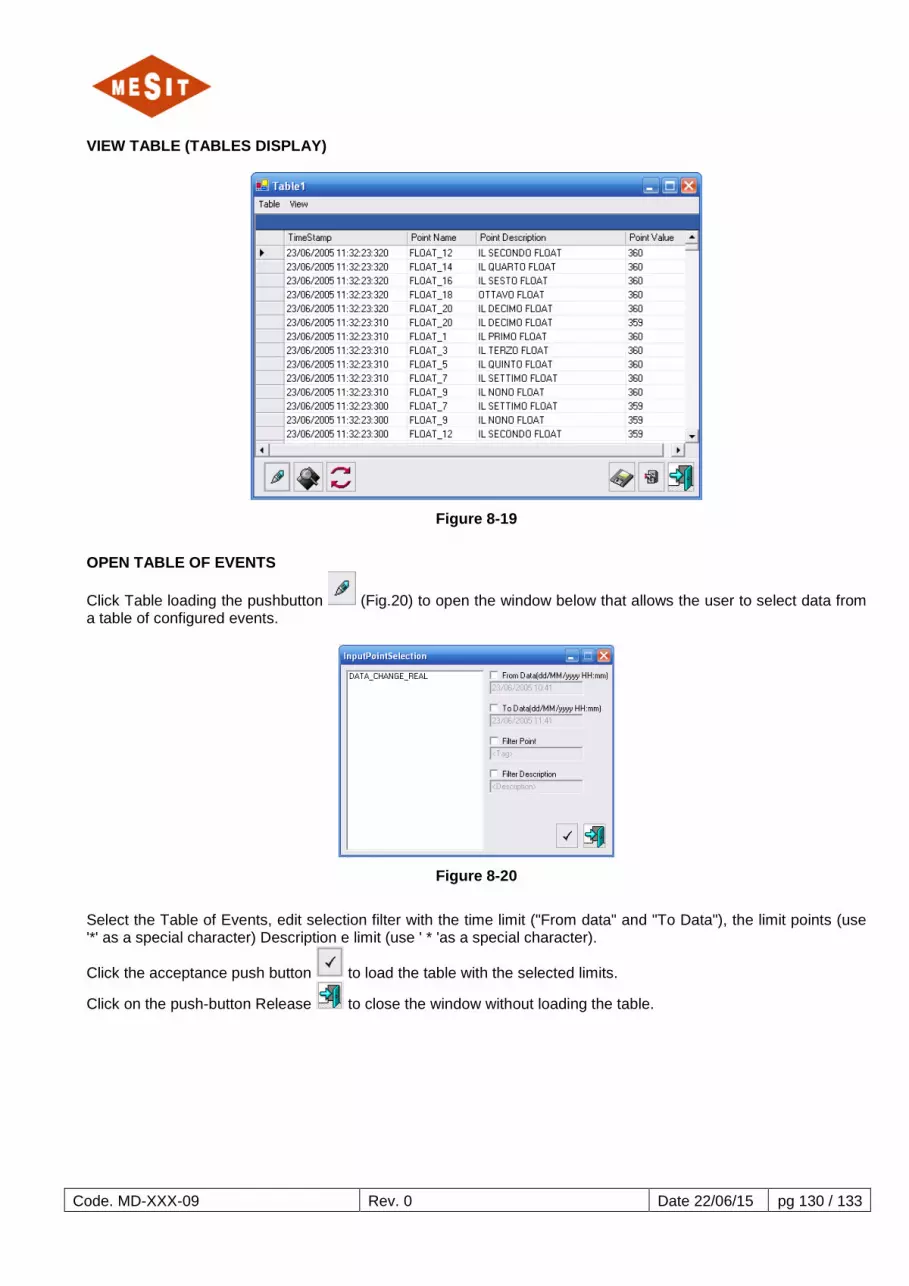
Code. MD-XXX-09 Rev. 0 Date 22/06/15 pg 130 / 133
VIEW TABLE (TABLES DISPLAY)
Figure 8-19
OPEN TABLE OF EVENTS
Click Table loading the pushbutton (Fig.20) to open the window below that allows the user to select data from a table of configured events.
Figure 8-20
Select the Table of Events, edit selection filter with the time limit ("From data" and "To Data"), the limit points (use '*' as a special character) Description e limit (use ' * 'as a special character).
Click the acceptance push button to load the table with the selected limits.
Click on the push-button Release to close the window without loading the table.

Code. MD-XXX-09 Rev. 0 Date 22/06/15 pg 131 / 133
EDIT THE FILTER SELECTION
Click on the Remove pushbutton éditation to open the dialog box of the filter table Current Events.
Figure 8-21
Edit the settings and click the accept button to confirm the changes.
Click on the push-button Release to close the window without editing the filter selection. REFRAÎCHIR TABLE OF EVENTS
Click on the pushbutton Refraîchir to reload the current table from the database. Save / load settings table This tool allows the viewer to record Historian in Table settings with a name User. All conFiguretions are always available for reloading.
Click on the recording-button (Fig.20) to open a new dialog box in which the user can enter the name of the ConFiguretion and choose whether to share settings with other users is not.
Figure 8-22
Click on the loading pushbutton (Fig.20) to open a new dialog box in which the user can select the settings to load.

Code. MD-XXX-09 Rev. 0 Date 22/06/15 pg 132 / 133
Figure 8-23
Select Table Settings from the list e click the accept button to load the selected table settings.
Click on the push-button deletion to delete the selected settings.
Click on the push-button Release to close the window without loading table settings. Export to CSV data
Figure 8-24
Click on the push button "Export to CSV ..." (export to CSV) from the Table menu (Table), enter a file name and click on the registration push button. The Excel does not open a CSV file with more than 65000 rows. RESEARCH POINTS AUTOMATIC
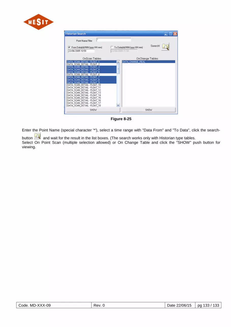
Code. MD-XXX-09 Rev. 0 Date 22/06/15 pg 133 / 133
Figure 8-25
Enter the Point Name (special character '*'), select a time range with "Data From" and "To Data", click the search-
button and wait for the result in the list boxes. (The search works only with Historian type tables. Select On Point Scan (multiple selection allowed) or On Change Table and click the "SHOW" push button for viewing.


