Embed Size (px)
Citation preview

E-BOOKjanuary 2020
Manure Disposal
dealer information
T h e b e n e f i t s o f c o m f o r t

hisTory
spinder since 1973
Read instruction:Green pages Main programRed pages Items for projects and/or service. These are non-stock items that have a lead time of approximately 6 to 8 weeks from order to delivery.
The copyrights of this publication are held by Spinder Dairy Housing Concepts B.V., Harkema, The Netherlands.This publication or part thereof may be reproduced, in any form or by any means, subject to the prior written permissionof Spinder Dairy Housing Concepts B.V. stating: "Source: Spinder Dairy Housing Concepts brochure".Specifications, illustrations and instructions are not binding and may be subject to changes.
Tjip Spinder started manufacturing and selling dividers and feed fronts in 1973, using the name Spinder Stalinrichting. What started as a metal workshop, quickly became a small factory and eventually grew into Spinder as we know it today: a leading, advanced manufacturing company with a modern range for contemporary dairy farms.
Tjip Spinder was a real all-rounder and expected the same from his employees. “You were given an overall and a task and that was it”, says Dick van der Meer, employee since the start and now co-foreman in the assembly department. With the ink barely dry on his technical school diploma, he went to see Tjip Spinder in 1973 to ask if there was work for him and was told he could start immediately. “Tjip set high standards. Not just for commitment and quality, but also for behaviour. But he didn’t go easy on himself either. He was the first to arrive at work at six in the morning and he would only go home late at night when his wife decided that enough was enough and came to fetch him. They lived next door to the workshop.”
Spinder has always responded to developments in dairy farming. As livestock increased, so did manufacturing and the range changed along with the requirements and insights of farmers. Especially in the 70s and 80s of the last century, the period that farmers opted for cubicle systems en masse, Spinder experienced considerable growth.
Spinder’s growth during the early years was mostly thanks to two good friends of Tjip, who both owned a construction company. They were barn builders and introduced Spinder when the barns they built also needed equipment. When son
Pieter took the reins, he made some changes and implemented innovations. This caused a large improvement in efficiency. It was no longer expected that everyone could do ‘everything’: the work was divided over various departments. After Pieter, who went to Canada to run a farm, Spinder ceased to be a family-run company in 1995 and was taken over by management. The company is still owned by the board.
Production manager Sjouke van der Meer joined Spinder in 1981. Like Dick van der Meer, he has seen many changes within the company: “Highlights, growth, less successful periods, changes to management, product innovation, you name it. But one thing has remained unchanged and that’s the commitment of all colleagues to Spinder. Although Spinder hasn’t been a family-run business since 1995, it still feels like family here. And just like in 1973, the bar is still set high. Everything that leaves these premises is of absolute top quality. We are proud of that and that’s what we work for, together.”
In 2017 Spinder acquired the BUC brand, specialist in dual waterbeds.
As market dynamics are demanding Spinder has had a new premises build, fully in operation from 2020.

Manure disposal
Manure disposal 00 31 (0)512 - 237800 E-mail: [email protected] Website: spinderdhc.com january 2020
Manure disposal
• Manurescrapers 6.1
• DriveunitsforPE-ropescrapersystems 6.1A
• Controlpanels 6.2
• Slattedfloorscrapers 6.3
• Solidfloorscrapers 6.4
• Slottedfloorscrapers 6.5
• Manurescrapersinpractice 6.6
• Components 6.6A
• Tractordrivenmanuremixers 6.7
• Electricdrivenmanuremixers 6.9

Manure disposal 00 31 (0)512 - 237800 E-mail: [email protected] Website: spinderdhc.com january 2020
manure scrapers 6.1
Scraper with Spinder PE rope drive
In order to be able to work quickly and efficiently and to promote the welfare of your cows, it is important that passages and cubicles in the barn are clean and dry. For that reason, the proper and rapid removal of manure will be necessary. Moisture and manure on floors may cause sliding and falling and constitute excellent breeding places for pathogenic bacteria. These are often the cause of serious leg and hoof problems. Besides, the manure stuck on the legs of the cows make for dirty stalls and, as a consequence, for dirty udders.To prevent these problems, Spinder offers a manure-scraper unit consisting of two drive units with drive drum, a number of plastic corner wheels and one or more scrapers that are driven by Spinder PE rope. A very animal-friendly and maintenance-free installation with which the floors can be kept clean and dry.
Important features:• The system consists of two drive drums, which can be placed
both on a console and on the floor;• The unit is constructed in a heavy and robust manner. Virtually
all parts have been hot-dip galvanized;• The synthetic corner pulleys are maintenance-free;• Spinder PE rope is an 8 or 10 mm thick synthetic rope with a
tensile strength of 6000 and 9000 kg respectively, and a negli-gible stretch (ca. 3 a 4 %) to ensure a smooth, quiet run of the scraper. The rope has a long service life and is above all very animal-friendly;
• Standard fitted with digital timer, frost protection and emer-gency stop;
• A suitable solution for every barn, even with unequal passage lengths;
• Most suitable for an odd number of dung passages.
Important advantages:• Cleaner passages and cleaner livestock;• Less hoof problems and cleaner stalls;• Using less sawdust or straw;• Milking more hygienically and faster with cleaner cows;• Therefore, a better milk quality.
Dung scrapersAs well as driving a slatted floor scraper, the Spinder PE rope drive can also be used for driving the combi-scrapers.
65.12.455 Drive unit PE-rope on console, 0,55 kW65.12.465 Drive unit PE-rope on console, 0,75 kW65.12.450 Drive unit PE-rope for concrete floor, 0,55 kW65.12.460 Drive unit PE-rope for concrete floor, 0,75 kW
65.12.130 Mounting set drive unit for grid floor65.12.140 Mounting set drive unit for concrete floor
65.12.185 Corner wheel/PE-rope/for grid floor65.12.180 Corner wheel/PE-rope/for concrete floor
65.12.175 Scraper stop for grid floor65.12.170 Scraper stop for concrete floor
65.84.125 Spinder PE-rope 10 mm, per meter
• Rope scraper for grid floors with Spinder PE-rope in a situation with 3 alleys
• Rope driven
• Drive unit on console
M
M
Manure disposal 00 31 (0)512 - 237800 E-mail: [email protected] Website: spinderdhc.com january 2020
drive units for PE-rope scraper systems 6.1A
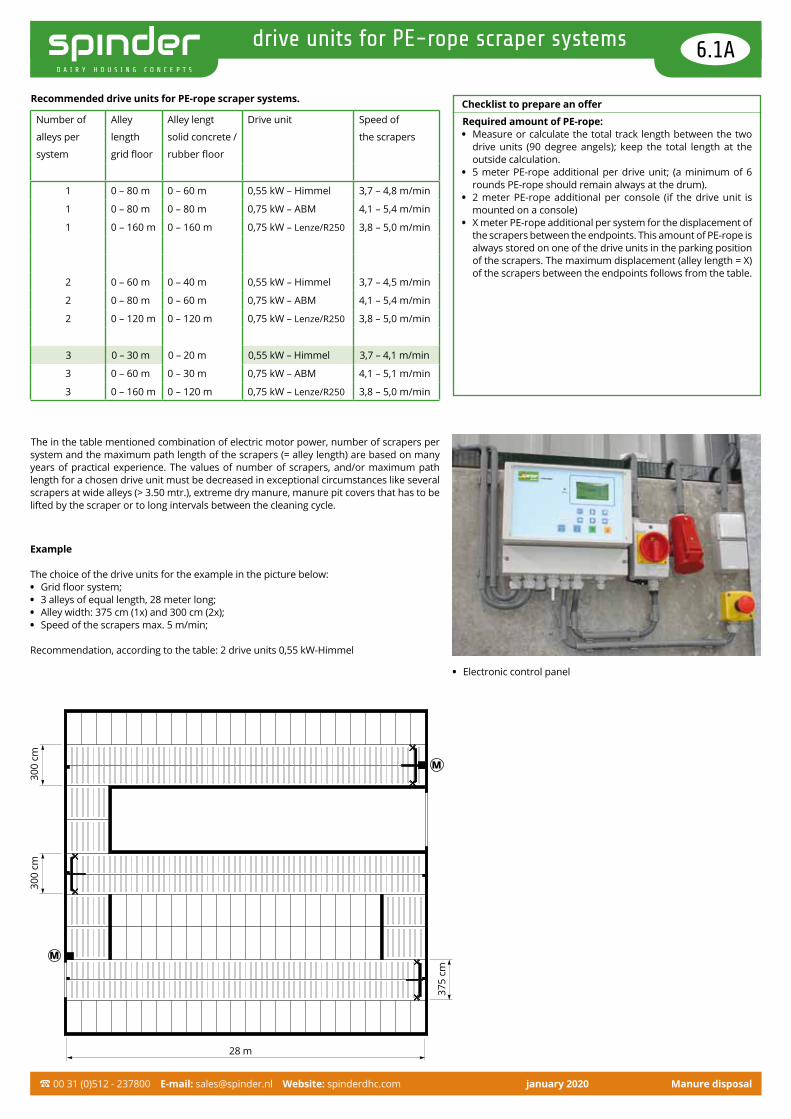
Checklist to prepare an offer
Required amount of PE-rope:• Measure or calculate the total track length between the two
drive units (90 degree angels); keep the total length at the outside calculation.
• 5 meter PE-rope additional per drive unit; (a minimum of 6 rounds PE-rope should remain always at the drum).
• 2 meter PE-rope additional per console (if the drive unit is mounted on a console)
• X meter PE-rope additional per system for the displacement of the scrapers between the endpoints. This amount of PE-rope is always stored on one of the drive units in the parking position of the scrapers. The maximum displacement (alley length = X) of the scrapers between the endpoints follows from the table.
M
M
28 m
375
cm
Example
The choice of the drive units for the example in the picture below:• Grid floor system;• 3 alleys of equal length, 28 meter long;• Alley width: 375 cm (1x) and 300 cm (2x);• Speed of the scrapers max. 5 m/min;
Recommendation, according to the table: 2 drive units 0,55 kW-Himmel
Recommended drive units for PE-rope scraper systems.
The in the table mentioned combination of electric motor power, number of scrapers per system and the maximum path length of the scrapers (= alley length) are based on many years of practical experience. The values of number of scrapers, and/or maximum path length for a chosen drive unit must be decreased in exceptional circumstances like several scrapers at wide alleys (> 3.50 mtr.), extreme dry manure, manure pit covers that has to be lifted by the scraper or to long intervals between the cleaning cycle.
300
cm30
0 cm
• Electronic control panel
Number of
alleys per
system
Alley
length
grid floor
Alley lengt
solid concrete /
rubber floor
Drive unit Speed of
the scrapers
1 0 – 80 m 0 – 60 m 0,55 kW – Himmel 3,7 – 4,8 m/min
1 0 – 80 m 0 – 80 m 0,75 kW – ABM 4,1 – 5,4 m/min
1 0 – 160 m 0 – 160 m 0,75 kW – Lenze/R250 3,8 – 5,0 m/min
2 0 – 60 m 0 – 40 m 0,55 kW – Himmel 3,7 – 4,5 m/min
2 0 – 80 m 0 – 60 m 0,75 kW – ABM 4,1 – 5,4 m/min
2 0 – 120 m 0 – 120 m 0,75 kW – Lenze/R250 3,8 – 5,0 m/min
3 0 – 30 m 0 – 20 m 0,55 kW – Himmel 3,7 – 4,1 m/min
3 0 – 60 m 0 – 30 m 0,75 kW – ABM 4,1 – 5,1 m/min
3 0 – 160 m 0 – 120 m 0,75 kW – Lenze/R250 3,8 – 5,0 m/min

Manure disposal 00 31 (0)512 - 237800 E-mail: [email protected] Website: spinderdhc.com january 2020
drive for spinder PE rope 6.1B
• 0,75 kW drive unit on console
• Detail of adjustable band brake on a 0,55 kW drive station (protective cover removed)
• Drive unit R250 / 0,75 kW
Drive for Spinder PE rope
All drives for Spinder PE rope installations consist of a robust, hot-dip galvanized frame containing a winding drum for the PE rope. On one side, the winding drum is fitted with a heavy-duty, maintenance-free bearing block; on the other side, the motor reductor is mounted directly onto the shaft of the winding drum. All winding drums are fitted with an adjustable band brake, except for the winding drum of the Turtle drive station. The unwinding speed of the Turtle drive station is so low, that an additional band brake is not required for controlled rope unwinding.
The drive stations can be placed either directly onto the floor or onto a console. The drives for direct mounting onto the floor come with an ad-ditional protective cover to shield the rope entry. The drive stations on console come complete with a plastic wind-ing reel at the base of the console.
Drive station 0,55 kW
- Himmel motor reductor in cast iron housing - Drum diameter Ø 200 mm - Scraper speed 3,7 - 4,5 m/min
65.12.455 drive unit Himmel-0,55 kW on console65.12.450 drive unit Himmel-0,55 kW on concrete floor
Drive station 0,75 kW
- ABM motor reductor in aluminium housing - Drum diameter Ø 200 mm - Scraper speed 4,1 - 5,4 m./min.
65.12.465 drive unit ABM-0,75 kW on console65.12.460 drive unit ABM-0,75 kW on concrete floor
Drive station R250 / 0,75 kW
- Lenze motor reductor in cast iron housing - Drum diameter Ø 250 mm - Scraper speed 3,8 - 5,0 m./min.
65.12.645 drive unit R250/0,75 kW on console65.12.640 drive unit R250/0,75kW on concrete floor
Accessories65.12.130 mounting set drive unit for grid floor65.12.140 mounting set drive unit for concrete

Manure disposal 00 31 (0)512 - 237800 E-mail: [email protected] Website: spinderdhc.com january 2020
drive for spinder PE rope 6.1C
Drive station 0,75 kW
• ABM motor reductor in aluminium housing • Scraper speed 4,1 – 5,4 m./min.
65.12.460 Drive unit ABM-0,75 kW on concrete floor65.12.465 Drive unit ABM-0,75 kW on console
61.23.302 Drive unit EWB3/4 0,75kW (1 to 6)61.23.305 Motor plus reduction 0.75 kW for EWB4 (1)
• Model: FGA1353 • Gear ratio: 216 • Rated voltage: 230 / 400 V • Rated current: 3,45 / 2,0 A • Rated frequency: 50 Hz • Hollow shaft, diameter: 50 mm
61.23.315 Driving drum for EWB4 and EWB3 0.75 kw (3 to 6) • Drum diameter: Ø 200 mm • Drum width: 180 mm • Shaft end: 50 mm • with brake band
61.23.230 Bearing unit UCP208 for axis 40 mm (3)61.23.210 Brake volumes for 0,55/0,75 KW drive (4)61.23.320 Driving reel for EW4 0,75 kW (5)61.23.225 Frame for EW4 (6)
Drive station 0,55 kW
• Himmel motor reductor in cast iron housing • Scraper speed 3,7 – 4,5 m./min.
65.12.450 Drive unit Him-0,55 kW on concrete floor65.12.455 Drive unit Himmel-0,55 kW on console
61.23.202 Drive unit EWB3/4 0,55 kW (1 to 6)61.23.207 Motor plus reduction 0,55 kW Himmel (1) • Model: FDAZ41 • Gear ratio: 237 • Rated voltage: 230 / 400 V • Rated current: 2,8 / 1,6 A • Rated frequency: 50 Hz • Hollow shaft, diameter: 40 mm
61.23.215 Driving drum with frame for EWB4 and (3 to 6) • Drum diameter: Ø 200 mm • Drum width: 180 mm • Shaft end: 40 mm • with brake band
61.23.230 Bearing unit UCP208 for axis 40 mm (3)61.23.210 Brake volumes for 0,55/0,75 KW drive (4)61.23.220 Driving reel for EWB4 0,55 kW (5)61.23.225 Frame for EW4 (6)
When the 0,55 kW drive station came with a Flender Himmel motor reductor (blue colour) at the time and it needs to be replaced, we will supply the 0,55 kW Himmel model (61.23.207). The motor flange must also be replaced before mounting.
61.23.208 Motor flange for motor reduction 0,55 kW
Motor plus reduction (1) Driving reel (5)
Frame (6) Motor flange (2)
435
6
2
1

Manure disposal 00 31 (0)512 - 237800 E-mail: [email protected] Website: spinderdhc.com january 2020
control panels 6.2
All Spinder PE rope installations can be controlled using the Prinzing electronic control panels. The operating procedure of the electronic control panels is based on continuously measuring the power consumption of the drive mo-tor. The drive motor is turned off when the set value for maximum traction / power consumption is exceeded.
Important features of the Prinzing control panel:• Continuous traction measurement by measuring the power consumption
from drive motor;• Automatic or manual setting maximum traction / power consumption;• Possibility for various values for maximum traction / power consumption
with direction of movement forward or in reverse;• Automatic program start on the freely programmable starting times in the
integrated timer;• Automatic program start via temperature sensor (frost program);• Connection for external control elements (e.g. push buttons, safety switch
strips, emergency stops, etc.) and an external fault signal (siren).
• Electronic control BASIC - ESB210
• Electronic control Comfort - ESC200
Electronic control BASIC - ESB210
• Suitable for one system, consisting of two drive units;• Turned off when the maximum traction is exceeded;• Learning programme;• Automatic adjustment to power fluctuations in the electricity network;• Choose from manual (push buttons) and fully automatic (timer);• Max. 20 starting times per day in the timer;• 2 scraper programmes;• Adjustable parking position;• 2 frost programmes;• The settings will be preserved in the event of a power outage;• Illuminated display.
61.06.042 Control panel, model Basic - ESB21061.06.026 Main switch
Electronic control Comfort - ESC200
Compared to the Basic - ESB210 extended with:• Animal and obstacle detection;• Depositing in the centre is possible;• Moving step by step is possible;• Connection for the controls of an external relay.
61.06.044 Control panel, model Comfort - ESC20061.06.026 Main switch
Electronic control Premium - ESC300, with remote control
Compared to the Basic - ESB210 extended with:• Suitable for up to 6 systems with 2 drive units each;• Remote control with a range of up to 300 metres;• Loading terminal for remote control• Individually programming of each manure removal system;• Max 24 starting times per day;• 4 scraper programmes;• Continuous registration of the entire operation;• Log file exportable via SD card, read-out e.g. in Excel.
Electronic control Premium - ESC300 Electronic, remote-controlled switch box with, complete with
hand-held transmitter, charging station for hand-held trans-mitter and reception aerial
61.06.161 Control unit, model Premium - ESC300-161.06.162 Control unit, model Premium - ESC300-261.06.163 Control unit, model Premium - ESC300-361.06.164 Control unit, model Premium - ESC300-461.06.165 Control unit, model Premium - ESC300-561.06.166 Control unit, model Premium - ESC300-6
Accessories for all control boxes61.06.026 Main switch
Optional:61.06.068 Emergency switch (1 emergency button per manure removal
system is recommended)61.06.169 External receiver (if necessary e.g. in 2nd building)• Electronic control Premium - ESC300
includes wireless remote control

Manure disposal 00 31 (0)512 - 237800 E-mail: [email protected] Website: spinderdhc.com january 2020
slatted floor scrapers 6.3
Slatted floor scraper
The scraper is the heart of the slatted floor scraper unit and determines the final scraping results. The Spinder slatted floor scraper has a modular structure. From a basic frame, a suitable scraper can be assembled for each type of slatted floor - with or without a rubber top layer - and for each dung passage.
Important features:• Basically, no protruding parts that could harm the animals;• Fully hot-dip galvanized according to ISO 1461: 2009;• Very accurate depth adjustment by means of 4 adjusting bolts;• Fitted with special rubber star wheels on the sides of the slatted
floor scraper to get around support posts of e.g. the feed front, water mains, etc.;
• No lateral guidance required. On the place where a stall edge starts or ends, the rubber star wheel turns the slatted floor scraper in a flowing movement between or from the side guide;
• From the point of view of animal welfare, it would be recom-mended to apply a 50 cm shorter slatted floor scraper with one rubber star wheel between the stall floor and the feeding passage;
• The scraper is kept as flat as possible (approx. 12 cm high) for minimal effects on the walking movements of the cows;
• Fitted all around the scraper is a special wear-resistant rubber strip for optimal cleaning of the slatted floor;
• Simple attachment of the Spinder PE rope to the scraper by means of the special rope socket provided;
• Also suitable for low-emission floors (ask your Spinder dealer for advice).
65.10.200 Scraper – 200 cm65.10.250 Scraper 201 – 250 cm65.10.300 Scraper 251 – 300 cm65.10.350 Scraper 301 – 350 cm65.10.400 Scraper 351 – 400 cm
= =
• Slatted floor scraper with trapezium end
• Slatted floor scraper
feed
alle
y
cubi
cles
width
= =
width
cubi
cles
cubi
cles
ca.50

Manure disposal 00 31 (0)512 - 237800 E-mail: [email protected] Website: spinderdhc.com january 2020
solid floor scrapers 6.4
Combi scraping system
In a building with solid concrete floors it is extremely important to keep the floors free of manure as much as possible. This can only be achieved by scraping a great number of times to keep the alleys clean to avoid slipping and sliding of the cows. In addition the fast removal of the manure prevents a large am-monia accumulation in the barn. The Spinder combi scraper is developed for solid concrete floors, with or without a rubber top layer. The scraper has a sturdy construction and is completely hot-dipped galvanized, it is build for intensive use. Each scraper is customized for type of floor and alley width.
Important advantages:• The scraper has a sturdy construction and is completely hot-
dipped galvanized; • For each barn situation is a solution, even when the alleys are
of a different length;• Each scraper is customized for type of floor and alley width;• The flaps under the scraper open automatically in the return
action;• The flaps take care of the cleaning alleys with an irregular width;• Manure can be dumped in a pit or a grid channel;• Drive unit can be located inside or outside a building;• Trouble-free maintenance, grease nipples are easy accessible;
Combiscraper for solid floor:65.45.250 200 – 250 cm65.45.300 251 – 300 cm65.45.350 301 – 350 cm65.45.400 351 – 400 cm
• 2 drive units, mounted on console, inside the building • Dump unit, located outside the building

Manure disposal 00 31 (0)512 - 237800 E-mail: [email protected] Website: spinderdhc.com january 2020
slotted floor scrapers 6.5
Combi-scraper for slotted floors
The floor elements are fitted with slots running parallel to the feeding passage. The slots in the floor elements separate urine from manure, resulting in lower emission compared to traditional slatted floors.Cleaning the slots is by way of the so-called tines on the scra-per blade, with polyurethane synthetic material. The standard widths of the scrapers are between 200 and 400 cm. Alternative dimensions and construction of the combi-scraper are available upon request.
Important features:• Heavy, welded scraper blades ensure a clean scraper result;• Wear-resistant slides under the scraper made of manganese
steel;• Hinged side blades clean the stall edges and/or sides;• Valves below the scraper open in a return movement;• Valves easily disassembled for possible maintenance;• Scraper drive with Spinder PE rope;• Alternative dimension / construction is available upon request.
65.50.200 Combi-scraper slotted floors 200 cm65.50.220 Combi-scraper slotted floors 220 cm65.50.250 Combi-scraper slotted floors 250 cm65.50.275 Combi-scraper slotted floors 275 cm65.50.300 Combi-scraper slotted floors 300 cm65.50.325 Combi-scraper slotted floors 325 cm65.50.350 Combi-scraper slotted floors 350 cm65.50.375 Combi-scraper slotted floors 375 cm65.50.400 Combi-scraper slotted floors 400 cm

Manure disposal 00 31 (0)512 - 237800 E-mail: [email protected] Website: spinderdhc.com january 2020
manure scrapers in practice 6.6
Maintenance
Manure removing equipment works every day, 7 days a week, 365 days a year.The Spinder manure removing equipment is maintenance-free and has no grease nipples. The equipment is subject to wear and tear though. Some parts (bearing bushes, corner pulleys, ropes, strips) will need replacing at some point in time.
Sand as cubicle bedding has an abrasive effect; this has a negative influence on the service life of the installation.
Experience has shown that replacement of bearing bushes is sometimes delayed for too long, which may cause unnecessary faults. A service contract may prevent this from happening. Ask your dealer.
Safety
It often happens that manure is pushed below an obstacle. This may increase the risk of jamming. The manure scraper control measures the tractive force; the manure scraper turns off after exceeding the set limit.It would still be advisable to install safety strips at obstacles. A safety strip turns the manure scraper off at the slightest touch.
Safety strips at wall passages or walkways.61.06.030 Emergency stop strip, 201 - 300 cm wide61.06.031 Emergency stop strip, 301 - 400 cm wide61.06.032 Emergency stop strip, 401 - 500 cm wide61.06.035 Switch box for emergency strip (one for each ma-
nure removing system when placing one or more safety strips).
• Emergency stop strip, mounted on walkway
Manure disposal 00 31 (0)512 - 237800 E-mail: [email protected] Website: spinderdhc.com january 2020
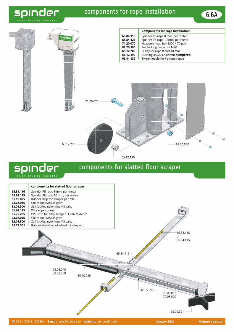
components for rope installation 6.6A
components for slatted floor scraper
Components for rope installation
65.84.116 Spinder PE-rope 8 mm, per meter65.84.125 Spinder PE-rope 10 mm, per meter71.20.070 Hexagon-head bolt M20 x 70 galv.82.20.500 Self locking nylon nut M2065.12.200 Pulley for rope 8 and 10 mm65.12.190 Bushing 35x20 L=30 mm, tempered65.84.135 Twine needle for Pe-rope repair
65.12.190
65.12.200 82.20.500
71.20.070
components for slatted floor scraper
65.84.116 Spinder PE-rope 8 mm, per meter65.84.125 Spinder PE-rope 10 mm, per meter65.10.025 Rubber strip for scraper per mtr73.08.045 Coach bolt M8x48 galv.82.08.500 Self locking nylon nut M8 galv.65.84.115 Wire rope socket65.72.285 PVC strip for alley scraper, 3000x70x6mm73.08.035 Coach bolt M8x35 galv.82.08.500 Self locking nylon nut M8 galv.65.72.301 Rubber star-shaped wheel for alley scr.
65.84.116or65.84.125
65.72.285
65.72.301
65.84.115
65.10.025
73.08.04582.08.500
73.08.035 72.08.500

Manure disposal 00 31 (0)512 - 237800 E-mail: [email protected] Website: spinderdhc.com january 2020
parts solid floor scrapers 6.6B
Parts solid floor scrapers
65.40.130 Slide 3m, cpl. with plastic rollers (standard length)65.40.120 Slide 2m, cpl. with plastic rollers (short version)65.40.150 Guidance frame for slide incl. bolts+nuts
65.10.025 Rubber strip for scraper per mtr65.72.285 PU-strip for alley scraper, length 3 m73.08.045 Coach bolt M8 x 48 galv.73.08.035 Coach bolt M8 x 35 galv.82.08.500 Self locking nylon nut M8 galv.65.45.050 Slider combi-scraper 30/50 mm
65.40.058 Side flap (standard length), L=53 cm with rubber strip, R/L
65.40.057 Rubber strip for side flap, L=53 cm65.40.055 Side flap (standard length), L=53 cm with PU-strip,
R/L65.40.051 PU-strip for side flap, L=53 cm65.40.050 Side flap with holes, L=53 cm
65.40.068 Side flap (short version), L=33 cm with rubber strip, R/L
65.40.067 Rubber strip for side flap, L=33 cm65.40.065 Side flap (short version), L=33 cm with PU-strip, R/L65.40.061 PU-strip for side flap, L=33 cm65.40.060 Side flap with holes, L=33 cm
71.20.180 Hexagon-head bolt M20 x 180 galv.82.20.500 Self locking nylon nut M2065.40.005 Snap lock 9mm for scraper blade and side flaps
(when rubber or plastic strips are not used)
65.45.030 End piece combi-scraper V-shape, left65.45.040 End piece combi-scraper V-shape, right73.12.120 Coach bolt M12 x 120 el.galv.02.90.060 Filling ring M12 DIN798982.12.500 Self locking nylon nut M12 galv.82.12.970 Connecting nut M12, 3D galv.71.12.045 Hexagon-head bolt M12 x 45 galv.
71.10.040 Hexagon-head tap bolt M10 x 40 galv82.10.500 Self locking nylon nut M10 galv.
65.84.115 Wire rope socket71.12.040 Hexagon-head bolt M12 x 40 galv.82.12.500 Self locking nylon nut M12 galv.
71.10.04082.10.500
65.40.055
65.40.130 73.08.035 82.08.500
65.72.285
71.12.04582.12.970
65.40.150
73.08.045 82.08.500
65.45.040
65.45.030
71.20.18082.20.500
65.10.025
Left
Right
71.12.04082.12.50065.84.115
73.12.12002.90.06082.12.500
65.40.058
End piece Slider
Side flap Right/Left

Manure disposal 00 31 (0)512 - 237800 E-mail: [email protected] Website: spinderdhc.com january 2020
tractor driven manure mixers 6.7
Buschmann slurry mixers
The robust Buschmann slurry mixers meet the most stringent operational requirements. The stable construction guarantees a long service life and minimum maintenance work. The mixers have a tube diameter of 102 mm and come standard as 420 and 520 cm in length. Alternative lengths are available upon request. The standard frame dimension is 70 x 70 cm. The mixers are available as PTO-driven and as electromixer. The electromixer comes standard with a continuous PTO, making it also suitable for PTO drive.
Important features:• The very extensive range of Buschmann mixers offers a solution
for each pit for mixing different types of liquid manure;• The bearings and sealings are very robust and suitable for
continuous operation;• The best performances by dynamically shaped propellers;• The propellers are balanced to help in running smoothly;• Virtually all parts have been hot-dip galvanized.
BearingsModels E1 -102 and L-E1 are fitted with ball bearings. All bearings - including the centre bearings - are maintenance-free groove ball bearings with 2RS sealing. The combination with a special dual simmer ring sealing on a stainless-steel sliding ring near the propeller provides a solid transmission that works without oil fill. The maximum permissible speed is 1000 rpm.
Model C/E1-102 is fitted with a maintenance-free groove ball bearing on the PTO side, sleeve bearings as centre bearings and a sleeve bearing near the propeller. The maximum permissible speed is 540 rpm. These mixer models are identical to the above-mentioned model E1-102 in terms of construction and design, but come at a substantially lower cost thanks to a simpler bearing construction.
Reverse gearboxIn practice, a reverse gearbox is used if liquid and solid manure remain separated. Especially when the pit is almost filled up, it may happen that a sucking mixer spills the manure over the edge. Running the mixer for a short period of time will make the manure move faster and better. When a reverse gearbox is frequently used, we recommend a model E1/102 mixer. Please note! When using the reversing function:• Peak speed: 540 rpm;• Maximum power on (upper) PTO shaft stub: 65 hp.
Technical data of PTO mixers:• Number of revolutions: type E1 -102 max. 1000 rpm; type C/E1-102 max. 540 rpm;• Absorbed power: 130-160 hp at 1000 rpm; 60-80 hp at 540 rpm;• Auger: suction auger Ø560 mm;• Direction of rotation: reversible, standard sucking;• Mixing capacity: 3352 m3 at 540 rpm.
Buschmann slurry mixer, type E1-102, with three-point hitch
11.33.102 Length 420 cm, (pit depth max. 190 cm)11.33.202 Length 520 cm, (pit depth 190 cm or more)11.33.800 Reversing gearbox
When using reverse gear: • Max 540 rpm • Max 65 hp
guide bars
suspension support
min. 180 (for mixer 420 cm)min. 220 (for mixer 520 cm)
built- in frame
Mixer 420 cm Mixer 520 cm
Pit depth D Length L Pit depth Length L130 cm 389 cm 200 cm 470 cm140 cm 385 cm 210 cm 466 cm150 cm 382 cm 220 cm 461 cm160 cm 378 cm 230 cm 456 cm170 cm 373 cm 240 cm 451 cm180 cm 368 cm 250 cm 446 cm190 cm 363 cm 260 cm 440 cm
• Buschmann P.T.O. driven mixer, with 3-point hitch
Different dimensionsavailable upon request
• Kantelbare driepuntsbok met verstelspindel en omkeerkast
D
100 L
30
20
30°

Manure disposal 00 31 (0)512 - 237800 E-mail: [email protected] Website: spinderdhc.com january 2020
tractor driven manure mixers 6.8
Stationary arrangement of Buschmann slurry mixers
A stationary (fixed) arrangement of one or more PTO-driven Buschmann slurry mixers is labour saving. Compared with slurry mixers with a 3-point hitch, carrying the slurry mixer in and out of the pit and cleaning afterwards is a thing of the past. The Buschmann adjustable stand for slurry mixers without a 3-point hitch is a solid support for stationary arrangement and fits in any pit of no less than 60 cm and no more than 170 cm wide.
Accessories for manure mixers11.33.910 Set of guide bars 500 cm11.30.960 Suspension support (for free suspension of guide
bars in mixer pit)11.11.220 Floor anchor M10 x 86 (4 per suspension support)
Stand for manure mixers without 3-point hitch11.33.963 Stand, standard, 60 - 120 cm11.33.962 Stand, reinforced, 100 - 170 cm11.11.240 Floor anchor M12 x 106 (4 pieces per stand)
• The adjustable stand is a solid support and fits in any pit of no less than 60 cm and no more than 170 cm wide.
• An adjustable stand and a filling hose. Cover removed.
• The mixing pit is well protected and the mixer end has a simple cover (jerry can).

Manure disposal 00 31 (0)512 - 237800 E-mail: [email protected] Website: spinderdhc.com january 2020
electric driven manure mixers 6.9
Slalom system
In the slalom system, the pit walls are situated in such a way that the manure circulates in a slalom movement under the barn during mixing. Mixing the manure takes place from a fixed loca-tion. We recommend the use of an electromixer when the slalom system is applied. The advantage is that this mixer, in combination with a timer, can be in operation at fixed times.
Technical data of electromixers:• Number of revolutions: 516 rpm (electro-drive) max. 1000 rpm
(PTO);• Auger: propulsion auger;• Direction of rotation: reversible, standard pushing.
Buschmann electromixer, type L-E1
Electromixer, includes 2 support triangles, excludes switches and cabling.
11.33.500 Length 420 cm, 11 kW/15 pk11.33.510 Length 520 cm, 11 kW/15 pk11.33.600 Length 420 cm, 15 kW/20 pk11.33.610 Length 520 cm, 15 kW/20 pk11.33.700 Length 420 cm, 18,5 kW/25 pk11.33.710 Length 520 cm, 18,5 kW/25 pk
Switchbox with softstart, rotation direction switch, emergency stop and timer.
11.33.855 For motor 11 kW11.33.865 For motor 15 kW11.33.875 For motor 18,5 kW
Power Propellor diameter Mixing capacity
11 kW/15 pk Ø400 mm 1452 m³/hour15 kW/20 pk Ø420 mm 1620 m³/hour18,5 kW/25 pk Ø440 mm 1795 m³/hour
• Buschmann electromixer
• Slalom systeem

Manure disposal 00 31 (0)512 - 237800 E-mail: [email protected] Website: spinderdhc.com january 2020
electric driven manure mixers 6.10
Technical data:• Outer diameter : Ø102 mm• Bearings : conical bearings and friction bearings• Sealing : SiC/SiC sealing• Lubrication : mixer tuber in oil bath, with storage tank• Standard lengths : 3700, 4200, 4600, 5200, 6000, 7000, 8000, 9000 mm• Revolutions : 350-400 rpm (electric driven) Max 1000 rpm (tractor driven)• Propellor : pushing• Dimensions mixerframe : 70 x 70 cm
• Buschmann electromixer, type Speed
Electromixer type Speed
The Speed model slurry mixers are driven by a special 6-pole three-phase motor with plenty of torque and a maintenance-free drive line. The combination of a lower number of revolutions and a larger diameter propeller allows a more effective mixture and homogenising of slurry, with a mixing capacity of approx. 45% higher than the standard electromixers of the L-E1 model.
Buschmann electromixer, type Speed
Includes 2 support stands to be fitted on guide bars, excludes switch and cabling.
11.33.515 Length 520 cm, 11 kW/15 pk11.33.615 Length 520 cm, 15 kW/20 pk11.33.715 Length 520 cm, 18,5 kW/25 pk
11.33.525 Length 600 cm, 11 kW/15 pk11.33.625 Length 600 cm, 15 kW/20 pk11.33.725 Length 600 cm, 18,5 kW/25pk11.33.820 Length 600 cm, 22 kW/30pk
Switchbox with main switch, softstart, rotation direction switch, emergency stop and timer
11.33.855 For motor 11 kW11.33.865 For motor 15 kW11.33.875 For motor 18,5 kW11.33.885 For motor 22 kW
Accessories for manure mixers11.33.940 Frame for building in 70 x 70 cm11.33.910 Set of guide bars 500 cm11.33.915 Set of guide bars 600 cm, gelaste uitvoering11.30.960 Suspension support (for free suspension of guide
bars in mixer pit)11.11.220 Floor anchor M10 x 86 (4 per suspension support)
Mixing capacity is expressed in displaced water m³/hour
Power propellor diameter mixing capacity
11 kW/15 pk Ø560 mm 1943 m³/hour15 kW/20 pk Ø600 mm 2229 m³/hour18,5 kW/25 pk Ø600 mm 2670 m³/hour22 kW/30 pk Ø600 mm 2848 m³/hour

“ Choose spinder, choose 100% Dutch quality”

Zeppelinlaan 39207 JG DrachtenThe Netherlands
00 31 (0)512 - 237800E-mail:[email protected] Website: spinderdhc.com


