Embed Size (px)
Citation preview
PRONAR Sp. z o.o. 17-210 Narew, ul. Mickiewicza 101A; woj. podlaskie tel./fax: +48 085 681 63 29; +48 085 681 64 29; +48 085 681 63 81; +48 085 681 63 82; +48 085 681 63 84; fax: +48 085 681 63 83; +48 085 682 71 10;
www.pronar.pl
MANURE SPREADER „HERKULES 14”
N262/1
OPERATION & MAINTENANCE MANUAL
Edition II
Narew 2006

07-12-2006/II/B
1
PRONAR Sp. z o.o. 17-210 NAREW, ul. Mickiewicza 101A; woj. podlaskie tel./fax: +48 085 681 63 29; +48 085 681 64 29; +48 085 681 63 81; +48 085 681 63 82; +48 085 681 63 84; fax: +48 085 681 63 83; +48 085 682 71 10;
www.pronar.pl
MANURE SPREADER „HERKULES 14”
N262/1
OPERATION & MAINTENANCE MANUAL
Identification of the machine
Symbol /Type: N262/1
KTM Symbol: 0822-312-226-212
Serial: ..............................
The serial is stamped on the type plate and on the front of the spreader’s frame. The type plate is riveted to the load-carrying body. In the course of purchase check conformity of the serial stamped on the spreader with the serial given in the warranty card, in purchase documents and in the operation manual.
Hydraulic system is filled with HL32 hydraulic oil
Quality Inspection Sign.................................. The manual is valid together with the annex No. ........... dated on ...........

2
The manufacturer reserves the right to introduce design modifications for the purpose of simplified maintenance and improved operation quality. Remarks and notices about design and operation of the spreader should be submitted to the manufacturer. This information allows us to evaluate objectively manufactured machines and will be used as hints for further modernisation. Information about major design alterations will be supplied to users in the form of enclosed information leaflets (annexes).
CAUTION!
The operation & maintenance manual is the substantial equipment of the spreader.
The user should read carefully the manual before operation and observe all recommendations given in the manual. This will ensure safe maintenance and failure-free
operation of the machine.
The machine has been designed in accordance with generally recognised standards, documents and currently binding legal regulations.

3
Contents
1. Introduction ...................................................6
1.1 General information..................................................................... 6
1.2 Application of the spreader......................................................... 6
2. Operational safety .........................................7
2.1 Basic safety rules ........................................................................ 7
2.2 Coupling and uncoupling to the tractor..................................... 8
2.3 Operation with the PTO shaft...................................................... 8
2.4 Pneumatic & hydraulic systems ................................................. 9
2.5 Tyres ............................................................................................. 9
2.6 Maintenance ................................................................................. 9
2.7 Principles of use on public roads............................................. 10
2.8 Residual risk............................................................................... 11
2.9 Information & warning stickers ................................................ 12
3. Additional information ................................. 17
3.1 Spreader equipment .................................................................. 17
3.2 Warranty conditions .................................................................. 17
3.3 Transport .................................................................................... 18
3.4 Delivery....................................................................................... 18
3.5 Disposal of the spreader ........................................................... 18
4. Operational data .......................................... 19
4.1 Technical data ............................................................................ 19
4.2 Structure and operational principle ......................................... 20 4.2.1 Undercarriage and load crate ....................................................20 4.2.2 Power transmission system .......................................................21 4.2.3 Chain conveyor ..........................................................................23 4.2.4 Comminuting adapter.................................................................24 4.2.5 Wide spreading system..............................................................25 4.2.6 Main brake .................................................................................26 4.2.7 Elements of automatic of the pneumatic system .......................27 4.2.8 Parking brake.............................................................................28 4.2.9 Wiring, lighting, signalling ..........................................................29 4.2.10 Hydraulic system......................................................................30

4
5. Operation principles .................................... 32
5.1 Preparation for work.................................................................. 32
5.2 Coupling / uncoupling from the tractor.................................... 32
5.3 Uploading of the load crate....................................................... 33
5.4 Transport drive........................................................................... 33
5.5 Principles of use of tyres .......................................................... 33
5.6 Spreading and load dose adjustment ...................................... 34
6. Maintenance ................................................ 36
6.1 Adjustment of wheel bearings .................................................. 36
6.2 Adjustment of brakes ................................................................ 38
6.3 Maintenance of the pneumatic system .................................... 39
6.4 Maintenance of the hydraulic system ...................................... 39
6.5 Lubrication ................................................................................. 40
6.6 Maintenance of the suspension system .................................. 44
6.7 Adjustment of tension of the adapter drive chain................... 44
6.8 Adjustment of tension of the floor conveyor chain ................ 45
5
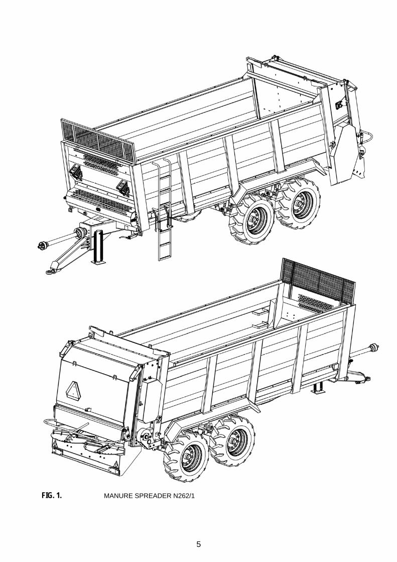
FIG. 1. MANURE SPREADER N262/1

6
Chapter
1
1. Introduction
1.1 General information The manual describes basic rules of safe operation & maintenance of the manure spreader. If information contained within the manual will be not comprehensible for the user please do not hesitate to contact your dealer or directly the manufacturer. Especially important are information and recommendation marked in the text by bold characters or preceded by the word “CAUTION”. Information, descriptions of danger and precautions as well as commands and orders concerning safe operations are marked with following sign:
and mentioned in the chapter „Safe operation ".
1.2 Application of the spreader The manure spreader is designed for uniform spreading of peat, compost, each type of manure, lime and sewage sediments – semi-fluid materials from sewage treatment plants. Brakes, lighting and signalling systems fulfil all requirements of traffic regulations. The spreader is adapted for coupling with agricultural tractors fitted with external hydraulic system and a lower hook of 2500 kG load capacity. The spreader is fitted with a rotary string with an eye of Ø50 mm diameter or – for a special order - with an eye of Ø45 mm diameter.
CAUTION
The machine is designed for spreading of manure and is fitted with integral safety guards. It is prohibited to remove the spreading adapter and to use the machine for other purposes. It is prohibited to remove guards and to use the spreader without guards. The spreader must not be used contrary to its proper application and especially for transporting of persons & animals.

7
Chapter
2
2. Operational safety
2.1 Basic safety rules
• Before operation of the spreader the user should read carefully the manual and the PTO
shaft manual and observe all recommendations given in these manuals during operation.
• Prior to each use of the spreader check the machine, if it is properly prepared for operation, especially with regard to safety.
• If information contained within the manual will be not comprehensible for the user please do not hesitate to contact your dealer, who also provides repair & service or directly the manufacturer.
• Climbing on the spreader is allowed only if the spreader is completely stopped, tractor’s engine off and disconnected PTO shaft.
• Careless and improper operation & maintenance of the spreader as well as lack of observation of recommendations given in present manual may endanger human health and life.
• The spreader can be operated only when all guards and other protective elements are efficient and on their places.
• There is the risk of residual danger, thus application of safe operation rules should be the basic principle of spreader’s use.
• Persons unauthorised for driving agricultural tractors including children and drunken persons have no right to use the spreader.
• It is prohibited to use the spreader contrary to its purposes. User, who utilise the spreader in other than prescribed manner, takes responsibility for all consequences resulting from spreader’s use.
• Any unauthorised modification absolves the PRONAR Narew from responsibility for resulting damage or health detriment.
• Prior to each spreader’s use check its technical condition, especially coupling system, drive system, brakes and signalling lights.
8
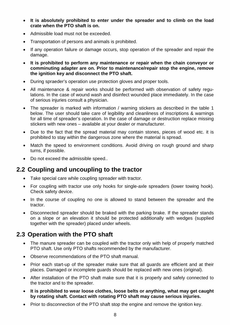
• It is absolutely prohibited to enter under the spreader and to climb on the load crate when the PTO shaft is on.
• Admissible load must not be exceeded.
• Transportation of persons and animals is prohibited.
• If any operation failure or damage occurs, stop operation of the spreader and repair the damage.
• It is prohibited to perform any maintenance or repair when the chain conveyor or comminuting adapter are on. Prior to maintenance/repair stop the engine, remove the ignition key and disconnect the PTO shaft.
• During spraeder’s operation use protection gloves and proper tools.
• All maintenance & repair works should be performed with observation of safety regu-lations. In the case of wound wash and disinfect wounded place immediately. In the case of serious injuries consult a physician.
• The spreader is marked with information / warning stickers as described in the table 1 below. The user should take care of legibility and cleanliness of inscriptions & warnings for all time of spreader’s operation. In the case of damage or destruction replace missing stickers with new ones – available at your dealer or manufacturer.
• Due to the fact that the spread material may contain stones, pieces of wood etc. it is prohibited to stay within the dangerous zone where the material is spread.
• Match the speed to environment conditions. Avoid driving on rough ground and sharp turns, if possible.
• Do not exceed the admissible speed..
2.2 Coupling and uncoupling to the tractor • Take special care while coupling spreader with tractor.
• For coupling with tractor use only hooks for single-axle spreaders (lower towing hook). Check safety device.
• In the course of coupling no one is allowed to stand between the spreader and the tractor.
• Disconnected spreader should be braked with the parking brake. If the spreader stands on a slope or an elevation it should be protected additionally with wedges (supplied together with the spreader) placed under wheels.
2.3 Operation with the PTO shaft • The manure spreader can be coupled with the tractor only with help of properly matched
PTO shaft. Use only PTO shafts recommended by the manufacturer.
• Observe recommendations of the PTO shaft manual.
• Prior each start-up of the spreader make sure that all guards are efficient and at their places. Damaged or incomplete guards should be replaced with new ones (original).
• After installation of the PTO shaft make sure that it is properly and safely connected to the tractor and to the spreader.
• It is prohibited to wear loose clothes, loose belts or anything, what may get caught by rotating shaft. Contact with rotating PTO shaft may cause serious injuries.
• Prior to disconnection of the PTO shaft stop the engine and remove the ignition key.

9
• While operating in poor visibility conditions illuminate the PTO shaft and its surroundings with tractor’s working lights.
• During transport the PTO shaft should be positioned horizontally to avoid damage of guards and other protective elements.
• Telescope tubes should overlap during operation by 1/3 of their length. • During operation of the PTO shaft and the spreader do not use other PTO shaft rotation
speed than 1000 rpm. It is prohibited to overload the shaft and the spreader and to uncouple the clutch rapidly.
• The chain protecting the shaft guards against rotation should be fastened on a fixed structure element of the spreader.
• It is prohibited to use protective chains for suspending of the shaft during stops or transportation works.
• It is prohibited to pass under / above the shaft and to stand onto it during operation as well as during stop.
• The PTO shaft housing is marked with a sign showing, which end should be connected to the tractor.
2.4 Pneumatic & hydraulic systems • The hydraulic system is under high pressure during operation
• While connecting hydraulic conduits to a tractor make sure that hydraulic systems of the tractor and the spreader are pressure-free,
• Check regularly all connections and hydraulic & pneumatic conduits.
• In case of any failure of the hydraulic/pneumatic system stop operation and remove the failure.
2.5 Tyres • During works connected to spreader’s tyres make sure to protect the spreader against
accidental movement with edges supplied together with the spreader.
• All repairs of tyres should be performed by trained and authorised personnel. Works should be performed with proper tools.
• After each installation of a wheel tighten nuts after first 50 km and then check their tightening each 100 km.
• Check the tyre pressure regularly.
2.6 Maintenance • All maintenance, preservation and cleaning works should be performed only when the
tractor’s engine is off and the ignition key removed from the ignition switch.
• During maintenance works with guards in upper position secure the guards with suitable supports.
• Check all screwed connections.

10
• During maintenance works use protection gloves and proper tools.
• Prior to welding or electric works disconnect the spreader from power supply.
• Check condition of all protective elements and their fastening.
• During the guarantee period all repairs may be performed only by authorised Manufacturer’s service stations.
• If it is necessary to replace an element/part it is recommended to use only original parts or paints recommended by the Manufacturer. Inobservance of this requirements may cause danger to health or life of operators or third persons as well as damage of the machine.
2.7 Principles of use on public roads • While driving public roads observe traffic regulations.
• Spreader’s overload may cause its damage and endanger traffic safety.
• Do not exceed the maximum speed. Adjust the speed to traffic conditions.
• It is prohibited to leave unsecured spreader. Always activate the parking brake.
• While driving public roads the spreader should be equipped with certified or approved warning reflecting triangle.
• Rear wall should be equipped with a triangular plate for slowly moving vehicles, if the spreader is the last vehicle in a set (Fig. 2).

11
FIG. 2. LOCATION OF A TRIANGULAR PLATE FOR SLOWLY MOVING VEHICLES.
2.8 Residual risk The firm Pronar Sp. z o. o. in Narew has made all efforts to eliminate any risk of an accident. However, there is certain residual risk, which may lead to an accident and is connected to actions described below:
• application of the spreader for other purposes than described in the manual
• presence of persons between the tractor and the spreader, when the engine is on
• too close distance to rotating elements and spread material
• operation with removed or inefficient spreader guards
• operation of the spreader by unauthorised or drunken persons
• use of inefficient PTO shaft
• stay on the spreader during work
• cleaning, maintenance and inspection of the spreader
The residual risk can be reduced to minimum if following recommendations will be observed:
• judicious and haste-free operation of the spreader
• observation of hints included in the operation manual
• safe distance from dangerous zones
• prohibition of stay on the machine during its operation
• execution of maintenance works according to safety rules
• use of protective clothes

12
• protection of the machine against access of unauthorised persons, and especially children
2.9 Information & warning stickers Table 1. Information & warning stickers.
No. on the Fig. 3 Sign Description Location
1
Read the operation manual Front wall
2
Prior to maintenance & repair stop the engine and remove
the ignition key Front wall
3
Thrown out objects, danger to the entire body. Keep safe distance from the adapter,
min. 25 m
Under wide spreading discs, left and right.
4
Do not stay under raised rear adapter guard
Adapter guard, left and right
13
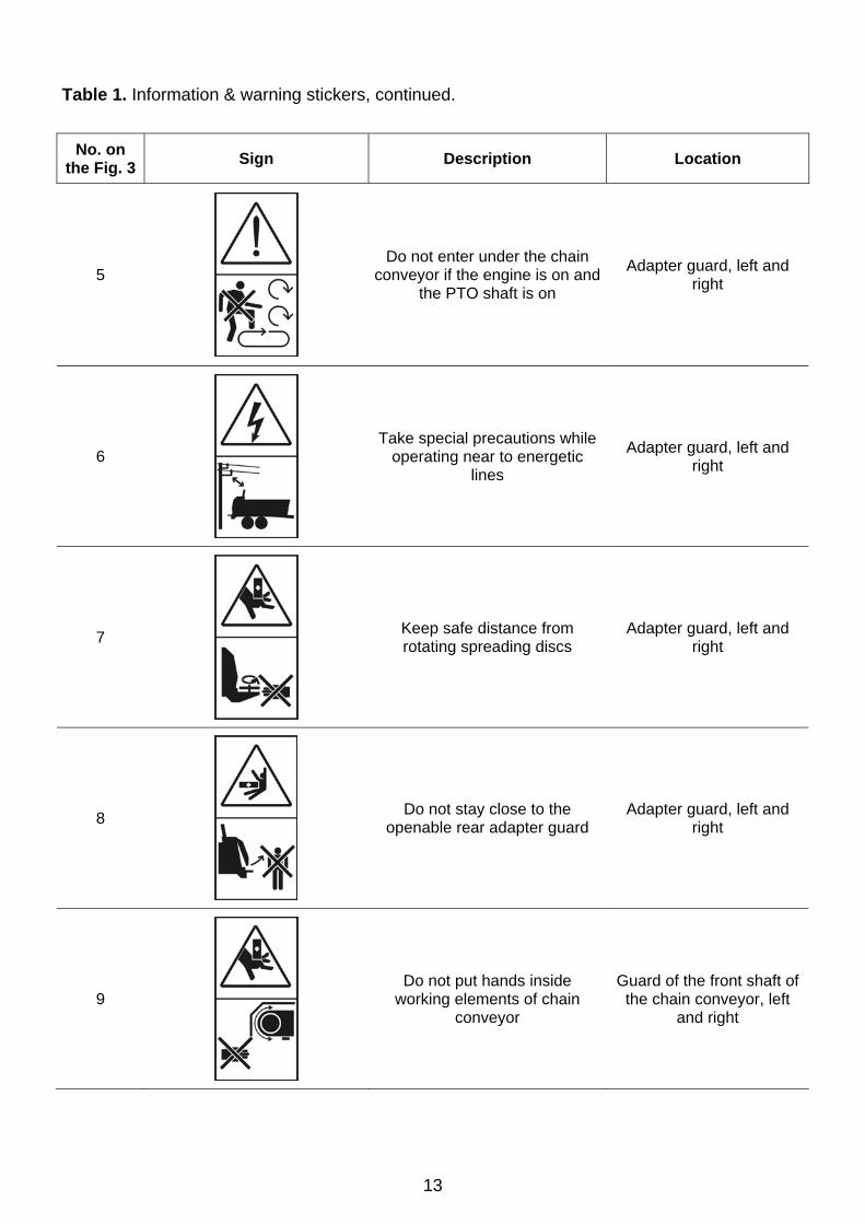
Table 1. Information & warning stickers, continued.
No. on the Fig. 3 Sign Description Location
5
Do not enter under the chain conveyor if the engine is on and
the PTO shaft is on
Adapter guard, left and right
6
Take special precautions while operating near to energetic
lines
Adapter guard, left and right
7
Keep safe distance from rotating spreading discs
Adapter guard, left and right
8
Do not stay close to the openable rear adapter guard
Adapter guard, left and right
9
Do not put hands inside working elements of chain
conveyor
Guard of the front shaft of the chain conveyor, left
and right
14
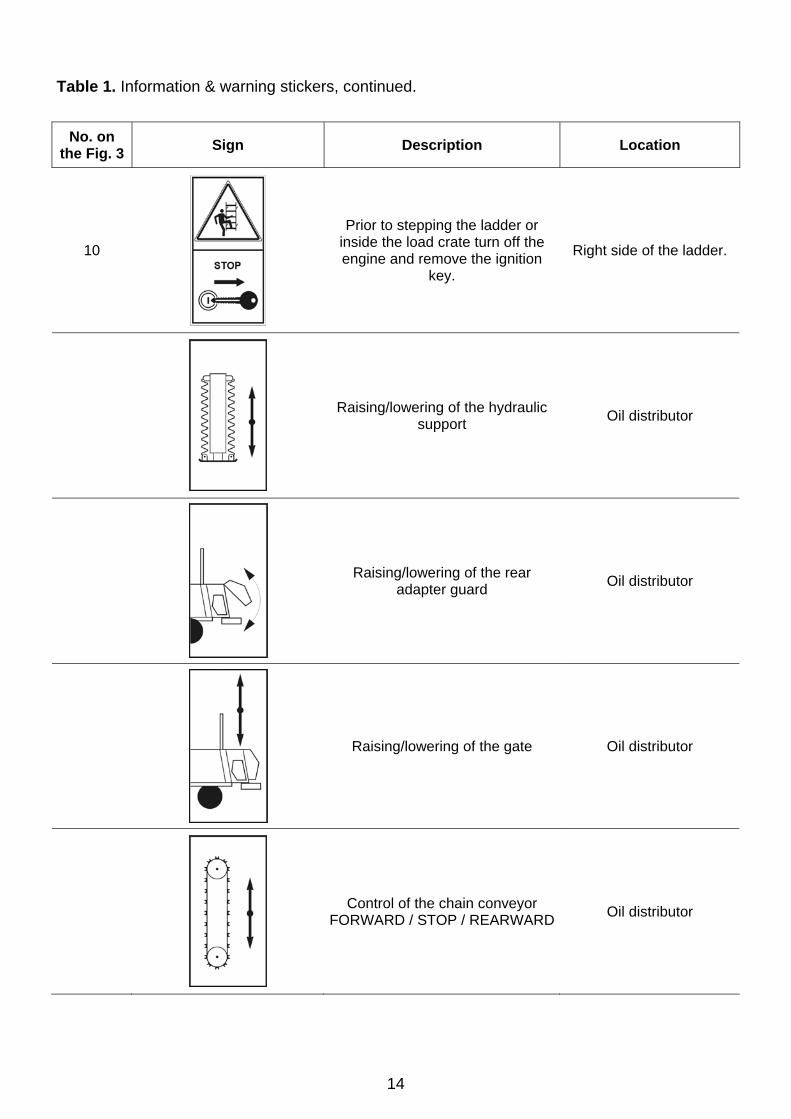
Table 1. Information & warning stickers, continued.
No. on the Fig. 3 Sign Description Location
10
Prior to stepping the ladder or inside the load crate turn off the engine and remove the ignition
key.
Right side of the ladder.
Raising/lowering of the hydraulic support Oil distributor
Raising/lowering of the rear adapter guard Oil distributor
Raising/lowering of the gate Oil distributor
Control of the chain conveyor FORWARD / STOP / REARWARD Oil distributor

15
Table 1. Information & warning stickers, continued.
No. on the Fig. 3 Sign Description Location
11
Tyre pressure Above wheels, right and left
12
Rotation speed of the PTO shaft Shaft guard
Do not wear loose cloth, loose hair, jewellery or anything what
could get caught by rotating PTO shaft.
Contact with rotating shaft may cause serious injuries or
death.
PTO shaft
Operation with inefficient or removed PTO shaft guards is
prohibited. PTO shaft
Do not approach to the rotating PTO shaft. Prior to maintenance turn off the engine and remove
the ignition key.
PTO shaft
13 Right and left wall
14 Right and left wall
15
Lubricate according to the manual Front wall
16
Check condition of screwed connections of wheels Front wall
16
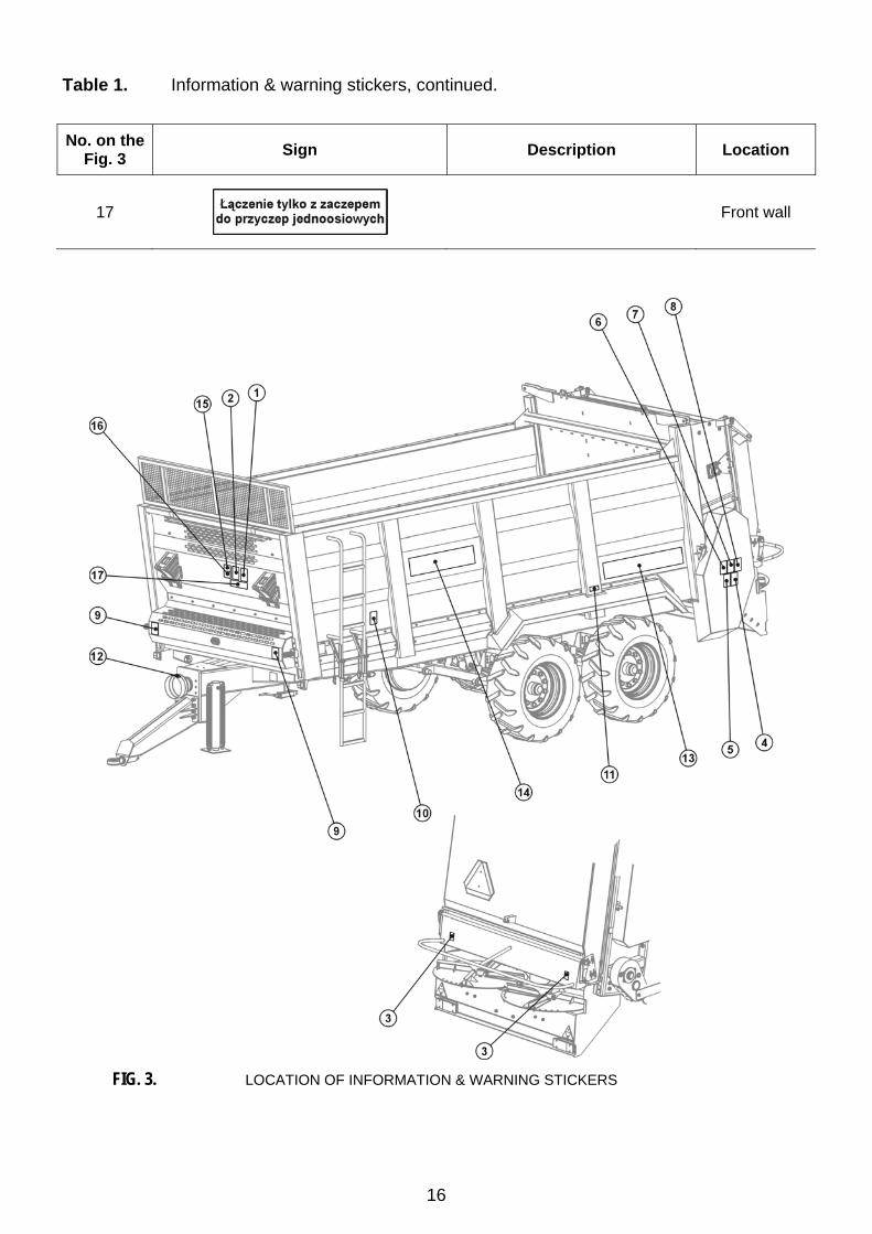
Table 1. Information & warning stickers, continued. No. on the
Fig. 3 Sign Description Location
17
Front wall
FIG. 3. LOCATION OF INFORMATION & WARNING STICKERS

17
Chapter
3
3. Additional information
3.1 Spreader equipment Spreader equipment consists of:
• operation & maintenance manual and spare parts list - 1
• warranty card - 1
• connector for the electric installation - 1
• wheel wedges - 2
• fold-up ladder - 1 For user’s order the spreader may be equipped additionally with:
• PTO shaft + operation & maintenance manual
- manufacturer: Bondioli & Pavesi , type: 7 106 091 CE 008 007, (21/6)(
- manufacturer: Bondioli & Pavesi , type: 7 106 091 CE 007 007, (6/6) (
• warning reflecting triangle
• triangular plate for slowly moving vehicles
• indicator of gate upper position ( shaft end with 6 or 21 splines
3.2 Warranty conditions "PRONAR" Sp. z o.o. in Narew guarantees efficient operation of the spreader if utilised according to technical & operation conditions described in the manual. Failures detected within warranty period will be removed by the Warranty Service within no longer than 14 working days from the date of delivery to a repair station or within any other agreed period. Normally wearing parts i.e. tyres, brake linings as well as mechanical damage, damage resulted from improper use, adjustment or maintenance are not subject of warranty. Detailed warranty conditions are mentioned in the warranty card supplied together with the newly bought spreader.
18
CAUTION
Demand your dealer to fill the warranty card and complaint coupons exactly and completely. Lack of e.g. sale date or dealer’s stamp may render your possible complaint void.
3.3 Transport
3.4 Delivery The spreader is delivered for sale fully assembled and requires no package. Packed are only: the manual, the connection cable and – if ordered – the warning triangle. The spreader is supplied to the user with a truck or the user can take it by himself with his own tractor.
CAUTION
If the user takes the spreader by himself he should read present manual and observe all recom-mendations given in the manual. In the case of transportation with a truck the spreader is fastened on the load crate according to generally recognised safety rules. The truck driver should take special precautions while transporting the spreader, because the gravity centre of the loaded truck is shifted upwards.
3.5 Disposal of the spreader If the user decides to dispose the spreader, the complete spreader should be delivered to local scrapyard. Parts removed in the course of e.g. repair should be supplied to a recycling firm. The certificate from the scrapyard should be submitted while unregistering the spreader.
19
Chapter
4
4. Operational data
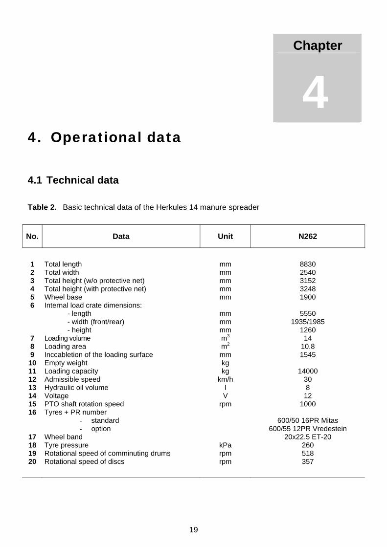
4.1 Technical data Table 2. Basic technical data of the Herkules 14 manure spreader
No. Data Unit N262
1 2 3 4 5 6
7 8 9
10 11 12 13 14 15 16
17 18 19 20
Total length Total width Total height (w/o protective net) Total height (with protective net) Wheel base Internal load crate dimensions: - length - width (front/rear) - height Loading volume Loading area Inccabletion of the loading surface Empty weight Loading capacity Admissible speed Hydraulic oil volume Voltage PTO shaft rotation speed Tyres + PR number
- standard - option
Wheel band Tyre pressure Rotational speed of comminuting drums Rotational speed of discs
mm mm mm mm mm
mm mm mm m3
m2
mm kg kg
km/h l V
rpm
kPa rpm rpm
8830 2540 3152 3248 1900
5550
1935/1985 1260
14 10.8 1545
14000
30 8
12 1000
600/50 16PR Mitas
600/55 12PR Vredestein 20x22.5 ET-20
260 518 357
20
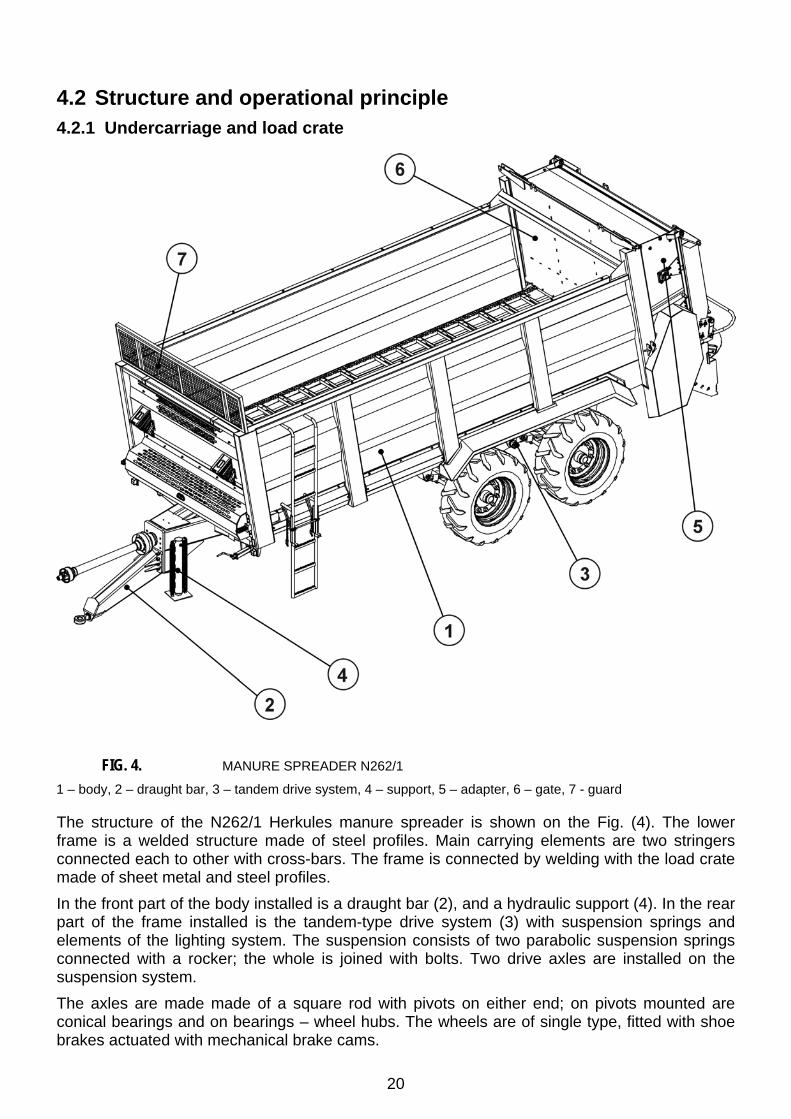
4.2 Structure and operational principle 4.2.1 Undercarriage and load crate
FIG. 4. MANURE SPREADER N262/1
1 – body, 2 – draught bar, 3 – tandem drive system, 4 – support, 5 – adapter, 6 – gate, 7 - guard
The structure of the N262/1 Herkules manure spreader is shown on the Fig. (4). The lower frame is a welded structure made of steel profiles. Main carrying elements are two stringers connected each to other with cross-bars. The frame is connected by welding with the load crate made of sheet metal and steel profiles. In the front part of the body installed is a draught bar (2), and a hydraulic support (4). In the rear part of the frame installed is the tandem-type drive system (3) with suspension springs and elements of the lighting system. The suspension consists of two parabolic suspension springs connected with a rocker; the whole is joined with bolts. Two drive axles are installed on the suspension system. The axles are made made of a square rod with pivots on either end; on pivots mounted are conical bearings and on bearings – wheel hubs. The wheels are of single type, fitted with shoe brakes actuated with mechanical brake cams.

21
The hydraulic oil distributor installed in front of the front wall of the load crate is used for control of spreader operation. In the rear part of the load crate installed is a comminuting adapter (5) together with the wide spreading system. Inside the load crate there is a chain conveyor powered with a hydraulic motor. Between the load crate and the adapter installed is a gate (6), controlled hydraulically with help of two hydraulic cylinders.
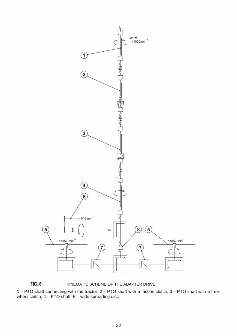
4.2.2 Power transmission system The comminuting adapter and wide spreading discs are powered by the power transmission system, which structure is shown on the Fig. (5). The kinematic scheme of the system is shown on the Fig (6).
FIG. 5. POWER TRANSMISSION SYSTEM
1 – PTO shaft connecting the tractor with the spreader, 2 – PTO shaft with an overload clutch, 3 – PTO shaft with a free-wheel clutch, 4 – PTO shaft, 5 – articulated joint, 6 - angular reduction gear for adapter drive, 7 – adapter drive shaft, 8 – wide spreading system, 9 – comminuting adapter, 10 – shaft connector
Power is transmitted from the tractor through PTO shafts (1), (2), (3) and (4), the angular reduction gear (6) to discs of the wide spreading system and to comminuting drums of the adapter (9). The PTO shafts are connected with help of shaft connectors (10). The comminuting drums are driven with chain gears (Fig. (8) and Fig. (20)). The power transmission system is protected against excessive torque with help of a clutch installed on the PTO shaft (2).
22
FIG. 6. KINEMATIC SCHEME OF THE ADAPTER DRIVE
1 – PTO shaft connecting with the tractor, 2 – PTO shaft with a friction clutch, 3 – PTO shaft with a free-wheel clutch, 4 – PTO shaft, 5 – wide spreading disc
23
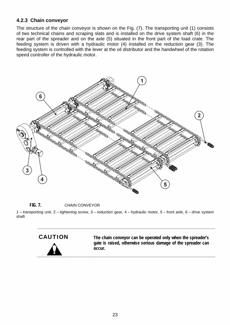
4.2.3 Chain conveyor The structure of the chain conveyor is shown on the Fig. (7). The transporting unit (1) consists of two technical chains and scraping slats and is installed on the drive system shaft (6) in the rear part of the spreader and on the axle (5) situated in the front part of the load crate. The feeding system is driven with a hydraulic motor (4) installed on the reduction gear (3). The feeding system is controlled with the lever at the oil distributor and the handwheel of the rotation speed controller of the hydraulic motor.
FIG. 7. CHAIN CONVEYOR
1 – transporting unit, 2 – tightening screw, 3 – reduction gear, 4 – hydraulic motor, 5 – front axle, 6 – drive system shaft
CAUTION
The chain conveyor can be operated only when the spreader’s gate is raised, otherwise serious damage of the spreader can occur.
24
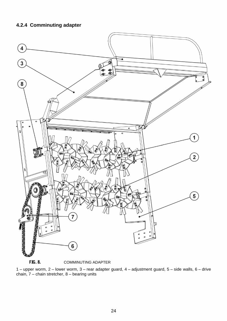
4.2.4 Comminuting adapter
FIG. 8. COMMINUTING ADAPTER
1 – upper worm, 2 – lower worm, 3 – rear adapter guard, 4 – adjustment guard, 5 – side walls, 6 – drive chain, 7 – chain stretcher, 8 – bearing units
25
Main assemblies of the adapter are shown on the Fig. (8). Side walls (5) together with the upper cover and rear guard are installed in the rear part on the load crate in the rear part of the spreader. The shafts of comminuting worms (1) and (2) are supported with bearing units (8). The system is driven via two chain gears situated on both sides of the adapter. The left-hand chain gear receives power from the power transmission system (pos. (6) Fig. (5)) and drives the lower worm shaft. The right-hand chain gear (Fig. 20) transmits power from the lower worm to the upper worm. Chain tension (6) is realised by the chain stretcher (7).
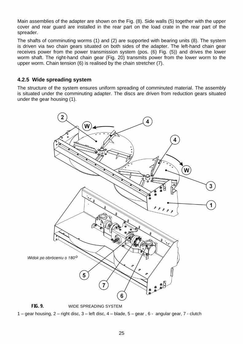
4.2.5 Wide spreading system The structure of the system ensures uniform spreading of comminuted material. The assembly is situated under the comminuting adapter. The discs are driven from reduction gears situated under the gear housing (1).
FIG. 9. WIDE SPREADING SYSTEM
1 – gear housing, 2 – right disc, 3 – left disc, 4 – blade, 5 – gear , 6 - angular gear, 7 - clutch
26
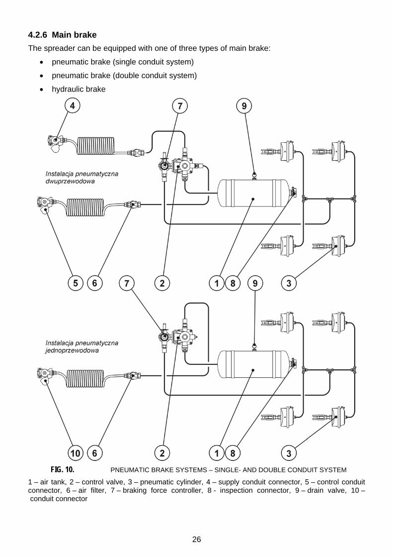
4.2.6 Main brake The spreader can be equipped with one of three types of main brake:
• pneumatic brake (single conduit system)
• pneumatic brake (double conduit system)
• hydraulic brake
FIG. 10. PNEUMATIC BRAKE SYSTEMS – SINGLE- AND DOUBLE CONDUIT SYSTEM
1 – air tank, 2 – control valve, 3 – pneumatic cylinder, 4 – supply conduit connector, 5 – control conduit connector, 6 – air filter, 7 – braking force controller, 8 - inspection connector, 9 – drain valve, 10 – conduit connector
27
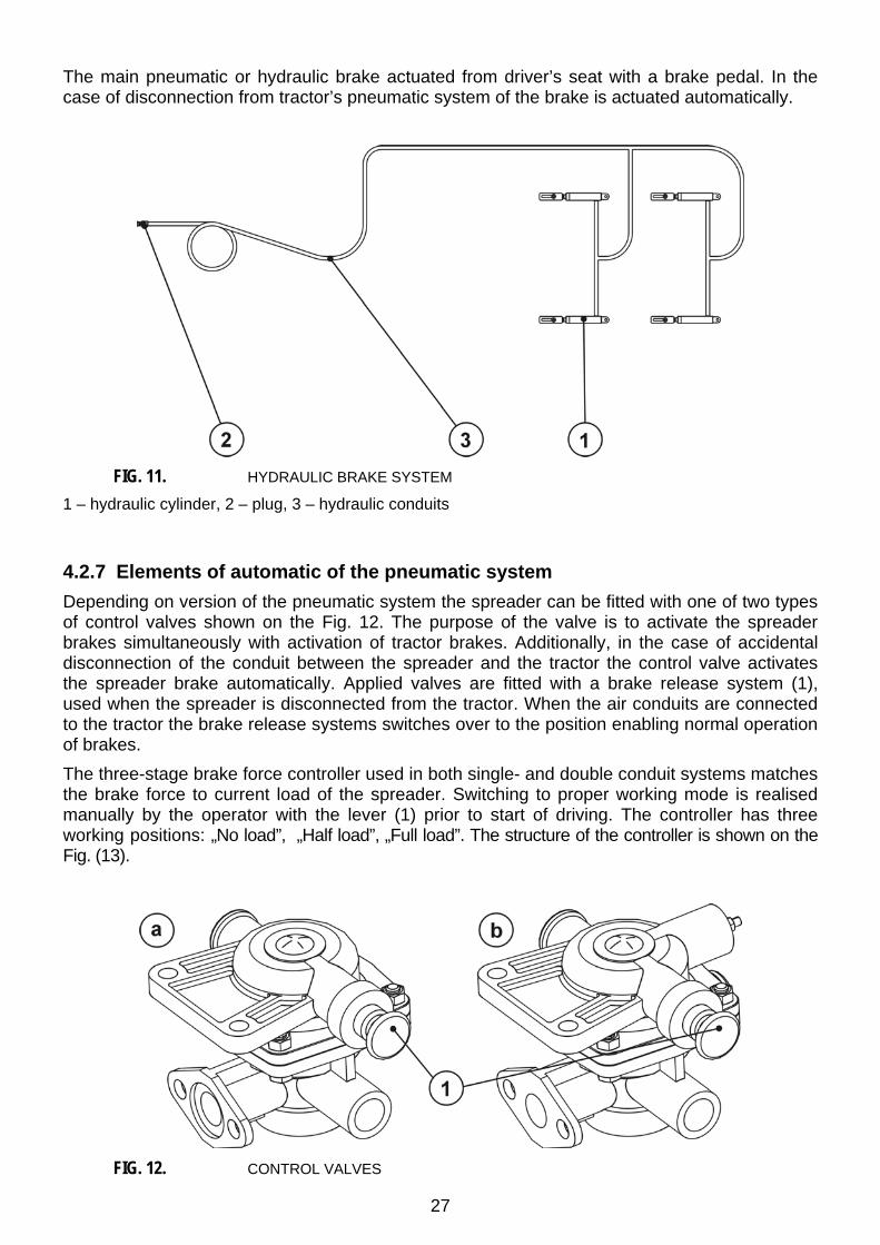
The main pneumatic or hydraulic brake actuated from driver’s seat with a brake pedal. In the case of disconnection from tractor’s pneumatic system of the brake is actuated automatically.
FIG. 11. HYDRAULIC BRAKE SYSTEM
1 – hydraulic cylinder, 2 – plug, 3 – hydraulic conduits
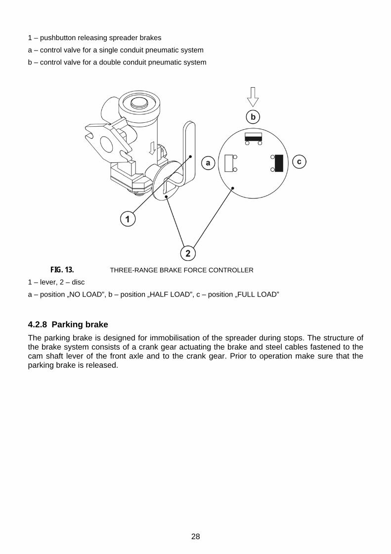
4.2.7 Elements of automatic of the pneumatic system Depending on version of the pneumatic system the spreader can be fitted with one of two types of control valves shown on the Fig. 12. The purpose of the valve is to activate the spreader brakes simultaneously with activation of tractor brakes. Additionally, in the case of accidental disconnection of the conduit between the spreader and the tractor the control valve activates the spreader brake automatically. Applied valves are fitted with a brake release system (1), used when the spreader is disconnected from the tractor. When the air conduits are connected to the tractor the brake release systems switches over to the position enabling normal operation of brakes. The three-stage brake force controller used in both single- and double conduit systems matches the brake force to current load of the spreader. Switching to proper working mode is realised manually by the operator with the lever (1) prior to start of driving. The controller has three working positions: „No load”, „Half load”, „Full load”. The structure of the controller is shown on the Fig. (13).
FIG. 12. CONTROL VALVES
28
1 – pushbutton releasing spreader brakes
a – control valve for a single conduit pneumatic system
b – control valve for a double conduit pneumatic system
FIG. 13. THREE-RANGE BRAKE FORCE CONTROLLER
1 – lever, 2 – disc
a – position „NO LOAD”, b – position „HALF LOAD”, c – position „FULL LOAD”
4.2.8 Parking brake The parking brake is designed for immobilisation of the spreader during stops. The structure of the brake system consists of a crank gear actuating the brake and steel cables fastened to the cam shaft lever of the front axle and to the crank gear. Prior to operation make sure that the parking brake is released.

29
4.2.9 Wiring, lighting, signalling The wiring system is adapted for power supply with 12 V DC. The spreader wiring should be connected to the tractor with a suitable connecting cable.
FIG. 14. WIRING DIAGRAM OF THE SPREADER
PP (PL) - contour lamp, right (left), ZP (ZL) - rear compact lamp, right (left), GP – 7-pin socket, front (rear)

30
FIG. 15. CONNECTION OF CONDUCTORS
Conductor colours p – orange, c – black, k – red, r – rose, n – blue, c/t – black-green, t - green,
31 – frame, R (L) – right (left) blinker, 58R (58L) – right (left) position lamp, 54 - „STOP”, „+” – power supply +12V DC
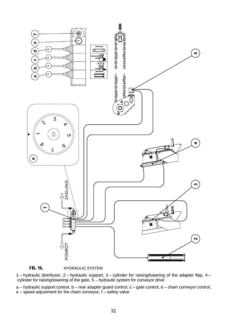
4.2.10 Hydraulic system The hydraulic system consists of four independent control circuits for individual units of the spreader:
• hydraulic support
• rear guard of the adapter
• gate
• chain conveyor drive
The above mentioned circuits are controlled with the hydraulic distributor (1) (Fig. 16).
31
FIG. 16. HYDRAULIC SYSTEM
1 – hydraulic distributor, 2 – hydraulic support, 3 – cylinder for raising/lowering of the adapter flap, 4 – cylinder for raising/lowering of the gate, 5 – hydraulic system for conveyor drive
a – hydraulic support control, b – rear adapter guard control, c – gate control, d – chain conveyor control, e – speed adjustment for the chain conveyor, f – safety valve

32
Chapter
5
5. Operation principles
5.1 Preparation for work During preparation for work it is necessary to check following items:
• condition of tyres and tyre pressure (see table)
• torque of tightening of nuts fixing wheels – the torque should amount to 450 Nm
• other screwed connections, and especially fastening torque of the draught bar (draught bar screws should be tightened with the torque of 350 Nm)
• function of lighting & signalling systems
• function of the braking system
• condition and fastening of covers and guards
• condition of the PTO shaft
• tension of the chain of the chain conveyor and drive chains of the adapter
5.2 Coupling / uncoupling from the tractor Prior to coupling with tractor check if the spreader is braked with the parking brake. To couple the spreader with a tractor it is necessary to perform following operations:
• Position the draught bar eye at suitable level.
• Precise adjustment of the draught bar can be achieved with help of the hydraulic support. For this purpose draw back the tractor and connect two hydraulic distributor conduits to the tractor; then adjust the draught bar height with the valve lever (Fig. 16 lever (a)).
• Draw back the tractor, couple hitch rod eye with the lower tow coupling on the tractor and check its fastening.
• Raise the support
• Connect electrical and brake conduits to the tractor
• Connect the PTO shaft
• Unlock the spreader’s parking brake.
33
CAUTION
In the course of coupling no-one is allowed to stand between spreader and tractor.
5.3 Uploading of the load crate The load crate can be loaded only when the spreader is coupled with a tractor and positioned onto flat, level surface. It is recommended to distribute the load within the load crate uniformly. It is recommended to use a loader or a conveyor for loading. Prior to uploading make sure that the load crate gate is closed. Do not overload the spreader.
CAUTION
It is prohibited to exceed the admissible spreader load. Overload may endanger traffic safety and damage the spreader. Prior to move forward check if the load crate gate is closed and the rear guard is in lower position.
5.4 Transport drive • While driving public roads observe traffic regulations.
• Do not exceed the maximum admissible speed. Adjust the speed to traffic conditions.
• While driving public roads the spreader should be equipped with certified or approved warning reflecting triangle.
• Rear wall should be equipped with a triangular plate for slowly moving vehicles.
5.5 Principles of use of tyres • During assembly/disassembly of tyres protect the spreader against accidental
movements.
• Repair/replacement of tyres should be performed by trained personnel and with proper tools.
• After each installation of a wheel tighten nuts after first 50 km and then check their tightening each 100 km (the tightening torque should amount to 450Nm).
• Regularly check the tyre pressure and keep the pressure value according to the manual (especially after longer standstills).
• Tyre pressure should be checked during all-day intensive work. Take into consideration the fact that the temperature increase can raise the pressure even by 1 bar. In the case of such raise of temperature and pressure reduce the load or the speed.
• Never reduce the pressure through venting, if the pressure increase was the result of temperature increase.
• Protect tyre valves with proper caps to avoid penetration of impurities.
• Do not exceed the maximum speed.

34
• During all-day working cycle check the tyre temperature.
• Use 30-minute pauses after each 75 km or 150 minutes of drive, depending on what happens first.
• Avoid holes, quick and variable manoeuvres and high speed during turns.
5.6 Spreading and load dose adjustment Prior to operation check once again hydraulic connections and protection guards on the spreader and on the PTO shaft.
CAUTION
Operation with removed guards and/or damaged PTO shaft may endanger health or life of third persons and operators.
The manure spreader Herkules is fitted with a hydraulically controlled chain conveyor. The conveyor can work in two directions:
• forward – the load is shifted towards the front wall
• rearward – the load is shifted towards the comminuting adapter
CAUTION
The load can be shifted forward only exceptionally e.g. when the comminuting drums are blocked or when the rear tractor wheels have lost contact with the ground. While shifting the load forward avoid contact of the load with the front wall due to possibility of damage of the load crate or the power transmission system.
Shift speed can be adjusted with the controller handwheel situated on the control valve (Fig. (16), pos. (e)).
CAUTION
Real working range of the controller starts from the second turn of the handwheel. Increase of the oil flow (= increase of the rotation speed of the hydraulic motor and the chain conveyor speed) is realised by turning the handwheel counterclockwise. The handwheel disc is scaled from 1 to 8 (Fig. (16)). The highest conveyor speed is obtained by turning the handwheel as far as it will go.
Prior to spreading of the load first start the comminuting adapter and the wide spreading system i.e. turn on the PTO shaft at 1000 rpm.
35
CAUTION
It is prohibited to apply other PTO shaft rotation speed than 1000 rpm. Lower rpm may cause that the discs of the wide spreading system and comminuting drums would rotate too slow and the drive would be endangered with damage.
Raise the rear gate as far as it will go. While raised start the chain conveyor at previously set shifting speed. The dose of spread load depends on the chain conveyor speed, spreader’s driving speed and setting of blades (Fig. (9) pos. (4)). When the blades are set as shown on the Fig. (9), the width of spreading is greatest. When the blades are reset as shown on the Fig. (9), direction (W), the spreading width becomes smaller. The rear adjustment guard allows adjustment of the spreading width only within the small range.
CAUTION
While spreading the manure it is prohibited to set the rear guard forward. When set in this way the guard may cause stopping of the space below the rear gate and blocking of comminuting drums, what may result in destruction of overload clutch
CAUTION
It is prohibited to close the gate or to stop operation of the spreading system when the chain conveyor is on, for this may cause serious damage of the machine. It is allowed to raise the rear gate partially while spreading granulated mineral fertilisers and semi-fluid sewage slimes. The position of the gate must be defined empirically. The Manufacturer takes no responsibility for damage resulting from exces-sively lowered gate. In case of any doubt contact the Manufacturer.
CAUTION
Due to the fact that the spread material may contain stones, pieces of wood etc. it is prohibited to stay within the dangerous zone where the material is spread.
36
Chapter
6
6. Maintenance
CAUTION
• Once a year make detailed technical inspection
of the spreader and check before all: technical condition of the hook system, drive system, brake system and signalling system.
• If any operation failure or damage occurs, stop operation of the spreader and repair the damage/ remove the failure.
• It is prohibited to carry on maintenance or repairs when the tractor engine is on.
• All maintenance & repair works should be performed with observation of safety regulations. In the case of wound wash and disinfect wounded place immediately. In the case of serious injuries consult a physician.
6.1 Adjustment of wheel bearings After first 500 km and after every next 1500-2000 km check and – if necessary – adjust play of wheel bearings.
37
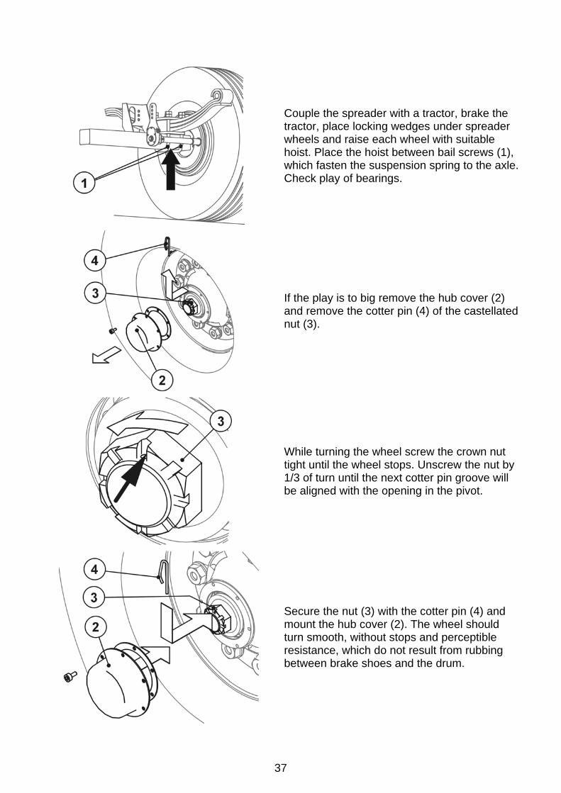
Couple the spreader with a tractor, brake the tractor, place locking wedges under spreader wheels and raise each wheel with suitable hoist. Place the hoist between bail screws (1), which fasten the suspension spring to the axle. Check play of bearings.
If the play is to big remove the hub cover (2) and remove the cotter pin (4) of the castellated nut (3).
While turning the wheel screw the crown nut tight until the wheel stops. Unscrew the nut by 1/3 of turn until the next cotter pin groove will be aligned with the opening in the pivot.
Secure the nut (3) with the cotter pin (4) and mount the hub cover (2). The wheel should turn smooth, without stops and perceptible resistance, which do not result from rubbing between brake shoes and the drum.
38
6.2 Adjustment of brakes The brakes should be adjusted if:
• excessive play between shoe and drum appears due to wear of brake shoes; braking efficiency falls down
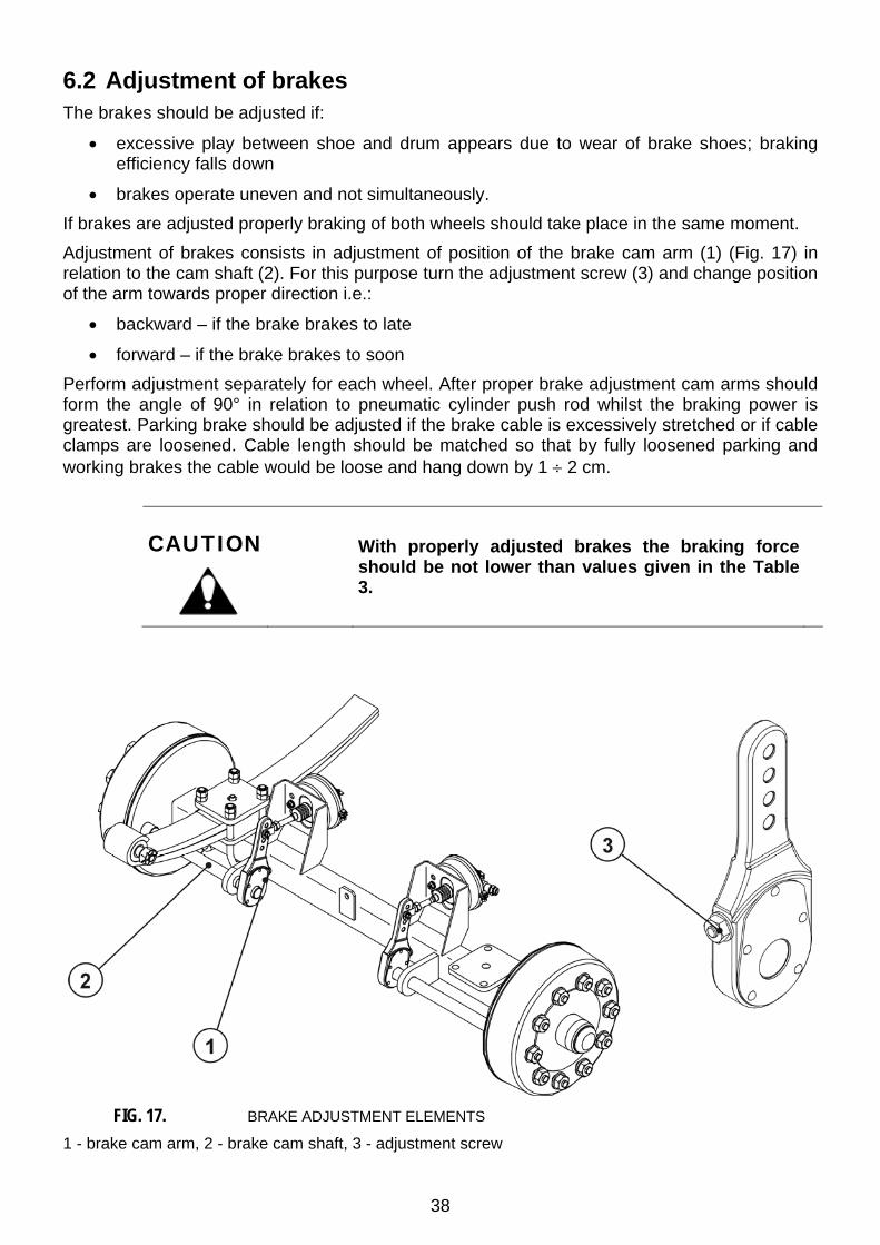
• brakes operate uneven and not simultaneously. If brakes are adjusted properly braking of both wheels should take place in the same moment. Adjustment of brakes consists in adjustment of position of the brake cam arm (1) (Fig. 17) in relation to the cam shaft (2). For this purpose turn the adjustment screw (3) and change position of the arm towards proper direction i.e.:
• backward – if the brake brakes to late
• forward – if the brake brakes to soon Perform adjustment separately for each wheel. After proper brake adjustment cam arms should form the angle of 90° in relation to pneumatic cylinder push rod whilst the braking power is greatest. Parking brake should be adjusted if the brake cable is excessively stretched or if cable clamps are loosened. Cable length should be matched so that by fully loosened parking and working brakes the cable would be loose and hang down by 1 ÷ 2 cm.
CAUTION
With properly adjusted brakes the braking force should be not lower than values given in the Table 3.
FIG. 17. BRAKE ADJUSTMENT ELEMENTS
1 - brake cam arm, 2 - brake cam shaft, 3 - adjustment screw

39
Table 3. Braking force.
Main brake braking force (kN) Parking brake braking force (kN)
70 35
Difference between left and right wheel braking forces must not exceed 30% with assumption that the “100%” means the greater force.
CAUTION
The spreader braking force is the sum of braking forces of both wheels.
6.3 Maintenance of the pneumatic system Within the scope of maintenance operations it is necessary to perform inspection of pneumatic system tightness, especially at all connections. Tightness test should be executed with system pressure rated at ca. 600 kPa (6,0 kg/cm2). If conduits, sealing or other elements of the system are damaged, air will get out in points of damage with typical hiss or – in the case of small leakage – in the form of small air bubbles. Small leakage can be detected with soap water or washing agent. Damaged sealing or conduits should be replaced with new ones. If the reason of leakage is the damaged pneumatic cylinder – replace it. Periodically remove condensed water from the air tank. For this purpose pull out the drain valve arbour located in the upper part of the tank. Compressed air will push the water out. After loosening the mandrel the valve should close automatically and stop airflow from the tank. Once a year just before the winter unscrew the drain valve and clean it from accumulated dirt.
6.4 Maintenance of the hydraulic system It is necessary to take as the principle that the oil in the spreader hydraulic system and the oil in the external tractor hydraulic system is of the same type. Application of different oil types is prohibited. Brand new spreaders are filled with HL32 hydraulic oil. The hydraulic system of the spreader should be absolutely tight. In the end of the manual there is a table containing admissible oil types. Test of tightness consists in coupling of the spreader with a tractor, activation of the hydraulic cylinders for the rear gate and for the rear adapter guard and keeping them in its maximally pulled out position for 30 s. If oil leaks at connections of hydraulic conduits, screw the connection tightly; if leakage persists – replace the conduit or the connector with a new one. If oil leaks between connections (leaky conduit), replace the damaged conduit. Each mechanical damage requires replacement of damaged element.

40
If the body of the hydraulic cylinder is polluted with oil check the reason of leakage. While the cylinders are entirely pulled out check all sealings. Small leakage of “sweating off” type are admissible; if drops of oil are observed – stop the operation and repair the failure.
CAUTION
Operation of the spreader with leaky tilting hydraulic system is prohibited. Condition of the hydraulic system should be checked all time during spreader’s operation.
If the hydraulic system is used very intensively replace hydraulic conduits every 4 years.
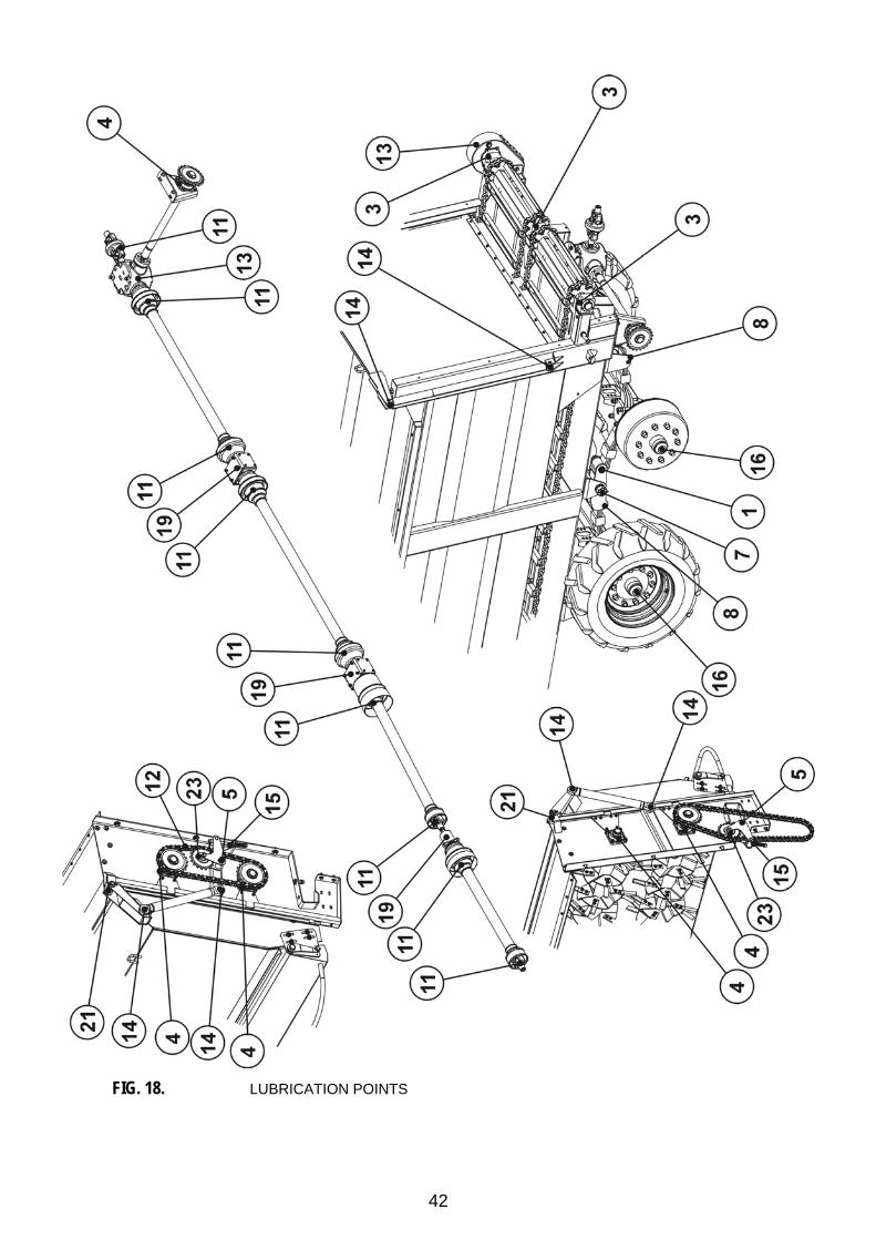
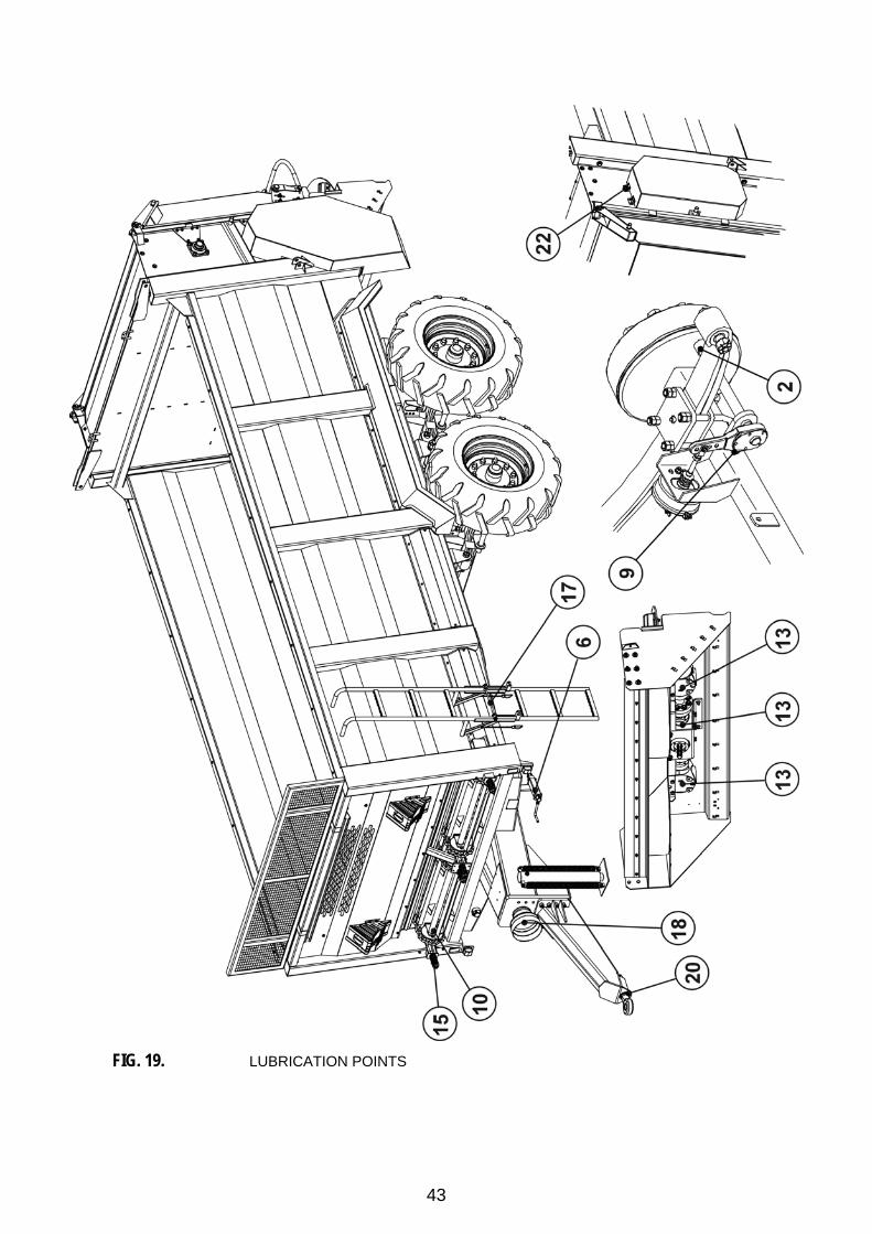
6.5 Lubrication The spreader should be lubricated in points shown on Figs 18 and 19, and described in the Table 4.

41
Table 4. Spreader lubrication points
No. on the Fig. 18, 19
Lubrication point Number of points Grease type Frequency
1 Suspension spring bolt 4 SOLID every 1 month
2 Brake cam shaft sleeves 8 SOLID every 6 months
3 Bearing bushes in PTO shaft housings 3 SOLID every 8 hrs
4 Bearing unit 5 SOLID every 6 months
5 Stretcher bolt 2 SOLID every 3 months
6 Parking brake screw 1 SOLID every 3 months
7 Rocker bolt 2 SOLID every 1 month
8 Slide surfaces of suspension springs 4 SOLID every 1 month
9 Adjustment screw of the brake cam shaft 4 SOLID every 6 months
10 Bearing bushes of the front conveyor axle 4 SOLID every 8 hrs
11 Articulated joints of shafts 10 SOLID every 3 months
12 Drive chain for adapter drums 2 SOLID, GRAPHITE every 1 week
13 Gears 5 OIL ∗ every 24 months
14 Hydraulic cylinder eyes 8 SOLID every 3 months
15 Tightening screw 4 SOLID every 6 months
16 Wheel bearings 4 SOLID every 24 months
17 Ladder bolt 2 SOLID every 3 months
18 Surface of splines of the PTO shaft 8 SOLID every 6 months
19 Bearings of connector of shaft system 3 SOLID every 24 months
20 Rotary string 1 SOLID every 6 months
21 Adapter cover bolts 2 SOLID every 6 months
22 Hinges of adapter side guards 4 SOLID every 3 months
23 Bearings and bearing bushes of the chain stretcher 4 SOLID every 3 months
∗ gear oil GL4 (SAE 90)
42
FIG. 18. LUBRICATION POINTS
43
FIG. 19. LUBRICATION POINTS
44
6.6 Maintenance of the suspension system Maintenance of suspension system consists in periodical lubrication in points given in the Table 4 and inspection of condition of suspension spring leafs. Suspension spring leafs should be covered with thin layer of penetrating anticorrosive & lubricating agent. Avoid accumulation of dried mud layer on suspension springs.
CAUTION
In the case of break of a spring leaf in any suspension spring stop operating the spreader and remove the failure.
6.7 Adjustment of tension of the adapter drive chain
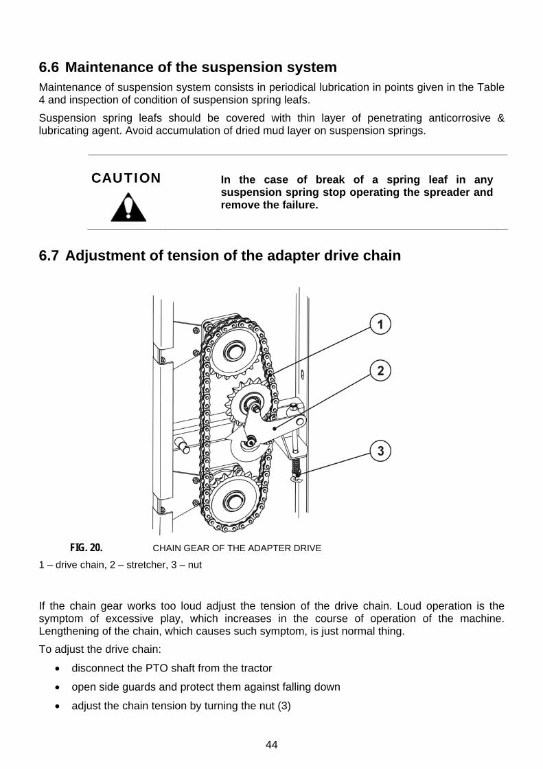
FIG. 20. CHAIN GEAR OF THE ADAPTER DRIVE
1 – drive chain, 2 – stretcher, 3 – nut
If the chain gear works too loud adjust the tension of the drive chain. Loud operation is the symptom of excessive play, which increases in the course of operation of the machine. Lengthening of the chain, which causes such symptom, is just normal thing. To adjust the drive chain:
• disconnect the PTO shaft from the tractor
• open side guards and protect them against falling down
• adjust the chain tension by turning the nut (3)

45
Proper chain play measured in the half length of the working part should amount to 5 - 15 mm. If it is impossible to adjust the chain tension, replace the chain with a new one. Prior to removal of the chain first loosen the stretcher with the nut (3). Removal of the chain is realised by disconnection of the connection link (2) of the chain.
FIG. 21. REMOVAL OF THE CHAIN
1 – bolt, 2 – connection link, 3 – cotter pin
6.8 Adjustment of tension of the floor conveyor chain In the course of operation of the spreader, especially within the initial period, pay attention to proper tension of conveyor chains. The tension is checked by raising the chains in their half length perpendicularly to the floor. The play should amount to 20 - 50 mm when applied force amounts to ca. 60 kg. Chain tension is realised with help of tightening screws situated on the front beam of the spreader.
CAUTION
Excessive chain play may cause serious damage of the spreader and endanger operators and third persons.

46


