Embed Size (px)
Citation preview
1
Materials for Advanced
Commercial Aircraft Structures
Anoush Poursartip, Ph.D., P.Eng.
Professor, Department of Materials Engineering
The University of British Columbia
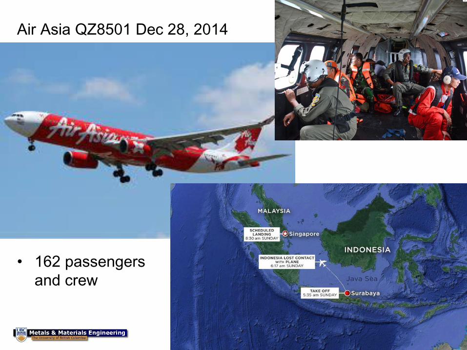
Air Asia QZ8501 Dec 28, 2014
• 162 passengers
and crew
2
• MH
3
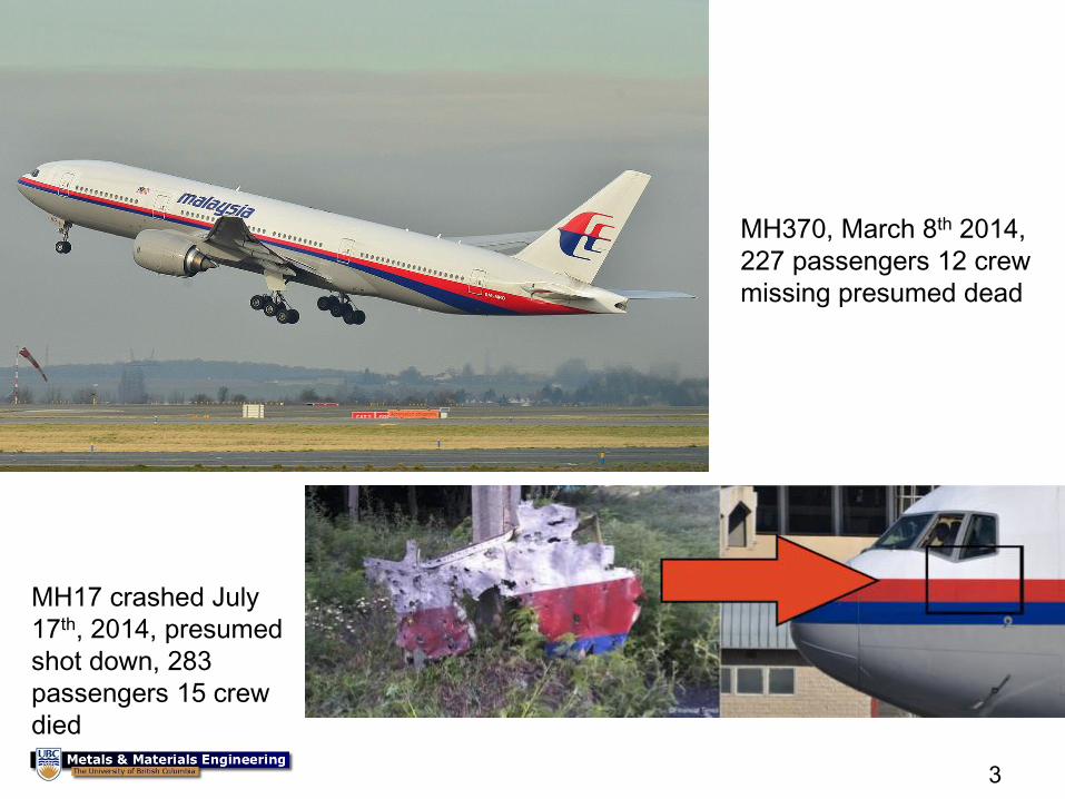
MH370, March 8th 2014,
227 passengers 12 crew
missing presumed dead
MH17 crashed July
17th, 2014, presumed
shot down, 283
passengers 15 crew
died
4
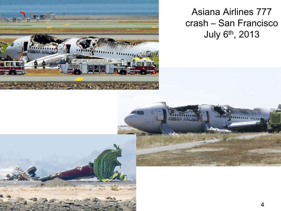
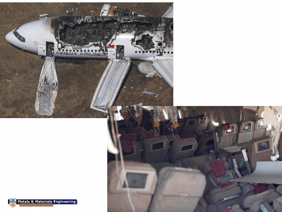
Asiana Airlines 777
crash – San Francisco
July 6th, 2013
5
6

7
9 May 2012
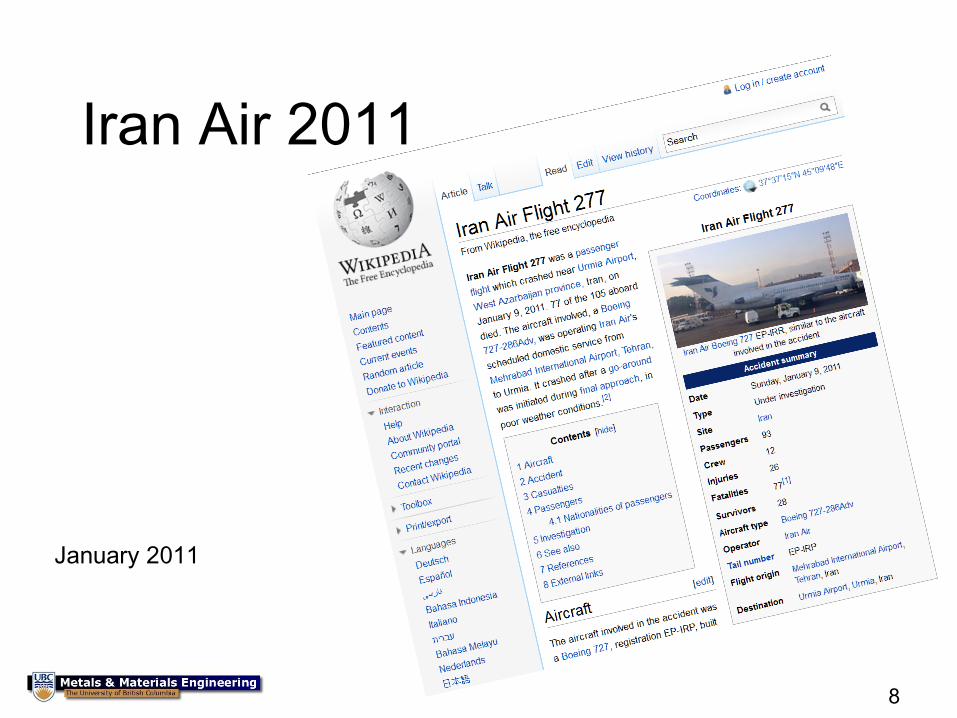
Iran Air 2011
8
January 2011
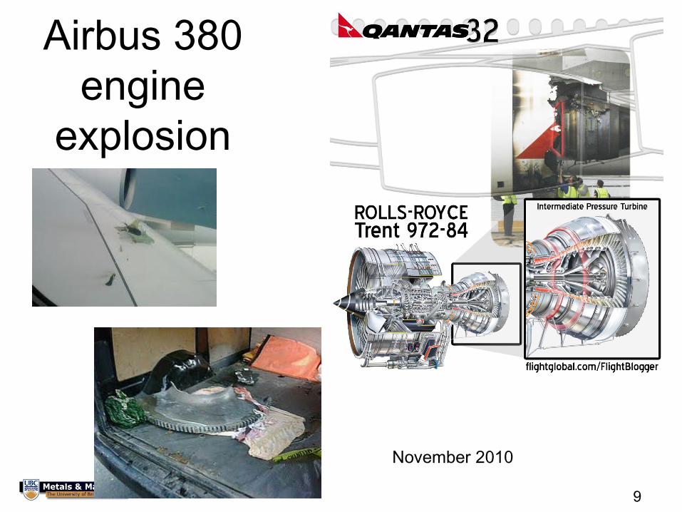
Airbus 380
engine
explosion
9
November 2010

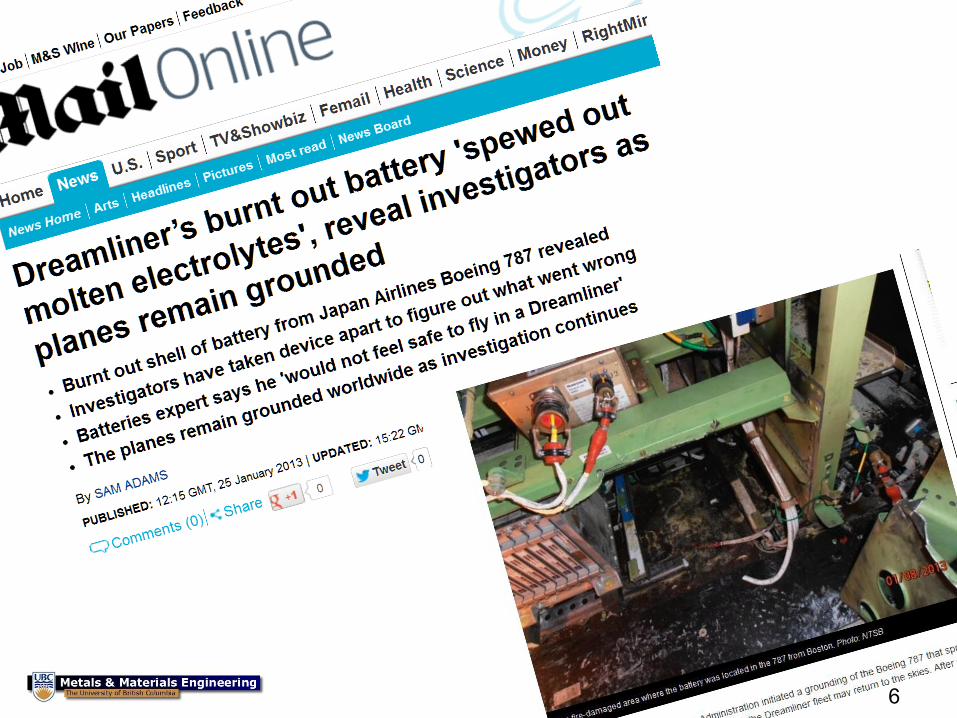
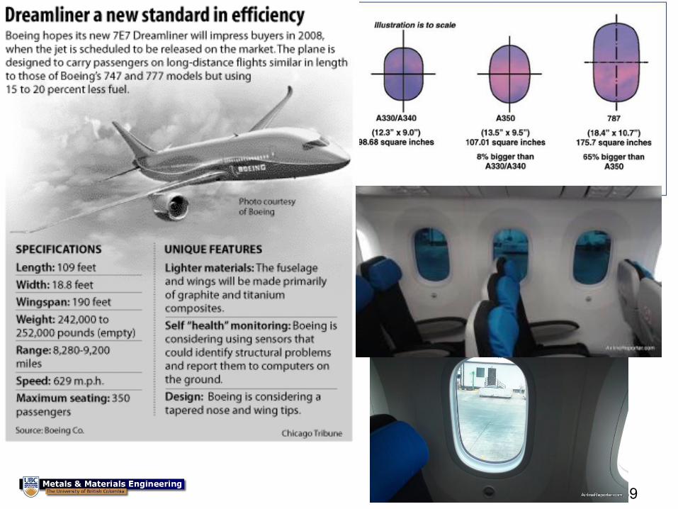
Boeing 787
electrical fire
10
Similar 777
electrical
panel fire
November 2010
11
Case Study Objective, Concepts
and Content • To introduce you to engineering
– The difference between science and engineering
– The history of our profession
• To introduce you to materials engineering – All objects are made of something, and what material you
use has functional, aesthetic, cost, safety, and environmental implications
• To introduce you to an important industry: aerospace
• To introduce you to the decisions an engineer makes

12 Salisbury Cathedral, ~1250 AD
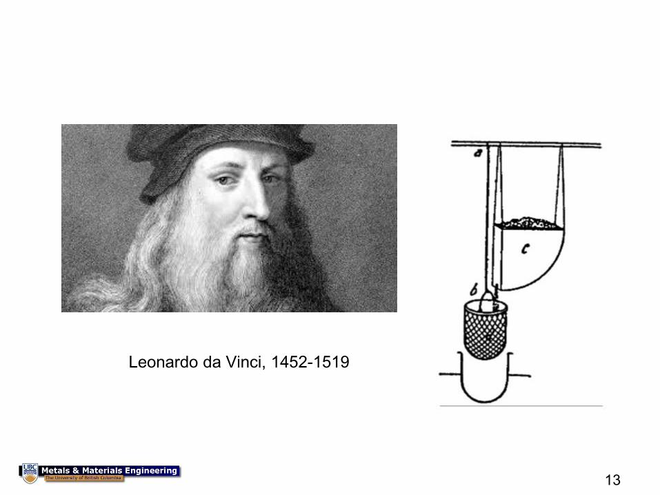
13
Leonardo da Vinci, 1452-1519

14
How you will be assessed
• This case-study is part of the overall
APSC150 course, directed and organized by
Professor Bhushan Gopaluni
• This case study is assessed by a single
closed book multiple choice quiz at the end of
case study.
• The quiz will be Feb 3rd, 2015 6:30-8:30 pm
CIRS 1250
15
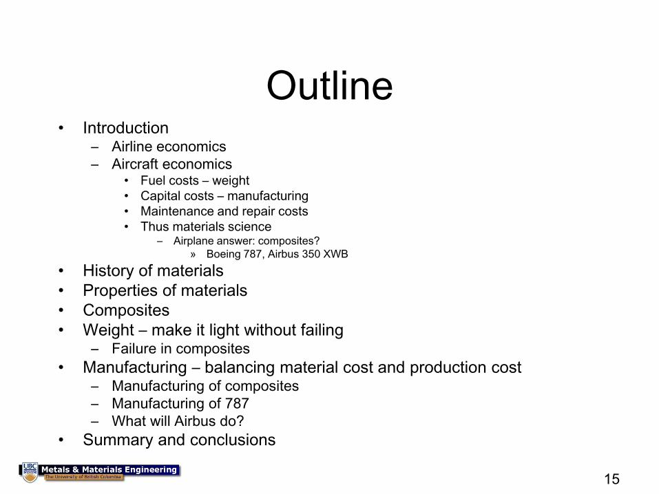
Outline • Introduction
– Airline economics
– Aircraft economics • Fuel costs – weight
• Capital costs – manufacturing
• Maintenance and repair costs
• Thus materials science – Airplane answer: composites?
» Boeing 787, Airbus 350 XWB
• History of materials
• Properties of materials
• Composites
• Weight – make it light without failing – Failure in composites
• Manufacturing – balancing material cost and production cost – Manufacturing of composites
– Manufacturing of 787
– What will Airbus do?
• Summary and conclusions
16
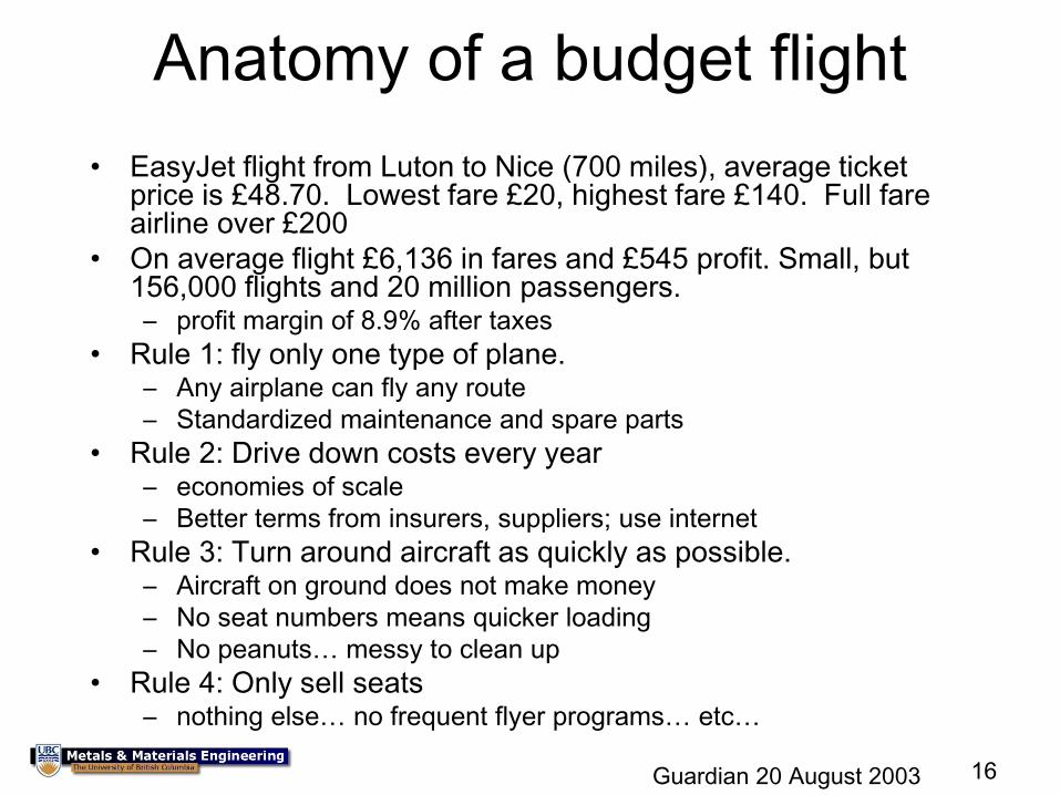
Anatomy of a budget flight
• EasyJet flight from Luton to Nice (700 miles), average ticket price is £48.70. Lowest fare £20, highest fare £140. Full fare airline over £200
• On average flight £6,136 in fares and £545 profit. Small, but 156,000 flights and 20 million passengers. – profit margin of 8.9% after taxes
• Rule 1: fly only one type of plane. – Any airplane can fly any route
– Standardized maintenance and spare parts
• Rule 2: Drive down costs every year – economies of scale
– Better terms from insurers, suppliers; use internet
• Rule 3: Turn around aircraft as quickly as possible. – Aircraft on ground does not make money
– No seat numbers means quicker loading
– No peanuts… messy to clean up
• Rule 4: Only sell seats – nothing else… no frequent flyer programs… etc…
Guardian 20 August 2003
17
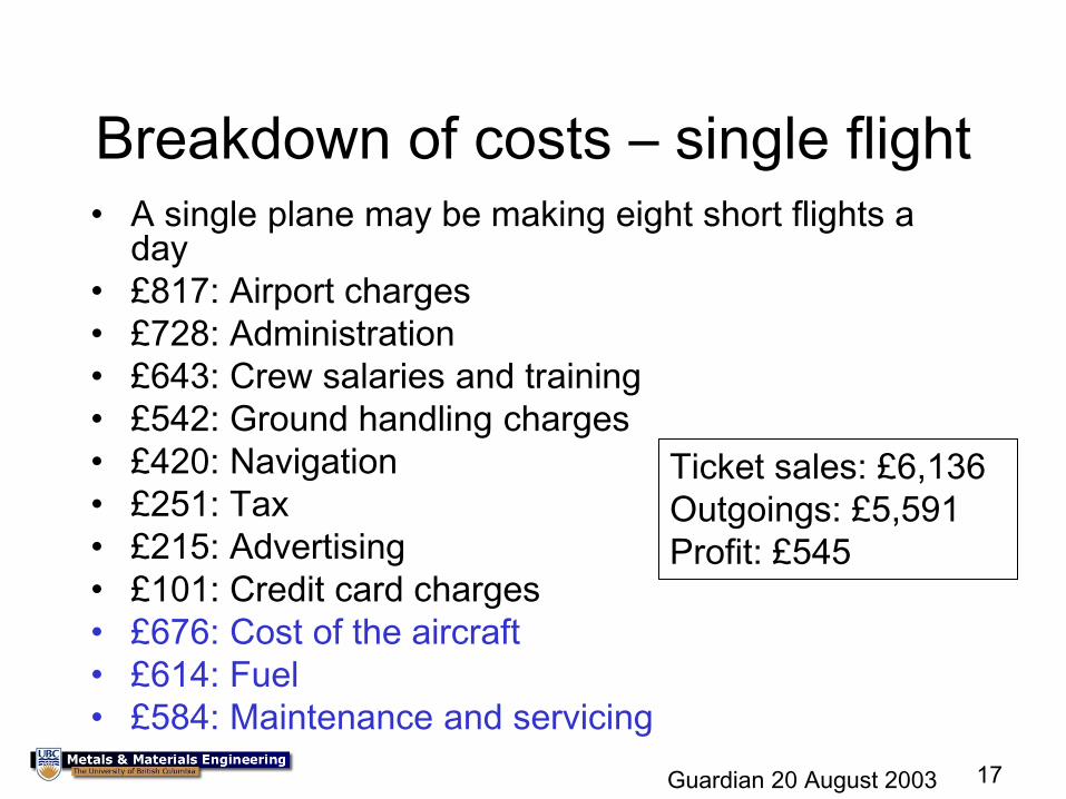
Breakdown of costs – single flight • A single plane may be making eight short flights a
day
• £817: Airport charges
• £728: Administration
• £643: Crew salaries and training
• £542: Ground handling charges
• £420: Navigation
• £251: Tax
• £215: Advertising
• £101: Credit card charges
• £676: Cost of the aircraft
• £614: Fuel
• £584: Maintenance and servicing
Ticket sales: £6,136
Outgoings: £5,591
Profit: £545
Guardian 20 August 2003
18
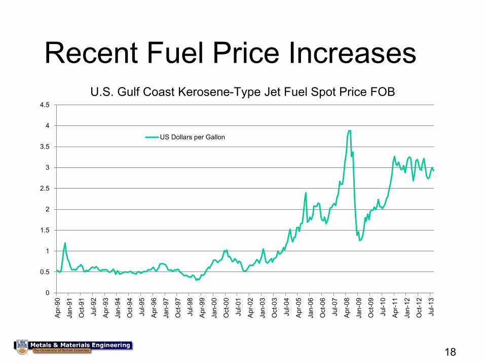
Recent Fuel Price Increases
0
0.5
1
1.5
2
2.5
3
3.5
4
4.5
Apr-
90
Jan-9
1
Oct-
91
Jul-9
2
Apr-
93
Jan-9
4
Oct-
94
Jul-9
5
Apr-
96
Jan-9
7
Oct-
97
Jul-9
8
Apr-
99
Jan-0
0
Oct-
00
Jul-0
1
Apr-
02
Jan-0
3
Oct-
03
Jul-0
4
Apr-
05
Jan-0
6
Oct-
06
Jul-0
7
Apr-
08
Jan-0
9
Oct-
09
Jul-1
0
Apr-
11
Jan-1
2
Oct-
12
Jul-1
3
U.S. Gulf Coast Kerosene-Type Jet Fuel Spot Price FOB
US Dollars per Gallon
19
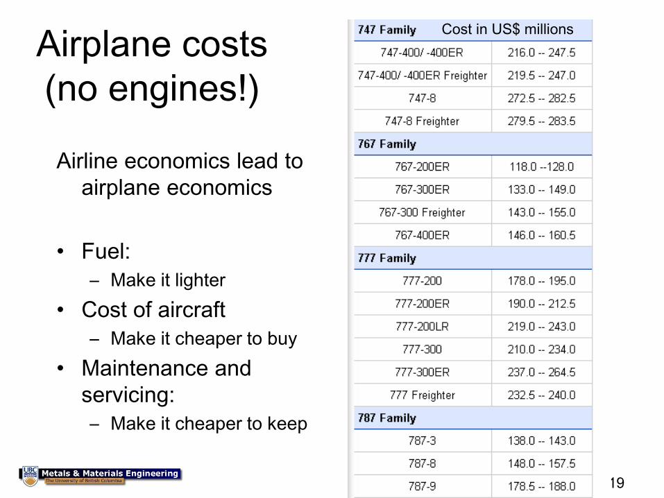
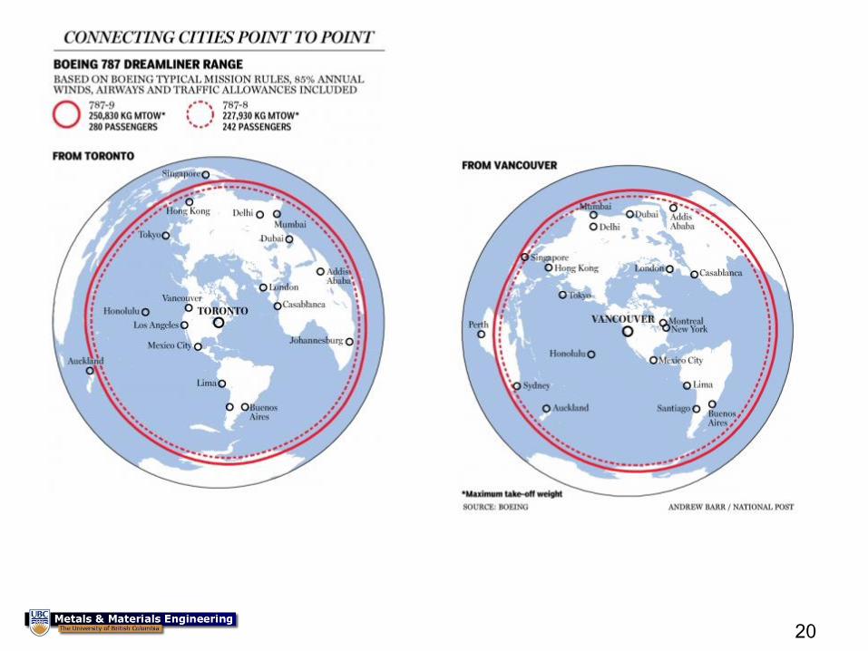
Airplane costs
(no engines!)
Airline economics lead to
airplane economics
• Fuel:
– Make it lighter
• Cost of aircraft
– Make it cheaper to buy
• Maintenance and
servicing:
– Make it cheaper to keep
Cost in US$ millions
20
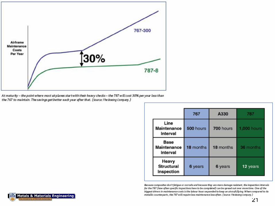
21
22
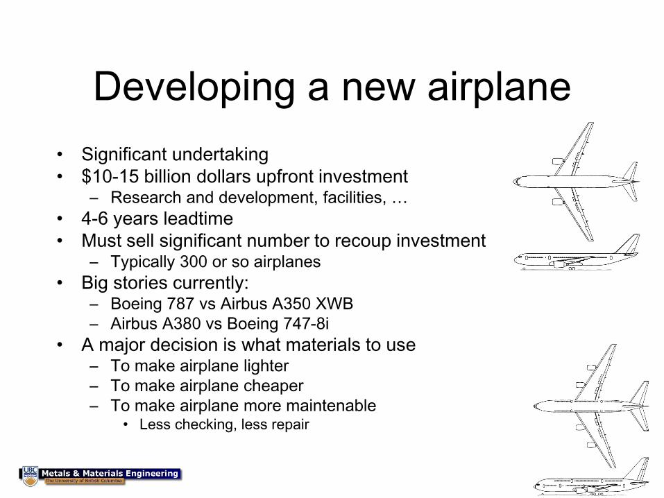
Developing a new airplane
• Significant undertaking
• $10-15 billion dollars upfront investment – Research and development, facilities, …
• 4-6 years leadtime
• Must sell significant number to recoup investment – Typically 300 or so airplanes
• Big stories currently: – Boeing 787 vs Airbus A350 XWB
– Airbus A380 vs Boeing 747-8i
• A major decision is what materials to use – To make airplane lighter
– To make airplane cheaper
– To make airplane more maintenable • Less checking, less repair

23
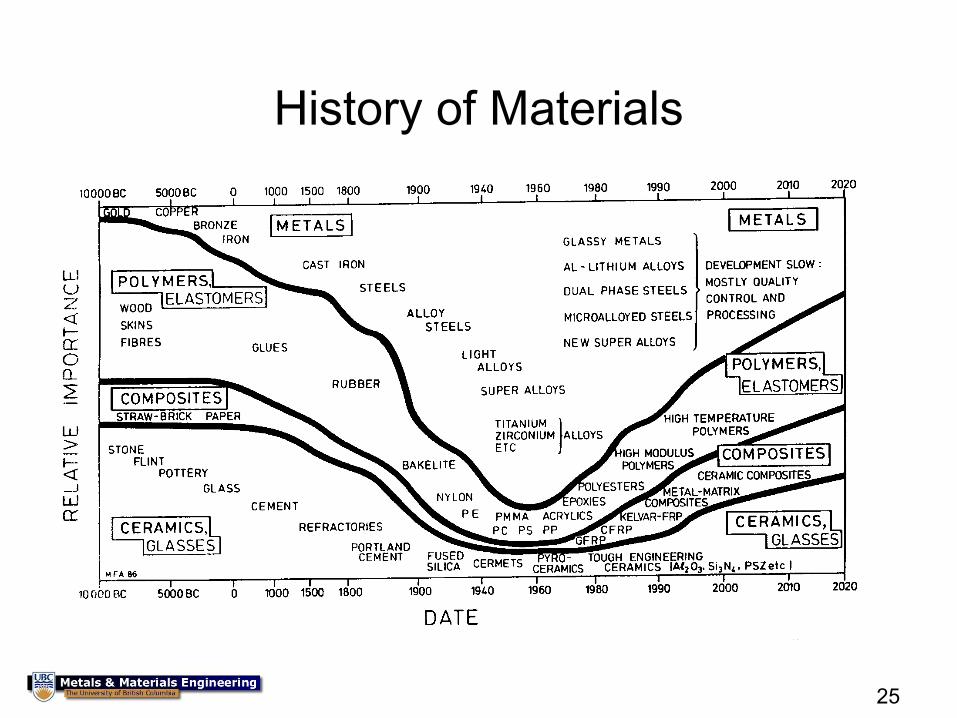
Overview of materials
History
Considerations in design
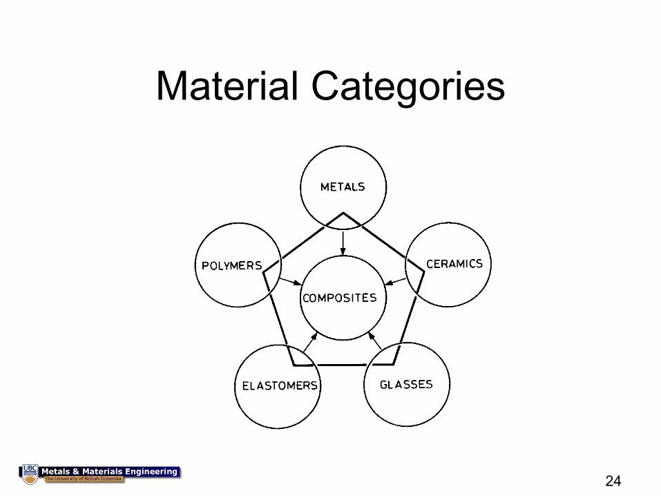
24
Material Categories
25
History of Materials
26
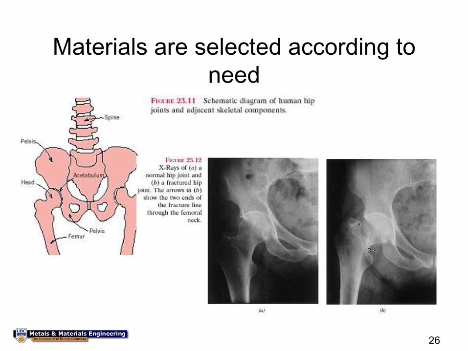
Materials are selected according to
need
27
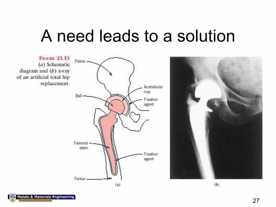
A need leads to a solution
28
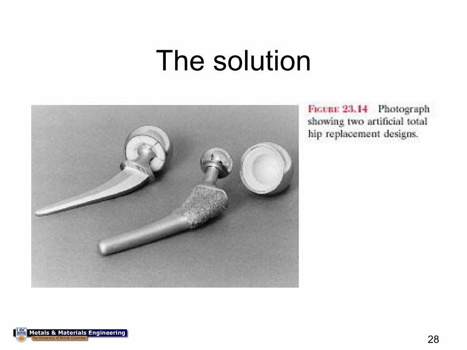
The solution
29
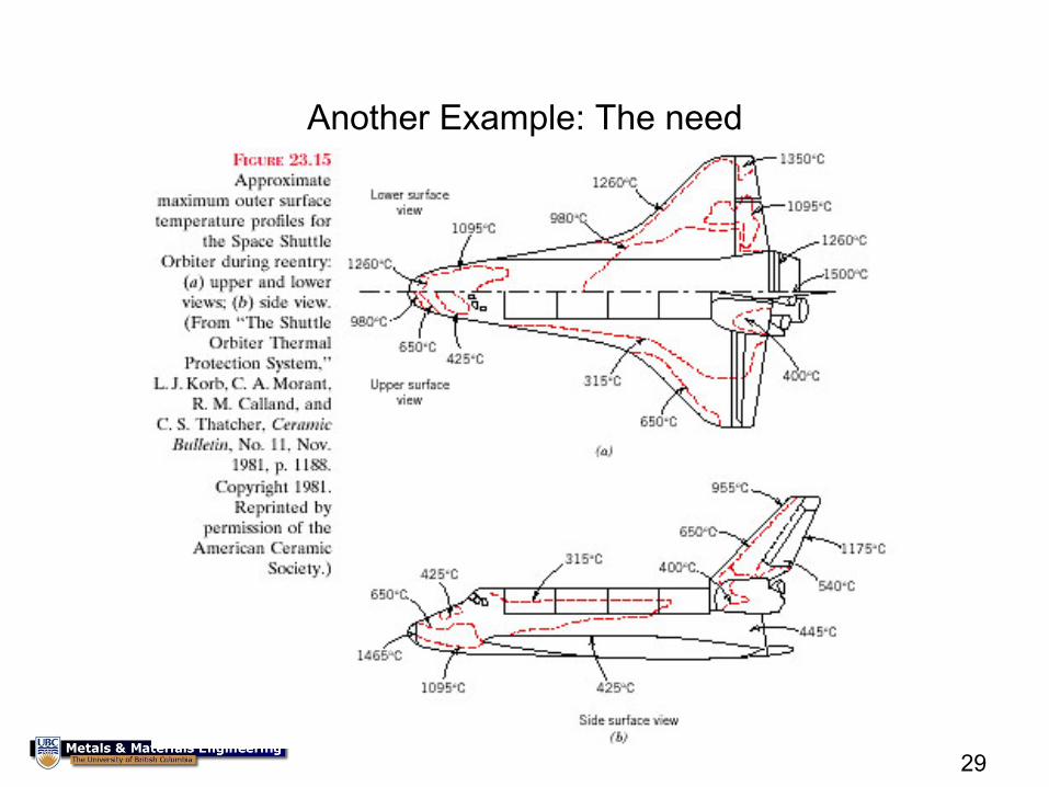
Another Example: The need
30
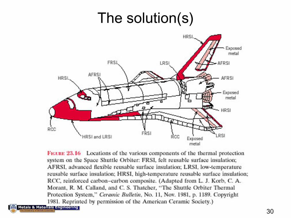
The solution(s)
31
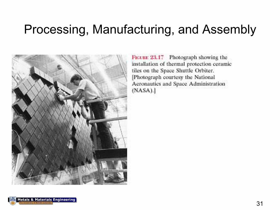
Processing, Manufacturing, and Assembly
32
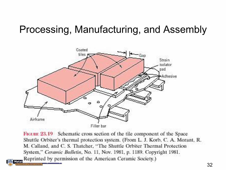
Processing, Manufacturing, and Assembly
33
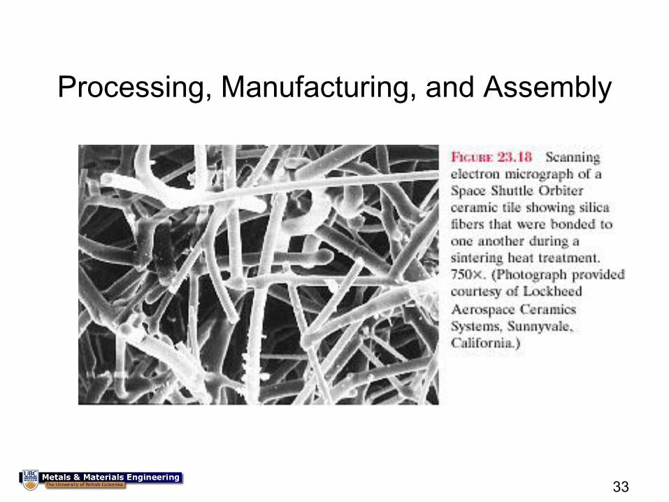
Processing, Manufacturing, and Assembly
34
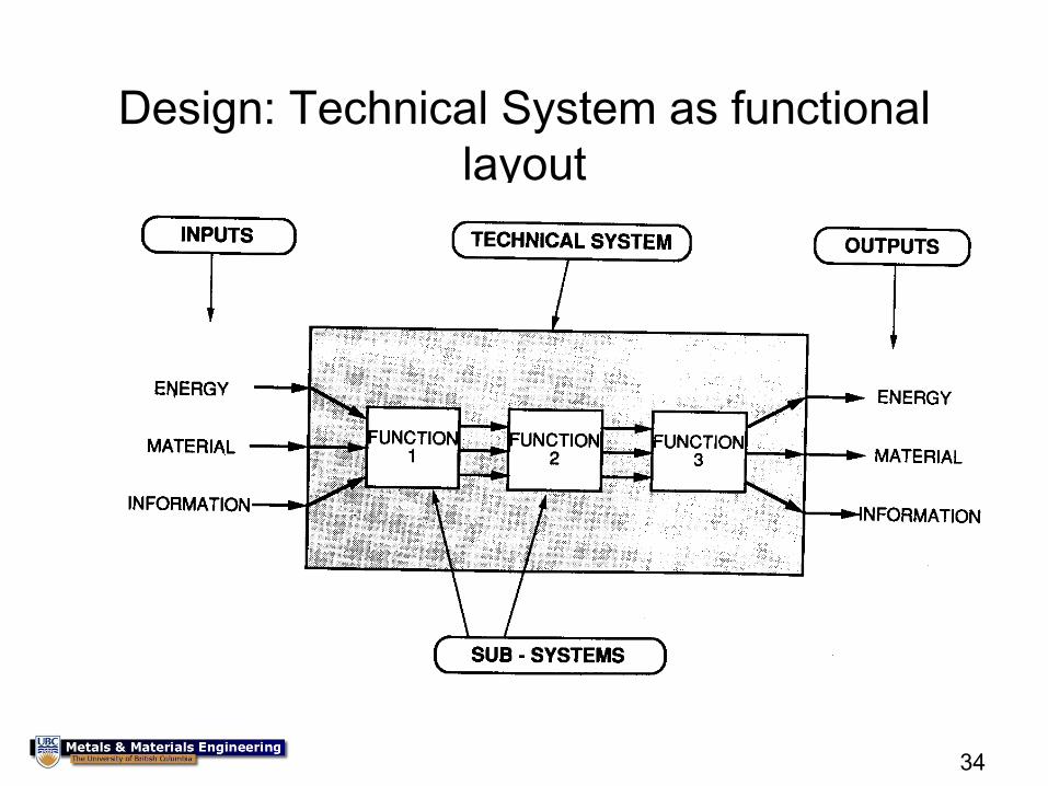
Design: Technical System as functional
layout
35
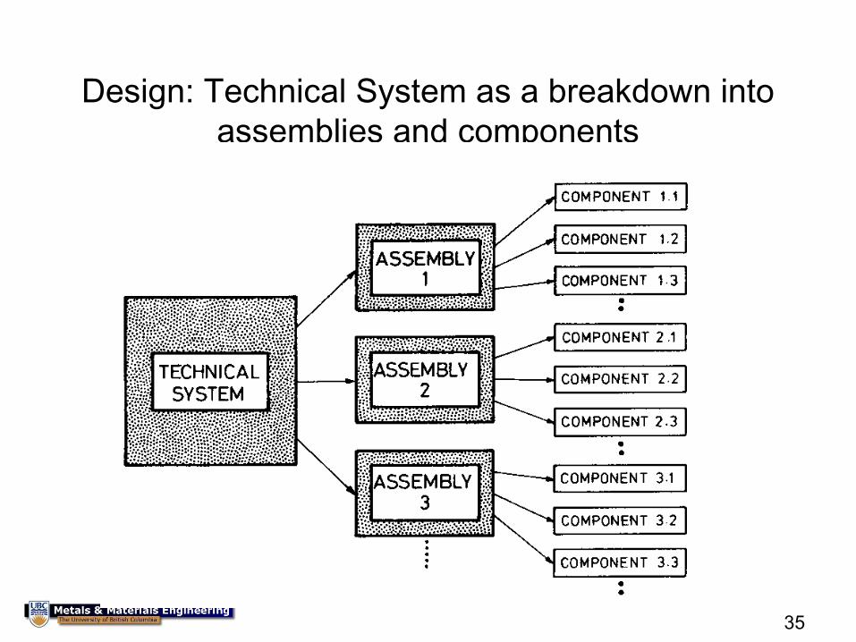
Design: Technical System as a breakdown into
assemblies and components
36
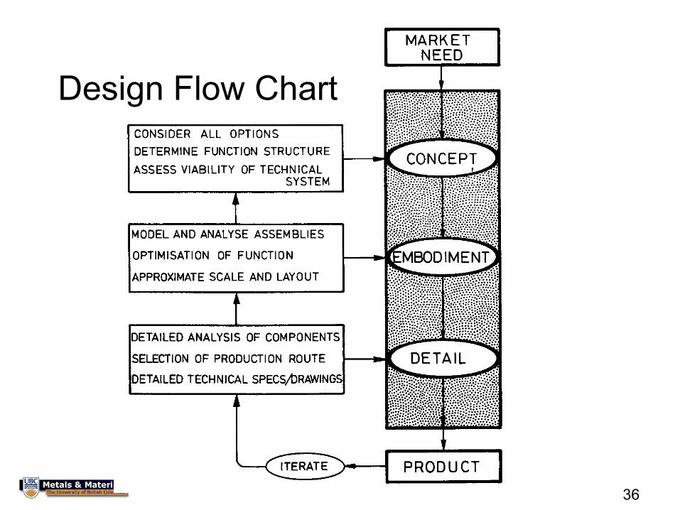
Design Flow Chart
37
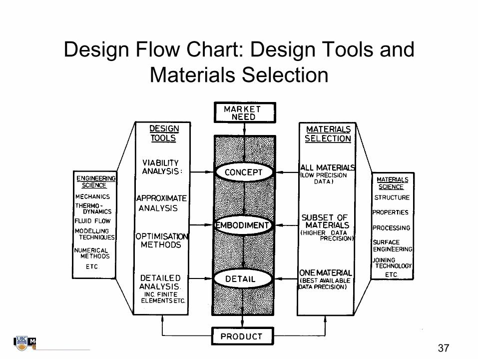
Design Flow Chart: Design Tools and
Materials Selection
38
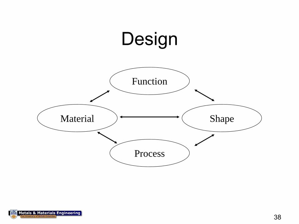
Design
Function
Process
Material Shape
39
40
41
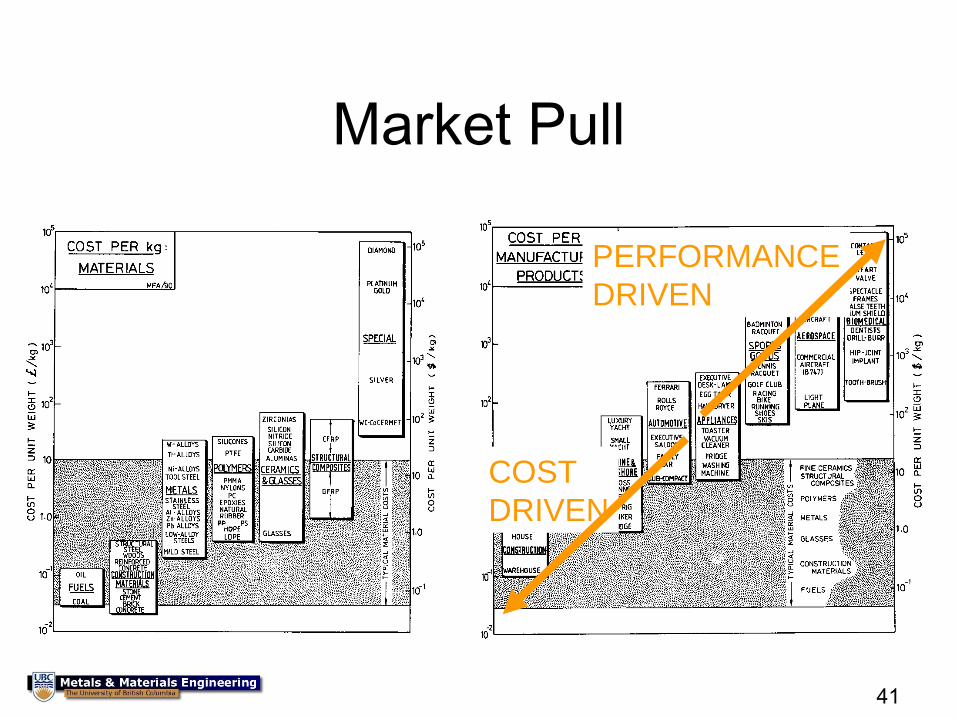
Market Pull
PERFORMANCE
DRIVEN
COST
DRIVEN
42
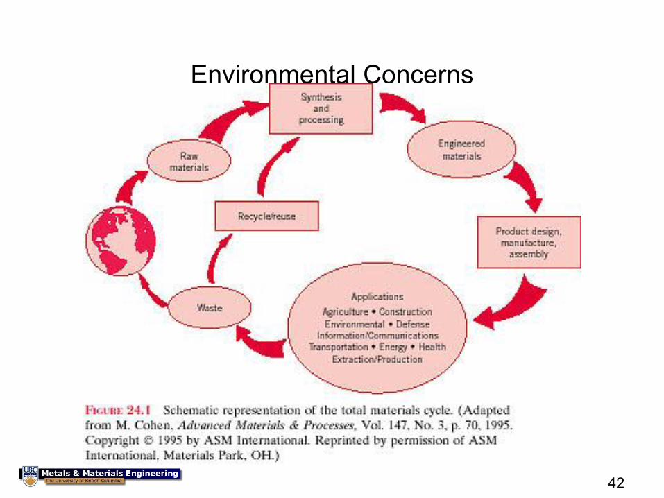
Environmental Concerns
43
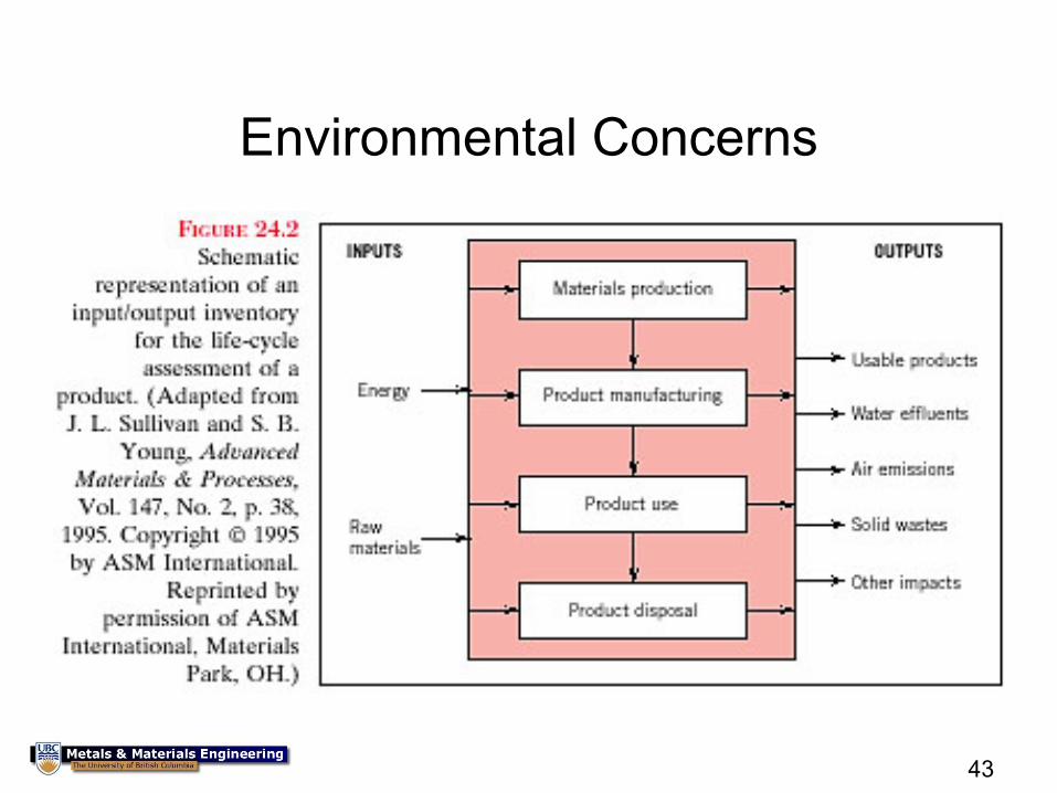
Environmental Concerns
44
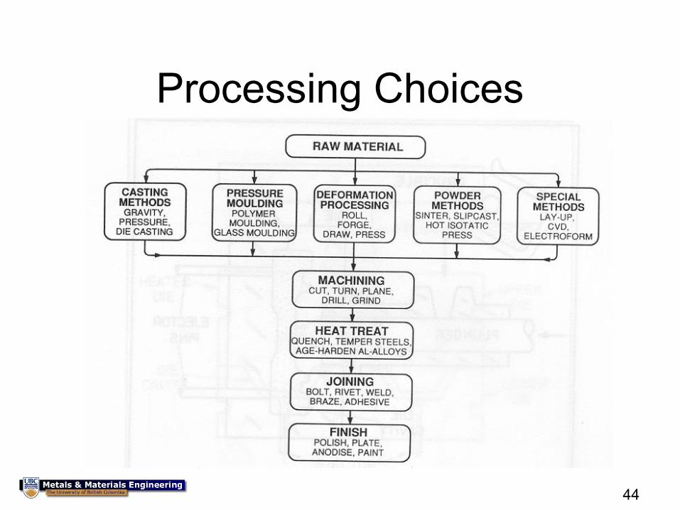
Processing Choices
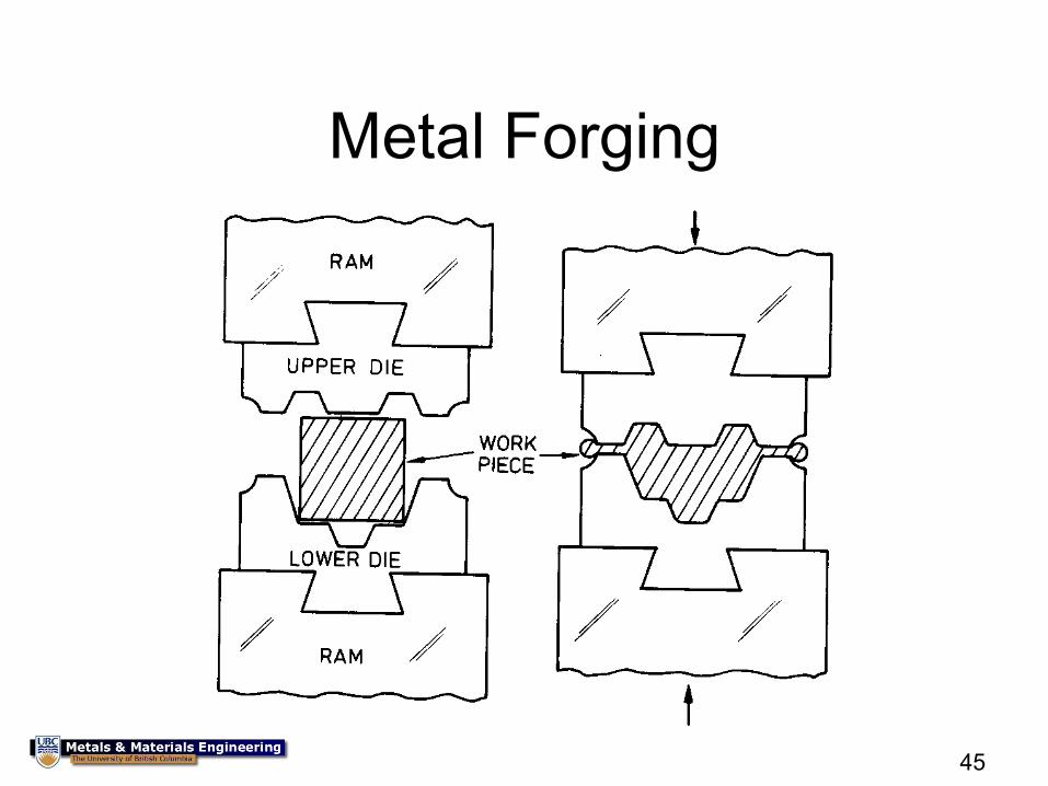
45
Metal Forging
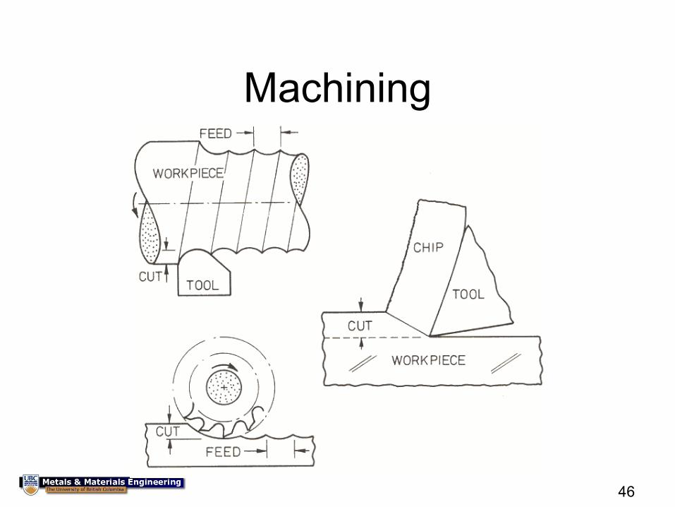
46
Machining
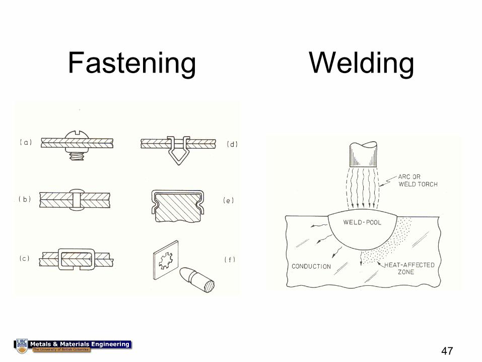
47
Fastening Welding
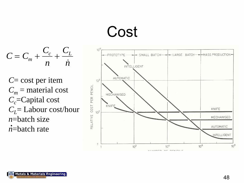
48
Cost
C CC
n
C
nm
c L
C= cost per item
Cm = material cost
Cc=Capital cost
CL= Labour cost/hour
n=batch size
n=batch rate .
49
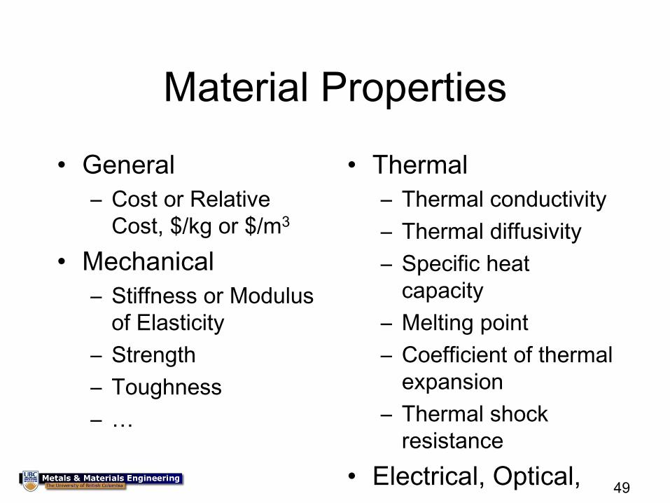
Material Properties
• General
– Cost or Relative
Cost, $/kg or $/m3
• Mechanical
– Stiffness or Modulus
of Elasticity
– Strength
– Toughness
– …
• Thermal
– Thermal conductivity
– Thermal diffusivity
– Specific heat
capacity
– Melting point
– Coefficient of thermal
expansion
– Thermal shock
resistance
• Electrical, Optical,
…
50
Material Properties
• In general, there are two routes to defining properties – Fundamental properties: based on sound physics, with a
simple basis. There is good understanding, which generally leads to property values that are insensitive to test method details, and are easy to interpret: e.g. Melting Point
– Complex, derived properties: based more on need, with the physics and understanding incomplete or too complex. Therefore different test methods lead to different results and it is more difficult to interpret and compare: e.g. Bike Helmet Liner Material Performance
• So that we all get the same values for properties, we use the concept of a ‘standard’ – An agreed upon method to determine the properties or
behaviour of a material
– CSA, ASTM, DIN, ISO, ….
51
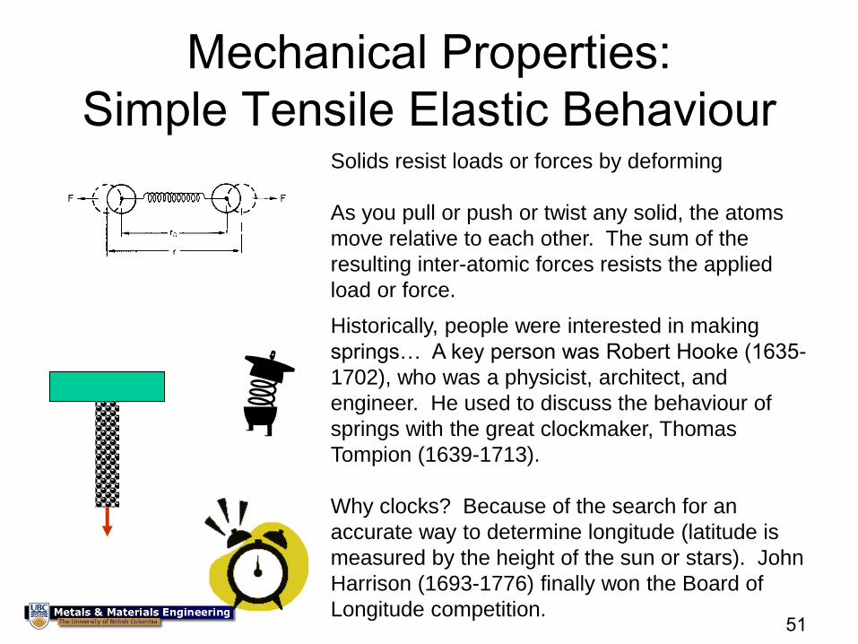
Mechanical Properties:
Simple Tensile Elastic Behaviour Solids resist loads or forces by deforming
As you pull or push or twist any solid, the atoms
move relative to each other. The sum of the
resulting inter-atomic forces resists the applied
load or force.
Historically, people were interested in making
springs… A key person was Robert Hooke (1635-
1702), who was a physicist, architect, and
engineer. He used to discuss the behaviour of
springs with the great clockmaker, Thomas
Tompion (1639-1713).
Why clocks? Because of the search for an
accurate way to determine longitude (latitude is
measured by the height of the sun or stars). John
Harrison (1693-1776) finally won the Board of
Longitude competition.
52
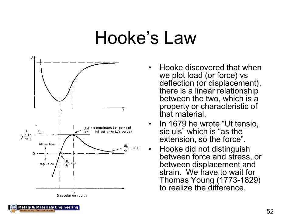
Hooke’s Law
• Hooke discovered that when we plot load (or force) vs deflection (or displacement), there is a linear relationship between the two, which is a property or characteristic of that material.
• In 1679 he wrote “Ut tensio, sic uis” which is “as the extension, so the force”.
• Hooke did not distinguish between force and stress, or between displacement and strain. We have to wait for Thomas Young (1773-1829) to realize the difference.
53
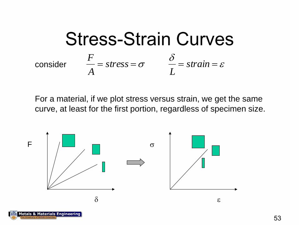
Stress-Strain Curves
consider stressA
F
strain
L
For a material, if we plot stress versus strain, we get the same
curve, at least for the first portion, regardless of specimen size.
F
54
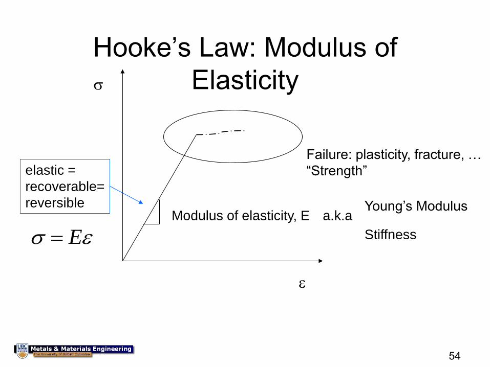
Hooke’s Law: Modulus of
Elasticity
Modulus of elasticity, E Young’s Modulus
Stiffness
Failure: plasticity, fracture, …
“Strength” elastic =
recoverable=
reversible a.k.a
E
55
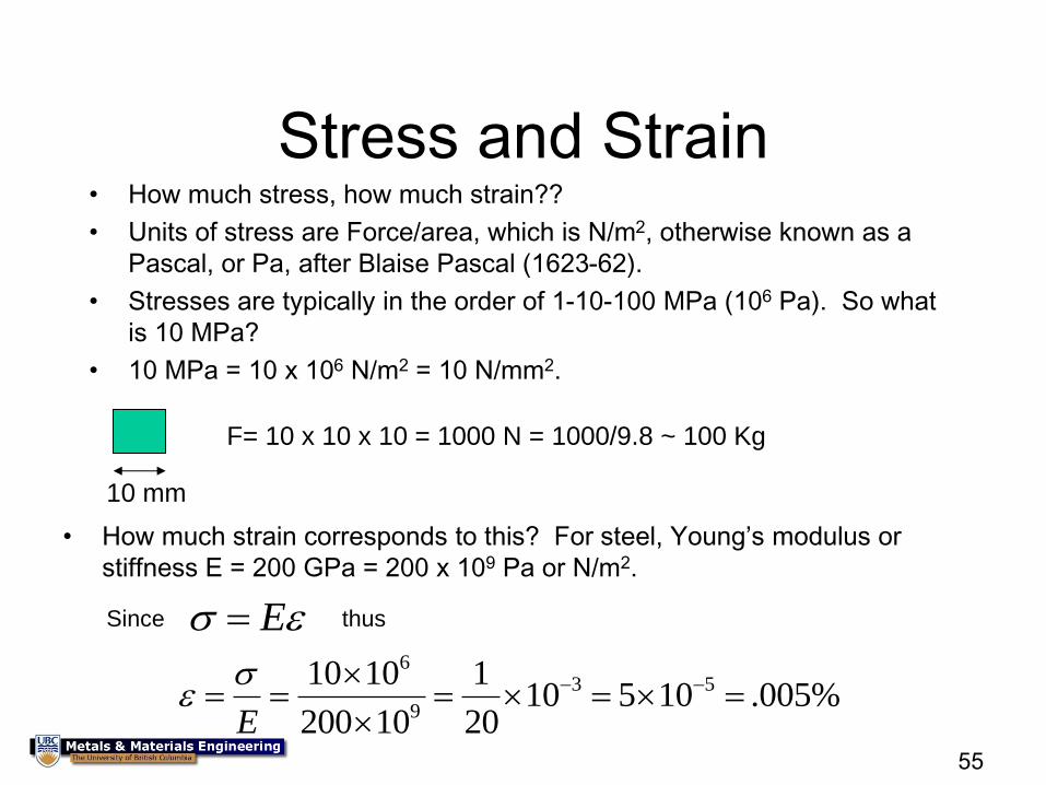
Stress and Strain • How much stress, how much strain??
• Units of stress are Force/area, which is N/m2, otherwise known as a
Pascal, or Pa, after Blaise Pascal (1623-62).
• Stresses are typically in the order of 1-10-100 MPa (106 Pa). So what
is 10 MPa?
• 10 MPa = 10 x 106 N/m2 = 10 N/mm2.
10 mm
F= 10 x 10 x 10 = 1000 N = 1000/9.8 ~ 100 Kg
• How much strain corresponds to this? For steel, Young’s modulus or
stiffness E = 200 GPa = 200 x 109 Pa or N/m2.
Since E thus
63 5
9
10 10 110 5 10 .005%
200 10 20E
56
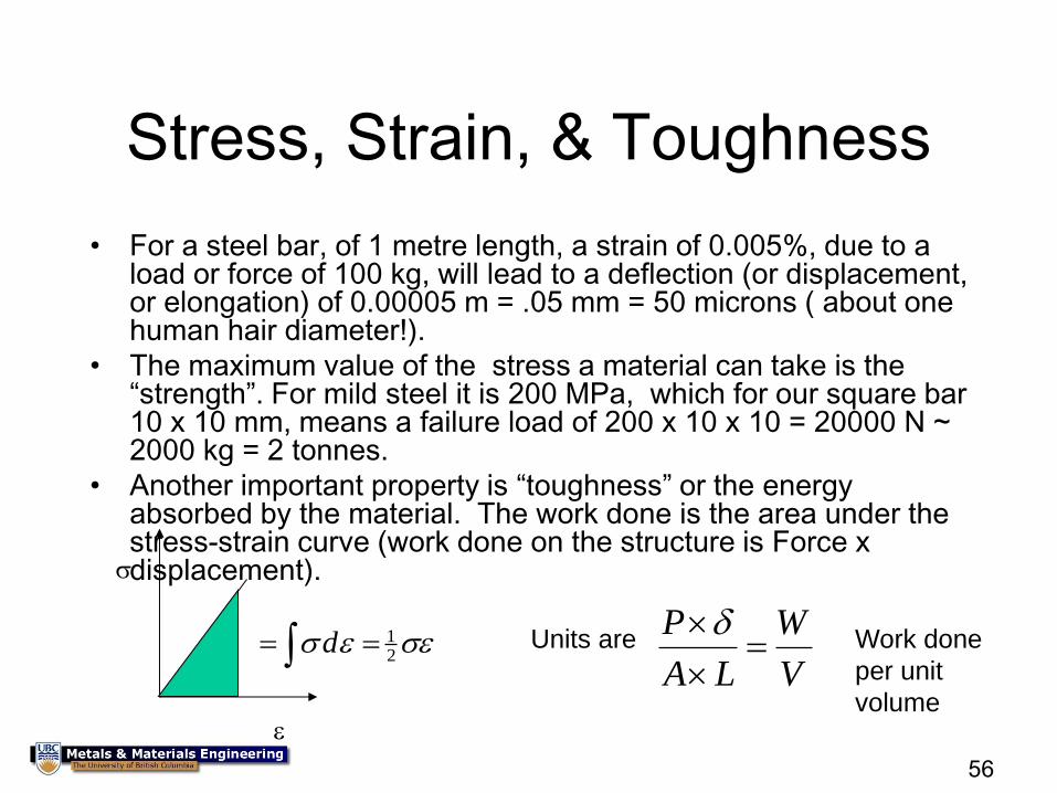
Stress, Strain, & Toughness
• For a steel bar, of 1 metre length, a strain of 0.005%, due to a load or force of 100 kg, will lead to a deflection (or displacement, or elongation) of 0.00005 m = .05 mm = 50 microns ( about one human hair diameter!).
• The maximum value of the stress a material can take is the “strength”. For mild steel it is 200 MPa, which for our square bar 10 x 10 mm, means a failure load of 200 x 10 x 10 = 20000 N ~ 2000 kg = 2 tonnes.
• Another important property is “toughness” or the energy absorbed by the material. The work done is the area under the stress-strain curve (work done on the structure is Force x displacement).
12
d Units are P W
A L V
Work done
per unit
volume
57
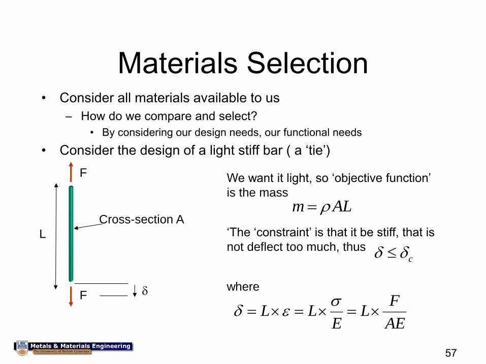
Materials Selection • Consider all materials available to us
– How do we compare and select?
• By considering our design needs, our functional needs
• Consider the design of a light stiff bar ( a ‘tie’)
L
F
F
Cross-section A
We want it light, so ‘objective function’
is the mass
m AL
‘The ‘constraint’ is that it be stiff, that is
not deflect too much, thus c
FL L L
E AE
where
58
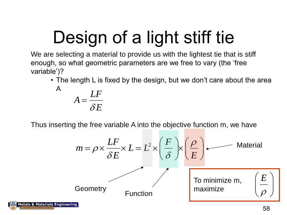
Design of a light stiff tie We are selecting a material to provide us with the lightest tie that is stiff
enough, so what geometric parameters are we free to vary (the ‘free
variable’)?
• The length L is fixed by the design, but we don’t care about the area
A LF
AE
2LF Fm L L
E E
Thus inserting the free variable A into the objective function m, we have
Geometry Function
Material
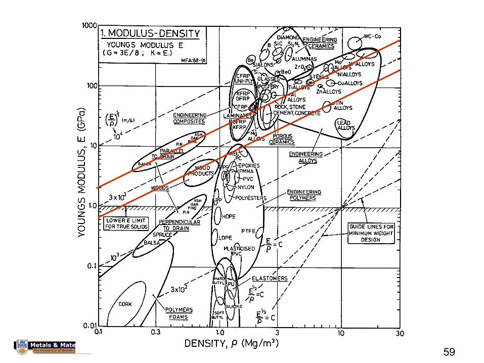
E
To minimize m,
maximize
59
60
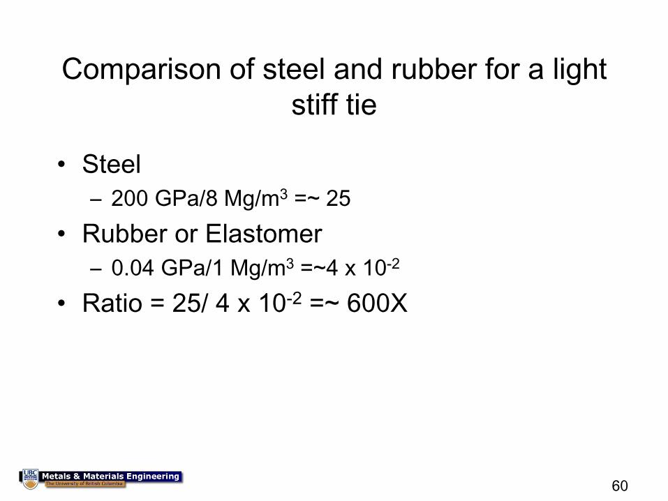
Comparison of steel and rubber for a light
stiff tie
• Steel
– 200 GPa/8 Mg/m3 =~ 25
• Rubber or Elastomer
– 0.04 GPa/1 Mg/m3 =~4 x 10⁻²
• Ratio = 25/ 4 x 10-2 =~ 600X
61
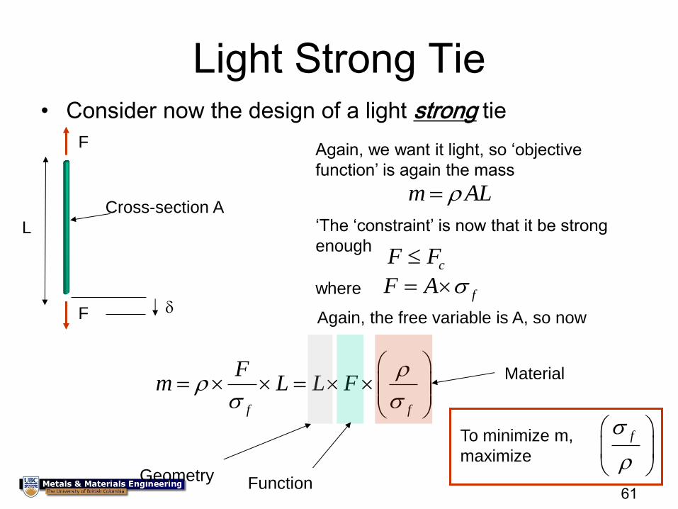
Light Strong Tie • Consider now the design of a light strong tie
L
F
F
Cross-section A
Again, we want it light, so ‘objective
function’ is again the mass
m AL
‘The ‘constraint’ is now that it be strong
enough cF F
fF A where
Again, the free variable is A, so now
f f
Fm L L F
Geometry Function
Material
f
To minimize m,
maximize
62
63
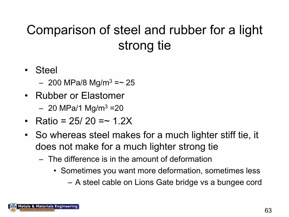
Comparison of steel and rubber for a light
strong tie
• Steel
– 200 MPa/8 Mg/m3 =~ 25
• Rubber or Elastomer
– 20 MPa/1 Mg/m3 =20
• Ratio = 25/ 20 =~ 1.2X
• So whereas steel makes for a much lighter stiff tie, it
does not make for a much lighter strong tie
– The difference is in the amount of deformation
• Sometimes you want more deformation, sometimes less
– A steel cable on Lions Gate bridge vs a bungee cord
64
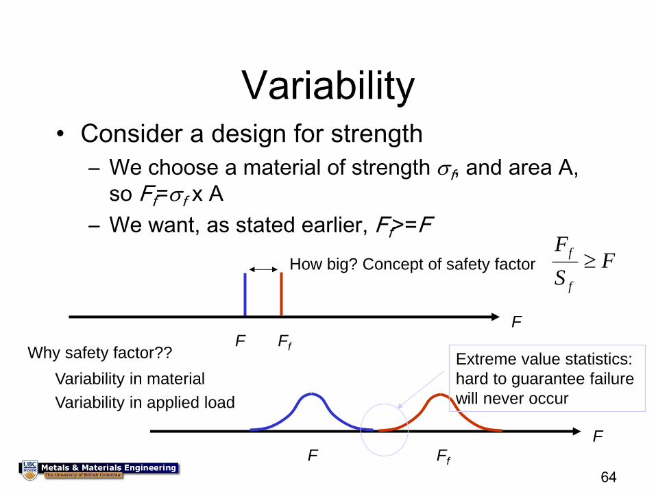
Variability • Consider a design for strength
– We choose a material of strength f, and area A,
so Ff=f x A
– We want, as stated earlier, Ff>=F
Ff F F
How big? Concept of safety factor f
f
FF
S
Why safety factor??
Variability in material
Variability in applied load
F F Ff
Extreme value statistics:
hard to guarantee failure
will never occur
65
Certification
• We have already discussed the concept of a standard
– Standards are often required by the customer or by government, but otherwise they are ‘passive’
• You know of the concept of a “Professional Engineer”
– An ethical responsibility to ensure that the design meets minimum requirements
• Both the above are there to protect the public and the end-user, however, this is typically not sufficient for complicated or critical systems
• Thus for complex systems, or critical systems, there is ‘Certification’
– Approval, normally by government, of your design and decisions
• Air: FAA, JAA, Transport Canada
• Marine: US Coast Guard, DNV, Lloyds
66
Composites
67
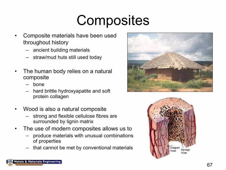
Composites • Composite materials have been used
throughout history
– ancient building materials
– straw/mud huts still used today
• The human body relies on a natural composite
– bone
– hard brittle hydroxyapatite and soft protein collagen
• Wood is also a natural composite
– strong and flexible cellulose fibres are surrounded by lignin matrix
• The use of modern composites allows us to
– produce materials with unusual combinations of properties
– that cannot be met by conventional materials
68
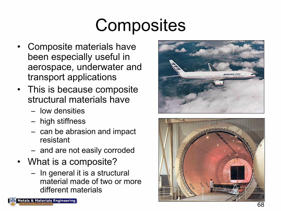
Composites • Composite materials have
been especially useful in aerospace, underwater and transport applications
• This is because composite structural materials have – low densities
– high stiffness
– can be abrasion and impact resistant
– and are not easily corroded
• What is a composite? – In general it is a structural
material made of two or more different materials
69
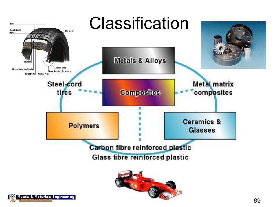
Classification
70
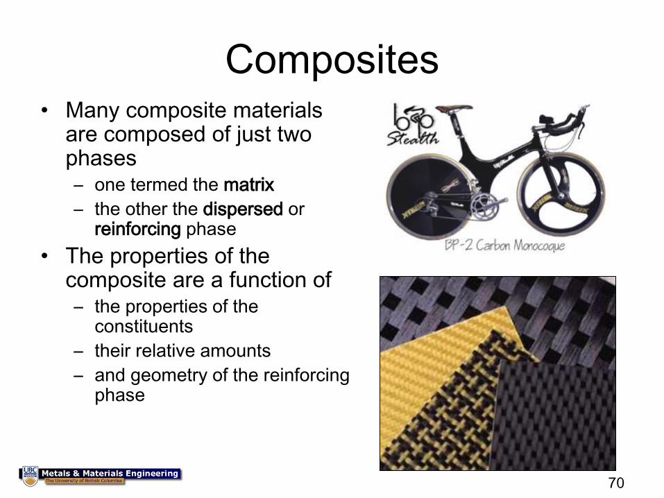
Composites • Many composite materials
are composed of just two phases – one termed the matrix
– the other the dispersed or reinforcing phase
• The properties of the composite are a function of – the properties of the
constituents
– their relative amounts
– and geometry of the reinforcing phase
71
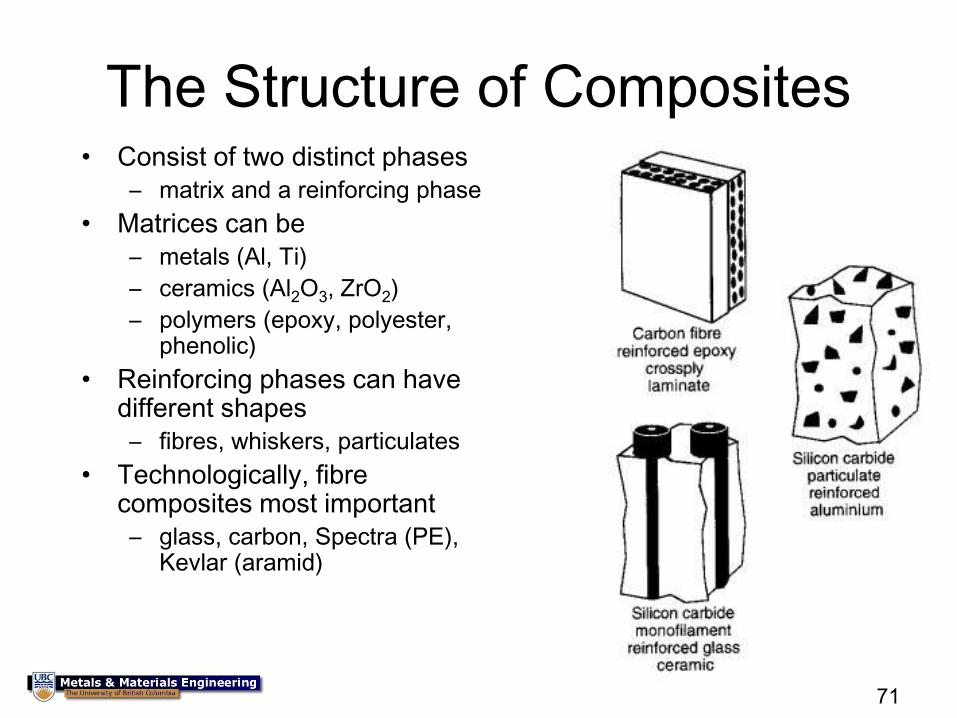
The Structure of Composites • Consist of two distinct phases
– matrix and a reinforcing phase
• Matrices can be
– metals (Al, Ti)
– ceramics (Al2O3, ZrO2)
– polymers (epoxy, polyester, phenolic)
• Reinforcing phases can have different shapes
– fibres, whiskers, particulates
• Technologically, fibre composites most important
– glass, carbon, Spectra (PE), Kevlar (aramid)
72
Fibre composites
• Usually combinations of ceramic, polymer or glass
fibres in a polymer matrix
• Typically 40-60 % fibre by volume
• Utilize the very good properties of the fibres
• Fibre composites have a good combination of
stiffness, density and fracture toughness
• However they are often expensive
• They may be difficult to process
• Often difficult to detect damage (cracks)
73
Properties of Fibres
• High strength of materials can be achieved
due to low probability of flaws in individual
fibres
• Polymers may be oriented into fibres (Spectra
or Kevlar) to utilize the strong C – C bonds of
polymer backbone
• For carbon fibres, graphite plate structure can
be oriented to take advantage of strong
bonding
74
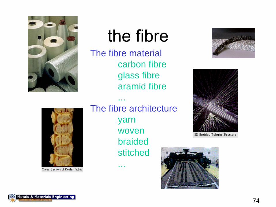
the fibre The fibre material
carbon fibre
glass fibre
aramid fibre
...
The fibre architecture
yarn
woven
braided
stitched
...
75
76
Properties of Matrix
• The matrix binds the fibres together and protects them from
external damage
• It transmits external loads to the fibres
– the matrix itself usually carries only a small fraction of the load
• It separates the fibres and stops cracks from propagating directly
from fibre to fibre
• It supports the fibres laterally under compression loading
• It is usually has a low density to produce a composite with a low
density
• It is advantageous if the matrix has some ductility
– reinforcing phase often very stiff
77
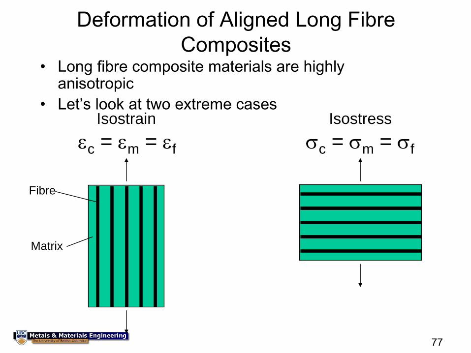
Deformation of Aligned Long Fibre
Composites • Long fibre composite materials are highly
anisotropic
• Let’s look at two extreme cases
Fibre
Matrix
Isostrain Isostress
c = m = f c = m = f
78
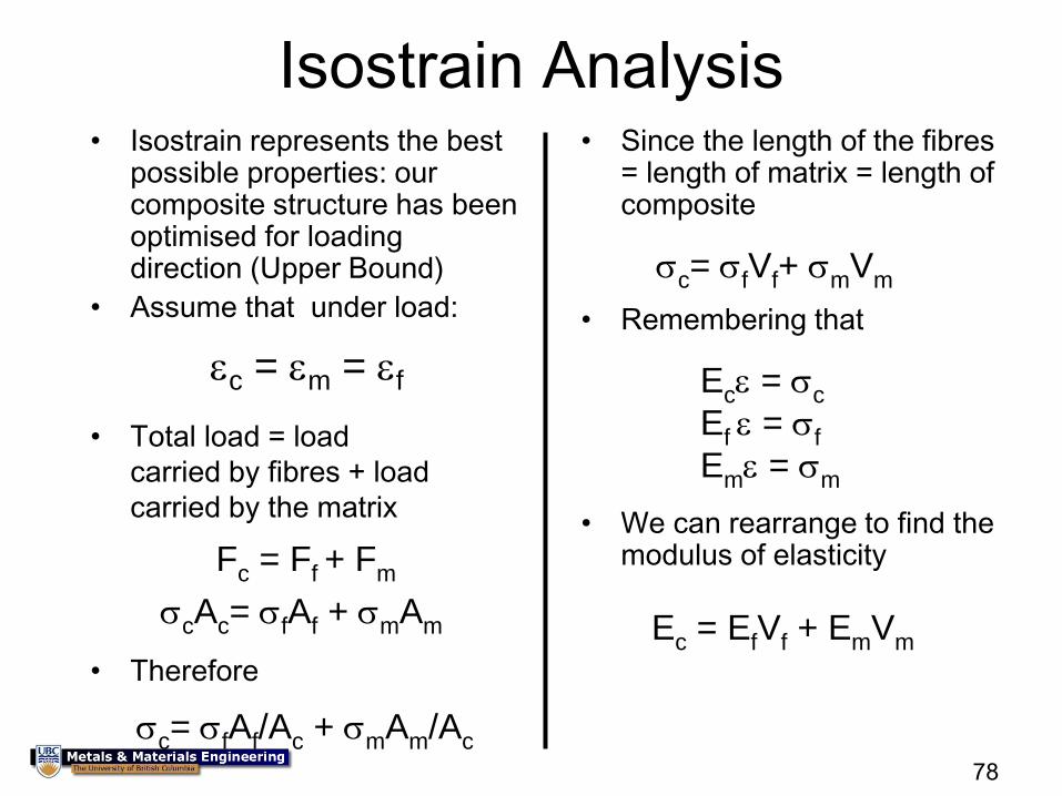
Isostrain Analysis • Isostrain represents the best
possible properties: our composite structure has been optimised for loading direction (Upper Bound)
• Assume that under load:
c = m = f
• Total load = load
carried by fibres + load
carried by the matrix
Fc = Ff + Fm
cAc= fAf + mAm
• Therefore
c= fAf/Ac + mAm/Ac
• Since the length of the fibres = length of matrix = length of composite
c= fVf+ mVm
• Remembering that
Ec = c
Ef = f
Em = m
• We can rearrange to find the modulus of elasticity
Ec = EfVf + EmVm
79
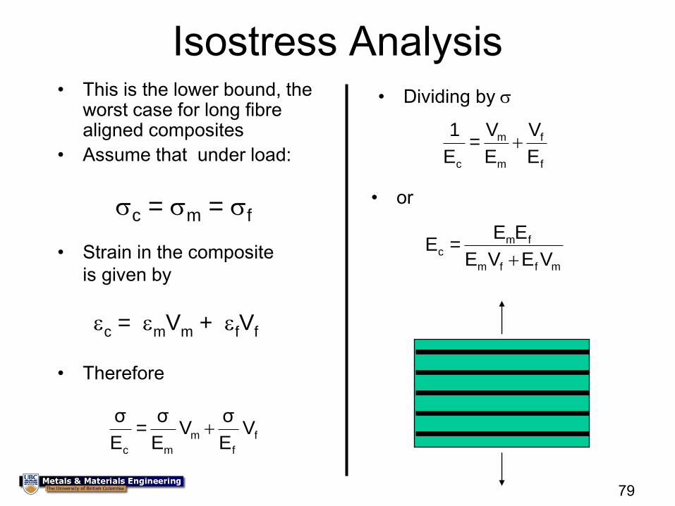
• This is the lower bound, the worst case for long fibre aligned composites
• Assume that under load:
• Strain in the composite
is given by
c = m = f
c = mVm + fVf
f
f
m
mc
VE
σV
E
σ =
E
σ
f
f
m
m
c E
V
E
V =
E
1
• Dividing by
• Therefore
mffm
fmc
VEVE
EE = E
• or
Isostress Analysis
80
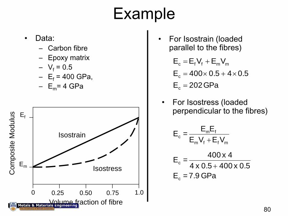
• Data:
– Carbon fibre
– Epoxy matrix
– Vf = 0.5
– Ef = 400 GPa,
– Em= 4 GPa GPa 202E
0.5 4 0.5 400 E
c
c
• For Isostress (loaded perpendicular to the fibres)
mffm
fmc
VEVE
EE = E
GPa 7.9= E
0.5 x 400 0.5 x 4
4 x 400 = E
c
c
• For Isostrain (loaded parallel to the fibres)
Ef
Em
0 1.0 0.50 0.25 0.75
Isostrain
Isostress
Volume fraction of fibre
Com
posite M
odulu
s
mmffc VE VE E
Example
81
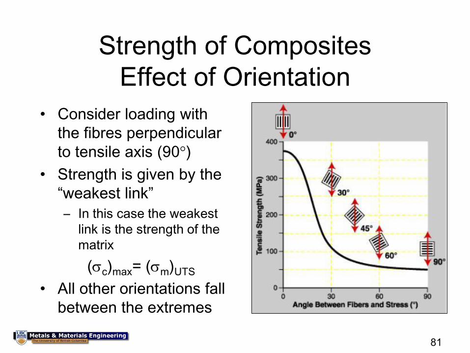
Strength of Composites
Effect of Orientation
• Consider loading with
the fibres perpendicular
to tensile axis (90°)
• Strength is given by the
“weakest link”
– In this case the weakest
link is the strength of the
matrix
(c)max= (m)UTS
• All other orientations fall
between the extremes
82 0° 60° 30° 90°
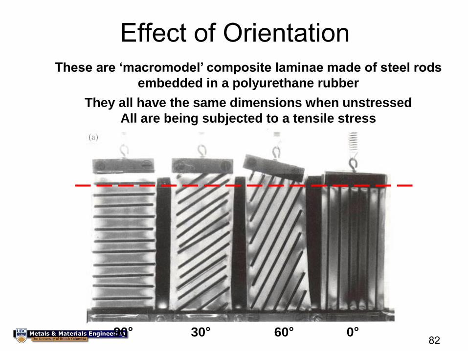
Effect of Orientation These are ‘macromodel’ composite laminae made of steel rods
embedded in a polyurethane rubber
They all have the same dimensions when unstressed
All are being subjected to a tensile stress
83
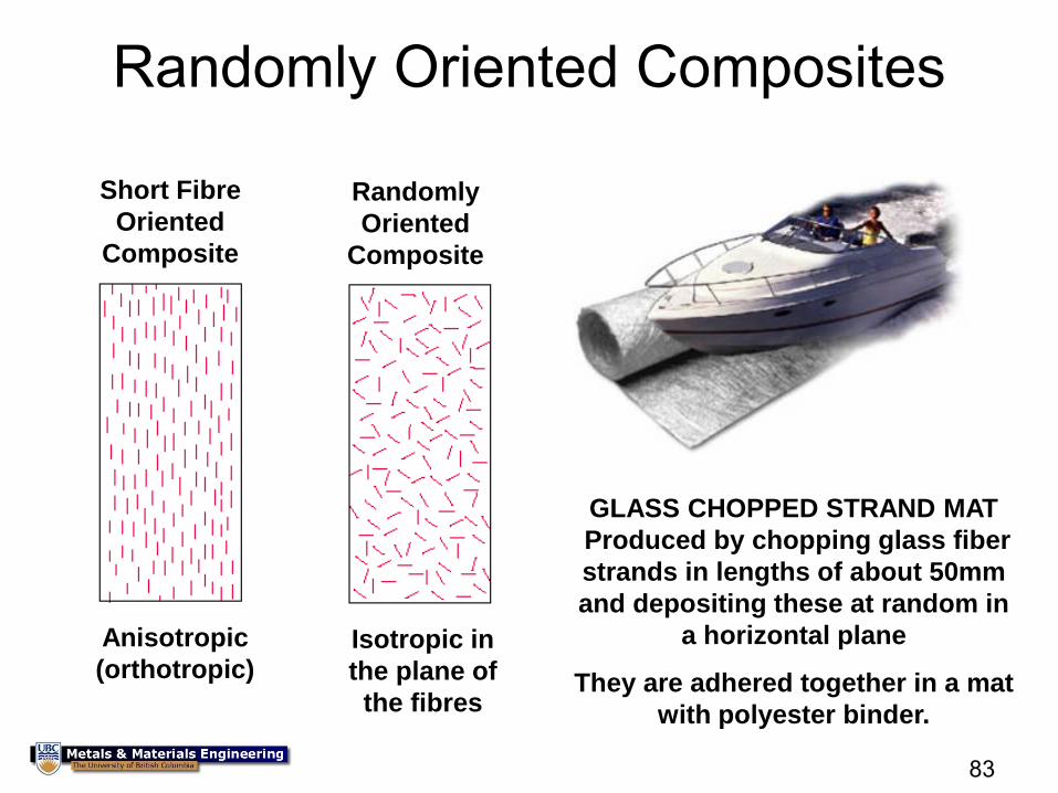
Randomly Oriented Composites
Short Fibre
Oriented
Composite
Anisotropic
(orthotropic)
Randomly
Oriented
Composite
Isotropic in
the plane of
the fibres
GLASS CHOPPED STRAND MAT
Produced by chopping glass fiber
strands in lengths of about 50mm
and depositing these at random in
a horizontal plane
They are adhered together in a mat
with polyester binder.
84
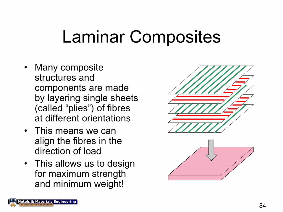
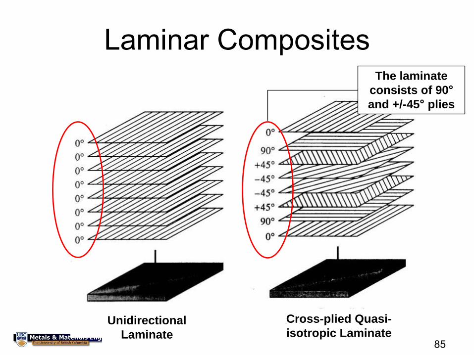
Laminar Composites
• Many composite structures and components are made by layering single sheets (called “plies”) of fibres at different orientations
• This means we can align the fibres in the direction of load
• This allows us to design for maximum strength and minimum weight!
85
Laminar Composites
Unidirectional
Laminate
Cross-plied Quasi-
isotropic Laminate
The laminate
consists of 90°
and +/-45° plies
86
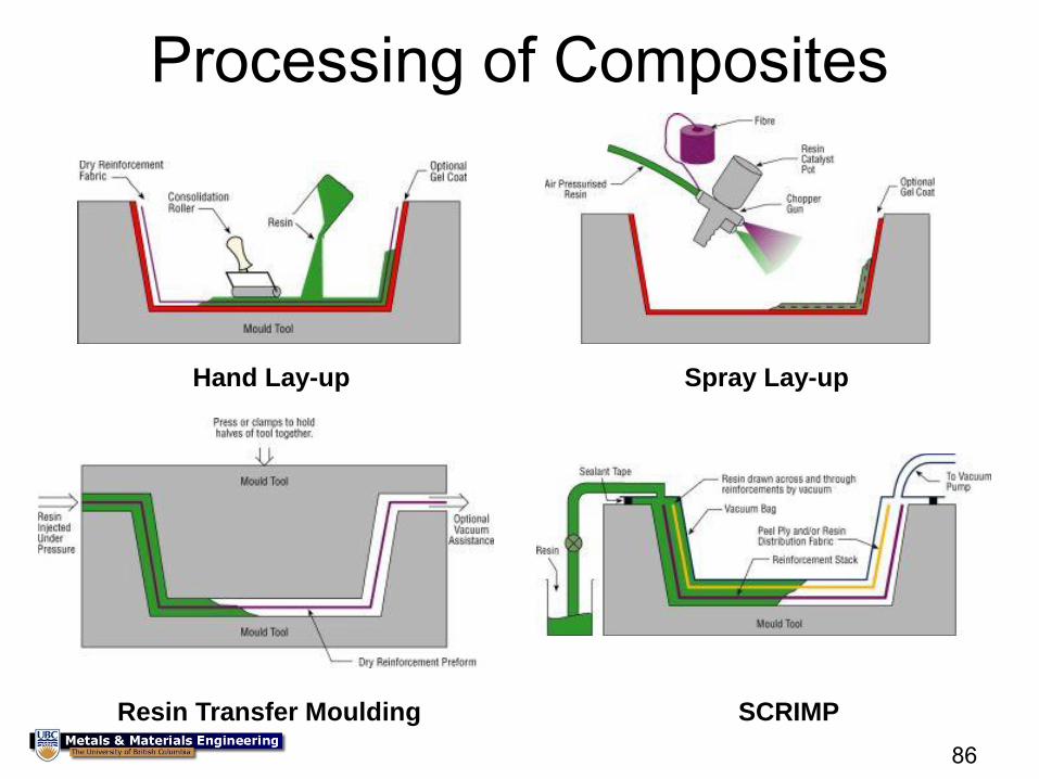
Processing of Composites
Spray Lay-up Hand Lay-up
SCRIMP Resin Transfer Moulding
87
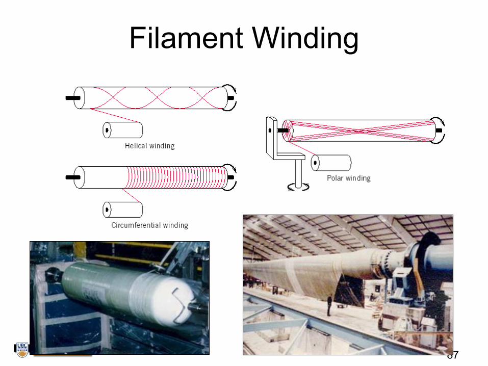
Filament Winding
88
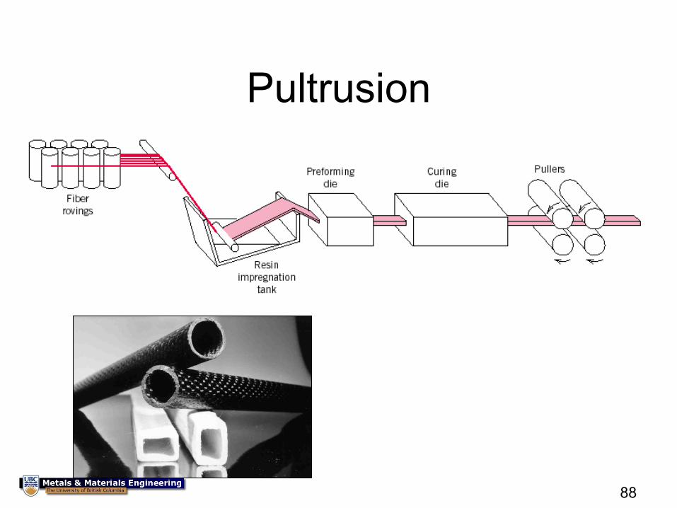
Pultrusion
89
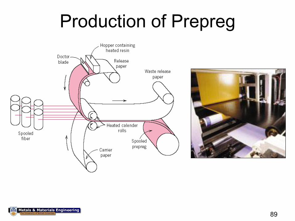
Production of Prepreg
90
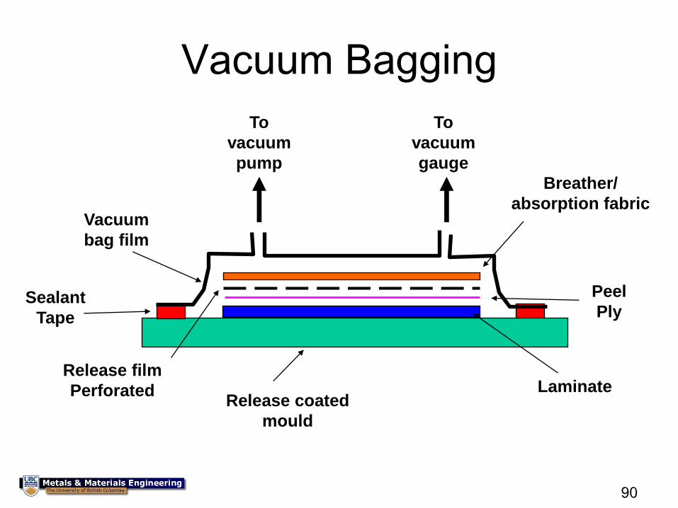
Vacuum Bagging
To
vacuum
pump
To
vacuum
gauge
Breather/
absorption fabric
Peel
Ply
Release coated
mould
Sealant
Tape
Vacuum
bag film
Release film
Perforated Laminate
91
Advantages & disadvantages
• Structurally efficient
• Complex shapes with ease
• Durable and low-
maintenance
• Net shape process
• Reduced part count
– simplified assembly
– resultant savings
• Complex design
– most engineers not comfortable designing with composites
– Understanding not as advanced
• Difficult to detect damage and repair
• Higher material cost
– But dropping fairly fast
• Manufacturing of complex structures is difficult
92
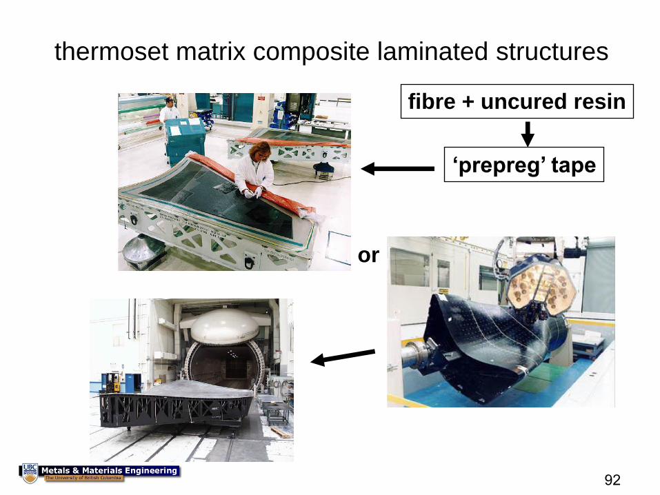
or
fibre + uncured resin
‘prepreg’ tape
thermoset matrix composite laminated structures
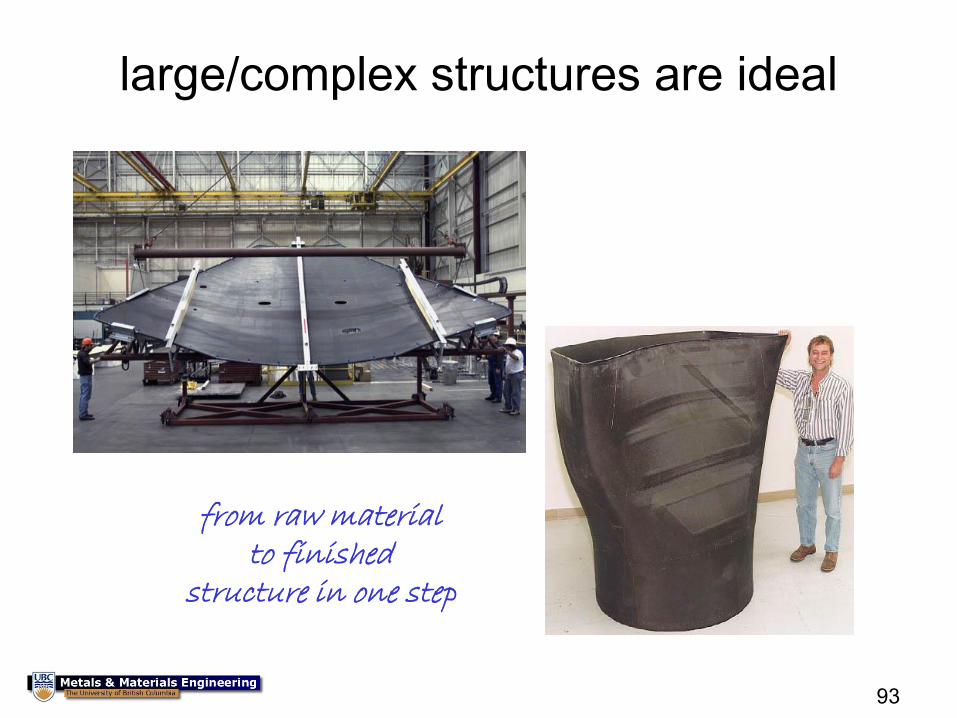
93
large/complex structures are ideal
from raw material to finished
structure in one step
94
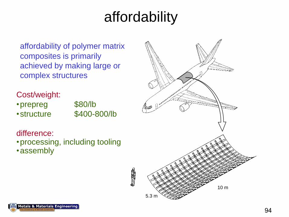
10 m
5.3 m
affordability of polymer matrix
composites is primarily
achieved by making large or
complex structures
Cost/weight:
•prepreg $80/lb
•structure $400-800/lb
difference: •processing, including tooling •assembly
affordability
95
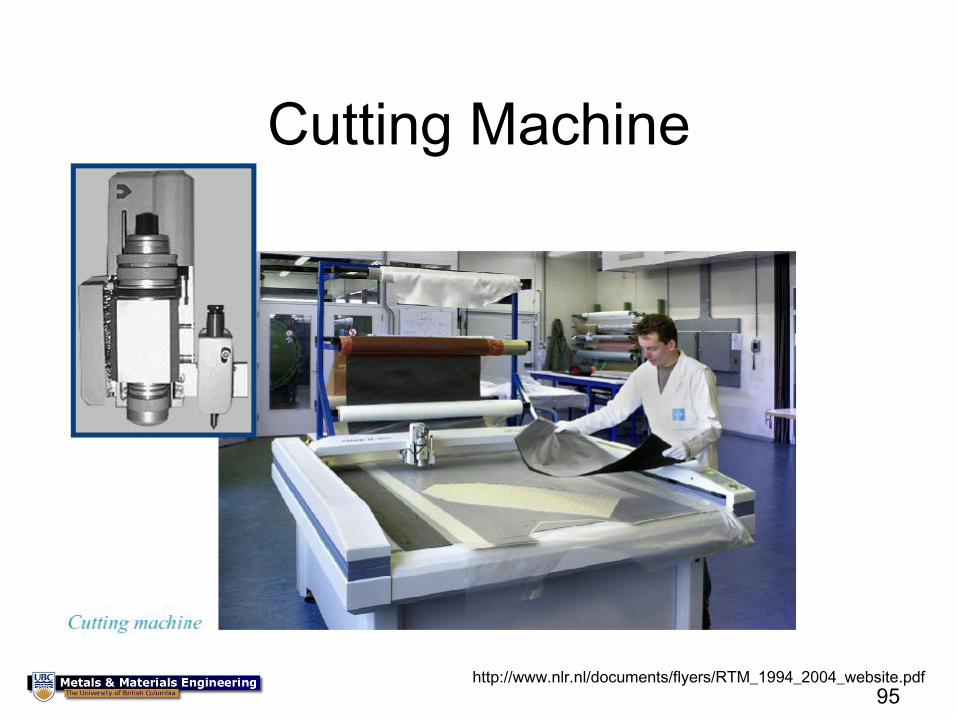
Cutting Machine
http://www.nlr.nl/documents/flyers/RTM_1994_2004_website.pdf
96
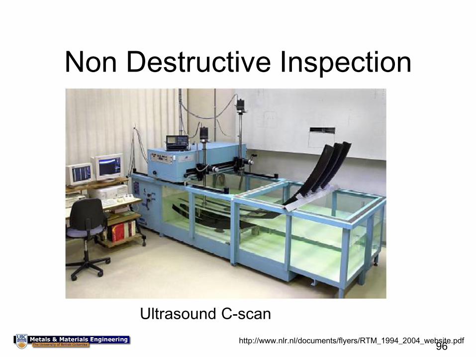
Non Destructive Inspection
Ultrasound C-scan
http://www.nlr.nl/documents/flyers/RTM_1994_2004_website.pdf
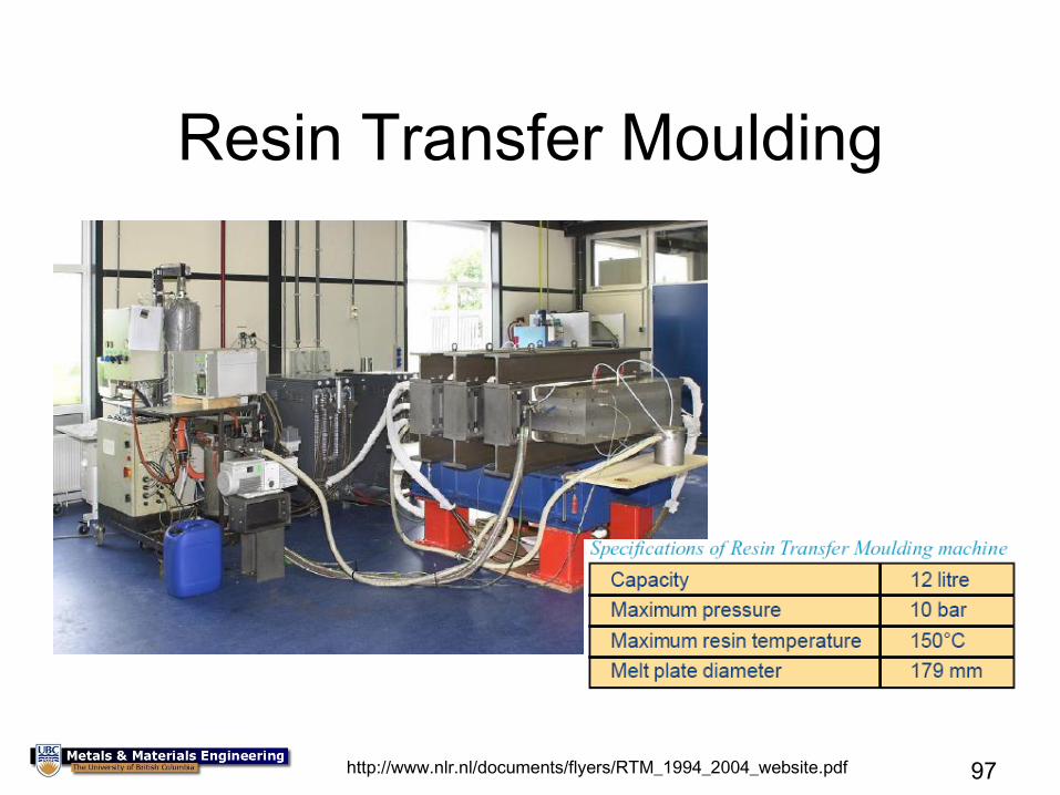
97
Resin Transfer Moulding
http://www.nlr.nl/documents/flyers/RTM_1994_2004_website.pdf
98
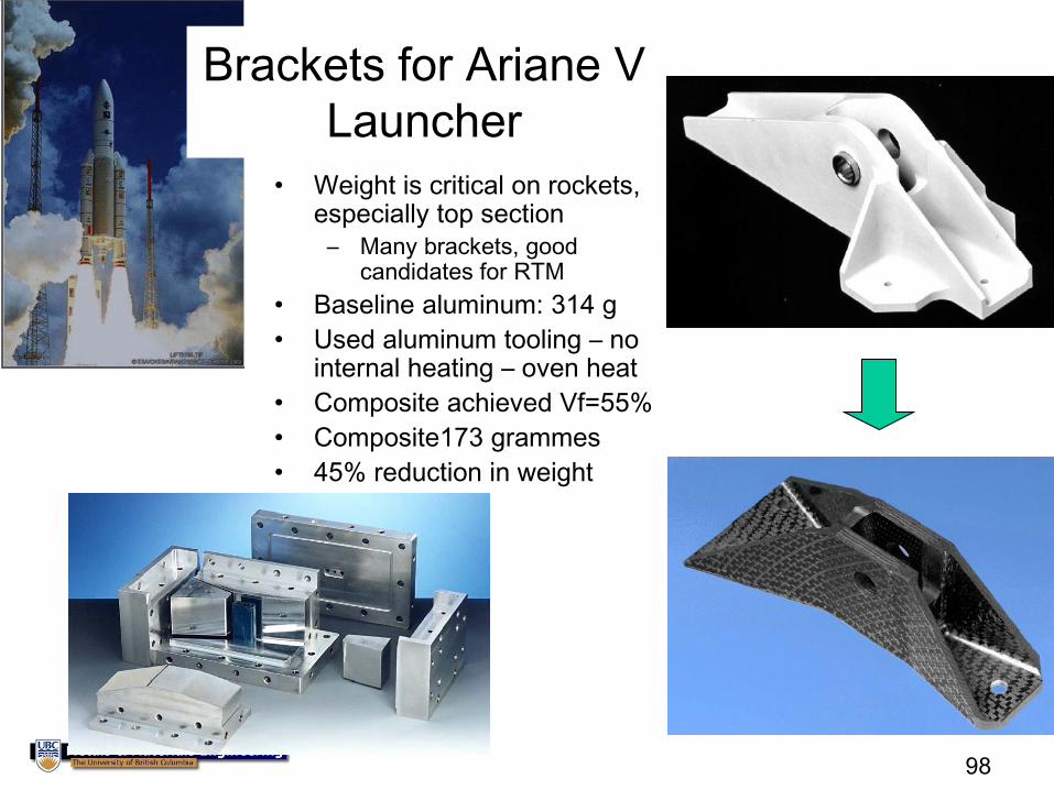
• Weight is critical on rockets, especially top section
– Many brackets, good candidates for RTM
• Baseline aluminum: 314 g
• Used aluminum tooling – no internal heating – oven heat
• Composite achieved Vf=55%
• Composite173 grammes
• 45% reduction in weight
Brackets for Ariane V
Launcher
99
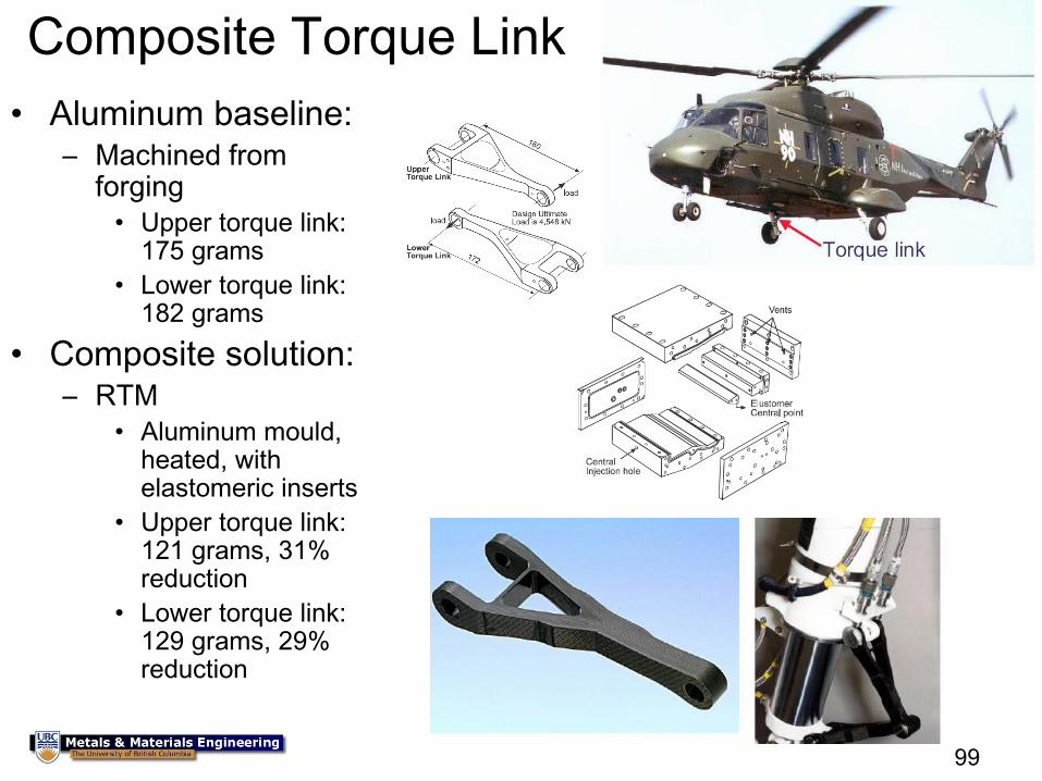
Composite Torque Link
• Aluminum baseline: – Machined from
forging
• Upper torque link: 175 grams
• Lower torque link: 182 grams
• Composite solution: – RTM
• Aluminum mould, heated, with elastomeric inserts
• Upper torque link: 121 grams, 31% reduction
• Lower torque link: 129 grams, 29% reduction
100
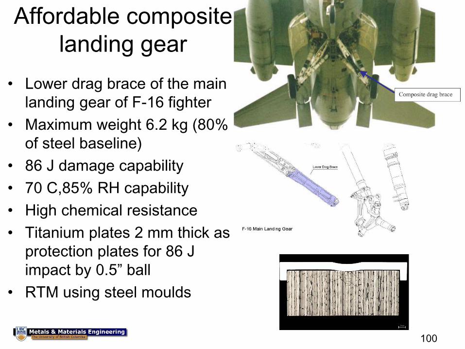
Affordable composite
landing gear
• Lower drag brace of the main
landing gear of F-16 fighter
• Maximum weight 6.2 kg (80%
of steel baseline)
• 86 J damage capability
• 70 C,85% RH capability
• High chemical resistance
• Titanium plates 2 mm thick as
protection plates for 86 J
impact by 0.5” ball
• RTM using steel moulds
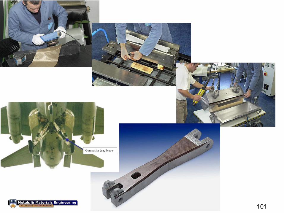
101
102
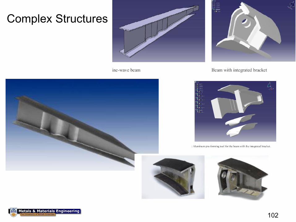
Complex Structures
103
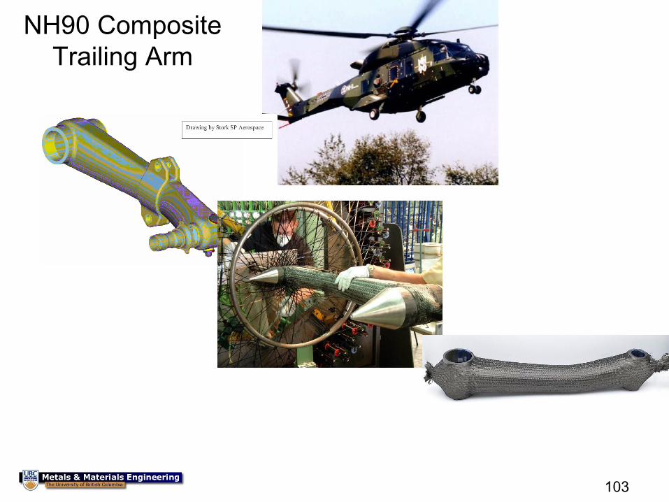
NH90 Composite
Trailing Arm
104
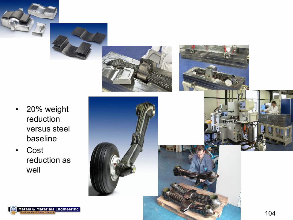
• 20% weight
reduction
versus steel
baseline
• Cost
reduction as
well
105
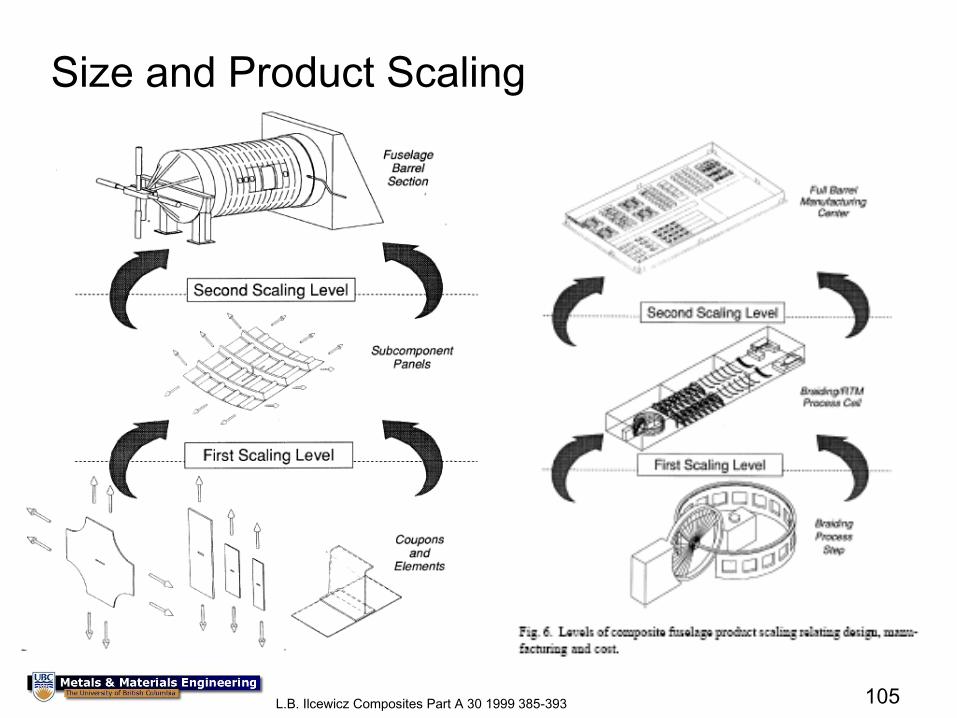
Size and Product Scaling
L.B. Ilcewicz Composites Part A 30 1999 385-393
106
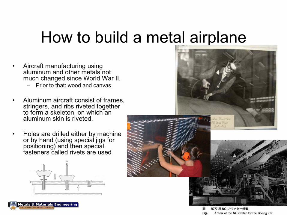
How to build a metal airplane
• Aircraft manufacturing using aluminum and other metals not much changed since World War II.
– Prior to that: wood and canvas
• Aluminum aircraft consist of frames, stringers, and ribs riveted together to form a skeleton, on which an aluminum skin is riveted.
• Holes are drilled either by machine or by hand (using special jigs for positioning) and then special fasteners called rivets are used
107
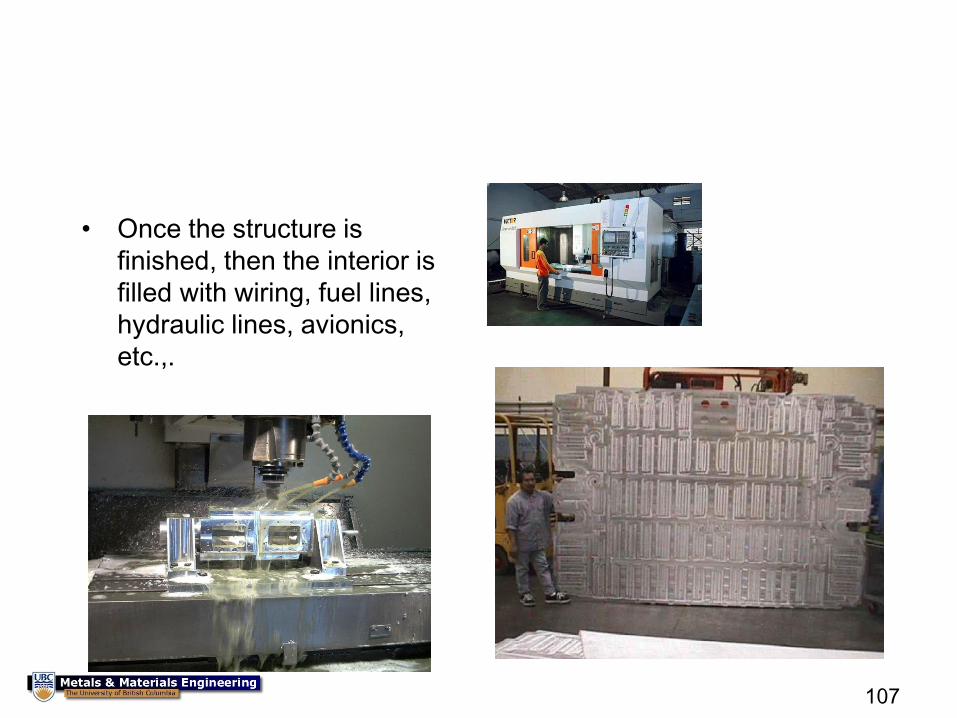
• Once the structure is
finished, then the interior is
filled with wiring, fuel lines,
hydraulic lines, avionics,
etc.,.
108
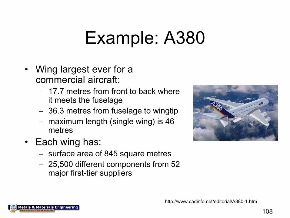
Example: A380
• Wing largest ever for a commercial aircraft: – 17.7 metres from front to back where
it meets the fuselage
– 36.3 metres from fuselage to wingtip
– maximum length (single wing) is 46 metres
• Each wing has: – surface area of 845 square metres
– 25,500 different components from 52 major first-tier suppliers
http://www.cadinfo.net/editorial/A380-1.htm
109
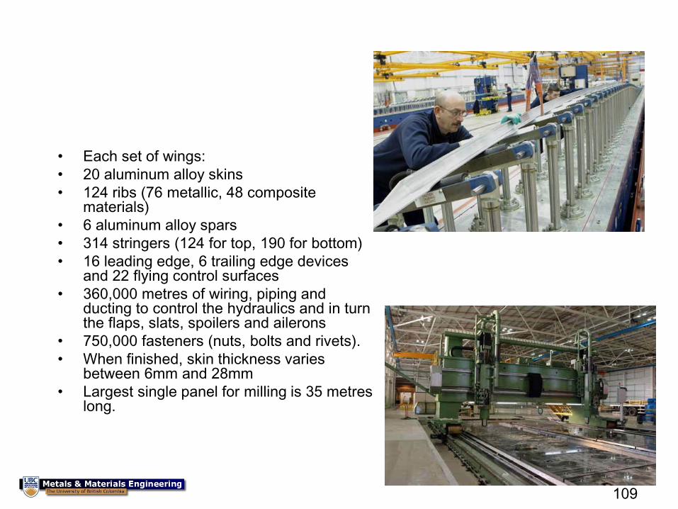
• Each set of wings:
• 20 aluminum alloy skins
• 124 ribs (76 metallic, 48 composite materials)
• 6 aluminum alloy spars
• 314 stringers (124 for top, 190 for bottom)
• 16 leading edge, 6 trailing edge devices and 22 flying control surfaces
• 360,000 metres of wiring, piping and ducting to control the hydraulics and in turn the flaps, slats, spoilers and ailerons
• 750,000 fasteners (nuts, bolts and rivets).
• When finished, skin thickness varies between 6mm and 28mm
• Largest single panel for milling is 35 metres long.
110
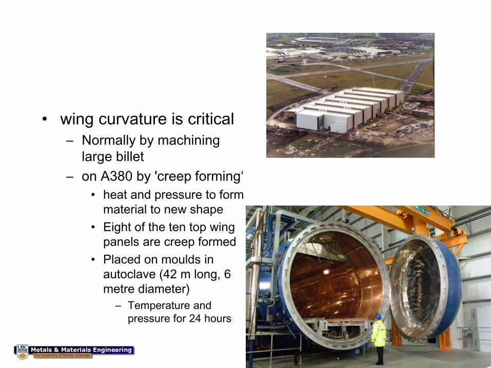
• wing curvature is critical
– Normally by machining
large billet
– on A380 by 'creep forming‘
• heat and pressure to form
material to new shape
• Eight of the ten top wing
panels are creep formed
• Placed on moulds in
autoclave (42 m long, 6
metre diameter)
– Temperature and
pressure for 24 hours
111
Failure of Aircraft
The goal is to make an airplane as
light as possible without failure in
service
112
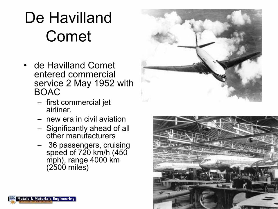
De Havilland
Comet
• de Havilland Comet entered commercial service 2 May 1952 with BOAC – first commercial jet
airliner.
– new era in civil aviation
– Significantly ahead of all other manufacturers
– 36 passengers, cruising speed of 720 km/h (450 mph), range 4000 km (2500 miles)
113
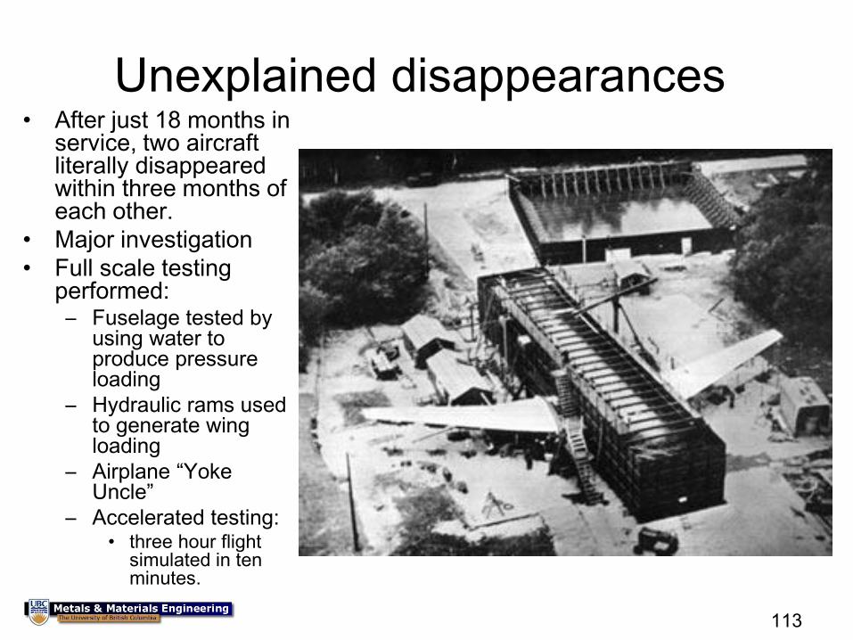
Unexplained disappearances • After just 18 months in
service, two aircraft literally disappeared within three months of each other.
• Major investigation
• Full scale testing performed: – Fuselage tested by
using water to produce pressure loading
– Hydraulic rams used to generate wing loading
– Airplane “Yoke Uncle”
– Accelerated testing: • three hour flight
simulated in ten minutes.
114
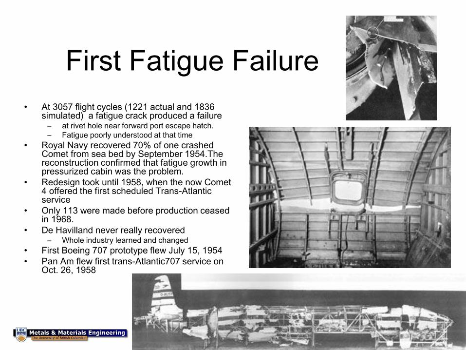
First Fatigue Failure
• At 3057 flight cycles (1221 actual and 1836 simulated) a fatigue crack produced a failure
– at rivet hole near forward port escape hatch.
– Fatigue poorly understood at that time
• Royal Navy recovered 70% of one crashed Comet from sea bed by September 1954.The reconstruction confirmed that fatigue growth in pressurized cabin was the problem.
• Redesign took until 1958, when the now Comet 4 offered the first scheduled Trans-Atlantic service
• Only 113 were made before production ceased in 1968.
• De Havilland never really recovered – Whole industry learned and changed
• First Boeing 707 prototype flew July 15, 1954
• Pan Am flew first trans-Atlantic707 service on Oct. 26, 1958
115
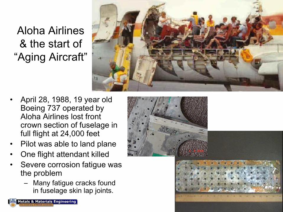
Aloha Airlines
& the start of
“Aging Aircraft”
• April 28, 1988, 19 year old Boeing 737 operated by Aloha Airlines lost front crown section of fuselage in full flight at 24,000 feet
• Pilot was able to land plane
• One flight attendant killed
• Severe corrosion fatigue was the problem
– Many fatigue cracks found in fuselage skin lap joints.
116
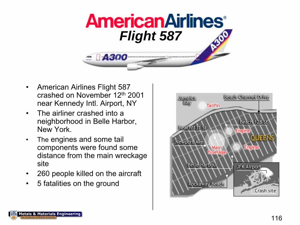
Flight 587
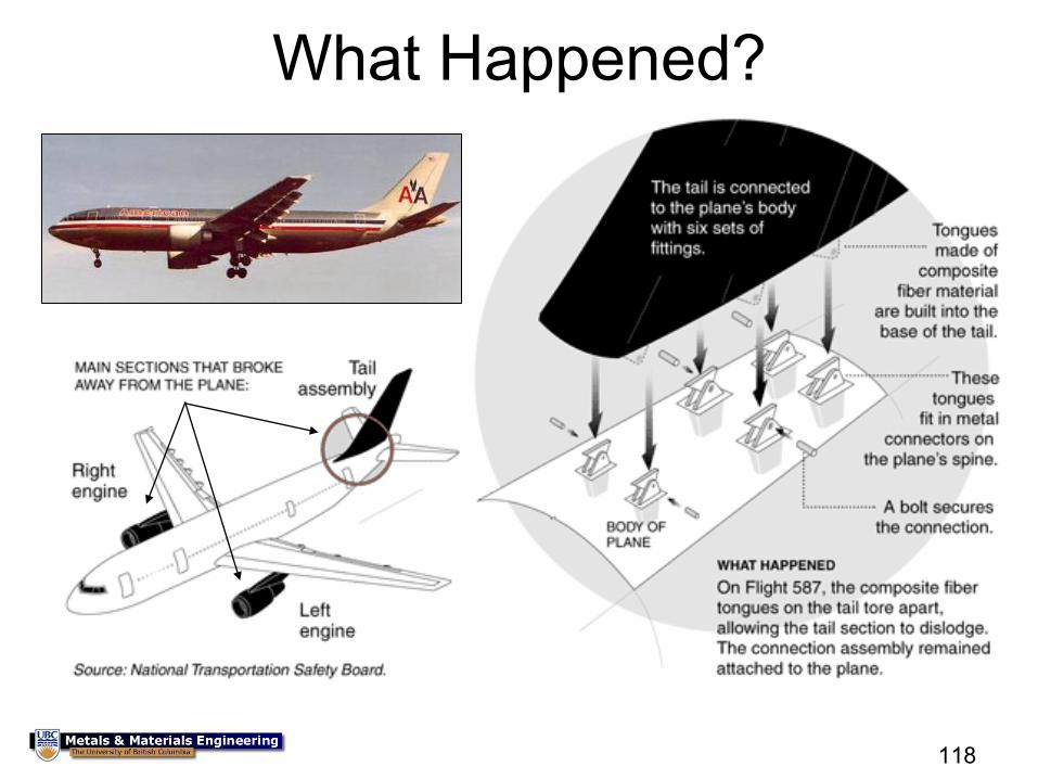
• American Airlines Flight 587 crashed on November 12th 2001 near Kennedy Intl. Airport, NY
• The airliner crashed into a neighborhood in Belle Harbor, New York.
• The engines and some tail components were found some distance from the main wreckage site
• 260 people killed on the aircraft
• 5 fatalities on the ground
118
What Happened?
119
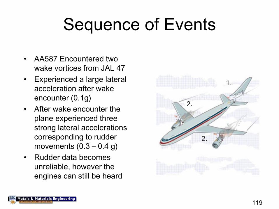
Sequence of Events
• AA587 Encountered two
wake vortices from JAL 47
• Experienced a large lateral
acceleration after wake
encounter (0.1g)
• After wake encounter the
plane experienced three
strong lateral accelerations
corresponding to rudder
movements (0.3 – 0.4 g)
• Rudder data becomes
unreliable, however the
engines can still be heard
1.
2.
2.
120
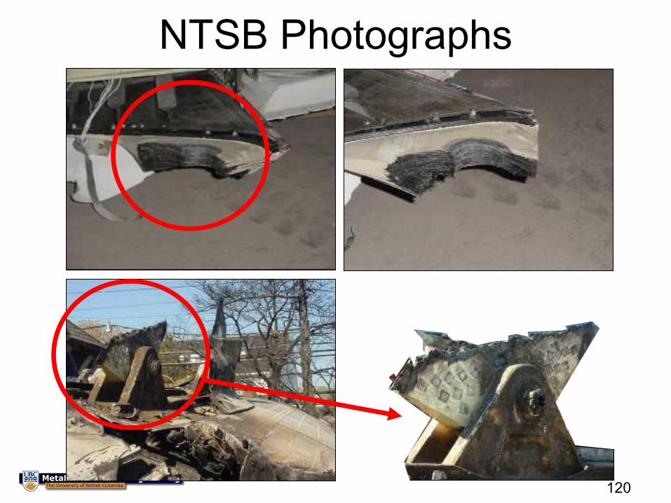
NTSB Photographs
122
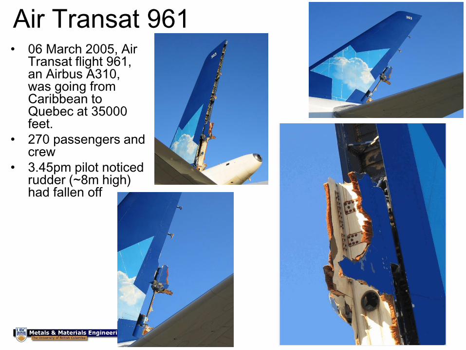
Air Transat 961 • 06 March 2005, Air
Transat flight 961, an Airbus A310, was going from Caribbean to Quebec at 35000 feet.
• 270 passengers and crew
• 3.45pm pilot noticed rudder (~8m high) had fallen off
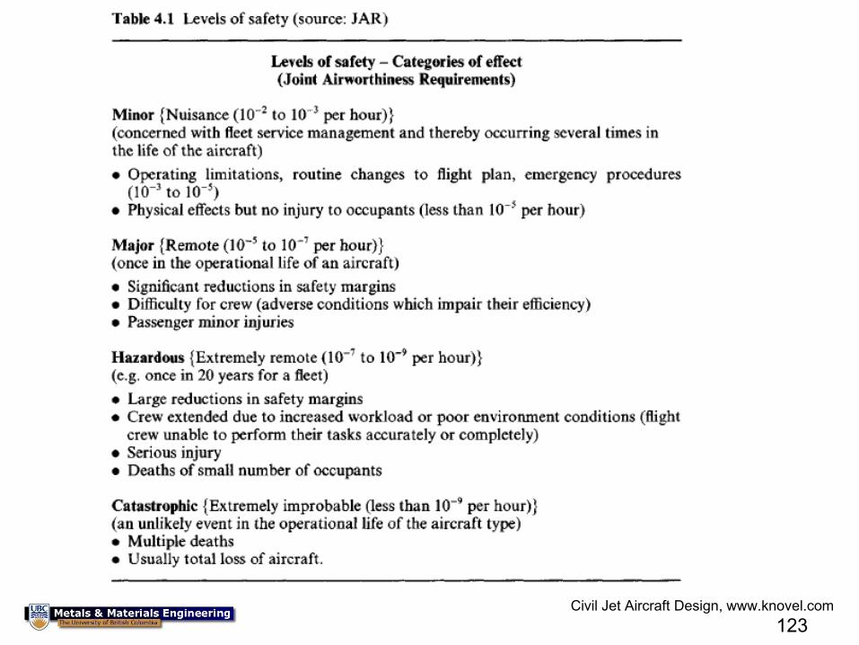
123
Civil Jet Aircraft Design, www.knovel.com
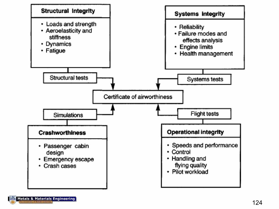
124
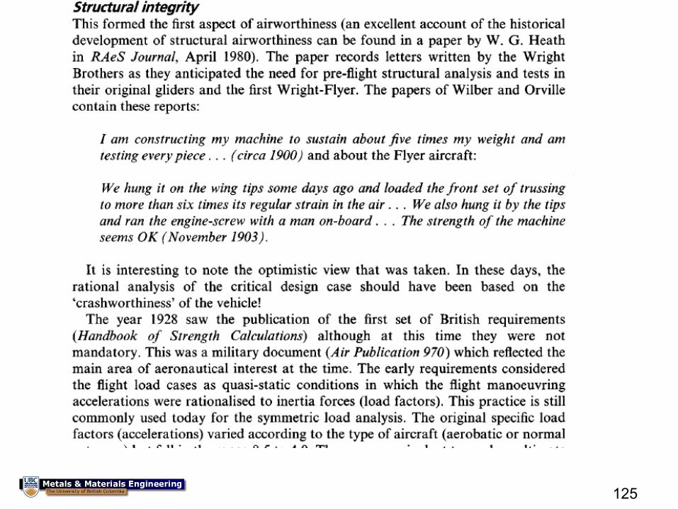
125
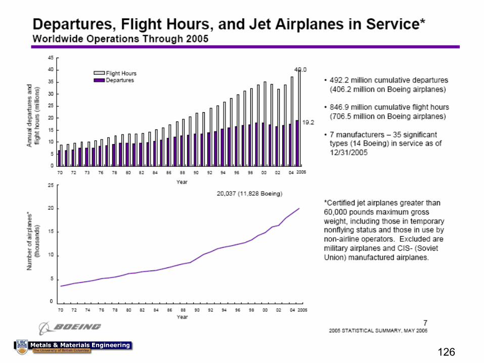
126
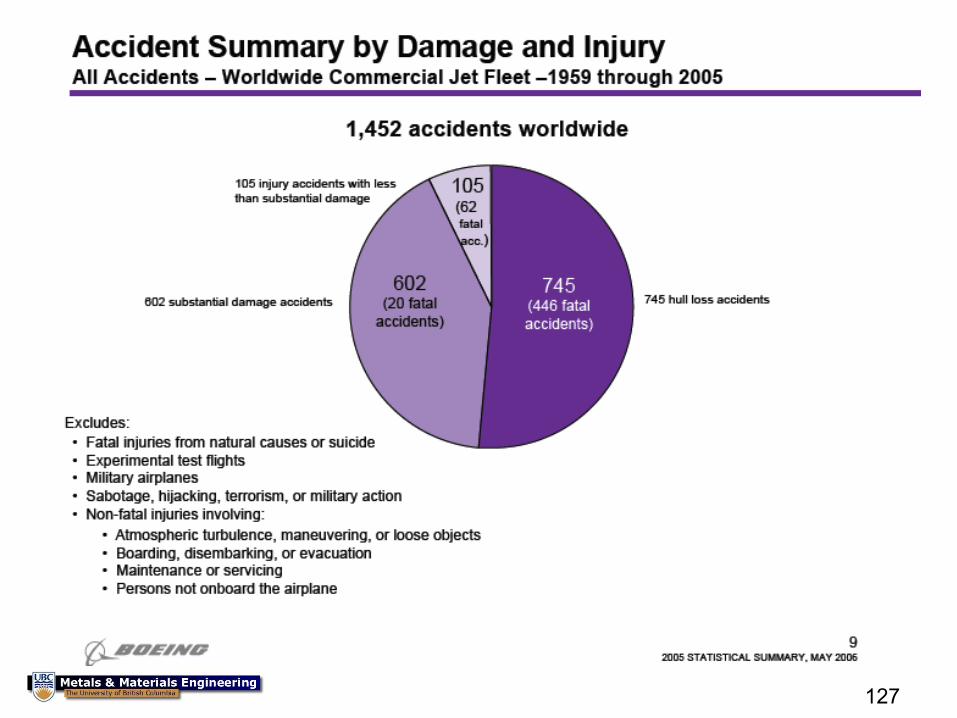
127
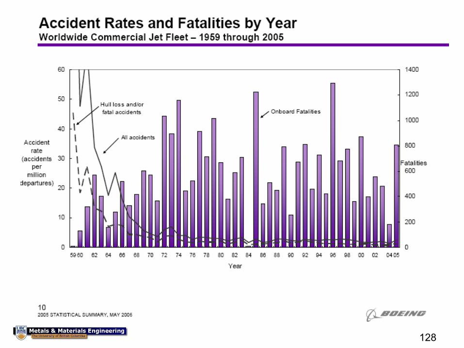
128
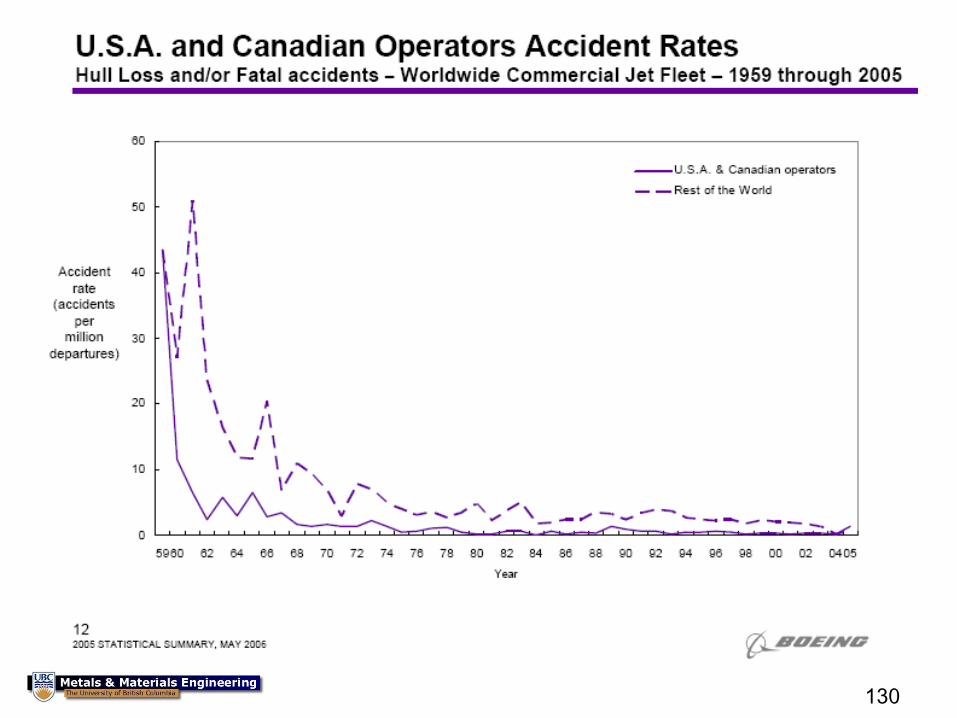
130
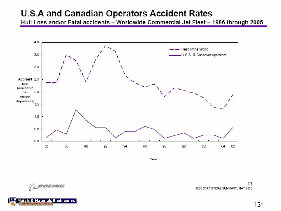
131
133
134
Designing against failure for
composite structures
135
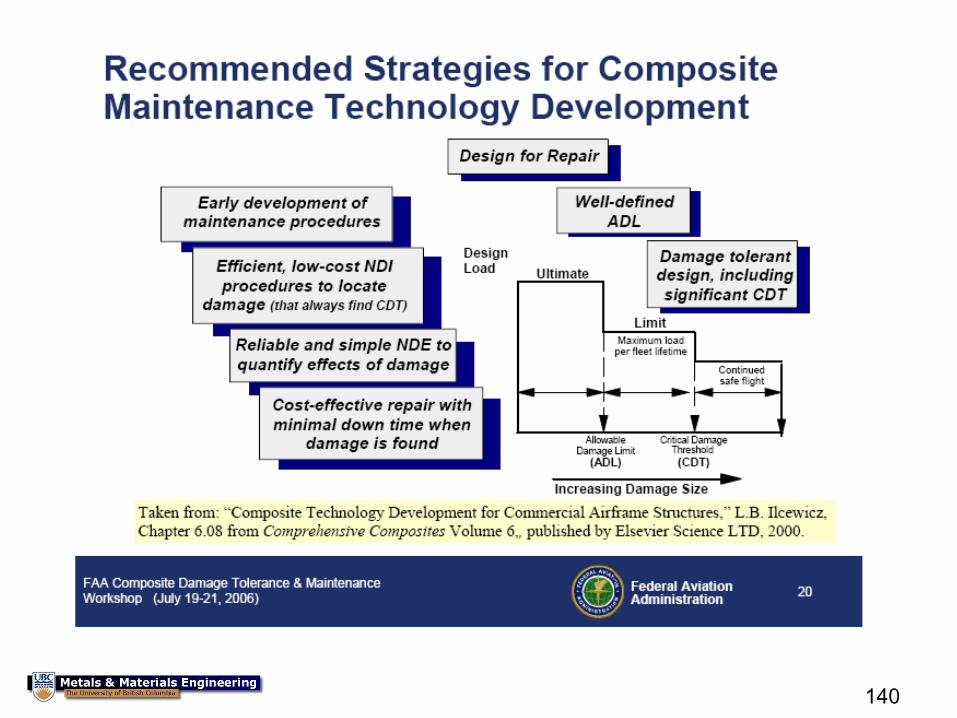
Ilcewicz FAA May 25th, 2006
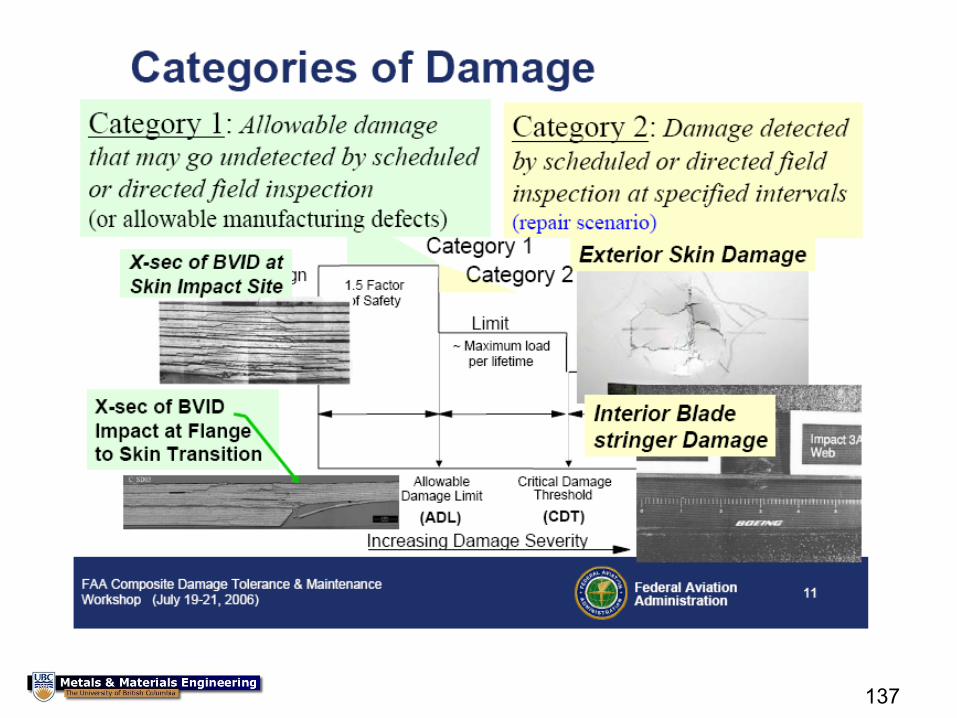
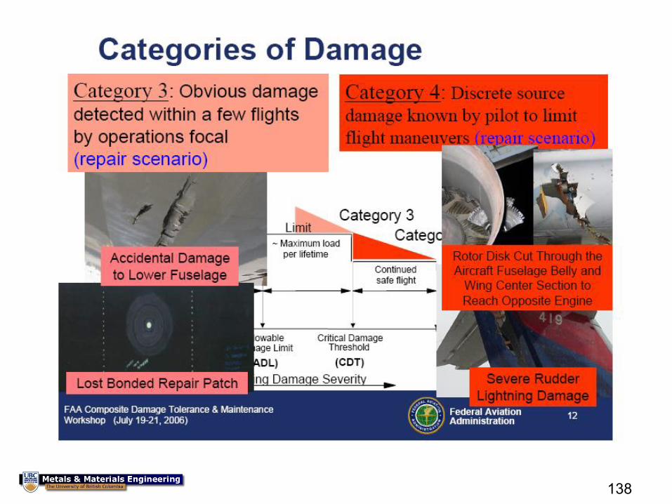
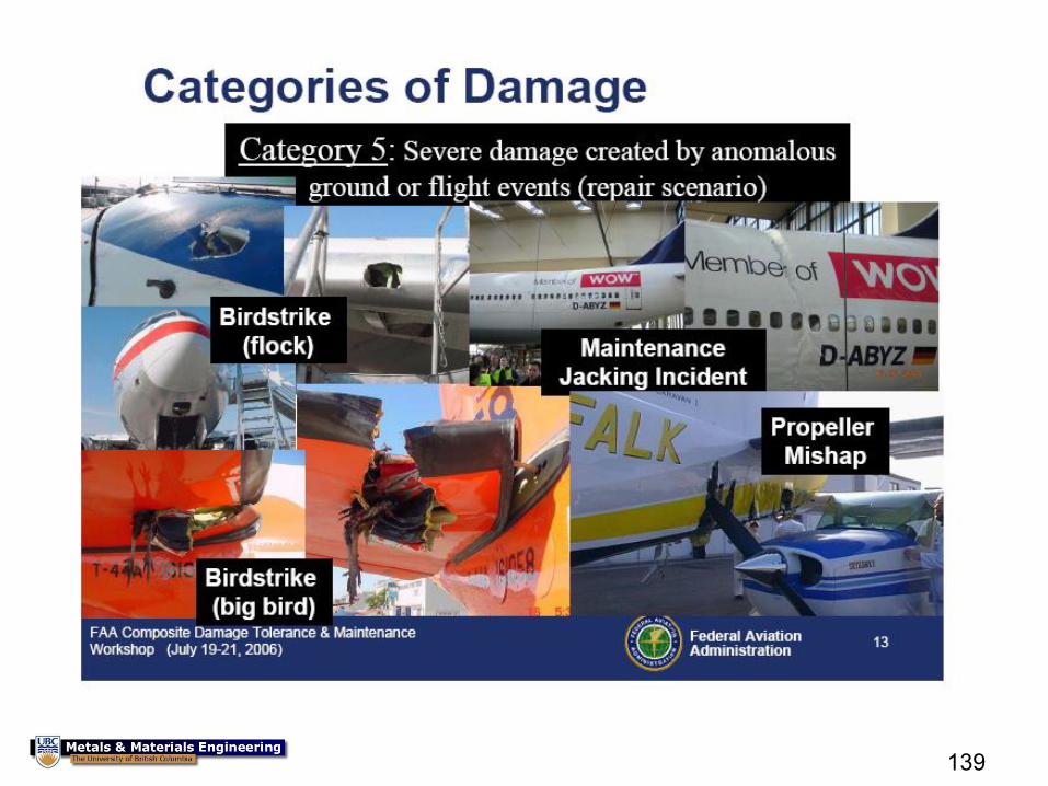
136
137
138
139
140
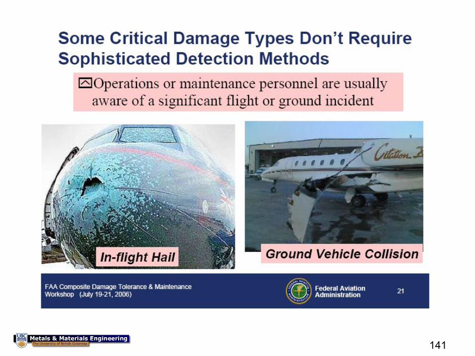
141
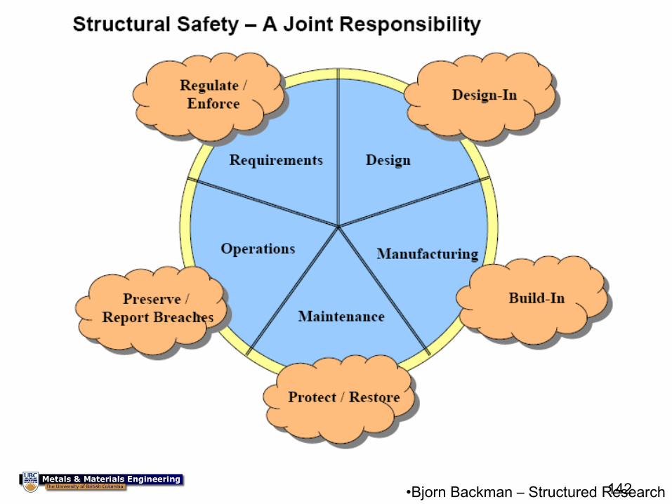
142
•Bjorn Backman – Structured Research
157
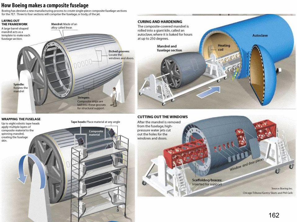
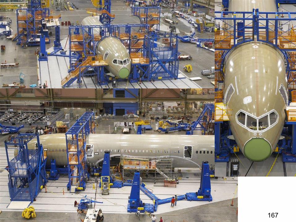
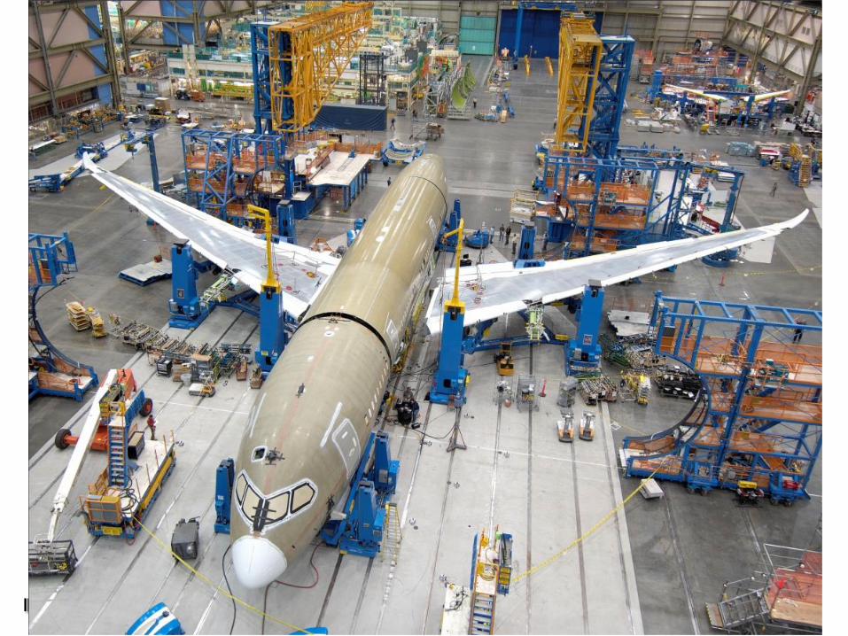
Making the Boeing 787
158
159
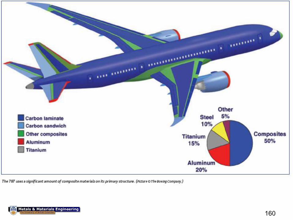
160
161
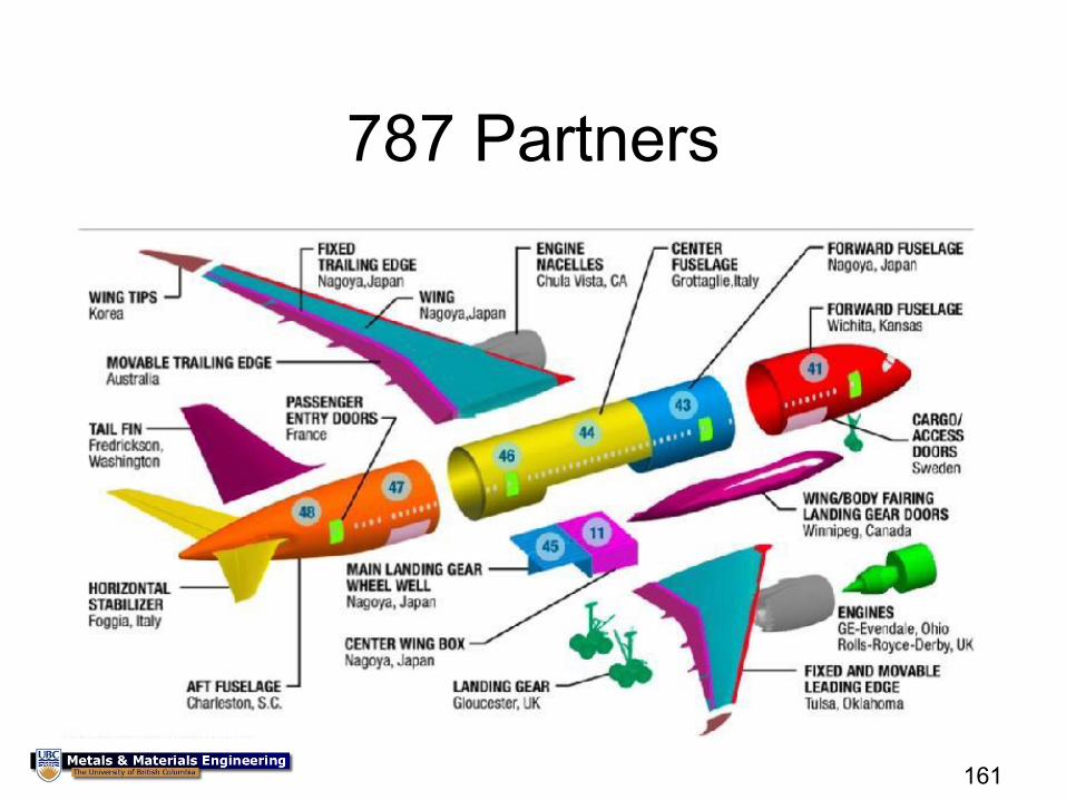
787 Partners
162
163
Video
164
Production and Certification
165
166
167
168
169
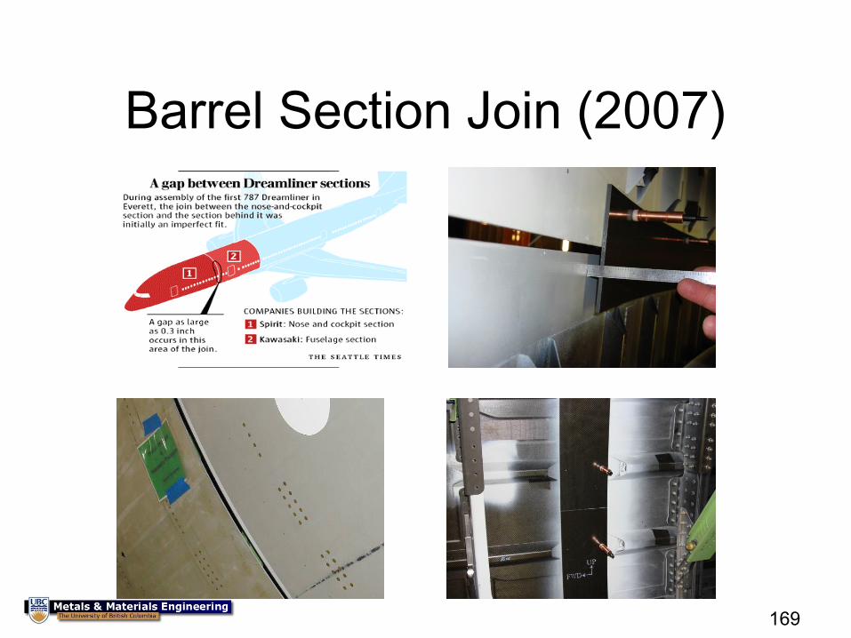
Barrel Section Join (2007)
170
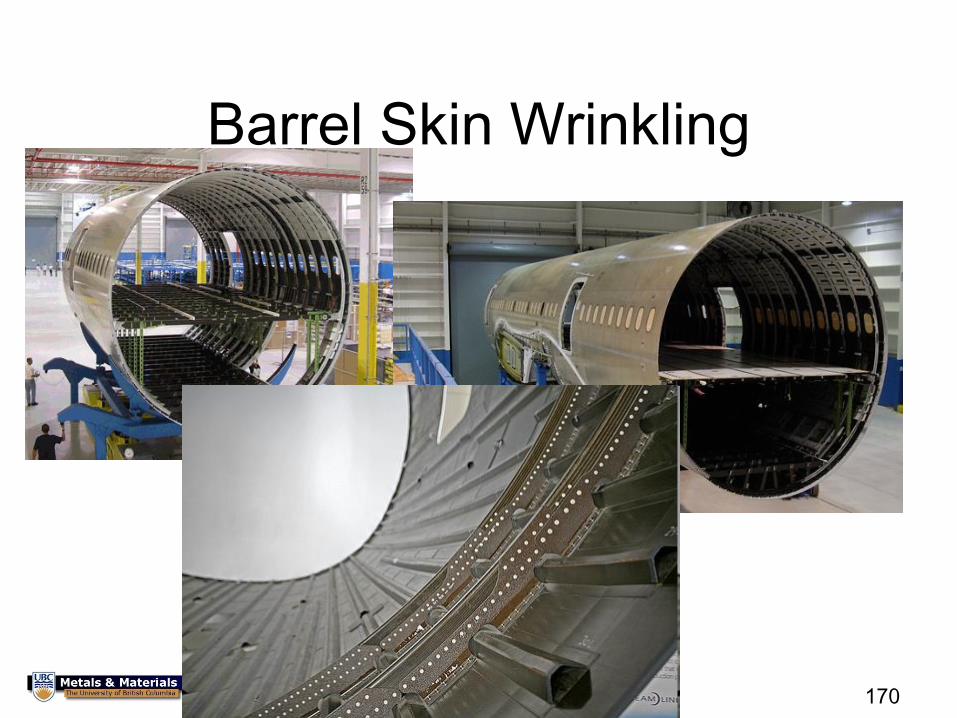
Barrel Skin Wrinkling
171
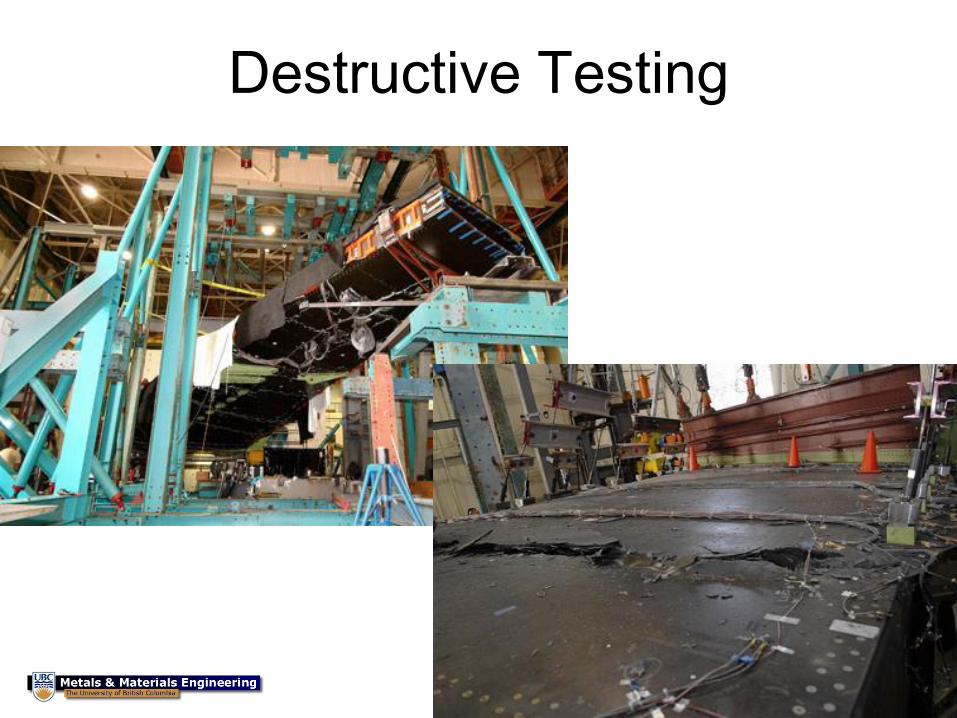
Destructive Testing
172
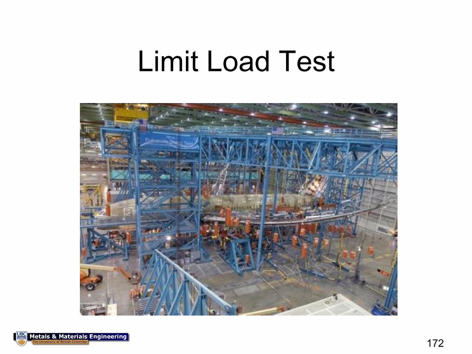
Limit Load Test
173
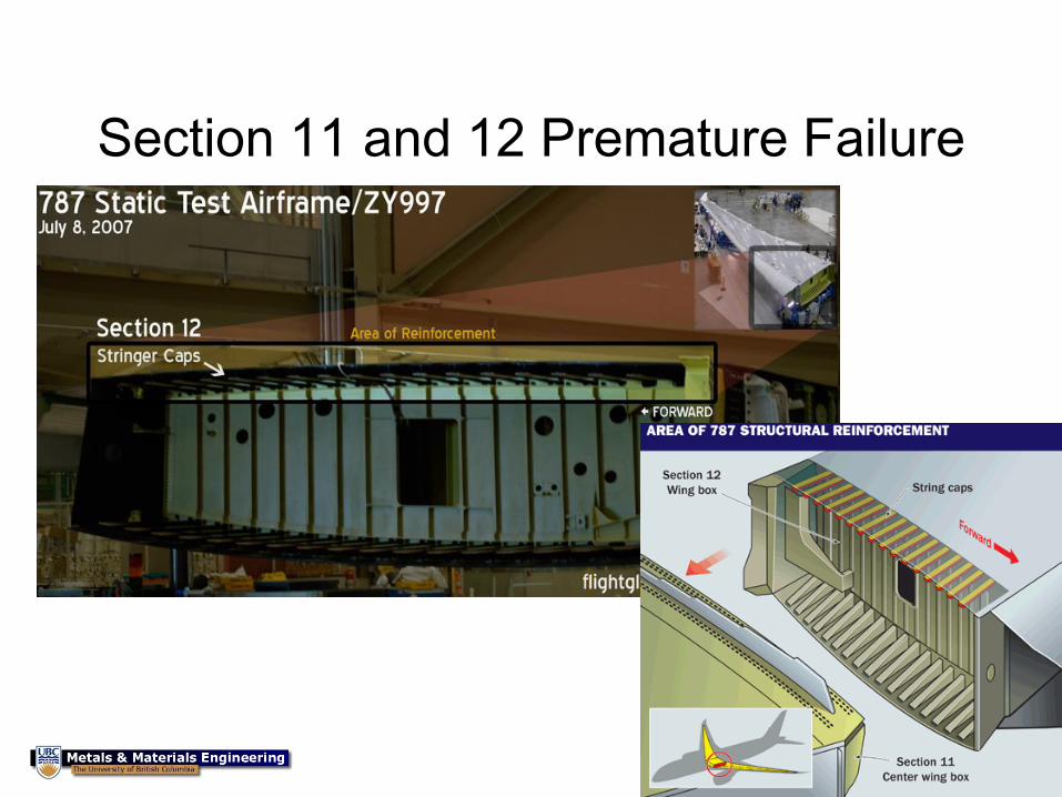
Section 11 and 12 Premature Failure
174
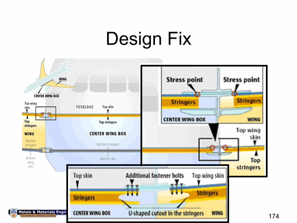
Design Fix
175
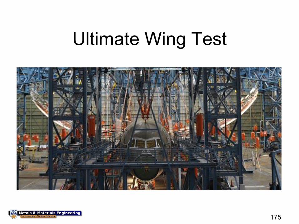
Ultimate Wing Test
Timeline of problems
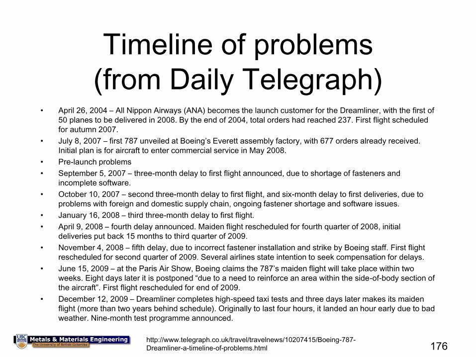
(from Daily Telegraph) • April 26, 2004 – All Nippon Airways (ANA) becomes the launch customer for the Dreamliner, with the first of
50 planes to be delivered in 2008. By the end of 2004, total orders had reached 237. First flight scheduled
for autumn 2007.
• July 8, 2007 – first 787 unveiled at Boeing’s Everett assembly factory, with 677 orders already received.
Initial plan is for aircraft to enter commercial service in May 2008.
• Pre-launch problems
• September 5, 2007 – three-month delay to first flight announced, due to shortage of fasteners and
incomplete software.
• October 10, 2007 – second three-month delay to first flight, and six-month delay to first deliveries, due to
problems with foreign and domestic supply chain, ongoing fastener shortage and software issues.
• January 16, 2008 – third three-month delay to first flight.
• April 9, 2008 – fourth delay announced. Maiden flight rescheduled for fourth quarter of 2008, initial
deliveries put back 15 months to third quarter of 2009.
• November 4, 2008 – fifth delay, due to incorrect fastener installation and strike by Boeing staff. First flight
rescheduled for second quarter of 2009. Several airlines state intention to seek compensation for delays.
• June 15, 2009 – at the Paris Air Show, Boeing claims the 787’s maiden flight will take place within two
weeks. Eight days later it is postponed “due to a need to reinforce an area within the side-of-body section of
the aircraft”. First flight rescheduled for end of 2009.
• December 12, 2009 – Dreamliner completes high-speed taxi tests and three days later makes its maiden
flight (more than two years behind schedule). Originally to last four hours, it landed an hour early due to bad
weather. Nine-month test programme announced.
176 http://www.telegraph.co.uk/travel/travelnews/10207415/Boeing-787-
Dreamliner-a-timeline-of-problems.html
Timeline of problems
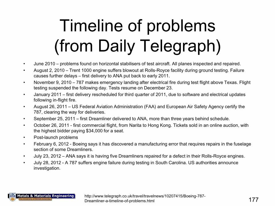
(from Daily Telegraph) • June 2010 – problems found on horizontal stabilisers of test aircraft. All planes inspected and repaired.
• August 2, 2010 – Trent 1000 engine suffers blowout at Rolls-Royce facility during ground testing. Failure
causes further delays – first delivery to ANA put back to early 2011.
• November 9, 2010 – 787 makes emergency landing after electrical fire during test flight above Texas. Flight
testing suspended the following day. Tests resume on December 23.
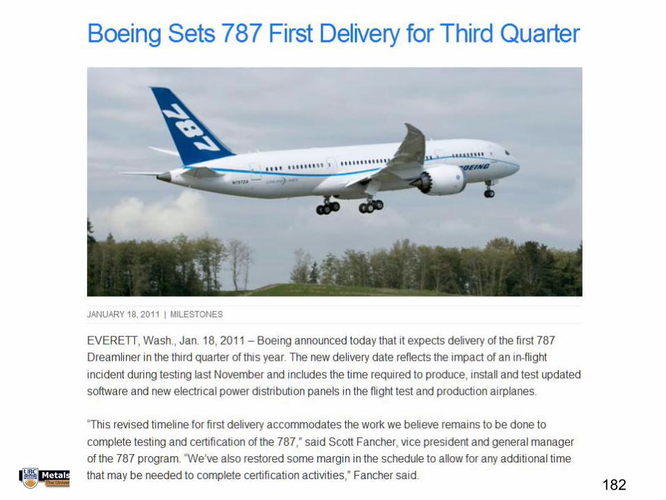
• January 2011 – first delivery rescheduled for third quarter of 2011, due to software and electrical updates
following in-flight fire.
• August 26, 2011 – US Federal Aviation Administration (FAA) and European Air Safety Agency certify the
787, clearing the way for deliveries.
• September 25, 2011 – first Dreamliner delivered to ANA, more than three years behind schedule.
• October 26, 2011 - first commercial flight, from Narita to Hong Kong. Tickets sold in an online auction, with
the highest bidder paying $34,000 for a seat.
• Post-launch problems
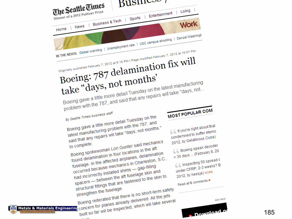
• February 6, 2012 - Boeing says it has discovered a manufacturing error that requires repairs in the fuselage
section of some Dreamliners.
• July 23, 2012 – ANA says it is having five Dreamliners repaired for a defect in their Rolls-Royce engines.
• July 28, 2012 - A 787 suffers engine failure during testing in South Carolina. US authorities announce
investigation.
177 http://www.telegraph.co.uk/travel/travelnews/10207415/Boeing-787-
Dreamliner-a-timeline-of-problems.html
Timeline of problems
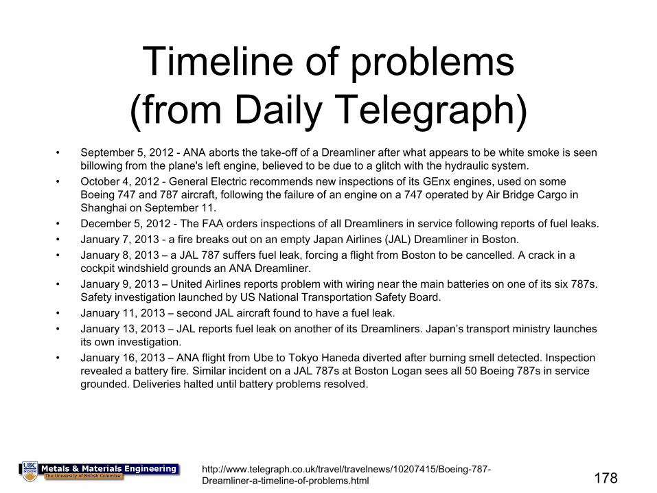
(from Daily Telegraph) • September 5, 2012 - ANA aborts the take-off of a Dreamliner after what appears to be white smoke is seen
billowing from the plane's left engine, believed to be due to a glitch with the hydraulic system.
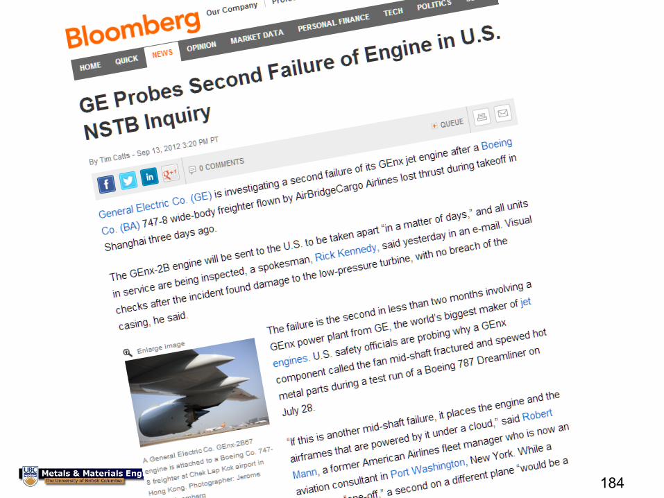
• October 4, 2012 - General Electric recommends new inspections of its GEnx engines, used on some
Boeing 747 and 787 aircraft, following the failure of an engine on a 747 operated by Air Bridge Cargo in
Shanghai on September 11.
• December 5, 2012 - The FAA orders inspections of all Dreamliners in service following reports of fuel leaks.
• January 7, 2013 - a fire breaks out on an empty Japan Airlines (JAL) Dreamliner in Boston.
• January 8, 2013 – a JAL 787 suffers fuel leak, forcing a flight from Boston to be cancelled. A crack in a
cockpit windshield grounds an ANA Dreamliner.
• January 9, 2013 – United Airlines reports problem with wiring near the main batteries on one of its six 787s.
Safety investigation launched by US National Transportation Safety Board.
• January 11, 2013 – second JAL aircraft found to have a fuel leak.
• January 13, 2013 – JAL reports fuel leak on another of its Dreamliners. Japan’s transport ministry launches
its own investigation.
• January 16, 2013 – ANA flight from Ube to Tokyo Haneda diverted after burning smell detected. Inspection
revealed a battery fire. Similar incident on a JAL 787s at Boston Logan sees all 50 Boeing 787s in service
grounded. Deliveries halted until battery problems resolved.
178 http://www.telegraph.co.uk/travel/travelnews/10207415/Boeing-787-
Dreamliner-a-timeline-of-problems.html
Timeline of problems
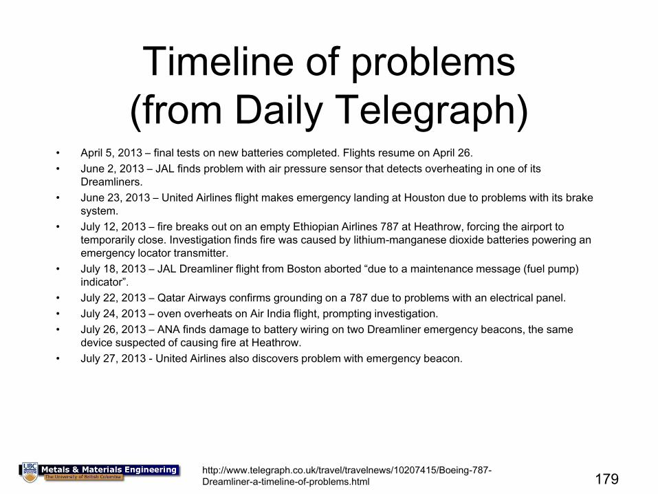
(from Daily Telegraph) • April 5, 2013 – final tests on new batteries completed. Flights resume on April 26.
• June 2, 2013 – JAL finds problem with air pressure sensor that detects overheating in one of its
Dreamliners.
• June 23, 2013 – United Airlines flight makes emergency landing at Houston due to problems with its brake
system.
• July 12, 2013 – fire breaks out on an empty Ethiopian Airlines 787 at Heathrow, forcing the airport to
temporarily close. Investigation finds fire was caused by lithium-manganese dioxide batteries powering an
emergency locator transmitter.
• July 18, 2013 – JAL Dreamliner flight from Boston aborted “due to a maintenance message (fuel pump)
indicator”.
• July 22, 2013 – Qatar Airways confirms grounding on a 787 due to problems with an electrical panel.
• July 24, 2013 – oven overheats on Air India flight, prompting investigation.
• July 26, 2013 – ANA finds damage to battery wiring on two Dreamliner emergency beacons, the same
device suspected of causing fire at Heathrow.
• July 27, 2013 - United Airlines also discovers problem with emergency beacon.
179 http://www.telegraph.co.uk/travel/travelnews/10207415/Boeing-787-
Dreamliner-a-timeline-of-problems.html
180
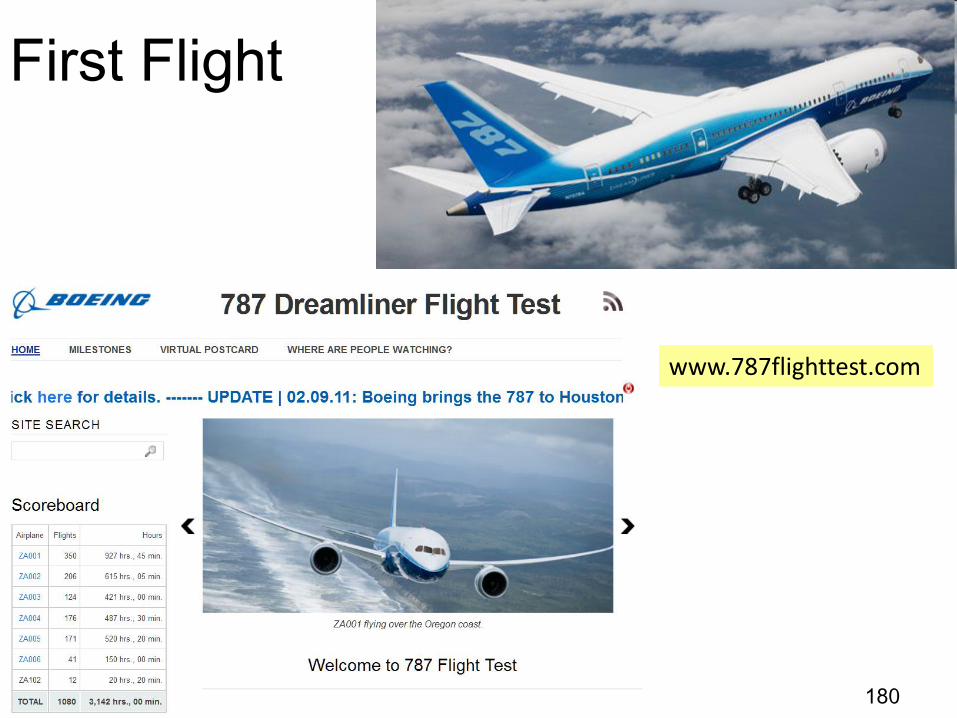
First Flight
www.787flighttest.com
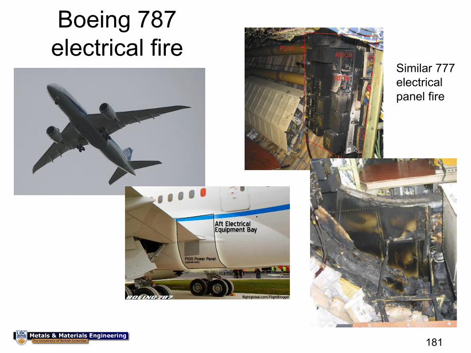
Boeing 787
electrical fire
181
Similar 777
electrical
panel fire
182
184
185
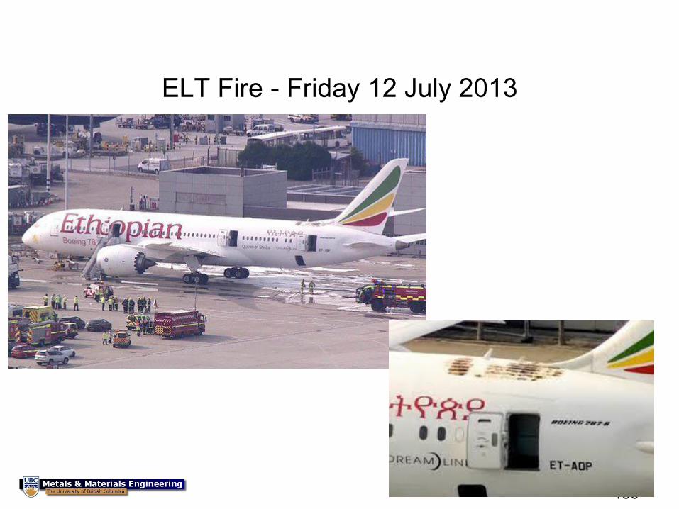
ELT Fire - Friday 12 July 2013
186
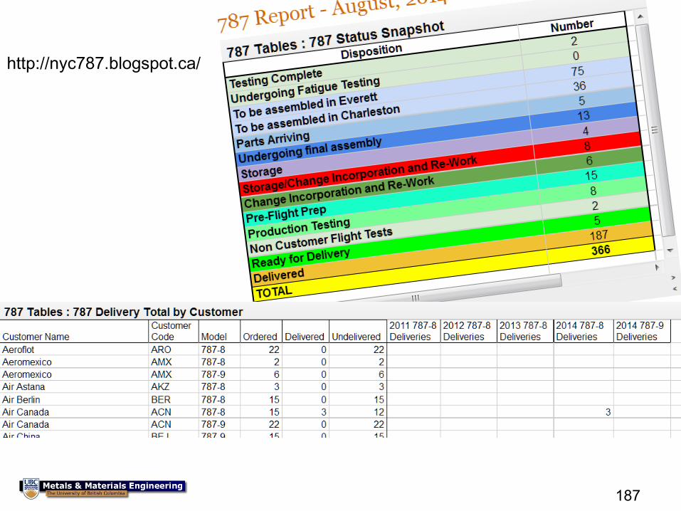
187
http://nyc787.blogspot.ca/
188
Summary and Conclusions
• Materials are chosen for an application based on their properties – You want to maximize performance without exceeding
certain constraints
• In aircraft, the ideal is to mimize fuel costs, aircraft costs, and maintenance/repair costs – Although aluminum has been the material of choice for
aircraft to date, the current bet by Boeing and Airbus (and other smaller aircraft manufacturers such as Bombardier, Mitsubishi, and Learjet) is that composites have finally matured to the point that they will best aluminum on all three counts