Embed Size (px)
Citation preview
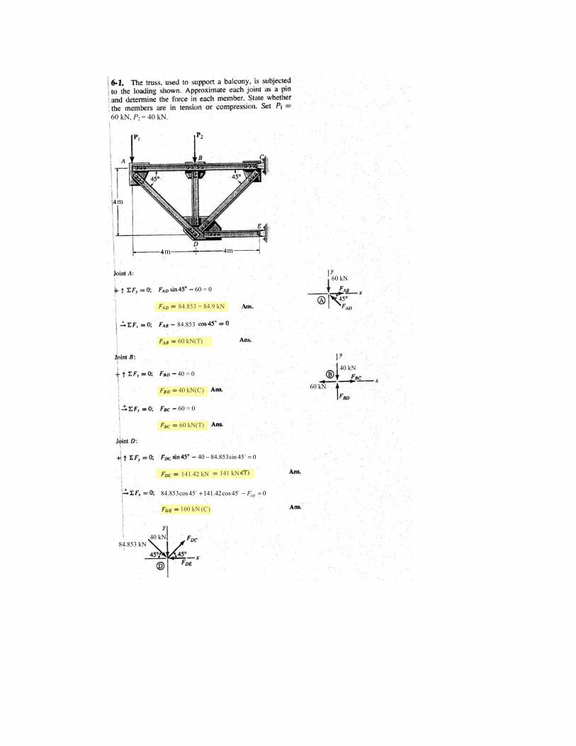
60 kN, P2 = 40 kN.
m
m m
60 kN
4 0 kN
60 kN
4 0 kN 84.853 kN
60 = 0
84.853 = 84.9 kN Ans.
60 kN(T)
84.853
4 0 = 0
40 kN(C )
60 = 0
60 kN(T)
40 84.853sin 45 0− =
141.42 kN 141 kN
84.853cos45 141.42cos45 0OEF+ − =
160 kN (C )
.
.
.
.
.
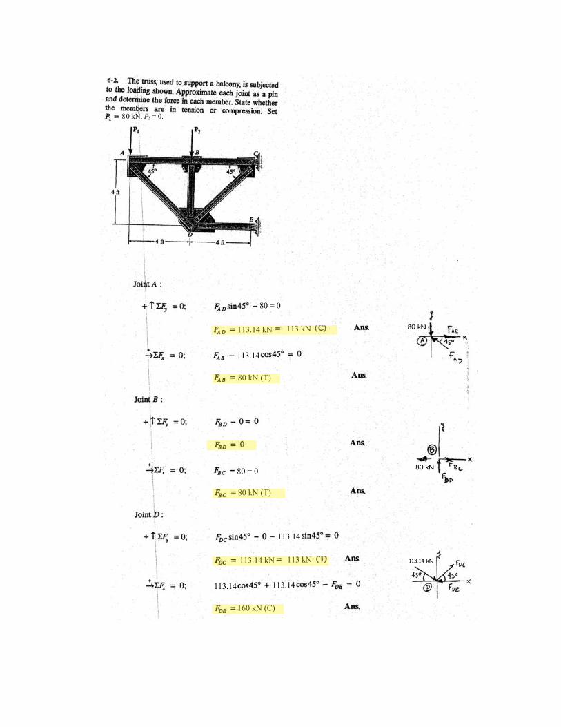
P2 = 0. 8 0 kN,
8 0 = 0
113.14 kN 113 kN
113.14
80 kN (T)
80 = 0
80 kN (T)
113.14
113.14 kN 113 kN
113.14 113.14
160 kN (C)
80 kN
80 kN
113.14 kN
.
.
.
.
.
.
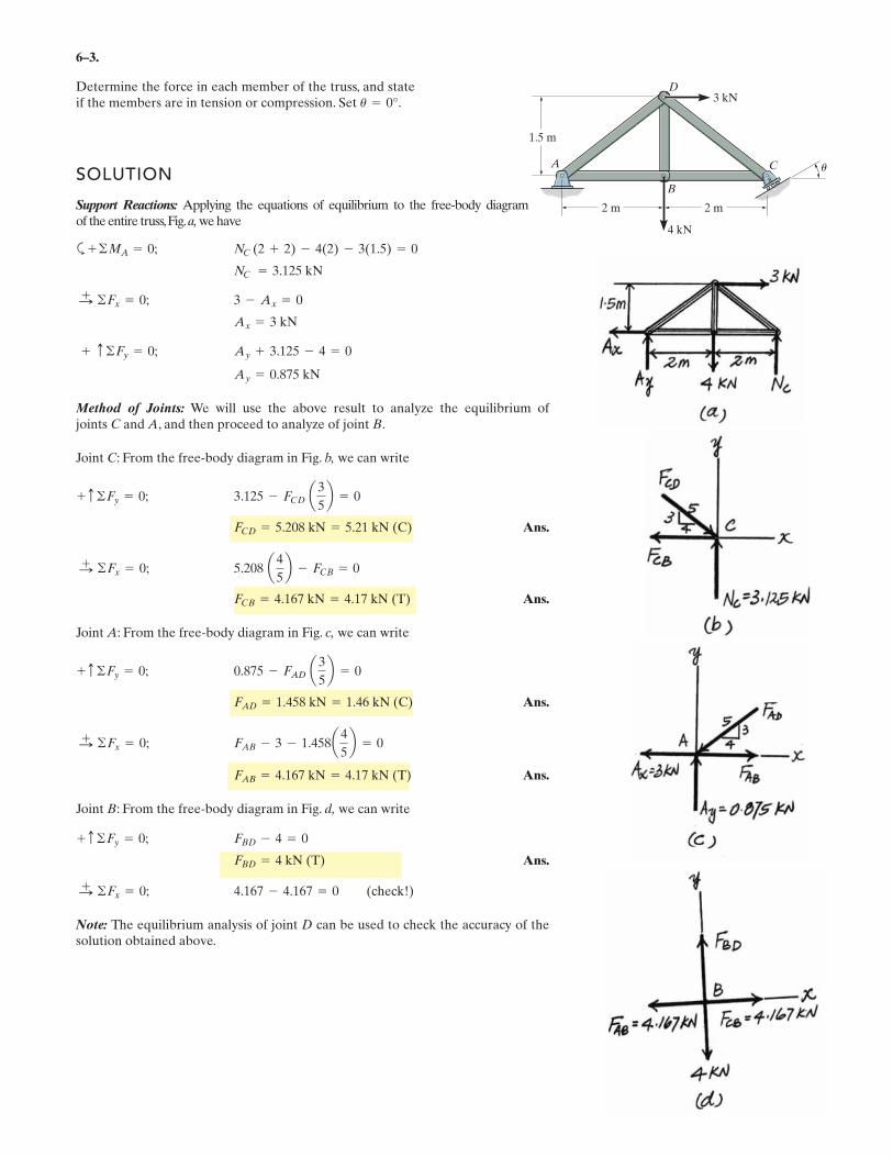
6–3.
Determine the force in each member of the truss, and stateif the members are in tension or compression. Set .
SOLUTION
Support Reactions: Applying the equations of equilibrium to the free-body diagram of the entire truss,Fig.a, we have
a
Method of Joints: We will use the above result to analyze the equilibrium of joints C and A, and then proceed to analyze of joint B.
Joint C: From the free-body diagram in Fig. b, we can write
Ans.
Ans.
Joint A: From the free-body diagram in Fig. c, we can write
Ans.
Ans.
Joint B: From the free-body diagram in Fig. d, we can write
Ans.
Note: The equilibrium analysis of joint D can be used to check the accuracy of thesolution obtained above.
4.167 - 4.167 = 0 (check!)©Fx = 0;:+
FBD = 4 kN (T)
FBD - 4 = 0+ c ©Fy = 0;
FAB = 4.167 kN = 4.17 kN (T)
FAB - 3 - 1.458a 4
5b = 0©Fx = 0;:
+
FAD = 1.458 kN = 1.46 kN (C)
0.875 - FAD a3
5b = 0+ c ©Fy = 0;
FCB = 4.167 kN = 4.17 kN (T)
5.208 a4
5b - FCB = 0©Fx = 0;:
+
FCD = 5.208 kN = 5.21 kN (C)
3.125 - FCD a 3
5b = 0+ c ©Fy = 0;
Ay = 0.875 kN
Ay + 3.125 - 4 = 0+ c ©Fy = 0;
Ax = 3 kN
3 - Ax = 0©Fx = 0;:+
NC = 3.125 kN
NC (2 + 2) - 4(2) - 3(1.5) = 0+ ©MA = 0;
u = 0°
A C
B
D
2 m
4 kN
3 kN
2 m
1.5 m
u
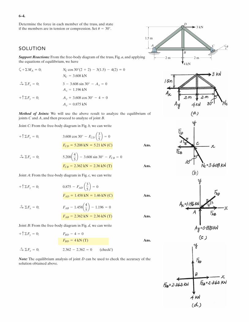
6–4.
Determine the force in each member of the truss, and stateif the members are in tension or compression. Set .
SOLUTION
Support Reactions: From the free-body diagram of the truss, Fig. a, and applyingthe equations of equilibrium, we have
a
Method of Joints: We will use the above result to analyze the equilibrium of joints C and A, and then proceed to analyze of joint B.
Joint C: From the free-body diagram in Fig. b, we can write
Ans.
Ans.
Joint A: From the free-body diagram in Fig. c, we can write
Ans.
Ans.
Joint B: From the free-body diagram in Fig. d, we can write
Ans.
Note: The equilibrium analysis of joint D can be used to check the accuracy of thesolution obtained above.
2.362 - 2.362 = 0 (check!)©Fx = 0;:+
FBD = 4 kN (T)
FBD - 4 = 0+ c ©Fy = 0;
FAB = 2.362 kN = 2.36 kN (T)
FAB - 1.458a 4
5b - 1.196 = 0©Fx = 0;:
+
FAD = 1.458 kN = 1.46 kN (C)
0.875 - FAD a3
5b = 0+ c ©Fy = 0;
FCB = 2.362 kN = 2.36 kN (T)
5.208a4
5b - 3.608 sin 30° - FCB = 0©Fx = 0;:
+
FCD = 5.208 kN = 5.21 kN (C)
3.608 cos 30° - FCD a3
5b = 0+ c ©Fy = 0;
Ay = 0.875 kN
Ay + 3.608 cos 30° - 4 = 0+ c ©Fy = 0;
Ax = 1.196 kN
3 - 3.608 sin 30° - Ax = 0©Fx = 0;:+
NC = 3.608 kN
NC cos 30°(2 + 2) - 3(1.5) - 4(2) = 0+ ©MA = 0;
u = 30°
A C
B
D
2 m
4 kN
3 kN
2 m
1.5 m
u
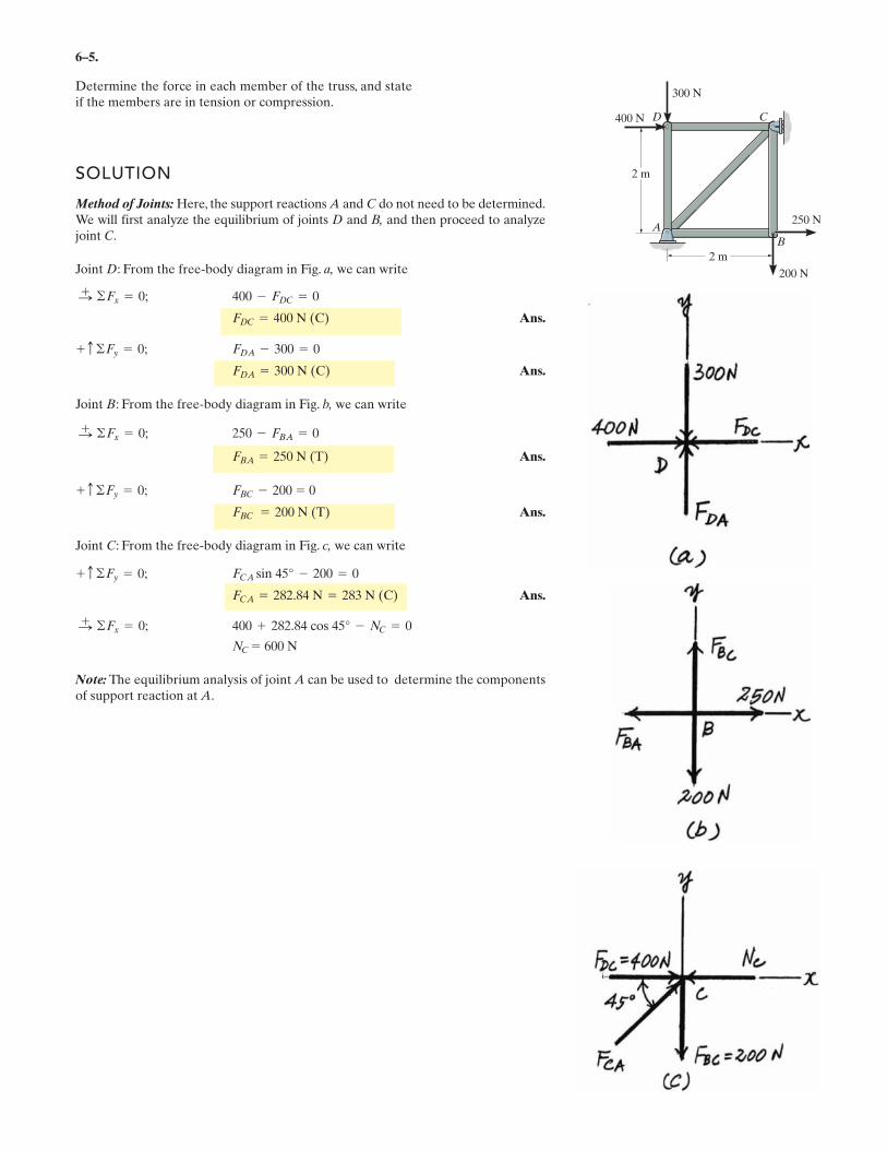
6–5.
Determine the force in each member of the truss, and stateif the members are in tension or compression.
SOLUTION
Method of Joints: Here, the support reactions A and C do not need to be determined.We will first analyze the equilibrium of joints D and B, and then proceed to analyzejoint C.
Joint D: From the free-body diagram in Fig. a, we can write
Ans.
Ans.
Joint B: From the free-body diagram in Fig. b, we can write
Ans.
Ans.
Joint C: From the free-body diagram in Fig. c, we can write
Ans.
Note: The equilibrium analysis of joint A can be used to determine the componentsof support reaction at A.
NC = 600 N
400 + 282.84 cos 45° - NC = 0©Fx = 0;:+
FCA = 282.84 N = 283 N (C)
FCA sin 45° - 200 = 0+ c ©Fy = 0;
FBC = 200 N (T)
FBC - 200 = 0+ c ©Fy = 0;
FBA = 250 N (T)
250 - FBA = 0©Fx = 0;:+
FDA = 300 N (C)
FDA - 300 = 0+ c ©Fy = 0;
FDC = 400 N (C)
400 - FDC = 0©Fx = 0;:+
400 N
300 N
200 N
250 N
2 m
2 m
A
B
D C
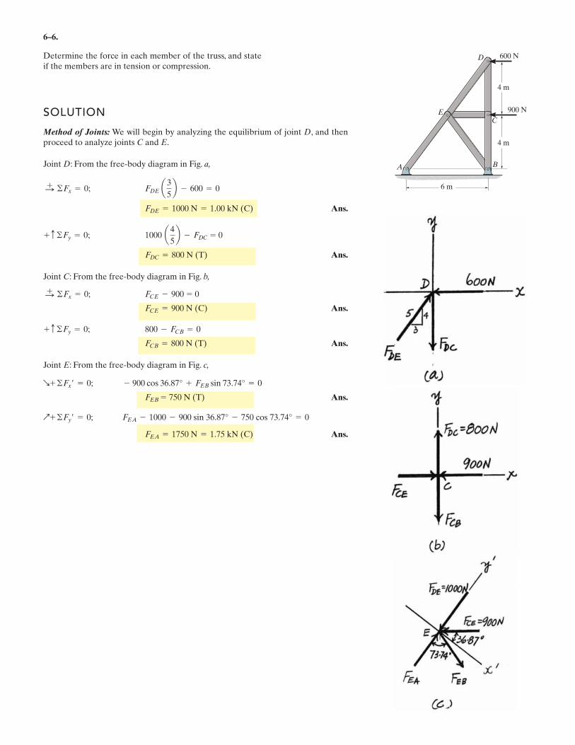
6–6.
Determine the force in each member of the truss, and stateif the members are in tension or compression.
SOLUTION
Method of Joints: We will begin by analyzing the equilibrium of joint D, and thenproceed to analyze joints C and E.
Joint D: From the free-body diagram in Fig. a,
Ans.
Ans.
Joint C: From the free-body diagram in Fig. b,
Ans.
Ans.
Joint E: From the free-body diagram in Fig. c,
Ans.
Ans.FEA = 1750 N = 1.75 kN (C)
FEA - 1000 - 900 sin 36.87° - 750 cos 73.74° = 0Q+ ©Fy¿ = 0;
FEB = 750 N (T)
- 900 cos 36.87° + FEB sin 73.74° = 0R+ ©Fx¿ = 0;
FCB = 800 N (T)
800 - FCB = 0+ c ©Fy = 0;
FCE = 900 N (C)
FCE - 900 = 0©Fx = 0;:+
FDC = 800 N (T)
1000 a4
5b - FDC = 0+ c ©Fy = 0;
FDE = 1000 N = 1.00 kN (C)
FDE a3
5b - 600 = 0©Fx = 0;:
+
B
E
D
A
C
600 N
900 N
4 m
4 m
6 m
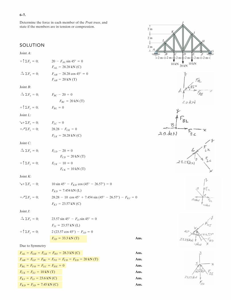
6–7.
Determine the force in each member of the Pratt truss, andstate if the members are in tension or compression.
SOLUTION
Joint A:
Joint B:
Joint L:
Joint C:
Joint K:
Joint J:
Ans.
Due to Symmetry
Ans.
Ans.
Ans.
Ans.
Ans.
Ans.FKD = FID = 7.45 kN (C)
FKJ = FIJ = 23.6 kN (C)
FCK = FEI = 10 kN (T)
FBL = FFH = FLC = FHE = 0
FAB = FGF = FBC = FFE = FCD = FED = 20 kN (T)
FAL = FGH = FLK = FHI = 28.3 kN (C)
FJD = 33.3 kN (T)
2 (23.57 cos 45°) - FJD = 0+ c ©Fy = 0;
FJI = 23.57 kN (L)
23.57 sin 45° - FJI sin 45° = 0©Fx = 0;:+
FKJ = 23.57 kN (C)
28.28 - 10 cos 45° + 7.454 sin (45° - 26.57°) - FKJ = 0+Q©Fy = 0;
FKD = 7.454 kN (L)
10 sin 45° - FKD cos (45° - 26.57°) = 0R+ ©Fx - 0;
FCK = 10 kN (T)
FCK - 10 = 0+ c ©Fy = 0;
FCD = 20 kN (T)
FCD - 20 = 0©Fx = 0;:+
FLK = 28.28 kN (C)
28.28 - FLK = 0+Q©Fy = 0;
FLC = 0R+ ©Fx = 0;
FBL = 0+ c ©Fy = 0;
FBC = 20 kN (T)
FBC - 20 = 0©Fx = 0;:+
FAB = 20 kN (T)
FAB - 28.28 cos 45° = 0©Fx = 0;:+
FAL = 28.28 kN (C)
20 - FAL sin 45° = 0+ c ©Fy = 0;
A
B C D E FG
H
I
J
K
L
2 m
2 m
2 m 2 m
10 kN 10 kN20 kN
2 m 2 m 2 m
2 m
2 m

�
Determine the force in each member of the truss and state if the members are in tension or
compression. Hint: The horizontal force component at A must be zero. Why?
���� ����
�� 103���
������
�� 600����
�� 800����
� 4���
� 3���
� 60�����
���������
Initial Guesses
�� 1���� ��! 1���� �"� 1���� �"! 1����
�����
Joint C �"�� �� #�� �( )�� 0= �"!� �� ��� �( )�� 0=
Joint B �"� ��!�
�2
�2
�
�� 0= �� � ��!�
�2
�2
�
�� ��� 0=
Positive means Tension
Negative means
Compression
��
��!
�"�
�"!
�
������
���� �� ��!� �"�� �"!�� ���
��
��!
�"�
�"!
�
������
1133�
667
400�
693�
�
�����
���
.
Ans.
–
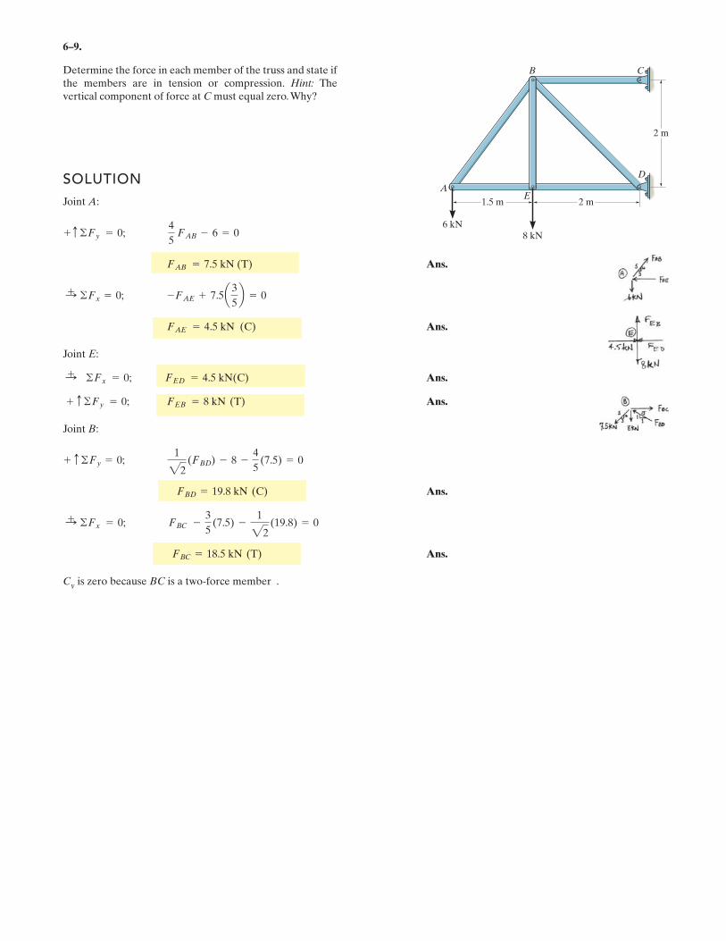
6–9.
SOLUTION
Joint A:
Ans.
Ans.
Joint E:
Ans.
Ans.
Joint B:
Ans.
Ans.
Cy is zero because BC is a two-force member .
FBC = 18.5 kN (T)
:+ ©Fx = 0; FBC -
3
5(7.5) -
1
22(19.8) = 0
FBD = 19.8 kN (C)
+ c ©Fy = 0;1
22(FBD) - 8 -
4
5(7.5) = 0
+ c ©Fy = 0; FEB = 8 kN (T)
:+ ©Fx = 0; FED = 4.5 kN(C)
FAE = 4.5 kN (C)
:+ ©Fx = 0; -FAE + 7.5a3
5b = 0
FAB = 7.5 kN (T)
+ c ©Fy = 0;4
5FAB - 6 = 0
Determine the force in each member of the truss and state ifthe members are in tension or compression. Hint: Thevertical component of force at C must equal zero.Why?
B
EA
C
D
1.5 m
6 kN8 kN
2 m
2 m
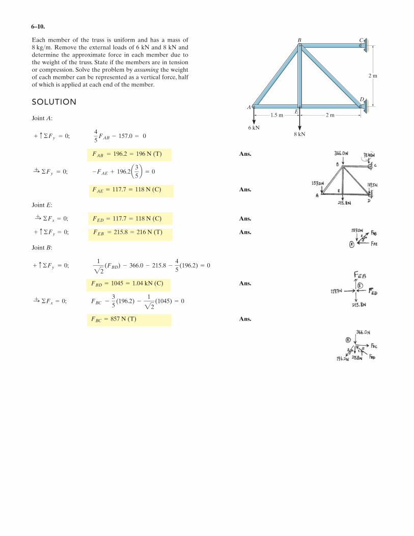
6–10.
Each member of the truss is uniform and has a mass ofRemove the external loads of 6 kN and 8 kN and
determine the approximate force in each member due tothe weight of the truss. State if the members are in tensionor compression. Solve the problem by assuming the weightof each member can be represented as a vertical force, halfof which is applied at each end of the member.
8 kg>m.
SOLUTION
Joint A:
Ans.
Ans.
Joint E:
Ans.
Ans.
Joint B:
Ans.
Ans.FBC = 857 N (T)
:+ ©Fx = 0; FBC -
3
5(196.2) -
1
22(1045) = 0
FBD = 1045 = 1.04 kN (C)
+ c ©Fy = 0;1
22(FBD) - 366.0 - 215.8 -
4
5(196.2) = 0
+ c ©Fy = 0; FEB = 215.8 = 216 N (T)
:+ ©Fx = 0; FED = 117.7 = 118 N (C)
FAE = 117.7 = 118 N (C)
:+ ©Fy = 0; -FAE + 196.2a3
5b = 0
FAB = 196.2 = 196 N (T)
+ c ©Fy = 0;4
5FAB - 157.0 = 0
B
EA
C
D
1.5 m
6 kN8 kN
2 m
2 m
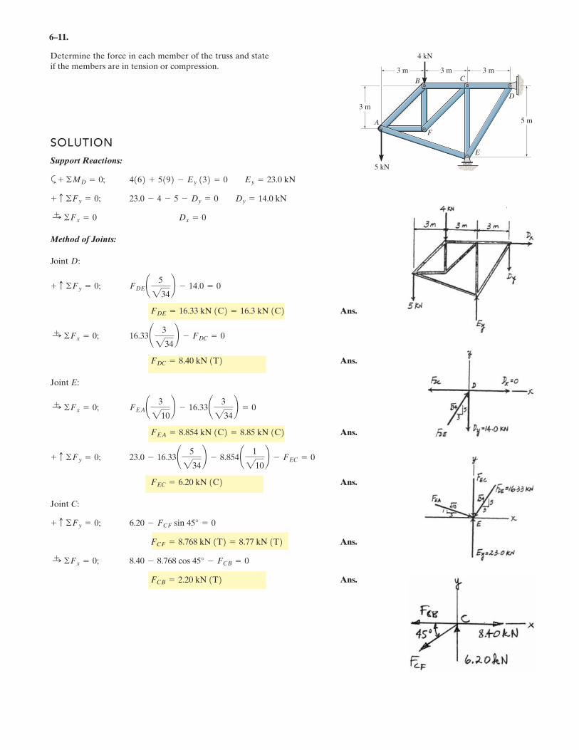
6–11.
SOLUTION
Support Reactions:
a
Method of Joints:
Joint D:
Ans.
Ans.
Joint E:
Ans.
Ans.
Joint C:
Ans.
Ans.FCB = 2.20 kN T
8.40 - 8.768 cos 45° - FCB = 0:+ ©Fx = 0;
FCF = 8.768 kN 1T2 = 8.77 kN 1T26.20 - FCF sin 45° = 0+ c ©Fy = 0;
FEC = 6.20 kN 1C223.0 - 16.33¢ 5
234≤ - 8.854¢ 1
210≤ - FEC = 0+ c ©Fy = 0;
FEA = 8.854 kN 1C2 = 8.85 kN 1C2FEA¢ 3
210≤ - 16.33¢ 3
234≤ = 0:
+ ©Fx = 0;
FDC = 8.40 kN 1T216.33¢ 3
234≤ - FDC = 0:
+ ©Fx = 0;
FDE = 16.33 kN 1C2 = 16.3 kN 1C2FDE¢ 5
234≤ - 14.0 = 0+ c ©Fy = 0;
Dx = 0:+ ©Fx = 0
23.0 - 4 - 5 - Dy = 0 Dy = 14.0 kN+ c ©Fy = 0;
4162 + 5192 - Ey 132 = 0 Ey = 23.0 kN+ ©MD = 0;
Determine the force in each member of the truss and stateif the members are in tension or compression.
E
D
CB
F
A 5 m
3 m
5 kN
4 kN
3 m 3 m 3 m
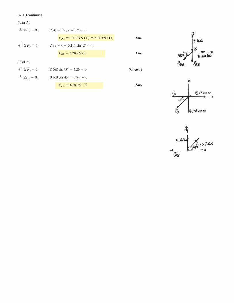
6–11. (continued)
Joint B:
Ans.
Joint F:
(Check!)
Ans.FFA = 6.20 kN 1T28.768 cos 45° - FFA = 0:
+ ©Fx = 0;
8.768 sin 45° - 6.20 = 0+ c ©Fy = 0;
FBF = 6.20 kN 1C2FBF - 4 - 3.111 sin 45° = 0+ c ©Fy = 0;
FBA = 3.111 kN 1T2 = 3.11 kN 1T22.20 - FBA cos 45° = 0:
+ ©Fx = 0;
Ans.
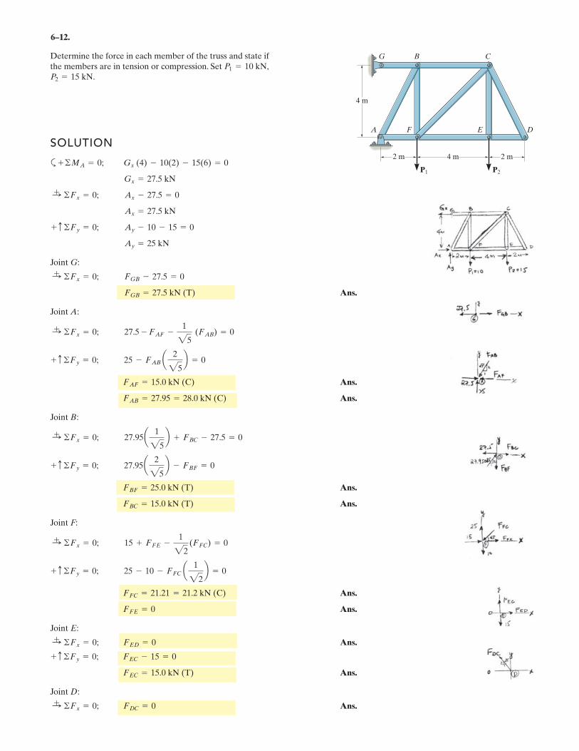
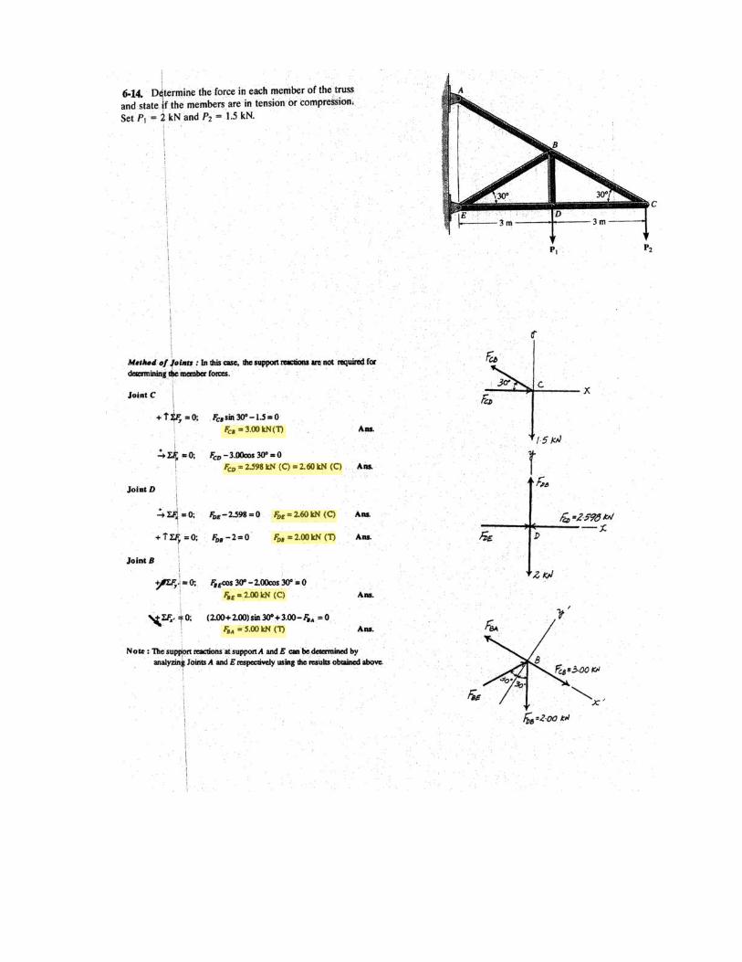
6–12.
Determine the force in each member of the truss and state ifthe members are in tension or compression. SetP2 = 15 kN.
P1 = 10 kN,
SOLUTION
a
Joint G:
Ans.
Joint A:
Ans.
Ans.
Joint B:
Ans.
Ans.
Joint F:
Ans.
Ans.
Joint E:
Ans.
Ans.
Joint D:
Ans.:+ ©Fx = 0; FDC = 0
FEC = 15.0 kN (T)
+ c ©Fy = 0; FEC - 15 = 0
:+ ©Fx = 0; FED = 0
FFE = 0
FFC = 21.21 = 21.2 kN (C)
+ c ©Fy = 0; 25 - 10 - FFC a 1
22b = 0
:+ ©Fx = 0; 15 + FFE -
1
22(FFC) = 0
FBC = 15.0 kN (T)
FBF = 25.0 kN (T)
+ c ©Fy = 0; 27.95a 2
25b - FBF = 0
:+ ©Fx = 0; 27.95a 1
25b + FBC - 27.5 = 0
FAB = 27.95 = 28.0 kN (C)
FAF = 15.0 kN (C)
+ c ©Fy = 0; 25 - FAB a 2
25b = 0
:+ ©Fx = 0; 27.5 - FAF -
1
25(FAB) = 0
FGB = 27.5 kN (T)
:+ ©Fx = 0; FGB - 27.5 = 0
Ay = 25 kN
+ c ©Fy = 0; Ay - 10 - 15 = 0
Ax = 27.5 kN
:+ ©Fx = 0; Ax - 27.5 = 0
Gx = 27.5 kN
+ ©MA = 0; Gx (4) - 10(2) - 15(6) = 02 m 2 m4 m
4 m
A F E
G B C
D
P1 P2
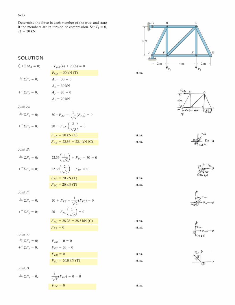
6–13.
Determine the force in each member of the truss and stateif the members are in tension or compression. Set P2 = 20 kN.
P1 = 0,
SOLUTION
a
Ans.
Joint A:
Ans.
Ans.
Joint B:
Ans.
Ans.
Joint F:
Ans.
Ans.
Joint E:
Ans.
Ans.
Joint D:
Ans.FDC = 0
:+ ©Fx = 0;
1
25(FDC) - 0 = 0
FEC = 20.0 kN (T)
FED = 0
+ c ©Fy = 0; FEC - 20 = 0
:+ ©Fx = 0; FED - 0 = 0
FFE = 0
FFC = 28.28 = 28.3 kN (C)
+ c ©Fy = 0; 20 - FFC a 1
22b = 0
:+ ©Fx = 0; 20 + FFE -
1
22(FFC) = 0
FBC = 20 kN (T)
FBF = 20 kN (T)
+ c ©Fy = 0; 22.36a 2
25b - FBF = 0
:+ ©Fx = 0; 22.36a 1
25b + FBC - 30 = 0
FAB = 22.36 = 22.4 kN (C)
FAF = 20 kN (C)
+ c ©Fy = 0; 20 - FAB a 2
25b = 0
:+ ©Fx = 0; 30 -FAF -
1
25(FAB) = 0
Ay = 20 kN
+ c ©Fy = 0; Ay - 20 = 0
Ax = 30 kN
:+ ©Fx = 0; Ax - 30 = 0
FGB = 30 kN (T)
+ ©MA = 0; -FGB (4) + 20(6) = 02 m 2 m4 m
4 m
A F E
G B C
D
P1 P2
.
.
.
.
.
.
.
.
.
.
.
.
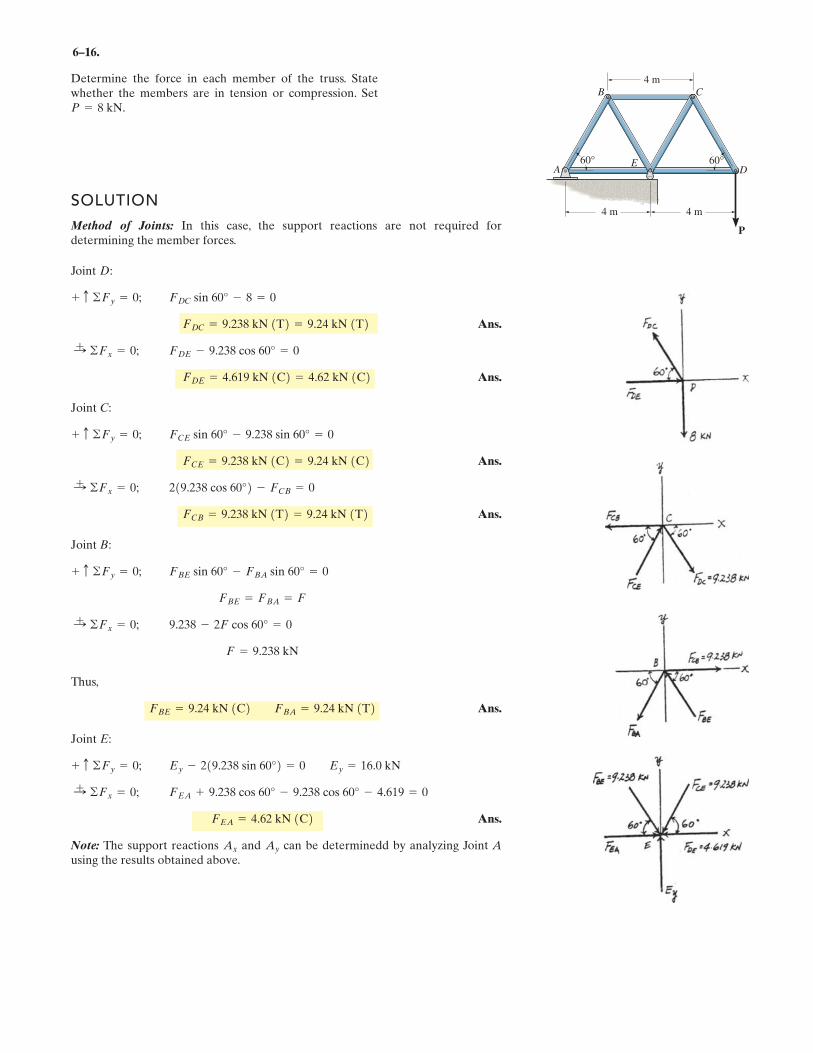
6–16.
SOLUTION
Method of Joints: In this case, the support reactions are not required fordetermining the member forces.
Joint D:
Ans.
Ans.
Joint C:
Ans.
Ans.
Joint B:
Thus,
Ans.
Joint E:
Ans.
Note: The support reactions and can be determinedd by analyzing Joint Ausing the results obtained above.
AyAx
FEA = 4.62 kN 1C2FEA + 9.238 cos 60° - 9.238 cos 60° - 4.619 = 0:
+ ©Fx = 0;
Ey - 219.238 sin 60°2 = 0 Ey = 16.0 kN+ c ©Fy = 0;
FBE = 9.24 kN 1C2 FBA = 9.24 kN 1T2
F = 9.238 kN
9.238 - 2F cos 60° = 0:+ ©Fx = 0;
FBE = FBA = F
FBE sin 60° - FBA sin 60° = 0+ c ©Fy = 0;
FCB = 9.238 kN 1T2 = 9.24 kN 1T2219.238 cos 60°2 - FCB = 0:
+ ©Fx = 0;
FCE = 9.238 kN 1C2 = 9.24 kN 1C2FCE sin 60° - 9.238 sin 60° = 0+ c ©Fy = 0;
FDE = 4.619 kN 1C2 = 4.62 kN 1C2FDE - 9.238 cos 60° = 0:
+ ©Fx = 0;
FDC = 9.238 kN 1T2 = 9.24 kN 1T2FDC sin 60° - 8 = 0+ c ©Fy = 0;
Determine the force in each member of the truss. Statewhether the members are in tension or compression. SetP = 8 kN.
60°60°
4 m 4 m
B
ED
C
A
4 m
P
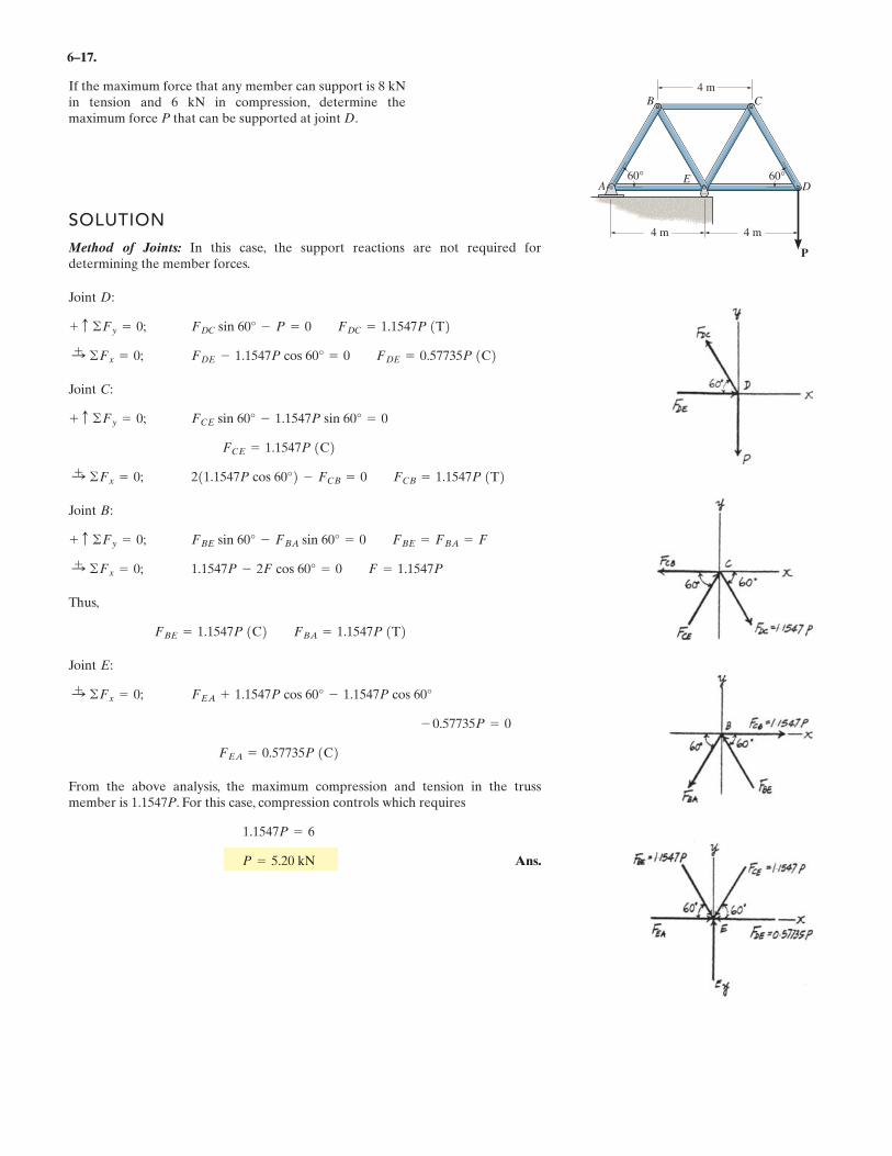
6–17.
If the maximum force that any member can support is 8 kNin tension and 6 kN in compression, determine themaximum force P that can be supported at joint D.
SOLUTION
Method of Joints: In this case, the support reactions are not required fordetermining the member forces.
Joint D:
Joint C:
Joint B:
Thus,
Joint E:
From the above analysis, the maximum compression and tension in the trussmember is 1.1547P. For this case, compression controls which requires
Ans.P = 5.20 kN
1.1547P = 6
FEA = 0.57735P 1C2- 0.57735P = 0
FEA + 1.1547P cos 60° - 1.1547P cos 60°:+ ©Fx = 0;
FBE = 1.1547P 1C2 FBA = 1.1547P 1T2
1.1547P - 2F cos 60° = 0 F = 1.1547P:+ ©Fx = 0;
FBE sin 60° - FBA sin 60° = 0 FBE = FBA = F+ c ©Fy = 0;
211.1547P cos 60°2 - FCB = 0 FCB = 1.1547P 1T2:+ ©Fx = 0;
FCE = 1.1547P 1C2FCE sin 60° - 1.1547P sin 60° = 0+ c ©Fy = 0;
FDE - 1.1547P cos 60° = 0 FDE = 0.57735P 1C2:+ ©Fx = 0;
FDC sin 60° - P = 0 FDC = 1.1547P 1T2+ c ©Fy = 0;
60°60°
4 m 4 m
B
ED
C
A
4 m
P
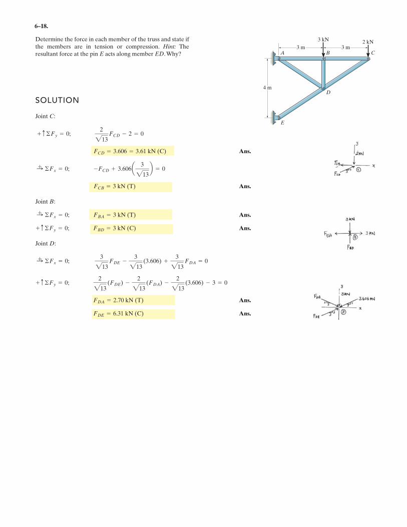
6–18.
Determine the force in each member of the truss and state ifthe members are in tension or compression. Hint: Theresultant force at the pin E acts along member ED.Why?
SOLUTION
Joint C:
Ans.
Ans.
Joint B:
Ans.
Ans.
Joint D:
Ans.
Ans.FDE = 6.31 kN (C)
FDA = 2.70 kN (T)
+ c ©Fy = 0;2
213(FDE) -
2
213(FDA) -
2
213(3.606) - 3 = 0
:+ ©Fx = 0;
3
213FDE -
3
213(3.606) +
3
213FDA = 0
+ c ©Fy = 0; FBD = 3 kN (C)
:+ ©Fx = 0; FBA = 3 kN (T)
FCB = 3 kN (T)
:+ ©Fx = 0; -FCD + 3.606a 3
213b = 0
FCD = 3.606 = 3.61 kN (C)
+ c ©Fy = 0;2
213FCD - 2 = 0
D
C
3 kN 2 kN
BA
E
3 m
4 m
3 m
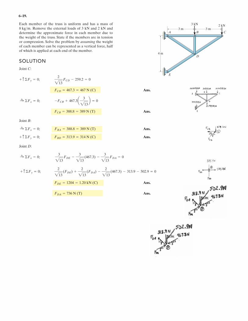
6–19.
Each member of the truss is uniform and has a mass ofRemove the external loads of 3 kN and 2 kN and
determine the approximate force in each member due tothe weight of the truss. State if the members are in tensionor compression. Solve the problem by assuming the weightof each member can be represented as a vertical force, halfof which is applied at each end of the member.
8 kg>m.
SOLUTION
Joint C:
Ans.
Ans.
Joint B:
Ans.
Ans.
Joint D:
:+ ©Fx = 0;
3
213FDE -
3
213(467.3) -
3
213FDA = 0
+ c ©Fy = 0; FBD = 313.9 = 314 N (C)
:+ ©Fx = 0; FBA = 388.8 = 389 N (T)
FCB = 388.8 = 389 N (T)
:+ ©Fx = 0; -FCB + 467.3a 3
213b = 0
FCD = 467.3 = 467 N (C)
+ c ©Fy = 0;2
213FCD - 259.2 = 0
D
C
3 kN 2 kN
BA
E
3 m
4 m
3 m
+ c ©Fy = 0;2
213(FDE) +
2
213(FDA) -
2
213(467.3) - 313.9 - 502.9 = 0
Ans.
Ans.FDA = 736 N (T)
FDE = 1204 = 1.20 kN (C)
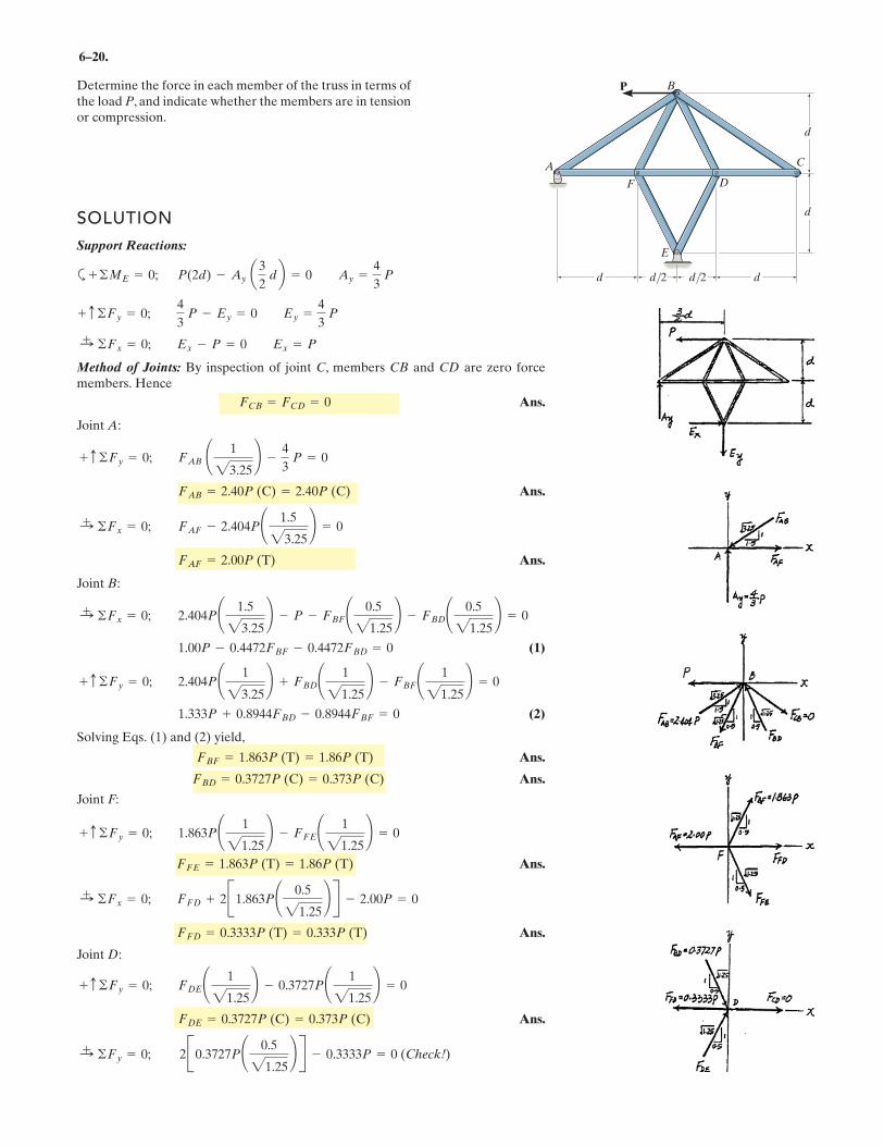
6–20.
Determine the force in each member of the truss in terms ofthe load P, and indicate whether the members are in tensionor compression.
SOLUTION
Support Reactions:
a
Method of Joints: By inspection of joint C, members CB and CD are zero forcemembers. Hence
Ans.
Joint A:
Ans.
Ans.
Joint B:
(1)
(2)
Solving Eqs. (1) and (2) yield,
Ans.
Ans.
Joint F:
Ans.
Ans.
Joint D:
Ans.
:+ ©Fy = 0; 2B0.3727P¢ 0.5
21.25≤ R - 0.3333P = 0 (Check!)
FDE = 0.3727P (C) = 0.373P (C)
+ c ©Fy = 0; FDE¢ 1
21.25≤ - 0.3727P¢ 1
21.25≤ = 0
FFD = 0.3333P (T) = 0.333P (T)
:+ ©Fx = 0; FFD + 2B1.863P¢ 0.5
21.25≤ R - 2.00P = 0
FFE = 1.863P (T) = 1.86P (T)
+ c ©Fy = 0; 1.863P¢ 1
21.25≤ - FFE¢ 1
21.25≤ = 0
FBD = 0.3727P (C) = 0.373P (C)
FBF = 1.863P (T) = 1.86P (T)
1.333P + 0.8944FBD - 0.8944FBF = 0
+ c ©Fy = 0; 2.404P¢ 1
23.25≤ + FBD¢ 1
21.25≤ - FBF¢ 1
21.25≤ = 0
1.00P - 0.4472FBF - 0.4472FBD = 0
:+ ©Fx = 0; 2.404P¢ 1.5
23.25≤ - P - FBF¢ 0.5
21.25≤ - FBD¢ 0.5
21.25≤ = 0
FAF = 2.00P (T)
:+ ©Fx = 0; FAF - 2.404P¢ 1.5
23.25≤ = 0
FAB = 2.40P (C) = 2.40P (C)
+ c ©Fy = 0; FAB ¢ 1
23.25≤ -
4
3P = 0
FCB = FCD = 0
:+ ©Fx = 0; Ex - P = 0 Ex = P
+ c ©Fy = 0;4
3P - Ey = 0 Ey =
4
3P
+ ©ME = 0; P(2d) - Ay a3
2db = 0 Ay =
4
3P
A
B
C
DF
E
P
d
d
d d/2 d/2 d
6–21.
SOLUTION
Support Reactions:
a
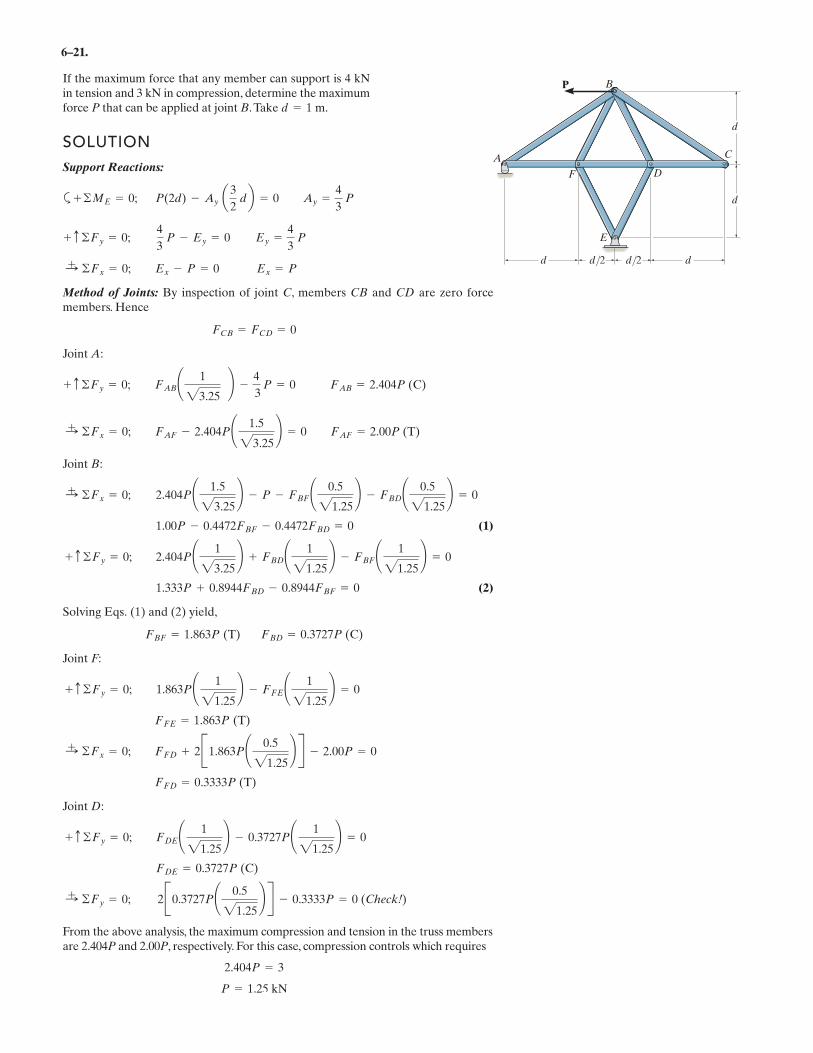
Method of Joints: By inspection of joint C, members CB and CD are zero forcemembers. Hence
Joint A:
Joint B:
(1)
(2)
Solving Eqs. (1) and (2) yield,
Joint F:
Joint D:
From the above analysis, the maximum compression and tension in the truss membersare 2.404P and 2.00P, respectively. For this case, compression controls which requires
P = 1.25 kN
2.404P = 3
:+ ©Fy = 0; 2B0.3727P¢ 0.5
21.25≤ R - 0.3333P = 0 (Check!)
FDE = 0.3727P (C)
+ c ©Fy = 0; FDE¢ 1
21.25≤ - 0.3727P¢ 1
21.25≤ = 0
FFD = 0.3333P (T)
:+ ©Fx = 0; FFD + 2B1.863P¢ 0.5
21.25≤ R - 2.00P = 0
FFE = 1.863P (T)
+ c ©Fy = 0; 1.863P¢ 1
21.25≤ - FFE¢ 1
21.25≤ = 0
FBF = 1.863P (T) FBD = 0.3727P (C)
1.333P + 0.8944FBD - 0.8944FBF = 0
+ c ©Fy = 0; 2.404P¢ 1
23.25≤ + FBD¢ 1
21.25≤ - FBF¢ 1
21.25≤ = 0
1.00P - 0.4472FBF - 0.4472FBD = 0
:+ ©Fx = 0; 2.404P¢ 1.5
23.25≤ - P - FBF¢ 0.5
21.25≤ - FBD¢ 0.5
21.25≤ = 0
:+ ©Fx = 0; FAF - 2.404P¢ 1.5
23.25≤ = 0 FAF = 2.00P (T)
+ c ©Fy = 0; FAB¢ 1
23.25≤ -
4
3P = 0 FAB = 2.404P (C)
FCB = FCD = 0
:+ ©Fx = 0; Ex - P = 0 Ex = P
+ c ©Fy = 0;4
3P - Ey = 0 Ey =
4
3P
+ ©ME = 0; P(2d) - Ay a3
2db = 0 Ay =
4
3P
If the maximum force that any member can support is 4 kNin tension and 3 kN in compression, determine the maximumforce P that can be applied at joint B.Take .d = 1 m
A
B
C
DF
E
P
d
d
d d/2 d/2 d
6–22.
SOLUTION
c
Joint F:
(1)
Joint C:
Joint A:
From Eq.(1), and Symmetry,
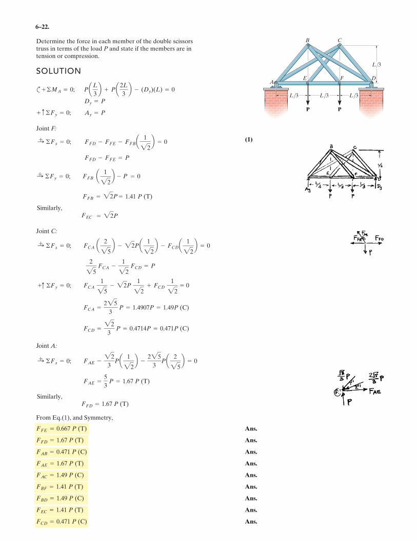
Ans.
Ans.
Ans.
Ans.
Ans.
Ans.
Ans.
Ans.
Ans.FCD = 0.471 P (C)
FEC = 1.41 P (T)
FBD = 1.49 P (C)
FBF = 1.41 P (T)
FAC = 1.49 P (C)
FAE = 1.67 P (T)
FAB = 0.471 P (C)
FFD = 1.67 P (T)
FFE = 0.667 P (T)
FAE =5
3P = 1.67 P (T)
:+ ©Fx = 0; FAE -
22
3Pa 1
22b -
225
3Pa 2
25b = 0
FCD =22
3P = 0.4714P = 0.471P (C)
FCA =225
3P = 1.4907P = 1.49P (C)
2
25FCA -
1
22FCD = P
:+ ©Fx = 0; FCA a 2
25b - 22Pa 1
22b - FCDa 1
22b = 0
FCA 1
25- 22P
1
22+ FCD
1
22= 0
FFD - FFE = P
1
2
FFB = = 1.41 P (T)
:+ ©Fy = 0; FFB a
2b - = 0
22P
P
:+ ©Fx = 0; FFD - FFE - FFBa 1
22b = 0
+ c ©Fy = 0; Ay = P
Dy = P
+ ©MA = 0; PaL
3b + Pa2L
3b - (Dy)(L) = 0
Determine the force in each member of the double scissorstruss in terms of the load P and state if the members are in tension or compression.
= 22P
Similarly, FEC
Similarly, FFD=1.67 P (T)
ADFE
P P
B C
L/3
L/3L/3L/3
+c ©Fy = 0;
6–23.
SOLUTION
Entire truss:
a
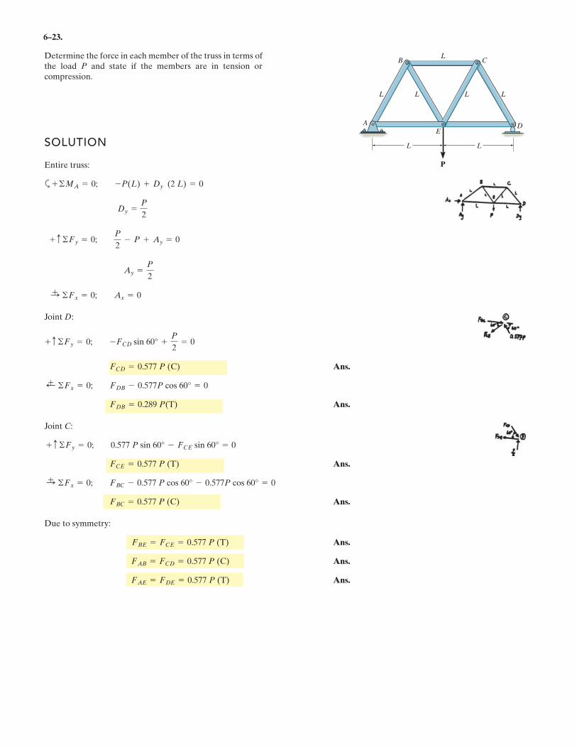
Joint D:
Ans.
Ans.
Joint C:
Ans.
Ans.
Due to symmetry:
Ans.
Ans.
Ans.FAE = FDE = 0.577 P (T)
FAB = FCD = 0.577 P (C)
FBE = FCE = 0.577 P (T)
FBC = 0.577 P (C)
:+ ©Fx = 0; FBC - 0.577 P cos 60° - 0.577P cos 60° = 0
FCE = 0.577 P (T)
+ c ©Fy = 0; 0.577 P sin 60° - FCE sin 60° = 0
FDB = 0.289 P(T)
;+ ©Fx = 0; FDB - 0.577P cos 60° = 0
FCD = 0.577 P (C)
+ c ©Fy = 0; -FCD sin 60° +P
2= 0
:+ ©Fx = 0; Ax = 0
Ay =P
2
+ c ©Fy = 0;P
2- P + Ay = 0
Dy =P
2
+ ©MA = 0; -P(L) + Dy (2 L) = 0
Determine the force in each member of the truss in terms ofthe load P and state if the members are in tension orcompression.
P
A
E
L L
L
L
L
L
CB
D
L
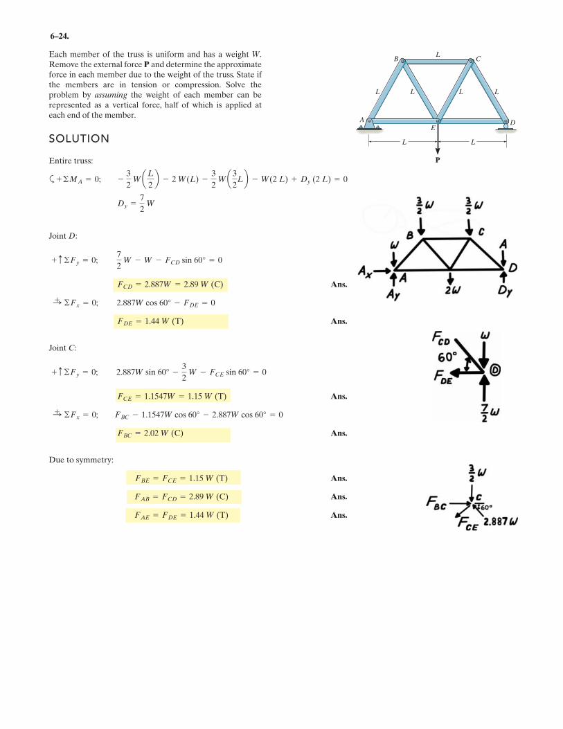
6–24.
Each member of the truss is uniform and has a weight W.Remove the external force P and determine the approximateforce in each member due to the weight of the truss. State ifthe members are in tension or compression. Solve theproblem by assuming the weight of each member can berepresented as a vertical force, half of which is applied ateach end of the member.
SOLUTION
Entire truss:
a
Joint D:
Ans.
Ans.
Joint C:
Ans.
Ans.
Due to symmetry:
Ans.
Ans.
Ans.FAE = FDE = 1.44 W (T)
FAB = FCD = 2.89 W (C)
FBE = FCE = 1.15 W (T)
FBC = 2.02 W (C)
:+ ©Fx = 0; FBC - 1.1547W cos 60° - 2.887W cos 60° = 0
FCE = 1.1547W = 1.15 W (T)
+ c ©Fy = 0; 2.887W sin 60° -3
2W - FCE sin 60° = 0
FDE = 1.44 W (T)
:+ ©Fx = 0; 2.887W cos 60° - FDE = 0
FCD = 2.887W = 2.89 W (C)
+ c ©Fy = 0;7
2W - W - FCD sin 60° = 0
Dy =7
2W
+ ©MA = 0; -3
2WaL
2b - 2 W(L) -
3
2Wa3
2Lb - W(2 L) + Dy (2 L) = 0
P
A
E
L L
L
L
L
L
CB
D
L
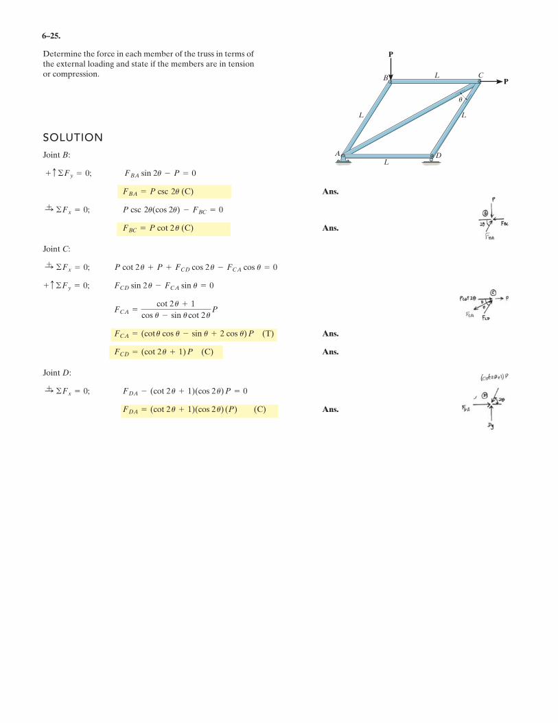
6–25.
Determine the force in each member of the truss in terms ofthe external loading and state if the members are in tensionor compression.
SOLUTION
Joint B:
Ans.
Ans.
Joint C:
Ans.
Ans.
Joint D:
Ans.FDA = (cot 2 u + 1)(cos 2 u) (P) (C)
:+ ©Fx = 0; FDA - (cot 2 u + 1)(cos 2 u) P = 0
FCD = (cot 2 u + 1) P (C)
FCA = (cot u cos u - sin u + 2 cos u) P (T)
FCA =cot 2 u + 1
cos u - sin ucot 2 uP
+ c ©Fy = 0; FCD sin 2 u - FCA sin u = 0
:+ ©Fx = 0; P cot 2 u + P + FCD cos 2 u - FCA cos u = 0
FBC = P cot 2 u (C)
:+ ©Fx = 0; P csc 2u(cos 2u) - FBC = 0
FBA = P csc 2u (C)
+ c ©Fy = 0; FBA sin 2u - P = 0
A
L
B
P
PL C
L
DL
u
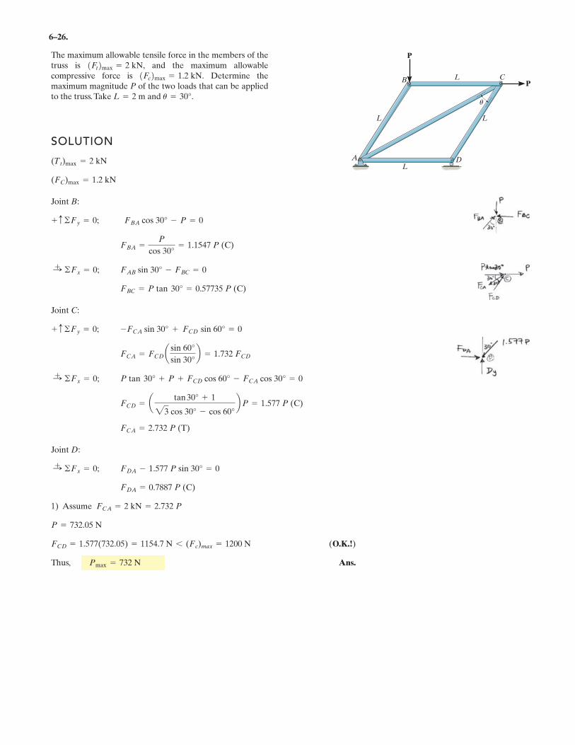
6–26.
The maximum allowable tensile force in the members of thetruss is and the maximum allowablecompressive force is Determine themaximum magnitude P of the two loads that can be appliedto the truss.Take and u = 30°.L = 2 m
1Fc2max = 1.2 kN.1Ft2max = 2 kN,
SOLUTION
Joint B:
Joint C:
Joint D:
1) Assume
(O.K.!)
Thus, Ans.Pmax = 732 N
FCD = 1.577(732.05) = 1154.7 N 6 (Fc)max = 1200 N
P = 732.05 N
FCA = 2 kN = 2.732 P
FDA = 0.7887 P (C)
:+ ©Fx = 0; FDA - 1.577 P sin 30° = 0
FCA = 2.732 P (T)
FCD = a tan 30° + 1
23 cos 30° - cos 60°b P = 1.577 P (C)
:+ ©Fx = 0; P tan 30° + P + FCD
cos 60° - FCA cos 30° = 0
FCA = FCD a sin 60°
sin 30°b = 1.732 FCD
+ c ©Fy = 0; -FCA sin 30° + FCD sin 60° = 0
FBC = P tan 30° = 0.57735 P (C)
:+ ©Fx = 0; FAB sin 30° - FBC = 0
FBA =P
cos 30°= 1.1547 P (C)
+ c ©Fy = 0; FBA cos 30° - P = 0
(FC)max = 1.2 kN
(Tt)max = 2 kN A
L
B
P
PL C
L
DL
u
.
.
.
.
.
.
6
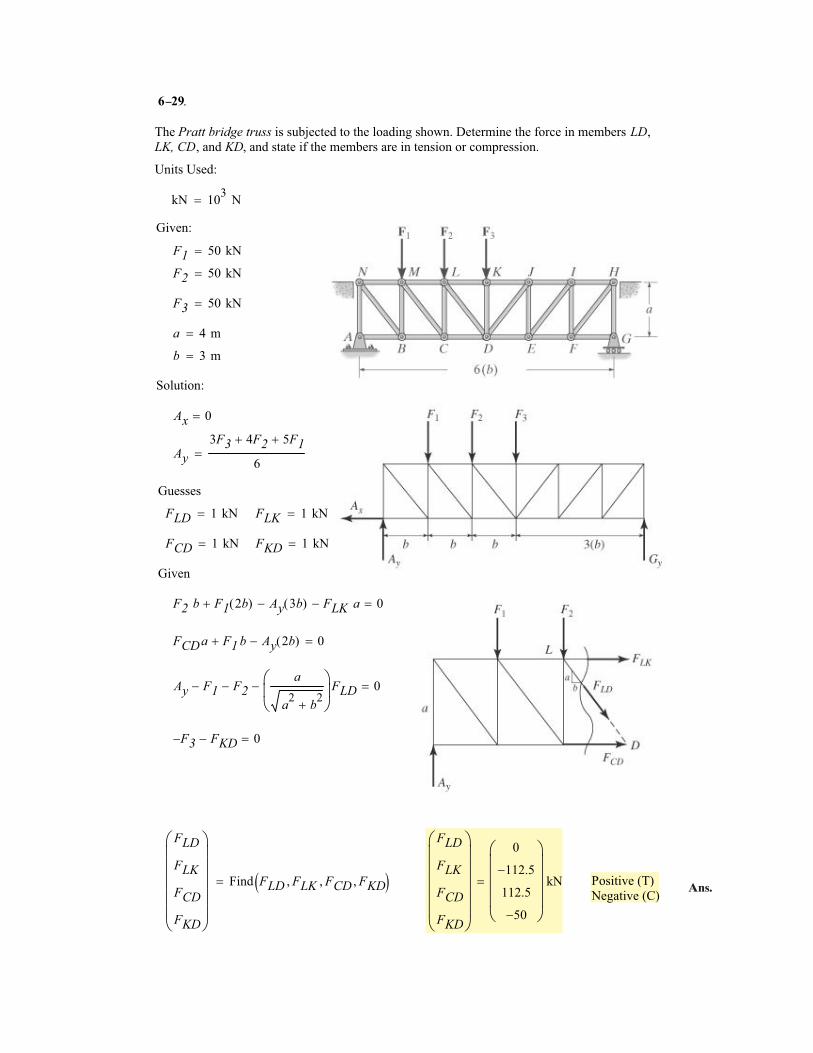
The Pratt bridge truss is subjected to the loading shown. Determine the force in members LD,
LK, CD, and KD, and state if the members are in tension or compression.
Units Used:
kN 103
N�
Given:
F1 50 kN�
F2 50 kN�
F3 50 kN�
a 4 m�
b 3 m�
Solution:
Ax 0�
Ay
3F3 4F2� 5F1�
6�
Guesses
FLD 1 kN� FLK 1 kN�
FCD 1 kN� FKD 1 kN�
Given
F2 b F1 2b( )� Ay 3b( )� FLK a� 0�
FCDa F1 b� Ay 2b( )� 0�
Ay F1� F2�a
a2
b2
�
�
��
FLD� 0�
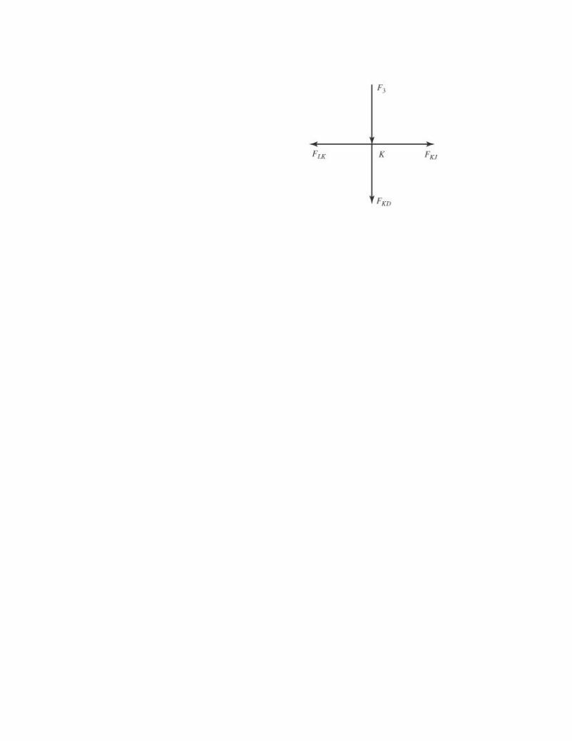
F3� FKD� 0�
FLD
FLK
FCD
FKD
�
������
Find FLD FLK� FCD� FKD�� ��
FLD
FLK
FCD
FKD
�
������
0
112.5�
112.5
50�
�
�����
kN� Positive (T)
Negative (C)
29.
Ans.
–
6 3
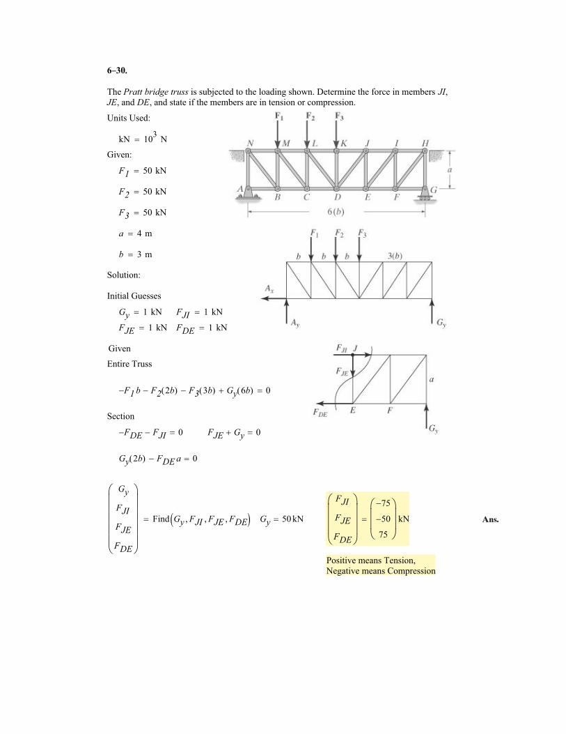
The Pratt bridge truss is subjected to the loading shown. Determine the force in members JI,JE, and DE, and state if the members are in tension or compression.
Units Used:
kN 103
N�
Given:
F1 50 kN�
F2 50 kN�
F3 50 kN�
a 4 m�
b 3 m�
Solution:
Initial Guesses
Gy 1 kN� FJI 1 kN�
FJE 1 kN� FDE 1 kN�
Given
Entire Truss
F1� b F2 2b( )� F3 3b( )� Gy 6b( )� 0�
Section
FDE� FJI� 0� FJE Gy� 0�
Gy 2b( ) FDE a� 0�
Gy
FJI
FJE
FDE
�
������
Find Gy FJI� FJE� FDE�� �� Gy 50 kN�
FJI
FJE
FDE
�
����
75�
50�
75
�
���
kN�
Positive means Tension,
Negative means Compression
0.
Ans.
–
6 3 .
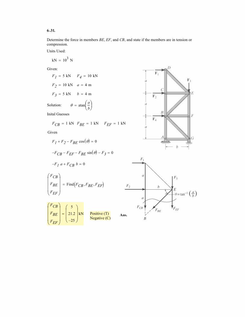
Determine the force in members BE, EF, and CB, and state if the members are in tension or
compression.
Units Used:
kN 103
N�
Given:
F1 5 kN� F4 10 kN�
F2 10 kN� a 4 m�
F3 5 kN� b 4 m�
Solution: � atana
b
���
�
Inital Guesses
FCB 1 kN� FBE 1 kN� FEF 1 kN�
Given
F1 F2� FBE cos �� �� 0�
FCB� FEF� FBE sin �� �� F3� 0�
F1� a FCB b� 0�
FCB
FBE
FEF
�
����
Find FCB FBE� FEF�� ��
FCB
FBE
FEF
�
����
5
21.2
25�
�
���
kN� Positive (T)
Negative (C)
1
Ans.
–
6 3
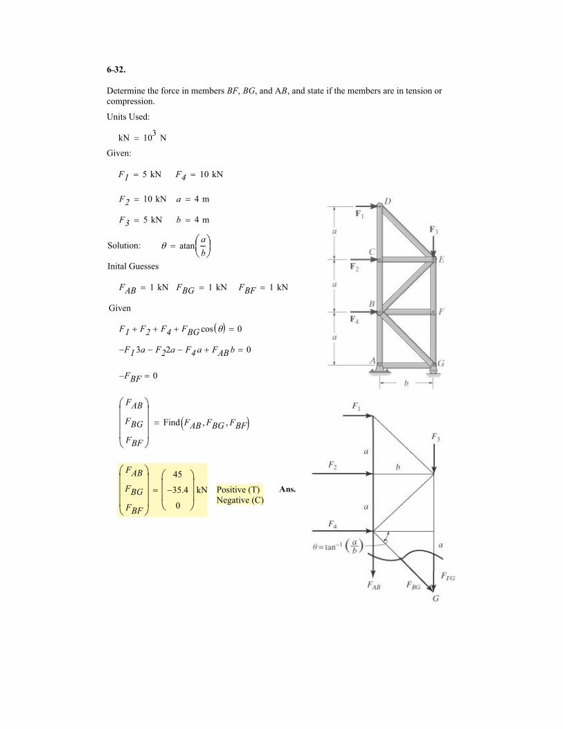
Determine the force in members BF, BG, and AB, and state if the members are in tension or
compression.
Units Used:
kN 103
N�
Given:
F1 5 kN� F4 10 kN�
F2 10 kN� a 4 m�
F3 5 kN� b 4 m�
Solution: � atana
b
���
�
Inital Guesses
FAB 1 kN� FBG 1 kN� FBF 1 kN�
Given
F1 F2� F4� FBG cos �� �� 0�
F1� 3a F22a� F4 a� FAB b� 0�
FBF� 0�
FAB
FBG
FBF
�
����
Find FAB FBG� FBF�� ��
FAB
FBG
FBF
�
����
45
35.4�
0
�
���
kN� Positive (T)
Negative (C)
2.
Ans.
–
6
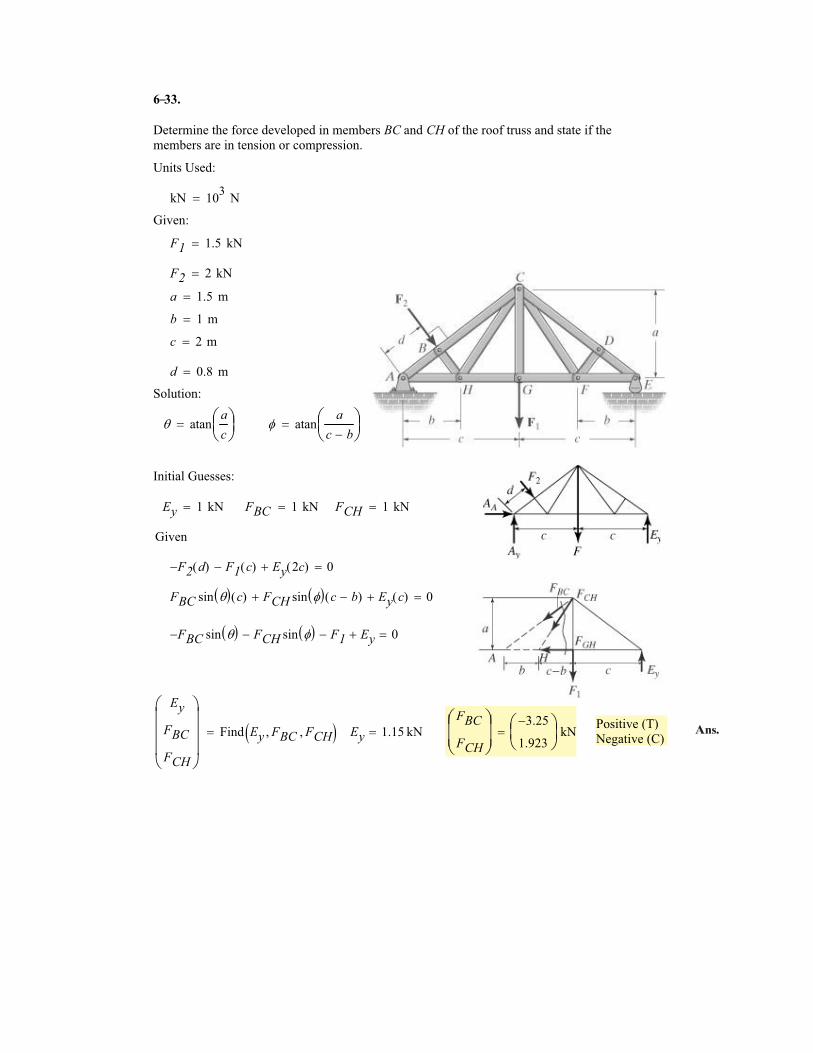
Determine the force developed in members BC and CH of the roof truss and state if the
members are in tension or compression.
Units Used:
kN 103
N�
Given:
F1 1.5 kN�
F2 2 kN�
a 1.5 m�
b 1 m�
c 2 m�
d 0.8 m�
Solution:
� atana
c
���
� � atana
c b��
��
�
Initial Guesses:
Ey 1 kN� FBC 1 kN� FCH 1 kN�
Given
F2� d( ) F1 c( )� Ey 2c( )� 0�
FBC sin �� � c( ) FCH sin �� � c b�( )� Ey c( )� 0�
FBC� sin �� � FCH sin �� �� F1� Ey� 0�
Positive (T)
Negative (C)
Ey
FBC
FCH
�
����
Find Ey FBC� FCH�� �� Ey 1.15 kN�FBC
FCH
�
���
3.25�
1.923
�
��
kN�
33.
Ans.
–

6
Determine the force in members CDand GF of the truss and state if the
members are in tension or
compression. Also indicate all
zero-force members.
Units Used:
kN 103
N�
Given:
F1 1.5 kN�
F2 2 kN�
a 1.5 m�
b 1 m�
c 2 m�
d 0.8 m�
Solution:
� atana
c
���
� � atana
c b��
��
�
Initial Guesses:
Ey 1 kN� FCD 1 kN� FGF 1 kN�
Given
F2� d( ) F1 c( )� Ey 2c( )� 0�
Ey b( ) FCDsin �� � b( )� 0�
Ey c( ) FGF a( )� 0�
Positive (T)
Negative (C)
Ey
FCD
FGF
�
����
Find Ey FCD� FGF�� �� Ey 1.15 kN�FCD
FGF
�
���
1.917�
1.533
�
��
kN�
DF and CF are zero force members.
34.
Ans.
–
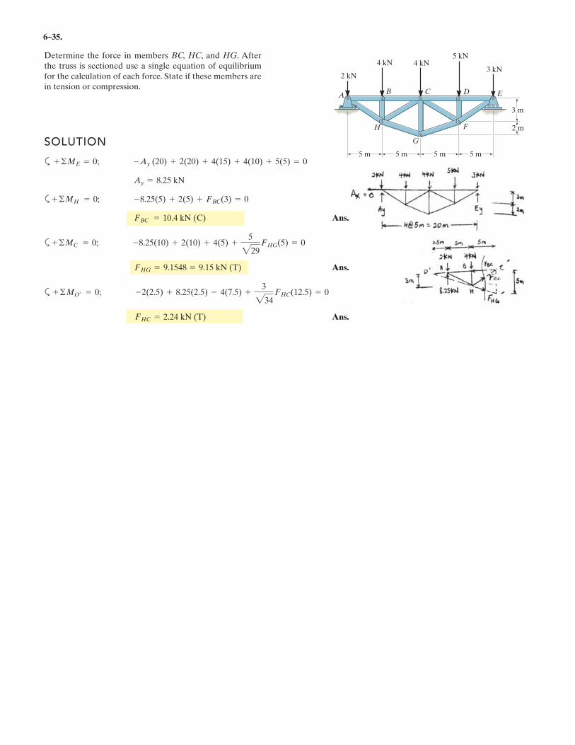
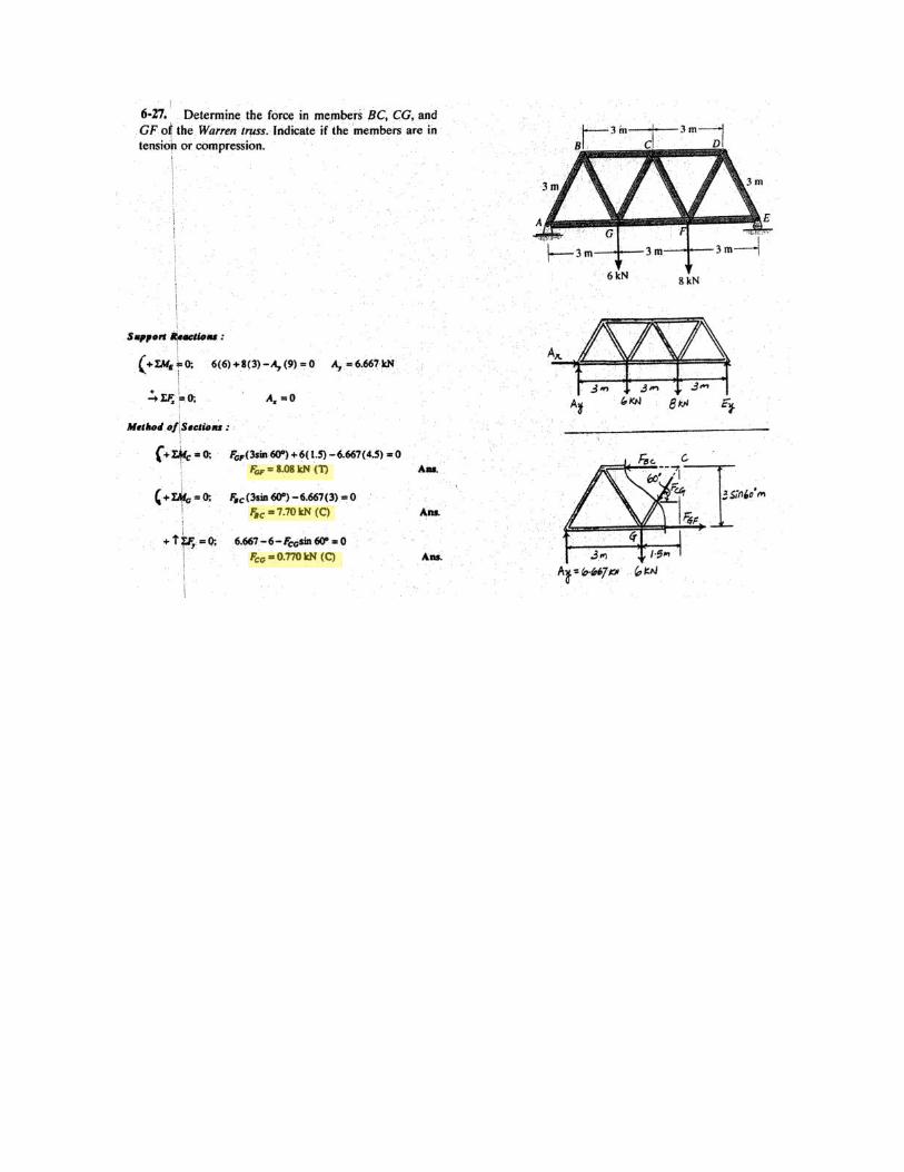
6–35.
Determine the force in members BC, HC, and HG. Afterthe truss is sectioned use a single equation of equilibriumfor the calculation of each force. State if these members arein tension or compression.
SOLUTION
a
a
Ans.
a
Ans.
a
Ans.FHC = 2.24 kN (T)
+ ©MO¿ = 0; -2(2.5) + 8.25(2.5) - 4(7.5) +3
234FHC(12.5) = 0
FHG = 9.1548 = 9.15 kN (T)
+ ©MC = 0; -8.25(10) + 2(10) + 4(5) +5
229FHG(5) = 0
FBC = 10.4 kN (C)
+ ©MH = 0; -8.25(5) + 2(5) + FBC(3) = 0
Ay = 8.25 kN
+ ©ME = 0; -Ay (20) + 2(20) + 4(15) + 4(10) + 5(5) = 0
AC D
H
G
F
4 kN
3 m
2 m
5 m5 m5 m 5 m
B E
4 kN5 kN
3 kN2 kN
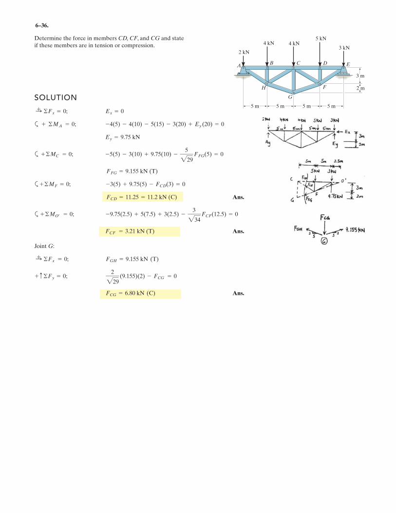
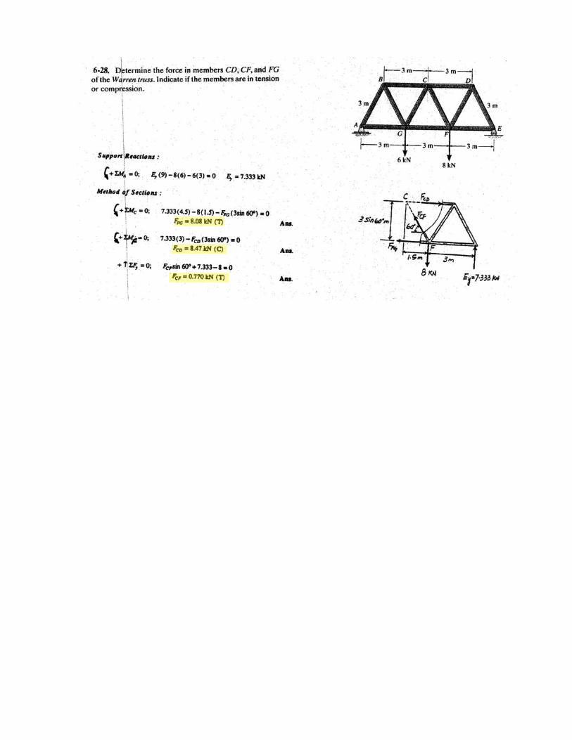
6–36.
Determine the force in members CD, CF, and CG and stateif these members are in tension or compression.
SOLUTION
a
a
a
Ans.
a
Ans.
Joint G:
Ans.FCG = 6.80 kN (C)
+ c ©Fy = 0;2
229(9.155)(2) - FCG = 0
:+ ©Fx = 0; FGH = 9.155 kN (T)
FCF = 3.21 kN (T)
+ ©MO¿ = 0; -9.75(2.5) + 5(7.5) + 3(2.5) -3
234FCF(12.5) = 0
FCD = 11.25 = 11.2 kN (C)
+ ©MF = 0; -3(5) + 9.75(5) - FCD(3) = 0
FFG = 9.155 kN (T)
+ ©MC = 0; -5(5) - 3(10) + 9.75(10) -5
229FFG(5) = 0
Ey = 9.75 kN
+ ©MA = 0; -4(5) - 4(10) - 5(15) - 3(20) + Ey (20) = 0
:+ ©Fx = 0; Ex = 0
AC D
H
G
F
4 kN
3 m
2 m
5 m5 m5 m 5 m
B E
4 kN5 kN
3 kN2 kN
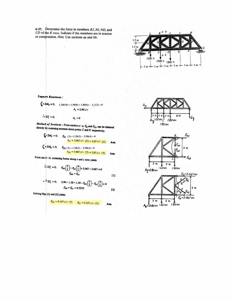
1.5 m
1.5 m
2 m 2 m 2 m 2 m 2 m 2 m
N N N
2 m 2 m 2 m m
kN kN
kN
2 m 2 m
3 m
kN kN kN
kN
3 m
kN
2 m 2 m
kN kN kN
1.20(10) 1.50(8) 1.80(6) (12) 0yA+ + − =
kN
(3) 1.20(2) 2.90(4) 0+ − =
kN kN
(3) 1.20(2) 2.90(4) 0+ − =
kN kN
kN kN
.
.
.
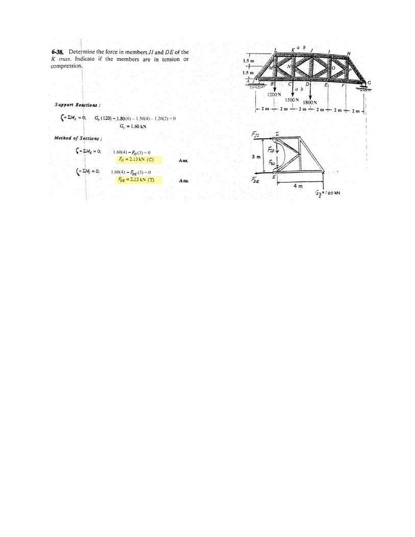
2 m 2 m 2 m 2 m 2 m 2 m
1.5 m
1.5 m
3 m
4 m
(6) – 1.50(4) – 1.20(2) = 0
kN
kN
kN
1.60(4) (3) = 0
1.60(4) (3) = 0
kN
NN
N
.
.
6–39.
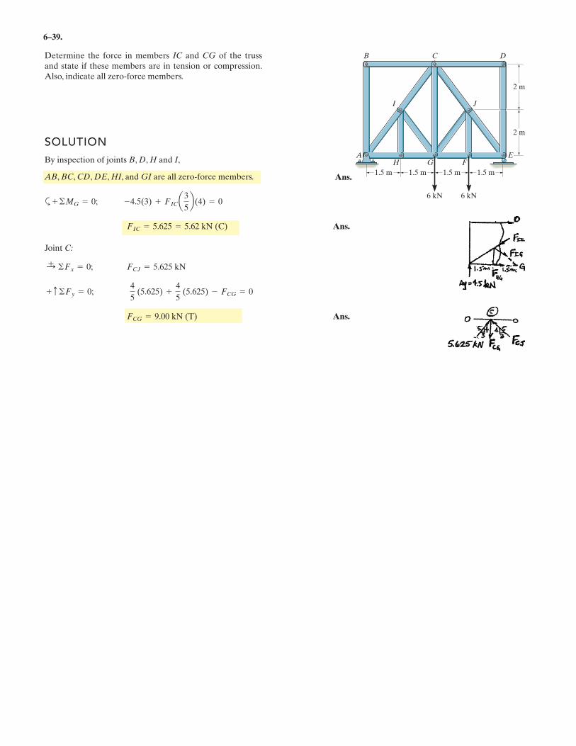
Determine the force in members IC and CG of the trussand state if these members are in tension or compression.Also, indicate all zero-force members.
SOLUTION
By inspection of joints B, D, H and I,
AB, BC, CD, DE, HI, and GI are all zero-force members.
a
Ans.
Joint C:
Ans.FCG = 9.00 kN (T)
+ c ©Fy = 0;4
5(5.625) +
4
5(5.625) - FCG = 0
:+ ©Fx = 0; FCJ = 5.625 kN
FIC = 5.625 = 5.62 kN (C)
+ ©MG = 0; -4.5(3) + FICa3
5b(4) = 0
1.5 m 1.5 m 1.5 m
AH
B C D
JI
G FE
1.5 m
2 m
2 m
6 kN 6 kN
Ans.
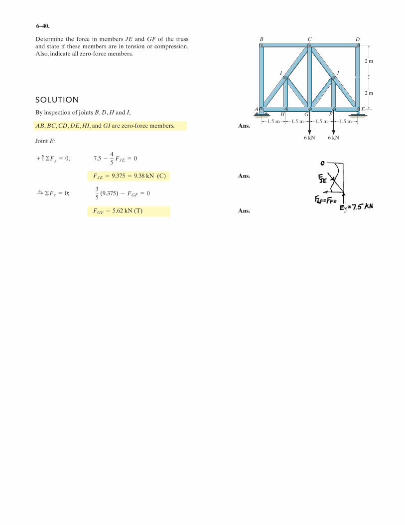
6–40.
SOLUTION
By inspection of joints B, D, H and I,
AB, BC, CD, DE, HI, and GI are zero-force members. Ans.
Joint E:
Ans.
Ans.FGF = 5.62 kN (T)
:+ ©Fx = 0;
3
5(9.375) - FGF = 0
FJE = 9.375 = 9.38 kN (C)
+ c ©Fy = 0; 7.5 -4
5FJE = 0
Determine the force in members JE and GF of the trussand state if these members are in tension or compression.Also, indicate all zero-force members.
1.5 m 1.5 m 1.5 m
AH
B C D
JI
G FE
1.5 m
2 m
2 m
6 kN 6 kN
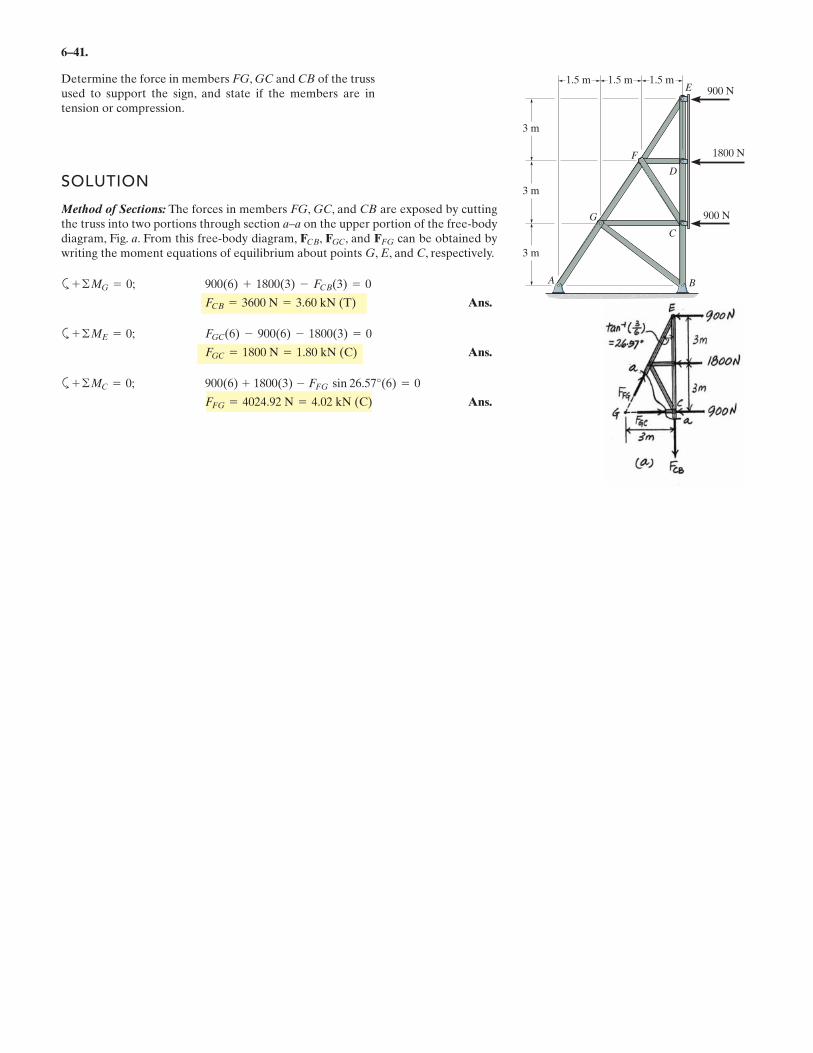
6–41.
Determine the force in members FG, GC and CB of the trussused to support the sign, and state if the members are intension or compression.
SOLUTION
Method of Sections: The forces in members FG, GC, and CB are exposed by cuttingthe truss into two portions through section a–a on the upper portion of the free-bodydiagram, Fig. a. From this free-body diagram, , , and can be obtained bywriting the moment equations of equilibrium about points G, E, and C, respectively.
a
Ans.
a
Ans.
a
Ans.FFG = 4024.92 N = 4.02 kN (C)
900(6) + 1800(3) - FFG sin 26.57°(6) = 0+ ©MC = 0;
FGC = 1800 N = 1.80 kN (C)
FGC(6) - 900(6) - 1800(3) = 0 + ©ME = 0;
FCB = 3600 N = 3.60 kN (T)
900(6) + 1800(3) - FCB(3) = 0+ ©MG = 0;
FFGFGCFCB
1.5 m
3 m
A B
C
D
E
F
G
1.5 m
3 m
3 m
1.5 m900 N
1800 N
900 N
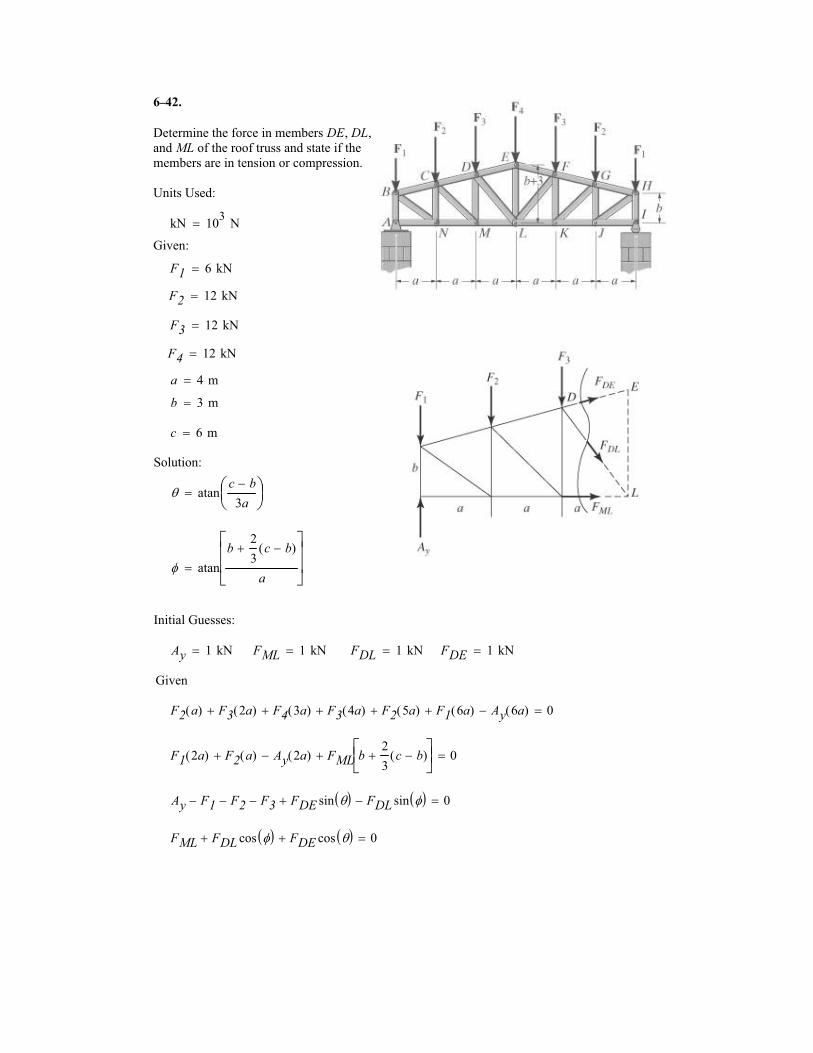
6
Determine the force in members DE, DL,
and ML of the roof truss and state if the
members are in tension or compression.
Units Used:
kN 103
N�
Given:
F1 6 kN�
F2 12 kN�
F3 12 kN�
F4 12 kN�
a 4 m�
b 3 m�
c 6 m�
Solution:
� atanc b�
3a
�
��
�
� atan
b2
3c b�( )�
a
����
����
�
Initial Guesses:
Ay 1 kN� FML 1 kN� FDL 1 kN� FDE 1 kN�
Given
F2 a( ) F3 2a( )� F4 3a( )� F3 4a( )� F2 5a( )� F1 6a( )� Ay 6a( )� 0�
F1 2a( ) F2 a( )� Ay 2a( )� FML b2
3c b�( )���
����
� 0�
Ay F1� F2� F3� FDE sin �� �� FDL sin �� �� 0�
FML FDL cos �� �� FDE cos �� �� 0�
42.–
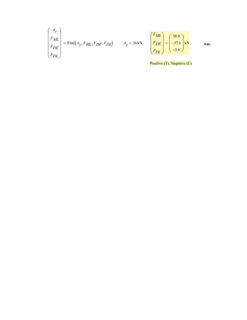
Ay
FML
FDE
FDL
�
������
Find Ay FML� FDE� FDL�� �� Ay 36 kN�
FML
FDE
FDL
�
����
38.4
37.1�
3.8�
�
���
kN�
Positive (T), Negative (C)
Ans.
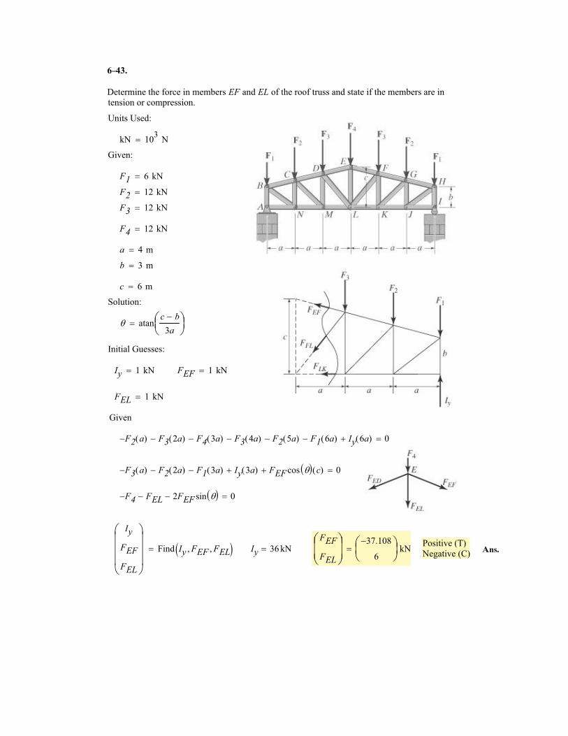
6
Determine the force in members EF and EL of the roof truss and state if the members are in
tension or compression.
Units Used:
kN 103
N�
Given:
F1 6 kN�
F2 12 kN�
F3 12 kN�
F4 12 kN�
a 4 m�
b 3 m�
c 6 m�
Solution:
� atanc b�
3a
�
��
�
Initial Guesses:
Iy 1 kN� FEF 1 kN�
FEL 1 kN�
Given
F2� a( ) F3 2a( )� F4 3a( )� F3 4a( )� F2 5a( )� F1 6a( )� Iy 6a( )� 0�
F3� a( ) F2 2a( )� F1 3a( )� Iy 3a( )� FEF cos �� � c( )� 0�
F4� FEL� 2FEF sin �� �� 0�
Positive (T)
Negative (C)
Iy
FEF
FEL
�
����
Find Iy FEF� FEL�� �� Iy 36 kN�FEF
FEL
�
���
37.108�
6
�
��
kN�
43.
Ans.
–
6–44.
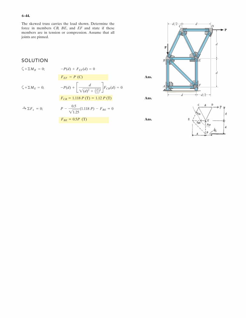
The skewed truss carries the load shown. Determine theforce in members CB, BE, and EF and state if thesemembers are in tension or compression. Assume that alljoints are pinned.
SOLUTION
a
Ans.
a
Ans.
Ans.FBE = 0.5P (T)
:+ ©Fx = 0; P -
0.5
21.25(1.118 P) - FBE = 0
FCB = 1.118 P (T) = 1.12 P (T)
+ ©ME = 0; -P(d) + B d
2(d)2 + Ad2 B2 RFCB (d) = 0
FEF = P (C)
+ ©MB = 0; -P(d) + FEF(d) = 0
d/2 d
d/2d
F
EB
C DP
P
A
d
d
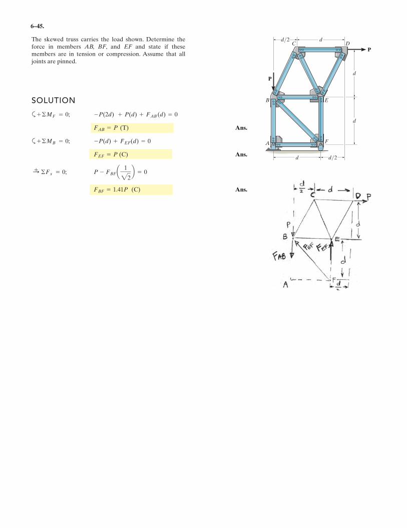
6–45.
The skewed truss carries the load shown. Determine theforce in members AB, BF, and EF and state if thesemembers are in tension or compression. Assume that alljoints are pinned.
SOLUTION
a
Ans.
a
Ans.
Ans.FBF = 1.41P (C)
:+ ©Fx = 0; P - FBFa 1
22b = 0
FEF = P (C)
+ ©MB = 0; -P(d) + FEF(d) = 0
FAB = P (T)
+ ©MF = 0; -P(2d) + P(d) + FAB (d) = 0
d/2 d
d/2d
F
EB
C DP
P
A
d
d
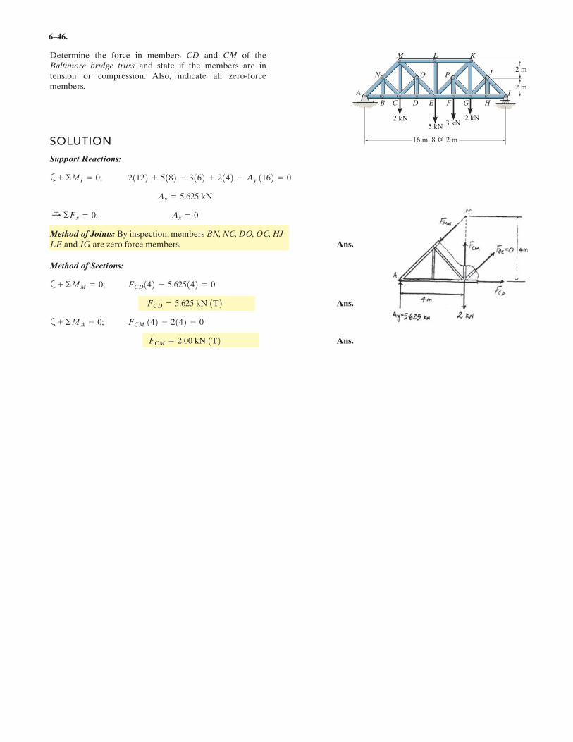
6–46.
SOLUTION
Support Reactions:
a
Method of Joints: By inspection, members BN, NC, DO, OC, HJ
LE and JG are zero force members. Ans.
Method of Sections:
a
Ans.
a
Ans.FCM = 2.00 kN T
FCM 142 - 2142 = 0+ ©MA = 0;
FCD = 5.625 kN 1T2FCD142 - 5.625142 = 0+ ©MM = 0;
Ax = 0:+ ©Fx = 0;
Ay = 5.625 kN
21122 + 5182 + 3162 + 2142 - Ay 1162 = 0+ ©MI = 0;
Determine the force in members CD and CM of theBaltimore bridge truss and state if the members are intension or compression. Also, indicate all zero-forcemembers.
16 m, 8 @ 2 m
A
B C D E F G H
J
KLM
N O P2 m
2 m
2 kN
5 kN
2 kN3 kN
I
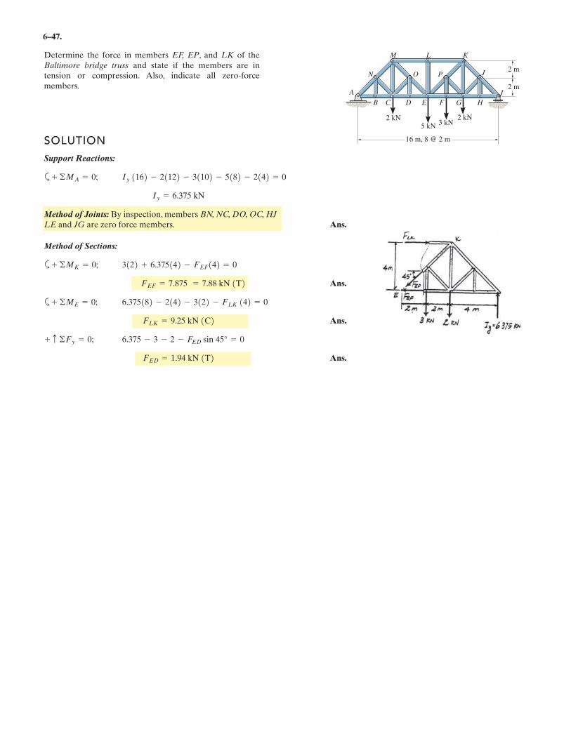
6–47.
Determine the force in members EF, EP, and LK of theBaltimore bridge truss and state if the members are intension or compression. Also, indicate all zero-forcemembers.
SOLUTION
Support Reactions:
a
Method of Joints: By inspection, members BN, NC, DO, OC, HJ
LE and JG are zero force members. Ans.
Method of Sections:
a
Ans.
a
Ans.
Ans.FED = 1.94 kN T
6.375 - 3 - 2 - FED sin 45° = 0+ c ©Fy = 0;
FLK = 9.25 kN 1C26.375182 - 2142 - 3122 - FLK 142 = 0+ ©ME = 0;
FEF = 7.875 = 7.88 kN 1T23122 + 6.375142 - FEF142 = 0+ ©MK = 0;
Iy = 6.375 kN
Iy 1162 - 21122 - 31102 - 5182 - 2142 = 0+ ©MA = 0;
16 m, 8 @ 2 m
A
B C D E F G H
J
KLM
N O P2 m
2 m
2 kN
5 kN
2 kN3 kN
I
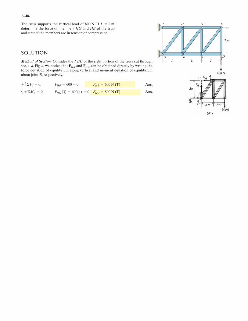
6–48.
The truss supports the vertical load of . If ,determine the force on members HG and HB of the trussand state if the members are in tension or compression.
SOLUTION
Method of Section: Consider the of the right portion of the truss cut throughsec. a–a, Fig. a, we notice that and can be obtained directly by writing theforce equation of equilibrium along vertical and moment equation of equilibriumabout joint B, respectively.
Ans.
a Ans.FHG (3) - 600(4) = 0 FHG = 800 N (T)+ ©MB = 0;
FHB - 600 = 0 FHB = 600 N (T)+ c ©Fy = 0;
FHGFHB
FBD
L = 2 m600 N
A B C
3 m
600 N
D
I H G E
L L L
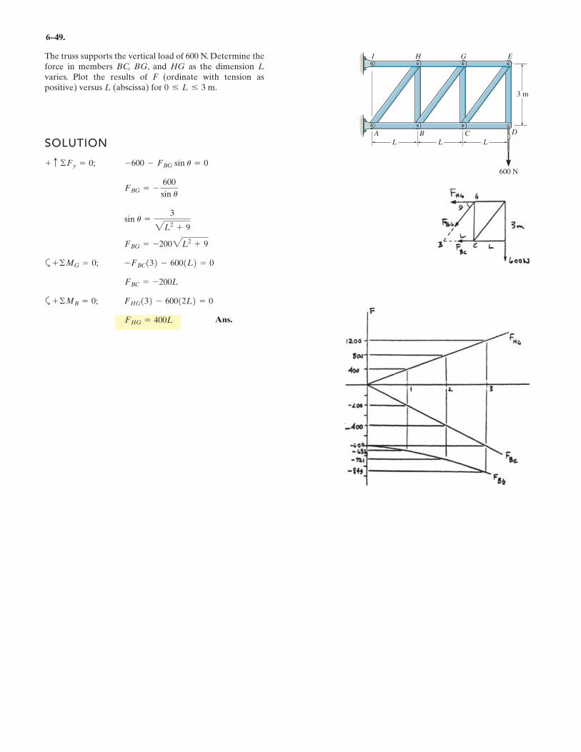
6–49.
The truss supports the vertical load of 600 N. Determine theforce in members BC, BG, and HG as the dimension L
varies. Plot the results of F (ordinate with tension aspositive) versus L (abscissa) for 0 … L … 3 m.
SOLUTION
a
a
FHG = 400L
FHG132 - 60012L2 = 0+ ©MB = 0;
FBC = -200L
-FBC132 - 6001L2 = 0+ ©MG = 0;
FBG = -2002L2 + 9
sin u =3
2L2 + 9
FBG = -
600
sin u
-600 - FBG sin u = 0+ c ©Fy = 0;
A B C
3 m
600 N
D
I H G E
L L L
Ans.
6 5 .
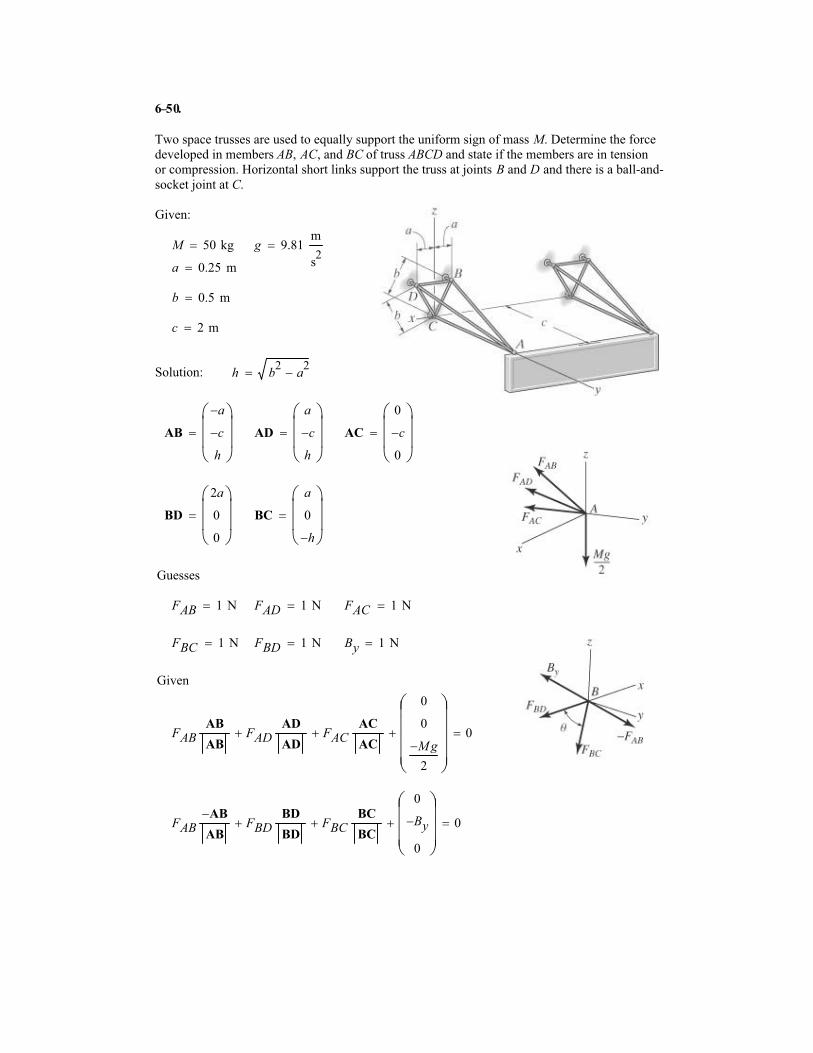
Two space trusses are used to equally support the uniform sign of mass M. Determine the force
developed in members AB, AC, and BC of truss ABCD and state if the members are in tension
or compression. Horizontal short links support the truss at joints B and D and there is a ball-and-
socket joint at C.
Given:
M 50 kg� g 9.81m
s2
�
a 0.25 m�
b 0.5 m�
c 2 m�
Solution: h b2
a2
��
AB
a�
c�
h
�
���
� AD
a
c�
h
�
���
� AC
0
c�
0
�
���
�
BD
2a
0
0
�
���
� BC
a
0
h�
�
���
�
Guesses
FAB 1 N� FAD 1 N� FAC 1 N�
FBC 1 N� FBD 1 N� By 1 N�
Given
FABAB
ABFAD
AD
AD� FAC
AC
AC�
0
0
M� g
2
�
�����
� 0�
FABAB�
ABFBD
BD
BD� FBC
BC
BC�
0
By�
0
�
����
� 0�
0–
FAB
FAD
FAC
FBC
FBD
By
�
���������
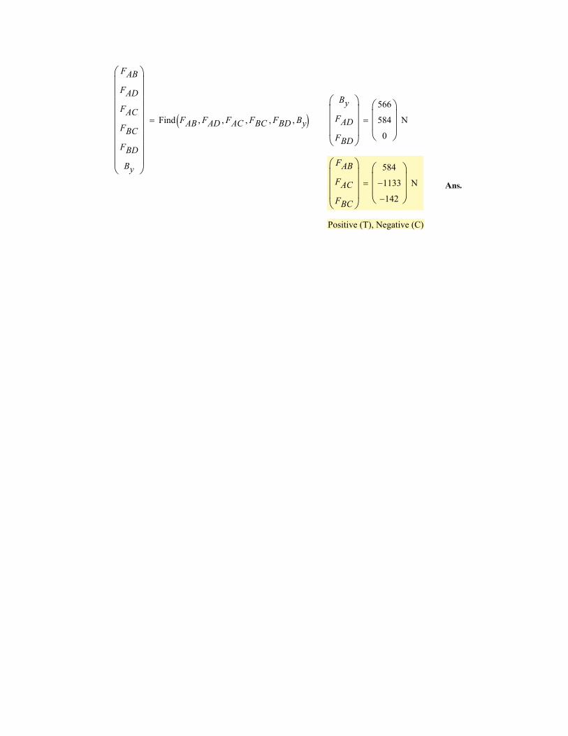
Find FAB FAD� FAC� FBC� FBD� By�� ��
By
FAD
FBD
�
����
566
584
0
�
���
N�
FAB
FAC
FBC
�
����
584
1133�
142�
�
���
N�
Positive (T), Negative (C)
Ans.
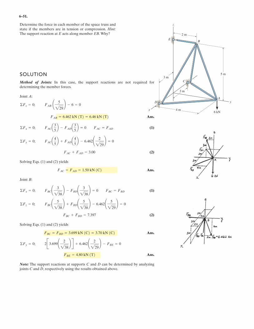
6–51.
Determine the force in each member of the space truss andstate if the members are in tension or compression. Hint:
The support reaction at E acts along member EB. Why?
y
x
D
A
6 kN
C
BE
z
5 m
2 m
4 m
3 m
3 m
SOLUTION
Method of Joints: In this case, the support reactions are not required fordetermining the member forces.
Joint A:
Ans.
(1)
(2)
Solving Eqs. (1) and (2) yields
Ans.
Joint B:
(1)
(2)
Solving Eqs. (1) and (2) yields
Ans.
Ans.
Note: The support reactions at supports C and D can be determined by analyzingjoints C and D, respectively using the results obtained above.
FBE = 4.80 kN 1T22B3.699¢ 2
238≤ R + 6.462¢ 2
229≤ - FBE = 0©Fy = 0;
FBC = FBD = 3.699 kN 1C2 = 3.70 kN 1C2
FBC + FBD = 7.397
FBC¢ 5
238≤ + FBD¢ 5
238≤ - 6.462¢ 5
229≤ = 0©Fz = 0;
FBC¢ 3
238≤ - FBD¢ 3
238≤ = 0 FBC = FBD©Fx = 0;
FAC = FAD = 1.50 kN 1C2
FAC + FAD = 3.00
FACa4
5b + FADa4
5b - 6.462¢ 2
229≤ = 0©Fy = 0;
FACa3
5b - FADa3
5b = 0 FAC = FAD©Fx = 0;
FAB = 6.462 kN 1T2 = 6.46 kN 1T2
FAB ¢ 5
229≤ - 6 = 0©Fz = 0;
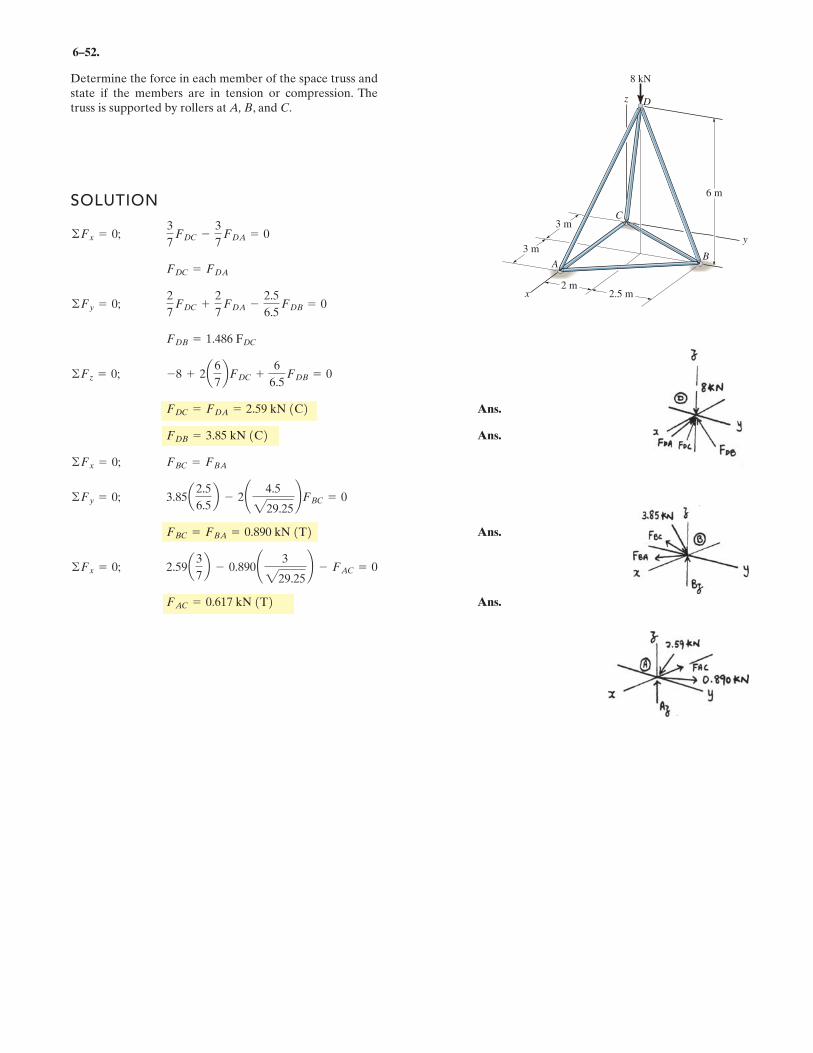
6–52.
SOLUTION
Ans.
Ans.
Ans.
Ans.FAC = 0.617 kN 1T22.59a3
7b - 0.890¢ 3
229.25≤ - FAC = 0©Fx = 0;
FBC = FBA = 0.890 kN 1T23.85a2.5
6.5b - 2¢ 4.5
229.25≤FBC = 0©Fy = 0;
FBC = FBA©Fx = 0;
FDB = 3.85 kN 1C2FDC = FDA = 2.59 kN 1C2-8 + 2a6
7bFDC +
6
6.5 FDB = 0©Fz = 0;
FDB = 1.486 FDC
2
7FDC +
2
7FDA -
2.5
6.5FDB = 0©Fy = 0;
FDC = FDA
3
7FDC -
3
7FDA = 0©Fx = 0;
Determine the force in each member of the space truss andstate if the members are in tension or compression. Thetruss is supported by rollers at A, B, and C.
z
8 kN
x
AB
C
D
y
3 m
2.5 m2 m
3 m
6 m
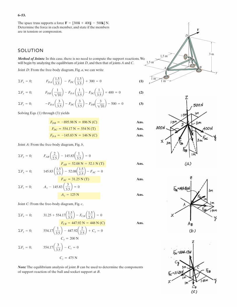
6–53.
The space truss supports a force Determine the force in each member, and state if the membersare in tension or compression.
SOLUTION
Method of Joints: In this case, there is no need to compute the support reactions. Wewill begin by analyzing the equilibrium of joint D, and then that of joints A and C.
Joint D: From the free-body diagram, Fig. a, we can write
(1)
(2)
(3)
Solving Eqs. (1) through (3) yields
Ans.
Ans.
Ans.
Joint A: From the free-body diagram, Fig. b,
Ans.
Ans.
Ans.
Joint C: From the free-body diagram, Fig. c,
Ans.
Note: The equilibrium analysis of joint B can be used to determine the components
of support reaction of the ball and socket support at B.
Cz = 475 N
554.17 a 3
3.5b - Cz = 0©Fz = 0;
Cy = 200 N
554.17a 1
3.5b - 447.92a 2
2.5b + Cy = 0©Fy = 0;
FCB = 447.92 N = 448 N (C)
31.25 + 554.17a1.5
3.5b - FCB a1.5
2.5b = 0©Fx = 0;
Az = 125 N
Az - 145.83 a 3
3.5b = 0©Fz = 0;
FAC = 31.25 N (T)
145.83 a1.5
3.5b - 52.08a 1.5
2.5b
- FAC = 0©Fx = 0;
FAB = 52.08 N = 52.1 N (T)
FAB a 2
2.5b - 145.83a 1
3.5b = 0©Fy = 0;
FDA = -145.83 N = 146 N (C)
FDC = 554.17 N = 554 N (T)
FDB = -895.98 N = 896 N (C)
-FDA a 3
3.5b - FDC a 3
3.5b
- FDBa 3
110b - 500 = 0©Fz = 0;
FDB a 1
110b - FDA a 1
3.5b
- FDCa 1
3.5b + 400 = 0©Fy = 0;
FDA a1.5
3.5b - FDC a1.5
3.5b + 300 = 0©Fx = 0;
F = [300i + 400j - 500k] N.
x
y
z
D
A
C
B
F
3 m
1 m1 m
1.5 m
1.5 m
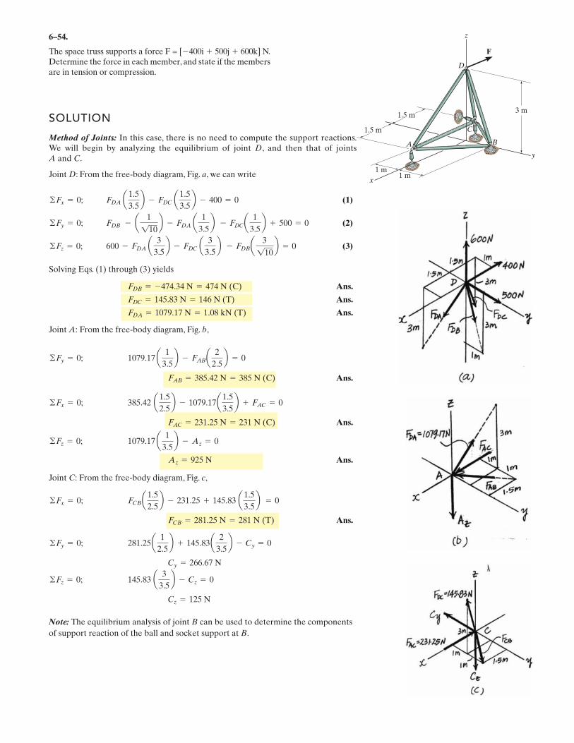
6–54.
The space truss supports a force F = [�400i � 500j � 600k] N.Determine the force in each member, and state if the membersare in tension or compression.
SOLUTION
Method of Joints: In this case, there is no need to compute the support reactions.We will begin by analyzing the equilibrium of joint D, and then that of joints A and C.
Joint D: From the free-body diagram, Fig. a, we can write
(1)
(2)
(3)
Solving Eqs. (1) through (3) yields
Ans.
Ans.
Ans.
Joint A: From the free-body diagram, Fig. b,
Ans.
Ans.
Ans.
Joint C: From the free-body diagram, Fig. c,
Ans.
Note: The equilibrium analysis of joint B can be used to determine the components
of support reaction of the ball and socket support at B.
Cz = 125 N
145.83 a 3
3.5b - Cz = 0©Fz = 0;
Cy = 266.67 N
281.25a 1
2.5b + 145.83a 2
3.5b - Cy = 0©Fy = 0;
FCB = 281.25 N = 281 N (T)
FCBa1.5
2.5b - 231.25 + 145.83 a 1.5
3.5b
= 0©Fx = 0;
Az = 925 N
1079.17 a 1
3.5b - Az = 0©Fz = 0;
FAC = 231.25 N = 231 N (C)
385.42 a1.5
2.5b - 1079.17a1.5
3.5b + FAC = 0©Fx = 0;
FAB = 385.42 N = 385 N (C)
1079.17 a 1
3.5b - FABa 2
2.5b = 0©Fy = 0;
FDA = 1079.17 N = 1.08 kN (T)
FDC = 145.83 N = 146 N (T)
FDB = -474.34 N = 474 N (C)
600 - FDA a 3
3.5b - FDC a 3
3.5b
- FDBa 3
110b = 0©Fz = 0;
FDB - a 1
110b - FDA a 1
3.5b
- FDCa 1
3.5b + 500 = 0©Fy = 0;
FDA a 1.5
3.5b - FDC a1.5
3.5b - 400 = 0©Fx = 0;
x
y
z
D
A
C
B
F
3 m
1 m1 m
1.5 m
1.5 m
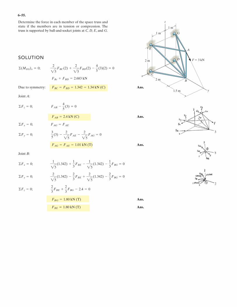
6–55.
Determine the force in each member of the space truss andstate if the members are in tension or compression. Thetruss is supported by ball-and-socket joints at C, D, E, and G.
G
A
F 3 kN
B
C
E
y
z
x
D
1 m
2 m
2 m
1.5 m
1 m
SOLUTION
Due to symmetry: Ans.
Joint A:
Ans.
Ans.
Joint B:
Ans.
Ans.FBE = 1.80 kN (T)
FBG = 1.80 kN (T)
©Fz = 0;2
3FBE +
2
3FBG - 2.4 = 0
©Fy = 0;2
25(1.342) -
2
3FBE +
2
25(1.342) -
2
3FBG = 0
©Fx = 0;1
25(1.342) +
1
3FBE -
1
25(1.342) -
1
3FBG = 0
FAG = FAE = 1.01 kN (T)
©Fy = 0;3
5(3) -
2
25FAE -
2
25FAG = 0
©Fx = 0; FAG = FAE
FAB = 2.4 kN (C)
©Fz = 0; FAB -4
5(3) = 0
FBC = FBD = 1.342 = 1.34 kN (C)
FBc + FBD = 2.683 kN
©(MEG)x = 0;2
25FBC
(2) +2
25FBD
(2) -4
5(3)(2) = 0
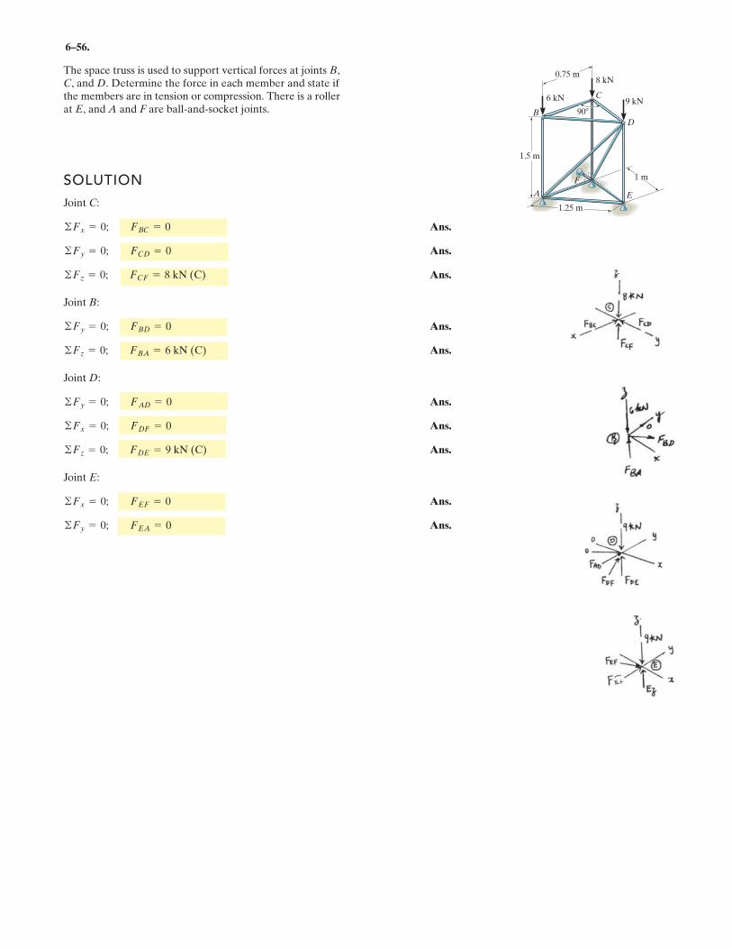
6–56.
The space truss is used to support vertical forces at joints B, C, and D. Determine the force in each member and state if the members are in tension or compression. There is a roller at E, and A and F are ball-and-socket joints.
SOLUTION
Joint C:
Ans.
Ans.
Ans.
Joint B:
Ans.
Ans.
Joint D:
Ans.
Ans.
Ans.
Joint E:
Ans.
Ans.©Fy = 0; FEA = 0
©Fx = 0; FEF = 0
©Fz = 0; FDE = 9 kN (C)
©Fx = 0; FDF = 0
©Fy = 0; FAD = 0
©Fz = 0; FBA = 6 kN (C)
©Fy = 0; FBD = 0
©Fz = 0; FCF = 8 kN (C)
©Fy = 0; FCD = 0
©Fx = 0; FBC = 0
6 kN
8 kN
C
D
E
F
B
A
9 kN
0.75 m
90
1.5 m
1.25 m
1 m
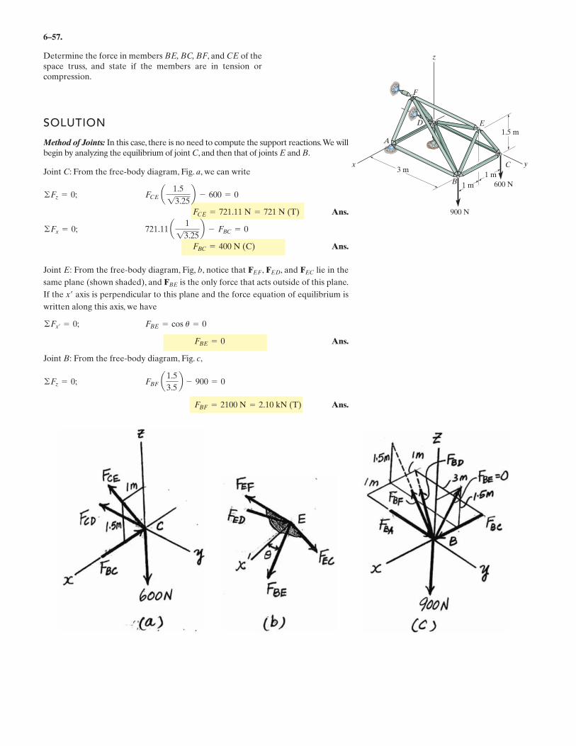
6–57.
Determine the force in members BE, BC, BF, and CE of thespace truss, and state if the members are in tension orcompression.
SOLUTION
Method of Joints: In this case, there is no need to compute the support reactions.We willbegin by analyzing the equilibrium of joint C, and then that of joints E and B.
Joint C: From the free-body diagram, Fig. a, we can write
Ans.
Ans.
Joint E: From the free-body diagram, Fig, b, notice that , , and lie in the
same plane (shown shaded), and is the only force that acts outside of this plane.
If the x� axis is perpendicular to this plane and the force equation of equilibrium is
written along this axis, we have
Ans.
Joint B: From the free-body diagram, Fig. c,
Ans.FBF = 2100 N = 2.10 kN (T)
FBF a 1.5
3.5b - 900 = 0©Fz = 0;
FBE = 0
FBE = cos u = 0©Fx¿ = 0;
FBE
FECFEDFEF
FBC = 400 N (C)
721.11 a 1
13.25b - FBC = 0©Fx = 0;
FCE = 721.11 N = 721 N (T)
FCE a 1.5
13.25b - 600 = 0©Fz = 0;
x y
z
F
A
ED
C
B
3 m1 m
1.5 m
1 m
900 N
600 N
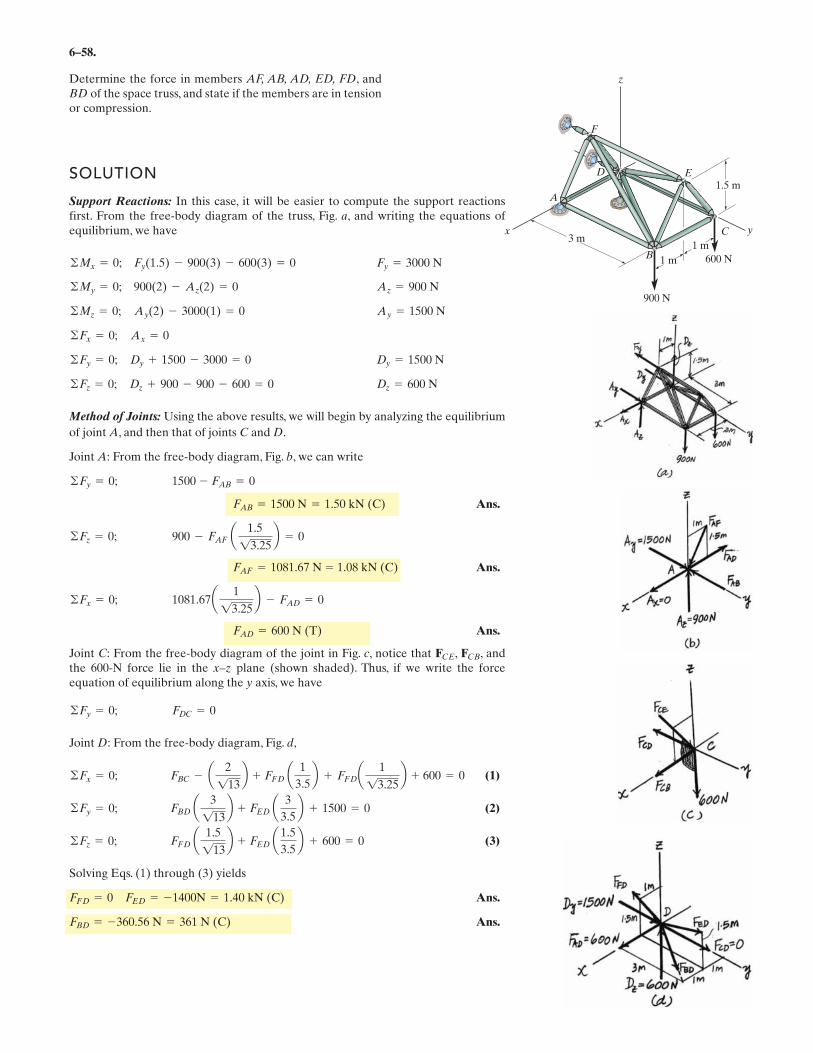
6–58.
Determine the force in members AF, AB, AD, ED, FD, andBD of the space truss, and state if the members are in tensionor compression.
SOLUTION
Support Reactions: In this case, it will be easier to compute the support reactionsfirst. From the free-body diagram of the truss, Fig. a, and writing the equations ofequilibrium, we have
Method of Joints: Using the above results, we will begin by analyzing the equilibrium
of joint A, and then that of joints C and D.
Joint A: From the free-body diagram, Fig. b, we can write
Ans.
Ans.
Ans.
Joint C: From the free-body diagram of the joint in Fig. c, notice that , , andthe 600-N force lie in the x–z plane (shown shaded). Thus, if we write the forceequation of equilibrium along the y axis, we have
Joint D: From the free-body diagram, Fig. d,
(1)
(2)
(3)
Solving Eqs. (1) through (3) yields
Ans.
Ans.FBD = -360.56 N = 361 N (C)
FFD = 0 FED = -1400N = 1.40 kN (C)
FFD a 1.5
113b + FED a 1.5
3.5b + 600 = 0©Fz = 0;
FBD a 3
113b + FED a 3
3.5b + 1500 = 0©Fy = 0;
FBC - a 2
113b + FFD a 1
3.5b + FFDa 1
13.25b + 600 = 0©Fx = 0;
FDC = 0©Fy = 0;
FCBFCE
FAD = 600 N (T)
1081.67a 1
13.25b - FAD = 0©Fx = 0;
FAF = 1081.67 N = 1.08 kN (C)
900 - FAF a 1.5
13.25b = 0©Fz = 0;
FAB = 1500 N = 1.50 kN (C)
1500 - FAB = 0©Fy = 0;
Dz = 600 N©Fz = 0; Dz + 900 - 900 - 600 = 0
Dy = 1500 N©Fy = 0; Dy + 1500 - 3000 = 0
©Fx = 0; Ax = 0
Ay = 1500 N©Mz = 0; Ay(2) - 3000(1) = 0
Az = 900 N©My = 0; 900(2) - Az(2) = 0
Fy = 3000 N©Mx = 0; Fy(1.5) - 900(3) - 600(3) = 0
x y
z
F
A
ED
C
B
3 m1 m
1.5 m
1 m
900 N
600 N
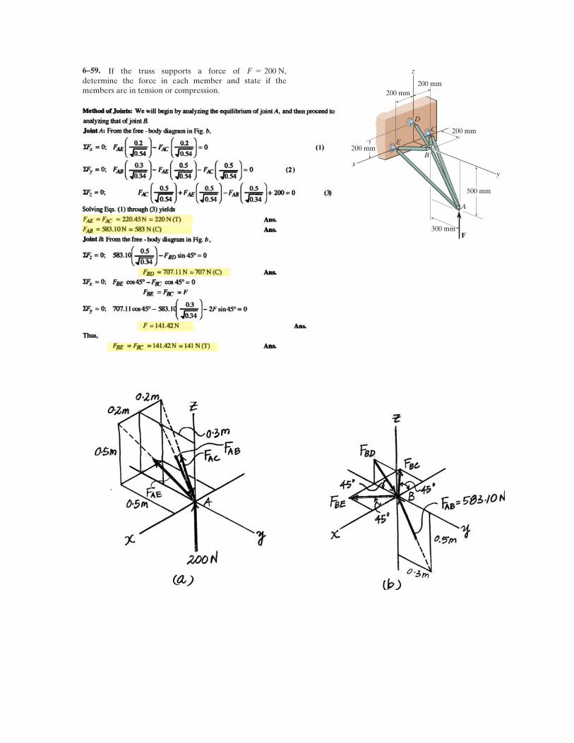
If the truss supports a force of ,determine the force in each member and state if themembers are in tension or compression.
F = 200 N
y
D
E
F
x
z
C
B
A
200 mm
200 mm
200 mm
200 mm
500 mm
300 mm
6–59.
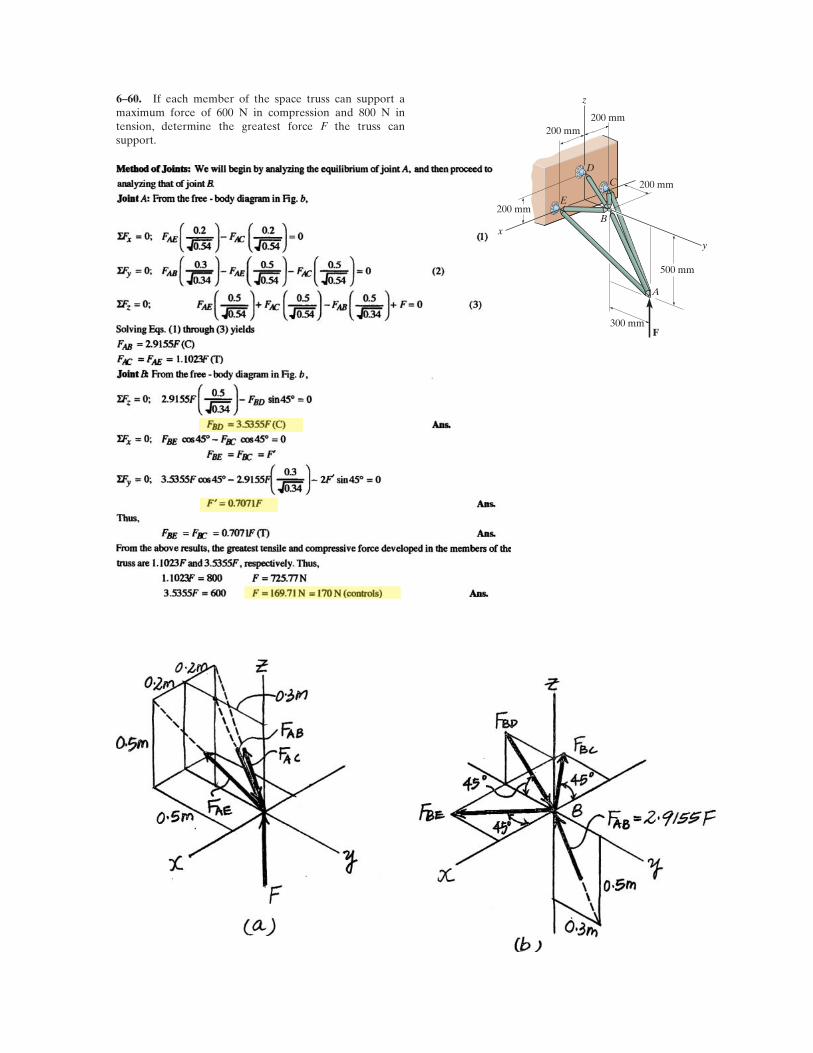
If each member of the space truss can support amaximum force of 600 N in compression and 800 N intension, determine the greatest force F the truss cansupport.
y
D
E
F
x
z
C
B
A
200 mm
200 mm
200 mm
200 mm
500 mm
300 mm
6–60.
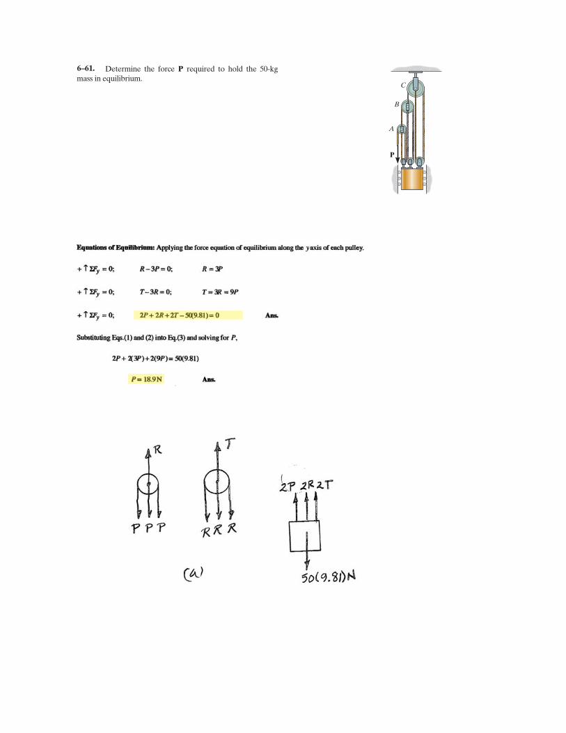
Determine the force required to hold the 50-kgmass in equilibrium.
P
P
A
B
C
6–61.
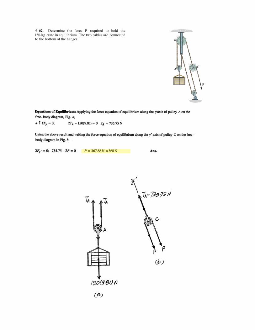
Determine the force required to hold the 150-kg crate in equilibrium. The two cables are connected
P
P
A
B
C
6–62.
to the bottom of the hanger.
6–63.
SOLUTION
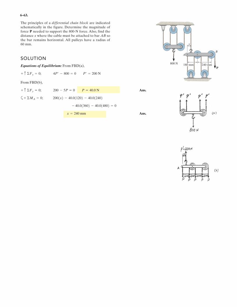
Equations of Equilibrium: From FBD(a),
From FBD(b),
Ans.
a
Ans.x = 240 mm
- 40.013602 - 40.014802 = 0
2001x2 - 40.011202 - 40.012402+ ©MA = 0;
200 - 5P = 0 P = 40.0 N+ c ©Fy = 0;
4P¿ - 800 = 0 P¿ = 200 N+ c ©Fy = 0;
The principles of a differential chain block are indicatedschematically in the figure. Determine the magnitude offorce P needed to support the 800-N force. Also, find thedistance x where the cable must be attached to bar AB sothe bar remains horizontal. All pulleys have a radius of60 mm.
A
P
x
B
800 N180 mm 240 mm
6–64.
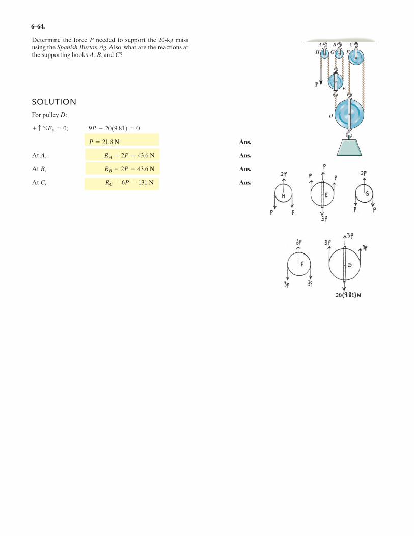
Determine the force P needed to support the 20-kg massusing the Spanish Burton rig. Also, what are the reactions atthe supporting hooks A, B, and C?
SOLUTION
For pulley D:
Ans.
At A, Ans.
At B, Ans.
At C, Ans.RC = 6P = 131 N
RB = 2P = 43.6 N
RA = 2P = 43.6 N
P = 21.8 N
9P - 2019.812 = 0+ c ©Fy = 0;
P
A B C
H G F
E
D
5
0.7 m
0.8 m 0.8 m
8 6
2 P ,
5 (2 P)2 + (P)2
2.24 kN
1.6 m
0.8 m
.
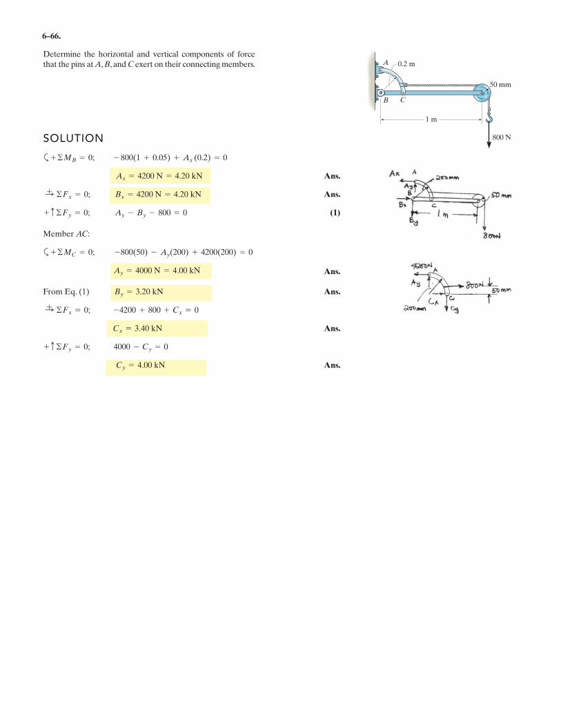
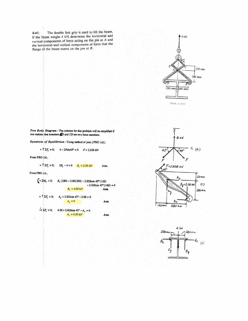
6–66.
Determine the horizontal and vertical components of forcethat the pins at A, B, and C exert on their connecting members.
SOLUTION
a
Ans.
Ans.
(1)
Member AC:
a
Ans.
From Eq. (1) Ans.
Ans.
Ans.Cy = 4.00 kN
+ c ©Fy = 0; 4000 - Cy = 0
Cx = 3.40 kN
:+ ©Fx = 0; -4200 + 800 + Cx = 0
By = 3.20 kN
Ay = 4000 N = 4.00 kN
+ ©MC = 0; -800(50) - Ay(200) + 4200(200) = 0
+ c ©Fy = 0; Ay - By - 800 = 0
:+ ©Fx = 0; Bx = 4200 N = 4.20 kN
Ax = 4200 N = 4.20 kN
+ ©MB = 0; - 800(1 + 0.05) + Ax (0.2) = 0
800 N
50 mm
1 m
A
B C
0.2 m
.
.
.
.
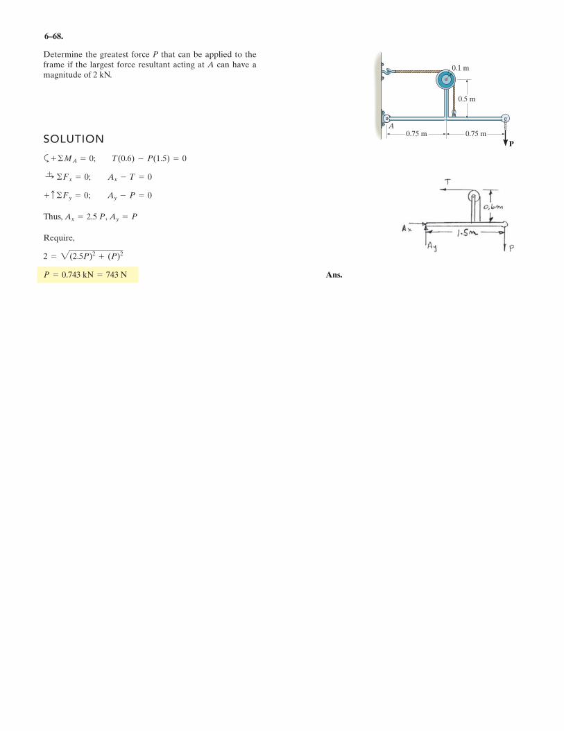
6–68.
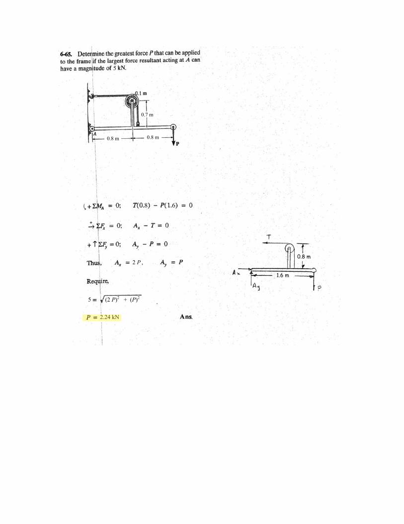
Determine the greatest force P that can be applied to theframe if the largest force resultant acting at A can have amagnitude of 2 kN.
SOLUTION
a
Thus, ,
Require,
Ans.P = 0.743 kN = 743 N
2 = 2(2.5P)2 + (P)2
Ay = PAx = 2.5 P
+ c ©Fy = 0; Ay - P = 0
:+ ©Fx = 0; Ax - T = 0
+ ©MA = 0; T(0.6) - P(1.5) = 0
P
A0.75 m 0.75 m
0.5 m
0.1 m
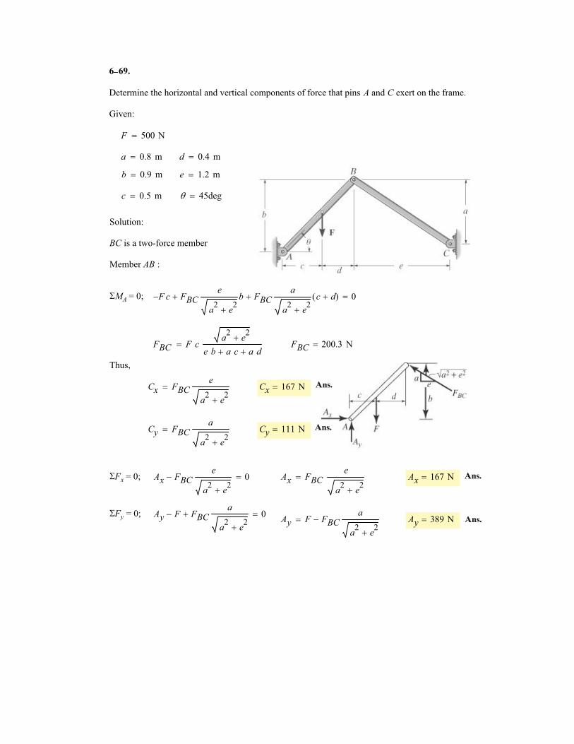
6
Determine the horizontal and vertical components of force that pins A and C exert on the frame.
Given:
F 500 N�
a 0.8 m� d 0.4 m�
b 0.9 m� e 1.2 m�
c 0.5 m� � 45deg�
Solution:
BC is a two-force member
Member AB :
�MA = 0; F� c FBC
e
a2
e2
�
b� FBCa
a2
e2
�
c d�( )� 0�
FBC F ca
2e2
�
e b a c� a d�� FBC 200.3 N�
Thus,
Cx FBCe
a2
e2
�
� Cx 167 N�
Cy FBCa
a2
e2
�
� Cy 111 N�
�Fx = 0; Ax FBCe
a2
e2
�
� 0� Ax FBCe
a2
e2
�
� Ax 167 N�
�Fy = 0; Ay F� FBCa
a2
e2
�
� 0�Ay F FBC
a
a2
e2
�
�� Ay 389 N�
69.
Ans.
Ans.
Ans.
Ans.
–
.
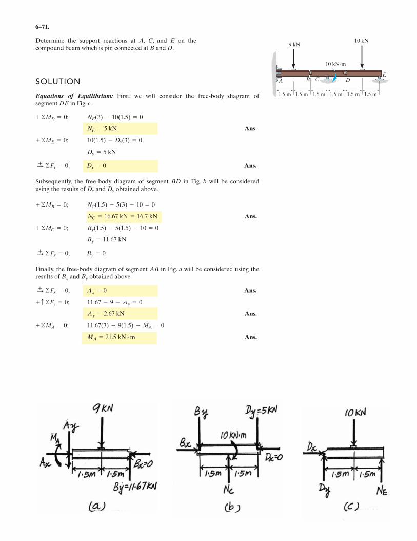
6–71.
Determine the support reactions at A, C, and E on thecompound beam which is pin connected at B and D.
SOLUTION
Equations of Equilibrium: First, we will consider the free-body diagram ofsegment DE in Fig. c.
Ans.
Ans.
Subsequently, the free-body diagram of segment BD in Fig. b will be consideredusing the results of and obtained above.
Ans.
Finally, the free-body diagram of segment AB in Fig. a will be considered using theresults of and obtained above.
Ans.
Ans.
Ans.MA = 21.5 kN # m
11.67(3) - 9(1.5) - MA = 0+ ©MA = 0;
Ay = 2.67 kN
11.67 - 9 - Ay = 0+ c ©Fy = 0;
Ax = 0©Fx = 0;:+
ByBx
By = 0©Fx = 0;:+
By = 11.67 kN
By(1.5) - 5(1.5) - 10 = 0+ ©MC = 0;
NC = 16.67 kN = 16.7 kN
NC(1.5) - 5(3) - 10 = 0+ ©MB = 0;
DyDx
Dx = 0©Fx = 0;:+
Dy = 5 kN
10(1.5) - Dy(3) = 0+ ©ME = 0;
NE = 5 kN
NE(3) - 10(1.5) = 0+ ©MD = 0;
A B C DE
1.5 m
9 kN
10 kN m
10 kN
1.5 m1.5 m 1.5 m 1.5 m 1.5 m
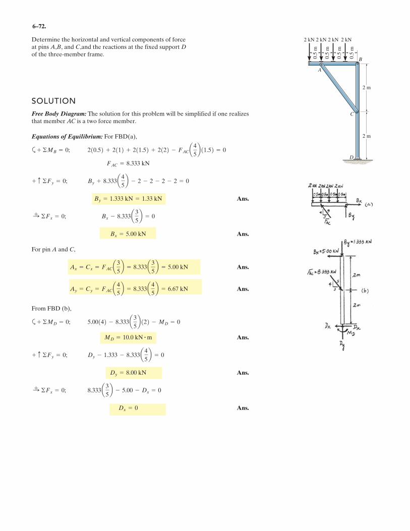
6–72.
SOLUTION
Free Body Diagram: The solution for this problem will be simplified if one realizesthat member AC is a two force member.
Equations of Equilibrium: For FBD(a),
a
Ans.
Ans.
For pin A and C,
Ans.
Ans.
From FBD (b),
a
Ans.
Ans.
Ans.Dx = 0
8.333a3
5b - 5.00 - Dx = 0:
+ ©Fx = 0;
Dy = 8.00 kN
Dy - 1.333 - 8.333a4
5b = 0+ c ©Fy = 0;
MD = 10.0 kN # m
5.00142 - 8.333a3
5b122 - MD = 0+ ©MD = 0;
Ay = Cy = FACa4
5b = 8.333a 4
5b = 6.67 kN
Ax = Cx = FACa3
5b = 8.333a 3
5b = 5.00 kN
Bx = 5.00 kN
Bx - 8.333a3
5b = 0:
+ ©Fx = 0;
By = 1.333 kN = 1.33 kN
By + 8.333a4
5b - 2 - 2 - 2 - 2 = 0+ c ©Fy = 0;
FAC = 8.333 kN
210.52 + 2112 + 211.52 + 2122 - FACa4
5b11.52 = 0+ ©MB = 0;
Determine the horizontal and vertical components of forceat pins A,B, and C,and the reactions at the fixed support Dof the three-member frame.
2 kN 2 kN 2 kN 2 kN
0.5
m
0.5
m
0.5
m
0.5
m
2 m
2 m
A
B
C
D
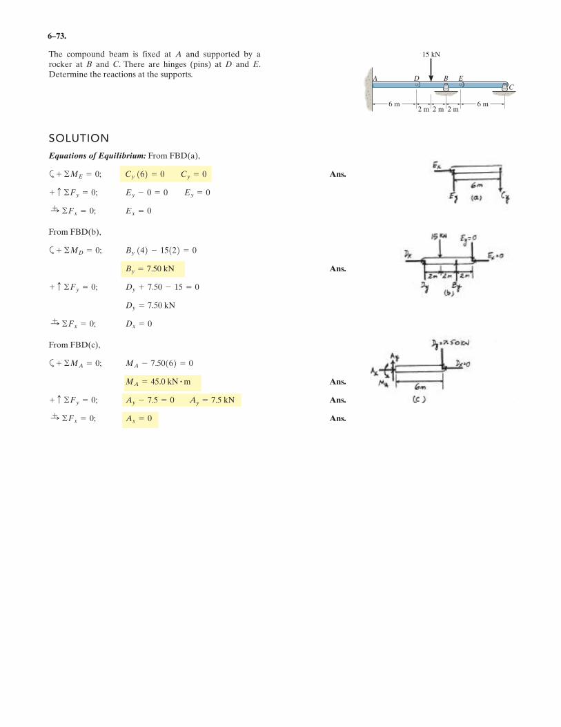
6–73.
SOLUTION
Equations of Equilibrium: From FBD(a),
a Ans.
From FBD(b),
a
Ans.
From FBD(c),
a
Ans.
Ans.
Ans.Ax = 0:+ ©Fx = 0;
Ay - 7.5 = 0 Ay = 7.5 kN+ c ©Fy = 0;
MA = 45.0 kN # m
MA - 7.50162 = 0+ ©MA = 0;
Dx = 0:+ ©Fx = 0;
Dy = 7.50 kN
Dy + 7.50 - 15 = 0+ c ©Fy = 0;
By = 7.50 kN
By 142 - 15122 = 0+ ©MD = 0;
Ex = 0:+ ©Fx = 0;
Ey - 0 = 0 Ey = 0+ c ©Fy = 0;
Cy 162 = 0 Cy = 0+ ©ME = 0;
The compound beam is fixed at A and supported by arocker at B and C. There are hinges (pins) at D and E.Determine the reactions at the supports.
6 m2 m
6 m2 m 2 m
15 kN
A D B E
C
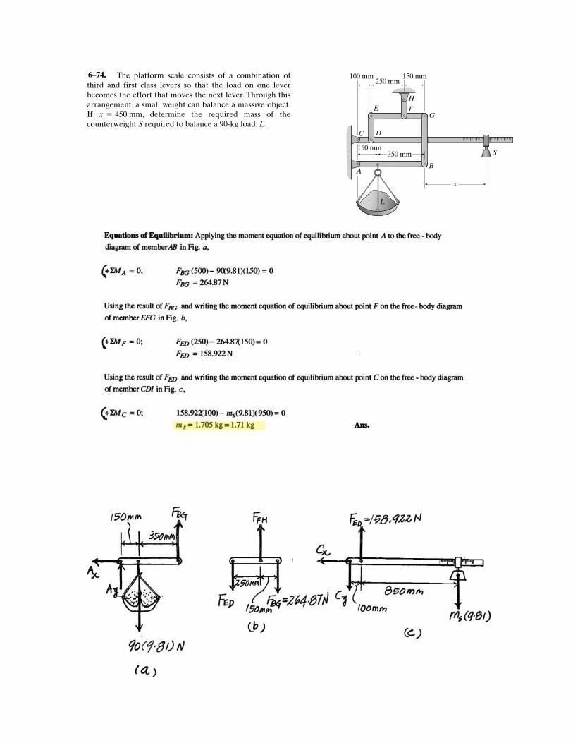
The platform scale consists of a combination ofthird and first class levers so that the load on one leverbecomes the effort that moves the next lever. Through thisarrangement, a small weight can balance a massive object.If , determine the required mass of thecounterweight S required to balance a 90-kg load, L.
x = 450 mm
350 mm150 mm
150 mm100 mm250 mm
BA
C D
E F
H
G
x
L
S
6–74.
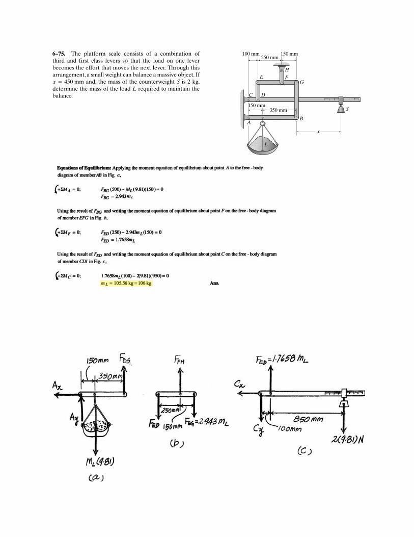
The platform scale consists of a combination ofthird and first class levers so that the load on one leverbecomes the effort that moves the next lever. Through thisarrangement, a small weight can balance a massive object. If
and, the mass of the counterweight S is 2 kg,determine the mass of the load L required to maintain thebalance.
x = 450 mm
350 mm150 mm
150 mm100 mm250 mm
BA
C D
E F
H
G
x
L
S
6–75.
mL
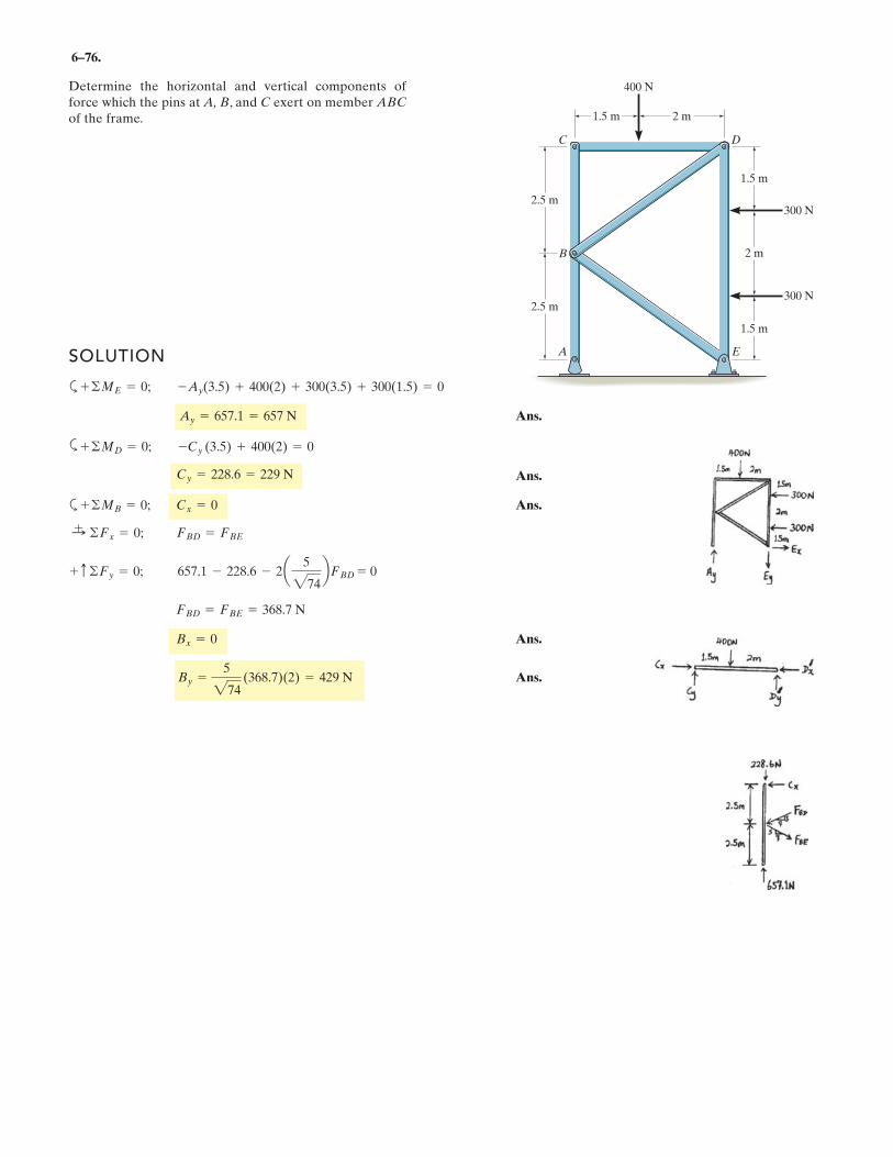
6–76.
Determine the horizontal and vertical components offorce which the pins at A, B, and C exert on member ABC
of the frame. 2 m1.5 m
2.5 m
2.5 m
1.5 m
1.5 m
2 m
300 N
300 N
400 N
D
E
C
A
B
SOLUTION
a
Ans.
a
Ans.
a Ans.
Ans.
Ans.By =5
274(368.7)(2) = 429 N
Bx = 0
FBD = FBE = 368.7 N
+ c ©Fy = 0; 657.1 - 228.6 - 2a 5
274bFBD = 0
:+ ©Fx = 0; FBD = FBE
+ ©MB = 0; Cx = 0
Cy = 228.6 = 229 N
+ ©MD = 0; -Cy (3.5) + 400(2) = 0
Ay = 657.1 = 657 N
+ ©ME = 0; -Ay(3.5) + 400(2) + 300(3.5) + 300(1.5) = 0
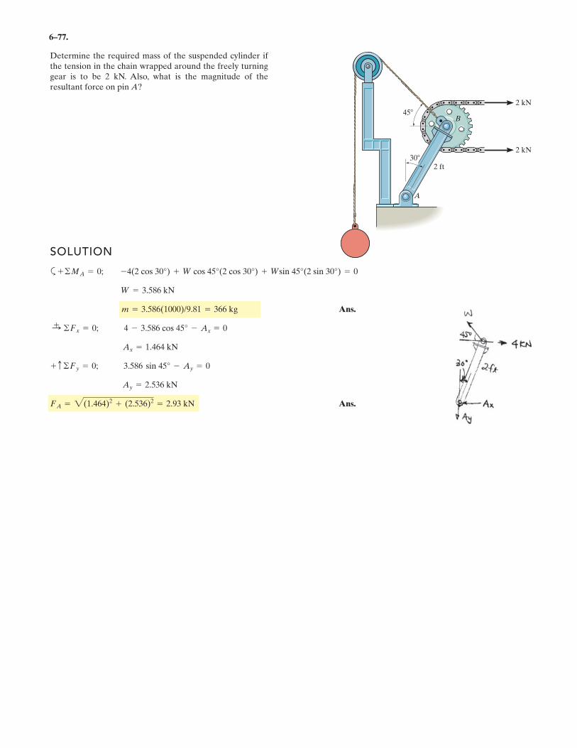
6–77.
Determine the required mass of the suspended cylinder ifthe tension in the chain wrapped around the freely turninggear is to be 2 kN. Also, what is the magnitude of theresultant force on pin A?
2 kN
2 kN
B45
302 ft
A
SOLUTION
a
Ans.
Ans.FA = 2(1.464)2 + (2.536)2 = 2.93 kN
Ay = 2.536 kN
+ c ©Fy = 0; 3.586 sin 45° - Ay = 0
Ax = 1.464 kN
:+ ©Fx = 0; 4 - 3.586 cos 45° - Ax = 0
m = 3.586(1000)/9.81 = 366 kg
W = 3.586 kN
+ ©MA = 0; -4(2 cos 30°) + W cos 45°(2 cos 30°) + Wsin 45°(2 sin 30°) = 0
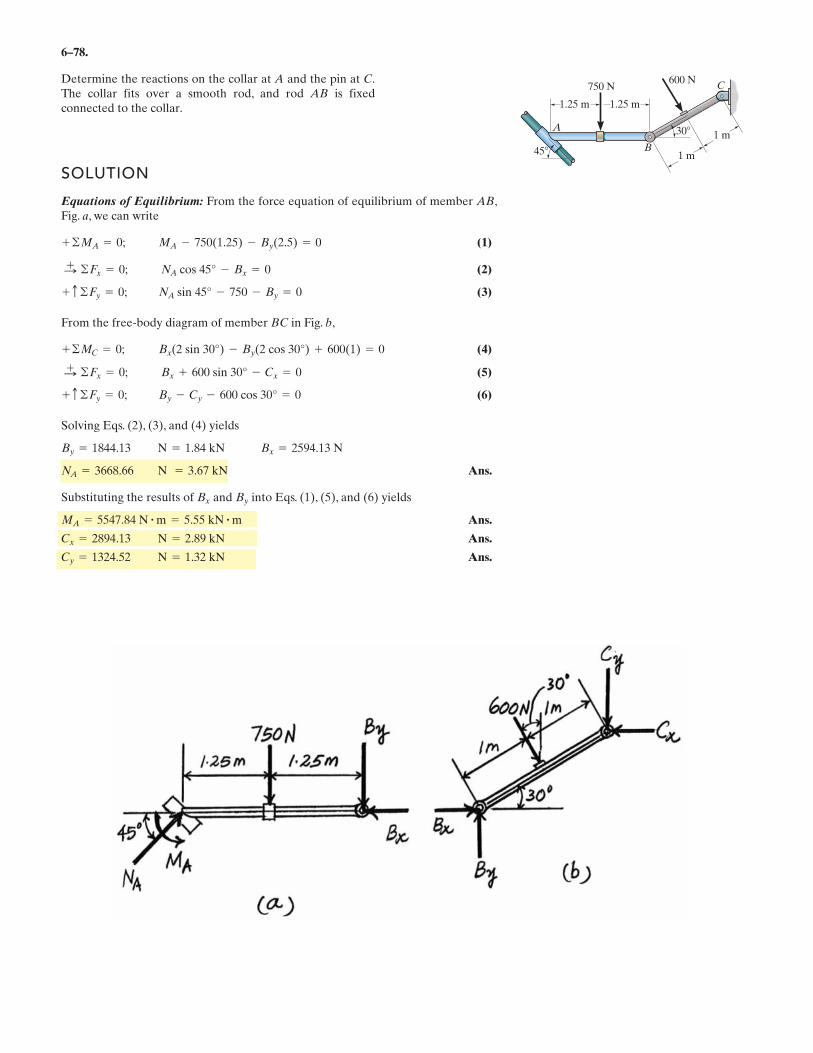
6–78.
Determine the reactions on the collar at A and the pin at C.The collar fits over a smooth rod, and rod AB is fixedconnected to the collar.
SOLUTION
Equations of Equilibrium: From the force equation of equilibrium of member AB,Fig. a, we can write
(1)
(2)
(3)
From the free-body diagram of member BC in Fig. b,
(4)
(5)
(6)
Solving Eqs. (2), (3), and (4) yields
Ans.
Substituting the results of and into Eqs. (1), (5), and (6) yields
Ans.
Ans.
Ans.N = 1.32 kNCy = 1324.52
N = 2.89 kNCx = 2894.13
MA = 5547.84 N # m = 5.55 kN # m
ByBx
N = 3.67 kNNA = 3668.66
Bx = 2594.13 NN = 1.84 kNBy = 1844.13
By - Cy - 600 cos 30° = 0+ c ©Fy = 0;
Bx + 600 sin 30° - Cx = 0©Fx = 0;:+
Bx(2 sin 30°) - By(2 cos 30°) + 600(1) = 0+ ©MC = 0;
NA sin 45° - 750 - By = 0+ c ©Fy = 0;
NA cos 45° - Bx = 0©Fx = 0;:+
MA - 750(1.25) - By(2.5) = 0+ ©MA = 0;
A
B
C
30
45
1.25 m 1.25 m
1 m
750 N600 N
1 m
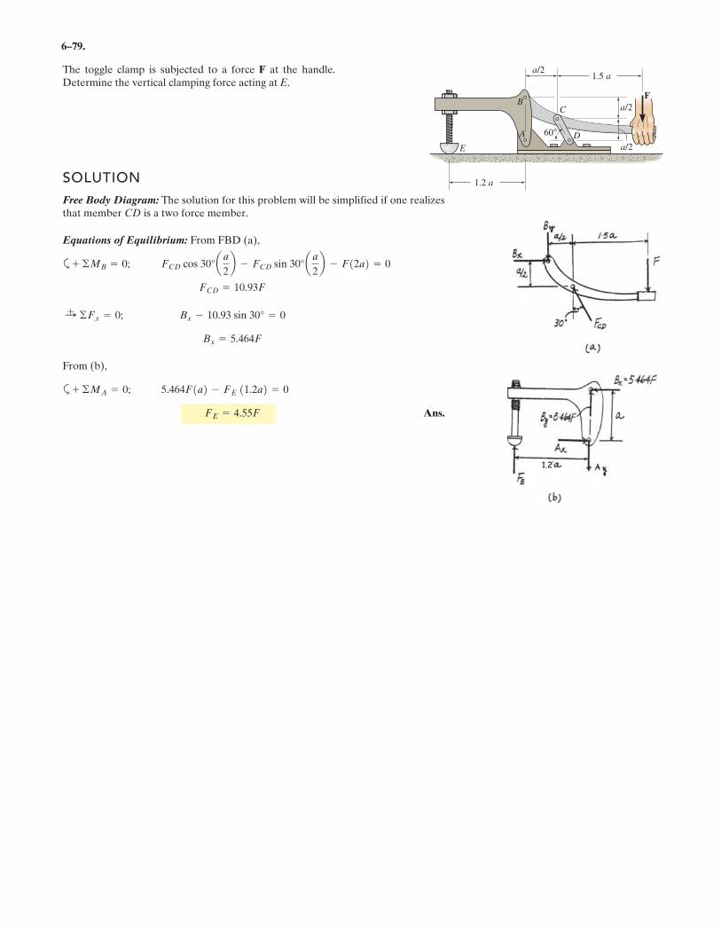
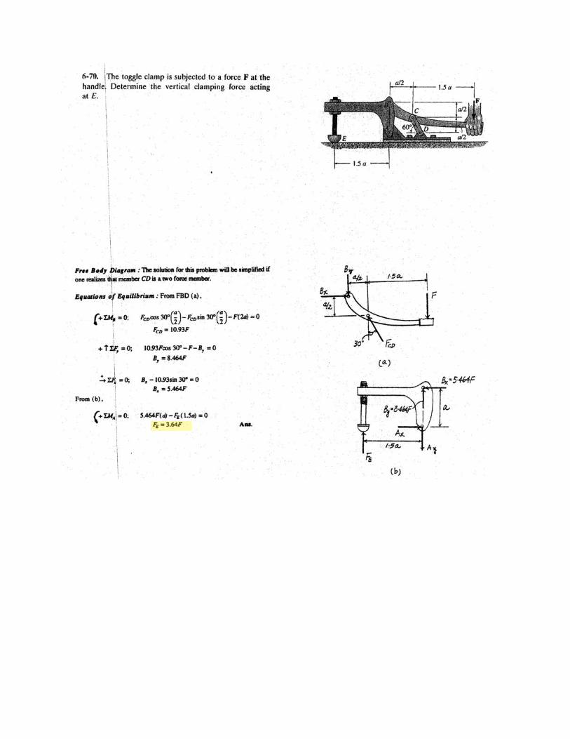
6–79.
The toggle clamp is subjected to a force F at the handle.Determine the vertical clamping force acting at E.
1.5 a
1.2 a
60°
a/2
a/2
a/2E
C
D
FB
A
SOLUTION
Free Body Diagram: The solution for this problem will be simplified if one realizesthat member CD is a two force member.
Equations of Equilibrium: From FBD (a),
a
From (b),
a
Ans.FE = . F
5.464F1a2 - FE 11.2a2 = 0+ ©MA = 0;
Bx = 5.464F
Bx - 10.93 sin 30° = 0:+ ©Fx = 0;
FCD = 10.93F
FCD cos 30°aa
2b - FCD sin 30°aa
2b - F12a2 = 0+ ©MB = 0;
4 55
1.2
6–80.
.
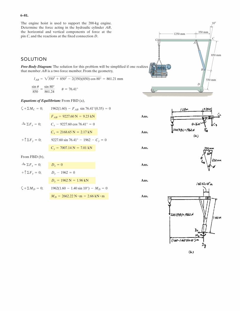
6–81.
The engine hoist is used to support the 200-kg engine.Determine the force acting in the hydraulic cylinder AB,the horizontal and vertical components of force at thepin C, and the reactions at the fixed connection D.
C
D
AG
1250 mm350 mm
850 mm
550 mm
10
B
SOLUTION
Free-Body Diagram:
The solution for this problem will be simplified if one realizesthat member AB is a two force member. From the geometry,
Equations of Equilibrium: From FBD (a),
a
Ans.
Ans.
Ans.
From FBD (b),
Ans.
Ans.
a
Ans.MD = 2662.22 N # m = 2.66 kN # m
+ ©MD = 0; 1962(1.60 - 1.40 sin 10°) - MD = 0
Dy = 1962 N = 1.96 kN
+ c ©Fy = 0; Dy - 1962 = 0
:+ ©Fx = 0; Dx = 0
Cy = 7007.14 N = 7.01 kN
+ c ©Fy = 0; 9227.60 sin 76.41° - 1962 - Cy = 0
Cx = 2168.65 N = 2.17 kN
:+ ©Fx = 0; Cx - 9227.60 cos 76.41° = 0
FAB = 9227.60 N = 9.23 kN
+ ©MC = 0; 1962(1.60) - FAB sin 76.41°(0.35) = 0
sin u
850=
sin 80°
861.24 u = 76.41°
lAB = 23502 + 8502 - 2(350)(850) cos 80° = 861.21 mm
.
.
.
.
.
.
6
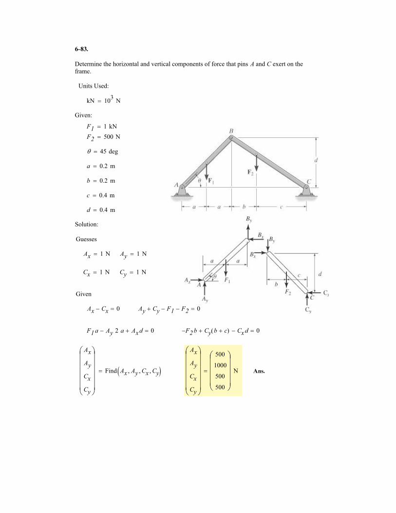
Determine the horizontal and vertical components of force that pins A and C exert on the
frame.
Units Used:
kN 103
N�
Given:
F1 1 kN�
F2 500 N�
� 45 deg�
a 0.2 m�
b 0.2 m�
c 0.4 m�
d 0.4 m�
Solution:
Guesses
Ax 1 N� Ay 1 N�
Cx 1 N� Cy 1 N�
Given
Ax Cx� 0� Ay Cy� F1� F2� 0�
F1 a Ay 2 a� Ax d� 0� F2� b Cy b c�( )� Cx d� 0�
Ax
Ay
Cx
Cy
�
������
Find Ax Ay� Cx� Cy�� ��
Ax
Ay
Cx
Cy
�
������
500
1000
500
500
�
�����
N�
83.
Ans.
–
6
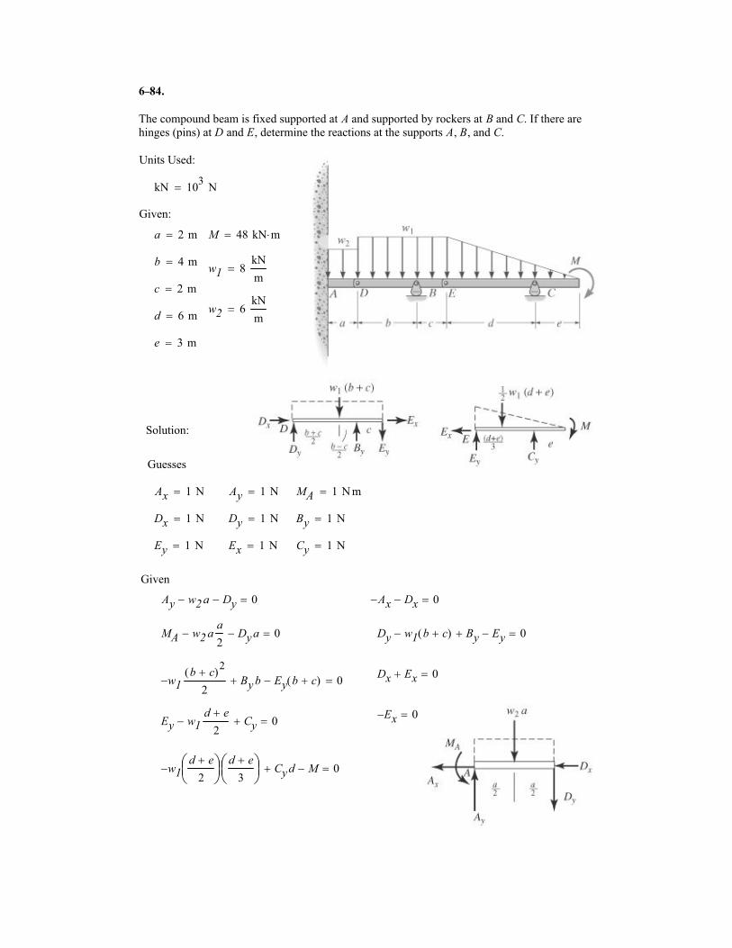
The compound beam is fixed supported at A and supported by rockers at B and C. If there are
hinges (pins) at D and E, determine the reactions at the supports A, B, and C.
Units Used:
kN 103
N�
Given:
a 2 m� M 48 kN m��
b 4 m�w1 8
kN
m�
c 2 m�
w2 6kN
m�
d 6 m�
e 3 m�
Solution:
Guesses
Ax 1 N� Ay 1 N� MA 1 N m�
Dx 1 N� Dy 1 N� By 1 N�
Ey 1 N� Ex 1 N� Cy 1 N�
Given
Ay w2 a� Dy� 0� Ax� Dx� 0�
MA w2 aa
2� Dy a� 0� Dy w1 b c�( )� By� Ey� 0�
Dx Ex� 0�w1�
b c�( )2
2By b� Ey b c�( )� 0�
Ex� 0�Ey w1
d e�
2� Cy� 0�
w1�d e�
2
�
��
d e�
3
�
��
Cy d� M� 0�
84.–
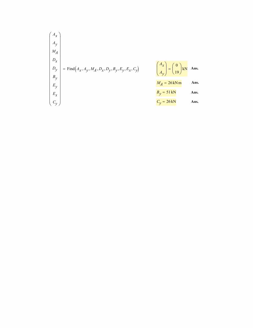
Ax
Ay
MA
Dx
Dy
By
Ey
Ex
Cy
�
��������������
Find Ax Ay� MA� Dx� Dy� By� Ey� Ex� Cy�� ��Ax
Ay
�
���
0
19
�
��
kN�
MA 26 kN m�
By 51 kN�
Cy 26 kN�
Ans.
Ans.
Ans.
Ans.
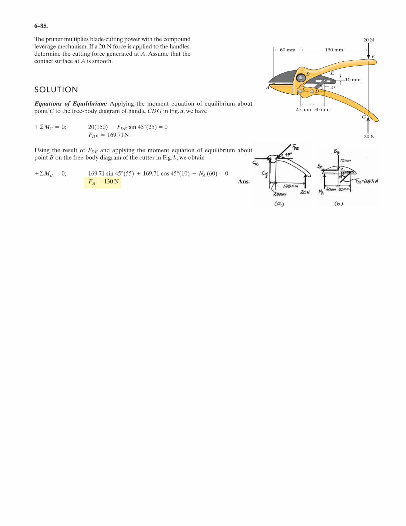
6–85.
The pruner multiplies blade-cutting power with the compoundleverage mechanism. If a 20-N force is applied to the handles,determine the cutting force generated at A. Assume that thecontact surface at A is smooth.
SOLUTION
Equations of Equilibrium: Applying the moment equation of equilibrium aboutpoint C to the free-body diagram of handle CDG in Fig. a, we have
Using the result of and applying the moment equation of equilibrium aboutpoint B on the free-body diagram of the cutter in Fig. b, we obtain
Ans.FA = 130 N
169.71 sin 45°(55) + 169.71 cos 45°(10) - NA (60) = 0+ ©MB = 0;
FDE
FDE = 169.71 N
20(150) - FDE sin 45°(25) = 0+ ©MC = 0;
25 mm 30 mm
45A
E
F
G
10 mm
150 mm
20 N
20 N
60 mm
B
CD
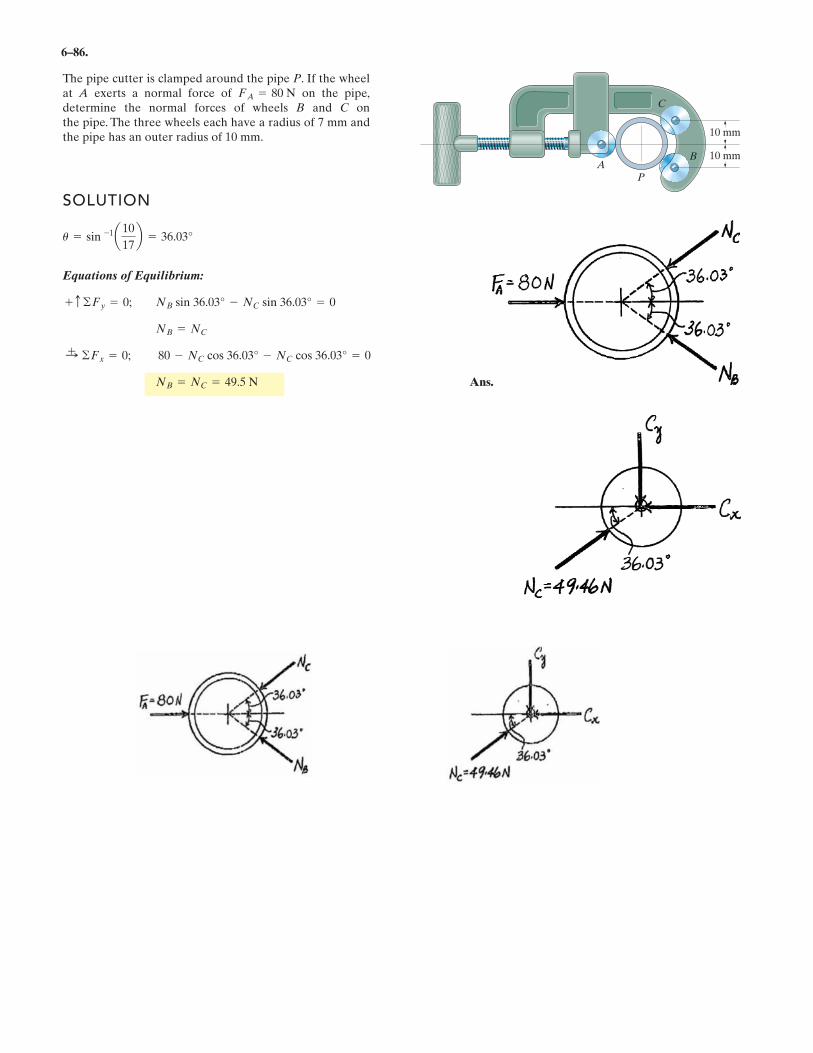
6–86.
The pipe cutter is clamped around the pipe P. If the wheelat A exerts a normal force of on the pipe,determine the normal forces of wheels B and C onthe pipe. The three wheels each have a radius of 7 mm andthe pipe has an outer radius of 10 mm.
FA = 80 N
10 mm
10 mm
P
C
BA
SOLUTION
Equations of Equilibrium:
Ans.NB = NC = 49.5 N
:+ ©Fx = 0; 80 - NC cos 36.03° - NC cos 36.03° = 0
NB = NC
+ c ©Fy = 0; NB sin 36.03° - NC sin 36.03° = 0
u = sin -1a10
17b = 36.03°
N.
N
N N
N
N
N
N
N
.
.
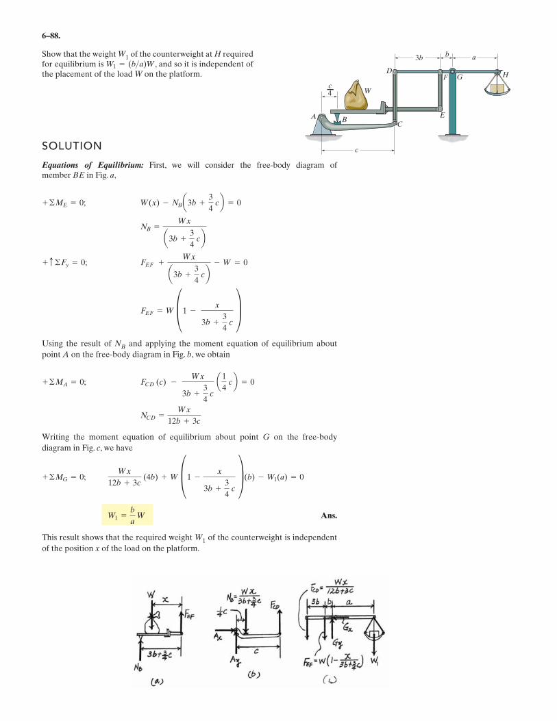
6–88.
Show that the weight W1 of the counterweight at H requiredfor equilibrium is , and so it is independent ofthe placement of the load W on the platform.
SOLUTION
Equations of Equilibrium: First, we will consider the free-body diagram of member BE in Fig. a,
Using the result of NB and applying the moment equation of equilibrium about
point A on the free-body diagram in Fig. b, we obtain
Writing the moment equation of equilibrium about point G on the free-body
diagram in Fig. c, we have
Ans.
This result shows that the required weight W1 of the counterweight is independent
of the position x of the load on the platform.
W1 =b
a W
Wx
12b + 3c (4b) + W §1 -
x
3b +3
4 c
¥(b) - W1(a) = 0+ ©MG = 0;
NCD =Wx
12b + 3c
FCD (c) - Wx
3b +3
4 c
a1
4 cb = 0+ ©MA = 0;
FEF = W §1 - x
3b +3
4 c
¥FEF +
Wx
a3b +3
4 cb
- W = 0+ c ©Fy = 0;
NB =Wx
a3b +3
4 cb
W(x) - NBa3b +3
4 cb = 0+ ©ME = 0;
W1 = (b>a)W
A B
W
C
E
G HD
F
c
b3b a
c4
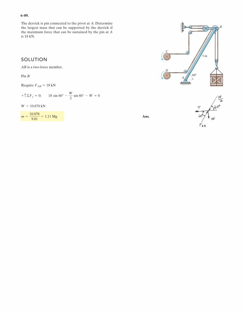
6–89.
The derrick is pin connected to the pivot at A. Determinethe largest mass that can be supported by the derrick ifthe maximum force that can be sustained by the pin at Ais 18 kN.
SOLUTION
AB is a two-force member.
Pin B
Require
Ans.m =10.878
9.81= 1.11 Mg
W = 10.878 kN
+ c ©Fy = 0; 18 sin 60° -W
2sin 60° - W = 0
FAB = 18 kN
A
5 m
60
B
D
C
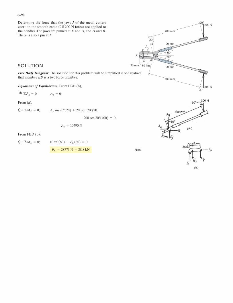
6–90.
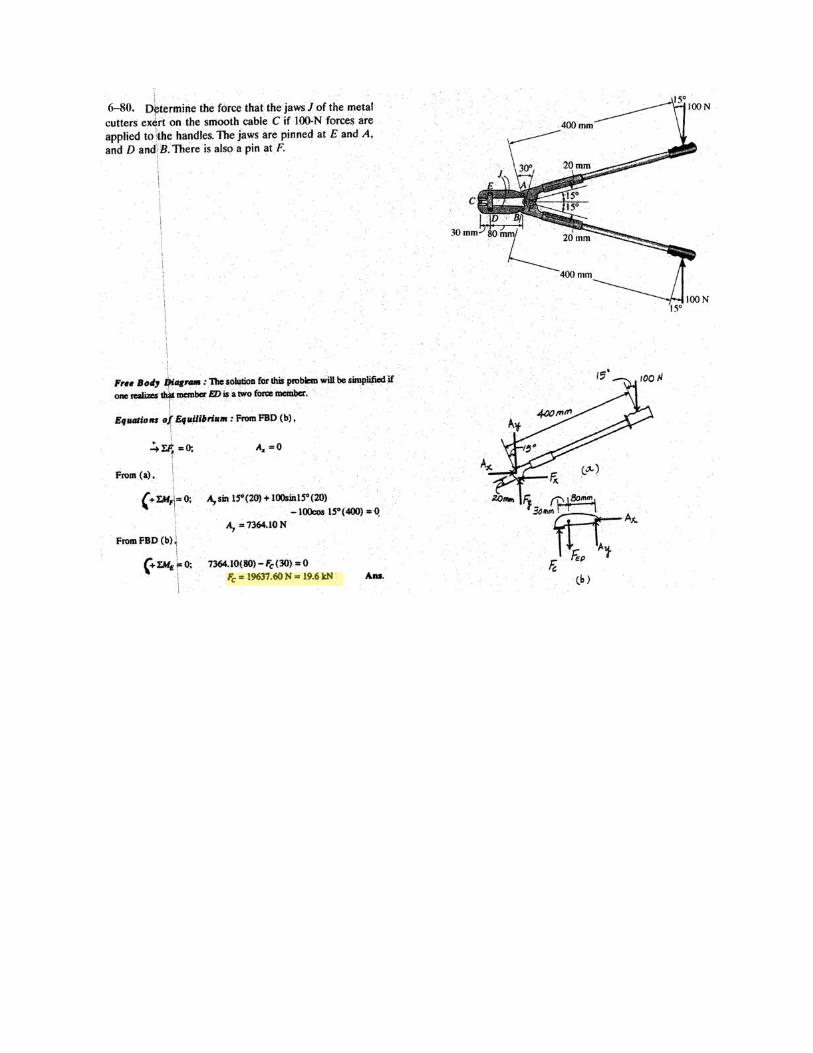
Determine the force that the jaws J of the metal cuttersexert on the smooth cable C if 200-N forces are applied tothe handles. The jaws are pinned at E and A, and D and B.There is also a pin at F.
F °
°
°
20 mm
20 mm
30 mm 80 mm
B
J
C
D
E
A
°
°
400 mm
400 mm
00 N
SOLUTION
Free Body Diagram: The solution for this problem will be simplified if one realizesthat member ED is a two force member.
Equations of Equilibrium: From FBD (b),
From (a),
a
From FBD (b),
a
Ans.FC = N = . kN
1802 - FC1302 = 0+ ©ME = 0;
Ay =
- 14002 = 0
Ay sin 20°1202 + 1202+ ©MF = 0;
Ax = 0:+ ©Fx = 0;
200 sin 20°
200 cos 20°
10790 N
10790
28773 28 8
200 N20
20
20
20
202
20° 200 N
20°
6
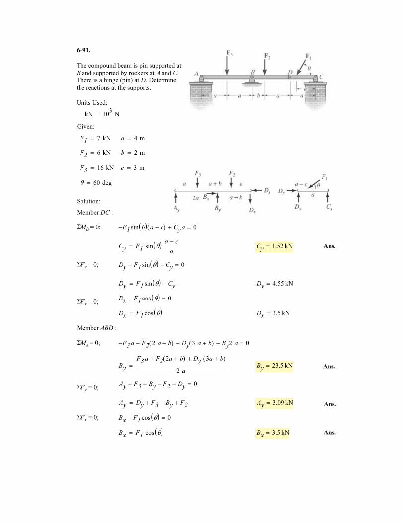
The compound beam is pin supported at
B and supported by rockers at A and C.
There is a hinge (pin) at D. Determine
the reactions at the supports.
Units Used:
kN 103
N�
F1 7 kN� a 4 m�
F2 6 kN� b 2 m�
F3 16 kN� c 3 m�
� 60 deg�
Solution:
Member DC :
�MD = 0; F1� sin �� � a c�( ) Cy a� 0�
Cy F1 sin �� � a c�
a� Cy 1.52 kN�
�Fy = 0; Dy F1 sin �� �� Cy� 0�
Dy F1 sin �� � Cy�� Dy 4.55 kN�
Dx F1 cos �� �� 0��Fx = 0;
Dx F1 cos �� �� Dx 3.5 kN�
Member ABD :
�MA = 0; F3� a F2 2 a b�( )� Dy 3 a b�( )� By2 a� 0�
By
F3 a F2 2a b�( )� Dy 3a b�( )�
2 a� By 23.5 kN�
Ay F3� By� F2� Dy� 0��Fy = 0;
Ay Dy F3 By�� F2�� Ay 3.09 kN�
�Fx = 0; Bx F1 cos �� �� 0�
Bx F1 cos �� �� Bx 3.5 kN�
Given:
91.
Ans.
Ans.
Ans.
Ans.
–
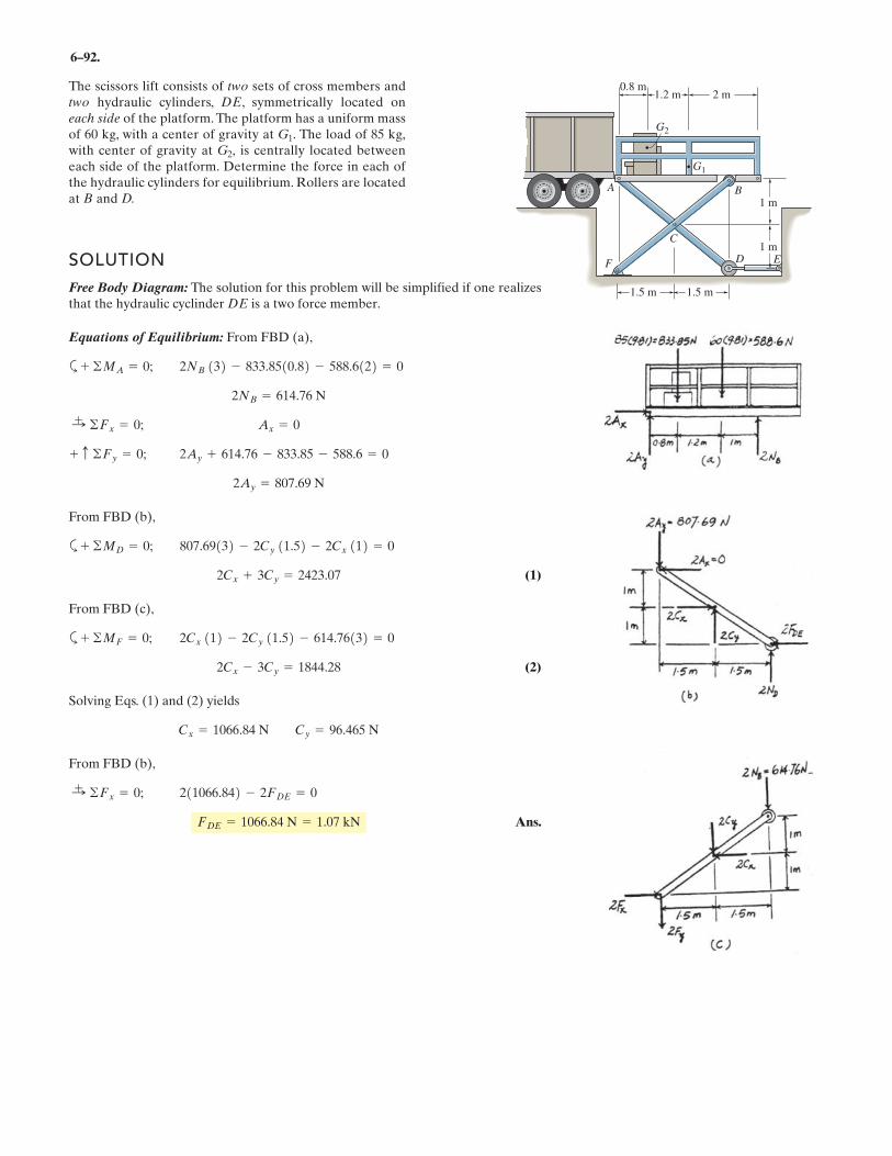
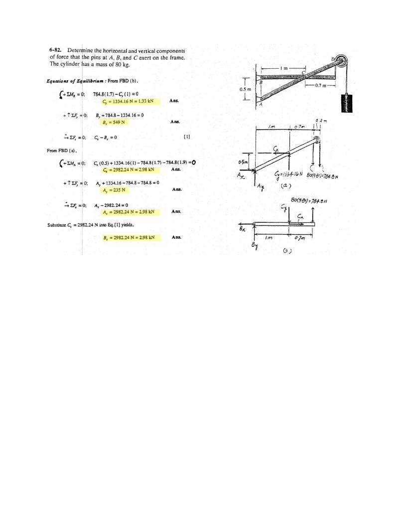
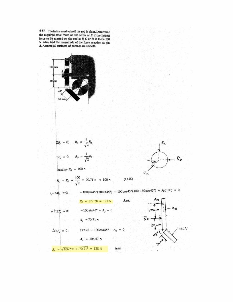
6–92.
The scissors lift consists of two sets of cross members andtwo hydraulic cylinders, DE, symmetrically located oneach side of the platform. The platform has a uniform massof 60 kg, with a center of gravity at The load of 85 kg,with center of gravity at is centrally located betweeneach side of the platform. Determine the force in each ofthe hydraulic cylinders for equilibrium. Rollers are locatedat B and D.
G2,G1.
2 m
1.5 m1.5 m
1 m
1 m
1.2 m0.8 m
A B
EF
G2
G1
C
DSOLUTION
Free Body Diagram: The solution for this problem will be simplified if one realizesthat the hydraulic cyclinder DE is a two force member.
Equations of Equilibrium: From FBD (a),
a
From FBD (b),
a
(1)
From FBD (c),
a
(2)
Solving Eqs. (1) and (2) yields
From FBD (b),
Ans.FDE = 1066.84 N = 1.07 kN
211066.842 - 2FDE = 0:+ ©Fx = 0;
Cx = 1066.84 N Cy = 96.465 N
2Cx - 3Cy = 1844.28
2Cx 112 - 2Cy 11.52 - 614.76132 = 0+ ©MF = 0;
2Cx + 3Cy = 2423.07
807.69132 - 2Cy 11.52 - 2Cx 112 = 0+ ©MD = 0;
2Ay = 807.69 N
2Ay + 614.76 - 833.85 - 588.6 = 0+ c ©Fy = 0;
Ax = 0:+ ©Fx = 0;
2NB = 614.76 N
2NB 132 - 833.8510.82 - 588.6122 = 0+ ©MA = 0;
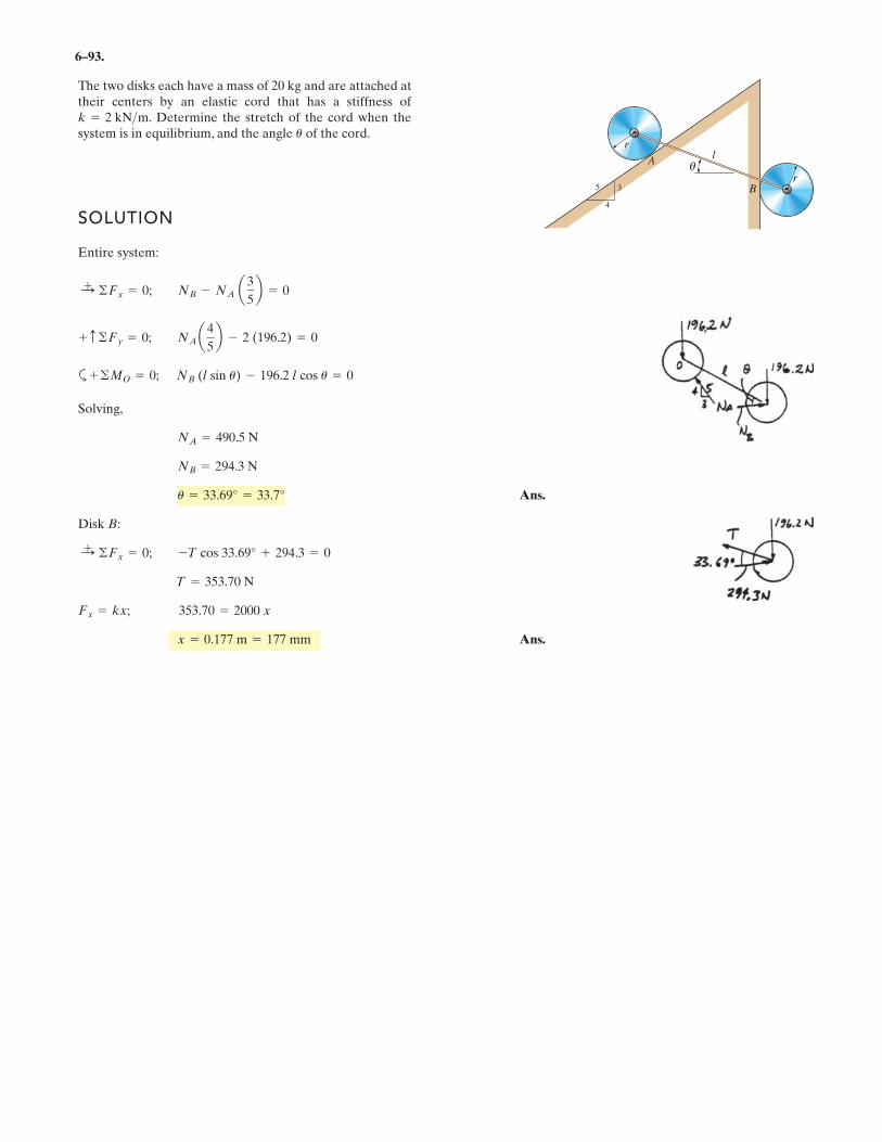
6–93.
SOLUTION
Entire system:
a
Solving,
Ans.
Disk B:
Ans.x = 0.177 m = 177 mm
Fx = kx; 353.70 = 2000 x
T = 353.70 N
:+ ©Fx = 0; -T cos 33.69° + 294.3 = 0
u = 33.69° = 33.7°
NB = 294.3 N
NA = 490.5 N
+ ©MO = 0; NB (l sin u) - 196.2 l cos u = 0
+ c ©Fy = 0; NA a4
5b - 2 (196.2) = 0
:+ ©Fx = 0; NB - NA a3
5b = 0
The two disks each have a mass of 20 kg and are attached attheir centers by an elastic cord that has a stiffness of
. Determine the stretch of the cord when thesystem is in equilibrium, and the angle of the cord.u
k = 2 kN>m
rθ
4
5 3
lA
r
B
6–107. A man having a weight of 175 lb attempts to holdhimself using one of the two methods shown. Determine thetotal force he must exert on bar AB in each case and the normal reaction he exerts on the platform at C. Neglectthe weight of the platform.
C C
A B
A B
(a) (b)
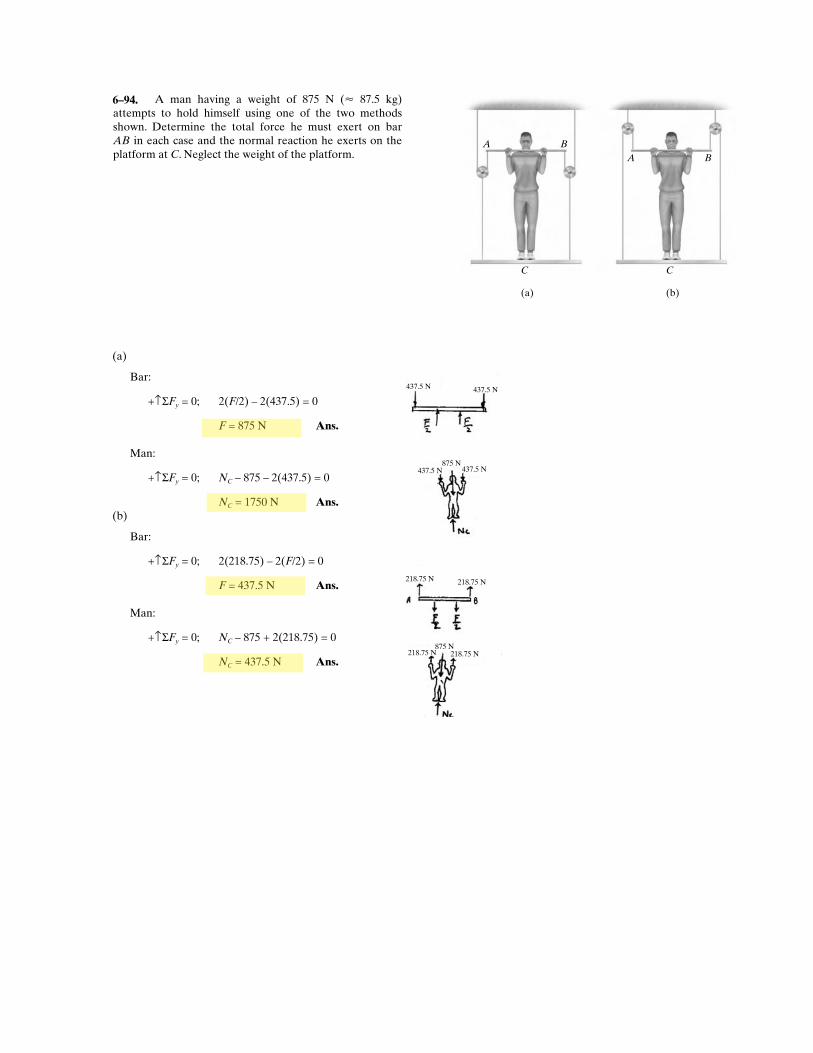
A man having a weight of 875 N (� 87.5 kg) attempts to hold himself using one of the two methods shown. Determine the total force he must exert on bar AB in each case and the normal reaction he exerts on the platform at C. Neglect the weight of the platform.
218.75 N218.75 N875 N
218.75 N218.75 N
437.5 N437.5 N875 N
437.5 N437.5 N
(a)
Bar:
+↑ΣFy = 0; 2(F/2) – 2(437.5) = 0
F = 875 N Ans.
Man:
+↑ΣFy = 0; NC – 875 – 2(437.5) = 0
NC = 1750 N Ans.
(b)
Bar:
+↑ΣFy = 0; 2(218.75) – 2(F/2) = 0
F = 437.5 N Ans.
Man:
+↑ΣFy = 0; NC – 875 + 2(218.75) = 0
NC = 437.5 N Ans.
6–94.
6–108. A man having a weight of 175 lb attempts to holdhimself using one of the two methods shown. Determine thetotal force he must exert on bar AB in each case and thenormal reaction he exerts on the platform at C.The platformhas a weight of 30 lb.
C C
A B
A B
(a) (b)
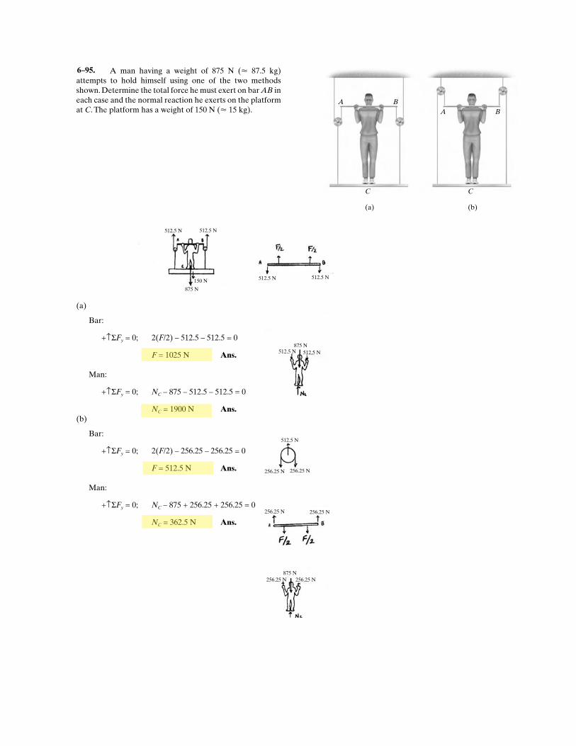
A man having a weight of 875 N (� 87.5 kg) attempts to hold himself using one of the two methods shown. Determine the total force he must exert on bar AB in each case and the normal reaction he exerts on the platform at C. The platform has a weight of 150 N (� 15 kg).
512.5 N512.5 N875 N
512.5 N512.5 N
512.5 N 512.5 N
150 N
875 N
512.5 N
256.25 N256.25 N
256.25 N 256.25 N
256.25 N256.25 N
875 N
(a)
Bar:
+↑ΣFy = 0; 2(F/2) – 512.5 – 512.5 = 0
F = 1025 N Ans.
Man:
+↑ΣFy = 0; NC – 875 – 512.5 – 512.5 = 0
NC = 1900 N Ans.
(b)
Bar:
+↑ΣFy = 0; 2(F/2) – 256.25 – 256.25 = 0
F = 512.5 N Ans.
Man:
+↑ΣFy = 0; NC – 875 + 256.25 + 256.25 = 0
NC = 362.5 N Ans.
6–95.
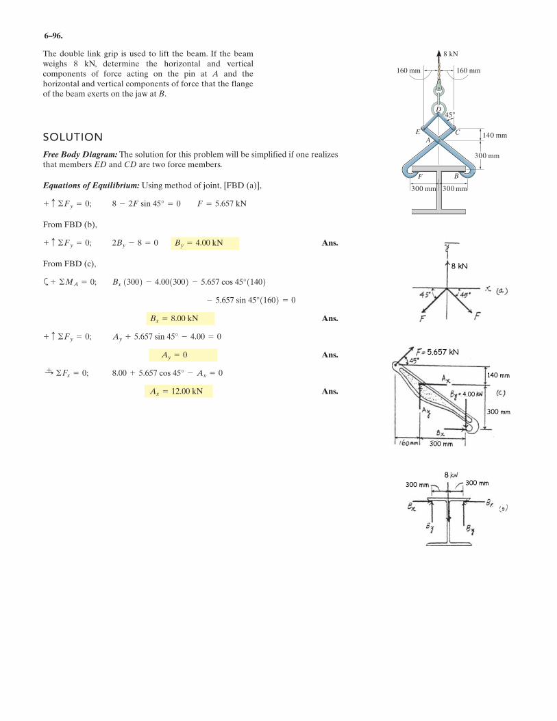
6–96.
SOLUTION
Free Body Diagram: The solution for this problem will be simplified if one realizesthat members ED and CD are two force members.
Equations of Equilibrium: Using method of joint, [FBD (a)],
From FBD (b),
Ans.
From FBD (c),
a
Ans.
Ans.
Ans.Ax =
+ - Ax = 0:+ ©Fx = 0;
Ay = 0
Ay + . sin 45° - .00 = 0+ c ©Fy = 0;
Bx =
- 11602 = 0
Bx 1 2 - 1 2 - 11402+ ©MA = 0;
2By - = 0 By =+ c ©Fy = 0;
- 2F sin 45° = 0 F =+ c ©Fy = 0;
The double link grip is used to lift the beam. If the beamweighs 8 kN, determine the horizontal and verticalcomponents of force acting on the pin at A and thehorizontal and vertical components of force that the flangeof the beam exerts on the jaw at B.
D
BF
CA
140 mm
45°
160 mm 160 mm
E
8 5.657 kN
8 4.00 kN
300 3004.00 5.657 cos 45°
5.657 sin 45°
8.00 kN
5 657 4
8.00 5.657 cos 45°
12.00 kN
8 kN
300 mm
300 mm300 mm
8 kN
5.657 kN
140 mm
300 mm
300 mm
4.00
300 mm 300 mm
8
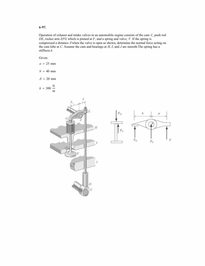
6
Operation of exhaust and intake valves in an automobile engine consists of the cam C, push rod
DE, rocker arm EFG which is pinned at F, and a spring and valve, V. If the spring is
compressed a distance � when the valve is open as shown, determine the normal force acting on
the cam lobe at C. Assume the cam and bearings at H, I, and J are smooth.The spring has a
stiffness k.
Given:
a 25 mm�
b 40 mm�
� 20 mm�
k 300N
m�
97.–
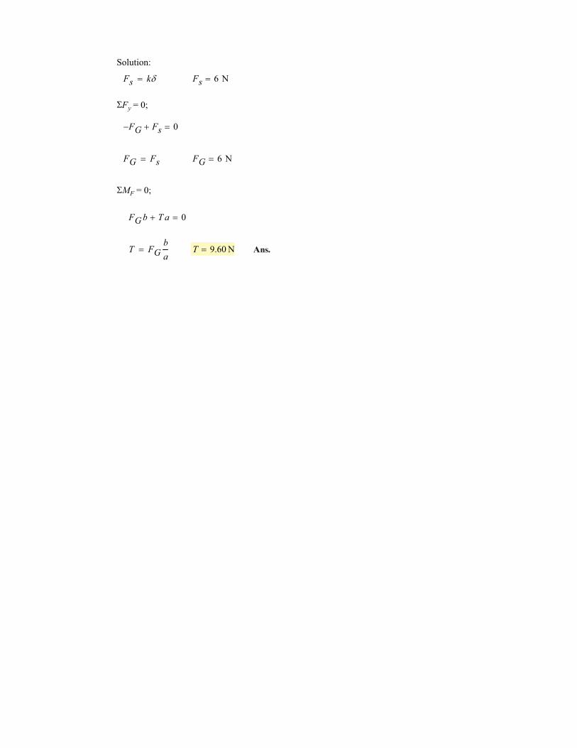
Solution:
Fs k�� Fs 6 N�
�Fy = 0;
FG� Fs� 0�
FG Fs� FG 6 N�
�MF = 0;
FG b T a� 0�
T FGb
a� T 9.60 N� Ans.
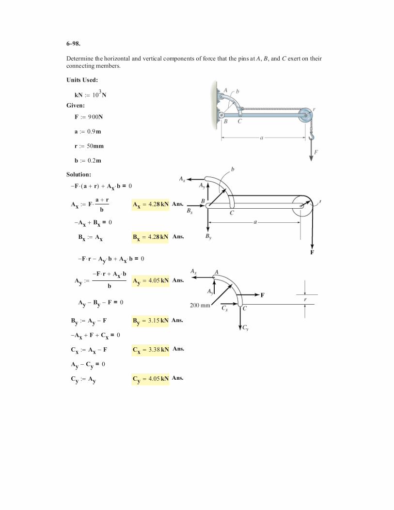
6 98.
Determine the horizontal and vertical components of force that the pins at A, B, and C exert on their
connecting members.
Units Used:
kN 103
N��
Given:
F N��
a ��
r 50mm��
b 0.2m��
Solution:
F� a r�( )� Ax b�� 0=
Ax Fa r�
b��� Ax 4.2�
Ax� Bx� 0=
Bx Ax�� Bx 4.2�
F� r� Ay b�� Ax b�� 0=
Ay
F� r� Ax b��
b�� Ay 4.05 kN�
Ay By� F� 0=
By Ay F��� By 3.15 kN�
Ax� F� Cx� 0=
Cx Ax F��� Cx 3.38 kN�
Ay Cy� 0=
Cy Ay�� Cy 4.05 kN�
9 00
0.9 m
8 kN
8 kN
Ans.
Ans.
Ans.
Ans.
Ans.
Ans.
–
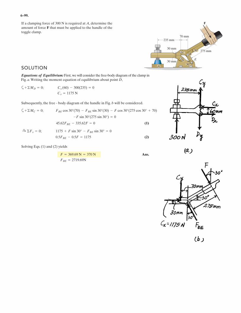
6–99.
If a clamping force of is required at A, determine theamount of force F that must be applied to the handle of thetoggle clamp.
300 N
275 mm30
30
235 mm
30 mm
30 mm
70 mm
F
C
E
B
D
A
a
(1)
(2)
Solving Eqs. (1) and (2) yields
Ans.
FBE = 2719.69N
F = 369.69 N = 370 N
0.5FBE - 0.5F = 1175
:+ ©Fx = 0; 1175 + F sin 30° - FBE sin 30° = 0
45.62FBE - 335.62F = 0
-F sin 30°(275 sin 30°) = 0
+ ©MC = 0; FBE cos 30°(70) - FBE sin 30°(30) - F cos 30°(275 cos 30° + 70)
SOLUTION
Equations of Equilibrium: First, we will consider the free-body diagram of the clamp in Fig. a. Writing the moment equation of equilibrium about point D,
a
Subsequently, the free - body diagram of the handle in Fig. b will be considered.
Cx = 1175 N
+ ©MD = 0; Cx (60) - 300(235) = 0
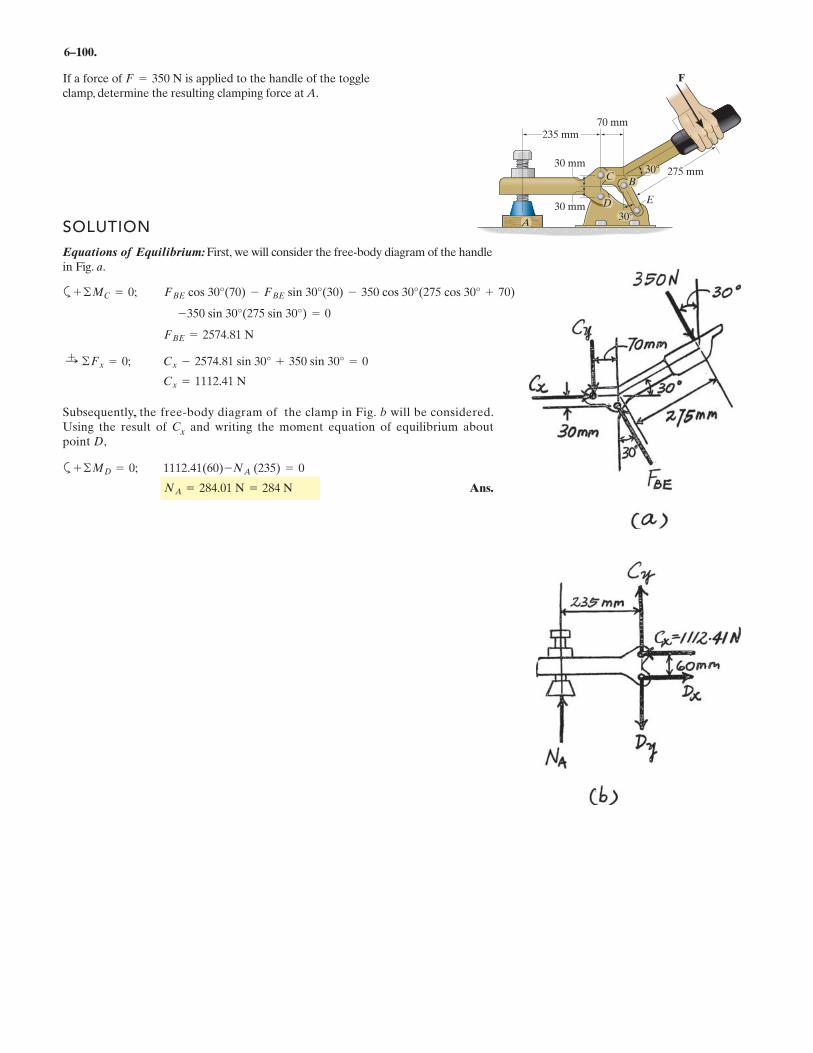
6–100.
If a force of is applied to the handle of the toggleclamp, determine the resulting clamping force at A.
F = 350 N
275 mm30
30
235 mm
30 mm
30 mm
70 mm
F
C
E
B
D
ASOLUTION
Equations of Equilibrium: First, we will consider the free-body diagram of the handle in Fig. a.
a
Cx = 1112.41 N
:+ ©Fx = 0; Cx - 2574.81 sin 30° + 350 sin 30° = 0
FBE = 2574.81 N
-350 sin 30°(275 sin 30°) = 0
+ ©MC = 0; FBE cos 30°(70) - FBE sin 30°(30) - 350 cos 30°(275 cos 30° + 70)
Subsequently, , the free-body diagram of the clamp in Fig. b will be considered. Using the result of Cx and writing the moment equation of equilibrium aboutpoint D,
a
Ans.NA = 284.01 N = 284 N
+ ©MD = 0; 1112.41(60)-NA (235) = 0
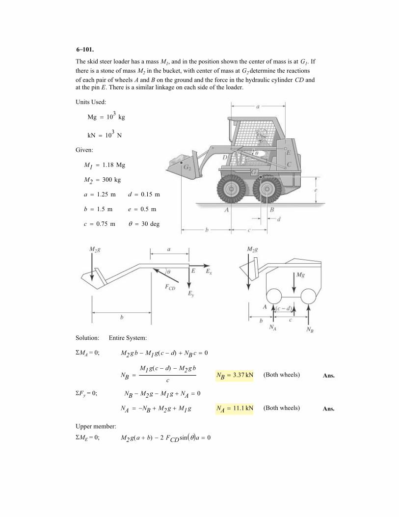
The skid steer loader has a mass M1, and in the position shown the center of mass is at G1. If
there is a stone of mass M2 in the bucket, with center of mass at G2 determine the reactions
of each pair of wheels A and B on the ground and the force in the hydraulic cylinder CD and
at the pin E. There is a similar linkage on each side of the loader.
Units Used:
Mg 103
kg�
kN 103
N�
Given:
M1 1.18 Mg�
M2 300 kg�
a 1.25 m� d 0.15 m�
b 1.5 m� e 0.5 m�
c 0.75 m� � 30 deg�
Solution: Entire System:
�MA = 0; M2 g b M1 g c d�( )� NB c� 0�
NB
M1 g c d�( ) M2 g b�
c� NB 3.37 kN� (Both wheels)
�Fy = 0; NB M2 g� M1 g� NA� 0�
NA NB� M2 g� M1 g�� NA 11.1 kN� (Both wheels)
Upper member:
�ME = 0; M2 g a b�( ) 2 FCDsin �� �a� 0�
6 101.
Ans.
Ans.
–
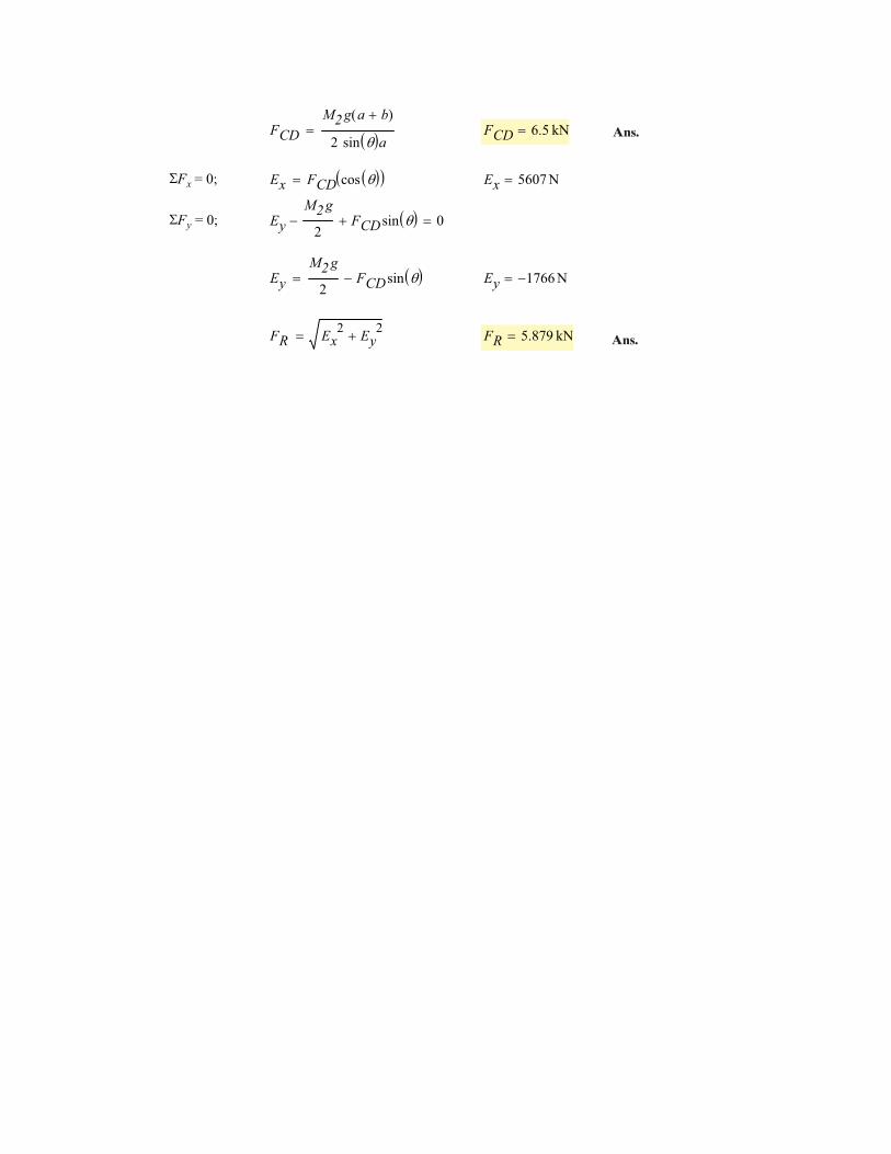
FCD
M2 g a b�( )
2 sin �� �a� FCD 6.5 kN�
�Fx = 0; Ex FCD cos �� �� �� Ex 5607 N�
�Fy = 0; Ey
M2 g
2� FCDsin �� �� 0�
Ey
M2 g
2FCDsin �� ��� Ey 1766� N�
FR Ex2
Ey2
�� FR 5.879 kN� Ans.
Ans.
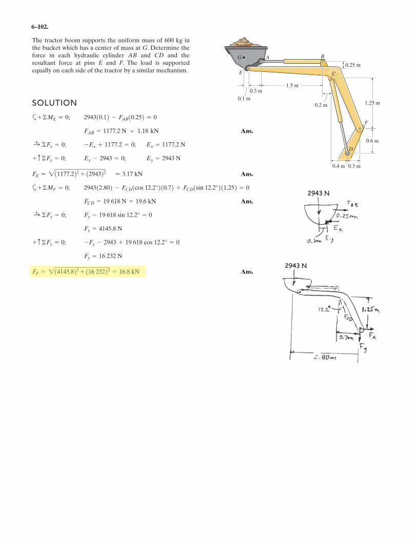
6–102.
1.5 m
0.25 m
0.3 m
0.1 m
0.2 m 1.25 m
0.6 m
0.4 m 0.3 m
A B
C
F
D
G
E
SOLUTION
a
Ans.
Ans.
a
Ans.
Ans.FF = 21 22 + 116 23222 = 16.8 kN
Fy = 16 232 N
-Fy - 2943 + 19 618 cos 12.2° = 0+ c ©Fy = 0;
Fx =
Fx - 19 618 sin 12.2° = 0:+ ©Fx = 0;
FCD = 19 618 N = 19.6 kN
294312.802 - FCD1cos 12.2°210.72 + FCD1sin 12.2°211.252 = 0+ ©MF = 0;
FE = 21 22 + 1294322 =
Ey = 2 NEy - 2 = 0;+ c ©Fy = 0;
Ex =-Ex + = 0;:+ ©Fx = 0;
FAB =
294310.12 - FAB10.252 = 0+ ©ME = 0;
The tractor boom supports the uniform mass of 600 kg inthe bucket which has a center of mass at G. Determine theforce in each hydraulic cylinder AB and CD and theresultant force at pins E and F. The load is supportedequally on each side of the tractor by a similar mechanism.
1177.2 N = 1.18 kN
1177.2 1177.2 N
943 943
1177.2 3.17 kN
4145.8 N
4145.8
2943 N
2943 N
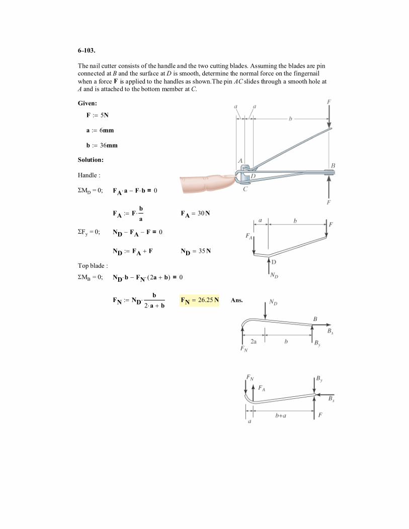
�$%.
The nail cutter consists of the handle and the two cutting blades. Assuming the blades are pin
connected at B and the surface at D is smooth, determine the normal force on the fingernail
when a force � is applied to the handles as shown.The pin AC slides through a smooth hole at
A and is attached to the bottom member at C.
������
� 5���
� 6����
� 36����
���������
Handle :
�MD = 0; � �� � ��� 0=
� ��
���� � 30��
�Fy = 0; �! � � �� 0=
�! � ���� �! 35��
Top blade :
�MB = 0; �! �� �� 2� ��( )�� 0=
�� �!�
2 �� ����� �� 26.25�� Ans.
–
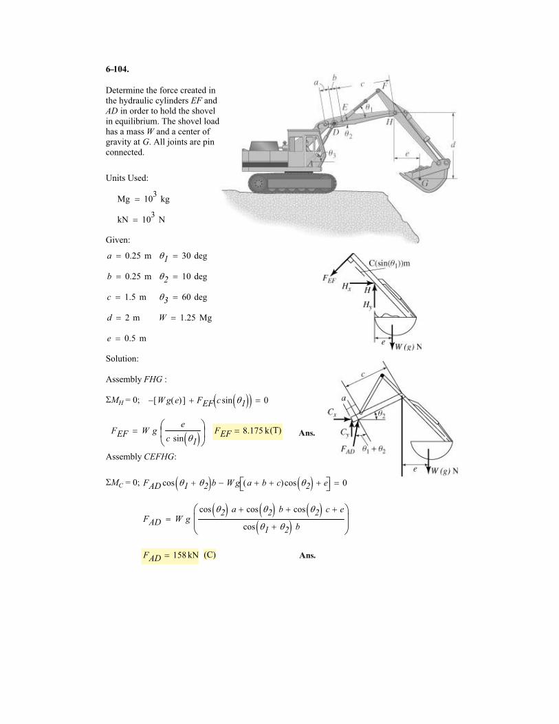
6 1
Determine the force created in
the hydraulic cylinders EF and
AD in order to hold the shovel
in equilibrium. The shovel load
has a mass W and a center of
gravity at G. All joints are pin
connected.
Units Used:
Mg 103
kg�
kN 103
N�
Given:
a 0.25 m� �1 30 deg�
b 0.25 m� �2 10 deg�
c 1.5 m� �3 60 deg�
d 2 m� W 1.25 Mg�
e 0.5 m�
Solution:
Assembly FHG :
�MH = 0; W g e( )[ ]� FEF c sin �1� �� �� 0�
FEF W ge
c sin �1� ��
��
� FEF 8.175 kN� (T)
Assembly CEFHG:
�MC = 0; FAD cos �1 �2�� �b W g a b� c�( )cos �2� � e��� ��� 0�
FAD W gcos �2� � a cos �2� � b� cos �2� � c� e�
cos �1 �2�� � b
�
��
�
FAD 158 kN� (C)
04.
Ans.
Ans.
–
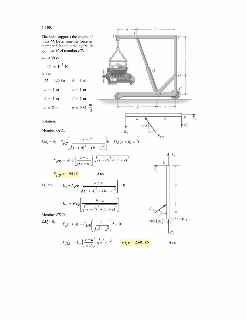
6 10
The hoist supports the engine of
mass M. Determine the force in
member DB and in the hydraulic
cylinder H of member FB.
Units Used:
kN 103
N�
Given:
M 125 kg� d 1 m�
a 1 m� e 1 m�
b 2 m� f 2 m�
c 2 m� g 9.81m
s2
�
Solution:
Member GFE:
�ME = 0; FFB�c d�
c d�( )2
b e�( )2
�
���
���
b M g a b�( )� 0�
FFB M ga b�
b c d�( )
���
���
c d�( )2
b e�( )2
��
FFB 1.94 kN�
�Fx = 0; Ex FFBb e�
c d�( )2
b e�( )2
�
���
���
� 0�
Ex FFBb e�
c d�( )2
b e�( )2
�
���
���
�
Member EDC:
��c = 0;Ex c d�( ) FDB
e
e2
d2
�
�
��
d� 0�
FDB Exc d�
e d
�
��
e2
d2
�� FDB 2.601 kN�
5.
Ans.
Ans.
–
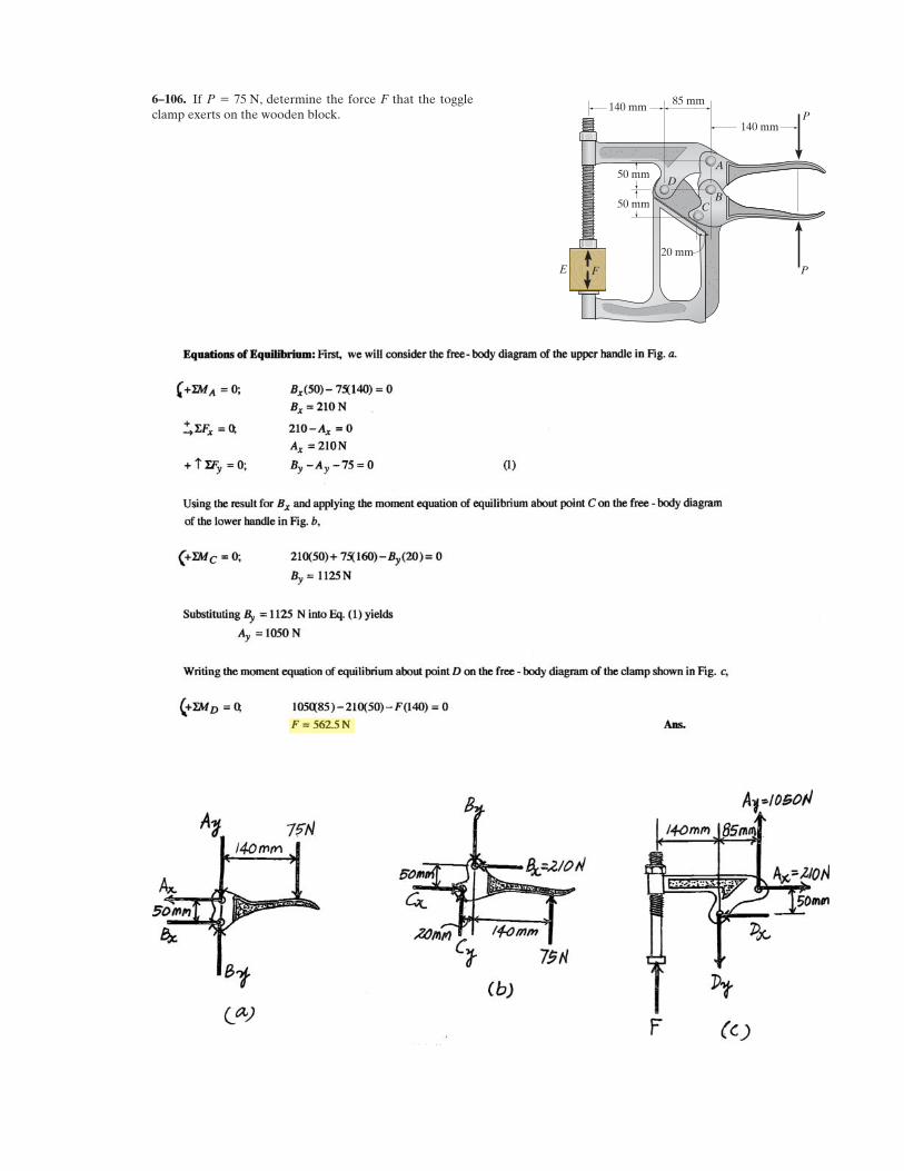
If , determine the force F that the toggleclamp exerts on the wooden block.
P = 75 N 85 mm140 mm
50 mm
50 mm
20 mm
140 mmP
P F
A
BC
D
E
6–106.
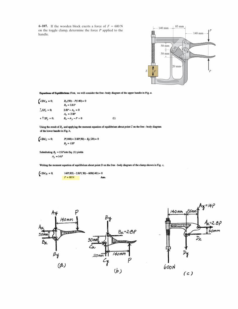
If the wooden block exerts a force of on the toggle clamp, determine the force P applied to thehandle.
F = 600 N 85 mm140 mm
50 mm
50 mm
20 mm
140 mmP
P F
A
BC
D
E
6–107.
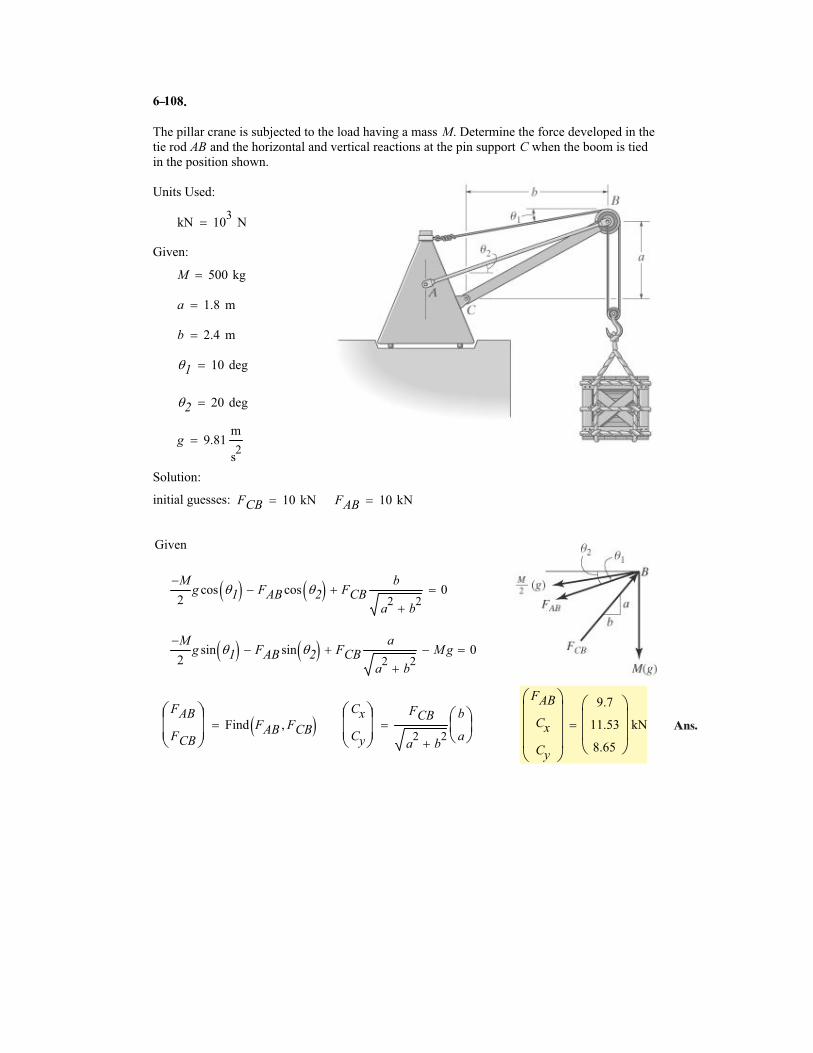
6 10
The pillar crane is subjected to the load having a mass M. Determine the force developed in the
tie rod AB and the horizontal and vertical reactions at the pin support C when the boom is tied
in the position shown.
Units Used:
kN 103
N�
Given:
M 500 kg�
a 1.8 m�
b 2.4 m�
�1 10 deg�
�2 20 deg�
g 9.81m
s2
�
Solution:
initial guesses: FCB 10 kN� FAB 10 kN�
Given
M�
2g cos �1� � FAB cos �2� �� FCB
b
a2
b2
�
� 0�
M�
2g sin �1� � FAB sin �2� �� FCB
a
a2
b2
�
� M g� 0�
FAB
FCB
�
���
Find FAB FCB�� ��Cx
Cy
�
���
FCB
a2
b2
�
b
a
���
�
FAB
Cx
Cy
�
����
9.7
11.53
8.65
�
���
kN�
8.
Ans.
–
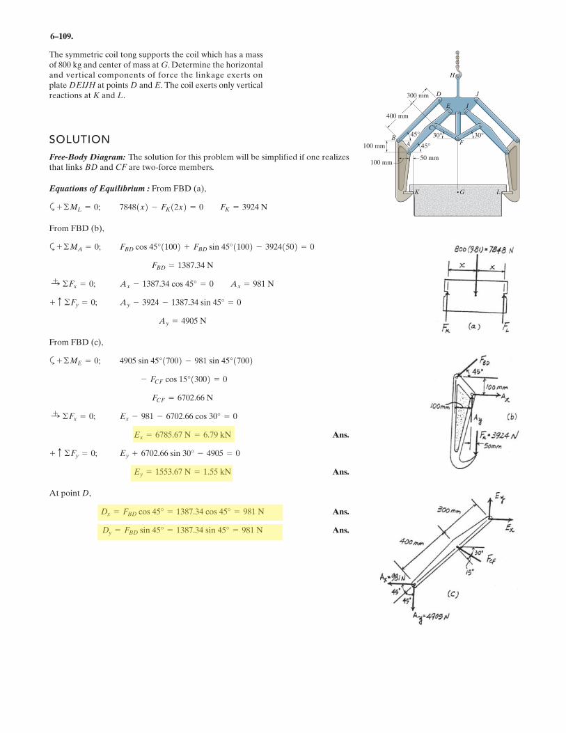
6–109.
SOLUTION
Free-Body Diagram: The solution for this problem will be simplified if one realizesthat links BD and CF are two-force members.
Equations of Equilibrium : From FBD (a),
a
From FBD (b),
a
From FBD (c),
a
Ans.
Ans.
At point D,
Ans.
Ans.Dy = FBD sin 45° = 1387.34 sin 45° = 981 N
Dx = FBD cos 45° = 1387.34 cos 45° = 981 N
Ey = 1553.67 N = 1.55 kN
Ey + 6702.66 sin 30° - 4905 = 0+ c ©Fy = 0;
Ex = 6785.67 N = 6.79 kN
Ex - 981 - 6702.66 cos 30° = 0:+ ©Fx = 0;
FCF = 6702.66 N
- FCF cos 15°13002 = 0
4905 sin 45°17002 - 981 sin 45°17002+ ©ME = 0;
Ay = 4905 N
Ay - 3924 - 1387.34 sin 45° = 0+ c ©Fy = 0;
Ax - 1387.34 cos 45° = 0 Ax = 981 N:+ ©Fx = 0;
FBD = 1387.34 N
FBD cos 45°11002 + FBD sin 45°11002 - 39241502 = 0+ ©MA = 0;
78481x2 - FK12x2 = 0 FK = 3924 N+ ©ML = 0;
The symmetric coil tong supports the coil which has a massof 800 kg and center of mass at G. Determine the horizontaland vertical components of force the linkage exerts on plate DEIJH at points D and E. The coil exerts only vertical reactions at K and L.
400 mm
45°
300 mm
45°
30° 30°
100 mm
100 mm50 mm
AB
C
D J
E I
H
G LK
F
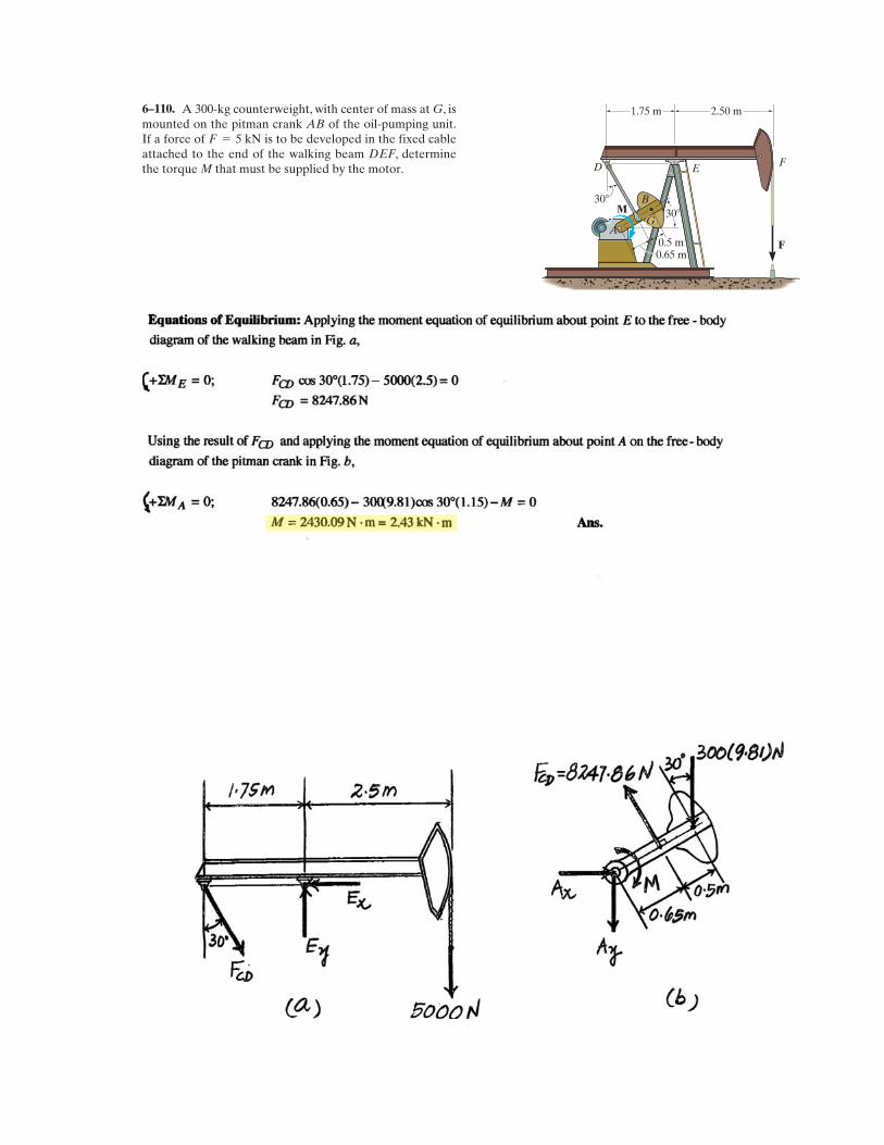
A 300-kg counterweight, with center of mass at G, ismounted on the pitman crank AB of the oil-pumping unit.If a force of is to be developed in the fixed cableattached to the end of the walking beam DEF, determinethe torque M that must be supplied by the motor.
F = 5 kN
A
BM
D EF
F0.5 m
30�
30�
1.75 m 2.50 m
G
0.65 m
6–110.
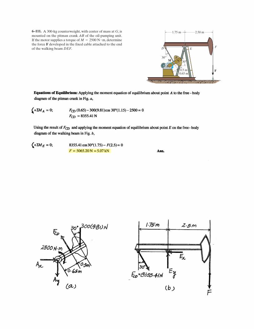
A 300-kg counterweight, with center of mass at G, ismounted on the pitman crank AB of the oil-pumping unit.If the motor supplies a torque of , determinethe force F developed in the fixed cable attached to the endof the walking beam DEF.
M = 2500 N # m
A
BM
D EF
F0.5 m
30�
30�
1.75 m 2.50 m
G
0.65 m
6–111.
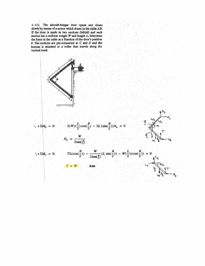
6–112.
.
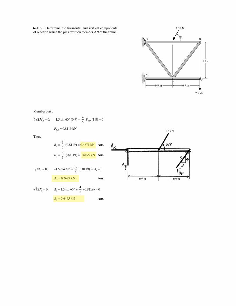
Determine the horizontal and vertical componentsof reaction which the pins exert on member AB of the frame.
A
E
B
CD
500 lb
300 lb
3 ft 3 ft
4 ft
60�
1.5 kN
0.9 m0.9 m
0.9 m 0.9 m
2.5 kN
1.5 kN
1.2 m
Member AB :
�
+ ΣMA = 0; –1.5 sin 60° (0.9) + 4
5 FBD (1.8) = 0
FBD = 0.8119 kN
Thus,
Bx = 3
5 (0.8119) = 0.4871 kN Ans.
By = 4
5 (0.8119) = 0.6495 kN Ans.
+→ ΣFx = 0; –1.5 cos 60° +
3
5 (0.8119) + Ax = 0
Ax = 0.2629 kN Ans.
+↑ΣFy = 0; Ay – 1.5 sin 60° + 4
5 (0.8119) = 0
Ay = 0.6495 kN Ans.
6–113.
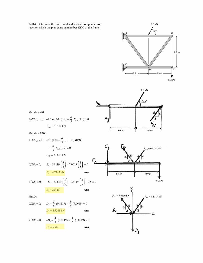
Determine the horizontal and vertical components ofreaction which the pins exert on member EDC of the frame.
A
E
B
CD
500 lb
300 lb
3 ft 3 ft
4 ft
60�
1.5 kN
0.9 m0.9 m
2.5 kN
1.2 m
0.9 m 0.9 m
1.5 kN
0.9 m 0.9 m
2.5 kN
FBD = 0.8119 kN
FBD = 0.8119 kNFAD = 7.0619 kN
Member AB :
�
+ ΣMA = 0; –1.5 sin 60° (0.9) + 4
5 FBD (1.8) = 0
FBD = 0.8119 kN
Member EDC :
�
+ ΣMg = 0; –2.5 (1.8) – 4
5 (0.8119) (0.9)
+ 4
5 FAD (0.9) = 0
FAD = 7.0619 kN
+→ ΣFx = 0; Ex – 0.8119
3
5
⎛
⎝⎜⎞
⎠ – 7.0619
3
5
⎛
⎝⎜⎞
⎠ = 0
Ex = 4.7243 kN Ans.
+↑ΣFy = 0; –Ey + 7.0619 4
5
⎛
⎝⎜⎞
⎠ – 0.8119
4
5
⎛
⎝⎜⎞
⎠ – 2.5 = 0
Ey = 2.5 kN Ans.
Pin D :
+→ ΣFx = 0; Dx –
3
5 (0.8119) –
3
5 (7.0619) = 0
Dx = 4.7243 kN Ans.
+↑ΣFy = 0; –Dy – 4
5 (0.8119) +
4
5 (7.0619) = 0
Dy = 5 kN Ans.
6–114.
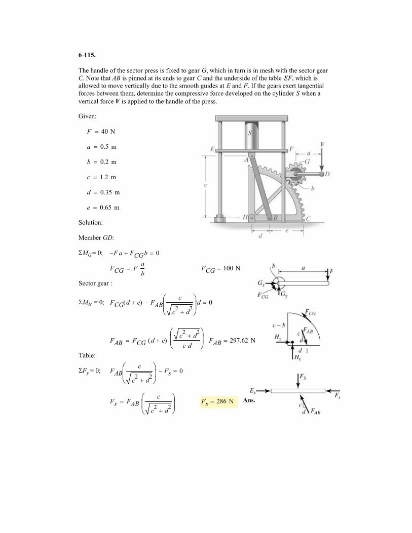
6 11
The handle of the sector press is fixed to gear G, which in turn is in mesh with the sector gear
C. Note that AB is pinned at its ends to gear C and the underside of the table EF, which is
allowed to move vertically due to the smooth guides at E and F. If the gears exert tangential
forces between them, determine the compressive force developed on the cylinder S when a
vertical force F is applied to the handle of the press.
Given:
F 40 N�
a 0.5 m�
b 0.2 m�
c 1.2 m�
d 0.35 m�
e 0.65 m�
Solution:
Member GD:
�MG = 0; F� a FCGb� 0�
FCG Fa
b� FCG 100 N�
Sector gear :
�MH = 0; FCG d e�( ) FABc
c2
d2
�
�
��
d� 0�
FAB FCG d e�( )c2
d2
�
c d
�
��
� FAB 297.62 N�
Table:
�Fy = 0; FABc
c2
d2
�
�
��
Fs� 0�
Fs FABc
c2
d2
�
�
��
� Fs 286 N�
5.
Ans.
–
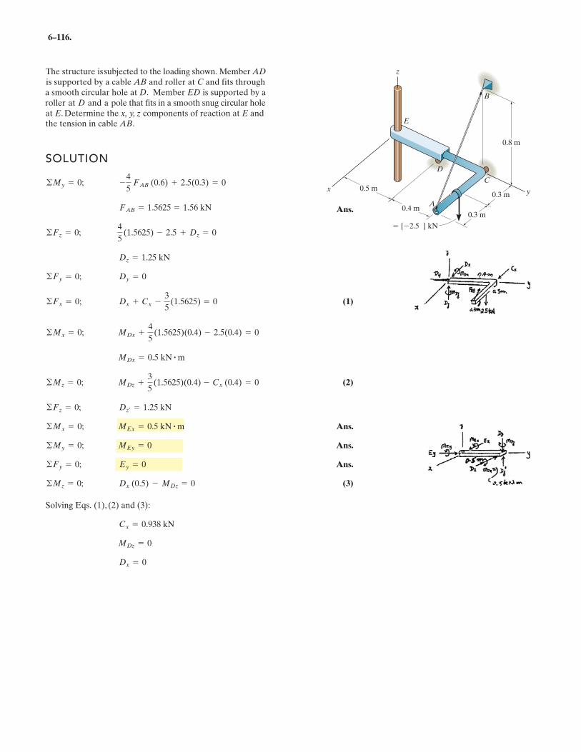
6–116.
SOLUTION
Ans.
(1)
(2)
Ans.
Ans.
Ans.
(3)
Solving Eqs. (1), (2) and (3):
©Fz = 0; 4
5(1.5625) - 2.5 + Dz = 0
Dx = 0
MDz = 0
Cx = 0.938 kN
©Mz = 0; Dx (0.5) - MDz = 0
©Fy = 0; Ey = 0
©My = 0; MEy = 0
©Mx = 0; MEx = 0.5 kN # m
©Fz = 0; Dz¿ = 1.25 kN
©Mz = 0; MDz +3
5(1.5625)(0.4) - Cx (0.4) = 0
MDx = 0.5 kN # m
©Mx = 0; MDx +4
5(1.5625)(0.4) - 2.5(0.4) = 0
©Fx = 0; Dx + Cx -3
5(1.5625) = 0
©Fy = 0; Dy = 0
Dz = 1.25 kN
FAB = 1.5625 = 1.56 kN
©My = 0; -4
5 FAB (0.6) + 2.5(0.3) = 0
The structure is subjected to the loading shown. Member AD
is supported by a cable AB and roller at C and fits through a smooth circular hole at D. Member ED is supported by a roller at D and a pole that fits in a smooth snug circular hole at E. Determine the x, y, z components of reaction at E and the tension in cable AB.
z
C
A
D
B
E
0.3 m y
0.3 m
0.5 m
0.4 m
{ 2.5 } kN
x
0.8 m
Ans.
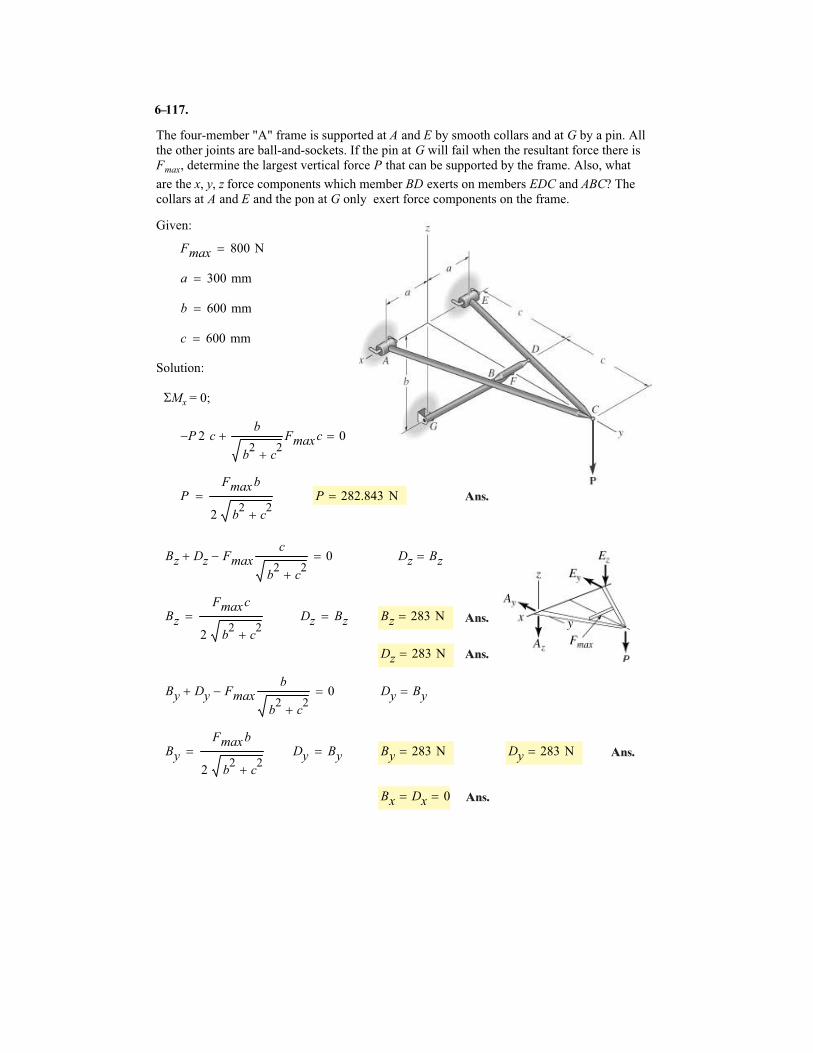
The four-member "A" frame is supported at A and E by smooth collars and at G by a pin. All
the other joints are ball-and-sockets. If the pin at G will fail when the resultant force there is
Fmax, determine the largest vertical force P that can be supported by the frame. Also, what
are the x, y, z force components which member BD exerts on members EDC and ABC? The
collars at A and E and the pon at G only exert force components on the frame.
Given:
Fmax 800 N�
a 300 mm�
b 600 mm�
c 600 mm�
Solution:
�Mx = 0;
P� 2 cb
b2
c2
�
Fmaxc� 0�
PFmaxb
2 b2
c2
�
� P 282.843 N�
Bz Dz� Fmaxc
b2
c2
�
� 0� Dz Bz�
Bz
Fmaxc
2 b2
c2
�
� Dz Bz� Bz 283 N�
Dz 283 N�
By Dy� Fmaxb
b2
c2
�
� 0� Dy By�
By
Fmaxb
2 b2
c2
�
� Dy By� By 283 N� Dy 283 N�
Bx Dx� 0�
6 117.
Ans.
Ans.
Ans.
Ans.
Ans.
–
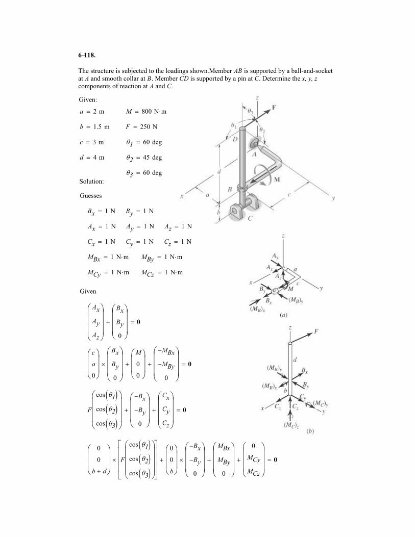
6 1
The structure is subjected to the loadings shown.Member AB is supported by a ball-and-socket
at A and smooth collar at B. Member CD is supported by a pin at C. Determine the x, y, zcomponents of reaction at A and C.
Given:
a 2 m� M 800 N m��
b 1.5 m� F 250 N�
c 3 m� �1 60 deg�
d 4 m� �2 45 deg�
�3 60 deg�Solution:
Guesses
Bx 1 N� By 1 N�
Ax 1 N� Ay 1 N� Az 1 N�
Cx 1 N� Cy 1 N� Cz 1 N�
MBx 1 N m�� MBy 1 N m��
MCy 1 N m�� MCz 1 N m��
Given
Ax
Ay
Az
�
����
Bx
By
0
�
����
� 0�
c
a
0
�
���
Bx
By
0
�
����
�
M
0
0
�
���
�
MBx�
MBy�
0
�
����
� 0�
F
cos �1� �cos �2� �cos �3� �
�
����
Bx�
By�
0
�
����
�
Cx
Cy
Cz
�
����
� 0�
0
0
b d�
�
���
F
cos �1� �cos �2� �cos �3� �
�
����
�����
�����
�
0
0
b
�
���
Bx�
By�
0
�
����
��
MBx
MBy
0
�
����
�
0
MCy
MCz
�
����
� 0�
18.–
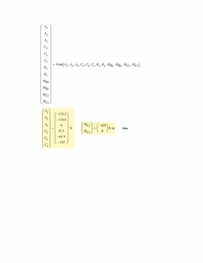
Ax
Ay
Az
Cx
Cy
Cz
Bx
By
MBx
MBy
MCy
MCz
�
��������������������
Find Ax Ay� Az� Cx� Cy� Cz� Bx� By� MBx� MBy� MCy� MCz�� ��
Ax
Ay
Az
Cx
Cy
Cz
�
���������
172.3�
114.8�
0
47.3
61.9�
125�
�
��������
N�MCy
MCz
�
���
429�
0
�
��
N m�� Ans.
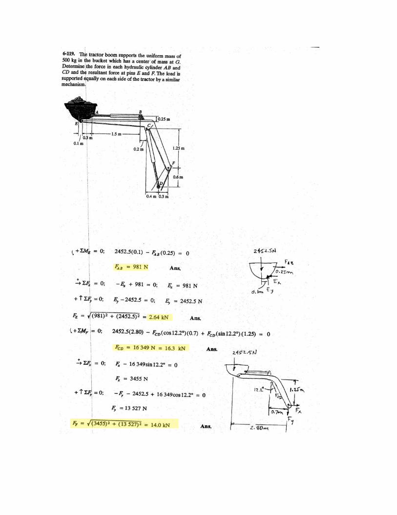
.
.
.
.
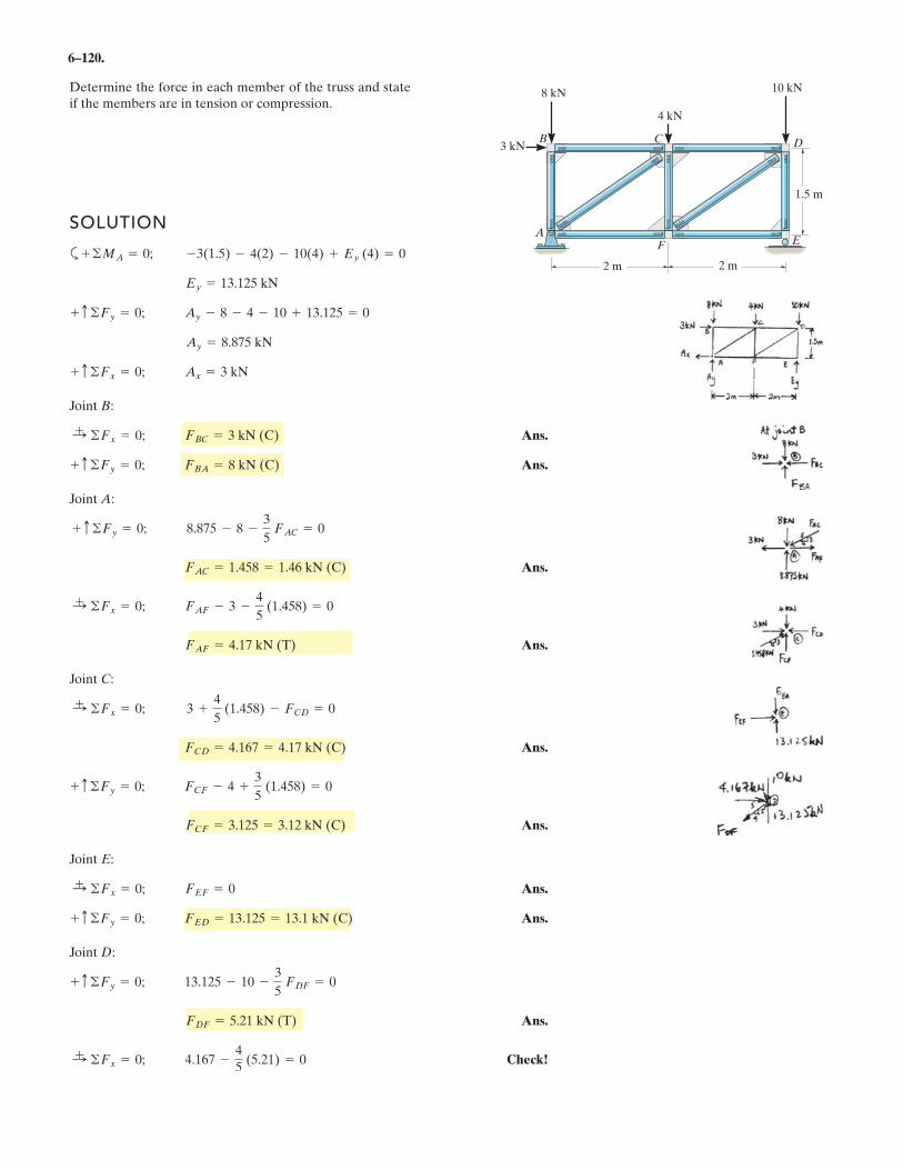
6–120.
Determine the force in each member of the truss and stateif the members are in tension or compression.
SOLUTION
a
Joint B:
Ans.
Ans.
Joint A:
Ans.
Ans.
Joint C:
Ans.
Ans.
Joint E:
Ans.
Ans.
Joint D:
Ans.
Check!:+ ©Fx = 0; 4.167 -
4
5(5.21) = 0
FDF = 5.21 kN (T)
+ c ©Fy = 0; 13.125 - 10 -3
5FDF = 0
+ c ©Fy = 0; FED = 13.125 = 13.1 kN (C)
:+ ©Fx = 0; FEF = 0
FCF = 3.125 = 3.12 kN (C)
+ c ©Fy = 0; FCF - 4 +3
5(1.458) = 0
FCD = 4.167 = 4.17 kN (C)
:+ ©Fx = 0; 3 +
4
5(1.458) - FCD = 0
FAF = 4.17 kN (T)
:+ ©Fx = 0; FAF - 3 -
4
5(1.458) = 0
FAC = 1.458 = 1.46 kN (C)
+ c ©Fy = 0; 8.875 - 8 -3
5FAC = 0
+ c ©Fy = 0; FBA = 8 kN (C)
:+ ©Fx = 0; FBC = 3 kN (C)
+ c ©Fx = 0; Ax = 3 kN
Ay = 8.875 kN
+ c ©Fy = 0; Ay - 8 - 4 - 10 + 13.125 = 0
Ey = 13.125 kN
+ ©MA = 0; -3(1.5) - 4(2) - 10(4) + Ey (4) = 02 m
1.5 m
2 m
4 kN
FA
8 kN 10 kN
3 kN
E
DCB
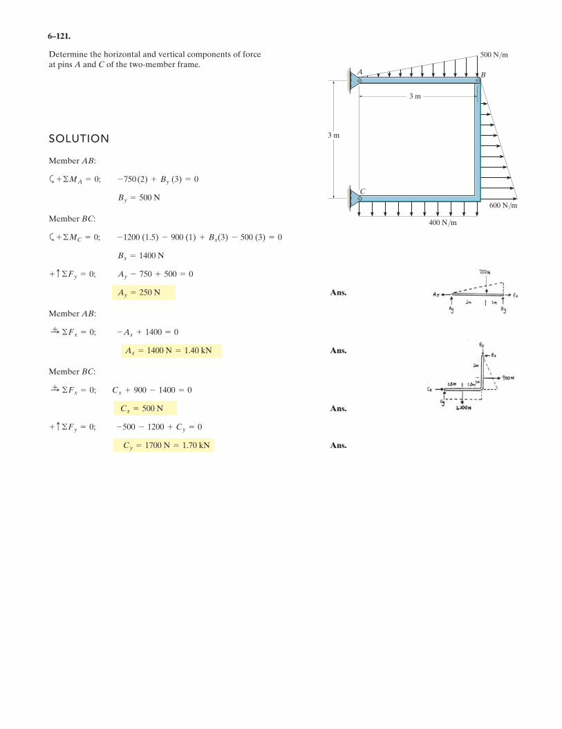
6–121.
Determine the horizontal and vertical components of forceat pins A and C of the two-member frame.
3 m
3 m
500 N/m
600 N/m
400 N/m
A B
C
SOLUTION
Member AB:
a
Member BC:
a
Ans.
Member AB:
Ans.
Member BC:
Ans.
Ans.Cy = 1700 N = 1.70 kN
+ c ©Fy = 0; -500 - 1200 + Cy = 0
Cx = 500 N
:+ ©Fx = 0; Cx + 900 - 1400 = 0
Ax = 1400 N = 1.40 kN
:+ ©Fx = 0; -Ax + 1400 = 0
Ay = 250 N
+ c ©Fy = 0; Ay - 750 + 500 = 0
Bx = 1400 N
+ ©MC = 0; -1200 (1.5) - 900 (1) + Bx(3) - 500 (3) = 0
By = 500 N
+ ©MA = 0; -750(2) + By (3) = 0
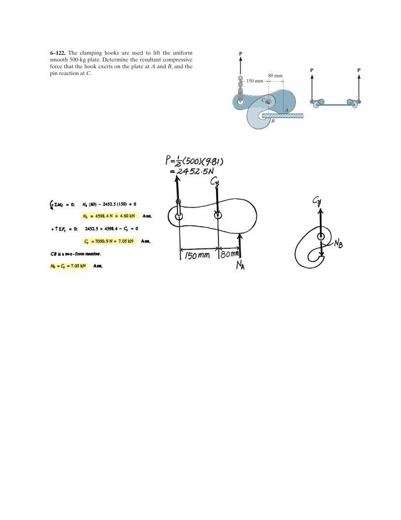
The clamping hooks are used to lift the uniformsmooth 500-kg plate. Determine the resultant compressiveforce that the hook exerts on the plate at A and B, and thepin reaction at C.
A
B
80 mm
P
P P
150 mm
C
6–122.
.
.
.
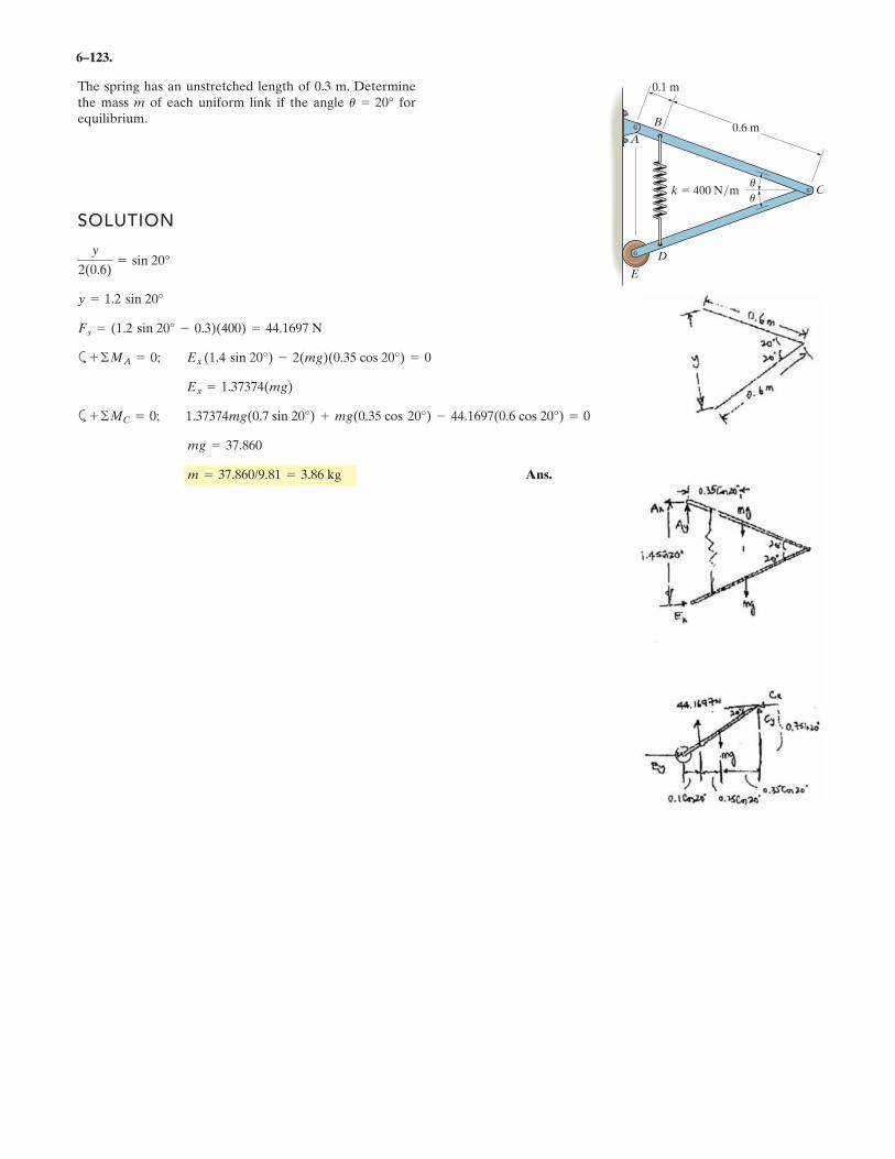
6–123.
The spring has an unstretched length of 0.3 m. Determinethe mass m of each uniform link if the angle forequilibrium.
u = 20°
0.6 m
k 400 N/m
D
E
A
B
C
0.1 m
u
u
SOLUTION
a
a
Ans.m = 37.860/9.81 = 3.86 kg
mg = 37.860
+ ©MC = 0; 1.37374mg(0.7 sin 20°) + mg(0.35 cos 20°) - 44.1697(0.6 cos 20°) = 0
Ex = 1.37374(mg)
+ ©MA = 0; Ex (1.4 sin 20°) - 2(mg)(0.35 cos 20°) = 0
Fs = (1.2 sin 20° - 0.3)(400) = 44.1697 N
y = 1.2 sin 20°
y
2(0.6)= sin 20°
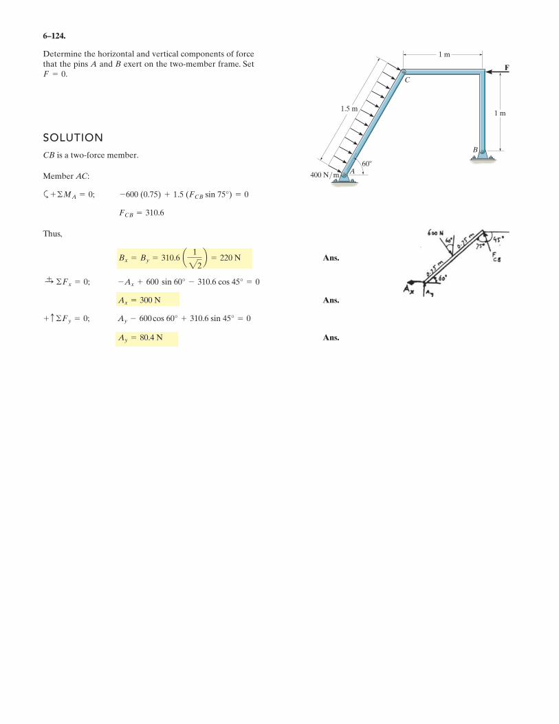
6–124.
Determine the horizontal and vertical components of forcethat the pins A and B exert on the two-member frame. SetF = 0.
1.5 m
400 N/ m
60
1 m
1 m
B
C
A
F
SOLUTION
CB is a two-force member.
Member AC:
a
Thus,
Ans.
Ans.
Ans.
+ c ©Fy = 0; Ay - 600 cos 60° + 310.6 sin 45° = 0
Ax = 300 N
Ay = 80.4 N
:+ ©Fx = 0; -Ax + 600 sin 60° - 310.6 cos 45° = 0
Bx = By = 310.6 a 1
22b = 220 N
FCB = 310.6
+ ©MA = 0; -600 (0.75) + 1.5 (FCB sin 75°) = 0
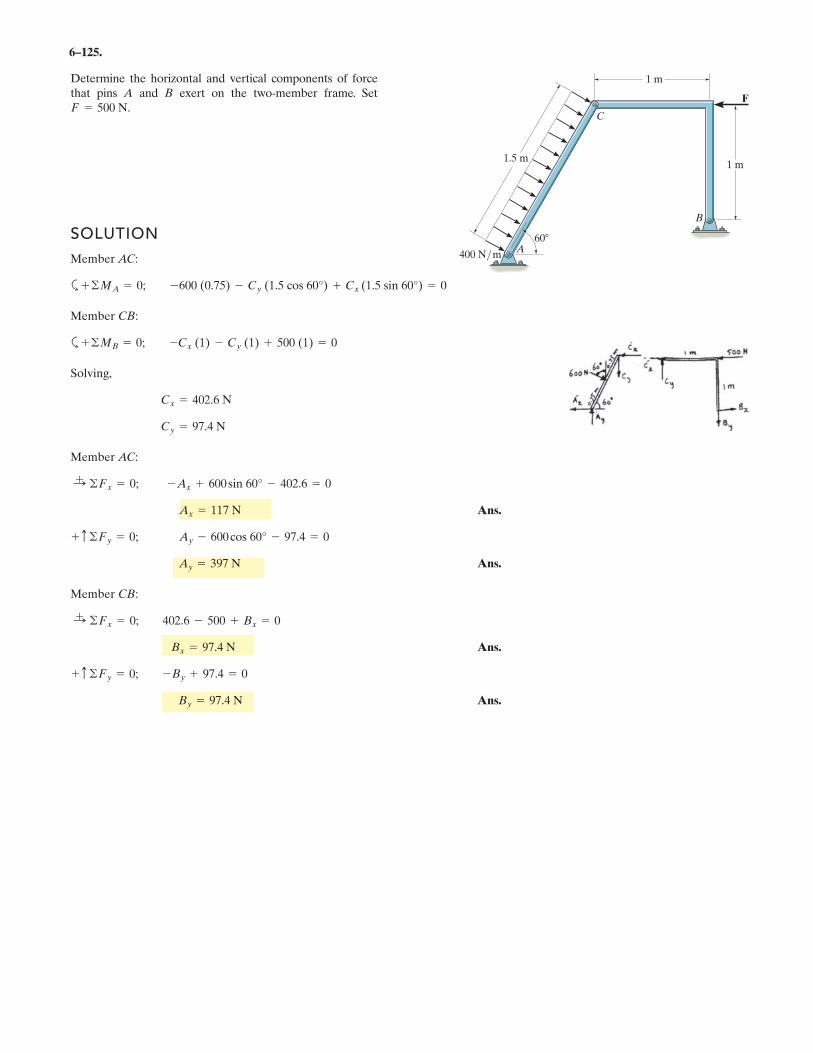
6–125.
Determine the horizontal and vertical components of forcethat pins A and B exert on the two-member frame. SetF = 500 N.
1.5 m
400 N/ m
60
1 m
1 m
B
C
A
F
SOLUTION
Member AC:
a
Member CB:
a
Solving,
Member AC:
Ans.
Ans.
Member CB:
Ans.
Ans.By = 97.4 N
+ c ©Fy = 0; -By + 97.4 = 0
Bx = 97.4 N
:+ ©Fx = 0; 402.6 - 500 + Bx = 0
Ay = 397 N
+ c ©Fy = 0; Ay - 600cos 60° - 97.4 = 0
Ax = 117 N
:+ ©Fx = 0; -Ax + 600sin 60° - 402.6 = 0
Cy = 97.4 N
Cx = 402.6 N
+ ©MB = 0; -Cx (1) - Cy (1) + 500 (1) = 0
+ ©MA = 0; -600 (0.75) - Cy (1.5 cos 60°) + Cx (1.5 sin 60°) = 0
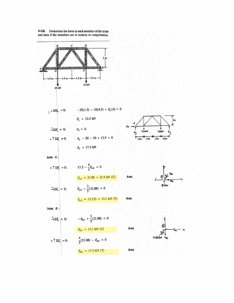
.
.
.
.
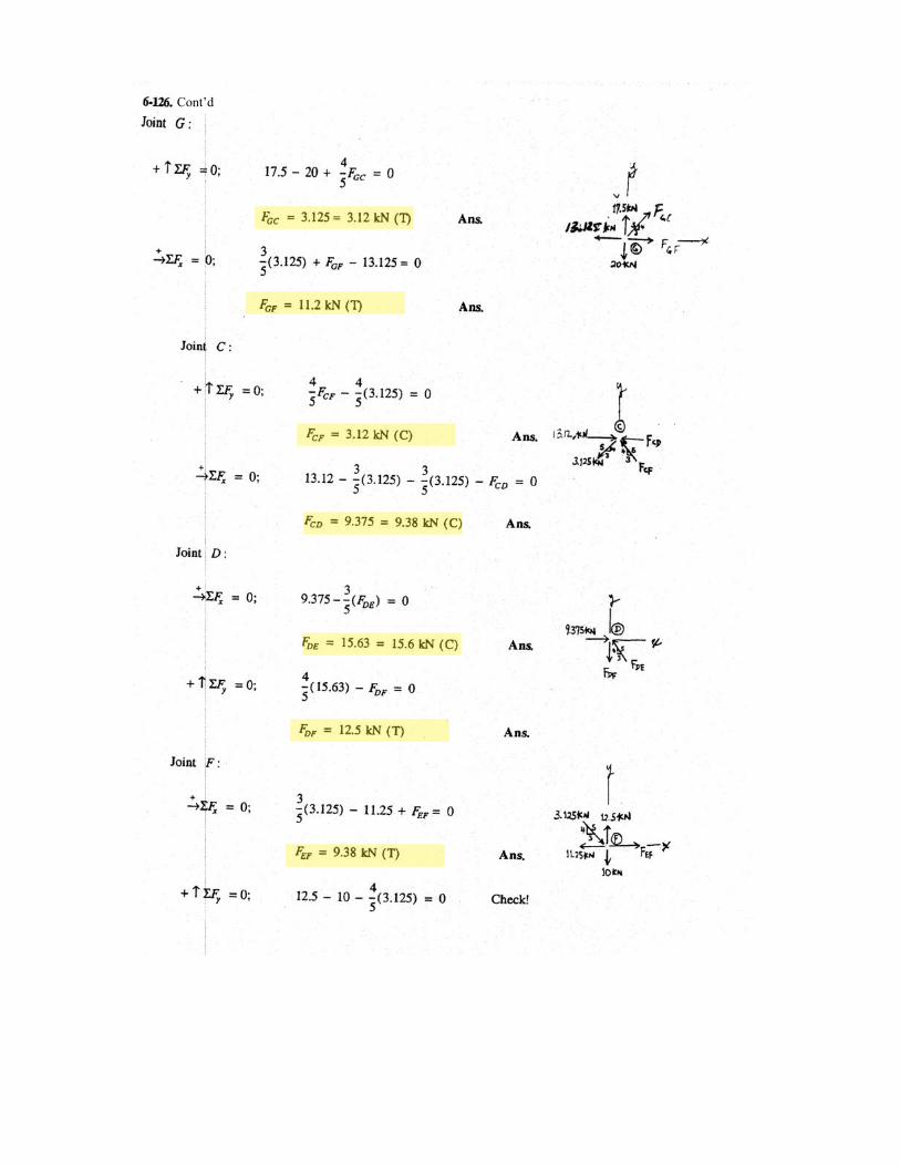
Cont’d
.
.
.
.
.
.
.


![[ACADEMIC] Mathcad - FTW drive calculations.xmcd](https://img.pdfslide.net/doc/110x75/631704bd1e5d335f8d0a3781/academic-mathcad-ftw-drive-calculationsxmcd.jpg)

![[ACADEMIC] Mathcad - PTC Community](https://img.pdfslide.net/doc/110x75/631772a4f68b807f8803a3e0/academic-mathcad-ptc-community.jpg)