Embed Size (px)
Citation preview
MCS-4000USERS MANUAL
(Red text indicates object links. Clicking on the text takes you to that portion of the manual.)
INDEX
SECTION 1 Page
INTRODUCTION 3INSTALLATION
Location/Mounting 9Transformer 10Grounding 10Local I/O Bus 10Global w/Com-5002 10Sensors & Accessories 11Relay-8 11Digital Input-8 11Analog Input-8 or 16 11Analog Out-4 13RTU Board 13Singles Board 13CIO Board 13Pulse Modulated Output Board 13
BASIC INFORMATION & OPERATIONSGetting Started 14Keypads 14Activating the Display 14Adjusting the Display Viewing Angle 15Screen Layout 15Help 15Setup 15Passwords 16Changing a Sensor Type 16Board Numbering System - Addressing 17Setting Board Types 18I/O Assignment 18I/O Overrides 19Analog Offsets 20Inversion 20Alarms 21Setting the Clock 22Setting the MCS-4000 Address Switch 22Configuring the System 22
1
MCS-4000USERS MANUALINDEX (CONT.)
USING THE SYSTEM PageTask Status 23Summaries 26Alarm History 29Runtime History 30Graphs 30Task Settings 31
Task Setpoints 31Analog Alarms 32Digital Alarms 33Float Assignments 34Float Limits 35Setup Menu 36I/O Menu 36Board Status 37Schedules 37Run/Stop/Monitor 40
Miscellaneous 40Set-up Graphs 41Graph Interval 42Alarm Enables 42Defrost Time Map 43
Schedule Overrides 44Emergency Defrost 44
SECTION 2MCS-4000 SETUP
Introduction 1Tasks Common to All Libraries 1Rack Library 2HVAC Library 2SNGL Library 3CSTR Library 3
Tasks Common to All LibrariesAnti-Sweat Group 3Lighting Group 8Unit Heater/Exhaust Fans 13Options Tasks 18
AI Monitor Task 25DI Monitor Task 26RO On Rise Task 27
2
MCS-4000USERS MANUAL
INDEX (CONT.) Page
Options Tasks (cont.)RO On Fall Task 29RO and DI Task 31Analog Out Task 32Subcooler Task 34Desuperheater Task 35Surge Valve Task 35Crossover Valve Task 35Freon Sniffer Task 36Assorted Options Tasks 36
Rack LibraryCompressor Group 39Condenser Fans 49Temp/Defr 55Satellite Compressor 62Single Compressor 67
HVAC LibraryLarge/Central Packages 68RTU/Small Packages 87
SNGL (Singles) LibrarySingles Group 95
CSTR Library 105
SECTION 3APPENDIX
DrawingsMCS-4000 Front Panel 1MCS-4000 Processor Board 2Relay Output Board 3Digital Input Board 4
Analog Input Board AI-16 5Analog/Digital Input Board AI-16/DI-8 6CIO Board 7RTUBoard 8Singles Board 9Pulse Modulated Output Board 10
Definition of Terms 11
3
MCS-4000MULTI-FUNCTION CONTROL SYSTEM
USERS MANUAL10/06/98
INTRODUCTION
The MCS-4000, or 4K, is a microprocessor based control system that may be used for awide variety of control applications. Its particular application is defined by thesoftware/firmware, called an algorithm library that is installed in the basic controller.There are currently 3 libraries that deal with supermarket & refrigerated warehousecontrol applications including compression systems, circuit control (temperature anddefrost), condensers, HVAC, TOD scheduling, and miscellaneous. A fourth library isavailable for drug store or C-Store applications, where simple compressor control,lighting and HVAC are required.
One 4K may be used to control the complete operation of a Rack, or single Condensingunit, or HVAC and Lighting. The MCS-4000 is capable of performing 50 assignabletasks. A task is a defined unit of control. Any single task can have a maximum of 12relay outputs, 12 digital inputs, 12 analog inputs, and 4 analog outputs. An example ofa task, is the control of one refrigeration circuit. This task would include the defrostrelay, temperature control relay, control temperature (analog) inputs, terminationtemperature inputs or digital inputs and appropriate alarm indicators. Thus, while alarge number of I/O points could be used to control this single circuit, it is onlyconsidered as one task to the controller, giving the MCS-4000 sufficient capacity tohandle even the largest refrigeration racks.
The MCS-4000 may be used in a totally stand-alone environment or multiple 4K's maybe connected to a COM-5002 Communications Controller or to the 6000 Advantagecolor touch screen MMI (man machine interface) via the high speed COM-NET globalbus providing complete centralized local and remote communications. The COM-5002or 6000 is also necessary to pass information between multiple 4K's, to interface withthe PMA (pulse meter adapter) which
handles up to eight utility meter pulses, and for the custom 25 character descriptionsassociated with each I/O point. The 6000 Advantage provides many other features.See the 6000 Manual for more information.
The I/O (input/output) is fully distributed. That is, the I/O boards may be located up to5000 feet from the 4K controller. The I/O boards are connected to the 4K by the
4
RS-485 high speed Local Bus with a 3-conductor cable. There are 10 types ofinput/output boards of various configurations including 3 combination boards.
The 4K can support up to 16 relay board addresses, 16 analog addresses, 16 digitalboard addresses, and 16 analog output board addresses as the long as the total pointcount does not exceed the following rules:
Relays Digital Inputs Analog Inputs Analog Outputs 63 63 127* 31
* There are ten analog inputs that are always assumed to be present whether used ornot. They are called global inputs. They are included in the 127 total. They are: headpressure, intermediate pressure, ambient temp, liquid temp, drop leg temp, low gas (AI),light level #1, dew point/relative humidity, and 2 spares.
There are also 32 local transfer points: used to pass computed values within a 4K, and32 global transfer points: used to transfer inputs between 4K's over the global bus.
The 4K utilizes a 16 line x 42 character back-lit LCD display and a unique keypadarrangement that takes system set-up, programming, and interrogation to anunprecedented level of ease. This controller is truly EZ-SET. The large LCD display,two to four times larger than competitive systems, makes it possible to displaysignificantly more data without having to move to additional screens, and graphs havegreater resolution. The LCD back-light is equipped with an automatic time-out feature,to pro-long the life of the display. After 15 minutes of no usage, the back-light turns off;touching any key, except Cancel, will turn it back on.
The keypad design is actually made up of two keypads. There are 14 keys, 7 on eachside of the LCD display, that are visually connected with lines on the overlay to 14 of theLCD display lines; similar to the concept used in banking ATM's. Then, there is asecond keypad below the screen with 20 keys for numbers, cursor movement, etc. Thecombination of these two keypads with the display software produces a simple, flexible,and very powerful user interface. The system is set-up/configured by answering aseries of questions with choices that can be selected by pressing the appropriate key atthe side of the display.
Note: With the 6000 Advantage, the 4K's may be ordered without their displays andkeypads if desired.
The system contains built-in refrigerant temperature/pressure tables, set points, andstandard names for most of the normal supermarket fixtures and refrigeration systems.Thus, the 4K can automatically furnish about 90% of the necessary set-pointparameters based upon the answers supplied to a few questions. The user then has toenter or modify only a few set-points to suit the specific application. I/O points may beautomatically or manually assigned. The 4K thus greatly simplifies and speeds-up theset-up and programming process typically experienced in other controllers.
5
The 4K also features a built-in manual that is accessed from any screen by pressing theHELP key. This is another feature that separates it from other systems. If the userdoesn't understand a particular screen or question, simply pressing the HELP keyprovides the explanation. The documentation is always at hand, it can't "walk away".
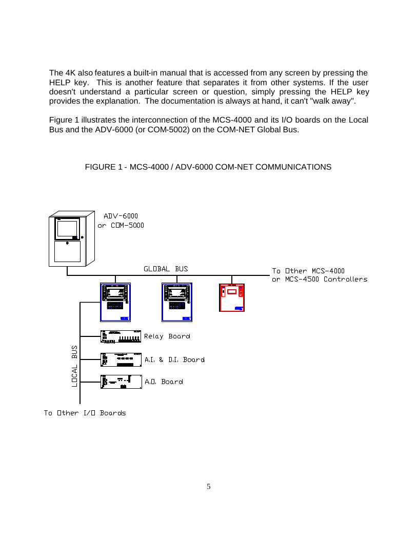
Figure 1 illustrates the interconnection of the MCS-4000 and its I/O boards on the LocalBus and the ADV-6000 (or COM-5002) on the COM-NET Global Bus.
FIGURE 1 - MCS-4000 / ADV-6000 COM-NET COMMUNICATIONS
6
The CPU board utilizes a Hitachi 64180 microprocessor running at 6 MHz. 256K ofEPROM is provided for program storage and 256K of battery backed ram for temporarydata storage. It has two communications ports; the local I/O bus (RS-485 @ 19.2Kbaud) and the Global COM-NET communications bus (RS-485 @ 38.4 Kbaud ). Areset switch is provided to re-boot the system.
Two alarm outputs are provided to drive a remote audible (SONALERT) alarm, and avisual alarm (flashing light). One alarm input is provided for remote silencing of theaudible output.
Power requirements are 1 amp @ 115/230 volts AC (fused, user selectable) at 50/60Hz. The environmental limitations are 32 F to 148 F, 95 % RH non-condensing for theCPU. This range is limited by the LCD display; below these temperatures, the LCDblinking speed will decrease, and ultimate failure may occur; above these temperatures,it will turn black. When the temperature drops below the upper limit, the display willoperate normally. The I/O boards are rated from -40 F to 150 F.
The transformer/terminations module is located in the rear section of the enclosure (oris provided separately). Connections are provided for 230/115 VAC. The MCS-4000will operate over a voltage range of 90 volts to 245 volts. Varistors are provided forsurge suppression. An additional terminal block is provided for field wiring connectionsfor the alarm outputs/inputs, and for the local and global buses.
A dip switch is located on the CPU board to set the 4000 controller address and otheroptions.
The viewing angle of the display may also be adjusted with a potentiometer located atthe left side of the CPU board.
The MCS-4000 is mounted in a 10.25 x 12 x 4.5 in. metal enclosure with a locking door.It weighs 6 lbs. The MCS-4000 can also be purchased on a surface mount frame,without the enclosure, or in a 2.5" deep enclosure, for OEM mounting in existingcabinets. These configurations are provided with a cable harness, 10 feet in length,with connectors at one end, and a transformer that may be mounted where convenientin the OEM cabinet.
There are 10 types of I/O boards available for the MCS-4000; relay output, digital input,analog/digital input 8 or 16, analog output, analog input 16 with 8 digital inputs, a specialHVAC RTU board, a singles condensing unit board, a CIO (combination input/output)board, and a pulse/solid state relay driver board. They are connected to the 4000 bythe local RS-485 bus, which is a 2 wire plus ground cable, that may be run in star ordaisy chain fashion. The I/O boards can be located as much as 5,000 feet from theMCS-4000. Each board has a 16 position rotary switch that is used to set the boardaddress. Each board has a RED LED that indicates when the local bus is transmitting
7
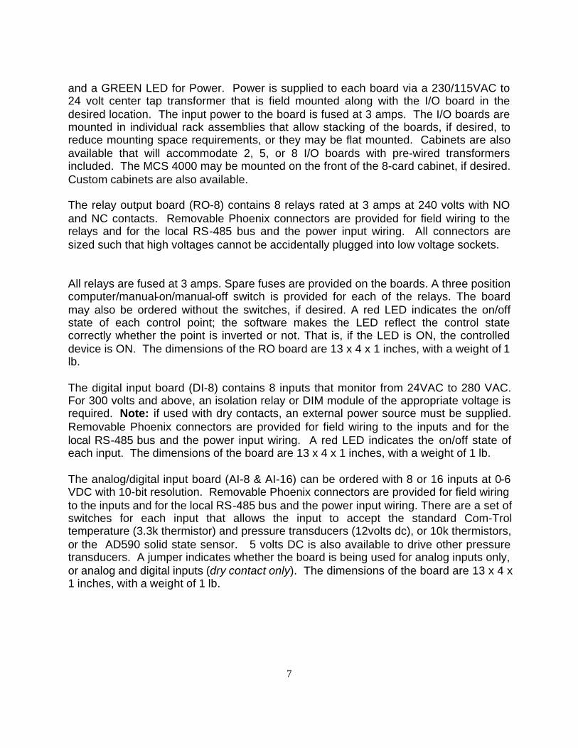
and a GREEN LED for Power. Power is supplied to each board via a 230/115VAC to24 volt center tap transformer that is field mounted along with the I/O board in thedesired location. The input power to the board is fused at 3 amps. The I/O boards aremounted in individual rack assemblies that allow stacking of the boards, if desired, toreduce mounting space requirements, or they may be flat mounted. Cabinets are alsoavailable that will accommodate 2, 5, or 8 I/O boards with pre-wired transformersincluded. The MCS 4000 may be mounted on the front of the 8-card cabinet, if desired.Custom cabinets are also available.
The relay output board (RO-8) contains 8 relays rated at 3 amps at 240 volts with NOand NC contacts. Removable Phoenix connectors are provided for field wiring to therelays and for the local RS-485 bus and the power input wiring. All connectors aresized such that high voltages cannot be accidentally plugged into low voltage sockets.
All relays are fused at 3 amps. Spare fuses are provided on the boards. A three positioncomputer/manual-on/manual-off switch is provided for each of the relays. The boardmay also be ordered without the switches, if desired. A red LED indicates the on/offstate of each control point; the software makes the LED reflect the control statecorrectly whether the point is inverted or not. That is, if the LED is ON, the controlleddevice is ON. The dimensions of the RO board are 13 x 4 x 1 inches, with a weight of 1lb.
The digital input board (DI-8) contains 8 inputs that monitor from 24VAC to 280 VAC.For 300 volts and above, an isolation relay or DIM module of the appropriate voltage isrequired. Note: if used with dry contacts, an external power source must be supplied.Removable Phoenix connectors are provided for field wiring to the inputs and for thelocal RS-485 bus and the power input wiring. A red LED indicates the on/off state ofeach input. The dimensions of the board are 13 x 4 x 1 inches, with a weight of 1 lb.
The analog/digital input board (AI-8 & AI-16) can be ordered with 8 or 16 inputs at 0-6VDC with 10-bit resolution. Removable Phoenix connectors are provided for field wiringto the inputs and for the local RS-485 bus and the power input wiring. There are a set ofswitches for each input that allows the input to accept the standard Com-Troltemperature (3.3k thermistor) and pressure transducers (12volts dc), or 10k thermistors,or the AD590 solid state sensor. 5 volts DC is also available to drive other pressuretransducers. A jumper indicates whether the board is being used for analog inputs only,or analog and digital inputs (dry contact only). The dimensions of the board are 13 x 4 x1 inches, with a weight of 1 lb.

8
The combination analog and digital input board (AI-16/DI-8) has the same analogcapabilities as stated above with 16 inputs, but the 8 digital inputs are dry contact only,with the board supplying the necessary voltage. It has the same physicalcharacteristics as the other boards. Analog inputs on this board may not be used fordry contact DI's due to addressing conflicts.
The analog output board (AO-4) contains 4 outputs, with 8-bit resolution, of 0 to 5, 0 to10, 0 to 15 and 0 to 20 VDC, jumper selectable for each output. Removable Phoenixconnectors are provided for field wiring to the inputs and for the local RS-485 bus andthe power input wiring. The dimensions of the board are 13 x 4 x 1 inches, with aweight of 1 lb.
The RTU board contains 6 relay outputs for a fan, 2 cool, 2 heat, and 1 damper. It has1 analog output for modulating dampers. It has 8 inputs for analog/digital inputs such aszone, outside, supply air, and return air temperatures or digital inputs such as airflow/fan proof. This board is normally used for the small RTU selection in the HVACalgorithm library but may be used for other applications as appropriate. It has the samephysical characteristics as the other boards.
The Singles board has 4 relay outputs, 4 digital inputs (same characteristics as DI-8board), and 8 analog inputs. It has the same physical characteristics as the otherboards.
The CIO board has 8 relay outputs that are individually jumper selectable for normallyopen or normally closed operation. It has 8 inputs that may be used for analog or digitalinputs (dry contact) as explained previously. Physical characteristics are the same asfor all other I/O boards.
The Pulse/Solid State Relay Driver board has four outputs that can drive solid staterelays for pulsed output applications such as anti-sweat heaters or pulse type expansionvalves. Up to ten solid state relays can be driven off of each output. Physicalcharacteristics are the same as for all other I/O boards.
The MCS-4000 is UL listed/recognized and its I/O boards are UL recognized. Italso has CSA approval.
9
INSTALLATION
An MCS-4000 Installation Manual is available and should be used in conjunction withthe following information to achieve the best results.
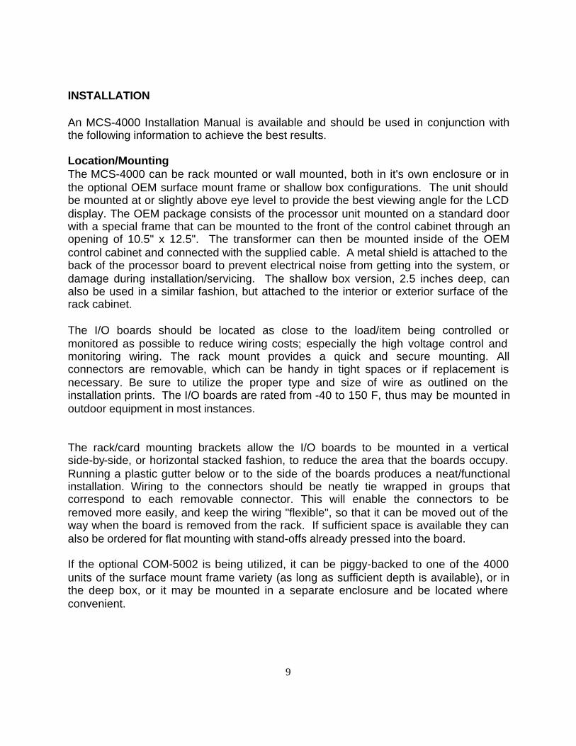
Location/MountingThe MCS-4000 can be rack mounted or wall mounted, both in it's own enclosure or inthe optional OEM surface mount frame or shallow box configurations. The unit shouldbe mounted at or slightly above eye level to provide the best viewing angle for the LCDdisplay. The OEM package consists of the processor unit mounted on a standard doorwith a special frame that can be mounted to the front of the control cabinet through anopening of 10.5" x 12.5". The transformer can then be mounted inside of the OEMcontrol cabinet and connected with the supplied cable. A metal shield is attached to theback of the processor board to prevent electrical noise from getting into the system, ordamage during installation/servicing. The shallow box version, 2.5 inches deep, canalso be used in a similar fashion, but attached to the interior or exterior surface of therack cabinet.
The I/O boards should be located as close to the load/item being controlled ormonitored as possible to reduce wiring costs; especially the high voltage control andmonitoring wiring. The rack mount provides a quick and secure mounting. Allconnectors are removable, which can be handy in tight spaces or if replacement isnecessary. Be sure to utilize the proper type and size of wire as outlined on theinstallation prints. The I/O boards are rated from -40 to 150 F, thus may be mounted inoutdoor equipment in most instances.
The rack/card mounting brackets allow the I/O boards to be mounted in a verticalside-by-side, or horizontal stacked fashion, to reduce the area that the boards occupy.Running a plastic gutter below or to the side of the boards produces a neat/functionalinstallation. Wiring to the connectors should be neatly tie wrapped in groups thatcorrespond to each removable connector. This will enable the connectors to beremoved more easily, and keep the wiring "flexible", so that it can be moved out of theway when the board is removed from the rack. If sufficient space is available they canalso be ordered for flat mounting with stand-offs already pressed into the board.
If the optional COM-5002 is being utilized, it can be piggy-backed to one of the 4000units of the surface mount frame variety (as long as sufficient depth is available), or inthe deep box, or it may be mounted in a separate enclosure and be located whereconvenient.
10
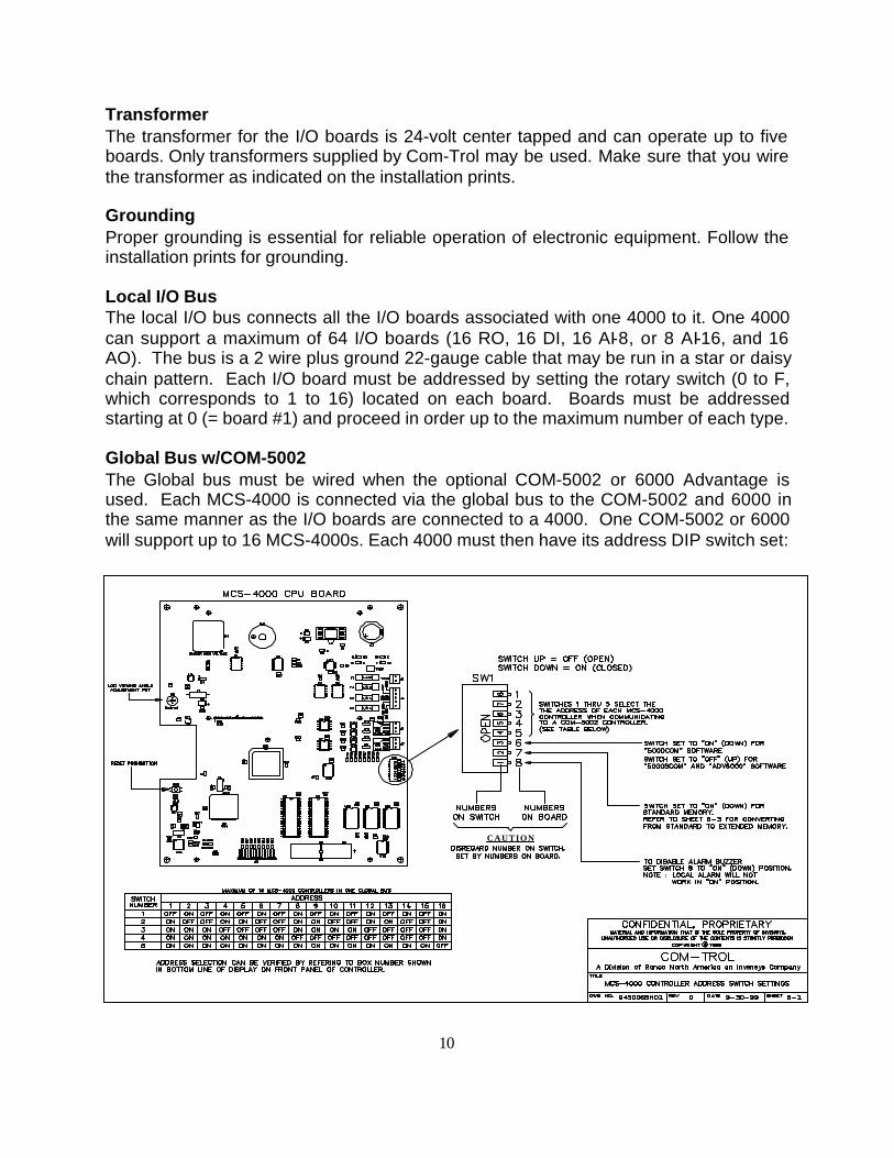
TransformerThe transformer for the I/O boards is 24-volt center tapped and can operate up to fiveboards. Only transformers supplied by Com-Trol may be used. Make sure that you wirethe transformer as indicated on the installation prints.
GroundingProper grounding is essential for reliable operation of electronic equipment. Follow theinstallation prints for grounding.
Local I/O BusThe local I/O bus connects all the I/O boards associated with one 4000 to it. One 4000can support a maximum of 64 I/O boards (16 RO, 16 DI, 16 AI-8, or 8 AI-16, and 16AO). The bus is a 2 wire plus ground 22-gauge cable that may be run in a star or daisychain pattern. Each I/O board must be addressed by setting the rotary switch (0 to F,which corresponds to 1 to 16) located on each board. Boards must be addressedstarting at 0 (= board #1) and proceed in order up to the maximum number of each type.
Global Bus w/COM-5002The Global bus must be wired when the optional COM-5002 or 6000 Advantage isused. Each MCS-4000 is connected via the global bus to the COM-5002 and 6000 inthe same manner as the I/O boards are connected to a 4000. One COM-5002 or 6000will support up to 16 MCS-4000s. Each 4000 must then have its address DIP switch set:
CAUTION
11
Sensors & Accessories
The standard sensors and accessories available with other Com-Trol products areavailable with the MCS-4000. They include standard temp sensor (-50 to 150F), hightemp sensor (50 to 250F), 0 to 100 psi, 0 to 200 psi, 0 to 500 psi, and 0 to 1000 psigpressure transducers, humidity sensor, dew point sensor, and light level sensor (0 to300 FC). See the installation drawings for further information.
Relay-8
The Relay-8 board contains eight relay outputs with or without manual overrideswitches. The RO-8 relays are rated at 3 amps at 250 volts. Both normally open andnormally closed contacts are provided. See the installation prints for the appropriateconnections for your application. The removable Phoenix connectors will accept wire upto 10 gauge. Use the smallest wire appropriate for the load. A flexible jacket ispreferred. See the installation prints for recommended wire and sizing.
Digital Input-8The DI-8 will accept 24 vac to 280 vac. If 440 volts is present, then an interposing relaywith the appropriate coil voltage, or a Com-Trol DIM (digital input module) of the propervoltage must be used to produce a dry contact. For use with dry contacts, an externalvoltage source must be used.
Analog Input-8 or 16The analog/digital-input board can be ordered with 8 or 16 inputs. It may be used forvarious analog sensors or for digital inputs, dry contact only.
NOTE: If used for dry contact DI's, the input must still be treated like an analog input.Refer to Com-Trol Tech Note #95001 and the installation drawings.
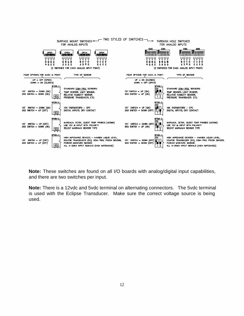
There is a jumper to tell whether the board is being used for analog inputs only oranalog and digital. There are two switches for each input to support various types ofsensors. The following table illustrates the switch settings and the sensor typesupported:
12
Note: These switches are found on all I/O boards with analog/digital input capabilities,and there are two switches per input.
Note: There is a 12vdc and 5vdc terminal on alternating connectors. The 5vdc terminalis used with the Eclipse Transducer. Make sure the correct voltage source is beingused.
13
Analog Output-4The analog output board will drive from one to four devices. There is a jumper pin foreach output that must be set to the desired output range, 0-5, 0-10, 0-15 & 0-20 vdc. Itis shipped with the pins set at 0 to 10 volts. See the installation drawings for type andsize of wire, and restrictions.
RTU BoardThe RTU board has all the inputs and outputs normally associated with the operation ofa typical small RTU unit on it, as described previously. It has the same analog circuitryas the AI-8 and AI-16 boards. See the installation prints for wiring hookup.
Singles Board
The Singles Board has all the inputs and outputs normally associated with the operationof a typical condensing unit on it, as described previously. It has the same analogcircuitry as the AI-8 and AI-16 boards, but dry contact DI’s are not available as it has 4high voltage DI inputs on it. See installation prints for wiring hookup.
CIO BoardThe CIO board has 8 relays and 8 analog inputs. Jumpers must be set fornormally open or normally closed contact operation for each relay. It has the sameanalog circuitry as the AI-8 and AI-16 boards. See installation prints for wiring hookup.
Pulse Modulated Output Board
The pulse modulated output board provides 4 drivers that can operate solid state relays(not to be used to drive coils/contactors). Normal application is in conjunction withCom-Trol’s anti-sweat heater control panel. See installation prints for wiring hookup.
14
COM-TROL MCS-4000 BASIC INFORMATION & OPERATIONS
Getting StartedThe following information is provided to assist the first time user with the basicoperations associated with the MCS-4000. For further information, refer to the UsersManual and Installation Prints.
KeypadsThe 4000 has two keypads that are part of the front panel overlay (refer to Appendix A,Figure 1). The top keypad consists of 14 keys, 7 on each side of the LCD. Each ofthese keys points to two lines on the display. These keys are used to select the desireditem displayed on the LCD screen; the item indicates selection when it is placed ininverse video (blue lettering with white background). Sometimes these keys will beused to 'toggle' options in the setup procedure.
The lower keypad consists of 20 keys that include the numerical keys 0 to 9, a decimalpoint, a minus or dash, the 4 directional arrow keys, the HELP key, the ESCAPE key(normally used to backup between menus or exit screens), the CANCEL key (used toacknowledge alarms and to cancel an entry), and the ENTER key (which normally actsto save the entry).
Normal usage requires the pressing of the appropriate side key on the upper keyboardto select a menu choice, then pressing ENTER on the lower keyboard to activate thechoice.
KEY instructions for each screen are given on the next to the bottom line and on theHELP screens.
Activating The DisplayThe liquid crystal display, LCD, on the 4000 has an automatic shut-off feature that turnsoff the display back-light if no keys are pressed for 15 minutes. It can be turned ON bypressing any of the keys on the lower keypad except theCANCEL key. The CANCEL key is used to acknowledge alarms.
Note: The display will also turn off if the ESCAPE key is pressed when on the HomeMenu.
Note: As long as the green 'Active' LED, located at the lower left corner of the display,is flashing, the 4000 is alive and functioning.
15
Adjusting the Display Viewing AngleIf the display is not providing a well focused image, open the door and turn the viewingangle adjustment knob until the display obtains the best focus (see Figure 2, AppendixA). If the 4000 was mounted much below eye level, it may not be possible to get a well-focused display; lowering the eye level may be necessary for best viewing in this case.
Screen LayoutThe top line of the display (line 1) is normally used for the title of the screen and fordisplay of the name of the task currently being setup/reviewed. The bottom line (line16) displays the software Library Type and Version that is installed in this 4000 (e.g.Rack 1.326), the mode (running, monitor, stopped) the 4000 is operating in, the addressor Box number of this 4000 i.e. “#01", and the date and time of the clock in this 4K. Line15 normally provides Key usage prompts. Lines 2 through 14 display information,menus, data, etc. and are addressed by the side keys as appropriate.
Note: The system must be in the 'Running' mode to provide output control.In the 'Monitor' mode, the inputs are processed but the relay outputs are not turnedon/off. In the 'Stopped' mode, the system does no control or monitoring. It will onlyremain in the stopped mode for 1 hour.
HelpOne of the unique features of the MCS-4000 is the built-in HELP information. If you donot understand a particular screen/menu, press the key labeled 'HELP'. This will pop upa HELP screen(s) that may consist of several pages of information concerning thescreen/menu you are currently on. Make sure you read all pages, the number of whichare shown in the upper right hand corner, by pressing the down arrow, to go from pageto page.
SetupBefore a 4000 can do anything, the 'SETUP' procedure must be completed. Thisprocess provides the 4000 with all the information it needs to assign the necessary inputand output points, and the alarm and control set points. In many installations, especiallynew construction, the 4000 will have been setup at the factory, with the program beingmaintained by batteries for several months. If the Setup has not been performed, theMain Menu 'Setup' option will be highlighted.
Note: Clear Memory before doing set-up; It is found on the 'Miscellaneous' Menu.Failure to clear memory prior to programming the system for the first time can lead touncertain results.
To perform the 'Setup', certain information must be available, such as a refrigerationschedule, plans and specifications, etc. to enable the person doing the setup to supplyanswers or make correct choices required in the setup procedure. Make sure you havethis information before beginning the Setup.
16
Com-Trol also has the Setup procedure available on a diskette (or bulletin board) thatallows the user to perform the setup on a PC, and to printout an input/output boardpoints list. This program also allows the setup information to be uploaded to and/ordownloaded from the 4000 when direct connected from the PC to the globalcommunications port, utilizing an RS-232/485 adapter module, available from Com-Trol,or it can be loaded through the COM-5002 or 6000 Advantage, when present. Thisprogram is called EZSET2. A separate manual is provided for EZSET2.
See the ‘Setup’ section of the manual for complete information.
PasswordsPasswords are built-in to the MCS-4000 to provide some measure of security forpreventing unauthorized individuals from changing set points or performing otheroperations, which can have a profound affect on the operation of the system.
Three passwords are present in the MCS-4000. They are initially set-up asfollows: Level 1 = 7777, Level 2 = 8888, Level 3 = 9999.The high level password is necessary to perform the Setup operation, Auto Assign I/O,Clear the program/memory, Clear the Alarm History, Edit Passwords, to change theRun, Stopped or Monitor modes, and to setup I/O Board Types.To change the passwords, the high level password must first be active and then the'change code' entered. The change code is 1843.
Note: The low and high level passwords should be changed upon completion of theinstallation by the responsible authority to maintain proper system security.
Note: Some items, such as 'Emergency Defrost', have the option of requiring apassword or not, posed during the 'Setup' process.
Changing A Sensor TypeNormally, the 4000 will automatically assign all the analog input sensors of theappropriate type necessary for the application. However, in some instances it may benecessary to change the sensor type; for example the 4000 assigns all suction pressuretransducers as 0 to 200 psi types. If a 0 to 100 psi transducer was used, the type maybe changed by selecting 'Setup' on the Main Menu, and 'I/O Menu' on the submenu.Select ‘Analog Ins’, and then press Enter. A list of all the Tasks will then be displayed.Select the Task that the analog input is associated with and press Enter. The firstanalog will be displayed. Pressing Enter will move you through all the analog inputsassociated with this task. Stop at the one you want to change and press the left side keypointing to ‘Type’. Next, press the up/down arrows to rotate through a list of the sensortypes available. When you arrive at the desired type, press Enter. There are 33 sensortypes as follows:
17
Reg f Regular Com-Trol temperature sensor (-45F to 120F).Hi F Com-Trol high temperature sensor (0 to 300F).Reg c Regular Com-Trol temp sensor in degrees Celsius.Hi C Com-Trol high temp sensor in degrees Celsius.Dewp f Com-Trol dewpoint sensor, degrees Fahrenheit.Dewp c Com-Trol dewpoint sensor, degrees Celsius.Etmp f Not available at this time.Etmp c Not available at this time.Johns6 Johnson Controls oil pressure transducer (6 psi trip).Johns9 Johnson Controls oil pressure transducer (9 psi trip).Abient Ambient temp sensor with special range.Car 5K Accepts the Carlyle 5k sensor built into screw comps.P100 Com-Trol 12v pressure transducer, 0 to 100 psi.P200 Com-Trol 12v pressure transducer, 0 to 200 psi.P500 Com-Trol 12v pressure transducer, 0 to 500 psi.P1000Com-Trol 12v pressure transducer, 0 to 1000 psi.4-20ma Yields 1-5 v; requires 250 ohm 1% resistor across input.FtCndlCom-Trol light level sensor 0-300 foot candles.Frost Not available at this time.Cfreon Com-Trol Freon sensor; 1 to 6 volts, 0 - 2000 ppm.Ammonia Com-Trol ammonia sensor; `1 to 6 volts, 0-300 ppm.Oil Pr Differential pressure xducer; 1 to 6volts; 0-100psi.HnsLq Hansen liquid level sensor; 1 to 6 volts, 0 to 100%.Margau Margaux temperature sensor; AD590.Percnt Percent; based on 0 to 5 volt input.Freon Freon sensor; 0 to 5 volts, 0 - 500 ppm.P100 E Com-Trol Eclipse pressure transducer; 5 volt; 0-100 psi.P200 E Com-Trol Eclipse pressure transducer; 5 volt; 0-200 psi.P500 E Com-Trol Eclipse pressure transducer; 5 volt; 0-500 psi.P1000E Com-Trol Eclipse pressure transducer; 5 volt; 0-1000 psi.Offs f Special purpose.User#1 User definable; must be linear sensors.User#2 User definable; must be linear sensors.User#3 User definable; must be linear sensors.User#4 User definable; must be linear sensors.
Note: Types that appear as *-**-* are spares that have not been defined.
I/O Board Numbering System – Addressing
The input and output boards and each point are referenced in various places by thefollowing scheme: ##-#; where the first two numbers represent the board number (from1 to 16) and the number after the dash represents the point number (from 1 to 8). Forexample: 01-1 indicates board 01, point 1.
18
Note: When an analog input board with 16 inputs (AI-16) is used, it occupies twoaddresses; even though only one physical address switch is set.
Note: For boards with combinations of inputs/outputs, each type of input will occupythat address. For Example - the AI-16/DI-8 board will occupy analog addresses 1 & 2and digital address 1.
The board number/address is set by turning the rotary DIP switch located at the top leftcorner (see Figure 3, Appendix A), with a small screw driver in the slot, or with thefingers, when equipped with the appropriate style of switch, as indicated on theinstallation prints; i.e. board 01 = 0, board 02 = 1.... board 11 = A, board 12 = B etc.
Remember that each type of board (relay, digital, analog in, analog out) can haveaddresses from 1 to 16 for each 4000.
Setting Board Types
If analogs are present on board types other than AI-8, the Board Type may be selectedby selecting ‘Task Settings’ with the side key on the ‘Main Menu’, press “Enter”. NextSelect ’I/O Menu’ with side key and press “Enter”. Press the side key aligned with‘Board Types’, Press “Enter”. You will be prompted for the high level password if notpreviously entered. Use the arrow keys to move to the desired board address, press theside key aligned with the reverse video “Select” menu item (bottom right), then use theup/down arrow keys to rotate through the board types. The choices are AI-8, AI-16,RTU, Sngl, and CIO. Stop on the desired type, and then press “Enter”. Continue untilall Board Types have been set. Press “Enter” again to return to the previous menu.
The I/O configuration shown on the "Summary"/"Relay", "Digital Inputs", and "AnalogInputs", and "Analog Output" screens will now reflect the proper number of inputspresent for each board type/address.
I/O Assignment
The 4000 can provide all input/output assignment automatically, or the assignments canbe made manually.
To automatically assigned the I/O, after all tasks are set-up, select ‘Task Settings’ fromthe ‘Main Menu’, and press “Enter”. Select ’I/O Menu’ and press “Enter”. Select ‘AutoI/O Assign’ and press “Enter”. Two choices are now available, ‘Pack Tight’ or ‘Skip byTask’.
‘Pack Tight’ assigns all the I/O point required in a predetermined order leaving nospaces/unused points. This would give the minimum number of boards required, butwould not consider that the boards may need to be in different locations for certaintasks.

19
‘Skip by Task’, assigns all the points required for a given task type/category, then jumpsto a new board(s) for the next Task type; i.e. condenser would be separate fromcompressors, temp/defr circuits would be separate, etc. This would enable, the boardsassociated with the task type to be physically located where the device is located.
Either one of these may be used with some manual assignment/re-assignment to getthe desired layout.
Manual assignment is accomplished as indicated above, but selecting ‘Relays’, ‘DigitalIns’, ’Analog Ins’, and ‘Analog Outs’, instead of ‘Auto I/O Assign’. Each task is thenselected from the Task list displayed. The first point of the selected type will thenappear. Use the side key to select ‘Bd-Pt’, and type in the board and point number withthe number keys, with a “.” or “-” separating the board number from the point number.
Note: If an assignment is already present, remember that for Relays and AnalogOutputs, the system will not allow you to assign it to another point that hasalready been assigned. You may have to use unused points temporarily to getrelays and analog outs moved around. Digital inputs and Analog inputs may bemultiply assigned, if required. An asterisk, *, will be placed after the ‘Bd-Pt’ toindicate multiple assignment.
Note: The EZSET2 editor may also be used to assign I/O. See EZSET2 Manual.
Assignments may be changed at any time for service or installation purposes.
I/O Overrides
Any input or output may be overridden/forced to a specified on/off state, or value (foranalog input and outputs). Overrides are useful for testing or to temporarily "fix" a badsensor.
Relay Override - Select ‘Task Settings’ on the Main Menu with the side key andpress “Enter”. Select ‘I/O Menu’ with the side key, press “Enter”. Select‘Relays’ with the side key, press ”Enter”. Enter password, if prompted.Pick the desired task from the list of tasks displayed with the side key,press “Enter”; use the up/down arrows to get to other tasks, if notdisplayed on current page. The first relay associated with the selectedtask will be displayed. Use the side key to select ‘State’, then use theup/down arrows to toggle through the choices; “Com”, “On, Off”. Com =computer control, On = put relay in override On; Off = put relay in overrideOff. Press “Enter” to secure the desired state. Proceed through rest ofrelays, as appropriate; Pressing “Enter” continues through all relaysassociated with the selected task.
20
Relay (or other I/O types) will remain in the selected overridden state until userputs back to Com mode.
Digital Ins - same process as for relays, except select ‘Digital Ins’ on the I/O Menu screen.
Analog Ins - Same process as for ‘Relays’ above except select ‘Analog Ins’ fromthe I/O Menu screen and when you select ‘State’, the only choices are,Com and On. Then, select ‘Units/Override Value’ with the side key, andtype in the desired override value you want the input to read, and press“Enter”. Thus, it is a two step process to implement an override on ananalog input.
Analog Outs - same process as for ‘Analog Ins’.
Note: If no inputs or outputs of the category selected are associated with the task;nothing will happen when you press “Enter”.
Analog OffsetsAnalog inputs and Outputs can have an offset value (an amount that is added orsubtracted from the sensor input value before using it for control), entered if needed.This is normally used to adjust the value of a pressure transducer or a temp sensor tomatch a known good reference. The procedure used is similar to the analog overrideprocedure explained previously, except select ‘Units/offset’ with the side key, and enterthe desired offset value with the number keys (may be plus or minus (-)), then press“Enter”.
Note: The temperature sensors and transducers are normally very accurate and offsetsshould rarely be required. Don't assume your gauge is more accurate than the sensor;be sure.
Inversion RelaysRelay output states and control states are defined within the 4000 software. Relayinversion/failsafe mode is normally properly handled by the 4000 in the Setup routine.However, there may be a few instances where the relay output needs to be inverted orthe inversion removed.
Relays specified as 'Normal', are defined so that they are wired to the normally closedcontacts, so that they fail on, such as refrigeration compressors and circuit temperaturecontrol solenoids. Relays specified as 'Inverted' are wired to the normally open contactsand fail off, such as defrost.
21
Select ‘Task Settings’ on the Main Menu with the side key and press“Enter”. Select ‘I/O Menu’ with the side key, press “Enter”. Select ‘Relays’with the side key, press ”Enter”. Enter password if prompted. Pickthe desired task from the list of tasks displayed with the side key, press“Enter”; use the up/down arrows to get to other tasks, if not displayed oncurrent page. The first relay associated with the selected task will bedisplayed. Use the side key to select ‘Inv/Inversion’, then use theup/down arrows to toggle through the choices; “Normal” or “Invert”. Press“Enter” to secure the desired choice. Proceed through rest of relays bypressing “Enter”.
Digital InputsDigital inputs may also be inverted. Process is same as for relays, except select DigitalIns from the “I/O Menu”.
Analog OutputsAnalog outputs may also be inverted if needed. If inverted, the output signal goes frommaximum to minimum; e.g. 10v to 0v. Follow same process as for Relays explainedpreviously, except select ‘Analog Outs’ from the I/O Menu.
AlarmsVarious alarms are created during the Setup/programming routine. These alarms maybe altered or disabled by selecting ‘Task Settings’ on the Main Menu with the side key,then press “Enter”. Next select ‘Analog Alms’ or ‘Digital Alms’ as appropriate, with theside keys and press “Enter”. Next, select the Task, side key; from the task list screensthat you want to modify alarms for and press “Enter”. Use the left/right side keys for theparameter you wish to alter, type in the desired value, and press “Enter”. Press “Enter”again to move on to the next alarm associated with that task, or keep pressing until youreturn to the task list.
When an alarm occurs, the red LED at the lower right of the display (just above the keylock) will be ON and the horn will be sounding (unless dip switch #8 is set to ON). Thehorn may be silenced by pressing the CANCEL key, while viewing the ‘Alarm History”,which acknowledges the alarm. The Red LED will stay on however, until the alarmcondition clears.
NOTE: IF DIP SWITCH NUMBER 8 IS SET TO THE RIGHT, THE 4K ALARM HORNWILL NOT SOUND, AND IF A 5K2 IS PRESENT, THE 5K2 HORN OUTPUT WILL NOTSOUND (FOR ALARMS ON THAT PARTICULAR 4K). THE ALARM LED ON THE 4KAND THE 5K2 ALARM LIGHT OUTPUT WILL OPERATE, HOWEVER.
To view the alarm history, select ‘Alarm History’, on the Main Menu. The most currentalarm will be at the top of the list, proceeding to the oldest (use down arrow to step backthrough the log). The last 40 alarms are maintained. Use the right arrow to view the‘Cleared’ and ‘Acknowledged’ time stamps.
22
Setting The Clock
If the time and date do not appear correctly at the bottom right of the display, select‘Miscellaneous’ on the Main Menu, then 'Set Time' on the sub menu. Use the right arrowto move to the desired element to change and type in the desired value with thenumerical keys. Press “Enter” when done to secure the change.
Note: When a Com-5002, its clock is used to set/synchronize the clocks on all 4000'sconnected to it. The clocks are synchronized every hour at 5 minutes past the hour.
Setting the MCS-4000 Address SwitchIf a COM-5002, Communications Controller, or 6000 Advantage is present in theinstallation, then each MCS-4000 must have its address switch set to a unique valuefrom 1 to 16. The address switch is reached by opening the door and locating the DIPswitch at the middle right side of the CPU board (see Figure 2). Set the first 4000 ataddress 01 and proceed upwards. Dip switch settings are shown on the installationdrawings. Switches 1 - 5 are used for the address. The switch setting can be verified bylooking at the bottom line of the display; 'Box01' would indicate that the 4000 had itsaddress switches set to 01.
Configuring the SystemIf a COM-5002 is present in the installation, then once the global bus is connected to allMCS-4000 controllers and each 4000 has been setup/programmed, the system must beconfigured. This is accomplished by plugging in a terminal or PC to the local RS-232port on the COM-5k2, or by calling it up over the phone line utilizing the built-in modem.When the system answers/connects, type in the number that represents the type ofterminal or PC you are using. The password screen will appear. Enter the password,initially set to UEI450. The Main Menu will then be displayed. Type a 'Z' to obtain the'Monitor Commands' menu. Select 'Configure All' and press Enter. The COM will thenstart polling at address 01 over the global bus. For each 4000 that responds, the tasksinformation and default names will be created for the system/task menu. This processwill be repeated for each 4000 that responds. The COM-5002 has now stored thesystem configuration in its battery backed memory. If the Task or I/O configuration isaltered at anytime after this process, then it needs to be repeated to obtain the newconfiguration information.
Refer to the COM-5002 Users Manual for further information on communications.
23
USING THE SYSTEM
The MCS-4000 provides the user with an abundance of information. The followingdiscussions deals with the screens that you will normally use once the system has beenprogrammed and is up and running.
Task StatusThe Task Status screen provides you with the most complete data picture of what iscurrently going on with each task and you will use it frequently. You may also godirectly from the selected task status screen to all items associated with it, simply bypressing a number key between 1 and 9. These quick access keys are defined asfollows:
1 = set points2 = schedules (if applicable to the selected task)3 = relays4 = digital inputs5 = analog inputs6 = analog outputs7 = analog alarms8 = digital alarms9 = removes any computer relays overrides for the selected task.
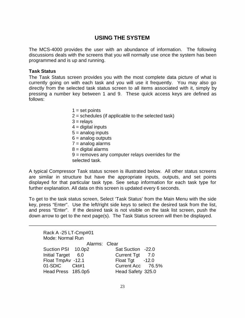
A typical Compressor Task status screen is illustrated below. All other status screensare similar in structure but have the appropriate inputs, outputs, and set pointsdisplayed for that particular task type. See setup information for each task type forfurther explanation. All data on this screen is updated every 6 seconds.
To get to the task status screen, Select ‘Task Status’ from the Main Menu with the sidekey, press “Enter”. Use the left/right side keys to select the desired task from the list,and press “Enter”. If the desired task is not visible on the task list screen, push thedown arrow to get to the next page(s). The Task Status screen will then be displayed.
Rack A -25 LT-Cmp#01Mode: Normal Run
Alarms: ClearSuction PSI 10.0p2 Sat Suction -22.0Initial Target 6.0 Current Tgt 7.0Float TmpAv -12.1 Float Tgt -12.001-SDIC Ckt#1 Current Acc 76.5%Head Press 185.0p5 Head Safety 325.0
24
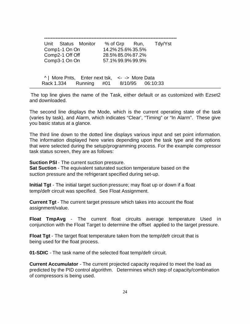
---------------------------------------------------------------------------------Unit Status Monitor % of Grp Run, Tdy/YstComp1-1 On On 14.2% 25.6% 35.5%Comp2-1 Off Off 28.5% 85.0% 87.2%Comp3-1 On On 57.1% 99.9% 99.9%
^ | More Pnts, Enter next tsk, <- -> More Data Rack 1.334 Running #01 8/10/95 06:10:33
The top line gives the name of the Task, either default or as customized with Ezset2and downloaded.
The second line displays the Mode, which is the current operating state of the task(varies by task), and Alarm, which indicates “Clear’, “Timing” or “In Alarm”. These giveyou basic status at a glance.
The third line down to the dotted line displays various input and set point information.The information displayed here varies depending upon the task type and the optionsthat were selected during the setup/programming process. For the example compressortask status screen, they are as follows:
Suction PSI - The current suction pressure.Sat Suction - The equivalent saturated suction temperature based on the suction pressure and the refrigerant specified during set-up.
Initial Tgt - The initial target suction pressure; may float up or down if a float temp/defr circuit was specified. See Float Assignment.
Current Tgt - The current target pressure which takes into account the float assignment/value.
Float TmpAvg - The current float circuits average temperature Used inconjunction with the Float Target to determine the offset applied to the target pressure.
Float Tgt - The target float temperature taken from the temp/defr circuit that is being used for the float process.
01-SDIC - The task name of the selected float temp/defr circuit.
Current Accumulator - The current projected capacity required to meet the load aspredicted by the PID control algorithm. Determines which step of capacity/combinationof compressors is being used.
25
Head Press - The current head/discharge pressure.
Head Safety - The pressure at which compressors will start staging off for safety purposes.
Information below the dotted line:
Unit - The name of the relay output(s).
Status - The On/Off and override status. If overridden by software, a “r” will appearnext to the on or off; if switched at the relay I/O board, a “s” will be present; and ifoverridden both ways, a “b” will be displayed.
Monitor - If a monitor/proof input was selected during set-up, it will appear in thiscolumn. It should match the relay state within 6 sec. (Unless something is getting in theway).
% of Grp - For compressor groups, indicates the percentage of the totalcapacity that each compressor represents, based upon the HP or Btuh values enteredduring the set-up process.
Run Tdy/Yst -These two columns provide the calculated percentage of runtime foreach relay for today (thus far), and yesterday.
Pressing right arrows, as indicated at the bottom of the screen, will provide additionalinformation in these columns. This includes, the runtime and cycles for today andyesterday, and the last on and last off and total runtime since the system was set-up/reprogrammed.
Use the down arrows to get to additional relays, if necessary.
The bottom line always displays the following information:Software Library present and its version number.Mode - running, monitor, stopped.Box AddressDate and Time
Remember, to save time, use the quick access keys (1-9) from this screen to getto all additional information about this task.
26
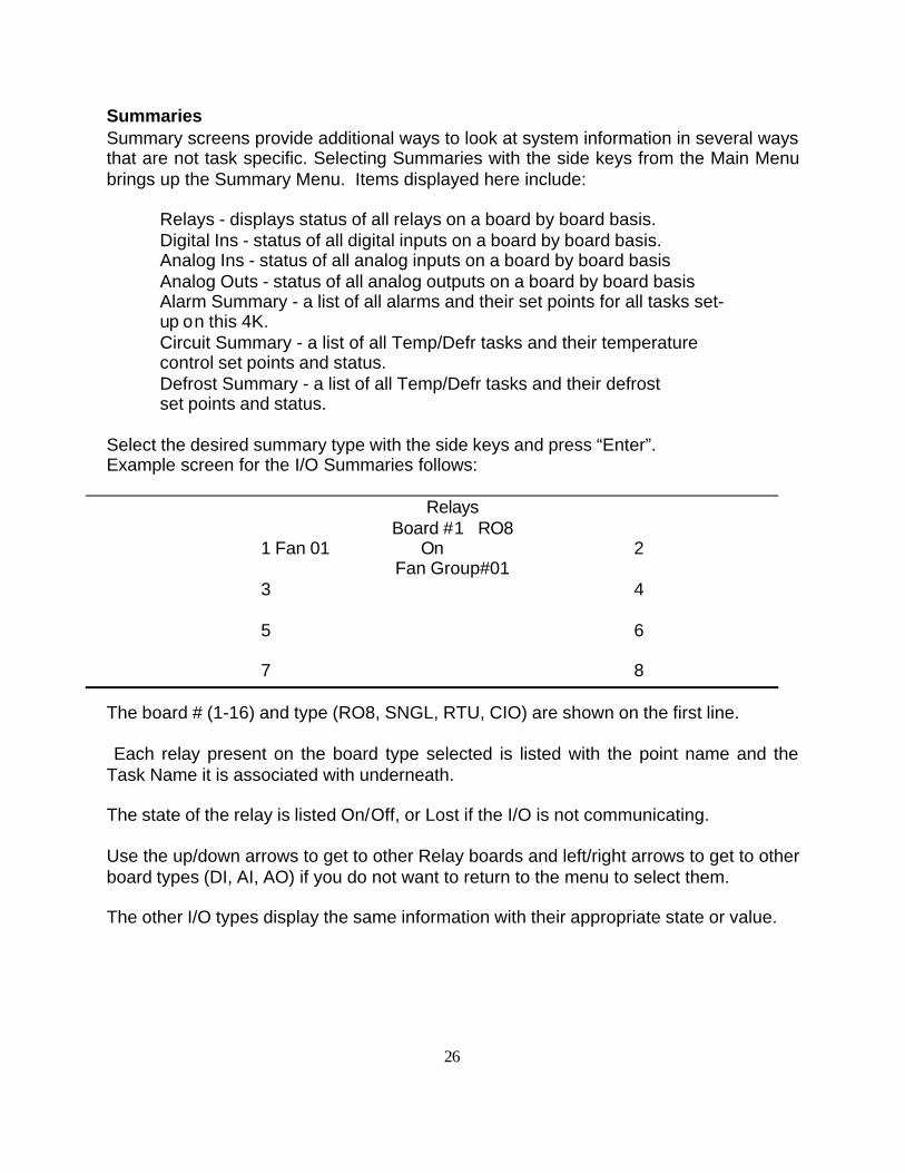
SummariesSummary screens provide additional ways to look at system information in several waysthat are not task specific. Selecting Summaries with the side keys from the Main Menubrings up the Summary Menu. Items displayed here include:
Relays - displays status of all relays on a board by board basis.Digital Ins - status of all digital inputs on a board by board basis.Analog Ins - status of all analog inputs on a board by board basisAnalog Outs - status of all analog outputs on a board by board basisAlarm Summary - a list of all alarms and their set points for all tasks set-up on this 4K.Circuit Summary - a list of all Temp/Defr tasks and their temperature control set points and status.Defrost Summary - a list of all Temp/Defr tasks and their defrost set points and status.
Select the desired summary type with the side keys and press “Enter”.Example screen for the I/O Summaries follows:
RelaysBoard #1 RO8
1 Fan 01 On 2Fan Group#01
3 4
5 6
7 8
The board # (1-16) and type (RO8, SNGL, RTU, CIO) are shown on the first line.
Each relay present on the board type selected is listed with the point name and theTask Name it is associated with underneath.
The state of the relay is listed On/Off, or Lost if the I/O is not communicating.
Use the up/down arrows to get to other Relay boards and left/right arrows to get to otherboard types (DI, AI, AO) if you do not want to return to the menu to select them.
The other I/O types display the same information with their appropriate state or value.
27
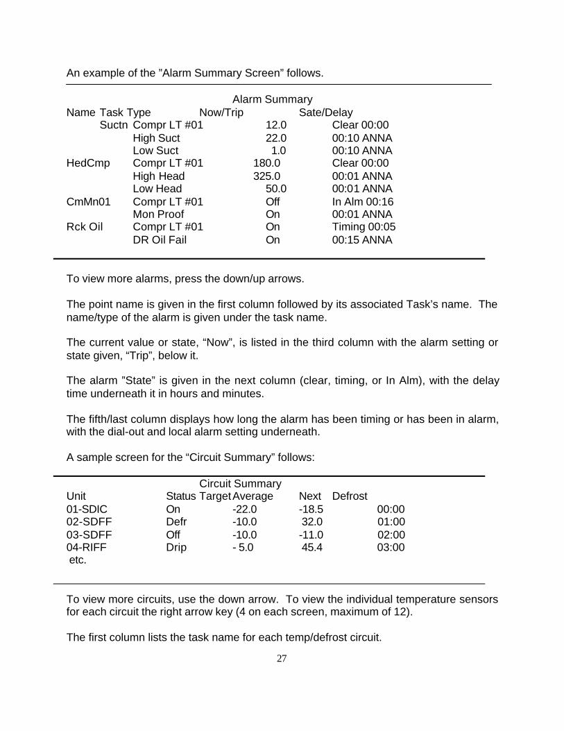
An example of the ”Alarm Summary Screen” follows.
Alarm SummaryName Task Type Now/Trip Sate/Delay
Suctn Compr LT #01 12.0 Clear 00:00High Suct 22.0 00:10 ANNALow Suct 1.0 00:10 ANNA
HedCmp Compr LT #01 180.0 Clear 00:00High Head 325.0 00:01 ANNALow Head 50.0 00:01 ANNA
CmMn01 Compr LT #01 Off In Alm 00:16Mon Proof On 00:01 ANNA
Rck Oil Compr LT #01 On Timing 00:05DR Oil Fail On 00:15 ANNA
To view more alarms, press the down/up arrows.
The point name is given in the first column followed by its associated Task’s name. Thename/type of the alarm is given under the task name.
The current value or state, “Now”, is listed in the third column with the alarm setting orstate given, “Trip”, below it.
The alarm ”State” is given in the next column (clear, timing, or In Alm), with the delaytime underneath it in hours and minutes.
The fifth/last column displays how long the alarm has been timing or has been in alarm,with the dial-out and local alarm setting underneath.
A sample screen for the “Circuit Summary” follows:
Circuit SummaryUnit Status TargetAverage Next Defrost01-SDIC On -22.0 -18.5 00:0002-SDFF Defr -10.0 32.0 01:00 03-SDFF Off -10.0 -11.0 02:00 04-RIFF Drip - 5.0 45.4 03:00 etc.
To view more circuits, use the down arrow. To view the individual temperature sensorsfor each circuit the right arrow key (4 on each screen, maximum of 12).
The first column lists the task name for each temp/defrost circuit.
28
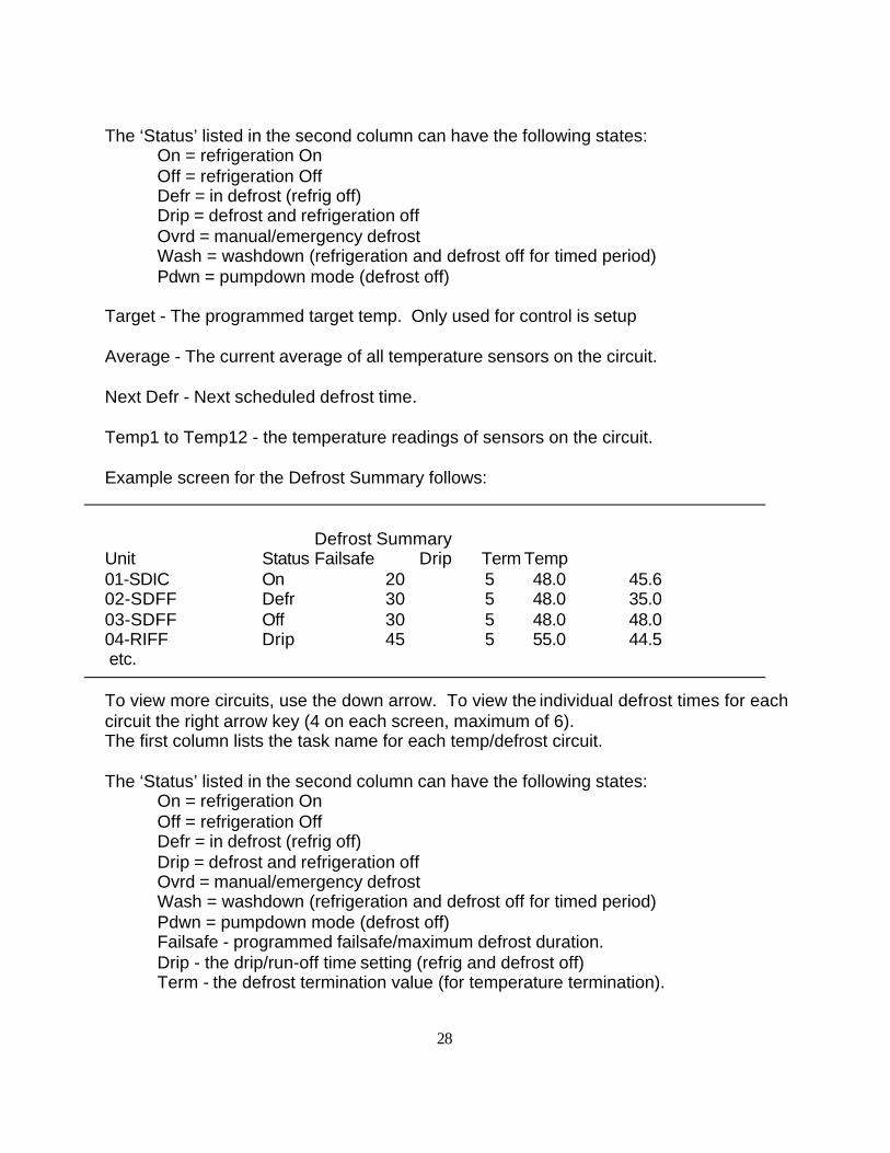
The ‘Status’ listed in the second column can have the following states:On = refrigeration OnOff = refrigeration OffDefr = in defrost (refrig off)Drip = defrost and refrigeration offOvrd = manual/emergency defrostWash = washdown (refrigeration and defrost off for timed period)Pdwn = pumpdown mode (defrost off)
Target - The programmed target temp. Only used for control is setup
Average - The current average of all temperature sensors on the circuit.
Next Defr - Next scheduled defrost time.
Temp1 to Temp12 - the temperature readings of sensors on the circuit.
Example screen for the Defrost Summary follows:
Defrost SummaryUnit Status Failsafe Drip Term Temp01-SDIC On 20 5 48.0 45.602-SDFF Defr 30 5 48.0 35.003-SDFF Off 30 5 48.0 48.004-RIFF Drip 45 5 55.0 44.5 etc.
To view more circuits, use the down arrow. To view the individual defrost times for eachcircuit the right arrow key (4 on each screen, maximum of 6).The first column lists the task name for each temp/defrost circuit.
The ‘Status’ listed in the second column can have the following states:On = refrigeration OnOff = refrigeration OffDefr = in defrost (refrig off)Drip = defrost and refrigeration offOvrd = manual/emergency defrostWash = washdown (refrigeration and defrost off for timed period)Pdwn = pumpdown mode (defrost off) Failsafe - programmed failsafe/maximum defrost duration.Drip - the drip/run-off time setting (refrig and defrost off)Term - the defrost termination value (for temperature termination).
29
Temp - the lowest temperature of all sensors on the circuit that was reached atthe time of termination the last time a defrost was performed.Time1 through Time6 - the scheduled defrost start times.
Alarm History
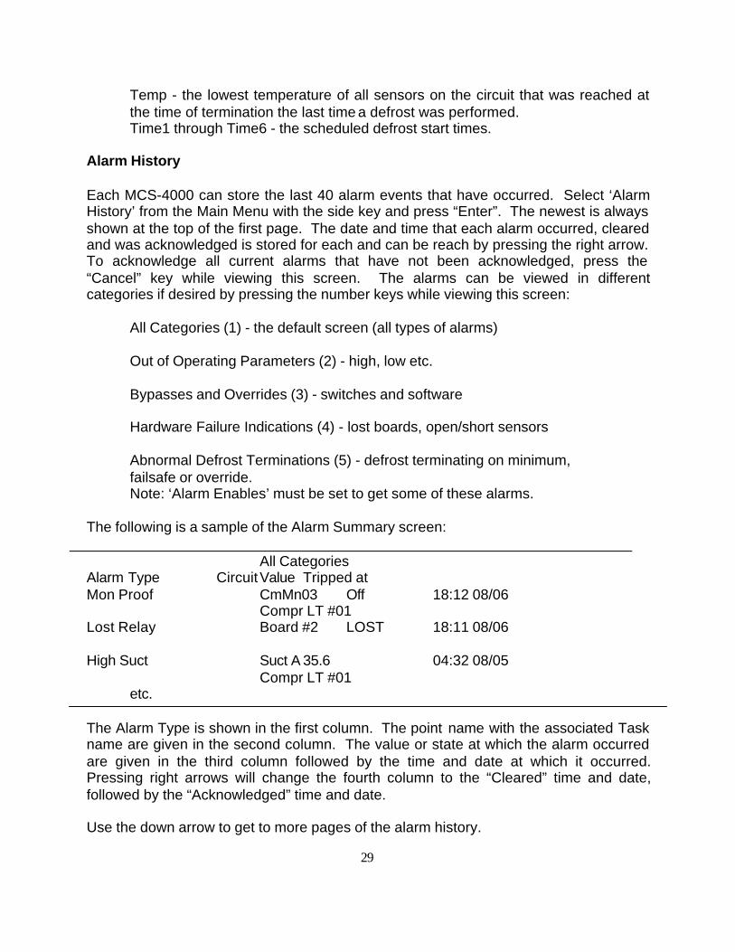
Each MCS-4000 can store the last 40 alarm events that have occurred. Select ‘AlarmHistory’ from the Main Menu with the side key and press “Enter”. The newest is alwaysshown at the top of the first page. The date and time that each alarm occurred, clearedand was acknowledged is stored for each and can be reach by pressing the right arrow.To acknowledge all current alarms that have not been acknowledged, press the“Cancel” key while viewing this screen. The alarms can be viewed in differentcategories if desired by pressing the number keys while viewing this screen:
All Categories (1) - the default screen (all types of alarms)
Out of Operating Parameters (2) - high, low etc.
Bypasses and Overrides (3) - switches and software
Hardware Failure Indications (4) - lost boards, open/short sensors
Abnormal Defrost Terminations (5) - defrost terminating on minimum, failsafe or override.Note: ‘Alarm Enables’ must be set to get some of these alarms.
The following is a sample of the Alarm Summary screen:
All CategoriesAlarm Type CircuitValue Tripped atMon Proof CmMn03 Off 18:12 08/06
Compr LT #01Lost Relay Board #2 LOST 18:11 08/06
High Suct Suct A 35.6 04:32 08/05Compr LT #01
etc.
The Alarm Type is shown in the first column. The point name with the associated Taskname are given in the second column. The value or state at which the alarm occurredare given in the third column followed by the time and date at which it occurred.Pressing right arrows will change the fourth column to the “Cleared” time and date,followed by the “Acknowledged” time and date.
Use the down arrow to get to more pages of the alarm history.
30
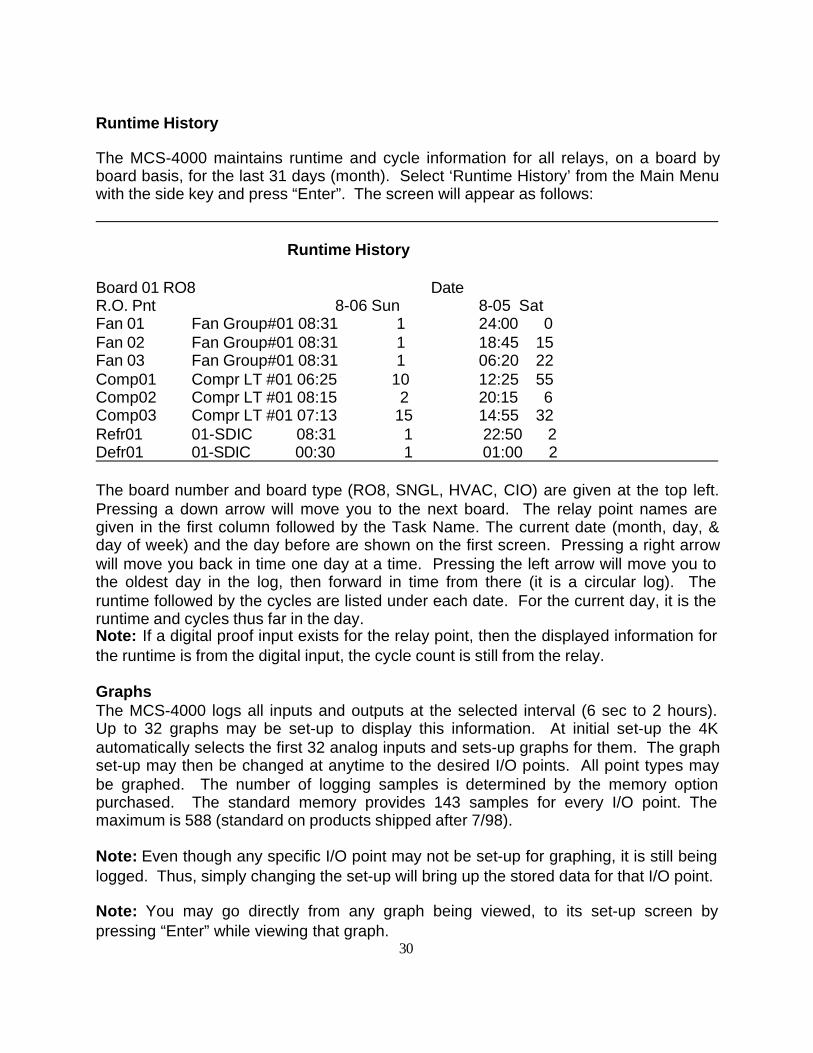
Runtime History
The MCS-4000 maintains runtime and cycle information for all relays, on a board byboard basis, for the last 31 days (month). Select ‘Runtime History’ from the Main Menuwith the side key and press “Enter”. The screen will appear as follows:
Runtime History
Board 01 RO8 DateR.O. Pnt 8-06 Sun 8-05 SatFan 01 Fan Group#01 08:31 1 24:00 0Fan 02 Fan Group#01 08:31 1 18:45 15Fan 03 Fan Group#01 08:31 1 06:20 22Comp01 Compr LT #01 06:25 10 12:25 55Comp02 Compr LT #01 08:15 2 20:15 6Comp03 Compr LT #01 07:13 15 14:55 32Refr01 01-SDIC 08:31 1 22:50 2Defr01 01-SDIC 00:30 1 01:00 2
The board number and board type (RO8, SNGL, HVAC, CIO) are given at the top left.Pressing a down arrow will move you to the next board. The relay point names aregiven in the first column followed by the Task Name. The current date (month, day, &day of week) and the day before are shown on the first screen. Pressing a right arrowwill move you back in time one day at a time. Pressing the left arrow will move you tothe oldest day in the log, then forward in time from there (it is a circular log). Theruntime followed by the cycles are listed under each date. For the current day, it is theruntime and cycles thus far in the day.Note: If a digital proof input exists for the relay point, then the displayed information forthe runtime is from the digital input, the cycle count is still from the relay.
GraphsThe MCS-4000 logs all inputs and outputs at the selected interval (6 sec to 2 hours).Up to 32 graphs may be set-up to display this information. At initial set-up the 4Kautomatically selects the first 32 analog inputs and sets-up graphs for them. The graphset-up may then be changed at anytime to the desired I/O points. All point types maybe graphed. The number of logging samples is determined by the memory optionpurchased. The standard memory provides 143 samples for every I/O point. Themaximum is 588 (standard on products shipped after 7/98).
Note: Even though any specific I/O point may not be set-up for graphing, it is still beinglogged. Thus, simply changing the set-up will bring up the stored data for that I/O point.
Note: You may go directly from any graph being viewed, to its set-up screen bypressing “Enter” while viewing that graph.
31
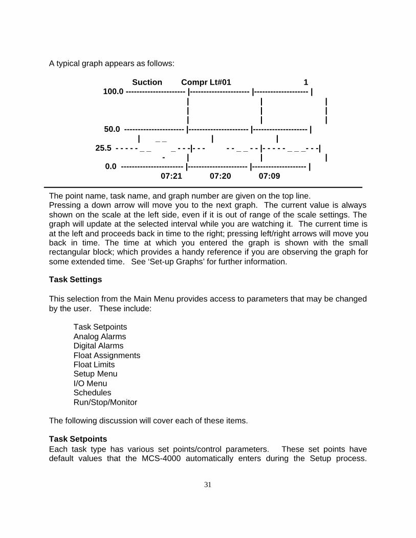
A typical graph appears as follows:
Suction Compr Lt#01 1100.0 ---------------------- |---------------------- |-------------------- |
| | || | || | |
50.0 ---------------------- |---------------------- |-------------------- || _ _ | |
25.5 - - - - - _ _ _ - - -|- - - - - _ _ - - |- - - - - _ _ _- - -|- | | |
0.0 ----------------------- |---------------------- |-------------------- |07:21 07:20 07:09
The point name, task name, and graph number are given on the top line.Pressing a down arrow will move you to the next graph. The current value is alwaysshown on the scale at the left side, even if it is out of range of the scale settings. Thegraph will update at the selected interval while you are watching it. The current time isat the left and proceeds back in time to the right; pressing left/right arrows will move youback in time. The time at which you entered the graph is shown with the smallrectangular block; which provides a handy reference if you are observing the graph forsome extended time. See ‘Set-up Graphs’ for further information.
Task Settings
This selection from the Main Menu provides access to parameters that may be changedby the user. These include:
Task Setpoints Analog Alarms
Digital AlarmsFloat AssignmentsFloat LimitsSetup MenuI/O MenuSchedulesRun/Stop/Monitor
The following discussion will cover each of these items.
Task SetpointsEach task type has various set points/control parameters. These set points havedefault values that the MCS-4000 automatically enters during the Setup process.
32
These values can be altered at that time or at anytime in the future. Setpoints arepassword protected (level 2).
To get to the Task Set points, select ‘Task Settings’ on the Main Menu with the sidekeys, and press “Enter”. Next, select ‘Task Set points’ with the side key and press“Enter”. You will then be presented with a list of all the tasks. Select the desired taskwith the side key and press “Enter”. A menu of choices will be presented that varies bytask. Select the desired item with the side key and press “Enter”. Select the desiredset point to change with the side key, type in the appropriate value, then press “Enter”.Press “Enter” again when all desired changes have been made.
Note: You can also go directly to the set point screen, by pressing a “1" while viewingthe ‘Task Status’ screen, as previously discussed.
Refer to the ‘Setup’ section of this manual for details on the various set point screens.
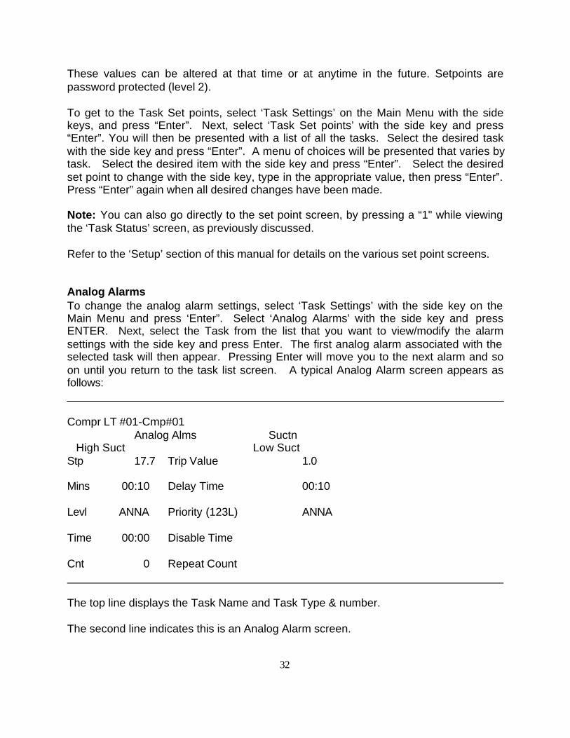
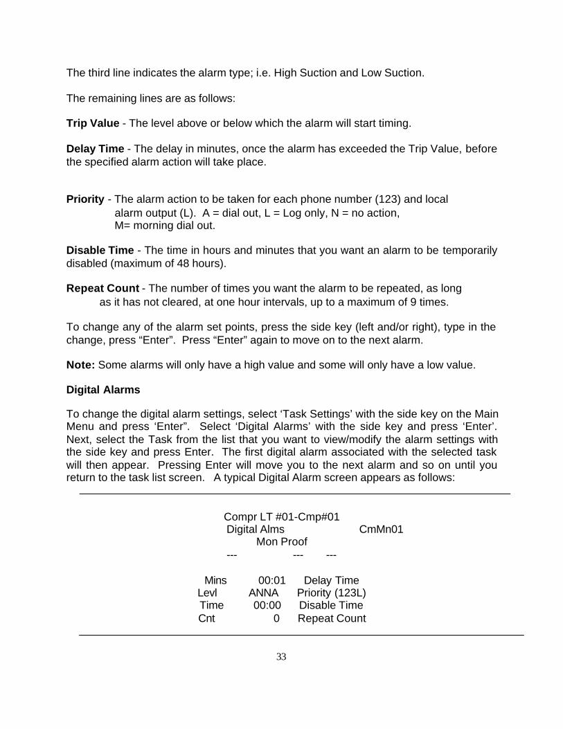
Analog AlarmsTo change the analog alarm settings, select ‘Task Settings’ with the side key on theMain Menu and press ‘Enter”. Select ‘Analog Alarms’ with the side key and pressENTER. Next, select the Task from the list that you want to view/modify the alarmsettings with the side key and press Enter. The first analog alarm associated with theselected task will then appear. Pressing Enter will move you to the next alarm and soon until you return to the task list screen. A typical Analog Alarm screen appears asfollows:
Compr LT #01-Cmp#01Analog Alms Suctn
High Suct Low SuctStp 17.7 Trip Value 1.0
Mins 00:10 Delay Time 00:10
Levl ANNA Priority (123L) ANNA
Time 00:00 Disable Time
Cnt 0 Repeat Count
The top line displays the Task Name and Task Type & number.
The second line indicates this is an Analog Alarm screen.
33
The third line indicates the alarm type; i.e. High Suction and Low Suction.
The remaining lines are as follows:
Trip Value - The level above or below which the alarm will start timing.
Delay Time - The delay in minutes, once the alarm has exceeded the Trip Value, beforethe specified alarm action will take place.
Priority - The alarm action to be taken for each phone number (123) and local alarm output (L). A = dial out, L = Log only, N = no action,
M= morning dial out.
Disable Time - The time in hours and minutes that you want an alarm to be temporarilydisabled (maximum of 48 hours).
Repeat Count - The number of times you want the alarm to be repeated, as long as it has not cleared, at one hour intervals, up to a maximum of 9 times.
To change any of the alarm set points, press the side key (left and/or right), type in thechange, press “Enter”. Press “Enter” again to move on to the next alarm.
Note: Some alarms will only have a high value and some will only have a low value.
Digital Alarms
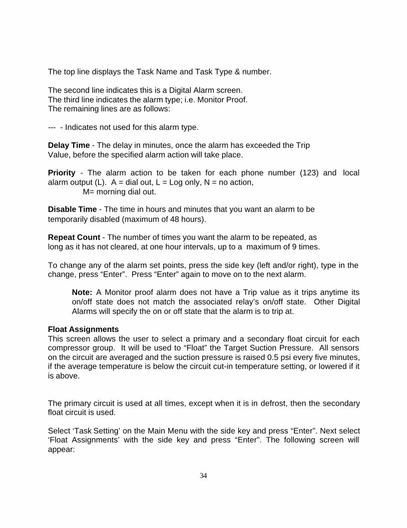
To change the digital alarm settings, select ‘Task Settings’ with the side key on the MainMenu and press ‘Enter”. Select ‘Digital Alarms’ with the side key and press ‘Enter’.Next, select the Task from the list that you want to view/modify the alarm settings withthe side key and press Enter. The first digital alarm associated with the selected taskwill then appear. Pressing Enter will move you to the next alarm and so on until youreturn to the task list screen. A typical Digital Alarm screen appears as follows:
Compr LT #01-Cmp#01Digital Alms CmMn01
Mon Proof--- --- ---
Mins 00:01 Delay TimeLevl ANNA Priority (123L)Time 00:00 Disable TimeCnt 0 Repeat Count
34
The top line displays the Task Name and Task Type & number.
The second line indicates this is a Digital Alarm screen.The third line indicates the alarm type; i.e. Monitor Proof.The remaining lines are as follows:
--- - Indicates not used for this alarm type.
Delay Time - The delay in minutes, once the alarm has exceeded the Trip Value, before the specified alarm action will take place.
Priority - The alarm action to be taken for each phone number (123) and localalarm output (L). A = dial out, L = Log only, N = no action, M= morning dial out.
Disable Time - The time in hours and minutes that you want an alarm to be temporarily disabled (maximum of 48 hours).
Repeat Count - The number of times you want the alarm to be repeated, as long as it has not cleared, at one hour intervals, up to a maximum of 9 times.
To change any of the alarm set points, press the side key (left and/or right), type in thechange, press “Enter”. Press “Enter” again to move on to the next alarm.
Note: A Monitor proof alarm does not have a Trip value as it trips anytime itson/off state does not match the associated relay’s on/off state. Other DigitalAlarms will specify the on or off state that the alarm is to trip at.
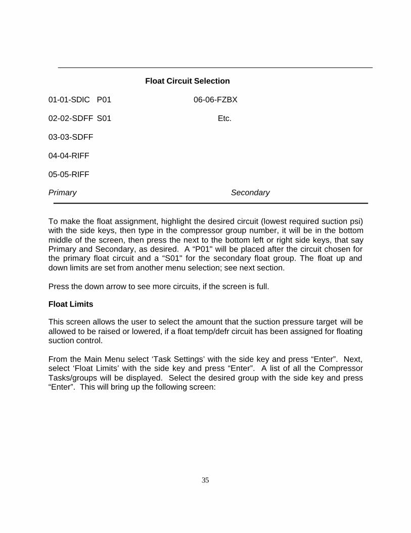
Float AssignmentsThis screen allows the user to select a primary and a secondary float circuit for eachcompressor group. It will be used to “Float” the Target Suction Pressure. All sensorson the circuit are averaged and the suction pressure is raised 0.5 psi every five minutes,if the average temperature is below the circuit cut-in temperature setting, or lowered if itis above.
The primary circuit is used at all times, except when it is in defrost, then the secondaryfloat circuit is used.
Select ‘Task Setting’ on the Main Menu with the side key and press “Enter”. Next select‘Float Assignments’ with the side key and press “Enter”. The following screen willappear:
35
Float Circuit Selection
01-01-SDIC P01 06-06-FZBX
02-02-SDFF S01 Etc.
03-03-SDFF
04-04-RIFF
05-05-RIFF
Primary Secondary
To make the float assignment, highlight the desired circuit (lowest required suction psi)with the side keys, then type in the compressor group number, it will be in the bottommiddle of the screen, then press the next to the bottom left or right side keys, that sayPrimary and Secondary, as desired. A “P01" will be placed after the circuit chosen forthe primary float circuit and a “S01" for the secondary float group. The float up anddown limits are set from another menu selection; see next section.
Press the down arrow to see more circuits, if the screen is full.
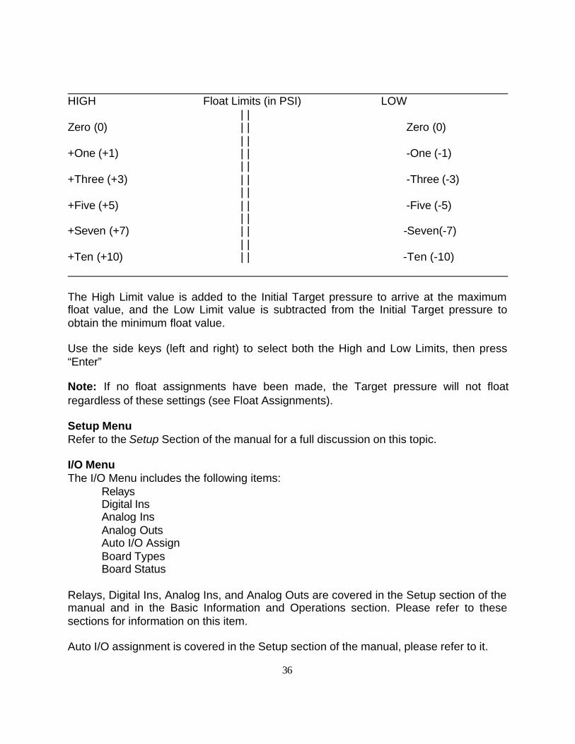
Float Limits
This screen allows the user to select the amount that the suction pressure target will beallowed to be raised or lowered, if a float temp/defr circuit has been assigned for floatingsuction control.
From the Main Menu select ‘Task Settings’ with the side key and press “Enter”. Next,select ‘Float Limits’ with the side key and press “Enter”. A list of all the CompressorTasks/groups will be displayed. Select the desired group with the side key and press“Enter”. This will bring up the following screen:
36
HIGH Float Limits (in PSI) LOW | |
Zero (0) | | Zero (0) | |
+One (+1) | | -One (-1) | |
+Three (+3) | | -Three (-3) | |
+Five (+5) | | -Five (-5) | |
+Seven (+7) | | -Seven(-7) | |
+Ten (+10) | | -Ten (-10)
The High Limit value is added to the Initial Target pressure to arrive at the maximumfloat value, and the Low Limit value is subtracted from the Initial Target pressure toobtain the minimum float value.
Use the side keys (left and right) to select both the High and Low Limits, then press“Enter”
Note: If no float assignments have been made, the Target pressure will not floatregardless of these settings (see Float Assignments).
Setup MenuRefer to the Setup Section of the manual for a full discussion on this topic.
I/O MenuThe I/O Menu includes the following items:
RelaysDigital InsAnalog InsAnalog OutsAuto I/O AssignBoard TypesBoard Status
Relays, Digital Ins, Analog Ins, and Analog Outs are covered in the Setup section of themanual and in the Basic Information and Operations section. Please refer to thesesections for information on this item.
Auto I/O assignment is covered in the Setup section of the manual, please refer to it.
37
Note: You should not need to use this function after the system is set-up andrunning unless you want all the I/O assignments to be re-done. This could havedrastic results, unless you know what you’re doing. It requires the high levelpassword for this reason.
Board Types is covered both in the Setup and Basic Information sections of the manual.
Board StatusThe board status screen is a handy diagnostic tool to determine the communicationstate of the local bus to all I/O boards. Use the side key to select ‘Task Settings’ fromthe Main Menu. Next, select ‘I/O Menu’ with the side key and press “Enter”. Use theside key to select ‘Board Status’ and press “Enter”. The 4k will then scan all 16addresses for each board type and report the results as follows:
K = the board has points assigned to it and it is responding; this is the desired state.
U= the board doesn’t have anything assigned to it, but it is responding.
L = the board has points assigned to it, but is not responding.
“.” = No assignment and no response.
The board types are list down the left side with the 16 possible addresses shown acrossthe top.
If you would like it to re-scan all addresses, Escape from the screen, and then return toit. If you want to re-scan any particular I/O type, press the side key next to it, asindicated in the instructions on the screen.
Schedules
Schedules control the on/off time of day control for tasks that need this function. Fromthe Main Menu select ‘Schedules’ and press “Enter”.
There are three items on the Scheduling submenu. Press the side key aligned with thedesired selection and press “Enter”. The choices are as follows:
Schedules - on/off schedules for each task; the 4k will support up to a total of 84 schedules. Multiple tasks may be placed in the same scheduling group.
38
Press the side key to choose from the list of tasks that have schedules, and press “Enter”.
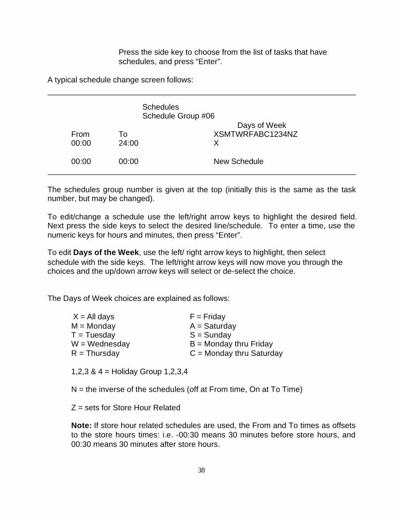
A typical schedule change screen follows:
SchedulesSchedule Group #06
Days of WeekFrom To XSMTWRFABC1234NZ00:00 24:00 X
00:00 00:00 New Schedule
The schedules group number is given at the top (initially this is the same as the tasknumber, but may be changed).
To edit/change a schedule use the left/right arrow keys to highlight the desired field.Next press the side keys to select the desired line/schedule. To enter a time, use thenumeric keys for hours and minutes, then press “Enter”.
To edit Days of the Week, use the left/ right arrow keys to highlight, then selectschedule with the side keys. The left/right arrow keys will now move you through thechoices and the up/down arrow keys will select or de-select the choice.
The Days of Week choices are explained as follows:
X = All days F = FridayM = Monday A = SaturdayT = Tuesday S = SundayW = Wednesday B = Monday thru FridayR = Thursday C = Monday thru Saturday
1,2,3 & 4 = Holiday Group 1,2,3,4
N = the inverse of the schedules (off at From time, On at To Time)
Z = sets for Store Hour Related
Note: If store hour related schedules are used, the From and To times as offsetsto the store hours times: i.e. -00:30 means 30 minutes before store hours, and00:30 means 30 minutes after store hours.
39
Note: When adding a new schedule, highlight the new schedule line first, thenset desired days of week, then set From/To times.
Store Hours - the open/closed hours of the store - used for relative scheduling. From the Scheduling Menu select Store Hours and press “Enter”.
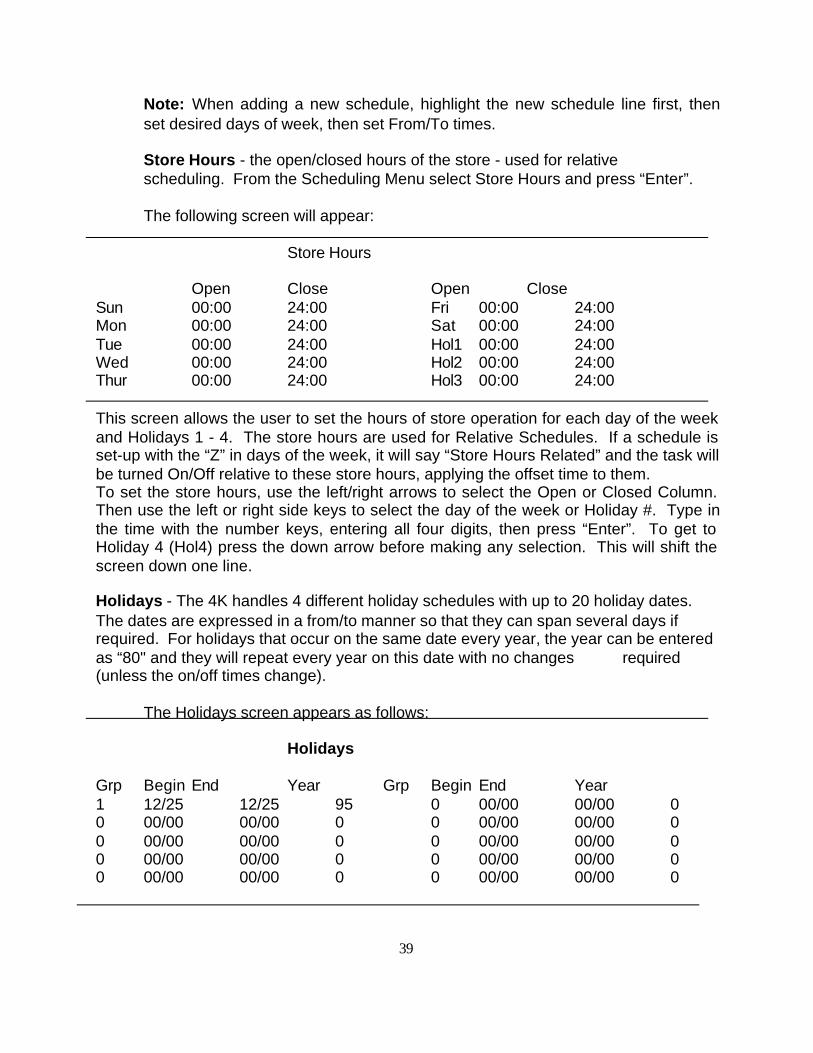
The following screen will appear:
Store Hours
Open Close Open CloseSun 00:00 24:00 Fri 00:00 24:00Mon 00:00 24:00 Sat 00:00 24:00Tue 00:00 24:00 Hol1 00:00 24:00Wed 00:00 24:00 Hol2 00:00 24:00Thur 00:00 24:00 Hol3 00:00 24:00
This screen allows the user to set the hours of store operation for each day of the weekand Holidays 1 - 4. The store hours are used for Relative Schedules. If a schedule isset-up with the “Z” in days of the week, it will say “Store Hours Related” and the task willbe turned On/Off relative to these store hours, applying the offset time to them.To set the store hours, use the left/right arrows to select the Open or Closed Column.Then use the left or right side keys to select the day of the week or Holiday #. Type inthe time with the number keys, entering all four digits, then press “Enter”. To get toHoliday 4 (Hol4) press the down arrow before making any selection. This will shift thescreen down one line.
Holidays - The 4K handles 4 different holiday schedules with up to 20 holiday dates.The dates are expressed in a from/to manner so that they can span several days ifrequired. For holidays that occur on the same date every year, the year can be enteredas “80" and they will repeat every year on this date with no changes required(unless the on/off times change).
The Holidays screen appears as follows:
Holidays
Grp Begin End Year Grp Begin End Year1 12/25 12/25 95 0 00/00 00/00 00 00/00 00/00 0 0 00/00 00/00 00 00/00 00/00 0 0 00/00 00/00 00 00/00 00/00 0 0 00/00 00/00 00 00/00 00/00 0 0 00/00 00/00 0
40
This screen allows you to program up to 20 dates/periods and assigns them to any oneof 4 holiday Groups/schedules. Any task that has a schedule programmed with aHoliday type will follow that schedule while the Holiday date is active; otherwise it willbe turned OFF!
To program a Holiday Date, first use the left/right arrow keys to highlight the Grpheading; the Group number must be entered first before it will accept any of theother entries. Next, use the side keys to highlight the line item. Use the number keys toenter the Grp number (1 to 4) and press “Enter”. Again, use the left/right arrow keys tohighlight the ‘Begin’ column. Use the number keys to enter the month and day with aperiod or dash used to separate them: i.e. 12-25 or 12.25 = 12/25, then press “Enter”.Proceed in the same manner for the ‘End’ of the Holiday date; then the ‘Year’ as 95 for1995.
If the Holiday is only for one day, put the same date for ‘Begin’ and ‘End’ date.
Use up/down arrows to get to the second page of 10 date entries, if required.
Run/Stop/Monitor
Caution: Do not use this feature unless you know what you’re doing! If you placethe 4K in the “monitor” mode, it will stay that way until someone puts it back, it will notbe controlling any relays or analog outputs. If placed in the “stopped” mode, it willreturn to the “running” mode automatically in one hour.
Note: When you are downloading a setup/program into the 4k, you will see it go to thestopped mode for the duration of the download, then return to running.
Miscellaneous
The Miscellaneous menu selection provides access to the following items:
Set Time - covered previously, see page xxEdit Passwords - change passwords; see page xxSet-up Graphs - change graphing set-up; point, offset & scaleGraph Interval - change graph/logging intervalAlarm Enables - provides access to the alarm enables screen; This includessetting up the desired alarming for Lost Boards, Sensor Fail, Oil Failure,Discharge Temp, Abnormal Termination, Sw Override, Sw Overtime, and IOOverride. Clear Program/Memory - Clears entire setup/program; do not usethis function unless you intend to perform the setup again, or have a newprogram to download. Requires high level password.Clear Alarm Events - Clears out alarm history log (last 40 events). Requires top level password.Defrost Time Map - displays a graphical representation of all defrostschedules (view only).
41
Set-up Graphs
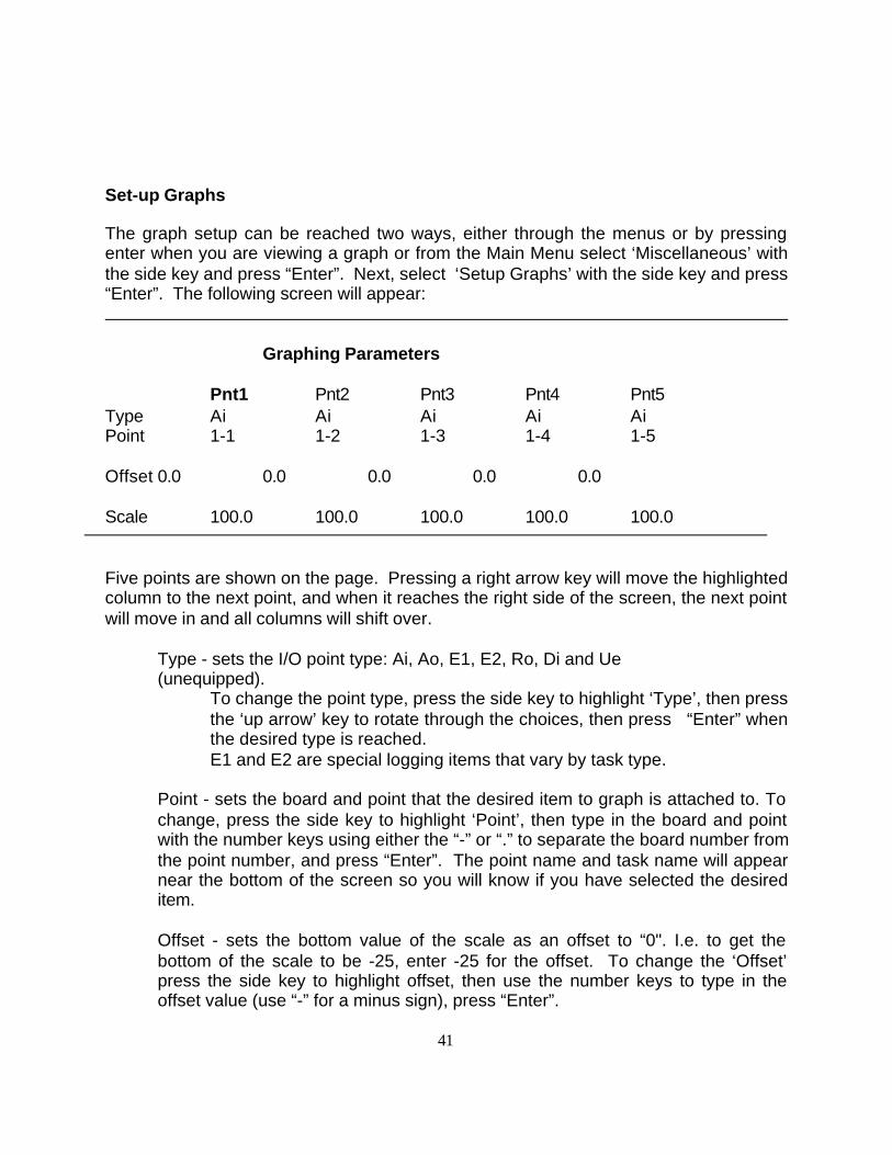
The graph setup can be reached two ways, either through the menus or by pressingenter when you are viewing a graph or from the Main Menu select ‘Miscellaneous’ withthe side key and press “Enter”. Next, select ‘Setup Graphs’ with the side key and press“Enter”. The following screen will appear:
Graphing Parameters
Pnt1 Pnt2 Pnt3 Pnt4 Pnt5Type Ai Ai Ai Ai AiPoint 1-1 1-2 1-3 1-4 1-5
Offset 0.0 0.0 0.0 0.0 0.0
Scale 100.0 100.0 100.0 100.0 100.0
Five points are shown on the page. Pressing a right arrow key will move the highlightedcolumn to the next point, and when it reaches the right side of the screen, the next pointwill move in and all columns will shift over.
Type - sets the I/O point type: Ai, Ao, E1, E2, Ro, Di and Ue (unequipped).
To change the point type, press the side key to highlight ‘Type’, then pressthe ‘up arrow’ key to rotate through the choices, then press “Enter” whenthe desired type is reached.E1 and E2 are special logging items that vary by task type.
Point - sets the board and point that the desired item to graph is attached to. Tochange, press the side key to highlight ‘Point’, then type in the board and pointwith the number keys using either the “-” or “.” to separate the board number fromthe point number, and press “Enter”. The point name and task name will appearnear the bottom of the screen so you will know if you have selected the desireditem.
Offset - sets the bottom value of the scale as an offset to “0". I.e. to get thebottom of the scale to be -25, enter -25 for the offset. To change the ‘Offset’press the side key to highlight offset, then use the number keys to type in theoffset value (use “-” for a minus sign), press “Enter”.
42
Scale - sets the total range of the vertical scale (in units of 10, from 10 to 500). This value is added to the offset to get the maximumvalue of the scale. To change, highlight ‘Scale’ with the side key, then enter thedesired value with the number keys, noting that 10 = 100, 50 = 500 etc., thenpress “Enter”.
Note: if you have trouble selecting any item, when you first enter thisscreen, press the “Escape” key once then try again.
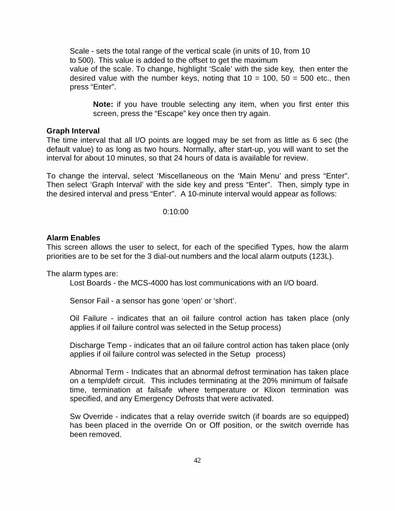
Graph IntervalThe time interval that all I/O points are logged may be set from as little as 6 sec (thedefault value) to as long as two hours. Normally, after start-up, you will want to set theinterval for about 10 minutes, so that 24 hours of data is available for review.
To change the interval, select ‘Miscellaneous on the ‘Main Menu’ and press “Enter”.Then select ‘Graph Interval’ with the side key and press “Enter”. Then, simply type inthe desired interval and press “Enter”. A 10-minute interval would appear as follows:
0:10:00
Alarm EnablesThis screen allows the user to select, for each of the specified Types, how the alarmpriorities are to be set for the 3 dial-out numbers and the local alarm outputs (123L).
The alarm types are:Lost Boards - the MCS-4000 has lost communications with an I/O board.
Sensor Fail - a sensor has gone ‘open’ or ‘short’.
Oil Failure - indicates that an oil failure control action has taken place (onlyapplies if oil failure control was selected in the Setup process)
Discharge Temp - indicates that an oil failure control action has taken place (onlyapplies if oil failure control was selected in the Setup process)
Abnormal Term - Indicates that an abnormal defrost termination has taken placeon a temp/defr circuit. This includes terminating at the 20% minimum of failsafetime, termination at failsafe where temperature or Klixon termination wasspecified, and any Emergency Defrosts that were activated.
Sw Override - indicates that a relay override switch (if boards are so equipped)has been placed in the override On or Off position, or the switch override hasbeen removed.
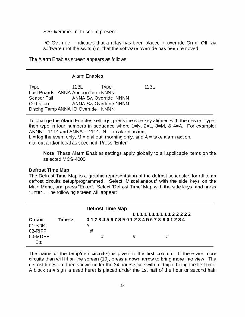
43
Sw Overtime - not used at present.
I/O Override - indicates that a relay has been placed in override On or Off viasoftware (not the switch) or that the software override has been removed.
The Alarm Enables screen appears as follows:
Alarm Enables
Type 123L Type 123LLost Boards ANNA AbnormTerm NNNNSensor Fail ANNA Sw Override NNNNOil Failure ANNA Sw Overtime NNNNDischg Temp ANNA IO Override NNNN
To change the Alarm Enables settings, press the side key aligned with the desire ‘Type’,then type in four numbers in sequence where 1=N, 2=L, 3=M, & 4=A. For example :ANNN = 1114 and ANNA = 4114. N = no alarm action,L = log the event only, M = dial out, morning only, and A = take alarm action,dial-out and/or local as specified. Press “Enter”.
Note: These Alarm Enables settings apply globally to all applicable items on theselected MCS-4000.
Defrost Time MapThe Defrost Time Map is a graphic representation of the defrost schedules for all tempdefrost circuits setup/programmed. Select ‘Miscellaneous’ with the side keys on theMain Menu, and press “Enter”. Select ’Defrost Time’ Map with the side keys, and press“Enter”. The following screen will appear:
Defrost Time Map 1 1 1 1 1 1 1 1 1 1 2 2 2 2 2
Circuit Time-> 0 1 2 3 4 5 6 7 8 9 0 1 2 3 4 5 6 7 8 9 0 1 2 3 401-SDIC #02-RIFF #03-MDFF # # # Etc.
The name of the temp/defr circuit(s) is given in the first column. If there are morecircuits than will fit on the screen (10), press a down arrow to bring more into view. Thedefrost times are then shown under the 24 hours scale with midnight being the first time.A block (a # sign is used here) is placed under the 1st half of the hour or second half,
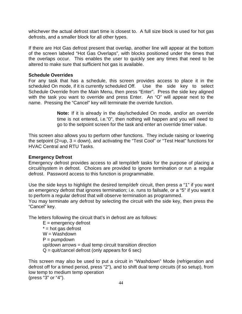
44
whichever the actual defrost start time is closest to. A full size block is used for hot gasdefrosts, and a smaller block for all other types.
If there are Hot Gas defrost present that overlap, another line will appear at the bottomof the screen labeled “Hot Gas Overlaps”, with blocks positioned under the times thatthe overlaps occur. This enables the user to quickly see any times that need to bealtered to make sure that sufficient hot gas is available.
Schedule OverridesFor any task that has a schedule, this screen provides access to place it in thescheduled On mode, if it is currently scheduled Off. Use the side key to selectSchedule Override from the Main Menu, then press “Enter”. Press the side key alignedwith the task you want to override and press Enter. An “O” will appear next to thename. Pressing the “Cancel” key will terminate the override function.
Note: If it is already in the day/scheduled On mode, and/or an overridetime is not entered, i.e.”0", then nothing will happen and you will need togo to the setpoint screen for the task and enter an override timer value.
This screen also allows you to perform other functions. They include raising or loweringthe setpoint (2=up, 3 = down), and activating the “Test Cool” or “Test Heat” functions forHVAC Central and RTU Tasks.
Emergency DefrostEmergency defrost provides access to all temp/defr tasks for the purpose of placing acircuit/system in defrost. Choices are provided to ignore termination or run a regulardefrost. Password access to this function is programmable.
Use the side keys to highlight the desired temp/defr circuit, then press a “1" if you wantan emergency defrost that ignores termination; i.e. runs to failsafe, or a “5" if you want itto perform a regular defrost that will observe termination as programmed.You may terminate any defrost by selecting the circuit with the side key, then press the“Cancel” key.
The letters following the circuit that’s in defrost are as follows:E = emergency defrost* = hot gas defrostW = WashdownP = pumpdownup/down arrows = dual temp circuit transition directionQ = quit/cancel defrost (only appears for 6 sec)
This screen may also be used to put a circuit in “Washdown” Mode (refrigeration anddefrost off for a timed period, press “2"), and to shift dual temp circuits (if so setup), fromlow temp to medium temp operation(press “3" or “4").

1
MCS-4000 SETUP
Introduction
Setup refers to the initial programming of an MCS-4000 (4K) controller. This proceduremay be accomplished directly from the front panel of the controller, or on a PC utilizingthe EZSET2 program. The setup file/program may then be loaded into the controllerdirectly from the PC with a Com-Trol RS232/RS485 download module (part number90TB049G01), or direct connect (part number 50TB171G01) via a COM5002Communications Controller, or over the phone line/modem with the COM-5002 or 6000Advantage, using the Com-Trol EZCOM program.
The following discussion will apply to the front panel programming procedure.Refer to the Ezset2 Manual for computer programming.
Note: Prior to programming the first task, make sure that the Clear Memory function isperformed. This is accomplished by selecting 'Miscellaneous' on the Main Menu, thenselecting 'Clear Memory'. You will be prompted for the High Level Password (initially9999) and warned that any existing program will be erased/lost if you proceed.
To begin programming, select Task Settings on the Main Menu with the side key (topright) and press "Enter". Select Setup Menu (upper right) with side key and press"Enter". Select Setup/Add Task with side key (upper left), and press "Enter". A list ofTasks will be displayed as appropriate to the software Library present in the 4k you areworking on. Use the side keys to select the desired Task Type and press "Enter". Youwill then proceed through a series of screens as appropriate to the task type selected.Refer to the Library and Task type information that follows.
The set-up is performed on a Task by Task basis. A Task is defined as a job to bedone. A program is a collection of tasks necessary to meet the needs of an application.
Each MCS-4000 may have one Library installed. The following is a list of the availableLibraries and the task types they contain.
Tasks that are common to all Libraries include:
Anti-sweat GrpControls case anti-sweat heaters based upon dew point or relativehumidity. Control may be by relays on 5,10 or 15-minute cycles, or bypulse/solid state relays on a 6-sec interval.
2
Lighting GrpProvides scheduling/time-of-day control. Light level control by photocell(digital) or light level sensors (analog) is available. Push-button overridesare an option.
Unit Heaters/Exhaust FansProvides control of unit heaters and/or exhaust fans.
Options TaskThere are currently 63 different Option Task Types, including such thingsas AI Monitors, DI Monitors, subcoolers, Master Hot Gas Valve, SurgeValve, Heat Reclaim, etc.
Rack Library (RACK 1.3xx)Compressor Grp
Provides control and monitoring of up to 8 parallel compressors/unloadersof equal or unequal capacities, and all control functions associated withcompressor control, including oil failure control. Variable speed and screwcompressors are handled as well.
Condenser FansControls air-cooled or evaporative condenser/water coolers of fixed speed,two speed, or variable speed design. Condensers may be single or multi-circuit. Provides control of up to 4 splits. Only one condenser Task perRack 4K.
Temp/Defr CircuitControls and/or monitors all aspects of a circuit, including temperaturecontrol, defrost control and case temperature monitoring.
Satellite CmprControls a satellite compressor and the circuit/defrost associated with it.
Single CmprControls single compressors and their associated defrost.
HVAC Library (HVAC 2.3xx):Large/Central Packages
Provides control and monitoring for large built-up central HVAC systemsor large "doghouse" systems. Handles single, two fan, two speed, andvariable speed fans. Maximum of 12 control/relay outputs.
Rtu/Small PackagesIntended for control of smaller packaged rooftop mounted HVAC units.Limited to a fan, 2 cool and 2 heat stages.
3
Singles Library (SNGL 3.3xx):Singles Compressor
Controls/monitors all aspects of a single condensing unit compressor.May also control a single compressor with an unloader, or a twin/dualcompressor unit. Up to twenty single condensing units may be controlledon a single 4k.
Condenser FansSame as Rack Condenser Fans; see above.
Temp/Defr CircuitSame as Rack Temp/Defr Circuit; see above.
CSTR Library (CSTR 4.3xx)Large/Central Packages
Same features as HVAC above.
RTU/Small PackagesSame features as HVAC above.
Single Cmpr Same features as Rack Library Single Cmpr Task.
Each Software library will be covered on a task by task basis. Each screen will becovered in sequence with an explanation of each item/option following.
NOTE: Unequipped - means that this option/feature is not wanted.
TASKS COMMON TO ALL LIBRARIES
Anti-Sweat Grp
ANTI-SWEAT OPTIONS (screen 1)Digital Monitors - Unequipped
- EquippedProvides a digital input to monitor the contactor/relay.
Schedule mode - 24 hr (scheduled)Initially sets schedule to have in day mode at all times.
- Day/Nite (store hours)Sets-up a schedule based on Store Hours to switch from Day to Night Mode/setpoints.
4
Cycle Length (mins) - ASWSets-up an analog output to do pulse control (6 sec bandwidth).
- FiveSets the cycling interval to 5 minutes.
- TenSets the cycling interval to 10 minutes.
- FifteenSets the cycling interval to 15 minutes.
Humidity Sensor Type - DewpointSets the sensor type to Dewpoint for control of the Anti-sweat heaters.
- Relative HumiditySets the sensor type to relative humidity.
Humidity Sensor Assn - Use Common SensorIf dewpoint or relative humidity sensor already set-up forother tasks/purposes, will use it rather than assigning a newone.
- Assign New SensorSets-up a new sensor rather than use a previously assignedone for ASW control.
Use the side keys to set all options, then press "Enter" to move on to the next screen.
OVERRIDE CHOICES (screen 2)Test Digital Input - Unequipped
- EquippedProvides a digital input that will turn heaters on for testinterval time selected below.
Test Interval - 30 minutesSets test interval for option above to 30 minutes.- 60 minutesSets test interval to 60 minutes.- 90 minutesSets test interval to 90 minutes.- 120 minutesSets test interval to 120 minutes.
5
Override Schedule Inp - Unequipped- Start DIProvides a digital input for a push button switch to put theASW heaters in the Day mode.- Start/Stop DI’sProvides a digital input for a push button switch to put theASW heaters in the Day mode and a second DI that willcancel the override timer.
Use the side keys to set all options, then press "Enter" to move on to the next screen.“Escape” returns you to the previous screen and “Cancel” aborts the set-up of thecurrent Task.
ZONE USAGE (screen 3)Zone Relays Zone Relays
1-> 1 <-2
3-> <-4
5-> <-6
7-> <-8
This screen sets-up the number of relays or pulse outputs desired in the current ASWtask desired for control and on how many boards. Use the side keys to select theboard/zone (1-8), then use the Up arrow to set-up the number of relays/analog outputsdesired. Press “Enter” when complete.
ANTISWEAT#01 - ASW#01 (screen 4)Anti-sweat Day
Setp 55.0 For Maximum % On CycleSets dewpoint/RH level at which the heaters will be cycled at the maximum % on value given below,for the Day mode (based upon schedule settings).
Pcnt 80.0 Maximum % On CycleSets the maximum On time allowed for Day mode.
Setp 35.0 For Minimum % ON CycleSets dewpoint/RH level at which the heaters will be cycled atthe minimum % on value given below, for the Day mode.
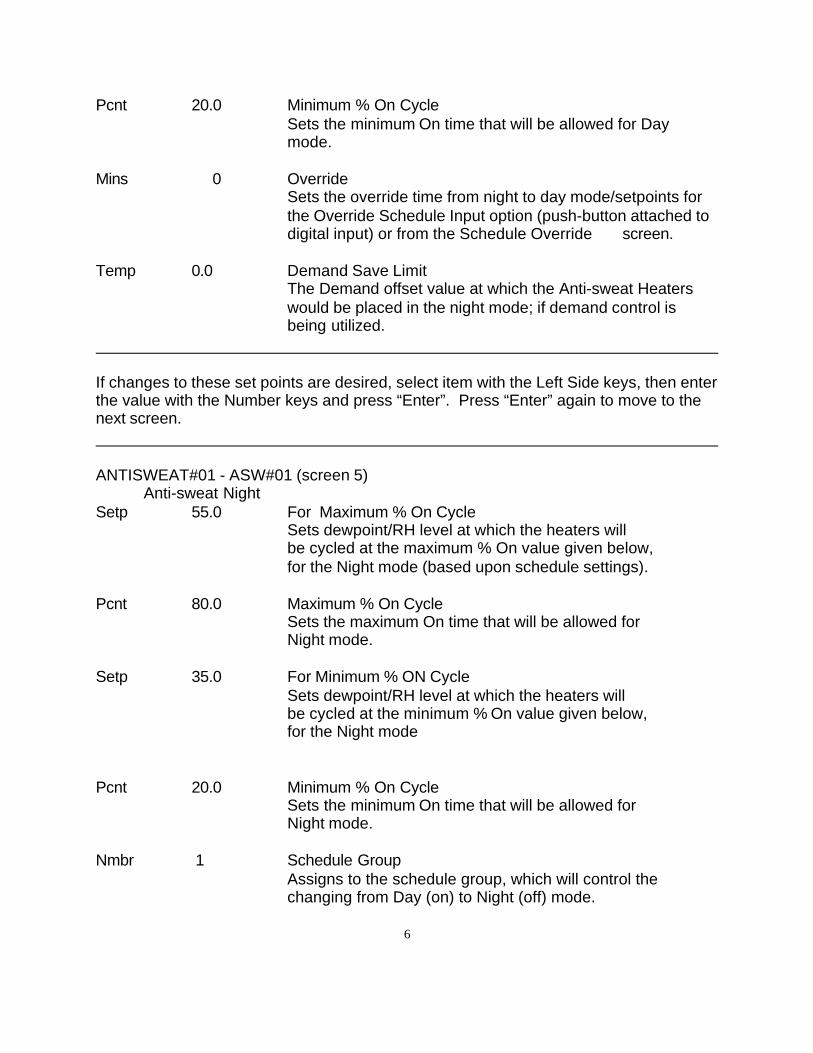
6
Pcnt 20.0 Minimum % On CycleSets the minimum On time that will be allowed for Daymode.
Mins 0 OverrideSets the override time from night to day mode/setpoints forthe Override Schedule Input option (push-button attached todigital input) or from the Schedule Override screen.
Temp 0.0 Demand Save LimitThe Demand offset value at which the Anti-sweat Heaterswould be placed in the night mode; if demand control isbeing utilized.
If changes to these set points are desired, select item with the Left Side keys, then enterthe value with the Number keys and press “Enter”. Press “Enter” again to move to thenext screen.
ANTISWEAT#01 - ASW#01 (screen 5)Anti-sweat Night
Setp 55.0 For Maximum % On CycleSets dewpoint/RH level at which the heaters willbe cycled at the maximum % On value given below,for the Night mode (based upon schedule settings).
Pcnt 80.0 Maximum % On CycleSets the maximum On time that will be allowed for Night mode.
Setp 35.0 For Minimum % ON CycleSets dewpoint/RH level at which the heaters will be cycled at the minimum % On value given below,for the Night mode
Pcnt 20.0 Minimum % On CycleSets the minimum On time that will be allowed for Night mode.
Nmbr 1 Schedule GroupAssigns to the schedule group, which will control the changing from Day (on) to Night (off) mode.

7
If changes to these set points are desired, select item with the Left Side keys, then enterthe value with the Number keys and press “Enter”. Press “Enter” again to move to thenext screen.
This completes the programming of the Anti-sweat Grp Task.
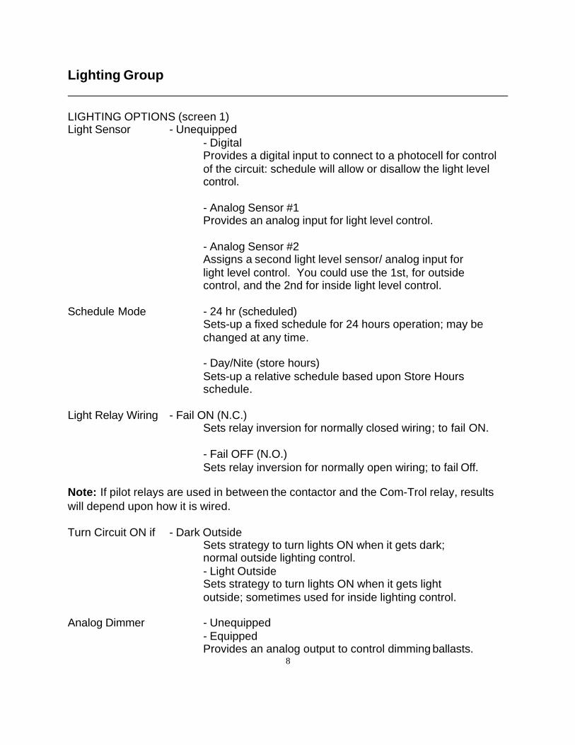
8
Lighting Group
LIGHTING OPTIONS (screen 1)Light Sensor - Unequipped
- DigitalProvides a digital input to connect to a photocell for controlof the circuit: schedule will allow or disallow the light levelcontrol.
- Analog Sensor #1Provides an analog input for light level control.
- Analog Sensor #2Assigns a second light level sensor/ analog input for light level control. You could use the 1st, for outside control, and the 2nd for inside light level control.
Schedule Mode - 24 hr (scheduled)Sets-up a fixed schedule for 24 hours operation; may bechanged at any time.
- Day/Nite (store hours)Sets-up a relative schedule based upon Store Hoursschedule.
Light Relay Wiring - Fail ON (N.C.)Sets relay inversion for normally closed wiring; to fail ON.
- Fail OFF (N.O.)Sets relay inversion for normally open wiring; to fail Off.
Note: If pilot relays are used in between the contactor and the Com-Trol relay, resultswill depend upon how it is wired.
Turn Circuit ON if - Dark OutsideSets strategy to turn lights ON when it gets dark; normal outside lighting control.- Light OutsideSets strategy to turn lights ON when it gets light outside; sometimes used for inside lighting control.
Analog Dimmer - Unequipped- EquippedProvides an analog output to control dimming ballasts.
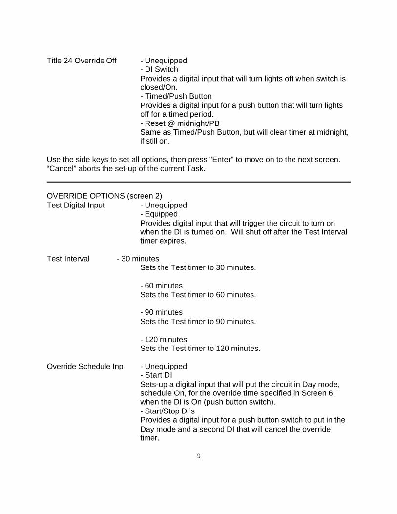
9
Title 24 Override Off - Unequipped- DI SwitchProvides a digital input that will turn lights off when switch isclosed/On.- Timed/Push ButtonProvides a digital input for a push button that will turn lightsoff for a timed period.- Reset @ midnight/PBSame as Timed/Push Button, but will clear timer at midnight,if still on.
Use the side keys to set all options, then press "Enter" to move on to the next screen.“Cancel” aborts the set-up of the current Task.
OVERRIDE OPTIONS (screen 2)Test Digital Input - Unequipped
- EquippedProvides digital input that will trigger the circuit to turn onwhen the DI is turned on. Will shut off after the Test Intervaltimer expires.
Test Interval - 30 minutesSets the Test timer to 30 minutes.
- 60 minutesSets the Test timer to 60 minutes.
- 90 minutesSets the Test timer to 90 minutes.
- 120 minutesSets the Test timer to 120 minutes.
Override Schedule Inp - Unequipped- Start DISets-up a digital input that will put the circuit in Day mode,schedule On, for the override time specified in Screen 6,when the DI is On (push button switch).- Start/Stop DI’sProvides a digital input for a push button switch to put in theDay mode and a second DI that will cancel the overridetimer.
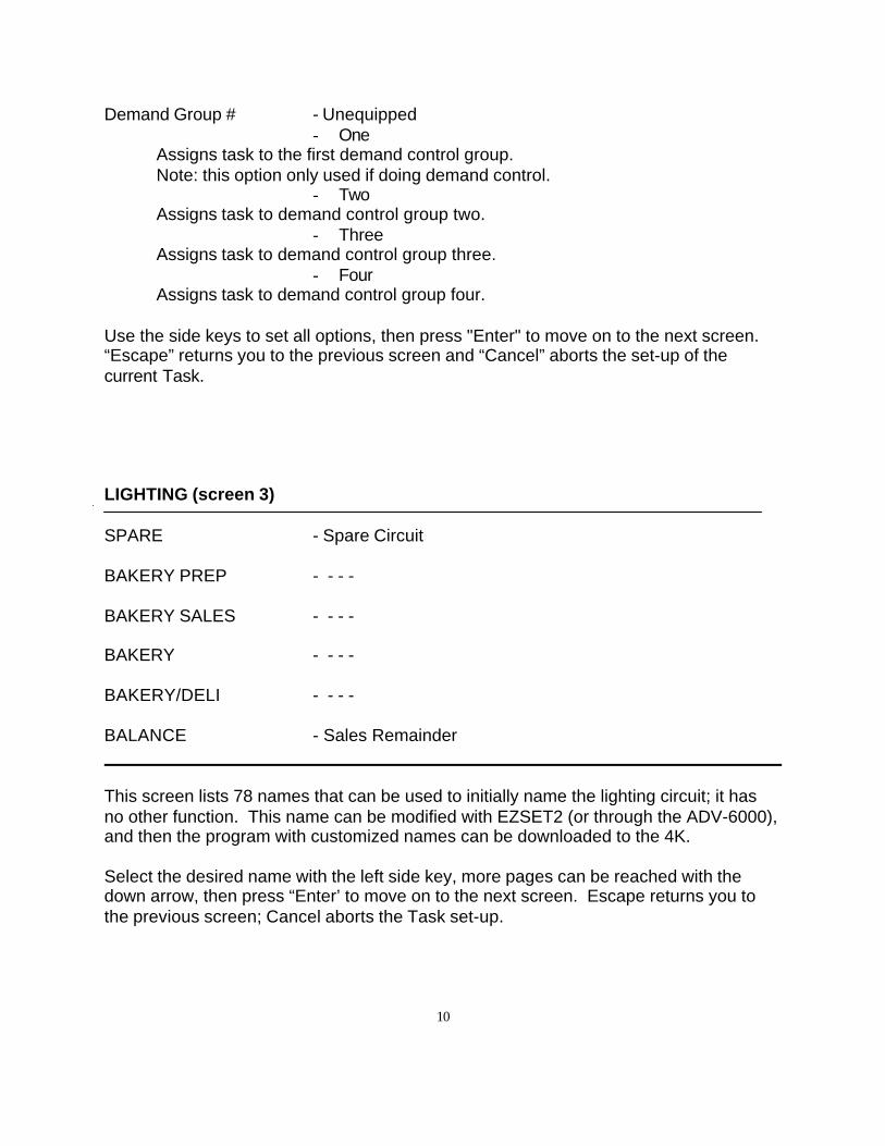
10
Demand Group # - Unequipped- One
Assigns task to the first demand control group.Note: this option only used if doing demand control.
- TwoAssigns task to demand control group two.
- ThreeAssigns task to demand control group three.
- FourAssigns task to demand control group four.
Use the side keys to set all options, then press "Enter" to move on to the next screen.“Escape” returns you to the previous screen and “Cancel” aborts the set-up of thecurrent Task.
LIGHTING (screen 3)
SPARE - Spare Circuit
BAKERY PREP - - - -
BAKERY SALES - - - -
BAKERY - - - -
BAKERY/DELI - - - -
BALANCE - Sales Remainder
This screen lists 78 names that can be used to initially name the lighting circuit; it hasno other function. This name can be modified with EZSET2 (or through the ADV-6000),and then the program with customized names can be downloaded to the 4K.
Select the desired name with the left side key, more pages can be reached with thedown arrow, then press “Enter’ to move on to the next screen. Escape returns you tothe previous screen; Cancel aborts the Task set-up.
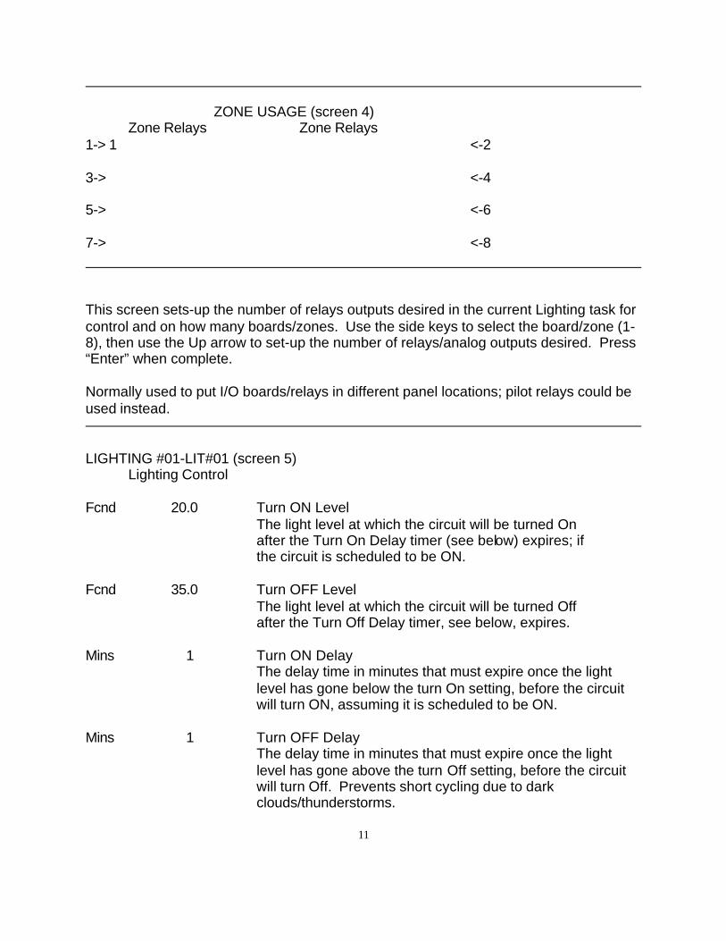
11
ZONE USAGE (screen 4)Zone Relays Zone Relays
1-> 1 <-2
3-> <-4
5-> <-6
7-> <-8
This screen sets-up the number of relays outputs desired in the current Lighting task forcontrol and on how many boards/zones. Use the side keys to select the board/zone (1-8), then use the Up arrow to set-up the number of relays/analog outputs desired. Press“Enter” when complete.
Normally used to put I/O boards/relays in different panel locations; pilot relays could beused instead.
LIGHTING #01-LIT#01 (screen 5)Lighting Control
Fcnd 20.0 Turn ON LevelThe light level at which the circuit will be turned On after the Turn On Delay timer (see below) expires; if the circuit is scheduled to be ON.
Fcnd 35.0 Turn OFF LevelThe light level at which the circuit will be turned Off after the Turn Off Delay timer, see below, expires.
Mins 1 Turn ON DelayThe delay time in minutes that must expire once the lightlevel has gone below the turn On setting, before the circuitwill turn ON, assuming it is scheduled to be ON.
Mins 1 Turn OFF DelayThe delay time in minutes that must expire once the lightlevel has gone above the turn Off setting, before the circuitwill turn Off. Prevents short cycling due to darkclouds/thunderstorms.
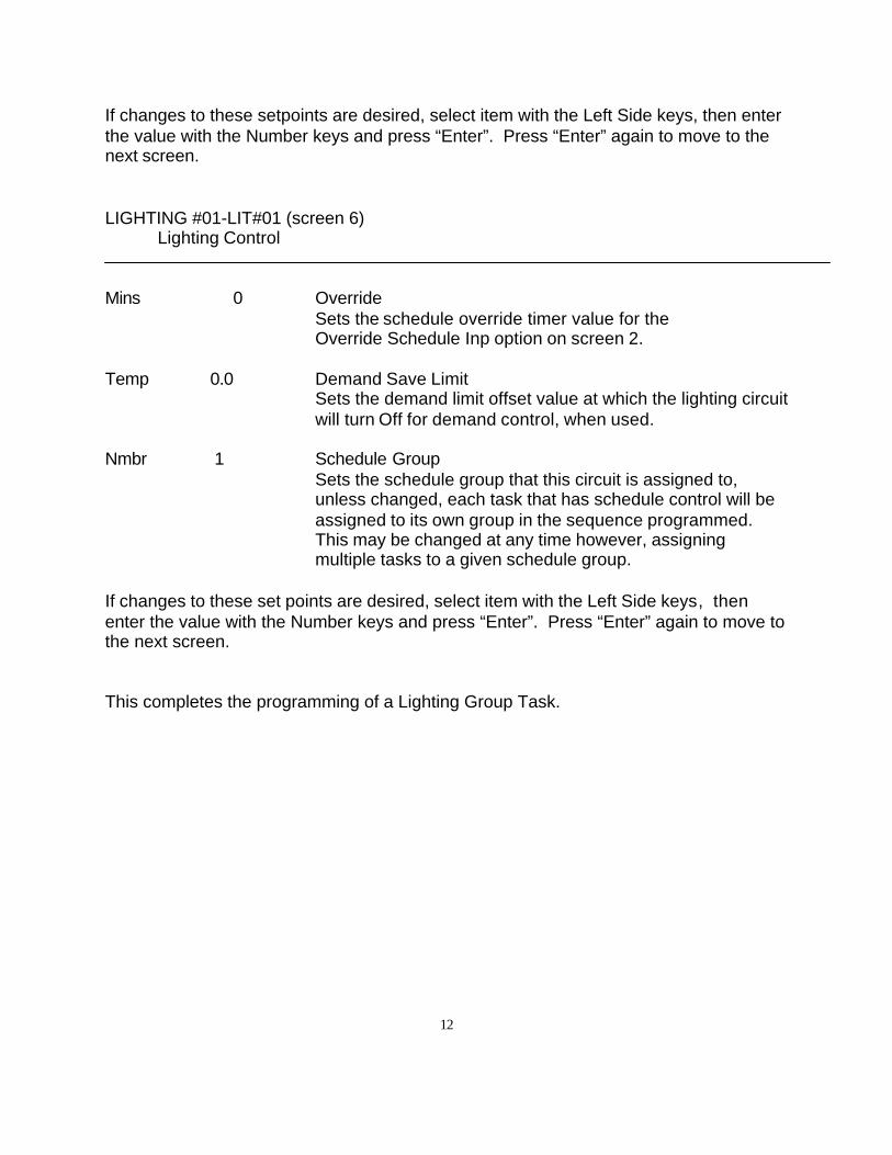
12
If changes to these setpoints are desired, select item with the Left Side keys, then enterthe value with the Number keys and press “Enter”. Press “Enter” again to move to thenext screen.
LIGHTING #01-LIT#01 (screen 6)Lighting Control
Mins 0 OverrideSets the schedule override timer value for the Override Schedule Inp option on screen 2.
Temp 0.0 Demand Save LimitSets the demand limit offset value at which the lighting circuitwill turn Off for demand control, when used.
Nmbr 1 Schedule GroupSets the schedule group that this circuit is assigned to,unless changed, each task that has schedule control will beassigned to its own group in the sequence programmed.This may be changed at any time however, assigningmultiple tasks to a given schedule group.
If changes to these set points are desired, select item with the Left Side keys, thenenter the value with the Number keys and press “Enter”. Press “Enter” again to move tothe next screen.
This completes the programming of a Lighting Group Task.
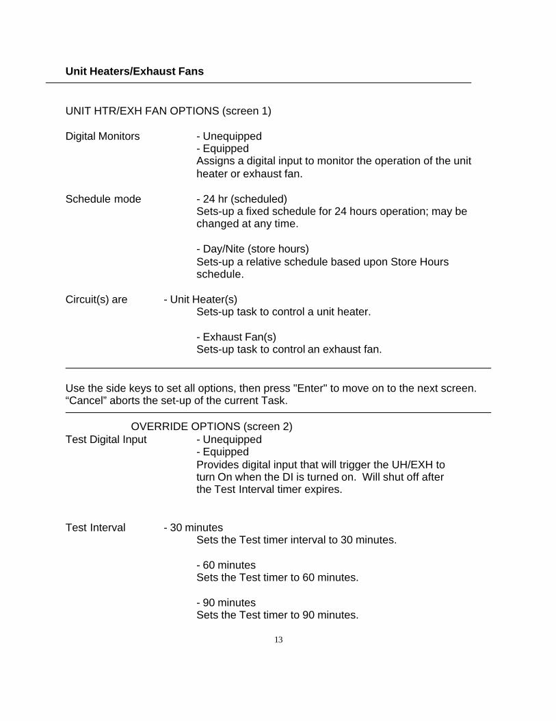
13
Unit Heaters/Exhaust Fans
UNIT HTR/EXH FAN OPTIONS (screen 1)
Digital Monitors - Unequipped- EquippedAssigns a digital input to monitor the operation of the unitheater or exhaust fan.
Schedule mode - 24 hr (scheduled)Sets-up a fixed schedule for 24 hours operation; may bechanged at any time.
- Day/Nite (store hours)Sets-up a relative schedule based upon Store Hoursschedule.
Circuit(s) are - Unit Heater(s)Sets-up task to control a unit heater.
- Exhaust Fan(s)Sets-up task to control an exhaust fan.
Use the side keys to set all options, then press "Enter" to move on to the next screen.“Cancel” aborts the set-up of the current Task.
OVERRIDE OPTIONS (screen 2)Test Digital Input - Unequipped
- EquippedProvides digital input that will trigger the UH/EXH to turn On when the DI is turned on. Will shut off after the Test Interval timer expires.
Test Interval - 30 minutesSets the Test timer interval to 30 minutes.
- 60 minutesSets the Test timer to 60 minutes.
- 90 minutesSets the Test timer to 90 minutes.
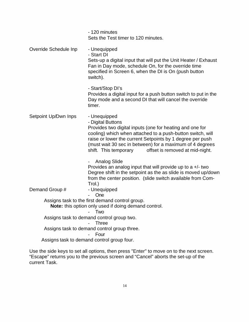
14
- 120 minutesSets the Test timer to 120 minutes.
Override Schedule Inp - Unequipped- Start DISets-up a digital input that will put the Unit Heater / ExhaustFan in Day mode, schedule On, for the override timespecified in Screen 6, when the DI is On (push buttonswitch).
- Start/Stop DI’sProvides a digital input for a push button switch to put in theDay mode and a second DI that will cancel the overridetimer.
Setpoint Up/Dwn Inps - Unequipped- Digital ButtonsProvides two digital inputs (one for heating and one forcooling) which when attached to a push-button switch, willraise or lower the current Setpoints by 1 degree per push(must wait 30 sec in between) for a maximum of 4 degreesshift. This temporary offset is removed at mid-night.
- Analog SlideProvides an analog input that will provide up to a +/- twoDegree shift in the setpoint as the as slide is moved up/downfrom the center position. (slide switch available from Com-Trol.)
Demand Group # - Unequipped- One
Assigns task to the first demand control group. Note: this option only used if doing demand control.
- TwoAssigns task to demand control group two.
- ThreeAssigns task to demand control group three.
- Four Assigns task to demand control group four.
Use the side keys to set all options, then press "Enter" to move on to the next screen.“Escape” returns you to the previous screen and “Cancel” aborts the set-up of thecurrent Task.
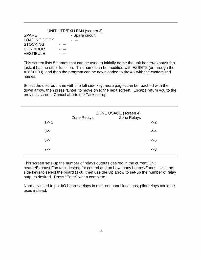
15
UNIT HTR/EXH FAN (screen 3)SPARE - Spare circuitLOADING DOCK - ---STOCKING - ---CORRIDOR - ---VESTIBULE - ---
This screen lists 5 names that can be used to initially name the unit heater/exhaust fantask; it has no other function. This name can be modified with EZSET2 (or through theADV-6000), and then the program can be downloaded to the 4K with the customizednames.
Select the desired name with the left side key, more pages can be reached with thedown arrow, then press “Enter’ to move on to the next screen. Escape return you to theprevious screen, Cancel aborts the Task set-up.
ZONE USAGE (screen 4)Zone Relays Zone Relays
1-> 1 <-2
3-> <-4
5-> <-6
7-> <-8
This screen sets-up the number of relays outputs desired in the current Unitheater/Exhaust Fan task desired for control and on how many boards/Zones. Use theside keys to select the board (1-8), then use the Up arrow to set-up the number of relayoutputs desired. Press “Enter” when complete.
Normally used to put I/O boards/relays in different panel locations; pilot relays could beused instead.
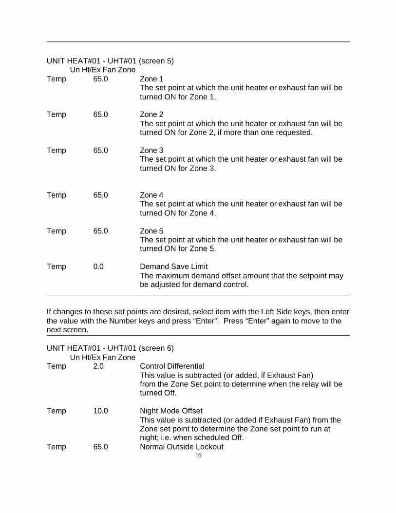
16
UNIT HEAT#01 - UHT#01 (screen 5)Un Ht/Ex Fan Zone
Temp 65.0 Zone 1The set point at which the unit heater or exhaust fan will beturned ON for Zone 1.
Temp 65.0 Zone 2The set point at which the unit heater or exhaust fan will beturned ON for Zone 2, if more than one requested.
Temp 65.0 Zone 3The set point at which the unit heater or exhaust fan will beturned ON for Zone 3.
Temp 65.0 Zone 4The set point at which the unit heater or exhaust fan will beturned ON for Zone 4.
Temp 65.0 Zone 5The set point at which the unit heater or exhaust fan will beturned ON for Zone 5.
Temp 0.0 Demand Save LimitThe maximum demand offset amount that the setpoint maybe adjusted for demand control.
If changes to these set points are desired, select item with the Left Side keys, then enterthe value with the Number keys and press “Enter”. Press “Enter” again to move to thenext screen.
UNIT HEAT#01 - UHT#01 (screen 6)Un Ht/Ex Fan Zone
Temp 2.0 Control DifferentialThis value is subtracted (or added, if Exhaust Fan)from the Zone Set point to determine when the relay will beturned Off.
Temp 10.0 Night Mode OffsetThis value is subtracted (or added if Exhaust Fan) from theZone set point to determine the Zone set point to run atnight; i.e. when scheduled Off.
Temp 65.0 Normal Outside Lockout
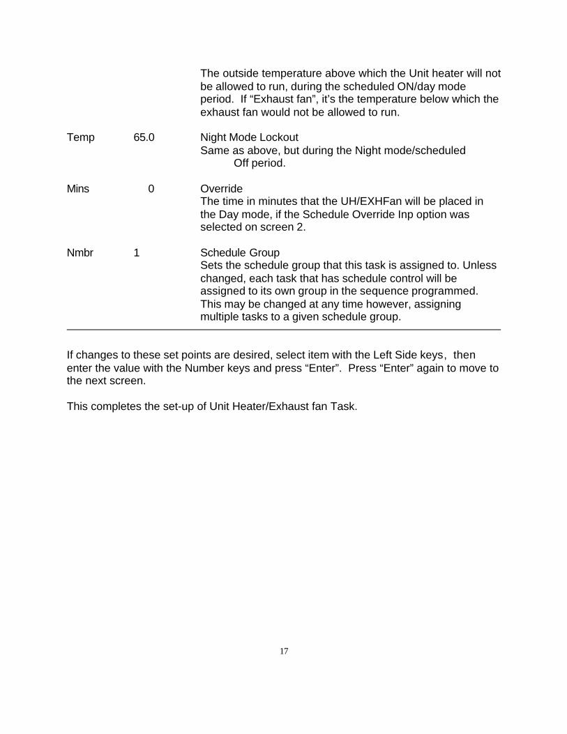
17
The outside temperature above which the Unit heater will notbe allowed to run, during the scheduled ON/day modeperiod. If “Exhaust fan”, it’s the temperature below which theexhaust fan would not be allowed to run.
Temp 65.0 Night Mode LockoutSame as above, but during the Night mode/scheduled
Off period.
Mins 0 OverrideThe time in minutes that the UH/EXHFan will be placed inthe Day mode, if the Schedule Override Inp option wasselected on screen 2.
Nmbr 1 Schedule GroupSets the schedule group that this task is assigned to. Unlesschanged, each task that has schedule control will beassigned to its own group in the sequence programmed.This may be changed at any time however, assigningmultiple tasks to a given schedule group.
If changes to these set points are desired, select item with the Left Side keys, thenenter the value with the Number keys and press “Enter”. Press “Enter” again to move tothe next screen.
This completes the set-up of Unit Heater/Exhaust fan Task.
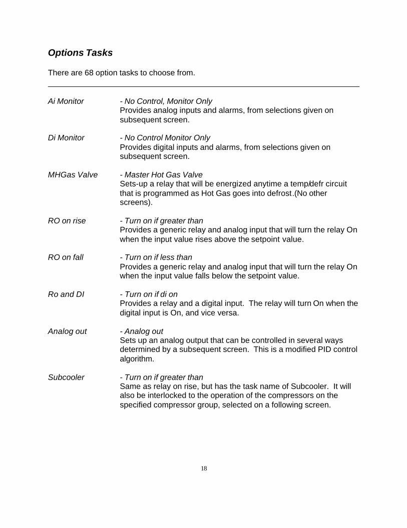
18
Options Tasks
There are 68 option tasks to choose from.
Ai Monitor - No Control, Monitor OnlyProvides analog inputs and alarms, from selections given onsubsequent screen.
Di Monitor - No Control Monitor OnlyProvides digital inputs and alarms, from selections given onsubsequent screen.
MHGas Valve - Master Hot Gas ValveSets-up a relay that will be energized anytime a temp/defr circuitthat is programmed as Hot Gas goes into defrost.(No otherscreens).
RO on rise - Turn on if greater thanProvides a generic relay and analog input that will turn the relay Onwhen the input value rises above the setpoint value.
RO on fall - Turn on if less thanProvides a generic relay and analog input that will turn the relay Onwhen the input value falls below the setpoint value.
Ro and DI - Turn on if di onProvides a relay and a digital input. The relay will turn On when thedigital input is On, and vice versa.
Analog out - Analog outSets up an analog output that can be controlled in several waysdetermined by a subsequent screen. This is a modified PID controlalgorithm.
Subcooler - Turn on if greater thanSame as relay on rise, but has the task name of Subcooler. It willalso be interlocked to the operation of the compressors on thespecified compressor group, selected on a following screen.
19
Desuperheatr - Turn on if greater thanSame as relay on rise, but has the task name of Desuperheater. Itwill also be interlocked to the operation of the compressors on thespecified compressor group, selected on a following screen.
Surge Valve - Turn on if less thanSame as relay on fall, but has task name of Surge Valve.
Crosovr Valve - Turn on if greater thanSame as relay on rise, but has the task name of Crosovr Valve. Itwill also be interlocked to the operation of the compressors on thespecified compressor group, selected on a following screen.
Freon Sniffr - Turn on if greater thanSame as relay on rise, but has the task name of Freon Sniffr. Canbe used to control exhaust fans, alarm bells, etc, as required basedupon freon exceeding desired ppm level.
Motor Rm Fan - Turn on if greater thanSame as relay on rise with name change.
Motor Rm Htr - Turn on if less thanSame as relay on fall with name change.
Misc Pump - Turn on if greater thanSame as relay on rise with name change.
Hot Water Ht - Turn on if less thanSame as relay on fall with name change.
Heat Reclaim - Turn on if di onSame RO and DI with name change.
Parallel Bypass - Turn on if di onSame as RO and DI with name change.
Dsc tmp lock - Turn off if greater thanSets-up a relay and analog input. Relay will turn Off whentemperature goes above the setpoint. Relay will turn back Onwhen input value goes below setpoint minus the deadband value.
Low oil tmp - Turn on if less thanSame as Relay on Fall with name change.
20
Hi oil temp - Turn off if greater thanSame as Dsc tmp lock, above, with name change.
Oil cooler - Turn on if greater thanSame as Relay on Rise with name change.
Oil heater - Turn on if less thanSame as Relay on Fall with name change.
Oil pump - Turn on if greater thanSame as Relay on Rise with name change.
Oil solenoid - Turn on if greater thanSame as Relay on Rise with name change.
Oil Bypass - Turn on if greater thanSame as Relay on Rise with name change.
Oil Fans - Turn on if greater thanSame as Relay on Rise with name change.
Glycol Fans - Turn on if greater thanSame as Relay on Rise with name change.
Transfer AI - Transfer to GlobalsSets-up an analog input and an analog output to transfer anyphysical analog input on one MCS-4000 controller to any othercontroller(s) via the global bus/COM5002 or 6000 Advantage.Board and point addresses 17.1 to 20.8 are used for this globaltransfer process.
Transfer DI - Transfer to GlobalsSets-up a digital input and a relay output to transfer any physicaldigital input on one MCS-4000 controller to any other controller(s)via the global bus/COM5002 or 6000 Advantage. Board and pointaddresses 17.1 to 20.8 are used for this global transfer process.
Dewpoint - Transfer to GlobalsComputes dewpoint from RH and Zone sensor inputs. Sets-up ananalog output to transfer the result to any desired global input.

21
Abs Humidity - Transfer to GlobalsComputes Absolute Humidity from RH and Zone sensor inputs.Sets-up an analog output to transfer the result to any desired globalinput.
Enthalpy - Transfer to GlobalsComputes Enthalpy from RH and Zone sensor inputs. Sets-up ananalog output to transfer the result to any desired global input.
Wet-Bulb - Transfer to GlobalsComputes Wet-bulb from RH and Zone sensor inputs. Sets-up ananalog output to transfer the result to any desired global input.
Special Purp - Special PurposeA special control algorithm; contact Com-Trol for details.
Ro on rise- - Turn on if > previous lowSpecial purpose; don’t use.
RO on fall- - Turn on if < previous lowSpecial purpose, don’t use.
Analog out- - Analog out previous lowSpecial purpose, don’t use.
RO on rise+ - Turn on if > previous highSpecial purpose, don’t use.
RO on fall+ - Turn on if < previous highSpecial purpose, don’t use.
Analog out+ - Analog out previous highSpecial purpose, don’t use.
RO rise, w/L - On if >, w/inhibitSets-up a relay and two analog inputs. The first analog input iscompared to a setpoint and deadband for On/Off control, like ROon Rise. The second analog input is used to lock the relay off, ifthe input value is greater than the Inhibit setpoint.
RO fall, w/L - On if <, w/inhibitLike RO rise, w/L above, but the relay is turned on when the firstinput value falls below the setpoint.
22
Alarm 1 - Light Only, No reset – 6kSets-up a relay output for a system using the 6000 Advantage to attach to an alarm device; bell or light.
Alarm 2 - Light/Sound/Reset – 6kSets-up two relays and a digital input for a system using the 6000Advantage to attach to the Com-Trol remote alarm panel with light,buzzer and push-button silence switch.
Gas Rcvr 1 - Press/temp differenceUsed for control of receiver bypass mechanisms. Provides onepressure input, that is converted to a saturated temperature basedupon the refrigerant selected, and another temperature input. Thetwo values are compared and the difference taken; if the differencebetween the temperature input and the converted pressure input isgreater than the setpoint, a relay is turned on.
Gas Rcvr 2 - Press/temp difference & HGSame as Gas Rcvr 1 except also turns relay on when the Hot Gasflag is on.
Compr Float - Float passingSets up an analog input with a setpoint that can be selected in thefloat assignments to float the suction of a compressor group.Provides float capability where temp/defrost circuits are notused/available.
Analog pump - Inverted OutputSets up an analog output that can be controlled in several waysdetermined by a subsequent screen. This is a modified PID controlalgorithm. The output is inverted – the higher the input abovetarget, the lower the output.
High in set - Highest analog of groupSets up one to six analog inputs, picks the highest of the group,and outputs the value to an analog output for local or globaltransfer.
Low in set - Lowest analog of groupSets up one to six analog inputs, picks the lowest of the group, andoutputs the value to an analog output for local or global transfer.

23
Avg of set - Average of analogs in groupSets up one to six analog inputs, calculates the average of thegroup, and outputs the value to an analog output for local or globaltransfer.
Temp to PSI - Transfer to globalsProvides a temperature input and computes a pressure based uponthe refrigerant selected assuming saturation. Provides an analogoutput for local or global transfer.
PSI to Temp - Transfer to globalsProvides a pressure input and computes a saturated temperaturebased upon the refrigerant selected. Provides an analog output forlocal or global transfer.
Fast Float - Adjustable float passingProvides an analog input to use for floating suction pressure, thathas adjustable settings for setpoint, deadband, control interval, andamount of float adjust per interval.
HotGas by DI - Provides a digital input to trigger the hot gas relay flag.Has suction group assignment and delay time before off setpoints.
RO rt/cy Alm - Relay Runtime/Cycle AlarmProvides runtime and cycle alarms for one to six relays. Providesalarms for total runtime, maximum daily hours and maximum dailycycles, minimum daily hours and minimum daily cycles.
DI rt/cy Alm - DI Runtime/Cycle AlarmProvides runtime and cycle alarms for one to six digital inputs.Provides alarms for total runtime, maximum daily hours andmaximum daily cycles, minimum daily hours and minimum dailycycles.
Alarm 3 - Alarm 1 direct by 4KSame as Alarm 1 except does not require a ADV-6000; i.e. can usedirectly with MCS-4000.
Alarm 4 - Alarm 2 direct by 4kSame as Alarm 2 except does not require a ADV-6000; i.e. can usedirectly with MCS-4000.
24
Transfer Dif - Transfer to GlobalsProvides two analog inputs, computes the difference between andoutputs to an analog output for local or global transfer.
Rotation - Lead/Lag/StandbyProvides 2 or 3 outputs to provide hourly, daily, weekly, or monthlyrotation (as in lead/lag or standby pumps); lead, lag and standbyoutputs may be qualified by one to four digital inputs with and/ orlogic.
And/Or - RO qualified by and/or DI’sProvides one to three relays that may be qualified by one to fourdigital inputs with and/or logic.
Math - Add, subtract, multiply, divide operations on analog inputs.
Generator - Turn on GeneratorProvides control of a generator in conjunction with ADV-6000demand management to limit demand. Can also be used toexercise generator on a scheduled basis.
HACCP -Sets up analog inputs with a HACCP control number for monitoringproduct temperatures and keying the appropriate HACCPinstruction pages on the AV-6000.
Mod Valve - Modulating ValveProvides PID control for a modulating valve(s) with user adjustableparameters.
Test/Demo - Test/Demo OutputProvides an analog output that can be assigned to an analog inputthat can be used for testing or demonstrations – user can setmax./min. value, increment, interval, and hold at max/min. tosimulate a live analog input.
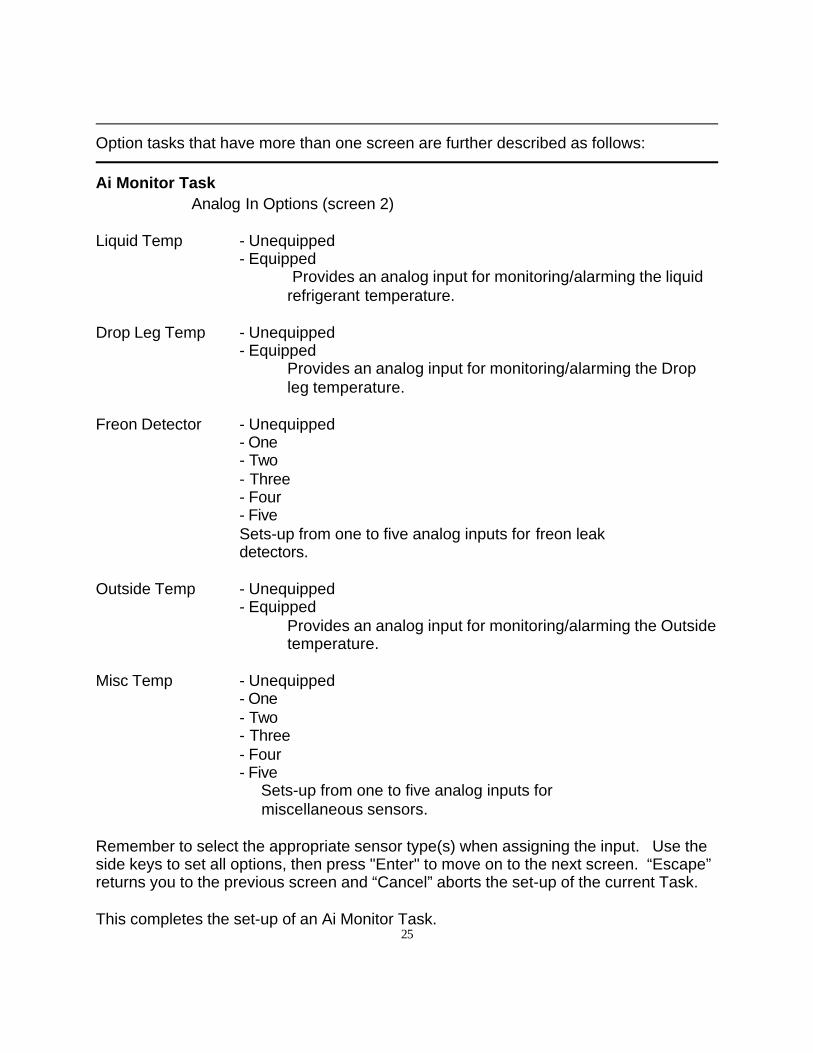
25
Option tasks that have more than one screen are further described as follows:
Ai Monitor TaskAnalog In Options (screen 2)
Liquid Temp - Unequipped- Equipped
Provides an analog input for monitoring/alarming the liquidrefrigerant temperature.
Drop Leg Temp - Unequipped- Equipped
Provides an analog input for monitoring/alarming the Dropleg temperature.
Freon Detector - Unequipped- One- Two- Three- Four- FiveSets-up from one to five analog inputs for freon leak detectors.
Outside Temp - Unequipped- Equipped
Provides an analog input for monitoring/alarming the Outsidetemperature.
Misc Temp - Unequipped- One- Two- Three- Four- Five Sets-up from one to five analog inputs for miscellaneous sensors.
Remember to select the appropriate sensor type(s) when assigning the input. Use theside keys to set all options, then press "Enter" to move on to the next screen. “Escape”returns you to the previous screen and “Cancel” aborts the set-up of the current Task.
This completes the set-up of an Ai Monitor Task.
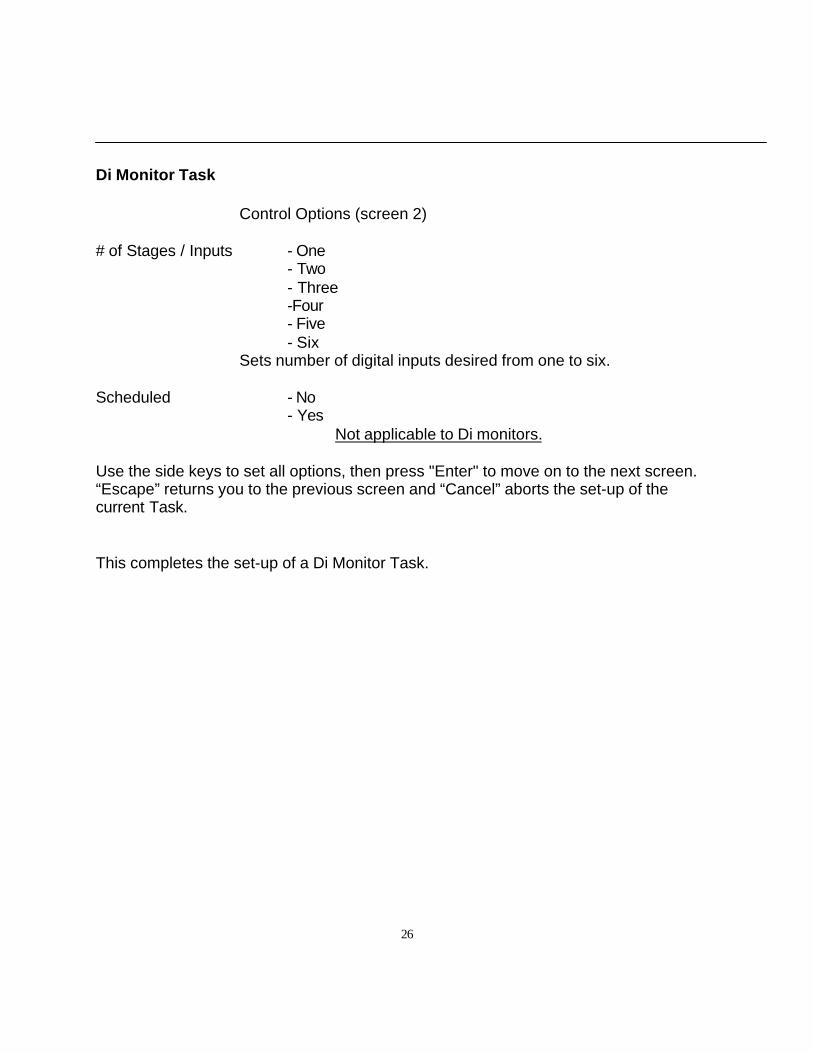
26
Di Monitor Task
Control Options (screen 2)
# of Stages / Inputs - One- Two- Three-Four- Five- Six
Sets number of digital inputs desired from one to six.
Scheduled - No- Yes
Not applicable to Di monitors.
Use the side keys to set all options, then press "Enter" to move on to the next screen.“Escape” returns you to the previous screen and “Cancel” aborts the set-up of thecurrent Task.
This completes the set-up of a Di Monitor Task.
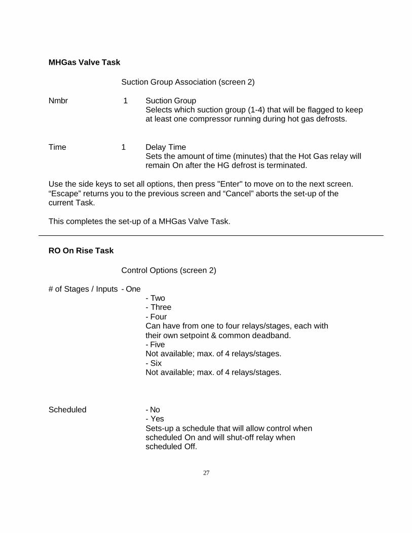
27
MHGas Valve Task
Suction Group Association (screen 2)
Nmbr 1 Suction GroupSelects which suction group (1-4) that will be flagged to keepat least one compressor running during hot gas defrosts.
Time 1 Delay TimeSets the amount of time (minutes) that the Hot Gas relay willremain On after the HG defrost is terminated.
Use the side keys to set all options, then press "Enter" to move on to the next screen.“Escape” returns you to the previous screen and “Cancel” aborts the set-up of thecurrent Task.
This completes the set-up of a MHGas Valve Task.
RO On Rise Task
Control Options (screen 2)
# of Stages / Inputs - One- Two- Three- FourCan have from one to four relays/stages, each with their own setpoint & common deadband.- FiveNot available; max. of 4 relays/stages.- SixNot available; max. of 4 relays/stages.
Scheduled - No- YesSets-up a schedule that will allow control when scheduled On and will shut-off relay whenscheduled Off.
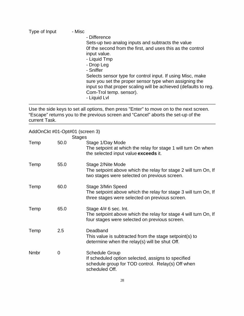
28
Type of Input - Misc- DifferenceSets-up two analog inputs and subtracts the value0f the second from the first, and uses this as the controlinput value.- Liquid Tmp- Drop Leg- SnifferSelects sensor type for control input. If using Misc, makesure you set the proper sensor type when assigning theinput so that proper scaling will be achieved (defaults to reg.Com-Trol temp. sensor).- Liquid Lvl
Use the side keys to set all options, then press "Enter" to move on to the next screen.“Escape” returns you to the previous screen and “Cancel” aborts the set-up of thecurrent Task.
AddOnCkt #01-Opt#01 (screen 3)Stages
Temp 50.0 Stage 1/Day ModeThe setpoint at which the relay for stage 1 will turn On whenthe selected input value exceeds it.
Temp 55.0 Stage 2/Nite ModeThe setpoint above which the relay for stage 2 will turn On, Iftwo stages were selected on previous screen.
Temp 60.0 Stage 3/Min SpeedThe setpoint above which the relay for stage 3 will turn On, Ifthree stages were selected on previous screen.
Temp 65.0 Stage 4/# 6 sec. Int.The setpoint above which the relay for stage 4 will turn On, Iffour stages were selected on previous screen.
Temp 2.5 DeadbandThis value is subtracted from the stage setpoint(s) todetermine when the relay(s) will be shut Off.
Nmbr 0 Schedule GroupIf scheduled option selected, assigns to specified schedule group for TOD control. Relay(s) Off when scheduled Off.
29
If changes to these setpoints are desired, select item with the Left Side keys, then enterthe value with the Number keys and press “Enter”. Press “Enter” again to move to thenext screen.
AddOnCkt #01-Opt#01 (screen 4)
Mins 0.0 Hold Off DelayThe amount of time the relay will be held off before turningon when setpoint is reached.
If changes to these setpoints are desired, select item with the Left Side keys , then enterthe value with the Number keys and press “Enter”. Press “Enter” again to move to thenext screen.
This completes the set-up of a RO on rise Task.
RO On Fall Task
Control Options (screen 2)
# of Stages / Inputs - One- Two- Three- FourCan have from one to four relays/stages, each with their own setpoint & common deadband.- FiveNot available; max. Of 4 relays/stages.- SixNot available; max. Of 4 relays/stages.
Scheduled - No- YesSets-up a schedule which will allow control when scheduledOn and will shut-off relay when scheduled Off.
Type of Input - Zone- Misc
30
- DifferenceSets-up two analog inputs and subtracts the value of thesecond from the first, and uses this as the control inputvalue.- Liquid Tmp- Drop Leg- SnifferSelects sensor type for control input. If use Misc, make sureyou set the proper sensor type when assigning the input sothat proper scaling will be achieved (defaults to reg. Com-Trol temp. sensor).- Liquid Level
Use the side keys to set all options, then press "Enter" to move on to the next screen.“Escape” returns you to the previous screen and “Cancel” aborts the set-up of thecurrent Task.
AddOnCkt #01-Opt#01 (screen 3)
Temp 50.0 Stage 1/Day ModeThe setpoint at which the relay for stage 1 will turn On whenthe selected input value falls below it.
Temp 55.0 Stage 2/Night ModeThe setpoint below which the relay for stage 2 will turn On, Iftwo stages were selected on previous screen.
Temp 60.0 Stage 3/Min SpeedThe setpoint below which the relay for stage 3 will turn On, Ifthree stages were selected on previous screen.
Temp 65.0 Stage 4/#6 sec. int.The setpoint below which the relay for stage 4 will turn On,If four stages were selected on previous screen.
Temp 2.5 DeadbandThis value is added to the stage setpoint(s) to determine when the relay(s) will be shut Off.
Nmbr 0 Schedule GroupIf scheduled option selected, assigns to specified schedule group for TOD control. Relay(s) Off when scheduled Off.
31
If changes to these setpoints are desired, select item with the Left Side keys, then enterthe value with the Number keys and press “Enter”. Press “Enter” again to move to thenext screen.
AddOnCkt #01-Opt#01 (screen 4)
Mins 0.0 Hold Off DelayThe amount of time the relay will be held off before turningon when setpoint is exceed.
If changes to these setpoints are desired, select item with the Left Side keys , then enterthe value with the Number keys and press “Enter”. Press “Enter” again to move to thenext screen.
This completes the set-up of a RO on fall Task.
RO and DI Task
Control Options (screen 2) # of Stages / Inputs - One
Sets up one relay with one digital input.- Two
Sets up two relays with one digital input for each relay.- Three
Sets up three relays with one digital input for each relay.- Four
Sets up four relays with one digital input for each relay.- Five
Sets up five relays with one digital input for each relay.- SixSets up six relays with one digital input for each relay.
Scheduled - No- YesSets up a schedule which will allow relay to follow DI when scheduled On and will shut-off relay when scheduled Off.
32
Type of Input - Misc- Difference- Liquid Tmp- Drop Leg- Sniffer- Liquid Lvl
Not applicable; no analog inputs in this task type.
Use the side keys to set all options, then press "Enter" to move on to the next screen.“Escape” returns you to the previous screen and “Cancel” aborts the set-up of thecurrent Task.
AddOnCkt #01-Opt#01 (screen 4)
Mins 0.0 Hold Off DelayThe amount of time the relay will be held off before turningon when DI turns On.
If changes to these setpoints are desired, select item with the Left Side keys, then enterthe value with the Number keys and press “Enter”. Press “Enter” again to move to thenext screen.
This completes the set-up of a RO and DI task.
Analog Out Task
Control Options (screen 2)# of Stages / Inputs - One
Only choice applicable to this task type.- Two- Three- Four- Five- SixTwo - six not applicable to this task type.
Scheduled - No- YesNot applicable to this task type.
Type of Input - MiscSelects sensor type for control input. If use Misc, make sure
33
you set the proper sensor type when assigning the input sothat proper scaling will be achieved (defaults to reg. Com-Trol temp. sensor).- DifferenceSets-up two analog inputs and subtracts the value of thesecond from the first, and uses this as the control inputvalue.- Liquid Tmp- Drop Leg- Sniffer- Liquid Lvl
Monitor Ai Input - Unequipped- EquippedAdds an additional analog input for monitor purposes only;shows up on Task Status Screen.
Use the side keys to set all options, then press "Enter" to move on to the next screen.“Escape” returns you to the previous screen and “Cancel” aborts the set-up of thecurrent Task.
Analog Out -Opt#01 (screen 3)
Setp 50.0 Stage 1/Day ModeThe setpoint/target for the PID control for the Day Mode (ifnot scheduled, always in Day mode). The input value iscompared to this number, + or - the Deadband, for the basisof its computations.
Setp 55.0 Stage 2/Nite ModeThe setpoint/target for the PID control in the Nite Mode, ifscheduled. The input value is compared to this number, + or- the Deadband, for the basis of its computations.
Setp 60.0 Stage 3/Min SpeedThe setpoint the minimum speed.
Setp 65.0 Stage 4/# 6 sec. int.The setpoint that sets how often the algorithm will run i.e.the number of 6 second intervals that will elapse before thespeed is adjusted. (minimum setting is 1)
Temp 2.5 Deadband
34
This value is added and subtracted from the Stage 1 setpointto set the control deadband outside of which the accumulatorwill operate and output the corresponding value/voltage tothe analog output.
Nmbr 0 Schedule GroupSets the schedule group that will control the Day/Nite Mode.
If changes to these setpoints are desired, select item with the Left Side keys, then enterthe value with the Number keys and press “Enter”. Press “Enter” again to move to thenext screen.
This completes the set-up of a Analog Output Task.
Subcooler Task
Same screens apply as for RO on Rise, with the default Type of Input set to Liquid, andthe following screen is added in between screens 2 & 4.
AddOnCkt #01 - Opt#01 (screen 3) Suction Group Association
Nmbr 1 Suction GroupThis associates the subcooler with the specifiedSuction group to provide an interlock, such that the subcooler will not turn On unless at least one compressor in the group is running to prevent flooding.
Time 0 Delay TimeNot used.
If changes to these setpoints are desired, select item with the Left Side keys, then enterthe value with the Number keys and press “Enter”. Press “Enter” again to move to thenext screen.
This completes the set-up of a Subcooler Task.
35
Desuperheatr TaskSame screens apply as for RO on Rise, with the default Type of Input set to Misc, andthe following screen is added in between screens 2 & 4.
AddOnCkt #01 - Opt#01 (screen 3) Suction Group Association
Nmbr 1 Suction GroupThis associates the desuperheater with the specified Suctiongroup to provide an interlock, such that the Desuperheaterwill not turn On unless at least one compressor in the groupis running to prevent flooding.
Time 0 Delay TimeNot used.
If changes to these setpoints are desired, select item with the Left Side keys, then enterthe value with the Number keys and press “Enter”. Press “Enter” again to move to thenext screen.
This completes the set-up of a Desuperheatr Task.
Surge Valve Task
Same screens apply as for RO on Fall, with the default Type of Input set to Drop Leg.
Crosovr Valv Task
Same screens apply as for RO on Rise, with the default Type of Input set to Misc, andthe following screen is added in between screens 2 & 4.
AddOnCkt #01 - Opt#01 (screen 3) Suction Group Association
Nmbr 1 Suction GroupThis associates the Crossover valve with the specifiedSuction group to provide an interlock, such that theCrossover valve will not turn On unless at least onecompressor in the group is running to prevent flooding.Normally suction pressure is used for this control so makesure you set the sensor type to P200e sensor type, if that’sthe case.
36
Time 0 Delay TimeNot used.
If changes to these setpoints are desired, select item with the Left Side keys , then enterthe value with the Number keys and press “Enter”. Press “Enter” again to move to thenext screen.
This completes the set-up of a Crosovr Valv Task.
Freon Sniffr Task
Same screens apply as for RO on Rise, with the default Type of Input set to Sniffer.
Motor Rm Fan Task
Same screens apply as for RO on Rise, with the default Type of Input set to Zone.
Motor Rm Htr Task
Same screens apply as for RO on Fall, with the default Type of Input set to Zone.
Misc Pump Task
Same screens apply as for RO on Rise, with the default Type of Input set to Misc.
Hot Water Ht Task
Same screens apply as for RO on Fall, with the default Type of Input set to Misc.
Heat Reclaim Task
Same screens apply as for RO and DI, with the default Type of Input set to Misc.
37
Parallel Byp Task
Same screens apply as for RO and DI, with the default Type of Input set to Misc.
If a switch is present to implement the bypass action, then it should be tied into thedigital input. If not, do not assign the DI, just wire the relay so that if the I/O lossespower, the proper failsafe condition is obtained to switch over to the back-up controls.
Dsc tmp lock Task
Same screens apply as for RO on Rise, with the default Type of Input set to Misc.
Low Oil Tmp Task
Same screens apply as for RO on Fall, with the default Type of Input set to Misc.
Hi Oil temp Task
Same screens apply as for RO on Rise, with the default Type of Input set to Misc.
Oil Cooler Task
Same screens apply as for RO on Rise, with the default Type of Input set to Misc.
Oil Heater Task Same screens apply as for RO on Fall, with the default Type of Input set to Misc.
Oil Pump TaskSame screens apply as for RO on Rise, with the default Type of Input set to Misc.
Oil Solenoid Task
Same screens apply as for RO on Rise, with the default Type of Input set to Misc.
Oil Bypass Task
Same screens apply as for RO on Rise, with the default Type of Input set to Misc.
Oil Fans Task
Same screens apply as for RO on Rise, with the default Type of Input set to Misc.
38
Glycol Fans Task
Same screens apply as for RO on Rise, with the default Type of Input set to Misc.
RO rise, w/L Task
Same screens apply as for RO on Rise, with the default Type of Input set to Misc.
RO fall, w/L Task
Same screens apply as for RO on Rise, with the default Type of Input set to Misc.
39
Rack Library
The Rack Library is structured to control all facets of a modern refrigeration rack,including compressor control, condenser control, circuit temperature and defrost control.
A Rack is defined as a common refrigerant system that may have up to 4 multi-compressor suction groups, but only one discharge pressure.
Oil failure and discharge temperature control may be provided based upon specificcompressor makes.
Compressor GrpUsed to control a group of parallel compressors all operating at the same suctionpressure, either even or uneven in size. A maximum of 8 relays are provided to controlcompressors and their unloaders in any combination. All ancillary functions associatedwith compressor control, monitoring, and alarms are provided including direct oil failurecontrol, if desired.
The screens associated with the set-up of a Compressor Grp Task follow in sequence,with all options and control strategies explained.
RACK/GROUP Type (screen 1)Primary
Use this selection for any single suction or multiple suction, non-two stagerack. Up to four primary (or secondary) suction groups/tasks can be setupin one MCS-4000 with Rack software library.
SecondaryUsed when multiple suction groups are present on the same rack for the second suction group. (Not required; may use multiple primary groups if desired.)
Hi StageHigh stage of a two stage rack. Program the high stage first, then the lowstage. Automatically provides the interlock, whereby if any compressor isrunning on the low stage, the high stage will force a compressor to run.
Lo StageLow stage of a two stage rack; works in conjunction with the high stage group, above.
40
Use the side key to select the desired Rack Type, then press "Enter".
REFRIGERANT (screen 2)R-502 R-507(AZ50)R-22 R-402B(HP80)R-12 R-402A(HP81)R-717(Ammonia) R-401B(MP66)R-134A G-125R-404A(HP62)R-401A (MP39)
This screen lists 12 of the most commonly used refrigerants. The MCS-4000 uses thisinformation to provide the Temperature/Pressure conversions in various places. Thus,you will know what the saturated suction temp is based upon the suction pressure,condensing temp based upon the head pressure, etc.
Use the side key to select the desired Refrigerant Type, then press "Enter".
SUCTION TEMP, F (screen 3)-35.0 F +5.0 F-30.0 F +10.0 F-25.0 F +15.0 F-20.0 F +20.0 F-15.0 F +25.0 F-10.0 F +30.0 F-5.0 F +35.0 F
Selects the suction temperature, which will in turn select the initial target suctionpressure based, upon the refrigerant chosen above. This value can be changed on alater screen or anytime thereafter. Value also sets "LT" or "MT" (+20 and above) that isappended to the default compressor task name.
Use the side key to select the desired Suction Temp, then press "Enter".
COMPRESSOR OPTIONS (screen 4)Compr Monitors - Equipped
Provides a digital input for each compressor later specified for a proof/feedbackindication/alarm. Normally connected to the load side of the compressorcontactor, or to auxiliary contacts, pilot relays, or current sensing relays. Worksin conjunction with the control relay to proof whether the compressor is followingthe control commands.
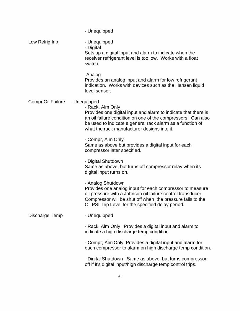
41
- Unequipped
Low Refrig Inp - Unequipped- DigitalSets up a digital input and alarm to indicate when thereceiver refrigerant level is too low. Works with a floatswitch.
-AnalogProvides an analog input and alarm for low refrigerantindication. Works with devices such as the Hansen liquidlevel sensor.
Compr Oil Failure - Unequipped- Rack, Alm OnlyProvides one digital input and alarm to indicate that there isan oil failure condition on one of the compressors. Can alsobe used to indicate a general rack alarm as a function ofwhat the rack manufacturer designs into it.
- Compr, Alm OnlySame as above but provides a digital input for each compressor later specified.
- Digital ShutdownSame as above, but turns off compressor relay when itsdigital input turns on.
- Analog ShutdownProvides one analog input for each compressor to measureoil pressure with a Johnson oil failure control transducer.Compressor will be shut off when the pressure falls to theOil PSI Trip Level for the specified delay period.
Discharge Temp - Unequipped
- Rack, Alm Only Provides a digital input and alarm toindicate a high discharge temp condition.
- Compr, Alm Only Provides a digital input and alarm foreach compressor to alarm on high discharge temp condition.
- Digital Shutdown Same as above, but turns compressoroff if it's digital input/high discharge temp control trips.
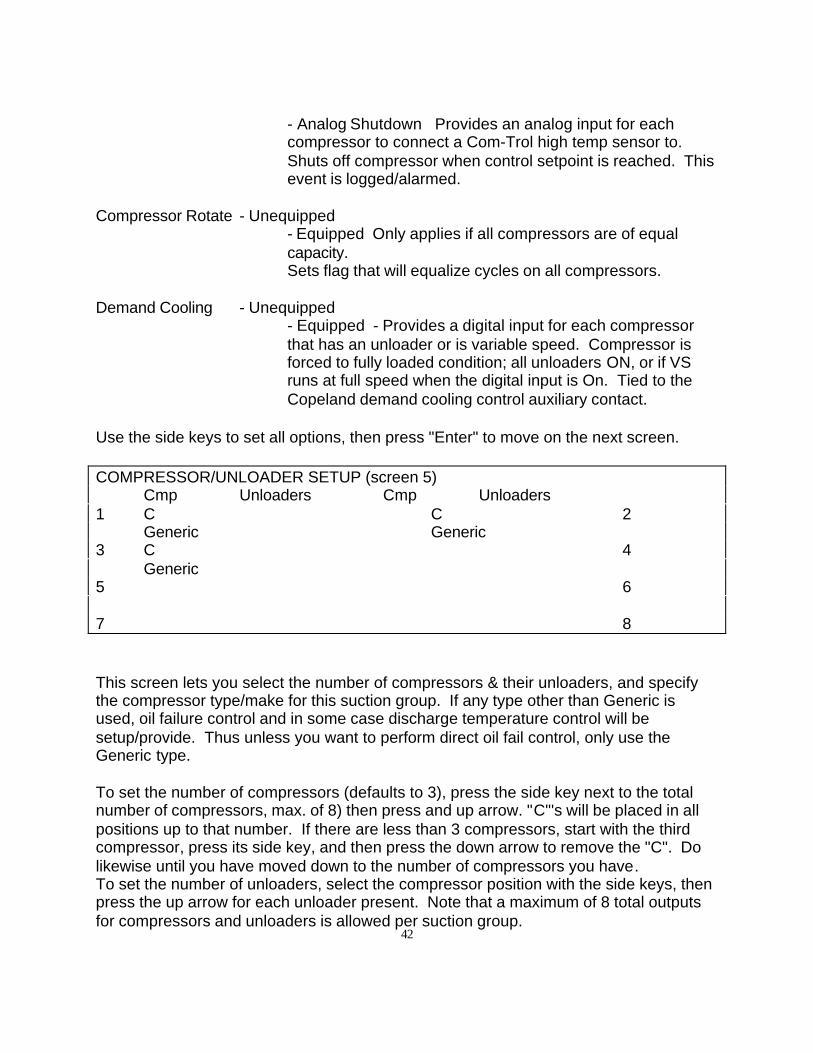
42
- Analog Shutdown Provides an analog input for eachcompressor to connect a Com-Trol high temp sensor to.Shuts off compressor when control setpoint is reached. Thisevent is logged/alarmed.
Compressor Rotate - Unequipped- Equipped Only applies if all compressors are of equalcapacity.Sets flag that will equalize cycles on all compressors.
Demand Cooling - Unequipped- Equipped - Provides a digital input for each compressorthat has an unloader or is variable speed. Compressor isforced to fully loaded condition; all unloaders ON, or if VSruns at full speed when the digital input is On. Tied to theCopeland demand cooling control auxiliary contact.
Use the side keys to set all options, then press "Enter" to move on the next screen.
COMPRESSOR/UNLOADER SETUP (screen 5)Cmp Unloaders Cmp Unloaders
1 C C 2Generic Generic
3 C 4Generic
5 6
7 8
This screen lets you select the number of compressors & their unloaders, and specifythe compressor type/make for this suction group. If any type other than Generic isused, oil failure control and in some case discharge temperature control will besetup/provide. Thus unless you want to perform direct oil fail control, only use theGeneric type.
To set the number of compressors (defaults to 3), press the side key next to the totalnumber of compressors, max. of 8) then press and up arrow. "C"'s will be placed in allpositions up to that number. If there are less than 3 compressors, start with the thirdcompressor, press its side key, and then press the down arrow to remove the "C". Dolikewise until you have moved down to the number of compressors you have.To set the number of unloaders, select the compressor position with the side keys, thenpress the up arrow for each unloader present. Note that a maximum of 8 total outputsfor compressors and unloaders is allowed per suction group.
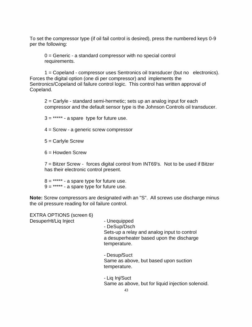
43
To set the compressor type (if oil fail control is desired), press the numbered keys 0-9per the following:
0 = Generic - a standard compressor with no special control requirements.
1 = Copeland - compressor uses Sentronics oil transducer (but no electronics).Forces the digital option (one di per compressor) and implements theSentronics/Copeland oil failure control logic. This control has written approval ofCopeland.
2 = Carlyle - standard semi-hermetic; sets up an analog input for each compressor and the default sensor type is the Johnson Controls oil transducer.
3 = ***** - a spare type for future use.
4 = Screw - a generic screw compressor
5 = Carlyle Screw
6 = Howden Screw
7 = Bitzer Screw - forces digital control from INT69's. Not to be used if Bitzerhas their electronic control present.
8 = ***** - a spare type for future use.9 = ***** - a spare type for future use.
Note: Screw compressors are designated with an "S". All screws use discharge minusthe oil pressure reading for oil failure control.
EXTRA OPTIONS (screen 6)DesuperHt/Liq Inject - Unequipped
- DeSup/DschSets-up a relay and analog input to control a desuperheater based upon the discharge temperature.
- Desup/SuctSame as above, but based upon suction temperature.
- Liq Inj/SuctSame as above, but for liquid injection solenoid.
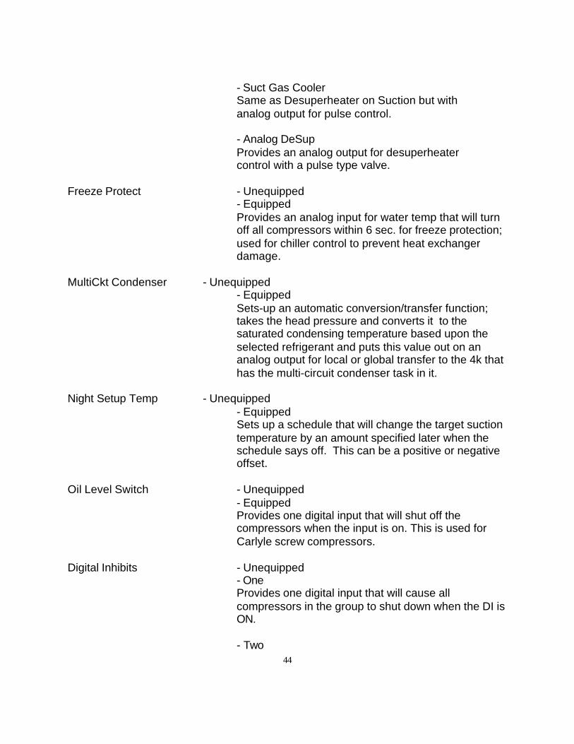
44
- Suct Gas CoolerSame as Desuperheater on Suction but with analog output for pulse control.
- Analog DeSupProvides an analog output for desuperheater control with a pulse type valve.
Freeze Protect - Unequipped- EquippedProvides an analog input for water temp that will turnoff all compressors within 6 sec. for freeze protection;used for chiller control to prevent heat exchangerdamage.
MultiCkt Condenser - Unequipped- EquippedSets-up an automatic conversion/transfer function;takes the head pressure and converts it to thesaturated condensing temperature based upon theselected refrigerant and puts this value out on ananalog output for local or global transfer to the 4k thathas the multi-circuit condenser task in it.
Night Setup Temp - Unequipped- EquippedSets up a schedule that will change the target suctiontemperature by an amount specified later when theschedule says off. This can be a positive or negativeoffset.
Oil Level Switch - Unequipped- EquippedProvides one digital input that will shut off thecompressors when the input is on. This is used forCarlyle screw compressors.
Digital Inhibits - Unequipped- OneProvides one digital input that will cause allcompressors in the group to shut down when the DI isON.
- Two
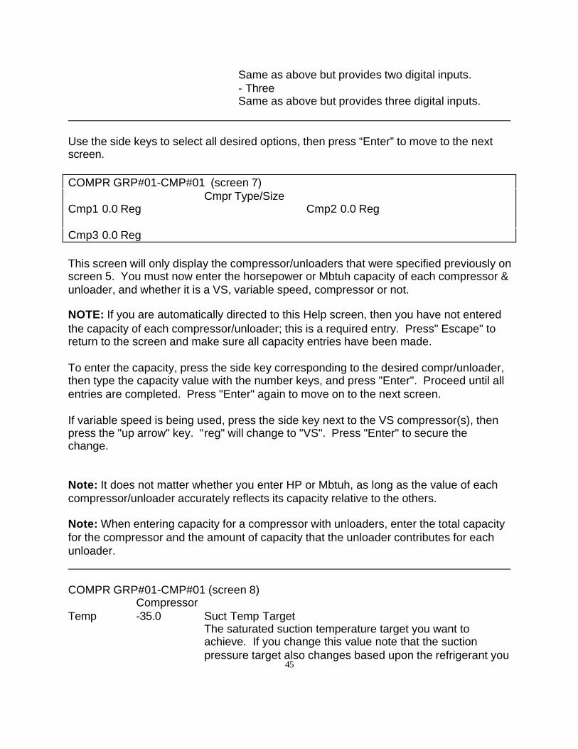
45
Same as above but provides two digital inputs.- ThreeSame as above but provides three digital inputs.
Use the side keys to select all desired options, then press “Enter” to move to the nextscreen.
COMPR GRP#01-CMP#01 (screen 7)Cmpr Type/Size
Cmp1 0.0 Reg Cmp2 0.0 Reg
Cmp3 0.0 Reg
This screen will only display the compressor/unloaders that were specified previously onscreen 5. You must now enter the horsepower or Mbtuh capacity of each compressor &unloader, and whether it is a VS, variable speed, compressor or not.
NOTE: If you are automatically directed to this Help screen, then you have not enteredthe capacity of each compressor/unloader; this is a required entry. Press" Escape" toreturn to the screen and make sure all capacity entries have been made.
To enter the capacity, press the side key corresponding to the desired compr/unloader,then type the capacity value with the number keys, and press "Enter". Proceed until allentries are completed. Press "Enter" again to move on to the next screen.
If variable speed is being used, press the side key next to the VS compressor(s), thenpress the "up arrow" key. "reg" will change to "VS". Press "Enter" to secure thechange.
Note: It does not matter whether you enter HP or Mbtuh, as long as the value of eachcompressor/unloader accurately reflects its capacity relative to the others.
Note: When entering capacity for a compressor with unloaders, enter the total capacityfor the compressor and the amount of capacity that the unloader contributes for eachunloader.
COMPR GRP#01-CMP#01 (screen 8)
CompressorTemp -35.0 Suct Temp Target
The saturated suction temperature target you want toachieve. If you change this value note that the suctionpressure target also changes based upon the refrigerant you
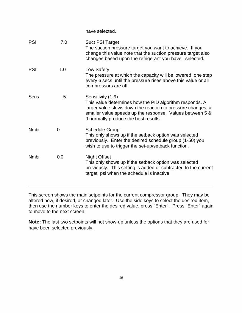
46
have selected.
PSI 7.0 Suct PSI TargetThe suction pressure target you want to achieve. If youchange this value note that the suction pressure target alsochanges based upon the refrigerant you have selected.
PSI 1.0 Low SafetyThe pressure at which the capacity will be lowered, one stepevery 6 secs until the pressure rises above this value or allcompressors are off.
Sens 5 Sensitivity (1-9)This value determines how the PID algorithm responds. Alarger value slows down the reaction to pressure changes, asmaller value speeds up the response. Values between 5 &9 normally produce the best results.
Nmbr 0 Schedule GroupThis only shows up if the setback option was selectedpreviously. Enter the desired schedule group (1-50) youwish to use to trigger the set-up/setback function.
Nmbr 0.0 Night OffsetThis only shows up if the setback option was selectedpreviously. This setting is added or subtracted to the currenttarget psi when the schedule is inactive.
This screen shows the main setpoints for the current compressor group. They may bealtered now, if desired, or changed later. Use the side keys to select the desired item,then use the number keys to enter the desired value, press "Enter". Press "Enter" againto move to the next screen.
Note: The last two setpoints will not show-up unless the options that they are used forhave been selected previously.
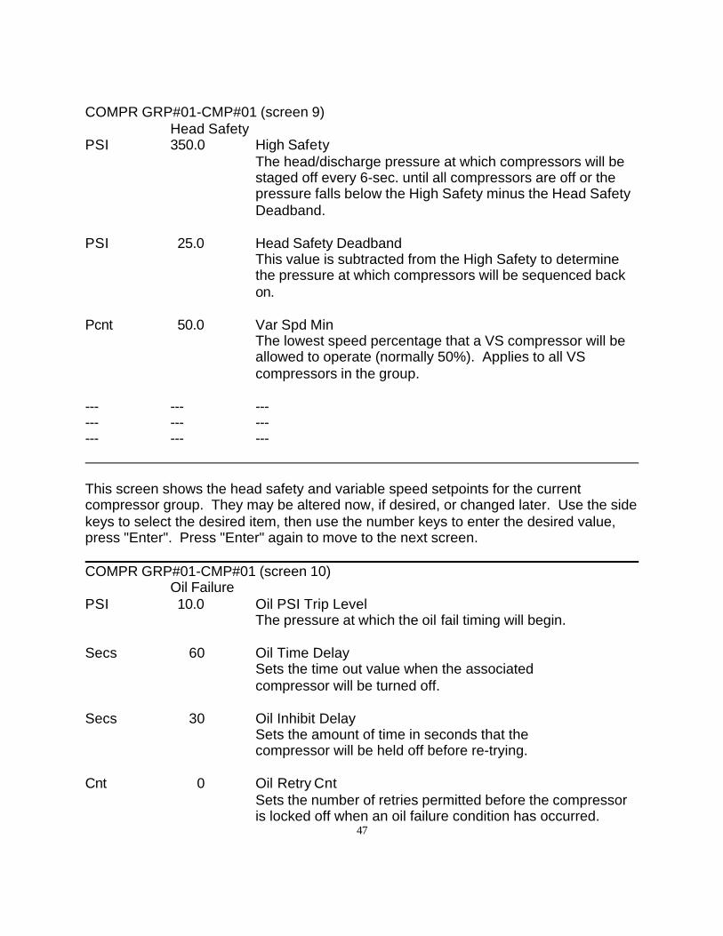
47
COMPR GRP#01-CMP#01 (screen 9)Head Safety
PSI 350.0 High SafetyThe head/discharge pressure at which compressors will bestaged off every 6-sec. until all compressors are off or thepressure falls below the High Safety minus the Head SafetyDeadband.
PSI 25.0 Head Safety DeadbandThis value is subtracted from the High Safety to determinethe pressure at which compressors will be sequenced backon.
Pcnt 50.0 Var Spd MinThe lowest speed percentage that a VS compressor will beallowed to operate (normally 50%). Applies to all VScompressors in the group.
--- --- ------ --- ------ --- ---
This screen shows the head safety and variable speed setpoints for the currentcompressor group. They may be altered now, if desired, or changed later. Use the sidekeys to select the desired item, then use the number keys to enter the desired value,press "Enter". Press "Enter" again to move to the next screen.
COMPR GRP#01-CMP#01 (screen 10)Oil Failure
PSI 10.0 Oil PSI Trip LevelThe pressure at which the oil fail timing will begin.
Secs 60 Oil Time DelaySets the time out value when the associated compressor will be turned off.
Secs 30 Oil Inhibit DelaySets the amount of time in seconds that the compressor will be held off before re-trying.
Cnt 0 Oil Retry CntSets the number of retries permitted before the compressoris locked off when an oil failure condition has occurred.
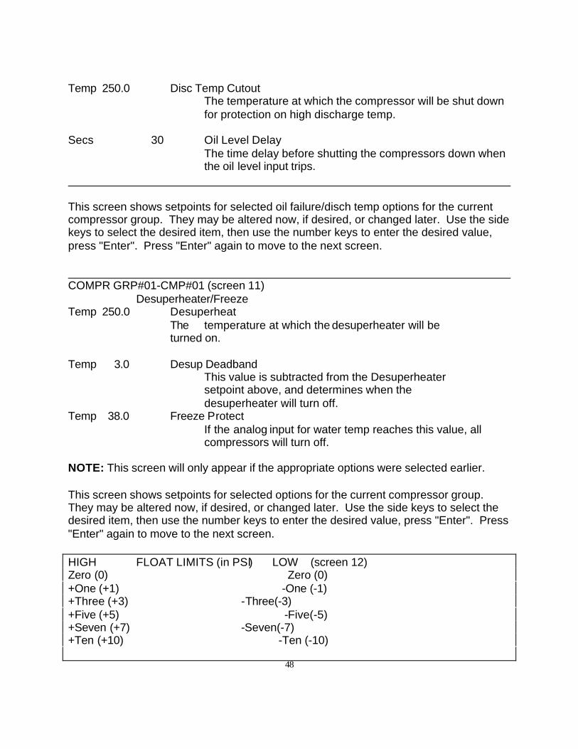
48
Temp 250.0 Disc Temp CutoutThe temperature at which the compressor will be shut downfor protection on high discharge temp.
Secs 30 Oil Level DelayThe time delay before shutting the compressors down whenthe oil level input trips.
This screen shows setpoints for selected oil failure/disch temp options for the currentcompressor group. They may be altered now, if desired, or changed later. Use the sidekeys to select the desired item, then use the number keys to enter the desired value,press "Enter". Press "Enter" again to move to the next screen.
COMPR GRP#01-CMP#01 (screen 11)Desuperheater/Freeze
Temp 250.0 DesuperheatThe temperature at which the desuperheater will be turned on.
Temp 3.0 Desup DeadbandThis value is subtracted from the Desuperheater setpoint above, and determines when the desuperheater will turn off.
Temp 38.0 Freeze ProtectIf the analog input for water temp reaches this value, allcompressors will turn off.
NOTE: This screen will only appear if the appropriate options were selected earlier.
This screen shows setpoints for selected options for the current compressor group.They may be altered now, if desired, or changed later. Use the side keys to select thedesired item, then use the number keys to enter the desired value, press "Enter". Press"Enter" again to move to the next screen.
HIGH FLOAT LIMITS (in PSI) LOW (screen 12)Zero (0) Zero (0)+One (+1) -One (-1)+Three (+3) -Three(-3)+Five (+5) -Five(-5) +Seven (+7) -Seven(-7)+Ten (+10) -Ten (-10)
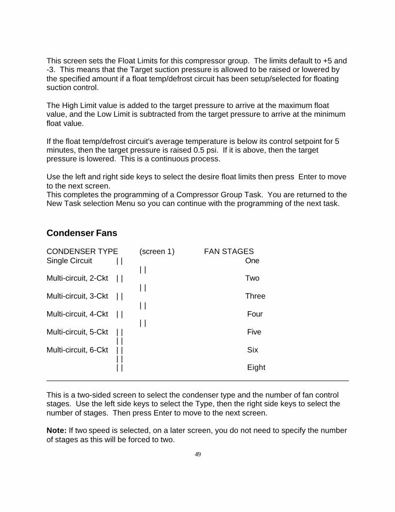
49
This screen sets the Float Limits for this compressor group. The limits default to +5 and-3. This means that the Target suction pressure is allowed to be raised or lowered bythe specified amount if a float temp/defrost circuit has been setup/selected for floatingsuction control.
The High Limit value is added to the target pressure to arrive at the maximum floatvalue, and the Low Limit is subtracted from the target pressure to arrive at the minimumfloat value.
If the float temp/defrost circuit's average temperature is below its control setpoint for 5minutes, then the target pressure is raised 0.5 psi. If it is above, then the targetpressure is lowered. This is a continuous process.
Use the left and right side keys to select the desire float limits then press Enter to moveto the next screen.This completes the programming of a Compressor Group Task. You are returned to theNew Task selection Menu so you can continue with the programming of the next task.
Condenser Fans
CONDENSER TYPE (screen 1) FAN STAGESSingle Circuit | | One
| |Multi-circuit, 2-Ckt | | Two
| |Multi-circuit, 3-Ckt | | Three
| |Multi-circuit, 4-Ckt | | Four
| |Multi-circuit, 5-Ckt | | Five
| |Multi-circuit, 6-Ckt | | Six
| || | Eight
This is a two-sided screen to select the condenser type and the number of fan controlstages. Use the left side keys to select the Type, then the right side keys to select thenumber of stages. Then press Enter to move to the next screen.
Note: If two speed is selected, on a later screen, you do not need to specify the numberof stages as this will be forced to two.
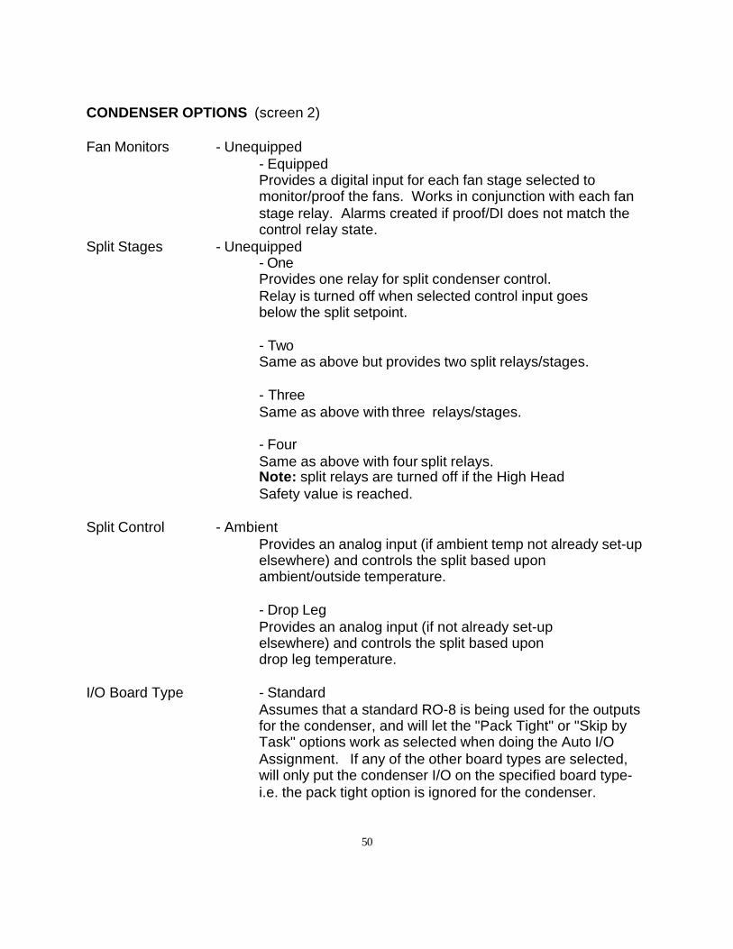
50
CONDENSER OPTIONS (screen 2)
Fan Monitors - Unequipped- EquippedProvides a digital input for each fan stage selected tomonitor/proof the fans. Works in conjunction with each fanstage relay. Alarms created if proof/DI does not match thecontrol relay state.
Split Stages - Unequipped- OneProvides one relay for split condenser control.Relay is turned off when selected control input goes below the split setpoint.
- TwoSame as above but provides two split relays/stages.
- ThreeSame as above with three relays/stages.
- FourSame as above with four split relays.Note: split relays are turned off if the High Head Safety value is reached.
Split Control - AmbientProvides an analog input (if ambient temp not already set-upelsewhere) and controls the split based uponambient/outside temperature.
- Drop LegProvides an analog input (if not already set-up elsewhere) and controls the split based upon drop leg temperature.
I/O Board Type - StandardAssumes that a standard RO-8 is being used for the outputsfor the condenser, and will let the "Pack Tight" or "Skip byTask" options work as selected when doing the Auto I/OAssignment. If any of the other board types are selected,will only put the condenser I/O on the specified board type-i.e. the pack tight option is ignored for the condenser.
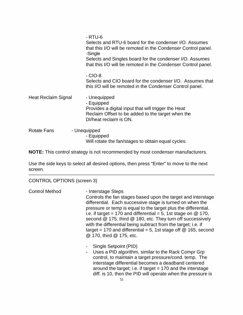
51
- RTU-6Selects and RTU-6 board for the condenser I/O. Assumesthat this I/O will be remoted in the Condenser Control panel.-SingleSelects and Singles board for the condenser I/O. Assumesthat this I/O will be remoted in the Condenser Control panel.
- CIO-8Selects and CIO board for the condenser I/O. Assumes thatthis I/O will be remoted in the Condenser Control panel.
Heat Reclaim Signal - Unequipped- EquippedProvides a digital input that will trigger the Heat Reclaim Offset to be added to the target when the DI/heat reclaim is ON.
Rotate Fans - Unequipped- EquippedWill rotate the fan/stages to obtain equal cycles.
NOTE: This control strategy is not recommended by most condenser manufacturers.
Use the side keys to select all desired options, then press "Enter" to move to the nextscreen.
CONTROL OPTIONS (screen 3)
Control Method - Interstage StepsControls the fan stages based upon the target and interstagedifferential. Each successive stage is turned on when thepressure or temp is equal to the target plus the differential.i.e. if target = 170 and differential = 5, 1st stage on @ 170,second @ 175, third @ 180, etc. They turn off successivelywith the differential being subtract from the target; i.e. iftarget = 170 and differential = 5, 1st stage off @ 165, second@ 170, third @ 175, etc.
- Single Setpoint (PID)- Uses a PID algorithm, similar to the Rack Compr Grp
control, to maintain a target pressure/cond. temp. Theinterstage differential becomes a deadband centeredaround the target; i.e. if target = 170 and the interstagediff. is 10, then the PID will operate when the pressure is
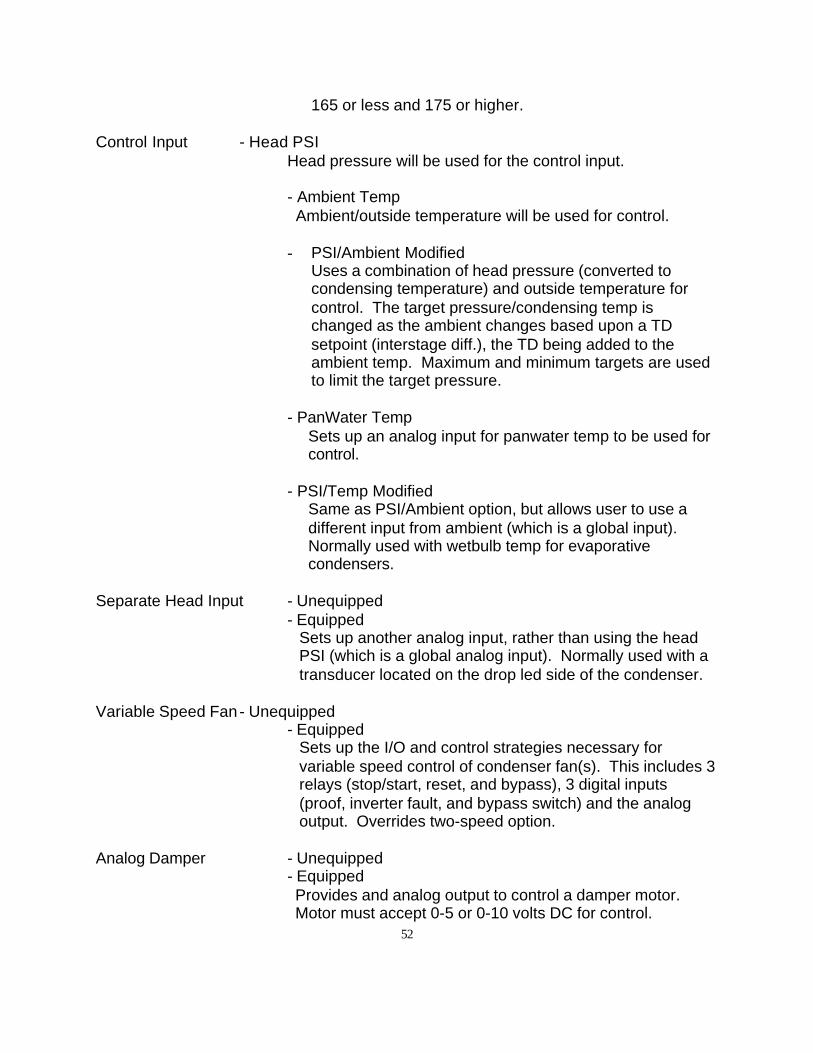
52
165 or less and 175 or higher.
Control Input - Head PSIHead pressure will be used for the control input.
- Ambient Temp Ambient/outside temperature will be used for control.
- PSI/Ambient ModifiedUses a combination of head pressure (converted tocondensing temperature) and outside temperature forcontrol. The target pressure/condensing temp ischanged as the ambient changes based upon a TDsetpoint (interstage diff.), the TD being added to theambient temp. Maximum and minimum targets are usedto limit the target pressure.
- PanWater TempSets up an analog input for panwater temp to be used forcontrol.
- PSI/Temp ModifiedSame as PSI/Ambient option, but allows user to use adifferent input from ambient (which is a global input).Normally used with wetbulb temp for evaporativecondensers.
Separate Head Input - Unequipped- Equipped
Sets up another analog input, rather than using the headPSI (which is a global analog input). Normally used with atransducer located on the drop led side of the condenser.
Variable Speed Fan- Unequipped- Equipped
Sets up the I/O and control strategies necessary forvariable speed control of condenser fan(s). This includes 3relays (stop/start, reset, and bypass), 3 digital inputs(proof, inverter fault, and bypass switch) and the analogoutput. Overrides two-speed option.
Analog Damper - Unequipped- EquippedProvides and analog output to control a damper motor.Motor must accept 0-5 or 0-10 volts DC for control.
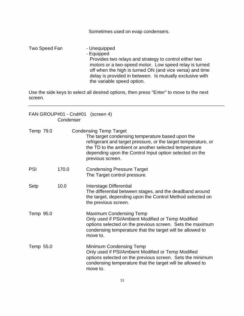
53
Sometimes used on evap condensers.
Two Speed Fan - Unequipped- Equipped
Provides two relays and strategy to control either twomotors or a two-speed motor. Low speed relay is turnedoff when the high is turned ON (and vice versa) and timedelay is provided in between. Is mutually exclusive withthe variable speed option.
Use the side keys to select all desired options, then press "Enter" to move to the nextscreen.
FAN GROUP#01 - Cnd#01 (screen 4) Condenser
Temp 79.0 Condensing Temp TargetThe target condensing temperature based upon therefrigerant and target pressure, or the target temperature, orthe TD to the ambient or another selected temperaturedepending upon the Control Input option selected on theprevious screen.
PSI 170.0 Condensing Pressure TargetThe Target control pressure.
Setp 10.0 Interstage DifferentialThe differential between stages, and the deadband aroundthe target, depending upon the Control Method selected onthe previous screen.
Temp 95.0 Maximum Condensing TempOnly used if PSI/Ambient Modified or Temp Modifiedoptions selected on the previous screen. Sets the maximumcondensing temperature that the target will be allowed tomove to.
Temp 55.0 Minimum Condensing TempOnly used if PSI/Ambient Modified or Temp Modifiedoptions selected on the previous screen. Sets the minimumcondensing temperature that the target will be allowed tomove to.
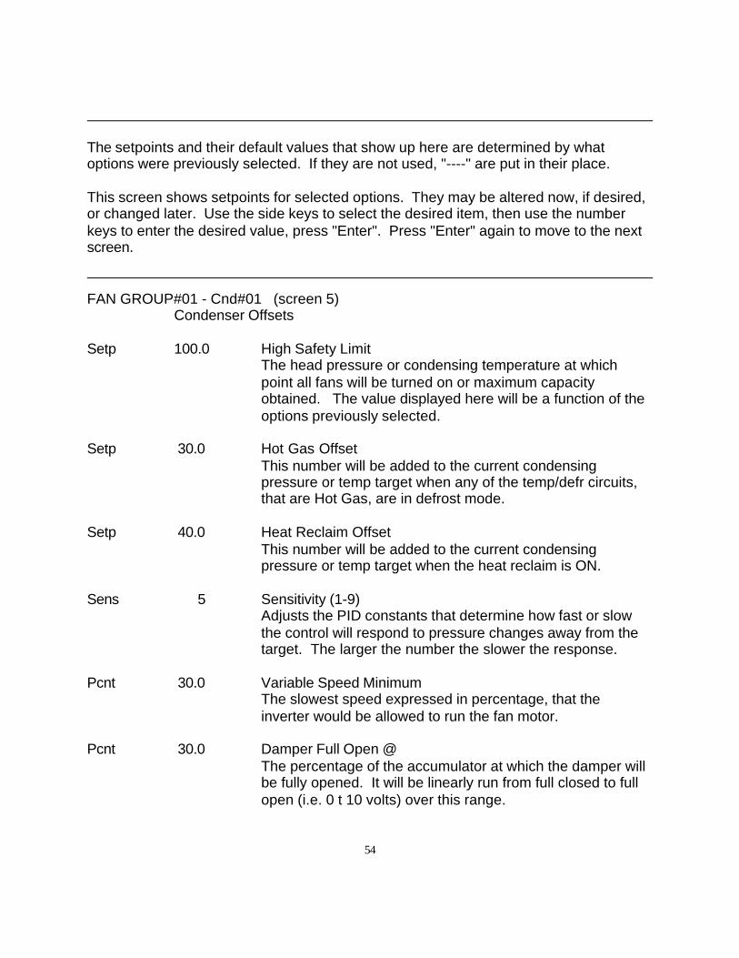
54
The setpoints and their default values that show up here are determined by whatoptions were previously selected. If they are not used, "----" are put in their place.
This screen shows setpoints for selected options. They may be altered now, if desired,or changed later. Use the side keys to select the desired item, then use the numberkeys to enter the desired value, press "Enter". Press "Enter" again to move to the nextscreen.
FAN GROUP#01 - Cnd#01 (screen 5) Condenser Offsets
Setp 100.0 High Safety LimitThe head pressure or condensing temperature at whichpoint all fans will be turned on or maximum capacityobtained. The value displayed here will be a function of theoptions previously selected.
Setp 30.0 Hot Gas OffsetThis number will be added to the current condensingpressure or temp target when any of the temp/defr circuits,that are Hot Gas, are in defrost mode.
Setp 40.0 Heat Reclaim OffsetThis number will be added to the current condensingpressure or temp target when the heat reclaim is ON.
Sens 5 Sensitivity (1-9)Adjusts the PID constants that determine how fast or slowthe control will respond to pressure changes away from thetarget. The larger the number the slower the response.
Pcnt 30.0 Variable Speed MinimumThe slowest speed expressed in percentage, that theinverter would be allowed to run the fan motor.
Pcnt 30.0 Damper Full Open @The percentage of the accumulator at which the damper willbe fully opened. It will be linearly run from full closed to fullopen (i.e. 0 t 10 volts) over this range.
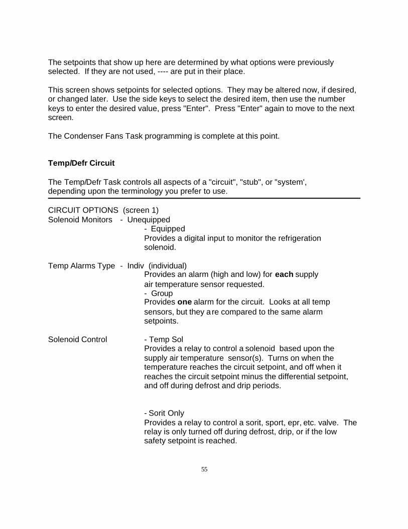
55
The setpoints that show up here are determined by what options were previouslyselected. If they are not used, ---- are put in their place.
This screen shows setpoints for selected options. They may be altered now, if desired,or changed later. Use the side keys to select the desired item, then use the numberkeys to enter the desired value, press "Enter". Press "Enter" again to move to the nextscreen.
The Condenser Fans Task programming is complete at this point.
Temp/Defr Circuit
The Temp/Defr Task controls all aspects of a "circuit", "stub", or "system',depending upon the terminology you prefer to use.
CIRCUIT OPTIONS (screen 1)Solenoid Monitors - Unequipped
- EquippedProvides a digital input to monitor the refrigeration solenoid.
Temp Alarms Type - Indiv (individual)Provides an alarm (high and low) for each supply air temperature sensor requested. - GroupProvides one alarm for the circuit. Looks at all temp sensors, but they a re compared to the same alarm setpoints.
Solenoid Control - Temp SolProvides a relay to control a solenoid based upon thesupply air temperature sensor(s). Turns on when thetemperature reaches the circuit setpoint, and off when itreaches the circuit setpoint minus the differential setpoint,and off during defrost and drip periods.
- Sorit OnlyProvides a relay to control a sorit, sport, epr, etc. valve. Therelay is only turned off during defrost, drip, or if the lowsafety setpoint is reached.
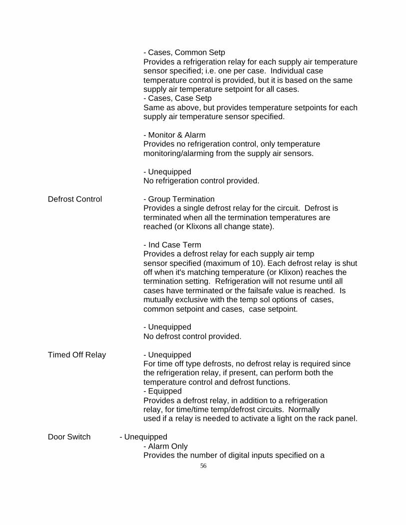
56
- Cases, Common SetpProvides a refrigeration relay for each supply air temperaturesensor specified; i.e. one per case. Individual casetemperature control is provided, but it is based on the samesupply air temperature setpoint for all cases.- Cases, Case SetpSame as above, but provides temperature setpoints for eachsupply air temperature sensor specified.
- Monitor & AlarmProvides no refrigeration control, only temperaturemonitoring/alarming from the supply air sensors.
- UnequippedNo refrigeration control provided.
Defrost Control - Group TerminationProvides a single defrost relay for the circuit. Defrost isterminated when all the termination temperatures arereached (or Klixons all change state).
- Ind Case TermProvides a defrost relay for each supply air tempsensor specified (maximum of 10). Each defrost relay is shutoff when it's matching temperature (or Klixon) reaches thetermination setting. Refrigeration will not resume until allcases have terminated or the failsafe value is reached. Ismutually exclusive with the temp sol options of cases,common setpoint and cases, case setpoint.
- UnequippedNo defrost control provided.
Timed Off Relay - UnequippedFor time off type defrosts, no defrost relay is required sincethe refrigeration relay, if present, can perform both thetemperature control and defrost functions.- EquippedProvides a defrost relay, in addition to a refrigeration relay, for time/time temp/defrost circuits. Normally used if a relay is needed to activate a light on the rack panel.
Door Switch - Unequipped- Alarm OnlyProvides the number of digital inputs specified on a
57
later screen and an alarm to monitor cooler /freezer box doors.
- Refr OFF < 15 min Same as above, but turns off the circuit refrigeration relay whenever the door is open for up to 15 mins.
- Refr OFF < 30, 45, 60 min Same as above with timers of 30, 45, or 60 minutes.
Use the side keys to select all desired options, then press Enter to move to the nextscreen.
DUAL TEMP/ WASH DOWN (screen 2)
Wash Down Switch - Unequipped- Equipped
Provides a digital input that will shut off refrigerationand defrost for an adjustable time period.Automatically resumes normal operation when timeexpires.
Cmpr Task Off in Dfr - No- YesOnly used for single compressor tasks where you want thecompressor to turn off while the circuit is in defrost. Notapplicable to racks.
Night Setup Temp - Unequipped- EquippedAllows a circuit to run at a different control temperaturebased upon a schedule.
Dual Temp Case - Unequipped- EquippedProvides set-up for a dual temp circuit. Provides two sets ofsetpoints based upon two fixture types selected for tempcontrol, defrost control and alarms.
Dual Temp Switch - Unequipped- EquippedProvides a digital input to connect to a switch to activate thedual temp selection. Note: If no switch input provided canchange through 4k via the Emergency Defrost screen.
58
Dual Temp Relay - Unequipped- Normal OperationProvides an additional relay which will follow thedual temp switch action. Normally used to force sorit to wideopen.
- Off during defrostSame as above but will turn off during defrost period.
Use the side keys to select all desired options, then press Enter to move to the nextscreen.
DEFROST TYPE (screen 3) TERMINATION TYPEHot Gas Supply Air Temp
Electric Klixon Din
Reverse Air Coil Temp
Timed Off/Cycle Time Only
Suction Pressure
This is a two-sided screen where choices are made with both left and right side keys.Select both the Defrost Type and Termination Type then proceed to the next screen.
Suction pressure termination is normally only applicable to single compressor systems.
FIXTURES (screen 4)A list of case/fixture types is presented here. There are 63 types to choose from. Thetype selected determines what default parameters/setpoints will be used from the MCS-4000's built-in database. They can, however, be modified at any time.
Use the arrow keys to move to the desired page of fixture types, then press the side keyto select the fixture type. Press "Enter" and move on to the next screen.Note: The four-character name can be modified with EZSET2, if desired.
SENSOR COUNT (screen 5)
Cnt 1 Supply Air SensorsDetermines the number of supply air sensors desired.
59
Maximum of 12.
Cnt 1 Termination SensorsDetermines number of digital inputs provided for Klixons ortermination stats. Maximum of 12. Normally use one and wire statsin series.
Cnt 0 Frost SensorsNot currently available - future control of defrost initiation by a frostsensor.
Cnt 0 Door SensorsProvides digital input(s), maximum of 12, for alarm/controlas specified previously.
Nmbr 1 Ckt NumberEnter the circuit number designation to match the rack/RSnumbering. Automatically increments based upon previous circuit,but you may change as desired.
Nmbr 1 Assoc CMPR Group NumberIndicates which suction group the circuits are associated with. Notnecessary to change unless multiple hot gas pressure differentialvalves are present. (Used with SingleCondensing Unit to match defrost circuit with corresponding singlecompressor).
Use the side keys to select the desired item, then use the number keys to enter thedesired value, press "Enter". Press "Enter" again to move to the next screen.
TEMPERATURE (screen 6)Setp -22.0 Circuit Setpoint
If solenoid control selected determines when refrigerationrelay will be turned on.
Setp 2.0 Control DifferentialIs solenoid control selected, determines when refrigerationrelay will be turned off - value is subtracted from circuitsetpoint.
Setp -37.0 Low SafetyValue at which solenoid or sorit relay will be shut off.
Setp 0.0 Demand Save LimitIf demand control is implemented, determines the maximum
60
amount the circuit temperature my be raised (0 to 10degrees).
Nmbr 0 Schedule GroupIf night offset is being used, this assigns the circuit to aschedule group (1 to 100).
Setp 0.0 Night OffsetThe amount that the temperature is to be raised or lowered (-), during the off period of the schedule.
This screen shows setpoints for selected options. They may be altered now, if desired,or changed later. Use the side keys to select the desired item, then use the numberkeys to enter the desired value, press "Enter". Press "Enter" again to move to the nextscreen.
DEFROST (screen 7)Mins 20 Failsafe Time
The maximum time in minute that the defrost may last.
Mins 5 Drain TimeThe amount of time between the end of defrost and theresumption of refrigeration. Gives water time to run-offbefore starting up refrigeration.
Mins 48.0 Terminate ValueThe temperature at which the defrost will be terminated if asupply air or coil temp sensor is present.Note: If a Klixon or termination stat is present, this value canstill terminate the defrost if it is reached before thetermination stat trips. Set this value high if you don't want itto control.
Mins 0 Pump Down DelayThe amount of time that will occur once the refrigerationrelay is turned off, before the defrost relay will be turned on.Normally only used on single compressor systems.
Mins 60 Wash Down DelayIf washdown option was selected earlier, sets the amount oftime that the circuit will have it's refrigeration and defrostturned off based upon the digital input/push-button switchactivation.
This screen shows setpoints for selected options. They may be altered now, if desired,or changed later. Use the side keys to select the desired item, then use the number
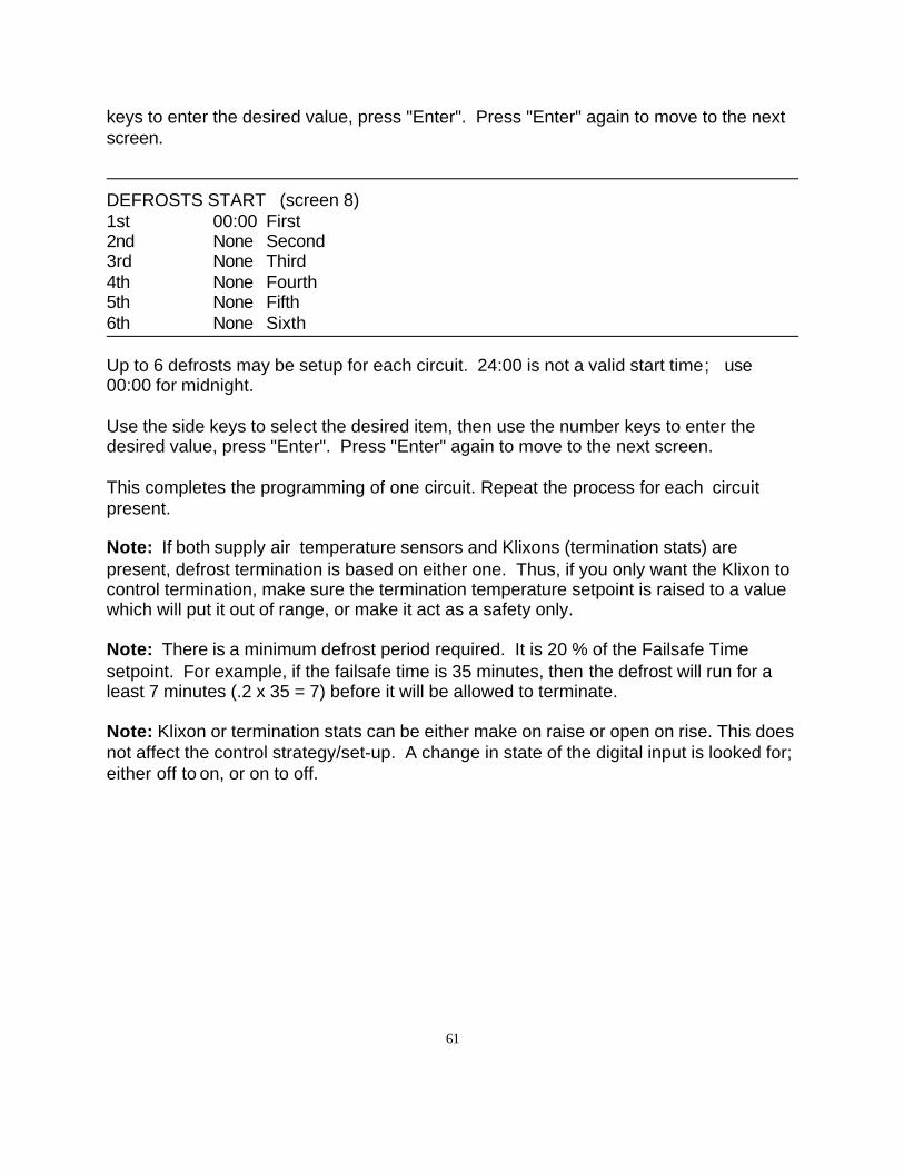
61
keys to enter the desired value, press "Enter". Press "Enter" again to move to the nextscreen.
DEFROSTS START (screen 8)1st 00:00 First2nd None Second3rd None Third4th None Fourth5th None Fifth6th None Sixth
Up to 6 defrosts may be setup for each circuit. 24:00 is not a valid start time; use00:00 for midnight.
Use the side keys to select the desired item, then use the number keys to enter thedesired value, press "Enter". Press "Enter" again to move to the next screen.
This completes the programming of one circuit. Repeat the process for each circuitpresent.
Note: If both supply air temperature sensors and Klixons (termination stats) arepresent, defrost termination is based on either one. Thus, if you only want the Klixon tocontrol termination, make sure the termination temperature setpoint is raised to a valuewhich will put it out of range, or make it act as a safety only.
Note: There is a minimum defrost period required. It is 20 % of the Failsafe Timesetpoint. For example, if the failsafe time is 35 minutes, then the defrost will run for aleast 7 minutes (.2 x 35 = 7) before it will be allowed to terminate.
Note: Klixon or termination stats can be either make on raise or open on rise. This doesnot affect the control strategy/set-up. A change in state of the digital input is looked for;either off to on, or on to off.
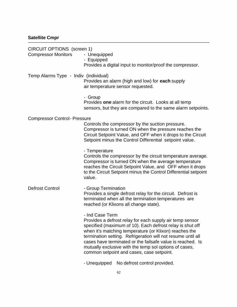
62
Satellite Cmpr
CIRCUIT OPTIONS (screen 1)Compressor Monitors - Unequipped
- EquippedProvides a digital input to monitor/proof the compressor.
Temp Alarms Type - Indiv (individual)Provides an alarm (high and low) for each supply air temperature sensor requested.
- GroupProvides one alarm for the circuit. Looks at all tempsensors, but they are compared to the same alarm setpoints.
Compressor Control- PressureControls the compressor by the suction pressure.Compressor is turned ON when the pressure reaches theCircuit Setpoint Value, and OFF when it drops to the CircuitSetpoint minus the Control Differential setpoint value.
- TemperatureControls the compressor by the circuit temperature average.Compressor is turned ON when the average temperaturereaches the Circuit Setpoint Value, and OFF when it dropsto the Circuit Setpoint minus the Control Differential setpointvalue.
Defrost Control - Group TerminationProvides a single defrost relay for the circuit. Defrost isterminated when all the termination temperatures arereached (or Klixons all change state).
- Ind Case TermProvides a defrost relay for each supply air temp sensorspecified (maximum of 10). Each defrost relay is shut offwhen it's matching temperature (or Klixon) reaches thetermination setting. Refrigeration will not resume until allcases have terminated or the failsafe value is reached. Ismutually exclusive with the temp sol options of cases,common setpoint and cases, case setpoint.
- Unequipped No defrost control provided.
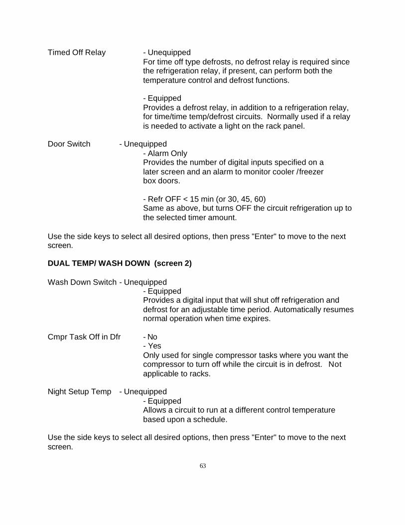
63
Timed Off Relay - UnequippedFor time off type defrosts, no defrost relay is required sincethe refrigeration relay, if present, can perform both thetemperature control and defrost functions.
- EquippedProvides a defrost relay, in addition to a refrigeration relay,for time/time temp/defrost circuits. Normally used if a relayis needed to activate a light on the rack panel.
Door Switch - Unequipped- Alarm OnlyProvides the number of digital inputs specified on a later screen and an alarm to monitor cooler /freezer box doors.
- Refr OFF < 15 min (or 30, 45, 60)Same as above, but turns OFF the circuit refrigeration up tothe selected timer amount.
Use the side keys to select all desired options, then press "Enter" to move to the nextscreen.
DUAL TEMP/ WASH DOWN (screen 2)
Wash Down Switch - Unequipped- EquippedProvides a digital input that will shut off refrigeration anddefrost for an adjustable time period. Automatically resumesnormal operation when time expires.
Cmpr Task Off in Dfr - No- YesOnly used for single compressor tasks where you want thecompressor to turn off while the circuit is in defrost. Notapplicable to racks.
Night Setup Temp - Unequipped- EquippedAllows a circuit to run at a different control temperaturebased upon a schedule.
Use the side keys to select all desired options, then press "Enter" to move to the nextscreen.
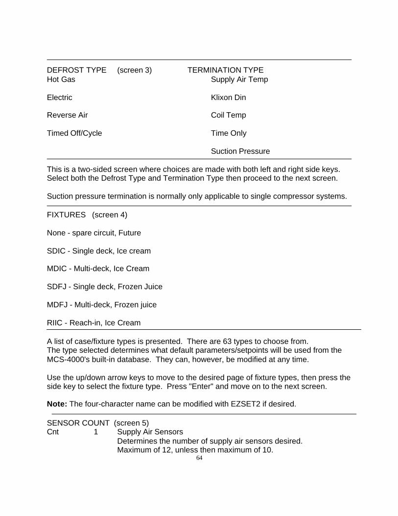
64
DEFROST TYPE (screen 3) TERMINATION TYPEHot Gas Supply Air Temp
Electric Klixon Din
Reverse Air Coil Temp
Timed Off/Cycle Time Only
Suction Pressure
This is a two-sided screen where choices are made with both left and right side keys.Select both the Defrost Type and Termination Type then proceed to the next screen.
Suction pressure termination is normally only applicable to single compressor systems.
FIXTURES (screen 4)
None - spare circuit, Future
SDIC - Single deck, Ice cream
MDIC - Multi-deck, Ice Cream
SDFJ - Single deck, Frozen Juice
MDFJ - Multi-deck, Frozen juice
RIIC - Reach-in, Ice Cream
A list of case/fixture types is presented. There are 63 types to choose from.The type selected determines what default parameters/setpoints will be used from theMCS-4000's built-in database. They can, however, be modified at any time.
Use the up/down arrow keys to move to the desired page of fixture types, then press theside key to select the fixture type. Press "Enter" and move on to the next screen.
Note: The four-character name can be modified with EZSET2 if desired.
SENSOR COUNT (screen 5)Cnt 1 Supply Air Sensors
Determines the number of supply air sensors desired.Maximum of 12, unless then maximum of 10.
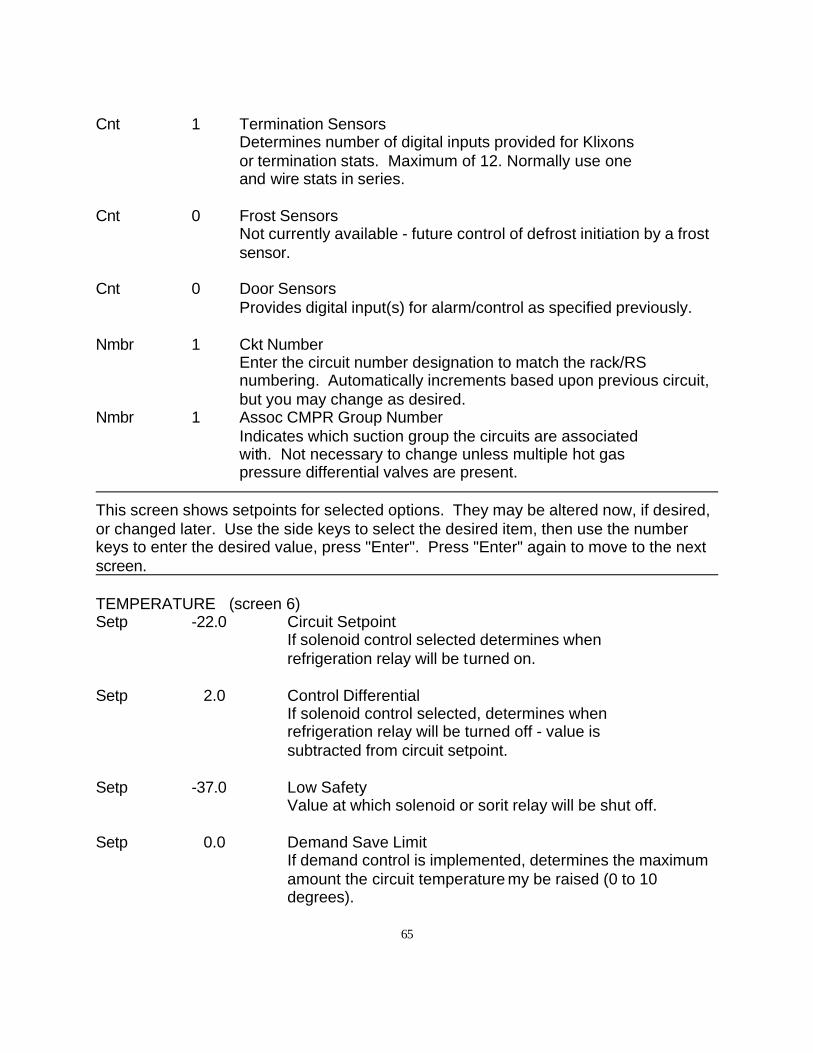
65
Cnt 1 Termination SensorsDetermines number of digital inputs provided for Klixons or termination stats. Maximum of 12. Normally use one and wire stats in series.
Cnt 0 Frost SensorsNot currently available - future control of defrost initiation by a frostsensor.
Cnt 0 Door SensorsProvides digital input(s) for alarm/control as specified previously.
Nmbr 1 Ckt NumberEnter the circuit number designation to match the rack/RSnumbering. Automatically increments based upon previous circuit,but you may change as desired.
Nmbr 1 Assoc CMPR Group NumberIndicates which suction group the circuits are associated with. Not necessary to change unless multiple hot gas pressure differential valves are present.
This screen shows setpoints for selected options. They may be altered now, if desired,or changed later. Use the side keys to select the desired item, then use the numberkeys to enter the desired value, press "Enter". Press "Enter" again to move to the nextscreen.
TEMPERATURE (screen 6)Setp -22.0 Circuit Setpoint
If solenoid control selected determines when refrigeration relay will be turned on.
Setp 2.0 Control DifferentialIf solenoid control selected, determines when refrigeration relay will be turned off - value is subtracted from circuit setpoint.
Setp -37.0 Low Safety Value at which solenoid or sorit relay will be shut off.
Setp 0.0 Demand Save LimitIf demand control is implemented, determines the maximumamount the circuit temperature my be raised (0 to 10degrees).
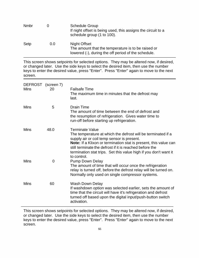
66
Nmbr 0 Schedule GroupIf night offset is being used, this assigns the circuit to aschedule group (1 to 100).
Setp 0.0 Night OffsetThe amount that the temperature is to be raised or lowered (-), during the off period of the schedule.
This screen shows setpoints for selected options. They may be altered now, if desired,or changed later. Use the side keys to select the desired item, then use the numberkeys to enter the desired value, press "Enter". Press "Enter" again to move to the nextscreen.
DEFROST (screen 7)Mins 20 Failsafe Time
The maximum time in minutes that the defrost may last.
Mins 5 Drain TimeThe amount of time between the end of defrost and the resumption of refrigeration. Gives water time to run-off before starting up refrigeration.
Mins 48.0 Terminate ValueThe temperature at which the defrost will be terminated if asupply air or coil temp sensor is present.Note: If a Klixon or termination stat is present, this value canstill terminate the defrost if it is reached before thetermination stat trips. Set this value high if you don't want itto control.
Mins 0 Pump Down DelayThe amount of time that will occur once the refrigerationrelay is turned off, before the defrost relay will be turned on.Normally only used on single compressor systems.
Mins 60 Wash Down DelayIf washdown option was selected earlier, sets the amount oftime that the circuit will have it's refrigeration and defrostturned off based upon the digital input/push-button switchactivation.
This screen shows setpoints for selected options. They may be altered now, if desired,or changed later. Use the side keys to select the desired item, then use the numberkeys to enter the desired value, press "Enter". Press "Enter" again to move to the nextscreen.
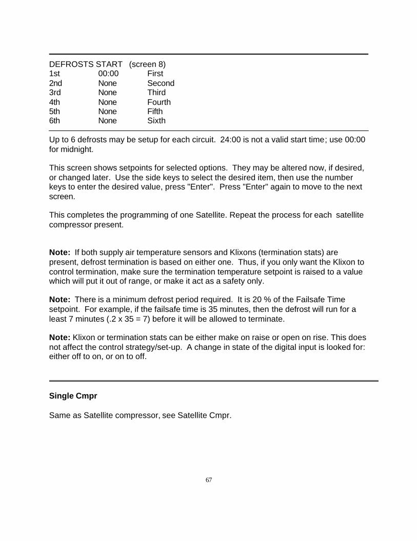
67
DEFROSTS START (screen 8)1st 00:00 First2nd None Second3rd None Third4th None Fourth5th None Fifth6th None Sixth
Up to 6 defrosts may be setup for each circuit. 24:00 is not a valid start time; use 00:00for midnight.
This screen shows setpoints for selected options. They may be altered now, if desired,or changed later. Use the side keys to select the desired item, then use the numberkeys to enter the desired value, press "Enter". Press "Enter" again to move to the nextscreen.
This completes the programming of one Satellite. Repeat the process for each satellitecompressor present.
Note: If both supply air temperature sensors and Klixons (termination stats) arepresent, defrost termination is based on either one. Thus, if you only want the Klixon tocontrol termination, make sure the termination temperature setpoint is raised to a valuewhich will put it out of range, or make it act as a safety only.
Note: There is a minimum defrost period required. It is 20 % of the Failsafe Timesetpoint. For example, if the failsafe time is 35 minutes, then the defrost will run for aleast 7 minutes (.2 x 35 = 7) before it will be allowed to terminate.
Note: Klixon or termination stats can be either make on raise or open on rise. This doesnot affect the control strategy/set-up. A change in state of the digital input is looked for:either off to on, or on to off.
Single Cmpr
Same as Satellite compressor, see Satellite Cmpr.
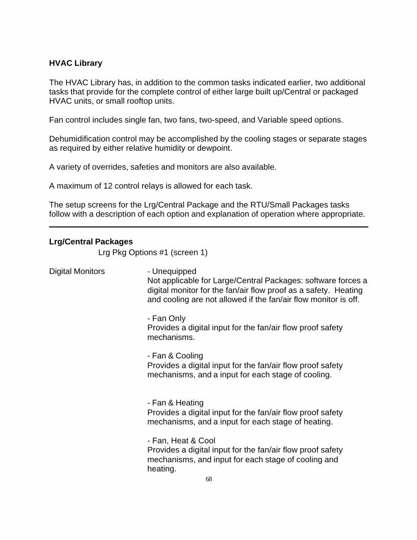
68
HVAC Library
The HVAC Library has, in addition to the common tasks indicated earlier, two additionaltasks that provide for the complete control of either large built up/Central or packagedHVAC units, or small rooftop units.
Fan control includes single fan, two fans, two-speed, and Variable speed options.
Dehumidification control may be accomplished by the cooling stages or separate stagesas required by either relative humidity or dewpoint.
A variety of overrides, safeties and monitors are also available.
A maximum of 12 control relays is allowed for each task.
The setup screens for the Lrg/Central Package and the RTU/Small Packages tasksfollow with a description of each option and explanation of operation where appropriate.
Lrg/Central PackagesLrg Pkg Options #1 (screen 1)
Digital Monitors - UnequippedNot applicable for Large/Central Packages: software forces adigital monitor for the fan/air flow proof as a safety. Heatingand cooling are not allowed if the fan/air flow monitor is off.
- Fan OnlyProvides a digital input for the fan/air flow proof safetymechanisms.
- Fan & CoolingProvides a digital input for the fan/air flow proof safetymechanisms, and a input for each stage of cooling.
- Fan & HeatingProvides a digital input for the fan/air flow proof safetymechanisms, and a input for each stage of heating.
- Fan, Heat & CoolProvides a digital input for the fan/air flow proof safetymechanisms, and input for each stage of cooling andheating.
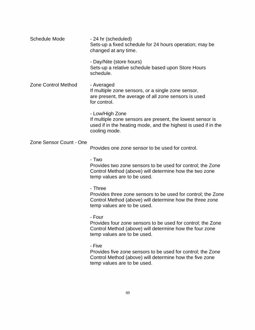
69
Schedule Mode - 24 hr (scheduled)Sets-up a fixed schedule for 24 hours operation; may bechanged at any time.
- Day/Nite (store hours)Sets-up a relative schedule based upon Store Hoursschedule.
Zone Control Method - AveragedIf multiple zone sensors, or a single zone sensor,are present, the average of all zone sensors is used for control.
- Low/High ZoneIf multiple zone sensors are present, the lowest sensor isused if in the heating mode, and the highest is used if in thecooling mode.
Zone Sensor Count - OneProvides one zone sensor to be used for control.
- TwoProvides two zone sensors to be used for control; the ZoneControl Method (above) will determine how the two zonetemp values are to be used.
- ThreeProvides three zone sensors to be used for control; the ZoneControl Method (above) will determine how the three zonetemp values are to be used.
- FourProvides four zone sensors to be used for control; the ZoneControl Method (above) will determine how the four zonetemp values are to be used.
- FiveProvides five zone sensors to be used for control; the ZoneControl Method (above) will determine how the five zonetemp values are to be used.
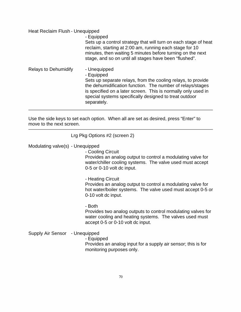
70
Heat Reclaim Flush - Unequipped- EquippedSets up a control strategy that will turn on each stage of heatreclaim, starting at 2:00 am, running each stage for 10minutes, then waiting 5 minutes before turning on the nextstage, and so on until all stages have been “flushed”.
Relays to Dehumidify - Unequipped- EquippedSets up separate relays, from the cooling relays, to providethe dehumidification function. The number of relays/stagesis specified on a later screen. This is normally only used inspecial systems specifically designed to treat outdoorseparately.
Use the side keys to set each option. When all are set as desired, press “Enter” tomove to the next screen.
Lrg Pkg Options #2 (screen 2)
Modulating valve(s) - Unequipped- Cooling CircuitProvides an analog output to control a modulating valve forwater/chiller cooling systems. The valve used must accept0-5 or 0-10 volt dc input.
- Heating CircuitProvides an analog output to control a modulating valve forhot water/boiler systems. The valve used must accept 0-5 or0-10 volt dc input.
- BothProvides two analog outputs to control modulating valves forwater cooling and heating systems. The valves used mustaccept 0-5 or 0-10 volt dc input.
Supply Air Sensor - Unequipped- EquippedProvides an analog input for a supply air sensor; this is formonitoring purposes only.
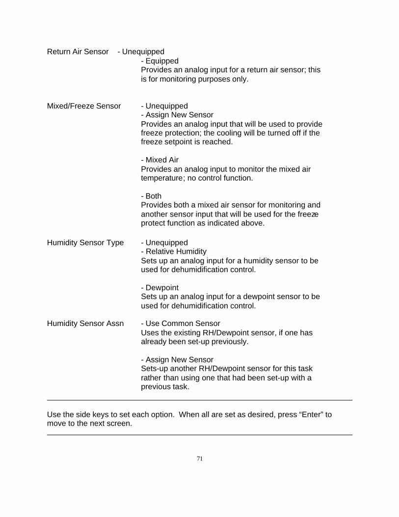
71
Return Air Sensor - Unequipped- EquippedProvides an analog input for a return air sensor; this is for monitoring purposes only.
Mixed/Freeze Sensor - Unequipped- Assign New SensorProvides an analog input that will be used to provide freeze protection; the cooling will be turned off if the freeze setpoint is reached.
- Mixed AirProvides an analog input to monitor the mixed air temperature; no control function.
- Both Provides both a mixed air sensor for monitoring and another sensor input that will be used for the freeze protect function as indicated above.
Humidity Sensor Type - Unequipped- Relative HumiditySets up an analog input for a humidity sensor to be used for dehumidification control.
- DewpointSets up an analog input for a dewpoint sensor to be used for dehumidification control.
Humidity Sensor Assn - Use Common SensorUses the existing RH/Dewpoint sensor, if one has already been set-up previously.
- Assign New SensorSets-up another RH/Dewpoint sensor for this task rather than using one that had been set-up with a previous task.
Use the side keys to set each option. When all are set as desired, press “Enter” tomove to the next screen.
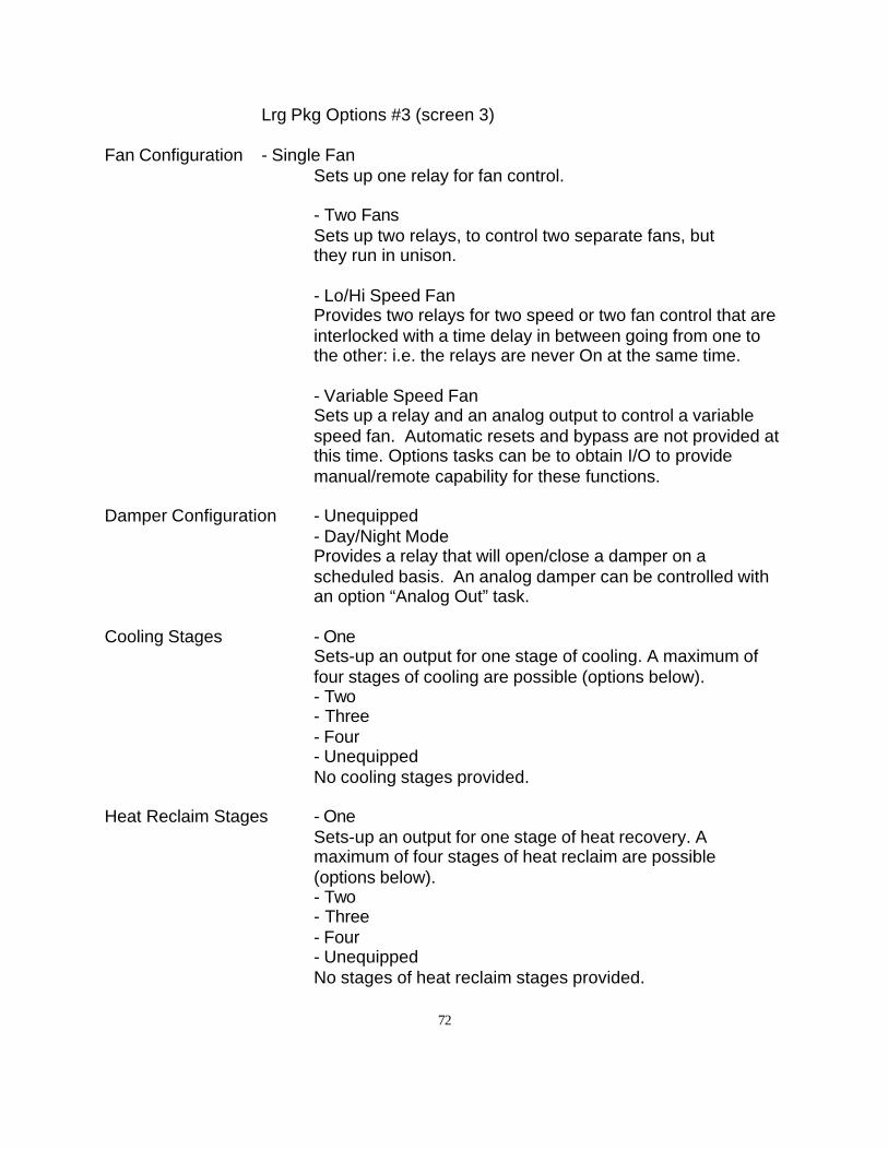
72
Lrg Pkg Options #3 (screen 3)
Fan Configuration - Single FanSets up one relay for fan control.
- Two FansSets up two relays, to control two separate fans, but they run in unison.
- Lo/Hi Speed FanProvides two relays for two speed or two fan control that areinterlocked with a time delay in between going from one tothe other: i.e. the relays are never On at the same time.
- Variable Speed FanSets up a relay and an analog output to control a variablespeed fan. Automatic resets and bypass are not provided atthis time. Options tasks can be to obtain I/O to providemanual/remote capability for these functions.
Damper Configuration - Unequipped- Day/Night ModeProvides a relay that will open/close a damper on ascheduled basis. An analog damper can be controlled withan option “Analog Out” task.
Cooling Stages - OneSets-up an output for one stage of cooling. A maximum offour stages of cooling are possible (options below).- Two- Three- Four- UnequippedNo cooling stages provided.
Heat Reclaim Stages - OneSets-up an output for one stage of heat recovery. Amaximum of four stages of heat reclaim are possible(options below).- Two- Three- Four- UnequippedNo stages of heat reclaim stages provided.
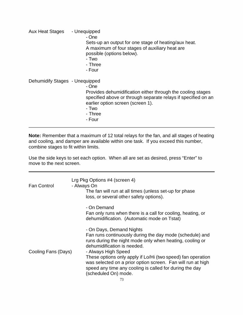
73
Aux Heat Stages - Unequipped- OneSets-up an output for one stage of heating/aux heat. A maximum of four stages of auxiliary heat are possible (options below).- Two- Three- Four
Dehumidify Stages - Unequipped- OneProvides dehumidification either through the cooling stagesspecified above or through separate relays if specified on anearlier option screen (screen 1).- Two- Three- Four
Note: Remember that a maximum of 12 total relays for the fan, and all stages of heatingand cooling, and damper are available within one task. If you exceed this number,combine stages to fit within limits.
Use the side keys to set each option. When all are set as desired, press “Enter” tomove to the next screen.
Lrg Pkg Options #4 (screen 4)Fan Control - Always On
The fan will run at all times (unless set-up for phase loss, or several other safety options).
- On DemandFan only runs when there is a call for cooling, heating, ordehumidification. (Automatic mode on Tstat)
- On Days, Demand NightsFan runs continuously during the day mode (schedule) andruns during the night mode only when heating, cooling ordehumidification is needed.
Cooling Fans (Days) - Always High SpeedThese options only apply if Lo/Hi (two speed) fan operationwas selected on a prior option screen. Fan will run at highspeed any time any cooling is called for during the day(scheduled On) mode.
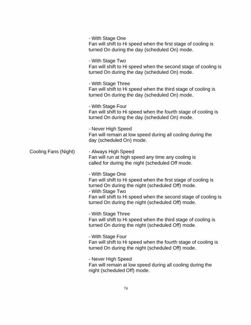
74
- With Stage OneFan will shift to Hi speed when the first stage of cooling isturned On during the day (scheduled On) mode.
- With Stage TwoFan will shift to Hi speed when the second stage of cooling isturned On during the day (scheduled On) mode.
- With Stage ThreeFan will shift to Hi speed when the third stage of cooling isturned On during the day (scheduled On) mode.
- With Stage FourFan will shift to Hi speed when the fourth stage of cooling isturned On during the day (scheduled On) mode.
- Never High SpeedFan will remain at low speed during all cooling during theday (scheduled On) mode.
Cooling Fans (Night) - Always High SpeedFan will run at high speed any time any cooling is called for during the night (scheduled Off mode.
- With Stage OneFan will shift to Hi speed when the first stage of cooling isturned On during the night (scheduled Off) mode.- With Stage TwoFan will shift to Hi speed when the second stage of cooling isturned On during the night (scheduled Off) mode.
- With Stage ThreeFan will shift to Hi speed when the third stage of cooling isturned On during the night (scheduled Off) mode.
- With Stage FourFan will shift to Hi speed when the fourth stage of cooling isturned On during the night (scheduled Off) mode.
- Never High SpeedFan will remain at low speed during all cooling during thenight (scheduled Off) mode.

75
Heating Fans (Days) - Always High SpeedThese options only apply if Lo/Hi (two speed) fan operationwas selected on a prior option screen. Fan will run at highspeed any time any heating is called for during the day(scheduled On) mode.- With Stage OneFan will shift to Hi speed when the first stage of heating isturned On during the day (scheduled On) mode.
- With Stage TwoFan will shift to Hi speed when the second stage of heatingis turned On during the day (scheduled On) mode.
- With Stage ThreeFan will shift to Hi speed when the third stage of heating isturned On during the day (scheduled On) mode.
- With Stage FourFan will shift to Hi speed when the fourth stage of heating isturned On during the day (scheduled On) mode.
- Never High SpeedFan will remain at low speed during all heating during theday (scheduled On) mode.
Heating Fans (Night) - Always High SpeedFan will run at high speed any time any heating is called forduring the night (scheduled Off mode.
- With Stage OneFan will shift to Hi speed when the first stage of heating isturned On during the night (scheduled Off) mode.
- With Stage TwoFan will shift to Hi speed when the second stage of heatingis turned On during the night (scheduled Off) mode.
- With Stage ThreeFan will shift to Hi speed when the third stage of heating isturned On during the night (scheduled Off) mode.- With Stage FourFan will shift to Hi speed when the fourth stage of heating isturned On during the night (scheduled Off) mode.
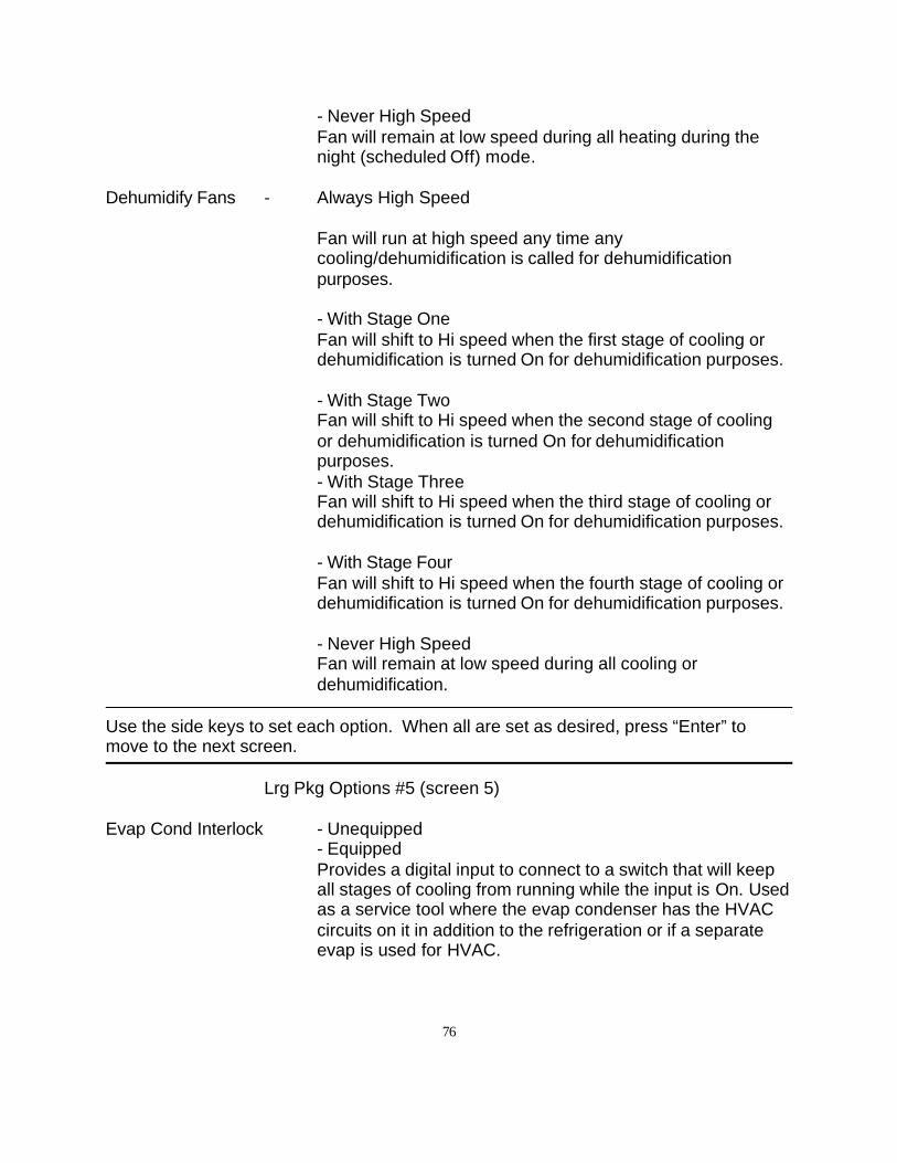
76
- Never High SpeedFan will remain at low speed during all heating during thenight (scheduled Off) mode.
Dehumidify Fans - Always High Speed
Fan will run at high speed any time anycooling/dehumidification is called for dehumidificationpurposes.
- With Stage OneFan will shift to Hi speed when the first stage of cooling ordehumidification is turned On for dehumidification purposes.
- With Stage TwoFan will shift to Hi speed when the second stage of coolingor dehumidification is turned On for dehumidificationpurposes. - With Stage ThreeFan will shift to Hi speed when the third stage of cooling ordehumidification is turned On for dehumidification purposes.
- With Stage FourFan will shift to Hi speed when the fourth stage of cooling ordehumidification is turned On for dehumidification purposes.
- Never High SpeedFan will remain at low speed during all cooling or dehumidification.
Use the side keys to set each option. When all are set as desired, press “Enter” tomove to the next screen.
Lrg Pkg Options #5 (screen 5)
Evap Cond Interlock - Unequipped- EquippedProvides a digital input to connect to a switch that will keepall stages of cooling from running while the input is On. Usedas a service tool where the evap condenser has the HVACcircuits on it in addition to the refrigeration or if a separateevap is used for HVAC.
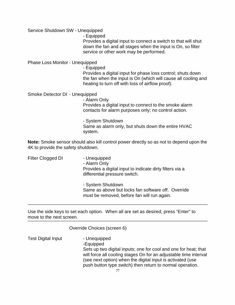
77
Service Shutdown SW - Unequipped- EquippedProvides a digital input to connect a switch to that will shutdown the fan and all stages when the input is On, so filterservice or other work may be performed.
Phase Loss Monitor - Unequipped- EquippedProvides a digital input for phase loss control; shuts downthe fan when the input is On (which will cause all cooling andheating to turn off with loss of airflow proof).
Smoke Detector DI - Unequipped- Alarm OnlyProvides a digital input to connect to the smoke alarmcontacts for alarm purposes only; no control action.
- System ShutdownSame as alarm only, but shuts down the entire HVACsystem.
Note: Smoke sensor should also kill control power directly so as not to depend upon the4K to provide the safety shutdown.
Filter Clogged DI - Unequipped- Alarm OnlyProvides a digital input to indicate dirty filters via adifferential pressure switch.
- System ShutdownSame as above but locks fan software off. Override must be removed, before fan will run again.
Use the side keys to set each option. When all are set as desired, press “Enter” tomove to the next screen.
Override Choices (screen 6)
Test Digital Input - Unequipped-EquippedSets up two digital inputs; one for cool and one for heat; thatwill force all cooling stages On for an adjustable time interval(see next option) when the digital input is activated (usepush button type switch) then return to normal operation.
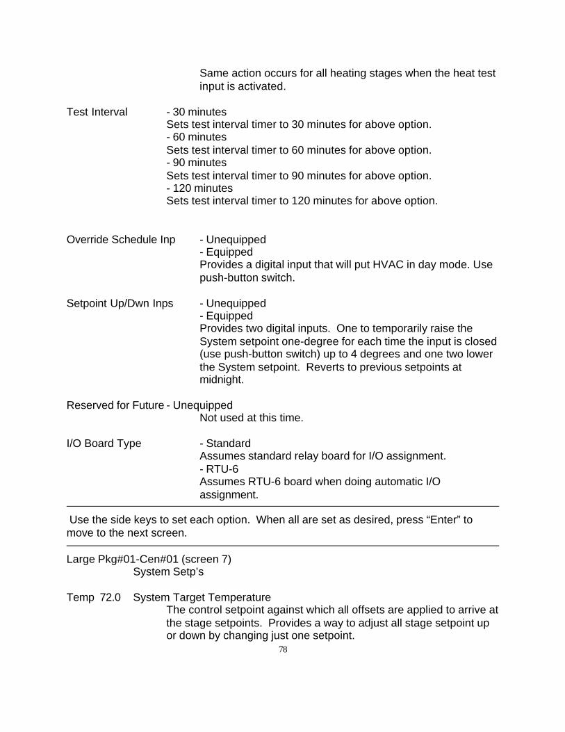
78
Same action occurs for all heating stages when the heat testinput is activated.
Test Interval - 30 minutesSets test interval timer to 30 minutes for above option.- 60 minutesSets test interval timer to 60 minutes for above option.- 90 minutesSets test interval timer to 90 minutes for above option.- 120 minutesSets test interval timer to 120 minutes for above option.
Override Schedule Inp - Unequipped- EquippedProvides a digital input that will put HVAC in day mode. Usepush-button switch.
Setpoint Up/Dwn Inps - Unequipped- EquippedProvides two digital inputs. One to temporarily raise theSystem setpoint one-degree for each time the input is closed(use push-button switch) up to 4 degrees and one two lowerthe System setpoint. Reverts to previous setpoints atmidnight.
Reserved for Future - Unequipped
Not used at this time.
I/O Board Type - StandardAssumes standard relay board for I/O assignment. - RTU-6Assumes RTU-6 board when doing automatic I/O assignment.
Use the side keys to set each option. When all are set as desired, press “Enter” tomove to the next screen.
Large Pkg#01-Cen#01 (screen 7)System Setp’s
Temp 72.0 System Target TemperatureThe control setpoint against which all offsets are applied to arrive atthe stage setpoints. Provides a way to adjust all stage setpoint upor down by changing just one setpoint.
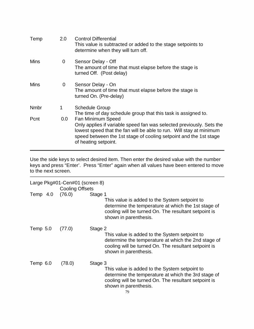
79
Temp 2.0 Control DifferentialThis value is subtracted or added to the stage setpoints to determine when they will turn off.
Mins 0 Sensor Delay - OffThe amount of time that must elapse before the stage is turned Off. (Post delay)
Mins 0 Sensor Delay - OnThe amount of time that must elapse before the stage is turned On. (Pre-delay)
Nmbr 1 Schedule GroupThe time of day schedule group that this task is assigned to.
Pcnt 0.0 Fan Minimum SpeedOnly applies if variable speed fan was selected previously. Sets thelowest speed that the fan will be able to run. Will stay at minimumspeed between the 1st stage of cooling setpoint and the 1st stageof heating setpoint.
Use the side keys to select desired item. Then enter the desired value with the numberkeys and press “Enter’. Press “Enter” again when all values have been entered to moveto the next screen.
Large Pkg#01-Cen#01 (screen 8)Cooling Offsets
Temp 4.0 (76.0) Stage 1This value is added to the System setpoint todetermine the temperature at which the 1st stage ofcooling will be turned On. The resultant setpoint isshown in parenthesis.
Temp 5.0 (77.0) Stage 2This value is added to the System setpoint todetermine the temperature at which the 2nd stage ofcooling will be turned On. The resultant setpoint isshown in parenthesis.
Temp 6.0 (78.0) Stage 3This value is added to the System setpoint todetermine the temperature at which the 3rd stage ofcooling will be turned On. The resultant setpoint isshown in parenthesis.
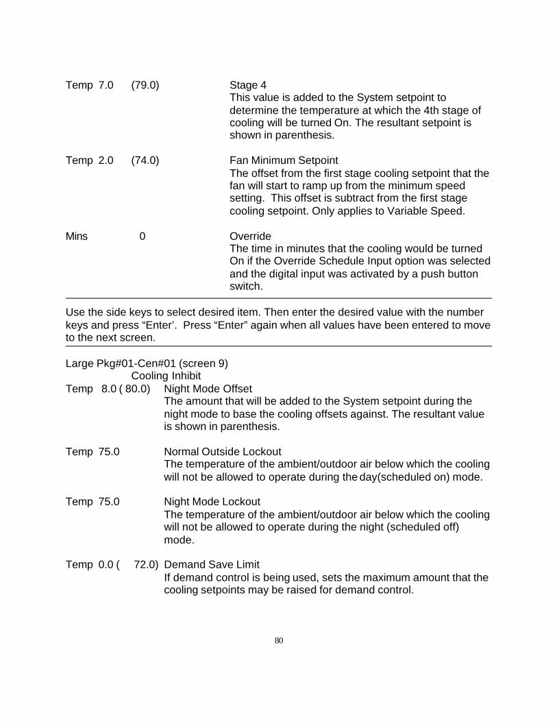
80
Temp 7.0 (79.0) Stage 4This value is added to the System setpoint todetermine the temperature at which the 4th stage ofcooling will be turned On. The resultant setpoint isshown in parenthesis.
Temp 2.0 (74.0) Fan Minimum SetpointThe offset from the first stage cooling setpoint that thefan will start to ramp up from the minimum speedsetting. This offset is subtract from the first stagecooling setpoint. Only applies to Variable Speed.
Mins 0 OverrideThe time in minutes that the cooling would be turnedOn if the Override Schedule Input option was selectedand the digital input was activated by a push buttonswitch.
Use the side keys to select desired item. Then enter the desired value with the numberkeys and press “Enter’. Press “Enter” again when all values have been entered to moveto the next screen.
Large Pkg#01-Cen#01 (screen 9)Cooling Inhibit
Temp 8.0 ( 80.0) Night Mode OffsetThe amount that will be added to the System setpoint during thenight mode to base the cooling offsets against. The resultant valueis shown in parenthesis.
Temp 75.0 Normal Outside LockoutThe temperature of the ambient/outdoor air below which the coolingwill not be allowed to operate during the day(scheduled on) mode.
Temp 75.0 Night Mode LockoutThe temperature of the ambient/outdoor air below which the coolingwill not be allowed to operate during the night (scheduled off)mode.
Temp 0.0 ( 72.0) Demand Save LimitIf demand control is being used, sets the maximum amount that thecooling setpoints may be raised for demand control.
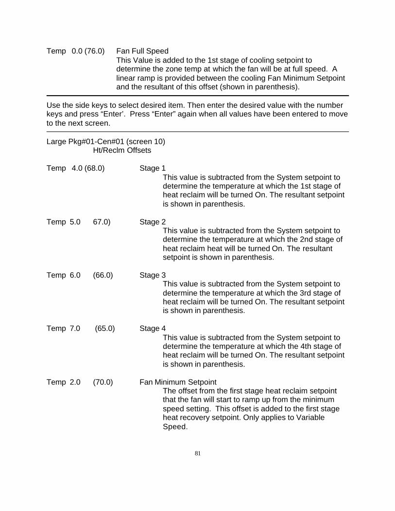
81
Temp 0.0 (76.0) Fan Full SpeedThis Value is added to the 1st stage of cooling setpoint todetermine the zone temp at which the fan will be at full speed. Alinear ramp is provided between the cooling Fan Minimum Setpointand the resultant of this offset (shown in parenthesis).
Use the side keys to select desired item. Then enter the desired value with the numberkeys and press “Enter’. Press “Enter” again when all values have been entered to moveto the next screen.
Large Pkg#01-Cen#01 (screen 10)Ht/Reclm Offsets
Temp 4.0 (68.0) Stage 1This value is subtracted from the System setpoint todetermine the temperature at which the 1st stage ofheat reclaim will be turned On. The resultant setpointis shown in parenthesis.
Temp 5.0 67.0) Stage 2This value is subtracted from the System setpoint todetermine the temperature at which the 2nd stage ofheat reclaim heat will be turned On. The resultantsetpoint is shown in parenthesis.
Temp 6.0 (66.0) Stage 3This value is subtracted from the System setpoint todetermine the temperature at which the 3rd stage ofheat reclaim will be turned On. The resultant setpointis shown in parenthesis.
Temp 7.0 (65.0) Stage 4This value is subtracted from the System setpoint todetermine the temperature at which the 4th stage ofheat reclaim will be turned On. The resultant setpointis shown in parenthesis.
Temp 2.0 (70.0) Fan Minimum SetpointThe offset from the first stage heat reclaim setpointthat the fan will start to ramp up from the minimumspeed setting. This offset is added to the first stageheat recovery setpoint. Only applies to VariableSpeed.
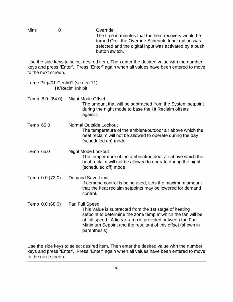
82
Mins 0 OverrideThe time in minutes that the heat recovery would beturned On if the Override Schedule Input option wasselected and the digital input was activated by a pushbutton switch.
Use the side keys to select desired item. Then enter the desired value with the numberkeys and press “Enter’. Press “Enter” again when all values have been entered to moveto the next screen.
Large Pkg#01-Cen#01 (screen 11)Ht/Reclm Inhibit
Temp 8.0 (64.0) Night Mode Offset.The amount that will be subtracted from the System setpointduring the night mode to base the Ht Reclaim offsetsagainst.
Temp 65.0 Normal Outside LockoutThe temperature of the ambient/outdoor air above which theheat reclaim will not be allowed to operate during the day(scheduled on) mode.
Temp 65.0 Night Mode LockoutThe temperature of the ambient/outdoor air above which theheat reclaim will not be allowed to operate during the night(scheduled off) mode
Temp 0.0 (72.0) Demand Save LimitIf demand control is being used, sets the maximum amountthat the heat reclaim setpoints may be lowered for demandcontrol.
Temp 0.0 (68.0) Fan Full SpeedThis Value is subtracted from the 1st stage of heatingsetpoint to determine the zone temp at which the fan will beat full speed. A linear ramp is provided between the FanMinimum Sepoint and the resultant of this offset (shown inparenthesis).
Use the side keys to select desired item. Then enter the desired value with the numberkeys and press “Enter’. Press “Enter” again when all values have been entered to moveto the next screen.
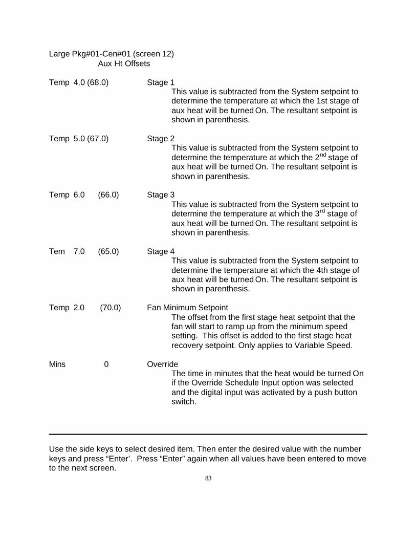
83
Large Pkg#01-Cen#01 (screen 12)Aux Ht Offsets
Temp 4.0 (68.0) Stage 1This value is subtracted from the System setpoint todetermine the temperature at which the 1st stage ofaux heat will be turned On. The resultant setpoint isshown in parenthesis.
Temp 5.0 (67.0) Stage 2This value is subtracted from the System setpoint todetermine the temperature at which the 2nd stage ofaux heat will be turned On. The resultant setpoint isshown in parenthesis.
Temp 6.0 (66.0) Stage 3This value is subtracted from the System setpoint todetermine the temperature at which the 3rd stage ofaux heat will be turned On. The resultant setpoint isshown in parenthesis.
Tem 7.0 (65.0) Stage 4This value is subtracted from the System setpoint todetermine the temperature at which the 4th stage ofaux heat will be turned On. The resultant setpoint isshown in parenthesis.
Temp 2.0 (70.0) Fan Minimum SetpointThe offset from the first stage heat setpoint that thefan will start to ramp up from the minimum speedsetting. This offset is added to the first stage heatrecovery setpoint. Only applies to Variable Speed.
Mins 0 OverrideThe time in minutes that the heat would be turned Onif the Override Schedule Input option was selectedand the digital input was activated by a push buttonswitch.
Use the side keys to select desired item. Then enter the desired value with the numberkeys and press “Enter’. Press “Enter” again when all values have been entered to moveto the next screen.
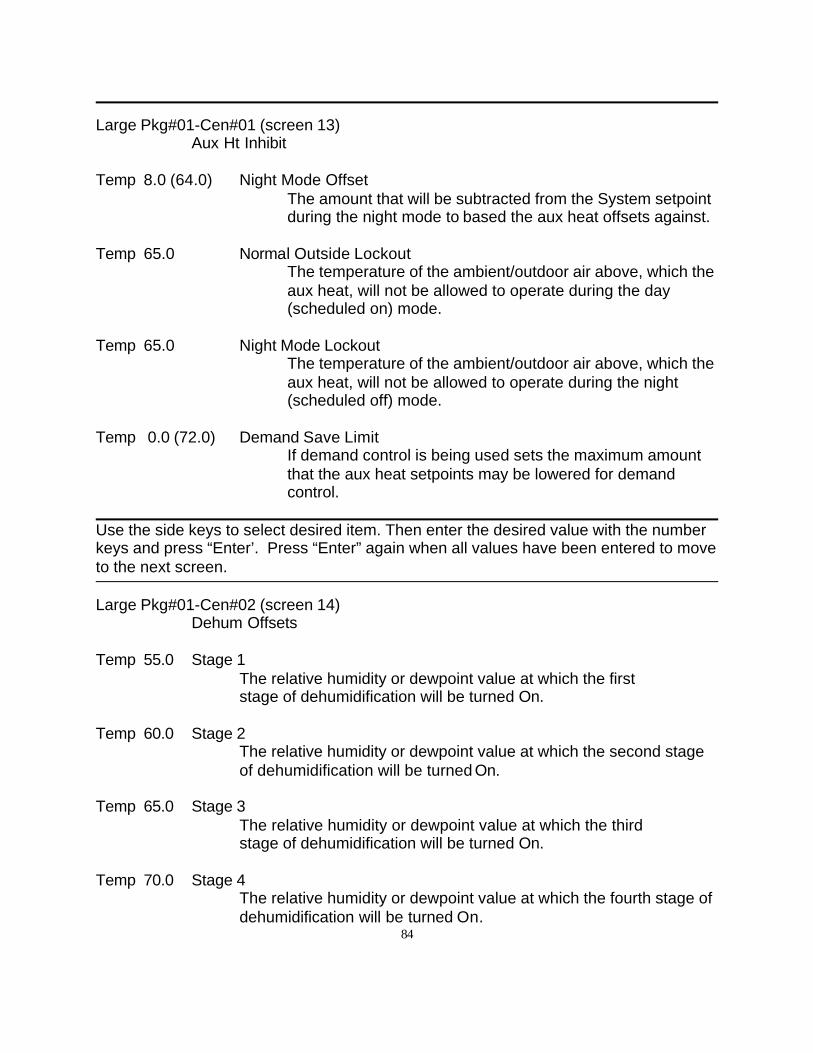
84
Large Pkg#01-Cen#01 (screen 13)Aux Ht Inhibit
Temp 8.0 (64.0) Night Mode OffsetThe amount that will be subtracted from the System setpointduring the night mode to based the aux heat offsets against.
Temp 65.0 Normal Outside LockoutThe temperature of the ambient/outdoor air above, which theaux heat, will not be allowed to operate during the day(scheduled on) mode.
Temp 65.0 Night Mode LockoutThe temperature of the ambient/outdoor air above, which theaux heat, will not be allowed to operate during the night(scheduled off) mode.
Temp 0.0 (72.0) Demand Save LimitIf demand control is being used sets the maximum amountthat the aux heat setpoints may be lowered for demandcontrol.
Use the side keys to select desired item. Then enter the desired value with the numberkeys and press “Enter’. Press “Enter” again when all values have been entered to moveto the next screen.
Large Pkg#01-Cen#02 (screen 14)Dehum Offsets
Temp 55.0 Stage 1The relative humidity or dewpoint value at which the first stage of dehumidification will be turned On.
Temp 60.0 Stage 2The relative humidity or dewpoint value at which the second stageof dehumidification will be turned On.
Temp 65.0 Stage 3The relative humidity or dewpoint value at which the third stage of dehumidification will be turned On.
Temp 70.0 Stage 4The relative humidity or dewpoint value at which the fourth stage ofdehumidification will be turned On.
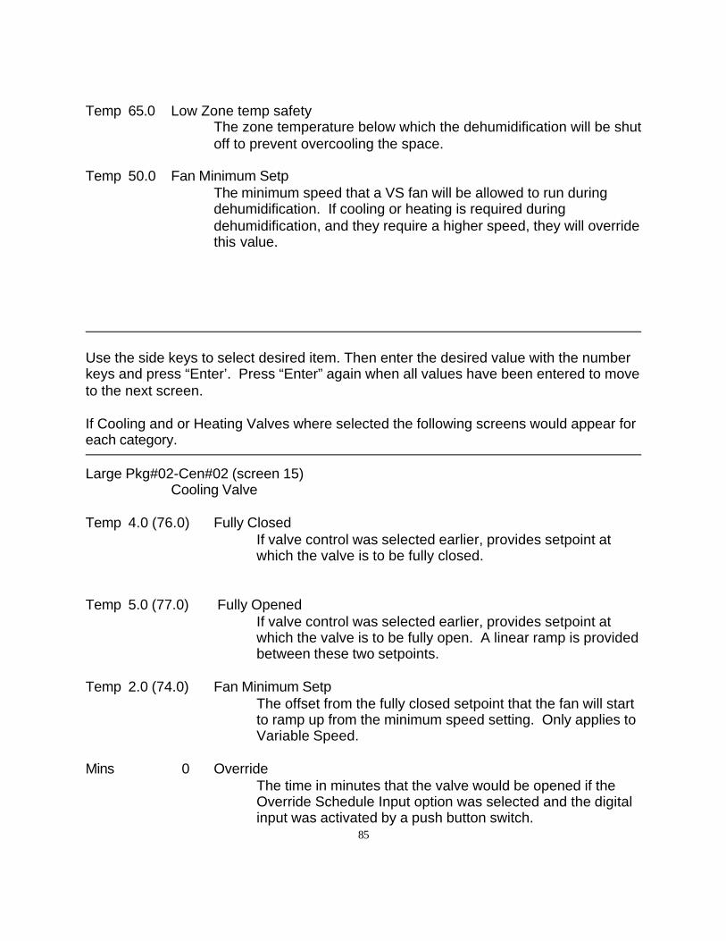
85
Temp 65.0 Low Zone temp safetyThe zone temperature below which the dehumidification will be shutoff to prevent overcooling the space.
Temp 50.0 Fan Minimum SetpThe minimum speed that a VS fan will be allowed to run duringdehumidification. If cooling or heating is required duringdehumidification, and they require a higher speed, they will overridethis value.
Use the side keys to select desired item. Then enter the desired value with the numberkeys and press “Enter’. Press “Enter” again when all values have been entered to moveto the next screen.
If Cooling and or Heating Valves where selected the following screens would appear foreach category.
Large Pkg#02-Cen#02 (screen 15)Cooling Valve
Temp 4.0 (76.0) Fully ClosedIf valve control was selected earlier, provides setpoint atwhich the valve is to be fully closed.
Temp 5.0 (77.0) Fully OpenedIf valve control was selected earlier, provides setpoint atwhich the valve is to be fully open. A linear ramp is providedbetween these two setpoints.
Temp 2.0 (74.0) Fan Minimum SetpThe offset from the fully closed setpoint that the fan will startto ramp up from the minimum speed setting. Only applies toVariable Speed.
Mins 0 OverrideThe time in minutes that the valve would be opened if theOverride Schedule Input option was selected and the digitalinput was activated by a push button switch.
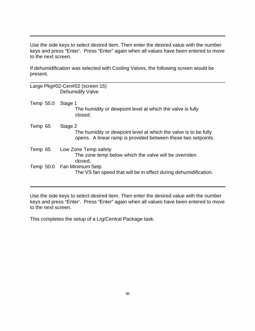
86
Use the side keys to select desired item. Then enter the desired value with the numberkeys and press “Enter’. Press “Enter” again when all values have been entered to moveto the next screen.
If dehumidification was selected with Cooling Valves, the following screen would bepresent.
Large Pkg#02-Cen#02 (screen 15)Dehumidify Valve
Temp 55.0 Stage 1The humidity or dewpoint level at which the valve is fully closed.
Temp 65 Stage 2The humidity or dewpoint level at which the valve is to be fullyopens. A linear ramp is provided between these two setpoints.
Temp 65 Low Zone Temp safetyThe zone temp below which the valve will be overriden closed.
Temp 50.0 Fan Minimum SetpThe VS fan speed that will be in effect during dehumidification.
Use the side keys to select desired item. Then enter the desired value with the numberkeys and press “Enter’. Press “Enter” again when all values have been entered to moveto the next screen.
This completes the setup of a Lrg/Central Package task.
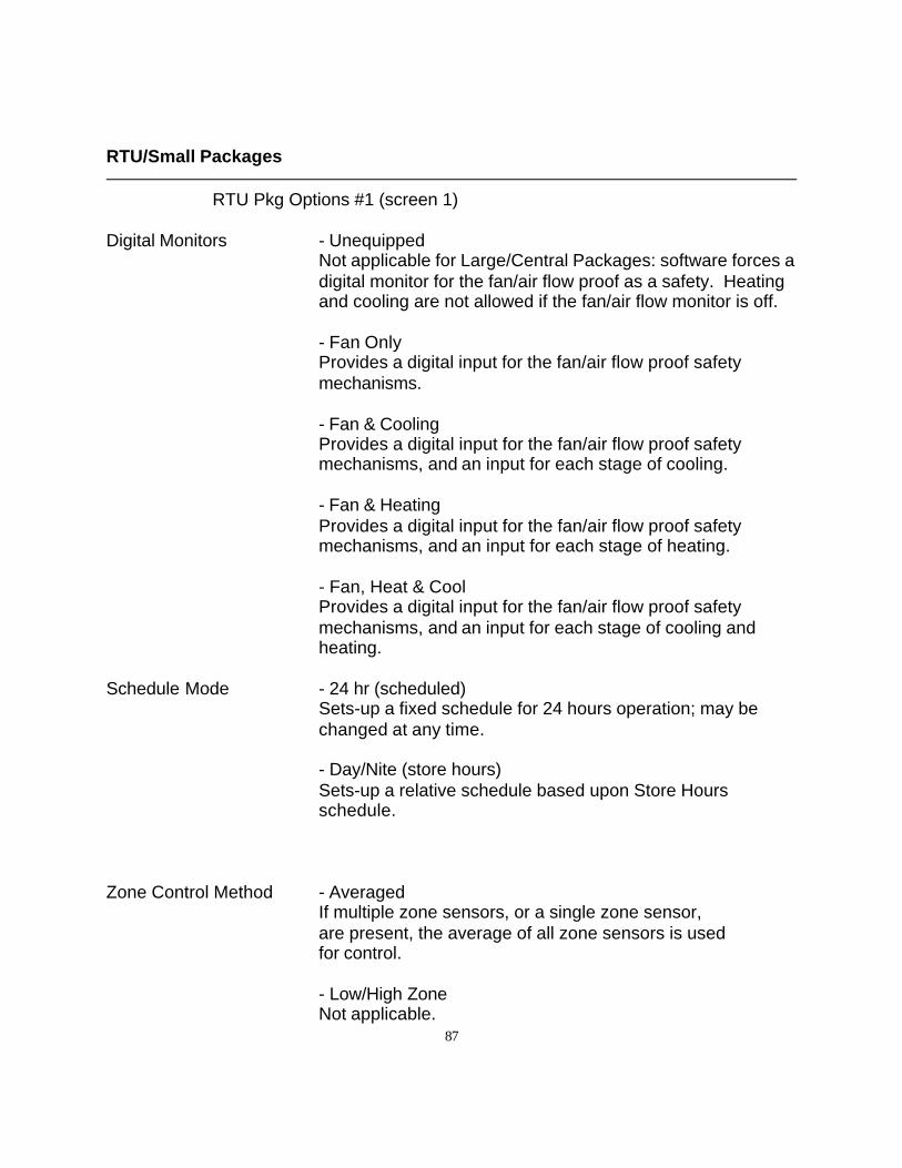
87
RTU/Small Packages
RTU Pkg Options #1 (screen 1)
Digital Monitors - UnequippedNot applicable for Large/Central Packages: software forces adigital monitor for the fan/air flow proof as a safety. Heatingand cooling are not allowed if the fan/air flow monitor is off.
- Fan OnlyProvides a digital input for the fan/air flow proof safetymechanisms.
- Fan & CoolingProvides a digital input for the fan/air flow proof safetymechanisms, and an input for each stage of cooling.
- Fan & HeatingProvides a digital input for the fan/air flow proof safetymechanisms, and an input for each stage of heating.
- Fan, Heat & CoolProvides a digital input for the fan/air flow proof safetymechanisms, and an input for each stage of cooling andheating.
Schedule Mode - 24 hr (scheduled)Sets-up a fixed schedule for 24 hours operation; may bechanged at any time.
- Day/Nite (store hours)Sets-up a relative schedule based upon Store Hoursschedule.
Zone Control Method - AveragedIf multiple zone sensors, or a single zone sensor,are present, the average of all zone sensors is used for control.
- Low/High ZoneNot applicable.
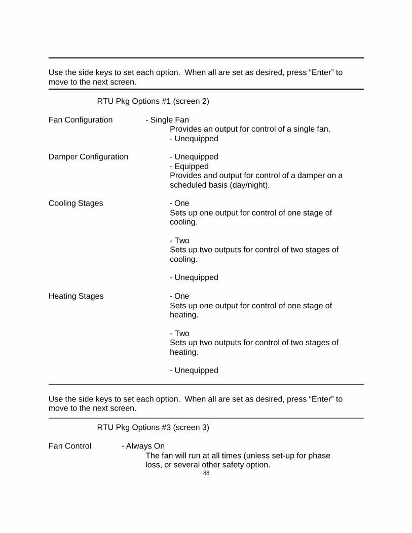
88
Use the side keys to set each option. When all are set as desired, press “Enter” tomove to the next screen.
RTU Pkg Options #1 (screen 2)
Fan Configuration - Single FanProvides an output for control of a single fan.- Unequipped
Damper Configuration - Unequipped- EquippedProvides and output for control of a damper on ascheduled basis (day/night).
Cooling Stages - OneSets up one output for control of one stage of cooling.
- TwoSets up two outputs for control of two stages ofcooling.
- Unequipped
Heating Stages - OneSets up one output for control of one stage of heating.
- TwoSets up two outputs for control of two stages ofheating.
- Unequipped
Use the side keys to set each option. When all are set as desired, press “Enter” tomove to the next screen.
RTU Pkg Options #3 (screen 3)
Fan Control - Always OnThe fan will run at all times (unless set-up for phase loss, or several other safety option.
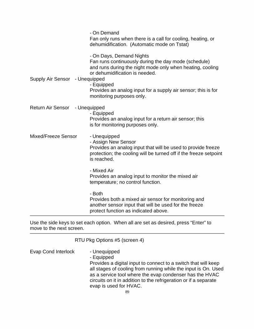
89
- On DemandFan only runs when there is a call for cooling, heating, ordehumidification. (Automatic mode on Tstat)
- On Days, Demand NightsFan runs continuously during the day mode (schedule)and runs during the night mode only when heating, coolingor dehumidification is needed.
Supply Air Sensor - Unequipped- EquippedProvides an analog input for a supply air sensor; this is formonitoring purposes only.
Return Air Sensor - Unequipped- EquippedProvides an analog input for a return air sensor; this is for monitoring purposes only.
Mixed/Freeze Sensor - Unequipped- Assign New SensorProvides an analog input that will be used to provide freezeprotection; the cooling will be turned off if the freeze setpointis reached.
- Mixed AirProvides an analog input to monitor the mixed air temperature; no control function.
- Both Provides both a mixed air sensor for monitoring and another sensor input that will be used for the freeze protect function as indicated above.
Use the side keys to set each option. When all are set as desired, press “Enter” tomove to the next screen.
RTU Pkg Options #5 (screen 4)
Evap Cond Interlock - Unequipped- EquippedProvides a digital input to connect to a switch that will keepall stages of cooling from running while the input is On. Usedas a service tool where the evap condenser has the HVACcircuits on it in addition to the refrigeration or if a separateevap is used for HVAC.
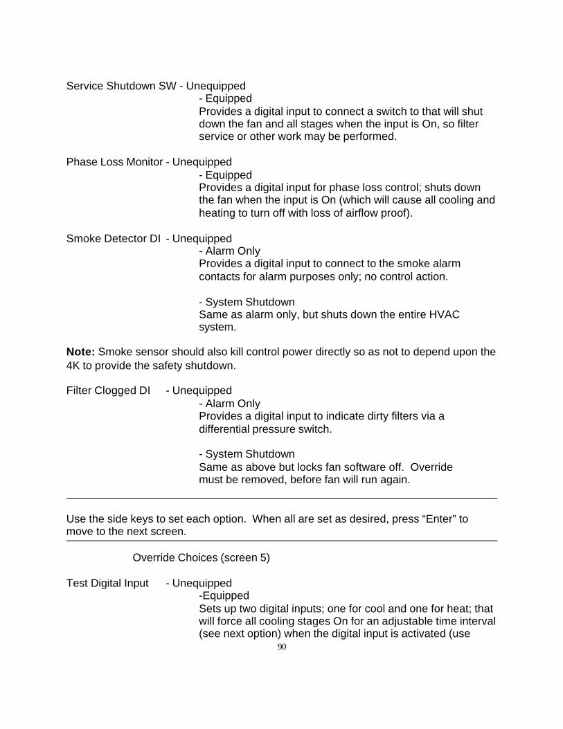
90
Service Shutdown SW - Unequipped- EquippedProvides a digital input to connect a switch to that will shutdown the fan and all stages when the input is On, so filterservice or other work may be performed.
Phase Loss Monitor - Unequipped- EquippedProvides a digital input for phase loss control; shuts downthe fan when the input is On (which will cause all cooling andheating to turn off with loss of airflow proof).
Smoke Detector DI - Unequipped- Alarm OnlyProvides a digital input to connect to the smoke alarmcontacts for alarm purposes only; no control action.
- System ShutdownSame as alarm only, but shuts down the entire HVACsystem.
Note: Smoke sensor should also kill control power directly so as not to depend upon the4K to provide the safety shutdown.
Filter Clogged DI - Unequipped- Alarm OnlyProvides a digital input to indicate dirty filters via a differential pressure switch.
- System ShutdownSame as above but locks fan software off. Override must be removed, before fan will run again.
Use the side keys to set each option. When all are set as desired, press “Enter” tomove to the next screen.
Override Choices (screen 5)
Test Digital Input - Unequipped-EquippedSets up two digital inputs; one for cool and one for heat; thatwill force all cooling stages On for an adjustable time interval(see next option) when the digital input is activated (use
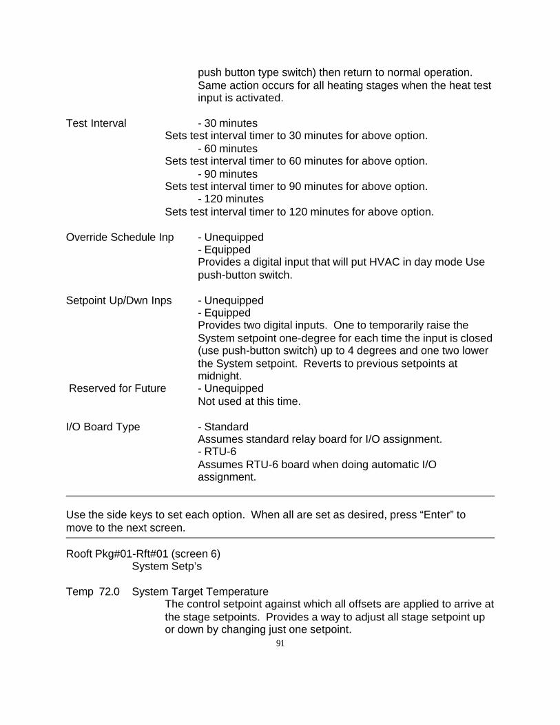
91
push button type switch) then return to normal operation.Same action occurs for all heating stages when the heat testinput is activated.
Test Interval - 30 minutesSets test interval timer to 30 minutes for above option.
- 60 minutesSets test interval timer to 60 minutes for above option.
- 90 minutesSets test interval timer to 90 minutes for above option.
- 120 minutesSets test interval timer to 120 minutes for above option.
Override Schedule Inp - Unequipped- EquippedProvides a digital input that will put HVAC in day mode Usepush-button switch.
Setpoint Up/Dwn Inps - Unequipped- EquippedProvides two digital inputs. One to temporarily raise theSystem setpoint one-degree for each time the input is closed(use push-button switch) up to 4 degrees and one two lowerthe System setpoint. Reverts to previous setpoints atmidnight.
Reserved for Future - UnequippedNot used at this time.
I/O Board Type - StandardAssumes standard relay board for I/O assignment. - RTU-6Assumes RTU-6 board when doing automatic I/O assignment.
Use the side keys to set each option. When all are set as desired, press “Enter” tomove to the next screen.
Rooft Pkg#01-Rft#01 (screen 6)System Setp’s
Temp 72.0 System Target TemperatureThe control setpoint against which all offsets are applied to arrive atthe stage setpoints. Provides a way to adjust all stage setpoint upor down by changing just one setpoint.
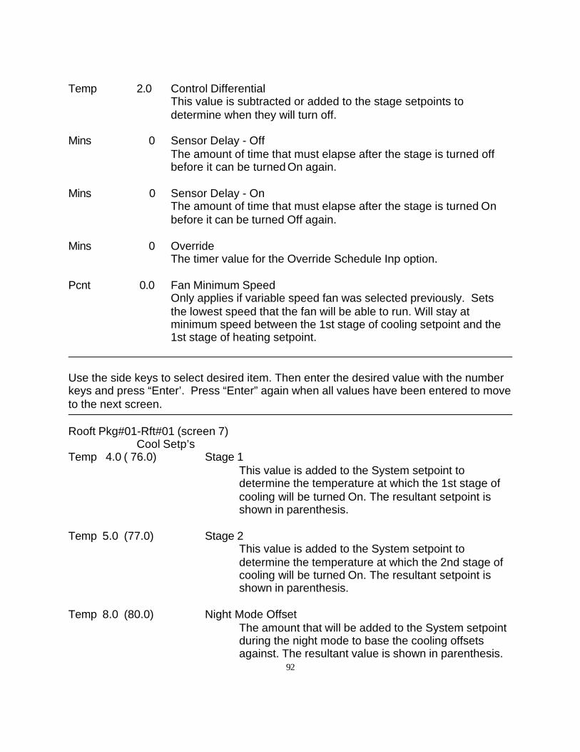
92
Temp 2.0 Control DifferentialThis value is subtracted or added to the stage setpoints to determine when they will turn off.
Mins 0 Sensor Delay - OffThe amount of time that must elapse after the stage is turned offbefore it can be turned On again.
Mins 0 Sensor Delay - OnThe amount of time that must elapse after the stage is turned Onbefore it can be turned Off again.
Mins 0 OverrideThe timer value for the Override Schedule Inp option.
Pcnt 0.0 Fan Minimum SpeedOnly applies if variable speed fan was selected previously. Setsthe lowest speed that the fan will be able to run. Will stay atminimum speed between the 1st stage of cooling setpoint and the1st stage of heating setpoint.
Use the side keys to select desired item. Then enter the desired value with the numberkeys and press “Enter’. Press “Enter” again when all values have been entered to moveto the next screen.
Rooft Pkg#01-Rft#01 (screen 7)Cool Setp’s
Temp 4.0 ( 76.0) Stage 1This value is added to the System setpoint todetermine the temperature at which the 1st stage ofcooling will be turned On. The resultant setpoint isshown in parenthesis.
Temp 5.0 (77.0) Stage 2This value is added to the System setpoint todetermine the temperature at which the 2nd stage ofcooling will be turned On. The resultant setpoint isshown in parenthesis.
Temp 8.0 (80.0) Night Mode OffsetThe amount that will be added to the System setpointduring the night mode to base the cooling offsetsagainst. The resultant value is shown in parenthesis.
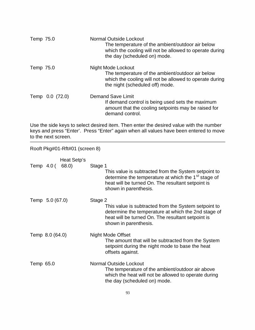
93
Temp 75.0 Normal Outside LockoutThe temperature of the ambient/outdoor air belowwhich the cooling will not be allowed to operate duringthe day (scheduled on) mode.
Temp 75.0 Night Mode LockoutThe temperature of the ambient/outdoor air belowwhich the cooling will not be allowed to operate duringthe night (scheduled off) mode.
Temp 0.0 (72.0) Demand Save LimitIf demand control is being used sets the maximumamount that the cooling setpoints may be raised fordemand control.
Use the side keys to select desired item. Then enter the desired value with the numberkeys and press “Enter’. Press “Enter” again when all values have been entered to moveto the next screen.
Rooft Pkg#01-Rft#01 (screen 8)
Heat Setp’sTemp 4.0 ( 68.0) Stage 1
This value is subtracted from the System setpoint todetermine the temperature at which the 1st stage ofheat will be turned On. The resultant setpoint isshown in parenthesis.
Temp 5.0 (67.0) Stage 2This value is subtracted from the System setpoint todetermine the temperature at which the 2nd stage ofheat will be turned On. The resultant setpoint isshown in parenthesis.
Temp 8.0 (64.0) Night Mode OffsetThe amount that will be subtracted from the Systemsetpoint during the night mode to base the heatoffsets against.
Temp 65.0 Normal Outside LockoutThe temperature of the ambient/outdoor air abovewhich the heat will not be allowed to operate duringthe day (scheduled on) mode.

94
Temp 65.0 Night Mode LockoutThe temperature of the ambient/outdoor air abovewhich the heat will not be allowed to operate duringthe night (scheduled off) mode.
Temp 0.0 (72.0) Demand Save LimitIf demand control is being used sets the maximumamount that the heat setpoints may be lowered fordemand control.
Use the side keys to select desired item. Then enter the desired value with the numberkeys and press “Enter’. Press “Enter” again when all values have been entered to moveto the next screen.
This completes the programming of a RTU/small packaged HVAC unit.
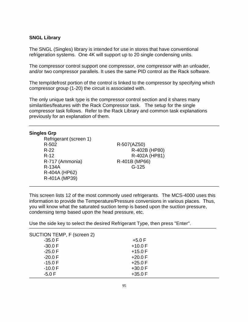
95
SNGL Library
The SNGL (Singles) library is intended for use in stores that have conventionalrefrigeration systems. One 4K will support up to 20 single condensing units.
The compressor control support one compressor, one compressor with an unloader,and/or two compressor parallels. It uses the same PID control as the Rack software.
The temp/defrost portion of the control is linked to the compressor by specifying whichcompressor group (1-20) the circuit is associated with.
The only unique task type is the compressor control section and it shares manysimilarities/features with the Rack Compressor task. The setup for the singlecompressor task follows. Refer to the Rack Library and common task explanationspreviously for an explanation of them.
Singles GrpRefrigerant (screen 1)R-502 R-507(AZ50)R-22 R-402B (HP80)R-12 R-402A (HP81)R-717 (Ammonia) R-401B (MP66)R-134A G-125R-404A (HP62)R-401A (MP39)
This screen lists 12 of the most commonly used refrigerants. The MCS-4000 uses thisinformation to provide the Temperature/Pressure conversions in various places. Thus,you will know what the saturated suction temp is based upon the suction pressure,condensing temp based upon the head pressure, etc.
Use the side key to select the desired Refrigerant Type, then press "Enter".
SUCTION TEMP, F (screen 2)-35.0 F +5.0 F-30.0 F +10.0 F-25.0 F +15.0 F-20.0 F +20.0 F-15.0 F +25.0 F-10.0 F +30.0 F-5.0 F +35.0 F
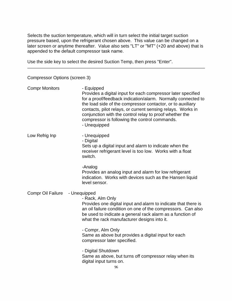
96
Selects the suction temperature, which will in turn select the initial target suctionpressure based, upon the refrigerant chosen above. This value can be changed on alater screen or anytime thereafter. Value also sets "LT" or "MT" (+20 and above) that isappended to the default compressor task name.
Use the side key to select the desired Suction Temp, then press "Enter".
Compressor Options (screen 3)
Compr Monitors - EquippedProvides a digital input for each compressor later specifiedfor a proof/feedback indication/alarm. Normally connected tothe load side of the compressor contactor, or to auxiliarycontacts, pilot relays, or current sensing relays. Works inconjunction with the control relay to proof whether thecompressor is following the control commands.- Unequipped
Low Refrig Inp - Unequipped- DigitalSets up a digital input and alarm to indicate when thereceiver refrigerant level is too low. Works with a floatswitch.
-AnalogProvides an analog input and alarm for low refrigerantindication. Works with devices such as the Hansen liquidlevel sensor.
Compr Oil Failure - Unequipped- Rack, Alm OnlyProvides one digital input and alarm to indicate that there isan oil failure condition on one of the compressors. Can alsobe used to indicate a general rack alarm as a function ofwhat the rack manufacturer designs into it.
- Compr, Alm OnlySame as above but provides a digital input for each compressor later specified.
- Digital ShutdownSame as above, but turns off compressor relay when itsdigital input turns on.
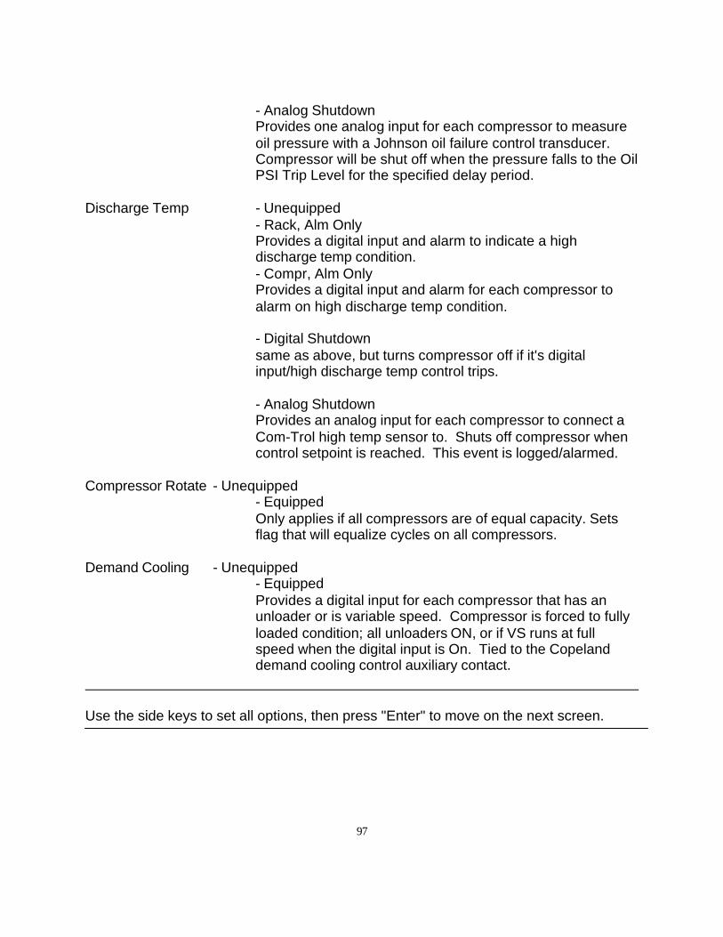
97
- Analog ShutdownProvides one analog input for each compressor to measureoil pressure with a Johnson oil failure control transducer.Compressor will be shut off when the pressure falls to the OilPSI Trip Level for the specified delay period.
Discharge Temp - Unequipped- Rack, Alm OnlyProvides a digital input and alarm to indicate a high discharge temp condition.- Compr, Alm OnlyProvides a digital input and alarm for each compressor toalarm on high discharge temp condition.
- Digital Shutdownsame as above, but turns compressor off if it's digitalinput/high discharge temp control trips.
- Analog ShutdownProvides an analog input for each compressor to connect aCom-Trol high temp sensor to. Shuts off compressor whencontrol setpoint is reached. This event is logged/alarmed.
Compressor Rotate - Unequipped- EquippedOnly applies if all compressors are of equal capacity. Setsflag that will equalize cycles on all compressors.
Demand Cooling - Unequipped- EquippedProvides a digital input for each compressor that has anunloader or is variable speed. Compressor is forced to fullyloaded condition; all unloaders ON, or if VS runs at fullspeed when the digital input is On. Tied to the Copelanddemand cooling control auxiliary contact.
Use the side keys to set all options, then press "Enter" to move on the next screen.
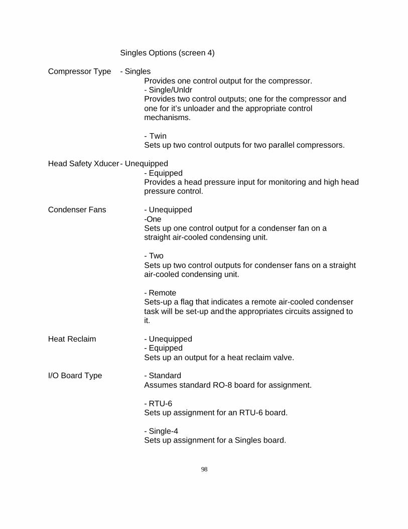
98
Singles Options (screen 4)
Compressor Type - SinglesProvides one control output for the compressor.- Single/UnldrProvides two control outputs; one for the compressor andone for it’s unloader and the appropriate controlmechanisms.
- TwinSets up two control outputs for two parallel compressors.
Head Safety Xducer - Unequipped- EquippedProvides a head pressure input for monitoring and high headpressure control.
Condenser Fans - Unequipped-OneSets up one control output for a condenser fan on a straight air-cooled condensing unit.
- TwoSets up two control outputs for condenser fans on a straightair-cooled condensing unit.
- RemoteSets-up a flag that indicates a remote air-cooled condensertask will be set-up and the appropriates circuits assigned toit.
Heat Reclaim - Unequipped- EquippedSets up an output for a heat reclaim valve.
I/O Board Type - StandardAssumes standard RO-8 board for assignment.
- RTU-6Sets up assignment for an RTU-6 board.
- Single-4Sets up assignment for a Singles board.
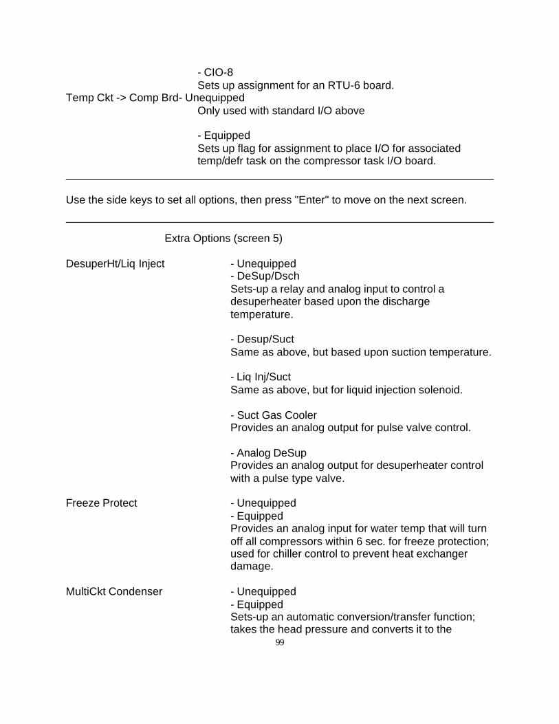
99
- CIO-8Sets up assignment for an RTU-6 board.
Temp Ckt -> Comp Brd- UnequippedOnly used with standard I/O above
- EquippedSets up flag for assignment to place I/O for associatedtemp/defr task on the compressor task I/O board.
Use the side keys to set all options, then press "Enter" to move on the next screen.
Extra Options (screen 5)
DesuperHt/Liq Inject - Unequipped- DeSup/DschSets-up a relay and analog input to control adesuperheater based upon the dischargetemperature.
- Desup/SuctSame as above, but based upon suction temperature.
- Liq Inj/SuctSame as above, but for liquid injection solenoid.
- Suct Gas CoolerProvides an analog output for pulse valve control.
- Analog DeSupProvides an analog output for desuperheater controlwith a pulse type valve.
Freeze Protect - Unequipped- EquippedProvides an analog input for water temp that will turnoff all compressors within 6 sec. for freeze protection;used for chiller control to prevent heat exchangerdamage.
MultiCkt Condenser - Unequipped- EquippedSets-up an automatic conversion/transfer function;takes the head pressure and converts it to the
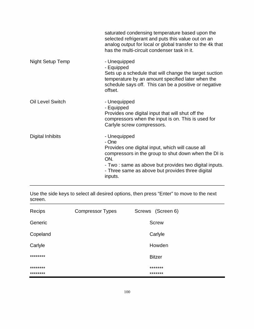
100
saturated condensing temperature based upon theselected refrigerant and puts this value out on ananalog output for local or global transfer to the 4k thathas the multi-circuit condenser task in it.
Night Setup Temp - Unequipped- EquippedSets up a schedule that will change the target suctiontemperature by an amount specified later when theschedule says off. This can be a positive or negativeoffset.
Oil Level Switch - Unequipped- EquippedProvides one digital input that will shut off thecompressors when the input is on. This is used forCarlyle screw compressors.
Digital Inhibits - Unequipped- OneProvides one digital input, which will cause allcompressors in the group to shut down when the DI isON.- Two : same as above but provides two digital inputs.- Three same as above but provides three digitalinputs.
Use the side keys to select all desired options, then press “Enter” to move to the nextscreen.
Recips Compressor Types Screws (Screen 6)
Generic Screw
Copeland Carlyle
Carlyle Howden
******** Bitzer
******** *************** *******
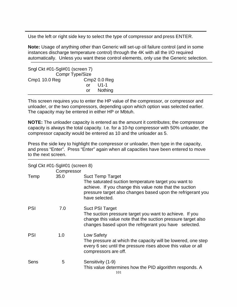
101
Use the left or right side key to select the type of compressor and press ENTER.
Note: Usage of anything other than Generic will set-up oil failure control (and in someinstances discharge temperature control) through the 4K with all the I/O requiredautomatically. Unless you want these control elements, only use the Generic selection.
Sngl Ckt #01-Sgl#01 (screen 7)Compr Type/Size
Cmp1 10.0 Reg Cmp2 0.0 Reg or U1-1 or Nothing
This screen requires you to enter the HP value of the compressor, or compressor andunloader, or the two compressors, depending upon which option was selected earlier.The capacity may be entered in either HP or Mbtuh.
NOTE: The unloader capacity is entered as the amount it contributes; the compressorcapacity is always the total capacity. I.e. for a 10-hp compressor with 50% unloader, thecompressor capacity would be entered as 10 and the unloader as 5.
Press the side key to highlight the compressor or unloader, then type in the capacity,and press “Enter”. Press “Enter” again when all capacities have been entered to moveto the next screen.
Sngl Ckt #01-Sgl#01 (screen 8)Compressor
Temp 35.0 Suct Temp TargetThe saturated suction temperature target you want toachieve. If you change this value note that the suctionpressure target also changes based upon the refrigerant youhave selected.
PSI 7.0 Suct PSI TargetThe suction pressure target you want to achieve. If youchange this value note that the suction pressure target alsochanges based upon the refrigerant you have selected.
PSI 1.0 Low SafetyThe pressure at which the capacity will be lowered, one stepevery 6 sec until the pressure rises above this value or allcompressors are off.
Sens 5 Sensitivity (1-9)This value determines how the PID algorithm responds. A
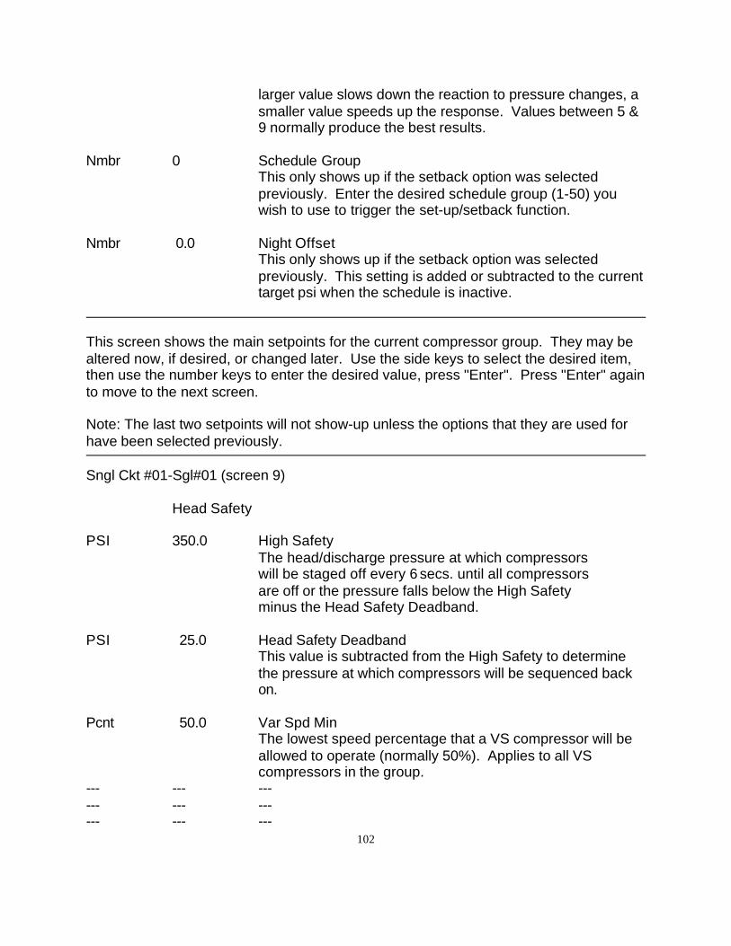
102
larger value slows down the reaction to pressure changes, asmaller value speeds up the response. Values between 5 &9 normally produce the best results.
Nmbr 0 Schedule GroupThis only shows up if the setback option was selectedpreviously. Enter the desired schedule group (1-50) youwish to use to trigger the set-up/setback function.
Nmbr 0.0 Night OffsetThis only shows up if the setback option was selectedpreviously. This setting is added or subtracted to the currenttarget psi when the schedule is inactive.
This screen shows the main setpoints for the current compressor group. They may bealtered now, if desired, or changed later. Use the side keys to select the desired item,then use the number keys to enter the desired value, press "Enter". Press "Enter" againto move to the next screen.
Note: The last two setpoints will not show-up unless the options that they are used forhave been selected previously.
Sngl Ckt #01-Sgl#01 (screen 9)
Head Safety
PSI 350.0 High SafetyThe head/discharge pressure at which compressors will be staged off every 6 secs. until all compressors are off or the pressure falls below the High Safety minus the Head Safety Deadband.
PSI 25.0 Head Safety DeadbandThis value is subtracted from the High Safety to determinethe pressure at which compressors will be sequenced backon.
Pcnt 50.0 Var Spd MinThe lowest speed percentage that a VS compressor will beallowed to operate (normally 50%). Applies to all VScompressors in the group.
--- --- ------ --- ------ --- ---
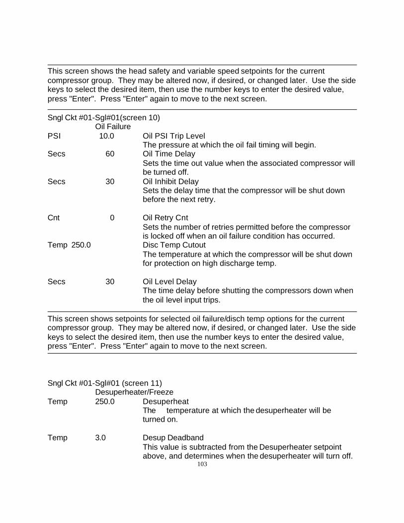
103
This screen shows the head safety and variable speed setpoints for the currentcompressor group. They may be altered now, if desired, or changed later. Use the sidekeys to select the desired item, then use the number keys to enter the desired value,press "Enter". Press "Enter" again to move to the next screen.
Sngl Ckt #01-Sgl#01(screen 10)Oil Failure
PSI 10.0 Oil PSI Trip LevelThe pressure at which the oil fail timing will begin.
Secs 60 Oil Time DelaySets the time out value when the associated compressor willbe turned off.
Secs 30 Oil Inhibit DelaySets the delay time that the compressor will be shut downbefore the next retry.
Cnt 0 Oil Retry CntSets the number of retries permitted before the compressoris locked off when an oil failure condition has occurred.
Temp 250.0 Disc Temp CutoutThe temperature at which the compressor will be shut downfor protection on high discharge temp.
Secs 30 Oil Level DelayThe time delay before shutting the compressors down whenthe oil level input trips.
This screen shows setpoints for selected oil failure/disch temp options for the currentcompressor group. They may be altered now, if desired, or changed later. Use the sidekeys to select the desired item, then use the number keys to enter the desired value,press "Enter". Press "Enter" again to move to the next screen.
Sngl Ckt #01-Sgl#01 (screen 11)Desuperheater/Freeze
Temp 250.0 DesuperheatThe temperature at which the desuperheater will be turned on.
Temp 3.0 Desup DeadbandThis value is subtracted from the Desuperheater setpointabove, and determines when the desuperheater will turn off.
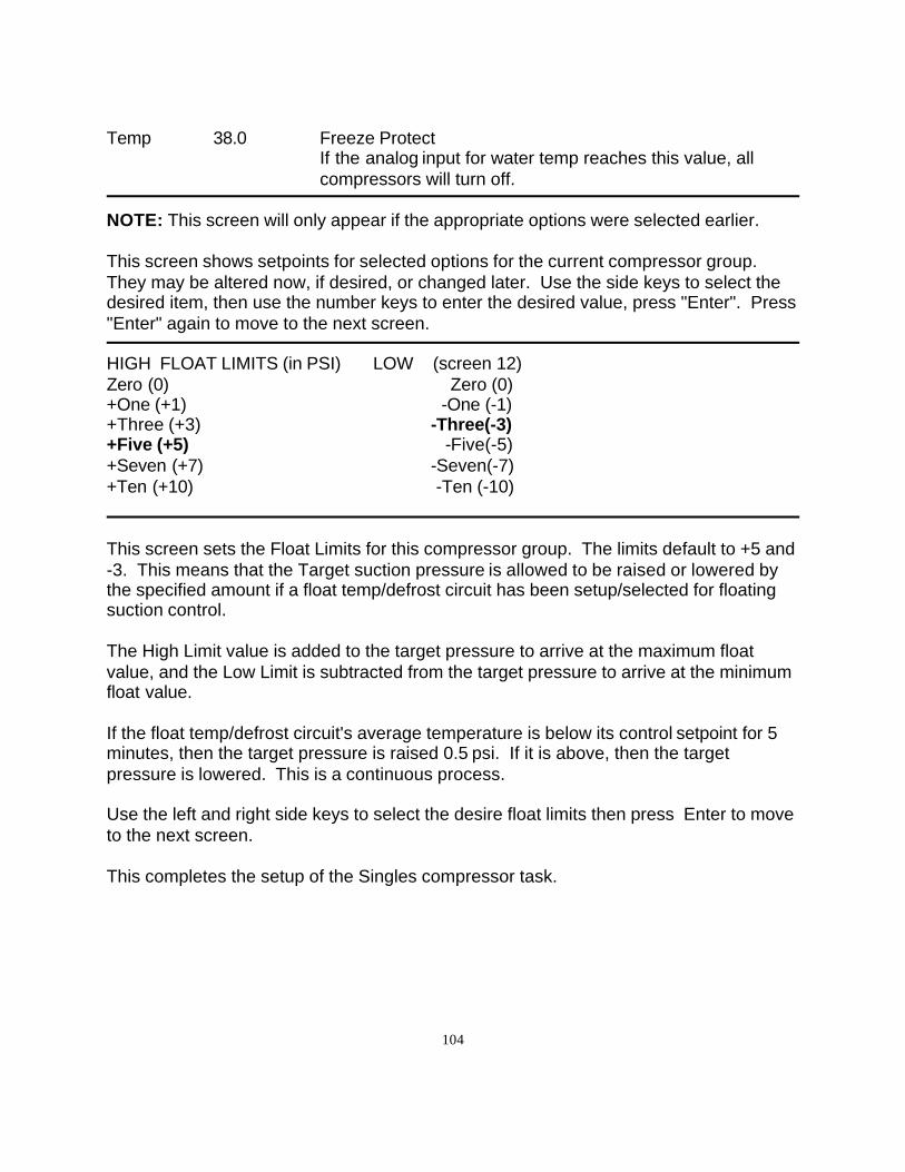
104
Temp 38.0 Freeze ProtectIf the analog input for water temp reaches this value, allcompressors will turn off.
NOTE: This screen will only appear if the appropriate options were selected earlier.
This screen shows setpoints for selected options for the current compressor group.They may be altered now, if desired, or changed later. Use the side keys to select thedesired item, then use the number keys to enter the desired value, press "Enter". Press"Enter" again to move to the next screen.
HIGH FLOAT LIMITS (in PSI) LOW (screen 12)Zero (0) Zero (0)+One (+1) -One (-1)+Three (+3) -Three(-3)+Five (+5) -Five(-5) +Seven (+7) -Seven(-7)+Ten (+10) -Ten (-10)
This screen sets the Float Limits for this compressor group. The limits default to +5 and-3. This means that the Target suction pressure is allowed to be raised or lowered bythe specified amount if a float temp/defrost circuit has been setup/selected for floatingsuction control.
The High Limit value is added to the target pressure to arrive at the maximum floatvalue, and the Low Limit is subtracted from the target pressure to arrive at the minimumfloat value.
If the float temp/defrost circuit's average temperature is below its control setpoint for 5minutes, then the target pressure is raised 0.5 psi. If it is above, then the targetpressure is lowered. This is a continuous process.
Use the left and right side keys to select the desire float limits then press Enter to moveto the next screen.
This completes the setup of the Singles compressor task.
105
CSTR Library
The CSTR (C Store) library is a compilation of task types from the other libraries. It isintended for use in convenience stores, small supermarkets with conventionalrefrigeration, and drug stores. It does not support Rack/parallel refrigeration systems,only single compressor systems.
Refer to the Common tasks and CSTR library explanation at the beginning of thisdocument for further information.
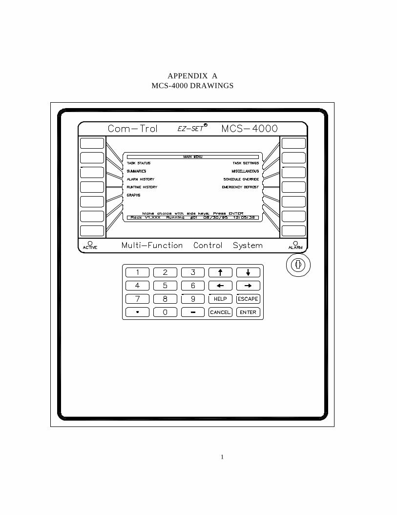
1
APPENDIX AMCS-4000 DRAWINGS
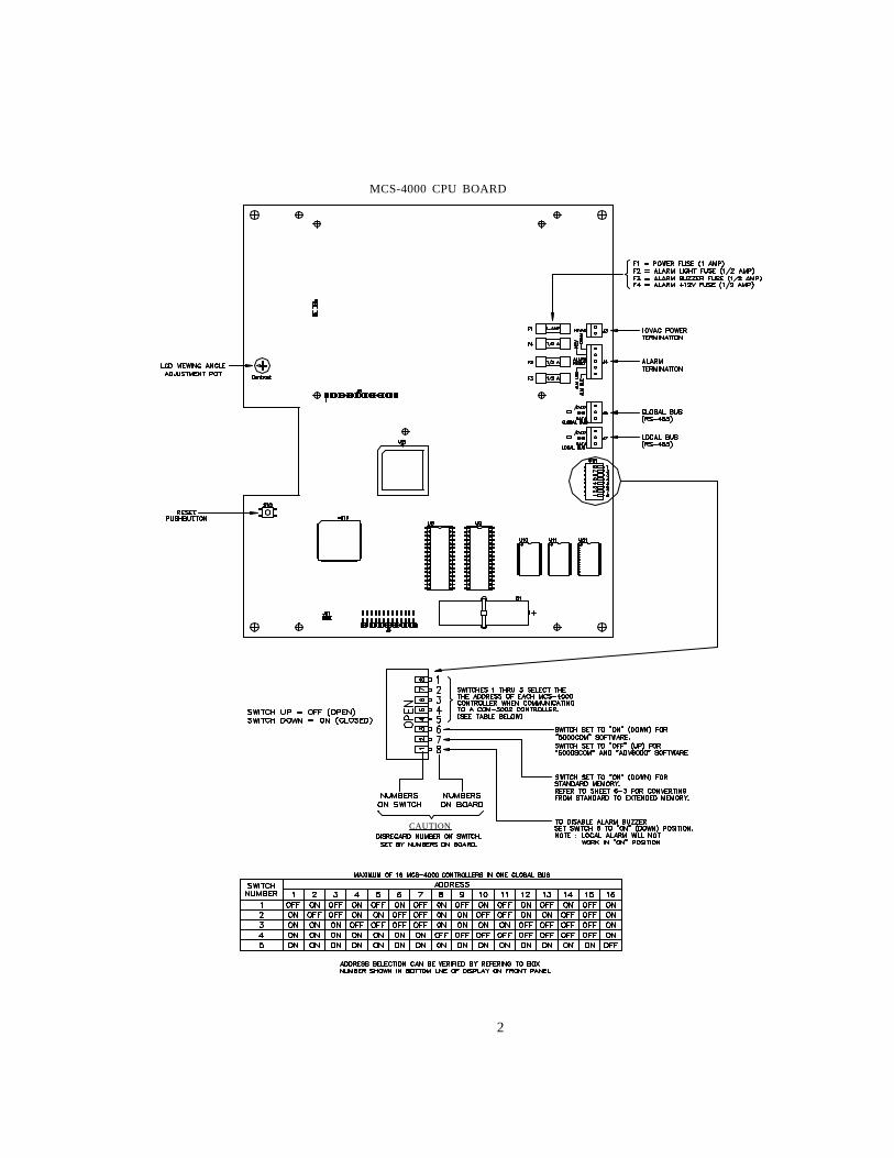
2
MCS-4000 CPU BOARD
CAUTION
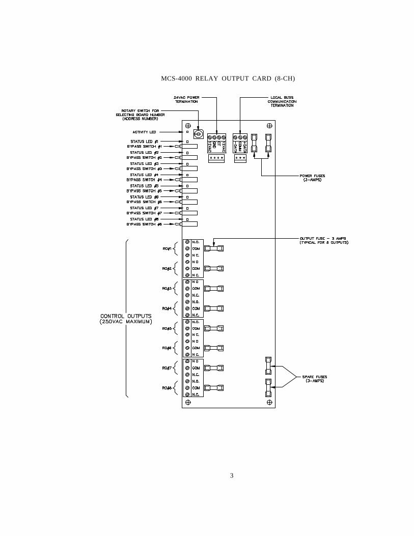
3
MCS-4000 RELAY OUTPUT CARD (8-CH)
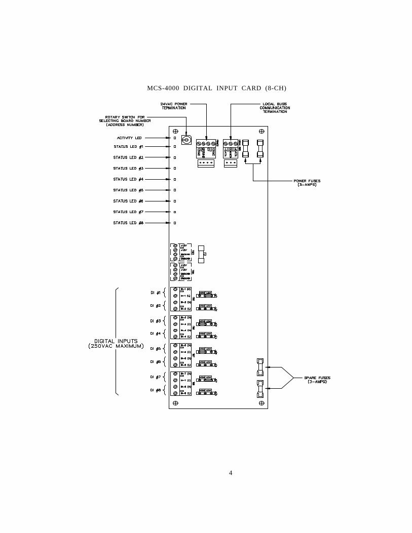
4
MCS-4000 DIGITAL INPUT CARD (8-CH)
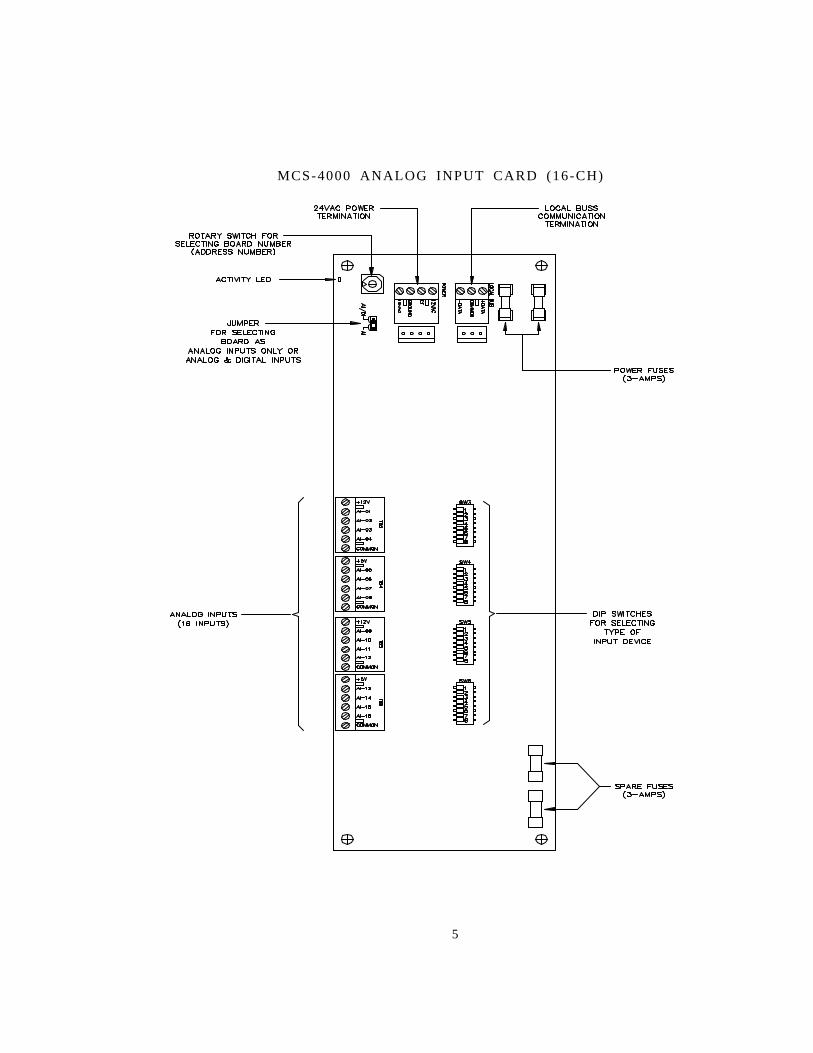
5
MCS-4000 ANALOG INPUT CARD (16-CH)
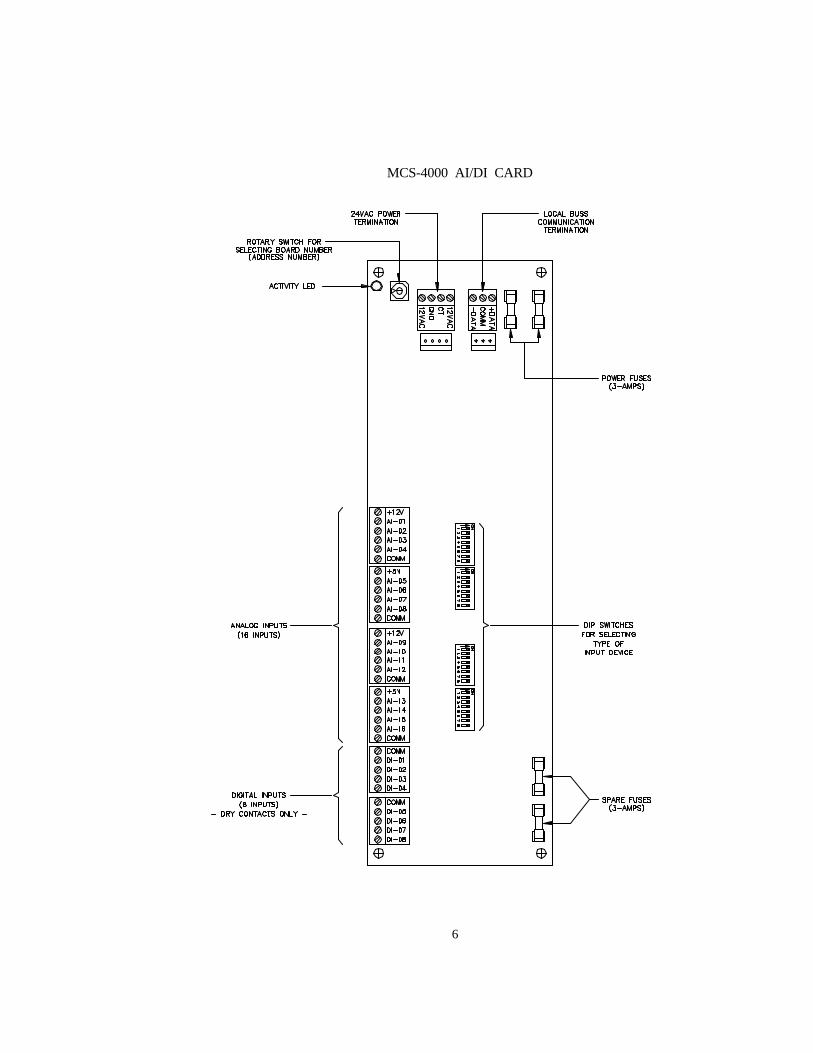
6
MCS-4000 AI/DI CARD
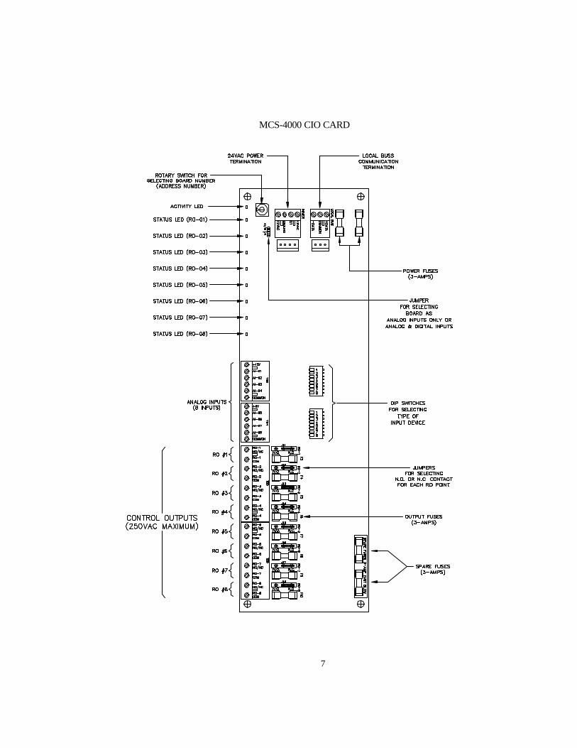
7
MCS-4000 CIO CARD
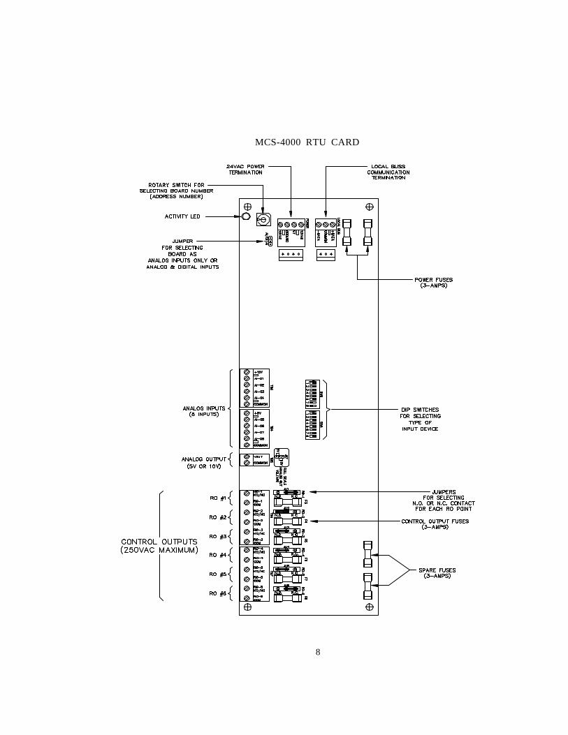
8
MCS-4000 RTU CARD
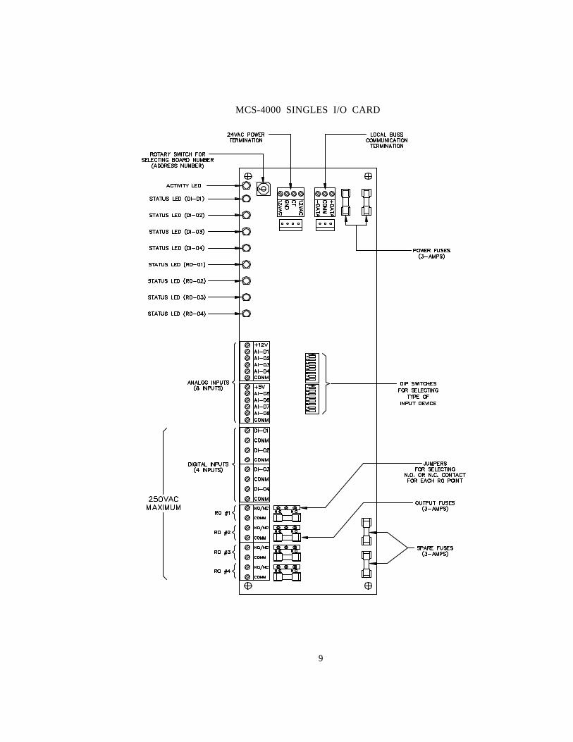
9
MCS-4000 SINGLES I/O CARD
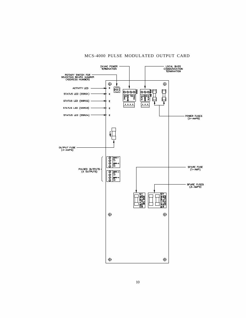
10
MCS-4000 PULSE MODULATED OUTPUT CARD
11
DEFINITION OF TERMS
AHUAir Handling Unit: generally refers to a centralized HVAC system mounted inside thefacility.
ALGORITHMA set of control instructions that are usually involved, and repetitious, which takesinformation from inputs, outputs, time, etc. and arrives at decisions to turn on/off ormodulate the relay/analog outputs.
ANALOG INPUTA continuously variable (as opposed to on/off) signal input to the control system, suchas temperature or pressure.
BATTERY BACK RAMRandom Access Memory that has a battery connected to the circuit so that theinformation stored can be maintained without external power.
BAUDRefers to the rate of transmission of data measured in bits per second. Normalmodem communications are at 2400 or 14.4k baud.
BOX (CONTROLLER)A Com-Trol term that refers to a 4000 Series Controller.
BUSA communication pathway (3 wire cable) that allows multiple MCS-4000 controllers tocommunicate with a central controller/host, COM-5002, or a MCS-4000 tocommunicate with its input and output boards.
CPUCentral Processing Unit: the main PC board that contains the microprocessor chip,memory, and supporting components.
DEWPOINTThe ambient temperature at which moisture will begin to condense.
12
DIGITAL INPUTAn input signal to the control system that can report an on or off condition.
DIMDigital Input Module: an electronic interface that converts high voltage to a contactclosure (dry contact), that can be introduced into the control system as a digital input.
DIPSWITCHA series of small switches, usually packaged in groups of four or eight, that are usedon PC boards to provide on/off signals for various purposes; usually to set an addressor select options.
FLOATING SUCTIONA control technique which raises or lowers the suction pressure target based upon afeedback from a temperature sensor(s) indicating whether the target temperature isbeing maintained or not.
GLOBAL BUSThe communication path between all controllers and the central communicationscontroller (COM-5002).
GUARD TIMEA Com-Trol term which indicates the amount of time that the system will wait after analarm temperature or pressure has been exceeded before the alarm isactuated/sounded.
GUARD TEMP/PRESSA Com-Trol term which indicates the temperature, pressure, etc. setting that indicatesan alarm condition.
JACKUsually refers to a phone jack, which is receptacle that the phone cord/connector isplugged into. RJ-11 is the name for the standard phone jack.
LOCAL BUSThe communication path between the MCS-4000 controller and its input/output boards.
13
MENUGenerally refers to a list of choices that are displayed on a CRT screen from which theuser selects to have the system perform a specific task or provide desired information.
MODEMA communications device that changes information from computer form to a formsuitable for transmission over telephone lines or satellites. A modem is required atboth ends of the transmission path to convert the signal back to a form useable byprinters, terminals, or computers.
PASSWORDCode(s) that must be entered before access to a control system is allowed, or to beable to make changes or view specific information within the system.
PIDProportional, Integral and Derivative: a method of control which takes into account notonly how far away from setpoint the target item is, but how long it has been away fromtarget, and which direction it is moving.
PROBETerm normally used to refer to a temperature sensor.
PROMPTA statement or a question usually presented at the bottom of a CRT screen to cue theoperator as to what to do next.
PSIPound per Square Inch – U.S. unit of measure for pressure.
RACKNormally refers to refrigeration system that consists of multiple compressors connectedto a common suction manifold.
RAMRandom Access Memory: the storage medium/chips used for temporary data storagein control systems and computers.
14
RELATIVE HUMIDITYA measurement of the amount of moisture in the air as compared tot he amount ofmoisture the air could hold before becoming saturated expressed as a percentage.
RELAY OUTPUT (DIGITAL OUTPUT)The control output which turns a device on or off.
RIBBON CABLEA cable of multiple wires that is manufactured so that it is flat, with the wires runningside by side connected together by the jacket.
RS-232CA standardized communications format that is normally used with microprocessorcontrol systems for connections with modems, printers, terminals and computers.
RS-485A standardized communications format used in control systems. Normally used for busapplications in Com-Trol systems.
RTURoof Top Unit: a packaged heating and/or cooling unit mounted on the roof of thefacility.
SENSORNormally refers to a temperature measuring device, such as a thermistor, RTD, orthermocouple which provides an analog input signal to the control system.
SHIELDED CABLEA cable consisting of multiple wires that are all surrounded by a metal sheath or jacketwhich helps to filter out noise induced by other electrical circuits.
TERMINALA device used for communicating with a control system/computer which usuallyconsists of a CRT and keyboard.
TRANSDUCERA pressure measuring device that provides an analog input signal to the controlsystem.