Embed Size (px)
Citation preview
OTISEuropean and Transcontinental
Operations
PRODUCTADMINISTRATION
FIELD COMPONENT MANUAL
Software DataMCS - RCB II
Installation Parameters - MCS 311 / 321 / 411/ 413
Part: 4 - AA3No.: GCA21270A VIIIaVintage: 01 / 9Page: 1 / 32D1: 27-Feb-1998Date: 16-Feb-00SCN: GAE 30075 HAB
MCS - RCB IISoftware - Installation Parameters MCS 311 / 321 / 411 / 413
Copyright 1998, OTIS GmbH Berlin. No part of this document may be copied orreproduced in any form or by any means without the prior written consent of OTIS GmbH.
Authorization Date D1: 27 February 1998
Running on PCB: GCA 21270 A4 or higher
Software Version: GAE 30075 HAB
Document Revision :
Date SCN Author Comment24-Jan-1994 GAC 30075 BAA Botta Original Document27-Jul-1994 GAE 30075 CAA Schneider Revision14-Oct-1994 GAE 30075 DAA Schneider Revision31-Mar-1995 GAE 30075 EAA Schneider Revision30-Jun-1995 GAE 30075 EAA Szekeres Major revision of document20-Jan-1996 GAE 30075 FAA Hildebrand Revision, Separation of MCS 311 /411
and MCS 32125-Sep-1996 GAE 30075 GAA Szekeres update for GAA release31-July-1997 GAE 30075 HAA Szekeres update for HAA release16-Feb-1998 GAE 30075 HAB Dridi update for HAB release
OTISEuropean and Transcontinental
Operations
PRODUCTADMINISTRATION
FIELD COMPONENT MANUAL
Software DataMCS - RCB II
Installation Parameters - MCS 311 / 321 / 411/ 413
Part: 4 - AA3No.: GCA21270A VIIIaVintage: 01 / 9Page: 2 / 32D1: 27-Feb-1998Date: 16-Feb-00SCN: GAE 30075 HAB
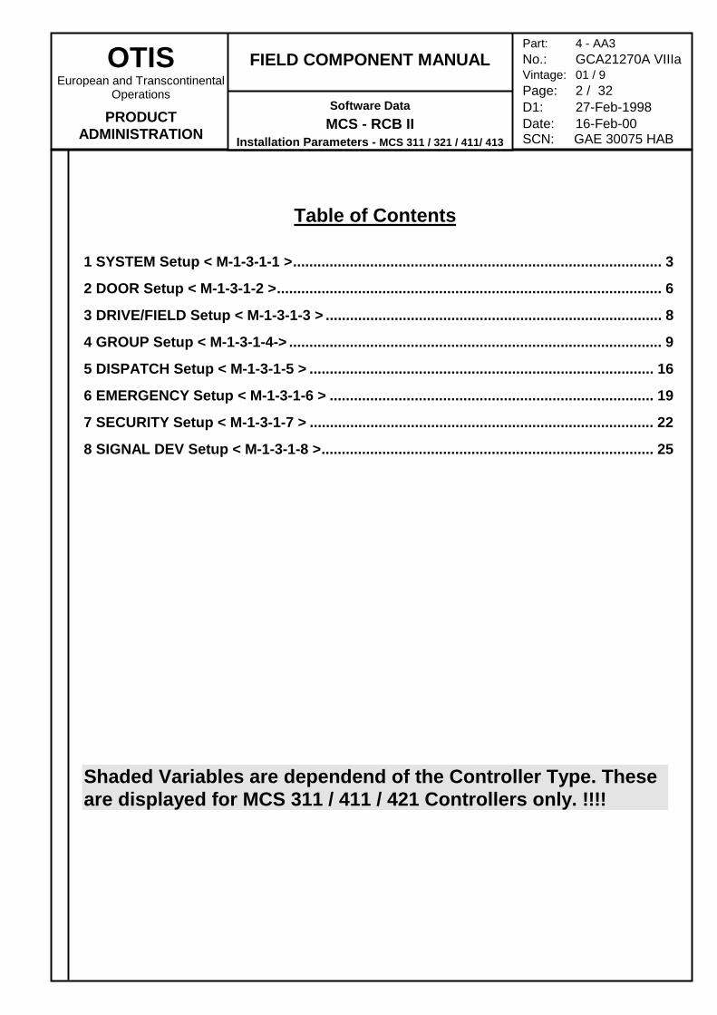
Table of Contents
1 SYSTEM Setup < M-1-3-1-1 >........................................................................................... 3
2 DOOR Setup < M-1-3-1-2 >............................................................................................... 6
3 DRIVE/FIELD Setup < M-1-3-1-3 > ................................................................................... 8
4 GROUP Setup < M-1-3-1-4-> ............................................................................................ 9
5 DISPATCH Setup < M-1-3-1-5 > ..................................................................................... 16
6 EMERGENCY Setup < M-1-3-1-6 > ................................................................................ 19
7 SECURITY Setup < M-1-3-1-7 > ..................................................................................... 22
8 SIGNAL DEV Setup < M-1-3-1-8 >.................................................................................. 25
Shaded Variables are dependend of the Controller Type. Theseare displayed for MCS 311 / 411 / 421 Controllers only. !!!!
OTISEuropean and Transcontinental
Operations
PRODUCTADMINISTRATION
FIELD COMPONENT MANUAL
Software DataMCS - RCB II
Installation Parameters - MCS 311 / 321 / 411/ 413
Part: 4 - AA3No.: GCA21270A VIIIaVintage: 01 / 9Page: 3 / 32D1: 27-Feb-1998Date: 16-Feb-00SCN: GAE 30075 HAB
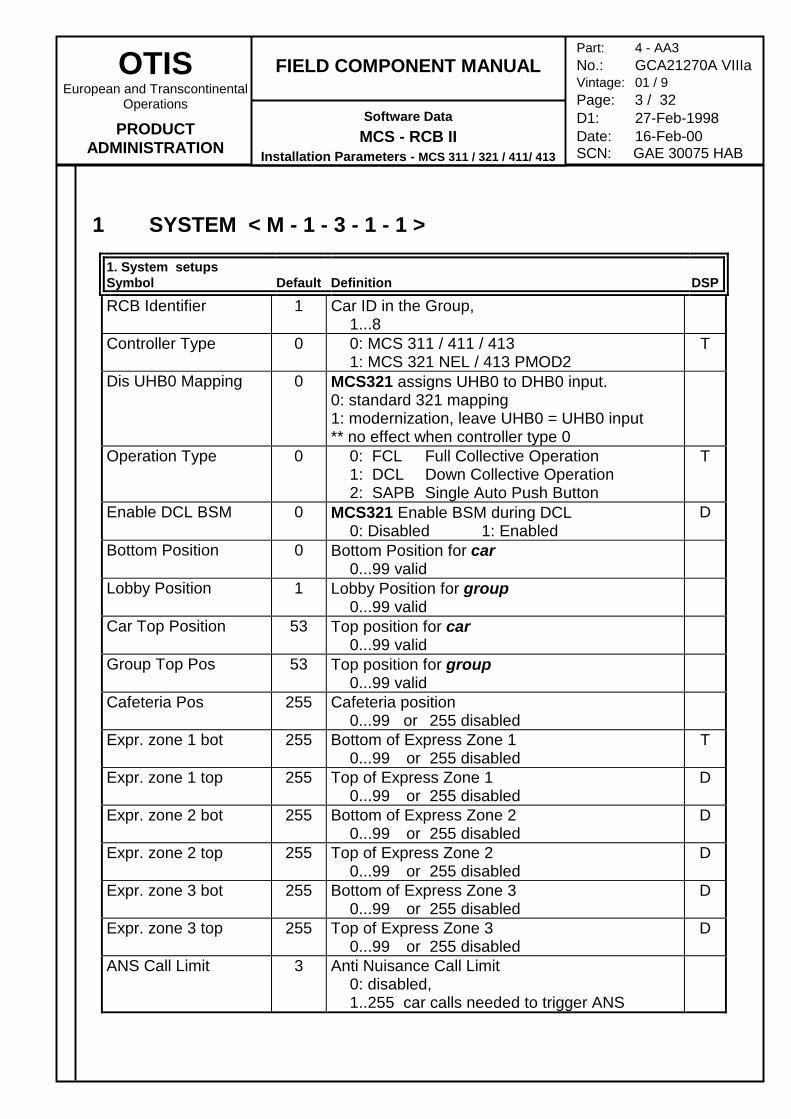
1 SYSTEM < M - 1 - 3 - 1 - 1 >
1. System setupsSymbol Default Definition DSP
RCB Identifier 1 Car ID in the Group,1...8
Controller Type 0 0: MCS 311 / 411 / 413 1: MCS 321 NEL / 413 PMOD2
T
Dis UHB0 Mapping 0 MCS321 assigns UHB0 to DHB0 input.0: standard 321 mapping1: modernization, leave UHB0 = UHB0 input** no effect when controller type 0
Operation Type 0 0: FCL Full Collective Operation1: DCL Down Collective Operation2: SAPB Single Auto Push Button
T
Enable DCL BSM 0 MCS321 Enable BSM during DCL0: Disabled 1: Enabled
D
Bottom Position 0 Bottom Position for car0...99 valid
Lobby Position 1 Lobby Position for group0...99 valid
Car Top Position 53 Top position for car0...99 valid
Group Top Pos 53 Top position for group0...99 valid
Cafeteria Pos 255 Cafeteria position0...99 or 255 disabled
Expr. zone 1 bot 255 Bottom of Express Zone 10...99 or 255 disabled
T
Expr. zone 1 top 255 Top of Express Zone 10...99 or 255 disabled
D
Expr. zone 2 bot 255 Bottom of Express Zone 20...99 or 255 disabled
D
Expr. zone 2 top 255 Top of Express Zone 20...99 or 255 disabled
D
Expr. zone 3 bot 255 Bottom of Express Zone 30...99 or 255 disabled
D
Expr. zone 3 top 255 Top of Express Zone 30...99 or 255 disabled
D
ANS Call Limit 3 Anti Nuisance Call Limit0: disabled,1..255 car calls needed to trigger ANS
OTISEuropean and Transcontinental
Operations
PRODUCTADMINISTRATION
FIELD COMPONENT MANUAL
Software DataMCS - RCB II
Installation Parameters - MCS 311 / 321 / 411/ 413
Part: 4 - AA3No.: GCA21270A VIIIaVintage: 01 / 9Page: 4 / 32D1: 27-Feb-1998Date: 16-Feb-00SCN: GAE 30075 HAB
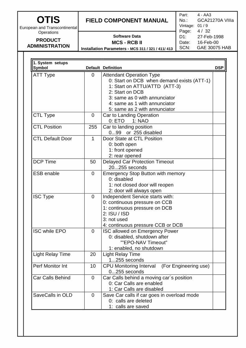
1. System setupsSymbol Default Definition DSP
ATT Type 0 Attendant Operation Type0: Start on DCB when demand exists (ATT-1)1: Start on ATTU/ATTD (ATT-3)2: Start on DCB3: same as 0 with annunciator4: same as 1 with annunciator5: same as 2 with annunciator
CTL Type 0 Car to Landing Operation0: ETO 1: NAO
CTL Position 255 Car to landing position0...99 or 255 disabled
CTL Default Door 1 Door State at CTL Position0: both open1: front opened2: rear opened
DCP Time 50 Delayed Car Protection Timeout20...255 seconds
ESB enable 0 Emergency Stop Button with memory0: disabled1: not closed door will reopen2: door will always open
ISC Type 0 Independent Service starts with:0: continuous pressure on CCB1: continuous pressure on DCB2: ISU / ISD3: not used4: continuous pressure CCB or DCB
ISC while EPO 0 ISC allowed on Emergency Power0: disabled, shutdown after
””EPO-NAV Timeout”1: enabled, no shutdown
Light Relay Time 20 Light Relay Time1...255 seconds
Perf Monitor Int 10 CPU Monitoring Interval (For Engineering use)0...255 seconds
Car Calls Behind 0 Car Calls behind a moving car´s position0: Car Calls are enabled1: Car Calls are disabled
SaveCalls in OLD 0 Save Car calls if car goes in overload mode0: calls are deleted1: calls are saved
OTISEuropean and Transcontinental
Operations
PRODUCTADMINISTRATION
FIELD COMPONENT MANUAL
Software DataMCS - RCB II
Installation Parameters - MCS 311 / 321 / 411/ 413
Part: 4 - AA3No.: GCA21270A VIIIaVintage: 01 / 9Page: 5 / 32D1: 27-Feb-1998Date: 16-Feb-00SCN: GAE 30075 HAB
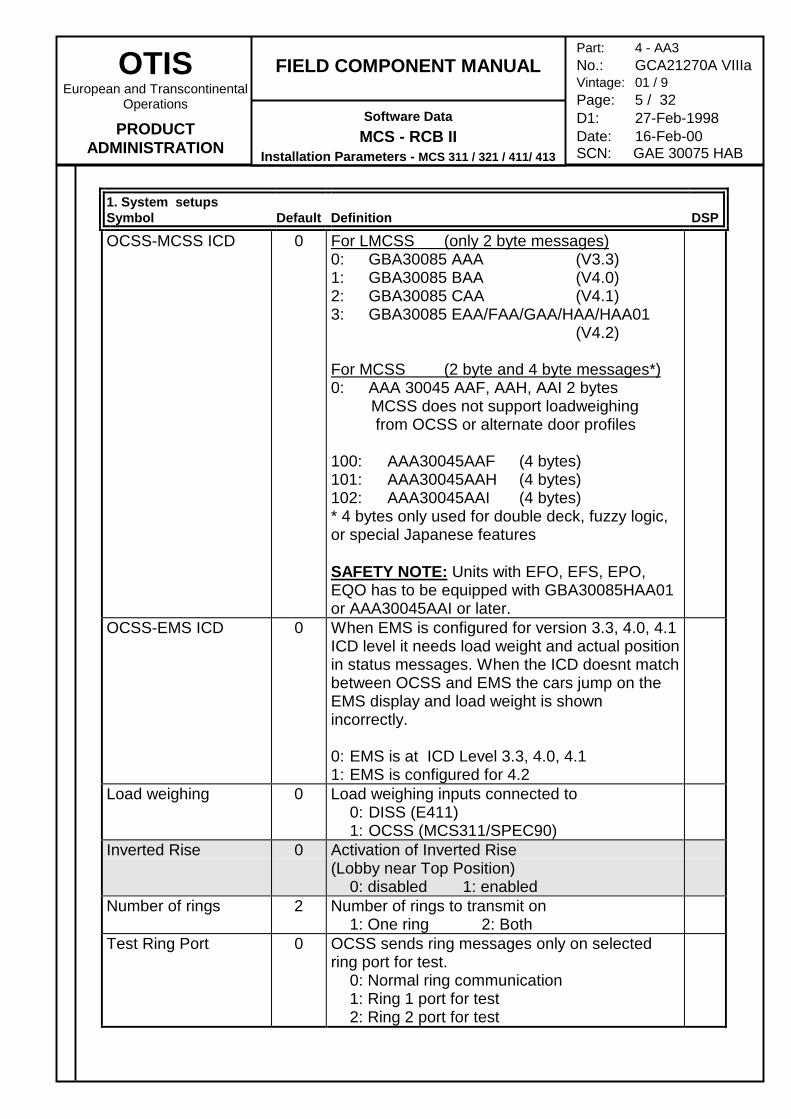
1. System setupsSymbol Default Definition DSP
OCSS-MCSS ICD 0 For LMCSS (only 2 byte messages)0: GBA30085 AAA (V3.3)1: GBA30085 BAA (V4.0)2: GBA30085 CAA (V4.1)3: GBA30085 EAA/FAA/GAA/HAA/HAA01
(V4.2)
For MCSS (2 byte and 4 byte messages*)0: AAA 30045 AAF, AAH, AAI 2 bytes MCSS does not support loadweighing from OCSS or alternate door profiles
100: AAA30045AAF (4 bytes)101: AAA30045AAH (4 bytes)102: AAA30045AAI (4 bytes)* 4 bytes only used for double deck, fuzzy logic,or special Japanese features
SAFETY NOTE: Units with EFO, EFS, EPO,EQO has to be equipped with GBA30085HAA01or AAA30045AAI or later.
OCSS-EMS ICD 0 When EMS is configured for version 3.3, 4.0, 4.1ICD level it needs load weight and actual positionin status messages. When the ICD doesnt matchbetween OCSS and EMS the cars jump on theEMS display and load weight is shownincorrectly.
0: EMS is at ICD Level 3.3, 4.0, 4.11: EMS is configured for 4.2
Load weighing 0 Load weighing inputs connected to0: DISS (E411)1: OCSS (MCS311/SPEC90)
Inverted Rise 0 Activation of Inverted Rise(Lobby near Top Position)
0: disabled 1: enabledNumber of rings 2 Number of rings to transmit on
1: One ring 2: BothTest Ring Port 0 OCSS sends ring messages only on selected
ring port for test.0: Normal ring communication1: Ring 1 port for test2: Ring 2 port for test
OTISEuropean and Transcontinental
Operations
PRODUCTADMINISTRATION
FIELD COMPONENT MANUAL
Software DataMCS - RCB II
Installation Parameters - MCS 311 / 321 / 411/ 413
Part: 4 - AA3No.: GCA21270A VIIIaVintage: 01 / 9Page: 6 / 32D1: 27-Feb-1998Date: 16-Feb-00SCN: GAE 30075 HAB
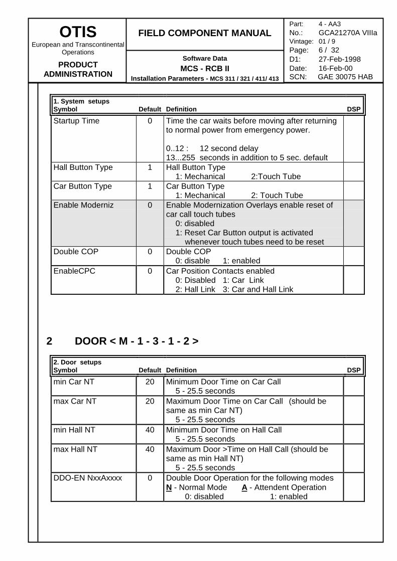
1. System setupsSymbol Default Definition DSP
Startup Time 0 Time the car waits before moving after returningto normal power from emergency power.
0..12 : 12 second delay13...255 seconds in addition to 5 sec. default
Hall Button Type 1 Hall Button Type1: Mechanical 2:Touch Tube
Car Button Type 1 Car Button Type1: Mechanical 2: Touch Tube
Enable Moderniz 0 Enable Modernization Overlays enable reset ofcar call touch tubes
0: disabled1: Reset Car Button output is activated
whenever touch tubes need to be resetDouble COP 0 Double COP
0: disable 1: enabledEnableCPC 0 Car Position Contacts enabled
0: Disabled 1: Car Link2: Hall Link 3: Car and Hall Link
2 DOOR < M - 1 - 3 - 1 - 2 >
2. Door setupsSymbol Default Definition DSP
min Car NT 20 Minimum Door Time on Car Call5 - 25.5 seconds
max Car NT 20 Maximum Door Time on Car Call (should besame as min Car NT)
5 - 25.5 secondsmin Hall NT 40 Minimum Door Time on Hall Call
5 - 25.5 secondsmax Hall NT 40 Maximum Door >Time on Hall Call (should be
same as min Hall NT)5 - 25.5 seconds
DDO-EN NxxAxxxx 0 Double Door Operation for the following modesN - Normal Mode A - Attendent Operation
0: disabled 1: enabled
OTISEuropean and Transcontinental
Operations
PRODUCTADMINISTRATION
FIELD COMPONENT MANUAL
Software DataMCS - RCB II
Installation Parameters - MCS 311 / 321 / 411/ 413
Part: 4 - AA3No.: GCA21270A VIIIaVintage: 01 / 9Page: 7 / 32D1: 27-Feb-1998Date: 16-Feb-00SCN: GAE 30075 HAB
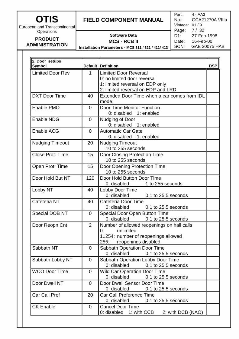
2. Door setupsSymbol Default Definition DSP
Limited Door Rev 1 Limited Door Reversal0: no limited door reversal1: limited reversal on EDP only2: limited reversal on EDP and LRD
DXT Door Time 40 Extended Door Time when a car comes from IDLmode
Enable PMO 0 Door Time Monitor Function 0: disabled 1: enabled
Enable NDG 0 Nudging of Door 0: disabled 1: enabled
Enable ACG 0 Automatic Car Gate 0: disabled 1: enabled
Nudging Timeout 20 Nudging Timeout10 to 255 seconds
Close Prot. Time 15 Door Closing Protection Time10 to 255 seconds
Open Prot. Time 15 Door Opening Protection Time10 to 255 seconds
Door Hold But NT 120 Door Hold Button Door Time0: disabled 1 to 255 seconds
Lobby NT 40 Lobby Door Time0: disabled 0.1 to 25.5 seconds
Cafeteria NT 40 Cafeteria Door Time0: disabled 0.1 to 25.5 seconds
Special DOB NT 0 Special Door Open Button Time0: disabled 0.1 to 25.5 seconds
Door Reopn Cnt 2 Number of allowed reopenings on hall calls0: unlimited1..254: number of reopenings allowed255: reopenings disabled
Sabbath NT 0 Sabbath Operation Door Time0: disabled 0.1 to 25.5 seconds
Sabbath Lobby NT 0 Sabbath Operation Lobby Door Time0: disabled 0.1 to 25.5 seconds
WCO Door Time 0 Wild Car Operation Door Time0: disabled 0.1 to 25.5 seconds
Door Dwell NT 0 Door Dwell Sensor Door Time0: disabled 0.1 to 25.5 seconds
Car Call Pref 20 Car Call Preference Time0: disabled 0.1 to 25.5 seconds
CK Enable 0 Cancel Door Time0: disabled 1: with CCB 2: with DCB (NAO)
OTISEuropean and Transcontinental
Operations
PRODUCTADMINISTRATION
FIELD COMPONENT MANUAL
Software DataMCS - RCB II
Installation Parameters - MCS 311 / 321 / 411/ 413
Part: 4 - AA3No.: GCA21270A VIIIaVintage: 01 / 9Page: 8 / 32D1: 27-Feb-1998Date: 16-Feb-00SCN: GAE 30075 HAB
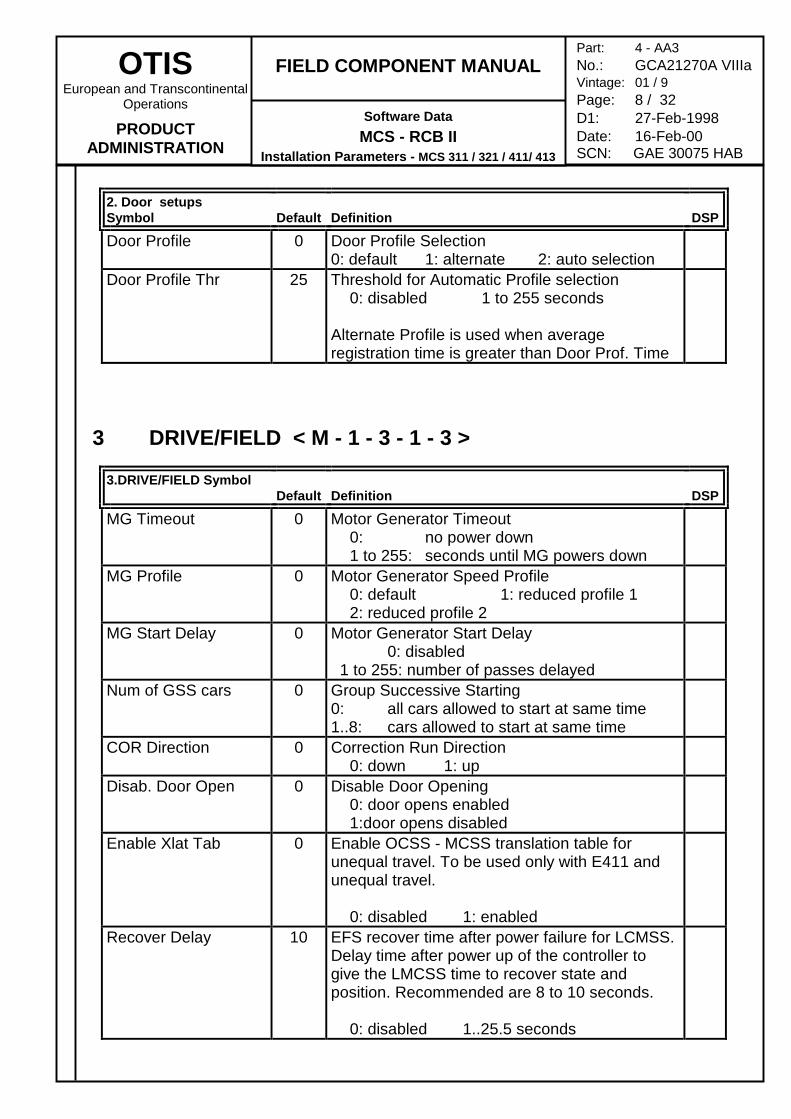
2. Door setupsSymbol Default Definition DSP
Door Profile 0 Door Profile Selection0: default 1: alternate 2: auto selection
Door Profile Thr 25 Threshold for Automatic Profile selection0: disabled 1 to 255 seconds
Alternate Profile is used when averageregistration time is greater than Door Prof. Time
3 DRIVE/FIELD < M - 1 - 3 - 1 - 3 >
3.DRIVE/FIELD SymbolDefault Definition DSP
MG Timeout 0 Motor Generator Timeout0: no power down1 to 255: seconds until MG powers down
MG Profile 0 Motor Generator Speed Profile0: default 1: reduced profile 12: reduced profile 2
MG Start Delay 0 Motor Generator Start Delay0: disabled
1 to 255: number of passes delayedNum of GSS cars 0 Group Successive Starting
0: all cars allowed to start at same time1..8: cars allowed to start at same time
COR Direction 0 Correction Run Direction0: down 1: up
Disab. Door Open 0 Disable Door Opening0: door opens enabled1:door opens disabled
Enable Xlat Tab 0 Enable OCSS - MCSS translation table forunequal travel. To be used only with E411 andunequal travel.
0: disabled 1: enabledRecover Delay 10 EFS recover time after power failure for LCMSS.
Delay time after power up of the controller togive the LMCSS time to recover state andposition. Recommended are 8 to 10 seconds.
0: disabled 1..25.5 seconds
OTISEuropean and Transcontinental
Operations
PRODUCTADMINISTRATION
FIELD COMPONENT MANUAL
Software DataMCS - RCB II
Installation Parameters - MCS 311 / 321 / 411/ 413
Part: 4 - AA3No.: GCA21270A VIIIaVintage: 01 / 9Page: 9 / 32D1: 27-Feb-1998Date: 16-Feb-00SCN: GAE 30075 HAB
4 GROUP < M - 1 - 3 - 1 - 4 >
4.GROUP setupsSymbol Default Definition DSP
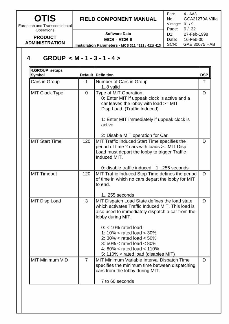
Cars in Group 1 Number of Cars in Group1..8 valid
T
MIT Clock Type 0 Type of MIT Operation0: Enter MIT if uppeak clock is active and a car leaves the lobby with load >= MIT Disp Load. (Traffic Induced)
1: Enter MIT immediately if uppeak clock is active
2: Disable MIT operation for Car
D
MIT Start Time 120 MIT Traffic Induced Start Time specifies theperiod of time 2 cars with loads >= MIT DispLoad must depart the lobby to trigger TrafficInduced MIT.
0: disable traffic induced 1...255 seconds
D
MIT Timeout 120 MIT Traffic Induced Stop Time defines the periodof time in which no cars depart the lobby for MITto end.
1...255 seconds
D
MIT Disp Load 3 MIT Dispatch Load State defines the load statewhich activates Traffic Induced MIT. This load isalso used to immediately dispatch a car from thelobby during MIT.
0: < 10% rated load1: 10% < rated load < 30%2: 30% < rated load < 50%3: 50% < rated load < 80%4: 80% < rated load < 110%5: 110% < rated load (disables MIT)
D
MIT Minimum VID 7 MIT Minimum Variable Interval Dispatch Timespecifies the minimum time between dispatchingcars from the lobby during MIT.
7 to 60 seconds
D
OTISEuropean and Transcontinental
Operations
PRODUCTADMINISTRATION
FIELD COMPONENT MANUAL
Software DataMCS - RCB II
Installation Parameters - MCS 311 / 321 / 411/ 413
Part: 4 - AA3No.: GCA21270A VIIIaVintage: 01 / 9Page: 10 / 32D1: 27-Feb-1998Date: 16-Feb-00SCN: GAE 30075 HAB
4.GROUP setupsSymbol Default Definition DSP
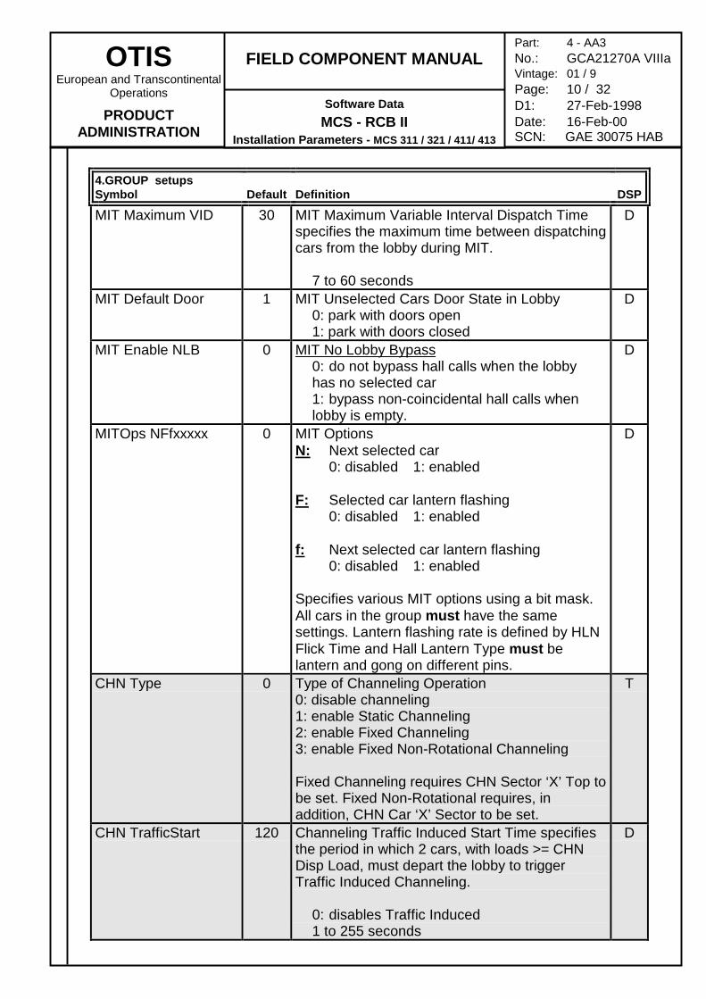
MIT Maximum VID 30 MIT Maximum Variable Interval Dispatch Timespecifies the maximum time between dispatchingcars from the lobby during MIT.
7 to 60 seconds
D
MIT Default Door 1 MIT Unselected Cars Door State in Lobby0: park with doors open1: park with doors closed
D
MIT Enable NLB 0 MIT No Lobby Bypass0: do not bypass hall calls when the lobby has no selected car1: bypass non-coincidental hall calls when lobby is empty.
D
MITOps NFfxxxxx 0 MIT OptionsN: Next selected car
0: disabled 1: enabled
F: Selected car lantern flashing0: disabled 1: enabled
f: Next selected car lantern flashing0: disabled 1: enabled
Specifies various MIT options using a bit mask.All cars in the group must have the samesettings. Lantern flashing rate is defined by HLNFlick Time and Hall Lantern Type must belantern and gong on different pins.
D
CHN Type 0 Type of Channeling Operation0: disable channeling1: enable Static Channeling2: enable Fixed Channeling3: enable Fixed Non-Rotational Channeling
Fixed Channeling requires CHN Sector ‘X’ Top tobe set. Fixed Non-Rotational requires, inaddition, CHN Car ‘X’ Sector to be set.
T
CHN TrafficStart 120 Channeling Traffic Induced Start Time specifiesthe period in which 2 cars, with loads >= CHNDisp Load, must depart the lobby to triggerTraffic Induced Channeling.
0: disables Traffic Induced1 to 255 seconds
D
OTISEuropean and Transcontinental
Operations
PRODUCTADMINISTRATION
FIELD COMPONENT MANUAL
Software DataMCS - RCB II
Installation Parameters - MCS 311 / 321 / 411/ 413
Part: 4 - AA3No.: GCA21270A VIIIaVintage: 01 / 9Page: 11 / 32D1: 27-Feb-1998Date: 16-Feb-00SCN: GAE 30075 HAB
4.GROUP setupsSymbol Default Definition DSP
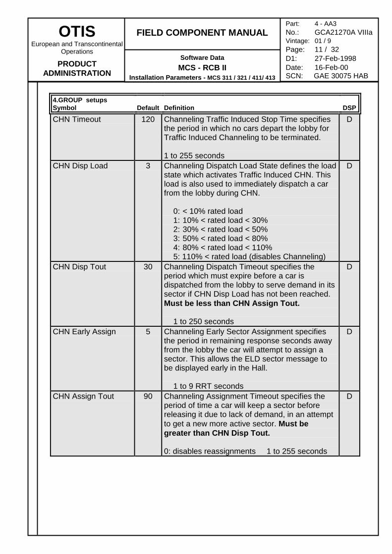
CHN Timeout 120 Channeling Traffic Induced Stop Time specifiesthe period in which no cars depart the lobby forTraffic Induced Channeling to be terminated.
1 to 255 seconds
D
CHN Disp Load 3 Channeling Dispatch Load State defines the loadstate which activates Traffic Induced CHN. Thisload is also used to immediately dispatch a carfrom the lobby during CHN.
0: < 10% rated load1: 10% < rated load < 30%2: 30% < rated load < 50%3: 50% < rated load < 80%4: 80% < rated load < 110%5: 110% < rated load (disables Channeling)
D
CHN Disp Tout 30 Channeling Dispatch Timeout specifies theperiod which must expire before a car isdispatched from the lobby to serve demand in itssector if CHN Disp Load has not been reached.Must be less than CHN Assign Tout.
1 to 250 seconds
D
CHN Early Assign 5 Channeling Early Sector Assignment specifiesthe period in remaining response seconds awayfrom the lobby the car will attempt to assign asector. This allows the ELD sector message tobe displayed early in the Hall.
1 to 9 RRT seconds
D
CHN Assign Tout 90 Channeling Assignment Timeout specifies theperiod of time a car will keep a sector beforereleasing it due to lack of demand, in an attemptto get a new more active sector. Must begreater than CHN Disp Tout.
0: disables reassignments 1 to 255 seconds
D
OTISEuropean and Transcontinental
Operations
PRODUCTADMINISTRATION
FIELD COMPONENT MANUAL
Software DataMCS - RCB II
Installation Parameters - MCS 311 / 321 / 411/ 413
Part: 4 - AA3No.: GCA21270A VIIIaVintage: 01 / 9Page: 12 / 32D1: 27-Feb-1998Date: 16-Feb-00SCN: GAE 30075 HAB
4.GROUP setupsSymbol Default Definition DSP
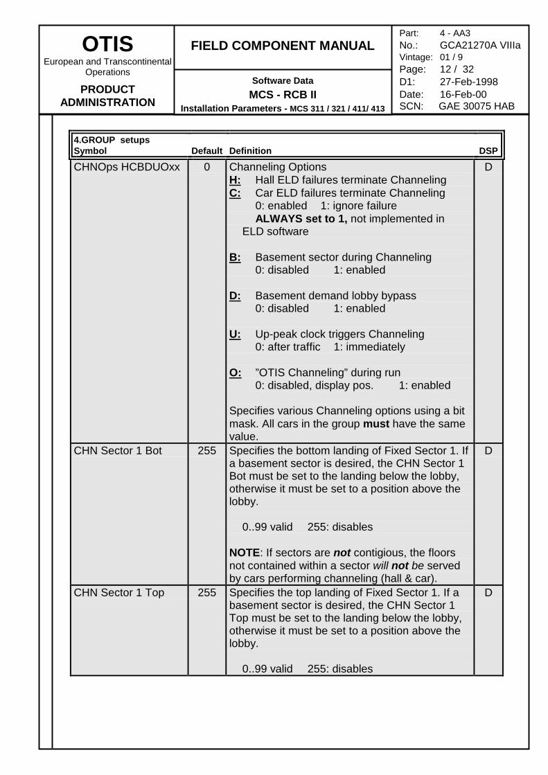
CHNOps HCBDUOxx 0 Channeling OptionsH: Hall ELD failures terminate ChannelingC: Car ELD failures terminate Channeling
0: enabled 1: ignore failureALWAYS set to 1, not implemented in
ELD software
B: Basement sector during Channeling0: disabled 1: enabled
D: Basement demand lobby bypass0: disabled 1: enabled
U: Up-peak clock triggers Channeling0: after traffic 1: immediately
O: ”OTIS Channeling” during run0: disabled, display pos. 1: enabled
Specifies various Channeling options using a bitmask. All cars in the group must have the samevalue.
D
CHN Sector 1 Bot 255 Specifies the bottom landing of Fixed Sector 1. Ifa basement sector is desired, the CHN Sector 1Bot must be set to the landing below the lobby,otherwise it must be set to a position above thelobby.
0..99 valid 255: disables
NOTE: If sectors are not contigious, the floorsnot contained within a sector will not be servedby cars performing channeling (hall & car).
D
CHN Sector 1 Top 255 Specifies the top landing of Fixed Sector 1. If abasement sector is desired, the CHN Sector 1Top must be set to the landing below the lobby,otherwise it must be set to a position above thelobby.
0..99 valid 255: disables
D
OTISEuropean and Transcontinental
Operations
PRODUCTADMINISTRATION
FIELD COMPONENT MANUAL
Software DataMCS - RCB II
Installation Parameters - MCS 311 / 321 / 411/ 413
Part: 4 - AA3No.: GCA21270A VIIIaVintage: 01 / 9Page: 13 / 32D1: 27-Feb-1998Date: 16-Feb-00SCN: GAE 30075 HAB
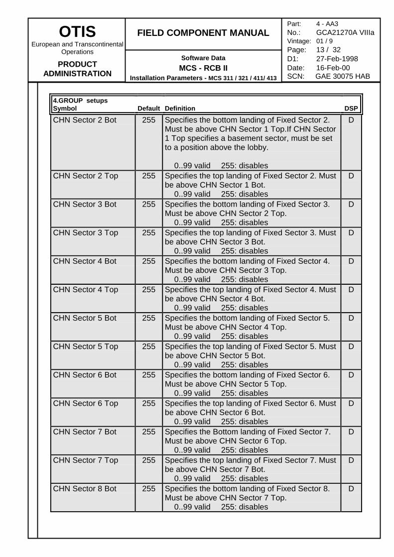
4.GROUP setupsSymbol Default Definition DSP
CHN Sector 2 Bot 255 Specifies the bottom landing of Fixed Sector 2.Must be above CHN Sector 1 Top.If CHN Sector1 Top specifies a basement sector, must be setto a position above the lobby.
0..99 valid 255: disables
D
CHN Sector 2 Top 255 Specifies the top landing of Fixed Sector 2. Mustbe above CHN Sector 1 Bot.
0..99 valid 255: disables
D
CHN Sector 3 Bot 255 Specifies the bottom landing of Fixed Sector 3.Must be above CHN Sector 2 Top.
0..99 valid 255: disables
D
CHN Sector 3 Top 255 Specifies the top landing of Fixed Sector 3. Mustbe above CHN Sector 3 Bot.
0..99 valid 255: disables
D
CHN Sector 4 Bot 255 Specifies the bottom landing of Fixed Sector 4.Must be above CHN Sector 3 Top.
0..99 valid 255: disables
D
CHN Sector 4 Top 255 Specifies the top landing of Fixed Sector 4. Mustbe above CHN Sector 4 Bot.
0..99 valid 255: disables
D
CHN Sector 5 Bot 255 Specifies the bottom landing of Fixed Sector 5.Must be above CHN Sector 4 Top.
0..99 valid 255: disables
D
CHN Sector 5 Top 255 Specifies the top landing of Fixed Sector 5. Mustbe above CHN Sector 5 Bot.
0..99 valid 255: disables
D
CHN Sector 6 Bot 255 Specifies the bottom landing of Fixed Sector 6.Must be above CHN Sector 5 Top.
0..99 valid 255: disables
D
CHN Sector 6 Top 255 Specifies the top landing of Fixed Sector 6. Mustbe above CHN Sector 6 Bot.
0..99 valid 255: disables
D
CHN Sector 7 Bot 255 Specifies the Bottom landing of Fixed Sector 7.Must be above CHN Sector 6 Top.
0..99 valid 255: disables
D
CHN Sector 7 Top 255 Specifies the top landing of Fixed Sector 7. Mustbe above CHN Sector 7 Bot.
0..99 valid 255: disables
D
CHN Sector 8 Bot 255 Specifies the bottom landing of Fixed Sector 8.Must be above CHN Sector 7 Top.
0..99 valid 255: disables
D
OTISEuropean and Transcontinental
Operations
PRODUCTADMINISTRATION
FIELD COMPONENT MANUAL
Software DataMCS - RCB II
Installation Parameters - MCS 311 / 321 / 411/ 413
Part: 4 - AA3No.: GCA21270A VIIIaVintage: 01 / 9Page: 14 / 32D1: 27-Feb-1998Date: 16-Feb-00SCN: GAE 30075 HAB
4.GROUP setupsSymbol Default Definition DSP
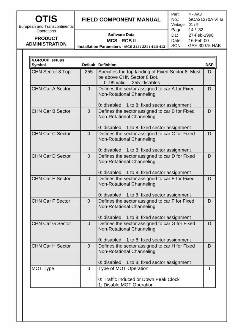
CHN Sector 8 Top 255 Specifies the top landing of Fixed Sector 8. Mustbe above CHN Sector 8 Bot.
0..99 valid 255: disables
D
CHN Car A Sector 0 Defines the sector assigned to car A for FixedNon-Rotational Channeling.
0: disabled 1 to 8: fixed sector assignment
D
CHN Car B Sector 0 Defines the sector assigned to car B for FixedNon-Rotational Channeling.
0: disabled 1 to 8: fixed sector assignment
D
CHN Car C Sector 0 Defines the sector assigned to car C for FixedNon-Rotational Channeling.
0: disabled 1 to 8: fixed sector assignment
D
CHN Car D Sector 0 Defines the sector assigned to car D for FixedNon-Rotational Channeling.
0: disabled 1 to 8: fixed sector assignment
D
CHN Car E Sector 0 Defines the sector assigned to car E for FixedNon-Rotational Channeling.
0: disabled 1 to 8: fixed sector assignment
D
CHN Car F Sector 0 Defines the sector assigned to car F for FixedNon-Rotational Channeling.
0: disabled 1 to 8: fixed sector assignment
D
CHN Car G Sector 0 Defines the sector assigned to car G for FixedNon-Rotational Channeling.
0: disabled 1 to 8: fixed sector assignment
D
CHN Car H Sector 0 Defines the sector assigned to car H for FixedNon-Rotational Channeling.
0: disabled 1 to 8: fixed sector assignment
D
MOT Type 0 Type of MOT Operation
0: Traffic Induced or Down Peak Clock1: Disable MOT Operation
T
OTISEuropean and Transcontinental
Operations
PRODUCTADMINISTRATION
FIELD COMPONENT MANUAL
Software DataMCS - RCB II
Installation Parameters - MCS 311 / 321 / 411/ 413
Part: 4 - AA3No.: GCA21270A VIIIaVintage: 01 / 9Page: 15 / 32D1: 27-Feb-1998Date: 16-Feb-00SCN: GAE 30075 HAB
4.GROUP setupsSymbol Default Definition DSP
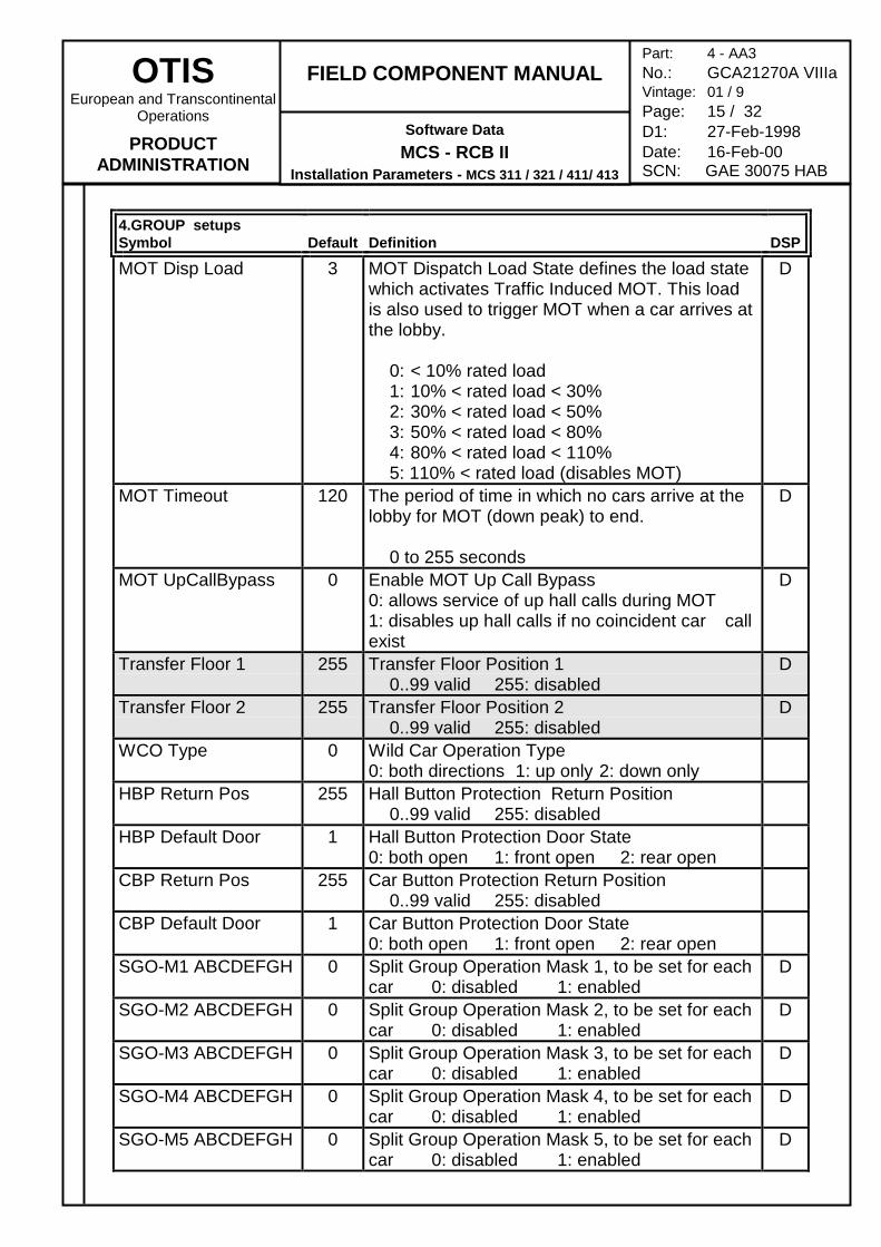
MOT Disp Load 3 MOT Dispatch Load State defines the load statewhich activates Traffic Induced MOT. This loadis also used to trigger MOT when a car arrives atthe lobby.
0: < 10% rated load1: 10% < rated load < 30%2: 30% < rated load < 50%3: 50% < rated load < 80%4: 80% < rated load < 110%5: 110% < rated load (disables MOT)
D
MOT Timeout 120 The period of time in which no cars arrive at thelobby for MOT (down peak) to end.
0 to 255 seconds
D
MOT UpCallBypass 0 Enable MOT Up Call Bypass0: allows service of up hall calls during MOT1: disables up hall calls if no coincident car callexist
D
Transfer Floor 1 255 Transfer Floor Position 10..99 valid 255: disabled
D
Transfer Floor 2 255 Transfer Floor Position 20..99 valid 255: disabled
D
WCO Type 0 Wild Car Operation Type0: both directions 1: up only 2: down only
HBP Return Pos 255 Hall Button Protection Return Position0..99 valid 255: disabled
HBP Default Door 1 Hall Button Protection Door State0: both open 1: front open 2: rear open
CBP Return Pos 255 Car Button Protection Return Position0..99 valid 255: disabled
CBP Default Door 1 Car Button Protection Door State0: both open 1: front open 2: rear open
SGO-M1 ABCDEFGH 0 Split Group Operation Mask 1, to be set for eachcar 0: disabled 1: enabled
D
SGO-M2 ABCDEFGH 0 Split Group Operation Mask 2, to be set for eachcar 0: disabled 1: enabled
D
SGO-M3 ABCDEFGH 0 Split Group Operation Mask 3, to be set for eachcar 0: disabled 1: enabled
D
SGO-M4 ABCDEFGH 0 Split Group Operation Mask 4, to be set for eachcar 0: disabled 1: enabled
D
SGO-M5 ABCDEFGH 0 Split Group Operation Mask 5, to be set for eachcar 0: disabled 1: enabled
D
OTISEuropean and Transcontinental
Operations
PRODUCTADMINISTRATION
FIELD COMPONENT MANUAL
Software DataMCS - RCB II
Installation Parameters - MCS 311 / 321 / 411/ 413
Part: 4 - AA3No.: GCA21270A VIIIaVintage: 01 / 9Page: 16 / 32D1: 27-Feb-1998Date: 16-Feb-00SCN: GAE 30075 HAB
4.GROUP setupsSymbol Default Definition DSP
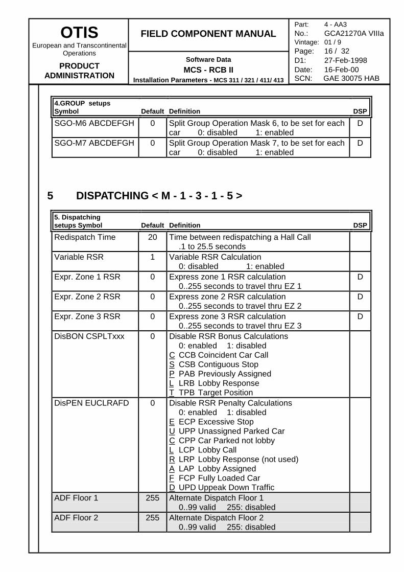
SGO-M6 ABCDEFGH 0 Split Group Operation Mask 6, to be set for eachcar 0: disabled 1: enabled
D
SGO-M7 ABCDEFGH 0 Split Group Operation Mask 7, to be set for eachcar 0: disabled 1: enabled
D
5 DISPATCHING < M - 1 - 3 - 1 - 5 >
5. Dispatchingsetups Symbol Default Definition DSP
Redispatch Time 20 Time between redispatching a Hall Call.1 to 25.5 seconds
Variable RSR 1 Variable RSR Calculation0: disabled 1: enabled
Expr. Zone 1 RSR 0 Express zone 1 RSR calculation0..255 seconds to travel thru EZ 1
D
Expr. Zone 2 RSR 0 Express zone 2 RSR calculation0..255 seconds to travel thru EZ 2
D
Expr. Zone 3 RSR 0 Express zone 3 RSR calculation0..255 seconds to travel thru EZ 3
D
DisBON CSPLTxxx 0 Disable RSR Bonus Calculations0: enabled 1: disabled
C CCB Coincident Car CallS CSB Contiguous StopP PAB Previously AssignedL LRB Lobby ResponseT TPB Target Position
DisPEN EUCLRAFD 0 Disable RSR Penalty Calculations0: enabled 1: disabled
E ECP Excessive StopU UPP Unassigned Parked CarC CPP Car Parked not lobbyL LCP Lobby CallR LRP Lobby Response (not used)A LAP Lobby AssignedF FCP Fully Loaded CarD UPD Uppeak Down Traffic
ADF Floor 1 255 Alternate Dispatch Floor 10..99 valid 255: disabled
ADF Floor 2 255 Alternate Dispatch Floor 20..99 valid 255: disabled
OTISEuropean and Transcontinental
Operations
PRODUCTADMINISTRATION
FIELD COMPONENT MANUAL
Software DataMCS - RCB II
Installation Parameters - MCS 311 / 321 / 411/ 413
Part: 4 - AA3No.: GCA21270A VIIIaVintage: 01 / 9Page: 17 / 32D1: 27-Feb-1998Date: 16-Feb-00SCN: GAE 30075 HAB
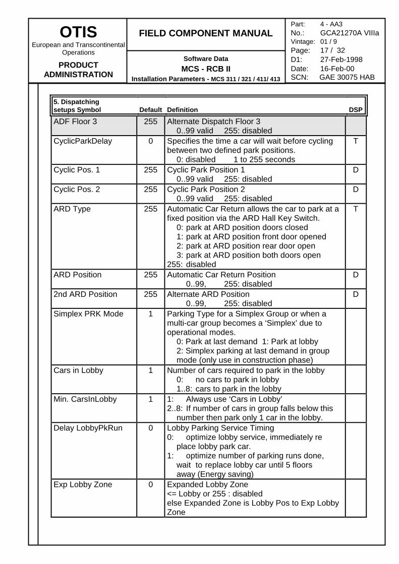
5. Dispatchingsetups Symbol Default Definition DSP
ADF Floor 3 255 Alternate Dispatch Floor 30..99 valid 255: disabled
CyclicParkDelay 0 Specifies the time a car will wait before cyclingbetween two defined park positions.
0: disabled 1 to 255 seconds
T
Cyclic Pos. 1 255 Cyclic Park Position 10..99 valid 255: disabled
D
Cyclic Pos. 2 255 Cyclic Park Position 20..99 valid 255: disabled
D
ARD Type 255 Automatic Car Return allows the car to park at afixed position via the ARD Hall Key Switch.
0: park at ARD position doors closed1: park at ARD position front door opened2: park at ARD position rear door open3: park at ARD position both doors open
255: disabled
T
ARD Position 255 Automatic Car Return Position0..99, 255: disabled
D
2nd ARD Position 255 Alternate ARD Position0..99, 255: disabled
D
Simplex PRK Mode 1 Parking Type for a Simplex Group or when amulti-car group becomes a ‘Simplex’ due tooperational modes.
0: Park at last demand 1: Park at lobby2: Simplex parking at last demand in group mode (only use in construction phase)
Cars in Lobby 1 Number of cars required to park in the lobby0: no cars to park in lobby1..8: cars to park in the lobby
Min. CarsInLobby 1 1: Always use ‘Cars in Lobby’2..8: If number of cars in group falls below this
number then park only 1 car in the lobby.Delay LobbyPkRun 0 Lobby Parking Service Timing
0: optimize lobby service, immediately replace lobby park car.
1: optimize number of parking runs done, wait to replace lobby car until 5 floors away (Energy saving)
Exp Lobby Zone 0 Expanded Lobby Zone<= Lobby or 255 : disabledelse Expanded Zone is Lobby Pos to Exp LobbyZone
OTISEuropean and Transcontinental
Operations
PRODUCTADMINISTRATION
FIELD COMPONENT MANUAL
Software DataMCS - RCB II
Installation Parameters - MCS 311 / 321 / 411/ 413
Part: 4 - AA3No.: GCA21270A VIIIaVintage: 01 / 9Page: 18 / 32D1: 27-Feb-1998Date: 16-Feb-00SCN: GAE 30075 HAB
5. Dispatchingsetups Symbol Default Definition DSP
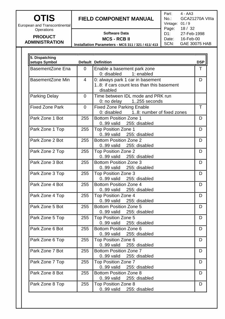
BasementZone Ena 0 Enable a basement park zone0: disabled 1: enabled
T
BasementZone Min 4 0: always park 1 car in basement1..8: if cars count less than this basement
disabled
D
Parking Delay 0 Time between IDL mode and PRK run0: no delay 1..255 seconds
Fixed Zone Park 0 Fixed Zone Parking Enable0: disabled 1..8: number of fixed zones
T
Park Zone 1 Bot 255 Bottom Position Zone 10..99 valid 255: disabled
D
Park Zone 1 Top 255 Top Position Zone 10..99 valid 255: disabled
D
Park Zone 2 Bot 255 Bottom Position Zone 20..99 valid 255: disabled
D
Park Zone 2 Top 255 Top Position Zone 20..99 valid 255: disabled
D
Park Zone 3 Bot 255 Bottom Position Zone 30..99 valid 255: disabled
D
Park Zone 3 Top 255 Top Position Zone 30..99 valid 255: disabled
D
Park Zone 4 Bot 255 Bottom Position Zone 40..99 valid 255: disabled
D
Park Zone 4 Top 255 Top Position Zone 40..99 valid 255: disabled
D
Park Zone 5 Bot 255 Bottom Position Zone 50..99 valid 255: disabled
D
Park Zone 5 Top 255 Top Position Zone 50..99 valid 255: disabled
D
Park Zone 6 Bot 255 Bottom Position Zone 60..99 valid 255: disabled
D
Park Zone 6 Top 255 Top Position Zone 60..99 valid 255: disabled
D
Park Zone 7 Bot 255 Bottom Position Zone 70..99 valid 255: disabled
D
Park Zone 7 Top 255 Top Position Zone 70..99 valid 255: disabled
D
Park Zone 8 Bot 255 Bottom Position Zone 80..99 valid 255: disabled
D
Park Zone 8 Top 255 Top Position Zone 80..99 valid 255: disabled
D
OTISEuropean and Transcontinental
Operations
PRODUCTADMINISTRATION
FIELD COMPONENT MANUAL
Software DataMCS - RCB II
Installation Parameters - MCS 311 / 321 / 411/ 413
Part: 4 - AA3No.: GCA21270A VIIIaVintage: 01 / 9Page: 19 / 32D1: 27-Feb-1998Date: 16-Feb-00SCN: GAE 30075 HAB
5. Dispatchingsetups Symbol Default Definition DSP
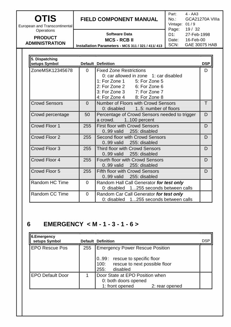
ZoneMSK12345678 0 Fixed Zone Restrictions0: car allowed in zone 1: car disabled
1: For Zone 1 5: For Zone 52: For Zone 2 6: For Zone 63: For Zone 3 7: For Zone 74: For Zone 4 8: For Zone 8
D
Crowd Sensors 0 Number of Floors with Crowd Sensors0: disabled 1..5: number of floors
T
Crowd percentage 50 Percentage of Crowd Sensors needed to triggera crowd. 1..100 percent
D
Crowd Floor 1 255 First floor with Crowd Sensors0..99 valid 255: disabled
D
Crowd Floor 2 255 Second floor with Crowd Sensors0..99 valid 255: disabled
D
Crowd Floor 3 255 Third floor with Crowd Sensors0..99 valid 255: disabled
D
Crowd Floor 4 255 Fourth floor with Crowd Sensors0..99 valid 255: disabled
D
Crowd Floor 5 255 Fifth floor with Crowd Sensors0..99 valid 255: disabled
D
Random HC Time 0 Random Hall Call Generator for test only0: disabled 1...255 seconds between calls
Random CC Time 0 Random Car Call Generator for test only0: disabled 1...255 seconds between calls
6 EMERGENCY < M - 1 - 3 - 1 - 6 >
6.Emergency setups Symbol Default Definition DSP
EPO Rescue Pos 255 Emergency Power Rescue Position
0..99 : rescue to specific floor100: rescue to next possible floor255: disabled
EPO Default Door 1 Door State at EPO Position when0: both doors opened1: front opened 2: rear opened
OTISEuropean and Transcontinental
Operations
PRODUCTADMINISTRATION
FIELD COMPONENT MANUAL
Software DataMCS - RCB II
Installation Parameters - MCS 311 / 321 / 411/ 413
Part: 4 - AA3No.: GCA21270A VIIIaVintage: 01 / 9Page: 20 / 32D1: 27-Feb-1998Date: 16-Feb-00SCN: GAE 30075 HAB
6.Emergency setups Symbol Default Definition DSP
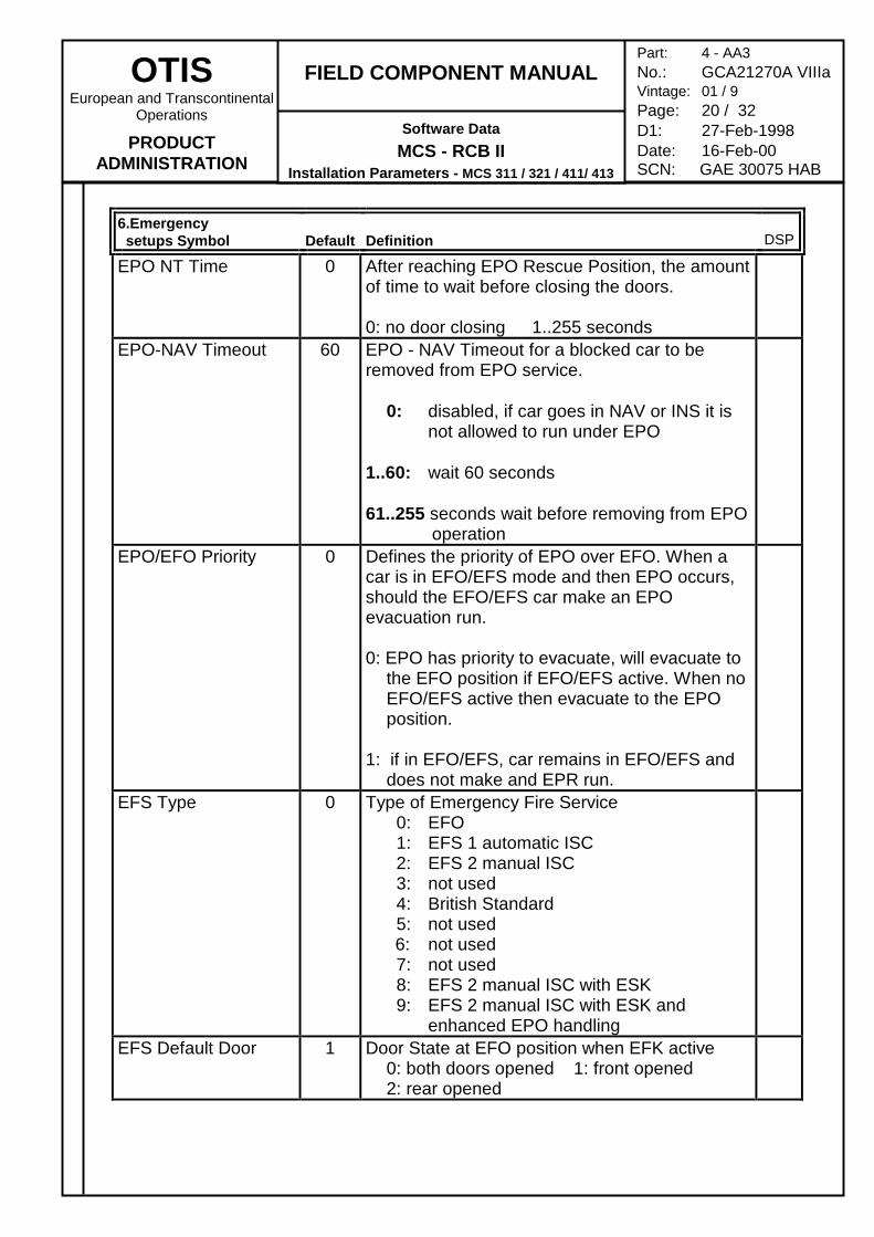
EPO NT Time 0 After reaching EPO Rescue Position, the amountof time to wait before closing the doors.
0: no door closing 1..255 secondsEPO-NAV Timeout 60 EPO - NAV Timeout for a blocked car to be
removed from EPO service.
0: disabled, if car goes in NAV or INS it is not allowed to run under EPO
1..60: wait 60 seconds
61..255 seconds wait before removing from EPO operation
EPO/EFO Priority 0 Defines the priority of EPO over EFO. When acar is in EFO/EFS mode and then EPO occurs,should the EFO/EFS car make an EPOevacuation run.
0: EPO has priority to evacuate, will evacuate to the EFO position if EFO/EFS active. When no EFO/EFS active then evacuate to the EPO position.
1: if in EFO/EFS, car remains in EFO/EFS and does not make and EPR run.
EFS Type 0 Type of Emergency Fire Service 0: EFO 1: EFS 1 automatic ISC 2: EFS 2 manual ISC 3: not used 4: British Standard 5: not used
6: not used 7: not used 8: EFS 2 manual ISC with ESK 9: EFS 2 manual ISC with ESK and
enhanced EPO handlingEFS Default Door 1 Door State at EFO position when EFK active
0: both doors opened 1: front opened2: rear opened
OTISEuropean and Transcontinental
Operations
PRODUCTADMINISTRATION
FIELD COMPONENT MANUAL
Software DataMCS - RCB II
Installation Parameters - MCS 311 / 321 / 411/ 413
Part: 4 - AA3No.: GCA21270A VIIIaVintage: 01 / 9Page: 21 / 32D1: 27-Feb-1998Date: 16-Feb-00SCN: GAE 30075 HAB
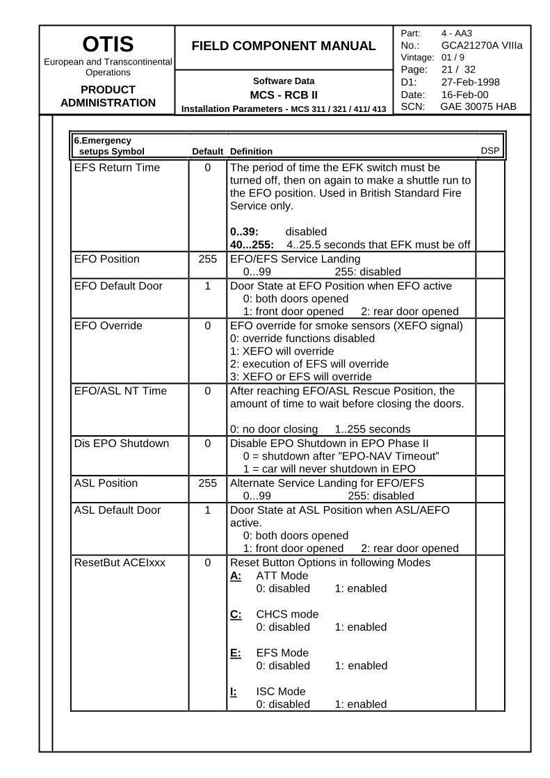
6.Emergency setups Symbol Default Definition DSP
EFS Return Time 0 The period of time the EFK switch must beturned off, then on again to make a shuttle run tothe EFO position. Used in British Standard FireService only.
0..39: disabled40...255: 4..25.5 seconds that EFK must be off
EFO Position 255 EFO/EFS Service Landing0...99 255: disabled
EFO Default Door 1 Door State at EFO Position when EFO active0: both doors opened1: front door opened 2: rear door opened
EFO Override 0 EFO override for smoke sensors (XEFO signal)0: override functions disabled1: XEFO will override2: execution of EFS will override3: XEFO or EFS will override
EFO/ASL NT Time 0 After reaching EFO/ASL Rescue Position, theamount of time to wait before closing the doors.
0: no door closing 1..255 secondsDis EPO Shutdown 0 Disable EPO Shutdown in EPO Phase II
0 = shutdown after ”EPO-NAV Timeout”1 = car will never shutdown in EPO
ASL Position 255 Alternate Service Landing for EFO/EFS0...99 255: disabled
ASL Default Door 1 Door State at ASL Position when ASL/AEFOactive.
0: both doors opened1: front door opened 2: rear door opened
ResetBut ACEIxxx 0 Reset Button Options in following ModesA: ATT Mode
0: disabled 1: enabled
C: CHCS mode0: disabled 1: enabled
E: EFS Mode0: disabled 1: enabled
I: ISC Mode0: disabled 1: enabled
OTISEuropean and Transcontinental
Operations
PRODUCTADMINISTRATION
FIELD COMPONENT MANUAL
Software DataMCS - RCB II
Installation Parameters - MCS 311 / 321 / 411/ 413
Part: 4 - AA3No.: GCA21270A VIIIaVintage: 01 / 9Page: 22 / 32D1: 27-Feb-1998Date: 16-Feb-00SCN: GAE 30075 HAB
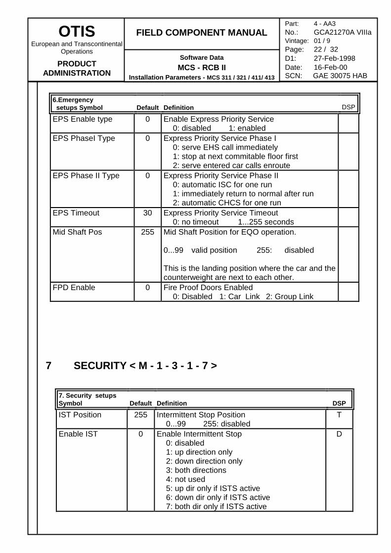
6.Emergency setups Symbol Default Definition DSP
EPS Enable type 0 Enable Express Priority Service0: disabled 1: enabled
EPS PhaseI Type 0 Express Priority Service Phase I0: serve EHS call immediately1: stop at next commitable floor first2: serve entered car calls enroute
EPS Phase II Type 0 Express Priority Service Phase II0: automatic ISC for one run1: immediately return to normal after run2: automatic CHCS for one run
EPS Timeout 30 Express Priority Service Timeout0: no timeout 1...255 seconds
Mid Shaft Pos 255 Mid Shaft Position for EQO operation.
0...99 valid position 255: disabled
This is the landing position where the car and thecounterweight are next to each other.
FPD Enable 0 Fire Proof Doors Enabled0: Disabled 1: Car Link 2: Group Link
7 SECURITY < M - 1 - 3 - 1 - 7 >
7. Security setupsSymbol Default Definition DSP
IST Position 255 Intermittent Stop Position0...99 255: disabled
T
Enable IST 0 Enable Intermittent Stop0: disabled1: up direction only2: down direction only3: both directions4: not used5: up dir only if ISTS active6: down dir only if ISTS active7: both dir only if ISTS active
D
OTISEuropean and Transcontinental
Operations
PRODUCTADMINISTRATION
FIELD COMPONENT MANUAL
Software DataMCS - RCB II
Installation Parameters - MCS 311 / 321 / 411/ 413
Part: 4 - AA3No.: GCA21270A VIIIaVintage: 01 / 9Page: 23 / 32D1: 27-Feb-1998Date: 16-Feb-00SCN: GAE 30075 HAB
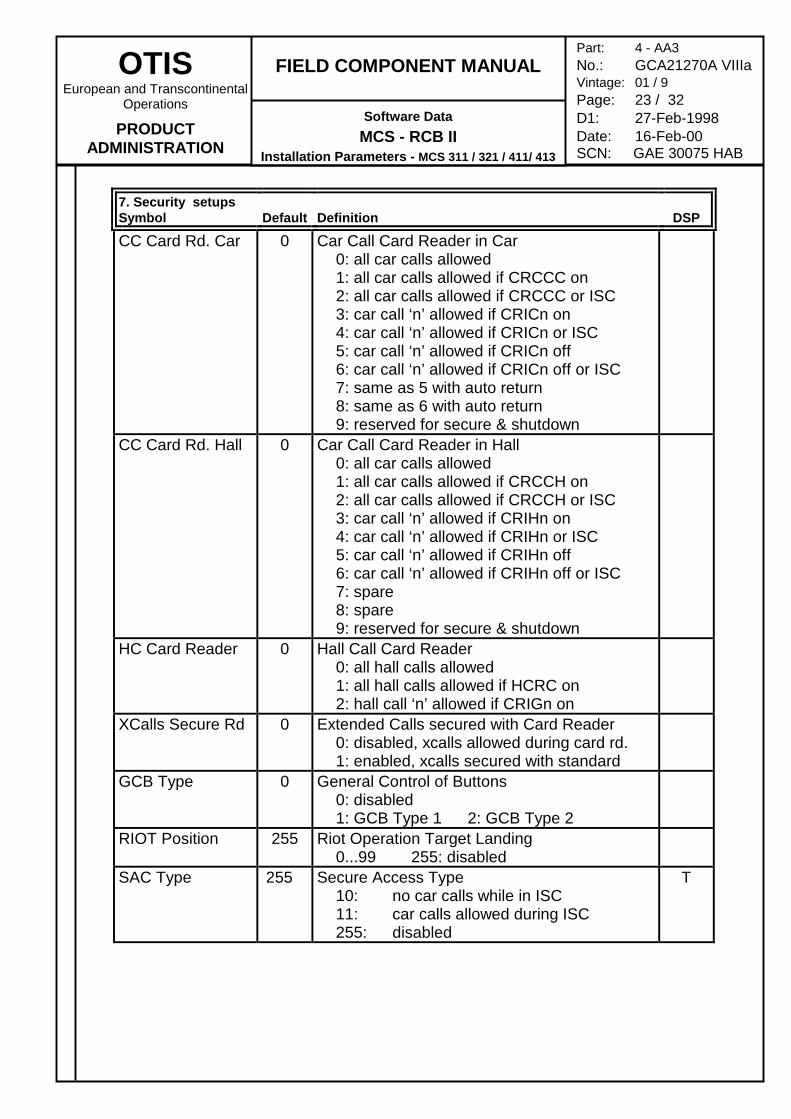
7. Security setupsSymbol Default Definition DSP
CC Card Rd. Car 0 Car Call Card Reader in Car0: all car calls allowed1: all car calls allowed if CRCCC on2: all car calls allowed if CRCCC or ISC3: car call ‘n’ allowed if CRICn on4: car call ‘n’ allowed if CRICn or ISC5: car call ‘n’ allowed if CRICn off6: car call ‘n’ allowed if CRICn off or ISC7: same as 5 with auto return8: same as 6 with auto return9: reserved for secure & shutdown
CC Card Rd. Hall 0 Car Call Card Reader in Hall0: all car calls allowed1: all car calls allowed if CRCCH on2: all car calls allowed if CRCCH or ISC3: car call ‘n’ allowed if CRIHn on4: car call ‘n’ allowed if CRIHn or ISC5: car call ‘n’ allowed if CRIHn off6: car call ‘n’ allowed if CRIHn off or ISC7: spare8: spare9: reserved for secure & shutdown
HC Card Reader 0 Hall Call Card Reader0: all hall calls allowed1: all hall calls allowed if HCRC on2: hall call ‘n’ allowed if CRIGn on
XCalls Secure Rd 0 Extended Calls secured with Card Reader0: disabled, xcalls allowed during card rd.1: enabled, xcalls secured with standard
GCB Type 0 General Control of Buttons0: disabled1: GCB Type 1 2: GCB Type 2
RIOT Position 255 Riot Operation Target Landing0...99 255: disabled
SAC Type 255 Secure Access Type10: no car calls while in ISC11: car calls allowed during ISC255: disabled
T
OTISEuropean and Transcontinental
Operations
PRODUCTADMINISTRATION
FIELD COMPONENT MANUAL
Software DataMCS - RCB II
Installation Parameters - MCS 311 / 321 / 411/ 413
Part: 4 - AA3No.: GCA21270A VIIIaVintage: 01 / 9Page: 24 / 32D1: 27-Feb-1998Date: 16-Feb-00SCN: GAE 30075 HAB
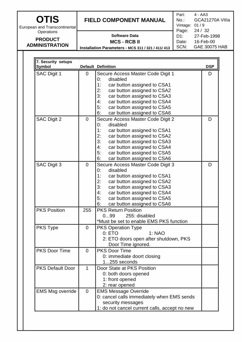
7. Security setupsSymbol Default Definition DSP
SAC Digit 1 0 Secure Access Master Code Digit 10: disabled1: car button assigned to CSA12: car button assigned to CSA23: car button assigned to CSA34: car button assigned to CSA45: car button assigned to CSA56: car button assigned to CSA6
D
SAC Digit 2 0 Secure Access Master Code Digit 20: disabled1: car button assigned to CSA12: car button assigned to CSA23: car button assigned to CSA34: car button assigned to CSA45: car button assigned to CSA56: car button assigned to CSA6
D
SAC Digit 3 0 Secure Access Master Code Digit 30: disabled1: car button assigned to CSA12: car button assigned to CSA23: car button assigned to CSA34: car button assigned to CSA45: car button assigned to CSA56: car button assigned to CSA6
D
PKS Position 255 PKS Return Position0...99 255: disabled
*Must be set to enable EMS PKS functionPKS Type 0 PKS Operation Type
0: ETO 1: NAO2: ETO doors open after shutdown, PKS
Door Time ignored.PKS Door Time 0 PKS Door Time
0: immediate doort closing1...255 seconds
PKS Default Door 1 Door State at PKS Position0: both doors opened1: front opened2: rear opened
EMS Msg override 0 EMS Message Override0: cancel calls immediately when EMS sends
security messages1: do not cancel current calls, accept no new
OTISEuropean and Transcontinental
Operations
PRODUCTADMINISTRATION
FIELD COMPONENT MANUAL
Software DataMCS - RCB II
Installation Parameters - MCS 311 / 321 / 411/ 413
Part: 4 - AA3No.: GCA21270A VIIIaVintage: 01 / 9Page: 25 / 32D1: 27-Feb-1998Date: 16-Feb-00SCN: GAE 30075 HAB
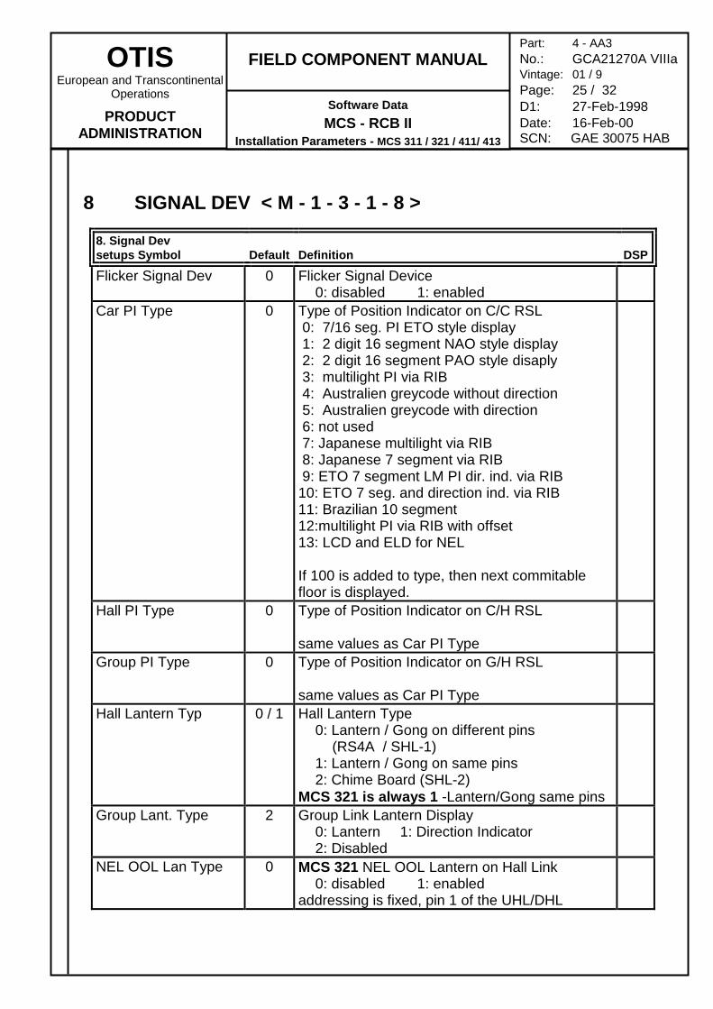
8 SIGNAL DEV < M - 1 - 3 - 1 - 8 >
8. Signal Devsetups Symbol Default Definition DSP
Flicker Signal Dev 0 Flicker Signal Device0: disabled 1: enabled
Car PI Type 0 Type of Position Indicator on C/C RSL 0: 7/16 seg. PI ETO style display 1: 2 digit 16 segment NAO style display 2: 2 digit 16 segment PAO style disaply 3: multilight PI via RIB 4: Australien greycode without direction 5: Australien greycode with direction 6: not used 7: Japanese multilight via RIB 8: Japanese 7 segment via RIB 9: ETO 7 segment LM PI dir. ind. via RIB10: ETO 7 seg. and direction ind. via RIB11: Brazilian 10 segment12:multilight PI via RIB with offset13: LCD and ELD for NEL
If 100 is added to type, then next commitablefloor is displayed.
Hall PI Type 0 Type of Position Indicator on C/H RSL
same values as Car PI TypeGroup PI Type 0 Type of Position Indicator on G/H RSL
same values as Car PI TypeHall Lantern Typ 0 / 1 Hall Lantern Type
0: Lantern / Gong on different pins(RS4A / SHL-1)
1: Lantern / Gong on same pins2: Chime Board (SHL-2)
MCS 321 is always 1 -Lantern/Gong same pinsGroup Lant. Type 2 Group Link Lantern Display
0: Lantern 1: Direction Indicator2: Disabled
NEL OOL Lan Type 0 MCS 321 NEL OOL Lantern on Hall Link0: disabled 1: enabled
addressing is fixed, pin 1 of the UHL/DHL
OTISEuropean and Transcontinental
Operations
PRODUCTADMINISTRATION
FIELD COMPONENT MANUAL
Software DataMCS - RCB II
Installation Parameters - MCS 311 / 321 / 411/ 413
Part: 4 - AA3No.: GCA21270A VIIIaVintage: 01 / 9Page: 26 / 32D1: 27-Feb-1998Date: 16-Feb-00SCN: GAE 30075 HAB
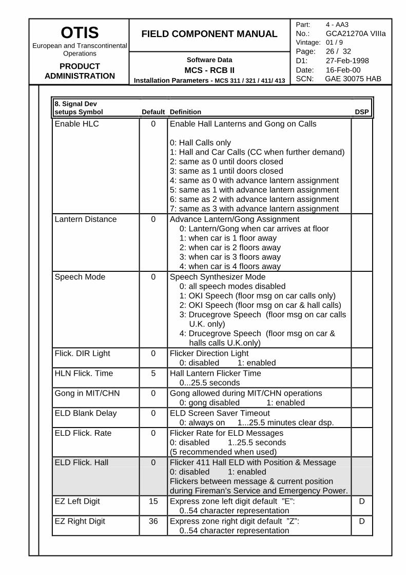
8. Signal Devsetups Symbol Default Definition DSP
Enable HLC 0 Enable Hall Lanterns and Gong on Calls
0: Hall Calls only1: Hall and Car Calls (CC when further demand)2: same as 0 until doors closed3: same as 1 until doors closed4: same as 0 with advance lantern assignment5: same as 1 with advance lantern assignment6: same as 2 with advance lantern assignment7: same as 3 with advance lantern assignment
Lantern Distance 0 Advance Lantern/Gong Assignment0: Lantern/Gong when car arrives at floor1: when car is 1 floor away2: when car is 2 floors away3: when car is 3 floors away4: when car is 4 floors away
Speech Mode 0 Speech Synthesizer Mode0: all speech modes disabled1: OKI Speech (floor msg on car calls only)2: OKI Speech (floor msg on car & hall calls)3: Drucegrove Speech (floor msg on car calls
U.K. only)4: Drucegrove Speech (floor msg on car &
halls calls U.K.only)Flick. DIR Light 0 Flicker Direction Light
0: disabled 1: enabledHLN Flick. Time 5 Hall Lantern Flicker Time
0...25.5 secondsGong in MIT/CHN 0 Gong allowed during MIT/CHN operations
0: gong disabled 1: enabledELD Blank Delay 0 ELD Screen Saver Timeout
0: always on 1...25.5 minutes clear dsp.ELD Flick. Rate 0 Flicker Rate for ELD Messages
0: disabled 1..25.5 seconds(5 recommended when used)
ELD Flick. Hall 0 Flicker 411 Hall ELD with Position & Message0: disabled 1: enabledFlickers between message & current positionduring Fireman’s Service and Emergency Power.
EZ Left Digit 15 Express zone left digit default ”E”:0..54 character representation
D
EZ Right Digit 36 Express zone right digit default ”Z”:0..54 character representation
D
OTISEuropean and Transcontinental
Operations
PRODUCTADMINISTRATION
FIELD COMPONENT MANUAL
Software DataMCS - RCB II
Installation Parameters - MCS 311 / 321 / 411/ 413
Part: 4 - AA3No.: GCA21270A VIIIaVintage: 01 / 9Page: 27 / 32D1: 27-Feb-1998Date: 16-Feb-00SCN: GAE 30075 HAB
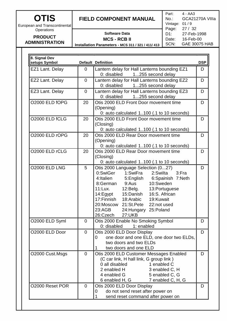
8. Signal Devsetups Symbol Default Definition DSP
EZ1 Lant. Delay 0 Lantern delay for Hall Lanterns bounding EZ10: disabled 1...255 second delay
D
EZ2 Lant. Delay 0 Lantern delay for Hall Lanterns bounding EZ20: disabled 1...255 second delay
D
EZ3 Lant. Delay 0 Lantern delay for Hall Lanterns bounding EZ30: disabled 1...255 second delay
D
O2000 ELD fOPG 20 Otis 2000 ELD Front Door movement time(Opening)
0: auto calculated 1..100 (.1 to 10 seconds)
D
O2000 ELD fCLG 20 Otis 2000 ELD Front Door movement time(Closing)
0: auto calculated 1..100 (.1 to 10 seconds)
D
O2000 ELD rOPG 20 Otis 2000 ELD Rear Door movement time(Opening)
0: auto calculated 1..100 (.1 to 10 seconds)
D
O2000 ELD rCLG 20 Otis 2000 ELD Rear Door movement time(Closing)
0: auto calculated 1..100 (.1 to 10 seconds)
D
O2000 ELD LNG 5 Otis 2000 Language Selection (0...27) 0:SwiGer 1:SwiFra 2:SwiIta 3:Fra 4:Italien 5:English 6:Spainish 7:Neth 8:German 9:Aus 10:Sweden11:Lux. 12:Belg. 13:Portuguese14:Egypt 15:Danish 16:S. African17:Finnish 18:Arabic 19:Kuwait20:Moscow 21:St.Pete 22:not used23:AGB 24:Hungary 25:Poland26:Czech 27:UKB
D
O2000 ELD Syml 0 Otis 2000 Enable No Smoking Symbol0: disabled 1: enabled
D
O2000 ELD Door 0 Otis 2000 ELD Door Display0 one door and one ELD, one door two ELDs,
two doors and two ELDs1 two doors and one ELD
D
O2000 Cust.Msgs 0 Otis 2000 ELD Customer Messages Enabled(C car link, H hall link, G group link )0 all disabled 1 enabled C2 enabled H 3 enabled C, H4 enabled G 5 enabled C, G6 enabled H, G 7 enabled C, H, G
D
O2000 Reset POR 0 Otis 2000 ELD Door Display0 do not send reset after power on1 send reset command after power on
D
OTISEuropean and Transcontinental
Operations
PRODUCTADMINISTRATION
FIELD COMPONENT MANUAL
Software DataMCS - RCB II
Installation Parameters - MCS 311 / 321 / 411/ 413
Part: 4 - AA3No.: GCA21270A VIIIaVintage: 01 / 9Page: 28 / 32D1: 27-Feb-1998Date: 16-Feb-00SCN: GAE 30075 HAB
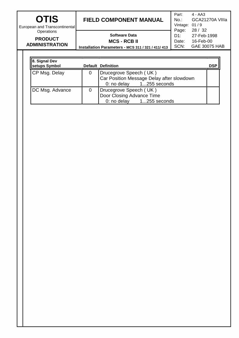
8. Signal Devsetups Symbol Default Definition DSP
CP Msg. Delay 0 Drucegrove Speech ( UK )Car Position Message Delay after slowdown
0: no delay 1...255 secondsDC Msg. Advance 0 Drucegrove Speech ( UK )
Door Closing Advance Time0: no delay 1...255 seconds
OTISEuropean and Transcontinental
Operations
PRODUCTADMINISTRATION
FIELD COMPONENT MANUAL
Software DataMCS - RCB II
Installation Parameters - MCS 311 / 321 / 411/ 413
Part: 4 - AA3No.: GCA21270A VIIIaVintage: 01 / 9Page: 29 / 32D1: 27-Feb-1998Date: 16-Feb-00SCN: GAE 30075 HAB
INDEX
—2—2nd ARD Position ....................................................... 17
—A—ADF Floor ................................................................... 16ANS Call Limit .............................................................. 3ARD Position .............................................................. 17ARD Type................................................................... 17ASL Default Door ....................................................... 21ASL Position............................................................... 21ATT Type...................................................................... 4
—B—BasementZone Ena.................................................... 18BasementZone Min .................................................... 18Bottom Position ............................................................ 3
—C—Cafeteria NT ................................................................. 7Cafeteria Pos................................................................ 3Car Button Type ........................................................... 6Car Call Pref................................................................. 7Car Calls Behind .......................................................... 4Car PI Type ................................................................ 25Car Top Position........................................................... 3Cars in Group ............................................................... 9Cars in Lobby ............................................................. 17CBP Default Door....................................................... 15CBP Return Pos ......................................................... 15CC Card Rd. Car ........................................................ 23CC Card Rd. Hall........................................................ 23CHN Assign Tout........................................................ 11CHN Car A Sector ...................................................... 14CHN Disp Load .......................................................... 11CHN Disp Tout ........................................................... 11CHN Early Assign....................................................... 11CHN Sector Bot......................................................... 12CHN Sector Top ........................................................ 12CHN Timeout.............................................................. 11CHN TrafficStart ......................................................... 10CHN Type................................................................... 10CHNOps HCBDUOxx ................................................. 12CK Enable .................................................................... 7Close Prot. Time........................................................... 7Controller Type............................................................. 3COR Direction .............................................................. 8CP Msg. Delay............................................................ 28Crowd Floor 1............................................................. 19Crowd percentage ...................................................... 19Crowd Sensors........................................................... 19CTL Default Door ......................................................... 4CTL Position................................................................. 4
CTL Type...................................................................... 4Cyclic Pos................................................................... 17CyclicParkDelay ......................................................... 17
—D—DC Msg. Advance....................................................... 28DCP Time..................................................................... 4DDO-EN NxxAxxxx ....................................................... 6Delay LobbyPkRun..................................................... 17Dis EPO Shutdown..................................................... 21Dis UHB0 Mapping ....................................................... 3Disab. Door Open......................................................... 8DisBON CSPLTxxx..................................................... 16DisPEN EUCLRAFD................................................... 16Door Dwell NT .............................................................. 7Door Hold But NT ......................................................... 7Door Profile .................................................................. 8Door Profile Thr ............................................................ 8Door Reopn Cnt ........................................................... 7Double COP ................................................................. 6DXT Door Time............................................................. 7
—E—EFO Default Door....................................................... 21EFO Override ............................................................. 21EFO Position .............................................................. 21EFO/ASL NT Time...................................................... 21EFS Default Door ....................................................... 20EFS Return Time........................................................ 21EFS Type.................................................................... 20ELD Blank Delay ........................................................ 26ELD Flick. Hall............................................................ 26ELD Flick. Rate .......................................................... 26EMS Msg override ...................................................... 24Enable ACG ................................................................. 7Enable DCL BSM ......................................................... 3Enable HLC ................................................................ 26Enable IST.................................................................. 22Enable Moderniz........................................................... 6Enable NDG ................................................................. 7Enable PMO ................................................................. 7Enable Xlat Tab............................................................ 8EnableCPC................................................................... 6EPO Default Door....................................................... 19EPO NT Time ............................................................. 20EPO Rescue Pos ....................................................... 19EPO/EFS Priority........................................................ 20EPO-NAV Timeout ..................................................... 20EPS Enable type ........................................................ 22EPS Phase II Type ..................................................... 22EPS PhaseI Type ....................................................... 22EPS Timeout .............................................................. 22ESB enable .................................................................. 4Exp Lobby Zone ......................................................... 17
OTISEuropean and Transcontinental
Operations
PRODUCTADMINISTRATION
FIELD COMPONENT MANUAL
Software DataMCS - RCB II
Installation Parameters - MCS 311 / 321 / 411/ 413
Part: 4 - AA3No.: GCA21270A VIIIaVintage: 01 / 9Page: 30 / 32D1: 27-Feb-1998Date: 16-Feb-00SCN: GAE 30075 HAB
Expr. zone bot ............................................................. 3Expr. zone top ............................................................. 3Expr. Zone RSR ......................................................... 16EZ Left Digit................................................................ 26EZ Right Digit ............................................................. 26EZ1 Lant. Delay.......................................................... 26EZ2 Lant. Delay.......................................................... 27EZ3 Lant. Delay.......................................................... 27
—F—Fixed Zone Park ......................................................... 18Flick. DIR Light ........................................................... 26Flicker Signal Dev ...................................................... 25FPD Enable ................................................................ 22
—G—GCB Type................................................................... 23Gong in MIT/CHN....................................................... 26Group Lant. Type ....................................................... 25Group PI Type ............................................................ 25Group Top Pos ............................................................. 3
—H—Hall Button Type........................................................... 6Hall Lantern Typ ......................................................... 25Hall PI Type................................................................ 25HBP Default Door....................................................... 15HBP Return Pos ......................................................... 15HC Card Reader......................................................... 23HLN Flick. Time.......................................................... 26
—I—Inverted Rise ................................................................ 5ISC Type ...................................................................... 4ISC while EPO.............................................................. 4IST Position ................................................................ 22
—L—Lantern Distance ........................................................ 26Light Relay Time .......................................................... 4Limited Door Rev.......................................................... 7Load weighing .............................................................. 5Lobby NT...................................................................... 7Lobby Position.............................................................. 3
—M—max Car NT .................................................................. 6max Hall NT.................................................................. 6MG Profile .................................................................... 8MG Start Delay............................................................. 8MG Timeout.................................................................. 8Mid Shaft Pos ............................................................. 22min Car NT ................................................................... 6min Hall NT................................................................... 6Min. CarsInLobby ....................................................... 17
MIT Clock Type ............................................................ 9MIT Default Door ........................................................ 10MIT Disp Load .............................................................. 9MIT Enable NLB ......................................................... 10MIT Maximum VID...................................................... 10MIT Minimum VID......................................................... 9MIT Start Time.............................................................. 9MIT Timeout ................................................................. 9MITOps NFfxxxxx ....................................................... 10MOT Disp Load .......................................................... 15MOT Timeout.............................................................. 15MOT Type................................................................... 14MOT UpCallBypass .................................................... 15
—N—NEL OOL Lan Type .................................................... 25Nudging Timeout .......................................................... 7Num of GSS cars ......................................................... 8Number of rings............................................................ 5
—O—O2000 Cust.Msgs....................................................... 27O2000 ELD Door........................................................ 27O2000 ELD fCLG ....................................................... 27O2000 ELD fOPG....................................................... 27O2000 ELD LNG ........................................................ 27O2000 ELD rCLG ....................................................... 27O2000 ELD rOPG....................................................... 27O2000 ELD Syml........................................................ 27O2000 Reset POR...................................................... 27OCSS-EMS ICD ........................................................... 5OCSS-MCSS ICD......................................................... 5Open Prot. Time ........................................................... 7Operation Type............................................................. 3
—P—Park Zone Bot ........................................................... 18Park Zone Top........................................................... 18Parking Delay ............................................................. 18Perf Monitor Int ............................................................. 4PKS Default Door ....................................................... 24PKS Door Time........................................................... 24PKS Position .............................................................. 24PKS Type ................................................................... 24
—R—Random CC Time....................................................... 19Random HC Time....................................................... 19RCB Identifier ............................................................... 3Recover Delay.............................................................. 8Redispatch Time ........................................................ 16ResetBut ACEIxxx ...................................................... 21RIOT Position ............................................................. 23
—S—Sabbath Lobby NT........................................................ 7Sabbath NT .................................................................. 7
OTISEuropean and Transcontinental
Operations
PRODUCTADMINISTRATION
FIELD COMPONENT MANUAL
Software DataMCS - RCB II
Installation Parameters - MCS 311 / 321 / 411/ 413
Part: 4 - AA3No.: GCA21270A VIIIaVintage: 01 / 9Page: 31 / 32D1: 27-Feb-1998Date: 16-Feb-00SCN: GAE 30075 HAB
SAC Digit 1................................................................. 23SAC Digit 2................................................................. 24SAC Digit 3................................................................. 24SAC Type ................................................................... 23SaveCalls in OLD ......................................................... 4SGO-M ABCDEFGH................................................... 15Simplex PRK Mode .................................................... 17Special DOB NT ........................................................... 7Speech Mode ............................................................. 26Startup Time................................................................. 6
—T—Test Ring Port .............................................................. 5Transfer Floor 1.......................................................... 15
—V—Variable RSR.............................................................. 16
—W—WCO Door Time........................................................... 7WCO Type.................................................................. 15
—X—XCalls Secure Rd ....................................................... 23
—Z—ZoneMSK12345678.................................................... 19


