Embed Size (px)
Citation preview
Measurements for fuel reforming for scramjet thermal
management and combustion optimization: Status of the
COMPARER project
Marc Bouchez, Emeric Daniau, Nicolas Gascoin, Philippe Gillard, Stephane
Bernard, Gregory Abraham, Youssoufi Toure
To cite this version:
Marc Bouchez, Emeric Daniau, Nicolas Gascoin, Philippe Gillard, Stephane Bernard, et al..Measurements for fuel reforming for scramjet thermal management and combustion optimiza-tion: Status of the COMPARER project. A Collection of Technical Papers - 14th AIAA/AHIInternational Space Planes and Hypersonic Systems and Technologies Conference, 2006, 2,pp.935-944. <hal-00641632>
HAL Id: hal-00641632
https://hal.archives-ouvertes.fr/hal-00641632
Submitted on 17 Nov 2011

HAL is a multi-disciplinary open accessarchive for the deposit and dissemination of sci-entific research documents, whether they are pub-lished or not. The documents may come fromteaching and research institutions in France orabroad, or from public or private research centers.
L’archive ouverte pluridisciplinaire HAL, estdestinee au depot et a la diffusion de documentsscientifiques de niveau recherche, publies ou non,emanant des etablissements d’enseignement et derecherche francais ou etrangers, des laboratoirespublics ou prives.

American Institute of Aeronautics and Astronautics
1
Measurements for fuel reforming for scramjet thermal management and
combustion optimization : status of the COMPARER project.
N. GASCOIN*, P. GILLARD
†, S. BERNARD
‡, G. ABRAHAM
1
Orleans university, Laboratoire Energétique, Explosion, Structure - 63, nue de Lattre de Tassigny - 18020 Bourges Cedex
M. BOUCHEZ§, E. DANIAU
**,
MBDA-France, 8 rue Le Brix, 18020 Bourges Cedex, France
Y. TOURE††
Orleans university, Laboratoire Vision Robotique - 63, nue de Lattre de Tassigny - 18020 Bourges Cedex
It is common knowledge that one of the main issues of hypersonic flight is the thermal management of the
overall vehicle and more specifically the cooling of the engine, since even composite materials can't withstand
the large heat load found in a Scramjet combustion chamber. Another critical point is that mixing and
combustion should be sufficiently fast in order to avoid long combustion chamber caused by supersonic
internal flow and short residence time. Cryogenic fuels are a logical choice but their lack of storability and
low density make them second choice compared to liquid hydrocarbons for small vehicle application.
Researches are currently conducted in order to optimize the cooling by the endothermic thermal
decomposition of the fuel itself circulating trough the engine. The other benefit of this decomposition is the
expected shift in the fuel mole fraction, from heavy hydrocarbons (with long induction delays), to light species
(mainly H2, CH4 and C2H4).
MBDA-F launched with Orleans University a collaborative project named COMPARER, focusing on
system analysis to identify one or two characteristic parameters (able to be measured) needed to understand
and control the complex phenomena involved in the presented cooling technology and to evaluate some
associated sensors. COMPARER is the French acronym for "COntrol and Measure of PArameters in a
REacting stReam". The aim of this project is to identify one or two characteristic parameters (able to be
measured) needed to understand and control the complex phenomena involved in the presented cooling
technology and to evaluate some associated sensors.
Computations are first performed, leading to the design of a specific well-documented test bench where
the “innovative” techniques will be tested in an realistic environment in steady state and in unsteady
computations. Many measurements techniques to be applied to measure the decomposed fuel features in
flight were scanned, on the principle basis, then with the help of existing numerical simulations and models
(NANCY, CHEMKIN, HITRAN, …).
A specific test bench has been designed, with some characterization methods (not to be used in flight) on
another hand and a place to test “COMPARER” systems planned to be possibly used in flight for actual
regulation of a hydrocarbon-fuel-regeneratively-cooled engine. The paper shows results obtained at this test
* PhD, [email protected], AIAA Member.
† University Professor, [email protected].
‡ Researcher, [email protected]
1 PhD, [email protected]
§ Aerospace engineer, [email protected], AIAA Member.
** Aerospace engineer, [email protected], AIAA Member.
†† University Professor, scientific head of Orleans University, [email protected].
American Institute of Aeronautics and Astronautics
2
bench up to full C12H26 decomposition up to 6 MPa pressure as well as three examples of possible “simple”
measurement techniques to be used on an actual system.
Nomenclature
C/SiC : carbon / silicon carbide composite
CC : Combustion Chamber
DMR : Dual Mode Ramjet
GC : gaz chromatography
PAH : Polycyclic Aromatics Hydrocarbons
MS : mass spectrometry
λ : thermal conductivity (W.m-1
.K-1
)
ρ : density (kg.m-3
)
PC : heat capacity (J.kg-1
.K-1
)
η : viscosity (Pa.s)
I. Introduction
Hypersonic flight is expected to be achieved with
dual-mode-Ramjet (Ramjet under Mach 6 and
Scramjet beyond) because of its high specific impulse
and its capability to be reusable (especially
interesting for space transportation)1, but one of the
main issues at these flight conditions is the thermal
management of the engine and the vehicle. Different
cooling strategies have been evaluated by MBDA-
France (calculations, material tests). Metallic panels
have been tested as composite ones (C/SiC)2, which
seem to be promising. But even composite materials
could not withstand such large heat load (for
example, total temperature of external air reaches
2000 K at Mach 7 and combustion add more energy
as the inner part of the engine cannot be radiatively
cooled). Consequently an active cooling system has
to be used but not a dedicated one because it would
increase the vehicle weight. Furthermore, another
issue occurs under theses flight conditions. The time
allocated to mix the injected fuel with inlet air, to
ignite the combustion and to complete it before the
chamber outlet is about 1 ms.
These two points lead to the so-called "regenerative
cooling" solution : using the fuel to cool down the
engine’s wall and then burning it in the CC. The fuel
is injected in a composite channel (which surrounds
the engine) near the outlet of the CC, it flows to the
injection on the opposite way of the burned gases. A
heavy hydrocarbon fuel is chosen here because of its
high density compared to cryogenic fuels (800 kg.m-3
instead of 70/80 kg.m-3
for cryogenic hydrogen, with
a specific impulse of liquid hydrocarbon halved)3.
When heated and pyrolysed, it produces lighter
hydrocarbons species that are both more energetic
and easier to ignite. This point allows responding to
rapid phenomenon in the CC.
But this cooling system requires knowing firstly
how the fuel is decomposed and ensures the cooling
and secondly how it will burn in the CC (to manage
the thrust). It has to be noticed that due to the
expected high pressure in the cooling loop (>3 MPa)
the fluid becomes supercritical in the channel, which
leads to some modelling difficulties (fluid properties
and flow rate measurement) for the cooling study.
The injected flow rate is expected to be slightly
different from the one pumped out of the tank
because a carbon deposit (coke) could appears at high
temperature (above 1000 K) and because
transpiration cooling is planned to be used through
the mastered porosity of the C/SiC wall. This
phenomenon will also change the carbon/hydrogen
ratio of the fuel in the channel. This point needs to be
studied because it influences the combustion and a
priori the thrust.
In addition to the long established cooperation
with ONERA4
5 on this topic, MBDA launched two
small-scale programs in collaboration with French
laboratories and universities6.
II. Future measurements for hydrocarbon-
cooled reactive systems
A. Presentation of the COMPARER
project
COMPARER is the French acronym for "
COntrol and Measure of PArameters in a REacting
stReam". The aim of this project is to identify one or
two characteristic parameters (able to be measured)
needed to understand and control the complex
phenomena involved in the presented cooling
technology and to evaluate some associated sensors.
The different actors of this program are MBDA-F,
the "Laboratoire Energétique, Explosions et
Structures" (LEES, explosions dynamics and reactive
systems laboratory), the "Laboratoire Vision et
Robotique" (LVR, vision and robotics laboratory)
and the "Pôle Capteurs & Automatismes" (excellence
centre for sensors and control), all located in
Bourges, in France.
The target is to define and to evaluate, by means
of calculation and of experimentation, one or two
innovating technologies for the measurement of
characteristic parameters of a heated hydrocarbon at
high temperature (mass flow rate, specific chemical
species).
These measurement techniques will eventually be
used for experimental engines (for example for

American Institute of Aeronautics and Astronautics
3
ground testing during development phase of
hydrocarbon-cooled system) as well as operational
systems.
If primary applications are regeneratively
hydrocarbon cooled engines such as dual-mode
ramjets, the techniques could be used for the
measurement and the control of any system dealing
with heat exchanges and hot/decomposed
hydrocarbons : fuel cells for example.
B. Hydrocarbon reacting systems
computations
The used strategy was to headline the different
parts of the engine involved in the cooling. The
coupling between the combustion chamber and the
possibily porous hot skin cooled by the hydrocarbon
fuel was selected. The question of burning capability
of the decomposed hydrocarbon was also addressed.
Then, steady simulations have been conducted with a
specific code7 developed thanks to the existing in-
house MBDA program (called NANCY). This code
deals with stationary heat exchanges between two
fluids flowing upstream. Implemented fluids are air,
nitrogen, water and hydrogen, but it is possible to
input other fluids (such as kerosene or endothermic
hydrocarbons8) by defining their thermal
characteristics versus their temperature and pressure.
The code calculates step by step walls and fuel
temperatures of each section and thus the cooling of
the panels. Moreover it estimates thermal and
mechanical stresses in the coolant channel material
and computes the pressure drop.
The code can be coupled with kinetic modeling of
the fuel degradation, here with detailed a pyrolysis
mechanism9 for the n-dodecane written in
CHEMKIN II format. The code allows taking into
account the endothermic effects on the wall cooling10
.
This numerical tool was used both for the study of
a generic DMR used as reference as well as to
perform many preliminary computations of the
COMPARER test bench that has been used since end
of 2005 and will be presented below.
0
0,05
0,1
0,15
0,2
0,25
0,3
0,35
0,4
0,45
0 0,2 0,4 0,6 0,8 1 1,2 1,4 1,6 1,8 2 2,2
Channel Abscissa (m)
Mo
le F
rac
tio
n
0
0,1
0,2
0,3
0,4
0,5
0,6
0,7
0,8
0,9
1
Do
dec
an
Mo
le F
rac
tio
n
C2H2T C3H8 CH4C2H6 C3H6Y H2C4H8Y C2H4Z n-C12H26
Fuel
Figure 1. Repartition of components
concentrations in a cooling channel of a generic
DMR (C12H26).
Different test cases have been calculated for
various heat wall fluxes, channel length and
configuration, fuel flow rate, pressure condition.
The Figure 2 shows the fuel remaining mole
fraction as a function of the fuel temperature.
We could conclude that for a limited range of
residence time (from tenth of seconds to seconds), the
pyrolysis of long-chain alkane such as C12H26
temperature-dependent except in a small area where
the conversion rate is maximal (slightly above
1000 K). These computations were conducted with
elementary reactors with various residence times
from 0,1 s to 1 s.
0,00
0,20
0,40
0,60
0,80
1,00
1,20
0 200 400 600 800 1000 1200 1400 1600 1800
Temperature (K)
Mo
le F
rac
tio
n
Figure 2. Main effect of the temperature on the
C12H26 pyrolysis
Previous computations taking into account the
fuel mass flow rate and the expected heat fluxes show
that the fuel temperature in our DMR engine is
expected to reach 1300 K and maybe up to 1500 K in
some cases, such high temperatures leading to a clear
100 % conversion degree.
With the decomposition of the initial molecule, a
lot of secondary products could be found in the fuel
(Figure 1). For the chained alkane, the main products
are ethylene (C2H4), ethane (C2H6) methane (CH4)
and hydrogen at high temperature (H2)).
The case of hydrogen is very interesting because
its production rate in the primary mechanism is very
low and that any large mole fraction of H2 implies
also a large number of lowly hydrogenated
components such as benzene (C6H6), toluene (C7H8),
PAH and even coke.
Typ
e 1

American Institute of Aeronautics and Astronautics
4
From Figure 1, it appears that the pyrolysis of
long chain alkanes occurs in two step. The first step
involve the decomposition of the initial molecule and
the formation of a wide range of middle-weight
compounds, mainly alkenes and alkanes.
After this step, and if the temperature increases
again, the middle-weight compounds start their
pyrolysis with the formation of hydrogen, methane
and coke.
Further investigation is currently taking benefit of
more complex modelling such as 3D thermal-
hydraulic computations11
or hydrocarbon fuel kinetic
modelling9, under current development for industrial
use by MBDA FRANCE with some research
institutes.
Another interest is the capability to check the
unsteady behaviour of such a cooled structure.
NANCY is a steady state code, but similar unsteady
version called RESPIRE is under validation with the
same models but other 1D equations and numerical
scheme12
.
III. A well documented experiment to
investigate possible measurement systems
A. The COMPARER test bench
In order to identify the possible and interesting
control measurements, some generic engines were
studied in steady conditions, and the different parts of
the coupling cooling/burning loop was analyzed with
pluridisciplinary, simplified but unsteady approach.
This sensitivity analysis allowed us to headline
critical parameters and to develop strategies to
implement the measurement of those parameters in a
real engine.
The next step of this program was to build a
research test bench (Figure 3) that will enable the
development and calibration of specific sensors that
could be used for the on-board regulation of a DMR.
The combustion heating of the cooling circuit is
simulated thanks to a high temperature oven.
The cooling channel is reduced to a single
cylindrical chemical reactor (tube) with different
possible geometries and materials.
The future measurement system is evaluated at
the exit of the tube , outside of the oven.
The combustion process is today simulated by a
cold academic burner that allows to burn the non-
condensed part of the decomposed-then-cooled
hydrocarbon fluid.
Test series were conducted with liquid dodecane,
some test were done with pure hydrocarbon gases.
MM
Q
Q
Dod
ecane
No
rpar
Arg
on
Hydraulic
pump
Heater
Heat exchanger
Temperature
gages
Spectro.
Burner
Spectro.
Burner
M.S.M.S.M.S.
Liquid sampling
for G.P.C
Liquid / gas separation volume
-gas analysis w/ M.S and G.P.C.
-liquid analysis w/ G.P.C.
Temperature
gage
G.P.C.G.P.C.
COMPARER
measurement bloc
Drain
G.P.C. with built-in gas sampling
C/SiC Composite
reactor
G.P.C. : Gas Phase Chromatography
M.S. : Mass Spectrometer
Figure 3. COMPARER test bench sketch
The fuel is flowing through a metallic (or in the
future C/SiC) reactor installed in a high temperature
oven (1800 K) and then passes through a
measurement prototype block, then is cooled and
burnt in an academic flame.
This working bench will be used to validate the
unsteady model of the engine and to evaluate
different real time measurement techniques on the
decomposed fuel : mass flow, decomposition level
and capacity to burn.
The identified techniques can be tested on
laboratory level on the fuel, at the exit of the reactor
(located as "COMPARER measurement bloc" in
Figure 3), with steady or unsteady conditions
(temperature, fuel mass flow rate, etc). At least for
steady operating points, some characterization is
planned both on the decomposition of the fuel and on
the academic burner, in order to analyze the
COMPARER real time measurements.
Due to security and sizing consideration, the fuel
mass flow rate in this reactor will be very low (0.05
to 0.5 g.s-1
) This way, the burner power at the end of
the line is limited to 5 kW and a real time
spectroscopy could be used as the combustion
diagnostic device.

American Institute of Aeronautics and Astronautics
5
Figure 4 : general view of COMPARER test bench
B. Characterization of the hydrocarbon
content at the exit of the oven.
A thermocouple can be implemented in the flow
at the exit of the oven, upstream the “measurement
block”.
The main diagnostic method on this test bench is
the Gas Phase Chromatography coupled to a Mass
Spectrometer. Those two methods will be used to
cross-checked the results obtained with the future
COMPARER sensors.
After the water-cooled heat exchanger, the
hydrocarbon compound cooled at roughly 30°C is
separated : the gaseous products are analysed by the
CDG (varian CP 3800) while the condensed products
are collected and analysed with a dedicated GC/M.S.
device (Agilent).
The figures below show the results of these
analysis for gaseous and liquid products, while the
maximum temperature in the oven (and then the
maximum fluid temperature) is increased.
The mass fractions are given referred to the phase
proportion, the liquid phase is continuously
decreasing with the temperature, while the
decomposition rate is increasing.
This example is given for a test campaign
obtained with automatic control of the dodecane
pressure (1 MPa) with a mass flow of 0,05 g.s-1
in a
tube of 4.5 mm internal diameter in stainless steel
316 L
0%
5%
10%
15%
20%
25%
620 712 790 809 903 1000 1089
Maximum Temperature inside the oven (K)
Mass F
racti
on
in t
he g
as
ph
ase
0%
20%
40%
60%
80%
100%
Fra
cti
on
Massiq
ue n
-C12
H2 CH4 C2H4 C2H6 C3H6 C3H8 n-C12H26
Figure 5 : example of the analysis of the gaseous
products
0%
20%
40%
60%
80%
100%
620 712 790 809 903 1000 1089
Maximum Temperature inside the oven (K)
Mass F
racti
on
in t
he l
iqu
id p
hase
C1-C3 C4-C6 C7-C10 C11 et plus n-C12H26
Figure 6 : example of the analysis of the liquid
products
C. Characterization of the heating
process
The oven is 900 mm long, but the heating process
inside is not uniform.
Figure 7 : external IR view of the oven (800°C
operation)
It was characterized thanks to thermocouples at
various locations, and associated computations were
done.
The fuel is heated, then cooled but the kinetic
detailed computation show that the decomposition
level remains high.
300
400
500
600
700
800
900
0 0,1 0,2 0,3 0,4 0,5 0,6 0,7 0,8 0,9 1
Position along the chemical reactor (m)
Flu
id T
em
pe
ratu
re (
K)
0 20 40 60 80 100
Cumulated residence time from the inlet (s)
Figure 8 : computed fuel temperature and
residence time along the tube in the oven
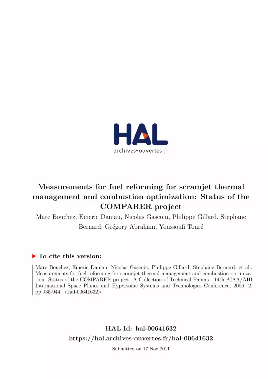
This computation illustrates how the considered
channel is far away from a perfectly stired reactor.
The C12H26 and CH4 computed fractions are quite
unchanged during the “cooling” part of the flow in
the oven.
American Institute of Aeronautics and Astronautics
6
0
0,1
0,2
0,3
0,4
0,5
0,6
0,7
0,8
0,9
1
0 0,1 0,2 0,3 0,4 0,5 0,6 0,7 0,8 0,9 1
Position along the chemical reactor (m)
n-C
12
H2
6 M
ass F
ractio
n
0
0,002
0,004
0,006
0,008
0,01
0,012
0,014
CH
4 M
ass F
ractio
n
n-C12H26 CH4
Figure 9 : computed C12H26 and CH4 in the tube in
the oven
D. Synthesis of the COMPARER
test bench capability
The COMPARER test bench has been running
since mid- 2005. Some adaptations of the test bench
have increase the knowledge of transient changes on
a chemical and cooling aspect (automatic pressure
regulation and mass flow meter have been
implemented available since May 2006).
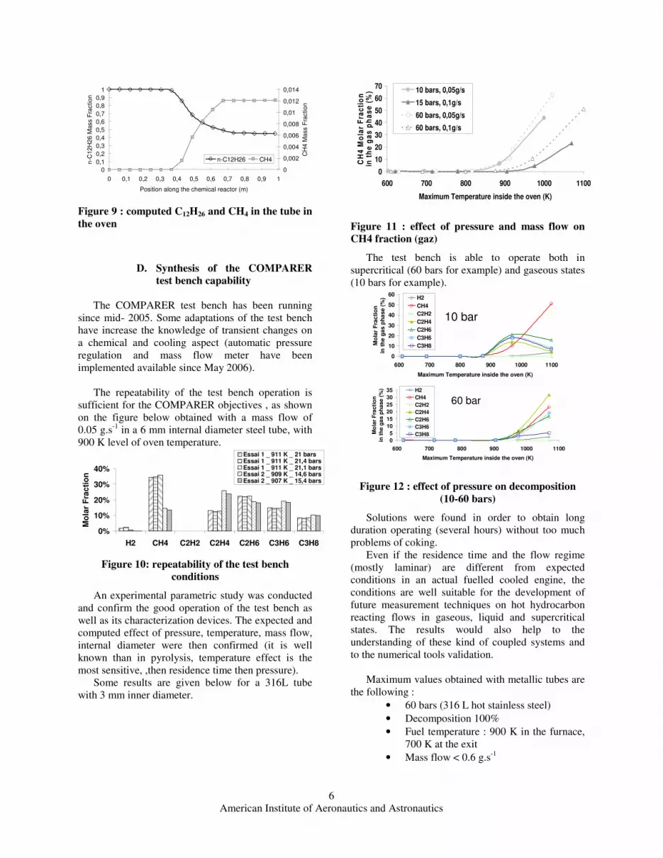
The repeatability of the test bench operation is
sufficient for the COMPARER objectives , as shown
on the figure below obtained with a mass flow of
0.05 g.s-1
in a 6 mm internal diameter steel tube, with
900 K level of oven temperature.
0%
10%
20%
30%
40%
H2 CH4 C2H2 C2H4 C2H6 C3H6 C3H8
Mo
lar
Fra
cti
on
Essai 1 _ 911 K _ 21 barsEssai 1 _ 911 K _ 21,4 barsEssai 1 _ 911 K _ 21,1 barsEssai 2 _ 909 K _ 14,6 barsEssai 2 _ 907 K _ 15,4 bars
Figure 10: repeatability of the test bench
conditions
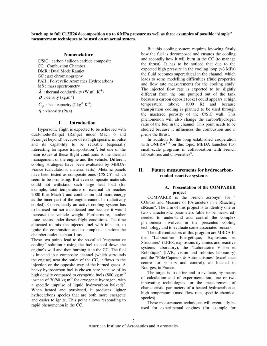
An experimental parametric study was conducted
and confirm the good operation of the test bench as
well as its characterization devices. The expected and
computed effect of pressure, temperature, mass flow,
internal diameter were then confirmed (it is well
known than in pyrolysis, temperature effect is the
most sensitive, ,then residence time then pressure).
Some results are given below for a 316L tube
with 3 mm inner diameter.
0
10
20
30
40
50
60
70
600 700 800 900 1000 1100
Maximum Temperature inside the oven (K)
CH
4 M
ola
r F
rac
tio
nin
th
e g
as
ph
as
e (
%) 10 bars, 0,05g/s
15 bars, 0,1g/s
60 bars, 0,05g/s
60 bars, 0,1g/s
Figure 11 : effect of pressure and mass flow on
CH4 fraction (gaz)
The test bench is able to operate both in
supercritical (60 bars for example) and gaseous states
(10 bars for example).
0
10
20
30
40
50
60
600 700 800 900 1000 1100
Maximum Temperature inside the oven (K)M
ola
r F
rac
tio
n
in t
he
ga
s p
ha
se
(%
) H2
CH4
C2H2
C2H4
C2H6
C3H6
C3H8
10 bar
60 bar
0
5
10
15
20
25
30
35
600 700 800 900 1000 1100
Maximum Temperature inside the oven (K)
Mo
lar
Fra
cti
on
in t
he g
as p
ha
se
(%
) H2
CH4
C2H2
C2H4
C2H6
C3H6
C3H8
Figure 12 : effect of pressure on decomposition
(10-60 bars)
Solutions were found in order to obtain long
duration operating (several hours) without too much
problems of coking.
Even if the residence time and the flow regime
(mostly laminar) are different from expected
conditions in an actual fuelled cooled engine, the
conditions are well suitable for the development of
future measurement techniques on hot hydrocarbon
reacting flows in gaseous, liquid and supercritical
states. The results would also help to the
understanding of these kind of coupled systems and
to the numerical tools validation.
Maximum values obtained with metallic tubes are
the following :
• 60 bars (316 L hot stainless steel)
• Decomposition 100%
• Fuel temperature : 900 K in the furnace,
700 K at the exit
• Mass flow < 0.6 g.s-1

American Institute of Aeronautics and Astronautics
7
• Typical time residence : less than 100
seconds.
The future use of C/Sic tube will allow to reach
higher level of temperature (maximum oven
temperature is 1600°C).
IV. Investigation of possible operational
measurement techniques
A. Introduction
As previously mentioned, the COMPARER
project aims to investigate some measurements
techniques that could be used for quick analysis of an
actual complex system, on ground or in flight.
The possible techniques are first evaluated by
computations, with the existing models. If they
appear interesting, the COMPARER test bench is
used to evaluate them experimentally.
investigated by computations then in the « measurement bloc »
Oven (1600°C maxi)
→ hydrocarbon → Burner
Oven (1600°C maxi)
→ hydrocarbon → Burner
Innovative measurements
Figure 13 : principle of test of "innovative
instrumentation" on COMPARER
The “measurement bloc” is a modular stainless
steel system with thermocouples, optical or
mechanical access.
It can be isolated from external natural cooling or
temperature-stabilized thanks to heating wires.
Figure 14 : CAD view of "measurement bloc"
Figure 15 : IR view of measurement bloc during
test
B. Predicting the fuel burning
capability
Giving the fact that temperature is the first
parameter governing the decomposition of
hydrocarbons fuel, this parameter could be sufficient
to know the pyrolysed mixture composition before
injection in the combustion chamber. But to control
the scramjet in terms of thrust, it is needed to predict
how the injected fuel can burn. A criterion has to be
found to represent the capacity for the mixture to
burn. The inflammation delay could be chosen
although other criteria like the fundamental flame
velocity or the activation energy are of great interest.
It can be chosen that the ignition delay should not be
greater than 0.1 ms. It corresponds roughly to a tenth
of the combustion chamber length as it is confirmed
in the literature13
.
Some preliminary work , with available models,
has been performed in order to give a proposal for
defining a “burning capability index” of the
decomposed fuel6.
As an example, Figure 1 shows the different
species mole fraction in a cooling channel. As some
species are more able to burn than others, it is
interesting to determine an "ideal" composition which
could respond to the chosen criterion of 0.1 ms.
Davidenko et al.14
estimates that a 20 % in mass of
hydrogen is needed in a binary mixture of methane
and hydrogen for the combustion in scramjet. It
should be reminded that hydrogen – air mixtures
typically exhibit the smallest ignition delay of all
gaseous hydrocarbons and that methane – air
mixtures, on the other hand, exhibit the longest
ignition delay. It is too early to surely associate a
criterion to control an actual regeneratively-cooled
hydrocarbon-fueled DMR, but this analyses allows to
identify some relationship between the composition
or the characteristics (physical, optical, chemical,
electrical, ...) of the decomposed fuel and its general
capability to burn easily.

American Institute of Aeronautics and Astronautics
8
After a review of the possible measurement
methods, passive IR spectroscopy was selected as one
of the promising and usable ways.
Some computations of the fuel IR spectrum, as a
function of the fuel temperature and composition,
have been done with the HITRAN software15
. This
data bank was used out of its nominal validation :
further spectrum measurement have to be done by
specialized team on COMPARER test bench to check
the actual spectra of decomposed hydrocarbons at
high temperature and pressure, including in
supercritical state and with possible heterogeneity.
These HITRAN computations were compared
with the laminar flames and ignition delay SENKIN
computations. • Luminance of hot fluids at
given wavelength …• Ignition delay
• Premix flame.
HITRAN 1996 computations CHEMKIN computations
0
2
4
6
8
10
12
14
16
18
20
Vit
esse lam
inair
e d
e f
lam
me d
e p
rém
éla
ng
e
(cm
/s)
0
0,2
0,4
0,6
0,8
1
1,2
1,4
1,6
1,8
2
Haute
ur
de fla
mm
e d
e p
rém
éla
nge (cm
)
BurnerBurner
0,0E+00
5,0E-05
1,0E-04
1,5E-04
2,0E-04
2,5E-04
3,0E-04
3,5E-04
4,0E-04
4,5E-04
100 1000 10000
Nombre d'onde (cm-1)
Lu
min
an
ce
CH4
Figure 16 : preliminary computations of IR signal
and possible correlation with combustion index
This theoretical preliminary work enable us to
identify some interesting wavelengths. For example,
one is located at 4170 cm-1
and its intensity is directly
related to the methane mole fraction inside the
mixture (Figure 17).
3,00E-04
4,00E-04
5,00E-04
6,00E-04
7,00E-04
8,00E-04
9,00E-04
1,00E-03
1,10E-03
0,2 0,3 0,4 0,5 0,6 0,7 0,8 0,9 1
CH4 Mole fraction
Lu
min
an
ce
(W
.m-2
.sr-1
)
CH4 + C2H6 - 1200K CH4 + C2H6 - 1500K CH4 + C2H2 - 1200K
Figure 17. intensity of the 4170 cm-1
wavelength
as a function of the temperature and the CH4 mole
fraction.
The COMPARER test bench is a useful tool for
testing the application of narrow-band, real-time IR
spectroscopy to fuel analysis for engine control.
Preliminary measurement have been done in 2006
with the LEEE laboratory from Paris X university.
Spectra obtained with through the optical access of
the “measurement bloc” with heated gases and
dodecane are currently under analysis.
C. Possible use of sonic throat to
measure the mass flow of
decomposed hydrocarbon Using the large amount of computations realized
for various heating processes in generic actual
engines or in the COMPARER test bench, a
computational analysis of the behaviour of the
decomposed fuel in sonic conditions has been
performed.
An example is given below, with the mass flow
through a 1 mm² sonic throat given as a function of
the decomposed C12H26 temperature (pressure is
3.5 MPa).
0
2
4
6
8
10
12
14
600 800 1000 1200 1400 1600
Fluid Temperature (K)
q/A
* (g
.mm
-2.s
-1)
Reference Engine (2.2m, 65g/s) Reference Engine (2.2m_60g/s)
e8mm0,1g1200mm1600C ent40mm1g1500K
Moteur de référence (1,1m) ent8mm0.1g900mm1600Cent8mm0.05g1200mm1600C tp2mm0.2g1200mm1600C
Figure 18 : computed mass flow through a sonic
throat
The sonic throat seems to be a valuable solution.
A sonic throat implementation has been prepared
on the measurement bloc, but the corresponding
diameter is so small with the COMPARER current
mass flow that this point has not been yet
experimented.
Figure 19 : sonic throat implementation in the
measurement bloc
D. Relationship between
gazeification and decomposition
rate Two important parameters are used to give a
general view of the decomposition process in such an
experiment.

American Institute of Aeronautics and Astronautics
9
The (molar) decomposition rate is the ratio
between the part of initial fluid (here C12H26) that as
been decomposed and its initial amount.
The (mass) gazeification rate is the ratio between
the mass of gas products and the initial mass of fluid
(C12H26 here).
The COMPARER experiments gives immediately
the gazeification rate, by comparing the mass flows
of gases, of liquids after the water-coled heat
exchanger and the pumped mass flow (if any leakage
in case of porous reactor tube). In order to quickly
obtain an estimation of the decomposition level, a
theoretical relationship between these two rates was
computed at MBDA-France, using the detailed
pyrolysis mechanisms of C12H26. It was done in a 0D
static numerical reactor, for fixed arrays of pressure,
temperature and residence time.
0,00
0,10
0,20
0,30
0,40
0,50
0,60
0,70
0,80
0,90
1,00
0,00 0,10 0,20 0,30 0,40 0,50 0,60 0,70
Mass gazeification rate
Mo
lar
déco
mp
os
itio
n r
ate
Temperature : 800 - 1200 K
Residence Time : 1e-5 - 5 s
Pressure : 2,0 ; 3,5 et 8,0 MPa
Figure 20 : theoretical relationship between
gazeification and decomposition
The complete set of data obtained during
COMPARER test bench first campaigns during the
parametric study was analyzed in the same way.
Some of the measures (referred as “experiment 2” in
the Figure 21) are close to the “theoretical” curve,
while others (referred as “experiment 1”) show more
linear relationship.
0%
20%
40%
60%
80%
100%
0% 10% 20% 30% 40% 50% 60% 70% 80% 90% 100
%
Mass gazeification rate
Mo
lar
pyro
lysis
rate
Série21
Experiment_1
Experiment_2
Numérical
Figure 21 : experimental relationship between
gazeification and decomposition
Analysis of these differences is currently done,
using the associate 1D thermal-chemical modeling.
Nevertheless, this technique seems to be a simple
way to characterize without detailed sampling with
GC/MS of the heated hydrocarbon on an
experimental engine, particularly in case of “open-
loop” cooled structures experimental checking.
V. Conclusion
The COMPARER project focused on the
characterization of hot fuel associated to the unsteady
behavior of a cooling loop.
Some promising measurement are under further
analysis. A small but complete specific test bench is
now operational for the testing of those methods.
The first experimental results are quite promising.
Among the different “innovative” measurement
systems, three were discussed in the present paper :
• Use of the gazeification level to estimate the
decomposition rate.
• Use of a sonic throat for the hot decomposed
fuel to measure its mass flow.
• IR spectroscopy to qualify its burning
capability.
Besides these applications, the COMPARER project
gives the opportunity to increase the scientific data
and enhance the cooperation at scientific level on
several dedicated topics with other laboratories or
research institutes.
COMPARER-1 finished its 3 years, the second phase
COMPARER-2 begins in October 2006, also for 3
years.
Acknowledgments
The authors want to thank for their contribution F.
Falempin, E. Jennequin from MBDA-France, X.
Rocourt and J.-C. Hargé from University.
The present work has been realised with the
contribution of the "Conseil Général du Cher (18)",
of the "Conseil Régional du Centre", of the FRED, of
the FEDER, of the FSE (European Union) and of
MBDA-France. The good evolution of the
COMPARER project was made possible thanks to
the contribution of Mr. Yves Parmantier, person in
charge of the project and coordinator of the "Pôle
Capteurs et Automatismes" of Bourges, which carried
the project phases until their effective beginning.
References
1 F. Falempin, D. Scherrer, G. Laruelle, Ph. Rostand,
G. Fratacci, J.L.Schultz, "French hypersonic
propulsion program PREPHA -results, lessons &

American Institute of Aeronautics and Astronautics
10
perspectives", AIAA - 98 - 1565 – Norfolk, November
1998. 2 Bouchez, M., and Beyer, S., "PTAH-SOCAR fuel
cooled composite material structure for dual mode
ramjet and liquid rocket engine – 2005 status", AIAA-
2005-3434. 3 Giraudot, T., Massot, A., Boselli, L., and Talbot, B.,
"Dual-fueled advanced high-speed ramjets : students
paper", AIAA-2002-5214, Orléans, France, October
2002. 4 Serre, L., Falempin, F., "PROMETHEE : The
French military hypersonic propulsion Program",
AIAA-2002-5141. 5 Daniau, E., and Sicard, M., " Experimental and
numerical investigations of an endothermic fuel
cooling capacity for scramjet application ", AIAA-
2005-. 6 Daniau, E. , Bouchez, M. Herbinet, O., Marquaire,
P.M., Gascoin, N., Gillard, P., « Fuel reforming for
scramjet thermal management and combustion
optimization”, AIAA-2005-3403. 7 Daniau, E., Bouchez, M., and Gascoin, N.,
"Scramjet Active Cooling Analysis Using n-
Dodecane as a Generic Endothermic Fuel",
Thermochemical Processes in Plasma Aerodynamics,
12-14 July 2004, St Petersburg, Russia. 8 Ser, F., Heinrich, B., Luc-Bouhali, A., "Carburants
liquides endothermiques : problématique du
refroidissement et projet d’études expérimentales à
l’ONERA", AAAF – Arcachon, France – March
2001. 9 Dahm, K.D., Virk, P.S., Bounaceur, R., Battin-
Leclerc, F., Marquaire, P.M., Fournet, R., Daniau, E.,
and Bouchez, M., "Experimental and modeling
investigation of the thermal decomposition of n-
dodecane", Journal of Analytical and Applied
Pyrolysis, 71 (2004) pp865-881. 10
Gascoin, N. Gillard, P., Touré Y., Bernard, S.,
Daniau, E., Bouchez, M., 21 Octobre 2004, "Mesures
et contrôle de paramètres pertinents pour la
régulation d'un statoréacteur mixte refroidi",
Troisième Rencontre Capteurs (Bourges). 11
Dufour, E., Bouchez, M., "Semi-empirical and
CFD analysis of actively cooled dual-mode ramjets",
AIAA-2002-5126, Orléans, France. 12
N. Gascoin, P. Gillard, S. Bernard, Y. Touré, E.
Daniau, E. Dufour, M. Bouchez, "Transient
Numerical Model of Scramjet Active Cooling,
Application to an Experimental Bench", 4th
International Energy Conversion Engineering
Conference and Exhibit (IECEC), 26-29 June 2006,
San Diego, USA 13
Buriko, Y., Vinogradov, V., Goltsev, V., Waltrup,
P.J., "Influence of Active Radical Concentration on
Self-Ignition Delay of a Propane/Air Mixture", AIAA
2001-3958 (2001). 14
Davidenko, D., Gökalp, I., Dufour, E., (2002)
"Kinetic mechanism validation and numerical
simulation of hypersonic combustion of methane-
hydrogen fuel", AIAA 2002-5207. 15
Rothman L. S. et al., "The Hitran Molecular
Spectroscopic Database And Hawks (Hitran
Atmospheric Workstation): 1996 Edition", J. Quant.
Spectrosc. Radiat. Transfer, Vol. 60, No. 5, (1998)
665-710.