Embed Size (px)
Citation preview


Mechanical Engineering Principles
Second Edition
Why are competent engineers so vital?
Engineering is among the most important of all professions. It is the authors’ opinions that engineers save more lives than medical doctors (physicians). For example, poor water or the lack of it, is the second largest cause of human death in the world, and if engineers are given the tools, they can solve this problem. The largest cause of human death is caused by the malarial mosquito, and even death due to malaria can be decreased by engineers - by providing helicopters for spraying areas infected by the mosquito and making and designing medical syringes and pills to protect people against catching all sorts of diseases. Most medicines are produced by engineers! How does the engineer put 1 mg of ‘medicine’ precisely and individually into millions of pills, at an affordable price?
Moreover, one of the biggest contributions by humankind was the design of the agricultural tractor, which was designed and built by engineers to increase food production many-fold for a human population which more-or-less quadruples every century! It is also interesting to note that the richest countries in the world are very heavily industrialised. Engineers create wealth! Most other professions don’t!
Even in blue sky projects, engineers play a major role. For example, most rocket scientists are chartered engineers or their equivalents and Americans call their Chartered Engineers (and their equivalents), scientists. Astronomers are space scientists and not rocket scientists; they could not design a rocket to conquer outer space. Even modern theoretical physicists are mainly interested in astronomy and cosmology and also nuclear science. In general a theoretical physicist cannot, without special training, design a submarine structure to dive to the bottom of the Mariana Trench, which is 11.52 km or 7.16 miles deep, or design a very long bridge, a tall city skyscraper or a rocket to conquer outer space.
This book presents a solid foundation for the reader in mechanical engineering principles, on which s/he can safely build tall buildings and long bridges that may last for a thousand years or more. It is the authors’ experience that it is most unwise to attempt to build such structures on shaky foundations; they may come tumbling down - with disastrous consequences.
John O. Bird is the former Head of Applied Electronics in the Faculty of Technology at Highbury College, Portsmouth, U.K. More recently, he has combined freelance lecturing at the University of Portsmouth, with Examiner responsibilities for Advanced Mathematics with City & Guilds, and examining for the International Baccalaureate Organisation. He is the author of some 120 textbooks on engineering and mathematical subjects with worldwide sales approaching 1 million copies. He is currently a Senior Training Provider at the Royal Naval School of Marine Engineering in the Defence College of Marine and Air Engineering at H.M.S. Sultan, Gosport, Hampshire, U.K.
Carl T. F. Ross gained his fi rst degree in Naval Architecture, from King’s College, Durham University; his PhD in Structural Engineering from the Victoria University of Manchester; and was awarded his DSc in Ocean Engineering from the CNAA, London. His research in the fi eld of engineering led to advances in the design of submarine pressure hulls. His publications to date exceed some 270 papers and books and he is Professor of Structural Dynamics at the University of Portsmouth, U.K.
See Carl Ross’s website below, which has an enormous content on science, technology and education. http://homepage.ntlworld.com/carl.ross/page3.htm


Mechanical Engineering Principles
Second Edition
John O. Bird, BSc(Hons), CEng, CMath, CSci, FIMA, FITE, FCollTCarl T. F. Ross, BSc(Hons), PhD, DSc, CEng, FRINA, MSNAME

Second edition published 2012by Routledge2 Park Square, Milton Park, Abingdon, Oxon OX14 4RN
Simultaneously published in the USA and Canadaby Routledge711 Third Avenue, New York, NY 10017
Routledge is an imprint of the Taylor & Francis Group, an informa business
© 2012 John O. Bird and Carl T. F. Ross
The right of John O. Bird and Carl T. F. Ross to be identified as authors of this work has been asserted by them in accordance with sections 77 and 78 of the Copyright, Designs and Patents Act 1988.
All rights reserved. No part of this book may be reprinted or reproduced or utilised in any form or by any electronic, mechanical, or other means, now known or hereafter invented, including photocopying and recording, or in any information storage or retrieval system, without permission in writing from the publishers.
This publication presents material of a broad scope and applicability. Despite stringent efforts by all concerned in the publishing process, some typographical or editorial errors may occur, and readers are encouraged to bring these to our attention where they represent errors of substance. The publisher and author disclaim any liability, in whole or in part, arising from information contained in this publication. The reader is urged to consult with an appropriate licensed professional prior to taking any action or making any interpretation that is within the realm of a licensed professional practice.
First edition published by Elsevier in 2002
Trademark notice: Product or corporate names may be trademarks or registered trademarks, and are used only for identification and explanation without intent to infringe.
British Library Cataloguing in Publication DataA catalogue record for this book is available from the British Library
Library of Congress Cataloguing in Publication DataA catalog record for this title has been requested
ISBN: 9780415517850 (pbk)ISBN: 9780203121146 (ebk)
Typeset in Timesby RefineCatch Limited, Bungay, Suffolk

Contents
Preface ix
Part One Revision of Mathematics 1
1 Revisionary Mathematics 31.1 Introduction 31.2 Radians and degrees 31.3 Measurement of angles 41.4 Triangle calculations 51.5 Brackets 71.6 Fractions 81.7 Percentages 91.8 Laws of indices 111.9 Simultaneous equations 14
Revision Test 1 Revisionary mathematics 18
Part Two Statics and Strength of Materials 21
2 The effects of forces on materials 232.1 Introduction 232.2 Tensile force 242.3 Compressive force 242.4 Shear force 242.5 Stress 242.6 Strain 252.7 Elasticity, limit of proportionality
and elastic limit 272.8 Hooke’s law 282.9 Ductility, brittleness and malleability 322.10 Modulus of rigidity 322.11 Thermal strain 332.12 Compound bars 33
3 Tensile testing 393.1 The tensile test 393.2 Worked problems on tensile testing 403.3 Further worked problems on
tensile testing 423.4 Proof stress 44
4 Forces acting at a point 464.1 Scalar and vector quantities 464.2 Centre of gravity and equilibrium 46
4.3 Forces 474.4 The resultant of two coplanar forces 484.5 Triangle of forces method 484.6 The parallelogram of forces method 504.7 Resultant of coplanar forces by
calculation 504.8 Resultant of more than two
coplanar forces 514.9 Coplanar forces in equilibrium 534.10 Resolution of forces 544.11 Summary 58
5 Simply supported beams 615.1 The moment of a force 615.2 Equilibrium and the principle of
moments 625.3 Simply supported beams
having point loads 645.4 Simply supported beams with couples 68
Revision Test 2 Forces, tensile testing and beams 72
6 Forces in structures 736.1 Introduction 736.2 Worked problems on mechanisms
and pin-jointed trusses 746.3 Graphical method 756.4 Method of joints
(a mathematical method) 796.5 The method of sections
(a mathematical method) 84
7 Bending moment and shear force diagrams 877.1 Bending moment (M) 877.2 Shearing force (F) 877.3 Worked problems on bending
moment and shearing force diagrams 887.4 Uniformly distributed loads 97
8 First and second moments of areas 1028.1 Centroids 1028.2 The first moment of area 1028.3 Centroid of area between a curve
and the x-axis 1038.4 Centroid of area between a
curve and the y-axis 103

vi Contents
8.5 Worked problems on centroids of simple shapes 104
8.6 Further worked problems on centroids of simple shapes 105
8.7 Second moments of area of regular sections 106
8.8 Second moment of area for ‘built-up’ sections 113
Revision Test 3 Forces in structures, bending moment and shear force diagrams, and second moments of area 119
9 Bending of beams 1209.1 Introduction 120
9.2 To prove that s = =M Ey I R
121
9.3 Worked problems on the bending of beams 122
10 Torque 12610.1 Couple and torque 12610.2 Work done and power transmitted
by a constant torque 12710.3 Kinetic energy and moment of inertia 12910.4 Power transmission and efficiency 132
11 Twisting of shafts 136
11.1 To prove that t θ= =T Gr J L
136
11.2 Worked problems on the twisting of shafts 138
Revision Test 4 Bending of beams, torque and twisting of shafts 142
Part Three Dynamics 143
12 Linear and angular motion 14512.1 The radian 14512.2 Linear and angular velocity 14512.3 Linear and angular acceleration 14712.4 Further equations of motion 14812.5 Relative velocity 150
13 Linear momentum and impulse 15413.1 Linear momentum 15413.2 Impulse and impulsive forces 157
14 Force, mass and acceleration 16214.1 Introduction 16214.2 Newton’s laws of motion 16314.3 Centripetal acceleration 165
14.4 Rotation of a rigid body about a fixed axis 16714.5 Moment of inertia (I) 167
15 Work, energy and power 17015.1 Work 17015.2 Energy 17415.3 Power 17515.4 Potential and kinetic energy 17815.5 Kinetic energy of rotation 181
Revision Test 5 Linear and angular motion, momentum and impulse, force, mass and acceleration, work, energy and power 184
16 Friction 18516.1 Introduction to friction 18516.2 Coefficient of friction 18616.3 Applications of friction 18716.4 Friction on an inclined plane 18816.5 Motion up a plane with the pulling
force P parallel to the plane 18816.6 Motion down a plane with the
pulling force P parallel to the plane 18916.7 Motion up a plane due to a horizontal
force P 18916.8 The efficiency of a screw jack 192
17 Motion in a circle 19617.1 Introduction 19617.2 Motion on a curved banked track 19817.3 Conical pendulum 19917.4 Motion in a vertical circle 20117.5 Centrifugal clutch 203
18 Simple harmonic motion 20518.1 Introduction to simple
harmonic motion (SHM) 20518.2 The spring-mass system 20618.3 The simple pendulum 20818.4 The compound pendulum 20918.5 Torsional vibrations 210
19 Simple machines 21219.1 Machines 21219.2 Force ratio, movement ratio and efficiency 21219.3 Pulleys 21419.4 The screw-jack 21619.5 Gear trains 21619.6 Levers 218
Revision Test 6 Friction, motion in a circle, simple harmonic motion and
simple machines 222

Contents vii
Part Four Heat Transfer and Fluid Mechanics 223
20 Heat energy and transfer 22520.1 Introduction 22520.2 The measurement of temperature 22620.3 Specific heat capacity 22620.4 Change of state 22820.5 Latent heats of fusion and vaporisation 22920.6 A simple refrigerator 23120.7 Conduction, convection and radiation 23120.8 Vacuum flask 23220.9 Use of insulation in conserving fuel 232
21 Thermal expansion 23521.1 Introduction 23521.2 Practical applications of
thermal expansion 23521.3 Expansion and contraction of water 23621.4 Coefficient of linear expansion 23621.5 Coefficient of superficial expansion 23821.6 Coefficient of cubic expansion 239
Revision Test 7 Heat energy and transfer, and thermal expansion 243
22 Hydrostatics 24422.1 Pressure 24422.2 Fluid pressure 24522.3 Atmospheric pressure 24722.4 Archimedes’ principle 24822.5 Measurement of pressure 24922.6 Barometers 24922.7 Absolute and gauge pressure 25122.8 The manometer 25222.9 The Bourdon pressure gauge 25322.10 Vacuum gauges 25322.11 Hydrostatic pressure on
submerged surfaces 25422.12 Hydrostatic thrust on curved surfaces 25522.13 Buoyancy 25522.14 The stability of floating bodies 255
23 Fluidflow 26123.1 Differential pressure flowmeters 26123.2 Orifice plate 26223.3 Venturi tube 262
23.4 Flow nozzle 26323.5 Pitot-static tube 26323.6 Mechanical flowmeters 26423.7 Deflecting vane flowmeter 26423.8 Turbine type meters 26423.9 Float and tapered-tube meter 26523.10 Electromagnetic flowmeter 26623.11 Hot-wire anemometer 26623.12 Choice of flowmeter 26723.13 Equation of continuity 26723.14 Bernoulli’s equation 26723.15 Impact of a jet on a stationary plate 269
24 Ideal gas laws 27224.1 Boyle’s law 27224.2 Charles’ law 27324.3 The pressure law 27424.4 Dalton’s law of partial pressure 27524.5 Characteristic gas equation 27524.6 Worked problems on the
characteristic gas equation 27524.7 Further worked problems on the
characteristic gas equation 277
25 The measurement of temperature 28125.1 Liquid-in-glass thermometer 28125.2 Thermocouples 28225.3 Resistance thermometers 28425.4 Thermistors 28625.5 Pyrometers 28625.6 Temperature indicating paints
and crayons 28725.7 Bimetallic thermometers 28825.8 Mercury-in-steel thermometer 28825.9 Gas thermometers 28825.10 Choice of measuring devices 288
RevisionTest8 Hydrostatics,fluidflow, gas laws and temperature measurement 290
A list of formulae for mechanical engineering principles 291
Greek alphabet 296
Answers to multiple-choice questions 297
Index 299


Preface
Mechanical Engineering Principles 2nd Edition aims to broaden the reader’s knowledge of the basic principles that are fundamental to mechanical engineering design and the operation of mechanical systems.
Modern engineering systems and products still rely upon static and dynamic principles to make them work. Even systems that appear to be entirely electronic have a physical presence governed by the principles of statics.
In this second edition of Mechanical Engineering Principles, a chapter has been added on revisionary mathematics; it is not possible to progress in engineering studies without a reasonable knowledge of mathematics, a fact that soon becomes obvious to both students and teachers alike. It is therefore hoped that this chapter on basic mathematics revision will be helpful and make the engineering studies more comprehensible. Minor modifications and some further worked problems have also been added throughout the text.
Free Internet downloads of full solutions to the fur-ther problems and a PowerPoint presentation of all the illustrations contained in the text is available – see page x.
For clarity, the text is divided into four parts, these being:
Part 1 Revision of MathematicsPart 2 Statics and strength of materials Part 3 Dynamics Part4 Heattransferandfluidmechanics
Mechanical Engineering Principles 2nd Edition is suitable for the following:
(i) National Certificate/Diploma courses inMechanical Engineering
(ii) Undergraduate courses in Mechanical, Civil, Structural, Aeronautical & Marine Engineering, together with Naval Architecture
(iii) Any introductory/access/foundation course involving Mechanical Engineering Principles at University, and Colleges of Further and Higher education.
Although pre-requisites for the modules covered in this book include Foundation Certificate/ diploma, or similar, in Mathematics and Science, each topic considered in the text is presented in a way that assumes that the reader has little previous knowledge of that topic.
Mechanical Engineering Principles 2nd Edition contains over 325 worked problems, followed by over 550 further problems (all with answers). The further problems are contained within some 140 Exercises; each Exercise follows on directly from the relevant section of work, every few pages. In addition, the text contains 276 multiple-choice questions (all with answers), and 260 short answer questions, the answers for which can be determined from the preceding material in that particular chapter. Where at all possible, the problems mirror practical situations found in mechanical engineering. 371 line diagrams enhance the understanding of the theory.
At regular intervals throughout the text are some 8 Revision Tests to check understanding. For example, Revision Test 1 covers material contained in Chapter 1, Test 2 covers the material in Chapters 2 to 5, and so on. No answers are given for the questions in the Revision Tests, but a Lecturer’s guide has been produced giving full solutions and suggested marking scheme. The guide is offered online free to lecturer’s/instructor’s – see below.
At the end of the text, a list of relevant formulae is included for easy reference.
‘Learning by Example’ is at the heart of Mechanical Engineering Principles, 2nd Edition.
JOHN BIRD Royal Naval School of Marine Engineering,
HMS Sultan, formerly University of Portsmouth and Highbury
College, Portsmouth CARL ROSS Professor, University of Portsmouth

x Preface
Free web downloads available to lecturers/instructors only at www.routledge.com/cw/bird
Worked Solutions to Exercises
Within the text are some 550 further problems arranged within 140 Exercises; all 550 worked solutions have been prepared.
Instructor’s manual
This provides full worked solutions and mark scheme for all 8 Revision Tests in this book.
Illustrations
Lecturers can download electronic files for all 371 illustrations in this second edition.

Revision of MathematicsPart One


Chapter 1
Revisionary mathematics
Mechanical Engineering Principles, Bird and Ross, ISBN 9780415517850
Mathematics is a vital tool for professional and chartered engineers. It is used in mechanical & manufacturing engineering, in electrical & electronic engineering, in civil & structural engineering, in naval architecture & marine engineering and in aeronautical & rocket engineering. In these various branches of engineering, it is very often much cheaper and safer to design your artefact with the aid of mathematics - rather than through guesswork. ‘Guesswork’ may be reasonably satisfactory if you are designing an artefact similar to one that has already proven satisfactory; however, the classification societieswillusually require you to provide the calculations proving that the artefact is safe and sound. Moreover, these calculations may not be readily available to you and you may have to provide fresh calculations, to prove that your artefact is ‘roadworthy’. For example, if you design a tall building or a long bridge by ‘guesswork’, and the building or bridge do not prove to be structurally reliable, it could cost you a fortune to rectifythedeficiencies.Thiscostmaydwarftheinitialestimate you made to construct these artefacts, and cause you to go bankrupt. Thus, without mathematics, the prospective professional or chartered engineer is very severely handicapped.
1.1 Introduction
As highlighted above, it is not possible to understand aspects of mechanical engineering without a good knowledge of mathematics. This chapter highlights some areas of mathematics which will make the understanding of the engineering in the following chapters a little easier.
1.2 Radians and degrees
There are 2π radians or 360° in a complete circle, thus:
π radians = 180° from which,
1 rad =180π°
or 1° =π
180 rad
where π = 3.14159265358979323846 .... to 20 decimal places!
Problem 1. Convert the following angles to degrees correct to 3 decimal places:(a) 0.1 rad (b) 0.2 rad (c) 0.3 rad
(a) 0.1 rad = 0.1 rad × 180radπ° = 5.730°
(b) 0.2 rad = 0.2 rad × 180radπ° = 11.459°
At the end of this chapter you should be able to:
• convert radians to degrees• convert degrees to radians• calculate sine, cosine and tangent for large and
small angles• calculate the sides of a right-angled triangle• use Pythagoras’ theorem• use the sine and cosine rules for acute-angled
triangles• expand equations containing brackets• be familiar with summing vulgar fractions
• understand and perform calculations with per-centages
• understand and use the laws of indices• solve simple simultaneous equations

4 Mechanical Engineering Principles
Part
One (c) 0.3 rad = 0.3 rad ×
180radπ°
= 17.189°
Problem 2. Convert the following angles to radians correct to 4 decimal places:(a) 5° (b) 10° (c) 30°
(a) 5° = 5° × rad180 36π π=° rad = 0.0873 rad
(b) 10° = 10° × rad180 18π π=° rad = 0.1745 rad
(c) 30° = 30° × rad180 6π π=° rad = 0.5236 rad
Now try the following Practise Exercise
Practise Exercise 1 Radians and degrees
1. Convert the following angles to degrees correct to 3 decimal places (where necessary):(a) 0.6 rad (b) 0.8 rad(c) 2 rad (d) 3.14159 rad
[(a) 34.377° (b) 45.837° (c) 114.592° (d) 180°]
2. Convert the following angles to radians correct to 4 decimal places:(a) 45° (b) 90°(c) 120° (d) 180°
[(a) 4π rad or 0.7854 rad
(b) 2π rad or 1.5708 rad
(c) 23π rad or 2.0944 rad
(d) π rad or 3.1416 rad ]
1.3 Measurement of angles
Angles are measured starting from the horizontal ‘x’ axis, in an anticlockwise direction, as shown by θ1 to θ4 in Figure 1.1. An angle can also be measured in a clockwise direction, as shown by θ5 in Figure 1.1, but in this case the angle has a negative sign before it. If, for example, θ4 = 300° then θ5 = – 60°.
Figure 1.1
Problem 3. Use a calculator to determine the cosine, sine and tangent of the following angles, each measured anticlockwise from the horizontal ‘x’ axis, each correct to 4 decimal places:(a) 30° (b) 120° (c) 250° (d) 320° (e) 390° (f) 480°
(a) cos 30° = 0.8660 sin 30° = 0.5000 tan 30° = 0.5774
(b) cos 120° = – 0.5000 sin 120° = 0.8660 tan 120° = – 1.7321
(c) cos 250° = – 0.3420 sin 250° = – 0.9397 tan 250° = 2.7475
(d) cos 320° = 0.7660 sin 320° = – 0.6428 tan 320° = – 0.8391
(e) cos 390° = 0.8660 sin 390° = 0.5000 tan 390° = 0.5774
(f) cos 480° = – 0.5000 sin 480° = 0.8660 tan 480° = – 1.7321
These angles are now drawn in Figure 1.2. Note that cosine and sine always lie between –1 and +1 but that tangent can be >1 and <1.
Figure 1.2

Revisionary mathematics 5
Part
OneNote from Figure 1.2 that θ = 30º is the same as
θ = 390º and so are their cosines, sines and tangents. Similarly, note that θ = 120º is the same as θ = 480º and so are their cosines, sines and tangents. Also, note that θ = – 40º is the same as θ = + 320º and so are their cosines, sines and tangents.
It is noted from above that
• in the firstquadrant, i.e. where θ varies from 0º to 90º, all (A) values of cosine, sine and tangent are positive
• in the second quadrant, i.e. where θ varies from 90º to 180º, only values of sine (S) are positive
• in the third quadrant, i.e. where θ varies from 180º to 270º, only values of tangent (T) are positive
• in the fourth quadrant, i.e. where θ varies from 270º to 360º, only values of cosine (C) are positive
These positive signs, A, S, T and C are shown in Figure 1.3.
Figure 1.3
Now try the following Practise Exercise
Practise Exercise 2 Measurement of angles
1. Find the cosine, sine and tangent of the fol-lowing angles, where appropriate each cor-rect to 4 decimal places:(a) 60° (b) 90° (c) 150°(d) 180° (e) 210° (f) 270°(g) 330° (h) – 30° (i) 420°(j) 450° (k) 510°
[ (a) 0.5, 0.8660, 1.7321 (b) 0, 1, ∞ (c) – 0.8660, 0.5, – 0.5774 (d) –1, 0, 0 (e) – 0.8660, – 0.5, 0.5774 (f) 0, –1, – ∞
(g) 0.8660, – 0.5000, – 0.5774 (h) 0.8660, – 0.5000, – 0.5774 (i) 0.5, 0.8660, 1.7321 (j) 0, 1, ∞ (k) – 0.8660, 0.5, – 0.5774]
1.4 Triangle calculations
(a) Sine, cosine and tangent
From Figure 1.4, sin θ = bcac
cos θ = abac
tan θ = bcab
Figure 1.4
Problem 4. In Figure 1.4, if ab = 2 and ac = 3, determine the angle θ.
It is convenient to use the expression for cos θ, since ‘ab’ and ‘ac’ are given.
Hence, cos θ = 23
abac = = 0.66667
from which, θ = cos–1(0.66667) = 48.19º
Problem 5. In Figure 1.4, if bc = 1.5 and ac = 2.2, determine the angle θ.
It is convenient to use the expression for sin θ, since ‘bc’ and ‘ac’ are given.
Hence, sin θ = 1.52.2
bcac = = 0.68182
from which, θ = sin–1(0.68182) = 42.99º
Problem 6. In Figure 1.4, if bc = 8 and ab = 1.3, determine the angle θ.
It is convenient to use the expression for tan θ, since ‘bc’ and ‘ab’ are given.

6 Mechanical Engineering Principles
Part
One Hence, tan θ = 8
1.3bcab = = 6.1538
from which, θ = tan–1(6.1538) = 80.77º
(b) Pythagoras’ theorem Pythagoras’ theorem states that: (hypotenuse)2 = (adjacent side)2 + (opposite side)2 i.e. in the triangle of Figure 1.5,
ac2 = ab2 + bc2
Figure 1.5
Problem 7. In Figure 1.5, if ab = 5.1 m and bc = 6.7 m, determine the length of the hypotenuse, ac.
From Pythagoras, ac2 = ab2 + bc2 = 5.12 + 6.72 = 26.01 + 44.89 = 70.90from which, ac = 70.90 = 8.42 m
Now try the following Practise Exercise
Practise Exercise 3 Sines, cosines and tangents and Pythagoras’ theorem
In problems 1 to 5, refer to Figure 1.5.
1. If ab = 2.1 m and bc = 1.5 m, determine angle θ. [35.54°]
2. If ab = 2.3 m and ac = 5.0 m, determine angle θ. [62.61°]
3. If bc = 3.1 m and ac = 6.4 m, determine angle θ. [28.97°]
4. If ab = 5.7 cm and bc = 4.2 cm, determine the length ac [7.08 cm]
5. If ab = 4.1 m and ac = 6.2 m, determine length bc. [4.65 m]
(c) The sine and cosine rulesFor the triangle ABC shown in Figure 1.6,
Figure 1.6
the sine rule states: sin sin sina b c
A B C= =
and the cosine rule states: a b c bc A= + −2 2 2 2 cos
Problem 8. In Figure 1.6, if a = 3 m, A = 20° and B = 120°, determine lengths b, c and angle C.
Using the sine rule, sin sina b
A B=
i.e. 3
sin 20 sin120b
=° °
from which, b = 3sin120 3 0.8660sin 20 0.3420
° ×=°
= 7.596 m
Angle, C = 180° – 20° – 120° = 40°
Using the sine rule again gives: sin sinc a
C A=
i.e. c = sin 3 sin 40
sin sin 20a C
A× °
= ° = 5.638 m
Problem 9. In Figure 1.6, if b = 8.2 cm. c = 5.1 cm and A = 70°, determine the length a and angles Band C.
From the cosine rule,
2 2 2 2 cosa b c bc A= + − = 2 28.2 5.1 2 8.2 5.1 cos 70+ − × × × ° = 67.24 + 26.01 – 2(8.2)(5.1)cos70° = 64.643
Hence, length, a = 64.643 = 8.04 cm
Using the sine rule: sin sina b
A B=

Revisionary mathematics 7
Part
Onei.e. 8.04 8.2
sin 70 sin B=°
from which, 8.04 sin B = 8.2 sin 70°
and sin B = 8.2sin 708.04
° = 0.95839
and B = 1sin− (0.95839) = 73.41°
Since A + B + C = 180°, then C = 180° – A – B = 180° – 70° – 73.41° = 36.59°
Now try the following Practise Exercise
Practise Exercise 4 Sine and cosine rules
In problems 1 to 4, refer to Figure 1.6.
1. If b = 6 m, c = 4 m and B = 100°, determine angles A and C and length a.
[A = 38.96°, C = 41.04°, a = 3.83 m]
2. If a = 15 m, c = 23 m and B = 67°, determine length b and angles A and C.
[b = 22.01 m, A = 38.86°, C = 74.14°]
3. If a = 4 m, b = 8 m and c = 6 m, determine angle A. [28.96°]
4. If a = 10.0 cm, b = 8.0 cm and c = 7.0 cm, determine angles A, B and C.
[A = 83.33°, B = 52.62°, C = 44.05°]
5. In Figure 1.7, PR represents the inclined jib of a crane and is 10.0 m long. PQ is 4.0 m long. Determine the inclination of the jib to the vertical (i.e. angle P) and the length of tie QR.
Figure 1.7
[P = 39.73°, QR = 7.38 m]
1.5 Brackets
The use of brackets, which are used in many engi-neering equations, is explained through the following worked problems.
Problem 10. Expand the bracket to determine A, given A = a(b + c + d)
Multiplying each term in the bracket by ‘a’ gives:
A = a(b + c + d) = ab + ac + ad
Problem 11. Expand the brackets to determine A, given A = a[b(c + d) – e(f – g)]
When there is more than one set of brackets the innermost brackets are multiplied out first. Hence,
A = a[b(c + d) – e(f – g)] = a[bc + bd – ef + eg] Note that –e × –g = +eg
Now multiplying each term in the square brackets by ‘a’ gives:
A = abc + abd – aef + aeg
Problem 12. Expand the brackets to determine A, given A = a[b(c + d – e) – f (g – h{j – k})]
The inner brackets are determined first, hence A = a[b(c + d – e) – f (g – h{j – k})] = a[b(c + d – e) – f (g – hj + hk)] = a[bc + bd – be – fg + fhj – fhk]i.e. A = abc + abd – abe – afg + afhj – afhk
Problem 13. Evaluate A, given A = 2[3(6 – 1) – 4(7{2 + 5} – 6)]
A = 2[3(6 – 1) – 4(7{2 + 5} – 6)] = 2[3(6 – 1) – 4(7 × 7 – 6)] = 2[3 × 5 – 4 × 43] = 2[15 – 172] = 2[– 157] = – 314
Now try the following Practise Exercise
Practise Exercise 5 Brackets
In problems 1 to 2, evaluate A1. A = 3( 2 + 1 + 4) [21]2. A = 4[5(2 + 1) – 3(6 – 7)] [72]

8 Mechanical Engineering Principles
Part
One Expand the brackets in problems 3 to 7.
3. 2(x – 2y + 3) [2x – 4y + 6]
4. (3x – 4y) + 3(y – z) – (z – 4x) [7x – y – 4z]
5. 2x + [y – (2x + y)] [0]
6. 24a – [2{3(5a – b) – 2(a + 2b)} + 3b] [11b – 2a]
7. ab[c + d – e(f – g + h{i + j})] [abc + abd – abef + abeg – abehi – abehj]
1.6 Fractions
An example of a fraction is 23 where the top line, i.e.
the 2, is referred to as the numerator and the bottom line, i.e. the 3, is referred to as the denominator.
A proper fraction is one where the numera-tor is smaller than the denominator, examples being2 1 3 5, , ,3 2 8 16, and so on.
An improper fraction is one where the denomi-nator is smaller than the numerator, examples being 3 2 8 16, , ,2 1 3 5 , and so on.
Addition of fractions is demonstrated in the follow-ing worked problems.
Problem 14. Evaluate A, given A = 1 12 3+
The lowest common denominator of the two denomi-nators 2 and 3 is 6, i.e. 6 is the lowest number that both 2 and 3 will divide into.
Then 1 32 6= and 1 2
3 6= i.e. both 12 and 1
3 have the common denominator, namely 6.The two fractions can therefore be added as:
A = +1 12 3
3 2 3 26 6 6
+= + = =
56
Problem 15. Evaluate A, given A = 2 33 4+
A common denominator can be obtained by multiply-ing the two denominators together, i.e. the common denominator is 3 × 4 = 12.
The two fractions can now be made equivalent, i.e. 2 83 12= and 3 9
4 12=
so that they can be easily added together, as follows:
A = 2 33 4+ = 8
12 + 9
12 = 8 9 17
12 12+
=
i.e. A = +2 33 4 = 5
112
Problem 16. Evaluate A, given A = 1 2 36 7 2+ +
A suitable common denominator can be obtained by multiplying 6 × 7 = 42, because all three denominators divide exactly into 42.
Thus, 1 76 42= , 2 12
7 42= and 3 632 42=
Hence, A = 1 2 36 7 2+ +
= 7 12 63 7 12 63 82 4142 42 42 42 42 21
+ ++ + = = =
i.e. A = + +1 2 36 7 2 =
201 21
Problem 17. Determine A as a single fraction,
given A = 1 2x y+
A common denominator can be obtained by multiply-ing the two denominators together, i.e. xy
Thus, 1 yx xy= and
2 2xy xy=
Hence, A = 1 2x y+ = y
xy + 2xxy
i.e. A = y x
xy+ 2
Note that addition, subtraction, multiplication and divi-sion of fractions may be determined using a calculator (for example, the CASIO fx-83ES or fx-991ES).
Locate the
and
functions on your calculator (the latter function is a shift function found above
the
function) and then check the following worked
problems.

Revisionary mathematics 9
Part
OneProblem 18. Evaluate 1 2
4 3+
(i) Press
function
(ii) Type in 1 (iii) Press ↓ on the cursor key and type in 4
(iv) 14 appears on the screen
(v) Press → on the cursor key and type in +
(vi) Press
function
(vii) Type in 2 (viii) Press ↓ on the cursor key and type in 3 (ix) Press → on the cursor key
(x) Press = and the answer 1112 appears
(xi) Press S ⇔ D function and the fraction changes to a decimal 0.9166666....
Thus, + =1 2 114 3 12 = 0.9167 as a decimal, correct to
4 decimal places.
It is also possible to deal with mixed numbers on the calculator.
Press Shift then the
function and
appears
Problem 19. Evaluate 1 35 35 4−
(i) Press Shift then the
function and
appears on the screen
(ii) Type in 5 then → on the cursor key (iii) Type in 1 and ↓ on the cursor key
(iv) Type in 5 and 15 5 appears on the screen
(v) Press → on the cursor key
(vi) Type in - and then press Shift then the
function and 15 5 –
appears on the screen
(vii) Type in 3 then → on the cursor key (viii) Type in 3 and ↓ on the cursor key
(ix) Type in 4 and 1 35 35 4− appears on the screen
(x) Press = and the answer 2920 appears
(xi) Press S ⇔ D function and the fraction changes to a decimal 1.45
Thus, − = =1 3 29 9
5 3 15 4 20 20 = 1.45 as a decimal.
Now try the following Practise Exercise
Practise Exercise 6 Fractions
In problems 1 to 3, evaluate the given fractions
1. 1 13 4+ [ 7
12 ]2. 1 1
5 4+ [ 920 ]
3. 1 1 16 2 5+ − [ 7
15 ]In problems 4 and 5, use a calculator to evaluate the given expressions
4. 1 3 83 4 21− × [ 1
21 ]5. 3 4 2 4
4 5 3 9× − ÷ [– 910 ]
6. Evaluate 3 5 18 6 2+ − as a decimal, correct to
4 decimal places. [ 1724 = 0.7083]
7. Evaluate 8 28 29 3÷ as a mixed number.
[ 13 3 ]8. Evaluate 1 1 73 1 15 3 10× − as a decimal, cor-
rect to 3 decimal places. [2.567]
9. Determine 2 3x y+ as a single fraction.
[ 3 2x yxy+ ]
1.7 Percentages
Percentages are used to give a common standard. The use of percentages is very common in many aspects

10 Mechanical Engineering Principles
Part
One of commercial life, as well as in engineering. Interest
rates, sale reductions, pay rises, exams and VAT are all examples where percentages are used.Percentages are fractions having 100 as their denominator.
For example, the fraction 40
100 is written as 40% and is
read as ‘forty per cent’.The easiest way to understand percentages is to go through some worked examples.
Problem 20. Express 0.275 as a percentage.
0.275 = 0.275 × 100% = 27.5%
Problem 21. Express 17.5% as a decimal number.
17.5% = 17.5100 = 0.175
Problem 22. Express 58 as a percentage.
58 = 5 100%8 × = 500 %8 = 62.5%
Problem 23. In two successive tests a student gains marks of 57/79 and 49/67. Is the second mark better or worse than the first?
57/79 = 5779 57 100%79= × 5700 %79=
= 72.15% correct to 2 decimal places.
49/67 = 4967
49 100%67= ×4900 %67=
= 73.13% correct to 2 decimal places.Hence, the second test is marginally better than the firsttest.
This question demonstrates how much easier it is to compare two fractions when they are expressed as percentages.
Problem 24. Express 75% as a fraction.
75% = 75
100 = 34
The fraction 75100 is reduced to its simplest form
by cancelling, i.e. dividing numerator and denominator by 25.
Problem 25. Express 37.5% as a fraction.
37.5% = 37.5100
= 375
1000 by multiplying numerator and denominator by 10
= 1540 by dividing numerator and
denominator by 25
= 38 by dividing numerator and
denominator by 5
Problem 26. Find 27% of £65.
27% of £65 = 27 65100 × = £17.55 by calculator
Problem 27. A 160 GB iPod is advertised as costing £190 excluding VAT. If VAT is added at 20%, what will be the total cost of the iPod?
VAT = 20% of £190 = 20 190100 × = £38
Total cost of iPod = £190 + £38 = £228A quicker method to determine the total cost is: 1.20 × £190 = £228
Problem 28. Express 23 cm as a percentage of 72 cm, correct to the nearest 1%.
23 cm as a percentage of 72 cm = 23 100%72 ×
= 31.94444...% = 32% correct
to the nearest 1%
Problem 29. A box of screws increases in price from £45 to £52. Calculate the percentage change in cost, correct to 3 significant figures.
% change = new value original value 100%original value
−×
= 52 45 10045
−× % = 7 10045 ×
= 15.6% = percentage change in cost

Revisionary mathematics 11
Part
OneProblem 30. A drilling speed should be set to
400 rev/min. The nearest speed available on the machine is 412 rev/min. Calculate the percentage over-speed.
% over-speed
= available speed correct speed 100%correct speed−
×
= 412 400 100%400−
×
= 12 100%400 × = 3%
Now try the following Practise Exercise
Practise Exercise 7 Percentages
In problems 1 and 2, express the given numbers as percentages.
1. 0.057 [5.7%]
2. 0.374 [37.4%]
3. Express 20% as a decimal number [0.20]
4. Express 1116 as a percentage [68.75%]
5. Express 513 as a percentage, correct to 3
decimal places [38.462%]
6. Place the following in order of size, the smallest first, expressing each as percent-ages, correct to 1 decimal place:
(a) 1221 (b) 9
17 (c) 59 (d) 6
11
[ (b) 52.9%, (d) 54.5%, (c) 55.6%, (a) 57.1% ]
7. Express 65% as a fraction in its simplest
form [ 1320 ]
8. Calculate 43.6% of 50 kg [21.8 kg]
9. Determine 36% of 27 m [9.72 m]
10. Calculate correct to 4 significant figures: (a) 18% of 2758 tonnes (b) 47% of 18.42 grams (c) 147% of 14.1 seconds
[(a) 496.4 t (b) 8.657 g (c) 20.73 s]
11. Express: (a) 140 kg as a percentage of 1 t (b) 47 s as a percentage of 5 min (c) 13.4 cm as a percentage of 2.5 m
[(a) 14% (b) 15.67% (c) 5.36%]
12. A computer is advertised on the internet at £520, exclusive of VAT. If VAT is payable at 20%, what is the total cost of the com-puter? [£624]
13. Express 325 mm as a percentage of 867 mm, correct to 2 decimal places. [37.49%]
14. When signing a new contract, a Premier-ship footballer’s pay increases from £15,500 to £21,500 per week. Calculate the percentage pay increase, correct 3 signifi-cant figures.
[38.7%]
15. A metal rod 1.80 m long is heated and its length expands by 48.6 mm. Calculate the percentage increase in length. [2.7%]
1.8 Laws of indices
The manipulation of indices, powers and roots is a cru-cial underlying skill needed in algebra.
Law 1: When multiplying two or more numbers having the same base, the indices are added.
For example, 2 32 2× = 2 32 + = 52
and 4 2 35 5 5× × = 4 2 35 + + = 95
More generally, am × an = am+n
For example, 3 4 3 4 7a a a a+× = =
Law 2: When dividing two numbers having the same base, the index in the denominator is subtract-ed from the index in the numerator.
For example, 5
5 33
2 22
−= = 22
and 8
8 5 35
7 7 77
−= =
More generally, m
naa
= am–n

12 Mechanical Engineering Principles
Part
One For example,
55 2 3
2c c cc
−= =
Law 3: When a number which is raised to a power is raised to a further power, the indices are multiplied.
For example, ( )32 2 3 62 2 2×= =
and ( )24 4 2 83 3 3×= =
More generally, (am)n = amn
For example, ( )32 2 3 6d d d×= =
Law 4: When a number has an index of 0, its value is 1.
For example, 30 = 1
and 017 1=
More generally, a0 = 1
Law 5: A number raised to a negative power is the reciprocal of that number raised to a positive power.
For example, 3–4 = 413
and 31
2− = 23
More generally, a–n = na1
For example, 22
1aa
− =
Law 6: When a number is raised to a fractional power the denominator of the fraction is the root of the number and the numerator is the power.
For example, 823 = 3 28 = (2)2 = 4
and 2512 = 2 125 = 125
= ± 5 (Note that ≡ 2 )
More generally, m
n mna a=
For example, 4
3 43x x=
Problem 31. Evaluate in index form 3 25 5 5× ×
3 25 5 5× × = 3 1 25 5 5× × (Note that 5 means 15 )
= 3 1 25 + + = 56 from law 1
Problem 32. Evaluate 5
433
From law 2 5
433
= 5 43 − = 13 = 3
Problem 33. Evaluate 4
422
4
422
= 4 42 − from law 2
= 02 = 1 from law 4Any number raised to the power of zero equals 1
Problem 34. Evaluate 2
43 3
3×
2
43 3
3×
= 1 2
43 3
3×
= 1 2
433
+=
3
433
= 3 43 − = 13− from laws 1 and 2
= 13 from law 5
Problem 35. Evaluate 3 2
810 10
10×
3 2
810 10
10×
= 3 2
81010
+ =
5
81010
from law 1
= 5 810 − = 310− from law 2
= 31
10+ = 11000 from law 5
Hence, 3 2
810 10
10×
= −310 =
11000 = 0.001
Problem 36. Simplify: (a) (23)4 (b) (32)5 expressing the answers in index form
From law 3: (a) (23)4 = 23×4 = 212
(b) (32)5 = 32×5 = 310
Problem 37. Evaluate: 2 3
4 2(10 )
10 10×
From laws 1, 2, and 3: 2 3
4 2(10 )
10 10× =
(2 3)
(4 2)1010
×
+
= 6
61010
= 106–6
= 100 = 1

Revisionary mathematics 13
Part
OneProblem 38. Evaluate (a) 41/2 (b) 163/4
(c) 272/3 (d) 9–1/2
(a) 41/2 = 4 = ±2
(b) 163/4 = 4 316 = (2)3 = 8 (Note that it does not matter whether the 4th root
of 16 is found first or whether 16 cubed is found first; the same answer will result)
(c) 272/3 = 3 227 = (3)2 = 9
(d) 9–1/2 = 1/ 21
9 = 1
9 = 1
3± = ±13
Problem 39. Simplify 2 3 2 5a b c ab c×
2 3 2 5 2 3 2 5a b c ab c a b c a b c× = × × × × × = 2 3 1 1 2 5a b c a b c× × × × ×Grouping together like terms gives: 2 1 3 2 1 5a a b b c c× × × × ×Using law 1 of indices gives: 2 1 3 2 1 5a b c+ + +× × = 3 5 6a b c× ×
i.e. 2 3 2 5a b c ab c× = a b c3 5 6
Problem 40. Simplify 5 2
2 3x y zx y z
5 2 5 2
2 3 2 3x y z x y zx yz x y z
× ×=
× × =
5 2
2 1 3x y zx y z
× ×
= 5 2 2 1 1 3x y z− − −× × by law 2
= 3 1 2x y z× × − = x y z−3 2 or x yz
3
2
Now try the following Practise Exercise
Practise Exercise 8 Laws of indices
In questions 1 to 18, evaluate without the aid of a calculator
1. Evaluate 2 42 2 2× × [ 72 = 128]
2. Evaluate 5 33 3 3× × in index form [ 93 ]
3. Evaluate 7
322
[ 42 = 16]
4. Evaluate 3
533
[ 22
1 13 93− = = ]
5. Evaluate 07 [1]
6. Evaluate 3 6
72 2 2
2× × [ 32 = 8]
7. Evaluate 6
510 10
10× [ 210 = 100]
8. Evaluate 410 10÷ [ 310 = 1000]
9. Evaluate 3 4
910 10
10×
[ 22
1 110 0.0110010− = = = ]
10. Evaluate 6 2 75 5 5× ÷ [5]
11. Evaluate (72)3 in index form [ 67 ]
12. Evaluate (33)2 [ 63 = 729]
13. Evaluate 7 4
53 3
3× in index form [ 63 ]
14. Evaluate 2 3
2(9 3 )(3 27)
××
in index form [ 43 ]
15. Evaluate 2
3(16 4)(2 8)
××
[1]
16. Evaluate 2
455
−
− [ 25 = 25]
17. Evaluate 2 4
33 3
3
−× [ 55
1 13 2433− = = ]
18. Evaluate 2 3
47 77 7
−
−××
[ 27 = 49]
In problems 19 to 36, simplify the following, giving each answer as a power
19. 2 6z z× [ 8z ]
20. 2 5a a a× × [ 8a ]
21. 8 5n n−× [ 3n ]
22. 4 7b b× [ 11b ]
23. 2 5b b÷ [ 33
1orbb
− ]24. 5 3 4c c c× ÷ [ 4c ]

14 Mechanical Engineering Principles
Part
One
25. 5 6
4 3m mm m
××
[ 4m ]
26. 2
6( )( )x x
x [ 3
31orxx
− ]27. ( )43x [ 12x ]
28. ( ) 32y−
[ 66
1oryy
− ]29. ( )23t t× [ 8t ]
30. ( ) 27c−− [ 14c ]
31. 32
5aa
[ 99
1oraa
− ]32.
4
31b
[ 12121 or b
b− ]
33. 22
7bb
−
[ 10b ]
34. ( )33
1
s [ 9
91 or ss
− ]35. 3 2 2 5 2p qr p q r pqr× × [ 6 7 5p q r ]
36. 3 2
5 3x y zx y z
[ 2 22 2or yx y z
x z− − ]
1.9 Simultaneous equations
The solution of simultaneous equations is demonstrat-ed in the following worked problems.
Problem 41. If 6 apples and 2 pears cost £1.80 and 8 apples and 6 pears cost £2.90, calculate how much an apple and a pear each cost.
Let an apple = A and a pear = P, then: 6A + 2P = 180 (1) 8A + 6P = 290 (2)
From equation (1), 6A = 180 – 2P
and A = 180 26
P− = 30 – 0.3333P (3)
From equation (2), 8A = 290 – 6P
and A = 290 6
8P−
= 36.25 – 0.75P (4)
Equating (3) and (4) gives: 30 – 0.3333P = 36.25 – 0.75Pi.e. 0.75P – 0.3333P = 36.25 – 30
and 0.4167P = 6.25
and P = 6.25
0.4167 = 15
Substituting in (3) gives: A = 30 – 0.3333(15) = 30 – 5 = 25
Hence, an apple costs 25p and a pear costs 15pThe above method of solving simultaneous equations is called the substitution method.
Problem 42. If 6 bananas and 5 peaches cost £3.45 and 4 bananas and 8 peaches cost £4.40, calculate how much a banana and a peach each cost.
Let a banana = B and a peach = P, then:
6B + 5P = 345 (1)
4B + 8P = 440 (2)Multiplying equation (1) by 2 gives:
12B + 10P = 690 (3)
Multiplying equation (2) by 3 gives:
12B + 24P = 1320 (4)
Equation (4) – equation (3) gives: 14P = 630
from which, P = 63014 = 45
Substituting in (1) gives: 6B + 5(45) = 345
i.e. 6B = 345 – 5(45)
i.e. 6B = 120
and B = 120
6 = 20
Hence, a banana costs 20p and a peach costs 45pThe above method of solving simultaneous equations is called the elimination method.

Revisionary mathematics 15
Part
OneProblem 43. If 20 bolts and 2 spanners cost £10,
and 6 spanners and 12 bolts cost £18, how much does a spanner and a bolt cost?
Let s = a spanner and b = a bolt.Therefore, 2s + 20b = 10 (1)
and 6s + 12b = 18 (2)
Multiplying equation (1) by 3 gives: 6s + 60b = 30 (3) Equation (3) – equation (2) gives: 48b = 12
from which, b = 1248 = 0.25
Substituting in (1) gives: 2s + 20(0.25) = 10
i.e. 2s = 10 – 20(0.25)
i.e. 2s = 5
and s = 52 = 2.5
Therefore, a spanner costs £2.50 and a bolt costs £0.25 or 25p
Now try the following Practise Exercises
Practise Exercise 9 Simultaneous equations
1. If 5 apples and 3 bananas cost £1.45 and 4 apples and 6 bananas cost £2.42, deter-mine how much an apple and a banana each cost. [apple = 8p, banana = 35p]
2. If 7 apples and 4 oranges cost £2.64 and 3 apples and 3 oranges cost £1.35, determine how much an apple and an orange each cost. [apple = 28p, orange = 17p]
3. Three new cars and four new vans sup-plied to a dealer together cost £93000, and five new cars and two new vans of the same models cost £99000. Find the respective costs of a car and a van. [car = £15000, van = £12000]
4. In a system of forces, the relationship between two forces F1 and F2 is given by:
5F1 + 3F2 = – 6 3F1 + 5F2 = – 18 Solve for F1 and F2 [F1 = 1.5, F2 = – 4.5]
5. Solve the simultaneous equations: a + b = 7
a – b = 3 [a = 5, b = 2]
6. Solve the simultaneous equations: 8a – 3b = 51
3a + 4b = 14 [a = 6, b = – 1]
Practise Exercise 10 Multiple-choice questions on revisionary mathematics
(Answers on page 297)
1. 73º is equivalent to: (a) 23.24 rad (b) 1.274 rad (c) 0.406 rad (d) 4183 rad
2. 0.52 radians is equivalent to: (a) 93.6º (b) 0.0091º (c) 1.63º (d) 29.79º
3. 3π/4 radians is equivalent to: (a) 135º (b) 270º (c) 45º (d) 67.5º
4. In the right-angled triangle ABC shown in Figure 1.8, sine A is given by:
(a) b/a (b) c/b (c) b/c (d) a/b
Figure 1.8
5. In the right-angled triangle ABC shown in Figure 1.8, cosine C is given by:
(a) a/b (b) c/b (c) a/c (d) b/a
6. In the right-angled triangle ABC shown in Figure 1.8, tangent A is given by:
(a) b/c (b) a/c (c) a/b (d) c/a

16 Mechanical Engineering Principles
Part
One 7. In the right-angled triangle PQR shown in
Figure 1.9, angle R is equal to: (a) 41.41º (b) 48.59º (c) 36.87º (d) 53.13º
Figure 1.9
8. In the triangle ABC shown in Figure 1.10, side ‘a’ is equal to:
(a) 61.27 mm (b) 86.58 mm (c) 96.41 mm (d) 54.58 mm
Figure 1.10
9. In the triangle ABC shown in Figure 1.10, angle B is equal to:
(a) 0.386º (b) 22.69º (c) 74.71º (d) 23.58º
10. Removing the brackets from the expres-sion: a[b + 2c – d{(e – f) – g(m – n)}] gives:
(a) ab + 2ac – ade – adf + adgm – adgn (b) ab + 2ac – ade – adf – adgm – adgn (c) ab + 2ac – ade + adf + adgm – adgn (d) ab + 2ac – ade – adf + adgm + adgn
11. 5 1 26 5 3+ − is equal to:
(a) 12 (b) 11
30
(c) 12− (d) 7110
12. 1 2 2 11 1 23 3 3 3+ ÷ − is equal to:
(a) 217 (b) 1924
(c) 12 21 (d) 518
13. 3 314 4÷ is equal to:
(a) 37 (b) 9116
(c) 5116 (d) 12 2
14. 11 mm expressed as a percentage of 41 mm is:
(a) 2.68, correct to 3 significant figures (b) 2.6, correct to 2 significant figures (c) 26.83, correct to 2 decimal places (d) 0.2682, correct to 4 decimal places
15. The value of 3
42 12
−
− − is equal to:
(a) 1 (b) 2
(c) – 12 (d) 1
2
16. In an engineering equation 43 1
93r = . The value of r is:
(a) –6 (b) 2 (c) 6 (d) – 2
17. 1634− is equal to:
(a) 8 (b) – 312
(c) 4 (d) 18
18. The engineering expression 2
4(16 4)(8 2)
××
is equal to:
(a) 4 (b) 2 4−
(c) 21
2 (d) 1
19. (1614− – 27
23− ) is equal to:
(a) 718 (b) – 7
(c) 1 89 (d) – 8 1
2
Revisionary mathematics 17
Part
One20. The solution of the simultaneous equa-
tions: 3a – 2b = 13 and 2a + 5b = – 4 is:
(a) a = –2, b = 3 (b) a = 1, b = – 5 (c) a = 3, b = – 2 (d) a = – 7, b = 2
References
There are many aspects of mathematics needed in engineering studies; a few have been covered in this chapter. For further engineering mathematics, see the following references:
[1] BIRD J O Basic Engineering Mathematics 5th Edition, Taylor & Francis, 2010
[2] BIRD J O Engineering Mathematics 6th Edition, Taylor & Francis, 2010

Part
One Revision Test 1 Revisionary mathematics
This Revision Test covers the material contained in Chapter 1. The marks for each question are shown in brackets at the end of each question.
1. Convert, correct to 2 decimal places:
(a) 76.8° to radians
(b) 1.724 radians to degrees (4)
2. In triangle JKL in Figure RT1.1, find
(a) length KJ correct to 3 significant figures
(b) sin L and tan K, each correct to 3 decimal places
Figure RT1.1
(4)
3. In triangle PQR in Figure RT1.2, find angle P in decimal form, correct to 2 decimal places
Figure RT1.2
(2)
4. In triangle ABC in Figure RT1.3, find lengths AB and AC, correct to 2 decimal places
Figure RT1.3
(4)
5. A triangular plot of land ABC is shown in Figure RT1.4. Solve the triangle and determine its area
Figure RT1.4
(9)
6. Figure RT1.5 shows a roof truss PQR with rafter PQ = 3 m. Calculate the length of (a) the roof rise PP′ (b) rafter PR, and (c) the roof span QR. Find also (d) the cross-sectional area of the roof truss
Figure RT1.5
(10)
7. Solve triangle ABC given b = 10 cm, c = 15 cm and ∠A = 60°. (7)
8. Remove the brackets and simplify 2(3x – 2y) – (4y – 3x) (3)
9. Remove the brackets and simplify 10a – [3(2a – b) – 4(b –a) + 5b] (4)
10. Determine, correct to 2 decimal places, 57% of 17.64 g (2)
11. Express 54.7 mm as a percentage of 1.15 m, correct to 3 significant figures. (3)
12. Simplify:
(a) 3 74 15− (b) 5 1 51 2 38 3 6− +
(8)
Part
One

Revisionary mathematics 19
Part
One13. Use a calculator to evaluate:
(a) 7 3 3
1 39 8 5× ×
(b) 2 16 13 3÷
(c) 1 1 21 23 5 5× ÷ (10)
14. Evaluate:
(a) 3 23 2 2× ×
(b) 1249 (4)
15. Evaluate:
(a) 7
222
(b) 4 5
6 210 10 10
10 10× ××
(4)
16. Evaluate:
(a) 3 2
42 2 2
2× ×
(b) ( )( )
23
3
2 16
8 2
×
×
(c) 1
21
4
−
(7)
17. Evaluate:
(a) (27)13− (b)
2
2
3 22 9
23
− −
(5)
18. Solve the simultaneous equations:
(a) 2x + y = 65x – y = 22
(b) 4x – 3y = 113x + 5y = 30 (10)


Statics and Strength of Materials
Part Two


Chapter 2
The effects of forces on materials
Mechanical Engineering Principles, Bird and Ross, ISBN 9780415517850
A good knowledge of some of the constants used in the study of the properties of materials is vital in most branches of engineering, especially in mechanical, manufacturing, aeronautical and civil and structural engineering. For example, most steels look the same, but steels used for the pressure hull of a submarine are about 5 times stronger than those used in the construction of a small building, and it is very important for the professional and chartered engineer to know what steel to use for what construction; this is because the cost of the high-tensile steel used to construct a submarine pressure hull is considerably higher than the cost of the mild steel, or similar material, used to construct a small building. The engineer must not only take into consideration the ability of the chosen material of construction to do the job, but also its cost. Similar arguments lie in manufacturing engineering, where the engineer must be able to estimate the ability of his/her machines to bend, cut or shape the artefact s/he is trying to produce, and at a competitive price! This chapter provides explanations of the different terms that are used in determining the properties of various materials.
2.1 Introduction
A force exerted on a body can cause a change in either the shape or the motion of the body. The unit of force is the newton, N.
No solid body is perfectly rigid and when forces are applied to it, changes in dimensions occur. Such changes are not always perceptible to the human eye since they are so small. For example, the span of a bridge will sag
At the end of this chapter you should be able to:
• define force and state its unit• recognise a tensile force and state relevant prac-
tical examples• recognise a compressive force and state relevant
practical examples• recognise a shear force and state relevant practi-
cal examples• define stress and state its unit
• calculate stress σ from σ = FA
• define strain
• calculate strain ε from ε = xL
• define elasticity, plasticity, limit of proportional-ity and elastic limit
• state Hooke’s law• define Young’s modulus of elasticity E and stiff-
ness• appreciate typical values for E
• calculate E from E = sε
• perform calculations using Hooke’s law• plot a load/extension graph from given data• define ductility, brittleness and malleability, with
examples of each• define rigidity or shear modulus• understand thermal stresses and strains• calculates stresses in compound bars

24 Mechanical Engineering Principles
Part
Two
under the weight of a vehicle and a spanner will bend slightly when tightening a nut. It is important for engi-neers and designers to appreciate the effects of forces on materials, together with their mechanical properties.The three main types of mechanical force that can act on a body are:
(i) tensile (ii) compressive and (iii) shear
2.2 Tensile force
Tension is a force that tends to stretch a material, as shown in Figure 2.1. For example,
(i) the rope or cable of a crane carrying a load is in tension
Figure 2.1
(ii) rubber bands, when stretched, are in tension(iii) when a nut is tightened, a bolt is under tension
A tensile force, i.e. one producing tension, increases the length of the material on which it acts.
2.3 Compressive force
Compression is a force that tends to squeeze or crush a material, as shown in Figure 2.2. For example,
Figure 2.2
(i) a pillar supporting a bridge is in compression (ii) the sole of a shoe is in compression (iii) the jib of a crane is in compression
A compressive force, i.e. one producing compression, will decrease the length of the material on which it acts.
2.4 Shear force
Shear is a force that tends to slide one face of the material over an adjacent face. For example,
(i) a rivet holding two plates together is in shear if a tensile force is applied between the plates – as shown in Figure 2.3
Figure 2.3
(ii) a guillotine cutting sheet metal, or garden shears, each provide a shear force
(iii) a horizontal beam is subject to shear force (iv) transmission joints on cars are subject to shear
forces
A shear force can cause a material to bend, slide or twist.
Problem 1. Figure 2.4(a) represents a crane and Figure 2.4(b) a transmission joint. State the types of forces acting, labelled A to F.
Figure 2.4
(a) For the crane, A, a supporting member, is in com-pression, B, a horizontal beam, is in shear, and C, a rope, is in tension.
(b) For the transmission joint, parts D and F are in tension, and E, the rivet or bolt, is in shear.
2.5 Stress
Forces acting on a material cause a change in dimensions and the material is said to be in a state of stress. Stress is the ratio of the applied force F to cross-sectional area A of the material. The symbol used for tensile and compressive stress is σ (Greek letter sigma). The unit of stress is the Pascal, Pa, where 1 Pa = 1 N/m2. Hence
σ = FA
Pa
where F is the force in Newtons and A is the cross-sectional area in square metres. For tensile and com-pressive forces, the cross-sectional area is that which is at right angles to the direction of the force. For a shear
force the shear stress is equal to FA
, where the cross-
sectional area A is that which is parallel to the direction

The effects of forces on materials 25
Part
Two
of the force. The symbol used for shear stress is the Greek letter tau, τ.
Problem 2. A rectangular bar having a cross-sectional area of 75 mm2 has a tensile force of 15 kN applied to it. Determine the stress in the bar.
Cross-sectional area A = 75 mm2 = 75 ×10–6 m2
and force F = 15 kN = 15 ×103 N
Stressinbar, σ = FA =
3
6 215 10 N
75 10 m−××
= 0.2 ×10⁹ Pa = 200 MPa
Problem 3. A wire of circular cross-section, has a tensile force of 60.0 N applied to it and this force produces a stress of 3.06 MPa in the wire. Determine the diameter of the wire.
Force F = 60.0 N and stress σ = 3.06 MPa = 3.06 × 10⁶ Pa
Since σ =FA then area, A = F
s = 660.0 N
3.06 10 Pa×
= 19.61 ×10⁻⁶m2 = 19.61 mm2
Cross-sectional area A = 2
4dπ
hence 19.61 = 2
4dπ
from which, d 2 = 4 19.61
π×
and d =4 19.61
π×
= 5.0
i.e. diameter of wire = 5.0 mm
Now try the following Practise Exercise
Practise Exercise 11 Further problems on stress
1. A rectangular bar having a cross-sectional area of 80 mm2 has a tensile force of 20 kN applied to it. Determine the stress in the bar. [250 MPa]
2. A circular section cable has a tensile force of 1 kN applied to it and the force produces a stress of 7.8 MPa in the cable. Calculate the diameter of the cable. [12.78 mm]
3. A square-sectioned support of side 12 mm is loaded with a compressive force of 10 kN. Determine the compressive stress in the sup-port. [69.44 MPa]
4. A bolt having a diameter of 5 mm is load-ed so that the shear stress in it is 120 MPa. Determine the value of the shear force on the bolt. [2.356 kN]
5. A split pin requires a force of 400 N to shear it. The maximum shear stress before shear occurs is 120 MPa. Determine the minimum diameter of the pin. [2.06 mm]
6. A tube of outside diameter 60 mm and in-side diameter 40 mm is subjected to a tensile load of 60 kN. Determine the stress in the tube. [38.2 MPa]
2.6 Strain
The fractional change in a dimension of a material pro-duced by a force is called the strain. For a tensile or compressive force, strain is the ratio of the change of length to the original length. The symbol used for strain is ε (Greek epsilon). For a material of length L metres which changes in length by an amount x metres when subjected to stress,
ε = xL
Strain is dimension-less and is often expressed as a per-centage, i.e.
percentage strain = xL ×100
For a shear force, strain is denoted by the symbol γ (Greek letter gamma) and, with reference to Figure 2.5, is given by:
γ = xL
Figure 2.5

26 Mechanical Engineering Principles
Part
Two
Problem 4. A bar 1.60 m long contracts axially by 0.1 mm when a compressive load is applied to it. Determine the strain and the percentage strain.
Strain ε = =×
= =
contractionoriginal length
mmmm
0 11 60 100 11600
3.
.. .0 00006225
Percentage strain = 0.0000625 × 100 = 0.00625%
Problem 5. A wire of length 2.50 m has a per-centage strain of 0.012% when loaded with a tensile force. Determine the extension of the wire.
Original length of wire = 2.50 m = 2500 mm
and strain = 0.012100 = 0.00012
Strain ε = extensionoriginallength
xL hence,
extension x = εL = (0.00012)(2500) = 0.30 mm
Problem 6. (a) A rectangular section metal bar has a width of 10 mm and can support a maximum compressive stress of 20 MPa; determine the minimum breadth of the bar when loaded with aforce of 3 kN. (b) If the bar in (a) is 2 m long and decreases in length by 0.25 mm when the force is applied, determine the strain and the percentage strain.
(a) Since stress, σ = forcearea
FA
then, area, A = 63000 N
20 10 Pa=
×Fs
= 150 × 10–6 m2 = 150 mm2
Cross-sectional area = width × breadth, hence
breadth = area 150width 10= = 15 mm
(b) Strain,ε = contraction 0.25original length 2000= = 0.000125
Percentage strain = 0.000125 ×100 = 0.0125%
Problem 7. A pipe has an outside diameter of 25 mm, an inside diameter of 15 mm and length 0.40 m and it supports a compressive load of 40 kN. The pipe shortens by 0.5 mm when the load
is applied. Determine (a) the compressive stress (b) the compressive strain in the pipe when supporting this load.
Compressive force F = 40 kN = 40000 N,
and cross-sectional area A = ( )2 24 D dπ
− ,
where D = outside diameter = 25 mm and d = inside diameter = 15 mm.
Hence, 2 2 2
2 2 6 2
4 2
(25 15 ) mm4
(25 15 ) 10 m43.142 10 m
−
−
= −
= − ×
= ×
A π
π
(a) Compressive stress, σ = 4 240000 N
3.142 10 mFA −=
×
= 12.73 × 10⁷Pa = 127.3 MPa
(b) Contraction of pipe when loaded, x = 0.5 mm = 0.0005 m, and original length
L = 0.40 m. Hence, compressive strain,
ε = 0.0005
0.4xL = = 0.00125 (or 0.125%)
Problem 8. A circular hole of diameter 50 mm is to be punched out of a 2 mm thick metal plate. Theshear stress needed to cause fracture is 500 MPa. Determine (a) the minimum force to be applied to the punch, and (b) the compressive stress in the punch at this value.
(a) The area of metal to be sheared, A = perimeter of hole × thickness of plate.
Perimeter of hole = πd = π(50 × 10–3) = 0.1571 m. Hence, shear area, A = 0.1571 × 2 × 10–3
= 3.142 ×10⁻⁴ m2
Since shear stress = forcearea ,
shear force = shear stress ×area = (500 ×106 × 3.142 ×10–4) N = 157.1 kN,which is the minimum force to be applied to the punch.
(b) Area of punch = 2 2(0.050)
4 4dπ π
=
= 0.001963 m2

The effects of forces on materials 27
Part
Two
Compressive stress
= forcearea =
3
2157.1 10 N0.001963m
×
= 8.003 × 10⁷ Pa = 80.03 MPa, which is the compressive stress in the punch.
Problem 9. A rectangular block of plastic material 500 mm long by 20 mm wide by 300 mm high has its lower face glued to a bench and a force of 200 N is applied to the upper face and in line with it. The upper face moves 15 mm relative to the lower face. Determine (a) the shear stress, and (b) the shear strain in the upper face, assuming the deformation is uniform.
(a) Shear stress, τ = force
area parallel to the force Area of any face parallel to the force
= 500 mm × 20 mm = (0.5 × 0.02) m2 = 0.01 m2
Hence, shear stress, τ = 2200 N
0.01m= 20000 Pa or 20 kPa
(b) Shear strain, γ = xL (see side view in Figure 2.6)
= 15300 = 0.05 (or 5%)
Figure 2.6
Now try the following Practise Exercise
Practise Exercise 12 Further problems on strain
1. A wire of length 4.5 m has a percentage strain of 0.050% when loaded with a tensile force. Determine the extension in the wire. [2.25 mm]
2. A metal bar 2.5 m long extends by 0.05 mm when a tensile load is applied to it. Deter-mine (a) the strain, (b) the percentage strain. [(a) 0.00002 (b) 0.002%]
3. An 80 cm long bar contracts axially by 0.2 mm when a compressive load is applied to it. Determine the strain and the percentage strain. [0.00025, 0.025%]
4. A pipe has an outside diameter of 20 mm, an inside diameter of 10 mm and length 0.30 m and it supports a compressive load of 50 kN. The pipe shortens by 0.6 mm when the load is applied. Determine (a) the com-pressive stress, (b) the compressive strain in the pipe when supporting this load. [(a) 212.2 MPa (b) 0.002 or 0.20%]
5. When a circular hole of diameter 40 mm is punched out of a 1.5 mm thick metal plate, the shear stress needed to cause fracture is 100 MPa. Determine (a) the minimum force to be applied to the punch, and (b) the com-pressive stress in the punch at this value. [(a) 18.85 kN (b) 15.0 MPa]
6. A rectangular block of plastic material 400 mm long by 15 mm wide by 300 mm high has its lower face fixed to a bench and a force of 150 N is applied to the upper face and in line with it. The upper face moves 12 mm relative to the lower face. Determine (a) the shear stress, and (b) the shear strain in the upper face, assuming the deformation is uniform. [(a) 25 kPa (b) 0.04 or 4%]
2.7 Elasticity, limit of proportionality and elastic limit
Elasticity is the ability of a material to return to its original shape and size on the removal of external forces.Plasticity is the property of a material of being perma-nently deformed by a force without breaking. Thus if a material does not return to the original shape, it is said to be plastic.
Within certain load limits, mild steel, copper, poly-thene and rubber are examples of elastic materials; lead and plasticine are examples of plastic materials.

28 Mechanical Engineering Principles
Part
Two
If a tensile force applied to a uniform bar of mild steel is gradually increased and the corresponding extension of the bar is measured, then provided the applied force is not too large, a graph depicting these results is likely to be as shown in Figure 2.7. Since the graph is a straight line, extension is directly proportional to the applied force.
Figure 2.7
The point on the graph where extension is no longer proportional to the applied force is known as the limit of proportionality. Just beyond this point the mate-rial can behave in a non-linear elastic manner, until the elastic limit is reached. If the applied force is large, it is found that the material becomes plastic and no longer returns to its original length when the force is removed. The material is then said to have passed its elastic limit and the resulting graph of force/extension
is no longer a straight line. Stress, σ = FA , from Section
2.5, and since, for a particular bar, area A can be con-sidered as a constant, then F α σ.
Strain ε = xL , from Section 2.6, and since for a par-
ticular bar L is constant, then x α ε. Hence for stress applied to a material below the limit of proportionality a graph of stress/strain will be as shown in Figure 2.8, and is a similar shape to the force/extension graph of Figure 2.7.
Figure 2.8
2.8 Hooke’s law
Hooke’s law states: Within the limit of proportionality, the extension of a material is proportional to the applied force
It follows, from Section 2.7, that:Within the limit of proportionality of a material, the strain produced is directly proportional to the stress producing it
Young’s modulus of elasticityWithin the limit of proportionality, stress α strain, hence
stress = (a constant) × strain
This constant of proportionality is called Young’s modulus of elasticity and is given the symbol E.
The value of E may be determined from the gradient of the straight line portion of the stress/strain graph. The dimensions of E are Pascals (the same as for stress, since strain is dimension-less).
E = sε Pa
Some typical values for Young’s modulus of elasticity, E, include:
Aluminium alloy 70 GPa (i.e. 70 × 109 Pa), brass 90 GPa, copper 96 GPa, titanium alloy 110 GPa, di-amond 1200 GPa, mild steel 210 GPa, lead 18 GPa, tungsten 410 GPa, cast iron 110 GPa, zinc 85 GPa, glass fibre 72 GPa, carbon fibre 300 GPa.
StiffnessA material having a large value of Young’s modulus is said to have a high value of material stiffness, where stiffness is defined as:
Stiffness = F
xforce
extension
For example, mild steel is a much stiffer material than lead.
Since E = sε , σ = FA and ε = x
L ,
then E = FAxL
= FLAx = F L
x A
i.e. E = (stiffness) × LA

The effects of forces on materials 29
Part
Two
Stiffness Fx
= is also the gradient of the force/exten-
sion graph, hence
E = (gradient of force/extension graph) LA
Since L and A for a particular specimen are constant, the greater Young’s modulus the greater the material stiffness.
Problem 10. A wire is stretched 2 mm by a force of 250 N. Determine the force that would stretch the wire 5 mm, assuming that the limit of propor-tionality is not exceeded.
Hooke’s law states that extension x is proportional to force F, provided that the limit of proportionality is not exceeded, i.e. x α F or x = kF where k is a constant.When x = 2 mm, F = 250 N, thus 2 = k(250), from which,
constant k = 2250 = 1
125When x = 5 mm, then 5 = kF
i.e. 5 = 1125
F
from which, force F = 5(125) = 625 NThus to stretch the wire 5 mm, a force of 625 N is required.
Problem 11. A tensile force of 10 kN applied to a component produces an extension of 0.1 mm. Determine (a) the force needed to produce an ex-tension of 0.12 mm, and (b) the extension when the applied force is 6 kN, assuming in each case that the limit of proportionality is not exceeded.
From Hooke’s law, extension x is proportional to force F within the limit of proportionality, i.e. x α F or x = kF, where k is a constant. If a force of 10 kN produces an extension of 0.1 mm, then 0.1 = k(10),
from which, constant k = 0.110 = 0.01
(a) When an extension x = 0.12 mm, then 0.12 = k(F), i.e. 0.12 = 0.01 F, from which,
force F = 0.120.01 = 12 kN
(b) When force F = 6 kN, then extension x = k(6) = (0.01)(6) = 0.06 mm
Problem 12. A copper rod of diameter 20 mm and length 2.0 m has a tensile force of 5 kN applied to it. Determine (a) the stress in the rod (b) by how much the rod extends when the load is applied. Take the modulus of elasticity for copper as 96 GPa.
(a) Force F = 5 kN = 5000 N and cross-sectional area
A = 2
4dπ = ( )20.020
4π
= 0.000314 m2
Stress, σ =FA = 2
5000 N0.000314m
= 15.92 × 10⁶ Pa = 15.92 MPa
(b) Since E = sε then strain ε =
6
915.92 10 Pa
96 10 PaEs ×
=×
= 0.000166
Strain ε = xL , hence extension,
x = εL = (0.000166)(2.0) = 0.000332 m i.e. extension of rod is 0.332 mm
Problem 13. A bar of thickness 15 mm and hav-ing a rectangular cross-section carries a load of 120 kN. Determine the minimum width of the bar to limit the maximum stress to 200 MPa. The bar, which is 1.0 m long, extends by 2.5 mm when carrying a load of 120 kN. Determine the modulus of elasticity of the material of the bar.
Force, F = 120 kN = 120000 N and cross-sectional area A = (15x)10–6 m2, where x is the width of the rectangu-lar bar in millimetres.
Stress σ =FA , from which,
A = 6120000 N
200 10 PaFs =
×= 6 ×10⁻⁴ m2
= 6 × 10–4 × 106 mm2 = 6 ×102 mm2 = 600 mm2
Hence, 600 = 15x, from which,
width of bar, x = 60015 = 40 mm
Extension of bar = 2.5 mm = 0.0025 m
Strain ε = xL = 0.0025
1.0 = 0.0025
Modulus of elasticity, E = stressstrain
= 6200 10
0.0025×
= 80 × 109 = 80 GPa

30 Mechanical Engineering Principles
Part
Two
Problem 14. An aluminium alloy rod has a length of 200 mm and a diameter of 10 mm. When subjected to a compressive force the length of the rod is 199.6 mm. Determine (a) the stress in the rod when loaded, and (b) the magnitude of the force. Take the modulus of elasticity for aluminium alloy as 70 GPa.
(a) Original length of rod, L = 200 mm, final length of rod = 199.6 mm, hence contraction, x = 0.4 mm.
Thus, strain, ε = 0.4200
xL = = 0.002
Modulus of elasticity, E = stressstrain
sε
hence stress,σ = Eε = 70 ×109 × 0.002 = 140 ×106 Pa = 140 MPa
(b) Since stress σ = forcearea
FA , then force, F = σA
Cross-sectional area, A = 2 2(0.010)
4 4dπ π
=
= 7.854 ×10⁻⁵ m2. Hence, compressive force,
F = σA = 140 ×106 × 7.854 ×10–5 = 11.0 kN
Problem 15. A brass tube has an internal diameter of 120 mm and an outside diameter of 150 mm and is used to support a load of 5 kN. The tube is 500 mm long before the load is applied. Determine by how much the tube contracts when loaded, taking the modulus of elasticity for brass as 90 GPa.
Force in tube, F = 5 kN = 5000 N, and
cross-sectional area of tube,
A ( ) ( )2 2 2 2
2
0.150 0.1204 40.006362m
D dπ π= − = −
=
Stress in tube, σ 2
6
5000 N0.006362m
0.7859 10 Pa
FA= =
= ×
Since the modulus of elasticity, E = stressstrain
sε
then strain, ε = 6
90.7859 10 Pa
90 10 PaEs ×
=×
= 8.732 × 10⁻⁶
Strain, ε = contraction
original lengthx
L thus,
contraction, x = εL = 8.732 ×10–6 × 0.500 = 4.37 ×10⁻⁶ m.Thus, whenloaded,thetubecontractsby4.37μm
Problem 16. In an experiment to determine the modulus of elasticity of a sample of mild steel, a wire is loaded and the corresponding extension noted. The results of the experiment are as shown.
Load (N) 0 40 110 160 200 250 290 340
Extension (mm)
0 1.2 3.3 4.8 6.0 7.5 10.0 16.2
Draw the load/extension graph. The mean diameter of the wire is 1.3 mm and its length is 8.0 m. Determine the modulus of elasticity E of the sample, and the stress at the limit of proportionality.
A graph of load/extension is shown in Figure 2.9
Figure 2.9
E = FAxL
sε = = F L
x A
Fx is the gradient of the straight line part of the load/
extension graph.
Gradient, Fx = 3
200 N6 10 m
BCAC −=
×= 33.33 ×10³ N/m

The effects of forces on materials 31
Part
Two
Modulus of elasticity = (gradient of graph) LA
Length of specimen, L = 8.0 m and cross-sectional area
A = ( )22 0.00134 4d ππ
=
= 1.327 × 10⁻⁶ m2
Hence modulus of elasticity,
E = (33.33 ×10³) 68.0
1.327 10− ×
= 201 GPa
The limit of proportionality is at point D in Fig-ure 2.9 where the graph no longer follows a straight line. This point corresponds to a load of 250 N as shown.
Stress at the limit of proportionality
= forcearea = 6
2501.327 10−×
= 188.4 × 10⁶ Pa = 188.4 MPaNote that for structural materials the stress at the elastic limit is only fractionally larger than the stress at the limit of proportionality, thus it is reasonable to assume that the stress at the elastic limit is the same as the stress at the limit of proportionality; this assumption is made in the remaining exercises. In Figure 2.9, the elastic limit is shown as point F.
Now try the following Practise Exercise
Practise Exercise 13 Further problems on Hooke’s law
1. A wire is stretched 1.5 mm by a force of 300 N. Determine the force that would stretch the wire 4 mm, assuming the elastic limit of the wire is not exceeded. [800 N]
2. A rubber band extends 50 mm when a force of 300 N is applied to it. Assuming the band is within the elastic limit, determine the extension produced by a force of 60 N. [10 mm]
3. A force of 25 kN applied to a piece of steel produces an extension of 2 mm. Assuming the elastic limit is not exceeded, determine (a) the force required to produce
an extension of 3.5 mm, (b) the extension when the applied force is 15 kN. [(a) 43.75 kN (b) 1.2 mm]
4. A test to determine the load/extension graph for a specimen of copper gave the following results:
Load (kN) 8.5 15.0 23.5 30.0Extension (mm) 0.04 0.07 0.11 0.14
Plot the load/extension graph, and from the graph determine (a) the load at an ex-tension of 0.09 mm, and (b) the extension corresponding to a load of 12.0 kN. [(a) 19 kN (b) 0.057 mm]
5. A circular section bar is 2.5 m long and has a diameter of 60 mm. When subjected to a compressive load of 30 kN it shortens by 0.20 mm. Determine Young’s modulus of elasticity for the material of the bar. [132.6 GPa]
6. A bar of thickness 20 mm and having a rectangular cross-section carries a load of 82.5 kN. Determine (a) the minimum width of the bar to limit the maximum stress to 150 MPa, (b) the modulus of elasticity of the material of the bar if the 150 mm long bar extends by 0.8 mm when carrying a load of 200 kN. [(a) 27.5 mm (b) 68.2 GPa]
7. A metal rod of cross-sectional area 100 mm2 carries a maximum tensile load of 20 kN. The modulus of elasticity for the material of the rod is 200 GPa. Deter-mine the percentage strain when the rod is carrying its maximum load. [0.10%]
8. A metal tube 1.75 m long carries a tensile load and the maximum stress in the tube must not exceed 50 MPa. Determine the extension of the tube when loaded if the modulus of elasticity for the material is 70 GPa. [1.25 mm]
9. A piece of aluminium wire is 5 m long and has a cross-sectional area of 100 mm2. It is subjected to increasing loads, the extension being recorded for each load applied. The results are:

32 Mechanical Engineering Principles
Part
Two
Load (kN) 0 1.12 2.94 4.76 7.00 9.10Extension (mm)
0 0.8 2.1 3.4 5.0 6.5
Draw the load/extension graph and hence determine the modulus of elasticity for the material of the wire. [70 GPa]
10. In an experiment to determine the modulus of elasticity of a sample of copper, a wire is loaded and the corresponding extension noted. The results are:
Load (N) 0 20 34 72 94 120Extension (mm)
0 0.7 1.2 2.5 3.3 4.2
Draw the load/extension graph and de-termine the modulus of elasticity of the sample if the mean diameter of the wire is 1.23 mm and its length is 4.0 m. [96 GPa]
2.9 Ductility, brittleness and malleability
Ductility is the ability of a material to be plastically deformed by elongation, without fracture. This is a property that enables a material to be drawn out into wires. For ductile materials such as mild steel, copper and gold, large extensions can result before fracture occurs with increasing tensile force. Ductile materials usually have a percentage elongation value of about 15% or more.
Brittleness is the property of a material manifested by fracture without appreciable prior plastic defor-mation. Brittleness is a lack of ductility, and brittle materials such as cast iron, glass, concrete, brick and ceramics, have virtually no plastic stage, the elastic stage being followed by immediate fracture. Little or no ‘waist’ occurs before fracture in a brittle material undergoing a tensile test.
Malleability is the property of a material whereby it can be shaped when cold by hammering or rolling. A malleable material is capable of undergoing plas-tic deformation without fracture. Examples of mal-leable materials include lead, gold, putty and mild steel.
Problem 17. Sketch typical load/extension curves for (a) an elastic non-metallic material, (b) a brittle material and (c) a ductile material. Give a typical example of each type of material.
(a) A typical load/extension curve for an elastic non-metallic material is shown in Figure 2.10(a), and an example of such a material is polythene.
Figure 2.10
(b) A typical load/extension curve for a brittle ma- terial is shown in Figure 2.10(b), and an example of such a material is cast iron.
(c) A typical load/extension curve for a ductile ma- terial is shown in Figure 2.10(c), and an example of such a material is mild steel.
2.10 Modulus of rigidity
Experiments have shown that under pure torsion (see Chapter 11), up to the limit of proportionality, we have Hooke’s law in shear, where
shear stressshear strain = rigidity (or shear) modulus
or tγ = G (2.1)
where τ = shear stress, γ = shear strain (see Figures 2.5 and 2.6) and G = rigidity (or shear) modulus.

The effects of forces on materials 33
Part
Two
2.11 Thermal strain
If a bar of length L and coefficient of linear expansion α were subjected to a temperature rise of T, its length will increase by a distance αLT, as described in Chapter 21. Thus the new length of the bar will be:
L + αLT = L(1 + αT)
Now, as the original length of the bar was L, then the thermal strain due to a temperature rise will be:
ε = extensionoriginal length
LTL
a=
i.e. thermal strain, ε = αT
However, if the bar were not constrained, so that it can expand freely, there will be no thermal stress.If, however, the bar were prevented from expanding then there would be a compressive stress in the bar.
Now ε = −
=− +
original length new lengthoriginal length
L L TL( )1 a
= L L L TL
a− −
i.e. strain, ε = –αTand, since stress = strain × E,then σ = – αTE
Problem 18. A steel prop is used to stabilise a building, as shown in Figure 2.11. (a) If the compressive stress in the bar at 20°C is 30 MPa, what will be the stress in the prop if the temperature is raised to 35°C? (b) At what tem-perature will the prop cease to be effective?Take E = 2 ×10¹¹N/m2 and α = 14 ×10–6/°C.
Figure 2.11
(a) Additional thermal strain, εT = –αT = –(14 × 10–6/°C) × (35 – 20)°C i.e. Tε = –14 × 10–6 ×15 = –210 × 10–6
Additional thermal stress, Ts = E Tε = 2 ×10¹¹ N/m2 × (– 210 × 10–6) i.e. Ts = – 42 MPa Hence, the stress at 35°C = initial stress + Ts = (–30 – 42) MPa i.e. σ = –72 MPa(b) For the prop to be ineffective, it will be neces-
sary for the temperature to fall so that there is no stress in the prop, that is, from 20°C the tempera-ture must fall so that the initial stress of 30 MPa is nullified. Hence, drop in stress = –30 MPa
Therefore, drop in thermal strain
= 6
1130 10 Pa2 10 PaE
s − ×=
× = – 1.5 ×10⁻⁴
Thermal strain, ε = αT from which, temperature
T = 4
61.5 1014 10
εa
−
−− ×
=×
= – 10.7°C
Hence, the drop in temperature T from 20°C is –10.7°C
Therefore, the temperature for the prop to be ineffective = 20°C – 10.7°C = 9.3°C
Now try the following Practise Exercise
Practise Exercise 14 Further problem on thermal strain
1. A steel rail may assumed to be stress free at 5°C. If the stress required to cause buckling of the rail is –50 MPa, at what temperature will the rail buckle? It may be assumed that the rail is rigidly fixed at its ‘ends’. Take E = 2 ×10¹¹N/m2 and α = 14 × 10–16/°C. [22.86°C]
2.12 Compound bars
Compound bars are of much importance in a number of different branches of engineering, including reinforced

34 Mechanical Engineering Principles
Part
Two
concrete pillars, composites, bimetallic bars, and so on. In this section, solution of such problems usually in-volve two important considerations, namely
(a) compatibility (or considerations of displace-ments)
(b) equilibrium
N.B. It is necessary to introduce compatibility in this section as compound bars are, in general, statically indeterminate (see Chapter 6). The following worked problems demonstrate the method of solution.
Problem 19. A solid bar of cross-sectional area A1, Young’s modulus E1 and coefficient of linear expansion α1 is surrounded co-axially by a hollow tube of cross-sectional area A2, Young’s modulusE2 and coefficient of linear expansion α2, as shown in Figure 2.12. If the two bars are secured firmly to each other, so that no slipping takes place withtemperature change, determine the thermal stressesdue to a temperature rise T. Both bars have an initial length L and α1 > α2.
Figure 2.12 Compound bar
There are two unknown forces in these bars, namely F1 and F2; therefore, two simultaneous equations will be required to determine these unknown forces. The first equation can be obtained by considering the compat-ibility (i.e. ‘deflections’) of the bars, with the aid of Figure 2.13.
Figure 2.13 ‘Deflections’ of compound bar
Free expansion of bar (1) = α1LTFree expansion of bar (2) = α2 LTIn practice, however, the final resting position of the compound bar will be somewhere in between these two positions (i.e. at the position A–A in Figure 2.13). To achieve this, it will be necessary for bar (2) to be pulled out by a distance ε2L and for bar (2) to be pushed in by a distance ε1L, where ε1 = compressive strain in (1)and ε2 = tensile strain in (2)From considerations of compatibility (‘deflection’) in Figure 2.13,
α1LT – ε1L = α2LT + ε2L
Dividing throughout by L gives: α1T – ε1 = α2T + ε2
and ε1 = (α1 – α2)T – ε2
Now, σ1 = E1 ε1
and σ2 = E2 ε2 (or ε2= 2
2Es
)
Hence, σ1 = (α1 – α2) E1T – E1ε2
i.e. σ1 = (α1 – α2) E1T – σ21
2
EE (2.2)
To obtain the second simultaneous equation, it will be necessary to consider equilibrium of the compound bar.Let F1 = unknown compressive force in bar (1) and F2 = unknown tensile force in bar (2)Now, from equilibrium considerations, F1 = F2
but σ1 = 1
1
FA and σ2 = 2
2
FA
Therefore, 1 1 2 2A As s=
or σ1 = A
As 2 2
1 (2.3)
Equating equations (2.2) and (2.3) gives
2 2
1
AA
s = (α1 – α2)E1T – σ2
1
2
EE
i.e. σ21
2
EE + 2 2
1
AA
s = (α1 – α2)E1T
and 1 22
2 1
E AE As +
= (α1 – α2)E1T

The effects of forces on materials 35
Part
Two
from which, σ2 = 1 2 1
1 22 1
( ) E TE AE A
a a− +
= 1 2 1
1 1 2 22 1
( ) E TA E A E
E A
a a−+
i.e. ( )
( )E E A T
A E A Ea as −
= +1 2 1 2 1
21 1 2 2
(tensile) (2.4)
and σ1 = 2 2
1
AA
s
i.e. ( )
( )E E A T
A E A Ea as −
= +1 2 1 2 2
11 1 2 2
(compressive) (2.5)
Problem 20. If the solid bar of Problem 19 did not suffer temperature change, but instead was subjected to a tensile axial force P, as shown in Figure 2.14, determine σ1 and σ2.
Figure 2.14 Compound bar under axial tension
There are two unknown forces in this bar, namely, F1 and F2; therefore, two simultaneous equations will be required. The first of these simultaneous equations can be ob-tained by considering compatibility, i.e.
deflection of bar (1) = deflection of bar (2)or d1 = d2
But d1 = ε1L and d2 = ε2L
Therefore, ε1L = ε2L or ε1 = ε2
Now, ε1 = 1
1Es and ε2 = 2
2Es
Hence, 1
1Es = 2
2Es
or 2 11
2
EE
ss = (2.6)
The second simultaneous equation can be obtained by considering the equilibrium of the compound bar.
Let F1 = tensile force in bar (1)and F2 = tensile force in bar (2)Now, from equilibrium conditions
P = F1 + F2
i.e. P = σ1A1 + σ2A2 (2.7)
Substituting equation (2.6) into equation (2.7) gives:
P = 2 1
2
EE
sA1 + σ2A2 = σ2
1 12
2
E A AE +
= σ21 1 2 2
2
A E A EE+
Rearranging gives: σ2 = ( )P E
A E A E+2
1 1 2 2 (2.8)
Since 2 11
2
EE
ss =
then σ1 = ( )P E
A E A E+1
1 1 2 2 (2.9)
N.B. If P is a compressive force, then both σ1 and σ2 will be compressive stresses (i.e. negative), and vice-versa if P were tensile.
Problem 21. A concrete pillar, which is rein-forced with steel rods, supports a compressive axial load of 2 MN. (a) Determine stresses σ1 and σ2 given the fol-
lowing: For the steel, A1 = 4 × 10⁻³ m2 and
E1 = 2 × 10¹¹ N/m2
For the concrete, A2 = 0.2 m2 and E2 = 2 × 10¹⁰ N/m2
(b) What percentage of the total load does the steel reinforcement take?
(a) F rom equation (2.9),
σ1 = – 1
1 1 2 2( )P E
A E A E+
= – ( )6 11
3 11 102 10 2 10
4 10 2 10 0.2 2 10−× × ×
× × × + × ×
= – ( )17 17 9
88 84 10 4 10 10
1248 108 10 40 10× ×
= =×× + ×
= – 83.3 × 10⁶
i.e. the stress in the steel, σ1 = – 83.3 MPa (2.10)
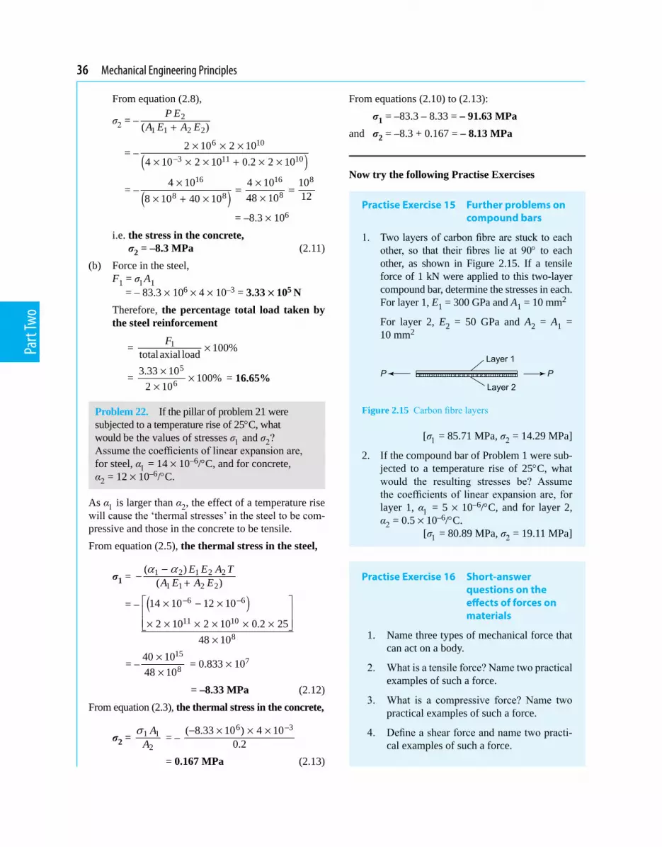
36 Mechanical Engineering Principles
Part
Two
From equation (2.8),
σ2 = – 2
1 1 2 2( )P E
A E A E+
= – ( )6 10
3 11 102 10 2 10
4 10 2 10 0.2 2 10−× × ×
× × × + × ×
= – ( )16 16 8
88 84 10 4 10 10
1248 108 10 40 10× ×
= =×× + ×
= –8.3 × 10⁶
i.e. the stress in the concrete, σ2 = –8.3 MPa (2.11)
(b) Force in the steel, F1 = σ1A1
= – 83.3 × 106 × 4 × 10–3 = 3.33 × 10⁵ N Therefore, the percentage total load taken by
the steel reinforcement
= 1 100%totalaxial loadF
×
= 5
63.33 10 100%
2 10×
××
= 16.65%
Problem 22. If the pillar of problem 21 were subjected to a temperature rise of 25°C, what would be the values of stresses σ1 and σ2? Assume the coefficients of linear expansion are, for steel, α1 = 14 × 10–6/°C, and for concrete, α2 = 12 × 10–6/°C.
As α1 is larger than α2, the effect of a temperature rise will cause the ‘thermal stresses’ in the steel to be com-pressive and those in the concrete to be tensile.From equation (2.5), the thermal stress in the steel,
σ1 = 1 2 1 2 2
1 1 2 2
( )( )
E E A TA E A E
a a−− +
= – ( )6 6
11 10
8
14 10 12 10
2 10 2 10 0.2 2548 10
− − × − × × × × × × ×
×
= –15
840 1048 10
××
= 0.833 × 107
= –8.33 MPa (2.12)From equation (2.3), the thermal stress in the concrete,
σ2 = 1 1
2
AA
s = –
6 3( 8.33 10 ) 4 100.2
−− × × ×
= 0.167 MPa (2.13)
From equations (2.10) to (2.13): σ1 = –83.3 – 8.33 = – 91.63 MPaand σ2 = –8.3 + 0.167 = – 8.13 MPa
Now try the following Practise Exercises
Practise Exercise 15 Further problems on compound bars
1. Two layers of carbon fibre are stuck to each other, so that their fibres lie at 90° to each other, as shown in Figure 2.15. If a tensile force of 1 kN were applied to this two-layer compound bar, determine the stresses in each. For layer 1, E1 = 300 GPa and A1 = 10 mm2
For layer 2, E2 = 50 GPa and A2 = A1 = 10 mm2
Figure 2.15 Carbon fibre layers
[σ1 = 85.71 MPa, σ2 = 14.29 MPa]
2. If the compound bar of Problem 1 were sub-jected to a temperature rise of 25°C, what would the resulting stresses be? Assume the coefficients of linear expansion are, for layer 1, α1 = 5 × 10⁻⁶/°C, and for layer 2, α2 = 0.5 × 10⁻⁶/°C. [σ1 = 80.89 MPa, σ2 = 19.11 MPa]
Practise Exercise 16 Short-answer questions on the effects of forces on materials
1. Name three types of mechanical force that can act on a body.
2. What is a tensile force? Name two practical examples of such a force.
3. What is a compressive force? Name two practical examples of such a force.
4. Define a shear force and name two practi-cal examples of such a force.

The effects of forces on materials 37
Part
Two
3. The unit of Young’s modulus of elasticity is: (a) Pascals (b) metres (c) dimension-less (d) newtons
4. A wire is stretched 3 mm by a force of 150 N. Assuming the elastic limit is not exceeded, the force that will stretch the wire 5 mm is:
(a) 150 N (b) 250 N (c) 90 N (d) 450 N
5. For the wire in question 4, the extension when the applied force is 450 N is:
(a) 1 mm (b) 3 mm (c) 9 mm (d) 12 mm
6. Due to the forces acting, a horizontal beam is in:
(a) tension (b) compression (c) shear
7. Due to forces acting, a pillar supporting a bridge is in:
(a) tension (b) compression (c) shear
8. Which of the following statements is false? (a) Elasticity is the ability of a material to
return to its original dimensions after deformation by a load.
(b) Plasticity is the ability of a material to retain any deformation produced in it by a load.
(c) Ductility is the ability to be permanent-ly stretched without fracturing.
(d) Brittleness is the lack of ductility and a brittle material has a long plastic stage.
9. A circular rod of cross-sectional area 100 mm2 has a tensile force of 100 kN applied to it. The stress in the rod is:
(a) 1 MPa (b) 1 GPa (c) 1 kPa (d) 100 MPa
10. A metal bar 5.0 m long extends by 0.05 mm when a tensile load is applied to it. The per-centage strain is:
(a) 0.1 (b) 0.01 (c) 0.001 (d) 0.0001
An aluminium rod of length 1.0 m and cross-sectional area 500 mm2 is used to
5. Define elasticity and state two examples of elastic materials.
6. Define plasticity and state two examples of plastic materials.
7. Define the limit of proportionality.
8. State Hooke’s law.
9. What is the difference between a ductile and a brittle material?
10. Define stress. What is the symbol used for (a) a tensile stress (b) a shear stress?
11. Strain is the ratio ..........
.
12. The ratio stressstrain is called .......
13. State the units of (a) stress (b) strain (c) Young’s modulus of elasticity.
14. Stiffness is the ratio .......... .
15. Sketch on the same axes a typical load/extension graph for a ductile and a brittle material.
16. Define (a) ductility (b) brittleness (c) mal-leability.
17. Define rigidity modulus.
18. The new length L2 of a bar of length L1, of coefficient of linear expansion α, when subjected to a temperature rise T is: L2 = ......
19. The thermal strain ε due to a temperature rise T in material of coefficient of linear ex-pansion α is given by: ε = ......
Practise Exercise 17 Multiple-choice questions on the effects of forces on materials
(Answers on page 297)
1. The unit of strain is: (a) pascals (b) metres (c) dimension-less (d) newtons
2. The unit of stiffness is: (a) newtons (b) pascals (c) newtons per metre (d) dimension-less

38 Mechanical Engineering Principles
Part
Two
support a load of 5 kN which causes the rod to contract by 100 mm. For questions 11 to 13, select the correct answer from the following list:
(a) 100 MPa (b) 0.001 (c) 10 kPa (d) 100 GPa (e) 0.01 (f) 10 MPa (g) 10 GPa (h) 0.0001 (i) 10 Pa
11. The stress in the rod.
12. The strain in the rod.
13. Young’s modulus of elasticity.
14. A compound bar of length L is subjected to a temperature rise of T. If α1 > α2, the strain in bar 1 will be:
(a) tensile (b) compressive (c) zero (d) αT
15. For Problem 14, the stress in bar 2 will be:
(a) tensile (b) compressive (c) zero (d) αT

Chapter 3
Tensile testing
Mechanical Engineering Principles, Bird and Ross, ISBN 9780415517850
In this chapter, additional material constants are introducedtohelpdefinethepropertiesofmaterials.In addition to this, a description is given of the standard tensile test used to obtain the strength of various materials, especially the strength and material stiffness of metals. This is aided by a standard tensile test, where the relationship of axial load on a specimen and its axial deflectionaredescribed.The engineercan tell a lot from the results of this experiment. For example,therelationshipbetweenloadanddeflectionis very different for steel and aluminium alloy and most other materials, including copper, zinc, brass, titanium, and so on. By carrying out this test, the engineer can determine the required properties of different materials, and this method, together with its interpretation, is discussed in this chapter.
is usually carried out using a universal testing machine that can apply either tensile or compressive forces to a specimen in small, accurately measured steps. British Standard 18 gives the standard procedure for such a test. Test specimens of a material are made to standard shapes and sizes and two typical test pieces are shown in Figure 3.1. The results of a tensile test may be plot-ted on a load/extension graph and a typical graph for a mild steel specimen is shown in Figure 3.2.
Figure 3.1
Figure 3.2
At the end of this chapter you should be able to:
• describe a tensile test• recognise from a tensile test the limit of propor-
tionality, the elastic limit and the yield point• plot a load/extension graph from given data• calculate from a load/extension graph, the mod-
ulus of elasticity, the yield stress, the ultimate tensile strength, percentage elongation and the percentage reduction in area
• appreciate the meaning of proof stress
3.1 The tensile test
A tensile test is one in which a force is applied to a spec-imen of a material in increments and the correspond-ing extension of the specimen noted. The process may be continued until the specimen breaks into two parts and this is called testing to destruction. The testing

40 Mechanical Engineering Principles
Part
Two
(i) Between A and B is the region in which Hooke’s law applies and stress is directly proportional to strain. The gradient of AB is used when determin-ing Young’s modulus of elasticity (see Chapter 2).
(ii) Point B is the limit of proportionality and is the point at which stress is no longer propor-tional to strain when a further load is applied.
(iii) Point C is the elastic limit and a specimen loaded to this point will effectively return to its original length when the load is removed, i.e. there is negligible permanent extension.
(iv) Point D is called the yield point and at this point there is a sudden extension to J, with no increase in load. The yield stress of the material is given by:
yield stress = load where yield begins to take place
original cross sectional area− The yield stress gives an indication of the duc-
tility of the material (see Chapter 2). (v) For mild steel, the extension up to the point J is
some 40 times larger than the extension up to the point B.
(vi) Shortly after point J, the material strain hard-ens, where the slope of the load-extension curve is about 1/50th the slope of the curve from A to B, for materials such as mild steel.
(vii) Between points D and E extension takes place over the whole gauge length of the specimen.
(viii) Point E gives the maximum load which can be applied to the specimen and is used to deter-mine the ultimate tensile strength (UTS) of the specimen (often just called the tensile strength)
UTS = maximum load
original cross-sectional area
(ix) Between points E and F the cross-sectional area of the specimen decreases, usually about half way between the ends, and a waist or neck is formed before fracture.
Percentage reduction in area
=
( )original cross-sectional area(final cross sectional area)-
original cross-sectional area
−
× 100%
The percentage reduction in area provides infor- mation about the malleability of the material (see Chapter 2). The value of stress at point F is greater than at point E since although the load on the specimen is decreasing as the extension in-creases, the cross-sectional area is also reducing.
(x) At point F the specimen fractures. (xi) Distance GH is called the permanent elonga-
tion andpermanent elongation
= -increase in lengthduring test todestruction
original cross sectional area × 100%
(xii) The point K is known as the upper yield point. It occurs for constant load experiments, such as when a hydraulic tensile testing machine is used. It does not occur for constant strain experiments, such as when a Hounsfield tensometer is used.
3.2 Worked problems on tensile testing
Problem 1. A tensile test is carried out on a mild steel specimen. The results are shown in the following table of values:
Load (kN) 0 10 23 32Extension (mm) 0 0.023 0.053 0.074
Plot a graph of load against extension, and from the graph determine (a) the load at an extension of 0.04 mm, and (b) the extension corresponding to a load of 28 kN.
The load/extension graph is shown in Figure 3.3. From the graph:
Figure 3.3

Tensile testing 41
Part
Two
(a) when the extension is 0.04 mm, the load is 17.2 kN(b) when the load is 28 kN, the extension is 0.065 mm
Problem 2. A tensile test is carried out on a mild steel specimen of gauge length 40 mm and cross-sectional area 100 mm2. The results obtained for the specimen up to its yield point are given below:
Load (kN) 0 8 19 29 36Extension (mm)
0 0.015 0.038 0.060 0.072
The maximum load carried by the specimen is 50 kN and its length after fracture is 52 mm. Determine (a) the modulus of elasticity, (b) the ultimate tensile strength, (c) the percentage elongation of the mild steel.
The load/extension graph is shown in Figure 3.4.
Figure 3.4
(a) Gradient of straight line is given by:
=BCAC 3
25000 N0.05 10 m−×
= 500 × 106 N/m
Young’s modulus of elasticity
= (gradient of graph) LA
, where
L = 40 mm (gauge length) = 0.040 m and area, A = 100 mm2 = 100 × 10–6 m2.
Young’s modulus of elasticity
= (500 × 106) 60.040
100 10− ×
= 200 × 109 Pa
= 200 GPa(b) Ultimate tensile strength
= maximum load
originalcross-sectionalarea
= 6 250000 N
100 10 m−× = 500 × 106 Pa = 500 MPa
(c) Percentage elongation
= increasein lengthoriginallength × 100
= 52 40
40− × 100
= 1240 × 100 = 30%
Problem 3. The results of a tensile test are: Diameter of specimen 15 mm; gauge length 40 mm; load at limit of proportionality 85 kN; extension at limit of proportionality 0.075 mm; maximum load 120 kN; final length at point of fracture 55 mm.Determine (a) Young’s modulus of elasticity (b) the ultimate tensile strength (c) the stress at the limit of proportionality (d) the percentage elongation.
(a) Young’s modulus of elasticity is given by:
E = stressstrain = =
FAxL
FLAx
where the load at the limit of proportionality, F = 85 kN = 85000 N,
L = gauge length = 40 mm = 0.040 m, A = cross-sectional area
= 2 2(0.015)
4 4dπ π
= = 0.0001767 m2, and
x = extension = 0.075 mm = 0.000075 m. Hence, Young’s modulus of elasticity
E = (85000)(0.040)
(0.0001767)(0.000075)FLAx =
= 256.6 × 10⁹ Pa = 256.6 GPa(b) Ultimate tensile strength
= maximum load 120000
originalcross-sectionalarea 0.0001767=
= 679 × 106 Pa = 679 MPa

42 Mechanical Engineering Principles
Part
Two
(c) Stress at limit of proportionality
= load at limit of proportionality
cross-sectionalarea
= 85000
0.0001767 = 481 × 106 Pa = 481 MPa
(d) Percentage elongation
increasein length 100originallength(55 40)mm 100 = 40mm
= ×
−= × 37.5%
Now try the following Practise Exercise
Practise Exercise 18 Further problems on tensile testing
1. What is a tensile test? Make a sketch of a typical load/extension graph for a mild steel specimen to the point of fracture and mark on the sketch the following: (a) the limit of proportionality (b) the elastic limit (c) the yield point.
2. In a tensile test on a zinc specimen of gauge length 100 mm and diameter 15 mm, a load of 100 kN produced an extension of 0.666 mm. Determine (a) the stress induced (b) the strain (c) Young’s modulus of elasticity. [(a) 566 MPa (b) 0.00666 (c) 85 GPa]
3. The results of a tensile test are: Diameter of specimen 20 mm, gauge length 50 mm, load at limit of proportionality 80 kN, extension at limit of proportionality 0.075 mm, maxi-mum load 100 kN, and final length at point of fracture 60 mm. Determine (a) Young’s modulus of elasticity (b) the ultimate tensile strength (c) the stress at the limit of propor-tionality (d) the percentage elongation.
[(a) 169.8 GPa (b) 318.3 MPa (c) 254.6 MPa (d) 20% ]
3.3 Further worked problems on tensile testing
Problem 4. A rectangular zinc specimen is sub-jected to a tensile test and the data from the test
is shown below. Width of specimen 40 mm; breadth of specimen 2.5 mm; gauge length 120 mm.
Load (kN)10 17 25 30 35 37.5 38.5 37 34 32
Extension (mm)0.15 0.25 0.35 0.55 1.00 1.50 2.50 3.50 4.50 5.00
Fracture occurs when the extension is 5.0 mm and the maximum load recorded is 38.5 kN. Plot the load/extension graph and hence determine (a) the stress at the limit of proportionality (b) Young’s modulus of elasticity (c) the ultimate tensile strength (d) the percentage elongation (e) the stress at a strain of 0.01 (f) the extension at a stress of 200 MPa.
A load/extension graph is shown in Figure 3.5.
Figure 3.5
(a) The limit of proportionality occurs at point P on the graph, where the initial gradient of the graph starts to change. This point has a load value of 26.5 kN.
Cross-sectional area of specimen = 40 mm × 2.5 mm = 100 mm2 = 100 × 10–6 m2
Stress at the limit of proportionality is given by:
s = 3
6 2force 26.5 10 Narea 100 10 m−
×=×
= 265 × 106Pa = 265 MPa(b) Gradient of straight line portion of graph is given
by:

Tensile testing 43
Part
Two
325000 N
0.35 10 mBCAC −=
× = 71.43 × 10⁶N/m
Young’s modulus of elasticity
= (gradient of graph) LA
= ( )3
66
120 1071.43 10100 10
−
− ×
× ×
= 85.72 × 10⁹ Pa = 85.72 GPa(c) Ultimate tensile strength
= maximum loadoriginalcross-sectionalarea
= 3
6 238.5 10 N
100 10 m−×
×
= 385 ×106 Pa = 385 MPa(d) Percentage elongation
= extension at fracturepoint 100originallength ×
= 5.0mm 100120mm × = 4.17%
(e) Strain ε = extensionoriginallength
xl , from which,
extension x = εl = 0.01 × 120 = 1.20 mm. From the graph, the load corresponding to an
extension of 1.20 mm is 36 kN. Stress at a strain of 0.01 is given by:
σ = 6 2
force 36000 Narea 100 10 m−=
× = 360 × 106 Pa = 360 MPa(f) When the stress is 200 MPa, then
force = area × stress = (100 ×10–6)(200 ×106) = 20 kN From the graph, the corresponding extension is
0.30 mm
Problem 5. A mild steel specimen of cross-sectional area 250 mm2 and gauge length 100 mm is subjected to a tensile test and the following data is obtained: within the limit of proportionality, a load of 75 kN produced an extension of 0.143 mm, load at yield point = 80 kN, maximum load on specimen = 120 kN, final cross-sectional area of waist at fracture = 90 mm2, and the gauge length had increased to 135 mm at fracture.
Determine for the specimen: (a) Young’s modulus of elasticity (b) the yield stress (c) the tensile strength (d) the percentage elongation and (e) the percentage reduction in area.
(a) Force F = 75 kN = 75000 N, gauge length L = 100 mm = 0.1 m, cross-sectional area A = 250 mm2 = 250 × 10–6 m2, and extension x = 0.143 mm = 0.143 × 10⁻³ m.
Young’s modulus of elasticity,
E = stress /strain /= =F A FL
x L Ax
6 3
(75000)(0.1)(250 10 )(0.143 10 )− −=
× ×
= 210 × 109 Pa = 210 GPa
(b) Yield stress = load when yield begins to takeplaceoriginalcross-sectionalarea
= 6 280000 N
250 10 m−× = 320 × 106 Pa = 320 MPa
(c) Tensile strength
6 2
maximum loadoriginalcross-sectionalarea
120000 N250 10 m−
=
=×
= 480 × 106 Pa = 480 MPa(d) Percentage elongation
= increasein length during test todestructionoriginallength
= 135 100
100−
× 100 = 35%
(e) Percentage reduction in area
=
(originalcross sectionalarea)(finalcross sectionalarea)or
−− −iiginalcross sectionalarea− ×100
= 250 90 160100 100250 250
− × = × = 64%
Now try the following Practise Exercise
Practise Exercise 19 Further problem on tensile testing
1. A tensile test is carried out on a specimen of mild steel of gauge length 40 mm and diameter 7.42 mm. The results are:

44 Mechanical Engineering Principles
Part
Two
Load (kN)0 10 17 25 30 34 37.5 38.5 36Extension (mm)0 0.05 0.08 0.11 0.14 0.20 0.40 0.60 0.90
At fracture the final length of the specimen is 40.90 mm. Plot the load/ extension graph and determine (a) the modulus of elasticity for mild steel (b) the stress at the limit of proportionality (c) the ultimate tensile strength (d) the percentage elongation.
[ (a) 210 GPa (b) 650 MPa (c) 890 MPa (d) 2.25% ]
2. An aluminium alloy specimen of gauge length 75 mm and of diameter 11.28 mm was subjected to a tensile test, with these results:
Load (kN)0 2.0 6.5 11.5 13.6 16.0 18.0 19.0 20.5 19.0
Extension (mm)0 0.012 0.039 0.069 0.080 0.107 0.133 0.158 0.225 0.310
The specimen fractured at a load of 19.0 kN.
Determine (a) the modulus of elasticity of the alloy (b) the percentage elongation.
[(a) 125 GPa (b) 0.413%]
3. An aluminium test piece 10 mm in diameter and gauge length 50 mm gave the following results when tested to destruction:
Load at yield point 4.0 kN, maximum load 6.3 kN, extension at yield point 0.036 mm, diameter at fracture 7.7 mm.
Determine (a) the yield stress (b) Young’s modulus of elasticity (c) the ultimate ten-sile strength (d) the percentage reduction in area.
[ (a) 50.93 MPa (b) 70.7 GPa (c) 80.2 MPa (d) 40.7% ]
3.4 Proof stress
Certain materials, such as high-tensile steel, aluminium alloy, titanium, and so on, do not exhibit a definite yield point in their stress-strain curves, unlike mild steel, as shown in Figure 3.6.
Figure 3.6 Stress-Strain curves for high tension steels, aluminium alloys, etc.
In this case, the equivalent yield stresses are taken in the form of either 0.1% or a 0.2% proof stress.For 0.1% proof stress, a strain of e = 0.1% =
0.1100 =
0.001, is set off on the horizontal strain axis of Figure 3.6 and a straight line is drawn parallel to the straight part of the stress-strain curve from this point, near to the bottom of the stress-strain curve where the angle is q. The intersection of this broken line with the stress-strain curve gives the 0.1% proof stress, as shown in Figure 3.6.
For the 0.2% proof stress, a strain of ε = 0.2% = 0.2100 =
0.002, is set off on the horizontal strain axis of Figure 3.6 and a straight line is drawn from this point at an angle q to the horizontal and parallel to the linear part of the bottom of the stress-strain curve as shown in Fig-ure 3.6. The 0.2% proof stress is not twice the value of the 0.1% proof stress! It may be about 10% larger.
Now try the following Practise Exercises
Practise Exercise 20 Short-answer questions on tensile testing
1. What is a tensile test?
2. Which British Standard gives the standard procedure for a tensile test?

Tensile testing 45
Part
Two
3. With reference to a load/extension graph for mild steel, state the meaning of (a) the limit of proportionality (b) the elastic limit (c) the yield point (d) the percentage elongation.
4. Define ultimate tensile strength.
5. Yield stress is the ratio ............
6. Define ‘percentage reduction in area’.
7. Briefly explain, with a diagram, what is meant by ‘0.1% proof stress’.
Practise Exercise 21 Multiple-choice questions on tensile testing
(Answers on page 297)
A brass specimen having a cross-sectional area of 100 mm2 and gauge length 100 mm is sub-jected to a tensile test from which the following information is obtained:
Load at yield point = 45 kN, maximum load = 52.5 kN, final cross-sectional area of waist at fracture = 75 mm2, and gauge length at fracture = 110 mm.
For questions 1 to 4, select the correct answer from the following list:(a) 600 MPa (b) 525 MPa(c) 33.33% (d) 10%(e) 9.09% (f) 450 MPa(g) 25% (h) 700 MPa
1. The yield stress.
2. The percentage elongation.
3. The percentage reduction in area.
4. The ultimate tensile strength.
References
Videos of the Tensile Test and Poisson’s Ratio experiment can be obtained by visiting the website below: www.routledge.com/cw/bird

Forces acting at a point
Mechanical Engineering Principles, Bird and Ross, ISBN 9780415517850
Chapter 4
In this chapter the fundamental quantities, scalars and vectors, which form the very basis of all branches of engineering, are introduced. A force is a vector quantity and in this chapter, the resolution of forces is introduced. Resolving forces is very important in structures, where the principle is used to determine the strength of roof trusses, bridges, cranes, etc. Great lengths are gone to, to explain this very fundamental skill, where step-by-step methods are adopted to help the reader understand this very important procedure. The resolution of forces is also used in studying the motion of vehicles and other particles in dynamics and in the case of the navigation of ships, aircraft, etc., the vectors take the form of displacements, velocities and accelerations. This chapter gives a sound introduction to the manipulation and use of scalars and vectors, by both graphical and analytical methods.
4.1 Scalar and vector quantities
Quantities used in engineering and science can be divided into two groups:
(a) Scalar quantities have a size (or magnitude) only and need no other information to specify them. Thus, 10 centimetres, 50 seconds, 7 litres and 3 kilograms are all examples of scalar quantities.
(b) Vector quantities have both a size or magnitude and a direction, called the line of action of the quantity. Thus, a velocity of 50 kilometres per hour due east, an acceleration of 9.81 metres per second squared vertically downwards and a force of 15 Newtons at an angle of 30 degrees are all examples of vector quantities.
4.2 Centre of gravity and equilibrium
The centre of gravity of an object is a point where the resultant gravitational force acting on the body may be taken to act. For objects of uniform thickness lying in a horizontal plane, the centre of gravity is ver-tically in line with the point of balance of the object. For a thin uniform rod the point of balance and hence the centre of gravity is halfway along the rod as shown in Figure 4.1(a).
Figure 4.1
At the end of this chapter you should be able to:
• distinguish between scalar and vector quantities• define ‘centre of gravity’ of an object• define ‘equilibrium’ of an object• understand the terms ‘coplanar’ and ‘concur-
rent’• determine the resultant of two coplanar forces
using (a) the triangle of forces method (b) the parallelogram of forces method
• calculate the resultant of two coplanar forces using (a) the cosine and sine rules (b) resolution of forces
• determine the resultant of more than two coplanar forces using (a) the polygon of forces method (b) calculation by resolution of forces
• determine unknown forces when three or more coplanar forces are in equilibrium

Forces acting at a point 47
Part
Two
A thin flat sheet of a material of uniform thickness is called a lamina and the centre of gravity of a rectangu-lar lamina lies at the point of intersection of its diago-nals, as shown in Figure 4.1(b). The centre of gravity of a circular lamina is at the centre of the circle, as shown in Figure 4.1(c).
An object is in equilibrium when the forces acting on the object are such that there is no tendency for the object to move. The state of equilibrium of an object can be divided into three groups.
(i) If an object is in stable equilibrium and it is slightly disturbed by pushing or pulling (i.e. a disturbing force is applied), the centre of gravity is raised and when the disturbing force is removed, the object returns to its original position. Thus a ball bearing in a hemispheri-cal cup is in stable equilibrium, as shown in Figure 4.2(a).
Figure 4.2
(ii) An object is in unstable equilibrium if, when a disturbing force is applied, the centre of grav-ity is lowered and the object moves away from its original position. Thus, a ball bearing balanced on top of a hemispherical cup is in unstable equilibrium, as shown in Figure 4.2(b).
(iii) When an object in neutral equilibrium has a disturbing force applied, the centre of grav-ity remains at the same height and the object does not move when the disturbing force is removed.
Thus, a ball bearing on a flat horizontal surface is in neutral equilibrium, as shown in Figure 4.2(c).
4.3 Forces
When forces are all acting in the same plane, they are called coplanar. When forces act at the same time and at the same point, they are called concurrent forces.
Force is a vector quantity and thus has both a mag-nitude and a direction. A vector can be represented graphically by a line drawn to scale in the direction of the line of action of the force. To distinguish between vector and scalar quantities, various ways are used. These include:
(i) bold print, (ii) two capital letters with an arrow above them to
denote the sense of direction, for example, AB→
where A is the starting point and B the end point of the vector,
(iii) a line over the top of letters, for example, AB or a (iv) letters with an arrow above, for example, a
, A
(v) underlined letters, for example, a (vi) xi + jy, where i and j are axes at right-angles to
each other; for example, 3i + 4j means 3 units in the i direction and 4 units in the j direction, as shown in Figure 4.3.
Figure 4.3
(vii) a column matrix ab
; for example, the vector OA
shown in Figure 4.3 could be represented by 34
Thus, in Figure 4.3,
OA ≡ OA
≡ OA ≡ 3i + 4j ≡ 34
The method adopted in this text is to denote vector quantities in bold print.

48 Mechanical Engineering Principles
Part
Two
Thus, ab in Figure 4.4 represents a force of 5 Newton’s acting in a direction due east.
Figure 4.4
4.4 The resultant of two coplanar forces
For two forces acting at a point, there are three pos-sibilities.
(a) For forces acting in the same direction and having the same line of action, the single force having the same effect as both of the forces, called the resultant force or just the resultant, is the arith-metic sum of the separate forces. Forces of F1 and F2 acting at point P, as shown in Figure 4.5(a), have exactly the same effect on point P as force F shown in Figure 4.5(b), where F = F1 + F2 and acts in the same direction as F1 and F2. Thus F is the resultant of F1 and F2
Figure 4.5
(b) For forces acting in opposite directions along the same line of action, the resultant force is the arith-metic difference between the two forces. Forces of F1 and F2 acting at point P as shown in Figure 4.6(a) have exactly the same effect on point P as
force F shown in Figure 4.6(b), where F = F2 – F1 and acts in the direction of F2, since F2 is greater than F1. Thus F is the resultant of F1 and F2
(c) When two forces do not have the same line of ac-tion, the magnitude and direction of the resultant force may be found by a procedure called vector addition of forces. There are two graphical meth-ods of performing vector addition, known as the triangle of forces method (see Section 4.5) and the parallelogram of forces method (see Section 4.6).
Problem 1. Determine the resultant force of two forces of 5 kN and 8 kN, (a) acting in the same direction and having the same line of action (b) acting in opposite directions but having the same line of action.
(a) The vector diagram of the two forces acting in the same direction is shown in Figure 4.7(a), which assumes that the line of action is horizontal, although since it is not specified, could be in any direction. From above, the resultant force F is given by: F = F1 + F2, i.e. F = (5 + 8) kN = 13 kN in the direction of the original forces.
Figure 4.7
(b) The vector diagram of the two forces acting in op-posite directions is shown in Figure 4.7(b), again assuming that the line of action is in a horizontal direction. From above, the resultant force F is given by: F = F2 – F1, i.e. F = (8 – 5) kN = 3 kN in the direction of the 8 kN force.
4.5 Triangle of forces method
A simple procedure for the triangle of forces method of vector addition is as follows:Figure 4.6

Forces acting at a point 49
Part
Two
(i) Draw a vector representing one of the forces, using an appropriate scale and in the direction of its line of action.
(ii) From the nose of this vector and using the same scale, draw a vector representing the second force in the direction of its line of action.
(iii) The resultant vector is represented in both mag-nitude and direction by the vector drawn from the tail of the first vector to the nose of the sec-ond vector.
Problem 2. Determine the magnitude and direc-tion of the resultant of a force of 15 N acting hori-zontally to the right and a force of 20 N, inclined at an angle of 60° to the 15 N force. Use the triangle of forces method.
Using the procedure given above and with reference to Figure 4.8:
(i) ab is drawn 15 units long horizontally
Figure 4.8
(ii) From b, bc is drawn 20 units long, inclined at an angle of 60° to ab. (Note, in angular mea-sure, an angle of 60° from ab means 60° in an anticlockwise direction.)
(iii) By measurement, the resultant ac is 30.5 units long inclined at an angle of 35° to ab. That is, the resultant force is 30.5 N, inclined at an an-gle of 35° to the 15 N force.
Problem 3. Find the magnitude and direction of the two forces given, using the triangle of forces method. First force: 1.5 kN acting at an angle of 30°Second force: 3.7 kN acting at an angle of –45°
From the above procedure and with reference to Figure 4.9:
Figure 4.9
(i) ab is drawn at an angle of 30° and 1.5 units in length.
(ii) From b, bc is drawn at an angle of –45° and 3.7 units in length. (Note, an angle of –45° means a clockwise rotation of 45° from a line drawn horizontally to the right)
(iii) By measurement, the resultant ac is 4.3 units long at an angle of –25°. That is, the resultant force is 4.3 kN at an angle of –25°
Now try the following Practise Exercise
Practise Exercise 22 Further problems on the triangle of forces method
1. Determine the magnitude and direction of the resultant of the forces 1.3 kN and 2.7 kN, having the same line of action and acting in the same direction.
[4.0 kN in the direction of the forces]
2. Determine the magnitude and direction of the resultant of the forces 470 N and 538 N having the same line of action but acting in opposite directions.
[68 N in the direction of the 538 N force]
In questions 3 to 5, use the triangle of forces method to determine the magnitude and direction of the resultant of the forces given.
3. 13 N at 0° and 25 N at 30° [36.8 N at 20°]
4. 5 N at 60° and 8 N at 90° [12.6 N at 79°]
5. 1.3 kN at 45° and 2.8 kN at –30° [3.4 kN at –8°]

50 Mechanical Engineering Principles
Part
Two
4.6 The parallelogram of forces method
A simple procedure for the parallelogram of forces method of vector addition is as follows:
(i) Draw a vector representing one of the forces, using an appropriate scale and in the direction of its line of action.
(ii) From the tail of this vector and using the same scale draw a vector representing the second force in the direction of its line of action.
(iii) Complete the parallelogram using the two vec-tors drawn in (i) and (ii) as two sides of the paral-lelogram.
(iv) The resultant force is represented in both magni-tude and direction by the vector corresponding to the diagonal of the parallelogram drawn from the tail of the vectors in (i) and (ii).
Problem 4. Use the parallelogram of forces method to find the magnitude and direction of the resultant of a force of 250 N acting at an angle of 135° and a force of 400 N acting at an angle of –120°.
From the procedure given above and with reference to Figure 4.10:
(i) ab is drawn at an angle of 135° and 250 units in length
Figure 4.10
(ii) ac is drawn at an angle of –120° and 400 units in length
(iii) bd and cd are drawn to complete the parallelo-gram
(iv) ad is drawn. By measurement, ad is 413 units long at an angle of –156°.
That is, the resultant force is 413 N at an angle of –156°
Now try the following Practise Exercise
Practise Exercise 23 Further problems on the parallelogram of forces method
In questions 1 to 5, use the parallelogram of forces method to determine the magnitude and direction of the resultant of the forces given.
1. 1.7 N at 45° and 2.4 N at –60° [2.6 N at –20°]
2. 9 N at 126° and 14 N at 223° [15.7 N at –172°]
3. 23.8 N at –50° and 14.4 N at 215° [26.7 N at –82°]
4. 0.7 kN at 147° and 1.3 kN at –71° [0.86 kN at –101°]
5. 47 N at 79° and 58 N at 247° [15.5 N at –152°]
4.7 Resultant of coplanar forces by calculation
An alternative to the graphical methods of deter- mining the resultant of two coplanar forces is by calculation. This can be achieved by trigonometry using the cosine rule and the sine rule, as shown in Problem 5 following, or by resolution of forces (see Section 4.10).
Problem 5. Use the cosine and sine rules to determine the magnitude and direction of the of a force of 8 kN acting at an angle of 50° to the horizontal and a force of 5 kN acting at an angle of –30° to the horizontal.
The space diagram is shown in Figure 4.11(a). A sketch is made of the vector diagram, 0a representing the 8 kN force in magnitude and direction and ab repre-senting the 5 kN force in magnitude and direction. The resultant is given by length 0b. By the cosine rule,

Forces acting at a point 51
Part
Two
Figure 4.11
0b2 = oa2 + ab2 – 2(oa)(ab) cos∠0ab = 82 + 52 – 2(8)(5) cos 100° (since ∠0ab = 180° – 50° – 30° = 100°) = 64 + 25 – (–13.892) = 102.892
Hence, 0b = 102.892 = 10.14 kN
By the sine rule, 5 10.14sin 0 sin100a b =∠ °
from which, sin ∠a0b = 5sin10010.14
° = 0.4856
Hence ∠a0b = sin–1 (0.4856) = 29.05°. Thus angle f in Figure 4.11(b) is 50° – 29.05° = 20.95°Hence the resultant of the two forces is 10.14 kN acting at an angle of 20.95° to the horizontal
Now try the following Practise Exercise
Practise Exercise 24 Further problems on the resultant of coplanar forces by calculation
1. Forces of 7.6 kN at 32° and 11.8 kN at 143° act at a point. Use the cosine and sine rules to calculate the magnitude and direction of their resultant. [11.52 kN at 105°]
In questions 2 to 5, calculate the resultant of the given forces by using the cosine and sine rules.
2. 13 N at 0° and 25 N at 30° [36.84 N at 19.83°]
3. 1.3 kN at 45° and 2.8 kN at –30° [3.38 kN at – 8.19°]
4. 9 N at 126° and 14 N at 223° [15.69 N at – 171.67°]
5. 0.7 kN at 147° and 1.3 kN at – 71° [0.86 kN at – 100.94°]
4.8 Resultant of more than two coplanar forces
For the three coplanar forces F1, F2 and F3 acting at a point as shown in Figure 4.12, the vector diagram is drawn using the nose-to-tail method of Section 4.5. The procedure is:
(i) Draw 0a to scale to represent force F1 in both magnitude and direction (see Figure 4.13)
Figure 4.12
Figure 4.13
(ii) From the nose of 0a, draw ab to represent force F2
(iii) From the nose of ab, draw bc to represent force F3
(iv) The resultant vector is given by length 0c in Figure 4.13. The direction of resultant oc is from where we started, i.e. point 0, to where we finished, i.e. point c. When acting by itself, the resultant force, given by 0c, has the same ef-fect on the point as forces F1, F2 and F3 have when acting together. The resulting vector diagram of Figure 4.13 is called the polygon of forces.

52 Mechanical Engineering Principles
Part
Two
Problem 6. Determine graphically the magnitude and direction of the resultant of the following three coplanar forces, which may be considered as acting at a point: Force A, 12 N acting horizontally to the right; force B, 7 N inclined at 60° to force A; force C, 15 N inclinedat 150° to force A.
The space diagram is shown in Figure 4.14. The vector diagram shown in Figure 4.15, is produced as follows:
Figure 4.14
Figure 4.15
(i) 0a represents the 12 N force in magnitude and direction
(ii) From the nose of 0a, ab is drawn inclined at 60° to 0a and 7 units long
(iii) From the nose of ab, bc is drawn 15 units long inclined at 150° to oa (i.e. 150° to the horizontal)
(iv) 0c represents the resultant; by measurement, the resultant is 13.8 N inclined at f = 80° to the horizontal.
Thus the resultant of the three forces, FA, FB and FC is a force of 13.8 N at 80° to the horizontal.
Problem 7. The following coplanar forces are acting at a point, the given angles being measuredfrom the horizontal: 100 N at 30°, 200 N at 80°, 40 N at –150°, 120 N at –100° and 70 N at –60°.
Determine graphically the magnitude and direction of the resultant of the five forces.
The five forces are shown in the space diagram of Figure 4.16. Since the 200 N and 120 N forces have the same line of action but are in opposite sense, they can be represented by a single force of 200 – 120, i.e. 80 N acting at 80° to the horizontal. Similarly, the 100 N and 40 N forces can be represented by a force of 100 – 40, i.e. 60 N acting at 30° to the horizontal. Hence the space diagram of Figure 4.16 may be rep-resented by the space diagram of Figure 4.17. Such a simplification of the vectors is not essential but it is easier to construct the vector diagram from a space diagram having three forces, than one with five.
Figure 4.16
Figure 4.17
The vector diagram is shown in Figure 4.18, 0a repre-senting the 60 N force, ab representing the 80N force and bc the 70 N force. The resultant, 0c, is found by measurement to represent a force of 112 N and angle f is 25°.

Forces acting at a point 53
Part
Two
Figure 4.18
Thus, thefiveforcesshowninFigure4.16mayberepresented by a single force of 112 N at 25° to the horizontal.
Now try the following Practise Exercise
Practise Exercise 25 Further problems on the resultant of more than two coplanar forces
In questions 1 to 3, determine graphically the magnitude and direction of the resultant of the coplanar forces given which are acting at a point.
1. Force A, 12 N acting horizontally to the right, force B, 20 N acting at 140° to force A, force C, 16 N acting 290° to force A.
[3.1 N at –45° to force A]
2. Force 1, 23 kN acting at 80° to the horizon-tal, force 2, 30 kN acting at 37° to force 1, force 3, 15 kN acting at 70° to force 2.
[53.5 kN at 37° to force 1 (i.e. 117° to the horizontal]
3. Force P, 50 kN acting horizontally to the right, force Q, 20 kN at 70° to force P, force R, 40 kN at 170° to force P, force S, 80 kN at 300° to force P. [72 kN at –37° to force P]
4. Four horizontal wires are attached to a tele-phone pole and exert tensions of 30 N to the south, 20 N to the east, 50 N to the north-east and 40 N to the north-west. Determine the resultant force on the pole and its direction.
[43.2 N at 39° east of north]
4.9 Coplanar forces in equilibrium
When three or more coplanar forces are acting at a point and the vector diagram closes, there is no resul-tant. The forces acting at the point are in equilibrium.
Problem 8. A load of 200 N is lifted by two ropes connected to the same point on the load, making angles of 40° and 35° with the vertical. Determine graphically the tensions in each rope when the system is in equilibrium.
The space diagram is shown in Figure 4.19. Since the system is in equilibrium, the vector diagram must close. The vector diagram, shown in Figure 4.20, is drawn as follows:
Figure 4.19
Figure 4.20
(i) The load of 200 N is drawn vertically as shown by 0a
(ii) The direction only of force F1 is known, so from point a, ad is drawn at 40° to the vertical

54 Mechanical Engineering Principles
Part
Two
(iii) The direction only of force F2 is known, so from point 0, 0c is drawn at 35° to the vertical
(iv) Lines ad and 0c cross at point b; hence the vector diagram is given by triangle oab. By measurement, ab is 119 N and 0b is 133 N.
Thus the tensions in the ropes are F1 = 119 N and F2 = 133 N
Problem 9. Five coplanar forces are acting on a body and the body is in equilibrium. The forces are: 12 kN acting horizontally to the right, 18 kN acting at an angle of 75°, 7 kN acting at an angle of 165°, 16 kN acting from the nose of the 7 kN force, and 15 kN acting from the nose of the 16 kNforce. Determine the directions of the 16 kN and 15 kN forces relative to the 12 kN force.
With reference to Figure 4.21, 0a is drawn 12 units long horizontally to the right. From point a, ab is drawn 18 units long at an angle of 75°. From b, bc is drawn 7 units long at an angle of 165°. The direction of the 16 kN force is not known, thus arc pq is drawn with a compass, with centre at c, radius 16 units. Since the forces are at equilibrium, the polygon of forces must close. Using a compass with centre at 0, arc rs is drawn having a radius 15 units. The point where the arcs intersect is at d.
Figure 4.21
By measurement, angle f = 198° and a = 291°Thus the 16 kN force acts at an angle of 198° (or –162°) to the 12 kN force, and the 15 kN force acts at an angle of 291° (or –69°) to the 12 kN force.
Now try the following Practise Exercise
Practise Exercise 26 Further problems on coplanar forces in equilibrium
1. A load of 12.5 N is lifted by two strings con-nected to the same point on the load, making angles of 22° and 31° on opposite sides of the vertical. Determine the tensions in the strings. [5.86 N, 8.06 N]
2. A two-legged sling and hoist chain used for lifting machine parts is shown in Figure 4.22. Determine the forces in each leg of the sling if parts exerting a downward force of 15 kN are lifted. [9.96 kN, 7.77 kN]
Figure 4.22
3. Four coplanar forces acting on a body are such that it is in equilibrium. The vector diagram for the forces is such that the 40 N force acts vertically upwards, the 40 N force acts at 65° to the 60 N force, the 100 N force acts from the nose of the 40 N force and the 90 N force acts from the nose of the 100 N force. Determine the direction of the 100 N and 90 N forces relative to the 60 N force.
[100 N force at 148° to the 60 N force, 90 N force at 277° to the 60 N force ]
4.10 Resolution of forces
A vector quantity may be expressed in terms of its horizontal and vertical components. For example, a vector representing a force of 10 N at an angle of

Forces acting at a point 55
Part
Two
60° to the horizontal is shown in Figure 4.23. If the horizontal line 0a and the vertical line ab are construct-ed as shown, then 0a is called the horizontal compo-nent of the 10 N force, and ab the vertical component of the 10 N force.
Figure 4.23
By trigonometry, cos 60° = 00ab , hence the horizontal
component, 0a = 10 cos 60°
Also, sin 60° = 0abb , hence the vertical component,
ab = 10 sin 60°This process is called findingthehorizontalandver-tical components of a vector or the resolution of a vector, and can be used as an alternative to graphical methods for calculating the resultant of two or more coplanar forces acting at a point. For example, to calculate the resultant of a 10 N force acting at 60° to the horizontal and a 20 N force acting at –30° to the horizontal (see Figure 4.24) the procedure is as follows:
Figure 4.24
(i) Determine the horizontal and vertical compo- nents of the 10 N force, i.e. horizontal component,
0a = 10 cos 60° = 5.0 N, and vertical component, ab = 10 sin 60° = 8.66 N
(ii) Determine the horizontal and vertical compo-nents of the 20 N force, i.e. horizontal compo-nent, 0d = 20 cos(–30°) = 17.32 N, and vertical component, cd = 20 sin(–30°) = –10.0 N
(iii) Determine the total horizontal component, i.e. 0a + 0d = 5.0 + 17.32 = 22.32 N (iv) Determine the total vertical component, i.e. ab + cd = 8.66 + (–10.0) = –1.34 N (v) Sketch the total horizontal and vertical compo-
nents as shown in Figure 4.25. The resultant of the two components is given by length 0r and, by Pythagoras’ theorem,
0r = 2 222.32 1.34+ = 22.36 N
Figure 4.25
and using trigonometry,
angle f = tan–1 1.3422.32 = 3.44°
Hence the resultant of the 10 N and 20 N forces shown in Figure 4.24 is 22.36 N at an angle of –3.44° to the horizontal.
Problem 10. Forces of 5.0 N at 25° and 8.0 N at 112° act at a point. By resolving these forces into horizontal and vertical components, determine their resultant.
The space diagram is shown in Figure 4.26.
Figure 4.26

56 Mechanical Engineering Principles
Part
Two
(i) The horizontal component of the 5.0 N force, 0a = 5.0 cos 25° = 4.532, and the vertical component of the 5.0 N force, ab = 5.0 sin 25° = 2.113
(ii) The horizontal component of the 8.0 N force, 0c = 8.0 cos 112° = –2.997
The vertical component of the 8.0 N force, cd = 8.0 sin 112° = 7.417
(iii) Total horizontal component = 0a + 0c = 4.532 + (–2.997) = + 1.535
(iv) Total vertical component = ab + cd = 2.113 + 7.417 = + 9.530
(v) The components are shown sketched in Figure 4.27.
Figure 4.27
By Pythagoras’ theorem, r = 2 21.535 9.530+ = 9.653,
and by trigonometry, angle f = tan–1 9.5301.535
= 80.85° Hence the resultant of the two forces shown in Figure 4.26 is a force of 9.653 N acting at 80.85° to the horizontal.
Problems 9 and 10 demonstrate the use of resolution of forces for calculating the resultant of two co- planar forces acting at a point. However the method may be used for more than two forces acting at a point, as shown in Problem 11.
Problem 11. Determine by resolution of forces the resultant of the following three coplanar forcesacting at a point: 200 N acting at 20° to the hori-zontal; 400 N acting at 165° to the horizontal; 500 N acting at 250° to the horizontal.
A tabular approach using a calculator may be made as shown below:
Horizontal componentForce 1 200 cos 20° = 187.94Force 2 400 cos 165° = –386.37Force 3 500 cos 250° = –171.01Total horizontal component = –369.44
Vertical componentForce 1 200 sin 20° = 68.40Force 2 400 sin 165° = 103.53Force 3 500 sin 250° = –469.85Total vertical component = –297.92 The total horizontal and vertical components are shown in Figure 4.28.
Figure 4.28
Resultant r = 2 2369.44 297.92+
= 474.60, and
angle f = tan–1 297.92369.44 = 38.88°,
from which, a = 180° – 38.88° = 141.12°
Thus the resultant of the three forces given is 474.6 N acting at an angle of –141.12° (or +218.88°) to the horizontal.
Problem 12. Determine by resolution the magnitude and direction of the following six concurrent coplanar forces: 150 N acting at 25° to the horizontal, 250 N acting at 90° to the horizontal, 200 N acting at 120° to the horizontal, 300 N acting at 200° to the horizontal, 60 N acting at 280° to the horizontal, and 220 N acting at 320° to the horizontal.

Forces acting at a point 57
Part
Two
A tabular approach using a calculator may be made as shown below:
Horizontal components of the forces 150 cos 25° = 135.9 250 cos 90° = 0 200 cos 120° = –100 300 cos 200° = –281.9 60 cos 280° = 10.42 220 cos 320° = 168.5 Total horizontal component, H = –67.1 N
Vertical components of the forces 150 sin 25° = 63.4 250 sin 90° = 250 200 sin 120° = 173.2 300 sin 200° = –102.6 60 sin 280° = –59.1 220 sin 320° = –141.4 Total vertical component, V = 183.5 N
H and V are shown plotted in Figure 4.29 and from Pythagoras’ theorem:
Figure 4.29
2 2 2R H V= + and resultant,
R = 2 2H V+ = 2 2( 67.1) (183.5)− + = 195.4 N
Angle q 1 1
1
183.5tan tan 67.1
tan (2.7347) 69.91°
VH
− −
−
= =
= =
Measuring from the positive horizontal axis, angle of the resultant R, α = 180° – 69.91° = 110.09°
Thus the resultant of the six forces given is 195.4 N acting at an angle of 110.09° to the horizontal.
Now try the following Practise Exercise
Practise Exercise 27 Further problems on resolution of forces
1. Resolve a force of 23.0 N at an angle of 64° into its horizontal and vertical components.
[10.08 N, 20.67 N]
2. Forces of 5 N at 21° and 9 N at 126° act at a point. By resolving these forces into hori-zontal and vertical components, determine their resultant. [9.09 N at 93.92°]
In questions 3 and 4, determine the magnitude and direction of the resultant of the coplanar forces given which are acting at a point, by reso-lution of forces.
3. Force A, 12 N acting horizontally to the right, force B, 20 N acting at 140° to force A, force C, 16 N acting 290° to force A.
[3.06 N at –45.40° to force A]
4. Force 1, 23 kN acting at 80° to the horizon-tal, force 2, 30 kN acting at 37° to force 1, force 3, 15 kN acting at 70° to force 2.
[ 53.50 kN at 117.27° to the horizontal ]
5. Determine, by resolution of forces, the re-sultant of the following three coplanar forces acting at a point: 10 kN acting at 32° to the horizontal, 15 kN acting at 170° to the hori-zontal; 20 kN acting at 240° to the horizontal. [18.82 kN at 210.03° to the horizontal]
6. The following coplanar forces act at a point: force A, 15 N acting horizontally to the right, force B, 23 N at 81° to the horizontal, force C, 7 N at 210° to the horizontal, force D, 9 N at 265° to the horizontal, and force E, 28 N at 324° to the horizontal. Determine the resultant of the five forces by resolution of the forces.
[34.96 N at –10.23° to the horizontal]
7. At a certain point, 12 different values of coplanar and concurrent, radially outward tensile forces are applied. The first force is applied horizontally to the right and the

58 Mechanical Engineering Principles
Part
Two
2. Explain the difference between a scalar and a vector quantity.
3. What is meant by the centre of gravity of an object?
4. Where is the centre of gravity of a rectan-gular lamina?
5. What is meant by neutral equilibrium?
6. State the meaning of the term ‘coplanar’.
7. What is a concurrent force?
8. State what is meant by a triangle of forces.
9. State what is meant by a parallelogram of forces.
10. State what is meant by a polygon of forces.
11. When a vector diagram is drawn represent-ing coplanar forces acting at a point, and there is no resultant, the forces are in ..........
12. Two forces of 6 N and 9 N act horizontally to the right. The resultant is .... N acting .....
13. A force of 10 N acts at an angle of 50° and another force of 20 N acts at an angle of 230°. The resultant is a force ...... N acting at an angle of .... °.
14. What is meant by ‘resolution of forces’?15. A coplanar force system comprises a 20 kN
force acting horizontally to the right, 30 kN at 45°, 20 kN at 180° and 25 kN at 225°. The resultant is a force of ...... N acting at an angle of .... ° to the horizontal.
Practise Exercise 29 Multiple-choice questions on forces acting at a point
(Answers on page 297)
1. A physical quantity which has direction as well as magnitude is known as a:
(a) force (b) vector (c) scalar (d) weight.
2. Which of the following is not a scalar quantity?
(a) velocity (b) potential energy (c) work (d) kinetic energy.
remaining 11 forces are applied at equally spaced intervals of 30° anti-clockwise. Start-ing from the first force and then 30° anti-clockwise to the second force, and so on, so that the 12 forces encompass a complete cir-cle of 360°. The magnitude of the 12 forces, in order of sequence, are: 30 kN, 250 kN, 200 kN, 180 kN, 160 kN, 140 kN, 120 kN, 100 kN, 80 kN, 60 kN, 40 kN and 20 kN.
Determine (a) the sum of the horizontal components of the forces, H, (b) the sum of the vertical components of the forces, V, (c) the magnitude, R, and the direction of the resultant force, q
[ H = –64.02 kN (b) V = 462.85 kN (c) R = 467.26 kN at 97.88°anticlockwise from the horizontal ]
4.11 Summary
(a) To determine the resultant of two coplanar forces acting at a point, four methods are commonly used. They are:
by drawing: (1) triangle of forces method, and (2) parallelogram of forces method, and
by calculation: (3) use of cosine and sine rules, and (4) resolution of forces.
(b) To determine the resultant of more than two co-planar forces acting at a point, two methods are commonly used. They are:
by drawing: (1) polygon of forces method, and
by calculation: (2) resolution of forces.
Now try the following Practise Exercises
Practise Exercise 28 Short-answer questions on forces acting at a point
1. Give one example of a scalar quantity and one example of a vector quantity.

Forces acting at a point 59
Part
Two
3. Which of the following is not a vector quantity?
(a) displacement (b) density (c) velocity (d) acceleration.
4. Which of the following statements is false? (a) Scalar quantities have size or magni-
tude only (b) Vector quantities have both magnitude
and direction (c) Mass, length and time are all scalar
quantities (d) Distance, velocity and acceleration are
all vector quantities.
5. If the centre of gravity of an object which is slightly disturbed is raised and the object returns to its original position when the dis-turbing force is removed, the object is said to be in
(a) neutral equilibrium (b) stable equilibrium (c) static equilibrium (d) unstable equilibrium.
6. Which of the following statements is false? (a) The centre of gravity of a lamina is at
its point of balance. (b) The centre of gravity of a circular lam-
ina is at its centre. (c) The centre of gravity of a rectangular
lamina is at the point of intersection of its two sides.
(d) The centre of gravity of a thin uniform rod is halfway along the rod.
7. The magnitude of the resultant of the vectors shown in Figure 4.30 is:
(a) 2 N (b) 12 N (c) 35 N (d) –2 N
Figure 4.30
8. The magnitude of the resultant of the vec-tors shown in Figure 4.31 is:
(a) 7 N (b) 5 N (c) 1 N (d) 12 N
Figure 4.31
9. Which of the following statements is false? (a) There is always a resultant vector
required to close a vector diagram rep-resenting a system of coplanar forces acting at a point, which are not in equilibrium.
(b) A vector quantity has both magnitude and direction.
(c) A vector diagram representing a system of coplanar forces acting at a point when in equilibrium does not close.
(d) Concurrent forces are those which act at the same time at the same point.
10. Which of the following statements is false? (a) The resultant of coplanar forces of
1 N, 2 N and 3 N acting at a point can be 4 N.
(b) The resultant of forces of 6 N and 3 N acting in the same line of action but opposite in sense is 3 N.
(c) The resultant of forces of 6 N and 3 N acting in the same sense and having the same line of action is 9 N.
(d) The resultant of coplanar forces of 4 N at 0°, 3 N at 90° and 8 N at 180° is 15 N.
11. A space diagram of a force system is shown in Figure 4.32. Which of the vector diagrams in Figure 4.33 does not represent this force system?
Figure 4.32

60 Mechanical Engineering Principles
Part
Two
Figure 4.33
12. With reference to Figure 4.34, which of the following statements is false?
Figure 4.34
(a) The horizontal component of FA is 8.66 N
(b) The vertical component of FB is 10 N (c) The horizontal component of FC is 0 (d) The vertical component of FD is 4 N
13. The resultant of two forces of 3 N and 4 N can never be equal to:
(a) 2.5 N (b) 4.5 N (c) 6.5 N (d) 7.5 N
14. The magnitude of the resultant of the vec-tors shown in Figure 4.35 is:
(a) 5 N (b) 13 N (c) 1 N (d) 63 N
Figure 4.35

Chapter 5
Simply supported beams
Mechanical Engineering Principles, Bird and Ross, ISBN 9780415517850
This chapter is very important for the design of beams which carry loads, acting transversely to them. These structures are of importance in the design of buildings, bridges, cranes, ships, aircraft, automobiles, and so on. The chapter commences with defining the moment of a force, and thenusing equilibrium considerations, demonstrates the principle of moments. This is a very important skill widely used in designing structures. Several examples are given, with increasing complexity to help the reader acquire these valuable skills. This chapter describes skills which are fundamental and extremely important in many branches of engineering.
more briefly, just a moment. The size of the moment acting on the nut depends on two factors:
(a) the size of the force acting at right angles to the shank of the spanner, and
(b) the perpendicular distance between the point of application of the force and the centre of the nut.
In general, with reference to Figure 5.1, the moment M of a force acting about a point P is: force × perpen-dicular distance between the line of action of the force and P,
i.e. M = F × d
Figure 5.1
The unit of a moment is the newton metre (N m). Thus, if force F in Figure 5.1 is 7 N and distance d is 3 m, then the moment M is 7 N × 3 m, i.e. 21 N m.
Problem 1. A force of 15 N is applied to a spanner at an effective length of 140 mm from the centre of a nut. Calculate (a) the moment of the force applied to the nut (b) the magnitude of the force required to produce the same moment if the effective length is reduced to 100 mm.
From above, M = F × d, where M is the turning moment, F is the force applied at right angles to the spanner and d is the effective length between the force and the centre of the nut. Thus, with reference to Figure 5.2(a):
At the end of this chapter you should be able to:
• define a ‘moment’ of a force and state its unit• calculate the moment of a force from M = F × d• understand the conditions for equilibrium of a
beam• state the principle of moments• perform calculations involving the principle of
moments• recognise typical practical applications of sim-
ply supported beams with point loadings• perform calculations on simply supported beams
having point loads• perform calculations on simply supported beams
with couples
5.1 The moment of a force
When using a spanner to tighten a nut, a force tends to turn the nut in a clockwise direction. This turning effect of a force is called the moment of a force or

62 Mechanical Engineering Principles
Part
Two
Figure 5.2
(a) Turning moment, M = 15 N × 140 mm = 2100 N mm
= 2100 N mm × 1m1000mm = 2.1 N m
(b) Turning moment, M is 2100 N mm and the effective length d becomes 100 mm (see Figure 5.2(b)). Applying M = F × d gives: 2100 N mm = F × 100 mm from which,
force, F = 2100 N mm100mm = 21 N
Problem 2. A moment of 25 N m is required to operate a lifting jack. Determine the effective length of the handle of the jack if the force applied to it is: (a) 125 N (b) 0.4 kN
From above, moment M = F × d, where F is the force applied at right angles to the handle and d is the effec-tive length of the handle. Thus:
(a) 25 N m = 125 N × d, from which effective length,
d = 25 N m125 N = 1
5 m = 15 ×1000 mm = 200 mm
(b) Turning moment M is 25 N m and the force F becomes 0.4 kN, i.e. 400 N.
Since M = F × d, then 25 N m = 400 N × d Thus,
effective length, d = 25 N m400 N = 1
16 m
= 1
16 ×1000 mm = 62.5 mm
Now try the following Practise Exercise
Practise Exercise 30 Further problems on the moment of a force
1. Determine the moment of a force of 25 N applied to a spanner at an effective length of 180 mm from the centre of a nut. [4.5 N m]
2. A moment of 7.5 N m is required to turn a wheel. If a force of 37.5 N applied to the rim of the wheel can just turn the wheel, calcu-late the effective distance from the rim to the hub of the wheel. [200 mm]
3. Calculate the force required to produce a moment of 27 N m on a shaft, when the effective distance from the centre of the shaft to the point of application of the force is 180 mm. [150 N]
5.2 Equilibrium and the principle of moments
If more than one force is acting on an object and the forces do not act at a single point, then the turning effect of the forces, that is, the moment of each of the forces, must be considered.
Figure 5.3 shows a beam with its support (known as its pivot or fulcrum) at P, acting vertically upwards, and forces F1 and F2 acting vertically downwards at distances a and b, respectively, from the fulcrum.
Figure 5.3
A beam is said to be in equilibrium when there is no tendency for it to move. There are two conditions for equilibrium:
(i) The sum of the forces acting vertically down-wards must be equal to the sum of the forces acting vertically upwards, i.e. for Figure 5.3, RP = F1 + F2
(ii) The total moment of the forces acting on a beam must be zero; for the total moment to be zero: the sum of the clockwise moments about any point must be equal to the sum of the anticlockwise, or counter-clockwise, moments about that point.
This statement is known as the principle of moments. Hence, taking moments about P in Figure 5.3,
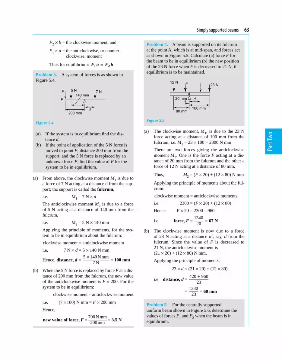
Simply supported beams 63
Part
Two
F2 × b = the clockwise moment, and
F1 × a = the anticlockwise, or counter-clockwise, moment
Thus for equilibrium: 1 2F a F b=
Problem 3. A system of forces is as shown in Figure 5.4.
Figure 5.4
(a) If the system is in equilibrium find the dis-tance d.
(b) If the point of application of the 5 N force is moved to point P, distance 200 mm from the support, and the 5 N force is replaced by an unknown force F, find the value of F for the system to be in equilibrium.
(a) From above, the clockwise moment M1 is due to a force of 7 N acting at a distance d from the sup-port; the support is called the fulcrum,
i.e. M1 = 7 N × d The anticlockwise moment M2 is due to a force
of 5 N acting at a distance of 140 mm from the fulcrum,
i.e. M2 = 5 N ×140 mm Applying the principle of moments, for the sys-
tem to be in equilibrium about the fulcrum: clockwise moment = anticlockwise moment i.e. 7 N × d = 5 × 140 N mm
Hence, distance, d = 5 140 N mm7 N
× = 100 mm
(b) When the 5 N force is replaced by force F at a dis-tance of 200 mm from the fulcrum, the new value of the anticlockwise moment is F × 200. For the system to be in equilibrium:
clockwise moment = anticlockwise moment
i.e. (7 ×100) N mm = F × 200 mm Hence,
new value of force, F = 700 N mm200mm = 3.5 N
Problem 4. A beam is supported on its fulcrum at the point A, which is at mid-span, and forces act as shown in Figure 5.5. Calculate (a) force F for the beam to be in equilibrium (b) the new position of the 23 N force when F is decreased to 21 N, if equilibrium is to be maintained.
Figure 5.5
(a) The clockwise moment, M1, is due to the 23 N force acting at a distance of 100 mm from the fulcrum, i.e. M1 = 23 × 100 = 2300 N mm
There are two forces giving the anticlockwise moment M2. One is the force F acting at a dis-tance of 20 mm from the fulcrum and the other a force of 12 N acting at a distance of 80 mm.
Thus, M2 = (F × 20) + (12 × 80) N mm
Applying the principle of moments about the ful-crum:
clockwise moment = anticlockwise moments i.e. 2300 = (F × 20) + (12 × 80) Hence F × 20 = 2300 – 960
i.e. force, F = 134020 = 67 N
(b) The clockwise moment is now due to a force of 23 N acting at a distance of, say, d from the fulcrum. Since the value of F is decreased to 21 N, the anticlockwise moment is (21 × 20) + (12 × 80) N mm.
Applying the principle of moments,
23 × d = (21 × 20) + (12 × 80)
i.e. distance, d = 420 96023+
= 138023 = 60 mm
Problem 5. For the centrally supported uniform beam shown in Figure 5.6, determine the values of forces F1 and F2 when the beam is in equilibrium.

64 Mechanical Engineering Principles
Part
Two
Figure 5.6
At equilibrium: (i) R = F1 + F2 i.e. 5 = F1 + F2 (1)and (ii) F1 × 3 = F2 × 7 (2)From equation (1), F2 = 5 – F1
Substituting for F2 in equation (2) gives: F1 × 3 = (5 – F1) × 7i.e. 3F1 = 35 – 7F1 10F1 = 35from which, F1 = 3.5 kN Since F2 = 5 – F1, F2 = 1.5 kNThus at equilibrium, force F1 = 3.5 kN and force F2 = 1.5 kN
Now try the following Practise Exercise
Practise Exercise 31 Further problems on equilibrium and the principle of moments
1. Determine distance d and the force acting at the support A for the force system shown in Figure 5.7, when the system is in equilibrium.
Figure 5.7
[50 mm, 3.8 kN]
2. If the 1 kN force shown in Figure 5.7 is replaced by a force F at a distance of 250 mm to the left of RA, find the value of F for the system to be in equilibrium. [560 N]
3. Determine the values of the forces acting at A and B for the force system shown in Figure 5.8.
Figure 5.8
[RA = RB = 25 N]
4. The forces acting on a beam are as shown in Figure 5.9. Neglecting the mass of the beam, find the value of RA and distance d when the beam is in equilibrium.
Figure 5.9
[5 N, 25 mm]
5.3 Simply supported beams having point loads
A simply supported beam is said to be one that rests on two knife-edge supports and is free to move horizontally.
Two typical simply supported beams having loads acting at given points on the beam, called point load-ing, are shown in Figure 5.10.
Figure 5.10

Simply supported beams 65
Part
Two
A man whose mass exerts a force F vertically down-wards, standing on a wooden plank which is simply supported at its ends, may, for example, be represented by the beam diagram of Figure 5.10(a) if the mass of the plank is neglected. The forces exerted by the sup-ports on the plank, RA and RB, act vertically upwards, and are called reactions.
When the forces acting are all in one plane, the algebraic sum of the moments can be taken about any point.For the beam in Figure 5.10(a) at equilibrium:
(i) RA + RB = Fand (ii) taking moments about A, F × a = RB (a + b) (Alternatively, taking moments about C,
RAa = RBb)
For the beam in Figure 5.10(b), at equilibrium
(i) RA + RB = F1 + F2 and (ii) taking moments about B,
RA (a + b) + F2c = F1b
Typical practical applications of simply supported beams with point loadings include bridges, beams in buildings, and beds of machine tools.
Problem 6. A beam is loaded as shown in Figure 5.11.
Figure 5.11
Determine (a) the force acting on the beam support at B (b) the force acting on the beam support at A, neglecting the mass of the beam.
A beam supported as shown in Figure 5.11 is called a simply supported beam.
(a) Taking moments about point A and applying the principle of moments gives:
clockwise moments = anticlockwise moments (2 × 0.2) + (7 × 0.5) + (3 × 0.8) kN m = RB × 1.0 m
where RB is the force supporting the beam at B, as shown in Figure 5.11(b).
Thus (0.4 + 3.5 + 2.4) kN m = RB × 1.0 m
i.e. RB = 6 31 0..kNmm = 6.3 kN
(b) For the beam to be in equilibrium, the forces acting upwards must be equal to the forces acting downwards, thus
RA + RB = (2 + 7 + 3) kN = 12 kN RB = 6.3 kN, thus RA = 12 – RB
= 12 – 6.3 = 5.7 kN
Problem 7. For the beam shown in Figure 5.12 calculate (a) the force acting on support A (b) distance d, neglecting any forces arising from the mass of the beam.
Figure 5.12
(a) From Section 5.2, (the forces acting in an upward direction) =
(the forces acting in a downward direction) Hence (RA + 40) N = (10 + 15 + 30) N
RA = 10 + 15 + 30 – 40 = 15 N
(b) Taking moments about the left-hand end of the beam and applying the principle of moments gives:
clockwise moments = anticlockwise moments
(10 × 0.5) + (15 × 2.0) N m + 30 N × d = (15 × 1.0) + (40 × 2.5) N m
i.e. 35 N m + 30 N × d = 115 N m
from which, distance, d = (115 35) N m30 N−
= 2.67 m

66 Mechanical Engineering Principles
Part
Two
Problem 8. A metal bar AB is 4.0 m long and is simply supported at each end in a horizontal position. It carries loads of 2.5 kN and 5.5 kN at distances of 2.0 m and 3.0 m, respectively, from A. Neglecting the mass of the beam, determine the reactions of the supports when the beam is in equilibrium.
The beam and its loads are shown in Figure 5.13.
Figure 5.13
At equilibrium, RA + RB = 2.5 + 5.5 = 8.0 kN (1)Taking moments about A, clockwise moments = anticlockwise moments
i.e. (2.5 × 2.0) + (5.5 × 3.0) = 4.0 RB or 5.0 + 16.5 = 4.0 RB
from which, RB = 21.54.0 = 5.375 kN
From equation (1), RA = 8.0 – 5.375 = 2.625 kN
Thus the reactions at the supports at equilibrium are 2.625 kN at A and 5.375 kN at B
Problem 9. A beam PQ is 5.0 m long and is simply supported at its ends in a horizontal position as shown in Figure 5.14. Its mass is equivalent to a force of 400 N acting at its centre as shown. Point loads of 12 kN and 20 kN act on the beam in the positions shown. When the beam is in equilibrium, determine (a) the reactions of the supports, RP and RQ, and (b) the position to which the 12 kN load must be moved for the force on the supports to be equal.
Figure 5.14
(a) At equilibrium, RP + RQ = 12 + 0.4 + 20 = 32.4 kN (1)
Taking moments about P: clockwise moments = anticlockwise moments
i.e. (12 × 1.2) + (0.4 × 2.5) + (20 × 3.5) = (RQ × 5.0)
14.4 + 1.0 + 70.0 = 5.0 RQ
from which, RQ = 85.45.0 = 17.08 kN
From equation (1), RP = 32.4 – RQ
= 32.4 – 17.08 = 15.32 kN
(b) For the reactions of the supports to be equal,
RP = RQ = 32.4
2 = 16.2 kN
Let the 12 kN load be at a distance d metres from P (instead of at 1.2 m from P). Taking moments about point P gives:
(12 × d) + (0.4 × 2.5) + (20 × 3.5) = 5.0 RQ
i.e. 12d + 1.0 + 70.0 = 5.0 × 16.2
and 12d = 81.0 – 71.0
from which, d = 10.012 = 0.833 m
Hence the 12 kN load needs to be moved to a position 833 mm from P for the reactions of the supports to be equal (i.e. 367 mm to the left of its original position).
Problem 10. A uniform steel girder AB is 6.0 m long and has a mass equivalent to 4.0 kN acting at its centre. The girder rests on two supports at C and B as shown in Figure 5.15. A point load of 20.0 kN is attached to the beam as shown. Determine the value of the force F that causes the beam to just lift off the support B.
Figure 5.15

Simply supported beams 67
Part
Two
At equilibrium, RC + RB = F + 4.0 + 20.0.
When the beam is just lifting off of the support B, then RB = 0, hence RC = (F + 24.0)kN. Taking moments about A:
Clockwise moments = anticlockwise moments
i.e. (4.0 × 3.0) + (5.0 × 20.0) = (RC × 2.5) + (RB × 6.0)i.e. 12.0 + 100.0 = (F + 24.0) × 2.5 + (0)
i.e. 112.0
2.5 = (F + 24.0)
from which, F = 44.8 – 24.0 = 20.8 kNi.e. the value of force F which causes the beam to just lift off the support B is 20.8 kN
Now try the following Practise Exercise
Practise Exercise 32 Further problems on simply supported beams having point loads
1. Calculate the force RA and distance d for the beam shown in Figure 5.16. The mass of the beam should be neglected and equilibrium conditions assumed.
Figure 5.16
[2.0 kN, 24 mm]
2. For the force system shown in Figure 5.17, find the values of F and d for the system to be in equilibrium.
Figure 5.17
[1.0 kN, 64 mm]
3. For the force system shown in Figure 5.18, determine distance d for the forces RA and RB to be equal, assuming equilibrium conditions. [80 m]
Figure 5.18
Figure 5.19
4. A simply supported beam AB is loaded as shown in Figure 5.19. Determine the load F in order that the reaction at A is zero. [36 kN]
5. A uniform wooden beam, 4.8 m long, is supported at its left-hand end and also at 3.2 m from the left-hand end. The mass of the beam is equivalent to 200 N acting verti-cally downwards at its centre. Determine the reactions at the supports. [50 N, 150 N]
6. For the simply supported beam PQ shown in Figure 5.20, determine (a) the reaction at each support (b) the maximum force which can be applied at Q without losing equilibrium.
Figure 5.20
[(a) R1 = 3 kN, R2 = 12 kN (b) 15.5 kN]
7. A uniform beam AB is 12.0 m long and is sup-ported at distances of 2.0 m and 9.0 m from A.
Loads of 60 kN, 104 kN, 50 kN and 40 kN act vertically downwards at A, 5.0 m from A, 7.0 m from A and at B. Neglecting the mass

68 Mechanical Engineering Principles
Part
Two
of the beam, determine the reactions at the supports. [133.7 kN, 120.3 kN]
8. A uniform girder carrying point loads is shown in Figure 5.21. Determine the value of load F which causes the beam to just lift off the support B.
Figure 5.21
[3.25 kN]
5.4 Simply supported beams with couples
The procedure adopted here is a simple extension to Section 5.3, but it must be remembered that the units of a couple are in: N m, N mm, kN m, etc, unlike that of a force. The method of calculating reactions on beams due to couples will now be explained with the aid of worked problems.
Problem 11. Determine the end reactions for the simply supported beam of Figure 5.22, which is subjected to an anti-clockwise couple of 5 kN m applied at mid-span.
Figure 5.22
Taking moments about B: Now the reaction RA exerts a clockwise moment about B given by: RA × 3 mAdditionally, the couple of 5 kN m is anti-clockwise and its moment is 5 kN m regardless of where it is placed.
Clockwise moments about B = anti-clockwise moments about B
i.e. RA × 3 m = 5 kN m (5.1)
from which, RA = 53 kN
or RA = 1.667 kN (5.2)Resolving forces vertically gives: Upward forces = downward forcesi.e. RA + RB = 0 (5.3)It should be noted that in equation (5.3) the 5 kN m couple does not appear; this is because it is a couple and not a force.From equations (5.2) and (5.3), RB = –RA = –1.667 kNi.e. RB acts in the opposite direction to RA, so that RB and RA also form a couple that resists the 5 kN m couple.
Problem 12. Determine the end reactions for the simply supported beam of Figure 5.23, which is subjected to an anti-clockwise couple of 5 kN m at the point C.
Figure 5.23
Taking moments about B gives:
RA × 3 m = 5 kN m (5.4)
from which, RA = 53 kN
or RA = 1.667 kN
Resolving forces vertically gives:
i.e. RA + RB = 0
from which, RB = –RA = –1.667 kN
It should be noted that the answers for the reactions are the same for Problems 11 and 12, thereby proving by induction that the position of a couple on a beam, simply supported at its ends, does not affect the values of the reactions.
Problem 13. Determine the reactions for the simply supported beam of Figure 5.24.

Simply supported beams 69
Part
Two
Figure 5.24
Taking moments about B gives: RA × 4 m + 8 kN m = 10 kN m + 6 kN mi.e. 4 RA = 10 + 6 – 8 = 8
from which, RA = 84 = 2 kN
Resolving forces vertically gives: RA + RB = 0 from which, RB = –RA = –2 kN
Problem 14. Determine the reactions for the simply supported beam of Figure 5.25.
Figure 5.25
Taking moments about B gives: RA × 4 m + 8 kN m + 6 kN × 1 m = 10 kN m i.e. 4 RA = 10 – 8 – 6 = – 4
from which, RA = – 44 = –1 kN (acting downwards)
Resolving forces vertically gives: RA + RB + 6 = 0 from which, RB = –RA – 6 = – (–1) – 6 i.e. RB = 1 – 6 = –5 kN (acting downwards)
Now try the following Practise Exercises
Practise Exercise 33 Further problems on simply supported beams with couples
For each of the following problems, determine the reactions acting on the simply supported beams:
1.
Figure 5.26
[RA = – 1 kN, RB = 1 kN]
2.
Figure 5.27
[RA = – 1 kN, RB = 1 kN]
3.
Figure 5.28
[RA = 1 kN, RB = – 1 kN]
4.
Figure 5.29
[RA = 0, RB = 0]
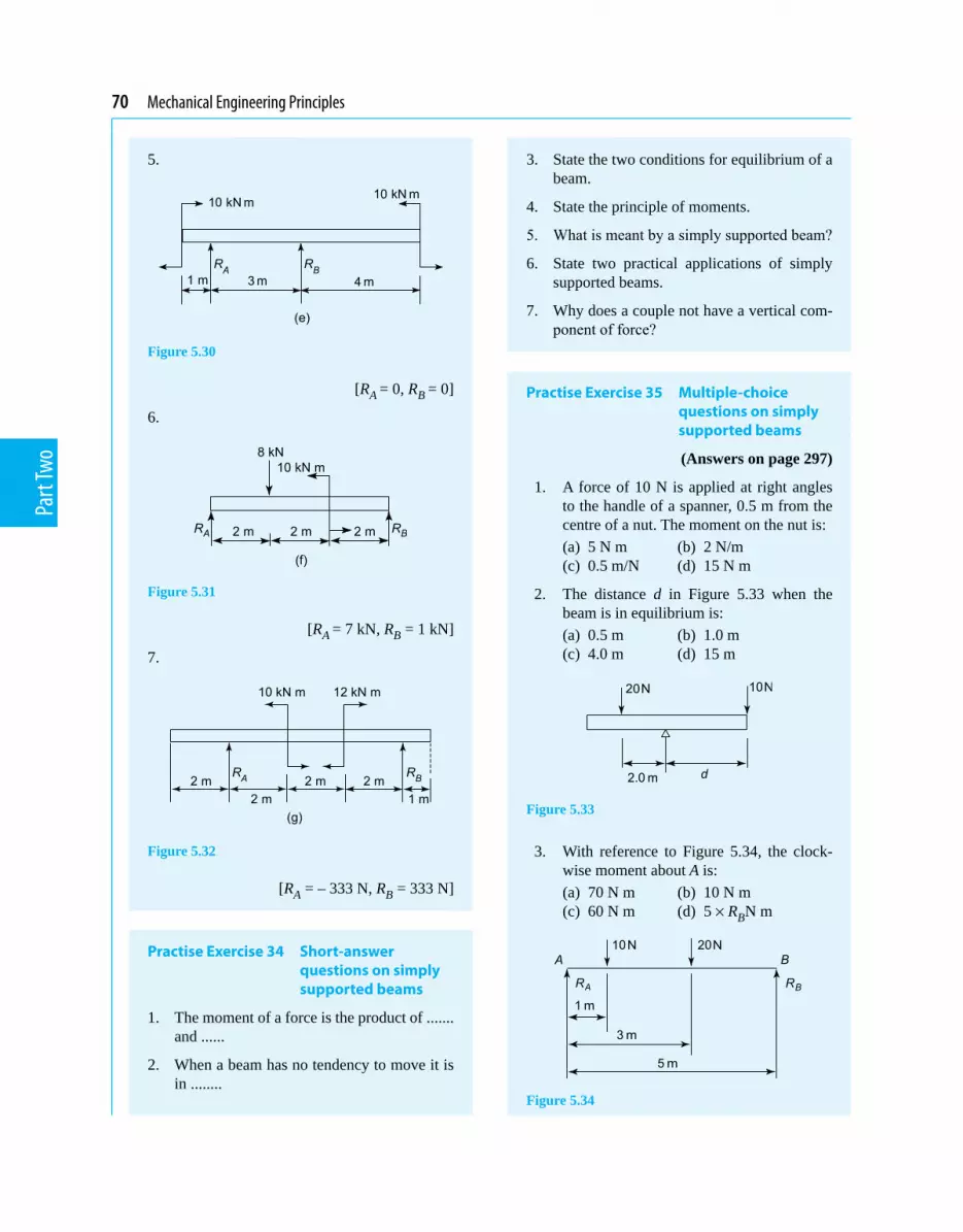
70 Mechanical Engineering Principles
Part
Two
5.
Figure 5.30
[RA = 0, RB = 0]
6.
Figure 5.31
[RA = 7 kN, RB = 1 kN]
7.
Figure 5.32
[RA = – 333 N, RB = 333 N]
Practise Exercise 34 Short-answer questions on simply supported beams
1. The moment of a force is the product of ....... and ......
2. When a beam has no tendency to move it is in ........
3. State the two conditions for equilibrium of a beam.
4. State the principle of moments.
5. What is meant by a simply supported beam?
6. State two practical applications of simply supported beams.
7. Why does a couple not have a vertical com-ponent of force?
Practise Exercise 35 Multiple-choice questions on simply supported beams
(Answers on page 297)
1. A force of 10 N is applied at right angles to the handle of a spanner, 0.5 m from the centre of a nut. The moment on the nut is:
(a) 5 N m (b) 2 N/m (c) 0.5 m/N (d) 15 N m
2. The distance d in Figure 5.33 when the beam is in equilibrium is:
(a) 0.5 m (b) 1.0 m (c) 4.0 m (d) 15 m
Figure 5.33
3. With reference to Figure 5.34, the clock-wise moment about A is:
(a) 70 N m (b) 10 N m (c) 60 N m (d) 5 × RBN m
Figure 5.34

Simply supported beams 71
Part
Two
4. The force acting at B (i.e. RB) in Figure 5.34 is:
(a) 16 N (b) 20 N (c) 5 N (d) 14 N
5. The force acting at A (i.e. RA) in Figure 5.34 is:
(a) 16 N (b) 10 N (c) 15 N (d) 14 N
6. Which of the following statements is false for the beam shown in Figure 5.35 if the beam is in equilibrium?
(a) The anticlockwise moment is 27 N (b) The force F is 9 N (c) The reaction at the support R is 18 N (d) The beam cannot be in equilibrium for
the given conditions
Figure 5.35
7. With reference to Figure 5.36, the reaction RA is:
(a) 10 N (b) 30 N (c) 20 N (d) 40 N
Figure 5.36
8. With reference to Figure 5.36, when mo-ments are taken about RA, the sum of the anticlockwise moments is:
(a) 25 N m (b) 20 N m (c) 35 N m (d) 30 N m
9. With reference to Figure 5.36, when mo-ments are taken about the right-hand end, the sum of the clockwise moments is:
(a) 10 N m (b) 20 N m (c) 30 N m (d) 40 N m
10. With reference to Figure 5.36, which of the following statements is false?
(a) (5 + RB) = 25 N m (b) RA = RB (c) (10 × 0.5) = (10 × 1) + (10 × 1.5) + RA (d) RA + RB = 40 N11. A beam simply supported at its ends is
subjected to two intermediate couples of 4 kN m clockwise and 4 kN m anti- clockwise. The values of the end reactions are:
(a) 4 kN (b) 8 kN (c) zero (d) unknown

Part
Two
1. A metal bar having a cross-sectional area of 80 mm2 has a tensile force of 20 kN applied to it. Determine the stress in the bar. (4)
2. (a) A rectangular metal bar has a width of 16 mm and can support a maximum compressive stress of 15 MPa; determine the minimum breadth of the bar when loaded with a force of 6 kN.
(b) If the bar in (a) is 1.5 m long and decreases in length by 0.18 mm when the force is ap-plied, determine the strain and the percentage strain. (7)
3. A wire is stretched 2.50 mm by a force of 400 N. Determine the force that would stretch the wire 3.50 mm, assuming that the elastic limit is not exceeded. (5)
4. A copper tube has an internal diameter of 140 mm and an outside diameter of 180 mm and is used to support a load of 4 kN. The tube is 600 mm long before the load is applied. Determine, in micrometres, by how much the tube contracts when loaded, taking the modulus of elasticity for copper as 96 GPa. (8)
5. The results of a tensile test are: diameter of specimen 21.7 mm; gauge length 60 mm; load at limit of proportionality 50 kN; extension at limit of proportionality 0.090 mm; maximum load 100 kN; final length at point of fracture 75 mm.
Determine (a) Young’s modulus of elasticity (b) the ultimate tensile strength (c) the stress at the limit of proportionality (d) the percentage elongation. (10)
6. A force of 25 N acts horizontally to the right and a force of 15 N is inclined at an angle of 30° to the 25 N force. Determine the magnitude and direc-tion of the resultant of the two forces using (a) the triangle of forces method (b) the parallelogram of forces method and (c) by calculation (12)
7. Determine graphically the magnitude and direc-tion of the resultant of the following three co- planar forces, which may be considered as acting at a point.
Force P, 15 N acting horizontally to the right
Force Q, 8 N inclined at 45° to force P
Force R, 20 N inclined at 120° to force P. (7)
8. Determine by resolution of forces the resultant of the following three coplanar forces acting at a point: 120 N acting at 40° to the horizontal; 250 N acting at 145° to the horizontal; 300 N acting at 260° to the horizontal. (8)
9. A moment of 18 N m is required to operate a lift-ing jack. Determine the effective length of the handle of the jack (in millimetres) if the force applied to it is (a) 90 N (b) 0.36 kN (6)
10. For the centrally supported uniform beam shown in Figure RT2.1, determine the values of forces F1 and F2 when the beam is in equilibrium. (7)
Figure RT2.1
11. For the beam shown in Figure RT2.2 calculate (a) the force acting on support Q, (b) distance d, neglecting any forces arising from the mass of the beam. (7)
Figure RT2.2
12. A beam of length 3 m is simply supported at its ends. If a clockwise couple of 4 kN m is placed at a distance of 1 m from the left hand support, determine the end reactions. (4)
Revision Test 2 Forces, tensile testing and beams
This Revision Test covers the material contained in Chapters 2 to 5. The marks for each question are shown in brackets at the end of each question.

Chapter 6
Forces in structures
Mechanical Engineering Principles, Bird and Ross, ISBN 9780415517850
6.1 Introduction
As stated above, in this chapter it will be shown how the principles described in Chapter 4 can be used to determine the internal forces in the members of a truss, due to externally applied loads. The definition of a truss is that it is a frame where the joints are assumed to be frictionless and pin-jointed, and that all external loads are applied to the pin joints. In countries where there
In this chapter it will be shown how the principles described in Chapter 4 on forces acting at a point can be used to determine the internal forces in the members of a truss, due to externally applied loads. In countries where there is a lot of rain, such structures are used to support the sloping roofs of the building; the externally applied loads acting on the pin-jointed trusses are usually due to snow and self-weight, and also due to wind. Tie bars and struts aredefined,Bow’snotationisexplainedandinternalforces in a truss are calculated by different methods.
is a lot of rain, such structures are used to support the sloping roofs of the building, as shown in Figure 6.1.
Figure 6.1 Pin-jointed truss
The externally applied loads acting on the pin-jointed trusses are usually due to snow and self-weight, and also due to wind, as shown in Figure 6.1. In Figure 6.1, the snow and self-weight loads act vertically downwards and the wind loads are usually assumed to act horizontally. Thus, for structures such as that shown in Figure 6.1, where the externally applied loads are assumed to act at the pin-joints, the internal members of the framework resist the externally applied loads in tension or compression.
Members of the framework that resist the externally applied loads in tension are called ties and members of the framework which resist the externally applied loads in compression are called struts, as shown in Figure 6.2.
Figure 6.2 Ties and struts with external loads
The internal resisting forces in the ties and struts will act in the opposite direction to the externally applied loads, as shown in Figure 6.3.
At the end of this chapter you should be able to:
• recognise a pin-jointed truss• recognise a mechanism• define a tie bar• define a strut• understand Bow’s notation• calculate the internal forces in a truss by a
graphical method• calculate the internal forces in a truss by the
‘method of joints’• calculate the internal forces in a truss by the
‘method of sections’

74 Mechanical Engineering Principles
Part
Two
Figure 6.3 Internal resisting forces in ties and struts
The methods of analysis used in this chapter break-down if the joints are rigid (welded), or if the loads are applied between the joints. In these cases, flexure occurs in the members of the framework, and other methods of analysis have to be used, as described in Chapters 5 and 7. It must be remembered, however, that even if the joints of the framework are smooth and pin-jointed and also if externally applied loads are placed at the pin-joints, members of the truss in com-pression can fail through structural failure (see refer-ences [1] and [2] on page 86).
It must also be remembered that the methods used here cannot be used to determine forces in statically indeterminate pin-jointed trusses, nor can they be used to determine forces in mechanisms. Statically indeterminate structures are so called because they cannot be analysed by the principles of statics alone. Typical mechanisms are shown in Figure 6.4; these are not classified as structures because they are not firm and can be moved easily under external loads.
Figure 6.4 Mechanisms
To make the mechanism of Figure 6.4(a) into a simple statically determinate structure, it is necessary to add one diagonal member joined to a top joint and an ‘opposite’ bottom joint. To make the mechanism of Figure 6.4(b) into a statically determinate structure, it is necessary to add two members from the top joint to each of the two bottom joints near the mid-length of the bottom horizontal.
Three methods of analysis will be used in this chapter – one graphical and two analytical methods.
6.2 Worked problems on mechanisms and pin-jointed trusses
Problem 1. Show how the mechanism of Figure 6.4(a) can be made into a statically determinate structure.
The two solutions are shown by the broken lines of Figures 6.5(a) and (b), which represent the placement of additional members.
Figure 6.5
Problem 2. Show how the mechanism of Figure 6.4(b) can be made into a statically determinate truss.
The solution is shown in Figures 6.6, where the bro-ken lines represent the placement of two additional members.
Figure 6.6
Problem 3. Show how the mechanism of Figure 6.4(a) can be made into a statically indeterminate truss.
The solution is shown in Figure 6.7, where the broken lines represent the addition of two members, which are not joined where they cross.
Figure 6.7
Problem 4. Why is the structure of Figure 6.7 said to be statically indeterminate?
As you can only resolve vertically and horizontally at the joints A and B, you can only obtain four simultaneous equations. However, as there are five members, each with an unknown force, you have one unknown force too many. Thus, using the principles of statics alone, the structure cannot be satisfactorily
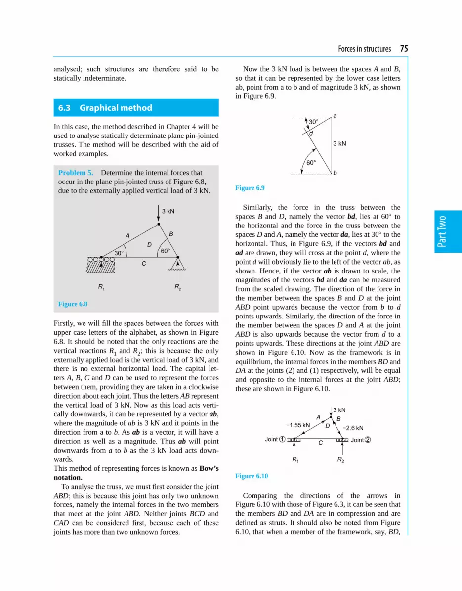
Forces in structures 75
Part
Two
analysed; such structures are therefore said to be statically indeterminate.
6.3 Graphical method
In this case, the method described in Chapter 4 will be used to analyse statically determinate plane pin-jointed trusses. The method will be described with the aid of worked examples.
Problem 5. Determine the internal forces that occur in the plane pin-jointed truss of Figure 6.8, due to the externally applied vertical load of 3 kN.
Figure 6.8
Firstly, we will fill the spaces between the forces with upper case letters of the alphabet, as shown in Figure 6.8. It should be noted that the only reactions are the vertical reactions R1 and R2; this is because the only externally applied load is the vertical load of 3 kN, and there is no external horizontal load. The capital let-ters A, B, C and D can be used to represent the forces between them, providing they are taken in a clockwise direction about each joint. Thus the letters AB represent the vertical load of 3 kN. Now as this load acts verti-cally downwards, it can be represented by a vector ab, where the magnitude of ab is 3 kN and it points in the direction from a to b. As ab is a vector, it will have a direction as well as a magnitude. Thus ab will point downwards from a to b as the 3 kN load acts down-wards.This method of representing forces is known as Bow’s notation.
To analyse the truss, we must first consider the joint ABD; this is because this joint has only two unknown forces, namely the internal forces in the two members that meet at the joint ABD. Neither joints BCD and CAD can be considered first, because each of these joints has more than two unknown forces.
Now the 3 kN load is between the spaces A and B, so that it can be represented by the lower case letters ab, point from a to b and of magnitude 3 kN, as shown in Figure 6.9.
Figure 6.9
Similarly, the force in the truss between the spaces B and D, namely the vector bd, lies at 60° to the horizontal and the force in the truss between the spaces D and A, namely the vector da, lies at 30° to the horizontal. Thus, in Figure 6.9, if the vectors bd and ad are drawn, they will cross at the point d, where the point d will obviously lie to the left of the vector ab, as shown. Hence, if the vector ab is drawn to scale, the magnitudes of the vectors bd and da can be measured from the scaled drawing. The direction of the force in the member between the spaces B and D at the joint ABD point upwards because the vector from b to d points upwards. Similarly, the direction of the force in the member between the spaces D and A at the joint ABD is also upwards because the vector from d to a points upwards. These directions at the joint ABD are shown in Figure 6.10. Now as the framework is in equilibrium, the internal forces in the members BD and DA at the joints (2) and (1) respectively, will be equal and opposite to the internal forces at the joint ABD; these are shown in Figure 6.10.
Figure 6.10
Comparing the directions of the arrows in Figure 6.10 with those of Figure 6.3, it can be seen that the members BD and DA are in compression and are defined as struts. It should also be noted from Figure 6.10, that when a member of the framework, say, BD,

76 Mechanical Engineering Principles
Part
Two
is so defined, we are referring to the top joint, because we must always work around a joint in a clock-wise manner; thus the arrow at the top of BD points upwards, because in Figure 6.9, the vector bd points upwards from b to d. Similarly, if the same member is referred to as DB, then we are referring to the bottom of this member at the joint (2), because we must always work clockwise around a joint. Hence, at joint (2), the arrow points downwards, because the vector db points downwards from d to b in Figure 6.9.
To determine the unknown forces in the horizontal member between joints (1) and (2), either of these joints can be considered, as both joints now only have two unknown forces. Let us consider joint (1), i.e. joint ADC. Now the vector ad can be measured from Figure 6.9 and drawn to scale in Figure 6.11.
Figure 6.11
Now the unknown force between the spaces D and C, namely the vector dc is horizontal and the unknown force between the spaces C and A, namely the vector ca is vertical, hence, by drawing to scale and direction, the point c can be found. This is because the point c in Figure 6.11 lies below the point a and to the right of d.
In Figure 6.11, the vector ca represents the magni-tude and direction of the unknown reaction R1 and the vector dc represents the magnitude and direction of the force in the horizontal member at joint (1); these forces are shown in Figure 6.12, where R1 = 0.82 kN and dc = 1.25 kN.
Figure 6.12
Comparing the directions of the internal forces in the bottom of the horizontal member with Figure 6.3, it can be seen that this member is in tension and therefore, it is a tie.
The reaction R2 can be determined by consider-ing joint (2), i.e. joint BCD, as shown in Figure 6.13, where the vector bc represents the unknown reaction R2 which is measured as 2.18 kN.
Figure 6.13
The complete vector diagram for the whole frame-work is shown in Figure 6.14, where it can be seen that R1 + R2 = 3 kN, as required by the laws of equilibrium. It can also be seen that Figure 6.14 is a combination of the vector diagrams of Figures 6.9, 6.11 and 6.13. Experi-ence will enable this problem to be solved more quickly by producing the vector diagram of Figure 6.14 directly.
Figure 6.14
The table below contains a summary of all the mea-sured forces.
Member Force (kN)
bd –2.6
da –1.55
cd 1.25
R1 0.82
R2 2.18
Problem 6. Determine the internal forces in the members of the truss of Figure 6.15 due to the externally applied horizontal force of 4 kN at the joint ABE.

Forces in structures 77
Part
Two
Figure 6.15
In this case, the spaces between the unknown forces are A, B, C, D and E. It should be noted that the reac-tion at joint (1) is vertical because the joint is on roll-ers, and that there are two reactions at joint (2) because it is firmly anchored to the ground and there is also a horizontal force of 4 kN which must be balanced by the unknown horizontal reaction H2. If this unknown horizontal reaction did not exist, the structure would ‘float’ into space due to the 4 kN load.
Consider joint ABE, as there are only two unknown forces here, namely the forces in the members BE and EA. Working clockwise around this joint, the vector diagram for this joint is shown in Figure 6.16.
Figure 6.16
Joint (2) cannot be considered next, as it has three unknown forces, namely H2, R2 and the unknown member force DE. Hence, joint (1) must be considered next; it has two unknown forces, namely R1 and the force in member ED. As the member AE and its direc-tion can be obtained from Figure 6.16, it can be drawn to scale in Figure 6.17. By measurement, de = 3 kN.
Figure 6.17
As R1 is vertical, then the vector da is vertical, hence, the position d can be found in the vector diagram of Figure 6.17, where R1= da (pointing downwards).
To determine R2 and H2, joint (2) can now be con-sidered, as shown by the vector diagram for the joint in Figure 6.18.
Figure 6.18
The complete diagram for the whole framework is shown in Figure 6.19, where it can be seen that this diagram is the sum of the vector diagrams of Figures 6.16 to 6.18.
Figure 6.19
The table below contains a summary of all the mea-sured forces
Member Force (kN)
be –2.1
ae 3.5
de –3.0
R1 –1.8
R2 1.8
H2 4.0
Couple and momentPrior to solving Problem 7, it will be necessary for the reader to understand the nature of a couple; this is described in Chapter 10, page 126. The magnitude of a couple is called its moment; this is described in Chapter 5, page 61.
Problem 7. Determine the internal forces in the pin-jointed truss of Figure 6.20.
Figure 6.20

78 Mechanical Engineering Principles
Part
Two
In this case, there are more than two unknowns at every joint; hence it will first be necessary to calculate the unknown reactions R1 and R2.To determine R1, take moments about joint (2):Clockwise moments about joint (2) = counter-clockwise (or anti-clockwise) moments about joint (2)
i.e. R1 × 8 m = 4 kN × 6 m + 3 kN × 4 m + 5 kN × 2 m = 24 + 12 + 10 = 46 kN m
Therefore, R1 = 46kN m
8m = 5.75 kN
Resolving forces vertically: Upward forces = downward forcesi.e. R1 + R2 = 4 + 3 + 5 = 12 kNHowever, R1 = 5.75 kN, from above,hence, 5.75 kN + R2 = 12 kNfrom which, R2 = 12 – 5.75 = 6.25 kN
Placing these reactions on Figure 6.21, together with the spaces between the lines of action of the forces, we can now begin to analyse the structure.
Figure 6.21
Starting at either joint AFE or joint DEJ, where there are two or less unknowns, the drawing to scale of the vector diagram can commence. It must be remembered to work around each joint in turn, in a clockwise man-ner, and only to tackle a joint when it has two or less unknowns. The complete vector diagram for the entire structure is shown in Figure 6.22.
Figure 6.22
The table below contains a summary of all the mea-sured forces.
Member Force (kN)
af –11.5
fe 10.0
jd –12.5
ej 10.9
bg –7.5
gf –4.0
ch –7.6
hg 4.6
jh –5.0
R1 5.75
R2 6.25
Now try the following Practise Exercise
Practise Exercise 36 Further problems on a graphical method
Determine the internal forces in the following pin-jointed trusses using a graphical method:
1.
Figure 6.23
[ R1 = 3.0 kN, R2 = 1.0 kN, 1 – 2, 1.7 kN, 1 – 3, – 3.5 kN, 2 – 3, – 2.0 kN ]
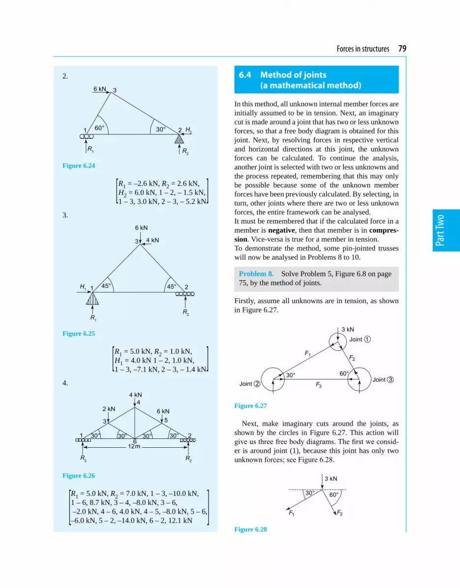
Forces in structures 79
Part
Two
2.
Figure 6.24
[ R1 = –2.6 kN, R2 = 2.6 kN, H2 = 6.0 kN, 1 – 2, – 1.5 kN, 1 – 3, 3.0 kN, 2 – 3, – 5.2 kN]
3.
Figure 6.25
[ R1 = 5.0 kN, R2 = 1.0 kN, H1 = 4.0 kN 1 – 2, 1.0 kN, 1 – 3, –7.1 kN, 2 – 3, – 1.4 kN]
4.
Figure 6.26
R1 = 5.0 kN, R2 = 7.0 kN, 1 – 3, –10.0 kN, 1 – 6, 8.7 kN, 3 – 4, –8.0 kN, 3 – 6, –2.0 kN, 4 – 6, 4.0 kN, 4 – 5, –8.0 kN, 5 – 6, –6.0 kN, 5 – 2, –14.0 kN, 6 – 2, 12.1 kN
6.4 Method of joints (a mathematical method)
In this method, all unknown internal member forces are initially assumed to be in tension. Next, an imaginary cut is made around a joint that has two or less unknown forces, so that a free body diagram is obtained for this joint. Next, by resolving forces in respective vertical and horizontal directions at this joint, the unknown forces can be calculated. To continue the analysis, another joint is selected with two or less unknowns and the process repeated, remembering that this may only be possible because some of the unknown member forces have been previously calculated. By selecting, in turn, other joints where there are two or less unknown forces, the entire framework can be analysed.It must be remembered that if the calculated force in a member is negative, then that member is in compres-sion. Vice-versa is true for a member in tension.To demonstrate the method, some pin-jointed trusses will now be analysed in Problems 8 to 10.
Problem 8. Solve Problem 5, Figure 6.8 on page 75, by the method of joints.
Firstly, assume all unknowns are in tension, as shown in Figure 6.27.
Figure 6.27
Next, make imaginary cuts around the joints, as shown by the circles in Figure 6.27. This action will give us three free body diagrams. The first we consid-er is around joint (1), because this joint has only two unknown forces; see Figure 6.28.
Figure 6.28

80 Mechanical Engineering Principles
Part
Two
Resolving forces horizontally at joint (1):
Forces to the left = forces to the right
i.e. F1 cos 30° = F2 cos 60°
i.e. 0.866 F1 = 0.5 F2
from which, F1 = 20.50.866
F
i.e. F1 = 0.577 F2 (6.1)
Resolving forces vertically at joint (1):Upward forces = downward forcesi.e. 0 = 3 kN + F1 sin 30° + F2 sin 60°i.e. 0 = 3 + 0.5 F1 + 0.866 F2 (6.2)Substituting equation (6.1) into equation (6.2) gives:
0 = 3 + 0.5 × 0.577 F2 + 0.866 F2
i.e. – 3 = 1.1545 F2
from which, F2 = – 31.1545
i.e. F2 = –2.6 kN (compressive) (6.3)
Substituting equation (6.3) into equation (6.1) gives:
F1 = 0.577 × (– 2.6)
i.e. F1 = –1.5 kN (compressive)
Considering joint (2), as it now has two or less un-known forces; see Figure 6.29.
Figure 6.29
Resolving horizontally: Forces to the left = forces to the righti.e. 0 = F1 cos 30° + F3
However, F1 = –1.5 kN,
hence, 0 = –1.5 × 0.866 + F3
from which, F3 = 1.30 kN (tensile)
These results are similar to those obtained by the graphical method used in Problem 5; see Figure 6.12 on page 76, and the table below.
Member Force (kN)
F1 –1.5
F2 –2.6
F3 1.3
Problem 9. Solve Problem 6, Figure 6.15 on page 77, by the method of joints.
Firstly, we will assume that all unknown internal forces are in tension, as shown by Figure 6.30.
Figure 6.30
Next, we will isolate each joint by making imagi-nary cuts around each joint, as shown by the circles in Figure 6.30; this will result in three free body dia-grams. The first free body diagram will be for joint (1), as this joint has two or less unknown forces; see Figure 6.31.
Figure 6.31
Resolving forces horizontally:
F1 cos 30° = 4 kN + F2 cos 60°
i.e. 0.866 F1 = 4 + 0.5 F2
from which, F1 = 24 0.50.866
F+
or F1 = 4.619 kN + 0.577 F2 (6.4)

Forces in structures 81
Part
Two
Resolving forces vertically: 0 = F1 sin 30° + F2 sin 60°i.e. 0 = 0.5 F1 + 0.866 F2
or – F1 = 20.8660.5
F
or F1 = –1.732 F2 (6.5)
Equating equations (6.4) and (6.5) gives:
4.619 kN + 0.577 F2 = –1.732 F2
i.e. 4.619 = –1.732 F2 – 0.577 F2
= –2.309 F2
Hence F2 = – 4.6192.309
i.e. F2 = –2 kN (compressive) (6.6)
Substituting equation (6.6) into equation (6.5) gives:
F1 = –1.732 × (–2)
i.e. F1 = 3.465 kN (6.7)
Consider next joint (2), as this joint now has two or less unknown forces; see Figure 6.32.
Figure 6.32
Resolving forces vertically:
R1 + F1 sin 30° = 0or R1 = –F1 sin 30° (6.8)
Substituting equation (6.7) into equation (6.8) gives:
R1 = –3.465 × 0.5i.e. R1 = –1.733 kN (acting downwards)
Resolving forces horizontally:
0 = F1 cos 30° + F3
or F3 = –F1 cos 30° (6.9)
Substituting equation (6.7) into equation (6.9) gives:
F3 = –3.465 × 0.866i.e. F3 = –3 kN (compressive) (6.10)
Consider next joint 3; see Figure 6.33.
Figure 6.33
Resolving forces vertically:
F2 sin 60° + R2 = 0i.e. R2 = –F2 sin 60° (6.11)
Substituting equation (6.6) into equation (6.11) gives:
R2 = –(–2) × 0.866
i.e. R2 = 1.732 kN (acting upwards)
Resolving forces horizontally:
F3 + F2 cos 60° + H2 = 0i.e. H2 = – F3 – F2 × 0.5 (6.12)
Substituting equations (6.6) and (6.10) into equation (6.12) gives:
H2 = –(–3) – (–2) × 0.5
i.e. H2 = 4 kN
These calculated forces are of similar value to those obtained by the graphical solution for Problem 6, as shown in the table below.
Member Force (kN)
F1 3.47
F2 –2.0
F3 –3.0
R1 –1.73
R2 1.73
H2 4.0
Problem 10. Solve Problem 7, Figure 6.20 on page 77, by the method of joints.
Firstly, assume all unknown member forces are in tension, as shown in Figure 6.34.

82 Mechanical Engineering Principles
Part
Two
Figure 6.34
Next, we will isolate the forces acting at each joint by making imaginary cuts around each of the five joints as shown in Figure 6.34.
As there are no joints with two or less unknown forces, it will be necessary to calculate the unknown reactions R1 and R2 prior to using the method of joints. Using the same method as that described for the solution of Problem 7, we have
R1= 5.75 kN and R2 = 6.25 kNNow either joint (1) or joint (2) can be considered, as each of these joints has two or less unknown forces. Consider joint (1); see Figure 6.35.
Figure 6.35
Resolving forces vertically: 5.75 + F1 sin 30° = 0i.e. F1 sin 30° = –5.75or 0.5 F1 = –5.75
i.e. F1 = – 5.750.5
i.e. F1 = –11.5 kN (compressive) (6.13)
Resolving forces horizontally: 0 = F2 + F1 cos 30°i.e. F2 = –F1 cos 30° (6.14)
Substituting equation (6.13) into equation (6.14) gives:
F2 = –F1 cos 30° = –(–11.5) × 0.866i.e. F2 = 9.96 kN (tensile)
Consider joint (2); see Figure 6.36.
Figure 6.36
Resolving forces vertically: R2 + F4 sin 30° = 0
i.e. R2 + 0.5 F4 = 0
or F4 = – 20.5R (6.15)
Since R2 = 6.25, F4 = – 6.250.5
i.e. F4 = –12.5 kN (compressive) (6.16)
Resolving forces horizontally: F3 + F4 cos 30° = 0i.e. F3 = –F4 cos 30° (6.17)Substituting equation (6.16) into equation (6.17) gives:
F3 = –(–12.5) × 0.866
i.e. F3 = 10.83 kN (tensile)
Consider joint (3); see Figure 6.37.
Figure 6.37
Resolving forces vertically:
F6 sin 30° = F1 sin 30° + F5 sin 30° + 4
i.e. F6 = F1 + F5 + 4
sin 30° (6.18)

Forces in structures 83
Part
Two
Substituting equation (6.13) into equation (6.18) gives:
F6 = –11.5 + F5 + 8 (6.19)
Resolving forces horizontally: F1 cos 30° = F5 cos 30° + F6 cos 30°i.e. F1 = F5 + F6 (6.20)
Substituting equation (6.13) into equation (6.20) gives: – 11.5 = F5 + F6
or F6 = –11.5 – F5 (6.21)
Equating equations (6.19) and (6.21) gives: – 11.5 + F5 + 8 = –11.5 – F5
or F5 + F5 = –11.5 + 11.5 – 8
i.e. 2 F5 = –8
from which, F5 = – 4kN (compressive) (6.22)
Substituting equation (6.22) into equation (6.21) gives: F6 = –11.5 – (– 4)i.e. F6 = –7.5 kN (compressive) (6.23)
Consider joint (4); see Figure 6.38.
Figure 6.38
Resolving forces horizontally: F6 cos 30° = F8 cos 30°
i.e. F6 = F8
but from equation (6.23), F6 = –7.5 kN
Hence, F8 = –7.5 kN (compressive) (6.24)
Resolving forces vertically: 0 = 3 + F6 sin 30° + F7 + F8 sin 30°
i.e. 0 = 3 + 0.5 F6 + F7 + 0.5 F8 (6.25)
Substituting equations (6.23) and (6.24) into equation (6.25) gives:
0 = 3 + 0.5 × – 7.5 + F7 + 0.5 × – 7.5
or F7 = –3 + 0.5 × 7.5 + 0.5 × 7.5
= –3 + 7.5
from which, F7 = 4.5 kN (tensile) (6.26)
Consider joint (5); see Figure 6.39.
Figure 6.39
Resolving forces horizontally:
F8 cos 30° + F9 cos 30° = F4 cos 30°
i.e. F8 + F9 = F4 (6.27)Substituting equations (6.24) and (6.16) into equation (6.27) gives: – 7.5 + F9 = –12.5i.e. F9 = –12.5 + 7.5i.e. F9 = – 5 kN (compressive)The results compare favourably with those obtained by the graphical method used in Problem 7; see the table below.
Member Force (kN)
F1 –11.5
F2 9.96
F3 10.83
F4 –12.5
F5 –4.0
F6 –7.5
F7 4.5
F8 –7.5
F9 –5.0

84 Mechanical Engineering Principles
Part
Two
Now try the following Practise Exercise
Practise Exercise 37 Further problems on the method of joints
Using the method of joints, determine the unknown forces for the following pin-jointed trusses:
1. Figure 6.23 (page 78)
[ R1 = 3.0 kN, R2 = 1.0 kN, 1 – 2, 1.73 kN, 1 – 3, –3.46 kN, 2 – 3, –2.0 kN]
2. Figure 6.24 (page 79)
[ R1 = –2.6 kN, R2 = 2.6 kN, H2 = 6.0 kN, 1 – 2, – 1.5 kN, 1 – 3, 3.0 kN, 2–3, – 5.2 kN ]
3. Figure 6.25 (page 79)
[ R1 = 5.0 kN, R2 = 1.0 kN, H1 = 4.0 kN 1 – 2, 1.0 kN, 1 – 3, –7.07 kN, 2 – 3, – 1.41 kN ]
4. Figure 6.26 (page 79)
R1 = 5.0 kN, R2 = 7.0 kN, 1 – 3, – 10.0 kN, 1 – 6, 8.7 kN, 3 – 4, – 8.0 kN, 3 – 6, – 2.0 kN, 4 – 6, 4.0 kN, 4 – 5, – 8.0 kN, 5 – 6, – 6 kN, 5 – 2, –14 kN, 2 – 6, 12.1 kN
6.5 The method of sections (a mathematical method)
In this method, an imaginary cut is made through the framework and the equilibrium of this part of the structure is considered through a free body diagram. No more than three unknown forces can be determined through any cut section, as only three equilibrium con-siderations can be made, namely
(a) resolve forces horizontally(b) resolve forces vertically(c) take moments about a convenient point.
Worked problem 11 demonstrates the method of sec-tions.
Problem 11. Determine the unknown member forces F2 , F5 and F6 of the truss of Figure 6.34, Problem 10, page 81, by the method of sections.
Firstly, all members will be assumed to be in tension and an imaginary cut will be made through the frame-work, as shown by Figure 6.40.
Figure 6.40
Taking moments about B; see Figure 6.41.
Figure 6.41
Clockwise moments = anti-clockwise momentsHence, 5.75 kN × 2 m = F2 × 1.155 m (where 2 tan 30° = 1.155 m from Figure 6.41)
i.e. F2 = 5.75 21.155
× = 9.96 kN (tensile) (6.28)
Resolving forces vertically: 5.75 kN + F6 sin 30° = F5 sin 30° + 4 kN
i.e. F5 = F6 + 5.750.5 – 4
0.5i.e. F5 = F6 + 3.5 (6.29)
Resolving forces horizontally: 0 = F2 + F5 cos 30° + F6 cos 30°from which, F5 cos 30° = –F2 – F6 cos 30°
and F5 = – 2cos30
F° – F6 (6.30)

Forces in structures 85
Part
Two
Substituting equation (6.28) into equation (6.30) gives:
F5 = –9.960.866 – F6
or F5 = –11.5 – F6 (6.31)
Equating equation (6.29) to equation (6.31) gives:
F6 + 3.5 = –11.5 – F6
from which, 2 F6 = –11.5 – 3.5 = –15
and F6 = –152 = –7.5 kN (compressive) (6.32)
Substituting equation (6.32) into equation (6.31) gives:
F5 = –11.5 – (– 7.5) = – 4 kN (compressive) (6.33)
i.e. F2 = 9.96 kN, F5 = – 4 kN and F6 = –7.5 kN The above answers can be seen to be the same as those obtained in Problem 10.
Now try the following Practise Exercises
Practise Exercise 38 Further problems on the method of sections
Determine the internal member forces of the fol-lowing trusses, by the method of sections:
1. Figure 6.23 (page 78)
[ R1 = 3.0 kN, R2 = 1.0 kN, 1 – 2, 1.73 kN, 1 – 3, – 3.46 kN, 2 – 3, – 2.0 kN]
2. Figure 6.24 (page 79)
[ R1 = –2.61 kN, R2 = 2.61 kN, H2 = 6 kN, 1 – 2, – 1.5 kN, 1 – 3, 3.0 kN, 2 – 3, –5.2 kN ]
3. Figure 6.25 (page 79)
[ R1 = 5.0 kN, R2 = 1.0 kN, H1 = 4.0 kN, 1 – 2, 1.0 kN, 1 – 3, –7.07 kN, 2 – 3, –1.41 kN]
4. Figure 6.26 (page 79) R1 = 5.0 kN, R2 = 7.0 kN, 1 – 3, –10.0 kN, 1 – 6, 8.7 kN, 3 – 4, –8.0 kN, 3 – 6, –2.0 kN, 4 – 6, 4.0 kN, 4 – 5, –8.0 kN, 5 – 6, –6.0 kN, 5 – 2, –14.0 kN, 6 – 2, 12.1 kN
Practise Exercise 39 Short-answer questions on forces in structures
1. Where must the loads be applied on a pin-jointed truss?
2. If there are three unknown forces in a truss, how many simultaneous equations are re-quired to determine these unknown forces?
3. When is a truss said to be statically indeter-minate?
4. For a plane pin-jointed truss, what are the maximum number of unknowns that can ex-ist at a joint to analyse that joint without ana-lysing another joint before it?
Practise Exercise 40 Multiple-choice questions on forces in frameworks
(Answers on page 297)
1. The truss of Figure 6.42 is a: (a) mechanism (b) statically determinate (c) statically indeterminate
Figure 6.42
2. The value of F1 in Figure 6.43 is: (a) 1 kN (b) 0.5 kN (c) 0.707 kN
Figure 6.43

86 Mechanical Engineering Principles
Part
Two
3. The value of F2 in Figure 6.43 is: (a) 0.707 kN (b) 0.5 kN (c) 0
4. If the Young’s modulus is doubled in the members of a pin-jointed truss, and the ex-ternal loads remain the same, the internal forces in the truss will:
(a) double (b) halve (c) stay the same
5. If the Young’s modulus is doubled in the members of a pin-jointed truss, and the loads remain the same, the deflection of the truss will:
(a) double (b) halve (c) stay the same
6. If the external loads in a certain truss are doubled, the internal forces will:
(a) double (b) halve (c) stay the same
References
[1] CASE, J, LORD CHILVER and ROSS, C.T.F. Strength of Materials and Structures Butterworth/Heinemann, 1999.
[2] ROSS, C.T.F., Mechanics of Solids, Woodhead Publish-ing Cambridge, U.K. 1999.

Chapter 7
Bending moment and shear force diagrams
Mechanical Engineering Principles, Bird and Ross, ISBN 9780415517850
7.1 Bending moment (M)
The units of bending moment are N mm, N m, kN m, etc. When a beam is subjected to the couples shown in Figure 7.1, the beam will suffer flexure due to the bending moment of magnitude M.
The members of the structures in the previous chapter withstood the externally applied loads in either tension or compression; this was because they were not subjected to bending. In practise many structures are subjected to bending action; such structures include beams and rigid-jointed frameworks (- a rigid-jointed framework is one which has its joints welded or riveted or bolted together; such structures are beyond the scope of this text - see reference [1], on page 86). In this chapter, bending moments and shearing forces are definedandcalculated,beforetheplottingofbendingmoment and shearing force diagrams are explained.
Figure 7.1 Bending moments
If the beam is in equilibrium and it is subjected to a clockwise couple of magnitude M on the left of the section, then from equilibrium considerations, the couple on the right of the section will be of exactly equal magnitude and of opposite direction to the cou-ple on the left of the section. Thus, when calculating the bending moment at a particular point on a beam in equilibrium, we need only calculate the magnitude of the resultant of all the couples on one side of the beam under consideration. This is because as the beam is in equilibrium, the magnitude of the resultant of all the couples on the other side of the beam is exactly equal and opposite. The beam in Figure 7.1(a) is said to be sagging and the beam in Figure 7.1(b) is said to be hogging.The sign convention adopted in this text is:
(a) sagging moments are said to be positive(b) hogging moments are said to be negative
7.2 Shearing force (F)
Whereas a beam can fail due to its bending moments being excessive, it can also fail due to other forces being too large, namely the shearing forces; these
At the end of this chapter you should be able to:
• define a rigid-jointed framework• define bending moment• define sagging and hogging• define shearing force• calculate bending moments• calculate shearing forces • plot bending moment diagrams• plot shearing force diagrams• define the point of contraflexure

88 Mechanical Engineering Principles
Part
Two
are shown in Figure 7.2. The units of shearing force are N, kN, MN, etc.
Figure 7.2 Shearing forces
It can be seen from Figures 7.2(a) and (b) that the shearing forces F act in a manner similar to that exerted by a pair of garden shears when they are used to cut a branch of a shrub or a plant through shearing action. This mode of failure is different to that caused by bend-ing action.
In the case of the garden shears, it is necessary for the blades to be close together and sharp, so that they do not bend the branch at this point. If the garden shears are old and worn the branch can bend and may lie be-tween the blades. Additionally, if the garden shears are not sharp, it may be more difficult to cut the branch because the shearing stress exerted by the blades will be smaller as the contact area between the blades and the branch will be larger.
The shearing action is illustrated by the sketch of Figure 7.3.
Figure 7.3 Shearing action
Once again, if the beam is in equilibrium, then the shearing forces either side of the point being consid-ered will be exactly equal and opposite, as shown in Figures 7.2(a) and (b). The sign convention for shear-ing force is that it is said to be positive if the right hand is going down; see Figure 7.2(a).
Thus, when calculating the shearing force at a particular point on a horizontal beam, we need to calculate the resultant of all the vertical forces on one side of the beam, as the resultant of all the vertical forces on the other side of the beam will be exactly equal and opposite. The calculation of bending moments and shearing forces and the plotting of their respective diagrams are demonstrated in the following worked problems.
7.3 Worked problems on bending moment and shearing force diagrams
Problem 1. Calculate and sketch the bending moment and shearing force diagrams for the horizontal beam shown in Figure 7.4, which is simply supported at its ends.
Figure 7.4
Firstly, it will be necessary to calculate the magnitude of reactions RA and RB
Taking moments about B gives:Clockwise moments about B =
anti-clockwise moments about Bi.e. RA × 5 m = 6 kN × 2 m = 12 kN m
from which, RA = 125 = 2.4 kN
Resolving forces vertically gives: Upward forces = downward forcesi.e. RA + RB = 6 kNi.e. 2.4 + RB = 6from which, RB = 6 – 2.4 = 3.6 kNAs there is a discontinuity at point C in Figure 7.4, due to the concentrated load of 6 kN, it will be neces-sary to consider the length of the beam AC separately from the length of the beam CB. The reason for this is that the equations for bending moment and shear-ing force for span AC are different to the equation for

Bending moment and shear force diagrams 89
Part
Two
the span CB; this is caused by the concentrated load of 6 kN. For the present problem, to demonstrate the nature of bending moment and shearing force, these values will be calculated on both sides of the point of the beam under consideration. It should be noted that nor-mally, the bending moment and shearing force at any point on the beam, are calculated only due to the resul-tant couples or forces, respectively, on one side of the beam.
Consider span AC:Bending momentConsider a section of the beam at a distance x from the left end A, where the value of x lies between A and C, as shown in Figure 7.5.
Figure 7.5
From Figure 7.5, it can be seen that the reaction RA causes a clockwise moment of magnitude RA × x = 2.4x on the left of this section and as shown in the lower diagram of Figure 7.5. It can also be seen from the up-per diagram of Figure 7.5, that the forces on the right of this section on the beam causes an anti-clockwise mo-ment equal to RB × (5 – x) or 3.6(5 – x) and a clockwise moment of 6 × (3 – x), resulting in an anti-clockwise moment of:
3.6(5 – x) – 6(3 – x) = 3.6 × 5 – 3.6x – 6 × 3 + 6x
= 18 – 3.6x – 18 + 6x = 2.4xThus, the left side of the beam at this section is sub-jected to a clockwise moment of magnitude 2.4x and the right side of this section is subjected to an anti- clockwise moment of 2.4x, as shown by the lower diagram of Figure 7.5. As the two moments are of equal magnitude but of opposite direction, they cause the beam to be subjected to a bending moment M = 2.4x. As this bending moment causes the beam to sag
between A and C, the bending moment is assumed to be positive, or at any distance x between A and C: Bending moment = M = +2.4x (7.1)
Shearing forceHere again, because there is a discontinuity at C, due to the concentrated load of 6 kN at C, we must con-sider a section of the beam at a distance x from the left end A, where x varies between A and C, as shown in Figure 7.6.
Figure 7.6
From Figure 7.6, it can be seen that the resultant of the vertical forces on the left of the section at x are 2.4 kN acting upwards. This force causes the left of the section at x to slide upwards, as shown in the lower diagram of Figure 7.6. Similarly, if the vertical forces on the right of the section at x are considered, it can be seen that the 6 kN acts downwards and that RB = 3.6 kN acts upwards, giving a resultant of 2.4 kN acting downwards. The effect of the two shearing forc-es acting on the left and the right of the section at x, causes the shearing action shown in the lower diagram of Figure 7.6. As this shearing action causes the right side of the section to glide downwards, it is said to be a positive shearing force.Summarising, at any distance x between A and C:
F = shearing force = +2.4 kN (7.2)
Consider span CB:Bending momentAt any distance x between C and B, the resultant mo-ment caused by the forces on the left of x is given by:
M = RA × x – 6(x – 3) = 2.4x – 6(x – 3) = 2.4x – 6x + 18i.e. M = 18 – 3.6x (clockwise) (7.3)The effect of this resultant moment on the left of x is shown in the lower diagram of Figure 7.7.

90 Mechanical Engineering Principles
Part
Two
Figure 7.7
Now from Figure 7.7, it can be seen that on the right side of x, there is an anti-clockwise moment of:
M = RB × (5 – x) = 3.6(5 – x) = 18 – 3.6xi.e. M = 18 – 3.6x (anti-clockwise) (7.4)The effect of the moment of equation (7.3) and that of the moment of equation (7.4), is to cause the beam to sag at this point as shown by the lower diagram of Figure 7.7, i.e. M is positive between C and B, and
M = +18 – 3.6x (7.5)
Shearing forceConsider a distance x between C and B, as shown in Figure 7.8.
Figure 7.8
From Figure 7.8, it can be seen that at x, there are two vertical forces to the left of this section, namely the 6 kN load acting downwards and the 2.4 kN load acting upwards, resulting in a net value of 3.6 kN act-ing downwards, as shown by the lower diagram of Figure 7.8. Similarly, by considering the vertical forc-es acting on the beam to the right of x, it can be seen that there is one vertical force, namely the 3.6 kN load acting upwards, as shown by the lower diagram of Figure 7.8. Thus, as the right hand of the section is tending to slide upwards, the shearing force is said to be negative, i.e. between C and B,
F = –3.6 kN (7.6)
It should be noted that at C, there is a discontinuity in the value of the shearing force, where over an infini-tesimal length the shearing force changes from +2.4 kN to – 3.6 kN, from left to right.
Bending moment and shearing force diagramsThe bending moment and shearing force diagrams are simply diagrams representing the variation of bend-ing moment and shearing force, respectively, along the length of the beam. In the bending moment and shear-ing force diagrams, the values of the bending moments and shearing forces are plotted vertically and the value of x is plotted horizontally, where x = 0 at the left end of the beam and x = the whole length of the beam at its right end.
In the case of the beam of Figure 7.4, bending moment distribution between A and C is given by equa-tion (7.1), i.e. M = 2.4x, where the value of x varies between A and C. At A, x = 0, therefore MA = 2.4 × 0 = 0and at C, x = 3 m, therefore MC = 2.4 × 3 = 7.2 kN mAdditionally, as the equation M = 2.4x is a straight line, the bending moment distribution between A and C will be as shown by the left side of Figure 7.9(a).
Figure 7.9 Bending moment and shearing force diagrams
Similarly, the expression for the variation of bending moment between C and B is given by equation (7.3), i.e. M = 18 – 3.6x, where the value of x varies between C and B. The equation can be seen to be a straight line between C and B.At C, x = 3 m, therefore MC = 18 – 3.6 × 3 = 18 – 10.8 = 7.2 kN m

Bending moment and shear force diagrams 91
Part
Two
At B, x = 5 m,therefore MB = 18 – 3.6 × 5 = 18 – 18 = 0Therefore, plotting of the equation M = 18 – 3.6x be-tween C and B results in the straight line on the right of Figure 7.9(a), i.e. the bending moment diagram for this beam has now been drawn.
In the case of the beam of Figure 7.4, the shearing force distribution along its length from A to C is given by equation (7.2), i.e. F = 2.4 kN, i.e. F is constant between A and C. Thus the shearing force diagram between A and C is given by the horizontal line shown on the left of C in Figure 7.9(b).
Similarly, the shearing force distribution to the right of C is given by equation (7.6), i.e. F = –3.6 kN, i.e. F is a constant between C and B, as shown by the horizontal line to the right of C in Figure 7.9(b). At the point C, the shearing force is indeterminate and changes from +2.4 kN to –3.6 kN over an infinitesimal length.
Problem 2. Determine expressions for the distri-butions of bending moment and shearing force for the horizontal beam of Figure 7.10. Hence, sketch the bending and shearing force diagrams.
Figure 7.10
Firstly, it will be necessary to calculate the unknown reactions RA and RB
Taking moments about B gives: RA × 5 m + 10 kN × 1 m = 5 kN × 7 m + 6 kN × 3 mi.e. 5 RA + 10 = 35 + 18 5 RA = 35 + 18 – 10 = 43
from which, RA =435 = 8.6 kN
Resolving forces vertically gives:
RA + RB = 5 kN + 6 kN + 10 kN
i.e. 8.6 + RB = 21
from which, RB = 21 – 8.6 = 12.4 kNFor the range C to A, see Figure 7.11.
Figure 7.11
To calculate the bending moment distribution (M), only the resultant of the moments to the left of the section at x will be considered, as the resultant of the moments on the right of the section of x will be exactly equal and opposite.
Bending moment (BM)From Figure 7.11, at any distance x, M = –5 × x (hogging) = –5x (7.7)
Equation (7.7) is a straight line between C and A.At C, x = 0, therefore MC = –5 × 0 = 0 kN mAt A, x = 2 m, therefore MA = –5 × 2 = –10 kN m
Shearing force (SF)To calculate the shearing force distribution (F) at any distance x, only the resultant of the vertical forces to the left of x will be considered, as the resultant of the vertical forces to the right of x will be exactly equal and opposite.From Figure 7.11, at any distance x, F = –5 kN (7.8)It is negative, because as the left of the section tends to slide downwards, the right of the section tends to slide upwards. (Remember, right hand down is positive).For the range A to D, see Figure 7.12.
Figure 7.12
Bending moment (BM)At any distance x between A and D M = –5 × x + RA × (x – 2) = –5x + 8.6(x – 2) = –5x + 8.6x – 17.2

92 Mechanical Engineering Principles
Part
Two
i.e. M = 3.6x – 17.2 (a straight line between A and D) (7.9)
At A, x = 2 m, MA = 3.6 × 2 – 17.2 = 7.2 – 17.2 = –10 kN mAt D, x = 4 m, MD = 3.6 × 4 – 17.2 = 14.4 – 17.2 = –2.8 kN m
Shearing force (SF)At any distance x between A and D, (7.10) F = –5 kN + 8.6 kN = 3.6 kN (constant)For the range D to B, see Figure 7.13.
Figure 7.13
Bending moment (BM)At x, M = –5 × x + 8.6 × (x – 2) – 6 × (x – 4) = –5x + 8.6x –17.2 – 6x + 24i.e. M = –2.4x + 6.8 (7.11)
(a straight line between D and B) At D, x = 4 m, therefore MD = –2.4 × 4 + 6.8 = –9.6 + 6.8i.e. MD = –2.8 kN mAt B, x = 7 m, therefore MB = –2.4 × 7 + 6.8 = –16.8 + 6.8i.e. MB = –10 kN m
Shearing force (SF)At x, F = –5 + 8.6 – 6 = –2.4 kN (constant) (7.12)For the range B to E, see Figure 7.14.
Figure 7.14
Bending moment (BM)In this case it will be convenient to consider only the resultant of the couples to the right of x (-remember
that only one side need be considered, and in this case, there is only one load to the right of x).
At x, M = –10 × (8 – x) = –80 + 10x (7.13)
Equation (7.13) can be seen to be a straight line between B and E.
At B, x = 7 m,therefore MB = –80 + 10 × 7 = –10 kN m
At E, x = 8 m,therefore ME = –80 + 10 × 8 = 0 kN m
Shearing force (SF)At x, F = + 10 kN (constant) (7.14)Equation (7.14) is positive because the shearing force is causing the right side to slide downwards. The bending moment and shearing force diagrams are plotted in Figure 7.15 with the aid of equations (7.7) to (7.14) and the associated calculations at C, A, D, B and E.
Figure 7.15
Problem 3. Determine expressions for the bend-ing moment and shearing force distributions for the beam of Figure 7.16. Hence, sketch the bending moment and shearing force diagrams.
Figure 7.16
Firstly, it will be necessary to calculate the reactions RA and RB

Bending moment and shear force diagrams 93
Part
Two
Taking moments about B gives: 15 kN m + RA × 5 m + 10 kN × 1 m = 30 kN mi.e. 5 RA = 30 – 10 – 15 = 5
from which, RA = 55 = 1 kN
Resolving forces vertically gives: RA + RB = 10 kNi.e. 1 + RB = 10from which, RA = 10 – 1 = 9 kNFor the span C to A, see Figure 7.17
Figure 7.17
Bending moment (BM)At x, M = 15 kN m (constant) (7.15)
Shearing force (SF)At x = 0, F = 0 kN (7.16)For the span A to D, see Figure 7.18.
Figure 7.18
Bending moment (BM)
At x, M = 15 kN m + RA × (x – 2) = 15 + 1(x – 2) = 15 + x – 2 i.e. M = 13 + x (a straight line) (7.17)
At A, x = 2 m,therefore MA = 13 + 2 = 15 kN m
At D, x = 4 m,therefore M ( )D − = 13 + 4 = 17 kN m
Note that M ( )D − means that M is calculated to the left of D
Shearing force (SF)At x, F = 1 kN (constant) (7.18)For the span D to B, see Figure 7.19.
Figure 7.19
Bending moment (BM)At x, M = 15 kN m + 1 kN m × (x – 2) – 30 kN m = 15 + x – 2 – 30i.e M = x – 17 (a straight line) (7.19)
At D, x = 4 m,therefore M ( )D + = 4 – 17 = –13 kN m
Note that M ( )D + means that M is calculated just to the right of D.
At B, x = 7 m,therefore M ( )B − = 7 – 17 = –10 kN m
Shearing force (SF)
At x, F = –1 kN (constant) (7.20)
For the span B to E, see Figure 7.20.
Figure 7.20
In this case we will consider the right of the beam as there is only one force to the right of the section at x.
M = –10 × (8 – x) = –80 + 10x (a straight line)At x, F = 10 kN (positive as the right hand is going
down, and constant).Plotting the above equations, for the various spans, results in the bending moment and shearing force diagrams of Figure 7.21.

94 Mechanical Engineering Principles
Part
Two
Figure 7.21
Problem 4. Calculate and plot the bending moment and shearing force distributions for the cantilever of Figure 7.22.
Figure 7.22
In the cantilever of Figure 7.22, the left hand end is free and the right hand end is firmly fixed; the right hand end is called the constrained end.
Bending moment (BM)At x in Figure 7.22, M = –5 kN × xi.e. M = –5x (a straight line) (7.21)
Shearing force (SF)At x in Figure 7.22, F = –5 kN (a constant) (7.22)For equations (7.21) and (7.22), it can be seen that the bending moment and shearing force diagrams are as shown in Figure 7.23.
Figure 7.23
Problem 5. Determine the bending moment and shearing force diagram for the cantilever shown in Figure 7.24, which is rigidly constrained at the end B.
Figure 7.24
For the span A to C, see Figure 7.25.
Figure 7.25
Bending moment (BM)At x, M = –5 kN × xi.e. M = –5x (a straight line) (7.23)
Shearing force (SF)At x, F = –5 kN (constant) (7.24)For the span C to B, see Figure 7.26.
Figure 7.26
Bending moment (BM)
At x, M = –5 kN × x – 10 kN ×(x – 2)
= –5x – 10x + 20
i.e. M = 20 – 15x (a straight line) (7.25)
At C, x = 2 m, therefore MC = 20 – 15 × 2
= 20 – 30i.e. MC = –10 kN m
At B, x = 3 m, therefore MB = 20 – 15 × 3 = 20 – 45i.e. MB = –25 kN m

Bending moment and shear force diagrams 95
Part
Two
Shearing force (SF)
At x in Figure 7.26, F = –5 kN – 10 kN
i.e. F = –15 kN (constant) (7.26)
From equations (7.23) to (7.26) and the associated calculations, the bending moment and shearing force diagrams can be plotted, as shown in Figure 7.27.
Figure 7.27
Problem 6. A uniform section, 6 m long, hori-zontal beam is simply-supported at its ends. If this beam is subjected to two vertically applied down-ward loads, one of magnitude 5 kN at 2 m from the left support, and the other of magnitude 10 kN, 4 m from the left support, calculate and plot the bending moment and shear force diagrams.
The loaded beam is shown in Figure 7.28.
Figure 7.28
Taking moments about B: RA × 6 = 5 × 4 + 10 × 2
i.e. 6 RA = 40 and RA = 406 = 6.67 kN
RA + RB = 5 + 10 = 15 kNhence RB = 15 – 6.67 = 8.33 kN
Bending momentsAt A, BM = 0; At C, BM = RA × 2 = 6.67 × 2
= 13.34 kN mAt D, BM = RA × 4 – 5 × 2 = 6.67 × 4 – 5 × 2
= 16.68 kN mAt B, BM = 0
Shearing forceAt A, SF = + RA = 6.67 kNAt C, SF = 6.67 – 5 = 1.67 kNAt D, SF = 6.67 – 5 – 10 = –8.33 kNAt B, SF = –8.33 kNThe bending moment and shearing force diagram is shown in Figure 7.29.
Figure 7.29

96 Mechanical Engineering Principles
Part
Two
Now try the following Practise Exercise
Practise Exercise 41 Further problems on bending moment and shearing force diagrams
Determine expressions for the bending moment and shearing force distributions for each of the following simply supported beams; hence, or otherwise, plot the bending moment and shearing force diagrams.
1.
Figure 7.30
[see Figure 7.45(a) on page 100)]
2.
Figure 7.31
[see Figure 7.45(b) on page 100)]
3.
Figure 7.32
[see Figure 7.45(c) on page 100)]
4.
Figure 7.33
[see Figure 7.45(d) on page 100)]
5.
Figure 7.34
[see Figure 7.45(e) on page 101)]
6.
Figure 7.35
[see Figure 7.45(f) on page 101)]
7.
Figure 7.36
[see Figure 7.45(g) on page 101)]

Bending moment and shear force diagrams 97
Part
Two
8. A horizontal beam of negligible mass is of length 7 m. The beam is simply-supported at its ends and carries three vertical loads, pointing in a downward direction. The first load is of magnitude 3 kN and acts 2 m from the left end, the second load is of magnitude 2 kN and acts 4 m from the left end, and the third load is of magnitude 4 kN and acts 6 m from the left end. Calculate the bending moment and shearing force at the points of discontinuity, working from the left support to the right support.
[ Bending moments (kN m): 0, 7.14, 8.28, 5.42, 0; Shearing forces (kN): 3.57, 3.57/0.57, 0.57/–1.43, –1.43/–5.43, –5.43
]7.4 Uniformly distributed loads
Uniformly distributed loads (UDL) appear as snow loads, self-weight of the beam, uniform pressure loads, and so on. In all cases they are assumed to be spread uniformly over the length of the beam in which they apply. The units for a uniformly distributed load are N/m, kN/m, MN/m, and so on.Worked problems 7 and 8 involve uniformly distrib-uted loads.
Problem 7. Determine expressions for the bend-ing moment and shearing force distributions for the cantilever shown in Figure 7.37, which is subjected to a uniformly distributed load, acting downwards, and spread over the entire length of the cantilever.
Figure 7.37
Bending moment (BM)
Figure 7.38
At any distance x in Figure 7.38,
M = –10 kN × x × 2x (7.27)
i.e. M = –5x2 (a parabola) (7.28)In equation (7.27), the weight of the uniformly distrib-uted beam up to the point x is (10 × x). As the centre of gravity of the UDL is at a distance of 2
x from the right
end of Figure 7.38, M = –10x × 2x
The equation is negative because the beam is hogging.At x = 0, M = 0
At x = 5 m, M = –10 × 5 ×52 = –125 kN m
Shearing force (SF)At any distance x in Figure 7.38, the weight of the UDL is (10 × x) and this causes the left side to slide down, or alternatively the right side to slide up.
Hence, F = –10x (a straight line) (7.29)
At x = 0, F = 0
At x = 5 m, F = –10 × 5 = –50 kN
Plotting of equations (7.28) and (7.29) results in the distributions for the bending moment and shearing force diagrams shown in Figure 7.39.
Figure 7.39

98 Mechanical Engineering Principles
Part
Two
Problem 8. Determine expressions for the bend-ing moment and shearing force diagrams for the simply supported beam of Figure 7.40. The beam is subjected to a uniformly distributed load (UDL) of 5 kN/m, which acts downwards, and it is spread over the entire length of the beam.
Figure 7.40
Firstly, it will be necessary to calculate the reactions RA and RB. As the beam is symmetrically loaded, it is evident that: RA = RB (7.30)Taking moments about B gives:
Clockwise moments about B = anti-clockwise moments about B
i.e. RA × 6 m = 5 kNm × 6 m × 3 m (7.31)
= 90 kN m
from which, RA = 906 = 15 kN = RB
On the right hand side of equation (7.31), the term 5 kN/m × 6 m is the weight of the UDL, and the length of 3 m is the distance of the centre of gravity of the UDL from B.
Bending moment (BM)At any distance x in Figure 7.41,
Figure 7.41
M = RA × x – 5 kNm × x × 2
x (7.32)
i.e. M = 15x – 2.5x2 (a parabola) (7.33)On the right hand side of equation (7.32), the term: (RA × x) is the bending moment (sagging) caused by
the reaction, and the term kN5 m 2
xx × × , which is
hogging, is caused by the UDL, where (5kNm × x) is
the weight of the UDL up to the point x, and 2x is the
distance of the centre of gravity of the UDL from the right side of Figure 7.41.At x = 0, M = 0 At x = 3 m, M = 15 × 3 – 2.5 × 32 = 22.5 kN mAt x = 6 m, M = 15 × 6 – 2.5 × 62 = 0
Shearing force (SF)At any distance x in Figure 7.41,
F = RA – 5kNm × x (7.34)
i.e. F = 15 – 5x (a straight line) (7.35)On the right hand side of equation (7.34), the term
kN5 m x × is the weight of the UDL up to the point x;
this causes a negative configuration to the shearing force as it is causing the left side to slide downwards.At x = 0, F = 15 kNAt x = 3 m, F = 15 – 5 × 3 = 0At x = 6 m, F = 15 – 5 × 6 = –15 kNPlotting of equations (7.33) and (7.35) results in the bending moment and shearing force diagrams of Figure 7.42.
Figure 7.42

Bending moment and shear force diagrams 99
Part
Two
Now try the following Practise Exercises
Practise Exercise 42 Further problems on bending moment and shearing force diagrams
Determine expressions for the bending moment and shearing force distributions for each of the following simply supported beams; hence, plot the bending moment and shearing force diagrams.
1. Figure 7.43(a)
Figure 7.43 Simply supported beams
[see Figure 7.46(a) on page 101)]
2. Figure 7.43(b)[see Figure 7.46(b) on page 101)]
Determine expressions for the bending mo-ment and shearing force distributions for each of the following cantilevers; hence, or otherwise, plot the bending moment and shearing force diagrams.
3. Figure 7.44(a)
Figure 7.44 Cantilevers
[see Figure 7.47(a) on page 101)]
4. Figure 7.44(b)[see Figure 7.47(b) on page 101)]
Practise Exercise 43 Short-answer questions on bending moment and shearing force diagrams
1. Define a rigid-jointed framework.
2. Define bending moment.
3. Define sagging and hogging.
4. State two practical examples of uniformly distributed loads.
5. Show that the value of the maximum shear-ing force for a beam simply supported at its ends, with a centrally placed load of 3 kN, is 1.5 kN.
6. If the beam in question 5 were of span 4 m, show that its maximum bending moment is 3 kN m.
7. Show that the values of maximum bending moment and shearing force for a cantilever of length 4 m, loaded at its free end with a concentrated load of 3 kN, are 12 kN m and 3 kN.
Practise Exercise 44 Multiple-choice questions on bending moment and shearing force diagrams
(Answers on page 297)
1. A beam simply supported at its end, carries a centrally placed load of 4 kN. Its maximum shearing force is:
(a) 4 kN (b) 2 kN (c) 8 kN (d) 0
2. Instead of the centrally placed load, the beam of question 1 has a uniformly distrib-uted load of 1 kN/m spread over its span of length 4 m. Its maximum shearing force is now:
(a) 4 kN (b) 1 kN (c) 2 kN (d) 4 kN

100 Mechanical Engineering Principles
Part
Two
3. A cantilever of length 3 m has a load of 4 kN placed on its free end. The magnitude of its maximum bending moment is:
(a) 3 kN m (b) 4 kN m (c) 12 kN m (d) 4/3 kN/m
4. The magnitude of the maximum shearing force for the cantilever of question 3 is:
(a) 4 kN (b) 12 kN (c) 3 kN (d) zero
5. A cantilever of 3 m length carries a UDL of 2 kN/m. The magnitude of the maximum shearing force is:
(a) 3 kN (b) 2 kN (c) 6 kN (d) zero
6. In the cantilever of question 5, the magni-tude of the maximum bending moment is:
(a) 6 kN m (b) 9 kN m (c) 2 kN m (d) 3 kN m
Answers to Exercise 41 (page 96)
Figure 7.45

Bending moment and shear force diagrams 101
Part
Two
Figure 7.45 (Continued)
Answers to Exercise 42 (page 99)
Figure 7.46
Figure 7.47

Chapter 8
First and second moment of areas
Mechanical Engineering Principles, Bird and Ross, ISBN 9780415517850
Thefirstmomentofareaisusuallyusedtofindthecentroid or centre of gravity of a two-dimensional shape or an artefact. The position of the centroid and centre of gravity is fundamental and often it is very important in very many branches of engineering. The second moment of area can be described as thegeometricabilityofatwo-dimensionalfigureorlamina to resist rotation about an axis through its plane. It is extensively used in structures, where it measures the geometric ability of the structure to resist bending. Likewise in the hydrostatic stability of ships and yachts, the second moment of area of a yacht or a ship’s water plane is a measure of the yacht or ship to resist rotations, such as those due to ‘heeling’ and ‘trimming’. This chapter starts by definingthefirstandsecondmomentsofareaoftwo-dimensionalfiguresand laminas,andextends thisto shapes that are useful in engineering, such as the shapes of the cross-sections of beams. For example, I beams, Tee beams and channel cross-sections are all very important in structural engineering.
8.1 Centroids
A lamina is a thin flat sheet having uniform thickness. The centre of gravity of a lamina is the point where it balances perfectly, i.e. the lamina’s centre of moment of mass. When dealing with an area (i.e. a lamina of negligible thickness and mass) the term centre of mo-ment of area or centroid is used for the point where the centre of gravity of a lamina of that shape would lie.
8.2 The first moment of area
The firstmomentofarea is defined as the product of the area and the perpendicular distance of its centroid from a given axis in the plane of the area. In Figure 8.1, the first moment of area A about axis XX is given by (Ay) cubic units.
Figure 8.1
At the end of this chapter you should be able to:
• define a centroid• define first moment of area• calculate centroids using integration• define second moment of area• define radius of gyration• state the parallel axis and perpendicular axis
theorems• calculate the second moment of area and radius
of gyration of regular sections using a table of standard results
• calculate the second moment of area of I, T and channel bar beam sections

First and second moment of areas 103
Part
Two
8.3 Centroid of area between a curve and the x-axis
(i) Figure 8.2 shows an area PQRS bounded by the curve y = f (x), the x-axis and ordinates x = a and x = b. Let this area be divided into a large number of strips, each of width δx. A typical strip is shown shaded drawn at point (x, y) on f (x). The area of the strip is approximately rectangular and is given by yδx. The centroid, C,
has coordinates , 2yx
Figure 8.2
(ii) First moment of area of shaded strip about axis Oy = (yδx)(x) = xyδx
Total first moment of area PQRS about axis
Oy = 0
limitx b b
ax x axy x xy dx
δδ
=
→ ==∑ ∫
(iii) First moment of area of shaded strip about axis
Ox = (yδx) 2y
= 1
2 y2x
Total first moment of area PQRS about axis
Ox = 2 20
1 1limit 2 2
x b b
ax x ay y dx
δ
=
→ ==∑ ∫
(iv) Area of PQRS, A =b
ay dx∫ (see Engineering
mathematics, 6th Edition, page 500)
(v) Let x and y be the distances of the centroid of area A about Oy and Ox respectively then:
( x )(A) = total first moment of area A about axis
Oy = b
axydx∫
from which,
b
ab
a
xy dyx
y dy=∫∫
and ( y)(A) = total moment of area A about axis
Ox = 212
b
ay dx∫
from which,
b
ab
a
y dxy
y dx=
∫∫
212
8.4 Centroid of area between a curve and the y-axis
If x and y are the distances of the centroid of area EFGH in Figure 8.3 from Oy and Ox respectively, then, by similar reasoning as above:
Figure 8.3
( x)(total area) = 20
1limit 2 2
y d d
cy y c
xx y x dyδ
δ=
→ =
= ∑ ∫
from which,
d
cd
c
x dyx
x dy=
∫∫
212
and ( y)(total area) = 0
limit ( )y d d
cy y cx y y xy dy
δδ
=
→ ==∑ ∫
from which,
d
cd
c
xy dyy
x dy=∫∫

104 Mechanical Engineering Principles
Part
Two
8.5 Worked problems on centroids of simple shapes
Problem 1. Show, by integration, that the centroid of a rectangle lies at the intersection of the diagonals.
Let a rectangle be formed by the line y = b, the x-axis and ordinates x = 0 and x = L as shown in Figure 8.4. Let the coordinates of the centroid C of this area be ( x , y ).
Figure 8.4
By integration,
[ ]
0 0
0 0
22
0
0
( )( )
22
2
= =
= = =
∫ ∫∫ ∫
L L
L L
L
L
xy dx x b dxx
y dx b dx
xb bLL
bLbx
and 2 2
0 0
0
220
1 12 2
12 2
2
L L
L
L
y dx b dxy bLy dx
b Lb x bbL bL
= =
= = =
∫ ∫∫
i.e. the centroid lies at ,L b
2 2 which is at the inter-
section of the diagonals.
Problem 2. Find the position of the centroid of the area bounded by the curve y = 3x2, the x-axis and the ordinates x = 0 and x = 2.
If ( x , y ) are the co-ordinates of the centroid of the given area then:
( )2 2 2
0 02 2 20 0
242 30 02 232
00
3
3
343 12 = 83
xy dy x x dxx
y dx x dx
xx dx
xx dx
= =
= = =
∫ ∫∫ ∫
∫∫
1.5
( )2 2 22 20 02
0
252 40 0
1 1 32 28
91 2 5928 8
9 322 5 18
8 5
y dy x dxy
y dx
xx dx
= =
= =
= = =
∫ ∫∫
∫
3.6
Hence the centroid lies at (1.5, 3.6)
Problem 3. Determine by integration the position of the centroid of the area enclosed by the line y = 4x, the x-axis and ordinates x = 0 and x = 3.
Let the coordinates of the centroid be ( x , y ) as shown in Figure 8.5.
Figure 8.5
Then ( )3 3
0 03 2
0 0
333 20 0
3 3200
4
4
434 36 21824
xy dy x x dxx
y dx x dx
xx dx
xx dx
= =
= = = =
∫ ∫∫ ∫
∫∫
First and second moment of areas 105
Part
Two
( )3 3 220 03
0
333 20 0
1 1 42 218
1 161 2 316 722 418 18 18
y dy x dxy
y dx
xx dx
= =
= = = =
∫ ∫∫
∫
Hence the centroid lies at (2, 4)In Figure 8.5, ABD is a right-angled triangle. The cen-troid lies 4 units from AB and 1 unit from BD showing that the centroid of a triangle lies at one-third of the perpendicular height above any side as base.
Now try the following Practise Exercise
Practise Exercise 45 Further problems on centroids of simple shapes
In Problems 1 to 5, find the position of the cen-troids of the areas bounded by the given curves, the x-axis and the given ordinates.
1. y = 2x; x = 0, x = 3 [(2, 2)]
2. y = 3x + 2; x = 0, x = 4 [(2.50, 4.75)]
3. y = 5x2; x = 1, x = 4 [(3.036, 24.36)]
4. y = 2x3; x = 0, x = 2 [(1.60, 4.57)]
5. y = x(3x + 1); x = –1, x = 0 [(–0.833, 0.633)]
8.6 Further worked problems on centroids of simple shapes
Problem 4. Determine the co-ordinates of the centroid of the area lying between the curve y = 5x – x2 and the x-axis.
y = 5x – x2 = x(5 – x). When y = 0, x = 0 or x = 5. Hence the curve cuts the x-axis at 0 and 5 as shown in Figure 8.6. Let the co-ordinates of the centroid be ( x , y ) then, by integration,
Figure 8.6
( )( )
5 5 20 05 5 20 0
53 45 2 30 05 52 320
0
5
5
53 4(5 )
5(5 )2 3
625 625 6253 4 12
125 125 1252 3 6
xy dy x x x dxx
y dx x x dx
x xx x dx
x xx x dx
−= =
−
− −
= = − −
−= =
−
∫ ∫∫ ∫
∫∫
= 625 6 512 125 2
= = 2.5
( )( )
5 5 22 20 05 5 20 0
5 2 3 40
53 4 5
0
1 1 52 2
5
1 (25 10 )2125
6
1 25 102 3 4 5
1256
y dy x x dxy
y dx x x dx
x x x dx
x x x
−= =
−
− +=
− +
=
∫ ∫∫ ∫
∫
=
1 25(125) 6250 6252 3 4125
6
− + = 2.5
Hence the centroid of the area lies at (2.5, 2.5)

106 Mechanical Engineering Principles
Part
Two
(Note from Figure 8.6 that the curve is symmetrical about x = 2.5 and thus x could have been determined ‘on sight’).
Problem 5. Locate the centroid of the area en-closed by the curve y = 2x2, the y-axis and ordi-nates y = 1 and y = 4, correct to 3 decimal places.
From Section 8.4,
4 421 14 4
1 1
42
143/2
1
1 12 2 2
2
1152 48 0.568142
3 23 2
yx dy dyx
yx dy dy
y
y
= =
= = =
∫ ∫∫ ∫
and
4 4
1 14
1
45/2
3/24
1 1
( )214
3 2
15222
14 143 2 3 2
yxy dy y dyy
x dy
yy dy
= =
= =
∫ ∫∫
∫
=
2 (31)5 2
143 2
= 2.657
Hence the position of the centroid is at (0.568, 2.657)
Now try the following Practise Exercise
Practise Exercise 46 Further problems on centroids of simple shapes
1. Determine the position of the centroid of a sheet of metal formed by the curve y = 4x – x2 which lies above the x-axis. [(2, 1.6)]
2. Find the coordinates of the centroid of the area that lies between the curve
yx = x – 2
and the x-axis. [(1, – 0.4)]
3. Determine the coordinates of the centroid of the area formed between the curve y = 9 – x2 and the x-axis. [(0, 3.6)]
4. Determine the centroid of the area lying be-tween y = 4x2, the y-axis and the ordinates y = 0 and y = 4. [(0.375, 2.40]
5. Find the position of the centroid of the area enclosed by the curve y = 5x , the x-axis and the ordinate x = 5. [(3.0, 1.875)]
6. Sketch the curve y2 = 9x between the limits x = 0 and x = 4. Determine the position of the centroid of this area. [(2.4, 0)]
8.7 Second moments of area of regular sections
The firstmomentofarea about a fixed axis of a lami-na of area A, perpendicular distance y from the centroid of the lamina is defined as Ay cubic units.The second moment of area of the same lamina as above is given by Ay2, i.e. the perpendicular distance from the centroid of the area to the fixed axis is squared.Second moments of areas are usually denoted by I and have units of mm4, cm4, and so on.Several areas, a1, a2, a3,.. at distances y1, y2, y3,.. from a fixed axis, may be replaced by a single area A, where A = a1 + a2 + a3 + .. at distance k from the axis, such that Ak2 = 2ay∑ .k is called the radius of gyration of area A about the given axis. Since Ak2 = 2ay∑ = I then the radius of
gyration, k =IA
The second moment of area is a quantity much used in the theory of bending of beams (see Chapter 9), in the torsion of shafts (see Chapter 11), and in calcula-tions involving water planes and centres of pressure (see Chapter 22).The procedure to determine the second moment of area of regular sections about a given axis is (i) to find the second moment of area of a typical element and (ii) to sum all such second moments of area by integrating between appropriate limits.
For example, the second moment of area of the rectangle shown in Figure 8.7 about axis PP is found by initially considering an elemental strip of width δx,

First and second moment of areas 107
Part
Two
parallel to and distance x from axis PP. Area of shaded strip = bδx. Second moment of area of the shaded strip about PP = (x2)(bδx).The second moment of area of the whole rectangle about PP is obtained by summing all such strips
between x = 0 and x = d, i.e. 2
0
x d
xx b xδ
=
=∑
Figure 8.7
It is a fundamental theorem of integration that
limitx xδ →
2
0
x d
xx b xδ
=
=∑ = 2
0
dx b dx∫
Thus the second moment of area of the rectangle
about PP = b 20
dx dx∫ = b
3
03
dx
= bd 3
3
Since the total area of the rectangle, A = db,
then IPP = (db)2
3d
=
Ad 2
3
Ipp = Ak2pp thus k2
pp = 2
3d
i.e. the radius of gyration about axis PP,
kpp = 2
3d =
d3
Parallel axis theorem
In Figure 8.8, axis GG passes through the centroid C of area A. Axes DD and GG are in the same plane, are parallel to each other and distance H apart. The parallel axis theorem states:
IDD = IGG + AH2
Figure 8.8
Using the parallel axis theorem the second moment of area of a rectangle about an axis through the cen-troid may be deter mined. In the rectangle shown in
Figure 8.9, Ipp = 3
3bd (from above)
Figure 8.9
From the parallel axis theorem
Ipp = IGG + (bd)2
2d
i.e. 3
3bd
= IGG +
3
4bd from which,
IGG = 3
3bd –
3
4bd
= bd 3
12
Perpendicular axis theorem
In Figure 8.10, axes OX, OY and OZ are mutually per-pendicular. If OX and OY lie in the plane of area A then the perpendicu lar axis theorem states:
IOZ = IOX + IOY

108 Mechanical Engineering Principles
Part
Two
Table 8.1 Summary of Standard Results of the Second Moments of Areas of Regular Sections
Shape Position of axis Second moment of area, I Radius of gyration, k
Rectanglelength dbreadth b
(1) Coinciding with b
(2) Coinciding with d
(3) Through centroid, parallel to b
(4) Through centroid, parallel to d
3
3bd
3
3db
3
12bd
3
12db
3d
3b
12d
12b
TrianglePerpendicular height hbase b
(1) Coinciding with b
(2) Through centroid, parallel to base
(3) Through vertex, parallel to base
3
12bh
3
36bh
3
4bh
6h
18h
2h
Circleradius rdiameter d
(1) Through centre perpendicular to
plane(i.e. polar axis)
(2) Coinciding with diameter
(3) About a tangent
4
2rπ
or
4
32dπ
4
4rπ
or 4
64dπ
454rπ or
4564dπ
2r
2r
52
r
Semicircleradius r Coinciding with diameter
4
8rπ
2r
Figure 8.10
A summary of derived standard results for the second moment of area and radius of gyration of regular sec-tions are listed in Table 8.1.
The second moment of area of a hollow cross-section, such as that of a tube, can be obtained by sub-tracting the second moment of area of the hole about its
centroid from the second moment of area of the outer circumference about its centroid. This is demonstrated in worked problems 10, 12 and 13 following.
Problem 6. Determine the second moment of area and the radius of gyration about axes AA, BB and CC for the rectangle shown in Figure 8.11.
Figure 8.11
First and second moment of areas 109
Part
Two
From Table 8.1, the second moment of area about axis AA,
IAA = 3
3bd =
3(4.0)(12.0)3 = 2304 cm4
Radius of gyration, kAA = 3
d = 12.0
3 = 6.93 cm
Similarly, IBB = 3
3db =
3(12.0)(4.0)3 = 256 cm4
and kBB = 3
b = 4.0
3 = 2.31 cm
The second moment of area about the centroid of a
rectangle is 3
12bd when the axis through the centroid
is parallel with the breadth b. In this case, the axis CC is parallel with the length d
Hence ICC = 3
12d b =
3(12.0)(4.0)12 = 64 cm4
and kCC = 12b =
4.012
= 1.15 cm
Problem 7. Find the second moment of area and the radius of gyration about axis PP for the rectangle shown in Figure 8.12.
Figure 8.12
IGG = 3
12d h where d = 40.0 mm
and h = 15.0 mm
Hence IGG = 3(40.0)(15.0)
12 = 11250 mm4
From the parallel axis theorem, IPP = IGG + AH2, where A = 40.0 ×15.0 = 600 mm2 and
H = 25.0 + 7.5 = 32.5 mm, the perpendicular distance between GG and PP.
Hence IPP = 11250 + (600)(32.5)2 = 645000 mm4
IPP = Ak2PP, from which,
kPP = PPIarea =
645000600
= 32.79 mm
Problem 8. Determine the second moment of area and radius of gyration about axis QQ of the triangle BCD shown in Figure 8.13.
Figure 8.13
Using the parallel axis theorem: IQQ = IGG + AH2, where IGG is the second moment of area about the centroid of the triangle,
i.e. 3
36bh =
3(8.0)(12.0)36
= 384 cm4,
A is the area of the triangle = 12bh
= 12
(8.0)(12.0)
= 48 cm2
and H is the distance between axes GG and QQ
= 6.0 + 13 (12.0)
= 10 cmHence the second moment of area about axis QQ,
IQQ = 384 + (48)(10)2
= 5184 cm4
Radius of gyration, kQQ = areaQQI
= 5184
48
= 10.4 cm
Problem 9. Determine the second moment of area and radius of gyration of the circle shown in Figure 8.14 about axis YY.

110 Mechanical Engineering Principles
Part
Two
Figure 8.14
In Figure 8.14,
IGG = 4
4rπ = 4
π (2.0)4 = 4π cm4
Using the parallel axis theorem, IYY = IGG + AH2,
where H = 3.0 + 2.0 = 5.0 cm.Hence, IYY = 4π + [π(2.0)2](5.0)2
= 4π + l00π = 104π = 327 cm4
Radius of gyration,
kYY = area
YYI = ( )2
1042.0π
π
= 26 = 5.10 cm
Problem 10. Determine the second moment of area of an annular section, about its centroidal axis. The outer diameter of the annulus is D2 and its inner diameter is D1
Second moment of area of annulus about its centroid, IXX = (IXX of outer circle about its diameter)
– (IXX of inner circle about its diameter)
= 4 4
2 164 64D Dπ π− from Table 8.1
i.e. IXX = ( )D Dπ
−4 42 164
Problem 11. Determine the second moment of area and radius of gyration for the semicircle shown in Figure 8.15 about axis XX.
Figure 8.15
The centroid of a semicircle lies at 43
rπ from its diam-
eter (see Engineering Mathematics 6th Edition, page 523).Using the parallel axis theorem: IBB = IGG + AH2,where (from Table 8.1)
IBB = 4
8rπ =
4(10.0)8
π = 3927 mm4,
A = 2
2rπ =
2(10.0)2
π = 157.l mm2
and H = 43
rπ = 4(10.0)
3π = 4.244 mm
Hence, 3927 = IGG + (157.1)(4.244)2
i.e. 3927 = IGG + 2830, from which, IGG = 3927 – 2830 = 1097 mm4
Using the parallel axis theorem again:
IXX = IGG + A(15.0 + 4.244)2
i.e. IXX = 1097 + (157.1)(19.244)2 = 1097 + 58179 = 59276 mm4
or 59280 mm4, correct to 4 significant figures.Radius of gyration,
kXX = areaXXI = 59276
157.1
= 19.42 mm
Problem 12. Determine the polar second mo-ment of area of an annulus about its centre. The outer diameter of the annulus is D2 and its inner diameter is D1
The polar second moment of area is denoted by J.Hence, for the annulus, J = (J of outer circle about its centre) – (J of inner circle about its centre)

First and second moment of areas 111
Part
Two
= 4 4
2 132 32D Dπ π− from Table 8.1
i.e. J = ( )D Dπ−4 4
2 132
Problem 13. Determine the polar second mo-ment of area of the propeller shaft cross-section shown in Figure 8.16.
Figure 8.16
The polar second moment of area of a circle, J = 4
32dπ
The polar second moment of area of the shaded area is given by the polar second moment of area of the 7.0 cm diameter circle minus the polar second moment of area of the 6.0 cm diameter circle.Hence, from Problem 12, the polar second moment of area of the cross-section shown
= ( )4 47.0 6.0 (1105)32 32π π
− = = 108.5 cm4
Problem 14. Determine the second moment of area and radius of gyration of a rectangular lamina of length 40 mm and width 15 mm about an axis through one corner, perpendicular to the plane of the lamina.
The lamina is shown in Figure 8.17.
Figure 8.17
From the perpendicular axis theorem: IZZ = IXX + IYY
IXX = 3
3db =
3(40)(15)3 = 45000 mm4
and IYY = 3
3bd =
3(15)(40)3 = 320000 mm4
Hence, IZZ = 45000 + 320000 = 365000 mm4 or 36.5 cm4
Radius of gyration, kZZ = areaZZI = 365000
(40)(15)
= 24.7 mm or 2.47 cm
Problem 15. Determine correct to 3 significant figures, the second moment of area about axis XX for the composite area shown in Figure 8.18.
Figure 8.18
For the semicircle, IXX = 4
8rπ =
4(4.0)8
π
= 100.5 cm4
For the rectangle, IXX = 3
3db =
3(6.0)(8.0)3
= 1024 cm4
For the triangle, about axis TT through centroid CT ,
ITT = 3
36bh =
3(10)(6.0)36 = 60 cm4
By the parallel axis theorem, the second moment of area of the triangle about axis XX
= 60 +21 1(10)(6.0) 8.0 (6.0)2 3
+ = 3060 cm4
Total second moment of area about XX = 100.5 + 1024 + 3060 = 4184.5 = 4180 cm4, correct to 3 significant figures.

112 Mechanical Engineering Principles
Part
Two
Now try the following Practise Exercise
Practise Exercise 47 Further problems on second moment of areas of regular sections
1. Determine the second moment of area and radius of gyration for the rectangle shown in Figure 8.19 about (a) axis AA (b) axis BB, and (c) axis CC.
[ (a) 72 cm4, 1.73 cm (b) 128 cm4, 2.31 cm (c) 512 cm4, 4.62 cm ]
Figure 8.19
Figure 8.20
2. Determine the second moment of area and radius of gyration for the triangle shown in Figure 8.20 about (a) axis DD (b) axis EE, and (c) an axis through the centroid of the triangle parallel to axis DD.
[ (a) 729 mm4, 3.67 mm (b) 2187 mm4, 6.36 mm (c) 243 mm4, 2.l2 mm ]
3. For the circle shown in Figure 8.21, find the second moment of area and radius of gyration about (a) axis FF and (b) axis HH
Figure 8.21
[(a) 201 cm4, 2.0 cm (b) 1005 cm4, 4.47 cm]
Figure 8.22
4. For the semicircle shown in Figure 8.22, find the second moment of area and radius of gyration about axis JJ.
[3927 mm4, 5.0 mm]
5. For each of the areas shown in Figure 8.23 determine the second moment of area and radius of gyration about axis LL, by using the parallel axis theorem.
Figure 8.23
[ (a) 335 cm4, 4.73 cm (b) 22030 cm4,14.3 cm (c) 628 cm4, 7.07 cm ]
6. Calculate the radius of gyration of a rectan-gular door 2.0 m high by 1.5 m wide about a vertical axis through its hinge. [0.866 m]
7. A circular door of a boiler is hinged so that it turns about a tangent. If its diameter is 1.0 m, determine its second moment of area and radius of gyration about the hinge.
[0.245 m4 , 0.559 m]
8. A circular cover, centre 0, has a radius of 12.0 cm. A hole of radius 4.0 cm and centre X, where 0X = 6.0 cm, is cut in the cover. Determine the second moment of area and the radius of gyration of the remainder about a diameter through 0 perpendicular to 0X. [14280 cm4, 5.96 cm]
9. For the sections shown in Figure 8.24, find the second moment of area and the radius of gyration about axis XX.
[ (a) 12190 mm4, 10.9 mm (b) 549.5 cm4, 4.18 cm ]

First and second moment of areas 113
Part
Two
Figure 8.24
Figure 8.25
10. Determine the second moments of areas about the given axes for the shapes shown in Figure 8.25 (In Figure 8.25(b), the circu-lar area is removed.)
[ IAA = 4224 cm4, IBB = 6718 cm4,ICC = 37300 cm4 ]
8.8 Second moment of area for ‘built-up’ sections
The cross-sections of many beams and members of a framework are in the forms of rolled steel joists (RSJ’s or I beams), tees, and channel bars, as shown in Figure 8.26. These shapes usually afford better bending resistances than solid rectangular or circular sections.
Figure 8.26 Built-up sections
Calculation of the second moments of area and the po-sition of the centroidal, or neutral axes for such sections are demonstrated in the following worked problems.
Problem 16. Determine the second moment of area about a horizontal axis passing through the centroid, for the I beam shown in Figure 8.27.
Figure 8.27
The centroid of this beam will lie on the horizontal axis NA, as shown in Figure 8.28.
Figure 8.28
The second moment of area of the I beam is given by: INA = (I of rectangle abdc) – (I of rectangle efhg)
– (I of rectangle jkml)Hence, from Table 8.1,
INA = 3 3 30.1 0.2 0.04 0.16 0.04 0.16
12 12 12× × ×
− −
= 6.667 ×10⁻⁵ – 1.365 ×10⁻⁵ – 1.365 ×10⁻⁵
i.e. INA = 3.937 × 10⁻⁵ m4
Problem 17. Determine the second moment of area about a horizontal axis passing through the centroid, for the channel section shown in Figure 8.29.

114 Mechanical Engineering Principles
Part
Two
Figure 8.29
The centroid of this beam will be on the horizontal axis NA, as shown in Figure 8.30.
Figure 8.30
The second moment of area of the channel section is given by:
INA = (I of rectangle abdc about NA) – (I of rectangle efhg about NA)
= 3 30.1 0.2 0.08 0.16
12 12× ×
−
= 6.667 ×10⁻⁵ – 2.731 ×10⁻⁵
i.e. INA = 3.936 × 10⁻⁵ m4
Problem 18. Determine the second moment of area about a horizontal axis passing through the centroid, for the tee beam shown in Figure 8.31.
Figure 8.31 Tee beam
In this case, we will first need to find the position of the centroid, i.e. we need to calculate y in Figure 8.31. There are several methods of achieving this; the tabular method is as good as any since it can lead to the use of a spreadsheet. The method is explained below with the aid of Table 8.2, below.First, we divide the tee beam into two rectangles, as shown in Figure 8.31.In the first column we refer to each of the two rect-angles, namely rectangle (1) and rectangle (2). Thus, the second row in Table 8.2 refers to rectangle (1) and the third row to rectangle (2). The fourth row refers to the summation of each column as appropriate. The second column refers to the areas of each individual rectangular element, a.
Thus, area of rectangle (1), a1 = 0.1 × 0.02 = 0.002 m2
and area of rectangle (2), a2 = 0.18 × 0.02 = 0.0036 m2
Hence, a∑ = 0.002 + 0.0036 = 0.0056 m2
The third column refers to the vertical distance of the centroid of each individual rectangular element from the base, namely XX.
Thus, y1 = 0.2 – 0.01 = 0.19 m
and y2 = 0.182 = 0.09 m
In the fourth column, the product ay is obtained by multiplying the cells of column 2 with the cells of column 3,
Table 8.2
Column 1 2 3 4 5 6
Row 1 Section a y ay ay2 i
Row 2 (1) 0.002 0.19 3.8 × 10⁻⁴ 7.22 × 10⁻⁵ 6.6 × 10⁻⁸
Row 3 (2) 0.0036 0.09 3.24 × 10⁻⁴ 2.916 × 10⁻⁵ 9.72 × 10⁻⁶
Row 4 ∑ 0.0056 7.04 × 10⁻⁴ 1.014 × 10⁻⁴ 9.786 × 10⁻⁶

First and second moment of areas 115
Part
Two
i.e. a1y1 = 0.002 × 0.19 = 3.8 ×10⁻⁴m3
a2y2 = 0.0036 × 0.09 = 3.24 × 10⁻⁴m3
and ay∑ = 3.8 ×10⁻⁴ + 3.24 ×10–4 = 7.04 ×10⁻⁴m3
In the fifth column, the product ay2 is obtained by mul-tiplying the cells of column 3 by the cells of column 4,
i.e. 2ay∑ is part of the second moment of area of the tee beam about XX,
i.e. a1y12 = 0.19 × 3.8 × 10–4 = 7.22 × 10⁻⁵m4
a2y22 = 0.09 × 3.24 × 10–4 = 2.916 × 10⁻⁵m4
and 2ay∑ = 7.22 × 10⁻⁵ + 2.916 × 10–5
= 1.014 × 10⁻⁴m4
In the sixth column, the symbol i refers to the second moment of area of each individual rectangle about its own local centroid.
Now i = 3
12bd from Table 8.1
Hence, i1 = 30.1 0.02
12× = 6.6 × 10⁻⁸ m4
i2 = 30.02 0.18
12× = 9.72 × 10⁻⁶ m4
and i∑ = 6.6 × 10⁻⁸ + 9.72 × 10–6 = 9.789 × 10⁻⁶ m4
From the parallel axis theorem: IXX = i∑ + 2ay∑ (8.1)
The cross-sectional area of the tee beam
= a∑ = 0.0056 m2 from Table 8.2.
Now the centroidal position, namely y , is given by:
y = ay
a
∑
∑ =
47.04 100.0056
−× = 0.1257 m
From equation (8.1), IXX = i∑ + 2ay∑ = 9.786 ×10⁻⁶ + 1.014 ×10⁻⁴
i.e. IXX = 1.112 × 10⁻⁴m4
From the parallel axis theorem:
INA = IXX – ( y )2 a∑ = 1.112 ×10⁻⁴ – (0.1257)2 × 0.0056 INA = 2.27 × 10⁻⁵m4
It should be noted that the least second moment of area of a section is always about an axis through its centroid.
Problem 19. (a) Determine the second moment of area and the radius of gyration about axis XX for the I-section shown in Figure 8.32.
Figure 8.32
(b) Determine the position of the centroid of the I-section.
(c) Calculate the second moment of area and radius of gyration about an axis CC through the centroid of the section, parallel to axis XX.
The I-section is divided into three rectangles, D, E and F and their centroids denoted by CD, CE and CF respectively.(a) For rectangle D: The second moment of area about CD (an axis
through CD parallel to XX)
= 3
12bd =
3(8.0)(3.0)12 = 18 cm4
Using the parallel axis theorem: IXX = 18 + AH2
where A = (8.0)(3.0) = 24 cm2 and H = 12.5 cm Hence IXX = 18 + 24(12.5)2 = 3768 cm4
For rectangle E: The second moment of area about CE (an axis
through CE parallel to XX)
= 3
12bd =
3(3.0)(7.0)12 = 85.75 cm4
Using the parallel axis theorem: IXX = 85.75 + (7.0)(3.0)(7.5)2 = 1267 cm4
For rectangle F: IXX = 3
3bd =
3(15.0)(4.0)3
= 320 cm4

116 Mechanical Engineering Principles
Part
Two
Total second moment of area for the I-section about axis XX,
IXX = 3768 + 1267 + 320 = 5355 cm4
Total area of I-section = (8.0)(3.0) + (3.0)(7.0) + (15.0)(4.0)
= 105 cm2
Radius of gyration, kXX = areaXXI = 5355
105
= 7.14 cm
(b) The centroid of the I-section will lie on the axis of symmetry, shown as SS in Figure 8.32. Using a tabular approach:
Table 8.3
Part Area(a cm2)
Distance of centroid from XX (i.e. y cm)
Moment about XX (i.e. ay cm3)
D 24 12.5 300
E 21 7.5 157.5
F 60 2.0 120
a∑ = A = 105 a∑ y = 577.5
A y = a∑ y, from which,
y = ayA
∑=
577.5105 = 5.5 cm
Thus the centroid is positioned on the axis of symmetry 5.5 cm from axis XX.
(c) From the parallel axis theorem: IXX = ICC + AH2
i.e. 5355 = ICC + (105)(5.5)2
= ICC + 3176 from which, second moment of area about axis
CC, ICC = 5355 – 3176 = 2179 cm4
Radius of gyration, kCC = 2179area 105
CCI =
= 4.56 cm
Now try the following Practise Exercises
Practise Exercise 48 Further problems on second moment of area of ‘built-up’ sections
Determine the second moments of area about a horizontal axis, passing through the centroids, for the ‘built-up’ sections shown below. All di-mensions are in mm and all the thicknesses are 2 mm.
1.
Figure 8.33
[17329 mm4]
2.
Figure 8.34
[37272 mm4]
3.
Figure 8.35
[18636 mm4]

First and second moment of areas 117
Part
Two
4.
Figure 8.36
[10443 mm4]
5.
Figure 8.37
[43909 mm4]
6.
Figure 8.38
[8922 mm4]
7.
Figure 8.39
[3242 mm4]
8.
Figure 8.40
[24683 mm4]
Practise Exercise 49 Short-answer questions on first and second moment of areas
1. Define a centroid.
2. Define the first moment of area.
3. Define second moment of area.
4. Define radius of gyration.
5. State the parallel axis theorem.
6. State the perpendicular axis theorem.
Practise Exercise 50 Multiple-choice questions on first and second moment of areas
(Answers on page 297) 1. The centroid of the area bounded by the
curve y = 3x, the x-axis and ordinates x = 0 and x = 3, lies at:
(a) (3, 2) (b) (2, 6) (c) (2, 3) (d) (6, 2)
2. The second moment of area about axis GG of the rectangle shown in Figure 8.41 is:
(a) 16 cm4 (b) 4 cm4
(c) 36 cm4 (d) 144 cm4
Figure 8.41

118 Mechanical Engineering Principles
Part
Two
3. The second moment of area about axis XX of the rectangle shown in Figure 8.41 is:
(a) 111 cm4 (b) 31 cm4
(c) 63 cm4 (d) 79 cm4
4. The radius of gyration about axis GG of the rectangle shown in Figure 8.41 is:
(a) 5.77 mm (b) 17.3 mm (c) 11.55 mm (d) 34.64 mm
5. The radius of gyration about axis XX of the rectangle shown in Figure 8.41 is:
(a) 30.41 mm (b) 25.66 mm (c) 16.07 mm (d) 22.91 mm
The circumference of a circle is 15.71 mm. Use this fact in questions 6 to 8.
6. The second moment of area of the circle about an axis coinciding with its diameter is:
(a) 490.9 mm4 (b) 61.36 mm4
(c) 30.69 mm4 (d) 981.7 mm4
7. The second moment of area of the circle about a tangent is:
(a) 153.4 mm4 (b) 9.59 mm4
(c) 2454 mm4 (d) 19.17 mm4
8. The polar second moment of area of the circle is:
(a) 3.84 mm4 (b) 981.7 mm4
(c) 61.36 mm4 (d) 30.68 mm4
9. The second moment of area about axis XX of the triangle ABC shown in Figure 8.42 is:
(a) 24 cm4 (b) 10.67 cm4
(c) 310.67 cm4 (d) 324 cm4
Figure 8.42
10. The radius of gyration about axis GG of the triangle shown in Figure 8.42 is:
(a) 1.41 cm (b) 2 cm (c) 2.45 cm (d) 4.24 cm

Part
Two
1. Determine the unknown internal forces in the pin-jointed truss of Figure RT3.1.
Figure RT3.1
(7)
2. Determine the unknown internal forces in the pin-jointed truss of Figure RT3.2.
Figure RT3.2
(12)
3. A beam of length 3 m is simply supported at its ends. A clockwise couple of 4 kN m is placed
at a distance of 1 m from the left hand support. (a) Determine the end reactions. (b) If the beam now carries an additional downward load of 12 kN at a distance of 1 m from the right hand support, sketch the bending moment and shearing force diagrams. (9)
4. A beam of length 4 m is simply supported at its right extremity and at 1 m from the left extrem-ity. If the beam is loaded with a downward load of 2 kN at its left extremity and with another down-ward load of 10 kN at a distance of 1 m from its right extremity, sketch its bending moment and shearing force diagrams. (7)
5. (a) Find the second moment of area and radius of gyration about the axis XX for the beam section shown in Figure RT3.3.
Figure RT3.3
(b) Determine the position of the centroid of the section.
(c) Calculate the second moment of area and radius of gyration about an axis through the centroid parallel to axis XX. (25)
Revision Test 3 Forces in structures, bending moment and shear force diagrams, and second moments of area
This Revision Test covers the material contained in Chapters 6 to 8. The marks for each question are shown in brackets at the end of each question.

Chapter 9
Bending of beams
Mechanical Engineering Principles, Bird and Ross, ISBN 9780415517850
If a beam of symmetrical cross-section is subjected to a bending moment, then stresses due to bending action will occur. In pure or simple bending, the beam will bend into an arc of a circle. Due to couples, the upper layers of the beam will be in tension, because their lengths have been increased, and the lower lay-ers of the beam will be in compression, because their lengths have been decreased. Somewhere in between these two layers lies a layer whose length has not changed, so that its stress due to bending is zero. This layer is called the neutral layer and its intersection with the beam’s cross-section is called the neutral axis. In this chapter stresses in a beam and the radius of curvature due to bending are calculated.
In pure or simple bending, the beam will bend into an arc of a circle as shown in Figure 9.2.
Figure 9.1
Figure 9.2
Now in Figure 9.2, it can be seen that due to these couples M, the upper layers of the beam will be in ten-sion, because their lengths have been increased, and the lower layers of the beam will be in compression, because their lengths have been decreased. Some-where in between these two layers lies a layer whose length has not changed, so that its stress due to bend-ing is zero. This layer is called the neutral layer and its intersection with the beam’s cross-section is called the neutral axis (NA). Later on in this chapter it will
At the end of this chapter you should be able to:
• define neutral layer• define the neutral axis of a beam’s cross-section
• prove that M E
y I Rs
= =
• calculate the stresses in a beam due to bending• calculate the radius of curvature of the neutral
layer due to a pure bending moment M
9.1 Introduction
If a beam of symmetrical cross-section is subjected to a bending moment M, then stresses due to bending action will occur. This can be illustrated by the horizontal beam of Figure 9.1, which is of uniform cross-section.

Bending of beams 121
Part
Two
be shown that the neutral axis is also the centroidal axis described in Chapter 8.
9.2 To prove that M E
y I R= =s
In the formula M E
y I Rs
= =
σ = the stress due to bending moment M occurring at a distance y from the neutral axis NA,
I = the second moment of area of the beam’s cross-section about NA,
E = Young’s modulus of elasticity of the beam’s material, and
R = radius of curvature of the neutral layer of the beam due to the bending moment M.
Now the original length of the beam element,
dx = Rθ (9.1)
At any distance y from NA, the length AB increases its length to:
CD = (R + y)θ (9.2)Hence, extension of AB = δ = (R + y)θ – Rθ = yθNow, strain ε = extension/original length,
i.e. ε = y yR Rθθ = (9.3)
However, stress ( )strain ( )
sε = E
or σ = Eε (9.4)
Substituting equation (9.3) into equation (9.4) gives:
σ = E yR (9.5)
or Ey Rs
= (9.6)
Consider now the stresses in the beam’s cross-section, as shown in Figure 9.3.
Figure 9.3
From Figure 9.3, it can be seen that the stress σ causes an elemental couple δM about NA, where:
δM = σ × (b × dy) × y
and the total value of the couple caused by all such stresses = M = Mδ∑ = b y dys∫ (9.7)
but from equation (9.5), σ = EyR
Therefore, M = Ey b y dyR∫ = 2E y b dyR∫
Now, E and R are constants, that is, they do not vary with y, hence they can be removed from under the inte-gral sign. Therefore,
M = 2E y b dyR ∫
However, 3
23
byy b dy =∫ = I = the second moment of
area of the beam’s cross-section about NA (from Table 8.1, page 108).
Therefore, M = E IR
or MI = E
R (9.8)
Combining equations (9.6) and (9.8) gives:
M Ey I R= =s
(9.9)
Position of NAFrom equilibrium considerations, the horizontal force perpendicular to the beam’s cross-section, due to the tensile stresses, must equal the horizontal force perpen-dicular to the beam’s cross-section, due to the compres-sive stresses, as shown in Figure 9.4.
Figure 9.4

122 Mechanical Engineering Principles
Part
Two
Hence, 1
0
yb dys∫ = 2
0
yb dys∫
or 1
0
yb dys∫ – 2
0
yb dys∫ = 0
or 1
2
y
yb dys
−∫ = 0
But from equation (9.5), σ = E yR
Therefore, 1
2
y
yEy b dyR−∫ = 0
Now, E and R are constants, hence
1
2
y
yE y b dyR −∫ = 0
However, y b dy∫ = the first moment of area about the centroid, and where this is zero, coincides with the centroidal axis, i.e. the neutral axis lies on the same axis as the centroidal axis.
Moment of resistance (M)From Figure 9.4, it can be seen that the system of tensile and compressive stresses perpendicular to the beam’s cross-section, cause a couple, which resists the applied moment M, where
M = 1
2( )
y
yb dy ys
−∫
But from equation (9.5), σ = E yR
Hence, M = 3
23
E E byy b dyR R
= ∫
or M = EIR
(as required)
9.3 Worked problems on the bending of beams
Problem 1. A solid circular section bar of diam-eter 20 mm, is subjected to a pure bending moment of 0.3 kN m. If E = 2 × 10¹¹N/m2, determine the resulting radius of curvature of the neutral layer of this beam and the maximum bending stress.
From Table 8.1, page 108,
I = 4
64dπ =
42064
π × = 7854 mm4
Now, M = 0.3 kN m × 1000N
kN ×1000mmm
= 3 ×10⁵N mm
and E = 2 × 10112
Nm
×1m
1000mm × 1m
1000mm
= 2 × 10⁵N/mm2
From equation (9.8), MI
= ERhence, radius of curvature,
R = EIM = 2 × 10⁵
2N
mm ×
4
57854mm
3 10 N mm×i.e. R = 5236 mm = 5.24 m
From equation (9.9), ys
= MI
and s = ˆM y
Iwhere s = maximum stress due to bending
and y = outermost fibre from NA = 20
2 2d
=
= 10 mmHence, maximum bending stress,
s = ˆM y
I = 5
43 10 N mm 10mm
7854mm× ×
= 382 N/mm2 = 382 × 106N/m2 = 382 MPa
Problem 2. A beam of length 3 m is simply supported at its ends and has a cross-section, as shown in Figure 9.5. If the beam is subjected to a uniformly distributed load of 2 tonnes/m, deter-mine the maximum stress due to bending and the corresponding value of the radius of curvature of the neutral layer.
Figure 9.5

Bending of beams 123
Part
Two
The total weight on the beam = wL, and as the beam is symmetrically loaded, the values of the end reactions,
R = 2wL , as shown in Figure 9.6.
Figure 9.6
Now the maximum bending moment, M , occurs at the mid-span, where
M = R × 2L – 2 4
wL L×
but R = 2
wL ,
hence M = 2wL
× 2
L – 2 4wL L
×
= 2 2
2 2 14 8 8
wL wL wL − − =
= 2
8wL =
( )2tonnes2 3mm8
× = 2.25 tonnes m
= 2.25 tonnes m 1000kg 9.81N
tonne kg× ×
i.e. maximum bending moment, M = 22073 N m
Second moment of area, I = 3 30.1 0.2 0.06 0.16
12 12× ×
−
= 6.667 × 10⁻⁵ – 2.048 × 10⁻⁵
i.e. I = 4.619 × 10⁻⁵m4
The maximum stress s occurs in the fibre of the beam’s cross-section, which is the furthest distance from NA, namely y
By inspection, y = 0.22 = 0.1 m
From ˆˆ
My Is
= ,
s = ˆM y
I = 5 422073N m 0.1m4.619 10 m−
××
i.e. maximum stress, s = 47.79 × 10⁶ N/m2 = 47.79 MPa
Problem 3. A cantilever beam, whose cross-section is a tube of diameter 0.2 m and wall thickness of 0.02 m, is subjected to a point load, at its free end, of 3 kN, as shown in Figure 9.7. Determine the maximum bending stress in this cantilever.
Figure 9.7
From problem 10, page 110, I = ( )4 4
2 164
D Dπ −
where D2 = the external diameter of the tube, and D1 = the internal diameter of the tube.
Hence I = ( )4 40.2 0.16
64π −
i.e. I = 4.637 × 10⁻⁵m4
The maximum bending moment, namely M , will occur at the built-in end of the beam, i.e. on the extreme right of the beam of Figure 9.7.Maximum bending moment,
M = W × L = 3 kN × 1.5 m × 1000 NkN
= 4500 N m
The maximum stress occurs at the outermost fibre of the beam’s cross-section from NA, namely at y
By inspection, y = 0.22 = 0.1 m
Hence, s = ˆM y
I = 5 44500 N m 0.1m4.637 10 m−
××
i.e. the maximum bending stress, s = 9.70 × 10⁶N/m2 = 9.70 MPa
Problem 4. A rectangular plank of wood of length 2.8 m is floating horizontally in still water, as shown in Figure 9.8. If the cross-section of the wooden plank is of rectangular form, of width

124 Mechanical Engineering Principles
Part
Two
B = 280 mm and of thickness, D = 80 mm, deter-mine the maximum bending stress in the plank, assuming that a concentrated mass of 320 kg is placed at its mid span. Let g = 9.81 m/s2. Neglect the self-weight of the plank.
Figure 9.8
Let m = mass of ‘weight’ = 320 kg,and W = weight of the mass = mg
= 320 kg × 9.81 m/s2 = 3139.2 NLet w = load per unit length, caused by the water
pressure, acting upwards.Resolving vertically: upward forces = downward forcesi.e. w = W
i.e. w = 3139.22.8
W=
= 1121.1 N/m
By inspection, the maximum bending moment, namelyM , will occur at mid-span, where
M = 2
2 4 8ww × × =
= 21121.1 (2.8)
8× = 1099 N m
I = second moment of area of the rectangular cross-
section about its neutral axis =3
12BD ,
i.e. I = ( )33 3280 10 80 10
12
− −× × ×
= 1.195 × 10⁻⁵m4
y = distance of the fibre of the rectangular cross-section from the neutral axis, i.e.
y = 380 10
2 2D −×
= = 40 × 10–3 m
Maximum stress = s =
3
5ˆ 1099 40 10
1.195 10M y
I−
−× ×
=×
= 3.68 MPa
Now try the following Practise Exercises
Practise Exercise 51 Further problems on the bending of beams
1. A cantilever of solid circular cross-section is subjected to a concentrated load of 30 N at its free end, as shown in Figure 9.9. If the diameter of the cantilever is 10 mm, deter-mine the maximum stress in the cantilever.
Figure 9.9
[367 MPa]
2. If the cantilever of Figure 9.9 were replaced with a tube of the same external diameter, but of wall thickness 2 mm, what would be the maximum stress due to the load shown in Figure 9.9? [421 MPa]
3. A uniform section beam, simply supported at its ends, is subjected to a centrally placed concentrated load of 5 kN. The beam’s length is 1 m and its cross-section is a solid circular one.
If the maximum stress in the beam is limited to 30 MPa, determine the minimum permissible diameter of the beam’s cross-section. [75 mm]
4. If the cross-section of the beam of Problem 3 were of rectangular shape, as shown in Fig-ure 9.10, determine its dimensions. Bending can be assumed to take place about the xx axis.
Figure 9.10
[79.4 mm × 39.7 mm]
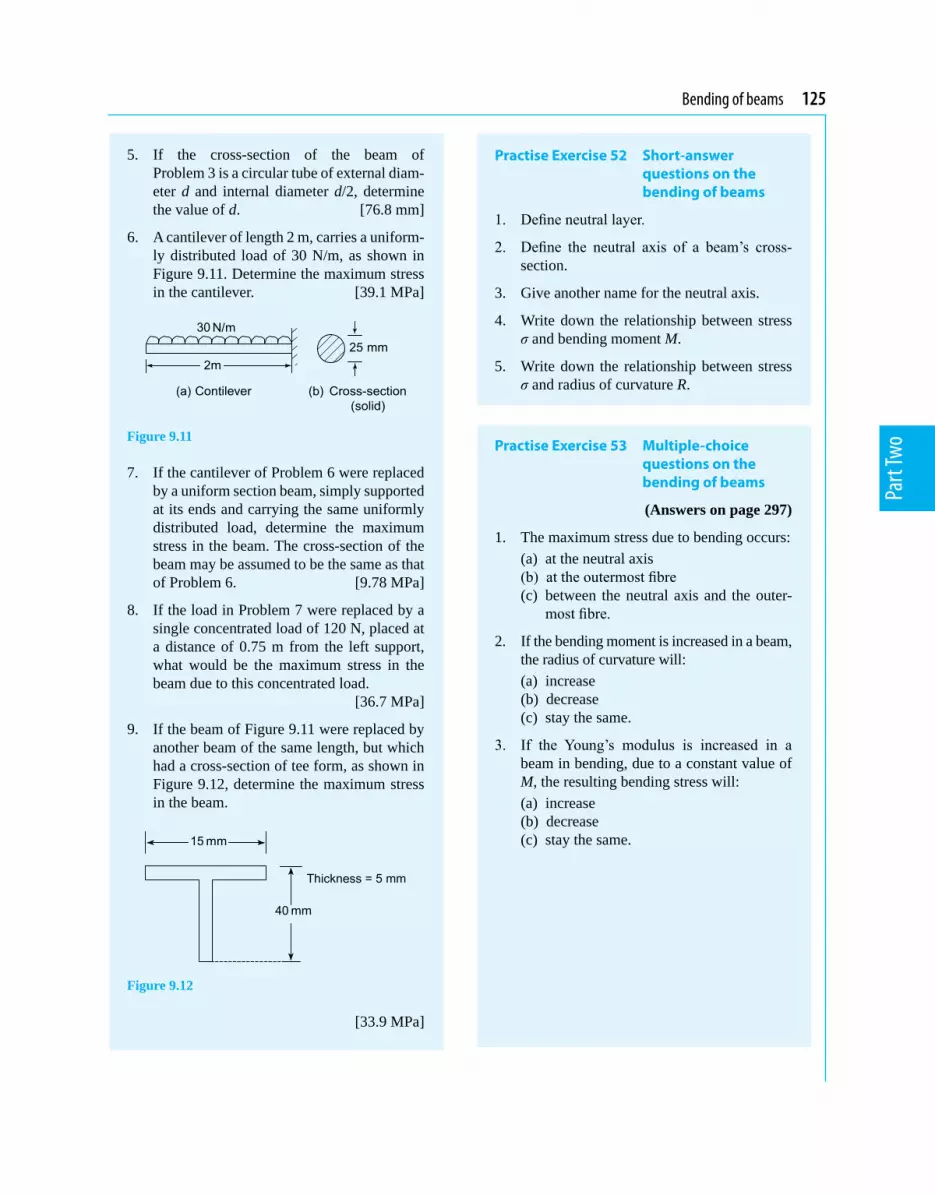
Bending of beams 125
Part
Two
5. If the cross-section of the beam of Problem 3 is a circular tube of external diam-eter d and internal diameter d/2, determine the value of d. [76.8 mm]
6. A cantilever of length 2 m, carries a uniform-ly distributed load of 30 N/m, as shown in Figure 9.11. Determine the maximum stress in the cantilever. [39.1 MPa]
Figure 9.11
7. If the cantilever of Problem 6 were replaced by a uniform section beam, simply supported at its ends and carrying the same uniformly distributed load, determine the maximum stress in the beam. The cross-section of the beam may be assumed to be the same as that of Problem 6. [9.78 MPa]
8. If the load in Problem 7 were replaced by a single concentrated load of 120 N, placed at a distance of 0.75 m from the left support, what would be the maximum stress in the beam due to this concentrated load.
[36.7 MPa]
9. If the beam of Figure 9.11 were replaced by another beam of the same length, but which had a cross-section of tee form, as shown in Figure 9.12, determine the maximum stress in the beam.
Figure 9.12
[33.9 MPa]
Practise Exercise 52 Short-answer questions on the bending of beams
1. Define neutral layer.
2. Define the neutral axis of a beam’s cross-section.
3. Give another name for the neutral axis.
4. Write down the relationship between stress σ and bending moment M.
5. Write down the relationship between stress σ and radius of curvature R.
Practise Exercise 53 Multiple-choice questions on the bending of beams
(Answers on page 297)
1. The maximum stress due to bending occurs: (a) at the neutral axis (b) at the outermost fibre (c) between the neutral axis and the outer-
most fibre.
2. If the bending moment is increased in a beam, the radius of curvature will:
(a) increase (b) decrease (c) stay the same.
3. If the Young’s modulus is increased in a beam in bending, due to a constant value of M, the resulting bending stress will:
(a) increase (b) decrease (c) stay the same.

Chapter 10
Torque
Mechanical Engineering Principles, Bird and Ross, ISBN 9780415517850
Thischaptercommencesbydefiningacoupleanda torque. It then shows how the energy and work done can be calculated from these terms. It then derives the expression which relates torque to the product of mass moment of inertia and the angular acceleration. The expression for kinetic energy due to rotation is also derived. These expressions are then used for calculating the power transmitted from one shaft to another, via a belt. This work is very important for calculating the power transmitted in rotating shafts and other similar artefacts in many branches of engineering.
The turning moment of a couple is called a torque, T.In Figure 10.1, torque = magnitude of either force ×perpendicular distance between the forces,
i.e. T = Fd
Figure 10.1
The unit of torque is the newton metre, N mWhen a force F newtons is applied at a radius r metres from the axis of, say, a nut to be turned by a spanner, as shown in Figure 10.2, the torque T applied to the nut is given by:
T = Fr N m
Figure 10.2
Problem 1. Determine the torque when a pulley wheel of diameter 300 mm has a force of 80 N applied at the rim.
Torque T = Fr, where force F = 80 N
and radius r = 3002 = 150 mm = 0.15 m
Hence, torque, T = (80)(0.15) = 12 N m
At the end of this chapter you should be able to:• define a couple• define a torque and state its unit• calculate torque given force and radius• calculate work done, given torque and angle
turned through• calculate power, given torque and angle turned
through• appreciate kinetic energy =
2
2Iω where I is the
moment of inertia• appreciate that torque T = Iα where α is the
angular acceleration• calculate torque given I and α• calculate kinetic energy given I and ω• understand power transmission by means of belt
and pulley• perform calculations involving torque, power
and efficiency of belt drives
10.1 Couple and torque
When two equal forces act on a body as shown in Figure 10.1, they cause the body to rotate, and the system of forces is called a couple.

Torque 127
Part
Two
Problem 2. Determine the force applied tangentially to a bar of a screw jack at a radius of 800 mm, if the torque required is 600 N m.
Torque, T = force × radius, from which
force = torqueradius = 3
600 N m800 10 m−×
= 750 N
Problem 3. The circular hand-wheel of a valve of diameter 500 mm has a couple applied to it composed of two forces, each of 250 N. Calculate the torque produced by the couple.
Torque produced by couple, T = Fd,
where force F = 250 N
and distance between the forces, d = 500 mm = 0.5 m
Hence, torque, T = (250)(0.5) = 125 N m
Now try the following Practise Exercise
Practise Exercise 54 Further problems on torque
1. Determine the torque developed when a force of 200 N is applied tangentially to a spanner at a distance of 350 mm from the centre of the nut. [70 N m]
2. During a machining test on a lathe, the tangential force on the tool is 150 N. If the torque on the lathe spindle is 12 N m, determine the diameter of the work-piece. [160 mm]
10.2 Work done and power transmitted by a constant torque
Figure 10.3(a) shows a pulley wheel of radius r metres attached to a shaft and a force F Newton’s applied to the rim at point P.
Figure 10.3
Figure 10.3(b) shows the pulley wheel having turned through an angle θ radians as a result of the force F being applied. The force moves through a distance s, where arc length s = rθ
Work done = force × distance moved by the force = F × rθ = Frθ N m = Frθ J
However, Fr is the torque T, hence,work done = Tθ joules
Average power = work donetime taken time taken
T θ= for a con-
stant torque THowever, (angle θ)/(time taken) = angular velocity, ω rad/s
Hence, power, P = Tω watts (10.1)
Angular velocity, ω = 2πn rad/s where n is the speed in rev/s
Hence, power, P = 2πnT watts (10.2)
Sometimes power is in units of horsepower (hp), where 1 horsepower = 745.7 watts
i.e. 1 hp = 745.7 watts
Problem 4. A constant force of 150 N is applied tangentially to a wheel of diameter 140 mm. Determine the work done, in joules, in 12 revolutions of the wheel.
Torque T = Fr, where F = 150 N
and radius r = 140
2 = 70 mm = 0.070 m
Hence, torque T = (150)(0.070) = 10.5 N m
Work done = Tθ joules, where torque, T = 10.5 N m and angular displacement,

128 Mechanical Engineering Principles
Part
Two
θ = 12 revolutions = 12 × 2π rad = 24π rad.
Hence, work done = Tθ = (10.5)(24π) = 792 J
Problem 5. Calculate the torque developed by a motor whose spindle is rotating at 1000 rev/min and developing a power of 2.50 kW.
Power P = 2πnT (from above), from which, torque,
T = 2P
nπ N m
where power, P = 2.50 kW = 2500 W and speed, n = 1000/60 rev/s
Thus, torque, T = 2500 2500 602 2 100010002 60
Pnπ π
π
×= = ×
= 23.87 N m
Problem 6. An electric motor develops a power of 5 hp and a torque of 12.5 N m. Determine the speed of rotation of the motor in rev/min.
Power, P = 2πnT, from which,
speed n = 2P
Tπ rev/s
where power, P = 5 hp = 5 × 745.7 = 3728.5 W
and torque T = 12.5 N m.
Hence, speed n = 3728.52 (12.5)π = 47.47 rev/s
The speed of rotation of the motor = 47.47 × 60 = 2848 rev/min.
Problem 7. In a turning-tool test, the tangential cutting force is 50 N. If the mean diameter of the work-piece is 40 mm, calculate (a) the work done per revolution of the spindle (b) the power required when the spindle speed is 300 rev/min.
(a) Work done = Tθ, where T = Fr
Force F = 50 N, radius r = 402 = 20 mm = 0.02 m
and angular displacement, θ = 1 rev = 2π rad.
Hence, work done per revolution of spindle = Frθ = (50)(0.02)(2π) = 6.28 J
(b) Power, P = 2πnT, where torque, T = Fr = (50)(0.02) = 1 N m and
speed, n = 30060 = 5 rev/s.
Hence, power required, P = 2π(5)(1) = 31.42 W
Problem 8. A pulley is 600 mm in diameter and the difference in tensions on the two sides of the driving belt is 1.5 kN. If the speed of the pulley is 500 rev/min, determine (a) the torque developed, and (b) the work done in 3 minutes.
(a) Torque T = Fr, where force F = 1.5 kN = 1500 N,
and radius r = 6002 = 300 mm = 0.3 m.
Hence, torque developed = (1500)(0.3) = 450 N m
(b) Work done = Tθ, where torque T = 450 N m and angular displacement in 3 minutes = (3 × 500) rev = (3 × 500 × 2π) rad.
Hence, work done = (450)(3 × 500 × 2π) = 4.24 × 10⁶ J = 4.24 MJ
Problem 9. A motor connected to a shaft develops a torque of 5 kN m. Determine the number of revolutions made by the shaft if the work done is 9 MJ.
Work don e = Tθ, from which, angular displacement,
θ = work done
torque
Work done = 9 MJ = 9 × 10⁶ J
and torque = 5 kN m = 5000 N m.
Hence, angular displacement, θ = 69 10
5000×
= 1800 rad.
2π rad = 1 rev, hence, the number of revolutions
made by the shaft = 18002π = 286.5 revs

Torque 129
Part
Two
Now try the following Practise Exercise
Practise Exercise 55 Further problems on work done and power transmitted by a constant torque
1. A constant force of 4 kN is applied tangen-tially to the rim of a pulley wheel of diam-eter 1.8 m attached to a shaft. Determine the work done, in joules, in 15 revolutions of the pulley wheel. [339.3 kJ]
2. A motor connected to a shaft develops a torque of 3.5 kN m. Determine the number of revolutions made by the shaft if the work done is 11.52 MJ. [523.8 rev]
3. A wheel is turning with an angular velocity of 18 rad/s and develops a power of 810 W at this speed. Determine the torque developed by the wheel. [45 N m]
4. Calculate the torque provided at the shaft of an electric motor that develops an out-put power of 3.2 hp at 1800 rev/min. [12.66 N m]
5. Determine the angular velocity of a shaft when the power available is 2.75 kW and the torque is 200 N m. [13.75 rad/s]
6. The drive shaft of a ship supplies a torque of 400 kN m to its propeller at 400 rev/min.
Determine the power delivered by the shaft. [16.76 MW]
7. A motor is running at 1460 rev/min and produces a torque of 180 N m. Determine the average power developed by the motor. [27.52 kW]
8. A wheel is rotating at 1720 rev/min and develops a power of 600 W at this speed. Calculate (a) the torque (b) the work done, in joules, in a quarter of an hour.
[(a) 3.33 N m (b) 540 kJ]
9. A force of 60 N is applied to a lever of a scew-jack at a radius of 220 mm. If the lever makes 25 revolutions, determine (a) the work done on the jack (b) the power, if the time taken to complete 25 revolutions is 40 s. [(a) 2.073 kJ (b) 51.84 W]
10.3 Kinetic energy and moment of inertia
The tangential velocity v of a particle of mass m mov-ing at an angular velocity ω rad/s at a radius r metres (see Figure 10.4) is given by:
v = ωr m/s
Figure 10.4
The kinetic energy of a particle of mass m is given by:
Kinetic energy = 12 mv2 (from Chapter 15)
= 12 m(ωr)2 =
12 m ω2r2 joules
The total kinetic energy of a system of masses rotating at different radii about a fixed axis but with the same angular velocity, as shown in Figure 10.5, is given by:
Figure 10.5
Total kinetic energy = 12 m1ω2r1
2 + 12 m2ω2r2
2
+ 12 m3ω2r3
2
= (m1r12 + m2r2
2+ m3r32)
2
2ω
In general, this may be written as:
Total kinetic energy = (Smr2)2
2ω = I
ω 2
2

130 Mechanical Engineering Principles
Part
Two
where I (= Smr2) is called the moment of inertia of the system about the axis of rotation and has units of kg m2.
The moment of inertia of a system is a measure of the amount of work done to give the system an angular velocity of ω rad/s, or the amount of work that can be done by a system turning at ω rad/s.
From Section 10.2, work done = Tθ, and if this work is available to increase the kinetic energy of a rotating body of moment of inertia I, then:
Tθ = 2 2
2 12I ω ω −
where ω1and ω2are the initial
and final angular velocities,
i.e. Tθ = I 2 12
ω ω+
(ω2– ω1)
However, 2 12
ω ω+
is the mean angular velocity,
i.e. tθ , where t is the time, and (ω2 – ω1) is the change
in angular velocity, i.e. αt, where α is the angular acceleration
Hence, Tθ = I tθ
(αt) from which, torque T = Iα
where I is the moment of inertia in kg m2, α is the angular acceleration in rad/s2 and T is the torque in N m.
Problem 10. A shaft system has a moment of inertia of 37.5 kg m2. Determine the torque required to give it an angular acceleration of 5.0 rad/s2.
Torque, T = Iα, where moment of inertia I = 37.5 kg m2 and angular acceleration, α = 5.0 rad/s2.Hence, torque, T = Iα = (37.5)(5.0) = 187.5 N m
Problem 11. A shaft has a moment of inertia of 31.4 kg m2. What angular acceleration of the shaft would be produced by an accelerating torque of 495 N m?
Torque, T = Iα, from which, angular acceleration,
α = TI , where torque, T = 495 N m and moment of
inertia I = 31.4 kg m2
Hence, angular acceleration, α = 49531.4
= 15.76 rad/s2
Problem 12. A body of mass 100 g is fastened to a wheel and rotates in a circular path of 500 mm in diameter. Determine the increase in kinetic energy of the body when the speed of the wheel increases from 450 rev/min to 750 rev/min.
From above, kinetic energy = I 2
2ω
Thus, increase in kinetic energy = 2 2
2 12I ω ω −
where moment of inertia, I = mr2, mass, m = 100 g = 0.1 kg and
radius, r = 500
2 = 250 mm = 0.25 m.
Initial angular velocity, ω1 = 450 rev/min
= 450 2
60π×
rad/s
= 47.12 rad/s,and final angular velocity, ω2 = 750 rev/min
= 750 2
60π×
rad/s
= 78.54 rad/s.
Thus, increase in kinetic energy = 2 2
2 12I ω ω −
= (mr2) 2 2
2 12
ω ω −
= (0.1)(0.252)2 278.54 47.12
2 −
= 12.34 J
Problem 13. A system consists of three small masses rotating at the same speed about the same fixed axis. The masses and their radii of rotation are: 15 g at 250 mm, 20 g at 180 mm and 30 g at 200 mm. Determine (a) the moment of inertia of the system about the given axis, and (b) the kinetic energy in the system if the speed of rotation is 1200 rev/min.
(a) Moment of inertia of the system, I = Smr2
i.e. I = [(15 ×10–3kg)(0.25 m)2] + [(20 ×10–3kg)(0.18 m)2]
+ [(30 ×10–3 kg)(0.20 m)2]
= (9.375 ×10⁻⁴) + (6.48 ×10⁻⁴) + (12 ×10–4)
= 27.855 ×10⁻⁴kg m2 = 2.7855 ×10⁻³kg m2

Torque 131
Part
Two
(b) Kinetic energy = I2
2ω , where
moment of inertia, I = 2.7855 × 10⁻³kg m2
and angular velocity, ω = 2πn = 2π 120060
rad/s
= 40π rad/s Hence, kinetic energy in the system
= (2.7855 × 10⁻³) ( )2402π
= 21.99 J
Problem 14. A shaft with its rotating parts has a moment of inertia of 20 kg m2. It is accelerated from rest by an accelerating torque of 45 N m. Determine the speed of the shaft in rev/min (a) after 15 s, and (b) after the first 5 revolutions.
(a) Since torque T = Iα, then angular acceleration,
α = 4520
TI = = 2.25 rad/s2
The angular velocity of the shaft is initially zero, i.e. ω1 = 0
From chapter 12, page 147, the angular velocity after 15 s,
ω2 = ω1 + αt = 0 + (2.25)(15) = 33.75 rad/s,
i.e. speed of shaft after 15 s
= (33.75)602π
rev/min
= 322.3 rev/min
(b) Work done = Tθ, where torque T = 45 N m and angular displacement, θ = 5 revolutions = 5 × 2π = 10π rad.
Hence work done = (45)(10π) = 1414 J. This work done results in an increase in kinetic
energy, given by I2
2ω
, where moment of inertia
I = 20 kg m2 and ω = angular velocity.
Hence, 1414 = (20)2
2ω
from which,
ω = 1414 2
20×
= 11.89 rad/s
i.e. speedof shaftafterthefirst5revolutions
= 11.89 ×602π = 113.5 rev/min
Problem 15. The accelerating torque on a turbine rotor is 250 N m.(a) Determine the gain in kinetic energy of the
rotor while it turns through 100 revolutions (neglecting any frictional and other resisting torques).
(b) If the moment of inertia of the rotor is 25 kg m2 and the speed at the beginning of the 100 revolutions is 450 rev/min, determine its speed at the end.
(a) The kinetic energy gained is equal to the work done by the accelerating torque of 250 N m over 100 revolutions,
i.e. gain in kinetic energy = work done = Tθ = (250)(100 ×2π) = 157.08 kJ
(b) Initial kinetic energy is given by:
I
2
21
450 2(25) 602 2
πω
×
= = 27.76 kJ
The final kinetic energy is the sum of the initial kinetic energy and the kinetic energy gained,
i.e. I2
22
ω = 27.76 kJ + 157.08 kJ = 184.84 kJ.
Hence, 2
2(25) 1848402ω = from which,
2184840 2
25ω × =
= 121.6 rad/s.
Thus, speed at end of 100 revolutions
= 121.6 602π× rev/min = 1161 rev/min
Problem 16. A shaft with its associated rotating parts has a moment of inertia of 55.4 kg m2. Determine the uniform torque required to accelerate the shaft from rest to a speed of 1650 rev/min while it turns through 12 revolutions.
From above, Tθ = 2 2
2 12I ω ω −
i.e. T = 2 2
2 12
I ω ωθ −

132 Mechanical Engineering Principles
Part
Two
where angular displacement θ = 12 rev = 12 × 2π = 24π rad,
final speed, ω2 = 1650 rev/min = 165060 × 2π
= 172.79 rad/s,initial speed, ω1 = 0, and moment of inertia, I = 55.4 kg m2.Hence, torque required,
T = Iθ
2 22 1
2ω ω −
= 2 255.4 172.79 0
24 2π −
= 10.97 kN m
Now try the following Practise Exercise
Practise Exercise 56 Further problems on kinetic energy and moment of inertia
1. A shaft system has a moment of inertia of 51.4 kg m2. Determine the torque required to give it an angular acceleration of 5.3 rad/s2. [272.4 N m]
2. A shaft has an angular acceleration of 20 rad/s2 and produces an accelerating torque of 600 N m. Determine the moment of inertia of the shaft. [30 kg m2]
3. A uniform torque of 3.2 kN m is applied to a shaft while it turns through 25 revolutions. Assuming no frictional or other resistances, calculate the increase in kinetic energy of the shaft (i.e. the work done). If the shaft is initially at rest and its moment of inertia is 24.5 kg m2, determine its rotational speed, in rev/min, at the end of the 25 revolutions.
[502.65 kJ, 1934 rev/min]
4. An accelerating torque of 30 N m is applied to a motor, while it turns through 10 revo-lutions. Determine the increase in kinetic energy. If the moment of inertia of the rotor is 15 kg m2 and its speed at the beginning of the 10 revolutions is 1200 rev/min, determine its speed at the end.
[1.885 kJ, 1209.5 rev/min]
5. A shaft with its associated rotating parts has a moment of inertia of 48 kg m2. Determine
the uniform torque required to accelerate the shaft from rest to a speed of 1500 rev/min while it turns through 15 revolutions. [6.283 kN m]
6. A small body, of mass 82 g, is fastened to a wheel and rotates in a circular path of 456 mm diameter. Calculate the increase in kinetic energy of the body when the speed of the wheel increases from 450 rev/min to 950 rev/min. [16.36 J]
7. A system consists of three small masses rotating at the same speed about the same fixed axis.The masses and their radii of rotation are: 16 g at 256 mm, 23 g at 192 mm and 31 g at 176 mm. Determine (a) the moment of inertia of the system about the given axis, and (b) the kinetic energy in the system if the speed of rotation is 1250 rev/min.
[(a) 2.857 × 10⁻³ kg m2 (b) 24.48 J]
8. A shaft with its rotating parts has a moment of inertia of 16.42 kg m2. It is accelerated from rest by an accelerating torque of 43.6 N m. Find the speed of the shaft (a) after 15 s, and (b) after the first four revolutions. [(a) 380.3 rev/min (b) 110.3 rev/min]
9. The driving torque on a turbine rotor is 203 N m, neglecting frictional and other re-sisting torques. (a) What is the gain in kinetic energy of the rotor while it turns through 100 revolutions? (b) If the moment of inertia of the rotor is 23.2 kg m2 and the speed at the beginning of the 100 revolutions is 600 rev/min, what will be its speed at the end? [(a) 127.55 kJ (b) 1167 rev/min]
10.4 Power transmission and efficiency
A common and simple method of transmitting power from one shaft to another is by means of a belt passing over pulley wheels which are keyed to the shafts, as shown in Figure 10.6. Typical applications include an electric motor driving a lathe or a drill, and an engine driving a pump or generator.

Torque 133
Part
Two
Figure 10.6
For a belt to transmit power between two pulleys there must be a difference in tensions in the belt on either side of the driving and driven pulleys. For the direction of rotation shown in Figure 10.6, F2 > F1The torque T available at the driving wheel to do work is given by:
T = (F2 – F1)rx N m
and the available power P is given by:
P = Tω = (F2 – F1)rxωx watts
From Section 10.3, the linear velocity of a point on the driver wheel, vx = rxωxSimilarly, the linear velocity of a point on the driven wheel, vy = ryωy. Assuming no slipping,
vx = vy i.e. rxωx = ryωy
Hence rx(2πnx) = ry (2πny)
from which, yx
y x
nr =r n
Percentage efficiency = useful work outputenergyoutput
×100
or efficiency= power outputpower input × 100%
Problem 17. An electric motor has an efficiency of 75% when running at 1450 rev/min. Determine the output torque when the power input is 3.0 kW.
Efficiency = power outputpower input × 100%
hence 75 = power output3000 × 100
from which, power output = 75100
× 3000
= 2250 W
From Section 10.2, power output, P = 2πnT
from which, torque, T = 2P
nπ
where n = (14 50/60) rev/s
Hence, output torque = 225014502 60π
= 14.82 N m
Problem 18. A 15 kW motor is driving a shaft at 1150 rev/min by means of pulley wheels and a belt. The tensions in the belt on each side of the driver pulley wheel are 400 N and 50 N. The diameters of the driver and driven pulley wheels are 500 mm and 750 mm respectively. Determine (a) the efficiency of the motor (b) the speed of the driven pulley wheel.
(a) From above, power output from motor = (F2
– F1)rxωx
Force F2 = 400 N and F1 = 50 N, hence (F2 – F1) = 350 N,
radius rx = 5002 = 250 mm = 0.25 m and
angular velocity, ωx = 1150 260
π× rad/s
Hence power output from motor = (F2 – F1)rxωx
= (350)(0.25) 1150 260
π×
= 10.54 kW
Power input = 15 kW
Hence, efficiencyofthemotor = power outputpower input
= 10.5415 ×100
= 70.27%
(b) From above, yx
y x
nrr n= from which,
speed of driven pulley wheels,
ny = x x
y
n rr = 1150 0.25
0.7502
× = 767 rev/min
Problem 19. A crane lifts a load of mass 5 tonne to a height of 25 m. If the overall efficiency of the crane is 65% and the input power to the hauling motor is 100 kW, determine how long the lifting operation takes.

134 Mechanical Engineering Principles
Part
Two
The increase in potential energy is the work done and is given by mgh (see Chapter 15), where mass, m = 5 t = 5000 kg, g = 9.81 m/s2 and height h = 25 m.Hence, work done = mgh = (5000)(9.81)(25)
= 1.226 MJ.Input power = 100 kW = 100000 W
Efficiency = output powerinput power ×100
hence 65 = output power100000 × 100
from which, output power =65
100 ×100000 = 65000 W
= work donetime taken
Thus, time taken for lifting operation
= 6work done 1.226 10 J
output power 65000W×= = 18.86 s
Problem 20. The tool of a shaping machine has a mean cutting speed of 250 mm/s and the average cutting force on the tool in a certain shaping operation is 1.2 kN. If the power input to the motor driving the machine is 0.75 kW, determine the overall efficiency of the machine.
Velocity, v = 250 mm/s = 0.25 m/s and force, F = 1.2 kN = 1200 NFrom Chapter 15, power output required at the cutting tool (i.e. power output), P = force × velocity = 1200 N × 0.25 m/s
= 300 WPower input = 0.75 kW = 750 WHence, efficiencyofthemachine
= output powerinput power ×100
= 300750 ×100 = 40%
Problem 21. Calculate the input power of the motor driving a train at a constant speed of 72 km/h on a level track, if the efficiency of the motor is 80% and the resistance due to friction is 20 kN.
Force resisting motion = 20 kN = 20000 N and
velocity = 72 km/h = 723.6 = 20 m/s
Output power from motor = resistive force × velocity of train (from Chapter 15) = 20000 × 20 = 400 kW
Efficiency = power outputpower input ×100
hence 80 = 400
power input × 100
from which, power input = 400 × 10080 = 500 kW
Now try the following Practise Exercises
Practise Exercise 57 Further problems on power transmission and efficiency
1. A motor has an efficiency of 72% when run-ning at 2600 rev/min. If the output torque is 16 N m at this speed, determine the power supplied to the motor. [6.05 kW]
2. The difference in tensions between the two sides of a belt round a driver pulley of radius 240 mm is 200 N. If the driver pulley wheel is on the shaft of an electric motor running at 700 rev/min and the power input to the mo-tor is 5 kW, determine the efficiency of the motor. Determine also the diameter of the driven pulley wheel if its speed is to be 1200 rev/min. [70.37%, 280 mm]
3. A winch is driven by a 4 kW electric motor and is lifting a load of 400 kg to a height of 5.0 m. If the lifting operation takes 8.6 s, calculate the overall efficiency of the winch and motor. [57.03%]
4. A belt and pulley system transmits a power of 5 kW from a driver to a driven shaft. The driver pulley wheel has a diameter of 200 mm and rotates at 600 rev/min. The diameter of the driven wheel is 400 mm. Determine the speed of the driven pulley and the tension in the slack side of the belt when the tension in the tight side of the belt is 1.2 kN. [404.2 N, 300 rev/min]
5. The average force on the cutting tool of a lathe is 750 N and the cutting speed is 400 mm/s. Determine the power input to the motor driv-ing the lathe if the overall efficiency is 55%.
[545.5 W]

Torque 135
Part
Two
6. A ship’s anchor has a mass of 5 tonne. Determine the work done in raising the an-chor from a depth of 100 m. If the hauling gear is driven by a motor whose output is 80 kW and the efficiency of the haulage is 75%, determine how long the lifting opera-tion takes. [4.905 MJ, 1 min 22s]
Practise Exercise 58 Short-answer questions on torque
1. In engineering, what is meant by a couple?
2. Define torque.
3. State the unit of torque.
4. State the relationship between work, torque T and angular displacement θ.
5. State the relationship between power P, torque T and angular velocity ω.
6. Complete the following: 1 horsepower = ..... watts.
7. Define moment of inertia and state the symbol used.
8. State the unit of moment of inertia.
9. State the relationship between torque, mo-ment of inertia and angular acceleration.
10. State one method of power transmission commonly used.
11. Define efficiency.
Practise Exercise 59 Multiple-choice questions on torque
(Answers on page 297)
1. The unit of torque is: (a) N (b) Pa (c) N/m (d) N m
2. The unit of work is: (a) N (b) J (c) W (d) N/m
3. The unit of power is: (a) N (b) J (c) W (d) N/m
4. The unit of the moment of inertia is: (a) kg m2 (b) kg (c) kg/m2 (d) N m
5. A force of 100 N is applied to the rim of a pulley wheel of diameter 200 mm. The torque is:
(a) 2 N m (b) 20 kN m (c) 10 N m (d) 20 N m
6. The work done on a shaft to turn it through 5π radians is 25π J. The torque applied to the shaft is:
(a) 0.2 N m (b) 125π2N m (c) 30π N m (d) 5 N m
7. A 5 kW electric motor is turning at 50 rad/s. The torque developed at this speed is:
(a) 100 N m (b) 250 N m (c) 0.01 N m (d) 0.1 N m
8. The force applied tangentially to a bar of a screw-jack at a radius of 500 mm, if the torque required is 1 kN m is:
(a) 2 N (b) 2 kN (c) 500 N (d) 0.5 N
9. A 10 kW motor developing a torque of (200/π) N m is running at a speed of:
(a) (π/20) rev/s (b) 50π rev/s (c) 25 rev/s (d) (20/π) rev/s
10. A shaft and its associated rotating parts has a moment of inertia of 50 kg m2. The angu-lar acceleration of the shaft to produce an accelerating torque of 5 kN m is:
(a) 10 rad/s2 (b) 250 rad/s2
(c) 0.01 rad/s2 (d) 100 rad/s2
11. A motor has an efficiency of 25% when running at 3000 rev/min. If the output torque is 10 N m, the power input is:
(a) 4π kW (b) 0.25π kW (c) 15π kW (d) 75π kW
12. In a belt-pulley wheel system, the effec-tive tension in the belt is 500 N and the diameter of the driver wheel is 200 mm. If the power output from the driving motor is 5 kW, the driver pulley wheel turns at:
(a) 50 rad/s (b) 2500 rad/s (c) 100 rad/s (d) 0.1 rad/s

Chapter 11
Twisting of shafts
Mechanical Engineering Principles, Bird and Ross, ISBN 9780415517850
The torsion of shafts appears in a number of dif-ferent branches of engineering, including propel-ler shafts for ships and aircraft, shafts driving the blades of a helicopter, shafts driving the rear wheels of an automobile and shafts driving food mixers, washing machines, tumble dryers, dishwashers, and so on. If the shaft is overstressed due to a torque, so that the maximum shear stress in the shaft exceeds the yield shear stress of the shaft’s material, the shaft can fracture. This is an undesirable phenom-enon and normally it should be designed out; hence the need for the theory contained in this chapter.
G = rigidity or shear modulus
θ = angle of twist, in radians, over its length L
Prior to proving the above formula, the following assumptions are made for circular section shafts:
(a) the shaft is of circular cross-section(b) the cross-section of the shaft is uniform along its
entire length(c) the shaft is straight and not bent(d) the shaft’s material is homogeneous (i.e. uniform)
and isotropic (i.e. exhibits properties with the same values when measured along different axes) and obeys Hooke’s law
(e) the limit of proportionality is not exceeded and the angles of twist due to the torque are small
(f) plane cross-sections remain plane and normal during twisting
(g) radial lines across the shaft’s cross-section remain straight and radial during twisting.
Consider a circular section shaft, built-in at one end, namely A, and subjected to a torque T at the other end, namely B, as shown in Figure 11.1.
Figure 11.1
At the end of this chapter you should be able to:
• appreciate practical applications where torsion of shafts occur
• prove that T G
r J Lt θ
= =
• calculate the shearing stress t, due to a torque, T• calculate the resulting angle of twist, θ, due to
torque, T• calculate the power that can be transmitted by a
shaft
11.1 To prove that t θ= =
T Gr J L
In the formula T Gr J Lt θ= = :
τ = the shear stress at radius r T = the applied torque J = polar second moment of area of the shaft
(note that for non-circular sections, J is the torsional constant and not the polar second moment of area)

Twisting of shafts 137
Part
Two
Let θ be the angle of twist due to this torque T, where the direction of T is according to the right hand screw rule. N.B. The direction of a couple, according to the right hand screw rule, is obtained by pointing the right hand in the direction of the double-tailed arrow and rotating the right hand in a clockwise direction.From Figure 11.1, it can be seen that: γ = shear strain, and that
γ L = R θ (11.1)
provided θ is small.
However, from equation (2.1, page 32), γ = Gt
Hence, L RGt θ =
or G
R Lt θ
= (11.2)
From equation (11.2), it can be seen that the shear stress τ is dependent on the value of R and it will be a maxi-mum on the outer surface of the shaft. On the outer surface of the shaft τ will act as shown in Figure 11.2.
Figure 11.2
For any radius r,
G
r Lt θ= (11.3)
The shaft in Figure 11.2 is said to be in a state of pure shear on these planes, as these shear stresses will not be accompanied by direct or normal stress.Consider an annular element of the shaft, as shown in Figure 11.3.
Figure 11.3
The torque T causes constant value shearing stresses on the thin walled annular element shown in Figure 11.4.
Figure 11.4 Annular element
The elemental torque δT due to these shearing stresses τ at the radius r is given by:
δT = τ × (2πrdr)r
and the total torque T = Tδ∑
or T = 20
(2 )R
r drt π∫ (11.4)
However, from equation (11.3), τ = G rLθ
Therefore, T = 20
(2 )R G r r drL
θ π∫
But G, θ, L and 2π do not vary with r,
hence, T = 30
(2 )RG r drL
θ π ∫
= 4
0(2 ) 4
RG rLθ π
= 4
2G RLθ π
However, from Table 8.1, page 108, the polar second
moment of area of a circle, J =4
2Rπ ,
hence, T = G JLθ
or T GJ L
θ= (11.5)
Combining equations (11.3) and (11.5) gives:
T G
r J Lt θ
= = (11.6)

138 Mechanical Engineering Principles
Part
Two
For a solid section of radius R or diameter D,
J = 4
2Rπ
or 4
32Dπ (11.7)
For a hollow tube of circular section and of internal radius R1 and external radius R2
J = ( )4 42 12 R Rπ
− (11.8)
or, in terms of external and internal diameters of D2 and D1 respectively, (see Problem 12, Chapter 8, page 110),
J = ( )4 42 132 D Dπ
− (11.9)
The torsional stiffness of the shaft, k, is defined by:
k = G JL (11.10)
The next section of worked problems will demonstrate the use of equation (11.6).
11.2 Worked problems on the twisting of shafts
Problem 1. An internal combustion engine of 60 horsepower (hp) transmits power to the car wheels of an automobile at 300 rev/min (rpm). Neglecting any transmission losses, determine the minimum permissible diameter of the solid circular section steel shaft, if the maximum shear stress in the shaft is limited to 50 MPa. What will be the resulting angle of twist of the shaft, due to the applied torque, over a length of 2 m, given that the rigidity modulus, G = 70 GPa? (Note that 1 hp = 745.7 hp).
Power = 60 hp = 60 hp × 745.7 Whp = 44742 W
From equations (10.1) and (10.2), page 127, power = Tω = 2πnT watts, where n is the speed in rev/s
i.e. 44742 = 2π radrev ×
30060
revs × T
= 31.42 T rad/s
from which, T = 44742W31.42rad/s
i.e. torque T = 1424 N m (since 1 W s = 1 N m)
From equation (11.6), T
r Jt
=
i.e. 6
2 450 10 N 1424 N m
m2
r rπ× =
and 4
61424 2
50 10rr π
×=
× × m3
from which, r3 = 61424 2
50 10π×
× ×
or shaft radius, r = 36
1424 250 10π
× × ×
= 0.0263 m
Hence, shaft diameter, d = 2 × r = 2 × 0.0263 = 0.0526 m
From equation (11.6), Gr Lt θ
=
from which, θ = 6
2
92
N50 10 2mm
N70 10 0.0263mm
LGrt × ×
=× ×
and θ = 0.0543 rad
= 0.0543 rad × 3602 radπ
°
i.e. angle of twist, θ = 3.11°
Problem 2. If the shaft in Problem 1 were replaced by a hollow tube of the same external diameter, but of wall thickness 0.005 m, what would be the maximum shear stress in the shaft due to the same applied torque, and the resulting twist of the shaft. The material properties of the shaft may be assumed to be the same as that of Problem 1.
Internal shaft diameter, D1 = D2 – 2 × wall thickness = 0.0525 – 2 × 0.005i.e. D1 = 0.0425 mThe polar second moment of area for a hollow tube,
J = ( )4 42 132 D Dπ
− from Problem 12, page 110.
Hence, J = ( )4 40.0525 0.042532π
−
= 4.255 × 10⁻⁷ m4
From equation (11.6), T
r Jt
=

Twisting of shafts 139
Part
Two
Hence, maximum shear stress,
t = 7 4
0.05251424 N m m24.255 10 m
TrJ −
×=
× = 87.85 MPa
From equation (11.6), Gr Lt θ
=
from which, θ = 6
2
92
N87.85 10 2mm
N70 10 0.02625mm
LGrt × ×
=× ×
i.e. θ = 0.0956 rad
= 0.0956 rad × 3602 radπ
°
i.e. angle of twist, θ = 5.48°
Problem 3. What would be the maximum shear stress and resulting angle of twist on the shaft of Problem 2, if the wall thickness were 10 mm, instead of 5 mm?
Internal shaft diameter, D1 = D2 – 2 × wall thickness = 0.0525 – 2 × 10 × 10–3
i.e. D1 = 0.0325 mThe polar second moment of area for a hollow tube,
J = ( )4 42 132 D Dπ
− from Problem 12, page 110.
Hence, J = ( )4 40.0525 0.032532π
−
= 6.36 × 10⁻⁷m4
From equation (11.6), T
r Jt
=
Hence, maximum shear stress,
t = 7 4
0.05251424 N m m26.36 10 m
TrJ −
×=
× = 58.75 MPa
From equation (11.6), Gr Lt θ
=
from which, θ = 6
2
92
N58.75 10 2mm
N70 10 0.02625mm
LGrt × ×
=× ×
i.e. θ = 0.06395 rad
= 0.06395 rad × 3602 radπ
°
i.e. angle of twist, θ = 3.66°
N.B. From the calculations in Problems 1 to 3, it can be seen that a hollow shaft is structurally more efficient than a solid section shaft.
Problem 4. A shaft of uniform circular section is fixed at its ends and it is subjected to an intermediate torque T, as shown in Figure 11.5, where a > b. Determine the maximum resulting torque acting on the shaft and then draw the torque diagram.
Figure 11.5
From equilibrium considerations, (see Figure 11.5), clockwise torque = the sum of the anticlockwise torques
T = T1 + T2 (11.11)
Let θC = the angle of twist at the point C.
From equation (11.6), T GJ L
θ=
from which, T = G JLθ
Therefore T1 = CG Jaθ (11.12)
and T2 = CG Jbθ (11.13)
Dividing equation (11.12) by equation (11.13) gives:
1
2
T bT a=
or T1 = 2bTa (11.14)
Substituting equation (11.14) into equation (11.11) gives:
T = 2bTa + T2 = 21 b Ta
+
or T2 = 1
T Tb a ba a
=+ +
= ( )T a
a b+ (11.15)
However, a + b = L
Therefore T2 = T aL (11.16)

140 Mechanical Engineering Principles
Part
Two
Substituting equation (11.16) into equation (11.14) gives:
T1 =
Tab La
= bTL (11.17)
As a > b, T2 > T1; therefore,
maximum torque = T2 = TaL
The torque diagram is shown in Figure 11.6.
Figure 11.6 Torque diagram
Now try the following Practise Exercises
Practise Exercise 60 Further problems on the twisting of shafts
1. A shaft of uniform solid circular section is subjected to a torque of 1500 N m. Deter-mine the maximum shear stress in the shaft and its resulting angle of twist, if the shaft’s diameter is 0.06 m, the shaft’s length is 1.2 m, and the rigidity modulus, G = 77 × 109 N/m2. What power can this shaft transmit if it is rotated at 400 rev/min? [35.4 MPa, 1.05°, 62.83 kW]
2. If the shaft in Problem 1 were replaced by a similar hollow one of wall thickness 10 mm, but of the same outer diameter, what would be the maximum shearing stress in the shaft and the resulting angle of twist? What power can this shaft transmit if it rotated at 500 rev/min. [44.1 MPa, 1.31°, 78.5 kW]
3. A boat’s propeller shaft transmits 50 hp at 100 rev/min. Neglecting transmission losses, determine the minimum diameter of a solid circular section phosphor bronze shaft, when the maximum permissible shear stress in the shaft is limited to 40 MPa. What will be the resulting angle of twist of this shaft, due to this torque, over a length of 1 m,
given that the rigidity modulus, G = 40 GPa. [76.8 mm, 1.49°]
4. A shaft to the blades of a helicopter trans-mits 1000 hp at 200 rev/min. Neglecting transmission losses, determine the mini-mum external and internal diameters of the hollow circular section aluminium alloy shaft, when the maximum permissible shear stress in the shaft is limited to 30 MPa. It may be assumed that the external diameter of this shaft is twice its internal diameter. What will be the resulting angle of twist of this shaft over a length of 2 m, given that the modulus of rigidity, G = 26.9 GPa? [182 mm, 91 mm, 1.5°]
5. A solid circular section shaft of diameter d is subjected to a torque of 1000 N m. If the maximum permissible shear stress in this shaft is limited to 30 MPa, determine the minimum value of d. [55.4 mm]
6. If the shaft in Problem 5 were to be replaced by a hollow shaft of external diameter d2 and internal diameter 0.5d2, determine the mini-mum value for d2, the design condition being the same for both shafts. What percentage saving in weight will result by replacing the solid shaft by the hollow one? [56.6 mm, 28.3 mm, 21.7%]
7. An internal combustion engine of a ship is of power 3000 hp and it transmits its power through two shafts at 300 rev/min (rpm). If the transmission losses are 10%, determine the minimum possible diameters of the shafts, given that the maximum permissible shear stress in the shafts is 80 MPa. (It may be assumed that 1 hp = 745.7 W). [d = 159 mm]
Practise Exercise 61 Short-answer questions on the twisting of shafts
1. State three practical examples where the torsion of shafts appears.
2. State the relationship between shear stress τ and torque T for a shaft.
Twisting of shafts 141
Part
Two
3. State the relationship between torque T and angle of twist θ for a shaft.
4. State whether a solid shaft or a hollow shaft is structurally more efficient.
Practise Exercise 62 Multiple-choice questions on the twisting of shafts
(Answers on page 297)
1. The maximum shear stress for a solid shaft occurs:
(a) at the outer surface (b) at the centre (c) in between the outer surface and the
centre
2. For a given shaft, if the values of torque T, length L and radius r are kept constant, but rigidity G is increased, the value of shear stress τ:
(a) increases (b) stays the same (c) decreases
3. If for a certain shaft, its length is doubled, the angle of twist:
(a) doubles (b) halves (c) remains the same
4. If a solid shaft is replaced by a hollow shaft of the same external diameter, its angle of twist:
(a) decreases (b) stays the same (c) increases
5. If a shaft is fixed at its two ends and subject-ed to an intermediate torque T at mid-length, the maximum resulting torque is equal to:
(a) T (b) 2T
(c) zero
6. If a hollow shaft is subjected to a torque T, the shear stress on the inside surface is:
(a) a minimum (b) a maximum (c) zero
References
[1] A link to the Twisting of Circular Section Shafts - www.routledge.com/cw/bird A video reference on YouTube which demonstrates a stan-
dard experimental test on the twisting of circular cross-section shafts. This experiment has to be carried out to determine the torsional material properties of a metal or a similar material.

Part
Two
1. A beam simply supported at its ends, is of length 1.4 m. If the beam carries a centrally-placed down-ward concentrated load of 50 kN, determine the minimum permissible dimensions of the beam’s cross-section, given that the maximum permis-sible stress is 40 MPa, and the beam has a solid circular cross-section. (6)
2. Determine the force applied tangentially to a bar of a screw-jack at a radius of 60 cm, if the torque required is 750 N m. (3)
3. Calculate the torque developed by a motor whose spindle is rotating at 900 rev/min and developing a power of 4.20 kW. (5)
4. A motor connected to a shaft develops a torque of 8 kN m. Determine the number of
revolutions made by the shaft if the work done is 7.2 MJ. (6)
5. Determine the angular acceleration of a shaft that has a moment of inertia of 32 kg m2 produced by an accelerating torque of 600 N m. (5)
6. An electric motor has an efficiency of 72% when running at 1400 rev/min. Determine the output torque when the power input is 2.50 kW. (5)
7. A solid circular section shaft is required to trans-mit 60 hp at 1000 rpm. If the maximum permis-sible shear stress in the shaft is 35 MPa, determine the minimum permissible diameter of the shaft. Determine the resulting angle of twist of the shaft per metre, assuming that the modulus of rigidity, G = 70 GPa and 1 hp = 745.7 W (10)
Revision Test 4 Bending of beams, torque and twisting of shafts
This Revision Test covers the material contained in Chapters 9 to 11. The marks for each question are shown in brackets at the end of each question.

DynamicsPart Three


Chapter 12
Linear and angular motion
Mechanical Engineering Principles, Bird and Ross, ISBN 9780415517850
Thischaptercommencesbydefininglinearandan-gular velocity and also linear and angular accelera-tion. It then derives the well-known relationships, under uniform acceleration, for displacement, ve-locity and acceleration, in terms of time and other parameters. The chapter then uses elementary vec-tor analysis, similar to that used for forces in Chap-ter 6, to determine relative velocities. This chapter deals with the basics of kinematics.
Figure 12.1
Since the arc length of a complete circle is 2pr and the angle subtended at the centre is 360°, then from equa-tion (12.1), for a complete circle,
2pr = rθ or θ = 2π radians
Thus, 2πradianscorrespondsto360° (12.2)
as stated in Chapter 1.
12.2 Linear and angular velocity
Linear velocity v is defined as the rate of change of linear displacement s with respect to time t, and for mo-tion in a straight line:
linear velocity = changeof displacementchangeof time
i.e. v = st (12.3)
The unit of linear velocity is metres per second (m/s).
Angular velocityThe speed of revolution of a wheel or a shaft is usually measured in revolutions per minute or revolutions
At the end of this chapter you should be able to:
• appreciate that 2p radians corresponds to 360°
• define linear and angular velocity• perform calculations on linear and angular
velocity using w = 2pn and v = wr• define linear and angular acceleration• perform calculations on linear and angular
acceleration using w2 = w
1 + at and a = ra
• select appropriate equations of motion when performing simple calculations
• appreciate the difference between scalar and vector quantities
• use vectors to determine relative velocities, by drawing and by calculation
12.1 The radian
The unit of angular displacement is the radian, where one radian is the angle subtended at the centre of a cir-cle by an arc equal in length to the radius, as shown in Figure 12.1.The relationship between angle in radians (q), arc length (s) and radius of a circle (r) is:
s = rθ (12.1)

146 Mechanical Engineering Principles
Part
Thre
e
per second, but these units do not form part of a coherent system of units. The basis used in SI units is the angle turned through (in radians) in one second.
Angular velocity is defined as the rate of change of angular displacement q, with respect to time t, and for an object rotating about a fixed axis at a constant speed:
angular velocity = angle turned through
time taken
i.e. ω = tθ
(12.4)
The unit of angular velocity is radians per second (rad/s).
An object rotating at a constant speed of n revolu-tions per second subtends an angle of 2pn radians in one second, that is, its angular velocity,
ω =2πn rad/s (12.5)
From equation (12.1), s = rq, and from equation (12.4), q = wt, hence
s = rwt or st = wr
However, from equation (12.3), v = st ,
hence v = ωr (12.6)
Equation (12.6) gives the relationship between linear velocity, v, and angular velocity, w.
Problem 1. A wheel of diameter 540 mm is rotating at (1500/p) rev/min. Calculate the angular velocity of the wheel and the linear velocity of a point on the rim of the wheel.
From equation (12.5), angular velocity w = 2pn, where n is the speed of revolution in revolutions per second,
i.e. n = 150060π revolutions per second.
Thus, angular velocity, ω = 2p150060π
= 50 rad/s
The linear velocity of a point on the rim, v = wr, where r is the radius of the wheel, i.e. r = 0.54/2 or 0.27 m.Thus, linear velocity, v = wr = 50 × 0.27 = 13.5 m/s
Problem 2. A car is travelling at 64.8 km/h and has wheels of diameter 600 mm.(a) Find the angular velocity of the wheels in
both rad/s and rev/min.
(b) If the speed remains constant for 1.44 km, determine the number of revolutions made by a wheel, assuming no slipping occurs.
(a) 64.8 km/h = 64.8 kmh
×1000 mkm
× 1 h
3600 s
= 64.83.6 m/s
= 18 m/s
i.e. the linear velocity, v, is 18 m/s
The radius of a wheel is (600/2) mm = 0.3 m From equation (12.6), v = wr, hence w = v/r
i.e. the angular velocity, ω = 180.3 = 60 rad/s
From equation (12.5), angular velocity, w = 2pn, where n is in revolutions per second. Hence
n = w/2p and angular speed of a wheel in revolu-tions per minute is 60w/2p; but w = 60 rad/s,
hence angular speed = 60 602π× = 573 revolu-
tions per minute (rpm)(b) From equation (12.3), time taken to travel
1.44 km at a constant speed of 18 m/s is:
1440m18m/s = 80 s.
Since a wheel is rotating at 573 revolutions per minute, then in 80/60 minutes it makes
573 8060× = 764 revolutions.
Now try the following Practise Exercise
Practise Exercise 63 Further problems on linear and angular velocity
1. A pulley driving a belt has a diameter of 360 mm and is turning at 2700/p revolutions per minute. Find the angular velocity of the pulley and the linear velocity of the belt assuming that no slip occurs.
[w = 90 rad/s, v = 16.2 m/s]
2. A bicycle is travelling at 36 km/h and the diameter of the wheels of the bicycle is 500 mm. Determine the angular velocity

Linear and angular motion 147
Part
Thre
e
of the wheels of the bicycle and the linear velocity of a point on the rim of one of the wheels.
[w = 40 rad/s, v = 10 m/s]
12.3 Linear and angular acceleration
Linear acceleration, a, is defined as the rate of change of linear velocity with respect to time. For an object whose linear velocity is increasing uniformly:
linear acceleration = changeof linear velocity
time taken
i.e. a = v v
t−2 1 (12.7)
The unit of linear acceleration is metres per second squared (m/s2). Rewriting equation (12.7) with v2 as the subject of the formula gives:
v2 = v1 + at (12.8)
where v2 = final velocity and v1 = initial velocity.Angular acceleration, α, is defined as the rate of change of angular velocity with respect to time. For an object whose angular velocity is increasing uniformly:
angular acceleration = changeof angular velocity
time taken
i.e. 2 1t
ω ωa −= (12.9)
The unit of angular acceleration is radians per second squared (rad/s2). Rewriting equation (12.9) with w
2 as the subject of the formula gives:
ω2 = ω1 + αt (12.10)
where w2 = final angular velocity and w
1 = initial
angular velocity.From equation (12.6), v = wr. For motion in a circle
having a constant radius r, v2 = w2r and v1 = w
1r, hence
equation (12.7) can be rewritten as:
a = ( )2 12 1 rr rt t
ω ωω ω −−=
But from equation (12.9), 2 1t
ω ω− = a
Hence a = rα (12.11)
Problem 3. The speed of a shaft increases uniformly from 300 revolutions per minute to 800 revolutions per minute in 10s. Find the angular acceleration, correct to 3 significant figures.
From equation (12.9), a = 2 1t
ω ω−
Initial angular velocity,
w1 = 300 rev/min = 300/60 rev/s
= 300 2
60π×
rad/s,
final angular velocity,
w2
= 800 2
60π×
rad/s and time, t = 10 s.
Hence, angular acceleration,
α = 800 2 300 2
60 6010
π π× ×− rad/s2
= 500 260 10
π×× = 5.24 rad/s2
Problem 4. If the diameter of the shaft in problem 3 is 50 mm, determine the linear acceleration of the shaft on its external surface, correct to 3 significant figures.
From equation (12.11), a = ra
The shaft radius is 502 mm = 25 mm = 0.025 m, and the
angular acceleration, a = 5.24 rad/s2,thus the linear acceleration, a = ra = 0.025 ´ 5.24 = 0.131 m/s2
Now try the following Practise Exercise
Practise Exercise 64 Further problems on linear and angular acceleration
1. A flywheel rotating with an angular velocity of 200 rad/s is uniformly accelerated at a rate of 5 rad/s2 for 15 s. Find the final angular velocity of the flywheel both in rad/s and revolutions per minute.
[275 rad/s, 8250/p rev/min]

148 Mechanical Engineering Principles
Part
Thre
e
2. A disc accelerates uniformly from 300 revolutions per minute to 600 revolutions per minute in 25 s. Determine its angular acceleration and the linear acceleration of a point on the rim of the disc, if the radius of the disc is 250 mm. [0.4p rad/s2, 0.1p m/s2]
12.4 Further equations of motion
From equation (12.3), s = vt, and if the linear velocity is changing uniformly from v1 to v2, then s = mean linear velocity × time
i.e. s =
1 22
v v+ t (12.12)
From equation (12.4), q = wt, and if the angular velocity is changing uniformly from w
1 to w
2, then
q = mean angular velocity × time
i.e. θ =
1 22
ω ω+ t (12.13)
Two further equations of linear motion may be derived from equations (12.8) and (12.11):
s = v1t + 12 at2 (12.14)
and v22 = v1
2 + 2as (12.15)
Two further equations of angular motion may be derived from equations (12.10) and (12.13):
θ = ω1t + 12 αt2 (12.16)
and ω22 = ω1
2 + 2αθ (12.17)
Table 12.1, on page 149, summarises the principal equations of linear and angular motion for uniform changes in velocities and constant accelerations and also gives the relationships between linear and angular quantities.
Problem 5. The speed of a shaft increases uni-formly from 300 rev/min to 800 rev/min in 10s. Find the number of revolutions made by the shaft during the 10 s it is accelerating.
From equation (12.13), angle turned through,
q = 1 22
ω ω+
t
= 300 2 800 2
60 602
π π× × +
(10) rad
However, there are 2p radians in 1 revolution, hence, number of revolutions
= 300 2 800 2
1060 602 2
π π
π
× × +
= ( )1 1100 102 60
= 110012
= 91.67 revolutions
Problem 6. The shaft of an electric motor, initially at rest, accelerates uniformly for 0.4 s at 15 rad/s2. Determine the angle (in radians) turned through by the shaft in this time.
From equation (12.16), q = w1t +
12 at2
Since the shaft is initially at rest, w1 = 0 and
q = 12 at2, the angular acceleration, a = 15 rad/s2 and
time t = 0.4 s.
Hence, angle turned through,
θ = 0 +12 × 15 × 0.42 = 1.2 rad
Problem 7. A flywheel accelerates uniformly at 2.05 rad/s2 until it is rotating at 1500 rev/min. If it completes 5 revolutions during the time it is accelerating, determine its initial angular velocity in rad/s, correct to 4 significant figures.
Since the final angular velocity is 1500 rev/min,
w2 = 1500
revmin ×
1min 2 rad60s 1rev
π×
= 50p rad/s

Linear and angular motion 149
Part
Thre
e
5 revolutions = 5 rev × 2 rad1revπ = 10p rad
From equation (12.17), 2 22 1ω ω= + 2aq
i.e. (50p)2 = 21ω + (2 ´ 2.05 ×10p)
from which, 21ω = (50p)2 – (2 ´ 2.05 ×10p)
= (50p)2 – 41p = 24545
i.e. 1ω = 24545 = 156.7 rad/sThus, the initial angular velocity is 156.7 rad/s, correctto4significantfigures.
Now try the following Practise Exercise
Practise Exercise 65 Further problems on equations of motion
1. A grinding wheel makes 300 revolu-tions when slowing down uniformly from 1000 rad/s to 400 rad/s. Find the time for this reduction in speed. [2.693 s]
2. Find the angular retardation for the grinding wheel in question 1. [222.8 rad/s2]
Table 12.1
s = arc length (m) r = radius of circle (m)
t = time (s) q = angle (rad)
v = linear velocity (m/s) w = angular velocity (rad/s)
v1 = initial linear velocity (m/s) w1 = initial angular velocity (rad/s)
v2 = final linear velocity (m/s) w2 = final angular velocity (rad/s)
a = linear acceleration (m/s2) a = angular acceleration (rad/s2)
n = speed of revolution (rev/s)
Equation number Linear motion Angular motion
(12.1) s = rq m
(12.2) 2p rad = 360°
(12.3) and (12.4) v = st w = t
θrad/s
(12.5) w = 2pn rad/s
(12.6) v = wr m/s2
(12.7) and (12.9) a = 2 1v vt− a = 2 1
tω ω−
(12.8) and (12.10) v2 = (v1 + at) m/s w2 = (w
1 + at) rad/s
(12.11) a = r a m/s2
(12.12) and (12.13) s = 1 22
v v+
t q = 1 22
ω ω+
t
(12.14) and (12.16) s = v1t + 12 at2 q = w
1 t + 1
2 at2
(12.15) and (12.17) 2 22 1v v= + 2as 2 2
2 1ω ω= + 2aq

150 Mechanical Engineering Principles
Part
Thre
e
3. A disc accelerates uniformly from 300 revolutions per minute to 600 revolutions per minute in 25 s. Calculate the number of revolutions the disc makes during this accelerating period. [187.5 revolutions]
4. A pulley is accelerated uniformly from rest at a rate of 8 rad/s2. After 20 s the accelera-tion stops and the pulley runs at constant speed for 2 min, and then the pulley comes uniformly to rest after a further 40 s. Calcu-late:
(a) the angular velocity after the period of acceleration
(b) the deceleration (c) the total number of revolutions made by
the pulley. [(a) 160 rad/s (b) 4 rad/s2 (c) 12000/p rev]
12.5 Relative velocity
Quantities used in engineering and science can be divided into two groups:
(a) Scalar quantities have a size or magnitude only and need no other information to specify them. Thus 20 centimetres, 5 seconds, 3 litres and 4 kilograms are all examples of scalar quantities.
(b) Vector quantities have both a size (or magnitude), and a direction, called the line of action of the quantity. Typical vector quantities include velocity, acceleration and force. Thus, a velocity of 30 km/h due west, and an acceleration of 7 m/s2 acting vertically downwards, are both vector quantities.
A vector quantity is represented by a straight line lying along the line of action of the quantity, and having a length that is proportional to the size of the quantity, as shown in Chapter 4. Thus ab in Figure 12.2 represents a velocity of 20 m/s, whose line of action is due west.
The bold letters, ab, indicate a vector quantity and the order of the letters indicate that the line of action is from a to b.
Consider two aircraft A and B flying at a constant altitude, A travelling due north at 200 m/s and B trav-elling 30° east of north, written N 30° E, at 300 m/s, as shown in Figure 12.3.
Figure 12.3
Relative to a fixed point 0, 0a represents the velocity of A and 0b the velocity of B. The velocity of B relative to A, that is the velocity at which B seems to be travelling to an observer on A, is given by ab, and by measurement is 160 m/s in a direction E 22° N. The velocity of A relative to B, that is, the velocity at which A seems to be travelling to an observer on B, is given by ba and by measurement is 160 m/s in a direction W 22° S.
Problem 8. Two cars are travelling on horizontal roads in straight lines, car A at 70 km/h at N 10° E and car B at 50 km/h at W 60° N. Determine, by drawing a vector diagram to scale, the velocity of car A relative to car B.
With reference to Figure 12.4(a), oa represents the velocity of car A relative to a fixed point o, and ob represents the velocity of car B relative to a fixed point o. The velocity of car A relative to car B is given by ba and by measurement is 45 km/h in a direction of E 35° N. Figure 12.2

Linear and angular motion 151
Part
Thre
e
Figure 12.4
Problem 9. Verify the result obtained in Problem 8 by calculation.
The triangle shown in Figure 12.4(b) is similar to the vector diagram shown in Figure 12.4(a). Angle BOA is 40°. Using the cosine rule (see chapter 1): BA2 = 502 + 702 – 2 × 50 × 70 × cos 40°
from which, BA = 45.14Using the sine rule:
50 45.14
sin sin 40BAO =∠ ° (also from Chapter 1)
from which, sinÐBAO = 50sin 40
45.14°
= 0.7120
Hence, angle BAO = 45.40° thus, angle ABO = 180° – (40° + 45.40°)
= 94.60°,
and angle q = 94.60° – 60° = 34.60°
Thus, ba is 45.14 km/h in a direction E 34.60° N by calculation.
Problem 10. A crane is moving in a straight line with a constant horizontal velocity of 2 m/s. At the same time it is lifting a load at a vertical velocity of 5 m/s. Calculate the velocity of the load relative to a fixed point on the earth’s surface.
A vector diagram depicting the motion of the crane and load is shown in Figure 12.5. oa represents the velocity of the crane relative to a fixed point on the Earth’s surface and ab represents the velocity of the load relative to the crane. The velocity of the load relative to the fixed point on the Earth’s surface is ob. By Pythagoras’ theorem (from Chapter 1):
Figure 12.5
ob2 = oa2 + ab2
= 4 + 25 = 29
Hence ob = 29 = 5.385 m/s
Tan q = 52 = 2.5, hence, q = tan–1 2.5 = 68.20°
i.e. the velocity of the load relative to a fixed point on the Earth’s surface is 5.385 m/s in a direction 68.20° to the motion of the crane.
Now try the following Practise Exercises
Practise Exercise 66 Further problems on relative velocity
1. A car is moving along a straight horizontal road at 79.2 km/h and rain is falling verti-cally downwards at 26.4 km/h. Find the velocity of the rain relative to the driver of the car. [83.5 km/h at 71.6° to the vertical]
2. Calculate the time needed to swim across a river 142 m wide when the swimmer can swim at 2 km/h in still water and the river is flowing at 1 km/h. At what angle to the bank should the swimmer swim?
[4 min 55 s, 60°]

152 Mechanical Engineering Principles
Part
Thre
e
3. A ship is heading in a direction N 60° E at a speed which in still water would be 20 km/h. It is carried off course by a current of 8 km/h in a direction of E 50° S. Calculate the ship’s actual speed and direction.
[22.79 km/h in a direction E 9.78° N]
Practise Exercise 67 Short-answer questions on linear and angular motion
1. State and define the unit of angular displacement.
2. Write down the formula connecting an angle, arc length and the radius of a circle.
3. Define linear velocity and state its unit.
4. Define angular velocity and state its unit.
5. Write down a formula connecting angular velocity and revolutions per second in coherent units.
6. State the formula connecting linear and angular velocity.
7. Define linear acceleration and state its unit.
8. Define angular acceleration and state its unit.
9. Write down the formula connecting linear and angular acceleration.
10. Define a scalar quantity and give two examples.
11. Define a vector quantity and give two examples.
Practise Exercise 68 Multiple-choice questions on linear and angular motion
(Answers on page 297)
1. Angular displacement is measured in: (a) degrees (b) radians (c) rev/s (d) metres
2. An angle of 34π radians is equivalent to:
(a) 270° (b) 67.5°
(c) 135° (d) 2.356°
3. An angle of 120° is equivalent to:
(a) 23π rad (b) 3
π rad
(c) 34π rad (d) 1
3 rad
4. An angle of 2 rad at the centre of a circle subtends an arc length of 40 mm at the circumference of the circle. The radius of the circle is:
(a) 40p mm (b) 80 mm (c) 20 mm (d) (40/p) mm 5. A point on a wheel has a constant angu-
lar velocity of 3 rad/s. The angle turned through in 15 seconds is:
(a) 45 rad (b) 10p rad (c) 5 rad (d) 90p rad 6. An angular velocity of 60 revolutions per
minute is the same as: (a) (1/2p) rad/s (b) 120p rad/s (c) (30/p) rad/s (d) 2p rad/s
7. A wheel of radius 15 mm has an angular velocity of 10 rad/s. A point on the rim of the wheel has a linear velocity of:
(a) 300p mm/s (b) 2/3 mm/s (c) 150 mm/s (d) 1.5 mm/s
8. The shaft of an electric motor is rotat-ing at 20 rad/s and its speed is increased uniformly to 40 rad/s in 5 s. The angular acceleration of the shaft is:
(a) 4000 rad/s2 (b) 4 rad/s2
(c) 160 rad/s2 (d) 12 rad/s2
9. A point on a flywheel of radius 0.5 m has a uniform linear acceleration of 2 m/s2. Its angular acceleration is:
(a) 2.5 rad/s2 (b) 0.25 rad/s2
(c) 1 rad/s2 (d) 4 rad/s2
Questions 10 to 13 refer to the following data.A car accelerates uniformly from 10 m/s to 20 m/s over a distance of 150 m. The wheels of the car each have a radius of 250 mm.10. The time the car is accelerating is: (a) 0.2 s (b) 15 s (c) 10 s (d) 5 s11. The initial angular velocity of each of the
wheels is: (a) 20 rad/s (b) 40 rad/s (c) 2.5 rad/s (d) 0.04 rad/s

Linear and angular motion 153
Part
Thre
e
12. The angular acceleration of each of the wheels is:
(a) 1 rad/s2 (b) 0.25 rad/s2
(c) 400 rad/s2 (d) 4 rad/s2
13. The linear acceleration of a point on each of the wheels is:
(a) 1 m/s2 (b) 4 m/s2
(c) 3 m/s2 (d) 100 m/s2

Chapter 13
Linear momentum and impulse
Mechanical Engineering Principles, Bird and Ross, ISBN 9780415517850
This chapter is of considerable importance in the study of the motion and collision of vehicles, ships, and so on. The chapter commences with definingmomentum, impulse, together with Newton’s laws of motion. It then applies these laws to solving practical problemsinthefieldsofballistics,piledrivers,etc.
Newton’sfirstlawofmotion states:
a body continues in a state of rest or in a state of uniform motion in a straight line unless acted on by some external force
Hence the momentum of a body remains the same pro-vided no external forces act on itThe principle of conservation of momentum for a closed system (i.e. one on which no external forces act) may be stated as:
the total linear momentum of a system is a constant
The total momentum of a system before collision in a given direction is equal to the total momentum of the system after collision in the same direction. In Figure 13.1, masses m1 and m2 are travelling in the same direc-tion with velocity u1 > u2. A collision will occur, and applying the principle of conservation of momentum:
Figure 13.1
total momentum before impact = total momentum after impact
i.e. m1u1 + m2u2 = m1v1 + m2v2
At the end of this chapter you should be able to:
• define momentum and state its unit• state Newton’s first law of motion• calculate momentum given mass and velocity• state Newton’s second law of motion• define impulse and appreciate when impulsive
forces occur• state Newton’s third law of motion• calculate impulse and impulsive force• use the equation of motion v2 = u2 + 2as in
calculations
13.1 Linear momentum
The momentum of a body is defined as the product of its mass and its velocity, i.e.
momentum = mu
where m = mass (in kg) and u = velocity (in m/s). The unit of momentum is kg m/s.Since velocity is a vector quantity, momentum is a vector quantity, i.e. it has both magnitude and direction.

Linear momentum and impulse 155
Part
Thre
e
where v1 and v2 are the velocities of m1 and m2 after impact.
Problem 1. Determine the momentum of a pile driver of mass 400 kg when it is moving downwards with a speed of 12 m/s.
Momentum = mass × velocity = 400 kg × 12 m/s = 4800 kg m/s downwards
Problem 2. A cricket ball of mass 150 g has a momentum of 4.5 kg m/s. Determine the velocity of the ball in km/h.
Momentum = mass × velocity, hence
velocity = 3momentum 4.5kg m/s
mass 150 10 kg× −= = 30 m/s
30 m/s = m s 1km30 3600s h 1000m× ×
= 30 × 3.6 km/h = 108 km/h = velocity of cricket ball.
Problem 3. Determine the momentum of a rail-way wagon of mass 50 tonnes moving at a velocity of 72 km/h.
Momentum = mass × velocity
Mass = 50 t = 50000 kg (since 1 t = 1000 kg)
and velocity = 72 km/h = km 1h m72 1000h 3600s km× ×
= 723.6 m/s = 20 m/s.
Hence, momentum = 50000 kg × 20 m/s = 1000000 kg m/s = 106kg m/s
Problem 4. A wagon of mass 10 t is moving at a speed of 6 m/s and collides with another wagon of mass 15 t, which is stationary. After impact, the wagons are coupled together. Determine the common velocity of the wagons after impact.
Mass m1 = 10 t = 10000 kg, m2 = 15000 kg and velocity u1 = 6 m/s, u2 = 0.
Total momentum before impact = m1u1 + m2u2
= (10000 × 6) + (15000 × 0) = 60000 kg m/sLet the common velocity of the wagons after impact be v m/s.
Since total momentum before impact = total momen-tum after impact: 60000 = m1v + m2v = v(m1 + m2) = v(25000)
Hence v = 6000025000 = 2.4 m/s
i.e. the common velocity after impact is 2.4 m/s in the direction in which the 10 t wagon is initially travelling.
Problem 5. A body has a mass of 30 g and is moving with a velocity of 20 m/s. It collides with a second body which has a mass of 20 g and which is moving with a velocity of 15 m/s. Assuming that the bodies both have the same velocity after impact, determine this common velocity, (a) when the initial velocities have the same line of action and the same sense, and (b) when the initial velocities have the same line of action but are opposite in sense.
Mass m1 = 30 g = 0.030 kg, m2 = 20 g = 0.020 kg, velocity u1 = 20 m/s and u2 = 15 m/s.
(a) When the velocities have the same line of action and the same sense, both u1 and u2 are considered as positive values.
Total momentum before impact = m1u1 + m2u2 = (0.030 ×20) + (0.020 ×15) = 0.60 + 0.30 = 0.90 kg m/s. Let the common velocity after impact be v m/s. Total momentum before impact = total momen-
tum after impact i.e. 0.90 = m1v + m2v = v(m1 + m2) 0.90 = v(0.030 + 0.020)
from which, common velocity, v = 0.900.050 = 18 m/s
in the direction in which the bodies are initially travelling.
(b) When the velocities have the same line of action but are opposite in sense, one is considered as positive and the other negative (because velocity is a vector quantity). Taking the direction of mass m1 as positive gives: velocity u1 = +20 m/s and u2 = –15 m/s.
Total momentum before impact = m1u1 + m2u2 = (0.030 × 20) + (0.020 × –15) = 0.60 – 0.30 = + 0.30 kg m/s

156 Mechanical Engineering Principles
Part
Thre
e
and since it is positive this indicates a momentum in the same direction as that of mass m1.
If the common velocity after impact is v m/s then 0.30 = v(m1 + m2) = v(0.050)
from which, common velocity, v = 0.300.050 = 6 m/s
in the direction that the 30 g mass is initially travelling.
Problem 6. A ball of mass 50 g is moving with a velocity of 4 m/s when it strikes a stationary ball of mass 25 g. The velocity of the 50 g ball after impact is 2.5 m/s in the same direction as before impact. Determine the velocity of the 25 g ball after impact.
Mass m1 = 50 g = 0.050 kg, m2 = 25 g = 0.025 kg. Initial velocity u1 = 4 m/s, u2 = 0; final velocity v1 = 2.5 m/s, v2 is unknown.
Total momentum before impact = m1u1 + m2u2
= (0.050 × 4) + (0.025 × 0) = 0.20 kg m/sTotal momentum after impact = m1v1 + m2v2
= (0.050 × 2.5) + (0.025 v2) = 0.125 + 0.025 v2Total momentum before impact = total momentum after impact, hence 0.20 = 0.125 + 0.025v2
from which, velocity of 25 g ball after impact,
v2 = 0.20 0.125
0.025− = 3 m/s
Problem 7. Three masses, P, Q and R lie in a straight line. P has a mass of 5 kg and is moving towards Q at 8 m/s. Q has a mass of 7 kg and a velocity of 4 m/s, and is moving towards R. Mass R is stationary. P collides with Q, and P and Q then collide with R. Determine the mass of R assuming all three masses have a common velocity of 2 m/s after the collision of P and Q with R.
Mass mP = 5 kg, mQ = 7 kg, velocity uP = 8 m/s and uQ = 4 m/s.
Total momentum before P collides with Q = mPuP + mQuQ
= (5 × 8) + (7 × 4) = 68 kg m/s.
Let P and Q have a common velocity of v1m/s after impact.
Total momentum after P and Q collide = mPv1 + mQv1
= v1 (mP + mQ) = 12v1
Total momentum before impact = total momentum after impact, i.e. 68 = 12v1, from which, common
velocity of P and Q, v1 = 68 2512 3= m/s.
Total momentum after P and Q collide with R = (mP+Q × 2) + (mR × 2) (since the common velocity after impact = 2 m/s) = (12 × 2) + (2 mR)Total momentum before P and Q collide with R = total momentum after P and Q collide with R, i.e.
(mP + Q × 523) = (12 × 2) + 2 mR
i.e. 12 × 523 = 24 + 2 mR
68 – 24 = 2 mR
from which, mass of R, mR = 442 = 22 kg.
Now try the following Practise Exercise
Practise Exercise 69 Further problems on linear momentum
(Where necessary, take g as 9.81 m/s2)
1. Determine the momentum in a mass of 50 kg having a velocity of 5 m/s.
[250 kg m/s] 2. A milling machine and its component have
a combined mass of 400 kg. Determine the momentum of the table and component when the feed rate is 360 mm/min.
[2.4 kg m/s] 3. The momentum of a body is 160 kg m/s
when the velocity is 2.5 m/s. Determine the mass of the body. [64 kg]
4. Calculate the momentum of a car of mass 750 kg moving at a constant velocity of 108 km/h. [22500 kg m/s]
5. A football of mass 200 g has a momentum of 5 kg m/s. What is the velocity of the ball in km/h. [90 km/h]

Linear momentum and impulse 157
Part
Thre
e
6. A wagon of mass 8 t is moving at a speed of 5 m/s and collides with another wagon of mass 12 t, which is stationary. After impact, the wagons are coupled together. Determine the common velocity of the wagons after impact. [2 m/s]
7. A car of mass 800 kg was stationary when hit head-on by a lorry of mass 2000 kg travelling at 15 m/s. Assuming no brakes are applied and the car and lorry move as one, determine the speed of the wreckage immediately after collision. [10.71 m/s]
8. A body has a mass of 25 g and is moving with a velocity of 30 m/s. It collides with a second body which has a mass of 15 g and which is moving with a velocity of 20 m/s. Assuming that the bodies both have the same speed after impact, determine their common velocity (a) when the speeds have the same line of action and the same sense, and (b) when the speeds have the same line of action but are opposite in sense.
[(a) 26.25 m/s (b) 11.25 m/s]
9. A ball of mass 40 g is moving with a veloc-ity of 5 m/s when it strikes a stationary ball of mass 30 g. The velocity of the 40 g ball after impact is 4 m/s in the same direction as before impact. Determine the velocity of the 30 g ball after impact. [1.33 m/s]
10. Three masses, X, Y and Z, lie in a straight line. X has a mass of 15 kg and is mov-ing towards Y at 20 m/s. Y has a mass of 10 kg and a velocity of 5 m/s and is moving towards Z. Mass Z is stationary. X collides with Y, and X and Y then collide with Z. Determine the mass of Z assuming all three masses have a common velocity of 4 m/s after the collision of X and Y with Z.
[62.5 kg]
13.2 Impulse and impulsive forces
Newton’s second law of motion states:
the rate of change of momentum is directly propor-tional to the applied force producing the change, and takes place in the direction of this force
In the SI system, the units are such that:
the applied force = rate of change of momentum
= changeof momentum
time taken (13.1)
When a force is suddenly applied to a body due to either a collision with another body or being hit by an object such as a hammer, the time taken in equation (13.1) is very small and difficult to measure. In such cases, the total effect of the force is measured by the change of momentum it produces.
Forces that act for very short periods of time are called impulsive forces. The product of the impul-sive force and the time during which it acts is called the impulse of the force and is equal to the change of momentum produced by the impulsive force, i.e.
impulse = applied force × time = change in linear momentum
Examples where impulsive forces occur include when a gun recoils and when a free-falling mass hits the ground. Solving problems associated with such occur-rences often requires the use of the equation of motion: v2 = u2 + 2as, from Chapter 12.
When a pile is being hammered into the ground, the ground resists the movement of the pile and this resistance is called a resistive force.
Newton’s third law of motion may be stated as:
for every action there is an equal and opposite reaction
The force applied to the pile is the resistive force; the pile exerts an equal and opposite force on the ground.In practice, when impulsive forces occur, energy is not entirely conserved and some energy is changed into heat, noise, and so on.
Problem 8. The average force exerted on the work-piece of a press-tool operation is 150 kN, and the tool is in contact with the work-piece for 50 ms. Determine the change in momentum.
From above, change of linear momentum = applied force × time (= impulse).Hence, change in momentum of work-piece = 150 ×103 N × 50 ×10–3s = 7500 kg m/s (since 1 N = 1 kg m/s2).
Problem 9. A force of 15 N acts on a body of mass 4 kg for 0.2 s. Determine the change in velocity.

158 Mechanical Engineering Principles
Part
Thre
e
Impulse = applied force × time = change in linear momentum
i.e. 15 N × 0.2 s = mass × change in velocity = 4 kg × change in velocity
from which, change in velocity
= 15 N 0.2s4kg×
= 0.75 m/s (since 1 N = 1 kg m/s2).
Problem 10. A mass of 8 kg is dropped vertically on to a fixed horizontal plane and has an impact velocity of 10 m/s. The mass rebounds with a velocity of 6 m/s. If the mass-plane contact time is 40 ms, calculate (a) the impulse, and (b) the average value of the impulsive force on the plane.
(a) Impulse = change in momentum = m(u1 – v1) where u1 = impact velocity = 10 m/s and
v1 = rebound velocity = –6 m/s
(v1 is negative since it acts in the opposite direc-tion to u1, and velocity is a vector quantity)
Thus, impulse = m(u1 – v1) = 8 kg (10 – –6) m/s = 8 × 16 = 128 kg m/s.
(b) Impulsive force = 3impulse 128kg m/s
time 40 10 s−=×
= 3200 N or 3.2 kN
Problem 11. The hammer of a pile-driver of mass 1 t falls a distance of 1.5 m on to a pile. The blow takes place in 25 ms and the hammer does not rebound. Determine the average applied force exerted on the pile by the hammer.
Initial velocity, u = 0, acceleration due to gravity, g = 9.81 m/s2 and distance, s = 1.5 m
Using the equation of motion: v2 = u2 + 2gsgives: v2 = 02 + 2(9.81)(1.5)
from which, impact velocity, v = (2)(9.81)(1.5)
= 5.425 m/s
Neglecting the small distance moved by the pile and hammer after impact,momentum lost by hammer = the change of momentum = mv = 1000 kg × 5.425 m/s
Rate of change of momentum
= changeof momentum
changeof time
= 31000 5.425
25 10−××
= 217000 N
Since the impulsive force is the rate of change of momentum, the average force exerted on the pile is 217 kN.
Problem 12. A mass of 40 g having a velocity of 15 m/s collides with a rigid surface and rebounds with a velocity of 5 m/s. The duration of the impact is 0.20 ms. Determine (a) the impulse, and (b) the impulsive force at the surface.
Mass m = 40 g = 0.040 kg, initial velocity, u = 15 m/s
and final velocity, v = –5 m/s (negative since the rebound is in the opposite direction to velocity u)
(a) Momentum before impact = mu = 0.040 × 15 = 0.6 kg m/s
Momentum after impact = mv = 0.040 × – 5 = – 0.2 kg m/s
Impulse = change of momentum = 0.6 – (–0.2) = 0.8 kg m/s
(b) Impulsive force
3
changeof momentumchangeof time
0.8kg m/s or 0.20 10 s×
4000 N 4 kN−
=
= =
Problem 13. A gun of mass 1.5 t fires a shell of mass 15 kg horizontally with a velocity of 500 m/s. Determine (a) the initial velocity of recoil, and (b) the uniform force necessary to stop the recoil of the gun in 200 mm.
Mass of gun, mg = 1.5 t = 1500 kg, mass of shell, ms = 15 kg,and initial velocity of shell, us = 500 m/s.
(a) Momentum of shell = msus = 15 × 500 = 7500 kg m/s.
Momentum of gun = mgv = 1500v where v = initial velocity of recoil of the gun.

Linear momentum and impulse 159
Part
Thre
e
By the principle of conservation of momentum, initial momentum = final momentum, i.e.
0 = 7500 + 1500v, from which,
velocity v = 7500
1500− = – 5 m/s (the negative sign
indicating recoil velocity) i.e. the initial velocity of recoil = 5 m/s.(b) The retardation of the recoil, a, may be deter-
mined using v2 = u2 + 2as, where v, the final velocity, is zero, u, the initial velocity, is 5 m/s and s, the distance, is 200 mm, i.e. 0.2 m.
Rearranging v2 = u2 + 2as for a gives:
a = 2 2 2 2
2
0 52 2(0.2)
25 62.5 m/s0.4
v us− −
=
−= = −
Force necessary to stop recoil in 200 mm = mass × acceleration
= 1500 kg × 62.5 m/s2
= 93750 N or 93.75 kN
Problem 14. A vertical pile of mass 100 kg is driven 200 mm into the ground by the blow of a 1 t hammer which falls through 750 mm. Determine (a) the velocity of the hammer just before impact (b) the velocity immediately after impact (assuming the hammer does not bounce), and (c) the resistive force of the ground assuming it to be uniform.
(a) For the hammer, v2 = u2 + 2gs, where v = final velocity, u = initial velocity = 0, g = 9.81 m/s2 and s = distance = 750 mm = 0.75 m
Hence, v2 = 02 + 2(9.81)(0.75), from which, velocity of hammer, just before impact, v = 2(9.81)(0.75) = 3.84 m/s(b) Momentum of hammer just before impact
= mass × velocity = 1000 kg × 3.84 m/s = 3840 kg m/s Momentum of hammer and pile after impact =
momentum of hammer before impact. Hence, 3840 kg m/s = (mass of hammer and pile)
× (velocity immediately after impact) i.e. 3840 = (1000 + 100)(v), from which, velocity immediately after impact,
v = 38401100 = 3.49 m/s
(c) Resistive force of ground = mass × acceleration. The acceleration is determined using v2 = u2 + 2as where v = final velocity = 0, u = initial velocity =3.49 m/s and s = distance driven in ground = 200 mm = 0.2 m.
Hence, 02 = (3.49)2 + 2(a)(0.2), from which,
acceleration, a = 2(3.49)
2(0.2)− = –30.45 m/s2 (the
minus sign indicates retardation, because accel-eration is a vector quantity).
Thus, resistive force of ground = mass × acceleration = 1100 kg × 30.45 m/s2 = 33.5 kN
Now try the following Practise Exercises
Practise Exercise 70 Further problems on impulse and impulsive forces
(Where necessary, take g as 9.81 m/s2)
1. The sliding member of a machine tool has a mass of 200 kg. Determine the change in momentum when the sliding speed is increased from 10 mm/s to 50 mm/s.
[8 kg m/s]
2. A force of 48 N acts on a body of mass 8 kg for 0.25 s. Determine the change in velocity. [1.5 m/s]
3. The speed of a car of mass 800 kg is increased from 54 km/h to 63 km/h in 2 s. Determine the average force in the direc-tion of motion necessary to produce the change in speed. [1 kN]
4. A 10 kg mass is dropped vertically on to a fixed horizontal plane and has an impact velocity of 15 m/s. The mass rebounds with a velocity of 5 m/s. If the contact time of mass and plane is 0.025 s, calculate (a) the impulse, and (b) the average value of the impulsive force on the plane.
[(a) 200 kg m/s (b) 8 kN]
5. The hammer of a pile driver of mass 1.2 t falls 1.4 m on to a pile. The blow takes place in 20 ms and the hammer does not rebound. Determine the average

160 Mechanical Engineering Principles
Part
Thre
e
applied force exerted on the pile by the hammer.
[314.5 kN]
6. A tennis ball of mass 60 g is struck from rest with a racket. The contact time of ball on racket is 10 ms and the ball leaves the racket with a velocity of 25 m/s. Calculate (a) the impulse, and (b) the aver-age force exerted by a racket on the ball.
[(a) 1.5 kg m/s (b) 150 N]
7. In a press-tool operation, the tool is in contact with the work piece for 40 ms. If the average force exerted on the work piece is 90 kN, determine the change in momentum. [3600 kg m/s]
8. A gun of mass 1.2 t fires a shell of mass 12 kg with a velocity of 400 m/s. Determine (a) the initial velocity of recoil, and (b) the uniform force necessary to stop the recoil of the gun in 150 mm.
[(a) 4 m/s (b) 64 kN]
9. In making a steel stamping, a mass of 100 kg falls on to the steel through a dis-tance of 1.5 m and is brought to rest af-ter moving through a further distance of 15 mm. Determine the magnitude of the re-sisting force, assuming a uniform resistive force is exerted by the steel. [98.1 kN]
10. A vertical pile of mass 150 kg is driven 120 mm into the ground by the blow of a 1.1 t hammer, which falls through 800 mm. Assuming the hammer and pile remain in contact, determine (a) the velocity of the hammer just before impact (b) the velocity immediately after impact, and (c) the resis-tive force of the ground, assuming it to be uniform.
[(a) 3.96 m/s (b) 3.48 m/s (c) 63.08 kN]
Practise Exercise 71 Short-answer questions on linear momentum and impulse
1. Define momentum.
2. State Newton’s first law of motion.
3. State the principle of the conservation of momentum.
4. State Newton’s second law of motion.
5. Define impulse.
6. What is meant by an impulsive force?
7. State Newton’s third law of motion.
Practise Exercise 72 Multiple-choice questions on linear momentum and impulse
(Answers on page 297)
1. A mass of 100 g has a momentum of 100 kg m/s. The velocity of the mass is:
(a) 10 m/s (b) 102m/s (c) 10–3m/s (d) 103m/s
2. A rifle bullet has a mass of 50 g. The momentum when the muzzle velocity is 108 km/h is:
(a) 54 kg m/s (b) 1.5 kg m/s (c) 15000 kg m/s (d) 21.6 kg m/s
A body P of mass 10 kg has a velocity of 5 m/s and the same line of action as a body Q of mass 2 kg and having a velocity of 25 m/s. The bodies collide, and their veloc-ities are the same after impact. In questions 3 to 6, select the correct answer from the following:
(a) 25/3 m/s (b) 360 kg m/s (c) 0 (d) 30 m/s (e) 160 kg m/s (f) 100 kg m/s (g) 20 m/s
3. Determine the total momentum of the system before impact when P and Q have the same sense.
4. Determine the total momentum of the system before impact when P and Q have the opposite sense.
5. Determine the velocity of P and Q after im-pact if their sense is the same before impact.
6. Determine the velocity of P and Q after impact if their sense is opposite before impact.

Linear momentum and impulse 161
Part
Thre
e
7. A force of 100 N acts on a body of mass 10 kg for 0.1 s. The change in velocity of the body is:
(a) 1 m/s (b) 100 m/s (c) 0.1 m/s (d) 0.01 m/s.
A vertical pile of mass 200 kg is driven 100 mm into the ground by the blow of a 1 t hammer which falls through 1.25 m. In questions 8 to 12, take g as 10 m/s2 and select the correct answer from the following:
(a) 25 m/s (b) 25/6 m/s (c) 5 kg m/s (d) 0 (e) 625/6 kN (f) 5000 kg m/s (g) 5 m/s (h) 12 kN
8. Calculate the velocity of the hammer im-mediately before impact.
9. Calculate the momentum of the hammer just before impact.
10. Calculate the momentum of the hammer and pile immediately after impact assum-ing they have the same velocity.
11. Calculate the velocity of the hammer and pile immediately after impact assuming they have the same velocity.
12. Calculate the resistive force of the ground, assuming it to be uniform.

Chapter 14
Force, mass and acceleration
Mechanical Engineering Principles, Bird and Ross, ISBN 9780415517850
When an object is pushed or pulled, a force is applied to the object. The effects of pushing or pulling an object are to cause changes in the motion and shape of the object. If a change occurs in the motion of the object then the object accelerates. Thus, acceleration results from a force being applied to an object. If a force is applied to an object and it does not move, then the object changes shape. Usually the change in shape is so small that it cannot be detected by just watching the object. However, when very sensitive measuring instruments are used, very small changes in dimensions can be detected. A force of attraction exists between all objects. If a person is taken as one object and the Earth as a second object, a force of attraction exists between the person and the Earth. This force is called the gravitational force and is the force that gives a person a certain weight when standing on the Earth’s surface. It is also this force that gives freely falling objects a constant acceleration in the absence of other forces.This chapter definesforce and acceleration, states Newton’s three lawsofmotionanddefinesmomentofinertia,alldemonstrated via practical everyday situations.
14.1 Introduction
As stated above, when an object is pushed or pulled, a force is applied to the object. This force is measured in newtons (N). The effects of pushing or pulling an object are:
(i) to cause a change in the motion of the object, and(ii) to cause a change in the shape of the object.
If a change occurs in the motion of the object, that is, its velocity changes from u to v, then the object accel-erates. Thus, it follows that acceleration results from a force being applied to an object. If a force is applied to an object and it does not move, then the object changes shape, that is, deformation of the object takes place. Usually the change in shape is so small that it cannot be detected by just watching the object. However, when very sensitive measuring instruments are used, very small changes in dimensions can be detected.
A force of attraction exists between all objects. The factors governing the size of this force F are the masses of the objects and the distances between their centres:
F α 1 22
m md
At the end of this chapter you should be able to:
• define force and state its unit• appreciate ‘gravitational force’• state Newton’s three laws of motion• perform calculations involving force F = ma• define ‘centripetal acceleration’
• perform calculations involving centripetal
force = 2mv
r• define ‘mass moment of inertia’
Force, mass and acceleration 163
Part
Thre
e
Thus, if a person is taken as one object and the Earth as a second object, a force of attraction exists between the person and the Earth. This force is called the gravi-tational force, (first presented by Sir Isaac Newton), and is the force that gives a person a certain weight when standing on the Earth’s surface. It is also this force that gives freely falling objects a constant accel-eration in the absence of other forces.
14.2 Newton’s laws of motion
To make a stationary object move or to change the direction in which the object is moving requires a force to be applied externally to the object. This concept is known as Newton’sfirst lawofmotion and may be stated as:
An object remains in a state of rest, or continues in a state of uniform motion in a straight line, unless it is acted on by an externally applied force
Since a force is necessary to produce a change of motion, an object must have some resistance to a change in its motion. The force necessary to give a stationary pram a given acceleration is far less than the force necessary to give a stationary car the same acceleration on the same surface. The resistance to a change in motion is called the inertia of an object and the amount of inertia depends on the mass of the object. Since a car has a much larger mass than a pram, the inertia of a car is much larger than that of a pram. Newton’s second law of motion may be stated as:
The acceleration of an object acted upon by an external force is proportional to the force and is in the same direction as the force
Thus, force α acceleration, or force = a constant × acceleration, this constant of proportionality being the mass of the object, i.e.
force = mass × acceleration
The unit of force is the newton (N) and is defined in terms of mass and acceleration. One newton is the force required to give a mass of 1 kilogram an acceleration of 1 metre per second squared. Thus
F = mawhere F is the force in newtons (N), m is the mass in kilograms (kg) and a is the acceleration in metres per
second squared (m/s2), i.e. 1 N = 21kg m
s
It follows that 1 m/s2 = 1 N/kg. Hence a gravitational acceleration of 9.8 m/s2 is the same as a gravitational field of 9.8 N/kg. Newton’s third law of motion may be stated as:
For every force, there is an equal and opposite reacting forceThus, an object on, say, a table, exerts a downward
force on the table and the table exerts an equal upward force on the object, known as a reaction force or just a reaction.
Problem 1. Calculate the force needed to accelerate a boat of mass 20 tonne uniformly from rest to a speed of 21.6 km/h in 10 minutes.
The mass of the boat, m, is 20 t, that is 20000 kg.The law of motion, v = u + at can be used to determine the acceleration a.The initial velocity, u, is zero, the final velocity,
v = 21.6 km/h = km 1h 1000m21.6 h 3600s 1km× ×
= 21.63.6 = 6 m/s,
and the time, t = 10 min = 600 s.Thus, v = u + at i.e. 6 = 0 + a × 600
from which, a = 6
600 = 0.01 m/s2
From Newton’s second law, F = mai.e. force = 20000 × 0.01 N = 200 N
Problem 2. The moving head of a machine tool requires a force of 1.2 N to bring it to rest in 0.8 s from a cutting speed of 30 m/min. Find the mass of the moving head.
From Newton’s second law, F = ma, thus m =Fa , where
force is given as 1.2 N. The law of motion v = u + at can be used to find acceleration a,
where v = 0, u = 30 m/min = 3060 m/s = 0.5 m/s,
and t = 0.8 s.Thus, 0 = 0.5 + a × 0.8
from which, a = – 0.50.8 = – 0.625 m/s2 or a retardation
of 0.625 m/s2.
Thus the mass, m = Fa = 1.2
0.625 = 1.92 kg

164 Mechanical Engineering Principles
Part
Thre
e
Problem 3. A lorry of mass 1350 kg accelerates uniformly from 9 km/h to reach a velocity of 45 km/h in 18 s. Determine (a) the acceleration of the lorry (b) the uniform force needed to accelerate the lorry.
(a) The law of motion v = u + at can be used to deter-mine the acceleration, where final velocity
v = km 1h 1000m45 h 3600s 1km× × = 45
3.6 m/s, initial
velocity u = 93.6 m/s and time t = 18 s.
Thus 453.6 = 9
3.6 + a ×18
from which, a = 1 45 9
18 3.6 3.6 −
= 118
363.6
= 1018 =
59 m/s2 or 0.556 m/s2
(b) From Newton’s second law of motion,
force, F = ma = 1350 × 59 = 750 N
Problem 4. Find the weight of an object of mass 1.6 kg at a point on the earth’s surface where the gravitational field is 9.81 N/kg (or 9.81 m/s2).
The weight of an object is the force acting vertically downwards due to the force of gravity acting on the object.Thus: weight = force acting vertically downwards = mass × gravitational field = 1.6 × 9.81 = 15.696 N
Problem 5. A bucket of cement of mass 40 kg is tied to the end of a rope connected to a hoist. Calculate the tension in the rope when the bucket is suspended but stationary. Take the gravitational field, g, as 9.81 N/kg (or 9.81 m/s2).
The tension in the rope is the same as the force acting in the rope. The force acting vertically downwards due to the weight of the bucket must be equal to the force acting upwards in the rope, i.e. the tension.
Weight of bucket of cement, F = mg = 40 × 9.81 = 392.4 N
Thus, the tension in the rope = 392.4 N
Problem 6. The bucket of cement in Problem 5 is now hoisted vertically upwards with a uniform acceleration of 0.4 m/s2. Calculate the tension in the rope during the period of acceleration.
With reference to Figure 14.1, the forces acting on the bucket are:
(i) a tension (or force) of T acting in the rope(ii) a force of mg acting vertically downwards, i.e.
the weight of the bucket and cement
Figure 14.1
The resultant force F = T – mg Hence, ma = T – mg i.e. 40 × 0.4 = T – 40 × 9.81 from which, tension, T = 408.4 N By comparing this result with that of Problem 5,
it can be seen that there is an increase in the ten-sion in the rope when an object is accelerating upwards.
Problem 7. The bucket of cement in Problem 5 is now lowered vertically downwards with a uniform acceleration of 1.4 m/s2. Calculate the tension in the rope during the period of acceleration.
With reference to Figure 14.2, the forces acting on the bucket are:
(i) a tension (or force) of T acting vertically upwards
Figure 14.2

Force, mass and acceleration 165
Part
Thre
e
(ii) a force of mg acting vertically downwards, i.e. the weight of the bucket and cement
The resultant force, F = mg – T Hence, ma = mg – T from which, tension, T = m(g – a)
= 40(9.81 – 1.4) = 336.4 N
By comparing this result with that of Problem 5, it can be seen that there is a decrease in the ten-sion in the rope when an object is accelerating downwards.
Now try the following Practise Exercise
Practise Exercise 73 Further problems on Newton’s laws of motion
(Take g as 9.81 m/s2, and express answers to three significant figure accuracy)
1. A car initially at rest, accelerates uniformly to a speed of 55 km/h in 14 s. Determine the accelerating force required if the mass of the car is 800 kg. [873 N]
2. The brakes are applied on the car in Question 1 when travelling at 55 km/h and it comes to rest uniformly in a distance of 50 m. Calcu-late the braking force and the time for the car to come to rest. [1.87 kN, 6.55 s]
3. The tension in a rope lifting a crate ver-tically upwards is 2.8 kN. Determine its acceleration if the mass of the crate is 270 kg. [0.560 m/s2]
4. A ship is travelling at 18 km/h when it stops its engines. It drifts for a distance of 0.6 km and its speed is then 14 km/h. Determine the value of the forces opposing the motion of the ship, assuming the reduction in speed is uniform and the mass of the ship is 2000 t. [16.5 kN]
5. A cage having a mass of 2 t is being lowered down a mineshaft. It moves from rest with an acceleration of 4 m/s2, until it is travelling at 15 m/s. It then travels at constant speed for 700 m and finally comes to rest in 6 s.
Calculate the tension in the cable supporting the cage during
(a) the initial period of acceleration (b) the period of constant speed travel (c) the final retardation period. [(a) 11.6 kN (b) 19.6 kN (c) 24.6 kN]
6. A miner having a mass of 80 kg is standing in the cage of Problem 5. Determine the reaction force between the man and the floor of the cage during (a) the initial period of acceleration (b) the period of constant speed travel, and (c) the final retardation period.
[(a) 464.8 N (b) 784.8 N (c) 984.8 N]
7. During an experiment, masses of 4 kg and 5 kg are attached to a thread and the thread is passed over a pulley so that both masses hang vertically downwards and are at the same height. When the system is released, find (a) the acceleration of the system, and (b) the tension in the thread, assuming no losses in the system. [(a) 1.09 m/s2 (b) 43.6 N]
14.3 Centripetal acceleration
When an object moves in a circular path at constant speed, its direction of motion is continually changing and hence its velocity (which depends on both magni-tude and direction) is also continually changing. Since acceleration is the (change in velocity)/(time taken) the object has an acceleration.
Let the object be moving with a constant angular velocity of ω and a tangential velocity of magnitude v and let the change of velocity for a small change of angle of θ (= ωt) be V (see Figure 14.3(a)). Then, v2 – v1 = V.
Figure 14.3

166 Mechanical Engineering Principles
Part
Thre
e
The vector diagram is shown in Figure 14.3(b) and since the magnitudes of v1 and v2 are the same, i.e. v, the vector diagram is also an isosceles triangle.Bisecting the angle between v2 and v1 gives:
sin 2θ
= 2
/22
V Vv v=
i.e. V = 2v sin 2θ
(14.1)
Since θ = ωt, then t = θω (14.2)
Dividing (14.1) by (14.2) gives:
2 sin sin2 2
2
v vVt
θ θωθ θω
= =
For small angles, sin 2
2
θ
θ is very nearly equal to unity
Therefore, V vt ω=
or, changeof velocity
changeof timeVt =
= acceleration, a = vω
But, ω = v/r, thus vω = v × vr =
2vr = acceleration
That is, the acceleration a is vr2
and is towards the centre of the circle of motion (along V). It is called the centripetal acceleration. If the mass of the rotating object is m, then by Newton’s second law, the centrip-
etal force is mvr
2, and its direction is towards the cen-
tre of the circle of motion.
Problem 8. A vehicle of mass 750 kg travels round a bend of radius 150 m, at 50.4 km/h. Determine the centripetal force acting on the vehicle.
The centripetal force is given by 2mv
r and its direction is towards the centre of the circle.
m = 750 kg,
v = 50.4 km/h = 50.43.6 m/s = 14 m/s
and r = 150 m
Thus, centripetal force = 2750 14
150×
= 980 N
Problem 9. An object is suspended by a thread 250 mm long and both object and thread move in a horizontal circle with a constant angular velocity of 2.0 rad/s. If the tension in the thread is 12.5 N, determine the mass of the object.
Centripetal force (i.e. tension in thread) = 2mv
r= 12.5 N
The angular velocity, ω = 2.0 rad/s and radius, r = 250 mm = 0.25 m.Since linear velocity v = ωr, v = 2.0 × 0.25 = 0.5 m/s,
and since F =2mv
r , then m = 2Frv
i.e. mass of object, m = 212.5 0.25
0.5×
= 12.5 kg
Problem 10. An aircraft is turning at constant alti-tude, the turn following the arc of a circle of radius 1.5 km. If the maximum allowable acceleration of the aircraft is 2.5 g, determine the maximum speed of the turn in km/h. Take g as 9.8 m/s2.
The acceleration of an object turning in a circle is 2v
r .
Thus, to determine the maximum speed of turn 2v
r = 2.5 g.
Hence, speed of turn, v = 2.5gr = 2.5 9.8 1500× ×
= 36750 = 191.7 m/s= 191.7 × 3.6 km/h = 690 km/h
Now try the following Practise Exercise
Practise Exercise 74 Further problems on centripetal acceleration
1. Calculate the centripetal force acting on a vehicle of mass 1 tonne when travelling round a bend of radius 125 m at 40 km/h. If

Force, mass and acceleration 167
Part
Thre
e
this force should not exceed 750 N, deter-mine the reduction in speed of the vehicle to meet this requirement. [988 N, 34.86 km/h]
2. A speed-boat negotiates an S-bend consisting of two circular arcs of radii 100 m and 150 m. If the speed of the boat is constant at 34 km/h, determine the change in acceleration when leaving one arc and entering the other. [0.3 m/s2]
3. An object is suspended by a thread 400 mm long and both object and thread move in a horizontal circle with a constant angular velocity of 3.0 rad/s. If the tension in the thread is 36 N, determine the mass of the object. [10 kg]
14.4 Rotation of a rigid body about a fixed axis
A rigid body is said to be a body that does not change its shape or size during motion. Thus, any two particles on a rigid body will remain the same distance apart during motion.Consider the rigidity of Figure 14.4, which is rotating about the fixed axis O.
Figure 14.4
In Figure 14.4,
α = the constant angular acceleration Dm = the mass of a particle r = the radius of rotation of Dm at = the tangential acceleration of Dm DFt = the elemental force on the particle
Now, force F = maor DFt = Dm at
= Dm (αr)
Multiplying both sides of the above equation by r, gives:
DFtr = Dm αr2
Since α is a constant
2tF r mra∆ = ∆∑ ∑
But DT = DFtr
and Dmr2 = DIo
Hence, T = Ioα (14.3)
where T = the total turning moment exerted on the rigid body = tF r∆∑
and Io = the mass moment of inertia (or second moment) about O (in kg m2).
Equation (14.3) can be seen to be the rotational equiva-lent of F = ma (Newton’s second law of motion).
Problem 11. Determine the angular acceleration that occurs when a circular disc of mass moment of inertia of 0.5 kg m2 is subjected to a torque of 6 N m. Neglect friction and other losses.
From equation (14.3), torque T = Iα,
from which, angular acceleration, α = TI = 2
6 N m0.5kg m
= 12 rad/s2
14.5 Moment of inertia (I)
The moment of inertia is required for analysing problems involving the rotation of rigid bodies. It is defined as:
I = mk2 = mass moment of inertia (kg/m2) or moment of inertia,
where m = the mass of the rigid body
k = its radius of gyration about the point of rotation (see Chapter 8).
In general, I = 2mr∆∑ where the definitions of Figure 14.4 apply.
168 Mechanical Engineering Principles
Part
Thre
e
Some typical values of mass and the radius of gyration are given in Table 14.1, where
A = cross-sectional area
L = length t = disc thickness R = radius of the solid disc R1 = internal radius R2 = external radius ρ = density
Table 14.1
Component mass k2
Rod, about mid-point
Rod, about an end
Flat disc
Annulus
ρAL
ρAL
ρπR2t
ρπ(R22 – R1
2)t
2
12L
2
3L
2
2R
2 21 2( )
2R R+
Parallel axis theoremThis is of similar form to the parallel axis theorem of Chapter 8, where
Ixx = IG + mh2
Ixx = the mass moment of inertia about the xx axis, which is parallel to an axis passing through the centre of gravity of the rigid body, namely at G
IG = the mass moment of inertia of the rigid body about an axis passing through G and parallel to the xx axis
h = the perpendicular distance between the above two parallel axes.
Problem 12. Determine the mass moment of inertia about its centroid for a solid uniform thickness disc. For the disc, its radius is 0.2 m, its thickness is 0.05 m, and its density is 7860 kg/m3.
From Table 14.1, for a disc, mass, m = rπR2t
= 7860 3kgm
× π × (0.2 m)2 × 0.05 m
= 49.386 kg
Mass moment of inertia about its centroid,
Io = 2
2mR =
2249.386 0.2 kg m2
×
= 0.988 kg m2
Now try the following Practise Exercises
Practise Exercise 75 Further problems on rotation and moment of inertia
1. Calculate the mass moment of inertia of a thin rod, of length 0.5 m and mass 0.2 kg, about its centroid. [0.004167 kg m2]
2. Calculate the mass moment of inertia of the thin rod of Problem 1, about an end.
[0.01667 kg m2]
3. Calculate the mass moment of inertia of a solid disc of uniform thickness about its centroid. The diameter of the disc is 0.3 m and its thickness is 0.08 m. The density of its material of construction is 7860 kg/m3.
[0.50 kg m2]
4. If a hole of diameter 0.2 m is drilled through the centre of the disc of Problem 3, what will be its mass moment of inertia about its centroid? [0.401 kg m2]
Practise Exercise 76 Short-answer questions on force, mass and acceleration
1. Force is measured in ........
2. The two effects of pushing or pulling an object are ........ or ........
3. A gravitational force gives free-falling objects a ........ in the absence of all other forces.
4. State Newton’s first law of motion.
5. Describe what is meant by the inertia of an object.
6. State Newton’s second law of motion.
7. Define the newton.
8. State Newton’s third law of motion.

Force, mass and acceleration 169
Part
Thre
e
9. Explain why an object moving round a circle at a constant angular velocity has an acceleration.
10. Define centripetal acceleration in symbols.
11. Define centripetal force in symbols.
12. Define mass moment of inertia.
13. A rigid body has a constant angular accel-eration α when subjected to a torque T. The mass moment of inertia, Io = ......
Practise Exercise 77 Multiple-choice questions on force, mass and acceleration
(Answers on page 297)
1. The unit of force is the: (a) watt (b) kelvin (c) newton (d) joule
2. If a = acceleration and F = force, then mass m is given by:
(a) m = a – F (b) m = Fa
(c) m = F – a (d) m = aF
3. The weight of an object of mass 2 kg at a point on the earth’s surface when the gravi-tational field is 10 N/kg is:
(a) 20 N (b) 0.2 N (c) 20 kg (d) 5 N
4. The force required to accelerate a loaded barrow of 80 kg mass up to 0.2 m/s2 on friction-less bearings is:
(a) 400 N (b) 3.2 N (c) 0.0025 N (d) 16 N
5. A bucket of cement of mass 30 kg is tied to the end of a rope connected to a hoist. If the gravitational field g = 10 N/kg, the tension in the rope when the bucket is suspended but stationary is:
(a) 300 N (b) 3 N (c) 300 kg (d) 0.67 N
A man of mass 75 kg is standing in a lift of mass 500 kg. Use this data to de-termine the answers to questions 6 to 9. Take g as 10 m/s2.
6. The tension in a cable when the lift is mov-ing at a constant speed vertically upward is:
(a) 4250 N (b) 5750 N (c) 4600 N (d) 6900 N
7. The tension in the cable supporting the lift when the lift is moving at a constant speed vertically downwards is:
(a) 4250 N (b) 5750 N (c) 4600 N (d) 6900 N
8. The reaction force between the man and the floor of the lift when the lift is travelling at a constant speed vertically upwards is:
(a) 750 N (b) 900 N (c) 600 N (d) 475 N
9. The reaction force between the man and the floor of the lift when the lift is travelling at a constant speed vertically downwards is:
(a) 750 N (b) 900 N (c) 600 N (d) 475 N
A ball of mass 0.5 kg is tied to a thread and rotated at a constant angular velocity of 10 rad/s in a circle of radius 1 m. Use this data to determine the answers to questions 10 and 11
10. The centripetal acceleration is:
(a) 50 m/s2 (b) 1002π m/s2
(c) 502π m/s2 (d) 100 m/s2
11. The tension in the thread is:
(a) 25 N (b) 502π N
(c) 252π N (d) 50 N
12. Which of the following statements is false? (a) An externally applied force is needed to
change the direction of a moving object. (b) For every force, there is an equal and
opposite reaction force. (c) A body travelling at a constant velocity
in a circle has no acceleration. (d) Centripetal acceleration acts towards
the centre of the circle of motion.13. An angular acceleration of 10 rad/s2 occurs
when a circular disc of mass moment of inertia of 0.5 kg m2 is subjected to a torque. The value of the torque is:
(a) 25 N m (b) 5 N m (c) 20 N m (d) 0.05 N m

Chapter 15
Work, energy and power
Mechanical Engineering Principles, Bird and Ross, ISBN 9780415517850
At the end of this chapter you should be able to:
• define work and state its unit• perform simple calculations on work done• appreciate that the area under a force/distance
graph gives work done• perform calculations on a force/distance graph
to determine work done• define energy and state its unit• state several forms of energy• state the principle of conservation of energy and
give examples of conversions• define and calculate efficiency of systems• define power and state its unit• understand that power = force × velocity• perform calculations involving power, work
done, energy and efficiency• define potential energy• perform calculations involving potential energy
= mgh• define kinetic energy• perform calculations involving kinetic energy =
12 mv2
• distinguish between elastic and inelastic collisions
This chaptercommencesbydefiningwork,powerand energy. It also provides the mid-ordinate rule, together with an explanation on how to apply it to calculatetheareasofirregularfigures,suchastheareas of ship’s water planes. It can also be used for calculating the work done in a force-displacement or similar relationship, which may result in the form of an irregular two-dimensional shape. This chapter is fundamental to the study and application of dynamics to practical problems.
15.1 Work
If a body moves as a result of a force being applied to it, the force is said to do work on the body. The amount of work done is the product of the applied force and the distance, i.e.
work done = force × distance moved in the direction of the force
The unit of work is the joule, J, which is defined as the amount of work done when a force of 1 newton acts for a distance of 1 m in the direction of the force. Thus, 1 J = 1 N mIf a graph is plotted of experimental values of force (on the vertical axis) against distance moved (on the horizontal axis) a force/distance graph or work diagram is produced. The area under the graph represents the work done.
For example, a constant force of 20 N used to raise a load a height of 8 m may be represented on a force/distance graph as shown in Figure 15.1. The area
• perform calculations involving kinetic energy in rotation = 1
2 Iω2
Figure 15.1

Work, energy and power 171
Part
Thre
e
under the graph shown shaded represents the work done. Hence
work done = 20 N × 8 m = 160 J
Similarly, a spring extended by 20 mm by a force of 500 N may be represented by the work diagram shown in Figure 15.2, where
Figure 15.2
work done = shaded area = 12 × base × height
= 12 × (20 × 10–3) m × 500 N = 5 J
It is shown in Chapter 14 that force = mass × accelera-tion, and that if an object is dropped from a height it has a constant acceleration of around 9.81 m/s2. Thus if a mass of 8 kg is lifted vertically 4 m, the work done is given by:
work done = force × distance = (mass × acceleration) × distance = (8 × 9.81) × 4 = 313.92 J
The work done by a variable force may be found by determining the area enclosed by the force/ distance graph using an approximate method such as the mid-ordinate rule.
Figure 15.3
To determine the area ABCD of Figure 15.3 using the mid-ordinate rule:
(i) Divide base AD into any number of equal inter-vals, each of width d (the greater the number of intervals, the greater the precision)
(ii) Erect ordinates in the middle of each interval (shown by broken lines in Figure 15.3)
(iii) Accurately measure ordinates y1, y2, y3, etc. (iv) Area ABCD = d(y1 + y2 + y3 + y4 + y5 + y6)In general, the mid-ordinate rule states:
Area = (width of interval) (sum of mid-ordinates)
Problem 1. Calculate the work done when a force of 40 N pushes an object a distance of 500 m in the same direction as the force.
Work done = force × distance moved in the direction of the force
= 40 N × 500 m = 20000 J (since 1 J = 1 N m)
i.e. work done = 20 kJ
Problem 2. Calculate the work done when a mass is lifted vertically by a crane to a height of 5 m, the force required to lift the mass being 98 N.
When work is done in lifting then: work done = (weight of the body)
× (vertical distance moved)Weight is the downward force due to the mass of an object. Hence work done = 98 N × 5 m = 490 J
Problem 3. A motor supplies a constant force of 1 kN which is used to move a load a distance of 5 m. The force is then changed to a constant 500 N and the load is moved a further 15 m. Draw the force/distance graph for the operation and from the graph determine the work done by the motor.
The force/distance graph or work diagram is shown in Figure 15.4. Between points A and B a constant force of 1000 N moves the load 5 m; between points C and D a constant force of 500 N moves the load from 5 m to 20 m.
Figure 15.4

172 Mechanical Engineering Principles
Part
Thre
e
Total work done = area under the force/distance graph = area ABFE + area CDGF
= (1000 N × 5 m) + (500 N × 15 m) = 5000 J + 7500 J = 12500 J = 12.5 kJ
Problem 4. A spring, initially in a relaxed state, is extended by 100 mm. Determine the work done by using a work diagram if the spring requires a force of 0.6 N per mm of stretch.
Force required for a 100 mm extension = 100 mm × 0.6 N/mm = 60 N. Figure 15.5 shows the force/extension graph or work diagram representing the increase in extension in proportion to the force, as the force is increased from 0 to 60 N. The work done is the area under the graph, hence
work done = 12 × base × height
= 12 × 100 mm × 60 N
= 12 × 100 × 10–3m × 60 N = 3 J
Figure 15.5
(Alternatively, average force during extension
= (60 0)2− = 30 N
and total extension = 100 mm = 0.1 m, hence work done = average force × extension
= 30 N × 0.1 m = 3 J )
Problem 5. A spring requires a force of 10 N to cause an extension of 50 mm. Determine the work done in extending the spring (a) from zero to 30 mm, and (b) from 30 mm to 50 mm.
Figure 15.6 shows the force/extension graph for the spring.
Figure 15.6
(a) Work done in extending the spring from zero to 30 mm is given by area AB0 of Figure 15.6,
i.e. work done = 12 × base × height
= 12 × 30 × 10–3m × 6 N
= 90 × 10–3J = 0.09 J
(b) Work done in extending the spring from 30 mm to 50 mm is given by area ABCE of Figure 15.6, i.e.
work done = area ABCD + area ADE
= (20 × 10–3m × 6 N) + 12 (20 × 10–3m)(4 N)
= 0.12 J + 0.04 J = 0.16 J
Problem 6. Calculate the work done when a mass of 20 kg is lifted vertically through a distance of 5.0 m. Assume that the acceleration due to gravity is 9.81 m/s2.
The force to be overcome when lifting a mass of 20 kg vertically upwards is mg,i.e. 20 × 9.81 = 196.2 N (see Chapter 14). Work done = force × distance = 196.2 × 5.0 = 981 J
Problem 7. Water is pumped vertically upwards through a distance of 50.0 m and the work done is 294.3 kJ. Determine the number of litres of water pumped. (1 litre of water has a mass of 1 kg).
Work done = force × distance
i.e. 294300 = force × 50.0
from which, force = 294300
50.0 = 5886 N

Work, energy and power 173
Part
Thre
e
The force to be overcome when lifting a mass m kg vertically upwards is mgi.e. (m × 9.81) N (see Chapter 14).Thus, 5886 = m × 9.81, from which
mass, m = 58869.81 = 600 kg.
Since 1 litre of water has a mass of 1 kg, 600 litres of water are pumped.
Problem 8. The force on a cutting tool of a shaping machine varies over the length of cut as follows:
Distance (mm) 0 20 40 60 80 100
Force (kN) 60 72 65 53 44 50
Determine the work done as the tool moves through a distance of 100 mm.
The force/distance graph for the given data is shown in Figure 15.7. The work done is given by the area under the graph; the area may be determined by an approxi-mate method. Using the mid-ordinate rule, with each strip of width 20 mm, mid-ordinates y1, y2, y3, y4 and y5 are erected as shown, and each is measured.
Figure 15.7
Area under curve = (width of each strip) (sum of mid-ordinate values)
= (20)(69 + 69.5 + 59 + 48 + 45.5) = (20)(291) = 5820 kN mm = 5820 N m
= 5820 JHence the work done as the tool moves through 100 mm is 5.82 kJ
Now try the following Practise Exercise
Practise Exercise 78 Further problems on work
1. Determine the work done when a force of 50 N pushes an object 1.5 km in the same direction as the force. [75 kJ]
2. Calculate the work done when a mass of weight 200 N is lifted vertically by a crane to a height of 100 m. [20 kJ]
3. A motor supplies a constant force of 2 kN to move a load 10 m. The force is then changed to a constant 1.5 kN and the load is moved a further 20 m. Draw the force/distance graph for the complete operation, and, from the graph, determine the total work done by the motor. [50 kJ]
4. A spring, initially relaxed, is extended 80 mm. Draw a work diagram and hence de-termine the work done if the spring requires a force of 0.5 N/mm of stretch. [1.6 J]
5. A spring requires a force of 50 N to cause an extension of 100 mm. Determine the work done in extending the spring (a) from 0 to 100 mm, and (b) from 40 mm to 100 mm.
[(a) 2.5 J (b) 2.1 J]
6. The resistance to a cutting tool varies dur-ing the cutting stroke of 800 mm as fol-lows: (i) the resistance increases uniformly from an initial 5000 N to 10000 N as the tool moves 500 mm, and (ii) the resistance falls uniformly from 10000 N to 6000 N as the tool moves 300 mm. Draw the work diagram and calculate the work done in one cutting stroke. [6.15 kJ]

174 Mechanical Engineering Principles
Part
Thre
e
15.2 Energy
Energy is the capacity, or ability, to do work. The unit of energy is the joule, the same as for work. Energy is expended when work is done. There are several forms of energy and these include:
(i) Mechanical energy (ii) Heat or thermal energy (iii) Electrical energy (iv) Chemical energy (v) Nuclear energy (vi) Light energy (vii) Sound energy
Energy may be converted from one form to another. The principle of conservation of energy states that the total amount of energy remains the same in such conversions, i.e. energy cannot be created or destroyed.Some examples of energy conversions include:
(i) Mechanical energy is converted to electrical energy by a generator
(ii) Electrical energy is converted to mechanical energy by a motor
(iii) Heat energy is converted to mechanical energy by a steam engine
(iv) Mechanical energy is converted to heat energy by friction
(v) Heat energy is converted to electrical energy by a solar cell
(vi) Electrical energy is converted to heat energy by an electric fire
(vii) Heat energy is converted to chemical energy by living plants
(viii) Chemical energy is converted to heat energy by burning fuels
(ix) Heat energy is converted to electrical energy by a thermocouple
(x) Chemical energy is converted to electrical energy by batteries
(xi) Electrical energy is converted to light energy by a light bulb
(xii) Sound energy is converted to electrical energy by a microphone
(xiii) Electrical energy is converted to chemical energy by electrolysis.
Efficiency is defined as the ratio of the useful output energy to the input energy. The symbol for efficiency is η (Greek letter eta). Hence
efficiency, η = useful output energyinput energy
Efficiency has no units and is often stated as a percent-age. A perfect machine would have an efficiency of 100%. However, all machines have an efficiency lower than this due to friction and other losses. Thus, if the input energy to a motor is 1000 J and the output energy
is 800 J then the efficiency is 800
1000 × 100% = 80%
Problem 9. A machine exerts a force of 200 N in lifting a mass through a height of 6 m. If 2 kJ of energy are supplied to it, what is the efficiency of the machine?
Work done in lifting mass = force × distance moved = weight of body × distance moved = 200 N × 6 m = 1200 J
= useful energy outputEnergy input = 2 kJ = 2000 J
Efficiency,η = useful output energy
input energy
= 12002000 = 0.6 or 60%
Problem 10. Calculate the useful output energy of an electric motor which is 70% efficient if it uses 600 J of electrical energy.
Efficiency, η = useful output energy
input energy
thus 70
100 = output energy600 J
from which, output energy = 70
100 × 600 = 420 J
Problem 11. 4 kJ of energy are supplied to a machine used for lifting a mass. The force required is 800 N. If the machine has an efficiency of 50%, to what height will it lift the mass?
Efficiency, η = useful output energyinput energy
i.e. 50
100 = output energy4000 J
from which, output energy = 50
100 × 4000 = 2000 J
Work done = force × distance movedhence 2000 J = 800 N × height

Work, energy and power 175
Part
Thre
e
from which, height = 2000J800 N = 2.5 m
Problem 12. A hoist exerts a force of 500 N in raising a load through a height of 20 m. The efficiency of the hoist gears is 75% and the efficiency of the motor is 80%. Calculate the input energy to the hoist.
The hoist system is shown diagrammatically in Figure 15.8.
Figure 15.8
Output energy = work done = force × distance = 500 N × 20 m = 10000 J
For the gearing, efficiency = output energyinput energy
i.e.
75100 = 10000
input energy
from which, the input energy to the gears
= 10000 × 10075 = 13333 J
The input energy to the gears is the same as the output energy of the motor. Thus, for the motor,
efficiency = output energyinput energy
i.e. 80100 = 13333
input energy
Hence, input energy to the hoist = 13333 × 10080
= 16667 J = 16.67 kJ
Now try the following Practise Exercise
Practise Exercise 79 Further problems on energy
1. A machine lifts a mass of weight 490.5 N through a height of 12 m when 7.85 kJ of energy is supplied to it. Determine the efficiency of the machine. [75%]
2. Determine the output energy of an electric motor which is 60% efficient if it uses 2 kJ of electrical energy. [1.2 kJ]
3. A machine that is used for lifting a particular mass is supplied with 5 kJ of energy. If the machine has an efficiency of 65% and exerts a force of 812.5 N to what height will it lift the mass? [4 m]
4. A load is hoisted 42 m and requires a force of 100 N. The efficiency of the hoist gear is 60% and that of the motor is 70%. Deter-mine the input energy to the hoist. [10 kJ]
15.3 Power
Power is a measure of the rate at which work is done or at which energy is converted from one form to an-other.
Power P = energy usedtime taken or P = work done
time taken
The unit of power is the watt, W, where 1 watt is equal to 1 joule per second. The watt is a small unit for many purposes and a larger unit called the kilowatt, kW, is used, where 1 kW = 1000 W.The power output of a motor, which does 120 kJ of work in 30 s, is thus given by
P = 120kJ30s = 4 kW
Since work done = force × distance, then
Power = work donetime taken
= force distancetime taken
×
= force × distancetime taken
However, distancetime taken
= velocity
Hence, power = force × velocity
Problem 13. The output power of a motor is 8 kW. How much work does it do in 30 s?
Power =work donetime taken
from which, work done = power × time = 8000 W × 30 s = 240000 J = 240 kJ
176 Mechanical Engineering Principles
Part
Thre
e
Problem 14. Calculate the power required to lift a mass through a height of 10 m in 20 s if the force required is 3924 N.
Work done = force × distance moved = 3924 N × 10 m = 39240 J
Power = work donetime taken = 39240J
20s
= 1962 W or 1.962 kW
Problem 15. 10 kJ of work is done by a force in moving a body uniformly through 125 m in 50 s. Determine (a) the value of the force, and (b) the power.
(a) Work done = force × distance hence 10000 J = force × 125 m
from which, force = 10000J125m = 80 N
(b) Power = work donetime taken = 10000J
50s = 200 W
Problem 16. A car hauls a trailer at 90 km/h when exerting a steady pull of 600 N. Calculate (a) the work done in 30 minutes and (b) the power required.
(a) Work done = force × distance moved.
The distance moved in 30 min, i.e. 12 h, at
90 km/h = 45 km. Hence, work done = 600 N × 45000 m
= 27000 kJ or 27 MJ
(b) Power required = work donetime taken =
627 10 J30 60s
××
= 15000 W or 15 kW
Problem 17. To what height will a mass of weight 981 N be raised in 40 s by a machine using a power of 2 kW?
Work done = force × distance. Hence, work done = 981 N × height.
Power = work donetime taken
, from which,
work done = power × time taken = 2000 W × 40 s = 80000 J
Hence, 80000 = 981 N × height, from which,
height = 80000J981N = 81.55 m
Problem 18. A planing machine has a cutting stroke of 2 m and the stroke takes 4 seconds. If the constant resistance to the cutting tool is 900 N, calculate for each cutting stroke (a) the power consumed at the tool point, and (b) the power input to the system if the efficiency of the system is 75%.
(a) Work done in each cutting stroke = force × distance = 900 N × 2 m = 1800 J
Power consumed at tool point
= work donetime taken = 1800J
4s = 450 W
(b) Efficiency = output energyinput energy = output power
input power
Hence, 75100 = 450
input power from which, input
power = 450 × 10075 = 600 W
Problem 19. An electric motor provides power to a winding machine. The input power to the motor is 2.5 kW and the overall efficiency is 60%. Calculate (a) the output power of the machine, (b) the rate at which it can raise a 300 kg load vertically upwards.
(a) Efficiency, η = power outputpower input
i.e. 60100 = power output
2500
from which, power output = 60100 × 2500
= 1500 W or 1.5 kW
(b) Power output = force × velocity, from which,
velocity = power outputforce
Force acting on the 300 kg load due to gravity = 300 kg × 9.81 m/s2 = 2943 N
Hence, velocity = 15002943
= 0.510 m/s or 510 mm/s

Work, energy and power 177
Part
Thre
e
Problem 20. A lorry is travelling at a constant velocity of 72 km/h. The force resisting motion is 800 N. Calculate the tractive power necessary to keep the lorry moving at this speed.
Power = force × velocity.The force necessary to keep the lorry moving at con-stant speed is equal and opposite to the force resisting motion, i.e. 800 N
Velocity = 72 km/h = 72 100060 60×× m/s = 20 m/s.
Hence, power = 800 N × 20 m/s = 16000 N m/s = 16000 J/s = 16000 W or 16 kW
Thus the tractive power needed to keep the lorry moving at a constant speed of 72 km/h is 16 kW
Problem 21. The variation of tractive force with distance for a vehicle which is accelerating from rest is:
force (kN) 8.0 7.4 5.8 4.5 3.7 3.0
distance (m) 0 10 20 30 40 50
Determine the average power necessary if the time taken to travel the 50 m from rest is 25 s.
The force/distance diagram is shown in Figure 15.9. The work done is determined from the area under the curve. Using the mid-ordinate rule with five intervals gives:
Figure 15.9
area = (width of interval)(sum of mid-ordinate) = (10)[y1 + y2 + y3 + y4 + y5] = (10)[7.8 + 6.6 + 5.1 + 4.0 + 3.3] = (10)[26.8] = 268 kN mi.e. work done = 268 kJ
Average power = work donetime taken = 268000J
25s
= 10720 W or 10.72 kW
Now try the following Practise Exercise
Practise Exercise 80 Further problems on power
1. The output power of a motor is 10 kW. How much work does it do in 1 minute?
[600 kJ]
2. Determine the power required to lift a load through a height of 20 m in 12.5 s if the force required is 2.5 kN. [4 kW]
3. 25 kJ of work is done by a force in moving an object uniformly through 50 m in 40 s. Calculate (a) the value of the force, and (b) the power. [(a) 500 N (b) 625 W]
4. A car towing another at 54 km/h exerts a steady pull of 800 N. Determine (a) the
work done in 14 hr, and (b) the power
required. [(a) 10.8 MJ (b) 12 kW]
5. To what height will a mass of weight 500 N be raised in 20 s by a motor using 4 kW of power? [160 m]
6. The output power of a motor is 10 kW. Determine (a) the work done by the motor in 2 hours, and (b) the energy used by the motor if it is 72% efficient.
[(a) 72 MJ (b) 100 MJ]
7. A car is travelling at a constant speed of 81 km/h. The frictional resistance to motion is 0.60 kN. Determine the power required to keep the car moving at this speed. [13.5 kW]
8. A constant force of 2.0 kN is required to move the table of a shaping machine when

178 Mechanical Engineering Principles
Part
Thre
e
a cut is being made. Determine the power required if the stroke of 1.2 m is completed in 5.0 s. [480 W]
9. The variation of force with distance for a vehicle that is decelerating is as follows:
Distance (m)
600 500 400 300 200 100 0
Force (kN)
24 20 16 12 8 4 0
If the vehicle covers the 600 m in 1.2 min-utes, find the power needed to bring the vehicle to rest. [100 kW]
10. A cylindrical bar of steel is turned in a lathe. The tangential cutting force on the tool is 0.5 kN and the cutting speed is 180 mm/s. Determine the power absorbed in cutting the steel. [90 W]
15.4 Potential and kinetic energy
Mechanical engineering is concerned principally with two kinds of energy, potential energy and kinetic energy.
Potential energy is energy due to the position of the body. The force exerted on a mass of m kg is mg N (where g = 9.81 m/s2, the acceleration due to gravity). When the mass is lifted vertically through a height h m above some datum level, the work done is given by:
force × distance = (mg)(h) J
This work done is stored as potential energy in the mass.
Hence, potential energy = mgh joules
(the potential energy at the datum level being taken as zero).
Kinetic energy is the energy due to the motion of a body. Suppose a force F acts on an object of mass m originally at rest (i.e. u = 0) and accelerates it to a velocity v in a distance s:
work done = force × distance = Fs = (ma)(s) (if no energy is lost)
where a is the acceleration
Since v2 = u2 + 2as (see Chapter 12)
and u = 0, v2 = 2as, from which a =2
2v
s
hence, work done = (ma)(s) = (m)2
2v
s
(s) = 12 mv 2
This energy is called the kinetic energy of the mass m,
i.e. kinetic energy = 12 mv2 joules
As stated in Section 15.2, energy may be converted from one form to another. The principle of conserva-tion of energy states that the total amount of energy remains the same in such conversions, i.e. energy can-not be created or destroyed.
In mechanics, the potential energy possessed by a body is frequently converted into kinetic energy, and vice versa. When a mass is falling freely, its poten-tial energy decreases as it loses height, and its kinetic energy increases as its velocity increases. Ignoring air frictional losses, at all times:
Potential energy + kinetic energy = a constant
If friction is present, then work is done overcoming the resistance due to friction and this is dissipated as heat. Then,
Initial energy =finalenergy + work done overcoming frictional resistance
Kinetic energy is not always conserved in colli-sions. Collisions in which kinetic energy is conserved (i.e. stays the same) are called elastic collisions, and those in which it is not conserved are termed inelastic collisions.
Problem 22. A car of mass 800 kg is climbing an incline at 10° to the horizontal. Determine the increase in potential energy of the car as it moves a distance of 50 m up the incline.
With reference to Figure 15.10,
sin 10° = opposite
hypotenuse 50h
=
from which, h = 50 sin 10° = 8.682 m
Figure 15.10

Work, energy and power 179
Part
Thre
e
Hence, increase in potential energy = mgh = 800 kg × 9.81 m/s2 × 8.682 m = 68140 J or 68.14 kJ
Problem 23. At the instant of striking, a hammer of mass 30 kg has a velocity of 15 m/s. Determine the kinetic energy in the hammer.
Kinetic energy = 12 mv2 =
12 (30 kg)(15 m/s)2
i.e. kinetic energy in hammer = 3375 J or 3.375 kJ
Problem 24. A lorry having a mass of 1.5 t is travelling along a level road at 72 km/h. When the brakes are applied, the speed decreases to 18 km/h. Determine how much the kinetic energy of the lorry is reduced.
Initial velocity of lorry,
v1 = 72 km/h = 72 kmh × 1000 m
km × 1h3600s
= 723.6 = 20 m/s,
final velocity of lorry,
v2 = 183.6 = 5 m/s and mass of lorry,
m = 1.5 t = 1500 kg
Initial kinetic energy of the lorry = 12 m v1
2
= 12 (1500)(20)2
= 300 kJ
Final kinetic energy of the lorry = 12 m v2
2
= 12 (1500)(5)2
= 18.75 kJHence, the change in kinetic energy = 300 – 18.75
= 281.25 kJ(Part of this reduction in kinetic energy is converted into heat energy in the brakes of the lorry and is hence dissipated in overcoming frictional forces and air friction).
Problem 25. A canister containing a meteorology balloon of mass 4 kg is fired vertically upwards from a gun with an initial velocity of 400 m/s. Neglecting the air resistance, calculate (a) its initial
kinetic energy (b) its velocity at a height of 1 km (c) the maximum height reached.
(a) Initial kinetic energy = 12 mv2
= 12 (4)(400)2 = 320 kJ
(b) At a height of 1 km, potential energy = mgh = 4 × 9.81 × 1000 = 39.24 kJ
By the principle of conservation of energy:
potential energy + kinetic energy at 1 km = initial kinetic energy.
Hence 39240 + 12 mv2 = 320000
from which, 12 (4)v2 = 320000 – 39240 = 280760
Hence, v = 2 280760
4×
= 374.7 m/s
i.e. the velocity of the canister at a height of 1 km is 374.7 m/s
(c) At the maximum height, the velocity of the can-ister is zero and all the kinetic energy has been converted into potential energy. Hence,
potential energy = initial kinetic energy = 320000 J (from part (a))
Then, 320000 = mgh = (4)(9.81)(h)
from which, height h = 320000(4)(9.81)
= 8155 m i.e. the maximum height reached is 8155 m or
8.155 km
Problem 26. A pile-driver of mass 500 kg falls freely through a height of 1.5 m on to a pile of mass 200 kg. Determine the velocity with which the driver hits the pile. If, at impact, 3 kJ of energy are lost due to heat and sound, the remaining energy being possessed by the pile and driver as they are driven together into the ground a distance of 200 mm, determine (a) the common velocity immediately after impact (b) the average resistance of the ground.
The potential energy of the pile-driver is converted into kinetic energy.

180 Mechanical Engineering Principles
Part
Thre
e
Thus potential energy = kinetic energy, i.e.
mgh = 12 mv2
from which, velocity v = 2gh
= (2)(9.81)(1.5) = 5.42 m/s.
Hence, the pile-driver hits the pile at a velocity of 5.42 m/s
(a) Before impact, kinetic energy of pile driver
= 12 mv2 =
12 (500)(5.42)2 = 7.34 kJ
Kinetic energy after impact = 7.34 – 3 = 4.34 kJ. Thus the pile-driver and pile together have a
mass of 500 + 200 = 700 kg and possess kinetic energy of 4.34 kJ
Hence, 4.34 × 103 = 12 mv2 =
12 (700)v2
from which, velocity v = 32 4.34 10
700 × ×
= 3.52 m/s Thus, the common velocity after impact is
3.52 m/s.(b) The kinetic energy after impact is absorbed in
overcoming the resistance of the ground, in a dis-tance of 200 mm.
Kinetic energy = work done = resistance × distance
i.e. 4.34 ×103 = resistance × 0.200
from which, resistance = 34.34 10
0.200× = 21700 N
Hence, the average resistance of the ground is 21.7 kN
Problem 27. A car of mass 600 kg reduces speed from 90 km/h to 54 km/h in 15 s. Determine the braking power required to give this change of speed.
Change in kinetic energy of car = 12 m v1
2 – 12 m v2
2
where m = mass of car = 600 kg,
v1 = initial velocity = 90 km/h
= 903.6 m/s = 25 m/s,
and v2 = final velocity = 54 km/h
= 543.6 m/s = 15 m/s.
Hence, change in kinetic energy = 12 m(v1
2 – v2
2)
= 12 (600)(252 – 152)
= 120000 J
Braking power change in energytime taken
120000J15s = 8000 W or 8 kW
=
=
Now try the following Practise Exercise
Practise Exercise 81 Further problems on potential and kinetic energy
(Assume the acceleration due to gravity, g = 9.81 m/s2)
1. An object of mass 400 g is thrown verti-cally upwards and its maximum increase in potential energy is 32.6 J. Determine the maximum height reached, neglecting air resistance. [8.31 m]
2. A ball bearing of mass 100 g rolls down from the top of a chute of length 400 m inclined at an angle of 30° to the horizontal. Determine the decrease in potential energy of the ball bearing as it reaches the bottom of the chute.
[196.2 J]
3. A vehicle of mass 800 kg is travelling at 54 km/h when its brakes are applied. Find the kinetic energy lost when the car comes to rest. [90 kJ]
4. A body of mass 15 kg has its speed reduced from 30 km/h to 18 km/h in 4.0 s. Calculate the power required to effect this change of speed. [83.33 W]
5. Supplies of mass 300 kg are dropped from a helicopter flying at an altitude of 60 m. Determine the potential energy of the sup-plies relative to the ground at the instant of release, and its kinetic energy as it strikes the ground. [176.6 kJ, 176.6 kJ]

Work, energy and power 181
Part
Thre
e
6. A shell of mass 10 kg is fired vertically upwards with an initial velocity of 200 m/s. Determine its initial kinetic energy and the maximum height reached, correct to the nearest metre, neglecting air resistance.
[200 kJ, 2039 m]
7. The potential energy of a mass is increased by 20.0 kJ when it is lifted vertically through a height of 25.0 m. It is now released and allowed to fall freely. Neglecting air resis-tance, find its kinetic energy and its velocity after it has fallen 10.0 m. [8 kJ, 14.0 m/s]
8. A pile-driver of mass 400 kg falls freely through a height of 1.2 m on to a pile of mass 150 kg. Determine the velocity with which the driver hits the pile. If, at impact, 2.5 kJ of energy are lost due to heat and sound, the re-maining energy being possessed by the pile and driver as they are driven together into the ground a distance of 150 mm, determine (a) the common velocity after impact (b) the average resistance of the ground.
[4.85 m/s (a) 2.83 m/s (b) 14.70 kN]
15.5 Kinetic energy of rotation
When linear motion takes place,
kinetic energy = 22m v∆∑
but when rotational motion takes place,
kinetic energy = 21 ( )2 m rω∆∑Since ω is a constant, kinetic energy = ω 2 21
2 m r∆∑But 2m r∆∑ = I
Therefore, kinetic energy (in rotation)
= 212 Iω joules
where I = the mass moment of inertia about the point of rotation
and ω = angular velocity.
Problem 28. Calculate the kinetic energy of a solid flat disc of diameter 0.5 m and of a uniform thickness of 0.1 m, rotating about its centre at 40 rpm. Take the density of the material as 7860 kg/m3.
Angular velocity, ω = 2π radrev × 40
revmin × 1min
60s
= 4.189 rad/s
From Table 14.1, page 168,
I = ρ × πR2 × t ×2
2R
= 7860 3kgm
× π × 0.252 m2 × 0.1 m ×2 20.25 m2
i.e. I = 4.823 kg m2
Hence, kinetic energy 2
2 22
121 14.823kg m (4.189)2 s
= 42.32 J
Iω=
= × ×
Now try the following Practise Exercises
Practise Exercise 82 Further problems on kinetic energy in rotation
1. Calculate the kinetic energy of a solid flat disc of diameter 0.6 m and of uniform thick-ness of 0.1 m rotating about its centre at 50 rpm. Take the density of the disc material as 7860 kg/m3. [137.1 J]
2. If the disc of Problem 1 had a hole in its centre of 0.2 m diameter, what would be its kinetic energy? [135.4 J]
3. If an annulus of external diameter 0.4 m and internal diameter 0.2 m were rotated about its centre at 100 rpm, what would be its kinetic energy? Assume the uniform thickness of the annulus is 0.08 m and the density of the material is 7860 kg/m3.
[81.2 J]
Practise Exercise 83 Short-answer questions on work, energy and power
1. Define work in terms of force applied and distance moved.
2. Define energy, and state its unit.

182 Mechanical Engineering Principles
Part
Thre
e
3. Define the joule.
4. The area under a force/distance graph rep-resents ........
5. Name five forms of energy.
6. State the principle of conservation of energy.
7. Give two examples of conversion of heat energy to other forms of energy.
8. Give two examples of conversion of electrical energy to other forms of energy.
9. Give two examples of conversion of chemical energy to other forms of energy.
10. Give two examples of conversion of mechanical energy to other forms of energy.
11. (a) Define efficiency in terms of energy input and energy output.
(b) State the symbol used for efficiency.
12. Define power and state its unit.
13. Define potential energy.
14. The change in potential energy of a body of mass m kg when lifted vertically upwards to a height h m is given by ........
15. What is kinetic energy?
16. The kinetic energy of a body of mass m kg and moving at a velocity of v m/s is given by ........
17. State the principle of conservation of energy.
18. Distinguish between elastic and inelastic collisions.
19. The kinetic energy of rotation of a body of moment of inertia I kg m2 and moving at an angular velocity of ω rad/s is given by .......
Practise Exercise 84 Multiple-choice questions on work, energy and power
(Answers on page 298)
1. State which of the following is incorrect: (a) 1 W = 1 J/s (b) 1 J = 1 N/m
(c) η = output energyinput energy
(d) energy = power × time
2. An object is lifted 2000 mm by a crane. If the force required is 100 N, the work done is:
(a) 120 N m (b) 200 kN m
(c) 200 N m (d) 20 J
3. A motor having an efficiency of 0.8 uses 800 J of electrical energy. The output energy of the motor is:
(a) 800 J (b) 1000 J (c) 640 J (d) 6.4 J
4. 6 kJ of work is done by a force in mov-ing an object uniformly through 120 m in 1 minute. The force applied is:
(a) 50 N (b) 20 N (c) 720 N (d) 12 N
5. For the object in question 4, the power developed is:
(a) 6 kW (b) 12 kW (c) 5/6 W (d) 0.1 kW
6. Which of the following statements is false? (a) The unit of energy and work is the same. (b) The area under a force/distance graph
gives the work done. (c) Electrical energy is converted to me-
chanical energy by a generator. (d) Efficiency is the ratio of the useful out-
put energy to the input energy
7. A machine using a power of 1 kW requires a force of 100 N to raise a mass in 10 s. The height the mass is raised in this time is:
(a) 100 m (b) 1 km (c) 10 m (d) 1 m
8. A force/extension graph for a spring is shown in Figure 15.11. Which of the following statements is false?
Figure 15.11

Work, energy and power 183
Part
Thre
e
The work done in extending the spring: (a) from 0 to 100 mm is 5 J (b) from 0 to 50 mm is 1.25 J (c) from 20 mm to 60 mm is 1.6 J (d) from 60 mm to 100 mm is 3.75 J
9. A vehicle of mass 1 tonne climbs an incline of 30° to the horizontal. Taking the acceleration due to gravity as 10 m/s2, the increase in potential energy of the vehicle as it moves a distance of 200 m up the incline is:
(a) 1 kJ (b) 2 MJ (c) 1 MJ (d) 2 kJ
10. A bullet of mass 100 g is fired from a gun with an initial velocity of 360 km/h. Ne-glecting air resistance, the initial kinetic energy possessed by the bullet is:
(a) 6.48 kJ (b) 500 J (c) 500 kJ (d) 6.48 MJ
11. A small motor requires 50 W of electrical power in order to produce 40 W of mechanical energy output. The efficiency of the motor is:
(a) 10% (b) 80% (c) 40% (d) 90%
12. A load is lifted 4000 mm by a crane. If the force required to lift the mass is 100 N, the work done is:
(a) 400 J (b) 40 N m (c) 25 J (d) 400 kJ
13. A machine exerts a force of 100 N in lift-ing a mass through a height of 5 m. If 1 kJ of energy is supplied, the efficiency of the machine is:
(a) 10% (b) 20% (c) 100% (d) 50%
14. At the instant of striking an object, a ham-mer of mass 40 kg has a velocity of 10 m/s. The kinetic energy in the hammer is:
(a) 2 kJ (b) 1 kJ (c) 400 J (d) 8 kJ
15. A machine which has an efficiency of 80% raises a load of 50 N through a verti-cal height of 10 m. The work input to the machine is:
(a) 400 J (b) 500 J (c) 800 J (d) 625 J
16. The formula for kinetic energy due to rota-tion is:
(a) mv2 (b) mgh
(c) I2
2ω
(d) ω2r

Part
Thre
e
Assume, where necessary, that the acceleration due to gravity, g = 9.81 m/s2
1. A train is travelling at 90 km/h and has wheels of diameter 1600 mm.
(a) Find the angular velocity of the wheels in both rad/s and rev/min.
(b) If the speed remains constant for 2 km, de-termine the number of revolutions made by a wheel, assuming no slipping occurs. (7)
2. The speed of a shaft increases uniformly from 200 revolutions per minute to 700 revolutions per minute in 12 s. Find the angular acceleration, cor-rect to 3 significant figures. (5)
3. The shaft of an electric motor, initially at rest, accelerates uniformly for 0.3 s at 20 rad/s2. Determine the angle (in radians) turned through by the shaft in this time. (4)
4. Determine the momentum of a lorry of mass 10 tonnes moving at a velocity of 81 km/h. (4)
5. A ball of mass 50 g is moving with a velocity of 4 m/s when it strikes a stationary ball of mass 25 g. The velocity of the 50 g ball after impact is 2.5 m/s in the same direction as before im-pact. Determine the velocity of the 25 g ball after impact. (7)
6. A force of 24 N acts on a body of mass 6 kg for 150 ms. Determine the change in velocity. (4)
7. The hammer of a pile-driver of mass 800 kg falls a distance of 1.0 m on to a pile. The blow takes place in 20 ms and the hammer does not rebound. Determine (a) the velocity of impact (b) the momentum lost by the hammer (c) the average applied force exerted on the pile by the hammer. (8)
8. Determine the mass of the moving head of a machine tool if it requires a force of 1.5 N to
bring it to rest in 0.75 s from a cutting speed of 25 m/min. (5)
9. Find the weight of an object of mass 2.5 kg at a point on the earth’s surface where the gravita-tional field is 9.8 N/kg. (4)
10. A van of mass 1200 kg travels round a bend of radius 120 m, at 54 km/h. Determine the centrip-etal force acting on the vehicle. (4)
11. A spring, initially in a relaxed state, is extended by 80 mm. Determine the work done by using a work diagram if the spring requires a force of 0.7 N per mm of stretch. (4)
12. Water is pumped vertically upwards through a distance of 40.0 m and the work done is 176.58 kJ. Determine the number of litres of water pumped. (1 litre of water has a mass of 1 kg). (4)
13. 3 kJ of energy are supplied to a machine used for lifting a mass. The force required is 1 kN. If the machine has an efficiency of 60%, to what height will it lift the mass? (4)
14. When exerting a steady pull of 450 N, a lorry travels at 80 km/h. Calculate (a) the work done in 15 minutes and (b) the power required. (4)
15. An electric motor provides power to a winding machine. The input power to the motor is 4.0 kW and the overall efficiency is 75%. Calculate (a) the output power of the machine (b) the rate at which it can raise a 509.7 kg load vertically upwards (4)
16. A tank of mass 4800 kg is climbing an incline at 12° to the horizontal. Determine the increase in potential energy of the tank as it moves a distance of 40 m up the incline. (4)
17. A car of mass 500 kg reduces speed from 108 km/h to 36 km/h in 20 s. Determine the brak-ing power required to give this change of speed. (4)
Revision Test 5 Linear and angular motion, momentum and impulse, force, mass and acceleration, work, energy and power
This Revision Test covers the material contained in Chapters 12 to 15. The marks for each question are shown in brackets at the end of each question.

Chapter 16
Friction
Mechanical Engineering Principles, Bird and Ross, ISBN 9780415517850
16.1 Introduction to friction
When an object, such as a block of wood, is placed on a floor and sufficient force is applied to the block, the force being parallel to the floor, the block slides
When an object is placed on a flat surface andsufficientforceisappliedtotheblock,theforcebeingparallel to the surface, the block slides across the surface. When the force is removed, motion of the block stops; thus there is a force which resists sliding. In this chapter, both dynamic and static frictions are explained, together with the factors that affect the sizeanddirectionoffrictionalforces.Alowcoefficientof friction is desirable in bearings, pistons moving within cylinders and on ski runs; however, for a force being transmitted by belt drives and braking systems, ahighvalueofcoefficient isnecessary.Advantagesand disadvantages of frictional forces are discussed and calculations are performed on friction on an inclinedplaneandscrewjackefficiency.
across the floor. When the force is removed, motion of the block stops; thus there is a force which resists slid-ing. This force is called dynamic or sliding friction. A force may be applied to the block, which is insufficient to move it. In this case, the force resisting motion is called the static friction or stiction. Thus there are two categories into which a frictional force may be split: (i) dynamic or sliding friction force which occurs
when motion is taking place, and (ii) static friction force which occurs before motion
takes place. There are three factors that affect the size and direction of frictional forces. (i) The size of the frictional force depends on the
type of surface (a block of wood slides more eas-ily on a polished metal surface than on a rough concrete surface).
(ii) The size of the frictional force depends on the size of the force acting at right angles to the sur-faces in contact, called the normal force; thus, if the weight of a block of wood is doubled, the frictional force is doubled when it is sliding on the same surface.
(iii) The direction of the frictional force is always op-posite to the direction of motion. Thus the frictional force opposes motion, as shown in Figure 16.1.
Figure 16.1
At the end of this chapter you should be able to:
• understand dynamic or sliding friction• appreciate factors which affect the size and di-
rection of frictional forces• define coefficient of friction, μ• perform calculations involving F = μN• state practical applications of friction• state advantages and disadvantages of frictional
forces• understand friction on an inclined plane• perform calculations on friction on an inclined
plane• calculate the efficiency of a screw jack
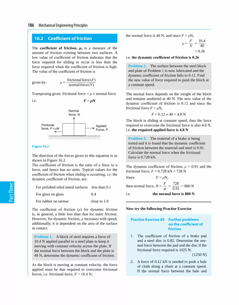
186 Mechanical Engineering Principles
Part
Thre
e
16.2 Coefficient of friction
The coefficient of friction, µ, is a measure of the amount of friction existing between two surfaces. A low value of coefficient of friction indicates that the force required for sliding to occur is less than the force required when the coefficient of friction is high. The value of the coefficient of friction is
given by: μ = frictional force ( )normal force ( )FN
Transposing gives: frictional force = μ × normal force
i.e. F = µN
Figure 16.2
The direction of the forces given in this equation is as shown in Figure 16.2. The coefficient of friction is the ratio of a force to a force, and hence has no units. Typical values for the coefficient of friction when sliding is occurring, i.e. the dynamic coefficient of friction, are:
For polished oiled metal surfaces less than 0.1
For glass on glass 0.4
For rubber on tarmac close to 1.0
The coefficient of friction (μ) for dynamic friction is, in general, a little less than that for static friction. However, for dynamic friction, μ increases with speed; additionally, it is dependent on the area of the surface in contact.
Problem 1. A block of steel requires a force of 10.4 N applied parallel to a steel plate to keep it moving with constant velocity across the plate. If the normal force between the block and the plate is 40 N, determine the dynamic coefficient of friction.
As the block is moving at constant velocity, the force applied must be that required to overcome frictional forces, i.e. frictional force, F = 10.4 N;
the normal force is 40 N, and since F = μN,
μ = FN =
10.440
= 0.26i.e. thedynamiccoefficientoffrictionis0.26
Problem 2. The surface between the steel block and plate of Problem 1 is now lubricated and the dynamic coefficient of friction falls to 0.12. Find the new value of force required to push the block at a constant speed.
The normal force depends on the weight of the block and remains unaltered at 40 N. The new value of the dynamic coefficient of friction is 0.12 and since the frictional force F = μN,
F = 0.12 × 40 = 4.8 NThe block is sliding at constant speed, thus the force required to overcome the frictional force is also 4.8 N, i.e. the required applied force is 4.8 N
Problem 3. The material of a brake is being tested and it is found that the dynamic coefficient of friction between the material and steel is 0.91. Calculate the normal force when the frictional force is 0.728 kN.
The dynamic coefficient of friction, μ = 0.91 and the frictional force, F = 0.728 kN = 728 NSince F = μN,
then normal force, N = Fµ =
7280.91 = 800 N
i.e. the normal force is 800 N
Now try the following Practise Exercise
Practise Exercise 85 Further problems on the coefficient of friction
1. The coefficient of friction of a brake pad and a steel disc is 0.82. Determine the nor-mal force between the pad and the disc if the frictional force required is 1025 N.
[1250 N]
2. A force of 0.12 kN is needed to push a bale of cloth along a chute at a constant speed. If the normal force between the bale and

Friction 187
Part
Thre
e
the chute is 500 N, determine the dynamic coefficient of friction. [0.24]
3. The normal force between a belt and its driver wheel is 750 N. If the static coefficient of friction is 0.9 and the dynamic coefficient of friction is 0.87, calculate
(a) the maximum force which can be trans-mitted, and
(b) maximum force which can be transmit-ted when the belt is running at a constant speed. [(a) 675 N (b) 652.5 N]
16.3 Applications of friction
In some applications, a low coefficient of friction is desirable, for example, in bearings, pistons moving within cylinders, on ski runs, and so on. However, for such applications as force being transmitted by belt drives and braking systems, a high value of coefficient is necessary.
Problem 4. State three advantages, and three disadvantages of frictional forces.
Instances where frictional forces are an advantage include:
(i) Almost all fastening devices rely on frictional forces to keep them in place once secured, examples being screws, nails, nuts, clips and clamps.
(ii) Satisfactory operation of brakes and clutches rely on frictional forces being present.
(iii) In the absence of frictional forces, most accelera-tions along a horizontal surface are impossible; for example, a person’s shoes just slip when walking is attempted and the tyres of a car just rotate with no forward motion of the car being experienced.
Disadvantages of frictional forces include:
(i) Energy is wasted in the bearings associated with shafts, axles and gears due to heat being generated.
(ii) Wear is caused by friction, for example, in shoes, brake lining materials and bearings.
(iii) Energy is wasted when motion through air oc-curs (it is much easier to cycle with the wind rather than against it).
Problem 5. Discuss briefly two design implica-tions that arise due to frictional forces and how lubrication may or may not help.
(i) Bearings are made of an alloy called white metal, which has a relatively low melting point. When the rotating shaft rubs on the white metal bearing, heat is generated by friction, often in one spot and the white metal may melt in this area, ren-dering the bearing useless. Adequate lubrication (oil or grease) separates the shaft from the white metal, keeps the coefficient of friction small and prevents damage to the bearing. For very large bearings, oil is pumped under pressure into the bearing and the oil is used to remove the heat gen-erated, often passing through oil coolers before being re-circulated. Designers should ensure that the heat generated by friction can be dissipated.
(ii) Wheels driving belts, to transmit force from one place to another, are used in many workshops. The coefficient of friction between the wheel and the belt must be high, and it may be increased by dressing the belt with a tar-like substance. Since frictional force is proportional to the nor-mal force, a slipping belt is made more efficient by tightening it, thus increasing the normal and hence the frictional force. Designers should incorporate some belt tension mechanism into the design of such a system.
Problem 6. Explain what is meant by the terms (a) the limiting or static coefficient of friction, and (b) the sliding or dynamic coefficient of friction.
(a) When an object is placed on a surface and a force is applied to it in a direction parallel to the sur-face, if no movement takes place, then the applied force is balanced exactly by the frictional force. As the size of the applied force is increased, a value is reached such that the object is just on the point of moving. The limiting or static coefficient of friction is given by the ratio of this applied force to the normal force, where the normal force is the force acting at right angles to the surfaces in contact.
(b) Once the applied force is sufficient to overcome the stiction or static friction, its value can be

188 Mechanical Engineering Principles
Part
Thre
e
reduced slightly and the object moves across the surface. A particular value of the applied force is then sufficient to keep the object moving at a constant velocity. The sliding or dynamic coef-ficient of friction is the ratio of the applied force, to maintain constant velocity, to the normal force.
16.4 Friction on an inclined plane
Angle of reposeConsider a mass m lying on an inclined plane, as shown in Figure 16.3. If the direction of motion of this mass is down the plane, then the frictional force F will act up the plane, as shown in Figure 16.3, where F = μ mg cos q.
Figure 16.3
Now the weight of the mass is mg and this will cause two other forces to act on the mass, namely N, and the component of the weight down the plane, namely mg sin θ, as shown by the vector diagram of Figure 16.4.
Figure 16.4 Components of mg
It should be noted that N acts normal to the surface.Resolving forces parallel to the plane gives: Forces up the plane = forces down the plane
i.e. F = mg sin θ (16.1)
Resolving force perpendicular to the plane gives:
Forces ‘up’ = forces ‘down’
i.e. N = mg cos θ (16.2)
Dividing equation (16.1) by (16.2) gives:
sin sin tancos cos
F mgN mg
θ θ θθ θ= = =
But FN µ= , hence, tan θ = µ
where μ = the coefficient of friction, and θ = the angle of repose.
If θ is gradually increased until the body starts mo-tion down the plane, then this value of θ is called the limiting angle of repose. A laboratory experiment based on the theory is a useful method of obtaining the maximum value of μ for static friction.
16.5 Motion up a plane with the pulling force P parallel to the plane
In this case the frictional force F acts down the plane, opposite to the direction of motion of the body, as shown in Figure 16.5.
Figure 16.5
The components of the weight mg will be the same as that shown in Figure 16.4.Resolving forces parallel to the plane gives:
P = mg sin θ + F (16.3)
Resolving forces perpendicular to the plane gives:
N = mg cos θ (16.4)
For limiting friction,
F = μN (16.5)

Friction 189
Part
Thre
e
From equations (16.3) to (16.5), solutions of problems in this category that involve limiting friction can be solved.
Problem 7. Determine the value of the force P, which will just move the body of mass of 25 kg up the plane shown in Figure 16.6. It may be assumed that the coefficient of limiting friction, μ = 0.3 and g = 9.81 m/s2.
Figure 16.6
From equation (16.4), N = mg cos θ = 25 × 9.81 × cos 15° = 245.3 × 0.966 = 236.9 NFrom equation (16.5), F = μN = 0.3 × 236.9
= 71.1 NFrom equation (16.3), P = mg sin θ + F
= 25 × 9.81 × sin 15° + 71.1 = 63.48 + 71.1i.e. force, P = 134.6 N (16.6)
16.6 Motion down a plane with the pulling force P parallel to the
plane
In this case, the frictional force F acts up the plane, opposite to the direction of motion of the plane, as shown in Figure 16.7.
Figure 16.7
The components of the weight mg are shown in Fig-ure 16.4, where it can be seen that the normal reaction,
N = mg cos θ, and the component of weight parallel to and down the plane = mg sin θResolving forces perpendicular to the plane gives:
N = mg cos θ (16.7)
Resolving forces parallel to the plane gives:
P + mg sin θ = F (16.8)
When the friction is limiting,
F = μN (16.9)
From equations (16.7) to (16.9), problems arising in this category can be solved.
Problem 8. If the mass of Problem 7 were subjected to the force P, which acts parallel to and down the plane, as shown in Figure 16.7, determine the value of P to just move the body.
From equation (16.7),
N = mg cos θ = 25 × 9.81 cos 15°= 236.9 N
From equation (16.9), F = μN = 0.3 × 236.9 = 71.1 N
From equation (16.8), P + mg sin θ = F
i.e. P + 25 × 9.81 sin 15° = 71.1
i.e. P + 63.5 = 71.1from which, force, P = 71.1 – 63.5 = 7.6 N (16.10)
From equations (16.6) and (16.10), it can be seen that the force required to move a body down the plane is so much smaller than to move the body up the plane.
16.7 Motion up a plane due to a horizontal force P
This motion, together with the primary forces, is shown in Figure 16.8.
Figure 16.8

190 Mechanical Engineering Principles
Part
Thre
e
Figure 16.9
In this, the components of mg are as shown in Figure 16.4, and the components of the horizontal force P are shown by the vector diagram of Figure 16.9.Resolving perpendicular to the plane gives:
Forces ‘up’ = forces ‘down’
i.e. N = mg cos θ + P sin θ (16.11)
Resolving parallel to the plane gives:
P cos θ = F + mg sin θ (16.12)
and F = μN (16.13)
From equations (16.11) to (16.13), problems arising in this category can be solved.
Problem 9. If the mass of Problem 7 were subjected to a horizontal force P, as shown in Figure 16.8, determine the value of P that will just cause motion up the plane.
Substituting equation (16.13) into equation (16.12) gives: P cos θ = μN + mg sin θor μN = P cos θ – mg sin θ
i.e. N = cos sinP mgθ θµ µ− (16.14)
Equating equation (16.11) and equation (16.14) gives:
mg cos θ + P sin θ = cos sinP mgθ θµ µ−
i.e. 25 × 9.81 cos 15° + P sin 15°
= cos15 25 9.81sin150.3 0.3
P ° × °−
245.3 × 0.966 + P × 0.259 = 0.966 245.3 0.2590.3 0.3
P× ×−
i.e. 237 + 0.259 P = 3.22 P – 211.8 237 + 211.8 = 3.22 P – 0.259 P
from which, 448.8 = 2.961 P
and force P = 448.82.961 = 151.6 N
Problem 10. If the mass of Problem 9 were subjected to a horizontal force P, acting down the plane, as shown in Figure 16.10, determine the value of P which will just cause motion down the plane.
Figure 16.10
The components for mg are shown by the phasor diagram of Figure 16.4, and the components for P are shown by the vector diagram of Figure 16.11.
Figure 16.11
Resolving forces down the plane gives: P cos θ + m g sin θ = F (16.15)Resolving forces perpendicular to the plane gives: Forces up = forces down N + P sin θ = mg cos θ (16.16)and F = μN (16.17)Substituting equation (16.17) into equation (16.15) gives: P cos θ + mg sin θ = μN
from which, N = cos sinP mgθ θµ µ+ (16.18)
From equation (16.16), N = mg cos θ – P sin θ (16.19) Equating equations (16.18) and (16.19) gives:
cos sinP mgθ θµ µ+ = mg cos θ – P sin θ

Friction 191
Part
Thre
e
i.e. cos15 25 9.81sin150.3 0.3
P ° × °+
= 25 × 9.81 cos 15° – P sin 15° 3.22 P + 211.6 = 236.9 – 0.259 P P(3.22 + 0.259) = 236.9 – 211.6 3.479 P = 25.3
from which, force P = 25.33.479 = 7.27 N
Problem 11. If in Problem 9, the contact surfaces were greased, so that the value of μ decreased and P = 50 N, determine the value of μ which will just cause motion down the plane.
The primary forces for this problem are shown in Figure 16.12, where it can be seen that F is opposite to the direction of motion.
Figure 16.12
Resolving forces perpendicular to the plane gives: Forces ‘up’ = forces ‘down’ N = mg cos θ + P sin θ (16.20)Resolving forces parallel to the plane gives: mg sin θ = F + P cos θ (16.21)and F = μN (16.22)Substituting equation (16.22) into equation (16.21) gives: mg sin θ = μN + P cos θ (16.23)Substituting equation (16.20) into equation (16.23) gives: mg sin θ = μ(mg cos θ + P sin θ) + P cos θ
i.e. 25 × 9.81 sin 15° = μ(25 × 9.81 cos 15° + 50 sin 15°) + 50 cos 15° Hence 63.48 = μ(236.89 + 12.94) + 48.3 63.48 – 48.3 = μ × 249.83
from which, μ = 15.18249.83 = 0.061
Now try the following Practise Exercise
Practise Exercise 86 Further problems on friction on an inclined plane
(Where necessary, take g = 9.81 m/s2)
1. A mass of 40 kg rests on a flat horizontal surface as shown in Figure 16.13. If the coefficient of friction μ = 0.2, determine the minimum value of a horizontal force P which will just cause it to move.
[78.48 N]
Figure 16.13
2. If the mass of Problem 1 were equal to 50 kg, what will be the value of P?
[98.1 N]
3. An experiment is required to obtain the static value of μ; this is achieved by in-creasing the value of θ until the mass just moves down the plane, as shown in Figure 16.14. If the experimentally obtained value for θ was 22.5°, what is the value of μ?
[μ = 0.414]
Figure 16.14
4. If in Problem 3, μ was 0.6, what would be the experimental value of θ? [θ = 30.96°]
5. For a mass of 50 kg just moving up an inclined plane, as shown in Figure 16.5, what would be the value of P, given that θ = 20° and μ = 0.4? [P = 352.1 N]

192 Mechanical Engineering Principles
Part
Thre
e
6. For a mass of 50 kg, just moving down an inclined plane, as shown in Figure 16.7, what would be the value of P, given that θ = 20° and μ = 0.4? [P = 16.6 N]
7. If in Problem 5, θ = 10° and μ = 0.5, what would be the value of P? [P = 326.7 N]
8. If in Problem 6, θ = 10° and μ = 0.5, what would be the value of P? [P = 156.3 N]
9. Determine P for Problem 5, if it were acting in the direction shown in Figure 16.8. [P = 438.6 N]
10. Determine P for Problem 6, if it were act-ing in the direction shown in Figure 16.10.
[P = 15.43 N]
11. Determine the value for θ which will just cause motion down the plane, when P = 250 N and acts in the direction shown in Figure 16.12. It should be noted that in this problem, motion is down the plane, μ = 0.5 and m = 50 kg.
[θ = 53.58°]
12. If in Problem 11, θ = 30°, determine the value of μ. [μ = 0.052]
16.8 The efficiency of a screw jack
Screw jacks (see Section 19.4, page 216) are often used to lift weights; one of their most common uses are to raise cars, so that their wheels can be changed. The theory described in Section 16.7 can be used to analyse screw jacks.
Consider the thread of the square-threaded screw jack shown in Figure 16.15.
Figure 16.15
Let p be the pitch of the thread, i.e. the axial distance that the weight W is lifted or lowered when the screw is turned through one complete revolution.
From Figure 16.15, the motion of the screw in lifting the weight can be regarded as pulling the weight by a horizontal force P, up an incline θ, where
tan θ = pdπ as shown in Figure 16.15,
and d = 1 2( )2
D D+
If μ is the coefficient of friction up the slope, then let tan λ = μReferring now to Figure 16.16, the screw jack can be analysed.
Figure 16.16
Resolving normal to the plane gives:
N = W cos θ + P sin θ (16.24)
Resolving parallel to the plane gives:
P cos θ = F + W sin θ (16.25)
and F = μN (16.26)
Substituting equation (16.26) into equation (16.25) gives:
P cos θ = μN + W sin θ (16.27)
Substituting equation (16.24) into equation (16.27) gives:
P cos θ = μ(W cos θ + P sin θ) + W sin θ
Dividing each term by cos θ and remembering that sincos
θθ = tan θ gives:
P = μ(W + P tan θ) + W tan θ
Rearranging gives:
P(1 – μ tan θ) = W(μ + tan θ)

Friction 193
Part
Thre
e
from which, P = ( tan ) (tan tan )
(1 tan ) (1 tan tan )W Wµ θ λ θ
µ θ λ θ+ +
=− −
since μ = tan λ
However, from compound angle formulae (see refer-ence [1] on page 195),
tan(λ + θ) = (tan tan )(1 tan tan )
λ θλ θ
+−
Hence, P = W tan(θ + λ) (16.28)
However, from Figure 16.15,
tan θ = pdπ and tan λ = μ
hence P = ( )tan tan1 tan tan
1
pW dWpd
µ πλ θλ θ µ
π
+ + =− −
(16.29)
Multiplying top and bottom of equation (16.29) by πd gives:
P = ( )( )
W d pd pµππ µ
+− (16.30)
The useful work done in lifting the weight W a distance of p = Wp (16.31)
From Figure 16.15, the actual work done = P × πd
= ( )( )
W d pd pµππ µ
+− ×πd (16.32)
Efficiency η = useful work doneactual work done
which is usually
expressed as a percentage
i.e. η = ( )( )
WpW d p d
d pµπ ππ µ
+ ×−
= ( )( )
p d pd p dπ µ
µπ π−
+ ×
Dividing throughout by πd gives:
1(1 tan tan )
( )
(1 tan tan )(tan tan )
pp d pd p pd d
pd
µπ λ θη µπ
π µ πλ θ
π λ θ
− −= =+ +
−= +
However, tan(λ + θ) = tan tan(1 tan tan )
λ θλ θ
+− from com-
pound angle formulae (see reference [1], page 195)
Hence, η = 1tan( )
pdπ λ θ+
but pdπ = tan θ
hence, efficiency, η = tantan( )
θλ θ+ (16.33)
From equations (16.31) and (16.32), the work lost in friction
= ( )
( )W d p
d pµπ
π µ+
− × πd – Wp (16.34)
Problem 12. The coefficient of friction on the sliding surface of a screw jack is 0.2. If the pitch equals 1 cm, and D1 = 4 cm and D2 = 5 cm, calcu-late the efficiency of the screw jack.
Working in millimetres, d = 1 2( ) (40 50)2 2
D D+ +=
= 45 mm, p = 1 cm = 10 mm,
tan θ = 1045
pdπ π= × = 0.0707,
from which, θ = tan–1 (0.0707) = 4.05° and tan λ = μ = 0.2,from which, λ = tan–1 (0.2) = 11.31°From equation (16.33),
efficiency η = tantan( )
θλ θ+
= 0.0707 0.0707tan(11.31 4.05) 0.2747=+ °
= 0.257i.e. η = 25.7%
Now try the following Practise Exercises
Practise Exercise 87 Further problem on the efficiency of a screw jack
1. The coefficient of friction on the sliding sur-face of a screw jack whose thread is similar to Figure 16.15, is 0.24. If the pitch equals 12 mm, and D1 = 42 mm and D2 = 56 mm, calculate the efficiency of the screw jack.
[24.06%]

194 Mechanical Engineering Principles
Part
Thre
e
Practise Exercise 88 Short-answer questions on friction
1. The ........ of frictional force depends on the ........ of surfaces in contact.
2. The ........ of frictional force depends on the size of the ........ to the surfaces in contact.
3. The ......... of frictional force is always ........ to the direction of motion.
4. The coefficient of friction between surfaces should be a ........ value for materials con-cerned with bearings.
5. The coefficient of friction should have a ........ value for materials concerned with braking systems.
6. The coefficient of dynamic or sliding fric-tion is given by .....
.....
7. The coefficient of static or limiting friction is given by .....
..... when ....... is just about to take place.
8. Lubricating surfaces in contact result in a ....... of the coefficient of friction.
9. Briefly discuss the factors affecting the size and direction of frictional forces.
10. Name three practical applications where a low value of coefficient of friction is desir-able and state briefly how this is achieved in each case.
11. Name three practical applications where a high value of coefficient of friction is required when transmitting forces and discuss how this is achieved.
12. For an object on a surface, two differ-ent values of coefficient of friction are possible. Give the names of these two coefficients of friction and state how their values may be obtained.
13. State the formula for the angle of repose.
14. What theory can be used for calculating the efficiency of a screw jack.
Practise Exercise 89 Multiple-choice questions on friction
(Answers on page 298)
1. A block of metal requires a frictional force F to keep it moving with constant velocity across a surface. If the coefficient of friction is μ, then the normal force N is given by:
(a) Fµ (b) μF
(c) Fµ (d) F
2. The unit of the linear coefficient of friction is:
(a) newtons (b) radians (c) dimensionless (d) newtons/metre
Questions 3 to 7 refer to the statements given below. Select the statement required from each group given.
(a) The coefficient of friction depends on the type of surfaces in contact.
(b) The coefficient of friction depends on the force acting at right angles to the surfaces in contact.
(c) The coefficient of friction depends on the area of the surfaces in contact.
(d) Frictional force acts in the opposite direc-tion to the direction of motion.
(e) Frictional force acts in the direction of motion.
(f) A low value of coefficient of friction is required between the belt and the wheel in a belt drive system.
(g) A low value of coefficient of friction is required for the materials of a bearing.
(h) The dynamic coefficient of friction is given by (normal force)/(frictional force) at constant speed.
(i) The coefficient of static friction is given by (applied force) ÷ (frictional force) as sliding is just about to start.
(j) Lubrication results in a reduction in the coefficient of friction.
3. Which statement is false from (a), (b), (f) and (i)?

Friction 195
Part
Thre
e
4. Which statement is false from (b), (e), (g) and (j) ?
5. Which statement is true from (c), (f), (h) and (i) ?
6. Which statement is false from (b), (c), (e) and (j)?
7. Which statement is false from (a), (d), (g) and (h)?
8. The normal force between two surfaces is 100 N and the dynamic coefficient of friction is 0.4
The force required to maintain a constant speed of sliding is:
(a) 100.4 N (b) 40 N (c) 99.6 N (d) 250 N
9. The normal force between two surfaces is 50 N and the force required to maintain a constant speed of sliding is 25 N. The dynamic coefficient of friction is:
(a) 25 (b) 2 (c) 75 (d) 0.5
10. The maximum force, which can be applied to an object without sliding occurring, is 60 N, and the static coefficient of friction is 0.3. The normal force between the two surfaces is:
(a) 200 N (b) 18 N (c) 60.3 N (d) 59.7 N
11. The formula for the angle of repose is: (a) F = μN (b) tan θ = μ
(c) μ = FN (d) tan θ =
sincos
θθ
Reference
[1] Bird, J O Engineering Mathematics 6th Edition, chapter 27, Taylor and Francis Publishers, 2010.
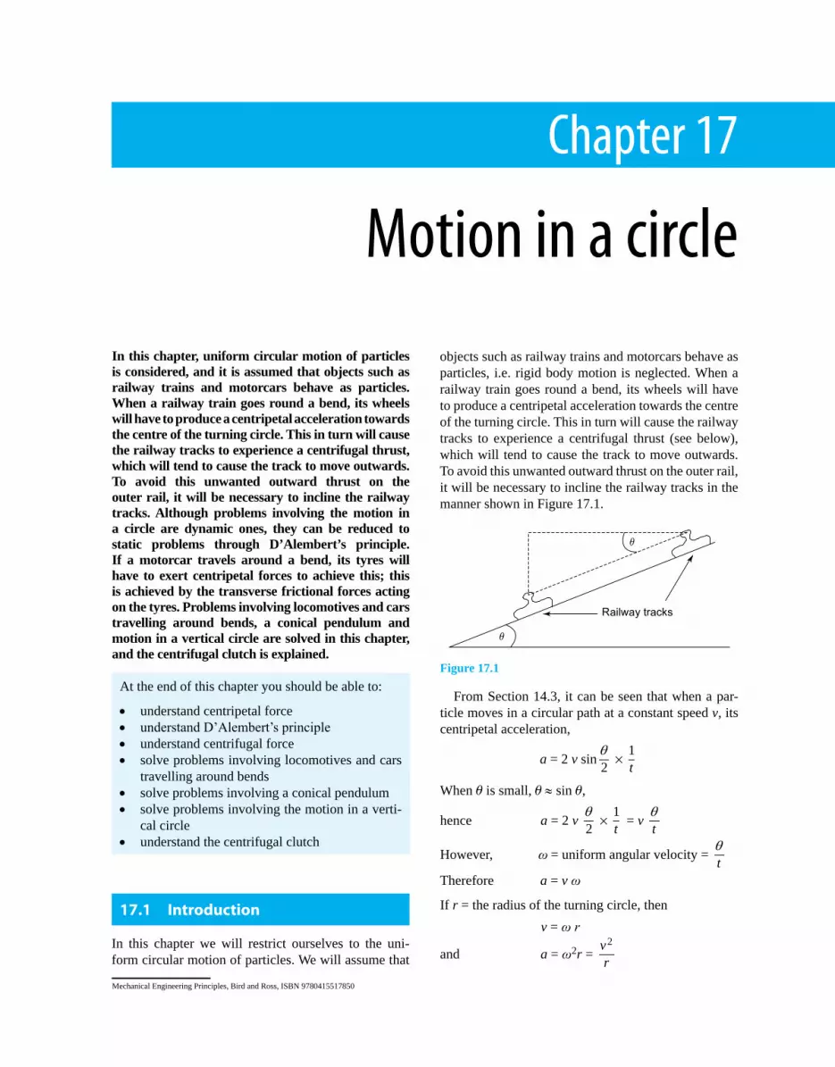
Chapter 17
Motion in a circle
Mechanical Engineering Principles, Bird and Ross, ISBN 9780415517850
In this chapter, uniform circular motion of particles is considered, and it is assumed that objects such as railway trains and motorcars behave as particles. When a railway train goes round a bend, its wheels will have to produce a centripetal acceleration towards the centre of the turning circle. This in turn will cause the railway tracks to experience a centrifugal thrust, which will tend to cause the track to move outwards. To avoid this unwanted outward thrust on the outer rail, it will be necessary to incline the railway tracks. Although problems involving the motion in a circle are dynamic ones, they can be reduced to static problems through D’Alembert’s principle. If a motorcar travels around a bend, its tyres will have to exert centripetal forces to achieve this; this is achieved by the transverse frictional forces acting on the tyres. Problems involving locomotives and cars travelling around bends, a conical pendulum and motion in a vertical circle are solved in this chapter, and the centrifugal clutch is explained.
objects such as railway trains and motorcars behave as particles, i.e. rigid body motion is neglected. When a railway train goes round a bend, its wheels will have to produce a centripetal acceleration towards the centre of the turning circle. This in turn will cause the railway tracks to experience a centrifugal thrust (see below), which will tend to cause the track to move outwards. To avoid this unwanted outward thrust on the outer rail, it will be necessary to incline the railway tracks in the manner shown in Figure 17.1.
Figure 17.1
From Section 14.3, it can be seen that when a par-ticle moves in a circular path at a constant speed v, its centripetal acceleration,
a = 2 v sin 2θ × 1
t
When q is small, q ≈ sin q,
hence a = 2 v 2θ × 1
t = v tθ
However, ω = uniform angular velocity = tθ
Therefore a = v ω
If r = the radius of the turning circle, then v = ω r
and a = ω2r = 2v
r
At the end of this chapter you should be able to:
• understand centripetal force• understand D’Alembert’s principle• understand centrifugal force• solve problems involving locomotives and cars
travelling around bends• solve problems involving a conical pendulum• solve problems involving the motion in a verti-
cal circle• understand the centrifugal clutch
17.1 Introduction
In this chapter we will restrict ourselves to the uni-form circular motion of particles. We will assume that

Motion in a circle 197
Part
Thre
e
Now force = mass × acceleration
Hence, centripetal force = m ω2r = 2m v
r (17.1)
D’Alembert’s principleAlthough problems involving the motion in a circle are dynamic ones, they can be reduced to static problems through D’Alembert’s principle. In this principle, the centripetal force is replaced by an imaginary centrifugal force which acts equal and opposite to the centripetal force. By using this principle, the dynamic problem is reduced to a static one.
If a motorcar travels around a bend, its tyres will have to exert centripetal forces to achieve this. This is achieved by the transverse frictional forces acting on the tyres, as shown in Figure 17.2.
Figure 17.2
In Figure 17.2, the following notation is used:
CG = centre of gravity of the car,
m = mass of car, R1 = vertical reaction of
‘inner’ wheel, F1 = frictional force on
‘inner’ wheel, h = vertical distance
of the centre of gravity of the car from the ground,
L = distance between the centre of the tyres,
μ = coefficient of friction,
CF = centrifugal force
=2mv
r ,
g = acceleration due to gravity,
R2 = vertical reaction of ‘outer’ wheel,
F2 = frictional force on ‘outer’ wheel,
r = radius of the turning circle.
Problem 1. Determine expressions for the frictional forces F1 and F2 of Figure 17.2. Hence determine the thrust on each tyre.
Resolving forces horizontally gives:
F1 + F2 = centrifugal force = CF = 2mv
r (17.2)
Resolving forces vertically gives: R1 + R2 = mg (17.3)Taking moments about the ‘outer’ wheel gives:
CF × h + R1 × L = mg 2L
i.e. 2mv
r h + R1L = mg 2L
or R1L = mg 2L –
2mvr h
Hence, R1L = m2
2gL v h
r
−
from which, R1= mL
2
2gL v h
r
− (17.4)
Also, F1 = m R1 and F2 = m R2 (17.5)
Substituting equation (17.4) into equation (17.3) gives:
mL
2
2gL v h
r
− + R2 = mg
Therefore, R2 = mg – mL
2
2gL v h
r
−
= mg – 2mg + m
L2v hr
i.e. R2 = mL
2
2gL v h
r
+ (17.6)
From equations (17.4) to (17.6):
F1= μ mL
−
2
2gL v h
r (17.7)
and F2= μ mL
+
2
2gL v h
r (17.8)
To calculate the thrust on each tyre:From Pythagoras’ theorem (see Chapter 1),
T1= 2 21 1F R+ = 2 2 2
1 1R Rµ +
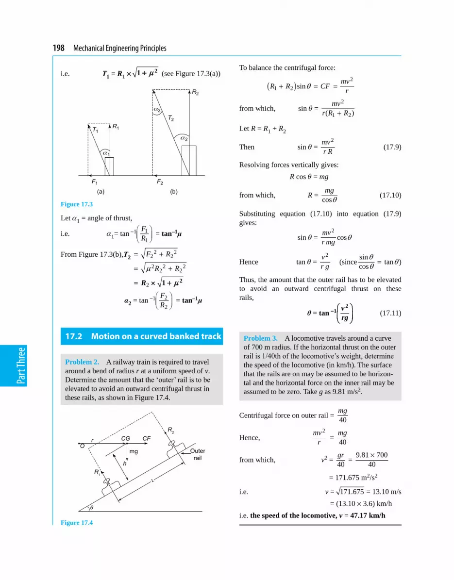
198 Mechanical Engineering Principles
Part
Thre
e
i.e. T1 = R1 × µ+ 21 (see Figure 17.3(a))
Figure 17.3
Let a1 = angle of thrust,
i.e. a1= tan 111
FR
−
= tan–1μ
From Figure 17.3(b),T2 2 22 2
2 2 22 2
2R µ+ 21
F R
R Rµ
= +
= +
= ×
α2 = tan 212
FR
−
= tan–1μ
17.2 Motion on a curved banked track
Problem 2. A railway train is required to travel around a bend of radius r at a uniform speed of v. Determine the amount that the ‘outer’ rail is to be elevated to avoid an outward centrifugal thrust in these rails, as shown in Figure 17.4.
Figure 17.4
To balance the centrifugal force:
( )2
1 2 sin mvR R CF rθ+ = =
from which, sin q = 2
1 2( )mv
r R R+
Let R = R1 + R2
Then sin q = 2mv
r R (17.9)
Resolving forces vertically gives: R cos q = mg
from which, R = cosmgθ (17.10)
Substituting equation (17.10) into equation (17.9) gives:
sin q = 2
cosmvr mg θ
Hence tan q = 2v
r g (sincesin tancos
θ θθ = )
Thus, the amount that the outer rail has to be elevated to avoid an outward centrifugal thrust on these rails,
θ = tan −
21 v
rg (17.11)
Problem 3. A locomotive travels around a curve of 700 m radius. If the horizontal thrust on the outer rail is 1/40th of the locomotive’s weight, determine the speed of the locomotive (in km/h). The surface that the rails are on may be assumed to be horizon-tal and the horizontal force on the inner rail may be assumed to be zero. Take g as 9.81 m/s2.
Centrifugal force on outer rail = 40mg
Hence, 2mv
r = 40
mg
from which, v2 = 40gr = 9.81 700
40×
= 171.675 m2/s2
i.e. v = 171.675 = 13.10 m/s = (13.10 × 3.6) km/hi.e. the speed of the locomotive, v = 47.17 km/h

Motion in a circle 199
Part
Thre
e
Problem 4. What angle of banking of the rails is required for Problem 3 above, for the outer rail to have a zero value of thrust? Assume the speed of the locomotive is 40 km/h.
From Problem 2, angle of banking, q = 2
1tan vrg
−
v = 40 km/h
= km 1h 1000m40 h 3600s 1km× ×
= 403.6 = 11.11 m/s
Hence, q = 2 2 2
12
11.11 m /stan700m 9.81m/s
− ×
= tan 1(0.01798)−
i.e. angle of banking, θ = 1.03°
Now try the following Practise Exercise
Practise Exercise 90 Further problems on motion in a circle
(Where needed, take g = 9.81 m/s2)
1. A locomotive travels around a curve of 500 m radius. If the horizontal thrust on the
outer rail is 150 of the locomotive weight,
determine the speed of the locomotive. The surface that the rails are on may be assumed to be horizontal and the horizontal force on the inner rail may be assumed to be zero. [35.64 km/h]
2. If the horizontal thrust on the outer rail of Problem 1 is 1
100 of the locomotive’s weight, determine its speed. [25.2 km/h]
3. What angle of banking of the rails of Prob-lem 1 is required for the outer rail to have a zero value of outward thrust? Assume the speed of the locomotive is 15 km/h. [0.203°]
4. What angle of banking of the rails is required for Problem 3, if the speed of the locomotive is 30 km/h ? [0.811°]
17.3 Conical pendulum
If a mass m were rotated at a constant angular velocity, ω, in a horizontal circle of radius r, by a mass-less taut string of length L, its motion will be in the form of a cone, as shown in Figure 17.5.
Figure 17.5 Conical pendulum
Let r = radius of horizontal turning circle, L = length of string, h = OC, w = constant angular velocity about C, m = mass of particle P, T = tension in string, and q = cone angle
Problem 5. Determine an expression for the cone angle q and the tension in the string T, for the conical pendulum of Figure 17.5. Determine also an expression for ω.
Resolving forces horizontally gives: Centrifugal force = CF = T sin qi.e. m ω2r = T sin q
from which, T = 2
sinm rω
θ (17.12)
Resolving forces vertically gives: T cos q = mg
from which, T = cosmgθ (17.13)

200 Mechanical Engineering Principles
Part
Thre
e
Equating equations (17.12) and (17.13) gives:
2
sinm rω
θ = cosmgθ
Rearranging gives: 2 sin
cosm r
mgω θ
θ=
i.e. tan q = 2r
gω
Hence, the cone angle, θ = tan
21 r
gω− (17.14)
From Figure 17.5, sin q = rL (17.15)
Hence, from equation (17.12), T = 2m r
rL
ω
i.e. the tension in the string, T = m ω2L (17.16)
From equation (17.14), 2r
gω
= tan q
But, from Figure 17.5, tan q = rh
Hence, 2r
gω
= rh
and ω2 = gh
Thus, angular velocity about C, ω = gh (17.17)
Problem 6. A conical pendulum rotates about a horizontal circle at 90 rpm. If the speed of rotation of the mass increases by 10%, how much does the mass of the pendulum rise (in mm)? Take g as 9.81 m/s2.
Angular velocity, ω = 2 2 9060 60
nπ π ×=
= 9.425 rad/s
From equation (16.17), ω = gh
or ω2 = gh
from which, height, h = 2gω
= 29.81
9.425
= 0.11044 m (see Figure 17.5)
When the speed of rotation rises by 10%, n2 = 90 × 1.1 = 99 rpm
Hence, ω2 = 22 2 9960 60
nπ π ×=
= 10.367 rad/s
From equation (17.17), ω2= 2
gh
or ω22 =
2
gh
Hence, h2 = 22
gω
= 29.81
10.367
i.e. the new value of height, h2= 0.09127 m
Rise in height of the pendulum mass = ‘old’ h – ‘new’ h = h – h2 = 0.11044 – 0.09127 = 0.01917 m = 19.17 mm
Problem 7. A conical pendulum rotates at a hori-zontal angular velocity of 5 rad/s. If the length of the string is 2 m and the pendulum mass is 0.3 kg, determine the tension in the string. Determine also the radius of the turning circle. Take g as 9.81 m/s2.
Angular velocity, ω = 5 rad/sFrom equation (17.16), tension in the string, T = m ω2L = 0.3 kg × (5 rad/s)2 × 2 mi.e. T = 15 kg m/s2
However, 1 kg m/s2 = 1 N, hence,
tension in the string, T = 15 N
From equation (17.13), T = cosmgθ
from which, cos q = mgT
= 20.3kg 9.81m/s
15 N×
= 0.1962Hence, the cone angle, θ = cos–1(0.1962)
= 78.685°
From equation (17.15), sin q =rL
from which, radius of turning circle, r = L sin q = 2 m × sin 78.685°
= 1.961 m

Motion in a circle 201
Part
Thre
e
Now try the following Practise Exercise
Practise Exercise 91 Further problems on the conical pendulum
1. A conical pendulum rotates about a horizontal circle at 100 rpm. If the speed of rotation of the mass increases by 5%, how much does the mass of the pendulum rise? [8.32 mm]
2. If the speed of rotation of the mass of Prob-lem 1 decreases by 5%, how much does the mass fall? [9.66 mm]
3. A conical pendulum rotates at a horizontal angular velocity of 2 rad/s. If the length of the string is 3 m and the pendulum mass is 0.25 kg, determine the tension in the string. Determine also the radius of the turning circle. [3 N, 1.728 m]
17.4 Motion in a vertical circle
This problem is best solved by energy considerations.Consider a particle P rotating in a vertical circle of radius r, about a point O, as shown in Figure 17.6. Neglect losses due to friction.
Figure 17.6 Motion in vertical circle
Let T = tension in a mass-less string,r = radius of turning circle,
and m = mass of particle.
Problem 8. Determine the minimum tangential velocity at A, namely, vA, which will just keep the string taut at the point B for the particle moving in the vertical circle of Figure 17.6.
At the point B the potential energy = mg × 2r (17.18)
and the kinetic energy = 2
2Bmv (17.19)
At the point A, the kinetic energy (KE) = 2
2Amv
(17.20)
and the potential energy (PE) = 0As there are no energy losses, KE at A = (KE + PE) at BHence, from equations (17.18) to (17.20):
2
2Amv = mg × 2r +
2
2Bmv
or 2
2Av =
2
2Bv + 2gr
from which, 2 2A Bv v= + 4gr (17.21)
At B, T = 0; this is because B is the highest point in the circle, where it can readily be observed that T will be a minimumThus, weight = centrifugal force at B,
or mg = 2
Bmvr
from which, 2Bv = gr (17.22)
Substituting equation (17.22) into equation (17.21) gives:
2Av = gr + 4gr = 5gr
Hence, the minimum tangential velocity at A, 5Av gr= (17.23)
Problem 9. A mass of 0.1 kg is being rotated in a vertical circle of radius 0.6 m. If the mass is attached to a mass-less string and the motion is such that the string is just taut when the mass is at the top of the circle, what is the tension in the string when it is horizontal? Neglect losses and take g as 9.81 m/s2.

202 Mechanical Engineering Principles
Part
Thre
e
At the top of the circle, potential energy = PE = 2 mgr
and KE =2
2Tmv
where vT = velocity at the topWhen the string is horizontal, PE = mgr
and kinetic energy, KE =2
12
mv
where v1 = velocity of mass at this point.From the conservation of energy, (PE + KE) at the top = (PE + KE) when the string is horizontal
i.e. 2 mgr = mgr + 2
12
mv – 2
2Tmv
or 2
12
mv = 2 mgr – mgr + 2
2Tmv
i.e. 2
12
v = gr + 2
2Tv
but CF at top = 2
Tmvr = mg or v 2
T = gr
Hence, 2
12
v = gr + 2gr = 3
2gr
i.e. 21v = 3gr
and 1 3 3 9.81 0.6v gr= = × × = 4.202 m/s
Resolving forces horizontally, Centrifugal force = T = tension in the string
Therefore, T = 2 2 2 2
1 0.1kg (4.202) m /s0.6m
mvr
×=
i.e. the tension in the string, T = 2.943 N
Problem 10. What is the tension in the string for Problem 9 when the mass is at the bottom of the circle?
From equation (17.23), the velocity at the bottom of the
circle = v = 5gr
i.e. v = 5 9.81 0.6× × = 5.4249 m/s.Resolving forces vertically, T = tension in the string
= centrifugal force + the weight of the mass
i.e. T = 2mv
r + mg = m
2v gr
+
= 0.1 ×25.4249 9.810.6
+
= 0.1 × (49.05 + 9.81)
= 0.1 × 58.86 Ni.e. tension in the string, T = 5.886 N
Problem 11. If the mass of Problem 9 were to rise, so that the string is at 45° to the vertical axis and below the halfway mark, what would be the tension in the string?
At 45°, PE = 2mgr
and KE = 2
22
mv
where v2 = velocity of the mass at this stage.From the conservation of energy, (PE + KE) at the top = (PE + KE) at this stage
Therefore, 2 mgr = 2mgr +
22
2mv –
2
2Tmv
From Problem 9, vT2 = gr
or 2
22
v = 2 2 2r rr − +
g
= 2gr
from which, 22v = 4gr
and v2 4
4 9.81 0.6
gr=
= × ×
= 4.852 m/s
Resolving forces in a direction along the string, T = tension in the string = centrifugal
force + component of weight at 45° to the vertical
i.e. T = 2
2mvr + mg cos 45°
= 20.1 (4.2852)
0.6× + 0.1 × 9.81 × 0.7071
= 3.924 N + 0.6937 Ni.e. the tension in the string, T = 4.618 N

Motion in a circle 203
Part
Thre
e
Now try the following Practise Exercise
Practise Exercise 92 Further problems on motion in a vertical circle
1. A uniform disc of diameter 0.1 m rotates about a vertical plane at 200 rpm. The disc has a mass of 1.5 kg attached at a point on its rim and another mass of 2.5 kg at another point on its rim, where the angle between the two masses is 90°clockwise. Determine the magnitude of the resultant centrifugal force that acts on the axis of the disc, and its posi-tion with respect to the 1.5 kg mass. [63.94 N at 59° clockwise]
2. If a mass of 4 kg is placed on some posi-tion on the disc in Problem 1, determine the position where this mass must be placed to nullify the unbalanced centrifugal force.
[ At a radius of 36.44 mm, 121° anti-clockwise to 1.5 kg mass]
3. A stone of mass 0.1 kg is whirled in a verti-cal circle of 1 m radius by a mass-less string, so that the string just remains taut. Deter-mine the velocity and tension in the string at (a) the top of the circle (b) the bottom of the circle (c) midway between (a) and (b).
[ (a) 3.132 m/s, 0 N (b) 7 m/s, 5.88 N(c) 5.42 m/s, 2.94 N ]
17.5 Centrifugal clutch
A clutch is an engineering device used for transferring motion from an engine to a gearbox or other machin-ery. The main purpose of the clutch is to transfer the motion in a smooth and orderly manner, so that the gears and wheels (in the case of the motor car) will accelerate smoothly and not in a jerky manner.
The centrifugal clutch works on the principle that the rotating driving shaft will cause the centrifugal weights, shown in Figure 17.7, to move radially out-wards with increasing speed of rotation of the driving shaft. These centrifugal weights will be restrained by the restraining springs shown, but when the speed of the driving shaft reaches the required value, the clutch material will engage with the driven shaft, through fric-tion, and cause the driven shaft to rotate. The driven
shaft will thus reach a high speed of rotation quite smoothly in the required time.Centrifugal clutches are popular when it is required to exert a high starting torque quickly and smoothly.A suitable clutch material is asbestos, but it is likely that asbestos will be replaced by more modern materi-als for health and safety reasons.
Now try the following Practise Exercises
Practise Exercise 93 Short-answer problems on motion in a circle
1. The centrifugal force of a mass m moving at velocity v at a radius r is given by: ........
2. What is the potential energy at the top of a circle for the motion in a vertical circle?
3. What is the potential energy at the bottom of a circle for the motion in a vertical circle?
4. What is the potential energy at the ‘middle’ of a circle for the motion in a vertical circle?
Exercise 94 Multiple-choice problems on motion in a circle
(Answers on page 298)
1. To decrease the horizontal thrust on the outer rail of a train going round a bend, the outer rail should be:
(a) lowered (b) raised (c) kept at the same level as the inner rail (d) made bigger
Figure 17.7

204 Mechanical Engineering Principles
Part
Thre
e
2. If the speed of rotation of a conical pendu-lum is increased, the height of the pendulum mass will:
(a) fall (b) become zero (c) stay the same (d) rise
3. The minimum tension on the top of a vertical circle, for satisfactory motion in a circle is:
(a) zero (b) mg
(c) 2mv
r (d) negative
4. If v is the velocity at the ‘middle’ for the motion in a vertical circle, the tension is:
(a) zero (b) 2mv
r (c) mg (d) negative
5. If the tension in the string is zero at the top of a circle for the motion in a vertical circle, the velocity at the bottom of the circle is:
(a) zero (b) 5gr (c) gr (d) 3gr

Chapter 18
Simple harmonic motion
Mechanical Engineering Principles, Bird and Ross, ISBN 9780415517850
Simple harmonic motion is of importance in a num-ber of branches of engineering and physics, includ-ing structural and machine vibrations, alternating electrical currents, sound waves, light waves, tidal motion, and so on. This chapter explains simple harmonic motion, determines natural frequencies for spring-mass systems, calculates periodic times and explains simple and compound pendulums.
f = 12Tωπ= (18.2)
To determine whether or not SHM is taking place, we will consider motion of A in the direction yy. Now yC = OA sin ωt,
i.e. yC = r sin ωt (18.3)
where t = time in seconds.
Plotting of equation (18.3) against t results in the sinusoidal variation for displacement, as shown in Figure 18.1(b).From Chapter 12, vA = ωr, which is the tangential ve-locity of the particle A.From the velocity vector diagram, at the point A on the circle of Figure 18.1(a),
vC = vA cos q = vA cos ωt (18.4)
Plotting of equation (18.4) against t results in the sinusoidal variation for the velocity vC , as shown in Figure 18(b).
The centripetal acceleration of A = aA = w2r
Now aC = – aA sin q
At the end of this chapter you should be able to:
• understand simple harmonic motion• determine natural frequencies for simple spring-
mass systems• calculate periodic times• understand the motion of a simple pendulum• understand the motion of a compound pendulum
18.1 Introduction to simple harmonic motion (SHM)
A particle is said to be under SHM if its acceleration along a line is directly proportional to its displacement along that line, from a fixed point on that line.
Consider the motion of a particle A, rotating in a circle with a constant angular velocity ω, as shown in Figure 18.1.
Consider now the vertical displacement of A from xx, as shown by the distance yC . If P is rotating at a constant angular velocity ω then the periodic time T to travel an angular distance of 2p, is given by:
T = 2πω (18.1)
Let f = frequency of motion C (in Hertz), where
Figure 18.1

206 Mechanical Engineering Principles
Part
Thre
e
Therefore, aC = – w2r sin wt (18.5)
Plotting of equation (18.5) against t results in the sinu-soidal variation for the acceleration at C, aC , as shown in Figure 18.1(b).
Substituting equation (18.3) into equation (18.5) gives:
aC = – ω2yC (18.6)
Equation (18.6) shows that the acceleration along the line yy is directly proportional to the displace-ment along this line, therefore the point C is moving with SHM.
Now T = 2πω , but from equation (18.6),
aC = ω2y, i.e. 2 ayω =
Therefore, T = 2ay
π or T = 2 yaπ
i.e. T = 2 dispacementaccelerationπ
In general, from equation (18.6),
a + ω2y = 0 (18.7)
18.2 The spring-mass system
(a) Vibrating horizontallyConsider a mass m resting on a smooth surface and attached to a spring of stiffness k, as shown in Figure 18.2.
Figure 18.2
If the mass is given a small displacement x, the spring will exert a resisting force of kx, i.e. F = – kx
But, F = ma
hence, ma = – kx
or ma + kx = 0
or a + km x = 0 (18.8)
Equation (18.8) shows that this mass is oscillating (or vibrating) in SHM, or according to equation (18.7). Comparing equation (18.7) with equation (18.8) we see that
2 kmω =
from which, kmω =
Now T = 2πω = 2 m
kπ
and f = frequency of oscillation or vibration
i.e. f = 12 2
km
ωπ π= (18.9)
(b) Vibrating verticallyConsider a mass m, supported by a vertical spring of stiffness k, as shown in Figure 18.3. In this equi-librium position, the mass has an initial downward static deflection of yo. If the mass is given an additional downward displacement of y and then released, it will vibrate vertically.
Figure 18.3
The force exerted by the spring = – k(yo + y)
Therefore, F = accelerating force – resisting force = ma
or F = mg – k(yo + y) = ma
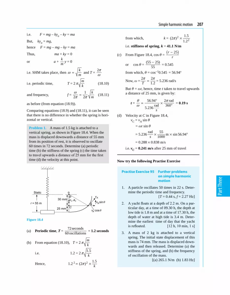
Simple harmonic motion 207
Part
Thre
e
i.e. F = mg – kyo – ky = ma
But, kyo = mg,hence F = mg – mg – ky = ma
Thus, ma + ky = 0
or a + km y = 0
i.e. SHM takes place, then kmω = and T =
2πω
i.e. periodic time, T = 2mkπ (18.10)
and frequency, f = 1
2 2km
ωπ π= (18.11)
as before (from equation (18.9)).
Comparing equations (18.9) and (18.11), it can be seen that there is no difference in whether the spring is hori-zontal or vertical.
Problem 1. A mass of 1.5 kg is attached to a vertical spring, as shown in Figure 18.4. When the mass is displaced downwards a distance of 55 mm from its position of rest, it is observed to oscillate 60 times in 72 seconds. Determine (a) periodic time (b) the stiffness of the spring (c) the time taken to travel upwards a distance of 25 mm for the first time (d) the velocity at this point.
Figure 18.4
(a) Periodic time, T = 72seconds60oscillations = 1.2 seconds
(b) From equation (18.10), T = 2 mkπ
i.e. 1.2 = 2 1.5kπ
Hence, 1.2 2 2 1.5(2 ) kπ= ×
from which, k = 22
1.5(2 )1.2
π ×
i.e. stiffness of spring, k = 41.1 N/m
(c) From Figure 18.4, cos q = ( )25rr−
or cos q = (55 25)55− = 0.545
from which, q = cos 10.545− = 56.94°
Now, ω = 2 21.2T
π π= = 5.236 rad/s
But q = ωt, hence, time t taken to travel upwards a distance of 25 mm, is given by:
t = 56.94 2 radrad 3605.236
θ πω
°= × °
s
= 0.19 s
(d) Velocity at C in Figure 18.4, vC = vA sin q = ωr sin q
= 5.236rad 55 m sin 56.941000× × °s
= 0.288×0.838 m/s i.e. vC = 0.241 m/s after 25 mm of travel
Now try the following Practise Exercise
Practise Exercise 95 Further problems on simple harmonic motion
1. A particle oscillates 50 times in 22 s. Deter-mine the periodic time and frequency.
[T = 0.44 s, f = 2.27 Hz]
2. A yacht floats at a depth of 2.2 m. On a par-ticular day, at a time of 09.30 h, the depth at low tide is 1.8 m and at a time of 17.30 h, the depth of water at high tide is 3.4 m. Deter-mine the earliest time of day that the yacht is refloated. [12 h, 10 min, 1 s]
3. A mass of 2 kg is attached to a vertical spring. The initial state displacement of this mass is 74 mm. The mass is displaced down-wards and then released. Determine (a) the stiffness of the spring, and (b) the frequency of oscillation of the mass.
[(a) 265.1 N/m (b) 1.83 Hz]

208 Mechanical Engineering Principles
Part
Thre
e
4. A particle of mass 4 kg rests on a smooth horizontal surface and is attached to a hori-zontal spring. The mass is then displaced horizontally outwards from the spring a dis-tance of 26 mm and then released to vibrate. If the periodic time is 0.75 s, determine (a) the frequency f (b) the force required to give the mass the displacement of 26 mm, (c) the time taken to move horizontally inwards for the first 12 mm.
[(a) 1.33 Hz (b) 7.30 N (c) 0.12 s]
5. A mass of 3 kg rests on a smooth horizontal surface, as shown in Figure 18.5. If the stiff-ness of each spring is 1 kN/m, determine the frequency of vibration of the mass. It may be assumed that initially, the springs are un-stretched.
Figure 18.5
[4.11 Hz]
6. A helical spring has a mass of 10 kg attached to its top. If the mass vibrates vertically with a frequency of 1.5 Hz, determine the stiffness of the spring. [888.3 N/m]
18.3 The simple pendulum
A simple pendulum consists of a particle of mass m attached to a mass-less string of length L, as shown in Figure 18.6.
Figure 18.6
From Section 14.4, page 167, T = oI a = – restoring couple = – mg(L sin q)
But, Io = mL2 = mass moment of inertia about the point of rotation
hence, 2mL a + mgL sin q = 0
For small deflections, sin q = q
Hence, 2L a + gLq = 0
or a + gLθ
= 0
But a + w2q = 0 (see Section 18.6)
Therefore, 2 gLω =
and ω = gL (18.12)
Now T = 2 2 L
gπ πω = (18.13)
and f = 1
2
gL
T π= (18.14)
Problem 2. If the simple pendulum of Figure 18.6 were of length 2 m, determine its frequency of vibration. Take g = 9.81 m/s2.
From equation (18.14), frequency, f =
9.812
2 2
gLπ π=
= 0.352 Hz
Problem 3. In order to determine the value of g at a certain point on the Earth’s surface, a simple pendulum is used. If the pendulum is of length 3 m and its frequency of oscillation is 0.2875 Hz, determine the value of g.
From equation (18.14), frequency, f = 2
gLπ
i.e. 0.2875 = 32
g
π

Simple harmonic motion 209
Part
Thre
e
and (0.2875) 2 2(2 ) 3gπ× =
3.263 = 3g
from which, acceleration due to gravity, g = 3 × 3.263 = 9.789 m/s
18.4 The compound pendulum
Consider the compound pendulum of Figure 18.7, which oscillates about the point O. The point G in Figure 18.7 is the position of the pendulum’s centre of gravity.
Figure 18.7
Let Io = mass moment of inertia about O
Now T = Ioa = – restoring couple = – mgh sin q
From the parallel axis theorem,
IG = Io – mh2 = mk 2G
or Io = mk 2G + mh2
where IG = mass moment of inertia about G,
k 2G = radius of gyration about G
Now T = Ioa
or – mgh sin q = Ioa
but Io = mk 2G + mh2
Therefore, ( )2 2Gmk mh a+ = – mgh sin q
but for small displacements, sin q = q
Hence, m ( )2 2Gk h a+ = – mgh q
i.e. ( )2 2Gk h a+ + ghq = 0
or a + ( )2 2G
ghk h
θ+
= 0
However, a + ω2q = 0
but this motion is simple harmonic motion (see equa-tion (18.7))
Therefore, ω2 = ( )2 2G
ghk h+
and ω = 2 2( )G
ghk h+
(18.15)
T = 2 22 ( )2 Gk hgh
π πω+
= (18.16)
and f = 2 21 1
2 ( )G
ghT k hπ=
+ (18.17)
Problem 4. It is required to determine the mass moment of inertia about G of a metal ring, which has a complex cross-sectional area. To achieve this, the metal ring is oscillated about a knife edge, as shown in Figure 18.8, where the frequency of oscillation was found to be 1.26 Hz. If the mass of the ring is 10.5 kg, determine the mass moment of inertia about the centre of gravity, IG. Take g = 9.81 m/s2.
Figure 18.8
210 Mechanical Engineering Principles
Part
Thre
e
By inspection of Figure 18.8, h = 75 mm = 0.075 m.
Now frequency, f = 2 21
2 ( )G
ghk hπ +
i.e. 1.26 = 2 21 9.81 0.075
2 ( 0.075 )Gkπ×
+
i.e. ( ) ( )2
2 2 21 9.81 0.0751.26
(2 ) 0.075Gkπ×
= ×+
from which, ( )22
0.735750.0056251.5876 (2 )Gk
π+ =
×
= 0.011739 k 2
G = 0.011739 – 0.005625 = 0.006114
from which, kG = 0.006114 = 0.0782The mass moment of inertia about the centre of gravity, IG = m kG
2 = 10.5 kg × 0.006114 m2
i.e. IG = 0.0642 kg m2
18.5 Torsional vibrations
From equation (18.7), it can be seen that for SHM in a linear direction,
a + ω2y = 0
For SHM in a rotational direction,
ar + ω2y = 0
or a + ω2 yr
= 0
or a + ω2q = 0 (see equation (18.7))
i.e θ
+ ω2q = 0 (18.18)
where q = yr = angular displacement, and
θ
= a = angular acceleration
Now try the following Practise Exercises
Practise Exercise 96 Further problems on pendulums
1. Determine the period of oscillation of a pendulum of length 2 m if g = 9.81 m/s2.
[0.3525 Hz]
2. What will be the period of oscillation if g = 9.78 m/s2 for the pendulum of Problem 1?
[0.3519 Hz]
3. What will be the period of oscillation if g = 9.832 m/2 for the pendulum of Problem 1?
[0.3529 Hz]
4. What will be the value of the mass moment of inertia through the centre of gravity, IG, for the compound pendulum of worked problem 4 on page 209, if the inner diameter of the disc of Figure 18.8 were 100 mm?
[0.0559 kg m2]
Practise Exercise 97 Short-answer questions on simple harmonic motion
1. State the relationship between the displace-ment (y) of a mass and its acceleration (a) for SHM to take place.
2. State the relationship between frequency f and periodic time T when SHM takes place.
3. State the formula for the frequency of oscil-lation for a simple pendulum.
4. State a simple method of increasing the period of oscillation of the pendulum of a ‘grandfather’ clock.
Practise Exercise 98 Multiple-choice questions on simple harmonic motion
(Answers on page 298)
1. Tidal motion is normally related to which mathematical function?
(a) tangent (b) sine (c) square root (d) straight line
2. If the mass of a simple pendulum is doubled, its period of oscillation:
(a) increases (b) decreases (c) stays the same (d) doubles
3. A pendulum has a certain frequency of oscillation in London. Assuming that tem-perature remains the same, the frequency of

Simple harmonic motion 211
Part
Thre
e
oscillation of the pendulum if it is measured on the equator:
(a) increases (b) decreases (c) remains the same (d) doubles
4. The period of oscillation of a simple pendu-lum of length 9.81 m, given g = 9.81 m/s2 is:
(a) 6.28 Hz (b) 0.455 Hz (c) 17.96 Hz (d) 0.056 Hz

Chapter 19
Simple machines
Mechanical Engineering Principles, Bird and Ross, ISBN 9780415517850
This chapter commences by defining load, effort,mechanicaladvantage,velocityratioandefficiency,where efficiency is then defined in terms ofmechanical advantage and velocity ratio. These terms,togetherwithothertermsdefinedinearlierchapters, are applied to simple and quite complex pulley systems, screw-jacks, gear trains and levers. This chapter is fundamental to the study of the behaviour of machines.
19.2 Force ratio, movement ratio and efficiency
The force ratio or mechanical advantage is defined as the ratio of load to effort, i.e.
Force ratio = loadeffort = mechanical advantage (19.1)
Since both load and effort are measured in newtons, force ratio is a ratio of the same units and thus is a dimension-less quantity.The movement ratio or velocity ratio is defined as the ratio of the distance moved by the effort to the distance moved by the load, i.e.
Movement ratio = distance moved by the effortdistance moved by the load
= velocity ratio (19.2)
Since the numerator and denominator are both mea-sured in metres, movement ratio is a ratio of the same units and thus is a dimension-less quantity.The efficiencyofasimplemachine is defined as the ratio of the force ratio to the movement ratio, i.e.
Efficiency force ratio
movement ratiomechanical advantage
velocity ratio
=
=
Since the numerator and denominator are both dimension-less quantities, efficiency is a dimension-less quantity. It is usually expressed as a percentage, thus:
Efficiency= force ratio 100%movement ratio × (19.3)
At the end of this chapter you should be able to:
• define a simple machine• define force ratio, movement ratio, efficiency
and limiting efficiency• understand and perform calculations with pulley
systems• understand and perform calculations with a sim-
ple screw-jack• understand and perform calculations with gear
trains• understand and perform calculations with
levers
19.1 Machines
A machine is a device that can change the magnitude or line of action, or both magnitude and line of action of a force. A simple machine usually amplifies an input force, called the effort, to give a larger output force, called the load. Some typical examples of simple machines include pulley systems, svcrew-jacks, gear systems and lever systems.

Simple machines 213
Part
Thre
e
Due to the effects of friction and inertia associated with the movement of any object, some of the input energy to a machine is converted into heat and losses occur. Since losses occur, the energy output of a ma-chine is less than the energy input, thus the mechanical efficiency of any machine cannot reach 100%
For simple machines, the relationship between effort and load is of the form: Fe = aFl + b, where Fe is the effort, Fl is the load and a and b are constants. From equation (19.1),
force ratio = load
effortl l
e l
F FF aF b= = +
Dividing both numerator and denominator by Fl gives:
1l
ll
FaF b ba F
=+ +
When the load is large, Fl is large and l
bF is small
compared with a. The force ratio then becomes approx-
imately equal to 1a and is called the limiting force
ratio, i.e.
limiting ratio = 1a
The limiting efficiency of a simple machine is defined as the ratio of the limiting force ratio to the movement ratio, i.e.
Limitingefficiency= 1 100%movement ratioa ××
where a is the constant for the law of the machine:
Fe = aFl + bDue to friction and inertia, the limiting efficiency of simple machines is usually well below 100%.
Problem 1. A simple machine raises a load of 160 kg through a distance of 1.6 m. The effort ap-plied to the machine is 200 N and moves through a distance of 16 m. Taking g as 9.8 m/s2, determine the force ratio, movement ratio and efficiency of the machine.
From equation (19.1),
force ratio = load 160kg 160 9.81N
effort 200 N 200 N×
= =
= 7.84
From equation (19.2),
movement ratio distance moved by the effortdistance moved by the load16 m1.6 m
=
= = 10
From equation (19.3),
efficiency = force ratio 100%movement ratio ×
= 7.8410 × 100
= 78.4%
Problem 2. For the simple machine of Problem 1, determine: (a) the distance moved by the effort to move the load through a distance of 0.9 m (b) the effort which would be required to raise a load of 200 kg, assuming the same efficiency (c) the efficiency if, due to lubrication, the effort to raise the 160 kg load is reduced to 180 N.
(a) Since the movement ratio is 10, then from equa-tion (19.2),
distance moved by the effort = 10 × distance moved by the load
= 10 × 0.9 = 9 m(b) Since the force ratio is 7.84, then from equation
(19.1),
effort = load7.84 =
200 9.87.84×
= 250 N(c) The new force ratio is given by
loadeffort
= 160 9.8180×
= 8.711
Hence, thenewefficiencyafterlubrication
= 8.711
10 × 100 = 87.11%
Problem 3. In a test on a simple machine, the effort/load graph was a straight line of the form Fe = aFl + b. Two values lying on the graph were at Fe = 10 N, Fl = 30 N, and at Fe = 74 N, Fl = 350 N. The movement ratio of the machine was 17. Determine: (a) the limiting force ratio (b) the limiting efficiency of the machine.
(a) The equation Fe = aFl + b is of the form y = mx + c, where m is the gradient of the graph. The slope

214 Mechanical Engineering Principles
Part
Thre
e
of the line passing through points (xl, yl) and (x2, y2) of the graph y = mx + c is given by:
m = 2 1
2 1
y yx x
−−
Thus for Fe = aFl + b, the slope a is given by:
a = 74 10
350 30−−
= 64320 = 0.2
The limiting force ratio is 1a = 1
0.2 = 5
(b) The limitingefficiency
= 1 100movement ratioa ××
=
1 1000.2 17 ×× = 29.4%
Now try the following Practise Exercise
Practise Exercise 99 Further problems on force ratio, movement ratio and efficiency
1. A simple machine raises a load of 825 N through a distance of 0.3 m. The effort is 250 N and moves through a distance of 3.3 m. Determine: (a) the force ratio (b) the movement ratio (c) the efficiency of the ma-chine at this load. [(a) 3.3 (b) 11 (c) 30%]
2. The efficiency of a simple machine is 50%. If a load of 1.2 kN is raised by an effort of 300 N, determine the movement ratio. [8]
3. An effort of 10 N applied to a simple ma-chine moves a load of 40 N through a dis-tance of 100 mm, the efficiency at this load being 80%. Calculate: (a) the movement ratio (b) the distance moved by the effort.
[(a) 5 (b) 500 mm]
4. The effort required to raise a load using a simple machine, for various values of load is as shown:
Load Fl (N) 2050 4120 7410 8240 10300
Effort Fe (N) 252 340 465 505 580
If the movement ratio for the machine is 30, determine (a) the law of the machine
(b) the limiting force ratio (c) the limiting efficiency.
[(a) Fe = 0.04 Fl + 170 (b) 25 (c) 83.3%]
5. For the data given in Question 4, determine the values of force ratio and efficiency for each value of the load. Hence plot graphs of effort, force ratio and efficiency to a base of load. From the graphs, determine the effort required to raise a load of 6 kN and the efficiency at this load. [410 N, 48%]
19.3 Pulleys
A pulley system is a simple machine. A single-pulley system, shown in Figure 19.1(a), changes the line of action of the effort, but does not change the mag-nitude of the force. A two-pulley system, shown in Figure 19.1(b), changes both the line of action and the magnitude of the force.
Figure 19.1

Simple machines 215
Part
Thre
e
Figure 19.1 (Continued)
Theoretically, each of the ropes marked (i) and (ii) share the load equally, thus the theoretical effort is only half of the load, i.e. the theoretical force ratio is 2. In practice the actual force ratio is less than 2 due to losses. A three-pulley system is shown in Figure 19.1(c). Each of the ropes marked (i), (ii) and (iii) carry one-third of the load, thus the theoretical force ratio is 3. In general, for a multiple pulley system having a total of n pulleys, the theoretical force ratio is n. Since the theoretical efficiency of a pulley system (neglecting losses) is 100 and since from equation (18.3),
efficiency = force ratio 100%movement ratio ×
it follows that when the force ratio is n,
100 = 100%movement ration
×
that is, the movement ratio is also n.
Problem 4. A load of 80 kg is lifted by a three-pulley system similar to that shown in Figure 19.1(c) and the applied effort is 392 N. Calculate (a) the force ratio (b) the movement ratio (c) the efficiency of the system. Take g to be 9.8 m/s2.
(a) From equation (19.1), the force ratio is given by load
effort
The load is 80 kg, i.e. (80 × 9.8) N, hence,
force ratio = 80 9.8392× = 2
(b) From above, for a system having n pulleys, the movement ratio is n. Thus, for a three-pulley sys-tem, the movement ratio is 3
(c) From equation (19.3),
efficiency = force ratio 100%movement ratio ×
= 23 × 100 = 66.67%
Problem 5. A pulley system consists of two blocks, each containing three pulleys and connected as shown in Figure 19.2. An effort of 400 N is required to raise a load of 1500 N. Determine (a) the force ratio (b) the movement ratio (c) the efficiency of the pulley system.
Figure 19.2
(a) From equation (19.1),
force ratio = loadeffort = 1500
400 = 3.75
(b) An n-pulley system has a movement ratio of n, hence this 6-pulley system has a movement ratio of 6
(c) From equation (19.3),
efficiency = force ratio 100%movement ratio ×
= 3.756 × 100 = 62.5%
Now try the following Practise Exercise
Practise Exercise 100 Further problems on pulleys
1. A pulley system consists of four pulleys in an upper block and three pulleys in a lower

216 Mechanical Engineering Principles
Part
Thre
e
block. Make a sketch of this arrangement showing how a movement ratio of 7 may be obtained. If the force ratio is 4.2, what is the efficiency of the pulley? [60%]
2. A three-pulley lifting system is used to raise a load of 4.5 kN. Determine the effort required to raise this load when losses are neglected. If the actual effort required is 1.6 kN, determine the efficiency of the pulley system at this load. [1.5 kN, 93.75%]
19.4 The screw-jack
A simple screw-jack is shown in Figure 19.3 and is a simple machine since it changes both the magnitude and the line of action of a force (see also Section 16.8).
Figure 19.3
The screw of the table of the jack is located in a fixed nut in the body of the jack. As the table is rotated by means of a bar, it raises or lowers a load placed on the table. For a single-start thread, as shown, for one com-plete revolution of the table, the effort moves through a distance 2πr, and the load moves through a distance equal to the lead of the screw, say, L.
Movement ratio = 2 rLπ (19.4)
For the efficiency of a screw-jack, see Section 16.8, page 192.
Problem 6. A screw-jack is being used to support the axle of a car, the load on it being 2.4 kN. The screw jack has an effort of effective radius 200 mm and a single-start square thread, having a lead of 5 mm. Determine the efficiency of the jack if an effort of 60 N is required to raise the car axle.
From equation (19.3),
efficiency = force ratio 100%movement ratio ×
where force ratio = load 2400 N
effort 60 N= = 40
From equation (19.4),
movement ratio = 2 2 (200) mm
5mmr
Lπ π
= = 251.3
Hence, efficiency = force ratio 100%movement ratio ×
= 40
251.3 × 100 = 15.9%
Now try the following Practise Exercise
Practise Exercise 101 Further problems on the screw-jack
1. Sketch a simple screw-jack. The single-start screw of such a jack has a lead of 6 mm and the effective length of the operating bar from the centre of the screw is 300 mm. Calcu-late the load which can be raised by an effort of 150 N if the efficiency at this load is 20%.
[9.425 kN]
2. A load of 1.7 kN is lifted by a screw-jack having a single-start screw of lead 5 mm. The effort is applied at the end of an arm of effective length 320 mm from the centre of the screw. Calculate the effort required if the efficiency at this load is 25%. [16.91 N]
19.5 Gear trains
A simple gear train is used to transmit rotary motion and can change both the magnitude and the line of action of a force, hence it is a simple machine. The gear train shown in Figure 19.4 consists of spur gears and has an effort applied to one gear, called the driver, and a load applied to the other gear, called the follower.
In such a system, the teeth on the wheels are so spaced that they exactly fill the circumference with a whole number of identical teeth, and the teeth on the driver and follower mesh without interference. Under these conditions, the number of teeth on the driver and

Simple machines 217
Part
Thre
e
follower are in direct proportion to the circumference of these wheels, i.e.
on number of teeth driveron followernumber of teeth circumference of driver
of followercircumference
=
(19.5)
If there are, say, 40 teeth on the driver and 20 teeth on the follower then the follower makes two revolutions for each revolution of the driver. In general:
number of revolutions made by drivernumber of revolutions made by the follower
number of teeth on followernumber of teeth on driver
=
(19.6)
It follows from equation (19.6) that the speeds of the wheels in a gear train are inversely proportional to the number of teeth. The ratio of the speed of the driver wheel to that of the follower is the movement ratio, i.e.
Movement ratio speed of driver
speed of followerteeth on followerteeth on driver
= =
(19.7)
When the same direction of rotation is required on both the driver and the follower an idler wheel is used as shown in Figure 19.5.
Figure 19.5
Let the driver, idler, and follower be A, B and C, respectively, and let N be the speed of rotation and T be the number of teeth. Then from equation (19.7),
B A
A B
N TN T= or B
A BA
TN N T= and
C B
B C
N TN T= or B
C BC
TN N T=
Thus, speed of speed of
BB
A AC B
BC
B C C
A B A
TNA N TC N TN T
T T TT T T
= =
= × =
This shows that the movement ratio is independent of the idler, only the direction of the follower being altered.
A compound gear train is shown in Figure 19.6, in which gear wheels B and C are fixed to the same shaft and hence NB = NC
Figure 19.6
From equation (19.7), A B
B A
N TN T= i.e. A
B AB
TN N T= ×
Also, D C
C D
N TN T= i.e. C
D CD
TN N T= ×
But NB = NC and CD B
D
TN N T= ×
therefore, A CD A
B D
T TN N T T= × × (19.8)
For compound gear trains having, say, P gear wheels,
......A C E OP A
B D F P
T T T TN N T T T T= × × × ×
from which,
movement ratio = ......A B D P
P A C O
N T T TN T T T= × ×
Figure 19.4

218 Mechanical Engineering Principles
Part
Thre
e
Problem 7. A driver gear on a shaft of a motor has 35 teeth and meshes with a follower having 98 teeth. If the speed of the motor is 1400 revolu-tions per minute, find the speed of rotation of the follower.
From equation (19.7),
speed of driver teeth on follower
speed of follower teeth on driver=
i.e. 1400
speed of follower = 9835
Hence, speed of follower = 1400 3598× = 500 rev/min
Problem 8. A compound gear train similar to that shown in Figure 19.6 consists of a driver gear A, having 40 teeth, engaging with gear B, having 160 teeth. Attached to the same shaft as B, gear C has 48 teeth and meshes with gear D on the output shaft, having 96 teeth. Determine (a) the move-ment ratio of this gear system and (b) the efficiency when the force ratio is 6.
(a) From equation (19.8), the speed of D
= speed of A C
B D
T TA T T× ×
From equation (19.7), movement ratio
= speed ofspeed of
B D
A C
A T TD T T= × = 160 96
40 48× = 8
(b) The efficiency of any simple machine
= force ratio 100%movement ratio ×
Thus, efficiency = 68 × 100 = 75%
Now try the following Practise Exercise
Practise Exercise 102 Further problems on gear trains
1. The driver gear of a gear system has 28 teeth and meshes with a follower gear having 168 teeth. Determine the movement ratio and the speed of the follower when the driver gear rotates at 60 revolutions per second.
[6, 10 rev/s]
2. A compound gear train has a 30-tooth driver gear A, meshing with a 90-tooth follower gear B. Mounted on the same shaft as B and attached to it is a gear C with 60 teeth, mesh-ing with a gear D on the output shaft having 120 teeth. Calculate the movement and force ratios if the overall efficiency of the gears is 72%. [6, 4.32]
3. A compound gear train is as shown in Figure 19.6. The movement ratio is 6 and the num-bers of teeth on gears A, C and D are 25, 100 and 60, respectively. Determine the number of teeth on gear B and the force ratio when the efficiency is 60%. [250, 3.6]
19.6 Levers
A lever can alter both the magnitude and the line of ac-tion of a force and is thus classed as a simple machine. There are three types or orders of levers, as shown in Figure 19.7.
Figure 19.7

Simple machines 219
Part
Thre
e
A lever of thefirst order has the fulcrum placed between the effort and the load, as shown in Figure 19.7(a).
A lever of the second order has the load placed be-tween the effort and the fulcrum, as shown in Figure 19.7(b).
A lever of the third order has the effort applied between the load and the fulcrum, as shown in Figure 19.7(c).
Problems on levers can largely be solved by apply-ing the principle of moments (see Chapter 5). Thus for the lever shown in Figure 19.7(a), when the lever is in equilibrium,
anticlockwise moment = clockwise moment
i.e. a × Fl = b × Fe
Thus, force ratio
distance of effort from fulcrumdistance of load from fulcrum
l
e
F bF a= =
=
Problem 9. The load on a first-order lever, similar to that shown in Figure 19.7(a), is 1.2 kN. Determine the effort, the force ratio and the move-ment ratio when the distance between the fulcrum and the load is 0.5 m and the distance between the fulcrum and effort is 1.5 m. Assume the lever is 100% efficient.
Applying the principle of moments, for equilibrium: anticlockwise moment = clockwise momenti.e. 1200 N × 0.5 m = effort × 1.5 m
Hence, effort = 1200 0.51.5× = 400 N
force ratio = l
e
FF = 1200
400 = 3
Alternatively, force ratio = ba = 1.5
0.5 = 3
This result shows that to lift a load of, say, 300 N, an effort of 100 N is required.Since, from equation (19.3),
efficiency = force ratio 100%movement ratio ×
then, movement ratio = force ratio 100%efficiency ×
= 3100 × 100 = 3
This result shows that to raise the load by, say, 100 mm, the effort has to move 300 mm.
Problem 10. A second-order lever, AB, is in a horizontal position. The fulcrum is at point C. An effort of 60 N applied at B just moves a load at point D, when BD is 0.5 m and BC is 1.25 m. Calculate the load and the force ratio of the lever.
A second-order lever system is shown in Figure 19.7(b). Taking moments about the fulcrum as the load is just moving, gives:
anticlockwise moment = clockwise moment
i.e. 60 N × 1.25 m = load × 0.75 m
Thus, load = 60 1.25
0.75× = 100 N
From equation (19.1),
force ratio = load
effort = 10060 = 1.67
Alternatively,
force ratio = distance of effort from fulcrumdistance of load from fulcrum
= 1.250.75 = 1.67
Now try the following Practise Exercises
Practise Exercise 103 Further problems on levers
1. In a second-order lever system, the force ratio is 2.5. If the load is at a distance of 0.5 m from the fulcrum, find the distance that the effort acts from the fulcrum if losses are negligible. [1.25 m]
2. A lever AB is 2 m long and the fulcrum is at a point 0.5 m from B. Find the effort to be applied at A to raise a load of 0.75 kN at B when losses are negligible. [250 N]
3. The load on a third-order lever system is at a distance of 750 mm from the fulcrum and the effort required to just move the load is 1 kN when applied at a distance of 250 mm from the fulcrum. Determine the value of the load and the force ratio if losses are negligible.
[333.3 N, 1/3]

220 Mechanical Engineering Principles
Part
Thre
e
Practise Exercise 104 Short-answer questions on simple machines
1. State what is meant by a simple machine. 2. Define force ratio. 3. Define movement ratio. 4. Define the efficiency of a simple machine
in terms of the force and movement ratios. 5. State briefly why the efficiency of a simple
machine cannot reach 100%. 6. With reference to the law of a simple ma-
chine, state briefly what is meant by the term ‘limiting force ratio’.
7. Define limiting efficiency. 8. Explain why a four-pulley system has a
force ratio of 4, when losses are ignored. 9. Give the movement ratio for a screw-jack
in terms of the effective radius of the effort and the screw lead.
10. Explain the action of an idler gear.11. Define the movement ratio for a two-gear
system in terms of the teeth on the wheels.12. Show that the action of an idler wheel
does not affect the movement ratio of a gear system.
13. State the relationship between the speed of the first gear and the speed of the last gear in a compound train of four gears, in terms of the teeth on the wheels.
14. Define the force ratio of a first-order lever system in terms of the distances of the load and effort from the fulcrum.
15. Use sketches to show what is meant by: (a) a first-order (b) a second-order (c) a third-order lever system. Give one practi-cal use for each type of lever.
Practise Exercise 105 Multiple-choice questions on simple machines
(Answers on page 298)
A simple machine requires an effort of 250 N moving through 10 m to raise a load of 1000 N
through 2 m. Use this data to find the correct an-swers to questions 1 to 3, selecting these answers from: (a) 0.25 (b) 4(c) 80% (d) 20%(e) 100 (f) 5(g) 100% (h) 0.2 (i) 25%
1. Find the force ratio.
2. Find the movement ratio.
3. Find the efficiency.
The law of a machine is of the form Fe = aFl + b. An effort of 12 N is required to raise a load of 40 N and an effort of 6 N is required to raise a load of 16 N. The move-ment ratio of the machine is 5. Use this data to find the correct answers to questions 4 to 6, selecting these answers from:
(a) 80% (b) 4 (c) 2.8 (d) 0.25
(e) 1
2.8 (f) 25%
(g) 100% (h) 2 (i) 25% 4. Determine the constant ‘a’. 5. Find the limiting force ratio. 6. Find the limiting efficiency.
7. Which of the following statements is false? (a) A single-pulley system changes the
line of action of the force but does not change the magnitude of the force, when losses are neglected.
(b) In a two-pulley system, the force ratio
is 12 when losses are neglected.
(c) In a two-pulley system, the movement ratio is 2.
(d) The efficiency of a two-pulley system is 100% when losses are neglected.
8. Which of the following statements con-cerning a screw-jack is false?
(a) A screw-jack changes both the line of action and the magnitude of the force.
(b) For a single-start thread, the distance moved in 5 revolutions of the table is 5, where is the lead of the screw.

Simple machines 221
Part
Thre
e
(c) The distance moved by the effort is 2πr, where r is the effective radius of the effort.
(d) The movement ratio is given by 25
rπ
9. In a simple gear train, a follower has 50 teeth and the driver has 30 teeth. The movement ratio is:
(a) 0.6 (b) 20 (c) 1.67 (d) 80
10. Which of the following statements is true?
(a) An idler wheel between a driver and a follower is used to make the direction of the follower opposite to that of the driver.
(b) An idler wheel is used to change the movement ratio.
(c) An idler wheel is used to change the force ratio.
(d) An idler wheel is used to make the direction of the follower the same as that of the driver.
11. Which of the following statements is false? (a) In a first-order lever, the fulcrum is
between the load and the effort. (b) In a second-order lever, the load is
between the effort and the fulcrum. (c) In a third-order lever, the effort is ap-
plied between the load and the fulcrum. (d) The force ratio for a first-order lever
system is given by:
distance of load from fulcrumdistance of effort from fulcrum
12. In a second-order lever system, the load is 200 mm from the fulcrum and the effort is 500 mm from the fulcrum. If losses are neglected, an effort of 100 N will raise a load of:
(a) 100 N (b) 250 N (c) 400 N (d) 40 N

Part
Thre
e
Assume, where necessary, that the acceleration due to gravity, g = 9.81 m/s2
1. The material of a brake is being tested and it is found that the dynamic coefficient of friction between the material and steel is 0.90. Calcu-late the normal force when the frictional force is 0.630 kN. (4)
2. A mass of 10 kg rests on a plane, which is in-clined at 30° to the horizontal. The coefficient of friction between the mass and the plane is 0.6. Determine the magnitude of a force, applied par-allel to and up the plane, which will just move the mass up the plane. (10)
3. If in Problem 2, the force required to just move the mass up the plane, is applied horizontally, what will be the minimum value of this force? (10)
4. A train travels around a curve of radius 400 m. If the horizontal thrust on the outer rail is to be 1/30th the weight of the train, what is the velocity of the train (in km/h)? It may be assumed that the inner and outer rail rails are on the same level and that the inner rail takes no horizontal thrust. (6)
5. A conical pendulum of length 2.5 m rotates in a horizontal circle of diameter 0.6 m. Determine its angular velocity. (6)
6. Determine the time of oscillation for a simple pendulum of length 1.5 m. (6)
7. A simple machine raises a load of 120 kg through a distance of 1.2 m. The effort applied to the ma-chine is 150 N and moves through a distance of 12 m. Taking g as 10 m/s2, determine the force ratio, movement ratio and efficiency of the machine. (6)
8. A load of 30 kg is lifted by a three-pulley system and the applied effort is 140 N. Calculate, taking g to be 9.8 m/s2, (a) the force ratio (b) the move-ment ratio (c) the efficiency of the system. (5)
9. A screw-jack is being used to support the axle of a lorry, the load on it being 5.6 kN. The screw jack has an effort of effective radius 318.3 mm and a single-start square thread, having a lead of 5 mm. Determine the efficiency of the jack if an effort of 70 N is required to raise the car axle. (6)
10. A driver gear on a shaft of a motor has 32 teeth and meshes with a follower having 96 teeth. If the speed of the motor is 1410 revolutions per minute, find the speed of rotation of the follower. (4)
11. The load on a first-order lever is 1.5 kN. Deter-mine the effort, the force ratio and the movement ratio when the distance between the fulcrum and the load is 0.4 m and the distance between the fulcrum and effort is 1.6 m. Assume the lever is 100% efficient. (7)
Revision Test 6 Friction, motion in a circle, simple harmonic motion and simple machines
This Revision Test covers the material contained in Chapters 16 to 19. The marks for each question are shown in brackets at the end of each question.

Heat Transfer and Fluid Mechanics
Part Four


Chapter 20
Heat energy and transfer
Mechanical Engineering Principles, Bird and Ross, ISBN 9780415517850
This chapter defines sensible and latent heat andprovides the appropriate formulae to calculate the amount of energy required to convert a solid to a gas and vice-versa, and also for other combinations of solids, liquids and gases. This information is often required by engineers if they are required to design an artefact (say) to convert ice to steam via the state of liquid water. An example of a household requirement of when this type of calculation is required is that of the simple domestic kettle. When the designer is required to design a domestic electric kettle, it is important that the design is such that the powering arrangement is (just) enough to boil the required amount of water in a reasonable time. If the powering weretoolow,youmayhavegreatdifficultyinboilingthe water when the kettle is full. Similar calculations are required for large water containers, which are required to boil large quantities of water for other uses, including for kitchens in schools, to make tea/coffee, etc, and for large hotels, which have many uses for hot water. The chapter also describes the three main methods of heat transfer, namely conduction, convection and radiation, together with their uses.
20.1 Introduction
Heat is a form of energy and is measured in joules.Temperature is the degree of hotness or coldness of a substance. Heat and temperature are thus not the same thing. For example, twice the heat energy is needed to boil a full container of water than half a container – that is, different amounts of heat energy are needed to cause an equal rise in the temperature of different amounts of the same substance.
Temperature is measured either (i) on the Celsius (°C) scale (formerly Centigrade), where the tem-perature at which ice melts, i.e. the freezing point of water, is taken as 0°C and the point at which water boils under normal atmospheric pressure is taken as 100°C, or (ii) on the thermodynamic scale, in which the unit of temperature is the kelvin (K). The kelvin scale uses the same temperature interval as the Celsius scale but as its zero takes the ‘absolute zero of temperature’ which is at about – 273°C. Hence,
kelvin temperature = degree Celsius + 273
i.e. K = (°C) + 273
At the end of this chapter you should be able to:
• distinguish between heat and temperature• appreciate that temperature is measured on the
Celsius or the thermodynamic scale• convert temperatures from Celsius into Kelvin
and vice versa• recognise several temperature measuring de-
vices• define specific heat capacity, c and recognise
typical values• calculate the quantity of heat energy Q using
Q = mc(t2 – t1)
• understand change of state from solid to liquid to gas, and vice versa
• distinguish between sensible and latent heat• define specific latent heat of fusion• define specific latent heat of vaporisation• recognise typical values of latent heats of fusion
and vaporisation• calculate quantity of heat Q using Q = mL• describe the principle of operation of a simple
refrigerator

226 Mechanical Engineering Principles
Part
Four
Thus, for example, 0°C = 273 K, 25°C = 298 K and 100°C = 373 K
Problem 1. Convert the following temperatures into the Kelvin scale: (a) 37°C (b) – 28°C
From above, Kelvin temperature = degree Celsius + 273(a) 37°C corresponds to a Kelvin temperature of
37 + 273, i.e. 310 K(b) –28°C corresponds to a Kelvin temperature of
–28 + 273, i.e. 245 K
Problem 2. Convert the following temperatures into the Celsius scale:(a) 365 K (b) 213 K
From above, K = (°C) + 273Hence, degree Celsius = Kelvin temperature –273(a) 365 K corresponds to 365 – 273, i.e. 92°C(b) 213 K corresponds to 213 – 273, i.e. – 60°C
Now try the following Practise Exercise
Practise Exercise 106 Further problems on temperature scales
1. Convert the following temperatures into the Kelvin scale:
(a) 51°C (b) –78°C (c) 183°C [(a) 324 K (b) 195 K (c) 456 K]
2. Convert the following temperatures into the Celsius scale:
(a) 307 K (b) 237 K (c) 415 K [(a) 34°C (b) –36°C (c) 142°C]
20.2 The measurement of temperature
A thermometer is an instrument that measures temperature. Any substance that possesses one or more properties that vary with temperature can be used to measure temperature. These properties include changes in length, area or volume, electrical resistance or in colour. Examples of temperature measuring devices include:
(i) liquid-in-glass thermometer, which uses the expansion of a liquid with increase in tempera-ture as its principle of operation,
(ii) thermocouples, which use the e.m.f. set up, when the junction of two dissimilar metals is heated,
(iii) resistance thermometer, which uses the change in electrical resistance caused by temperature change, and
(iv) pyrometers, which are devices for measuring very high temperatures, using the principle that all substances emit radiant energy when hot, the rate of emission depending on their temperature.
Each of these temperature measuring devices, together with others, are described in Chapter 25, page 281 .
20.3 Specific heat capacity
The specificheatcapacity of a substance is the quan-tity of heat energy required to raise the temperature of 1 kg of the substance by 1°C. The symbol used for spe-cific heat capacity is c and the units are J/(kg °C) or J/(kg K). (Note that these units may also be written as J kg–1 °C–1 or J kg–1 K–1).Some typical values of specific heat capacity for the range of temperature 0°C to 100°C include:
Water 4190 J/(kg °C),Ice 2100 J/(kg °C)Aluminium 950 J/(kg °C),
Copper 390 J/(kg °C)Iron 500 J/(kg °C),Lead 130 J/(kg °C)
Hence to raise the temperature of 1 kg of iron by 1°C requires 500 J of energy, to raise the temperature of 5 kg of iron by 1°C requires (500 × 5) J of energy, and to raise the temperature of 5 kg of iron by 40°C re-quires (500 × 5 × 40) J of energy, i.e. 100 kJ.
In general, the quantity of heat energy, Q, required to raise a mass m kg of a substance with a specific heat capacity of c J/(kg °C), from temperature t1 °C to t2 °C is given by:
Q = mc(t2 – t1) joules
Problem 3. Calculate the quantity of heat required to raise the temperature of 5 kg of water from 0°C to 100°C. Assume the specific heat ca-pacity of water is 4200 J/(kg °C).

Heat energy and transfer 227
Part
Four
Quantity of heat energy, Q = mc(t2 – t1) = 5 kg × 4200 J/(kg °C) × (100 – 0)°C = 5 × 4200 × 100 = 2100000 J or 2100 kJ or 2.1 MJ
Problem 4. A block of cast iron having a mass of 10 kg cools from a temperature of 150°C to 50°C. How much energy is lost by the cast iron? Assume the specific heat capacity of iron is 500 J/(kg °C).
Quantity of heat energy, Q = mc(t2 – t1) = 10 kg × 500 J/(kg °C) × (50 – 150)°C = 10 × 500 × (–100) = – 500000 J or – 500 kJ or – 0.5 MJ(Note that the minus sign indicates that heat is given out or lost).
Problem 5. Some lead having a specific heat capacity of 130 J/(kg °C) is heated from 27°C to its melting point at 327°C. If the quantity of heat required is 780 kJ, determine the mass of the lead.
Quantity of heat, Q = mc(t2 – t1), hence,
780 × 103 J = m × 130 J/(kg °C) × (327 – 27)°C
i.e. 780000 = m × 130 × 300
from which, mass, m = 780000
130 300× kg = 20 kg
Problem 6. 273 kJ of heat energy are required to raise the temperature of 10 kg of copper from 15°C to 85°C. Determine the specific heat capacity of copper.
Quantity of heat, Q = mc(t2 – t1), hence:
273 × 103 J = 10 kg × c × (85 – 15)°Cwhere c is the specific heat capacity,
i.e. 273000 = 10 × c × 70
from which, specificheatcapacity, c = 27300010 70×
= 390 J/(kg °C)
Problem 7. 5.7 MJ of heat energy are supplied to 30 kg of aluminium that is initially at a temperature
of 20°C. If the specific heat capacity of aluminium is 950 J(kg°C), determine its final temperature.
Quantity of heat, Q = mc(t2 – t1), hence, 5.7 × 10⁶ J = 30 kg × 950 J/(kg °C) × (t2 – 20)°C
from which, (t2 – 20) = 65.7 10
30 950×× = 200
Hence, the finaltemperature,t2 = 200 + 20 = 220°C
Problem 8. A copper container of mass 500 g contains 1 litre of water at 293 K. Calculate the quantity of heat required to raise the temperature of the water and container to boiling point, assuming there are no heat losses. Assume that the specific heat capacity of copper is 390 J/(kg K), the specific heat capacity of water is 4.2 kJ(kg K) and 1 litre of water has a mass of 1 kg.
Heat is required to raise the temperature of the water, and also to raise the temperature of the copper container.For the water: m = 1 kg, t1 = 293 K, t2 = 373 K (i.e. boiling point) and c = 4.2 kJ/(kg K)Quantity of heat required for the water is given by:
Qw = mc(t2 – t1) = (1 kg) kJ4.2 kg K
(373 – 293) K
= 4.2 × 80 kJi.e. Qw = 336 kJFor the copper container: m = 500 g = 0.5 kg, t1 = 293 K, t2 = 373 K and c = 390 J/(kg K) = 0.39 kJ(kg K)Quantity of heat required for the copper container is given by:
QC = mc(t2 – t1) = (0.5 kg)(0.39 kJ/(kg K)(80 K)
i.e. QC = 15.6 kJ
Total quantity of heat required, Q = Qw + QC = 336 + 15.6 = 351.6 kJ

228 Mechanical Engineering Principles
Part
Four
Now try the following Practise Exercise
Practise Exercise 107 Further problems on specific heat capacity
1. Determine the quantity of heat energy (in megajoules) required to raise the tem-perature of 10 kg of water from 0°C to 50°C. Assume the specific heat capacity of water is 4200 J/(kg °C). [2.1 MJ]
2. Some copper, having a mass of 20 kg, cools from a temperature of 120°C to 70°C. If the specific heat capacity of copper is 390 J/(kg °C), how much heat energy is lost by the copper ? [390 kJ]
3. A block of aluminium having a specific heat capacity of 950 J/(kg °C) is heated from 60°C to its melting point at 660°C. If the quantity of heat required is 2.85 MJ, de-termine the mass of the aluminium block.
[5 kg]
4. 20.8 kJ of heat energy is required to raise the temperature of 2 kg of lead from 16°C to 96°C. Determine the specific heat capacity of lead. [130 J/kg °C]
5. 250 kJ of heat energy is supplied to 10 kg of iron which is initially at a temperature of 15°C. If the specific heat capacity of iron is 500 J/(kg °C) determine its final tempera-ture. [65°C]
20.4 Change of state
A material may exist in any one of three states – solid, liquid or gas. If heat is supplied at a constant rate to some ice initially at, say, –30°C, its temperature rises as shown in Figure 20.1. Initially the temperature in-creases from –30°C to 0°C as shown by the line AB. It then remains constant at 0°C for the time BC required for the ice to melt into water.
When melting commences the energy gained by continual heating is offset by the energy required for the change of state and the temperature remains con-stant even though heating is continued. When the ice is completely melted to water, continual heating raises the temperature to 100°C, as shown by CD in Figure 20.1. The water then begins to boil and the temperature
again remains constant at 100°C, shown as DE, until all the water has vaporised.
Continual heating raises the temperature of the steam as shown by EF in the region where the steam is termed superheated.
Changes of state from solid to liquid or liquid to gas occur without change of temperature and such changes are reversible processes. When heat energy flows to or from a substance and causes a change of temperature, such as between A and B, between C and D and be-tween E and F in Figure 20.1, it is called sensible heat (since it can be ‘sensed’ by a thermometer).
Heat energy which flows to or from a substance while the temperature remains constant, such as be-tween B and C and between D and E in Figure 20.1, is called latent heat (latent means concealed or hidden).
Problem 9. Steam initially at a temperature of 130°C is cooled to a temperature of 20°C below the freezing point of water, the loss of heat energy being at a constant rate. Make a sketch, and briefly explain, the expected temperature/time graph rep-resenting this change.
A temperature/time graph representing the change is shown in Figure 20.2. Initially steam cools until it reaches the boiling point of water at 100°C. Tempera-ture then remains constant, i.e. between A and B, even though it is still giving off heat (i.e. latent heat). When all the steam at 100°C has changed to water at 100°C it starts to cool again until it reaches the freezing point of water at 0°C. From C to D the temperature again remains constant (i.e. latent heat), until all the water is converted to ice. The temperature of the ice then decreases as shown.
Figure 20.1

Heat energy and transfer 229
Part
Four
Figure 20.2
Now try the following Practise Exercise
Practise Exercise 108 A further problem on change of state
1. Some ice, initially at – 40°C, has heat sup-plied to it at a constant rate until it becomes superheated steam at 150°C. Sketch a typi-cal temperature/time graph expected and use it to explain the difference between sensible and latent heat.
[Similar to Figure 20.1, page 228]
20.5 Latent heats of fusion and vaporisation
The specificlatentheatoffusion is the heat required to change 1 kg of a substance from the solid state to the liquid state (or vice versa) at constant temperature.The specificlatentheatofvaporisation is the heat re-quired to change 1 kg of a substance from a liquid to a gaseous state (or vice versa) at constant temperature. The units of the specific latent heats of fusion and vaporisation are J/kg, or more often kJ/kg, and some typical values are shown in Table 20.1The quantity of heat Q supplied or given out during a change of state is given by:
Q = mL
where m is the mass in kilograms and L is the specific latent heat.
Thus, for example, the heat required to convert 10 kg of ice at 0°C to water at 0°C is given by
10 kg × 335 kJ/kg = 3350 kJ or 3.35 MJ
Besides changing temperature, the effects of supplying heat to a material can involve changes in dimensions, as well as in colour, state and electrical resistance. Most substances expand when heated and contract when cooled, and there are many practical applications and design implications of thermal movement (see Chapter 21).
Problem 10. How much heat is needed to melt completely 12 kg of ice at 0°C ? Assume the latent heat of fusion of ice is 335 kJ/kg.
Quantity of heat required, Q = mL = 12 kg × 335 kJ/kg
= 4020 kJ or 4.02 MJ
Problem 11. Calculate the heat required to con-vert 5 kg of water at 100°C to superheated steam at 100°C. Assume the latent heat of vaporisation of water is 2260 kJ/kg.
Quantity of heat required, Q = mL = 5 kg × 2260 kJ/kg = 11300 kJ or 11.3 MJ
Problem 12. Determine the heat energy needed to convert 5 kg of ice initially at – 20°C completely to water at 0°C. Assume the specific heat capacity
Table 20.1
Latent heat of fusion (kJ/kg)
Melting point (°C)
MercuryLeadSilver IceAluminium
11.8 22 100 335 387
– 39 327 957 0 660
Latent heat of vaporisation (kJ/kg)
Boiling point (°C)
OxygenMercuryEthyl alcoholWater
214 286 8572257
– 183 357 79 100

230 Mechanical Engineering Principles
Part
Four
of ice is 2100 J/(kg °C) and the specific latent heat of fusion of ice is 335 kJ/kg.
Quantity of heat energy needed, Q = sensible heat + latent heat.
The quantity of heat needed to raise the temperature of ice from –20°C to 0°C i.e. sensible heat,
Q1 = mc(t2 – t1)
= 5 kg × 2100 J/(kg°C) × (0 – – 20)°C = (5 × 2100 × 20) J = 210 kJ
The quantity of heat needed to melt 5 kg of ice at 0°C,
i.e. the latent heat, Q2 = mL = 5 kg × 335 kJ/kg = 1675 kJ
Total heat energy needed, Q = Q1 + Q2 = 210 + 1675 = 1885 kJ
Problem 13. Calculate the heat energy required to convert completely 10 kg of water at 50°C into steam at 100°C, given that the specific heat capac-ity of water is 4200 J/(kg °C) and the specific latent heat of vaporisation of water is 2260 kJ/kg.
Quantity of heat required = sensible heat + latent heat.
Sensible heat, Q1 = mc(t2 – t1)
= 10 kg × 4200 J/(kg °C) × (100 – 50)°C
= 2100 kJ
Latent heat, Q2 = mL = 10 kg × 2260 kJ/kg
= 22600 kJ
Total heat energy required, Q = Q1 + Q2
= (2100 + 22600) kJ
= 24700 kJ or 24.70 MJ
Problem 14. Determine the amount of heat energy needed to change 400 g of ice, initially at –20°C, into steam at 120°C. Assume the following: latent heat of fusion of ice = 335 kJ/kg, latent heat of vaporisation of water = 2260 kJ/kg, specific heat capacity of ice = 2.14 kJ/(kg °C), specific heat capacity of water = 4.2 kJ(kg °C) and specific heat capacity of steam = 2.01 kJ/(kg °C).
The energy needed is determined in five stages:
(i) Heat energy needed to change the temperature of ice from – 20°C to 0°C is given by:
Q1 = mc(t2 – t1) = 0.4 kg × 2.14 kJ/(kg °C) × (0 – – 20)°C = 17.12 kJ (ii) Latent heat needed to change ice at 0°C into
water at 0°C is given by: Q2 = mLf = 0.4 kg × 335 kJ/kg = 134 kJ (iii) Heat energy needed to change the temperature
of water from 0°C (i.e. melting point) to 100°C (i.e. boiling point) is given by:
Q3 = mc(t2 – t1) = 0.4 kg × 4.2 kJ/(kg °C) × 100°C = 168 kJ (iv) Latent heat needed to change water at 100°C into
steam at 100°C is given by: Q4 = mLv = 0.4 kg × 2260 kJ/kg = 904 kJ (v) Heat energy needed to change steam at 100°C
into steam at 120°C is given by: Q5 = mc(t1 – t2) = 0.4 kg × 2.01 kJ/(kg °C) × 20°C = 16.08 kJ Total heat energy needed,
Q = Q1 + Q2 + Q3 + Q4 + Q5
= 17.12 + 134 + 168 + 904 + 16.08 = 1239.2 kJ
Now try the following Practise Exercise
Practise Exercise 109 Further problems on the latent heats of fusion and vaporisation
1. How much heat is needed to melt completely 25 kg of ice at 0°C. Assume the specific latent heat of fusion of ice is 335 kJ/kg.
[8.375 MJ]
2. Determine the heat energy required to change 8 kg of water at 100°C to superheated steam at 100°C. Assume the specific latent heat of vaporisation of water is 2260 kJ/kg.
[18.08 MJ]

Heat energy and transfer 231
Part
Four
3. Calculate the heat energy required to convert 10 kg of ice initially at – 30°C completely into water at 0°C. Assume the specific heat capacity of ice is 2.1 kJ/(kg °C) and the spe-cific latent heat of fusion of ice is 335 kJ/kg.
[3.98 MJ]
4. Determine the heat energy needed to convert completely 5 kg of water at 60°C to steam at 100°C, given that the specific heat ca-pacity of water is 4.2 kJ/(kg °C) and the specific latent heat of vaporisation of water is 2260 kJ/kg. [12.14 MJ]
20.6 A simple refrigerator
The boiling point of most liquids may be lowered if the pressure is lowered. In a simple refrigerator a working fluid, such as ammonia or freon, has the pressure acting on it reduced. The resulting lower-ing of the boiling point causes the liquid to vaporise. In vaporising, the liquid takes in the necessary latent heat from its surroundings, i.e. the freezer, which thus becomes cooled. The vapour is immediately re-moved by a pump to a condenser that is outside of the cabinet, where it is compressed and changed back into a liquid, giving out latent heat. The cycle is repeated when the liquid is pumped back to the freezer to be vaporised.
20.7 Conduction, convection and radiation
Heat may be transferred from a hot body to a cooler body by one or more of three methods, these being: (a) by conduction (b) by convection or (c) by radiation.
ConductionConduction is the transfer of heat energy from one part of a body to another (or from one body to another) without the particles of the body moving.
Conduction is associated with solids. For example, if one end of a metal bar is heated, the other end will become hot by conduction. Metals and metallic alloys are good conductors of heat, whereas air, wood, plastic, cork, glass and gases are examples of poor conductors (i.e. they are heat insulators).
Practical applications of conduction include:
(i) A domestic saucepan or dish conducts heat from the source to the contents. Also, since wood and plastic are poor conductors of heat they are used for saucepan handles.
(ii) The metal of a radiator of a central heating sys-tem conducts heat from the hot water inside to the air outside.
ConvectionConvection is the transfer of heat energy through a substance by the actual movement of the substance it-self. Convection occurs in liquids and gases, but not in solids. When heated, a liquid or gas becomes less dense. It then rises and is replaced by a colder liquid or gas and the process repeats. For example, electric kettles and central heating radiators always heat up at the top first.
Examples of convection are:
(i) Natural circulation hot water heating systems depend on the hot water rising by convection to the top of the house and then falling back to the bottom of the house as it cools, releasing the heat energy to warm the house as it does so.
(ii) Convection currents cause air to move and there-fore affect climate.
(iii) When a radiator heats the air around it, the hot air rises by convection and cold air moves in to take its place.
(iv) A cooling system in a car radiator relies on con-vection.
(v) Large electrical transformers dissipate waste heat to an oil tank. The heated oil rises by con-vection to the top, then sinks through cooling fins, losing heat as it does so.
(vi) In a refrigerator, the cooling unit is situated near the top. The air surrounding the cold pipes be-come heavier as it contracts and sinks towards the bottom. Warmer, less dense air is pushed upwards and in turn is cooled. A cold convection current is thus created.
RadiationRadiation is the transfer of heat energy from a hot body to a cooler one by electromagnetic waves. Heat radiation is similar in character to light waves – it travels at the same speed and can pass through a vacuum – except that the frequency of the waves is different. Waves are emitted by a hot body, are trans-mitted through space (even a vacuum) and are not detected until they fall on to another body. Radiation

232 Mechanical Engineering Principles
Part
Four
is reflected from shining, polished surfaces but ab-sorbed by dull, black surfaces.
Practical applications of radiation include:
(i) heat from the sun reaching earth (ii) heat felt by a flame (iii) cooker grills (iv) industrial furnaces (v) infra-red space heaters.
20.8 Vacuum flask
A cross-section of a typical vacuum flask is shown in Figure 20.3 and is seen to be a double-walled bottle with a vacuum space between them, the whole sup-ported in a protective outer case.
Figure 20.3
Very little heat can be transferred by conduction be-cause of the vacuum space and the cork stopper (cork is a bad conductor of heat). Also, because of the vacuum space, no convection is possible. Radiation is mini-mised by silvering the two glass surfaces (radiation is reflected off shining surfaces).
Thus a vacuum flask is an example of prevention of all three types of heat transfer and is therefore able to keep hot liquids hot and cold liquids cold.
20.9 Use of insulation in conserving fuel
Fuel used for heating a building is becoming increas-ingly expensive. By the careful use of insulation, heat can be retained in a building for longer periods and the cost of heating thus minimised.
(i) Since convection causes hot air to rise it is im-portant to insulate the roof space, which is prob-ably the greatest source of heat loss in the home. This can be achieved by laying fibre-glass be-tween the wooden joists in the roof space.
(ii) Glass is a poor conductor of heat. However, large losses can occur through thin panes of glass and such losses can be reduced by using double-glazing. Two sheets of glass, separated by air, are used. Air is a very good insulator but the air space must not be too large otherwise convec-tion currents can occur which would carry heat across the space.
(iii) Hot water tanks should be lagged to prevent con-duction and convection of heat to the surround-ing air.
(iv) Brick, concrete, plaster and wood are all poor conductors of heat. A house is made from two walls with an air gap between them. Air is a poor conductor and trapped air minimises losses through the wall. Heat losses through the walls can be prevented almost completely by using cavity wall insulation, i.e. plastic-foam.
Besides changing temperature, the effects of supply-ing heat to a material can involve changes in dimen-sions, as well as in colour, state and electrical resis-tance.
Most substances expand when heated and contract when cooled, and there are many practical applications and design implications of thermal movement as ex-plained in Chapter 21 following.
Now try the following Practise Exercises
Practise Exercise 110 Short-answer questions on heat energy
1. Differentiate between temperature and heat.
2. Name two scales on which temperature is measured.
3. Name any four temperature measuring devices.
4. Define specific heat capacity and name its unit.
5. Differentiate between sensible and latent heat.

Heat energy and transfer 233
Part
Four
6. The quantity of heat, Q, required to raise a mass m kg from temperature t1° C to t2 °C, the specific heat capacity being c, is given by Q = ......
7. What is meant by the specific latent heat of fusion?
8. Define the specific latent heat of vaporisa-tion.
9. Explain briefly the principle of operation of a simple refrigerator.
10. State three methods of heat transfer.
11. Define conduction and state two practical examples of heat transfer by this method.
12. Define convection and give three examples of heat transfer by this method.
13. What is meant by radiation? Give three uses.
14. How can insulation conserve fuel in a typi-cal house?
Practise Exercise 111 Multiple-choice questions on heat energy
(Answers on page 298)
1. Heat energy is measured in: (a) kelvin (b) watts (c) kilograms (d) joules
2. A change of temperature of 20°C is equiva-lent to a change in thermodynamic temper-ature of:
(a) 293 K (b) 20 K (c) 80 K (d) 120 K
3. A temperature of 20°C is equivalent to: (a) 293 K (b) 20 K (c) 80 K (d) 120 K
4. The unit of specific heat capacity is: (a) joules per kilogram (b) joules (c) joules per kilogram kelvin (d) cubic metres
5. The quantity of heat required to raise the temperature of 500 g of iron by 2°C,
given that the specific heat capacity is 500 J/(kg °C), is:
(a) 500 kJ (b) 0.5 kJ (c) 2 J (d) 250 kJ
6. The heat energy required to change 1 kg of a substance from a liquid to a gaseous state at the same temperature is called:
(a) specific heat capacity (b) specific latent heat of vaporisation (c) sensible heat (d) specific latent heat of fusion
7. The temperature of pure melting ice is: (a) 373 K (b) 273 K (c) 100 K (d) 0 K
8. 1.95 kJ of heat is required to raise the tem-perature of 500 g of lead from 15°C to its final temperature. Taking the specific heat capacity of lead to be 130 J/(kg °C), the final temperature is:
(a) 45°C (b) 37.5°C (c) 30°C (d) 22.5°C
9. Which of the following temperature is ab-solute zero ?
(a) 0°C (b) – 173°C (c) – 273°C (d) – 373°C
10. When two wires of different metals are twisted together and heat applied to the junction, an e.m.f. is produced. This effect is used in a thermocouple to measure:
(a) e.m.f. (b) temperature (c) expansion (d) heat
11. Which of the following statements is false? (a) – 30°C is equivalent to 243 K (b) Convection only occurs in liquids and
gases (c) Conduction and convection cannot oc-
cur in a vacuum (d) Radiation is absorbed by a silver
surface
12. The transfer of heat through a substance by the actual movement of the particles of the substance is called:
(a) conduction (b) radiation

234 Mechanical Engineering Principles
Part
Four
(c) convection (d) specific heat capacity
13. Which of the following statements is true?
(a) Heat is the degree of hotness or cold-ness of a body.
(b) Heat energy that flows to or from a sub-stance while the temperature remains constant is called sensible heat.
(c) The unit of specific latent heat of fusion is J/(kg K).
(d) A cooker-grill is a practical application of radiation.

Chapter 21
Thermal expansion
Mechanical Engineering Principles, Bird and Ross, ISBN 9780415517850
Thermal expansion and contraction are very important features in engineering science. For example, if the metal railway lines of a railway track are heated or cooled due to weather conditions or time of day, their lengths can increase or decrease accordingly. If the metal lines are heated due to the weather effects, then the railway lines will attempt to expand, and depending on their construction, they can buckle, rendering the track useless for transporting trains. In countries with large temperature variations, this effect can be much worse, and the engineer may have to choose a superior metal to withstand these changes. The effect of metals expanding and contracting due to the rise and fall of temperatures, accordingly, can also be put to good use. A classic example of this is the simple humble domestic thermostat, which when the water gets too hot, will cause the metal thermostat to expand and switch off the electric heater; conversely, when the water becomes too cool, the metal thermostat shrinks, causing the electric heater to switch on again. All sorts of materials, besides metals, are affected by thermal expansion and contraction. The chapter also definesthecoefficientsoflinear,superficialandcubicexpansion.
21.1 Introduction
When heat is applied to most materials, expansion occurs in all directions (see Section 2.12, page 33). Conversely, if heat energy is removed from a material (i.e. the material is cooled) contraction occurs in all directions. The effects of expansion and contraction each depend on the change of temperature of the material.
21.2 Practical applications of thermal expansion
Some practical applications where expansion and con-traction of solid materials must be allowed for include:
(i) Overhead electrical transmission lines are hung so that they are slack in summer, otherwise their contraction in winter may snap the conductors or bring down pylons.
(ii) Gaps need to be left in lengths of railway lines to prevent buckling in hot weather (except where these are continuously welded).
At the end of this chapter you should be able to:
• appreciate that expansion and contraction occurs with change of temperature
• describe practical applications where expansion and contraction must be allowed for
• understand the expansion and contraction of water
• define the coefficient of linear expansion α• recognise typical values for the coefficient of
linear expansion• calculate the new length L2, after expansion or
contraction, using L2 = L1 [1 + α(t2 – t1)]
• define the coefficient of superficial expansion β• calculate the new surface area A2, after expan-
sion or contraction, using A2 = A1 [1 + β(t2 – t1)]• appreciate that β ≈ 2α• define the coefficient of cubic expansion γ• recognise typical values for the coefficient of
cubic expansion• appreciate that γ ≈ 3α• calculate the new volume V2, after expansion or
contraction, using V2 = V1 [1 + γ(t2 – t1)]

236 Mechanical Engineering Principles
Part
Four
(iii) Ends of large bridges are often supported on roll-ers to allow them to expand and contract freely.
(iv) Fitting a metal collar to a shaft or a steel tyre to a wheel is often achieved by first heating the collar or tyre so that they expand, fitting them in posi-tion, and then cooling them so that the contrac-tion holds them firmly in place; this is known as a ‘shrink-fit’. By a similar method hot rivets are used for joining metal sheets.
(v) The amount of expansion varies with different materials. Figure 21.1(a) shows a bimetallic strip at room temperature (i.e. two different strips of metal riveted together – see Section 2.12, page 33). When heated, brass expands more than steel, and since the two metals are riveted together the bimetallic strip is forced into an arc as shown in Figure 21.1(b). Such a movement can be arranged to make or break an electric circuit and bimetallic strips are used, in par-ticular, in thermostats (which are temperature- operated switches) used to control central heating systems, cookers, refrigerators, toasters, irons, hot-water and alarm systems.
Figure 21.1
(vi) Motor engines use the rapid expansion of heated gases to force a piston to move.
(vii) Designers must predict, and allow for, the ex-pansion of steel pipes in a steam-raising plant so as to avoid damage and consequent danger to health.
21.3 Expansion and contraction of water
Water is a liquid that at low temperature displays an unusual effect. If cooled, contraction occurs until, at about 4°C, the volume is at a minimum. As the temper-ature is further decreased from 4°C to 0°C expansion occurs, i.e. the volume increases. (For cold, deep fresh water, the temperature at the bottom is more likely to
be about 4°C, somewhat warmer than less deep water). When ice is formed, considerable expansion occurs and it is this expansion that often causes frozen water pipes to burst.
A practical application of the expansion of a liquid is with thermometers, where the expansion of a liquid, such as mercury or alcohol, is used to measure tem-perature.
21.4 Coefficient of linear expansion
The amount by which unit length of a material expands when the temperature is raised one degree is called the coefficient of linear expansion of the material and is represented by α (Greek alpha) – see Section 2.12, page 33.
The units of the coefficient of linear expansion are m/(mK), although it is usually quoted as just/K or K–1. For example, copper has a coefficient of linear expansion value of 17 × 10–6 K–1, which means that a 1 m long bar of copper expands by 0.000017 m if its temperature is increased by 1 K (or 1°C). If a 6 m long bar of copper is subjected to a temperature rise of 25 K then the bar will expand by (6 × 0.000017 × 25) m, i.e. 0.00255 m or 2.55 mm. (Since the Kelvin scale uses the same temperature interval as the Celsius scale, a change of temperature of, say, 50°C, is the same as a change of temperature of 50 K).
If a material, initially of length L1 and at a tempera-ture of t1 and having a coefficient of linear expansion α, has its temperature increased to t2, then the new length L2 of the material is given by:
New length = original length + expansion
i.e. L2 = L1 + L1 α(t2 – t1)
i.e. L2 = L1 [1 + α(t2 – t1)] (21.1)
Some typical values for the coefficient of linear expan-sion include:
Aluminium 23 × 10–6 K–1 Brass 18 × 10–6 K–1
Concrete 12 × 10–6 K–1 Copper 17 × 10–6 K–1
Gold 14 × 10–6 K–1 Invar (nickel-steel alloy)
0.9 × 10⁻⁶ K–1
Iron 11 – 12 × 10–6 K–1
Nylon 100 × 10–6 K–1

Thermal expansion 237
Part
Four
Steel 15 – 16 × 10–6 K–1
Tungsten 4.5 × 10⁻⁶ K–1
Zinc 31 × 10–6 K–1
Problem 1. The length of an iron steam pipe is 20.0 m at a temperature of 18°C. Determine the length of the pipe under working conditions when the temperature is 300°C. Assume the coefficient of linear expansion of iron is 12 × 10–6 K–1.
Length L1 = 20.0 m, temperature t1 = 18°C, t2 = 300°C and α = 12 × 10–6 K–1
Length of pipe at 300°C is given by: L2 = L1 [1 + α(t2 – t1)]
= 20.0[1 + (12 × 10–6)(300 – 18)]
= 20.0[1 + 0.003384]
= 20.0[1.003384] = 20.06768 mi.e. an increase in length of 0.06768 m or 67.68 mm.In practice, allowances are made for such expansions. U-shaped expansion joints are connected into pipelines carrying hot fluids to allow some ‘give’ to take up the expansion.
Problem 2. An electrical overhead transmission line has a length of 80.0 m between its supports at 15°C. Its length increases by 92 mm at 65°C. Determine the coefficient of linear expansion of the material of the line.
Length L1 = 80.0 m, L2 = 80.0 m + 92 mm = 80.092 m, temperature t1 = 15°C and temperature t2 = 65°C
Length L2 = L1 [1 + α(t2 – t1)]
i.e. 80.092 = 80.0[1 + α(65 – 15)]
80.092 = 80.0 + (80.0)(α)(50)
i.e. 80.092 – 80.0 = (80.0)(α)(50)Hence, the coefficient of linear expansion,
α = 0.092
(80.0)(50) = 0.000023
i.e. α = 23 × 10–6 K–1 (which is aluminium – see above)
Problem 3. A measuring tape made of copper measures 5.0 m at a temperature of 288 K.
Calculate the percentage error in measurement when the temperature has increased to 313 K. Take the coefficient of linear expansion of copper as 17 × 10–6 K–1.
Length L1 = 5.0 m, temperature t1 = 288 K, t2 = 313 K and α = 17 × 10–6 K–1
Length at 313 K is given by:Length L2 = L1 [1 + α(t2 – t1)]
= 5.0[1 + (17 × 10–6)(313 – 288)]
= 5.0[1 + (17 × 10–6)(25)]
= 5.0[1 + 0.000425]
= 5.0[1.000425] = 5.002125 mi.e. the length of the tape has increased by 0.002125 m Percentage error in measurement at 313 K
= increase in length
original length × 100%
= 0.002125
5.0 × 100 = 0.0425%
Problem 4. The copper tubes in a boiler are 4.20 m long at a temperature of 20°C. Determine the length of the tubes (a) when surrounded only by feed water at 10°C (b) when the boiler is operating and the mean temperature of the tubes is 320°C. Assume the coefficient of linear expansion of copper to be 17 × 10–6 K–1.
(a) Initial length, L1 = 4.20 m, initial temperature, t1 = 20°C, final temperature, t2 = 10°C and α = 17 × 10–6 K–1
Final length at 10°C is given by: L2 = L1 [1 + α(t2 – t1)] = 4.20[1 + (17 × 10–6)(10 – 20)] = 4.20[1 – 0.00017] = 4.1993 m i.e. the tube contracts by 0.7 mm when the
temperature decreases from 20°C to 10°C(b) Length, L1 = 4.20 m, t1 = 20°C, t2 = 320°C and
α = 17 × 10–6 K–1 Final length at 320°C is given by: L2 = L1 [1 + α(t2 – t1)] = 4.20[1 + (17 × 10–6)(320 – 20)] = 4.20[1 + 0.0051] = 4.2214 m

238 Mechanical Engineering Principles
Part
Four
i.e. the tube extends by 21.4 mm when the temperature rises from 20°C to 320°C
Now try the following Practise Exercise
Practise Exercise 112 Further problems on the coefficient of linear expansion
1. A length of lead piping is 50.0 m long at a temperature of 16°C. When hot water flows through it the temperature of the pipe rises to 80°C. Determine the length of the hot pipe if the coefficient of linear expansion of lead is 29 × 10–6 K–1. [50.0928 m]
2. A rod of metal is measured at 285 K and is 3.521 m long. At 373 K the rod is 3.523 m long. Determine the value of the coefficient of linear expansion for the metal.
[6.45 × 10⁻⁶ K–1]
3. A copper overhead transmission line has a length of 40.0 m between its supports at 20°C. Determine the increase in length at 50°C if the coefficient of linear expansion of copper is 17 × 10–6 K–1. [20.4 mm]
4. A brass measuring tape measures 2.10 m at a temperature of 15°C. Determine
(a) the increase in length when the tempera-ture has increased to 40°C
(b) the percentage error in measurement at 40°C. Assume the coefficient of linear expansion of brass to be 18 × 10–6 K–1.
[(a) 0.945 mm (b) 0.045%]
5. A pendulum of a ‘grandfather’ clock is 2.0 m long and made of steel. Determine the change in length of the pendulum if the temperature rises by 15 K. Assume the coefficient of linear expansion of steel to be 15 × 10–6 K–1. [0.45 mm]
6. A temperature control system is operated by the expansion of a zinc rod which is 200 mm long at 15°C. If the system is set so that the source of heat supply is cut off when the rod has expanded by 0.20 mm, determine the temperature to which the system is limited. Assume the coefficient of linear expansion of zinc to be 31 × 10–6 K–1. [47.26°C]
7. A length of steel railway line is 30.0 m long when the temperature is 288 K. Deter-mine the increase in length of the line when the temperature is raised to 303 K. Assume the coefficient of linear expansion of steel to be 15 × 10–6 K–1. [6.75 mm]
8. A brass shaft is 15.02 mm in diameter and has to be inserted in a hole of diameter 15.0 mm. Determine by how much the shaft must be cooled to make this possible, with-out using force. Take the coefficient of linear expansion of brass as 18 × 10–6 K–1. [74 K]
21.5 Coefficient of superficial expansion
The amount by which unit area of a material increases when the temperature is raised by one degree is called the coefficientofsuperficial(i.e.area) expansion and is represented by β (Greek beta).
If a material having an initial surface area A1 at temperature t1 and having a coefficient of superficial expansion β, has its temperature increased to t2, then the new surface area A2 of the material is given by:
New surface area = original surface area + increase in area
i.e. A2 = A1 + A1 β(t2 – t1)
i.e. A2 = A1 [1 + β(t2 – t1)] (21.2)
It is shown in Problem 5 below that the coefficient of superficial expansion is twice the coefficient of linear expansion, i.e. β = 2α, to a very close approximation.
Problem 5. Show that for a rectangular area of material having dimensions L by b, the coefficient of superficial expansion β ≈ 2α, where α is the coefficient of linear expansion.
Initial area, A1 = Lb. For a temperature rise of 1 K, side L will expand to (L + Lα) and side b will expand to (b + bα). Hence the new area of the rectangle, A2, is given by: A2 = (L + Lα)(b + bα) = L(1 + α)b(1 + α) = Lb(1 + α)2
= Lb(1 + 2α + α2) ≈ Lb(1 + 2α)since α2 is very small (see typical values in Section 21.4)

Thermal expansion 239
Part
Four
Hence, A2 ≈ A1 (1 + 2α)
For a temperature rise of (t2 – t1) K
A2 ≈ A1 [1 + 2α(t2 – t1)]
Thus, from equation (21.2), β≈2α
21.6 Coefficient of cubic expansion
The amount by which unit volume of a material increases for a one degree rise of temperature is called the coefficient of cubic (or volumetric) expansion and is represented by γ (Greek gamma).
If a material having an initial volume V1 at tem-perature t1 and having a coefficient of cubic expansion γ, has its temperature raised to t2, then the new volume V2 of the material is given by:
New volume = initial volume + increase in volume
i.e. V2 = V1 + V1 γ(t2 – t1)
i.e. V2 = V1 [1 + γ(t2 – t1)] (21.3)
It is shown in Problem 6 below that the coefficient of cubic expansion is three times the coefficient of linear expansion, i.e. γ = 3α, to a very close approximation. A liquid has no definite shape and only its cubic or volumetric expansion need be considered. Thus with expansions in liquids, equation (21.3) is used.
Problem 6. Show that for a rectangular block of material having dimensions L, b and h, the coefficient of cubic expansion γ ≈ 3α, where α is the coefficient of linear expansion.
Initial volume, V1 = Lbh. For a temperature rise of 1 K, side L expands to (L + Lα), side b expands to (b + bα) and side h expands to (h + hα) Hence the new volume of the block V2 is given by: V2 = (L + Lα)(b + bα)(h + hα)
= L(1 + α)b(1 + α)h(1 + α)
= Lbh(1 + α)3 = Lbh(1 + 3α + 3α2 + α3) ≈ Lbh(1 + 3α) since terms in α2 and α3 are very small
Hence, V2 ≈ V1 (1 + 3α)
For a temperature rise of (t2 – t1) K, V2 ≈ V1 [1 + 3α(t2 – t1)]Thus, from equation (21.3), γ≈3α
Some typical values for the coefficient of cubic expan-sion measured at 20°C (i.e. 293 K) include:
Ethyl alcohol
1.1 × 10⁻³ K–1 Mercury 1.82 × 10⁻⁴ K–1
Paraffin oil
9 × 10⁻² K–1 Water 2.1 × 10⁻⁴ K–1
The coefficient of cubic expansion γ is only constant over a limited range of temperature.
Problem 7. A brass sphere has a diameter of 50 mm at a temperature of 289 K. If the temperature of the sphere is raised to 789 K, determine the increase in (a) the diameter (b) the surface area (c) the volume of the sphere. Assume the coefficient of linear expansion for brass is 18 × 10–6 K–1.
(a) Initial diameter, L1 = 50 mm, initial temperature, t1 = 289 K, final temperature, t2 = 789 K and α = 18 × 10–6 K–1.
New diameter at 789 K is given by: L2 = L1 [1 + α(t2 – t1)] from equation (21.1) i.e. L2 = 50[1 + (18 × 10–6)(789 – 289)] = 50[1 + 0.009] = 50.45 mm Hence the increase in the diameter is 0.45 mm(b) Initial surface area of sphere,
A1 = 4πr2 = 4π250
2
= 2500π mm2
New surface area at 789 K is given by: A2 = A1 [1 + β(t2 – t1)] from equation (21.2) i.e. A2 = A1 [1 + 2α(t2 – t1)] since β = 2α, to a very close approximation Thus A2 = 2500π[1 + 2(18 × 10–6)(500)] = 2500π[1 + 0.018] = 2500π + 2500π(0.018) Hence increase in surface area = 2500π(0.018)
= 141.4 mm2
(c) Initial volume of sphere, V1 = 43 πr3
= 43 π
3502
mm3
New volume at 789 K is given by: V2 = V1 [1 + γ(t2 – t1)] from equation (21.3) i.e. V2 = V1 [1 + 3α(t2 – t1)]

240 Mechanical Engineering Principles
Part
Four
since γ = 3α, to a very close approximation
Thus V2 = 43
π(25)3 [1 + 3(18 × 10–6)(500)]
= 43
π(25)3 [1 + 0.027]
= 43
π(25)3 + 43
π(25)3 (0.027)
Hence, the increase in volume = 43
π(25)3 0.027)
= 1767 mm3
Problem 8. Mercury contained in a thermometer has a volume of 476 mm3 at 15°C. Determine the temperature at which the volume of mercury is 478 mm3, assuming the coefficient of cubic expansion for mercury to be 1.8 × 10⁻⁴ K–1.
Initial volume, V1 = 476 mm3, final volume, V2 = 478 mm3, initial temperature, t1 = 15°C and γ = 1.8 × 10⁻⁴ K–1
Final volume, V2 = V1 [1 + γ(t2 – t1)]
from equation (21.3)
i.e. V2 = V1 + V1 γ(t2 – t1)
from which, (t2 – t1) = 2 1
1
V VV γ−
= 4478 476
(476)(1.8 10 )−−×
= 23.34°C
Hence, t2 = 23.34 + t1 = 23.34 + 15 = 38.34°C
Hence, the temperature at which the volume of mercury is 478 mm3 is 38.34°C
Problem 9. A rectangular glass block has a length of 100 mm, width 50 mm and depth 20 mm at 293 K. When heated to 353 K its length increases by 0.054 mm. What is the coefficient of linear expansion of the glass? Find also (a) the increase in surface area (b) the change in volume resulting from the change of length.
Final length, L2 = L1 [1 + α(t2 – t1)] from equation (21.1), hence increase in length is given by: L2 – L1 = L1 α(t2 – t1)
Hence 0.054 = (100)(α)(353 – 293)
from which, the coefficient of linear expansion is given by: α =
0.054(100)(60) = 9 × 10⁻⁶ K–1
(a) Initial surface area of glass, A1 = (2 × 100 × 50) + (2 × 50 × 20) + (2 × 100 × 20) = 10000 + 2000 + 4000 = 16000 mm2
Final surface area of glass (from equation (21.2)), A2 = A1 [1 + β(t2 – t1)] = A1 [1 + 2α(t2 – t1)] since β = 2α to a very close approximation Hence, increase in surface area = A1 (2α)(t2 – t1) = (16000)(2 × 9 × 10–6)(60)
= 17.28 mm2
(b) Initial volume of glass, V1 = 100 × 50 × 20 = 100000 mm3
Final volume of glass(from equation (21.3)), V2 = V1 [1 + γ(t2 – t1)] = V1 [1 + 3α(t2 – t1)] since γ = 3α to a very close approximation Hence, increase in volume of glass = V1 (3α)(t2 – t1) = (100000)(3 × 9 × 10–6)(60) = 162 mm3
Now try the following Practise Exercises
Practise Exercise 113 Further problems on the coefficients of superficial and cubic expansion
1. A silver plate has an area of 800 mm2 at 15°C. Determine the increase in the area of the plate when the temperature is raised to 100°C. Assume the coefficient of linear expansion of silver to be 19 × 10–6 K–1.
[2.584 mm2]
2. At 283 K a thermometer contains 440 mm3 of alcohol. Determine the temperature at which the volume is 480 mm3 assuming that the coefficient of cubic expansion of the alcohol is 12 × 10–4 K–1. [358.8 K]
3. A zinc sphere has a radius of 30.0 mm at a temperature of 20°C. If the temperature of the sphere is raised to 420°C, determine the

Thermal expansion 241
Part
Four
increase in: (a) the radius, (b) the surface area, (c) the volume of the sphere. Assume the coefficient of linear expansion for zinc to be 31 × 10–6 K–1.
[(a) 0.372 mm (b) 280.5 mm2 (c) 4207 mm3]
4. A block of cast iron has dimensions of 50 mm by 30 mm by 10 mm at 15°C. Determine the increase in volume when the temperature of the block is raised to 75°C. Assume the coef-ficient of linear expansion of cast iron to be 11 × 10–6 K–1. [29.7 mm3]
5. Two litres of water, initially at 20°C, is heated to 40°C. Determine the volume of water at 40°C if the coefficient of volumet-ric expansion of water within this range is 30 × 10–5 K–1. [2.012 litres]
6. Determine the increase in volume, in litres, of 3 m3 of water when heated from 293 K to boiling point if the coefficient of cubic ex-pansion is 2.1 × 10⁻⁴ K–1 (1 litre ≈ 10–3 m3). [50.4 litres]
7. Determine the reduction in volume when the temperature of 0.5 litre of ethyl alcohol is reduced from 40°C to –15°C. Take the coef-ficient of cubic expansion for ethyl alcohol as 1.1 × 10⁻³ K–1. [0.03025 litres]
Practise Exercise 114 Short-answer questions on thermal expansion
1. When heat is applied to most solids and liquids ........ occurs.
2. When solids and liquids are cooled they usually ........
3. State three practical applications where the expansion of metals must be allowed for.
4. State a practical disadvantage where the expansion of metals occurs.
5. State one practical advantage of the expan-sion of liquids.
6. What is meant by the ‘coefficient of expan-sion’.
7. State the symbol and the unit used for the coefficient of linear expansion.
8. Define the ‘coefficient of superficial expan-sion’ and state its symbol.
9. Describe how water displays an unexpect-ed effect between 0°C and 4°C.
10. Define the ‘coefficient of cubic expansion’ and state its symbol.
Practise Exercise 115 Multiple-choice questions on thermal expansion
(Answers on page 298)
1. When the temperature of a rod of copper is increased, its length:
(a) stays the same (b) increases (c) decreases
2. The amount by which unit length of a ma- terial increases when the temperature is raised one degree is called the coefficient of:
(a) cubic expansion (b) superficial expansion (c) linear expansion
3. The symbol used for volumetric expansion is:
(a) γ (b) β (c) L (d) α
4. A material of length L1 at temperature θ1 K is subjected to a temperature rise of θ K. The coefficient of linear expansion of the mate-rial is α K–1. The material expands by:
(a) L2 (1 + αθ) (b) L1 α(θ – θ1) (c) L1 [1 + α(θ – θ1)] (d) L1 αθ
5. Some iron has a coefficient of linear expan-sion of 12 × 10–6 K–1. A 100 mm length of iron piping is heated through 20 K. The pipe extends by:
(a) 0.24 mm (b) 0.024 mm (c) 2.4 mm (d) 0.0024 mm
6. If the coefficient of linear expansion is A, the coefficient of superficial expansion is B and the coefficient of cubic expansion is C, which of the following is false?

242 Mechanical Engineering Principles
Part
Four
(a) C = 3A (b) A = B/2 (c) B = 3
2C (d) A = C/3
7. The length of a 100 mm bar of metal in-creases by 0.3 mm when subjected to a temperature rise of 100 K. The coefficient of linear expansion of the metal is:
(a) 3 × 10⁻³ K–1 (b) 3 × 10⁻⁴ K–1
(c) 3 × 10⁻⁵ K–1 (d) 3 × 10⁻⁶ K–1
8. A liquid has a volume V1 at temperature θ1. The temperature is increased to θ2. If γ is the coefficient of cubic expansion, the in-crease in volume is given by:
(a) V1 γ(θ2 – θ1) (b) V1 γ θ2 (c) V1 + V1 γ θ2 (d) V1 [1 + γ(θ2 – θ1)]
9. Which of the following statements is false? (a) Gaps need to be left in lengths of rail-
way lines to prevent buckling in hot weather.
(b) Bimetallic strips are used in thermo-stats, a thermostat being a temperature-operated switch.
(c) As the temperature of water is de-creased from 4°C to 0°C contraction occurs.
(d) A change of temperature of 15°C is equivalent to a change of temperature of 15 K
10. The volume of a rectangular block of iron at a temperature t1 is V1. The temperature is raised to t2 and the volume increases to V2. If the coefficient of linear expansion of iron is α, then volume V1 is given by:
(a) V2 [1 + α(t2 – t1)]
(b) ( )2
2 11 3V
t ta+ −
(c) 3V2 α(t2 – t1)
(d) ( )2 1
2
1 t tV
a+ −

Part
Four
1. A block of aluminium having a mass of 20 kg cools from a temperature of 250°C to 80°C. How much energy is lost by the aluminium? Assume the specific heat capacity of aluminium is 950 J/(kg °C). (5)
2. Calculate the heat energy required to convert completely 12 kg of water at 30°C to superheated steam at 100°C. Assume that the specific heat capacity of water is 4200 J/(kg °C), and the specific latent heat of vaporisation of water is 2260 kJ/(kg °C). (7)
Revision Test 7 Heat energy and transfer, and thermal expansion
This Revision Test covers the material contained in Chapters 20 and 21. The marks for each question are shown in brackets at the end of each question.
3. A copper overhead transmission line has a length of 60 m between its supports at 15°C. Calculate its length at 40°C, if the coefficient of linear expansion of copper is 17 × 10–6 K–1. (6)
4. A gold sphere has a diameter of 40 mm at a tem-perature of 285 K. If the temperature of the sphere is raised to 785 K, determine the increase in (a) the diameter (b) the surface area (c) the vol-ume of the sphere. Assume the coefficient of linear expansion for gold is 14 × 10–6 K–1. (12)

Chapter 22
Hydrostatics
Mechanical Engineering Principles, Bird and Ross, ISBN 9780415517850
Thischapterdescribesfluidpressure,togetherwithbuoyancy and hydrostatic stability. The chapter also definesArchimedes’ principle, which is usedto determine the buoyancy of boats, yachts, ships, etc. The chapter also describes metacentric height, which is used to determine the hydrostatic stability of the aforementioned vessels, and the explanation of this topic is aided with a number of simple worked examples. The chapters also describe gauges used in fluidmechanics,suchasbarometers,manometers,and the Bourdon pressure and vacuum gauges. These gauges are used to determine the properties and behaviour of fluids when they are met inpractice.Calculations are given of simplefloatingstructures and reference is made to the mid-ordinate rule, described earlier in Chapter 15, which can be used for determining the areas and volumes of complex shapes, such as those often met in naval architecture and civil engineering and many other branches of engineering.
22.1 Pressure
The pressure acting on a surface is defined as the per-pendicular force per unit area of surface. The unit of pressure is the pascal, Pa, where 1 pascal is equal to 1 newton per square metre. Thus pressure,
p = FA pascals
where F is the force in newtons acting at right angles to a surface of area A square metres.
When a force of 20 N acts uniformly over, and per-pendicular to, an area of 4 m2, then the pressure on the area, p, is given by:
p = 220 N4m
= 5 Pa
It should be noted that for irregularshapedflatsur-faces, such as the water planes of ships, their areas can be calculated using the mid-ordinate rule, described in Chapter 15.
Problem 1. A table loaded with books has a force of 250 N acting in each of its legs. If the contact area between each leg and the floor is 50 mm2, find the pressure each leg exerts on the floor.
From above, pressure p = forcearea
At the end of this chapter you should be able to:
• define pressure and state its unit• understand pressure in fluids• distinguish between atmospheric, absolute and
gauge pressures• state and apply Archimedes’ principle• describe the construction and principle of
operation of different types of barometer• describe the construction and principle of
operation of different types of manometer• describe the construction and principle of
operation of the Bourdon pressure gauge• describe the construction and principle of
operation of different types of vacuum gauge• calculate hydrostatic pressure on submerged
surfaces
• understand hydrostatic thrust on curved surfaces• define buoyancy• appreciate and perform calculations on the
stability of floating bodies

Hydrostatics 245
Part
Four
Hence, p = 2 6 2250 N 250 N
50 mm 50 10 m× −=
= 5 × 10⁶ N/m2 = 5 MPaThat is, thepressureexertedbyeachlegontheflooris 5 MPa
Problem 2. Calculate the force exerted by the atmosphere on a pool of water that is 30 m long by 10 m wide, when the atmospheric pressure is 100 kPa.
From above, pressure = forcearea
hence, force = pressure × area. The area of the pool is 30 m × 10 m = 300 m2
Thus, force on pool, F = pressure × area = 100 kPa × 300 m2 and since 1 Pa = 1 N/m2,
F = (100 × 103) 2N
m × 300 m2
= 3 × 10⁷ N = 30 × 106 N = 30 MNThat is, the force on the pool of water is 30 MN
Problem 3. A circular piston exerts a pressure of 80 kPa on a fluid, when the force applied to the piston is 0.2 kN. Find the diameter of the piston.
From above, pressure = forcearea
hence, area = forcepressure
Force in newtons = 0.2 kN 30.2 10 N= × = 200 N, and
pressure in pascals = 80 kPa = 80000 Pa = 80000 N/m2.
Hence, area = 2force 200 N
pressure 80000 N/m=
= 0.0025 m2
Since the piston is circular, its area is given by πd2/4, where d is the diameter of the piston.
Hence, area = 2
4dπ = 0.0025
from which, d 2 = 0.0025 × 4π = 0.003183
i.e. d = 0.003183 = 0.0564 m
= 56.4 mmHence, the diameter of the piston is 56.4 mm
Now try the following Practise Exercise
Practise Exercise 116 Further problems on pressure
1. A force of 280 N is applied to a piston of a hydraulic system of cross-sectional area 0.010 m2. Determine the pressure produced by the piston in the hydraulic fluid.
[28 kPa]
2. Find the force on the piston of Question 1 to produce a pressure of 450 kPa. [4.5 kN]
3. If the area of the piston in Question 1 is halved and the force applied is 280 N, deter-mine the new pressure in the hydraulic fluid. [56 kPa]
22.2 Fluid pressure
A fluid is either a liquid or a gas and there are four basic factors governing the pressure within fluids.
Figure 22.1
(a) The pressure at a given depth in a fluid is equal in all directions; see Figure 22.1(a).
(b) The pressure at a given depth in a fluid is inde-pendent of the shape of the container in which the fluid is held. In Figure 22.1(b), the pressure at X is the same as the pressure at Y.
(c) Pressure acts at right angles to the surface con-taining the fluid. In Figure 22.1(c), the pressures

246 Mechanical Engineering Principles
Part
Four
at points A to F all act at right angles to the container.
(d) When a pressure is applied to a fluid, this pressure is transmitted equally in all directions. In Figure 22.1(d), if the mass of the fluid is neglected, the pressures at points A to D are all the same.
The pressure, p, at any point in a fluid depends on three factors:
(a) the density of the fluid, ρ, in kg/m3
(b) the gravitational acceleration, g, taken as approxi-mately 9.8 m/s2 (or the gravitational field force in N/kg), and
(c) the height of fluid vertically above the point, h metres.
The relationship connecting these quantities is:
p = ρgh pascals
When the container shown in Figure 22.2 is filled with water of density 1000 kg/m3, the pressure due to the water at a depth of 0.03 m below the surface is given by:
Figure 22.2
p = ρgh = (1000 × 9.8 × 0.03)Pa = 294 Pa
In the case of the Mariana Trench, which is situated in the Pacific ocean, near Guam, the hydrostatic pressure is about 115.2 MPa or 1152 bar, where 1 bar = 105 Pa and the density of sea water being 1020 kg/m3.
Problem 4. A tank contains water to a depth of 600 mm. Calculate the water pressure (a) at a depth of 350 mm, and (b) at the base of the tank. Take the density of water as 1000 kg/m3 and the gravita-tional acceleration as 9.8 m/s2.
From above, pressure p at any point in a fluid is given by p = ρgh pascals, where ρ is the density in kg/m3, g is the gravitational acceleration in m/s2 and h is the height of fluid vertically above the point in metres.(a) At a depth of 350 mm = 0.35 m, p = ρgh = 1000 × 9.8 × 0.35 = 3430 Pa = 3.43 kPa
(b) At the base of the tank, the vertical height of the water is 600 mm = 0.6 m.
Hence, p = 1000 × 9.8 × 0.6 = 5880 Pa = 5.88 kPa
Problem 5. A storage tank contains petrol to a height of 4.7 m. If the pressure at the base of the tank is 32.2 kPa, determine the density of the pet-rol. Take the gravitational field force as 9.8 m/s2.
From above, pressure p = ρgh pascals, where ρ is the density in kg/m3, g is the gravitational acceleration in m/s2 and h is the vertical height of the petrol in metres.
Transposing gives: ρ = p
g h
Pressure p is 32.2 kPa = 32200 Pa
hence, density, ρ = 322009.8 4.7× = 699 kg/m3
That is, the density of the petrol is 699 kg/m3.
Problem 6. A vertical tube is partly filled with mercury of density 13600 kg/m3. Find the height, in millimetres, of the column of mercury, when the pressure at the base of the tube is 101 kPa. Take the gravitational field force as 9.8 m/s2.
From above, pressure p = ρgh, hence vertical height h is given by:
h = pgr
Pressure p = 101 kPa = 101000 Pa,
thus, h = 101000
13600 9.8× = 0.758 m
That is, the height of the column of mercury is 758 mm
Now try the following Practise Exercise
Practise Exercise 117 Further problems on fluid pressure
(Take the gravitational acceleration as 9.8 m/s2)
1. Determine the pressure acting at the base of a dam, when the surface of the water is 35 m above base level. Take the density of water as 1000 kg/m3. [343 kPa]

Hydrostatics 247
Part
Four
2. An uncorked bottle is full of sea water of density 1030 kg/m3. Calculate, correct to 3 significant figures, the pressures on the side wall of the bottle at depths of (a) 30 mm, and (b) 70 mm below the top of the bottle.
[(a) 303 Pa (b) 707 Pa]
3. A U-tube manometer is used to determine the pressure at a depth of 500 mm below the free surface of a fluid. If the pressure at this depth is 6.86 kPa, calculate the density of the liquid used in the manometer. [1400 kg/m3]
4. A submarine pressure hull in the form of a circular cylinder is of external diameter 10 m and length 200 m. It dives to the bottom of the Mariana Tench which is 11.52 km deep. What will be the mass of water acting on the submarine’s circular surface in terms of the number of London double-decker buses, giv-en that the mass of a London double-decker bus is 7 tonnes. Assume that the density of water, ρ = 1020 kg/m3 and gravitational ac-celeration, g = 9.81 m/s2. [10.55 million]
22.3 Atmospheric pressure
The air above the Earth’s surface is a fluid, having a density, ρ, which varies from approximately 1.225 kg/m3 at sea level to zero in outer space. Since p = ρgh, where height h is several thousands of metres, the air exerts a pressure on all points on the earth’s surface. This pressure, called atmospheric pressure, has a value of approximately 100 kilopascals (or 1 bar). Two terms are commonly used when measuring pressures:
(a) absolute pressure, meaning the pressure above that of an absolute vacuum (i.e. zero pressure), and
(b) gauge pressure, meaning the pressure above that normally present due to the atmosphere.
Thus, absolute pressure = atmospheric pressure + gauge pressure.
Thus, a gauge pressure of 50 kPa is equivalent to an absolute pressure of (100 + 50) kPa, i.e. 150 kPa, since the atmospheric pressure is approximately 100 kPa.
Problem 7. Calculate the absolute pressure at a point on a submarine, at a depth of 30 m below the
surface of the sea, when the atmospheric pressure is 101 kPa. Take the density of sea water as 1030 kg/m3 and the gravitational acceleration as 9.8 m/s2.
From Section 22.2, the pressure due to the sea, that is, the gauge pressure (pg) is given by: pg = ρgh pascals i.e. pg = 1030 × 9.8 × 30 = 302820 Pa = 302.82 kPaFrom above, absolute pressure = atmospheric pressure + gauge pressure = (101 + 302.82) kPa = 403.82 kPaThat is, the absolute pressure at a depth of 30 m is 403.82 kPa
Now try the following Practise Exercise
Practise Exercise 118 Further problems on atmospheric pressure
Take the gravitational acceleration as 9.8 m/s2, the density of water as 1000 kg/m3, and the den-sity of mercury as 13600 kg/m3.
1. The height of a column of mercury in a barometer is 750 mm. Determine the at-mospheric pressure, correct to 3 significant figures. [100 kPa]
2. A U-tube manometer containing mercury gives a height reading of 250 mm of mer-cury when connected to a gas cylinder. If the barometer reading at the same time is 756 mm of mercury, calculate the absolute pressure of the gas in the cylinder, correct to 3 significant figures. [134 kPa]
3. A water manometer connected to a condens-er shows that the pressure in the condenser is 350 mm below atmospheric pressure. If the barometer is reading 760 mm of mer-cury, determine the absolute pressure in the condenser, correct to 3 significant figures. [97.9 kPa]
4. A Bourdon pressure gauge shows a pressure of 1.151 MPa. If the absolute pressure is 1.25 MPa, find the atmospheric pressure in millimetres of mercury. [743 mm]

248 Mechanical Engineering Principles
Part
Four
22.4 Archimedes’ principle
Archimedes’ principle states that:
If a solid body floats, or is submerged, in a liquid, the liquid exerts an upthrust on the body equal to the grav-itational force on the liquid displaced by the body.
In other words, if a solid body is immersed in a liquid, the apparent loss of weight is equal to the weight of liquid displaced.
If V is the volume of the body below the surface of the liquid, then the apparent loss of weight W is given by:
W = Vω = Vρg
where ω is the specific weight (i.e. weight per unit volume) and ρ is the density.
If a body floats on the surface of a liquid all of its weight appears to have been lost. The weight of liquid displaced is equal to the weight of the floating body.
Problem 8. A body weighs 2.760 N in air and 1.925 N when completely immersed in water of density 1000 kg/m3. Calculate (a) the volume of the body (b) the density of the body and (c) the relative density of the body. Take the gravitational acceleration as 9.81 m/s2.
(a) The apparent loss of weight is 2.760 N – 1.925 N = 0.835 N. This is the weight of water displaced, i.e. Vρg, where V is the volume of the body and ρ is the density of water,
i.e. 0.835 N = V × 1000 kg/m3 × 9.81 m/s2 = V × 9.81 kN/m3
Hence, V = 30.835
9.81 10×m3
= 8.512 × 10⁻⁵ m3
= 8.512 × 104 mm3
(b) The density of the body
2 5 3
mass weightvolume
2.760 N9.81m/s 8.512 10 m−
= = ×
=× ×
g V
=5
3
2.760 kg 109.818.512m
×= 3305 kg/m3
= 3.305 tonne/m3
(c) Relative density = densitydensityof water
Hence, the relative density of the body
= 3
33305kg/m1000kg/m
= 3.305
Problem 9. A rectangular watertight box is 560 mm long, 420 mm wide and 210 mm deep. It weighs 223 N. (a) If it floats with its sides and ends vertical in water of density 1030 kg/m3, what depth of the box will be submerged? (b) If the box is held completely submerged in water of density 1030 kg/m3, by a vertical chain attached to the un-derside of the box, what is the force in the chain?
(a) The apparent weight of a floating body is zero. That is, the weight of the body is equal to the weight of liquid displaced. This is given by:
Vρg where V is the volume of liquid displaced, and ρ
is the density of the liquid. Here, 223 N = V × 1030 kg/m3 × 9.81 m/s2
= V × 10.104 kN/m3
Hence, V = 3223N
10.104 kN/m
= 22.07 × 10⁻³m3
This volume is also given by Lbd, where L = length of box, b = breadth of box, and d = depth of box submerged,
i.e. 22.07 × 10⁻³ m3 = L × b × d = 0.56 m × 0.42 m × d
Hence, depth submerged, d = 322.07 10
0.56 0.42−×
× = 0.09384 m = 93.84 mm(b) The volume of water displaced is the total vol-
ume of the box. The upthrust or buoyancy of the water, i.e. the ‘apparent loss of weight’, is greater than the weight of the box. The force in the chain accounts for the difference.
Volume of water displaced, V = 0.56 m × 0.42 m × 0.21 m = 4.9392 × 10⁻² m3
Weight of water displaced = Vρg = 4.9392 × 10⁻² m3 × 1030 kg/m3 × 9.81 m/s2
= 499.1 N

Hydrostatics 249
Part
Four
The force in the chain = weight of water displaced – weight of box
= 499.1 N – 223 N = 276.1 N
Now try the following Practise Exercise
Practise Exercise 119 Further problems on Archimedes’ principle
Take the gravitational acceleration as 9.8 m/s2, the density of water as 1000 kg/m3 and the den-sity of mercury as 13600 kg/m3.
1. A body of volume 0.124 m3 is completely immersed in water of density 1000 kg/m3. What is the apparent loss of weight of the body? [1.215 kN]
2. A body of weight 27.4 N and volume 1240 cm2 is completely immersed in water of specific weight 9.81 kN/m3. What is its apparent weight? [15.25 N]
3. A body weighs 512.6 N in air and 256.8 N when completely immersed in oil of density 810 kg/m3. What is the volume of the body? [0.03222 m3]
4. A body weighs 243 N in air and 125 N when completely immersed in water. What will it weigh when completely immersed in oil of relative density 0.8? [148.6 N]
5. A watertight rectangular box, 1.2 m long and 0.75 m wide, floats with its sides and ends vertical in water of density 1000 kg/m3. If the depth of the box in the water is 280 mm, what is its weight? [2.47 kN]
6. A body weighs 18 N in air and 13.7 N when completely immersed in water of density 1000 kg/m3. What is the density and relative density of the body?
[4.186 tonne/m3, 4.186]
7. A watertight rectangular box is 660 mm long and 320 mm wide. Its weight is 336 N. If it floats with its sides and ends vertical in water of density 1020 kg/m3, what will be its depth in the water? [159 mm]
8. A watertight drum has a volume of 0.165 m3 and a weight of 115 N. It is completely
submerged in water of density 1030 kg/m3, held in position by a single vertical chain attached to the underside of the drum. What is the force in the chain? [1.551 kN]
22.5 Measurement of pressure
As stated earlier, pressure is the force exerted by a fluid per unit area. A fluid (i.e. liquid, vapour or gas) has a negligible resistance to a shear force, so that the force it exerts always acts at right angles to its containing surface.The SI unit of pressure is the pascal, Pa, which is unit force per unit area, i.e. 1 Pa = 1 N/m2
The pascal is a very small unit and a commonly used larger unit is the bar, where 1 bar = 105Pa
Atmospheric pressure is due to the mass of the air above the Earth’s surface being attracted by Earth’s gravity. Atmospheric pressure changes continuously. A standard value of atmospheric pressure, called ‘standard atmospheric pressure’, is often used, having a value of 101325 Pa or 1.01325 bars or 1013.25 milli-bars. This latter unit, the millibar, is usually used in the measurement of meteorological pressures. (Note that when atmospheric pressure varies from 101325 Pa it is no longer standard.)
Pressure indicating instruments are made in a wide variety of forms because of their many different applications. Apart from the obvious criteria such as pressure range, accuracy and response, many mea-surements also require special attention to material, sealing and temperature effects. The fluid whose pres-sure is being measured may be corrosive or may be at high temperatures. Pressure indicating devices used in science and industry include:
(i) barometers (see Section 22.6), (ii) manometers (see Section 22.8), (iii) Bourdon pressure gauge (see Section 22.9), and (iv) McLeod and Pirani gauges (see Section 22.10).
22.6 Barometers
Introduction
A barometer is an instrument for measuring atmo-spheric pressure. It is affected by seasonal changes of temperature. Barometers are therefore also used for the

250 Mechanical Engineering Principles
Part
Four
measurement of altitude and also as one of the aids in weather forecasting. The value of atmospheric pres-sure will thus vary with climatic conditions, although not usually by more than about 10% of standard atmo-spheric pressure.
Construction and principle of operation
A simple barometer consists of a glass tube, just less than 1 m in length, sealed at one end, filled with mer-cury and then inverted into a trough containing more mercury. Care must be taken to ensure that no air enters the tube during this latter process. Such a barometer is shown in Figure 22.3(a) and it is seen that the level of the mercury column falls, leaving an empty space, called a vacuum. Atmospheric pressure acts on the surface of the mercury in the trough as shown and this pressure is equal to the pressure at the base of the col-umn of mercury in the inverted tube, i.e. the pressure of the atmosphere is supporting the column of mercury. If the atmospheric pressure falls the barometer height h decreases. Similarly, if the atmospheric pressure
rises, then h increases. Thus atmospheric pressure can be measured in terms of the height of the mercury column. It may be shown that for mercury the height h is 760 mm at standard atmospheric pressure, i.e. a vertical column of mercury 760 mm high exerts a pressure equal to the standard value of atmospheric pressure.There are thus several ways in which atmospheric pres-sure can be expressed:
Standard atmospheric pressure
= 101325 Pa or 101.325 kPa
= 101325 N/m2 or 101.325 kN/m2
= 1.01325 bars or 1013.25 mbars
= 760 mm of mercury
Another arrangement of a typical barometer is shown in Figure 22.3(b) where a U-tube is used instead of an inverted tube and trough, the principle being similar.
If, instead of mercury, water was used as the liquid in a barometer, then the barometric height h at standard atmospheric pressure would be 13.6 times more than for mercury, i.e. about 10.4 m high, which is not very practicable. This is because the relative density of mer-cury is 13.6.
Types of barometer
The Fortin barometer is an example of a mercury ba-rometer that enables barometric heights to be measured to a high degree of accuracy (in the order of one-tenth of a millimetre or less). Its construction is merely a more sophisticated arrangement of the inverted tube and trough shown in Figure 22.3(a), with the addition of a vernier scale to measure the barometric height with great accuracy. A disadvantage of this type of barom-eter is that it is not portable.
A Fortin barometer is shown in Figure 22.4. Mercury is contained in a leather bag at the base of the mercury reservoir, and height, H, of the mercury in the reservoir can be adjusted using the screw at the base of the barometer to depress or release the leather bag. To measure the atmospheric pressure the screw is adjusted until the pointer at H is just touching the surface of the mercury and the height of the mercury column is then read using the main and vernier scales. The measurement of atmospheric pressure using a Fortin barometer is achieved much more accurately than by using a simple barometer.
A portable type often used is the aneroid barometer. Such a barometer consists basically of a circular, hollow, Figure 22.3

Hydrostatics 251
Part
Four
sealed vessel, S, usually made from thin flexible metal. The air pressure in the vessel is reduced to nearly zero before sealing, so that a change in atmospheric pressure will cause the shape of the vessel to expand or contract. These small changes can be magnified by means of a lever and be made to move a pointer over a calibrated scale. Figure 22.5 shows a typical arrangement of an aneroid barometer. The scale is usually circular and calibrated in millimetres of mercury. These instruments require frequent calibration.
Figure 22.5
22.7 Absolute and gauge pressure
A barometer measures the true or absolute pressure of the atmosphere. The term absolute pressure means the pressure above that of an absolute vacuum (which is zero pressure), as stated earlier. In Figure 22.6 a pres-sure scale is shown with the line AB representing ab-solute zero pressure (i.e. a vacuum) and line CD rep-resenting atmospheric pressure. With most practical pressure-measuring instruments the part of the instru-ment that is subjected to the pressure being measured is also subjected to atmospheric pressure. Thus practical instruments actually determine the difference between the pressure being measured and atmospheric pres-sure. The pressure that the instrument is measuring is then termed the gauge pressure. In Figure 22.6, the line EF represents an absolute pressure which has a value greater than atmospheric pressure, i.e. the ‘gauge’ pres-sure is positive.
Figure 22.6
Thus, absolute pressure = gauge pressure + atmospheric pressure.Hence a gauge pressure of, say, 60 kPa recorded on an indicating instrument when the atmospheric pressure is 101 kPa is equivalent to an absolute pressure of 60 kPa + 101 kPa, or 161 kPa.
Pressure-measuring indicating instruments are re-ferred to generally as pressure gauges (which acts as a reminder that they measure ‘gauge’ pressure).
It is possible, of course, for the pressure indicated on a pressure gauge to be below atmospheric pressure, i.e. the gauge pressure is negative. Such a gauge pressure is often referred to as a vacuum, even though it does not necessarily represent a complete vacuum at abso-lute zero pressure. Such a pressure is shown by the line GH in Figure 22.6. An indicating instrument used for measuring such pressures is called a vacuum gauge.
Figure 22.4

252 Mechanical Engineering Principles
Part
Four
A vacuum gauge indication of, say, 0.4 bar, means that the pressure is 0.4 bar less than atmospheric pres-sure. If atmospheric pressure is 1 bar, then the absolute pressure is 1 – 0.4 or 0.6 bar.
22.8 The manometer
A manometer is a device for measuring or comparing fluid pressures, and is the simplest method of indicat-ing such pressures.
U-tube manometer
A U-tube manometer consists of a glass tube bent into a U shape and containing a liquid such as mercury. A U-tube manometer is shown in Figure 22.7(a). If limb A is connected to a container of gas whose pressure is above atmospheric, then the pressure of the gas will cause the levels of mercury to move as shown in Figure 22.7(b), such that the difference in height is h1. The measuring scale can be calibrated to give the gauge pressure of the gas as h1 mm of mercury.
Figure 22.7
If limb A is connected to a container of gas whose pressure is below atmospheric then the levels of mer-cury will move as shown in Figure 22.7(c), such that their pressure difference is h2 mm of mercury.
It is also possible merely to compare two pres-sures, say, PA and PB, using a U-tube manometer. Figure 22.7(d) shows such an arrangement with (PB – PA) equivalent to h mm of mercury. One appli-cation of this differential pressure-measuring device is in determining the velocity of fluid flow in pipes (see Chapter 23).For the measurement of lower pressures, water or paraffin may be used instead of mercury in the U-tube to give larger values of h and thus greater sensitivity.
Inclined manometers
For the measurement of very low pressures, greater sensitivity is achieved by using an inclined manom-eter, a typical arrangement of which is shown in Fig-ure 22.8. With the inclined manometer the liquid used is water and the scale attached to the inclined tube is calibrated in terms of the vertical height h. Thus when a vessel containing gas under pressure is connected to the reservoir, movement of the liquid levels of the manometer occurs. Since small-bore tubing is used the movement of the liquid in the reservoir is very small compared with the movement in the inclined tube and is thus neglected. Hence the scale on the manometer is usually used in the range 0.2 mbar to 2 mbar.
Figure 22.8
The pressure of a gas that a manometer is capable of measuring is naturally limited by the length of tube used. Most manometer tubes are less than 2 m in length and this restricts measurement to a maxi- mum pressure of about 2.5 bar (or 250 kPa) when mercury is used.

Hydrostatics 253
Part
Four
22.9 The Bourdon pressure gauge
Pressures many times greater than atmospheric can be measured by the Bourdon pressure gauge, which is the most extensively used of all pressure-indicating instruments. It is a robust instrument. Its main component is a piece of metal tube (called the Bourdon tube), usually made of phosphor bronze or alloy steel, of oval or elliptical cross-section, sealed at one end and bent into an arc. In some forms the tube is bent into a spiral for greater sensitivity. A typical arrangement is shown in Figure 22.9(a). One end, E, of the Bourdon tube is fixed and the fluid whose pressure is to be measured is connected to this end. The pressure acts at right angles to the metal tube wall as shown in the cross-section of the tube in Figure 22.9(b). Because of its elliptical shape it is clear that the sum of the pressure components, i.e. the total force acting on the sides A and C, exceeds the sum of the pressure
components acting on ends B and D. The result is that sides A and C tend to move outwards and B and D inwards tending to form a circular cross-section. As the pressure in the tube is increased the tube tends to uncurl, or if the pressure is reduced the tube curls up further. The movement of the free end of the tube is, for practical purposes, proportional to the pressure applied to the tube, this pressure, of course, being the gauge pressure (i.e. the difference between atmospheric pressure acting on the outside of the tube and the applied pressure acting on the inside of the tube). By using a link, a pivot and a toothed segment as shown in Figure 22.9(a), the movement can be converted into the rotation of a pointer over a graduated calibrated scale.
The Bourdon tube pressure gauge is capable of measuring high pressures up to 104 bar (i.e. 7600 m of mercury) with the addition of special safety features.
A pressure gauge must be calibrated, and this is done either by a manometer, for low pressures, or by a piece of equipment called a ‘dead weight tester’. This tester consists of a piston operating in an oil-filled cylinder of known bore, and carrying accurately known weights as shown in Figure 22.10. The gauge under test is at-tached to the tester and a screwed piston or ram applies the required pressure, until the weights are just lifted. While the gauge is being read, the weights are turned to reduce friction effects.
Figure 22.10
22.10 Vacuum gauges
Vacuum gauges are instruments for giving a visual in-dication, by means of a pointer, of the amount by which the pressure of a fluid applied to the gauge is less than the pressure of the surrounding atmosphere. Two ex-amples of vacuum gauges are the McLeod gauge and the Pirani gauge.Figure 22.9

254 Mechanical Engineering Principles
Part
Four
McLeod gauge
The McLeod gauge is normally regarded as a standard and is used to calibrate other forms of vacuum gauges. The basic principle of this gauge is that it takes a known volume of gas at a pressure so low that it cannot be measured, then compresses the gas in a known ratio until the pressure becomes large enough to be measured by an ordinary manometer. This device is used to measure low pressures, often in the range 10–6 to 1.0 mm of mercury. A disadvantage of the McLeod gauge is that it does not give a continuous reading of pressure and is not suitable for registering rapid variations in pressure.
Pirani gauge
The Pirani gauge measures the resistance and thus the temperature of a wire through which current is flowing. The thermal conductivity decreases with the pressure in the range 10–1 to 10–4 mm of mercury so that the increase in resistance can be used to measure pressure in this region. The Pirani gauge is calibrated by com-parison with a McLeod gauge.
22.11 Hydrostatic pressure on submerged surfaces
From Section 22.2, it can be seen that hydrostatic pres-sure increases with depth according to the formula:
p = ρgh
Problem 10. The deepest part of the oceans is the Marianas Trench, where its depth is approximately 11.52 km (7.16 miles). What is the gauge pressure at this depth, assuming that ρ = 1020 kg/m3 and g = 9.81 m/s2?
Gauge pressure, p = ρgh
= 1020 3kgm
× 9.81 2ms
× 11.52 × 103m
= 11.527 × 10⁷ N/m2 × 5 21bar
10 N/m
i.e. pressure, p = 1152.7 bar
Note that from the above calculation, it can be seen that a gauge pressure of 1 bar is approximately equivalent to a depth of 10 m.
Problem 11. Determine an expression for the thrust acting on a submerged plane surface, which is inclined to the horizontal by an angle θ, as shown in Figure 22.11.
Figure 22.11
From Figure 22.11, δF = elemental thrust on dA = ρgh × dABut h = y sin θHence, δF = ρgy sin θ dA
Total thrust on plane surface = F = sindF gy dAr θ=∫ ∫or F = ρg sin θ ∫ y dA
However, y dA∫ = A_h where A = area of the surface,
and _h = distance of the centroid of the plane from the
free surface.
Problem 12. Determine an expression for the position of the centre of pressure of the plane surface P(x′, y′) of Figure 22.11; this is also the position of the centre of thrust.
Taking moments about O gives:
F y′ = g siny dA yr θ ×∫However, F = ρg sin θ y dA∫
Hence, y′ = 2 2sin sin
sin sin
gy dA g y dA
g y dA g y dA
r θ r θ
r θ r θ=∫ ∫
∫ ∫
= ( )
_
2Ox
Ak
A y

Hydrostatics 255
Part
Four
where ( )2Ox
Ak
= the second moment of area about Ox
k = the radius of gyration from O.
Now try the following Practise Exercise
Practise Exercise 120 Further problems on hydrostatic pressure on submerged surfaces
(Take g = 9.81 m/s2)
1. Determine the gauge pressure acting on the surface of a submarine that dives to a depth of 500 m. Take water density as 1020 kg/m3. [50.03 bar]
2. Solve Problem 1, when the submarine dives to a depth of 780 m. [78.05 bar]
3. If the gauge pressure measured on the sur-face of the submarine of Problem 1 were 92 bar, at what depth has the submarine dived to? [919.4 m]
4. A tank has a flat rectangular end, which is of size 4 m depth by 3 m width. If the tank is filled with water to its brim and the flat end is vertical, determine the thrust on this end and the position of its centre of pressure. Take water density as 1000 kg/m3.
[0.235 MN; 2.667 m]
5. If another vertical flat rectangular end of the tank of Problem 4 is of size 6 m depth by 4 m width, determine the thrust on this end and position of the centre of pressure. The depth of water at this end may be assumed to be 6 m. [0.706 MN; 4 m]
6. A tank has a flat rectangular end, which is inclined to the horizontal surface, so that θ = 30°, where θ is as defined in Figure 22.11, page 254. If this end is of size 6 m height and 4 m width, determine the thrust on this end and the position of the centre of pressure from the top. The tank may be as-sumed to be just full. [0.235 MN; 2 m]
22.12 Hydrostatic thrust on curved surfaces
As hydrostatic pressure acts perpendicularly to a sur-face, the integration of δF over the surface can be complicated. One method of determining the thrust on a curved surface is to project its area on flat vertical and horizontal surfaces, as shown by AB and DE, respectively, in Figure 22.12.
Figure 22.12
From equilibrium considerations, F = Fx and W = Fy and these thrusts must act through the centre of pres-sures of the respective vertical and horizontal planes. The resultant thrust can be obtained by adding Fx and FY vectorially, where W = weight of the fluid enclosed by the curved surface and the vertical projection lines to the free surface, and G = centre of gravity of W.
22.13 Buoyancy
The upward force exerted by the fluid on a body that is wholly or partially immersed in it is called the buoy-ancy of the body.
22.14 The stability of floating bodies
For most ships and boats the centre of buoyancy (B) of the vessel is usually below the vessels’ centre of grav-ity (G), as shown in Figure 22.13(a). When this vessel is subjected to a small angle of keel (θ), as shown in Figure 22.13(b), the centre of buoyancy moves to the position B′,

256 Mechanical Engineering Principles
Part
Four
where BM = the centre of curvature of the centre of
buoyancy = IV , (given without proof)
GM = the metacentric height,
Figure 22.13
M = the position of the metacentre,
I = the second moment of area of the water plane about its centreline, and
V = displaced volume of the vessel.
The metacentric height GM can be found by a simple inclining experiment, where a weight P is moved trans-versely a distance x, as shown in Figure 22.14.
Figure 22.14
From rotational equilibrium considerations,
W(GM)tan θ = Px
Therefore, GM = PxW cot θ (22.1)
where W = the weight of the vessel,
and cot θ = 1
tanθ
Problem 13. A naval architect has carried out hydrostatic calculations on a yacht, where he has found the following:
Figure 22.15
M = mass of yacht = 100 tonnes, KB = vertical distance of the centre of buoyancy
(B) above the keel (K) = 1.2 m (see Figure 22.15),
BM = distance of the metacentre (M) above the centre of buoyancy = 2.4 m.
He then carries out an inclining experiment, where he moves a mass of 50 kg through a transverse distance of 10 m across the yacht’s deck. In doing this, he finds that the resulting angle of keel, θ = 1°. What is the metacentric height (GM) and the posi-tion of the centre of gravity of the yacht above the keel, namely KG? Assume g = 9.81 m/s2.
P = 50 kg × 9.81 = 490.5 N,
W = 100 tonnes × 1000 2kg m9.81tonne s
× = 981 kN,
x = 10 m, θ = 1° from which,
tan θ = 0.017455 and cot θ = 1tanθ = 57.29
From equation (22.1), GM = PxW cot q
= 3490.5 N 10m 57.29
981 10 N× ××
i.e. metacentric height, GM = 0.286 m
Now KM = KB + BM = 1.2 m + 2.4 m = 3.6 m
KG = KM – GM = 3.6 – 0.286 = 3.314 m
i.e. centre of gravity above the keel, KG = 3.314 m, (where ‘K’ is a point on the keel).
Problem 14. A barge of length 30 m and width 8 m floats on an even keel at a depth of 3 m. What is the value of its buoyancy? Take density of water, ρ, as 1000 kg/m3 and g as 9.81 m/s2.

Hydrostatics 257
Part
Four
The displaced volume of the barge, V = 30 m × 8 m × 3 m = 720 m3.From Section 22.4, buoyancy = Vρg = 720 m3 × 1000 3
kgm
× 9.81 2ms
= 7.063 MN
Problem 15. If the vertical centre of gravity of the barge in Problem 14 is 2 m above the keel, (i.e. KG = 2 m), what is the metacentric height of the barge?
Now KB = the distance of the centre of buoyancy of the
barge from the keel = 3m2 i.e. KB = 1.5 m.
From page 256, BM = IV and for a rectangle, I =
3
12Lb
from Table 8.1, page 108, where L = length of the waterplane = 30 m, and b = width of the waterplane = 8 m.
Hence, moment of inertia, I = 330 8
12× = 1280 m4
From Problem 14, volume, V = 720 m3,
hence, BM = 1280720
IV = = 1.778 m
Now, KM = KB + BM = 1.5 m + 1.778 m = 3.278 mi.e. the metacentre above the keel, KM = 3.278 m.Since KG = 2 m (given), then GM = KM – KG = 3.278 – 2 = 1.278 m,i.e. the metacentric height of the barge, GM = 1.278 m
Problem 16. A circular cylindrical steel buoy, made from 10 mm thick steel plate, is of a hollow box-like disc shape, as shown in Figure 22.16. It is sealed off at its top and bottom by circular plates so that it is watertight. (a) If the external diameter of the buoy, D, is 1 m and its height, h, is 0.5 m, deter-mine its weight, W, given that the density of steel, ρS = 7860 kg/m3. (b) At what depth, H, will the buoy float if the density of water, ρW = 1020 kg/m3? (c) What is its GM ? Take g to be 9.81 m/s2
Figure 22.16 Circular cylindrical buoy
(a) Weight of two end plates, W1 = 2 2SR t gπ r× × × × where radius R = D/2
= 2 3(0.5) (10 10 ) 7860 9.81 2π −× × × × × = 1211.2 N Weight of circular cylinder, W2 = mean2π rSR t h g× × ×
( )3 32 0.5 5 10 (10 10 )
0.5 7860 9.81 1199 N
π − −= × − × × ×
× × × =
Total weight of buoy, W = W1 + W2 = 1211 + 1199 = 2410 N
(b) Buoyancy, B = W = 2410 N = weight of water displaced (1)
Let H = draught of water of the buoy, so that:
B = 2 9.81WR Hπ r× ×
= 2(0.5) 1020 9.81Hπ × × × = 7858.9 H (2) Equating (1) and (2) gives: 7858.9 H = 2410
from which, depth, H = 2410
7858.9 = 0.307 m
(c) KB = 0.307
2 2H
= = 0.1533 m
BM 4
2
2 2
14
0.5 0.204 m4 4 0.307
ππ
= = ×
= = =×
I RV R HRH
KM = KB + BM = 0.153 + 0.204
= 0.357 m
GM = KM – KG = 0.357 – 0.52
Hence, GM = 0.107 m
Problem 17. A submarine pressure hull is in the form of a watertight circular cylindrical shell, of length 80 m, blocked off by flat ends, and of external diameter 10 m, and it descends to the bottom of the Mariana Trench, which is 11.52 km deep. What will be the hydrostatic pressure acting on it? If a double-decker London bus is of mass 7 tonnes what will be the equivalent number of double-decker London buses acting on this hull? Density of water, ρW = 1020 kg/m3. Take g to be 9.81 m/s2.

258 Mechanical Engineering Principles
Part
Four
Hydrostatic pressure, p = ρgh = 1020 × 9.81 × 11520
= 115.27 MPa = 6
5115.27 10
10 Pa/bar×
= 1152.7 bar ≡ 1152.7 atmosphere(since 105 pascals = 1 bar ≡ 14.5 psi)Let A = area of the external surface of the pressure hull assuming flat ends = 2 2 2R RLπ π× +
where R = external cylinder radius = 102 5= m and
L = length between its ends = 80 mHence, area A = 2(5) 2 2 5 80π π× + × × = 157.1 + 2513.3 = 2670.4 m2
Total hydrostatic head on the submarine hull = p × A = 115.27 × 106 × 2670.4 = 307817 MN
Hence, W = 307817 MN 610 N kg
MN 9.81N× ×
= 10 tonne3.1378 10 kg 1000kg× ×
= 31.378 × 10⁶ tonnesNumber of double-decker London buses,
N = 631.378 10
7× = 4.48 × 10⁶
Thus, N = 4.48 million equivalent weight of double-decker London busesBecause of the huge heads suffered by submarine pres-sure hulls, they are one of the most difficult structures to design. (see [1], page 260)
Now try the following Practise Exercises
Practise Exercise 121 Further problems on hydrostatics
(In the following problems, where necessary, take g = 9.81 m/s2 and density of water ρ = 1020 kg/m3)
1. A ship is of mass 10000 kg. If the ship floats in the water, what is the value of its buoy-ancy? [98.1 kN]
2. A submarine may be assumed to be in the form of a circular cylinder of 10 m external diameter and of length 100 m. If the sub- marine floats just below the surface of the water, what is the value of its buoyancy?
[78.59 MN]
3. A barge of length 20 m and of width 5 m floats on an even keel at a depth of 2 m. What is the value of its buoyancy? [2 MN]
4. An inclining experiment is carried out on the barge of Problem 3 where a mass of 20 kg is moved transversely across the deck by a dis-tance of 2.2 m. The resulting angle of keel is 0.8°. Determine the metacentric height, GM.
[0.0155 m]
5. Determine the value of the radius of curva-ture of the centre of buoyancy, namely, BM, for the barge of Problems 3 and 4, and hence the position of the centre of gravity above the keel, KG. [2.026 m]
6. If the submarine of Problem 2 floats so that its top is 2 m above the water, determine the centre of curvature of the centre of buoy-ancy, BM. [0.633 m]
Practise Exercise 122 Short-answer questions on hydrostatics
1. Define pressure.
2. State the unit of pressure.
3. Define a fluid.
4. State the four basic factors governing the pressure in fluids.
5. Write down a formula for determining the pressure at any point in a fluid in symbols, defining each of the symbols and giving their units.
6. What is meant by atmospheric pressure?
7. State the approximate value of atmospheric pressure.
8. State what is meant by gauge pressure.
9. State what is meant by absolute pressure.
10. State the relationship between absolute, gauge and atmospheric pressures.
11. State Archimedes’ principle.
12. Name four pressure measuring devices.
13. Standard atmospheric pressure is 101325 Pa. State this pressure in millibars.

Hydrostatics 259
Part
Four
14. Briefly describe how a barometer operates.
15. State the advantage of a Fortin barometer over a simple barometer.
16. What is the main disadvantage of a Fortin barometer?
17. Briefly describe an aneroid barometer.
18. What is a vacuum gauge?
19. Briefly describe the principle of operation of a U-tube manometer.
20. When would an inclined manometer be used in preference to a U-tube manometer?
21. Briefly describe the principle of operation of a Bourdon pressure gauge.
22. What is a ‘dead weight tester’?
23. What is a Pirani gauge?
24. What is a McLeod gauge used for?
25. What is buoyancy?
26. What does the abbreviation BM mean?
27. What does the abbreviation GM mean?
28. Define BM in terms of the second moment of area I of the water plane, and the dis-placed volume V of a vessel.
29. What is the primary purpose of a ship’s in-clining experiment?
Practise Exercise 123 Multiple-choice questions on hydrostatics
(Answers on page 298)
1. A force of 50 N acts uniformly over and at right angles to a surface. When the area of the surface is 5 m2, the pressure on the area is:
(a) 250 Pa (b) 10 Pa (c) 45 Pa (d) 55 Pa
2. Which of the following statements is false? The pressure at a given depth in a fluid
(a) is equal in all directions (b) is independent of the shape of the con-
tainer
(c) acts at right angles to the surface con-taining the fluid
(d) depends on the area of the surface
3. A container holds water of density 1000 kg/m3. Taking the gravitational acceleration as 10 m/s2, the pressure at a depth of 100 mm is:
(a) 1 kPa (b) 1 MPa (c) 100 Pa (d) 1 Pa
4. If the water in Question 3 is now replaced by a fluid having a density of 2000 kg/m3, the pressure at a depth of 100 mm is:
(a) 2 kPa (b) 500 kPa (c) 200 Pa (d) 0.5 Pa
5. The gauge pressure of fluid in a pipe is 70 kPa and the atmospheric pressure is 100 kPa. The absolute pressure of the fluid in the pipe is:
(a) 7 MPa (b) 30 kPa (c) 170 kPa (d) 10/7 kPa
6. A U-tube manometer contains mercury of density 13600 kg/m3. When the differ-ence in the height of the mercury levels is 100 mm and taking the gravitational accel-eration as 10 m/s2, the gauge pressure is:
(a) 13.6 Pa (b) 13.6 MPa (c) 13 710 Pa (d) 13.6 kPa
7. The mercury in the U-tube of Question 6 is to be replaced by water of density 1000 kg/m3. The height of the tube to con-tain the water for the same gauge pressure is:
(a) (1/13.6) of the original height (b) 13.6 times the original height (c) 13.6 m more than the original height (d) 13.6 m less than the original height
8. Which of the following devices does not measure pressure?
(a) barometer (b) McLeod gauge (c) thermocouple (d) manometer
9. A pressure of 10 kPa is equivalent to: (a) 10 millibars (b) 1 bar (c) 0.1 bar (d) 0.1 millibars
10. A pressure of 1000 mbars is equivalent to: (a) 0.1 kN/m2 (b) 10 kPa (c) 1000 Pa (d) 100 kN/m2

260 Mechanical Engineering Principles
Part
Four
11. Which of the following statements is false? (a) Barometers may be used for the mea-
surement of altitude. (b) Standard atmospheric pressure is the
pressure due to the mass of the air above the ground.
(c) The maximum pressure that a mercury manometer, using a 1 m length of glass tubing, is capable of measuring is in the order of 130 kPa.
(d) An inclined manometer is designed to measure higher values of pressure than the U-tube manometer.
In Questions 12 and 13 assume that atmospheric pressure is 1 bar.
12. A Bourdon pressure gauge indicates a pres-sure of 3 bars. The absolute pressure of the system being measured is:
(a) 1 bar (b) 2 bars (c) 3 bars (d) 4 bars
13. In question 12, the gauge pressure is: (a) 1 bar (b) 2 bars (c) 3 bars (d) 4 bars
In Questions 14 to 18 select the most suitable pressure-indicating device from the following list:
(a) Mercury filled U-tube manometer(b) Bourdon gauge(c) McLeod gauge(d) aneroid barometer(e) Pirani gauge(f) Fortin barometer(g) water-filled inclined barometer
14. A robust device to measure high pressures in the range 0 – 30 MPa.
15. Calibration of a Pirani gauge.16. Measurement of gas pressures comparable
with atmospheric pressure.17. To measure pressures of the order of 1 MPa.18. Measurement of atmospheric pressure to a
high degree of accuracy.19. Figure 22.7(b), on page 252, shows a
U-tube manometer connected to a gas under pressure. If atmospheric pressure is 76 cm of mercury and h1 is measured in centimetres then the gauge pressure (in cm of mercury) of the gas is:
(a) h1 (b) h1 + 76 (c) h1 – 76 (d) 76 – h1
20. In question 19 the absolute pressure of the gas (in cm of mercury) is:
(a) h1 (b) h1 + 76
(c) h1 – 76 (d) 76 – h1
21. Which of the following statements is true? (a) Atmospheric pressure of 101.325 kN/m2
is equivalent to 101.325 millibars. (b) An aneroid barometer is used as a stan-
dard for calibration purposes. (c) In engineering, ‘pressure’ is the force
per unit area exerted by fluids. (d) Water is normally used in a barometer
to measure atmospheric pressure.
22. Which of the following statements is true for a ship floating in equilibrium?
(a) The weight is larger than the buoyancy. (b) The weight is smaller than the buoy-
ancy. (c) The weight is equal to the buoyancy. (d) The weight is independent of the buoy-
ancy.
23. For a ship to be initially stable, the meta-centric height must be:
(a) positive (b) negative (c) zero (d) equal to the buoyancy
24. For a ship to be stable, it is helpful if KG is: (a) negative (b) large (c) small (d) equal to KM
References
[1] ROSS, C.T.F, Pressure Vessels; External Pressure Technology – 2nd Edition, Woodhead Publishers, Cam-bridge, UK.
[2] Pressure – www.routledge.com/cw/bird A video reference on YouTube on various types of
pressure, including atmospheric pressure, hydrostatic pressure and wind pressure, which in the case of the last type, was experienced by Hurricane Katrina & the tornadoes experienced in Alabama and elsewhere.
[3] Hydrostatic Stability – www.routledge.com/cw/bird A video reference on YouTube on the damage stability of
ro-ro ‘car’ ferries.

Chapter 23
Fluid flow
Mechanical Engineering Principles, Bird and Ross, ISBN 9780415517850
Themeasurementoffluidflowisofgreatimportancein many industrial processes, some examples includingairflow in theventilatingductsofacoalmine,theflowrateofwaterinacondenseratapowerstation,theflowrateofliquidsinchemicalprocesses,the control and monitoring of the fuel, lubricating andcoolingfluidsofshipsandaircraftengines,andsoon.Fluidflowisoneofthemostdifficultofindustrialmeasurements to carry out, since flow behaviourdepends on a great many variables concerning the physicalpropertiesofafluid.Thereareavailablealarge number of fluid flowmeasuring instrumentsgenerallycalledflowmeters,whichcanmeasuretheflowrateofliquids(inm3/s)orthemassflowrateofgaseousfluids(inkg/s).Thetwomaincategoriesofflowmetersaredifferentialpressureflowmetersandmechanical flowmeters. This chapter also containscalculations on Bernoulli’s equation and the impact of a jet on a stationary plate.
23.1 Differential pressure flowmeters
When certain flowmeters are installed in pipelines they often cause an obstruction to the fluid flowing in the pipe by reducing the cross-sectional area of the pipeline. This causes a change in the velocity of the fluid, with a related change in pressure. Figure 23.1 shows a section through a pipeline into which a flowmeter has been inserted. The flow rate of the fluid may be determined from a measurement of the difference between the pressures on the walls of the pipe at specified distances upstream and downstream of the flowmeter. Such devices are known as differentialpressureflowmeters.
Figure 23.1
The pressure difference in Figure 23.1 is measured using a manometer connected to appropriate pressure
At the end of this chapter you should be able to:
• appreciate the importance of measurement of fluid flow
• describe the construction, principle of operation, advantages and disadvantages, and practical applications of orifice plates, Venturi tubes, flow nozzles and Pitot-static tube and describe the principle of operation of deflecting vane and turbine type flowmeters
• describe the construction, principle of operation, advantages and disadvantages, and practical applications of float and tapered tube flowmeters, electromagnetic flowmeters, and hot-wire anemometer
• select the most appropriate flowmeter for a particular application
• state the continuity equation (i.e. the principle of conservation of mass)
• state and perform calculations on Bernoulli’s equation
• state and perform calculations on the impact of a jet on a stationary plate

262 Mechanical Engineering Principles
Part
Four
tapping points. The pressure is seen to be greater up-stream of the flowmeter than downstream, the pressure difference being shown as h.
Calibration of the manometer depends on the shape of the obstruction, the positions of the pressure tapping points and the physical properties of the fluid.
In industrial applications the pressure difference is detected by a differential pressure cell, the output from which is either an amplified pressure signal or an elec-trical signal.Examples of differential pressure flowmeters com- monly used include:
(a) Orifice plate (see Section 23.2)(b) Venturi tube (see Section 23.3)(c) Flow nozzles (see Section 23.4)(d) Pitot-static tube (see Section 23.5)
British Standard reference BS 1042: Part 1: 1964 and Part 2A: 1973 ‘Methods for the measurement of fluid flow in pipes’ gives specifications for measure-ment, manufacture, tolerances, accuracy, sizes, choice, and so on, of differential flowmeters.
23.2 Orifice plate
ConstructionAn orifice plate consists of a circular, thin, flat plate with a hole (or orifice) machined through its centre to fine limits of accuracy. The orifice has a diameter less than the pipeline into which the plate is installed and a typi-cal section of an installation is shown in Figure 23.2(a). Orifice plates are manufactured in stainless steel, monel metal, polyester glass fibre, and for large pipes, such as sewers or hot gas mains, in brick and concrete.
Figure 23.2
Principles of operation When a fluid moves through a restriction in a pipe, the fluid accelerates and a reduction in pressure oc-curs, the magnitude of which is related to the flow rate of the fluid. The variation of pressure near an orifice plate is shown in Figure 23.2(b). The position of mini-mum pressure is located downstream from the orifice plate where the flow stream is narrowest. This point of minimum cross-sectional area of the jet is called the ‘vena contracta’. Beyond this point the pressure rises but does not return to the original upstream value and there is a permanent pressure loss. This loss depends on the size and type of orifice plate, the positions of the upstream and downstream pressure tappings and the change in fluid velocity between the pressure tappings that depends on the flow rate and the dimensions of the orifice plate.
In Figure 23.2(a) corner pressure tappings are shown at A and B. Alternatively, with an orifice plate insert-ed into a pipeline of diameter d, pressure tappings are often located at distances of d and d/2 from the plate respectively upstream and downstream. At distance d upstream the flow pattern is not influenced by the presence of the orifice plate, and distance d/2 coincides with the vena contracta.
Advantagesoforificeplates (i) They are relatively inexpensive.(ii) They are usually thin enough to fit between an
existing pair of pipe flanges.
Disadvantagesoforificeplates (i) The sharpness of the edge of the orifice can be-
come worn with use, causing calibration errors. (ii) The possible build-up of matter against the plate. (iii) A considerable loss in the pumping efficiency
due to the pressure loss downstream of the plate.
ApplicationsOrifice plates are usually used in medium and large pipes and are best suited to the indication and control of essentially constant flow rates. Several applications are found in the general process industries.
23.3 Venturi tube
ConstructionThe Venturi tube or venturimeter is an instrument for measuring with accuracy the flow rate of fluids in pipes. A typical arrangement of a section through such a device is shown in Figure 23.3, and consists of a short converging conical tube called the inlet or

Fluid flow 263
Part
Four
upstream cone, leading to a cylindrical portion called the throat. A diverging section called the outlet or recov-ery cone follows this. The entrance and exit diameter is the same as that of the pipeline into which it is installed. Angle β is usually a maximum of 21°, giving a taper of β/2 of 10.5°. The length of the throat is made equal to the diameter of the throat. Angle a is about 5° to 7° to ensure a minimum loss of energy but where this is unimportant a can be as large as 14° to 15°.
Figure 23.3
Pressure tappings are made at the entry (at A) and at the throat (at B) and the pressure difference h which is measured using a manometer, a differential pressure cell or similar gauge, is dependent on the flow rate through the meter. Usually pressure chambers are fitted around the entrance pipe and the throat circumference with a series of tapping holes made in the chamber to which the manometer is connected. This ensures that an average pressure is recorded. The loss of energy due to turbulence that occurs just downstream with an ori-fice plate is largely avoided in the venturimeter due to the gradual divergence beyond the throat.
Venturimeters are usually made a permanent instal-lation in a pipeline and are manufactured usually from stainless steel, cast iron, monel metal or polyester glass fibre.
Advantages of venturimeters (i) High accuracy results are possible. (ii) There is a low pressure loss in the tube (typically
only 2% to 3% in a well proportioned tube). (iii) Venturimeters are unlikely to trap any matter
from the fluid being metered.
Disadvantages of venturimeters (i) High manufacturing costs.(ii) The installation tends to be rather long (typically
120 mm for a pipe of internal diameter 50 mm).
23.4 Flow nozzle
The flow nozzle lies between an orifice plate and the venturimeter both in performance and cost. A typi-cal section through a flow nozzle is shown in Figure 23.4, where pressure tappings are located immediately adjacent to the upstream and downstream faces of the nozzle (i.e. at points A and B). The fluid flow does not contract any further as it leaves the nozzle and the pressure loss created is considerably less than that occurring with orifice plates. Flow nozzles are suitable for use with high velocity flows for they do not suffer the wear that occurs in orifice plate edges during such flows.
Figure 23.4
23.5 Pitot-static tube
A Pitot-static tube is a device for measuring the veloc-ity of moving fluids or of the velocity of bodies mov-ing through fluids. It consists of one tube, called the Pitot tube, with an open end facing the direction of the fluid motion, shown as pipe R in Figure 23.5, and a second tube, called the piezometer tube, with the open-ing at 90° to the fluid flow, shown as T in Figure 23.5. Pressure recorded by a pressure gauge moving with
Figure 23.5

264 Mechanical Engineering Principles
Part
Four
the flow, i.e. static or stationary relative to the fluid, is called free stream pressure and connecting a pressure gauge to a small hole in the wall of a pipe, such as point T in Figure 23.5, is the easiest method of recording this pressure. The difference in pressure (pR – pT), shown as h in the manometer of Figure 23.5, is an indication of the speed of the fluid in the pipe.
Figure 23.6 shows a practical Pitot-static tube con-sisting of a pair of concentric tubes. The centre tube is the impact probe that has an open end which faces ‘head-on’ into the flow. The outer tube has a series of holes around its circumference located at right angles to the flow, as shown by A and B in Figure 23.6. The manometer, showing a pressure difference of h, may be calibrated to indicate the velocity of flow directly.
Figure 23.6
ApplicationsA Pitot-static tube may be used for both turbulent and non-turbulent flow. The tubes can be made very small compared with the size of the pipeline and the monitoring of flow velocity at particular points in the cross-section of a duct can be achieved. The device is generally unsuitable for routine measurements and in industry is often used for making preliminary tests of flow rate in order to specify permanent flow measuring equipment for a pipeline. The main use of Pitot tubes is to measure the velocity of solid bodies moving through fluids, such as the velocity of ships. In these cases, the tube is connected to a Bourdon pressure gauge that can be calibrated to read velocity directly. A development of the Pitot tube, a pitometer, tests the flow of water in water mains and detects leakages.
Advantages of Pitot-static tubes (i) They are inexpensive devices. (ii) They are easy to install. (iii) They produce only a small pressure loss in the
tube. (iv) They do not interrupt the flow.
Disadvantages of Pitot-static tubes (i) Due to the small pressure difference, they are
only suitable for high velocity fluids. (ii) They can measure the flow rate only at a particu-
lar position in the cross-section of the pipe. (iii) They easily become blocked when used with
fluids carrying particles.
23.6 Mechanical flowmeters
With mechanical flowmeters, a sensing element situat-ed in a pipeline is displaced by the fluid flowing past it. Examples of mechanical flowmeters commonly used include:
(a) Deflecting vane flowmeter (see Section 23.7)(b) Turbine type meters (see Section 23.8)
23.7 Deflecting vane flowmeter
The deflecting vane flowmeter consists basically of a pivoted vane suspended in the fluid flow stream as shown in Figure 23.7.
Figure 23.7
When a jet of fluid impinges on the vane it deflects from its normal position by an amount proportional to the flow rate. The movement of the vane is indi-cated on a scale that may be calibrated in flow units. This type of meter is normally used for measuring liquid flow rates in open channels or for measuring the velocity of air in ventilation ducts. The main dis- advantages of this device are that it restricts the flow rate and it needs to be recalibrated for fluids of differing densities.
23.8 Turbine type meters
Turbine type flowmeters are those that use some form of multi-vane rotor and are driven by the fluid being investigated. Three such devices are the cup

Fluid flow 265
Part
Four
anemometer, the rotary vane positive displacement meter and the turbine flowmeter.
(a) Cup anemometer. An anemometer is an instrument that measures the velocity of moving gases and is most often used for the measurement of wind speed. The cup anemometer has three or four cups of hemispherical shape mounted at the end of arms radiating horizontally from a fixed point. The cup system spins round the vertical axis with a speed approximately proportional to the velocity of the wind. With the aid of a mechanical and/or electrical counter the wind speed can be determined and the device is easily adapted for automatic recording.
(b) Rotary vane positive displacement meters measure the flow rate by indicating the quantity of liquid flowing through the meter in a given time. A typical such device is shown in section in Figure 23.8 and consists of a cylindrical chamber into which is placed a rotor containing a number of vanes (six in this case). Liquid entering the chamber turns the rotor and a known amount of liquid is trapped and carried round to the outlet. If x is the volume displaced by one blade then for each revolution of the rotor in Figure 23.8 the total volume displaced is 6x. The rotor shaft may be coupled to a mechanical counter and electri-cal devices which may be calibrated to give flow volume. This type of meter in its various forms is used widely for the measurement of domestic and industrial water consumption, for the accu-rate measurement of petrol in petrol pumps and for the consumption and batch control measure-ments in the general process and food industries for measuring flows as varied as solvents, tar and molasses (i.e. thickish treacle).
Figure 23.8
(c) A turbine flowmeter contains in its construc-tion a rotor to which blades are attached which spin at a velocity proportional to the veloc-ity of the fluid which flows through the meter. A typical section through such a meter is shown in Figure 23.9. The number of revolutions made by
the turbine blades may be determined by a mechanical or electrical device enabling the flow rate or total flow to be determined. Advantages of turbine flowmeters include a compact durable form, high accuracy, wide temperature and pres-sure capability and good response characteristics. Applications include the volumetric measurement of both crude and refined petroleum products in pipelines up to 600 mm bore, and in the water, power, aerospace, process and food industries, and with modification may be used for natural, industrial and liquid gas measurements. Turbine flowmeters require periodic inspection and clean-ing of the working parts.
Figure 23.9
23.9 Float and tapered-tube meter
Principle of operationWith orifice plates and venturimeters the area of the opening in the obstruction is fixed and any change in the flow rate produces a corresponding change in pres-sure. With the float and tapered-tube meter the area of the restriction may be varied so as to maintain a steady pressure differential. A typical meter of this type is shown diagrammatically in Figure 23.10 where a ver-tical tapered tube contains a ‘float’ that has a density greater than the fluid.
The float in the tapered tube produces a restriction to the fluid flow. The fluid can only pass in the annular area between the float and the walls of the tube. This reduction in area produces an increase in velocity and hence a pressure difference, which causes the float to rise. The greater the flow rate, the greater is the rise in the float position, and vice versa. The position of the float is a measure of the flow rate of the fluid and this is shown on a vertical scale engraved on a transpar-ent tube of plastic or glass. For air, a small sphere is used for the float but for liquids there is a tendency to instability and the float is then designed with vanes that cause it to spin and thus stabilize itself as the liquid flows past. Such meters are often called ‘rotameters’. Calibration of float and tapered tube flowmeters can be achieved using a Pitot-static tube or,

266 Mechanical Engineering Principles
Part
Four
more often, by using a weighing meter in an instrument repair workshop.
Advantagesoffloatandtapered-tubeflowmeters (i) They have a very simple design. (ii) They can be made direct reading. (iii) They can measure very low flow rates.
Disadvantagesoffloatandtapered-tubeflowmeters (i) They are prone to errors, such as those caused by
temperature fluctuations. (ii) They can only be installed vertically in a pipe-
line. (iii) They cannot be used with liquids containing
large amounts of solids in suspension. (iv) They need to be recalibrated for fluids of differ-
ent densities.
Practical applications of float and tapered-tube meters are found in the medical field, in instrument purging, in mechanical engineering test rigs and in simple process applications, in particular for very low flow rates. Many corrosive fluids can be handled with this device without complications.
23.10 Electromagnetic flowmeter
The flow rate of fluids that conduct electricity, such as water or molten metal, can be measured using
an electromagnetic flowmeter whose principle of operation is based on the laws of electromagnetic induction. When a conductor of length L moves at right angles to a magnetic field of density B at a velocity v, an induced e.m.f. e is generated, given by: e = BLv.
With the electromagnetic flowmeter arrangement shown in Figure 23.11, the fluid is the conductor and the e.m.f. is detected by two electrodes placed across the diameter of the non-magnetic tube.
Rearranging e = BLv gives:
velocity, v = e
BL
Figure 23.11
Thus with B and L known, when e is measured, the velocity of the fluid can be calculated.
Mainadvantagesofelectromagneticflowmeters (i) Unlike other methods, there is nothing directly
to impede the fluid flow. (ii) There is a linear relationship between the fluid
flow and the induced e.m.f. (iii) Flow can be metered in either direction by using
a centre-zero measuring instrument.
Applications of electromagnetic flowmeters are found in the measurement of speeds of slurries, pastes and viscous liquids, and they are also widely used in the water production, supply and treatment industry.
23.11 Hot-wire anemometer
A simple hot-wire anemometer consists of a small piece of wire which is heated by an electric current and positioned in the air or gas stream whose velocity is to be measured. The stream passing the wire cools it,
Figure 23.10

Fluid flow 267
Part
Four
the rate of cooling being dependent on the flow veloc-ity. In practice there are various ways in which this is achieved:
(i) If a constant current is passed through the wire, variation in flow results in a change of tempera-ture of the wire and hence a change in resistance which may be measured by a Wheatstone bridge arrangement. The change in resistance may be related to fluid flow.
(ii) If the wire’s resistance, and hence temperature, is kept constant, a change in fluid flow results in a corresponding change in current which can be calibrated as an indication of the flow rate.
(iii) A thermocouple may be incorporated in the as-sembly, monitoring the hot wire and recording the temperature which is an indication of the air or gas velocity.
Advantages of the hot-wire anemometer(a) Its size is small.(b) It has great sensitivity.
23.12 Choice of flowmeter
Problem 1. Choose the most appropriate fluid flow measuring device for the following circumstances:(a) The most accurate, permanent installation for
measuring liquid flow rate.(b) To determine the velocity of low-speed
aircraft and ships.(c) Accurate continuous volumetric measurement
of crude petroleum products in a duct of 500 mm bore.
(d) To give a reasonable indication of the mean flow velocity, while maintaining a steady pressure difference on a hydraulic test rig.
(e) For an essentially constant flow rate with reasonable accuracy in a large pipe bore, with a cheap and simple installation.
(a) Venturimeter(b) Pitot-static tube
(c) Turbineflowmeter
(d) Floatandtapered-tubeflowmeter
(e) Orificeplate.
Now try the following Practise Exercise
Practise Exercise 124 Further problems on the measurement of fluid flow
For the flow measurement devices listed 1 to 5, (a) describe briefly their construction (b) state their principle of operation (c) state their char-acteristics and limitations (d) state typical practi-cal applications (e) discuss their advantages and disadvantages.
1. Orifice plate
2. Venturimeter
3. Pitot-static tube
4. Float and tapered-tube meter
5. Turbine flowmeter.
23.13 Equation of continuity
The calibrations of many of the flowmeters described earlier are based on the equation of continuity and Bernoulli’s equation.
The equation of continuity states that for the steady flow of a fluid through a pipe of varying cross-section the rate of mass entering the pipe must be equal to the rate of mass leaving the pipe; this is really a statement of the principle of conservation of mass. Thus, for an incompressible fluid:
1 1 2 2a v a v=
where a1 = cross-sectional area at section 1, a2 = cross-sectional area at section 2, v1 = velocity of fluid at section 1, and v2 = velocity of fluid at section 2
23.14 Bernoulli’s equation
Bernoulli’s equation states that for a fluid flowing through a pipe from section 1 to section 2:
2 21 1 2 2
1 2( )2 2 fP v P v
gz g z h+ + = + + +r r
where ρ = density of the fluid, P1 = pressure at section 1, P2 = pressure at section 2,

268 Mechanical Engineering Principles
Part
Four
v1 = velocity at section 1, v2 = velocity at section 2, z1 = ‘height’ of pipe at section 1, z2 = ‘height’ of pipe at section 2, hf = friction losses (in m) due to the fluid flowing
from section 1 to section 2,and g = 9.81 m/s2 (assumed).
Problem 2. A storage tank contains oil whose free surface is 5 m above an outlet pipe, as shown in Figure 23.12. Determine the mass rate of flow at the exit of the outlet pipe, assuming that (a) losses at the pipe entry = 0.4 v2, and (b) losses at the valve = 0.25 v2. Pipe diameter = 0.04 m, density of oil, ρ = 770 kg/m3.
Figure 23.12
Let v2 = velocity of oil through the outlet pipe.From Bernoulli’s equation:
21 1
1
22 2 2 2
2 2 2
2
0.4 0.252
r
r
P v gz
P v gz v v
+ +
= + + + +
i.e. 0 + 0 + g(5 m) = 0 + 2
22
v + 0 + 0.65 v22
(where in the above, the following assumptions have been made: P1 = P2 = atmospheric pressure, and v1 is negligible)
Hence, 5 m × 9.81 2ms
= (0.5 + 0.65)v22
Rearranging gives: 1.15 v22 = 49.05
2
2ms
Hence, v22 =
49.051.15
from which, v2 = 49.051.15 = 6.531 m/s
Cross-sectional area of pipe = a2 =2 2
2 0.044 4dπ π ×
=
= 0.001257 m2
Massrateofflowthroughtheoutletpipe
= ρ a2v2 = 770 3kgm
× 1.257 × 10–3m2 × 6.531 ms
= 6.321 kg/s
FlowthroughanorificeConsider the flow of a liquid through a small orifice, as shown in Figures 23.13(a) and (b), where it can be seen that the vena contracta (VC) lies just to the right of the orifice. The cross-sectional area of the fluid is the smallest here and its decrease in area from the orifice is measured by the coefficient of contraction (Cc).
Figure 23.13
Due to friction losses there will be a loss in velocity at the orifice; this is measured by the coefficient of velocity, namely Cv, so that:
Cd = CV × Cc = thecoefficientofdischarge.
Let a = area of orifice. Due to the vena contracta the equivalent cross- sectional area = CcaNow the theoretical velocity at section 2 = v2 = 2gh , but due to friction losses, v2 = Cv 2gh
and due to contraction, v2 = CcCv 2gh
Hence discharge = Cca × Cv 2gh
But Cd = CvCc
Therefore, discharge = Cd × a gh2
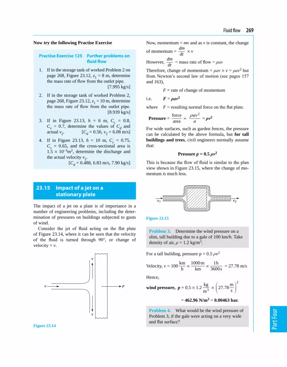
Fluid flow 269
Part
Four
Now try the following Practise Exercise
Practise Exercise 125 Further problems on fluid flow
1. If in the storage tank of worked Problem 2 on page 268, Figure 23.12, z1 = 8 m, determine the mass rate of flow from the outlet pipe.
[7.995 kg/s]
2. If in the storage tank of worked Problem 2, page 268, Figure 23.12, z1 = 10 m, determine the mass rate of flow from the outlet pipe. [8.939 kg/s]
3. If in Figure 23.13, h = 6 m, Cc = 0.8, Cv = 0.7, determine the values of Cd and actual v2. [Cd = 0.56, v2 = 6.08 m/s]
4. If in Figure 23.13, h = 10 m, Cc = 0.75, Cv = 0.65, and the cross-sectional area is 1.5 × 10⁻³m2, determine the discharge and the actual velocity v2. [Cd = 0.488, 6.83 m/s, 7.90 kg/s]
23.15 Impact of a jet on a stationary plate
The impact of a jet on a plate is of importance in a number of engineering problems, including the deter-mination of pressures on buildings subjected to gusts of wind.
Consider the jet of fluid acting on the flat plate of Figure 23.14, where it can be seen that the velocity of the fluid is turned through 90°, or change of velocity = v.
Figure 23.14
Now, momentum = mv and as v is constant, the change
of momentum = dmdt × v
However, dmdt = mass rate of flow = ρav
Therefore, change of momentum = ρav × v = ρav2 but from Newton’s second law of motion (see pages 157 and 163),
F = rate of change of momentum
i.e. F = ρav2
where F = resulting normal force on the flat plate.
Pressure = forcearea =
2ava
r = ρv2
For wide surfaces, such as garden fences, the pressure can be calculated by the above formula, but for tall buildings and trees, civil engineers normally assume that:
Pressure p = 0.5 ρv2
This is because the flow of fluid is similar to the plan view shown in Figure 23.15, where the change of mo-mentum is much less.
Figure 23.15
Problem 3. Determine the wind pressure on a slim, tall building due to a gale of 100 km/h. Take density of air, ρ = 1.2 kg/m3.
For a tall building, pressure p = 0.5 ρv2
Velocity, v = 100 km 1000m 1hh km 3600s× × = 27.78 m/s
Hence,
wind pressure, p = 0.5 × 1.2 3kgm
× 2m27.78 s
= 462.96 N/m2 = 0.00463 bar.
Problem 4. What would be the wind pressure of Problem 3, if the gale were acting on a very wide and flat surface?

270 Mechanical Engineering Principles
Part
Four
For a very wide surface,
pressure, p = ρv2 = 1.22
3kg m27.78 sm
×
= 926.1 N/m2 = 0.00926 bar
(or less than 1/100th of atmospheric pressure!)
Now try the following Practise Exercises
Practise Exercise 126 Further problems on the impact of jets on flat surfaces
1. A hurricane of velocity 220 km/h blows perpendicularly on to a very wide flat surface. Determine the wind pressure that acts on this surface due to this hurricane, when the density of air, ρ = 1.2 kg/m3. [0.0448 bar]
2. What is the wind pressure for Problem 1 on a slim, tall building? [0.0224 bar]
3. A tornado with a velocity of 320 km/h blows perpendicularly on to a very wide surface. Determine the wind pressure that acts on this surface due to this tornado, when the density of air, ρ = 1.23 kg/m3. [0.0972 bar]
4. What is the wind pressure for Problem 3 on a slim, tall building? [0.0486 bar]
5. If atmospheric pressure were 1.014 bar, what fraction of atmospheric pressure would be the wind pressure calculated in Problem 4?
[0.0479 ≈121]
Practise Exercise 127 Short-answer questions on the measurement of fluid flow
In the flowmeters listed 1 to 10, state typical practical applications of each.
1. Orifice plate.
2. Venturimeter.
3. Float and tapered-tube meter.
4. Electromagnetic flowmeter.
5. Pitot-static tube.
6. Hot-wire anemometer.
7. Turbine flowmeter.
8. Deflecting vane flowmeter.
9. Flow nozzles.
10. Rotary vane positive displacement meter.
11. Write down the relationship between the coefficients Cc, Cv and Cd
12. Write down the formula for the pressure due to a wind acting perpendicularly on a tall slender building.
Practise Exercise 128 Multiple-choice questions on the measurement of fluid flow
(Answers on page 298)
1. The term ‘flow rate’ usually refers to: (a) mass flow rate (b) velocity of flow (c) volumetric flow rate
2. The most suitable method for measuring the velocity of high-speed gas flow in a duct is:
(a) venturimeter (b) orifice plate (c) Pitot-static tube (d) float and tapered-tube meter
3. Which of the following statements is false? When a fluid moves through a restriction in a pipe, the fluid
(a) accelerates and the pressure increases (b) decelerates and the pressure decreases (c) decelerates and the pressure increases (d) accelerates and the pressure decreases
4. With an orifice plate in a pipeline the vena contracta is situated:
(a) downstream at the position of mini-mum cross-sectional area of flow
(b) upstream at the position of minimum cross-sectional area of flow
(c) downstream at the position of maxi-mum cross-sectional area of flow
(d) upstream at the position of maximum cross-sectional area of flow
Fluid flow 271
Part
Four
In Questions 5 to 14, select the most appropriate device for the particular requirements from the following list: (a) orifice plate (b) turbine flowmeter (c) flow nozzle (d) pitometer (e) venturimeter(f) cup anemometer (g) electromagnetic flowmeter (h) pitot-static tube (i) float and tapered-tube meter (j) hot-wire anemometer (k) deflecting vane flowmeter.
5. Easy to install, reasonably inexpensive, for high-velocity flows.
6. To measure the flow rate of gas, incorporat-ing a Wheatstone bridge circuit.
7. Very low flow rate of corrosive liquid in a chemical process.
8. To detect leakages from water mains.
9. To determine the flow rate of liquid metals without impeding its flow.
10. To measure the velocity of wind.
11. Constant flow rate, large bore pipe, in the general process industry.
12. To make a preliminary test of flow rate in order to specify permanent flow measuring equipment.
13. To determine the flow rate of fluid very ac-curately with low pressure loss.
14. To measure the flow rate of air in a ventilat-ing duct.
15. For a certain wind velocity, what fraction of the pressure would act on a tall slender building in comparison with a very wide surface?
(a) 0.01 (b) 0 (c) 0.5 (d) 0.99
16. For a wind speed of 190 km/h, what frac-tion (approximate) of atmospheric pressure will this be, when blowing perpendicularly to a very wide surface?
(a) 2.5 (b) 0.5 (c) 1/30 (d) 0

Chapter 24
Ideal gas laws
Mechanical Engineering Principles, Bird and Ross, ISBN 9780415517850
24.1 Boyle’s law
Boyle’s law states:
the volume V of a fixed mass of gas is inversely proportional to its absolute pressure p at con-stant temperature
i.e. p ∝ 1V
or p = kV
or pV = k at constant temperature, where
p = absolute pressure in pascals (Pa), V = volume in m3, and k = a constant.
Changes that occur at constant temperature are called isothermal changes. When a fixed mass of gas at con-stant temperature changes from pressure p1 and vol-ume V1 to pressure p2 and volume V1 then:
1 1 2 2p V p V=
Problem 1. A gas occupies a volume of 0.10 m3 at a pressure of 1.8 MPa. Determine (a) the pressure if the volume is changed to 0.06 m3at constant temperature, and (b) the volume if the pressure is changed to 2.4 MPa at constant temperature.
(a) Since the change occurs at constant temperature (i.e. an isothermal change), Boyle’s law applies,
The relationships that exist between pressure, volume and temperature in a gas are given in a set of laws called the gas laws, the most fundamental being those of Boyle’s, Charles’, and the pressure law, together with Dalton’s law of partial pressures and the characteristic gas equation. These laws are used for all sorts of practical applications, including for designing pressure vessels, in the form of circular cylinders and spheres, which are used for storing and transporting gases. An example of this is the pressure in car tyres, which can increase due to a temperature increase, and can decrease due to a temperature decrease. Other examples are large and medium size gas storage cylinders and domestic spray cans, which can explode if they are heated. In the case of domestic spray cans, these can explode dangerously in a domestic situation if they are left on a window sill where the sunshine acting on them causes them toheatupor,iftheyarethrownontoafire.Inthesecases, the consequence can be disastrous, so don’t throw your ‘full’ spray can on to a fire; youmayvery sadly and deeply regret it! Another example of a gas storage vessel is that used by your ‘local’ gas companies, which supply natural gas (methane) to domestic properties, businesses, etc.
At the end of this chapter you should be able to:
• state and perform calculations involving Boyle’s law
• understand the term isothermal• state and perform calculations involving Charles’
law• understand the term isobaric• state and perform calculations involving the
pressure law• state and perform calculations on Dalton’s law
of partial pressures
• state and perform calculations on the character-istic gas equation
• understand the term STP

Ideal gas laws 273
Part
Four
i.e. p1V1 = p2V2 where p1 = 1.8 MPa, V1 = 0.10 m3 and
V2 = 0.06 m3. Hence, (1.8)(0.10) = p2(0.06)
from which, pressure p2 = 1.8 0.10
0.06× = 3 MPa
(b) p1V1 = p2V2 where p1 = 1.8 MPa, V1 = 0.10 m3 and p2 = 2.4 MPa.
Hence, (1.8)(0.10) = (2.4)V2
from which, volume V2 =1.8 0.10
2.4× = 0.075 m3
Problem 2. In an isothermal process, a mass of gas has its volume reduced from 3200 mm3 to 2000 mm3. If the initial pressure of the gas is 110 kPa, determine the final pressure.
Since the process is isothermal, it takes place at con-stant temperature and hence Boyle’s law applies, i.e. p1V1 = p2V2, where p2 = 110 kPa, V1 = 3200 mm3 and V2 = 2000 mm3. Hence, (110)(3200) = p2(2000)
from which, finalpressure,p2 = 110 32002000×
= 176 kPa
Problem 3. Some gas occupies a volume of 1.5 m3 in a cylinder at a pressure of 250 kPa. A piston, sliding in the cylinder, compresses the gas isothermally until the volume is 0.5 m3. If the area of the piston is 300 cm2, calculate the force on the piston when the gas is compressed.
An isothermal process means constant temperature and thus Boyle’s law applies, i.e. p1V1 = p2V2
where V1 = 1.5 m3, V2 = 0.5 m3 and p1= 250 kPa. Hence, (250)(1.5) = p2(0.5)
from which, pressure, p2 = 250 1.50.5×
= 750 kPa
Pressure = forcearea , from which, force = pressure × area.
Hence, force on the piston = (750 × 103 Pa)(300 × 10–4 m2) = 22.5 kN
Now try the following Practise Exercise
Practise Exercise 129 Further problems on Boyle’s law
1. The pressure of a mass of gas is increased from 150 kPa to 750 kPa at constant tem-perature. Determine the final volume of the gas, if its initial volume is 1.5 m3. [0.3 m3]
2. In an isothermal process, a mass of gas has its volume reduced from 50 cm3 to 32 cm3. If the initial pressure of the gas is 80 kPa, determine its final pressure. [125 kPa]
3. The piston of an air compressor compresses air to 1
4 of its original volume during its stroke. Determine the final pressure of the air if the original pressure is 100 kPa, assuming an isothermal change. [400 kPa]
4. A quantity of gas in a cylinder occupies a volume of 2 m3 at a pressure of 300 kPa. A piston slides in the cylinder and compresses the gas, according to Boyle’s law, until the volume is 0.5 m3. If the area of the piston is 0.02 m2, calculate the force on the piston when the gas is compressed. [24 kN]
24.2 Charles’ law
Charles’ law states:
for a given mass of gas at constant pressure, the volume V is directly proportional to its thermo-dynamic temperature T
i.e. V ∝ Tor V = kT
or VT = k at constant pressure, where
T = thermodynamic temperature in Kelvin (K).
A process that takes place at constant pressure is called an isobaric process.
The relationship between the Celsius scale of tem-perature and the thermodynamic or absolute scale is given by:
kelvin = degrees Celsius + 273

274 Mechanical Engineering Principles
Part
Four
i.e. K = °C + 273
or °C = K – 273 (as stated in Chapter 20).
If a given mass of gas at a constant pressure occupies a volume V1 at a temperature T1 and a volume V2 at temperature T2, then
V VT T
1 21 2
=
Problem 4. A gas occupies a volume of 1.2 litres at 20°C. Determine the volume it occupies at 130°C if the pressure is kept constant.
Since the change occurs at constant pressure (i.e. an isobaric process), Charles’ law applies,
i.e. 1 2
1 2
V VT T=
where V1 = 1.2 litre, T1 = 20°C = (20 + 273)K = 293 K
and T2 = (130 + 273)K = 403 K.
Hence, 21.2293 403
V=
from which, volume at 130°C, V2 = (1.2)(403)
293
= 1.65 litres
Problem 5. Gas at a temperature of 150°C has its volume reduced by one-third in an isobaric process. Calculate the final temperature of the gas.
Since the process is isobaric it takes place at constant pressure and hence Charles’ law applies,
i.e. 1 2
1 2
V VT T=
where T1 = (150 + 273)K = 423 K
and V2 = 23 V1
Hence 11
2
23
423VV
T=
from which, finaltemperature,
T2 = 23 (423) = 282 K
or (282 – 273)°C i.e. 9°C
Now try the following Practise Exercise
Practise Exercise 130 Further problems on Charles’ law
1. Some gas initially at 16°C is heated to 96°C at constant pressure. If the initial volume of the gas is 0.8 m3, determine the final volume of the gas. [1.02 m3]
2. A gas is contained in a vessel of volume 0.02 m3 at a pressure of 300 kPa and a tem-perature of 15°C. The gas is passed into a vessel of volume 0.015 m3. Determine to what temperature the gas must be cooled for the pressure to remain the same. [–57°C]
3. In an isobaric process gas at a temperature of 120°C has its volume reduced by a sixth. Determine the final temperature of the gas. [54.5°C]
24.3 The pressure law
The pressure law states:
the pressure p of a fixed mass of gas is directly proportional to its thermodynamic temperature T at constant volume.
i.e. p ∝ T or p = kT or pT = k
When a fixed mass of gas at constant volume changes from pressure p1 and temperature T1, to pressure p2 and temperature T2 then:
p pT T
1 21 2
=
Problem 6. Gas initially at a temperature of 17°C and pressure 150 kPa is heated at constant volume until its temperature is 124°C. Determine the final pressure of the gas, assuming no loss of gas.
Since the gas is at constant volume, the pressure law
applies, i.e. 1 2
1 2
p pT T=
where T1= (17 + 273)K = 290 K, T2 = (124 + 273)K = 397 Kand p1 = 150 kPa

Ideal gas laws 275
Part
Four
Hence 2150290 397
p= from which,
finalpressure,p2 = (150)(397)
290
= 205.3 kPa
Now try the following Practise Exercise
Practise Exercise 131 A further problem on the pressure law
1. Gas, initially at a temperature of 27°C and pressure 100 kPa, is heated at constant volume until its temperature is 150°C. As-suming no loss of gas, determine the final pressure of the gas. [141 kPa]
24.4 Dalton’s law of partial pressure
Dalton’s law of partial pressure states:
the total pressure of a mixture of gases occupying a given volume is equal to the sum of the pressures of each gas, considered separately, at constant temperature.
The pressure of each constituent gas when occupying a fixed volume alone is known as the partial pressure of that gas.
An ideal gas is one that completely obeys the gas laws given in Sections 24.1 to 24.4. In practice no gas is an ideal gas, although air is very close to being one. For calculation purposes the difference between an ideal and an actual gas is very small.
Problem 7. A gas R in a container exerts a pressure of 200 kPa at a temperature of 18°C. Gas Q is added to the container and the pressure increases to 320 kPa at the same temperature. Determine the pressure that gas Q alone exerts at the same temperature.
Initial pressure, pR = 200 kPa, and the pressure of gases R and Q together, p = pR + pQ = 320 kPaBy Dalton’s law of partial pressure, the pressure of gas Q alone is
pQ = p – pR = 320 – 200 = 120 kPa.
Now try the following Practise Exercise
Practise Exercise 132 A further problem on Dalton’s law of partial pressure
1. A gas A in a container exerts a pressure of 120 kPa at a temperature of 20°C. Gas B is added to the container and the pressure in-creases to 300 kPa at the same temperature. Determine the pressure that gas B alone exerts at the same temperature. [180 kPa]
24.5 Characteristic gas equation
Frequently, when a gas is undergoing some change, the pressure, temperature and volume all vary simultane-ously. Provided there is no change in the mass of a gas, the above gas laws can be combined, giving
p V p VT T1 1 2 2
1 2= = k where k is a constant.
For an ideal gas, constant k = mR, where m is the mass of the gas in kg, and R is the characteristic gas
constant, i.e. pVT = mR
or pV = mRT
This is called the characteristic gas equation. In this equation, p = absolute pressure in pascals,
V = volume in m3, m = mass in kg, R = characteristic gas constant in J/(kg K), and T = thermodynamic temperature in Kelvin.
Some typical values of the characteristic gas constant R include: air, 287 J/(kg K), hydrogen 4160 J/(kg K), oxygen 260 J/(kg K) and carbon dioxide 184 J/(kg K).
Standard temperature and pressure (i.e. STP) refers to a temperature of 0°C, i.e. 273 K, and normal atmospheric pressure of 101.325 kPa.
24.6 Worked problems on the characteristic gas equation
Problem 8. A gas occupies a volume of 2.0 m3 when at a pressure of 100 kPa and a temperature of

276 Mechanical Engineering Principles
Part
Four
120°C. Determine the volume of the gas at 15°C if the pressure is increased to 250 kPa.
Using the combined gas law: 1 1 2 2
1 2
p V p VT T=
where V1 = 2.0 m3, p1 = 100 kPa, p2 = 250 kPa, T1 = (120 + 273)K = 393 K and
T2 = (15 + 273) K = 288 K, gives:
2(100)(2.0) (250)393 288
V=
from which, volume at 15°C,
V2 = (100)(2.0)(288)
(393)(250) = 0.586 m3
Problem 9. 20000 mm3 of air initially at a pressure of 600 kPa and temperature 180°C is expanded to a volume of 70000 mm3 at a pressure of 120 kPa. Determine the final temperature of the air, assuming no losses during the process.
Using the combined gas law: 1 1 2 2
1 2
p V p VT T=
where V1 = 20000 mm3, V2 = 70000 mm3, p1 = 600 kPa, p2 = 120 kPa, and
T1 = (180 + 273) K = 453 K
Hence 2
(600)(20000) (120) (70000)453 T=
from which, finaltemperature,
T2 = (120)(70000)(453)
(600)(20000) = 317 K or 44°C
Problem 10. Some air at a temperature of 40°C and pressure 4 bar occupies a volume of 0.05 m3. Determine the mass of the air assuming the characteristic gas constant for air to be 287 J/(kg K).
From above, pV = mRT,where p = 4 bar = 4 × 10⁵ Pa (since 1 bar = 105 Pa – see Chapter 22),
V = 0.05 m3, T = (40 + 273) K = 313 K,and R = 287 J/(kg K).
Hence (4 ×10⁵)(0.05) = m(287)(313)
from which, mass of air, m = 5(4 10 )(0.05)
(287)(313)×
= 0.223 kg or 223 g
Problem 11. A cylinder of helium has a volume of 600 cm3. The cylinder contains 200 g of helium at a temperature of 25°C. Determine the pressure of the helium if the characteristic gas constant for helium is 2080 J/(kg K).
From the characteristic gas equation, pV = mRT,
V = 600 cm3 = 600 ×10–6 m3, m = 200 g = 0.2 kg, T = (25 + 273) K = 298 K and R = 2080 J/(kg K)
Hence (p)(600 ×10–6) = (0.2)(2080)(298)
from which, pressure, p = 6(0.2)(2080)(298)
(600 10 )−×
= 206613333 Pa = 206.6 MPa
Problem 12. A spherical vessel has a diameter of 1.2 m and contains oxygen at a pressure of 2 bar and a temperature of –20°C. Determine the mass of oxygen in the vessel. Take the characteristic gas constant for oxygen to be 0.260 kJ/(kg K).
From the characteristic gas equation, pV = mRT, V = volume of spherical vessel
= 3
34 4 1.23 3 2rπ π =
= 0.905 m3,
p = 2 bar = 2 ×10⁵ Pa, T = (–20 + 273) K = 253 Kand R = 0.260 kJ/(kg K) = 260 J/(kg K)
Hence, (2 × 10⁵)(0.905) = m(260)(253)
from which, mass of oxygen, m = 5(2 10 )(0.905)
(260)(253)×
= 2.75 kg
Problem 13. Determine the characteristic gas constant of a gas which has a specific volume of 0.5 m3/kg at a temperature of 20°C and pressure 150 kPa.
From the characteristic gas equation, pV = mRT
from which, R = pVmT where p = 150 ×103 Pa,
T = (20 + 273) K = 293 K and
Ideal gas laws 277
Part
Four
specific volume, V/m = 0.5 m3/kg. Hence the characteristic gas constant,
R = ( )3150 10 0.5293
p VT m
× =
= 256 J/(kg K)
Now try the following Practise Exercise
Practise Exercise 133 Further problems on the characteristic gas equation
1. A gas occupies a volume of 1.20 m3 when at a pressure of 120 kPa and a temperature of 90°C. Determine the volume of the gas at 20°C if the pressure is increased to 320 kPa.
[0.363 m3]
2. A given mass of air occupies a volume of 0.5 m3 at a pressure of 500 kPa and a tem-perature of 20°C. Find the volume of the air at STP. [2.30 m3]
3. A spherical vessel has a diameter of 2.0 m and contains hydrogen at a pressure of 300 kPa and a temperature of –30°C. De-termine the mass of hydrogen in the vessel. Assume the characteristic gas constant R for hydrogen is 4160 J/(kg K). [1.24 kg]
4. A cylinder 200 mm in diameter and 1.5 m long contains oxygen at a pressure of 2 MPa and a temperature of 20°C. Determine the mass of oxygen in the cylinder. Assume the characteristic gas constant for oxygen is 260 J/(kg K). [1.24 kg]
5. A gas is pumped into an empty cylinder of volume 0.1 m3 until the pressure is 5 MPa. The temperature of the gas is 40°C. If the cylinder mass increases by 5.32 kg when the gas has been added, determine the value of the characteristic gas constant. [300 J/(kg K)]
6. The mass of a gas is 1.2 kg and it occupies a volume of 13.45 m3 at STP. Determine its characteristic gas constant. [4160 J/(kg K)]
7. 30 cm3 of air initially at a pressure of 500 kPa and temperature 150°C is expand-ed to a volume of 100 cm3 at a pressure of
200 kPa. Determine the final temperature of the air, assuming no losses during the process. [291°C]
8. A quantity of gas in a cylinder occupies a volume of 0.05 m3 at a pressure of 400 kPa and a temperature of 27°C. It is compressed according to Boyle's law until its pressure is 1 MPa, and then expanded according to Charles' law until its volume is 0.03 m3. Determine the final temperature of the gas. [177°C]
9. Some air at a temperature of 35°C and pres-sure 2 bar occupies a volume of 0.08 m3. Determine the mass of the air assuming the characteristic gas constant for air to be 287 J/(kg K). (1 bar = 105Pa) [0.181 kg]
10. Determine the characteristic gas constant R of a gas that has a specific volume of 0.267 m3/kg at a temperature of 17°C and pressure 200 kPa. [184 J/(kg K)]
24.7 Further worked problems on the characteristic gas equation
Problem 14. A vessel has a volume of 0.80 m3 and contains a mixture of helium and hydrogen at a pressure of 450 kPa and a temperature of 17°C. If the mass of helium present is 0.40 kg determine (a) the partial pressure of each gas, and (b) the mass of hydrogen present. Assume the characteristic gas constant for helium to be 2080 J/(kg K) and for hydrogen 4160 J/(kg K).
(a) V = 0.80 m3, p = 450 kPa, T = (17 + 273)K = 290 K, mHe = 0.40 kg, RHe = 2080 J/(kg K).
If pHe is the partial pressure of the helium, then using the characteristic gas equation,
pHeV = mHeRHeT gives:(pHe)(0.80) = (0.40)(2080)(290)
from which, the partial pressure of the helium,
pHe = (0.40)(2080)(290)
(0.80) = 301.6 kPa
By Dalton’s law of partial pressure the total pres-sure p is given by the sum of the partial pressures, i.e. p = pH + pHe, from which,

278 Mechanical Engineering Principles
Part
Four
the partial pressure of the hydrogen, pH = p – pHe = 450 – 301.6 = 148.4 kPa
(b) From the characteristic gas equation, pHV = mHRHT
Hence, (148.4 ×10³)(0.8) = mH (4160)(290) from which, mass of hydrogen,
mH = 3(148.4 10 )(0.8)
(4160)(290)× = 0.098 kg or 98 g
Problem 15. A compressed air cylinder has a volume of 1.2 m3 and contains air at a pressure of 1 MPa and a temperature of 25°C. Air is released from the cylinder until the pressure falls to 300 kPa and the temperature is 15°C. Determine (a) the mass of air released from the container, and (b) the volume it would occupy at STP. Assume the characteristic gas constant for air to be 287 J/(kg K).
V1 = 1.2 m3 (= V2), p1 = 1 MPa = 106 Pa, T1 = (25 + 273)K = 298 K,
T2 = (15 + 273)K = 288 K, p2 = 300 kPa = 300 × 103 Pa and R = 287 J/(kg K)(a) Using the characteristic gas equation,
p1V1 = m1RT1, to find the initial mass of air in the cylinder gives:
(106)(1.2) = m1(287)(298)
from which, mass m1 = 6(10 )(1.2)
(287)(298) = 14.03 kg
Similarly, using p2V2= m2RT2 to find the final mass of air in the cylinder gives:
(300 × 103)(1.2) = m2(287)(288)
from which, mass m2 =3(300 10 )(1.2)
(287)(288)× = 4.36 kg
Mass of air released from cylinder = m1 – m2 = 14.03 – 4.36 = 9.67 kg.
(b) At STP, T = 273 K and p = 101.325 kPa. Using the characteristic gas equation pV = mRT
volume, V =(9.67)(287)(273)
101325mRT
p = = 7.48 m3
Problem 16. A vessel X contains gas at a pressure of 750 kPa at a temperature of 27°C. It is connected via a valve to vessel Y that is filled
with a similar gas at a pressure of 1.2 MPa and a temperature of 27°C. The volume of vessel X is 2.0 m3 and that of vessel Y is 3.0 m3. Determine the final pressure at 27°C when the valve is opened and the gases are allowed to mix. Assume R for the gas to be 300 J/(kg K).
For vessel X: pX = 750 × 103 Pa, TX = (27 + 273)K = 300 K, VX = 2.0 m3 and R = 300 J/(kg K)From the characteristic gas equation, pXVX = mXRTX
Hence (750 × 103)(2.0) = mX (300)(300)from which, mass of gas in vessel X,
mX = 3(750 10 )(2.0)
(300)(300)× = 16.67 kg.
For vessel Y:
pY = 1.2 × 10⁶ Pa, TY = (27 + 273)K = 300 K, VY = 3.0 m3 and R = 300 J/(kg K)
From the characteristic gas equation, pYVY = mYRTY
Hence (1.2 × 10⁶)(3.0) = mY (300)(300)from which, mass of gas in vessel Y,
mY = 6(1.2 10 )(3.0)
(300)(300)× = 40 kg
When the valve is opened, mass of mixture, m = mX + mY = 16.67 + 40 = 56.67 kg. Total volume, V = VX + VY = 2.0 + 3.0 = 5.0 m3,
R = 300 J/(kg K), T = 300 K.From the characteristic gas equation, pV = mRT p(5.0) = (56.67)(300)(300)from which, finalpressure,
p = (56.67)(300)(300)
5.0 = 1.02 MPa
Now try the following Practise Exercises
Practise Exercise 134 Further questions on ideal gas laws
1. A vessel P contains gas at a pressure of 800 kPa at a temperature of 25°C. It is con-nected via a valve to vessel Q that is filled with similar gas at a pressure of 1.5 MPa

Ideal gas laws 279
Part
Four
and a temperature of 25°C. The volume of vessel P is 1.5 m3 and that of vessel R is 2.5 m3. Determine the final pressure at 25°C when the valve is opened and the gases are allowed to mix. Assume R for the gas to be 297 J/(kg K). [1.24 MPa]
2. A vessel contains 4 kg of air at a pressure of 600 kPa and a temperature of 40°C. The vessel is connected to another by a short pipe and the air exhausts into it. The final pres-sure in both vessels is 250 kPa and the tem-perature in both is 15°C. If the pressure in the second vessel before the air entered was zero, determine the volume of each vessel. Assume R for air is 287 J/(kg K).
[0.60 m3, 0.72 m3]
3. A vessel has a volume of 0.75 m3 and con-tains a mixture of air and carbon dioxide at a pressure of 200 kPa and a temperature of 27°C. If the mass of air present is 0.5 kg determine (a) the partial pressure of each gas and (b) the mass of carbon dioxide. As-sume the characteristic gas constant for air to be 287 J/(kg K) and for carbon dioxide 184 J/(kg K).
[(a) 57.4 kPa, 142.6 kPa (b) 1.94 kg]
4. A mass of gas occupies a volume of 0.02 m3 when its pressure is 150 kPa and its tempera-ture is 17°C. If the gas is compressed until its pressure is 500 kPa and its temperature is 57°C, determine (a) the volume it will oc-cupy and (b) its mass, if the characteristic gas constant for the gas is 205 J/(kg K).
[(a) 0.0068 m3 (b) 0.050 kg]
5. A compressed air cylinder has a volume of 0.6 m3 and contains air at a pressure of 1.2 MPa absolute and a temperature of 37°C. After use the pressure is 800 kPa absolute and the temperature is 17°C. Calculate (a) the mass of air removed from the cylinder, and (b) the volume the mass of air removed would occupy at STP conditions. Take R for air as 287 J/(kg K) and atmospheric pressure as 100 kPa. [(a) 2.33 kg (b) 1.83 m3]
Practise Exercise 135 Short-answer questions on ideal gas laws
1. State Boyle’s law.
2. State Charles’ law.
3. State the Pressure law.
4. State Dalton’s law of partial pressures.
5. State the relationship between the Celsius and the thermodynamic scale of temperature.
6. What is (a) an isothermal change, and (b) an isobaric change?
7. Define an ideal gas.
8. State the characteristic gas equation.
9. What is meant by STP?
Practise Exercise 136 Multiple-choice questions on ideal gas laws
(Answers on page 298)
1. Which of the following statements is false?
(a) At constant temperature, Charles’ law applies.
(b) The pressure of a given mass of gas decreases as the volume is increased at constant temperature.
(c) Isobaric changes are those which occur at constant pressure.
(d) Boyle’s law applies at constant tem-perature.
2. A gas occupies a volume of 4 m3 at a pres-sure of 400 kPa. At constant temperature, the pressure is increased to 500 kPa. The new volume occupied by the gas is:
(a) 5 m3 (b) 0.3 m3
(c) 0.2 m3 (d) 3.2 m3
3. A gas at a temperature of 27°C occupies a volume of 5 m3. The volume of the same mass of gas at the same pressure but at a temperature of 57°C is:
(a) 10.56 m3 (b) 5.50 m3
(c) 4.55 m3 (d) 2.37 m3

280 Mechanical Engineering Principles
Part
Four
4. Which of the following statements is false?
(a) An ideal gas is one that completely obeys the gas laws.
(b) Isothermal changes are those that occur at constant volume.
(c) The volume of a gas increases when the temperature increases at constant pressure.
(d) Changes that occur at constant pressure are called isobaric changes.
A gas has a volume of 0.4 m3 when its pressure is 250 kPa and its temperature is 400 K. Use this data in Questions 5 and 6.
5. The temperature when the pressure is increased to 400 kPa and the volume is in-creased to 0.8 m3 is:
(a) 400 K (b) 80 K (c) 1280 K (d) 320 K
6. The pressure when the temperature is raised to 600 K and the volume is reduced to 0.2 m3 is:
(a) 187.5 kPa (b) 250 kPa (c) 333.3 kPa (d) 750 kPa
7. A gas has a volume of 3 m3 at a temperature of 546 K and a pressure of 101.325 kPa. The volume it occupies at STP is:
(a) 3 m3 (b) 1.5 m3
(c) 6 m3
8. Which of the following statements is false? (a) A characteristic gas constant has units
of J/(kg K). (b) STP conditions are 273 K and
101.325 kPa. (c) All gases are ideal gases. (d) An ideal gas is one that obeys the gas
laws.
A mass of 5 kg of air is pumped into a con-tainer of volume 2.87 m3. The characteristic gas constant for air is 287 J/(kg K). Use this data in Questions 9 and 10.
9. The pressure when the temperature is 27°C is:
(a) 1.6 kPa (b) 6 kPa (c) 150 kPa (d) 15 kPa
10. The temperature when the pressure is 200 kPa is:
(a) 400°C (b) 127°C (c) 127 K (d) 283 K

Chapter 25
The measurement of temperature
Mechanical Engineering Principles, Bird and Ross, ISBN 9780415517850
25.1 Liquid-in-glass thermometer
A liquid-in-glass thermometer uses the expansion of a liquid with increase in temperature as its principle of operation.
ConstructionA typical liquid-in-glass thermometer is shown in Figure 25.1 and consists of a sealed stem of uniform small-bore tubing, called a capillary tube, made of glass, with a cylindrical glass bulb formed at one end. The bulb and part of the stem are filled with a liquid such as mercury or alcohol and the remaining part of the tube is evacuated. A temperature scale is formed by etching graduations on the stem. A safety reservoir is usually provided, into which the liquid can expand without bursting the glass if the temperature is raised beyond the upper limit of the scale.
Figure 25.1
Principle of operationThe operation of a liquid-in-glass thermometer depends on the liquid expanding with increase in temperature and contracting with decrease in temperature. The position of the end of the column of liquid in the tube is a measure of the temperature of the liquid in the
A change in temperature of a substance can often result in a change in one or more of its physi-cal properties. Thus, although temperature cannot be measured directly, its effects can be measured. Some properties of substances used to determine changes in temperature include changes in dimen-sions, electrical resistance, state, type and volume of radiation and colour.
Temperature measuring devices available are many and varied. Those described in this chapter are those most often used in science and industry.
At the end of this chapter you should be able to:
• describe the construction, principle of operation and practical applications of the following tem-perature measuring devices:
(a) liquid-in-glass thermometer (including ad-vantages of mercury, and sources of error)
(b) thermocouples (including advantages and sources of error)
(c) resistance thermometer (including limita-tions and advantages of platinum coil)
(d) thermistors (e) pyrometers (total radiation and optical
types, including advantages and disadvan-tages)
• describe the principle of operation of (a) temperature indicating paints and crayons (b) bimetallic thermometers (c) mercury-in-steel thermometer (d) gas thermometer• select the appropriate temperature measuring
device for a particular application.

282 Mechanical Engineering Principles
Part
Four
bulb – shown as 15°C in Figure 25.1, which is about room temperature. Two fixed points are needed to calibrate the thermometer, with the interval between these points being divided into ‘degrees’. In the first thermometer, made by Celsius, the fixed points chosen were the temperature of melting ice (0°C) and that of boiling water at standard atmospheric pressure (100°C), in each case the blank stem being marked at the liquid level. The distance between these two points, called the fundamental interval, was divided into 100 equal parts, each equivalent to 1°C, thus forming the scale.
The clinical thermometer, with a limited scale around body temperature, the maximum and/or minimum thermometer, recording the maximum day temperature and minimum night temperature, and the Beckman thermometer, which is used only in accurate measurement of temperature change, and has no fixed points, are particular types of liquid-in-glass thermometer which all operate on the same principle.
AdvantagesThe liquid-in-glass thermometer is simple in construc-tion, relatively inexpensive, easy to use and portable, and is the most widely used method of temperature measurement having industrial, chemical, clinical and meteorological applications.
DisadvantagesLiquid-in-glass thermometers tend to be fragile and hence easily broken, can only be used where the liquid column is visible, cannot be used for surface tempera-ture measurements, cannot be read from a distance and are unsuitable for high temperature measurements.
Advantages of mercuryThe use of mercury in a thermometer has many advan-tages, for mercury:
(i) is clearly visible, (ii) has a fairly uniform rate of expansion, (iii) is readily obtainable in the pure state, (iv) does not ‘wet’ the glass, (v) is a good conductor of heat.
Mercury has a freezing point of –39°C and can-not be used in a thermometer below this temperature. Its boiling point is 357°C but before this temperature is reached some distillation of the mercury occurs if the space above the mercury is a vacuum. To prevent this, and to extend the upper temperature limits to over 500°C, an inert gas such as nitrogen under pres-sure is used to fill the remainder of the capillary tube. Alcohol, often dyed red to be seen in the capillary
tube, is considerably cheaper than mercury and has a freezing point of –113°C, which is considerably lowerthan for mercury. However it has a low boiling point at about 79°C.
ErrorsTypical errors in liquid-in-glass thermometers may oc-cur due to:
(i) the slow cooling rate of glass (ii) incorrect positioning of the thermometer (iii) a delay in the thermometer becoming steady (i.e.
slow response time) (iv) non-uniformity of the bore of the capillary tube,
which means that equal intervals marked on the stem do not correspond to equal temperature intervals.
25.2 Thermocouples
Thermocouples use the e.m.f. set up when the junction of two dissimilar metals is heated.
Principle of operationAt the junction between two different metals, say, cop-per and constantan, there exists a difference in electri-cal potential, which varies with the temperature of the junction. This is known as the ‘thermo-electric effect’. If the circuit is completed with a second junction at a dif-ferent temperature, a current will flow round the circuit. This principle is used in the thermocouple. Two different metal conductors having their ends twisted together are shown in Figure 25.2. If the two junctions are at different temperatures, a current I flows round the circuit.
Figure 25.2
The deflection on the galvanometer G depends on the difference in temperature between junctions X and Y and is caused by the difference between voltages Vx and Vy. The higher temperature junction is usually called the ‘hot junction’ and the lower temperature

The measurement of temperature 283
Part
Four
junction the ‘cold junction’. If the cold junction is kept at a constant known temperature, the galvanometer can be calibrated to indicate the temperature of the hot junction directly. The cold junction is then known as the reference junction.
In many instrumentation situations, the measur-ing instrument needs to be located far from the point at which the measurements are to be made. Extension leads are then used, usually made of the same material as the thermocouple but of smaller gauge. The refer-ence junction is then effectively moved to their ends. The thermocouple is used by positioning the hot junc-tion where the temperature is required. The meter will indicate the temperature of the hot junction only if the reference junction is at 0°C for:
(temperature of hot junction) = (temperature of the cold junction) + (temperature difference)
In a laboratory the reference junction is often placed in melting ice, but in industry it is often positioned in a thermostatically controlled oven or buried under-ground where the temperature is constant.
ConstructionThermocouple junctions are made by twisting together the ends of two wires of dissimilar metals before welding them. The construction of a typical copper-constantan thermocouple for industrial use is shown in Figure 25.3. Apart from the actual junction the two conductors used must be insulated electrically from each other with appropriate insulation and is shown in Figure 25.3 as twin-holed tubing. The wires and insulation are usually inserted into a sheath for protection from environments in which they might be damaged or corroded.
ApplicationsA copper-constantan thermocouple can measure tem-perature from –250°C up to about 400°C, and is used
typically with boiler flue gases, food processing and with sub-zero temperature measurement. An iron- constantan thermocouple can measure temperature from –200°C to about 850°C, and is used typically in paper and pulp mills, re-heat and annealing furnaces and in chemical reactors. A chromel-alumel thermo-couple can measure temperatures from –200°C to about 1100°C and is used typically with blast furnace gases, brick kilns and in glass manufacture.
For the measurement of temperatures above 1100°C radiation pyrometers are normally used. However, thermocouples are available made of platinum-platinum/rhodium, capable of measuring temperatures up to 1400°C, or tungsten-molybdenum which can measure up to 2600°C.
AdvantagesA thermocouple:
(i) has a very simple, relatively inexpensive con-struction
(ii) can be made very small and compact (iii) is robust (iv) is easily replaced if damaged (v) has a small response time (vi) can be used at a distance from the actual mea-
suring instrument and is thus ideal for use with automatic and remote-control systems.
Sources of errorSources of error in the thermocouple, which are dif-ficult to overcome, include:
(i) voltage drops in leads and junctions (ii) possible variations in the temperature of the cold
junction(iii) stray thermoelectric effects, which are caused
by the addition of further metals into the ‘ideal’ two-metal thermocouple circuit.
Figure 25.3

284 Mechanical Engineering Principles
Part
Four
Additional leads are frequently necessary for exten-sion leads or voltmeter terminal connections.
A thermocouple may be used with a battery- or mains-operated electronic thermometer instead of a millivoltmeter. These devices amplify the small e.m.f.’s from the thermocouple before feeding them to a multi-range voltmeter calibrated directly with tem-perature scales. These devices have great accuracy and are almost unaffected by voltage drops in the leads and junctions.
Problem 1. A chromel-alumel thermocouple generates an e.m.f. of 5 mV. Determine the tem-perature of the hot junction if the cold junction is at a temperature of 15°C and the sensitivity of the thermocouple is 0.04 mV/°C.
Temperature difference for 5 m V = 5mV0.04mV/°C
= 125°C.Temperature at hot junction = temperature of cold junction + temperature difference
= 15°C + 125°C = 140°C
Now try the following Practise Exercise
Practise Exercise 137 Further problem on the thermocouple
1. A platinum–platinum/rhodium thermocouple generates an e.m.f. of 7.5 mV. If the cold junction is at a temperature of 20°C, deter-mine the temperature of the hot junction. Assume the sensitivity of the thermocouple to be 6 μV/°C [ 1270°C ]
25.3 Resistance thermometers
Resistance thermometers use the change in electrical resistance caused by temperature change.
ConstructionResistance thermometers are made in a variety of sizes, shapes and forms depending on the application for which they are designed. A typical resistance thermometer is shown diagrammatically in Figure 25.4. The most common metal used for the coil in such thermometers is platinum even though its sensitivity is not as high as other metals such as copper and nickel. However, platinum is a very stable metal and provides reproducible results in a resistance thermometer. A platinum resistance thermometer is often used as a calibrating device. Since platinum is expensive, connecting leads of another metal, usually copper, are used with the thermometer to connect it to a measuring circuit.
The platinum and the connecting leads are shown joined at A and B in Figure 25.4, although sometimes this junction may be made outside of the sheath. How-ever, these leads often come into close contact with the heat source which can introduce errors into the measurements. These may be eliminated by including a pair of identical leads, called dummy leads, which experience the same temperature change as the exten-sion leads.
Principle of operationWith most metals a rise in temperature causes an increase in electrical resistance, and since resistance can be measured accurately this property can be used to measure temperature. If the resistance of a length of wire at 0°C is R0, and its resistance at θ°C is Rθ, then Rθ = R0 (1 + αθ), where a is the temperature coefficient of resistance of the material.
Figure 25.4

The measurement of temperature 285
Part
Four
Rearranging gives: temperature, θ = R RR
00
θa−
Values of R0 and α may be determined experimen-tally or obtained from existing data. Thus, if Rθ can be measured, temperature θ can be calculated. This is the principle of operation of a resistance thermometer. Although a sensitive ohmmeter can be used to mea-sure Rθ, for more accurate determinations a Wheat-stone bridge circuit is used as shown in Figure 25.5. This circuit compares an unknown resistance Rθ with others of known values, R1 and R2 being fixed values and R3 being variable. Galvanometer G is a sensitive centre-zero microammeter. R3 is varied until zero deflection is obtained on the galvanometer, i.e. no current flows through G and the bridge is said to be ‘balanced’.
Figure 25.5
At balance: R2 Rθ= R1 R3
from which, Rθ = R R
R1 3
2
and if R1 and R2 are of equal value, then Rθ = R3
A resistance thermometer may be connected between points A and B in Figure 25.5 and its resistance Rθ at any temperature θ accurately measured. Dummy leads included in arm BC help to eliminate errors caused by the extension leads which are normally necessary in such a thermometer.
LimitationsResistance thermometers using a nickel coil are used mainly in the range –100°C to 300°C, whereas plati-num resistance thermometers are capable of measuring
with greater accuracy temperatures in the range –200°C to about 800°C. This upper range may be extended to about 1500°C if high melting point materials are used for the sheath and coil construction.
Advantages and disadvantages of a platinum coilPlatinum is commonly used in resistance thermom-eters since it is chemically inert, i.e. un-reactive, re-sists corrosion and oxidation and has a high melting point of 1769°C. A disadvantage of platinum is its slow response to temperature variation.
ApplicationsPlatinum resistance thermometers may be used as calibrating devices or in applications such as heat-treating and annealing processes and can be adapted easily for use with automatic recording or control systems. Resistance thermometers tend to be fragile and easily damaged especially when subjected to excessive vibration or shock.
Problem 2. A platinum resistance thermometer has a resistance of 25 W at 0°C. When measuring the temperature of an annealing process a resistance value of 60 W is recorded. To what temperature does this correspond? Take the temperature coefficient of resistance of platinum as 0.0038/°C
Rθ = R0 (1 + αθ), where R0 = 25 W, Rθ = 60 W and α = 0.0038/°C.
Rearranging gives: temperature, θ = 0
0
R RR
θa−
= 60 25
(0.0038)(25)− = 368.4°C
Now try the following Practise Exercise
Exercise 138 Further problem on the resistance thermometer
1. A platinum resistance thermometer has a resistance of 100 W at 0°C. When measur-ing the temperature of a heat process a re-sistance value of 177 W is measured using a Wheatstone bridge. Given that the tempera-ture coefficient of resistance of platinum is 0.0038/°C, determine the temperature of the heat process, correct to the nearest degree. [203°C]

286 Mechanical Engineering Principles
Part
Four
25.4 Thermistors
A thermistor is a semi-conducting material – such as mixtures of oxides of copper, manganese, cobalt, etc. – in the form of a fused bead connected to two leads. As its temperature is increased its resistance rap-idly decreases. Typical resistance/temperature curves for a thermistor and common metals are shown in Figure 25.6. The resistance of a typical thermistor can vary from 400 W at 0°C to 100 W at 140°C.
Figure 25.6
AdvantagesThe main advantages of a thermistor are its high sen-sitivity and small size. It provides an inexpensive method of measuring and detecting small changes in temperature.
25.5 Pyrometers
A pyrometer is a device for measuring very high tem-peratures and uses the principle that all substances emit
radiant energy when hot, the rate of emission depend-ing on their temperature. The measurement of thermal radiation is therefore a convenient method of determin-ing the temperature of hot sources and is particularly useful in industrial processes. There are two main types of pyrometer, namely the total radiation pyrometer and the optical pyrometer.
Pyrometers are very convenient instruments since they can be used at a safe and comfortable distance from the hot source. Thus applications of pyrometers are found in measuring the temperature of molten metals, the interiors of furnaces or the interiors of volcanoes. Total radiation pyrometers can also be used in conjunction with devices which record and control temperature continuously.
Total radiation pyrometerA typical arrangement of a total radiation pyrometer is shown in Figure 25.7. Radiant energy from a hot source, such as a furnace, is focused on to the hot junction of a thermocouple after reflection from a concave mirror. The temperature rise recorded by the thermocouple depends on the amount of radiant energy received, which in turn depends on the temperature of the hot source. The galvanometer G shown connected to the thermocouple records the current which results from the e.m.f. developed and may be calibrated to give a direct reading of the temperature of the hot source. The thermocouple is protected from direct radiation by a shield as shown and the hot source may be viewed through the sighting telescope. For greater sensitiv-ity, a thermopile may be used, a thermopile being a number of thermocouples connected in series. Total radiation pyrometers are used to measure temperature in the range 700°C to 2000°C.
Optical pyrometersWhen the temperature of an object is raised sufficient-ly, two visual effects occur; the object appears brighter
Figure 25.7

The measurement of temperature 287
Part
Four
and there is a change in colour of the light emitted. These effects are used in the optical pyrometer where a comparison or matching is made between the bright-ness of the glowing hot source and the light from a fila-ment of known temperature.
The most frequently used optical pyrometer is the disappearing filament pyrometer and a typical arrange-ment is shown in Figure 25.8. A filament lamp is built into a telescope arrangement which receives radiation from a hot source, an image of which is seen through an eyepiece. A red filter is incorporated as a protection to the eye.
The current flowing through the lamp is controlled by a variable resistor. As the current is increased, the temperature of the filament increases and its colour changes. When viewed through the eyepiece the filament of the lamp appears superimposed on the image of the radiant energy from the hot source. The current is varied until the filament glows as brightly as the background. It will then merge into the background and seem to disappear. The current required to achieve this is a measure of the temperature of the hot source and the ammeter can be calibrated to read the temperature directly. Optical pyrometers may be used to measure temperatures up to, and even in excess of, 3000°C.
Advantages of pyrometers (i) There is no practical limit to the temperature that
a pyrometer can measure. (ii) A pyrometer need not be brought directly into
the hot zone and so is free from the effects of heat and chemical attack that can often cause other measuring devices to deteriorate in use.
(iii) Very fast rates of change of temperature can be followed by a pyrometer.
(iv) The temperature of moving bodies can be mea-sured.
(v) The lens system makes the pyrometer virtually independent of its distance from the source.
Disadvantages of pyrometers (i) A pyrometer is often more expensive than other
temperature measuring devices. (ii) A direct view of the heat process is necessary.(iii) Manual adjustment is necessary. (iv) A reasonable amount of skill and care is required
in calibrating and using a pyrometer. For each new measuring situation the pyrometer must be re-calibrated.
(v) The temperature of the surroundings may affect the reading of the pyrometer and such errors are difficult to eliminate.
25.6 Temperature indicating paints and crayons
Temperature indicating paints contain substances which change their colour when heated to certain temperatures. This change is usually due to chemi-cal decomposition, such as loss of water, in which the change in colour of the paint after having reached the particular temperature will be a permanent one. How-ever, in some types the original colour returns after cooling. Temperature indicating paints are used where the temperature of inaccessible parts of apparatus and machines is required. They are particularly useful in heat-treatment processes where the temperature of the component needs to be known before a quenching operation. There are several such paints available and
Figure 25.8

288 Mechanical Engineering Principles
Part
Four
most have only a small temperature range so that dif-ferent paints have to be used for different temperatures. The usual range of temperatures covered by these paints is from about 30°C to 700°C.
Temperature sensitive crayons consist of fusible solids compressed into the form of a stick. The melt-ing point of such crayons is used to determine when a given temperature has been reached. The crayons are simple to use but indicate a single temperature only, i.e. its melting point temperature. There are over 100 different crayons available, each covering a particular range of temperature. Crayons are available for tem-peratures within the range of 50°C to 1400°C. Such crayons are used in metallurgical applications such as preheating before welding, hardening, annealing or tempering, or in monitoring the temperature of critical parts of machines or for checking mould temperatures in the rubber and plastics industries.
25.7 Bimetallic thermometers
Bimetallic thermometers depend on the expansion of metal strips which operate an indicating pointer. Two thin metal strips of differing thermal expansion are welded or riveted together and the curvature of the bimetallic strip changes with temperature change. For greater sensitivity the strips may be coiled into a flat spiral or helix, one end being fixed and the other being made to rotate a pointer over a scale. Bimetallic ther-mometers are useful for alarm and over-temperature applications where extreme accuracy is not essential. If the whole is placed in a sheath, protection from cor-rosive environments is achieved but with a reduction in response characteristics. The normal upper limit of temperature measurement by this thermometer is about 200°C, although with special metals the range can be extended to about 400°C.
25.8 Mercury-in-steel thermometer
The mercury-in-steel thermometer is an extension of the principle of the mercury-in-glass thermometer. Mercury in a steel bulb expands via a small bore capil-lary tube into a pressure indicating device, say a Bour-don gauge, the position of the pointer indicating the amount of expansion and thus the temperature. The advantages of this instrument are that it is robust and, by increasing the length of the capillary tube, the gauge can be placed some distance from the bulb and can thus be used to monitor temperatures in positions which are
inaccessible to the liquid-in-glass thermometer. Such thermometers may be used to measure temperatures up to 600°C.
25.9 Gas thermometers
The gas thermometer consists of a flexible U-tube of mercury connected by a capillary tube to a vessel con-taining gas. The change in the volume of a fixed mass of gas at constant pressure, or the change in pressure of a fixed mass of gas at constant volume, may be used to measure temperature. This thermometer is cumbersome and rarely used to measure temperature directly, but it is often used as a standard with which to calibrate other types of thermometer. With pure hydrogen the range of the instrument extends from –240°C to 1500°C and measurements can be made with extreme accuracy.
25.10 Choice of measuring devices
Problem 3. State which device would be most suitable to measure the following:
(a) metal in a furnace, in the range 50°C to 1600°C(b) the air in an office in the range 0°C to 40°C(c) boiler flue gas in the range 15°C to 300°C(d) a metal surface, where a visual indication is
required when it reaches 425°C(e) materials in a high-temperature furnace in the
range 2000°C to 2800°C(f) to calibrate a thermocouple in the range
–100°C to 500°C(g) brick in a kiln up to 900°C(h) an inexpensive method for food processing
applications in the range –25°C to –75°C.
(a) Radiation pyrometer(b) Mercury-in-glass thermometer(c) Copper-constantan thermocouple(d) Temperature sensitive crayon(e) Optical pyrometer(f) Platinum resistance thermometer or gas ther-
mometer(g) Chromel-alumel thermocouple(h) Alcohol-in-glass thermometer.

The measurement of temperature 289
Part
Four
Now try the following Practise Exercises
Practise Exercise 139 Short-answer questions on the measurement of temperature
For each of the temperature measuring devices listed in 1 to 10, state very briefly its principle of operation and the range of temperatures that it is capable of measuring.
1. Mercury-in-glass thermomete.
2. Alcohol-in-glass thermometer.
3. Thermocouple.
4. Platinum resistance thermometer.
5. Total radiation pyrometer.
6. Optical pyrometer.
7. Temperature sensitive crayons.
8. Bimetallic thermometer.
9. Mercury-in-steel thermometer.
10. Gas thermometer.
Practise Exercise 140 Multiple-choice questions on the measurement of temperature
(Answers on page 298)
1. The most suitable device for measuring very small temperature changes is a
(a) thermopile (b) thermocouple (c) thermistor
2. When two wires of different metals are twisted together and heat applied to the junction, an e.m.f. is produced. This effect is used in a thermocouple to measure:
(a) e.m.f. (b) temperature (c) expansion (d) heat
3. A cold junction of a thermocouple is at room temperature of 15°C. A voltmeter connected to the thermocouple circuit
indicates 10 mV. If the voltmeter is cali-brated as 20°C/mV, the temperature of the hot source is:
(a) 185°C (b) 200°C (c) 35°C (d) 215°C
4. The e.m.f. generated by a copper- constantan thermometer is 15 mV. If the cold junction is at a temperature of 20°C, the temperature of the hot junction when the sensitivity of the thermocouple is 0.03 mV/°C is:
(a) 480°C (b) 520°C (c) 20.45°C (d) 500°C
In Questions 5 to 12, select the most appropriate temperature measuring device from this list.
(a) copper-constantan thermocouple(b) thermistor(c) mercury-in-glass thermometer(d) total radiation pyrometer(e) platinum resistance thermometer(f) gas thermometer(g) temperature sensitive crayon(h) alcohol-in-glass thermometer(i) bimetallic thermometer(j) mercury-in-steel thermometer(k) optical pyrometer.
5. Over-temperature alarm at about 180°C.
6. Food processing plant in the range –250°C to +250°C.
7. Automatic recording system for a heat treating process in the range 90°C to 250°C.
8. Surface of molten metals in the range 1000°C to 1800°C.
9. To calibrate accurately a mercury-in-glass thermometer.
10. Furnace up to 3000°C.
11. Inexpensive method of measuring very small changes in temperature.
12. Metal surface where a visual indication is required when the temperature reaches 520°C.

Part
Four
Revision Test 8 Hydrostatics, fluid flow, gas laws and temperature measurement
This Revision Test covers the material contained in Chapters 22 to 25. The marks for each question are shown in brackets at the end of each question. When required take the density of water to be 1000 kg/m3 and gravitational acceleration as 9.81 m/s2.
1. A circular piston exerts a pressure of 150 kPa on a fluid when the force applied to the piston is 0.5 kN. Calculate the diameter of the piston, correct to the nearest millimetre. (6)
2. A tank contains water to a depth of 500 mm. Determine the water pressure
(a) at a depth of 300 mm, and
(b) at the base of the tank. (6)
3. When the atmospheric pressure is 101 kPa, calculate the absolute pressure, to the nearest kilopascal, at a point on a submarine which is 50 m below the sea water surface. Assume that the density of sea water is 1030 kg/m3. (5)
4. A body weighs 2.85 N in air and 2.35 N when completely immersed in water. Determine
(a) the volume of the body
(b) the density of the body, and
(c) the relative density of the body. (9)
5. A submarine dives to a depth of 700 m. What is the gauge pressure on its surface if the density of seawater is 1020 kg/m3 and g = 9.81 m/s2. (5)
6. State the most appropriate fluid flow measuring device for the following applications:
(a) A high accuracy, permanent installation, in an oil pipeline.
(b) For high velocity chemical flow, which does not suffer wear.
(c) To detect leakage in water mains.
(d) To measure petrol in petrol pumps.
(e) To measure the speed of a viscous liquid. (5)
7. A storage tank contains water to a depth of 7 m above an outlet pipe, as shown in Figure 23.12 on page 268. The system is in equilibrium until a valve in the outlet pipe is opened. Determine the initial mass rate of flow at the exit of the out-let pipe, assuming that losses at the pipe entry = 0.3 v2, and losses at the valve = 0.2 v2. The pipe diameter is 0.05 m and the water density, r, is 1000 kg/m3. (15)
8. Determine the wind pressure acting on a slender building due to a gale of 150 km/h that acts per-pendicularly to the building. Take the density of air as 1.23 kg/m3. (5)
9. Some gas occupies a volume of 2.0 m3 in a cylin-der at a pressure of 200 kPa. A piston, sliding in the cylinder, compresses the gas isothermally un-til the volume is 0.80 m3. If the area of the piston is 240 cm2, calculate the force on the piston when the gas is compressed. (5)
10. Gas at a temperature of 180°C has its volume reduced by a quarter in an isobaric process. Determine the final temperature of the gas. (5)
11. Some air at a pressure of 3 bar and at a tempera-ture of 60°C occupies a volume of 0.08 m3. Cal-culate the mass of the air, correct to the nearest gram, assuming the characteristic gas constant for air is 287 J/(kg K). (5)
12. A compressed air cylinder has a volume of 1.0 m3 and contains air at a temperature of 24°C and a pressure of 1.2 MPa. Air is released from the cylinder until the pressure falls to 400 kPa and the temperature is 18°C. Calculate
(a) the mass of air released from the container, and
(b) the volume it would occupy at S.T.P. Assume the characteristic gas constant for air to be 287 J/(kg K). (10)
13. A platinum resistance thermometer has a resistance of 24 W at 0°C. When measuring the temperature of an annealing process a resistance value of 68 W is recorded. To what temperature does this correspond ? Take the temperature coefficient of resistance of platinum as 0.0038/°C (5)
14. State which device would be most suitable to measure the following:
(a) materials in a high-temperature furnace in the range 1800°C to 3000°C.
(b) the air in a factory in the range 0°C to 35°C.
(c) an inexpensive method for food processing applications in the range –20°C to –80°C.
(d) boiler flue gas in the range 15°C to 250°C. (4)

Part
Four
A List of formulae for mechanical engineering principles
Formula Formula symbols Units
Stress = applied forcecross sectionalarea− s = F
A Pa
Strain = change in lengthoriginal length e = x
L
Young’s modulus of elasticity = stressstrain E =
sε
Pa
Stiffness = forceextension k = F
δ
N/m
Modulus of rigidity = shear stressshear strain G =
tγ Pa
Thermal strain = coefficient of linear expansion ×temperature rise
e = aT
Thermal stress in compound bar 1 2 1 2 21
1 1 2 2
( )( )
E E A TA E A E
a as −= + Pa
Ultimate tensile strength = maximum load
original cross sectional area Pa
Moment = force × perpendicular distance M = Fd N m
stress bending momentdistance from neutral axis second moment of area
Young s modulusradius of curvature
,=
=
M Ey I Rs
= =
N/m3
Torque = force × perpendicular distance T = Fd N m
Power = torque × angular velocity P = Tw = 2pnT W
Horsepower 1 hp = 745.7 W
Torque = moment of inertia × angular acceleration T = Ia N m
shear stress torqueradius polar second moment of area
(rigidity)(angle of twist)length
=
=
T Gr J Lt θ= =
N/m3
Average velocity = distance travelledtime taken v = s
t m/s

Part
Four
292 Mechanical Engineering Principles
Formula Formula symbols Units
Acceleration = change in velocitytime taken a = v u
t−
m/s2
Linear velocity v = wr m/s
Angular velocity w = tθ = 2pn rad/s
Linear acceleration a = ra m/s2
Relationships between initial velocity u, final velocity v, displacement s, time t and constant acceleration a
2 1
2
2 2
12
2
v v at
s ut at
v u as
= + = +
= +
m/s
m
(m/s)2
Relationships between initial angular velocity w1, final angular velocity w2, angle q, time t and angular accel-eration a
2 1
21
2 22 1
12
2
ω ω a
θ ω a
ω ω aθ
= + = +
= +
t
t t
rad/s
rad
(rad/s)2
Momentum = mass × velocity kg m/s
Impulse = applied force × time = change in momentum kg m/s
Force = mass × acceleration F = ma N
Weight = mass × gravitational field W = mg N
Centripetal acceleration a = 2v
r m/s2
Centripetal force F = 2mv
r N
Density = massvolume r = m
V kg/m3
Work done = force × distance moved W = Fs J
Efficiency = useful output energyinput energy
Power = energy used (or work done)time taken
= force × velocity P = Et = Fv
W
Potential energy = weight × change in height
kinetic energy = 12 × mass × (speed)2
Ep = mgh
Ek = 12 mv2
J
J

Part
Four
A List of formulae for mechanical engineering principles 293
Formula Formula symbols Units
kinetic energy of rotation
= 12 × moment of inertia × (angular velocity)2
Ek = 1
2 Iw2 J
Frictional force = coefficient of friction × normal force F = mN N
Angle of repose, q, on an inclined plane tan q = m
Efficiency of screw jack h = tan
tan( )θ
λ θ+
SHM periodic time T = 2displacementaccelerationπ
T = 2mass
stiffnessπ
T = 2 yaπ
T = 2 mkπ
s s
simple pendulum T = 2 L
gπ
s
compound pendulum T = 2 2( )2 Gk hghπ +
s
Force ratio = loadeffort
Movement ratio = distance moved by effortdistance moved by load
Efficiency = force ratiomovement ratio
Kelvin temperature = degrees Celsius + 273
Quantity of heat energy = mass × specific heat capacity
× change in temperature
Q = mc(t2 – t1) J
New length = original length + expansion L2 = L1 [1 + a(t2 – t1)] m
New surface area = original surface area + increase in area
A2 = A1 [1 + b(t2 – t1)]m2
New volume = original volume + increase in volume V2 = V1 [1 + g(t2 – t1)] m3
Pressure = forcearea
= density × gravitational acceleration × height
p = FA
p = rgh1 bar = 105 Pa
Pa

Part
Four
294 Mechanical Engineering Principles
Formula Formula symbols Units
Absolute pressure = gauge pressure + atmospheric pressure
Metacentric height, GM GM = PxW cot q m
Bernoulli’s equation 21 1
1
22 2
2
2
( )2 f
P v gz
P v g z h
r
r
+ +
= + + +
Coefficient of discharge Cd = Cv × Cc
Characteristic gas equation 1 1 2 2
1 2
p V p V kT T= =
pV = mRT
Circular segment
In Figure F1, shaded area = ( )2
sin2R a a−
Figure F1

Part
Four
A List of formulae for mechanical engineering principles 295
Summary of standard results of the second moments of areas of regular sections
Shape Position of axis Second moment of area, I Radius of gyration, k
Rectanglelength dbreadth b
(1) Coinciding with b
(2) Coinciding with d
(3) Through centroid, parallel to b
(4) Through centroid, parallel to d
3
3bd
3
3db
3
12bd
3
12db
3
d
3b
12d
12b
Triangle
Perpendicularheight hbase b
(1) Coinciding with b (2) Through centroid, parallel to base
(3) Through vertex, parallel to base
3
12bh
3
36bh
3
4bh
6h
18h
2h
Circle
radius rdiameter d
(1) Through centre perpendicular to plane (i.e. polar axis)
(2) Coinciding with diameter
(3) About a tangent
4
2rπ
or
4
32dπ
4
4rπ or
4
64dπ
454rπ
or
4564dπ
2r
2r
52
r
Semicircle
radius r Coinciding with diameter4
8rπ
2r

Part
Four
Greek alphabet
Letter Upper Case Lower Case
Alpha A a
Beta B b
Gamma G g
Delta D d
Epsilon E e
Zeta Z z
Eta H h
Theta Q q
Iota I i
Kappa K k
Lambda L l
Mu M m
Nu N n
Xi X x
Omicron O o
Pi P p
Rho R r
Sigma S s
Tau T t
Upsilon U u
Phi F f
Chi C c
Psi Y y
Omega W w

Part
Four
Answers to multiple-choice questions
Chapter 1 (Exercise 10, Page 15)
1. (b) 2. (d) 3. (a) 4. (d) 5. (a) 6. (b) 7. (c) 8. (a) 9. (b) 10. (c) 11. (b) 12. (d) 13. (a) 14. (c) 15. (a) 16. (c) 17. (d) 18. (b) 19. (a) 20. (c)
Chapter 2 (Exercise 17, Page 37)
1. (c) 2. (c) 3. (a) 4. (b) 5. (c) 6. (c) 7. (b) 8. (d) 9. (b) 10. (c) 11. (f) 12. (h) 13. (d) 14. (b) 15. (a)
Chapter 3 (Exercise 21, Page 45)
1. (f) 2. (d) 3. (g) 4. (b)
Chapter 4 (Exercise 29, Page 58)
1. (b) 2. (a) 3. (b) 4. (d) 5. (b) 6. (c) 7. (b) 8. (b) 9. (c) 10. (d) 11. (c) 12. (d) 13. (d) 14. (a)
Chapter 5 (Exercise 35, Page 70)
1. (a) 2. (c) 3. (a) 4. (d) 5. (a) 6. (d) 7. (c) 8. (a) 9. (d) 10. (c) 11. (c)
Chapter 6 (Exercise 40, Page 85)
1. (b) 2. (a) 3. (c) 4. (c) 5. (b) 6. (a)
Chapter 7 (Exercise 44, Page 99)
1. (b) 2. (c) 3. (c) 4. (a) 5. (c) 6. (b)
Chapter 8 (Exercise 50, Page 117)
1. (c) 2. (b) 3. (d) 4. (a) 5. (b) 6. (c) 7. (a) 8. (c) 9. (d) 10. (a)
Chapter 9 (Exercise 53, Page 125)
1. (b) 2. (b) 3. (c)
Chapter 10 (Exercise 59, Page 135)
1. (d) 2. (b) 3. (c) 4. (a) 5. (c) 6. (d) 7. (a) 8. (b) 9. (c) 10. (d) 11. (a) 12. (c)
Chapter 11 (Exercise 62, Page 141)
1. (a) 2. (b) 3. (a) 4. (c) 5. (b) 6. (a)
Chapter 12 (Exercise 68, Page 152)
1. (b) 2. (c) 3. (a) 4. (c) 5. (a) 6. (d) 7. (c) 8. (b) 9. (d) 10. (c) 11. (b) 12. (d) 13. (a)
Chapter 13 (Exercise 72, Page 160)
1. (d) 2. (b) 3. (f) 4. (c) 5. (a) 6. (c) 7. (a) 8. (g) 9. (f) 10. (f) 11. (b) 12. (e)
Chapter 14 (Exercise 77, Page 169)
1. (c) 2. (b) 3. (a) 4. (d) 5. (a) 6. (b) 7. (b) 8. (a) 9. (a) 10. (d) 11. (d) 12. (c) 13. (b)

Part
Four
298 Mechanical Engineering Principles
Chapter 15 (Exercise 84, Page 182)
1. (b) 2. (c) 3. (c) 4. (a) 5. (d) 6. (c) 7. (a) 8. (d) 9. (c) 10. (b) 11. (b) 12. (a) 13. (d) 14. (a) 15. (d) 16. (c)
Chapter 16 (Exercise 89, Page 194)
1. (c) 2. (c) 3. (f) 4. (e) 5. (i) 6. (c) 7. (h) 8. (b) 9. (d) 10. (a) 11. (b)
Chapter 17 (Exercise 94, Page 203)
1. (b) 2. (d) 3. (a) 4. (b) 5. (b)
Chapter 18 (Exercise 98, Page 210)
1. (b) 2. (c) 3. (b) 4. (a)
Chapter 19 (Exercise 105, Page 220)
1. (b) 2. (f) 3. (c) 4. (d) 5. (b) 6. (a) 7. (b) 8. (d) 9. (c) 10. (d) 11. (d) 12. (b)
Chapter 20 (Exercise 111, Page 233)
1. (d) 2. (b) 3. (a) 4. (c) 5. (b) 6. (b) 7. (b) 8. (a) 9. (c) 10. (b) 11. (d) 12. (c) 13. (d)
Chapter 21 (Exercise 115, Page 241)
1. (b) 2. (c) 3. (a) 4. (d) 5. (b) 6. (c) 7. (c) 8. (a) 9. (c) 10. (b)
Chapter 22 (Exercise 123, Page 259)
1. (b) 2. (d) 3. (a) 4. (a) 5. (c) 6. (d) 7. (b) 8. (c) 9. (c) 10. (d) 11. (d) 12. (d) 13. (c) 14. (b) 15. (c) 16. (a) 17. (b) 18. (f) 19. (a) 20. (b) 21. (c) 22. (c) 23. (a) 24. (c)
Chapter 23 (Exercise 128, Page 270)
1. (c) 2. (c) 3. (d) 4. (a) 5. (c) 6. (j) 7. (i) 8. (d) 9. (g) 10. (f) 11. (a) 12. (h) 13. (e) 14. (k) 15. (c) 16. (c)
Chapter 24 (Exercise 136, Page 279)
1. (a) 2. (d) 3. (b) 4. (b) 5. (c) 6. (d) 7. (b) 8. (c) 9. (c) 10. (b)
Chapter 25 (Exercise 140, Page 289)
1. (c) 2. (b) 3. (d) 4. (b) 5. (i) 6. (a) 7. (e) 8. (d) 9. (e or f) 10. (k) 11. (b) 12. (g)

Index
Absolute pressure, 247, 251Acceleration, centripetal, 165
linear and angular, 147Aneroid barometer, 250Angle, measurement of, 4
of repose, 188Angular acceleration, 147
velocity, 145Annulus, 110Applications of friction, 187Archimedes’ principle, 248Atmospheric pressure, 247
Bar, 249Barometer, 249Beckman thermometer, 282Belt, 132Bending moment, 87
diagram, 90Bending of beams, 120, 122Bernoulli’s equation, 267Bimetallic thermometer, 288Bourdon pressure gauge, 253Bow’s notation, 75Boyle’s law, 272Brackets, 7Brittleness, 32Built-up sections, 113Buoyancy, 255
Calculator, 8Celsius scale, 225Centre of gravity, 46, 102Centrifugal clutch, 203
force, 197Centripetal acceleration, 165
force, 166Centroidal axis, 122Centroids, 102, 104Channel bar, 113Change of state, 228Characteristic equation, 239
gas constant, 275Charles’ law, 273Clinical thermometer, 282Clutch, 203Coefficient of cubic expansion, 239
discharge, 268friction, 186linear expansion, 236superficial expansion, 238
Compatibility, 34Compound bars, 33
gear train, 217pendulum, 209
Compression, 24Compressive force, 24Concurrent forces, 47Conduction, 231Conical pendulum, 199Contraction, 235Convection, 231Coplanar forces, 47
in equilibrium, 53resultant of, 51
Cosine, 5rule, 6, 50
Couple, 77, 126Couples, 68Cubic expansion, coefficient of, 239Cup anemometers, 265
D’Alembert’s principle, 197Dalton’s law of partial pressure, 275Dead weight tester, 253Deflecting vane flowmeter, 264Degrees, 3Denominator, 8Differential pressure flowmeters, 261Ductility, 32Dynamic friction, 185
coefficient of, 186
Efficiency, 132, 174of a screw jack, 192of a simple machine, 212
Effort, 212Elastic collisions, 178
limit, 28, 40Elasticity, 27Electromagnetic flowmeter, 266Energy, 174
kinetic, 129potential, 178
Equation of continuity, 267Equations of motion, 148Equilibrium, 34, 47, 62Expansion, 235
and contraction of water, 236
First moment of area, 102Float and tapered tube meter, 265Flowmeters, 261
electromagnetic, 266mechanical, 264
Flow nozzle, 263Flow through an orifice, 268Fluid flow, 261
pressure, 245Follower, 216Force, 23, 162
centrifugal, 197centripetal, 166gravitational, 163ratio, 212
Forces, 23, 47acting at a point, 46in structures, 73
graphical method, 75method of joints, 79method of sections, 84
Formulae, list of, 291Fortin barometer, 250Fractions, 8Friction, 185
applications of, 187coefficient of, 186on an inclined plane, 188
Fulcrum, 62
Gas laws, 272thermometers, 288
Gauge pressure, 247, 251Gear trains, 216Gravitational force, 163Greek alphabet, 297
Heat, 225Hogging, 87Hooke’s law, 28Horizontal component, 54

300 Mechanical Engineering Principles
Part
Four
Horsepower, 127Hot-wire anemometer, 266Hydrostatic pressure, 246, 254
thrust on curved surface, 255Hydrostatics, 244
Ideal gas, 275laws, 272
Idler wheel, 217Impact of a jet, 269Improper fraction, 8Impulse, 157Impulsive forces, 157Inclined plane, friction on, 188
manometer, 252Indices, laws of, 11Inelastic collisions, 178Inertia, 163
moment of, 130, 167Insulation, use of conserving fuel, 232Isobaric process, 273Isothermal change, 272
Joule, 170
Kelvin, 225Kinetic energy, 129, 178
of rotation, 181
Lamina, 47, 102Latent heat, 228
of fusion, 229of vaporisation, 229
Law of machine, 213Laws of indices, 11Levers, 218Limiting angle of repose, 188
coefficient of friction, 186efficiency, 213force ratio, 213
Limit of proportionality, 28, 40Linear and angular acceleration, 147
motion, 145velocity, 145
Linear expansion, coefficient of, 236momentum, 154
Liquid-in-glass thermometer, 226, 281
Load, 212
Machines, 212Malleability, 32Manometer, 252Mariana Trench, 246Mathematics revision, 3
Maximum/minimum thermometers, 282
McLeod gauge, 254Measurement of angles, 4
pressure, 249temperature, 226, 281
Mechanical advantage, 212flowmeters, 264
Mechanisms, 74Mercury-in-steel thermometer, 288Mercury thermometers, 282Metacentric height, 256Method of joints, 79
sections, 84Mid-ordinate rule, 171Mixed numbers, 9Modulus of elasticity, 32
rigidity, 32, 136Moment, 61, 77
of a force, 61inertia, 129, 130, 167resistance, 122
Momentum, 154Motion down a plane, 189
in a circle, 196in a vertical circle, 201on a curved banked track, 198up a plane, 188
Movement ratio, 212, 216
Neck, 40Neutral axis, 120, 122
layer, 120Newton, 23, 162Newton metre, 61, 126Newton’s laws of motion, 154, 157,
163Normal force, 185Numerator, 8
Optical pyrometer, 286Orifice plate, 262
Parallel axis theorem, 107Parallelogram of forces, 50Partial pressure, 275Pascal, 24, 244Pendulum, compound, 209
conical, 199simple, 208
Percentages, 9Permanent elongation, 40Perpendicular axis theorem, 107Pirani gauge, 254Pitometer, 264Pitot-static tube, 263
Pivot, 62Plasticity, 27Platinum coil, 285Point loading, 64Polar second moment of area, 136Polygon of forces, 51Potential energy, 178Power, 175
transmission, 127, 132Practical applications of thermal
expansion, 235Pressure, 244
absolute, 247, 251atmospheric, 247fluid, 245gauge, 247, 251gauges, 251hydrostatic, 246law, 274measurement of, 249partial, 275
Principle of conservation of energy, 178
mass, 267momentum, 154
Principle of moments, 62Proof stress, 44Proper fraction, 8Pulleys, 214Pyrometers, 226, 286Pythagoras’ theorem, 6
Radian, 3, 145Radiation, 231Radius of gyration, 106Reaction, 163Reactions, 65Refrigerator, 231Relative velocity, 150Resistance thermometers, 226, 284Resolution of forces, 50, 54Resultant, 48, 88Resultant of coplanar forces, 48, 51
by calculation, 50by vector addition, 48
Rigidity modulus, 32, 136Rotameters, 265Rotary vane positive displacement
meters, 265Rotation of a rigid body, 167RSJ, 113
Sagging, 87Scalar quantity, 46, 150Screw jack, 192, 216
efficiency of, 192

Index 301
Part
Four
Second moments of area, 106for built-up sections, 113table of, 108
Sensible heat, 228Shear, 24
force, 24modulus, 136
Shearing force, 87diagram, 90
Simple harmonic motion (SHM), 205
machines, 212pendulum, 208
Simply supported beam, 61having point loads, 64practical applications, 65with couples, 68
Simultaneous equations, 14Sine, 5
rule, 6, 50Sliding friction, 185
coefficient of, 187Specific heat capacity, 226Spring-mass system, 206Spur gears, 216Stability of floating bodies, 255Standard temperature and pressure
(STP), 275Statically indeterminate trusses, 74Static friction, 185
coefficient of, 186Stiction, 185Stiffness, 28
Strain, 25thermal, 33
Stress, 24proof, 44
Strut, 73Superficial expansion, coefficient
of, 238
Tangent, 5Tee bar, 113Temperature, 225
indicating paints, 287measurement of, 226, 281sensitive crayons, 288
Tensile force, 24test, 39
Tension, 24Testing to destruction, 39Theorem of Pythagoras, 6Thermal expansion, 235
practical applications, 235Thermal strain, 33Thermistors, 226Thermocouples, 226, 282Thermodynamic scale, 225Thermometer, 226Tie, 73Torsional vibrations, 210Torsion of shafts, 136Torque, 126, 130Total radiation pyrometer, 286Triangle calculations, 5
of forces, 48
Turbine flowmeter, 264-type meters, 265
Twisting of shafts, 136, 138
Ultimate tensile strength (UTS), 40
Uniformly distributed loads (UDL), 97
Upper yield point, 40U-tube manometer, 252
Vacuum flask, 232gauge, 251, 253
Vector addition, 48quantity, 46, 150
Velocity, linear and angular, 145ratio, 212relative, 150
Venturi tube, 262Vertical component, 54
Waist, 40Water, expansion and contraction,
236Watt, 175Wheatstone bridge circuit, 285Work, 170
done, 127
Yield point, 40stress, 40
Young’s modulus of elasticity, 28

~StormRG~