Embed Size (px)
Citation preview

! 1
MECHANICS OF FAILURE IN FRP STRENGTHENED REINFORCED CONCRETE IN SHEAR
Grusova, M., Ibell, T. J., Darby, A. P., Evernden, M., Orr, J. Department of Architecture and Civil Engineering, University of Bath, Bath, United Kingdom
Abstract
Carbon fibre reinforced polymer (CFRP) composite sheets and bars were used to strengthen reinforced concrete across a known plane to resist shear friction. The uncracked push-off specimens were either externally reinforced with CFRP sheets with a reinforcement ratio of 0.8% and 1.6% or internally with CFRP bars as additional shear reinforcement corresponding to 0.8% reinforcement ratio. Two ratios of internal steel reinforcement were considered representing the nominal stirrup reinforcement according to both historic (0.17%) and current design codes (0.26%). The effects of varying anchorage length of the CFRP on the shear friction capacity of the push-off specimens with externally bonded reinforcement (EBR) were studied through various strengthening schemes. Experimental results showed an increase in shear strength ranging from 23 – 84% compared to the unstrengthened control specimens. Tests with various wrapping schemes showed no evidence that additional shear friction capacity can be developed when beyond a sufficient anchorage length. However, specimens with short anchorage length failed prematurely due to the early debonding of the CFRP. The shear friction strength of the initially uncracked push-off specimens was determined using experimental results combining the shear friction contribution of the individual structural components, extending the currently accepted approach for internal steel reinforcement.
Keywords: Reinforced Concrete, Strengthening, FRP, Shear, Anchorage, Deep Embedment
1 Introduction
Fibre-reinforced polymer (FRP) materials are widely used for improving performance of structurally deficient reinforced concrete structures to ensure sustainability and to meet the increasing traffic demands on our aging concrete infrastructure. Structural strengthening with externally bonded reinforcing (EBR) composite sheets is an effective technique for increasing shear capacity of slab-on-beam structures where the web of the beam is fully accessible. In cases where accessibility is an issue, a novel deep embedment technique using FRP bars as additional shear reinforcement may be more appropriate.
Currently, there is a lack of research considering debonding of continuous unidirectional FRP sheets stretched in the non-principal direction, which is invariably the case in shear-strengthening practice. The shear friction hypothesis was developed using experimental results from shear tests on initially uncracked push-off specimens for steel reinforced concrete (Birkeland and Birkeland, 1966) and investigated further by many researchers through experiments on both cracked and uncracked specimens including Hofbeck et al. (1969) and Walraven (1981). However, the amount of research on uncracked steel reinforced push-off specimens with FRP sheets and bars across a known shear plane is virtually non-existent. It is therefore imperative to further our understanding of the mechanics of failure in FRP strengthened steel reinforced concrete, and to investigate the contributions of the steel-concrete as well as FRP-concrete interactions to the overall shear friction capacity.
The shear friction capacity of reinforced concrete strengthened with FRP materials is according to current design codes assumed as the sum of the individual components, implying that the FRP contribution to the overall shear strength is constant regardless of the internal steel or FRP ratios

! 2
(TR 55, 2012). Such an assumption was recently proven inappropriate and simplistic in its application (Grusova et al., 2013). Therefore, shear tests on steel reinforced CFRP-strengthened push-off specimens were carried out and the results with theoretical predictions based on the shear friction theory are presented henceforth.
2 Experimental programme
A series of experiments were conducted on twelve initially uncracked reinforced concrete push-off specimens with varying percentages of internal steel and additional CFRP reinforcement. For externally applied CFRP composite sheets, issues of debonding under oblique stretching were investigated. For comparison with the externally bonded reinforcement (EBR), two specimens with varying steel percentages strengthened with deep embedded (DE) CFRP bars were included in this study.
2.1 Details of push-off shear tests
The size and geometry of the test specimens were based on the average short span beam width typical for reinforced concrete slab-on-beam structures. The specimens were 250 mm wide, 350 mm deep and 750 mm long, with a constant shear plane area 250 x 300 mm2; see Fig. 1. The asymmetric double-notched push-off specimens were designed to fail in shear at a known plane, a test originally proposed by Mattock and Hofbeck in 1969 and subsequently used by other researchers (Walraven, 1981, Ibell and Burgoyne, 1998) to isolate various shear friction effects.
!Fig. 1 Typical reinforcement detail for test specimens (all dimensions in mm)
!The main reinforcing steel was positioned away from the shear plane to promote failure across
the given plane and the specimens were over-reinforced to prevent undesirable failure modes. The steel cages were assembled from B500B 16 mm diameter deformed bars. Each test specimen consisted of eighteen L-shaped bars arranged and tied together with steel wires as shown in Fig. 1.
Smooth mild steel closed loop stirrups (grade S275) with yield strength 328 MPa (fy), ultimate tensile strength 435 MPa (fyt) and elongation 19% at failure (average values from a set of nine standard tensile tests) were used as internal shear reinforcement. Two internal steel reinforcement ratios (ρv) were considered representing the nominal stirrup reinforcement according to both historic and current design codes (BSI, 1969, BSI, 2004). Based on the internal steel ratio, the specimens were divided into two categories: Type I for nominally understrength reinforced concrete (0.17%) and Type II for reinforced concrete representative of material properties of new-
6.5 mm dia
16 mm dia
6.5 mm dia at 200 mm c/c (Type I) or at 100 mm c/c (Type II)
Shear plane 300 mm x 250 mm
Section A - A’
6.5 mm dia
16 mm dia A’!A’’!
A’!
! 3
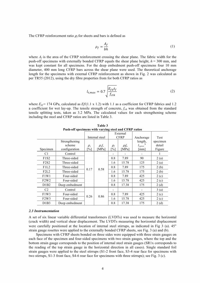
built structures (0.26%). The concrete compressive strength was 50 MPa at 28 days with tensile strength 3.2 MPa for both types, considered as normal strength concrete. A summary of geometric and material properties for both types of test specimens is presented in Table 1.
Table 1
Geometric and material properties of the test specimens
Type Number of
stirrups Spacing
[mm]
Nominal diameter
[mm] ρv
[%] ρvfy
[MPa]
Compressive strengtha
fcu [MPa]
Tensile strengthb
fct [MPa]
Number of specimens
I 2 200 6.5 0.17 0.58 50 3.2 8 II 3 100 6.5 0.26 0.85 50 3.2 4
2.2 Fabrication of test specimens
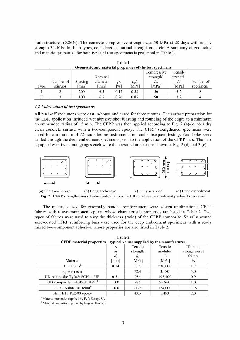
All push-off specimens were cast in-house and cured for three months. The surface preparation for the EBR application included wet abrasive shot blasting and rounding of the edges to a minimum recommended radius of 15 mm. The CFRP was then applied according to Fig. 2 (a)-(c) to a dry clean concrete surface with a two-component epoxy. The CFRP strengthened specimens were cured for a minimum of 72 hours before instrumentation and subsequent testing. Four holes were drilled through the deep embedment specimens prior to the application of the CFRP bars. The bars equipped with two strain gauges each were then resined in place, as shown in Fig. 2 (d) and 3 (c).
! ! ! !(a) Short anchorage (b) Long anchorage (c) Fully wrapped (d) Deep embedment Fig. 2 CFRP strengthening scheme configurations for EBR and deep embedment push-off specimens
!The materials used for externally bonded reinforcement were woven unidirectional CFRP
fabrics with a two-component epoxy, whose characteristic properties are listed in Table 2. Two types of fabrics were used to vary the thickness (ratio) of the CFRP composite. Spirally wound sand-coated CFRP reinforcing bars were used for the deep embedment specimens with a ready mixed two-component adhesive, whose properties are also listed in Table 2.
Table 2 CFRP material properties – typical values supplied by the manufacturer
Material
tf or df
[mm]
Tensile strength
ffu [MPa]
Tensile modulus
Ef [MPa]
Ultimate elongation at
failure [%]
Dry fibresa 0.14 3790 230,000 1.7 Epoxy-resina - 72.4 3,180 5.0
UD composite Tyfo® SCH-11UPa 0.51 986 105,400 0.9 UD composite Tyfo® SCH-41a 1.00 986 95,860 1.0
CFRP Aslan 201 rebarb 10.0 2173 124,000 1.75 Hilti HIT-RE500 epoxy - 43.5 1,493 2.0
a Material properties supplied by Fyfe Europe SA b Material properties supplied by Hughes Brothers
250
mm
ov
erla
p
! 4
The CFRP reinforcement ratio ρf for sheets and bars is defined as
!! =!!!ℎ (1)
where Af is the area of the CFRP reinforcement crossing the shear plane. The fabric width for the push-off specimens with externally bonded CFRP equals the shear plane height, h = 300 mm, and was kept constant for all specimens. For the deep embedment push-off specimens four 10 mm diameter, 400 mm long CFRP bars across the shear plane were used. The theoretical anchorage length for the specimens with external CFRP reinforcement as shown in Fig. 2 was calculated as per TR55 (2012), using the dry fibre properties from for both CFRP ratios as
!!,!"# = 0.7 !!"!!!!"# (2)
where Efd = 174 GPa, calculated as Ef/(1.1 x 1.2) with 1.1 as a coefficient for CFRP fabrics and 1.2 a coefficient for wet lay-up. The tensile strength of concrete, fctk was obtained from the standard tensile splitting tests, taken as 3.2 MPa. The calculated values for each strengthening scheme including the steel and CFRP ratios are listed in Table 3. !
Table 3 Push-off specimens with varying steel and CFRP ratios
Internal steel
External CFRP Anchorage
length, lt,prov
b
[mm]
Test specimen
detail Figure Specimen
Strengthening scheme
configuration ρv
[%] ρvfy
[MPa] ρf
[%] ρffu
[MPa] C1 Control
0.17 0.58
- - - 1 F1S2 Three-sided 0.8 7.89 90 2 (a) F2S2 Three-sided 1.6 15.78 125 2 (a) F1L2 Three-sided 0.8 7.89 175 2 (b) F2L2 Three-sided 1.6 15.78 175 2 (b) F1W1 Four-sided 0.8 7.89 425 2 (c) F2W2 Four-sided 1.6 15.78 425 2 (c) D1B2 Deep embedment 0.8 17.38 175 2 (d)
C2 Control
0.26 0.86
- - 3 (a) F1W3 Four-sided 0.8 7.89 425 2 (c) F2W3 Four-sided 1.6 15.78 425 2 (c) D1B3 Deep embedment 0.8 17.38 175 2 (d)
2.3 Instrumentation
A set of six linear variable differential transformers (LVDTs) was used to measure the horizontal (crack width) and vertical shear displacement. The LVDTs measuring the horizontal displacement were carefully positioned at the location of internal steel stirrups, as indicated in Fig 3 (a). 45° strain gauge rosettes were applied to the externally bonded CFRP sheets, see Fig. 3 (a) and (b).
Specimens with CFRP sheets bonded on three sides were equipped with three strain gauges on each face of the specimen and four-sided specimens with two strain gauges, where the top and the bottom strain gauge corresponds to the position of internal steel strain gauges (SR1x corresponds to the reading of the top strain gauge in the horizontal direction in all cases). Single standard foil strain gauges were applied to the steel stirrups (S1-2 front face, S3-4 rear face for specimens with two stirrups, S1-3 front face, S4-6 rear face for specimens with three stirrups); see Fig. 3 (c).

! 5
The CFRP bars were also equipped with strain gauges, where each bar was strain gauged with two unidirectional strain gauges on the opposing sides of the bars, see Fig. 3 (c) for details.
! ! !(a) Push-off specimen Type A, B
Unidirectional CFRP @ 0° (b) Push-off specimen Type C
Unidirectional CFRP @ 0° (c) Push-off specimen Type D
CFRP bars 10 mm dia @ 100 mm c/c Fig. 3 Strain gauge positioning for CFRP strengthened push-off specimens
2.4 Test set-up and testing procedure
All specimens were tested under axial compression in order to promote direct shear across the shear plane using a 200t hydraulic test rig. The specimens were loaded monotonically under a displacement rate 0.2 mm/min until failure. To apply an axially concentric load and minimize potential eccentricity or undesirable failure modes, a steel plate was inserted at the top and the bottom surface of the specimen to center the load as shown in Fig. 3. The plates were 150 mm wide, 15 mm thick and 250 mm long, carefully positioned before testing. The displacement was applied through the top plate of the machine, which was free to rotate to level the loading.
3 Results and discussion
3.1 Failure modes
All test specimens failed in shear as intended. The specimens with externally bonded CFRP sheets with short anchorage (F1S2 and F2S2) failed prematurely due to concrete cover separation as shown in Fig. 4 (a).
! ! ! !lt,prov = lt,max
(a) Cover separation lt,prov > lt,max
(b) IC debonding failure lt,prov > lt,max
(c) IC debonding failure
(d) Concrete spalling Fig. 4 Typical failure modes for specimens strengthened with CFRP
The specimens with long anchorage length (F1L2 and F2L2), where lt,prov > lt,max, failed due to intermediate crack (IC) debonding failure, where the CFRP sheet debonded from the concrete surface, Fig. 4 (b) and (c). Some degree of interlayer delamination was observed in the overlapping
SF1 SF2 SF4 SF3
Front! Side
S1-4 S2-5 S3-6
P
P
T1 T2 T3 T4
T5
T6
SR1-3 SR2-4
SR1-4 SR2-5 SR3-6

! 6
ends of the four-sided wrapping schemes (F1W2, F2W2, F1W3 and F2W3). Fig. 4 (d) illustrates the failure mode observed for deep embedment specimens (D1B2 and D2B3), which exhibited a brittle shear failure with concrete spalling across the shear plane due to transverse compressive forces. The measured slip of the CFRP bars was 0.3 mm in all cases and the possibility exists that the positioning of lead wires from the strain gauges caused premature debonding of the bars in one of the segments of the specimen. The bonded bar length in the other segment was however unaffected and the bars were fully bonded to the concrete when extracted after testing.
3.2 Shear stress – shear displacement and crack width relationship
Shear failure in concrete is in fact a sliding failure and occurs when the shear stress exceeds the sliding resistance of the section. The contributions to this sliding resistance can be determined as a sum of cohesion, a portion of internal steel-concrete interaction and that of CFRP-concrete. However, due to the nature of the shear-compression testing procedure separation failure across the shear plane coexisted when the tensile concrete strength was reached. The specimens were divided in four groups based on the strengthening scheme used and the internal steel ratio for comparison of structural behaviour of these elements. Fig. 5 shows the experimental shear stress vs. shear displacement and crack width curves for specimens with two internal steel stirrups (0.17%) using 0.8% externally bonded CFRP sheets with short anchorage (F1S2), long anchorage (F1L2) and fully wrapped (F1W2) in contrast to the unstrengthened control specimen (C1).
Fig. 5 Internal steel 0.17%: EBR CFRP 0.8%
Similarly, Fig. 6 shows the experimental shear stress vs. shear displacement and crack width curves for specimens with two internal steel stirrups (0.17%) using 1.6% externally bonded CFRP sheets with short anchorage (F2S2), long anchorage (F2L2) and fully wrapped (F2W2) in contrast to the unstrengthened control specimen (C1).
The ultimate shear capacity of the uncracked push-off specimens is highly variable and dependent on the anchorage length provided. The specimens with short anchorage length (F1S2 and F2S2) failed prematurely due to the early debonding of CFRP sheets when cracks in concrete were propagating from the failure plane towards the free ends of the CFRP sheets, resulting in a brittle failure. Specimens with long anchorage length (F1L2 and F2L2) transferred the shear stress across the shear plane until the bond between the CFRP sheets and concrete was reduced by crack propagation in the surface layer of the concrete. The tests with various wrapping schemes showed that only a small increase in shear friction capacity can be developed for a four-sided scheme compared to a three-sided scheme, exhibiting a 17% increase for specimens with 0.8% of CFRP ratio and 8% increase for 1.6% of CFRP ratio compared to the same percentages of CFRP using long anchorage length (lt,prov > lt,max).
2"
4"
6"
8"
10"
12"
0" 1" 2" 3" 4" 5" 6"
Shear&stress&[MPa
]&
Shear&displacement&[mm]&
2"
4"
6"
8"
10"
12"
0" 0.5" 1" 1.5" 2"Crack&width&[mm]&
C1"
F1S2"
F1L2"
F1W2"

! 7
!
Fig. 6 Internal steel 0.17%: EBR CFRP 1.6%
Fig. 7 shows the experimental shear stress vs. shear displacement and crack width curves for specimens with three internal steel stirrups (0.26%) fully wrapped with CFRP sheets, 0.8% (F1W3) and 1.6% (F2W3) CFRP ratio. The similarity in structural behaviour for both CFRP ratios suggests that a limiting shear friction capacity must exist, which can be achieved through the interfacial bond between concrete and CFRP sheets.
Fig. 7 Internal steel 0.26%: CFRP 0.8% and 1.6%
In general for crack widths exceeding 0.1 mm in the case of unstrengthened control specimens (C1 and C2), the contribution of tensile concrete capacity reduces to zero, manifested by the drop in load and subsequent steady increase in shear friction capacity until failure. The shear transfer at this point is through residual concrete shear resistance and that contributed by the yielding internal steel reinforcement.
The deep embedment specimens (D1B2 and D1B3) were compared with the specimens strengthened with externally applied CFRP sheets with long anchorage (F1L2 and F2L2), see Fig. 8. The test results showed that the DE strengthening scheme offers an equivalent increase in shear capacity for reinforced concrete specimens to the three-sided EBR push-off specimens, regardless of the CFRP and steel ratios. This is an important finding as the deep embedment solution represents a viable alternative to the EBR for cases where the web of a beam is not fully accessible.
!
2"
4"
6"
8"
10"
12"
0" 1" 2" 3" 4" 5" 6"
Shear&stress&[MPa
]&
Shear&displacement&[mm]&
2"
4"
6"
8"
10"
12"
0" 0.5" 1" 1.5" 2"Crack&width&[mm]&
C1"
F2S2"
F2L2"
F2W2"
2"
4"
6"
8"
10"
12"
0" 1" 2" 3" 4" 5" 6"
Shear&stress&[MPa
]&
Shear&displacement&[mm]&
2"
4"
6"
8"
10"
12"
0" 0.5" 1" 1.5" 2"Crack&width&[mm]&
C2"
F1W3"
F2W3"

! 8
Fig. 8 Deep embedment vs. EBR CFRP three-sided with long anchorage
3.3 Strain profiles from unstrengthened and deep embedment specimens
The longitudinal strains were measured on all steel and CFRP bars, generally exhibiting within each specimen similar strain levels in all cases. Therefore representative strain profiles in steel stirrups and CFRP bars are presented in Fig. 9. The yield point of the mild steel, 1600 microstrain (indicated by a vertical line in all graphs), was reached in all four specimens at peak load. The strains in the CFRP bars were developing at the same rate as those in steel, suggesting that internal CFRP reinforcement behaves in the same manner as internal steel reinforcement. Once the bond between the CFRP bars and the concrete was lost, slip occurred and the specimen failed.
(a) Stirrup strain profile (b) CFRP strain profile
Fig. 9 Deep embedment: shear stress vs. stirrup and CFRP strain profiles
3.4 Strain profiles from EBR three-sided specimens
Fig. 10 shows representative readings of strain levels obtained from the steel stirrups and CFRP sheets in the horizontal direction. The specimens with short anchorage length (F1S2 and F2S2) failed before the yield strength of the internal steel was reached. The experimental behaviour of these specimens suggests that the possibility exists that the concrete reached some limiting shear capacity and this is being discussed further in section 3.6.
The debonding of the CFRP sheets is indicated through the reversed strain readings shown in Fig. 10 (b). The specimens with long anchorage (F1L2 and F2L2) developed strains in steel up to the yield point and failed shortly thereafter. The strain in the CFRP reached similar values to that of
2"
4"
6"
8"
10"
12"
0" 1" 2" 3" 4" 5" 6"
Shear&stress&[MPa
]&
Shear&displacement&[mm]&
2"
4"
6"
8"
10"
12"
0" 0.5" 1" 1.5" 2"Crack&width&[mm]&
F1L2"
F2L2"
D1B2"
D1B3"
2"
4"
6"
8"
10"
12"
0" 1000" 2000" 3000" 4000" 5000" 6000"
Shear&stress&[MPa
]&
Microstrain&[1]&
C1"(S4)"
C2"(S5)"
D1B2"(S4)"
D1B3"(S3)"
steel"yields"2"
4"
6"
8"
10"
12"
0" 1000" 2000" 3000" 4000" 5000" 6000"Microstrain*[,]*
D1B2"(SF1a)"
D1B2"(SF2a)"
D1B3"(SF1a)"
D1B3"(SF2a)"
steel"yields"

! 9
steel, suggesting that the normal clamping stress in the section provided by the CFRP delays crack opening and hence the steel yielding. The average crack opening in these specimens was 0.2 mm (short anchorage) and 0.5 mm (long anchorage) at failure, compared to 0.8 mm for the unstrengthened control specimen.
(a) Stirrup strain profile (b) CFRP strain profile
Fig. 10 EBR three-sided scheme: shear stress vs. stirrup and CFRP strain profiles
3.5 Strain profiles from EBR fully wrapped specimens
Representative strain profiles from the internal steel stirrups and fully wrapped CFRP specimens are shown in Fig. 11. Similar to the specimens with long anchorage length (F1L2 and F2L2), the internal steel reached its yield point before the failure occurred. A slower increase in strain was observed for specimens with three internal stirrups (F1W3 and F2W3). Strain levels in externally bonded CFRP sheets reached similar values at failure, suggesting the shear friction capacity in fully wrapped reinforced concrete push-off specimens is independent of internal steel as well as CFRP ratios. In summary, a limiting shear friction capacity must exist with regard to the limiting bond strength between the CFRP sheets and concrete.
(a) Stirrup strain profile (b) CFRP strain profile
Fig. 11 EBR four-sided scheme: shear stress vs. stirrup and CFRP strain profiles
2"
4"
6"
8"
10"
12"
0" 1000" 2000" 3000" 4000" 5000" 6000"
Shear&stress&[MPa
]&
Microstrain&[1]&
F1S2"(S3)"
F2S2"(S1)"
F1L2"(S4)"
F2L2"(S3)"
steel"yields"2"
4"
6"
8"
10"
12"
0" 1000" 2000" 3000" 4000" 5000" 6000"Microstrain*[,]*
F1S2"(SR1x)"
F2S2"(SR1x)"
F1L2"(SR6x)"
F2L2"(SR4x)"
steel"yields"
2"
4"
6"
8"
10"
12"
0" 1000" 2000" 3000" 4000" 5000" 6000"
Shear&stress&[MPa
]&
Microstrain&[1]&
F1W2"(S3)"
F2W2"(S3)"
F1W3"(S1)"
F2W3"(S1)"
steel"yields"2"
4"
6"
8"
10"
12"
0" 1000" 2000" 3000" 4000" 5000" 6000"Microstrain*[,]*
F1W2"(SR3x)"
F2W2"(SR4x)"
F1W3"(SR1x)"
F2W3"(SR1x)"
steel"yields"

! 10
3.6 Shear-friction capacity of reinforced concrete with externally bonded CFRP sheets
The presented experimental results show that the specimens fail in two successive stages: 1) the shear stress is controlled by the concrete alone until the concrete tensile strength is reached and 2) the additional imposed shear stress is resisted by the steel-concrete and CFRP-concrete interaction, where the steel and the CFRP acts as a clamping force in the horizontal direction, resulting in additional aggregate interlock until cohesive concrete failure and bond failure of the CFRP composite occurs. Based on the currently accepted shear friction approach, a simple model is proposed to calculate the ultimate shear friction capacity of the specimen with CFRP reinforcement
!! = !!! + !! + !! ! (3) The individual components of Eq. (3) assume the ultimate shear capacity vu of a steel reinforced concrete section strengthened with CFRP materials as the sum of the shear friction capacity of the concrete vc, a portion of the shear friction capacity contributed by the steel-concrete interaction vs and that of CFRP-concrete vf. The equation therefore can be rewritten in the form
!! = !!"! + !!!!! + !!!!!!!! (4) where the first two terms were determined experimentally by Mattock in 2001: 1) the concrete shear friction strength with A as a bond factor (0.117), 2) the second term implies that steel-concrete interaction depends on the yield strength and amount of reinforcement with B as a shear friction coefficient (0.8) and the final term of Eq. (4) is the equivalent of the CFRP-concrete contribution to the overall shear strength of the section, with the C factor determined experimentally on CFRP-strengthened plain concrete specimens by Saenz and Pantelides (2005).
The equation then reads
!! = !0.117!! + 0.8!!!! + 0.505!!!!!!! (5) In order to take into account the effects of varying anchorage length, a shear friction reduction coefficient cf is introduced. Based on the geometry of the specimen and the bond length provided in this experimental study the coefficients are 0.514 for 0.8% CFRP ratio with short anchorage (F1S2), 0.714 for 1.6% ratio CFRP with short anchorage (F2S2), and 1.0 for long anchorage and fully wrapped specimens, see Table 4. The shear friction reduction coefficient can be calculated from
!! =!!,!"#$!!,!"#
≤ 1.0! (6)
For the fully wrapped specimens the shear reduction coefficient cf may be assumed as 1.0, since only a small amount of shear friction capacity increase is possible beyond the long anchorage length. Based on the experimental results presented in this paper, the proposed limiting shear friction contribution by the externally bonded CFRP can be expressed as
!!,!"# = !0.112!! ! (7)
3.7 Shear-friction capacity of reinforced concrete with deep embedded CFRP bars
The shear friction capacity of reinforced concrete specimens strengthened with CFRP bars can be generally expressed using Eq. (3). The first two terms of Eq. (8) remain the same as in the previous case with the final term of the equation adjusted according to the effective strain levels in the CFRP bars and was determined using the experimental data from this study. The factor 0.245 takes into

! 11
account the fraction of the CFRP-concrete interaction for deep embedded bars. This is much lower than the shear friction coefficient for steel (0.8) or externally bonded CFRP sheets (0.505) purely because the ultimate tensile force in the CFRP bars fu is much higher than that of CFRP composite sheets. However, the bond between the concrete and the CFRP bars is generally better than for externally bonded CFRP sheets or smooth internal steel.
!! = !0.117!! + 0.8!!!! + 0.245!!!! (8) Table 4 summarizes the experimental results and compares these to the theoretical values using the proposed shear friction model for CFRP-strengthened steel reinforced concrete. The agreement between experimental and theoretical values for the three-sided wrapping schemes with both short and long anchorage length is good.
Table 4 Summary of results for push-off Type I and II specimens
Experimental values Theoretical values
Specimen Type
CFRP ratio ρf
[%]
Failure load Vu
[kN]
Shear stress
vu [MPa]
CFRP strain at failure εfe
[%]
Shear friction
reduction factor
cf
Shear friction capacity
vcalc [MPa]
!!"#!!!
C1 I 0 411 5.48 - - 5.14 0.94 F1S2 IA 0.8 505 6.73 0.19 0.514 6.73 1.00 F2S2 IA 1.6 591 7.88 0.16 0.714 7.88 1.00 F1L2 IB 0.8 687 9.16 0.24 1.0 9.12 0.99 F2L2 IB 1.6 722 9.63 0.18 1.0 9.63 1.00 F1W2 IC 0.8 756 10.08 0.26 1.0 9.12 0.91 F2W2 IC 1.6 758 10.11 0.21 1.0 9.63 0.95 D1B2 ID 0.8 705 9.40 0.48 - 9.4 1.00
C2 II 0 637 8.49 - - 5.36 0.63 F1W3 IIC 0.8 796 10.61 0.27 1.00 9.34 0.88 F2W3 IIC 1.6 807 10.76 0.18 1.00 9.84 0.91 D1B3 IID 0.8 711 9.48 0.38 - 9.62 1.01
3.8 General behaviour
Mechanical behaviour typical for the unstrengthened reinforced concrete push-off specimens and that of strengthened with externally bonded CFRP sheets are presented in Fig. 12.
Generally, two phases can be observed in Fig. 12 (a) for unstrengthened control specimens. Events 2-3 are negligible for higher internal steel ratios and therefore are only shown for correlation with the experimental data. Event 2 represents the point where microcracks are formed across the shear plane and steel starts to yield once the separation of the shear surfaces exceeds 0.1 mm (Event 3). The shear stress is then resisted by residual steel-concrete friction until failure occurs, at which point the contact between the two shearing planes is lost entirely (Event 4). Some residual shear friction capacity can be observed post-peak, caused by the yielding reinforcement and a residual fraction of the concrete friction capacity (Event 5).
The externally strengthened specimens with varying anchorage length initially followed the same pattern, until Event 2 in Fig. 12 (b). At this point the maximum concrete shear friction capacity was reached at separation 0.1 mm and the shear stress was further resisted by the steel-concrete and CFRP-concrete interaction. The specimens with short anchorage (F1S2 and F2S2) failed prematurely when the shear friction capacity was significantly reduced due to the shorter anchorage length provided, resulting in early debonding of the CFRP sheets.

! 12
(a) Unstrengthened specimens (b) EBR strengthened specimens Fig. 12 Typical response in terms of slip/separation under increasing load (to scale)
The curved response between Events 2 and 3 suggests stretching of the CFRP composite coupled with progressive debonding. When the shear friction capacity in the three-sided specimens with long anchorage length is reached, the CFRP debonds from the concrete surface and the specimen fails. Only in the case of fully wrapped specimens, was Event 4 reached before failure. This is due to the additional anchorage provided through the overlapping ends where the debonding the CFRP laminate is prevented.
4 Conclusions
From the experimental study and theoretical results presented, the following conclusions may be drawn: Reinforced concrete strengthened with CFRP materials behaves like a system and must be treated as such. Isolation of shear forces carried by individual components of CFRP-strengthened reinforced concrete based on experimental readings reflects merely the behaviour of virgin materials and is therefore not representative of the structural behaviour of these elements in shear. A shear friction approach for prediction of the ultimate shear friction capacity of CFRP-strengthened reinforced concrete seems appropriate at this point and the theoretical values are in good agreement with the experimental data. However, since reinforced concrete members exhibit a strong size effect, a more robust mechanics based solution is required taking into account the effects of debonding, regardless of the size of the structure. A fracture mechanics approach is suggested for accurate description of the CFRP-concrete interaction. The concrete represents the weakest link in the test specimens, and controls the shear friction capacity in both strengthened and unstrengthened control specimens. The additional CFRP reinforcement – internal or external – contributes to the shear friction capacity by acting as a horizontal clamping force, which induces additional aggregate interlock until cohesive failure and bond failure of the CFRP materials occurs. The increase in shear strength due to the application of CFRP bars is comparable to that achieved with externally bonded CFRP sheets on three sides using long anchorage. Therefore the deep embedment technique can be a viable alternative to the externally bonded CFRP sheets in less accessible areas. Minimum increase in shear strength is possible for four-sided EBR schemes compared to the three-sided schemes with long anchorage length. This is because in theory no increase in shear capacity can be achieved beyond the long anchorage length.
Idealized(two(stirrups Idealized(three(stirrupsx y 0 0 0 0
1 0 0.522 0.167 0.522 0.1671 12 1.392 3.68128 0.919 3.945
1.474 3.2889 0.935 3.931.963 5.3668 2.23 8.42.116 1.126442.458 1.12644
2(
4(
6(
8(
10(
12(
0( 1( 2( 3( 4( 5( 6(
Shear&stress,&ν&
Shear&displacement,&δ&
2
2(
4(
6(
8(
10(
12(
0( 1( 2( 3( 4( 5( 6(Shear&displacement,&δ&
2 2
0(
1(
2(
3(
4(
5(
6(
0( 0.5( 1( 1.5( 2( 2.5( 3(
Idealized&
Idealized(
9(
10(
1: Establishment of firm contact
3
4: Loss of aggregate interlock and subsequent dowel action
5: Residual shear strength
Stiffness increases with increasing reinforcement parameter
I II
1: Establishment of firm contact
4: Loss of integrity of the system due to CFRP debonding
3: Debonded
Premature failure due to CFRP debonding
Short anchorage
Long anchorage
Fully wrapped
Idealized
Actual
Idealized
Actual
I II III

! 13
Acknowledgements
The authors gratefully acknowledge the help of the laboratory staff of University of Bath and the financial support of the Engineering and Physical Research Council (EPSRC EP/I018921/1) and the project partners and sponsors, namely the University of Cambridge, Parsons Brinckerhoff, Tony GEE Consultants, Ove Arup & Partners Ltd, LG Mouchel and Partners, Highways Agency, Concrete Repairs Ltd, The Concrete Society, Fyfe Europe S.A., Fibrwrap UK and Hughes Brothers.
References!Birkeland, P. W, Birkeland, H. W. (1966), Connections in precast concrete construction. ACI
Journal, 63 (3), 345-368. British Standards Institution, BS EN 1992-1-1:2004 (2004), Design of concrete structures. General
rules and rules for buildings. British Standards Institution, London. British Standards Institution, Code of Practice CP 114:1969 (1969), The Structural Use of
Reinforced Concrete in Buildings. British Standards Institution, London. Concrete Society Technical Report 55, (2012) Design Guidance for Strengthening Concrete
Structures using Fibre Composite Materials, 2nd Edition, The Concrete Society, Crowthorne, London.
Grusova, M., Ibell, T. J., Darby, A. P., Evernden, M. (2013b), Experimentally observed behaviour of CFRP sheet strengthening across a shear plane; presented at the 11th International Symposium on Fibre Reinforced Polymers for Reinforced Concrete Structures (FRPRCS-11), Guimarães, Portugal, June 26-28, 2013.
Hofbeck, J., Ibrahim, I. and Mattock, A. (1969) Shear Transfer in Reinforced Concrete. ACI Journal, 66(2), 119-128.
Ibell, T. J., Burgoyne, C. (1998), The shear strength of concrete containing fibre-reinforced-plastic (FRP) reinforcement, Proceedings of the 23rd Conference on our World in Concrete and Structures, Singapore, pp. 77-82.
Mattock, A. H. (2001), Shear friction and high-strength concrete. ACI Journal, 98(1), 50-59. Saenz, N. and Pantelides, C. P. (2005), Shear Friction Capacity of Concrete with External Carbon
FRP Strips. ASCE Journal of Structural Engineering, 131(12), 1911-1919. Walraven, J. C. (1981), Fundamental Analysis of Aggregate Interlock. Journal of the Structural
Division, 107(11), 2245 – 2270.


