Embed Size (px)
Citation preview

Available online at www.sciencedirect.com
Corrosion Science 49 (2007) 4504–4522
www.elsevier.com/locate/corsci
Mechanism of electrochemical chloride removal
B. Elsener *, U. Angst
ETH Zurich, Institute for Building Materials (IfB), ETH Honggerberg, CH-8093 Zurich, Switzerland
Received 19 February 2007; accepted 3 May 2007Available online 24 June 2007
Abstract
This paper presents the first laboratory results obtained from continuous monitoring of the freechloride content in concrete blocks during electrochemical chloride removal (ECR). Chloride sensi-tive electrodes have been embedded at different depths in concrete specimens and the free chlorideconcentration was measured during ECR. The total chloride content was determined prior to andafter the electrochemical treatment. Time and space resolved data on the removal of chloride ionsand information concerning the relationship between bound and free chloride was obtained. Dueto the removal of free chloride during the treatment, bound chloride is dissolved in order to re-estab-lish the equilibrium between bound and free chlorides. The rate of release of bound chloride is slowcompared to the rate of chloride removal and thus the ECR process quickly becomes inefficient. Cur-rent off periods allow the system to re-establish the equilibrium between bound and free chlorides.Subsequently, the process is efficient again. The results are discussed with respect to treatmentefficiency, treatment procedure and current distribution. It is concluded that the ECR process is cur-rently applied in an inefficient manner and the charge required for the desalination can be reducedsignificantly. This is also of interest with regard to the risk of undesirable side-effects that currentlylimit the use of ECR.� 2007 Elsevier Ltd. All rights reserved.
Keywords: A. Reinforced concrete; B. Galvanostatic; B. Polarization; C. Repassivation
1. Introduction
Corrosion of reinforcing steel due to exposure to chloride leads to degradation of steel-reinforced concrete structures. The conventional way of restoration of reinforced concrete
0010-938X/$ - see front matter � 2007 Elsevier Ltd. All rights reserved.
doi:10.1016/j.corsci.2007.05.019
* Corresponding author. Tel.: +41 44 6337291; fax: +41 44 6331147.E-mail address: [email protected] (B. Elsener).
B. Elsener, U. Angst / Corrosion Science 49 (2007) 4504–4522 4505
structures consists of removing the outer chloride-containing concrete zone and replacingthe old concrete by a new, alkaline mortar or concrete. It affects the environment (noise,dust, concrete waste, etc.), is time-consuming and causes very high direct costs (repairwork and material) as well as indirect costs (traffic jam, waiting times, etc.). Alternativenon-destructive techniques such as electrochemical chloride removal (ECR) have thusbeen developed and applied [1,2]. ECR has proven to be a durable, nearly non-destructiveand cost effective rehabilitation technique for reinforced concrete structures [3,4]. Undesir-able side-effects such as high current densities (and associated very negative potentials),hydrogen evolution, the risk of alkali–silica reaction for some type of aggregates andthe risk of increased porosity of the concrete near the interface limit the use of ECR inpractice [2,3,5].
An attempt to reduce the risk of side-effects recently reported is based on a ‘‘pushingaway concept’’ that does not aim at a complete desalination but push the chlorides awayfrom the reinforcement and ensure that no corrosion will occur within a certain period[6,7]. In this way, the applied charge can be reduced, but it is questionable how accuratelythe redistribution of chlorides in the concrete can be assessed.
Presently, the process of chloride removal during the electrochemical treatment isunderstood only in a global way, based on the concept of transference numbers in a migra-tion process [3,8]. It is well known and documented in literature that at longer treatmenttimes the chloride removal efficiency strongly decreases. As a consequence of the decliningchloride concentration in the pore solution and the generation of hydroxide ions by thecathodic reaction, the chloride transference number decreases and thus the chlorideremoval process is slowed down [1,2,9–12]. In the early work by one of the authors indi-cations of a chemical equilibrium between bound and free chlorides were shown [2,9]. Oth-ers have supported this idea and included it as a factor in proposed models [13,14]. Fromthe results of the modelling, the authors concluded that it is impossible to reach completedesalination in one step. From a certain point in time, the chloride transference number istoo low and no relevant amount of current is carried by chloride ions [13].
In another work [14], a mathematical model for ECR has been proposed which incor-porates a term describing the rate of release of bound chloride. It is based upon theassumption that the rate of dissolution of bound chloride is slow compared to the rateof free chloride extraction. Thus, the dissolution of bound chloride dominates the processand leads to an inefficient electrochemical treatment [14]. This agrees with a field studywhere increased chloride removal efficiency after an interruption of the current for a longerperiod was found [2].
It can reasonably be assumed that mainly the free chloride is removed by an ECR treat-ment. Precise time and space resolved data on the chloride removal process is lacking. It isbelieved that the ECR process is presently operated in an inefficient manner and the chargerequired for the desalination can be reduced significantly. Ion migration, specifically chlo-ride migration in concrete, is crucial for the understanding and prediction of the ECRprocess. So far, results were based on a comparison of chloride profiles in the concreteprior to and after the treatment. The combined chloride and resistivity sensor [15] devel-oped and tested at IfB (ETH Zurich) makes it possible to follow in situ the movement ofthe free chloride ions. By placing these sensors at different depths in the concrete, the freechloride profiles can be monitored continuously. In this study, the chloride and resistivitysensors were applied for the first time to monitor the free chloride ions during an ECRtreatment (in part published in [16]).

4506 B. Elsener, U. Angst / Corrosion Science 49 (2007) 4504–4522
2. Experimental
2.1. Concrete specimens
For the chloride removal experiments two concrete blocks prepared in an earlier work[17] for chloride uptake experiments were used. One of the specimens had a w/c ratio of0.50 (to which will be referred to as S-05) and the other one 0.60 (to which will be referredto as S-06). The mix design and total porosity is given in Table 1. The specimens had beencast and then cured for three weeks at 100% relative humidity. After drying, two chlorideuptake cycles had been performed with both specimens. For the first cycle, a 0.5 molarsolution of sodium chloride had been used; for the second cycle, the specimens had beensubmerged in a 2 molar solution of sodium chloride. At the time of this study, the spec-imens had been stored in the laboratory for seven years.
The two concrete blocks were identical in size, 320 · 245 · 70 mm; the reinforcementand sensor details are shown in Fig. 1. One layer of stainless steel reinforcement had beenembedded at a depth of 55 and 45 mm, respectively. In each block, combined free chlorideand resistivity sensors [15,17] had been embedded at a cover depth of 5–45 mm (Fig. 1).
2.2. Chloride and resistivity sensors
This laboratory study on the mechanism of electrochemical chloride removal was possi-ble only thanks to the availability of combined sensors for the free chloride content and theresistivity [15] developed at IfB (Fig. 2). Basically, these sensors consist of an ion-selectiveelectrode (silver wire coated with AgCl) in an isolating Teflon tube mounted in a 60 mmlong stainless steel tube. About 20 mm of active electrode surface is in contact with the con-crete. The chloride sensors allow the determination of the free chloride content in the poresolution of concrete. Actually, the potential difference between the chloride sensor and areference electrode is measured and converted to free chloride concentration (activity, to
Table 1Mix proportion (kg/m3) and porosity of the concrete blocks
w/c Water Cement Aggregate Density Porosity (%)
0.50 170 340 1860 2355 13.30.60 182 303 1860 2345 14.0
Fig. 1. Cross section of instrumented concrete block (dimensions mm).

Fig. 2. Combined chloride and resistivity sensor developed at IfB.
B. Elsener, U. Angst / Corrosion Science 49 (2007) 4504–4522 4507
be precise). The sensors have been calibrated in simulated pore solutions [17]. A lineardependence on the logarithm of chloride concentration according to Nernst law was found;the calibration equation at room temperature is E = �7 � 54· logcCl� (mV vs SCE) withgood linearity in the range from 0.01 to 2 mole/l chloride concentration [15,17].
The stainless steel tubes allow the measurement of the concrete resistance between twosensors. The results can then be converted to resistivity; for comparison only, the measure-ment of ohmic resistance is sufficient.
2.3. Electrochemical chloride removal and measurements
Prior to the ECR treatment the specimens were placed with the bottom side in tap waterto adsorb water for three weeks. During the water ingress, both the chloride concentrationsand the ohmic concrete resistance were measured by use of the chloride/resistivity sensors.After the water uptake, two cores (diameter 25 mm) were taken from each specimen, cutinto slices and powdered in order to determine the total chloride content (acid solublechloride).
Electrochemical chloride removal requires an external anode in an electrolyte at the con-crete surface and a DC power source. For the ECR treatment the concrete blocks were placedvertically as depicted in Fig. 3. In this study, the anode system consisted of a perforated stain-less steel plate embedded in two layers of foam plastic of about 1 cm thickness each. A plexi-glass plate was used to fix the foam layers and the anode on the specimens. At the upper sideof the foam plastic, a sprinkling hose delivered tap water in order to keep the foam plasticcontinuously wet; the electrolyte was ordinary tap water. The water trickled out of the systemat the lower side and was collected and drained in a plastic basin. As cathode the four parallelstainless steel bars at a depth of 45 mm in the specimen (Fig. 1) were used. The current densityapplied was 2 A/m2 related to the rebar area (0.0246 m2), resulting in a total current of49.2 mA. This corresponds to a current of 0.63 A/m2 related to the concrete area. The currentwas held constant by the DC power source. More details are given in [18].
The ECR treatment was performed in a discontinuous manner: current on for 7 days,followed by an off period of 12 days, again electrochemical treatment for 4 days, followedby an off period of 3 days and switched on again for 7 days. The schedule of the electro-chemical treatment is shown in Table 2.
The potentials of the chloride sensors were measured daily and then converted by use of thecalibration equation to free chloride content. For the measurements, the current was inter-

Fig. 3. Set-up for the electrochemical treatment.
Table 2Schedule of the electrochemical chloride extraction
Period Duration (days) Current Chargea (Ah/m2) Cumulative chargea (Ah/m2)
Part I 7 On 336 336Off period 12 Off – 336Part II 4 On 192 528Off period 3 Off – 528Part III 7 On 332 860
a Related to the steel surface.
4508 B. Elsener, U. Angst / Corrosion Science 49 (2007) 4504–4522
rupted for some minutes. Measurements of the ohmic resistance between two adjacent sen-sors and the potentials of the cathodically polarized steel rebars were carried out at the sametime.
After the electrochemical treatment, the specimens were stored in the laboratory for twoyears and then submerged in tap water again. As soon as water saturation was reached –indicated by constant ohmic resistance between the stainless steel tubes of the sensors –the free chloride concentrations were measured once more.
3. Results
3.1. Initial conditions
The total and free chloride concentration profiles before starting the ECR treatment areshown in Fig. 4. The total chloride content varies between 0.45% and 0.95% by mass ofcement in the case of specimen S-05 and between 1.10% and 1.45% by mass of cement

Fig. 4. Initial total and free chloride profiles in the specimens.
B. Elsener, U. Angst / Corrosion Science 49 (2007) 4504–4522 4509
in the case of specimen S-06. The profiles are quite similar: an increasing concentrationfrom the bottom side towards the upper side of the specimens was found. This can beattributed to the fact that during the initial uptake of chloride-containing water theone-dimensional flow of water moved the chloride ions from the lower towards the upperside (where the water evaporated).
3.2. Electrochemical treatment
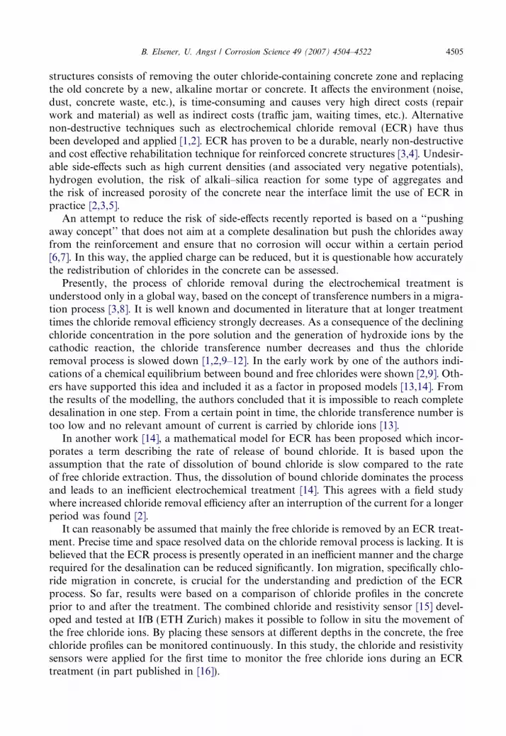
Fig. 5 shows the development of the free chloride concentrations at the sensors duringthe electrochemical desalination. A remarkable increase in free chloride concentration was
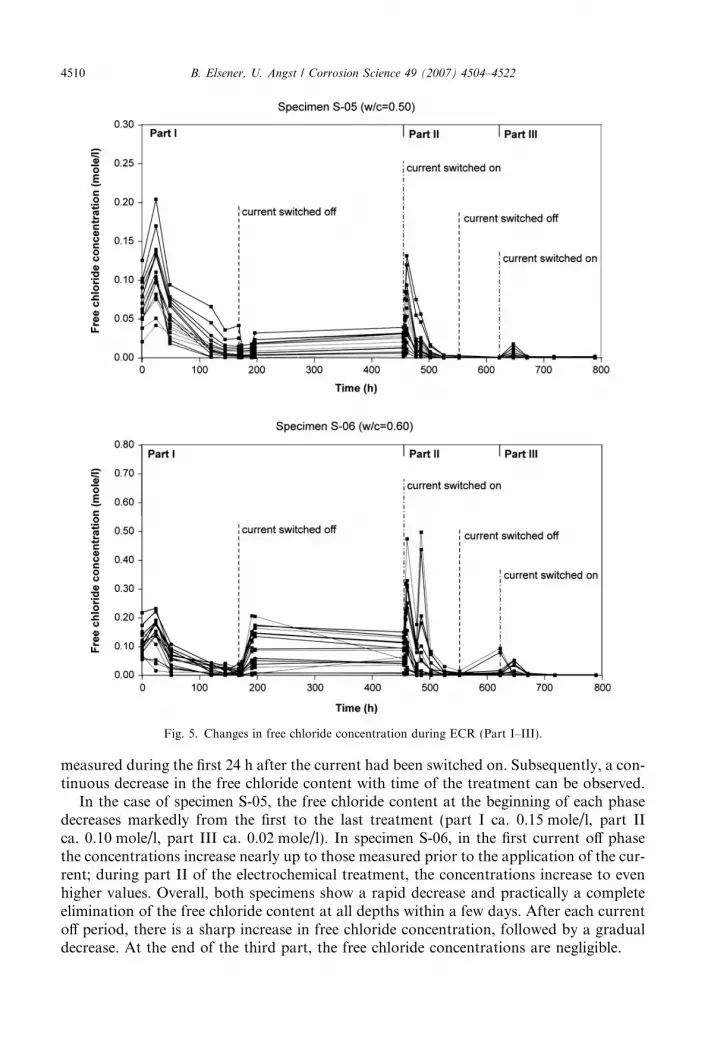
Fig. 5. Changes in free chloride concentration during ECR (Part I–III).
4510 B. Elsener, U. Angst / Corrosion Science 49 (2007) 4504–4522
measured during the first 24 h after the current had been switched on. Subsequently, a con-tinuous decrease in the free chloride content with time of the treatment can be observed.
In the case of specimen S-05, the free chloride content at the beginning of each phasedecreases markedly from the first to the last treatment (part I ca. 0.15 mole/l, part IIca. 0.10 mole/l, part III ca. 0.02 mole/l). In specimen S-06, in the first current off phasethe concentrations increase nearly up to those measured prior to the application of the cur-rent; during part II of the electrochemical treatment, the concentrations increase to evenhigher values. Overall, both specimens show a rapid decrease and practically a completeelimination of the free chloride content at all depths within a few days. After each currentoff period, there is a sharp increase in free chloride concentration, followed by a gradualdecrease. At the end of the third part, the free chloride concentrations are negligible.
B. Elsener, U. Angst / Corrosion Science 49 (2007) 4504–4522 4511
In Fig. 6, the changes in free chloride profiles during part I of the electrochemical treat-ment are depicted. Sensors at the same depth have been averaged (Fig. 1). Aroundt = 50 h, a significant decrease in free chloride content was found at sensors placed at aconcrete cover of 28 mm in both of the specimens. As the corresponding sensors are posi-tioned directly between cathodically polarized rebars and the anode (see cross section inFig. 1), the electric field strength is highest in this area. Thus, chloride ions in this areaare moved by a higher force than those measured at adjacent sensors. As a result, theconcentration locally decreases rapidly which leads to a lower chloride transference num-ber. Towards later stages, the efficiency in this area slows down and chlorides are extracted
Fig. 6. Changes in free chloride profiles during ECR (Part I).

4512 B. Elsener, U. Angst / Corrosion Science 49 (2007) 4504–4522
faster in areas where the concentrations – and thus the transference numbers – are stillhigher. Fig. 6 clearly shows this self-regulating effect of ECR.
3.3. Current off periods
The changes in free chloride content after the current had been switched off for the firsttime are presented in Fig. 7. In both specimens, the concentrations increase within the first24 h and then remain nearly constant. Obviously, bound chloride has been released intothe pore solution and re-established the equilibrium between bound and free chloride –and this to a considerable extent: e.g. in the case of specimen S-06, the chloride concentra-tions were below 0.05 mole/l during the last three days of the electrochemical treatmentpart I (Fig. 5); as soon as the current had been switched off, the chloride concentrationsincreased up to 0.21 mole/l within 24 h (Fig. 7).
Moreover, the shape of the curves of specimen S-05 in Fig. 7 indicates that some time isrequired for the equilibrium between bound and free chlorides to re-establish: only after18 h, a significant increase is observed. In the case of specimen S-06 this seems to occurearlier, but it cannot be verified as time-resolved data in the first 18 h is lacking.
Fig. 8 shows the changes in free chloride profiles during the first current off period. It isstriking that the free chloride concentrations show a pronounced increase at most of thesensors, whereas only a slight increase was measured around a depth of 25–30 mm (the elec-tric field strength was highest at these sensors). Obviously, bound chloride does not dissolvein this area, most probably because a considerable amount has already been removed.
3.4. Chloride content after the electrochemical treatment
The total chloride content obtained from two cores per specimen and the free chlorideconcentrations, as well as the measured values prior to the electrochemical treatment, are
Fig. 7. Changes in free chloride concentration during the first current off period.

Fig. 8. Changes in free chloride profiles during the first current off period.
B. Elsener, U. Angst / Corrosion Science 49 (2007) 4504–4522 4513
shown in Fig. 9. At the end of the ECR treatment, the free chloride concentration wasbelow 0.002 mole/l at all sensors (below the accuracy of the chloride sensors) and thusat negligibly low values. In both specimens, 100% of the free chloride had been extracted.
The total chloride content at the end of the treatment shows profiles similar to the ini-tial chloride content. In both specimens, the total chloride content was around or at leastonly slightly higher than 0.4% by mass of cement after the treatment. In total, after passinga charge of 860 Ah/m2 related to the steel surface, 63% of the initial total chloride contentwas removed in specimen S-05, in specimen S-06 even 69%.

Fig. 9. Total and free chloride profiles before and after the ECR treatment.
4514 B. Elsener, U. Angst / Corrosion Science 49 (2007) 4504–4522
By comparing the profiles of total and free chloride depicted in Fig. 9 it is important totake into account that the cores for analysis of total chloride were taken at a certain loca-tion in the specimen, but the chloride sensors are positioned elsewhere. This is of impor-tance since the position of a measurement with respect to the geometry of the cathodicrebars shows very different values due to inhomogeneous distribution of the electric field.
3.5. Cathode potentials and concrete resistance
The potentials of the cathode (stainless steel rebars) during the electrochemical treat-ment were between �800 and �1100 mV SCE. During the first current off phase, thepotential increased to approximately �400 and �600 mV SCE.

B. Elsener, U. Angst / Corrosion Science 49 (2007) 4504–4522 4515
Due to the sprinkling hose, constantly delivering tap water as electrolyte, the concreteresistance was kept low during the electrochemical treatment. In the current on phases, aslight increase could be noted, whereas the resistance decreased slightly in the current offphases. Since the conductivity of an electrolyte depends on the concentrations (and mobil-ities) of the available ions, the resistance measurements are in line with the chloride con-centrations measured during the ECR treatment.
The resistance of the concrete did not show any sharp decreases during the electrochem-ical treatment, which indicates that no cracks have been formed in the specimens.
Fig. 10. Free chloride after storage in the laboratory for two years.

4516 B. Elsener, U. Angst / Corrosion Science 49 (2007) 4504–4522
3.6. Measurements two years after ECR
After storage of the specimens for two years in the laboratory, the free chloride concen-trations have been measured again. Fig. 10 shows the free chloride profiles measured afterwater saturation of the concrete has been reached. Once more, bound chloride is releasedinto the pore solution, but only to a negligible extent.
4. Discussion
4.1. Bound and free chloride
It is well documented in literature that chloride ions can be present in concrete in theform of chemically bound chloride, physically adsorbed chloride on the pore walls and freechloride in the pore solution [12,19–26]. The degree of chloride binding depends on manyfactors, e.g. the quantity of the tricalcium aluminate phase in the cement (C3A) [12], thepH value of the pore solution [20–22], the cation of the chloride salt [22], etc. Moreover,it is suggested that bound and free chlorides are connected by a chemical equilibrium[23–26]. This relationship can be described by chloride binding isotherms according toFreundlich or Langmuir equations [24,26].
Usually, the free chloride content in the concrete is determined by expression of thepore solution. As this method includes a release of some loosely bound (adsorbed) chlorideunder pressure it leads to an overestimation of the free chloride content [27]. With thechloride sensors used in this work, it was possible to accurately measure the concentrationof the free chloride in the pore solution at different points in time. The total chloride con-tent was determined by acid soluble extraction.
If the volume of the pore solution (p) and the mass of cement (mcem) for a certain con-crete is known, the free chloride concentration Cl�free in mole per litre can be converted intopercent by mass of cement by the following equation:
Cl��free ¼p � 35:45� Cl�free
mcem
� 100 ð%by mass of cementÞ
where Cl��free is the free chloride content in percent by mass of cement and 34.45 is the molarmass of chloride. It is thus possible to compare free chloride concentrations with totalchloride contents and calculate the amount of bound chloride (meaning the sum of chem-ically bound and physically adsorbed chloride).
Fig. 11 shows the proportions of bound and free chloride in the specimens prior to andafter the electrochemical chloride extraction. After the treatment, no free chloride was leftin the concrete. Moreover, a considerable amount of bound chloride had been removed.As can also be seen from Fig. 9, a total chloride content around 0.4% by mass of cementwas found after the ECR treatment. Since no free chloride was left after the treatment, thisequals to bound chloride.
Measurements two years after the ECR treatment have shown that the free chlorideconcentration is still negligible. It appears that a certain amount of bound chloride doesnot dissolve anymore. From Fig. 5 it can be seen that already in the second current offperiod, only few bound chloride was released into the pore solution. A residual chloridecontent can thus not be extracted. This is in line with other studies, where it was foundthat some chlorides are irreversibly bound and can thus not be removed from the concrete

Fig. 11. Proportions of bound and free chloride.
B. Elsener, U. Angst / Corrosion Science 49 (2007) 4504–4522 4517
[12,26]. On the other hand, this residual chloride content does not present a corrosion risk,since only free chloride is considered to initiate corrosion.
4.2. Efficiency and effect of the electric current
It was shown that free chloride is removed at a high efficiency in the beginning (Fig. 5).As soon as the free chloride concentration is low, the current is primarily carried by

4518 B. Elsener, U. Angst / Corrosion Science 49 (2007) 4504–4522
migration of hydroxide ions and the chloride removal runs at a low efficiency. Since boundand free chlorides are connected by a chemical equilibrium, the removal of free chlorideleads to dissolution of bound chloride. If the rate of release of bound chloride is slow com-pared to the rate of removal of free chloride [14], the bound-free relationship is constantlyfar from equilibrium and the efficiency of the electrochemical chloride removal is low. Thefree chloride concentration in the pore solution then remains at very low values and no netchange can be measured at the sensors (Fig. 5).
After the current is switched off, an increase in free chloride concentration is observed(Fig. 7). This is attributed to the release of bound chloride into the pore solution. As canbe seen from Fig. 7 the equilibrium between bound and free chloride is re-established afterca. 24 h; later on, no significant changes in free chloride concentration have been observedduring the current off period.
As soon as the current is switched on again, an increase in free chloride concentration ismeasured (Fig. 5). Also at the very beginning of the electrochemical treatment, a pro-nounced increase in free chloride concentration was observed. It can be postulated that,as soon as the current is switched on, physically adsorbed chloride ions are released dueto interaction of the electric field with the double layer at the pore walls. As a result,the concentration of free chloride measured with the chloride sensors increases and bothfree and (previously) adsorbed chlorides are now available in the pore solution for theextraction process.
The ECR process can thus be understood based on a concept of two linked equilibria(Fig. 12): On the one hand, chemically bound and free chlorides are connected by an equi-librium and on the other hand, there is an equilibrium between free chloride and physicallyadsorbed chloride (considered as weakly bound chloride). It is suggested that under theeffect of an electric current field adsorbed chloride is released, which leads to an increasein free chloride concentration in the pore solution. Due to the electrochemical treatmentthe free chloride is then removed quickly until the process runs at low efficiency (limitedby the slow dissolution of bound chloride). When the current is switched off, the dissolu-tion of chemically bound chloride leads to re-establishing of the equilibrium betweenchemically bound chloride and free chloride. Moreover, part of the dissolved chloride willbe physically adsorbed on the pore walls and by this, the second equilibrium between freeand adsorbed chlorides is re-established as well.
Towards later stages, the efficiency of the ECR treatment is thus limited by the rateof release of bound chloride. Switching the current off for some time allows the system
Fig. 12. Equilibria between bound, adsorbed and free chloride in the ECR process.

B. Elsener, U. Angst / Corrosion Science 49 (2007) 4504–4522 4519
to re-establish the equilibria between chemically bound chloride, physically adsorbed chlo-ride and free chloride. As was found in this work, the ‘‘re-establishing-time’’ required isrelatively short (ca. 24–48 h). In addition, the efficiency of the electrochemical chlorideremoval is limited to a residual amount of bound chloride that does not dissolve and isthus not available for extraction.
In a recent study [12], very similar results have been obtained. The authors applied ECRon cylindrical concrete specimens with different duration of current flow. Total chloride(acid soluble chloride) and free chloride (water soluble chloride) contents were determined.It was also shown that the efficiency of the electrochemical treatment was highest in thebeginning and then slowed down; from a certain point in time the chloride contentremained constant in the specimen (around 0.5% by mass of cement). The free chloridewas almost completely removed, whereas some bound chloride remained in the concrete.The authors suggest that only a part of the bound chloride (considered as the part ofadsorbed chloride) is brought into solution under the effect of the direct current.
Tritthart et al. [28] found that under the influence of the applied current large quantitiesof bound chloride are released into the pore solution and extracted rapidly. However, ithas to be considered that in the concerning study, a very high current was applied(20 A/m2) which is about ten times higher than the current usually applied in ECR. Fur-thermore, the chloride had been added to the concrete mix; this strongly affects the type ofbound chloride in the concrete. It is known from other studies, that changes in the porestructure and alterations of cementitious phases can occur in the concrete due to the appli-cation of a direct current [29–31]. If, at high current densities, considerable decompositionof the cement paste occurs [32], this may significantly contribute to dissolution of boundchloride.
In an earlier study [33], hardened cement specimens had been exposed to a NaCl solu-tion in order to determine the rate of chloride adsorption and then stored in chloride-freewater to determine the rate of chloride release. It was found that there is a significant dif-ference between the speed of chloride uptake and the rate of dissolution of bound chloride.The rate of release of bound chloride can thus be assumed as slow.
4.3. Effect of pH on chloride dissolution
In Fig. 8 the changes in free chloride concentration during the first off period wereshown. Whereas at most of the sensors a considerable increase in free chloride concentra-tion was measured, the concentrations remain nearly constant around a depth of 25–30 mm. As these sensors are positioned directly between a cathodic rebar and the anode,the electric field strength is highest in this area. It can thus be concluded that at these sen-sors, the efficiency is relatively high and the chloride is quickly removed. After part I of theelectrochemical treatment, a high amount of free and bound chloride has been removedand thus, nearly no chloride does dissolve in the current off period.
Another aspect that possibly contributes to this phenomenon is the fact that when theelectrochemical treatment runs inefficiently, i.e. without significant chloride migration, theelectric current is mainly carried by migration of hydroxide ions. As a result of this,hydroxide ions migrate towards the anode to a higher extent in areas where no free chlo-ride is left, as was the case around a depth of 25–30 mm in this study. This leads to a higherpH of the pore solution in this area. In a recent work [20,21], the pH dependency of thesolubility of chloride in concrete has been investigated. The authors found that the soluble

4520 B. Elsener, U. Angst / Corrosion Science 49 (2007) 4504–4522
chloride content increases as the pH decreases. Mainly, there are two steps: a major part ofbound chloride is released as the pore solution pH decreases from values above 12.5 tolower ones; another part of bound chloride is dissolved around pH 12. At lower pH valuesnearly no bound chloride is left in the concrete.
By applying this to our study, it could be postulated that if some areas are more alka-line due to inefficient ECR, bound chloride is not dissolved there. Assuming that the pH ofadjacent regions is lower than 12.5, bound chloride could be released easier and the equi-librium between free and bound chloride is re-established.
5. Conclusions
Electrochemical chloride removal tests were carried out on two chloride contaminatedconcrete specimens instrumented with chloride sensitive electrodes. The ECR process wasmonitored by measuring the free chloride content at depths from 5 to 45 mm in the con-crete cover. The following major conclusions are derived:
1. Bound and free chlorides are connected by a chemical equilibrium. Thus, removing freechloride from the pore solution by the ECR treatment leads to dissolution of chemicallybound chloride. As the rate of release of bound chloride is slow compared to the rate ofchloride removal in the electric current field, the ECR process is inefficient as soon asthe free chloride concentration in the pore solution is low and the bound-free relation-ship is far from equilibrium. After switching the current off for some time, the ECRtreatment can be continued at a much higher efficiency. The current off period allowsthe system to re-establish the equilibrium between bound chloride and free chloride.As was found in this work, the ‘‘re-establishing-time’’ required is relatively short (ca.24–48 h).
2. It is suggested that part of the free chloride is physically adsorbed on the pore walls dueto an equilibrium between adsorbed and free chlorides. It appears that under the effectof the electric current field, the adsorbed chloride is set free and thus available forremoval.
3. After three cycles of current on/off the free chloride is completely removed. Due to thecurrent off periods considerable amount of bound chloride has been removed as well.After a charge of 860 Ah/m2 related to the steel surface, 60–70% of the initial total chlo-ride content (free and bound) have been removed. A residual amount of bound chloridearound 0.4% by mass of cement could not be removed, as it does not dissolve. Measure-ments two years after the electrochemical treatment show that the bound chloride stilldoes not dissolve.
4. The geometry of the reinforcement affects the removal efficiency: directly between arebar and the anode, the chloride is removed fastest. The streamlines of the electric cur-rent field are shortest in this area and thus the force acting on the chloride ions isstronger.
5. During the current flow, local chloride concentration differences in the concrete areeliminated. Due to higher chloride transference numbers in areas with higher chlorideconcentrations, the chloride in the concerning area is extracted at a higher efficiency.Towards later stages, the efficiency slows down and chloride is extracted faster in areaswhere the concentrations – and thus the transference numbers – are still higher. ECR isthus a self-regulating extraction process.

B. Elsener, U. Angst / Corrosion Science 49 (2007) 4504–4522 4521
6. The usual procedure for ECR in practice with a constantly applied current during sev-eral weeks is inefficient. By the application of an intermittent current flow, the chargerequired for the desalination can be reduced significantly. This is also of interest withregard to the risks of undesirable side-effects arising from the application of electro-chemical techniques.
Acknowledgements
The authors acknowledge the financial support of the European research action COST534 ‘‘New materials and systems for prestressed concrete structures’’ and of the ETHZurich.
References
[1] J. Mietz, Electrochemical rehabilitation methods for reinforced concrete structures – a state of the art report.EFC Publication No. 24, European Federation of Corrosion, London, 1998.
[2] B. Elsener, M. Molina, H. Bohni, Electrical removal of chlorides from reinforced concrete, CorrosionScience 35 (1993) 1563–1570.
[3] L. Bertolini, B. Elsener, P. Pedeferri, R. Polder, Corrosion of steel in concrete, Wiley, VCH, 2004.[4] B. Elsener, L. Zimmermann, D. Burchler, H. Bohni, Repair of reinforced concrete structures by
electrochemical techniques – field experience. In Corrosion of steel in concrete, EFC Publication No. 25,The Institute of Materials, London, 1999.
[5] R. Cigna, C. Andrade, U. Nurnberger, R. Polder, R. Weydert, E. Seitz (Eds.), Final report ‘‘Corrosion ofsteel in reinforced concrete structures’’, COST 521, Luxembourg, 1993.
[6] W. Yeih, J.J. Chang, C.C. Hung, Selecting an adequate procedure for the electrochemical chloride removal,Cement and Concrete Research 36 (2006) 562–570.
[7] J.J. Chang, Bond degradation due to the ECR process, Construction and Building Materials 17 (4) (2003)281–287.
[8] J. Tritthart, Electrochemical chloride removal – how does it work? in: Int. Conf. Repair of ConcreteStructures, Svolvaer, Norway 28–30, May 1997, Norwegian Public Road Administration, 1997, pp. 297–307.
[9] B. Elsener, Ionenmigration und elektrische Leitfahigkeit von Beton, SIA Dokumentation D065, Schweiz.Ingenieur und Architektenverein, Zurich, 1990, pp. 51–59.
[10] R.N. Swamy, S. McHugh, Effectiveness and structural implications of electrochemical chloride extractionfrom reinforced concrete beams, Cement and Concrete Composites 28 (2006) 722–733.
[11] G. Fajardo, G. Escadeillas, G. Arliguie, Electrochemical chloride extraction (ECE) from steel-reinforcedconcrete specimens contaminated by ‘‘artificial’’ sea-water, Corrosion Science 48 (2006) 110–125.
[12] J.C. Orellan Herrera, G. Escadeillas, G. Arliguie, Electrochemical chloride extraction: influence of C3A ofthe cement on treatment efficiency, Cement and Concrete Research 36 (2006) 1939–1946.
[13] M. Castellote, C. Andrade, C. Alonso, Electrochemical removal of chlorides – modelling of the extraction,resulting profiles and determination of the efficient time of treatment, Cement and Concrete Research 30(2000) 615–621.
[14] A.M. Hassanein, G.K. Glass, N.R. Buenfeld, A mathematical model for electrochemical removal of chloridefrom concrete structures, Corrosion NACE 54 (1998) 323–332.
[15] B. Elsener, L. Zimmermann, H. Bohni, Non destructive determination of the free chloride content in cementbased materials, Materials and Corrosion 54 (2003) 440–446.
[16] U. Angst, B. Elsener, Electrochemical chloride removal – new insights, in: Proc. 2nd Int. Conf. ‘‘ConcreteSolutions’’, St. Malo, France, June 2006, pp. 242–249.
[17] B. Elsener, L. Zimmermann, D. Fluckiger, D. Burchler, H. Bohni, Chloride penetration – non-destructivedetermination of the free chloride content in mortar and concrete, in: Proc. RILEM Int. Workshop‘‘Chloride penetration into concrete’’, RILEM, 1997, pp. 17–26.
[18] U. Angst, Electrochemical chloride extraction – efficiency measured with chloride sensors and effect onthe steel–concrete interface, Master’s thesis, Institute of Building Materials (IfB) ETH Zurich, January2005.

4522 B. Elsener, U. Angst / Corrosion Science 49 (2007) 4504–4522
[19] F. Pruckner, O.E. Gjørv, Effect of CaCl2 and NaCl additions on concrete corrosivity, Cement and ConcreteResearch 34 (2004) 1209–1217.
[20] G.K. Glass, B. Reddy, N.R. Buenfeld, The participation of bound chloride in passive film breakdown onsteel in concrete, Corrosion Science 42 (2000) 2013–2021.
[21] B. Reddy, G.K. Glass, P.J. Lim, N.R. Buenfeld, On the corrosion risk presented by chloride bound inconcrete, Cement and Concrete Composites 24 (2002) 1–5.
[22] J. Tritthart, Chloride binding in cement – II. The influence of the hydroxide concentration in the poresolution of hardened cement paste on chloride binding, Cement and Concrete Research 19 (1989) 683–691.
[23] E.P. Nielsen, D. Herfort, M.R. Geiker, Binding of chloride and alkalis in portland cement systems, Cementand Concrete Research 35 (2005) 117–123.
[24] N.R. Buenfeld, G.K. Glass, A.M. Hassanein, J.-Z. Zang, Chloride transport in concrete subjected to electricfield, Journal of Materials in Civil Engineering 10 (4) (1998).
[25] A. Delagrave, J. Marchand, J.-P. Ollivier, S. Julien, K. Hazrati, Chloride binding capacity of varioushydrated cement paste systems, Advanced Cement Based Materials 6 (1997) 28–35.
[26] L. Tang, L.-O. Nilsson, Chloride binding capacity and binding isotherms of OPC pastes and mortars,Cement and Concrete Research 23 (1993) 247–253.
[27] G.K. Glass, N.R. Buenfeld, The determination of chloride binding relationships, in: Proc. RILEM Int.Workshop ‘‘Chloride penetration into concrete’’, 1997, pp. 17–26.
[28] J. Tritthart, K. Pettersson, B. Sorensen, Electrochemical removal of chloride from hardened cement paste,Cement and Concrete Research 23 (1993) 1095–1104.
[29] M. Siegwart, J.F. Lyness, B.J. McFarland, Change of pore size in concrete due to electrochemical chlorideextraction and possible implications for the migration of ions, Cement and Concrete Research 33 (2003)1211–1221.
[30] T.D. Marcotte, C.M. Hansson, B.B. Hope, The effect of the electrochemical chloride extraction treatment onsteel-reinforced mortar, part II: microstructural characterization, Cement and Concrete Research 29 (1999)1561–1568.
[31] C. Alonso, C. Andrade, M. Castellote, Process developed during extraction and realkalisation, in: COST521,Proc. 2001 Workshop, Tampere Finland, 2001, pp. 271–276.
[32] H. Saito, S. Nakane, S. Ikari, A. Fujiwara, Preliminary experimental study on the deterioration ofcementitious materials by an acceleration method, Nuclear Engineering and Design 138 (1992) 151–155.
[33] J. Tritthart, Changes in pore water composition and in total chloride content at different levels of cementpaste plates under different storage conditions, Cement and Concrete Research 22 (1992) 129–138.


![1Benzyl3-[(trimethylsilyl)methyl]benzimidazolium chloride monohydrate](https://img.pdfslide.net/doc/110x75/631d0654a906b217b9073d43/1benzyl3-trimethylsilylmethylbenzimidazolium-chloride-monohydrate.jpg)


