Embed Size (px)
Citation preview
MHG‐F DX MODULAR
Manual Part Number 12A4171M13
Service Manual $50.00 USD
NOTICE
This manual is the property of the owner of this particular Tube-Ice®
machine.
Model #____________________ Serial #____________________.
It is to be left on the premises with this machine at all times. After start-
up, it should be stored in a safe place where it can be readily available
when needed for future reference in maintaining troubleshooting or
servicing.
Failure to comply with this notice will result in unnecessary
inconvenience and possible additional expenses.
This manual is intended as an informational tool for the installation,
operation, maintenance, troubleshooting, and servicing of this equipment.
If an existing situation calls for additional information not found herein,
we suggest that you contact your distributor first. If further assistance or
information is needed, please feel free to contact the factory at 502-635-
3000 or FAX at 502-635-3024.
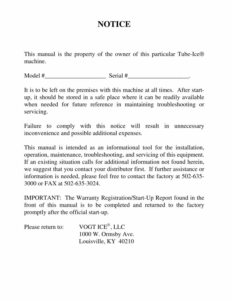
IMPORTANT: The Warranty Registration/Start-Up Report found in the
front of this manual is to be completed and returned to the factory
promptly after the official start-up.
Please return to: VOGT ICE, LLC
1000 W. Ormsby Ave.
Louisville, KY 40210
8/28/00
Warranty Registration / Start-Up Form (Medium & Large Machines)
Model Number: __________________________ Serial Number: __________________________
This form must be filled out completely and signed by the customer in order to assure acceptance by Vogt.
Date of Start-Up: _______________________________ Form Completed By: _____________________________________
AC Condenser Model Number: _____________________ AC Condenser Serial Number: _____________________________
Water Treatment System? Yes No Manufacturer: ____________________ Model: ________________________
Bin Manufacturer: _______________________ Model: _________________________ Bin Capacity: _______ lbs.
Distributor
Company Name: ____________________________________________ Phone: _______________________
Address: ____________________________________ City: _________________________ State: ___________ Zip: ___________
Service Company
Company Name: ____________________________________________ Phone: _______________________
Address: ____________________________________ City: _________________________ State: ___________ Zip: ___________
Customer (location of equipment)
Company Name: ____________________________________________ Phone: _______________________
Address: ____________________________________ City: _________________________ State: ___________ Zip: ___________
PRE-OPERATION CHECK Service Manual on hand
Machine room suitable 50°F minimum, 110°F maximum
Power Supply ______ V _____ PH _____ Hz (machine not running)
Compressor crankcase heater on 12 hour minimum
All valves opened or closed as tagged
Solenoid valve stems in auto position
System leak checked/tight
Auxiliary equipment overloads wired into control circuit
Water supply and drains connected properly
Sufficient make-up water supply (minimum 30 PSIG)
Instruction manual and warranty certificate left on-site
Name of person left with: __________________________________
OPERATION CHECK Power Supply ______ V _____ PH _____ HZ (machine running)
Pump , cutter & other motor direction of rotation correct
Water pump amps RLA__________ Actual __________
Condenser motor amps (if applicable) _________
Incoming potable water temperature: _____°F
All water distribution in place (visually inspected)
Make-up water float valve operates properly
Clear ice Yes No
Hour meter in control panel connected and operating
Suction Pressure: End of freeze ________ End of harvest ________
Discharge Pressure: End of freeze ________ End of harvest ________
Test
Cycle
Make-up
Water Temp
Freeze Time
Min/Sec
Harvest Time
Min/Sec
First Ice Out
Min/Sec
All Ice Out
Min/Sec
Avg. Hole
Size
Ice
Lb. Per Harvest
Ice
Lb. Per Day
#1
#2
#3
#4
Note: Ice lb. per day can be found by:
Remarks:
Technician Signature: ___________________________ End User Signature:_____________________________ I certify that I have performed all of the above procedures.
1440×+ me)harvest ti time(freeze
harvestper lb. ice
Vogt Ice L.L.C. 1000 W. Ormsby
Louisville, KY 40210
(502) 635-3235 FAX #502-635-3024
THIS FORM MUST BE SENT TO
VOGT TO ACTIVATE WARRANTY
Vogt Order Number: ____________________
Vogt/Turbo MHG‐F DX Series Installation, Operation,
& Maintenance Manual
12A4171M13 Page i December 2012
Table of Contents Chapter 1: Introduction TURBO REFRIGERATION CO. ......................................................................... 1‐1 1.1: A Brief History of Our Company ............................................................................................... 1‐1 1.2: Preview ..................................................................................................................................... 1‐1 1.3: Important Safety Notice ........................................................................................................... 1‐2 1.4: Safety Symbols & What They Mean ......................................................................................... 1‐2 1.5: Modular Ice Maker Introduction .............................................................................................. 1‐4
Chapter 2: Receipt of Your Vogt Ice Machine ..................................................................................... 2‐1 2.1: Inspection ................................................................................................................................. 2‐1 2.2: Description Of Machine ............................................................................................................ 2‐1 2.3: Safety Tags and Labels .............................................................................................................. 2‐1 2.4: Safety Valves............................................................................................................................. 2‐2 2.5: Equipment Storage ................................................................................................................... 2‐2 2.6: Rated Capacity .......................................................................................................................... 2‐2 2.7: Model Number ......................................................................................................................... 2‐2
Chapter 3: Installing Your Vogt/Turbo Modular Unit .......................................................................... 3‐1 3.1: Important Notice ...................................................................................................................... 3‐1 3.2: Machine Room ......................................................................................................................... 3‐1 3.3: Lifting Procedures ..................................................................................................................... 3‐2 3.4: Equipment Anchoring ............................................................................................................... 3‐3 3.5: Equipment Layout .................................................................................................................... 3‐3 3.6: Refrigerant Piping Connections ................................................................................................ 3‐8 3.7: Water Piping Connections ...................................................................................................... 3‐12 3.8: Wiring and Electrical Connections .......................................................................................... 3‐15 3.9: Installation Review Checklist .................................................................................................. 3‐21
Chapter 4: How Your Ice Machine Works ........................................................................................... 4‐1 4.1: Principle Of Operation .............................................................................................................. 4‐1
Chapter 5: Start‐Up and Operation ..................................................................................................... 5‐1 5.1: Refrigeration System Review ................................................................................................... 5‐1 5.2: Refrigerant Charge ................................................................................................................... 5‐2 5.3: Module Start‐up ....................................................................................................................... 5‐4 5.4: Thermal Expansion Valves ........................................................................................................ 5‐5 5.5: Hot Gas Regulator and Suction By‐pass Valve. ........................................................................ 5‐5 5.6: Module Shut‐down ................................................................................................................... 5‐6 5.7: Module Operating Tips ............................................................................................................. 5‐6
Chapter 6: Electrical Controls‐Description .......................................................................................... 6‐1 6.1: General ..................................................................................................................................... 6‐1 6.2: Configuring a New System or Module ...................................................................................... 6‐6 6.3: Modular Unit Operation ........................................................................................................... 6‐7 6.4: Master Panel Operation ........................................................................................................... 6‐8 6.5: Operator Interface Item Descriptions .................................................................................... 6‐13 6.6: Starting the Modular System ................................................................................................. 6‐14
Chapter 7: Maintenance ...................................................................................................................... 7‐1 7.1: Preventive Maintenance .......................................................................................................... 7‐1 7.2: Preventative Maintenance Form .............................................................................................. 7‐2 7.3: General Cleaning ...................................................................................................................... 7‐3 7.3.1: Procedure .......................................................................................................................... 7‐3
Vogt/Turbo MHG‐F DX Series Installation, Operation,
& Maintenance Manual
12A4171M13 Page ii December 2012
7.3.2: Water Distribution System ................................................................................................ 7‐3 7.3.3: Water Tank. ....................................................................................................................... 7‐4
7.4: Other Maintenance Operations ............................................................................................... 7‐5 7.4.1: Water Cooled Condenser Cleaning ................................................................................... 7‐5 7.4.2: Cooling Tower/Evaporative Condenser ............................................................................ 7‐5 7.4.3: Compressor ....................................................................................................................... 7‐6
Chapter 8: Troubleshooting ................................................................................................................ 8‐1 8.1: Symptom: Machine Stopped................................................................................................... 8‐2 8.2: Symptom: Freeze‐up due to extended freeze period ............................................................. 8‐3 8.3: Symptom: Freeze‐up due to ice failing to discharge ............................................................... 8‐4 8.4: Symptom: Low ice capacity. .................................................................................................... 8‐5 8.5: Symptom: Poor ice quality ...................................................................................................... 8‐6 8.6: Symptom: High discharge pressure (check gage accuracy) .................................................... 8‐6 8.7: Symptom: Low discharge pressure (check gage accuracy) ..................................................... 8‐7 8.8: Symptom: High suction pressure (check gage accuracy) ........................................................ 8‐8 8.9: Symptom: Compressor running unloaded during freeze (dedicated compressor only) ........ 8‐8 8.10: Symptom: Compressor oil pressure low (check gages) ........................................................ 8‐9 8.11: Symptom: Compressor loosing oil excessively ..................................................................... 8‐9 8.12: Symptom: High compressor discharge temperature .......................................................... 8‐10 8.13: Symptom: Suction line frosting to compressor .................................................................. 8‐10
Chapter 9: Service Operations ............................................................................................................ 9‐1 9.1: Pump‐down Procedure ............................................................................................................ 9‐1 9.2: Removal of Refrigerant from the Machine .............................................................................. 9‐1 9.3: Refrigerant Leaks ..................................................................................................................... 9‐2 9.4: Non‐condensable Gases .......................................................................................................... 9‐2
Table of Figures Figure 1‐1 Modular Front View ........................................................................................................... 1‐4 Figure 1‐2 Modular Back View ............................................................................................................ 1‐5 Figure 1‐3 Modular Right Side View ................................................................................................... 1‐5 Figure 2‐1 Model Number Structure................................................................................................... 2‐3 Figure 3‐1 Lifting Procedure ................................................................................................................ 3‐2 Figure 3‐2 Anchor Points ..................................................................................................................... 3‐3 Figure 3‐3 Side View Unit Access ........................................................................................................ 3‐4 Figure 3‐4 Plan View Unit Access ........................................................................................................ 3‐5 Figure 3‐5 Conveyor Transition ........................................................................................................... 3‐7 Figure 3‐7 Refrigerant Connections .................................................................................................. 3‐10 Figure 3‐8 Typical Refrigeration High Side ........................................................................................ 3‐11 Figure 3‐9 Water Connections .......................................................................................................... 3‐12 Figure 3‐10 Water Circuit .................................................................................................................. 3‐14 Figure 3‐11 Master Panel and Module Connection .......................................................................... 3‐16 Figure 3‐12 Typical Master Panel ...................................................................................................... 3‐16 Figure 3‐13 Master Panel Input Wiring ............................................................................................ 3‐17 Figure 3‐14 Input Connections .......................................................................................................... 3‐18 Figure 3‐15 Master Panel Output Wiring .......................................................................................... 3‐18 Figure 3‐16 Output Connections ....................................................................................................... 3‐19 Figure 3‐17 Drawing Legend ............................................................................................................. 3‐19
Vogt/Turbo MHG‐F DX Series Installation, Operation,
& Maintenance Manual
12A4171M13 Page iii December 2012
Figure 6‐1 Typical Master/Modular Set‐Up ........................................................................................ 6‐2 Figure 6‐2 Exterior Master Panel View ................................................................................................ 6‐3 Figure 6‐3 Internal Master Panel View ............................................................................................... 6‐4 Figure 6‐4 Exterior Module Panel View .............................................................................................. 6‐5 Figure 6‐5 Interior Modular Panel View ............................................................................................. 6‐5 Figure 6‐6 DIP Switch Setting ............................................................................................................. 6‐6 Figure 6‐7 Function Buttons on Interface........................................................................................... 6‐9 Figure 6‐8 Interface Main Menu ......................................................................................................... 6‐9 Figure 6‐9 Interface MCS Screen ...................................................................................................... 6‐14 Figure 6‐10 Interface Module Control .............................................................................................. 6‐14 Figure 7‐1 Water Distribution System ................................................................................................ 7‐4 Table of Tables Table 3‐1 Ice Volume ........................................................................................................................... 3‐5 Table 3‐2 Screw Trough Volume ......................................................................................................... 3‐6 Table 3‐3 Module Refrigerant Schematic Components ...................................................................... 3‐9 Table 3‐4 DX Refrigerant Connection Sizes ....................................................................................... 3‐10 Table 3‐5 Refrigerant High Side Components ................................................................................... 3‐11 Table 3‐6 Water Connection Sizes ..................................................................................................... 3‐12 Table 3‐7 Voltage Unbalance ............................................................................................................ 3‐20 Table 3‐8 Current Unbalance ............................................................................................................ 3‐21 Table 6‐1 Master Control Panel Components .................................................................................... 6‐4 Table 6‐2 Module Control Panel Components ................................................................................... 6‐6 Table 6‐3 DIP Switch Setting ............................................................................................................... 6‐7 Table 6‐4 Functions of Mode Switch .................................................................................................. 6‐8 Table 6‐5 Indicator Light Action ......................................................................................................... 6‐8 Table 6‐6 Interface Menu Map ......................................................................................................... 6‐11 Table 6‐7 Interface Menu Definitions ............................................................................................... 6‐13 Table 7‐1 Cooling Tower Maintenance Schedule ............................................................................... 7‐6 Table 7‐2 Suggested Compressor Oil Change Interval ....................................................................... 7‐7

Vogt/Turbo MHG‐F DX Series Installation, Operation, Introduction TURBO REFRIGERATION CO. & Maintenance Manual
12A4171M13 Page 1‐1 December 2012
Chapter 1: Introduction TURBO REFRIGERATION CO.
1.1: A Brief History of Our Company Henry Vogt Ice Machine Co. was founded as a small machine shop in Louisville, Kentucky in 1880. In 1938, Vogt built the first Tube‐Ice® machine and revolutionized the ice‐making industry. Our first “sized‐ice” machine quickly replaced the old can‐ice plants, which required much hard labor and large amounts of floor space for freezing, cutting, and crushing ice by hand. Turbo Refrigerating has been producing equipment for the ice industry since 1960. Since developing the plate icemaker, TURBO has been the leader in plate‐ice making technology. The ice makers described in this manual are part of a family of products designed specifically to meet the needs of the industrial ice users. The TIG/TIGAR series ice generators were introduced in 1985, they are built with the same high quality standards of engineering used to develop the icemakers of the 60’s. Many of the latest developments in technology are used to design the Modular series ice generators. Modular ice generators have also been used in packaged ice applications by adding a TURBO Ice Sizer and improving the ice handling systems. In 2000 an upgraded version of the TIGAR with a new larger evaporator plate was introduced for both the industrial and packaged ice markets. In 2010, The Modular ice maker was introduced Today, TUBE ICE® and TURBO® carry on the tradition as one of the world’s leading producers of ice‐making equipment.
1.2: Preview All the skill in engineering and fabrication that we have learned in over a century of experience is reflected in the Modular Plate Ice Machine. Furnished with your machine is the “Certificate of Test”, the report of operating data that is a record of the unit’s satisfactory operation on our factory test floor. It is evidence of our desire to deliver to you “the finest ice‐making unit ever made.” This manual is designed to assist you in the installation, start‐up, and maintenance of your unit. Your Modular plate ice machine will give you a lifetime of service when you install it, maintain it, and service it properly. Please read your manual carefully before attempting installation, operation, or servicing of this professionally designed piece of equipment. If you have additional questions, please call your distributor. Also, feel free to phone the factory direct at (502) 635‐3000 or 1‐800‐853‐8648.
Vogt/Turbo MHG‐F DX Series Installation, Operation, Introduction TURBO REFRIGERATION CO. & Maintenance Manual
12A4171M13 Page 1‐2 December 2012
1.3: Important Safety Notice This information is intended for use by individuals possessing adequate backgrounds of electrical, refrigeration and mechanical experience. Any attempt to repair major equipment may result in personal injury and property damage. The manufacturer or seller cannot be responsible for the interpretation of this information, nor can it assume any liability in connection with its use. Special Precautions To Be Observed When Charging Refrigeration Systems. Only technically qualified persons, experienced and knowledgeable in the handling of refrigerant (Appendix A contains the MSDS for R‐404 and R507) and operation of refrigeration systems, should perform the operations described in this manual. All local, federal, and EPA regulations must be strictly adhered to when handling refrigerants. If a refrigeration system is being charged from refrigerant cylinders, disconnect each cylinder when empty or when the system is fully charged. A gage should be installed in the charging line to indicate refrigerant cylinder pressure. The cylinder may be considered empty of liquid refrigerant when the gauge pressure is 25 pounds or less, and there is no frost on the cylinder. Close the refrigerant charging valve and cylinder valve before disconnecting the cylinder. Loosen the union in the refrigerant charging line‐‐carefully to avoid unnecessary and illegal release of refrigerant into the atmosphere.
! CAUTION ! Immediately close system charging valve at commencement of defrost or thawing cycle if refrigerant cylinder is connected. Never leave a refrigerant cylinder connected to system except during charging operation. Failure to observe either of these precautions can
result in transferring refrigerant from the system to the refrigerant cylinder, over‐filling it, and possibly causing the cylinder to rupture because of pressure from expansion of the
liquid refrigerant. ! CAUTION !
Refrigerant cylinders containing refrigerant should be stored in a cool place. They should never be exposed to temperatures higher than 120°F and should be stored in a manner to prevent abnormal mechanical shocks. Also, transferring refrigerant from a refrigeration system into a cylinder can be very dangerous and is not recommended.
! CAUTION ! It is not recommended that refrigerant be transferred from a refrigeration system directly into a cylinder. If such a transfer is made, the refrigerant cylinder must be an approved, CLEAN cylinder‐‐free of any contaminants or foreign materials‐‐and must be connected to an approved recovery mechanism with a safety shutoff sensor to assure contents do not
exceed net weight specified by cylinder manufacturer or any applicable code requirements. ! CAUTION !
1.4: Safety Symbols & What They Mean Prior to installation or operation of the Tube‐Ice® machine, please read this manual. Are you familiar with the installation, start‐up, and operation of a Tube‐Ice® machine? Before you operate, adjust or
Vogt/Turbo MHG‐F DX Series Installation, Operation, Introduction TURBO REFRIGERATION CO. & Maintenance Manual
12A4171M13 Page 1‐3 December 2012
service this machine, you should read this manual, understand the operation of this machine, and be aware of possible dangers. These Safety Symbols will alert you when special care is needed.
Please heed
! DANGER ! Indicates immediate hazards and that special precautions are necessary to avoid severe
personal injury or death. ! DANGER !
! WARNING ! Indicates a strong possibility of a hazard and that an unsafe practice could result in severe
personal injury. ! WARNING !
! CAUTION ! Means hazards or unsafe practices could result in personal injury or product or property
damage. ! CAUTION !
Vogt/Turbo MHG‐F DX Series Installation, Operation, Introduction TURBO REFRIGERATION CO. & Maintenance Manual
12A4171M13 Page 1‐4 December 2012
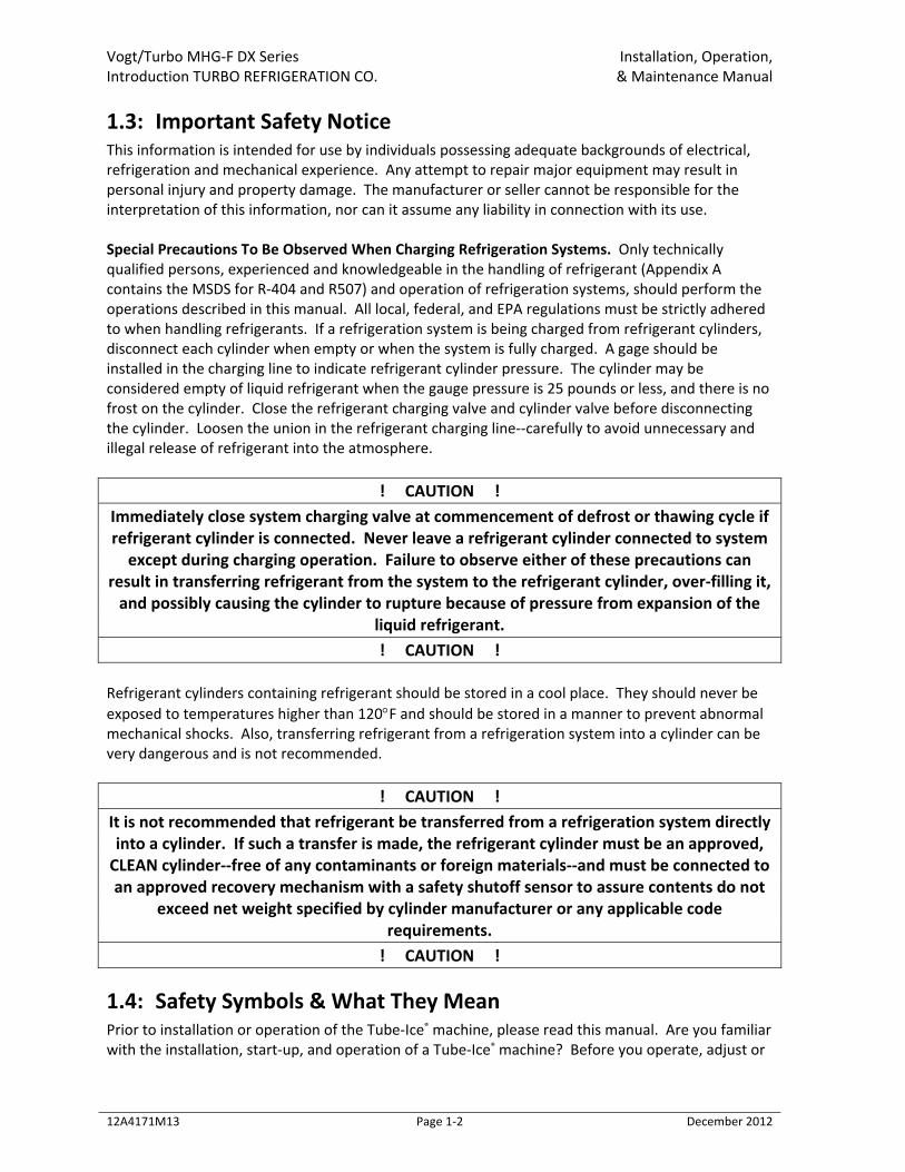
1.5: Modular Ice Maker Introduction The Modular Fragmented Ice System was introduced to give the customer flexibility in their ice production needs. Below are some figures introducing the Modular product line. These show the basic connections and orientation of the equipment. The Modules were designed to ease in the expansion process of ice plants today. Additional Modules may be set in place beside other Modules. The controls have been designed in a plug and play manner to further simplify expansion.
Figure 1‐1 Modular Front View
Vogt/Turbo MHG‐F DX Series Installation, Operation, Introduction TURBO REFRIGERATION CO. & Maintenance Manual
12A4171M13 Page 1‐5 December 2012
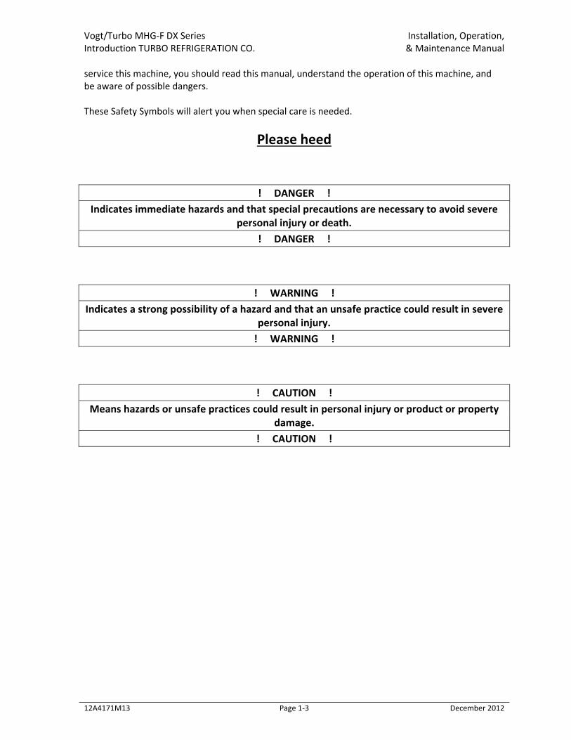
Figure 1‐2 Modular Back View
Figure 1‐3 Modular Right Side View

Vogt/Turbo MHG‐F DX Series Installation, Operation, Receipt of Your Vogt Ice Machine & Maintenance Manual
12A4171M13 Page 2‐1 December 2012
Chapter 2: Receipt of Your Vogt Ice Machine
! CAUTION ! Only service personnel experienced in servicing refrigeration equipment and qualified to work on high amperage electrical equipment should be allowed to install or service this Turbo Refrigerating machine. Eye protection should be worn by all personnel working on or around the Turbo Refrigerating machine. It is very important that you are familiar with
and adhere to all local, state, and federal, etc. ordinances and laws regarding the handling, storing, and use of refrigerant. An approved mask should be readily available for use in an emergency and all personnel should be aware of its location and proper use.
! CAUTION !
2.1: Inspection As soon as you receive your machine, inspect it for any damage or missing components. If damage is suspected or items are missing, note it on the shipper’s papers (i.e., the trucker’s Bill of Lading). Immediately make a separate written request for inspection by the freight line’s agent. Any repair work, replacement parts, or alteration to the machine without the permission of the Vogt Ice, LLC can void the machine’s warranty. You should also notify your Vogt distributor or the factory.
2.2: Description Of Machine A Vogt Ice Modular low side machine is a remote ice producing plant requiring refrigerant suction connection, refrigerant liquid connection, thaw gas connection, make‐up water supply, electrical connection, and the proper refrigerant charge. The machine has been partially factory tested prior to shipment and will require adjustment to meet the high side (condenser unit) operating conditions. See Start‐up and Operation for the correct setting of the controls. The machine is evacuated and charged with nitrogen gas pressure for shipment. This prevents air or moisture from entering the system during transit. There should be a positive pressure (20‐25 psig) indicated on the freezer pressure gage when the machine is received. The machine has been cleaned with ice machine cleaner and flushed so that the machine is ready for ice production.
2.3: Safety Tags and Labels Be sure to read and adhere to all special tags and labels attached to valves or applied to various areas of the machine. They provide important information necessary for safe and efficient operation of your equipment. The unit may have valves in the open or closed position and may be tagged with information about the required position for start‐up.
Vogt/Turbo MHG‐F DX Series Installation, Operation, Receipt of Your Vogt Ice Machine & Maintenance Manual
12A4171M13 Page 2‐2 December 2012
2.4: Safety Valves Where required, safety pressure relief valves are installed. Vent the pressure relief valves to the atmosphere in such a manner as to comply with local and national codes. Failure to do so creates a safety hazard that could cause injury or loss of life.
! Danger ! Safety Relief Valves should be vented to the atmosphere in a safe manner that complies
with local and national codes. ! Danger !
2.5: Equipment Storage If the equipment is received, but must be stored prior to installation, you should protect it from the weather, extreme temperatures, and high humidity. These type of conditions can deteriorate the various components used in the manufacture and assembly of the equipment.
2.6: Rated Capacity The Turbo Refrigerating machine is rated to produce a given amount of ice when operating under the proper conditions as specified in this manual. You should be prepared to handle the ice produced as it is discharged from the machine and move it to your storage or bagging area promptly.
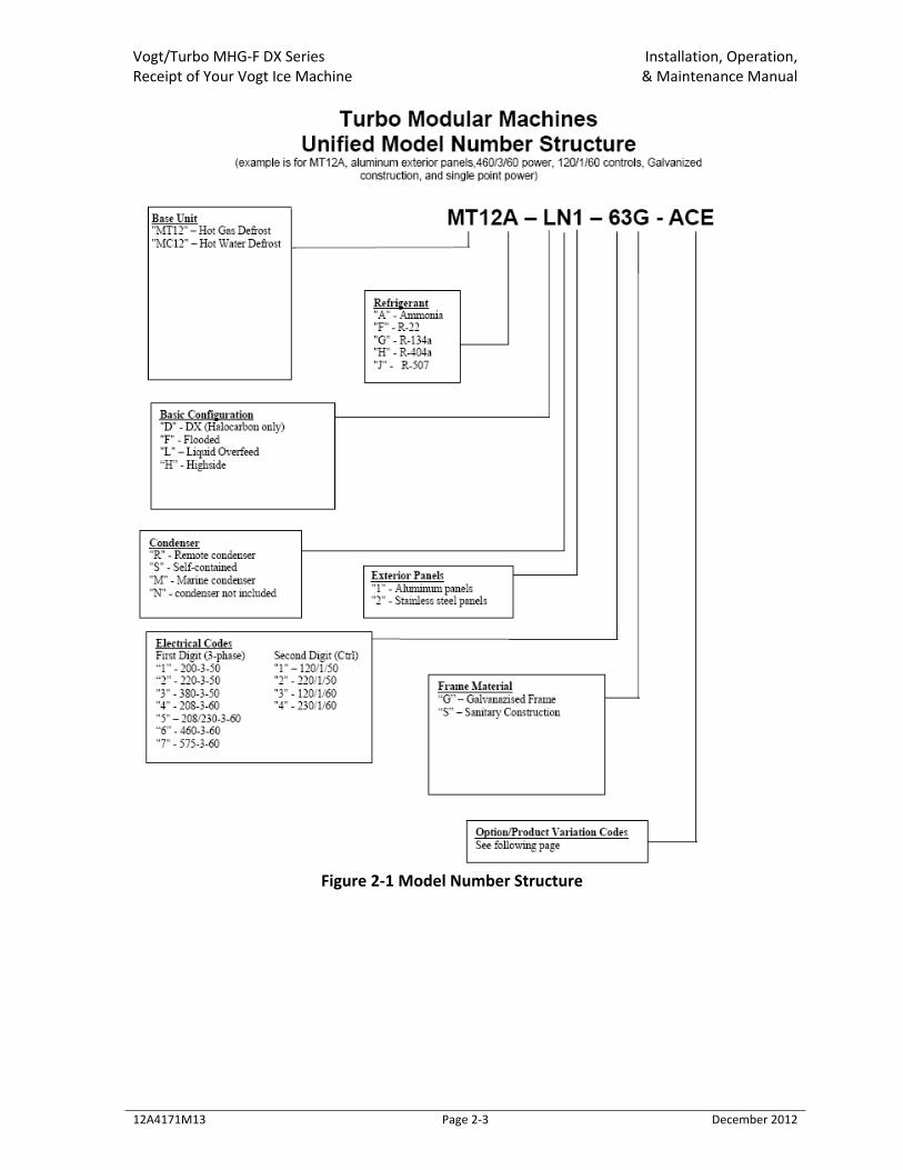
2.7: Model Number The machine nameplate is located on the front of the control panel. The model number and machine description are located in the top left hand corner. The following figure can be used to verify that the correct model has been received. See Figure 2‐1 Model Number Structure.
Vogt/Turbo MHG‐F DX Series Installation, Operation, Receipt of Your Vogt Ice Machine & Maintenance Manual
12A4171M13 Page 2‐3 December 2012
Figure 2‐1 Model Number Structure

Vogt/Turbo MHG‐F DX Series Installation, Operation, Installing Your Vogt/Turbo Modular Unit & Maintenance Manual
12A4171M13 Page 3‐1 December 2012
Chapter 3: Installing Your Vogt/Turbo Modular Unit ! WARNING !
Only service personnel experienced and certified in refrigeration and qualified to work with high voltage electrical equipment should be allowed to install or work on this Turbo
Refrigerating® machine. ! WARNING !
3.1: Important Notice The Warranty Registration / Start‐Up Form must be completed and returned to Vogt Turbo Refrigerating® to initiate and assure a full warranty. A postage paid envelope is provided or you may fax the report to 800‐770‐8648.
3.2: Machine Room The machine must be located inside a suitable building and must not be subjected to ambient temperatures below 50°F (10°C) or above 110°F (43.3°C). Heat from other sources (sunlight, furnaces, condenser, etc.) and unusual air current may affect the operation of the machine and should be avoided. The electrical components of the Turbo Refrigerating machine are rated NEMA 1. The machine should not be located in a hazardous area or sprayed with water. The machine should be installed in an area where water will not stand but will readily drain away from the machine. See Space Diagram for clearances and utility connections, Figure 3‐3 Side View Unit Access, and Figure 3‐4 Plan View Unit Access. The Master panel of the Modular system is equipped with an operator interface screen. While this screen is resistant to water, it is not advisable for it to be exposed to direct sunlight as it will be difficult to see and ultraviolet light will degrade the interface overtime.
Vogt/Turbo MHG‐F DX Series Installation, Operation, Installing Your Vogt/Turbo Modular Unit & Maintenance Manual
12A4171M13 Page 3‐2 December 2012
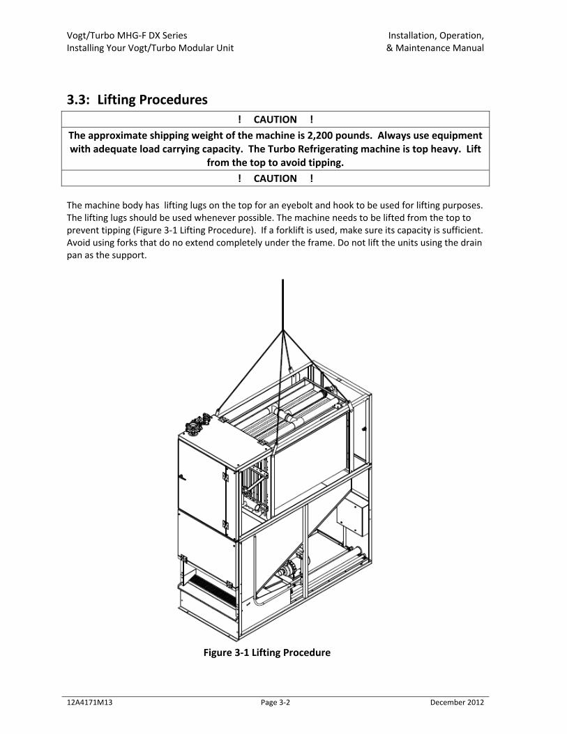
3.3: Lifting Procedures ! CAUTION !
The approximate shipping weight of the machine is 2,200 pounds. Always use equipment with adequate load carrying capacity. The Turbo Refrigerating machine is top heavy. Lift
from the top to avoid tipping. ! CAUTION !
The machine body has lifting lugs on the top for an eyebolt and hook to be used for lifting purposes. The lifting lugs should be used whenever possible. The machine needs to be lifted from the top to prevent tipping (Figure 3‐1 Lifting Procedure). If a forklift is used, make sure its capacity is sufficient. Avoid using forks that do no extend completely under the frame. Do not lift the units using the drain pan as the support.
Figure 3‐1 Lifting Procedure
Vogt/Turbo MHG‐F DX Series Installation, Operation, Installing Your Vogt/Turbo Modular Unit & Maintenance Manual
12A4171M13 Page 3‐3 December 2012
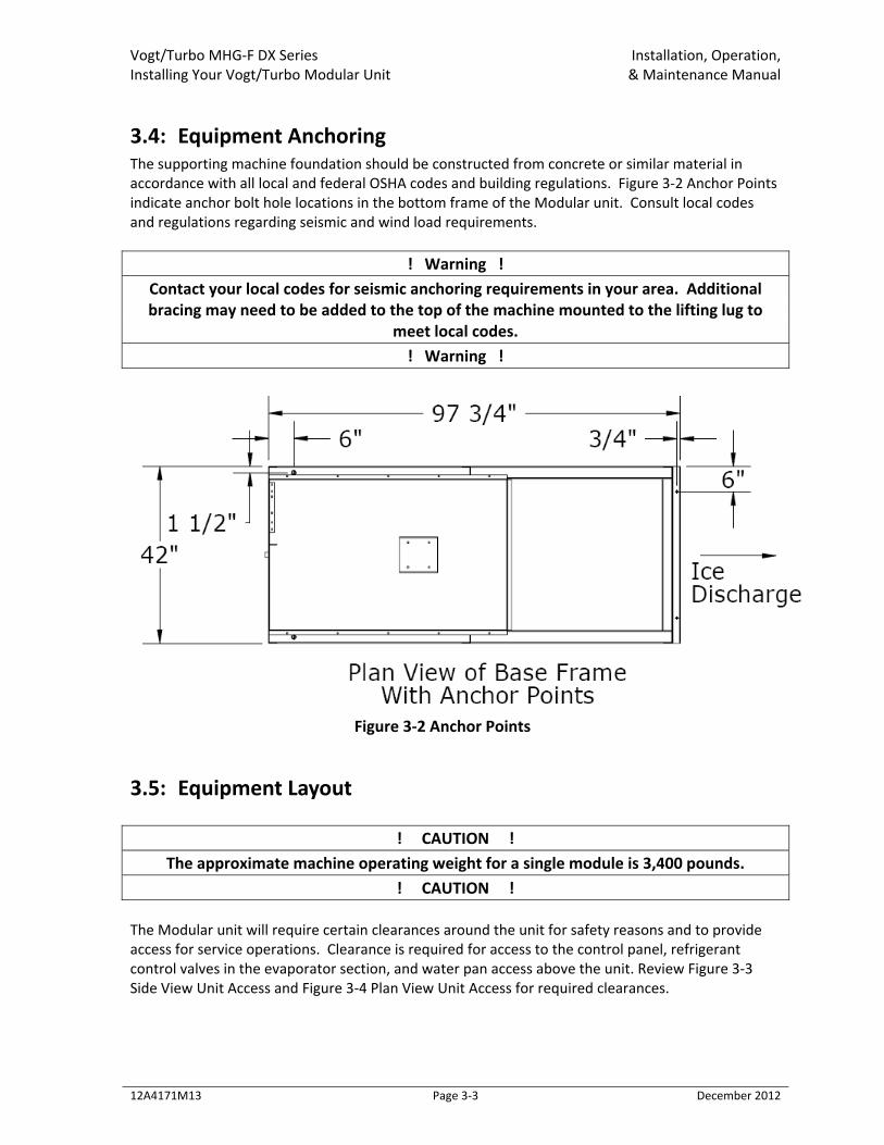
3.4: Equipment Anchoring The supporting machine foundation should be constructed from concrete or similar material in accordance with all local and federal OSHA codes and building regulations. Figure 3‐2 Anchor Points indicate anchor bolt hole locations in the bottom frame of the Modular unit. Consult local codes and regulations regarding seismic and wind load requirements.
! Warning ! Contact your local codes for seismic anchoring requirements in your area. Additional bracing may need to be added to the top of the machine mounted to the lifting lug to
meet local codes. ! Warning !
Figure 3‐2 Anchor Points
3.5: Equipment Layout
! CAUTION ! The approximate machine operating weight for a single module is 3,400 pounds.
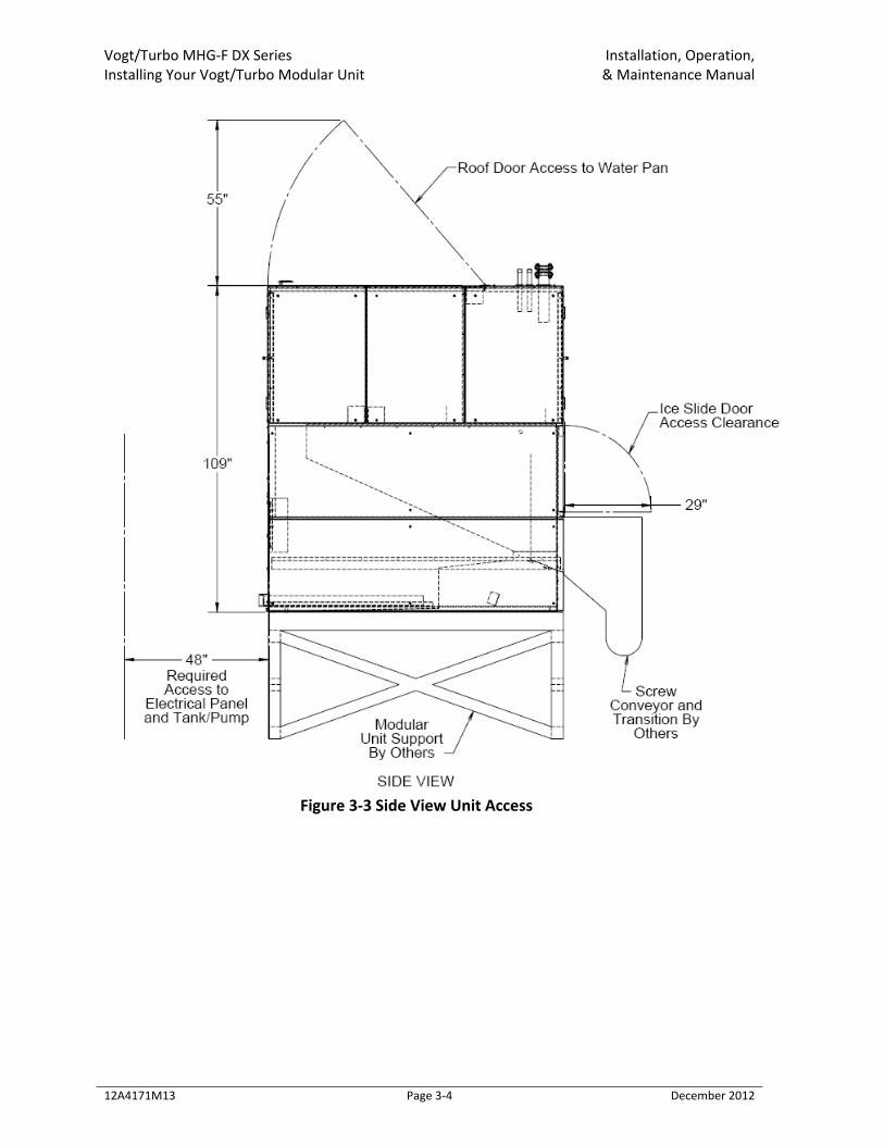
! CAUTION ! The Modular unit will require certain clearances around the unit for safety reasons and to provide access for service operations. Clearance is required for access to the control panel, refrigerant control valves in the evaporator section, and water pan access above the unit. Review Figure 3‐3 Side View Unit Access and Figure 3‐4 Plan View Unit Access for required clearances.
Vogt/Turbo MHG‐F DX Series Installation, Operation, Installing Your Vogt/Turbo Modular Unit & Maintenance Manual
12A4171M13 Page 3‐4 December 2012
Figure 3‐3 Side View Unit Access
Vogt/Turbo MHG‐F DX Series Installation, Operation, Installing Your Vogt/Turbo Modular Unit & Maintenance Manual
12A4171M13 Page 3‐5 December 2012
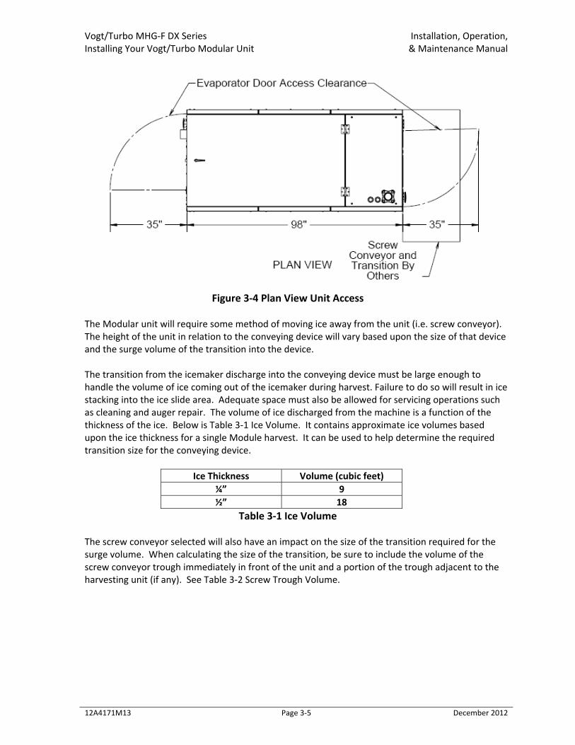
Figure 3‐4 Plan View Unit Access
The Modular unit will require some method of moving ice away from the unit (i.e. screw conveyor). The height of the unit in relation to the conveying device will vary based upon the size of that device and the surge volume of the transition into the device. The transition from the icemaker discharge into the conveying device must be large enough to handle the volume of ice coming out of the icemaker during harvest. Failure to do so will result in ice stacking into the ice slide area. Adequate space must also be allowed for servicing operations such as cleaning and auger repair. The volume of ice discharged from the machine is a function of the thickness of the ice. Below is Table 3‐1 Ice Volume. It contains approximate ice volumes based upon the ice thickness for a single Module harvest. It can be used to help determine the required transition size for the conveying device.
Ice Thickness Volume (cubic feet) ¼” 9 ½” 18
Table 3‐1 Ice Volume The screw conveyor selected will also have an impact on the size of the transition required for the surge volume. When calculating the size of the transition, be sure to include the volume of the screw conveyor trough immediately in front of the unit and a portion of the trough adjacent to the harvesting unit (if any). See Table 3‐2 Screw Trough Volume.
Vogt/Turbo MHG‐F DX Series Installation, Operation, Installing Your Vogt/Turbo Modular Unit & Maintenance Manual
12A4171M13 Page 3‐6 December 2012
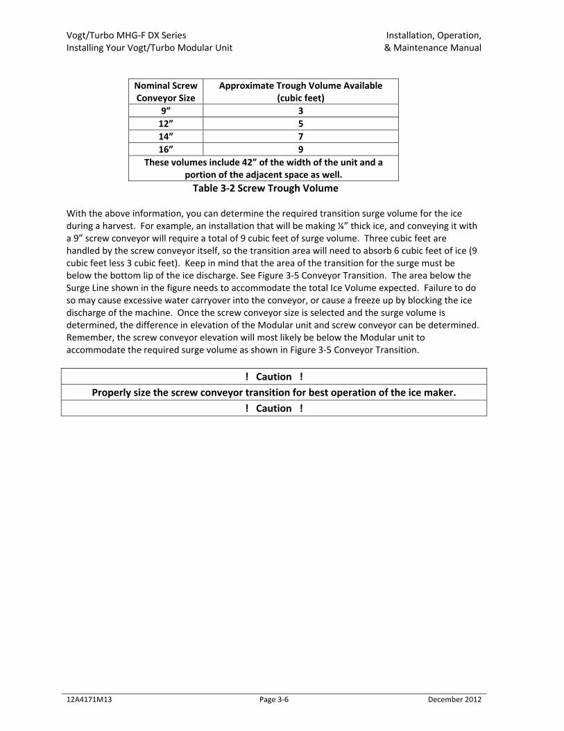
Nominal Screw Conveyor Size
Approximate Trough Volume Available (cubic feet)
9” 3 12” 5 14” 7 16” 9
These volumes include 42” of the width of the unit and a portion of the adjacent space as well. Table 3‐2 Screw Trough Volume
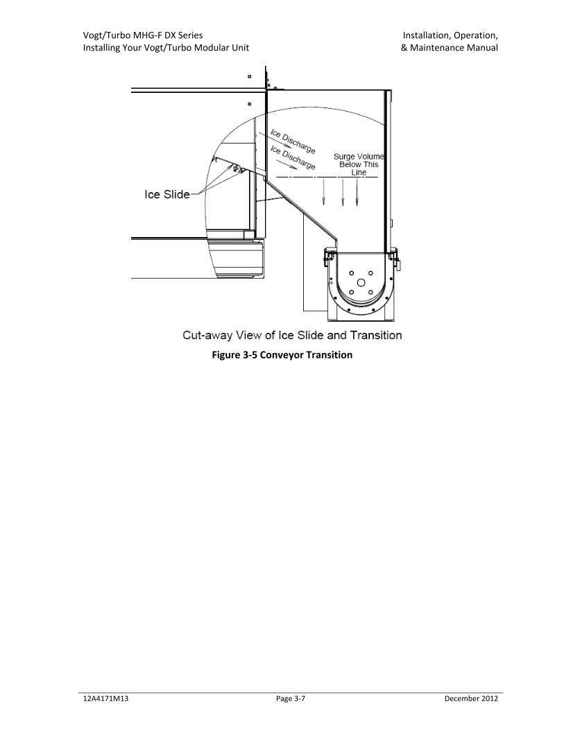
With the above information, you can determine the required transition surge volume for the ice during a harvest. For example, an installation that will be making ¼” thick ice, and conveying it with a 9” screw conveyor will require a total of 9 cubic feet of surge volume. Three cubic feet are handled by the screw conveyor itself, so the transition area will need to absorb 6 cubic feet of ice (9 cubic feet less 3 cubic feet). Keep in mind that the area of the transition for the surge must be below the bottom lip of the ice discharge. See Figure 3‐5 Conveyor Transition. The area below the Surge Line shown in the figure needs to accommodate the total Ice Volume expected. Failure to do so may cause excessive water carryover into the conveyor, or cause a freeze up by blocking the ice discharge of the machine. Once the screw conveyor size is selected and the surge volume is determined, the difference in elevation of the Modular unit and screw conveyor can be determined. Remember, the screw conveyor elevation will most likely be below the Modular unit to accommodate the required surge volume as shown in Figure 3‐5 Conveyor Transition.
! Caution ! Properly size the screw conveyor transition for best operation of the ice maker.
! Caution !
Vogt/Turbo MHG‐F DX Series Installation, Operation, Installing Your Vogt/Turbo Modular Unit & Maintenance Manual
12A4171M13 Page 3‐7 December 2012
Figure 3‐5 Conveyor Transition
Vogt/Turbo MHG‐F DX Series Installation, Operation, Installing Your Vogt/Turbo Modular Unit & Maintenance Manual
12A4171M13 Page 3‐8 December 2012
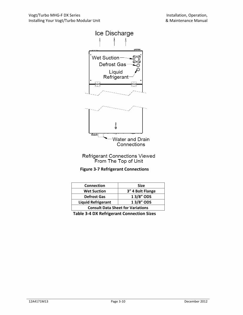
3.6: Refrigerant Piping Connections The refrigerant piping connections are located on the top of the unit as shown in Figure 3‐7 Refrigerant Connections. Refrigerant mains that are connected to the Module(s) must be properly sized for the refrigeration load. Refer to the table below for proper Main Line sizing. Avoid long piping runs. If they can’t be avoided, please consult the factory.
! WARNING ! Only service personnel experienced and certified in refrigeration and qualified to work with high voltage electrical equipment should be allowed to install or work on this Turbo
Refrigerating® machine. ! WARNING !
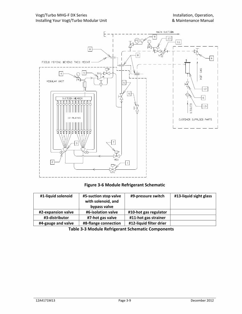
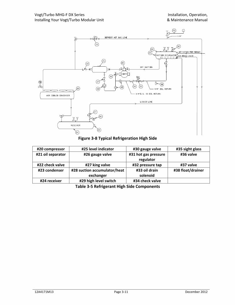
A typical Modular unit piping schematic is shown in Figure 3‐6 Module Refrigerant Schematic. The wet suction line is equipped with a suction stop valve that is normally open and actuated by a small pilot solenoid valve. The defrost gas line is equipped with an isolation valve and a solenoid valve. The liquid refrigerant line is also equipped with an isolation valve and a solenoid valve. All solenoid valves are equipped with a manually opening feature. These valves are controlled by the Module’s Programmable Logoic Controller (PLC) discussed later in this section. Typical connection sizes are listed in Table 3‐4 DX Refrigerant Connection Sizes. Not shown in this diagram are the other components required for the refrigeration circuit such as the compressor, condesner, oil separator‐oil return system, and combination suction accumulator/heat exchanger. It is extremely important that these compnents be sized properly for safe and reliable operation. Failure to size these compnents correctly will result poor perfromance and expensive repairs. If you need assistance in component selection, please contact the factory or your sales representative. For assistance in sizing the refrigerant mains, please contact the factory.
Vogt/Turbo MHG‐F DX Series Installation, Operation, Installing Your Vogt/Turbo Modular Unit & Maintenance Manual
12A4171M13 Page 3‐9 December 2012
Figure 3‐6 Module Refrigerant Schematic
#1‐liquid solenoid #5‐suction stop valve with solenoid, and
bypass valve
#9‐pressure switch #13‐liquid sight glass
#2‐expansion valve #6‐isolation valve #10‐hot gas regulator #3‐distributor #7‐hot gas valve #11‐hot gas strainer
#4‐gauge and valve #8‐flange connection #12‐liquid filter drier Table 3‐3 Module Refrigerant Schematic Components
Vogt/Turbo MHG‐F DX Series Installation, Operation, Installing Your Vogt/Turbo Modular Unit & Maintenance Manual
12A4171M13 Page 3‐10 December 2012
Figure 3‐7 Refrigerant Connections
Connection Size Wet Suction 3” 4 Bolt Flange Defrost Gas 1 3/8” ODS
Liquid Refrigerant 1 3/8” ODS Consult Data Sheet for Variations
Table 3‐4 DX Refrigerant Connection Sizes
Vogt/Turbo MHG‐F DX Series Installation, Operation, Installing Your Vogt/Turbo Modular Unit & Maintenance Manual
12A4171M13 Page 3‐11 December 2012
Figure 3‐8 Typical Refrigeration High Side
#20 compressor #25 level indicator #30 gauge valve #35 sight glass #21 oil separator #26 gauge valve #31 hot gas pressure
regulator #36 valve
#22 check valve #27 king valve #32 pressure tap #37 valve #23 condenser #28 suction accumulator/heat
exchanger #33 oil drain solenoid
#38 float/drainer
#24 receiver #29 high level switch #34 check valve Table 3‐5 Refrigerant High Side Components
Vogt/Turbo MHG‐F DX Series Installation, Operation, Installing Your Vogt/Turbo Modular Unit & Maintenance Manual
12A4171M13 Page 3‐12 December 2012
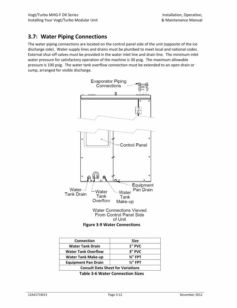
3.7: Water Piping Connections The water piping connections are located on the control panel side of the unit (opposite of the ice discharge side). Water supply lines and drains must be plumbed to meet local and national codes. External shut‐off valves must be provided in the water inlet line and drain line. The minimum inlet water pressure for satisfactory operation of the machine is 30 psig. The maximum allowable pressure is 100 psig. The water tank overflow connection must be extended to an open drain or sump, arranged for visible discharge.
Figure 3‐9 Water Connections
Connection Size Water Tank Drain 1” PVC
Water Tank Overflow 3” PVC Water Tank Make‐up ¾” FPT Equipment Pan Drain ½” FPT
Consult Data Sheet for Variations Table 3‐6 Water Connection Sizes
Vogt/Turbo MHG‐F DX Series Installation, Operation, Installing Your Vogt/Turbo Modular Unit & Maintenance Manual
12A4171M13 Page 3‐13 December 2012
! CAUTION !
External shut‐off valves must be provided in the water inlet line and drain line. The minimum inlet water pressure for satisfactory operation of the machine is 30 psig and
peak flow requirement is 10 GPM. The maximum allowable pressure is 100 psig. ! CAUTION !
! CAUTION ! The drain lines must NOT be connected into a pressure tight common header due to the
possibility that water may back up into the water tank. ! CAUTION !
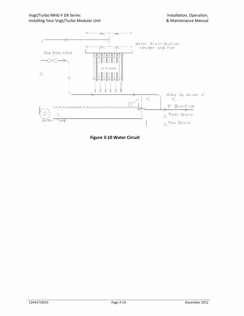
Water Tank Drain connection is for the purpose of flushing and draining the water tank of impurities, foreign material and cleaning chemicals used during servicing. It should be piped to an open drain or sump for visible discharge. It can be tied in with the overflow line but no others. A customer supplied valve is required to be installed in this line. Water Tank Overflow connection on the machine is provided to carry away overflow water during the thawing (harvest cycle). This water contains ice fines accumulated during harvesting and dissolved solids accumulated during the freezing cycle. Do not reduce the size of this line. Three inches is needed to provide sufficient area for ice fines to be flushed out, especially if the incoming flushing water is 55°F (13°C) or below. This overflow line should not tie in with any other drain line except the water tank drain. Water Tank Make‐up required for ice making must be potable water, safe for human consumption, and should be of the highest quality available. The best way to determine water quality is to have a complete water quality analysis by a qualified laboratory. It is advisable to install a particle filter in the make‐up line to trap dirt, sand, rust, or other solid particles prior to entering the water tank and contaminating the ice. Be sure to size the filter large enough to meet the water demands of 10 GPM (peak flow), allowing for a restriction through the filter as it traps these particles. Minimum required supply pressure is 30 psig. Unless water quality is superior, do not discharge the overflow water to the cooling tower system. This water contains additional dissolved solids left from the ice making process and can lead to excessive condenser fouling or cooling tower chemical usage. It is recommended that a heat exchanger be used in place of direct contact with condenser water. A blow down valve is supplied internal to the unit and is piped to the Tank Overflow line inside the machine. Blow down may be necessary to melt ice fines and flush dissolved solids from the water tank during the freezing cycle. This function is important and helps to maintain good ice quality. If water quality is superior, the supplied valve can be closed to conserve water.
Vogt/Turbo MHG‐F DX Series Installation, Operation, Installing Your Vogt/Turbo Modular Unit & Maintenance Manual
12A4171M13 Page 3‐14 December 2012
Figure 3‐10 Water Circuit
Vogt/Turbo MHG‐F DX Series Installation, Operation, Installing Your Vogt/Turbo Modular Unit & Maintenance Manual
12A4171M13 Page 3‐15 December 2012
3.8: Wiring and Electrical Connections
! WARNING ! Only service personnel experienced in refrigeration and qualified to work with high voltage electrical equipment should be allowed to install or work on the Turbo
Refrigerating® machine. ! WARNING !
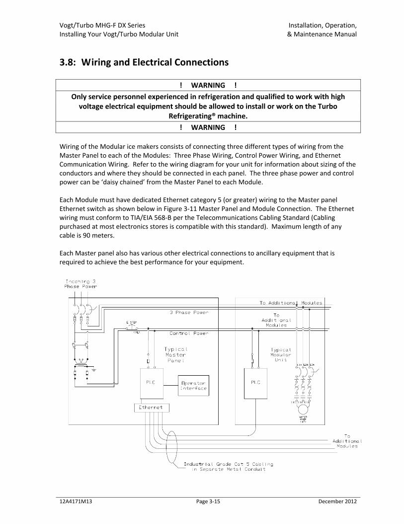
Wiring of the Modular ice makers consists of connecting three different types of wiring from the Master Panel to each of the Modules: Three Phase Wiring, Control Power Wiring, and Ethernet Communication Wiring. Refer to the wiring diagram for your unit for information about sizing of the conductors and where they should be connected in each panel. The three phase power and control power can be ‘daisy chained’ from the Master Panel to each Module. Each Module must have dedicated Ethernet category 5 (or greater) wiring to the Master panel Ethernet switch as shown below in Figure 3‐11 Master Panel and Module Connection. The Ethernet wiring must conform to TIA/EIA 568‐B per the Telecommunications Cabling Standard (Cabling purchased at most electronics stores is compatible with this standard). Maximum length of any cable is 90 meters. Each Master panel also has various other electrical connections to ancillary equipment that is required to achieve the best performance for your equipment.
Vogt/Turbo MHG‐F DX Series Installation, Operation, Installing Your Vogt/Turbo Modular Unit & Maintenance Manual
12A4171M13 Page 3‐16 December 2012
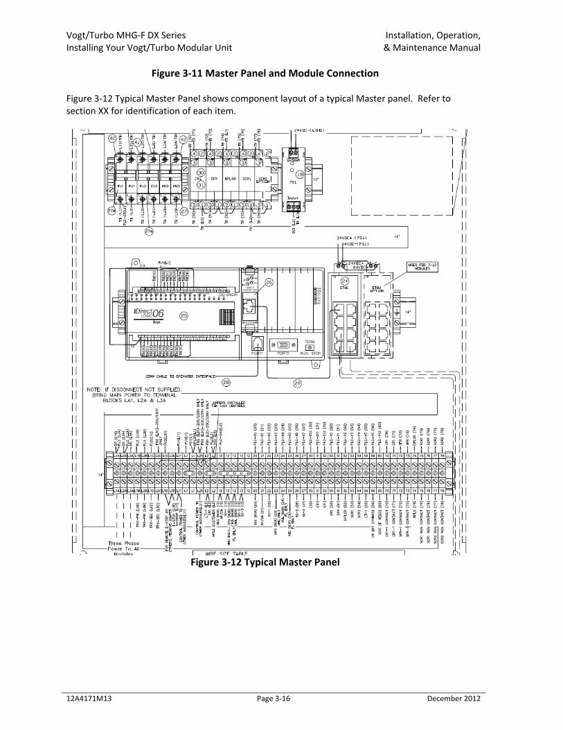
Figure 3‐11 Master Panel and Module Connection Figure 3‐12 Typical Master Panel shows component layout of a typical Master panel. Refer to section XX for identification of each item.
Figure 3‐12 Typical Master Panel
Vogt/Turbo MHG‐F DX Series Installation, Operation, Installing Your Vogt/Turbo Modular Unit & Maintenance Manual
12A4171M13 Page 3‐17 December 2012
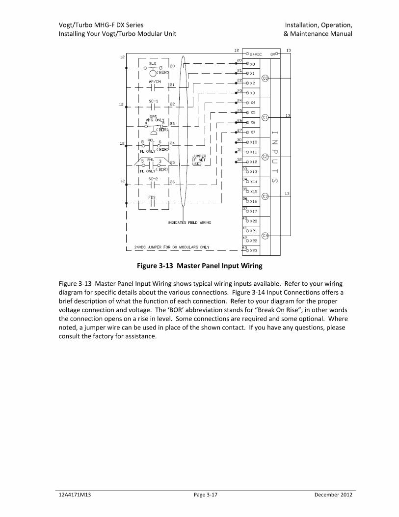
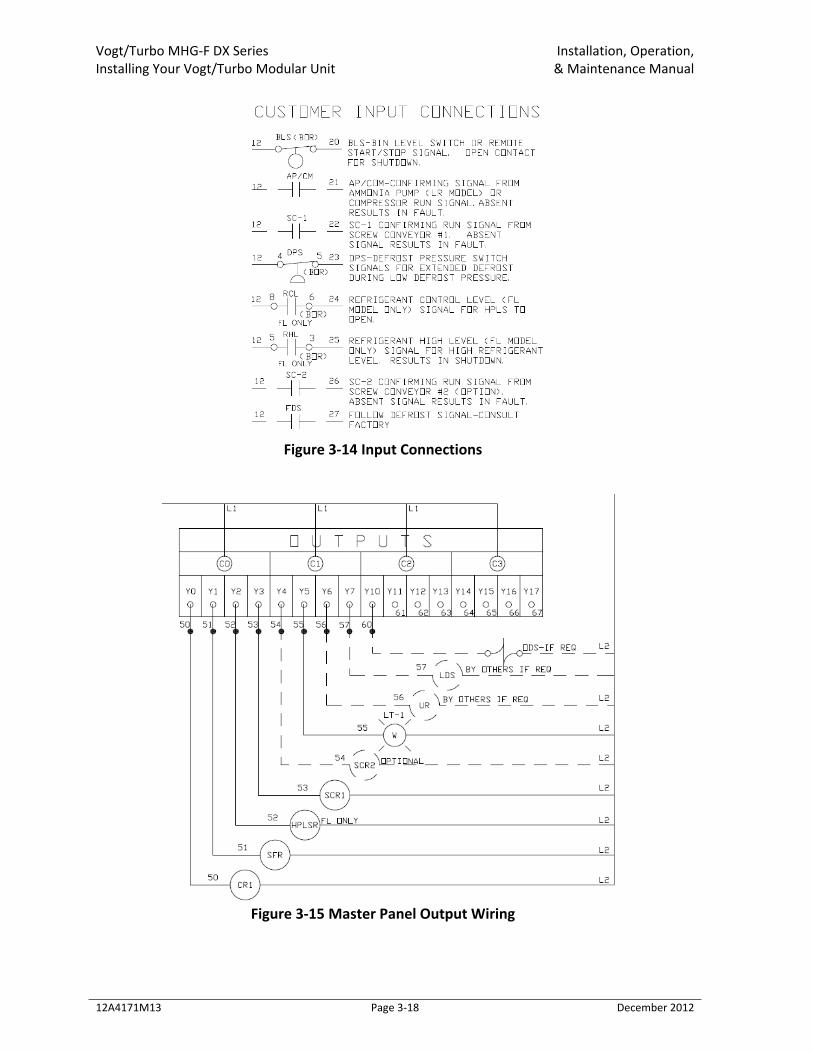
Figure 3‐13 Master Panel Input Wiring
Figure 3‐13 Master Panel Input Wiring shows typical wiring inputs available. Refer to your wiring diagram for specific details about the various connections. Figure 3‐14 Input Connections offers a brief description of what the function of each connection. Refer to your diagram for the proper voltage connection and voltage. The ‘BOR’ abbreviation stands for “Break On Rise”, in other words the connection opens on a rise in level. Some connections are required and some optional. Where noted, a jumper wire can be used in place of the shown contact. If you have any questions, please consult the factory for assistance.
Vogt/Turbo MHG‐F DX Series Installation, Operation, Installing Your Vogt/Turbo Modular Unit & Maintenance Manual
12A4171M13 Page 3‐18 December 2012
Figure 3‐14 Input Connections
Figure 3‐15 Master Panel Output Wiring
Vogt/Turbo MHG‐F DX Series Installation, Operation, Installing Your Vogt/Turbo Modular Unit & Maintenance Manual
12A4171M13 Page 3‐19 December 2012
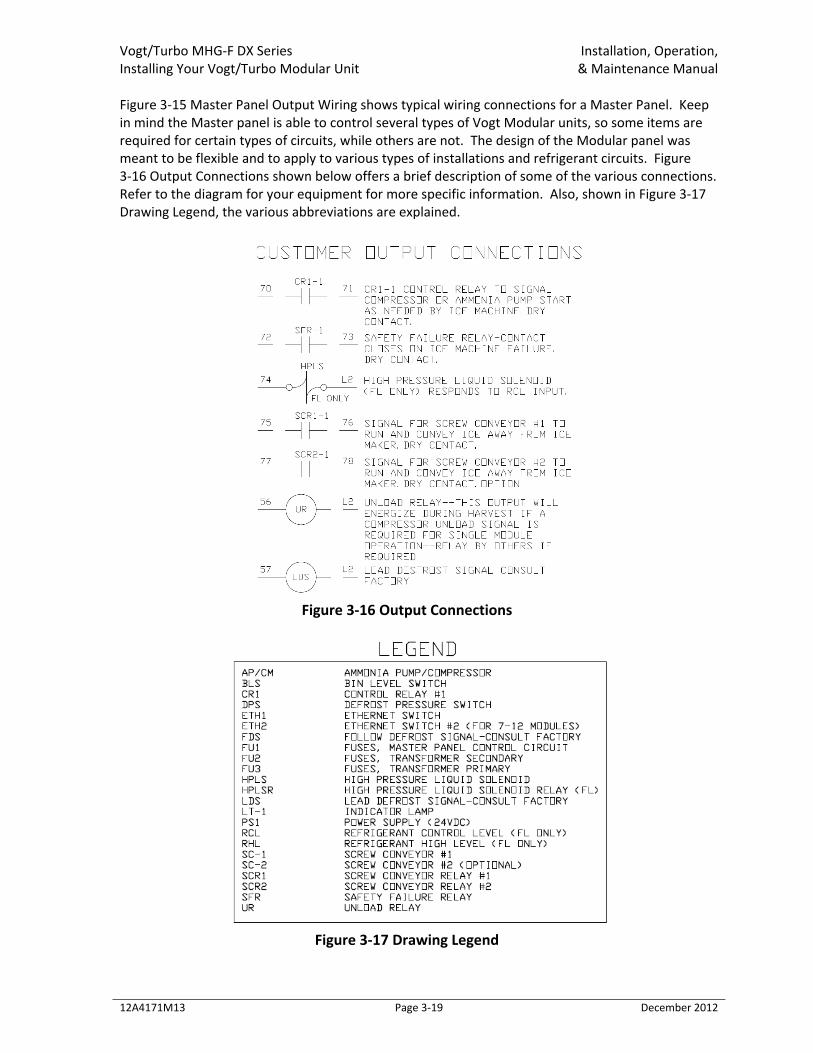
Figure 3‐15 Master Panel Output Wiring shows typical wiring connections for a Master Panel. Keep in mind the Master panel is able to control several types of Vogt Modular units, so some items are required for certain types of circuits, while others are not. The design of the Modular panel was meant to be flexible and to apply to various types of installations and refrigerant circuits. Figure 3‐16 Output Connections shown below offers a brief description of some of the various connections. Refer to the diagram for your equipment for more specific information. Also, shown in Figure 3‐17 Drawing Legend, the various abbreviations are explained.
Figure 3‐16 Output Connections
Figure 3‐17 Drawing Legend
Vogt/Turbo MHG‐F DX Series Installation, Operation, Installing Your Vogt/Turbo Modular Unit & Maintenance Manual
12A4171M13 Page 3‐20 December 2012
! CAUTION ! Do not attempt to start machine without insuring proper rotation of the water pump.
! CAUTION ! Pump motor rotation must be checked prior to start‐up. The pump rotation should match the marking on the pump housing. Improper pump rotation will lead to poor pump performance and potentially damage the pump. To change rotation of the pump, disconnect power and reverse L1 and L3 (incoming power wires) at the motor contactor.
! Danger ! Only qualified personnel should attempt to change rotation on any motor as high voltage
is present at the motor contactors. ! Danger !
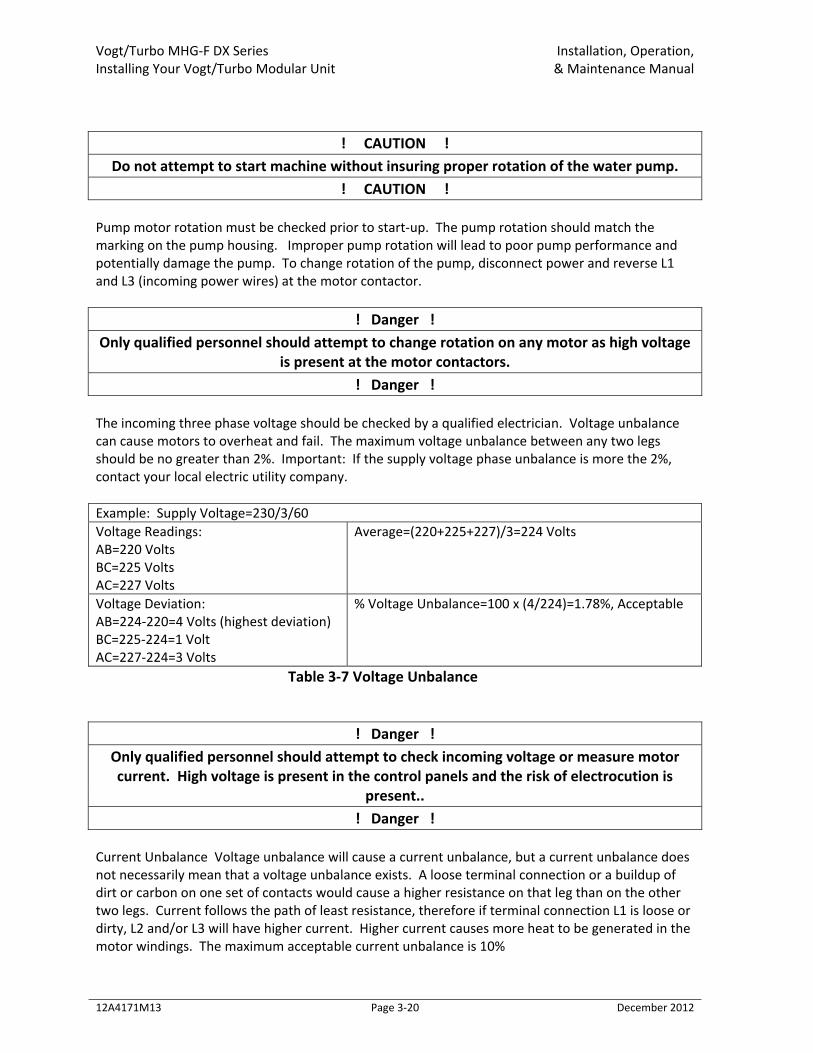
The incoming three phase voltage should be checked by a qualified electrician. Voltage unbalance can cause motors to overheat and fail. The maximum voltage unbalance between any two legs should be no greater than 2%. Important: If the supply voltage phase unbalance is more the 2%, contact your local electric utility company. Example: Supply Voltage=230/3/60 Voltage Readings: AB=220 Volts BC=225 Volts AC=227 Volts
Average=(220+225+227)/3=224 Volts
Voltage Deviation: AB=224‐220=4 Volts (highest deviation) BC=225‐224=1 Volt AC=227‐224=3 Volts
% Voltage Unbalance=100 x (4/224)=1.78%, Acceptable
Table 3‐7 Voltage Unbalance
! Danger ! Only qualified personnel should attempt to check incoming voltage or measure motor current. High voltage is present in the control panels and the risk of electrocution is
present.. ! Danger !
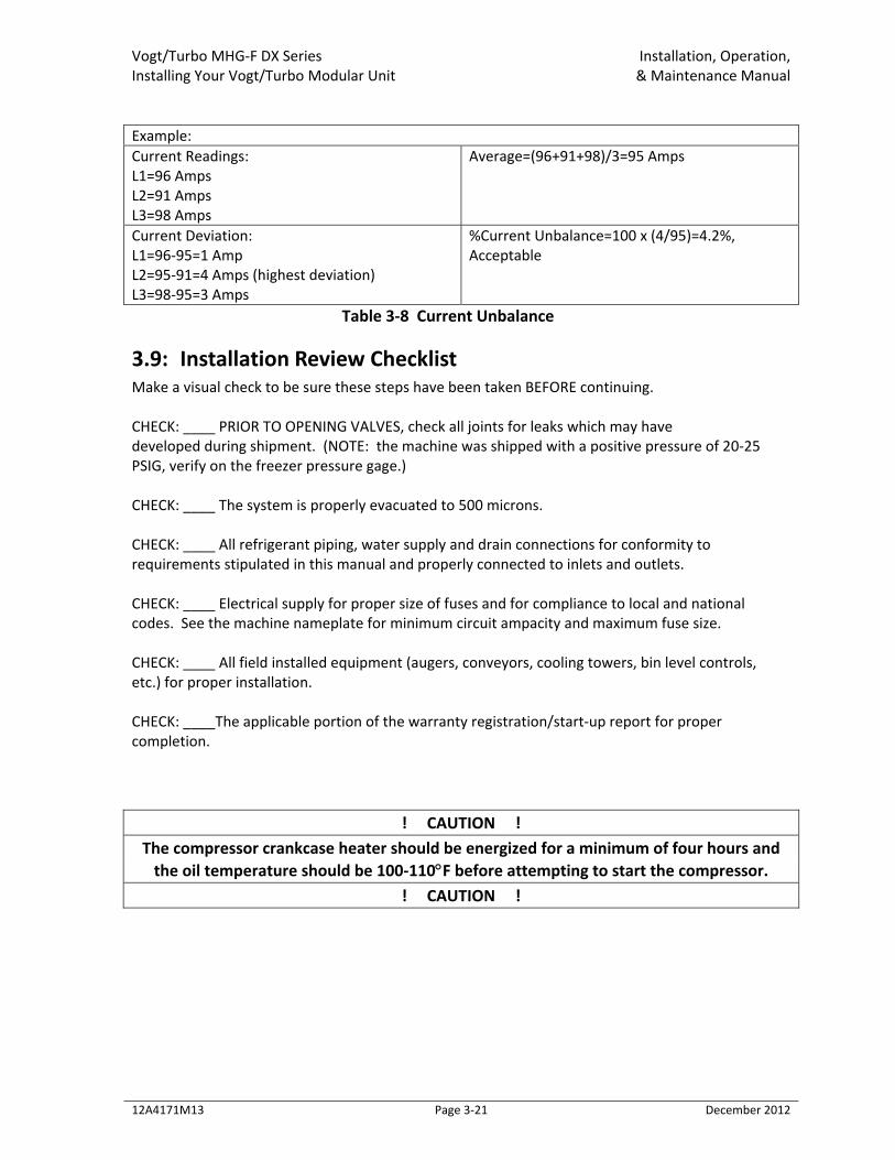
Current Unbalance Voltage unbalance will cause a current unbalance, but a current unbalance does not necessarily mean that a voltage unbalance exists. A loose terminal connection or a buildup of dirt or carbon on one set of contacts would cause a higher resistance on that leg than on the other two legs. Current follows the path of least resistance, therefore if terminal connection L1 is loose or dirty, L2 and/or L3 will have higher current. Higher current causes more heat to be generated in the motor windings. The maximum acceptable current unbalance is 10%
Vogt/Turbo MHG‐F DX Series Installation, Operation, Installing Your Vogt/Turbo Modular Unit & Maintenance Manual
12A4171M13 Page 3‐21 December 2012
Example: Current Readings: L1=96 Amps L2=91 Amps L3=98 Amps
Average=(96+91+98)/3=95 Amps
Current Deviation: L1=96‐95=1 Amp L2=95‐91=4 Amps (highest deviation) L3=98‐95=3 Amps
%Current Unbalance=100 x (4/95)=4.2%, Acceptable
Table 3‐8 Current Unbalance
3.9: Installation Review Checklist Make a visual check to be sure these steps have been taken BEFORE continuing. CHECK: ____ PRIOR TO OPENING VALVES, check all joints for leaks which may have developed during shipment. (NOTE: the machine was shipped with a positive pressure of 20‐25 PSIG, verify on the freezer pressure gage.) CHECK: ____ The system is properly evacuated to 500 microns. CHECK: ____ All refrigerant piping, water supply and drain connections for conformity to requirements stipulated in this manual and properly connected to inlets and outlets. CHECK: ____ Electrical supply for proper size of fuses and for compliance to local and national codes. See the machine nameplate for minimum circuit ampacity and maximum fuse size. CHECK: ____ All field installed equipment (augers, conveyors, cooling towers, bin level controls, etc.) for proper installation. CHECK: ____The applicable portion of the warranty registration/start‐up report for proper completion.
! CAUTION ! The compressor crankcase heater should be energized for a minimum of four hours and the oil temperature should be 100‐110°F before attempting to start the compressor.
! CAUTION !

Vogt/Turbo MHG‐F DX Series Installation, Operation, How Your Ice Machine Works & Maintenance Manual
12A4171M13 Page 4‐1 December 2012
Chapter 4: How Your Ice Machine Works ! WARNING !
Only service personnel experienced and certified in refrigeration and qualified to work with high voltage electrical equipment should be allowed to install or work on this Turbo
Refrigerating® machine. ! WARNING !
4.1: Principle Of Operation Your Vogt Modular Icemaker is equipped with a Master Control Panel that controls each Module or group of Modules. Each module also has its own control panel which responds to the commands from the Master Control Panel. For a detailed description of the functions of each control panel component, see Section 6. Starting and running of the Modular system is initiated from the Master Control Panels operator interface. For a detailed description of the function of the controls, refer to Section 6. If it should become necessary to instantly stop the machine, push the emergency “E‐Stop” button located on the Master Control Panel. To restart the machine, reset the E‐Stop button and use the Master Switch on the operator interface. Figure XX(3‐6) and figure XX(3‐9) illustrate the piping diagram of the refrigerant and water circuits of the Modular Plate Ice machine with numbers for easy reference. Throughout this manual, the numbers you see in parentheses refer to the numbers in this piping schematic. The evaporator is a plate bank assembly of 12 plates which ice forms on during the freeze cycle. During the freeze cycle, water is constantly recirculated on the exterior of the plates by a centrifugal water pump (Figure 3‐9). Make‐up water is maintained by a float valve in the water tank. During the freeze cycle, the liquid solenoid valve (1) is open and allows high pressure refrigerant to flow into the thermal expansion valve (2) and refrigerant distributor (3). As the liquid refrigerant flows through these components, it is allowed to expand and a resulting pressure drop occurs. From there it enters the evaporator plates where this expanding liquid refrigerant boils and absorbs heat from the water flowing over the outside surface of the plates. Once reaching the top of the plates, the refrigerant is mostly in a gas form with some remnants of liquid still present. It then flows past the sensing bulb for the thermal expansion valve, which signals the valve to modulate open or close. The gas‐rich mixture then flows past the open suction valve (5) and up into the main suction line. Refrigerant gas then passes through the suction accumulator (not shown and usually part of
Vogt/Turbo MHG‐F DX Series Installation, Operation, How Your Ice Machine Works & Maintenance Manual
12A4171M13 Page 4‐2 December 2012
the compressor skid), and to the compressor. Here the cool gas is compressed to a high temperature, high pressure gas which discharges through the oil separator and into the condenser. In the condenser, heat is removed and the gas is condensed to a high temperature, high pressure liquid. The high pressure liquid drains to the high pressure receiver (not shown). The liquid is then fed back into the liquid line, flows past the liqu9d sight glass (13), through the liquid filter drier (12) to be delivered once again to the liquid line solenoid valve (1). The freeze cycle is completed by action of the programmable controller in the Master Panel. This will initiate a defrost or harvest cycle. There are several preset options available that control the various aspects of the defrost cycle, refer to Section 6 for a complete description of these options. During the defrost cycle, the Liquid Solenoid (1) and the suction valve (5) will close. Warm gas from the compressor flows through the hot gas strainer (11) and hot gas regulator (10), then through the now open hot gas valve (7) and is discharged into the refrigerant distributor (3) and then into the plates. As this happens, the heat from the discharge gas begins to condense in the plates causing the plates to slightly warm. This results in thawing a thin layer of ice at the surface of the evaporator plate thus breaking the bond between the stainless steel plate and the ice sheet. The remaining ice then drops onto the ice slide for discharging. The remaining hot gas and condensed liquid then flows out the top of the plates and up to the closed suction valve. It is then metered through the suction bypass valve and into the main suction line. Once the defrost cycle is complete, the freeze cycle starts once again and this process repeats until the system is stopped. If thicker or thinner ice is desired, the Cycle Time must be adjusted on the Master Panel interface. The defrost time is to be set for the time required to discharge all the ice plus 20 seconds longer (usually 60 seconds to 140 seconds) depending on water pump operation.
! CAUTION ! Make sure all the ice clears the evaporator plates with at least 20 seconds to spare before
the next freeze period begins. This is to prevent refreezing. ! CAUTION !
Vogt/Turbo MHG‐F DX Series Installation, Operation, Start‐Up and Operation & Maintenance Manual
12A4171M13 Page 5‐1 December 2012
Chapter 5: Start‐Up and Operation ! WARNING !
Only service personnel experienced and certified in refrigeration and qualified to work with high voltage electrical equipment should be allowed to install or work on this Turbo
Refrigerating® machine. ! WARNING !
5.1: Refrigeration System Review The MHG‐DX Modular units were designed for R404a or R507 refrigerant. Please refer to your equipment purchase to verify which refrigerant is applicable to your units. Following the piping schematic (Figure xx, and xx), you will see that during the machine’s freeze cycle, the compressor (20) discharge gas goes through the oil separator (21) to remove any oil present in the discharge gas and return the oil to the compressor crankcase. It is then discharged into the condenser (23) and condensed into a liquid by the removal of heat with water or air (depending on the type of condenser). The liquid then drains into the receiver (24). Liquid from the receiver flows through the suction accumulator/heat exchanger coil (28), through the filter drier (12), then to the liquid solenoid valve (1). The liquid is then expanded through the thermal expansion valve (2) and into the evaporator plates. The cold wet refrigerant floods the evaporator. The heat contained in the water passes through the wall of the plates, lowering the temperature of the water causing it to freeze and form a sheet of ice that adheres to the outside of plates. Since the purest water freezes first, the circulating water continues to wash the dissolved solids down into the sump area of the water tank. The blow down valve helps to rid the water tank of increased dissolved solids by flushing them out the overflow during water pump operation. The wet suction gas leaves the plates and passes through the suction stop valve (5). From there the wet suction gas travels up into the refrigerant main suction line back to the wet suction connection on the suction accumulator/heat exchanger (28). There liquid droplets are removed, and allowing dry gas to enter the suction side of the compressor (20). The suction gas is then compressed and discharged once again, completing the cycle. As ice continues to form on the plates, the suction pressure slowly decreases. The freeze cycle concludes when the programmable controller signals the module to begin the harvest sequence. Note: Freezing time will vary, depending on make‐up water temperature and thickness of ice produced. The cycle time should be set (via the operator interface) to provide the correct time to produce ice at the required thickness under the current operating conditions. During the defrost cycle, the hot gas valve (7) opens. The compressor unloads (when required), allowing the warm high pressure gas from the compressor to enter the evaporator plates. As the plates warm up to slightly above freezing (approximately 40 °F / 5 °C), the ice releases and falls down onto the ice slide and discharges out. Harvesting requires about 60‐100 seconds, but can vary depending on ice thickness, suction pressure, discharge pressure, water pump operation and distance from the compressor to the evaporator.
Vogt/Turbo MHG‐F DX Series Installation, Operation, Start‐Up and Operation & Maintenance Manual
12A4171M13 Page 5‐2 December 2012
! IMPORTANT !
It is a good idea and will be profitable for you to observe and become familiar with the proper operating characteristics of your Tube‐Ice® machine. It will help you to recognize and correct minor irregularities as they occur in order to help prevent major problems.
“An ounce of prevention is worth a pound of cure.” ! IMPORTANT !
! WARNING !
Only service personnel experienced and certified in refrigeration and qualified to work with high voltage electrical equipment should be allowed to install or work on this Turbo
Refrigerating® machine. ! WARNING !
5.2: Refrigerant Charge Prior to charging the machine/system with the proper refrigerant, make sure the system is leak tight and free of non‐condensable gas or other contaminants. Make sure it is from a reputable supplier who can furnish quality refrigerant. The refrigerant charge for each module is approximately 135 pounds of R404a or R507. Consult factory for total system charges. Special precautions to be observed when charging refrigeration systems. Only technically qualified persons, experienced and knowledgeable in the handling refrigerant and operation of refrigeration systems should perform the operations described in this manual. All local, federal, and EPA regulations must be strictly adhered to when handling refrigerants. Follow these instructions with caution: Charging the Receiver Using a refrigerant approved charging hose, connect one end to the charging valve on the high pressure receiver. Connect the other end of the charging hose to the refrigerant bottle. It is best to have a gage in this line to indicate pressure. Open the charging valve and the fill valve from the bottle (electric band heater around the refrigerant bottle will aid in charging in this method. While observing the level indicator on the high pressure receiver, fill the receiver to the proper volume. Make sure the charging valve is closed and the cylinder valve is closed before attempting to disconnect the hose. Use caution when disconnecting the charging hose, it will contain liquid refrigerant. Adhere to local, state, and federal codes when handling refrigerant. Charging into the Low Side The machine may also be charged from refrigerant cylinders into the evaporator side of the circuit. To accomplish this, the compressor will have to operate to transfer the refrigerant from the evaporator to the receiver. Again, make sure all the necessary valves are opened for operation and the compressor crankcase heater has been energized for a minimum of four (4) hours.
Vogt/Turbo MHG‐F DX Series Installation, Operation, Start‐Up and Operation & Maintenance Manual
12A4171M13 Page 5‐3 December 2012
Follow these instructions with caution: Using an approved for refrigerant charging hose, connect one end to the gauge valve (4) located on the evaporator suction line. Lay a full cylinder of refrigerant horizontally with the cylinder valve outlet pointing up to withdraw liquid and the bottom end raised about 2” higher than the top end. Connect the other end of the charging hose to the cylinder valve. It is recommended that a gage be attached to this line to indicate cylinder pressure. Close the liquid line king valve (27). Open charging valve (4) and carefully purge air from the charging hose. Open the cylinder valve slowly, checking for leaks in the line and allow the suction pressure to build up to approximately 40 psig and check again for leaks in the system. This process assumes the compressor rotation has been checked and the crankcase heater has had 4 hours to warm the compressor oil. As the compressor may or may not have been supplied by Vogt, follow your compressor manufacturers/suppliers instructions for proper operation of your compressor. Set the water pump on one or modules to the “Manual” position via the operator interface allowing the circulating water pump to circulate water through the freezer (See Section 6). As the pressure continues to rise in the freezer, start the compressor and pump the refrigerant into the receiver. Make sure water is circulating through the condenser/fans are running and water distribution pan has water flowing through it. If a refrigeration system is being charged from refrigerant cylinders, disconnect each cylinder when empty or when the system is fully charged. A gage should be installed in the charging line to indicate refrigerant cylinder pressure. The cylinder may be considered empty of liquid refrigerant when the gauge pressure is 20 pounds or less and there is no frost on the cylinder. Close the refrigerant charging valve and cylinder valve before disconnecting the hose from the cylinder.
! CAUTION ! Immediately close system charging valve at commencement of defrost or thawing cycle if refrigerant cylinder is connected. Never leave a refrigerant cylinder connected to system except during charging operation. Failure to observe either of these precautions can
result in transferring refrigerant from the system to the refrigerant cylinder, over‐filling it, and possibly causing the cylinder to rupture because of pressure from expansion of the
liquid refrigerant. ! CAUTION !
Transferring refrigerant from a refrigeration system into a cylinder can be very dangerous and is not recommended. As the machine is being charged, continually observe the following operating characteristics: Discharge pressure ‐ 200 psi to 230 psi maximum Compressor oil pressure ‐ Mycom W‐Series, 18‐27 psi, Vilter 450‐Series, 35‐50 psi.
Vogt/Turbo MHG‐F DX Series Installation, Operation, Start‐Up and Operation & Maintenance Manual
12A4171M13 Page 5‐4 December 2012
Other models will vary (check manufacturer’s specifications). Liquid level in receiver Compressor oil level While charging the machine, the low pressure switch will stop operation of the compressor at the set point pressure. The switch will automatically reset at the differential pressure at which time you can restart the machine (some low pressure switches may be manual reset). It is best to use warm water in the tank and open the tank drain valve somewhat to allow cold water to exit and warm water to enter continually. The idea is to prevent ice from freezing on the plates as much as possible while charging. It may be necessary to initiate a short harvest cycle to dispel any ice made. To initiate a harvest cycle, close the charging valve and press the mode switch on the Module 4 times within 3 seconds (or use the operator interface at the Master Panel) while the compressor is running. This will initiate a harvest and another freeze cycle will start immediately following to continue the charging procedure. Be sure to close the cylinder shut off valve during the harvest period and open it once the machine goes back into the freeze cycle. When the liquid level in the receiver is near the pump down level and the freezer section is down to 15 psi suction with little or no frost on the surge drum shell, you can stop the charging procedure and disconnect the cylinder. Make sure the charging valve is closed and the cylinder valve is closed before attempting to disconnect the cylinder. When charging is complete, stop the machine, disconnect and lockout the power. Open liquid line king valve on the receiver and you will hear liquid refrigerant flowing through to the liquid solenoid valve. Turn main power disconnect to the on position and the machine is ready for start‐up and ice production.
5.3: Module Start‐up
! CAUTION ! The crankcase heater should be energized for a MINIMUM of 4 hours and the crankcase
must be free of liquid before attempting to operate the compressor. ! CAUTION !
Starting the machine in defrost mode: (NOTE: machine will always start in the harvest mode when started) Make sure the crankcase oil temperature is approximately 100 oF and there is no liquid refrigerant in the crankcase. Set each module to the Auto mode via the Mode Switch or use operator interface at the Master Panel. Make sure each water tank has sufficient water level to satisfy the water pump. If need be, you can turn the water pump to manual on via the operator interface to check.
Vogt/Turbo MHG‐F DX Series Installation, Operation, Start‐Up and Operation & Maintenance Manual
12A4171M13 Page 5‐5 December 2012
Push the MCS button to “ON” via the operator interface at the Master Panel. At the termination of the harvest (defrost) period, the machine will begin the freeze period. Observe the oil pressure, the oil level, the discharge pressure and listen for any unusual sounds. The compressor should start unloaded and automatically load after several seconds of operation. Set the defrost gas pressure regulator. See “Defrost Gas Regulator” on page xx for instructions. Be sure to observe a minimum of four (4) cycles of ice production to confirm the satisfactory operation of the machine. Complete the remaining part of the “Warranty Registration/Start‐Up Report” and return it to the TUBE ICE®, LLC.
! WARNING ! Only service personnel experienced and certified in refrigeration should be allowed to
install or work on this Turbo Refrigerating® machine. ! WARNING !
5.4: Thermal Expansion Valves Refrigerant feed is accomplished by two externally equalized thermal expansion valves. The desired superheat is 8°‐10°F just prior to defrost for a given module. Superheat is defined as the temperature of the suction gas measured at the thermal expansion valve bulb less the saturated suction pressure (converted to temperature) at the thermal expansion valve bulb.
5.5: Hot Gas Regulator and Suction By‐pass Valve. The following is the procedure for hot gas regulator valve adjustment. On single section Modules with dedicated compressor systems, the compressor must unload by 50% or greater during the harvest or a hot gas bypass must be installed to keep the compressor from shutting down on low pressure during harvest.
1. Install gauge and gauge valve in gauge port of regulator. 2. Pressure Regulators usually have two stems, one for manual opening of the valve, and one
for adjusting the regulated pressure. Put the manual stem in the automatic position. 3. Start the machine and initiate a harvest. 4. Adjust the hot gas regulator to build pressure to 100‐105 psig (1 turn is approximately 13
psig). 5. Adjust the suction valve by‐pass (5) to allow a small amount of flow through the suction line.
Open until ice release time is satisfactory. Note: opening this valve too far will lower the system capacity.
Vogt/Turbo MHG‐F DX Series Installation, Operation, Start‐Up and Operation & Maintenance Manual
12A4171M13 Page 5‐6 December 2012
5.6: Module Shut‐down
! CAUTION ! The red “E‐Stop” button should only be used for emergency shutdown. For normal
shutdown use the Master switch on the operator interface. ! CAUTION !
Set the “Master” switch on the operator interface to the “Off” position. Do not use the machine disconnect to stop the machine. If the disconnect is used the crankcase heater will be de‐energized and liquid refrigerant will migrate to the compressor. If in a freeze mode, the machine will continue to run. At the completion of the freeze cycle the machine will harvest and stop. The completion of a cycle ensures that all ice is removed from the plates to prevent refreeze when the machine is restarted. If in a defrost, the machine will complete the defrost and stop.
5.7: Module Operating Tips If the operation of your machine is not controlled by a timer, bin level control or some other mechanism to automatically start and stop ice production, you should use ONLY the Master switch on the interface to start and stop machine. By turning the Master switch “Off, the machine will stop after the next harvest cycle. Do not use the machine disconnect for normal shutdown of the machine. Throw the “Disconnect” only in an emergency or for safety when performing certain service or repairs to the machine. The compressor crankcase heater is de‐energized when the disconnect is thrown. The Mode Switch push button at any Module can be used to initiate a harvest cycle by pressing it 3 times within 3 seconds. When it is pushed during a freeze cycle, it will immediately initiate a harvest cycle and then turn off. If pushed 4 times within 3 seconds, it will immediately initiate a harvest cycle and then go back to the Auto mode.
Vogt/Turbo MHG‐F DX Series Installation, Operation, Electrical Controls‐Description & Maintenance Manual
12A4171M13 Page 6‐1 December 2012
Chapter 6: Electrical Controls‐Description
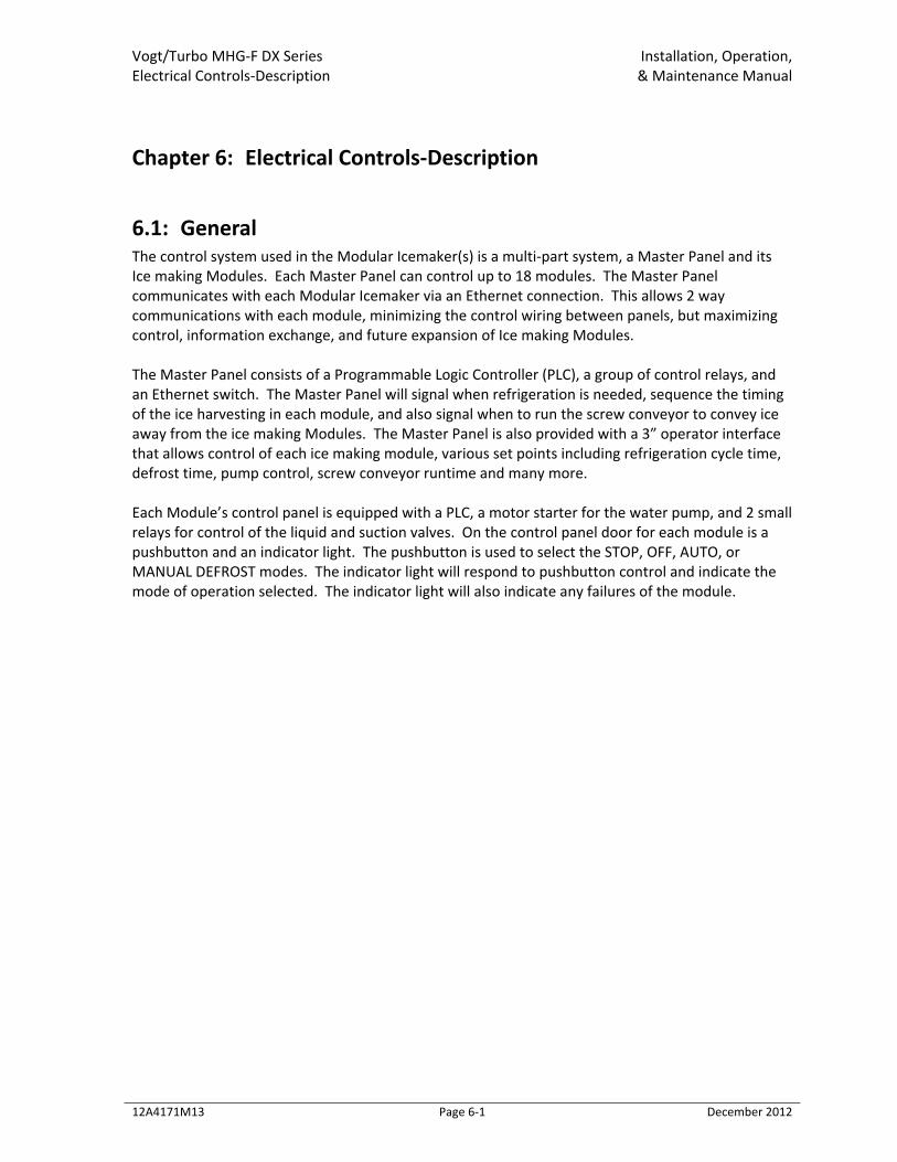
6.1: General The control system used in the Modular Icemaker(s) is a multi‐part system, a Master Panel and its Ice making Modules. Each Master Panel can control up to 18 modules. The Master Panel communicates with each Modular Icemaker via an Ethernet connection. This allows 2 way communications with each module, minimizing the control wiring between panels, but maximizing control, information exchange, and future expansion of Ice making Modules. The Master Panel consists of a Programmable Logic Controller (PLC), a group of control relays, and an Ethernet switch. The Master Panel will signal when refrigeration is needed, sequence the timing of the ice harvesting in each module, and also signal when to run the screw conveyor to convey ice away from the ice making Modules. The Master Panel is also provided with a 3” operator interface that allows control of each ice making module, various set points including refrigeration cycle time, defrost time, pump control, screw conveyor runtime and many more. Each Module’s control panel is equipped with a PLC, a motor starter for the water pump, and 2 small relays for control of the liquid and suction valves. On the control panel door for each module is a pushbutton and an indicator light. The pushbutton is used to select the STOP, OFF, AUTO, or MANUAL DEFROST modes. The indicator light will respond to pushbutton control and indicate the mode of operation selected. The indicator light will also indicate any failures of the module.
Vogt/Turbo MHG‐F DX Series Installation, Operation, Electrical Controls‐Description & Maintenance Manual
12A4171M13 Page 6‐2 December 2012
Figure 6‐1 Typical Master/Modular Set‐Up
Vogt/Turbo MHG‐F DX Series Installation, Operation, Electrical Controls‐Description & Maintenance Manual
12A4171M13 Page 6‐3 December 2012
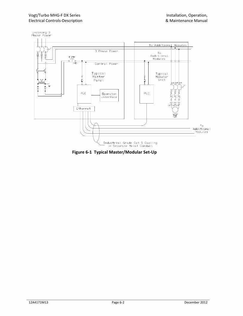
Figure 6‐2 Exterior Master Panel View
Vogt/Turbo MHG‐F DX Series Installation, Operation, Electrical Controls‐Description & Maintenance Manual
12A4171M13 Page 6‐4 December 2012
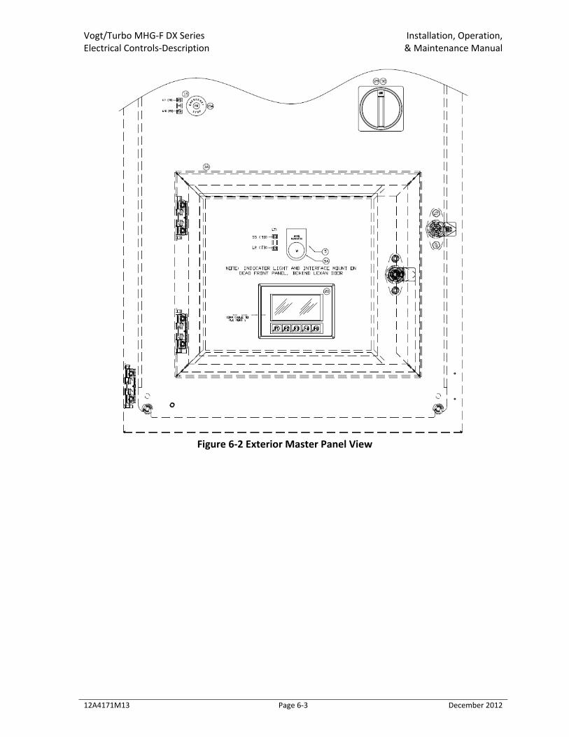
Figure 6‐3 Internal Master Panel View
PLC Programmable Logic Controller‐controls the various relays in the panel and contains the
program. FUSE Fuse‐protects the control circuit inside the control panel PS1 Power Supply for ETH1‐provides 24VDC for the ETH1 ETH1 Ethernet Switch‐used to connect the CAT5 wiring to each Modular ice maker CR1 Control Relay 1‐used to signal the ammonia pump or compressor high when to run. SFR Safety Failure Relay‐energized anytime the Master panel fails or detects a failure in one
of the Modules HPLSR High Pressure Liquid Solenoid Relay‐this relay energizes any time the level switch in the
surge detects a low level. SCR1 Screw Conveyor 1 Relay‐energizes to indicate when a customer supplied screw conveyor
needs to run to carry ice away from any module. Table 6‐1 Master Control Panel Components
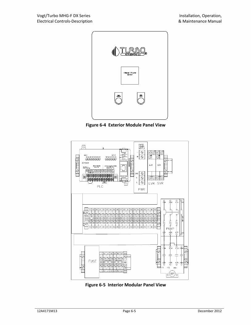
Vogt/Turbo MHG‐F DX Series Installation, Operation, Electrical Controls‐Description & Maintenance Manual
12A4171M13 Page 6‐5 December 2012
Figure 6‐4 Exterior Module Panel View
Figure 6‐5 Interior Modular Panel View
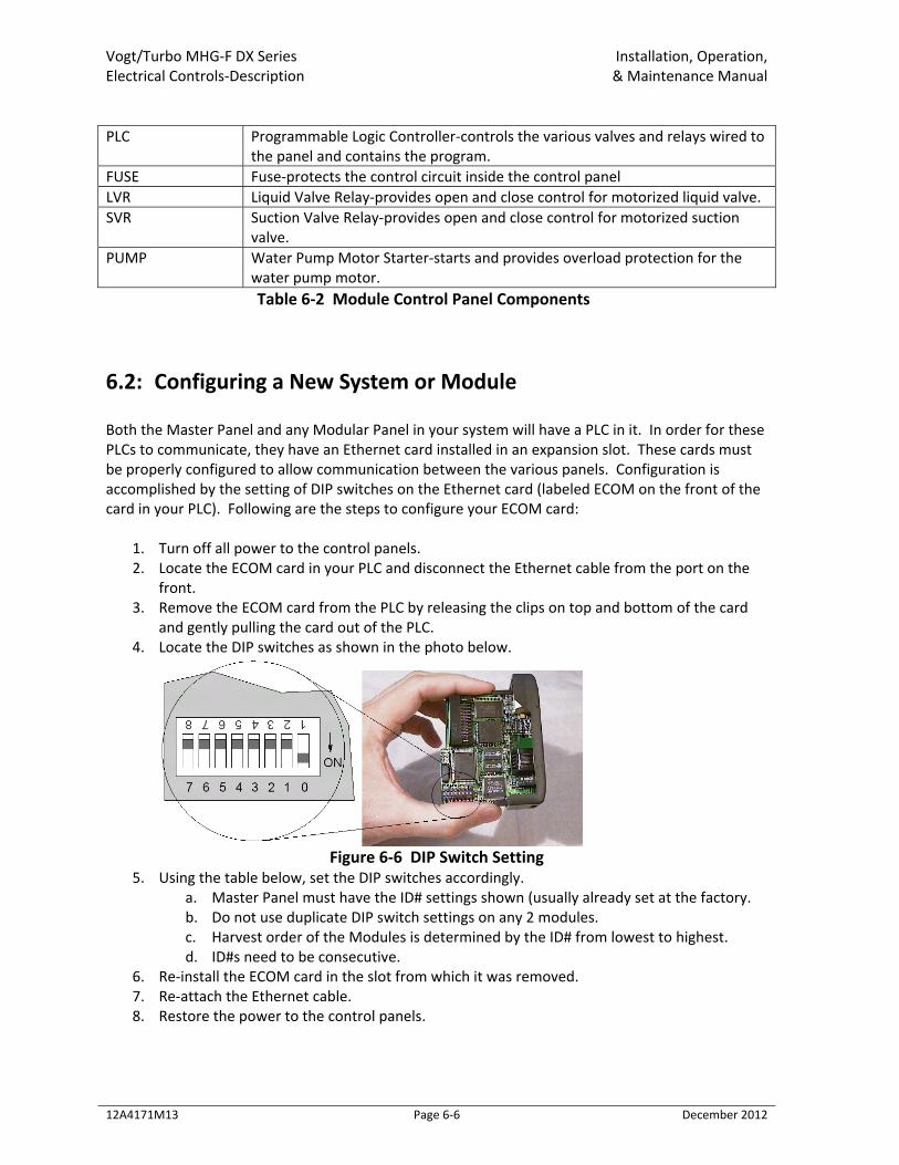
Vogt/Turbo MHG‐F DX Series Installation, Operation, Electrical Controls‐Description & Maintenance Manual
12A4171M13 Page 6‐6 December 2012
PLC Programmable Logic Controller‐controls the various valves and relays wired to
the panel and contains the program. FUSE Fuse‐protects the control circuit inside the control panel LVR Liquid Valve Relay‐provides open and close control for motorized liquid valve. SVR Suction Valve Relay‐provides open and close control for motorized suction
valve. PUMP Water Pump Motor Starter‐starts and provides overload protection for the
water pump motor. Table 6‐2 Module Control Panel Components
6.2: Configuring a New System or Module Both the Master Panel and any Modular Panel in your system will have a PLC in it. In order for these PLCs to communicate, they have an Ethernet card installed in an expansion slot. These cards must be properly configured to allow communication between the various panels. Configuration is accomplished by the setting of DIP switches on the Ethernet card (labeled ECOM on the front of the card in your PLC). Following are the steps to configure your ECOM card:
1. Turn off all power to the control panels. 2. Locate the ECOM card in your PLC and disconnect the Ethernet cable from the port on the
front. 3. Remove the ECOM card from the PLC by releasing the clips on top and bottom of the card
and gently pulling the card out of the PLC. 4. Locate the DIP switches as shown in the photo below.
Figure 6‐6 DIP Switch Setting
5. Using the table below, set the DIP switches accordingly. a. Master Panel must have the ID# settings shown (usually already set at the factory. b. Do not use duplicate DIP switch settings on any 2 modules. c. Harvest order of the Modules is determined by the ID# from lowest to highest. d. ID#s need to be consecutive.
6. Re‐install the ECOM card in the slot from which it was removed. 7. Re‐attach the Ethernet cable. 8. Restore the power to the control panels.
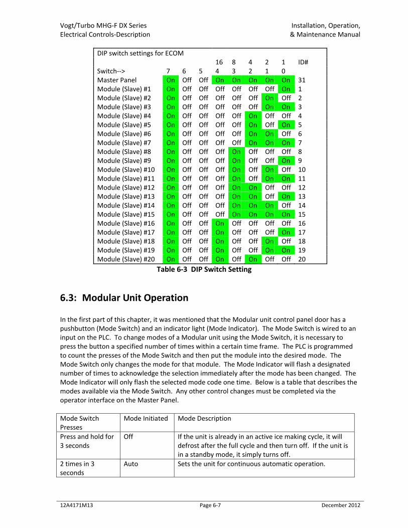
Vogt/Turbo MHG‐F DX Series Installation, Operation, Electrical Controls‐Description & Maintenance Manual
12A4171M13 Page 6‐7 December 2012
DIP switch settings for ECOM 16 8 4 2 1 ID# Switch‐‐> 7 6 5 4 3 2 1 0 Master Panel On Off Off On On On On On 31 Module (Slave) #1 On Off Off Off Off Off Off On 1 Module (Slave) #2 On Off Off Off Off Off On Off 2 Module (Slave) #3 On Off Off Off Off Off On On 3 Module (Slave) #4 On Off Off Off Off On Off Off 4 Module (Slave) #5 On Off Off Off Off On Off On 5 Module (Slave) #6 On Off Off Off Off On On Off 6 Module (Slave) #7 On Off Off Off Off On On On 7 Module (Slave) #8 On Off Off Off On Off Off Off 8 Module (Slave) #9 On Off Off Off On Off Off On 9 Module (Slave) #10 On Off Off Off On Off On Off 10 Module (Slave) #11 On Off Off Off On Off On On 11 Module (Slave) #12 On Off Off Off On On Off Off 12 Module (Slave) #13 On Off Off Off On On Off On 13 Module (Slave) #14 On Off Off Off On On On Off 14 Module (Slave) #15 On Off Off Off On On On On 15 Module (Slave) #16 On Off Off On Off Off Off Off 16 Module (Slave) #17 On Off Off On Off Off Off On 17 Module (Slave) #18 On Off Off On Off Off On Off 18 Module (Slave) #19 On Off Off On Off Off On On 19 Module (Slave) #20 On Off Off On Off On Off Off 20
Table 6‐3 DIP Switch Setting
6.3: Modular Unit Operation In the first part of this chapter, it was mentioned that the Modular unit control panel door has a pushbutton (Mode Switch) and an indicator light (Mode Indicator). The Mode Switch is wired to an input on the PLC. To change modes of a Modular unit using the Mode Switch, it is necessary to press the button a specified number of times within a certain time frame. The PLC is programmed to count the presses of the Mode Switch and then put the module into the desired mode. The Mode Switch only changes the mode for that module. The Mode Indicator will flash a designated number of times to acknowledge the selection immediately after the mode has been changed. The Mode Indicator will only flash the selected mode code one time. Below is a table that describes the modes available via the Mode Switch. Any other control changes must be completed via the operator interface on the Master Panel. Mode Switch Presses
Mode Initiated Mode Description
Press and hold for 3 seconds
Off If the unit is already in an active ice making cycle, it will defrost after the full cycle and then turn off. If the unit is in a standby mode, it simply turns off.
2 times in 3 seconds
Auto Sets the unit for continuous automatic operation.
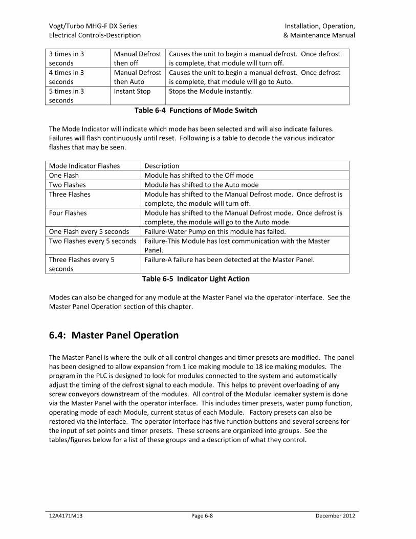
Vogt/Turbo MHG‐F DX Series Installation, Operation, Electrical Controls‐Description & Maintenance Manual
12A4171M13 Page 6‐8 December 2012
3 times in 3 seconds
Manual Defrost then off
Causes the unit to begin a manual defrost. Once defrost is complete, that module will turn off.
4 times in 3 seconds
Manual Defrost then Auto
Causes the unit to begin a manual defrost. Once defrost is complete, that module will go to Auto.
5 times in 3 seconds
Instant Stop Stops the Module instantly.
Table 6‐4 Functions of Mode Switch The Mode Indicator will indicate which mode has been selected and will also indicate failures. Failures will flash continuously until reset. Following is a table to decode the various indicator flashes that may be seen. Mode Indicator Flashes Description One Flash Module has shifted to the Off mode Two Flashes Module has shifted to the Auto mode Three Flashes Module has shifted to the Manual Defrost mode. Once defrost is
complete, the module will turn off. Four Flashes Module has shifted to the Manual Defrost mode. Once defrost is
complete, the module will go to the Auto mode. One Flash every 5 seconds Failure‐Water Pump on this module has failed. Two Flashes every 5 seconds Failure‐This Module has lost communication with the Master
Panel. Three Flashes every 5 seconds
Failure‐A failure has been detected at the Master Panel.
Table 6‐5 Indicator Light Action Modes can also be changed for any module at the Master Panel via the operator interface. See the Master Panel Operation section of this chapter.
6.4: Master Panel Operation The Master Panel is where the bulk of all control changes and timer presets are modified. The panel has been designed to allow expansion from 1 ice making module to 18 ice making modules. The program in the PLC is designed to look for modules connected to the system and automatically adjust the timing of the defrost signal to each module. This helps to prevent overloading of any screw conveyors downstream of the modules. All control of the Modular Icemaker system is done via the Master Panel with the operator interface. This includes timer presets, water pump function, operating mode of each Module, current status of each Module. Factory presets can also be restored via the interface. The operator interface has five function buttons and several screens for the input of set points and timer presets. These screens are organized into groups. See the tables/figures below for a list of these groups and a description of what they control.
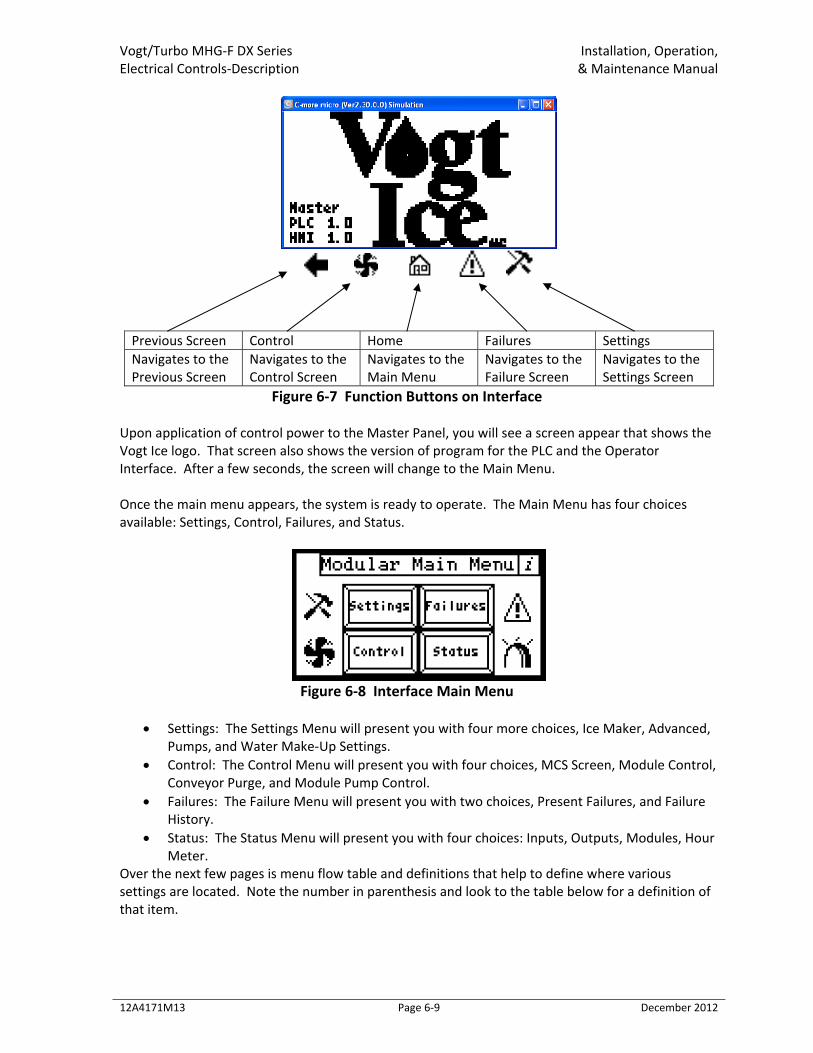
Vogt/Turbo MHG‐F DX Series Installation, Operation, Electrical Controls‐Description & Maintenance Manual
12A4171M13 Page 6‐9 December 2012
Previous Screen Control Home Failures Settings Navigates to the Previous Screen
Navigates to the Control Screen
Navigates to the Main Menu
Navigates to the Failure Screen
Navigates to the Settings Screen
Figure 6‐7 Function Buttons on Interface Upon application of control power to the Master Panel, you will see a screen appear that shows the Vogt Ice logo. That screen also shows the version of program for the PLC and the Operator Interface. After a few seconds, the screen will change to the Main Menu. Once the main menu appears, the system is ready to operate. The Main Menu has four choices available: Settings, Control, Failures, and Status.
Figure 6‐8 Interface Main Menu
• Settings: The Settings Menu will present you with four more choices, Ice Maker, Advanced,
Pumps, and Water Make‐Up Settings. • Control: The Control Menu will present you with four choices, MCS Screen, Module Control,
Conveyor Purge, and Module Pump Control. • Failures: The Failure Menu will present you with two choices, Present Failures, and Failure
History. • Status: The Status Menu will present you with four choices: Inputs, Outputs, Modules, Hour
Meter. Over the next few pages is menu flow table and definitions that help to define where various settings are located. Note the number in parenthesis and look to the table below for a definition of that item.
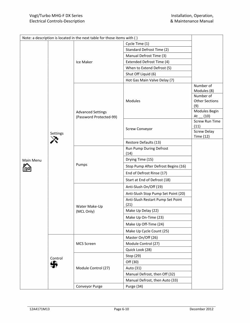
Vogt/Turbo MHG‐F DX Series Installation, Operation, Electrical Controls‐Description & Maintenance Manual
12A4171M13 Page 6‐10 December 2012
Note: a description is located in the next table for those items with ( )
Main Menu
Settings
Ice Maker
Cycle Time (1) Standard Defrost Time (2) Manual Defrost Time (3) Extended Defrost Time (4) When to Extend Defrost (5) Shut Off Liquid (6) Hot Gas Main Valve Delay (7)
Advanced Settings (Password Protected‐99)
Modules
Number of Modules (8) Number ofOther Sections (9) Modules Begin At __ (10)
Screw Conveyor
Screw Run Time (11) Screw Delay Time (12)
Restore Defaults (13)
Pumps
Run Pump During Defrost (14) Drying Time (15)
Stop Pump After Defrost Begins (16)
End of Defrost Rinse (17)
Start at End of Defrost (18)
Water Make‐Up (MCL Only)
Anti‐Slush On/Off (19)
Anti‐Slush Stop Pump Set Point (20) Anti‐Slush Restart Pump Set Point (21) Make Up Delay (22)
Make Up On‐Time (23)
Make Up Off‐Time (24)
Make Up Cycle Count (25)
Control
MCS Screen Master On/Off (26) Module Control (27) Quick Look (28)
Module Control (27)
Stop (29) Off (30) Auto (31) Manual Defrost, then Off (32) Manual Defrost, then Auto (33)
Conveyor Purge Purge (34)
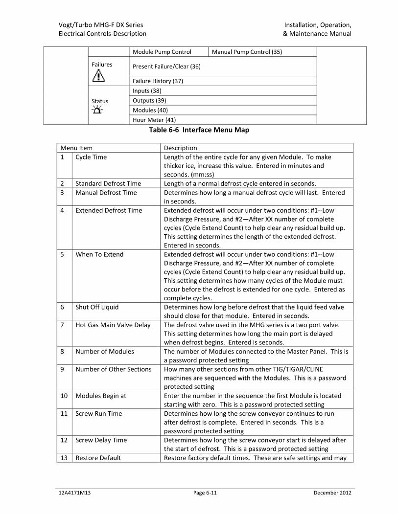
Vogt/Turbo MHG‐F DX Series Installation, Operation, Electrical Controls‐Description & Maintenance Manual
12A4171M13 Page 6‐11 December 2012
Module Pump Control Manual Pump Control (35)
Failures
Present Failure/Clear (36)
Failure History (37)
Status
Inputs (38) Outputs (39) Modules (40) Hour Meter (41)
Table 6‐6 Interface Menu Map Menu Item Description 1 Cycle Time Length of the entire cycle for any given Module. To make
thicker ice, increase this value. Entered in minutes and seconds. (mm:ss)
2 Standard Defrost Time Length of a normal defrost cycle entered in seconds. 3 Manual Defrost Time Determines how long a manual defrost cycle will last. Entered
in seconds. 4 Extended Defrost Time Extended defrost will occur under two conditions: #1‐‐Low
Discharge Pressure, and #2—After XX number of complete cycles (Cycle Extend Count) to help clear any residual build up. This setting determines the length of the extended defrost. Entered in seconds.
5 When To Extend Extended defrost will occur under two conditions: #1‐‐Low Discharge Pressure, and #2—After XX number of complete cycles (Cycle Extend Count) to help clear any residual build up. This setting determines how many cycles of the Module must occur before the defrost is extended for one cycle. Entered as complete cycles.
6 Shut Off Liquid Determines how long before defrost that the liquid feed valve should close for that module. Entered in seconds.
7 Hot Gas Main Valve Delay The defrost valve used in the MHG series is a two port valve. This setting determines how long the main port is delayed when defrost begins. Entered is seconds.
8 Number of Modules The number of Modules connected to the Master Panel. This is a password protected setting
9 Number of Other Sections How many other sections from other TIG/TIGAR/CLINE machines are sequenced with the Modules. This is a password protected setting
10 Modules Begin at Enter the number in the sequence the first Module is located starting with zero. This is a password protected setting
11 Screw Run Time Determines how long the screw conveyor continues to run after defrost is complete. Entered in seconds. This is a password protected setting
12 Screw Delay Time Determines how long the screw conveyor start is delayed after the start of defrost. This is a password protected setting
13 Restore Default Restore factory default times. These are safe settings and may
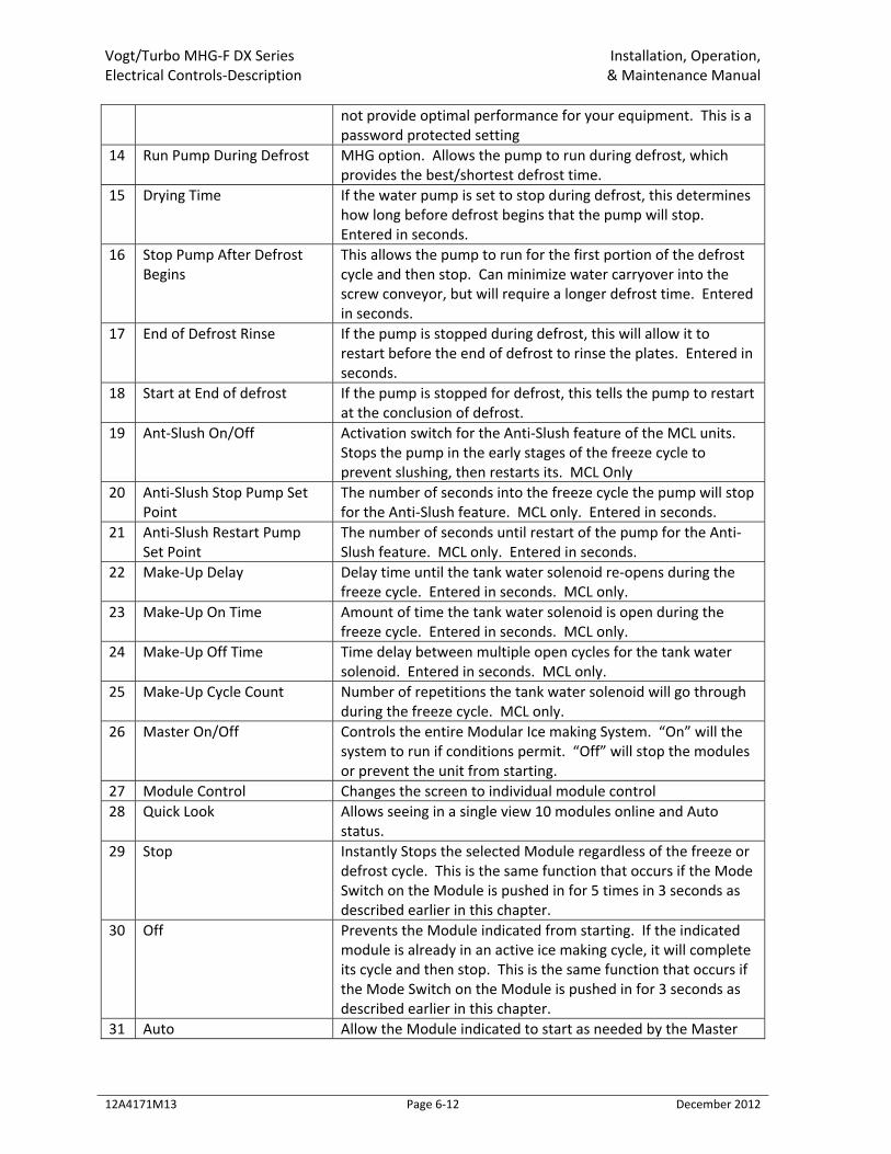
Vogt/Turbo MHG‐F DX Series Installation, Operation, Electrical Controls‐Description & Maintenance Manual
12A4171M13 Page 6‐12 December 2012
not provide optimal performance for your equipment. This is a password protected setting
14 Run Pump During Defrost MHG option. Allows the pump to run during defrost, which provides the best/shortest defrost time.
15 Drying Time If the water pump is set to stop during defrost, this determines how long before defrost begins that the pump will stop. Entered in seconds.
16 Stop Pump After Defrost Begins
This allows the pump to run for the first portion of the defrost cycle and then stop. Can minimize water carryover into the screw conveyor, but will require a longer defrost time. Entered in seconds.
17 End of Defrost Rinse If the pump is stopped during defrost, this will allow it to restart before the end of defrost to rinse the plates. Entered in seconds.
18 Start at End of defrost If the pump is stopped for defrost, this tells the pump to restart at the conclusion of defrost.
19 Ant‐Slush On/Off Activation switch for the Anti‐Slush feature of the MCL units. Stops the pump in the early stages of the freeze cycle to prevent slushing, then restarts its. MCL Only
20 Anti‐Slush Stop Pump Set Point
The number of seconds into the freeze cycle the pump will stop for the Anti‐Slush feature. MCL only. Entered in seconds.
21 Anti‐Slush Restart Pump Set Point
The number of seconds until restart of the pump for the Anti‐Slush feature. MCL only. Entered in seconds.
22 Make‐Up Delay Delay time until the tank water solenoid re‐opens during the freeze cycle. Entered in seconds. MCL only.
23 Make‐Up On Time Amount of time the tank water solenoid is open during the freeze cycle. Entered in seconds. MCL only.
24 Make‐Up Off Time Time delay between multiple open cycles for the tank water solenoid. Entered in seconds. MCL only.
25 Make‐Up Cycle Count Number of repetitions the tank water solenoid will go through during the freeze cycle. MCL only.
26 Master On/Off Controls the entire Modular Ice making System. “On” will the system to run if conditions permit. “Off” will stop the modules or prevent the unit from starting.
27 Module Control Changes the screen to individual module control 28 Quick Look Allows seeing in a single view 10 modules online and Auto
status. 29 Stop Instantly Stops the selected Module regardless of the freeze or
defrost cycle. This is the same function that occurs if the Mode Switch on the Module is pushed in for 5 times in 3 seconds as described earlier in this chapter.
30 Off Prevents the Module indicated from starting. If the indicated module is already in an active ice making cycle, it will complete its cycle and then stop. This is the same function that occurs if the Mode Switch on the Module is pushed in for 3 seconds as described earlier in this chapter.
31 Auto Allow the Module indicated to start as needed by the Master
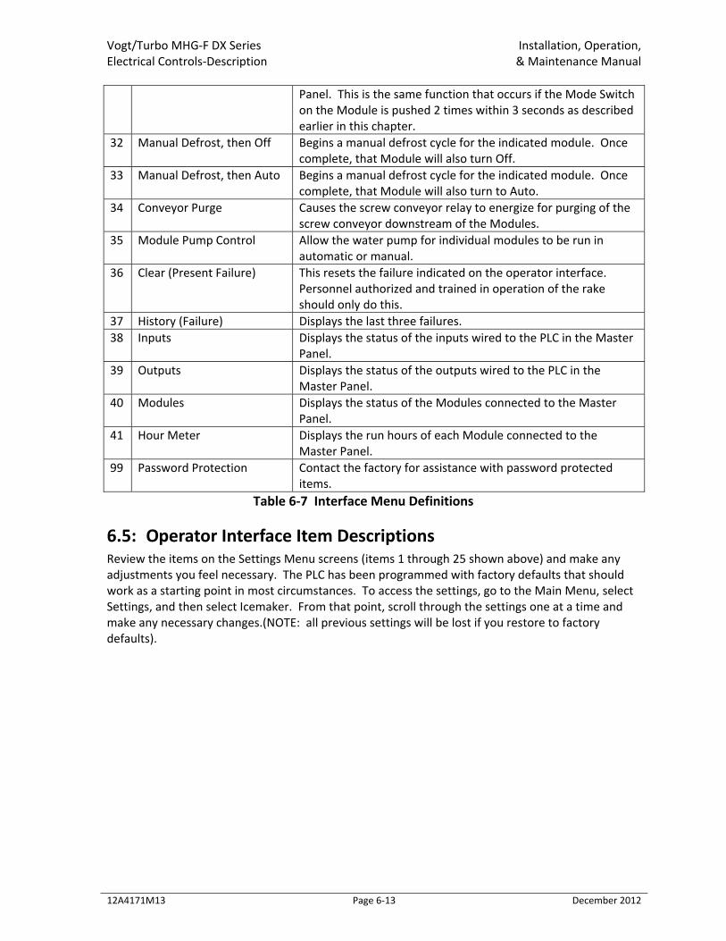
Vogt/Turbo MHG‐F DX Series Installation, Operation, Electrical Controls‐Description & Maintenance Manual
12A4171M13 Page 6‐13 December 2012
Panel. This is the same function that occurs if the Mode Switch on the Module is pushed 2 times within 3 seconds as described earlier in this chapter.
32 Manual Defrost, then Off Begins a manual defrost cycle for the indicated module. Once complete, that Module will also turn Off.
33 Manual Defrost, then Auto Begins a manual defrost cycle for the indicated module. Once complete, that Module will also turn to Auto.
34 Conveyor Purge Causes the screw conveyor relay to energize for purging of the screw conveyor downstream of the Modules.
35 Module Pump Control Allow the water pump for individual modules to be run in automatic or manual.
36 Clear (Present Failure) This resets the failure indicated on the operator interface. Personnel authorized and trained in operation of the rake should only do this.
37 History (Failure) Displays the last three failures. 38 Inputs Displays the status of the inputs wired to the PLC in the Master
Panel. 39 Outputs Displays the status of the outputs wired to the PLC in the
Master Panel. 40 Modules Displays the status of the Modules connected to the Master
Panel. 41 Hour Meter Displays the run hours of each Module connected to the
Master Panel. 99 Password Protection Contact the factory for assistance with password protected
items. Table 6‐7 Interface Menu Definitions
6.5: Operator Interface Item Descriptions Review the items on the Settings Menu screens (items 1 through 25 shown above) and make any adjustments you feel necessary. The PLC has been programmed with factory defaults that should work as a starting point in most circumstances. To access the settings, go to the Main Menu, select Settings, and then select Icemaker. From that point, scroll through the settings one at a time and make any necessary changes.(NOTE: all previous settings will be lost if you restore to factory defaults).
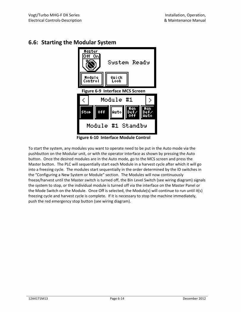
Vogt/Turbo MHG‐F DX Series Installation, Operation, Electrical Controls‐Description & Maintenance Manual
12A4171M13 Page 6‐14 December 2012
6.6: Starting the Modular System
Figure 6‐9 Interface MCS Screen
Figure 6‐10 Interface Module Control
To start the system, any modules you want to operate need to be put in the Auto mode via the pushbutton on the Modular unit, or with the operator interface as shown by pressing the Auto button. Once the desired modules are in the Auto mode, go to the MCS screen and press the Master button. The PLC will sequentially start each Module in a harvest cycle after which it will go into a freezing cycle. The modules start sequentially in the order determined by the ID switches in the “Configuring a New System or Module” section. The Modules will now continuously freeze/harvest until the Master switch is turned off, the Bin Level Switch (see wiring diagram) signals the system to stop, or the individual module is turned off via the interface on the Master Panel or the Mode Switch on the Module. Once Off is selected, the Module(s) will continue to run until it(s) freezing cycle and harvest cycle is complete. If it is necessary to stop the machine immediately, push the red emergency stop button (see wiring diagram).
Vogt/Turbo MHG‐F DX Series Installation, Operation, Maintenance & Maintenance Manual
12A4171M13 Page 7‐1 December 2012
Chapter 7: Maintenance
7.1: Preventive Maintenance A careful inspection of the Vogt Ice machines refrigeration system for leaks and correct operational functions at time of installation will start its long satisfactory life of service. In order to insure this degree of dependability, a systematic maintenance program is recommended. Therefore, the following schedule is suggested as a minimum. A. Daily
1) Check operating pressures (suction, discharge, oil). 2) Check ice quality. 3) Check “ice out” time (maintain 15 seconds of continued harvest after last ice is out). 4) Check compressor oil level. 5) Check refrigerant operation level. 6) Check frost pattern on freezer plates and oil trap. 7) Check make‐up water float valve adjustment.
B. Weekly (in addition to daily checks) 1) Check for leaks after 400 hours or four weeks of operation
C. Monthly (in addition to weekly checks) 1) Check calibration and operation of all controls (high and low pressure switches, oil
pressure switch, etc.) 2) Check cooling tower spray nozzles and pump suction screen for scaling and algae (consult
water treatment suppliers for corrective measures). 3) Check water distribution and freezer plates for scale accumulation. 4) Check water tank for solids to be removed. 5) Check all motor drive units (compressor, pump motors, cooling tower fan, and pump, etc.)
for abnormal noise and/or vibrations. 6) Check one complete freeze/thaw cycle, record data and compare with production check of
Registration/Start‐up Report. D. Yearly (in addition to weekly and monthly)
1) Check entire system for leaks. 2) Drain water from condenser and cooling tower and check condenser tubes. Check closely
for damage by corrosion or scale. 3) Remove all rust from all equipment, clean, and paint. 4) Check all motors for shaft wear and end play. 5) Check operation and general condition of all electrical controls, relays, motor starters, and
solenoid valves. 6) Check freezing time, ice release time, and ice out time. 7) Lubricate compressor motor bearings.
Vogt/Turbo MHG‐F DX Series Installation, Operation, Maintenance & Maintenance Manual
12A4171M13 Page 7‐2 December 2012
7.2: Preventative Maintenance Form This form can be removed and duplicated for record keeping. Date: ______________ Model #: __________________ Serial #: ___________________ The following service performed and checked:
Hour meter reading _______________ , Ambient temperature (inside)_______ °F Make‐Up water float valve adjusted properly Water distribution clean and in place All drains freely draining Cleaned and flushed water tank Compressor oil changed Cleaned and inspected inside compressor crankcase Changed compressor oil filter Checked/adjusted compressor belt tension or alignment Lubricate compressor motor bearings Leak check entire system Check liquid refrigerant level in receiver Drained oil from oil trap Compressor crankcase heater working Compressor net oil pressure (gage reading less suction)
Compressor Motor amps:________ Discharge Pressure________ Defrost Pressure_________ Module 1
Water Pump Amps_________ Suction Pressure (end of freeze)_______ Defrost Bypass Valve Turns Open_________ Superheat (end of cycle)_________ Full Sheets of Ice During Freeze_________ Ice Thickness____________
Module 2 Water Pump Amps_________ Suction Pressure (end of freeze)_______ Defrost Bypass Valve Turns Open_________ Superheat (end of cycle)_________ Full Sheets of Ice During Freeze_________ Ice Thickness____________
Repeat for all modules Tower fan cycles ___ On ___ Off Comments: _______________________________________________________________________ _________________________________________________________________________________ Name: __________________________________
Vogt/Turbo MHG‐F DX Series Installation, Operation, Maintenance & Maintenance Manual
12A4171M13 Page 7‐3 December 2012
7.3: General Cleaning The ice‐making section of the Vogt‐Ice machine should be cleaned at least twice a year (more often if water conditions cause mineral build‐up). Use an approved food‐grade ice machine cleaner. The water pump is used to circulate the cleaner through the system by manually operating it with the operator interface located at the Master Panel. Set the water pump to “Manual” operation from the “Module Pump Control” screen to start the water pump and to “Auto” when you are done to stop the water pump. For complete instructions, refer to the “Cleaning Procedure” attached to the equipment and duplicated here.
7.3.1: Procedure 1. Before cleaning any Tube‐Ice machine make sure the crankcase heater is working properly.
When the crankcase heater is not working there is a possibility for refrigerant evaporated by warm circulating water to migrate to the compressor during the cleaning operation
2. Turn the Module to “Off” with the Operator Interface. If the machine is running, it will shut down on completion of the next ice harvest period.
3. Remove ice from storage area or cover ice discharge opening to prevent water from splashing out and contaminating stored ice.
4. Shut off water supply and drain water tank by removing the over flow tube. Remove any loose sediment from tank.
5. Return the overflow piping and fill water tank (approximately 25 gallons) with warm water. 6. Add 72 ounces (8 ounces per 3 gallons) of Calgon™ ice machine cleaner (a food grade liquid
phosphoric acid) to water tank during the refill period. 7. Inspect the water pan. 8. Set the water pump to “Manual” operation from the “Module Pump Control” screen to start
the water pump. 9. Circulate cleaning solution until deposits are dissolved or solution is neutralized. Repeat
cleaning if necessary. 10. To stop the water pump, set the water pump to “Auto” operation from the “Module Pump
Control” screen. Then drain and flush water tank with fresh water. Open water supply to machine.
11. Drain and flush tank and then refill with fresh water. 12. Clean inside of ice storage area and remove any solution that entered during the cleaning
process. Remove cover if one was installed over opening into storage area. 13. Start ice making cycle by selecting “Auto” setting from the “Module Control” screen and
then selecting “On” from the MCS screen.
7.3.2: Water Distribution System The water distribution pan and perforated sheet is located under the top panel at the top of the plates. This pan may require occasional or periodic cleaning to remove solids and foreign particles accumulated from the make‐up water. The frequency of this cleaning operation will depend on the characteristics of the water supply. The cleaning operation is needed when the distribution pan holes become partially clogged and disrupt normal water flow onto the evaporator plates. See Figure 7‐1 Water Distribution System. To clean water pan, stop the unit and remove the water header on top of the plates. Note the orientation of the PVC perforated sheet and match mark it
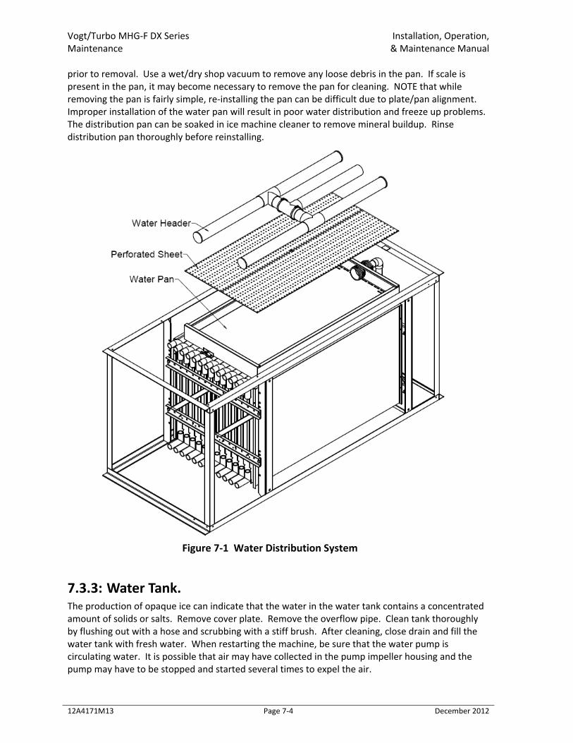
Vogt/Turbo MHG‐F DX Series Installation, Operation, Maintenance & Maintenance Manual
12A4171M13 Page 7‐4 December 2012
prior to removal. Use a wet/dry shop vacuum to remove any loose debris in the pan. If scale is present in the pan, it may become necessary to remove the pan for cleaning. NOTE that while removing the pan is fairly simple, re‐installing the pan can be difficult due to plate/pan alignment. Improper installation of the water pan will result in poor water distribution and freeze up problems. The distribution pan can be soaked in ice machine cleaner to remove mineral buildup. Rinse distribution pan thoroughly before reinstalling.
Figure 7‐1 Water Distribution System
7.3.3: Water Tank. The production of opaque ice can indicate that the water in the water tank contains a concentrated amount of solids or salts. Remove cover plate. Remove the overflow pipe. Clean tank thoroughly by flushing out with a hose and scrubbing with a stiff brush. After cleaning, close drain and fill the water tank with fresh water. When restarting the machine, be sure that the water pump is circulating water. It is possible that air may have collected in the pump impeller housing and the pump may have to be stopped and started several times to expel the air.
Vogt/Turbo MHG‐F DX Series Installation, Operation, Maintenance & Maintenance Manual
12A4171M13 Page 7‐5 December 2012
! CAUTION !
The water distribution system is critical to proper machine operation. Failure to maintain and clean water distribution components can result in improper machine operation and
compressor failure. ! CAUTION !
! DANGER !
Follow all lock‐out and tag‐out procedures before servicing any electrical equipment. ! DANGER !
7.4: Other Maintenance Operations The following sections outline some general guidelines for service of auxiliary equipment. Always follow the instructions provided by equipment manufacturers when performing service operations or scheduled maintenance.
7.4.1: Water Cooled Condenser Cleaning As water evaporates from a cooling tower, the solid impurities remain and must be flushed from the system to prevent a scale build‐up in the condenser and cooling tower. This can be accomplished by a continuous bleed off valve located in the pump discharge line. The valve should be adjusted to bleed off an equal amount of water that is evaporated. If water hardness is very high, a higher bleed off rate or chemical treatment may be required. Consult your local water treatment company for recommendations. If after a period of time, scale has formed inside the tubes, mechanical cleaning may be necessary. See “Servicing Section‐‐Condenser”.
7.4.2: Cooling Tower/Evaporative Condenser 1. Bleed off valve. The bleed off valve should be checked monthly to assure that is not blocked
and that water is flowing as required. If the unit is controlled by a water treatment system, the bleed off valve may not be required.
2. Strainer. The pan or sump strainer is located in the bottom of the sump at the suction connection to the pump. The strainer should be inspected monthly and kept clean. Do not operate the unit without the strainer in place.
3. Make‐up water float valve. This valve should be checked monthly for proper operation and adjustment. It should be adjusted to maintain a water level below the overflow and high enough to prevent the pump from cavitating when the system is in operation.
4. Spray nozzles. The spray nozzles should be checked monthly to make sure none are restricted and the spray pattern is complete and even.
5. Pump motor and fan motor. The motors should be checked and/or lubricated every six months according to the motor manufacturer’s recommendations.
Vogt/Turbo MHG‐F DX Series Installation, Operation, Maintenance & Maintenance Manual
12A4171M13 Page 7‐6 December 2012
6. Fan bearings. The fan bearings should be lubricated every six months. Make sure the proper grade of grease is used (normally conforms to NLCI‐Grade 2) and it is best to use a hand grease gun.
7. Fan belts. The fan belt tension should be checked weekly for the first two weeks of operation, then monthly during continuous use. The best tension for a V‐belt is the lowest tension at which the belt will not slip under its full load. Never use dressing on V‐belts. Keep belts and grooves clean and free of oil, grease, and foreign material. Clean with non‐flammable, non‐toxic degreasing agent or commercial detergent and water.
! CAUTION !
Follow all lock‐out and tag‐out procedures before servicing any electrical equipment. ! CAUTION !
Maintenance Operation Start‐Up Monthly Six Months Shutdown Clean debris from unit X X X Clean strainer and flush sump X X X Check fan and pump rotation X Clean spray nozzles X X Check belt tension X X Check for noise/vibration X X Check/adjust make‐up water valve X X Check/adjust bleed rate X X Check/lubricate fan bearings X X Lubricate motor base adj. Screw X X X Drain sump and piping X
Table 7‐1 Cooling Tower Maintenance Schedule
7.4.3: Compressor This section is only a guide; consult the compressor manual for manufacturers recommended maintenance. In starting and charging the unit, the oil sight glass should be continually checked to make sure an adequate oil level is maintained. The oil level should be 1/4‐3/4 of the sight glass. If the oil level drops below 1/4 of the glass, add refrigeration oil as per the compressor manufacturer recommendations. Never allow the oil level to be out of sight, above or below the sight glass when the compressor is operating.
! CAUTION ! The crankcase heater should be energized for a minimum of four hours and the oil temperature should be 100°‐110°F before attempting to start the compressor.
! CAUTION !
! DANGER !
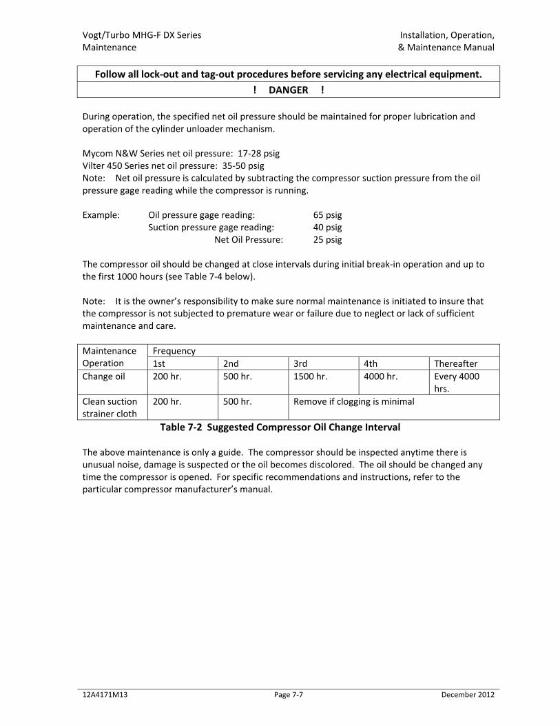
Vogt/Turbo MHG‐F DX Series Installation, Operation, Maintenance & Maintenance Manual
12A4171M13 Page 7‐7 December 2012
Follow all lock‐out and tag‐out procedures before servicing any electrical equipment. ! DANGER !
During operation, the specified net oil pressure should be maintained for proper lubrication and operation of the cylinder unloader mechanism. Mycom N&W Series net oil pressure: 17‐28 psig Vilter 450 Series net oil pressure: 35‐50 psig Note: Net oil pressure is calculated by subtracting the compressor suction pressure from the oil pressure gage reading while the compressor is running. Example: Oil pressure gage reading: 65 psig Suction pressure gage reading: 40 psig Net Oil Pressure: 25 psig The compressor oil should be changed at close intervals during initial break‐in operation and up to the first 1000 hours (see Table 7‐4 below). Note: It is the owner’s responsibility to make sure normal maintenance is initiated to insure that the compressor is not subjected to premature wear or failure due to neglect or lack of sufficient maintenance and care. Maintenance Operation
Frequency 1st 2nd 3rd 4th Thereafter
Change oil 200 hr. 500 hr. 1500 hr. 4000 hr. Every 4000 hrs.
Clean suction strainer cloth
200 hr. 500 hr. Remove if clogging is minimal
Table 7‐2 Suggested Compressor Oil Change Interval The above maintenance is only a guide. The compressor should be inspected anytime there is unusual noise, damage is suspected or the oil becomes discolored. The oil should be changed any time the compressor is opened. For specific recommendations and instructions, refer to the particular compressor manufacturer’s manual.

Vogt/Turbo MHG‐F DX Series Installation, Operation, Troubleshooting & Maintenance Manual
12A4171M13 Page 8‐1 December 2012
Chapter 8: Troubleshooting
! WARNING ! Only service personnel experienced and certified in refrigeration and qualified to work with high voltage electrical equipment should be allowed to install or work on this Turbo
Refrigerating® machine. ! WARNING !
! CAUTION !
Follow all lock‐out and tag‐out procedures before servicing any electrical equipment. ! CAUTION !
Note: Your machine’s electrical system has several built‐in safety and overload protection features to stop operation when a single component fails or there is a problem from an outside source such as a power supply. Make sure all auxiliary equipment is connected to incorporate safety and overload circuits and protect all related equipment. When the machine stops, it must be manually restarted by putting the Module in Auto and pushing the MCS button on the Master Panel operator interface. The machine will restart in a harvest to clear any ice from the plates before beginning another cycle. Always check the machine operation thoroughly after remedying the problem. Be sure to correct the source or cause of the problem to prevent the problem from occurring again. Contact your distributor first for technical service assistance about operation problems not covered in this manual. Also feel free to contact the factory for additional service (502) 635‐3000.
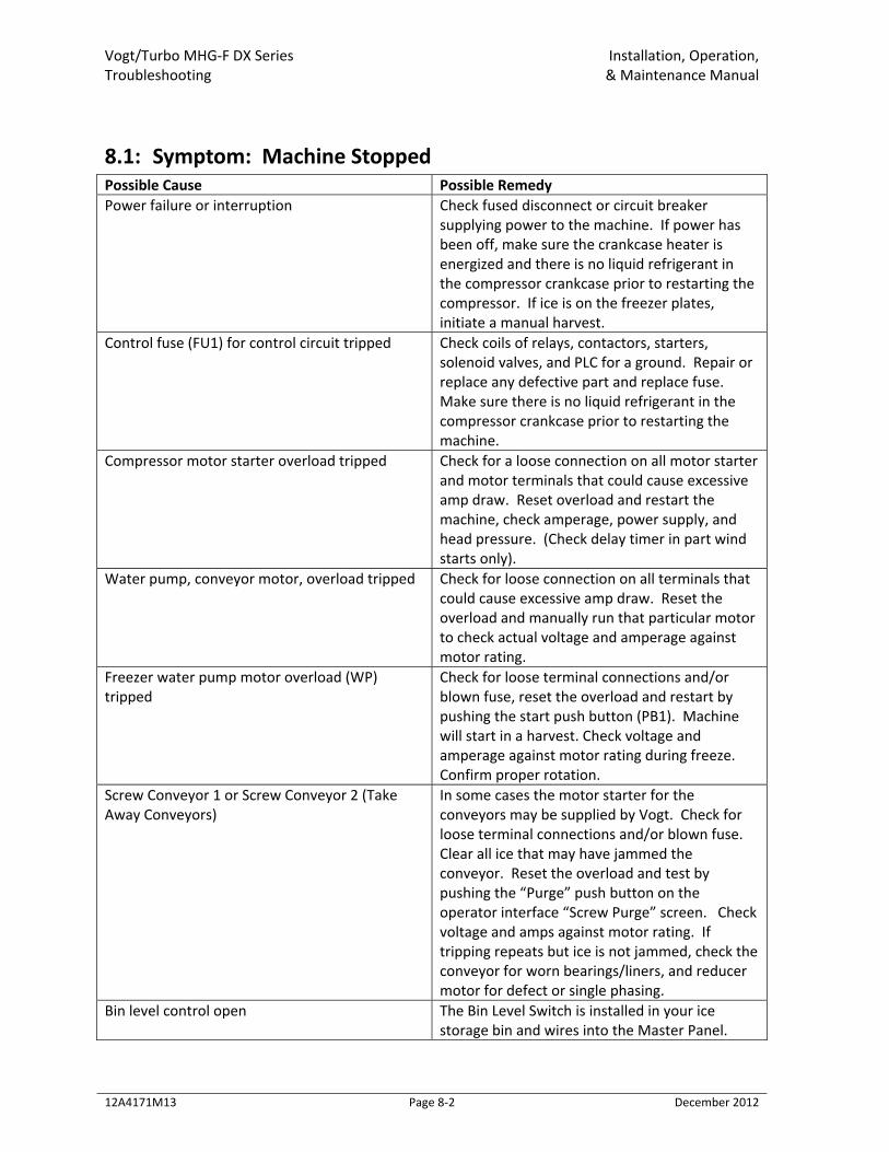
Vogt/Turbo MHG‐F DX Series Installation, Operation, Troubleshooting & Maintenance Manual
12A4171M13 Page 8‐2 December 2012
8.1: Symptom: Machine Stopped Possible Cause Possible Remedy Power failure or interruption Check fused disconnect or circuit breaker
supplying power to the machine. If power has been off, make sure the crankcase heater is energized and there is no liquid refrigerant in the compressor crankcase prior to restarting the compressor. If ice is on the freezer plates, initiate a manual harvest.
Control fuse (FU1) for control circuit tripped Check coils of relays, contactors, starters, solenoid valves, and PLC for a ground. Repair or replace any defective part and replace fuse. Make sure there is no liquid refrigerant in the compressor crankcase prior to restarting the machine.
Compressor motor starter overload tripped Check for a loose connection on all motor starter and motor terminals that could cause excessive amp draw. Reset overload and restart the machine, check amperage, power supply, and head pressure. (Check delay timer in part wind starts only).
Water pump, conveyor motor, overload tripped Check for loose connection on all terminals that could cause excessive amp draw. Reset the overload and manually run that particular motor to check actual voltage and amperage against motor rating.
Freezer water pump motor overload (WP) tripped
Check for loose terminal connections and/or blown fuse, reset the overload and restart by pushing the start push button (PB1). Machine will start in a harvest. Check voltage and amperage against motor rating during freeze. Confirm proper rotation.
Screw Conveyor 1 or Screw Conveyor 2 (Take Away Conveyors)
In some cases the motor starter for the conveyors may be supplied by Vogt. Check for loose terminal connections and/or blown fuse. Clear all ice that may have jammed the conveyor. Reset the overload and test by pushing the “Purge” push button on the operator interface “Screw Purge” screen. Check voltage and amps against motor rating. If tripping repeats but ice is not jammed, check the conveyor for worn bearings/liners, and reducer motor for defect or single phasing.
Bin level control open The Bin Level Switch is installed in your ice storage bin and wires into the Master Panel.
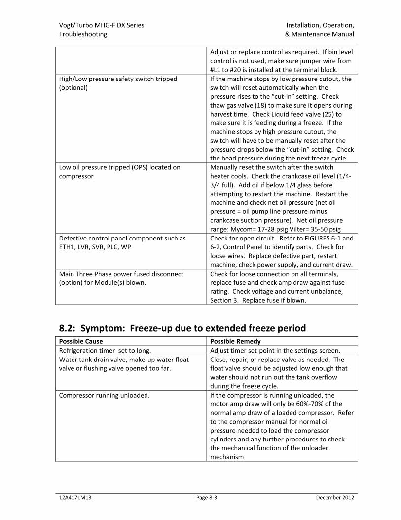
Vogt/Turbo MHG‐F DX Series Installation, Operation, Troubleshooting & Maintenance Manual
12A4171M13 Page 8‐3 December 2012
Adjust or replace control as required. If bin level control is not used, make sure jumper wire from #L1 to #20 is installed at the terminal block.
High/Low pressure safety switch tripped (optional)
If the machine stops by low pressure cutout, the switch will reset automatically when the pressure rises to the “cut‐in” setting. Check thaw gas valve (18) to make sure it opens during harvest time. Check Liquid feed valve (25) to make sure it is feeding during a freeze. If the machine stops by high pressure cutout, the switch will have to be manually reset after the pressure drops below the “cut‐in” setting. Check the head pressure during the next freeze cycle.
Low oil pressure tripped (OPS) located on compressor
Manually reset the switch after the switch heater cools. Check the crankcase oil level (1/4‐3/4 full). Add oil if below 1/4 glass before attempting to restart the machine. Restart the machine and check net oil pressure (net oil pressure = oil pump line pressure minus crankcase suction pressure). Net oil pressure range: Mycom= 17‐28 psig Vilter= 35‐50 psig
Defective control panel component such as ETH1, LVR, SVR, PLC, WP
Check for open circuit. Refer to FIGURES 6‐1 and 6‐2, Control Panel to identify parts. Check for loose wires. Replace defective part, restart machine, check power supply, and current draw.
Main Three Phase power fused disconnect (option) for Module(s) blown.
Check for loose connection on all terminals, replace fuse and check amp draw against fuse rating. Check voltage and current unbalance, Section 3. Replace fuse if blown.
8.2: Symptom: Freeze‐up due to extended freeze period Possible Cause Possible Remedy Refrigeration timer set to long. Adjust timer set‐point in the settings screen. Water tank drain valve, make‐up water float valve or flushing valve opened too far.
Close, repair, or replace valve as needed. The float valve should be adjusted low enough that water should not run out the tank overflow during the freeze cycle.
Compressor running unloaded. If the compressor is running unloaded, the motor amp draw will only be 60%‐70% of the normal amp draw of a loaded compressor. Refer to the compressor manual for normal oil pressure needed to load the compressor cylinders and any further procedures to check the mechanical function of the unloader mechanism
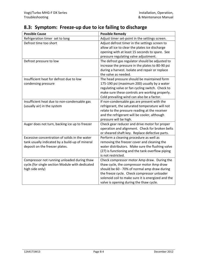
Vogt/Turbo MHG‐F DX Series Installation, Operation, Troubleshooting & Maintenance Manual
12A4171M13 Page 8‐4 December 2012
8.3: Symptom: Freeze‐up due to ice failing to discharge Possible Cause Possible Remedy Refrigeration timer set to long Adjust timer set‐point in the settings screen. Defrost time too short Adjust defrost timer in the settings screen to
allow all ice to clear the plates ice discharge opening with at least 15 seconds to spare. See pressure regulating valve adjustment.
Defrost pressure to low The defrost gas regulator should be adjusted to increase the pressure in the plates to 80‐90 psi during a harvest. Isolate and repair or replace the valve as needed.
Insufficient heat for defrost due to low condensing pressure
The head pressure should be maintained form 175‐190 psi (maximum 200) usually by a water regulating valve or fan cycling switch. Check to make sure these controls are working properly. Cold prevailing wind can also be a factor.
Insufficient heat due to non‐condensable gas (usually air) in the system
If non‐condensable gas are present with the refrigerant, the saturated temperature will not relate to the pressure reading at the receiver and the refrigerant will be cooler, although pressure will be high.
Auger does not turn, backing ice up to freezer Check gear reducer and drive motor for proper operation and alignment. Check for broken belts or sheared shaft key. Replace defective parts.
Excessive concentration of solids in the water tank usually indicated by a build‐up of mineral deposit on the freezer plates.
Perform a cleaning procedure as well as removing the freezer cover and cleaning the water distributors. Make sure the flushing valve (27) is functioning and the tank overflow piping is not restricted.
Compressor not running unloaded during thaw cycle.(for single section Module with dedicated high side only)
Check compressor motor Amp draw. During the thaw cycle, the compressor motor Amp draw should be 60 ‐ 70% of normal amp draw during the freeze cycle. Check compressor unloader solenoid coil to make sure it is energized and the valve is opening during the thaw cycle.
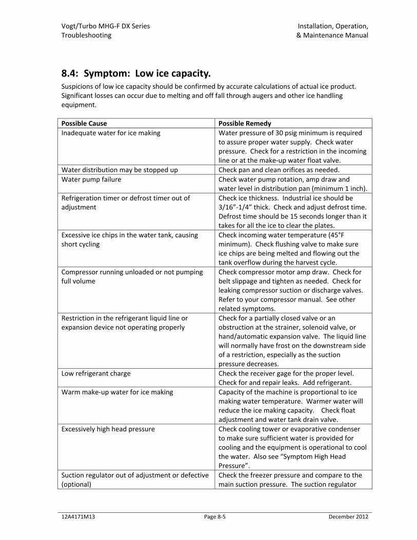
Vogt/Turbo MHG‐F DX Series Installation, Operation, Troubleshooting & Maintenance Manual
12A4171M13 Page 8‐5 December 2012
8.4: Symptom: Low ice capacity. Suspicions of low ice capacity should be confirmed by accurate calculations of actual ice product. Significant losses can occur due to melting and off fall through augers and other ice handling equipment. Possible Cause Possible Remedy Inadequate water for ice making Water pressure of 30 psig minimum is required
to assure proper water supply. Check water pressure. Check for a restriction in the incoming line or at the make‐up water float valve.
Water distribution may be stopped up Check pan and clean orifices as needed. Water pump failure Check water pump rotation, amp draw and
water level in distribution pan (minimum 1 inch). Refrigeration timer or defrost timer out of adjustment
Check ice thickness. Industrial ice should be 3/16”‐1/4” thick. Check and adjust defrost time. Defrost time should be 15 seconds longer than it takes for all the ice to clear the plates.
Excessive ice chips in the water tank, causing short cycling
Check incoming water temperature (45°F minimum). Check flushing valve to make sure ice chips are being melted and flowing out the tank overflow during the harvest cycle.
Compressor running unloaded or not pumping full volume
Check compressor motor amp draw. Check for belt slippage and tighten as needed. Check for leaking compressor suction or discharge valves. Refer to your compressor manual. See other related symptoms.
Restriction in the refrigerant liquid line or expansion device not operating properly
Check for a partially closed valve or an obstruction at the strainer, solenoid valve, or hand/automatic expansion valve. The liquid line will normally have frost on the downstream side of a restriction, especially as the suction pressure decreases.
Low refrigerant charge Check the receiver gage for the proper level. Check for and repair leaks. Add refrigerant.
Warm make‐up water for ice making Capacity of the machine is proportional to ice making water temperature. Warmer water will reduce the ice making capacity. Check float adjustment and water tank drain valve.
Excessively high head pressure Check cooling tower or evaporative condenser to make sure sufficient water is provided for cooling and the equipment is operational to cool the water. Also see “Symptom High Head Pressure”.
Suction regulator out of adjustment or defective (optional)
Check the freezer pressure and compare to the main suction pressure. The suction regulator
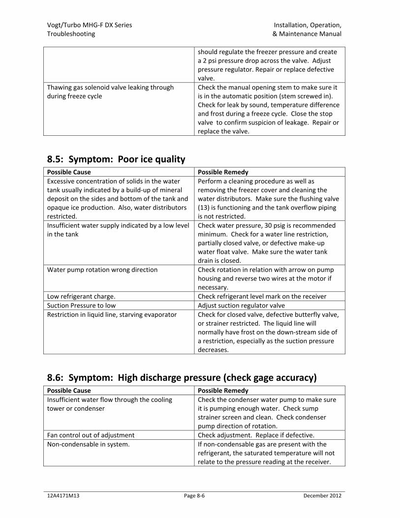
Vogt/Turbo MHG‐F DX Series Installation, Operation, Troubleshooting & Maintenance Manual
12A4171M13 Page 8‐6 December 2012
should regulate the freezer pressure and create a 2 psi pressure drop across the valve. Adjust pressure regulator. Repair or replace defective valve.
Thawing gas solenoid valve leaking through during freeze cycle
Check the manual opening stem to make sure it is in the automatic position (stem screwed in). Check for leak by sound, temperature difference and frost during a freeze cycle. Close the stop valve to confirm suspicion of leakage. Repair or replace the valve.
8.5: Symptom: Poor ice quality Possible Cause Possible Remedy Excessive concentration of solids in the water tank usually indicated by a build‐up of mineral deposit on the sides and bottom of the tank and opaque ice production. Also, water distributors restricted.
Perform a cleaning procedure as well as removing the freezer cover and cleaning the water distributors. Make sure the flushing valve (13) is functioning and the tank overflow piping is not restricted.
Insufficient water supply indicated by a low level in the tank
Check water pressure, 30 psig is recommended minimum. Check for a water line restriction, partially closed valve, or defective make‐up water float valve. Make sure the water tank drain is closed.
Water pump rotation wrong direction Check rotation in relation with arrow on pump housing and reverse two wires at the motor if necessary.
Low refrigerant charge. Check refrigerant level mark on the receiver Suction Pressure to low Adjust suction regulator valve Restriction in liquid line, starving evaporator Check for closed valve, defective butterfly valve,
or strainer restricted. The liquid line will normally have frost on the down‐stream side of a restriction, especially as the suction pressure decreases.
8.6: Symptom: High discharge pressure (check gage accuracy) Possible Cause Possible Remedy Insufficient water flow through the cooling tower or condenser
Check the condenser water pump to make sure it is pumping enough water. Check sump strainer screen and clean. Check condenser pump direction of rotation.
Fan control out of adjustment Check adjustment. Replace if defective. Non‐condensable in system. If non‐condensable gas are present with the
refrigerant, the saturated temperature will not relate to the pressure reading at the receiver.
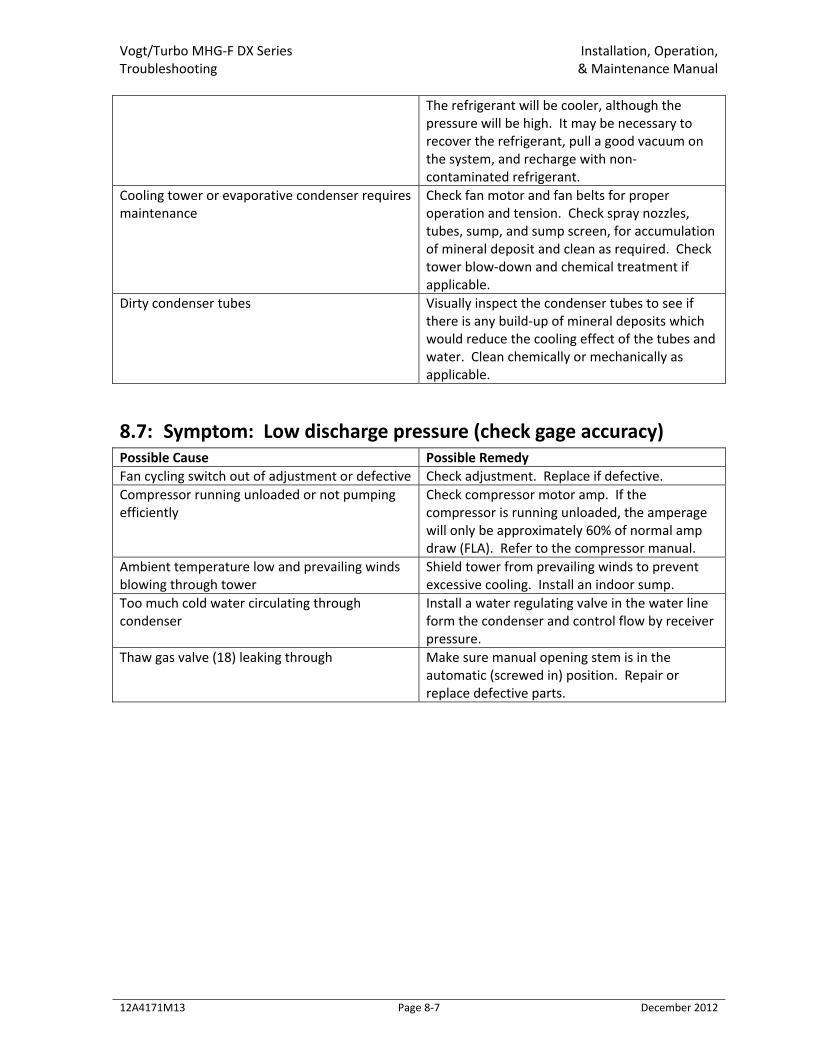
Vogt/Turbo MHG‐F DX Series Installation, Operation, Troubleshooting & Maintenance Manual
12A4171M13 Page 8‐7 December 2012
The refrigerant will be cooler, although the pressure will be high. It may be necessary to recover the refrigerant, pull a good vacuum on the system, and recharge with non‐contaminated refrigerant.
Cooling tower or evaporative condenser requires maintenance
Check fan motor and fan belts for proper operation and tension. Check spray nozzles, tubes, sump, and sump screen, for accumulation of mineral deposit and clean as required. Check tower blow‐down and chemical treatment if applicable.
Dirty condenser tubes Visually inspect the condenser tubes to see if there is any build‐up of mineral deposits which would reduce the cooling effect of the tubes and water. Clean chemically or mechanically as applicable.
8.7: Symptom: Low discharge pressure (check gage accuracy) Possible Cause Possible Remedy Fan cycling switch out of adjustment or defective Check adjustment. Replace if defective. Compressor running unloaded or not pumping efficiently
Check compressor motor amp. If the compressor is running unloaded, the amperage will only be approximately 60% of normal amp draw (FLA). Refer to the compressor manual.
Ambient temperature low and prevailing winds blowing through tower
Shield tower from prevailing winds to prevent excessive cooling. Install an indoor sump.
Too much cold water circulating through condenser
Install a water regulating valve in the water line form the condenser and control flow by receiver pressure.
Thaw gas valve (18) leaking through Make sure manual opening stem is in the automatic (screwed in) position. Repair or replace defective parts.
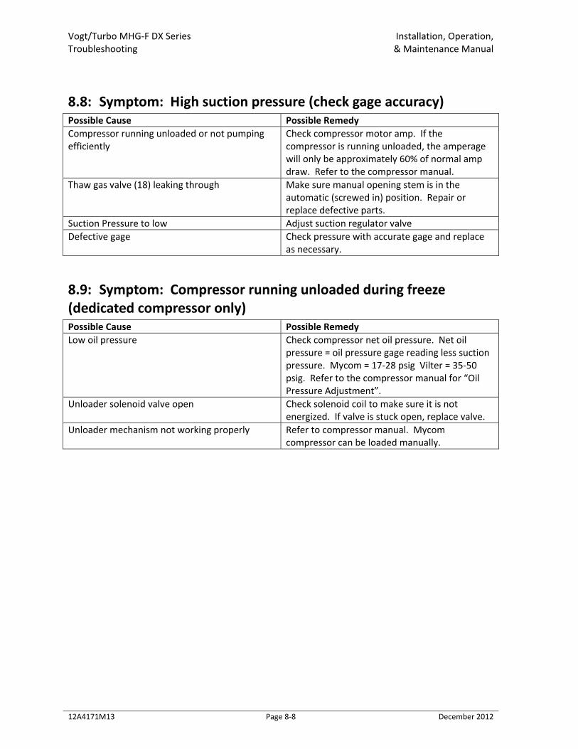
Vogt/Turbo MHG‐F DX Series Installation, Operation, Troubleshooting & Maintenance Manual
12A4171M13 Page 8‐8 December 2012
8.8: Symptom: High suction pressure (check gage accuracy) Possible Cause Possible Remedy Compressor running unloaded or not pumping efficiently
Check compressor motor amp. If the compressor is running unloaded, the amperage will only be approximately 60% of normal amp draw. Refer to the compressor manual.
Thaw gas valve (18) leaking through Make sure manual opening stem is in the automatic (screwed in) position. Repair or replace defective parts.
Suction Pressure to low Adjust suction regulator valve Defective gage Check pressure with accurate gage and replace
as necessary.
8.9: Symptom: Compressor running unloaded during freeze (dedicated compressor only) Possible Cause Possible Remedy Low oil pressure Check compressor net oil pressure. Net oil
pressure = oil pressure gage reading less suction pressure. Mycom = 17‐28 psig Vilter = 35‐50 psig. Refer to the compressor manual for “Oil Pressure Adjustment”.
Unloader solenoid valve open Check solenoid coil to make sure it is not energized. If valve is stuck open, replace valve.
Unloader mechanism not working properly Refer to compressor manual. Mycom compressor can be loaded manually.
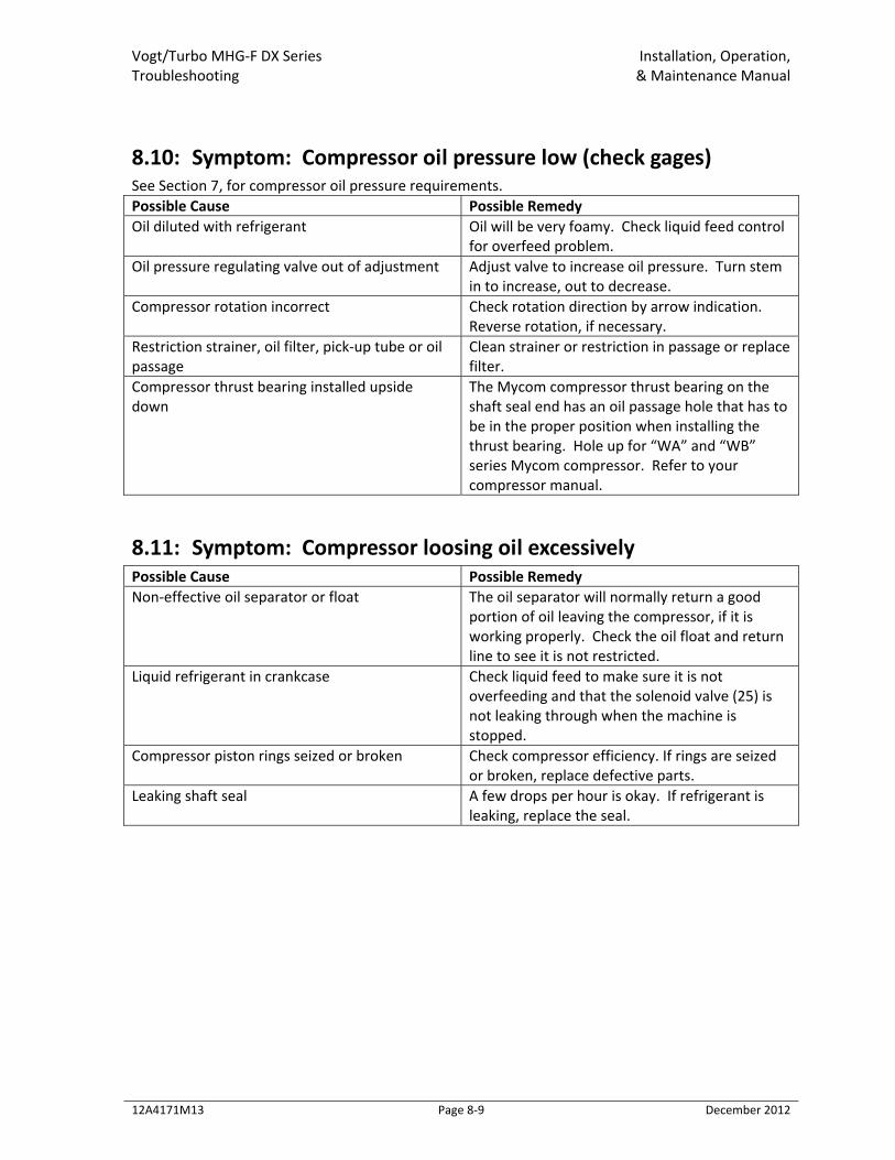
Vogt/Turbo MHG‐F DX Series Installation, Operation, Troubleshooting & Maintenance Manual
12A4171M13 Page 8‐9 December 2012
8.10: Symptom: Compressor oil pressure low (check gages) See Section 7, for compressor oil pressure requirements. Possible Cause Possible Remedy Oil diluted with refrigerant Oil will be very foamy. Check liquid feed control
for overfeed problem. Oil pressure regulating valve out of adjustment Adjust valve to increase oil pressure. Turn stem
in to increase, out to decrease. Compressor rotation incorrect Check rotation direction by arrow indication.
Reverse rotation, if necessary. Restriction strainer, oil filter, pick‐up tube or oil passage
Clean strainer or restriction in passage or replace filter.
Compressor thrust bearing installed upside down
The Mycom compressor thrust bearing on the shaft seal end has an oil passage hole that has to be in the proper position when installing the thrust bearing. Hole up for “WA” and “WB” series Mycom compressor. Refer to your compressor manual.
8.11: Symptom: Compressor loosing oil excessively Possible Cause Possible Remedy Non‐effective oil separator or float The oil separator will normally return a good
portion of oil leaving the compressor, if it is working properly. Check the oil float and return line to see it is not restricted.
Liquid refrigerant in crankcase Check liquid feed to make sure it is not overfeeding and that the solenoid valve (25) is not leaking through when the machine is stopped.
Compressor piston rings seized or broken Check compressor efficiency. If rings are seized or broken, replace defective parts.
Leaking shaft seal A few drops per hour is okay. If refrigerant is leaking, replace the seal.
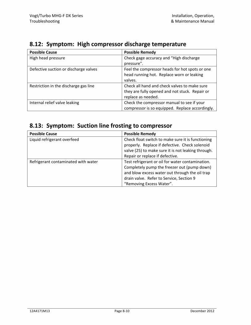
Vogt/Turbo MHG‐F DX Series Installation, Operation, Troubleshooting & Maintenance Manual
12A4171M13 Page 8‐10 December 2012
8.12: Symptom: High compressor discharge temperature Possible Cause Possible Remedy High head pressure Check gage accuracy and “High discharge
pressure”. Defective suction or discharge valves Feel the compressor heads for hot spots or one
head running hot. Replace worn or leaking valves.
Restriction in the discharge gas line Check all hand and check valves to make sure they are fully opened and not stuck. Repair or replace as needed.
Internal relief valve leaking Check the compressor manual to see if your compressor is so equipped. Replace accordingly.
8.13: Symptom: Suction line frosting to compressor Possible Cause Possible Remedy Liquid refrigerant overfeed Check float switch to make sure it is functioning
properly. Replace if defective. Check solenoid valve (25) to make sure it is not leaking through. Repair or replace if defective.
Refrigerant contaminated with water Test refrigerant or oil for water contamination. Completely pump the freezer out (pump down) and blow excess water out through the oil trap drain valve. Refer to Service, Section 9 “Removing Excess Water”.
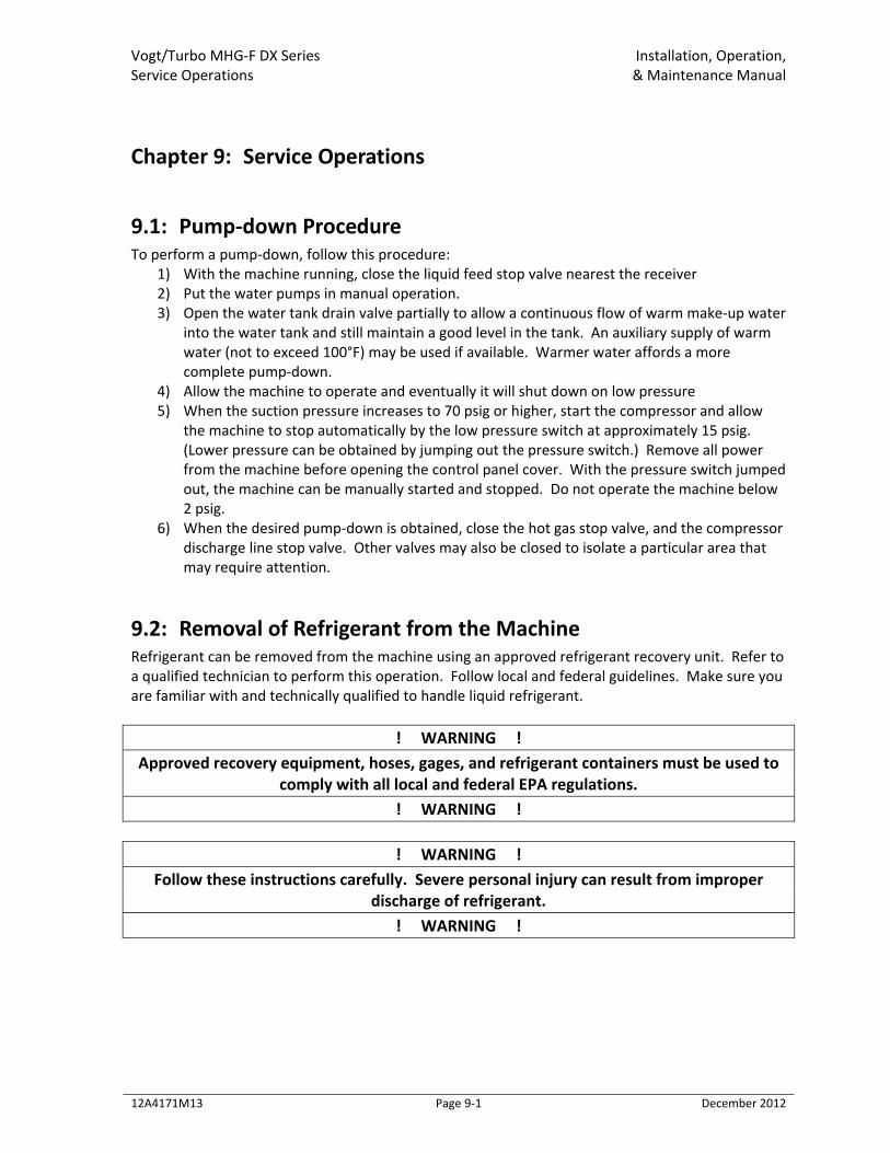
Vogt/Turbo MHG‐F DX Series Installation, Operation, Service Operations & Maintenance Manual
12A4171M13 Page 9‐1 December 2012
Chapter 9: Service Operations
9.1: Pump‐down Procedure To perform a pump‐down, follow this procedure:
1) With the machine running, close the liquid feed stop valve nearest the receiver 2) Put the water pumps in manual operation. 3) Open the water tank drain valve partially to allow a continuous flow of warm make‐up water
into the water tank and still maintain a good level in the tank. An auxiliary supply of warm water (not to exceed 100°F) may be used if available. Warmer water affords a more complete pump‐down.
4) Allow the machine to operate and eventually it will shut down on low pressure 5) When the suction pressure increases to 70 psig or higher, start the compressor and allow
the machine to stop automatically by the low pressure switch at approximately 15 psig. (Lower pressure can be obtained by jumping out the pressure switch.) Remove all power from the machine before opening the control panel cover. With the pressure switch jumped out, the machine can be manually started and stopped. Do not operate the machine below 2 psig.
6) When the desired pump‐down is obtained, close the hot gas stop valve, and the compressor discharge line stop valve. Other valves may also be closed to isolate a particular area that may require attention.
9.2: Removal of Refrigerant from the Machine Refrigerant can be removed from the machine using an approved refrigerant recovery unit. Refer to a qualified technician to perform this operation. Follow local and federal guidelines. Make sure you are familiar with and technically qualified to handle liquid refrigerant.
! WARNING ! Approved recovery equipment, hoses, gages, and refrigerant containers must be used to
comply with all local and federal EPA regulations. ! WARNING !
! WARNING !
Follow these instructions carefully. Severe personal injury can result from improper discharge of refrigerant.
! WARNING !
Vogt/Turbo MHG‐F DX Series Installation, Operation, Service Operations & Maintenance Manual
12A4171M13 Page 9‐2 December 2012
! WARNING !
It is not recommended that refrigerant be transferred from a refrigeration system into a cylinder. If such a transfer is made, the refrigerant cylinder must be an approved CLEAN
cylinder‐‐ free of any contaminants or foreign materials‐‐and must be weighed continuously to assure contents do not exceed net weight specified by cylinder
manufacturer or any applicable code requirements. ! WARNING !
9.3: Refrigerant Leaks Refrigerant leaks can be detected by soap solution or electronic detection equipment. Soap solution can be purchased from your refrigeration supply house or it can be made by mixing four parts water, one part liquid soap, and a few drops of Glycerin for better capillary attraction. Apply soap solutions with a narrow brush or spray bottle to all joints, welds, or areas of suspicion. The solution will form bubbles if there is a leak.
9.4: Non‐condensable Gases Satisfactory operation of the machine is not possible if non‐condensable gases (usually air) are present in the system. Excessive condensing pressure is an indication of such gases. Excessive condensing pressure in water cooled condensers may also be due to the accumulation of scale in the cooling coil or due to insufficient cooling water or excessive water temperature. See “Water Cooled Condensers”, Section 7. Non‐condensable gas effects are:
• Higher condensing pressure than desired. • Greater electrical power consumption. • Reduced refrigeration capacity. • Longer than normal compressor running time. • Slow ice release and long defrost cycle.
Air collects mostly in high pressure condensers, receivers, and other high‐pressure components. It collects mostly in the coolest, lowest‐velocity area of these components. Note: whenever excessive water is present in the system, the source should be identified and corrections made prior to further operation.