Embed Size (px)
Citation preview
LABORATORY MANUAL
MICROPROCESSOR AND MICROCONTROLLER
B.TECH
5TH SEMESTER
DEPARTMENT OF ELECTRICAL ENGINEERING
JHARKHAND RAI UNIVERSITY
KAMRE, RANCHI

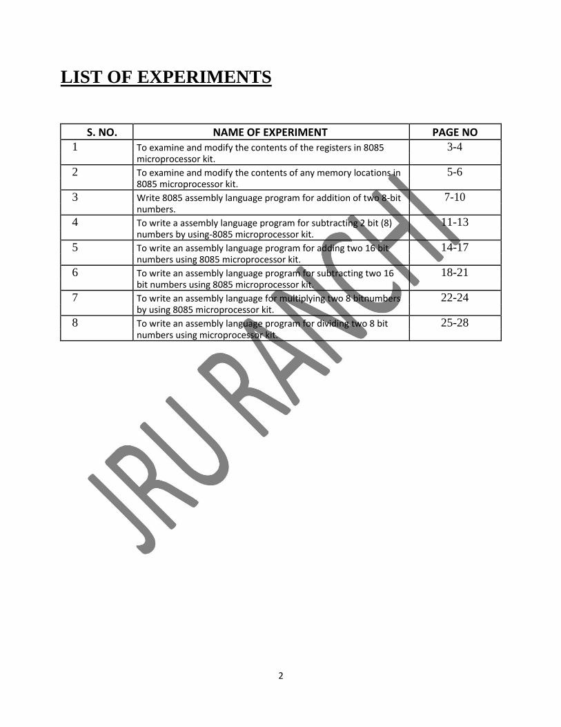
LIST OF EXPERIMENTS
S. NO. NAME OF EXPERIMENT PAGE NO 1 To examine and modify the contents of the registers in 8085 3-4
microprocessor kit.
2 To examine and modify the contents of any memory locations in 5-6 8085 microprocessor kit.
3 Write 8085 assembly language program for addition of two 8-bit 7-10 numbers.
4 To write a assembly language program for subtracting 2 bit (8) 11-13 numbers by using-8085 microprocessor kit.
5 To write an assembly language program for adding two 16 bit 14-17 numbers using 8085 microprocessor kit.
6 To write an assembly language program for subtracting two 16 18-21 bit numbers using 8085 microprocessor kit.
7 To write an assembly language for multiplying two 8 bitnumbers 22-24 by using 8085 microprocessor kit.
8 To write an assembly language program for dividing two 8 bit 25-28 numbers using microprocessor kit.
2

EXPERIMENT NO: 01
EXAMINING THE CONTENTS OF REGISTERS
AIM: To examine and modify the contents of the registers in 8085 microprocessor kit.
APPARATUS REQUIRED:8085 kit.
THEORY: This command is used to examine/modify any internal registers of the CPU. If one wants to examine the
contents of all the registers, one can start from register A and examine all the registers by pressing NEXT
key. Whereas if some specific registers is to be examined, then the key for that register can be entered
directly. The contents of any register can be changed.
PROCEDURE: To examine the registers. Step 1: press RESET key before executing program. Step2: press SHIFT key and then press EXREG key. Step3: Press registers key and NEXT key simultaneously. After step 3 follow these steps to modify the contents. Step1: press any register and change the data and then press NEXT key. Step2: press ‘.’ Key to terminate. Step3: press EXREG key and enter the particular register which is changed.
3
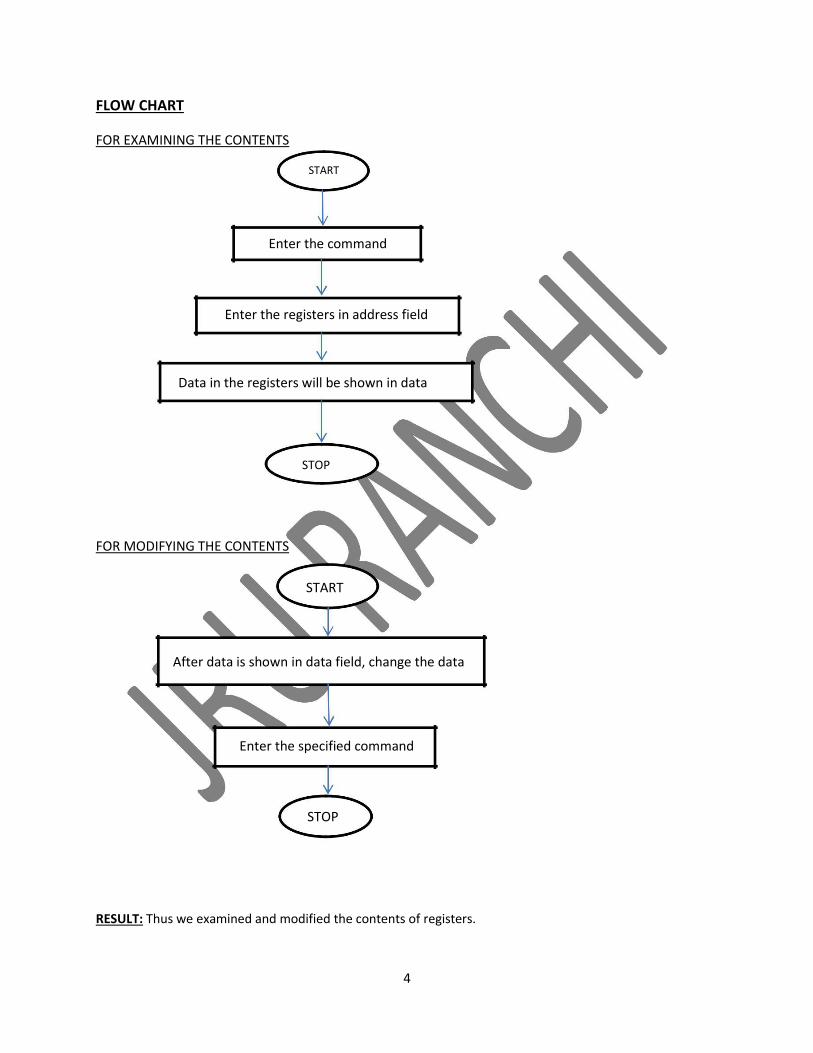
FLOW CHART
FOR EXAMINING THE CONTENTS
START
Enter the command
Enter the registers in address field
Data in the registers will be shown in data
STOP
FOR MODIFYING THE CONTENTS
START
After data is shown in data field, change the data
Enter the specified command
STOP
RESULT: Thus we examined and modified the contents of registers.
4
EXPERIMENT NO-02
EXAMINING THE CONTENTS OF MEMORY LOCATION
AIM: To examine and modify the contents of any memory locations.
THEORY: This command is used to examine the contents of any memory location and modify the contents of the
RAM area. On pressing this key, a dot is displayed in the end of address field. One can now enter the
address of any location one wants to examine. Enter the desired address and press NEXT. The content of
this location is displayed in the data field. If one wants to examine the contents of next location, just
press NEXT and the address in the address field will be incremented by one and its contents will be
displayed in the data field. Same way if one wants to examine the contents of previous location just
press PRE key and the address in the address field will be decremented by one and its contents will be
displayed in the data field.
PROCEDURE Step 1: Press RESET key. Step 2: Press EMEM Step 3: Enter the desired memory address and press NEXT key. Step 4: data will be displayed in data field. Step 5: press NEXT key and memory address will be incremented by one and data will be shown. To modify the data, after step 5 follow these steps Step 1: change the data Step 2: Press.’ key. Step 3: press EXMEM key and enter the memory address which is changed.
5
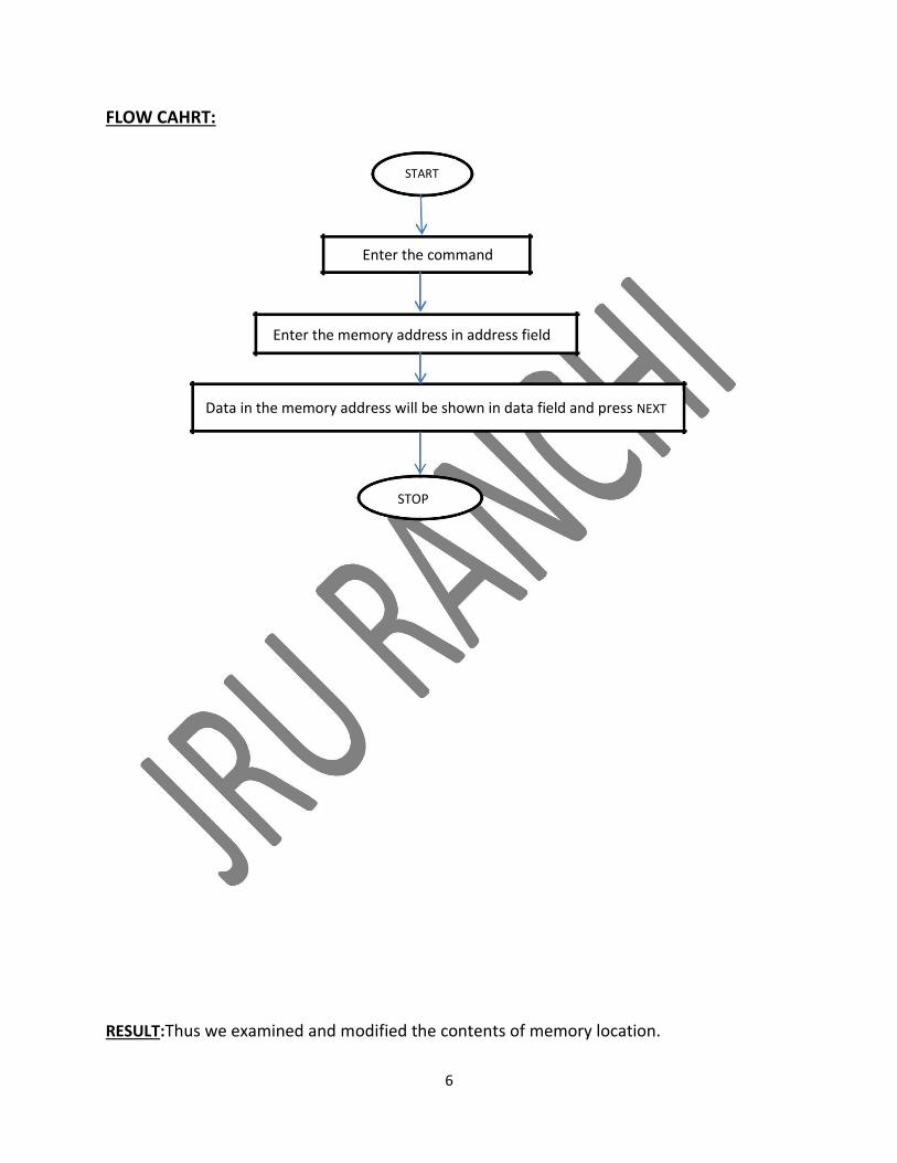
FLOW CAHRT:
START
Enter the command
Enter the memory address in address field
Data in the memory address will be shown in data field and press NEXT
STOP
RESULT:Thus we examined and modified the contents of memory location.
6
EXPERIMENT NO: 03
ADDITION OF TWO 8-BIT NUMBERS AND SUM IS 8-BIT
AIM: Write 8085 assembly language program for addition of two 8-bit numbers.
APPARATUS REQUIRED: 1. 8085 Microprocessor Kit 2. +5V Power supply
ALGORITHM
Step 1 : Start the microprocessor Step 2 : Initialize the carry as ‘Zero’ Step 3 : Load the first 8 bit data into the accumulator Step 4 : Copy the contents of accumulator into the register ‘B’ Step 5 : Load the second 8 bit data into the accumulator. Step 6 : Add the 2 - 8 bit data and check for carry. Step 7 : Jump on if no carry Step 8 : Increment carry if there is Step 9 : Store the added request in accumulator Step 10 : More the carry value to accumulator Step 11 : Store the carry value in accumulator Step 12 : Stop the program execution.
7
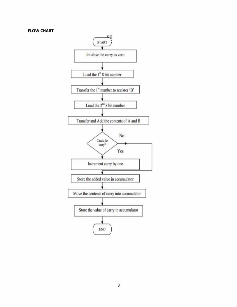
FLOW CHART
8
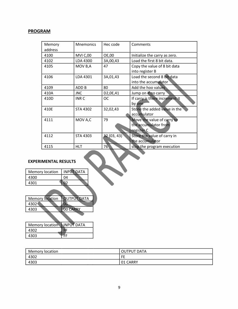
PROGRAM
Memory Mnemonics Hec code Comments
address
4100 MVI C,00 OE,00 Initialize the carry as zero.
4102 LDA 4300 3A,00,43 Load the first 8 bit data. 4105 MOV B,A 47 Copy the value of 8 bit data
into register B
4106 LDA 4301 3A,01,43 Load the second 8 bit data into the accumulator
4109 ADD B 80 Add the hoo values
410A JNC D2,0E,41 Jump on if no carry 410D INR C OC If carry is there increment it
by one
410E STA 4302 32,02,43 Stone the added value in the accumulator
4111 MOV A,C 79 Move the value of carry to the accumulator from
register C
4112 STA 4303 32 (03, 43) Store the value of carry in the accumulator
4115 HLT 76 stop the program execution
EXPERIMENTAL RESULTS
Memory location INPUT DATA
4300 04
4301 02
Memory location OUTPUT DATA
4302 06
4303 00 CARRY
Memory location INPUT DATA
4302 FF
4303 FF
Memory location OUTPUT DATA
4302 FE 4303 01 CARRY
9

CALCULATION
1111 1111
1111 1111
(1) 1111 1110
F E
RESULT: The assembly language program for 8 bit addition of two numbers was executed Successfully by using 8085 micro processing kit.
10
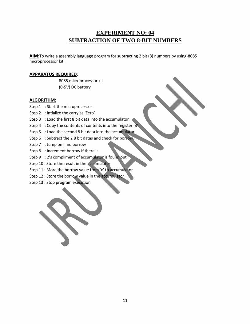
EXPERIMENT NO: 04
SUBTRACTION OF TWO 8-BIT NUMBERS
AIM:To write a assembly language program for subtracting 2 bit (8) numbers by using-8085 microprocessor kit.
APPARATUS REQUIRED: 8085 microprocessor kit
(0-5V) DC battery
ALGORITHM: Step 1 : Start the microprocessor Step 2 : Intialize the carry as ‘Zero’ Step 3 : Load the first 8 bit data into the accumulator Step 4 : Copy the contents of contents into the register ‘B’ Step 5 : Load the second 8 bit data into the accumulator. Step 6 : Subtract the 2 8 bit datas and check for borrow. Step 7 : Jump on if no borrow Step 8 : Increment borrow if there is Step 9 : 2’s compliment of accumulator is found out Step 10 : Store the result in the accumulator Step 11 : More the borrow value from ‘c’ to accumulator Step 12 : Store the borrow value in the accumulator Step 13 : Stop program execution
11
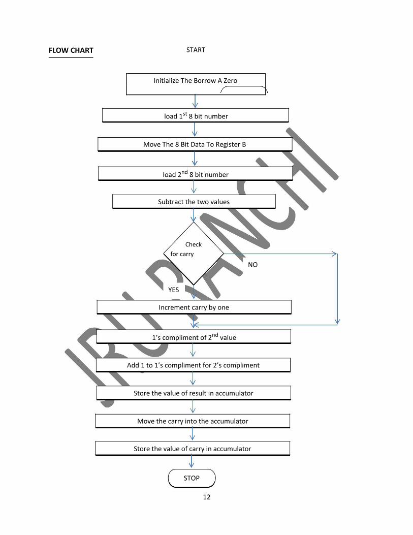
FLOW CHART START
Initialize The Borrow A Zero
load 1st 8 bit number
Move The 8 Bit Data To Register B
load 2nd 8 bit number
Subtract the two values
Check for carry
NO
YES
Increment carry by one
1’s compliment of 2nd value
Add 1 to 1’s compliment for 2’s compliment
Store the value of result in accumulator
Move the carry into the accumulator
Store the value of carry in accumulator
STOP
12
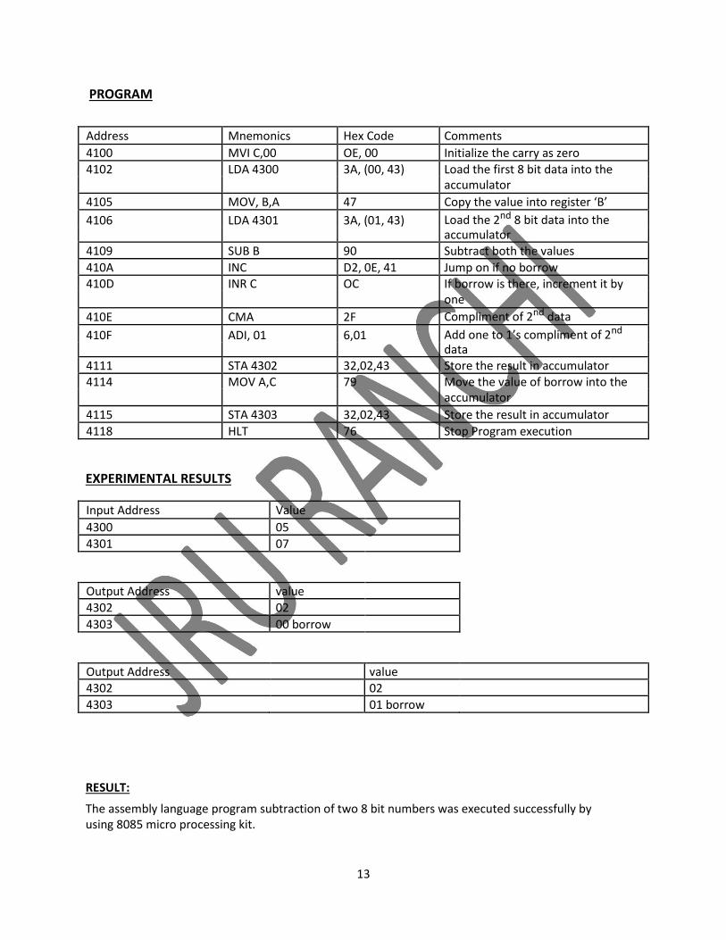
PROGRAM
Address Mnemonics Hex Code Comments
4100 MVI C,00 OE, 00 Initialize the carry as zero 4102 LDA 4300 3A, (00, 43) Load the first 8 bit data into the
accumulator
4105 MOV, B,A 47 Copy the value into register ‘B’
4106 LDA 4301 3A, (01, 43) Load the 2nd 8 bit data into the accumulator
4109 SUB B 90 Subtract both the values
410A INC D2, 0E, 41 Jump on if no borrow 410D INR C OC If borrow is there, increment it by
one
410E CMA 2F Compliment of 2nd data
410F ADI, 01 6,01 Add one to 1’s compliment of 2nd
data 4111 STA 4302 32,02,43 Store the result in accumulator 4114 MOV A,C 79 Move the value of borrow into the
accumulator
4115 STA 4303 32,02,43 Store the result in accumulator
4118 HLT 76 Stop Program execution
EXPERIMENTAL RESULTS
Input Address Value
4300 05
4301 07
Output Address value
4302 02
4303 00 borrow
Output Address value
4302 02
4303 01 borrow
RESULT:
The assembly language program subtraction of two 8 bit numbers was executed successfully by using 8085 micro processing kit.
13
EXPERIMENT NO: 05
ADDITION OF TWO 16 – BIT NUMBERS
AIM: To write an assembly language program for adding two 16 bit numbers using 8085 microprocessor kit.
APPARATUS REQUIRED: 8085 microprocessorkit(0-5V) DC battery
ALGORITHM: Step 1 : Start the microprocessor
Step 2 : Get the 1st8 bit in ‘C’ register (LSB) and 2nd8 bit in ‘H’ register (MSB) of 16 bit number.
Step 3 : Save the 1st16 bit in ‘DE’ register pair
Step 4 : Similarly get the 2nd16 bit number and store it in ‘HL’ register pair.
Step 5 : Get the lower byte of 1stnumber into ‘L’ register
Step 6 : Add it with lower byte of 2ndnumber Step 7 : tore the result in ‘L’ register
Step 8 : Get the higher byte of 1stnumber into accumulator
Step 9 : Add it with higher byte of 2ndnumber and carry of the lower bit addition. Step 10: Store the result in ‘H’ register Step 11 : Store 16 bit addition value in ‘HL’ register pair Step 12 : Stop program execution
14
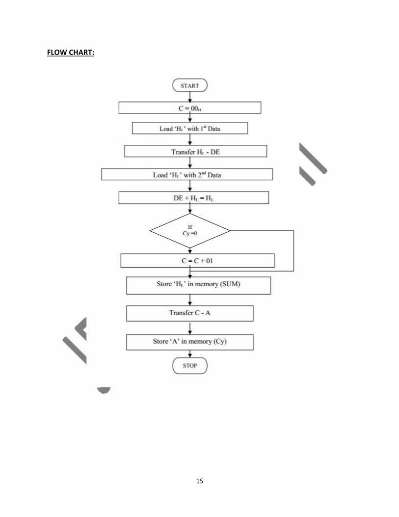
FLOW CHART:
15
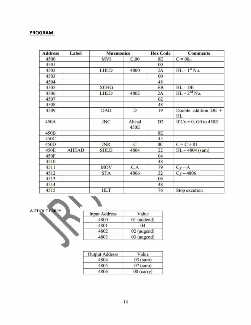
PROGRAM:
WITHOUT CARRY
16
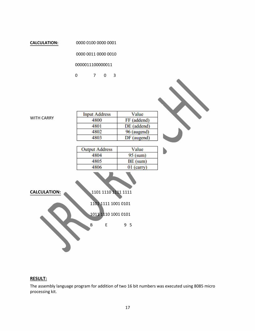
CALCULATION: 0000 0100 0000 0001
0000 0011 0000 0010
0000011100000011
0 7 0 3
WITH CARRY
CALCULATION: 1101 1110 1111 1111
1101 1111 1001 0101
1011 1110 1001 0101
B E 9 5
RESULT: The assembly language program for addition of two 16 bit numbers was executed using 8085 micro processing kit.
17
EXPERIMENT NO: 06
SUBTRACTION OF TWO 16 – BIT NUMBERS
AIM: To write an assembly language program for subtracting two 16 bit numbers using 8085 microprocessor kit.
APPARATUS REQUIRED: 8085 microprocessor kit
(0-5V) DC battery
ALGORITHM: Step 1 : Start the microprocessor
Step 2 : Get the 1st 16 bit in ‘HL’ register pair
Step 3 : Save the 1st 16 bit in ‘DE’ register pair
Step 4 : Get the 2nd 16 bit number in ‘HL’ register pair
Step 5 : Get the lower byte of 1st number
Step 6 : Get the subtracted value of 2nd number of lower byte by subtracting it with lower byte of 1st number Step 7 : Store the result in ‘L’ register
Step 8 : Get the higher byte of 2nd number
Step 9 : Subtract the higher byte of 1st number from 2nd number with borrow Step 10 : Store the result in ‘HL’ register Step 11 : Stop the program execution
18
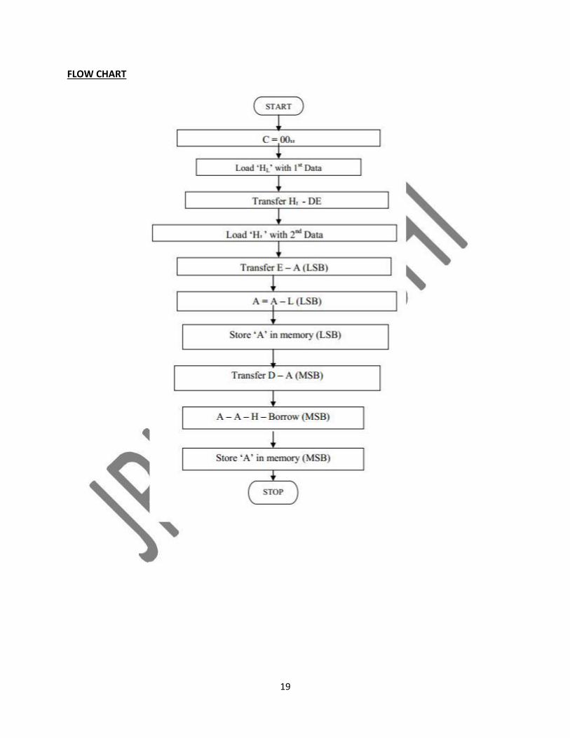
FLOW CHART
19
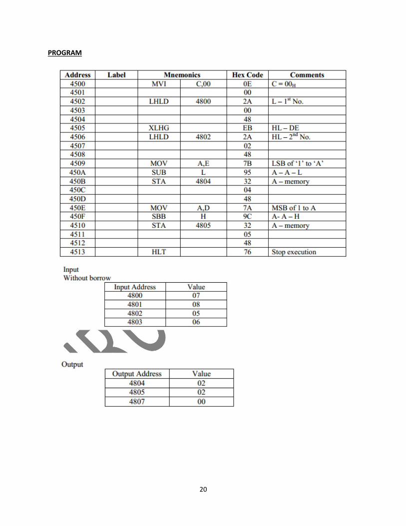
PROGRAM
20
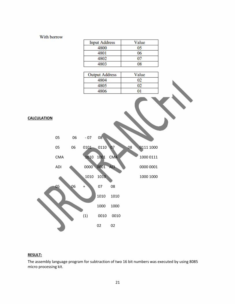
CALCULATION
05 06 - 07 08
05 06 0101 0110 07 08 0111 1000
CMA 1010 1001 CMA 1000 0111
ADI 0000 0001 ACI 0000 0001
1010 1010 1000 1000
05 06 + 07 08
1010 1010
1000 1000
(1) 0010 0010
02 02
RESULT: The assembly language program for subtraction of two 16 bit numbers was executed by using 8085 micro processing kit.
21
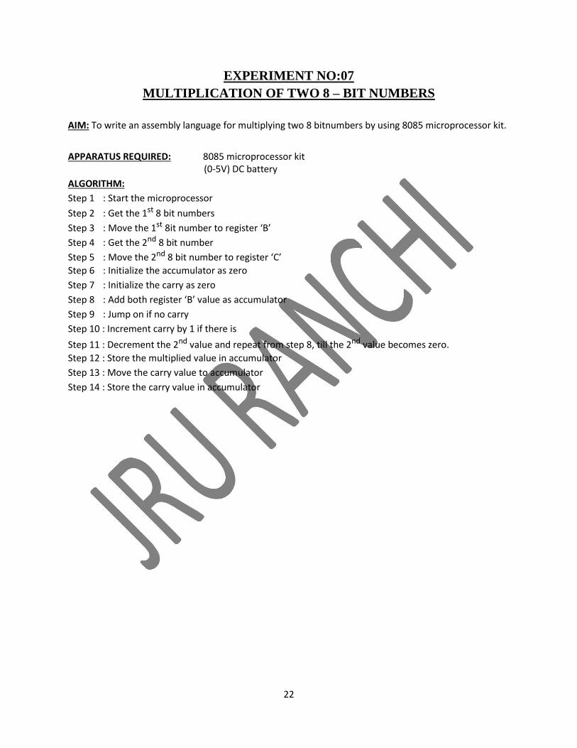
EXPERIMENT NO:07
MULTIPLICATION OF TWO 8 – BIT NUMBERS
AIM: To write an assembly language for multiplying two 8 bitnumbers by using 8085 microprocessor kit.
APPARATUS REQUIRED: 8085 microprocessor kit (0-5V) DC battery
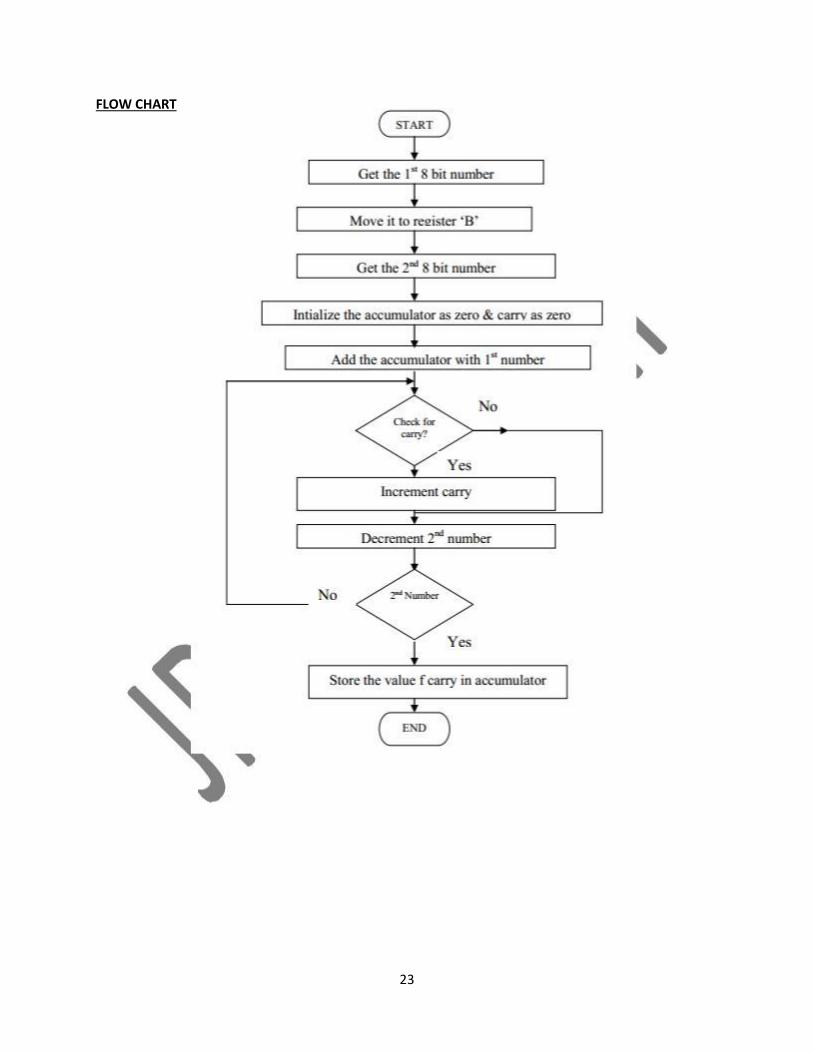
ALGORITHM: Step 1 : Start the microprocessor
Step 2 : Get the 1st 8 bit numbers
Step 3 : Move the 1st 8it number to register ‘B’
Step 4 : Get the 2nd 8 bit number
Step 5 : Move the 2nd 8 bit number to register ‘C’ Step 6 : Initialize the accumulator as zero Step 7 : Initialize the carry as zero Step 8 : Add both register ‘B’ value as accumulator Step 9 : Jump on if no carry Step 10 : Increment carry by 1 if there is
Step 11 : Decrement the 2nd value and repeat from step 8, till the 2nd value becomes zero. Step 12 : Store the multiplied value in accumulator Step 13 : Move the carry value to accumulator Step 14 : Store the carry value in accumulator
22
FLOW CHART
23
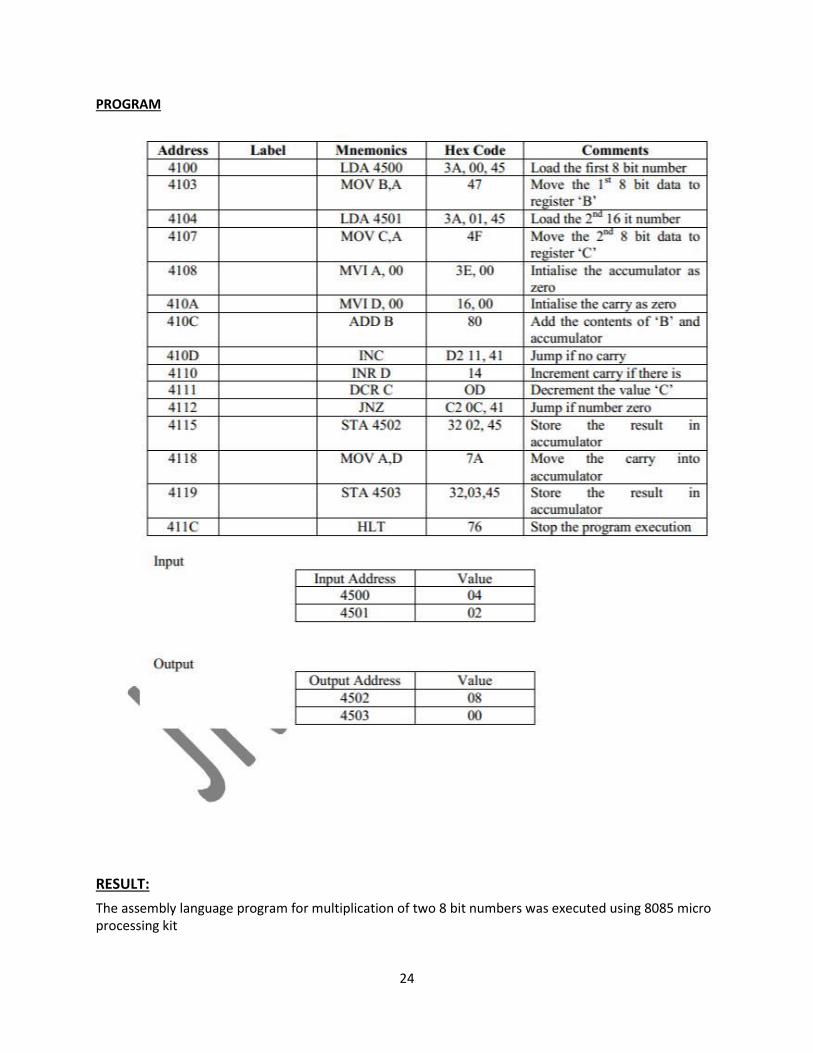
PROGRAM
RESULT: The assembly language program for multiplication of two 8 bit numbers was executed using 8085 micro processing kit
24
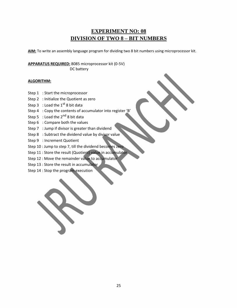
EXPERIMENT NO: 08
DIVISION OF TWO 8 – BIT NUMBERS
AIM: To write an assembly language program for dividing two 8 bit numbers using microprocessor kit.
APPARATUS REQUIRED: 8085 microprocessor kit (0-5V) DC battery
ALGORITHM:
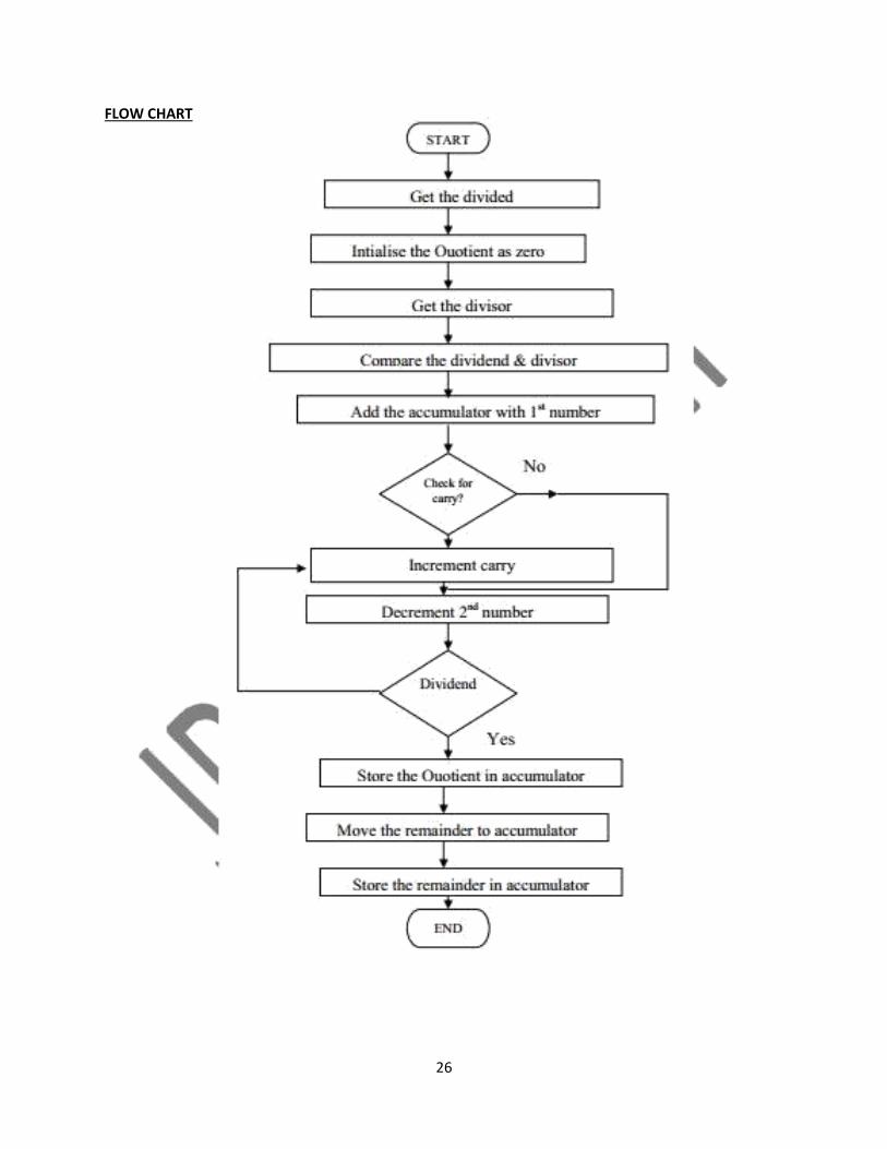
Step 1 : Start the microprocessor Step 2 : Initialize the Quotient as zero
Step 3 : Load the 1st 8 bit data Step 4 : Copy the contents of accumulator into register ‘B’
Step 5 : Load the 2nd 8 bit data Step 6 : Compare both the values Step 7 : Jump if divisor is greater than dividend Step 8 : Subtract the dividend value by divisor value Step 9 : Increment Quotient Step 10 : Jump to step 7, till the dividend becomes zero Step 11 : Store the result (Quotient) value in accumulator Step 12 : Move the remainder value to accumulator Step 13 : Store the result in accumulator Step 14 : Stop the program execution
25
FLOW CHART
26
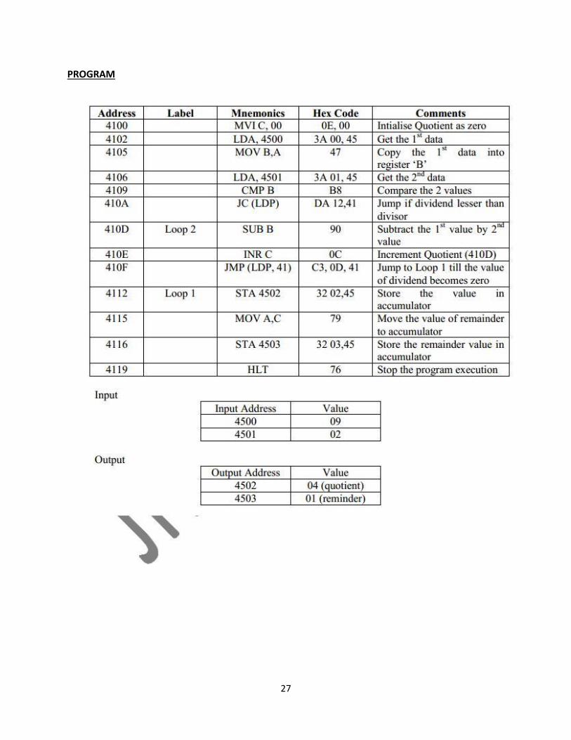
PROGRAM
27
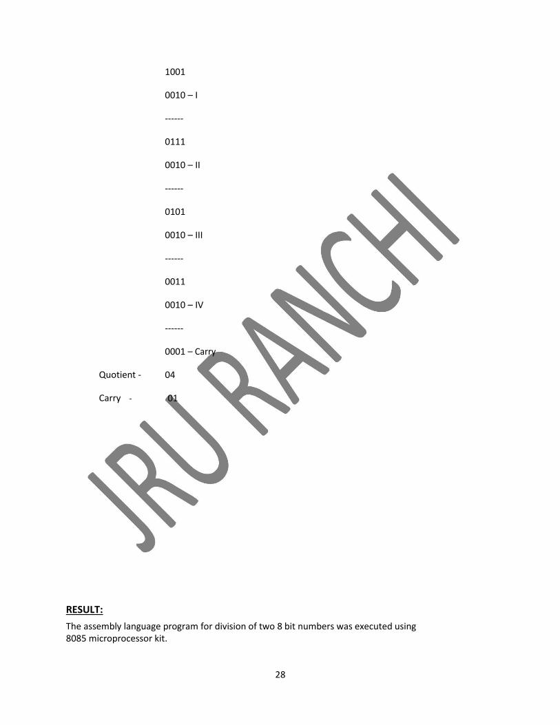
Quotient -
Carry -
1001
0010 – I
------
0111
0010 – II
------
0101
0010 – III
------
0011
0010 – IV
------
0001 – Carry
04
01
RESULT: The assembly language program for division of two 8 bit numbers was executed using 8085 microprocessor kit.
28


