Embed Size (px)
Citation preview

This content has been downloaded from IOPscience. Please scroll down to see the full text.
Download details:
IP Address: 18.58.7.26
This content was downloaded on 20/08/2014 at 15:41
Please note that terms and conditions apply.
Microstructural stability after severe plastic deformation of AZ31 Magnesium
View the table of contents for this issue, or go to the journal homepage for more
2014 IOP Conf. Ser.: Mater. Sci. Eng. 63 012077
(http://iopscience.iop.org/1757-899X/63/1/012077)
Home Search Collections Journals About Contact us My IOPscience

Microstructural stability after severe plastic deformation
of AZ31 Magnesium
J P Younga, H Askaria, Y Hovanskib, M J Heidena and D P Fielda a School of Mech. and Matls. Eng., Washington State University, 405 Spokane St, Pullman, WA 99163-2920 USA b Pacific Northwest National Laboratory, 902 Battell Blvd, Richland WA 99354, USA E-mail: [email protected]
Abstract. Friction stir processing (FSP) and equal channel angular pressing (ECAP) were used to modify the microstructure of twin roll cast (TRC) AZ31 magnesium. The influence of these processes on the microstructural properties of the material was investigated. It was found that both processes produced microstructures with an average grain size of less than 10 µm, suggesting that they have the potential for superplastic deformation. Heat treatments were performed on the TRC, ECAP and FSP materials to assess their microstructural stability. Both the ECAP and TRC material were found to be fairly stable, showing normal grain growth while the FSP material grew substantially at temperatures above 200°C. The activation energy of grain boundary motion of the TRC material was calculated to be 167 kJ/mol.
1. Introduction
The desire for ever lighter structural components in the aerospace and automotive industries has motivated recent interest in magnesium and its alloys [1-3]. However, due to its hexagonal close pack (HCP) structure and the resulting insufficient number of slip systems, magnesium and its alloys possess limited formability at room temperature [4-6]. This has limited the use of magnesium in automotive applications to mostly cast components [3]. In order to increase magnesium applications and achieve the desired weight savings, it is necessary to improve the plastic formability of magnesium alloys by material processing methods that can efficiently optimize the microstructure through grain refinement and texture control. These factors have motivated investigation into alternative forming methods including superplastic forming (SPF) [6-10]. As it has become commonly accepted that a fine grain size of less than 10 µm significantly improves the superplastic properties of magnesium and its alloys [7,8,11-13], the optimization of severe plastic deformation (SPD) techniques for grain refinement has become an area of substantial academic and industrial interest [12,14-16]. These techniques rely on their ability to change the shear path during deformation and thereby refine the grain size to the micron or even nano scale [17,18].
Equal channel angular pressing (ECAP), also called equal channel angular extrusion (ECAE), has become one of the more popular SPD techniques in recent years. Originally developed by Segal et al. [19, 20] this process involves the pressing of a billet through two dies of equal cross section oriented relative to each other at an angle between 60° and 135°. This well studied process has been shown to be effective at refining the grain size and improving the superplastic properties of magnesium and its alloys [21-23].
6th International Conference on Nanomaterials by Severe Plastic Deformation IOP PublishingIOP Conf. Series: Materials Science and Engineering 63 (2014) 012077 doi:10.1088/1757-899X/63/1/012077
Content from this work may be used under the terms of the Creative Commons Attribution 3.0 licence. Any further distributionof this work must maintain attribution to the author(s) and the title of the work, journal citation and DOI.
Published under licence by IOP Publishing Ltd 1

Friction stir processing (FSP) was originally developed as a joining process by The Welding Institute (TWI) in the early 1990’s [24, 25]. The process involves the plunging of a rotating weld tool into a workpiece. The frictional heat and rotation of the weld tool causes the material to flow around the tool thereby joining two workpieces as the tool travels transversely through the material. As a welding and processing method this technique has received significant academic and industrial investigation. Under the proper processing conditions, FSP has been shown to refine the grain size in the weld nugget or fusion zone of many metals, including magnesium [26-28].
Often the goal of these SPD techniques and others is to reduce the grain size of the material and thereby improve the superplastic properties. While many have demonstrated the ability of ECAP and FSP to reduce the grain size of magnesium and its alloys, less effort has been spent on investigating the stability of the microstructures produced by these techniques. As superplastic deformation is performed at relatively high temperatures, the ability of the material to maintain its fine grain size and texture during the heating time and deformation is an important aspect of achieving large superplastic deformation. 2. Experimental Procedure
The material investigated in this study is twin roll cast (TRC) AZ31 (Mg–3 wt% Al–1 wt% Zn) sheet (supplied by POSCO©) with an average thickness of 4 mm. This material is considered to be in the “as-received” condition throughout this work. Specimens of the as-received material were cut via water jet from the plate and mounted in epoxy for observation of the normal direction (ND) transverse direction (TD) plane. Specimens were mechanically ground and then polished on synthetic velvet cloths using 1 µm and then 0.25 µm diamond paste. The final polishing step used 0.05 µm colloidal silica solution on MultiTex© cloth made by SBT©. The specimens were ultra-sonically cleaned in anhydrous alcohol and rotated 90 degrees between each polishing step. Polishing continued until scratches from the previous step were eliminated. The final step was continued until Kikuchi patterns could be observed. Electron backscatter diffraction (EBSD) was performed using a FEI field emission scanning electron microscope (FESEM). For all scans an accelerating voltage of 20 KeV and a probe current of ~10 nA were used. Scans were analyzed using TSL Orientation Imaging Microscopy (OIM) Analysis EBSD software and a filter was used to eliminate any data with a confidence index (CI) below 0.1. CI standardization was the only clean up method used on the scanned EBSD data.
The FSP passes investigated in this study were run as bead-on-plate welds with the processing direction parallel to the rolling direction of the as-received plate. The weld tool used in these passes had a 25.4 mm diameter threaded shoulder and a 4.5 mm diameter and 2.26 mm tall pin. Processed material specimens were cut from the weld cross-section and mounted in epoxy for observation along the welding direction. FSP specimens were prepared for microstructural analysis using EBSD in the same manner as the as-received material.
For the ECAP experiments, strips measuring 12 mm in width and 101.6 mm in length were cut from the as received material with their major axis parallel to the rolling direction. Three strips were stacked and pressed at 25 mm/min and 473 K through an ECAP die with an internal angle of 90° and no external arc of curvature. Four passes were performed with the billets rotated +90° about their major axis between each pass. This route is commonly referred to as route Bc in literature [29]. ECAP material specimens were cut from the center of the
6th International Conference on Nanomaterials by Severe Plastic Deformation IOP PublishingIOP Conf. Series: Materials Science and Engineering 63 (2014) 012077 doi:10.1088/1757-899X/63/1/012077
2

billet and mounted for observation along the pressing direction. These specimens were prepared for EBSD analysis in the same manner as the as-received material
Heat treatments designed to observe the microstructural stability of the as-received, FSP and ECAP material were carried out by two methods. The first method was designed to assess at what temperature grain growth or any other significant microstructural change would occur. Specimens measuring 1 mm in thickness, 4 mm in height and 10 mm in width were machined from the from the as-received, FSP and ECAP materials. The as-received specimens were oriented for observation of the ND-TD plane, while the FSP and ECAP specimens were oriented for observation along the processing and pressing directions, respectively. The FSP specimens were machined from the center of the processed material to ensure the weld nugget could be observed in the specimen. These specimens were glued to an epoxy puck and prepared for EBSD in the manner discussed above. Once prepared for EBSD, the specimens were removed from the puck and a Vickers microhardness indenter was used to create fiducial marks on each specimen. Heat treatments were performed in an Argon furnace at temperatures between 100 and 400°C. The polished specimens were placed in the furnace, heated to the desired temperature, held at temperature for ten minutes and then removed from the furnace and allowed to air cool. Although a more rapid quench would better preserve the microstructural effects of the heat treatments, it was found that a water quench would destroy the polished surface of the specimens. At the higher temperatures, approximately >300°C, there was some degradation of the specimens polish, but a light polish using 0.05 µm typically restored the surface quality without loss of the fiducial marks. Following each heat treatment microstructural analysis using EBSD was performed on each specimen with scans run in the area designated by the fiducial marks. This heat treatment method allowed for observation of the same location on each specimen and made it possible to observe the reactions of individual grains to the heat treatments. The fiducial marks did not contribute significantly to the local deformation state of the material since it had already undergone severe deformation in both cases.
The second method involved a series of isothermal heat treatments of the as-received and FSP materials. These heat treatments were designed to assess the effects of time on the microstructural stability of the two materials. Specimens measuring 30 mm in width, 1 mm in thickness and 4 mm in height were cut from the ND-TD plane of the as-received material. Specimens of the same dimensions were cut from the center of the FSP material for observation along the processing direction. For the as-received material, heat treatments were performed at temperatures between 200 and 500°C, with specimens held at each temperature for 10, 30, 60 and 120 minutes. Two friction stir processed materials, processed under different conditions, were subjected to heat treatments between 200 and 300°C for 10, 30, 60 and 120 minutes. Specimens were placed in a furnace set to the desired temperature, held at temperature for the desired time, removed and water quenched. The specimens were then mounted in epoxy and prepared for EBSD in the manner discussed above.
3. Results 3.1 As-received and Severe Plastic Deformation Microstructures
6th International Conference on Nanomaterials by Severe Plastic Deformation IOP PublishingIOP Conf. Series: Materials Science and Engineering 63 (2014) 012077 doi:10.1088/1757-899X/63/1/012077
3

The microstructure and texture of the as-received TRC material is shown in Figure 1. The EBSD data used to produce the orientation map shown in Figure 1a was generated from a scan run in the center region of the plate in the ND-TD plane. It shows some twinning and a combination of both large and small grains. The pole figures shown in Figure 1b, generated from the orientations of approximately 20,000 grains, shows a weak basal texture aligned with the ND of the as received material. The average grain diameter (including twin grains), also calculated from approximately 20,000 grains, was found to be 15.3±1.2 µm. Orientation maps and pole figures representing the microstructures and textures of the nugget regions of the FSP materials are shown in Figures 2 and 3. Figure 2 shows the material processed at a weld tool travel speed of 300 mm/min and a rotational speed of 700 rpm, while Figure 3 shows the material processed at 1000 mm/min and 700 rpm. These processing conditions will be referred to as 3-7 and 10-7 through the rest of this work. Both processing conditions have produced a weld nugget of very fine, equiaxed grains. The nugget of the 3-7 specimen was found to have an average grain diameter of 1.7±1.1 µm, while the average grain diameter of 10-7 nugget was found to be 1.67±1.1 µm. The textures of both processing conditions are very similar. Generated from the orientations of approximately 10,000 grains, Figures 2b and 3b show a strong basal texture aligned approximately 45° above the processing directions. The ECAP material, shown in Figure 4, was found to have an average grain diameter of 6.5±1.2 µm and a basal texture aligned nearly parallel to the pressing direction. This
(b)
(a)
5µm
Figure 3. Microstructure and texture of the FSP material produced with tool travel speed of 1000 mm/min and a tool rotation speed of 700 rpm represent in (a) an ordination map and (b) pole figures where the welding direction is normal to the page.
(a) (b)
Figure 1. Microstructure and texture of the TRC AZ31 magnesium represented in (a) an orientation map and (b) pole figures.
100µm
(a) (b)
10µm Figure 2. Microstructure and texture of the FSP material produced with tool travel speed of 300 mm/min and a tool rotation speed of 700 rpm represent in (a) an ordination map and (b) pole figures where the welding direction is normal to the page.
(b)
6th International Conference on Nanomaterials by Severe Plastic Deformation IOP PublishingIOP Conf. Series: Materials Science and Engineering 63 (2014) 012077 doi:10.1088/1757-899X/63/1/012077
4

texture, generated from the orientations of approximately 7,000 grains, is also significantly weaker than the FSP materials. 3.2. Temperature Dependent Heat Treatments Figure 5 shows the evolution of the as-received material following heat treatments between room temperature (RT) and 400°C. Note that the heat treatments performed at 100°C and 150°C saw no significant change in the microstructure and were thus omitted from the figure. Generated from scans taken of the same area of the specimen following each heat treatment, these orientation maps show some microstructural changes associated with increasing treatment temperature. With increasing temperatures, large grains appear to grow normally and consume the smaller grains. The degree of twinning in the microstructure also decreased with increasing temperature. Some twinned grains appear to be consumed by surrounding grains, while in others the daughter grain is consumed by the parent grain. The evolution of the 3-7 FSP material following heat treatments between RT and 400°C is shown in Figure 6. Again, heat treatments that caused little change in the microstructure, 100, 150 and 300°C were omitted from the figure. Note that the orientation data used to generate the orientation map of the 400°C heat treatment was collected at a lower magnification than the previous scans. In this map, the four fiducial marks used to locate the position of previous scans can be seen near the center of the map. Within this marked area, the grains seen in the 250°C through 350°C heat treatments are still present in the 400°C heat treatment. The FSP material is fairly stable to 200°C. At 250°C the average grain diameter of the FSP increases rapidly. The 250°C heat treatment in Figure 6 shows significant growth, with several large grains consuming all other grains.
100µm 100µm 100µm 100µm 100µm 100µm
Room Temp. 200°C 250°C 300°C 350°C 400°C
Figure 5. Orientation maps showing the microstructural evolution of the TRC material subjected to heat treatments of the indicated temperature.
30µm
Figure 4. Microstructure and texture of the ECAP material represented in (a) an orientation map and (b) pole figures where the pressing direction is normal to the page.
(a) (b)
6th International Conference on Nanomaterials by Severe Plastic Deformation IOP PublishingIOP Conf. Series: Materials Science and Engineering 63 (2014) 012077 doi:10.1088/1757-899X/63/1/012077
5
12
14
16
18
20
22
24
RT 200°C 250°C 300°C 350°C 400°C 450°C 500°CHeat Treatment Temperature
Ave
. Gra
in D
iam
eter
(µm
) j
10 min 30 min60 min 120min
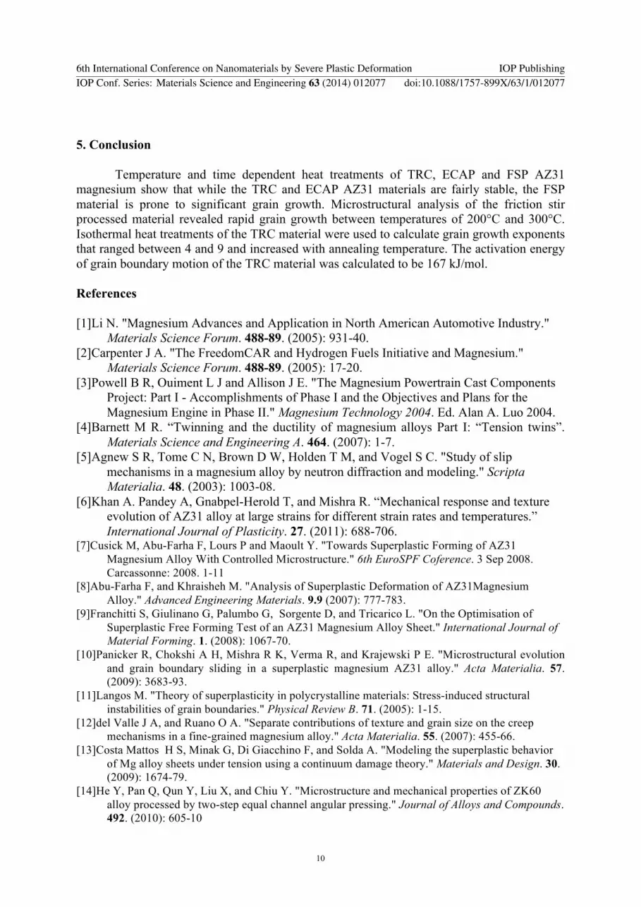
Figure 8. Average grain diameter of the as-received material as a function of heat treatment time and temperature.
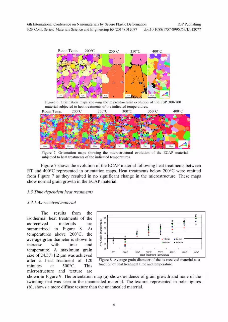
Figure 7 shows the evolution of the ECAP material following heat treatments between RT and 400°C represented in orientation maps. Heat treatments below 200°C were omitted from Figure 7 as they resulted in no significant change in the microstructure. These maps show normal grain growth in the ECAP material. 3.3 Time dependent heat treatments 3.3.1 As-received material The results from the isothermal heat treatments of the as-received materials are summarized in Figure 8. At temperatures above 200°C, the average grain diameter is shown to increase with time and temperature. A maximum grain size of 24.57±1.2 µm was achieved after a heat treatment of 120 minutes at 500°C. This microstructure and texture are shown in Figure 9. The orientation map (a) shows evidence of grain growth and none of the twinning that was seen in the unannealed material. The texture, represented in pole figures (b), shows a more diffuse texture than the unannealed material.
5µm 5µm 5µm 5µm 90µm
Room Temp. 200°C 250°C 350°C 400°C
Figure 6. Orientation maps showing the microstructural evolution of the FSP 300-700 material subjected to heat treatments of the indicated temperatures.
30µm 30µm 30µm 30µm 30µm 30µm
Room Temp. 200°C 250°C Room Temp.
300°C Room Temp.
350°C Room Temp.
400°C Room Temp.
Figure 7. Orientation maps showing the microstructural evolution of the ECAP material subjected to heat treatments of the indicated temperatures.
6th International Conference on Nanomaterials by Severe Plastic Deformation IOP PublishingIOP Conf. Series: Materials Science and Engineering 63 (2014) 012077 doi:10.1088/1757-899X/63/1/012077
6

The average grain size, D, of polycrystalline materials annealed at a constant temperature for a time, t, can be estimated by; D – Do = k tm (1) where Do is the initial grain size, k, is a material constant and m is the inverse grain growth exponent [30]. The logarithmic form of Equation (1) was taken to yield the following equation: ln ΔD = ln k + m ln t (2) Equation (2) was used to plot ln ΔD vs. ln t to give the curves shown in figure 10. The slope of these curves yielded the value of m. The inverse of these values as a function of temperature are showed in Table 1. Curves of Dn-Do
n vs t were plotted using the equation of isothermal annealing: Dn-Do
n = kt (3) where k is the grain growth constant which can be expressed by the Arrhenius equation: k = koexp(-Q/RT) (4) with Q as the activation energy for grain boundary motion, T is the absolute temperature in Kelvin and R as the gas constant. Figure 11 shows the linear relationship of Dn-Do
n vs t curve for the 350°C heat treatment. Other annealing temperatures yielded similar linear relationships but for simplicity only the 350°C heat treatment will be shown. The slopes of these curves correspond to the values of k and are shown as function of temperature in Table 1. Equation 4 was adapted into the logarithmic form to yield:
Annealing Temperature n (µm/min) k (µmn/min) 250°C 4.83 1.01(105) 300°C 5.18 2.87(105) 350°C 5.4 3.33(105) 400°C 5.55 5.05(105) 450°C 6.2 5.31(105) 500°C 9.1 1.03(106)
100µm
(a) (b)
Figure 9. Microstructure and texture of the as-received material following a heat treatment at 500°C for 120 minutes represented in (a) an orientation map and (b) pole figures.
0
0.5
1
1.5
2
2.5
2 2.5 3 3.5 4 4.5 5ln(time) (min)
ln(Δ
D) (
µm)
j
250°C
300°C
350°C
400°C
450°C
500 C
Linear(250°C)Linear(300°C)Linear(350°C)Linear(400°C)Linear(450°C)Linear(500 C)
Figure 10. Logarithmic of the change in grain size as a function of heat treatment time and temperature.
0.00E+00
2.00E+06
4.00E+06
6.00E+06
8.00E+06
1.00E+07
1.20E+07
0 20 40 60 80 100 120 140time (min)
D5.
4 -Do5.
4 (µm
5.4 )
Figure 11. Dn-Don as a function of time for the 350°C heat
treatment.
Table 1. Values of n and k as a function of annealing temperature
6th International Conference on Nanomaterials by Severe Plastic Deformation IOP PublishingIOP Conf. Series: Materials Science and Engineering 63 (2014) 012077 doi:10.1088/1757-899X/63/1/012077
7

ln k = ln ko - (Q/RT) (5) The curve of ln(k) vs. 1000/T is shown in Figure 12. The slope of this curve equates to –Q/R, thus making it possible to calculate the activation energy for grain boundary motion. The value of Q for the as-received material was found to be 167 kJ/mol. 3.3.2 Friction Stir Processed Material The average grain diameter as a function of heat treatment time and temperature for the FSP 3-7 and FSP 10-7 materials are shown in Figure 13. This shows that both annealing time and temperature had a significant impact on the grain size of the weld nugget. At 200°C, the microstructures of both processing conditions were stable. When annealed at 250°C, the average grain diameter of both friction stir processed materials grew linearly, reaching 4.86±1.1 µm and 7.6±1.1 µm after 120 minutes. At 300°C, both materials saw linear growth up to 30 minutes and then rapid growth following 60 minutes and almost no change in grain size between 60 and 120 minutes of annealing. The average grain diameter of the 3-7 and 10-7 FSP materials reached a final grain size of 21.9±1.1 µm and 13.5±1.1 µm, respectively. These microstructures and textures are shown in figures 14 and 15. Both reveal significant grain growth and weaker more diffuse textures than the
0.00
5.00
10.00
15.00
20.00
25.00
30.00
1.2 1.3 1.4 1.5 1.6 1.7 1.8 1.9 2
1000/T (K-1)ln
(k)
Figure 12. Logarithmic of k as a function of temperature.
0
5
10
15
20
25
0 10 30 60 120
Time (min)
Ave
. Gra
in D
iam
eter
(µm
) j
3-7 200°C3-7 250°C3-7 300°C10-7 200°C10-7 250°C10-7 300°C
Figure 13. Average grain size as a function of heat treatment time and temperature for the FSP 3-7 and FSP 10-7 material.
100µm
(a)
(b)
Figure 14. Microstructure and texture of the FSP material produced with tool travel speed of 300 mm/min and a tool rotation speed of 700 rpm and heat treated at a temperature of 300°C for 120 minutes represent in (a) an orientation map and (b) pole figures where the welding direction is normal to the page.
6th International Conference on Nanomaterials by Severe Plastic Deformation IOP PublishingIOP Conf. Series: Materials Science and Engineering 63 (2014) 012077 doi:10.1088/1757-899X/63/1/012077
8

unannealed materials. As the method used to calculate the activation energy for grain boundary motion of the TRC material relies on equations that assume normal grain growth, this method could not be applied for the FSP materials. 4. Discussion The grain growth kinetics of the as-received material were analyzed in section 4.3.1. The grain growth exponents for magnesium alloys annealed at temperatures between 250°C and 500°C have previously been reported to be between 2 to 8 [31-34]. The values of the grain growth exponent in this study were shown to increase with annealing temperature. Cao et al. and Thein et al. have reported temperature dependent n values that ranged between 5 and 8 in nano grained Mg-12.1 wt%Cu alloy and the Mg–5 wt%–Al and Mg–5 wt%–Al–10.3 wt%–Ti alloys, respectively [33,34]. Cao et al. attributed the temperature dependence of n to the fine grain size of their alloy thus not explaining the temperature dependence seen in this study. As the grain growth exponent can be used to represent the materials resistance to grain growth, with low values being more resistant, the results from this study suggest that at higher temperatures the as-received material became less resistant to grain growth. At 167 kJ/mol, 75 kJ/mol higher than the activation energy for pure magnesium (92 kJ/mol) [35], the activation energy for grain boundary motion calculated in this study suggest that the microstructure of the as-received is resistant to grain growth. Previous works by Wang et al. and Lambri et al. have reported Q values for AZ31 and AZ91 magnesium alloys of 110 kJ/mol [34,36]. They attributed this increase in Q when compared to pure magnesium to the presence of the intermetallic phase Al12Mg17. The fact that the as-received material was TRC, a process that involves casting and rolling in a single step, the high activation energy found in this study was likely the result of its processing condition and intermetallic phases.
The microstructures produced by both FSP and ECAP in this study are typical of AZ31 modified by these processes [21-25]. Both processes resulted in fine grain sizes and appear to have the potential for superplastic deformation. However, upon heat treatments it is revealed that the ECAP material is more stable than the FSP material. The orientation maps of the 3-7 FSP material shown in Figure 6 and the grain growth curves shown in Figure 12 suggest that the grains of the FSP materials will grow significantly upon annealing. Figure 6 suggests that this grain growth will occur at temperatures above 200°C while the curves in Figure 12 indicate that the microstructure is stable up to 300°C. This contradiction suggests that the heating time in the argon furnace used to preserve the polish of the specimens may have had an effect on the final grain size. These initial results suggest that relative microstructural stability of the ECAP makes it a more viable process for improving the superplastic properties of AZ31 magnesium.
100µm
(a)
(b)
Figure 15. Microstructure and texture of the FSP material produced with tool travel speed of 1000 mm/min and a tool rotation speed of 700 rpm and heat treated at a temperature of 300°C for 120 minutes represent in (a) an orientation map and (b) pole figures where the welding direction is normal to the page.
6th International Conference on Nanomaterials by Severe Plastic Deformation IOP PublishingIOP Conf. Series: Materials Science and Engineering 63 (2014) 012077 doi:10.1088/1757-899X/63/1/012077
9
5. Conclusion Temperature and time dependent heat treatments of TRC, ECAP and FSP AZ31 magnesium show that while the TRC and ECAP AZ31 materials are fairly stable, the FSP material is prone to significant grain growth. Microstructural analysis of the friction stir processed material revealed rapid grain growth between temperatures of 200°C and 300°C. Isothermal heat treatments of the TRC material were used to calculate grain growth exponents that ranged between 4 and 9 and increased with annealing temperature. The activation energy of grain boundary motion of the TRC material was calculated to be 167 kJ/mol. References [1]Li N. "Magnesium Advances and Application in North American Automotive Industry."
Materials Science Forum. 488-89. (2005): 931-40. [2]Carpenter J A. "The FreedomCAR and Hydrogen Fuels Initiative and Magnesium."
Materials Science Forum. 488-89. (2005): 17-20. [3]Powell B R, Ouiment L J and Allison J E. "The Magnesium Powertrain Cast Components
Project: Part I - Accomplishments of Phase I and the Objectives and Plans for the Magnesium Engine in Phase II." Magnesium Technology 2004. Ed. Alan A. Luo 2004.
[4]Barnett M R. “Twinning and the ductility of magnesium alloys Part I: “Tension twins”. Materials Science and Engineering A. 464. (2007): 1-7.
[5]Agnew S R, Tome C N, Brown D W, Holden T M, and Vogel S C. "Study of slip mechanisms in a magnesium alloy by neutron diffraction and modeling." Scripta Materialia. 48. (2003): 1003-08.
[6]Khan A. Pandey A, Gnabpel-Herold T, and Mishra R. “Mechanical response and texture evolution of AZ31 alloy at large strains for different strain rates and temperatures.” International Journal of Plasticity. 27. (2011): 688-706.
[7]Cusick M, Abu-Farha F, Lours P and Maoult Y. "Towards Superplastic Forming of AZ31 Magnesium Alloy With Controlled Microstructure." 6th EuroSPF Coference. 3 Sep 2008. Carcassonne: 2008. 1-11
[8]Abu-Farha F, and Khraisheh M. "Analysis of Superplastic Deformation of AZ31Magnesium Alloy." Advanced Engineering Materials. 9.9 (2007): 777-783.
[9]Franchitti S, Giulinano G, Palumbo G, Sorgente D, and Tricarico L. "On the Optimisation of Superplastic Free Forming Test of an AZ31 Magnesium Alloy Sheet." International Journal of Material Forming. 1. (2008): 1067-70.
[10]Panicker R, Chokshi A H, Mishra R K, Verma R, and Krajewski P E. "Microstructural evolution and grain boundary sliding in a superplastic magnesium AZ31 alloy." Acta Materialia. 57. (2009): 3683-93.
[11]Langos M. "Theory of superplasticity in polycrystalline materials: Stress-induced structural instabilities of grain boundaries." Physical Review B. 71. (2005): 1-15.
[12]del Valle J A, and Ruano O A. "Separate contributions of texture and grain size on the creep mechanisms in a fine-grained magnesium alloy." Acta Materialia. 55. (2007): 455-66.
[13]Costa Mattos H S, Minak G, Di Giacchino F, and Solda A. "Modeling the superplastic behavior of Mg alloy sheets under tension using a continuum damage theory." Materials and Design. 30. (2009): 1674-79.
[14]He Y, Pan Q, Qun Y, Liu X, and Chiu Y. "Microstructure and mechanical properties of ZK60 alloy processed by two-step equal channel angular pressing." Journal of Alloys and Compounds. 492. (2010): 605-10
6th International Conference on Nanomaterials by Severe Plastic Deformation IOP PublishingIOP Conf. Series: Materials Science and Engineering 63 (2014) 012077 doi:10.1088/1757-899X/63/1/012077
10

[15]Chen Y J, Wang Q D, Rover H J, Karlsen M, and Yu Y D. "Microstructure evolution in magnesium alloy AZ31 during cyclic extrusion compression." Journal of Alloys and Compounds. 462. (2008): 192-200.
[16]Kim W J, Lee H W, Yoo S J, and Park Y B. "Texture and mechanical properties of ultrafine-grained Mg–3Al–1Zn alloy sheets prepared by high-ratio differential speed rolling." Materials Science and Engineering A. 528. (2011): 874-79
[17]Zrnik J, Dobatkin S V, and Mamuzic L. “Processing of Metals by Sever Plastic Deformation (SPD) – Structure and Mechanical Properties Response.” Metalurgija, 47 (2008): 211-16.
[18]Verlinden B. “Severe Plastic Deformation of Metals.” Metalurgija – Journal of Metallurgy, 20: 165-82.
[19]Segal V M. “Equal channel angular extrusion: from micromechanics to structure formation.” Materials Science and Engineering A, 27 (1999): 322-33.
[20]Segal V M. Materials Science and Engineering A, 197 (1995), 157-164. [21]Figueiredo R, and Langdon T. "Grain refinement and mechanical behavior of a magnesium alloy
processed by ECAP." Journal of Material Science. 45. (2010): 4827-36. [22]He Y, Pan Q, Qin Y, Liu X, Li W, Chiu Y and Chen J J. “Microstructure and mechanical
properties of ZK60 alloy process by two-step equal channel angular pressing.” Journal of Alloys and Compounds, 492 (2010): 605-10.
[23]Mabuchi M, Ameyama K, Iwasaki H, and Higashi K. “Low temperature superplasticity of AZ91 magnesium alloy with non-equilibrium grain boundaries.” Acta mater, 47 (1999): 2047-57.
[24]The Welding Institute (TWI), W.M. Thomas, E.D. Nicholas, J.C. Needham, M.G. Murch, P. Temple-Smith, and C.J. Dawes: PCT World Patent Application WO 93/10935. Filed: Nov.27, 1992 (U.K. 9125978.8, Dec. 6, 1991). Publ: June 10, 1993.
[25]TWI; W.M. Thomas, E.D. Nicholas, J.C. Needham, P. Temple-Smith, W.K.W. Kallee S, and C.J. Dawes: U.K. Patent Application 2,306,366A. Filed: Oct, 17, 1996. Publ: May 7, 1993.
[26]Padmanaban G, Balasubramanian V, and Sarin Sundar J K. “Influences of Welding Processes on Microstructure, Hardness, and Tensile Properties of AZ31B Magnesium Alloy.” JMEPEG, 19 (2010): 155-65.
[27]Commin L, Dumont M, Masse J E, and Barrallier L. “Friction stir welding of AZ31 magnesium alloy rolled sheet: Influence of processing parameters.” Acta Materialia, 57 (2009): 326-34.
[28]Xunhong W, and Kuaishe W. “ Microstructure and properties of friction stir butt-welded AZ31 magnesium alloy.” Materials Science and Engineering A, 431 (2006): 114-17.
[29]Beyerlein I J, and Toth L S. “Texture evolution in equal-channel angular extrusion.” Progress in Materials Science, 54 (2009): 427-510.
[30]Humphreys F J, and Hatherly H. Recystallization and related annealing phenomena. New York: Elsevier Science Inc, 1995.
[31]Cao P, Lu L, and Lai M O. “Grain growth and kinetics for nanocystalline magnesium alloy process by mechanical alloying.” Materials Research Bulletin, 36 (2001): 981-88.
[32]Miao Q, Hu L, Wang X, and Wang E. “Grain growth kinetics of a fine-grained AZ31 magnesium alloy produced by hot rolling.” Journal of Alloys and Compounds, 493 (2010): 87-90.
[33]Thein M A, Lu L, and Lai M O. “ Kinetics of grain growth in nanocrystalline magnesium-based metal-metal composites synthesized by mechanical alloying.” Composites Science and Technology, 66 (2006) 531-37.
[34]Wang X, Hu L, Liu K, and Zhang Y. “Grain growth kinetics of bulk AZ31 magnesium alloy by hot pressing.” Journal of Alloys and Compounds, 527 (2012): 193-96.
6th International Conference on Nanomaterials by Severe Plastic Deformation IOP PublishingIOP Conf. Series: Materials Science and Engineering 63 (2014) 012077 doi:10.1088/1757-899X/63/1/012077
11

[35]Frost H J, Ashby M F (Eds.), Deformation-Mechanism Maps, the plasticity and creep of metals and ceramics, Pergamon Press, New York, 1982, pp. 43–45.
[36]Lambri O A, Riehemann W, and Trojanova Z. “Mechanical spectroscopy of commercial AZ91 magnesium alloy.” Scripta Materialia, 45 (2001): 1365-71.
6th International Conference on Nanomaterials by Severe Plastic Deformation IOP PublishingIOP Conf. Series: Materials Science and Engineering 63 (2014) 012077 doi:10.1088/1757-899X/63/1/012077
12


