Embed Size (px)
Citation preview
MIMAKI ENGINEERING CO., LTD.URL: https://mimaki.com/
You can also download the latest manual from our website.
D202869-17Oiginal instructions
i
Foreword ......................................................................................... vDISCLAIMER OF WARRANTY ............................................................ vRequests .............................................................................................. vFCC Statement (USA) .......................................................................... vInterference to televisions and radios ................................................... v
Safety Precautions ..........................................................................viSymbols ............................................................................................... viSafety interlock ...................................................................................viii
Warning labels ................................................................................ix
Chapter 1Before Use
Moving This Machine ................................................................... 1-2Where to Install This Machine ........................................................... 1-2Working Environmental Temperature................................................ 1-2Moving This Machine ........................................................................ 1-2
Names of Parts and Functions .................................................... 1-4Front Side of the Machine ................................................................. 1-4Rear Side and Right Side of the Machine ......................................... 1-5Operation Panel ................................................................................ 1-6Media sensor..................................................................................... 1-8Carriage............................................................................................. 1-8Cutter blade and slot for cutting ........................................................ 1-8Capping station ................................................................................. 1-8Pinch rollers and Feed rollers............................................................ 1-8
Connecting Cables ...................................................................... 1-9Connecting USB2.0 Interface Cable ................................................. 1-9Connecting the LAN cable................................................................. 1-9Connecting the power cable............................................................ 1-10
About Ink .................................................................................... 1-11About usable ink.............................................................................. 1-11Setting Ink ....................................................................................... 1-11Caution in handling of ink packs...................................................... 1-13
Media ......................................................................................... 1-14Usable sizes of media ..................................................................... 1-14Caution in handling of medias ......................................................... 1-14
Menu mode ................................................................................ 1-15
Chapter 2Basic Operations
Workflow ...................................................................................... 2-2Turning the Power ON/OFF ......................................................... 2-3
Turning the Power ON....................................................................... 2-3
TABLE OF CONTENTS
ii
Turning the Power OFF..................................................................... 2-3Setting a Media ............................................................................2-4
Adjusting the Head Height................................................................. 2-4Setting a roll media............................................................................ 2-5Using the tension bar to set the roll media ........................................ 2-8Take-up device................................................................................ 2-10Setting leaf media............................................................................ 2-14Changing the printing origin ............................................................ 2-15
Preparing for the Heaters ............................................................2-16Changing the Temperature Settings for the Heaters....................... 2-16
Test Printing ...............................................................................2-16Test Printing .................................................................................... 2-16
Head Cleaning ...........................................................................2-17About head cleaning........................................................................ 2-17Perform head cleaning depending on the test printing result .......... 2-17
Setting of Media Correction ........................................................2-18Setting of Media Correction............................................................. 2-18
If the Positions of Dots Shift... ....................................................2-18Printing Data ..............................................................................2-19
Starting a Printing Operation ........................................................... 2-19Stopping a Printing Operation ......................................................... 2-19Deleting Received Data (Data Clear) .............................................. 2-19Behavior after printing has been completed.................................... 2-19Cutting a media ............................................................................... 2-20
Chapter 3Setup
About SETUP MENU ...................................................................3-2SETUP MENU table .......................................................................... 3-3Register the optimal print conditions to match the use...................... 3-4Setting of Media Correction............................................................... 3-5If the Positions of Dots Shift... ........................................................... 3-6Setting the HEATER.......................................................................... 3-6Setting the Optional heater................................................................ 3-7Setting of Logical Seek...................................................................... 3-7Setting of Overprint ........................................................................... 3-8Setting of Drying Time....................................................................... 3-8Setting of Left and Right Margins ...................................................... 3-8Setting of Refresh.............................................................................. 3-9Setting of Vacuum Fan...................................................................... 3-9Setting of Feed Speed....................................................................... 3-9Setting of Feed Quality ...................................................................... 3-9Setting of MAPS4 ............................................................................ 3-10Setting Auto Cleaning...................................................................... 3-11Setting Interval wiping ..................................................................... 3-11Setting External heater .................................................................... 3-12Setting Pre-feed .............................................................................. 3-12
About MACHINE SETUP MENU ................................................3-13MACHINE SETUP MENU table ...................................................... 3-14Setting a AUTO Power-off ............................................................... 3-16Setting Take-up unit ........................................................................ 3-16
iii
Setting Top Blower .......................................................................... 3-16Setting the Display of Media Residual............................................. 3-17Setting the PG Drop Adjust ............................................................. 3-17Setting the Media Detection ............................................................ 3-17Setting the Drying Feed................................................................... 3-18Setting a LANGUAGE ..................................................................... 3-18Setting Time .................................................................................... 3-18Setting Unit (Temperature/ Length)................................................. 3-18Setting a KEY BUZZER................................................................... 3-19Setting the VIEW FEED .................................................................. 3-19Setting the amount of blank space between printed lines ............... 3-19Setting the SPACE FEED MODE.................................................... 3-19Set the network ............................................................................... 3-20Setting event mail function .............................................................. 3-20Initializing the Settings..................................................................... 3-24
About NOZZLE CHECK MENU ................................................. 3-25INFORMATION MENU table........................................................... 3-25Printing Check Flow ........................................................................ 3-26Printing Operations at “Nozzle Missing” Judgment and Error Occurrence 3-26Setting the Printing Check............................................................... 3-27Setting the NOZZLE RECOVERY................................................... 3-27Setting the Judgment Condition ...................................................... 3-27
About INFORMATION MENU .................................................... 3-28INFORMATION MENU table........................................................... 3-28Displaying the Information............................................................... 3-29
Chapter 4Maintenance
Maintenance ................................................................................ 4-2Precautions for Maintenance............................................................. 4-2About Cleaning Solution ....................................................................4-2Cleaning the Exterior Surfaces.......................................................... 4-2Cleaning the Platen........................................................................... 4-2Cleaning the Media Sensor ............................................................... 4-3Cleaning the Media Press ................................................................. 4-3
About MAINTENANCE MENU ..................................................... 4-4MAINTENANCE MENUs at-a-glance................................................ 4-5
Maintaining the Capping Station .................................................. 4-6Cleaning the Wiper and Cap ............................................................. 4-6Washing the Head Nozzle................................................................. 4-7Washing the Ink Discharge Passage ................................................ 4-9When the Machine Is Not Used for a Long Time ............................ 4-10
Cleaning the Ink Head and the Area around It .......................... 4-12Nozzle Recovery Function .....................................................................4-13
Reset the set value.......................................................................... 4-14Check the condition for which nozzle recovery cannot be performed........................................................................................................ 4-14Enabling or disabling nozzle recovery during a test print ................ 4-14
Automatic Maintenance Function .............................................. 4-15Setting the Refreshing Intervals ...................................................... 4-15
iv
Setting the Tube Wash Intervals ..................................................... 4-15Setting the Cleaning Intervals and Type ......................................... 4-15Suspend the nozzle cleaning .......................................................... 4-16
Fill up Ink ....................................................................................4-16Replacing consumables .............................................................4-16
Replacing the wiper......................................................................... 4-16If a Waste Ink Tank Confirmation Message Appears ...................... 4-17Replace the waste ink tank with another ......................................... 4-18Replacing the Cutter Blade ............................................................. 4-19Replacing the Spout Rubber ........................................................... 4-20Male Connector Absorbent for MBIS............................................... 4-21
Chapter 5Troubleshooting
Troubleshooting ...........................................................................5-2Power does not turn on ..................................................................... 5-2The machine does not start printing .................................................. 5-2Media get jammed / media is soiled .................................................. 5-2The heater’s temperature will not rise to the set level ....................... 5-3Image quality is poor ......................................................................... 5-3Nozzle is clogged .............................................................................. 5-3Ink IC warning appears ..................................................................... 5-3When the ink leakage occurs ............................................................ 5-4
Warning / Error Messages ...........................................................5-5Warning messages............................................................................ 5-5Error messages ................................................................................. 5-8
Chapter 6Appendix
Specifications ...............................................................................6-2Machine specifications ...................................................................... 6-2Ink specifications ............................................................................... 6-3
Setting orders depending on ink type ...........................................6-4Setting orders of ink cartridges.......................................................... 6-4
Sheet for inquiry ...........................................................................6-5
Foreword
v
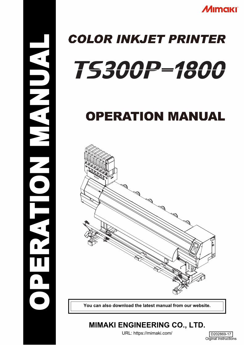
ForewordCongratulations on your purchase of MIMAKI color ink jetprinter "TS300P-1800" .“TS300P-1800” is a color inkjet printer that can print on1.8m-width media with sublimation dye ink (4-color, 6-color, 7-color and 8-color).
DISCLAIMER OF WARRANTY
THIS LIMITED WARRANTY OF MIMAKI SHALL BE THESOLE AND EXCLUSIVE WARRANTY AND IS IN LIEUOF ALL OTHER WARRANTIES, EXPRESS ORIMPLIED, INCLUDING, BUT NOT LIMITED TO, ANYIMPLIED WARRANTY OF MERCHANTABILITY ORFITNESS, AND MIMAKI NEITHER ASSUMES NORAUTHORIZES DEALER TO ASSUME FOR IT ANYOTHER OBLIGATION OR LIABILITY OR MAKE ANYOTHER WARRANTY OR MAKE ANY OTHERWARRANTY IN CONNECTION WITH ANY PRODUCTWITHOUT MIMAKI’S PRIOR WRITTEN CONSENT. IN NO EVENT SHALL MIMAKI BE LIABLE FORSPECIAL, INCIDNETAL OR CONSEQUENTIALDAMAGES OR FOR LOSS OF PROFITS OF DEALEROR CUSTOMERS OF ANY PRODUCT.
Requests
• This Operation Manual describes the operation andmaintenance of Model “Color Ink Jet Printer TS300P-1800” (hereinafter referred to as the machine).
• Please read and fully understand this OperationManual before putting the machine into service. It isalso necessary to keep this Operation Manual on hand.
• Make arrangements to deliver this Operation Manual tothe person in charge of the operation of this machine.
• This Operation Manual has been carefully prepared foryour easy understanding, however, please do nothesitate to contact your local distributor, our salesoffice, or service center.
• Description contained in this Operation Manual aresubject to change without notice for improvement.
• In the case where this Operation Manual should beillegible due to destruction or breakage, contact oursales office.
• You can also download the latest operation manualfrom our website.
FCC Statement (USA)
This equipment has been tested and found to comply withthe limits for a Class A digital device, pursuant to Part 15of the FCC Rules. These limits are designed to providereasonable protection against harmful interference whenthe equipment is operated in a commercial environment.This equipment generates, uses and can radiate radiofrequency energy and, if not installed and used inaccordance with the operation manual, may causeharmful interference to radio communications.Operation of this equipment in a residential area is likelyto cause harmful interference in which cause the user willbe required to correct the interference at his ownexpense.To prevent this, use of MIMAKI-recommended cable isessential for the connection of this printer.
Interference to televisions and radios
The product described in this manual generates low radiowaves while it is in operation. The product can interferewith radios and televisions if set up or commissionedunder improper conditions. The product is not guaranteedagainst any damage to specific-purpose radios andtelevisions.The product’s interference with your radio or television willbe checked by turning on/off the power switch of theproduct.In the event that the product is the cause of interference,try to eliminate it by taking one of the following correctivemeasures or taking some of them in combination.
• Change the direction of the receiving antenna or thefeeder of your radio/television.
• Move the receiver away from the product.• Plug the power cord of this machine into an outlet
which is isolated from power circuits connected to thetelevision set or radio.
Reproduction of this manual is strictly prohibited.All Rights Reserved.Copyright© 2015 MIMAKI ENGINEERING Co., Ltd.
• In the case where MIMAKI-recommended cable is not used for connection of this machine, limits provided by FCC rules can be exceeded. To prevent this, use of MIMAKI-recommended cable is essential for the connection of this machine.
Safety Precautions
vi
1
2
3
4
5
6
Safety PrecautionsSymbols
Symbols are used in this Operation Manual for safeoperation and for prevention of damage to the machine.The indicated sign is different depending on the content ofcaution.Symbols and their meanings are given below. Pleasefollow these instructions as you read this manual.
Examples
Warning for UsePrecautions in Use
Explanation
Failure to observe the instructions given with this symbolcan result in death or serious injuries to personnel. Besure to read it carefully and use it properly.
Failure to observe the instructions given with thissymbol can result in injuries to personnel ordamage to property.
Important notes in use of this machine are givenwith this symbol. Understand the notes thoroughlyto operate the machine properly.
Useful information is given with this symbol. Refer tothe information to operate the machine properly.
Indicates the reference page for related contents.
The symbol " " indicates that the instructions mustbe observed as strictly as the CAUTION instructions(including DANGER and WARNING instructions). A signrepresenting a precaution (the sign shown at left warns ofhazardous voltage) is shown in the triangle.
The symbol " " indicates that the actionshown is prohibited. A sign representing aprohibited action (the sign shown at left prohibitsdisassembly) is shown in or around the circle.
The symbol " " indicates that the action shown mustbe taken without fail or the instructions must be observedwithout fail. A sign representing a particular instruction(the sign shown at left instructs to unplug the cable fromthe wall outlet) is shown in the circle.
WARNING
• The set of power cables provided with this machine isfor use with this machine only, and cannot be usedwith other electrical devices. Do not use any powercables other than the ones provided with the machine.Failure to observe those instructions may result in fireor electric shocks.
• Take care not to damage, break or work upon thepower cable. If a heavy material is placed on the powercable, or if it is heated or pulled, the power cable canbreak, thus resulting in fire or electric shocks.
• Do not use this machine in an environment wherehumidity is high or the machine may get wet. Using themachine under such environment may result in fire orelectric shock, or cause malfunction.
• Use of the machine under an abnormal conditionwhere it produces smoke or strange smell can result infire or electric shocks. If such an abnormality is found,be sure to turn off the power switch immediately andunplug the cable from the wall outlet. Check first thatthe machine no longer produces smoke, and thencontact your distributor or a sales office of MIMAKI forrepair.
• Never repair your machine by yourself since it is verydangerous for you to do so.
• Never disassemble or remodel the main unit of themachine or the ink cartridge. Disassembly orremodeling can result in an electric shock orbreakdown of the machine.
• Take care that no dust or dirt sticks to Media TransferSurface heaters. Dust and dirt sticking heaters cancause fire.
• Do not use extension cords. Doing so may result in fireor electric shocks.
• Keep the power plug prong clear of any foreign objectsuch as a piece of metal. Failure to do so may result ina fire or electric shocks.
• Do not plug too may leads into a single socket. Doingso may result in fire or electric shocks.
• Do not use the machine if the power cord or plug isdamaged. Using the machine with damaged powercord may result in fire or electric shocks. Contact yourservice representative for replacement cord.
• Do not handle the power plug with wet hands. Doingso may result in electric shocks.
• In case of ink leakage, please turn off the main power,unplug the power cable and contact your localdistributor, our sales office, or service center.
• Grasp by holding the plug itself when removing thepower plug from wall outlet, and never hold by thecord. Holding and pulling the cord may damage thecord, leading to fire or electric shocks.
Hazardous Moving Parts• Keep Fingers and Other Body Parts Away• If a foreign object such as a small piece of metal or a
liquid such as water gets inside the machine, turn offthe machine and unplug the power cord immediately,then consult your service representative. Continuing touse the machine without proper maintenance or repairmay result in fire or electric shocks.
CAUTION
Power supply
• Leave the breaker turned ON.• Do not turn off the main power switch on the right
side of this machine.Heater
• Do not spill liquid on the Media Transfer Surface asthis may cause failure of the heater or firing.
• Do not touch Media Transfer Surface heaters with barehand while it is hot; otherwise, you can get burned.
WARNING
Safety Precautions
vii
CAUTIONS and NOTES
Handling of ink packs
• Keep ink away from an open flame. Also keep theroom well ventilated when you use or handle ink.
• If you get ink in your eyes, immediately wash youreyes with a lot of clean water for at least 15 minutes. Indoing so, also wash eyes to rinse ink away completely.Then, consult a doctor as soon as possible.
• Before using ink and cleaning solution, be sure to readthe Safety Data Sheet (SDS).
• If anyone drinks ink by mistake, keep him or her quietand see a doctor immediately. Do not allow him or herto swallow the vomit.Then contact the emergency number written in SDS.
• If you inhale a great deal of vapor and feel ill, immediatelymove to a location with plenty of fresh air, and keepyourself warm and quiet. Consult a doctor as soon aspossible.
• Store ink packs in a place that is out of the reach ofchildren.
• If the ink adheres to your skin, use a large amount of waterand soap or special detergent for skin to remove the ink.
• When you removed the ink pack from the seat before itends, wipe ink adhering to inside of the connector partof the ink pack with a cotton swab etc. If ink adheringto inside of the connector part may dry out, it maycause ink leakage when using it again.
• When removing eco case from the seat, be sure towear safety glasses etc. Ink may spatter and get inyour eyes. Do not pull out and insert the middlecartridge again as much as possible.
Handling of the power cable
• Connect to a socket-outlet with determinate polarity.• For PLUGGABLE EQUIPMENT, the socket-outlet shall be
installed near the equipment and shall be easily accessible.• Unplug the cord from the wall outlet and remove dust
from the power plug periodically, at least once a year.Failure to do so may result in fire or electric shocks.
• Do not use the machine unless it is connected to a powersupply that satisfies the displayed voltage condition.
• Check the voltage of the wall outlet and the capacity ofthe circuit breaker before you plug the power cords.Plug each power cord to different outlet that hasindependent circuit breaker. If you plug more than onepower cord to wall outlets that share the same circuitbreaker, the power may be cut off by the breaker.
Note on maintenance
• When handling ink and cleaning solution, pay closeattention to ventilation and be sure to wear theincluded safety glasses and gloves.
• Pay close attention to ventilation and be sure to wearthe included safety glasses and gloves.
• The gloves supplied with the machine are disposable.When all the gloves are expended, purchase anequivalent product on the market.
CAUTION
• Do not touch the sharp edge of the blade whenreplacing the cutter. Touching the sharp edge mayresult in injury.
Notes When Handling this machine
• Use the equipment in a well-ventilated or not-airtightroom.
• Ventilate the room sufficiently before using theequipment.
• Do not place the equipment in a humid or dusty place.Otherwise, there is a risk of fire or electrical shock.
• Do not place the equipment in an unstable place suchas on a shaky table and on a tilted surface. Theequipment may fall over or drop and cause injury.
• The equipment is provided with a built-in media cutter.To replace or feed a printing medium, or to remove ajammed printing medium, do not touch any area otherthan those specified in this document. Otherwise,there is a risk of injury.
• To replace a printing media, be careful not to pinchyour fingers or get injured.
• Do not leave the ink slot empty for a long time. Leav-ing it empty may dry the slot and solidify the ink in themachine, then the machine will become unable tosupply ink.
• If ink packs are not set in the ink slot, an errormessage will display on the printer to set ink packs.Set the same colored ink cartridge as the ink usedbefore.
• Consult with the service shop about cleaning inside theequipment.Leaving the equipment with dust inside withoutcleaning for a long time may cause a fire or devicefailure. Consult with the distributor or service shop forthe cost of cleaning inside the equipment.
• To move the equipment, contact the nearest serviceshop.
Warning
Disposition of this machine
• Consult your sales or service representative for proper disposal of this machine. Otherwise, commission an industrial waste disposal company.
Protection of media from dust
• Store media in a bag. Wiping off dust accumulated on media willadversely affect the media due to static electricity.
• When leaving the workshop after the working hours, do notleave any media on the roll hanger. If any media is left on the rollhanger, it can get dusty.
Periodic replacement parts
• Some parts of this machine must be replaced with a new oneperiodically by service personnel. Be sure to make a contractwith your distributor or dealer for After sale service to ensure along life of your machine.
CAUTION
Safety Precautions
viii
1
2
3
4
5
6
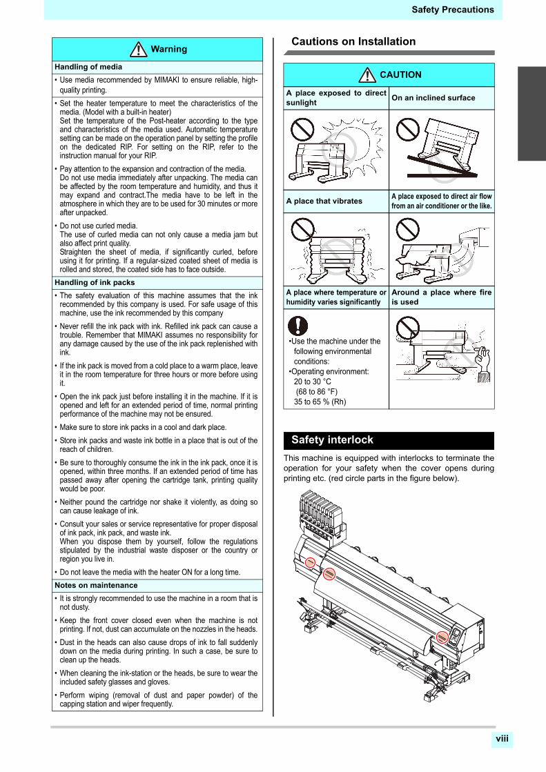
Cautions on Installation
Safety interlock
This machine is equipped with interlocks to terminate theoperation for your safety when the cover opens duringprinting etc. (red circle parts in the figure below).
Handling of media
• Use media recommended by MIMAKI to ensure reliable, high-quality printing.
• Set the heater temperature to meet the characteristics of themedia. (Model with a built-in heater)Set the temperature of the Post-heater according to the typeand characteristics of the media used. Automatic temperaturesetting can be made on the operation panel by setting the profileon the dedicated RIP. For setting on the RIP, refer to theinstruction manual for your RIP.
• Pay attention to the expansion and contraction of the media.Do not use media immediately after unpacking. The media canbe affected by the room temperature and humidity, and thus itmay expand and contract.The media have to be left in theatmosphere in which they are to be used for 30 minutes or moreafter unpacked.
• Do not use curled media.The use of curled media can not only cause a media jam butalso affect print quality.Straighten the sheet of media, if significantly curled, beforeusing it for printing. If a regular-sized coated sheet of media isrolled and stored, the coated side has to face outside.
Handling of ink packs
• The safety evaluation of this machine assumes that the inkrecommended by this company is used. For safe usage of thismachine, use the ink recommended by this company
• Never refill the ink pack with ink. Refilled ink pack can cause atrouble. Remember that MIMAKI assumes no responsibility forany damage caused by the use of the ink pack replenished withink.
• If the ink pack is moved from a cold place to a warm place, leaveit in the room temperature for three hours or more before usingit.
• Open the ink pack just before installing it in the machine. If it isopened and left for an extended period of time, normal printingperformance of the machine may not be ensured.
• Make sure to store ink packs in a cool and dark place.
• Store ink packs and waste ink bottle in a place that is out of thereach of children.
• Be sure to thoroughly consume the ink in the ink pack, once it isopened, within three months. If an extended period of time haspassed away after opening the cartridge tank, printing qualitywould be poor.
• Neither pound the cartridge nor shake it violently, as doing socan cause leakage of ink.
• Consult your sales or service representative for proper disposalof ink pack, ink pack, and waste ink.When you dispose them by yourself, follow the regulationsstipulated by the industrial waste disposer or the country orregion you live in.
• Do not leave the media with the heater ON for a long time.
Notes on maintenance
• It is strongly recommended to use the machine in a room that isnot dusty.
• Keep the front cover closed even when the machine is notprinting. If not, dust can accumulate on the nozzles in the heads.
• Dust in the heads can also cause drops of ink to fall suddenlydown on the media during printing. In such a case, be sure toclean up the heads.
• When cleaning the ink-station or the heads, be sure to wear theincluded safety glasses and gloves.
• Perform wiping (removal of dust and paper powder) of thecapping station and wiper frequently.
Warning
CAUTION
A place exposed to directsunlight
On an inclined surface
A place that vibratesA place exposed to direct air flowfrom an air conditioner or the like.
A place where temperature orhumidity varies significantly
Around a place where fireis used
•Use the machine under the following environmental conditions:
•Operating environment:20 to 30 °C (68 to 86 °F)35 to 65 % (Rh)
ix
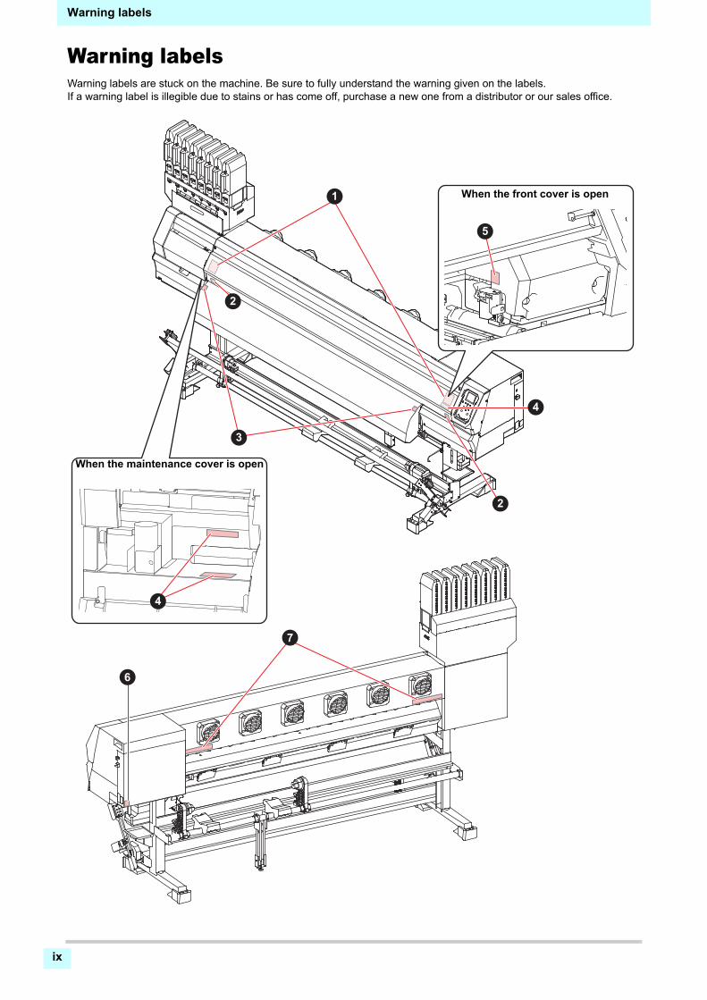
Warning labels
Warning labelsWarning labels are stuck on the machine. Be sure to fully understand the warning given on the labels.If a warning label is illegible due to stains or has come off, purchase a new one from a distributor or our sales office.
6
When the front cover is open
When the maintenance cover is open
x
1
2
3
4
5
6
Warning labels
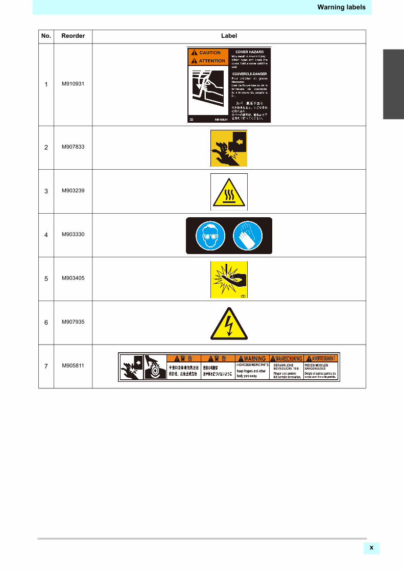
No. Reorder Label
1 M910931
2 M907833
3 M903239
4 M903330
5 M903405
6 M907935
7 M905811

xi
Warning labels
This chapter
describes the items required to understand before use, such as the name of each part ofthe machine or the installation procedures.
Moving This Machine .................................... 1-2Where to Install This Machine ..................... 1-2Working Environmental Temperature ......... 1-2Moving This Machine .................................. 1-2
Names of Parts and Functions...................... 1-4Front Side of the Machine ........................... 1-4Rear Side and Right Side of the Machine ... 1-5Operation Panel .......................................... 1-6Media sensor ............................................... 1-8Carriage ...................................................... 1-8Cutter blade and slot for cutting .................. 1-8Capping station ........................................... 1-8Pinch rollers and Feed rollers ..................... 1-8
Connecting Cables........................................ 1-9Connecting USB2.0 Interface Cable ............1-9Connecting the LAN cable ...........................1-9Connecting the power cable ......................1-10
About Ink ..................................................... 1-11About usable ink ........................................1-11Setting Ink ..................................................1-11Caution in handling of ink packs ................1-13
Media .......................................................... 1-14Usable sizes of media ................................1-14Caution in handling of medias ...................1-14
Menu mode ................................................. 1-15
Chapter 1
Before Use
Chapter 1 Before Use
1-2
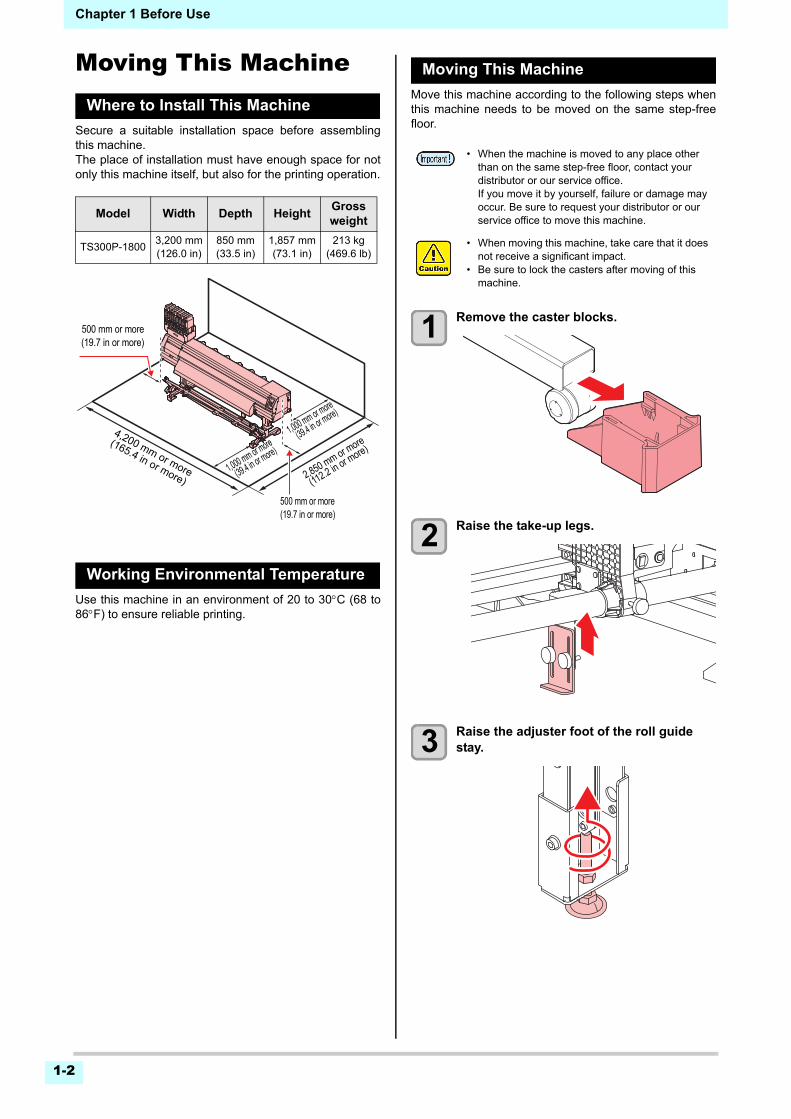
Moving This MachineWhere to Install This Machine
Secure a suitable installation space before assemblingthis machine.The place of installation must have enough space for notonly this machine itself, but also for the printing operation.
Working Environmental Temperature
Use this machine in an environment of 20 to 30C (68 to86F) to ensure reliable printing.
Moving This Machine
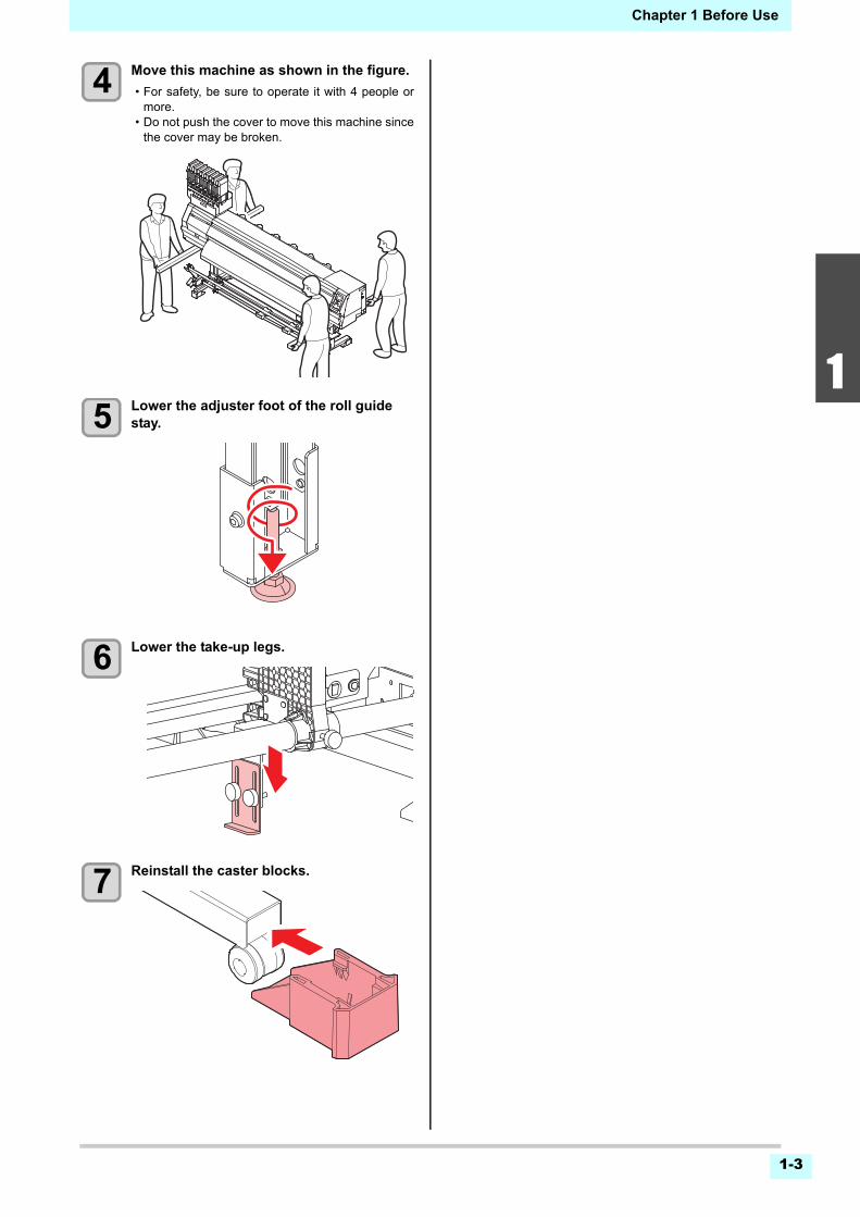
Move this machine according to the following steps whenthis machine needs to be moved on the same step-freefloor.
1 Remove the caster blocks.
2 Raise the take-up legs.
3 Raise the adjuster foot of the roll guide stay.
Model Width Depth HeightGross weight
TS300P-18003,200 mm(126.0 in)
850 mm(33.5 in)
1,857 mm(73.1 in)
213 kg(469.6 lb)
500 mm or more(19.7 in or more)
4,200 mm or more
(165.4 in or more) 2,850 mm or more
(112.2 in or m
ore)
500 mm or more(19.7 in or more)
1,000 mm or more
(39.4 in or more)
1,000 mm or more
(39.4 in or more)
• When the machine is moved to any place other than on the same step-free floor, contact your distributor or our service office.If you move it by yourself, failure or damage may occur. Be sure to request your distributor or our service office to move this machine.
• When moving this machine, take care that it does not receive a significant impact.
• Be sure to lock the casters after moving of this machine.
Chapter 1 Before Use
1-3
1
2
2
2
5
6
4 Move this machine as shown in the figure.
• For safety, be sure to operate it with 4 people ormore.
• Do not push the cover to move this machine sincethe cover may be broken.
5 Lower the adjuster foot of the roll guide stay.
6 Lower the take-up legs.
7 Reinstall the caster blocks.
1-4
Chapter 1 Before Use
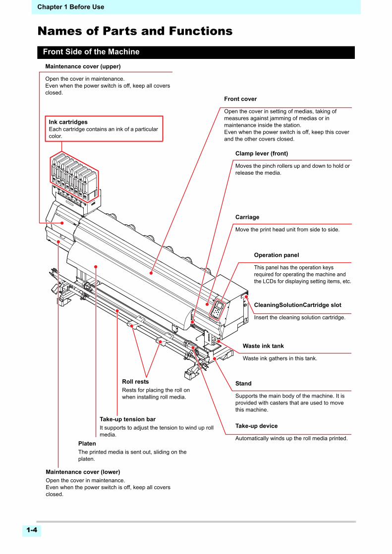
Names of Parts and FunctionsFront Side of the Machine
Front cover
Open the cover in setting of medias, taking of measures against jamming of medias or in maintenance inside the station. Even when the power switch is off, keep this cover and the other covers closed.
Operation panel
This panel has the operation keys required for operating the machine and the LCDs for displaying setting items, etc.
Clamp lever (front)
Moves the pinch rollers up and down to hold or release the media.
Waste ink tank
Waste ink gathers in this tank.
Stand
Supports the main body of the machine. It is provided with casters that are used to move this machine.
Maintenance cover (upper)
Open the cover in maintenance.Even when the power switch is off, keep all covers closed.
Platen
The printed media is sent out, sliding on the platen.
Ink cartridgesEach cartridge contains an ink of a particular color.
Take-up device
Automatically winds up the roll media printed.
Carriage
Move the print head unit from side to side.
Maintenance cover (lower)
Open the cover in maintenance.Even when the power switch is off, keep all covers closed.
CleaningSolutionCartridge slot
Insert the cleaning solution cartridge.
Roll rests
Rests for placing the roll on when installing roll media.
Take-up tension bar
It supports to adjust the tension to wind up roll media.
1-5
1
2
2
2
5
6
Chapter 1 Before Use
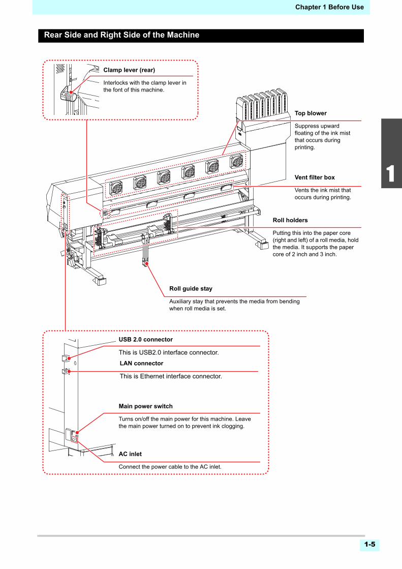
Rear Side and Right Side of the Machine
AC inlet
Connect the power cable to the AC inlet.
Clamp lever (rear)
Interlocks with the clamp lever in the font of this machine.
Main power switch
Turns on/off the main power for this machine. Leave the main power turned on to prevent ink clogging.
Roll guide stay
Auxiliary stay that prevents the media from bending when roll media is set.
Vent filter box
Vents the ink mist that occurs during printing.
Roll holders
Putting this into the paper core (right and left) of a roll media, hold the media. It supports the paper core of 2 inch and 3 inch.
LAN connector
This is Ethernet interface connector.
Top blower
Suppress upward floating of the ink mist that occurs during printing.
USB 2.0 connector
This is USB2.0 interface connector.
1-6
Chapter 1 Before Use
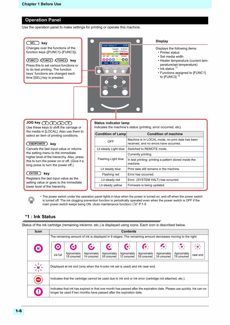
Operation Panel
Use the operation panel to make settings for printing or operate this machine.
*1 : Ink Status
Status of the ink cartridge (remaining ink/error, etc.) is displayed using icons. Each icon is described below.
Icon Contents
The remaining amount of ink is displayed in 9 stages. The remaining amount decreases moving to the right.
Displayed at ink end (only when the 4-color ink set is used) and ink near end.
Indicates that the cartridge cannot be used due to ink end or ink error (cartridge not attached, etc.).
Indicates that ink has expired or that one month has passed after the expiration date. Please use quickly. Ink can no longer be used if two months have passed after the expiration date.
width:1340mm
REMOTEMENU TEST PRINTCLEANING
30°/40°
width:1340mmheigth: 4.0mm
REMOTEMENU
POST1 POST2
TEST PRINTCLEANING
FAN
30°/40°30°/50° HIGH
Local <Setup 1> 12:00
Status indicator lampIndicates the machine’s status (printing, error occurred, etc).
Condition of Lamp Condition of machine
OFFMachine is in LOCAL mode, no print data has been received, and no errors have occurred.
Lit steady Light blue Switched to REMOTE mode.
Flashing Light blue
Currently printing.
In test printing: printing a pattern stored inside the machine.
Lit steady blue Print data still remains in the machine.
Flashing red Error has occurred.
Lit steady red Error (SYSTEM HALT) has occurred.
Lit steady yellow Firmware is being updated.
Display
Displays the following items:• Printer status• Set media width• Heater temperature (current tem-
perature/set temperature)• Ink status *1
• Functions assigned to [FUNC1] to [FUNC3] *2
key
Changes over the functions of the function keys ([FUNC1]–[FUNC3]).
/ / key
Press this to set various functions or to do test printing. The function keys’ functions are changed each time [SEL] key is pressed.
JOG key
Use these keys to shift the carriage or the media in [LOCAL]. Also use them to select an item of printing conditions.
key
Cancels the last input value or returns the setting menu to the immediate higher level of the hierarchy. Also, press this to turn the power on or off. (Give it a long press to turn the power off.)
key
Registers the last input value as the setting value or goes to the immediate lower level of the hierarchy.
• The power switch under the operation panel lights in blue when the power is turned on, and off when the power switch is turned off. The ink clogging prevention function is periodically operated even when the power switch is OFF if the main power switch keeps being ON. (Auto maintenance function) P.1-5
ink full Approximately 1/8 consumed
Approximately 1/4 consumed.
Approximately 3/8 consumed.
Approximately 1/2 consumed.
Approximately 5/8 consumed.
Approximately 3/4 consumed.
Approximately 7/8 consumed. near end
1-7
1
2
2
2
5
6
Chapter 1 Before Use
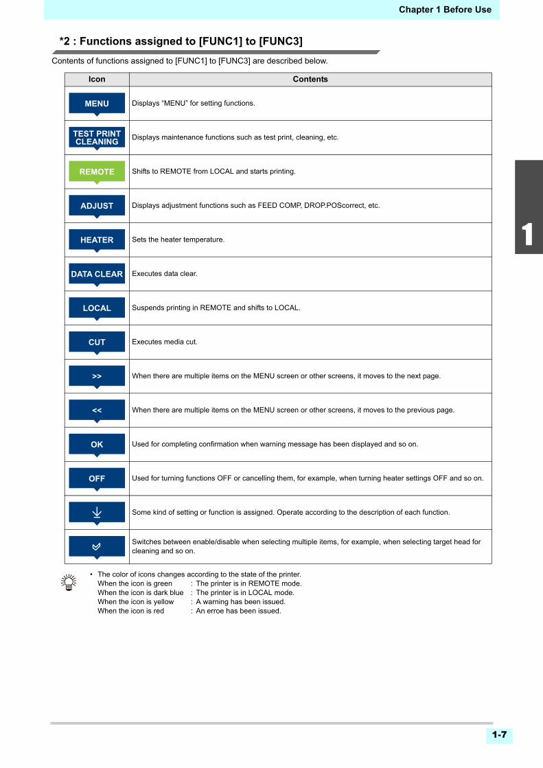
*2 : Functions assigned to [FUNC1] to [FUNC3]
Contents of functions assigned to [FUNC1] to [FUNC3] are described below.
Icon Contents
Displays “MENU” for setting functions.
Displays maintenance functions such as test print, cleaning, etc.
Shifts to REMOTE from LOCAL and starts printing.
Displays adjustment functions such as FEED COMP, DROP.POScorrect, etc.
Sets the heater temperature.
Executes data clear.
Suspends printing in REMOTE and shifts to LOCAL.
Executes media cut.
When there are multiple items on the MENU screen or other screens, it moves to the next page.
When there are multiple items on the MENU screen or other screens, it moves to the previous page.
Used for completing confirmation when warning message has been displayed and so on.
Used for turning functions OFF or cancelling them, for example, when turning heater settings OFF and so on.
Some kind of setting or function is assigned. Operate according to the description of each function.
Switches between enable/disable when selecting multiple items, for example, when selecting target head for cleaning and so on.
• The color of icons changes according to the state of the printer.When the icon is green : The printer is in REMOTE mode.When the icon is dark blue : The printer is in LOCAL mode.When the icon is yellow : A warning has been issued.When the icon is red : An erroe has been issued.
�
Chapter 1 Before Use
1-8
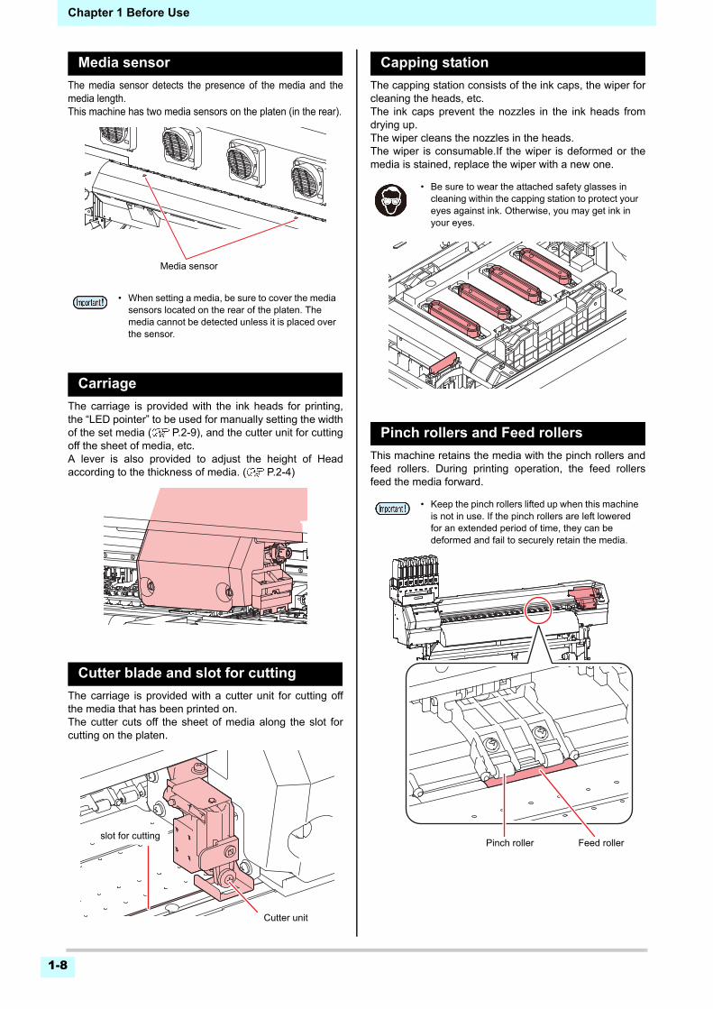
Media sensor
The media sensor detects the presence of the media and themedia length.This machine has two media sensors on the platen (in the rear).
Carriage
The carriage is provided with the ink heads for printing,the “LED pointer” to be used for manually setting the widthof the set media ( P.2-9), and the cutter unit for cuttingoff the sheet of media, etc. A lever is also provided to adjust the height of Headaccording to the thickness of media. ( P.2-4)
Cutter blade and slot for cutting
The carriage is provided with a cutter unit for cutting offthe media that has been printed on. The cutter cuts off the sheet of media along the slot forcutting on the platen.
Capping station
The capping station consists of the ink caps, the wiper forcleaning the heads, etc.The ink caps prevent the nozzles in the ink heads fromdrying up.The wiper cleans the nozzles in the heads.The wiper is consumable.If the wiper is deformed or themedia is stained, replace the wiper with a new one.
Pinch rollers and Feed rollers
This machine retains the media with the pinch rollers andfeed rollers. During printing operation, the feed rollersfeed the media forward.
• When setting a media, be sure to cover the media sensors located on the rear of the platen. The media cannot be detected unless it is placed over the sensor.
Media sensor
Cutter unit
slot for cutting
• Be sure to wear the attached safety glasses in cleaning within the capping station to protect your eyes against ink. Otherwise, you may get ink in your eyes.
• Keep the pinch rollers lifted up when this machine is not in use. If the pinch rollers are left lowered for an extended period of time, they can be deformed and fail to securely retain the media.
Feed rollerPinch roller
Chapter 1 Before Use
1-9
1
2
2
2
5
6
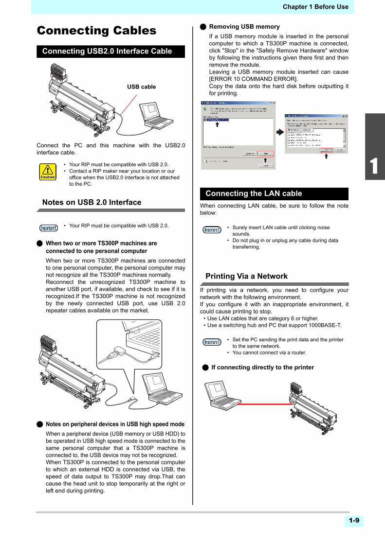
Connecting CablesConnecting USB2.0 Interface Cable
Connect the PC and this machine with the USB2.0interface cable.
Notes on USB 2.0 Interface
When two or more TS300P machines are connected to one personal computer
When two or more TS300P machines are connectedto one personal computer, the personal computer maynot recognize all the TS300P machines normally.Reconnect the unrecognized TS300P machine toanother USB port, if available, and check to see if it isrecognized.If the TS300P machine is not recognizedby the newly connected USB port, use USB 2.0repeater cables available on the market.
Notes on peripheral devices in USB high speed mode
When a peripheral device (USB memory or USB HDD) tobe operated in USB high speed mode is connected to thesame personal computer that a TS300P machine isconnected to, the USB device may not be recognized.When TS300P is connected to the personal computerto which an external HDD is connected via USB, thespeed of data output to TS300P may drop.That cancause the head unit to stop temporarily at the right orleft end during printing.
Removing USB memory
If a USB memory module is inserted in the personalcomputer to which a TS300P machine is connected,click "Stop" in the "Safely Remove Hardware" windowby following the instructions given there first and thenremove the module.Leaving a USB memory module inserted can cause[ERROR 10 COMMAND ERROR].Copy the data onto the hard disk before outputting itfor printing.
Connecting the LAN cable
When connecting LAN cable, be sure to follow the notebelow:
Printing Via a Network
If printing via a network, you need to configure yournetwork with the following environment.If you configure it with an inappropriate environment, itcould cause printing to stop.
• Use LAN cables that are category 6 or higher.• Use a switching hub and PC that support 1000BASE-T.
• Your RIP must be compatible with USB 2.0.• Contact a RIP maker near your location or our
office when the USB2.0 interface is not attached to the PC.
• Your RIP must be compatible with USB 2.0.
USB cable
• Surely insert LAN cable until clicking noise sounds.
• Do not plug in or unplug any cable during data transferring.
• Set the PC sending the print data and the printer to the same network.
• You cannot connect via a router.
If connecting directly to the printer
Chapter 1 Before Use
1-10
If the PC or device connected to the printer is not1000BASE-T, you cannot perform printing.After connecting, check the following.
(1) Check the printer screen display.• On the local screen or the media detection screen, press
the [Enter] key several times to display the informationscreen.
• Check that "1000Mbps" is displayed for the LAN statusitem.
(2) Check the green light of the LAN connector.• After turning on the machine, the lamp for the LAN
connector will light up as follows.
Connecting the power cable
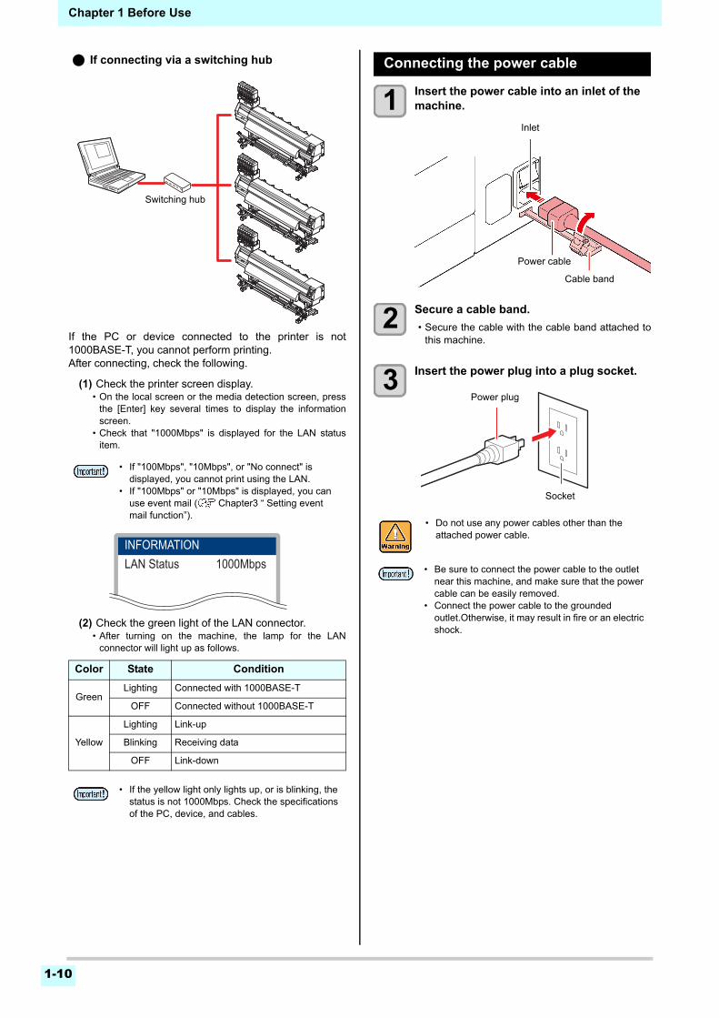
1 Insert the power cable into an inlet of the machine.
2 Secure a cable band.
• Secure the cable with the cable band attached tothis machine.
3 Insert the power plug into a plug socket.
• If "100Mbps", "10Mbps", or "No connect" is displayed, you cannot print using the LAN.
• If "100Mbps" or "10Mbps" is displayed, you can use event mail ( Chapter3 “ Setting event mail function”).
Color State Condition
GreenLighting Connected with 1000BASE-T
OFF Connected without 1000BASE-T
Yellow
Lighting Link-up
Blinking Receiving data
OFF Link-down
• If the yellow light only lights up, or is blinking, the status is not 1000Mbps. Check the specifications of the PC, device, and cables.
Switching hub
If connecting via a switching hub
INFORMATIONLAN Status 1000Mbps
• Do not use any power cables other than the attached power cable.
• Be sure to connect the power cable to the outlet near this machine, and make sure that the power cable can be easily removed.
• Connect the power cable to the grounded outlet.Otherwise, it may result in fire or an electric shock.
Inlet
Power cable
Cable band
Power plug
Socket
Chapter 1 Before Use
1-11
1
2
2
2
5
6
About InkAbout usable ink
You can use aqueous sublimation dye ink (Sb410/Sb411)for this machine.
Setting Ink
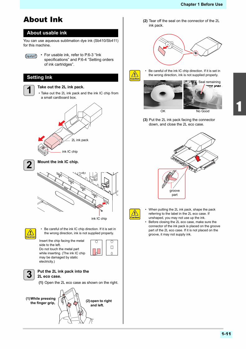
1 Take out the 2L ink pack.
• Take out the 2L ink pack and the ink IC chip froma small cardboard box.
2 Mount the ink IC chip.
3 Put the 2L ink pack into the 2L eco case.
(1) Open the 2L eco case as shown on the right.
(2) Tear off the seal on the connector of the 2L ink pack.
(3) Put the 2L ink pack facing the connector down, and close the 2L eco case.
• For usable ink, refer to P.6-3 “Ink specifications” and P.6-4 “Setting orders of ink cartridges”.
• Be careful of the ink IC chip direction. If it is set in the wrong direction, ink is not supplied properly.
2L ink pack
ink IC chip
ink IC chip
Insert the chip facing the metal side to the left.Do not touch the metal part while inserting. (The ink IC chip may be damaged by static electricity.)
(2)open to right and left.
(1)While pressing the finger grip,
• Be careful of the ink IC chip direction. If it is set in the wrong direction, ink is not supplied properly.
• When putting the 2L ink pack, shape the pack referring to the label in the 2L eco case. If unshaped, you may not use up the ink.
• Before closing the 2L eco case, make sure the connector of the ink pack is placed on the groove part of the 2L eco case. If it is not placed on the groove, it may not supply ink.
OK
Seal remaining
No Good
groove part
Chapter 1 Before Use
1-12
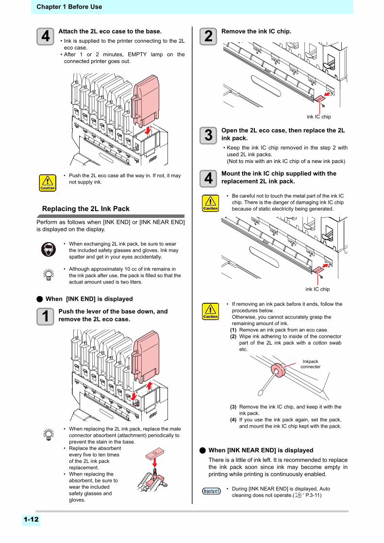
4 Attach the 2L eco case to the base.
• Ink is supplied to the printer connecting to the 2Leco case.
• After 1 or 2 minutes, EMPTY lamp on theconnected printer goes out.
Replacing the 2L Ink Pack
Perform as follows when [INK END] or [INK NEAR END]is displayed on the display.
When [INK END] is displayed
1 Push the lever of the base down, and remove the 2L eco case.
2 Remove the ink IC chip.
3 Open the 2L eco case, then replace the 2L ink pack.
• Keep the ink IC chip removed in the step 2 withused 2L ink packs.(Not to mix with an ink IC chip of a new ink pack)
4 Mount the ink IC chip supplied with the replacement 2L ink pack.
When [INK NEAR END] is displayed
There is a little of ink left. It is recommended to replacethe ink pack soon since ink may become empty inprinting while printing is continuously enabled.
• Push the 2L eco case all the way in. If not, it may not supply ink.
• When exchanging 2L ink pack, be sure to wear the included safety glasses and gloves. Ink may spatter and get in your eyes accidentally.
• Although approximately 10 cc of ink remains in the ink pack after use, the pack is filled so that the actual amount used is two liters.
• When replacing the 2L ink pack, replace the male connector absorbent (attachment) periodically to prevent the stain in the base.
• Replace the absorbent every five to ten times of the 2L ink pack replacement.
• When replacing the absorbent, be sure to wear the included safety glasses and gloves.
• Be careful not to touch the metal part of the ink IC chip. There is the danger of damaging ink IC chip because of static electricity being generated.
• If removing an ink pack before it ends, follow the procedures below.Otherwise, you cannot accurately grasp the remaining amount of ink.
(1) Remove an ink pack from an eco case.(2) Wipe ink adhering to inside of the connector
part of the 2L ink pack with a cotton swabetc.
(3) Remove the ink IC chip, and keep it with theink pack.
(4) If you use the ink pack again, set the pack,and mount the ink IC chip kept with the pack.
• During [INK NEAR END] is displayed, Auto cleaning does not operate.( P.3-11)
ink IC chip
ink IC chip
Inkpackconnecter
Chapter 1 Before Use
1-13
1
2
2
2
5
6
For Ink cartridge lamps
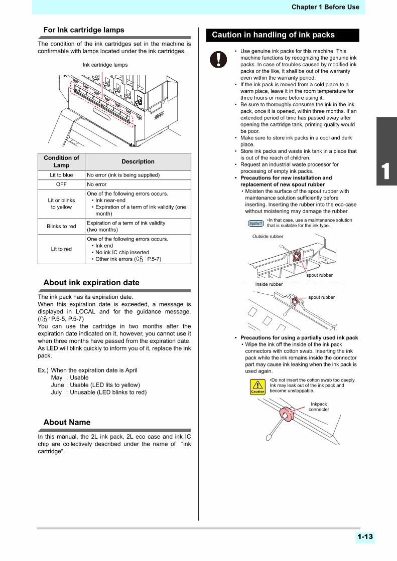
The condition of the ink cartridges set in the machine isconfirmable with lamps located under the ink cartridges.
About ink expiration date
The ink pack has its expiration date.When this expiration date is exceeded, a message isdisplayed in LOCAL and for the guidance message.( P.5-5, P.5-7)You can use the cartridge in two months after theexpiration date indicated on it, however, you cannot use itwhen three months have passed from the expiration date.As LED will blink quickly to inform you of it, replace the inkpack.
Ex.) When the expiration date is AprilMay : UsableJune : Usable (LED lits to yellow)July : Unusable (LED blinks to red)
About Name
In this manual, the 2L ink pack, 2L eco case and ink ICchip are collectively described under the name of "inkcartridge".
Caution in handling of ink packs
Condition of Lamp
Description
Lit to blue No error (ink is being supplied)
OFF No error
Lit or blinks to yellow
One of the following errors occurs.• Ink near-end• Expiration of a term of ink validity (one
month)
Blinks to redExpiration of a term of ink validity (two months)
Lit to red
One of the following errors occurs.• Ink end• No ink IC chip inserted• Other ink errors ( P.5-7)
Ink cartridge lamps
• Use genuine ink packs for this machine. This machine functions by recognizing the genuine ink packs. In case of troubles caused by modified ink packs or the like, it shall be out of the warranty even within the warranty period.
• If the ink pack is moved from a cold place to a warm place, leave it in the room temperature for three hours or more before using it.
• Be sure to thoroughly consume the ink in the ink pack, once it is opened, within three months. If an extended period of time has passed away after opening the cartridge tank, printing quality would be poor.
• Make sure to store ink packs in a cool and dark place.
• Store ink packs and waste ink tank in a place that is out of the reach of children.
• Request an industrial waste processor for processing of empty ink packs.
• Precautions for new installation and replacement of new spout rubber• Moisten the surface of the spout rubber with
maintenance solution sufficiently before inserting. Inserting the rubber into the eco-case without moistening may damage the rubber.
• Precautions for using a partially used ink pack• Wipe the ink off the inside of the ink pack
connectors with cotton swab. Inserting the ink pack while the ink remains inside the connector part may cause ink leaking when the ink pack is used again.
•In that case, use a maintenance solution that is suitable for the ink type.
Outside rubber
Inside rubber
spout rubber
spout rubber
•Do not insert the cotton swab too deeply. Ink may leak out of the ink pack and become unstoppable.
Inkpackconnecter
Chapter 1 Before Use
1-14
MediaUsable media sizes and notes for handling are described.
Usable sizes of media
Caution in handling of medias
Pay attention to the followings for handling of medias.
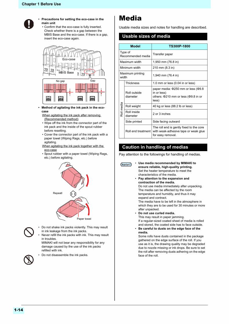
• Precautions for setting the eco-case in the main unit• Confirm that the eco-case is fully inserted.
Check whether there is a gap between the MBIS Base and the eco-case. If there is a gap, insert the eco-case again.
• Method of agitating the ink pack in the eco-caseWhen agitating the ink pack after removing
(Recommended method)• Wipe off the ink from the connector part of the
ink pack and the inside of the spout rubber before resetting.
• Cover the connector part of the ink pack with a paper towel (Wiping Rags, etc.) before agitating.
When agitating the ink pack together with the eco-case
• Spout rubber with a paper towel (Wiping Rags, etc.) before agitating.
• Do not shake ink packs violently. This may result in ink leakage from the ink packs.
• Never refill the ink packs with ink. This may result in troubles.MIMAKI will not bear any responsibility for any damage caused by the use of the ink packs refilled with ink.
• Do not disassemble the ink packs.
Gap
Eco-case
MBIS Base
No gap
Paper towel
Repeatl
Model TS300P-1800
Type of Recommended media
Transfer paper
Maximum width 1,950 mm (76.8 in)
Minimum width 210 mm (8.3 in)
Maximum printing width
1,940 mm (76.4 in)
Rol
l med
ia
Thickness 1.0 mm or less (0.04 in or less)
Roll outside diameter
paper media: Φ250 mm or less (Φ9.8 in or less)others: Φ210 mm or less (Φ9.8 in or less)
Roll weight 40 kg or less (88.2 lb or less)
Roll inside diameter
2 or 3 inches
Side printed Side facing outward
Roll end treatmentThe roll end is gently fixed to the core with weak-adhesive tape or weak glue for easy removal.
• Use media recommended by MIMAKI to ensure reliable, high-quality printing.Set the heater temperature to meet the characteristics of the media.
• Pay attention to the expansion and contraction of the media.Do not use media immediately after unpacking. The media can be affected by the room temperature and humidity, and thus it may expand and contract.The media have to be left in the atmosphere in which they are to be used for 30 minutes or more after unpacked.
• Do not use curled media.This may result in paper jamming.If a regular-sized coated sheet of media is rolled and stored, the coated side has to face outside.
• Be careful to dusts on the edge face of the media.Some rolls have dusts contained in the package gathered on the edge surface of the roll. If you use as it is, the drawing quality may be degraded due to nozzle missing or ink drops. Be sure to set the roll after removing dusts adhering on the edge face of the roll.
1-15
1
2
2
2
5
6
Chapter 1 Before Use
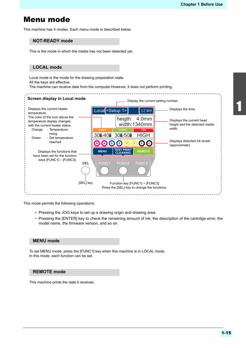
Menu modeThis machine has 4 modes. Each menu mode is described below.
NOT-READY mode
This is the mode in which the media has not been detected yet.
LOCAL mode
Local mode is the mode for the drawing preparation state.All the keys are effective.The machine can receive data from the computer.However, it does not perform printing.
This mode permits the following operations:
• Pressing the JOG keys to set up a drawing origin and drawing area.
• Pressing the [ENTER] key to check the remaining amount of ink, the description of the cartridge error, themodel name, the firmware version, and so on.
MENU mode
To set MENU mode, press the [FUNC1] key when this machine is in LOCAL mode.In this mode, each function can be set.
REMOTE mode
This machine prints the data it receives.
REMOTEMENU
POST1 POST2
TEST PRINTCLEANING
FAN
30�/40�30�/50� HIGH
Local <Setup 1> 12:00
width:1340mmheigth: 4.0mm
Displays the current heater temperature.The color of the icon above the temperature display changes with the current heater status.
Orange : Temperature rising
Green : Set temperature reached
Displays the current head height and the detected media width.
Displays detected ink levels (approximate)
Displays the functions thathave been set for the function
keys [FUNC1] – [FUNC3].
[SEL] key Function key [FUNC1] ~ [FUNC3]Press the [SEL] key to change the functions.
Screen display in Local mode
Displays the time.
Display the current setting number.

1-16
Chapter 1 Before Use
This chapter
describes procedures and setting methods for ink and media preparation, and printing.
Workflow .......................................................2-2Turning the Power ON/OFF ..........................2-3
Turning the Power ON ................................ 2-3Turning the Power OFF ............................... 2-3
Setting a Media .............................................2-4Adjusting the Head Height .......................... 2-4Setting a roll media ..................................... 2-5Using the tension bar to set the roll media .. 2-8Take-up device .......................................... 2-10Setting leaf media ..................................... 2-14Changing the printing origin ...................... 2-15
Preparing for the Heaters ............................2-16Changing the Temperature Settings for the Heaters ...................................................... 2-16
Test Printing ................................................2-16Test Printing .............................................. 2-16
Head Cleaning ............................................2-17About head cleaning ..................................2-17Perform head cleaning depending on the test printing result .............................................2-17
Setting of Media Correction .........................2-18Setting of Media Correction .......................2-18
If the Positions of Dots Shift... .....................2-18Printing Data ...............................................2-19
Starting a Printing Operation .....................2-19Stopping a Printing Operation ....................2-19Deleting Received Data (Data Clear) ........2-19Behavior after printing has been completed ..................................................2-19Cutting a media ..........................................2-20
Chapter 2
Basic Operations
2-2
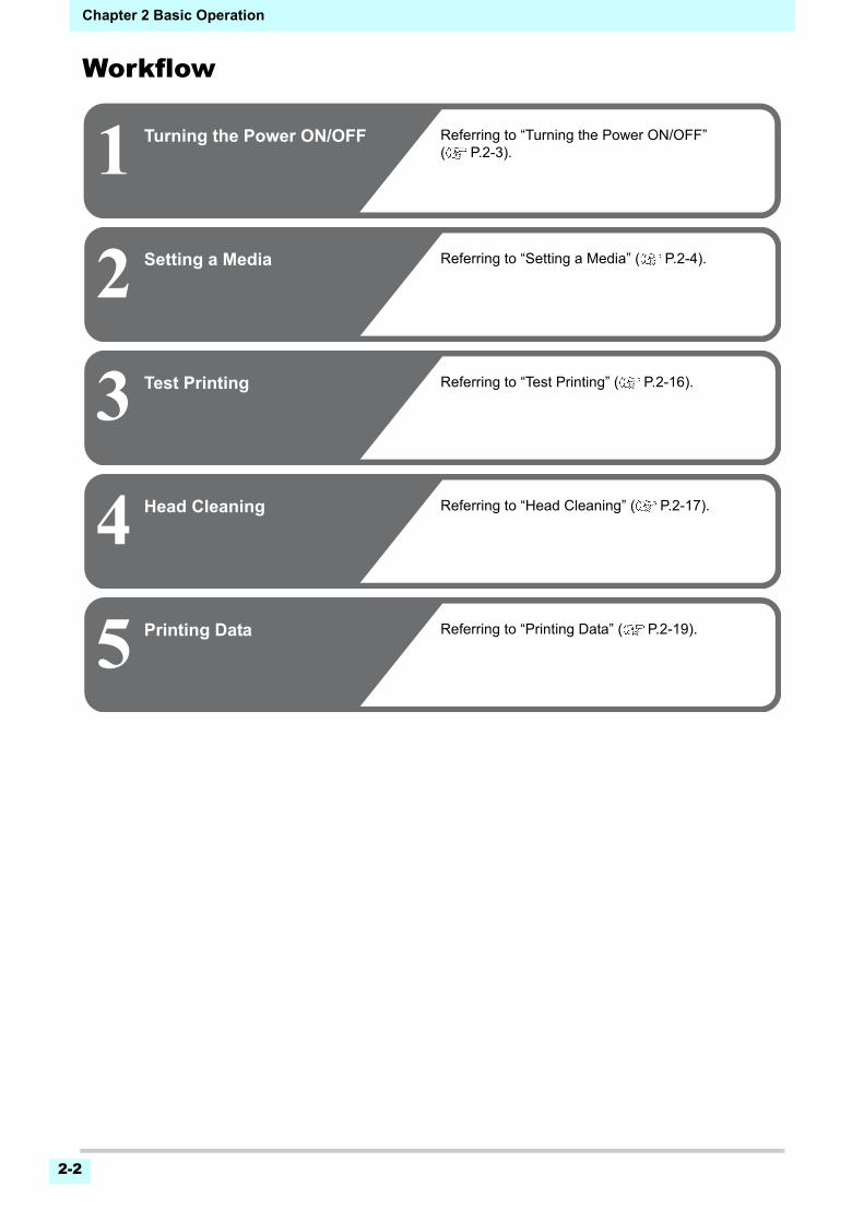
Chapter 2 Basic Operation
Workflow
1 Turning the Power ON/OFF
2
3
Setting a Media
4
Test Printing
Head Cleaning
Referring to “Turning the Power ON/OFF” ( P.2-3).
Referring to “Setting a Media” ( P.2-4).
Referring to “Test Printing” ( P.2-16).
Referring to “Head Cleaning” ( P.2-17).
5 Printing Data Referring to “Printing Data” ( P.2-19).
2-3
2
2
2
5
6
Chapter 2 Basic Operation
Turning the Power ON/OFFTurning the Power ON
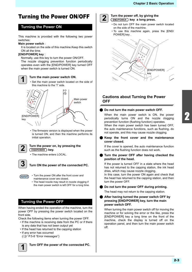
This machine is provided with the following two powerswitches:Main power switch :
It is located on the side of this machine.Keep this switchON all the time.
[END/POWER] key :Normally, use this key to turn the power ON/OFF.The nozzle clogging prevention function periodicallyoperates even with the [END/POWER] key turned OFFwhen the main power switch is turned ON.
1 Turn the main power switch ON.
• Set the main power switch located on the side ofthis machine to the “I” side.
• The firmware version is displayed when the poweris turned ON, and then the machine performs itsinitial operation.
2 Turn the power on, by pressing the key.
• The machine enters LOCAL.
3 Turn ON the power of the connected PC.
Turning the Power OFF
When having ended the operation of the machine, turn thepower OFF by pressing the power switch located on thefront side.Check the following items when turning the power OFF.
• If the machine is receiving data from the PC or if thereis any data that has not been output yet
• If the head has returned to the capping station• If any error has occurred
( P.5-8 “Error messages”)
1 Turn OFF the power of the connected PC.
2 Turn the power off, by giving the key a long press.
• Do not turn OFF the main power switch locatedon the side of the machine.
• To use this machine again, press the [END/POWER] key .
Cautions about Turning the Power OFF
Do not turn the main power switch OFF.
When the main power switch is ON, the powerperiodically turns ON and the nozzle cloggingprevention function (flushing function) operates.When the main power switch has been turned OFF,the auto maintenance functions, such as flushing, donot operate, and this may cause nozzle clogging.
Keep the front cover and the maintenancecover closed.
If the cover is opened, the auto maintenance functionsuch as the flushing function does not work.
Turn the power OFF after having checked theposition of the head.
If the power is turned OFF in a state where the headhas not returned to the capping station, the ink headdries, which may cause nozzle clogging.In this case, turn the power ON again and check thatthe head has returned to the capping station, and thenturn the power OFF.
Do not turn the power OFF during printing.
The head may not return to the capping station.
After having turned the power switch OFF by pressing [END/POWER] key, turn the main power switch OFF.
When turning the main power switch off for moving themachine or for solving the error or the like, press the[END/POWER] key a long time on the front of themachine, check the display is turned off on theoperation panel, and then turn the main power switchoff.
• Turn the power ON after the front cover and maintenance cover are closed.
• The head nozzle may result in nozzle clogging if the main power switch is left OFF for a long time.
Main power switch
[END/POWER] key
[END/POWER] key
Chapter 2 Basic Operation
2-4
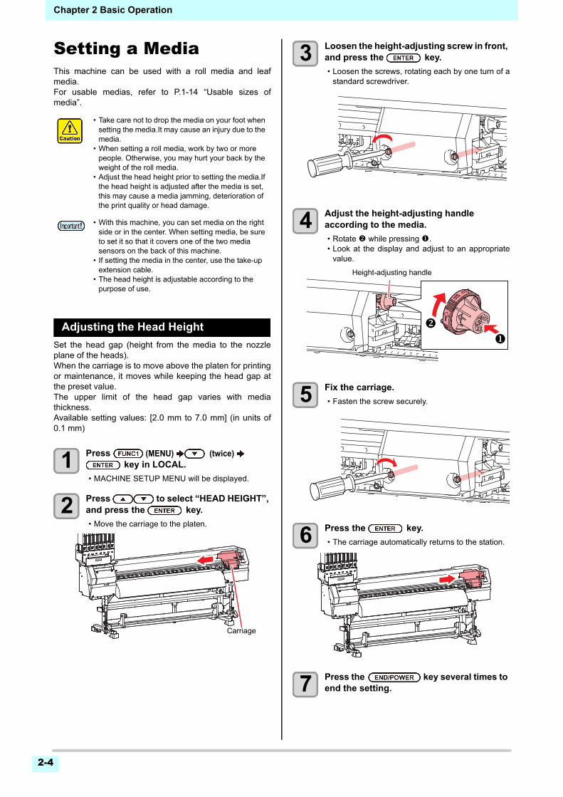
Setting a MediaThis machine can be used with a roll media and leafmedia.For usable medias, refer to P.1-14 “Usable sizes ofmedia”.
Adjusting the Head Height
Set the head gap (height from the media to the nozzleplane of the heads).When the carriage is to move above the platen for printingor maintenance, it moves while keeping the head gap atthe preset value.The upper limit of the head gap varies with mediathickness.Available setting values: [2.0 mm to 7.0 mm] (in units of0.1 mm)
1 Press (MENU) (twice) key in LOCAL.
• MACHINE SETUP MENU will be displayed.
2 Press to select “HEAD HEIGHT”, and press the key.
• Move the carriage to the platen.
3 Loosen the height-adjusting screw in front, and press the key.
• Loosen the screws, rotating each by one turn of astandard screwdriver.
4 Adjust the height-adjusting handle according to the media.
• Rotate while pressing .• Look at the display and adjust to an appropriate
value.
5 Fix the carriage.
• Fasten the screw securely.
6 Press the key.
• The carriage automatically returns to the station.
7 Press the key several times to end the setting.
• Take care not to drop the media on your foot when setting the media.It may cause an injury due to the media.
• When setting a roll media, work by two or more people. Otherwise, you may hurt your back by the weight of the roll media.
• Adjust the head height prior to setting the media.If the head height is adjusted after the media is set, this may cause a media jamming, deterioration of the print quality or head damage.
• With this machine, you can set media on the right side or in the center. When setting media, be sure to set it so that it covers one of the two media sensors on the back of this machine.
• If setting the media in the center, use the take-up extension cable.
• The head height is adjustable according to the purpose of use.
Carriage
Height-adjusting handle
2-5
2
2
2
5
6
Chapter 2 Basic Operation
Setting a roll media
Set a roll media to the roll media hanger located on theback of this machine.
1 Move the roll holder located in the back of the device to the direction of the middle of the device.
• Loosen the roll holder fixing screw and then move it.
2 Check the clamp lever is lowered.
3 Move the roll holder to the roll setting position.
If setting the media on the right side• Check the roll stopper is not caught between the
roll stopper arm and this machine.
If setting the media in the center• Move the roll holder so the media’s set position is
in the center of this machine.
4 Tighten the roll holder fixing screw.
• Check the Step 2 to 3 again.
5 Move the roll guide stay to match the position to set the media in.
(1) After moving the stay, setdown the adjuster foot.
(2) Turn the screw on the adjuster foot once.• Make sure that the
adjuster foot is fixedfirmly to the floor.
If setting the media on the right side• Move the roll guide stay so that it is to the left of
the right roll holder, as seen from the rear of themachine.
If setting the media in the center• Move the roll guide stay to the center of the roll
holder.
6 Set the left end of the core of the roll media on the left roll holder.
• Push the roll media onto the roll holder until theroll core is all the way seated.
Lock screw
Roll holder
Roll HolderSet Position
3 Inch Roll Media
2 Inch Roll Media
Rol l HolderSet Posi t ion
3 Inch Rol l Media2 Inch Rol l Media
Roll holder
Base
Roll Holder Side (The back of this machine)
Setting position of 2inch tube
Setting position of 3inch tube
Set the base position of roll holder within this range.
• There are two types of the internal diameter of the roll media paper tube: 2 inch and 3 inch.
Screw
Chapter 2 Basic Operation
2-6
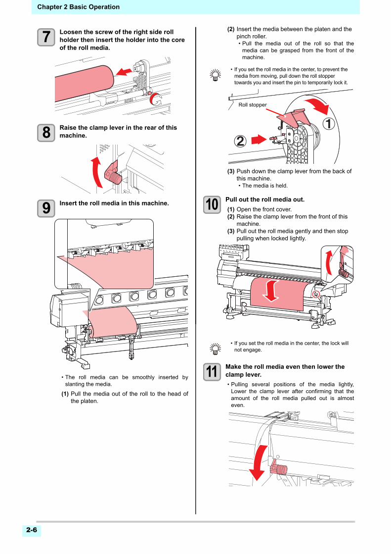
7 Loosen the screw of the right side roll holder then insert the holder into the core of the roll media.
8 Raise the clamp lever in the rear of this machine.
9 Insert the roll media in this machine.
• The roll media can be smoothly inserted byslanting the media.
(1) Pull the media out of the roll to the head ofthe platen.
(2) Insert the media between the platen and the pinch roller.• Pull the media out of the roll so that the
media can be grasped from the front of themachine.
(3) Push down the clamp lever from the back of this machine.• The media is held.
10 Pull out the roll media out.
(1) Open the front cover.(2) Raise the clamp lever from the front of this
machine.(3) Pull out the roll media gently and then stop
pulling when locked lightly.
11 Make the roll media even then lower the clamp lever.
• Pulling several positions of the media lightly,Lower the clamp lever after confirming that theamount of the roll media pulled out is almosteven.
• If you set the roll media in the center, to prevent the media from moving, pull down the roll stopper towards you and insert the pin to temporarily lock it.
• If you set the roll media in the center, the lock will not engage.
Roll stopper
2-7
2
2
2
5
6
Chapter 2 Basic Operation
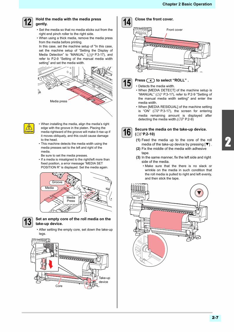
12 Hold the media with the media press gently.
• Set the media so that no media sticks out from theright end pinch roller to the right side.
• When using a thick media, remove the media pressfrom the media before printing.In this case, set the machine setup of "In this case,set the machine setup of “Setting the Display ofMedia Detection” to “MANUAL” ( P.3-17), andrefer to P.2-9 “Setting of the manual media widthsetting” and set the media width.
13 Set an empty core of the roll media on the take-up device.
• After setting the empty core, set down the take-uplegs.
14 Close the front cover.
15 Press to select “ROLL” .
• Detects the media width.• When [MEDIA DETECT] of the machine setup is
“MANUAL” ( P.3-17), refer to P.2-9 "Setting ofthe manual media width setting" and enter themedia width.
• When [MEDIA RESIDUAL] of the machine settingis “ON” ( P.3-17), the screen for enteringmedia remaining amount is displayed afterdetecting the media width.( P.2-9)
16 Secure the media on the take-up device. ( P.2-10)
(1) Feed the media up to the core of the rollmedia of the take-up device by pressing [] .
(2) Fix the middle of the media with adhesive tape.
(3) In the same manner, fix the left side and right side of the media.• Make sure that the there is no slack or
wrinkle on the media in such condition thatthe roll media is pulled to right and left evenly,and then stick the tape.
• When installing the media, align the media’s right edge with the groove in the platen. Placing the media rightward of the groove will make it rise up if it moves obliquely, and this could cause damage to the head.
• This machine detects the media width using the media presses set to the left and right of the media.Be sure to set the media presses.
• If a media is misaligned to the right/left more than fixed position, a error message “MEDIA SET POSITION R” is displayed. Set the media again.
Media press
Media
Groove
MediaPress
Core
Take-up device
Front cover
Chapter 2 Basic Operation
2-8
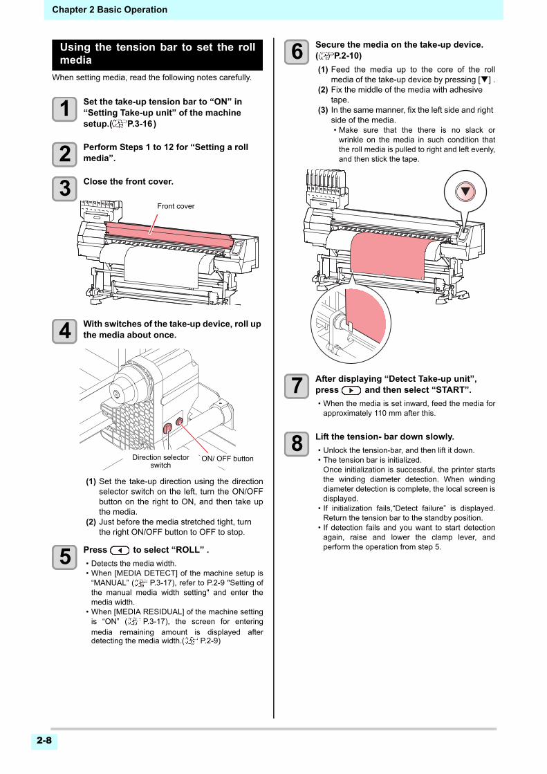
Using the tension bar to set the rollmedia
When setting media, read the following notes carefully.
1 Set the take-up tension bar to “ON” in “Setting Take-up unit” of the machine setup.( P.3-16)
2 Perform Steps 1 to 12 for “Setting a roll media”.
3 Close the front cover.
4 With switches of the take-up device, roll up the media about once.
(1) Set the take-up direction using the directionselector switch on the left, turn the ON/OFFbutton on the right to ON, and then take upthe media.
(2) Just before the media stretched tight, turn the right ON/OFF button to OFF to stop.
5 Press to select “ROLL” .
• Detects the media width.• When [MEDIA DETECT] of the machine setup is
“MANUAL” ( P.3-17), refer to P.2-9 "Setting ofthe manual media width setting" and enter themedia width.
• When [MEDIA RESIDUAL] of the machine settingis “ON” ( P.3-17), the screen for enteringmedia remaining amount is displayed afterdetecting the media width.( P.2-9)
6 Secure the media on the take-up device. ( P.2-10)
(1) Feed the media up to the core of the rollmedia of the take-up device by pressing [] .
(2) Fix the middle of the media with adhesive tape.
(3) In the same manner, fix the left side and right side of the media.• Make sure that the there is no slack or
wrinkle on the media in such condition thatthe roll media is pulled to right and left evenly,and then stick the tape.
7 After displaying “Detect Take-up unit”, press and then select “START”.
• When the media is set inward, feed the media forapproximately 110 mm after this.
8 Lift the tension- bar down slowly.
• Unlock the tension-bar, and then lift it down.• The tension bar is initialized.
Once initialization is successful, the printer startsthe winding diameter detection. When windingdiameter detection is complete, the local screen isdisplayed.
• If initialization fails,“Detect failure” is displayed.Return the tension bar to the standby position.
• If detection fails and you want to start detectionagain, raise and lower the clamp lever, andperform the operation from step 5.
Front cover
ON/ OFF buttonDirection selector switch
2-9
2
2
2
5
6
Chapter 2 Basic Operation
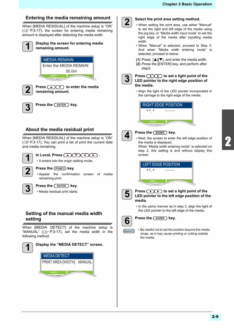
Entering the media remaining amount
When [MEDIA RESIDUAL] of the machine setup is “ON”( P.3-17), the screen for entering media remainingamount is displayed after detecting the media width.
1 Display the screen for entering media remaining amount.
2 Press to enter the media remaining amount.
3 Press the key.
About the media residual print
When [MEDIA RESIDUAL] of the machine setup is “ON”( P.3-17), You can print a list of print the current dateand media remaining.
1 In Local, Press .
• It enters into the origin setting mode.
2 Press the key.
• Appear the confirmation screen of mediaremaining print.
3 Press the key.
• Media residual print starts.
Setting of the manual media widthsetting
When [MEDIA DETECT] of the machine setup is“MANUAL” ( P.3-17), set the media width in thefollowing method.
1 Display the “MEDIA DETECT” screen.
2 Select the print area setting method.
• When setting the print area, use either "Manual"to set the right and left edge of the media usingthe jog key, or “Media width input mode” to set theright edge of the media after inputting mediawidth.
• When “Manual” is selected, proceed to Step 3.And when “Media width entering mode” isselected, proceed to below.
(1) Press [][], and enter the media width.(2) Press the [ENTER] key, and perform after
step3.
3 Press to set a light point of the LED pointer to the right edge position of the media.
• Align the light of the LED pointer incorporated inthe carriage to the right edge of the media.
4 Press the key.
• Next, the screen to enter the left edge position ofthe media is displayed.When “Media width entering mode” is selected onstep 2, this setting is end without display thisscreen.
5 Press to set a light point of the LED pointer to the left edge position of the media.
• In the same manner as in step 3, align the light ofthe LED pointer to the left edge of the media.
6 Press the key.
50.0mEnter the MEDIA REMAINMEDIA REMAIN
POST1 POST2
30°/40° 30°/35°
MEDIA DETECTPRINT AREA [WIDTH] MANUAL
POST1 POST2
30°/40° 30°/35°
• Be careful not to set the position beyond the media range, as it may cause printing or cutting outside the media.
RIGHT EDGE POSITION
POST1 POST2
30°/40° 30°/35°
LEFT EDGE POSITION
POST1 POST2
30°/40° 30°/35°
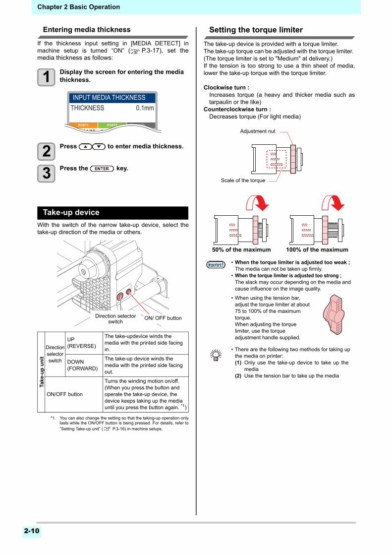
Chapter 2 Basic Operation
2-10
Entering media thickness
If the thickness input setting in [MEDIA DETECT] inmachine setup is turned “ON” ( P.3-17), set themedia thickness as follows:
1 Display the screen for entering the media thickness.
2 Press to enter media thickness.
3 Press the key.
Take-up device
With the switch of the narrow take-up device, select thetake-up direction of the media or others.
Setting the torque limiter
The take-up device is provided with a torque limiter. The take-up torque can be adjusted with the torque limiter. (The torque limiter is set to "Medium" at delivery.)If the tension is too strong to use a thin sheet of media,lower the take-up torque with the torque limiter.
Clockwise turn :Increases torque (a heavy and thicker media such astarpaulin or the like)
Counterclockwise turn :Decreases torque (For light media)
Take
-up
un
it
Direction selector switch
UP (REVERSE)
The take-updevice winds the media with the printed side facing in.
DOWN (FORWARD)
The take-up device winds the media with the printed side facing out.
ON/OFF button
Turns the winding motion on/off.(When you press the button and operate the take-up device, the device keeps taking up the media until you press the button again. *1)
*1. You can also change the setting so that the taking-up operation onlylasts while the ON/OFF button is being pressed. For details, refer to“Setting Take-up unit” ( P.3-16) in machine setups.
POST1 POST2 FAN
30°/40°30°/35°40°/50°
INPUT MEDIA THICKNESSTHICKNESS 0.1mm
ON/ OFF buttonDirection selector switch
• When the torque limiter is adjusted too weak ;The media can not be taken up firmly.
• When the torque limiter is adjusted too strong ;The slack may occur depending on the media and cause influence on the image quality.
• When using the tension bar, adjust the torque limiter at about 75 to 100% of the maximum torque.When adjusting the torque limiter, use the torque adjustment handle supplied.
• There are the following two methods for taking up the media on printer:(1) Only use the take-up device to take up the
media(2) Use the tension bar to take up the media
50% of the maximum 100% of the maximum
Scale of the torque
Adjustment nut
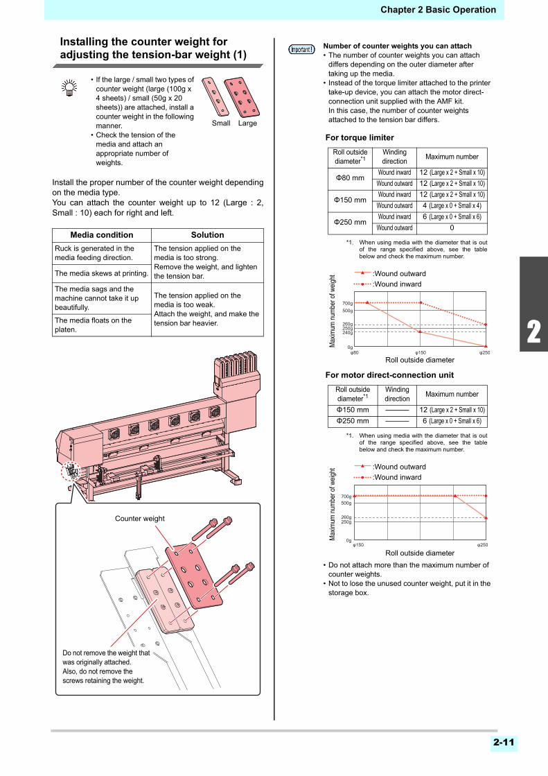
2-11
2
2
2
5
6
Chapter 2 Basic Operation
Installing the counter weight for adjusting the tension-bar weight (1)
Install the proper number of the counter weight dependingon the media type.You can attach the counter weight up to 12 (Large : 2,Small : 10) each for right and left.
• If the large / small two types of counter weight (large (100g x 4 sheets) / small (50g x 20 sheets)) are attached, install a counter weight in the following manner.
• Check the tension of the media and attach an appropriate number of weights.
Media condition Solution
Ruck is generated in the media feeding direction.
The tension applied on the media is too strong.Remove the weight, and lighten the tension bar.The media skews at printing.
The media sags and the machine cannot take it up beautifully.
The tension applied on the media is too weak.Attach the weight, and make the tension bar heavier.The media floats on the
platen.
Small Large
Counter weight
Do not remove the weight that was originally attached.Also, do not remove the screws retaining the weight.
Number of counter weights you can attach• The number of counter weights you can attach
differs depending on the outer diameter after taking up the media.
• Instead of the torque limiter attached to the printer take-up device, you can attach the motor direct-connection unit supplied with the AMF kit.In this case, the number of counter weights attached to the tension bar differs.
• Do not attach more than the maximum number of counter weights.
• Not to lose the unused counter weight, put it in the storage box.
For torque limiter
For motor direct-connection unit
Roll outside diameter*1
*1. When using media with the diameter that is outof the range specified above, see the tablebelow and check the maximum number.
Winding direction
Maximum number
Φ80 mmWound inward 12 (Large x 2 + Small x 10)
Wound outward 12 (Large x 2 + Small x 10)
Φ150 mmWound inward 12 (Large x 2 + Small x 10)
Wound outward 4 (Large x 0 + Small x 4)
Φ250 mmWound inward 6 (Large x 0 + Small x 6)
Wound outward 0
Roll outside diameter*1
*1. When using media with the diameter that is outof the range specified above, see the tablebelow and check the maximum number.
Winding direction
Maximum number
Φ150 mm 12 (Large x 2 + Small x 10)
Φ250 mm 6 (Large x 0 + Small x 6)
:Wound outward
:Wound inward
Max
imum
num
ber o
f wei
ght
Roll outside diameter
:Wound outward
:Wound inward
Max
imum
num
ber o
f wei
ght
Roll outside diameter
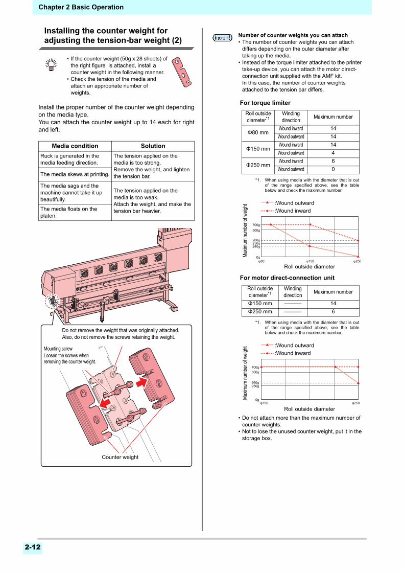
Chapter 2 Basic Operation
2-12
Installing the counter weight for adjusting the tension-bar weight (2)
Install the proper number of the counter weight dependingon the media type.You can attach the counter weight up to 14 each for rightand left.
• If the counter weight (50g x 28 sheets) of the right figure is attached, install a counter weight in the following manner.
• Check the tension of the media and attach an appropriate number of weights.
Media condition Solution
Ruck is generated in the media feeding direction.
The tension applied on the media is too strong.Remove the weight, and lighten the tension bar.The media skews at printing.
The media sags and the machine cannot take it up beautifully.
The tension applied on the media is too weak.Attach the weight, and make the tension bar heavier.The media floats on the
platen.
Counter weight
Mounting screwLoosen the screws when removing the counter weight.
Do not remove the weight that was originally attached.Also, do not remove the screws retaining the weight.
Number of counter weights you can attach• The number of counter weights you can attach
differs depending on the outer diameter after taking up the media.
• Instead of the torque limiter attached to the printer take-up device, you can attach the motor direct-connection unit supplied with the AMF kit.In this case, the number of counter weights attached to the tension bar differs.
• Do not attach more than the maximum number of counter weights.
• Not to lose the unused counter weight, put it in the storage box.
For torque limiter
For motor direct-connection unit
Roll outside diameter*1
*1. When using media with the diameter that is outof the range specified above, see the tablebelow and check the maximum number.
Winding direction
Maximum number
Φ80 mmWound inward 14
Wound outward 14
Φ150 mmWound inward 14
Wound outward 4
Φ250 mmWound inward 6
Wound outward 0
Roll outside diameter*1
*1. When using media with the diameter that is outof the range specified above, see the tablebelow and check the maximum number.
Winding direction
Maximum number
Φ150 mm 14
Φ250 mm 6
:Wound outward
:Wound inward
Max
imum
num
ber o
f wei
ght
Roll outside diameter
:Wound outward
:Wound inward
Max
imum
num
ber o
f wei
ght
Roll outside diameter
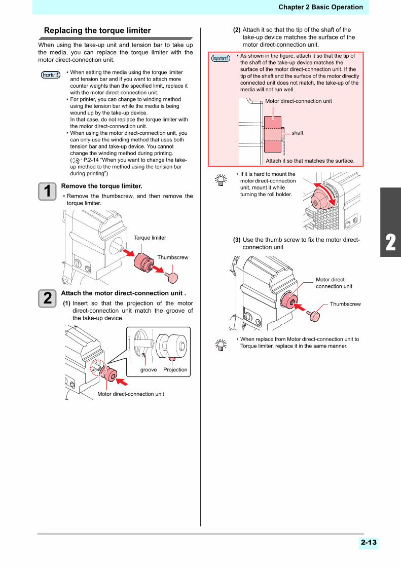
2-13
2
2
2
5
6
Chapter 2 Basic Operation
Replacing the torque limiter
When using the take-up unit and tension bar to take upthe media, you can replace the torque limiter with themotor direct-connection unit.
1 Remove the torque limiter.
• Remove the thumbscrew, and then remove thetorque limiter.
2 Attach the motor direct-connection unit .
(1) Insert so that the projection of the motordirect-connection unit match the groove ofthe take-up device.
(2) Attach it so that the tip of the shaft of the take-up device matches the surface of the motor direct-connection unit.
(3) Use the thumb screw to fix the motor direct-connection unit
• When setting the media using the torque limiter and tension bar and if you want to attach more counter weights than the specified limit, replace it with the motor direct-connection unit.
• For printer, you can change to winding method using the tension bar while the media is being wound up by the take-up device.In that case, do not replace the torque limiter with the motor direct-connection unit.
• When using the motor direct-connection unit, you can only use the winding method that uses both tension bar and take-up device. You cannot change the winding method during printing. ( P.2-14 “When you want to change the take-up method to the method using the tension bar during printing”)
Torque limiter
Thumbscrew
Motor direct-connection unit
groove Projection
• As shown in the figure, attach it so that the tip of the shaft of the take-up device matches the surface of the motor direct-connection unit. If the tip of the shaft and the surface of the motor directly connected unit does not match, the take-up of the media will not run well.
• If it is hard to mount the motor direct-connection unit, mount it while turning the roll holder.
• When replace from Motor direct-connection unit to Torque limiter, replace it in the same manner.
Motor direct-connection unit
shaft
Attach it so that matches the surface.
Motor direct-connection unit
Thumbscrew
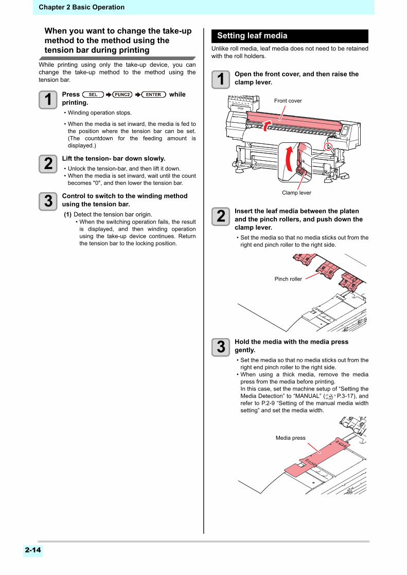
Chapter 2 Basic Operation
2-14
When you want to change the take-up method to the method using the tension bar during printing
While printing using only the take-up device, you canchange the take-up method to the method using thetension bar.
1 Press while printing.
• Winding operation stops.
• When the media is set inward, the media is fed tothe position where the tension bar can be set.(The countdown for the feeding amount isdisplayed.)
2 Lift the tension- bar down slowly.
• Unlock the tension-bar, and then lift it down.• When the media is set inward, wait until the count
becomes "0", and then lower the tension bar.
3 Control to switch to the winding method using the tension bar.
(1) Detect the tension bar origin.• When the switching operation fails, the result
is displayed, and then winding operationusing the take-up device continues. Returnthe tension bar to the locking position.
Setting leaf media
Unlike roll media, leaf media does not need to be retainedwith the roll holders.
1 Open the front cover, and then raise the clamp lever.
2 Insert the leaf media between the platen and the pinch rollers, and push down the clamp lever.
• Set the media so that no media sticks out from theright end pinch roller to the right side.
3 Hold the media with the media press gently.
• Set the media so that no media sticks out from theright end pinch roller to the right side.
• When using a thick media, remove the mediapress from the media before printing.In this case, set the machine setup of “Setting theMedia Detection” to “MANUAL” ( P.3-17), andrefer to P.2-9 “Setting of the manual media widthsetting” and set the media width.
Front cover
Clamp lever
Pinch roller
Media press
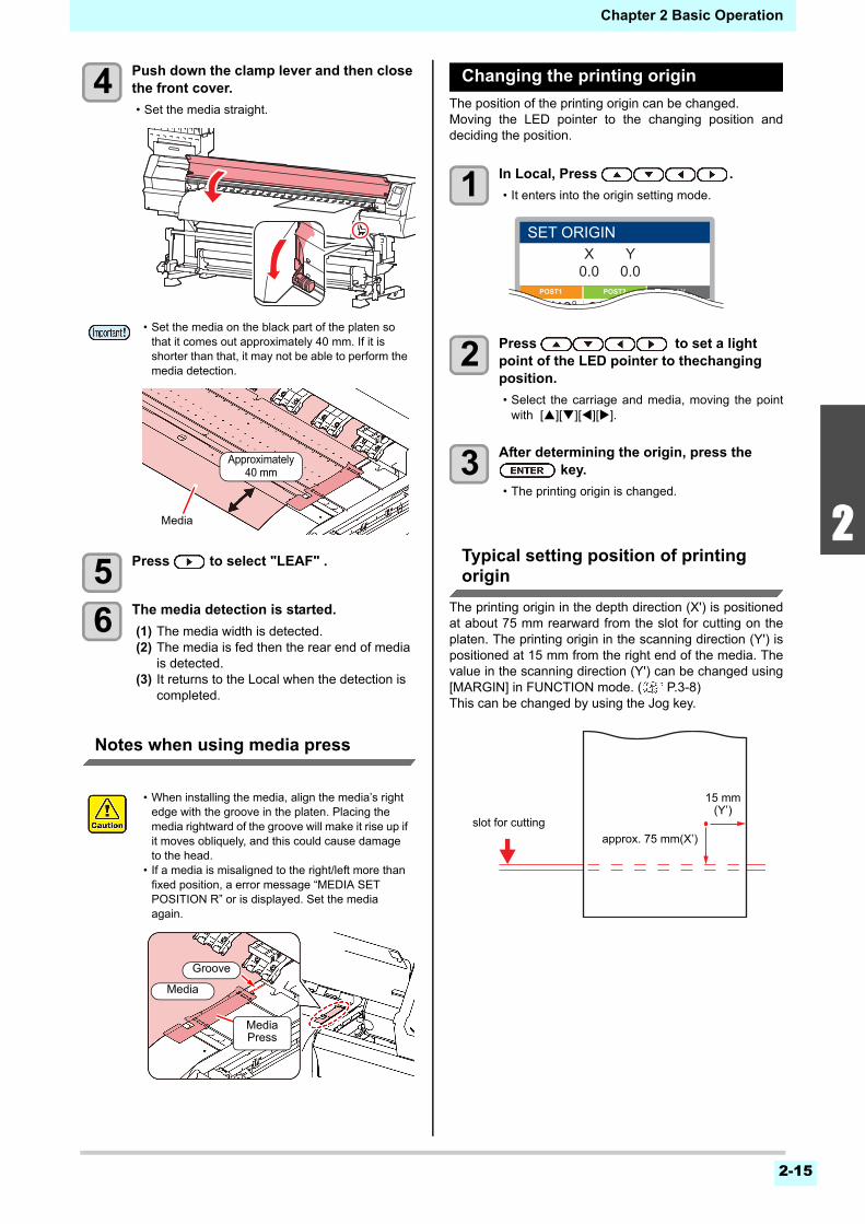
2-15
2
2
2
5
6
Chapter 2 Basic Operation
4 Push down the clamp lever and then close the front cover.
• Set the media straight.
5 Press to select "LEAF" .
6 The media detection is started.
(1) The media width is detected.(2) The media is fed then the rear end of media
is detected.(3) It returns to the Local when the detection is
completed.
Notes when using media press
Changing the printing origin
The position of the printing origin can be changed.Moving the LED pointer to the changing position anddeciding the position.
1 In Local, Press .
• It enters into the origin setting mode.
2 Press to set a light point of the LED pointer to thechanging position.
• Select the carriage and media, moving the pointwith [][][][].
3 After determining the origin, press the key.
• The printing origin is changed.
Typical setting position of printing origin
The printing origin in the depth direction (X') is positionedat about 75 mm rearward from the slot for cutting on theplaten. The printing origin in the scanning direction (Y') ispositioned at 15 mm from the right end of the media. Thevalue in the scanning direction (Y') can be changed using[MARGIN] in FUNCTION mode. ( P.3-8) This can be changed by using the Jog key.
• Set the media on the black part of the platen so that it comes out approximately 40 mm. If it is shorter than that, it may not be able to perform the media detection.
• When installing the media, align the media’s right edge with the groove in the platen. Placing the media rightward of the groove will make it rise up if it moves obliquely, and this could cause damage to the head.
• If a media is misaligned to the right/left more than fixed position, a error message “MEDIA SET POSITION R” or is displayed. Set the media again.
Media
Approximately 40 mm
Media
Groove
MediaPress
X0.0
Y0.0
POST1 POST2 FAN
SET ORIGIN
30°/40°30°/35°40°/50°
slot for cutting
approx. 75 mm(X’)
15 mm (Y’)
Chapter 2 Basic Operation
2-16
Preparing for the HeatersChanging the Temperature Settingsfor the Heaters
You can change/save the temperature settings for theheaters with “Heater” or “OPTION HERATER” of thesetting mode. ( P.3-6, P.3-7)Here, changing method of the temperature set in thesetting mode is explained.Set the heater temperature according to thecharacteristics of the media you use.The temperature of the heaters has been set to "OFF" asdefault.Appropriate temperature adjustment can be made becausethe temperature can be adjusted even during printing.It may take several minutes to tens of minutes for the settemperature to be reached, depending on the ambient temperature.
1 Press the key,and then press the (Heater) in LOCAL.
• The heater temperature adjustment screen will bedisplayed.
2 Press to set the temperature of each heater.
Heater selecting : Select with [][]Temperature setting : Set with [][]
• The heater starts to get hot.
3 The heating of the heater stops.
• When the heater temperature reaches the settemperature, the heater icon lights in green.
4 Press the key to stop heating.
• The screen returns to LOCAL.
Test PrintingPrint a test pattern to check that there are no dischargingdefects such as nozzle clogging (slight touching of ink ornozzle missing).
Relationship between head row and test pattern
The relations between head row and test pattern printposition are as follow.
Note on test printing
Test Printing
Print a test pattern to check that there are no dischargingdefects such as nozzle clogging (slight touching of ink ornozzle missing).In addition, you can select the orientation of the testpattern to print from two types in order to perform testprinting repeatedly. Select one depending on your use.
• Use this machine under 20 to 30C. The temperature may not reach the set value due to the environmental temperature condition.
• The TS300P has two heaters (POST1, POST2) in the machine, and an optional fan heater.Normally, printing is possible at ±3°C of the set temperature. However, the heaters are easily affected by heat from other heaters, so printing is possible using the following specifications.
• Press [FUNC3] (OFF) in Step 2 to turn all heaters OFF.Or, press [FUNC1] to raise the POST1/POST2 heaters in 10°C increments.
Heater type Heater specifications
POST1
• Maximum set temperature= 50ºC(However, a temperature higher than POST2 cannot be set.)
• Heat from POST2 affects this heater, so you print even if the upper temperature range is more than 3ºC.
POST2
• Maximum set temperature= 60ºC• If you have installed the optional fan heater, the
optional fan heater affects this heater, so you print even if the upper temperature range is more than 3ºC.
• When using leaf media, set a media of more than A3 size put horizontally. If a media with narrow width is set, printing will only be conducted to midway.
• When using a roll media, rewind the media by hand before printing so that it is not loose. When the roll media has not been rewound tightly, it may cause image quality to deteriorate.
Check before test printing.
• If a media has been set P.2-4
• If the origin position has been set
• If the head gap has been adjusted P.2-4
• If the necessary settings have been configured for nozzle recovery P.4-13
Test pattern
Med
ia a
dva
nce
dire
ctio
n
Head 1
Media-feeding direction
: When the the test pattern orientation is "SCAN DIR."
: When the the test pattern orientation is "FEED DIR."
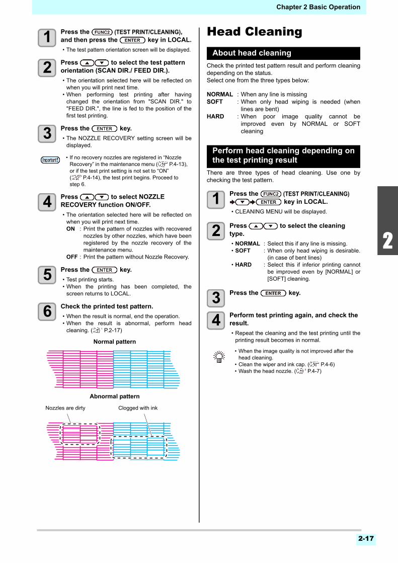
2-17
2
2
2
5
6
Chapter 2 Basic Operation
1 Press the (TEST PRINT/CLEANING),and then press the key in LOCAL.
• The test pattern orientation screen will be displayed.
2 Press to select the test pattern orientation (SCAN DIR./ FEED DIR.).
• The orientation selected here will be reflected onwhen you will print next time.
• When performing test printing after havingchanged the orientation from "SCAN DIR." to"FEED DIR.", the line is fed to the position of thefirst test printing.
3 Press the key.
• The NOZZLE RECOVERY setting screen will bedisplayed.
4 Press to select NOZZLE RECOVERY function ON/OFF.
• The orientation selected here will be reflected onwhen you will print next time.ON : Print the pattern of nozzles with recovered
nozzles by other nozzles, which have beenregistered by the nozzle recovery of themaintenance menu.
OFF : Print the pattern without Nozzle Recovery.
5 Press the key.
• Test printing starts.• When the printing has been completed, the
screen returns to LOCAL.
6 Check the printed test pattern.
• When the result is normal, end the operation.• When the result is abnormal, perform head
cleaning. ( P.2-17)
Head CleaningAbout head cleaning
Check the printed test pattern result and perform cleaningdepending on the status.Select one from the three types below:
NORMAL : When any line is missingSOFT : When only head wiping is needed (when
lines are bent)HARD : When poor image quality cannot be
improved even by NORMAL or SOFTcleaning
Perform head cleaning depending onthe test printing result
There are three types of head cleaning. Use one bychecking the test pattern.
1 Press the (TEST PRINT/CLEANING) key in LOCAL.
• CLEANING MENU will be displayed.
2 Press to select the cleaning type.
• NORMAL : Select this if any line is missing.• SOFT : When only head wiping is desirable.
(in case of bent lines)• HARD : Select this if inferior printing cannot
be improved even by [NORMAL] or[SOFT] cleaning.
3 Press the key.
4 Perform test printing again, and check the result.
• Repeat the cleaning and the test printing until theprinting result becomes in normal.
• If no recovery nozzles are registered in “Nozzle Recovery” in the maintenance menu ( P.4-13), or if the test print setting is not set to “ON” ( P.4-14), the test print begins. Proceed to step 6.
Abnormal pattern
Clogged with ink
Normal pattern
Nozzles are dirty
• When the image quality is not improved after the head cleaning.
• Clean the wiper and ink cap. ( P.4-6)• Wash the head nozzle. ( P.4-7)
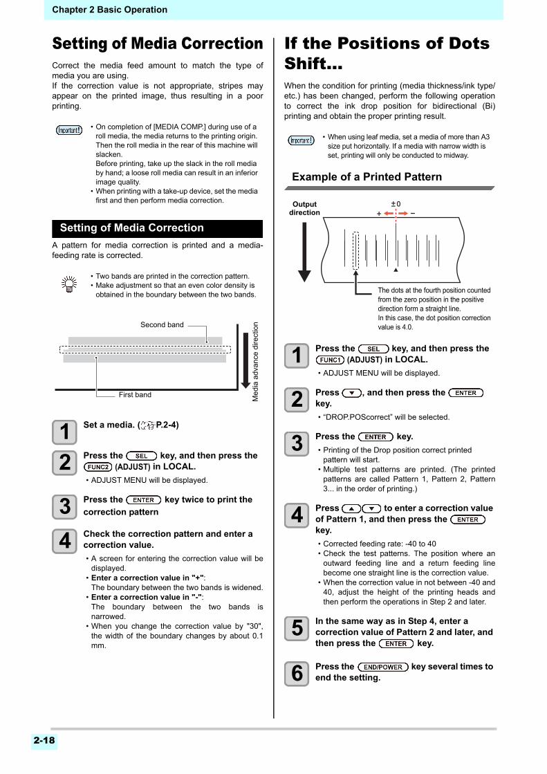
Chapter 2 Basic Operation
2-18
Setting of Media CorrectionCorrect the media feed amount to match the type ofmedia you are using.If the correction value is not appropriate, stripes mayappear on the printed image, thus resulting in a poorprinting.
Setting of Media Correction
A pattern for media correction is printed and a media-feeding rate is corrected.
1 Set a media. ( P.2-4)
2 Press the key, and then press the (ADJUST) in LOCAL.
• ADJUST MENU will be displayed.
3 Press the key twice to print the
correction pattern
4 Check the correction pattern and enter a correction value.
• A screen for entering the correction value will bedisplayed.
• Enter a correction value in "+":The boundary between the two bands is widened.
• Enter a correction value in "-":The boundary between the two bands isnarrowed.
• When you change the correction value by "30",the width of the boundary changes by about 0.1mm.
If the Positions of Dots Shift...When the condition for printing (media thickness/ink type/etc.) has been changed, perform the following operationto correct the ink drop position for bidirectional (Bi)printing and obtain the proper printing result.
Example of a Printed Pattern
1 Press the key, and then press the (ADJUST) in LOCAL.
• ADJUST MENU will be displayed.
2 Press , and then press the key.
• “DROP.POScorrect” will be selected.
3 Press the key.
• Printing of the Drop position correct printed pattern will start.
• Multiple test patterns are printed. (The printedpatterns are called Pattern 1, Pattern 2, Pattern3... in the order of printing.)
4 Press to enter a correction value of Pattern 1, and then press the key.
• Corrected feeding rate: -40 to 40• Check the test patterns. The position where an
outward feeding line and a return feeding linebecome one straight line is the correction value.
• When the correction value in not between -40 and40, adjust the height of the printing heads andthen perform the operations in Step 2 and later.
5 In the same way as in Step 4, enter a correction value of Pattern 2 and later, and then press the key.
6 Press the key several times to end the setting.
• On completion of [MEDIA COMP.] during use of a roll media, the media returns to the printing origin. Then the roll media in the rear of this machine will slacken.Before printing, take up the slack in the roll media by hand; a loose roll media can result in an inferior image quality.
• When printing with a take-up device, set the media first and then perform media correction.
• Two bands are printed in the correction pattern.• Make adjustment so that an even color density is
obtained in the boundary between the two bands.
Second band
First band
Med
ia a
dvan
ce d
irect
ion
• When using leaf media, set a media of more than A3 size put horizontally. If a media with narrow width is set, printing will only be conducted to midway.
The dots at the fourth position counted from the zero position in the positive direction form a straight line.In this case, the dot position correction value is 4.0.
Output direction
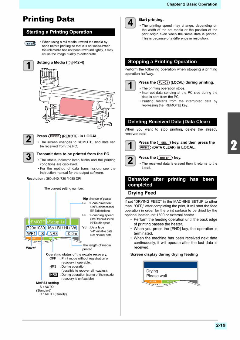
2-19
2
2
2
5
6
Chapter 2 Basic Operation
Printing DataStarting a Printing Operation
1 Setting a Media ( P.2-4)
2 Press (REMOTE) in LOCAL.
• The screen changes to REMOTE, and data canbe received from the PC.
3 Transmit data to be printed from the PC.
• The status indicator lamp blinks and the printingconditions are displayed.
• For the method of data transmission, see theinstruction manual for the output software.
4 Start printing.
• The printing speed may change, depending onthe width of the set media or the position of theprint origin even when the same data is printed.This is because of a difference in resolution.
Stopping a Printing Operation
Perform the following operation when stopping a printingoperation halfway.
1 Press the (LOCAL) during printing.
• The printing operation stops.• Interrupt data sending at the PC side during the
data is sent from the PC.• Printing restarts from the interrupted data by
repressing the [REMOTE] key.
Deleting Received Data (Data Clear)
When you want to stop printing, delete the alreadyreceived data.
1 Press the key, and then press the (DATA CLEAR) in LOCAL.
2 Press the key.
• The received data is erased then it returns to theLocal.
Behavior after printing has beencompleted
Drying Feed
If set "DRYING FEED" in the MACHINE SETUP to otherthan "OFF," after completing the print, it will start the feedoperation in order for the print surface to be dried by theoptional heater unit 1800 or external heater.
• Perform the feeding operation until the back edgeof printing passes the heater.
• When you press the [END] key, the operation isterminated.
• When the machine has been received next datacontinuously, it will operate after the last data isreceived.
Screen display during drying feeding
• When using a roll media, rewind the media by hand before printing so that it is not loose.When the roll media has not been rewound tightly, it may cause the image quality to deteriorate.
0.0m720x1080 16p / Bi / Hi / Vd
POST1 POST2 FAN
REMOTE <Setup 1>
30°/40°30°/35°40°/50°
WF1 / S / NRS
Resolution : 360 /540 /720 /1080 DPI
The length of media printed
16p : Number of passesBi : Scan direction
Uni/ UnidirectionalBi/ Bidirectional
Hi : Scanning speedStd/ Standard speedHi/ Double speed
Vd : Data typeVd/ Variable dataNd/ Normal data
MAPS4 settingS : AUTO
(Standard)Q : AUTO (Quality)
Operating status of the nozzle recovery.OFF : Print mode without registration or
recovery inoperable.NRS : During operation
(possible to recover all nozzles).: During operation (some of the nozzle recovery is unfeasible)
NRS
Wavef
The current setting number.
DryingPlease wait
POST1 POST2 FAN
30°/40°30°/35°40°/50°
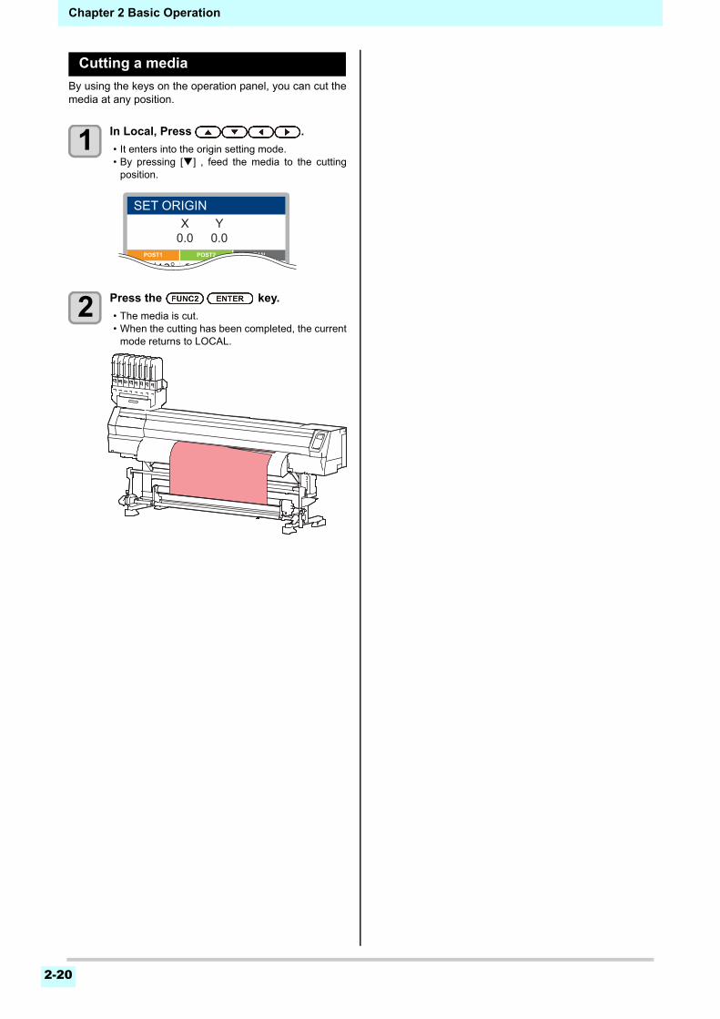
Chapter 2 Basic Operation
2-20
Cutting a media
By using the keys on the operation panel, you can cut themedia at any position.
1 In Local, Press .
• It enters into the origin setting mode.• By pressing [] , feed the media to the cutting
position.
2 Press the key.
• The media is cut.• When the cutting has been completed, the current
mode returns to LOCAL.
X0.0
Y0.0
POST1 POST2 FAN
SET ORIGIN
30°/40°30°/35°40°/50°
This chapter
describes the various setting of this machine.
About SETUP MENU ....................................3-2SETUP MENU table.................................... 3-3Register the optimal print conditions to match the use ........................................................ 3-4Setting of Media Correction......................... 3-5If the Positions of Dots Shift... ..................... 3-6Setting the HEATER ................................... 3-6Setting the Optional heater ......................... 3-7Setting of Logical Seek ............................... 3-7Setting of Overprint ..................................... 3-8Setting of Drying Time................................. 3-8Setting of Left and Right Margins................ 3-8Setting of Refresh ....................................... 3-9Setting of Vacuum Fan................................ 3-9Setting of Feed Speed ................................ 3-9Setting of Feed Quality................................ 3-9Setting of MAPS4...................................... 3-10Setting Auto Cleaning ............................... 3-11Setting Interval wiping ............................... 3-11Setting External heater.............................. 3-12Setting Pre-feed ........................................ 3-12
About MACHINE SETUP MENU ................3-13MACHINE SETUP MENU table ................ 3-14Setting a AUTO Power-off......................... 3-16Setting Take-up unit .................................. 3-16Setting Top Blower.................................... 3-16
Setting the Display of Media Residual ....... 3-17Setting the PG Drop Adjust........................ 3-17Setting the Media Detection....................... 3-17Setting the Drying Feed............................. 3-18Setting a LANGUAGE................................ 3-18Setting Time............................................... 3-18Setting Unit (Temperature/ Length) ........... 3-18Setting a KEY BUZZER............................. 3-19Setting the VIEW FEED............................. 3-19Setting the amount of blank space between printed lines ............................................... 3-19Setting the SPACE FEED MODE.............. 3-19Set the network.......................................... 3-20Setting event mail function......................... 3-20Initializing the Settings............................... 3-24
About NOZZLE CHECK MENU ..................3-25INFORMATION MENU table ..................... 3-25Printing Check Flow................................... 3-26Printing Operations at “Nozzle Missing” Judgment and Error Occurrence ............... 3-26Setting the Printing Check ......................... 3-27Setting the NOZZLE RECOVERY ............. 3-27Setting the Judgment Condition................. 3-27
About INFORMATION MENU .....................3-28INFORMATION MENU table ..................... 3-28Displaying the Information ......................... 3-29
Chapter 3
Setup
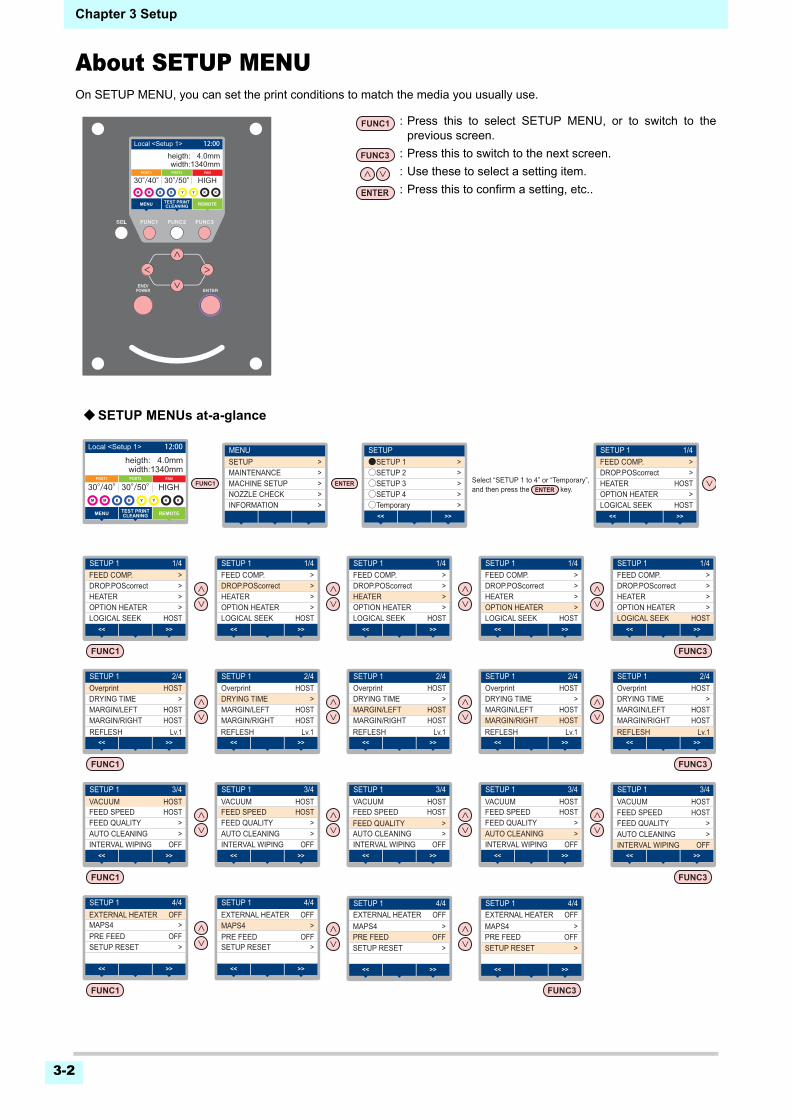
Chapter 3 Setup
3-2
About SETUP MENUOn SETUP MENU, you can set the print conditions to match the media you usually use.
SETUP●SETUP 1 >
>○SETUP 2>○SETUP 3>○SETUP 4>○Temporary
>><<
Select “SETUP 1 to 4” or “Temporary”,and then press the key.
MENUSETUP >
>MAINTENANCE>MACHINE SETUP>NOZZLE CHECK>INFORMATION
SETUP 1 1/4FEED COMP. >
>DROP.POScorrectHOSTHEATER
>HOST
OPTION HEATERLOGICAL SEEK
>><<
SETUP 1 2/4Overprint HOST
>DRYING TIMEHOSTMARGIN/LEFTHOSTMARGIN/RIGHT
>><<
SETUP 1 3/4
FEED SPEED HOST>FEED QUALITY>
OFFAUTO CLEANINGINTERVAL WIPING
>><<
SETUP 1 3/4
FEED SPEED HOST>FEED QUALITY>
OFFAUTO CLEANINGINTERVAL WIPING
>><<
SETUP 1 3/4
FEED SPEED HOST>FEED QUALITY>
OFFAUTO CLEANINGINTERVAL WIPING
>><<
SETUP 1 4/4
>><<
PRE FEED OFFSETUP RESET >
>MAPS4
SETUP 1 3/4
FEED SPEED HOST>FEED QUALITY>
OFFAUTO CLEANINGINTERVAL WIPING
>><<
SETUP 1 3/4
FEED SPEED HOST>FEED QUALITY>
OFFAUTO CLEANINGINTERVAL WIPING
>><<
SETUP 1 2/4Overprint HOST
>DRYING TIMEHOSTMARGIN/LEFTHOST
HOST
MARGIN/RIGHTLv.1REFLESH
VACUUM
>><<
SETUP 1 2/4Overprint HOST
>DRYING TIMEHOSTMARGIN/LEFTHOST
HOST
MARGIN/RIGHT
VACUUM
>><<
SETUP 1 2/4Overprint HOST
>DRYING TIMEHOSTMARGIN/LEFTHOST
HOST
MARGIN/RIGHT
VACUUM
>><<
SETUP 1 2/4Overprint HOST
>DRYING TIMEHOSTMARGIN/LEFTHOSTMARGIN/RIGHT
>><<
SETUP 1 4/4
PRE FEED OFFSETUP RESET
>MAPS4
>
>><<
SETUP 1 4/4
>><<
PRE FEED OFFSETUP RESET >
>MAPS4
SETUP 1 1/4FEED COMP. >
>DROP.POScorrect>HEATER>
HOSTOPTION HEATERLOGICAL SEEK
>><<
SETUP 1 1/4FEED COMP. >
>DROP.POScorrect>HEATER>
HOSTOPTION HEATERLOGICAL SEEK
>><<
SETUP 1 1/4FEED COMP. >
>DROP.POScorrect>HEATER>
HOSTOPTION HEATERLOGICAL SEEK
>><<
SETUP 1 1/4FEED COMP. >
>DROP.POScorrect>HEATER>
HOSTOPTION HEATERLOGICAL SEEK
>><<
SETUP 1 1/4FEED COMP. >
>DROP.POScorrect>HEATER>
HOSTOPTION HEATERLOGICAL SEEK
>><<
width:1340mm
REMOTEMENU TEST PRINTCLEANING
30°/40°
width:1340mmheigth: 4.0mm
REMOTEMENU
POST1 POST2
TEST PRINTCLEANING
FAN
30°/40°30°/50° HIGH
Local <Setup 1> 12:00
width:1340mm
REMOTEMENU TEST PRINTCLEANING
30°/40°
width:1340mmheigth: 4.0mm
REMOTEMENU
POST1 POST2
TEST PRINTCLEANING
FAN
30°/40°30°/50° HIGH
Local <Setup 1> 12:00
OFFEXTERNAL HEATER OFFEXTERNAL HEATER OFFEXTERNAL HEATERSETUP 1 4/4
>><<
PRE FEED OFFSETUP RESET >
>MAPS4OFFEXTERNAL HEATER
HOSTVACUUM HOSTVACUUM
Lv.1REFLESHLv.1REFLESHLv.1REFLESHLv.1REFLESH
: Press this to select SETUP MENU, or to switch to theprevious screen.
: Press this to switch to the next screen.
: Use these to select a setting item.
: Press this to confirm a setting, etc..
SETUP MENUs at-a-glance
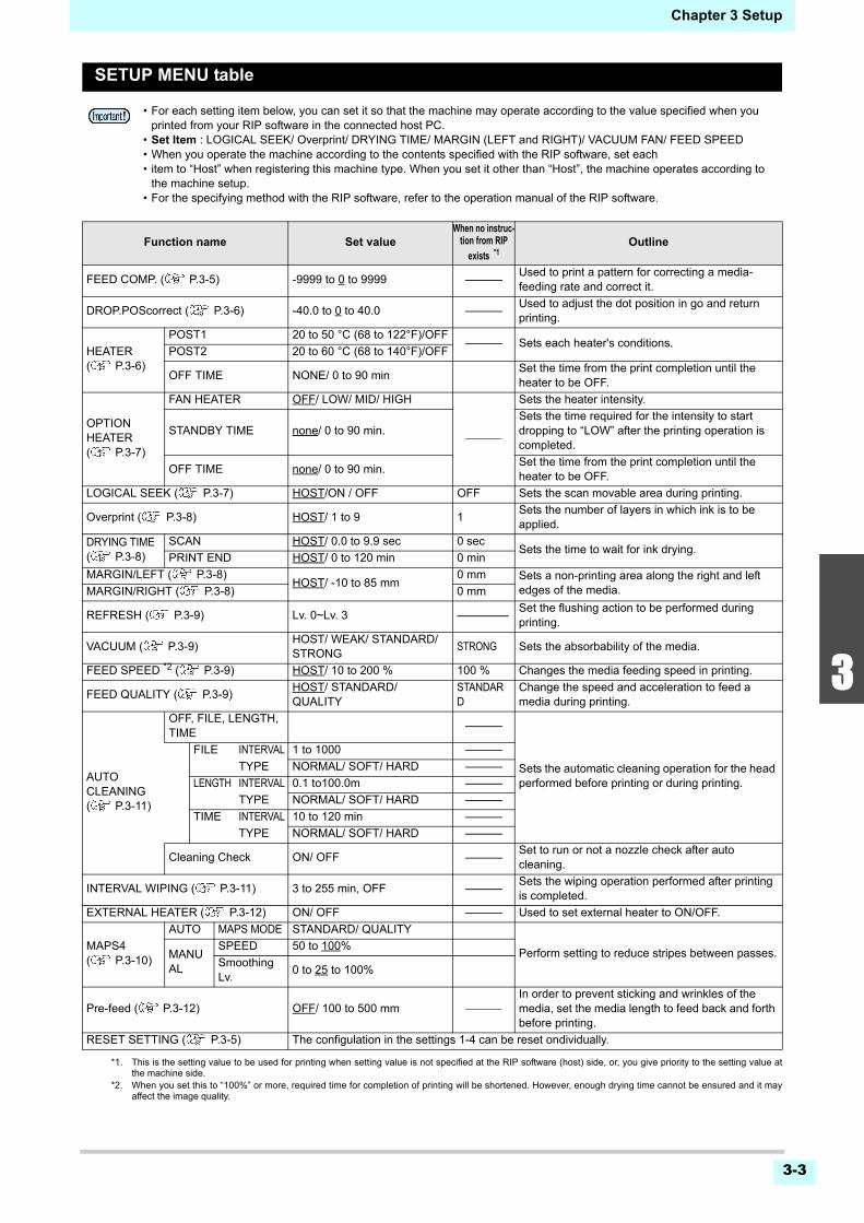
3-3
1
2
3
4
5
6
Chapter 3 Setup
SETUP MENU table
• For each setting item below, you can set it so that the machine may operate according to the value specified when you printed from your RIP software in the connected host PC.
• Set Item : LOGICAL SEEK/ Overprint/ DRYING TIME/ MARGIN (LEFT and RIGHT)/ VACUUM FAN/ FEED SPEED• When you operate the machine according to the contents specified with the RIP software, set each• item to “Host” when registering this machine type. When you set it other than “Host”, the machine operates according to
the machine setup.• For the specifying method with the RIP software, refer to the operation manual of the RIP software.
Function name Set valueWhen no instruc-
tion from RIP
exists *1
*1. This is the setting value to be used for printing when setting value is not specified at the RIP software (host) side, or, you give priority to the setting value atthe machine side.
Outline
FEED COMP. ( P.3-5) -9999 to 0 to 9999 Used to print a pattern for correcting a media-feeding rate and correct it.
DROP.POScorrect ( P.3-6) -40.0 to 0 to 40.0 Used to adjust the dot position in go and return printing.
HEATER( P.3-6)
POST1 20 to 50 °C (68 to 122°F)/OFF Sets each heater's conditions.
POST2 20 to 60 °C (68 to 140°F)/OFF
OFF TIME NONE/ 0 to 90 minSet the time from the print completion until the heater to be OFF.
OPTION HEATER( P.3-7)
FAN HEATER OFF/ LOW/ MID/ HIGH
Sets the heater intensity.
STANDBY TIME none/ 0 to 90 min.Sets the time required for the intensity to start dropping to “LOW” after the printing operation is completed.
OFF TIME none/ 0 to 90 min.Set the time from the print completion until the heater to be OFF.
LOGICAL SEEK ( P.3-7) HOST/ON / OFF OFF Sets the scan movable area during printing.
Overprint ( P.3-8) HOST/ 1 to 9 1Sets the number of layers in which ink is to be applied.
DRYING TIME( P.3-8)
SCAN HOST/ 0.0 to 9.9 sec 0 secSets the time to wait for ink drying.
PRINT END HOST/ 0 to 120 min 0 min
MARGIN/LEFT ( P.3-8)HOST/ -10 to 85 mm
0 mm Sets a non-printing area along the right and left edges of the media. MARGIN/RIGHT ( P.3-8) 0 mm
REFRESH ( P.3-9) Lv. 0~Lv. 3 Set the flushing action to be performed during printing.
VACUUM ( P.3-9)HOST/ WEAK/ STANDARD/ STRONG
STRONG Sets the absorbability of the media.
FEED SPEED *2 ( P.3-9)
*2. When you set this to “100%” or more, required time for completion of printing will be shortened. However, enough drying time cannot be ensured and it mayaffect the image quality.
HOST/ 10 to 200 % 100 % Changes the media feeding speed in printing.
FEED QUALITY ( P.3-9)HOST/ STANDARD/ QUALITY
STANDARD
Change the speed and acceleration to feed a media during printing.
AUTO CLEANING( P.3-11)
OFF, FILE, LENGTH, TIME
Sets the automatic cleaning operation for the head performed before printing or during printing.
FILE INTERVAL 1 to 1000
TYPE NORMAL/ SOFT/ HARD
LENGTH INTERVAL 0.1 to100.0m
TYPE NORMAL/ SOFT/ HARD
TIME INTERVAL 10 to 120 min
TYPE NORMAL/ SOFT/ HARD
Cleaning Check ON/ OFF Set to run or not a nozzle check after auto cleaning.
INTERVAL WIPING ( P.3-11) 3 to 255 min, OFF Sets the wiping operation performed after printing is completed.
EXTERNAL HEATER ( P.3-12) ON/ OFF Used to set external heater to ON/OFF.
MAPS4( P.3-10)
AUTO MAPS MODE STANDARD/ QUALITY
Perform setting to reduce stripes between passes.MANUAL
SPEED 50 to 100%
Smoothing Lv.
0 to 25 to 100%
Pre-feed ( P.3-12) OFF/ 100 to 500 mm In order to prevent sticking and wrinkles of the media, set the media length to feed back and forth before printing.
RESET SETTING ( P.3-5) The configulation in the settings 1-4 can be reset ondividually.
3-4
Chapter 3 Setup
Register the optimal print conditionsto match the use
In this machine, you will be able to register printconditions, SETUP 1 to 4 individually to match the mediain advance.For example, after print on different types of media, returnto the media always use. In such case you can set theoptimum printing conditions by simply selecting theregistered SETUP 1 to 4.
Register the print conditions to SETUP 1 to 4
1 Press (MENU) in LOCAL.
2 Press to select SETUP 1 to 4, and press the key.
• The item selected indicates ● and others show○ .
• SETUP MENU will be displayed.
3 Press to select and set each item in the setup menu list.
• Please see the reference page in the setup menulist for detailed configuration procedure.
How to use [Temporary]
[Temporary] is not only to set the print condition to beused only once, but also can be used for partial change ofthe registered SETUP "1 to 4", or for reflecting the printconditions set by the [Temporary] to SETUP 1 to 4.
Register the print conditions in [Temporary]
Registration of the print conditions to [Temporary] canbe done as the same method as to SETUP 1 to 4.
1 Press (MENU) in LOCAL.
2 Press to select “Temporary”, and press the key.
• SETUP MENU will be displayed.
3 Press to select and set each item in the setup menu list.
• Please see the reference page in the setup menulist for detailed configuration procedure.
Copy the contents of SETUP 1 to 4 to [Temporary]
You can use it with changing the part of registrationcontents of SETUP 1 to 4.Select “copy” from the registration screen of [Temporary],and specify the copy source (SETUP 1 to 4).
1 Press (MENU) in LOCAL.
2 Press to select “Temporary”, and press the key.
• SETUP MENU will be displayed.
3 Press (<<).
4 Press to select “COPY”, and press the key.
• Selection screen of the copy source will bedisplayed.
5 Press to SELECT the copy source (SETUP 1 to 4) and press the
key.
• Confirmation screen of the copy will be displayed.
6 Press the key.
• Settings selected in step 5 is copied toTemporary.
7 Press to select the setting item to be changed, and press the key.
• Please see the reference page in the setup menulist for detailed configuration procedure.
Reflect The Content Set In [Temporary] To Setup 1 To 4
1 Press (MENU) in LOCAL.
2 Press to select “Temporary”, and press the key.
• SETUP MENU will be displayed.
3 Press to select and set each item in the setup menu list.
• Please see the reference page in the setup menulist for detailed configuration procedure.
4 Display the last page of Temporary and select “SAVE SETTING”, and press the
key.
• Selection screen of the save location will bedisplayed.
5 Press to select the location selected (SETUP 1 to 4), and press the
key.
• Save confirmation screen will be displayed.
• Print conditions that can be pre-registered with the machine are the four types, “SETUP 1” to “SETUP 4”.
• If you print with the print condition which do not often use, you will be able to set the print conditions by selecting "Temporary".If turn on the power again, settings in "Temporary" will return to the original state when it was purchased.Also if turn on the power again in “Temporary” state, it will be the state in selecting “SETUP 1”.
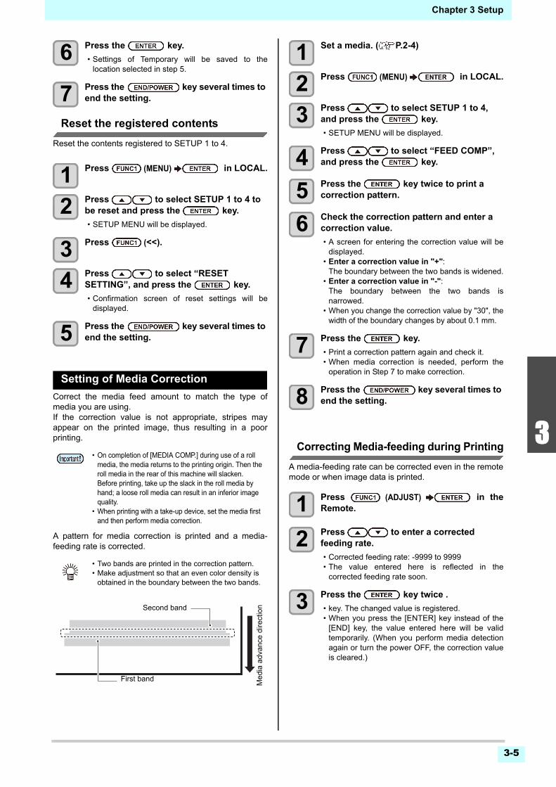
3-5
1
2
3
4
5
6
Chapter 3 Setup
6 Press the key.
• Settings of Temporary will be saved to thelocation selected in step 5.
7 Press the key several times to end the setting.
Reset the registered contents
Reset the contents registered to SETUP 1 to 4.
1 Press (MENU) in LOCAL.
2 Press to select SETUP 1 to 4 to be reset and press the key.
• SETUP MENU will be displayed.
3 Press (<<).
4 Press to select “RESET SETTING”, and press the key.
• Confirmation screen of reset settings will bedisplayed.
5 Press the key several times to end the setting.
Setting of Media Correction
Correct the media feed amount to match the type ofmedia you are using.If the correction value is not appropriate, stripes mayappear on the printed image, thus resulting in a poorprinting.
A pattern for media correction is printed and a media-feeding rate is corrected.
1 Set a media. ( P.2-4)
2 Press (MENU) in LOCAL.
3 Press to select SETUP 1 to 4, and press the key.
• SETUP MENU will be displayed.
4 Press to select “FEED COMP”, and press the key.
5 Press the key twice to print a correction pattern.
6 Check the correction pattern and enter a correction value.
• A screen for entering the correction value will bedisplayed.
• Enter a correction value in "+":The boundary between the two bands is widened.
• Enter a correction value in "-":The boundary between the two bands isnarrowed.
• When you change the correction value by "30", thewidth of the boundary changes by about 0.1 mm.
7 Press the key.
• Print a correction pattern again and check it.• When media correction is needed, perform the
operation in Step 7 to make correction.
8 Press the key several times to end the setting.
Correcting Media-feeding during Printing
A media-feeding rate can be corrected even in the remotemode or when image data is printed.
1 Press (ADJUST) in theRemote.
2 Press to enter a corrected feeding rate.
• Corrected feeding rate: -9999 to 9999• The value entered here is reflected in the
corrected feeding rate soon.
3 Press the key twice .
• key. The changed value is registered.• When you press the [ENTER] key instead of the
[END] key, the value entered here will be validtemporarily. (When you perform media detectionagain or turn the power OFF, the correction valueis cleared.)
• On completion of [MEDIA COMP.] during use of a roll media, the media returns to the printing origin. Then the roll media in the rear of this machine will slacken.Before printing, take up the slack in the roll media by hand; a loose roll media can result in an inferior image quality.
• When printing with a take-up device, set the media first and then perform media correction.
• Two bands are printed in the correction pattern.• Make adjustment so that an even color density is
obtained in the boundary between the two bands.
Second band
First band
Me
dia
adva
nce
dire
ctio
n
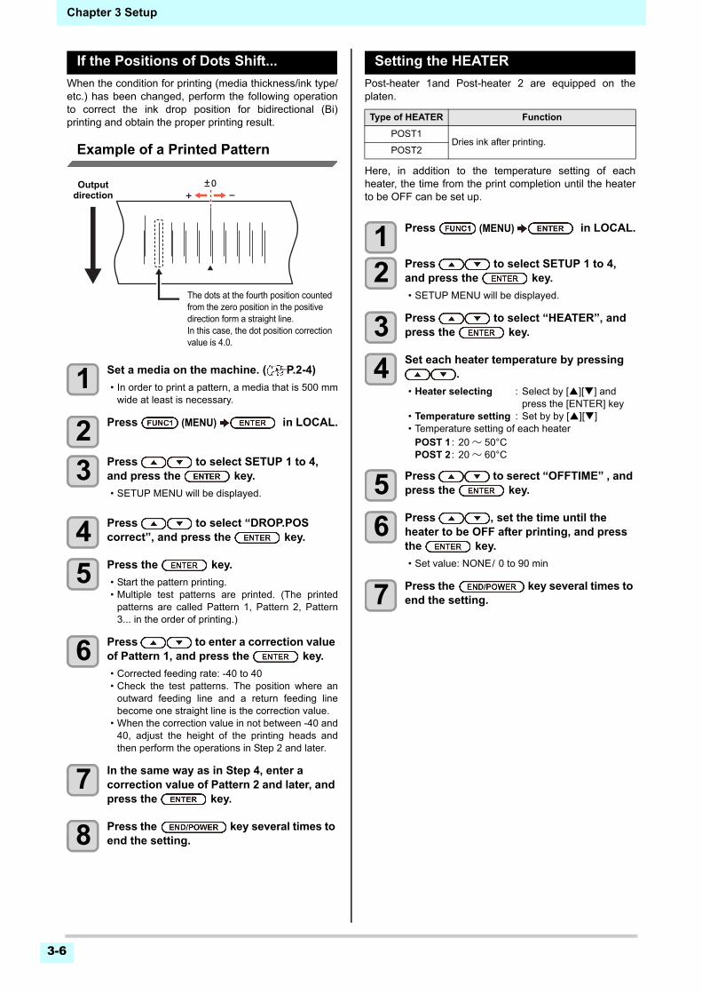
3-6
Chapter 3 Setup
If the Positions of Dots Shift...
When the condition for printing (media thickness/ink type/etc.) has been changed, perform the following operationto correct the ink drop position for bidirectional (Bi)printing and obtain the proper printing result.
Example of a Printed Pattern
1 Set a media on the machine. ( P.2-4)
• In order to print a pattern, a media that is 500 mmwide at least is necessary.
2 Press (MENU) in LOCAL.
3 Press to select SETUP 1 to 4, and press the key.
• SETUP MENU will be displayed.
4 Press to select “DROP.POS correct”, and press the key.
5 Press the key.
• Start the pattern printing.• Multiple test patterns are printed. (The printed
patterns are called Pattern 1, Pattern 2, Pattern3... in the order of printing.)
6 Press to enter a correction value of Pattern 1, and press the key.
• Corrected feeding rate: -40 to 40• Check the test patterns. The position where an
outward feeding line and a return feeding linebecome one straight line is the correction value.
• When the correction value in not between -40 and40, adjust the height of the printing heads andthen perform the operations in Step 2 and later.
7 In the same way as in Step 4, enter a correction value of Pattern 2 and later, and press the key.
8 Press the key several times to end the setting.
Setting the HEATER
Post-heater 1and Post-heater 2 are equipped on theplaten.
Here, in addition to the temperature setting of eachheater, the time from the print completion until the heaterto be OFF can be set up.
1 Press (MENU) in LOCAL.
2 Press to select SETUP 1 to 4, and press the key.
• SETUP MENU will be displayed.
3 Press to select “HEATER”, and press the key.
4 Set each heater temperature by pressing .
• Heater selecting : Select by [][] and press the [ENTER] key
• Temperature setting : Set by by [][]• Temperature setting of each heater
POST 1 : 20 ~ 50°CPOST 2 : 20 ~ 60°C
5 Press to serect “OFFTIME” , and press the key.
6 Press , set the time until the heater to be OFF after printing, and press the key.
• Set value: NONE/ 0 to 90 min
7 Press the key several times to end the setting.
The dots at the fourth position counted from the zero position in the positive direction form a straight line.In this case, the dot position correction value is 4.0.
Output direction
Type of HEATER Function
POST1Dries ink after printing.
POST2
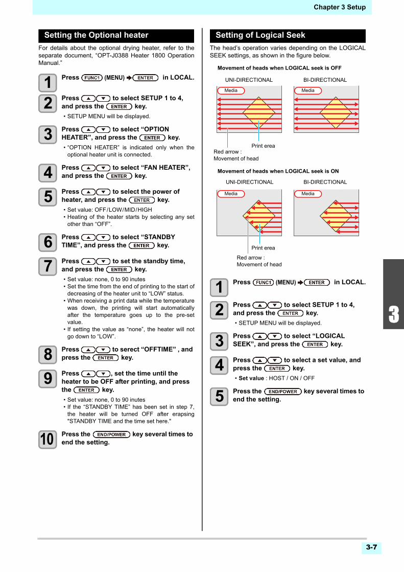
3-7
1
2
3
4
5
6
Chapter 3 Setup
Setting the Optional heater
For details about the optional drying heater, refer to theseparate document, “OPT-J0388 Heater 1800 OperationManual.”
1 Press (MENU) in LOCAL.
2 Press to select SETUP 1 to 4, and press the key.
• SETUP MENU will be displayed.
3 Press to select “OPTION HEATER”, and press the key.
• “OPTION HEATER” is indicated only when theoptional heater unit is connected.
4 Press to select “FAN HEATER”, and press the key.
5 Press to select the power of heater, and press the key.
• Set value: OFF/LOW/MID/HIGH• Heating of the heater starts by selecting any set
other than “OFF”.
6 Press to select “STANDBY TIME”, and press the key.
7 Press to set the standby time, and press the key.
• Set value: none, 0 to 90 inutes• Set the time from the end of printing to the start of
decreasing of the heater unit to “LOW” status.• When receiving a print data while the temperature
was down, the printing will start automaticallyafter the temperature goes up to the pre-setvalue.
• If setting the value as “none”, the heater will notgo down to “LOW”.
8 Press to serect “OFFTIME” , and press the key.
9 Press , set the time until the heater to be OFF after printing, and press the key.
• Set value: none, 0 to 90 inutes• If the “STANDBY TIME” has been set in step 7,
the heater will be turned OFF after erapsing"STANDBY TIME and the time set here."
10 Press the key several times to end the setting.
Setting of Logical Seek
The head’s operation varies depending on the LOGICALSEEK settings, as shown in the figure below.
1 Press (MENU) in LOCAL.
2 Press to select SETUP 1 to 4, and press the key.
• SETUP MENU will be displayed.
3 Press to select “LOGICAL SEEK”, and press the key.
4 Press to select a set value, and press the key.
• Set value : HOST / ON / OFF
5 Press the key several times to end the setting.
UNI-DIRECTIONAL BI-DIRECTIONAL
Movement of heads when LOGICAL seek is OFF
Movement of heads when LOGICAL seek is ON
UNI-DIRECTIONAL BI-DIRECTIONAL
Media
Red arrow :Movement of head
Print erea
Red arrow :Movement of head
Print erea
Media
Media Media
3-8
Chapter 3 Setup
Setting of Overprint
Sets the number of layers in which ink is to be applied.
1 Press (MENU) in LOCAL.
2 Press to select SETUP 1 to 4, and press the key.
• SETUP MENU will be displayed.
3 Press (>>) .
4 Press to select “Overprint” , and press the the key.
5 Press to set number of Overprint, and press the the key.
• Setting value : Host/ 1 to 9 times
6 Press the key several times to end the setting.
Setting of Drying Time
In the drying time setting, the following items for ink dryingtime are set.
• SCAN : Ink drying time for each scanning is set. (During bidirectional printing, the machine stops for a certain period of time specified for each of the outward and return scanning.)
• PRINT END : Ink drying time after printing has been complete is set.
1 Press (MENU) in LOCAL.
2 Press to select SETUP 1 to 4, and press the key.
• SETUP MENU will be displayed.
3 Press (>>) .
4 Press to select “DRYING TIME”, and press the key.
5 Press the key.
6 Press to set drying time, and press the key.
• Set the drying time for canning and after printingis completed. To enable the drying time specifiedin your RIP, select “Host”.
• Scanning setting value : Host or 0.0 sec. to 9.9 sec.
• Print end setting value:Host or 0 sec. to 120 inutes.
• Item selecting : by the [][] keys• Time setting : by the [][] keys
7 Press the key several times to end the setting.
Setting of Left and Right Margins
Set a non-printing area along the left and right edges ofthe media.The offset value against the standard margin 15 mm is sethereupon.
1 Press (MENU) in LOCAL.
2 Press to select SETUP 1 to 4, and press the key.
• SETUP MENU will be displayed.
3 Press (>>) .
4 Press to select “Margin/L” or “Margin/R”, and press the key.
5 Press to select a set value, and press the key.
• Set value : HOST / -10 to 85 mm
6 Press the key several times to end the setting.
• When you give priority to the setting at the RasterLink side, make the setting value “Host”.
• “SCAN” set in this machine is displayed as “Pause Time per Scan” in the RasterLink.
• You cannot specify the print end at the RasterLink side. When you set this machine to “Host”, printing will be performed in “PRINT END= 0 min.” status.
• When you give priority to the setting at the RIP software side, make the setting value “Host”.
• You cannot specify the margins at the attached RIP software (RasterLink). When you use the RasterLink, if you set this machine to “Host”, printing will be performed in “Margins for right and left off set value= 0 mm” status.
• The margin setting is reflected when the media width is detected.
• Pay attention to that printing may start on the media press if a right and left margin is set to 5 mm or less when the media press is used in printing.
3-9
1
2
3
4
5
6
Chapter 3 Setup
Setting of Refresh
Set the amount of refresh ink ejected during printing.Every time you raise the level, the discharge amount willincrease.
1 Press (MENU) in LOCAL.
2 Press to select SETUP 1 to 4, and press the key.
• SETUP MENU will be displayed.
3 Press (>>).
4 Press to select “REFRESH”, and press the key.
5 Press to select a set value, and press the key.
• Set value : Lv. 0~Lv. 3
6 Press the key several times to end the setting.
Setting of Vacuum Fan
Sets the absorbability of the media.By setting the absorption power to match the media, youcan prevent print errors due to media rise-up.
1 Press (MENU) in LOCAL.
2 Press to select SETUP 1 to 4, and press the key.
• SETUP MENU will be displayed.
3 Press (>>) .
4 Press to select “VACUUM FAN”, and press the key.
5 Press to select a set value, and press the key.
• Set value : HOST/WEAK /STANDARD/ STRONG
6 press the key several times to end the setting.
Setting of Feed Speed
Changes the media feeding speed in printing.
1 Press (MENU) in LOCAL.
2 Press to select SETUP 1 to 4, and press the key.
• SETUP MENU will be displayed.
3 Press (>>) twice.
4 Press to select “FEED SPEED”, and press the key.
5 Press to select a set value, and press the key.
• Set value : HOST / 10 to 200%
6 Press the key several times to end the setting.
Setting of Feed Quality
Change the speed and acceleration to feed a mediaduring printing. If the media feed is not stable, change thesetting into [QUALITY] may improve the situation.
Action will be changed as follows according to a setting.• STANDARD : The media feed is done with the default value
of the speed and acceleration.• QUALITY : The media feed is done with the speed and
acceleration slower than the default setting value.
1 Press (MENU) in LOCAL.
2 Press to select SETUP 1 to 4, and press the key.
• SETUP MENU will be displayed.
3 Press (>>) twice.
4 Press to select “FEED QUALITY”, and press the key.
5 Press to select a set value, and press the key.
• Set value:HOST / STANDARD / QUALITY
6 Press the key several times to end the setting.
• Some speed is not changed according to a setting condition.
• The media feed speed during printing is decided by this setting and the set value in [Setting of Feed Quality].
• The media feed speed during printing is decided by this setting and the set value in [Setting of Feed Speed].
3-10
Chapter 3 Setup
Setting of MAPS4
The MAPS (Mimaki Advanced PassSystem) function todisperse the pass boundary to make the feeding stripesless visible.
Setting MAPS4 Function (AUTO)
1 Press (MENU) in LOCAL.
2 Press to select SETUP 1 to 4, and press the key.
• SETUP MENU will be displayed.
3 Press (>>) twice.
4 Press to select “MAPS4” , and press the key.
5 Press to select “AUTO”, and press the key.
• To select “MANUAL” for the setting, refer to P.3-10“Setting MAPS4 Function (MANUAL)”.
6 Press to select the “MAPS MODE”, and press the key.
7 Press to select the setting value (STANDARD/QUALITY), and press the
key.
STANDARD : Prints in standard quality mode.?QUALITY : Prints in high quality mode.
“Prints more slowly than when“STANDARD” is selected.
8 Press the key several times to end the setting.
Setting MAPS4 Function (MANUAL)
1 Press (MENU) in LOCAL.
2 Press to select SETUP 1 to 4, and press the key.
• SETUP MENU will be displayed.
3 Press (>>) twice.
4 Press to select “MAPS4” , and press the key.
5 Press to select “MANUAL”, and press the key.
• To select “AUTO” for the setting, refer to P.3-10“Setting MAPS4 Function (AUTO)”.
6 Press to select the “SPEED” (50 to 100%), and press the key.
• Select a speed for printing. By using standardquality printing as reference, set in the direction ofminus (-) to decrease the print speed, and set inthe direction of plus (+) to increase the printspeed.
7 Press to select the "Smoothing Lv.”, and press the key.
8 Press to change the smoothing level, and press the key.
• Set Value : 0 to 100% (set in units of 5%)• The MAPS4 effect become strong as the set value
increase, and become weak as the set value decrease.
9 Press the key several times to end the setting.
• Changing the MAPS4 settings may change the color tone. Check the effects before use.
• MAPS may not be effective depending on image to be printed. Use it after checking effect in advance.
Conditions disabling MAPS function
The MAPS function may be disabled under the follow-ing conditions. In addition, the MAPS may not be effec-tive, depending on the image to be printed.
4-colors ink set
Resolution Pass Scan speed MAPS MODE
360x 360 1 pass Normal speed
Standard540x 360 2 pass High speed
720x 720 4 pass High speed
720x 1080 6 pass High speed
6-colors, 7-colors, 8-colors ink set
Resolution Pass Scan speed MAPS MODE
360x 360 2 pass Normal speed
Standard540x 360 4 pass High speed
720x 720 8 pass High speed
720x 1080 12 pass High speed • If the speed is changed, NOZZLE RECOVERY ( P.3-27) may not become effective. Check in advance before use.
3-11
1
2
3
4
5
6
Chapter 3 Setup
Setting Auto Cleaning
You can set the machine so that it counts the number ofprinted files or the length or time after printing has beencompleted, and performs cleaning automatically if required.You can select the auto cleaning setting from three typesbelow:
• PAGE : Set the cleaning intervals by the number of printed files.
• LENGTH : Set the cleaning intervals by the printed length.
• TIME : Set the cleaning intervals by the printed time.
Besides, automatic nozzle check after auto cleaning canbe set. (Cleaning Check function)The machine can perform a stable printing operation withits heads always kept clean.
1 Press (MENU) in LOCAL.
2 Press to select SETUP 1 to 4, and press the key.
• SETUP MENU will be displayed.
3 Press (>>) twice.
4 Press to select “AUTO CLEANING”, and press the key.
5 Press the key, and press to select the type of auto cleaning.
• There are “PAGE”, “LENGTH” and “TIME” forauto cleaning.FILE : When the set number of prints has
been completed, the machine performs head cleaning automatically.
LENGTH : When the set length has passed, the machine performs head cleaning automatically.
TIME : When the set time has passed, the machine performs head cleaning automatically.
• If you do not set auto cleaning, first select “OFF”and then proceed to the Step 6.
6 Press , and press to select the cleaning interval.
• Depending on the auto cleaning type selected inthe Step 3, the setting value differs.For FILE : 1 to 1000 fileFor LENGTH : 0.1 to 100.0m (in 0.1m increment)For TIME : 10 to 120min (in 10min increment)
7 Press the key, and press to select the cleaning type.
• Set Value : NORMAL/ SOFT/HARD
8 Press the key, and press to select “Cleaning Check”.
9 Press the key, and press to select set value.
• Set Value : ON/ OFF
10 Press the key .
11 Press the key several times to end the setting.
Setting Interval wiping
When the set time has passed, nozzle face of the head iscleaned automatically to remove ink droplets on thenozzle face.In case that deflection, nozzle missing, or symptom whichink droplets fall down occurred, set the interval betweeneach operation shorter.
1 Press (MENU) in LOCAL.
2 Press to select SETUP 1 to 4, and press the key.
• SETUP MENU will be displayed.
3 Press (>>) twice.
4 Press to select “INTERVAL WIPING”, and press the key.
5 Press to set intervals.
• Set Value : 3 to 255 Minutes, OFF• When [OFF] is set, periodical wiping is not
executed.
6 Press the key.
7 Press the key several times to end the setting.
• Depending on the state of the heads, etc., the image quality deterioration may not be improved even with this function performed.In this case, contact our service office or the distributor in your region.
3-12
Chapter 3 Setup
Setting External heater
Used to set external heater to ON/OFF.
1 Press (MENU) in LOCAL.
2 Press to select SETUP 1 to 4, and press the key.
• SETUP MENU will be displayed.
3 Press (<<).
4 Press to select “EXTERNAL HEATER”, and press the key.
5 Press to select set value.
• Set Value: ON/OFF
6 Press the key.
7 Press the key several times to end the setting.
Setting Pre-feed
The following effects can be expected by feeding backand forth the media before printing.
• Prevent media from sticking to the various rollers and the platen of this machine.
• If the wrinkle is shifted to the media, wrinkle reduction can be expected.
1 Press (MENU) in LOCAL.
2 Press to select SETUP 1 to 4, and press the key.
• SETUP MENU will be displayed.
3 Press (>>) twice.
4 Press to select “Pre-Feed”, and press the key.
5 Press to set the feeding media lengths.
• Set Value : OFF, 100 to 500 mm• When [OFF] is set, pre-feed is not executed.
6 Press the key.
7 Press the key several times to end the setting.
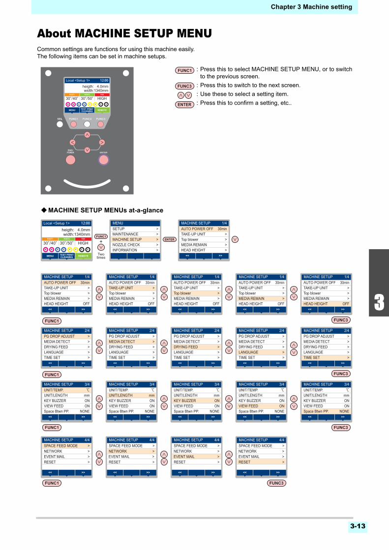
Chapter 3 Machine setting
3-13
1
2
3
4
5
6
About MACHINE SETUP MENUCommon settings are functions for using this machine easily.The following items can be set in machine setups.
Twotimes
MENUSETUP >
>MAINTENANCE>MACHINE SETUP>NOZZLE CHECK>INFORMATION
MACHINE SETUP 1/4AUTO POWER OFF 30min
>TAKE-UP UNIT>Top blower>>
MEDIA REMAINHEAD HEIGHT
>><<
MACHINE SETUP 2/4PG DROP ADJUST >
>MEDIA DETECT>DRYING FEED>>
LANGUAGETIME SET
>><<
MACHINE SETUP 3/4UNIT/TEMP. ℃
mmUNIT/LENGTHONKEY BUZZERONVIEW FEED
NONESpace Btwn PP.>><<
MACHINE SETUP 4/4
NETWORK >>EVENT MAIL>RESET
>SPACE FEED MODE
>><<
MACHINE SETUP 2/4PG DROP ADJUST >
>MEDIA DETECT>DRYING FEED>>
LANGUAGETIME SET
>><<
MACHINE SETUP 3/4UNIT/TEMP. ℃
mmUNIT/LENGTHONKEY BUZZERON
NONEVIEW FEEDSpace Btwn PP.
>><<
MACHINE SETUP 4/4
NETWORK >>EVENT MAIL>RESET
>SPACE FEED MODE
>><<
MACHINE SETUP 2/4PG DROP ADJUST >
>MEDIA DETECT>DRYING FEED>>
LANGUAGETIME SET
>><<
MACHINE SETUP 3/4UNIT/TEMP. ℃
mmUNIT/LENGTHONKEY BUZZERON
NONEVIEW FEEDSpace Btwn PP.
>><<
MACHINE SETUP 4/4
>EVENT MAIL>RESET
>SPACE FEED MODENETWORK >
>><<
MACHINE SETUP 2/4PG DROP ADJUST >
>MEDIA DETECT>DRYING FEED>>
LANGUAGETIME SET
>><<
MACHINE SETUP 3/4UNIT/TEMP. ℃
mmUNIT/LENGTHONKEY BUZZERON
NONEVIEW FEEDSpace Btwn PP.
>><<
MACHINE SETUP 2/4PG DROP ADJUST >
>MEDIA DETECT>DRYING FEED>>
LANGUAGETIME SET
>><<
MACHINE SETUP 3/4UNIT/TEMP. ℃
mmUNIT/LENGTHONKEY BUZZERON
NONEVIEW FEEDSpace Btwn PP.
>><<
MACHINE SETUP 4/4
NETWORK >>EVENT MAIL>RESET
>SPACE FEED MODE
>><<
MACHINE SETUP 1/4AUTO POWER OFF 30min
>TAKE-UP UNIT>Top blower>
OFFMEDIA REMAINHEAD HEIGHT
>><<
MACHINE SETUP 1/4AUTO POWER OFF 30min
>TAKE-UP UNIT>Top blower>
OFFMEDIA REMAINHEAD HEIGHT
>><<
MACHINE SETUP 1/4AUTO POWER OFF 30min
>TAKE-UP UNIT>Top blower>
OFFMEDIA REMAINHEAD HEIGHT
>><<
MACHINE SETUP 1/4AUTO POWER OFF 30min
>TAKE-UP UNIT>Top blower>
OFFMEDIA REMAINHEAD HEIGHT
>><<
MACHINE SETUP 1/4AUTO POWER OFF 30min
>TAKE-UP UNIT>Top blower>
OFFMEDIA REMAINHEAD HEIGHT
>><<
width:1340mm
REMOTEMENU TEST PRINTCLEANING
30°/40°
width:1340mmheigth: 4.0mm
REMOTEMENU
POST1 POST2
TEST PRINTCLEANING
FAN
30°/40°30°/50° HIGH
Local <Setup 1> 12:00
width:1340mm
REMOTEMENU TEST PRINTCLEANING
30°/40°
width:1340mmheigth: 4.0mm
REMOTEMENU
POST1 POST2
TEST PRINTCLEANING
FAN
30°/40°30°/50° HIGH
Local <Setup 1> 12:00
: Press this to select MACHINE SETUP MENU, or to switchto the previous screen.
: Press this to switch to the next screen.
: Use these to select a setting item.
: Press this to confirm a setting, etc..
MACHINE SETUP MENUs at-a-glance
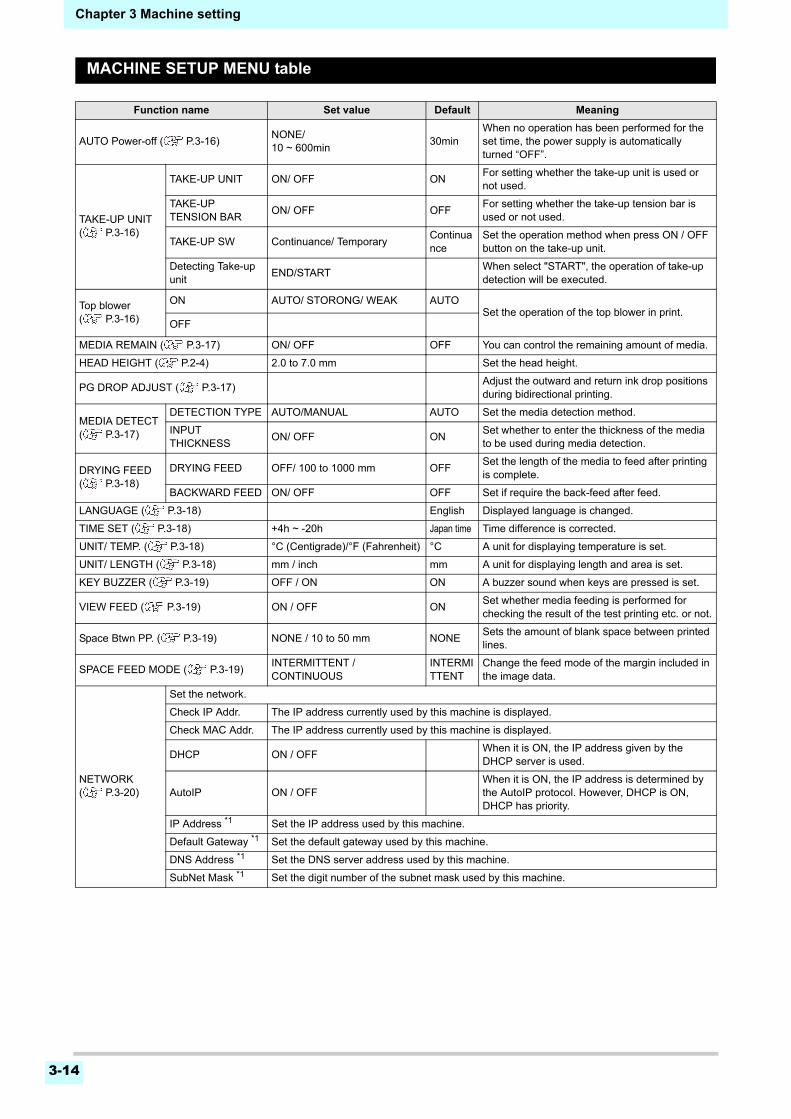
3-14
Chapter 3 Machine setting
MACHINE SETUP MENU table
Function name Set value Default Meaning
AUTO Power-off ( P.3-16)NONE/10 ~ 600min
30minWhen no operation has been performed for the set time, the power supply is automatically turned “OFF”.
TAKE-UP UNIT( P.3-16)
TAKE-UP UNIT ON/ OFF ONFor setting whether the take-up unit is used or not used.
TAKE-UP TENSION BAR
ON/ OFF OFFFor setting whether the take-up tension bar is used or not used.
TAKE-UP SW Continuance/ TemporaryContinuance
Set the operation method when press ON / OFF button on the take-up unit.
Detecting Take-up unit
END/STARTWhen select "START", the operation of take-up detection will be executed.
Top blower ( P.3-16)
ON AUTO/ STORONG/ WEAK AUTOSet the operation of the top blower in print.
OFF
MEDIA REMAIN ( P.3-17) ON/ OFF OFF You can control the remaining amount of media.
HEAD HEIGHT ( P.2-4) 2.0 to 7.0 mm Set the head height.
PG DROP ADJUST ( P.3-17)Adjust the outward and return ink drop positions during bidirectional printing.
MEDIA DETECT ( P.3-17)
DETECTION TYPE AUTO/MANUAL AUTO Set the media detection method.
INPUT THICKNESS
ON/ OFF ONSet whether to enter the thickness of the media to be used during media detection.
DRYING FEED( P.3-18)
DRYING FEED OFF/ 100 to 1000 mm OFFSet the length of the media to feed after printing is complete.
BACKWARD FEED ON/ OFF OFF Set if require the back-feed after feed.
LANGUAGE ( P.3-18) English Displayed language is changed.
TIME SET ( P.3-18) +4h ~ -20h Japan time Time difference is corrected.
UNIT/ TEMP. ( P.3-18) °C (Centigrade)/°F (Fahrenheit) °C A unit for displaying temperature is set.
UNIT/ LENGTH ( P.3-18) mm / inch mm A unit for displaying length and area is set.
KEY BUZZER ( P.3-19) OFF / ON ON A buzzer sound when keys are pressed is set.
VIEW FEED ( P.3-19) ON / OFF ONSet whether media feeding is performed for checking the result of the test printing etc. or not.
Space Btwn PP. ( P.3-19) NONE / 10 to 50 mm NONESets the amount of blank space between printed lines.
SPACE FEED MODE ( P.3-19)INTERMITTENT / CONTINUOUS
INTERMITTENT
Change the feed mode of the margin included in the image data.
NETWORK( P.3-20)
Set the network.
Check IP Addr. The IP address currently used by this machine is displayed.
Check MAC Addr. The IP address currently used by this machine is displayed.
DHCP ON / OFFWhen it is ON, the IP address given by the DHCP server is used.
AutoIP ON / OFFWhen it is ON, the IP address is determined by the AutoIP protocol. However, DHCP is ON, DHCP has priority.
IP Address *1 Set the IP address used by this machine.
Default Gateway *1 Set the default gateway used by this machine.
DNS Address *1 Set the DNS server address used by this machine.
SubNet Mask *1 Set the digit number of the subnet mask used by this machine.
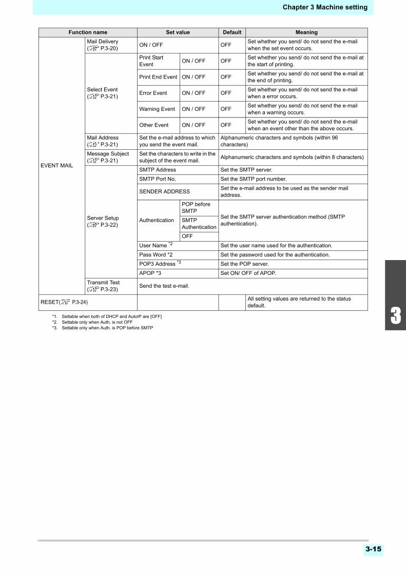
Chapter 3 Machine setting
3-15
1
2
3
4
5
6
EVENT MAIL
Mail Delivery( P.3-20)
ON / OFF OFFSet whether you send/ do not send the e-mail when the set event occurs.
Select Event( P.3-21)
Print Start Event
ON / OFF OFFSet whether you send/ do not send the e-mail at the start of printing.
Print End Event ON / OFF OFFSet whether you send/ do not send the e-mail at the end of printing.
Error Event ON / OFF OFFSet whether you send/ do not send the e-mail when a error occurs.
Warning Event ON / OFF OFFSet whether you send/ do not send the e-mail when a warning occurs.
Other Event ON / OFF OFFSet whether you send/ do not send the e-mail when an event other than the above occurs.
Mail Address( P.3-21)
Set the e-mail address to which you send the event mail.
Alphanumeric characters and symbols (within 96 characters)
Message Subject( P.3-21)
Set the characters to write in the subject of the event mail.
Alphanumeric characters and symbols (within 8 characters)
Server Setup( P.3-22)
SMTP Address Set the SMTP server.
SMTP Port No. Set the SMTP port number.
SENDER ADDRESSSet the e-mail address to be used as the sender mail address.
Authentication
POP before SMTP
Set the SMTP server authentication method (SMTP authentication).
SMTP Authentication
OFF
User Name *2 Set the user name used for the authentication.
Pass Word *2 Set the password used for the authentication.
POP3 Address *3 Set the POP server.
APOP *3 Set ON/ OFF of APOP.
Transmit Test( P.3-23)
Send the test e-mail.
RESET( P.3-24) All setting values are returned to the status default.
*1. Settable when both of DHCP and AutoIP are [OFF]*2. Settable only when Auth. is not OFF*3. Settable only when Auth. is POP before SMTP
Function name Set value Default Meaning
Chapter 3 Machine setting
3-16
Setting a AUTO Power-off
When no operation has been performed for the set time,the power supply is automatically turned “OFF”.
1 Press (MENU) (twice) in LOCAL.
• MACHINE SETUP MENU will be displayed.
2 Press to select “AUTO POWER OFF”, and press the key.
3 Press to select a set value, and press the key.
• Set Value : none, 10 to 600min
4 Press the key several times to end the setting.
Setting Take-up unit
For the “TAKE-UP UNIT” settings, set the following items:• Use take-up unit/ Do not use take-up unit.• Use/Do not use the take-up tension bar.• Operation when the ON/OFF switch for take-up unit is
pressed.• "START" is selected and execute the operation of take-up
detection.
1 Press (MENU) (twice) in LOCAL.
• MACHINE SETUP MENU will be displayed.
2 Press to select “TAKE-UP UNIT”, and press the key.
3 Press the key.
• “TAKE-UP UNIT” will be selected.
4 Press to select a set value, and press the key.
• Set Value : ON/ OFF
5 Press , and press the key.
• “TAKE-UP TENSION BAR” will be selected.
6 Press to select a set value, and press the key.
• Set Value : ON/ OFF
7 Press , and press the key.
• “TAKE-UP SW” will be selected.
8 Press to select a set value, and press the key.
• Set Value : Continuance/ TemporaryContinuance :
Switching ON / OFF the winding operation whenpressing the switch each time. (Take-up unit inoperation does not stop until press again ON /OFF switch.)
Temporary :Do the winding operation only while holdingdown the switch. (When release the switch,winding operation is stopped. )
9 Press to select “Detecting Take-up unit”.
• “Detecting Take-up unit” will be displayed.
10 Press .
• “START” is selected so execute the operation oftake-up detection.
11 Press the key several times to end the setting.
Setting Top Blower
Set the operation of the top blower in print.Turn the top blower setting “ON”, and you can set thestrength for the blower.
1 Press (MENU) (twice) in LOCAL.
• MACHINE SETUP MENU will be displayed.
2 Press to select “Top blower”, and press the key.
3 Press to select “ON”, and press the key.
ON : You can choose the air volume of the blower.OFF : The top blower does not work while printing
process. Proceed to step 6.
4 Press to select “STRENGTH”, and press the key.
5 Press to select a set value (AUTO/ STRONG/ WEAK), and press the
key.
• Set value : ON/ OFF
6 Press the key several times to end the setting.
• If you are using a direct-connection unit, even set to “Continuance”, it will automatically run the “Temporary” operation.
Chapter 3 Machine setting
3-17
1
2
3
4
5
6
Setting the Display of Media Residual
Whether the screen displays the remaining amount of amedia is set.
1 Press (MENU) (twice) in LOCAL.
• MACHINE SETUP MENU will be displayed.
2 Press to select “MEDIA REMAIN”, and press the key.
3 Press to select ON/OFF.
4 Press the key.
5 Press the key several times to end the setting.
Setting the PG Drop Adjust
Adjust the outward and return ink drop positions duringbidirectional printing.PG Drop Adjust adjusts the ink drop positions at twopoints where the head height is not the same, so that highquality printing can be realized by automatically adjustingthe ink drop positions even if the head height changes.
1 Press (MENU) (twice) in LOCAL.
• MACHINE SETUP MENU will be displayed.
2 Press (>>).
3 Press to select “PG DROP ADJUST”, and press the key.
4 Loosen the carriage height adjustment screw and press the key.
• Loosen the screen by referring to P.2-4 “Adjustingthe Head Height”.
5 With the head height set as 3 mm, tighten the height adjustment screw.
6 Press the key twice.
• Ink drop position adjustment patterns 1 to 5 will beprinted.
7 Correct the dot positions in patterns 1 to 5 by referring to P.3-6 “If the Positions of Dots Shift...”.
8 By referring to steps 4 to 7, change the head height to 4 mm and then correct the dot positions in patterns 1 to 5.
9 Press the key several times to end the setting.
Setting the Media Detection
Set the following two items in media detection settings.
1 Press (MENU) (twice) in LOCAL.
• MACHINE SETUP MENU will be displayed.
2 Press (>>).
3 Press to select “MEDIA DETECT”, and press the key.
4 Press the key.
• “DETECTION TYPE” will be selected.
5 Press to select “AUTO/MANUAL”, and press the key.
6 Press to select “INPUT THICKNESS”, and press .
7 Press to select ON/OFF, and press the key.
When the media remaining amount display is turned to "ON"
the remaining amount of a media is displayed in Remote.(However, when a leaf media is used, the length of the media to be printed is displayed.)
When the media remaining amount display is turned to "OFF"
the remaining amount of a media is not displayed in the Remote.
• The amount of a media that has been fed by the printing and jog keys is reflected in the remaining amount of a media.
• The length of a media (initial value of the remaining amount) is entered when a roll media is detected.( P.2-9)
• The setting configured here does not become effective unless media detection is performed after the setting has been complete.
• When set "ON" the media remaining display, you can print the list of current media remaining amount and the date. ( P.2-9)
Setting of Media Detection
When seting the media, set whether to detect the media width automatically (AUTO) or decide the print (or cut) range manually (MANUAL).
Setting of Media Thickness
Set whether to enter the thickness of the media during media detection.
• When using the media that cannot be detected by the sensor, set the media detection setting to "MANUAL".
Chapter 3 Machine setting
3-18
8 Press the key several times to end the setting.
Setting the Drying Feed
After printing, set the media feed length for dryinguniformly to the end of the media.
1 Press (MENU) (twice) in LOCAL.
• MACHINE SETUP MENU will be displayed.
2 Press (>>).
3 Press to select “DRYING FEED”, and press the key.
4 Press the key.
• “DRYING FEED” will be selected.
5 Press to input the feed length of media, and press the key.
6 Press to select “BACKWARD FEED”, and press the key.
7 Press to select “ON/OFF”, and press the key.
8 Press the key several times to end the setting.
Setting a LANGUAGE
You can change the displayed language.
1 Press (MENU) (twice) in LOCAL.
• MACHINE SETUP MENU will be displayed.
2 Press (>>).
3 Press to select “LANGUAGE”, and press the key .
4 Press to select language, and press the key .
5 Press the key several times to end the setting.
Setting Time
You can set time of your country (time difference).
1 Press (MENU) (twice) in LOCAL.
• MACHINE SETUP MENU will be displayed.
2 Press (>>).
3 Press to select “TIME”, and press the key.
4 Press to enter time, and press the key.
• Year/Month/Day/Time selecting:by the [][]
• Year/Month/Day/Time inputting:by the [][]
5 Press the key several times to end the setting.
Setting Unit (Temperature/ Length)
Units used by this machine are set.
1 Press (MENU) (twice) in LOCAL.
• MACHINE SETUP MENU will be displayed.
2 Press (>>).
3 Press to select “UNIT/TEMP.” or “UNIT/LENGTH”, and press the key.
4 Press to select a set value, and press the key.
• Set value of tempture : °C / °F• Set value of length : mm / inch
5 Press the key several times to end the setting.
• To improve image quality for printing, we recommend selecting “ON” in step 7.
• According to the position of your optional heater unit 1800 or external heater, please configure that the rear end of printing can pass through the heater.
• -20 hours to +4 hours can be set.
Chapter 3 Machine setting
3-19
1
2
3
4
5
6
Setting a KEY BUZZER
You can turn off the buzzer sound when pressing the key.
1 Press (MENU) (twice) in LOCAL.
• MACHINE SETUP MENU will be displayed.
2 Press (>>) twice.
3 Press to select “KEY BUZZER”, and press the key.
4 Press to select a set value, and press the key.
• Set value : ON/ OFF
5 Press the key several times to end the setting.
Setting the VIEW FEED
Set whether media feeding is performed for checking theresult of the test printing etc. or not.
1 Press (MENU) (twice) in LOCAL.
• MACHINE SETUP MENU will be displayed.
2 Press (>>) twice.
3 Press to select “VIEW FEED”, and press the key.
4 Press to select a set value, and press the key .
• Set value : ON/ OFF
5 Press the key several times to end the setting.
Setting the amount of blank spacebetween printed lines
Sets the amount of blank space between printed lines.
1 Press (MENU) in Local.
2 Press to select “Machine Setup”, and press the key.
3 Press (>>) twice.
4 Press to select “Space Btwn PP.”, and press the key.
5 Press to set the amount of blank space, and press the key.
• Set value : None / 10 to 500 mm
6 Press the key several times to end the setting.
Setting the SPACE FEED MODE
Change the feed mode of the margin included in theimage data (the space of no data to be printed). If printdata with much margin, set to “continuous”, then the printtime can be shorten.
1 Press the (MENU) (twice) key in LOCAL.
• MACHINE SETUP MENU will be displayed.
2 Press (>>) twice.
3 Press to select “SPACE FEED MODE” , and press the key.
4 Press to select a set value, and press the key.
INTERMITTENT:Perform intermittent feedoperation of the path division unit
CONTINUOUS :Feed the no data part at a time
5 Press the key several times to end the setting.
• When the key buzzer is set to "OFF", the buzzer sound for errors, warnings, operation completion, etc. cannot be shut off.
• Back-feed operation is performed when printing ends if the amount of blank space is set in the decreasing direction.Be careful of the following in such cases.
• The media tension of the next printing will change due to back-feed, possibly causing the feed rate of the media of only the leading edge of the printed image to change. In such cases, manually rewind the media.
• This function is disabled if back-feed after drying feed is set to OFF in the machine settings “DRYING FEED” ( P.3-18).
• If the printed data already has a blank space, using this function will result in “Blank space of the data + Amount of blank space set by using this function” being output as a blank space.
Chapter 3 Machine setting
3-20
Set the network
You can also perform network setting with “NetworkConfigurator”, the tool to perform network setting ofMimaki’s product. To download the Network Configurator,check " Driver / Utility" on the download page at MimakiEngineering (http://eng.mimaki.co.jp/download/).
1 Press (MENU) (twice) in LOCAL.
• MACHINE SETUP MENU will be displayed.
2 Press (>>) twice.
3 Press to select “NETWORK”, and press the key.
4 Press the key.
• “CHECK IP ADDRESS” will be selected.• The IP address currently used by this machine is
displayed.• When you have finished the check, press the
[ENTER] key.
5 Press , and press the key.
• “CHECK MAC ADDRESS” will be selected.• The MAC address currently used by this machine
is displayed.• When you have finished the check, press the
[ENTER] key.
6 Press , and press the key.
• “DHCP” will be selected.
7 Press to select a set value, and press the key.
• Set value : ON/ OFF• When it is ON, the IP address given by the DHCP
server is used.
8 Press , and press the key.
• “AutoIP” will be selected.
9 Press to select a set value, and press the key.
• Set value : ON/ OFF• When it is ON, the IP address is determined by
the AutoIP protocol. However, DHCP is ON,DHCP has priority.
10 Press , and press .
• “IP ADDRESS” will be selected.
11 Press to select a set value, and press the key.
• Set value : ON/ OFF• Both of DHCP and AutoIP is OFF, you can set IP
Address. For other than above, proceed to theStep 14.
12 Press .
• The setting items DEFAULT GATEWAY, DNSADDRESS and SUBNET MASK will be displayed.
• Both of DHCP and AutoIP is OFF, you can setDEFAULT GATEWAY/ DNS ADDRESS/ SUBNETMASK. For other than above, proceed to the Step14.
13 Press several times to select setting item, and press the key.
14 Press to select a set value, and press the key.
15 Press the key several times to end the setting.
Setting event mail function
Set the function to send e-mails to the set e-mail addresswhen events such as cutting start/ end and stop due to anerror.You can also perform network setting with “NetworkConfigurator”, the tool to perform network setting ofMimaki’s product. To download the Network Configurator,check " Driver / Utility" on the download page at MimakiEngineering (http://eng.mimaki.co.jp/download/).
Enable the event mail function
1 Press (MENU) (twice) in LOCAL.
• MACHINE SETUP MENU will be displayed.
2 Press (<<).
3 Press to select “EVENT MAIL”, and press the key.
4 Press the key.
• “MAIL DELIVERY” will be selected.
• After connecting with the network, it takes time until the IP address is determined. If the IP address has not been determined, “0.0.0.0” is displayed.
• To reflect network setting, once turn off the power supply and turn it on again.
• Disclaimer• The customer is responsible for the communication fee for
Internet communication such as e-mail notification.• The notification by the event mail function may not be
delivered due to Internet environment, failure of the device/ the power supply, etc. Mimaki has absolutely no responsibility for any damages or loss resulting from non-delivery or delays.
• You can use event mail function by connecting LAN to this machine. Please prepare for LAN cable connection beforehand.
• Not compatible with SSL communication.
Chapter 3 Machine setting
3-21
1
2
3
4
5
6
5 Press to select “ON”, and press the key.
6 Press the key several times to end the setting.
Set the event to send an event mail
1 Press (MENU) (twice) in LOCAL.
• MACHINE SETUP MENU will be displayed.
2 Press (<<).
3 Press to select “EVENT MAIL”, and press the key.
4 Press , and press the key.
• “SELECT EVENT” will be selected.
5 Press to select the event, and press ().
• After selecting the event, press [FUNC2] key andput a check in the check box.An email will be sent when the event whose boxhas been checked occurs.
• To select multiple events, use [][] to put thecursor over the events you want, and put a checkin their boxes by pressing [FUNC2].
6 Press the key several times to end the setting.
Set the e-mail address
1 Press (MENU) (twice) in LOCAL.
• MACHINE SETUP MENU will be displayed.
2 Press (<<).
3 Press to select “EVENT MAIL”, and press the key.
4 Press twice, and press the key.
• “MAIL ADDRESS” will be selected.
5 Press to set mail address, and press the key.
• Set the e-mail address to which you send theevent mail.
• Set it with alphanumeric characters and symbolswithin 96 characters.
6 Press the key several times to end the setting.
Set the subject
1 Press (MENU) (twice) in LOCAL.
• MACHINE SETUP MENU will be displayed.
2 Press (<<).
3 Press to select “EVENT MAIL”, and press the key.
4 Press 3 times, and press the key.
• “MASSAGE SUBJECT” will be selected.
5 Press to set subject, and press the key.
• Set the characters to write in the subject of theevent mail.
• Set it with alphanumeric characters and symbolswithin 8 characters.
6 Press the key several times to end the setting.
Event name Outline
PRINT START
Sets sending/not sending of an email when printing starts.
PRINT ENDSets sending/not sending of an email when printing ends.
ERRORSets sending/not sending of an email when printing is stopped due to occurrence of an error.
WARNINGSets sending/not sending of an email when a warning occurs during printing.
etc.Sets sending/not sending of an email when an event other than the above occurs.
Chapter 3 Machine setting
3-22
Set the server
1 Press (MENU) (twice) in LOCAL.
• MACHINE SETUP MENU will be displayed.
2 Press (<<).
3 Press to select “EVENT MAIL”, and press the key.
4 Press 4 times, and press the key.
• “SERVER SETUP” will be selected.
5 Press the key.
• “SMTP ADDRESS” will be selected.
6 Press to set SMTP Address, and press the key.
• Press jog key [][][][] to set SMTP address.• Input the SMTP address name.
7 Press , and press the key.
• “SMTP PORT No.” will be selected.
8 Press to set SMTP Port No., and press the key.
• Set the SMTP port number.
9 Press , and press the key.
• “SENDER ADDRESS” will be selected.
10 Press to set SENDER ADDRESS, and press the key.
• Press [][][][] and set the e-mail address tobe used as the sender mail address.
• Set it with alphanumeric characters and symbolswithin 64 characters.
11 Press , and press the key.
• “AUTHENTICATION” will be selected.
12 Press to set authentication method, and press the key.
• Set the authentication method of the SMTPserver.
• When you select [OFF], proceed to the Step 20.
13 Press , and press the key.
• “USER NAME” will be selected.
14 Press to set User Name, and press the key.
• Press [][][][] to set the user name to usefor the authentication.
• Set it with alphanumeric characters and symbolswithin 30 characters.
15 Press , and press the key.
• “PASSWORD” will be selected.
16 Press to set Pass Word, and press the key.
• Press [][][][] to set the password to use forthe authentication.
• Set it with alphanumeric characters and symbolswithin 15 characters.
• When you select [POP before SMTP] in the Step11, set the items in the Step 16 to 19.
17 Press , and press the key.
• “POP3 ADDRESS” will be selected.
18 Press to set POP3 Address, and press the key.
• Press [][][][] to set POP server.• Input the POP server name.
19 Press , and press the key.
• “APOP” will be selected.
20 Press to set ON/ OFF, and press the key.
21 Press the key several times to end the setting.
• Depending on your server, if you do not set the e-mail address not supporting the account, sending/ receiving e-mails may be unavailable.
• On the password setting screen, you can only check the value that you are currently inputting.
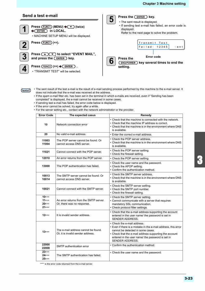
3-23
1
2
3
4
5
6
Chapter 3 Machine setting
Send a test e-mail
1 Press (MENU) (twice) in LOCAL.
• MACHINE SETUP MENU will be displayed.
2 Press (<<).
3 Press to select “EVENT MAIL”, and press the key.
4 Press (>>) .
• “TRANSMIT TEST” will be selected.
5 Press the key.
• The sent result is displayed.• If sending test e-mail has failed, an error code is
displayed.Refer to the next page to solve the problem.
6 Press the key several times to end the
setting.
T r a n s m i t T e s t
F a i l e d : 1 2 3 4 5 : e n t
Error code
• The sent result of the test e-mail is the result of e-mail sending process performed by this machine to the e-mail server. It does not indicate that the e-mail was received at the address.
• If the spam e-mail filter etc. has been set in the terminal in which e-mails are received, even if “Sending has been completed” is displayed, the e-mail cannot be received in some cases.
• If sending test e-mail has failed, the error code below is displayed.• If the error cannot be solved, try again after a while.• For the server setting etc., contact with the network administrator or the provider.
Error Code The expected casus Remedy
10 Network connection error
• Check that the machine is connected with the network.• Check that the machine IP address is correct.• Check that the machine is in the environment where DNS
is available.
20 No valid e-mail address. • Enter the correct e-mail address.
1100311004
The POP server cannot be found. Or cannot access DNS server.
• Check the POP server address.• Check that the machine is in the environment where DNS
is available.
11021 Cannot connect with the POP server. • Check the POP server setting.• Check the firewall setting.
12010 An error returns from the POP server. • Check the POP server setting.
13000 The POP authentication has failed.• Check the user name and the password.• Check the APOP setting.• Confirm the authentication method.
1001310014
The SMTP server cannot be found. Or cannot access DNS server.
• Check the SMTP server address.• Check that the machine is in the environment where DNS
is available.
10021 Cannot connect with the SMTP server.• Check the SMTP server setting.• Check the SMTP port number.• Check the firewall setting.
10112021
An error returns from the SMTP server.Or, there was no response.
• Check the SMTP server setting.• Cannot communicate with a server that requires
mandatory SSL communication.• Check protocol filter settings.
12 It is invalid sender address.• Check that the e-mail address supporting the account
entered in the user name/ the password is set in SENDER ADDRESS.
13The e-mail address cannot be found.Or, it is invalid sender address.
• Check the e-mail address.• Even if there is a mistake in the e-mail address, this error
cannot be detected in some cases.• Check that the e-mail address supporting the account
entered in the user name/ the password is set in SENDER ADDRESS.
2200022008
SMTP authentication error • Confirm the authentication method.
232425
The SMTP authentication has failed.• Check the user name and the password.
“***” is the error code returned from the e-mail server.
Chapter 3 Machine setting
3-24
Initializing the Settings
You can return the setting of “SETUP”, “MAINTENANCE”and “MACHINE SETUP” to the status before shipment.
1 Press (MENU) (twice) in LOCAL.
• MACHINE SETUP MENU will be displayed.
2 Press (<<) .
3 Press to select “RESET”, and press the key.
4 Press the key.
• The already configured settings are initialized.
5 Press the key several times to end the setting.
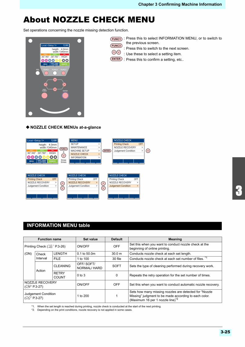
3-25
1
2
3
4
5
6
Chapter 3 Confirming Machine Information
About NOZZLE CHECK MENUSet operations concerning the nozzle missing detection function.
INFORMATION MENU table
Function name Set value Default Meaning
Printing Check ( P.3-26) ON/OFF OFFSet this when you want to conduct nozzle check at the beginning of online printing.
(ON) Check Interval
LENGTH 0.1 to 50.0m 30.0 m Conducts nozzle check at each set length.
FILE 1 to 100 30 file Conducts nozzle check at each set number of files. *1
*1. When the set length is reached during printing, nozzle check is conducted at the start of the next printing.
Action
CLEANING OFF/ SOFT/NORMAL/ HARD
SOFT Sets the type of cleaning performed during recovery work.
RETRY COUNT
0 to 3 0 Repeats the retry operation for the set number of times.
NOZZLE RECOVERY( P.3-27)
ON/OFF OFF Set this when you want to conduct automatic nozzle recovery.
Judgement Condition ( P.3-27)
1 to 200 1Sets how many missing nozzles are detected for “Nozzle Missing” judgment to be made according to each color. (Maximum 16 per 1 nozzle line)*2
*2. Depending on the print conditions, nozzle recovery is not applied in some cases.
threetimes
NOZZLE CHECKPrinting Check OFF
>NOZZLE RECOVERY>Judgement Condition
MENUSETUP >
>MAINTENANCE>MACHINE SETUP>NOZZLE CHECK>INFORMATION
NOZZLE CHECKPrinting Check OFF
>NOZZLE RECOVERY>Judgement Condition
NOZZLE CHECKPrinting Check OFF
>NOZZLE RECOVERY>Judgement Condition
NOZZLE CHECKPrinting Check OFF
>NOZZLE RECOVERY>Judgement Condition
width:1340mm
REMOTEMENU TEST PRINTCLEANING
30°/40°
width:1340mmheigth: 4.0mm
REMOTEMENU
POST1 POST2
TEST PRINTCLEANING
FAN
30°/40°30°/50° HIGH
Local <Setup 1> 12:00
width:1340mm
REMOTEMENU TEST PRINTCLEANING
30°/40°
width:1340mmheigth: 4.0mm
REMOTEMENU
POST1 POST2
TEST PRINTCLEANING
FAN
30°/40°30°/50° HIGH
Local <Setup 1> 12:00
: Press this to select INFORMATION MENU, or to switch tothe previous screen.
: Press this to switch to the next screen.
: Use these to select a setting item.
: Press this to confirm a setting, etc..
NOZZLE CHECK MENUs at-a-glance
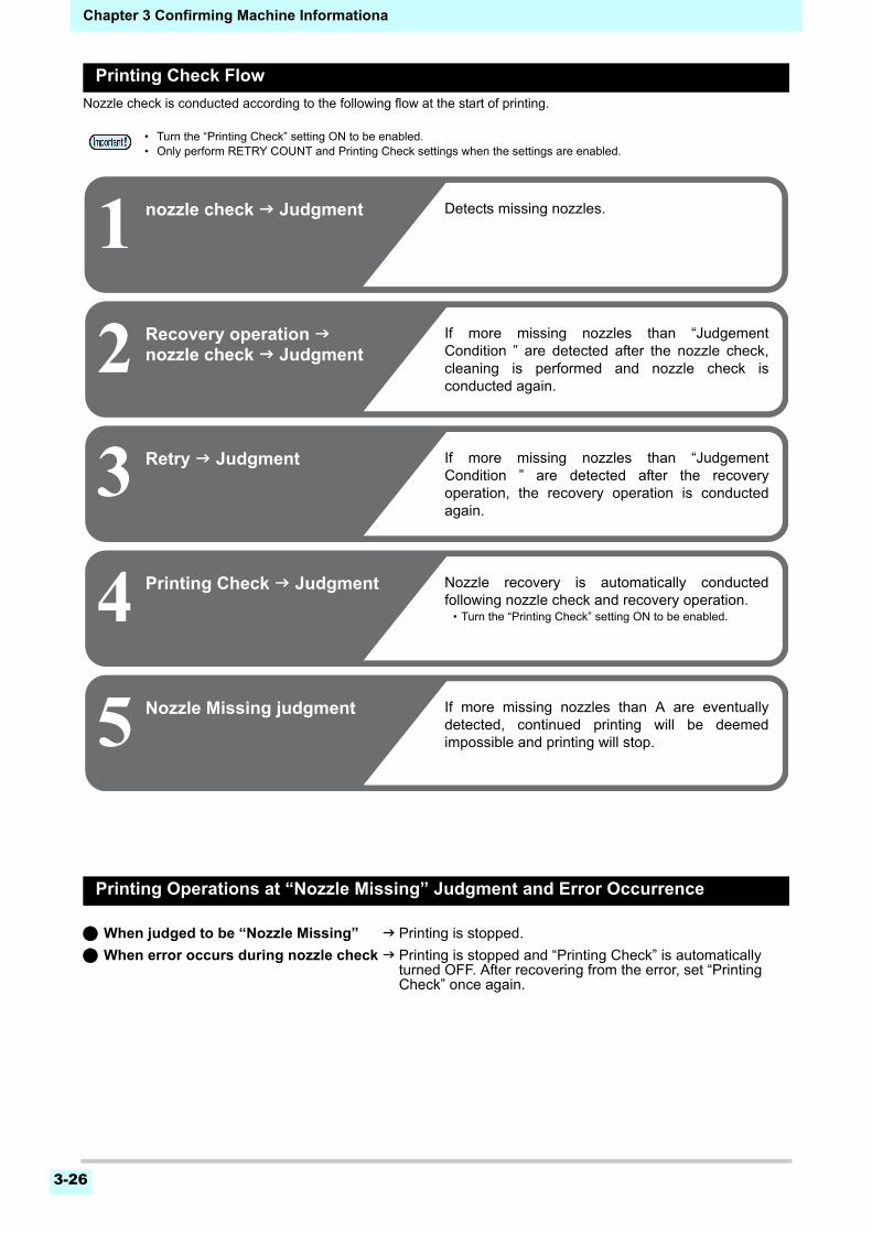
Chapter 3 Confirming Machine Informationa
3-26
Printing Check Flow
Nozzle check is conducted according to the following flow at the start of printing.
Printing Operations at “Nozzle Missing” Judgment and Error Occurrence
When judged to be “Nozzle Missing” Printing is stopped.
When error occurs during nozzle check Printing is stopped and “Printing Check” is automatically turned OFF. After recovering from the error, set “Printing Check” once again.
• Turn the “Printing Check” setting ON to be enabled.• Only perform RETRY COUNT and Printing Check settings when the settings are enabled.
1 nozzle check Judgment
2
3
Recovery operation nozzle check Judgment
4
Retry Judgment
Printing Check Judgment
Detects missing nozzles.
If more missing nozzles than “JudgementCondition ” are detected after the nozzle check,cleaning is performed and nozzle check isconducted again.
5 Nozzle Missing judgment If more missing nozzles than A are eventuallydetected, continued printing will be deemedimpossible and printing will stop.
If more missing nozzles than “JudgementCondition ” are detected after the recoveryoperation, the recovery operation is conductedagain.
Nozzle recovery is automatically conductedfollowing nozzle check and recovery operation.
• Turn the “Printing Check” setting ON to be enabled.
3-27
1
2
3
4
5
6
Chapter 3 Confirming Machine Information
Setting the Printing Check
Select ON when you want to conduct nozzle check at thestart of online printing.
1 Press (MENU) (3 times) in LOCAL.
• NOZZLE CHECK MENU will be displayed.
2 Press the key.
• “Printing Check” will be selected.
3 Press to select ON, and press the key.
• The “Check Interval” setting screen will bedisplayed.
• “Select OFF to not set nozzle check. Proceed toStep 11.
4 Press the key.
5 Press to select setting item, and press the key.
• select the nozzle check interval from “LENGTH”or “FILE”.LENGTH : nozzle check is conducted when the
printed length reaches the set length.FILE : nozzle check is conducted when the
number of printed files reaches theset number.
6 Press to select setting value, and press the key.
• The set value will differ according to the settingselected in Step 5.LENGTH : 0.1 to 50.0 mFILE : 1 to 100 files
7 Press the key twice.
• The “Action” setting screen will be displayed.
8 Press the key.
• “CLEANING TYPE” will be selected.
9 Press to select cleaning type, and press the key.
Setting value : OFF/SOFT/ NORMAL/ HARD
10 Press to select retry count, and press .
Setting value : 0 to 3
11 Press the key several times to end the setting.
Setting the NOZZLE RECOVERY
set this if you want to conduct automatic nozzle recoverywhen nozzle missing is detected.
1 Press (MENU) (3 times) in LOCAL.
• NOZZLE CHECK MENU will be displayed.
2 Press , and press the key.
• “NOZZLE RECOVERY” will be selected.
3 Press to select ON/OFF, and press .
4 Press the key several times to end the setting.
Setting the Judgment Condition
Set the conditions for judging nozzle missing.
1 Press (MENU) (3 times) in LOCAL.
• NOZZLE CHECK MENU will be displayed.
2 Press twice, and press the key.
• “Judgement Condition” will be selected.
3 Press to select color, and press the key.
4 Press to set the number of nozzles for judgment, and press the
key.
5 Press the key several times to end the setting.
• The type of color changes depending on the ink set.
Chapter 3 Confirming Machine Information
3-28
About INFORMATION MENUThe information of this machine can be confirmed.The following items can be confirmed as machine information.
INFORMATION MENU table
Item Description
USAGE
WIPING This displays how many wipings have been done.
WASTE TANKThis displays how much waste ink has built up in the waste ink tank, as a rough percentage of the tank capacity.
PRINT LENGTH This displays the total length of the printing done to date.
PRINT AREA This displays the total area of the printing done to date.
USE TIME This displays the total time for which the printer has been used to date.
Spout Rubber This displays the total time for which Spout Rubber has been used.
VERSION This displays the version information of this machine.
Ink REPL. Report This prints ink history of this machine.
ERROR HISTORYThis displays the history of errors and warnings to date.When you press [][], the date of occurrence (year/month/day/hour/minute) and the error/warning information are displayed alternately in the order of occurrence.
LIST This allows you to print the settings of this machine.
fourtimes
INFORMAITIONUSAGE >
>VERSION>INK REPLACE REPORT>>
ERROR HISTORYLIST
MENUSETUP >
>MAINTENANCE>MACHINE SETUP>NOZZLE CHECK>INFORMATION
INFORMAITIONUSAGE >
>VERSION>INK REPLACE REPORT>>
ERROR HISTORYLIST
INFORMAITIONUSAGE >
>VERSION>INK REPLACE REPORT>>
ERROR HISTORYLIST
INFORMAITIONUSAGE >
>VERSION>INK REPLACE REPORT>>
ERROR HISTORYLIST
INFORMAITIONUSAGE >
>VERSION>INK REPLACE REPORT>>
ERROR HISTORYLIST
INFORMAITIONUSAGE >
>VERSION>INK REPLACE REPORT>>
ERROR HISTORYLIST
width:1340mm
REMOTEMENU TEST PRINTCLEANING
30°/40°
width:1340mmheigth: 4.0mm
REMOTEMENU
POST1 POST2
TEST PRINTCLEANING
FAN
30°/40°30°/50° HIGH
Local <Setup 1> 12:00
width:1340mm
REMOTEMENU TEST PRINTCLEANING
30°/40°
width:1340mmheigth: 4.0mm
REMOTEMENU
POST1 POST2
TEST PRINTCLEANING
FAN
30°/40°30°/50° HIGH
Local <Setup 1> 12:00
: Press this to select INFORMATION MENU, or to switch tothe previous screen.
: Press this to switch to the next screen.
: Use these to select a setting item.
: Press this to confirm a setting, etc..
INFORMAITION MENUs at-a-glance
Chapter 3 Confirming Machine Information
3-29
1
2
3
4
5
6
Displaying the Information
1 Press (MENU) (4 times) in LOCAL.
• INFORMATION MENU will be displayed.
2 Press to select a information.
• Refer to the “INFORMATION MENU”, and select the information to be displayed.
3 Press the key.
• If you selected [LIST] in step 2, the machine’s settings will be printed.
4 Press the key several times to end the setting.
• When you reset the used count of the wiper, press [FUNC2] key while [RESET?] is displayed. When you press the [ENTER] key, the number of wipings is reset.
• By pressing the function key during display of “WIPING information,” “WASTE TANK information” and “Spout Rubber” in USAGE, the used counts can be reset.When resetting WIPING information : Press [FUNC2]When resetting WASTE TANK information : Press [FUNC1]When resetting Spout Rubber : Press [FUNC3]

3-30
Chapter 3 Confirming Machine Information
This chapter
describes the items required to use this machine more comfortably, which are themethods for the daily care, the maintenance of the ink cartridges etc.
Maintenance .................................................4-3Precautions for Maintenance ...................... 4-3About Cleaning Solution.............................. 4-3Cleaning the Exterior Surfaces ................... 4-3Cleaning the Platen ..................................... 4-3Cleaning the Media Sensor ......................... 4-4Cleaning the Media Press ........................... 4-4
About MAINTENANCE MENU ......................4-5MAINTENANCE MENUs at-a-glance .......... 4-6
Maintaining the Capping Station ...................4-7Cleaning the Wiper and Cap ....................... 4-7Washing the Head Nozzle ........................... 4-8Washing the Ink Discharge Passage ........ 4-10When the Machine Is Not Used for a Long Time .................................................................. 4-11
Cleaning the Ink Head and the Area around It ................................................................4-13Nozzle Recovery Function ..............................4-14
Reset the set value ................................... 4-15
Check the condition for which nozzle recovery cannot be performed ..................................4-15Enabling or disabling nozzle recovery during a test print .....................................................4-15
Automatic Maintenance Function ................4-16Setting the Refreshing Intervals .................4-16Setting the Tube Wash Intervals ................4-16Setting the Cleaning Intervals and Type ....4-16Suspend the nozzle cleaning .....................4-17
Fill up Ink .....................................................4-17Replacing consumables ..............................4-17
Replacing the wiper ...................................4-17If a Waste Ink Tank Confirmation Message Ap-pears ..........................................................4-18Replace the waste ink tank with another ...4-19Replacing the Cutter Blade ........................4-20Replacing the Spout Rubber ......................4-21Male Connector Absorbent for MBIS .........4-22
Chapter 4
Maintenance
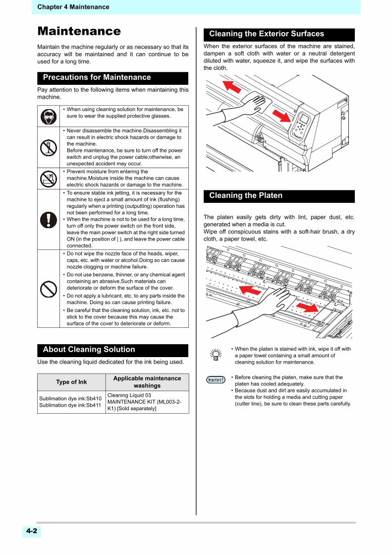
Chapter 4 Maintenance
4-2
MaintenanceMaintain the machine regularly or as necessary so that itsaccuracy will be maintained and it can continue to beused for a long time.
Precautions for Maintenance
Pay attention to the following items when maintaining thismachine.
About Cleaning Solution
Use the cleaning liquid dedicated for the ink being used.
Cleaning the Exterior Surfaces
When the exterior surfaces of the machine are stained,dampen a soft cloth with water or a neutral detergentdiluted with water, squeeze it, and wipe the surfaces withthe cloth.
Cleaning the Platen
The platen easily gets dirty with lint, paper dust, etc.generated when a media is cut.Wipe off conspicuous stains with a soft-hair brush, a drycloth, a paper towel, etc.
• When using cleaning solution for maintenance, be sure to wear the supplied protective glasses.
• Never disassemble the machine.Disassembling it can result in electric shock hazards or damage to the machine.Before maintenance, be sure to turn off the power switch and unplug the power cable;otherwise, an unexpected accident may occur.
• Prevent moisture from entering the machine.Moisture inside the machine can cause electric shock hazards or damage to the machine.
• To ensure stable ink jetting, it is necessary for the machine to eject a small amount of ink (flushing) regularly when a printing (outputting) operation has not been performed for a long time.
• When the machine is not to be used for a long time, turn off only the power switch on the front side, leave the main power switch at the right side turned ON (in the position of | ), and leave the power cable connected.
• Do not wipe the nozzle face of the heads, wiper, caps, etc. with water or alcohol.Doing so can cause nozzle clogging or machine failure.
• Do not use benzene, thinner, or any chemical agent containing an abrasive.Such materials can deteriorate or deform the surface of the cover.
• Do not apply a lubricant, etc. to any parts inside the machine. Doing so can cause printing failure.
• Be careful that the cleaning solution, ink, etc. not to stick to the cover because this may cause the surface of the cover to deteriorate or deform.
Type of InkApplicable maintenance
washings
Sublimation dye ink:Sb410Sublimation dye ink:Sb411
Cleaning Liquid 03 MAINTENANCE KIT (ML003-2-K1) [Sold separately]
• When the platen is stained with ink, wipe it off with a paper towel containing a small amount of cleaning solution for maintenance.
• Before cleaning the platen, make sure that the platen has cooled adequately.
• Because dust and dirt are easily accumulated in the slots for holding a media and cutting paper (cutter line), be sure to clean these parts carefully.
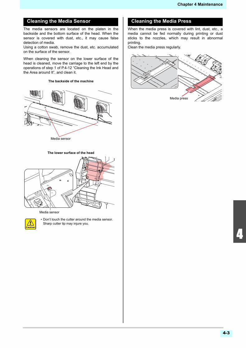
Chapter 4 Maintenance
4-3
1
2
2
4
5
6
Cleaning the Media Sensor
The media sensors are located on the platen in thebackside and the bottom surface of the head. When thesensor is covered with dust, etc., it may cause falsedetection of media.Using a cotton swab, remove the dust, etc. accumulatedon the surface of the sensor.
When cleaning the sensor on the lower surface of thehead is cleaned, move the carriage to the left end by theoperations of step 1 of P.4-12 “Cleaning the Ink Head andthe Area around It”, and clean it.
Cleaning the Media Press
When the media press is covered with lint, dust, etc., amedia cannot be fed normally during printing or duststicks to the nozzles, which may result in abnormalprinting.Clean the media press regularly.
• Don’t touch the cutter around the media sensor. Sharp cutter tip may injure you.
Media sensor
The backside of the machine
The lower surface of the head
Media sensor
Media press
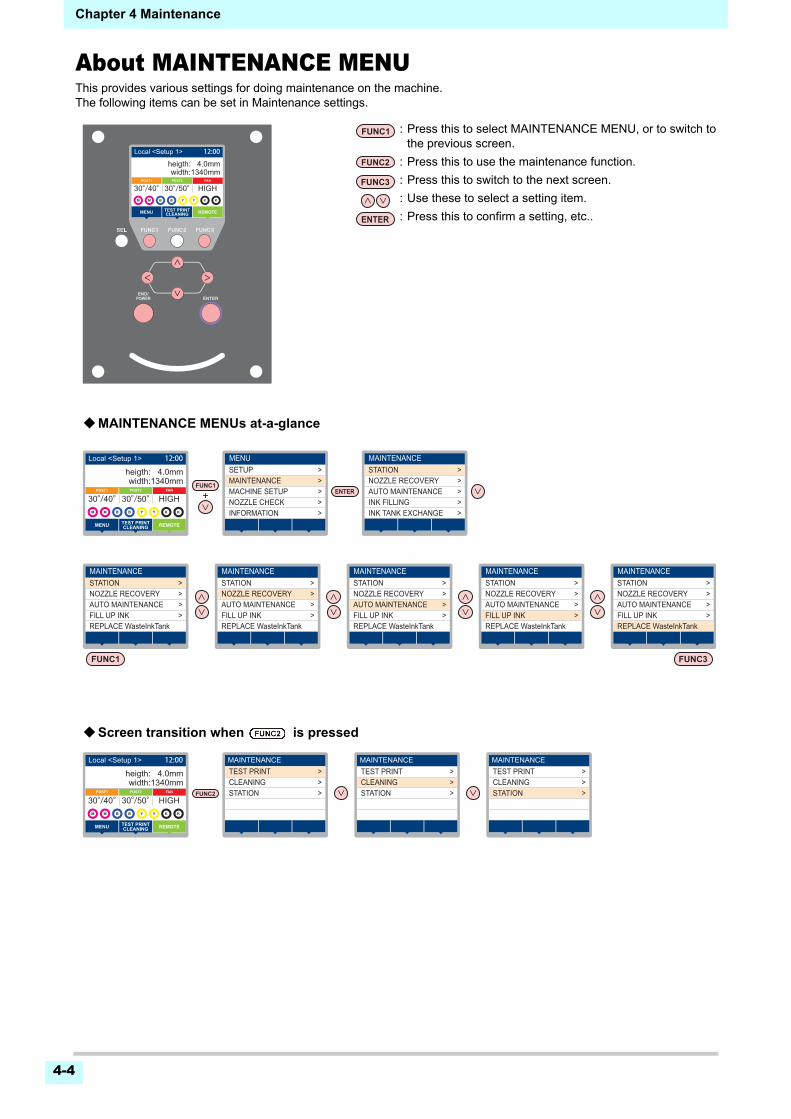
Chapter 4 Maintenance
4-4
About MAINTENANCE MENUThis provides various settings for doing maintenance on the machine.The following items can be set in Maintenance settings.
TEST PRINT >>CLEANING>STATION
MAINTENANCESTATION >
>NOZZLE RECOVERY>AUTO MAINTENANCE>INK FILLING
INK TANK EXCHANGE
page >< page
>
MENUSETUP >
>MAINTENANCE>MACHINE SETUP>NOZZLE CHECK>INFORMATION
MAINTENANCESTATION >
>NOZZLE RECOVERY>AUTO MAINTENANCE>FILL UP INK
REPLACE WasteInkTank
TEST PRINT >>CLEANING>STATION
MAINTENANCESTATION >
>NOZZLE RECOVERY>AUTO MAINTENANCE>FILL UP INK
REPLACE WasteInkTank
TEST PRINT >>CLEANING>STATION
MAINTENANCESTATION >
>NOZZLE RECOVERY>AUTO MAINTENANCE>FILL UP INK
REPLACE WasteInkTank
MAINTENANCESTATION >
>NOZZLE RECOVERY>AUTO MAINTENANCE>FILL UP INK
REPLACE WasteInkTank
MAINTENANCESTATION >
>NOZZLE RECOVERY>AUTO MAINTENANCE>FILL UP INK
REPLACE WasteInkTank
width:1340mm
REMOTEMENU TEST PRINTCLEANING
30°/40°
width:1340mmheigth: 4.0mm
REMOTEMENU
POST1 POST2
TEST PRINTCLEANING
FAN
30°/40°30°/50° HIGH
Local <Setup 1> 12:00
width:1340mm
REMOTEMENU TEST PRINTCLEANING
30°/40°
width:1340mmheigth: 4.0mm
REMOTEMENU
POST1 POST2
TEST PRINTCLEANING
FAN
30°/40°30°/50° HIGH
Local <Setup 1> 12:00
width:1340mm
REMOTEMENU TEST PRINTCLEANING
30°/40°
width:1340mmheigth: 4.0mm
REMOTEMENU
POST1 POST2
TEST PRINTCLEANING
FAN
30°/40°30°/50° HIGH
Local <Setup 1> MAINTENANCE MAINTENANCE MAINTENANCE12:00
: Press this to select MAINTENANCE MENU, or to switch tothe previous screen.
: Press this to use the maintenance function.
: Press this to switch to the next screen.
: Use these to select a setting item.
: Press this to confirm a setting, etc..
MAINTENANCE MENUs at-a-glance
Screen transition when is pressed
4-5
1
2
2
4
5
6
Chapter 4 Maintenance
MAINTENANCE MENUs at-a-glance
Item Set value Meaning
STATION MAINTENANCE
For carrying out maintenance on the carriage and station periphery.
CARRIAGE OUT( P.4-6)
Moves the carriage out, for carrying out cleaning of the cap periphery, head, wipers, etc.
NOZZLE WASH( P.4-7)
1 to 99minSoaks the nozzle surfaces in maintenance cleaning fluid, for carrying out recovery from nozzle clogging or bent.
DISWAY WASH( P.4-9)
Executes washing of the suction pump tubes.
CUSTODY WASH( P.4-10)
1 to 99minCarried out when the machine is going to be out of use for an extended period. Washes the nozzles and tubes beforehand, to keep the machine in fine condition.
WIPER EXCHANGE( P.4-16)
Used when replacing the wiper. If the wiper is replaced, the number of times the wiper was used that is managed in this machine is reset.
NOZZLE RECOVERY( P.4-13)
For printing using another nozzle, if nozzle wash and so forth fail to effect recovery from nozzle missing, etc.
PRINT Used to print a pattern and to check and/or register clogged nozzles.
ENTRY Registers the faulty nozzle identified by “PRINT”.
RESET Resets a registered faulty nozzle.
CHECK Checks recoverable printable conditions.
TEST PRINT ON/OFFEnables or disables the configuration of the nozzle recovery function during a test print.
AUTO MAINT.( P.4-15)
For having the various maintenance functions executed automatically. Set the execution interval for each maintenance function.
REFRESH The setting is different depending on your ink type.
For setting the activation interval for refresh.
PUMP TUBE CLEANING
For setting the activation interval for the ink discharge passage cleaning.
CLEANINGINTERVAL For setting the activation interval for the head cleaning.
TYPE NORMAL/ HARD Select the cleaning type for head cleaning.
FILL UP INK( P.4-16)
Supplies ink to correct nozzle clogging.
REPLACE WasteInkTank( P.4-18)
Resets or corrects the used count for the waste ink tank.
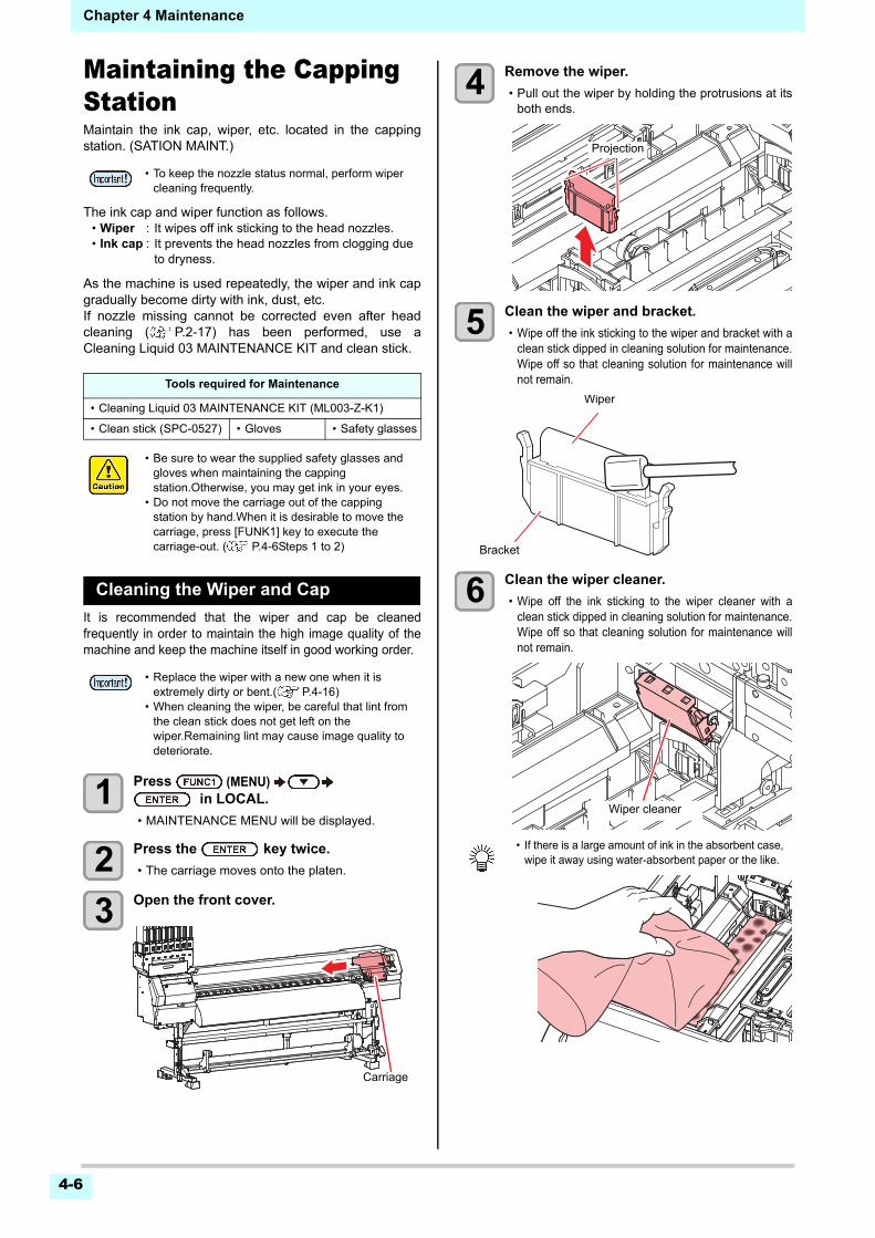
4-6
Chapter 4 Maintenance
Maintaining the Capping StationMaintain the ink cap, wiper, etc. located in the cappingstation. (SATION MAINT.)
The ink cap and wiper function as follows.• Wiper : It wipes off ink sticking to the head nozzles.• Ink cap : It prevents the head nozzles from clogging due
to dryness.
As the machine is used repeatedly, the wiper and ink capgradually become dirty with ink, dust, etc.If nozzle missing cannot be corrected even after headcleaning ( P.2-17) has been performed, use aCleaning Liquid 03 MAINTENANCE KIT and clean stick.
Cleaning the Wiper and Cap
It is recommended that the wiper and cap be cleanedfrequently in order to maintain the high image quality of themachine and keep the machine itself in good working order.
1 Press (MENU) in LOCAL.
• MAINTENANCE MENU will be displayed.
2 Press the key twice.
• The carriage moves onto the platen.
3 Open the front cover.
4 Remove the wiper.
• Pull out the wiper by holding the protrusions at itsboth ends.
5 Clean the wiper and bracket.
• Wipe off the ink sticking to the wiper and bracket with aclean stick dipped in cleaning solution for maintenance.Wipe off so that cleaning solution for maintenance willnot remain.
6 Clean the wiper cleaner.
• Wipe off the ink sticking to the wiper cleaner with aclean stick dipped in cleaning solution for maintenance.Wipe off so that cleaning solution for maintenance willnot remain.
• To keep the nozzle status normal, perform wiper cleaning frequently.
Tools required for Maintenance
• Cleaning Liquid 03 MAINTENANCE KIT (ML003-Z-K1)
• Clean stick (SPC-0527) • Gloves • Safety glasses
• Be sure to wear the supplied safety glasses and gloves when maintaining the capping station.Otherwise, you may get ink in your eyes.
• Do not move the carriage out of the capping station by hand.When it is desirable to move the carriage, press [FUNK1] key to execute the carriage-out. ( P.4-6Steps 1 to 2)
• Replace the wiper with a new one when it is extremely dirty or bent.( P.4-16)
• When cleaning the wiper, be careful that lint from the clean stick does not get left on the wiper.Remaining lint may cause image quality to deteriorate.
Carriage
• If there is a large amount of ink in the absorbent case, wipe it away using water-absorbent paper or the like.
Projection
Wiper
Bracket
Wiper cleaner
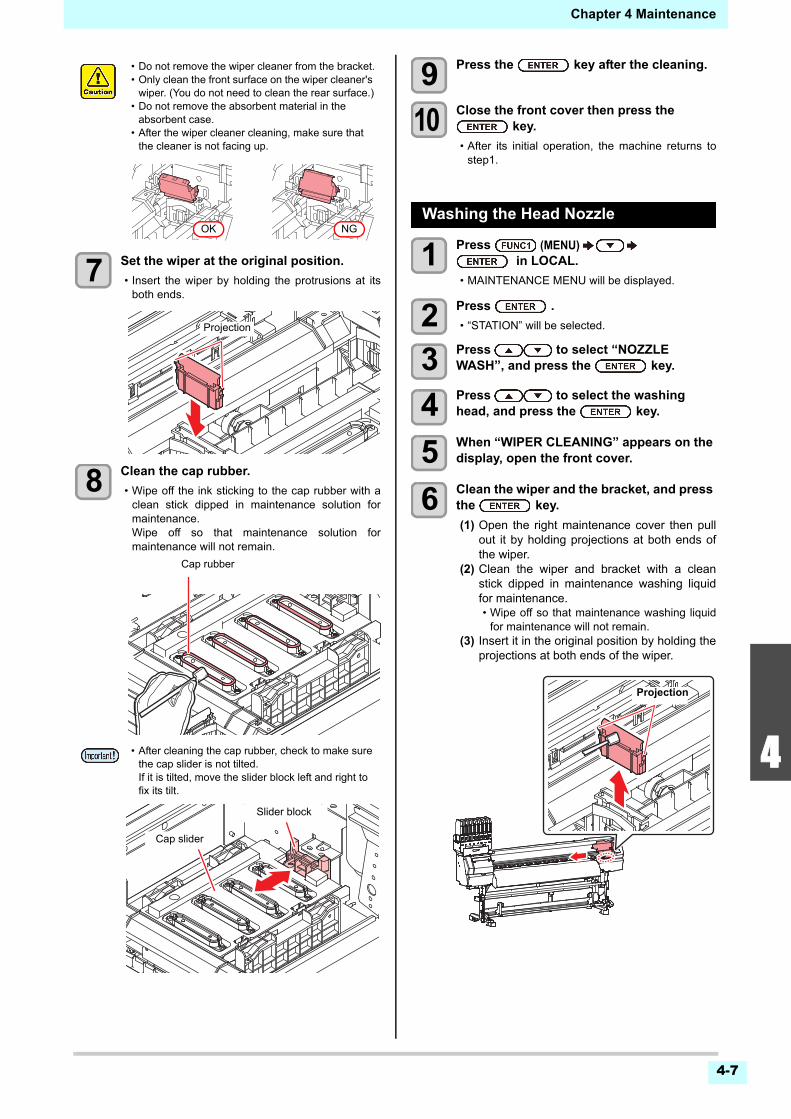
4-7
1
2
2
4
5
6
Chapter 4 Maintenance
7 Set the wiper at the original position.
• Insert the wiper by holding the protrusions at itsboth ends.
8 Clean the cap rubber.
• Wipe off the ink sticking to the cap rubber with aclean stick dipped in maintenance solution formaintenance.Wipe off so that maintenance solution formaintenance will not remain.
9 Press the key after the cleaning.
10 Close the front cover then press the key.
• After its initial operation, the machine returns tostep1.
Washing the Head Nozzle
1 Press (MENU) in LOCAL.
• MAINTENANCE MENU will be displayed.
2 Press .
• “STATION” will be selected.
3 Press to select “NOZZLE WASH”, and press the key.
4 Press to select the washing head, and press the key.
5 When “WIPER CLEANING” appears on the display, open the front cover.
6 Clean the wiper and the bracket, and press the key.
(1) Open the right maintenance cover then pullout it by holding projections at both ends ofthe wiper.
(2) Clean the wiper and bracket with a cleanstick dipped in maintenance washing liquidfor maintenance.• Wipe off so that maintenance washing liquid
for maintenance will not remain.(3) Insert it in the original position by holding the
projections at both ends of the wiper.
• Do not remove the wiper cleaner from the bracket.• Only clean the front surface on the wiper cleaner's
wiper. (You do not need to clean the rear surface.)• Do not remove the absorbent material in the
absorbent case.• After the wiper cleaner cleaning, make sure that
the cleaner is not facing up.
• After cleaning the cap rubber, check to make sure the cap slider is not tilted.If it is tilted, move the slider block left and right to fix its tilt.
OK NG
Projection
Cap rubber
Slider block
Cap slider
Projection
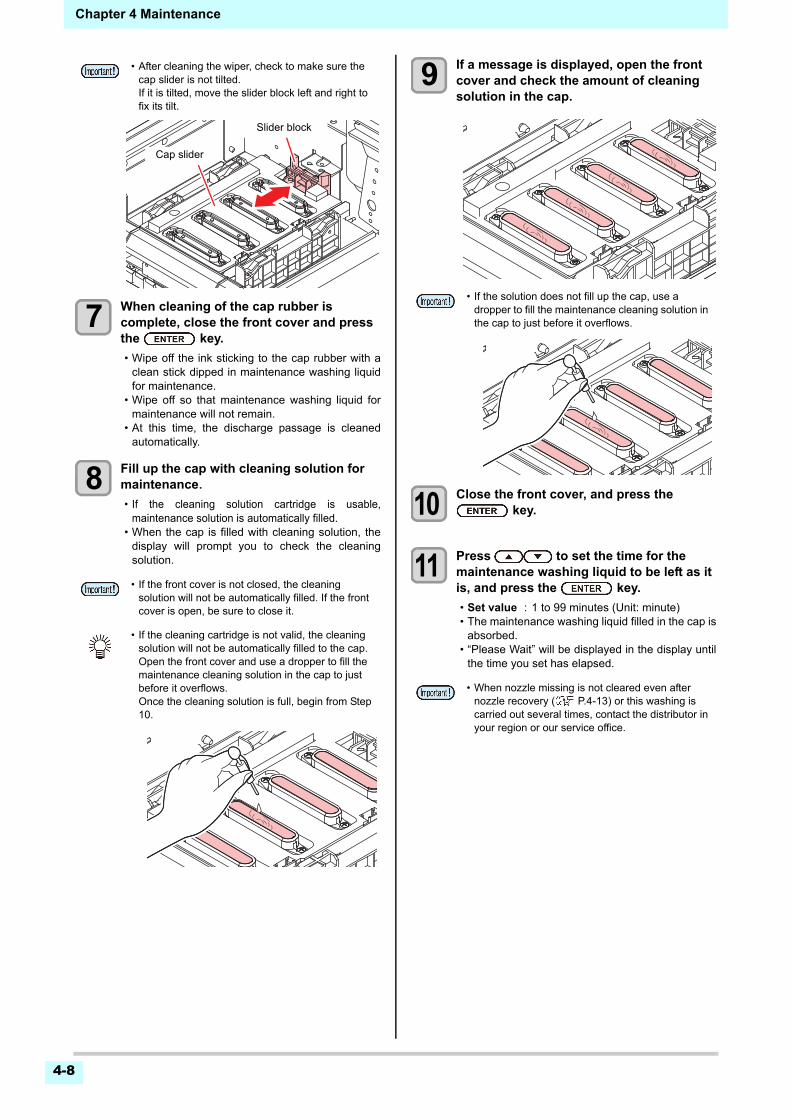
4-8
Chapter 4 Maintenance
7 When cleaning of the cap rubber is complete, close the front cover and press the key.
• Wipe off the ink sticking to the cap rubber with aclean stick dipped in maintenance washing liquidfor maintenance.
• Wipe off so that maintenance washing liquid formaintenance will not remain.
• At this time, the discharge passage is cleanedautomatically.
8 Fill up the cap with cleaning solution for maintenance.
• If the cleaning solution cartridge is usable,maintenance solution is automatically filled.
• When the cap is filled with cleaning solution, thedisplay will prompt you to check the cleaningsolution.
9 If a message is displayed, open the front cover and check the amount of cleaning solution in the cap.
10 Close the front cover, and press the key.
11 Press to set the time for the maintenance washing liquid to be left as it is, and press the key.
• Set value : 1 to 99 minutes (Unit: minute)• The maintenance washing liquid filled in the cap is
absorbed.• “Please Wait” will be displayed in the display until
the time you set has elapsed.
• After cleaning the wiper, check to make sure the cap slider is not tilted.If it is tilted, move the slider block left and right to fix its tilt.
• If the front cover is not closed, the cleaning solution will not be automatically filled. If the front cover is open, be sure to close it.
• If the cleaning cartridge is not valid, the cleaning solution will not be automatically filled to the cap.Open the front cover and use a dropper to fill the maintenance cleaning solution in the cap to just before it overflows.Once the cleaning solution is full, begin from Step 10.
Slider block
Cap slider
• If the solution does not fill up the cap, use a dropper to fill the maintenance cleaning solution in the cap to just before it overflows.
• When nozzle missing is not cleared even after nozzle recovery ( P.4-13) or this washing is carried out several times, contact the distributor in your region or our service office.
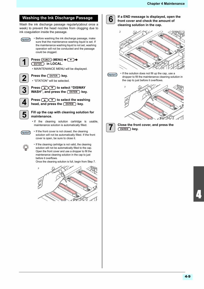
4-9
1
2
2
4
5
6
Chapter 4 Maintenance
Washing the Ink Discharge Passage
Wash the ink discharge passage regularly(about once aweek) to prevent the head nozzles from clogging due toink coagulation inside the passage.
1 Press (MENU) in LOCAL.
• MAINTENANCE MENU will be displayed.
2 Press the key.
• “STATION” will be selected.
3 Press to select “DISWAY WASH”, and press the key.
4 Press to select the washing head, and press the key.
5 Fill up the cap with cleaning solution for maintenance.
• If the cleaning solution cartridge is usable,maintenance solution is automatically filled.
6 If a END message is displayed, open the front cover and check the amount of cleaning solution in the cap.
7 Close the front cover, and press the key.
• Before washing the ink discharge passage, make sure that the maintenance washing liquid is set. If the maintenance washing liquid is not set, washing operation will not be conducted and the passage could be clogged.
• If the front cover is not closed, the cleaning solution will not be automatically filled. If the front cover is open, be sure to close it.
• If the cleaning cartridge is not valid, the cleaning solution will not be automatically filled to the cap.Open the front cover and use a dropper to fill the maintenance cleaning solution in the cap to just before it overflows.Once the cleaning solution is full, begin from Step 7.
• If the solution does not fill up the cap, use a dropper to fill the maintenance cleaning solution in the cap to just before it overflows.
4-10
Chapter 4 Maintenance
When the Machine Is Not Used for aLong Time
When the machine is not going to be used for a week ormore, use the cleaning function for custody to clean thehead nozzles and ink discharge passage.After this, keepthe machine in custody.
1 Press (MENU) in LOCAL.
• MAINTENANCE MENU will be displayed.
2 Press the key.
• “STATION” will be selected.
3 Press to select “CUSTODY WASH”, and press the key.
• Carriage will move onto the platen.
4 When “WIPER CLEANING” appears on the display, open the front cover.
5 Clean the wiper and the bracket.
(1) Open the front cover then pull out it byholding projections at both ends of the wiper.
(2) Clean the wiper and bracket with a cleanstick dipped in cleaning solution formaintenance. Wipe off so that cleaningsolution for maintenance will not remain.
(3) Insert it in the original position by holding theprojections at both ends of the wiper.
6 Press the key.
7 Clean the cap rubber.
• Wipe off the ink sticking to the cap rubber with aclean stick dipped in maintenance solution formaintenance.
• Wipe off so that maintenance solution formaintenance will not remain.
• At this time, the discharge passage is cleanedautomatically.
• Use the machine with always turning “ON” the main power. The function preventing nozzle clogging operates automatically to protect the head of the nozzle.
• The head nozzle may result in nozzle clogging if the main power switch is left OFF for a long time.
Check the items on the right beforehand.
Is [NEAR END] or [INK END] displayed?• The cleaning solution or ink is absorbed when the nozzles
are washed. At this time, if the state of "no ink" or "almost no ink" is detected, the nozzle washing operation cannot start.
• Replace the ink IC chip with another from which the state of "almost no ink" or "no ink" is not detected.
• When the worning messages “Check waste ink” are indicated, check the waste ink tank, and operate it, referring to P.4-17 “If a Waste Ink Tank Confirmation Message Appears” according to the situation.
• Until wiper cleaning is competed, [COMPLETED (NEXT): ENT] is displayed on the screen. After the work up to the step 5 is completed, press the [ENTER] key. If you press the [ENTER] key before cleaning is completed, the machine moves to the next washing procedure.
• After cleaning the cap rubber, check to make sure the cap slider is not tilted.If it is tilted, move the slider block left and right to fix its tilt.
Projection
Cap rubber
Slider block
Cap slider
4-11
1
2
2
4
5
6
Chapter 4 Maintenance
8 Close the front cover and press the key.
9 Fill up the cap with cleaning solution for maintenance.
• If the cleaning solution cartridge is usable,maintenance solution is automatically filled.
• When the cap is filled with cleaning solution, thedisplay will prompt you to check the cleaningsolution.
10 If a message is displayed, open the front cover and check the amount of cleaning solution in the cap.
11 Close the front cover, and press the key.
12 Press to set the time for the cleaning solution to be left as it is.
• Set Value:1 to 99 min (by the unit of 1 min)
13 Press the key.
• The nozzles are washed.• When the nozzles have been completely washed,
the head moves to the maintenance position.
14 Fill up the cap with cleaning solution for maintenance.
• If the cleaning solution cartridge is usable,maintenance solution is automatically filled.
15 If a END message is displayed, open the front cover and check the amount of cleaning solution in the cap.
16 Close the front cover and press the key.
• After its initial operation, the machine returns tostep2.
• If the front cover is not closed, the cleaning solution will not be automatically filled. If the front cover is open, be sure to close it.
• If the cleaning cartridge is not valid, the cleaning solution will not be automatically filled to the cap.Open the front cover and use a dropper to fill the maintenance cleaning solution in the cap to just before it overflows.Once the cleaning solution is full, begin from Step 11.
• If the solution does not fill up the cap, use a dropper to fill the maintenance cleaning solution in the cap to just before it overflows.
• If the front cover is not closed, the cleaning solution will not be automatically filled. If the front cover is open, be sure to close it.
• If the cleaning cartridge is not valid, the cleaning solution will not be automatically filled to the cap.Open the front cover and use a dropper to fill the maintenance cleaning solution in the cap to just before it overflows.Once the cleaning solution is full, begin from Step 16.
• If the solution does not fill up the cap, use a dropper to fill the maintenance cleaning solution in the cap to just before it overflows.
4-12
Chapter 4 Maintenance
Cleaning the Ink Head and the Area around ItBecause the ink head employs a very precisemechanism, due care needs to be taken when it iscleaned.Using a clean stick, etc., rub off gelatinous ink or dust thatmay stick to the lower part of the slider and the areaaround the ink head.In doing so, never rub the nozzles ofthe head.
1 Press (MENU) in LOCAL.
• MAINTENANCE MENU will be displayed.
2 Press the key twice.
• “CARRIAGE OUT” will be selected.
3 Press to select “HEAD MAINTENANCE”, and press the key.
• Carriage will move to the left end of this machine.
4 Open the maintenance cover.
5 Wipe ink sticking to the side of the head off with a clean stick.
• Never rub the nozzles.
6 Press the key after the cleaning.
7 Close the maintenance cover, and press the key.
• After its initial operation, the machine returns toLOCAL.
Tools required for cleaning
• Clean stick (SPC-0527) • Gloves
• Safety glasses
• Be sure to wear the included safety glasses and gloves when cleaning the area around the ink head.Otherwise, you may get ink in your eyes.
• The ink contains organic solvent.If you get the ink on your skin or in your eyes, wash it away with plenty of water immediately.
Clean the side surface of the head (shown in deep gray) with a clean stick.
The nozzle part (Never touch it.)
Clean with a clean stick or a waste cloth.
4-13
1
2
2
4
5
6
Chapter 4 Maintenance
Nozzle Recovery FunctionNOZZLE RECOVERY: When nozzles missing can not beimproved at specific points, other good nozzles can beused as alternatives for printing.
1 Press (MENU) in LOCAL.
• MAINTENANCE MENU will be displayed.
2 Press to select “NOZZLE RECOVERY”, and press the key.
3 Press the key twice.
• Printing of the nozzle pattern will start.• Select “ENTRY” then “Move to select of the
Nozzle line (Step 4) without drawing a pattern”
4 Select the Nozzle line that needs NOZZLE RECOVERY by pressing , and press the key.
5 Register the Nozzle number that needs NOZZLE RECOVERY and press the
key.
(1) Select the registration number from 1 to 10by pressing [][] and press the [ENTER]key.
(2) Register the nozzle number that needsrecovery by pressing [][] and press the[ENTER] key.
6 Press the key several times to end the setting.
110
2130
4150
6170
8190
101110
121130
141150
161170
181190
201210
221230
110
2130
4150
6170
8190
101110
121130
141150
161170
181190
201210
221230
110
2130
4150
6170
8190
101110
121130
141150
161170
181190
201210
221230
110
2130
4150
6170
8190
101110
121130
141150
161170
181190
201210
221230
110
2130
4150
6170
8190
101110
121130
141150
161170
181190
201210
221230
110
2130
4150
6170
8190
101110
121130
141150
161170
181190
201210
221230
110
2130
4150
6170
8190
101110
121130
141150
161170
181190
201210
221230
110
2130
4150
6170
8190
101110
121130
141150
161170
181190
201210
221230
241250
261270
281290
301310
241250
261270
281290
301310
241250
261270
281290
301310
241250
261270
281290
301310
241250
261270
281290
301310
241250
261270
281290
301310
241250
261270
281290
301310
241250
261270
281290
301310
H3 H4
Overhead view
H1-AB H2-CD H3-AB H4-AB
Nozzle line
H1-CD H2-AB H3-CD H4-CD
• When using leaf media, set a media of more than A3 size put horizontally. If a media with narrow width is set, printing will only be conducted to midway.
Nozzle pattern of Head 1
SELECT ENTRY NOZZLEH1-AB >
>H1-CD>H2-AB>H2-CD
>><<
>****
Head No.(H1 to H4)
Nozzle line
• Up to 10 nozzles can be registered per 1 nozzle line.
• Even if you use this function, time required for drawing does not change.
• When printing has been done with the lowest path, nozzle recovery is not reflected.
Head1-ABNo.1No.2
16128
No.3 184No.4 OFFNo.5 OFF
>><<
Recovery nozzle No. or OFF
Registration number : 1 to 10
110
2130
4150
6170
8190
101110
121130
141150
161170
181190
201210
221230
Nozzle missingNo.184
Nozzle number
Nozzle missing No.16
Nozzle missingNo.128
Registration number
Recovery Nozzle No.
State
1 16 Target for nozzle recovery
2 128 Target for nozzle recovery
3 184 Target for nozzle recovery
4 OFF No registration
5 OFF No registration
Example of nozzle to be recovered
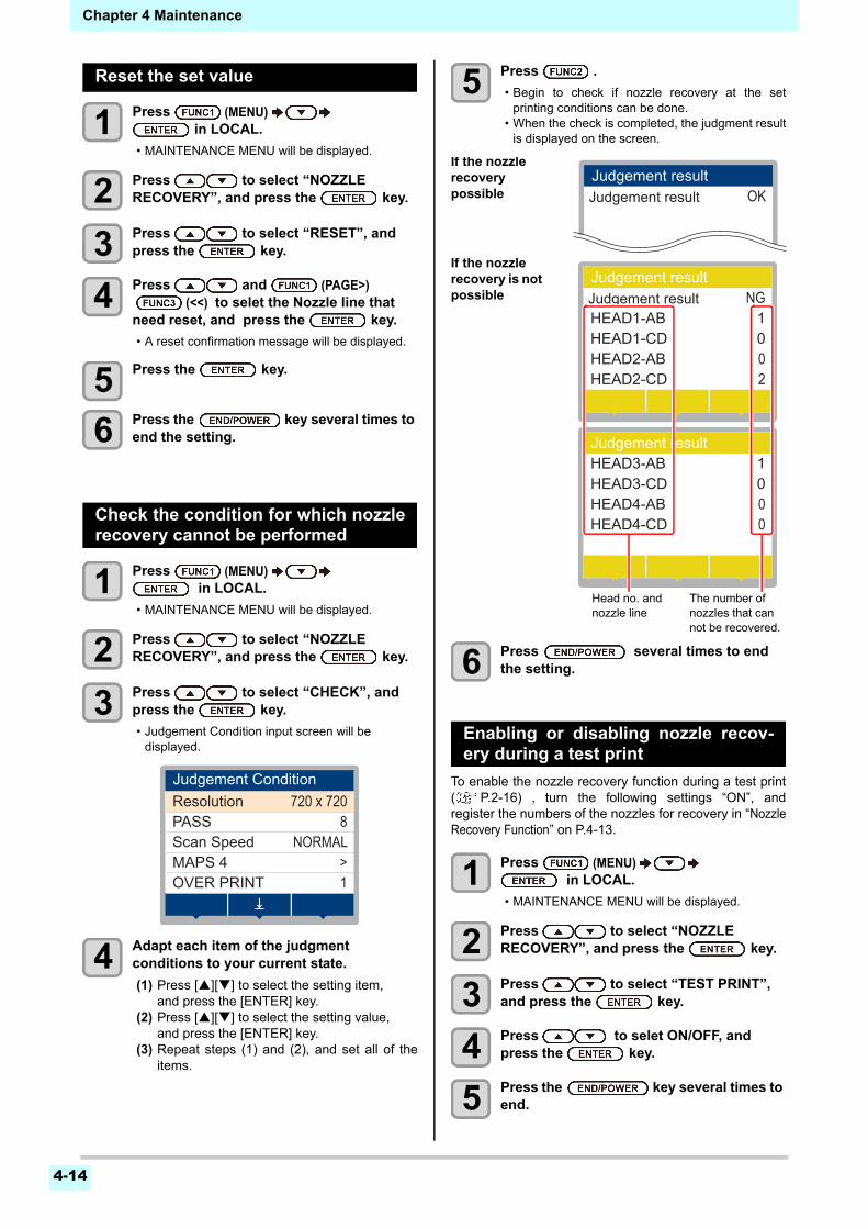
4-14
Chapter 4 Maintenance
Reset the set value
1 Press (MENU) in LOCAL.
• MAINTENANCE MENU will be displayed.
2 Press to select “NOZZLE RECOVERY”, and press the key.
3 Press to select “RESET”, and press the key.
4 Press and (PAGE>) (<<) to selet the Nozzle line that need reset, and press the key.
• A reset confirmation message will be displayed.
5 Press the key.
6 Press the key several times to end the setting.
Check the condition for which nozzlerecovery cannot be performed
1 Press (MENU) in LOCAL.
• MAINTENANCE MENU will be displayed.
2 Press to select “NOZZLE RECOVERY”, and press the key.
3 Press to select “CHECK”, and press the key.
• Judgement Condition input screen will be displayed.
4 Adapt each item of the judgment conditions to your current state.
(1) Press [][] to select the setting item,and press the [ENTER] key.
(2) Press [][] to select the setting value,and press the [ENTER] key.
(3) Repeat steps (1) and (2), and set all of theitems.
5 Press .
• Begin to check if nozzle recovery at the setprinting conditions can be done.
• When the check is completed, the judgment resultis displayed on the screen.
6 Press several times to end the setting.
Enabling or disabling nozzle recov-ery during a test print
To enable the nozzle recovery function during a test print( P.2-16) , turn the following settings “ON”, andregister the numbers of the nozzles for recovery in “NozzleRecovery Function” on P.4-13.
1 Press (MENU) in LOCAL.
• MAINTENANCE MENU will be displayed.
2 Press to select “NOZZLE RECOVERY”, and press the key.
3 Press to select “TEST PRINT”, and press the key.
4 Press to selet ON/OFF, and press the key.
5 Press the key several times to end.
Judgement ConditionResolution 720 x 720
8PASSNORMALScan Speed
>MAPS 41OVER PRINT
Judgement resultJudgement result
OK
If the nozzle recovery possible
HEAD1-AB 1HEAD1-CD 0HEAD2-AB 0HEAD2-CD 2
NG
HEAD3-AB 1HEAD3-CD 0HEAD4-AB 0HEAD4-CD 0
Judgement resultJudgement result
Judgement result
If the nozzle recovery is not possible
Head no. and nozzle line
The number of nozzles that can not be recovered.
4-15
1
2
2
4
5
6
Chapter 4 Maintenance
Automatic Maintenance FunctionTo use this machine comfortably, you can set variousmaintenances to be performed automatically.Here, set performing intervals of various automaticmaintenances.You can prevent troubles such as ink clogging byperforming automatic maintenance periodically (automaticmaintenance function).For the auto maintenance functions, the following itemscan be set:
Setting the Refreshing Intervals
The interval between each operation of ejecting a smallamount of ink from the nozzles to prevent nozzle cloggingis set.
1 Press (MENU) in LOCAL.
• MAINTENANCE MENU will be displayed.
2 Press to select “AUTO MAINTENANCE”, and press the key.
3 Press the key.
• “REFRESH” will be selected.
4 Press to set the refreshing interval, and press the key.
• Set value : The set value will differ according tothe ink type being used.
5 Press the key several times to end the setting.
Setting the Tube Wash Intervals
For setting the interval at which washing of the ink tubeswill be carried out, in order to prevent ink clogging due tocoagulation of ink inside the ink tubes.
1 Press (MENU) in LOCAL.
• MAINTENANCE MENU will be displayed.
2 Press to select “AUTO MAINTENANCE”, and press the key.
3 Press , and press .
• “PUMP TUBE CLEANING” will be selected.
4 Press to set the tube washing interval, and press .
• Set value : The set value will differ according tothe ink type being used.
5 Press the key several times to end the setting.
Setting the Cleaning Intervals andType
The cleaning type and the interval between each cleaningoperation are set.
1 Press (MENU) in LOCAL.
• MAINTENANCE MENU will be displayed.
2 Press to select “AUTO MAINTENANCE”, and press the key.
3 Press several times to select “Interval” or “Type”, and press the
key.
4 Press to select a set value, and press the key.
• Set value : The set value will differ according tothe ink type being used.
• Set value of type : NORMAL/ HARD
5 Press the key several times to end the setting.
• When you perform maintenance manually, after manual maintenance is completed and when time set with the automatic maintenance function has passed, maintenance starts automatically.
• If using the Automatic Maintenance Function, make sure that the maintenance washing liquid is set. If the maintenance washing liquid is not set, tube washing operation will not be regularly conducted and the passage could be clogged.
Function name Descriptions
REFRESHThe interval between each refreshing operation is set.
PUMP TUBE CLEANING
The activation interval for tube washing is set.
CLEANING (Interval)
The interval between each cleaning operation is set.
CLEANING (Type) The cleaning type is set.
NOZZLE WASH Setting for the action can not be changed.
• If the “Check waste ink” warning message is displayed, the operation set in the auto maintenance function is not carried out. Perform the operations of P.4-18 “Replace the waste ink tank with another” if required.
• When the power switch on the front of the machine is turned off, check the waste ink tank.
• In order to perform tube washing with the Automatic Maintenance Function, the maintenance washing liquid needs to be set. If the maintenance washing liquid is not set, tube washing operation will not be regularly conducted and the passage could be clogged.
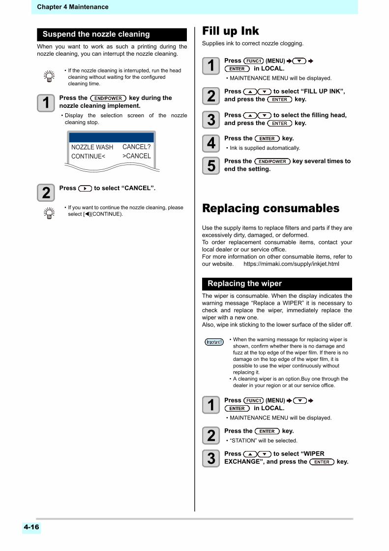
4-16
Chapter 4 Maintenance
Suspend the nozzle cleaning
When you want to work as such a printing during thenozzle cleaning, you can interrupt the nozzle cleaning.
1 Press the key during the nozzle cleaning implement.
• Display the selection screen of the nozzlecleaning stop.
2 Press to select “CANCEL”.
Fill up InkSupplies ink to correct nozzle clogging.
1 Press (MENU) in LOCAL.
• MAINTENANCE MENU will be displayed.
2 Press to select “FILL UP INK”, and press the key.
3 Press to select the filling head, and press the key.
4 Press the key.
• Ink is supplied automatically.
5 Press the key several times to end the setting.
Replacing consumablesUse the supply items to replace filters and parts if they areexcessively dirty, damaged, or deformed.To order replacement consumable items, contact yourlocal dealer or our service office.For more information on other consumable items, refer toour website. https://mimaki.com/supply/inkjet.html
Replacing the wiper
The wiper is consumable. When the display indicates thewarning message “Replace a WIPER” it is necessary tocheck and replace the wiper, immediately replace thewiper with a new one.Also, wipe ink sticking to the lower surface of the slider off.
1 Press (MENU) in LOCAL.
• MAINTENANCE MENU will be displayed.
2 Press the key.
• “STATION” will be selected.
3 Press to select “WIPER EXCHANGE”, and press the key.
• If the nozzle cleaning is interrupted, run the head cleaning without waiting for the configured cleaning time.
• If you want to continue the nozzle cleaning, please select [](CONTINUE).
NOZZLE WASH CANCEL?CONTINUE< >CANCEL
• When the warning message for replacing wiper is shown, confirm whether there is no damage and fuzz at the top edge of the wiper film. If there is no damage on the top edge of the wiper film, it is possible to use the wiper continuously without replacing it.
• A cleaning wiper is an option.Buy one through the dealer in your region or at our service office.
4-17
1
2
2
4
5
6
Chapter 4 Maintenance
4 Press the key.
• The carriage will move onto the platen..
5 Remove the wiper.
• Pull out the wiper by holding the protrusions at itsboth ends.
6 Insert a new wiper.
• Insert the wiper by holding the protrusions at itsboth ends.
7 Close the front cover, and press the key.
• After its initial operation, the machine returns toLOCAL.
If a Waste Ink Tank ConfirmationMessage Appears
Ink used in head cleaning, etc. is stored in the waste inktank on the lower right side of the machine.This machinecounts the accumulated amount of discharged ink. Whenthat reaches a specified amount, the machine displays aconfirmation message.(When this message is displayed,consider the replacement of the waste ink tank.)
Confirmation Message in LOCAL
1 The warning message “Check waste ink” is displayed.
2 Check the state of the waste ink tank
• For any difference between the displayed leveland the actual level of discharge amount, carryout the operations described in and after step 3.
• If there is no difference between the displayedlevel and the actual level, and if you replace(dispose of) the waste ink tank, carry out theprocedure described in “Replace the waste inktank with another” ( P.4-18)
3 Press (MENU) in LOCAL.
• MAINTENANCE MENU will be displayed.
4 Press to select “REPLACE WasteInkTank”, and press the key.
5 If the amount of waste ink needs to be adjusted, press the key.
6 Press to adjust the level, and press .
7 Press the key.
Carriage
Projection
Projection
• The message is displayed when it reaches 80% (1.6L ) of the 2L tank.
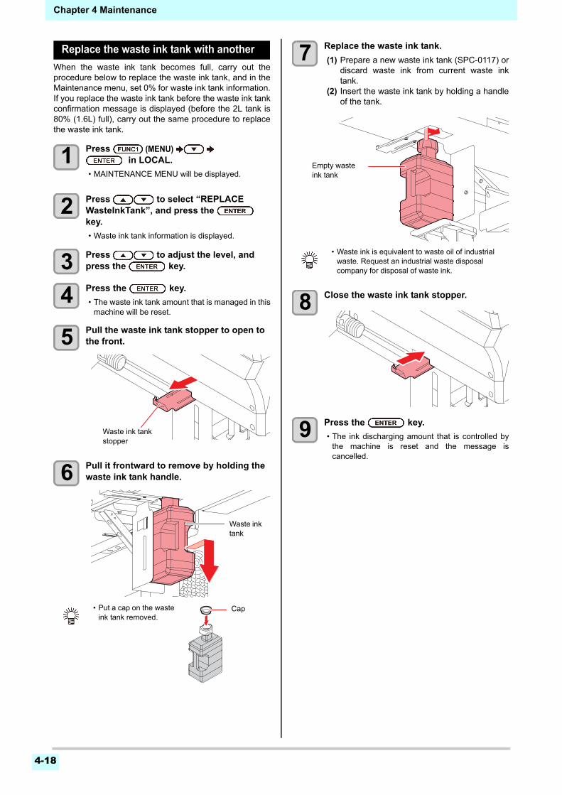
4-18
Chapter 4 Maintenance
Replace the waste ink tank with another
When the waste ink tank becomes full, carry out theprocedure below to replace the waste ink tank, and in theMaintenance menu, set 0% for waste ink tank information.If you replace the waste ink tank before the waste ink tankconfirmation message is displayed (before the 2L tank is80% (1.6L) full), carry out the same procedure to replacethe waste ink tank.
1 Press (MENU) in LOCAL.
• MAINTENANCE MENU will be displayed.
2 Press to select “REPLACE WasteInkTank”, and press the key.
• Waste ink tank information is displayed.
3 Press to adjust the level, and press the key.
4 Press the key.
• The waste ink tank amount that is managed in thismachine will be reset.
5 Pull the waste ink tank stopper to open to the front.
6 Pull it frontward to remove by holding the waste ink tank handle.
7 Replace the waste ink tank.
(1) Prepare a new waste ink tank (SPC-0117) ordiscard waste ink from current waste inktank.
(2) Insert the waste ink tank by holding a handleof the tank.
8 Close the waste ink tank stopper.
9 Press the key.
• The ink discharging amount that is controlled bythe machine is reset and the message iscancelled.
• Put a cap on the waste ink tank removed.
Waste ink tank stopper
Waste ink tank
Cap
• Waste ink is equivalent to waste oil of industrial waste. Request an industrial waste disposal company for disposal of waste ink.
Empty waste ink tank
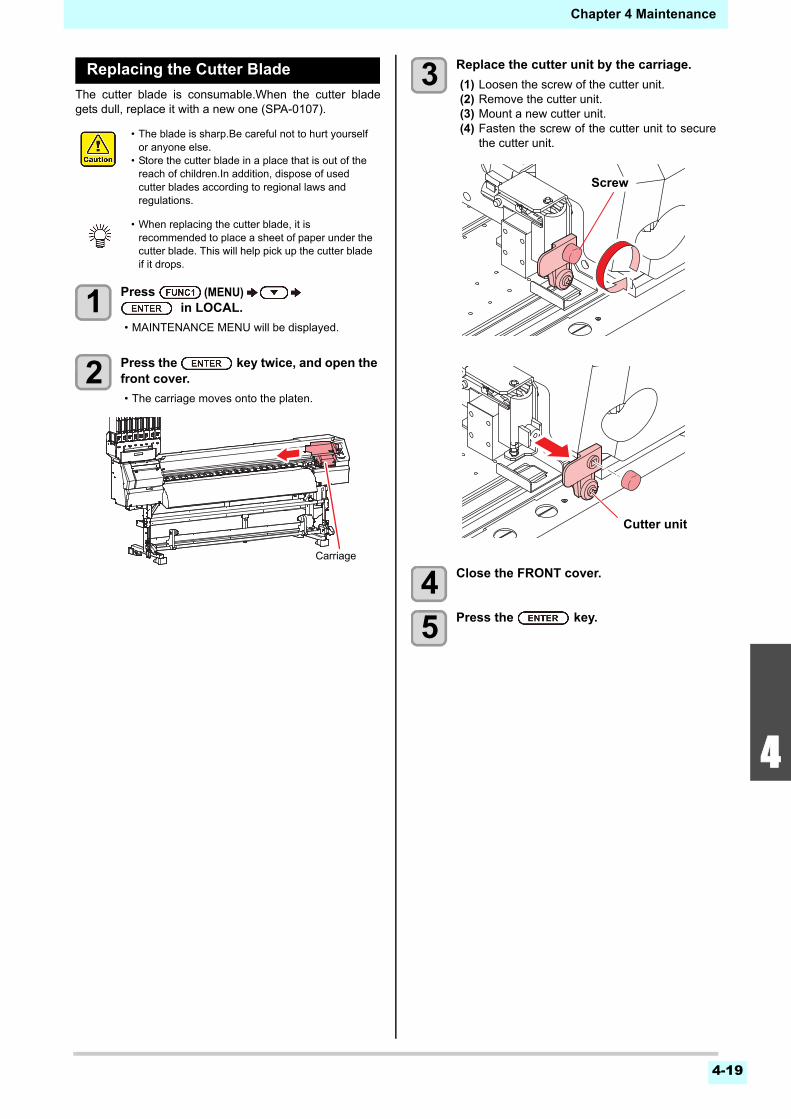
4-19
1
2
2
4
5
6
Chapter 4 Maintenance
Replacing the Cutter Blade
The cutter blade is consumable.When the cutter bladegets dull, replace it with a new one (SPA-0107).
1 Press (MENU) in LOCAL.
• MAINTENANCE MENU will be displayed.
2 Press the key twice, and open the front cover.
• The carriage moves onto the platen.
3 Replace the cutter unit by the carriage.
(1) Loosen the screw of the cutter unit.(2) Remove the cutter unit.(3) Mount a new cutter unit.(4) Fasten the screw of the cutter unit to secure
the cutter unit.
4 Close the FRONT cover.
5 Press the key.
• The blade is sharp.Be careful not to hurt yourself or anyone else.
• Store the cutter blade in a place that is out of the reach of children.In addition, dispose of used cutter blades according to regional laws and regulations.
• When replacing the cutter blade, it is recommended to place a sheet of paper under the cutter blade. This will help pick up the cutter blade if it drops.
Carriage
Screw
Cutter unit
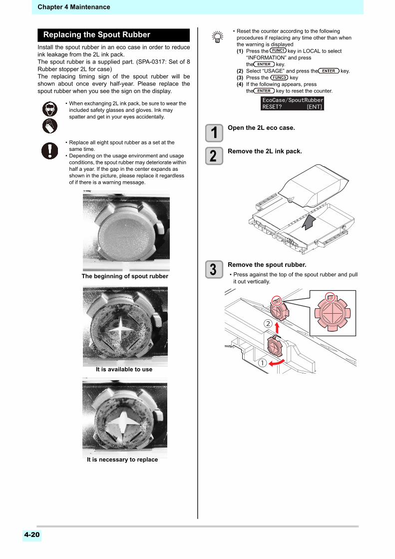
4-20
Chapter 4 Maintenance
Replacing the Spout Rubber
Install the spout rubber in an eco case in order to reduceink leakage from the 2L ink pack.The spout rubber is a supplied part. (SPA-0317: Set of 8Rubber stopper 2L for case)The replacing timing sign of the spout rubber will beshown about once every half-year. Please replace thespout rubber when you see the sign on the display.
1 Open the 2L eco case.
2 Remove the 2L ink pack.
3 Remove the spout rubber.
• Press against the top of the spout rubber and pullit out vertically.
• When exchanging 2L ink pack, be sure to wear the included safety glasses and gloves. Ink mayspatter and get in your eyes accidentally.
• Replace all eight spout rubber as a set at thesame time.
• Depending on the usage environment and usageconditions, the spout rubber may deteriorate withinhalf a year. If the gap in the center expands asshown in the picture, please replace it regardlessof if there is a warning message.
The beginning of spout rubber
It is available to use
It is necessary to replace
• Reset the counter according to the followingprocedures if replacing any time other than whenthe warning is displayed(1) Press the key in LOCAL to select
“INFORMATION” and press the key.
(2) Select “USAGE” and press the key.(3) Press the key(4) If the following appears, press
the key to reset the counter.
[ENT]
①
②
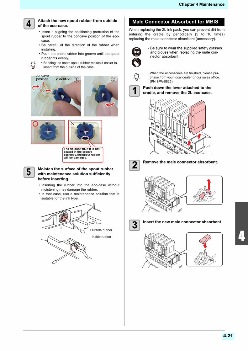
4-21
1
2
2
4
5
6
Chapter 4 Maintenance
4 Attach the new spout rubber from outside of the eco-case.
• Insert it aligning the positioning protrusion of thespout rubber to the concave position of the eco-case.
• Be careful of the direction of the rubber wheninstalling.
• Push the entire rubber into groove until the spoutrubber fits evenly.
5 Moisten the surface of the spout rubber with maintenance solution sufficiently before inserting.
• Inserting the rubber into the eco-case withoutmoistening may damage the rubber.
• In that case, use a maintenance solution that issuitable for the ink type.
Male Connector Absorbent for MBIS
When replacing the 2L ink pack, you can prevent dirt fromentering the cradle by periodically (5 to 10 times)replacing the male connector absorbent (accessory).
1 Push down the lever attached to the cradle, and remove the 2L eco-case.
2 Remove the male connector absorbent.
3 Insert the new male connector absorbent.
• Bending the entire spout rubber makes it easier toinsert from the outside of the case.
① ②concaveposition protrusion
〇〇 ×
The rib don't fit. If it is not seated in the groove correctly, the spout rubber will be damaged.
Inside rubber
Outside rubber
• Be sure to wear the supplied safety glassesand gloves when replacing the male con-nector absorbent.
• When the accessories are finished, please pur-chase from your local dealer or our sales office.(PN:SPA-0625)
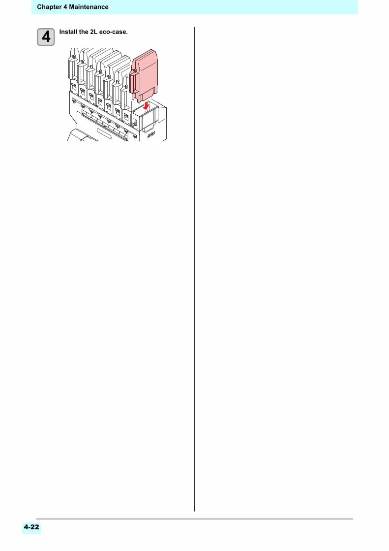
4-22
Chapter 4 Maintenance
4 Install the 2L eco-case.

This chapter
describes the corrective measures to be taken for a phenomenon suspected to be trou-ble and the procedures to clear the error number displayed on the LCD.
Troubleshooting ...............................................................................5-2Power does not turn on ................................................................... 5-2The machine does not start printing ................................................ 5-2Media get jammed / media is soiled ................................................ 5-2The heater’s temperature will not rise to the set level ..................... 5-3Image quality is poor ....................................................................... 5-3Nozzle is clogged ............................................................................ 5-3Ink IC warning appears.................................................................... 5-3When the ink leakage occurs .......................................................... 5-4
Warning / Error Messages ...............................................................5-5Warning messages.......................................................................... 5-5Error messages ............................................................................... 5-8
Chapter 5
Troubleshooting
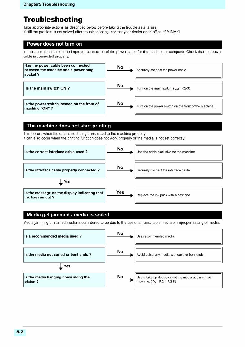
Chapter5 Troubleshooting
5-2
TroubleshootingTake appropriate actions as described below before taking the trouble as a failure.If still the problem is not solved after troubleshooting, contact your dealer or an office of MIMAKI.
Power does not turn on
In most cases, this is due to improper connection of the power cable for the machine or computer. Check that the powercable is connected properly.
The machine does not start printing
This occurs when the data is not being transmitted to the machine properly.It can also occur when the printing function does not work properly or the media is not set correctly.
Media get jammed / media is soiled
Media jamming or stained media is considered to be due to the use of an unsuitable media or improper setting of media.
Has the power cable been connected between the machine and a power plug socket ?
Securely connect the power cable.
Is the main switch ON ? Turn on the main switch. ( P.2-3)
Is the power switch located on the front of machine "ON" ?
Turn on the power switch on the front of the machine.
Is the correct interface cable used ? Use the cable exclusive for the machine.
Is the interface cable properly connected ? Securely connect the interface cable.
Yes
Is the message on the display indicating that ink has run out ?
Replace the ink pack with a new one.
Is a recommended media used ? Use recommended media.
Is the media not curled or bent ends ? Avoid using any media with curls or bent ends.
Yes
Is the media hanging down along the platen ?
Use a take-up device or set the media again on the machine. ( P.2-4,P.2-8)
No
No
No
No
No
Yes
No
No
No
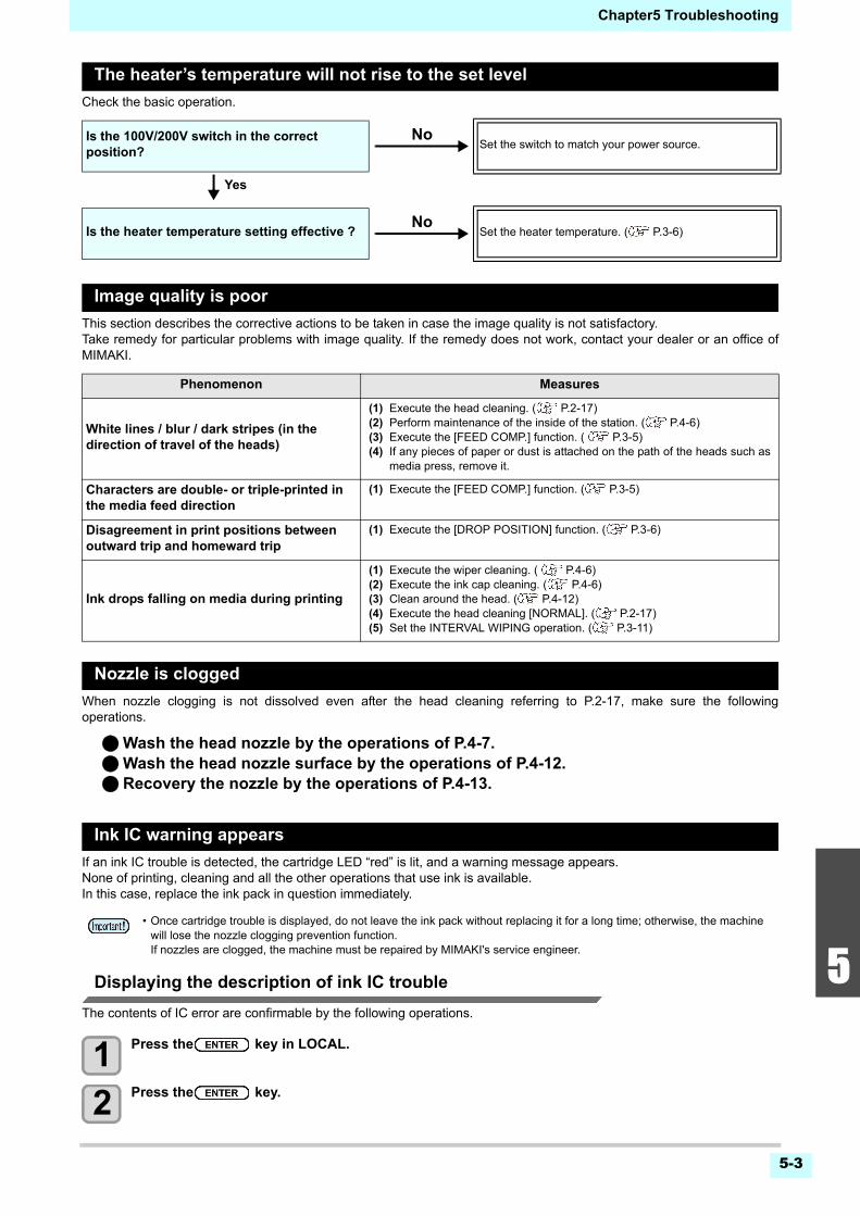
5-3
1
2
2
2
5
6
Chapter5 Troubleshooting
The heater’s temperature will not rise to the set level
Check the basic operation.
Image quality is poor
This section describes the corrective actions to be taken in case the image quality is not satisfactory.Take remedy for particular problems with image quality. If the remedy does not work, contact your dealer or an office ofMIMAKI.
Nozzle is clogged
When nozzle clogging is not dissolved even after the head cleaning referring to P.2-17, make sure the followingoperations.
Wash the head nozzle by the operations of P.4-7.Wash the head nozzle surface by the operations of P.4-12. Recovery the nozzle by the operations of P.4-13.
Ink IC warning appears
If an ink IC trouble is detected, the cartridge LED “red” is lit, and a warning message appears.None of printing, cleaning and all the other operations that use ink is available.In this case, replace the ink pack in question immediately.
Displaying the description of ink IC trouble
The contents of IC error are confirmable by the following operations.
1 Press the key in LOCAL.
2 Press the key.
Is the 100V/200V switch in the correct position?
Set the switch to match your power source.
Yes
Is the heater temperature setting effective ? Set the heater temperature. ( P.3-6)
Phenomenon Measures
White lines / blur / dark stripes (in the direction of travel of the heads)
(1) Execute the head cleaning. ( P.2-17)(2) Perform maintenance of the inside of the station. ( P.4-6)(3) Execute the [FEED COMP.] function. ( P.3-5)(4) If any pieces of paper or dust is attached on the path of the heads such as
media press, remove it.
Characters are double- or triple-printed in the media feed direction
(1) Execute the [FEED COMP.] function. ( P.3-5)
Disagreement in print positions between outward trip and homeward trip
(1) Execute the [DROP POSITION] function. ( P.3-6)
Ink drops falling on media during printing
(1) Execute the wiper cleaning. ( P.4-6)(2) Execute the ink cap cleaning. ( P.4-6)(3) Clean around the head. ( P.4-12)(4) Execute the head cleaning [NORMAL]. ( P.2-17)(5) Set the INTERVAL WIPING operation. ( P.3-11)
• Once cartridge trouble is displayed, do not leave the ink pack without replacing it for a long time; otherwise, the machine will lose the nozzle clogging prevention function.If nozzles are clogged, the machine must be repaired by MIMAKI's service engineer.
No
No

Chapter5 Troubleshooting
5-4
When the ink leakage occurs
In case of ink leakage, please turn off the main power, unplug the power cable and contact your local distributor, our salesoffice, or service center.
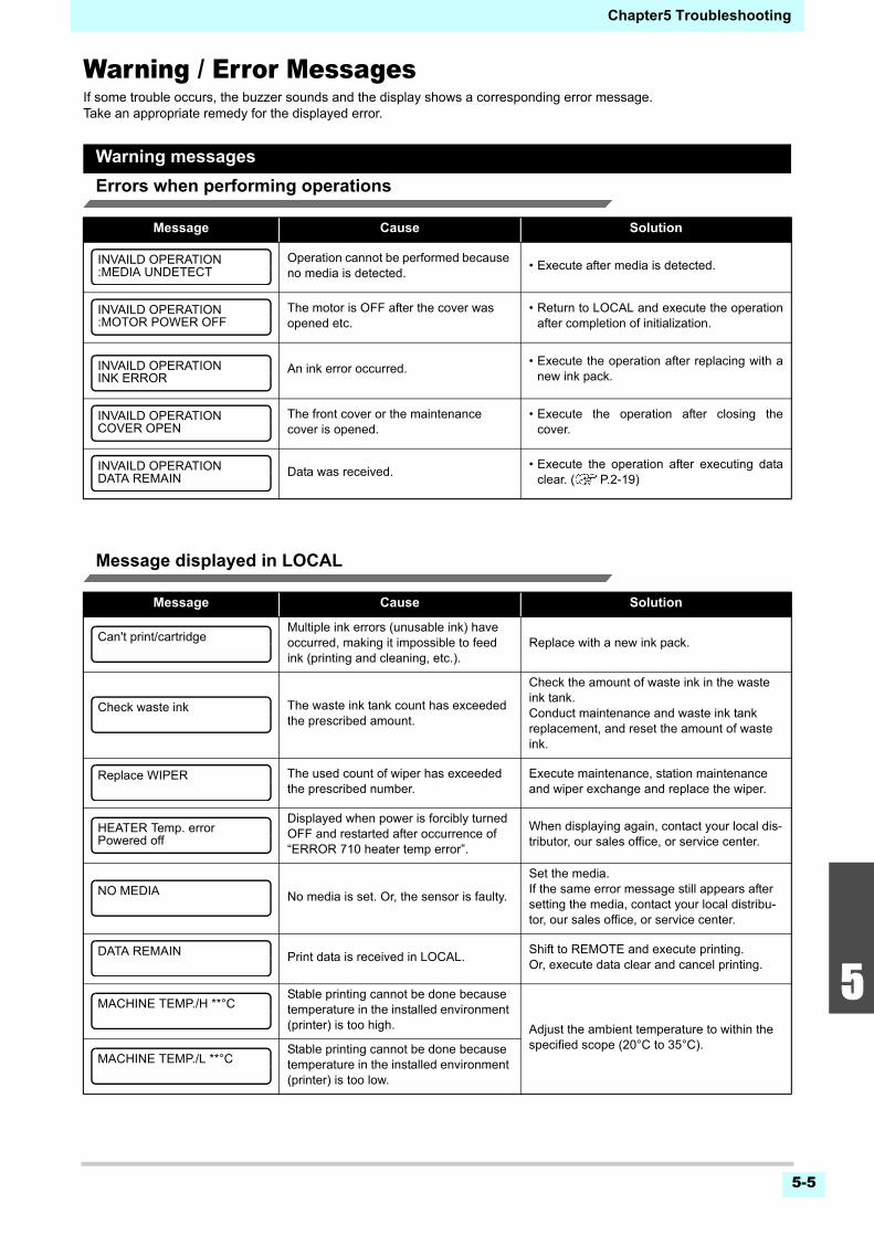
5-5
1
2
2
2
5
6
Chapter5 Troubleshooting
Warning / Error MessagesIf some trouble occurs, the buzzer sounds and the display shows a corresponding error message.Take an appropriate remedy for the displayed error.
Warning messages
Errors when performing operations
Message displayed in LOCAL
Message Cause Solution
Operation cannot be performed because no media is detected.
• Execute after media is detected.
The motor is OFF after the cover was opened etc.
• Return to LOCAL and execute the operationafter completion of initialization.
An ink error occurred.• Execute the operation after replacing with a
new ink pack.
The front cover or the maintenance cover is opened.
• Execute the operation after closing thecover.
Data was received.• Execute the operation after executing data
clear. ( P.2-19)
Message Cause Solution
Multiple ink errors (unusable ink) have occurred, making it impossible to feed ink (printing and cleaning, etc.).
Replace with a new ink pack.
The waste ink tank count has exceeded the prescribed amount.
Check the amount of waste ink in the waste ink tank.Conduct maintenance and waste ink tank replacement, and reset the amount of waste ink.
The used count of wiper has exceeded the prescribed number.
Execute maintenance, station maintenance and wiper exchange and replace the wiper.
Displayed when power is forcibly turned OFF and restarted after occurrence of “ERROR 710 heater temp error”.
When displaying again, contact your local dis-tributor, our sales office, or service center.
No media is set. Or, the sensor is faulty.
Set the media.If the same error message still appears after setting the media, contact your local distribu-tor, our sales office, or service center.
Print data is received in LOCAL.Shift to REMOTE and execute printing.Or, execute data clear and cancel printing.
Stable printing cannot be done because temperature in the installed environment (printer) is too high. Adjust the ambient temperature to within the
specified scope (20°C to 35°C).Stable printing cannot be done because temperature in the installed environment (printer) is too low.
INVAILD OPERATION:MEDIA UNDETECT
INVAILD OPERATION:MOTOR POWER OFF
INVAILD OPERATIONINK ERROR
INVAILD OPERATIONCOVER OPEN
INVAILD OPERATIONDATA REMAIN
Can't print/cartridge
Check waste ink
Replace WIPER
HEATER Temp. errorPowered off
NO MEDIA
DATA REMAIN
MACHINE TEMP./H **°C
MACHINE TEMP./L **°C
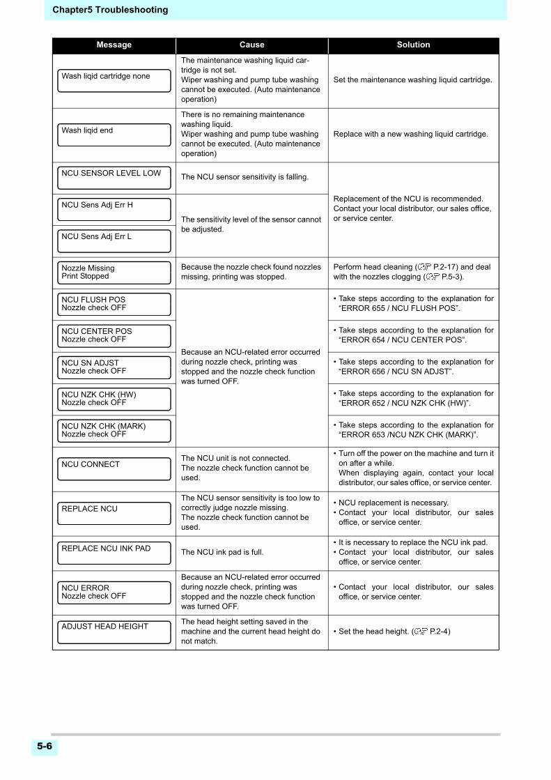
Chapter5 Troubleshooting
5-6
The maintenance washing liquid car-tridge is not set.Wiper washing and pump tube washing cannot be executed. (Auto maintenance operation)
Set the maintenance washing liquid cartridge.
There is no remaining maintenance washing liquid.Wiper washing and pump tube washing cannot be executed. (Auto maintenance operation)
Replace with a new washing liquid cartridge.
The NCU sensor sensitivity is falling.
Replacement of the NCU is recommended.Contact your local distributor, our sales office, or service center.The sensitivity level of the sensor cannot
be adjusted.
Because the nozzle check found nozzles missing, printing was stopped.
Perform head cleaning ( P.2-17) and deal with the nozzles clogging ( P.5-3).
Because an NCU-related error occurred during nozzle check, printing was stopped and the nozzle check function was turned OFF.
• Take steps according to the explanation for“ERROR 655 / NCU FLUSH POS”.
• Take steps according to the explanation for“ERROR 654 / NCU CENTER POS”.
• Take steps according to the explanation for“ERROR 656 / NCU SN ADJST”.
• Take steps according to the explanation for“ERROR 652 / NCU NZK CHK (HW)”.
• Take steps according to the explanation for“ERROR 653 /NCU NZK CHK (MARK)”.
The NCU unit is not connected.The nozzle check function cannot be used.
• Turn off the power on the machine and turn iton after a while.When displaying again, contact your localdistributor, our sales office, or service center.
The NCU sensor sensitivity is too low to correctly judge nozzle missing.The nozzle check function cannot be used.
• NCU replacement is necessary.• Contact your local distributor, our sales
office, or service center.
The NCU ink pad is full.• It is necessary to replace the NCU ink pad.• Contact your local distributor, our sales
office, or service center.
Because an NCU-related error occurred during nozzle check, printing was stopped and the nozzle check function was turned OFF.
• Contact your local distributor, our salesoffice, or service center.
The head height setting saved in the machine and the current head height do not match.
• Set the head height. ( P.2-4)
Message Cause Solution
Wash liqid cartridge none
Wash liqid end
NCU SENSOR LEVEL LOW
NCU Sens Adj Err H
NCU Sens Adj Err L
Nozzle MissingPrint Stopped
NCU FLUSH POSNozzle check OFF
NCU CENTER POSNozzle check OFF
NCU SN ADJSTNozzle check OFF
NCU NZK CHK (HW)Nozzle check OFF
NCU NZK CHK (MARK)Nozzle check OFF
NCU CONNECT
REPLACE NCU
REPLACE NCU INK PAD
NCU ERRORNozzle check OFF
ADJUST HEAD HEIGHT
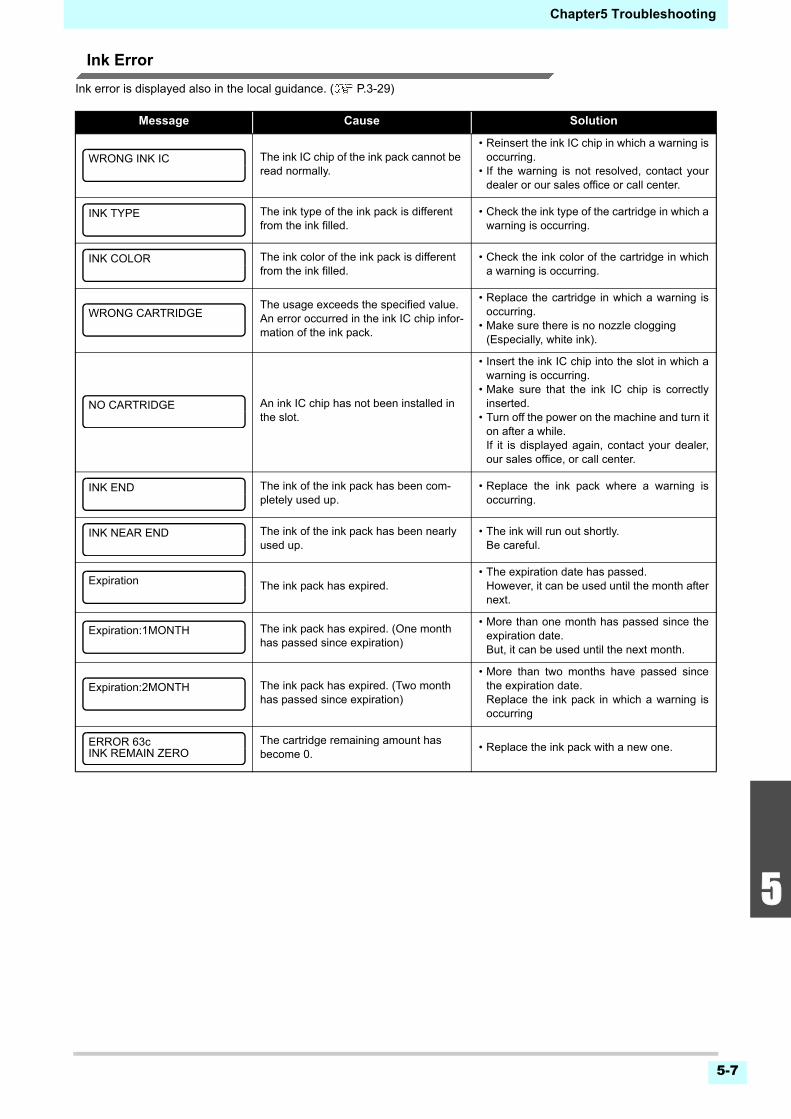
5-7
1
2
2
2
5
6
Chapter5 Troubleshooting
Ink Error
Ink error is displayed also in the local guidance. ( P.3-29)
Message Cause Solution
The ink IC chip of the ink pack cannot be read normally.
• Reinsert the ink IC chip in which a warning isoccurring.
• If the warning is not resolved, contact yourdealer or our sales office or call center.
The ink type of the ink pack is different from the ink filled.
• Check the ink type of the cartridge in which awarning is occurring.
The ink color of the ink pack is different from the ink filled.
• Check the ink color of the cartridge in whicha warning is occurring.
The usage exceeds the specified value.An error occurred in the ink IC chip infor-mation of the ink pack.
• Replace the cartridge in which a warning isoccurring.
• Make sure there is no nozzle clogging(Especially, white ink).
An ink IC chip has not been installed in the slot.
• Insert the ink IC chip into the slot in which awarning is occurring.
• Make sure that the ink IC chip is correctlyinserted.
• Turn off the power on the machine and turn iton after a while. If it is displayed again, contact your dealer,our sales office, or call center.
The ink of the ink pack has been com-pletely used up.
• Replace the ink pack where a warning isoccurring.
The ink of the ink pack has been nearlyused up.
• The ink will run out shortly.Be careful.
The ink pack has expired.• The expiration date has passed.
However, it can be used until the month afternext.
The ink pack has expired. (One month has passed since expiration)
• More than one month has passed since theexpiration date.But, it can be used until the next month.
The ink pack has expired. (Two month has passed since expiration)
• More than two months have passed sincethe expiration date.Replace the ink pack in which a warning isoccurring
The cartridge remaining amount has become 0.
• Replace the ink pack with a new one.
WRONG INK IC
INK TYPE
INK COLOR
WRONG CARTRIDGE
NO CARTRIDGE
INK END
INK NEAR END
Expiration
Expiration:1MONTH
Expiration:2MONTH
ERROR 63cINK REMAIN ZERO
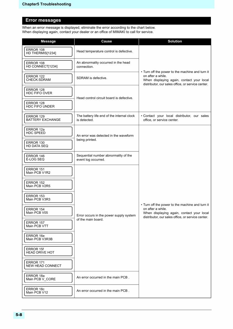
Chapter5 Troubleshooting
5-8
Error messages
When an error message is displayed, eliminate the error according to the chart below.When displaying again, contact your dealer or an office of MIMAKI to call for service.
Message Cause Solution
Head temperature control is defective.
• Turn off the power to the machine and turn iton after a while.When displaying again, contact your localdistributor, our sales office, or service center.
An abnormality occurred in the head connection.
SDRAM is defective.
Head control circuit board is defective.
The battery life end of the internal clock is detected.
• Contact your local distributor, our salesoffice, or service center.
An error was detected in the waveform being printed.
• Turn off the power to the machine and turn iton after a while.When displaying again, contact your localdistributor, our sales office, or service center.
Sequential number abnormality of the event log occurred.
Error occurs in the power supply system of the main board.
An error occurred in the main PCB .
An error occurred in the main PCB .
ERROR 108HD THERMIS[1234]
ERROR 108HD CONNECT[1234]
ERROR 122CHECK:SDRAM
ERROR 128HDC FIFO OVER
ERROR 128HDC FIFO UNDER
ERROR 129BATTERY EXCHANGE
ERROR 12aHDC SPEED
ERROR 130HD DATA SEQ
ERROR 146E-LOG SEQ
ERROR 151Main PCB V1R2
ERROR 152Main PCB V2R5
ERROR 153Main PCB V3R3
ERROR 154Main PCB V05
ERROR 157Main PCB VTT
ERROR 16eMain PCB V3R3B
ERROR 15fHEAD DRIVE HOT
ERROR 171NEW HEAD CONNECT
ERROR 18aMain PCB V_CORE
ERROR 18cMain PCB V12
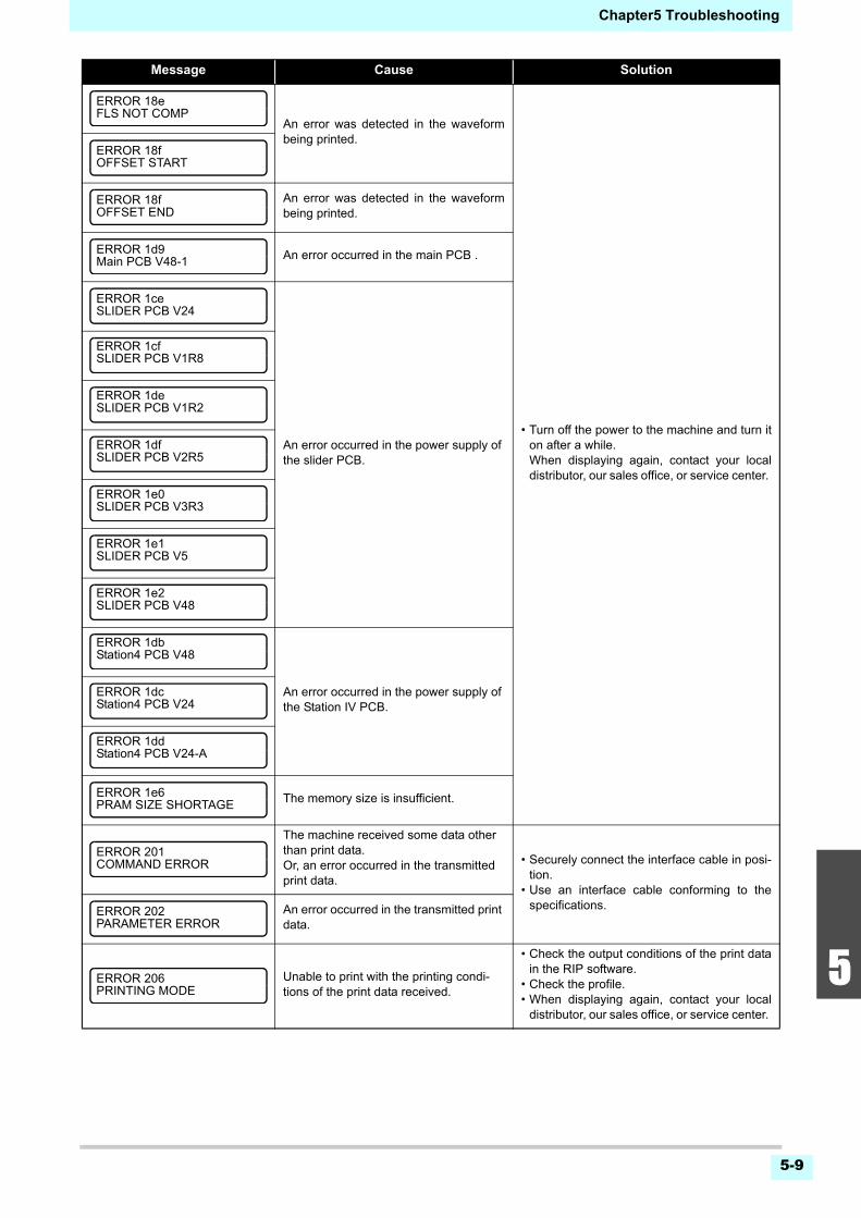
5-9
1
2
2
2
5
6
Chapter5 Troubleshooting
An error was detected in the waveformbeing printed.
• Turn off the power to the machine and turn iton after a while.When displaying again, contact your localdistributor, our sales office, or service center.
An error was detected in the waveformbeing printed.
An error occurred in the main PCB .
An error occurred in the power supply of the slider PCB.
An error occurred in the power supply of the Station IV PCB.
The memory size is insufficient.
The machine received some data other than print data.Or, an error occurred in the transmitted print data.
• Securely connect the interface cable in posi-tion.
• Use an interface cable conforming to thespecifications.An error occurred in the transmitted print
data.
Unable to print with the printing condi-tions of the print data received.
• Check the output conditions of the print datain the RIP software.
• Check the profile.• When displaying again, contact your local
distributor, our sales office, or service center.
Message Cause Solution
ERROR 18eFLS NOT COMP
ERROR 18fOFFSET START
ERROR 18fOFFSET END
ERROR 1d9Main PCB V48-1
ERROR 1ceSLIDER PCB V24
ERROR 1cfSLIDER PCB V1R8
ERROR 1deSLIDER PCB V1R2
ERROR 1dfSLIDER PCB V2R5
ERROR 1e0SLIDER PCB V3R3
ERROR 1e1SLIDER PCB V5
ERROR 1e2SLIDER PCB V48
ERROR 1dbStation4 PCB V48
ERROR 1dcStation4 PCB V24
ERROR 1ddStation4 PCB V24-A
ERROR 1e6PRAM SIZE SHORTAGE
ERROR 201COMMAND ERROR
ERROR 202PARAMETER ERROR
ERROR 206PRINTING MODE
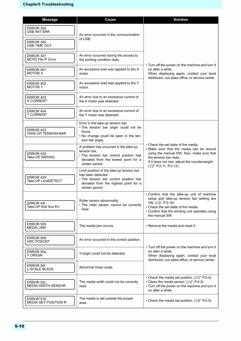
Chapter5 Troubleshooting
5-10
An error occurred in the communication of USB.
• Turn off the power on the machine and turn iton after a while.When displaying again, contact your localdistributor, our sales office, or service center.
An error occurred during the access to the printing condition data.
An excessive load was applied to the X motor.
An excessive load was applied to the Y motor.
An error due to an excessive current of the X motor was detected.
An error due to an excessive current of the Y motor was detected.
Error in the take-up tension bar.• The tension bar origin could not be
found.• No change could be seen in the ten-
sion bar angle.• Check the set state of the media.• Make sure that the media can be wound
using the manual SW. Also, make sure thatthe tension bar rises.If it does not rise, adjust the counterweight.( P.2-11, P.2-12)
A problem has occurred in the take-up tension bar.• The tension bar control position has
deviated from the lowest point for acertain period.
Limit position of the take-up tension bar has been detected.• The tension bar control position has
deviated from the highest point for acertain period.
Roller sensor abnormality• The roller sensor cannot be correctly
read.
• Confirm that the take-up unit of machinesetup and take-up tension bar setting areON. ( P.3-16)
• Check the set state of the media.• Confirm that the winding unit operates using
the manual SW.
The media jam occurs. • Remove the media and reset it.
An error occurred in the control position.
• Turn off the power on the machine and turn iton after a while.When displaying again, contact your localdistributor, our sales office, or service center.
Y-origin could not be detected.
Abnormal linear scale.
The media width could not be correctly read.
• Check the media set position. ( P.2-4)• Clean the media sensor. ( P.4-3)• Turn off the power on the machine and turn it
on after a while.
The media is set outside the proper area.
• Check the media set position. ( P.2-5)
Message Cause Solution
ERROR 304USB INIT ERR
ERROR 305USB TIME OUT
ERROR 307MCFD File IF Error
ERROR 401MOTOR X
ERROR 402MOTOR Y
ERROR 403X CURRENT
ERROR 404Y CURRENT
ERROR 423TAKE-UP TENSION-BAR
ERROR 425Take-UP WRONG
ERROR 429Take-UP LimitDETECT
ERROR 44fTake-UP Roll Sns Err
ERROR 505MEDIA JAM
ERROR 509HDC POSCNT
ERROR 50aY ORIGIN
ERROR 50fL-SCALE BLACK
ERROR 52cMEDIA WIDTH SENSOR
ERROR 516MEDIA SET POSITION R
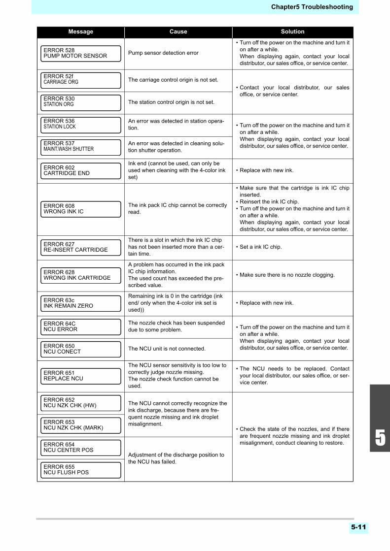
5-11
1
2
2
2
5
6
Chapter5 Troubleshooting
Pump sensor detection error
• Turn off the power on the machine and turn iton after a while.When displaying again, contact your localdistributor, our sales office, or service center.
The carriage control origin is not set.
• Contact your local distributor, our salesoffice, or service center.
The station control origin is not set.
An error was detected in station opera-tion. • Turn off the power on the machine and turn it
on after a while. When displaying again, contact your localdistributor, our sales office, or service center. An error was detected in cleaning solu-
tion shutter operation.
Ink end (cannot be used, can only be used when cleaning with the 4-color ink set)
• Replace with new ink.
The ink pack IC chip cannot be correctly read.
• Make sure that the cartridge is ink IC chipinserted.
• Reinsert the ink IC chip.• Turn off the power on the machine and turn it
on after a while. When displaying again, contact your localdistributor, our sales office, or service center.
There is a slot in which the ink IC chip has not been inserted more than a cer-tain time.
• Set a ink IC chip.
A problem has occurred in the ink pack IC chip information.The used count has exceeded the pre-scribed value.
• Make sure there is no nozzle clogging.
Remaining ink is 0 in the cartridge (ink end/ only when the 4-color ink set is used))
• Replace with new ink.
The nozzle check has been suspended due to some problem. • Turn off the power on the machine and turn it
on after a while. When displaying again, contact your localdistributor, our sales office, or service center. The NCU unit is not connected.
The NCU sensor sensitivity is too low to correctly judge nozzle missing.The nozzle check function cannot be used.
• The NCU needs to be replaced. Contactyour local distributor, our sales office, or ser-vice center.
The NCU cannot correctly recognize the ink discharge, because there are fre-quent nozzle missing and ink droplet misalignment.
• Check the state of the nozzles, and if thereare frequent nozzle missing and ink dropletmisalignment, conduct cleaning to restore.
Adjustment of the discharge position to the NCU has failed.
Message Cause Solution
ERROR 528PUMP MOTOR SENSOR
ERROR 52fCARRIAGE ORG
ERROR 530STATION ORG
ERROR 536STATION LOCK
ERROR 537MAINT.WASH SHUTTER
ERROR 602CARTRIDGE END
ERROR 608WRONG INK IC
ERROR 627RE-INSERT CARTRIDGE
ERROR 628WRONG INK CARTRIDGE
ERROR 63cINK REMAIN ZERO
ERROR 64CNCU ERROR
ERROR 650NCU CONECT
ERROR 651REPLACE NCU
ERROR 652NCU NZK CHK (HW)
ERROR 653NCU NZK CHK (MARK)
ERROR 654NCU CENTER POS
ERROR 655NCU FLUSH POS
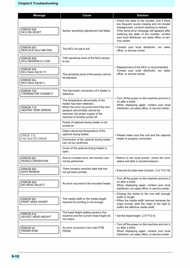
Chapter5 Troubleshooting
5-12
Sensor sensitivity adjustment has failed.
• Check the state of the nozzles, and if thereare frequent nozzle missing and ink dropletmisalignment, conduct cleaning to restore.If the same error message still appears afterrestoring the state of the nozzles, contactyour local distributor, our sales office, or ser-vice center.
The NCU ink pat is full.• Contact your local distributor, our sales
office, or service center.
THE sensitivity level of the NCU sensor is low.
• Replacement of the NCU is recommended.Contact your local distributor, our salesoffice, or service center.The sensitivity level of the sensor cannot
be adjusted.
The thermistor connection of a heater is defective.
• Turn off the power on the machine and turn iton after a while. When displaying again, contact your localdistributor, our sales office, or service center.
The temperature abnormality of the heater has been detected.When this error occurred and if the tem-perature abnormality cannot be resolved, the power supply of the machine is forcibly turned off.
Power of optional drying heater is not turned on.
• Please make sure this unit and the optionalheater is properly connected.
Detect abnormal temperature of the optional drying heater.
Connection of the optional drying heater can not be confirmed.
Cover of the optional drying heater is open.
Due to a certain error, the function can-not be performed.
• Return to the local screen, check the errorstatus and take a countermeasure.
There remains received data that has not yet been printed.
• Execute the data clear function. ( P.2-19)
An error occurred in the mounted heads.
• Turn off the power on the machine and turn iton after a while. When displaying again, contact your localdistributor, our sales office, or service center.
The media width or the media length required for printing is not enough.
• Change the media to the one with enoughwidth or length.
• When the media width narrows because theorigin moved, slide the origin to the right towiden the effective media width.
The head height setting saved in the machine and the current head height do not match.
• Set the head height. ( P.2-4)
An error occurred in the main PCB FROM.
• Turn off the power on the machine and turn iton after a while.When displaying again, contact your localdistributor, our sales office, or service center.
Message Cause Solution
ERROR 656NCU SN ADJST
ERROR 657REPLACE NCU INK PAD
ERROR 658NCU SENSOR LV LOW
ERROR 65bNCU Sens Adj Err H
ERROR 65cNCU Sens Adj Err L
ERROR 702THERMISTOR CONNECT
ERROR 710HEATER TEMP ERROR
ERROR 71bFAN HEATER ERROR
ERROR 901INVAILD OPERATION
ERROR 902DATA REMAIN
ERROR 90dNO HEAD SELECT
ERROR 90fPRINT AREA SHORT
ERROR 91aADJUST HEAD HEIGHT
ERROR 04PARAM ROM
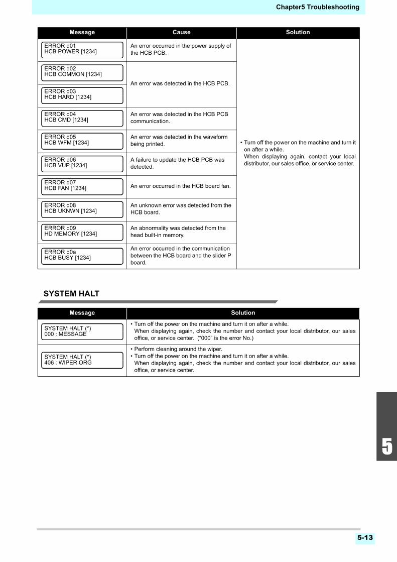
5-13
1
2
2
2
5
6
Chapter5 Troubleshooting
SYSTEM HALT
An error occurred in the power supply of the HCB PCB.
• Turn off the power on the machine and turn iton after a while.When displaying again, contact your localdistributor, our sales office, or service center.
An error was detected in the HCB PCB.
An error was detected in the HCB PCB communication.
An error was detected in the waveform being printed.
A failure to update the HCB PCB was detected.
An error occurred in the HCB board fan.
An unknown error was detected from the HCB board.
An abnormality was detected from the head built-in memory.
An error occurred in the communication between the HCB board and the slider P board.
Message Solution
• Turn off the power on the machine and turn it on after a while.When displaying again, check the number and contact your local distributor, our salesoffice, or service center. (“000” is the error No.)
• Perform cleaning around the wiper.• Turn off the power on the machine and turn it on after a while.
When displaying again, check the number and contact your local distributor, our salesoffice, or service center.
Message Cause Solution
ERROR d01HCB POWER [1234]
ERROR d02HCB COMMON [1234]
ERROR d03HCB HARD [1234]
ERROR d04HCB CMD [1234]
ERROR d05HCB WFM [1234]
ERROR d06HCB VUP [1234]
ERROR d07HCB FAN [1234]
ERROR d08HCB UKNWN [1234]
ERROR d09HD MEMORY [1234]
ERROR d0aHCB BUSY [1234]
SYSTEM HALT (*)000 : MESSAGE
SYSTEM HALT (*)406 : WIPER ORG

Chapter5 Troubleshooting
5-14

This chapter
contains the lists of the specifications and functions of this machine.
Specifications ..................................................................................6-2Machine specifications .................................................................... 6-2Ink specifications ............................................................................. 6-3
Setting orders depending on ink type ..............................................6-4Setting orders of ink cartridges........................................................ 6-4
Sheet for inquiry ..............................................................................6-5
Chapter 6
Appendix
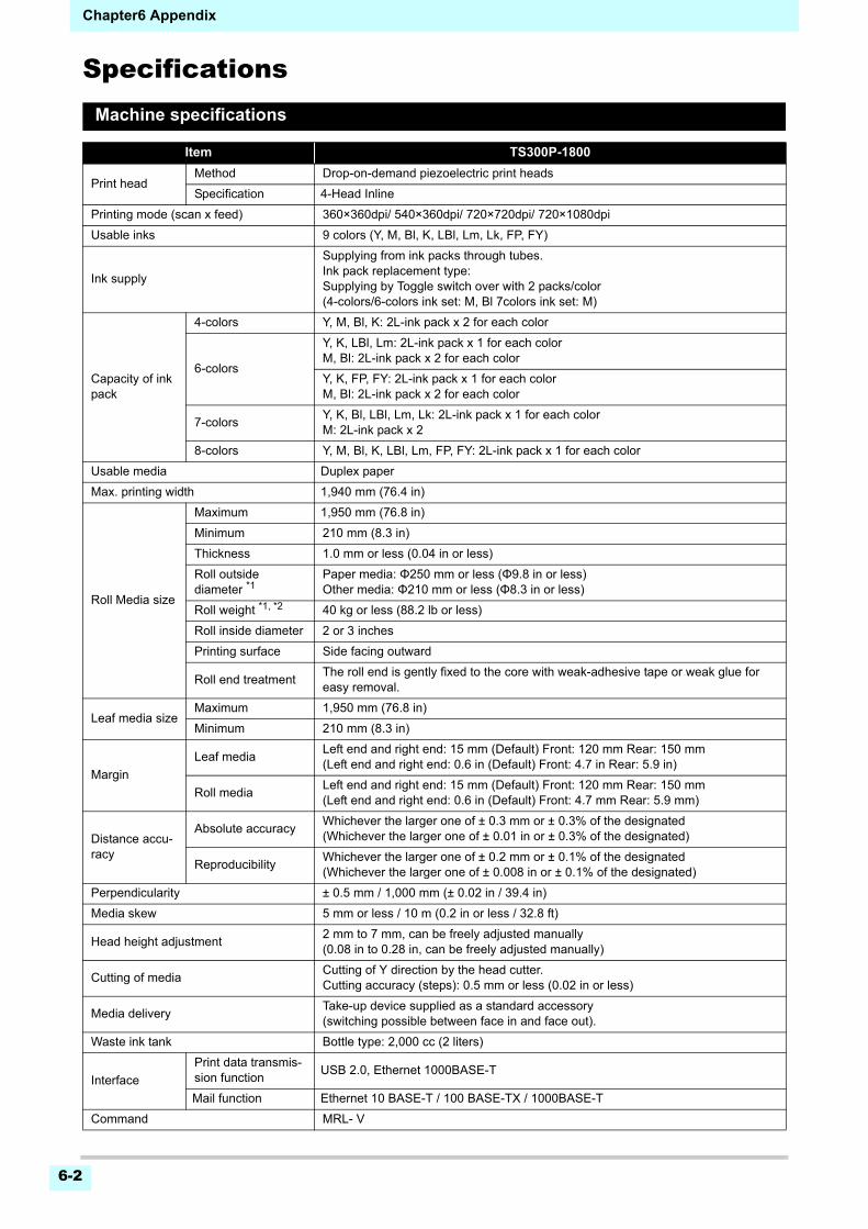
Chapter6 Appendix
6-2
SpecificationsMachine specifications
Item TS300P-1800
Print headMethod Drop-on-demand piezoelectric print heads
Specification 4-Head Inline
Printing mode (scan x feed) 360×360dpi/ 540×360dpi/ 720×720dpi/ 720×1080dpi
Usable inks 9 colors (Y, M, Bl, K, LBl, Lm, Lk, FP, FY)
Ink supply
Supplying from ink packs through tubes.Ink pack replacement type: Supplying by Toggle switch over with 2 packs/color (4-colors/6-colors ink set: M, Bl 7colors ink set: M)
Capacity of ink pack
4-colors Y, M, Bl, K: 2L-ink pack x 2 for each color
6-colors
Y, K, LBl, Lm: 2L-ink pack x 1 for each colorM, Bl: 2L-ink pack x 2 for each color
Y, K, FP, FY: 2L-ink pack x 1 for each colorM, Bl: 2L-ink pack x 2 for each color
7-colorsY, K, Bl, LBl, Lm, Lk: 2L-ink pack x 1 for each colorM: 2L-ink pack x 2
8-colors Y, M, Bl, K, LBl, Lm, FP, FY: 2L-ink pack x 1 for each color
Usable media Duplex paper
Max. printing width 1,940 mm (76.4 in)
Roll Media size
Maximum 1,950 mm (76.8 in)
Minimum 210 mm (8.3 in)
Thickness 1.0 mm or less (0.04 in or less)
Roll outside diameter *1
Paper media: Φ250 mm or less (Φ9.8 in or less)Other media: Φ210 mm or less (Φ8.3 in or less)
Roll weight *1, *2 40 kg or less (88.2 lb or less)
Roll inside diameter 2 or 3 inches
Printing surface Side facing outward
Roll end treatmentThe roll end is gently fixed to the core with weak-adhesive tape or weak glue for easy removal.
Leaf media sizeMaximum 1,950 mm (76.8 in)
Minimum 210 mm (8.3 in)
Margin
Leaf mediaLeft end and right end: 15 mm (Default) Front: 120 mm Rear: 150 mm(Left end and right end: 0.6 in (Default) Front: 4.7 in Rear: 5.9 in)
Roll mediaLeft end and right end: 15 mm (Default) Front: 120 mm Rear: 150 mm(Left end and right end: 0.6 in (Default) Front: 4.7 mm Rear: 5.9 mm)
Distance accu-racy
Absolute accuracyWhichever the larger one of ± 0.3 mm or ± 0.3% of the designated(Whichever the larger one of ± 0.01 in or ± 0.3% of the designated)
ReproducibilityWhichever the larger one of ± 0.2 mm or ± 0.1% of the designated(Whichever the larger one of ± 0.008 in or ± 0.1% of the designated)
Perpendicularity ± 0.5 mm / 1,000 mm (± 0.02 in / 39.4 in)
Media skew 5 mm or less / 10 m (0.2 in or less / 32.8 ft)
Head height adjustment2 mm to 7 mm, can be freely adjusted manually(0.08 in to 0.28 in, can be freely adjusted manually)
Cutting of mediaCutting of Y direction by the head cutter.Cutting accuracy (steps): 0.5 mm or less (0.02 in or less)
Media deliveryTake-up device supplied as a standard accessory (switching possible between face in and face out).
Waste ink tank Bottle type: 2,000 cc (2 liters)
Interface
Print data transmis-sion function
USB 2.0, Ethernet 1000BASE-T
Mail function Ethernet 10 BASE-T / 100 BASE-TX / 1000BASE-T
Command MRL- V
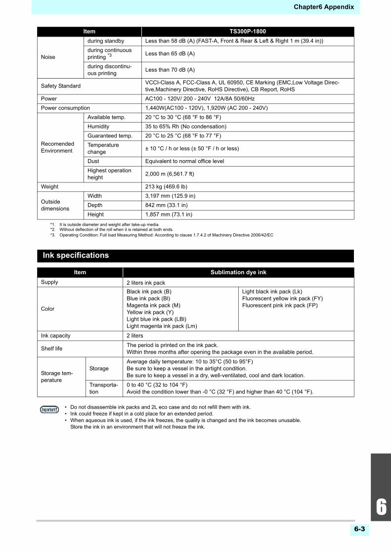
6-3
2
2
2
6
Chapter6 Appendix
Ink specifications
Noise
during standby Less than 58 dB (A) (FAST-A, Front & Rear & Left & Right 1 m (39.4 in))
during continuous printing *3
Less than 65 dB (A)
during discontinu-ous printing
Less than 70 dB (A)
Safety StandardVCCI-Class A, FCC-Class A, UL 60950, CE Marking (EMC,Low Voltage Direc-tive,Machinery Directive, RoHS Directive), CB Report, RoHS
Power AC100 - 120V/ 200 - 240V 12A/8A 50/60Hz
Power consumption 1,440W(AC100 - 120V), 1,920W (AC 200 - 240V)
Recomended Environment
Available temp. 20 °C to 30 °C (68 °F to 86 °F)
Humidity 35 to 65% Rh (No condensation)
Guaranteed temp. 20 °C to 25 °C (68 °F to 77 °F)
Temperature change
± 10 °C / h or less (± 50 °F / h or less)
Dust Equivalent to normal office level
Highest operation height
2,000 m (6,561.7 ft)
Weight 213 kg (469.6 lb)
Outside dimensions
Width 3,197 mm (125.9 in)
Depth 842 mm (33.1 in)
Height 1,857 mm (73.1 in)
*1. It is outside diameter and weight after take-up media. *2. Without deflection of the roll when it is retained at both ends.*3. Operating Condition: Full load Measuring Method: According to clause 1.7.4.2 of Machinery Directive 2006/42/EC
Item Sublimation dye ink
Supply 2 liters ink pack
Color
Black ink pack (B)Blue ink pack (Bl)Magenta ink pack (M)Yellow ink pack (Y)Light blue ink pack (LBl)Light magenta ink pack (Lm)
Light black ink pack (Lk)Fluorescent yellow ink pack (FY)Fluorescent pink ink pack (FP)
Ink capacity 2 liters
Shelf lifeThe period is printed on the ink pack.Within three months after opening the package even in the available period.
Storage tem-perature
StorageAverage daily temperature: 10 to 35°C (50 to 95°F)Be sure to keep a vessel in the airtight condition.Be sure to keep a vessel in a dry, well-ventilated, cool and dark location.
Transporta-tion
0 to 40 °C (32 to 104 °F)Avoid the condition lower than -0 °C (32 °F) and higher than 40 °C (104 °F).
• Do not disassemble ink packs and 2L eco case and do not refill them with ink.• Ink could freeze if kept in a cold place for an extended period.• When aqueous ink is used, if the ink freezes, the quality is changed and the ink becomes unusable.
Store the ink in an environment that will not freeze the ink.
Item TS300P-1800
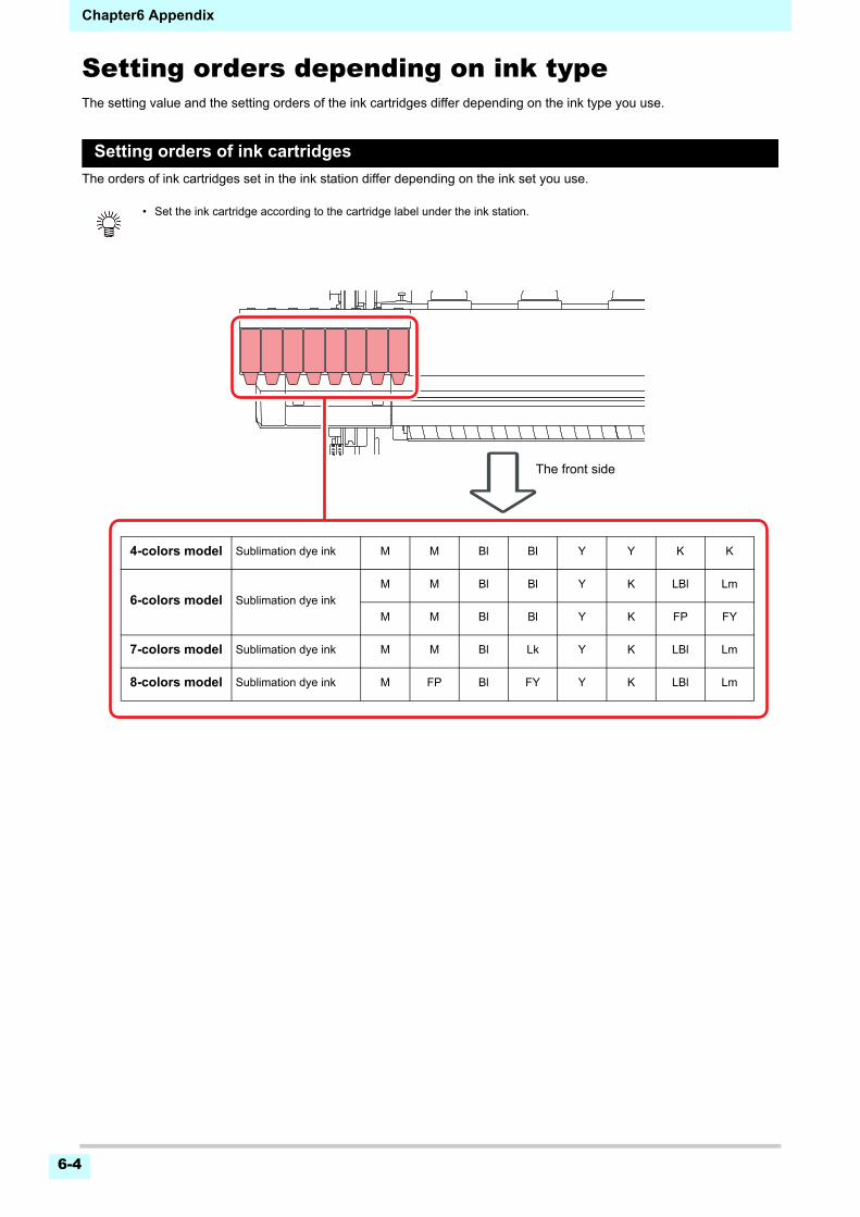
Chapter6 Appendix
6-4
Setting orders depending on ink typeThe setting value and the setting orders of the ink cartridges differ depending on the ink type you use.
Setting orders of ink cartridges
The orders of ink cartridges set in the ink station differ depending on the ink set you use.
• Set the ink cartridge according to the cartridge label under the ink station.
The front side
4-colors model Sublimation dye ink M M Bl Bl Y Y K K
6-colors model Sublimation dye ink
M M Bl Bl Y K LBl Lm
M M Bl Bl Y K FP FY
7-colors model Sublimation dye ink M M Bl Lk Y K LBl Lm
8-colors model Sublimation dye ink M FP Bl FY Y K LBl Lm
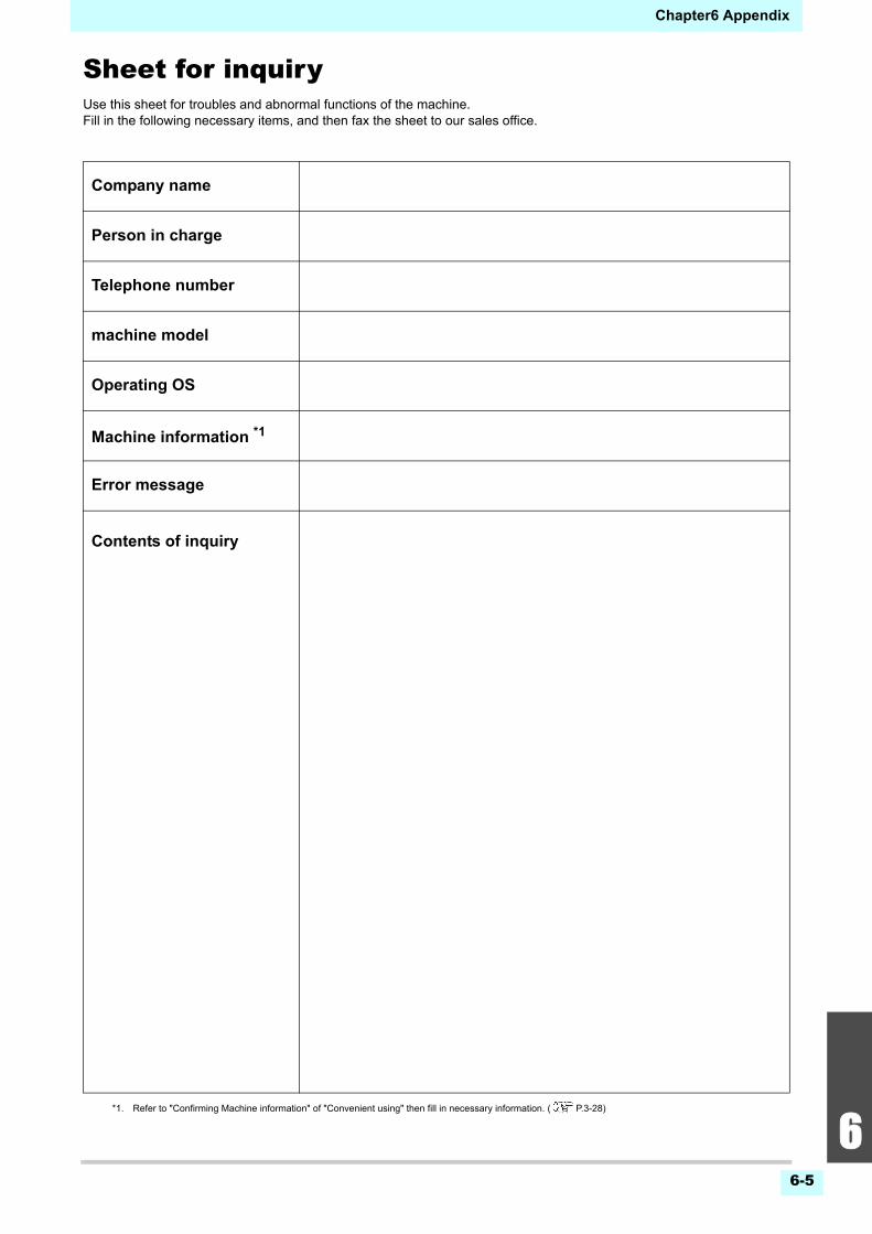
6-5
2
2
2
6
Chapter6 Appendix
Sheet for inquiryUse this sheet for troubles and abnormal functions of the machine.Fill in the following necessary items, and then fax the sheet to our sales office.
Company name
Person in charge
Telephone number
machine model
Operating OS
Machine information *1
*1. Refer to "Confirming Machine information" of "Convenient using" then fill in necessary information. ( P.3-28)
Error message
Contents of inquiry

Chapter6 Appendix
6-6

TS300P-1800 Operation Manual
May, 2021
MIMAKI ENGINEERING CO.,LTD.2182-3 Shigeno-otsu, Tomi-shi, Nagano 389-0512 JAPAN
D202869-17-08052021

© MIMAKI ENGINEERING CO., LTD.2015
AT
FW : 3.60


