Embed Size (px)
Citation preview
1
Mirror production for the Cherenkov telescopes of the ASTRI Mini-
Array and of the MST project for the Cherenkov Telescope Array N. La Palombara1,*, G. Sironi2, E. Giro3, S. Scuderi1, R. Canestrari4, S. Iovenitti2,5, M.
Garczarczyk6, M. Krause6, S. Diebold7, R. Millul2, F. Marioni8, N. Missaglia8, M. Redaelli8,
G. Valsecchi8, F. Zocchi8, A. Zanoni9, and G. Pareschi2
for the ASTRI10 and the CTA11 projects 1INAF - IASF Milano, Via A. Corti 12, Milano, Italy, I-20133 2INAF - Osservatorio Astronomico di Brera, Via Bianchi 46, Merate, Italy, I-23807 3INAF – Osservatorio Astronomico di Padova, Vicolo Osservatorio 5, Padova, Italy, I-35122 4INAF - IASF Palermo, Via U. La Malfa 153, Palermo, Italy, I-90146 5Dipartimento di Fisica, Università degli Studi di Milano, via Celoria 16, Milano, Italy, I-20133 6Deutsches Elektronen-Synchrotron (DESY), Platanenallee 6, Zeuthen, Germany, D-15738 7Institut für Astronomie und Astrophysik Tübingen (IAAT), Sand 1, Tübingen, Germany, D-72076 8Media Lario s.r.l., Via al Pascolo, Bosisio Parini, Italy, I-23842 9ZAOT s.r.l., Via E. Restelli 20, Vittuone, Italy, I-20010 10http://www.astri.inaf.it/ 11https://www.cta-observatory.org/
Abstract. The Cherenkov Telescope Array (CTA) is the next ground-based gamma-ray observatory in the TeV -
ray spectral region operating with the Imaging Atmospheric Cherenkov Technique. It is based on almost 70
telescopes of different class diameters – LST, MST and SST of 23, 12, and 4 m, respectively - to be installed in two
sites in the two hemispheres (at La Palma, Canary Islands, and near Paranal, Chile). Several thousands of reflecting
mirror tiles larger than 1 m2 will be produced for realizing the segmented primary mirrors of a so large number of
telescopes. Almost in parallel, the ASTRI Mini-Array (MA) is being implemented in Tenerife (Canary Islands),
composed of nine 4 m diameter dual-mirror Cherenkov telescopes (very similar to the SSTs). We completed the
mirror production for all nine telescopes of the ASTRI MA and two MST telescopes (400 segments in total) using
the cold glass slumping replication technology. The results related to the quality achieved with a so large-scale
production are presented, also discussing the adopted testing methods and approaches. They will be very useful for
the adoption and optimization of the quality assurance process for the huge production (almost 3000 m2 of reflecting
surface) of the MST and SST CTA telescopes.
Keywords: ASTRI, CTA, Cherenkov, -ray, cold-slumping technology, hot-slumping technology, quality
assurance.
* E-mail: [email protected]
1 Introduction
Imaging Atmospheric Cherenkov Telescopes (IACTs) are ground-based telescopes designed to
observe -ray celestial sources at very-high energies (VHE), in the TeV energy range [1]. After
the first detection of a VHE source, obtained in 1989 with the Whipple telescope [2], several
other sources have been found over the last three decades, thanks to the H.E.S.S. [3], MAGIC [4],
and VERITAS [5] telescopes. Currently, more than 200 VHE sources are known*: some of them
have been identified with different classes of celestial objects, but a significant fraction of VHE
sources are still unidentified [6]; in addition, due to the limited sensitivity of the current
generation of instruments, in most cases the origin of the observed VHE emission is not fully
understood. Therefore, new facilities with better performance are necessary.
* http://tevcat.uchicago.edu/
2
ASTRI is a project led by the Italian National Institute for Astrophysics (INAF) that aims to
realize a series of dual-mirror IACTs. They are characterized by innovative technological
solutions, such as the Schwarzschild-Couder optical configuration [7], a modular, light and
compact focal-plane camera consisting of an array of multi-pixel silicon photo-multiplier
sensors, and an efficient and fast front-end electronics, specifically designed for ASTRI. The
feasibility of this innovative design has been successfully demonstrated with the ASTRI-Horn
prototype. This telescope, installed in 2014 at the Serra La Nave site on Mount Etna (Catania,
Italy), is the first Schwarzschild-Couder telescope to be built and tested [8]: it observed its first
light in May 2017† and detected the Crab nebula in December 2018 [9].
On behalf of INAF, the ASTRI Collaboration is developing a Mini-Array (ASTRI MA)
composed of nine dual-mirror IACTs, based on the design of the ASTRI-Horn prototype [10, 11].
They will be installed at the Teide Astronomical Observatory, operated by the Instituto de
Astrofisica de Canarias (IAC), on Mount Teide, in the Canary island of Tenerife. The ASTRI
MA will be operated by INAF based on a host agreement with IAC‡ [12].
In addition, the ASTRI Collaboration is participating to the preparatory effort for the
realization of the Cherenkov Telescope Array (CTA). It will be located in two different sites, one
in the northern and one in the southern hemisphere, and will be made up of three different types
of IACTs [13]:
the Large-Sized Telescopes (LSTs), with a 23 m mirror diameter, will cover the low-energy
range between 20 GeV and 3 TeV;
the Medium-Sized Telescopes (MSTs), with a 12 m mirror diameter, will observe the core
energy range between 80 GeV and 50 TeV;
the Small-Sized Telescopes (SSTs), with a 4 m primary mirror diameter, will be devoted to
the high-energy range from 1 TeV up to more than 300 TeV.
With respect to the initial design configuration that was based on almost 100 telescopes [14],
the CTAO arrays have recently been descoped: the baseline configuration, dubbed as “Alpha
Configuration”, will consist of a Northern Array with 4 LSTs and 9 MSTs and a Southern Array
with 14 MSTs and 37 SSTs.
The improvement in the on-axis differential sensitivity of the two CTAO Arrays with respect
to the currently existing instruments of the same kind (mainly MAGIC, H.E.S.S., and VERITAS)
is a factor 5 to 10 depending on the energy range§ [15]. Particularly relevant is the CTAO
improvement in terms of off-axis sensitivity. Between 3 and 4 degrees away from the pointing
direction the differential sensitivity worsens just by less than a factor 2 at all energies with
respect to the on-axis sensitivities. CTAO has therefore a -ray Field-of-View (FoV) of seven
degrees in diameter at 1 TeV (even more at higher energies).
It should be noted that the performance of CTAO would also be improved, after the
implementation of this “Alpha Configuration”, with the installation of additional telescopes, in
particular for the southern site, where there is a large area that could be populated with additional
telescopes. In this respect, it should be noted that another kind of medium size telescopes, based
on the dual mirror Schwarzschild-Couder aplanatic telescopes (9 m in diameter) and named
pSCT, would be possibly implemented, similar to the prototype already developed and operated
in Arizona (USA) [16, 17].
† https://www.cta-observatory.org/cta-prototype-telescope-astri-achieves-first-light/ ‡ http://www.inaf.it/en/inaf-news/astri-a-new-pathfinder-of-the-arrays-of-cherenkov-telescopes § Public CTAO webpage reporting a full set of performance plots for the Alpha Configuration can be found at https://www.cta-
observatory.org/science/ctao-performance/
3
In the context of CTA, INAF is leading the international collaboration [18, 19] that will
provide, in terms of in-kind contribution to CTAO, the SST telescopes. The design will be based
on that of the ASTRI-Horn prototype and of the ASTRI MA telescopes. The mirrors will be
provided by INAF and they will be of the same type of the ASTRI MA.
The MSTs are based on a single-mirror Davies-Cotton optical design [20]. Each of the 12 m
primary mirrors will be made assembling together 86 identical hexagonal segments with
spherical profile and a maximum size of 120 cm. INAF, in the context of the ASTRI
collaboration, is also responsible for the procurement of all the reflecting segments for the 9
MSTs that will be implemented at the Northern site (800 segments to be produced, including the
spares). The sandwiched mirror segments are produced using the so-called glass cold-slumping
replication technology, initially set-up by INAF - Osservatorio Astronomico di Brera (OAB) and
Media Lario (ML) company (Bosisio Parini, Italy) for the MAGIC II telescope [21] and then
specifically developed to fit the requirements and specifications of the MSTs [22]. In this
respect, ASTRI is cooperating with the Deutsches Elektronen-Synchrotron (DESY, Germany),
responsible for the MST structures.
Also, the reflecting segments of the primary mirrors for the ASTRI MA are produced using
the same technology [23] and they will be used for the production of segments for the primary
mirrors of the 37 (extendable to 40) SST telescopes to be installed at the southern site (with
about other 800 segments to be produced, including the spares). Each primary is based on 18
hexagonally-shaped segments, with a maximum size of 85 cm.
At the end of 2019, we completed the mirror production for both the nine telescopes of the
ASTRI MA (200 reflecting segments of three different curvature radii and profile, corresponding
to the three coronas of segments to form a primary) and two MST telescopes (with 200 identical
reflecting segments with spherical shape produced). In this effort the ML Company represents
the industrial partner, while ZAOT (Vittuone, Italy) is involved for the application of the
reflective coating on the substrates. In this context, we have performed independent verifications
of the optical performance of representative mirror samples.
In this paper, the aspects related to the large-scale production of these segments are
presented, with a particular regard to the qualification activities that have been performed in
order to assess and consolidate the production process. In this respect, the criteria adopted for the
quality assurance, in order to monitor and verify the production reliability, are discussed in terms
of performance and compliance with respect to the input requirements. Different methods and
techniques have been used to perform the verifications. Finally, we present the performance of
the produced segments and discuss their compliance and production yield with respect to the
input requirements. The results of the present work will be very useful for the adoption and
optimization of the quality assurance process for the huge production of the MST north and SST
CTA telescopes, for which thousands of reflecting segments have to be manufactured and
qualified.
2 Optical Design
2.1 The Optical Design of the telescopes for ASTRI MA
The dual-mirror telescopes of the ASTRI MA are based on the polynomial Schwarzschild-
Couder optical design, an aplanatic layout that, thanks to the combination of the two mirrors, is
characterized by a wide field of view, a low vignetting and isochrony. The plate scale of the
ASTRI telescopes is 37.6 mm/°.
4
The primary mirror (ASTRI M1) has a radial symmetry and its optical profile is described by
an aspherical polynomial function (of order 10), where the radius of the spherical component is
8.223 m. It has a diameter of 4.3 m and is segmented into 18 hexagonal segments; the face-to-
face dimension of each segment is 85 cm. They are distributed in three concentric coronae
(COR1, COR2, and COR3) of six identical segments each, where each corona has a different
radial distance from the telescope axis. In fact, the best-fit radius of curvature (RoC) of the
segments is 8.6, 9.8, and 11.7 m, respectively for the inner, medium, and outer corona [24].
The secondary mirror (ASTRI M2) is a monolithic element and has a diameter of 1.8 m. It
has an aspherical shape, with a radius of 2.18 m for the spherical component, and is installed at a
distance of 3.108 m from ASTRI M1. This implies an equivalent focal length for the whole
telescope of 2.15 m [18].
2.2 The Optical Design of the Single-Mirror MST
The medium-sized telescope has a single-mirror configuration with a modified Davies-Cotton
optical design [25], where the optical parameters are optimized to reduce the time spread at the
Cherenkov camera focal plane from light reflected at different mirror positions. The mirror is
segmented into 86 hexagonal segments, for a diameter of 12 m. All segments are identical: they
have a spherical profile, with a RoC of 32.14 m, and the face-to-face size is 1.2 m. The telescope
focal length is 16 m and the mirror segments are aligned to reflect rays parallel to the optical axis
into the focal point. They are mounted on a spherical dish with a radius of 19.2 m. The plate
scale of the MST telescopes is 280 mm/°.
3 Mirror Design and Production
In the framework of CTA several different methods have been considered for the mirror
realization, which are based on different technologies [26, 27, 28, 29]: they include sandwich
concepts with cold-slumped surfaces made of thin float glass and different core materials (like
aluminum honeycomb, glass foams or aluminum foams), constructions based on carbon
fiber/epoxy or glass fiber substrates, as well as sandwich structures made entirely of aluminum.
In addition, lightweight polished aluminum mirrors with Ni/P alloy (“electroless Nickel”)
cladding as the reflecting surface were proposed for the Gamma-ray Cherenkov Telescope
(GCT), the other dual-mirror telescope with a Schwarzschild-Couder optical design [30] that was
proposed for the SSTs before the selection of the ASTRI design as the baseline. In this respect,
the electroless nickel [31] (composed of nickel - Ni - and 9% to 12% of phosphorus – P -) is
often added as a cladding layer of a few tens of micrometers onto the aluminum-based surface
because of its hard and – at the same time - amorphous microstructure, which makes easier the
super-polishing process of the optical surface. This allows us to achieve very low micro-
roughness levels on metallic surfaces (up to a fraction of nanometer root mean squared (RMS),
see e.g. [32, 33]).
Both the ASTRI M1 segments and the MST segments are realized using an improved version
of glass cold-slumping technology**, which was developed in synergy between OAB and ML.
This approach has been already successfully used for the two telescopes of the MAGIC
experiment array operated at the Observatorio di Roque de Los Muchacos astronomical site (La
Palma, Canary Islands) [21, 34, 35]. The main steps of the mirror production are shown in Fig. 1.
** In this context, however, it should be noted that part of the mirrors for MST are being realized also with alternative
technologies.
5
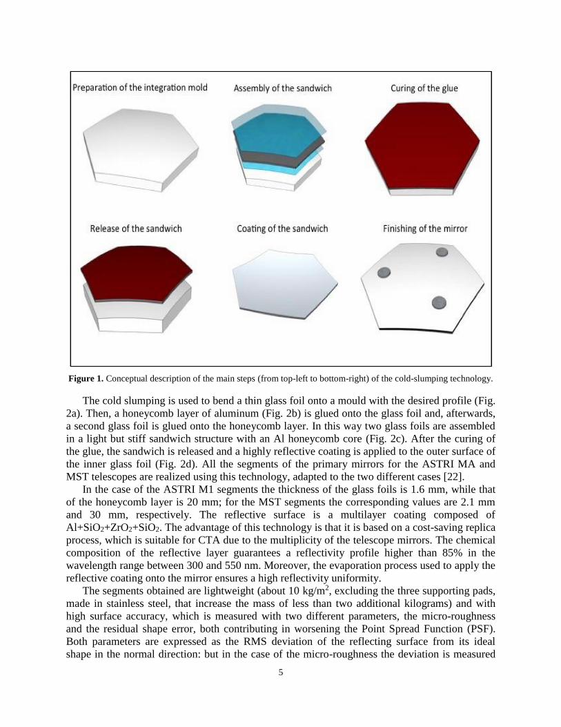
Figure 1. Conceptual description of the main steps (from top-left to bottom-right) of the cold-slumping technology.
The cold slumping is used to bend a thin glass foil onto a mould with the desired profile (Fig.
2a). Then, a honeycomb layer of aluminum (Fig. 2b) is glued onto the glass foil and, afterwards,
a second glass foil is glued onto the honeycomb layer. In this way two glass foils are assembled
in a light but stiff sandwich structure with an Al honeycomb core (Fig. 2c). After the curing of
the glue, the sandwich is released and a highly reflective coating is applied to the outer surface of
the inner glass foil (Fig. 2d). All the segments of the primary mirrors for the ASTRI MA and
MST telescopes are realized using this technology, adapted to the two different cases [22].
In the case of the ASTRI M1 segments the thickness of the glass foils is 1.6 mm, while that
of the honeycomb layer is 20 mm; for the MST segments the corresponding values are 2.1 mm
and 30 mm, respectively. The reflective surface is a multilayer coating composed of
Al+SiO2+ZrO2+SiO2. The advantage of this technology is that it is based on a cost-saving replica
process, which is suitable for CTA due to the multiplicity of the telescope mirrors. The chemical
composition of the reflective layer guarantees a reflectivity profile higher than 85% in the
wavelength range between 300 and 550 nm. Moreover, the evaporation process used to apply the
reflective coating onto the mirror ensures a high reflectivity uniformity.
The segments obtained are lightweight (about 10 kg/m2, excluding the three supporting pads,
made in stainless steel, that increase the mass of less than two additional kilograms) and with
high surface accuracy, which is measured with two different parameters, the micro-roughness
and the residual shape error, both contributing in worsening the Point Spread Function (PSF).
Both parameters are expressed as the RMS deviation of the reflecting surface from its ideal
shape in the normal direction: but in the case of the micro-roughness the deviation is measured
6
on microscopic spatial scales (with spatial wavelengths from a few micrometers up to 1 mm), at
high spatial frequencies [36], while in the case of the shape error the deviation is measured at
longer spatial scales. Surface micro-roughness affects the optical performance by degrading the
PSF and reducing the image contrast [37], while the residual shape error causes deviation from
the ideal focusing directions due to the geometrical imperfections. In accordance to the study
performed by Taybaly et al. 2015 [36], the micro-roughness shall be less than 7.0 nm RMS, as
measured in the 7-500 μm spatial wavelength range, in order to avoid spread of scattered photons
> 15 % beyond a diameter of 0.12° of the focal spot.
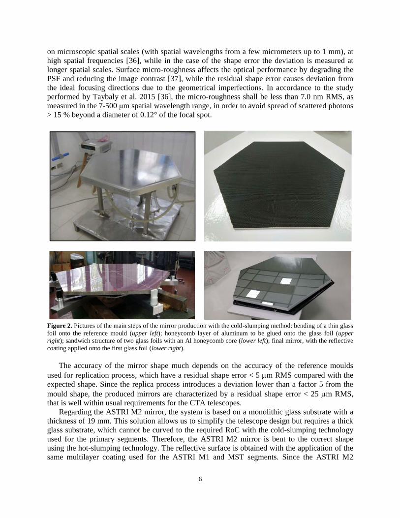
Figure 2. Pictures of the main steps of the mirror production with the cold-slumping method: bending of a thin glass
foil onto the reference mould (upper left); honeycomb layer of aluminum to be glued onto the glass foil (upper
right); sandwich structure of two glass foils with an Al honeycomb core (lower left); final mirror, with the reflective
coating applied onto the first glass foil (lower right).
The accuracy of the mirror shape much depends on the accuracy of the reference moulds
used for replication process, which have a residual shape error < 5 m RMS compared with the
expected shape. Since the replica process introduces a deviation lower than a factor 5 from the
mould shape, the produced mirrors are characterized by a residual shape error < 25 m RMS,
that is well within usual requirements for the CTA telescopes.
Regarding the ASTRI M2 mirror, the system is based on a monolithic glass substrate with a
thickness of 19 mm. This solution allows us to simplify the telescope design but requires a thick
glass substrate, which cannot be curved to the required RoC with the cold-slumping technology
used for the primary segments. Therefore, the ASTRI M2 mirror is bent to the correct shape
using the hot-slumping technology. The reflective surface is obtained with the application of the
same multilayer coating used for the ASTRI M1 and MST segments. Since the ASTRI M2
7
mirrors are produced with a completely different technology, the relevant production and
qualification activities will not be described in this paper.
As mentioned in the Introduction (Section 1), the CTA southern array could be possibly
extended after the implementation of the baseline configuration. In this context, additional
Medium Size - 9 m diameter - aplanatic telescopes may be added with dual-mirror
Schwarzschild-Couder configuration [7]. This design is capable to minimize the spherical and
comatic aberrations across a large Field of View together with a reduction of the astigmatism by
adopting a bended focal plane detection surface. An end-to-end prototype (pSCT, prototype
Schwarzschild-Couder Telescope) has been successfully developed in US, Arizona [16], at the
site at the Fred Lawrence Whipple Observatory. The telescope optical system of pSCT consists
of a 9.7 m diameter primary mirror and a 5.4 m secondary. The primary is based on 48 individual
mirror asymmetric petals: an inner and an outer rings of 16 and 32 asymmetric petals
respectively (with an average area of 1.2 m2). The secondary reflector is also segmented, with 8
petals forming an inner ring and 16 petals forming the outer ring (with an average area of 0.94
m2). It should be noted that the reflecting panels have been realized by ML, supported also by
INAF, using a glass replication technology almost identical to the production method adopted for
the mirrors of ASTRI MA e MST. However, in the case of the innermost panels of the secondary
mirror, due to the large sag of the segments, thin thermally pre-shaped glass foils have been used
[38], instead of adopting a pure cold replication method. The use of pre-shaped glass foils via hot
slumping for making the sandwiched panels presented a few challenging aspects, in particular
related to the formation of micro-cracks on the surface of the glass that made the material less
resistant to the stresses generated during the replication process. The pSCT telescope has been
successfully tested and calibrated. Its functionality has been demonstrated with the
characterization of the imaging capability [39] and the detection of the Crab nebula in gamma
rays [40].
A couple of other cold replication approaches, and alternative to the one proposed by INAF
and ML, have been proposed for making the reflecting segments of the MST telescopes. In
particular, the solution based on open-structure composite segmented mirrors has been
investigated by the Institute of Nuclear Physics of the Polish Academy of Sciences (IFJ PAN)
[41]. Another similar method, but based on a close sealed structure, is the one investigated at
IRFU-Saclay (France), with the panels made of layers of different materials [42]. At the time
being, the two groups are engaged in an effort aiming at merging together the competences
developed by the two groups, in order to deliver together all the reflecting panels for the 14 MST
telescopes of the CTAO Southern Array.
In the case of the CTA LST telescopes, the mirrors are manufactured using the cold slumping
technique and have a sandwich structure consisting of an aluminum honeycomb between two
glass sheets, with a technology pretty similar to the one developed by INAF and ML [43, 44].
The parabolic primary mirror of CTA-LST is 23 m diameter and its focal length is 28 m. The
primary mirror consists of 198 segmented mirrors. Each mirror has a hexagonal shape of 1.51 m
side-by-side size. All the mirrors for the first LST have been already produced and successfully
installed.
It should be noted that Will et al. (2019) [45], in collaboration with ML, are testing a new
kind of back-coated glass mirrors for the MAGIC Telescopes. This technology represents an
evolution of the INAF glass replication approach, but in this case a protective layer of an ultra-
thin glass sheet which is back-coated with aluminum is used instead of the SiO2 thin coating
deposited under vacuum onto the aluminum reflecting layer. Finally, another promising
8
replication process under investigation by INAF and ML foresees a new fabrication scheme,
similar to the cold glass replication, but where the reflecting slab is a low-cost laminate pre-
coated reflecting aluminum strips instead of glass sheets†† [46].
4 Applicable Requirements
For the development of the manufacturing process for the mirror segments, the CTA
requirements have been assumed, not only for the case of the MST tiles but also for the one of
the ASTRI MA (which are the same of the SST Telescopes). These reference parameters regard
not only the optical performance of each item but also its reliability, taking also into account the
environmental conditions of the observing sites (Table 1) and the durability prescriptions.
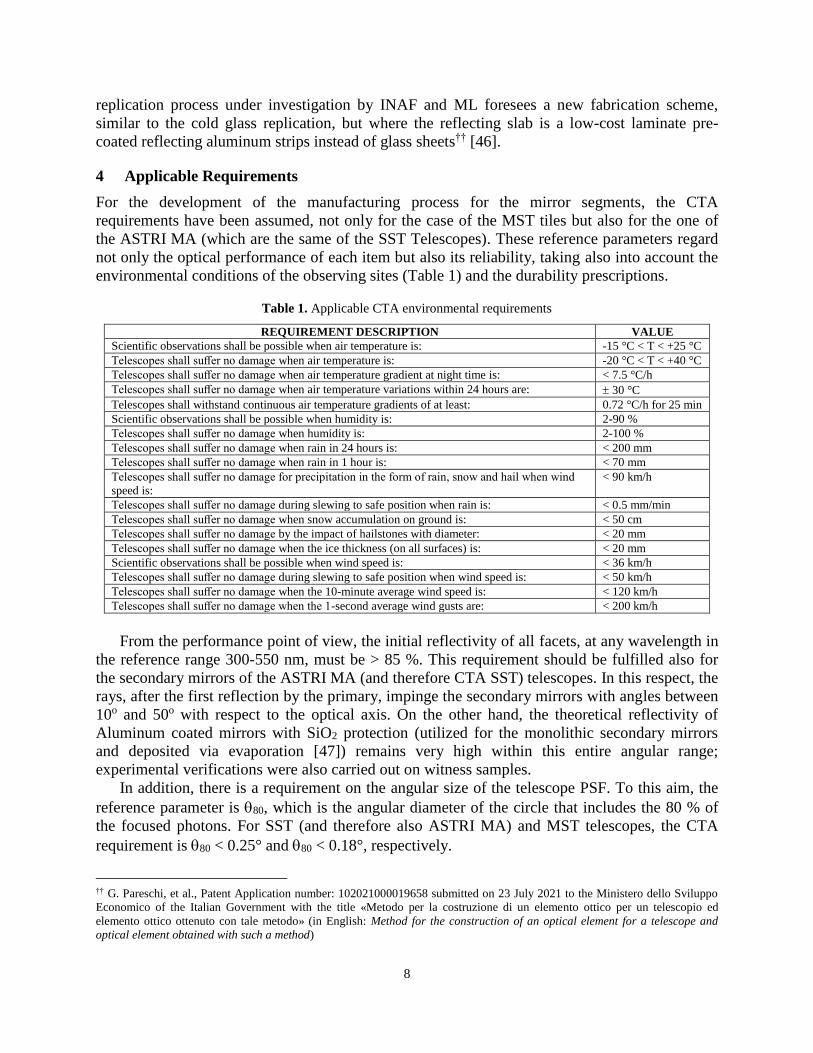
Table 1. Applicable CTA environmental requirements
REQUIREMENT DESCRIPTION VALUE
Scientific observations shall be possible when air temperature is: -15 °C < T < +25 °C
Telescopes shall suffer no damage when air temperature is: -20 °C < T < +40 °C
Telescopes shall suffer no damage when air temperature gradient at night time is: < 7.5 °C/h
Telescopes shall suffer no damage when air temperature variations within 24 hours are: 30 °C
Telescopes shall withstand continuous air temperature gradients of at least: 0.72 °C/h for 25 min
Scientific observations shall be possible when humidity is: 2-90 %
Telescopes shall suffer no damage when humidity is: 2-100 %
Telescopes shall suffer no damage when rain in 24 hours is: < 200 mm
Telescopes shall suffer no damage when rain in 1 hour is: < 70 mm
Telescopes shall suffer no damage for precipitation in the form of rain, snow and hail when wind
speed is:
< 90 km/h
Telescopes shall suffer no damage during slewing to safe position when rain is: < 0.5 mm/min
Telescopes shall suffer no damage when snow accumulation on ground is: < 50 cm
Telescopes shall suffer no damage by the impact of hailstones with diameter: < 20 mm
Telescopes shall suffer no damage when the ice thickness (on all surfaces) is: < 20 mm
Scientific observations shall be possible when wind speed is: < 36 km/h
Telescopes shall suffer no damage during slewing to safe position when wind speed is: < 50 km/h
Telescopes shall suffer no damage when the 10-minute average wind speed is: < 120 km/h
Telescopes shall suffer no damage when the 1-second average wind gusts are: < 200 km/h
From the performance point of view, the initial reflectivity of all facets, at any wavelength in
the reference range 300-550 nm, must be > 85 %. This requirement should be fulfilled also for
the secondary mirrors of the ASTRI MA (and therefore CTA SST) telescopes. In this respect, the
rays, after the first reflection by the primary, impinge the secondary mirrors with angles between
10o and 50o with respect to the optical axis. On the other hand, the theoretical reflectivity of
Aluminum coated mirrors with SiO2 protection (utilized for the monolithic secondary mirrors
and deposited via evaporation [47]) remains very high within this entire angular range;
experimental verifications were also carried out on witness samples.
In addition, there is a requirement on the angular size of the telescope PSF. To this aim, the
reference parameter is 80, which is the angular diameter of the circle that includes the 80 % of
the focused photons. For SST (and therefore also ASTRI MA) and MST telescopes, the CTA
requirement is 80 < 0.25° and 80 < 0.18°, respectively.
†† G. Pareschi, et al., Patent Application number: 102021000019658 submitted on 23 July 2021 to the Ministero dello Sviluppo
Economico of the Italian Government with the title «Metodo per la costruzione di un elemento ottico per un telescopio ed
elemento ottico ottenuto con tale metodo» (in English: Method for the construction of an optical element for a telescope and
optical element obtained with such a method)
9
It should be noted that the PSF requirement for the MST is strictly referred just to the on-axis
direction, in order to allow the quality assurance verification of each spherical tile. Indeed, while
the SST (and ASTRI MA) telescopes are aplanatic within their FoV, one should be reminded that
the MST optical system is instead affected by an inherent off-axis degradation of the PSF, as
they are based on the single-mirror Davis-Cotton design [29]. A worsening of the angular
resolution is then associated to the increase of the off-set angles and the PSF also becomes
asymmetric in the two directions, with the spot size which is always larger in the radial direction.
This is mostly due to the non-Gaussian tails of the PSF and the effect tends to be more enhanced
with the increase of the focal length/diameter ratio. At the border of the FoV of the MST
telescopes (± 3.7°), the maximum degradation due to the design will be about 0.10°, i.e. in any
case lower than the angular resolution requirement. Therefore, also for off-axis rays, the PSF of
the MST is expected to be dominated by the fabrication and alignment errors.
The main environmental requirements are reported in Table 1; furthermore, there are also
requirements on the resistance to aggressive atmosphere, dust and sand blasting, and lightning.
Finally, the provided mirrors and segments must have a lifetime > 15 yr. Of course, this last
parameter could not be directly proven within the activities and tests performed and reported in
the present work. However, the experience coming from the glass sandwiched mirrors on the
MAGIC II telescope since 2007, that up to now have shown a very small degradation, and the
aging tests performed so far indirectly indicate that this requirement can be met.
In view of the mirror production, all the CTA environmental requirements reported in Table
1 were considered as applicable requirements for ML, the industrial supplier of MST and ASTRI
M1 segments; we only reinforced the air temperature range where telescopes shall suffer no
damage (-20 °C < T < +70 °C), to take into account also the transport and storage conditions
before the segment integration on the telescope. Moreover, we required that the mirror segments
are water-proof and that the reflective coating can survive to a tape adhesion test with a pulling
force up to 16 N. Finally, from the reliability point of view, we required that the lifetime of the
reflective coating is > 6 yr, with an end-of-life reflectivity > 65 % in the reference wavelength
range. A number of aging tests on the coating were performed [23], while one should note that
the reflectivity loss of the mirrors mounted on MAGIC II at the Observatorio del Roque de los
Muchachos (i.e. the same astronomical site in La Palma, Canary islands, where the northern
array of CTA will be operated) was less than 2 % after more than 5 years‡‡. Recent tests
performed on a MST mirror that was mounted on a truss in Paranal (Chile) at the site where the
CTA southern array will be installed, didn’t show any degradation after 1 year of exposition to
the local environment§§.
From the performance point of view, we required an initial reflectivity value > 85 % in the
wavelength range 300-550 nm. In addition, we required a maximum value < 8 % (over the entire
mirror surface) for the reflectivity non-uniformity, which is defined as the maximum difference
between the average surface reflectivity measured at different positions over the mirror.
Concerning the micro-roughness, the criterion adopted for the production was to maintain the
already excellent RMS level <2 nm, i.e. a value much lower than the maximum acceptable value
of 7 nm RMS estimated by Tayabaly et al (2015, 2016) [36,48] in order to not exceeding the
MST 80 requirement because of scattering.
‡‡ Markus Garczarczyk, Reflectivity of the MAGIC-II reflector, MAGIC Document 111003 (2011) §§ M. Garczarczyk, Report from the Chile mirror test campaign, CTAO MST-STR-RD-36144000-00011-2 Issue 1 (2021)
10
We required that the micro-roughness be < 2 nm RMS, thus constraining the dispersion of
peaks and valleys of the real surface profile. For the MST segments we required a D80 (the linear
dimension of 80) < 12 mm at the nominal focal length for the on-axis single mirror, which is
half of the RoC (due to the spherical shape of the mirror). For a focal length of 16.07 m this
corresponds to about 0.045°, which is well within the CTA requirement. Regarding the radius of
curvature, we considered as a guideline that RoC = 32.14 0.04 m. For the ASTRI M1 segments
there is no requirement on the RoC, since they are aspheric. In their case we introduced two
requirements, one on the radius of the spherical component (between 8198 and 8298 mm) and
one on the residual shape error (< 20 m RMS for corona 1 and < 25 m RMS for coronae 2 and
3). Finally, for both the MST and ASTRI M1 segments the tolerance on the hexagon side-to-side
size is 2 mm.
5 Qualification of the Production Process
Before starting with the mass production of the mirror segments, it was necessary to validate the
production process and to perform qualification tests on a set of preliminary segments. To this
end, the industrial activity started in February 2017 with the development phase. During this
phase, the moulds used to produce the different types of segments were qualified and the
parameters of the glass cold-shaping process were fine-tuned, in order to satisfy the performance
requirements of the mirrors. Several segment prototypes were then produced and tested along
this period, in order to ascertain that the production process was stable and repeatable.
Afterwards, one qualification segment of each type went through a complete set of performance
measurements and environmental and reliability tests. During the qualification process, the
following environmental tests were performed on each qualification segment:
1) 5 thermal cycles composed of the following steps:
From 20°C to -20°C
Plateau of 12 h
From -20°C to 70°C
Plateau of 4 h
Cool down to 20°C
For all steps the temperature gradient is 0.125°C/min
2) Dry Heat test (according to ISO 9022-2:2002(E))
3) Dump Heat test (according to ISO 9022-2:2002(E))
Before and after each of the above tests, the tested segment was characterized in terms of
integrity, reflectivity, and residual shape error map; this was computed as difference between the
measured shape, verified with a POLI TCX Coordinate Measurement Machine (CMM) on a 10
mm square grid, and the designed one. In all cases, after the test: 1) the visual inspection
revealed no degradation in term of panel integrity and quality; 2) the measured reflectivity was
fully compatible with the original one; 3) the comparison of the residual maps revealed no
significant variation of the surface shape error. Moreover, the immersion in a water tank was
executed, in order to verify the water tightness.
11
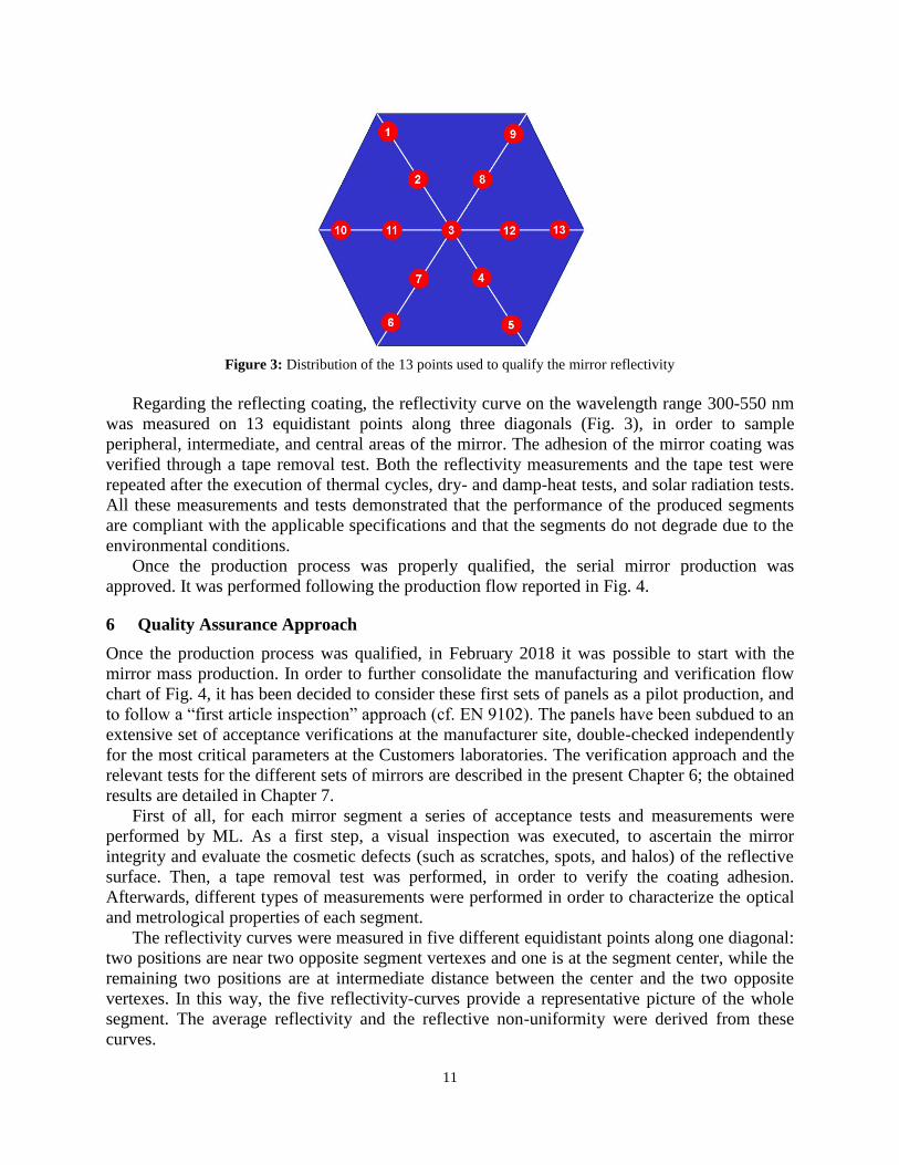
Figure 3: Distribution of the 13 points used to qualify the mirror reflectivity
Regarding the reflecting coating, the reflectivity curve on the wavelength range 300-550 nm
was measured on 13 equidistant points along three diagonals (Fig. 3), in order to sample
peripheral, intermediate, and central areas of the mirror. The adhesion of the mirror coating was
verified through a tape removal test. Both the reflectivity measurements and the tape test were
repeated after the execution of thermal cycles, dry- and damp-heat tests, and solar radiation tests.
All these measurements and tests demonstrated that the performance of the produced segments
are compliant with the applicable specifications and that the segments do not degrade due to the
environmental conditions.
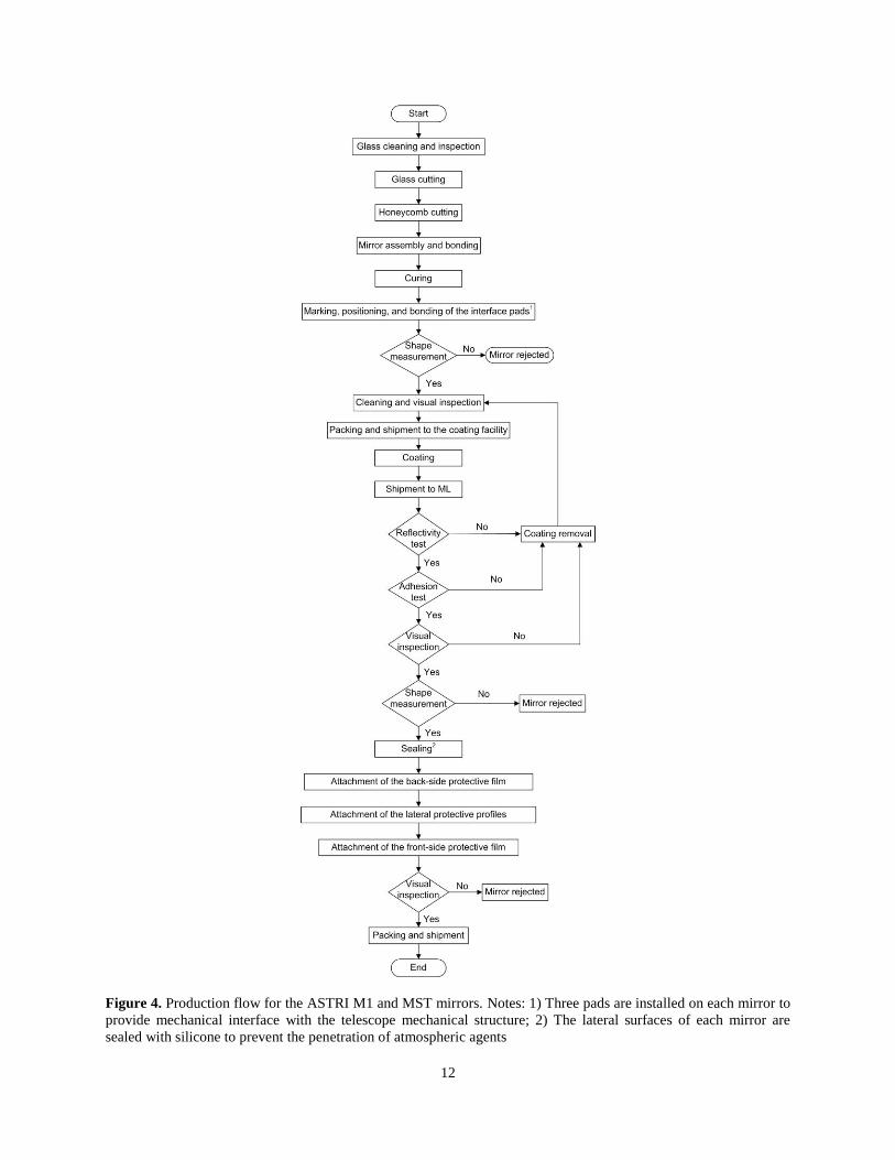
Once the production process was properly qualified, the serial mirror production was
approved. It was performed following the production flow reported in Fig. 4.
6 Quality Assurance Approach
Once the production process was qualified, in February 2018 it was possible to start with the
mirror mass production. In order to further consolidate the manufacturing and verification flow
chart of Fig. 4, it has been decided to consider these first sets of panels as a pilot production, and
to follow a “first article inspection” approach (cf. EN 9102). The panels have been subdued to an
extensive set of acceptance verifications at the manufacturer site, double-checked independently
for the most critical parameters at the Customers laboratories. The verification approach and the
relevant tests for the different sets of mirrors are described in the present Chapter 6; the obtained
results are detailed in Chapter 7.
First of all, for each mirror segment a series of acceptance tests and measurements were
performed by ML. As a first step, a visual inspection was executed, to ascertain the mirror
integrity and evaluate the cosmetic defects (such as scratches, spots, and halos) of the reflective
surface. Then, a tape removal test was performed, in order to verify the coating adhesion.
Afterwards, different types of measurements were performed in order to characterize the optical
and metrological properties of each segment.
The reflectivity curves were measured in five different equidistant points along one diagonal:
two positions are near two opposite segment vertexes and one is at the segment center, while the
remaining two positions are at intermediate distance between the center and the two opposite
vertexes. In this way, the five reflectivity-curves provide a representative picture of the whole
segment. The average reflectivity and the reflective non-uniformity were derived from these
curves.
12
Figure 4. Production flow for the ASTRI M1 and MST mirrors. Notes: 1) Three pads are installed on each mirror to
provide mechanical interface with the telescope mechanical structure; 2) The lateral surfaces of each mirror are
sealed with silicone to prevent the penetration of atmospheric agents

13
From the metrological point of view, in the case of the focusing MST segments, the
measurement of the RoC and of the PSF size (at both the best and the nominal focal length) was
performed. In the case of the aspheric ASTRI M1 segments, instead, the best-fit value of the
spherical component and the residual shape error were measured. The accuracy of the RoC
measurement performed with the CMM is about 50 mm and is obtained by spherical best-fit of
the measured data points. In production, the optical surface is sampled in 536 points. The above
uncertainty has been estimated by comparison with the shape of the mirror derived from
measurements done with a much finer grid, which is impractical in an industrial environment.
The measurement of the PSF size is obtained with an optical bench, based on a 2𝑓
configuration, which generates a spherical wave and detects the focused back-reflected light
beam. The set-up of this facility consists of a point-like (with respect to mirror dimension and
curvature) laser source at 632 nm that is converted into a spherical wave by means of a
microscope eye-piece. The required numerical aperture is about 0.016 and it is easily achieved.
The MST mirror is positioned at a distance of 32140 mm with an accuracy of the order of 1 mm.
The back-reflected radiation illuminates a screen positioned at the focal plane, which is in turn
imaged on a 2048 × 2048 pixel CCD camera. The camera covers a physical area of 170 mm ×
170 mm. In order to avoid superposition between the source and the image plane, each of them is
transversally displaced from the optical axis by 100 mm. The measurement of the D80 diameter
has an accuracy of 3 mm. This is due to several reasons, which include the contribution of
variable daylight illumination (despite of the presence of a filter in front of the CCD), the finite
area of the focal plane imaged onto the CCD, the scattering of light from the screen. The entity
of the accuracy (3 mm) has been estimated by repeated measurements and comparison with
controlled laboratory conditions, which of course are not completely possible in an industrial
environment.
Apart from the acceptance tests performed on each segment, additional tests were performed
by ML on some individual segments regarding the micro-roughness and the water tightness.
These tests were necessary in order to keep under control the production process.
The contract assigned to ML requires that each mirror segment is associated with an "Identity
Card" (IC), which reports the results of all the acceptance tests and measurements. The IC is the
reference document to control the mirror quality. Along the production phase, the Quality
Assurance team used it to monitor the production process and decide which segments required a
direct inspection, in order to evaluate if they can be accepted or rejected. In case a segment
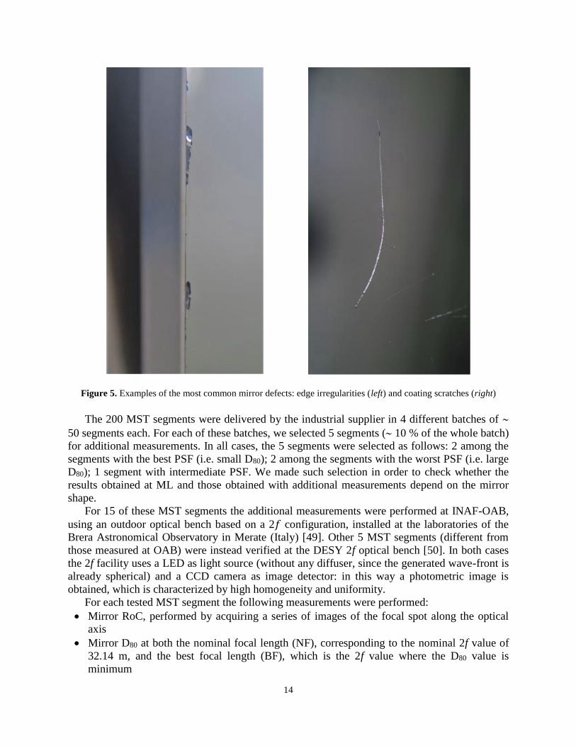
showed a major anomaly (see Fig. 5), which however did not affect its performance or reliability
(such as a scratch or a wide halo), it was accepted only if a comprehensive description of the
anomaly was reported in a Non-Conformance Report (NCR). If, on the other hand, the detected
anomaly compromised the segment performance or reliability (such as a large spalling of the
mirror edge), the segment was rejected. After its delivery, each segment must be followed by its
IC (and the relevant NCRs, if any) for all its life. In this way, at any time it will be possible to
retrieve the mirror properties and evaluate if it is suitable for the installation on the telescope.
Additional sample tests were performed by OAB and DESY at their laboratories on 10% of
the produced mirrors. Such tests concerned the RoC and PSF measurement for the MST
segments and the shape measurement for the ASTRI M1 segments. In this way we obtained an
independent check of the segment properties, monitored the reliability of the production process
and provided feedback to the industrial supplier.
14
Figure 5. Examples of the most common mirror defects: edge irregularities (left) and coating scratches (right)
The 200 MST segments were delivered by the industrial supplier in 4 different batches of
50 segments each. For each of these batches, we selected 5 segments ( 10 % of the whole batch)
for additional measurements. In all cases, the 5 segments were selected as follows: 2 among the
segments with the best PSF (i.e. small D80); 2 among the segments with the worst PSF (i.e. large
D80); 1 segment with intermediate PSF. We made such selection in order to check whether the
results obtained at ML and those obtained with additional measurements depend on the mirror
shape.
For 15 of these MST segments the additional measurements were performed at INAF-OAB,
using an outdoor optical bench based on a 2𝑓 configuration, installed at the laboratories of the
Brera Astronomical Observatory in Merate (Italy) [49]. Other 5 MST segments (different from
those measured at OAB) were instead verified at the DESY 2f optical bench [50]. In both cases
the 2f facility uses a LED as light source (without any diffuser, since the generated wave-front is
already spherical) and a CCD camera as image detector: in this way a photometric image is
obtained, which is characterized by high homogeneity and uniformity.
For each tested MST segment the following measurements were performed:
Mirror RoC, performed by acquiring a series of images of the focal spot along the optical
axis
Mirror D80 at both the nominal focal length (NF), corresponding to the nominal 2f value of
32.14 m, and the best focal length (BF), which is the 2f value where the D80 value is
minimum
15
The final measurement regarded the focused reflectivity of the MST segments. In fact, while
the average reflectivity reported in the IC of each segment is the average of the surface
reflectivity measured at five different positions along one diagonal, the focused reflectivity is the
reflectivity of the overall segment measured at the focal plane. Therefore, it is a parameter which
truly represents the CTA requirement. The measurement of this parameter has been performed at
the 2f UV-CCD facility of the Institut für Astronomie und Astrophysik (IAAT) of the University
of Tübingen (Germany) [51], using the same five MST segments which were verified at DESY.
7 Results
7.1 Overview
The mirror production was completed at the end of 2019. The whole set includes 200 MST
segments and 200 ASTRI M1 segments (68 COR1, 66 COR2, and 66 COR3). The MST
segments correspond to two full mirrors (of 86 segments each) plus 28 spare segments. In the
case of ASTRI M1, the delivered segments correspond to 11 complete M1 mirrors (of 6 × 3
segments each) plus two additional COR1 segments for test purposes.
7.2 Results for MST segments
7.2.1 Results obtained at ML
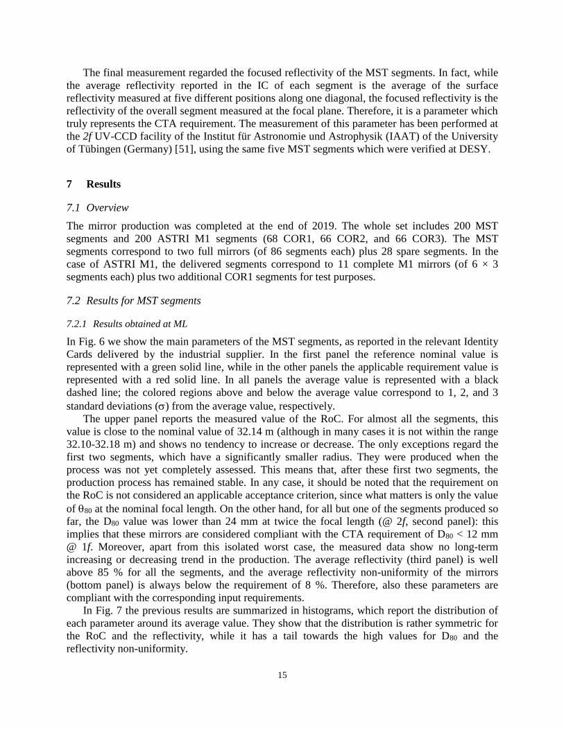
In Fig. 6 we show the main parameters of the MST segments, as reported in the relevant Identity
Cards delivered by the industrial supplier. In the first panel the reference nominal value is
represented with a green solid line, while in the other panels the applicable requirement value is
represented with a red solid line. In all panels the average value is represented with a black
dashed line; the colored regions above and below the average value correspond to 1, 2, and 3
standard deviations () from the average value, respectively.
The upper panel reports the measured value of the RoC. For almost all the segments, this
value is close to the nominal value of 32.14 m (although in many cases it is not within the range
32.10-32.18 m) and shows no tendency to increase or decrease. The only exceptions regard the
first two segments, which have a significantly smaller radius. They were produced when the
process was not yet completely assessed. This means that, after these first two segments, the
production process has remained stable. In any case, it should be noted that the requirement on
the RoC is not considered an applicable acceptance criterion, since what matters is only the value
of 80 at the nominal focal length. On the other hand, for all but one of the segments produced so
far, the D80 value was lower than 24 mm at twice the focal length (@ 2f, second panel): this
implies that these mirrors are considered compliant with the CTA requirement of D80 < 12 mm
@ 1f. Moreover, apart from this isolated worst case, the measured data show no long-term
increasing or decreasing trend in the production. The average reflectivity (third panel) is well
above 85 % for all the segments, and the average reflectivity non-uniformity of the mirrors
(bottom panel) is always below the requirement of 8 %. Therefore, also these parameters are
compliant with the corresponding input requirements.
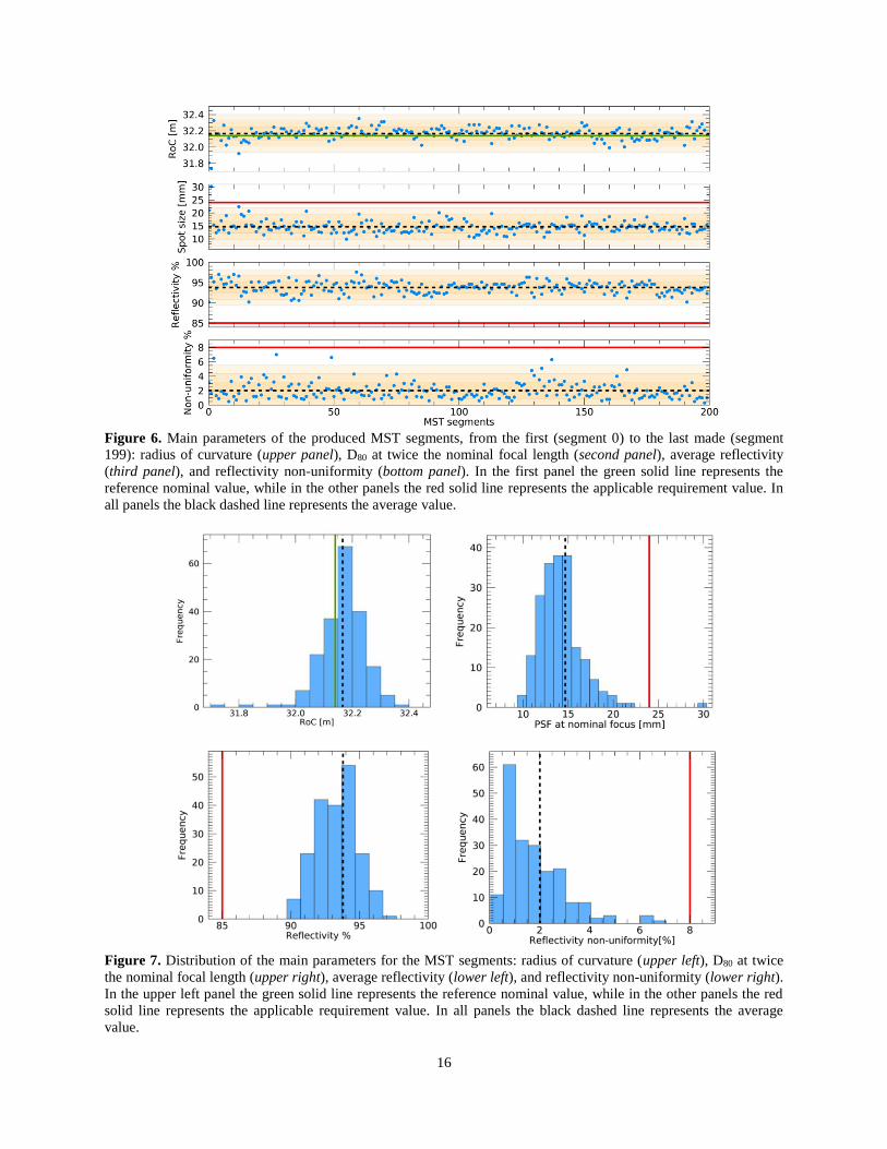
In Fig. 7 the previous results are summarized in histograms, which report the distribution of
each parameter around its average value. They show that the distribution is rather symmetric for
the RoC and the reflectivity, while it has a tail towards the high values for D80 and the
reflectivity non-uniformity.
16
Figure 6. Main parameters of the produced MST segments, from the first (segment 0) to the last made (segment
199): radius of curvature (upper panel), D80 at twice the nominal focal length (second panel), average reflectivity
(third panel), and reflectivity non-uniformity (bottom panel). In the first panel the green solid line represents the
reference nominal value, while in the other panels the red solid line represents the applicable requirement value. In
all panels the black dashed line represents the average value.
Figure 7. Distribution of the main parameters for the MST segments: radius of curvature (upper left), D80 at twice
the nominal focal length (upper right), average reflectivity (lower left), and reflectivity non-uniformity (lower right).
In the upper left panel the green solid line represents the reference nominal value, while in the other panels the red
solid line represents the applicable requirement value. In all panels the black dashed line represents the average
value.
17
7.2.2 Results of sample tests performed at INAF-OAB and DESY
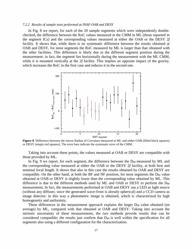
In Fig. 8 we report, for each of the 20 sample segments which were independently double-
checked, the difference between the RoC values measured at the CMM in ML (those reported in
the segment ICs) and the corresponding values measured at either the OAB or the DESY 2f
facility. It shows that, while there is no systematic difference between the results obtained at
OAB and DESY, for most segments the RoC measured by ML is larger than that obtained with
the other facilities. This difference is likely due to the different segment position during the
measurement: in fact, the segment lies horizontally during the measurement with the ML CMM,
while it is mounted vertically at the 2f facility. This implies an opposite impact of the gravity,
which increases the RoC in the first case and reduces it in the second one.
Figure 8. Difference between the mirror Radius of Curvature measured at ML and either OAB (filled black squares)
or DESY (empty red squares). The error bars indicate the systematic error of the CMM.
Taking into account these points, the values measured at OAB or DESY are compatible with
those provided by ML.
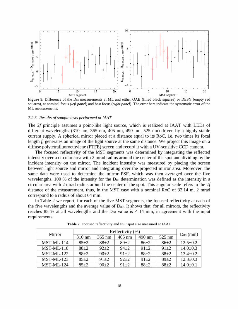
In Fig. 9 we report, for each segment, the difference between the D80 measured by ML and
the corresponding value measured at either the OAB or the DESY 2f facility, at both best and
nominal focal length. It shows that also in this case the results obtained by OAB and DESY are
compatible. On the other hand, at both the BF and NF position, for most segments the D80 value
obtained at OAB or DESY is slightly lower than the corresponding value obtained by ML. This
difference is due to the different methods used by ML and OAB or DESY to perform the D80
measurement. In fact, the measurements performed at OAB and DESY use a LED as light source
(without any diffuser, since the generated wave-front is already spherical) and a CCD camera as
image detector: in this way a photometric image is obtained, which is characterized by high
homogeneity and uniformity.
These differences in the measurement approach explains the larger D80 value obtained (on
average) by ML, compared with that obtained at OAB and DESY. Taking into account the
intrinsic uncertainty of these measurements, the two methods provide results that can be
considered compatible; the results just confirm that D80 is well within the specification for all
segments also using a different configuration for the characterization.
18
Figure 9. Difference of the D80 measurements at ML and either OAB (filled black squares) or DESY (empty red
squares), at nominal focus (left panel) and best focus (right panel). The error bars indicate the systematic error of the
ML measurements.
7.2.3 Results of sample tests performed at IAAT
The 2f principle assumes a point-like light source, which is realized at IAAT with LEDs of
different wavelengths (310 nm, 365 nm, 405 nm, 490 nm, 525 nm) driven by a highly stable
current supply. A spherical mirror placed at a distance equal to its RoC, i.e. two times its focal
length f, generates an image of the light source at the same distance. We project this image on a
diffuse polytetrafluoroethylene (PTFE) screen and record it with a UV-sensitive CCD camera.
The focused reflectivity of the MST segments was determined by integrating the reflected
intensity over a circular area with 2 mrad radius around the center of the spot and dividing by the
incident intensity on the mirror. The incident intensity was measured by placing the screen
between light source and mirror and integrating over the projected mirror area. Moreover, the
same data were used to determine the mirror PSF, which was then averaged over the five
wavelengths. 100 % of the intensity for the D80 determination was defined as the intensity in a
circular area with 2 mrad radius around the center of the spot. This angular scale refers to the 2f
distance of the measurement, thus, in the MST case with a nominal RoC of 32.14 m, 2 mrad
correspond to a radius of about 64 mm.
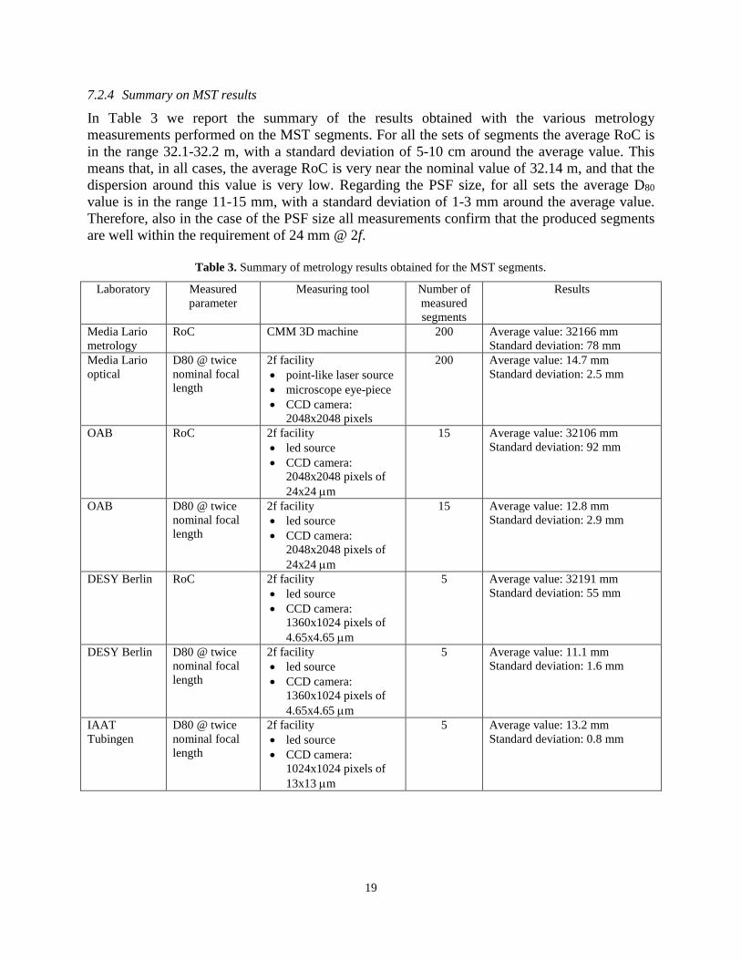
In Table 2 we report, for each of the five MST segments, the focused reflectivity at each of
the five wavelengths and the average value of D80. It shows that, for all mirrors, the reflectivity
reaches 85 % at all wavelengths and the D80 value is ≤ 14 mm, in agreement with the input
requirements.
Table 2. Focused reflectivity and PSF spot size measured at IAAT
Mirror Reflectivity (%)
D80 (mm) 310 nm 365 nm 405 nm 490 nm 525 nm
MST-ML-114 85±2 88±2 89±2 86±2 86±2 12.5±0.2
MST-ML-118 88±2 92±2 94±2 91±2 91±2 14.0±0.3
MST-ML-122 88±2 90±2 91±2 88±2 88±2 13.4±0.2
MST-ML-123 85±2 91±2 92±2 91±2 89±2 12.3±0.3
MST-ML-124 85±2 90±2 91±2 88±2 88±2 14.0±0.1
19
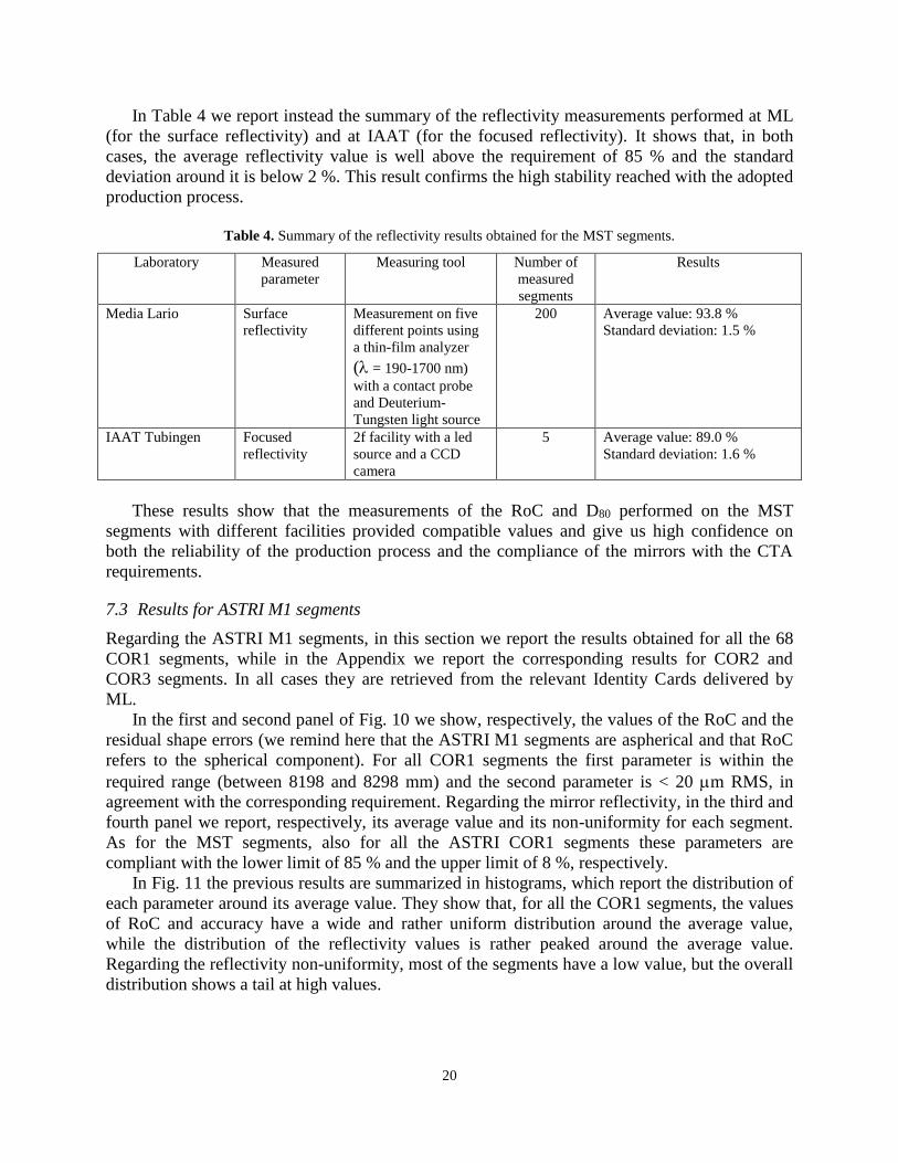
7.2.4 Summary on MST results
In Table 3 we report the summary of the results obtained with the various metrology
measurements performed on the MST segments. For all the sets of segments the average RoC is
in the range 32.1-32.2 m, with a standard deviation of 5-10 cm around the average value. This
means that, in all cases, the average RoC is very near the nominal value of 32.14 m, and that the
dispersion around this value is very low. Regarding the PSF size, for all sets the average D80
value is in the range 11-15 mm, with a standard deviation of 1-3 mm around the average value.
Therefore, also in the case of the PSF size all measurements confirm that the produced segments
are well within the requirement of 24 mm @ 2f.
Table 3. Summary of metrology results obtained for the MST segments.
Laboratory Measured
parameter
Measuring tool Number of
measured
segments
Results
Media Lario
metrology
RoC CMM 3D machine 200 Average value: 32166 mm
Standard deviation: 78 mm
Media Lario
optical
D80 @ twice
nominal focal
length
2f facility
point-like laser source
microscope eye-piece
CCD camera:
2048x2048 pixels
200 Average value: 14.7 mm
Standard deviation: 2.5 mm
OAB RoC 2f facility
led source
CCD camera:
2048x2048 pixels of
24x24 m
15 Average value: 32106 mm
Standard deviation: 92 mm
OAB D80 @ twice
nominal focal
length
2f facility
led source
CCD camera:
2048x2048 pixels of
24x24 m
15 Average value: 12.8 mm
Standard deviation: 2.9 mm
DESY Berlin RoC 2f facility
led source
CCD camera:
1360x1024 pixels of
4.65x4.65 m
5 Average value: 32191 mm
Standard deviation: 55 mm
DESY Berlin D80 @ twice
nominal focal
length
2f facility
led source
CCD camera:
1360x1024 pixels of
4.65x4.65 m
5 Average value: 11.1 mm
Standard deviation: 1.6 mm
IAAT
Tubingen
D80 @ twice
nominal focal
length
2f facility
led source
CCD camera:
1024x1024 pixels of
13x13 m
5 Average value: 13.2 mm
Standard deviation: 0.8 mm
20
In Table 4 we report instead the summary of the reflectivity measurements performed at ML
(for the surface reflectivity) and at IAAT (for the focused reflectivity). It shows that, in both
cases, the average reflectivity value is well above the requirement of 85 % and the standard
deviation around it is below 2 %. This result confirms the high stability reached with the adopted
production process.
Table 4. Summary of the reflectivity results obtained for the MST segments.
Laboratory Measured
parameter
Measuring tool Number of
measured
segments
Results
Media Lario Surface
reflectivity
Measurement on five
different points using
a thin-film analyzer
( = 190-1700 nm)
with a contact probe
and Deuterium-
Tungsten light source
200 Average value: 93.8 %
Standard deviation: 1.5 %
IAAT Tubingen Focused
reflectivity
2f facility with a led
source and a CCD
camera
5 Average value: 89.0 %
Standard deviation: 1.6 %
These results show that the measurements of the RoC and D80 performed on the MST
segments with different facilities provided compatible values and give us high confidence on
both the reliability of the production process and the compliance of the mirrors with the CTA
requirements.
7.3 Results for ASTRI M1 segments
Regarding the ASTRI M1 segments, in this section we report the results obtained for all the 68
COR1 segments, while in the Appendix we report the corresponding results for COR2 and
COR3 segments. In all cases they are retrieved from the relevant Identity Cards delivered by
ML.
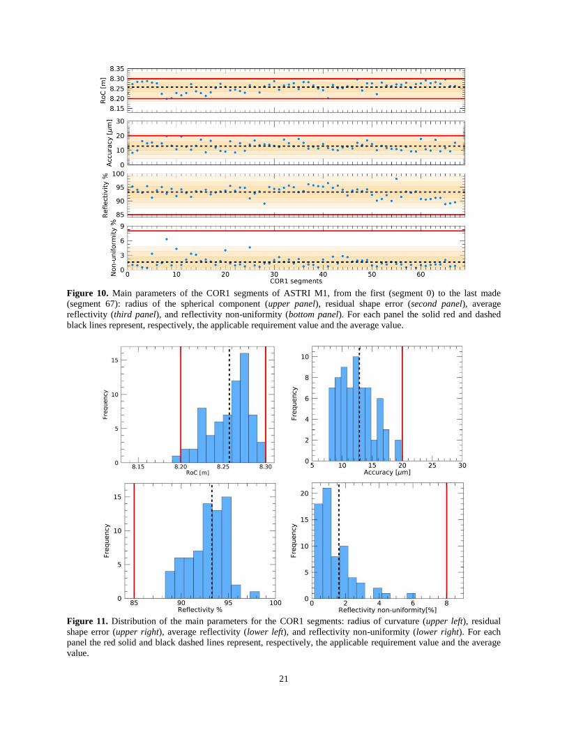
In the first and second panel of Fig. 10 we show, respectively, the values of the RoC and the
residual shape errors (we remind here that the ASTRI M1 segments are aspherical and that RoC
refers to the spherical component). For all COR1 segments the first parameter is within the
required range (between 8198 and 8298 mm) and the second parameter is < 20 m RMS, in
agreement with the corresponding requirement. Regarding the mirror reflectivity, in the third and
fourth panel we report, respectively, its average value and its non-uniformity for each segment.
As for the MST segments, also for all the ASTRI COR1 segments these parameters are
compliant with the lower limit of 85 % and the upper limit of 8 %, respectively.
In Fig. 11 the previous results are summarized in histograms, which report the distribution of
each parameter around its average value. They show that, for all the COR1 segments, the values
of RoC and accuracy have a wide and rather uniform distribution around the average value,
while the distribution of the reflectivity values is rather peaked around the average value.
Regarding the reflectivity non-uniformity, most of the segments have a low value, but the overall
distribution shows a tail at high values.
21
Figure 10. Main parameters of the COR1 segments of ASTRI M1, from the first (segment 0) to the last made
(segment 67): radius of the spherical component (upper panel), residual shape error (second panel), average
reflectivity (third panel), and reflectivity non-uniformity (bottom panel). For each panel the solid red and dashed
black lines represent, respectively, the applicable requirement value and the average value.
Figure 11. Distribution of the main parameters for the COR1 segments: radius of curvature (upper left), residual
shape error (upper right), average reflectivity (lower left), and reflectivity non-uniformity (lower right). For each
panel the red solid and black dashed lines represent, respectively, the applicable requirement value and the average
value.
22
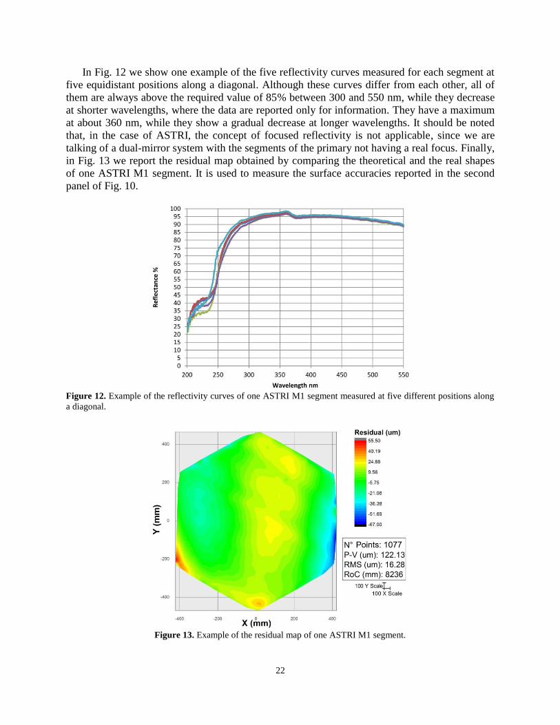
In Fig. 12 we show one example of the five reflectivity curves measured for each segment at
five equidistant positions along a diagonal. Although these curves differ from each other, all of
them are always above the required value of 85% between 300 and 550 nm, while they decrease
at shorter wavelengths, where the data are reported only for information. They have a maximum
at about 360 nm, while they show a gradual decrease at longer wavelengths. It should be noted
that, in the case of ASTRI, the concept of focused reflectivity is not applicable, since we are
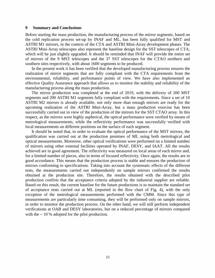
talking of a dual-mirror system with the segments of the primary not having a real focus. Finally,
in Fig. 13 we report the residual map obtained by comparing the theoretical and the real shapes
of one ASTRI M1 segment. It is used to measure the surface accuracies reported in the second
panel of Fig. 10.
Figure 12. Example of the reflectivity curves of one ASTRI M1 segment measured at five different positions along
a diagonal.
Figure 13. Example of the residual map of one ASTRI M1 segment.
23
9 Summary and Conclusions
Before starting the mass production, the manufacturing process of the mirror segments, based on
the cold replication process set-up by INAF and ML, has been fully qualified for MST and
ASTRI M1 mirrors, in the context of the CTA and ASTRI Mini-Array development phases. The
ASTRI Mini-Array telescopes also represent the baseline design for the SST telescopes of CTA,
which will be just slightly upgraded. It should be reminded that INAF will provide the entire set
of mirrors of the 9 MST telescopes and the 37 SST telescopes for the CTAO northern and
southern sites respectively, with about 1600 segments to be produced.
In the present work it has been verified that the developed manufacturing process ensures the
realization of mirror segments that are fully compliant with the CTA requirements from the
environmental, reliability, and performance points of view. We have also implemented an
effective Quality Assurance approach that allows us to monitor the stability and reliability of the
manufacturing process along the mass production.
The mirror production was completed at the end of 2019, with the delivery of 200 MST
segments and 200 ASTRI M1 segments fully compliant with the requirements. Since a set of 10
ASTRI M2 mirrors is already available, not only more than enough mirrors are ready for the
upcoming realization of the ASTRI Mini-Array, but a mass production exercise has been
successfully carried out in view of the production of the mirrors for the SST CTAO array. In this
respect, as the mirrors were highly aspherical, the optical performance were verified by means of
metrological measurements, while the reflectivity performance was successfully verified with
local measurements on different positions on the surface of each segment.
It should be noted that, in order to evaluate the optical performance of the MST mirrors, the
qualification was carried out at the production premises of ML using both metrological and
optical measurements. Moreover, other optical verifications were performed on a limited number
of mirrors using other external facilities operated by INAF, DESY, and IAAT. All the results
achieved are in good agreement. The reflectivity was measured on local areas of each mirror and,
for a limited number of pieces, also in terms of focused reflectivity. Once again, the results are in
good accordance. This means that the production process is stable and ensures the production of
mirrors conforming to specifications. Taking into account the systematic effects of the different
tests, the measurements carried out independently on sample mirrors confirmed the results
obtained at the production site. Therefore, the results obtained with the described pilot
production confirm that the acceptance criteria adopted by the industrial supplier are reliable.
Based on this result, the current baseline for the future productions is to maintain the standard set
of acceptance tests carried out at ML (reported in the flow chart of Fig. 4), with the only
exception of the metrological measurements performed with the CMM. Since this type of
measurements are particularly time consuming, they will be performed only on sample mirrors,
in order to monitor the production process. On the other hand, we will still perform independent
verifications at OAB and DESY laboratories, but on a reduced percentage of mirrors compared
with the 10 % adopted for the pilot production.
24
Acknowledgments Part of the results reported in this paper were anticipated in 2019 at the SPIE Conference 11119 “Optics for EUV,
X-Ray, and Gamma-Ray Astronomy IX”, and were reported in the relevant SPIE Proceedings (La Palombara et al.
2019, SPIE Proc. 111191U). This work has been supported by the Italian Ministry of University and Research
(MUR) with funds specifically assigned to the Italian National Institute of Astrophysics (INAF) for the Cherenkov
Telescope Array (CTA), and by the Italian Ministry of Economic Development (MISE) within the “Astronomia
Industriale” program. We acknowledge support from the Brazilian Funding Agency FAPESP (Grant 2013/10559-5)
and from the South African Department of Science and Technology through Funding Agreement 0227/2014 for the
South African Gamma-Ray Astronomy Programme. This work was conducted in the context of the CTA SST and
MST Working Groups. We gratefully acknowledge financial support from the agencies and organizations listed
here: http://www.cta-observatory.org/consortium_acknowledgments. We thank Dr. G. Tagliaferri, who coordinates
the INAF participation to the MST Consortium, for his support to this activity. We thank Dr. G. Grisoni (ML) for
providing us with useful comments and suggestions. This work has gone through internal review by the ASTRI
Collaboration and by the CTA Consortium.
References
1. M. de Naurois & D. Mazin, “Ground-based detectors in very-high-energy gamma-ray astronomy”,
Comptes Rendus Physique 16(6), 610-617 (2015) [10.1016/j.crhy.2015.08.011]
2. T. C. Weekes et al, “Observation of TeV Gamma Rays from the Crab Nebula Using the
Atmospheric Cerenkov Imaging Technique”, Astrophys. J. 342, 379-395 (1989) [10.1086/167599]
3. F. Aharonian et al., “Observations of the Crab nebula with HESS”, A&A 457(3), 899-915 (2006)
[10.1051/0004-6361:20065351]
4. J. Aleksić et al., “Performance of the MAGIC stereo system obtained with Crab Nebula data”,
Astroparticle Physics 35(7), 435-448 (2012) [10.1016/j.astropartphys.2011.11.007]
5. N. Park and VERITAS Collaboration, “Performance of the VERITAS experiment”, in 34th
International Cosmic Ray Conference, ICRC 34, 771, 1-8 (2015)
6. H. Abdalla et al., HESS Collaboration, “The H.E.S.S. Galactic plane survey”, A&A 612, A1, 1-61
(2018) [10.1051/0004-6361/201732098]
7. V. Vassiliev, S. Fegan , P. Brousseau, “Wide field aplanatic two-mirror telescopes for ground-based
γ-ray astronomy”, Astroparticle Physics 28, 10-27 (2007) [10.1016/j.astropartphys.2007.04.002]
8. E. Giro et al., “First optical validation of a Schwarzschild Couder telescope: the ASTRI SST-2M
Cherenkov telescope”, A&A 608, A86, 1-6 (2017) [10.1051/0004-6361/201731602]
9. S. Lombardi et al., “First detection of the Crab Nebula at TeV energies with a Cherenkov telescope in
dual-mirror Schwarzschild-Couder configuration: the ASTRI-Horn telescope”, A&A 634, A22, 1-6
(2020) [10.1051/0004-6361/201936791]
10. G. Pareschi, “The ASTRI SST-2M prototype and mini-array for the Cherenkov Telescope Array
(CTA)”, Proc. SPIE 9906, 99065T, 1-13 (2016) [10.1117/12.2232275]
11. S. Scuderi, “From the Etna volcano to the Chilean Andes: ASTRI end-to-end telescopes for the
Cherenkov Telescope Array”, Proc. SPIE 10700, 107005Z, 1-14 (2018) [10.1117/12.2312453]
12. L. A. Antonelli, “The ASTRI Mini-Array at Teide Observatory”, Proc. ICRC 37, 832, 1-8 (2021)
13. B. S. Acharya et al., CTA Consortium, “Introducing the CTA concept”, Astroparticle Physics 43, 3-
18 (2013) [10.1016/j.astropartphys.2013.01.007]
14. B. S. Acharya et al., CTA Consortium, “Science with the Cherenkov Telescope Array”, World
Scientific Publishing Co. Pte. Ltd., Singapore (2019) [10.1142/10986]
15. R. Zanin, “CTA – the World’s largest ground-based gamma-ray observatory”, Proc. ICRC 37, 1478,
1-8 (2021)
16. J. Rousselle, “Toward the construction of a medium size prototype Schwarzschild-Couder telescope
for CTA”, Proc. SPIE 9603, 960305, 1-12 (2015) [10.1117/12.2188381]
17. C. Adams et al., “Alignment of the optical system of the 9.7-m prototype Schwarzchild-Coulder
Telescope”, Proc. SPIE 11445, 114456A, 1-15 (2020) [10.1117/12.2564653]
25
18. G. Pareschi et al., “The dual-mirror Small Size Telescope for the Cherenkov Telescope Array”, Proc.
ICRC 33, 0466, 1151-1154 (2013)
19. R. White et al., “The Small-Sized Telescopes for the Southern Site of the Cherenkov Telescope
Array”, Proc. ICRC 37, 638, 1-9 (2021)
20. J. M. Davies & E. S. Cotton, “Design of the quartermaster solar furnace”, J. Sol. Energy Sci. Eng.
1(2), 16-22 (1957)
21. G. Pareschi, E. Giro, R. Banham et al., “Glass mirrors by cold slumping to cover 100 m2 of the
MAGIC II Cherenkov telescope reflecting surface”, Proc. SPIE 7018, 70180W, 1-11 (2008)
[10.1117/12.790404]
22. R. Canestrari and G. Sironi, “An overview on mirrors for Cherenkov telescopes manufactured by
glass cold-shaping technology”, Proc. SPIE 9603, 960302, 1-9 (2015) [10.1117/12.2191429]
23. R. Canestrari et al., “The glass cold-shaping technology for the mirrors of the Cherenkov Telescope
Array”, Proc. SPIE 9151, 91512V, 1-10 (2014) [10.1117/12.2055838]
24. R. Canestrari et al., “The ASTRI SST-2M prototype for the next generation of Cherenkov telescopes:
structure and mirrors”, Proc. SPIE 8861, 886102, 1-13 (2013) [10.1117/12.2024379]
25. M. Garczarczyk, “Medium size telescopes for the Cherenkov Telescope Array”, Proc. SPIE 10700,
1070023, 1-7 (2018) [10.1117/12.2312000]
26. A. Förster et al., “Mirror development for CTA”, Proc. SPIE 7437, 743712, 1-6 (2009)
[10.1117/12.827726]
27. A. Förster et al., “Mirror Development for the Cherenkov Telescope Array”, Proc. ICRC 33, 0747,
1147-1150 (2013)
28. G. Pareschi et al., “Status of the technologies for the production of the Cherenkov Telescope Array
(CTA) mirrors”, Proc. SPIE 8861, 886103, 1-19 (2013) [10.1117/12.2025476]
29. M. Actis et al., “Design concepts for the Cherenkov Telescope Array CTA: an advanced facility for
ground-based high-energy gamma-ray astronomy”, Exp. Astron. 32, 193–316 (2011)
[10.1007/s10686-011-9247-0]
30. J.L. Dournaux et al., “Aspherical mirrors for the Gamma-ray Cherenkov Telescope, a Schwarschild-
Couder prototype proposed for the future Cherenkov Telescope Array”, Proc. SPIE 9912, 991240, 1-
12 (2016) [10.1117/12.2232091]
31. K. Hari Krishnan, et al., “An overall aspect of electroless Ni-P depositions - A review”, Metallurgical
and Materials Transactions 37, Issue 6 (2006)
32. R. Graue and G. Valsecchi, “Superfinish technology for enhanced grazing incidence reflectivity in X-
ray telescopes”, Proc. SPIE 2805, 293-300 (1996) [10.1117/12.245106]
33. Y. Namba et al., “Ultra-precision polishing of electroless nickel molding dies for shorter wavelength
applications”, CIRP Annals 57, Issue 1 , 337-340, (2008)
34. D. Vernani, R. Banham, O. Citterio et al., “Development of cold-slumping glass mirrors for imaging
Cherenkov telescopes”, Proc. SPIE 7018, 70180V, 1-11 (2008) [10.1117/12.790631]
35. R. Canestrari et al., “Cold-shaping of thin glass foils as a method for mirror processing: from basic
concepts to mass production of mirrors”, Optical Engineering 52, 051204, 1-12 (2013)
[10.1117/1.OE.52.5.051204]
36. K. Tayabaly et al., “Roughness tolerances for Cherenkov telescope mirrors”, Proc. SPIE 9603,
960307, 1-14 (2015) [10.1117/12.2187025]
37. J.M Bennett & L. Mattsson, “Introduction to Surface Roughness and Scattering”, Optical Society of
America (1989)
38. R. Canestrari, et al., “Techniques for the manufacturing of stiff and lightweight optical mirror panels
based on slumping of glass sheets: concepts and results”, Proc. SPIE 7437, 743711, 1-12 (2009)
[10.1117/12.826145]
39. C.B. Adams et al, “Verification of the optical system of the 9.7-m prototype Schwarzschild-Couder
Telescope”, Proc. SPIE 11488, 1148805, 1-19 (2020) [10.1117/12.2568134]
40. C.B. Adams et al, “Detection of the Crab Nebula with the 9.7 m prototype Schwarzschild-Couder
telescope”, Astroparticle Physics 128, 102562 (2021) [10.1016/j.astropartphys.2021.102562]
26
41. M. Dyrda et al., “Open-structure Composite Mirrors for the Cherenkov Telescope Array”, Proc.
ICRC 33, 0281, 2852-2855 (2013)
42. P. Brun, et al., “Composite mirror facets for ground-based gamma ray astronomy”, NIM A 714, 58
(2013) [10.1016/j.nima.2013.01.051]
43. M. Hayashida et al., “The Optical System for the Large Size Telescope of the Cherenkov Telescope
Array”, Proc. ICRC 34, 927, 1-8 (2015)
44. T. Inada, et al., “Design and production of segment mirrors for the Large-Sized Telescopes of the
Cherenkov Telescope Array”, Proc. SPIE 11451, 114510G, 1-10 (2020) [10.1117/12.2562111]
45. M. Will et al., “Novel Back-coated Glass Mirrors for the MAGIC Telescopes”, Proc. ICRC 36, 823
(2019)
46. G. Pareschi et al., “Aluminum-based Segmented Mirrors for gamma-ray Cherenkov Telescopes:
status and perspectives”, Proc. SPIE 11822, 1182203, 1-12 (2021) [10.1117/12.2596490]
47. R. Canestrari et al., “The ASTRI SST-2M prototype for the Cherenkov Telescope Array:
manufacturing of the structure and the mirrors”, Proc. SPIE 9145, 91450M, 1-10 (2014)
[10.1117/12.2055805]
48. K. Tayabaly et al., “Point spread function computation in normal incidence for rough optical
surfaces”, Proc. SPIE 9911, 99111X, 1-10 (2016) [10.1117/12.2232320]
49. G. Sironi et al., “The Cherenkov optics qualification facilities at INAF-OAB laboratories”, Nuclear
Inst. and Methods in Physics Research A 952, 162163, 1-4 (2020) [10.1016/j.nima.2019.05.004]
50. A. Schulz et al., “Methods for the characterization of mirror facets for Imaging Atmospheric
Cherenkov Telescopes”, Proc. ICRC 32, 0580, 1-4 (2011) [10.7529/ICRC2011/V09/0580]
51. J. Dick, A. Bonardi, S. Bressel et al., “Recent developments for the testing of Cherenkov Telescope
Array mirrors and actuators in Tübingen”, Proc. ICRC 34, 1040, 1-8 (2015)
27
Appendix: Results for ASTRI COR2 and COR3 segments
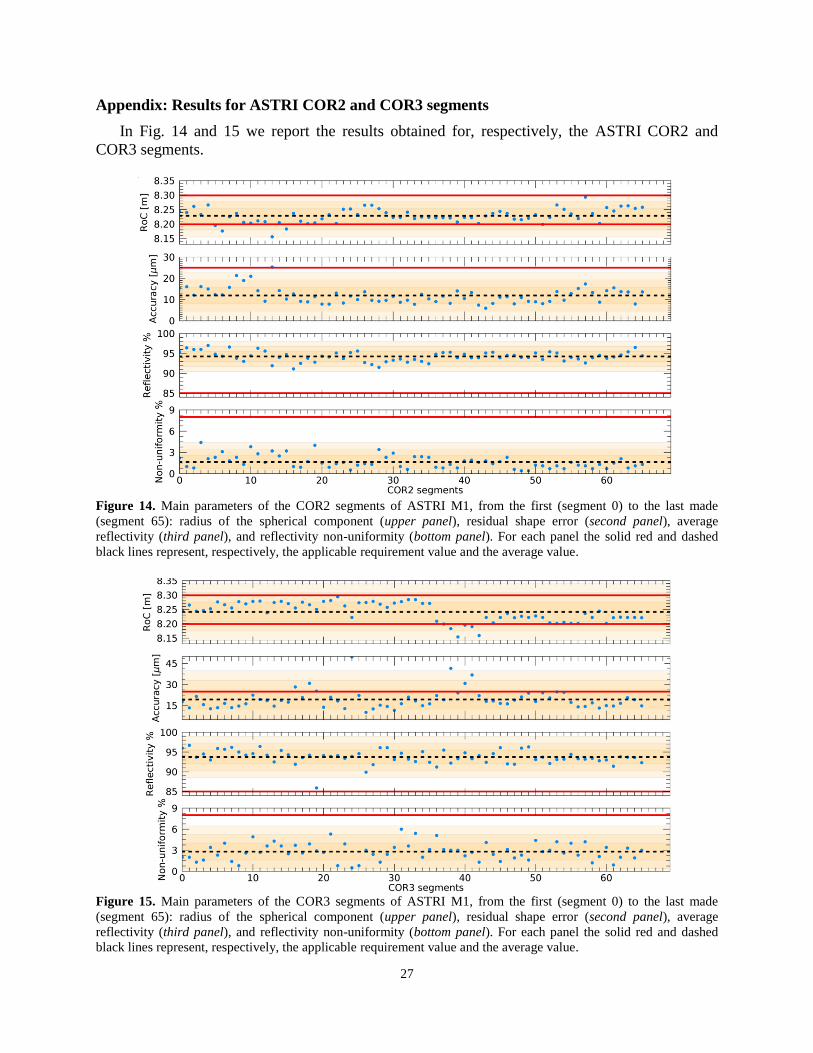
In Fig. 14 and 15 we report the results obtained for, respectively, the ASTRI COR2 and
COR3 segments.
Figure 14. Main parameters of the COR2 segments of ASTRI M1, from the first (segment 0) to the last made
(segment 65): radius of the spherical component (upper panel), residual shape error (second panel), average
reflectivity (third panel), and reflectivity non-uniformity (bottom panel). For each panel the solid red and dashed
black lines represent, respectively, the applicable requirement value and the average value.
Figure 15. Main parameters of the COR3 segments of ASTRI M1, from the first (segment 0) to the last made
(segment 65): radius of the spherical component (upper panel), residual shape error (second panel), average
reflectivity (third panel), and reflectivity non-uniformity (bottom panel). For each panel the solid red and dashed
black lines represent, respectively, the applicable requirement value and the average value.
28
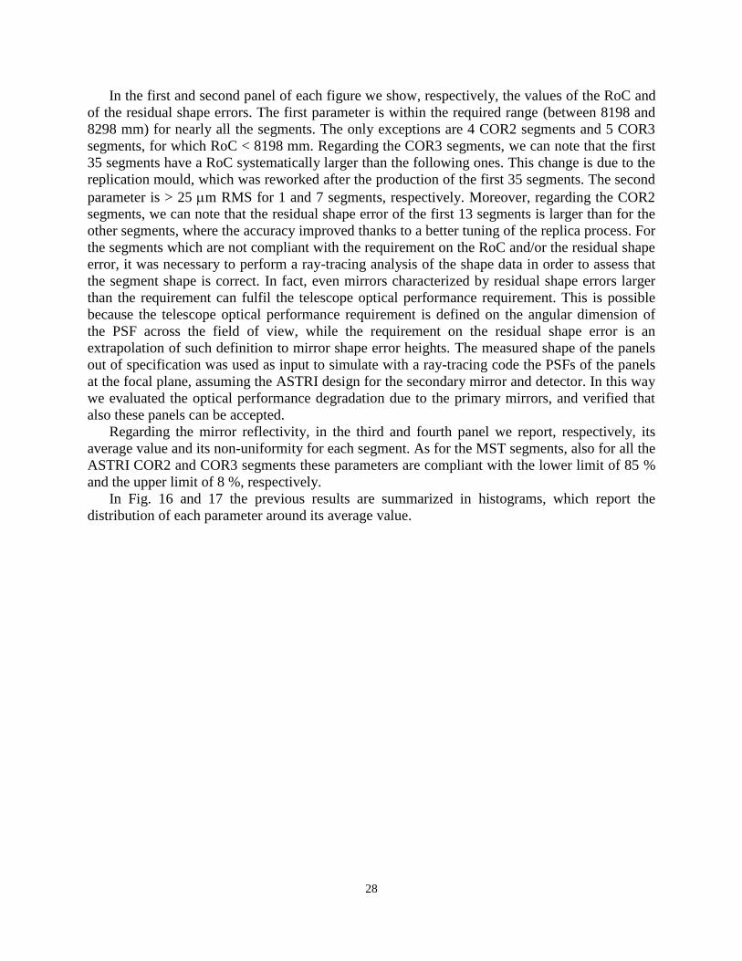
In the first and second panel of each figure we show, respectively, the values of the RoC and
of the residual shape errors. The first parameter is within the required range (between 8198 and
8298 mm) for nearly all the segments. The only exceptions are 4 COR2 segments and 5 COR3
segments, for which RoC < 8198 mm. Regarding the COR3 segments, we can note that the first
35 segments have a RoC systematically larger than the following ones. This change is due to the
replication mould, which was reworked after the production of the first 35 segments. The second
parameter is > 25 m RMS for 1 and 7 segments, respectively. Moreover, regarding the COR2
segments, we can note that the residual shape error of the first 13 segments is larger than for the
other segments, where the accuracy improved thanks to a better tuning of the replica process. For
the segments which are not compliant with the requirement on the RoC and/or the residual shape
error, it was necessary to perform a ray-tracing analysis of the shape data in order to assess that
the segment shape is correct. In fact, even mirrors characterized by residual shape errors larger
than the requirement can fulfil the telescope optical performance requirement. This is possible
because the telescope optical performance requirement is defined on the angular dimension of
the PSF across the field of view, while the requirement on the residual shape error is an
extrapolation of such definition to mirror shape error heights. The measured shape of the panels
out of specification was used as input to simulate with a ray-tracing code the PSFs of the panels
at the focal plane, assuming the ASTRI design for the secondary mirror and detector. In this way
we evaluated the optical performance degradation due to the primary mirrors, and verified that
also these panels can be accepted.
Regarding the mirror reflectivity, in the third and fourth panel we report, respectively, its
average value and its non-uniformity for each segment. As for the MST segments, also for all the
ASTRI COR2 and COR3 segments these parameters are compliant with the lower limit of 85 %
and the upper limit of 8 %, respectively.
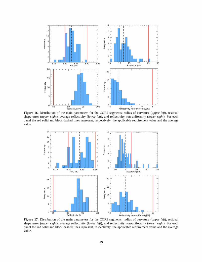
In Fig. 16 and 17 the previous results are summarized in histograms, which report the
distribution of each parameter around its average value.
29
Figure 16. Distribution of the main parameters for the COR2 segments: radius of curvature (upper left), residual
shape error (upper right), average reflectivity (lower left), and reflectivity non-uniformity (lower right). For each
panel the red solid and black dashed lines represent, respectively, the applicable requirement value and the average
value.
Figure 17. Distribution of the main parameters for the COR3 segments: radius of curvature (upper left), residual
shape error (upper right), average reflectivity (lower left), and reflectivity non-uniformity (lower right). For each
panel the red solid and black dashed lines represent, respectively, the applicable requirement value and the average
value.


