Embed Size (px)
Citation preview
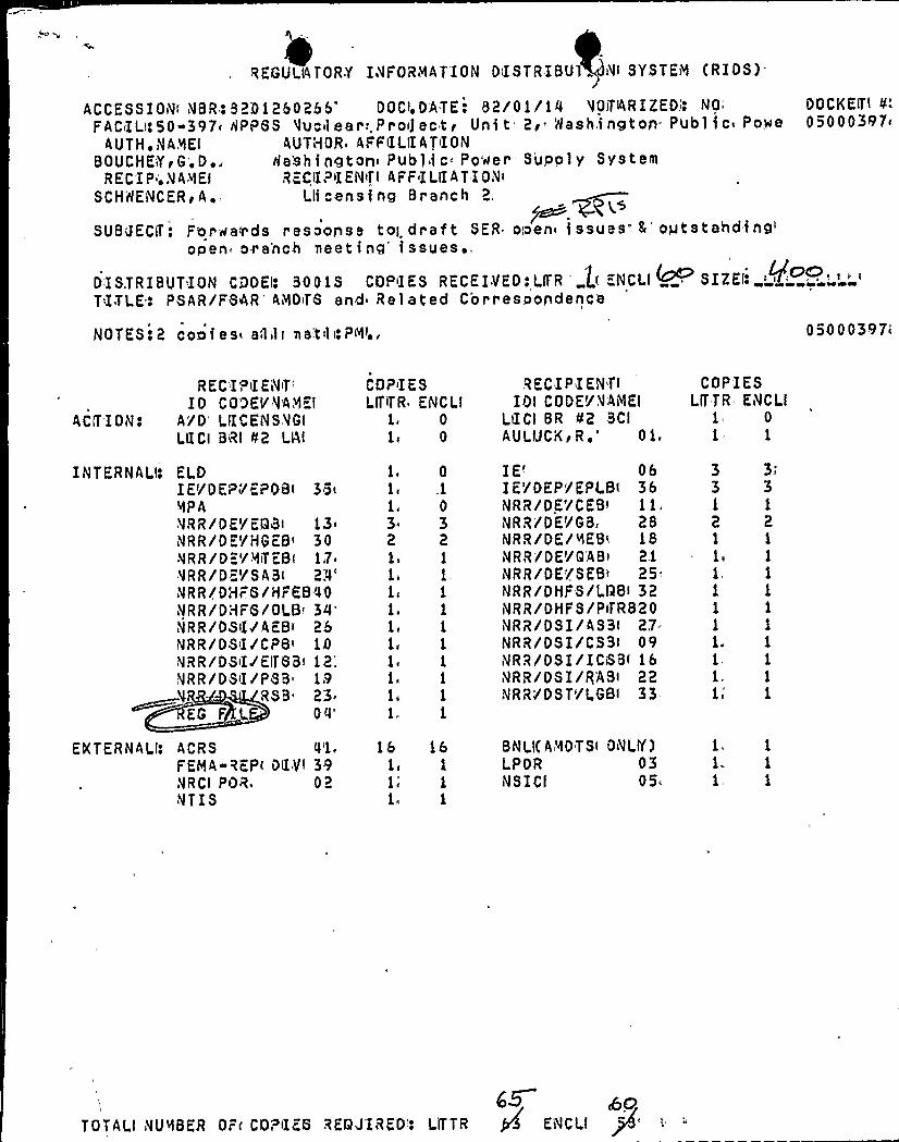
REGULATORY I VFORI»IATION DiISTRIBUl IVI SYSTEM (RIOS)
ACCESSIOIVi NBR: 82D1260266'OCIS O'ATES 82/01/14 VOiTIARIZEOi!NO'AC»ILi!50397» APP8S VuCil ear:,Pr Oij eCti Uni t 2> WaShingtOn'ubl iC POWe
AUTH, VAiiIEI AUTHOR AFFCLIIATIONBDUGHKiYEG'.D~ . Ha'shington» Public- Power supply system
REC'IP. VAREI RKCIIPIIKNiTI AFF ILIIATIONiSCHHENCKR<A. Llicensing Branch 2.
gS
SUBJECIT: For weir ds resoorise toI draf t SKR ooen» i ssues"- E'gtstahding'pen
ora'nchmeeting'ssues'�
,
DISTRISUTION CDDEI: SDOIS CDI»~IES RECEIVED:LrTR lr =NCLI SIZEi:TXTLE'. PSAR/FBAR" Al»IOrT8 and Related Correspondence
NOTES:2 cool es» atlili ma'till Pili.,
OOCKKITI tt«"'
50 0 0397»
05000397»
R EC'IPiIENiTiI O CO'3EI/ V'AAEI
ACCT IOiV! A'/O'IICEiVSVGILIICI BRI C2 LAI
INTERNALIo ELOIET/DEPT'EPOB< 3@i%PANRR/OE/E93i 13NRR/DE»/HGKB» 30NR R/0 K'/ RiT EB< 17»VRR/DKT/SABi
2!0'VRR/DHFS/HFEB'0QNRR/DHF8/OLBi
34'VRR/DSil/AKB»26iVRR/DSiI/CPB» 1DiVRR/OSIIIEITBBi 12';,
NRR/DSiI/P8B 19* RSB» 23
EG F L
QQ'XTERNALI:
ACRS 0'1«
FERA-REPi DC.YI 39NRCI POR'2NTIS
COP»I E S
LITiTR EiV C LI1. 01» 0
1 Q
1 .1
1 03.2 21 1
1» 1,
1»
1 1
1» 1
1 1
1 1
1» 1
1» 1
1, 1
16 ib1» 1
li1
RKCIPIEIVTIIOI CODET/,VAiMEI
I.tICI BR 42 BCIAULUCI(ER ~" 01
IK< 06IE»/DEP/KPLBi 36NRR/OK'/CEB» 11.NRR/DE'/GB 28NRR/DE/iiIEB< 18NRR/DE'/GAB» 2.1iVRR/OE'/SEBT 25"NRR/OHFS/LTIBi 32NRR/OHFS/PiTR820IVRR/OSI/ASSI 27NRR/DSI/C33i 09NRR/DSI/ICiSB< 16NRR/OS I/RABi 22NRR/DST'/LGBI 33
BNLI(A'ROTSi ONLIY)LPOR 03NSICI 05»
COPrIESLITTR EiVCLI
1» 0
1 1
3"
3 31 1
2 21
1» 1
1 1
1
1 1
1 1
1. 1
1
1 1
1
1 1
1. 1
1, 1
acTOTALl NURSER Drr CORrIEO REOJ'ISED': LITTR g ENCl.l pf'"

I~ ~
1
~ C T
'A
II
glI4 I
L
~ ~
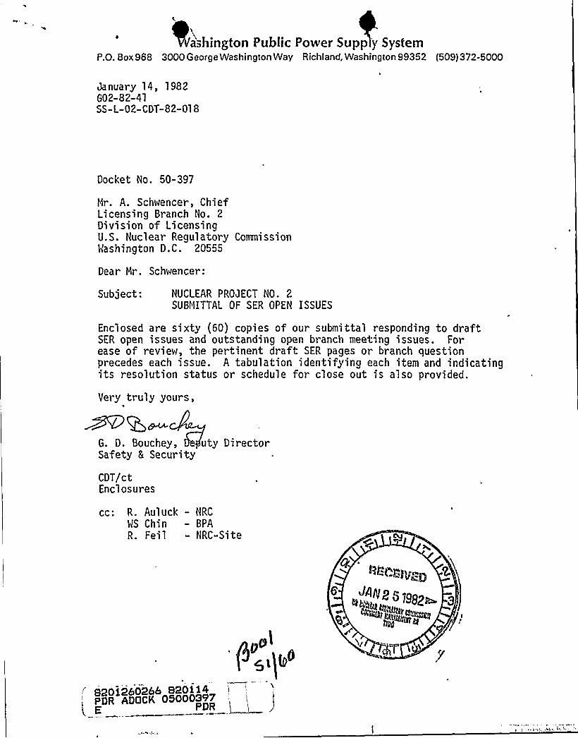
a+~hington Public Power Supp 'y SystemPO. Box 968 3000George Washington Way Richland, Washington 99352 (509) 372-5000
January 14, 1982G02-82-41SS-L-02-CDT-82-018
Docket No. 50-397
Mr. A. Schwencer, ChiefLicensing Branch No. 2Division of LicensingU.S. Nuclear Regulatory CommissionIi'ashington D.C. 20555
Dear Mr. Schwencer:
Subject: NUCLEAR PROJECT NO. 2SUBMITTAL OF SER OPEN ISSUES
Enclosed are sixty (60) copies of our submittal responding to draftSER open issues and outstanding open branch meeting issues. Forease of review, the pertinent draft SER pages or branch questionprecedes each issue. A tabulation identifying each item and indicatingits resolution status or schedule for close out is also provided.
Very truly yours,
G. D. Bouchey, uty DirectorSafety 8 Security
CDT/ctEnclosures
cc: R. Auluck - NRC
WS Chin — BPAR. Feil - NRC-Site
gl) g0
S20i2b02bb 820114PDR ADQCK OS0003'P7E PDR
d
e
>f
IJ
II
~ 5
li a )
'I,
Wy
P'4
4
6j;0;,"
". 4'sI
~~(4 Wf8@P~fljfPfg
26 /!ij
82012602661 ':~00'0'6'~'6006 '26
P 2i )l'0
~ '.g 'j.j".8'68i~*:, >6 "",$80 > ~ Cj -'2'<4''>. «QQ)~P gggjOgy Qf y ., '~;:; g~'
6i'Pl.'';,'
" 'IRKED '" ".'., ' ' i,-""'. % '. '.„'-'',< '-, ', f' „~ ',', ',,'~ ~ ';' "' .'''2''.;< 00 ".~ ,,i r.i :''' ': ~ , 6'0 .", '0 ,4 ~'W, ~
' 6'g , ; j ~6
a>2: ~ .', ~,'~ „" ~ ...'.„, '
~, ~ g, ti20 W If':]6.. ~ 6g',, ~ ~ ','W 'j6
~
0
I "ii
ff
f
f
f
jy8 +'I'' '
6 ~ P. ~ ~
0
I4OI% 5lCNAJ1IN% OW'
)6 'J ~
I~ ~'0WW ~ " ~
i ~neo ""-<'"'"="
fI. C+~'I'jj CU0Tf ~ 6'F'Q:'' %7 A 6~ '0 ~ g'y'0 ~ 862 6 0 I" L'W '6, ~ 'i",I'0, 6, f ~~ 8 6 ~
6
WNP-2
Open SER issue
3.9.5.c NUREG-0619m BWR Feedwater Nozzle and ControlRod Drive Return Line Nozzle Crackin

W NP-2
Open SER Issue
3.9.5.c NUREG-0619'WR Feedwater Nozzle and ControlRod Drive Return Line Nozzle Crackin
A response to this issue was submitted January13'982'n
letter G0.2-82-36.

of s ructural integrity or impairment of func ion. The design procedures and
criteria used by the applicant in %e design of the Mt(P-2 reac.or internalscomply wi h Standard Review Plan Sectian 3.9.5 and constitute an acceptablebasis for satisfying the applicable requirements of General Oesign.Criteria 1,
2, '4, and 10.
3.9.6 Inservice Tes ina of Pumps and 'lalves
In Sections 3.9.2 and 3.9.3 of this Safety Evaluation Repor- we discussed the
design of safety"related pumps and valves in the 'HHP"2 facility. The design ofthese pumps and valves is intended to demons rate that. they will"be capable
of performing their safety function (open, clo'se, start; etc.) at any time "during the plant life. However, to provide added assurance of the reliabili'
I
of:these components, 'tlie applicants will periodically est all its safe y"J
re' e"re' ed pumps and valves. 'These tests are performed in general accordance wi".h
the rules of Section XI af the ASIDE Code, These tests verify-"h. t .tie'. s sK pLmps
and'alves ooerhte successfully when called upon. Additionally, periodicmeasurements are ma'de of various parameters and compared to baseline measure-
ments 1n order to detect longterm degradatian of the pump or valve performance.
ur rev'.ew under Standard Review Plan Sec-ion 3.9.6 covers he applicant'sprogram -or preservice and inservice tes ing of pumps and valves. 'ale give
par icular a tention to those areas of the test program for which the applicantreques s relict from the requirements of Section XI of the AS/1E Code.
t e appl;cant must provide a commitment that the inservice .esting of AERIE
Class 1,. 2, and 3 components will be in accordance with the revised'ules of10 CFR, Par. 50, Section 50.55a, paragraph (g). The applicant has not yetsubmi ted its program for the preservice and inservice '.esting af pumps and
valves; therefore-; we have not yet compl ted our review. Any requests forrelief from ASIDE Section XI should be submitted as soon as possible.
There are several sa,ety sys ems connected to the reactor coolant pressure
boundary thai have design pressure below the rated reactor coolant'sys em (RCS)
pressure. There are also some systems which are rated at full reactor pressure
Rene L-;"~'t(P SER/3
Open SER Issue
3.9.6 Preservice and Inservice Testi n Pro rams
A response to this issue was submitted October 1, 1981, by letternumber G02-81-322.
JC Martin-927MBA Holmberg-904ARG Matlock-901AWC Bibb-901A
M Nelson-906DTaylor-9060 .
Bouchey-396
VIIIVIIV I I I C
kf/file-CDT/LBGDB/LBsf 2
W. PSS CORF~~PGN)EHC NO.
October 1, 1981G02-322
Docket Ho. 50-397
Hr. A. SchwencerLicensing Branch No. 2Division of LicensingV. S..Nuclear Regul'atory CommissionWashington, D.C. 20555
Dear . Mr. Schwencer:
Subject: SUPPLY SYSTEM NUCLEAR PROJECT NO. 2
PUMP AND"VAL'VE TEST PROGRAM PC.AN
Enclosed are sixty (60) copies of the Pump and Valve Test; ProgramPlan for WNP-2. These changes will be incorporated into an amend-
nent within four months.
Very truly yours,
Enclosure
GDB/CDT/ldm
G. D. BoucheyDirector, Nuclear Safety .,
cc: WS Chin — BPAAD Toth - NRC ResidentNS Reynolds -Debevoise & Liberman
'C
Plunkett - NUS 'CorporationR Auluck - NRC DC
OK Earle - B&R RO
EF Beckett - NPIWNP-2 Files
AVTilOR:SECTION
C. D. Ta lor FOR SIGNATOR OF:
-QR APPRovA QF ) RMAPPROVED
I DATE '2/SBA 1 r RG atlock
Cj
~ g
- ~ ~ ~ <(
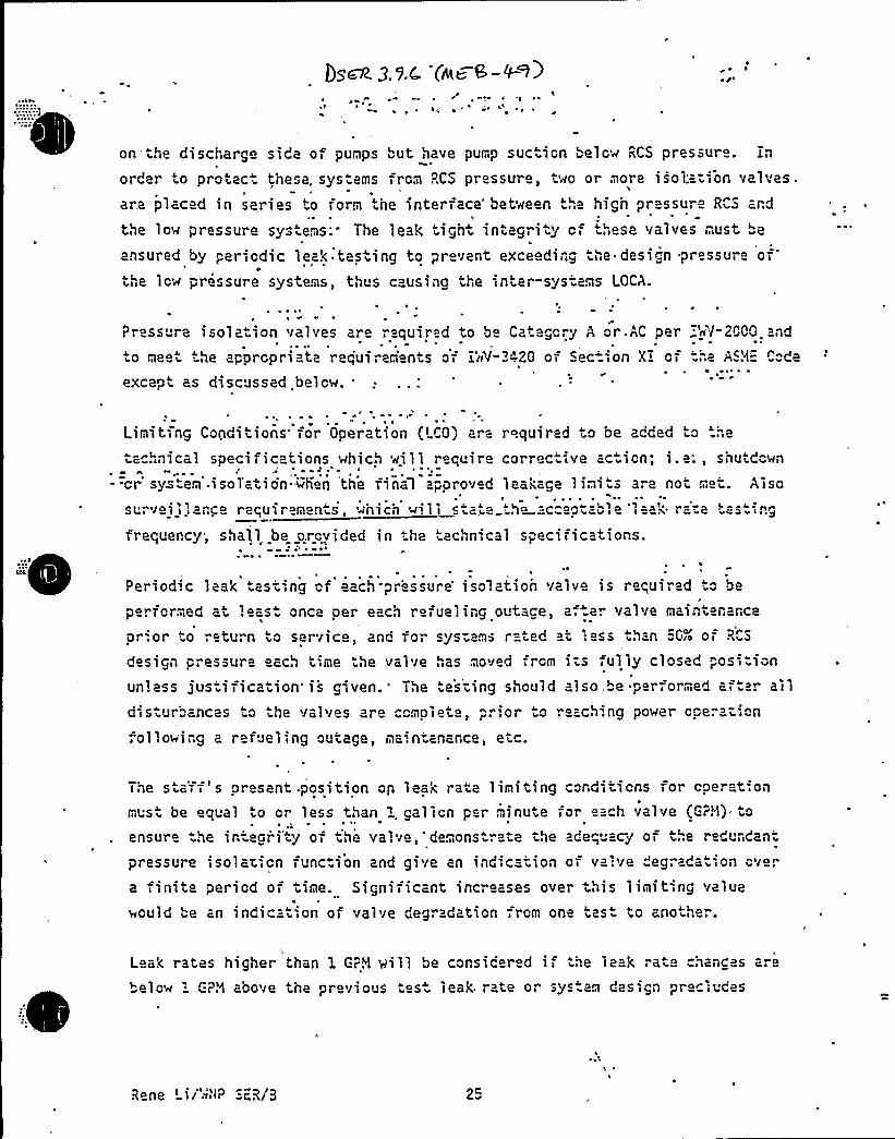
on the discharge side of puMps but have pump suction below RCS pressure. inorder to protect these, sys ams from RCS pressure, two or more isol.'=-ion valves
are placed in series to Torm the interface" between the high pressure RCS ard
the low pressure systems; The leak tight integ"ity cf these valves must 2
ensured by pericdic leak tas ing to prevent exceeding he design pressure ofthe lcw pressure systems, thus causing the tnter-sys-ams LOCA.
Press re isolation valves are required to bo Category A or.AC pero meet the appropriate requirem'en s or i'nV- -".20 of Section X> of
except as discussed below..
'n~(-2OOO and
='he 'SH'"de~ ~
Limit ng Conditions for Operation (LCO) are required o be added to "12
2 ~ 1ical speci ficati ons which ui 1 1 requi r corrective ac ion; i . 2:, shu downh
--cr system'.isoiation-~iierI the fina1 2"proved leakage 1imi 5 are noi . et. Aiso'~1survei ~'ance raqulreman s, whic1 will 5 ata =h« =-cca"table 'ia«k r=-"-.2 tasting
frequency, shall be provided in . he technical specifications.~ ~
Periodic leak test',ng of'each-pressure'solation valve is r equired '.". be
performed at least once oer each refuel irg outace, af er valve maintenance
pr'.or to return to service, 2nd for sys-ams rated «t 1«ss than "G- of R"S
design pressure eac,l time the valve,",as moved from i;5 fully closed posi=ion
unless justification'is given. The 2's'-ing should also,"e performed ar ar alldi stur aflc25 ' the valves «i 2 m01 etc
> p. lor o ~ each ng powel ope' on
"ollowing a refueling outage, Ma'.ntanance, etc.
The sta'ff's oresent position on leak rata limiting conditions for cperat',o1
mus be equal to or less than i gallon par minute for each valve (G?H) to
ensure he integr'i'ty of the valve,'demons rate the adeq"acy of the redundant
pressure 'solar,;On Tunction and give an indication OT va'ive "egrada 'on Over
a finite pericd OT time. Significant incr ases over this limiting value
would be an indication of valve degr«dation frcm one tas to another.
tl
Leak rates higher than 1 C?M will be corsicered if the leak rate chances aro
below l P."1 aoove tne previous 'es leak. rate or sys am d2stgn pleciudes
Rene Lii'~'~P ScR/0 2c
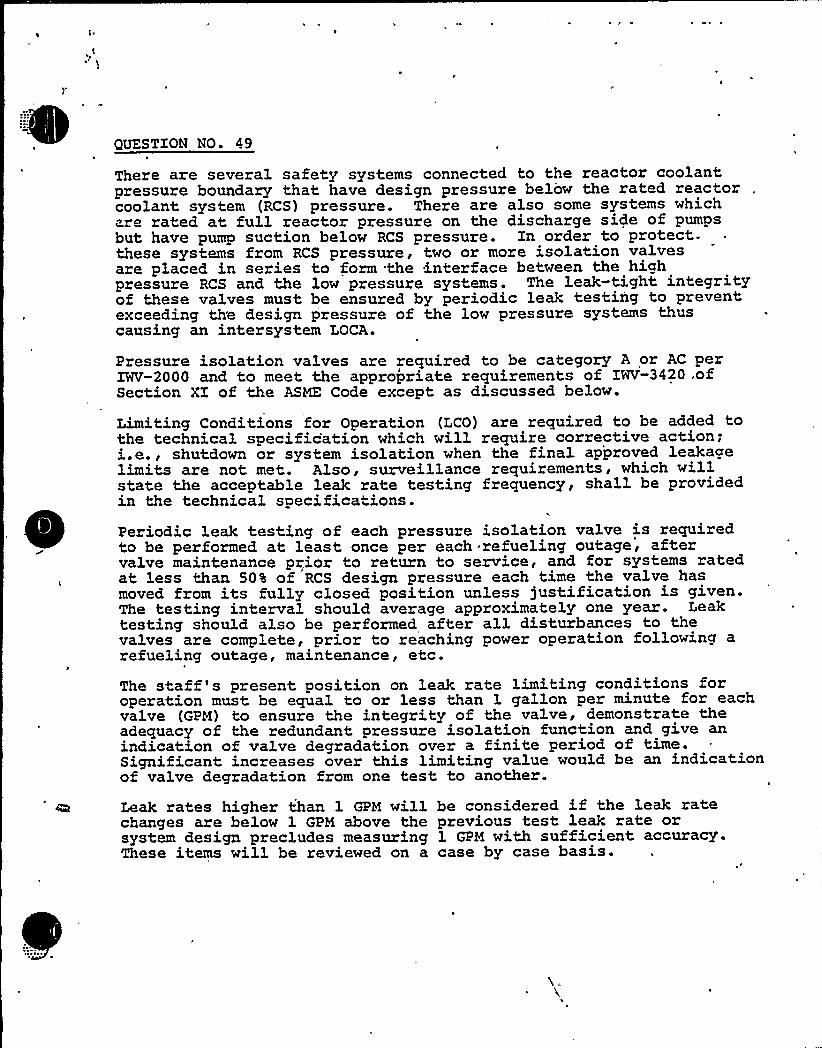
)'UESTIONNO 49
There are several safety systems connected to the reactor coolantpressure boundary that have design pressure belo~ the rated reactorcoolant system (RCS) pressure. There are also some systems whichare rated at full reactor pressure on the discharge side of pumpsbut have pump suction below RCS pressure. Zn order to protect-these systems from RCS pressure, two or more isolation valvesare placed in series to form the interface between the highpressure RCS and the low pressure systems . The leak-tight integrityof these valves must be ensured by periodic leak testing to preventexceeding th'e design pressure of the low pressure systems thuscausing an intersystem LOCA.
Pressure isolation valves are required to be category A or AC perIWV-2000 and to meet the appropriate requirements of ZNV-3420 ofSection ZZ of the ASIDE Code except as discussed below.
Limiting Conditions for Operation (LCO) are required to be added tothe technical specification which will require corrective action;i.e., shutdown or system isolation when the final approved leakagelimits are not met. Also, surveillance requirements, which willstate the acceptable leak rate testing frequency, shall be providedin the technical specifications.Periodic leak testing of each pressure isolation valve is requiredto be performed at, least once per each refueling outage, aftervalve maintenance prior to return to service, and for systems ratedat, less than 50% of RCS design pressure each time the valve hasmoved from its fully closed position unless justification is given.The testing interval should average approximately one year. Leaktesting should also be performed after all disturbances to thevalves are complete, prior to reaching power operation following arefueling outage, maintenance, etc.
The staff's present position on leak rate limiting conditions foroperation must be equal to or less than 1 gallon per minute for eachvalve (GPM) to ensure the integrity of the valve, demonstrate theadequacy of the redundant pressure isolation function and give anindication of valve degradation over a finite period of time.Significant increases over this limiting value would be an indicationof valve degradation from one test to another.
Leak rates higher than 1 GPM willchanges are below 1 GPM above thesystem design precludes measuringThese items will be reviewed on a
be considered if the leak rateprevious test leak rate or1 GPM with sufficient accuracy.case by case basis.
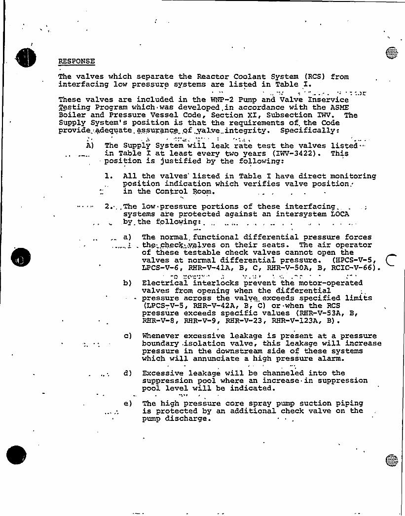
RESPONSE
The valves which separate the Reactor Coolant System (RCS) frominterfacing low pressure systems are listed in Table I.These valves are included in the WNP-2 Pump and Valve XnserviceJesting Program which was developed .in accordance with the ASMEBoiler and Pressure Vessel. Code, Section XI, Subsection XWV. TheSupply System's position is that the requirements of. the Codepzovide..adequate assurance .qf.yalve,.integrity. Specifically:
A) The Supply System will leak rate test the valves listed "in Table I at least every two years (XWV-3422). This
- position is justified by the following:l. All the valves'isted in Table I have direct. monitoring
position indication which verifies valve position,.in the Control Room.
2. The low pressure portions of these interfacing.systems are protected against an intersystem LOCA,by. the following:
a) The normal. functional differential pressure forcesthy„.chec~...yplves on their seats. The air operatorof these testable check valves cannot open thevalves at normal differential pressure (.HPCS-V-5,LPCS-V-6 p RHR V 41Ap Bp C p RHR V 50A~ B, RCIC V 66)
b) Electrical interlocks prevent the motor-operatedvalves from opening when the diffezentialpressure across the valve exceeds specified limits(LPCS-V-S, RHR-V-42A< B, C) or. when the RCSpressure exceeds specific values (RHR-V-53A, B,RHR-V-8p RHR-V-9, RHR-V-23'HR-V-123A, B)
c) Whenever excessive leakage is present. at a pressureboundary .isolation valve, this leakage vill increasepressure in the downstream side of these systemswhich will annunciate a high pressure alarm.
d) Excessive leakage will be channeled into thesuppression pool where an increase in suppressionpool level will be indicated.
Nlv
e) The high pressure core spray pump suction pipingis protected by an additional check valve on thepump discharge.
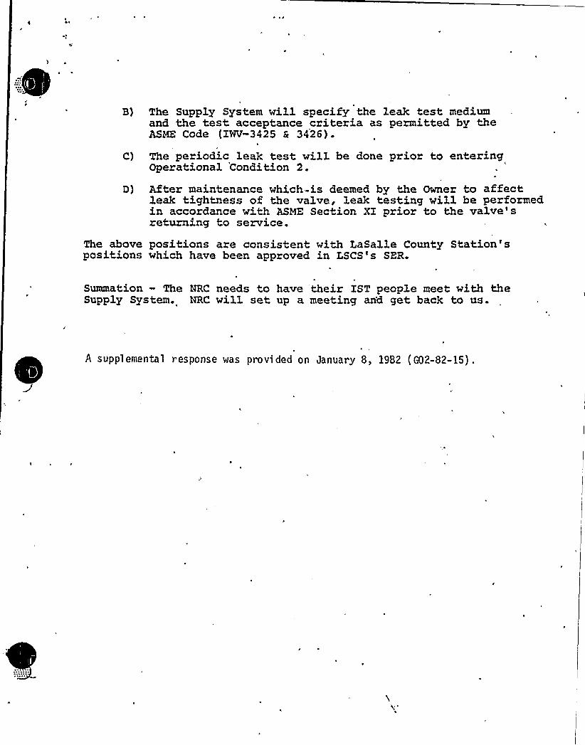
B) The Supply System will specify the leak test mediumand the test acceptance criteria as permitted by theASME Code (INV-3425 & 3426).
C) The periodic leak test will be done prior to enteringOperational 'Condition 2.
After maintenance which-is deemed by the Owner to affectleak tightness of the valve, leak testing will be performedin accordance with ASME Section X1 prior to the valve'sreturning to service.
The above positions are consistent with LaSalle County Station'spositions which have been approved in LSCS's SER.
Summation — The NRC needs to have their XST people meet with theSupply System. NRC will set up a meeting an'd get back to us.
A supplemental response was provided on January 8, 1982 (G02-82-15) .
I ~ e
~ g ~
~ ~
'I ~ I~ 0
~ '~ ~
~ ~ ~ ~
~ ~ ~
~ r~
'I ~ I'I ~ I~ ~
~ i lr ~
I ~
~ ~ I~ ~ ~
I ~
~ ~
I ~ ~ I
I - ~
~ ~ ~
~ ~ I
~ ~ ~
~ ~
~ ~ ~ ~ ~ ~
0 e r ~ ~ ~ ~ ~ ~ ~ ~
~ ~ ~ ~ ~
~ ~ ~
) ~ ~
~ ~ ~ ~ ~ ~
~~
e ~ ~ ~ ~ ~ ~ ~
I ~ ~
I-~ I -~
'
~ ~
~ gr. ~
Nl
I ~ ~ ~
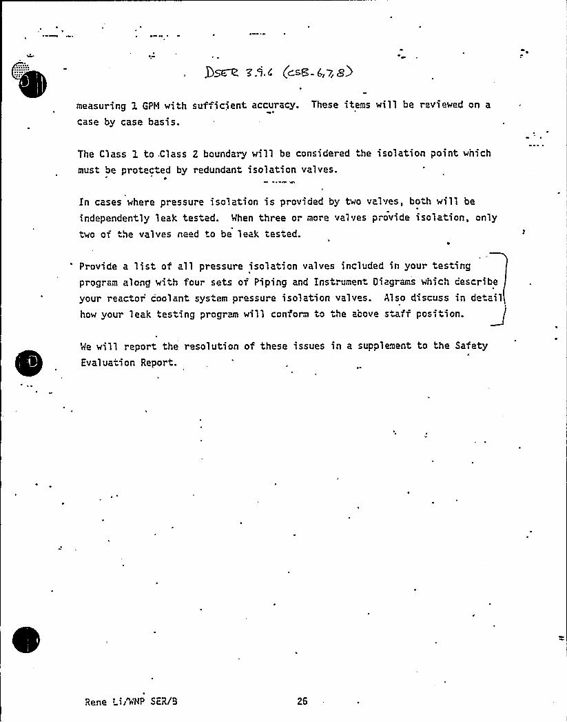
measuring 1 GPH wi h sufficient accuracy. These items will be reviewed on a
case by case basis.
The Class 1 to.Class 2 boundary will be considered he isolation point which
must be protec ed by redundant isolation valves.
In cases where pressure isolation is provided by two valves, both will be
independently leak tes ad. Mhen three or more valves provide isolation, onlytwo of he valves need to be leak tested.
Provide a list of all pressure isola ion valves included in your tes ingprogram along with four sets of Piping and Instrument Oiagrams which cescribe
your reactor'oolant system pressure isolation valves. Also discuss in detailhow your leak tes ing program will conform to he above staff pos tion.
Me will report the resolution of these issues in a supplement to the Safety
Evalua ion Report.
Rene Lii"~'HP SER/9 26
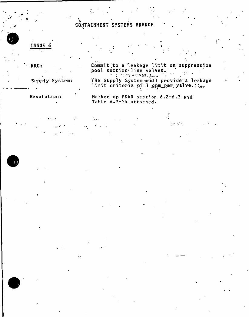
CONTAINMENT SYSTEMS BRANCH
ISSUE 6
NRC:
Supply System:
Commit',to a 'leakage limit on suppressionpool suction line
valves..'I"
~ ye~ I
The Supply System~<1 provide. a 1'eakagel.imit. criteria of 1 gpm p~r valve.::~
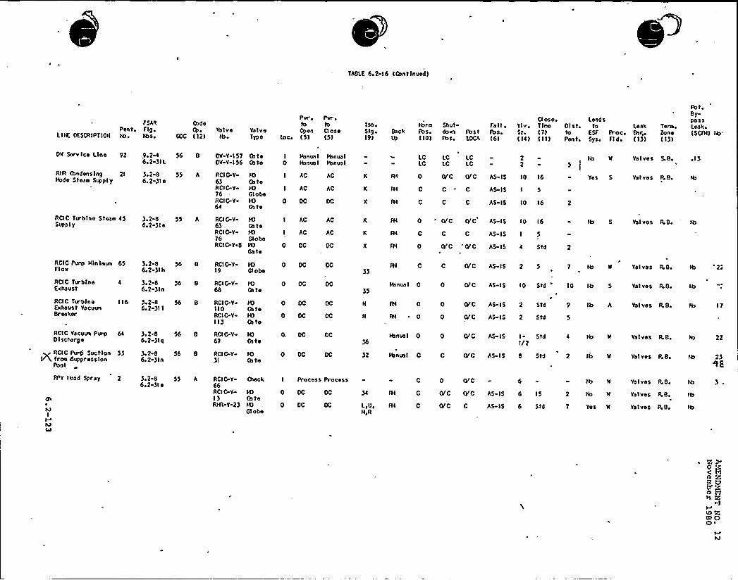
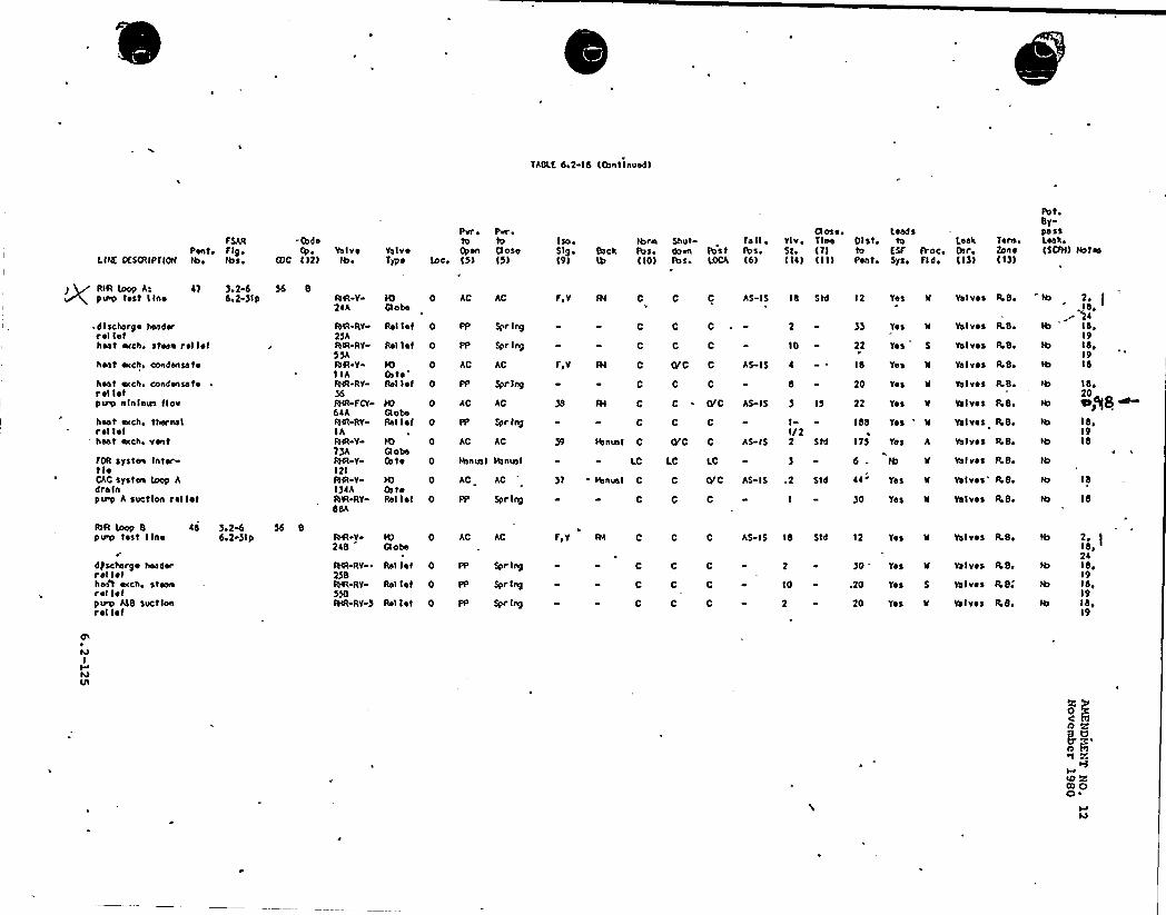
Re solut,i on: Narked up FSAR section 6.2-6.3 andTable 6.2-16 .attached-

0I
~ NP-2 ~eJC> i'%AJJ'ICei'0 J. LliJ ~
June -1979
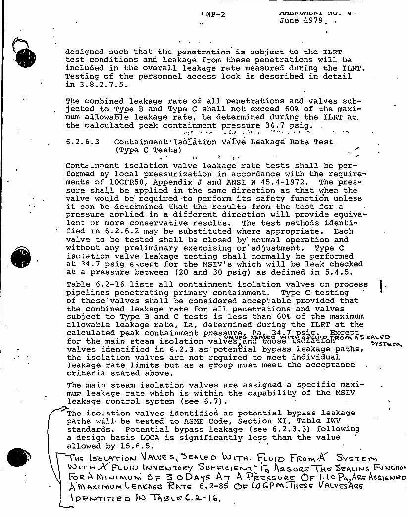
designed such that the penetration is subject to the ILRTtest conditions and leakage from these penetrations will beincluded in the overall leakage rate measured during the ILRT.Testing of the personnel access lock is described in detailin 3.8.2.7.5.
The combined leakage rate of all penetrations and valves sub-jected to Type B and Type C shall not exceed 60% of the maxi-mum allowable leakage rate, La determined during the ILRT at„,the calculated peak containment. pressure 34.7 psig.
r .. ~
6.2.6.3 Containment'Iso3.ation Valve Le'akag'e Rate Test(Type C Tests)
Cont~ nugent isolation valve leakage rate tests shall be per-formed ny local pressurization in accordance with the require-ments of 10CFR50, Appendix J and ANSI N 45.4-1972. The pres-sure shall be applied in the same direction as that when thevalve would be'equired to perform its safety function unlessit can be determined that the results from the test
for.a'ressureapplied in a different, direction will provide equiva-len+:ir more conservative results. The test methods identi-fied xn 6.2.6.2 may be substituted where appropriate. Eachvalve to be tested shall be closed by'ormal operation andwithout any preliminary exercising or adjustment. Type Cist;:ation valve leakage testing shall normally he performedat :4 ' psig @ ~cent for the MSIV's which will be leak checkedat a pressure between (20 and 30 psig) as defined in 5.4.5.Table 6.2-16 lists all containment isolation valves on processpipelines penetrating primary containment. Type C testingof these'valves shall be considered acceptable provided thatthe combined leakage rate for all penetrations and valvessubject to Type B and C tests is less than 60% of the maximumallowable leakage rate, La, determined during the ILRT at thecalculated peak containment- pressure< Pa 34.7 ps'. Exceptfor the main steam isolation valves "nc". tfiose ss81aKFoPvalves identified in 6.2.3.as potential bypass leakage paths,the isolation valves are not required to meet individualleakage rate limits but as a group must meet the acceptancecriteria seated above.The main steam isolation valves are assigned a specific maxi-mum'eakage rate which is within the capability of the MSIVleakage control system (see 6.7).The isolation valves identified as potential bypass leakagepaths will be tested to ASME Code, Section XI, Table INVstandards. Potential bypass leakage (see 6. 2. 3. 3) followinga design basis LOCA is significantly less than the valueallowed by 15.F.5.
ls'ot +>to+ UAtue S> +Ence O M <m~. Fi.vlo F t~omk Sys~e~KLl H 9 Fl v<Q l&QC~zoRy'VF'PlciC~g~< gs,~~g~ ( gc SeqgtNc
F«~o'OR
4 R>Mi~v~ 6 p 3 6 DAp< ~W ~ PR+S>++< QF 'lo l POLAR< 48lceH<OQ + Qg,( ~QVH L 9 flan(A,6Q RL>a 6 . 2-85 +p (0 C P w . TH me ~,~«esAa6'
PM~Pl Pl 6 O l ~+Bl.~ C. 0 "lb,

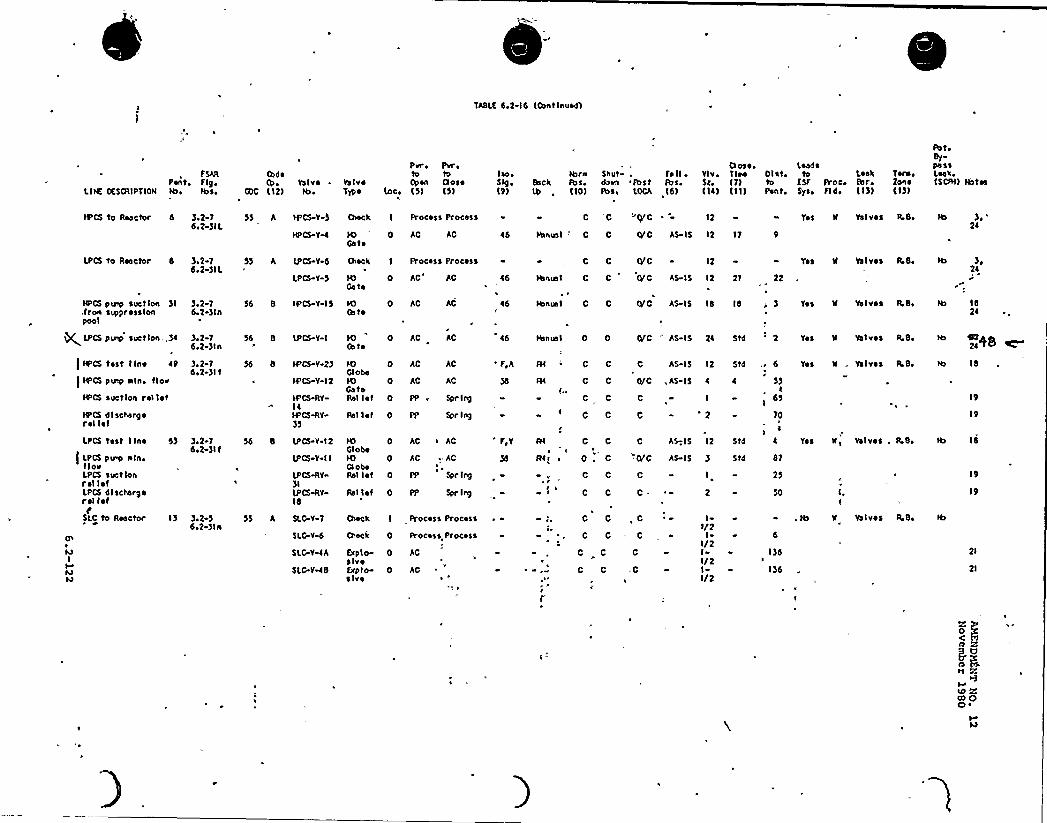
TABLE 6.2-16, (O>et I nuod)
fSARPont» Fig»
LINE OESO(IPTION lh» lba»
Code
Q)C (12)Valvelb»
VolvoTypo
Pvr ~ Pvroto toOpen Ooso
(oco (5) (5)
Iso»Slg»(9)
It>rhBeck Pos.
(10)
O oso.Shut Fa H ~ Vlv. Tine
Fust Fos» Sl. (7)POS» LOCA (6) (14) (11)
Blat,toPent»
Leedsto Leak
ESF PrOC» SeroSys, fldo ( 13)
7erst»2on e(IS)
PetoSYpe soLeek»(SCIH) Hotel
)O'CS to Reactor d )»2-15»2-3IL
55 A IPCS-Y-S O>ock I Process Process C -C v+C .- 12 Yos 8 Valves R.B»2l
IO*
Ge to0 AC AC 46 Ie>nusl
'
C 0/C AS IS 12 11
LPCS to Reactor 8
HPCS pairs> svet Ion )I.fron svppresslonpool
)»2-76>2-)IL
)»2 16»2 )ln
55 A LPCS V d
LPCS V-S
56 8 IPCS V-15
O>eck
IOGe te
IOOs to
I Process Process
0 AC AC
0 AC AC
46
~ 6
C 0 0/0 12
H>nvo1 C C 0/C AS-IS lb Ib
Hsnusl C C 0/C AS IS 12 27
Yos 8 Vo I vss R. 8»
Yes N Valves R.B,
Hs24
Ib24
~ LPCS P Inc> Suction,,)4
) fb'CS tost fino 49
)HPCS pu>p sin» floe
If>CS suction rel I ~ I
HPCS diect»argorol I ~ f
LPCS test I lno 5)
[ LPCS pup nln,I IovLPCS suctionrol I ~ fLPCS dl sehorgorel lofF
SLC to Reactor I)
MI
MM
)»2-16»2 )ln
3»2-75»'2 )It
)»2 75»2-)It
)»2-56»2 )ln
55 8 (PCS V-I
55 8 IPCS-V 2)
IPCS Y-12
IPCS RV-IlIPCS-RV)S
55 b (PCS V 12
IPCS Y IILPCS ILV«
)l(PCS RVIb
S) h SLCV 1
SLC V-d
SLC Y lA
SLC V»48
H)(b to
IOGlobeIOGateRel I ~ I
0 AC AC
0 AC AC
0 AC AC
0 PP» Spring
Rel I ~ I 0 PP Spr Ing
lOGI obeH)Gi oboRel I et
0 AC ~ AC
0 AC . AC'
0 PP Spr Ing
Rel I ~ t 0 PP Spr Ing
O>eek
E>tplo-s lvof»plo-s Ivo
0 Process Process
0 AC
0 AC
Ou>ek I Process Process
46
FIA
F,Y
C C
C C
~ 0 . C
C C
C C
C C
C C
tt>nun I 0 0
Sl ' C
CI"
C
C
0/C
AS-I5 12 Std
,AS IS 4 4
AS-. I5 12 Std
6
S)1
6S
10
s
4
0/C AS IS 3 Std 87
25
50
, C II/2
II/2II/2II/2
135
I)6
0/C AS IS '24 Std ' Yos W Valves R.B,
Yes II . Ye Ivs s R» So
Yos Valves . Ibb»
. Ib N Valves R»8»
Ib
19
19
ib I 8
19
2l
21
0) Q0 ~
V
TABLK 6,2-16 ((bat lnued)
L IHE OES(AIPT IOHPont)bi
F SARF lg,lbs,
(bde(b ~
GOC (12)ValveIb ~
ValveType
Prr,toOpen
loci (5)
Pvr ito(3 ose(5)
Iso iSlg Back(9)
fbrofbs»(10)
Shutdora fbstfbs. LOCA
Fa II ~
fbs.(61
Cl oso.Ylv. Tine 01st.Sti (7) to(14) (11) Pent,
leadsto
ESF Proc.Sysi Fldi
Lea'kBtr„(13)
Tenn ~
Zone(13)
Pot,By-passLeak.(SCFH)
Ib'u
Service Line 92 9i2%6i2-)IL
Ou v-157Du v-156
Oa te(bte
I Htnus I0 Ibnua I
annual
fbnuslLCLC
I.C I.CLC LC
22
Ib Val ves 5 Bi ~ I)
RIR (bndenslng 21lbde Stean Supply
RCIC Turbfno Stean 45Supply
)i2-86.2-)le
3.2-86i2-)le
55 A
55 A
RCI 0-Y6)RCI G-Y76RCIG-Y64
RCIG-V63RCI G-V76RCIG-V 8
)0Ga te
GlobeN)Gn te
N)Ga teN)GlobeHOGa te
I AC
I AC
0 OC
I AC
I AC
0 DC
AC
AC
AC
AC
K fH
K R4
X fH
K fH
K R4
X fH
0/C (VC AS-IS IO 16
C C
C C
AS-I5 I 5
AS- I 5 10 16
C C AS-IS I 5
CV C O' AS-15 4 Std
0 ()r0 (vc As- I 5 I 0 16
Yes S Val ves F.B.
Valves
RCIC Purp Hlnlnua 65Flor
RCIC Tublneexhaust
)i2-86i2-) I h
3.2-86.2-)ln
56 8
56 8
RCIG-V19
RCIG Y68
N)Ga te
0 DC )b nun I 035
0 Or C AS- IS
C C Gr C AS- IS 2 5
10 Std -'D Ib 5
Valves )LB.
ValveS RB.
Ib '27
Ib
RCIC TurbineExhaust YacuorBreaker
RCIC Yacuur Purp0 I scharge
~ RCIC Purp Suction 33VY froo duppress Ion
Poo I
RPY Ibad Spray 2
cn
MI
M4l
116 )i2-86,2 )II
)i2-86i2-)fq
)i2-86.2-)ln
).2-86i2-)I ~
56 8
56 8
56 8
55 A
RCI 0-VI I 0RCI G.Y113
RCIGrY69
RCIG Y)I
RCIG Y66RCIG V
13Rfst-Y-23
N)Oa teN)Ga to
N)Ga te
N)(ate
(heck
N)Ga te
Globe
0 DC
0 DC
0. OC DC
0 OC
0 OC
OC
I Process Process
H fH 0 (V'0 AS-IS 2 Std
0 e'C *S-IS 2 Std
9 lb A
Ibnun I36
0 ()rC AS IS I - StdI/2
32 Htnun I C
0 (VC 6 lb H
c Orc vc As Is 6 15 2 Ib W
L,Ui R4HiR
Q/C C AS-I5 6 Std Yes H
C O'0 AS-IS 8 Std 2
Valves RB.
Valves fkB.
Valves ILBi
Valves R.B.
Vol v as R.B.
Valves R.B.
17
Ib 22
23
Ib
c R
u) K0) 0O ~
TASLL 6,2-16 ICOntlnuedl
F SARPente F lg,
LIAC CCSCRIPT10W
"CodsValve
CCC 112) Ibe
Pvr ~ Pvrelo to Iso e
Valve Open 0ose SlgeTypo Ioce 15) '15) 19)
H>re Shut Fall ~
Back Ibse doen fbst fbs,Ib 110) Pos. LCCA 16)
Ct ose. Lead sYIV~ Tine Dl ate tO LeakSte 17) to ESF Roce Ba ~
Ila) 111) Pont. Sya, Fld, 11))
Tore e
Zone11) I
PoteBy-passLoakeISCFH) Nates
RIFI loop At a7pcno tost line
. discharge headerrel 1stheat ecch. stean roll~ I
heat ecch, condensate
host «cch, condonsatorol lolpeep elnlecca IIOv
heat ecch, therealrol I~ theat ecch, vent
FOR systcee Intertl~CAC systeec Loop Adre fnperp A suction roll~ I
)e2-6be2 )Ip
56 8AIR Y2aA
AN-RY25AAIR-RY5)AAIR VI IARHR RY)6ftCR-FCY6aAACR RYIAAIR Y7)ARHR Y12IAIR Y-I)4ARHR RY-dBA
N 0Qobe
AC AC
Rel Iel 0 PP Spr Iny
)0 0Cate
'elI~ I 0
10 0QobeRal I~ I 0
IQ 00 obaCate 0
It) 0CateRel lot 0
AC AC
PP Spr lny
AC AC
PP Spr Iny
AC AC
Ibnual Ibncel
AC AC
PP Spr Iny
Rol Iel 0 PP SPr Ing
F>V
C
Fey
C
W C
C
fal c
C
Itcncel C
LC
57 Ibnua1 C
C
C C AS-IS 18 Std
C C ~ 2
C C
Cc0 C
C C
10
AS-I5 6
C ~ 0C C AS- IS ) 15
C C
O'C C
LC LC
AS- IS
II/22 Std
C O'C AS IS .2 Std
C C
12 Yes N
)) Yes
168
175
Yos 'lYes A
6 Ib N
as Yea W
)0 Tes ll
22 Yes S
18 Yes
20 Yes II
22 Tos
Valves R Be
Valves LSe
Valves ReBe
Valves R,S,
Valves LBe
Valves LBe
Valves f.8,
Valves R 8,
Ya I vos R B.
Valves' Be
Valves R.be
2.
2aIS ~
19l be
19Ib
Ide
Pf8IS ~
19ld
IS
Ib
ISR Loop 8pccep test line
dpschargo headerret lethoot ecch ~ steanrel I~ Iperp ALB Suctionrot lot
)e2%6e2 )Ip AIR V
248
AIR-RY ~
2)BW-RY-
RHR-RY 5
IL) 0Q obe
Rel I~ I 0
Ral Iet 0 pp
AC AC
Spr Iny
Spr Iny
Rol I~ I 0 PP Spr Iny
F,Y AI C
C
C
C
C C
C C
C C
C C
AS IS Id Std
2
10
2
12 Yes W
)0 Tos II
.20 Tes 5
20 Yea IC
Valves LB,
Valves ILB. Ib
Valves RB.
Valves RBe
2,lde2aI be19Ib,19Id,19
l4I
MVl
~I2'o
oOe
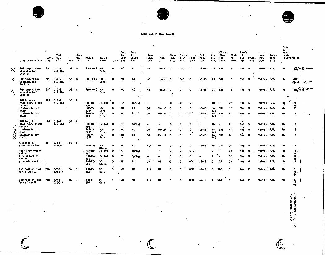
TABLE 6,2 16 (Continued)
fSAR (bd ~Pcrlte f19 ~ (be Valv~
LINE DESCRIPT IOk kee IDSe GDC ( 12) Ibe
Per Prr e
to toYe Iv ~ Open OuseType loce 15) (5)
Iso e
S19 ~
(9)
IbmBack lbs.
( IO)
Shutc)svn postFuse LOCA
fa 11 ~
Pot.(61
()ose.Ylv ~ T leeSz, (7)( Il) (I I)
01st,toPent,
LeedsIo Leak
ESF Proc, Bsr,Syse Fld ( I))
Tens,Zan(I))
PeteBy-passLeahe(SCI)1)
RIR IOOp A Sup )5press(on PoolSuet I(In
AR loop 8 SID )2pression poolSect Ion
AR loop C Ssp-pression tholSuet lon
)eZW. 566.2-)ln
).2e6 566 2 )ln
).Zed6eZ )ln
8 AR YelA IO 0Ga te
8 RIR VMS sO 0Oste
8 AR-VelCOs to
AC AC
AC AC
AC AC
l6
l6
Ibnua I 0
HInual 0
Hsncssl 0
0/C 0
0/C 0
0 0
AS IS 2l Std
AS IS 2l 514
AS IS 2l 5td
'yesI
k Valves R Be
Tee k Valves R 8,
YeS W Vol VeS R.Be
QR (oop Athest ecch, steanrel I~ tcondensate potdre Incondensate potdre In
RIR loop Bc lidheat ecche steanrel I~ Icondensate pot
I dre lncondensate potns drain
).2%6e2 )ld
) ~ 2& S66e2 )Id
AR Ry-9)AAR-YIZlAAR V12lB
AR RV
958AR-Y115AAR-Y-1258
Rel 1st 0
IO 0Gate
0Ga te
PP Spr Ing
AC AC
AC AC )9
H) 0Ga toIO 0Ga te
AC AC
AC AC
Rel I et 0 PP Spr Ind
C
Manual 0
Hsnua I 0
C
HInua I 0
Hcnusl C
C C
C C AS IS
C C
C C
C C
AS IS
AS IS
0 «0 AS IS
IO
I StdI/2I St4I/2
10
I StljI/2I StdI/2
Zl
12
17
ITea
19yes
5 Valves p.d.
K Valves R.B.
W Valves P.B.Tet
Tes 5 valves R,B
Tea W Tel ves R, B.
Tec N Valves R Be
ld,19ld
Id
Id
IS
Id
RIR loop Ctperp test line
discharge headerreliefperp C suctionrel letp csee ~ In)cue tlor
Suppress(on Pool 2)ASpray (oop A
).1-6de2-)It
)e2% 566e1 )lh
8AR-Y 21
RIR RV2)CAR-RySSCAR FCV6lc
0GlobeRel let 0
AC AC
PP Spr Ing
0Gl oae
AC AC
8 AR-V2)A
IO 0Ga te
AC AC
Rel I ~ t 0 PP Spr I nd
Fey
Fev
C C
C C.C C
AS IS IS 5td
2
I
)0
)7
C 0/C AS IS 6 5td
C 0/C AS 15 ) 15 )0
Yes 'k Ya Ives R Be
Tes
Tea
k Valves ILBe
'k, Valves P,B,
Yes k Valves R.B.
Ves W Valves R.B.
ld
IS,19ld,19
2.IS ~'Zl
Suppression Pool 258Spray (oop 8
) 2ed S66e2-)Ih
8 AR Y-278
IO 0Gate
AC AC Fev C 0/C AS IS 6 Std 6 Tes II Valves R 8lde2l
Z
c> OO ~
M

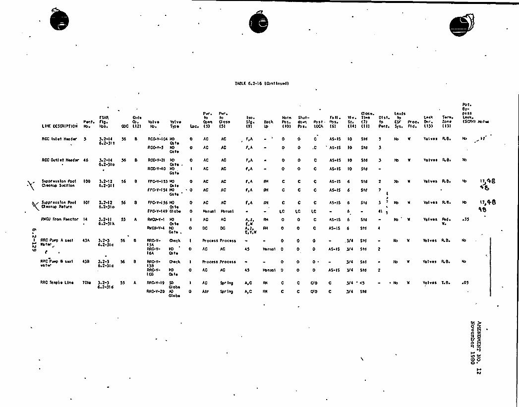
TABLE 6,2-16 (Continued)
LINE DES(y(IPT ION
TSARPanto Fig>Ibo Ibao
tbdetb>
COC (12)Yal vs
IC> ~
Per ~ Pvr ~
to toValve Open 0oseType loc. (5) (5)
iso>Slg o
(9)
thr>oBack fbs,
(101
Shutdo onfb so
Fa II ~
fbst - >bs.LOCA t6)
YlvoStot 141
0 ose. LandsTine 01st to(y) to ESF Proc>III) Pent> Sys, Fldo
Leak8>r,( I))
Eon e( I))
Pot,BypassLeak ~
(SCf)I) ra>toa
RCC Inlet )tender 5 )>2 146>2 )It
RCG.Y 104
RX-Y-5
Ic) 0Os toIO 0Gate
AC
AC
AC
AC
F,A
F,A
0
0
AS-IS IO Std
O,C 'S IS 10 Std
Valves FLB> ty
RGC Out l et Header 46 ).2-146>2-)lo
56 8 RCG-Y 21
RCG-VAO
IG 0Gate ~
HO ICa te
AC
AC
AC
AC
F,h
F>A
0
0
AS IS 10 SM
AS IS 10 Std
Valves R.B ~
Suppress)on fbolCleanup Suction
r S>4>press(on PoolCleanup Rate n
100 ).2 126>2 )II
IOI )>2-126.2-)lo
Sd 8 FPC Y IS)
FPG-V Ifl
56 8 FPC-V I )6
FPC V 149
IC) 0thteIa) 0Gate
0Os teCl obe 0
AC
AC
AC
AC
AC AC
Ibnus1 lbnual
F,A
F,A
F,h
fH C
IH C
fl( C
LC
C C
LC LC
AS-IS 6 SM 2
AS-IS 6 SM
7I
'o
~ I
AS-IS 6 Std
Valves lk8~
Valves R.BE
I) 4g
is,+5'tS
Ru()) Fron Reactor 14 )>2 II6>2 )Ik
55 A fb>()) Y-I
RNCU YQ
It) IGate
0Cate .
AC AC A>)~
E>wA>)~E>Y>N
AI 0
III 0
AS IS 6 SM
AS-IS 6
Vaf vs a fbd olfo
~ )5
RRC Pu>p A sealkate>'
F
RAC Pap 8 sealva ter
4)A )>2-)6.2-)lc
4)B )>2 )6>2 )lc
56 8 RA('rY
15ARRG.Y-16A
RAG-YI )BRAG Y-168
Oleck I
I() 0Gate
t)leek I
It) 0Gs te
Process Process
AC AC
AC AC
Process Process
45
0
lbnual 0
0
tbnw>l 0
, )/4 Std
AS-I5 )/4 SM
)/4 Std
AS- I5 )/4 Std
Valves R.B.
Valves R.B>
RRC Saepl ~ Line T)Aa )>2-)6>2 )ld
55 A RAG Y-19
RRG V 20
SO IGlobeAD 0Globe
AG
Alr
Spr Ing
Spr lng
A>C
A,C
Ra C
W C
C G>0 C
C 0'0 C
)/4 <5
)/4 Std
Valves T>B> ~ Of
ID Zos oQ ~
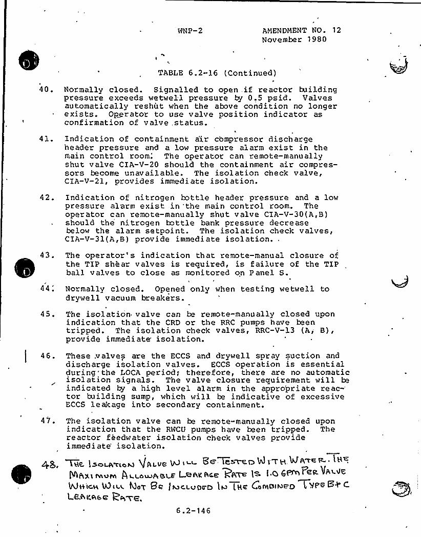
WNP-2 AMENDMENT NO. 12November 1980
40.
TABLE 6.2-16 (Continued)
Normally closed. Signalled to open .if reactor buildingpressure exceeds wetwell pressure ty 0.5 psid. Valvesautomatically reshut when the above condition no longerexists. Operator to use valve position indicator asconfirmation of valve, status.
41.'
Indication of containment a'ir compressor dischargeheader pressure and a low pressure alarm exist in themain control room.'he operator can remote-manuallyshut valve CIA-V-20 should the containment air compres-sors become unavailable. The isolation check valve,CIA-V-21, provides immedi ate isolation.
42. Indication of nitrogen bottle header pressure and a lowpressure alarm exist in 'the main control room. Theoperator can remote-manually shut valve CIA-V-30(A,B)should the nitrogen bottle bank pressure decreasebelow the alarm setpoi nt. The isolation check valves,CIA-U-31(A,B) provide immediate isolation..
44
The operator' indication that remote-manual closure ofthe TIP shear valves is required, is failure of the TIPball valves to close as monitored on P anel S.
Normally closed. Opened only when testing wetwell todrywe 1 1 vacuum breakers.
45. The isolation valve can be remote-manually closed uponindication that the CRD or the RRC pumps have beentripped. The isolation check valves, RRC-V-13 (A, B),provide immediate isolation.
4t.
47
'hese.valves are the ECCS and drywell spray suction and
discharge isolation valves. ECCS operation is essentialduring the LOCA period; therefore, there are no automaticisolation signals. The valve closure requirement will beindicated by a high level alarm in the appro'priate
reac-'or
building sump, which will be indicative of excessiveECCS leakage into secondary containment.
The isolation valve can be remote-manually closed uponindication that the RWCU pumps have been tripped. Thereactor feedwater isolation check valves provideimmedi ate'solation.
8 c'~as~ ~ 8 i'7 H ~~< ~ ~
LSE lsoLA'VL4hJ g fllVCI+PIXI~~M Al LouJASLF LHAKACE PPi~ l~ ALOD
K~«~ %~«40m Bc t ~~~uog n )w [gz Cowo)~ac) l YPB 8+ c1 ee rose pp~p
6. 2-146
CONTAINMEHT SYSTEMS BRANCH
ISSUE 7
NRC:
Supply System:
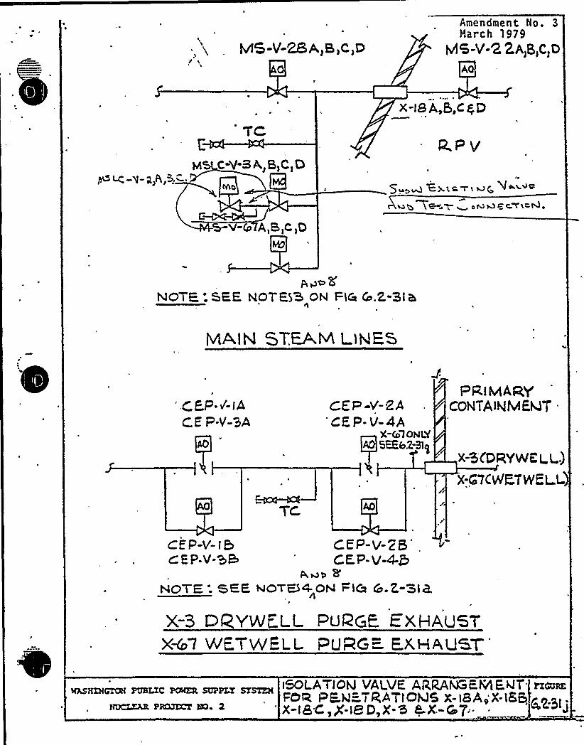
Figure 6.2-.31j - are all four LCS valveson mainsteam isolation valves tes.ted atthe same time?
The Supply System will revise Figure6.2-3lj to show a capability to testthe valves individually.
Resolution: Pevi sed Figure 6.2-31 j attached.
fQ
p~
0 ~
~ r0
E
~ ~
1.E
IlQ
~ ~
a .
~ ~
II
fQet4w
y e e
~ ~ ' ' - IA'l0 p ~
P'
P a
k
t'I
CONTAINMENT SYSTEMS BRANCH
ISSUE 8
NRC:
Supply System:
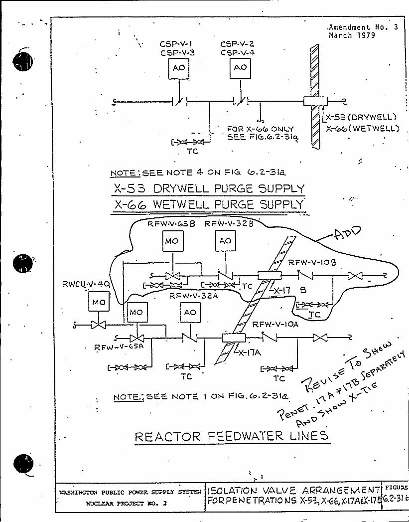
Figure 6.2-31b, feedwater line RWCU-V-40How is this valve to be tested?
The Supply System will revise Figure6.2-31b to indicate test connectionsavailable for RWCU-V-40.
Resolution: Re vi sed Fi gure 6.2-31b a t tached.
CSP-V- lCSP-V-3
AO
CSP-V-2CSP-V-4
.Amendment Ho. 3
triarch 1979
TC
FOR X-(o& ONLY5 z. r iC"..& '2-Sly.
X-53 (DRYWE,LL)"~~(wzTe E.cQ
HOT:: FE. NOTE. 4 QN —,i9 (o.Z-Sla.
DgvVlE.LL PURGE, 5UPpLYX-&C XETeE.i~ PuRcE
Supp'.FwV
v-cnS 9 RFW-V-328
MO AO
R FR-V-10 Q
RWCU-'J-4.0 C~4—= 1-
rcF W"V-32A S
L
TC%FR-V-lOA
PEW-V 45&X-1 lA
C-M~~C
TC
y,OTE..SEE XOTE, '> OV FlC .Co.Z-3>a.~ cR.
~o~~Q
REACTOR FEED'IIMATcR. I lklES
~HIViGTC8 PUBLIC PCWER SUPPLY SYS~~k
hUCLZAX PRQJE 'O 2
fH)LATJOk'ALV„= AR~AWGEMcNTFOP PE 4 E'TigATlQ f35 X-H,8 56,)('l7AC'17
FICU~~
G.2-3l'
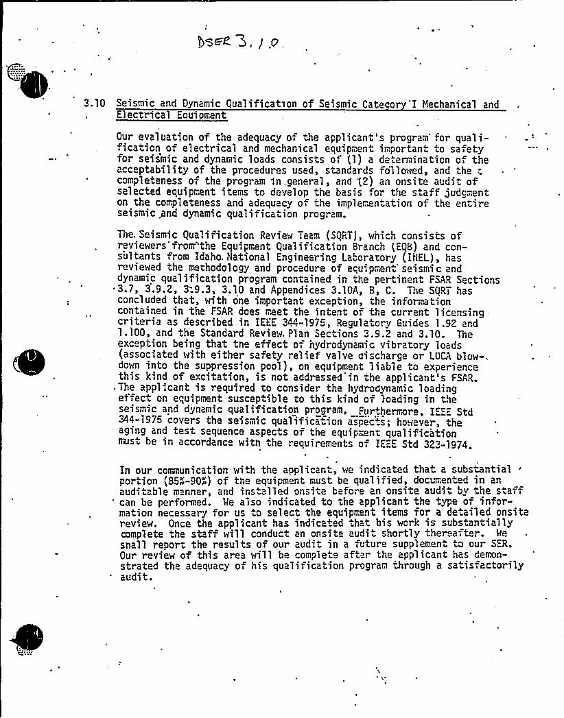
3.10, Seismic and Dynamic Qualification of Seismic Cateco 'I Mechanical andElectrical Equi ment
Our evaluation of the adequacy of the applicant's program for quali-fication of electrical and mechanical equipment important to safetyfor seBmic and dynamic loads consists of (1) a determination of theacceptability of the procedures used, standards followed, and the '.complet ness of the program in,.general, and g2) an onsite audit ofselected equipment items to develop the basis for the s .aff judgmenton the completeness and adequacy of the implemen.ation of the entireseismic pnd dynamic quaIificaiion program.
The, Seismic Quali ication Review Team (SQRT), which consists ofreviewers'from'the Equipment Qualification Branch (EQB) and con-sultants from Idaho. National Engineering Laboratory (INEL), hasreviewed the trethodology and procedure of ecuipr. nt'eismi c anddynamic qualification program contained in the pertinent FSAR Sections3-7, 3.9.2, 3:9.3, 3.10 and Appendices 3.10A, 8, C. The SQRT hasconcluded that, with one important exception, the informationcontained in the FSAR does meet the intent of the current licensingcriteria as described in IEEE 344-1975, Regulatory Guides 1.92 and1.100, and th Standard Review. P'lan Sec ions 3.9.2 and 3.10. Theexc phon being that tno e feet of nydrcdynamic vibratory loads(associated with either safeiy relief valve aischarge or LOCA blow-.down into the suppression pool), on equipment liable to experiencethis kind of excitation, is not addr ssed'in the applicant's FSAR.
.The applicant is required to consider th hydrodynamic loadingeffect on equipment suscep.ible to this kind of loading in theseismic and dynamic quali ication program. Furtherrrar IEEE Std344-1975 covers the seismic qualifica ion as!ects; however, theaging and test sequence aspects of the equipment qualificationnest be in accordanc with the requirements of IEEE Std 323-1974.
'I
In our communication wi.h the applicant, we indicated that a subswntialportion (85~-90~) of the equipment must be qualified, documented in anauditable n nner, and ins alled onsi.e b fore an onsite audi by the s.aff'an be performed. Me also indicated to the applicant the type of infor-mation necessary for us to select the equipment items for a de ailed onsitereview. Once the applicant has indica ed that bis work is subs.antiallycomplete he staff will conduct an onsite audi. shortly thereafter. 4esnail report the results of our audit in a future supplement to our SER.Our review of this area will be complete aft r the applicant has Cemn-strated the adequacy of his qualification program through a sa is actorilyaudit.

WNP-2
Open SER Issue
3.10 K drod namic Vibrator Loadin Effect
The response to this issue will be included in the Equi pment
qualification Program Submittal ..
~ 'J
~ I ~,
~ ~
I ~ ~ v

2. operation beyond Cycle 1 is not permitted until stability analysis
is provided and approved for the additional cycles of operation;
3. the natural circulation operating mode is not permitted; and
4. the core flow should be checked at least once per day and the
average power range monitor flow biased scram calibrated at least
once per month to account for possible effects of crud deposition.
The above restrictions should be incorporated into the proposed Tech-
nical Specifications, except for Item 2 which should be incorporated as a
license condition.
In addition, the following open item should be resolved prior to issuance
of the operating license:
- the operating limit NCPR calculated by including the ODYN methods
must be provided for review and approval.
Me conclude that, with the exceptions noted above, the thermal-hydraulic
design of the core conforms to the -requirements of General Design
Criterion 10 of 10 CFR Part 50, Regulatory Guides 1.68 and 1.133, and
Section 4.4 of the Standard Review Plan and is, therefore, acceptable.
WNP-2
4.4 NCPR .0 eratin Limit Calculation b ODYN
The operating limithas been establishezation transients.Systems Branch questhe ODYN analyses ~
15 Or 15 1 Zr 15 2the ODYN ana lyses.
.minimum critical power ratio (OLNCPR)d using ODYN methods for rapid pressuri-
The Supply System resp.op.ses to, Re.actortions 211.049 and 211.084 commi't ted to
FSAR Section 4.4 (Tabl.e 4-4-1) i 5.2.2r2 and 15.2.3 have been modified to reflect(Refer to SER„item 15- ODYN Reanalysis)
~ ~t ~ Ig ~ )
1. A description and evaluation of diagnostic procedures used to
confirm the presence of a loose part.
2. A description of how the operators will be t.ained in the purpose
and implementa ion of the system.
Me will review the applicants conformance evaluation report when itbecomes available, consistent with our plans for review of the operating
plants. Any action resulting rom our review will be apnlied at that
time. On .his basis, we find ihe LPhS acceptable for an operating
license.
~SUmmar
The staff has reviewed-the thermal-hydraulic design of the core as
described in Section 4.4 of the FSAR for HNP-2. The scope of the review
included the design criteria, implementation of the design criteria as
presented by the final core design', and the steady-state analysis of ther,
core thermal-hydraulic performance. The applicant's thermal-hydraulic
analyses were performed using approved methods and correlations and
found acceptable. However, the operating license should be restricted
to the following conditions:
1. single loop operation is not permitted unless supporting analyses
are provided and approved;

SER Open Item - Thermal Hydraulic Section - Core Performance BranchSection 4.4 Thermal Hydraulic Design Evaluation
NRC POSITION
Reference: Memo L. S. Rubenstein, Assistant Director for Core and PlantSystems, DSI to R. L. Tedesco, Assistant Director forLicensing, -DL, SER. Input'or Thermal and Hydraulic Designof 'the Core for WNP-2 Power Plant, December 1, 1981.
Prior to release of the SER, the applicant should provide a written commit-ment to evaluate the Loose Parts Monitoring System (LPMS) in accordancewith the Regulatory Guide 1.133, Revision 1 (May 1981) on a schedule speci-fied by the applicant. The conformance evaluation report should emphasizethe programmatic aspects such as establishing the alert level, the operatortraining in the purpose and implementation of the LPMS, and diagnosticprocedures used to confirm the presence of a loose part.
WNP-2 POSITION1
Letter G02-81-335, G. D. Bouchey to Schwencer, Loose Parts Detection SystemConformance Report, October 5, 1981 confirms that the WNP-2 Loose PartsDetection System has been designed and specified to meet the requirementsof Regulatory Guide 1.133 Revision 1, May 1981., In addition, the SupplySystem will prepare a conformance evaluation report which emphasizes theprogrammatic aspects of implementing the detection program.
The report will discuss the program that the Supply System will be imple-menting. This program will-include..'-"".;-:
1)„., A description of. the- operator training program for the system. " .This program will include discussion on the purpose and functionof the LPMS.
2) A description of the operating and diagnostic procedures usedwhen the system is operated in the manual mode - listening toaudio signals from all installed sensors. Alert levels will beestablished.
3) A description of the operating and diagnostic procedures usedwhen the system is operated in the automatic mode. Alert levelswill be established.
C
4) A description of the Technical Specifications for operation ofthe system.
5) The reporting requirements necessary if a loose part is confirmed.
The conformance report will be submitted for review prior to the time ofinitial reactor startup testin'g.
-13-
'ased on our evaluation,'e conclude that these systems, taken together,
satisfy the requirements of General Design Criteria 20, "Protection System
Functions," 26, "Reactivity Limits," and 28,"Reactivity Control System
Redundancy and Capability," as noted above.
The CRDS is capable of providing reactivity control ollowing postulated
accidents with an appropriate margin for a s uck=rod. This capability is
demonstrated by the loss-of-coolant accident and rod dropout analyses
presented Gy he applicant wMch, in turn, show that the consequ nces are
acceptable and core cooling is maintained, as required by General'Desig'n
Criteria 20, "Protec ion System Func ions," 27, "Combined R activity
Control Systems Capability," and 2B, "Reactivity Limiw."
The instrumented volume (IV) is closely coupled hydraulically to the scram
discharge volume (SDY} by sloping tho SDV toward the IY and increasing .he
pipe sizes over previous SDV section's pipe sizes. A the connection of the
SDY and IY the SDY is an eight-inch pipe and the IY is a 12-inch pipe.
Therefore filling of the SDV wi hout an indication in the IY is not possible,
such'as by a slow or partial loss of air pressure to the scram discharge
vaTves. Any water. leaking into the SDV 'would enter the IV and exit through
the'drain. Leakage in excess of the drain's capacity would fill the IY and
result first in an alarm followed by a rod block and hen a reac or scram
if the problem was not corrected ih time.
[The applicant has not yet responded to our reques for additional information
in a letter dated May 5, 1981 regarding our Office of Analyses and Evaluation
of Opera ional Data (AEOD} report entitled, "Sa,ety Concerns Associated-.
with a Pipe Break in the BMR Scram System." The report desnibm a poten-
tial sequence of events which could result from a break in the BMR scram
discharge piping duiing a scram condition concurrent with an inability
to reclose the scram outlet valves. Me will report resolution of this itea
in a supplement to this SER.3
~ ~\ „I ~ '
I 1
*IJI ~ I ~
~ ~
\II
~ ~
~ I 4 ~ 'I t ~
II
~ ' I
I ~ 4 t ~
~ ~
„'I~
Open SER Issue
4.6 Safet Concerns Associated with Pi e Break
A.response to this issue was submitted»>u>r/ "3> "982< bYLetter G02-82-37.
Washington Public Power'Supply SystemP.O. Box 968 3000 George Washington Way Richland, Washington 99352 (509) 372-5000
January 13, 1982G02-82-37SS-L-02-CDT-82-017
Docket No. 50-397
Mr. A. Schwencer, DirectorLicensing Branch No. 2Division of LicensingU.S. Nuclear Regulatory CommissionWashington, D.C. 20555
Dear Mr. Schwencer:
Subject: NUCLEAR PROJECT NO. 2" RESPONSES TO REQUEST FOR INFORMATION
Enclosed are sixty (60) copies of the Supply System 120-day responseto the NRC's concern regarding Pipe Breaks in the BWR Scram DischargeYolume (see Reference 1 to the Attachment).
Al
Also, this is the Supply System's response to Generic Letter 81-34(see Reference 4 to the Attachment).
Yery truly yours,
G. D. BoucheyDeputy Director, Safety and Security
CDT/jcaEnclosures
cc: R Auluck - NRC
WS Chin - BPAR Feil - NRC Site

!
f
-14»
/The applicant has not responded to-our concern relating to th'e effects on the
safety and operability of the control rod drive hydraulic sys.em if he drive
or'ooling water control Valves fail closed or fail open.* Me will report.resolu-
tion of this item in a supplement to this SER].
The applicant has responded to the concerns identified in the
HRC generic study, "BWR Scram Discharge System Safety Evalua.ion" datM
December 1, 1980. The applicant .'gd ntified the ne d .to upgrade the scram
discharge control system in four areas.
l. Addition of redundant vent and drain isolation valves
2. Addi ion of redundant and diverse level instrument tion .for scram
3. Relocation and piping of instrument piping directly . o the scum instru-ment volume
e c
4. Addition of new surveillance and operating procedures.
'Me have reviewed the applicant's responses and find the applicant has demonstrated0(
complianc with the required upgrading to the gen r',c safety evaluation. Based on
our review, we conclude that the scram discharge sys em me ts the requirements of
the NPC generic study, "BMR Scram. Discharge Sys em Safety Evaluation" dated
December 1, 1980 and is, therefore, acceptable, pending confirmatory receipt of'I
an acceptable revised Section 4.6 of the FSAR to rerlec these modifications and
confirmation by the Office of Inspection and Enforcement that the four afore-
mentioned modificat',ons have been installed.
)Based on our review, we cannot conclude that the control rod drive system is
not acceptable regarding the control valve failure or scram sys em pipe break
until the applicant provides the'in.ormation discussed above. Me wi11 provide
our evaluation of the resolution of these items in a supplement .o .his SER].
Open SER issue
4.6 CRD Hydraulic System (Q. 10.43)
A response to Q. 10 43 was submitted on December18'981'n
l e t te r 602-81-533.
v f ~ "'4 4 I
LJNP-2
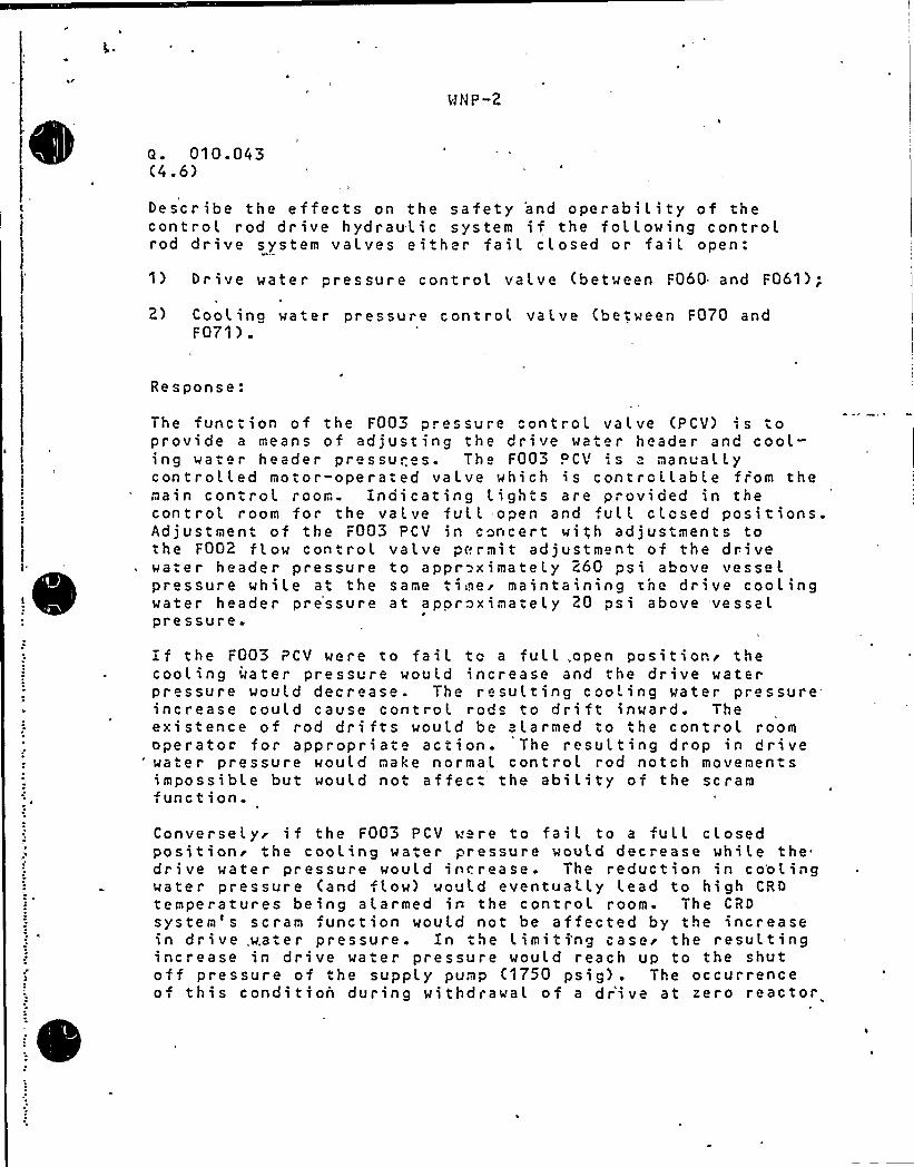
a. 010. 043(4.6)
Describe the effects on the safety 'and operabi L i ty of thecontroL rod drive hydraulic system if the following controlrod drive system valves either faiL closed or fail open:
Drive water pressure control vaLve (between F060 and F061);
2) Cooling water pressure control valve (between F070 andF071 ) ~
Response:
The function of the F003 pressure control valve (PCV) is toprovide a means of adjusting the drive water head r and cooL"ing water header pressures. The F003 . CV ',s a nanualLycontrolled motor-operated valve which is controllable from themain controL room. Indicating lights are provided in thecontroL room for the valve full open and full cLosed positions.Adjustment of the F003 PCV in concert with adjustments tothe F002 flow control valve permit adjustm nt of the drivewater header pressure to appr ximate ly 260 psi above vesse lpressure while at the same timei maintaining the drive coolingwater header pre'ssure at aporoximate ly 20 psi above vesselpressure.
if the F003 PCV were to faiL to a fuLL,open positions thecooling water pressure would increase and the drive waterpressure would decrease. The resulting cooLing water pressureincrease could cause controL rods to dri ft inward. Theexistence of rod drifts would be alarmed to the controL roomoperatoc for appropriate action. The resulting drop in drivewater pressure would nake normal control rod notch movenentsimpossible but would not affec. the ability of the scramfunction.
Converselyr if the F003 PCV were to faiL to a fuLL closedpositions the cooling water pressure wou'Ld decrease while thedrive water pressure would increase. The reduction ',n co'olingwater pressure (and flow) would eventuaLLy Lead to high CRDtemperatures being alarmed ia the control room. The CRDsystem's scram function would not be affected by the increasein drive,water pressure. En the Limiti'ng casei the resultingincrease in drive water pressure would reach up to the shutoff pressure of the supply pump (1750 psig) . The occurrenceof this condition during withdrawal of a drive at zero reactor
pressure will 'result in a drive pressure increase from 260psig to no nore than 1750 psig. CalcuLations and testsindicate that the drive would accelerate from 3 inches persecond to no more- than 6.5 inches per second. The rodmovement would stop after the driving signal is "removedor rod block is enforced by the Reactor Manual Control,System- (RNCS). In the unlikely event where RNCS ails, toenforce a rod blockr the -peak fueL enthalpy for driVe speedsof 6.5 inch s per second is weLL below the fueL claddingfailure threshold design limit. Th reforer due to provisionsin the system design and margin in the fuel designs thispcstula ~ ed scenario will not conpromise the integrity of thefuel.
In both of the cases described above'he manually opera edbypass PCV (F004) in con junc ~ ion with the isolation gatevalves Loca.ed upstream and downstream of the F003 PCV wouLdenable the operators to take corrective action..in conclusions although the failure to the full open or fullc.osed pos'. t ion o, .he dr-'e/cool ing wa te r PCV wi L L causeperturbation in the CRD system operations it does not presenta safety. probLem or affect the scram capability of tbe CRD
4sys tem.
The PCV F005 was dele ~ ed from ~ he CRD hydrauL ic system in~ he process of implement ing the CRD return line deLetionmooificationsi thereforer this question is not appLicable.See response to Question 211.138 for additionaL details onthe. dele ti on of the CRD return Line.,
~ ~ i
NlP-2 OPEN ITEMS
l. Overoressuriza ion Protection 5.2.2 - The applicant must submit or our reivew
and approval, a plant specific overpressurization analysis using the ODYN code
and including the effect of recirculation pump trip.h
2. Saf tv/Relief Valve Surveillance (5.2.2 - The applicant must cormit to
participate in a surveillance program to ronitor the performance of safety/relief
val ves.
4
3. P.essure Interlocks on ECC In ec.ion Valves 6.3 - The applicant must verify
that in erlocks are present a. all times or both manual and automatic valve
op ration and that the in erlocks do not allow valve opening until the reactor
coo'tant pressure is below ihe desian pressure of the ECC system involved, or.Drovide an alternative configuratson which satifies the requirements of SRPSection 6.3.
4. Prema ure LPCI Oiversion 6.3 - The applicant must provide= assurance that
LPCI flow will not be diverted to containm nt cooling before adequate core cooling
is providM. (Me have accepted a discussion of emergency procedures and
operator raining for this item on other applications.)
5. Lon Term Air SuDDl to 'ADS Valves 6.3 - The applicant must verify
that the bottled air supply serving as a backup to the normal air supply 'for
the AOS valves is valved in during normal operation, or provide jusiification
as to why credit should be given to this air supply.
kgb:.
power ronitor time constant,
specifications or that no credit be taken for the thermal power monitor in
transient analyses.
k
6. Tnermal Power Monitor in Transient Anal ses (15)- Me require that the thermal
. be included in the plant technical
m

WNP-2
5.2.2 Over pressurization Protection (RSB-1)
Refer to ODYN reanat.ysi s (SER Sect ion 15'SB-7) for a
response to this issue.
WNP-2
5.2.2 Safety/Relief Valve (RSB-2)
Refer to LRG submittal response to RSB-28. (Appendix I)
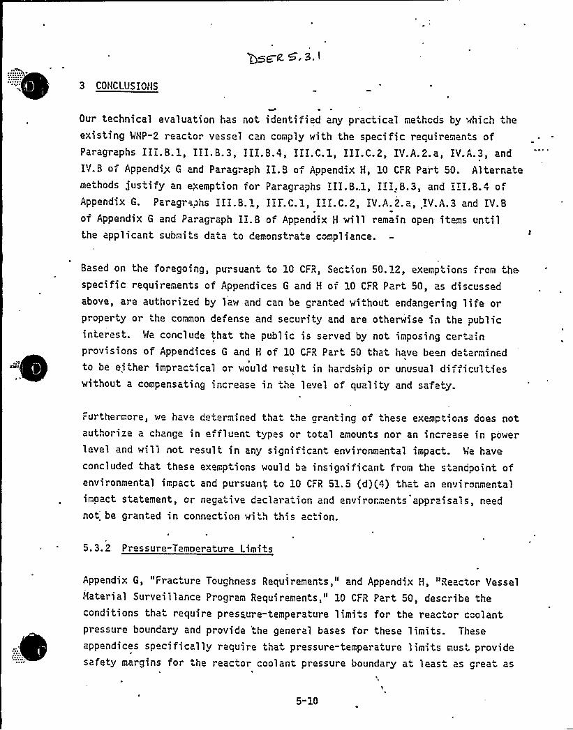
3 CONCLUSIONS
Our technical evaluation has not identified any practical methods by which theexisting 'MNP-2 reactor vessel can comply with the specific requiremen s ofParagraphs III.B.1, III.B.3, IIE.B.4, III.C.l, EII.C.2, IV.A.2.a, IY.A.3, and
IV.B of Appending G and Paragraph II.B of Appendix H, 10 CFR Part 50. Alternatemethods justify an exemption for Paragraphs III.8..1, IEI.B.3, and III.B.4 ofAppendix G. Paragr=phs III.B.1, III.C.1, IEE.C.2, IV.A.2.a, IV.A.3 and IV.Bof Appendix G and Paragraph II.B of Appendix H will remain open- items untilthe applicant submi ts data to demonstra.e compliance.
Based on the foregoing, pursuant to 10 CFR, Section 50. 12, exemptions from thespecific requirements of Appendices G and H of 10 CFR Part 50, as discussedabove are authorized by law and can be granted without endangering life orproperty or the common defense and security and are otherwise in the publicinterest. Me conclude that the public is served by not imposing certainprovisions of Appendices G and H of 10 CFR Part 50 that have been determinedto be either imprac ical or would result in hardship or unusual difficultieswithout a compensating increase in the level of quality and safety.
Furthermore, we have determined that the granting of hese exemptions does notauthorize a change in effluen types or total amounts nor an increase ln powellevel and will not result in any significant environmental impact. Me haveconcluded hat these exemptions would be insignificant from the standpoint ofenvironmental, impact and pursuant to 10 CFR 51.5 (d)(4) that an environmentalimoact statement, or negative declara ion and envirorments appraisals, need
not be granted in connection wi .h this ac ion.
5.3.2 Pressure-Temperature Limits
Appendix G, Fracture Toughness Requirements," and Appendix H, "Reactor Vesselmaterial Surveillance Program Requirements," 10 CFR Part 50, describe theconditions that require pressure-temperature limi .s for the reactor coolantpressure boundary and provide the general bases for these limits. These
appendices specifically require that pressure-temperature limits must providesafety margins for the reactor coolant pressure boundary at leas as great as
5-10

s
MNP-2
Open SER Issue
5.3.1 10CFR50 A endices G and H Com liance
A response to this issue was submitted December 18, 1981, by letternumber GO2-81-532.
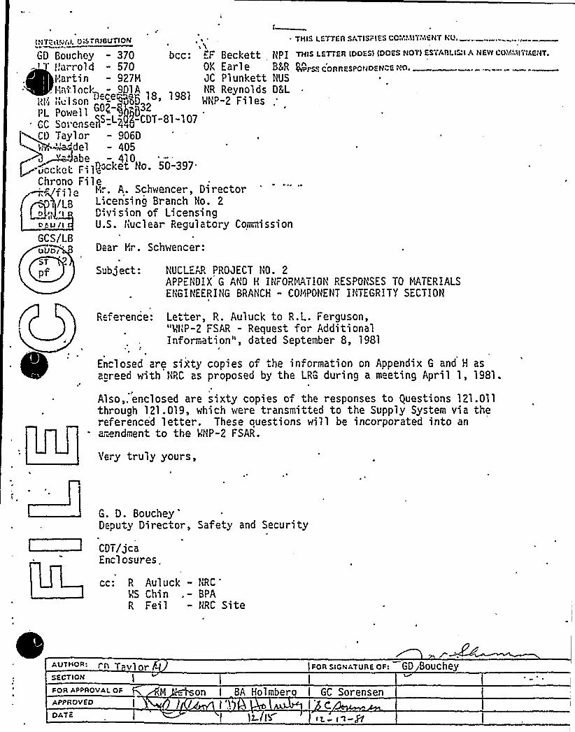
Subject: NUCLEN PROJECT NO. 2APP""NDIX G AND H INFORMATION RESPONSES TO MATERIALSENGINEERING BRANCH - COMIPONENT INTEGRITY SECTION
0 S'"RIBUTION THIS I.ETTEA SATISFIES CCii'AIITiY'ENTNu.INTER'4AI. Qe& ~ RIBUTIO
GD Bouchey - 370 bcc: „"F Beckett NPI THIS I.ETTER IOOESI IooES NCTI ESTAIILI"IA-'" Harrold - 570 OK Earle BM @PsscoRREsPCNoEN ENo.
Martin - 927M JC Plunkett NUS
. hatlocI; - 9 lA NR Reynolds DLL
CD Taylor - 906D>, "-"del - 405
- abe - 410.„ocke„. F=,10~acket Ho.
50-397'hrono
Fi 1 eM.. A. Schwencer, DirectoreLicensing Branch No. 2
o;, I D'vi sion of Licensingo u I U.S. Nuclear Regulatory CommissionGCS/LB
Dear Mr. Schwencer:
GV
NEW I'OiYiI.IITMENTe
R ference: Le ter, R. Auluck to R.L. Ferguson,"VNP-2 FSAR - Request for AdditionalInformation", dated September 8, 1981
Enclosed are sixty copies of the information on Appendix G and H asagreed with NRC as proposed by the LRG during a m eting April 1, 1981.
Also,. enclosed are sixty copies of the responses to questions 121.011through 121.019, which were transmitted to the Supply System via thereference'd letter. These ouestions will be incorporated into anar~ndment to the MNP-2 FSAR.
Yery truly yours,
G. D . Bouchey'eputyDirector, Safety and Security
CDT/jcaEnclosures.
cc: R Auluck - NRC'S
Chin . — BPAR Feil - NRC Site
AUTHCR: n vlorSF.CTION I
FOR APPROVAL OF
APPROV EO
DATE
M 'n BA Holmberat I t'.>
I 12
)FoR slcNATURE oF: GD Bouchey
GC Sorensen
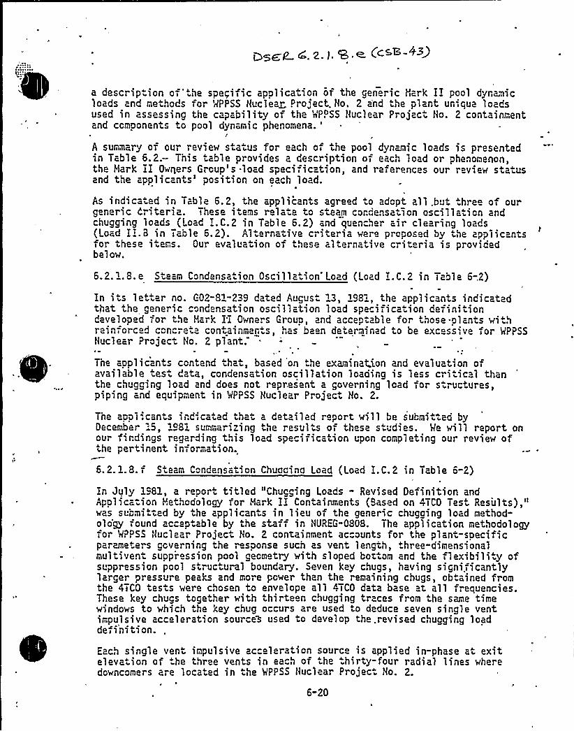
~ ~g gp) ~~(c.sE43$
a descrip.ion of'.he spegific application of the generic Hark II pool dynamicloads and meihods for MPPSS Hucieag Project. No. 2 a'nd ihe plant unique loadsused in assessing the capability of the MP. SS Nuclear Projaci Ho. 2 containmentand ccmponen s to pool dynamic phenomena.'
summary of our review s aius for each of the pool dynamic loads is presentedin Table 6.2:- This table provides a description of each load or phenomenon,the Hark II Owners Group's .load specification, and references our review statusand the applicants'osition on each load.
As indicaied in Table 6.2, the applicants agreed .o adopt all.bu .hree of ourgeneric Criteria. These iiems rela e to sieam cordensatlon oscillaiion andchucging loads (Load I.C.2 in Table 6.2) and quencher air clearing loads(Load I .8 in Table 6.2). Al ernaiive criieria were proposed by the applicantsfor these items. Our evaluaiion of these alierna ive criteria is providedbel ow.
6.2.1.8.e Sieam Condensa ion Oscillaiion Load (Load I.C.2 in Table 6-.2)
In its letter no. G02-81-239 dated Augus. 13, 1981, the applicants indicatedthat the generic condensation oscillation load specificaiion def iniiiondeveloped for the Mark II Owners Group, and accepiable for those-plants withreinforced c"ncre.a coniainmants as been determined io be excess',ve for MPPSSNuclear Projeci No. 2 plant.
The applicants contend that, based on the examinat.ion and evaluation ofavailable tesi data, condensation oscillation loading is less cri ic 1 thanthe chugging load and does not represent a governing load for siructures,piping and equipment in MPPSS Nuclear Projeci Ho. 2.
The appi'.cants indicated that a detailed report will be submi iad byDecember 15, 1 81 summa",izing the resul is of these studies. Me will report onour firdings regarding this load specification upon completing our review ofthe pertinent information.
6.2. 1.8.f S earn C"ndensa ion Chuccinc Load (Load I.C.2 in Table 6-2)
In July 1981, a repor titled "Chugging Loads - Revised Definition andApplicaiion Meihoaology for Hark II Containments (Based on 4TCO Test Results),"was suumi tied by the appl icants in 1 i eu of the generic chugging load method-oio'gy found ac" ptable by the staf in HUREG-0808. The application methodologyfor MPPSS Nuclear Project Ho 2 containment ac ounts for the plant specificparameters ccverning the ~sponse such as vent lengih, three-dimensionalmultivent suopression pool geometry with sloped bottom and the flexibilityofsuppression pool s ruc ural boundary. Seven key chugs, having signi.ficantlylarger pressure peaks and more power than the remaining chugs, obtained fromthe 47CO tes is were chosen to envelope all 4TCO data base at all freouencies.These key chugs togeiher with thirteen chugging traces from the same timewindows to which the key chug occurs are used to deduce seven single ventimpulsive acceleration sources used .o develop the .revised chugging loadde,inition.
Each single veni impulsive acceleration source is applied in-phase ai exiteleva ion of he three vents in each of ihe .hirty-four radial lines wheredowncomers are located in ihe MPPSS Huclear Projec. Ho. 2.
6-20
HNP-2
ISSUE 43
NRC:
Supply System:
The NRC will not be able to review theWNP-2 condensation oscillation report,scheduled to be submitted by. December 15,.1981, by the SER date. The only way tomeet the SER and SSER date, WNP-2 willhave to accept the generic condensationoscillation load specification. Anyplant unique data may require a NRC
review of 6 to 12 months.
Condensation Oscillation Report wassubmitted to NRC on December 24, 1981,by letter number G02-81-552.
'i C
\
LTBAJD
".,-,1erbach-927hE-i b'"-.901A
i sc'nev 'o70
edeniburg-906D.:arrold-410Holmberg-901A
artin-927t1ttelson-906D
INT Ra(A'ISTRIBUTION
CC 'orensen c20cnrono iledccke-. =ilekf/fi;e o06DEA'F/lbBAH/lbRt'if</1 bRGII/lb
G"5/lbST 2
THIS LETTER SATISFIES CCPAMITMENT ND.
THIS e.ETTFR IDOESI IDO 5 NOTI ESTABLISH A NEW COMMITMENT.
WFFS C RRESFONDE>CE >D
Docket i!o. 50-397
December 24, 1981G02-81-552
WQtir. A. Schwencer-, DirectorLicensing Branch !Io. 2
Division of Licensingt
d.'nuclear R actor RegulationL'.S. Nuclear Regulatory Com~issIonwashington, D.C. 20555
Dear ter. Schwencer:
Subject: NUCLEAR PROJECT 40. 2COl'D-NSATIOI'I OSC>LLATIO'I LOAD FOR I'tlP-2
Reference: G02-81-239, August 31, 198',, G. D. Bouchey, Supply System,to R. L. Tedesco, tlRC
The Reference letter advised you that the Hark II Owners group generic con-densation oscillation (CO) load definition was excessive for the tt!IP-2 plant,tha. preliminary studies indicated CO loadino should not be a governing loadfor plant assessments, and that a final report summarizirg the results ofthese studies would be submitted by the end of 1981. Th" s issue was discussedfurther with the HRC sta f and consulta..ts at the Contairment Systems Branchreview meeting in Richland during the w ek of September I4, 1981, and is cur-~
~
~
rently identified as an open item in he draft SER for t,",'P-2.
t f tTransmitted herewith is the final repor-, "Comparison of Condensation Osci'Ila-tion and Chuggino Loads for Assessment cf ! PPSS tluclear Project tto. 2", pre-pared on our behalf, by Burns and Roe, Inc. This report summarizes resultso-, studies performed to evalu-te data fro.-. single-vent tests (4TCO), to revie«results of multi-vent tests (JA=RI), anc -.o cor pare CO and chuoning loads.As concluded in the report these,studies confirm that the CO load does notrepresent a governirg loao fol r.'Ih'P-2, arid consequently need not be consideredin assessments of structures, piping, arc equipment.
nI I ede..our- FGR s!GNATURE oF: Gg ~ 4nev
I sEcTIG<
~PQ n AP ~ sl G'ui A I. O F I BA Holi;..~ergI
II I
IOCK g I r:: IIe I SOn
DATE
j'1M I ./ +iii'r... ) - ~-. F= -~I fc, 4 I r/ I
t'.r: A. SchwencerPage 2December 24, 1931G02-8I-552
Please note that boih a'roprietary and a nonproprietary version o-, theCO report are enclosed. The proprietary version incl'es fig res whichhave been desionated proprietary by JAERI, the General Electric Comoany,and by Burns and Poe,'Inc. Consisient wi.th the provisions unde. whichthis information was made available to the Supply System and to B r.',sand Roe, and as attested to by .he attached affidavit, we request 'thatthe proorietary ve,sion of this repori be wiihheld from public disclosurein accordance w',th the provisions of 10CFR2.790.
We would be pleased to meei wiih the HRC staff and consultants, at ycurearliest convenience, to respond to any questions or to further d;scussthe contents of the enclosed report.
Very truly yours,
G. D. BoucheyDeputy Director,Safety and Security
EAF:kjf
w/proprietary report {1 copv)w/o attachmentw/o attachmentw/o attachmentw/o attachmentw/proprietary repor (1 copy)w/o attachmentw/o at.achmentw/proprie arv repcr- (2 copies)w/o a ..achmentw/o attachmentw/o attachmentw/o attachmentw/o attachmentw/0 attachmentw/o at achment
Enclosure: Summary Report, "Comparison of Condensation Oscillationand Chugging Loads for Assessment of WPPSS Nuclear Project No. 2"
I
cc: R. Auluck - HRCEF Beckett - Nuclear Projects, Inc.WS Chin - BPAAI Cygelman - B8R SiteOK Earle - B8R ROF. Eltawila - HRCR. Feil - NRC SiteJA Forrest - B8R ROJ. Lehrer - Brookhaven Na.ional Lab.ND Lewis - EFSECFA tlacLean - General ElectricJC Plunkett, Jr.,- NUSi'S Reynolds - D8LS. Smith - General ElectricRE Snaith - BE(R HYJJ Verderber - BER HY
,MNP-2 Files
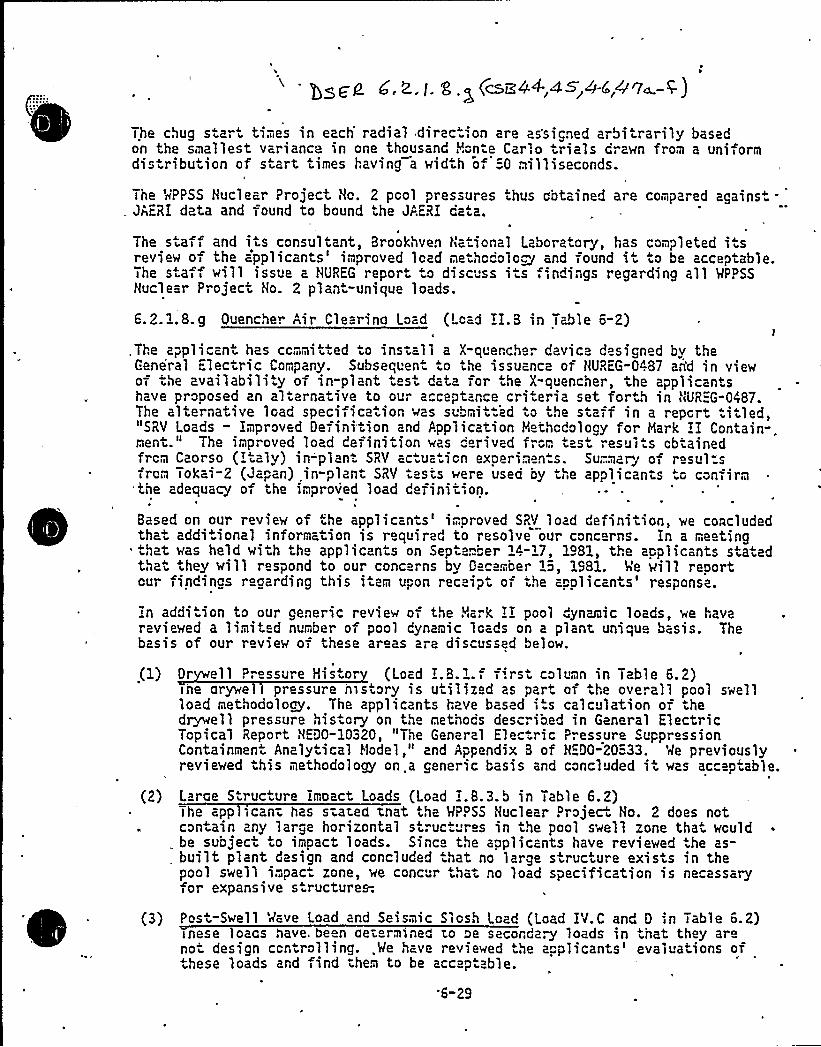
The chug s art times in each'adial dirac.',on are assicned arbiirarily basedon the smallest variance in one thousand Mon e Carlo trials drawn from a uniformdis ribuiion of s art times having a wid-'h of:-0 milliseconds.
The MPPSS Nuclear Project Ho. 2 pool pressures thus obtained are compared agains.-JAERI data and found to bound ihe JAERI data.
The staff and i is consultant, Brookhven National Laboratory, has completed i sreview of the a'pplicants'mproved load methcdolo~ and found i'o be acceptable.The s a , will issue a HUREG report o discuss i s indings regarding all MPPSSNuclear Project Ho. 2 plan -unique loads.
6. 2. 1.8. g Quencher Air Clearino Load (Load II.B in Table 6-2)
, The a/pl 1 cant has ccmml tted 0 1 nstel 1 a X quenche. devi ce des i gned by theGene'ral Electric Company. Subsequeni .o the issuance of HUREG-0487 an'd in viewof the availabiliiy of in-plant tesi data for .he X"quencher, the applicantshave proposed an aliernative to our a ceptance cri eria set forth in HUREG-0487.The alternative load specificaiion was submii.ed io ihe staff in a report ti led,"SRY Loads " Improved Definition and Application Methodology for Mark II Contain-.ment." The improved load definition was derived f m iast esul s obtainedfrom Caorso (Iialy) in"'plani SRV ac ua ion experimen.s. Su.. lary ol resul sfrom Tokai-2 (Japan) in-plant SRV tests were used by the applicants to confirmthe adequacy of the improved load definition.
8ased on our review of <he applican s'mproved SRV load definition, we concludedthat additional information is required to resolve our concerns. In a meeting'ilat was hei d wi ih the appl icanis on Sep iamber 14-17, 1481, the app 1 icants staiedthat they will respond to our conc ms by Dec . ber 1i, 1981. h'e will reportcur findings r garding this i am upon rec ipt of .he a olicanis'esponse.
In addi ion to our generic review of the Mark II pool "ynamic loads, we havereviewed a limit d number of pool dynamic loads on a plant uniqu basis. Thebasis of our review of these areas are discussed below.
(1) Dr ell Pressure His or (Load I.B. l.f f'.rst column in Table 6.2)ihe arywell pressure history is utilized as part of ihe overall pool swellload methodology. The applicants have based its calculation of hedr„dwell pressure hisiory on the methocs described in General ElectricTopical Report HED0-10320, "The General Elec ric Pressure SuppressionContainmen Analy ical Model," and Appendix 8 of HEDO-20:"33. Me previouslyreviewed ihis methodology on.a generic basis and concluded i i was accepiable.
(2) Large Structure Impact Loads (Load I.8.3.b in Table 6.2)The applicant has siated tnat the MPPSS Huclear Projeci Ho. 2 does notcontain any large horizontal s ruci res in the pool swell zone that wouldbe subject to inipact loads. Since the applicants have reviewed the as-built plant design and concluded .hat no large siruc ure exists in thepool swell impac zone, we conc r that no load specification is necessaryfor expansive s ructures-.
(3) Pos i"Swell Wave Load and Seismic Slosh Load (Load IV.C and D in Table 6.2)inese loaas have. be n aei rmined to oe secorda~ loads in hat they arenot design controlling. .Me have reviewed he applicants'valuations ofihese loads and find ihem to be accepiable.
6-29
WNP-2
ISSUE 44
NRC: Caorso air volume in discharge Line issmalLer than WNP-2. Thereforer Load ishigher- Comparisons between the two areconcerns to the NRC-
Supply System: See Issue 47 a-f
ISSUE 45
NRC Question 022.055. The NRC is concernedabout the statement saying maximum pressurefor multiple valve actuation is higher than5.87 psi.
Supply System: See Issue 47 a-f ---.
ISSUE 46NRC'he NRC believes that DFFR requires thepressure di f f erence (ca Lculated to ext ra-polate Caorso conditions to WNP-2 conditions)be added to Caorso measured peak pressuresrrather than used to calculate 'a 'multipL'ierras was done in the WNP"2 SRV Load definition.
SuppLy System: See Issue 47 a-f
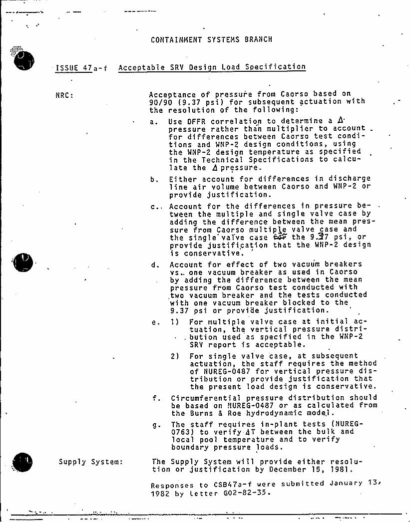
CONTAINMENT SYSTEMS BRANCH
ISSUE 47 a-f Acceptable SRV Desi n Load S ecification
NRC: Acce90/9thea.
b.
c ~
e.
9 ~
ptance of pressur'e from Caorso based on0 (9.37 psi) for subsequent actuation withresolution of the following:Use DFFR correlation to determine a 3pressure rather than multiplier to accountfor differences between Caorso test condi-tions and WNP-2 design conditions, usingthe WNP-2 design temperature as specifiedin the Technical Specifications to calcu-late the A pressure.Either account for differences in dischargeline air volume between Caorso and WNP-2 orprovide justification.Account for the differences in pressure be-tween the multiple and single valve case byadding the difference between the mean pr'es-sure from Caorso multip|,e valve case andthe single'alve case QP the 9.37 psi, orprovide justification that the WNP-2 designis conservative.Account for effect of two vacuum breakersvs.. one vacuum breaker as used in Caorsoby adding the difference between the meanpressure from Caorso test conducted withtwo vacuum breaker and the tests conductedwith one vacuum breaker blocked to the9.37 psi or provide justification.I) For multiple valve case at initial ac-
tuation, the vertical pressure distri-~ . bution used a" specified in the MNP-2
SRV report is acceptable.2) For single valve case, at subsequent
actuation, the staff requires the methodof NUREG-0487 for vertical pressure dis-tribution or provide justification thatthe present load design is conservative.
Circumferential pressure distribution shouldbe based on HUREG-0487 or as calculated fromthe Burns 8 Roe hydrodynamic model.The staff requires in-plant tests (NUREG-0763) to verify 4T between the bulk andlocal pool temperature and to verifyboundary pressure loads.
Supply System: The Supply System will provide either resolu-tion or justification by December 15, 1981.
Responses to CSB47a-f were submitted January13'982
by Letter G02-82-35.

Washington Public Power Supply SystemP.Q. Box 968 3000 George Washington Way Richland, Washington 99352 (509) 372-5000
January 13, 1982G02-82-35SS-L-02-CDT-82-015
Docket No. 50-397.
Mr. A. Schwencer, ChiefLicensing Branch No. 2
Division of LicensingU.S. Nuclear Regulatory Commissionl]ashington, D.C. 20555
Dear Mr. Schwencer:
Subject: NUCLEAR PROJECT NO. 2
RESPONSES TO CSB OPEN ITEMS 44-48
Enclosed are sixty (60) copies of the responses to open items44 - 48 from the Containment Systems Branch meeting heldSeptember 14-17, 1981. These items should be closed byreceipt of this submittal.
Very truly yours,
G. D. BoucheyDeputy Director, Safety and Security
CDT/ jcaEnclosures
cc: R Auluck - NRC
MS Chin - BPAR Feil - NRC Si te

0
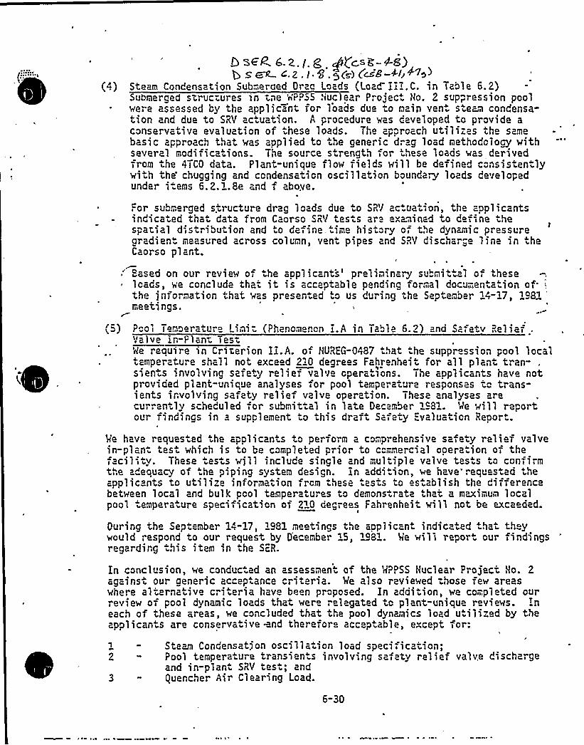
D seP a. z. < .g ggcs <". -4«)b S ~ ~.Z.I.S.gCs) C~S-4Ir<b)
Steam Condensation Submerged Dree Loads (Load Iii.C. in Table 6.2)Submerged structures in tne MP?SS .'iuclear Proiec Ho. 2 suppression poolwere assessed by the applicant for loads due to main ven. s~te~s condensa-tion and due to SRY actuation. A procedure was caveloped to provide aconservative evaluation of these loads. Tt e approach utilizes the samebasic approach that was applied to the generic drag load methodology withseveral modifications. The source s rength for 'hese loads was d rivedTr om the 4TCO data. Plant-unique flow fields will be def'ined c"nsistentlywith the'hugging and condensation oscillation boundary loads developedunder items 6.2.1.8e and f above.
For submerged structure drag loads due to SRV ac uation, the applicantsindicated that data from Caorso SRV tests are examined to de<i<ne thespati<al distribution and o de<inc. ime history o< the dynamic pressuregradient measured across column, vent pipes and SRV dischar," line in heCaorso plant.
'ased on our review o< the applicants'reliminary suLmit.ai o< these1 cads, we concl ude that it i s accaptab1 e pending fo"„-,al documentati on o fthe jnformation .hat was presented to us during the September 14-17, 1981meetings. l
(") Pool Temoerature Limit (Phenomenon i.A in Table 6.2) and Saretv ReliefValve in-Fiant iestMe require in Criterion II.A. of HUREG-0487 that the suppr ssion pool localtemperature shall not exce d 2"0 degrees Fahrenhei for all plant~tran- .
sients involving safety relief valve opera >ons. The applicants have notprovided plant-unique analyses <or pool temperature responses to trans-ients involving sa<ety relief valve operation. These analyses arecu
e'en
ly scheduled for submit al in late December 1981. Me 'will re~crtour findings in a supplem<ent to this draft Safety Evaluation Report.
'«e have requested the applicants to perform a comprehensive safe y relief valvein-plan- test which is to be completed prior to commercial ooeration of the<acili<ty. Tnese ests we'll include single and <",ultiple valve tes s tc confi m
the a"equacy of the piping system design. in addition, we have" requested t leapplicants to utilize information,rcm these tests to establish the di<ferencebetween local and bulk pool tempera ures to demons. rate that a maximum localpool empera ure speci<ication of 2~0 de,rees Fahrenheit will not be exce ded.
During the September 14-17, 1981 meetings the applicant indicated hat theywould respond to our request by December 15< 1981. Me will repor. our findingsregarding this item in the SER.
In conclusion, we conduc-ad an assessmen of the K~PSS Huclear Project Ho. 2
agains . our generic acceptance criteria. Me also reviewed -hose rew areaswhere alternative criteria have been proposed. In addition, we completed ourrevie~ o< pool dynamic loads that were relegated to plant-unique reviews. Ineach of these areas, we concluded that the pool dynamics load u iiized by theapplicants are conservative ~nd therefor acceptable, except <or:
2
3
Steam Condensatjon oscilla~ion load specification;Pool temperature transients involving sa,aty relief valve dischargeand in-plant SRV test; andquencher Air Clearing Load.
6-30

0
CONTAINMENT SYSTEMS SRANCH
ISSUE 48
NRC:
Supply System:
The staff believes that the WNP-2 im-proved chugging load definition isreasonably conservative. The appli-cant has responded to our concerns ina sat.isfactory manner..
Preliminary information regarding SRVand LOCA submerged structure drag loadsseems to be reasonabl'y conservative.
Information provided, to the NRC onchugg- ng ~ SRV and LOC'A submergedstructure drag loads was provided fordiscussion purposes, and will be sub-mitted formally by October 2, 1981.
Response submit ted January13'982'y
letter G02-82-35.

Washington Public Power Supply SystemP.O. Box 968 3000 George Washington Way Richland, Washington 99352 (509) 372-5000
January 13, 1982G02-82-35SS-L-02-CDT-82-015
Docket No. 50-397
Mr. A. Schwencer, ChiefLicensing Branch No. 2Division of LicensingU.S. Nuclear Regulatory CommissionWashington, D.C. '20555
Dear Mr. Schwencer.:
Subject: NUCLEAR PROJECT NO. 2
RESPONSES TO CSB OPEN ITEMS 44-48
Enclosed are sixty (60) copies of the responses to open items44 - 48 from the Containment Systems Branch meeting heldSeptember 14-17, 1981. These items should be closed byreceipt of this submittal.
Very truly yours,
G. D. BoucheyDeputy Director, Safety and Security
CD'caEnclosures
cc: R Auluck - NRC
WS Chin - BPAR Feil - NRC Si te
CONTAINYiENT SYSTENS BRANCH
IS S IJE 41
NRC: When wilL NRC receive WNP-2 Pool „
Tempe rat ure Ana L ysi s (NUREG-0783) .
Supply System: The analysis was submitted on December ISED
1981 by Letter 602-81"524.
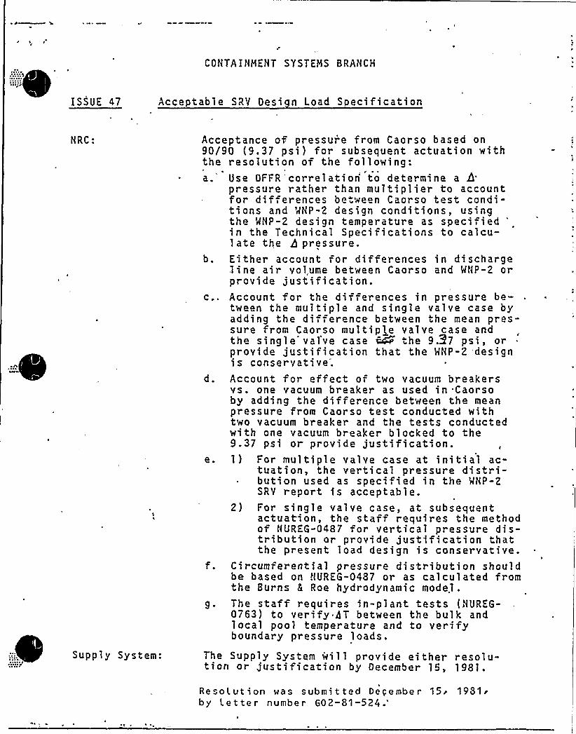
'ISSUE 47
CONTAINMEHT SYSTEMS BRANCH
Acceptable SRV Desi n Load Specification
NRC: Acce90/9thea.
b.
C. ~
d.
e.
ptance of pressur'e from Caorso based on0 (9.37 psi) for subsequent actuation withresolution of the following:Use OFFR'correlation'o determine a 6pressure rather than multiplier to accountfor dif erences be. we n Caorso test condi-tions and MNP-2 design conditions, usingthe MHP-2 design temperature as speci i ed
'n
the Technical Specifications to calcu-late the 3 pressure.Either account for differences in dischargeline air vol.ume between Caorso and WNP-2 orprovide justification.Account for the differences in pressure be-tween the multiple and single valve case byadding the di ference between the mean pres-sure from Caorso multiple valve case andthe single'alve case ~ the 9.37 psi, orprovide justification that the MNP-2 designis conservative.Account for effect of two vacuum breakersvs. one vacuum breaker as used in Caorsoby adding the difference between the meanpressure from Caorso test conducted withtwo vacuum breaker and the tests conductedwith one vacuum breaker blocked to the9.37 psi or provide justification.I) For multiple valve case at initial ac-
tuation, the vertical pressure distri-~ bution used as specified in the MNP-2
SRY report is acceptable.2) For single valve case, at subsequent
actuation, the staff requires the methodof NUREG-0487 for vertical pressure dis-tribution or provide justification thatthe present load design is conservative.
Circumferential pressure distribution shouldbe based on HUREG-0487 or as calculated fromthe Burns & Roe hydrodynamic model.The staff requires in-plant tests {HUREG-0763) to verify 5T between the bulk andlocal pool temperature and to verifyboundary pressure loads.
Supply System: The Supply System will provide either resolu-tion or justification by December IS, 1981.
Resolut ion was submi t ted Deqembe r15'981'y
Letter number G02-81"524.'
INTEANAL OISTRIBUTIOSTRI BUTION .. ' THIS LETTER SATISF IES COMMITMENTNO.
GK Aff1 erbach-927M RM Nel son-906D BAH/lb THIS LETTER IDoEs) IDoEs NoTI EsTABusH A NEw IMMI TRENT.
W Bibb-901 A. 'C Sorensen-420 JD! I/lb ~~ coRREsPoNo'ENGE No.-uchey-370 chrono file-906D RMN/lb
redenburg-906D docket file-906D sf(2)L Harrold-410 . kf/file-906D pf(l).,:.BA Holmberg-906D EAF/lbJD. Martin-927M RGM/lb
Vcr-2/''2/
Mr. A. Schwencer, ChiefLicensing Branch*No. 2Division of LicensingNuclear Reactor RegulationU.S. Nuclear Regulatory CommissionWashington,'.C. 20555
~1
*
Dear Mr.. Schwehcer:
Subject: NUCLE
NUREG 0763 provides guidelines. for determining'whether plant-specific tests,may be required to measure SRV discharge. loads and pool temperature. grad-ients. The stated policy is that new plant-specific tests will be, requiredif plant parameters affecting loads and temperature distribution are sub-stantially different from those previously tested. According to NUREG 0763."applicants may be able to demonstrate that discharge conditions in theirplants are sufficiently similar to conditions previously tested to obviatethe need for any new tests or to curtail the scope of tests."
AR PROJECT NO. 2SUPPRESSION POOL TEMPERATURE TRANSIENTANALYSIS AND IN-PLANT SRV TEST
The purpose. of this letter is to transmit the results of the suppressionpool temperature transient analysis for WNP-2, and to advise you that we
will perform an in-plant test to measure the difference between .local andbulk poo'1 temperatures during main steam relief valve discharge. Both of
. these were identified as open items during the Containment Systems Branchreview meeting in Richland in September 1981, and in the draft SER for WNP-2.
Results of the pool temperature. transient analysis are contained in theattached Report No. 14057-U(D)-1, "Suppression Pool Temperature Analysis",prepared for Washington Public Power'upply System Nuclear Project No. 2
by Stone and Webster Engineering Corporation. This analysis indicates thatfor th8 cases evaluated, the iIIaximum suppression pool peak bulk temperatureis 198 F. For wetwell airspace pressure of 0 psi gage, this is 35 F belowsaturation temperature at the quencher centerline elegation, and thus al-lows for a local-to-bulk temperature difference of 15 F, in accordancewith the acceptance crjteria of draft NUREG 0783 for steam mass flow rates~ of less .than 42 1bs/ft /sec.
AUTH0R: EA re enourgSECTION
FoR sIONATURE oF: GD Bouchey
FOR APPROVAI OF
APPROVEO
OATE
RM Nelson BA Holmber .J Martin RG Matlock
Plant parameters defined in NOREG 0763 which must be evaluated for similarityto parameters previously tested are as follows:
1; discharge device geometry2. discharge line parameters: line length, area, volume, quencher
submergence, vacuum breaker size, available pool area per quencher3. steam flow rate4. quencher location and orientation, and pool geometry5. structural characteristics of containment
In-plant tests performed in the Caorso plant in Italy and in the Tokai plant'n
Japan are directly applicable to MNP-2. Both Caorso and Tokai have MarkII containments geometrically similar to MHP-2, with SRV discharge line para-meters and quencher geometry essentially identical to WNP-2. The bottom ofboth the Caorso and Tokai containments are flat, while the WNP-2 containmenthas a trapezoidal-shaped bottom. 'The Caorso containment is reinforced con-crete, while Tokai utilizes a steel containment similar to MNP-2.
I
Data from both the Caorso and Tokai tests have been extensively evaluatedon our behalf by Burns and Roe, Inc. Of the two in-plant tests, Gaol so has
been the most thoroughly investigated due to the availability of data throughthe Nark II Owners group.
The quencher air clearing load definition for WNP-2 was based on detailedanalysis of data from the in-plant SRY tests in Caorso, and confirmed byevaluation of data from the Tokai tests. Differences between the Caorso plantconditions, and MNP-2, were accounted for in the load definition report sub-mitted to the NRC in August 1980 ("SRY Loads-Improved Definition and Applica-tion Nethodology for Mark II Containments"). NRC review of the SRV load defi-nition for HNP-2 considered all of the plant parameters identified above whichcould affect quencher air clearing loads. Differences between Coarso andWNP-2 plant parameters were addressed by the Supply System in response to NRC
questions during the licensing process. Following discussions with the NRC
during the Containment Systems Branch review meetings in Richland in September1981, some modifications to the SRV load definition were made to account forminor differences in these parameters.
A summary of comparisons, of the Caorso and WNP-2 significant plant parameterspotentially affecting the quencher air-clearing load is provided below:
guencher Geometr
The Caorso and WNP-2 quenchers are essentially identical. (See FSAR question22.053);" '
SRY Dischar e Line
SRV discharge line lengths, areas, volumes, and quencher submergence forCaorso and MNP-2 are similar. Minor differences are accounted for inthe response to CSB issue f47 from the September 1981 review of MNP-2.)
Yacuum Breaker Size
'The SRV discharge line vacuum breakers affect the reflood transient withinthe SRV line, and therefore the internal water level within the line for a
subsequent SRV actuation. The Caorso test conditions included a diversityof SRY 1ine initial water levels. Since the MNP-2 SRY load definition en-velopes the 1oads observed at Caorso, differences in vacuum breakers areaccounted for. (See FSAR questions 22.054, 22.057, and the response to CSB
issue Ã7 from the September,1981 review of MNP-2.)
Pool Ar a er uencher
The pool surface area per. quencher for MNP-2 is slightly .larger in WHP-2
than in Caorso. This difference would have no significant effect on thequencher air clearing load. (See FSAR question 022.107, and the responseto CSB issue Ã7 from the September 1981 review of MNP-2.)
Steam Flow Rate
The steam flow rates .in MNP-2 range from 236 to 252 ibm/sec. Steam flowrates in the Caorso tests ranged from 238 to 244 ibm/sec. The Caorsosteam flow rates were within 1" of the flow rates for the.six lowest set- "point SRY's at WNP-2, and within 2.5~ of the flow rates for the highestsetpoint SRV at MNP-2. These differences are not significant.
Ouencher location and Orientation
guenchers at both Caorso and MNP-2 are arranged around the suppressionpool in an inner circle and an outer circle. The outer quenchers in MNP-2are farther away from the containment wall (9.95 feet) than the outer dis-charging quencher in the Caorso tests (7.'5 feet). Since bubble pressureattenuates with distance, using Caorso test. pressures applied directly tothe MNP-2 containment is conservative.
Pool Geometr
Except for the trapezoidal-shaped bottom on MHP-2, Caorso and Tokai haveessentially identical geometries to MHP-2. Since the magnitude of the SRV
quencher air clearing loads acting on the containment wall have been foundto be primarily a function of proximity of containment to the quencher. theeffect of the shape of the pool bottom is not significant.
Structural Characteristics of Containment
Fluid/structure interaction (FSl)'ffects during the Caorso tests and theanalytical methods used to extract rigid wall pressures from the test mea-surements are discussed in detail in the SRV load definition report sub-mitted to NRC. As shown therein, the analytical model used to predict boun-dary pressures in a Mark EE containment is in good agreement with Caorso
'estmeasurements. Also discussed is the applicaticn of FSI effects to the
steel containment structure of WNP-2. Differences between Caorso structuralcharacteristics and WNP-2 are thus accounted for in the SRV load definition.(Also, see FSAR question 22.063.)
Based on this comparison of plant parameters, only minor differences betweenWNP-2 and Caorso are found to exist, and these differences are conservativelyaccounted for in the SRV load definition fot WNP-2. We have concluded thatan in-plant test to confirm the adequacy of the quencher..air-clearing loadwould not substantially add to the body of knowledge already obtained fromother in-plant tests, and is therefore not required for WNP-2, per the guide-lines of NUREG 0763.
Suppression pool temperature response was also measured in the Caorso tests.As previously mentioned, the only significant difference between WNP-2 andCaorso which could conceivably affect pool temperature gradients is the shapeof the pool bottom. Since .the local-to=.bulk pool temperature difference mea-sured in the Caorso tests, as reported i'n NED0-24798, .was only 5oF, it doesnot appear likely that ths temperature difference for WNP-2 would approachthe allowable value of 15 F determined from the attached report. However,because 'the NRC has questioned the influence of the trapezoidal-shaped poolbottom on flow characteristics and temperature distribution in the suppressionpool during SRY discharge, and because of uncertainties which would be asso-ciated with a purely analytical approach to this problem, the Supply Systemco+nits to conducting an in-plant test to measure the local-to-bulk temperaturedifference. Local temperature will be measured by temperature sensors mountedon the containment wall opposite the discharging quencher, in accordance withthe guidelines of draft NUREG 0783. The existing suppression pool temperaturemonitoring system will be utilized in these tests, for measurement of both lo-cal and bulk pool temperatures.
G. D. BoucheyDeputy DirectorSafety and Security
EAF:kjf
Enclosure: Report No. 14057-U(D)-1"Suppression Pool Temperature Analysis"
cc: R. Auluck - NRCEF Beckett - Nuclear Projects Inc.WS Chin - BPAAI Cygelman - BER Site (954W)F. Eltawila - NRCR. Feil - Resident InspectorJA Forrest - B8R ROSA Giusti - BPC (904)ND Lewis - EFSEC, OlympiaFA MacLean - GE, San JoseTA Mangelsdorf - BPC (982)S. Smith - GE, San JoseRE Snaith - BAR NYJJ Yerderber - BIIR NY
(w/1 attachment)(w/o attachment)(w/o attachment)(w/o attachment)w/1 attachment)
(w/o attachment)(w/o attachment)(w/o attachment)(w/o attachment)(w/o attachment)(w/o attachment)(w/o attachment)w/o attachment)w/o attachment)
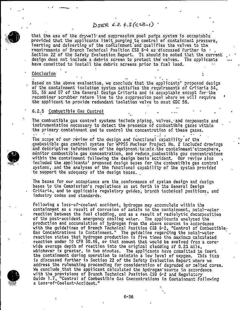
that the use of the drywell and suppression p'ool pu"'.-ce sys.em is acceptableprovided that the applicants limit p~urging to control of ccntair..-..ent „",assure,inerting and deiner ing of the containment and q alifies he valves o herequirements of Branch Technical Position CSB 6-4 as'disc ssed fur-.her inSection 22 of the Safety "valuation Report. 'It should bo noted that the c irrentdesign does not include a debris screen to protac- the valves. Th= applican shave cor mitted to install the debris screens prior to fuel load.
Conclusion~ 0
Based cn .he above evaluation, we conclude tha the applicants'r."posed designof .he containment isolation system satisfies the requirements of Cr'.-'aria 5-".,55, 56 and 57 of the General Oesign Criteria and is ac"eptable except for .therecombiner scrubber return line to the s'pression "ool where we will requirethe applicant to provide redundant isola.ion valve to meet GOC 56.
6.2.5 Combus ible Gas Control
The combustible gas control systems include piping, valves,. and cc;..ponants ardinsf. Umentation necessary to detec the presence of c".".,bus ible cases wi hinthe primary containment and to control tho concentr tion of these asas.
The sc"pe of oul, evlew of the des ign and func ional capa ility 0 thecombustibla gas cont"ol system for MPPSS tluclear Projec t/o. 2 incluce" crawingsand descriptive information of "the equipment:to:mix .the c ntainmen' Qsphe e,monitor combustible gas concentration, and reduce c"mbustible gas c"rcentrationswithin the containment following the design basis accident. Our review alsoincluded the applicants'rooosed design bases for the c '' ustib le gas con rolsystems, and the analyses of the func ional capability o-. the syst~-., provid dto support the adequacy of the desian bases.
The bases for our acceptance are t e Gnformance of system design anc designbases .o the Commission's regulatiors as set for h in -'..",o Ceneral DasicnCriteria, and to applicable regula.ory guides, branch tecnnical positions, andindus ry codes and s andards.
Following a loss-of-coolant accidert, hydrogen may acc;m late within thecontainment as a esult of corrosion of me als in the cont"inment, .-,e-'.al-wa.erreaction between the fuel cladding, and as- a result oi radiolytic cac"mpositlonof the post-accident, emergency cooling ~ater. Tne applic rts analyzed heproduc ion and accumulation of hydrogen from the above sources in accordancewith the guidelines of Branch Tochnical Position CSB 6-2,. "Control oi Combus.ible ~
Gas Concentrations in Containment. The guideline reoa irg the metal-waterreaction states that hydrogen production is five times the maximum calculatedreaction under 10 CFR 50.46, or hat amount that would be evolved fro.-. a core-wide average depth of reaction in o the original cladd'.ng "f 0.23 -.ils,whichever is great r, in two minutes. The applicants have committed to inertthe containment during operation to ;aintain a low level of oxygen. This iis discussed further in Section 22 of the Safety valuation Repor. where weaddress the rulemaking proceeding for consider ation of degraded or welted cores.Me conclude that the applicant calculated the hydrog n sou a ln ac ancewith the provisions of Branch Technical Position CSB 6-2 ard RegulatoryGuide 1.7, "Control of Combus ible Gas Conc ntra ions in Contain™an . ollowinga Loss-of-Coolan -Accident."
6"36
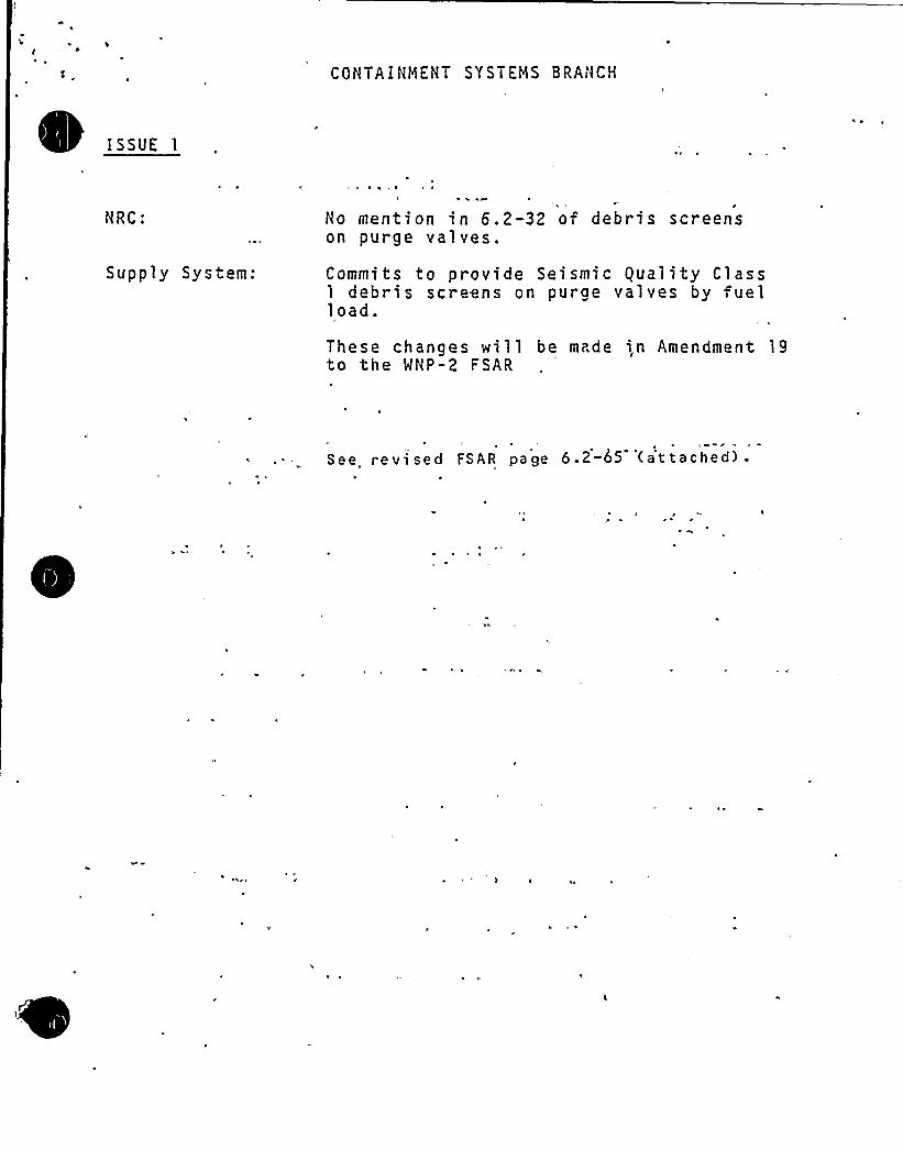
COHTAIHMENT SYSTEMS 8RANCH
iSSUE 1
NRC:
Supply System:
~ ~ I ~
1
Ho mention in 6.2-32 of debris screenson purge valves.
Commits to provide Seismic equality Class1 debris screens on purge valves by uelload.
These changes will be made i,n Amendment 19to the WNP-2 FSAR
See revised FSAR page 6.2-65 (at tached) .

NNP-2AMEND>iiENT NO. 5August 1979
rom the control room. These valves provide assurance oftisolating these lines in" the event of a break and alsoprovide long-term leakage control. ln addition, the pipingis considered an extension of containment boundary sinceit must be available for long-term usage following a designbasis loss-of-coolant accident, and, as such, is designed tothe same qual'y standards as the primary containment.
6.2.4.3.2.2.3.2 Containment. Purge LinesI
The drywell and suppression chamber purge lines have isolationcapabilities commensurate with the importance to safety of'olat'ng these lines. Each line has two air ooerated springclosing valves located outside the primary con ainment. The'solat'on valves for the purge lines are designed to be lockedclosed in the main control xoom. These isolation valves areinterlocked to preclude opening of the valves while a con-tainment isolation signal exists as noted in Table 6.2-16.
6.2.4.3.2.2.3.3 Drywell and Suppression Chamber AirSampling Lines
The radiation lines penetrate the primary containment and areused for continuously drawing containment air during normalooeration as part of the leak detection system. These lines=are equipped with two automatic isolation valves located out-side and as close as possible to the containment. The hydrogenmonitoring lines penetrate the primary containment and areused to continuously monitox the primary containment airduring the post-LOCA accident period. These lines areequipoed with check or excess flow check valves located out-side and as close as possible to the containment. Con-tainment, isolation requirements are met on the basis thatthese lines are low-pressure lines constructed to the samequality standa ds as the containment and lead to Class 1Eessential instruments. Fu-thermore, the consecuences of abreak in these lines result in no significant safetyconsideration.
'
6. 2. 4. 3. 2. 2. 3. 4 Suppression Chambe Soray Lines
The supp ession chamber spray lines oenetrate the containmentto remove energy by condensing steam and cooling nonconden-sible gases in the suporession chamber. The line is equipoedwith a normally. closed motor-ooerated valve located outsideand as close as possible to the primary containment. Thisnormally closed valve receives an automatic isolation signal.Containment isolation requirements are met on the basis that .
the spray header injection lines are normally closed, lowpressure lines constructed to the same quality standards asthe conta'nment.
8
v>
9'0 e.
Q (Q g
V)
4) R y~
W 8'g~0m ~
~~p4~WR4 1<
6.2-65
that the use of the drywell and suppression pcol pu"'.-ge system is acceptableprovided that the applicants limit purging to control of containment pressure,inerting and deinerting of the conta- r~ent and q 'alifies he valves to therequirements of Branch Technical Posi icn CSB 6-4 as 'discussed fur her inSec ion 22 of the Safety .Evaluation Repor . t should be no ed tra+ the currentdesign does not include a debris screen to pro ec the valves. The applicantshave committed to install the debris screens prior to fuel load.
Conclusion
Based on the above evaluation, we conclude tha the applicants'roposed designof the containment isolation systeg satis, ies he requirement's of'riteria 54,55; 55 and 57 of the General Design Cri aria and is accep&le except for 'herecogbiner scrubber return line to e supo. assi n pool 'khere 'we will requirethe applicant to provide redundant isola.ion valve ~o meet GDC 56.
6.2.5 Ccmbus ible Gas Control
The ccmbustible gas control sys ems include piping, valves,-and comoonents andins=rumentation necessary to detec the presence oi combus ible gases within+he primary conwinment and to control the concen.r ticn of these gases.
The s"ope of our review of he desicn and func ional capability of thecombustible gas control system for MPPSS Nuclear Project Ho. 2 included drawingsand descriptive information of'the equipmen .'w:mx .the containment'atmosphere,moni or combustible gas concentration, and reduce combustible gas concentrationswithin the containment following the design basis acci ent. Our review alsoincluded the applicants'roposed design bases for he ccmbus ible gas con.rolsystems, and the analyses of the functional cap&ility of the system providedto suppor the adequacy of the design bases.
The bases for our acceptance are the confor.„area of system design and designbases to the Commission's regula iors as set ,or a in +he General DesignCriteria, and to applicable regulatory guides, brarch technical positions, andindus ry codes and s andards.
Following a loss-of-coolant accident, hydrogen may accumulate within thecontainment as a ",esult of corrosion of "etals in the containmert, metal-waterreac'tion between the fuel cladding, and as a r suit of radiolytic deccgpositionof he post"accident emergency cooling water. The applicants analyzed theproduc ion and accumulation of hydrogen from ~he above sources in accordancewith the guidelines of Branch Technic 1 Position CSB 6-2, "Control of Combus ible.Gas Concentrations in Containment." The guideline r eaarding the metal-waterreaction states that hydrogen produc ion is five imes the maximum calculatedreac ion under 10 CFR 50.46, or ha amount that would be evolved frog a core-wide average depth of reaction into the original cladding of 0.23 mils,whichever is greater, in two minutes. The applicants have commit ed o inertthe, containment during opera~ion to mainwin a lcw level of oxygen. This itemis discussed further in Section 22 of the Safety Evaluation Report where weaddress the rulemaking proceeding for ccnsideraticn of degraded or melted cores.Me conclude that the applicant calculated the hycrogen source in accordancewith the provisions of Branch Technical Position CSB 6-2 and RegulatoryGuide 1.7, "Control of Combus ible Gas Concentra icns in Containment Followinga Loss-of-Coolant-Accident."
6-36
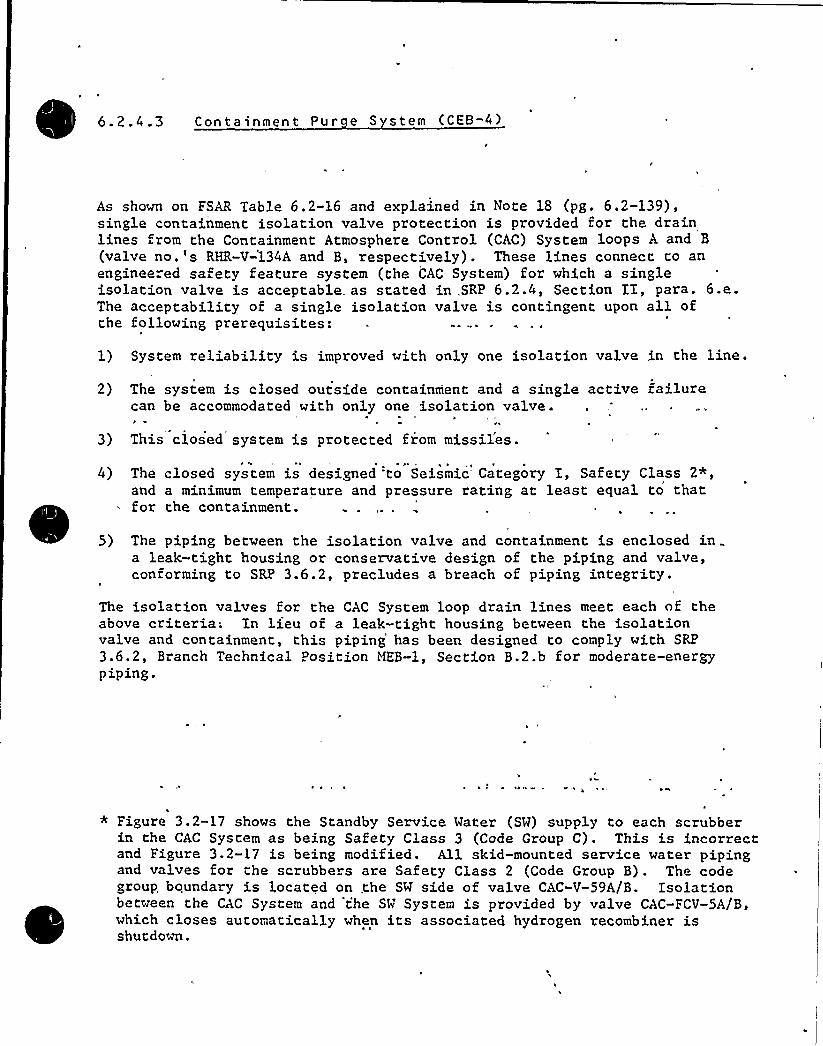
6.2.4.3 Containment Pur e S stem (CEB-4)~ ~
As shown on FSAR Table 6.2-16 and explained in Note 18 (pg. 6.2-139),single containment isolation valve protection is provided for the drainlines from the Containment Atmosphere Control (CAC) System loops A and B
(valve no.'s RHR-V-134A and B, respectively). These lines connect to anenginee"ed safety feature system (the CAC System) for which a singleisolation valve is acceptable as stated in .SRP 6.2.4, Section II, para. 6.e.The acceptability of a single isolation valve is contingent upon all ofrhe following prerequisites:
1) System reliability is improved with only one isolation valve in the line.
2) The system is closed outside containment and a single active failurecan be accommodated with only one isolation valve .
3) This closed system is protected from missil'es.
for the containment.
5) The piping between the isolation valve and containment is enclos ed ina leak-tight housing or conservative design of the piping and valve,conforming to SRP 3.6.2, precludes a breach of piping integrity.
4) The closed system is designed to Seismic Category I, Safety Class 2
and a minimum temperature and pressure rating at least equal to that
The isolation valves for the CAC System loop drain lines meet each of theabove criteria; In lieu of a leak-right housing between the isolationvalve and containment, this piping has been designed to comply with SRP
3.6.2, Branch Technical Position MEB-1., Section B.2.b for moderate-energypiping.
* Figure 3.2-17 shows the Standby Service Water (SW) supply to each scrubberin the CAC System as being Safety Class 3 (Code Group C). This is incorrectand Figure 3.2-17 is being modified. All skid-mounted service water pipingand valves for the scrubbers are Safety Class 2 (Code Group B). The codegroup. boundary is located on .the SW side of valve CAC-V-59A/B. Isolationbetween the CAC System and 't'e SW System is provided by valve CAC-FCV-5A/B,which closes auromatically when its associated hydrogen recombiner isshutdown.
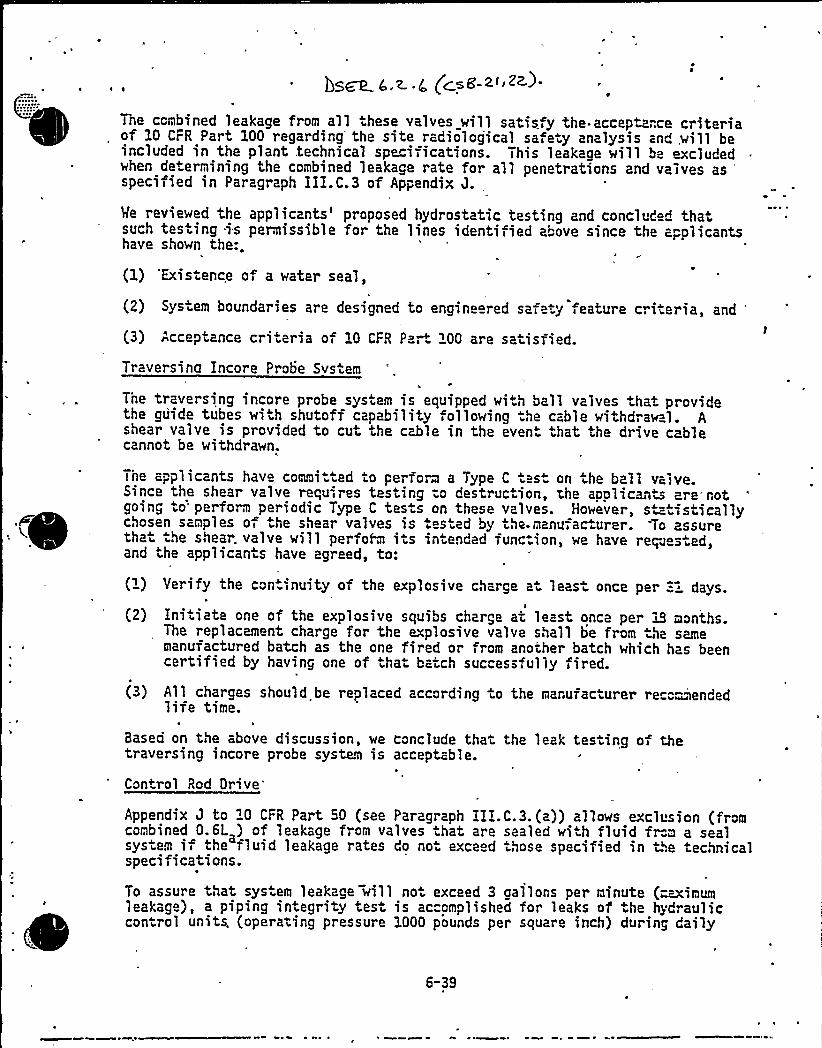
b>~< ~ < Ccs<-~~ ~+>-
6@
Me reviewed the applicants'roposed hydrostatic testing and conclud d thasuch testing is permissible for the lines identiiied above since the a„olicantshave shown the:.
(1) 'Exis.ence of a water seal,
(2) Sys em boundaries are designed to engineered safe y eature criieria, and
(3) Acceptance criteria of 10 CFR Part 100 are saiisfied.
Traversing Incore Probe System
The traversing incore probe system is equipped with ball valves that providethe guide tubes wi h shutoff capability following he cable withdraw 1. Ashear valve is provided to cut the cable in the even hat the drive cablecannot be withdrawn.
The combined leakage from all these valves will satisfy the-acceptance criteriaof 10 CFR Part 100 regarding'he site radiological safe y analysis and will beincluded in the plant technical specifications. This leakage will be excludedwhen de+ermining the combined leakage rate for all penetrations and valves as
'pecifiedin Paragraph III.C.3 of Appendix J.
Tne applicants have commi .ied to perform a Type C test on the ball valve.Since the shear valve requ<r es testing -o destruciion, the applicanis are*notgoing .o'erform periodic Type C tes .s on these valves. Howeve~, s =iisticallychosen samples of he shear valves is es ed by the-manufac urer. To assurethat he shear. valve will perfoR i.s in ended func.ion, we have requ s ed,and ihe applicants have agreed, to:
(1) Yerify the con.inuity of the explosive charge a least once per "-~ days.
(2) Initiate one of the explosive squibs charge at least once per iS mon+hs.The replacement charge for the explosive valve shall be from the samemanufactured batch as the one fired or from another batch which has beencertified by having one of .ha baich successfully fired.
(3) All charges should be replaced according io the manufac urer reco-~endedlife time.
Based on the above discussion, we conclude thai the leak tes ing of thetraversing incore probe system is acceptable.
Con+rol Rod Drive
Appendix J to "0 CFR Part 50 (see Paragraph III.C.3.(a)) allows exclusion (fromcombined 0. 6L ) of leakage from valves .hat are sealed wi h fluid fr".m a sealsys.em if the fluid leakage rates do no exce d those specified in the echnicalspecifications.
To assure that sys em leakage will no. exceed 3 gallons per minute (-mimumleakag ), a piping integrity tes is accomplished for leaks of he hydrauliccontrol units, (operating pressure 1000 pounds per square inch) during daily
6-39
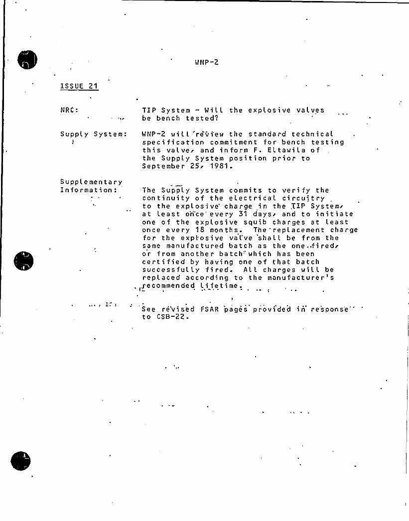
WNP-2
ISSUE 21
NRC: TIP System — MiLL the explosive valvesbe bench tested~
Supply System: MNP-2 will revi'ew the standard technicaLspecification commitment for bench testingthis valvei and inform F. Eltawila ofthe SuppLy System position prior toSeptember 25'981.
SupplementaryInformation: The Supply System commits to veri fy the
continuity of the electrical ci rcuj t ryto the explosi ve'harge. in the .TIP Systemrat Least ori'ce" every 31 days'nd to init iateone of the explosive squib charges at Leastonce every 18 months. The replacement chargefor the explosive vaL've 'shat L be from thesame manufactured batch as the one
.fired'r
from another batch" which has beencertified by having one of that batchsuccessfully fired. All charges will berepl aced according to the manufacture r '
,.J e c o mm e n d e d L i fe t i me .
See re'vised FSAR pages provided in response''t o CSB-22.

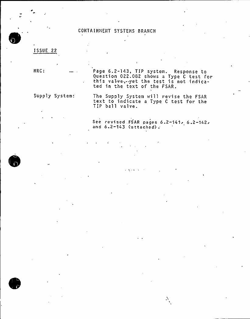
CONTAIHt1EtiT SYSTEi'hS BRANCH
ISSUE 22
HRC:
Supply System:
Page 6.2-143, TIP system. Response toquestion 022.082 shoves a Type C test orthis valve,-'yet the test is not indica-ted in the text of the FSAR.
The Supply System ivill revise the FSARtext to indicate a Type C test for theTIP bal 1 valve.
See re vi sed . FSAR pages 6.2-141'.2-142'nd
6.2-143 (a ttached) .'
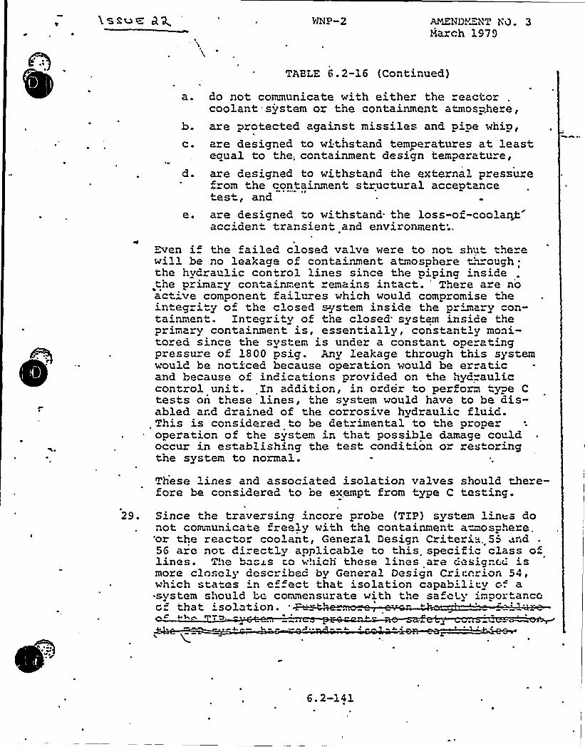
passu< ANZND~"NT ibO. 3March 1979
TABLE 6.2-16 (Continued)
a. do not communicate with either the reactorcoolant system or the containment atmos-.he e,
b. are protected against missiles and pipe whip,c. are designed to withstand temperatures at least
ecrual to the. containment design temperature,d. are designed to withstand the external pressure
rom the containment structural acceptancetest, and
e. are designed to withstand the loss-of-coola~accident transient and environment;.
Even i the ailed closed valve were to not shu" "he ewill be no leakage of containment atmosphere t'moughthe hydraulic control lines since the piping insidetne primary containment remains intact. There a e noactive component failures which would compromise theintegrity of the closed system inside the primary "on-tainment. Xntegrity of the closed'ystem insice theprimary conta'nment is, essentially, constant'y moni-tored since the svstem is under a constant ope at'ngpressure of 1800 psig. Any leakage through this systemwould be no"iced because operation would be erraticand because of indications provided on the hyd=auliccontrol unit. Xn addition, in order to perform type Ctests on these lines, the system would have to be dis-abled ard drained of the corrosive hydraulic fluid.
, This is considered to be detrimental to the properoperation of the system in that possible damage couldoccur in establishing the test condition or restoringthe system to normal.
These lines and associated isolation valves should there-fore be considered to oe exempt from type C testing.
29. Since the traversing incore probe (TIP) system lin~s donot communicate fre ly with the containment aerosphere.'or t?.e reactor coolant, General Design Criteria, 5 ~nd56 are not di=ectly applicable to this. specific c'lass oflines. The ba".~s co which these lines are design>;c.'smore clo. cly describec by General Design Criterion 54,wh'ch sta es 'n ef ect that isolation capab:1't;y c". acsystem should be conmensurate with the safeLy importancecf that 'solation.
4h «g «L
~ «.'r
6. 2-141

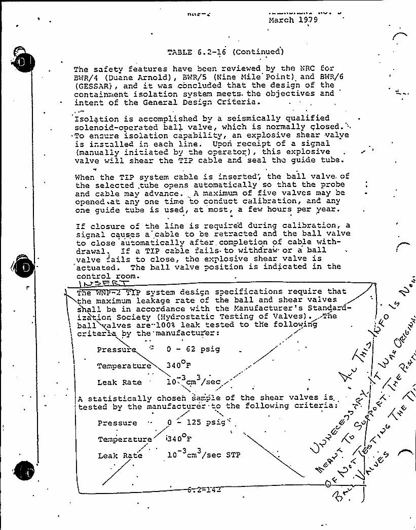
Aaac ~ 4 ~llQs w ~ ~ 4 aaV ~
March 1979
ABLE 6.2-16 (Continued)
The safety features have been reviewed by t:he NRC forBUR/4 (Duane Arnold), Bt~R/5 (Nine Mile Point) and BNR/6(GESSAR), and 't was concluded that the design of thecontainment isolat'on system meets. the objectives and
'ntentof the General Des gn Criteria.Isolation is accomplished by a seismically qualifiedsolenoid-operated ball va've, which is normally closed.".To ens re isolation capability, an explosive shear valveis ins"alled i.. each line. Upon receipt of a signal(manually initiated by the operator), this explosivevalve w'l shear the TIP cab'e and seal the guiae tube.
H
Nhen the TIP sys em cable 's 'r.serted; the ball valve. ofthe selected, tube opens automatically so that the p obeand cable may advance. A maximum of five valves may beopened..at any one time to con uct calibration, and anyone guide tube is used, at most, a few hours per year.
Zf closure o "he 1'ne is e.",ui e'd during calibration, asignal causes a cable to o ret,=acted and the ball valveto close automa"icallv after, completion of cable with-arawal. If a TIP cable fails to withdraw or a ballva've fails to close, the explos've shear valve isactuated. The ball valve position is indicated in tnecontrol room.
es is.ter':@
7
p
-,1the ma'ximum leakage rate of the ball and shear valvesshall be in accoraance w'h the Manufacturer ' Standard-ization Society (Hydrostatic Testing of Valves) ..-Tnehallgalvea are-100'4 lea'k tea" eo to tne following
. criteria by the'manufactu er:
Pressur '- 0 — 62 ps'goTempera"ure 340 PL-3 3.....*
Leak Rate '0. cm /sec >r ~ I
A statistically chosen sar:.o e of the shear valv'tested by the manufacturer to the following cri
P essure - 0 — 125 ps'g'
Temperature I340 P
-3 3Leak Rate 10 cm /sec STP

WNP-2
Insert to Page 6.2-142
The baLL valves wiLL be type C tested in accordance withAppendix J of 10CFR50. Because the shear valves haveexplosive squibs and require testing to destruction theywiLL not be type C tested. To assure shear valve operabilityihowever':
1. The continuity of the exolosive charge wiLL be verifiedat Least once every 31 day"s.
2. One of the explosive squib charoes will be initiated atLeast once every 18 months. The replacement charge forthe explosive valve shall be from the same manufacturedbatch as the one fired or from another batch which hasbeen certified by having one of that batch successfullyfired.
3. All shear valve charges wiLL be replaced according to themanufacturer's recommended Lifetime.

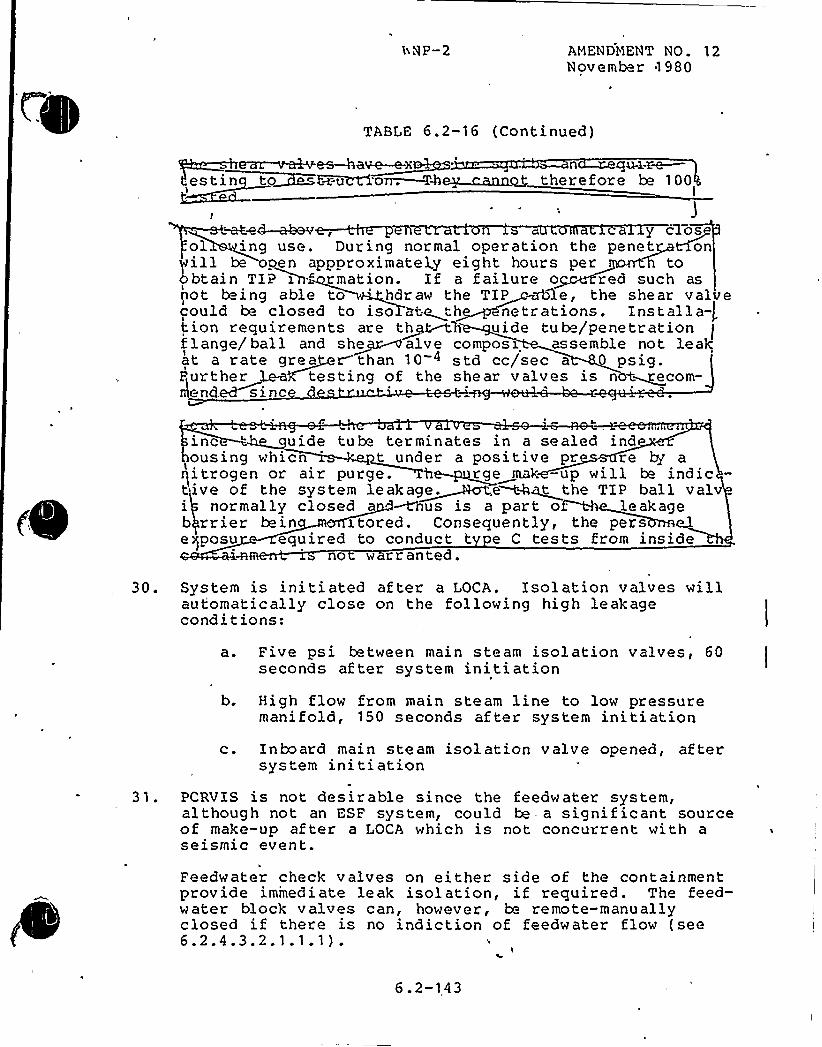
bNP-2 AMENDl'1ENT NO. 12November 1980
TABLE 6.2-16 (Continued)
~~~~aiete ~~xI'
n qv-M~therefore be 100
I
ad—ahern-,~~~ a y c1o~sol ing use. During normal operation the penet ~on
will be pen appproximatel„y eight hours per toobtain TIP inf rmation. If a failure o red such asnot be ing able to 'dr aw the TIP e, the she ar v alv ecould he closed to iso ate th~ nettations. installa-)tion requirements are t~h~'h uide tube/penetrationflange/ball and she~~alve composi assemble not leakat a rate grea r than 10 4 std cc/sec a 0 psig.Further testing of the shear valves is not~ecom-mend. si nc d
a ~ ~ I
inc uide tube terminates in a sealed indousing whic t under a positive pr re by a9vv "v" !ive ot the system leakag~e. e t+at the TIP ball valv
i normally closed a ~us is a par t o leakageb rrier bein z tored. Consequently, the pers e3.eqposu equired to conduct t e C tests from inside
no w rranted.
30. System is initiated after a LOCA. Isolation valves willau t'orna t ic al ly close on the fol lowing hi g h le ak ageconditions:
a. t'ive psi tetween main steam isolation valves, 60seconds af ter system initiation
b. High flow from main steam line to low pressuremanifold, 150 seconds af ter system initiation
31.
c. Inboard main steam isolation valve opened, af tersystem initiation
PCRVIS is not desirable since the feedwater system,although not an ESF system, could be - a signif icant sourceof make-up after a LOCA which is not concurrent with aseismic event.
Feedwater check valves on either side of the containmentprovide immediate leak isolation, if required. The feed-water block valves can, however, be remote-manuallyclosed if there is no indiction of feedwater flow (see6.2.4.3.2.1.1.1).
6.2-143

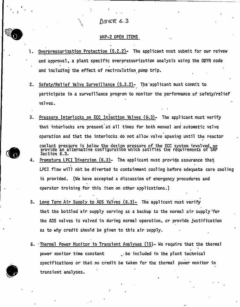
WNP-2 OPEN ITEMS
l. Over ressurization Protection 5.2.2 - The applicant must submit for our reivew
and approval, a plant specific overpressurization analysis using the ODYN code
and including the effect of recirculation pump trip.
2. Safet /Relief Valve Surveillance 5.2.2 - The'applicant must commit to
participate in a surveillance program to monitor the performance of safety/relief
val ves.
3. Pressure Interlocks on ECC In'ection Valves 6.3 - The applicant must verify
that interlocks are present at all times for both manual and automatic valve
operation and that the interlocks do not allow valve opening until the reactor
coolant pressure is below the design pressure of the ECC system involved, oporovide an alternative configuration which satifies the requirements of SRPSection 6.3.
4. Premature LPCI l)iversion 6.3 - The applicant must provide assurance that
LPCI flow will not be diverted to containment cooling before adequate core cooling
is provided. (We have accepted a discussion of emergency procedures and'I
operator training for this item on other applications.)
5. Lon Term Air Sup 1 to ADS Valves (6.3 - The applicant must verify
that the bottled air supply serving as a backup to the normal air supply'for
the AOS valves is valved in during normal operation, or provide justification
as to why credit should be given to this air supply.
6. Thermal Power Monitor in Transient Anal ses 15)- We require that the thermal
power mnitor time constant .. be included in the plant technical
specifications or that no credit be taken f'r the thermal power monitor in
transient analyses.

0
WNP-2t
6.3 Premature LPCI Di version (RSB4)
Question:
Provide assurance that LPCI flow wiLL not be diverted tocontainment cooL ing before adequat'e core cool'in'g ~s "p'rovi'ded.'
Response:
The LPCI (Low pressure coolant injection) mode is the designbasis mode for the RHR (residua l heat removaL) system in ICC(emergency core cooling) operation. The LPCI mode is initiatedautoma ticaL Ly on Low'ooL'a'nt Level'r high containment atmospherepressure. Any other mode of RHR operation which might be inprogress at the time is automatically valved off. For thepostulated worst ~ caser which is the instantaneous doubLe-endedgillotine pipe rupture. All three RHR pumps are star tedautomaticaL Ly in the LPCI mode „to, flood th'. reactor'ore ~
After Level has been restored and the RPV has depressurizedione RHR pump operating in the LPCI mode is sufficient forcore cooling. Loop A or Loop 8 (which include a heat'xchanger)or both may then'be used for containment spray or suppressionpool cooling. The operator can not open containment spray orsuppression pool cooling,.val ves unti L the, in jection .va L ve in ..the s'arne Loop is fuLLy clos'ed'; s'ince 'RPV'Level change is th'expected response to changing injection valve positions theoperator~..attention wiLL be directed to the operating parameterensuring adequate core cooling.
Additionallyi emergency procedures now being developed usingthe BWR Owner's Group guidel'ines wiLL caution the operator
to.'ssureadequate core cooling prior to diverting injection flowaway from the core.
'WNP-2
6.3 Lon Term Air Su l to ADS Valves
Question:4
Verify. that the bottledvalved in during normalas to why credit should
ai r supply for'he ADS valves isoperations or provide justi ficationbe given to this air supply.
Answer:
During normaL operations all eighteen relief valves aresupplied with pressurized air from a common supply header.In additions each valve has an individual air accumulatorwith an inlet check valve. Each valve can continue to operatefor a number of strokes from the accumulatorr if air pressureis Lost in the header. Seven of these 18 valves are used forthe ADS (automatic depressurization system) function. Inaddition to the regular air accumulator'for these seven valvesreach valve has a redundant pilot valve with a correspondingredundant accumuLator and check valve. . These redundantaccumulators are supplied from two nitrogen supply headerswhich during normaL operation are pressurized with air. Ifair pressure is Lostr pressurized nitrogen is supplied tothe headers.
The nitrogen supply header from bottle bank A supplies threeADS valves. Bottle bank.B supplies four ADS valves. Ifpressurized air is Lostr each nitrogen supply header isindividually isolated from the common air supply Line oncethe nitrogen pressure closes the corresponding. check valve.-Ni trogen supply i s initiated when pressure sensor CIA-PS-21 A(for bottle bank A) or CIA"PS-21B (for. bottle bank B) sensesa line pressure below 140 psig. ALL nitrogen bottles are'val ved into the system during normal ope'rat i one except thata solenoid valve on each individual bottle is normally closed.The Low pressure signal from the air pressure sensor activatesthe stepping programmer (CIA-PROG-1A for bank Ar CIA-PROG-18 forbank B) which open the solenoid valve for the first nitrogenbottle- This bottle then supplies nitrogen through a pressurereducing valve to the nitrogen supply header and redundantnitrogen accumulator. After the first gas bottle is depletedithe stepping programmer is again activated by a low pressuresignal. The programmer advances by one steps opens (de-energizes)the valve 'for the depleted bottle. In this ways the two banksof bottles are cont rol led independently and each bank. usesonly one bottle at a time. Plant startup check Lists wiLLinclude a step to assure the CIA system is properly alignedto support plant operation.
WNP-2
References
Burns 8 Roe PAID N-"556
Burns 5 Roe System Description 24A
Burns & Roe Logic Diagram on drawing N-620'heets 556-5and 556-6

~ ~
umo disch In accordance with monthly surveillance procedures
the vent lines in the filled systems are opened and checked for flow to eliminate
the possibility of the formation of air pockets. Pressure instrumen tiprovided. on the jockey ump discharae line initiat n o w n
control room when pressure in the discharae line, is less than the vdr
head required to maintain the line full of water uo to the in ection valves.
Q5'~ 6. g. 2.'5'
Ohe of the design'requirements of the emergency core cooling system is that~ ~
~
~
~ ~ ~ ~ ~
cooling water flow be providea rapidly fowlloing the initiation signal. By
always keeping the emergency core cooling system pump discharge lines full,
the lag time between the signal for pump start and the initiation of flow into
the reactor pressure vessel can. be minimized. In addition, full discharge lines
will prevent potentially damaging water-hammer occurrences on system startup.
At QNP-2 a fill system consisting of a jockey pump in the RCIC system and in each
of the ECCS subsystems (except ADS) is provided. Maintenance of the filled VRnAe
IF
X]
1
The emergency core cooling system pumps must have the capability to operate
for an extended period of time during the long-term recirculating cooling phase
following a loss-of-coolant accident. The applicant has provided pump reliability
information based upon actual operation experience on similar pumps manufactured
by Ingersall-Rand, the WHP-'2 supplier. As discussed in Section 5.4.7 we a«aw» ing
additional information from the applicant on deep draft pump reliability.
Safety/relief valve operability will be demonstrated during the power ascension~ ~ ~ I ~
phase of the plant startup test program by manually actuating each safety/relief
valve (including the ADS valves) one at a time to measure discharge capacity and
to demonstrate that no blockage exists in the valve discharge line. After
comercial turnover all of the safety relief valves will be tested in accordance
with Section XI, Article I>JV of the ASME Boiler and Pressure Vessel Code. The
~ applicant has also stated that direct valve position indication, via acoustic

~ ~
SEE. 4.The applicant also discussed the simultaneous closure ef a recirculation flow
~ ~
~ ~ ~
~
~
'control valve during a loss-of-coolant accident.. The applicant's basis forthe closure time was an electronic velocity limiter designed to limit the open-
ing and closing rate to 11 percent per second. The valve controller is notclassified as equipment which is essential to safety. Therefore, the controlleris not scrutinized by us to the same extent that a component required for safetywould be. However,-for the loss-of-coolant accident, the valve is not calledupon to actively mitigate the consequences of the accident, but is only needed topassively remain in its current position If the control valve were in the
automatic 'mode at the time of the loss-of-coolant accident, the control system
would normally call for the valve'o open. If the control valve were in the
manual mode, operator action would normally be required to close the valve; Two
failures in the control'ogic would be required for the valve to c1ose even atthe ll per'cent per second rate. Further, the control logic is outside the drywelland is not subject to the loss-of-coolant accident environment. Therefore, thell percent per second closure rate, which will be verified by periodic testsrequired by plant technical specifications, is a reasonable limit on valve closurerate for the loss-of-coolant accident analysis. The applicant indicated that ifthis additional failure is included in the loss-of-coolant accident, the peak
I temperature for the worst break would be increased approximately 50 degrees Fahren-
heit which still satisfies the criteriori of 10"CFR-Set:tion'50.46; Therefore, we
find the loss-of-coolant accident analyses to be acceptable.

HA.W~~ -.~~The. design of the SGTS was ccnpared to the criteria of Regula~ry
Guide 1.52 and the following deviations vere noted
~dt d: yd ydyy y 'y i:, d' Rypressure drops and flue rates at the control roan. Instruraentation
's provided only to alarm abnor.al pressur drops, to record a1ar s
(abnormal pressure dropl; and to indica e (but not record) system
f1 mr rate. The applicant's FSAR notes these deviations but giv sPppf)i ~~<
no bases or justifications vor the deviations. ~e should
. provide his rationale for not meeting Section 2g..Section 2i: The FSAR states that SGTS filters can be bypassed for
testing but that there is no provision for indica ion of bypass
status in con"rol r co i [Not e 4, oage 6. 5-20); i n effact,'his
an accident,
informed of
if the bypass .is in us
system status.
regates the au~t".atic activation o ".hase sys.."s in the event'of
and does no ke p the operator
Section 3a: Note &, page 6.5-20 of the rSM, indicates that the
SGTS demis ers are not qualified in accordance with the requireaentse ~
of MSAR 73.-4', ut that the manuiacturer contends that the addition
Vi~
*d
~ ~
tes.
~ d
ed
4
SER Items Requiring Verification
1&28'erification that the'ECCS discharge line fillsystems are provided withcontinuous indication of pump operation, pump discharge pressure and lowpressure alarms in the control room is provided in the response to ques-tion 211.079 submitted in Amendment ll, September 1980.
3 PA Verification that the RRC flow control'alve closure time is limited to an
opening and closing rate of 11% per second by'a flow limiter is prov'dedin response to question 211.188 submitted in Amendment 20'ovembers 1981.
C
Verification that the RRC control valve would tend to open post-LOCA w'nen
in the automatic mode, is provided in response to question 31.001(3) sub-mitted in Amendment 14, April 1981, and question 31.058, submitted inAmendment 3,, March 1979.
4,***
Verification that the maximum peak cladding temperature for the worstbreak would be increased by approximately 50'F (=45'F) is provided inthe response to question 211.083, submitted in Amendment ll, September1980.-
I ' ~I
See response to SER Open Item 6.3 (RSB-4).h J
~ ~
'< - Draft'ER Section 6.3.2.3, 5th paragraph.»'< — Draft SER Section 6.3.4, 7th paragraph.
**~ — Draft SER Section- 6.3.4, 8th paragraph.
The low pressure coolant injection flow may be diverted manually to d~ellSDray cooling or to suppression pool cooling. The appl icanpz
have stated that the AN=8 emergency procedures contain adequate
cautions to deter the operator from premature flow diversion. These proce-
dures, which are based on guidelines accepted by us (see Chapter 22 Item I.C.1),caution the operator against divers'ion u'nless adequate core cooling is assured.
I
LPCI diversion is identified in the procedure as secondary to core. cooling-requirements except in those ins.ances outside the design envelope involving
multiple failures for which maintenance of conminment integrity is required
to minimize risk to the environmen~. Me have reviewed the containment'response
analyses =for the design basis event to determine .the need for low pressure
coolant injec ion diversion. These analyses indicate that there, should be no
need for,wetwell spray actuation in the time frame during which the peak
cladding temperature is reached. The operator's focus would, therefore, be on
maintaining core cooling. Based on these, analyses and the emergency procedures
discussed above, we find the applicants'osition on low pressure coolant
injection diversion to be acceptable. Review of all emergency procedures is
being addressed in Items I. C. 1 and I. C. 8 of Chapter 22 of this report.
The core spray sparger for both the high and low pressure core spray systems
each consists of two semicircular segments which form an essentially complete
circular sparger. Mater is sprayed radially onto the tops of the fuel assem-
blies by short elbow nozzles spaced around the sparger. Tests of this type of
spray system were performed in a full-scale test in which air at atmospheric
pressure simulated .he post loss-of-coolant accident s+ am envirormen and
indicated adequate cooling was delivered o each fuel assembly. However,
recent tests conducted on a single nozzle indicate that the actual steam
environment may adversely affect the dis.ribution of flow from certain types
of core spray nozzles. As discussed in HUREG-0410, "NRC Program for the
Resolution of Generic Issues Related to Huclear Power Plants," this problem is~ being studied by us under Task Action A-16 entitled, "Steam Effects on BWR
Core Spray Oistribution." PreTiminary analyses and measurements have been
made which support the existence of a .significant safety margin between that
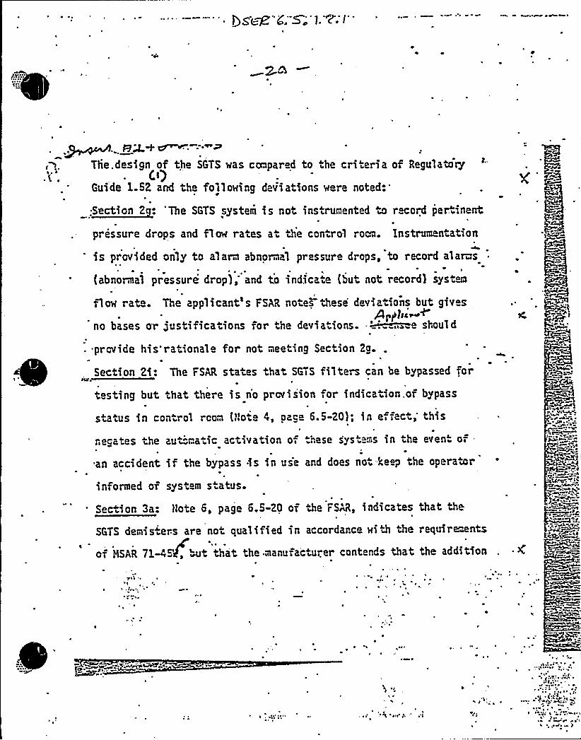
~n.. en~ ~~==~The. design of the SGTS was ccnpared to the criteria of Regulatory
C~')Guide 1.52 and the following deviations were noted
,~att 2: yy yyyy y ', „ i,:„,,„,y",,K py."
pressure drops and flow rates at he control roaa. instrumentation
's provided only to alarm abnormal pressure drops, to record alar s0 ~ ~ ~
(abnormal pressure drop); and to indica, e (but not record) system
flow rate. The applicant's FSAR notes these deviations but givesPpPbi~<
no bases or justifications for tbe deviations..~ sbouid
. provide his rational for not mee ing Section 2g..
Section 2i: The FSAR states that SGTS filters can be bypassed forate
testing but that there is no provision for indication. of bypass
s a.us in control room (llo" 4, page 6.5-20); in e, fact, this
negates the
an accident
informed of
au~matic activation o,
if the bypass is in us
system status.
.hase syst. s in the even" of .
and does no ke p the operator
Section 3a: Note 6, page 6.5-20 of the FSN, indicates that the
SGTS demisiers are not qualified in accordance with the requirments
of HSAR 71-45'J, ~~t that, the manuiactu"..er contends that the addition
7<a -~
~ s
~ ~~ ~
Ay

Nk
I ~C
II
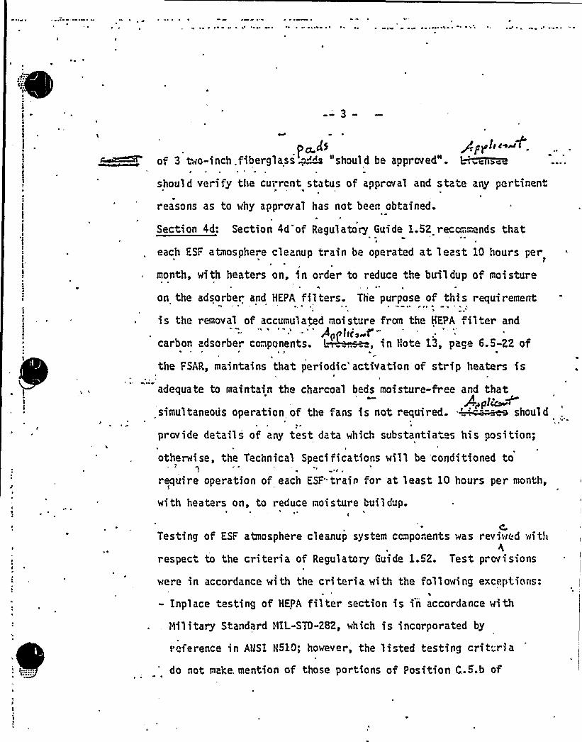
~ w ~ s ~ ~ 0' '
3
l e ~
p~D gppl>c A'f
3 Oeo-inch, fiberglass ~~" "should be aPProreds e br ~~c
should verify the current status of approval and state any pertinent
reasons as to why approval has not been obtained.
Section 4d: Section 4d of Regulatory Guide 1.52 rect.,mnds that
each ESF atmosphere cleanup train be operated at least 10 hours per
month, with heaters on, in order to reduce the buildup of moisture
on the adsorber and HEPA filters. The purpose of this requir ement*
is the removal of accumulated moisture fran the HEPA filter and''Ap t)c, f'-
carbon adsorber components. L, in Note 13, page 6.5-22 of
the FSAR, maintains that periodic'activation of strip heaters is
adequate to maintain the charcoal beds moisture-free and thatPp pl~
simultaneous operation of the fans is not required. ~~ shoulde
provide details of any test data which substantia s his position;
otherwise, the Technical Specifications will be conditioned toe
require operation of each ESF"train for at least 10 hours per month,
with heaters on, to reduce moisture buildup.
4
Testing of ESF atmosphere cleanup system components was reviwed withh
respect to the criteria of Regulatory Guide 1.52. Test pr ovisinns
were in accordance with the criteria with the following exceptions:
- Inplace testing of HEPA filter section is in accordance with
, Nilitary Standard t1IL-STD-282, which is incorporated by
reference in AUSI H510; however, the listed testing crit ria
do not make, mention of those portions of Position C..5.b of

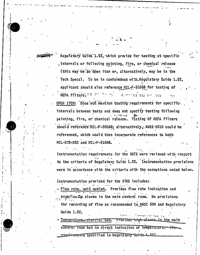
~ ~
~ ~
~eeR Regulatory Gui'de'"1.5K, Qhich provide for testing at specific
.intervals or follcving painting, fire, or chemical release
(this may be"an'open item or, alternatively, may be in the
Tech Specs). To be in conformance wi Ji.Regulatory Guide 1.52,
applicant should also reference MIL-F-51068 for iesting of
HEPA filtersOPEN ITEM:
*
Does'not rIiention testing. requirements for specific
intervals between tests and does not specify testing following~ I ~ i
4'ainting,fire, or'chem',ca1 release. TEsting 'of HEPA filtersshould reference NIL-F-50168; al te'rnatively,. AWSl-.N510 could be
referenced, which would then incorporate references to both
MIL-STO-282 and MIL-F-51068.
lt t
Instrumentation requirements for tho SGTS~ 'l
to the criteria of Regulatory Guide 1.52.> ~
were in accordance with the criteria with
were reviewed with respect
Instr umentatlon provisions
the exceptions noted below;
Instrumentation provided for the STGS includes:I ~
- Flow rate, 'unit outlet. Provides flow rate indication and
high/lowhp alarms in the main control room. No provisionsl ~ I 8 ~
for recording of flow as recommended in ANSI 509 and Regulato~4
Guide 1.52.h e I 6 ~
~ gomn e ~ rG ives a the naia
co pro room but no direct indicaiion of tempe aiu c.I
is specified in'Regulator

l
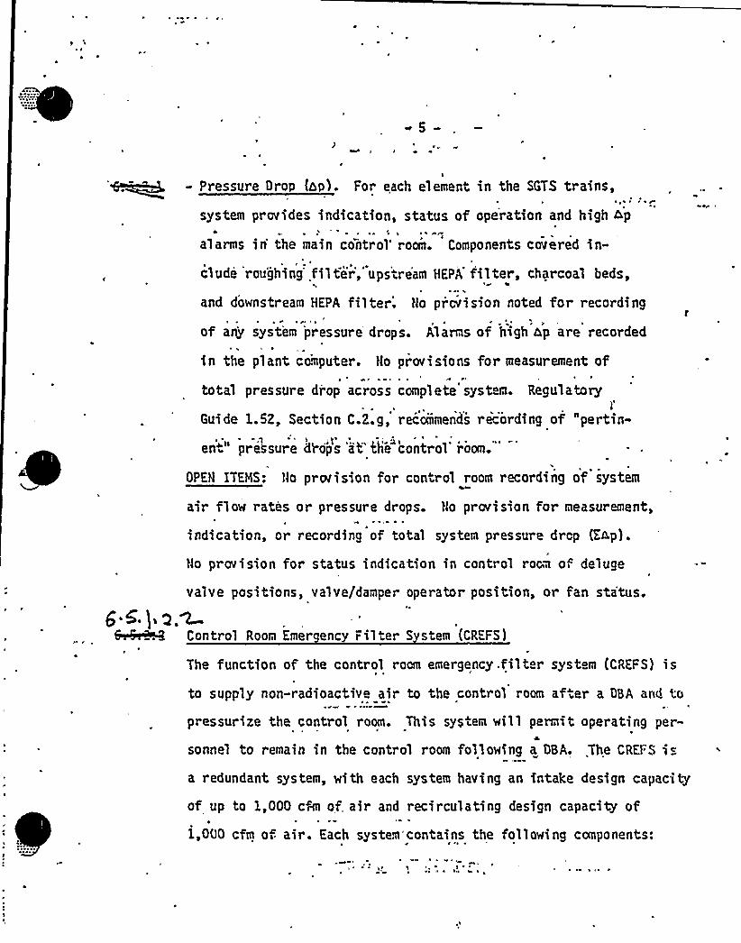
~ ~
w 5
\- Pressure Drop (zp). For each element in the SGTS trains,
system provides indication, status of operation and high 4p*
~ ~
alarms in'he main control'om. Components covered in-
elude rou'ghing filter','ups'tream HEPA'ilter, charcoal beds,
and downstream HEPA filter'. Ho provision noted for recording~ ~
of any system 'pressure drops. Alarms of high Ap are recorded
in the plant computer. No provisions for measurement of
total pressure drop across complete'system. Regulatory
1'uide1.52, Section C.2.g, recommends recording of "pertin-
ent" pr essure drops 'at"the control'oom."
OPEN ITEMS: No provision for control room recording of system
air flow rates or pressure drops. Ho provision for measurement,' ~
indication, or recording of total system pressure drop (Earp).
No provision for status indication in contr ol room of deluge
valve positions, valve/damper operator position, or fan status.6''. j g.m6m&~ Control Room Emergency Filter S stem (CREFS)
The function of the control room emergency .filt r syst m (CREFS) is
to supply non-radioactive air to the control room af.er a DBA and toC
pressurize the control room. This system will permit operating per-A
sonnel to remain in the control room following a DBA. The CREFS is
a redundant system, with each system having an intake design capacity
of up to 1,000 cArr of, air and recirculating design capacity of
1,000 cfm of air. Each system contains the following components:
~ ~ \ ~

0 en Xssue:C.".a ter 6.5.1.2.1~
~
~
~
~
~
~
~ ~
Section 2 of Re ulator Guide 1 52
The SGTS system is not instrumented to record pertinent pressuredrops and flow rates at the control room. Instrumentation isprovided only to alarm abnormal pressure drops, to record alarms(abnormal pressure drop), and to indicate (but not record) systemflow rate. The applicant's FSAR notes th'ese deviations but givesno bases or justification 'for the deviations. Applicant shouldprovide his rationale for not meeting Section 2g.
~Res onse:
See revised Table 6.5-2, Note 3.
t i~ J ~
~ ~
~ ~
~ >
5'I
() ~ ~ ~ 4 ~ ~ ~
1t ~ ~ ''r ~ ~

0
Open SZR issue charter- 6:.5. l.2. le lSection 2i o Reaulator Guide 1.52
'I
The =SAR states that SGTS filters can be bypassed for testingbu" tha.t there is no- provision zor ind'cation of bypass statusin control room (Note 4, page 6.5-20); in effect, this nega.testhe automatic activation of these systems in the event oz anaccident if the bypass is in use and does'ot }seep the operatorin o~ed of system status.
Response:
Note 4 on page 6.5-20 was meant to address item C-2-j ofRG1.52i not C-2i. The FSAR has been revi sed to correct thi serror. (draft FSAR page change attached)
Howeveri in direct response.to the comment in":the draft SERi theSGTS is in full compliance with RG1-47. This is discussed inFSAR Section 7.1.2.4. The Logic diagrams (Fig. 7.3-14) are inthe process of being updated to show the system bypass. indicationLogic.
I f the system i s bypassed mechprocedure would caLL for Lockiappropriate filter bank closedannunciate a system inoperableadditioni procedure would callbypass status indication for a
render a filte r train inoperat
anica lly for filter repLacementing the isolation dampers to the
This would automaticallystatus in the control room. Infor manuaL initiation of system
ny maintenance operation which mighti ve.
en SER issue 6.5.1.2.1Section 3a of Re ulator Guide 1,. 52
(
Note 5,- page 6.5-20 of the FSAR, indicates that the SGTSdemisters are not qualified in accordance with the re-quirements of MSAR 71-45, but that the manufacturer con-tends that the addition of 3 two-inch fiberglass 'pads"should be approved". Applicant should verify the currentstatus of approval and state any pertinent reasons as towhy approval has not been obtained.
~Res onse
See revised Table 6.5-2, Note 5.

en SER issue 6. 5. l. 2. 1Section 3a of Re ulatorv Guide 1.52
Note 5, page 6. 5-20 of the FSAR, indicates that, the SGTSdemisters are not. qualified in accoidance with the re-quirements of MSAR 71-45, but that the manufacturer con-tends that the addition of 3 two-„inch fiberglass 'pads"should be approved". Applicant should verify the currentstatus of approval and, state any pertinent reasons as towhy approval has not been obtained.
Response
See revised Table 6.5-2, Note 5.

f
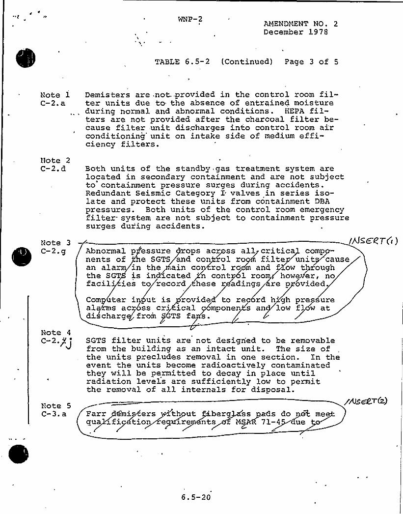
"C a WHP-2At!END~TENT NO. 2December 1978
TABLE 6.5-2 (Continued) Page 3 of 5
Note 1C-2. a
Demisters are not. provided in the control room fil-ter units due to the absence of entrained moisturedur'ng normal and abnormal conditions. HEPA fil-ters are not provided after the charcoal filter be-cause filter unit discharges into control room airconditioning'nit on intake side of medium effi-ciency filters.
Note 2C-2. d
Note 3C-2 g
Note 4
C-2.pJ
Both units of the standby gas treatment system arelocated in secondary containment and are not subjectto containment pressure surges during accidents.Redundant Seismic Category I valves in series iso-late and protect these units from containment DBApressures. Both units of he control room emergencyfilter system are not subject to containment, pressuresurges dur'ing accidents.
Abnormal p essure ops acr ss all critica compnents of '
SGTS and con ol ro filte unit causean alarm in the ain co rol ro m and ow throughthe SGT is in icated 'n cont 1 roo however, nofacil'es to record hese r adings re p ovided.
Com ter i ut is rovide to re ord h gh pressureal s ac ss cr ical mponen s an low f w atdi chaarg froin
PTS fa a.
SGTS filter units are not designed to be removablefrom the building as an intact unit. The size ofthe units precludes removal in one section. In theevent the units become radioactively contaminatedthey will be permitted to decay in place untilradiation levels are sufficiently low to permitthe removal of all internals for disposal.
psscg7-C i
Note 5C-3. a Parrgemi ers Mth t gi.berg ss s do me
qua ~fi Ktion e z.re ants NS 71-4 tue
yAsM>&)
6. 5-20
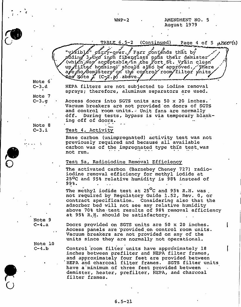
l
Note 6C-3.d
Note 7C-3.g
Note 8C-3.i
AMENDMENT NO. 5August 1979
TA 6. 5-2 (Continued) Page 4 o f 5 lpJ~~z)P4p P I"v'b " par.+-ov'er...~ Fax'r don/ends th'at by
din, 3~<wd'nch f~e~lasd pcs the'ir de'mister(wh''.;ea acyeptable~fn,.the/crt s't. vrain cleanup i3.t d hoasing)" shoul'd apso bd approved. -'/+erea ego emi stere"'o/ tip cojtrol~rooy"t',i'lter /nit/s~ee te - (CP. g above.
~~~HEPA filters are not subjected to iodine removalsprays; therefore, aluminum separators are used.
Access doors into SGTS units are 50 x 20 inches.Vacuum breakers are not provided'on doors of SGTSand control room-units.-'nit fans -are normallyoff. *During tests, bypass is via temporary blank-ing off of doors. '*
Test 4, ActivitBase carbon (unimpregnated) activity test was notpreviously required and because all availablecarbon was of the impregnated type this test wasnot run.
Note 9C-4.a
Note 10C-4.b
Test Sa, Radioiodine Removal EfficiencThe activated carbon (Barnebey Cheney 727) radio-iodine removal efficiency for methyl iodide at25 C and 95% relative humidity is 98% instead of99%.
The methyl iodide test at 25 C and 95% R.H. was,not required by Regulatory Guide 1.52, Rev. 0, orcontract specification. Considering also that theadsorber bed will not see any relative humidityabove 70% the test results of 98% removal efficiencyat 95% R.H. should be satisfactory.Doors provided on SGTS units are 50 x 20 inches.Access panels are 'provided on control room units.Vacuum breakers are not provided on any of theunits since they are normally not operational.Control room filter units have approximately 18inches between prefilter and HEPA filter frames,and approximately four feet are provided betweenHEPA and charcoal filter frames. SGTS filter unitshave a'minimum of three feet provided betweendemis ter, heater, pre filter, HEPA, and charcoalfilter frames.
6.5-21
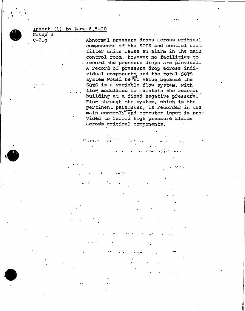
Insert 1 to Pa e 6. 5-20Note/'C-2.g Abnormal pressure drops across critical
components of the SGTS and control roomfilter units cause an alarm in the maincontrol room, however no facil'ities to
. record the pressure drops are provided.A record of pressure drop across indi-vidual components and the total SGTS
o0system would be+no value because theSGTS is a variable flow system, withflow modulated to maintain the reactorbuilding at a fixed negative piessuie.Flow through the system, which is thepertinent parameter, is recorded in themain control>, and computer input is pro-vided to record high pressure alarmsacros's critical components.
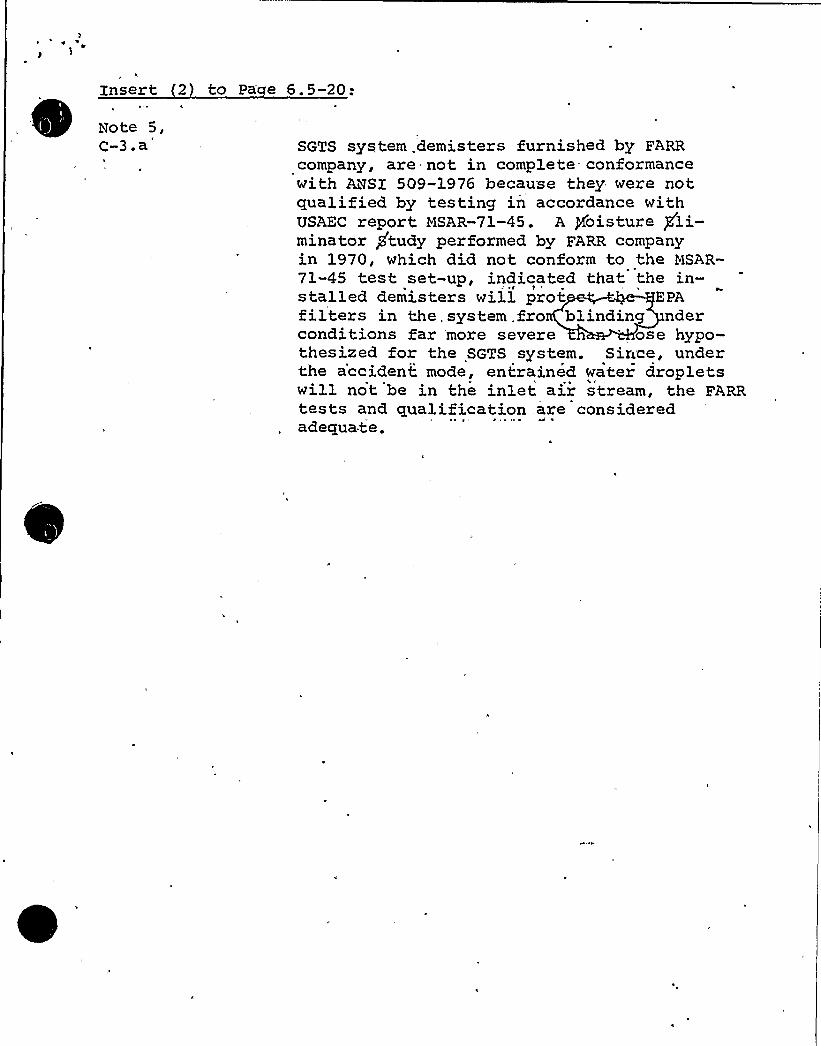
Insert 2) to Pa e 6. 5-20:
C-3.a SGTS system .demis ters furnished by FARRcompany, are not in complete conformancewith ANSI 509-1976 because they were notqualified by, testing in accordance withUSAEC report MSAR-71-45. A /moisture gli-minator study performed by FARR companyin 1970, which did not conform to the MSAR-71-45 test set-up, indicated that the in-stalled demisters will prot EPAfilters in the, system .fro blindi.ng nderconditions far more severe ose hypo-thesized for the SGTS system. Since, underthe accident mode, entrained water dropletswill not be in the inlet air stream, the FARRtests and qualification, are consideredadequate.

Open SER Issue
26.5.1.2 S cticn 4d of 'Reoulator Guide 1.52
Section L": of Requla ory Guide 1 .'2 recommiends that each =SF aBiospherec I eanup i. ~ ain be G."e. ated ai.. I as i 10 hours per month l i ih hea<ers on.Applicant, in Ilote 13, p. 6.5-22 cf ti~e FSAR; maintains that periodicact iva-ion "= s-'ri- heat rs i s ade.",uat to maintain chiarcoal beds moi sture-fre "and th simultaneous operation of the fans is not reouired.Applica."t sh='ld pro;ice details of any test data whicn substantiates
his pcs1 io,i otrIe. wise the Techn1cal Sp ci fications wi 1 1 be condi tionedi.o I eguir '' ra 1on of each =SF t".a,in for a i least 0 hr p r month,wl i.h heai.=. s Gn, to reduce liioisture biJlldup ~
Resvons
Techn1c=l S ecifica-'ion 4.6.5.3. a states tnat each. SGTS subsystem shallbe oper=ted =or at least 10 hr/r.onth with the heaters in a moisture reducing
. miode.
Open SER Issue 6.5-1-Z-'i
Re;ie;; Fosi-ion'-; h ?ecard To Reo. Guide >.52, C.5.b
Lis.ed -'=sting criteri do not ni.eke iileqtion cf Position c.5.b of,Reg.Guide 1.52.
P>esoonse
Initiel .estie "so".'-e."s i 1
Reou) re,.:en> isae e included
ng of airflow;1-be includedor testino e
in ii =- Techni
distribution to,HEP'ilters and iodinei;-itn preoperetio"=1 iesiino of t;.e SGTS.
fter, > Icint n=-nce af fectinG tn f1 04'i stributioncel Specifications, Section 4.o.5.3.
Open SER Issue 6:5.1.2.1Testing Followino Painiino, Fire, or C~i mical Release
Does no. mention testing requirements for s"eci-,ic -'.ntervals b tweentests and Goes riot spec i fy i.esting fol lowing paint ing, fire, or chemicalrelease. Testing of H:-P.-". iilters should rererence hIL-F-50168; alternatively,ANSI N510 co ld 'o r =er need, which wo.ld then incorporate references toboth li.'-STD-282 and ."iL-F-5IO68.
R soonse
Technical pecificai.ion ..6.5.3.b pecifies testino ol the GTS at lees.once per i8 r."onthis or iollowing paintin iire, or chemical release, inaccordance with Reg. Guice 1.52, S ctiion C.5.2. Peference to AllSI. ti5lO isalso included in Technic=-1 Specification 4.6.5.3.b.
S=-R 0~en Zssu.e 6.5.1'.2.1e
n s tr"-..:en-a t.: on fo" SGTSF
low «ate, t'ni t opt't. provides flow rate ind'ation andhigh/low h,p a~arms, in the main contro~ room. Fo provisionsor record'..g o= flow as recommended 'n ~2;SX 509 and ¹gula-
tory Guide l. 52.
Resoo'nse:
The flow rate reco d'ng -"or the SGTS has been added ~o the 4'HP-2des'gn. please see rev'sed 6 5 s 2- (attached) *
*Note. See response to SER issu'e 6.5.1.2.1 on Section C.2.gof RG 1.52 for rationale on ap.
~
~
~
~ ~~
~
S="R 0~en 'Issue 6.5.1.2.1Section C.2.a of.Reculatorv Guide 1.52
Pressure Droa 5 a . For each element in the SGTS trains, systemprovides indication, s'tatus o operation and high dp alarms inthe main control room. 'omponents covered include roughing filter,upstream E:=-PA filter, charcoal beds, and downstream .ZPA filter.Ho provisio'n noted for recording of any system pressure drops.Alarms of high D p are recorded in the plant computer, Ho pro-visions for mea,surement of total pressure drop across completesystem. Regulatory Guide 1.52, Section C. 2.g, recommends record-ing of "pertinent" pressure drops at the control roon.
Resoonse:
The SG S system is a variable flow system with flow modulated tomaintain the reactor building at a fixed pressure with respect tooutdoo s (-.25 inch W.G.) .. Since'ystem flow is a variable,pressure drop across the system fiiters, which is proportional tothe scuare of the flow, is a. meaningless variable except duringtests when the unit is operated at the design flow rate of 4,457 cfm.Therefore, the pressure drop (p p) recorders and total system
~
~
~pressure drop recorcers are not being added because this data wouldbe of no va,lue for this system.
With regard to indication o system status in main control room,please note the following:
a. The fire p otec ion system deluge valve assembly ispresently be'ng revised to a supervised system. Statusand. fault annunciators will be. added to the main. controlroom fire display panel.
Status of the SGTS system (system unoperable) is annun-ciated on status annunciator board BD-S in the main con-trol room. ?misalignment of any valve or fan in the systemautomatically causes inoperable status display in acco d--nce with Regulatory Guide 1.47. FSAR Figu es 7-3-19 arebeing revised to indicate the present system. Duringsystem tes ing, the misalignment of fan discharge valveswill result in system inoperable status display annuncia-tions.
NOTF: Response to similar SER item on page 20 of SER 6.5.1.2.1 onItem C.2. j revises note 3a addressing Item C.2.g to providejustification.
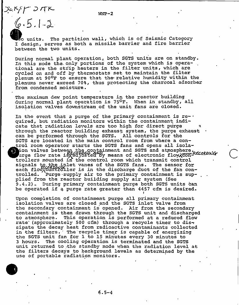
o units. The partition wall, which is of Seismic Categorydesign, serves as both a missile barrier and fire barrier
between the two units.
During normal plant operation, both SGTS units are on standby.In this mode the. only portions of the system which is opera-tional are the strip heaters in the filter units, which arecycled on and off by thermostats set to maintain the filterplenum at 90 F to ensure that the- relative humidity within theplenums never exceed 70%, thus protecting the charcoal adsorberfrom condensed moisture.
The maximum dew point temperature in the reactor buildingduring normal plant. operation is 75oF. Nhen in standby, allisolation valves downstr'earn of the unit fans are closed.
Xn the event that a purge of the primary containment is re-quired, but radiation monitors within the 'containment indi»cate that radiation levels are too high for direct purgethrough the reactor building exhaust system, the purge exhaustcan be performed through the SGTS. All controls for theSGTS are located in the main control room from where a con-trol room operator starts the SGTS fans and opens all isola-
'on valves betwe tQg gongyinment and SGTS and atmosphere.rge flow rate i 8j8&e8 5y means of electronic flowj(con~~+~~
trollers mounted zn the control room which transmit controlsignals ~y ~q j.nlet vanes of the SGTS fans. The sensor foreach flow P &3.ler is in the discharge duct of the fan con-+rolled. Purge supply air to the primary containment. is sup-plied from the reactor building supply air system (See9.4.2) ., During primary containment purge both SGTS units canbe operated if y purge rate greater than 4457 cfm is desired.
l
Upon completion of containment purge all primary containmentisolation valves are closed and the SGTS inlet valve fromthe secondary containment is opened. Air from the secondary-containment is then drawn through the SGTS unit, and dischargedto atmosphere. This operation is performed at a reduced flowrate'approximately 500 cfm) through a recycle timer to dis-.sipate the decay heat from radioactive contaminants collectedin the filters. 'he recycle timer is capable of energizingthe SGTS unit fan for 1 to 15 minutes every 30 minutes to3 hours'he cooling operation is terminated and the SGTSunit returned to . the standby mode when the radiation level atthe filters decays to background levels as determined by theuse of portable rad'iation monitors.
6 ~ 5-4
Osage 4,7
-'19-I
Sync th. system would 5e called on-to.function only in the eventof,a'oss-of-CoolantAccid nt (LOCA), we have reviewed the sys ==. to assure that
it is capa51e of performing its safety function under .he exp'ected LOCA
environ nial conditions appropriate io the system equipmen. location.
Furthe., the componen s of such subsystmi are prot cied by separation and
barriers acainsi internally generated missiles, externally generated missiles,V
and dynamic effects associated with pip breaks sucn ha t:;eir furction will
not be impaired under postulated LOCA conditions, hus .he rejuir ~ n.s of
General Design Criterion 4, "Etivironraental and Missile Desicn Bases," and
the guid lines of R gulatory Guide 1.117, "Tornado Design Classificai cn,"
and Branch Technical Position.ASB 3-1, ."Protection Against Posiulat d.Piping
Failures in Fluid Systems Outside Containment," are satisifed.0 ~ ~
~s
I The applicant must verify tha ihe leakage rates used ar as specified in
ihe Standard Techn ical Speci fica iions ar e used before we can confirm compliance
with tn gui'delines of Regulatory Guide 1.96, "0 sign of V<ain Steers; isolationII 1Valv Leakage Control Systems for Boil ing 4'ater Peactor lfuclear Pow r Plants ~ J
Based on our review, we conclude th" t iviSIVLCS ls in con-,or;..ance wi.h,herequirem nts o-, General Design Cri. ria 2 and 4 with respeci io i is proteciionagainst natural phenomena, missiles and nvironmenta1 e-,=, cts, and ,he guide-lines of Regulatory Guides 1.29, 1.102 and.l.ll7 and Branch Technical Posiiion
'V
AS3 3-l.with respect to its pro. ection against f1ooding, tornado missiles and
pipe break effec.s, and is, therefore, acceptable. f.we cannot conclude that .
ihe cuidel ines of Regul ato ry Guide 1 . 96 rela iing to the 55:VLCS -,unciional

WNP-2
Open SER Issue
6.7 Main Steam Isolation Valve Leaka e Control S stem
The MSIV-LCS, as designed, imposes a maximum process 'load of 80 lbs.of saturated steam at 35 psia, vented to the reactor building volumeserved by the Standby Gas Treatment System (SGTS), followed by thecontinuous MSIV leakage flow r'ate of 46 scfh (11.5 scfh at 25 psigper valve).
The in'itial discharge will have no significant effect on buildingpressure buildup and the continuous flow is considered negligiblecompared to the SGTS design flow rate of''4QOO scfm.'heMSIV-LPS conditions the exhaust, temperature and.hjimidity to within.the design requirements of the SGTS prior to deliVery'to'he SGTS
by diluting the 46 scfh MSIV Leakage with 50 scfm. of air from the,-- 'eactor'ui lding; -
'NP-2Technical Specifications, Section 3.6.1.2, limits the MSIV
leakage to 11.5 scfh, per valve, at 25 psig and requires t'estingeach valve to verify the leak rate at least once every 18 months
'he
MSIV leak rates are, therefore, verified to be within the designcapabi 1 ity'n a routi ne bas i s.
I

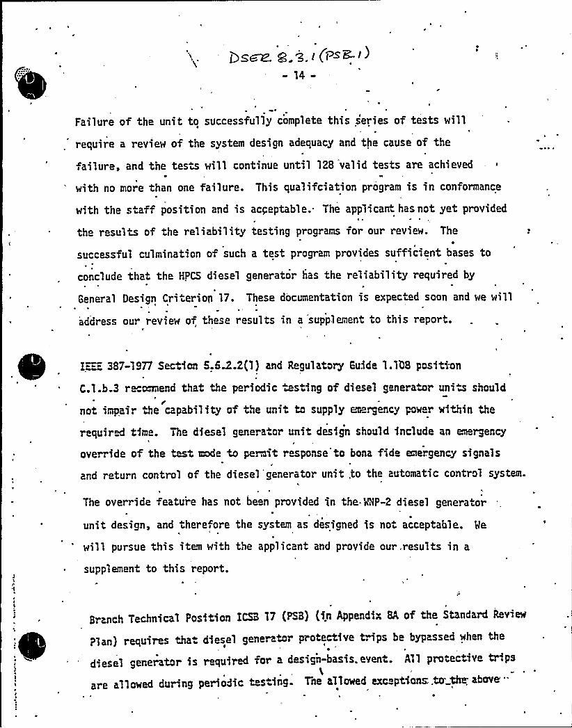
E
tat
Failure of the unit to successfully complete this series of tests willt
require a review of the system design adequacy and the cause of the
failure, and the tests will continue until 128 valid tests are achieved
with no more than one failure. This qualifciation program is in conformance
with the staff position and is acceptable.. The applicant has not yet provided
the resu'its of the reliability testing programs for our review. The
successful culmination of such a test program provides sufficient bases to
conclude that the HPCS diesel generator has the reliability required byt
General Oesign Cri ierion 17. These documentation is expected soon and we will
address our review of these results in a supplement to this report.
E:-=i 387-19?7 Section S.GD.2(1) and Regulatory Guide 1.1b8 posftiton
C.l.b.3 re maend that the periodic ws ing of diesel generator uniu should/
not impair the capability of the unit to supply erargency pow r within the
required time. The diesel gen rator unit. design should include an en rgencyt
override of the test mode to petit response to bona fido emergency signals
and return control of the diesel'generator unit .to the automatic control system.
The override feature has not been provided in the.'r%P-2 diesel genera. or
unit design, and there ore the system as designed is not acceptable. Me
will pursue this item with the applicant and provide our tresults in a
supplement to this report.
Branch Technical Position ICSB 17 (PSB) (in Appendix 8A of the Standard Review
Plan} requires tha diesel generator protective trips be bypassed when the
diesel generator is required for a design-basis. event. All protective trips
are allowed during periodic t s ing. Tne allowed exc ptCons;.to the above'"

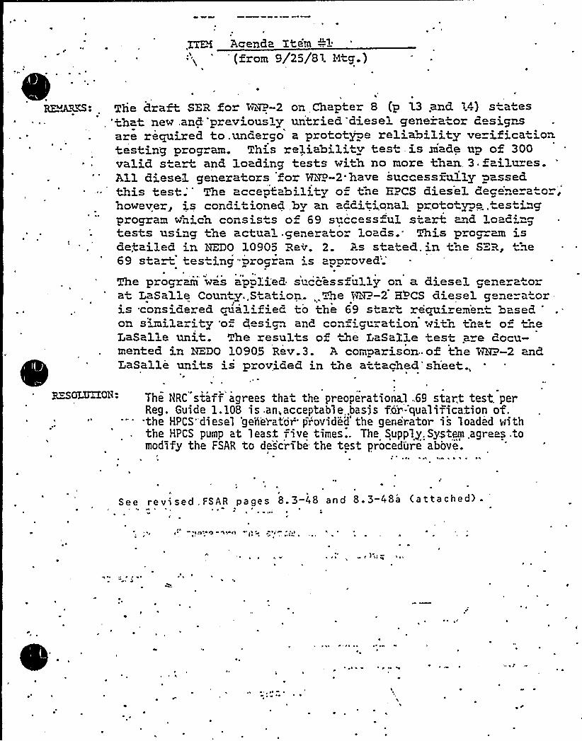
Aeenda Item O'2
(from 9/25/81. Ntg-)
RE.WKM: The draft SZR for 1vNi~-2 on Chapter 8 (p l3 .ancL 14) s a es,'that new .and 'previously untried,'diesel genera or d signsare required to.undergo a prototype reliability ve ifica ion.testing program. This reliability tes is ziade up of 300valid s ar and, loading tests with no more than. 3.failu es.All diesel generators for HHP-2 have successfully passed.this test;'he accep"'ability of tne EPCS diesel deg 'neratohowever~ is condi ioned,by an acditional proto ype.. estinprogram wnich consis. s o 69 si ccess ul start ~ad loaditests using the actual. generator loads. This prop am isdetailed in REDO l0905 Rev. 2. As stated. in the S=-R, tne69 start tes ing"program is approved';
The program was app3.'i.'ed s'uccess~u11y on a diesel gene atorat LaSalle County.,Station,. %he SF'-2 25'CS diesel g ncra"oris considered qualified to the 69 star requiremen based
'n
similarity 'of d si~ and con= guration with that of iheLaSalle unit. The resul s of the LaSalle tesi are docu-mented in ADO 10905 R v.3. A comparison" of the HHP-2 and,eLaSalle units is provided in the at ached'sheet..
The HRC staff agrees that the preoperationa1 ..69 start test. perReg. Guide 1.108 is. an, acceptable,.basjs fear -qualiTica.iion of."'the HPCS "diesel 'gen'erat'or pr'ovided the generator is loaded anththe HPCS pump at least five times.. The Supply. System .agrees .tomodify the FSAR to describe- the test procedure above.
~ % ( ~ ~ 'I ~
See revised. FSAR pages 8.3-48 and 8.3-48a (attached) .
\ ~
)'4 "l4 '

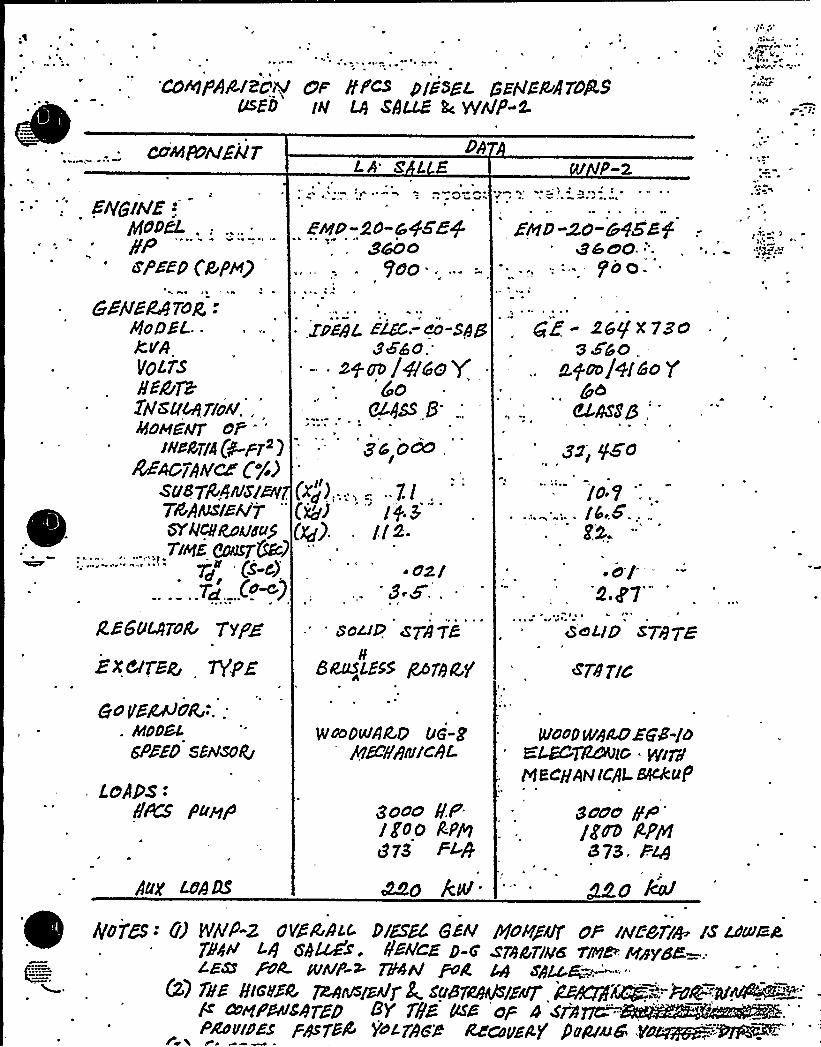
~ r
CaePAA/ZCM e A I'CS PlSSSZ. gSHC+ATORSusz5 w M sAu8 L: @AD-L r '
~hf&hlEiV7
E4$WZ:.PfPPf'L,:pP
'""zpszp Cp pep
5EiVEC97vg,-PloDSL..CPAVOLTSHMQ2PlSLf7/oA/.,AfdMEAg PP
weary'-pr')WmQA~ C%)
s'ua pgrfn/s/uv.TBAesrsA'jQ'QCg~glgu57cwi cnsTCR)
(s-cPZ~ (am)
RsSuvroa Trpbixerox', vgagc yEAUoR'.:
. hfDDSL
SPEED S&fSO4
LeAps -.
b~ PuaP
LA ZLEI
&M&'WWI
(xg)..,.. -, "7.I .
(@rJ 'fb"(~) ll~-
m/'8-F .
sod@. s7818
Beast,855 gor8Cg
yraoDu!AA? g QG-gpfgcp/N/c86
8cno gFlgoO R;P~8 /3 P/P
Md k4-
~ „«v, ~ r
/P-2
Eau-~a-CVS8$ghoO-:.
5'0 o-
gg- XggX7Za3$5d ..
gym/q(So y
844789,'ug
..,... lb,,5,:gN.
al.0 Z7'"
QeLID sprp7 S
~A'PC
tUOODSgCOEg8'-/dKL&"TddVis. He&MacHAN(c/4 Bf4tuP
gone pPglue App1873, P
Mo km'
»
~ .r
~I
A'DTEs - 0) sP-z 0YEQc< D/8Ãc 8'' goHg4r uP /N/Nri+- ts ~siam4~«E D-4'rate'a ster sayer="..isa P4 wP-> 7P44 PX ~ spy.p~-""
(2) 7h'E 8/ASC 7MrVslze'y S SugyeyfSIZa7 gW~.'-.Wg~'.yr&4Eu~:-R ~WPAvs8TED 8Y f!/8 tcsS ep 4 4&PAfnlf/JES /~754 jhow 7+pg ~~pp]K] Purr~@ V~ppgp.--mei~
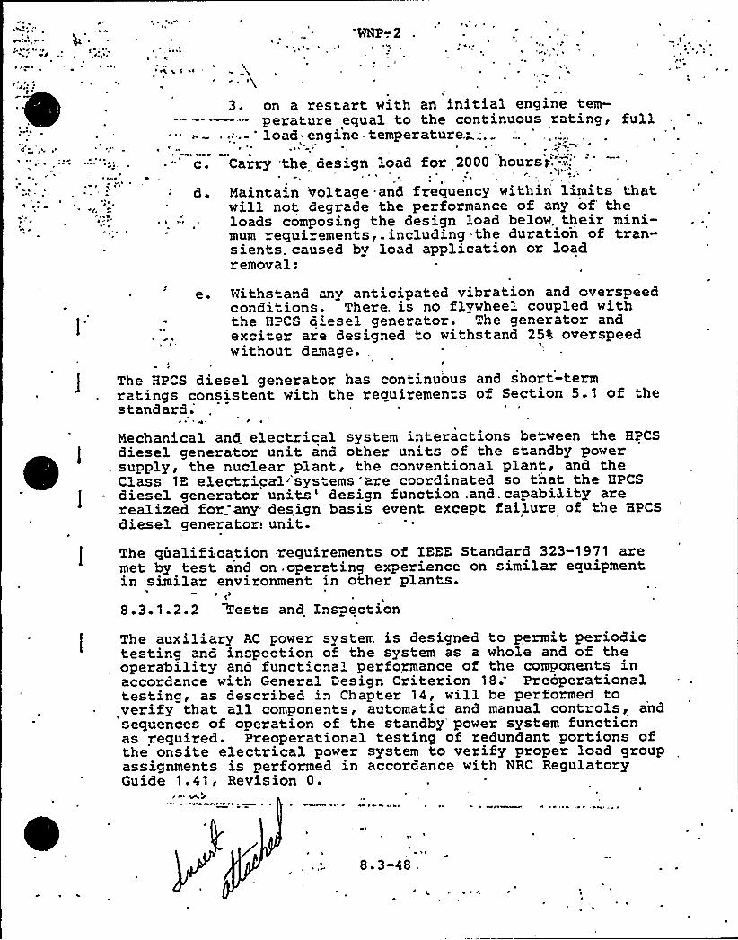
~ g
WNP-.2
~ ~
~-
3. on a restart with an initial engine tem-perature equal to the continuous rating, full
'" - 'oad engine - temperature ..—..„
~ '--'. Carry 'the design load for 2000 hours,"=;-:.,'.
Maintain 'voltage and frequency within limits thatwill not degrade the performance of any of'heloads composing the design load below. their mini-mum requirements,, including-the duration of tran-sients. caused by load application or loadremoval;
e. withstand any anticipated vibration and overspeedconditions. There. is no flywheel coupled withthe HPCS o'esel generator. The generator andexciter are designed to withstand 25% overspeedwithout damage..
The HPCS diesel generator has continuous and short-termratings consistent with the requirements of Section 5.1 of thestandard;
Mechanical and electrical system interactions between the HPCSdiesel generator unit and other units of the standby power
. supply, the nuclear plant, the conventional plant, and theClass '1E electrical''systems 'are coordinated so that the HPCSdiesel generator units'esign function,and.capability arerealized for. any design basis event except failure of the HPCSdiesel generator! unit.
1The qualification requirements of IEEE Standard 323-1971 aremet by test and on operating experience on similar equipmentin similar environment in other plants.
8.3.1.2.2 Rests and Inspection
1
The auxiliary AC power system is designed to permit periodictesting and inspection o" the system as a whole and of theoperability and funct'cna'erformance of the components inaccordance with General Design Criterion 18.'reoperationaltesting, as described in Chapter 14, will be performed toverify that all components, automatic and manual controLs, andsequences of operation of the standby'ower system functionas required. Preoperational testing of redundant portions ofthe onsite electrical power system to verify proper load groupassignments is performed in accordance with NRC RegulatoryGuide 1.41, Revision 0.
I 6 I
'"
8.3-48

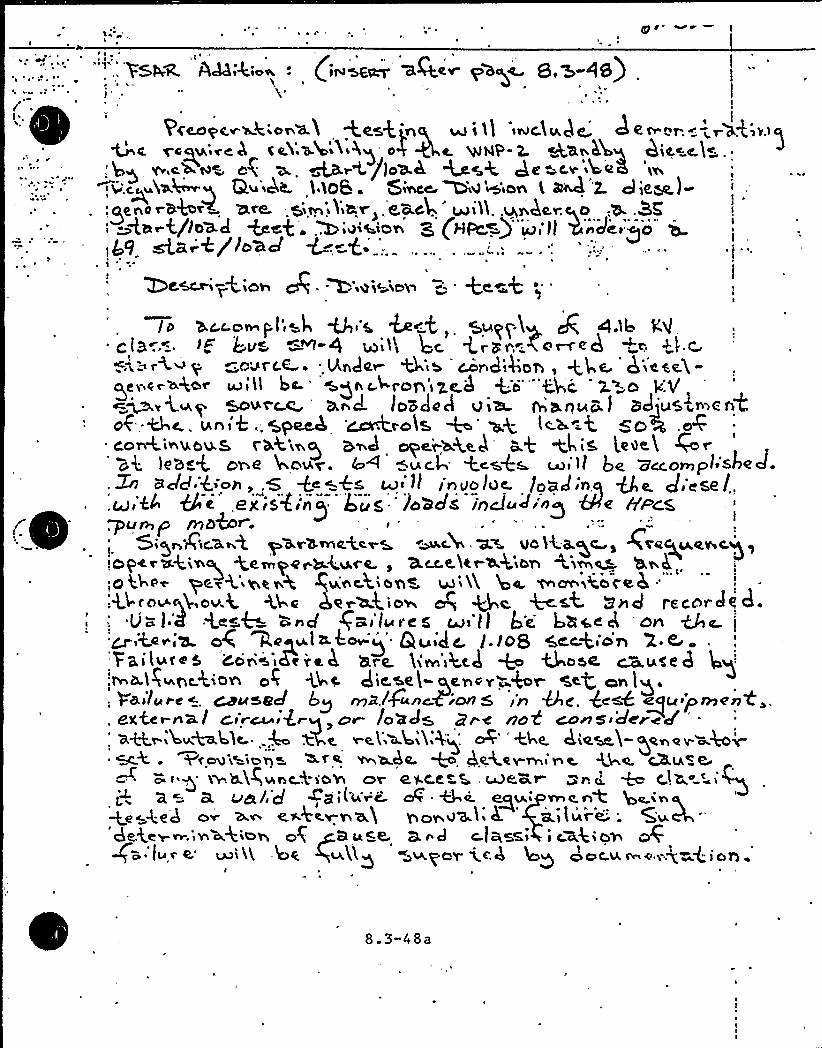
'g
~ ~ *~ i
""", '>SW< AA;4;~a .. (riskier'Qev p>cc 8,%-<8)~ r
Pccoqcrr ic'ona11 West jnq up i )1 iriclv ) e' e n.en ir'a4rr>gregN.'~e. A C eY.W')Cihe4g Ok ~a W)4V'- L ~ax 5 g ChiC,~C,)S ..
',. hH rr c+l4% og W, ~~rC/)ocLh ~%4 Qe -cr ~beK w,>~C~~NaMg Q~44 ) LOB. 5ieCe MO)'e+'iOn 'L M '2. d je~)'.dna r'5'ter+ NC'6. gism Y~L'<>.C.aCQ ~iA, .VW4ergO e+ .3K !
'4or4/lose) +sg.,Z)i~(e.iorr E (HpC.=)"'up,')) 5'nclei c)'o" j1 g9 ~a E'/ oad~ p+
ZOC~i ~+iOA Q ~ ~egi<iCQ ~- +C,~~+ 'I c Wc, .com)'-ll sL V 'S, &~A,, Wyq4 ide, c).1). VI
eI3 .-. ~~ k-v» -~-4 ~i>'~ 4ryr .<e~<d«CarC.E ~ 'ncIer &'ib ~ndiQOA, +Ma hi<%e)I,-
aev e~~4o~ e<'ll bc-'gn chrop'~ye.4 <'ci'"'<4')-„g~-osoot'c 0 hr d los JeA vi& banuc J sdju&in~c AC
0'6, &4' thh~'6 .. 5pRk CcÃtt.otal + 4+ tc-h ='t +04 .o rcoirt.ir usus ran'i g iver ck ape)-'rge.h «Q tt iS leech
)e'hr4 or e )no~a. 1'o ) ariel tcs+w coi)l Qe accompl'sire J.Zn 8Jd:4'ah,,G +<~as Mi'~t I'nuoloc. load'n,q Qa. J csel.,6 eexisC ',re E;uc '-)oacIs incluJ'n'g '4e iri'iocc.
lvent)" I
Sir) 7Qc'cL ~ 4 pcLr'l!rne+cr K ~ck 'K% Vd lk'ck+r r Zeec) Lcerrc.g!Operec+(rrq e'er ye~)azure. r Kcceler a.4
iorr'0'&erlper+iger.c pane(lorlL rirl'li )oe.trrcmrrcoceh:"'4ro~q4ov.<
<ka 4er~4io~ ~ Qe. +est 5~4 racon JC d.Ua)4 4es+ bncI (Si) rue@ ui)] Q'e. hhcec) 'Crn Qc.
)
o4 W~qu,~>~o j Quid'. (.lOS 4cc+io~ X.CVailuc~5 Cc'r'~iBreh hre Livn~htk + Lc~@r a.)g p<<',on o( <4~ Die.se(-pc.oov-b~ <cg o~lg.
, Failure ~ Cause J by mklguncgion 5 in@c'. 4csk eyer prrren4,.. )C!%ter-nial Cia"~agrq > C)r /Od J5, Bred NOH COASTS dered'u~'%~M) lc. 4 W4e. ~c('W4'Mg. oi'+) e k~eseh-gene~
YfOg Ribby +f~ Wh.CLL +, $C:4Y.Vhe h t. +4%. GALA<C~i g n-.)c>Z~rc+~oV or arcerc. meai- ~n~ '~ C)< r iQ
a. g~/,J ~j,(-~..i A.~e. @v., ~e.~4 g~;.q,ge~<ek o~ ~~ c.h«r»3 yu>v~l'h. 'i/ure .'deke~~.'agio'( ~B La~@ 3 nd c.I+~si i cxgiQNgB:)ur e.'i11 .)oe +uALg av d'or xck )oy oocrc <m. $
radian
r
8. 3-48a
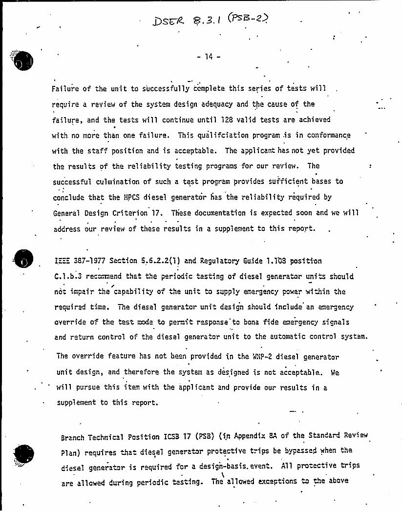
- 14-
Failure of ihe unit to successfully complete this series of tests will
require a review of the system d sign ad quacy and the cause of the
ailure, and the tes s will coniinue until 128 valid tests are achiev d
with no more than one failure. This qualifciation program .is in conformance
with the s a = position and is acceptable. The applicant has not yet provided
th r sul is of the reliability iesting programs for our review. The
success,ul culmination of such a test program provides sufficieni bases to
conclude that th HPCS diesel generator has the reliability required by
Gen ral Design Criterion 17. These documentation is expected soon ard we will
address our review of these resul:ts in a supplement to this report.
I„-„=„= 387-1977 Se tion 5.6.2.2(1) and 'ihgulatory Guide 1.108 position
C.l.b.3 r n end that the periodic testing of diesel generator uni a should
noi imp ir ihe cap biliiy of ih unii 4 supply &z~rgency power %f ~iin ih
r quired tim . one diesel genera. or uni" design should include an e.. r g ncy
override of the tes i wfe to perm i response to bona fide emergency signal s
and r iurn conirol o the diesel aenerator unit to the automatic control syst m.
The override feaiure has not been provided in the 'r'NP-2 diesel generaior
unit design, and there ore the system as designed is noi acceptable. Me
will pursue this item with the applicant and provide our results in a
supplement to this report.
Br nch Technical Position ICSB 17 (PSB) (in Appendix 8" of the Standard Revim
?lan) requires that diesel generator prote~ive trips be bypasseg when the
d esel generaior is requirM for a design-basis.eveni. All pro-ective irips
are allowed during periodic sting. 7ne a11owed axc ptions u the above
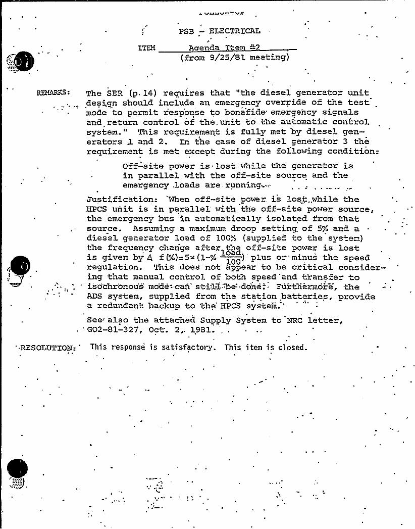
PSB —ELECTRICALr
Aaenda te.(from 9/25/8'L meeting)
REHQKS:
)'
The SER (p. 14) requires that "the diesel generator un'tdesi,gn should. include an emergency override of the testmode to permit r'esponse to bonafxde emergency signalsand return control of the, unit to the automatic controlsystem " This requirement is fully met 'by diesel gen-erators 3. and. 2. Xn the case of diesel genera o 3 therequirement is met except during 0he followirg cordition-
Off-site power is. lost wh'le the generato= isin parallel with the off-site source ard, theemerg ncy,loads are running;-.
Justification: 'When off-site poli. is lostn„while ~heHPCS unit is in parallel with the off-site power source,the emergency bus in automatica ly isolated from thatsource. Assuming a maximum droop setti.ng. of 5% and. adiesel generator load o 100;~> (supplied to the sys-em)the frequency change after thy ozz-sits poser is 1ostis given by Q t(%)=gs(1-% )'lus or'minus tne speez(
loaregulation. This does not appear to be critical consider-ing that manual control of both speed and transfer toisochr'onou's'o'de"-'caA'ti'lI be"do'ne-. ~ Fur~riermore, theM3S system, supplied from the station batteries, providea redundant backup to ~he'PCS
system.'ee'lso
the attached Supply System to HRC letter,'O2-81-327, Oct'. 2,. 1981.
RES OLUTTOM: This response is satisfactory. This item is closed.

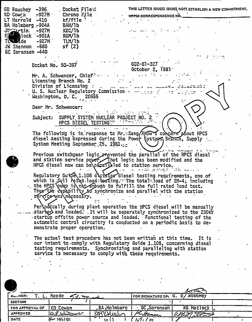
THIS LETTER IDOES) tDOEj NOTl ESTABLISH A NEYl COMMITMENT.
VtPPSS CORRESPONDENCE NO
Docket. Fkle-;"Chrono rilekf/file
'AH/lb
KDC/lbRGM/1 bTLM/lbsf (2)
GD Bouchey -396,KD Cow-'I> -927MLT Harrold -410BA Holmberg ;904AJI " rtin. -927M
lock '-901ATL de -927MJW Shannon -660GC Sorensen -440
Dccket No. 50-397 G02-81-3272, 1981'ctober
Mr. A. Schwencer, Chief. "-Licensing Branch No. 2Division of LicensingU. S. Nuclear Regulatory Commission-Washington, D. C. 20555
~ I'
v
Per o cally during plant oper'ation the HPCS diesel will be manually,.star and loaded; . It will be separately synchronized to the 230KItstartup offsite power source and loaded; . Functional testing of theautomatic control circuitry is conducted on a periodic basis to 'de-monstrate proper operation.
The actual test procedure has not been writ en at this time. It isour intent to .comply with Regulatory Guide 1.108, concerning dieseltesting requirements. Synchronizing and paralleling with stationservice is necessary to comply with. these requirements.
Dear Mr. Schwencer:
Subject: SUPPLY. SYSTEM NUCLEAR PROJECT NO. 2HPCS DIES L TESTING".'"
N
The followiig is in. response to Mr.:Sang.R,ow ~ co ~e . out HPCSdiesel, testing expressed during the Powe yst . Bra i~, Supply...System Meeting September. 25, 1981.: -.
Previous switchgear logic . vented the parallel of the HPCS d'iesel'*
and s ation service po hat logic has been modified and theHPCS diesel now can be led to station service.
H
Regulatory Gu 1.108 d diesel tes ing requirements, one ofwhich is - ll t d load.: ang:-"The total:load of SM-4; includingthe HP"S u p i n n ugh to fulfill:the full rated load test.Th "
p bils synchronize and parallel with the stationc s 'n essary.
.~oR: T. L. MeadeSECTION
FoR sIcNATURE oF: G O +o~~y
FOR APPROVAL. OF
APPROVED
DATE
KO 'CowanQi 4 g
Igi/Sl
BA Holmber
'..llGC Sorensen,
li'iIm
RG Mat o g
I~ ~
Rr. A. SchwencerPage 2G02-81-327October 2, 1981
Administrative procedures will be used to prevent'concurrent testingaf more than. one diesel.
Please contact us if further information is necessary.~ ~
~ ~ P*'I Qhh hA Q h
Very'ruly yours,W ~ ~ ~ ~ I
MtI' ~ I
G. D. BoucheyDeputy DirectorSafet5 &-Security .'
I
GDB/TLN/1dm—'I
~ I ~
cc: MS Chin - BPA
AD Toth - NRC, ResidentNS Reynolds - Debevo'use & LibermanJC Plunkett,.- NUS, CorporationR Auluck=- NRC DC
S "Rhow - NRC.DC
OK Earle - B&R RO
EF Beckett - NPIMNP-2 Files
' .
Er
~ ~ . ~ i.
~ tr ~
r I I ~
~ * r v
* r ~ ~
H
~ h I

i
0
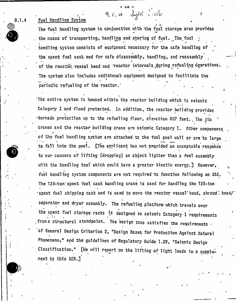
CO
\1
Fuel Handlino S stem
The fuel handling system in conjunction with the fuel storage area provides
the means of .ransporting, handling and sioring of fu 1. The fuel
handling sys em consis.s of equipment n cessary for the safe handling of
ihe spent fuel cask and'for safe disassembly, handling, and reassemMy\
o the reac or. vessel head and 'receptor interna'1s during re,ueling operations.
Tne sys em also includes addiiional- equipm ni designed to facilita the
periodic refueling of the reactor.
'Th
niire sys. m is housed wi.hin the reactor building which is seismic
Ca-.e ory I and flood proiected. In addi.ion, .he reactor bui1ding provides~ tornado proiec.ion up to the refueling floor, elevation 507 f ei The Jibcranes and tho reactor building crane, are seismic Caiegory I. Oiher components
H
o7 he Tuel nandl ing system are attached to the fuel pool wal 1 or are to lao arge
io fall into the pool. [The applicant has not pr„vided an acceptable responseP
to cur concern of lifting {dropping) an cbj ct lighter than a fuel assembly
with the»andling iool which could have a greater kine.ic energy.] However,
fuel handl ing system components are not required to ~ unction following an SSc, ~
The 12'- on'spen fuel cask handling crane is us d or handl'ing the 123-ton
spent fu 1 shipping cask and is used to mov he reac.or vessel'head, shroud: head/
separator and dryer assembly. The refueling plat orm which rav lsthe speni fue1 storage racks is designed to seis"' o Iitic aiegory I requiremenis
from a struc„ural standpoint. The aesi gn thus satis ies hes he requirementsof General Design Criterion 2, "Design Bases for Prot c ion Against NaturalPheno;ena;" and the guidelines of Regulatory Guide 1.29, "Se
Classification." Ll<e will report on the lifting of ligh" 1 dof ig, oa s sn a supple-ment o this SiR.]
WNP "2
a. 010.055(9.1-2)
Describei discuss'nd verify that the maximum potential kineticenergy contained in alL objects of Less weight than a spent fueLassembly which will be handled over spent fuel will not exceedthe effects .of the fuel handling accident described in section15.7.4 of the FSAR.
Response:
Table 010.055 has been prepared as a response to this question.This response also closes out an open item from the AuxiliarySystems Branch meet ing October 7i 1981.
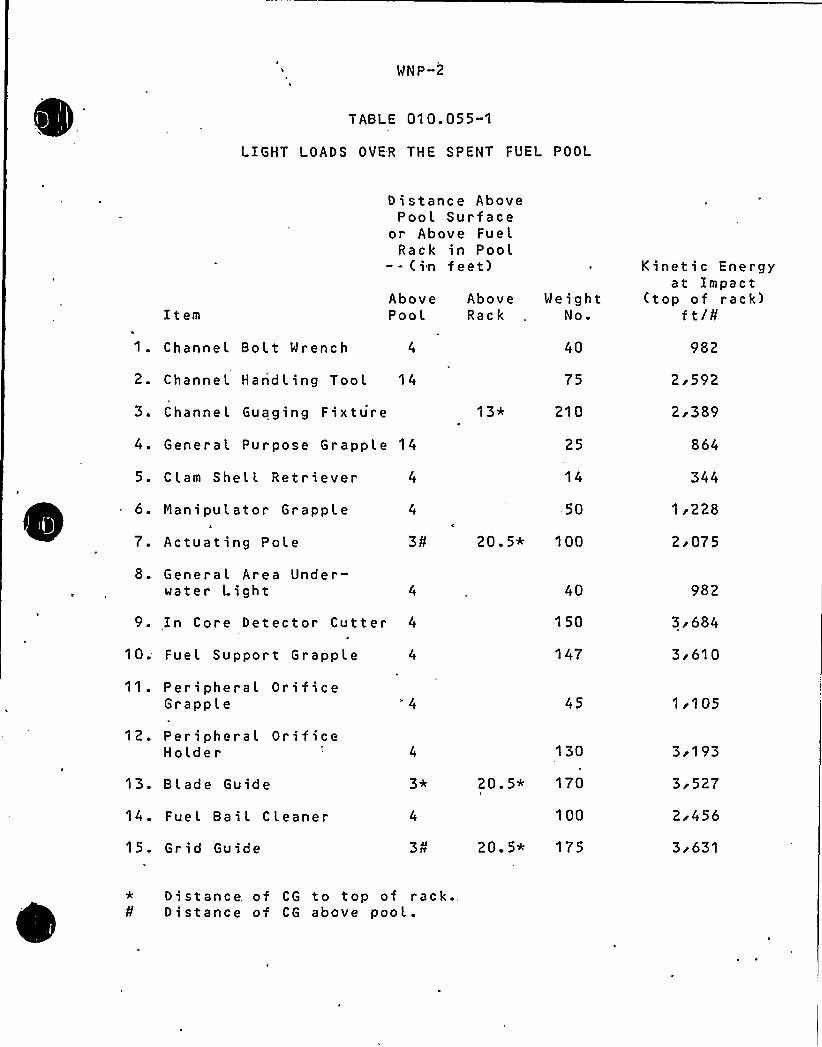
WNP-2
TABLE 010.055-1
LIGHT LOADS OVER THE SPENT FUEL POOL
ItemAbovePoo t.
AboveRack
Distance AbovePool Surface
or Above FuelRack in Pool-- (in feet)
WeightNo.
Kinetic Energyat Impact
(top of rack)f t/0
1. Channel Bolt Wrench 4
2. Channel H anhd l ing Tool 14h
3. Channel Guaging Fixture
4. General Purpose Grapple 14
5. C lam Shell Ret r i ever 4
1 3*
40
75
210
25
14
982
2i592
2r389
864
344
6. Rani pulator Grapple
7. Actuating Pole
8. General Area Under-water Light
9. In Core Detector Cutter 4
10; Fuel Support Grapple 4
11. Peripheral OrificeGrapple
50
20.5* 100
40
150
147
45
1r228
2 i075
982
3r684
3s61 0
1r105
12. Peripheral OrificeHolder
13. Bl ade Guide
14. Fuel Ba i l C leaner
15. Gr id Guide 3A
130
20. 5* 170
100
20.5* 175
3i193
3i 527
2i456
3i 631
* Distance of CG to top of rack.Distance of CG above pool.
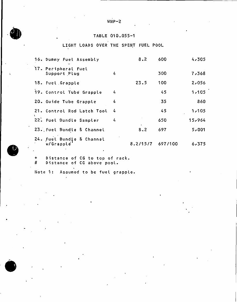
WNP-2
TABI E 010.055-1
LIGHT LOADS OVER THE SPENT FUEL POOL
16. Dummy Fuel Assembly
17. Peripheral FuelSupport Plug
18. Fuel Gr appl e
19. Control Tube Grapple
20. Guide Tube Grapple 4
21. Control Rod Latch Tool 4
22. Fuel Bundle Sampler 4
23-, Fuel Bundle 5 Channel
24- Fue l Bund) e 8 Channelw/G r a pp l
e'.2600
300
23.5 100
35
650
8.2 697
8. 2/1 5/7 697/1 00
4r305
7i368
2i056
1r105
860
I i105
15i964
Si001
6i375
* Distance of CG to top of rack.¹ Distance of CG above pool.
Note 1: Assumed to be fuel grapple.

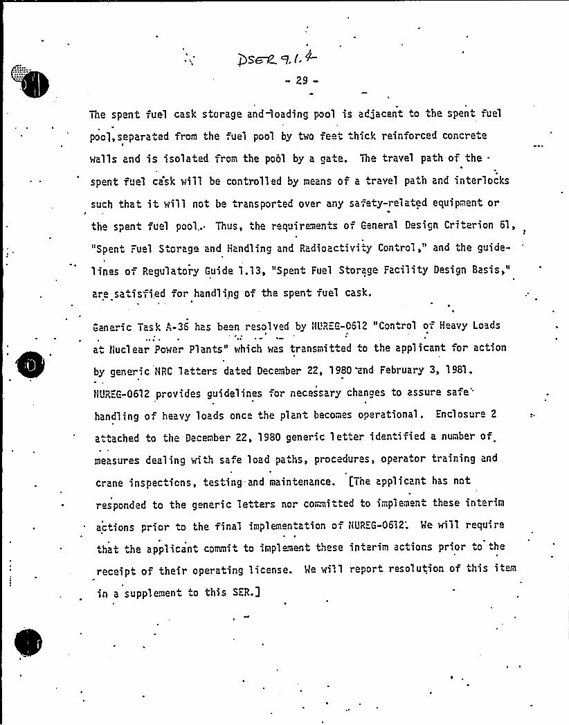
»29-
The spent fuel cask storage anddoading pool is adjacent to the spent fuel
poo],separated from the ,uel pool by two fe t hick reinforced concrete
walls and is isolated from the pool by a ga.e. The travel path of the .
spent fuel cask will be controlled by means of a travel path and interlocks
such that it will not be transported over any safety-rela.ed equipmen or
the spent fuel pool.. Thus, the r quirements of General Design Criterion 61,
"Spent Fuel Storage and Handling and Radioactivity Control," and the guide-
lines of Regulatory Guide 1.13, "Spent Fuel Storage Facility Design Basis,"
ar sa isfi,ed for handling o, the spent fuel cask.
Generic Task A-36 has be n resolved by t/UR="G-0612 "Control of Heavy Loads
a Nuclear Power Plants" which was transmitted .o the applicant for action
by generic NRC let.ers dated December 22, 1980 ~nd February 3, 1981.
HUREG-0612 provides guidelines for necessary changes to assuresafe'andling
of heavy loads once the plant becomes operational. Enclosure 2
attached to the December 22, 1980 generic letter identified a number of
measures dealing wi h safe load paths, procedur s, operator training and
crane inspec ions, testing=and maintenance. I.'The applicant has not
responded to the generic letters nor committed to implement these interim
actions prior to the final implementation of HUREG-0612; Me will requ-;re
.hat he applican commit to impl ment these
receipt of their operating license. Me wi'.1
in a supplement to this SER.]
interim actions prior to the
report resolution of this item
Open SER Issue
9.1.4 NUREG-0612
A response to ~ this issue was submitted „January 13'982 inLetter G02-82-'32.

Washington Public Power Supply SystemP.O. Box 968 3000 George Washington Way Richland, Washington 99352 (509) 372-5000
January 13, 1982G02-82-32SS-L-02-CDT-82-012
Docket No. 50-397
Nr. A. Schwencer, ChiefLicensing Branch No. 2Division of LicensingU.S. Nuclear Regulatory Commissiont<ashington, D.C; 20555
Dear Mr. Schwencer:
Subject:
Reference:
NUCLEAR PROJECT NO. 2RESPONSE TO NUREG-0612CONTROL OF HEAVY LOADS
Letter, D.C. Eisenhut to all Licensees,et al, "Control of Heavy Loads," datedDecember 22, 1980
Enclosed are sixty (60) copies of the MNP-2 response to NUREG-0612,"Control 'of Heavy Loads" transmitted via the reference letter. TheMNP-2 draft SER open item'n this subject should be closed uponrec ei pt of thi s res pons e.
Very truly yours,
G. D. BoucheyDeputy Director, Safety and Security
CDT/jca
Enclosures
cc: R Auluck - NRC
MS Chin - BPAR Feil - NRC Site
See k 5.4--8
-59-
loca. d in. the seismic Ca'tegory I, .ornado protected diesel genera. or building.
Thus the guid lines of Regulatorv 1.29, "Seismic Design Classification,"
are met. [The applicant has not provided a description of the effects of
losing the sys. em as ihe l sul ~v 0 f 'ornado miss H es entering through the '.
louve. s -or loss of the air handling unit as a single failure concurrent with
the tornadic event. We cannot provide any conclusions as to conformance
wi h G neral Design Criteria 2, "Design Bases or Protec ion Against Natural
Phenom na," and 4,-"Environmental and Missile Design Bases" and he guide-
lin s of Regulatory 1.11? relating to he prot c.ion against the effe ts of.
tornado missil 's. He will report resolution of this item in a supplemen .
t o vn > s ba.li] o
The cable cooling systom is not located near any high or modera e onee energy pip>ng,thus, .he guideli:nes of Branch Technical Position ASB'-1 concernino highand moderate energy pipe breaks, and is, there-,ore, acceptable.
Based on the above, we conclude Diesel-Generator area cable cooling system is'
in con ormance with the guidelines of Regula ory Guides 1.29 and Branch TechnicalPosition ASB 3-1 relating to the sys.em's seismic classific tion and highand moderate energy pipe breaks and'is, therefore, acceptable. [He canno
conclude .ha"'the requirements of G neral Design Criteria 2 and 4 as rela es
to pro.ec.ion against natural phenomena, nvironment and missile effects and
the guidelines of Regulatory Guide 1.117 concerning protection against the
effects of tornado missiles are met 'until the applican..provides acceptable
additional in orma ion. We will report resolution of this item in a supple-ment- to this SER.j

Open SER Issue
9.4.8 Diesel-Generator Area Cable Coolin S stem
See revised FSAR page 9.4-50 attached.

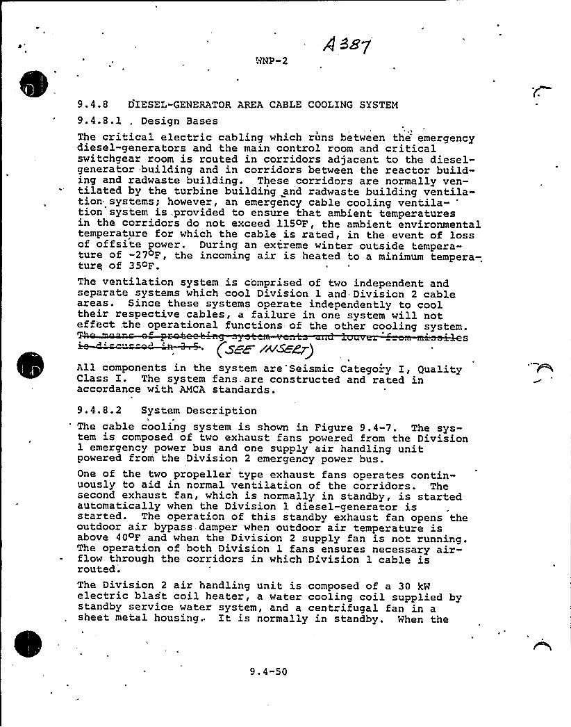
WNP-2
9.4.8 DIESEL-GENERATOR AREA CABLE COOLING SYSTEM
9.4.8.1 . Design Bases, 'I
The critical electric cabling which runs between the emergencydiesel-generators and the main control room and criticalswitchgear room is routed in corridors adjacent to the diesel-generator building and in corridors between the reactor build-ing and radwaste building. These corridors are normally ven-tilated by the turbine building and radwaste building ventila-tion systems; however, an emergency cable cooling ventila-
'ionsystem is,provided to ensure that ambient temperaturesin the corridors do not exceed 115oF, the ambient environmentaltemperature for which the cable is rated, in the event of lossof offsite power. During an extreme winter outside tempera-ture of -27 F, the incoming air is heated to a minimum tempera-ture of 35oF.The ventilation system is comprised of two independent andseparate systems which cool Division 1 and Division 2 cableareas. Since these systems operate independently to cooltheir respective cables, a failure in one system will noteffect, the operational functions of the other cooling system.
~tIs
("zan zwse~)All components in the system are Seismic Categoiy I, QualityClass I. The system fans. are constructed and rated inaccordance with AMCA standards.
9.4.8.2 System Description'he cable cooling system is shown in Figure 9.4-7. The sys-
tem is composed of two exhaust fans powered from the Division1 emergency power bus and one supply air handling unitpowered from the Division 2 emergency power bus.
lOne of the two propeller type exhaust fans operates contin-uously to aid in normal ventilation of the corridors. Thesecond exhaust fan, which is normally in standby, is startedautomatically when the Division 1 diesel-generator isstarted. The operation of this standby exhaust fan opens theoutdoor air bypass damper when outdoor air temperature isabove 40oF and when the Division 2 supply fan is not running.The operation of both Division 1 fans ensures necessary air-flow through the corridors in which Division 1 cable isrouted.The Division 2 air handling unit is composed of a 30 kWelectric blas't coil heater, a water cooling coil supplied bystandby service water system, and a centrifugal fan in asheet metal housing; It is normally in standby. When the
9.4-50

In se r t to pa ge 9.4-50
The ':fr es'h'ir intake'.pen;i;ng..i.s..;Loqa.ted, in the south ..exterior wall and is shielded by a'concrete: barrier, ~
which would preclude entry by a missile such as generatedby a tornado. Division I'xhaust fan di scharges air intothe HPCS diesel generator pipe chase. The chase openingto the atmosphere is 'through a concrete .structure whichis shieLded by a Labyrinth. Division II exhaust fandischarges air into .a cable cha'se which is not open to. ~
the atmosphere. The air is removed by the radwaste buildingexhaust system.

0
gg~~ q 4. (g
-63-
Hakeuo Ma.er Pump House Heatina =-nd Yen i'latin System
Th miakeup water pumphous heating and ven.ilating system consists of
two full capacity air handling units, each consisting of a fan, hea'er,
cooling coil, and filter. One air handling unit nor ally op ra. s with
.he second unit on s andby. The rakeup water pumps are not. needed under
a seismic event but are needed during a .ornado (?efer to Section 9.2.o' this S"-P) . Therefore, the makeup wat r pump house HYAC is non-seismic
Category I but is to'rnado protected "'hus the requiremeJix of General
Design Criterion 2, Design Bases for Protec.ion Against Natural Phenomena'„
are me.. Iihe FSAR states .he ven.s and louvers are miissile protec.ed
by reference to Section 3.5. 'ection 3;S of the FSAR does not specify:
tha the vents and louvers of .he m cup water punp house HYAC are missile
protect d, Thus, we cannot conclude conformance with the requirements of
General Design Criterion 4, "Environmental and Hissile Design B»ses,"
and the guidelines of Regulatory Guice 1.117, "Tornado Design Bases",n
are imet. We will report resolution'of this item in a supplement to this
S"=R3.
Based on 'the above, we conclude that the makeup ~ater pump house heating
and ventilation, system is in conio-.„,ance with the requiremients of General
Design Criterion Z.m r lated to pro c"ion ag inst na .ural phenomen , are
met. [We cannot conclude confor,anc wi.h the requirements of G n ral Design
Criterion 4 as relating to prot ction fromi environmental and missile e,feet,.
and the guidelines of Regulatory Gu-',de 1.117 as relating to prot ction
against tornado missiles, as being ret. Me will report resolution of this item
in a supplement to this SFR.]
Open SER Issue
9.4.12 Nakeu Water Pum House Heatin 5 Ventilatin S stem
See revised FSAR page 9.4-63 attached.
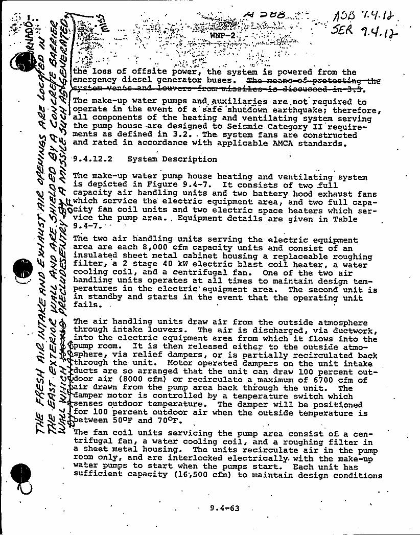
fjord '~Y.IJ.~
~
- I>t *
1 7
the loss of offsite power, the system is powered from theemergency diesel generator buses.
~ ~
The make-up water pumps and. auxiliaries are .not required tooperate in the event of a'safe shutdown earthquake; therefore,all components of the heating and ventilating system servingthe pump house are designed to Seismic Category II require-
+ ~4 ments as defined in 3.2. ~ The. system fans are constructedy ~ '4 and rated in accordance with applicable AMCA standards.
9.4.12.2 System Description
The make-up water pump house heating and ventilating systemis depicted in Figure 9.4-7. It consists of two fullcapacity air handling units and two battery hood exhaust fans
gwhich service the electric equipment area, and two full capa-gcity fan coil units and two electric space heaters which ser-
vice the pump area., Equipment details are given in Table< 9.4-7. . *
The two air handling units serving the electric equipment~
~
.area are each 8,000 cfm capacity units and consist of aninsulated sheet metal cabinet housing a replaceable roughingfilter, a 2 stage 40 kW electric hlast coil heater, a watercooling coil, and a centrifugal fan. One of the two airhandling units operates at all times to maintain design tem-peratures in the electric'equipment area. The-second unit isin standby and starts in the event that the operating unit
i< bQ fails.
4gE~
~x.kh
The air handling units draw air from the outside atmospherethrough intake louvers. The air is discharged, via ductwork,into the electric equipment area from which it flows into thepump room. It is then released either to the outside atmo-sphere, via relief dampers, or is partially recirculated backthrough the unit. Motor operated dampers on the unit intakeducts are so arranged that the unit can draw 100 percent out-oor air (8000 cfm) or recirculate a maximum of 6700 cfm ofir drawn from the pump area back through the unit. Theamper motor is controlled by a temperature switch whichenses outdoor temperature. The damper will be positionedfor 100 percent outdoor air when the outside temperature isetVeen 50oF and 70oF
The fan coil units servicing the pump area consist of. a cen-trifugal fan, a water cooling coil, and a roughing filter ina sheet metal housing. The units recirculate air in the pumproom only, and are interlocked electrically, with the make-upwater pumps to start when the pumps start. Each unit hassufficient capacity (16;500 cfm) to maintain design conditions
9. 4-.63
l
~' '
~ , ', ~ ~ , ~ ~
Evaluate'ion and Findinos
~ ~- The applicant has comit ed io a posi-accident sampling system thai naets
the requirements of t<UREG-6737, i.em II.B.3 in Amendmeni17, but has no .proved d
the technical informatioh required by tiL~R G-0737'or cur evaluation. Imp1emen- ...~ ~
tation of th~ requirem nt is not necessary prier io lcw power op raticn because~ e ~ ~
only smal.l quantities of radicnuclida inventory will oxist in the reactcr ccolant
syst m'and therefcre will not affect the health and safety of the public. Prior
to exceeding i" pcwer operation the applicant must d ~cnstrat the capability
to promp.ly cbtain reactor coolant s~~ples in'h event of an accident'in which
there is core damage consisient with the conditions sia.ied below.-0
~ ~
1. Demonstrate compliance with all requira7ants of NL~REG-0737, II.B.3 for
sampling, ciiemical and radionucljde 'ana1ysis c>pability, under accident
conditions.
~ ~
2.
3;I~ ~
Provide sufficient shi 1ding:to me the requiremanis of GDC-19, assuming
Reg. Guid 1.3 source terms.~ ~
wgP
Cawiit io i-e i he sampling and'analysis'requirements of Reg. Guide 1.97I
~ ~ '~
'ev.
~ p'l
Yerify that. all elecirically powered cc"ponents associated with post accidente 'L ~ ~
sampling are capable of being supplied with'rwer and,operated, within thirty'minutes of an accident in which'ihere.is cor degradation, assuming loss of
~ 'I
off siie power.
~, ~
WNP-2,
Open SER Issue
10.4.6 NUREG-0737/II.B.3 Post Accident Sam (inA response to this issue is provided in the TNI submittal(Appendix B) .
~ '( ~'
h ) A ~ = ~~ < r ~ ~ a '
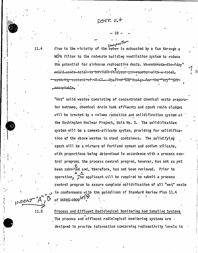
—19-
11.4c. P"
flow in the vicinity of the. ~ is exhausted by a fan through a
HEPA filter to the radwaste building ventilation system to reduce
)I ~ V I Wt>S ~ r
.."~i ~ O~'" &'d IR 4 "- ~MQ 2 P
the potential for airborne radioactive dusts, V--"s -'-."- ,"~d~"'4e v ~sC ~ 4v all v ~ I v ~ ~ ) I aa ~
hi o
I
"Vet" solid wastes consisting of concentrated chemical waste evapora-
tor bottoms, chemical drain tank effluents and spent resin sludg s
will be treated by a volume reduction ard so1idifica"ion system at
the Mashington Nuclear Project, Unit halo. 2. The solidificationII
system will be a cement-silicate sys.em, p'roviding for solidifica-
tion of the above wastes in steel containers. The solidifying
agent will be a mixture of Portland cement and sodium silicate,
with proportions being deter, ined in accordance with a proc ss con-
trol program; the process control program, however, has not as yet
been submit d and, therefore, has not been reviewed. Prior toA
operation> 'he applicant will be r quired to submit a processrcontrol program to assure complete solidification of all "wet" waste
,, in conformance wi.h the guidelines of Stardard Review Plan 11.4
>~~7 P l & of WUREG-08001+5
Process and Effluent Radiolo ical t<onitorin And Sam ling S stems
The process and effluent radiological monitoring systems are
designed to provide information concerning radioactivity levels in

0
Open SER Issue
11.4 Process Control Pro ram
See revised FSAR pages 11-vir 11.4-11 and 11.4"11a through11.4"11d-
WNP-2
11.4.2.2
11.4.2.3
11.4.2.4
TABLE OF CONTENTS (Continued)
Radwaste Disposal System for ReactorWater Cleanup Sludge
Radwaste Disposal System for CondensateDeminerali'zer Sludge
Radwaste Disposal System for Fuel Pool,Floor Drain and Waste Collector FilterSludge
~Pa e
11.4-3
11.4-4
11.4-4
11.4.2.5 Radwaste Disposal System for Spent Resin 11.4-4
11.4.2.6 Radwaste Disposal System for ConcentratedSolutions
11.4-5
11.4.2.12
11.4.2.13
11.4.2.13.1
Shipment
Process Monitoring
Reactor Water Cleanup Phase SeparatorInstrumentation
11.4.2e7 Radwaste Solids Handling System
11.4.2.8 Miscellaneous Solid Waste System
11.4.2.9 Expected Volumes
11. 4.2. 10 ~ Packaging
11.4.2.11 Storage Facilities
11.4~5
11.4-8
11.4-8
11.4-9
13 .4-9
11.4-10
11.4-10
11. 4-10
11.4.2 13-2
11.4.2.13.3
Condensate Phase SeparatorInstrumentati on
Waste Sludge Phase SeparatorInstrumentation .
ll.4-11
11.4-11
11.4.2.14 Spent Resin Tank Instrumentation
11.4.2.15 Concentrated Waste Measuring TankInstrumentation
11.4.2.16 Hopper Instrumentation
I l.4. 3 Process Coe4raf Pro) ™l 1.4. B. l gbJe,~e) vc,
ggser7~ 11-viP
11.4«11
11.4-11
11.4-11
r
C
.E
A r ~~ i . -.r.*~ ~
' ~'
4 '..:: .//;4 .:8:.:::.."
-z'-.-.,'.'.,:ll-::<:::
.X-"'-'":: ~:: ~MA'.
r
r
r'I
I
I~ ~ r ~ ~
~ . ~
1P
V
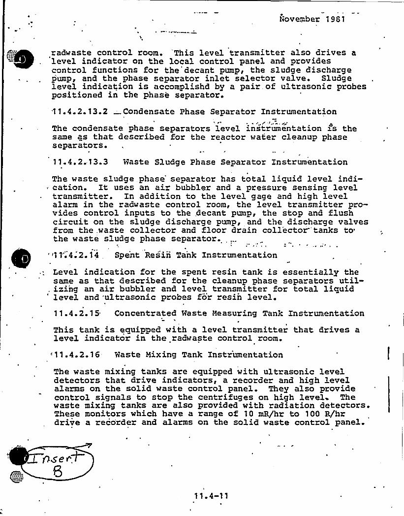
hove."..ber 1981
radwaste control room. 'This level transmitter also drives alevel indicator on the local control panel and providescontrol functions for the'decant pump, the sludge discharge-pump, and the phase separator inlet selector valve. Sludgelevel indication is accomplishd by a pair. of ultrasonic probespositioned in the phase separator.
11.4.2. 13.2 Condensate Phase Separator Instrumentationr 4The condensate phase separators level instrumentation xs the
same as that described for the reactor water cleanup phaseseparators.
11. 4. 2. 13.3 Haste Sludge Phase Separator Instrumentation
The waste sludge. phase" separator has total liquid level indi-~ cation. It uses an air bubbler and a pressure sensing leveltransmitter. In addition to the level gage and high levelalarm in the radwaste control room, the level transmitter pro-vides control inputs to the, decant pump, the stop and flushcircuit on the sludge discharge pump, and the discharge valvesfrom the waste collector and floor drain coll'ector'tanks tothe waste sludge phase separator.
'~11'.4.2.14 Spent Resin Tank Instrumentation
Level ind'cation for the spent resin tank is essentially thesame as that described for the cleanup phase separators util-
, izing an air bubbler and level transmitter for total liquid'evel and ultrasonic probes for resin level.11.4. 2. 15 Concentrated Waste Measuring Tank Instrumentation
This tank is equipped with a level transmitter that. drives alevel indicator in the radwaste control room.
<11.4.2.16 Waste Mixing Tank Instrumentationt
The waste mixing tanks are equipped with ultrasonic leveldetectors that drive indicators, a recorder and high levelalarms on the solid waste control panel. They also providecontrol signals to stop the centrifuges on high level Thewaste mixing tanks are also provided with radiation detectors.These monitors which have a range of 10 mR/hr to 100 R/hrdrive a recorder and alarms on the solid waste control panel.

f
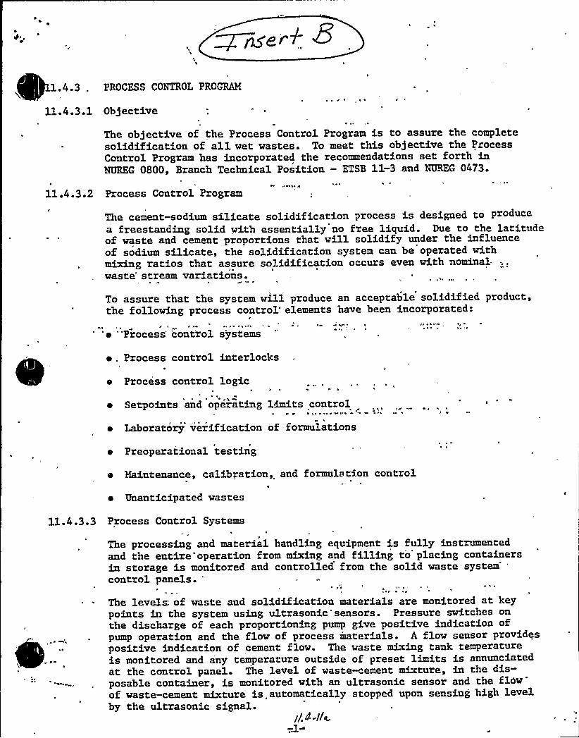
1.4 3 . PROCESS CONTROL PROGRAM
11.4.3.1 Ob)ective'
11.4.3.2
The objective of the Process Contxol Program is to assure the completesolidification of all wet wastes. To meet this ob]ective the ProcessControl Program has incorporated the recommendations set forth inNUREG 0800, Branch Technical Position — ETSB 11-3 and NUREG 0473.
h
Process Control Program
The cement-sodium silicate solidification process is designed to producea freestanding solid with essentially no free liquid. Due to the latitudeof waste and cement proportions that will solidify under the influenceof sodium sQ.icate, the solidification system can be operated withimbuing ratios that assure solidification occurs even with nominal.waste" stream variations.
To assure that the system will produce an acceptable solidified product,the following process control'lements have been incorporated:
h
'e "Process'ont'rol systems
~ , Process control interlocks
a Process control logic
~ Setpoints and operating limits control
~ Laboratory verification of formulations
~ rh
e Preoperational testing
o Maintenance, calibration, and formulation control
~ Unanticipated wastes
11.4.3.3 Process Control Systems
The processing and material handling equipment is fully instrumentedand the entire'operation from mixing and filling to placing containersin storage is monitored and controlled from the solid waste
system'ontrol
panels.
The levels: of waste and solidification materials are monitored at keypoints in the system using ultrasonic'sensors. Pressure switches onthe discharge of each proportioning pump give positive indication ofpump operation and the flow of process materials. A flow sensor providespositive indication of cement flow. The waste mixing tank temperatureis monitored and any temperature outside of preset limits is annunciatedat the control panel. The level of waste-cement mixture, in the dis-posable container, is monitored with an ultrasonic sensor and the flowof waste-cement mixture is automatically stopped upon sensing high levelby the ultrasonic signal.
qI.4 it~—.1~
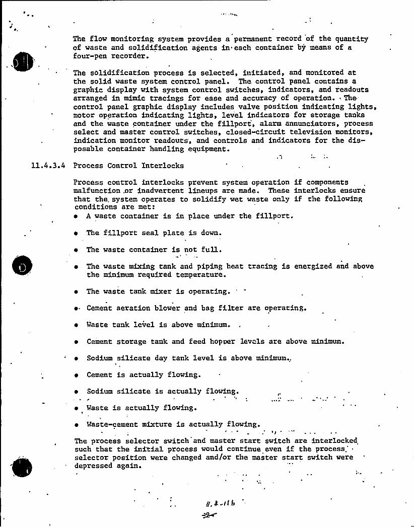
The flow monitoring system provides a permanent record of the quantityof waste and solidification agents- in each container by means of afour-pen recorder.
The solidification process is selected, initiated, and monitored atthe solid waste system control panel. The control panel contains agraphic display with system control switches, indicators, and readoutsarranged in mimic tracings for ease and accuracy of operation. 'hecontrol panel graphic display includes valve position indicating lights,motor operation indicating lights, level indicators for storage tanksand the waste container under the fillport, alarm annunciators, processselect and master control switches, closed-circuit television monitors,indication monitor readouts, and controls and indicators for the dis-posable container handling equipment.
11.4.3.4 Process Control Interlocks
Process control interlocks prevent system operation if componentsmalfunction .or inadvertent lineups are made. These interlocks ensurethat the. system operates to solidify wet waste only if the followingconditions are met:~ A waste container is in place under the fillport.~ The fillport seal plate is down.
~ The waste container is not full.~ The waste mixing tank and piping heat tracing is energized and above
the minimum required temperature.
~ The waste tank mixer is operating.
~ Cement aeration blower and bag filter are operating.
~ Waste tank level is above minimum.
~ Cement storage tank and feed hopper lev"ls are above minimum.
~ Sodium silicate day tank level is above minimum..
~ Cement is actually flowing.
~ Sodium silicate is actually flowing.
~ Waste is actually flowing.
~ Waste-cement mixture is actually flowing.
The process selector switch and master start switch are interlockedsuch that the initial process would continue even if the
process.'electorposition were changed and/or the master start switch weredepressed again.

4
1
The ultrasonic level monitors on the bulk storage tanks prevent systemstartup if=either insufficient cement, waste, or sodium silicate isavailable for a complete process run.
Process Control Logic
The solidification system contains a logic control unit that controlsthe sequence and duration of process operations. The control unitcontains logic control steps designated to perform Mternal checks ofsystem conditions prior to initiation. of subsequent process operations.Continuation of the process is dependent upon satisfying the conditionalsetpoints. Any time during a process run that a setpoint is exceededthe process is automatically stopped and annunciated. Conditionalsetpoints will be determined based on preoperational test results.
Setpoints and Operating Control
The laboratory verification of solidification formulations and theconfirming data developed by full scale preopezational testin willdetermine the setpoint values for each component in the system.Setpoints for .parameters that are critical to the solidificationprocess are preset to assure operation at the required conditions.The critical setpoint conditions are segregated in a locked subpanelin the rear of the main process control panel. This provides for directadministrative control of access to and adjustments of the contxolsystem setpoints.
I
The preset values for setpoints and the preset ratios of waste, cement,and sodium sil.icate are different for each particular type of waste.The proper values are automatically selected by an operatorcontrolledmaster switch with positions labelled according to the type of wasteto be processed.
Laboratory Verification of Formulations
The design of the solidify.cation system is based on laboratory, pi1otplant, and full-scale system studies of each type of waste. 'Laboratoryverification .allows setpoint ad)ustments to compensate for plantvariations from typical formulations.
Successful solidification of wet wastes is assured by development ofsolidification blends based on plant-waste composition coupled withlaboratory solidification studies.
Preoperational Testing
The preoperational testing program will. be designed to functionallytest "the solidification equipment under all mode's of operation.The test program, in conjunction with the laboratory verification pro-.gram, will determine the optimum setpoints and operating parametersnecessary to insure the solidification of all wet waste matrices.In addition, the test program will also define the minimum andmaximum parameter boundaries that still produce a freestanding solidwith essentially no free liquid.
II. 4-Ilz
The solidified waste containers will be section.ed and the contentsexamined for homogeneity and the absence of free liquid. The resultsof this inspection will be documented and compared to the laboratoryverification program results. If the results from both tests indicatethe presence of a .freestanding solid with essentially no free liquid, this info:mation will then be recorded and used for future reference. Discrepanciesbetween the laboratory verification program results and the actualresults will be documented and resolved.
11.4.3.9 Maintenance, Calibration, and Formulation Control
Control of solidification parameters is assured by a maintenance,calibration, and formulation control program. The Operation andMaintenance Manual, supplied by the vendor, recommends specificmaintenance and calibration frequencies for the various systemcomponents. The manual also recommends that a periodic verificationof the quality and,condition of the cement and sodium silicate inthe plant storage tanks be performed. Laboratory verification of theeffectiveness of the solidification formulations are performed todetermine if system setpoint adjustments are required to maintainoptimum product quality.
11.4.3.10. Un'antidipatedWastes'rom
time-to-time't'ill-=become necessary to solidify wet. wasteswhich have never been verified 'by laboratory formulation. Examplesof such wastes are; decontamination solutions and laundry detergents.
When this occurs the solidification requirements must be determinedon a case-by-case basis using th'e laboratory verification of formulationprogram.'ecords and results of such testing "wi"1 be retained forfuture use. 1

0
0
12.3. 4 br e a Bad i at i on and Ai rbo me Rad i oa'c t iv'. ty Noni t or na
I~s ruskin atinIi
The objectives of the applicant's area radia.ion monitoring
system are; 1) to warn'f excessive gamna radiation levels in areas
«here nuclear fueL is s.ored or handled; 2) to provide ooerating
personnel in the control roon with a continuous record and indication
of gamma radiation Levels at various Locations throughou- he plant;
3) to assist in he detection of unauthoriz d or inadvert nt movement
of radioac- ive materiaL; and 4) to warn of increased radiation levels
by alarming when the radiation Level's exceed present levels. In order
to neet these objec ~ ivesi the applicant plans to use thirty area
nonitorsr Located in areas «her e personnel nay be presen- and where
radiation Levels could become significant. These monitors «iLL be
equipped with Local and remote audible alarms and a fac i Lity or central
recording As a result of our review> alL area monitors Located in
high noi se areas will be equipped with visual alarns as well. Area
monitors will have a range of four decadesi except for the two contain-
nent high-range radiation monitors provided in response to NUREG-0737.
These monitors wi'Ll have a range of seven decadesr from 10 to 107 R/hr
The applicant has provided area monitors in fueL storage and handt ing
ar as in accordance with
8.12r "Criticality Accid
10 CFR Part 70.24(a) (1) and Regulatory Guide
ent Alarm Systems". Regulatory Guide 1.97
(Revision 2) states that
have area monitors with
areas r quiring post-accident access shoul
a 'range of 10 " R/hr to 10 R/hr. MNP-2 ha
no monitors (except in the fue L area) with this. upper range. This isE
an open item. ALL area radiation monitors wiLL be calibrated once every1
18 months.
WNP-2
Open SER Issue
12.3.4 Area Radiation and Airborne RadioactivitNonitorin Instrumentation
See revi sed FSAR pages 12.3-.23m„12.3.28'2.3-29'nd12.3-30 (attached) ~

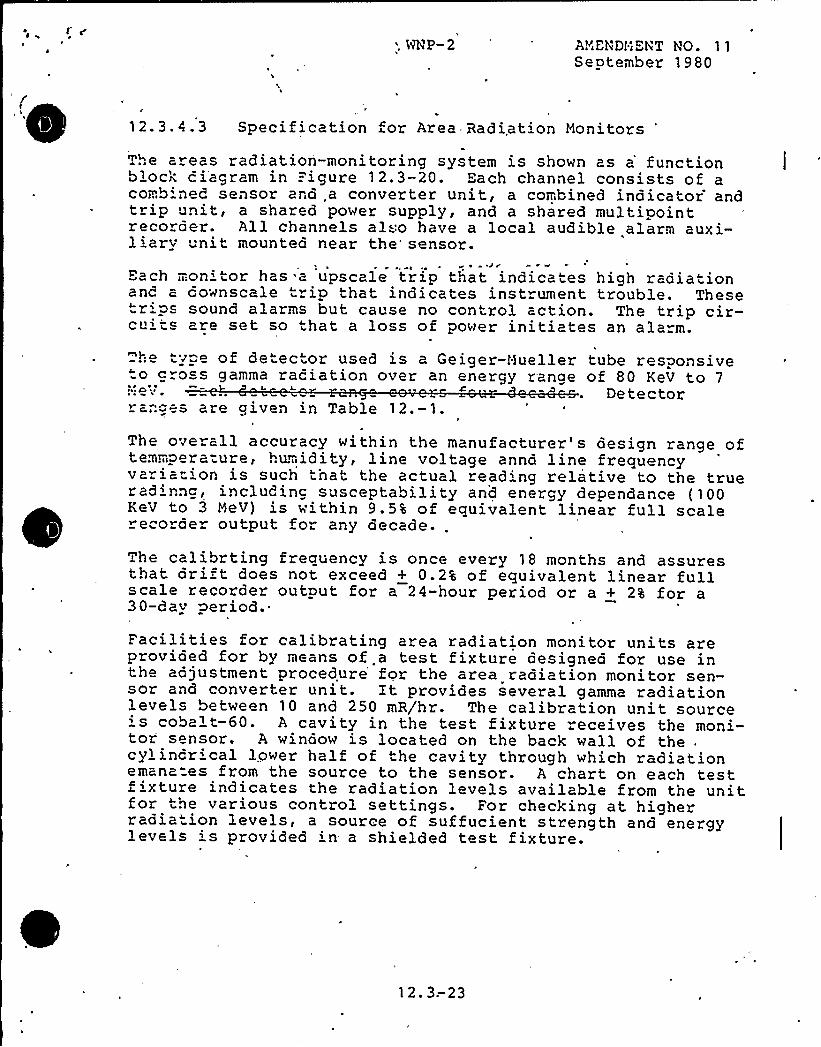
'NP-2 ANENDhENT HO. 11September 1980
12.3.4.3 Specification for Area Radiation monitors
The areas radiation-monitoring system is shown as a'unctionblock ciagram in Figure 12.3-20 'ach channel consists of acomb ned sensor and „a converter unit, a combined indicator andtrip unit, a shared power supply, and a shared multipointrecorder. All channels al:o have a local audible alarm auxi-liary nit mounted near the* sensor.
~ J w
Each mon'tor has a upscale trip that indicates high radiationand a downscale trip that indicates instrument trouble. Thesetrips sound alarms but cause no control action. The trip cir-cu'ts are set so that a loss of power initiates an ala"m.
h type of de"ector used is a Geiger-Hueller tube responsiveto g"oss gamma raciation over an energy range of 80 KeV to 7l I CV ~ Detector
ranges are given in Table 12.-1.
The overall accuracy within the manufacturer's design range oftevmpera-ure, humidity, line voltage annd line frequencyvaria" ion is such tnat the actual read'ng relative to the trueradinng, including susceptability and energy dependance (100KeV to 3 HeV) is within 9.5% of equivalent linear full scalerecorde output for any decade..
he calibrting frequency is once every 18 months and assuresthat drift does not exceed + 0.2% of equivalent linear fullscale recorder output for a 24-hour period or a + 2% for a30-day period.
Facilities for calibrating area radiation monitor units areprovided for by means of a test fixture designed for use inthe adjustment procedure'or the area radiation monitor sen-sor and converter unit. It provides several gamma radiationlevels between 10 and 250 mR/hr. The calibration unit source' cobalt-60. A cavity in the test fixture receives the moni-tor sensor. A window is located on the back wall of thecylindr'cal lower half of the cavity through which radiationemana=es from the source to the sensor. A chart on each testfixture indicates the radiation levels available from the unitfor the various control settings. For checking at higherradia"ion levels, a source of suffucient strength and energylevels is provided in- a shielded test fixture.
12. 3.-23

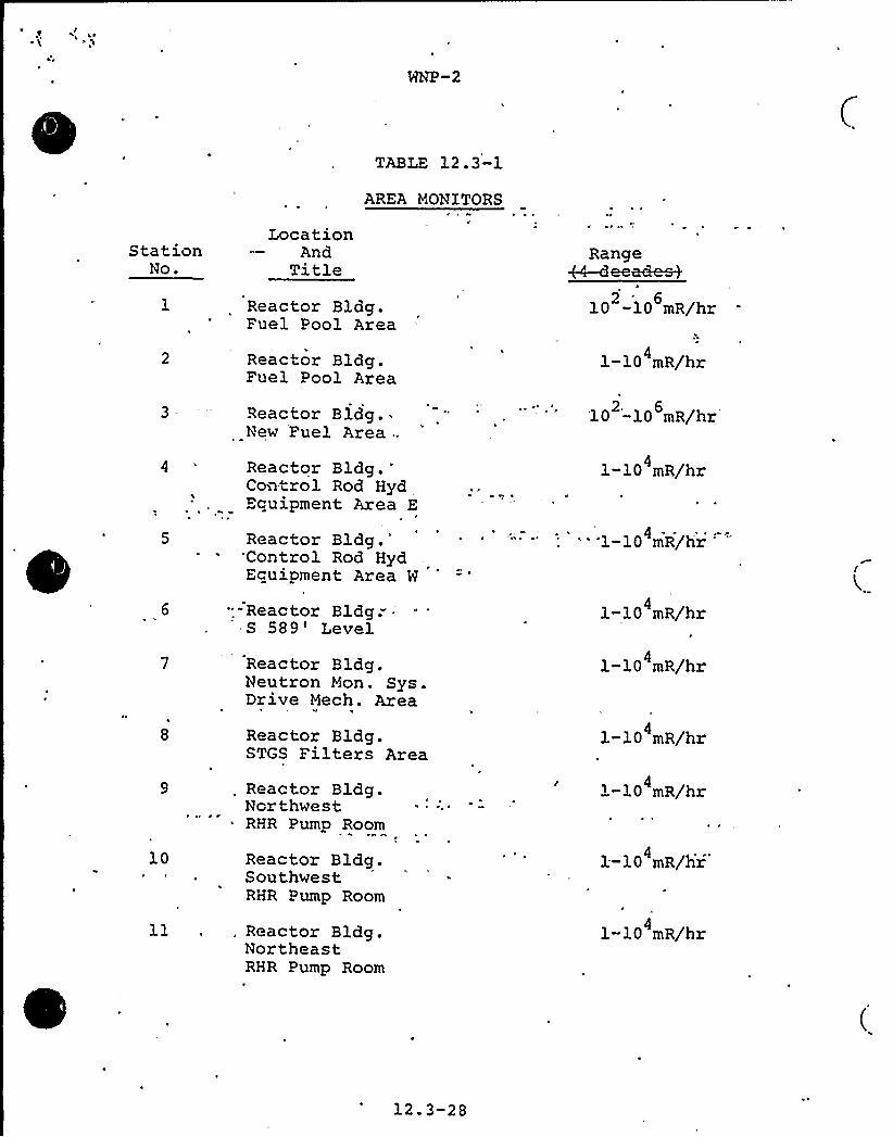
TABLE 12 . 3-1
AREA MONXTORS
StationNo.
3
6
8
10
LocationAnd
TitleReactor Bldg.Fuel Pool Area
Reactor Bldg.Fuel Pool Area
Reactor Bldg. ~
New Fuel Area .,
ReactorBldg.'ontrol
Rod HydEquipment Area E
ReactorBldg.'ontrolRod Hyd
Ecuipment Area W
- - Reac tor Bldg." '589 'evel
Reactor Bldg.Neutron Mon. Sys.Drive Mech. Area
Reactor Bldg.STGS Filters Area
Reactor Bldg.NorthwestRHR Pump Room
Reactor Bldg.SouthwestRHR Pump Room
Range+4-deem~
10 -10 mR/hr2 '
1-10 mR/hr4
2. 6'10 '-10 mR/hr
1-10 mR/hr4
- '1-10 mR/hr
1-10 mR/hr4
1-10 mR/hr4
1-10 mR/hr4
1-10 mR/hr4
1-10 mR/hr4
ll , . Reactor Bldg.NortheastRHR Pump Room
1-10 mR/hr4
12.3-28
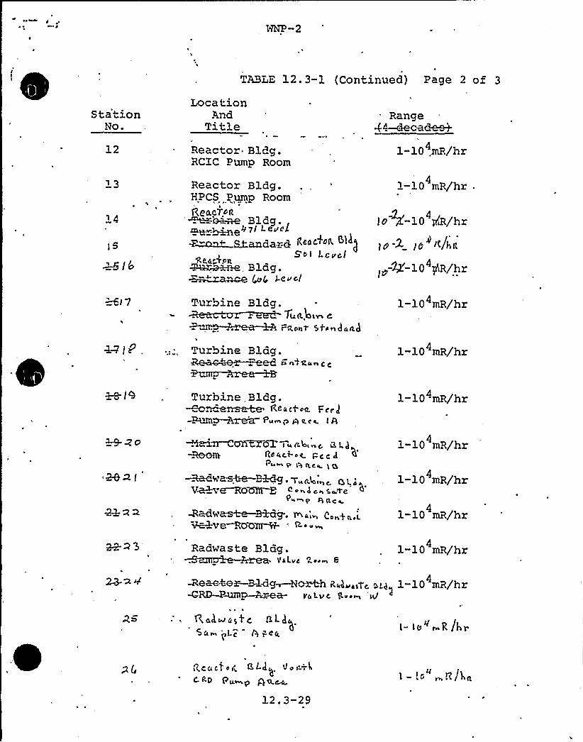
NNP-2
TABLE 12.3-1 (Continued) Page 2 of 3
S ta'tionNo.
12
LocationAnd
TitleReactor Bldg.RCIC Pump Room
Reactor Bldg.HPCS Pump Room
Rt. acTo ttBldg.
mg.v~e07I Levela+ ~andard Reactor
So> LevelSc.a» O1LA~~, Blag.a~m~ ~(, g.evcI
Range44—decades+
1-10 .mR/hr4
41-10 mR/hr
4lo ~-10 piR/hr
] p -2 (Q I~/hR
4Z-10 gR/hr
Gl 7 Turbine
Turbine
Bldg.74K.kiln C
r~o~~ Sti~gaad
Blag.
1-10 mR/hr
1-10 mR/hr4
1-8- I 9 . Turbine . Bldg.Rcac+oo. Fe'cJ~i~~ Pum ia Q 4 c t I A
1-104mR/hr
aezi
Aai~CYl'KZ(5T iua4i c, aL)RQ'RRt Ac«c,f-oe pc c g
' i %' n. C< ( g<-a<<~~g. Vua4i a LV~~o~ < on d c~ s~ve
Racwd '~GO~ '~ <m
Radwaste Blag.VDLvc +y oem 6
1-10 mR/hr4
1-10 mR/hr
1-10 mR/hr4
1-10 mR/hr4
~act>~~<g~o~ ~«4~.ac a d~1-10 mR/hr4
WRD P~p~ea pa Lu c g.vs g/
R,alwas$ c, GLggSa~ j Lc Q pea,
i- ie" ~R(hp
12.3-29
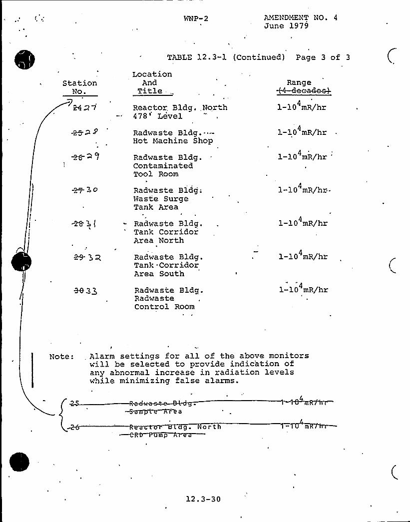
WNP-2 AYiEND!~iENT NO. 4June 1979
N
TABLE 12.3-1 (Continued) Page 3 of 3
StationNo.
LocationAnd
Title -,.
Reactor, Bldg.,North478'evelRadwaste Bldg. -"-Hot Machine Shop
Radwaste Bldg.ContaminatedTool Room
Radwaste Bldg;Naste SurgeTank Area
Radwaste Bldg.Tank CorridorArea North
Radwaste Bldg.Tank CorridorArea South
Range+4-deea4e~
1-10 mR/hr4
1-10 mR/hr4
1-10 mR/hr4
1-10 mR/hr--4
1-10 mR/hr4
1-10 mR/hr4
Radwaste Bldg.RadwasteControl Room
1-10 mR/hr
Note: Alarm settings for all of the above monitorswill be selected to provide indication ofany abnormal increase in radiation levelswhile minimizing false alarms.
r a
g. orth
12.3-30
- 16
.the authority for direct contact with the PLant Nanager in matters of
health and safety that could affect onsite and/or offsite personnel
The Health Physics/Che'mi stry"Nan5ger can interact directly wi th the
Plant Nanager during the meetings of the PLant Operations Committee.
He reports at the sane Level as tne Operations Supervisor. The itens
discussed'above. are in agreement with the criteria of NUREG-0731 and
Regulatory Guide 8.8 (Rev. 3) and are acceptable ~
Based on information transmitted to the staff„via a phone call with theh
applicanti the Health Physics/Chenistry ilanager at MNP-2 neets the
qualification criteria of Regulatory Guide 1-8 -or Radiation Protection
Nanager The draf t ANS 3.1 recommends that individuals temporari lyfilling'he RPN position should have a B.S degree in science or
engineeringr and 2 years experience in radiation protection~ 1 year of
which should be nuclear p'Lant experiencei 6 non hs of which should be
onsite. The Health Physics Supe'rvi'sori who will serve as the backup to
the RPN in his absences satisf ies these 'requir mentsi according, to
information transmitted by a phone conversation wi.h the applicant.
The staff must formally receive this information in writing from the
applicant before ue can receive:the issue oi Ouatiiications. This is'an open issue-
NVREG-0731 and Section I.5.2 of ANSX 18.1 specify t
two years experience in their specialty. The appli
that technicians at MNP 2 function in two specialit
hat technicians have
cant has proposed
iesi health physics
and chemistryr with only two years of training Health Physics
Appraisals at operating plants h'ave found that such combined healthe ~ ~ P ~
\
physicslchemistry technicians have Lead to poor performance in both
specialities because the technic ians do not receive adequate trainingrquaLification and retraining in both specialities. Until the staffcan discuss thi s item fur ther wi th the applicants we wi LL'onsider
this an open ite~The equipmentr instrumentationi and facilities used to implement the
radiological safety program at MNP-2 folLow the guidance of the folLow-
ing regulatory guides ~here appl~ ~icable:
Regulator'y Guide 8 3r "Fi'lm
Regulatory Guide 8.4r "0 ireBide Performance Criteria".'
~ o
ct-Reading and Indirect"Reading
Pocket. Dosimeter
r esponse tests)-s".,(except for Section C-2-b on calibrationl
5
a'egulatory
Guide 8-Br "Znfornation Relevant to Ensuring That
Occupational Radiation Exposures at Nuclear Power Stations
Will Be As Low As Is ReasonabLy Achievable" (Rev 3)
Regulatory Guide 8 9r "Acceptable Conceptsi Nodelsi Equationsi(
and Assumptions For a Bioassay Program"
WNP-2 has two main Locker-change rooms Temporary change areasi as
well as personnel and equipment monitoring stations~ ar set up as
necessary to control the spread of contamination. There are three
facilities for equipment and tool decontamination a<i MNP-2. Other

WNP-2
Open SER Issue
12.5.1 Education of HP Su ervisor/Chem Tech.
A response to this issue was submitted January11'982'nletter G02-82-25.
R
R
IR
,Washington Public Power Supply SystemP.O. Box 968 3000 George Washington Way Richland, Washington 99352 (509) 372-5000
January ll, 1982 ,
G02-82-25SS-L-02-CDT-82-007
Docket No. 50-397
Mr. A. Schwencer, DirectorLicensing Branch No. 2
Division of LicensingU.S. Nuclear Regulatory CommissionMashington D.C. 20555
Dear Mr. Schwencer:
Subject: NUCLEAR PROJECT NO. 2EDUCATION AND QUALIFICATIONS OF-HEALTH PHYSICS SUPERVISOR AND TECHNICIANS
In response to open items on pages 16 and 17,of section 12.5.1 of thedraft SER for MNP-2; enclosed are sixty (60) copies of the subjectinformation. This information should close out these open items.
Very truly yours,
G. . BoucheyDeputy Director, Safety and Security
CDT/ctEnclosures
cc: R. Auluck - NRC
MS Chin - BPAR. Feil - NRC-Site
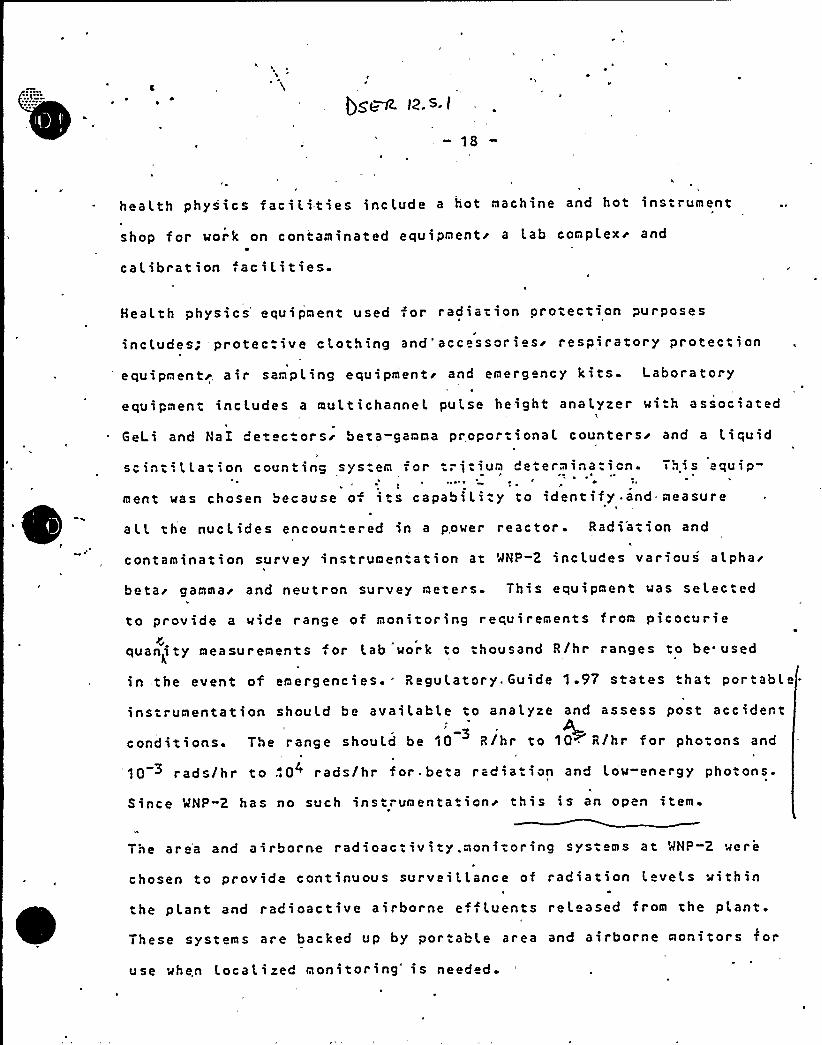
- 18
heal.th physics faci Lities include a hot machine and hot instrument
shop for work on contaminated equipmenti a Lab complex~ and
calibration ac i lities-
Heal.th physics'quipment used s or radiation orotection purposes
incl,udes; 'protec.ive clothing and'accessoriesr respiratory protec.ion
equipmentr. air sanpLing equipmentr and emergency kits. Laboratory
equipment includes a mul.tichannel pul.se height analyzer with associated
GeLi and NaI detectorsr beta-gamma proportional counters'nd a l.iquid
.Thi s equipsaint'.LLat',on counting system for tritium determination.
ment was chosen because o its capability to identify.and measure
all the nuclides encoun ered in a power reactor- Radi'ation and
contanination survey instrumen-.ation at WNP-2 includes variousalpha'eta'ammar
and neutron survey meters. This equipment was selected
to provide a wide range of monitoring requirements from picocurie
quanity neasurements for Lab work to thousand R/hr ranges to be used
in the event of emergencies'egulatory. Guide 1-97 states that portabLe-
ins:runentation should be available to analyze and assess post accident~3conditions. The range should be 10 g/hr to 10 g/hr for photons and
10 rads/hr to,10 rads/hr for. beta radiation and low-energy photons.
Since WNP 2 has no such instrumentationr this is an open item.
The are'a and airborne radioactivity .monitoring systems at WNP-2 were
0chosen to provi
the plant and r
de continuous surveill.ance of radiation l.evels within
adioactive airborne eff Luents released from the plant.
These systems are backed up by portable area and airborne monitors for
use when localized monitoring's needed.
WNP-2
Open SER Issue
12.5.1 Post Accident Portable Monitor Ran e,
See revised FSAR page 12.5-3 (attached) .
b. Regulatory Guide 8.4 is implemented except forC.2.b, ~ which states, "The calibration/responsetest;result.should not exceed +10% of an exposurefrom a source traceable to the h'ational Bureauof Standards". This is accepted on the minusside, but. is- considered excessively stringenton the positii'e side. Since the error on thepositive side results in exposure conservatism
'o
the worker,.„+$ 0%, is a more reasonable limitfor rejection of a pencil dosimeter.
12.5.2.1 Criteria for Selection
a ~
geo
b-
Radiation and Contamination Survey instrumenta-tion — This equipment, was selected o coverthe wide range requirements extending from pico-curie quantity measu ements in the laboratory
~to the thousand R/hour ranges necessary foremergen'cy dose rate determinations. The labora-tory instrumentation was chosen to provide capa-bility for the quantitative and qualitativeanalyses required to identify and measure theradionuclides encountered in a power reactor.The portable instrumentation includes low leve3.detection capabilities for alpha, beta, andgamma contamination and vide ranges of dose ratemeasuring instruments for beta, gamma, andneutron radiation. The criteria for quantityselection were to provide aoequate availablecounting time for anticipated demand in thelaboratory and sufficient. portable instrumentsto cover normal operational and emergency re-quirements in all areas of the WNP-2 facility.Airborne Radioactivity Monitoring — Basic criteriafor selection of this equipment was to provide ameans for determining racioactive airborne efflu-ents released from the plant, and to effectivelymonitor airborne radioactivity levels within theplant, environs. Provisions have been made forcontinuing response monitoring of noble gasesdischarged from gaseous release points from thereactor, radwaste and turbine building, and forcontinuous sampling of radioiodines and particu-lates at these same locations. Interna3. plantair monitoring instrumentation is used withinthese buildings with readout locally and in the
12.5-3
contained in Regulatory Guide 1.33, Rev. 2, March 1978 r garding the minimum
'procedural requirements for safety-related operations; (4) compliance with
the guidance contained in ANSI 18.7-1976/ANS 3.2; and (5) the applicant's
program for compliance with Task Action Plan (NUREG-0660) Item I.C.l, "Guidance.
for the .Evaluation and Development of Procedures for Transients and Accidents",
for the development of Emergency Operatino Procedur Guidelines. Additionally,
'the applicant's program for compliance with Item I.C.1 of NUREG-0737 for the
development of Emergency Operating Procedures will bo reviewed and reported
in a supplement to this Safety Evaluation Report.
B. 0 eratin and Maintenance Procedure Pro ram
The appli ant has committed in FSAR Chapter 17, guali y Assurance, to a program
in which all activities are to be conducted in accordance with detailed writtenI
and approved procedures meetino the requirements of Reoulatory Guide 1.33, Rev. 2,
March i978, "equality Assurance Program Requirements (Operation)", and ANSI 18.7-
1976/ANS 3.2. However, FSAR Section 13.5 still refers to Rev. 1, June 1977 of
.,egulatory Guide 1.33. '!!e require the applicant to modify Section 13.5 to referI
to Revision 2 of the guide.
The appli'cant uses the following categories of procedures'or those operations
performed by. licensed operators in the control room: h
System Operations (Including Radioactive Maste Systems)
General Operation
Abnormal Conditions (Including Annunciator Pesponse)
Emergencies
Surveillance

Open SER Issue
13.5.2 0 eratin and Naintenance Procedure Pro ram
See revised FSAR „page C.3.28 (attached) ~

HNP-2
Regulatory Guide 1.33, Rev.~June 197~Quality Assurance Program Requirements (Operation)
Compliance or Alternate Approach..Statement:-1
WP-2 complies with the intent, of the guidance setforth in .,this 'regulatory guide,hy an alternate approach.
Compliance or Alternate Approach Assessment:-
Compliance is discussed in the topical reportreferenced in 17.2
Specific Evaluation Refeience:
Re fer to 13.5. 1. 1 and 17.2.
C.3-28
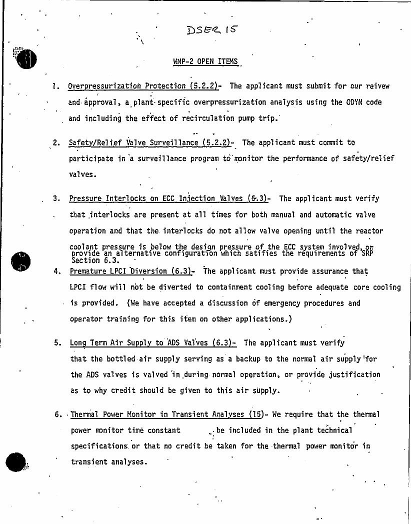
MHP-2 OPEN ITEMS
l. Over ressurization Protection 5.2.2 - The applicant must submit for our reivew
and approval, a, plant specific overpressurization analysis using the ODYN code
and including the effect of recirculation pumptrip.'.
Safet /Relief Valve Surveillance 5.2.2 - The applicant must commit to
participate in a sur veillance program to monitor the performance of safety/relief
val ves.
3. Pressure Interlocks on ECC In ection Valves 6.3 - The'pplicant must verify
that interlocks, are present at all times for both manual and automatic valve
operation and that the. interlocks do not allow valve opening until the reactor
coolant pressure is below the design pressure of the ECC system involved, or.
~ ~
~ ~ ~
rovide an alternative configuratson which satifies the requirements of SRPection 6.3.
4. Premature LPCI Diversion 6.3 - The applicant must provide assurance that
LPCI flow will not be diverted to containment cooling before adequate core cooling
is provided. {Me have accepted a discussion of emergency procedures and
operator training for this item on other applications.)
5. Lon Term Air Su 1 to ADS Valves 6.3 - The applicant must verify
that the bottled air supply serving as a backup to the normal air supply 'for
the ADS valves is valved in .during normal operation, or provide justification
as to why credit should be given to this air supply.
6.. Thermal Power Monitor in Transient Anal ses 15)- Me require that the thermalr l'
power mnitor time constant . be included in the plant technical
specifications; or that no credit be taken for the thermal power monitor in
transient analyses.
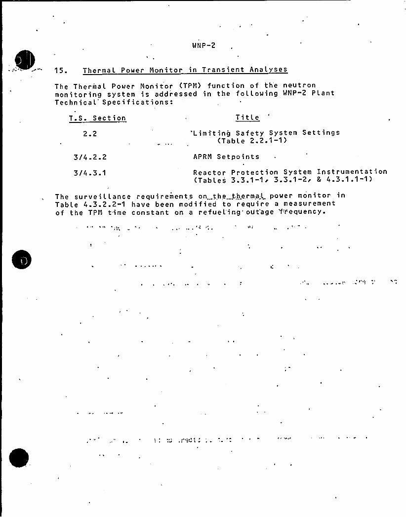
.WNP-2
15. Thermal Power Nonitor in Transient Anal ses
The ThermaL Power Nonitor (TPN) function of the neutronmonitoring system is addressed in the following WNP-2 PlantTechnical Specifications:
T.S. Section Title2.2 'Limiting Safety System Settings
(Table 2. 2.1-1)
3/4.2.2
3/4.3 '
APRN Setpoints
Reactor Protection System Instrumentation(Tables 3 3 ~ 1-1r 3.3.1-2r 5 4.3.1.1-1)
The surveillance requirements on the,.thermaL power monitor inTabLe 4.3.2.2-1 have been modified to require a measurementof the TPN time constant on a refueLing'0t'age 'frequency.
ts e
i ~ ~y ~ ~ ' (
e
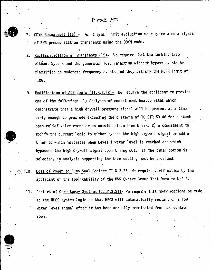
Y
7. ODYH Regnal ses 15 - For thermal limit evaluation we require a re-analysis
of BWR pressurization transients using the ODYH code.
8. Reclassiffcation of Transients 15 - We require that the turbine trip
without bypass and the generator load rejection without bypass events'e
classified as moderate frequency events .and they sptisfy the MCPR limit of/
9. Modification of ADS Lo ic II.K.3.18 - We require the applicant to provide
one of the following: 1) Analyses .of, containment heatup. rates which
demonstrate that a high drywell pressure signal will be present at a time
early enough to preclude exceeding the criteria of 10 CFR 50.46 for a stuck
open relief valve event or an outside steam line break, 2) a cormitment to
codify the current logic to either bypass the high drywell signal or add a
timer to which initiates when Level 1 water level is reached and which
bypasses the high drywell signal upon timing out. If the timer option is
selected, an analysis supporting the time setting must be provided.
Loss of Power -to Pum Seal Coolers. II.K.3.25- We require verification by the
applicant of the applicability of the BWR Owners Group Test Data to WHP-2.
ll. Restart of Core S ra S stems II.K.3.21)- We require that modifications be made
to the HPCS system logic so that HPCS will automatically restart on a low
water level signal after it has been manually terminated from the control
room.
WNP-2
Open SER Issue15. Re'c(.assi fication of Transients
Refer to ODYN reanalysis (SER Section 15m RSB.7) for a
response to this issue.

Open SER Issue
15 ODYN .Regna L ses
A response to this issue was submitted January 11r'982in Letter 602-82-26.

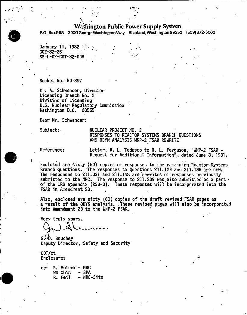
~ J
h
Washington Public Power Supply SystemP.O. Box968 3000 George Washington Way Richland, Washington 99352 (509) 372-5000
January 11, 1982 ""'.
G02-82-26'S-L-02-CDT-82-008'-~
Docket No. 50-397
Mr. A. Schwencer, DirectorLicensing Branch No. 2Division of LicensingU.S. Nuclear Regulatory CommissionWashington D.C. 20555
Dear Mr. Schwencer:
Subject:=-
Reference:
NUCLEAR'PROJECT NO. 2RESPONSES TO REACTOR SYSTEMS BRANCH QUESTIONSAND ODYN ANALYSIS MNP-2 FSAR REWRITE
Letter, R. L. Tedesco to R. L. Ferguson, "WNP-2 FSAR-Request for Additional Information", dated June 8, 1981.
Enclosed are sixty (60) copies of responses to the remaining Reactor SystemsBranch questions.:The responses to guestions 211.129 and 211.136 are new.The responses to 211.031 and 211.148 are rewrites of responses previouslysubmitted to the NRC. The response to 211.209 was also submitted as a partof the LRG appendix (RSB-3). These responses will be incorporated into theFSAR in Amendment 23.
Also, enclosed are sixty (60) copies of the draft revised FSAR pages as, a result of the ODYN analysis. . These revised pages will also be incorporated
into Amendment 23 to the WNP-2 FSAR.
Very truly yours,
G.' BoucheyDeputy Director,'Safety and Security
CDT/ctEnclosures
I
cc: R. Auluck — NRC
WS Chin — BPAR. Feil — NRC-Site
I, e ~
I'\
)PE P I5.8-8-
~ ~~ p ' e
A'I
.'The Gi Owners'roup is. currently developing a set of Reactivity Control
Guidelines, which will incorporate the above steps for mitigating A7rlS
events. The applicant's procedure'"for" mitigating A7rlS will be reviewed0
under the emergency operating procedure program as described in Section
13.5.2. The results o> the sta>f review will be reported in a supplement
.- to this Safety Evaluation Report.

WNP-2Open SER Issue
15.8 ATWS Emer enc 0 eratin Procedures
The BHR Owners'roup, of which the Supply System is a member, is currentlyr I V
de'veloping guidelines for preparation o'f emergency operating procedures
including a guidel'ine for ASS. WNP-2 will prepare an emergency procedure' h + tt
for ATWS using the Owners'roup guideline.
The procedure will be sufficiently simple to permit prompt operator recognition
of an ATWS and performance of mitigating actions. Direction will be provided
for the interval from identification of the ATWS until all rods are inserted
to more than position 06.
Prior to approval, the ATWS procedure will be verified correct by performing
independent reviews and Control Room walk-throughs. Following approval, each
operating shift will receive walk-through training'. Operations personnel will
be trained on the simulator when 'it becomes available; retraining will be
conducted semi-annually.
The ATWS and other emergency procedures will be located in the Control Room and
readily available to operating personnel. Procedure contr'ol measures will
insure all'perators are advised regarding changes.

7. ODYN Regnal ses 15 - For thermal limit evaluation we require a re-analysis
of BWR pressurization transients using the ODYH code.
8. Reclassification of Transients 15 - We require that the tut bine trip
without 'bypass and the generator load rejection without bypass events be
classified as moderate frequency events and they sptisfy the MCPR limit of-1'.06.
9. Modification of ADS Lo ic II.K.3.18 -" We require the applicant to provide
one of the following:,1) Analyses;of containment heatup rates whichI ~
demonstrate that a high drywell pressure signal will be present at a time
early enough to preclude exceeding the criteria of 10 CFR 50.46 for a stuck
open relief valve event or an outside ste'am line break, 2) a coamitment to
mdify the current logic to eithe~ bypass the high drywell signal or add a
timer to which initiates when Level 1. water level is rea'ched and which
bypasses the high drywell signal upon timing out. If the timer option is
selected, an analysis supporting the time setting must be provided.
19. Loss of Power to Pum Seal Coolers II.K.3.25- We require verification by the
applicant of the applicability of the BWR Owners Group Test Data to WHP-2.
ll. Restart of Core S ra S stems ( II.K.3.21 - We require that modifications be made
to the HPCS system logic so that HPCS will automatically restart on a low
wa .er level signal after-it has been manually terminated from the control
room.

a
WNP-2
Open SER Issues
II.K.3.18II.K.21
I I .K .3.25
Nodification of ADS Lo ic (RSB-9)
Restart of Core S ra S stems (RSB-11)
Loss of Power to Pum .Seal Coolers (RSB-10)
Responses to the above SER issues are included in theTNI submit ta l (Appendi x 8) .
'WNP-2
Open SER Issues
Attached as formal submittals are the responses toContainment Systems Branch issues'SB-3, 5, 10, 13, 14,17, 27, 28, 34, 35, 36 and 42 which were closed "at the9/14/81 - 9/17/81 branch meeting.
Issues CSB-,1r 6i 7i 8r 21'2m 41 and 43 through 48 wereaddressed in the responses to draft SER issues.
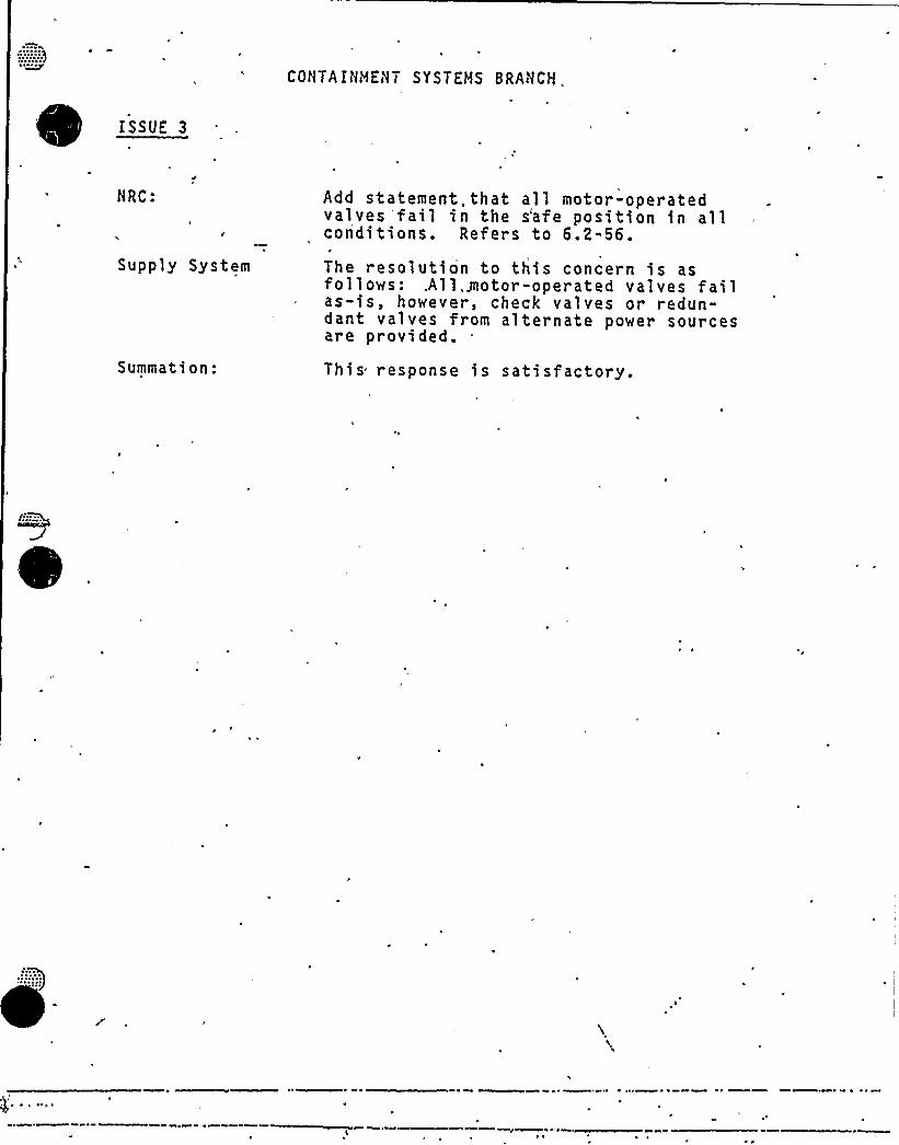
CONTA IN'N7 5 Y ST EHS 8 RAN CH,
ISSUE 3
NRC:
Supply System
Summation:
Add statement~ that all motor-operated
valves fail in the s'afe position in allconditions. Refers to 6.2-56.
The resolution to this concern is asfollows: .All,motor-operated valves failas-is, however, check valves or redun-dant valves from alternate power sourcesare provided.This response is satisfactory.
$'
~ ~ - ~ ~
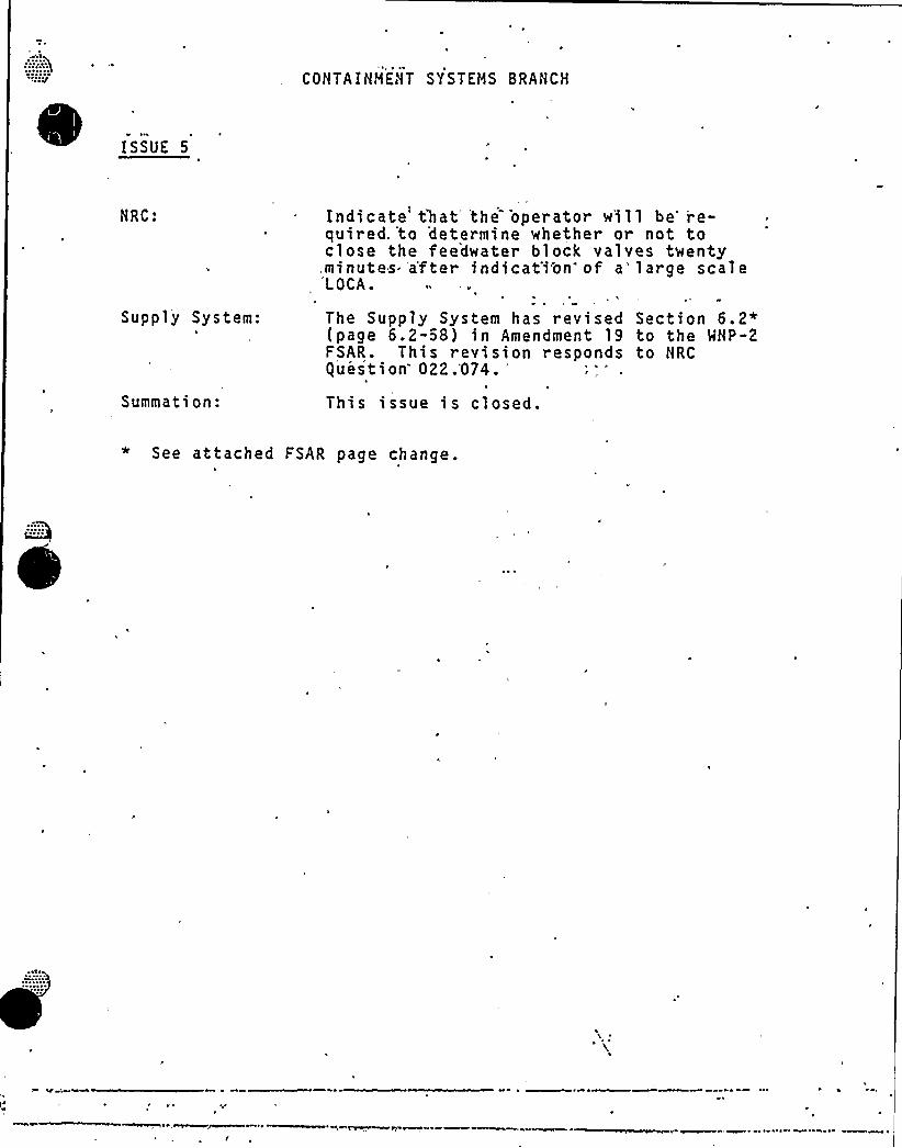
COHTAINHEHT SYSTEMS BRANCH
ISSUE 5
NRC:
Supply System:
Summation:
Indicate that, the .operator w'ill be re-quired,'to determine whether or not toclose the feedwater block valves twenty.minutes- a'fter indicat'ion of a'large scale'LOCA.
The Supply System has revised Section 6.2*{page 6.2-58) in Amendment 19 to the MHP-2FSAR. This revision responds to HRCguestion
022.074.'his
issue is closed.
* See attached FSAR page change.

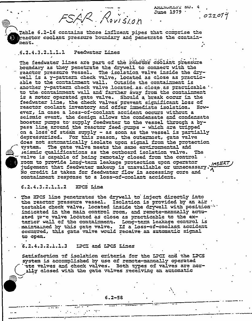
4iJL~l la C4U ~ !~e
uune 1479
i > < ~ 5 t. 0 flTahle 6.2-'6 contains ""ose influe"t aisles ~~ coma ise ".e~
~ ~
eacto= coolan p-essu=e bounda=g a"d penet=ate >De can~ment+
/
022.-0I /
,,6.2.4.3.2.1.3..3. = edwa ~ >~sThe ceedwa e 1'"es a=e aa o-" &e reactor coaLant = essu=ebounda~ as &ey pene=a e Me d~ell to connec w" M ™&ereac o press~a vessel. The -isola -'on valve '"s'de "se dr-we» .'s a y-pat=a~ check va've, Locamd as close as prac-'c»ahle to 2e ca-~~' teat wall. Cue'de Qe canta~en 'sanothe y-pa ~ c'"eck valve 'oc te'.a,s. c'ose, as prac='cahot.e '
m t"'e- con- ~eat w~! a"d'a "e away ="m t"e can '"me's a mtor oae ated gate valve. Should a break oc m m "Ne"ee wate Lwe, De cheA valves' event si~=icant loss ofcaco» caola=t inventory and offer ~ediate 'sola 'on. =ow-
ever, in case a Loss-oz«coolant ac ident oc= -s ~i 'wu ase'smic evenC, ~Be design a'! ows De caKe sate a-8. cond~atebaoste p~s to supply feeds~ m Me vessel ~~~ugh a by-~ass 'ine a=ou=d Ze eac "~,feed ~s - which a=e t=ippedon a 3.osi o steam su"~ly - m soon as Me vessel : s pa~'allvdepressu='ed. =-o= "'"'s eason, Me ou egest, pa~ valvedoes no au~ 'c 'ly iso'! e upon si~ from ' p=o ect'ontvms w. he gate valve me=s ">e same env'"on@en~~~deism'c cpxa~ 'c "ons as &e outhoa=d iso~~tion va1ve. The
c" —valve is capah' of he~ remo ely c'osed =om Me con=ol ~
oom to prov'"e long-te~ LeaMqe protec 'on upon operatorjudqemen= ~= fee wate= make~ 's u"availahle or unnecessa~.No c=edit 's Men or eMwam f~ow in accessinq ca=e andcon~!me es-„onse to a loss-o -coolan accide
6.2.4.3.2.1.I,.2 MCS Line
=a es the d~eM~e vessel. Zsola
',Located ~icecant=ol mcm,'a ed, as c'ose as pcan~~ment.
ca va'e. > ao valve would
race'PCZ
and LPCS ~~es
The KCS l~e pene" to injec d'-ec 'y ~the eacmr p=assu on is provided hy an a'-es~3.e check valv De d~el3. wiD pos'on"''
''cated in Ze ma and remote-manually ac a-aced ~~-e valve loc racmcahle ta Me ex-
es~ og waT l Leakace ca" w3. 's5K!a~ed hy ~<r' 'ss~ f~aolan ac='e"oc~~~~ed g this ve,an automat'c sigma~to open+
6. Z. 4.3.2.1.1.3
Sa~ ac~ f isolat'on c=-'te='a o- Me ~MCZ a=d ~ L2CSsys em m ac=—lished hv use o= remote-ma ua»y one~ted
t r'te va'ves ~ check valves. Both ~es o= valves a=a nor-y c'osed. w' "e ~™e valves ece'vms an an oman.c
:::"-)
6.2-58

I ~
guestion 022.074
Insert to 6.2-58
r
The operator can determine if make-up from the feedwater systemis unavailable by use of the feedwater flow indicator in thecontrol'oom, which will show high flow for a feedwater pipebreak or no flow for feedwater pump trip.The operator can also determine if make-up from the feedwatersystem is unn'ecessary by verifying that the ECCS is functioningproperly and the r eactor water level is being adequately main-tained. ECCS operation signals and reactor vessel water levelindication are provided in the c'ontrol room for operator infor-mation.
Since due to the check valves it is'ot n'ecessary to immediatelyisolate the feedwater system for leakage mitigation, there is noneed to alert 'the operator to initiate the feedwater isolationsignal other than as described above. However, for long-termisolation purposes, the operator may close the motor-operatedgate valves at any convenient time.
Emergency procedures will require the operator to evaluatewhethe'r the operator should close the reactor feedwater blockvalves within twenty minutes following indication of a LOCA.If information indicates a degrad'ed core condition prior totwenty minutes, the operator will. take action to close thereactor feedwater block valve at that time.
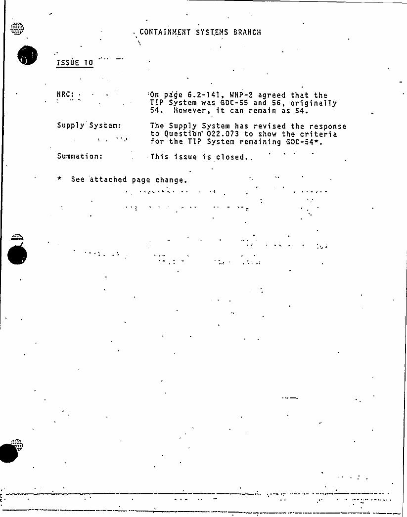
COHTAIHHEilT 5YST.EBS 8RAHCH
ISSUE 10
HRC:
Supply System:
Summation:
'On page 6.2-141, MHP-2 agreed that theTIP System was GDC-55 and 56, originally54. However, it can remain as 54.
The Supply System has revised the responseto guestion'22.073 to show the criteriafor the TIP System remaining GDC-54+.
This issue is closed..
* See attached page change.r
~ ~ r

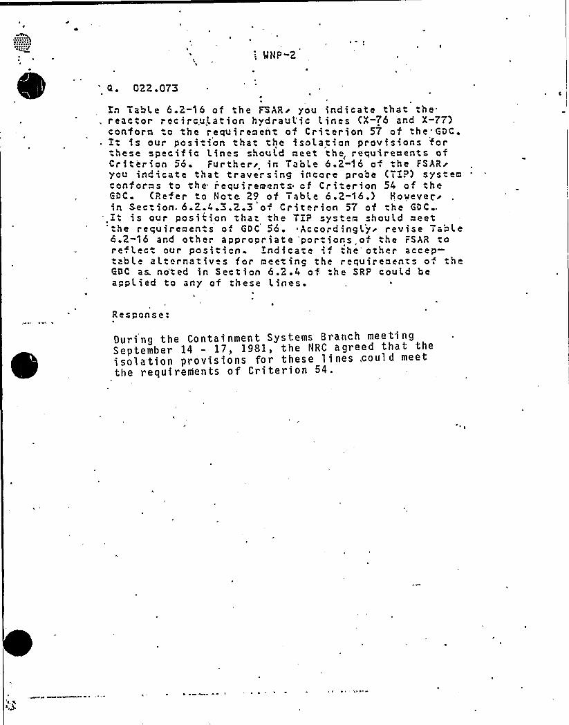
': MNP-2
022 . 073
Tn Table 6.2-16 of the FSARr you indicate that, .he. reac "or recirculation hydraul'ic Lines (X-76 and X"77)
conf ora .o the r equireaent o Cri.erion 57 of .he GDC.is our posi.ion that the isolation provisions for
these specif ic lines should neet the, requirements ofCriterion 56. Further'n Table 6.2-i6 o the FSAR~you indicate that traversing incore probe (TTP) sys" eaconforms to the r'equireeents cf Criterion 54 of theGDC. (i?e.'er o Note 29 of Table 6.2"16.) However~in Section- 6.2.4 3.2.3 o Cr iterion 57 of the GOC .
.Xt is our posi" ion that .he T:P syste~ should oeet':he requirements of GDC 56. ~ Accordinglyr revise Table6.2 16 and other appropriate 'portions of the FSAR tore. Lec. our position. i'ndi cate if the'ther accep-.able al:ernatives for meeting the reruireoents of theC C as. no'ted in Section 6.2.4 of:he SRP could beapplied to any of these Lines.
t
Response:
During the Containment Systems Branch meetingSeptember 14 - 17, 1981, the NRC agreed that theisola'tion provisions for these lines,could meetthe requirements of Criterion 54.

COHTAIHMEHT SYSTEMS'RAHCH
ISSUE 13
HRC:
Supply System:
Summation:
Page 6.2-1,23, -RCIC steam supply indi-cates RCIC-Y-8 valve open during norma1operation, is this correct?
Yes; the, valve is left open so that coldpipe is not thermal shocked. This modeof operation is a standard design..
Ho acti on required.,

CONTAIHHEHT SYSTEMS 8RANCH
ISSUE 14
NRC:
Supply System:
Inerting will not be required untilafter commer'cia1 opei ati'on's defined.by sustained 95" power operation.
The Supply'ystem verifies MNP-2 willinert during commercial operation.

'
CONTA'INHENT SYSTEMS BRANCH
ISSUE 17
NRC:
Supply System:
P
1'I
When wil,l containment inerting designbe available?
'WNP-2 provided containment inertingdescription in docket let er committingto inerting, and is. acceptable.
'+ ~

.
/'3
ISSUE 27
COHTAINMEHT SYSTEMS BRANCH
HRC:
Supply System:
Summation:
A A/~of 0.028 is used in 'steam bypassanalysis. This is not acceptable. Seeguestion 022.069.
l ~
Provided response to guestion 022.069using A/~k = 0.050.
F. Eltawila will review response andinform the Supply System, of any furtherclarification required.

i~
CCNTAINMENT SYSTEMS BRANCH
iSSUE 28
NRC'upply
System:
Confirm that analysis for guestion 022.069does not t ke cr dit for heat sinks in thewetwell.
The NRC will r spond to the Supply Syst mif more information 'is needed oh"thisissue. Position is *acceptable.
CONTAIHHEliT SYSTEHS BRAHCH'
'L
'SSUE
34
HRC: The Supply System downcomer vacuumbreakers are flange mounted. Pet orma Type 8 test on the flange aft r anyreplac=ment or removal of the vacuumbreakers.
,Supply System:
Summation:
The S uppl y Sys tern pro pos es to per fo'r m
a drywell/wetwell leak test at 5 psigto verify the pressure boundary, orperform an equivalent local test onthe flange.
This is an acceptable position.

-R~ ~
,ISSUE 35
COHTAiHiRENT SYSTEHS BRANCHA
\
HRC:
Supply System:
Summa"ion:
RHR heat exchanger thermal reliefvalve and Hx vent pipe length justi-.fication must be provided.
The problem is that the, relief valveis a containment boundary but is loca-ted approximately I50 feet from thecontainment wall. The vent line sharesa common discharge line with the reliefvalve and its isolation valve is alsoat the PHR heat exchanger so as not tonega.e the function of the relief vaIve.The NRC recognizes that the utili yposition is that the relief 'valve isloca.ed "as close as possible" to thecontainment wall.
I
The Supply System will await NRC clari-fication of this generic concern. '

COHTA IHNEHT SYS7iHS BRAHCH
IiSSUE 36
NRC: 'MNP-2,ISI',plan submitted to the HRC forreview, does not provide for inspectionof penetr at,ion weld on the SR'/DL pene-tration through the downcomer. CSBwill defer this issue to the MEB forfurther review.
Supply System:
Summation:
The Supply System has performed an ASt1ESection III fatigue analysis per class1 rules on this SRVDL penetration toverify that the usage factor is lessthan 1.0.
The Supply System will await any furtherrequests from the MEB.

COHTAINHEHT SYSTEMS BRANCH
ISSUE 42
HRC: 'NRC would like'a comparison of quencher.,and arm tie-.down load..specifications ver-sus Caorso test results.
Supply System: The NRC-will review NUREG.-0487 and letthe Supply System knowwhether more information is required.
Analysis of quenchers for quencher armloads and tie-down loads will be documentedin the DAR and compared against Caorso testres ul ts .
Open SER Issues
Attached are formal responses to Containment Systems Branchi ssues CSB- 4, 9, 11, 12, 15, 16, 18, 1.9/24, 20, 23, 25/29,26, 30, 31, 32, 33, 37, 38, 39 and 40, which required furtherdocumentation following the «9/14/81 - 9/17/81 branch meeting.
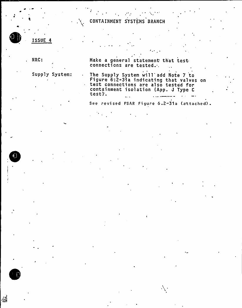
4
CONTAINMENT SYSTEMS BRANCH
k
I'SSUE4
NRC:
Supply System:
Make a general statement th'at testconnections are tested..The Supply System will'dd Note 7 toFigure 6:2-31a indicating that valves ontest connections are also tested forcontainment isolation (App. J Type Ctest)'.
P
See revi sed FSAR Fi gure 6.2-31a (aC tached) .
1
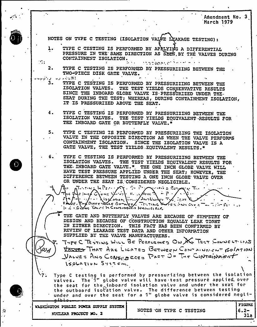
Amendment No. 3'March 1979
NOTES ON TYPE C ESTZNG (ISOLATION V AKAGE TESTING):
1. TYPE C .TESTING ZS PERFOKKD BY AP LYI G A DIFFERENTIALPRESSURE IN THE'AME DIRECTION AS S, BY THE VALVES DURINGCON AXNYZNT ZSOLATZON
2. TYPE C TESTING IS PERFOEQKD BY PRESSURZZXNG BED'TEZN THETWO=PIECE DESK GATE VALVE
4yv ~ J a g rI~" }le r ~ ~ r
3 TYPE C TESTING IS PERFORMED BY PRESSURIZING BETHEEN THEISOLATION VALVES~ THE TEST YIELDS CONSERVATIVE RESULTSSZNCE THE XNBOARD GLOBE VALVE ZS. PPZSSSRZZED UNDER T.K.SEAT DURING THE TEST; WHEREAS g DURING CONTAZNNENT
ISOLATION'T
XS PRESSURIZED ABOVE THE SEAT ~
4. TYPE C TESTING IS PERFORMED BY PRESSURIZING BETHEEN THEISOLATION VALVES. THE TEST YIELDS EQUIVALENT.RESULTS FORTHE INBOARD GATE OR BUTTERFLY VALVE.*
5 TYPE C TESTING IS. PERFORMED BY PRESSURIZING THE ISOLATIONVALVE IN THE, OPPOSITE DIRECTION AS WHEN THE VALVE PERFORMSCONTAINMENT ISOLATION. SINCE THE ISOLATION VALVE IS AGATE VALVEi THE TEST YIELDS.EQUIVALENT RESULTS.*
6. TYPE C TESTING ZS PERFORMED BY PRESSURIZING BETWEEN THEISOLATION VALVES THE TEST YIELDS EQUIVALENT RESULTS FORTHE INBOARD GATE VALVE * THE ONE INCH GLOBE VALVE MILLHAVE TEST PRESSURE APPLIED UNDER THE SEAT; HOHEVERg THEDIFFERENCE BETWEEN TESTXNG A ONE XNCH GLOBE VALVE OVEROR UNDER THE SEAT XS,'CONSIDERED NEGLIGIBLE.
!+ ~ > <+,~+>~ ' t 7r. ~
p p
v
Ai'o~ ~
':
' ls~ O'T!Cg !"' ! <>~l4!
cog lg!.,". }iCe~s!nial'en Qcw s! vl f'lpga
~, '
~ Jl
. c~ ~ h!s!,'e+ s ~ ..' }'
THE GATE AND BUTTERFLY VALVES ARE BECAUSE OF SYM'ETRY OFDESIGN AND BECAUS OF CONSTRUCTION EQUALLY LEAK TIGHTZN EXTHER DIRECTION. THIS FACT HAS BEEN CONFIRMED BYP~XHJ OF LE2QCAGE TEST DATA AND OTHER INFORMATIONSUPPLIED BY THE VALVE MANUFACTURERS ~
Tape C Ti~wiu's A~ii0< 'Pcavoe.vreg Qv)C 7a" w ~oboe . '.~it4g $<H+~ 7\16'7 AQ,%. l s! i "RQ l3c'7'Ae'g ~ '4 ow b<)Jr.'~ rv +gift'p(oh)
V~<4~ <}~0 } CQg~.~ Z,C9 iy ~ +< ' ~ '!~= ~ M~lg~~<~ ~
(59} Ag)vN S
7; Type C testing is performed by pressurizing between the isolationvalves. The 1" globe valve will have test pressure applied. overthe seat for the inboard i solat ion v'a lve and under the se'at forthe outboard isolation valve. The difference between testingunder and over the seat for a 1" globe valve is considered negli-
WLSP~~ RRLXC POMER SUPPLY SYSTZN
hd~~ PRMXCT )~NOTES 'ON TYPE C TESTING
FIGURE
6.2-31a

V
l
0
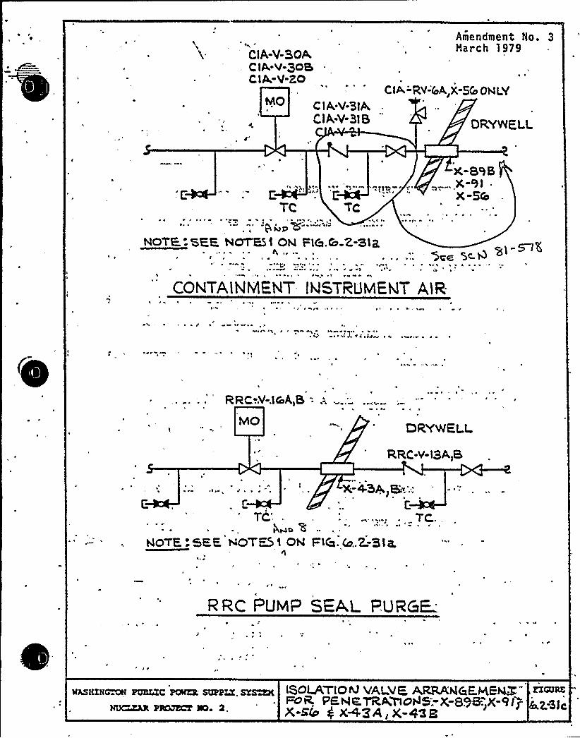
CiA-V-BOAClA V 305CIA-V-20
C lA.V-3lA,ClA;V-RS
Amendment No. 3March 1979
~ ~
CIA-'RV-&A)X-SCo ONLY
TC
»» ~ »I ~ »»Pq u» .g ~
X-BRS.. X-9l .
x-Sa
» ~ ~ » ~ h ~~4 '» tp 45 I~ II
NOTE.-SEE NOTES) OV Fia.|'-3lZ) : ~
lSee '5<~
' ' ~
CON~A~NMENT I~S~RuMExT A~z-"I
I ~ ~:I ) I
~ )»» ~ ) ~
h ~ $ h $ ~ ~ha» q» ~
» ~ » p ~
1
» w " '
RRC-.V-.lCoA,S - A ~ ~ hM~ 4 ~
DRYWEU
RRC-V-l3A)B
» ~ ~ ~
r .. t:
TC'wo ~HO-rE:SEE NOTES 1 ON
nI ~
X;-4-5A)E.',
TC..
FlCa. 4a.2=Bi a,
I
RZC PuvI SEAL PURCF
wamzNmw roaxzc pcs sappLY. srmxKNUCsZLR HCkJECT %la 2.
lSOLATlOIV YALEK AREA't46EHEMXFOR. PF HKTRA>@AS-)(-89K,X-RI~X-5b $ X+3A)X-O'Zl
RZCURK
2..Sic
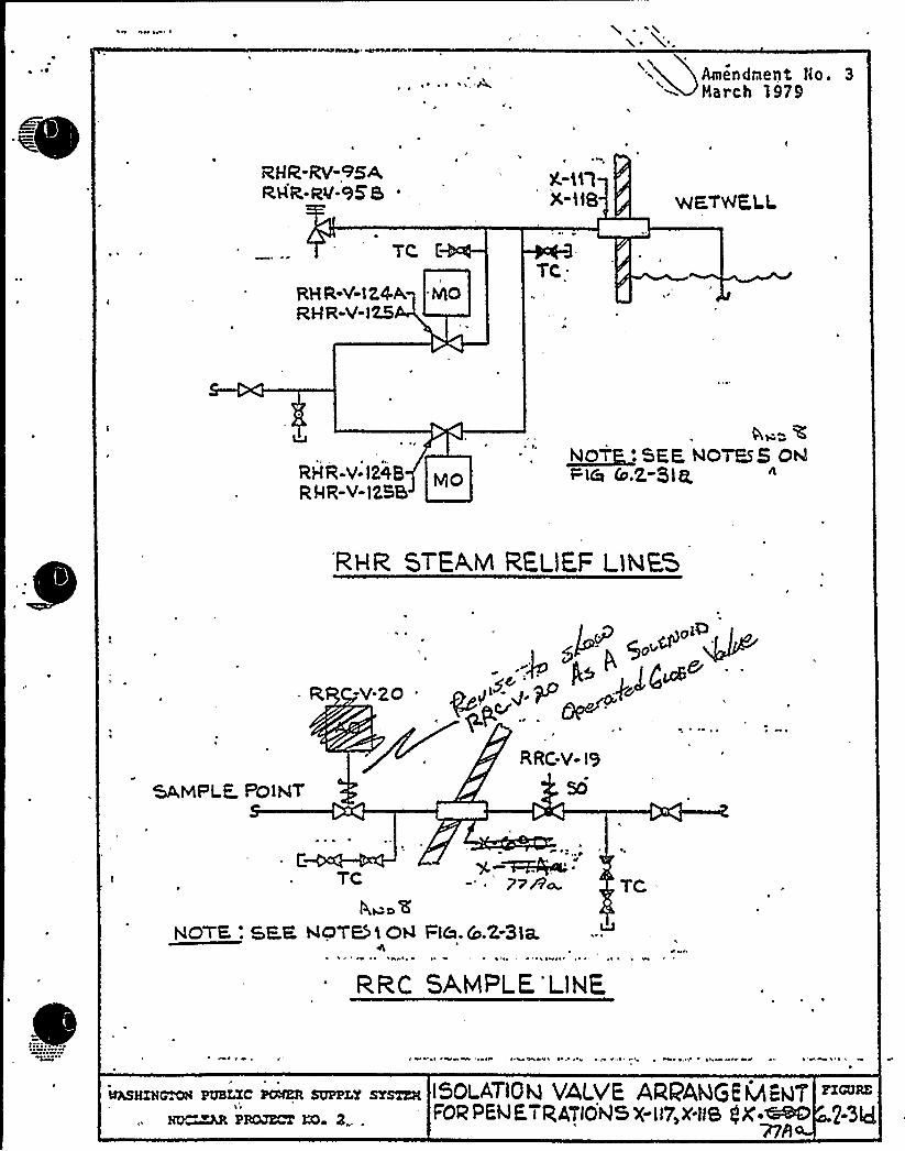
~ ~ ~
II.0!~
mF)/
i~i't
0
=ma e 4
0 r
gr
'S~t r~ R
C.
0> ~ ~ A ~
' r Its
~ ~ fy P 0 P )
'
a r Fi
.1
t ~
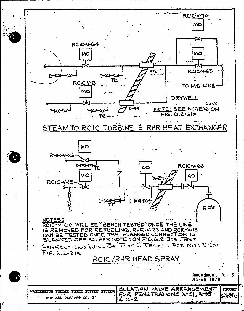
I
4o% ~o$ CA~i I Itea ee% 4 & Ief
mm m
4Q '
0 00
0
P
~ ~
~ I ty 01 ' I,~ ~ lrIAI 'Ill''rsP
w eP. ~ '
" ~ «»' r NO

e
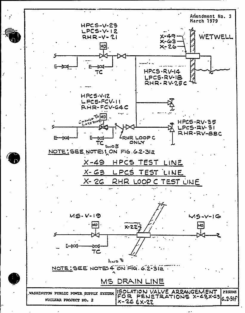
ver.s-v-ZSI PCS-V- I P.
RV R-V- 'LI
H0.
g-4RX.-&3X-Z.b
Amendment No. 3Narch 1979
WF7vJF LL.
~ 'I' ' " A ~
HPC 5. RV-t4LPCS-0 V-ISQWQ- RV-25c
(
HPC 5-V-IZLPCS FCV-I I
P,I-I a- FCV-t".4C
C~ co'.pa~ HPCS-RV-'5 5
I PC5-RV- 5 I
9, HQ,-y'-5g g
X- t-B L.PCS 7ESY LIklE.X- 2G IZHfZ LOOP C TE.ST t lk!E
RHR l-oQP CTC, ON I 'Y
o,wagNOTF:SEE hlOTESL ON FI&.Cn.2-3lg
x-49 HPc5 TE5T LlNF
Mg- O'- I'8~ Isa X-22 ",
M5 -v- I Q
Rue>NOTE:GKE NC)'TE54. ON FTCi. S.Z-3la
MS DRAIN LINE.@ASH NGTON PUBLIC PtÃKK SUPP'' SI'STER
NJ~ PROJECT 50 2
I5OL.ATIOM VAL.VK ARWhJGE,
EPACT
FO Q PEhJ FIR.A'blah)5 X-49,845x-z,z,
PZGURK
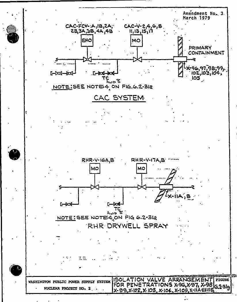
~ ~
i~i
) k
ll I~ L
~ — x ~
~ PA Pe

0
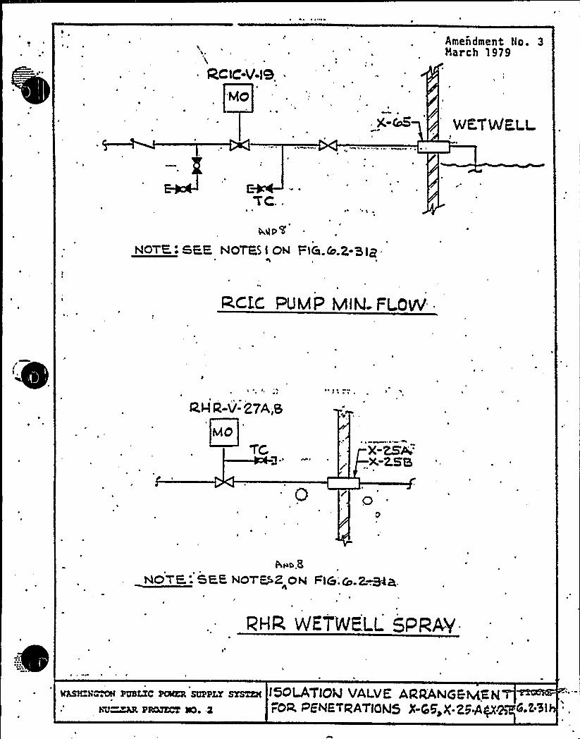
~ I
WE
~i
/pl
II
tip
r r
!5
E
r Oa a
~ ' ~ lA'l' ~ ~ re eI>
' ~ r ~ ~
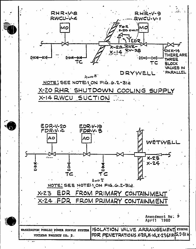
H QeP-PRM/CU-'4-4
I
~Yaoq
NX-I+THFRF ARKTHRKKT'C amex,VALVE5 IN
Q QQ~p gg 'PA,[email protected]
NOTE:%PE NOT%5 Ohl 'Pi&.&.2. 31ct
X-ZO RHR'HLITDQWhJ COOl lklG SUPPl 'l(
X-i4 RN/Cu, 5 UC.7i Otd
EDR-v-2ot=DR-V-4.
Ao
Ec R-V-te1=912-V- $Ao
7C 'iCA>~ Y
NOTE: &KB NOT&t„ON FIG. &.2-3IQ
K-CS.x-z4
X-ZS ED% FReM PRiMARY COWTAIWMP,X-24. FC>Q. FROM PPJMAQY CONJ|'Alki+fkli
MASHZBGTOR PUBLIC PDbtKR SUPPZX SYSTEM
h~AR PRRZCR EXla
Amendment No'.April 1980
tarot AT>OQ VALVEARPAVSEMFN
FN PENK1WTlOIJS NM,X.14,X 2'lpga
EPICURE
2.8!
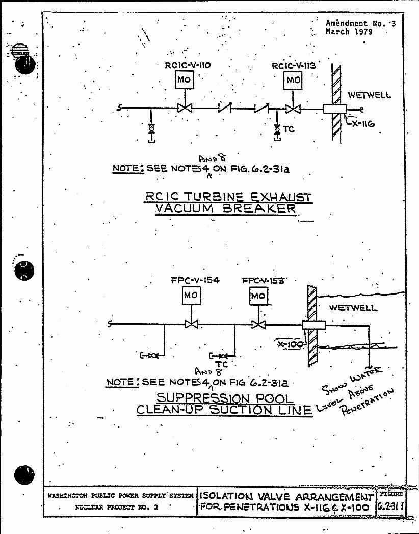
Amendment No '3Narch 1979
RC) C-V-llo
MO
Rt:tC-V-l13
hho
X->5
NOTE; SEE NOTK+ ON l=l&.Co.Z. ElkR
zt" tt- vuzaiN xHAus~v CLJLIM BRF & KER
%PC-v-ISA PPt .V-l83"
X-lOC7
'FNOTE: SEE NOTES+ ON l=l& Cc .2-3IB,
Super S M VO LCLEA.N-UP 'SUCTl LIME<
VASHIN~ QH PUBLIC PCWKR SUPPLY SYSTEM
b~hR PROJECT IOe 2
tSOLAV~OQ VALVE ARRAQGEhAB4TFoe'PSWE'TaAVtoLJS X-lt|oC X-lOO
PICURE'.2-3f
I

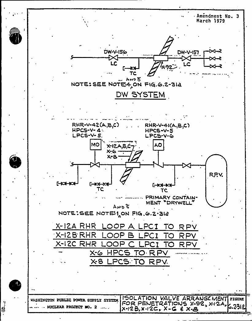
~ ~ ~
~ l
~ ' II'. ~ ~' + ~
~ &

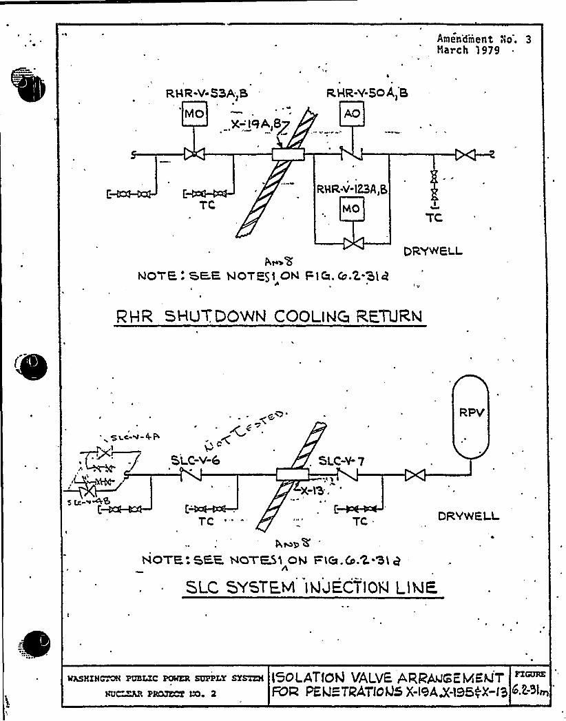
~ ~
S
E5 5
404 %0) 4+4 %~II r I
k
e ~ o
OOf C e," Po'1
/I
~ '- A' 4 o r ~ I '
' P0 P p ~

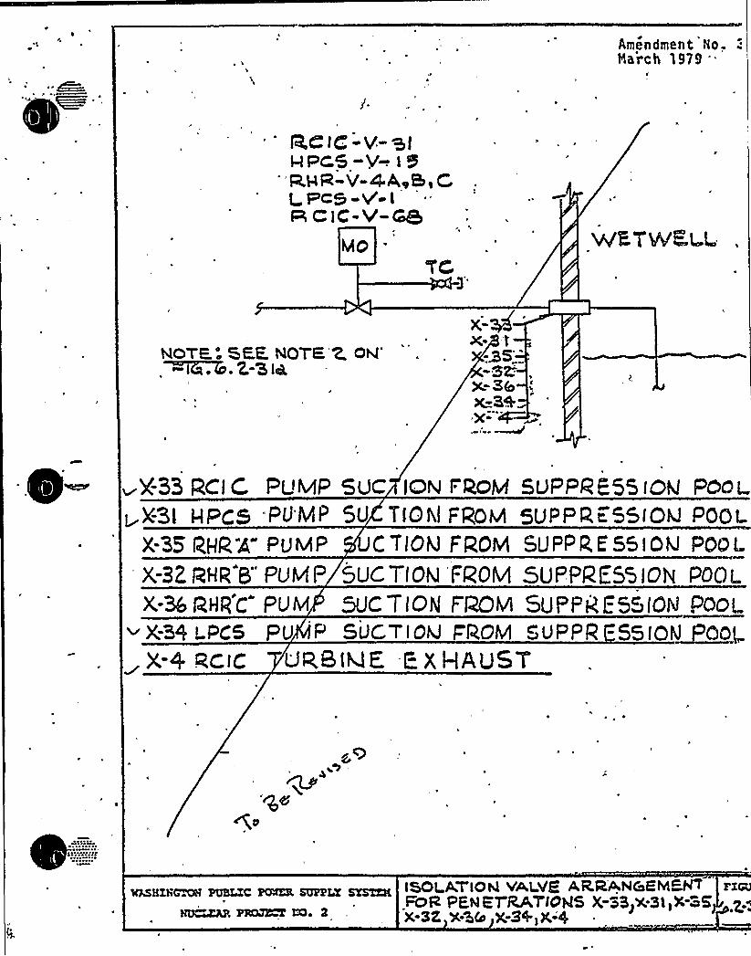
s
f
J a
W.EIj)
~
iQ ~ rr~~ y
e a
e ~
~or0 «0
0 ~ ~ 5
e r ~ ~ ~ g
e
0 OOI
~ ' 1
A
~ ' ~ W A: ~ VP
P lO 0

k
I
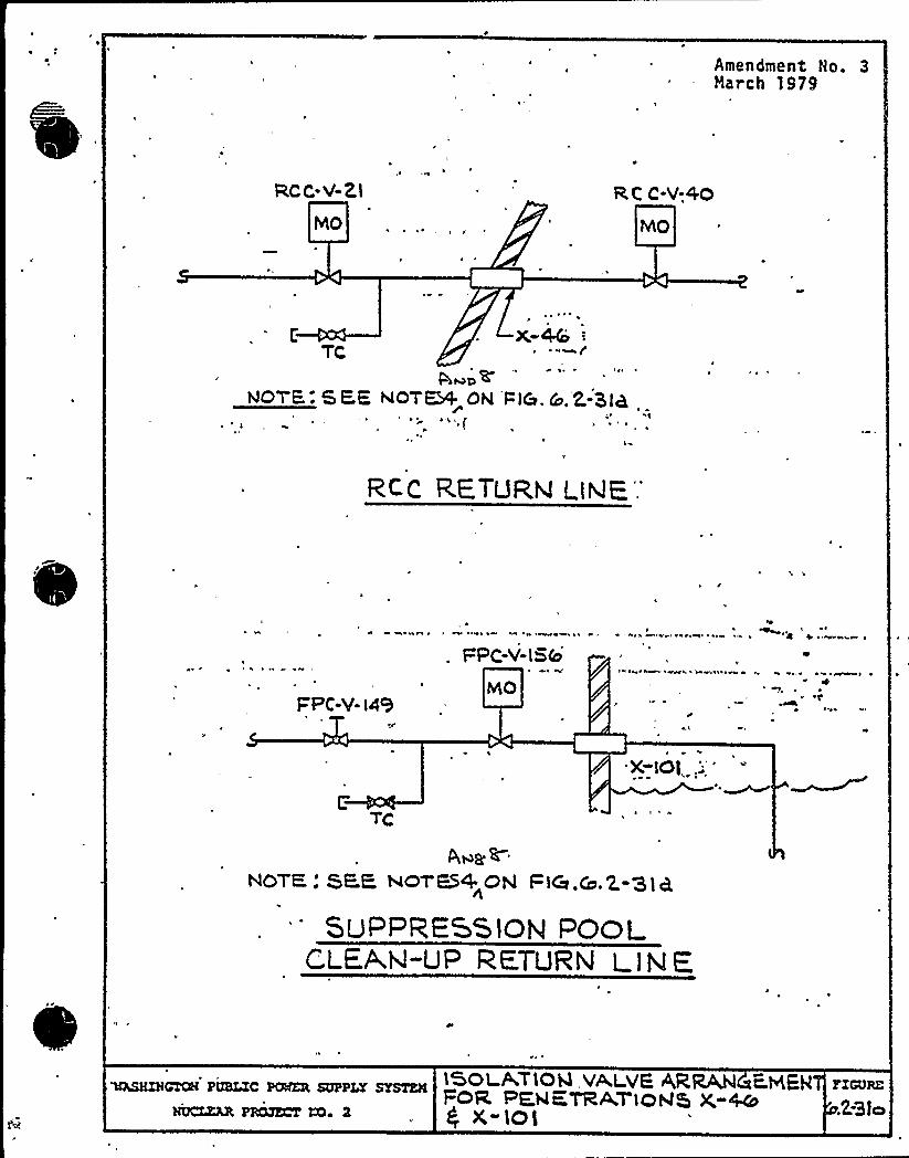
«IWE
0
!5~ «0
~ ~ ~ 0
~ ' ~ I' < ff»ff 0 ~ ~ O O'
~ Of ~ r 40
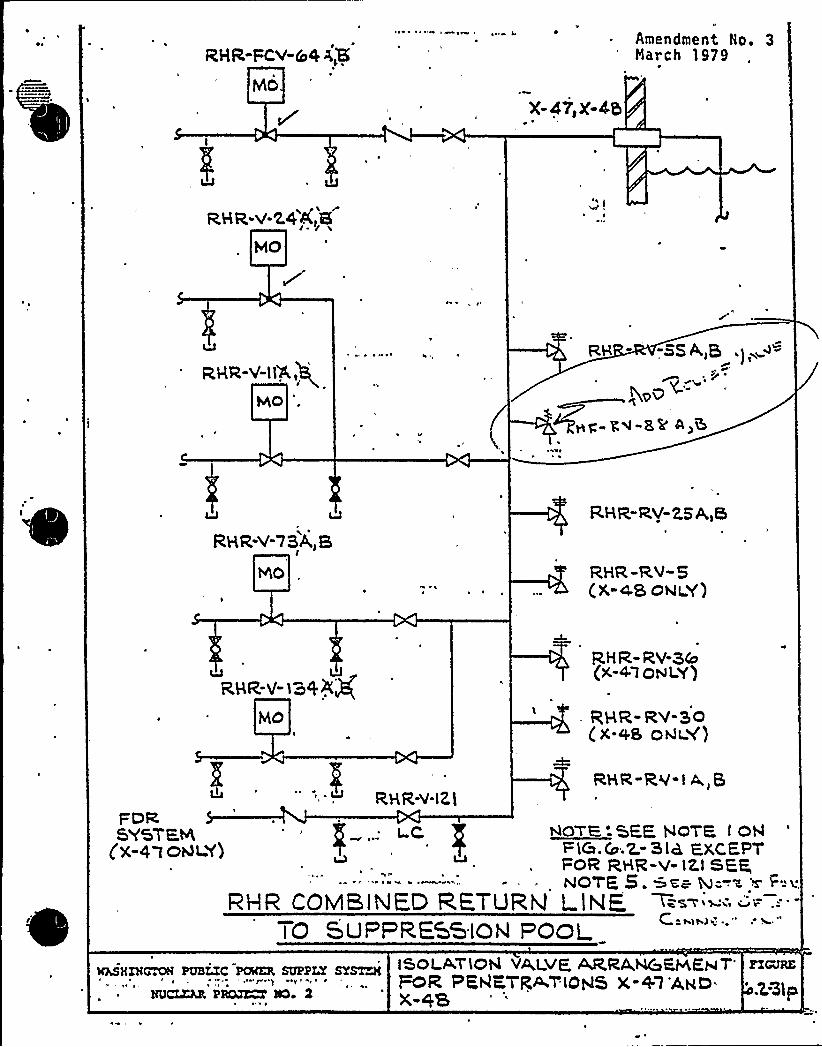
~ ~
rL
P P
W
~ y
~ o
4
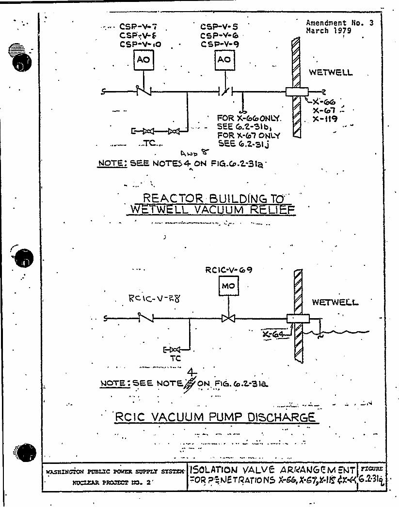
'lQ R9 tR
r ~
e
i( l
>Ig
~~l]
0
~ 1 ~' 4 ~ ' I 'I
~ e ~ o s xe y r P 4

0
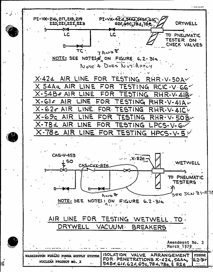
e
p. 4;
.e <q
~ ~
i L ~
Q
i
Ig e
y
I ~~
AICQ
~ . e. ' S' - IA'll' ~ ~
~ P
W

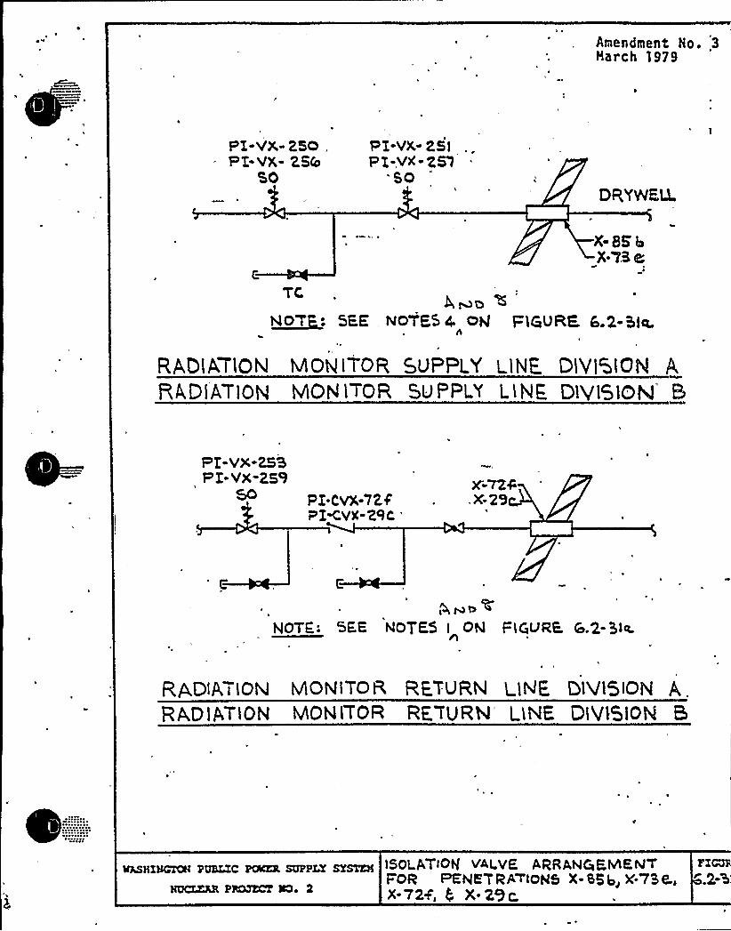
1
Amendment No. 3Harch 1979
PI-VX-250 .,
WX-VX-Z,BSO
PT-VX- P.5IP Z-VM-ZSl
SODRYeFU.
X BKbX-'7.8 e
C
TCbmoc >
N~O'T: SEE NOTE$ 4 ON t=iGURK 6.2-hia.
RAG(A,TlON MON lTOR 50PPLY LlNE DlV1510N ABAD)AT10N MON lTOR SUPPLY LlNE Dl'915)C)N'
PT-Vx-2HP I-VX-259
50 PZ-CVX-72$PIKVX-Z9C
'-7Z4X-2'9
NOTE: SEE NOTES I ON PlCilJRE6.2-$.la.
RgotA t lON MONITOR RETURN L1HE DlU15ION A,
RAD1ATlON MON tTOR RF TURN LINE D1V/510M B
lQSHISCTOH PUBIC PfÃKR SUPPLY SYSTEM
NUCZZLR P8MECT ÃQ» 2
150LATIOhf V4LVF ARRANQEhhKNTFOR PEEVE'7RP'tOHS X- SS b~ )C-7S LoX.724, $ X.2$
FICUSf'gl

0
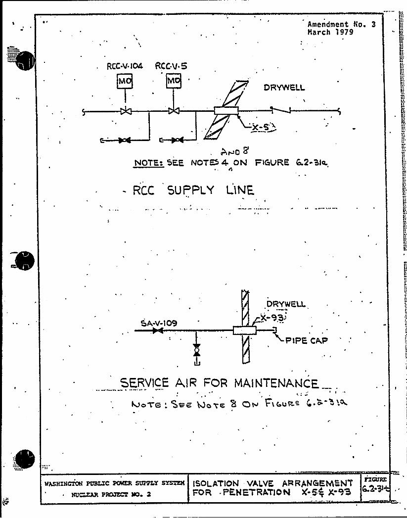
~ W
1E
e W ~
4%
r~-
r
]i
(
~ ~ ~ wz' 0 ~ 0'I
'

CONTAINHENT SYSTEMS BRANCH
ISSUE 9
NRC:
Supply System:
Is it correct to show LPCS minimum flowlines open during normal operations
The Supply System will revise Table6.2-16 to'indicate these valves areclosed during normal operation.
See revised FSAR page 6.2- 122 (attached).
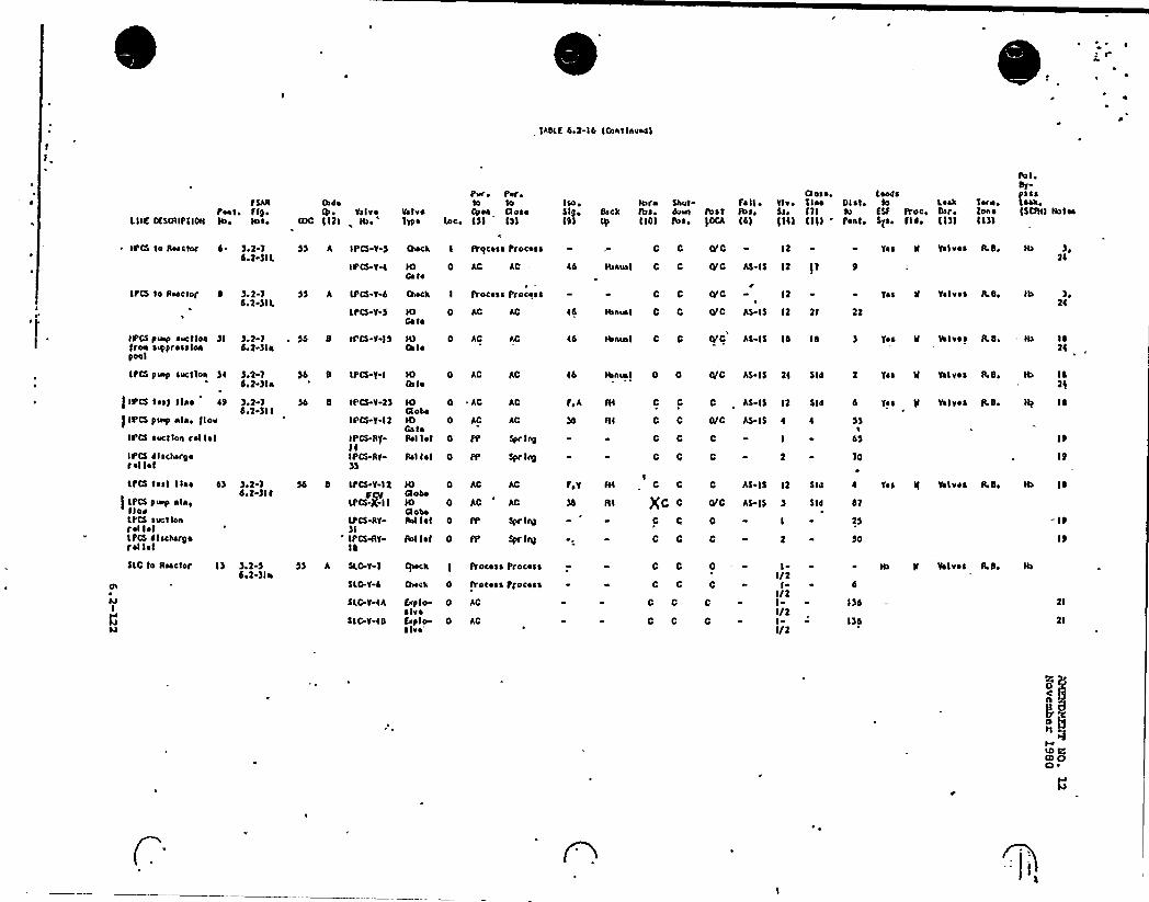
IABLS 4,2-14 IOwtlhuedl
fShnPeat ~ f19 ~
LIIE OSSGllpflON its ~ Rsse
Os reValve
COC 1'I 21 Ib u
Peru Peruto
Vs 1 vs Oten ttoseYtpe lnc, 151 151
Isoo519 ~
191
tbro Saut Fe II ~tbs. deus &st R>s,1101 Rss, )GCA td)
Ct os ~ 0 LeaseYtvi Slee Ol s4 tn5si 111 tu 4 Sf IVoc,)141 1111 'eat, Sgs. fl~ i
Leakbar ~
11)l
templone11)l
Rs I ~
bt-
(SGIIII Holes
IPCS to Reactor 4 ~ )el-14.2-)IL
SS h IPCS-T 5 Sock I ITqcess Process C C EYC 12 Yes 8 Valves Lb, Ils24
IPCS Y 4 IO 0Ge te
AC 44 Itsnus I C C iVC AS-I5 I2 )1 9
LPCS to Reactor 4
IPCS puip sucttea )IIroa s~prossloapool
).2-14 2)IL
)216 2-)la
LPCS-Y S
)d 8 IPCS-V 15
IO 0Gate
IO 0Gs te
AC
$$ h LPGS-V 4 tkeck I process Process
46
44
C C
tunus I C 0
IBnusl C 0
0/0
0/C AS IS
0 C AS-IS
12
12 lt 22
14 14
Yes II Valves AB,
Yoa W Valves Abi
Ib24
1414
IPCS pm'ucllea )4
) IPCS test line 49
JIPCS pulp nla ~ Jlor
IPCS suction roll~ I
IPCS clsckar9erel I~ I
).2 1de2 )Ia
)o2 1de2 )11
54 8 LPCS-Y-I
54 8 IPCS V 2)
IPCS V-12
IPCS-Rfl4IPGS-RY-)5
IO 0Gs to
AC AC
IO 0Gl okeIO 0Ga laRelist 0
AC
AC
AC
AC
Spr IhD
Spr lhbRel let 0 PP
44
F,A
Hs nun l 0 0
C C
C 0
C C
C 0
0/C AS 1524 Sla 2 Yes It Valves L8~ Its I ~
0/0 AS-IS
0
C
4 4 $ 5
I 4$
2 - 10
19
19
C AS IS ll 514 6 Tes Il Valves Abo III 14
LPCS tost lian
)LPCS p~ alastlorLPCS suctionrel I ~ ILPGS ~ I sckarB ~rel I~ I
4) ).2 16+2-)It
LPCS Y 12per
LPCS+I I
IPCS RY)IIPCS4Y14
IO 0aoaIO 0GledRel 1st 0
AC AG
Spr Int
Rol I~ I 0 PP
F,Y
RI
IC C
Xt- c
C 0
0 C
0/C AS IS
0
C
514 41
I 25
2 $0
C AS IS 12 $ 14 Yea It Volvs a R b. Its t ~
19
cn
ksI
SLC to Reactor I) ).2-5do2-)ln
SLG.V-4
SLG-V-th
SLC V-48
Ovsck 0 IVocess I'recess
&pie- 0s Ivafvp le 0elva'C
SS h SLG-Y-1 ~ck t IVocoss f'recess 0 C
C C
C C
C 0
0
0
C
0
I/2I 4
I/2I I)4I/2I- I)4I/2
tb II Valves AD,
21
us tgIO 0GS ~

CONTAIN'MENT SYSTENS ~ BRANCH
ISSUE 11
NRC'eactor recirculation hydraulic linepenetrations X-76'-77 are to meetGDC-56 to GDC-57 as indicated in theFSAR. Justify why WNP-2 'does not supplytwo isolation valves. It is not an ESPsystem and cannot be considered a closedsystem inside or outside containment.
Supply System: Second isolation valve added outboard perLetterr WPBR-RO-81-183'ated October
12'981'ndthe attached FSAR page changes.
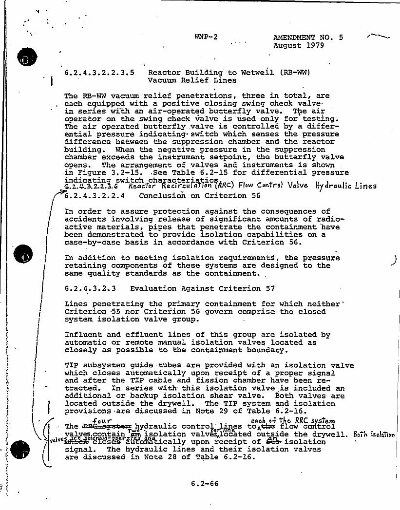
WNP-2 AMENDMENT NO 5August 1979
6.2.4.3.2.2.3.5 Reactor Building to Wetwell (RB-WW)Vacuum Relief Lines
The RB-WW vacuum relief penetrations, three in total, areeach equipped with a positive closing swing check'alve.in series with an air-operated butterfly valve. Tge airoperator on the swing check valve is used only for testing.The air operated butterfly,valve is controlled by a differ-ential pressure indicating switch which senses the pressuredifference between the suppression chamber and the reactorbuilding. When the negative pressure in the suppressionchamber exceeds the instrument setpoint, the butterfly valveopens. The a rangement of valves and instruments is shownin Figure 3.2-15. See Table 6.2-15 for differential pressureindicatincr switch [email protected].$ .3.z.z.5.C Reactor Recirciil aTion (RRc) Ftow ConOrol Valve Hy Jraul jc Ljgas6.2.4.3.2.2.4 Conclusion on Criterion 56
In order to assure protection against the consequences ofaccidents involving release of significant amounts of radio-active materials, pipes that penetrate the containment 'havebeen demonstrated to provide isolation capabilities on acase-by-case basis in accordance with Criterion 56.
In addition to meeting isolation requirements, the pressureretaining components of these systems are designed to thesame quality standards as the containment.
6.2.4.3.2 3 Evaluation Against Criterion 57
Lines penetrating the primary containment for whichneither'riterion-55 nor Criterion 56 govern comprise the closed
system isolation valve group.
Influent and effluent lines of this group are isolated byautomatic or remote manual isolation valves located asclosely as possible to the containment boundary.
TIP subsystem guide tubes are provided with an isolation valvewhich closes automatically upon receipt of a proper signaland after the TIP cable and fission chamber have been re-tracted. In series with this isolation valve is included anadditional or backup isolation shear valve. both valves are
r
located outside the drywell. The TIP system and isolationprovisions are discussed in Note 29 of Table 6.2-16.
4'our each o4 O'e, RRC system
valves~co@tain py isplation valves„located outside the drywell. Hain isola;ion«~" hN~ cTose'a~ZutomLWically upon receipt of aVs. isolation
signal. The hydraulic 'lines and their isolation valvesi~~
are discussed in Note 28 of Table 6.2-16.
6.2-66
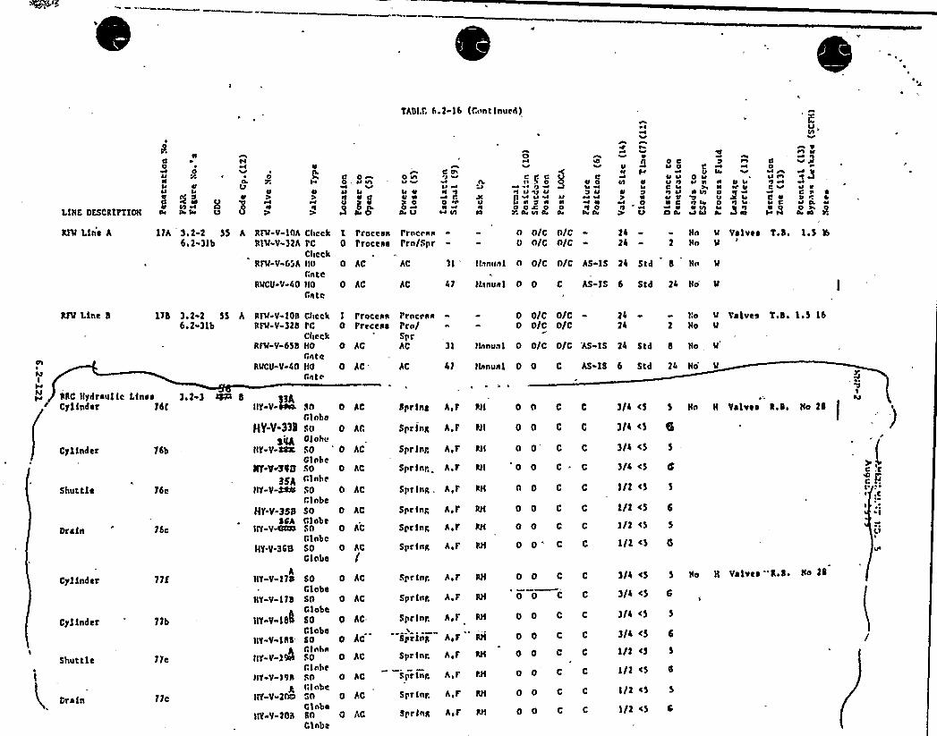
Thbl.r. 6.2-I 6 {Cunt lnued),
P.
c0V4V
LIHC DESCRIPTIOH 0
h«
0r<
»
nl
~ 000
~4~l
C 0~0 . 4J Vl~l 4
V Cu gV
8 08'
IhV ««
~I VV h
C UIJ
~Ip0h W
~«vl
C«I ~ 0V ~g
i0 02W l4 cn
0 3V
V~l iI0 0
Oo g4
C0li MV«i ~
~I 0Car OI
~ I«<
«Iv V
0hlrt 4V
0Ij<P
0 cV 0~i
V VV ilc 4
4IU Uh C
V0 l4
00
0 UV h ii
hhul 0Vil 4e 0
~J 5 h
«4i«I
0 lih'4
~l li=
00~J WC ««
C V4 C
VV
~«Q~IC h VV 0 lv 0,2» P.
RIM Line A 11h 3I2 2 5$ h RFM-V-IOA6I2 3lb RI'M V-)IA
RFM-V GSA
RMCU-V-40
CheckPC
CheckHoCateHQ
Gate0 AC Ac
I Process Prncean0 I'toceaa I'tn/Spr
0 Ac Ac 1 I IL<nua1
47 ILlnua I
0 o/c nlco 0/c olc
2424
Ho 'M Valve ~
Hn M
0 0/C 0/C AS IS 24 Std 8 Hn M
0 0 C AS IS 6 Std 24 Ho M
T.b. 1.$ '5
CheckI'CCheckHQCateIIQCat<
RIM-V-IOSRFM-V-32b
Valves T.b. 1.5 16Iyb 3,2 2 $ $6.2-31b
o o/c o/co o/c o/c
o o/c o/c
RFM Line b 2424
Ho M
Ho 'MI Protean0 Preceaa
PtoclnaI'rn/SptAc 310 AC
NI
WRRC Hydraulic f.IncaCylinder 76I
16bCyiindet
16cShuttie
76cDrain
77fCylinder
71bCylinder
IShuttle 710
77cDrain
'AS IS 24 Std 8 Ho MHanunlRFM-V-GS b
RMCQ-V-40 47 Hanual 0 0 C hs IS 6 Std 24 Ho M0 AC AC
3/4 <53,23 %+ 8 33KHY-V-W 0 0 c c
0 0 C C
0 O' C
0 C " C
0 o c c
dprlnb h,r RII
Spring A.F RII
5pr lnb A.r IN
Sprint A,r RII
Spr lng, A.r
Spring Air
I
Ho 280 ACSoGl nbalioGloboSQGl nbeSoC.lnbesoGlobeSoGlobeSoGlnbcSOGlobe
3/4 <5 63/4 <5 5
3/4 «5 IS
1/2 <5
5 Hn H Valves R,b,
HY-V-3»s%l
HY-V-40K
0 AC
0 AC
0 ACIIY«V«S42I
3SAHY-V-S4 0 Ac
o o c c I/2 <5 60 AcHY.V-BSBSSAHY-V~ 1/2 <5 5
I/2 <5 6
3/4 <5 5 Ho H Valves ='Rib. Hn 2b
3/4 <5 6
3/4 <5 5
3/4 <5 6
1/2 <5
1/2 <5
I/2 <5 5
1/2 <5 6
0 0 C C
o o c c
Spt lob h,r
Spr lnh A,F
0 Ac
IN0 AcHf V«365
AHY-V-I70 o o c cSprint h, F IN
Spr lnp A, F RH
SoGlobeSoGlobeSoClobeSoCilnbhSQGlnbeRnGlnbe"IQ
GinbaSQ
Clnbe
0 Ac
0 0 C0 AcHY V 17b
IIY-V lb' C C
0 c c
C C
o 0 C C
O 0 C C
0 0 C c
A,F RHSpr lnp
8prlnR
0 Ac
hlro AcHY-V-Ibb
HY-V-14 Spr lnr A,F
A,F PNSprint0 AG
o hc
HY«V-19bA
HY V 200 Sprint A,F IN
Sprlnn A,F RH0 ACHY Y-208
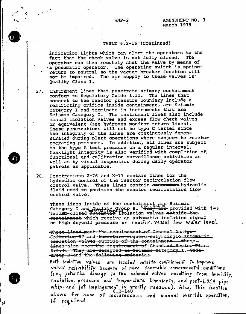
At4ENDliENT NOo 3March 1979
TABLE 6.2-16 '(Continued)
indication lights which can alert the operators to thefact that the check valve is not fully closed. Theoperator can then remotely shut the valve by means ofa pneumatic operator. The operating switch is spring-return to neutral so the vacuum breaker function willnot be impaired. The air supply to these valves is{}uality Class I.
.27 ~ Instrument lines that penetrate primary containmentconform to Regulatory Guide 1.11. The lines thatconnect to the reactor pressure boundary include arestricting orifice inside containment, are SeismicCategory I and terminate in instruments that areSeismic Category I. The instrument lines also includemanual isolation valves and excess flow check valvesor equivalent (see hydrogen monitor return lines) .These penetrations will not be type C tested sincethe integrity of the lines are continuously demon-strated during plant operations where subject to reactoroperating pressure. In addition, all lines are subjectto the type A test pressure on a regular interval.Leaktight integrity is also verified with completion offunctional and calibration surveillance activities aswell as by visual inspection during daily operatorpatrols as applicable.
28. Penetrations X-76 and X-77 contain lines for thehydraulic control of the reactor recirculation flowcontrol valve. These lines contain 'ydraulicfluid used to position the reactor recirculation flowcontrol valve.
These lines inside of the contaipne~nf, are Seismic"'"""* '"'.o" u'".oo"'which receive an automatic isolation signal
on high drywell pressure or reactor. vessel( low vVafer levef.
Poth jsold'ion valves are locat'elf ou7side containment To iynprove.ValVe'eliability because o$ more favcrabie environmental condifions(j.e.j p'ofenf'ia] damage. to f'he solenoid valves resuI?in'rom humidity~/If adiation, pressure and tempe«4r- Transienl's, and post-L.OCA pipewhip and jet impinoement is greatly reduced). Also> T'his location
'.2-140allows for e a se of m ai ngen an c e. and lnanu a! 0Verride
operandi
onlif reg ui red.
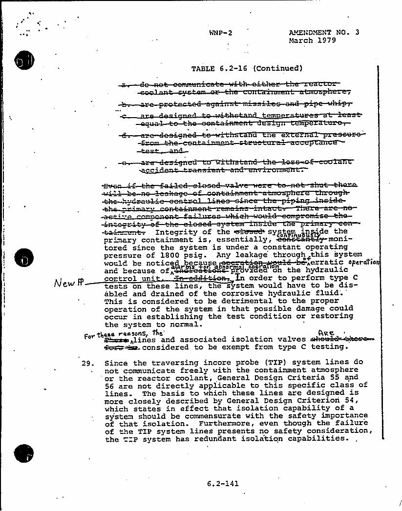
~ ~ ~ AY&hDNENT NO. 3March 1979
TABLE 6.2-16 (Continued)
tern
e e
I
'"' IBprimary containment is, essentially, moni-tored since the system is under a constant operatingpressure of 1800 psig. Any leakage through this systemwould be notice],„ecgupe 'erratic operas'ioanc because of„ ' vV e5. oh the hydrauliccontrol un' 'n order to perform type C
tests on these lines, the system would have to be dis-abled and drained of the corrosive hydraulic fluid'.This is considered to be detrimental to the properope ation of the system in that possible damage couldoccur in establishing the test condition or restoringthe system to normal.
For ggaaa raosonsI+c'ame<lines and associated isolation valves
considered to be exempt. from type C testing.
29. Since the traversing incore probe (TIP) system lines do~ not communicate freely with the containment atmosphere
'or the reactor coolant, General Design Criteria 55 and56 are not directly applicable to this specific class oflines. The basis to which these lines are designed ismore closely described by General Design Criterion 54,which states in effect that isolation capability of asys e~ should be commensurate with the safety importanceof tMt-isolation. Furthermore, even though the failureof 'xe TXP system lines presents no safety consideration,the "P system has redundant isolation capabilities.
6. 2-141

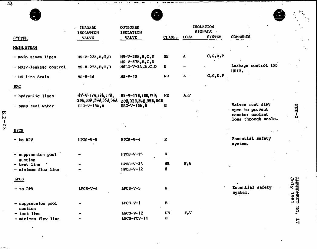
SYSTEH
INBOARDISOLATION
VALVE
OUTBOARD
ISOLATIONVALVE C ESSE . ECCH
ISOLATIONSIGNALS
SYSTEM COMMENTS
HIIYII,STEIIH
- main steam linea
— MSIV-leakage control
— MS line drain
MS-V-22A)B)CED
MS-V-22A)BECED
MS-V-16
MS-V-2BAEB)C)D NE
MS-V-67AEBEC)DMSLC-V-'AEB)CED E
MS-V-19
C,G,D,P
CEGEDEP
Leakage control for.MSIV,
RRC
— hydraulic lines
- pump seal waterU3
1
HPCS
}lV-V-17A) ISA) l9A) HY-V-178) le8,1'lS) NE
20AQ3A)><A)3<A)36h 208)>38)%$ )358)368RRC-V-13A)B RRC-V-16A)B E Valves must stay
open to preventreactor coolantloss through seals.
- to RPV HPCS-V-5 HPCS"V-4 Essential safetysys'tems
— suppression poolsuction- test line
— minimum flow line
HPCS-V-15
HPCS-V-23HPCS-V-12
NE
E
F)A
LPCS
— to RPV
— suppression poolsuction
— test lice- minimum flow line
LPCS-V-6 LPCS-V-5
LPCS-V-1
LPCS-V-12LPCS-FCV-11
FtV
Essential safetysystem.
h
CONTAINMENT SYSTEMS BRANCH
ISSUE 12
NRC:
Supply System:
Page 6.2-123,, RCIC turbine exhaust hasonly one val ve shown. Add the checkval ve (RCEC-V.-40) for containmenti sol a tion purposes.
The Supply System will revise page 6.2-123to indicate that the check valve is acontainment isolation val ve.
Check val ve RCIC-V-28 in the Vacuum PumpDischarge Line (Penet. 64) must also beincluded as an isolation valve.

0
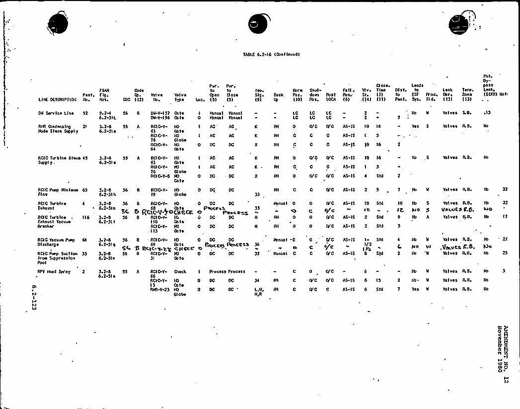
TABLE 6 2-16 (Cantlnuud)
F SARPant, F Ig,
L IIX'ESCRIPT IOH Ib tbs,
(hdeValve
GOO ( 12) tb,ValveTypo
Prr, Prr,Io tuOpen Ouse
Lac. (5) (5)
iso+5lg i Back(9)
Ibmfbs,(10)
Shutdarn fb stfbs. LOCA
Fa II ~
Ibad(6)
CI ose, LeadsYlv, Tlno Olsti ta Loa'k Tera,St. (7) to ESF Roc, Bar, Zone
.(]4) (11) Pent. Sys. Fld, (13) (\))
AntiBy-passLanka(SCFH) Ibt<
OW Serv lce Line 92 9m 2-46I2 )IL
56 8 DW Y 157 GateDW-Y-I56 (hte
I thnua I lbnun I0 tbnua1 tbnual
LCLC
LC LCLC LC
22 5
Ib W Valves S.B. ~ I)
At(I (bndans lag 2Itbde Stean Supply
)o2 86.2-)le
SS A ACIG"Y- ID6) GateRCIG-Y- )D76 GlobeRCIG-Y- )D64 (h to
I AC'CI AC AC
0 DC DC
K *Rl
K 84
X R4
C C
C 0
AS IS I 5
AS-)5 )0 16
OfC (YC AS IS 10 16 Yes 5 Va I vss R.B.
ACIC TLrblne Stean 45Suppl y .
ROC Puap Hlnlnua 65F for
RCIC Tu'bloc 4Exhaust
ROC Turb)no = 116Exhaust YacuuaBreaker
) 2-86a2 )I ~
)e2-86o2-)lh
3.2-86.2-)ln
)I2-86.2-)II
55 A RCI G-V ID63 GateROG Y I4)76 Q abcRCIG-Y 8 HO
Gate
56 8 RCI G-V- H)19 Q obe
56 8 ACIG.Y- tD68 Gate~ 6 R('iC-V-WE)C.Se,CX
S6 8 RCIG-Y K110 BateRCI G-Y ID-II) Gate
I AC AC
0 DC DC
0 O(j DC
K ~ R(
X R4
R(3)
0 OC DCpeocrs Xe Pstec at
0 DC DC
))H
tbnual '
0
H RI 0
I AC AC K R( VC GrC AS IS 10 16
C C AS-15 I 5
OrC GC AS IS 4 Std
0 Gt'0 ASIS 2 5
0 O'C
o/c0 tVC
AS- I5 10 Std
toAS-IS 2 Std
0 O'C AS-IS 2 Std
tb 5
7 tb W
10 Ib 5
)2'so 59 tb A
Valves LB,
Valves R.B.
Valves LBiVhiuES ((.t),Yet vos fLBo
tb 22
ha(s
Ib 17
RCIC Yacuua Puap 64
Discharge
RCIC Punp Suction 33froo Suppressionpool
3+2-86o2 )lq)o2&6e2-)In
S6 8 RCI G-V-69
5C '5 RCIK q-2.y56 8 RCI C-Y-
)I
N) 0 OC DCGate 'praacEs) Acocfssc)(ccH'aH) 0 OC OCCato
tb nun I36
)2 tbnua I
'0
C
0 " Oj'C
c o/cC (YC
AS-IS
AS- IS
I StdI/2
(fc8 5(d
4
C
2
tb W
)toIb W
Valves fLB.
,VhcuES. P.6.Valves LBi
tb 22
lOotb 2)
APV tautd Spray 2 )o2-86o2 )le
55 h RCI 0-Y-66RCIC V-I)R% V 23
Outck
ID(ateIDGlobo
I Process Process
0 OC DC
0 OC DC
34 Rl
L,U, R(H,R
(VC C AS- IS 6 Std
0 (VC
O'C (VC AS-)5 6 15
tb W
2 Ib ~ W
Yes W
Vol vos R.B.
Valves LB.
Valves LB.
ta g
Cl R(tt ()0 ~

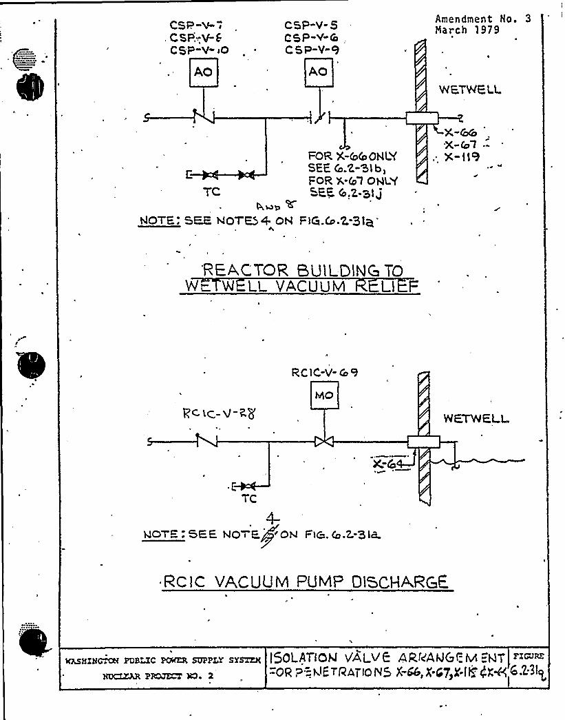
tQ 1
~ i ~IS
0
a
Ul~
1 r
~
~ ~ 0
I
~ ~

CONTAINMENT SYSTEMS BRANCH
ISSUE 15
NRC:
Supply System:
Page 6.2-125;- RHR-88a, pump suction reliefvalve, is not shown in Figure 6.2-3lp.
Figure 6.2-31p will be revised accordingly
See revised FSAR Figure 6.2-31p (attached}.
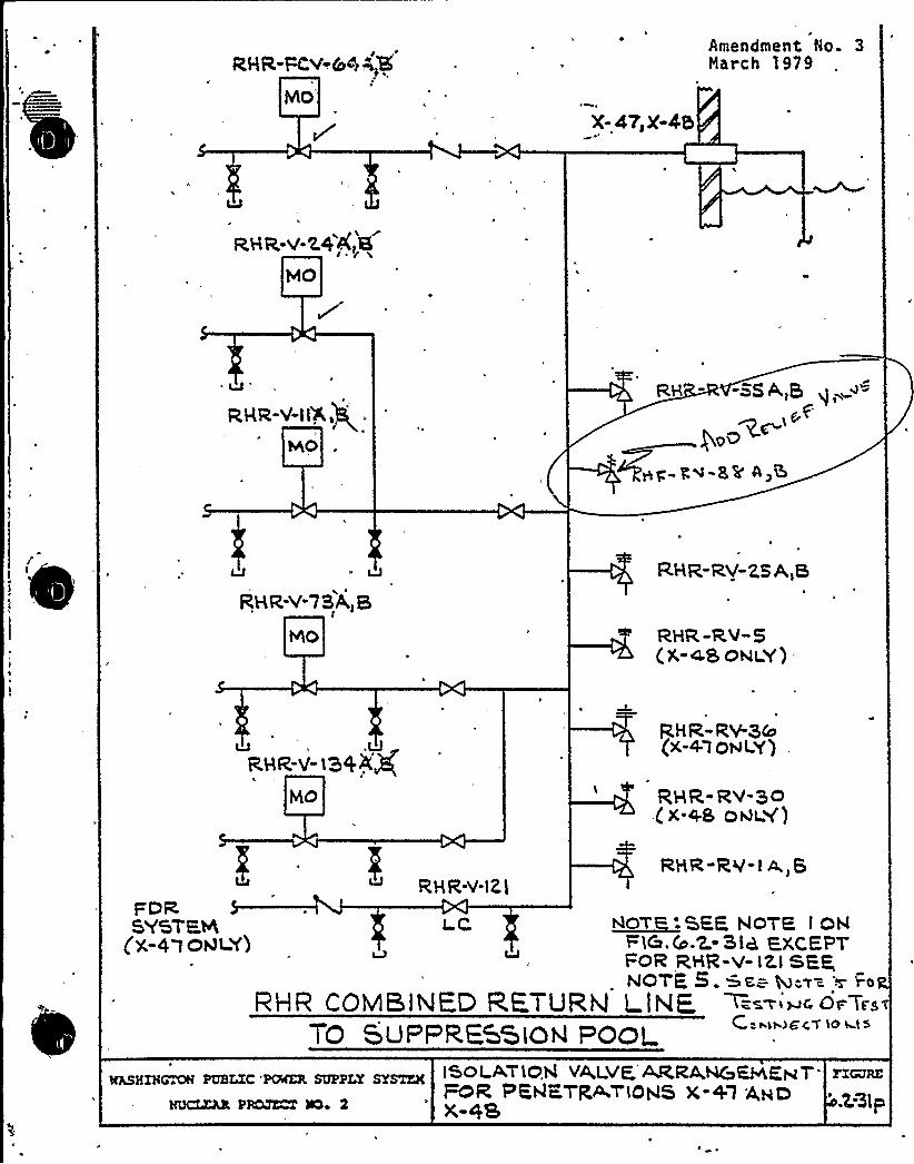
aHR,-r-c,v-| e~,'E
bAO'
X-4?, X-45
Amendment No. 3March 1979
RHR-V-Z.44,,8MO
am-v-isa + .
hhO
RH " -SS A,Q
ygo+~g rs-82 A,S
RHR-V-73A,8MO
RHR-RV-ZS A)5
RHR -Rv"5(X-<8OeI Y)
u ', .URHR-v- lHXg
MO
R,HR-RV-W(X-4.iOwl.y') .
QHR-RV QO< x.as oviY)
RHR-V-121RHR-RV-I A)8
FDRSYSTEM
(X-4lOQl Y)I C <~o> '-SEE NoTR I QH
F1C. (o.Z.-Sla, ZXCEHFOR QHR-V- IZI SPPNOTE 5. ms=- >=z ~ w Wo
RHR COMBINED R.ETURM L.lNE, ~ 'c ~".TO SUPF R.ESSiok POoL
MhSHIHCMH PUHLIC *AMER SUPPLY SYSTEM
HUCLZkX PR~ NO~ 2
ISOI AT1034 VA I VE. ATRA,~~/~7"FOR PKQKrR~TIOHS X-+1 A~aX-AS
FZGVRZ
'.Z 31p
CONTAINMENT SYSTEMS BRANCH
ISSVE 16
NRC:
Supply System:
Add Seismic Quality Class 1 debrisscreens 'to vacuum breaker.
The Supply,,System wi1 1 install byFuel Load per issue number 1 state-ment.
See revised FSAR page 6.2-66 (attached) .

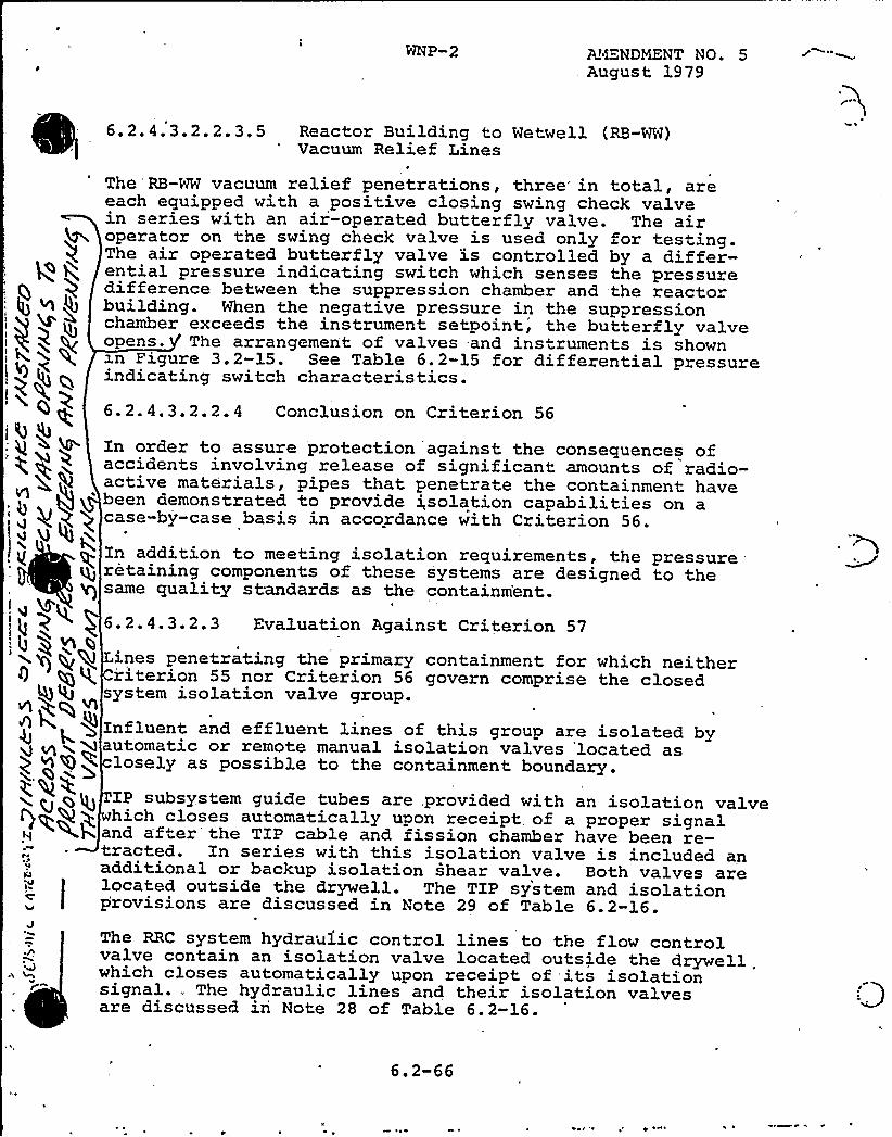
WNP-2 Alr~NDMENT NO. 5August 1979
~ ~ ~ ~ ~ ~6.2.4.3.2.2.3.5 Reactor Building to Wetwell (RB-WW)Vacuum Relief Lines
Ql
I 4 ~4
The RB-WW vacuum relief penetrations, three'n total, areeach equipped with a positive closing swing check valvein series with an air-operated butterfly valve. The airoperator on the swing check valve is used only for testing.The air operated butterfly valve is controlled by a differ-ential pressure indicating switch which senses the pressuredifference between the suppression chamber and the reactorbuilding. When the negative pressure in the suppressionchamber exceeds the instrument setpoint, the butterfly valveopens. The arrangement of valves and instruments is shownxn Figure 3.2-15. See Table 6.2-15 for differential pressureindicating switch characteristics.6.2.4.3.2.2.4 Conclusion on Criterion 56
In order to assure protection against the consequences ofaccidents involving release of significant amounts of radio-active materials, pipes that penetrate the containment havebeen demonstrated to provide i,solation capabilities on acase-by-case basis in accordance with Criterion 56.
In addition to meeting isolation requirements, the pressureretaining components of these systems are designed to thesame quality standards as the containm'ent.
6.2.4.3.2.3 Evaluation Against Criterion 57
Q
~+q Vl
ines penetrating the primary containment for which neitherriterion 55 nor Criterion 56 govern comprise the closedsystem isolation valve group.
Influent and effluent lines of this group are isolated byautomatic or remote manual isolation valves located aslosely as possible to the containment boundary.
'J
.n
IP subsystem guide tubes are, provided with an isolation valvehich closes automatically upon receipt, of a proper signaland after the TIP cable and fission chamber have been re-tracted. In series with this isolation valve is included anadditional or backup isolation shear valve. Both valves arelocated outside the drywell. The TIP system and isolationprovisions are discussed in Note 29 of Table 6.2-16.The RRC system hydraulic control lines to the flow controlvalve contain an isolation valve located outside the drywell.which closes automatically upon receipt of its isolationsignal., The hydraulic lines and their isolation valvesare discussed in Note 28 of Table 6.2-16.
6.2-66
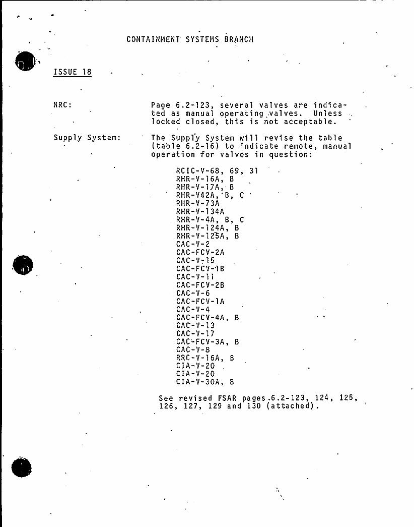
CONTAINMENT SYSTEMS BRQNCH
ISSUE 18
NRC:
Supply System:
Page 6.2-123, several valves are indica-ted as manual operating .valves. Unlesslocked closed, this is not acceptable.
The Supply System will revise the table(table 6.2-16) to indicate remote, manualoperation for valves in question:
RCIC-V-68, 69, 31RHR-Y-16A, 8RHR-V-1,7A, 8RHR-V42A,'8, C
RHR-V-73ARHR-Y-134ARHR-V-4A, 8, C
RHR-Y-124A, 8RHR-V-125A, 8CAC-Y-2CAC-FCV-2ACAC-Y-,15CAC-FCV-'18CAC-V-llCAC-FCY-28CAC-V-6CAC-FCV-lACAC-V-4CAC-FCV-4A, 8CAC-V-13CAC-V-17CAC'-FCV-3A, 8CAC-V-8RRC-V-16A, 8CIA-Y-20CIA-V-20CIA-V-30A, 8
See revised FSAR pages .6.2-123, 124, 125,126, 127, 129 and 130 (attached).
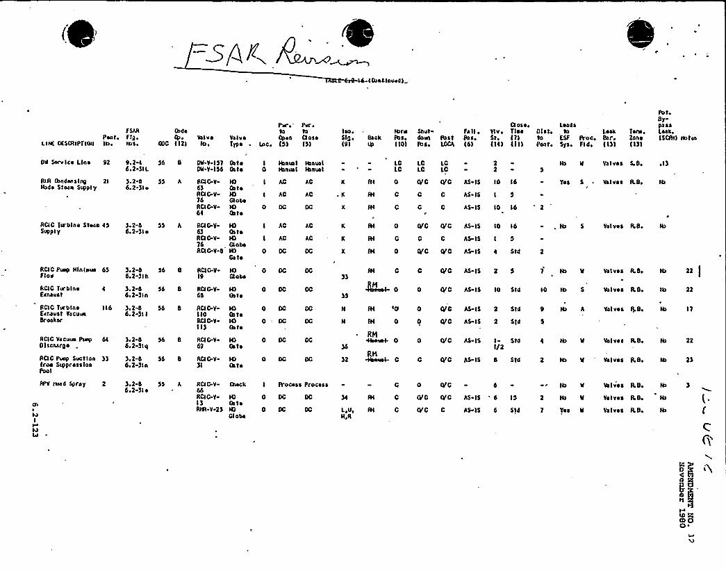
ad-f Gunatnuvd I
Lttn, OESNIPTIOtI
fSARPont, fIg.Ibe tbs ~
IbdoQt ~
GOC l 121ValvsIb,
Pllr~ fur 0
to toVa1 vs Gpan 0osoTypo ~ Inc. l5) l5)
lao»Slg,l9)
tbrnBack fbs.
l 1 0l
Shut fall ~
dovn Post lbs.fbs, LOCA 161
Gl oso. Loa4$Ylvi Tins Glott ba Look Tora.St. l T l to ESF Roc. Bar. ZoneIIi) l Ill Panti Sys, Fl 4, l I)l ll)l
fbtoBy-passLaakeISCfIII tbtea
Ott Serv leo Line 92 go 2%6 I2-)IL
56 8 Dtt-V-IS) GhtoOg-V-f56 Oats
Hanua IHanna I
Ibnua IIbnual
LCLC
LC LCLC LC
22
Va1 vos SeSo el)
RIA (hndons lug 21 ).2-8Ibda Stoan Supply 6.2-)to
ACID Te'blno Stean 45 ).2-6Supply 6a2-31 ~
55 A
55 A
ACID-V-63RGI G-V-76RCIC-V-
'66
RCI G-V63RCI G-V-16RCI 0-V-4
tOOa toIOGloboIOGa to
IOCatoIOGlobotOGath
I AC
I AC
0 OC
AC
I AC
AC
AC
AC
AC
AI 0
IH C
IH C
fH C
fH 0
QtC Q 0 AS IS 10 16
0 0 AS-IS I 5
0 0 AS- I5 10 16
QtC Q C AS-IS 10 16
0 C AS IS I 5
QtC O'C AS IS 4 St4
Yoa S ~ Volvas RS,
Valvos RSi
AGIO Tarblnofxnauat
RGIC TurblnoSkbaust VacuaSroakor
4 ). 2-tt6.2-)ln
116 ).2-86.2-311
RCI C Puap IQnlnua 65 )i2-8Flov 6o2-)lb
56 8
56 8
56 8
RGIG V19
RCIC V66
ACID.V-IIORGIG-V-I I)
IOth to
IOIhtoIOCato
0
35
fH C
0
C QrC AS IS 2 5
0. Qr 0 AS-IS 10 Std
IH tQ 0 Qt C AS- IS 2 Std
2 ST4fH 0 0 0/C AS IS
10 tb S Valves A.S,
Val vss RS.
If Valvos ILSi
tb
22)
AGIO Vacuua Pua$ tOl soka rg a
6l )o2-66.2-)lq
ACIC Puap Suction )) 3.2-8iron S~pross loa 6s2-)lnPool
56 8
RGI G.V69
RCIG V)I
IOGa to
IOlh to
)2
Rpl0
RNC
0 QtC AS IS I St4I/2
0 VC AS IS 8 ST4
tb II Val vos RS,
Il valvos RSi
Ql
MI
IJW
RPV tkutd Spray 2 ),2-8
6a2-)I'D
55 A RCI G-V-66RCI G-VI)Rtft V 2)
IOCatoIOGlobo
I Procoss Procasa
0 DC OC
0 DC
C
IH C
0 QrC 6
Qr 0 tvc As- Is 6 15
fH C VC C AS IS 6 Std
2 Ib Il
Yos II
Volvos R8,
Va1 van RS,
Va1vos RS,
tb
C
6'O
QIO 00 ~
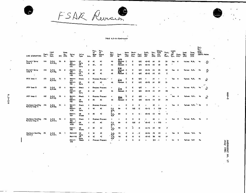
PBL( 4.2-id (Gastfnwet)
(ltd U(SCRIP'f fdtf
fSA'IPest, Flg,tfo, A>s,
ColeCp
CC ((2)ValveRo>
Vol vo(ype
Pvr Pvr ~to to(Pso Cl ceo
loc, (5) () I
lsoSl)
tforhBacaVp (10)
Snvt-dawn
'Close, , LeastFat I ~ Vlv, Tine 01st, to Lett> Ter ~ .
Post Pos St (I) to (SF Proc, f)or 2osolOCA (d) - (Il) I I I) Pest, Sys Fl d, (I)) (I))
eat,By-passLean,(SCFH)
pry>ail )pre/Loop A
Dry>all SprayLoop fi
LFCI (oop A
IIA ).2 64,2-)I)
I fit ) 2w)>(v2-)Ig
12A )244.2 )t(
)d 0 AR V
16AIUA TI)A
~ AR VI (0
Fall V
ISftR Y41A$bA Y
IOCataIOCato
IOCatetOOtto
IOCate
0 /C,
0 JC
0 IC
I Process I'rocess '
AC
44
44
~ 6
44
RNRH
C
RHS(PS
C
0/0 AS IS Id IO
0/C AS IS Id IO
0/0 AS IS Id Ig
0/C AS-IS 16 15
I~
0/C AS IS I~ 21
26
24
12
2I
fes
Tes k
Yet k
Ya Iv«R,B Vo
Ya I vos R.B.
Tais«R 0, ttt
I1,'24
11,21
2l
LICI )oap 0 1211 ).2 66 2)IL
55 A fOR V
410AR Y IO
Otto
Proc«s I'rocess
0 AC AC 44RH
C
I~
0/C AS IS ll 21
Ya I vos R,B,24
LFCf loop C
Savtdo>n Cool lngRotsrn (aap A
Snvtdcwn Cool lo)Ratwn (nap 0
l)C ).2 66.2 )IL
ISA ),2-46.2 )te
tall ),2 44.2 )lo
55 A
A
AA V
4ICRIA 'V
AR V
AA YI2)A
IUR Y5)A
AA Y5AA T-12%
R>R Y
5))
IOCato
IOCato
IOCI oao
tOCato
tOCioao
Process Procesa
I Process Proc«s
I IC
Proc«s I'roc«s
I A
F,LU,N,RII,L>V>R
RV>L~V,R
RNC
A\
Rl
Ri
14
0/C AS IS ll 21
C 12
0/C C AS-I5 I SIC
C , AS IS 12 l0
C 12
C Af IS 12 40
0/C C AS IS I - Sfp
Tes k
k
Tos k
Tats«R 0
Ya Iv«R,B,
Yatv«R 0,
24'0Iat
Snvtdvws Cool lngSection
20 ) 246.2-) fa
55 AA Yd
IbR Td
IhA Y20)
IOCatoIOCato
I IC
0 AC
I IYacess Process
L>V>„ N,R
L>Il,ll>R
Rl
RI
C AS IS 20 40
C AS IS 20 40
C
T«
k
Yal >o> a >I
Yai ves
>fo
ts> 4 5>O 5'C
g
td0
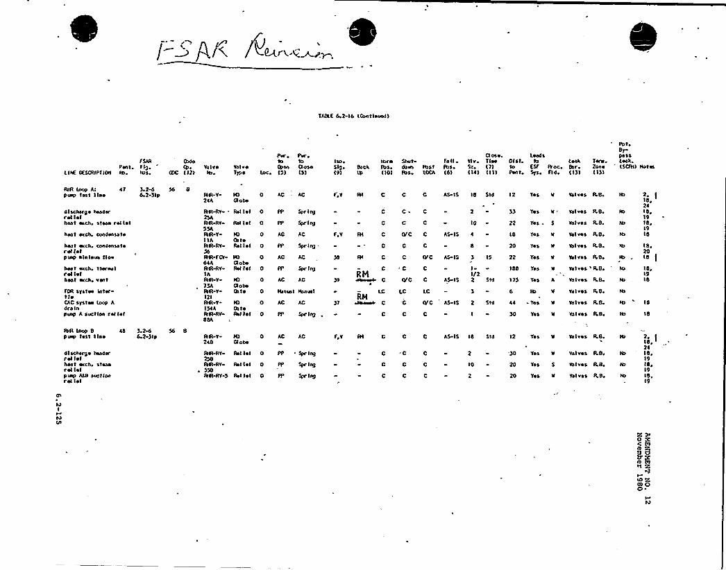
tABLE 6.2 16 IOsntlnuod)
F SARPont, f Ig
I.lnE RSOIIPfloaf tas aa>s
IhdoValve
G)C 112)ValveType
Pw ~ Pur.to
Opon OuseInci 15) 15)
IsoSlg Back19)
tbfo Shul Fn II ~
Ibs dose Ibst fbaI IO) pes. LOCA 16)
Ct use. Load svlv Tfne 01st LeakSz IT) to ESF A oc EerI la) Ii)) Pont Sys Fl di 113)
TersZone1131
PutBrpa ssLeakISCfH)
RIR Inop Af it 3 ~pusp test I lao 6.2-31p
discharge headerreliefhest eICh Stean rol lel
hoot ecch cnodansato
heat eICh Condonsatorol letp usp ~ In ious I Inn
heat ecch, thereofref Ielheat ecch, vent
FOR systes IntertieCAC Syaten lOOp Adre lnpusp A suction rol lef
56 8AR-V2iA
IN%V
IN%V55AIN YI IAARLY
AVI-FCt6thAft-Rv-IAAft-v,)3AIN-v121AR Y13iAAtfhR�-V6�
IOOs toRol lot
IOaohoRel Iof
IOQoheOnto
IOOntoRol lot
0 AC AC
0 PP Spr Ing
0 AC AC
0 PP Spr Ing
0 AC AC
0 Ihnus1 ahnua I
0 AC AC
0 PP Spr Ing
Rol Iel 0 PP Spr Ing
Rel 1st 0 PP Spring
r.v
3)
RN
RH
C AS IS 16 StdC C
C C~
C C
C
C 10
8
C (VC C AS IS
CC C
C C
C 9C
OfC AS-IS
12 Tes W Valves LB
33 Tos K = Valves R.B
22 Yes . S
18 Tos W
20 Tea ll
22 Tea u
166 Tos u
Valves RB
Valves RBi
Valves RB
Valves Lgivalves 'LB,
Ib
C OfC C AS-IS
II/22 Std 1)5 Yos A valves RB
LC LC LC valves RB
LB
C C 30 Yes W Valves RBo Ra
C .C Of C AS-IS 2 Std ii - Tos x- valves
16o2i16 ~19Igo1916
18 ~
2018
16,1916
16
18
Qs
haI
hsvs
Ibft loop 8 i6puap tost line
discharge headerrol 1stheat eIcho steanrol lofPIup A&8 suctionrel tel
3.2&623lp
56 8Aft V2iB
fN Rv238IN+V558IN-Rv 5
0 AC AC
Rel 1st 0 PP " Spring
Rol let 0 PP Spr III)
Rel Iof 0 FP Spr Iag
Fov C C
C -C
C C
C C
AS IS 16 S14
2
IO
2
12 Tos u
-30 Yes
20 Tea S
20 Tes w
valves R,B
Valves LB.
vs Ivss R 8
Yalvos RB
18 ~
2i16 ~
19Iga1918,19
cs 5
ID ~0) Ocs
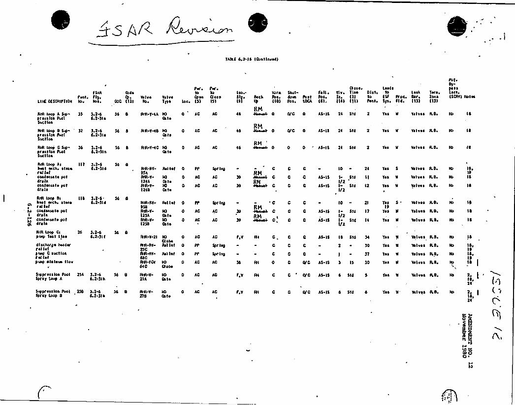
~ ~ P/( f~~o~m.
YABLS 6.2-14 ICunt lnorsdI
L II% OESI)IIPYION
fSAR
Panto flO~les ~ Ios»
RIR loop A Sop-prossloa lbolSuet los
)5 ),2-64.2-)la
AR loop C Sopprossloa lbolSuet los
)o2%4,2-)ln
AR ioop 8 SNr )2 ).2-6pressloa Root do2-)IsSuctloa
IhdoQo
IOC II)I
54 8
54 4
ValveIbo
VolvoTyfo
AR VMS IOCeto
AR YHC LO0s to
AR Y IA IOOs to
Peri
+onloci IS)
0 AC
0 AC
0 AC
PwotoQose151
AC
AC
AC
Iso o. Nsrn5loo Beck Ibs,191 IB 1101
RHi4 OeosooH- 0
RMi4 heoouoss 0
RMI6 Obswso 0
Shw'Idown Ibstlb so LOCA
fall ~
lbs.l41.
TorsoRona11) I
0/C 0 AS IS Ri Std 2 Yos N Valves LBo
CIC 0 AS I5 2i $ 14 2 'Yes V valves LSi
0 0 'S IS 2i $ td 2 Yon N Valves LB.
Closoo LeadsYlv, Ties 0 I st i lo Look)so III to $)f P'oc. Bsr,Ili1 IIII Penti Sysi fld. I I)I
PofiSy
t:l.',I5CRII tkrtee
14
14
14
RIR loop AIkeel «ECho Sfeenrel 1stcondensate pofdre lacond«lsel ~ Iot4rola
111 )o2%do'R-)ld AR-RV-
95hAVI-V-IRihIN YIRIS
IOCofoNICeto
0 AC
0 AC
Rol 1st 0 PP Spr le0
AC
CRHJ4ao4. CRhl
C 0 C AS IS
C 0
0 C AS 15
10 2i
I- Std 11I/2I Std 12I/2
Yes 5
Yes
Yos
vs Ives LS.
Valves LBo
Valves IL8
14,19IS
14
RIR Loop BIhoof orcho sfoser el 1stcondense I~ po f
I dra lacoadenssto potdrala
114 )oR-4doR )I'R-RY-
958AN-V125hfdR-Y-1258
IOSetoIOCeto
0 AC
0 AC
Rel let 0 PP Spr IRR
AC
'0RH
Ohsaa4 C
RHOksnwek C,
C C
C C
C 0
AS IS
AS-I5
10 - Rl
I- Std I)I/2I $ 14 IiI/2
Yss19
Yos
Yos
Valves LSi
Valves LSi
Valves L8,
19
14
14
RIR Loop CIpuep fssf line
4l scherde heed«I'sl 1stpuip C suctloarel I~Ipusp ~ lalaus flow
Supprossloa IbolSpray Loop A
26 ).R-ddo2-)It
RSA )oR&4o2-)Ik
56 8
IN V 2I
IIR-RY-RSCAR+Y-44CAVI-fOrdiC
AR-V21 A
IOCloseRel 1st
0 AC
0 PP
IOCtooo
IOCeto
0 AC
0 AC
Rel 1st 0 PP
AC
Spr In9
Spr ln9
AC
fV AI C. C C
C 0 C
C 0
)0
t - )'I
AS-I4 14 Std
)4 AI 0
fiy Al C
C CIC AS IS ) 15 )0
0 'IC AS-IS 4 St4 5
'yes '8
Yss N
Yes N
Yes N
Vetvos LS
Valves LS,
Valves LS,
Valves R,B,
Valves LBo
14
14 ~
19I ~ ,19t8
14,24
SoPpr sos los PoolSpray Loop 8
254 )o2%do2-)Ih
AR-V-178
IOCato
AC f V AI C C 0/C AS IS d St4 4 Yos N- Valves LS '2, II ~ ,2i
ID QIO OO ~
~ tl ~

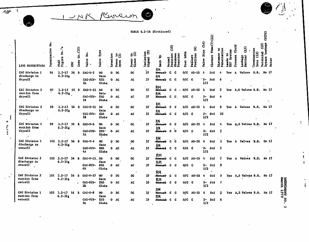
TAB[.E 6 2-16 (Continued)
LIHE DESCRIPTIOH
CAC Dlvlslon Idischarge tadryucll
o0
peeudl4
96 3.2-17 56 B CAC-V-26.2-31g
CAC FCV-2h
gel
HO
GaeaKHO
GlobeAC
37
AC 37
oR 8-~ eM vl
pe 5 M coR~~s'M
C C
RH44swA C C
5 a
1lQ ee
e
u
aP
gPE
04
'cl uellA 0
0/C AS-XS 4 Scd 4 Yes h Valves R.B. No 17
0/C C 2- Std 61/2
CAC Division 2suction froadryuell
CAC Division 2discharge todryucl 1
CAC Division 1succlon frondryuell
CAC Division 1discharge touecuell
CAC Division 2discharge touetuell
CAC Division 2succion frosuetuell
CAC Divlslon 1
suction fronuetuell
91 3.2-17 56 B
.&.2-3lgCAC V-15
CAC-FCV-1B
9S 3. 2-17 56 B CAC-V-116.2-31g
CAC-FCV-2B
99 3.2-17 56 B
6.2-318CAC-V"6
CAC-FCV-lh
102 3. 2-17 56 B CAC-V-46.2-31g
103 3.2-17 56 B-6.2-3lg
CAC-FCV-4A
Ch C-V-13 .
CAC-FCV-4B
105 3,2-17 56 B CAC V-86. 2-3lg
CAC-FCV
3h
104 3.2-17 56 B CAC-V-17&.2-3lg
CAC»FCV-3B
HO
CateKNO
Globe
HO
GateESO
Globe
HO
GateKNO
Globe
HO
GateEHO
Globe
HO
GateKNO
Globe
HO
GateENO
Globe
HO
GateENO
Clobe
DC
AC
AC
AC
AC
AC
AC
AC
AC
AC
AC
AC
AC
AC
37
37
37
37
37
37
37
37
RM =
RN44aeeeb
RM
RM
RM
RM
RM
RN
RM
RN
C C . 0/C AS-IS 4 Std 2 Yes A,S Valves R.B. Ho 17
C C 0/C C
C C 0/C AS-IS
CC 0/CC
2- Std 4
I/2
4 Std 8 Yes h Valves R.B. No 17
2- Scd 10I/2
C C 0/C AS-IS 4 Scd 4 Yes 4,S Valves R.B. No 17
C C 0/C C 2- Scd1I2
C C 0/C AS-IS 4 Scd 3 Yes h Valves B.B, No 17
C C OIC C =2- Scd 5
1/2
C C 0/0 C 2- Std 91/2
G C 0/C AS IS 4 Std 5 Yes A fi Valvhs R B
C 0 0/C 0 2« Std1/2
C C 0/C AS-IS 4 Std g Yes A,S Valves R.B.
Ho 17
Ho 17
C C 0/C C 2- Std 6I/2
C C 0/C AS-IS 4 Scd 7 Yes A Valves R.B. Ho 17
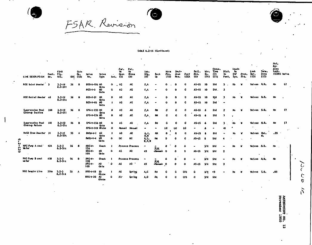
TASLS 4 2 l6 IContlnuad)
F SARPent FIO>
LIIC CLSOAPJIOH IA> HJS ~
O>d ~
Ih>COC I l2)
,Valvetao
Va I vsType
PK> PK ~'lo to+aa Close
toc. IS) I)lIsa>
I9t
tbroS>ck Ibao
I)0)
Saut fa I)do~ Ibst lbs.R s. LOCA ld)
Cause ~ LoadsVlv, Tlao Gist, LeakSa. I)) to ESP Proc. Serolldl lll) Pont, Sys. A 4. I I))
Tea« o
ZoaoI I))
Ib toSy-passLess>I)OH) aaatoo
RCC islet NoadK 5
RCC Outlot HaadK ad
$ >oprosatoa fbol IOOC)sanup Sac)los
$>opressloa Ibol IOIClean>0 Ratura
RdCJ froa Reactor Id
glo
saI RRC Puap h seal d)A
SatKsaIO
).2-ld6>2-)lt
).1-I 4d>2-)lo
)>2 l26>2-)II
)>2 l24>1-)lo
)>1-II4>2-)lk
).2-)do'2-)Ic
56 8 RCG.V-I Ot
RCG.V 5
54 8 RCG.V-)I
RCG.V 40
54 8 fPC-V-IS)
FPC-V-I 54
HOOntoIOGa to
IOIhtoIOGs to
lOOatsIOCato
0 .AC AC
0 AC AC
0 AC
I AC
0 AC
AC
AC
0 AC AC
IOIhtoaoao
Sd 8 FPC.V-IS4
fPC.V IS9
55 A RVCJ-y-I
%CO VH
N)GateIOGate
0 AC AC
0 Haaual Iaausl
I AC
0 OC
56 4 RRC-VI)ARRC.V)6A
IOOats
0 AC AC
0«ck I Process Process
F>A
f>A
F,A
f,h
0
0
0
0
C AS IS IO Std
0 AS IS IO $ )d
AS-IS IO $ )4
Valves RS>
f,A
f h IVI C
C
C
A$ )$ d Std 2
AS I$ 6 $ t4 7
Valves R.S> ly
f,h III C C C AS-IS 6 Std Va)ves RS, IA IT
A J>4>VA,J,E>T>1
LCI
84 0
LC LC
Ist 0 0
d
AS IS 4 $ td
AS l$ 4 Std
sl
Volvss Ib4.lto
AD )5
45
0RM
0
)/4 Std
AS IS )/4 Std 2
Vs)ves R.S.
0 C AS IS IO Std S . IA tt Valves RS> IA I P
RRC Puap 8 seal 4)Sla )K
)>1-)6>2 )Ic
RRC V1)SRRC-y
'
CSIa)th to
0 AC AC
0>ocA I Process Process 0RM
0
0 0 )/4 Std
AS-I5 5/4 Std
Va I 'vss R So
RRC Saepl ~ Llao 2)ha 5.2-)d>2-)I 4
55 A RRC-V l9
RRO.V 20
$0Clot>olOGl ooo
I AC
0 Alr Spr l>V)
A,C
A,C
FII c c r/0 c
III C C gO C
)/4 a5
5/4 Std
Valves T>S> ~OS
Il0 OICO OQ ~
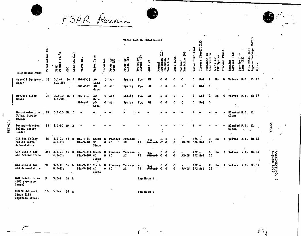
LIHK DESCRIPTION
4
u
OÃQ
0
EARLS 6,2-16 (Continued)
g31C
o u ope pe a4
u 0u aIJ u lO
g Q
8
5i3~
Dryuel 1 Equi pueac 23Drain
3.2-9 56 86.2-31k
EDR-V-19 AOCace
EOR-V-20 AOCsee
0 Air
0 hir
Spring P,h'N 0 0 C C 3 Std 2 Ho M Valves R.B. Ho 17
Spring - P,k RH 0 0 C C 3 Std
Dryuc1 1 PloorDrsia
3.2-10 56 8 PDR-V-36.2-31k
FDR-V-4
AO 0CateAO 0Gate
hir Spriag P,h RH 0 0 C C
hir Spring P h RH 0 0 C C
3 Scd 2 Ho M Valves
3 Std 3
Q.B. No 17
Decoacsaiastiongalen. SupplyHeader
0 concauinacfonSolca. ReturnNeeder
94 3. 2-10 Hh 8
95 3.2-10 Hh 8
4 - " - - Blaaked R.B. IjoClose
Slsnked R.B. HoClose
Clh for SafetyRelief Valvehccuculators
56 3.2-21 56„8 CIA-V-21 Check 0 Process Process6. 2-31c CIA-V-20 HO 0 AC'C 41
Globe
C. C4h@re4 0'
C0 kS-IS
3/4-3/4 Scd
3 Ho10
A Valves R.B. Ho 17
CIA Line h forADS Accunulstors
CIA Liae B forADS hccuaulstors
898 3.2-21 56 B Clh-V-31A Check 0 Process'6.2-3lc Clh-V-30h HO 0 AC
Globe
ProcessAC 42
91 3.2-21 56 B CIA-V-318 Check 0 Process Process6.2-3lc CIA-V-3DB HO 0 kC AC 42
ClubsP 00 C - 1/2-
0 AS-IS 1/2 Scd
C C C - 1/2-0 0 0 AS-IS 1/2 Scd
5 No15
2 Ho15
A Valves R.B.
A Valves R.B.
Ho 17
83No 17
CRD Iaserc Lines 9 3.2-4 56 8(185 separateliaes)
CRD llichdraual 10 3.2-4 56 Blines (185separate lines)
See Hoce 4
See Hoce 4
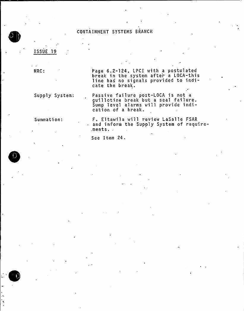
CONTA INtlENT SYSTEMS 8RANCH
ISSUE 19
NRC:
Supply System:
Summation:
Page 6.2-124, LPCI with a postulatedbreak in the system afte'r a LOCA-thisline has no signals provided to indi-cate the break.
Passive failure post-LOCA is not a
guillotine break but a seal failure.Sump level alarms will provide indi-cation of a break.
F. Eltawila will review LaSalle FSARand inform the Supply System of require-ments.,See Item 24.

CONTAINMENT SYSTENS BRAflCH
ISSUE 24
NRC: See LaSalle LPCI injection line. Note31 in LaSalle'SAR, Table 6.2-21. pene-trations i'1-12 through H-14 have remotemanual and other signals to isolate theselines. Identify these signals and e'valuateapplicabil.ity to MNP-2.
Supply System:
S uppl ementaryInformation:
LaSalle will be contacted and an evaluationas to applicability to WNP-2 will be madeby October 2, 1981 (see issue 19).
The WNP-2 LaSalle isolation valve designsfor the LPCI injection val ve are similar.The only di fference is that LaSalle has a3/4 inch air-operated globe valve inparallel with the check valve inside contain-ment, which have isolation signals to close.WNP-2 has no such bypass line. Neither WNP-2or LaSal 1'e has isolation si gnals to closethe LPCI injection val ves. WNP-2 us'es val vepacking leakage indication, and reactor bldg.sump level indication, as well as reactor waterlevel and suppression pool water level instru-mentation: to alert the operator o f excessi ve1 eakage.
Issues 19 and 24
. The LaSalle isolation design for the LPCI containment penetration is similarto the MNP-2 design in. that .containment isolation is provided by a motoroperated gate valve outside containment and a testable check valve insidecontainment, (see Figure 1). The only difference in the design is thatLaSalle has a 3/4-inch globe valve in parallel with the testable check valveinside containment.
The 3/4" air operated globe valve receives the reactor vessel low-low waterlevel and high drywell isolation signals, has remote manual operation fromthe control room and fails closed on loss of power. The only signal tothe LPCI injection line isolation valves, however, is a remote manual signalto the gate valve outside containment, which is identical to the isolationvalve control logic at MNP-2.
LaSalle and MNP-2, therefore, both depend on:
l. Leak detection systems consisting of sumps with redundant level indi-cation in the control room and stem leak off instrumentation to deter-mine the location of a leak or line failure and allow the operator toclose the isolation valve associated with the line.
2. RPY level information to ascertain whether or not the flow is actuallyreaching the RPV.
3. Suppression pool water level information to identify the occurrence ofleakage or a line failure.
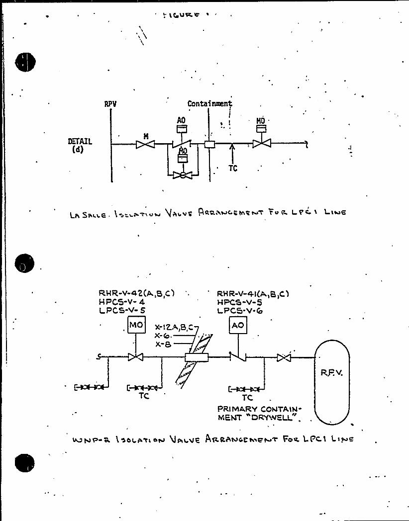
Conte'aent
TC
p gaits ~ hs" se i'm Qwivg 'H+i~a<Rtnzeu< Yoi~ LV'C. S Llu6
Rva-v-<2(a,a,c)HPC.'5-V- 4LPCS-v- 8
X-.Z.A,a,-X-Q.x"9
RHR-V-+i(A,,a,C)epcs-v-5cpcs-v-0
AO
r.
TC, TCPRIMA.RY COhlTALN-MENT DRY'-'VKLL
R,.P.v.
CONTAINMENT SYSTEMS BRANCH
ISSUE'0
'RC: Page 6.2-131, penetrations 56, 89b, 91and 82E show check valves outside con-tainment. Check valves outside contain-ment are not acceptable.
Supply System: The Supply System will relocate checkvalves and containment isolation valvesinside cont'ainment. See revised FSAR pages6.2-130 and 6.2-131 and Figures 6.2-31c and6.2-31r (attached) .
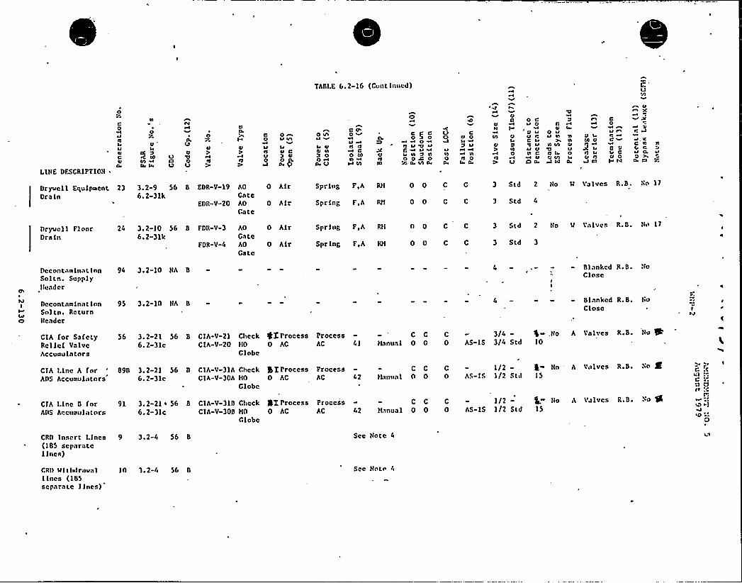
TASI.E 6.2-16 (Cunt lnued)
LINE DFSCRIPTION
0)'
04
~Ia4leal
C4I
oe
0004ItI
4) CJ )
4l
c0
4I al
Q
0 nu ae1
~e4I C
4l
0 a/aUVQ N
O0 A
ae 0
C Q'~~I
cC
0 40NW Vl
ohio0el u '0 U
LlI N 0 NO 0 W O
ae Vl 0
O CQ 4l 0
~I~a ~ ~
a4 ~ NO a4 0ne V ae
Cln
QllVl Cl
~e
Q) a40
0 CU 0
a
Q UQ r,C U
Ual ClN C
4Icl 0
n0 U
'N
N VI
el Ia,Q V:W lal
Q UCC 4l
0 tl Ie4 Q 00 ACI
C0ur wC ~g~e CQ 0~ 44
4Ine
JC
VC N Nr~a 0,0
!
Dryvcll Equfpnent 23Drain
3.2-9 56 8 EDR-V-196.2-31k
EDR-V-20
AO
GateAOGate
0 Alr
0 Alt
SprlnB F,A Rtl 0 0 C
Spr fng FA RM 0 0 C C
3 Std 2 No V Valves R.B. Nn 17
3 Std 4
Dryucll Floor 24Drain
3.2-10 56 8 FDR-V-36. 2-31k
FDR-V-4
AO
GateAO
Gate
0 Air
0 Alr
Spring F A Rtt 0 0 C C
Spr fng FA RM 0 0 C C
3 Std 2 No N 'Valves
3 Std 3
R.B. thl 17
Decnnt1Nlnat lnn 94Sol tn. SupplyHeader
3. 2-10 NA 8 4 - *- - - Blanked R.B. NoClc sc
MI
IeI4)
Decontanlnat inn 95Snltn. Returntlcader
3.2-10 NA 8 4 — - — - Blanked R.B. huClose e
CIA for Safety 56Rellcf ValveAccunu la tors
3.2-21 566.2-3lc
8 CIA-V-21 Ctlcck 4I ProcessCIA-V-20 HO 0 AC
Glnbe
ProcessAC 4l
C
tlanual 0C C
0 03/4-
As-ls 3/4 Std$ - .No10
A Valves R.B ~ No %
CIA I.lne A fnr 890ADS Accunulntors
3.2-21 566.2-31c
0 CIA-V-31A CheckCIA-V-30A HO
Globe
gI Process0 AC
ProcessAC 42
C
tLInua I 0C C
0 0 As-IsI/2-I/2 Std
Nn15
* Va IVCS R.S. aN4
CIA Line 0 for 91ADS Accurullntnrs
3. 2-21 56 8 CIA-V-310 Check6.2-31c CIA-V-300 HO
Globe
QJ,Process Process0 AC AC 42
C
tLinua1 0C C
0 0I/2-
AS-IS I/2 Stdtto
15A ialvcs R 8 ~o 0
CRD Insert Lines 9 3.2-4 56 8(185 separatelines)
See Note 4
CRlt ltlthalrnval 10 3.2-4 56 8Ilncs (185separate lines)
See Nntl'a

0
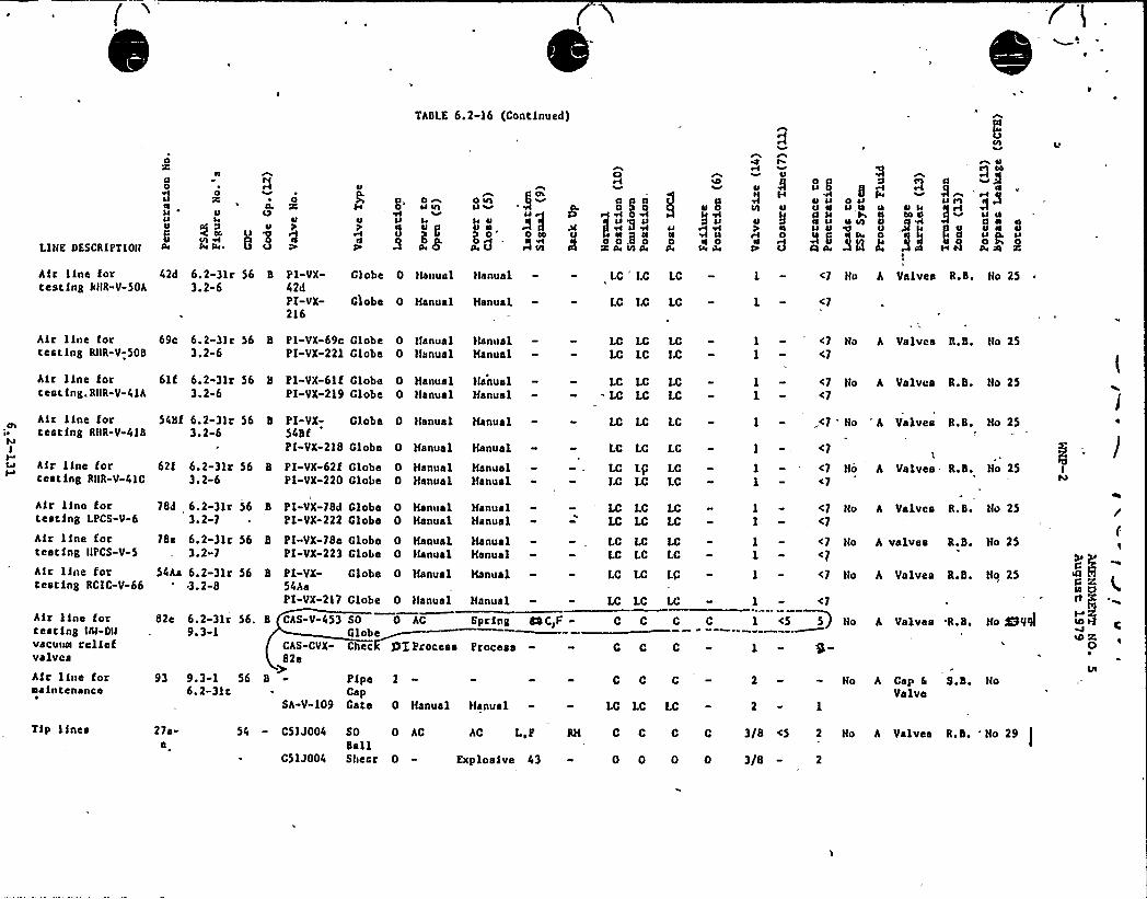
(
TABLE 6.2-16 (Continued)
LIKE DESCRIPTION
o
n0
ou 4
g I lt on Pa,. 0
~ 00
uj4g,
o 4J
c'4J
Q vl
uo 4 u$
o 4IUl uuu
45A l4
8P4
0 4JIJ,u u
a4lo 0u
3Q 0
B0j""
4
3go up
n u u
aoa4 2
Air line for 42d 6.2-3lr 56cesting RNR-V-50A 3.2-6
B PI-VX-42dPI-VX-216
Globe 0 klanua 1 klanua1
Globe 0 Manual Hanua1
LC"
LC LC
LC LC LC
1 - <7 No h Valves R.B. No 25
1 - <7
hir line fortesting RIIR-V-50S
69c 6.2-3}r 563.2-6
S Pl-VX-69c Globe 0 klanualPI-VX-221 Clobe
" 0 Hanual}IanualHanual
LC LCLC LC
LCLC
1 - <7
1 -- <7No h Valves R.B. No 25
hir line forcasting. RIIR-V-4lh
61f 6.2-31r 56 8 PI-VX-61f Clobe 0 Hanus13.2-6 PI«VX-219 Globe 0 }lanusl
ManualHanual
LC LC— LC LC
LCLC
I - <71 - <7
Ho h Valves R.B. No 25
hir line forteacing RNR-V-41$
kuI
Air line forcasting RKR-V-41C
Air i}no fortesting LPCS-V-6
hir line fortesting IIPCS-V-5
54bf 6.2-3lr 56 b PI-VX-3.2-6 548f
PI-VX-218
Globe 0 Hanual Hanual
Globe 0 Hanua1 Hanus1
62t 6.2-31r 56 8 PI-VX-62f Globe 0 Hanual3.2-6 Pl-VX-220 Globe 0 Manual
Hanna IHanusl
HanualHanusl
HanualHanus1
78d 6.2-3lr 56 B PI-VX-78d Globe 0 Hanual3.2-7 ~ PI-VX-222 Clobe 0 Hanual
78e 6.2-31r 56 8 PI-VX-78e Globe 0 Hanual3.2-7 PI-VX-223 Clobe 0 Manual
LC LPIS LC
LC LCLC LC
LC LCLC LC
LCLC
LCLC
LCLC
LC LC LC
LC LC LC
1 « '71 - <7
No A Valves - R.b. No 25
1 - <7I -,<7 No h Valves R.S. Nu 25
I - <7 Ho h valves R.S. No 25
1 - „<7 'o "h Valves R.S. No 25
I - <7
hir line fortesting RCIC-V-66
54ha 6 '-3lr 563.2-8
8 Pl-VX-54AaPI-VX-217
Clobe 0 Hanua1 Manual
Globe 0 Manual Hanusl
LC LC LG
LC
I - <7 Ho A
1 - <7
Valves R.S. Ho 25
Air line fortea Cing IIII-Dlkvacua reliefvalvesAir line fornaintcnance
Tip lines
93 9.3-1 566.2-3lc
CAS-CVX-82e
B
SA-V-109
27s-e
54 - C5] J004
C51J004
82e 6. 2-3lr 56. B CAS-V-4539. 3-1
C C
PipeCapCate
SO
SallSheer
0 Hanua1 Hanua1
0 AC
0
AC L,P RH
Explosive 43
C C C
LC LC LC
0 C C C
0 0 0 0
SO 0 AC Spring CSC>F - C CGlobeGhee glIProceas Process - - C C
1 <5 5 Ho A Valves R.B. Ho WV9l
2 Ko A Cap 6Valve
S.S.
No 29
2 - 1
3/8 <5 2 No A Valves R.B.
3/8 - 2

I
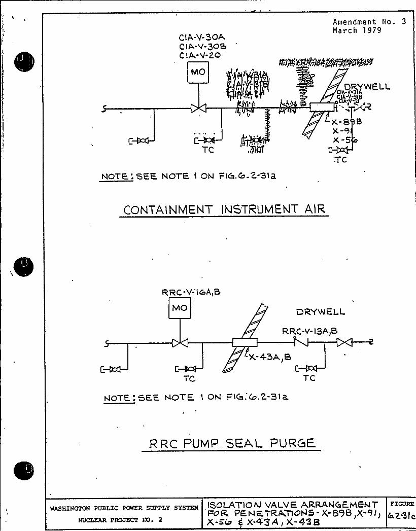
ClA-V-BOAC lA-V-)0$C l A-V-ZO
I'
Amendment No. 3
March 1979
~'f rrN'~5$~@5tPP'„DR/WE
LLCIA V-)IBC)A-V-g
C,
TCPg ~ ~ I
x-8 1X-)X-5
NOTE.: SEE NOTE ) ON Fi&.& 2-Sip
CONTAlNlv1E,NT'NSTRUMENT A,IR
,RRC-V- lc A,S
MO DRYWALL
RRC-V- l3A)B
C
TC
-X-45A B)
NOTE: SEE NOTE 1 ON .-<Ca. &.2-31 a.
.R RC PUMP SEA,L P URC E.
WASHINGTON PUBLIC POWER SUPPLY SYSTEH
NUCLEAR PRCLGKT KQ 2
lSOLATlOIVYALVE ARRAhlCiE.KENTFOR PF-NK ) RA'F0~5- X;89~,X-9I)x-Eb x+3 A, x-43 8
FIGURE
.2-Std

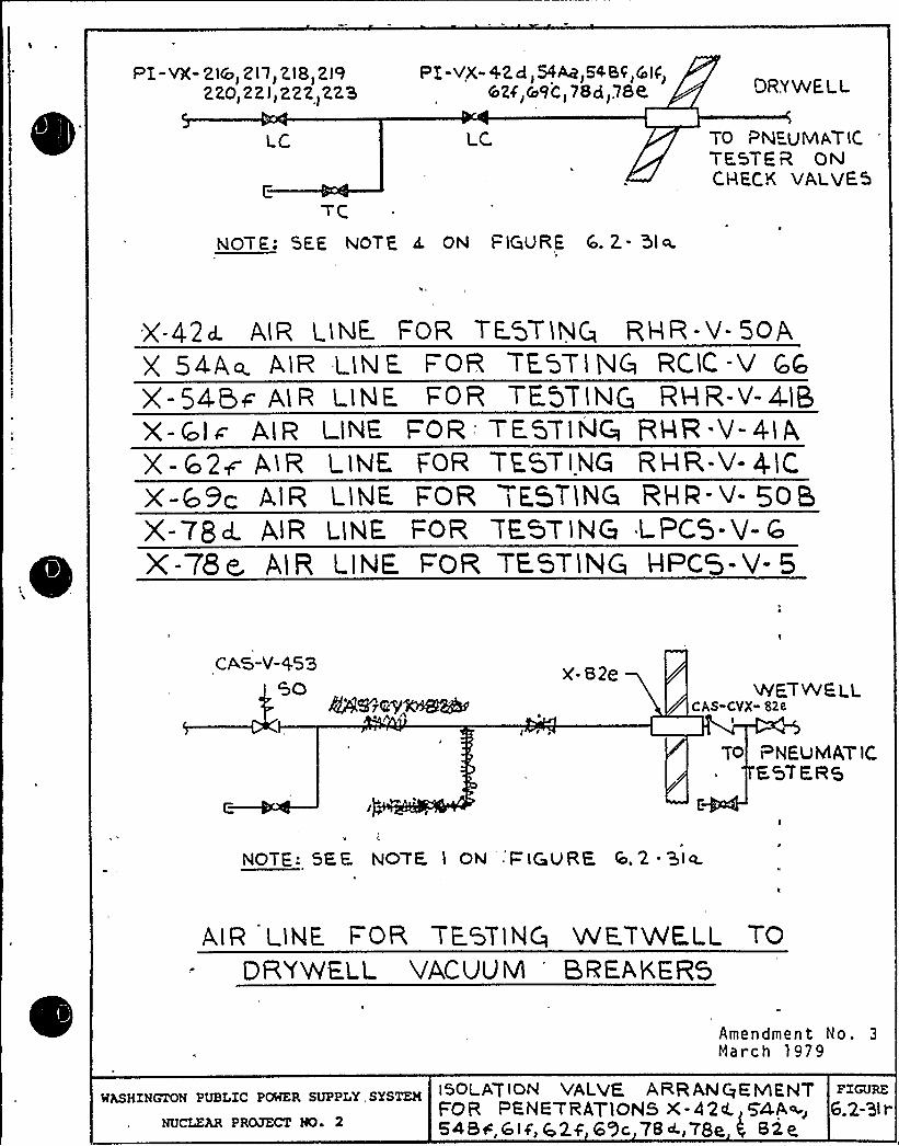
PI - VX-21') 2 l1) 2I8) 2l9220) 22 I)222]22'8
LC
PX-VX-+28)54C4R)54BF)Cot(')&24')&9C) 78d) 78K DRYWE.LL
TO P¹UMAT iCTE.STF R ONCHEC.K VALVES
NOT F: SEE, NOTE cL ON FiGURE Q. 2. - '5l a.
.
'\
X-42d. AlR l lNE FOR 7'E STING RHR-'vt- 5OAX 54-Aa AlR LlNE. F OR TE.QT156 RC1C -V Qto
X- 54.5c''I R LINE, FOR TE QT IN@ RHR-V- 4-IBX-GIc AIR LINE F'R: TEGTIhJCq RHR-V-4IAX - G2p 4iR LlNF FOR TESTING RHRV 41CXCo9|- AlR LlNE. FOR l E5TlNG RHR V- 505X-78cL AIR LINE FOR TESTING LF'CS-V- rX-78m. AIR LINE. FOR TE.STING HPCS-V- 5
CAS-V-45350
r@k5 ~zV~agvX-82t'ETWELL
CAS-CVX- 82e
TO evcuMA7iCEST ERG
>QTE: 5E,E. NO'TF l ON F'ICIURE, Icl. 2
alp l lNE. FOR TE.GTlNQ METRE.LL TODRYWE.LL VACUUM 'RFAKER5
WASHINGTON PUBLIC POWER SUPPLY, SYSTEM
NUCLEAR PROJECT NO 2
Amendment No, 3
March 1979
ISOLA'7 iON VALVE ARRANGE IVlEHTFOR PBNETRATlONS X-42<4 54A~, 6.2-Sic54BFGif,$ 2,C 6'3c 78<,78e 82e

CONTAINMENT SYSTEMS BRANCH
ISSUE 23
NRC: Paragraph 6.2.4.3.2.2.1.3 - Please clarifythe wording of this'ubsection, and addmore detail to Figure 6.2-31p."
Supply System: Figure 6.2-31p will be revised, and thetext clari fied in the FSAR. See r evisedFSAR page 6.2-64 and Figure 6.2-3lp (attached}.,

0
I
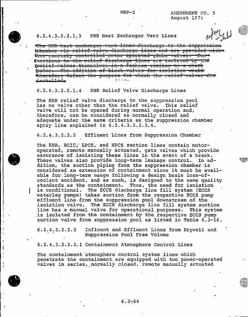
3'KP-2 A!~iENDNEHT ";:0.August 197~
6.2.4.3.2.2.1.3 RHR Heat Exchanger Vent Lines
C~~me '
QcMefw-" C ~ .
6.2.4.3.2.2.1.4 RHR Relief Valve D'charge Lines
The RHR relief valve discharge to the suppression pool~as ..o va've otner than the relief valve. This reliefvalve will not be opened during normal operation and,therefore, can be considered as, normally closed andacecuate under the same criteria as the suppression chamberspray line explained in 6.2.4.3.2.2.3.4.6. 2. 4. 3. 2. 2. 2 Effluent Lines from Suppression Chamber
The RHR, RCXC,'PCS, and HPCS suction lines contain motor-operated, remote manually actuated, gate valves which provideassurance of isolating these lines in the. event of a break.These valves also provide long-term leakage control. Zn ad-dition, the suction piping from the suppression chamber isconsidered an extension of containment since it must be avail-able for, long-term usage following a design basis loss-of-coo'ant accident, and as such, is designed to the same qualitystandards as the containment. Thus, the need for isolationis conditional. The ECCE discharge line fill system (ECCEwaterleg pumps) takes suction from the respective ECCS pumpeffluent line from the suppression pool downstream of theisolation valve. The ECCS discharge 1-'ne fill system suctionline has a manual valve for operational purposes. This system.is isolated from the containment by the respective ECCS pumpsuction valve from suppression pool as listed in Table 6.2-16.
6.2.4.3.2.2.3 influent and Effluent Lines from Drywell andSuppression Pool Free Volume
6.2.4.3.2.2.3.1 Containment Atmosphere Cont ol Lines
The containment 'atmosphere control system lines whichpenetrate the containment are equipped with two power-operatedvalves in series, normally closed, remote manually actuated
6.2-64
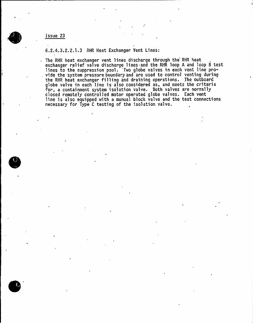
issue 23
1
6.2.4.3.2.2.1.3 RHR Heat Exchanger Vent Lines:
The RHR heat exchanger vent lines discharge through the'HR heatexchanger relief valve discharge lines and the RHR loop A and loop 8 testlines to the suppression pool. 'Two globe valves in each vent line pro-vide the system pressure boundary and are used to control venting duringthe RHR heat exchanger filling and draining operations. The outboardglobe valve in each line is also considered as, and meets the criteriafor, a containment system isolation valve. Both valves are normallyclosed remotely controlled motor operated globe valves. Each ventline is also equipped with a manual block valve and the test connectionsnecessary for Type C testing of the isolation valve.

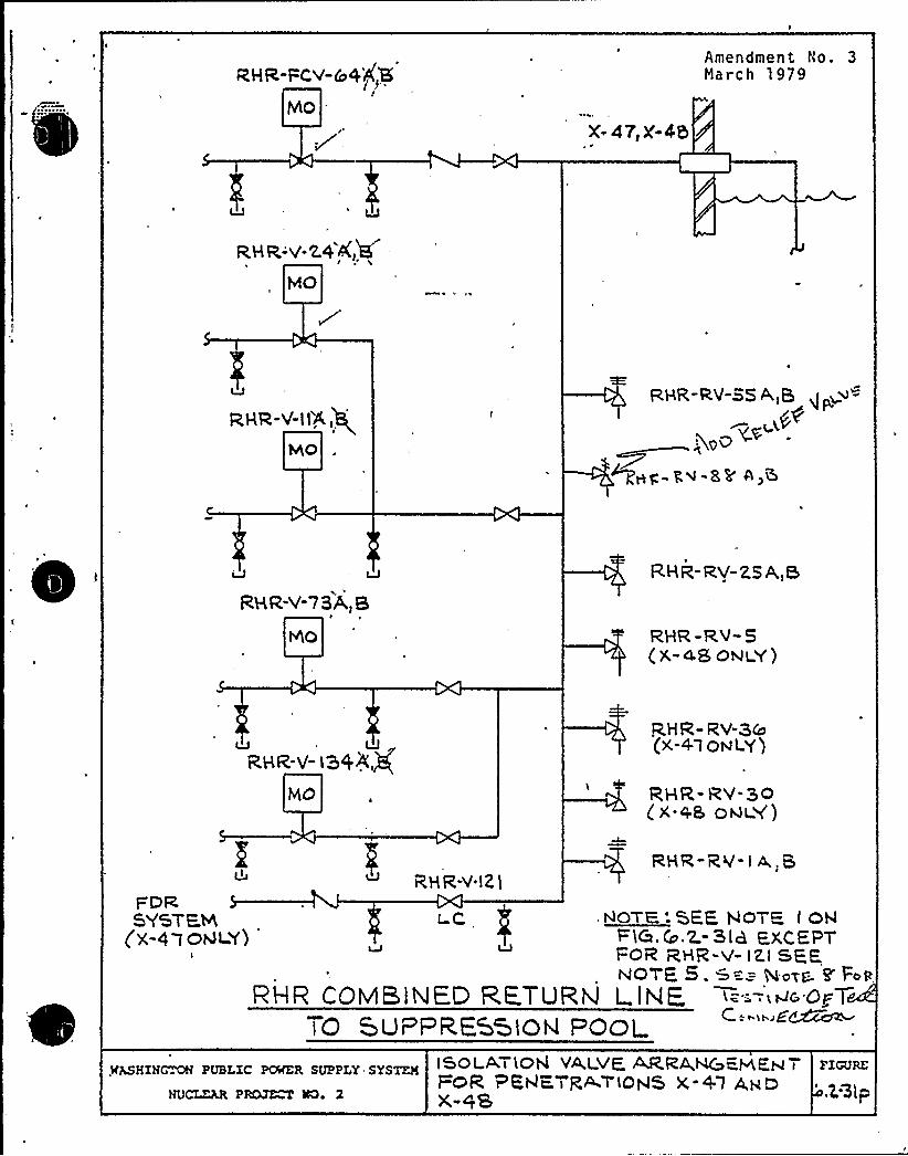
RHR-FCV"&4')SS,]8
MOX 47)X-45
Amendment No. 3March 1979
RHR-V-Z,4 4, EL
MO
RHR-V-II'A
hhO
R.HR-RV-SS A,5
0>
*><
RHR-V-7BA,B
RHR- RV-ZS A,8
QHR -RV-5(X-48 oNLY)
LJ LJgSR-V- ia%Ag
MO
QHR- RV-3&(x-4 t osLY)
R HR- RV-30( X +8 ODDLY)
R,HR-Y.IZlRHR-RV- I A, 8
I=DRSYSTEM
(X-4a oQL Y)I
ic NOTE,:SFE HOTS I OhlF)C.C .Z.-SIa E,XCEPTFOR RHR-V- IXI SEENOTE 5 . w =-=- gong- F Fc R
RHR COMBlNED RE.TURN 1 INE, <='-'-«c'op 7TO SuPf R.ESStoN FOol
.lCLSHZN~ PUBLZC POINTER SUPPLY SYSTEM
NUCLZAR PRQJ~ lK) 2
ISOLATION VA,LVE ~RA,NGENEH Tt=OR PKhlKTR,~TIOht5 X +"t ANDX-QS
FIGURE
'Z,Sip
CONTAINtlfNT SYSTE HS BRANCH
ISSUE 25
HRC:'Perform a pre-op ILRT at. full pressurefor twenty-four (24) hours wi'th all sub-sequent tests at a twelve (12) hourduration.
Supply System:
SupplementaryInformation;
The Supply System will provide justifica-tion for -performance of the test at atwelve (12) hour durat'.on at the ILRTfrequency by October 2, 1981.
Justi fication for performance of thesubsequent ILRT tests over a 12-hourduration, instead of a'4-hour, duration,wi 1 1 be provi ded by November 6, 1981.See revised FSAR pages 6.2-81 and 6.2-83(attached) .
CONTAINMENT SYSTEMS BRANCH
ISSUE 29
NRC:
Supply System:
Question 031.070, containment systemdrywell/wetwell leak test. The-FSA'Rshould. b'e ch'anges to indicate that thedrywelllwetwell leak test be- performedat a higher pressure than 1 psi.The pressure for the test should beapproximately submergence pressure,5 psig.
The Supply System proposes to performtest's at the following frequency:
fWa. Pre-operati.ona)'est: l~> & 5 psig
lb. First Refue.ling:, 13 ~ps''
)c. Fi'rst ILRT Interval. 1) 8 5 psigd. WNP-2 will demonstrate that 1) psigtest is adequate, based on informa-
tion obtained from items a-c above,and will request discontinuation ofthe 5 psig and perform 1$ ps-ig testsat each, succeeding refueling outage.
The basis for the 5 psi test is that a 5 psidi fferential pressure is relatively high butdoes not clear the water column out of thedownc'omers . The I> ps i test wi 1 1 be demons tra tedto be adequate by comparison with a 5 psi test.The advantage of a I> psi test is that testscan be performed either just prior to 'a shutdownor during a startup without causing a containmentisolation or scram=.
Summation: F ~ El tawila will review the Supply System positionand advise the Supply System of acceptability.
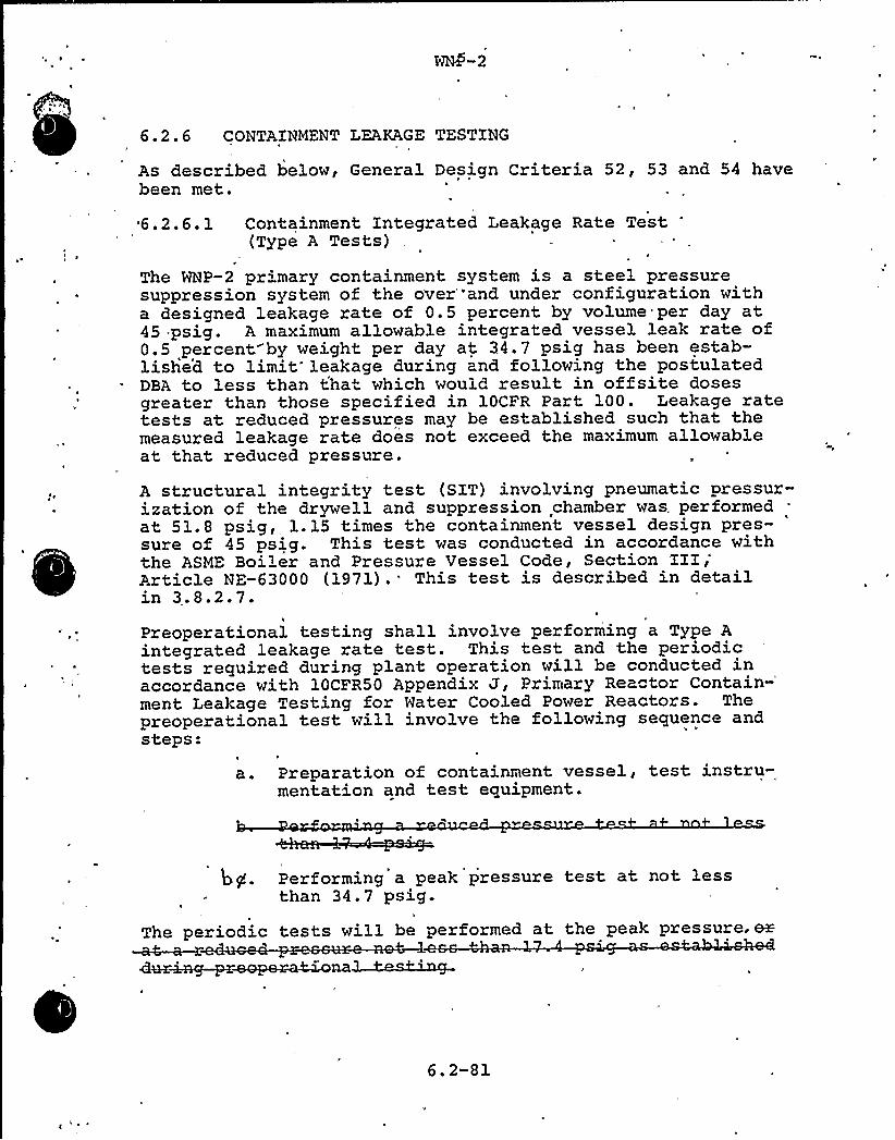
6. 2 ~ 6 CONTAINMENT LEAKAGE TESTING
As described below, General Design Criteria 52, 53 and 54 havebeen met.
6.2.6.1 Containment Integrated Leakage Rate Test'TypeA Tests)
The WNP-2 primary containment system is a steel pressuresuppression system of the over "and under configuration witha designed leakage rate of 0.5 percent by volume per day at45 psig. A maximum allowable integrated vessel leak rate of0;5 percent by weight, per day at 34.7 psig has been estab-lished to limit leakage during and following the postulatedDBA to less than tha" which would result in offsite dosesgreater than those specified in lOCFR Part 100. Leakage ratetests at reduced pressures may be established such that themeasured leakage rate does not exceed the maximum allowableat that reduced pressure.
A structural integrity test (SIT) involving pneumatic pressur-ization of the drywell and suppression chamber was. performedat 51.8 psig, 1.15 times the containment vessel design pres-sure of 45 psig. This test was conducted in accordance withthe ASME Boiler and Pressure Vessel Code, Section III;Article NE-63000 (1971). This test is described in detailin 3.8.2.7.
Preoperational testing shall involve performing a Type Aintegrated leakage rate test. This test and the periodictests required during plant operation will be conducted inaccordance with 10CFR50 Appendix J, Primary Reactor
Contain-'ent
Leakage Testing for Water Cooled Power Reactors. Thepreoperational test will involve the following sequence andsteps:
a. Preparation of containment vessel, test instru-mentation and test equipment.
bg. Performing a peak pressure test at not lessthan 34.7 psig.
The periodic tests will be performed at the peak pressure. m
6.2-81
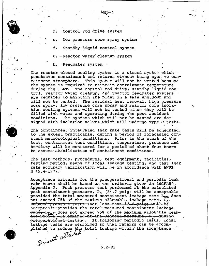
WNj—2
d. Control rod drive system
e. Low pressure core spray system
Standby liquid control system
g. - Reactor water cleanup system
h. Feedwater system
The reactor closed cooling system is a closed system which "
penetrates containment and returns without being open to con-tainment atmosphere. This system will not be vented becausethe system is required to maintain containment temper'atureduring the ILRT. The control zod d ive, standby liquid con-trol, reactor water cleanup, and,reactor feedwater systemsare required to maintain the plant in a safe shutdown andwill not be vented. The 'residual heat removal,:high pressurecore spray, low pressure core spray and reactor coze isola-tion cooling systems will not be vented since they will befilled with water and opezating during the post accidentconditions. The systems which will not be vented are de-signed with isolation valves, which will undergo Type C tests.
n
The containment integrated leak rate tests will be scheduled,to the extent practicable, during a period of forecasted con-stant meteorological'onditions. Prior to the start of thetest, containment test conditions, temperature,. pressure andhumidity will be monitored for a period of about four hoursto ensure stabilization of containment conditions.
The test methods, procedures, test equipment, facilities,testing period, means of local leakage testing, and test leakrate accuracy veri ficati on will be in accordance with ANSIN 45.4-1972.
Acceptance criteria for the preoperational and periodic leakrate tests shall be based on the criteria given in 10CFR50,Appendix J. Peak pressure test performed at the calculatedpeak containment pressure, Pa (34.7 psig) will be acceptableprovided the total measured containment leakage rate Lam doesnot exceed 75% of the maximum allowable leakage rate, La.
4d
~~a<~~etwx-mined-aC —the —reduced-pz~eur~~~e~~preoperaMwaal —ttes~~ If following periodic tests, localleakage tests are per formed so that repairs can be accom-plished to reduce total leakage within'he acceptance
6.2-83

0
The initial preoperational type A test wiLL be performed fora duration of twenty-four (24) hours at Pa. Subsequent testswill be performed for a minimum of 12 hours and wiLL becontinued untiL the 95 percent upper confidence Limit is Lessthan or equal to 0.75 La.

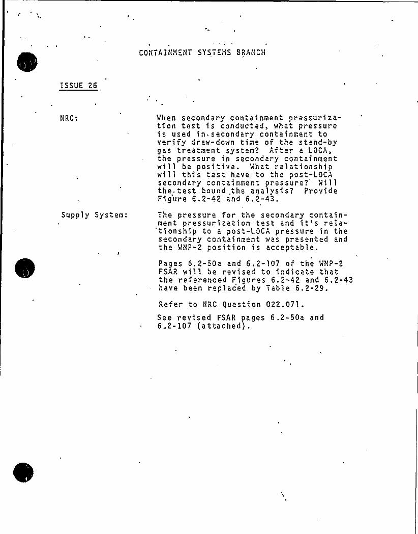
COHTAIHY4"-HT SYST="NS BRAHCH
ISSUE 26
HRC:
Supply System:
When secondary containmeni pressuriza-tion test is conduc ed, wnat pressureis used in secondary containment toverify draw-down iime of ihe stand-bygas treaimeni s Jsi Q? Af er a LOCA,the pressure in secondary containmentwill be posi ive. 'rihat relationshipwi II this ies . have to the post-LOCAsecondary con ainmen: pressure? Millthe. test bound ihe analysis? ProvideFigure 6.2-42 and 6.2-43.
The pressure or the secondary contain-ment pressurization .est and it's rela-'tionship to a post-LOCA pressure in thesecondary coniainmen ~ was presen.ed andthe MHP-2 position is acceptable.
Pages 6.2-=0a and 6.2-107 of he MHP-2FSAR will be revised o indicate thaiihe referenc d Figur s 6.2-42 and 6.2-43have been re~laced by Table 6.2-24.
Refer .o HRC gues ion 022.071.See revised FSAR pages 6.2-50a and6..2-107 (a ttached) .
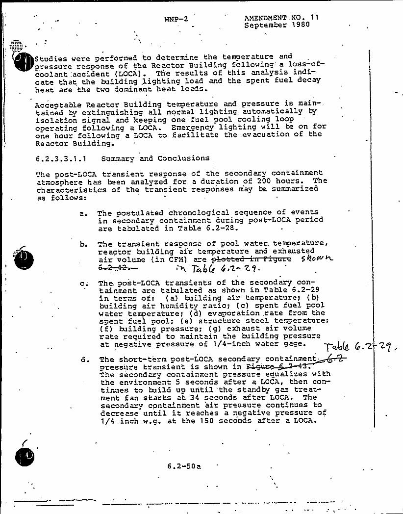
ANENDNENT NOSeptember 1980
Studies were performed to determine the temoer ature andp=essure response o "he Reactor Building followina a loss-of-coolant 'accident (LOCA) . Th'e results of this, analysis indi-cate that the building,lighting load and the spent fuel decay'neat are the two dorwnant heat loads.
Acceotable Reactor Building temperature and pressure is main-,tained by extinguish'ng all normal lighting automaticallyisolation signal and Keeping one fuel pool cooling loopooe ating following a LOCA. Emergency lighting will be on forone hour ollowing a LOCA to facilitate the evacuation of theRe actor Building.
6. 2.3.3.1. 1 Summary and Conclusions
.he post-LOCA t ansient response of the secondary containmentatmosphere has been analyzed for a duration of 200 hours. Thecharacteristics of the transient responses may be summarizedas follows:
a. The postulated chronological sequence of events' secondary containment during post-LOCA periodare tabulated in Table 6.2-28.
b. he transient response of pool water. temoerature,reactor building ai'r temoerature ana exhausteda'r volume (in CFN) a"e 50oW~
4 T 6Q 4'<-7-'t.ci
a.
The. post-LOCA transients of the second y con-tainment are tabulated as shown in Table 6.2-29in te ms of: (a) building air temperature; (b)building a = humiaitv at'o; (c) spent fuel poolw ater temoer ature; (d) ev aoor ation,r ate from thespent uel pool; (e) structure steel temperature;(f) building pressure; (g) exhaust air volumerate required to maintain the building pressureat nega" ive pressure of 1/4-inch water gage.
The short-term post-LOCA secondary containmentpress'ure transient is shown in "
'.".e secondary containment pressure equa~izes w ththe env'ronment 5 seconas a er a LOCA, then con-tinues to build up until 'the standby gas t=eat-ment an sta ts at 34 seconds after LOCA. Thesecond~~ containment air pressure cont'nues todec ease until it reaches a .".egative pressure of1/4 inch w.g. at the 150 seconds after a LOCA.
6.2-50 a
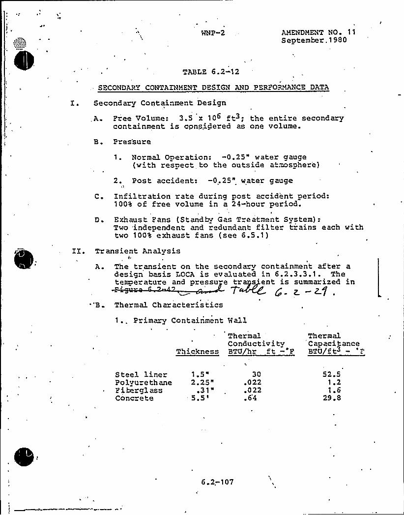
HNP-2 AMENDMENT NO 11September.1980
TABIE 6.2-12
SECONDARY CONTAINMENT DESIGN AND PER" OR~VCE DATA
I. Secondary Containment Design
A. Pree Volume: 3.5 x 10 ft3; the entire secondarycontainment is cpnsidered as one volume.
B. Pres'sure
C.
D ~
1. Normal Operation: -0.25" water gauge(with respect to the outside at.ensphere)
2. Post accident: -0.25" water gauge
Infiltration rate du-ing post accident period:100% of free volume in a 24-hour period.
Exhaust Pans (Standbv Gas Treatment System):Two .independent and redundant filter trains each withtwo 100% exhaust fans (see 6.5.1)
A ~
"B. Thermal Char acte istics
Tr ansient Analysis
The transient on the secondary containment after adesign basis LOCA is evaluated in 6.2.3.3.1. Thetemperature and pressu e tr s'ent is summarized in
T g z-zI,1 .. P imary Containment Hall
ThermalConductivity
Thickness BTU/hr t — E
ThermalCapacitanceBTU/ft3 - '-;
Steel linerPolvu ethaneE ibergl assConc ete
1.5"2.25"
~ 31"5.5'0.022.022. 6'4
52.51 21.6
29.8
6 2.-107

l4
CONTAINMENT 'YSTEMS BRANCH
ISSUE 3D
NRC:
Supply System:
Page 6;2-32 - Purging during normaloperations - statement requires revisiondue to containment inerting commitment.
The FSAR will be revised, and changesmade, to reflect inerted conditions whenthe FSAR text is added for containmentinerting. The rewrite wi 11 show purgingfor inerting, deinerting, and pressure
. control due to pneumatic leakage. Purging~ will not be done for temperature or humi-
dity control. The text revision willeliminate the. 1% lifetime limit for thepurge va.ives."
See attached FSAR pages,6;2-31, 32, and 33.
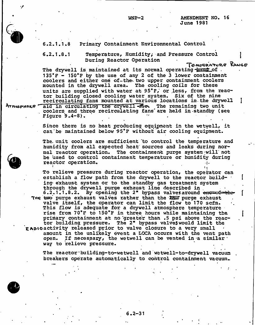
WNP-2 AMENDMENT NOe 16June 1981
6.2.1.1.8 Primary Containment Environmental Control
t6.2.1.8.1 Temperature, Humidity; and Pressure ControlDuring Reactor Operation
T~wqcg,aaMELQ'A~r eThe dzywell is maintained at its normal operatinggzERR„of .
135'F — 150'F by the use of any 2 of the 3 lower containmentcoolers and either one of-the; two upper containment coolersmounted in the drywell area. The cooling coils for theseunits are supplied with water at 95'F,'r less, from the reac-tor building closed cooling water system. Six of the ninerecirculating fans mounted at various locations in. the drywel1 J
WteespHea.c ax xn circu atxng e zywe The remaining two unit, coolers and three'ecirculating fans are held in standby (see
Figure 9 4-8).
Since there is no heat producing equipnent in the wetwell, 'tcan'be maintained below 95'F without air cooling equipment.
The. unit coolers are sufficient 'to control the temperature andhumidity from all expected heat'ources and leaks during noz-mal reactor operation. The containmen4 purge system will'otbe 'used to control containmen't temperature or humidity duringreactor operation. -I.
I 'tTo relieve pressure during reactor operation, the operator canestablish a flow path from the dzywell to the reactor build-ing e'xhaus< system or to the standby gas tzeatment systemthrough the drywell purge exhaust line described in,
y p tg h 2'ptag 'tare purge exhaust valves rather than the -RK purge exhaust
valve itself, the operator can limit the flow to 170 scfm.This flow is adequate for a dzywell atmosphere tempezaturerise from 70 Pto '150'F in three hours while maintaining the tprimary containment at no 'greate'r than .5 psi above the reac-tor building, pressure. The 2" bypass valveSwould limit the
p po<oactivity released prioz to valve closure to a very smallamount in the unlikely event a TOCA occurs with the vent pathopen. If necessary, the wetwe14 can be vented in a similar
'ayto relieve pressure.The reactor*building-to-wetwell and wetwell-to-drywell vacuumbreakers operate automatically to control containment vacuum
6 ~ 2-31

'
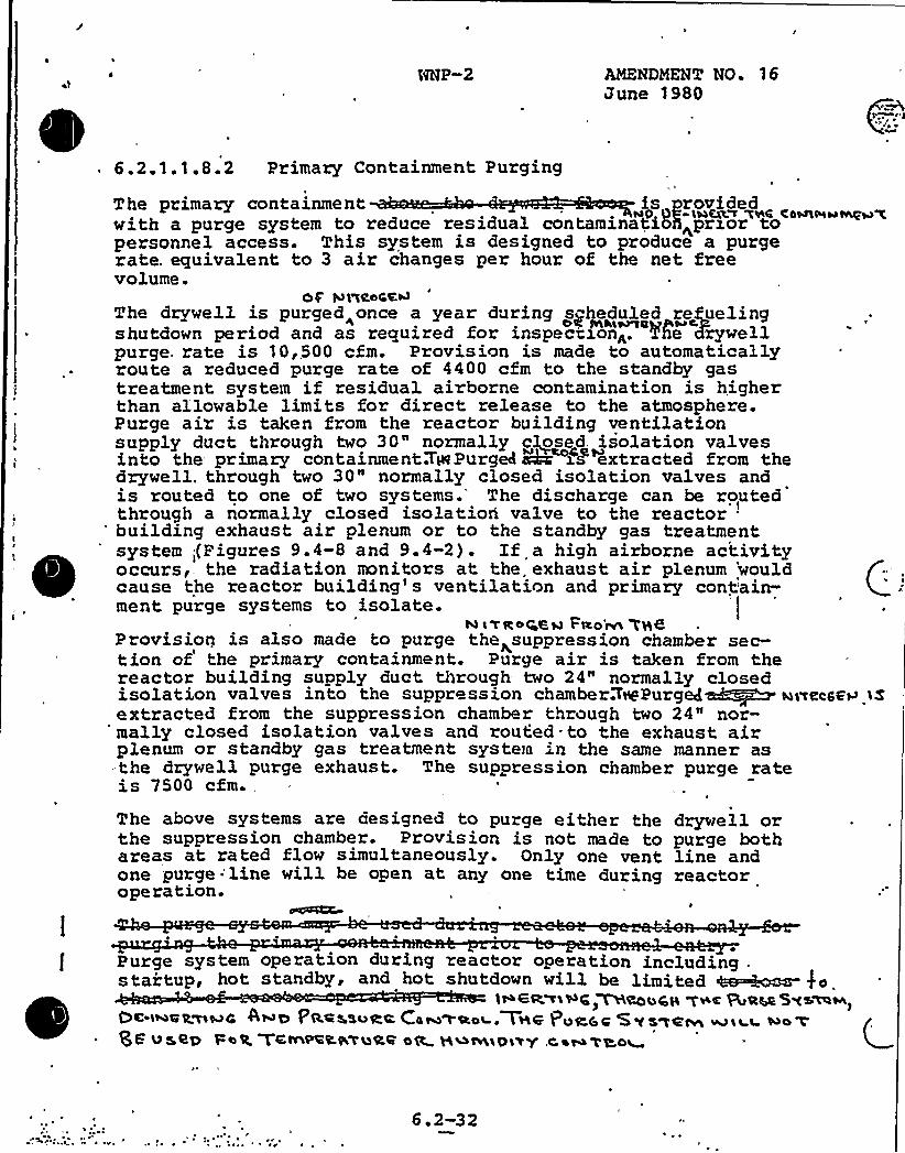
NNP-2 mamDZEMT NO. 16June 1980
6.2.1.1.8.2 Primary Containment Purging
The primary containment~ '+P llACg':T ~4%4 C004lblos ~Qis provided
with a purge system to reduce residual contaminati35<prxor topersonnel access. This system is designed to produce a purgerate. equivalent to 3 air changes per hour of the net freevolume.
0$ '41'%Ran<The drywell is purged„once a year during scheduled refuelingshutdown period and as required for inspection<. Ne Kxywellpurge. rate is 10,,500 cfm. Provision is made to automaticallyroute a reduced purge rate of 4400 cfm to the standby gastreatment system if residual airborne contamination is higherthan allowable limits for direct release to the atmosphere.Purge air is taken from the reactor building ventilationsupply duct through two 30" normally ciosed. isolation valvesinto the primary containment3HePurgedekr xf extracted from thedrywell. through two 30" normally closed isolation valves andis routed to one of two systems.'he discharge can be routedthrough a normally closed isolatiori valve to the reactorbuilding exhaust air plenum or to the standby gas treatmentsystem;(Figures 9.4-8 and 9.4-2). Xf a high airborne activityoccurs,. the radiation monitors at the. exhaust air plenum 'wouldcause the reactor building's ventilation and primary cont'ain-ment purge systems to isolate.
N ~ Ta~C,6m Feo'nn WH6Provision is also made to purge the<suppression chamber sec-tion of the primary containment. Purge air is taken from thereactor building supply duct through two 24" normally closedisolation valves into the suppression chamber.'7%Purged~+M ~>extracted from the suppression chamber through two 24" nor-mally closed isolation valves and routed to the exhaust airplenum or standby gas treatment system in the same manner as-the drywell purge exhaust. The suppression chamber purge rateis 7500 cfm.
The above systems are designed to purge either the drywell orthe suppression chamber. Provision is not made to purge bothareas at rated flow simultaneously. Only one vent line andone purge'line will be open at any one time during reactoroperation.
wecsFH 1$
Purge system operation during reactor operation including .
startup, hot standby, and hot shutdown will be limited 4~~ $ o.1>6R~iWC, VHeo~ag ~v e R aw 5w~~~,
Oe-i~eRwwc 4>o PA+asvec Ca~>ac~.T~e Puac.c Swszeivl ~ILLgf v5RQ 'PbQ Ychh&LKTLsRRbC 5~cw'D1>'f .C at+'tL4~
6.2-32

0
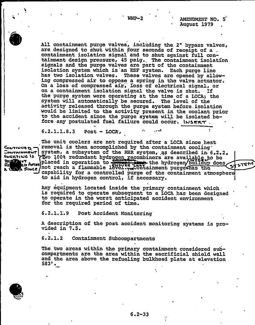
WRP 2 AMENDMENT NO 5August 1979
Ca+'tl&0%+~ghgmemdl
l~cg.y<~C 'Ls
5iwec
1All containment purge valves, including the 2" bypass vaLves,are designed to shut within four seconds of receipt of acontainment isolation signal and to shut against full con-tainment design pressure, 45 psig. The containment isolatxonsignals and the purge valves are part of the containmentisolation system which is an ESF system. Each puxge linehas two isolation valves. These valves are opened by allow-ing compressed air to oppose a spring in the valve actuator.On a loss of compressed air> loss of electrical signal., oron a containment isolation signal the valve is shut. Xfthe purge system were operating at the time of a LOCA; thesystem will automatically be secured. The level of theactivity xeleased through the purge system before, isolationwould be limited to the activity present in the coolant priorto the accident since the purge system will be isolated be-fore any postulated fuel failure could occur. twseaw .
6.2.1.1 8.3 Post - LOCtL'~
The unit coolexs are, not required after a LOCA since heat,'emoval is then accomplished by the containmentcooling'ystem>a subsystem of the RHR system, qs described in 6,2,2 ~
5to 100a redundant hydr en ecombiners are ava~aPg~ beplaced in operation to the hydrogegbuxX8up doesnot reach a flammable 1 ver.~on%ainment purge as ecapability for a controlled purge of the containment atmospherto aid in hydxogen contxol> if necessary.
Any equipment located inside the primary containment whichis required to operate subsequent to a LOCA,has been designedto opexate in the worst anticipated accident environment,fox'he xequired period of time.
6.2.1. 1'. 9 Post Accident Monitoring
A description of the post accident monitoring systems is pro-vided in 7.5.
6.2.1.2 Containment Subcompartments
The two areas within the primary containment considered sub-compartments ax'e the area within the sacrificial shield walland the area above the refueling bulkhead plate at elevation583'.
~s~ vahs1 J ~
6. 2-33
Insert to Pa e 6.2-33):
Dual isolation valves are also pxovided on the nitrogeninerting makeup piping connecting to the purge piping down«stxeam of the 30" and 24" isolation. valves. This permitsup 0 .c75 cfm of nitrogen to be added to the containment
atedduring reactox operation to compensate for the postula eleakage listed in Table 6.2-1.

1
CONTAINMENT SYSTEMS BRANCH
ISSUE 31
NRC:
Supply System:
Page 6.2-4 - Blown-off panels indicatedas exi'sting in primary containment.Please clarify.The FSAR text will be revised to reflectinsulation panels that are blown-off.
See revised FSAR page 6.2-4 (attached).
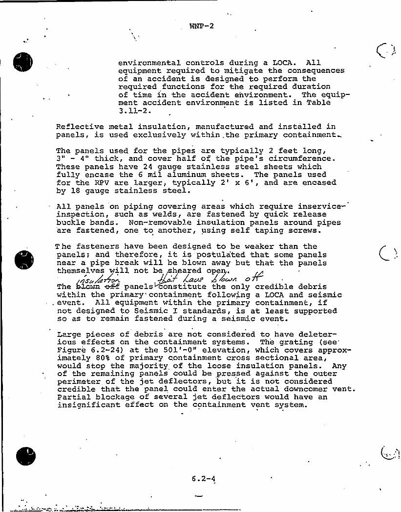
environmental controls during a LOCA. Allequipment required to mitigate the consequencesof an accident is designed to perform therequired functions for the required durationof time in the accident environment. The equip-ment accident, environment is listed in Table3.11-2.
Reflective metal insulation, manufactured and installed inpanels, is used exclusively within .the primary containment
The panels used for the pipes are typically 2 feet long,3" - 4" hick, and cover half of the pipe's circumference.These panels have 24 gauge stainless steel sheets whichfully encase the 6 mil aluminum sheets. The panels usedfor the RPV are larger, typically 2' 6', and are encasedby 18 gauge stainless steel..All panels on piping covering areas which require inservice-'nspection, such as welds, are fastened by quick releasebuckle bands. Non-removable insolation panels around pipesa e fastened, one to another, using self taping screws.
T he fasteners have been designed to be weaker than thepanels; and therefore, 't is postulated that some panelsnea a pipe break will be blown away but that the panelsthemselves will not be sheared opep.
ggz /4 '. g "6 EauThe boom eH panels constitute the only credible debriswithin the primary containment following a LOCA and seismic
. event. All equipment within the primary containment., ifnot designed to Seismic I standards, is at least supportedso as to remain fastened during a seismic event.
Large pieces of debris are not considered to have deleter-ious effects on the containment systems. The grating
(see'igure6.2-24) at the 501'-0" elevation, which covers approx-imately 80% of primary containment cross sectional area,would stop the majority of the loose insulation panels. Any
~ of the remaining panels could be pressed against the outerperimeter of the jet deflectors, but it is not consideredcredible that. the panel could enter the actual downcomer vent.Partial blockage of several jet deflectors would have anins:gnificant effect on the containment vent system.
6.2-4
CONTAINMENT SYSTEMS BRANCH
ISSUE 32
NRC:
Supply System:
'F
Airlock doors..- Commit to testing airlockdoors within 72 hours of last closing.
The Supply System will commit to testingairlock doors within 72 hours of lastclosing.Attached Revised Section 6.2.6.4 incorporatesAppendix J Revisions and reflects FSAR Tech.Spec 3/4.6.1.3 Position.
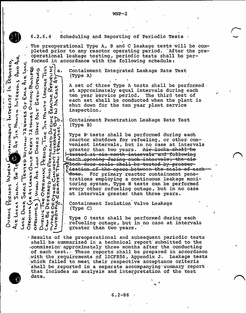
WNP-2
6.2.6.4 Scheduling and Reporting of Periodic Tests
The preoperational Type A, B and C leakage tests will be com-pleted prior to any reactor operating period. 'After the pre-operational leakage testing, periodic tests shall be per-formed in accordance with the fo'llowing schedule:
y Va. Containment Integrated Leakage Rate Test
(Type A)
d ~ttICl y,
27
02.
2
0
0LI0
tC
cf2
3
01
2
2
0
r
2Ig
Oo
'~xfCf p
i ~ill
~Ld
dU
~~ 0
th V
Cbl ct
0
0
Q 2
2D~a
ul
t2
Q g~ r2
2
A set of three Type A tests shall be performedat approximately equal intervals during eachten year service period. The third test ofeach set shall be conducted when the plant isshut down for the ten year plant serviceinspection.
5 ll~~ac ~
~It
0cTt2 tu2
20Qg
H
'~ ~4r
p 4l $
g lk ZIK
" a>f-2 g 2grcc~g „
g IOOp
g cck6 ~ p~~$ tL.O
1 >0<ttI
2g e~~ 2pH~4'02Ov 0-
Containment Penetration Leakage Rate Test(Type B)
Type B tests shall be performed during eachreactor shutdown for refueling, or other con-venient intervals, but in no case at intervalsgreater than two years.
l
2
d
Q-
2 0
9 bl
g~For primary reactor containment pene-'rations employing a continuous, leakage moni-
toring system, Type B tests can be performedevery other refueling outage, but in no caseat intervals greater than three years.
Containment Isolation Valve Leakage(Type C)
Type C tests shall be performed during eachrefueling outage, but in no case at intervalsgreater than two years.
- Results of the preoperational and subsequent periodic testsshall be summarized in a technical report, submitted to thecommission'pproximately three months after the conductingof each test. These reports shall be prepared in accordance,with the requirements of 10CFR50, Appendix J. Leakage testswhich failed to meet their respective acceptance criteriashall be reported in a separate accompanying summary report,that includes an analysis and interpretation of the testdata.
6.2-86
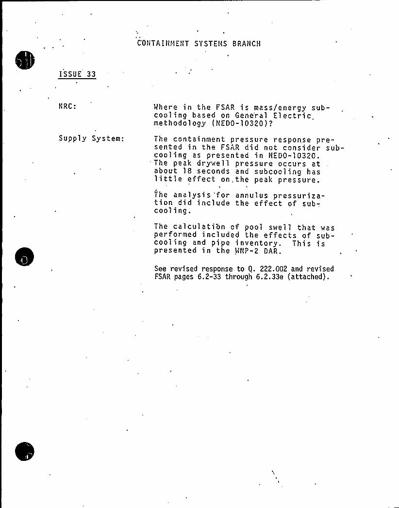
C'ONTA I Ht1ENT SY ST EHS BRANCH
ISSUE 33
hRC Where in the FSAR is mass/energy sub-cooling based on Gene'ral Electricmethodology (NEDO-10320)?
Supply System: The containment presssented in th FSAR dicooling as presented
— The p ak drywell presabout 18 seconds andlittle ef ect on, the
The analysis 'for annution did include thecooling.
ure response pre-d not consider sub-in.NED0-10320.sure occurs atsubcooling haspeak pressure.
lus pressuriza-effect of sub-,
The calculation of pool swell that wasperformed included the effects of sub-cooling and pipe inventory. This ispresented in the MNP-2 DAR.
See revised response to g. 222.002 and revisedFSAR pages 6.2-33 through 6.2,33e (attached),
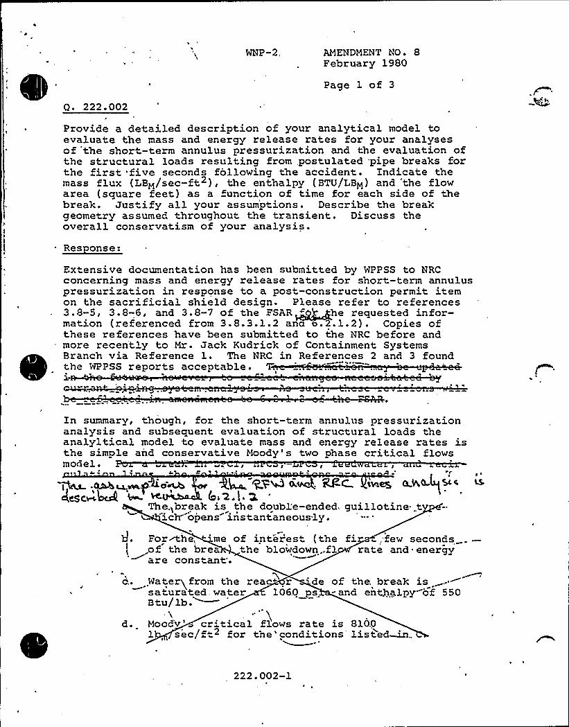
Q. 222.002
WNP-2, AMENDMENT NO ~ 8February 1980
Page 1 of 3
Provide a detailed description of your analytical model toevaluate the mass and energy release rates for your analysesof the short-term annulus pressurization and the evaluation ofthe structural loads resulting from,postulated pipe breaks forthe first five seconds following the accident. Indicate themass flux (LBM/sec-ft ), the enthalpy (BTU/LBM) and 'the flowarea (square feet) as a function of time for each side of thebreak. Jus ify all your assumptions. Describe the breakgeometry assumed throughout the transient. Discuss theoverall conservatism of your analysis.
Res onse:
Ex"ensive documentation has been submitted by WPPSS to NRCconcerning mass and energy release rates for short-term annuluspressurization in response to a post-construction permit itemon the sacrificial shield design. Please refer to references3.8-5, 3.8-6, and 3.8-7 of the FSAR -" he requested infor-mation (referenced from 3.8.3.1.2 an .2.1.2) . Copies ofthese references have been submitted to the NRC before andmore recent'y to Mr. Jack Kudrick of Containment SystemsBranch via Reference 1. The NRC in References 2 and 3 foundthe WPPSS reports acceptable.
T'n
summary, though, for the short-term annulus pressurizationanalysis and subsequent evaluation of structural loads theanalyltical model to evaluate mass and energy release rates isthe simple and conservative Moody' two phase critical flowsmodel. QJ % I ala g Jl I I I
4 C ~ p
M~g~ .~~~P. o~ ~ +PM 0 . ~C tie~ 0 W(L)Sic4esc~4crk m ',z.l. z
The,>break is the double-ended. guillotine t"ich- opens instantaneously.
IFor<he, 'me of inter'est (the fi,few seconds.of the brea .the blowdown..fl rate and energy'~ are constant'.
c...Wateryfrom the rea " r 'de of the. break issaturated water 1060 ps - and entgalpy of 550Btu/lb.~
~.'.Mooc'v'r'tical flows rate is 8100
1 sec/f" for tne'conditions listed~
222.002-1
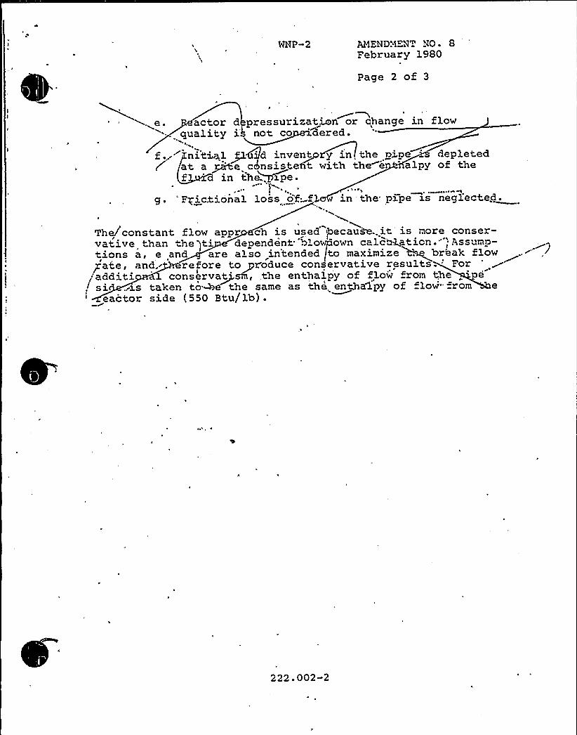
WNP-2 AMENDMENT NO ~ 8February 1980
Page 2 of 3
* ~~e. actor d pressurization or change in flowquality ih not co 'dered.
f.~ nitiwl+Cild inven~t y in the gi.pe 'epletedat a ~e chnsisteht with the e alpy of thef 'n tne~ipe.
ee
g. "Frictional loss of f3. in the pl.pe xs neglected.P~
The/constant flow appr ch is used igecau&..it is more conser-vative than ne Iti dependent blowpown calculation.""; Ass 'mp-tions a, e and are also in'tended (to maximize . break flowgate, and, refore to yx'oduce conservative results.'oradditi conserva~t', the enthalpy of flow from the . e
! si .ia.'s taken to-be the same as the enthalpy of low'" from eeactor side (550 Btu/lb) .
222.002-2

WNP-2
All containment purge valves, including the 2" bypass valves,are. designed to shut within four seconds of receipt of a con-tainment isolation signal and to shut against full containmentdesign pressure, 45 psig. The containment isolation signalsand the purge valves are part of the containment isolationsystem which is an ESP system. Each purge line has two iso-lation valves. These valves are opened by allowing compressedair to oppose a spring in the valve actuator. On a loss ofcompressed air, loss of electrical signal, or on a containmentisolation signal the valve is shut. Xf the purge system wereoperating at the time of a LOCA, the system will automaticallybe secured. The level of the activity released through thepurge system before isolation would be limited to the activitypresent in the coolant prior to the accident since the purgesystem will be isolated before an'y postulated fuel failurecould occur.
6.2.1.1.8.3 Post — LOCA
The unit coolers are not required after a LOCA since heatremaval is then accomplished by the containment coolingsystem, a subsystem of the RHR system, as described in 6.2.2.Two 100% redundant hydrogen recombiners are available to beplaced in operation to ensure that the hydrogen buildup doesnot reach a flammable level. Containment purge has the capa-bility for a controlled purge of the containment atmosphere toaid in hydrogen ccntrol, if necessary.
Any equipment located inside the primary containment which isrequired to operate subsequent to a LOCA has been designed tooperate in the worst anticipated acciden't environment for- therequired period of time.
6.2.1.1.9 Post Accident Monitoring
A description of the post accident monitoring systems is pro-vided in 7.5.
6.2.1.2 Containment Subcompartments
The two areas within the primary containment considered sub-compartments are the area within the sacrificial shield walland the area above the refueling bulkhead plate at elevation583'
Subcompartment analyses for a postulated high energy pipebreak in the primary containment were performed for the annu-lus inside the sacrificial shield wall, and the regions aboveand below the bulkhead plate 'hich divides the drywell intothe upper head region and the lower region.
6.2-33
WNP-2
Two analyses were performed to ensure the adequacy of therefueling bulkhead and inner refueling bellows at elevation583'. The first analysis, a break of the RCIC head sprayline, determines the maximum downward loading due to pipebreaks, and the second analysis,. a break of the RRC suctionline, determines the maximum upward loading. Information withrespect to the analyses for the upper head region and.thelowe region is provided below:
1
a. For the subcompartment analysis in the upper headregion, the worst case is a double ended guillo-tine break in the 6" RCIC line above the RPV headat approximately elevation 595.1 ft. For theanalysis in the lower region in order to deter-mine the differential pressure across thebulkhead plate, the worst case is a double endedguillotine break in the 24" recirculation lineanywhere inside the drywell. The pipe breakswere postulated for the subcompartment structural
.design and the component support design.
b. The blowdown mass and energy release rates asfunctions of time for the 6" RCIC line break areshown in Table 6.2-20 (Steam) and 6.2-21 (Water).The blowdown mass and energy release rates asfunctions of time for the 24" recirculation linebreak are shown in Table 6.2-22 (Steam) and6.2-23 (Water).
c. The subcompartment analyses for the case of a 6"RCIC line break in the upper head region and thecase of a 24" recirculation line break were per-formed with the computer code RELAP4/NOD5 (Re-ference 6.2-14). In the computer model, thedrywe ll volume is represented by two nodes. Nodel represents the upper head region and Node 2represents the lower region of the drywell. Forreasons of conservatism, the wet well is notmodeled ip the analyses. Vent paths connectingNode 1 and Node 2 pass through the bulkheadplate. For the break in the upper head regionthree sets of vents are considered. The threesets of vents are two open vents, two ventsthrough backdraft dampers (setting 3IWG) and theventilating fans, and two vents through the HVACducts and backdraft dampers (setting 9IWG). Forthe break in the lower region of the drywell twosets of vents are considered. The two sets ofvents are the two open vents and two ventsthrough backdraft dampers (setting 3IWG) and the
6.2-33a'
WNP-'2
HVAC ducts. In the computer model backdraftdamper opening delays of 1 psi and 0.25 secondare assumed.
Figure 6.2-36 shows the nodalization scheme inthe drywell. Figure 6.2-37(2a) shows the planview of vents in the bulkhead plate. Figure6.2-37(2b, 2c, 2d) .show the sectional views anddimensions of the three types of vent which arebeing incorporated in the design.
The nodal volume data used for the analysis of a6" RCIC line break in the upper head region andthe analysis of a 24" recirculation line break inthe lower region is shown in Table 6.2-24 Table6.2-25 shows the flow path data for the analysisof a 6" RCIC line break and Table 6.2-26 showsthe flow path data for the analysis of a 24"recirculation line. break. Form loss coefficientswere determined based on the data in Reference6.2-15.
Since there are no significant obstructions inthe proximity of the pipe break considered inthe analyses, significant pressure variationin any direction is not expected. The two nodemodel used for the analyses is considered to beadequate and a sensitively study is not neces-
saryy.
There are no movable obstructions in the vicinityof the vent. Insulation for piping and com-ponents was assumed to remain intact during theaccident, and volume of insulation was sub-tracted from the nodal vo'mes.
The absolute pressure responses as a function oftime in the upper head region and the lowerregion in the drywell are shown in Figure 6.2-38for the case of a 6" RCIC line break, and inFigure 6.2-39 for the case of a 24" recirculationline break. Figures 6.2-40 and 6.2-41 show thepressure differential across the bulkhead platefor the case of a 6" RCIC line break, and thecase of a 24" recirculation line break, respec-tively.The peak differential pressure and the time ofthe peak for the case of a 6" RCIC line breakand the case of a 24" recirculation line breakare shown in Table 6.2-27.
6. 2-33b
NNP-2
Peak and transient loading in other major com-partments, such as the drywell and the upperhead region of primary containment were includedin the basic design. Since these compartmentsare large and relatively unencumbered, the loadsare time dependent but relatively uniformthroughout the compartment in question. The timedependent loads were applied as equivalent staticloads, utilizing the appropriate dynamic loadfactors. The component stresses were found to bewithin the values specified in the appropriateCodes; however, after a LOCA, the refuelingbulkhead would requi e requalification prior touse. This is considered acceptable since therefueling bulkhead does not perform a safety-related function and would not become a missileduring the postulated LOCA.
The analyses for the a nulus were reported in full detail inReferences 6.2-9 thr g h 6.2-11. All potential pipe breakswithin the sacrificia shield wall have been evaluated. Theinformation is contained in References 3.8-5, 3.8-6, 3.8-7,and 3.8-24. These references have been previously submittedto the NRC. The result of the case of a 60-node model of theshield wall annulus for pressure transient c+ulation was con-firmed by the NRC, and the analysis was considered acceptablefor the shield wall base design and the design of the shieldwall above the base, as stated in NRC letters (References6.2-12 and 6.2-13).
Peak and transient loading used to establish the adequacy ofthe sacrif icial shield wall, includinq the time/space depen-dent forcing functions are presented in References 6.2-9through 6.2-1,1 'and 3.8-24 .
Subsequently, a more realistic approach was used in deter-mining loads from postulated pipe breaks within the annulusarea. These loads were used to produce response spectra foruse in evaluating the secondary effects (the dynamic effectson'piping systems, equipment and components attached to thesacrificial shield wall or the RPV) . Three principal changeswere made in the assumptions used in the previous more conser-vative sacrifical shield wall analysis. Namely:
a. The volume in the annulus was utilized to receivethe blowdown with the RPV insulation volume. con-servatively assumed not to be available.
b. A finite time dependent blowdown was used for therecirculation breakutjli,zing NSSS supplier/methodology.'ytuu ep~ + Su~gIWo 4~~ ~
6.2-33c
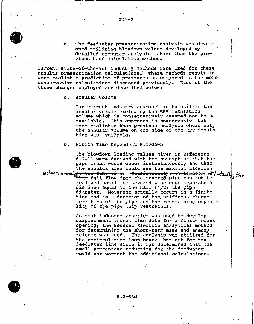
WNP-2
c. The feedwater pressurization analysis was devel-oped utilizing blowdown values developed bydetailed computer analysis rather than the pre-vious hand calculation method.
Current state-of-the-art industry methods were used for theseannulus pressurization calculations. These methods result inmore realistic prediction of pressures as compared to the moreconservative calculations discussed previously. Each of thethree changes employed are described below:
a. Annular Volume
The current industry approach is to utilize theannular volume excluding the RPV insulationvolume which is conservatively assumed 'not to beavailable. This approach is conservative butmore realistic than previous analyses where onlythe annular volume on one side of the RPV insula-tion was available.
b. Finite Time Dependent Blowdown
The blowdown loading values given in Reference6.2-11 were derived with the assumption that thepipe break would occur instantaneously and thatthe annulus area would see the maximum blowdown
keg~ I<full flow from the severed pipe can not berealized until the severed pipe ends separate adistance equal to one half (1/2) the pipediameter. Movement actually occurs in a finitetime and is a function of the, stiffness charac-teristics of the pipe and the restraining capabi-lity of the pipe whip restraints.Current industry practice was used to developdisplacement versus time data for a finite breakopening; the General Electric analytical methodfor determining the short-term mass and energyrelease was used. The analysis was utilized forthe recirculation loop break, but not for thefeedwater line since it was determined that thesmall percentage reduction for the feedwaterwould not warrant the additional calculations.
6. 2-33d

c. Peedwater Break Blowdown Data
The blowdown analysis for the postulated feed-water line break was based on a comprehensive
water system from the condenser to the reactorvessel. This model, in conjunction with theRELAP 4/MOD 5 computer program (Reference 6.2-14)was used to calculate the transient and energyblowdown data.
6.2-33e
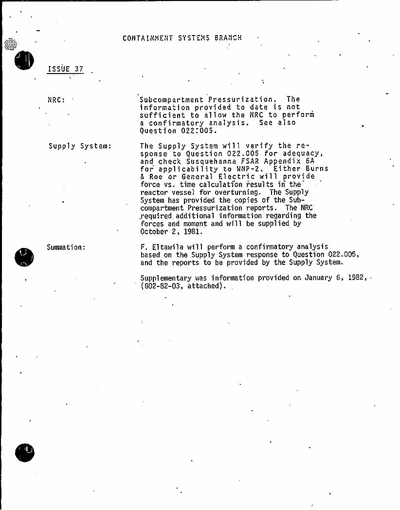
E
EISSUE 37
CONTAIHHEl<T SYSTEMS BRA'( H
ilRC:
Supply System:
Summati on:
Subcompartment Pressurization. Theinformation provided to date is notsufficient to allow the NRC to performa con irmatory analysis. See alsoguestion 022.005.
The Supply Sys m will veri fy the re-sponse to guestion 022.005 for adequacy,and check Susquehanna FSAR Appendix 6Afor applicability to MHP-2. Either Burns5 Roe or General Electric will provideforce vs. time calculation results in thereactor vessel for overturning. The SupplySystem has provided the copies of the Sub-compartment Pressurization reports. The NRC
.required. additional information regarding theforces and moment and will be supplied byOctober 2, 1981.
F. Eltawila will perform a confirmatory analysisbased on the Supply System response to guestion 022.005,and the reports to be provided by the Supply System.
Supplementary was information provided on January 6, 1982,(G02-82-03, attached). .

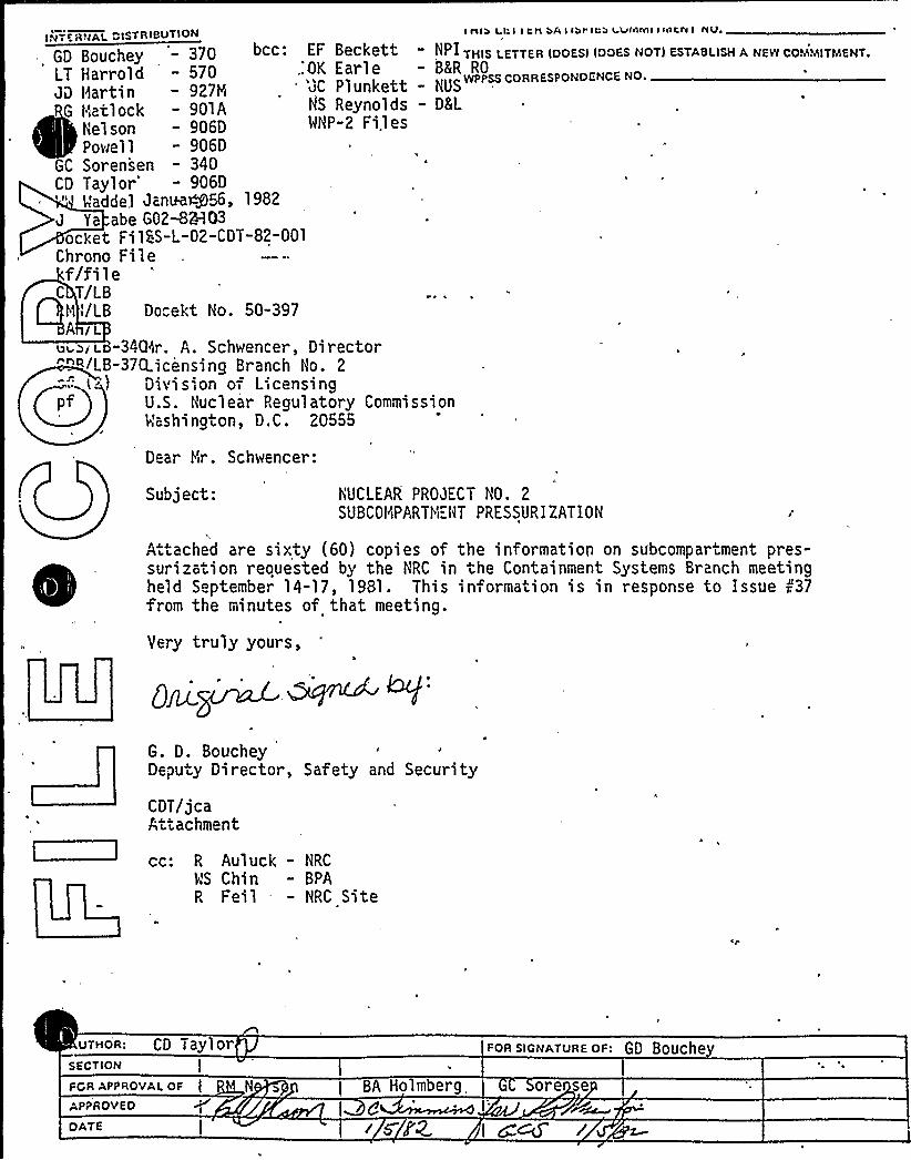
I fllb L.l I I tH bA I lbt' Ca i VMMI< sALA I NV,I.Ti E R ~ jAL DISTRIBUTION
bcc: EF Beckett,:OK Earle'JC Plunkett
HS ReynoldsWHP-2 Files
GD Bouchey - 370LT Harrold - 570JD Hartin — 927M
G Hatlock - 901ANelson - 906DPowell - 906D
GC Sorensen - 340CD Taylor' 906D
Waddel Janua56, 1982J Ya abe G02-8%03ocket FilSS-L-02-CDT-82-001
Chrono Filef/file
~
~
C T/LBHi/LB Docekt No. 50-397A I
L ~~i L -34Q<r. A. Schwencer, Director""II/LB-37CLicensing Branch Ho. 2
~
~
Division o= Licensingpf U.S. Nuclear Pegulatory Commission
Washington, D.C. 20555
THIS LETTER IDOESI IDOES NOT) ESTABLISH A NEW COMMITMENT,- BKR RO
NUSwPPss coRREsPDNDENcE No.
- DEL
Dear Hr. Schwencer:
Subject: NUCLEAR PROJECT HO. 2SUBCOHIPARTH"HT PRESSURIZATION
Attached are sixty (60) copies of the information on subcompartment pres-surization reouested by the NRC in the Containment Systems Branch meetingheld September 14-17, 1981. This information is in response to Issue r'37from the minutes of that meeting.
Yery truly yours,
G. D. BoucheyDeputy Director, Safety and Security
CDT/jcaAttachment
cc: R Auluck - NRC
WS Chin - BPAR Feil - NRC Site
UTHDR: CD Tayl orSECTION I
FOR APPROVAI. OF l
APPROVED
BA Holmberg
FoR slGNATURE DF: GD Bouche
ore se
DATE isIZ I ~~ r
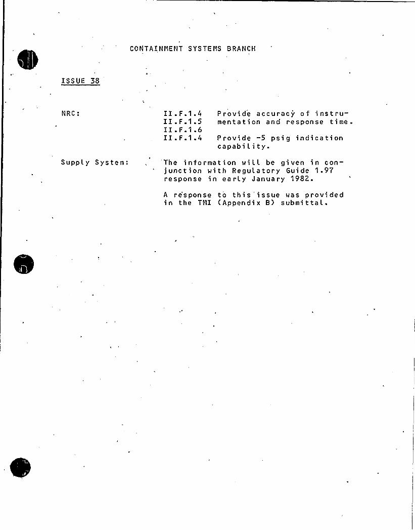
CONTAINMENT SYSTEMS BRANCH
I SS UE 38
NRC: II.F.1.4II.F.1.5II.F.1.6II.F.1.4
P rovi de accuracy of ins t ru-menta t i on and response time.
Provide -5 psig indicationcapabi l i ty.
Supply System: The information wiLL be given in con-* junction with Regulatory Guide 1.97
response in ea rly January 1982.
A re'sponse to this issue was providedin the TMI (Appendix B) submittal.

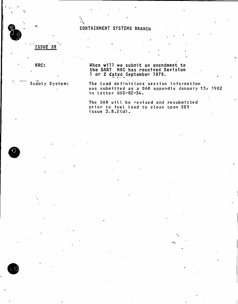
I
\
CONTAINMENT SYSTEMS BRANCH
ISSUE 39
NRC:
Supply System:
Mhen wi11 we submit an amendment tothe OAR?= NRC has received Revision1 or 2 dated September 1979.
The Load definitions section informationwas submitted as a DAR appendix January 13'982in Letter G02-82-34.
The DAR wi L L be revi sed and resubmi t tedprior to fuel Load to close open SER"issue 3.8.2(d)-

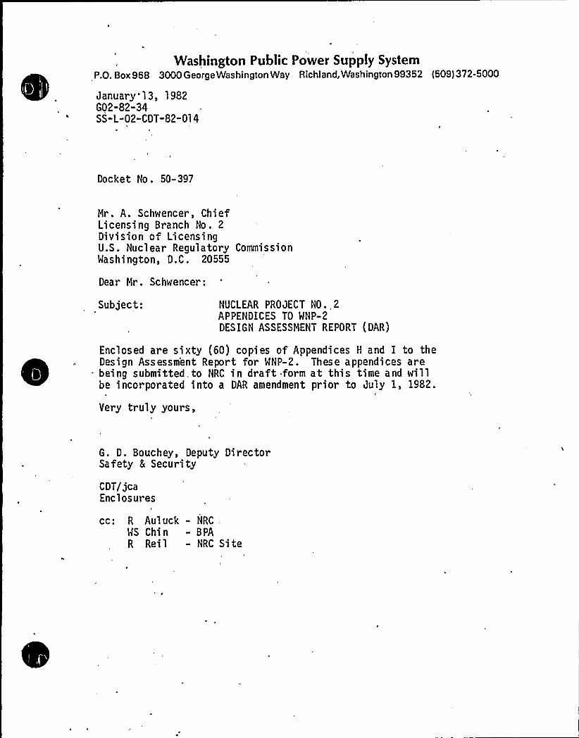
Washington Public Power Supply SystemP.O. Box 968 3000 George Washington Way Richland, Washington 99352 (509) 372-5000
January'13, 1982G02-82-34SS-L-02-CDT-82-014
Docket No. 50-397
Mr. A. Schwencer, ChiefLicensing Branch No. 2Division of LicensingU.S. Nuclear Regulatory CommissionWashington, D.C. 20555
Dear Mr. Schwencer:
Subject: NUCLEAR PROJECT NO .,2APPENDICES TO WNP-2DESIGN ASSESSMENT REPORT (DAR)
Enclosed are sixty (60) copies of Appendices H and I to the
~
~
~
~
~
~
~
~
~
~
Design Assessm'ent Report for WNP-2. These appendices are- being submitted to NRC in draft. form at this time and will
be incorporated into a DAR amendment prior to July 1, 1982.
Very truly yours,
G. D. Bouchey, Deputy DirectorSafety 8 Security
CDT/jcaEnclosures
cc: R Auluck - NRC .
WS Chin - BPA
R Rei1 - NRC Si te
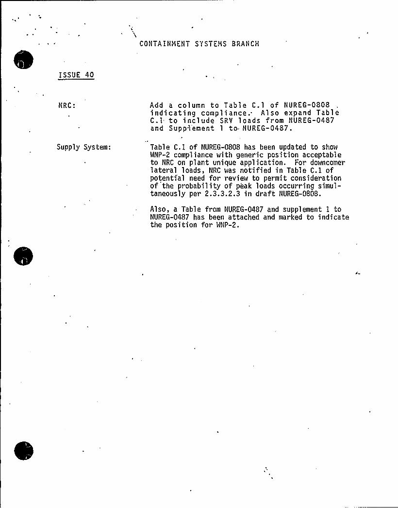
,COHTAIHilEHT SYSTEMS BRANCH
ISSUE 40
HRC:
Supply System:
Add a column to Tabl e C. 1 of HUREG-0808indicating compliance.- Also expand TableC.l to include SRV loads from HUREG-0487and Supplement 1 to NUREG-0487.
Table C. 1 of NUREG-0808 has been updated to showWNP-2 compliance with generic position acceptableto NRC on plant unique application. For downcomerlateral loads, NRC was notified in Table C. 1 ofpotenti'al need for review to permit considerationof the probability of peak loads occurring simul-taneously per 2.3.3.2.3 in draft NUREG-0808.
Also, a Table from NUREG-0487 and supplement I toNUREG-0487 has been attached and marked to indicatethe position for WNP-2.
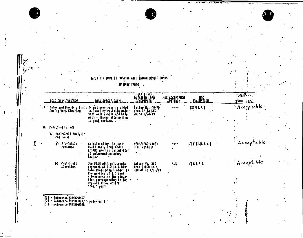
Ir) ~ .
~ Q ~
fholE C-l JINK Jl JOCA DElhllfl JJYDRODYIJAIJJC lOADSP
SVIRIARV PRIE
lAD . g.
DFIhllf0 lobo~Q~AII BR I/flttltlNg ltilllttfttfgfk'Ltiilt . iitSLRjpglllli
'.h.'tbeeroed Dotuulary foatfs 2$ psf overplessnre atl<led fatfer Ko. 00-79During Venf. CfaqrlpD fq loca Jtytfroslaf5c Italo'inn GE to IIRC
'enlee L (walls and base- alafatl 3/go/'l9nal) - Inaar allennallqgla poo) sqrface.-
II. 5'oaf;Qqff foatfs
1, Poof-SMefl hnalyll-cal Iladel
KRC ACCfPJIICE . KRC
CD]yfQlh Lynllhllnl
(2)aff h )
a) Afr-DuldifeI'ressnro
lt) I'ool-Sue J IE loyal fan
Cafcnfafed Jt~ Iho pool-swelf enalylfca) stnda)pSAH) Dsed ln cqlcnfaffonaf spftoofned flangdaffloatfs..
Usa Pshlf pfth Itnfyfroplcottponanl. of 1.2 lo a stax-fotus hwefl ftofoitf uhfcl> lslite crueler ol l.fi Veal.sitlwergencu ar,lho eluua-.lfon carraspandfn0 lo fhe
'rywallfloor upi illalt-2.9 psld.
afoE/a>00-2 fog)Kfof-2)54$-Jt
feller Ko. 360fron lllCD ln:.JJJIC (Idled 2/J6/79
hl
fl)JJJ,D.3.a.l
(2)ff h 2
I - Reference IDlkfn-0(072 - Reference JDIRfG-0587 Suftltfeeenl l '
- Jlcferance JJDRJ0.0000
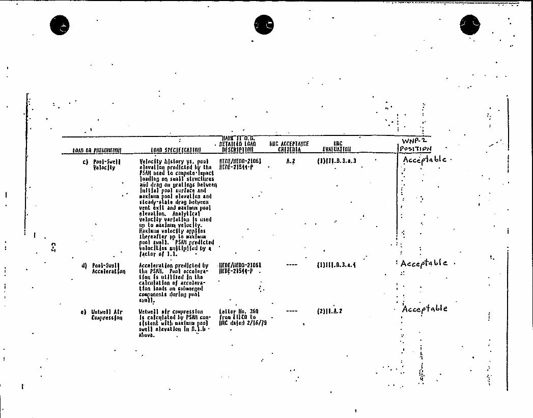
~~
lhR fD)..~ Dffhllfg lghg
DfSCRJP1LDll
IlfDf/llfDg-2106)llfgf-2184-1'I>All
AR IIEIIIllll>I~EAUEIERJE>RA>I>II
c) Poo)-SR>ctl ycl»ctky history ys. pool'ifolocjky elevation proillcked by tho
PSAH used to co»puke lop»el.)Oa>ling On Saall StruCtureSadd drag on gratings beti>ccqlultlal pool surface anilaaxla>ia pool okcvatfon aiulskcaily.stake drag bctyccnvent exit and aaxlaua poolelevation. hnalytlcalvclpclty varlatlon Is useiliip to aaxlai>Es vol»city.tlaxlaiia velocity appIlosllicreafkcr pp to aaxlIIE>apool suell. PsQI prcdtctc>fVolocltles a>ii)ttpllcd by afeeler of 1 ko
d) 1'ool-Suoll Acceleration predicted byhcceleral]on tho PShkl. Pu»1 cecal»ra-
tion s utlllsc>l ln thecalcu ation of accelera-tion oads on s»baergeilco>qioncnks ilurlng p»nlsnail.
llfDf/lkfDD-2kg6lllfDE-2154$-P
lNC hCCfPthilCE kiRC
ER>JEIIIU EVAIUA>fllll
lk.2 (1) ill.8.3.a.3
(1) I I (.8.3.a. (
R
VdpkP-'4Po~kWtPA
Aceep4n 4(c .
'ccef tn 4re.
e) Matuett AtrcoR>k>ress)on
Mekuell air coaprcsskon letter No. 360Is calculate>k ty PShlk con- froa tllCD kus(stout with aaxka»a poo) Jll(C daloil 2/16/$ 9sMell elevation ln D.l.b .
aliove.
(2)ll h 2
iAccepts( I e
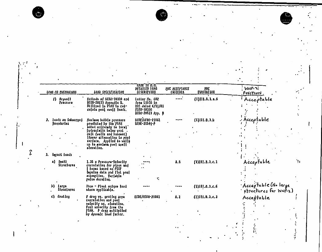
~ ~
lIIIAIISPECIQllllillg ii
fdlbnils of 0Nll-30320 and l elIfoo-20533 hlpendtx 0. franIL lltrdd tn l'Khll'lo cal- nl(Cculato pon) swell loads. tKA
tif00
- ~ghO Aggllll~M!lffAll
f) nrywettpressure
loails on Sutiisorodi) tlaxtniss Iuibble pressurelloulularlas prddtclcd by lbn'pNI
aililoil upi lornly ln liica)'iyilroslaltc tiatow yoni
natl (wet ts anil fiasdnal)linear alldnuul.tou lo poolsurface, hpplldit lo wat)sup lo siaxtnini punt swellel oval Ion.
lho .0.IL'Thtlfo toho tfoC hCCEPthlKE tIC
sf IllillgJI (NiJill/~AIIIAllAll
ler tlo. 002 (l)I t l.0.3.a.6lttcn lo
dal ail 6/l t/Atlt-t0320
-20533 hpp. fl
tlfnE/0Fno-2tn61 -- (l)lll.ll.3.II(l'nE-2154$ p
.: WNP-~posl7lohl .
'ccc stable
. Acccto44jer
3. tepact. loads
a) Seal}Slruclures
b) large5lruc lures
c) Orating
3.35 x Pressure-Yetocttycorrolalton for ptpes anil
!tidans besoil on PStp
opu)so italo anil ftal tioot~ sswpllon. (urtablopulse i!ural ton.
Ihw>o - Plant unique loadwhere appltcab)e.
l'rag vs. grallng areacorrolallon and poof
'.velocity vs. olovalton.oo) veloclly froa IboSN. P drag aulltpl tcd
iy dynantc loiul taclor.
tffnf/gfgg-2l06l
fl)) I t. tt.3.c. l
(l)ttl,0.3.c.6
(l)ll!.0.3.c,3
4(e (Ho les t)e,')t'uc4rcs For WNP->)
bccc(ta4li
~ i
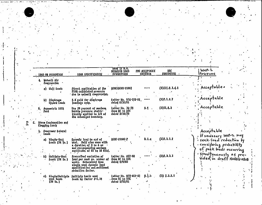
o
~ I
~ ~
~ a
OAD OR IEIIOHCIIOIIk
Metuell AlrCoop res s lon
a) llall toailse
b) 0 laptiragoUpuard leads
5. Asyiiioetrlc tOCAPool
C. Stian Condensatfan pnl)CIaigglng toads
Oouncoaer l.ateralto oils
n) 'Single-Meritteals (24 $ n.)
- b) Ibiltlplo Venttoads (2E ln.)
IIRCEVAI.Uh lgl
Direct.appllcat(an pf )IiePSAII ca)cl>lated pressure
" Ilila ta kelso)) caoprasstprl,
5.5 psld for dlaliI>registoadln4s oply.
Usa 20 percent of naxlnwsIbubble pressure stalls-tlcally applied to I/2 ofthe siilsoergad bown lary.
(lfDE/IIE04-2106)
latter IIo. IIFII-125-gtilat pi( 6/30/01
letter llo, 76-79frais fsE to IIllcdated 3/16/79
(3)2.1.2.7
(2) t I,A.3
Pynanlc load to egd ofvent. Ihlf sine sieve ultlsa dgratlon of 3 lo 6 osand correspenillng Na»laiioaopl)tudes of 65 tn lD IIIbf.
Prescribed varlatlan af)oad per vent vs. nuJier ofvedts. Oeternlned fransingle vent dynaalc loadspeclflcat lan and.siulttventredact/an (aeter.
IIEOE-23006-P
loller Ilo. Oll-BQfrait GE to IIIICdalai) )/9/OD
D.l.a (3)2.3.3.2
(3)2.3.3.3
NROETAIIE 0 t0hg IIBC ACCPTAIICE'""'IIM—"'R'—'"IILll
s
'NP-L! Pp 5>Tic t4
Ace.e pt 44l e.
',
Accepffft4l e
~ i IIV
Acce.pt'ct 41 e,e
,I:I'l I
I ~,a
AcceIkq LieIf teceSS4r~ gap-W >4gsee.lc- lo4 J r c Joc.flnH bsf
eonsiiierinS isr ia lilsjltgof'c4k (onym J os„ppiqg
" $ I+csl)ABC+La s (sI 4 6 pro
c). Single/kls>ttlptevent loails
'20ln.)
lliiltlplybasic venttoads liy factor f~l.3t
totter llo. NII-OI2-01. frars OE lo IIRC
doled l/l6/Ol
fl. l.b~ s
(3) 2.3.2.1

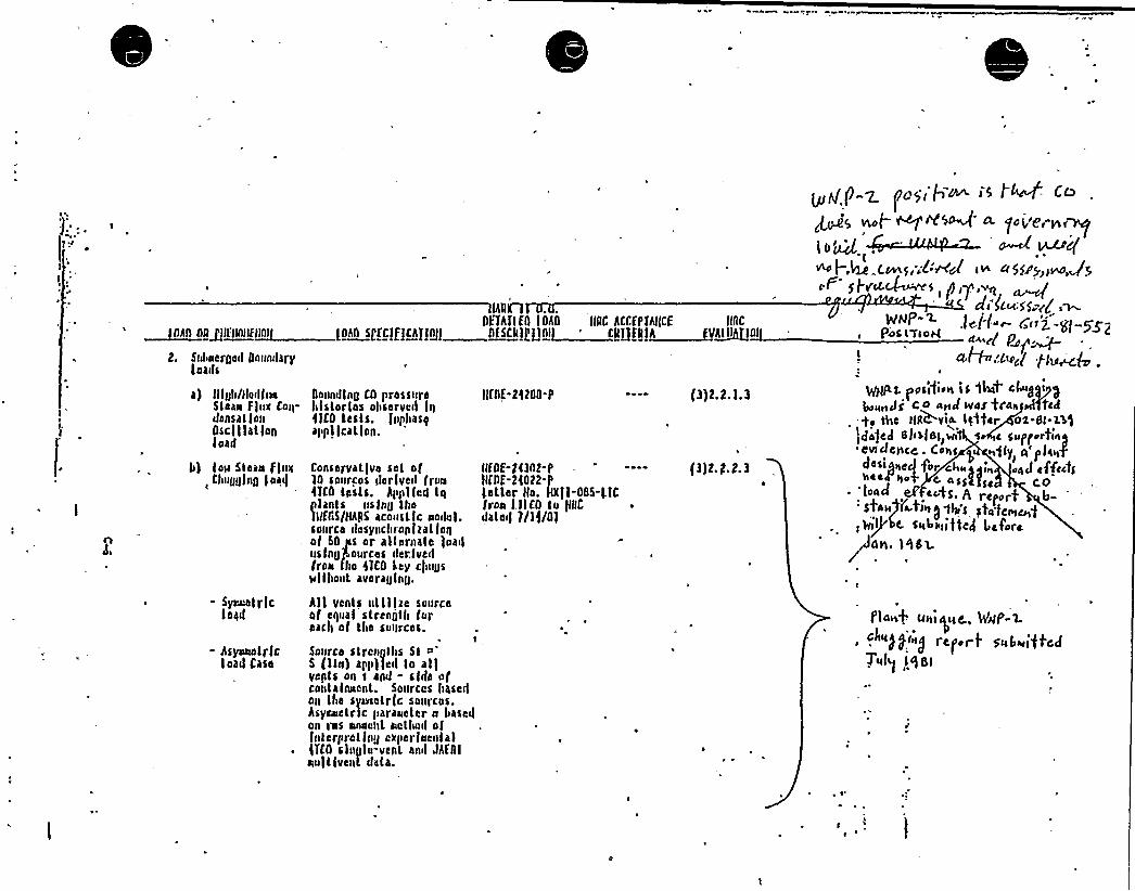
a) lllgh/tlo>lineStean f)ux Co>pdensatlonOsci) let ionload
Oounkllng CD prossurahlslorlos observe>l l>t<tCD tests. tnpbasqappl leal Ion.
fifgf-24200-P (3) 2,2.1. 3
4) lo>> Stoa>s flueChugging iaaf
Conservative sel of10 sources >lerlved fraa(Tco tests. Applfed tq
lanls usfng lhollfgS/HAAS acoustic uo>h>i.
source dasyncbronltatfon, of 50 t>s or alternale )oad
using'sources derfveftIron tho )TCO ley c)Rugs3>t tbout averaging.
BEDE-24302-/ — -- f3)2.2.2.3HfllE-24022
5'ellerHo. Qtf-005-tfCIron fttCA ta fgCdale>i 7/tf/Ol
Ihllf1OFTAftfg lOAO t(RC ACCCPfht(Cf fNC~llkkkkgltfltktklllllg ikiltl I[EEI>lfk>II@I> ktffkl>LIlltj 'RJJERI~RV~RIII lilt>
2. S>>boerged goon>loryloads
~gP ~ t>rEEI'Jan. ik I ~ Cfk
J yAfq vs t ~ M'0 vf ~ fo j,'8i"tfs~
>no I .4e C~S "L:WJ» a5ESPy»m+5SF St >rat,~s
c(> Jcu.'55 gg k~lcH'~ C~»2. -g-55)PR>sir>oh( ~g p
+~'<'oct /.f3e~g .
gott. p>>s>f>e>3 is 14t cfklkgtksk)
bok>E> J j g 0 4>>J WOS 'trAEE Wfeft-g, tt>e tN&via llutter ox.Sl-l3)}Elapsed
e l>3l Sty wt s c skff>pkkrt>l>ft'Cv>clencC. >-ohS e kkgly a f>fake
JQao I for chkk%o>fk EI4J effcc4heea-»op e assay CO
~ to4d + ec'ts ~ A report b-'4Np%ttk>
~gt»'s stag<<~g
rlkPIRR Err<a>i>EE> I airrran, l )bw
'r
- Syouetrlcteed
hsy»tndl ffcload Casa
All vents utt lice sourceof equal strength foroacfl of the so»rces.
tSource strengths St ='
(tin) app)led to al)yents on s and - sfdo ofco»talnuent. Sources basedon the sya>f>etrfc saurcas.Asyeuetrlc parauelar a basedon res e>one»t sletbad ofluterpretfng c>fperfuentalITCD single-vent and Jhfgle>uttfvent data.
f'inn/ s»>i E}kee., 4'uf'-x
rcfot t'»6>vi'tf'cdTE4fq lk)5t
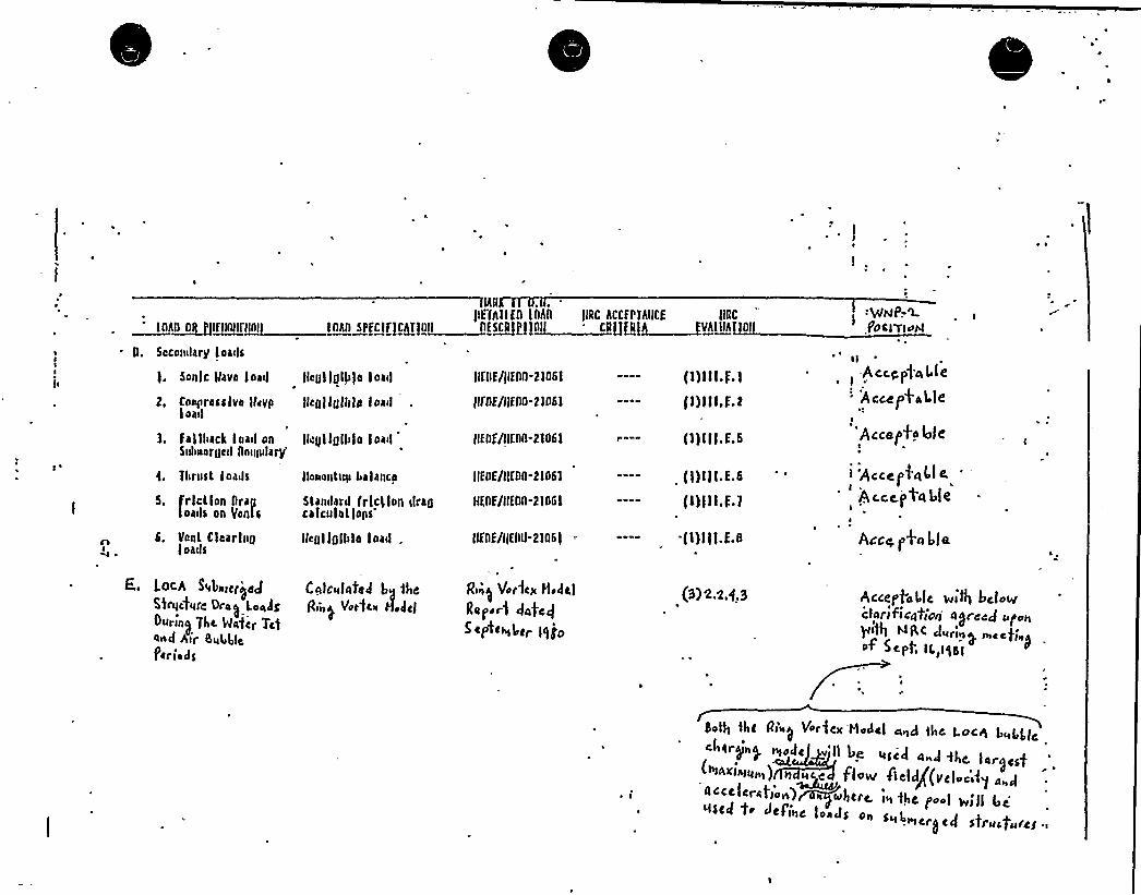
~ ~
lhgflE'(AllEn lnhn llRc hccEPThllcE llRc
IIIAA 0IL>>fflltlllnlnl> IAAII APEclncnlllll AE~ASA >>>>~II 'll[J[II~EAIIIA[IAIn. Seconslary Eoa(ls
QNP.-'L1 ocI'rlc>H
sonfc 'gave loasl
2, Cool>resslve lhyyload
fleglfglf>)e load
Ilcgl lgl1>la l oall
lnrusl loads
5. fr le lion nragloa>IS on Yenta
6. Vent Clearingloads
loch S4be>cri>fo JSbqcfurc Ore~ loadgOurin~ jhc 'Ha'fcr Tc)one{ Air Su44lcl>criers
lls>nant>ay balanca
6larolard (rlcllon <Irancalcnla 1
fons'lcgl
lgll>le load,
Calculated b~ thcg>ny Vot'fcfs Hoffcf
3. falll>ack load on l(ellllgll>lo loadSnheergcd nnnndaqj
llEnE/flEng-21061
llQE/ljEM-21061
J1Enf/llfnn-21061
llEDE/geng-21061
mnE/gEng-21061
11EnE/1fEng-2106) =
R>»of Vorlage Hodcf
Sopor) date)S clstc>s>l>ar ls) jp
(1)lll.E.1
l1) III,E.2
l 1) 1 l l.E. 6
fl)illE 6
(1) I 1 I.E.)
tl)Ill.E.g
(3) 2.1.4.3
,-Acct,p).csf fe
'Accefot'al leA
'Accet>fo 4leA
1 'Accel>4 "l e
Accc.I>tel ble
Acesf
hllsaA
ACCelAfoLIC Willi bctoWClarl fieqtiarj a A)reed >A/ <n
NQC Jur>ny n>ccrc'i»of Sept, 1L,IA151
nofg lhc p»'s>f Vor]cx 'Moslcl aP>d thc l.oc 1 bc>LLlc
A ~Acre(err lf rf'>~~w>ffrc. is>Ac p I Irf'll Srcsl$ ccl to ~cflnc loaJS on sA>L» s~.n>cr~cd structures A

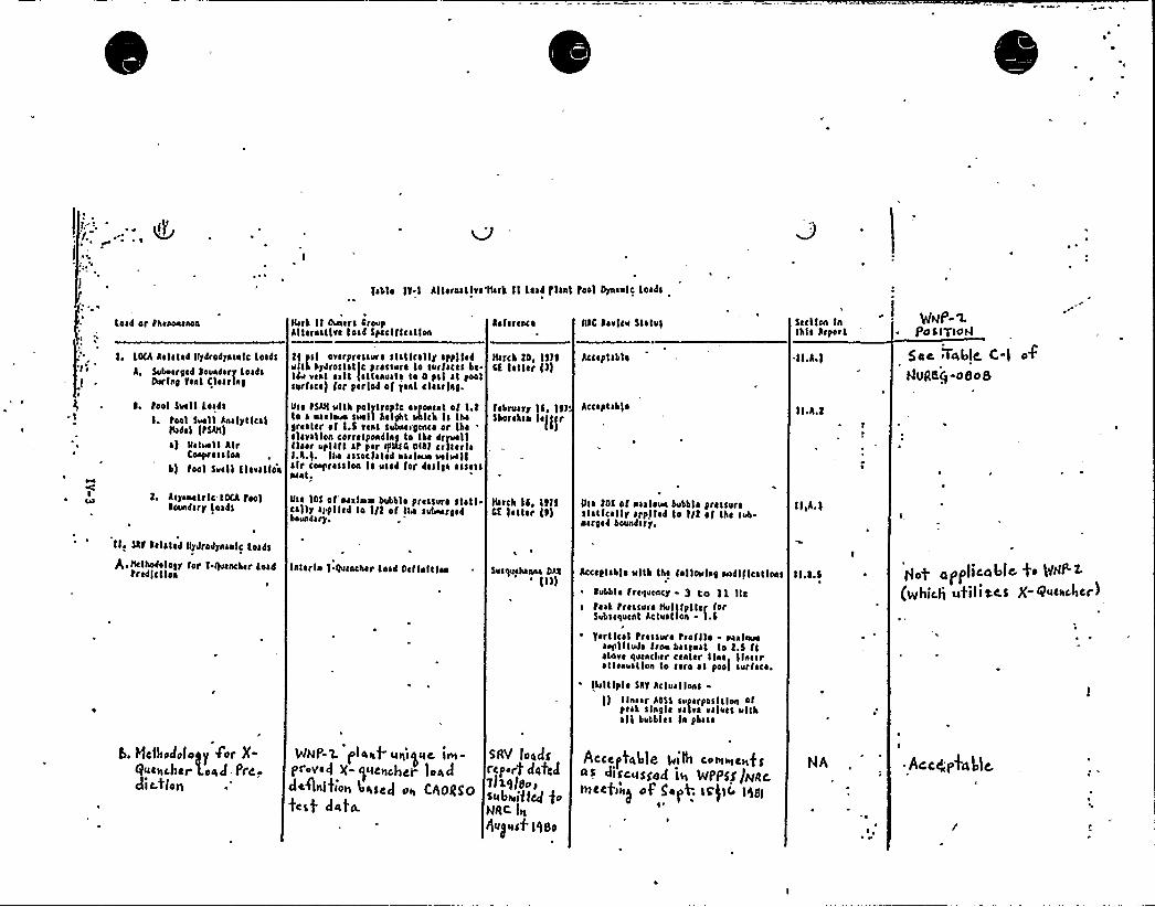
0
i-- L'abt~ IY.I Alternative 14rh II Laa4 )lani fool Dynaulc Loads
sW
Lead or Phaeonanon
!~ LOCA Aal ~ ta4 Ilydrodynanlc Loads
A, Suboargad leundary LoadsDurlnl yaat Clssrlal
l. Pool Swll Los4s
I. Pool Swll AnalyticalItsde I (PSAtt)
~ ) Vatwtt AlrConpr as s Ion
b) pool Suall tlarslloe
2. Asyanatrtc lOCA Paolloundsry loads
Vast II Owars CroupAlternative load Spaclf Ication
tt psl ovsrprcssurs stsllcslly spp)ladulth hydroststfc pressure lo surfaces bc-tdu vast ~ ~ Il fattanuat ~ te 0 pat ~ I foolsurface) for period of jant clasrlal.
Vss PSASI ulth polytroplc ~ rponcnL of l.tlo ~ nsvsouo swll helsht shish Is lhalrcstcr of I.S rant subnarlence or tbs~ levallen corraspondlnl to lbc 4rywllfleer uplift sp par rpNsC ot41 crlsarl ~
I.A.I. IIN ~ ssaclased uaatarM wtwtlsir c~rasslon Is used for daslla ~ cressncnl.
Vs ~ 1OS of'aatava bubble pressure stati-cs)ly applied lo I/2 of tse subosrtadboundary.
laferc»co
ltsrcb 2D, liftCt letter f1)
fsbrwry IS,ll1'hofahsn
la])fr
Itarch IS, Il)lCK 'I ~ liar ll)
fstC lavlcu Statul
Arcs p I all ~
Accaptah)e
I
Vss tOS of nsalew bubble pressurest ~ I Icatly applied Ie I/2 ~ f the sub-ncrlcd boundary.
Scctlon Inlhls lrpart
II.Aa)
II.A.2
II,A.S
gup-~POSI TIOPI
5ec 7cblsIC. C-l o4
hlLIRKQ-08o S
llr SAY Cela!ad ltydrodynsutc toads
Q.Hclhodaloty for f-quench«r toadPrcdlcl los insert ~ f quencher Load Oct lnltlon Susquehanna DAI'tl) Acceptable utth the folloulal nodl flcatloas
~ Cobble frequency - 3 Co 1 L llcr teat pressure Hultlpttcr for
Subsequent Actusllon I.S
~ farttcal Prasswe prattle oaaluwsaplttuda tron bassuat to 2.S ftclare queerer center line 'linear~ ttenuatlon to sere at pool surface.
lhslt Iple SAY Actual lons-lloaar A4$$ suparposltton orpest slnstc valra reluct »lthsll bubbles ln phase
II.~ .S pli(Ipdhic)I tsfilitCS X- Qssdholscr~
b, Hc))spdofoyy 4'or X-Qssctnchcr load Preydi C.tlost
WHp-'L lo)aqf castigate irvs-protrecl X $ IcstchCI loaC{deflnlftoss )sate J oss Css)oggpfeb) da4.
sRv loadsrcp.rt datedVibrlff.sScs)psuiftaf foNRC lss
gss~ ssdf'') 8O
Acccg4MI». )uiltq censuses,fsaS cliS<stSSecl its Wppgg/NRC,l77 4 C
fist~cs f g n tv+ ISt I Lr ) s) g
~ '
Ar.cgp4blc,

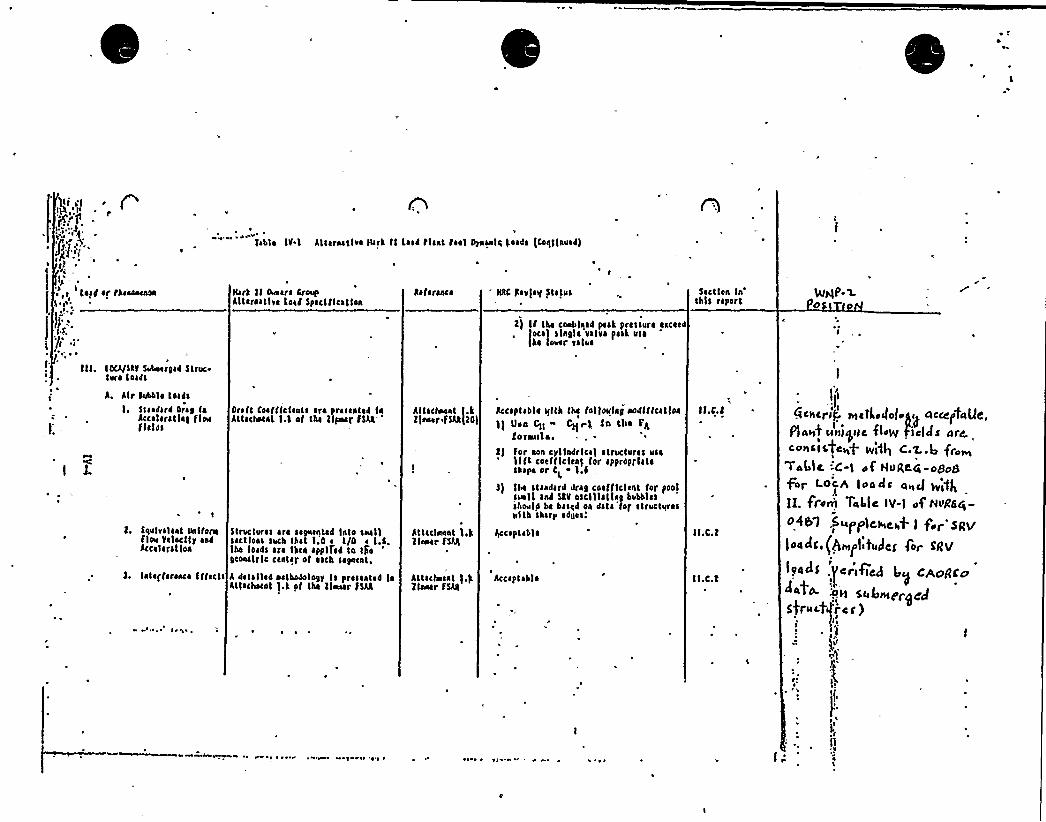
f'~ l'..'j>"./'
I
taf d or rhaaonanon ltark II 0unara groupAllarastlve Load Spaclf Ication
gaforance ttAC gavlaif Status
t) lf tha cooblqad pest prcssure aaceao.
Ioca'I slngl ~ valve peak us ~he Iouar value
Iabl ~ Ig I Altaraatlva lurk II Lead plant pool 0rnanlc toads (rogtlnuad)
Sactlaa Inthis rcport
IA/QP-l.cs
toCA/Stp Subacid gad S truetoro toads
A. Alr Sushi ~ toads
I, Stsedat4 greg faAccalsratlag floufields
Oraft Coafttctants are prasaatad laAttacsocat I.t et tha llpvsar fSAA
t. Iqulralcat unl tomfloe galocllr aadAccelcratloa
Structures ~ ro sagnantad Into seal'Isections such that 1.0 r I/O a I.g.lba loads aro lkca applrcd lo t)iegconslrlc ccatar of each sagncat,
~ ~ v w v ~ ~ ~ ~
lnlaffaranca Iftacts A dat ~ Ile4 oatbosotogy Is prasante4 lnAttachoaot ).k of tba tinier ISAA
Attacsoant I.kllavser fSAA II01
Attaclnnnt \,'kItanar FSAA
Attaclaant I.kllnacr FSAA
Accaptabl ~
~ I ~ ~ I
Acceptable ullh tbe folloulag aodlftcat ton
11 tton CII ~ Q rk In tlia FALor anil a.
I) for aoa cyltndrlca) structures usa1l It coat flclaal tor appropriateshape or C ~ I,C .
Ibe standard drag coatflclant for poolsnail and SAY osclllallag bubblesihoul4 bs basc4 oa data for structuresHlth sharp
edges.'captabl
~
II.C.t
II.C.t
II.C.t
l
i.)L,d.l ~ ~ <t Ue,
Plank ss'Isiqstc f)oz ficlcls stre.cossals fess+ WAR c-.'L 4 jrom
744lc. sC-) of IIDReca-od)otkfr «C/h lo«C and W;4A
11. FCorst TaLlc IV-) of piss/tttcg«
o'lS1 .<~pyle,mba l for SRV
lazar.(harl'tuJcs for vav
~v4ai .fcrifica uy GAoaro4~0- lsht Ss bwtf-~~/
Strata)'rc r )I
pic
c'1
~ s
11

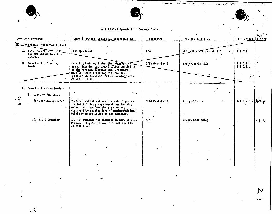
Ilark II ~Pool D naaslc Load Se«»ar 1able
toad or Ishcssrksscsson
S -Related llydrodynas»lc Loads
A, Pool Tc»lscratur~nltsfur alai and GE four araquencher
S. flocncher Alr ClearingLoads
kzSS SS 0 r5 krorP lead Ske<Jflcatlok
llonc spcclf lcd
clark II plants utlllzlng the Kla~ucs cln.'ruse au lntcrln Ioad~pcclf Ication cunslstlngof tho canshcad calculatlunal procedure.H~rll pl»sits utlllzlng tlse four ars»quencher use quencher load ascthodology des-cribed ln NfR.
Reference
li/A
OffR Rcvlslon 2
RRC Rcvlcw Status
IIRc crtterla II.I and llk3
RRC Crl teria IL2
SUI..Sect lon g~~o
I I I.C; I
III.C.?.bI II.C.2.c
C. bencher Tle-Ilown Loads
I. Ikjcnclier Ars» Loads
fa) four Arn Quencher
. fb) KN J quencher
Vertical anil lateral an» luasls dcvc)oiled unthc Lasls of lsoussillng assus»ptlons for air/water discharge frow tlute qsscnclscr andconservative cos»bloat lons nf »sari»»nl/Dllnl»»14Iebble pressure acting on the quencher.
KN "I" quencher not Included In Itsrk II O.G.Progran. I quencher aim loads not spcclfledat this tfne.
RffR Revision 2
II/A
'cceptable
Review Contlnulng
III.C.2.e.l Accej
~ H.A

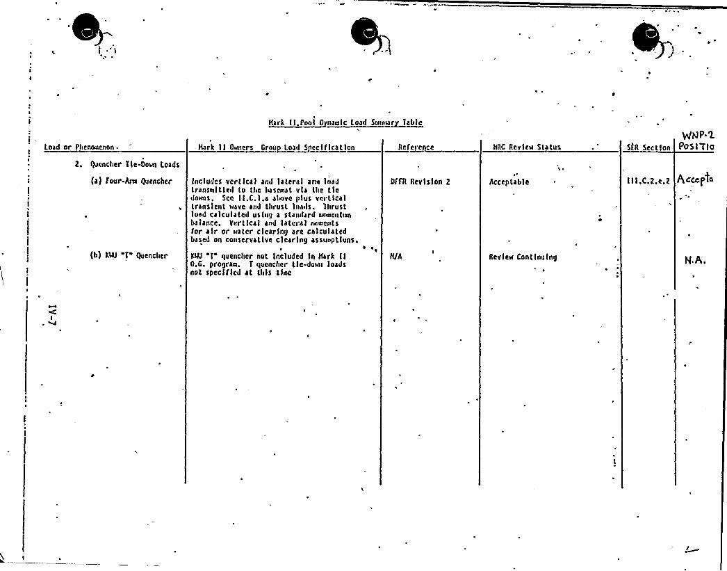
Hark tk r~ool tt aaoto toad Sao aa~rtak)o
Load or Phenotnenon.I
Z. Quencher Tle-Dow Loads
Hark II Okntcrs Group Loa~dS eclf Ication Reference NRC Revleu Status SIR Section
gldP-XPOS I TIo
i
(a) Four-Ann Quencher
(b) KW "'T" Quencher
Includes vcrtlcal and lateral arts loadtransttklttetl to thc Itascmat via lite tiedoms, Scc II.C.l.a alkove plus verticaltransient ~ave and thrust Ioatls. Thrustload calculatetl using a stantlard atnutcntksabalance. Ycrt ical and la tera I ttatttcntsfor air or uatcr clearing are calculaledbased on conservative clcarlng assutptluns.
~ ~
KN "T quencher not included ln Hark IlO.G. prograttt. T quencher tlc-down loadsnot speclflcd at this tlttte
DfFA Aevlslon 2
N/A
Acceptable
Aevi eke Cont lnulng~ ~
lll.C,Z,e,Z gt.cc,pro
N A.

e
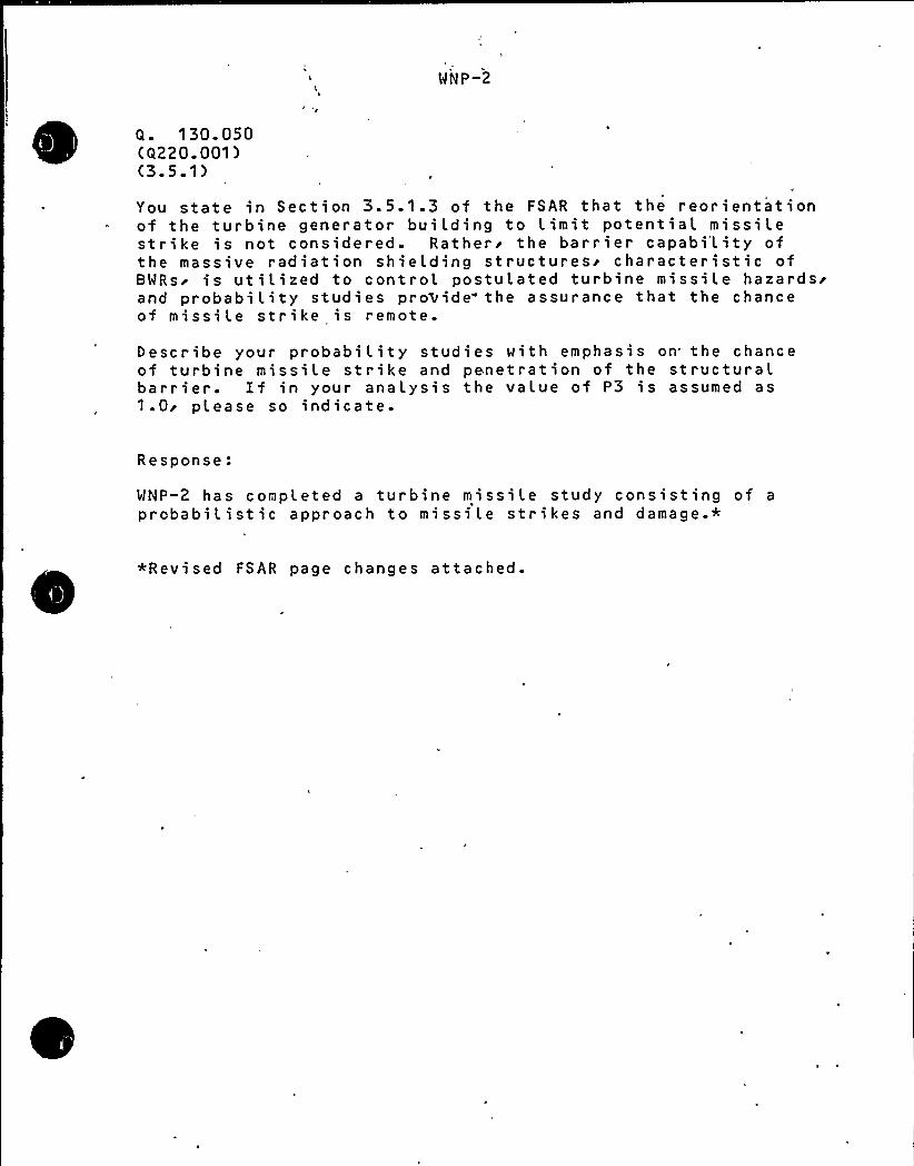
WNP-2
Q. 130.050(Q220.001)(3.5.1)
Ã
You state in Section 3.5.1.3 of the FSAR that the reorientationof the turbine generator building to Limit potential missilestrike is not considered ~ Ratheri the barr i er capabi'L i ty ofthe massive radiation shielding structuresi characteristic ofBWRsr is utilized to control postulated turbine missile hazardsrand probability studies pro>ide- the assurance that the chanceof missi le strike is remote.
Describe your probability studies with emphasis on the chanceof turbine missile strike and penetration of the structuralbarrier. If in your analysis the value of P3 is assumed as1.0r please so indicate.
Response:
WNP-2 has completed a turbine missile study consisting of a
probabilistic approach to missile strikes and damage.*
*Revised FSAR page changes attached.

Washington Public Power Supply SystemP.O. Box 968 3000 George Washington Way Richland, Washington 99352 (509) 372-5000
January 13, 1982G02-82-33SS-L-02-CDT-82-013
Dock e t No . 50-397
Mr. A. Schwencer, ChiefLicensing Branch No. 2Division of LicensingU.S. Nuclear Regulatory CommissionWashington, D.C. 20555
Dear Mr. Schwencer:
'ubject:
I
NUCLEAR PROJECT NO. 2
NRC QUESTION 130.050TURBINE MISSILE STUDY
Enclosed are sixty (60) copies of the draft response to'RCguestion 130.050 and revised WNP-2 FSAR pages. This response
'hows the results of the turbine missile study for WNP-2.'
All enclosed information will be incorporated into the WNP-2FSAR in Amendment, 23.
'ery truly yours,
G. D. Bouchey, Deputy DirectorSafety 8 Security
CDT/jcaEnclosures
cc: R Auluck -, NRC
WS Chin - BPAR Feil - NRC Si te
Open SER issue
"I CSB-I
tern
2
Concern:
Address R.G. 1.97 on an item-by-item basis by submittinga revised FSAR Section 7.5 by 12.31.81.
Response:
A response to this issue was submitted on January 13'982in Letter G02-82-30-

Mfashington Public Power Supply SystemP.O. Box 968 3000 George Washington Way Richland, Washington 99352 (509) 372-5000
January 13, 1982G02-82-30SS-L-02-CDT-82-010
Docket No. 50-397
Mr. A. Schwencer, ChiefLicensing Branch No. 2Division of LicensingU.S. Nuclear Regulatory CommissionWashington D.C. 20555
Dear Mr. Schwencer:
Subject: NUCLEAR PROJECT NO. 2CHAPTER 7.5 REWRITE
Enclosed are sixty (60) copies of the WNP-2 revised FSAR Section7.5, which addresses Regulatory Guide 1.97 on an item-by-itembasis. This issue was identified as ICSB-2 at the branch meetingSeptember 25, 1981 and closes the open SER issue.
These revised FSAR pages will be included in Amendment 23 to theWNP-2 FSAR.
Very truly yours,
G. D. Bouchey, 'Deputy DirectorSafety 8 Security
CDT/ctEnclosure
cc: R. Auluck - NRC
WS Chin - BPAR. Feil - NRC-Site
WNP-2
ICSB-I t em 3
Concern:
WNP-2 was requested to prov'ide a functional description ofthe multiplexers used to relay system status (parameters)to the control room and to provide re,liability information.
Response:
The attached article provides the functionaL description andreliabi L ity information about the mult iplexers.
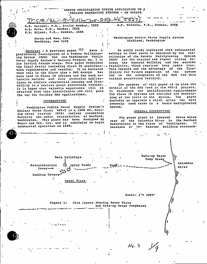
REHOTZ HULTIPLKXIHC SYSTKH APPLICATIOH TO A~ HUC'KAR CKNERATINC STATION» AH UPDATE
0 S Ya-co"i' E , Se-'o- l'emhe ~ K KA.L Cava, P.E , Hembez, KEECr De BLjocr «P a Ee ~ Hember « IKEK
H.r. Hiltala, P.E., Hembcr« IKKE
Burns and Roe, ncHoodbczy, Nev York
Hashing ton Public Pover Supply SystemRichland, Vashington
Vashington Public Pove Supolv System'sNuclear Pover .='n VNP-2 ' a '00 Hl' bo il-L g vate «actor (BUR) cele« gene atfacility tov unde co,s tc o at Ha o»d ~
Vasl ng on. 5' plan has been designed byBurns anC Roe, nc. and 's scheduled to begincon-ezcial opera 'on in 1980
'bstrac" - A previous paper ( ) gave a
preli=ina.y Cescziption c a Remote Hul iplex-Lng System (RES) or the lashing on Puhl'cPovc Supply Sys em's Nuc'ar P oject No. 2 inits initial Cesicn.s ace. 5's paper describesthe final design 'ncluding C'ass IZ qualifica-tion zecuireme..ts and testing. 's believ«Cthat his 's the 'rst ti=e a RHS design hasbeen used 'n C'ass "Z syste=s and oz such ex-'tcns'vc cor trol and Cata cather'nc appl'ca-tions o achieve substantial eco=cmy and lex-abili y 'n a nuc'ea" pov«r c«ceram'ng station.I Ls hopeC that valuab e expe='nce v' heobtained -o= th's installation and vill pavethe vay oz =rther RHS ap=licat'ons.
II
:N PODUCT OH
An early study indicated that substantialsavincs in „cost could be obtained by the sub-stL utLon of t..e Remote Hu) tiplexing System(PHS) for thc ccntzol and signal vining be-tveen the Cont ol Building and the outsLdefac'ities, vhich zcqu':ed long cable runs..his feature anC the aCvantage of the lex-Lhil'ty o" future expansio" of the system) ed to the accep ance o the PHS fo thisnuclear gene at'ng fac' i 'y.
The purpose cf thL s paper 's to cive theC«tai s 0 he RHS use C ' .e H!'P 2 pro 3 ec ~
CLscusses .He cualif'cation zeruizenentsfor Class ZZ svstems and includes the descrip-tion o thc tests cn the svs c=. The pace
~ Lncludcs an Appe,d x A vh ch elves he mostcommonly useC terms in a basic rultiplex'ngsystem
DZSCRZP»~OH
he povez plant is locateC three milesvest o the Columbia River in the HanfozCRese va ion (n the s ate o vash'rgton.consists o) tb» Reacto Buildirg su zound-
« ~
Hain Build=ngs
Heteozoloc icalTove
Cooling Tover M
Spray Ponds
OO D««O«
Hake-up Wa erPump House
Ro+
lColumb'River
Pov«» Pier t
Scale «1 ~3080'Lgu
e S' 'aycut Shov'ng Pover PlantAnd Hake-up Hater Pumphouse
Il

pl
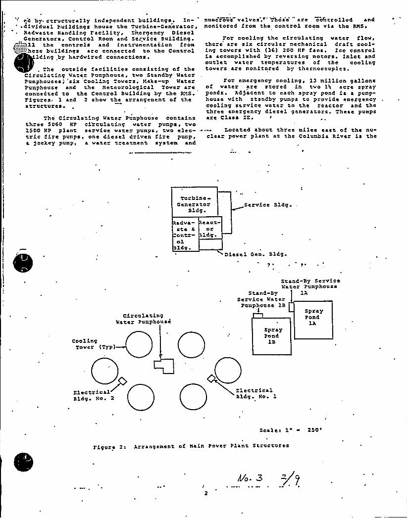
by structural)y independent buildings ~ In' dfvfdual buildings house he .urbine-Generators
Radvaste ltandling Fac'lfty, Essergency DieselGenerators, Cont.ol Roon and So=vice Building.
(:.:.::.tll the controls and instrumentatfon from~s:::-':.hose buildLngs are connected to tho Control
ldfng by hardvfzed connectfons
.he outs'de fac''tLes consisting of theCiroula irg Va e PunphOuSe, tvO Standby MaterPurphouses;'six Coo''ng ove s, Make-up MaterPunphouse and the Meteorological Tover a»econnected to the Control Building by the R.".S.FLgures. 1 and 2 shov he azrangenent of thestzuctuzeso
The CLrcula 'ng Mate Punphouse containsthree 5060 HP ci cola Lng vates'umps'vo1500 YP plant serv{,ce vate punps, tvo elec-tric ze purps, one diesel dz'ven -'ze pumpsa Jockey purp, a vate- reatnen system and
numerous valves. " hoie' are cahtrolIod andmonitored fzom the control room via the RMS ~
Fo cooling the circulating vater flov,there a e six circular mechanical draft cool-Lng tovcrs vfth (36) 200 ItP fans'ce controlf,s accomplished by reversing
motored'nletand
outlet vater temperatures of the coolLngtovers aze monitored by thermoccuples.
For emergency cooling, 13 million gallonso vater are s ored fn tvo lss acre sprayponds hd)acent o each spray pond is a punp-house vith standby pumps to provide emergencycoolLng service vate to the reactor and thethree enezgency diesel generarors. These pumpsare Class IZ~
~ » Iocated about th ee miles east of the nu-clea pover plant at the Colunbia River is the
Turbine»Gene ato
Bldg.Service Bldg
~ dva-steon t»olid@.
~eactoz
ldg.
Diesel Gen Bldg~ ~
CoolLngTovez (.yp)
CirculatingVatez Pu=phouse
Stand-By Se viceVater Punphouse
Stand-By lAS ervice hate
Punphouse 1BSprayPond
lRSprayPond
1B
ElectzicalBldg'o. 2
ElectricalBldg Ho 1
Scales 1 ~
250'Lgure
2s Arrangement of Nafn Pover P'ant Structures
~ ~
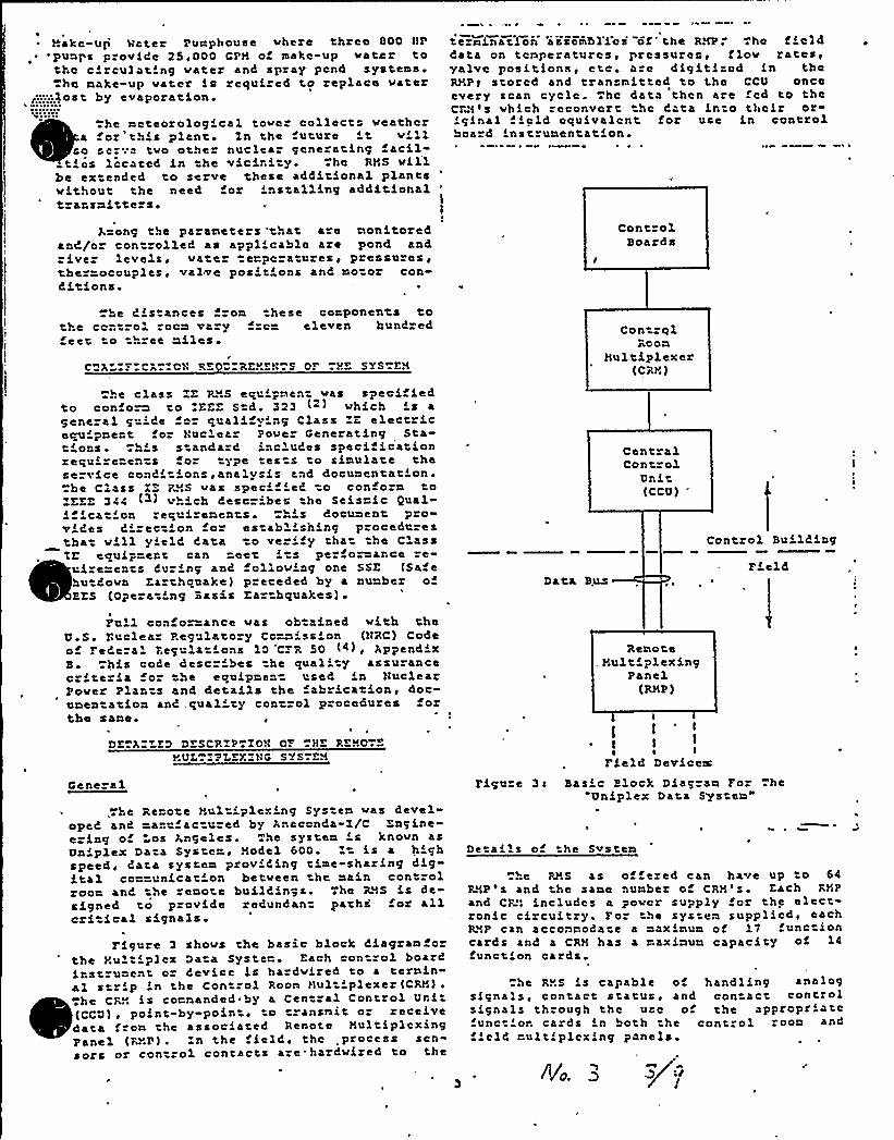
)'.akc-uj Hater Purphouse vhere three 000 HP
'puaps p ovLde 25,000 GFN of make up vair tothc circulating uater and spray pend systeas
hc nake-up vater Ls required to replaco vater<.,.,boost by evaporation.
he ncteorological tover collects veathcra or this plane Zn the uture Lt v'll
ro scrv- tvo other nuclear generating acil-tics located Ln he viciri y..hc RNS vill
be extended to serve these additional plantsvithout the need for 'astalling additionalt aasnitte si I
I
Aaong the paraneters 'that a e nonitoredaad/or con rolled as appl'cab)e aze pond andriver levels, vatez e=pcza ares, pzessuzes,ther=ocouples, valve posirions and no oz con-Citions.
te "nination 'asscnbl'Lcs of 'he RNP ..hc t Lc) ddata on tcaperaturcs, pressures> flov rates<valve positions, ctc ~ a c digitizod Ln thcRNP! stored and transnitted to l.he CCU onceevery scan cycle. .hc data then are fcd to theCRN is vhich zcconvcr hc Cata Lnto thoLr or-Lginal field equivalent for use in controlboa d Lnstrunentation.
ControlBoards
he CLstances fzon hese corponeats tothe control coen ra y rc= eleven hund ed
eec o th ee nllesr
C X :CR CH RE U REHEH.S OF .HZ SYS-EN
Con -qlRoon
Nultiplexer(CRN)
«he class ZZ RNS ecuipnent vas specif iedto con o~ co ZZZZ Std. 323 (2) vhich 's ageneral g 'Ce for cualify'ng Class ZZ electricecuipae" t for Nuclear Pove Generating Sta-tioas ..h's standard iac'udes specificationzequL eaents o" ype tests to sinulate theserv'e condit'ns .analysis and docunentation .
be Class ZZ P .S vas spec'ed o confoza toZZZE 344 (-) v ch describes the Seisaic Qualifica 'oa requizenents his docunent provides direct'n o establish'ng procedurestba vill yield Cata to ve Lfy that he ClassTE ecuip eat can rect Lcs pe foaance se-
tcire=en s Curing aad ollouiag one SSZ (Sa ehu Coun Eazthcuake) pzeceded by a aunber ofBZS (Operating Basis Ea hquakes)
Data B.lL$
Cent alCont"ol
Unit(CCU)
Control Building
FLeld
Full coafo=ance uas obtained vith theU.S ~ Ruclea Pcgulato y Co~ission (HRC) Codeof FeCera'egulations 10 'C; R 50 (4), AppendixB. his code describes the qual' assuranceczi tezia fo" the ecuipaeac used 'a NuclearPover Plarts and detai)s he abricatioa, doc-unea acioa and qual'ty coa rol procedures forthe sane.
DE AZZEDDZSCPZP«ZOH OF HE REND ZNUT . ZPI EXZHG SYS-EN
aen a1
he Reaote Nultiplexing Sys ea vas devel-oped and -anc ectured by Rnaconda-1/C Zagine-e ing o os A,ngelcs..he syscen ' knovn asUaiplex Data Systen, Nodel 600. 1 is a h'ghspeed data systen proviCing tine-sharing digital co==unicat'on betveen the naia controlzoon and he reaote buildings. he RNS is de-signed to p ovide redundant par hs oz allcri ical signals
FLguze 3 shovs the basic block Ciagran orthe Nultiplcx Da a Syste . Each con zol boa d
iastruaent oz device Ls hardvired to a ternin-al strip Ln the Con rol Roon Nul iplexer(CRN).L L
tZ f
tt«hc CRN Ls coaaanded
gaby
a Central Control Uri(CCU) ~ poLnt-by-point ~ to transmit or receivedata f on the associated Rcoote NultiplcxingPanel (P".P) . Zn the fielC, the process sen-sors or con zol contacts aze harduized to the
RenoteNultiplexing
Panel(RHP )
I
t)
IFLeld Devices:
Figu e 3c Basic Block Diagran Fo .heUniplex Data Systen"
De ails of he Svsten
he PAS as of ered can have up to 64RNP 's and the sane nunber of CRN'. Each RNPand CR!l includes a povcr supply for he elecronic circuitry. Fo" the systen supplied, eachR".P can acconnoda e a aaxinun of 17 func ioncards and a CRH has a naxinun capacity of 14function cards.
.he RHS is capable o handling analogsignals, con'tact status ~ and contact controlsignals through thc u c of the appropriatefunction cards ln both the control roon andfLcld rultiplcxing panels.
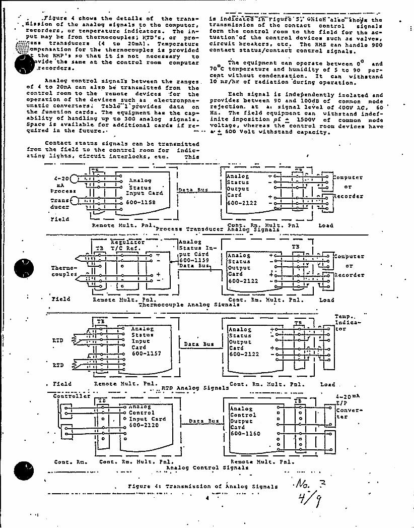
.g Lgure 4 shove the details of the trans-,ZILssLon of tho analog signals to tho computoze
recorders, or temperature indicators. The in-put nay be f on thermocouplese RTD's, or pro
g':.:.'.-,os'ransducezs (4 to 20nA) ~ Temperature':,';::ompensation for the theznocouples is provided
thc RRPes so that it is not necessary tovide the sane ar. the control room computer.recorders
Analog cont ol signal's betveen the ranges „of 4 to 20nA can also be transni ted f om thecon rol oom to he renote devices or theoperation of the devices such as elec ronpne-uratic convcz ezs; .able 1 p.ovides data onthe unction ca ds he equLpnent has the cap-ability of handling up to 300 analog signals.Space is available fo additional ca ds if re-quLzed La the uture
is LndKcat.cK in FLguio 5> which al'so'ho)s thetransnLasion of the contact control signalsfora the control roon to the fLeld for the actuation'of the control devices such as valves,circuit breakers, etc The RMS can handle 900contact status/contact conrzol signals.
0 .he equipment can operate betveen 0 and70 C temperature and humidity of 5 to 90 per-cent without condensation. Zt can vi thstand10 nz/hr of zadiation during operation.
Each signal is independently Lsolated andprovides betveen 90 and 100dB of common moderefection. at ae, signal level o 400V AC ~ 60H=. he field equipment can withstand indef-inite imposition pf ~ 1500V of connon modevoltage, whereas he control roon devices havea + 600 Volt withstand capacity
Contact sta us signa's can be t=ansnittedf o- the f'eld to he contzcl zoon for indic-zt'ng 'ghtse circui 'n=ezlocks+ etc ~ his
4 20
Processaas
duce=
~,eI e I Analog$ 'tztusnput Card.II I I
e,e I I I 600 1158
Da a BusI
azlogStatusOutput
!
Card600-2122
I ~ ~ ~onputer
oz
ecorder
rieldRenotc cult. Pnl. Con . Rn. t!ult. PnlProcess zaasduce Ana)oc Signals Load
Therno-couples
RegulatorTB T/C Re
eeel I
ee'I I I
~a1
AnalogStatus Ia- l!put Card600-1159Data Bus
A 'nzl 0 gStatusOutputCard600-2122
TTB
' e
J%Lpga
o»
Recorder
yield Renote .'!ult ~ Pal. Cont. Rn. cult e Pnl.5eznocouple Analog Signals Load
RTD
RTD
~ e e I I~ e e
ee I e
eee I I
br slogStatusInputCzzd600-1157
Data Bus OutputCard +
-212260D
!
Temp ~,Iadica-toz
Field Remote Nuit. Pal. Coat. Ra. ev.air.. Pal... R D Analog Signals Load
Coatroll er
I eI I
el I
nna JogControlI
o Input Card600-2120
Data Bus
AnalogControlOutputCard600-1160
L
00
00
TB
0o
o0
20 nAE/PConveter
Coat Rn Cont Rn Hult. PnlAnalog
Remote Nuit PalControl Signals
figure CI .zansmissLon of Analog Signals ~ Aa
v7
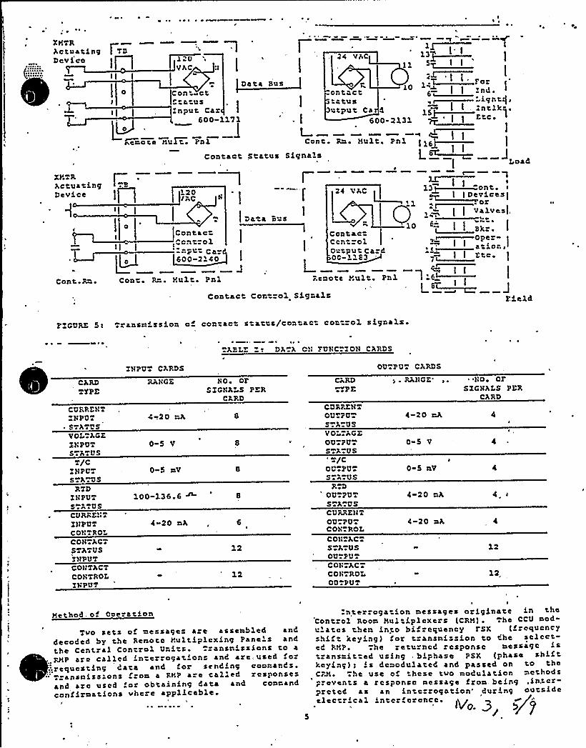
~ ~I
~ ~
X)tTRActuatingDevice
8'::
X)'TRActuacingDevice
Cont.Rn
|TVI
I
'fh DII,I I . Pelf)l
CCC
24 VAC120VAC
Data Sus 10Con ~ctta usnpu't Car
"
l'00-1171
cntncttatusutput Ca
LCesote ltuIt~ Pnl Cont.
Contact Status Signals
I-r1
Da a Sus
Illi ccv..I ID vlcccI
] f CCValvesl,
I ccrc. I
DP ~I I
'
C a iov ~
I I ffc
Eield
24 VAC120lAC
ContacCcn =olO.cpu Card00 1183
CcntrolvtPu Ca C
~COO-i'c I
JRenote Yult. PnlCont Rn Hulr. Pnl
Contact Con ol Signals
600-2131
I tMflfc
.Pf1 I
C
I
FZCVRE 51 Trans11ission of concac s ates/contact con rol signals
«AEIE 2! DA A Cvv FUhC ZON CARDS
OI DCPD
CQRREhTZYPPQTSTATUSVOI, ACEShPVTSTATUS
T/CZHPQTS A QS
ZH PUT CARDS
4 .20 nA
0-5 V
0-5 nV
NO ~ OFSZGhAI S PER
CA RD
CARDTT PE
CQRPKNTOUTPQS ACUSVO» AG EOUTPUTS A.US'T/COQ PVTS A US
OQTPVT CARDS
; . RANGE'
20 nA
0 5 V
0-5 nV
" 'HO ~ OFSZGHALS PER
CARD
RTDZhPUTS.ATUSCURRE)l TZNPQTCOhTROLCONTACTSTADUSINPUTCONTACTCONTROLIYPUT
100-136 6 ~ 8
4-20 nA,, 6
12
12
RTDOU PUTSTA.QSCURRENTOU PQTCOH ROLCOH ACTSTATUSOU. PUTCONTACTCDNTROLOU PUT
4-20 nA
4-20 nA
12
12
Hechod of One ation
Tvo sets of nessages are assenbled anddecoded by the Renocc Hulciplcxing Panels anC
t,he Central Control Uni s. . ansnissions to a
~ 1
~~
..R)tP are called interrogations and are,t used 0
..'1requescing Cata and 'or sending coonat:Cs."
~ ransniss ons ron a RHP are calleC responsesand arc used for obtaining Cata and connandconf irnations vhe e applicable
nter.ogacion nessages originace in cheCont"ol Roon )tul iplcxers (CR)t). ~ he CCU nod-e aces then il pc bif equency FSK {frequencyshi t key'ng) for transnission co the selccc-eC RHP. .he returned response nessage isransnit ed using biphase PSF. tphase shift
keying): is dcnodulatcC and passed on to theCR)t. .he use of hose cvo nodulation ncthodsprevents a response nessage fron. beingprcceC as an inccrrogacion'uring outsideelec rical intcrfercncc ~
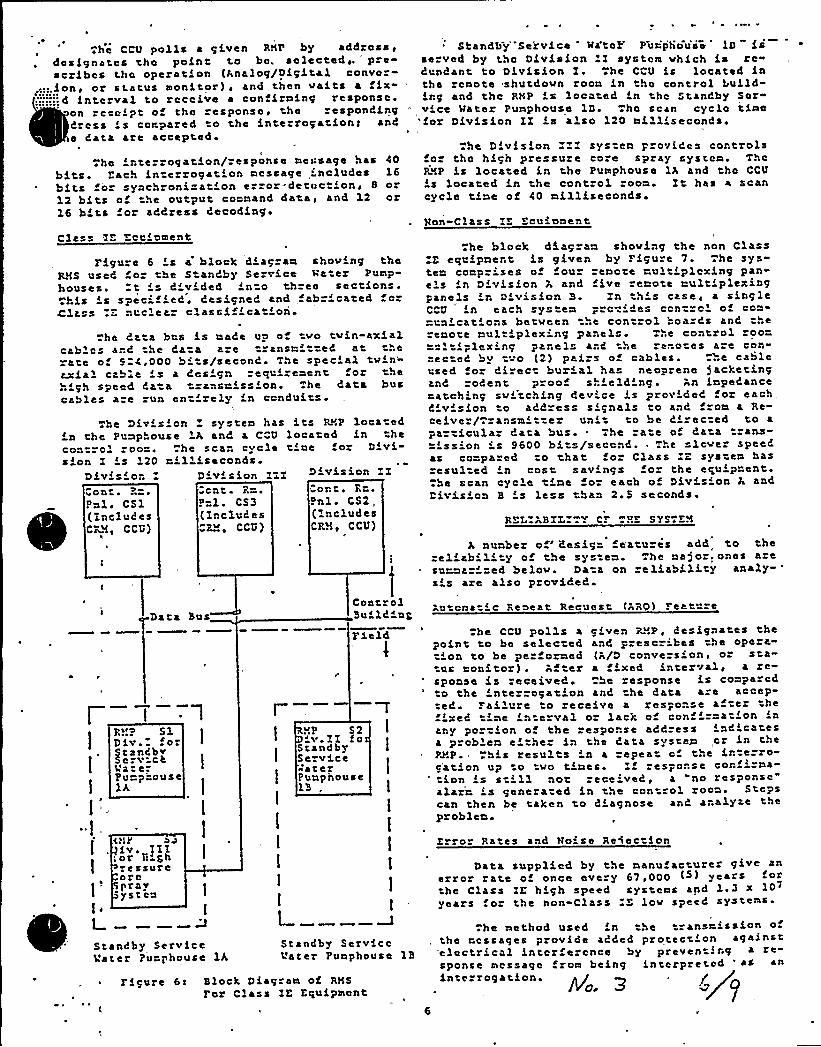
he 'ntezzogation/response message has 40bits ~ Each intezrogation message 'ncludes 16bits o synchroni=at'on c =or- detcc 'on, 8 or12 bits a he output command data, and 12 oz16 b'ts or address CecodLng
Class IE Ecuiament
I'igure 6 Ls 4 block Ciac an shoving theR8S use6 or he S anCby Service va er Pump-houses. t Ls 6'v'ded 'n"o three sec fons.«his 's spec'f'ed'esigned an6 abr cated a»
Clz.ss "- nuclear classification.he Ca a bus is made up of vo tvin-axLal
cables and the Cata aze transni ted at therate of 9 4,000 bi!s/second. The special tv''-axfal cable 's a Cesign requirement or hehigh speed Cata tzansrissfan. .he data buscables aze run entirely 'n canduits
The Div'sian systcn has its RNP loca cdin the Punphouse !A and a CCU located Ln hecartral zoo=. «he scan cycle tine oz Dfvi-sfon I 's 120 n'lliseconds
DivisionCant e ~
Pal. CS1(XncludcsCRNe CCU)
'Divis ion ZIIIcut a- ~
P" 1. CS3(Xr.clud esCR ~ CCU)
D'vision ZZ
Can t. Rr..Pnl. CS2„(Xnclu6esCRN ~ CCU)
~ ~
Thc CCU polls a given RNP by addross,des Lgnatcs tha point to be. selected ~ . prcsczfbcs the operation (Analog/Digital convor-
~:::.Lan~ or status monitor) ~ and then vaf ts a fix::::.:.:.d Lnterval to recaLve a confLrning response.
an "eccL pt of the response, the respondingCress 's compared ta the interrogation> andc Cata are acceptcd!
Standby" Servf cc Ma'taf'uiphausc lDserved by thc DLvfsion I system vhich Ls re«Cundant to Division Z. he CCU Ls located inthc remote shutdovn roon Ln t'ho control bufld-irg and thc RNP L s located Ln the Standby Sarvi ce Mater Pumphouse 1D. ha scan cyclo timefor Dfvisian IZ Ls also 120 milliseconds ~
he Division I systen prarLCcs controlsfo the high pressuze core spray system. Thcpvp is located in the pumphouse 1A and the CCU
Ls located in the control oon Zt has a scancycle tLne of CO nLlliscconds
Man-Class IE Ecuianent
he block 65.agzan shoving the nan ClassIE equipnent is given by Figure 7. he sys-tem canpz'cs of four senate rult'lcxing pan-els in DLvisfon A and five ceno!c multiplexi'ngPanels 'r; D'visLon B. Zn th's case, a singleCCU Ln each sys en pzc-'Ces ccn za'f con-nrn'at'ns betveen hc cont ol boa" Cs and thc"cnote nultiplexing panels ..c control zoo"=" It'lex Lng panels anC thc rc.=ate s are con-nec eC by tvo (2) pairs of cables. T«e cableused fo direct burial has neoprene 5acketfnganC rodent p oof sh'eld'ng. An inpcCanceratch'ng sv'tching dev'ce Ls provided fo each,Civ'sion o address s'gnals to and fzon a Re-ceiver/Tzansn'er un'o be C'rected to a
Particular Cata bus. The rate af Cata trans-=Lssian is 9600 bits/sccan6. The slcvcz speedas compared to that o Class E system hasresul cd 'n cast sav'ngs f a the cgufpncnt
he scan cycle tine for each of Divis'on A andDivision B 's less than 2.5 seconds ~
REL BZL Y CF HE SYS EA
A nunbez o 'esign c'aturcs ad6 to theclcabilc!y of »4e sys en. !he major.ones a e
sunna 'ed belov Data on e liability analy-s's aze also provided
Data BusControlBuilding
utcna i c Reseat Recucst tARO) Feat '
l
I
I
l
I
F.v.p SlDfv. fa
tsnCbvc v CR
Va e-Pu=p'"auselh
<uk'v.]XI:or li Sh
rc ssureareprayystcu
1
I
I
l
I
I
I
l
I
I
lI
I
Field
.uP 52'v.XX faStandbyService«aterPunphause1B .
I
1
1
he CCU polls a c'ven RvP, designates thePoint to be selec ed and p escr'bes the opeza-t'on to be pc darned (A/D conversion, oz sta-
us nan toz) ~ Af I cr a 'xcd interval ~ a re-sponse fs'eceived he response is comparedto the 'tezragation and he data a c accep-ted Failu e to eceive a res-ouse af-ez the
any portion of the esponse address inCicatcsa problem cL he" in the Cata systen,cr Ln theP3'P. This results ' a repeat a the ir. erro-cation up !o va tines. If res"onsc cor. Lzna-ion is st'l not received, a "no response"
alair Ls genezatcd in the control zoon! Stepscan then be taken to dLagnose and analyze thcproblem!
Error Pates and Raise Rciectian
Data supplic6 by the manufacturer give anerror rate o once every 67,000 (S) years
he Class ZE high speed systems apd 1 ~ 3 x10'earsfor the non-Class L'ov speed ystcms
I
Standby ServiceVc ter Punphouse lh
Standby ServiceVa ter Punphouse 1B
hc method used Ln !he ansrissLon ofthe ressages provide added protection againstelectrical inter c ence by preven Lrg a
sponsc message from being fntcrpretcd ' * an
~ Ffgure 6c Block Diag-an of RMS
For Class IE Equipmentinterrogation. > /leo.
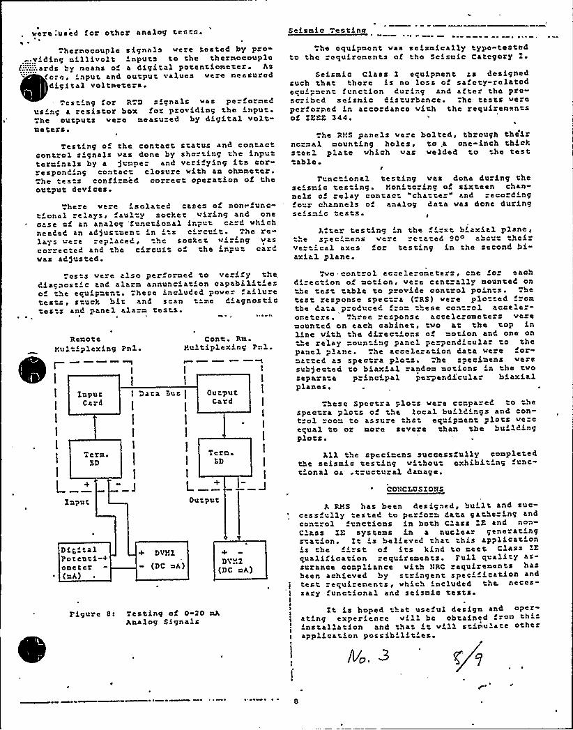
vore .'used for other analog tessto»
. hernocouple signals vere tested by pzo«-.yiding rillivolt 'nputs to the theznocouplo
F:::::;ards by sseans of a digital potentiometer» Asfore, 'cput and output values vere measureddigital voltneters ~
.Es 'ng or RTD signals vas perfoznedusirg a resistor box for providing the input..
he outputs vere measu ed by digital voltmeters.
Testing o the contact status and contactcontrol signals vas done by shorting the Lnputter mals by a jumper and veri ying i ts cor-responCLng contact, closure vith an ohnnctcr.
he tes s confirmed correc operation of theoutput devices
here ve e isolated case of non.-func-t'onal clays, faulty socket viz'ng and onecase cf an analog 'nct'nal Lnput card vhichneeded an ad)ustment 'n ' ci cui Thc re-lays vere rep'aced, he socket v'g vascozrec ed and the cizcui o the input cardvas ad)usted.
Se isni c Tee tL nc
The equipment vas seismically typc-testedto the rcquircssents of tho ScisaLc Category Z ~
The RMS panels ve cncraal mounting holes,steel plate vhLch vas
able ~I
bolted, through the'Lrto,a one-inch thickvelded to the test
FunctLonal testing vas done du ing theseismic testing. Noni c Ls:g of sixteen chan-nels of relay contact "cha te " and record'ngfo r channels o analog data vas done duringse sa c tes'ts ~
Aftc testing 'n the 'rst biaxial plane,he s-ec'mens vere rc a ed SOo abc' seiz
ve" 'cal axes for testing in the second bi-axLal plane.
seismic Class I equipment rs d'csigncdsuch that there Ls no loss of safcty-relatodequipacn fane ion Curing and after the pro-se Lbed seLsmic C's uzbance. he tests verepcrforped in accordance vith the requirementsof ZEEE 344
RemoteYul Lplex'ng Pn1.
rCont Rm
YultiplexLng Pnl.
InputCard
( Data %us l Ou» putCard
l
l
1
l
L
Tera»SD
Tera»ED
.csts vere also per orned to ve ' theCiagnost'c anC alarm annunc'a 'on capabilitfeo he equip en . hese included pover aLluzetests, stuck bLt and scan t ne C'agnostictes s and panel alarm tests ~
Tvo control accelezoaete s, cne or eachC'rec 'on of notion, vere centrally nounteC on
he test table to prove Ce control points hetest response spectra ( RS) ve e plotted fromtba Ca a produced from these control acceler-oaetcrs. Three response accele omete s veremounted on each cabinet, tvo at the top Lnline v'ith the directLons of notion and, one on"e relay mounting panel perpendicular to the
panel plane. Ne acceleration Cata vere or"matted as spec ra plots. he specLnens veresub)ected to biax'l random motions 'n the tvosepara-e p"Lncipal pe~andi'cular biaxialplanes,
hese Spec ra plots vere ccrpareC to hespectra plcts of the local buildings and con-trol roon to assu e that equipment plots vereequa1 to or acre severe han the bu'ldingplots.
All the specimens success ully coapletedthe scisa'c testing vithout exhibit'ng func-t'onal oc tzuctural damage.
COHCZUSZONS
Input
DLSLtalPotenti"+oaeter
~ (aA)
+ DVYI
(DC aA)
Output
'+DVv2
(DC ELA)
A RMS has been designed, bu't and suc-cessfully testeC to per ora Cata gather'ng andcan zol functions 'n both Class E and non-C'ass ZE sys eas Ln a nuclear generatings'tation. Zt ' bel'ved rhat this appli cat'nLs the first of its kLnd to rect Classquali Lear'on requireaents. Full quality as-suzance coapl'nce vith HRC requirements hasbeen achieved by stzLngent spec'fication and
j tert zequi enents, vhich included he. neces-sary func ional and seisaic tests
I
Figure Ss Testing of 0-20 nAAnalog Signals
sign and opere
L nstallation and .hat. ''1 s Lnulate otherapplication possib litfcs»
»'
~ 8

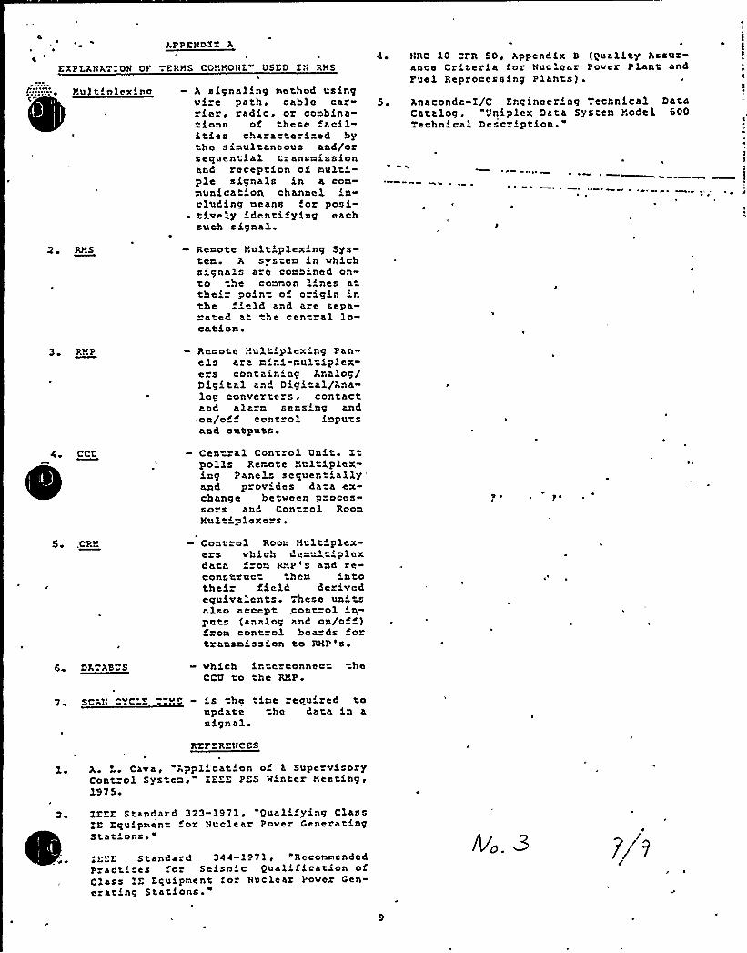
OAPPENDTX A
zxPLANAT70N or TzRrs CDNroNL" DSED xN RNS
A signaling method usingvise path, cable car-rier~ radio, or combina-tiona of these acilities characterized bythc simultaneous and/orsequential transmissionand reception of multi-ple signals in a com-municat'on channel in-clud'ng means for posi-
~ tively identifying eachsuch signal
4 ~ NRC 10 CFR 50, Append'x B ((Iuality Assurance Criteria for Nuclear Paver Plant, andFuel Reprocess ing Plants) .
5, Anaconda-I/C Engineer'ng Technical DataCatalog, "6Jniplex Data Sys em .".odel 600echn'a1 Description."
6
»
6
2 Rr.s - Remote Nuit'lexing Sys-tem ~ A sys»e'm in Mhichsignal.s are comb'ned on-to he common 1'nes atheir point of ozi,gin inthe ield and a e sepa»-ated a the central lo-cation ~
3 RrP - Remote rul 'plex'ng Panels a e mi..i-multip1ex,-e s containing Analog/Digital and Digital/Analog converte s6 contactand alarm secs'ng and.on/of control impu sand outputs
- Cen ral Control Unit. Xtpolls Remote r6ul iolex,ing Panels sequentiallyand provides data exchange between p oces-sors and Control RoomNultiplexers.
J ~ 7 ~
5» CPR Control Room Hultiplex-ers vhich demultiplcxdata f om RMP 6 s and reconstruct ther. intothei field derivedequivalents. These unitsalso accept,control inputs (analog and on/off)f om cont ol boards fortransmission to R61P's ~
6 66 666 - vhich interconnect theCCQ to he Rrp
7 \ sc N c~cLE 7=RE is he 'me requ zed toupdate he data in asignal
RZrZRZNCZS
L Cava, Appl'cation o 1 Supervi oryControl Sys em," XZEE PES Minter Neeting,1975
.lzzz Standard 323-1971, Quali ying ClassZE Equipment or Nuclear Pover GeneratingStat'ns.-EEE Standard 344-1971 RecommendedPractices or Seismic Qualification ofClass lz Equipment fo Nuclear PoMer Cen-ezating Stations."
Ij l

ICSB Item 4
.COliC-
:.ailur in Vessel Revel Sew="g L'w s C"=on to Con"-ol ando oiec ie Syst &«s
have ocr'"=ed " VR reac"o vessel l vel = =ere"ce s~ "g l'" sand ~it in rsosi cases the fai'~~~ s have «snl —«d '=oneouslynigh acta- vess l L ve'nd'cation. =o= 3'~~'s, co=on "snsing L'"es a"e used =or feed"a== cort=ol a"c as "" basis forestabl'sh'"g vessel'Level m""e~ tr=as for o"e ox =ore of the
'roiec"=vunctions (reacto= sc"a", ~SLAV clos-" , ZCTC, :"-CE, A3So" o~ ".i at~on). =a "res ux sum se~w="j lwes, nay causereduct'on in " d"ater clos: a"d coveouentiaL delav a =0 sir"'"Ae related prot ct.ve, c~~nnel.
If an admit otal =a. u"e, pe""aps of e ec=".'Cal "a"""e, is assmeda protective c'"a~=e not de"wc "- or t"e a Led smwg l e,
protec"='ve ac==on nay not ocr" o" may oe delayed Long enough toresul z unacceptable conseowc s. L's de@en s on ke logic fo=coaoini" g ~""e t "s to ac".eve ac"=ons.
Xt is ou= posi =on'~t ~ose " " " "c 'l "es co=on to t"= feei-vate» cont ol ~nnc on, and to a y o ««e p Qte~ ve "~c ons oloss of fe dvat eve"ts be ic nt = ed and ~t Ae consecnenc soz failu=es i" such "«=«"-nce "" s c""c"—-"i «iL ""e vors-
~ ~
circa m be analyze"'.
RESPONSE:
A pos ula- d br ak in an ins-rum ac line plus an addi ional -,ailuris beyond the desion basis, or -'his plani; however, an assessmMwo= plant response =.o ".his even~ is hery provide".
one insiru~enz re-,orence lines eo~n to,eedwater control ed zprotec-ive sys.em sensors have been identified Rr "his plant.analysis was per-,on",ed o determine the conseouences o-, failures insuch re-;erence 1ines concurren. wiih additional sincle Tailures inprotec:ive channels noi dependent on the failed se~s-na line Tne
Sequence o= »"vents are si"own in -;he at ach"„en'.
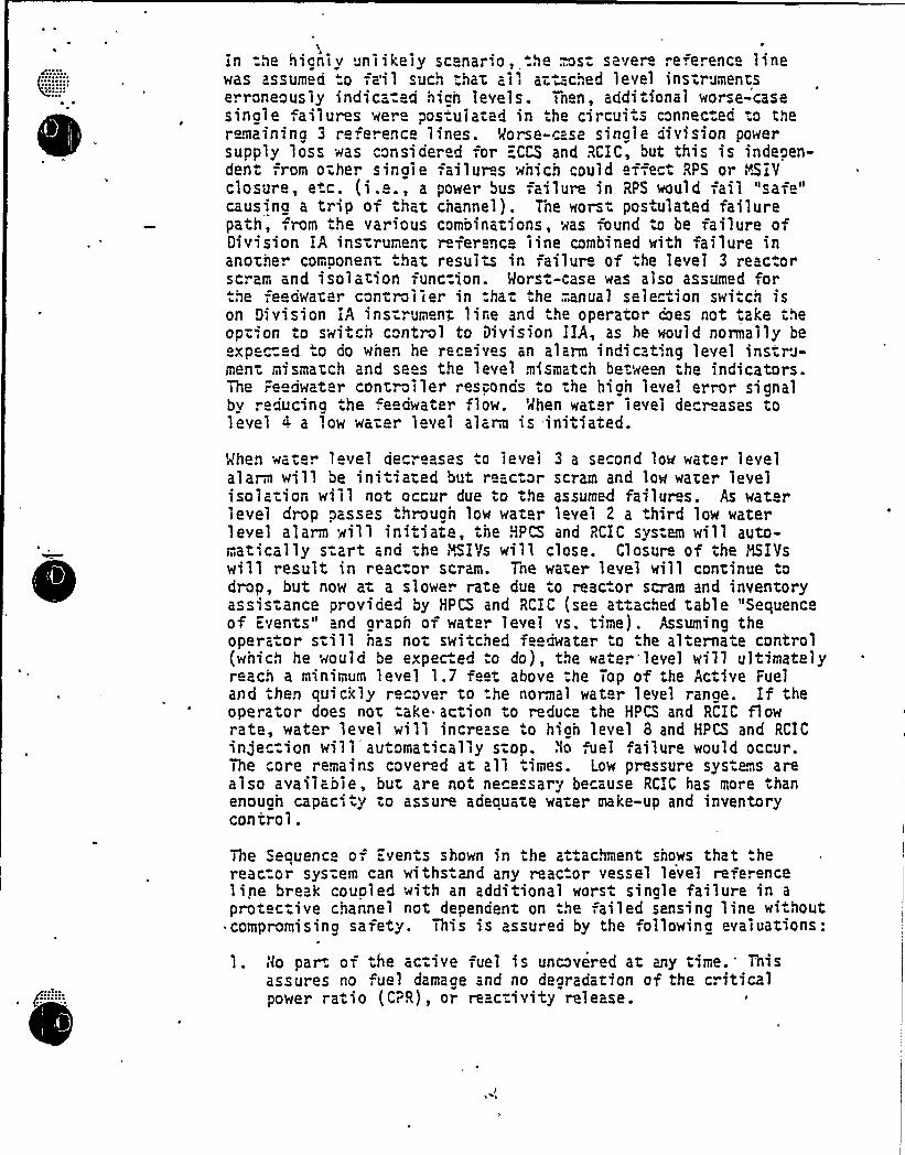
in =he hignly unlikely sc nario, .he est severe refe.ence finewas assumed "o fai I such that all attached level ins"rumentse. roneously indica: d hian Ieveis. Th n, additional worse-casesinale ailures we. Pos-uiated in the circui .s connected to theremainina 3 reference lines. Morse-case sinale division powersupply loss was considered -,or ECrd and RCIC, but this is indeoen-dent -,rom othe. sinaie failur s wnich could effect RPS or i~hIYclosure, etc. (i.e., a power bus failure in RPS would fail "safe"causina a trip of that channel). The worst pos ulated failurepath,,rom the various combinations, was ound to be failure ofDivision IA ins-rument r ference iine combined with failure inanothe. component hat results in failure of the leve1 3 reactorscram and isolation func=ion. Mors -case was also assumed for.he fe dwater controller in ha- .he;.anual selection switch ison Division iA ins:rument line and he operator coes not .ake theoption to swi ch control to division IIA, as he would normally beexpe~ed "o do when he receives an alarm indicat':ng level instru-ment mismatch and sees the level mismatch between the indicators.The Feedwater controller responds to the high level error signalbv . educina the feedwate. flow. When water level de r ases tolevel 4 a Iow water level alarm is initiated.
When wate. level decreases to level 3 a second low water levelalarm will be initiated but reactor scram and low water levelisolation will not occur due to the assumed failur s. As waterlevel drop passes throuah low water level 2 a third low waterlevel alarm will initiate, the HPCS and RCIC system will auto-maticaily s:art and the HSIVs will close. Closure of the KSIYswill result in reactor scram. The water level will continue D
drop, but now at a slowe. rate due o reac.or scram and inventoryassis .ance provided by HPCS and RCIC (see attached table "Sequenceof Events" and araoh of water level vs. time). Assuming theoperator s.ill nas not switched feedwater to .he alternate control(which he would be expected :o do), the wate. "level will ultimatelyreach a minimum level 1.7 feet above .he Top of the Active Fueland then quickly recover to -he normal water level ranae. If theoperator does not take action to reduce the HPCS and RCIC flowrate, water level will increase .o hian level 8 and HPCS and RCICinjection will automat~cally stop. No ,uei failure would occur.=The core remains covered at all times. Low pressure systens arealso available, but are not ne ssary because RCIC has more .hanenouah capac-ity to assure adeauate water make-, up and inventorycontrol .
The Sequence of Events shown in the at.achment sho~s that:hereac-or sys:em can withstand any reac or vessel level refe.enceline break coupled with an additional worst sinale failure in a
protective channel not dependent on the failed sensing line wi.hout~ compromisina safety. This is assured by the,ollowina evaluations:
I. t(o par. of .he ac:ive uel is uncovered at any time.'hisassures no fuel damaae and no dearadation of the criticalpower ratio (CPR), or reactivity release.
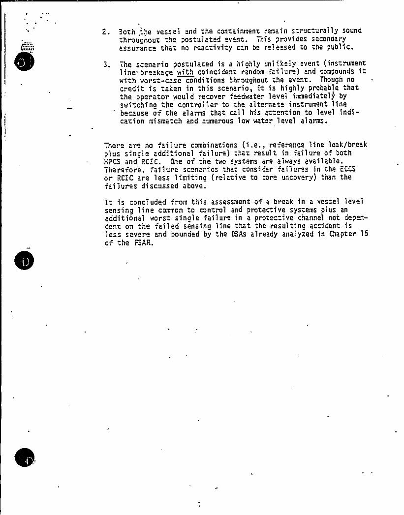
2. 3oth -.~e vessel and the containment .-emain struc:urally soundthroucnout:he pos.ul ated ven-. This provides secondaryassurance that no reac:ivity can be;e.eased to the public.
The scenario pos ulated is a highly unl'.k .y event (instrumentline breakage with coincident r ndom failur ) and compounds itwith worst-case conditions hroughout the event. Though no
credit is taken in this scenario, it is highly probaole hatthe operator would recover eedwater level inmediately byswitchina ,he controller to the alternate instrument linebemuse of the alarms .hat c-ll his at-ention to level indi-ca-ion mismatch and numerous low wate. level alarms.
,nere are no failure combinations (i.e., reference 1ine leak/breakplus s-ngle addi.-'onal failur j that result in failure of bothHPCS and RC.'C. One of the two systems are always available.Therefore, failure scenarios tha: consider ailuros in the iCCSor RCIC are less limiting ( r lative to core uncovery) tnan thefai lur s discussed above.
It is concluded from this assessment of a break in a vessel levelsensing line common .o control and protec.ive systems plus anadditional wors single ailur in a protec= ve channel not depen-dent on the ailed sensing line that the resulting accident isless severe and bounded by .he HAs already analyzed in Chapter 15
of the r=AR.
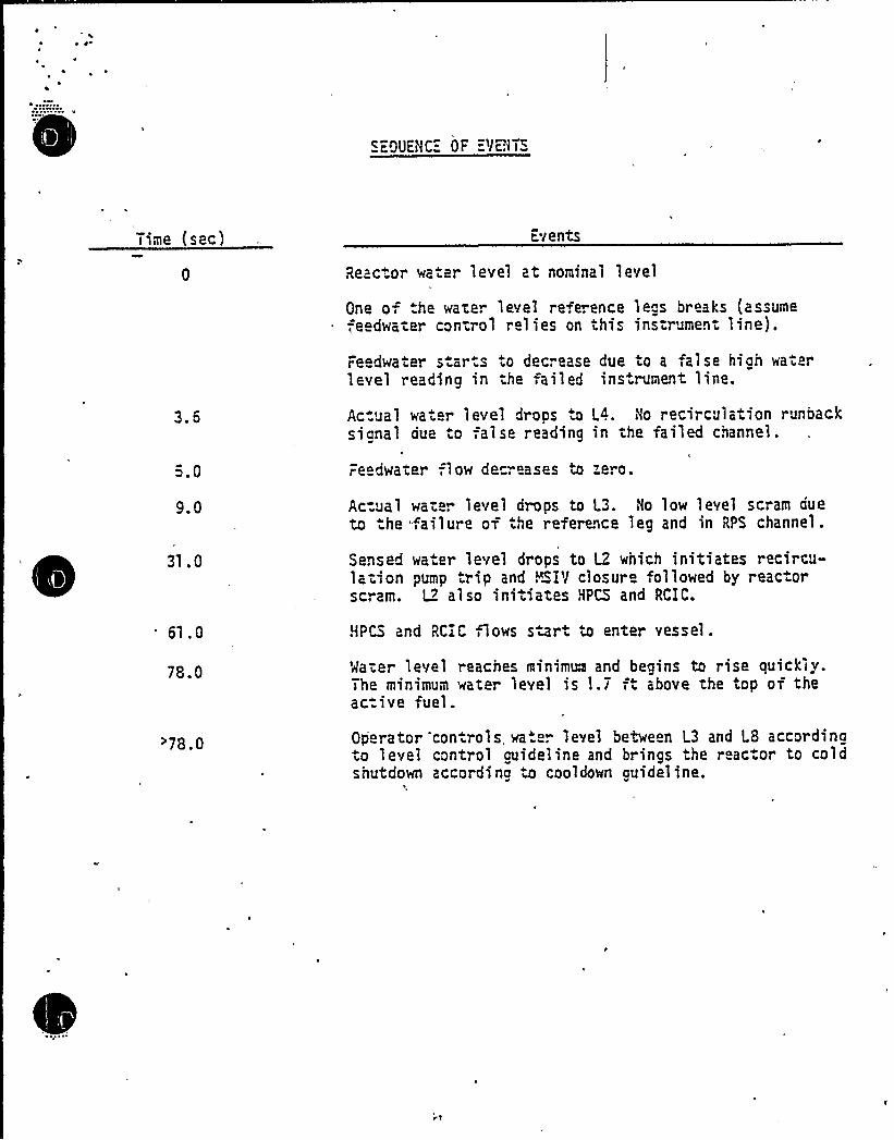
Time (sec) E,vents
Reac or wa .er level at nominal level
3.6
5.0
One o, .he wate. level refe. ence leos breaks (assumefe dwa-er con-.rol relies on this ins-.rument line).
Feedwater s.ar.s to decrease due to a false hiah waterlevel reading in he failed ins rument line.
Ac-ual wa .er level drops to L4. No recirculation runbacksianal due to false reading in the failed channel.
Feedwater 1 ow decreases to zero.
9.0
31.0
Ac=ual wat r level drops to L3. Ho low level scram aueto the. ailure of the reference leg and in RPS channel.
Sensed wa.er level drops to LZ which initiates recircu-ladon pump trip and MS$ V closure ollowed by reac orscram. I2 also initiates HPCS and RCIC.
Gl . 0 NPCS and RCiC,1ows swrt to enter vessel.
78.0 '>later level reaches minimum and begins to rise quickly.The minimum water level is 1.7 ft above the top of theac.ive fuel.
~78.0 Operator controls, wa. ". level between L3 and L8 accordinato level control auideline and brinas the reac or to coldshutdown accordina to cooldown guideline.
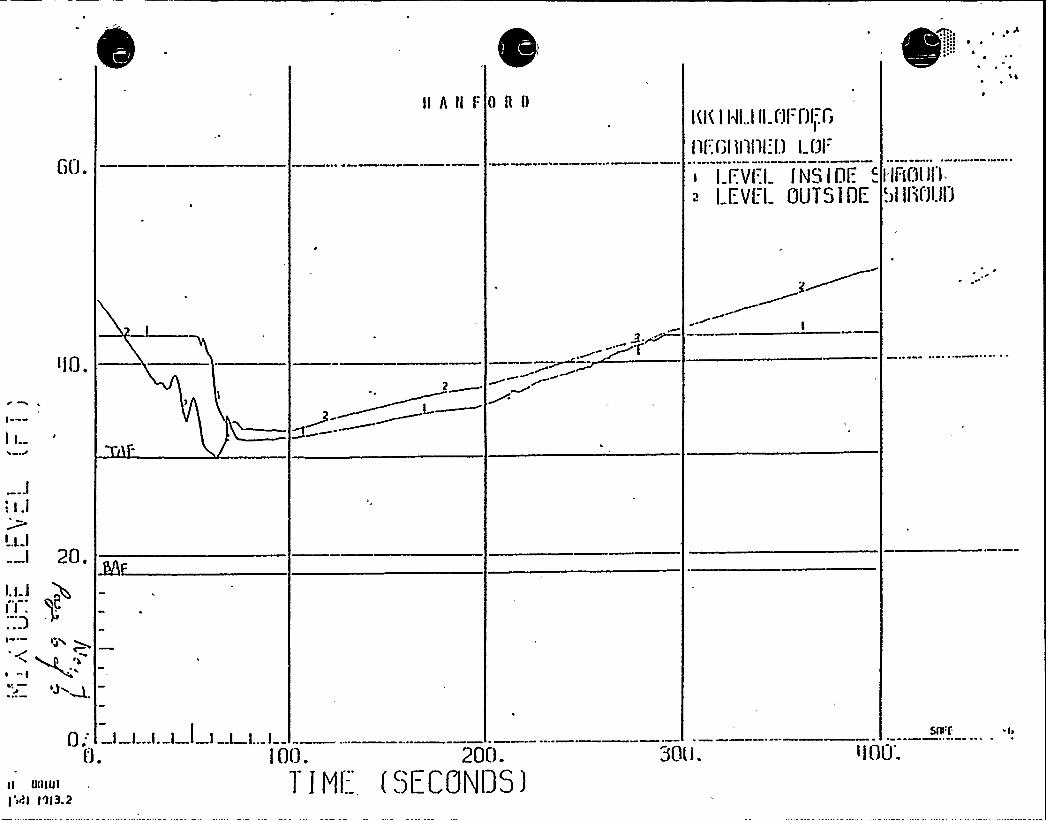
~ 8~ ~
C)0.
IIAHF OBI)ILl( l ldl..l II l'3l. f)lj CJ
ill::foal tlllll:I.) l Ui=
I l..Vl.l lNS(DE 'EYf.l ClUTSIOE
I IAC)LJI')-
.ii >iicii.~o
I
I i.
<l0.2~.
I
„9~~
l
3
I y )
I
I.i J
I I .:;3
20. ~
ly~
P
0," —I —L-I- I I l l L I
C).
SS'f 4
)( 00lUl)'iRI I'll3.2
ino. zoo.1 I Ml;-- ( SECGNI) 5 )
30lJ. <l00;

0
WNP-2
ICSB ITEN 6
Concern:
WNP-2 TNI Item on SRV Position indication — They wiLL modifyAppendix B to incLude use of thermocouples as backup means ofdetection and emergency procedures for use of theme
Response:
See revised Appendix Bi item II.D.3-

0
MNP-2
Open SER Issues
I CSB-7
ICSB-8aICSB-8b
Nodification of ADS Logic (II.K.3.18)r (RSB-9).Restart of Core Spray Systems (II.K.21) r (RSB-11) .
Separation of HPCI and RCIC System InitiationLeve l s (II.K.3.13) .
I CSB-9
Responses to the above issues were submitted inthe TNI (Appendix B) sumbittal.
LPCS and LPCI System InterlocksA response to this issue was provided in theresponse to open SER i ssue 6.3.

WNP-2
ICSB-I tem 10
Concern:
Present design description of the instrumentation and controlaspects of the spray pond pumps and the standby service waterpumps- bescribe how the Level instrumentation which trips theSSW pumps on Low spray pond Level are protected against
freezing'Bring
drawings for review).
Response:
Each Standby Service Water Spray Pond Level is monitored bya Level transducer (Pressure Sensing Probe) located in thepump suction pit about 24'" below the spray pond normalwater Level. Freezing at this depth is not a concern. Thetransducer sends an electrical signaL to a transmitter Locatedon a Local instrument rack in the pump house. The transmitterprovides the necessary output signals to operate the Levelswitches for pump and valve interlocks and Level indi cati on.
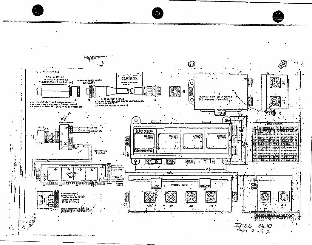
+'T TI<C
t <e I Coal ~
OVC I II fiaIJDSOIIII'II.ssutsteariIsz,r& 1 ~
I10 Clli ael>444<aaA< PalwA<ea opiaCkeal 4
~ ~ ~ ,JL< 1 ~ ~
Jl~ „'e!e ul ICt af lace <<<DO'll ICH<<ILi 4eu DT r<Lclsuac/ua cs. wileI as!»atl'I<DO SCL {P I~ CT) Of aaaaltt SIC<
~ I onct rCS Can-t Pt,,a~To e spec.-ulc Lani.= ~CDSff CSIICIc ul Fff7tcee~psc- scaocls {<sore)
P T) Jl ~ Q
Jscaau ce!. 4-to EsfCTIIO<IIPSlt fstff.04C T.'fTa<4IIefCLC
~
~ ~
UQ'-
aI
I I
(I I'I
I
I< ~
<a
4<el CI~ ~ 'I~
4«raS *II nl:{ 1 l
t SC~ ~
at
e e
CtiI
] ee
I'I j'I
'Ter.a<let<eel4aa aull
i %kg:
{f) 'tt ~ ~a
(g actS eear
,I ITi'<'1 G .1=
~~
I ~'I
~
)$
lWaf aua<I
1
t;
r
I ~
. CCSOL{trO'SI<el \;I
ala< I ~
Ir.SO~-r.s reVIS~'IIS'
'0so~t! 0 1
<0 III elf I
III C4C<e<S ISv<Isaof k O'I'lp po~la<IOil ISIT S<OIS <CHIL PO
kISIDIt <IS C~ II
SIIIIeM ' I4 1
VIS<Cue.a<$ . 0VIS I~. 114VISCOUS CSAS
COSCTS30150f QlIISSef4<DS- ~ $ PJSISSIOIS Cs<SS PS
JlfSIDIAS<LS~ Pc
Vl)CL+AILHL~PSIISS<DI PITS It'DVSSIOIt lW ID PS
Wa I Se leee4<<e le<recall<I
, l.;
'.1 EELf)ZFfKEF12TJ19
% ISriff<a<<I
Cleek'a<aICraas "... ~
TTP<CSt flat JSJSgf ffITI CTS DPDT
CSICD Sa IILTSCI
~ ~ ~ * fk4<ISCIIQ<aff SO)4ff t)tp) 0
jOS.3Rflf.riVTIL4'«a
~a
I<at
\ ~
l
Wa ~ ~ I
'J6 .' I J7
HODC.L tIC 0Dir
c t<
r:.g]0 i"
I ~
~ I*I ~
; 4
JO ' J llI ~ ~
aI
I~I
~ j
r <8er{jl
' JlaXQMrisra'~;{,E{ECtKF net 0 If.,'; . '1
Wctu+ ~4 IQoae e- 2 op
MNP-2
ICSB-Item 11
Concern:
FSAR Tables 7.3-3r 5r 7r 23 show Level 1 trips at -149 inches ~
The instrument range extends to -150 inches. Instrumentaccuracy is stated to be +7.5 inches. Discuss the effect oferrors within the stated accuracy at -149 inches.
Response:
See revised response to NRC Question 031.116'ttached.
Q. 031 .116(77.3-3)(T7.3-5)(T7.3-7)
- (T7.3-9)
The use of l.evel switches. wi.h a range of -150 inches/0/-:60 inches to initiate the autonatic depressuriza" ionsystem (ACS) r the low pressure core spray (LPCS)sys em and the Low pressure coolant injection (L.PCX)sys-em with a setpoint of -149 inches as shown inTables 7.3-3r 7.3-5r and 7.3-7 o the FSARr respec-tivel.yi if no ~ a conservative design feature. Asimilar situation exists for the differential pr s-sure switch on the R'CEC turbine'tean l ine where therange is given as -200 inches/0/ 200 inches and thehigh f Low t'rip point is, indicated in Table 7.3-9 tobe 'l98 inches. Pr ovid just i f ication for using these
'instruments whose extreme range is barely above hetrip point or the setpoint. Justify the use of thesranges in these applications. Discuss the accuracyof the trip settings and how they are affected byLong-term drift and by normal environmentaL conditionsand those occuring during and af ter postuLa.ed'cci-dents.
Response:
The values provided in C
onLy sine setpoints areTechnical spec ificat ionssetpoints for the parame7 3 3r 7w3 5z 7 3 7 andChapter 16 TechnicaL S peef feet fol.Low each of th
haptenotare
ters7.3-9ClL ice Tab
r 7 are for infofinialized un" ilcompLeted. Theconta ined in Tab
wiLL be shownat ions. Notes tL s in ques t ion
rma.ionth=
actuaLl.es
0 ', il 1 s
The val.ues shown on the tabLes in Chapt r 7 wiLLeither be updated or deLeted and reference mad =othe TechnicaL Specifications once these sp cificationsare compl.ete.
When the Technical Specif ications are issuedr thLPCK/LP"S/ADS reactor vesseL Low water Level trip set-point wilL be approximateLy 181 inches.
Theses,etpoTechnmentaetc.
s etio int sint marginsical Spec iftion dr1. tJ
ar e der ived through appl ica ion of.as delineated in the BWR Standard
ic at ions tak ing into account ins ru-Loop ac cur acyl ca librat i'on er."orsr
-129 inches. The RCEC.high steam f Low trip setpoi'nt willbe approxinately
WNP-2
ICSB-Item 12
Concern:
Present system description and show how the instrumentationand control aspects of the Nain Steam Line Leakage ControlSystem satisfies the single failure criterion (Bring drawingsfor review)-
Response:
Refer to Section 6.7.3.1 (pages 6.7-12'3 and 14) and responseto Q. 031.076 (Amendment No. 14~ April 1981).
MNP-2
Open SER Issue
ICSB-Al
Concern:
Provide a discussion as to how the WNP-2 design of the RecirculationPump Trip (ATWS Interim fix) conforms to Appendix C of NUREG-0460,
Volume 3 (Candidate for drawing review meeting December 7-11, 1981).
Response:
Refer to guestion 031. 115 (attached) and LRG issue RSB-22 in LicensingReview Group submittal (Appendix I).
WNP-2
Q. 031 115(.7.2)
The WNP-2 SER issued at the CP stage of our r eview inSeptember 1971 acknowl.edges your commitment to includea recirculation pump trip (RPT) on receipt of a signalindicating hi'gh reactor pr essure. This trip isintended to mitigate the. effects of a failure to scr am.Provide the details of your proposed RPT design;indentify and justi y any exceptions to the require-men s of the reactor protection system (RPS) .
Response:
A recircula ion pump trip on high reactor pressure isprovided to mitigate the effects of failure to scram(ATWS condition). This ATWS RPT is designed to benon-saf ety related.A modification of Appendix H to the FSAR provides adescription of the equipment and function.*As stated in the insert to the text~ the ATMS RPT doesnot interact with the RPSr nor are any of the RPSrequirements addressed by this function.*graft FSAR page change attached.
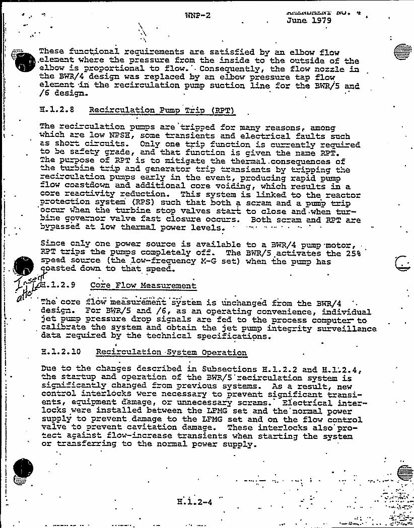
~e
I ~
June. 1979
' These unctional recui ements are satis ied by an elbow flowelement where the p essure from the inside to tho ou,tside of theeD~ow 's p oportional to flow.'onsecruently, Ze flow nozzle inthe BRR/4 design was replaced by an elbow pressure tap flowel~et in the recirculation pump suction line for the BUR/5 and/6 design.
2.1.2.8 Recirculation Puma Tria (RPT)
The ec'-culption pcs are tripped or many reasons, amongwhich a=e low NPSE, some t=ansients and electrical aults suchas short circui,m. Only one trip unc 'on 's cu=ently reau'd,
o be sa e y grade, and that func4"'on is given the name RPT.The
purposeof RPT is to mi igate the thermal.consecpxences of~d generatOr tre p tranS i en4S by tripping therec'-mrna "on pumps ea ly in the event, producing rapid pump
=low coas down and additional core voiWg, which results in aco e eacavi y reduction. This system is Linked to the eactorprotec ~on system (RPS) such that both a scram and a pump t ipoem~- wnen tne turbine stop va1ves s a~ to close and when tur-b'ae governor va1ve fas closure occurs. Both scram and RPT arebypassed a4 low thermal power levels.S mce only one power sou ce is available to a BNR/4 pump motor,RPT -'ps the pumps completely o . The BHR/5 activates the 25%speed. source (De low-frecuency Z-G set) when the pump hasoasted down. to Mt speed.
.1.2.9 Co-e Plow Meeeu emene
he core . low measly emeii system is uncnanged from, the BWR/4~ design. =or BNR/5 and /6, as an ope a~g conven:ence, individual
je pup p essure drop signals a e fed to the process compute~ toca1ib=a"e the svs em and obtain 4&e jet pump integ ity surveillancedata re~ed by the technical specifications.
I
e
2.1.2.10 Reci cula ion Svs em Operation
Due to 4e changes desc ibed in Subsections H.1.2.2 and H.3:.2.4,~4e s~~m and operat'on of the BWR/5'circu1at'on system issign'ficantly changed =om previous systems. As a result newcon"-ol interloc)cs we e necessary to prevent significant trmsi-ents, empment d'amage, or uvaecessa~ scrams. =~'ectrical in er-locxs were ins alled between the LFMG set and. the'normal powersupply to prevent damage to the LE'MG set and on the flow controlvalve o p=event cavitation damage. These in e locks also'pro-tec" agai"st flow-'~crease transients when starting the sys emor ""ms erring to the normal power supply.
H.1.2-4
1 ~
Ins.ert to Pa ge H.~'1.2W:
In addition to th'e RPT associated with a reactor scram'nd
~
~
~
~ ~
~
~
~ ~
the normal pump tripsr a high vessel pressure or Low Lowvessel. Level (level 2) wi ll initiate a reci rculation pumpmotor trip without transfer. to the 25% speed source. Eachtrip sensor and channel is, separate and independent from thereactor protection systems and includes a testability featurethat will aLLow testing of each trip sensor while therecircuLation system is in operation. The abnormal positionof the test switch is annunciated.

ICSB-Item A3
Concern:
Describe any design change to the scram discharge volume Levelsensing system? Diversity? Present design is float switches.Are you going to have the standard GE design of ~P Level sensingand f l oat switch'?
Response:
See response to NRC Question 010.41 attached. Standard GE designof >P Level sensing and fLoat switch wiLL be provided at WNP-2.
WNP "2
Q. 010.041~ (4.6)
Demonstrate that the scram discharge system meets the criteriaenumerated in the Generic Safety Evaluation Report BWR ScramDischarge Systems dated December 1r 1980.
Response:I
The scram discharge systen 'or WNP-2 has been evaluated againstthe Generic Safety Evaluation Reports "BWR Scran DischargeSystem" r dated December 1i 1980. In shorti the evaluationindicated that the WNP-2 scram discharge system, needed upgradingin the following areas:
1)2)
3)
4)
Addition of redundant vent and drain isoAddition of redundant and diverse Levelfor scram;Relocat ion arid repi ping of instrument pito the scram instrument voLume;Addition of new surveillance and operati
Lation valves;instrumentation
ping directlyng procedures.
A summary of our evaluation results is provided below:
FUNCTIONAl CRITERIA
The scram discharge volume (SDV) shaLL have sufficientcapacity to receive and contain water exhausted by a
full reactor scram without adversely affecting control-rod-drive scram performance.
WNP-2 Compliance:
WNP-2's SDV system is currently designed to meet the 3.34gallons per drive requirement specified in the GE DesignSpecification 22A4260. This is an acceptable means ofcompliance as documen ~ ed in the "Acceptable Compliance"statement for this ite" in the Generic SER.
SAFETY CRITERIA
1. No single active failure of a component or service functionshall prevent a'eactor scram'nder the most degradedconditions that are operationally accepted.
WNP-2 Compliance:
The WNP-2 system hacriteria. The SDVvolume (IV) which pof liquid accumulatredundant and singlof service function
s been designed to meet single failureis designed with an integra l instrumentrovides direct and immediate detectionion. The SDV instrumentation ise failure proof (including partial Losss).
WNP-2
2. No single failure shall result in uncontrolled Loss of~~
~reactor coolant.
WNP-2 Complianc.e:
A redundant air-operated vent valve and drain valve wi'lLbe added on the SDV in series to insure system isolationduring reactor scrams. This includes independent solenoidvalves for each set of air-operated vent and drain valves.
3 ~ The scram discharge system instrumentation shaLL bedesigned to provide redundancyr to operate reliably underalL conditionsr and shalL not be adversely affected byhydrodynamic forces or flow characteristics.WNP-2 Compliance:
Six additionaL diverse Level sensors wiL l be added to theSDV system to ensure diversity and redundancy in Levelmonitoring and scram functions. Common cause failureswill be considered in the selection of the i.".struments-This is in agreement with Alternative 3 of the "Accept-able Compliance" statement for this item in the GenericSER.
4. System operating conditions which are required for scramshaLL be continuously monitored.
WNP 2 Compli'ance:
The addition of the Level switchesand periodic survei glance testingprovide a continuous means of moniL eve L and insur ing inst rument rel iacceptable means of compliance. as"AcceptabLe Compliance" statementGene r i c SFR.
described in 3 aboveof the instruments wiLLtoring the SDV LiquidabiLity. This is andocumented in thefor this item in the
5 ~ Repairs replacements adjustmenti or surveillance of anysystem component shall not require the scram function tobe bypassed.
WNP-2 Compliance'.
During r'outine surveiLcalibration the associscram C1 out of 2) conplants technicaL specimeans of compliance asCompliance" statement
Lance testings instrument repair orated Logic wilL be placed in a half-f iguration1in accordance wi th thefications. This is an acceptabledocumented in the Acceptable
for this item in the Generic SER.

0
WNP "2
~~
OP ERATI ONAL CR ITE RI A
1. 'LeveL instrumentation shaLL be designed to be maintainedrtestedr or calibration during plant operation withoutcausing a scram;
2. The system sha l( include sufficient supervisory instru-mentation and alarms to permit surveillance of systemoperation;
3. The system shalL be designed to minimize the exposure ofopera t ing pe rsonne L to rad i at ion;
4. Vent paths shalL be provided to assure adequate drainingin preparation for scram reset;
5. Vent and drain functions shall not be adversely af fectedby other system, interfaces. The objective of this require-ment i s to preclude water backup in t'e scram instrumentvolume which could cause spurious scram.
MNP"2 Compliance:
1. The system Logic is designed as a one out of two'wiceconfiguration. Each of the associated instrument channels
.is capable of being separately isolated for maintenanceitesting or calibration without inadvertently scrammingthe reactor.
2. The SDV is provided with a high Liquid Level alarm oneach IV to alert the operator to Liquid accumulation inthe SDV.
3. The SDV system has been designed in accor'dance with GE
design specification 22A4260 to minimize the exposureof operating personnel to radiation. In additions thesystem is being reviewed as part o'f the WNP 2 ALARA program.
4. The SDV vents direct ly to the reactor building atmosphereand is independent from other plant vent system.
5. The vent and drain system for the SDV is totally independentfrom other plant systensr and is therefore not susceptibleto blockage or water buildup through system interfaces.

0
DESIGN CRITERIAI E
The scran discharge headers shall be sized in accordancewith GE OER-54 and shall be hydraulicaLly coupled to theinstrumented volume(s) in a manner to permit operabilityof the scram Level instrume'ntation prior to Loss ofsystem unction. Each system shall be'nalyzed based ona plant-specific maximum inleakage to ensure that thesysten function is not lost prior to initiation of auto-matic scram. Nax inurn in'Leakage i s the maximum f Low ratethrough the scram discharge Line without control-rodmotion summed over all control rods. The analysis shouldshow no need for vents or drains.
WiMP 2 Compl iance:
WNP-2 ' IVs have been desattached directly to thea direct hydraulic coupleinsures immediate and conthe SDV. This is an ac-cedocumented in the "Acceptthis item in the Generic,
igned as vertical extensionsSDV. Thi s conf igurat ion provides
between the SDV and IVs a'ndtinuous Liquid LeveL monitor inptable neans of co;..nliance asable Compliance" statement forSER.
2. Level instrumenta'tion shaLL be provided for automatic.scram initiation while sufficient volume exists in thescram discharge volume.
WHP-2 Compliance:
WNP'-2 ' SDV i s adequate L y c oupl ed to the IV to allowproper instrument operation. The SDV instrument set-point for scram was establ i shed to insure an availablevolume of 3.34 gallons per drive (185 drives) . Thi s isan acceptable means of compliance as documented in the"Acceptable Compliance" statement for this item in theGeneric SER.
3. Inst ruminstrum
entation taps shall be provided on the verticaLen. volune and not on the connected piping.
WNP.-2 Compliance:
ALL therep i pe'dpi p inc ~
test ingThis isthe "AcGeneric
WNP-2 SDV instrunentation wiLL be relocated and'directly to the IV instead of the vent and drain
Procedures wilL be modified to include functionaLof SDV Level instrumentation after each scram.an acceptable means of compliance as documented. in
c ptable Compliance" statement for this item in theSER.
WNP-2
The scram instrumentation shall be capable of detectingwater accumulation in the instrumented volume(s) assuninga single active failure in the instrumentation system orthe plugging of an instrument line.WHP-2 Compliance:
'The addition of the redundant and diverse instrumentsdescribed under Safety Criterion 3 and rerouting ofthe instrument piping to the IV provide an acceptablemea'ns of compliance as documented'n the "AcceptableCompliance" statement for this item in the Generic SER.
5 ~ Structural and component d esign shaLL consider Loads,andconditions including those due to fluid dynamicsi thermalexpansions internal pressures seisnic considerationsrand adverse environments.
WNP-2 Compliance:
The WNP-2 SDV design compliance with the Latest GE designcriteria as outlined in GE Design Specification 22A4260.In additionr the system will be reviewed as part of. theequi pment quaL ification program.
6. - The power"operated vent and drain valves shalL close underLoss of air and/or electric power. Valve position indi"cat ion sha Ll be provided in the controL ro'om.
WNP-2 Compliance:E
WNP-2's present design conf igurat ion meets these r equire"ments.
7. Any reductions in the system pi pin~ flow path shaLL beanalyzed to assure system reliability and operabilityunder at L modes of operation.WNP-2 Compliance:
WNP-2's SDV header system i s desiexpanding path from the 185 3/4"charge (withdrawaL) Lines to oneIV systems Cone system per approxEach iritegrated SDV/IV system condownsloping piping run expanding
gned as a continuallyindividual scram dis-of two integrated SDV/imately haLf the drives).sists of a continuouslyfrom the SDV (consisting

WNP-2
of seven 6" return headers from the individual hydrauliccontrol, uni t (HCU) banks to an 8" combined return header)
.to the 12" vertically oriented IV. The Location whereblockage need be assumed (piping Less than 2" diameter)is in the 3/4" discharge Line from the individuaL HCU.Blockage here would only cause failure of one .controlrod to insert. This is an acceptabl.e consequence for a
single failure and has been evaluated as part of the plantdesign basis. Accordinglyr this design complies with the"Acceptable CompLiance" statement for this item in theGeneric SER.
8. System piping geometry (i.e.r pitchy line sizes orienta-tion) shall be such that the system drains continuouslyduring normal pLant operation.
WNP-2 Compliance:
The WNP-2 SOV has been designed to" insure a positive down"ward slope of scram header and drain piping.
9. Instrumentation shaLL be provided to aid the operatorin the detection of water accumulation in the instrumentedvolume(s) prior to scram initiation.WtlP-2 Compl i ance:
Each IV is provided with high Liquid Level and rod blockinstrumen ~ ation at ~ ached directly to it. The generic SERstates that this is acceptable.
10. Vent and drain Line valves shaLL be provided to containtne scram discharge waterr with a single active failureand to minimize operational exposure.
WNP-2 Compt.iance:
As stated under Sa ety Criterion 2r redundant air-operatedvent and drain valves wiLL be provided for system
isolation'hisis an acceptable means of compliance as documentedin the 'Acceptable Compliance" statement for this itemin the Generic SER.
SURVEILLANCE CRITERIA
1. Vent and drain valves shaLL be periodical l y .tested.
WNP-2
WNP "2 C ompl i anc e '.
The vent and drain valves will be tested in accordancewith the plant technical specification to verify valvec Losur~ in l ess than 30 seconds (cur rent GE spec ifica"tion). This is an acceptable neans of complia'nce asdocumented in the "AcceptabLe Compliance" statement forthis item in the Generic SER.
2. Verifying and Level detection instrumentation shall beperiodicaLly tested in place.
WNP-2 Compl i anc e:
The SDV instrumentation will be tested in accordancewith the plants technical specification which wiLLinclude post scram test ing to veri fy instrument oper"abi l ity.
3. The oper ability of the entire system as an integratedwhole shall be demonstrated periodically and during eachoperating cyclei by demonstrating scram instrumentresponse and valve function at pressure and temperatureat approximately 50% control "rod density.
WNP-2 Compliance:
SurveilLance testing will be performed in accordance withthe plants technical specifications..
1 The plant technical spec ifi cat ions will'e based on the Standar d
Technical Specifications for Boiling Water ReactorsrNUREG"0123'rovided
by the NRC.
MflP-2
ICSB-item A5
Conc'em:
Drawing Review — HPCS and RCiC automatic switchover of suctionsource .from condensate storage. Show that separation existsbetween HPCS and RCIC sensors for the transfer and describewhy seismic events do not affect the transfer. Describe anymanual valve interlocks and how controLLed-
Response:
See revised responses to NRC Questions 031.128'11.146 and211.197 (attached).
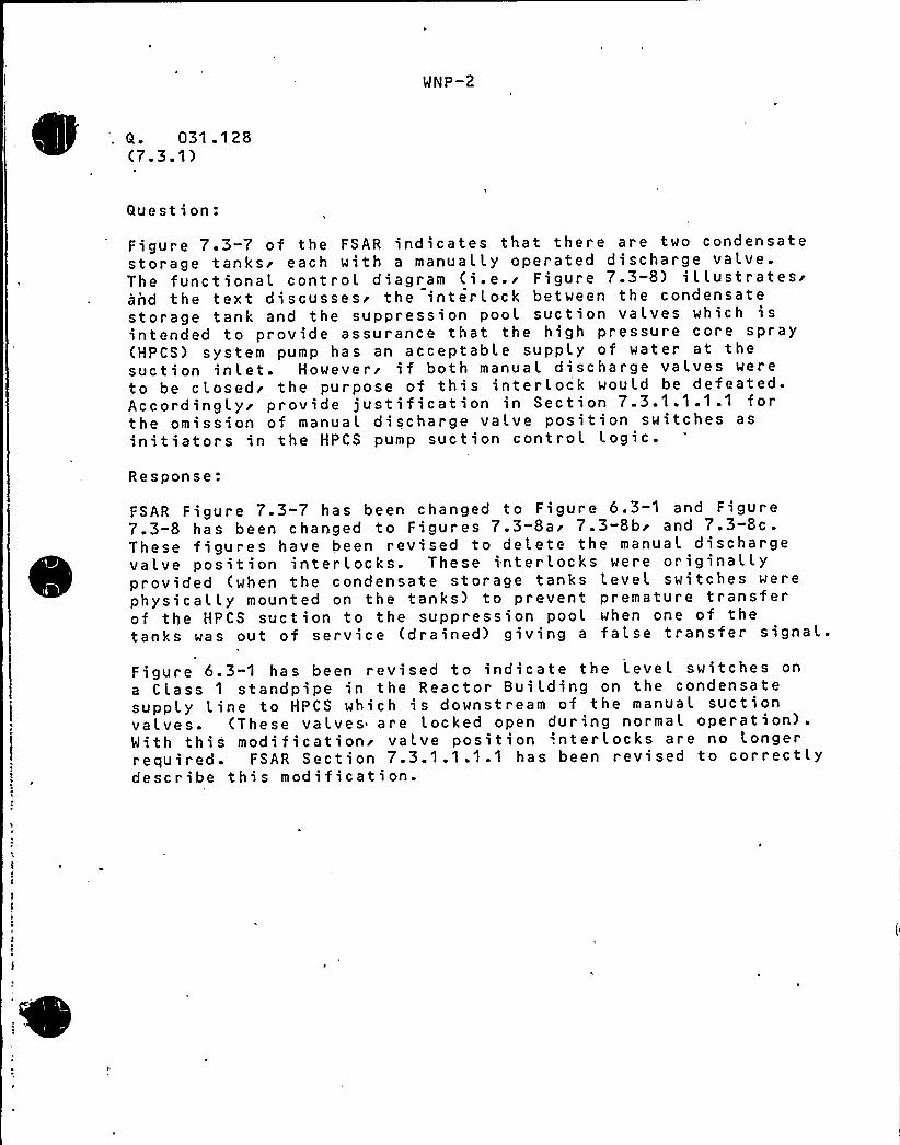
t
I
~
~ ~
Q. 031 .1 28(7.3.1)
WNP-2
Question:
Figure 7.3-7 of the FSAR indicates that there are two condensatestorage tanks'ach with a manually operated discharge valve.The functional controL diagram (i.e.r Figure 7.3-8) iLLustratesrand the text discussesr the interlock between the condensatestorage tank and the suppression pooL suction valves which isintended to provide assurance that the high pressure core spray(HPCS) system pump has an acceptable supply of water at thesuction inlet. Howevers if both manuaL discharge valves wereto be closedi the purpose of this interlock would be defeated.Accordinglyi provide justification in Section 7.3.1.1.1.1 forthe omission of manual discharge valve position switches asinitiators in the HPCS pump suction control Logic.
Response:
FSAR Figure 7 3 7 has been changed to Figure 6 3 1 and Figure7.3-8 has been changed to Figures 7.3-8ai 7.3-8br and 7.3-8c.These figures have been revised to delete the manual dischargevalve position interlocks. These interlocks were originallyprovided (when the condensate storage tanks Level switches werephysically mounted on the tanks) to prevent premature transferof the HPCS suction to the suppression pool when one of thetanks was out of service (drained) giving a false transfer signaL.
Figure 631 has been revised to indicate the Level switches on
a Class 1 standpipe in the Reactor BuiLding on the condensatesupply Line to HPCS which is downstream of the manual suctionvalves. (These vaLves are Locked open during normal operation).With this modificationr vaLve position '.nter locks are no Longerrequired. FSAR Section 7.3.1.1.1.1 has been revised to correctlydescribe this modification.

'
. j->/1( /< ~ ~j r,AMENDMENT NO. 10July. 1980
gg ll~b. Automatic depressurization system (ADS);
c. Low pressure core spray system (LPCS);
d. Low pressure coolant injection (LPCI) mode of theresidual heat removal system (RHRS).
The following plant variables are monitored and prdvide auto-matic initiation of the ECCS when these variables exceed pre-d e te rmined 1 imits:
1. Reactor Vessel Hater Level
A- low water level in the reactor vessel could indicate thatreactor coolant is being lost through a breach in the reactorcoolant pre'ssure boundary and that the core is in'anger ofbecoming overheated as the reactor coolant inventorydiminishes. 'Refer to Figure 7.3-9 (Nuclear Boiler P&ID) for aschematic arrangement of reactor vessel instrumentation.
2. Drywell Pressure
High pressure in the drywell could indicate a breach of thereactor coolant pressure boundary inside the drywell and thatthe core is in danger of becoming overheated as reactorcoolant inventory diminishes.
7.3.1.1.1.1 High Pressure Core Spray (HPCS) System—Instrumentation and Controls
a. HPCS Function
The purpose of the HPCS is to provide high pressure reactorvessel core spray for small line breaks which do notdepressurize the reactor vessel. In addition, HPCS is redun-dant to the RCIC syst: em for mitigation of the consequences ofvarious events listed in Appendix 15A. Refer also to6.3.2.2.1.
b'. HPCS Operationj'Schematicrrangements of system mechanical equipment is shown
in Figure- ~~~HPCS P&ID). HPCS system component controllogic is shown in Figure 7.3-8 (HPCS FCD) and Figure 7.3-4(HPCS Power Supply FCD). Instrument specifi'cations are listed.in Tables 7.3-1 and 7.3-2. Plant Layout drawings andElectrical Schematics are identified in 1.7. OperatorInformation Displays are shown in Figure ~~ (HPCS P&ID) andFigure 7.3-8 (HPCS and HPCS Power Supply =~
Fc&l
NNP-2 AMENDMENT NO ~ 10July 1980
SCjtJ — @ ply J~8
~ggM on ~ C/ass g afandpipa l~ fAg gee,cI r Ba(ldcloses. Two level switches~are used to detect low water levelin <~~m the condensate storage tanks. Either switch cancause automatic suction transfer.. The suppression pool suc-tion valve also automatically opens if high water level isdetected in the suppression pool'. Two level switches monitorsuppression pool water level and either switch can initiateopening of the suppression pool suction valve. To preventlosing suction to the pump, the suction valves are interlockedso that one suction path must be open before the other closes.
The HPCS provides makeup water to the reactor until the vesselwater level reaches the high level trip (Trip Level 8) at which
'. time the injection valve MOF004 is automatically closed. Thepump will continue to run on minimum flow recirculation. Theinjection valve will automatically reopen if vessel level again
, drops to the low'evel (Trip Level 2) initiation point.The HPCS pump motor and injection valve are provided withmanual override controls. These controls permit the reactoroperator to manually control the system following automaticinitiation.7.3.1;1.1.2 Automatic Depressurization System (ADS)—
Instrumentation and Controls1
a. ADS System Function
The automatic depressurization system is designed to provideautomatic depressurization of the reactor vessel by activatingseven safety/relief valves. These valves vent steam to thesuppression pool in the event that the HPCS cannot maintainthe reactor water level following a LOCA. ADS reduces thereactor pressure so that flow from the low pressure ECCS, LPCXsystem and LPCS, can inject. into the reactor vessel in time tocool the'ore and limit fuel cladding temperature. Refer alsoto 6.3.2.2.2.
b. ADS Operation
Schematic arrangements of system mechanical equipment is shownin Figure 7.3-9 (Nuclear Boiler PRIED). ADS component controllogic is shown in Figure 7.3-10 (Nuclear Boiler FCD).Instrumentation spec'cations are listed in Tables 7.3-3 and7.3-4. Plant Layout Drawings and Electrical Schematics areidentified in "1.7. Operator Information "Displays are shown inFigure 7.3-9 (Nuclear Boiler P&ID) and Figure 7.3-10 (NuclearBoiler FCD).
7.3-4
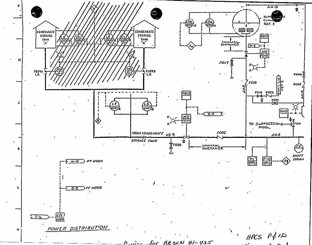
AA 5
CONOEHSATC
STORAGE
TANK
h
FOO'I AI.O.
5l
I0 I
CONOENSATCSTORAGE
ThNII8
FOMIE.O.
L ~~~ JLAIillMgl
DlA'fAJ4C C
rO17
h10>5
Ip~ ~ I
FOICo
rook
FOOT
r-~I
I If 5 ES
pal 4II
1I
tS I
po I g
FAO41 CO>>DE>ISATF
SN)PAGE TAPE
t
MD'~
~ 810OOI
F030 AJ INITIALCI15 FAIJC
LJ
FOiS FOX5
IOUS
yg LJr-tr,gt IIluqPOOa
AA-B
a
Foii
~JI lC g 0fI.V004IIII
II
e. ~0. /T Af005
PT "~iA DRAIA
OOI
.i/5+~CC5~COO
POWEFP D<SrzsaU7 ou
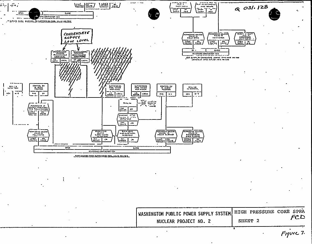
tolls
N ~ ee o( ! ~ Oet ~ !( Ig
<aol(INC Ital~ CIO ~ <ct
!(!!:(ll:0"!h.!!1!!"i'!.L
~ I t'1'1~ «( >o I ! <4~(Sell'a" ISee<CA VALI(J give((a ~ aae
JC
~ e ~I ol
Ave < te< NAO
I~ oeieo, oea e ~ opal l~
A
aCCAL~ 1 a<gS I~ Caa
CmlDEgs8 TFsueslYg.(( W
~ o Ia
~ ~ ~
L
IL ~
t(lasl In< Vaa(llI<a ~ I ol
Ivaa< oel ~
tl~ I I <~oo'lliel v4I<all I'I~ e I ~ ~ IINL
"-'I'-'-"-:-,':1.""-<I ~ I ~ seaC c011<CIO< Il~
i<Least oi No<~ e ea
~e< ~ Ieaett I~ooe< Iaoaov
I< I»Lvooe N e
<(Sl C< ~ eea I~ Cttl(~ (OIC 1<teel IOAA INOI eet INOII Ao(<see. <so< I lot,ela INoi ooa loll
1 e a ~
I
COO< ~ Oa SeOtla'tloIve ~
Sleet ~ (11 Oa Vtt<C ~ SetaOO, va<(4
as<a v ~ I(cCOO<ate lv
oa '<<OIC~ 4<i<i<a
~ I<a eaI ~ <vill~ I
~ 1 ~ ~ al < ~~441 ~ LOC Ia~ L
~ el N ~ ~ 1 ~
ta eve<a ~ otva all ~ <Aee te. ~Aat Iaaa ~ cata(D
1<< ~, oe
A 1aa t.< ~ C ~
l'.L.II~(e) OVA~ ~ e
Sv «N~aae.a Aa ~ 'I~
~ s ~ ~ ae ~s ~ te«' Ite
<<tv<
~ lac 11 ~ I veal 1<I~ ~ I ~ ~~ v ~ I ~ I~
Loco ~ Oa'Iaolc eol11
~Iae.el ~ Iva ~ ~ 1'1Oi< 4 ALe ~ ~ ae ee
a< to<<
tile rVe<~HLLail SWL
ol It<a«.1~ve
live<<
tctovaae< sea<LaLea.vC
<4.LV Cata((1
<eel teseat<» taavC
el <vol < se< v4 c ~ IIH11 e ~4e( ~ 10 ~ Ov< ~vvoa l (a 41 a<
IO ~ OOC Oalve<C«easel
Otl~
~ I ~ I~ I al coal ~ C<oa ~ 1 ~
~vet gv~oo~aIt+eg+~t< )( oa~tgoeJ e~e J
<<41(
MASHINGTOH PNLIC POWER SUPPLY SYSTEH
NUCLEAR PROJECT NO. 2
EEXGEE PRHSSUEU" COEN S PRA
Pc. QSEEEHT 2
i jgU/C 7
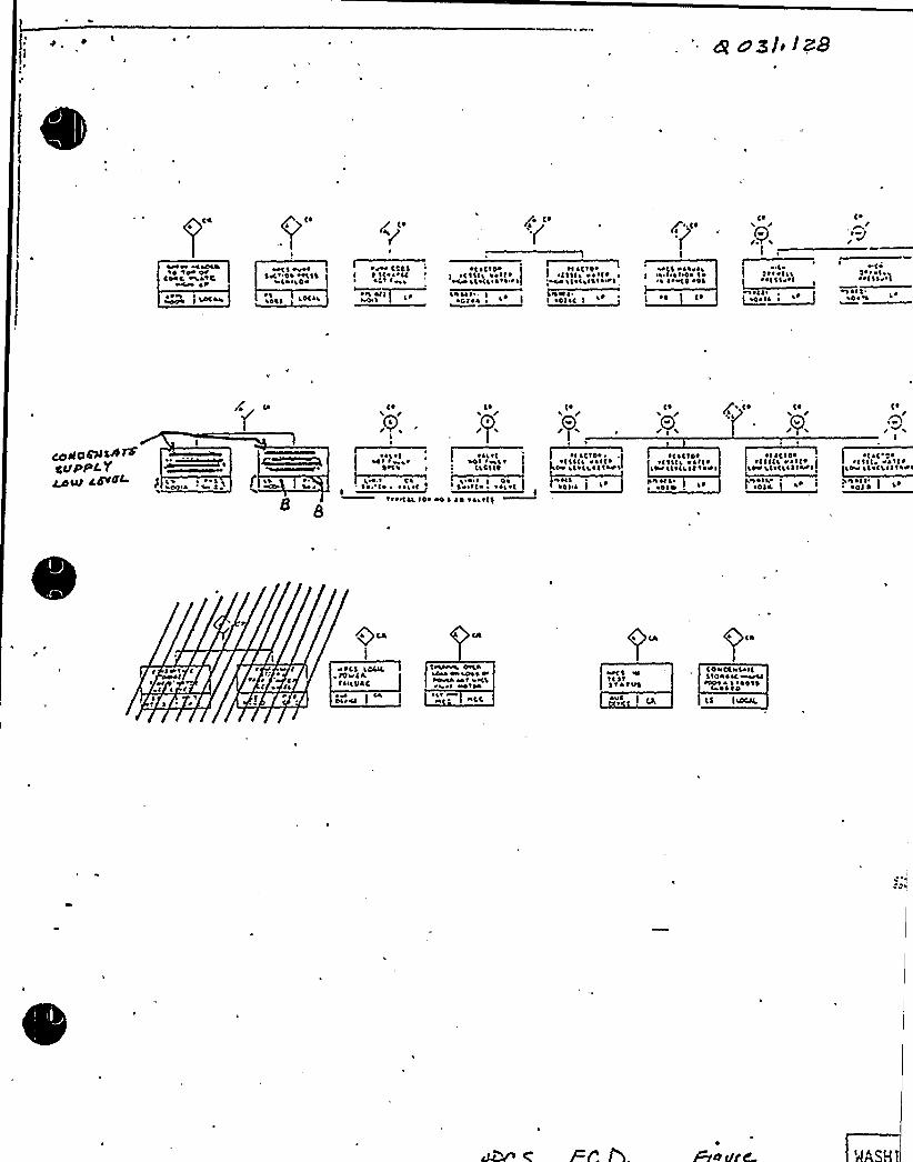
'Poooo« WoOOIO14 ra«OJ
CO«C «a«IC
t CO(aa
»($ «oooloC ~ '04 oolll
~ I ~ LO«
~ I~441
I ~ I< orCC r~lt toro
~ \VI I~~«« I I
~ 1 ~ Ctlo~
rC ~ ~ CI «art ~
Iavt'- I
~ < $ 1<I ~ ~ It ~ ~',oa« Il~ I~ I~ I or«1
Iroatl
~o<$ «ILOOLI I Ir~ Iroo I~' ~ r«10 ol'
C ~
(4
1
rl1 ~ r ~ <IIrolllool
( ~
~ J'1
1 ~ ~ ~ I ~»1 lira<oo ~II
~ Oo~
( ~Ã. (~ Ph (~
LL(~ (~
JrA«
ceAorAaAWeSSS WC. YCuW CdVSF4. ~ ~ ~ II
LOI r~ot0«C'I I
. I ~ .'1 ~ ~ oooo<4 I~ ~ rCIL 104 «4
~ al ~ (aOt tool ~
~ 14 oao't($
~I ~(Ila,~ tll<I oat( ~
ILC ala<ad<I~I«Ot I
~ 4<ra i la
~ 1 IC IOt~ <11<I Oat< ~I~ I<alit ~ I~ rot
0rI ot I~ Olla
~ <ICIOIICIICI «a ~ < ~
a< ~ <III fartt I~ < ~ C ~ 0 ~
~ 111( ~ ~ at< ~IO Ilo<LII~ Loot
',\ rr ItI~ 010 <
I
I 1a«ra<I »
I Irr ~" ~
0 tl~ r ~
« ICS lOCICtOvl ILCarl VAC
~ ra
t«I«rhoa OLI«Iaoo 4«VIII«~r«aa too or<I~ h rt Wfla
~Lr~r «I,C
«ot 1 rrt<lit~ tatltSatra
C 0 «OC ra Sa I<$10«a«i ~
~404« I ~ 401 ~I 4 ~ 10
CS
MNP-2
Q. 211.146(5.4.6)
Quest ion:
In the responses to Questions 211.046 and 031.015't is statedthat an automatic safety"grade switchover from the condensatestorage tank to a Seismic Category I supply (i.e.r the suppressionpool.) has been provided as a convenience to the operator. Providea description of the automatic switchover feature and itsinitiating signal and confirm that both electrical and mechanicalfeatures are safety grade.
Response:
The automatic switchover feature for HPCS and RCIC consists oftwo Class IE Level switches for each system which will be mountedon a standpipe in the pump suction Line. This standpipe isLocated on the common condensate supply Line inside the ReactorBuilding at the Reactor Building/Service Building interface.The standpipe is open ended and is used to indicate either a lowwater level condition in the Condensate Storage Tanks (CST) ora Loss of suction supply from the CST. The standpipe is
designed'abricatedand instaLLed to Seismic Category 1r Quality Class 1
and ASYiE Section III Class 2 standards.
The piping from the Reactor Building/Service Building interfaceto both the RCIC and HPCS systems have been upgraded to SeismicCategory I; each circumferential buttweld has been radiographicallyexamined per ASNE Section III'C-5230'nd a chemical analysisha's been performed on all pi ping materials and as-depositedweld materials.
The HPCS PAID (Figure 6.3-1) and Functional Control Diagram(FCD (Figure 7.3-8) and the RCIC PLID (Figure 5.4-9) andFCD (Figure 7.4-2) have been revised to indicate this designfeature.
WNP- 2 PRE!lDMEYT NO. 8
February 1980
~g gf "f35gglllSC
g zrt.(~4.where the shutdown coolant system can be placedinto oper. ation.
Following a reactor scram, steam generation will continue a"a reduced rate due to the core fission product decay heat.At this time the turbine bypass system will divert the steamto the main condenser, and the feedwater system will supplythe make-up water required to maintain'eactor vessel inven-tory.In the event the reactor vessel is isolated, and the feedwatersupply is unavailable,. relief valves are provided to automati-cally (or remote manually) maintain vessel pressure withindesirable limits. The water level 'n the reac "or vessel willdrop due to continued steam generation by decay heat.
Upon reaching a predetermined low level, the RCXC System isinitiated automatically. The turbine driven pump will supplydemineralized make-up water from the condensate storage tankto the reactor vessel. The suction line from this source isprovided with an in-line reserve ~ with appropriate safety-related level instrumentation. In the event that the watersupply from the condensate storage tank becomes exhausted, thelevel instrumentation in the in-line reserve ~.... initi'ates anautomatic switchover to the suppression pool as the watersource for the RCXC pump. The in-line reserve ~ has suf-f icien't volume to maintain the minimum required RCIC pump HPSH
. plus a two foot marg in while the. switchover occurs, thusassuring a water supply for continuous "operation of the RCXCsystem. The turbine will be driven with a portion of thedecay heat steam from the reactor vessel, and will exhaust tothe suppression pool.
During RCXC operation, the suppression pool shall act as theheat sink for steam generated by reactor decay heat. Thiswill result in a rise in pool water temperature. Heatexch'angers in the Residual Heat Removal System are used tomaintain pool water temperature within acceptable limits bycooling the pool water directly or by condensing generatedsteam prior to entering the suppression pool. When usingthe steam condensing mode, the condensate discharge fromthe heat exchangers may be used as RCXC pump suction supply.
5. 4. 6. 2. l. 2 Diagrams
The following diagrams are included for the RCIC Systems.
A schematic "Piping and Instrumentation Diagram"(Figure 5. 4-9) shows all components, piping,points where interface system anc subsystems tie
5. 4-22

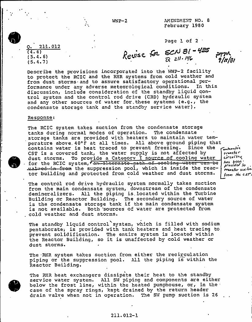
WNP-2 AHEN Di~!E.'3T NO. 8
February 1980
0. 211. 012(4. 6)(5. 4. 6)(5. 4.7)
Page 'f 2
~ gcP8(-@g ztI ~ I'l0 g/~/y<
Describe the prov isions incorporated into the Alp-2 facilityto protect the RCIC and the RHR sys" ems from cold weather andfrom dust storms= and to as'sure satisfactory operational per-ormance under any adverse meteorological conditions. In this
discussion, include consideration c„ the standby 1'cuid con-trol system and the cont ol rod dr've (CRD) hydraulic systemand any other sources of water or. these systems (e.g., thecondensate storage tank and the s ancby service water).
The RCIC system takes suction from tne concensate storagetanks during normal modes of opera ion. The condensatestorage tanks are provided with hea" ers to maintain water tem-perature above. 40'F at all times. All above ground piping thatcontains water is heat traced to prevent freezing. Since theCST is a covered tank, the wate" s"pply is not affected bydust storms. To provide a Categorv I so f cool'in waterfor the RCIC system,
the suppression pool, which is inside the reac-tor building and protected from co'd weather and cust storms.
The control rod dr've hyoraulic syste. normally takes suctionfrom the main condensate system, downstream of the condensatedemineralizers. All the piping is. ocated within the TurbineBuilding or Reactor Building. The secondary source of wateris the condensate storage tank if the main condensate systemis not available. Both 'sources o wate- are protected fromcold weather and dust storms.
~b~gjICpraeSFC <Circai erghaS bC~
'ravid~iC I~sfcr see rIa
fran gc CSf
The standby liauid control system, wh'ch is filled with sodiumpentaborate-,- is provided with tank heate"s and heat tracing toprevent solidification. The ent're system is located withinthe Reactor Building, so it is una =ected bv cold weather ordust storms.
The RHR system takes suction from e''..er the recirculationpiping or the supp" ession pool. All the piping is within theReactor Building.
The ><R heat exchangers dissipate the'r heat to the standbyserv ice water system. All SN piping and components are eitherbelow the frost line, within the heated pumphouse, or, in thecase of the spray rings, kept crained by the return headerdrain valve when not in operation. The Sit pump suction is 26
211. 012-1
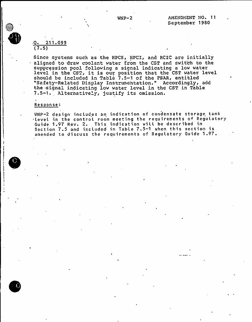
NNP- 2 AMENOHENT NO 11September 1980
Q- 211. 099(7.5)Since systems such as the HPCS, HPCI, and RCIC are initiallyaligned to draw coolant water from the CST and switch to thesuopression pcol =ollowing a signal indicating a low waterlevel in the CS., it is our position that the CST water levelshould be included in Table 7.5-1 of the FSAR, entitled"Safety-Reiated Display Instrume'ntation." Accordingly, addthe signal indicating low water level in the CST in Table7.5-1. Alt rnative'y, justify its omission.
Response:
MNP-2 desion incLudes an indication of condensate storage tank.Level in the control room meeting the requirements of RegulatoryGuide 1.97 Rev. 2. This indication wiLL be described inSection 7.5 and included in Table 7.5-1 when this section isamended to di scuss the requirements of Regulatory Guide 1.97.
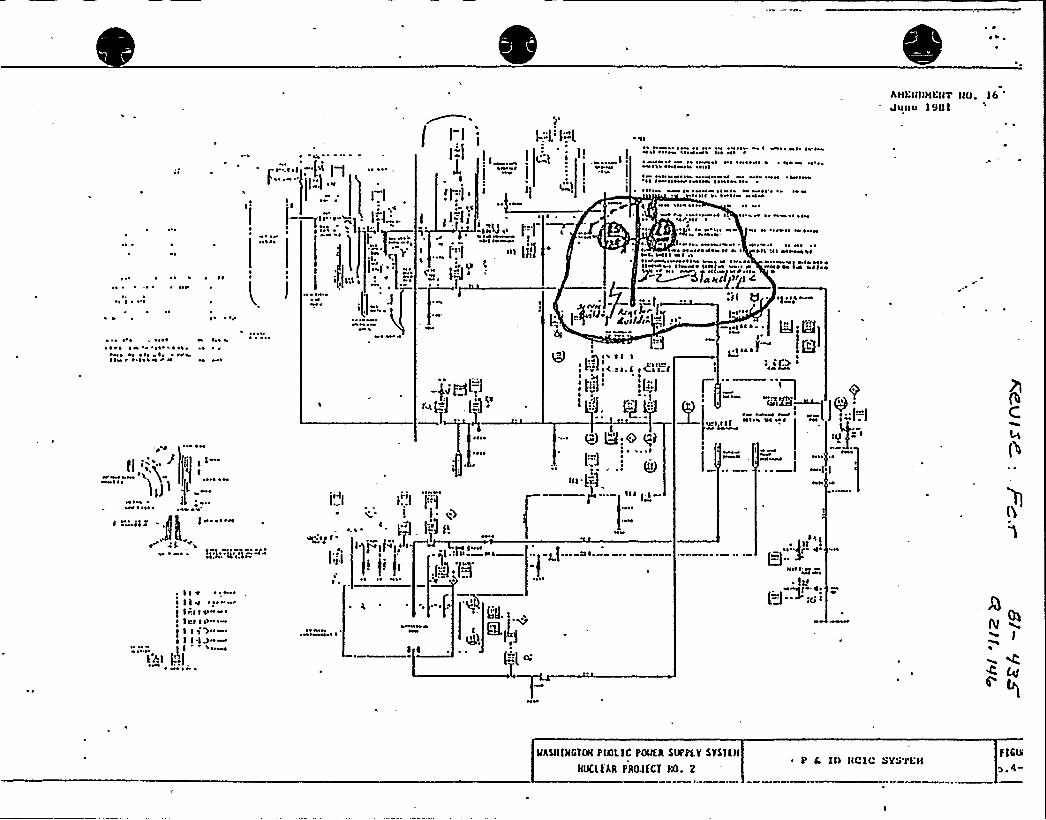
~ 4 ~
AHI:ill)HVHTllO. l6'Ullasl 90 l
~ ~ ~ ~
f'v'll
I
~ ~ 4 ~
-.f.'j(=( ~
Iv ~ "~~I
>-I
IIP') I
0
)I'a I
jiI"I I
a taaI(4 IJ ll
N ~
~ ~ « ~ ~ ~ ~ ~~ 0NI \ ~ 0«0N ~ ~ I~ ~ ~ ~
~ « ~ H ~ ~ ~ ~ \ ~ ~ I 4 HH ~ st 4«I IN 0«l
H t4«I ~ I 0V ~ IH I ~ \ H ~
~ I~ ~ ~ ~ ~ ~ ~ ~ 0« H' tt~ oas ~ ~ l«00««NH
NN 100' ~ ~~ ~ 4 ~ ~ ~ ~ I ~ ~ ~ 0% ~ 0 ~ No100 HI ~
~ ~ ~ lo ~ « ' ~ ~ ~ I 04 ~ NN ~ 4 Nt~ ~ ~ » 0« ~ ~ «« ~ No
4 ~ I~ 00%VI«H N I ~ ll HI Not«H\II I HSI ~ Hl~ IVH0 HIIIHI ~ H ~ ~ 4 ~ H VS «04H ~ ~
X~gfzkl(jvjlcIll Q ~ Il 0tH
~ ~ 4 ~ H1~ ~ ~ 4 ~ « ' % ~ ~ ~ ~ ~ ~
~«1 ot ~ I~ I ~~ I ~ ~ ~ I ~ N 4
«I ~ ~Ht ~ HI ~ '
~ ~ ~
NsI
41
jinni
L'-.]
W-(" J
0000
'dg
sat ~ ~
',t-„'0
U:c q~
:.=i,.i -~i)
~ 0«~ It
I Hl~ 00 ts Its~ Ka II
~ N No ~
~«.I~slt
00 ~ ~
,a ~ Ia- ~ g gIsaac I 2I;
I if) ~
~NO
7l
C
(b
~ Is t '~ Ilv ~ ~ I
Iv.l a as«N~ IKa as>
f I lt>"I I I'I3"~
l'Sl (';)
(I'I
)
~ ~~ «I ~ ~ ~
I ~
~4H
va I«%0
,i4 (5~0
0.: -aJ--"-F 00
~ 11~ aI
~Iol Sg~ l.
~l.J+ 'I'
I
«10
MhS(llNClQl PINLIC PINER SIIPPLY SYS'lEH
liUClEAA PRO.lECl lIO. 2~ P C, II) IICII'YHTI:H PIC>
>.R-

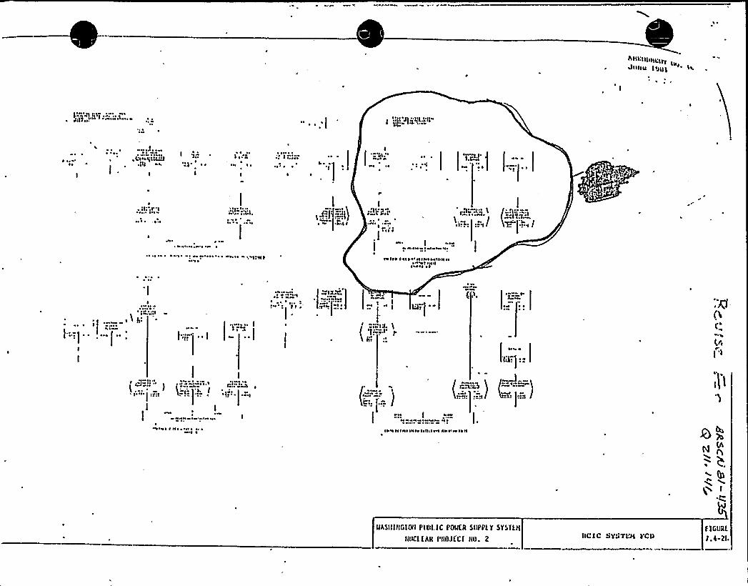
e
~ ~
~ ~~ o
I
.'...Jfg Ao.
~ ~
~ ~
I
~ ~
~ ~
~ tott
~ ~
.;It1r 1~ h
Ieef Idtdtb
~ ~
f I~ t
io'I ~ I
1'li .'I~re \
/
H% ~
»»»» ~ o
eetfot f»efo'ottnee»IIIIIII~ ~ 0 f ~ tl III'ott ~ ~ ~
W~ ~
» ~
Il:
I
I
I"' ttf~r.l'
Re
(lJ o'»)
H
I
4I »'o1
~ ir'
I
»o»»
)»»» ~ » ~
~ ~
tt»t I fl~ ~ ~I ~ ~ ~~ ~ II el nenf letto ftff I tw anteee tote
MASIIIIIGISIPIOI.IC PowfR SIIPPLT STSTtII
IIIKlfARPIIMECt IIO. 2 IIC!C SYJTL'H VCDF lGIIRL
I.(-2I
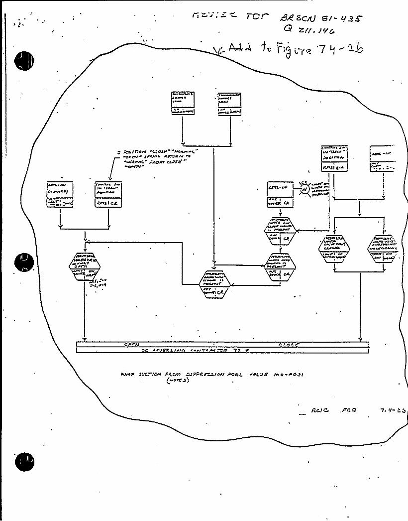
eu
<radar)
eie errrerePrer errN
C~sl ct
+ I l7oeN eee'e os/ uceeceeeeeg
~rCeeeeie SeeOerce Atyku rrnt cCPS'C
CWlVr
Crr ~ k re N rCSSw
Prie trVN
WSI eS 0
CS I
[SEIZE Ih
c I~rrcII CC
~
A'Q'r
r recV
w re ree
Pa+ crvn~eeet/Jere erer
~ree Eg ceeektee q
II V
ege SH~e~ ~ ~
~l'v
y ~
C4
~eeIT I
I
CPcW~<e/A 5 /eee J rpl . pfV'p 7
OVPIIr Sat.—./04 6 "m uPHfalau POOC. >AC Ja IV O-PO rl(Nod'y)
RcJ C,, «ca 7 l/~ r ~

WNP-2
Q., 211.197
Quest ion:
Section 6.3.2.2.1 of the FSAR states that the HPCS systemwill automatically switch over from the condensate storagetank (CST) to the suppression pcoL if the CST water supplybecomes exhausted or is not available. Review of Figure 7.3-10bindicates that automatic switchover will only occur if the CSTwater Level drops to the minimum Level and act ivates any oneof the four leveL switches (two per tank). Howevers in theevent that CST water cannot be supplied to the pump while theCST water Level is above the minimum water Levels automaticswitchover is precluded. Resolve this apparent discrepancybetween the PSIDs'nd Section 6.3.2.2.1.
Response:
Figure 7.3-10br High Pressure Core Sprays Functional ControlDiagram Sheet 2i has been changed to Figure 7.3-8b in'Amendment 10. The Level indicators which provide the signal'for automatic switchover of both HPCS and RCIC are mounted ona Seismic Category I standpipe in the Reactor Building. TheseLevel indicators as installed wiLL sense a Loss of suction
, supply as weLL as Low Level in the condensate storage tanksfor the non-Seismic Category I portion of the condensate system.The piping downstream of the standpipe has been upgraded toSeismic Category I and will guarantee a suction supply duringsuction switchover to the suppression pooL. Figure 6.3-1iHPCS PSID-has been revised to indicate these changes. See aLsothe revised response to Question 211.146.

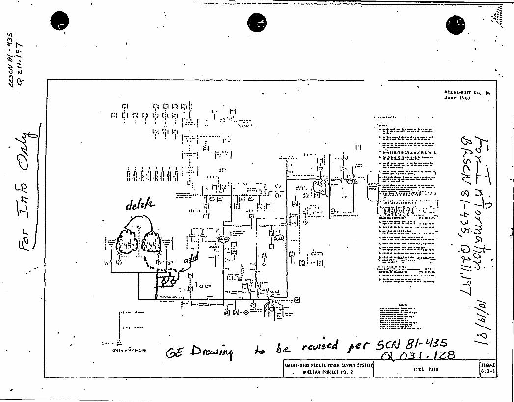
1 ~ ~ I'
I'-.'J I'5: I'I
t. I 5II';(
I;-I
C.5I II ~
»I
c:..„
I '3:...,. "r.5
Oil',t S
(', I'
.' I
I .'. ~ ' I.I I r:.5
. L'J
,I ~ 1
.,I, gd -('-".
' i(5g q Ii'I
I-".I I:.4 L.3 I"I I::i~.'
I L'..I I"l L'.II I: J 1.'1 ":IN
~ ~ ~ ~ ~ ~I
I,'I I;J I::I
I ~
s..!''-"! i::: II
I ~
L':;I'.
p~
LtOLP( LIJ .II'.-I:I
~ ~ r 'N
pl ~
~ ~ OOOPNO ~
~01 ~ I
~tl~ ~ IN It M N ~ ~ 'N ~ ~
H N\~ IIH\»IN ~ ~ ~ NII ~~ I ~ ~ tH IHN» ~ lt ~ I~ Nl
~PH»It»4» ~I~ N IIN»NI~ OIPII~ N ~ ~ ~ Pl tt ~ tl ~ ~ ~
~ ~ IN N N IN NIIN INOI 0 IHtl ~ Hl
4 ~ 'N ~ I ~ ~ ~ N I«ttN ~ I NtH
!
M I ~ HN It INOI ~ I ~ ~
~NNHPO» ~ ~ ~ ~ ~ ~~ ~ » ~ NNI Hl
~ ~ I ~
. ~ ~ I ~ I ~ ~ I~ I I» 'I IIPOHO ~~» ~ I~ H ~ I»»l ~ I ~ NN~ IH I» N» I ~ ~
I ~ 'll ~ ~ ~ I~ 0 ~ ~
~ ~ ~ » ~ I ~ \ ~~ ~ P I~ ~ NI
UUUOU IUUIOU III IllS II
~ » ~III~ ~Ht ~ ~ ~ ~ ~ ~ ~
~, NN INN ~ IIN NON ~, ~ ~ 1$ NHM IN ~ NISI ~ \N HOII HHVIVII~ ~ MI 'MNM~ ttMIH ONO ~ I~IIM ttt'NM~ ~ I HH ~ It ~ ~ ~ Ht ~ ~ ~ ~ ON
H 11 ~ 4 P ~ I~ I
~ElMllllJ~l ~ III'I II4 ~ IOHI I INOO I»P ~ ~ 'INII~ ~OIM» INOIO~ ~ ~ N ~ I~ Nt
~ ItNt ~ I ~ I» 0 Il~ ltt'H
AttRttttttt:ttYJVnI. I'lilt
INI~ cl i.. 1
N ~ N .'L S <Iod
~ t 1» 11
~0 ~ ~ t
.I(0$
iQ
IIVU
I ~ I~ t»t ~ ~ IP ~ ~ ~
I ~
~t ~ 010 tr CVt.gVtaeJ Per 5CnJ 8/-"~~~
l ~
ltASIIIRGIOtt PINLIC PDMCR SUPPLY STSYLII
tRKLLAR PROJLCI t(9. giiPCS PL 10
FIGURC
tot 3

~ ~PSB-E-,misc D.G Loading Sequence
uMG4. As agreec; o 'in tr.e we~~.'ng, ". e stv.~emend on p 8.3-2 hasbeen c~e,ri-."ied in t~e revised Ch. 8.3
The Supply Syst m has submitted a -simpli ied logic diagramdescribing the loading sequenc oT the diesel generator(including starting and op ra.ion and .he second level ofundervoltage protection) . This information will be includedin th FSAR..- The Supply. System also agre s to reflect theuse of electro-meehan',cal relays'n diesel Generator loadsequencing 'on p 8.3-2 of the re'sad ch. 8.3.

Cl
PSB — ELECTRICAL
8. 3 REV
RKMARKS: As agreed to in the attached correspondence., arevised Ch. 8.3 has been submitted to the NRCinformally. This change will be included in theFSAR in. a future amendment.
RESOLtFZXON:
Revised Chapter 8.3 submit ted January 13'982'nG02-82-31.

Washington Public Power Supply SystemP.O. Box 968 3000 George Washington Way Richland, Washington 99352 (509) 372-5000
, January 13, 1982G02-82-31SS-L-02-CDT-82-011
Docket No. 50-397
Mr. A. Schwencer, ChiefLicensing Branch No. 2Division of LicensingU.S. Nuclear Regulatory ComtissionWashington D.C. 20555.
Dear Mr. Schwencer:
Subject: NUCLEAR PROJECT NO. 2SECTION 8.3 REWRITE
Letter, R. L. Tedesco to R. L. Ferguson, "WNP-2 - Requestfor Additional Information", dated July 22, 1981
Enclosed are sixty (60) copies of the draft revised pages for the WNP-2FSAR Section 8.3 rewrite. Included in this enclosure is the response toNRC guestion 040.088 which was transmitted to the Supply System by thereference letter.
Reference:
Very truly yours,
Responses to the remaining Power Systems Branch guestions will be submittedto thh NRC prior to January 31, 1982 as committed to in the PSB meetingDecember .16-18,. 1981. Both the Section 8.3 rewrite and the NRC questionwill be included in Amendment 23.
G. 0. Bouchey, Deputy DirectorSafety'5 Security
CDT/ctEnclosure
cc: R. Auluck - NRCWS Chin - BPAR. Feil - NRC-Site

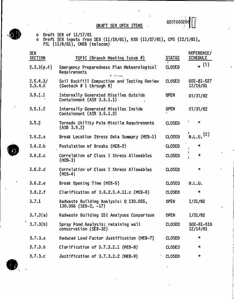
DRAFT SER OPEN ITEMS
J
820l26026I
o Draft SER of 11/17/81o Draft SER inputs from SEB (11/18/81), RSB {ll/27/81), CPS (12/1/81),
PSl (11/6/81), CMEB (tel econ)
SER
SECTION
2.3.3(p.4)
2.5.4.3/2.5.4.5
3.5.1.1
3.5.1.2
TOPIC (Branch Meetin Issue ¹Emergency Preparedness Plan MeteorologicalRequirements
Soil Backfill Compaction and Testing Review(Geotech ¹ 1 through 8)
Internally Generated Missiles OutsideContainment (ASB 3.5.1.1)
Internally Generated Missiles InsideContainment (ASB 3.5.1.2)
STATUS
CLOSED
CLOSED
OPEN
OPEN
REFERENCE/SCHEDULE
G02-81-52712/15/81
01/31/82
01/31/82
3.5.2 Tornado Utility Pole Missile Requirements{ASB 3.5.2)
CLOSED'
3.6.2.a
3.6.2.b
3.6.2.c
Postulation of Breaks (MEB-2)1
Correl'ation of Class I Stress Allowables(MEB-3)
Ci OSED
CLOSED
Break Location Stress Data Summary (MEB-1) CLOSED N.L.U.
*
3.6.2.d
3.6.2. e
3.6.2. f3.7.1
3.7.3(a)
3.7.3(b)
3.7.3.a
3. 7.3. b
3 '.3 '
Correlation of Class I Stress Allowables(MEB-4)
Break Opening Time (MEB-5)
Clarification of 3.6.2.5.4.11.c (MEB-6)
Radwaste Building Analysis: 9 130.055,130.056 (SEB-2, -17)
Radwaste Building SSI Analyses Comparison
Spray Pond Analysis: retaining wallconservatism (SEB-32)
Reduced Load Factor Justification (MEB-7)
Clarification of 3.7.3.2.1 (MEB-8)
Justification of 3.7.3.2.2 (MEB-9)
CLOSED
CLOSED N.L.U.
CLOSED
OPEN 1/31/82
OPEN 1/31/82
CLOSED G02-81-51812/14/81
CLOSED
CLOSED
CLOSED

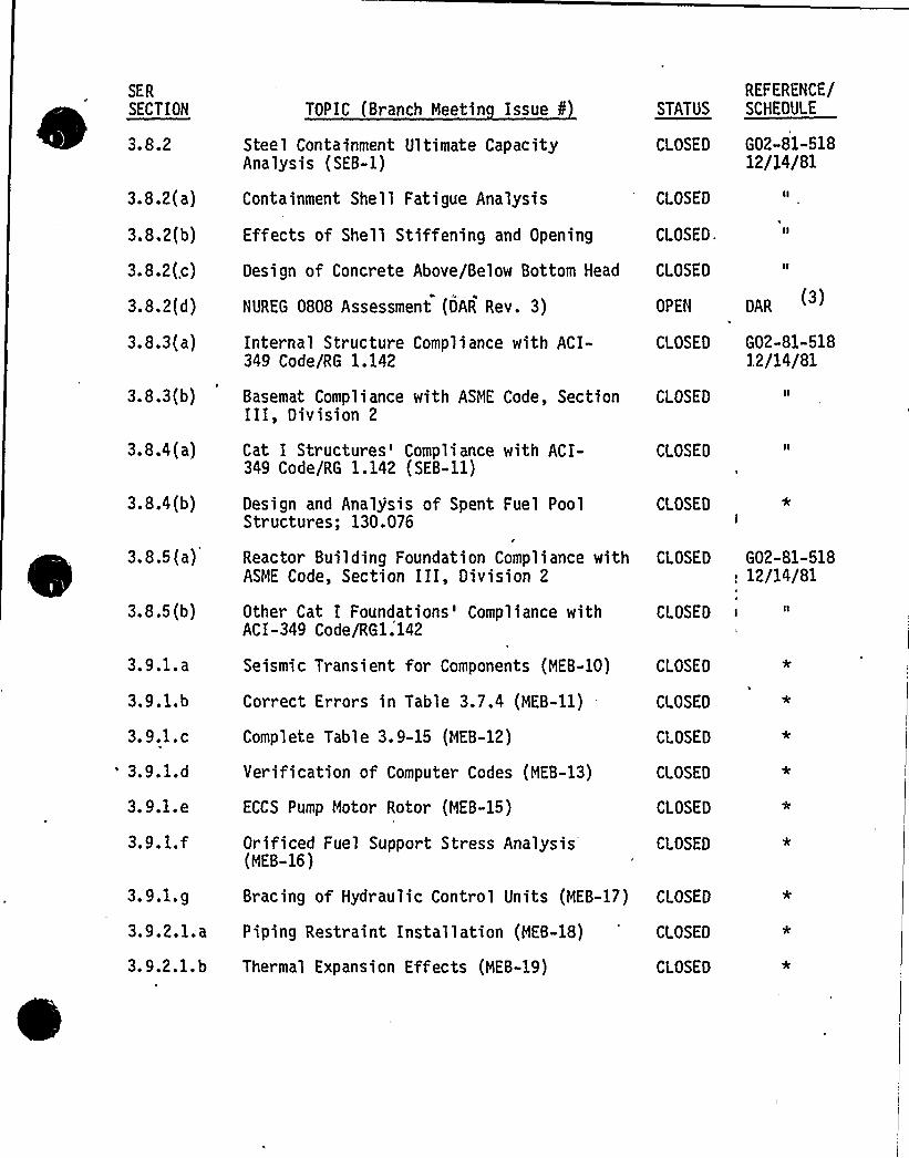
SER
~ ~
SECTION
3.8.2
3.8.2(a)
3.8.2(b)
3.8.2{.c)
3.8.2(d)
3.8.3(a)
3.8.3(b)
3.8.4 (a)
3.8.4 (b)
3.8.5 (a)
3.8.5 (b)
3.9.1. a
3.9.1. b
3. 9.1. c
'.9.1.d3.9.1. e
3.9.1.f
TOPIC (Branch Meetin Issue tSteel Containment Ultimate CapacityAnalysis (SEB-1)
Containment Shell Fatigue Analysis
Effects of Shell Stiffening and Opening
Design of Concrete Above/Below Bottom Head
NUREG 0808 Assessment (DAR Rev. 3)
Internal Structure Compliance with ACI-349 Code/RG 1.142
Basemat Compliance with ASME Code, SectionIII, Division 2
Cat I Structures'ompliance with ACI-349 Code/RG 1.142 (SEB-11)
Design and Analjsis of Spent Fuel PoolStructures; 130.076
Reactor Building Foundation Compliance withASME Code, Section III, Division 2
Other Cat I Foundations'ompliance withACI-349 Code/RG1.142
Seismic Transient for Components (MEB-10)
Correct Errors in Table 3.7.4 (MEB-11)
Complete Table 3. 9-15 {MEB-12)
Verification of Computer Codes {MEB-13)
ECCS Pump Motor Rotor (MEB-15)
Orificed Fuel Support Stress Analysis(MEB-16)
STATUS
CLOSED
CLOSED
CLOSED.
CLOSED
OPEN
CLOSED
CLOSED
CLOSED
CLOSED
CLOSED
CLOSED
CLOSED
CLOSED
CLOSED
CLOSED
CLOSED
CLOSED
REFERENCE/SCHEDULE
G02-81-51812/14/81
DAR
G02-81-51812/14/81
G02-81-518. 12/14/81
3.9.l.g
3.9.2.1;a
3.9.2.1. b
Piping Restraint Installation (MEB-18)
Thermal Expansion Effects (MEB-19)
CLOSED
CLOSED
Bracing of Hydraulic Control Units (MEB-17) CLOSED
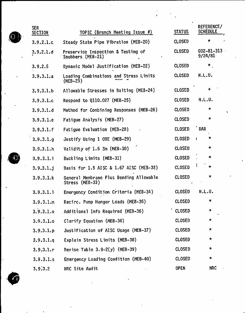
SER
~ ~ ~ ~
SECTION TOPIC Branch Meetin Issue 0
3.9.2.1.c Steady State Pipe Vibration (MEB-20)
3. 9.2.1. d Preser v ice Inspection E Testing ofSnubbers (MEB-21)
3.9.2.5 Dynamic Model Justification (MEB-22)
3.9.3.1.a Loading Combinations and Stress Limits(MEB-23)
3.9.3.1.b Allowable Stresses in Bolting (MEB-24)
3.9.3.l.c Respond to 9110.027 (MEB-25)
3.9.3.l.d Method for Combining Responses (MEB-26)
3.9.3.l.e Fatigue Analysis (MEB-27)
3.9.3.1. f Fati gue Evaluation (MEB-28)
3.9.3.1.g Justify Using 1 OBE (MEB-29),
3.9.3.1.h Validity of 1.5 Sm (MEB-30)
3.9.3.1. i Buckling Limits (MEB-31)
3.9.3.1.j Basis for 1.5 AISC |I 1.67 AISC (MEB-32)
CLOSED
CLOSED
CLOSED
CLOSED
N.L.U.
CLOSED DAR
CLOSED i *
CLOSED
CLOSED
P
REFERENCE/STATUS SCHEOULE
CLOSED *
CLOSED G02-81-3139/24/81
CLOSED
CLOSED N.L.U.
3.9.3.1.'k General Membrane Plus Bending AllowableStress (MEB-33)
CLOSED *
CLOSED
3. 9.3.1. l
3.9.3.l.m
3.9.3.1. n
3.9.3.1.o
3.9.3.1.p
3.9.3.1.q
3.9.3.1. r3.9.3.1.s
3.9.3.2
Emergency Condition Criteria (MEB-34)
Recirc. Pump Hanger Loads (MEB-35)
Additional Info Required (MEB-36)
Clarify Equation (MEB-36)
Justification of AISC Usage (MEB-37)
Explain Stress Limits (MEB-38)
Revise Table 3. 9-2(y) (MEB-39)
Emergency Loading Condition (MEB-40)
NRC Site Audit
CLOSED
CLOSED
'LOSED
CLOSED
CLOSED
CLOSED
CLOSED
CLOSED
OPEN
N.L.U.
NRC
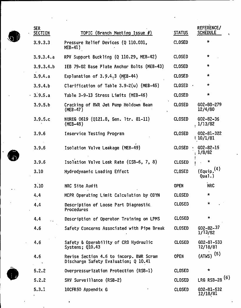
SER
SECTION
3.9.3.3
TOPIC Branch Meetin Issue 0
Pressure Relief Devices (Q 110.031,MEB-41)
REFERENCE/'STATUS SCHEDULE
CLOSED
3.9.3.4.a
3.9.3.4.b
3. 9.4. a
3.9.4.b
3.9.5. a
3.9.5.b
RPV Support Buckling (Q 110.29, MEB-42) CLOSED
Explanation of 3. 9.4.3 (MEB-44)
Clarification of Table 3.9-2(u) (MEB-45)
Table 3-9-13 Stress Limits (MEB-46)
Cracking of BWR Jet Pump Holdown Beam(MEB-47)
CLOSED
CLOSED
CLOSED
CLOSED
IEB 79-02 Base Plate Anchor Bolts (MEB-43) CLOSED
G02-80-27912/4/80
3.9.5.c
3.9.6
3.9.6
3.9.6
3.10
3.10
4.4
4.4
4.4
NUREG 0619 (Q121.8, Gen. 1tr. 81-11)(MEB-48)
Inservice Testing Program
Isolation Valve Leakage (MEB-49)
Isolation Valve Leak Rate (CSB-6, 7, 8)
Hydrodynamic Loading Effect
NRC Site Audit
MCPR Operating Limit Calculation by ODYN
Description of Loose Part DiagnosticProcedures
Description of Operator Training on LPMS
CLOSED
Cl OSED
CLOSED
CLOSED
CLOSED
OPEN
CLOSED
CLOSED
CLOSED
G02-82-36, 1/13/82
G02-81-322! 10/1/81
~ G02-82-15', 1/8/82
*
(Equip.Qual.)
NRC
4.6
4.6
4.6
Safety 5 Operability of CRD HydraulicSystems; Q10.43
Revise Section 4.6 to incorp. BWR ScramDischarge Safety Evaluation; Q 10.41
CLOSED
OPEN
Safety Concerns Associated with Pipe Break CLOSED G02-82-371/l 3/82
G02-81-53312/18/81
(ATWS) ( )
5.2.2
5.2.2
5.3.1
Overpressurization Protection (RSB-1)
SRV Surveillance (RSB-2)
10CFR50 Appendix G
CLOSED *
CLOSED LRG RSB-28
CLOSED G02-81-53212/18/81

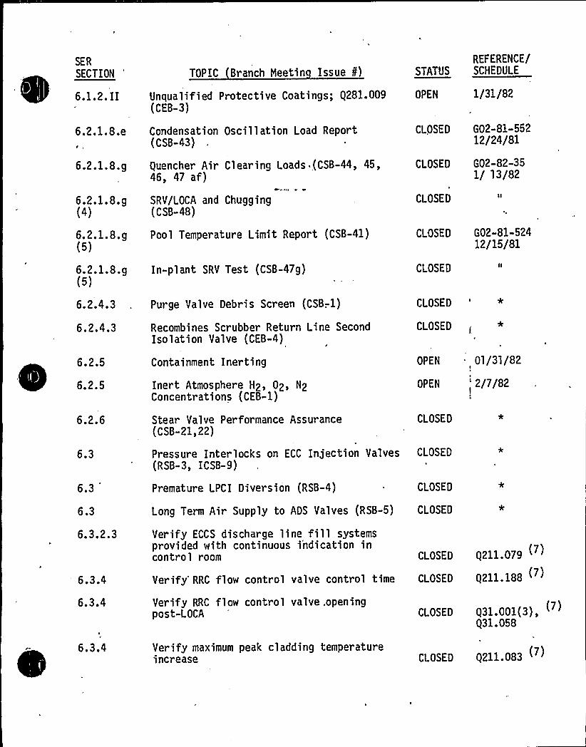
SER
~ ~ ~
SECTION
6.1.2.II
6.2.1.8.e
6.2.1.8.g
6.2.1.8.g(4)
6.2.1.8.g(5)
6.2.1.8.g(5)
6.2.4.3
6.2.4.3
6.2.5
6.2.5
6.2.6
6.3
6.3
TOPIC Branch Meetin Issue ¹)
Unqualified Protective Coatings; Q281.009(CEB-3)
Condensation Oscillation Load Report(CSB-43)
Quencher Air Clearing Loads (CSB-44, 45,46, 47 af)
SRV/LOCA and Chugging(CSB-48)
Pool Temperature Limit Report (CSB-41)
In-plant SRV Test (CSB-47g)
Purge Valve Debris Screen (CSB-. 1)
Recombines Scrubber Return Line SecondIsolation Valve (CEB-4)
Containment Inerting
Inert Atmosphere H2, 02, N2Concentrations (CEB-1)
Stear Valve Performance Assurance(CSB-21,22)
Pressure Interlocks on ECC Injection Valves(RSB-3, ICSB-9)
Premature LPCI Diversion (RSB-4)
REFERENCE/STATUS SCHEDULE
OPEN 1/31/82
CLOSED G02-81-55212/24/81
CLOSED G02-82-351/ 13/82
CLOSED
CLOSED G02-81-52412/15/81
CLOSED
CLOSED'
CLOSED
OPEN 01/31/82
OPEN '/7/82
CLOSED
CLOSED
CLOSED
6.3
6.3.2.3
6.3.4
6.3.4
Verify ECCS discharge line fill systemsprovided with continuous i'ndication incontrol room CLOSED
Verify'RC flow control valve control time CLOSED
Q211 079
Q211.188
Verify RRC flow control valve. openingpost-LOCA CLOSED Q31.001(3),
Q31.058
Long Term Air Supply to ADS Valves (RSB-5) CLOSED
6.3.4 Verify maximum peak cladding temperatureincrease CLOSED Q211.083

0
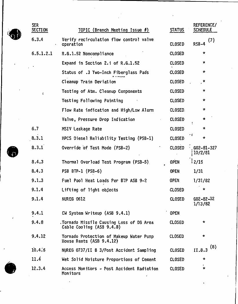
SER
SECTION
~ ~6.3.4
TOPIC Branch Meetin Issue f)
Verify recirculation flow control valveoperation
6.5.1.2.1 R.G.1.52 Noncompli ance
Expand in Section 2.i of R.G.1.52
Status of .3 Two-Inch Fiberglass PadsCl' 44 Yh;I
Cleanup Train Deviation
STATUS
CLOSED
CLOSED
CLOSED
CLOSED
CLOSED
REFERENCE/SCHEDULE
(7)RSB-4
6.7
8.3.1
8.3.1
8.4.3
8.4.3
9.1.3
9.1.4
9.1.4
9.4.1
9.4.8
9.4.12
Testing of Atm. Cleanup Components
Testing Foll owing Painting
Flow Rate indication and High/Low Alarm
Valve, Pressure Drop Indication
MSIY Leakage Rate
HPCS Diesel Reliability Testing (PSB-1)
Override of Test Mode (PSB-2)
Thermal Overload Test Program (PSB-5),
PSB BTP-1 (PSB-6)
Fuel Pool Heat Loads Per BTP ASB 9-2
Lifting of light objects
NVREG 0612
CW System Writeup (ASB 9.4.1)
.Tornado Missile Causing Loss of DG AreaCable Cooling (ASB 9.4.8)
Tornado Protection of Makeup Mater PumpHouse Rents (ASB 9.4.12)
CLOSED
CLOSED
CLOSED.
CLOSED
CLOSED
CLOSED
CLOSED
OPEN
OPEN
OPEN
CLOSED
CLOSED
OPEN
CLOSED
CLOSED
' G02-81-32710/2/81
I2/15
1/31'/31/82
G02-82-321/l 3/82
10.4.'6
11.4
12.3.4
NUREG 0737/II B 3/Post Accident Sampling
Met Solid Moisture Proportions of Cement
Access Monitors - Post Accident RadiationMonitors
(8)CLOSED II.B.3
CLOSED
CLOSED

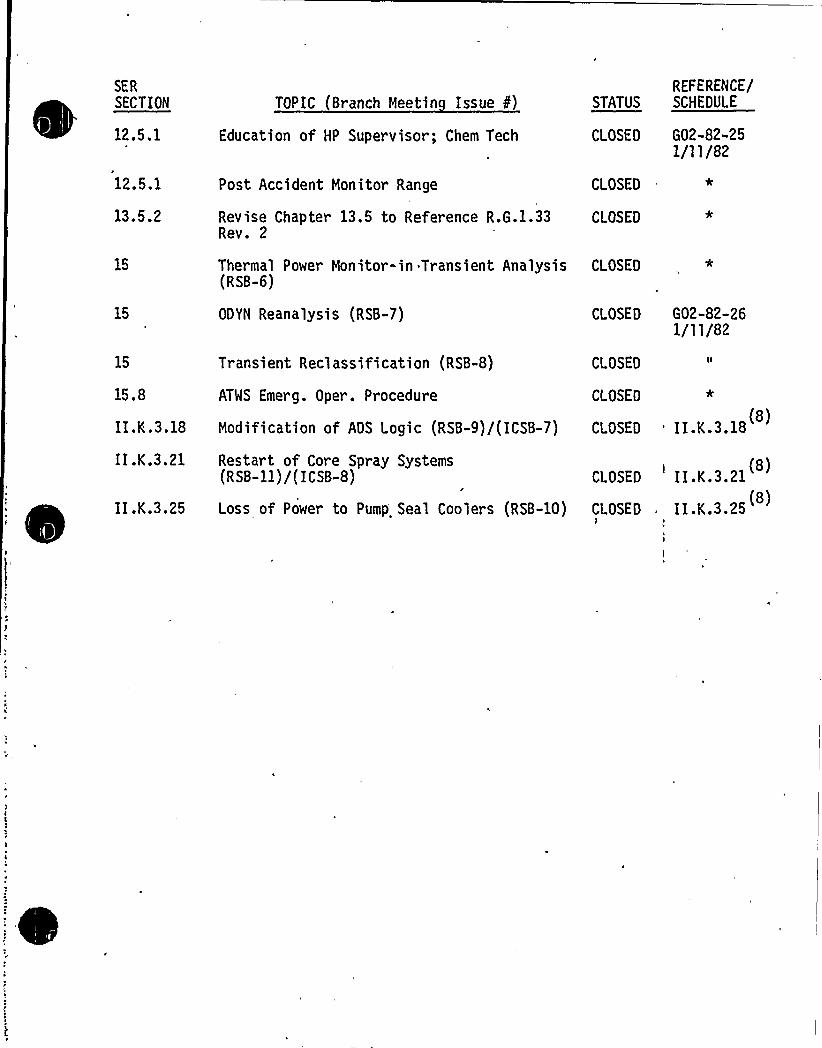
SER
SECTION
12.5.1
12.5.1
13.5.2
15
15. 8
TOPIC Br anch Meetin Issue 8)
Education of HP Supervisor; Chem Tech
Post Accident Monitor Range
Revise Chapter 13.5 to Reference R.G.1.33Rev. 2
Thermal Power Monitor-in Transient Analysis(RSB-6)
ODYN Reanalysis (RSB-7)
Transient Reel assification (RSB-8)
ATWS Emerg. Oper. Procedure
REFERENCE/STATUS SCHEDULE
CLOSED G02-82-251/11/82
CLOSED
CLOSED
CLOSED ,*
CLOSED G02-82-261/11/82
CLOSED
CLOSED
II.K.3.18
II.K.3.21
II .K.3. 25
Restart of Core Spray Systems(R SB-11) /( ICSB-8)
Loss of Power to Pump Seal Coolers (RSB-10)
CLOSED
CLOSEDi
Modification of ADS Logic (RSB-9)/(ICSB-7) CLOSED 'I.K.3.18 (8)
II.K.3.21
II.K.3.25 (8)
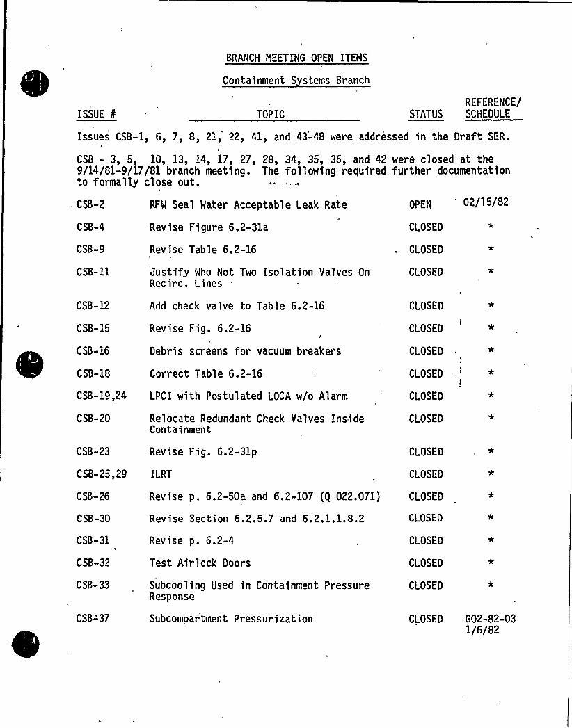
ISSUE 8
BRANCH MEETING OPEN ITEMS
Containment S stems Branch
TOPICREFERENCE/
STATUS SCHEDULE
Issues CSB-l, 6, 7, 8, 21, 22, 41, and 43-48 were addressed in the Draft SER.
CSB - 3, 5, 10, 13, 14, 17, 27, 28, 34, 35, 36, and 42 were closed at the9/14/81-9/17/81 branch meeting. The following required further documentationto formally close out.
CSB-2
CSB-4
CSB-9
CSB-11
RFW Seal Water Acceptable Leak Rate
Revise Figure 6.2-31a
Revise Table 6.2-16
Justify Who Not Two Isolation Valves OnRecirc. Lines
OPEN '2/15/82
CLOSED
CLOSED
CLOSED
CSB-12
CSB-15
CSB-16
CSB-18
Add check valve to Table 6.2-16
Revise Fig. 6.2-16
Debris screens for vacuum breakers
Correct Table 6.2-16
CSB-20
CSB-23
Relocate Redundant Check Valves InsideContainment
Revise Fig. 6.2-31p
CSB-25,29 ILRT
CSB-26
CSB-30
CSB-31
CSB-32
CSB-33
Revise p. 6.2-50a and 6.2-107 (g 022.071)
Revise Section 6.2.5.7 and 6.2.1.1.8.2
Revise p. 6.2-4
Test Airlock Doors
Subcooling Used in Containment PressureResponse
CSB-19,24 LPCI with Postulated LOCA w/o Alarm
CLOSED
CLOSED
CLOSED
CLOSED
*l
CLOSED
CLOSED
CLOSED
CLOSED
CLOSED
CLOSED
CLOSED
CLOSED
CLOSED *
CSB-'37 Subcompartment Pressurization CLOSED G02-82-031/6/82

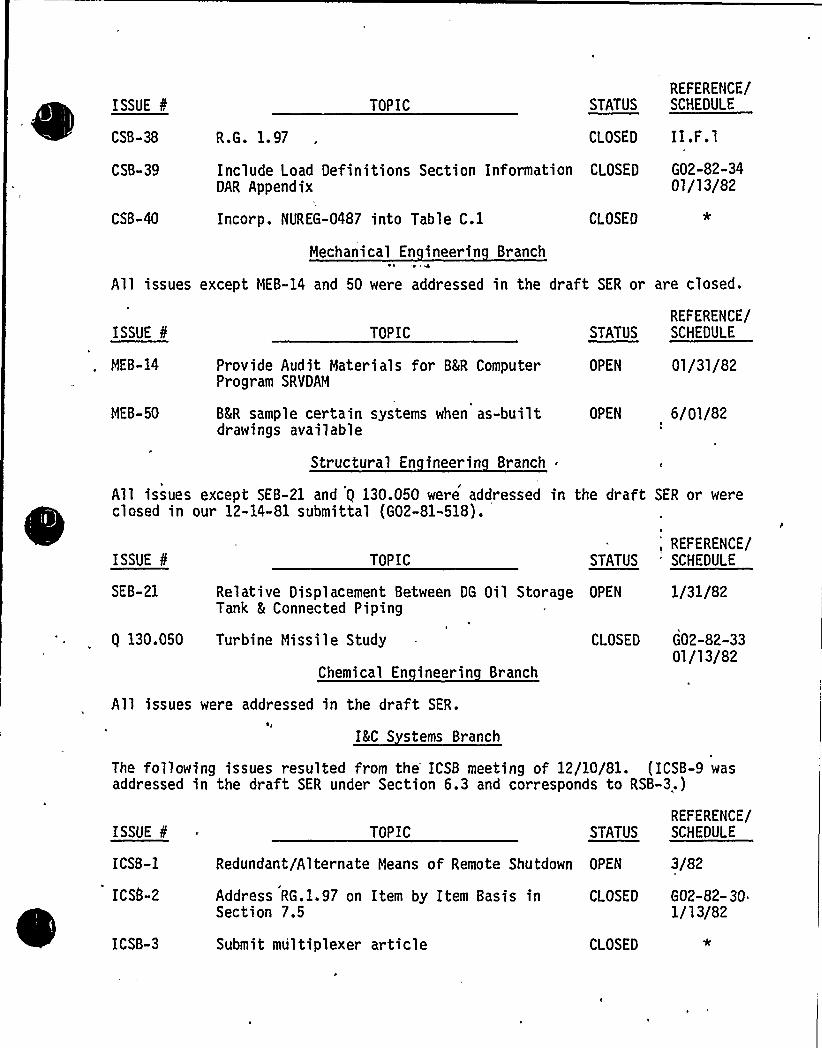
ISSUE 8
CSB-38 R.G. 1.97
TOPIC STATUSREFERENCE/SCHEDULE
CLOSED II.F.lCSB-39 Include Load Definitions Section Information CLOSED
DAR AppendixG02-82-3401/13/82
CSB-40 Incorp. NUREG-0487 into Table C.l CLOSED
Mechanical En ineerin Branch4
All issues except MEB-14 and 50 were addressed in the draft SER or are closed.
ISSUE 8
MEB-14
TOPIC
Provide Audit Materials for BImR ComputerProgram SRVDAM
STATUS
OPEN
REFERENCE/SCHEDULE
01/31/82
MEB-50 BImR sample certain systems when as-builtdrawings available
Structural En ineerin Branch .
OPEN 6/Ol/82
All issues except SEB-21 and Q 130.050 were addressed in the draft SER or wereclosed in our 12-14-81 submittal (G02-81-518).
ISSUE 8 TOPIC;
REFERENCE/STATUS 'CHEDULE
SE8-21 Relative Displacement Between DG Oil Storage OPEN 1/31/82Tank 5 Connected Piping
Q 130.050 Turbine Missile Study
Chemical En ineerin Branch
All issues were addressed in the draft SER.
IKC S stems Branch
CLOSED G02-82-3301/13/82
The following issues resulted from the ICSB meeting of 12/10/81. (ICSB-9 wasaddressed in the draft SER under Section 6.3 and corresponds to RSB-3.)
ISSUE 8
ICSB-1
ICSS-2
TOPIC STATUS
Redundant/Alternate Means of Remote Shutdown OPEN
Address RG.1.97 on Item by Item Basis in CLOSEDSection 7.5
REFERENCE/SCHEDULE
3/82
G02-82-30.1/13/82
ICSB-3 Submit multiplexer article CLOSED

0
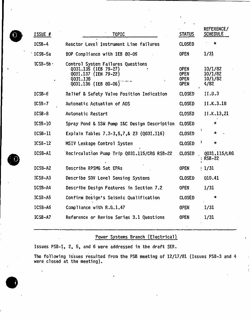
ISSUE
tm'CSB-4
'CSB-5a
ICSB-5b .
ICSB-6
ICSB-7
ICSB-8
ICSB-10
ICSB-11
ICSB-12
ICSB-A1
ICSB-A2
ICSB-A3
ICSB-A4
ICSB-A5
ICSB-A6
ICSB-A7
TOPIC
Reactor Level Instrument Line failures
BOP Compliance with IEB 80-06
Control System Failures QuestionsQ031.135 (IEB 79-27)Q031.137 (IEN 79-22)Q031.138Q031.136 (IEB 80-06)
Relief 5 Safety Valve Position Indication
Automatic Actuation of ADS
Automatic Restart
REFERENCE/STATUS SCHEDULE
CLOSED'
OPEN 1/3f
OPEN
OPEN
OPEN
OPEN
CLOSED
10/1/8210/1/8210/1/824/82
II.D.3
CLOSED I I.K.3.18
CLOSED I I .K.13,21
Explain Tables 7.3-3,5,7,E 23 (Q031.116)
MSIY Leakage Control System
Recirculation Pump Trip Q031.115/CRG RSB-22
Describe RPSMG Set EPAs
Des cr ibe SDY L eve 1 Sens i ng Systems
Describe Design Features in Section 7.2
Confirm Design's Seismic Qualification
Compli ance with R.G.1.47
Reference or Revise Series 3.1 Questions
CLOSED
CLOSED '
CLOSED
OPEN
Q031.115/LRGRSB-22
I
i 1/31
CLOSED Q10.41
OPEN
CLOSED
OPEN
OPEN
1/31
1/31
1/31
Spray Pond Im SSW Pump IIIC Design Description CLOSED
Power S stems Branch Electrical
Issues PSB-1, 2, 5, and 6 were addressed in the draft SER.
The following issues resulted from the PSB meeting of 12/17/81 (Issues PSB-3 and 4were closed at the meeting).

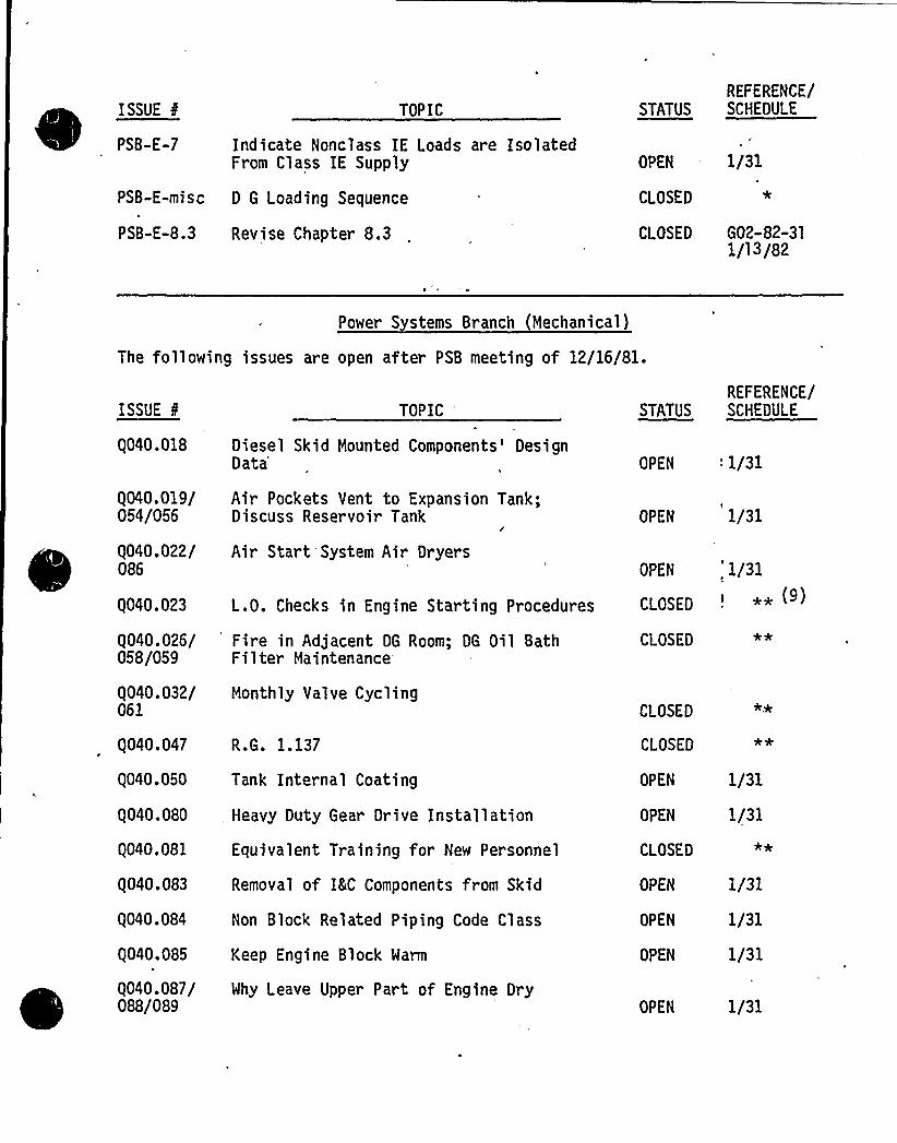
ISSUE E
PSB-E-7
PSB-E-misc
PSB-E-8.3
TOPIC
Indicate Nonclass IE Loads are IsolatedFrom Class IE Supply
D G Loading Sequence
Revise Chapter 8.3
OPEN
CLOSED
1/31
CLOSED G02-82-3l1/13/82
REFERENCE/STATUS SCHEDULE
Power S stems Branch (Mechanical)
The following issues are open afte~ PSB meeting of 12/16/81.
ISSUE 8
Q040.018
Q040.019/054/056
Q040.022/086
Q040.023
Q040.026/058/059
Q040.032/061
Q040.047
Q040.050
TOPIC"
Diesel Skid Mounted Components'esignData'ir
Pockets Vent to Expansion Tank;Discuss Reservoir Tank
I
Air Start'System Air Dryers
L.O. Checks in Engine Starting Procedures
Fire in Adjacent DG Room; DG Oil BathFilter Maintenance
Monthly Valve Cycling
R.G. 1.137
Tank Internal Coating
OPEN '/31
OPEN 1/31
OPEN 1/31
CLOSED '*CLOSED
CLOSED
CLOSED
OPEN 1/31
REFERENCE/STATUS SCHEDULE
Q040.080 ,Heavy Duty Gear Drive Installation OPEN 1/31
Q040.081
Q040.083
Q040.084
Q040.085
Q040.087/088/089
Equivalent Training for New Personnel
Removal of IKC Components from Skid
Non Block Related Piping Code Class
Keep Engine Block Warm
Why Leave Upper Part of Engine Dry
CLOSED
OPEN
OPEN
OPEN
OPEN
1/31
1/31
1/31
1/31

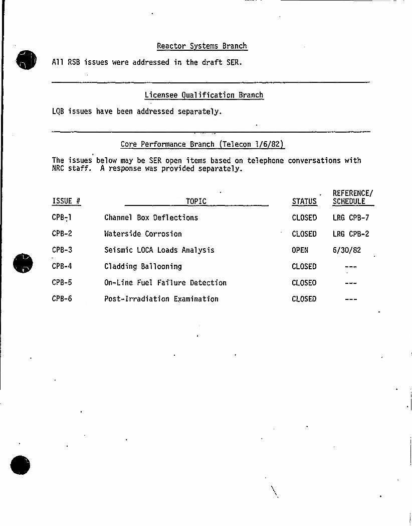
Reactor S stems Branch
All RSB issues were addressed in the draft SER.
Licensee gualification Branch
LgB issues have been addressed separately.
Core Performance Branch Telecon 1/6/82
The issues below may be SER open items based on telephone conversations withNRC staff. A response was provided separately.
ISSUETI'PB-1
CPB-2
CPB-3
CPB-4
CPB-5
CPB-6
TOPIC
Channel Box Deflections
Waterside Corrosion
Seismic LOCA Loads Analysis
Cladding Ballooning
On-Line Fuel Failure Oetection
Post-Irradiation Examination
OPEN
CLOSED
CLOSED
CLOSED
6/30/82
REFERENCE/STATUS SCHEDULE
CLOSED LRG CPB-7
CLOSED LRG CPB-2
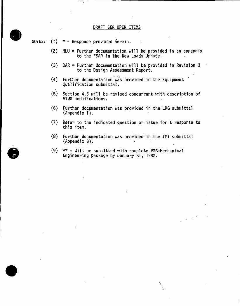
DRAFT SER OPEN ITEMS
NOTES: (1) * = Response provided herein.
(2) NLU = Further documentation will be provided in an appendixto the FSAR in the New Loads Update.
(3) DAR = Further documentation will be provided in Revision 3to the Design Assessment Report.
(4) Further documentation was provided in the Equipmentqualification submittal.
(5) Section 4.6 will be revised concurrent with description ofATWS modifications.
(6) Further documentation was provided in the LRG submittal(Appendix I).
(7) Refer to the indicated question or issue for a response tothis item.
(8) Further documentation was provided in the TMI submittal(Appendix B).
(9) ,",
" = Will be submitted with complete PSB-MechanicalEngineering package by January 31, 1982.

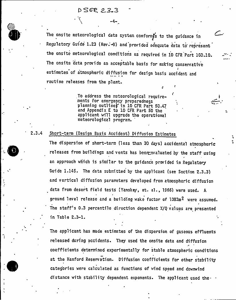
~ ~
e
The onsite m teorological data system conform s to the auidance inRegulatory Guid 1.23 (Rev.'H) and provided edequa e data to represent
the onsite m teorological conditions as required in 10 CrR Part 1GQ.i0.
The onsit data provide an acceptable basis for making conservat-ve
estimates of atmospheric diffusion for design basis accident and
routine releases from the plant.
To address the ri. teorological require-ments for er roency preparednessplannino outline/ in 10 CFR Part 00A7and Appendix E to 10 CFR Part 50 theapplicant will upgrade the operationalmeteorological program.
'hor- erm (D sign Basis Accident} Diffusion Estimates
The dispersion of short-term (less than 30 days) accidental a.mospheric
releases from buildings and vents has b ez. valua ed by the sta, f usinge
an approach which is similar to the guidance provided in Regula ory
Guide 1.145. The data submitted by the applicant (see Section 2.3.3)
and vertical diffusion parameters developed fron a~mspheric diffusion
data from desert field tests (Yanskey, et. al., lg66) were used. A
ground level release and a building wake factor of 1383m2 were assumed.
The staff's 0.3 percentile direction depend nt X/g values are presented
in Table 2.3-1.
The applicant has made estimates of the dispersion of gaseous effluen.s
released during accidents. They used the onsite data and diffusionr
coefficients determined experimentally for stable atmospheric conditions
at the Hanford Reservation. Diffusion coefficients or other s .abilitycateg'ories were calculated as functions of wind speed and downwind
distance with stability dependen exponen s. The applicant used the.
Open SER Issue
2.33 Emer enc Pre aredness Plan Meteorolo ical Re uirements
See revised FSAR page 2.3-37 (attached).

0
~ WJ1 4 llV~
August 1979\
In several of the monthly summary reports, the computer pro-grams as applied to dummy data have been compiled as calledfor in the Quality Assurance Ilanual(23) fcr the purpose ofdocumenting proper programming and proper computer performince.
These computer computations have been verified with hand cal-culations made with the dummy data..The computational, pro-'rams for x/Q were similarly tested.
2.3.3.2.4 Meteorological Monitoring Program DuringPlant, Operation
fue ad. The system. will be put in operation at lea womonths p to fuel load to ensure reliable oper ' atfuel load. S m measurements will include ' speed anddirection and tempe ures at 245 and 3 ', ht between 245 and33', and dewpoint,.at 33 . " quali assurance program willbe utilized to ensure measur accuracies within thoserecommended by Regulato uide 1. Those parameters whichwill be multiplexe the control room 'ude wind speedand direction ~ m 245'nd 33'nd the bt b ~en 245'nd33'., Th ontrol room displays will consist of in'aneousan (strip'hart) valves of each of the multiplexed
2. 3. 3. 3 Other Meteorological Measurement ProgramsConsidered. for the Data Comparisons
'.3.3.3.1. HEW-2 Temporary Tower
A temporary 23 foot onsite tower was used during the periodApril 1, 1972 through August 31, 1974 to obtain data inputfor MNP-2 environmental studies and to. provide a comparativeoverlap with the initially measured permanent tower data.
The temporary tower was located in the vicinity of the perman-ent, towers with its base at. approximately 448 feet MSL. Winddata from the temporary tower were obtained at the 23 footlevel'while temperature data were acquired at the three footlevel. Wet bulb data from the temporary tower were establishedfrom techniques and data contained in the U.S. Departmentof Commerce, Weather Bureau Office Document: Relative Humidi-ty and Dewpoint, Table. As a special quality assurance program
'asnot initiated for the temporary tower installation, it isnot possible to assert that this tower's data complied withthe requirements contained in Regulatory Guide 1.23.
2 ~ 3 37

Insert to Page 2.3-37:
The Supply System Meteorological Measurements Program (MMP) treats ""P-2 and~
~ ~ ~ ~
~~
~
~
MNP-1/4 as an integrated whole. As MNP-2 fuel load is scheduled prior toWNP-1/4 fuel load, the MNP-1/4 MMP will incorporate the procedures appliedto WNP-2. The instruments and data acquired are described in Subsection2.3.3.1. This data forms the primary'nput data which will be relayed to thecontrol room and site computers, as required, on a real-time basis. Data isalso multiplexed to the WNP-1/4 control room, the FFTF, and the PSP8L Skagit-Hanford site required by contract. The data is available to indicated loca-tions as 5-minute average analog values and are converted to digital valuesfor CRT and ~~ printout displays with various analog meter displaysalso available. These digitized, electronically averaged, five-minute datawill be processed into 15-minute averages 'for utilization in Supply Systemdispersion models. Longer period averages will also be computed for trendanalysis and report generation. These data will be routed to satisfy displayand processing requirements of the on-site Technical Support Centers and theEmergency Operations Facility (EOF). The primary meteorological tower datawill be stored on tape at the tower and also stored for 24 hours in raw andprocessed form by the plant Data Acquisition System. Instrument calibrationsand maintenance procedures will be implemented to meet the data recovery andsystem accuracy requirements of Regulatory Guide 1.23. The backup systemwill be sited near the EOF after appropriate consideration of local topographyand the final EOF building configuration. Instrumentation, maintenance,calibration, and processing of sensor data will be identical to that of theprimary system. Sensor data obtained from'he backup system will be 10-meter,5-minute averaged windspeed, wind direction, Sigma Theta, Temperature, dewpoint,a temperature difference (over a to-be-determined height) and a 5-minute
~
~ ~
~
~
~~
precipitation total; This system is designed to meet or exceed a data unavail-ability of 0.01 and backup system data access of less than 5-minutes. Allsensor data will be interactively accessable as detailed in the WNP-2
Emergency Preparedness Plan. Spatial data acquisitions are planned from anetwork of approximately twenty 10-meter towers operated by Battelle PacificNorthwest Laboratories for DOE. Data will also be obtained as availablefrom the 400-meter HMS tower and auxiliary systems operated by Battelle.Terrain data requirements per Regulatory Guide 1.23 will be satisfied byselecting the appropriate 10-meter tower data following written and automatedselection procedures based on the current meteorological situation. Whereeconomically feasible, the Supply System will aequi",.e any additional datarequired for the safety of the public. Data exchange with state and federalagencies will be incorporated in the MMP to meet their requirements. Theaccuracy, calibration, and reliability of all data not directly controllableby the Supply System will be determined by the private/governmental- control-ling agency.

0
2.5.4.3 Evaluation of Foundations
Beneath all seismic Category 7 struc ural oundations, the existing upper loose
sandy material was excavated down to the und rlying very dense Ringold gravel.
and replaced ir. a denser state by-'compaction. The excavations to.the'Ringold
forma.ion ex ended down io 385 fe t (msl) .o 392 feet (msl) with some localized
areas as"deep as 375.8 feet (msl). Th 'thicknoss o7 the.compac.ed back illand .he main foundation features of the principal seismic Category I plant
s.ruc.ur s are shown'n Table 1;
Ccmoac ed Back=ill
The'pplicant in.=or;,>ed-'the NRC- Staff'n: April=22, 1981 and September.l; 1981
that ther is a po"e~tially repor'table condition concerning soil back'f$ 11ing',
coapac"ion ard 't s ing; The applican 's int rim reports describing he
,de>iciency indicate tha he labora ory maxi>mun density tes ing for the Class 1I
backfill perfor ed since tray 1976 may have been performed incorrectly. The
applicant is for,.ulating a list of all..he aff cted areas and will evaluate i,. any of these areas have to be retested. The staff will review the applicant's
conclusions and provide evaluation o> the applicant's study in a supplement
to this SER.
'The applicant has provided for 'a safe y factor in excess of 3 in calculating
allowable s.a.ic design bearing capacity. The staff agr es that this margin
o safety is adequate for the support o, the plant. facilities.

0
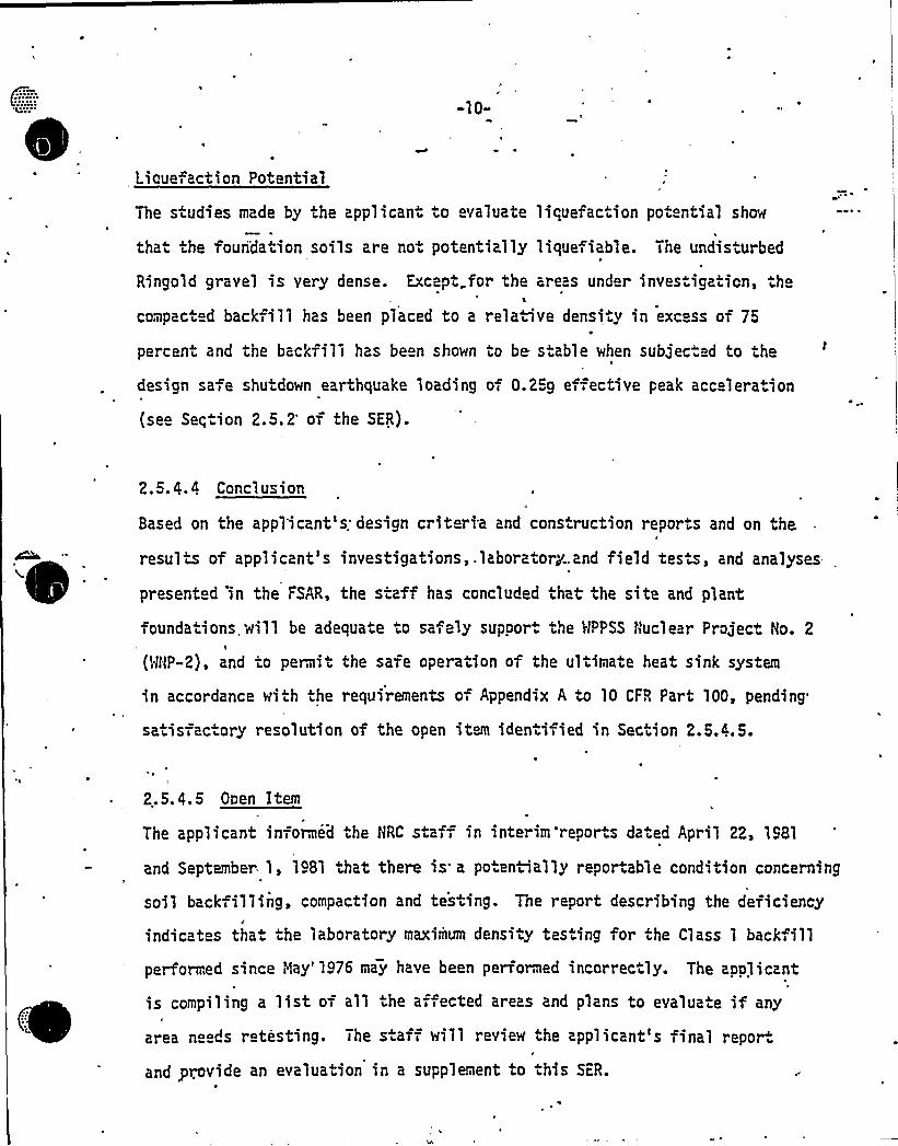
-10-
Lioue action Potential
The studies made by the applicant o evaluate
that the fouridation soils are not potentially
Ringold gravel is very dense. Except„for the
compacted backfill has been placed to a rela.i
percent and the backfill has been shown to be.
liquefaction potential show
liquef i able. The undisturbed
areas under investigation, the
ve density in excess of 75
s.able when subjec. d to the
design safe shutdown earthquake loading of 0.23g effective peak acc leration
(se Seqtion 2.5.2'f the SER).
2.3.4. 4 Conclusion
Based on the appl'icant's: design crit ria and cons. ruction reports and on theI'esultof applicant's investigations,.laboratory.and field test, and analyses
present d in the FSAR, the staff has concluded that the site and plant
founda.ions,will be adequate to sa ely supoor. the 3|PPSS Nuclear Project No. 2!
(WflP-2), and .o pernit the safe operation of the ultimate heat sink system
in accordance with the requirements of Appendix A to 10 CFR Part 100, pending
satisfac ory resolution of the open item identified in Section 2.3.4.5.
2.5.4.5 Oven Item
The applicant informed the HRC staff in interim'reports dated April 22, 1981
and September. 1, 1981 that there is a po eniially reportable condition concerning
soil back illing, compaction and tes ing. The report describing the deficiency
indicat s that the laboratory maximum density tes ing for the Class 1 back,ill
performed since Hay'976 may have been performed incorrec ly. The applicant
is compiling a list of all he af ected areas and plans to evalua,e if any
area ne ds retesting. The s aff will review the applicant's final repor.
and provide an evaluation in a supplement to this SFR.
Washington Pub1ic Power Supply SystemP.O. Box 968 3000 George Washington Way Richland, Washington 99352 (509) 372-5000
Docket No. 50-397 December 15iL981G02-81-527
Hr. R. A. Schwencer, ChiefLicensing Branch No. 2Division of LicensingNuclear Reactor RegulationU. S. Nuclear Regulatory ComissionVashington, D; C. 20555
Subject: NUCLEAR PROJECT 2QUALITY CLASS I SOIL BACKFILL TEST PROGRAM
Reference: G02-81-462, November 12, 1981, GD Bouchey (Supply System)to RA Schwencer (NRC)
The Reference letter provided a svmnary of the efforts being taken to re-solve a suspected deficiency concerning soil backfill placed since May 1976for support of Quality Class I vtilities and structures (remote air intakestructures, remote ai'r intake piping, standby service water piping, andelectrical duct banks for the standby service water system). To resolvethe concerns regarding this backfill, an extensive test program was con-ducted to determine in-situ properties of the. soil. The attached report,"Evaluation of Quality Class I UtilityBackfill, GA File 81-605", was pre-pared by Geologic Associates, Inc. and Burns and Roe to summarize the re-
'sults of the test program and conclusions regarding the acceptability ofthe soil. The report conclvdes that although, the existing soil does notmeet specification requirements for relative density, the effect on safety-related utilities and structures is acceptable.
A copy of this report way given to Mr. Dinesh Gupta of the NRC, GeosciencesBranch, during his visit to the MNP-2 site on December 7, 1981, to discussthis matter.
Based on the conclusions of the report, we have informed NRC, Inspection andEnforcement Branch, Region V, that this condition, which had been identifiedas a potentially reportable condition vnder the provision of 10CFR50.55(e),is not reportable.

0
Mith transmittal of this report, and subject to your review, the openiten identified in the draft SER for MNP-2 is considered closed.
During a meeting with the NRC staff on this matter on October 7, 1981, theSupply System was requested to assess the significance of the soil backfilldeficiencies in light of IE Circular No. 81-08, and advise the staff of ourconclusions. IE Circular No. 81-08 is primarily concerned with insufficientcompac ion of foundation and backfill materials leading to excessive settle-ment of plant structures. As stated in a separate report by Shannon and Milsondated Nay 11, 1976 (Referenced in FSAR.Chapter 2.5), the compaction and back-fillwork performed for the major plant structures prior to t/ay 1976"is accept-able. This is'urther verified by the excellent results of the settlement moni-
~ toring program in progress (Reference NRC question 362.10 and the response),Accordingly, it is concluded that the primary concern of IE Circular 81-08(excessive settlement of major plant structures) is not a problem at the MNP-2
, facility.
GD Bouchey (650)Deputy Director
'afety and Security
EAF:kjfAttachment: "Evaluation of equality Class I UtilityBackfill,
MNP-2, Hanford, Washington", GA File 81-605 (3 copies)
cc: JA Forrest - BKR RO
RE Snaith - BER NYJJ Verderber - BSR NYAI Cygelman - BER 954MFA HacLean - General ElectricS. Smith - General ElectricND Lewis - EFSEC, OlympiaMS Chin - BPANS Reynolds - Debevoise 8 LibermanOK Earle - BKR ROE. Beckett - Nuclear Projects, Inc.AD Toth - Resident InspectorQA Satir - BSR NYMNP-2 Files
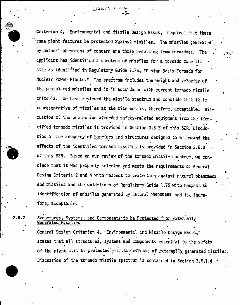
Criterion 4, "Environmental and Missile Design Bases," requires that theset ~
same plant features be protected against missiles. The missiles generated
by natural phenomena of concern are those resulting from ornadoes. The
applicant has identified a spectrum of missiles for a tornado zone IIIsite as identified in Regula.ory Guide 1.76, "Design Basis'Tornado forNuclear Power Plants." The spectrum includes the w ight and veloci,y ofthe postulated missiles and is in accordance wi h current tornado missile
criteria. We have reviewed the missile spectrum and conclude that it isrepresentative of missiles at the site -and is, therefore, acceptable. Dis-
I
cussion of the protection afforded safety-related equipment from the iden-
tified tornado missiles is provided in Sec.ion 3.5.2 oi this SER. 'Discus-
sion of the adequacy of barriers and structures designed to withstand. the
effects of the identified tornado missiles is provided in Section 3.5.3
of this SER. Based on our review of the tornado missile spectrum, we con-
elude that it was properly selected and meets the requirements of 6 neral
Design Criteria 2 and 4 with respect to pro ection against natural phenomena
and missiles and the guidelines of Regulatory Guide 1.76 with respect to
identification of missiles generat d by natural Pheno ena and is, there-
fore, acceptable.
Stru'c ures, S stems and Comoonen s to be Pro ected from ExternallvGenerated Nssssies
General Design Criterion 4, "Environmental and Missile Design Bases,"
states that all structures, systems and components essential to the safety
of the plant tnust be prptected'from.the'e fec s.ot .externa11y generated missiles.I
Discussion of the tornado missile spectrum is contained in Sec ion 3;5.1.4

0
w7w
of this S"=R. [The applicant has not committed to provide tornado missile
pro e tion rom the utility pole to an elevation of 30 feet above
the'ighest
grade elevation within 0.5 miles of the facility structures as per the
guidelines of Standard Review Plan 3.3.1.4. Me cannot concur with the appli-
cant's evaluation until this commitmen is made.3 All stored fuel is located
wi hin tornado missile protected reactor building and the spent fuel pool
walls. This assures compliance with.the specific guidance of Regulatory
Guide 1.13, "Spent Fuel Storage Facili.y Design Basis," relating to external
missile protection for stored fuel- The piping to the ultimate heat sink
is Gvried'7.fe t below grade and backfilled with high density Class I fillto provid missile protection and, therefore, to conforn to Regula.ory Guide
1.27, "Ultimate Heat Sink for Nuclear Power Plants," relating to external
missile protection, for the ultimate heat sink. fUntil the applicant providesE
an accepu5le r sponse to our question concerning SRP 3.5.1.4, we vill be
unable to confirm compliance with Regulatory Guide 1.117, "Tornado Design
Classification,'elating to specific protection of'afety-related systems
and components from tornado missiles.g
Based on the above, we conclude hat the design of the plant for protection
against externally generated missiles is in conformance .with the guidelines
of Regul atory Gui des 1 . 1 3 and 1; 27 concerni ng protection of the spent fuel
and the ultimate heat sink from tornado generatedhissiles, and is, there-
fore acceptable. I Until the applicant verifies conformance with the
Standard Review Plan 3.5.1.4 as it relates to protection of structures,
systems and components from ornado generated missiles, we cannot cdnclude
conformance with the requirements of General Design Criterion 4 with respect
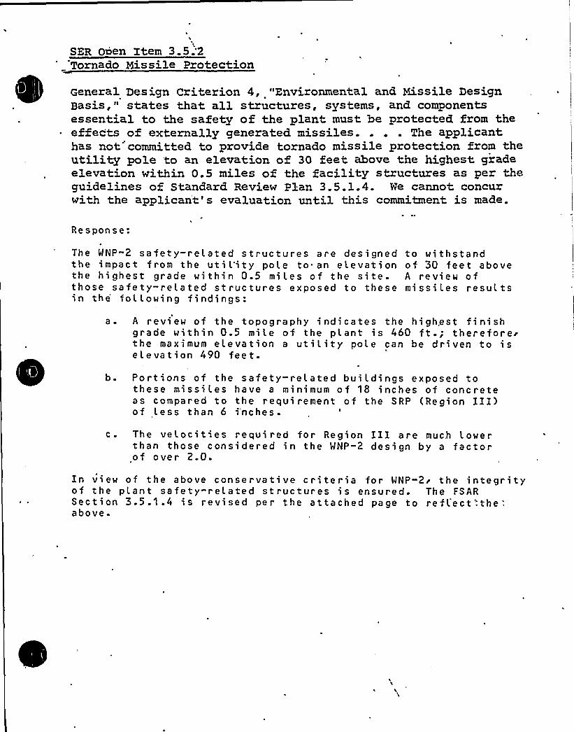
SER 0&en Item 3.5;2Tornado Missile Protection
General Design Criterion 4, "Environmental and Missile DesignBasis," states that all structures, systems, and componentsessential to the safety of the plant must be protected from the
~ effects of externally generated missiles.... The applicanthas not'ommitted to provide tornado missile protection from theutility pole 'to an elevation of 30 feet above the highest gradeelevation within 0.5 miles of the facility structures as per theguidelines of Standard Review plan 3.5.1.4. We cannot concurwith the applicant's evaluation until this commitment is made.
Response:
The WNP"2 safety-related structures are designed to withstandthe impact from the ut i l'it y pole to an e levat i on of 30 feet abovethe highest grade within 0.5 miles of the site. A review ofthose safety-related structures exposed to these missiLes resultsin the following findings:
a. A review of the topography indicates the highest finishgrade within 0.5 mile of the plant is 460 ft.; thereforerthe maximum elevation a utility pole can be driven to iselevation 490 feet.
b. Portions of the safety-related buildings exposed tothese missiles have a minimum of 18 inches of concreteas compared to the requirement of the SRP (Region III)of Less than 6 i'nches.
c. The velocities required for Region III are much Lowerthan those considered in the WNP-2 design by a factorof over 2.0.
In view of the above conservative criteria for WNP"2r the integrityof the plant safety-related structures is ensured. The FSARSection 3.5.1.4 is revi sed per the attached page to ref L'ect '-the '.
above.

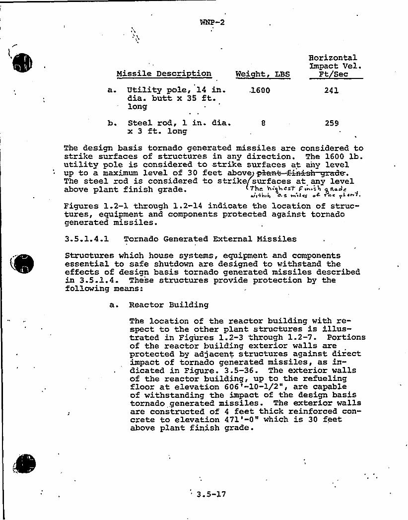
~ $
Missile Descri tionHorizontalXmpact Vel.
Ft Sec
a. Utilitypole, 14 in.dia. butt x 35 ft.long
1600 241
b. Stee1 rod, 1 in. dia.x 3 ft. long
259
The design basis tornado generated missiles are considered tostrike surfaces of structures in any direction. The 1600 lb.utility pole is considered to strike surfaces at airy levelup to a maximum level of 30 feet aboveThe steel rod is considered to strike surfaces at any levelabove plant finish grade. The ha'ghost p'nish grady
Qpg lpga 0 $ ill~ LQ 04 TAc 'pL sn4.
Figures 1.2-1 through 1.2-14 indicate the location of struc-tures, equipment and components protected against tornadogenerated missiles'.
3.5.1.4.1 Tornado Generated External Missiles
Structures which house systems, equipment and componentsessential to safe shutdown are designed to withstand theeffects of design basis tornado generated missiles describedin 3.5.1.4. These structures provide protection by thefollowing means:
a. Reactor Building
The location of the reactor building with re-spect to the other plant structures is illus-trated in Figures 1.2-3 hrough 1.2-7. Portionsof the reactor building exterior walls areprotected by adjacent structures against directimpact of tornado generated missiles, as in-dicated in Figure. 3.5-36. The exterior wallsof the reactor building, up to the refuelingfloor at elevation 606'-10-1/2", are capableof withstanding the impact of the design basistornado, generated missiles. The exterior wallsare constructed of 4 feet thick reinforced con-crete to elevation 471'-0" which is 30 feetabove plant finish grade.
'.5-3.7

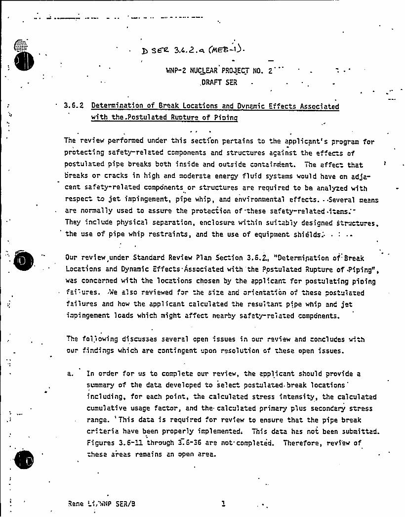
~ ~
p gyes 3,4,.2.~ (jkEE-~) ~
MHP"2 NUCl,EAR PROJECT HO.
DRAFT SiR
2
3,5.2 Determi~ation of Br ak Locations and Dynamic Efiects Associatedwith the.Postulated Ruotur of Pioin
The review performed under this section pertains to +he applicant's program forprotec.iing safety-related components and structures acainst the e,,ec-.s ofpostulated pipe breaks both inside and outside contairr'. nt. Thi e ef ec thatbreaks or cracks in high and moderate ener~ fluid sys ams would have on adja-cent sa,ety-related components or structures are reouired to be analyzed withrespect to jet impingement, pipe whip, and environmental effects. --Several means
are normally used to assure the protec ion of hese sa ety-related.iitems.'hey
'.nclude physical separation, enclosure within sui.ably desicned s ruc u es,ihe use of pipe whip restraints, and the use of equipment
shields.'ur
review under Standard Revie~ Plan Sec.ion 3.6.7., "Determigation of BreakLocations and Dynamic iffects Associated with the Pos ulated Rupture of .Piping",was concerned wi h he loc tions chosen by the appl'.can for postulating pining;ai ures. 'Ae also reviewed for he size anc or-en a ii n oi hese . os ulatedfaiilures and how the applicant calculated the resuitan p',pe whip and jetimp ngement loads which might affect nearby safety-reia:ed components.
.he foliowing discusses several open issues in our -.eview and =oncludes wi h
our i.indings which are contiingent pon resolution ci :hese open issues.
a. In order for us to complete our review, he appliicant should provide a
summary of the data developed to se'.ec postulated breaklocations'ncluding,
for each point, the calculated s ress intensi y, the calculatedcumulative usage actor, and the calculated primary plus seconda~ stressrance. 'his da a is required or review to ensure tha he pipe breakcr'.teria have been properly implemented. This data has not been submitted.Figures 3.6-U. through 3.5-36 are not completed. Therefore, revi'ew of:hese areas remains zn open area.
R ne ',".NP SER/B
~\ ~
iQiP-2
3.6.2 Date~'nation o 3 aak Lccations ard. Dvnar c E fec sAssociate with the Poszu3.ate Runt" a of Piainc
Questicn. 1
order for us ~a. complete cur rev'aw, the appl'ant shouldp"ovide a summa~ of the data developed to selac pcstulatedbreak Xccz iona including, for each point, the calculatedstress in ansi"y, the calculated nebula 've usage fac=or,the calculated pri ary plus secondary stress rance. Thisdata is required fo eviaw to ensure that the pipe breakcriteria have been properly implemented. Figu=es 3.6-11through 3.6-36 are not completed.
Response:
Postulated pipe b eak locations were selec ed cn a bas's ofsigni "cant change 'a lexibility in high energy piping sys-
Zxamples of change in flexility a e pipe fit~gs(elbows, tees and reduce s) and, c"'rcumfarential correctionsto valves and 'anges. This method cf salec""'on was chosensince i. was consecrative and. most expedien", not raauir~gthe'vailabiw~j of ce ailed s =ass analysis o= the p'pingsvstams. The use of this critar'a could on'y resu'" m theneed for too zany pipe wh'p ress aints ratha man too faw.Zn cases whe e the Resign and insta3.lation o apprcpriatepipe whip restricts might prove to be Q.f icult, an opticn .
always rem~ed "c evalua ~ Me need for. t?xe res -ain on thebasis of stress cr teria when the final st=ass analysis be-came available. The s'g ificance of tNe use of la~ilitycrite ia for postulated pipe break locations 's that it per-mi" ed the deswga..of pipe whip astrain.~. ("'".ramv'-ad). at anearly data in ~De. project.Follcwing selecticn o pcstulated break po'".ts, it was necas-sa~ to data~a the movemen o tha pipe cue to jat reaction.Zt vas rot always necessa~ to prov'Be a. pipe vhip estraint forevery posts~ted break; Hhera 't was dat~~~ned that thamovement of the p'e d'c. not st='Re any. piping sys m and/orecuipment necessa~ for sa=e shutdown of the reactor or nacas-sa~ 'tc.M~gz~ the ccnsecuenc s of a LOCA and where thewhipping p'pe would no- d'c"'y str-'ke the pr~~a~ con-~envessel Den pipe wh'p =es —an't was not ecw ed.. WH'.e e p'pevh='p rect aint was ac~red.;. ~Me pipe vh'p ras -a'- was designedto meet the unique conc'cns c the postulated. break.
As ™d'ater above, s=ess cr'e 'a refe ed to 'a the cues-" "'cn O'P„ not ente '""o ""e es ablisr ent of "".e basic
desi'o'P-2.Howeve , add'tional s "c'..a e "cw'vzderwaywherein s"ress cr'teria fo dete~a~'on of brea3c loca" onsa"e be~@ applied. S"-ess-related in= raaticn used in conn c--'onw'A Nese stud'es w'l'e prov'ded when 't becomes availablea~en the. co~lan'" .of. these s uc'es.
S~~ilation - Zn connect'n with "".e addit'nal studies d'cussedin paragraph 3 of the response, the esults of these studieswill be supplied in the =SAR together with specific stress criteriato complete P'cures 3.6-11 through 3.6-36.

I ~
b; Paragraph 3.6.2.1.'1.l.b (2)(b)/Page 3.6-25) implies that he cumulativeusage actor limit of 0.1.is considered only when high stress occurs.is the staff's position hat, breaks mus be pos.ulated at any locationwhere the cumulative usage fac.or exceeds 0.1. At these loca ions bothcircmaferertial and longitudinal pipe breaks should be postulated, unlessit can be clearly shown that the high usage factor is due primarily tos resses in only one principle di".ec-ion. The applicant response o
question "'0.012 states that the ".ules set for h in 3.5.2.1.4.1.e (1) and
(2) exempt car-'.ain break orientations based solely on stress and a, e inde-~ ~ '
pendent of calculated cumulative usage fac or. Clarification of =his areais required.
C. Paragraph 3.6.2.1.1.1.b (2)(c)(Page 3.6-25) implies that breaks arepos ulated when the stress ranges s calcula.ed by Equa ions M or 3 ofthe code exceed 2 ". 5 and Equation 0 exceeds 3 5 . It is the staff's
m m
position that if Eq. '(10), as calculated by Paragr=ph 'i% 3553, AB!E Code
ection jj:, exceeds 2.4 5, then Eqs. ('~) aiqd (13) must be evaluated.If either iq. (M) or (~H) exceeds 2.4 5, a break must be postulated. In
m
other words, a break is postula ed '.f
or{:0) > 2.'. S and "-"„. (:2) > 2.'. 5
rq. (:0) > 2.'. 5 nd =q. ('3).> 2.4 5
d. r tnose por. Ions of ASr!", 5ec on 'ij, Class pipe o discussed in ."SAR
Sec-ions 3.6. 2.~M. 1 and designed o seismic Catagc.„I I s andards and
included in he break exclusion area breaks need nc be postula ad
providing all of the fo1lowing cr. erie are met.
(1) =q. ( 0) as calculated by Paragraph No-3653, ASi'!E Code, Sec-:-;onII„'oes
not exceed 2.4 S .
Rene ' «NP SER/8

0
WNP-2 .
3.6.2 Determination of Break Locations and Dynamic EffectsAssociated with the Postulated Ru tuze of Paean
Question 2
Xt is the staff's position that breaks must be postulated at anylocation where the cumulative, usage factor exceeds 0.1. Atthese locations, both ci cumferential and longitudinal pipebreaks should be postulated, unless it can be clea"ly shownthat the high usage factor is due primarily to stresses in onlyone principle direction. The applicant's response to Q. 110 .012states that the rules set forD in 3.6.2.1.4.le (1) and (2) exemptcertain break orientations based solely on stress and areindependent of calculated cumulative usage actor. Clari icationof this area is required."RESPONSE
Where cumulative usage facto" is a determinant in establishinga postulated break location, then to detezm'ne whether both aci cumferent'al and longitudinal break need be postulated, thestresses in the two directions are compared.
FSAR page change (3.6-30a) agreed." (1) Zf the result of a detailed stress analysis
indicates that the maximum stress range inthe axial direction is at least 1.5 timesthat in the circumferential direction, onlya circumferential break is postulated. Whereusage factor is a determinant in establishinga postulated break location, the fatiguedominant stresses are examined as indicatedabove to determine whether longitudinal,circumferential or both are postulated"
Summation — This item is closed.
See revised FSAR page 3.6-30a (attached).
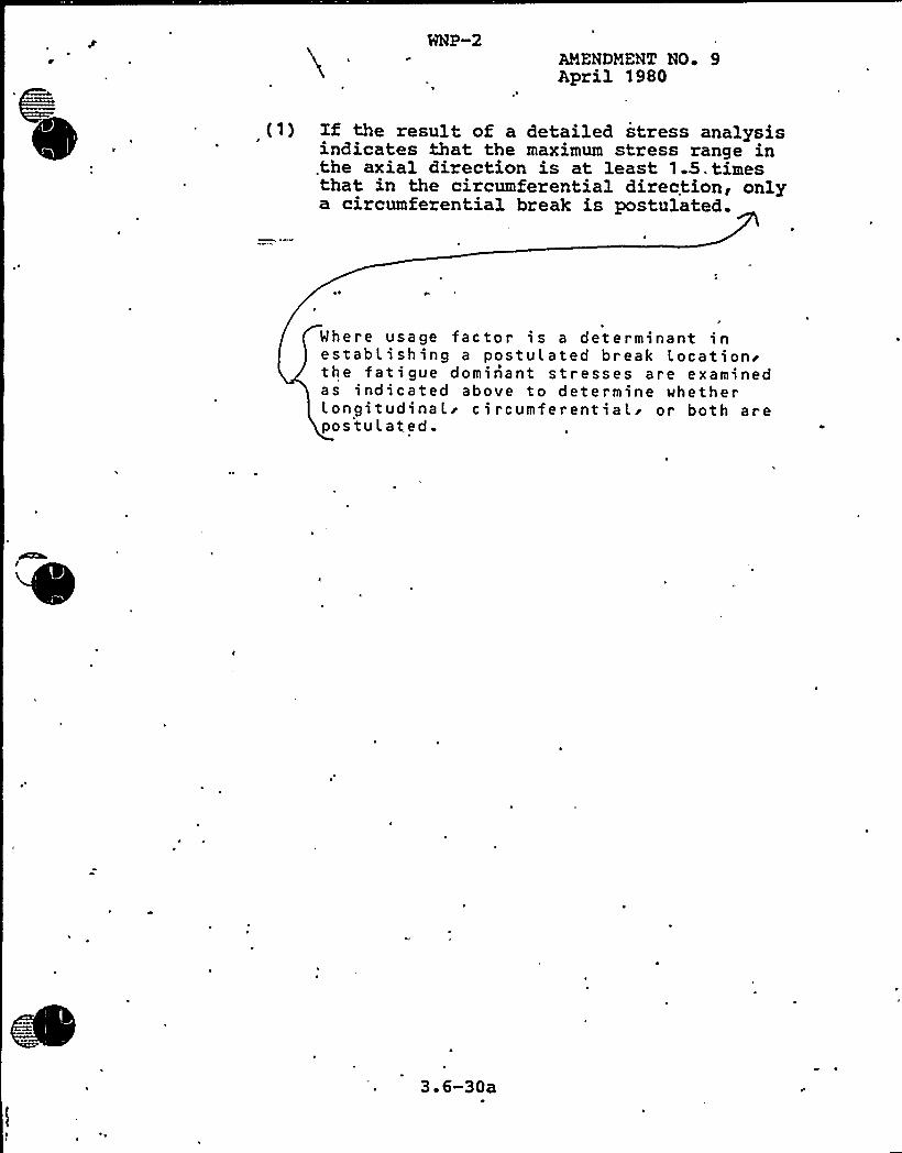
WNP-2AMENDMENT NO 9April 3980
Zf the result of a detailed stress analysisindicates that the maximum stress range inthe axial direction is at least 1.5,timesthat in the circumferential direction, onlya circumferential break is postulated.
Where usage factor is a determinant inestablishing a postulated break Locationithe fatigue dominant stresses are examinedas indicated above to determine whetherlongitudinal'ircumferentiali or both arepostul at.ed.
3 6-30a

I
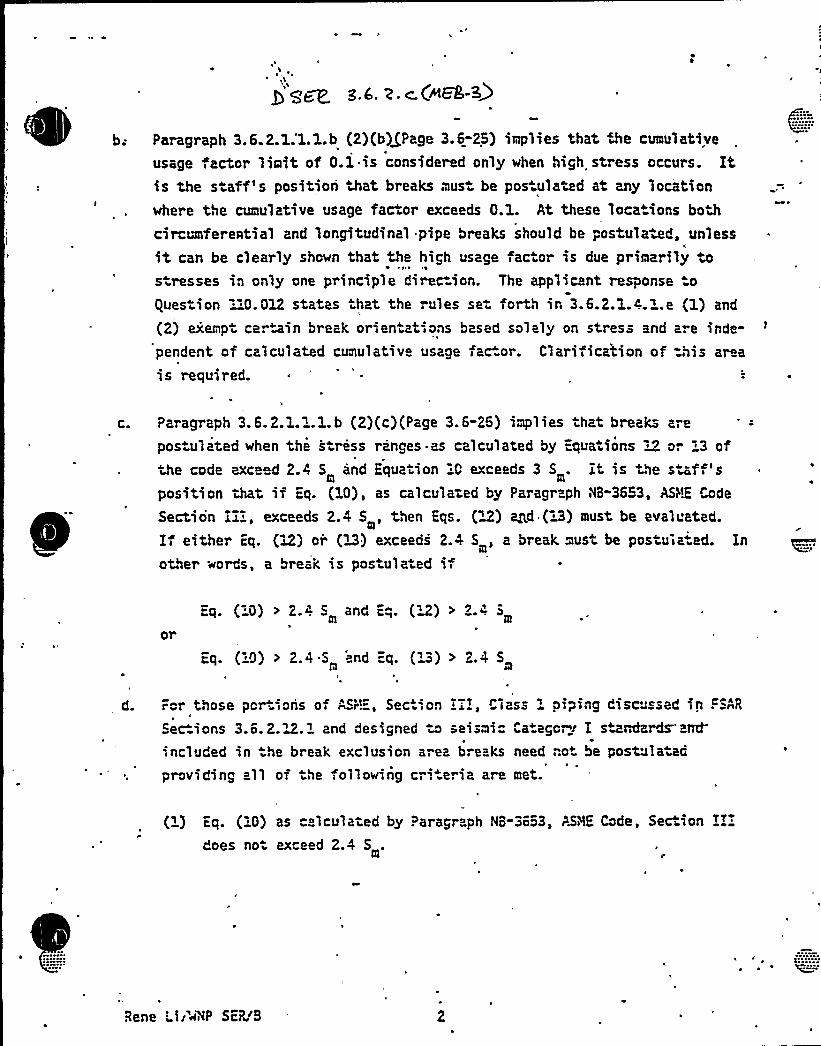
b; Paragraph 3.6.2.1:1.1.b (2)(b)/Page 3.6-25) implies that De cumulative
usage factor limit of 0.1 is considered only when high stress occurs. Itis the s aff's position that breaks must be pos ulated at any locationwhere the cumulative usage factor exceeds 0.1. At these loca ions both
cir mnferential and longitudinal pipe breaks should be postulated, unless
it can be clearly shown that the high usage factor is due primarily tos resses in only one principle direc ion. The applicant response o
Ques ion " 0.012 states hat the rules se forth in 3.6.2.1.4.1.e (1) and
(2) exempt certain break orien ations based solely on stress and areinde-'endent
of calculated cumulative usage fac or. Clariiication of =his area
is required.
C. Paragraph 3.'6.2.1.1.1.b (2)(c)(Page 3.6-26) implies that break- are
pos ulated when the s ress ranges as calculated by =qua ions M or '3 ofthe code exceed 2.4 5 and Equation 0 exceeds 3 5 . I is the staf-,'sposition that if iq. (10), as calculated by Paragraph NB-3653, ASIDE Code
Section II:, exceeds 2.4 5, then Eqs. ( ) ~d (H) must be evaluated.mi
If either iq. (12) or (D) exceeds 2.4 5, a break must be postuia.ed. Inother «ords, a break '.s postulated '.i
iq. (:0) > Z.~ 5 and =.-„. (W) > Z.-. 5,m
iq. (:0) > 2.4 5 'nd iq. ('3) > 2.4 5
d. For those portions of ASH", SectIon Li Ciass piping discussed ln ~ SAR
Sec-ions 3.6.2.~%.1 and designed to seismic Ca ego~i I standa~atrd-'
'.ncluded in he break exclusion area breaks need not be postulatedproviding all of he following cri.eria are met.
(1) iq. ( 0) as calculated by Paragraph NB-36o3, PARE Code, Sec" ion II:does no exceed 2.4 5 .
Rene 'I'«NP SER.IB 2
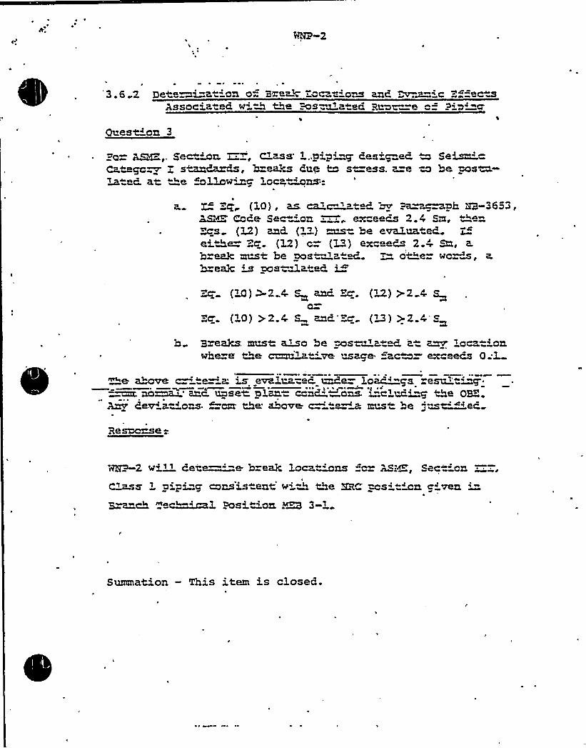
~ r o ~
3.6 2 Detawi"a "'on o- Brag%:"c t ons anc, ~wic = "aceAssocia a6 wiA the =os~Qatac 3z~z—a ==
pig'uest'n 3
po ~,„Secern. ~, Class'„oip' 6esi~eC mSeism"'a.tag@~
7 s~daxPs, breach Guy M s ass. @=a to be pos~-~wtad. at ~e ~oLawwc Locamns:-
a. L. =g (10), as. ca~ c~tM m Pa~~ph M-3653,~ C"Pe Sec "'on excaecs 2.4 Sm. the~ms (l2) and. (lZ) must be em'.up aC.ei>e Zc. (I2) c= (32) exceed 2.4 Sn, a.
bxcak mast be @os'a M. >- othe= wc~a, a.
b=aa3c m mstMa. ~ i~
("0) ~2..4 ~~ anc. ~~. (~M) >2 4 So
Kc. (l0) >2.4 S inc. =~ (~M) >2 O'Sm
b 3zGRks must: ~o be ~s~~~ p~ 6 pt p~ oczt onwhe e the curn~ 've maga =ac% exc ecs 0;l
>e cL+ov8 c ta~ K is GvKllRuac. @de loN $$ IasuZ=~ no~ err use< elm.= c™nd. 'ons. mcluc.'-g the QBZ.6e~ Btions ~~ Me'bo~ ~ ~~~ mus ~ be gus~~<eP
Resecase -..
2 wi» 8eze x"'"e. b=aak loc ~ns =ca ASi~, Sec ions 'i-i"g consis ant v~ M Me HRC msitmn c-'ven
S~~c" ac ~l Posiwon P3 3-4
Summation - This item is closed.
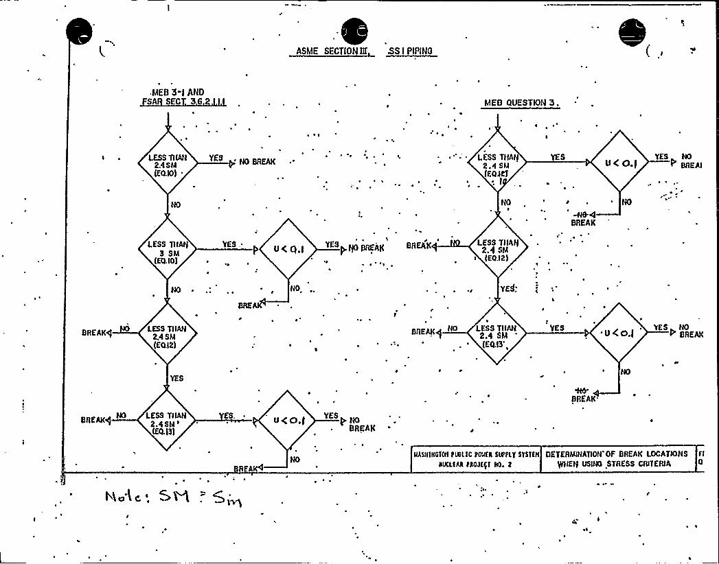
ASME SECTION HI SS I PIPING
WEB 3-) ANDSA SEC 36 MEO QUESTION 3.
~ ~
~ ~
LESS TIIAN YES NO BREAK ~
24SM{EQ.IO) ~
LESS TIIAI{2.4 SM{EQNT
~ ~
UC O.IYES NO
BAEAI
NO NO
BREAK
LESS TIIAI{3 SM
{EQ.IO)
'YESUC q,) yf{OBREAK
~ ~
BREAK LESS TIIAN2.4 SM{EO.I2)
~~
NO. YE~: c
BREAK<]LESS TIIAN
2.4 SM{EQ.I2)
BREAKqNO LESS TIIAN
2.4 SM{EQ.I3',
YES~ UCO,(
'BREAK
YES NO
BREW/NO LESS TIIAN
2.4SM'EQ.)3)
ES. U<O.] P NOBREAK
BREAK
N5IIIIIGTNIPISEIC POMER 5UPPLT 5YSIEII DETERMINATION'OF BREAK LOCATIONS FI
HIICLEAR PROJEP RD. t PIIEN USINO STRESS CRITERIA
4 ~

>a~ S.c,. z.>gem-43
(2) J Eq. ( 0) does exceed 2.4 S, then Eqs. (~D) and (13) must be
evaluated. If neither Eq. ('2) or (13) exceeds 2.4 S, a break need
not be postulated. In other words, a break need not be postulated if:
$q. (10) > 2.4 5 and Eq. (12) < 2.45'nd
Eq. (13) < 2.4 5
,.3) ihe cumulative fatigue Usage fact or is less ihan O.l.
(4) For plants with isola ion valves inside containment, the maximum
s ress, as calculated by Eq. (9) in PSME Code Sec ion III, .
Paragraph HB-3652 under .he loadings of internal pressure, dead-
weight and a postula ad piping failure of f",uid systems upstream or
downstream cf the containment pen 'ration areas mus not exceed
2 25 5 .
ine above crii eria ',s evaluated under loadings resulting from normal and
set plant conditions includ'...g he C8E.
'n addi iion, augmented inse, vice inspec on is . eq'"i. ed on all nSi".E
Class 1, 2 and 3 pipirg iin the break exclusion area. '. is rot clear~nether ;oo ..ote ',a) on Page 3.6-2S or the FS~R '.s appliicable o
Section 3.6.2.1. 2. 2.
.he apolican- must provide assurances .hat heir "ritaria for piping inthe "reak ex"liusion areas complies wi ", he requirement out'.ines above
. and =hose of 5 andar" Review Plan 3.6.2.
A lis . of all sys ems included in he break exclusion areas must be
included in the FSAR. n addition, break axc',usicn ar as should be shown
on he appropriate piping drawings.
Rer.e '.i"~HP SERi'3
3.6.2 Detestation of Brea3c Loca ions and Dynamic Z~ectsAssociated with the Pos ulated Ruutu=e of Picking
uestion 4
A. ~w those portions of ASK Section IIE Class 1 piping dis-cussed in PSAR Sec"ion 3.6.2.1.2.1 and seismic Categoxy Zstandards and included in the hrea3c exclusion a ea, hrea3csneed not he postulated providiag all of the following m-teria a=e met:
a. Eq. (10) as calmQated hy Pa~raph H3-3653,ASME Code, Section IZE, does not exceed 2.4 Sm.
Xf Za'. (10) does exceed 2.4 Sm, then Zas. (12)and (13) must be evaluated X neither Ea. (12)or (13) exceeds 2.4 Sm, a brea3c need not be pos-tulated. 'n othe words, a brea3c need. not bepostulated ':Eq. (10) 0 2.4 Sm and E?-. (12)g2.4 S 4~Eq (13)< 2 4 S
c The cumulat ve atigue usage factor is less. than 0.1
d. Por plants with isolation valves inside coa-ta~ent, the maximum st=ess, as calcu3.ated hyZq (9) in ASNE Code Sect 'on XXX, ParagraphNB-3552 under the loadings of inw~l pressure,deadweight and a pos ulated piping failu=e off3.uid svstems upst=eam or downs~am of the con-tainment penetration a ea must aet exceed 2.25S
The above c=i eria is evaluated under loadings resu3.~g =omnormal and upset plant condi"'ons including OBE.
Zn addition, augmented inse~ce inspection is recgzired oaall ASME CLass 3., 2 and 3 piping in the hrea3c exclusion axea.Zt is not clear whethe footnote (a) on page 3.6-28 of the
@SAR is applicable to Section'.6.2.1.2.2. The appli,cantt provide assurances that their 'criteria foz piping in= thebreak exclusion areas complies wi,th the requirements outlinedabove and those of Standard Review Plan 3.6.3: A list of allsys ems included in the break exclusion areas must be
eluded in the TSAR Zn addition, break exclusion areasshould be shown on the appropriate piping cL~wings.
B. a Document the method used to verify that the stressesin welded flued head. fittings meets the limits,specifiedin HEB 3-1. Indicate on which piping system the weldedflued heads are used.
b. Describe the insezvice inspection of the welded fluedhead fit~gs.
Remonse-
Footnote (a) on page 3.6-28 is not applicable to 3.6.2.1.2.2.The revision,~w page 3.6-2S indicates the systems with breakexclusion a=eas between prim my containment isolation valves.These svstems a e ASME Section IZX Class 1 systems.
>Pith aspect to loadings resulting from postulated pipingailu e outside the exclusion area (Section B.l.b. (1,) (d) of
ZEB 3-1) detailed analyses we e performed for the main steamand feedwatez systems for breaks inside and outside of con-tainment. These analyses have confirmed the acceptability ofmain steam and feedwater systems and have been used to con-elude that detailed analyses for small,er lines aze not z~i ed.
Please refer to revised FSAR page 3.6-28 for a list ofall systems included in the break exclusion area SeeFigures 3.6-147a through 3.6-147e for break exclusion areas.
B.a A project unique analysis of the welded flued headfitting in the mainsteam penetration has been performedto assure meeting the code stress limits and the HRCcriteria for the break exclusion area and documentedin the WNP-2 Stress Report,. In addition, GE hasdemonstrated the physical integrity of the HNP-2flued head by a, bounding generic finite elementanalysis on a sim'la= configuration; this isdocumented in the .G=- Report ¹D0-23652.
The lued head to process pipe weld;is examinedvolumetrically from axial and perpendicular su facesusing ultrasonic methods. By using 45 and 60 degreeshear wave from the perpendicular surface and 0 degreelongitudinal wave rom the axial surface completecoverage of Ne weld is assured. Details of theexamination are can ained 'n procedure UTP-33, whichis contained in the WP-2 PSI Program Plan. Inaddition, su=face examination will be performed onthe accessible portion o the weld.
Summation'- This item is closed.
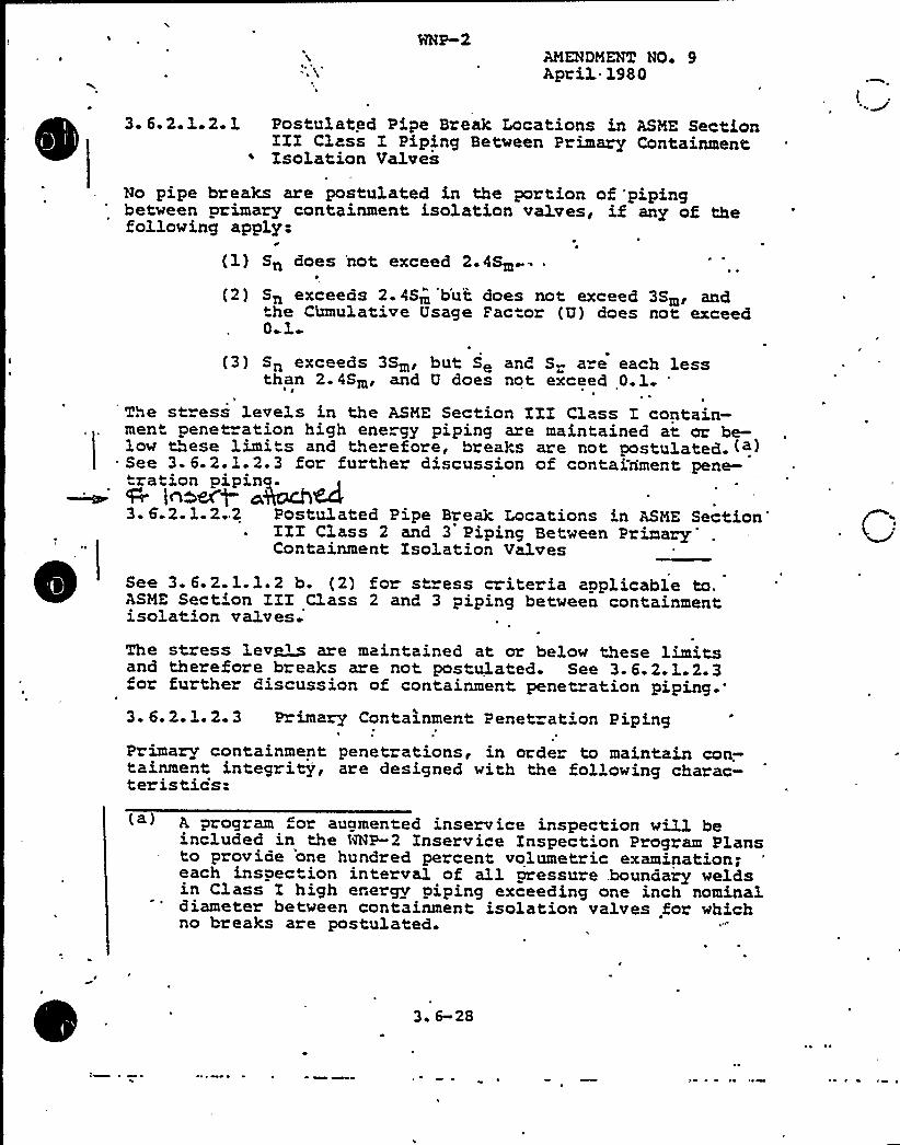
AMENDMENT NO+ 9April 1980
3. 6.2.1.2.1 Postulated Pipe Break Locations in ASME SectionIII Class I Piping Between Primary ContainmentIsolation Valves
No pipe breaks are postulated in the portion of 'pipingbetween primary containment isolation valves, if any of thefollowing apply:
0
(1) Sn does 'not exceed 2.4Sm
(2) Sn exceeas 2.4Sm b'ut does not exceed 3Sm, andthe Cianulative Usage Factor (U) does not exceed0 1
(3) Sn exceeds 3Sm, but Se and S are each lessthan 2.4Sm, and U does not, exceed 0.1
The st ess levels in the ASME Section III Class I contain-ment penetration high energy piping are maintained at or be-low these limits and therefore, breaks are not postulated. (a)
= See 3. 6.2.1.2.3 for further discussion of containment pene-ration pipin-lh~ef o
3. 6.2.1.2..2 Postu1ated Pipe Break Locations in ASME SectionIIIClass 2 and 3 Piping BetweenPrimary'ontainmentIsolation Valves
See 3. 6.2-1.1.2 b. (2) for st ess criteria appLicable to.ASME Section II Class 2 and 3 piping between containmentisolation valves
The stress Lev~~ are maintained at or below these limitsand therefore breaks are not pos ulated. See 3.6.2.L.2.3for further discussion of containment penetration
piping.'.
6.2.1.2.3 P imary Containment Penetrat'on PipingPrimary containment penetrations, in order to maintain con.—tainment integrity, are designed with the following charac-ter is ties:
A program or augmented inservice inspection will beincluded in the ANP-2 Inservice Inspection Program Plansto provide 'one hundred percent volumetric examination;each inspection interval -of all aressure .bounaary weldsin Class I high energy piping exceeding one inch nominaldiameter between containment isolation valves for whichno breaks are postulated
3 ~ 6-2S

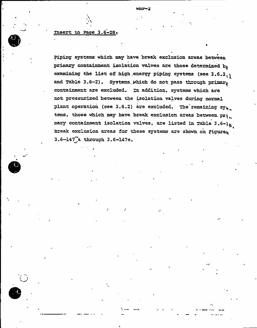
Insert to Pace 3.6-28:
Piping systems which may have brea3c exclusion areas between
primary containment isolation valves are those Petezminect by1!. ! .. ~ pl !.~ ! 6 I,!
an6 Table 3.6-2) . Systems„.which do not pass t"-oughprimae'ontainmentare excluded. ~ acKi~on, systems which are
not pressurizel between the isolation valves Ciurinp normalplant operation (see 3.6.2) a=e exclude6. The remain."~ sy„tems, those which may have brea3c exclusion a eas between. prjmary containment isolation valves, are listed in Table 3.6-)~
IZrea3c exclusion areas for these systems a e shown on pipz eq
3.6-147 a through 3.6-147e.
~ ~

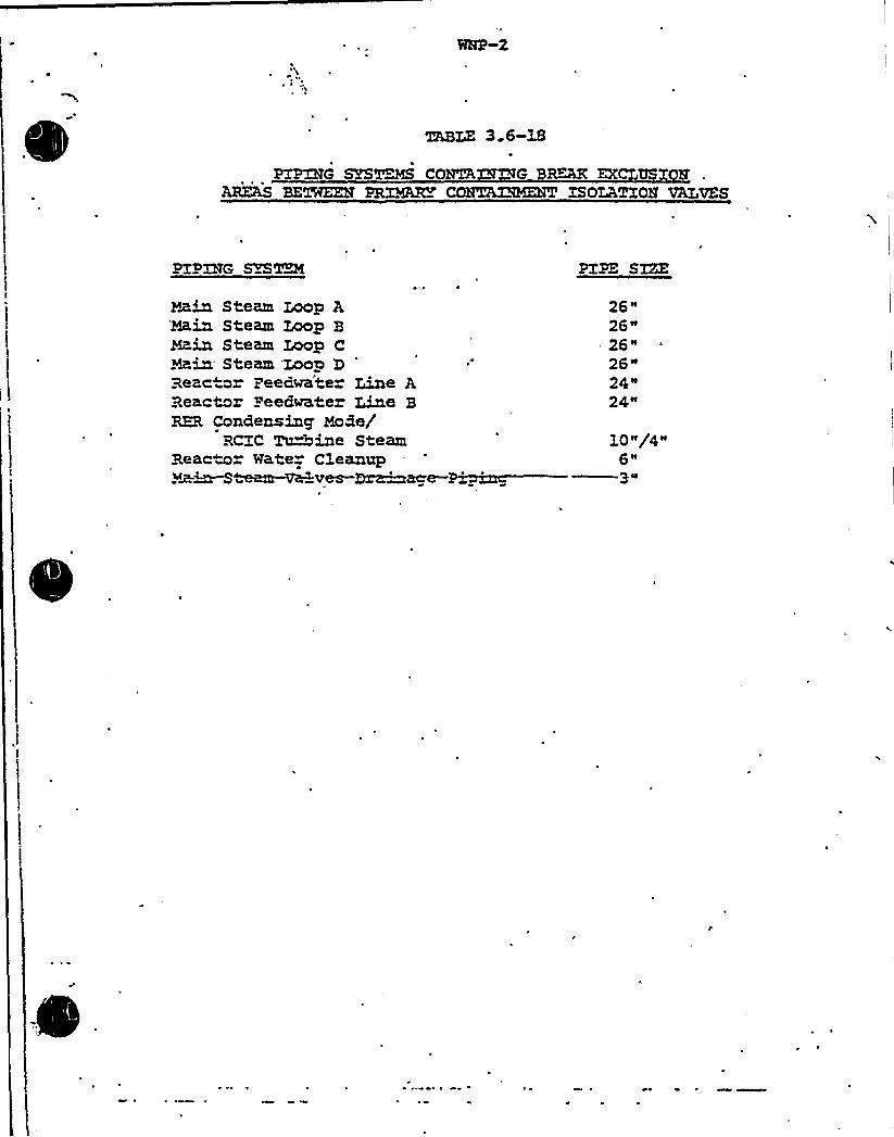
PTERYG
mBLZ 3.6-1B
M~ CONGA G ~~ EX US lfABZAS BETWEEN PR:BQBZ C ISOIATXOM VALVES
PZPXRG PZSTKC
Hain Steam Loop A'Hain Steam Loop 3Ma,in Steam Loop CHain Steam Loop 3Reac or Zeedwate Line AReactor Peedwater Line BRER Condensing MoBe/
RCZC ~ine SteamReactor Nate Cleanup
teem~ ver-E)~age-
26"26"26"26"24"24"
1P~g4~6n$ II

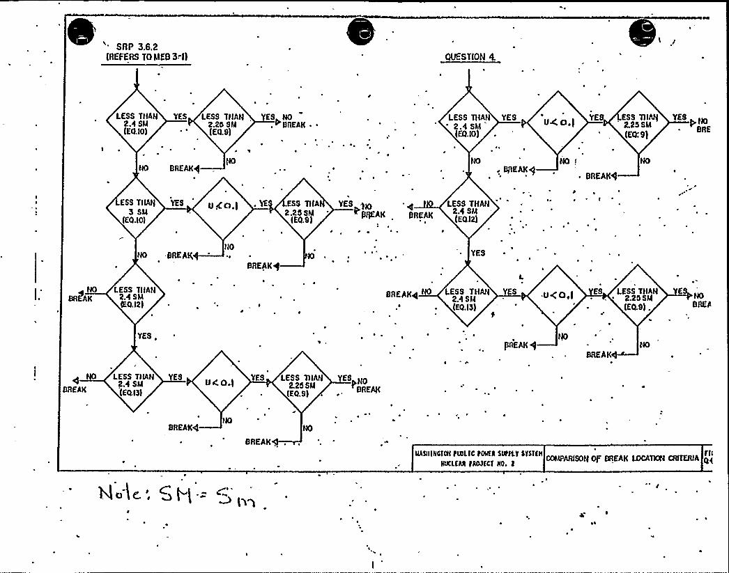
SAP 3.6.2(REFERS TO MES 3<l) OUESTION 4.
\
LESS THAN YES2.4 SM(EQ.IO)
I ~
LESS THAN ES NO2.25 SM . ~ BREAK ~ ~
(EQ.S)
~ ~
LESS TIIAN YES2.4 SM(EQ.IO)
u4 's - Ess THAI( YEsusa I 2.259M(EQ:9)
BREAK/NO NO I
BIIEAK4~ BREAK/
ESS THAII3 SLI
(EQ.IO)
YES u gal ) . YE ESS TIIA YES BIO~ q LESS THAN
2 25SM ~
PIIIIEAK BREAK24 SM
(EQ.S) ~ .. (EQ32)
NO BREAKNO
BREAK
YES
~ NO LESS THANBRfAK 2.4 SM
IEQ.I2)
YES,
BREAKS LESS THAN2.4 SM(EQ. IS)
.u<o,( ES LESS THAN~ . 2.255M
(EQ.s) .
NOBREA
BREAK
LESS TIIAN ES24 SM(EQ.I3)
NOBREAKS
YES LESS TIIAN Y NO2.25 SMIEQ.S)
BREAK
BREAK
IIAQIINlmlPINLIC PSlfR SUPPLY STSTlll FII
e.'~~ 0 4
~ I ~ ~

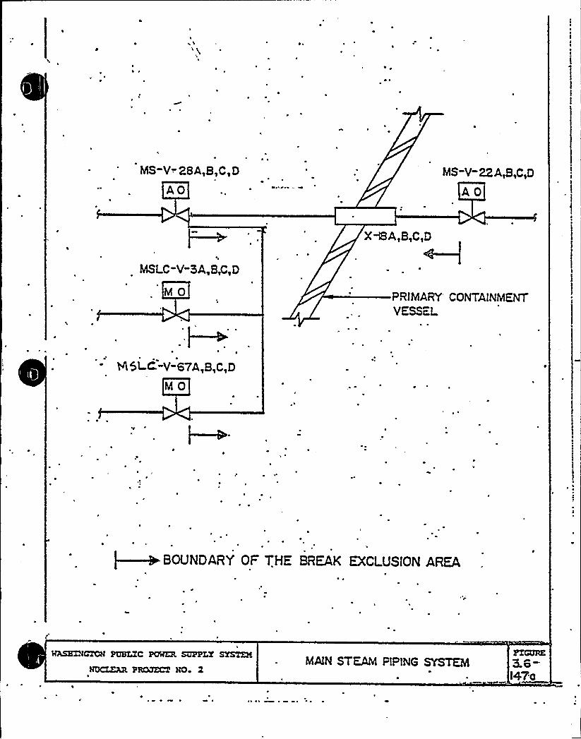
W 1
~ ~
MS-V-. 28A,B,C, D
AO
AS-V-22A,B,C,D
AO
MSLC-Y-3A,B,C,D
PRINIARY'ONTAlNMENTVESSEL.
8 5I-C -V-67A,B,C,D
MO
~ ~
l
~BOUNDARY OF THE BREAK EXCLUSION AREA
WASXZÃGTCÃ PUBLIC POWER SUPPLT SYSTEM
NQCZZAR PBCQZCT NO» 2MAlN STEAM PIPING SYSTEM
FZCQRE3.8-tea

0
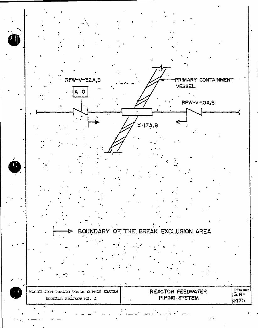
l a
W ~lgl
gl
~O I~ ~ R
01. O' o X'
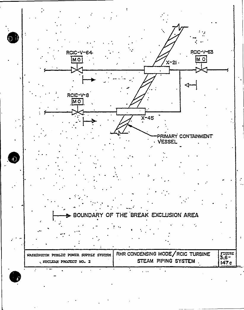
~ ~ 1
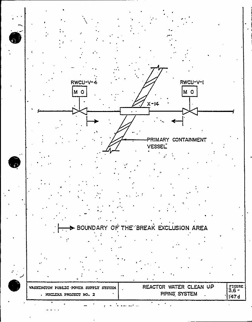
leI
'I
et ~
~ ~
r ~
~ ~
RWCU-Y-4
M 0
RICU-V-I
M 0
X-I4
RIMARY CONTAINMENT
VESSEt
r ~
~e
BOUNDARY OI= THE''BREAK EXCLUSlON AREAI
P
WASKDI~~N PUBLZC 'POWER SUPPLY STS~ XNQ~ PRQJZC~ BO~
REACTOR WATER CLEAN VPPIPING.'SYSTEM
Z'RZ3.6-I47d

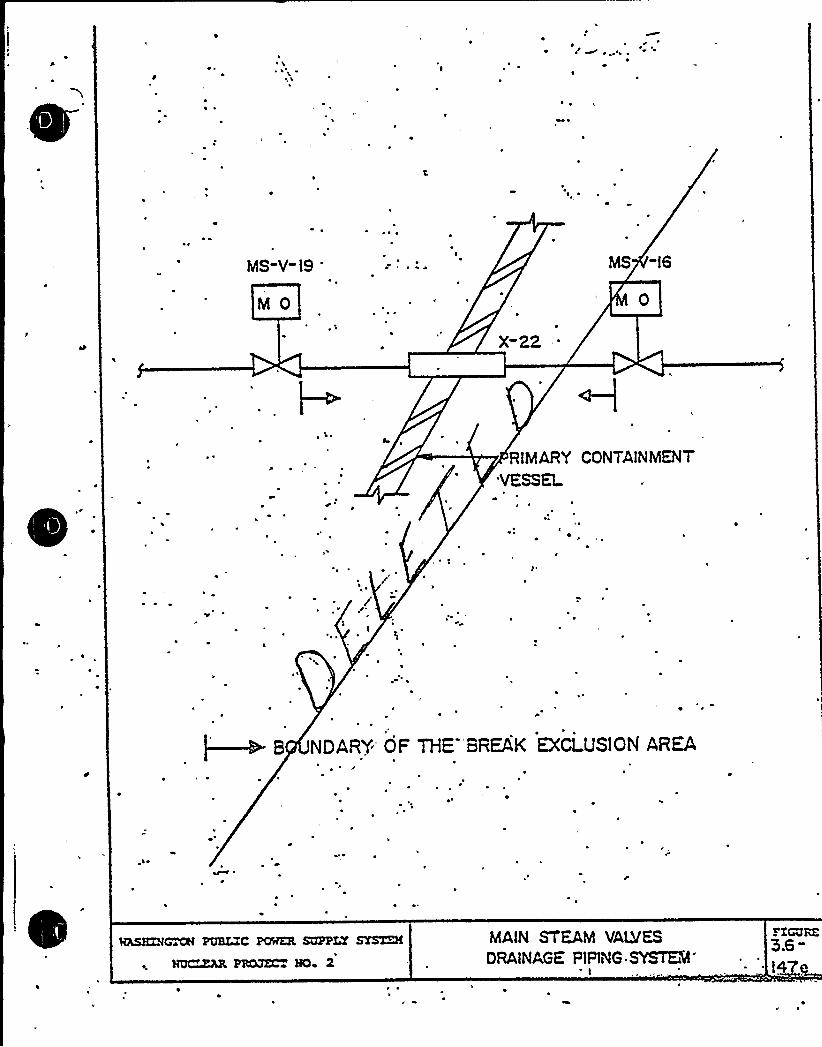
gl, ~
~ g 0 ~ a l ~ k
e x'o' k
' 7

e.- . Any ins ances with limi eP break openings or break opening times exceedingone millisecond must be identifiied. Any analytical methods, representingtest result or based on a mechanistiic approach, used to justify ~ie abovemus be proviided and explained in detail. This appl.ies to con ainment and
arinulus pr„ssurization as well as general pipe break.
Paragraph 3. 6.2.5.4.11 c (Page 3. 6-70) states, "A pipe break in one of thesix lines, '.. unrestrained, may resul: in pipe whip impact with ad„'acentisolation va Ives, possibly renCering hem inopera ive Urther.„ore, unre-strained motion may cause impact «i h other lines, which may result inescalation cf pipe breaks. Such a condition may unacceptably increase theseverity of the -initial pipe break." The way this paragraph is written,it is not apparent that sufficient protection has been provided o precludetne failure conCi:iions discussed or whet,.er these are failure conditionsfor wnich:he protection was'prcviced. Clar'if'.cation di this area isreaues ed:.
Su jec. w resolution of he above open issues, our findings are as ..ollows:
The appl can- ".as proposed "riter'.a for "'etarmining he loca iion, t'ze and
ef i aces of pos ~1 atad pipe brea+" in ihiigh enerov p i ping systems and postulatedpipe cracks in moderate enercy piping sys ems. The applicant has used theef.acts ~ esulting f. A "ese pos.ulatad pipe fa".~ares to evaluate the designb i systems porenets, and str c-ures necessa'-.j o safely shut the plantdown and to mi i gate the ef, ects of these pos la.ed piping ai', ures. The
applicant has stated that pipe whip res ". aints, jet impingemen "arriers, and
other such devices vill be used o mi.igate he effects of these postulated .
piping failures.
'ate have reviewed hese cr'.teria and have concluded that they provide for a
spec -. m of postuiated pipe breaks and pipe .cracks which includes the most
likely locations .or piping. failures, anc hat the 'ypes of breaks ard theireffec s are conservatively assumed. Me find that he ..ethods used to designthe pipe '«hip restraints provice adequate assurance "hat they «ill function
Rene Lil«hiP cR/ B

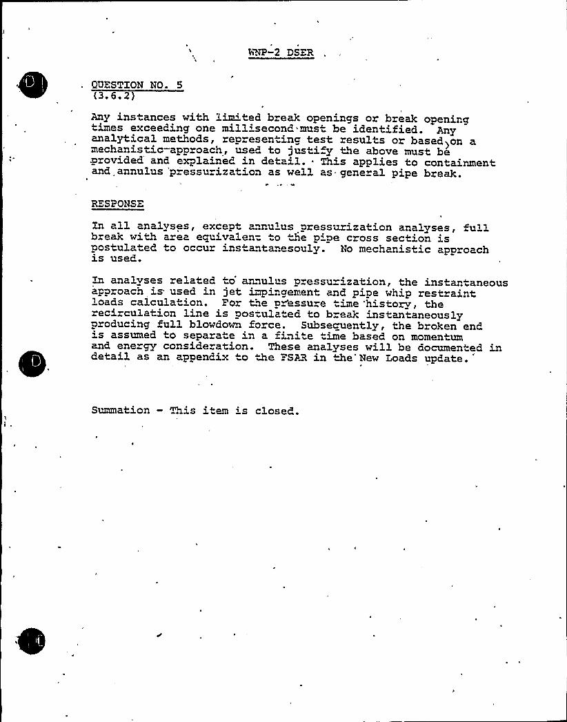
MP-2 DSER
QUESTION NO. 5(3. 6. 2)
Any instances with lim"'ted break openings or break openingtimes exceeding one mill'second must be identified. Anyanalytical methods, representing test results or based>on amechanistic-approach, used to justi y the above must be.provided and explained in detail. ~ This applies to containmentand annulus 'p essurization as well as gene al pipe break.
RESPONSE
In all analyses, except annulus pressurization analyses, fullbreak with area eguivalen= to he p'pe cross section ispostulated to occur ins antanesouly. No mechanistic approachis used.
analyses related to'nnulus p essur'zation, the instan aneousapproach is used in jet impingement and pipe whip restraintbroads calcula ion. For toe pressure time history therecirculation line is pos-ulated to break instantaneouslyproducing full blowdown force. Subsecuently, the broken end's assumed to separate in a ini e time based on momentumand ene gy conside ation. These analyses will be documented indetail as an appendix to the =SAR in the'New Loads update.
Summation — This item 's closed.

p g (MGR-( )
Any instances with limi ed break openings or break opening times exceeding
one millisecond must be identified. Any analytical methods, representingtest results or based on a mechanistic approach, used to justify Ne above
must be provided and explained in detail. This applies to con ainment and
annulus prgssurization as well as general pipe break.
Paragraph 3. 6. 2.5.4.13. c (Page 3. 6-70) s ates, "A pipe break'n one of the
six lines, ii unres rained, may resul. in pipe whip iripact with ad„-:ace..
isolation valves, possibly rendering hem incpera ive ~ ur hermore unre-
strained motion may ca~se impact wi h otner lines, which may result inescalation of pipe breaks. ~ Such a condition may unacceptably increase the
severity of the-initial pipe b~eak." The way this paragraph is written,it is not apparent that sufficient protection has been provided to precludethe fai'iure condi .ions discussed or whether these are iai lure condi ions
ior which .he protection was'provided. Clar'ification af this area isreouested.-
Subjec. to resolution of the above 'open issues, cur findings are as :ollows:
The applican=, ".as proposed "ri er'.a for =e-e~ining "he location, t;ae and
efiec s of postulaied pipe breaks in h'.gh 'energy p~iping systems and postulated
pipe cracks in moderate energy 'piping sys ems. he applicant has used the
ef acts esul ting i r"m these postul ated pipe f.-"res to eve.l uata the desi gn
bf SYSTems ~ mponenets, and st. uc ur 5 aces sa J o sa ~ ely shut the pl ant
down and .o mi igate the ef ects of "hese pos ula.ed piping ailures. The
applican7. has stated that pipe whip restraints, jet imp'.ngemen. barriers, and
other such dev'.ces «ill be used to mi.igate the effects of these postulated .
piping iaiilures.
Me have reviewed hese criteria and have concluded that they provide for a
spec rum of postulated pipe breaks and pipe. cracks which includes the mos
likely loca-ions ior piping failures, and hat the 'ypes of break- ard theireffec.s are conservatively assumed. 'rfe find that he,.ethods used to design
the pipe '«hip restrain s provice adequa a assurance hat they «ill function
Re..e Li/'~NP ScRiB
3.6 2 L'e e~a~on o= ~ah >~ca~'ons and ~mac =~ ecmAssoc'ate'id ""e P s ~a= 8 Real-.e of >z>c
Que~on 6 ~
-zpam6 paz~~ph 3 6.2 5 4 LLc. M p~vMe assa~ce ~ sn~-~c~ en pm'~'can has been. ~vs M pxecLuKe ~>e pipe
hwak, Garage o m~w steam M =sacer =eecva ~ pip~t"e maw st ~e~.Resoonse:
Please ~~a ~m ev~ec. 3.6 2 ~ 4 ~~ ~ ~e ~ess W
ation — ~~is item is closet+
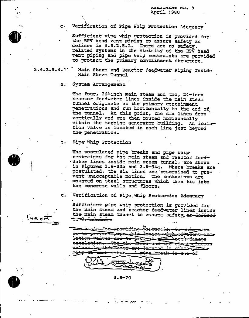
Ca Ve i"ication of gripe Whip Protec 'on Adequacy
Suffic'ent-pipe whip protect'on is provided for".the RPV head vent piping ~w assure safety asdefined in 3.6.2.5.2. There are no safety.related svstems in the vicinity of the RPV headvent piping and pipe wh'p -rest=aints are providedto protect the primary containment st=ucture..
3.6.2.5.4.11 'Hain Steam and Reactor Peedwater Piping Inside, Main Steam Tunnel
a 4
~ 4 4
System Ar angemen
he four, 26-'inch main steam and two, 24-inchreactor feedwater lines ins'de the main steamtunnel origina"e at De wimarv containmentpenet=ations and run horizontally to the end ofthe tunnel. A this point, the six 1'nes dropver&cally and are then routed horizontallywithin the turbine generator bu'lding. An isola-tion valve is located in each line just beyondthe pene~tion-
b P'pe Whip P otectionhe pos ulated pipe breaks and pipe whiprestraints for the main steam and reactor feed-
s wa e lines inside main steam tunnel, are shownin Pigures 3.6-33a and 3.6-34a Where breaks arepostulated, 2e six lines are rm -ained to pre»vent unacceptable motion. The restraints aremounted on steel structures which then tie intothe conc ete stalls and floors.
t NScv(
Ce Ve ification of P'pe. Whip Protec 'on Adequacy
Suffic'ent. pipe whip prote tion is provided forthe main steam and reactor feedwater lines insidethe. main steam ~mnnel to assure safety„
44
»4»4» ~l
3.6-70
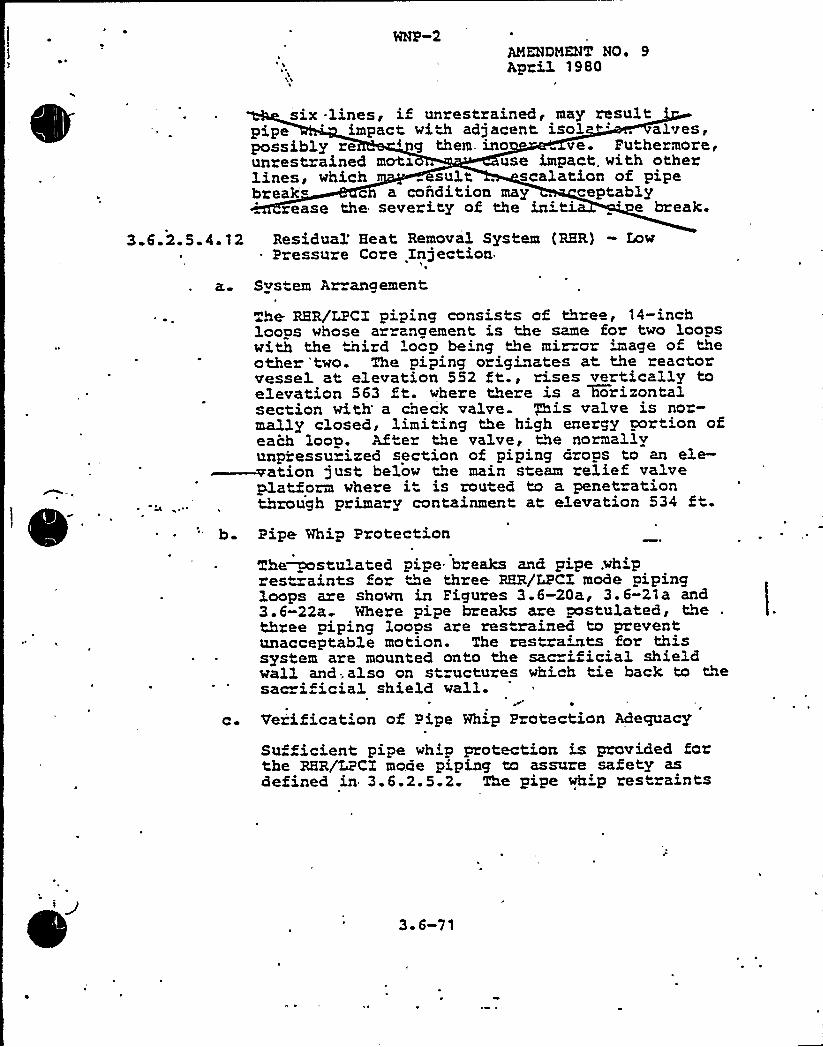
AMENDNENT NOe 9April 1980
six lines, if unrestrained, may resultpipe 'mpact with adjacent isol ~' alves,possibly re 'ng them, ino ve. Puthexmore,unrestrained mo<x use impact. with otherlines, which suit . scalation of pipebreak~ c a condition may . ceptably
rease the severity of the in'i „' break.
3.6.2.5.4.12 Residual'eat Removal System (RHR) — LowPressure Core Injection
s'
a. System Ar angement
The. RHR/LPCI piping consists of three, 14-inchloops whose ar angement is the same for two loopswith the third 'ocp be'ng the mix or wage of theother 'two. The piping originates at the reactorvessel at elevation 552 ft., rises vertically toelevation 563 ft. where there is a Worizontalsection with' check valve +is valve is nor-mally closed, limiting the high energy portion ofeach loop. After the valve, the normallyunpressurized section of piping dxops to an ele-~ation just below the main steam relief valveplatform where i" is routed to a penetrationthrough primary containment at elevation 534 ft.
b. Pipe Whip Protection
The~stulated pipe breaks and pipe .wh'prestraints for the three RBR/ZPCI mode pipingloops are shown in Pigures 3.6-20a, 3.6-21a and3.6-22a Where pipe breaks are postulated, the .
thxee piping loops are res rained to preventunacceptable motion. The restra'its for thissystem are mounted onto the sa.c=ificial shieldwall and;also on structures which tie back to thesac i icial shield walL.
c Verification of Pipe Whip Protection Adequacy
Su ficient pipe whip protection is provided forthe RHR/LPCI mode piping to assure safety asdefined in 3.6.2.5.2 The pipe wh:p restraints
3 ~ 6-71
P
„Insert: to Pace 3.6-70:
Pipe whip est=ain s are provided to prevent pipe whipimpact with the main steam or feedwater isola ion valves.Ll addition impact with adj acen main steam or feedwatez
4 ~- *C
es is prevented. Refer to Pigu=es 3.6-6g ""«ough 3.6-6R.

~ *
g rg
ps<a s.c. z(j) (se-8-3Q
si~ad frequencfas, assassmant was made by the epplfcant and shown to eeet 'the
requfments'f Regulatory Gufda.1.SL
Tha absolute sum (ABS) of tm earthquake components of the maximum codfroctfonalresponses was used instead of SRSS of three components of the earthquake cationfor both the fce hfsto~ and response spectrum. methods. Comparfsops of theresults obtained fan both the ABS.and SRSS methods were made by tha applicantand it was demonstrated that for all frequencies larger than 1.25 Hz tha A8$
method used by the applicant is conservative. This finding is acceptable tothe staff. since the frequency range of interest/concern in MAP-2 Category Istructures and systems is always larger than 5 Hz.
The present technical'osition of the staff requires that the accidentaltorsion, minimum of & of the base dimension, be included in the design ofstructures. This is in addition to that which results from the actual geometry
and mass dfstributfon of the building. In response to staff request, thoapplicant provided calculation of design margin accounting for tha accfcLntaltorsion for all Category I structures .and showed that even for the structurosAth the lowast design eergfn, the factor safety values change by lass than 2K
and are still zdaquata. This is acceptable to the staff.I
Floor spectra inputs used for design and test verifications of structures,systens, and aaponents were generated from the time history method, takinginto account, variatfon of parameters by'peak widening. A vertical safscdcsystem dynamic analysis is'mployed for all structures, systems, and components
where analyses show significant structural amplification fn the vartfca'l.direction. Torsional affects and stybflity against overturning ara consfdorod.
The lcc33ped |Ms~ring method was used to evaluate soil-structure fntaractfonand structu interaction effects upon saisnfc rasponsos. Heaver,the current-staff position regarding the soil-structure interaction roqufras,in addition.to tha usa of elastic half-space approach, the use of ffnfta element
method. The applicant provided tha aayarfsons of the original soil springanalysis versus th finfta element approach at different key locations in the
reactor bufldfng Gnd concluded that the sof1 spring analysis results onvelop
those flea the ffnfte aleaent method. Furthermore, the applf~edH parfom.
the analysis using the ~ different methods for radwaste building and submitthe results by November X3, 3981.for staff revi~ and acceptance.
\ I
r
The applicant used the equ)valent static ~lysis for the spray ponds retainingmll and slabs'ommitted to,provide analysis procedures and calculationsdemonstrating the conservatism of the 488thod Ltsed for staff ~vi8ht-and
The acceptance of the applicant's seismic system and subsystem analysis ispending on the resolution of the above cited items.
3.7.4 i Instrumentation Pro am
The type, number, location, and utilization of strong motion accelerographs torecord septic events and to provide data on the'frequency, amp1itude, and phase
relationship of the seismic response of the Category I structures comply vfthRegulatory Guide 3 I2. Supporting instrumentation is .being.installod on
Category I structures, systems, and components in order to provide. data'or theverification of the seismic responses determined analytically for such Category Iitems.
The installation of the. specified seismic instrumentation in the reictor con-,tainment structure and at other Category I structures, systems, and auponentsconstitutes an acceptable program to record data oq seismic ground -cotion as
well as data on the frequency and'amplitude relationship of the response of~or structures and systems. A prompt readout, of pertinent data- at the controlroom can be exp'o yield sufficient information to guide'.the operator on atimely basis for the purpose of evaluating the seismic responses in the evontof an earthquake.'ata obtained from such installed seismic instrmentationvill be sufficient to determine that the seismic analysis assumptions and theanalytical model used for the design of the plant are adequate and that'alliablestresses are.not exceeded under conditions where continuity of operation isintepded. Provision of such seismic instrumentatioh complies with RegulatoryGuide 1.X2.
7
WNP-2
Open SER Issue .
3.7.3(b) S ra Pond Anal sis Retainin Wall Conservation (SEB-32)
A response to this issue was submitted December 14, .1981, by letternumber G02-81-518.
IhIS I.r'TTKR lQOESI tDOES NOT) ESTAGI.ISH A NEYf CQ,'lbhlT.'RENT- NPI ~
BgR @Pss coanisPohoENcz No.
- HUS'
DKL
bcc: EF Beckett'OK Earle',J'lunkett
NS ReynoldsWNP-2 Fi 1 es
GD Bouchey - 370BA Vo1 luerg - 906DRG Matlock - 901ARH Nelson - 906DGC Sorensen' 340
Waddel - 405ket File .
rono File Docket No. 50-397I y or - 9060 \
r — 370 December 14. 1981BAH/LB - 906D G02-81-518GCS/LB - 440 SS-L-02-CDT-81-109
LB
Qf 2)
e — 410PL Powetl — 906Df/ eMH 8
Mr. A. Schwencer, ChiefLicensing Branch No. 2Division of Licensing
.U.S. Nuclear Regulatory Commission'Washington, D.C. 20555
Dear Yr. Schwencer:t
'Subject: NUCLEAR PROJECT NO. 2* OPEN ITEMS FROM SEB MEETING
Attached are sixty copies of the open items from the Structural Engineer-ing Branch meeting held in Woodbury, New York, October 5 - 8, 1981.
Very truly yours,
D'.
D. Bouchey, Deputy DirectorSaf ety a nd Sec ur i ty
CDT/rchAttachments
cc: R Auluck - NRC
WS Chin - BPAR Feil - NRC Site
SECTION
THOR~ vlor GD8 h
PIIOV
APPROVED l
DATE
el son A o ber GC orensen

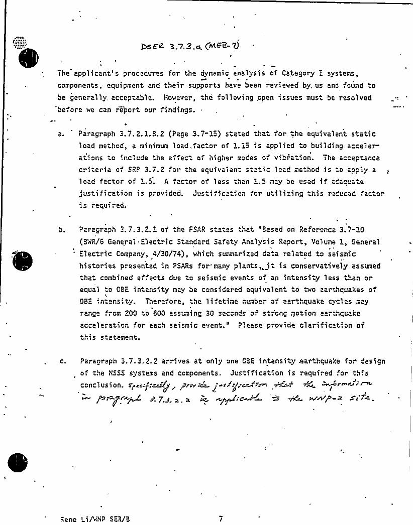
The applicant's procedures for the dynamic analysis of Category I sys ems,
components, equipment and their supports have been r viewed by, us and ound tobe cenerally accep-able. However, the following open issues must be resolved
'before we can repor our findings.
Paragraph 3.7. 2. 1. 8. 2 (Page 3.7-1"-) stz ed the. or he eouivalent s a icload method, a minimum load,fac or of i.i5 is applied o building,accelerations to encl de he effect of higher modes of vibrat>on. ihe ac™ep-ance
criteria o- SRP 3.7.2 for the equivalent sta i" loa me hcd is o app>y a
load factor of 'i.5. A factor of less than i.= may be used ir a"'eq atejustification is provided. Jus i ication for v ilizing this reduced fac.ori s required.
Paraciaph 3. 7. 3. 2 1 of he FSAR states that "Hased on Referer ce 3. 7-10
(BMR/6 General Elec ric Standard Safety Analysis Report, Volume i, General
Electric Company, 4/30/74), which summarized daia ".elated to seismichistories presented in PSARs for'many plants,. it is conservatively assumed
tha.. combined effects due to seismic events of an intensi y less than or
equal o OBE in ensity may be considered equivaien. o two ear hquakes oi
0BE ', n-ens', '. I heref ore, the 1 i -, ctime number "= ear+i quake yc. es may
rango ,". om 200 to 600 assuming 30 sec"nds of s ".'ong motion aar:h"'i'eacceleration for each seismic event." Please provide clarificat'.on of-",is s atemen".
C. Paraoraph 3.7.3.2.2 arrives a only one GBE intensity .ear.hquake for "esignof the NSSS systems and components. Justifica ton is required for th.s
~p n ~ii.~collclus i on. Spec,: j,~g prwr~ ~sAt; ~Pr Pc ~l ~. 7.g . g ~ gpss'cW~ ~ W awe-z sc f4.

QUESTION NO. 7
Provide justification for utilizing the load factor of 1.15for the equivalent. static load method. The acceptance criteriaof SRP 3.7.2 for the equivalent static load method is to applya load factor of 1.5.
RESPONSE
a. Paragraph 3.7.2.1.8.2 has been revised to clarify thealternate simplified method of analyses. (See attachedrevision).
b. A summary from the study performed to verify the adequacyof the alternate simplified method is attached.
Summation — This item is closed.
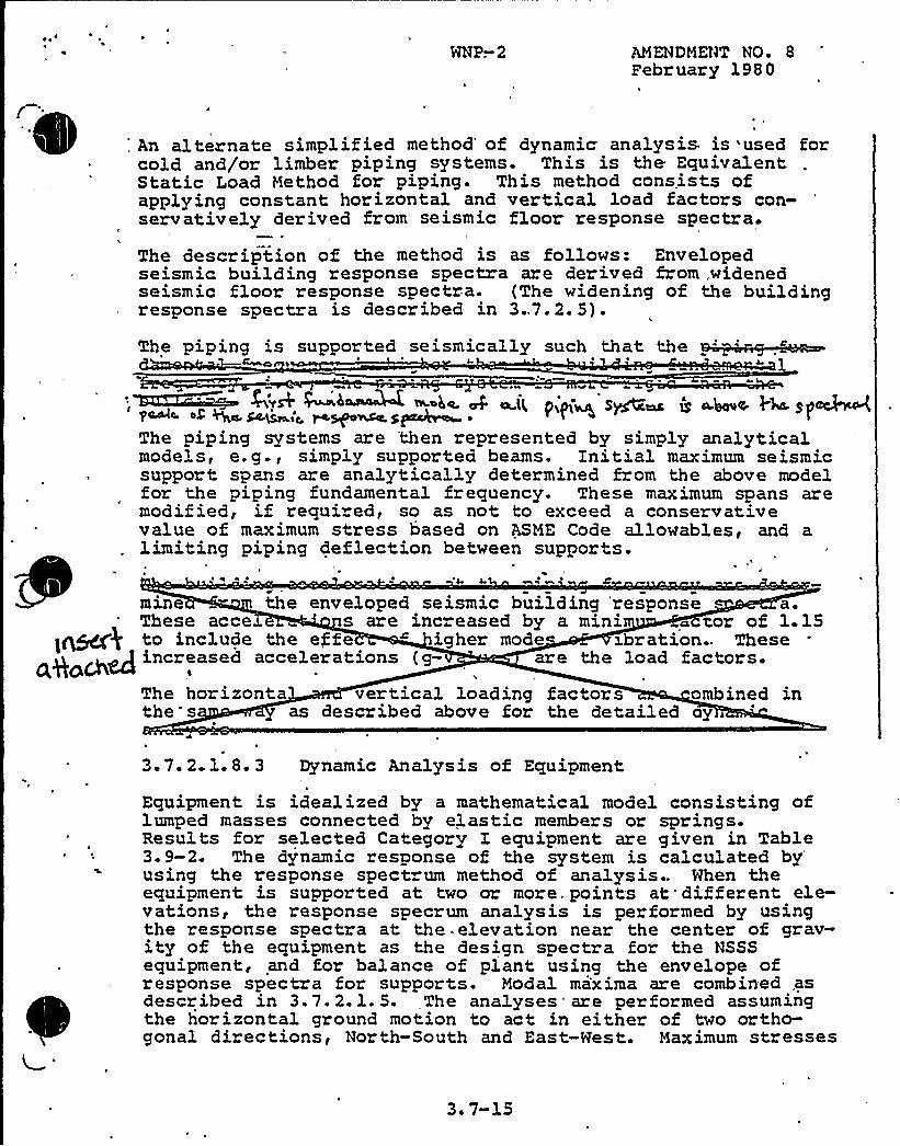
~ ~~
NNP-.2 AMENDMENT NO. 8February 1980
: An alternate simplified method'f dynamic analysis is used forcold and/or limber piping systems. This is the EquivalentStatic Load Method for piping. This method consists ofapplying constant horizontal and vertical load factors con-servatively derived from seismi.c floor response spectra.
The description of the method is as follows: Envelopedseismic building response spectra are derived from,widenedseismic floor response spectra. (The widening of the buildingresponse spectra is described in 3.,7.2. 5).
p'p' 'ly d' 1|y h th th
4 1
~ h~ A ~i< pip~ s~~ ~ ~~~ ~~Spcb<'~~ ~> ~s 6:a m~~sp~ ~
The piping systems are 'then represented by simply analyticalmodels, e. g., simply supported beams. Initial maximum seismicsupport spans are analytically determined from the above modelfor the piping fundamental frequency. These maximum spans aremodified, if requi ed, so as not to exceed a conservativevalue of maximum stress based on ASME Code allowables, and alimiting piping deflection between supports.
k
~ e e ~ I ~ ~
mine the enveloped seismic building 'response asThese acce ' are increased by a mini ~ d'or of 1 15to inciude the effe igher m d xhration. These
J increased accelerations (g are the load factors-The horizonta t cal loading factors ombined inthe s as described above for the detailed oy
3.7. 2.1. 8. 3 Dynamic Analysis of Equipment
Equipment is idealized by a mathematical model consisting oflumped masses connected by elastic members or springs.Results for selected Category I equipment are given in Table3.9-2. The dynamic response of the system is calculated byusing the,. response spectrum method of analysis.. Nhen theequipment is supported at two or more points at different ele-vations, the response specrum analysis is performed by usingthe response spectra at the. elevation near the center of grav-ity of the equipment as the design spectra for the NSSSequipment, and for balance of plant using the envelope ofresponse spectra for supports. Modal maxima are combined .asdescribed in 3.7.2.1. 5. The analyses are performed assumingthe horizontal ground motion to act in either of two ortho-gonal directions, North-South and East-Nest. Maximum stresses
3. 7-15
MNP-2 AMENDMENT NO ~ 9April 1 980
resulting from any one horizontal or vertical excitation areconsidered to act simultaneously and the absolute values areadded directly, as described, in 3.7.2.6 and 3.7.2..7.
The relative displacements between .anchors are determined fromthe dynamic analysis of the structures. All cases of relativedisplacement between anchors are considered. If significaht,these relative displacements are then used in a static analy-sis to determine additional stresses imposed on equipment.Purther details are given in -3;7:2.1.8.3.1 for the NSSS equip-ment,and 3.7.3.9 for all other equipment. The cases where therelative displacements between anchors are insignificant and
3. 7-15a
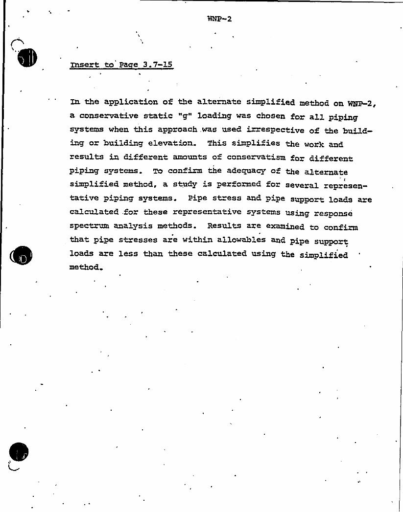
Insert to pa e 3.7-15
~ the application of the alternate simplified method on ~2,a conservative static "g" loading was chosen for all pipingsystems when this approach,was used irrespective ofing or building elevation. This simplifiesresults in different amounts of conservatism for differentpiping systems. To confirm the adequacy of the alternatesimplified method, a study is performed for several represen-tati.ve piping systems. Pipe st=ess and pipe support loads arecalculated for these representative systems using responsespecMm analysis methods. Results are examined to confirmthat pipe stresses are within allowables and pipe supportloads are less than these calculated using the simpmethod

WNP-2
JustificationA study was .conducted to demonstrate that the equivalent staticanalysis criteria employed on WNP-2 is conservative as compared,to.response spectrum analysis methods.A.
B.
C.
D.
AaoroachDynamo.c response spectra analysis was performed on thesample problems. The results from the equivalent staticmethod and response spectrum method were compared.
Pi in S stems Studied *1. Six (6) Seisin.c Category I piping systems w'ere
selected as representative systems.2. The piping systems chosen represent a variety of
sizes from 3" to 24" pipe diameters.3. Two svstems were chosen from each of the Seismic
Category I structures; the Reactor Building, theService Water Pump House and the Diesel GeneratorBuilding.
Results of the StudThe results of the equivalent static analysis and theresponse spectrum analysis were compared for each pipingsystem studied and is summarized as follows:1. Where piping system design was established by the
equivalent static analysis criteria, analyses usingthe response spectrum method have shown that stressesare well within code allowables in all cases.A total of 192 pipe supports were compared. Asummary of Support Loads for 30 of the 192 supportsis shown in Table 1 and lists in ascending order theload ratio for the five (5) supports with the smallestload ratio in each system. The minimum ratio (loadratio) of equivalent static method/response spectrummethod, shown in Table 1 is 1.80.
ConclusionThe Equivalent Static Analysis Criteria used in pipinganalysis on the WNP-2 project is conservative and providesan adequate basis for piping system design.
2.
Additional considerations factored into the study to ensure thatthe six systems chosen for study represent a conservative basisfor comparison:(1) Piping systems located at higher elevations in the building
were 'chosen for study, since seismic response spectraat higher elevations are larger, in order to represent aconservative basis for comparison.
(2) Piping systems which are extensive in length and therebyexhibiting a variety of configurations and spans werechosen.

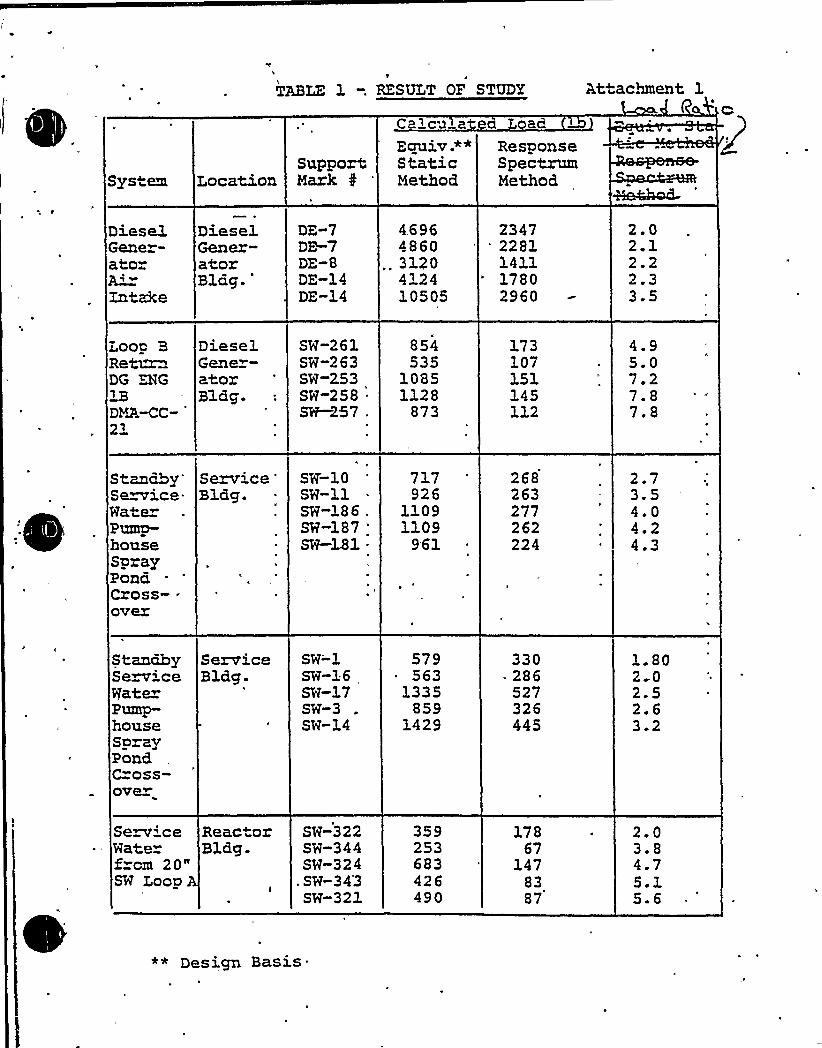
1
TABLE 1 -. RESULT OP STUDY
C lcu at a L ad
At achment 1
Sys"em LocationSupportMark
Equiv P*StaticMethod
ResponseSpectrumMethod
Diese1Gener-atorAZntzke
DieselGener-atorBldg.'E-7DE-7
DE-8DE-14DE-14
4.6964860
.. 31704" 2410505
2347" 2281
141117802960
2.02.12.22.33.5
Loop BRet~DG DG1BDMAMC-
DieselGene-atorBldg.
SW-261SW-263SW-2.53SW-258SW—257 .
854535
10851128
873
173107151145112
4.95.07.27.87.8
StanahySemice-WaterPump-houseSprayPonaCross- ~
over
Service'lag.SW-10SW-llSW-186 .
SW-187 .
SW-181 .
717926
11091109
961
268263277262224
2.73.54.04.24.3
StanahyServiceligulatePump-houseSprayPondC=oss-over
ServiceSlag.
SW-'1SW-16SW-17SW-3SW-14
579563
1335859
1429
330286527326445
l. 802 02.52.63.2
ServiceMate»f cm 20"SW Loop
Reac orBldg.
SW-322SW-344SW-324
.SW-34'3SW-321
359253683426490
17867
1478387
2.03.84.75.15.6
** Design Basis'

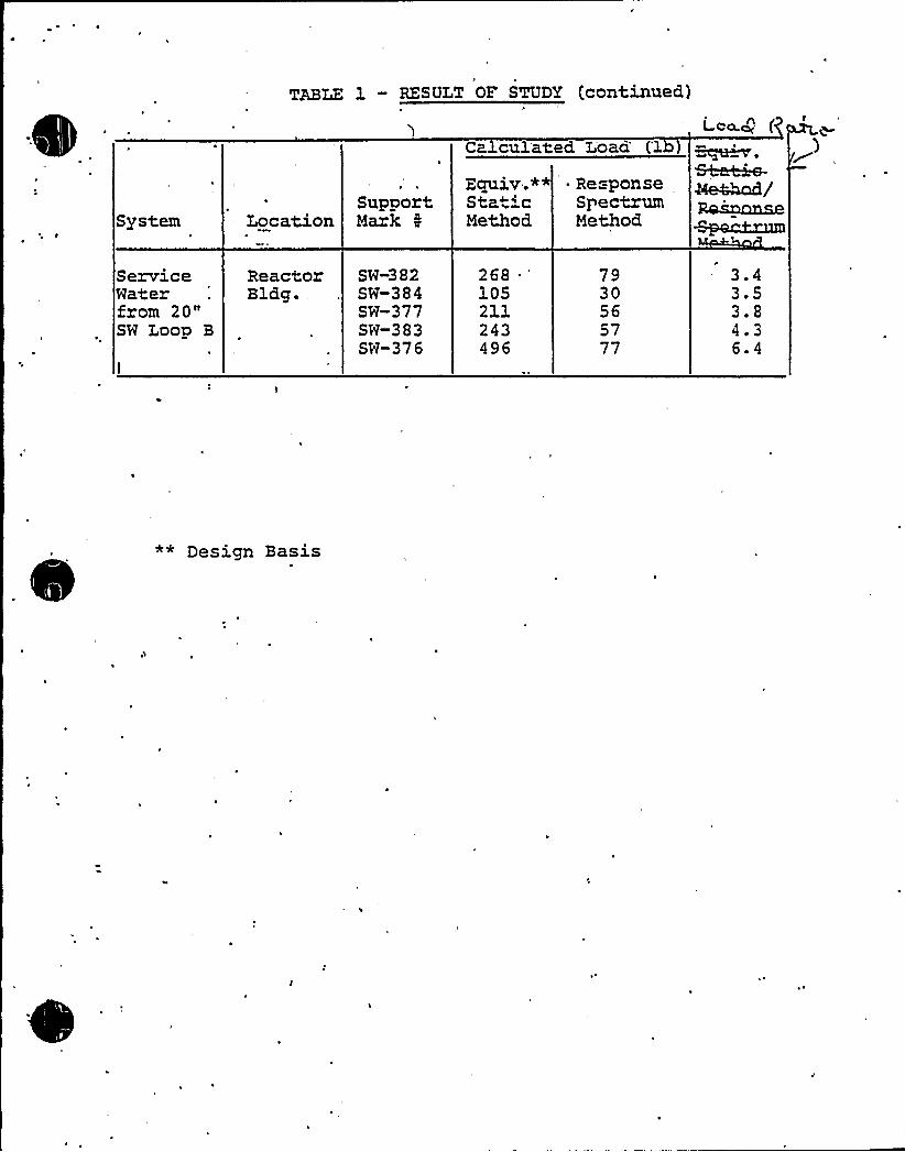
F
TABLE 1 « RESULT OF STUDY (continued)
Ca 'culated Loaa''lb)Lca.cg (
System LocationSupportMark 0
Equiv.** . ResponseSta 'c SpectrumMethod Method
&ha~Ae44nd/Roam~
ServiceWaterfrom 20"SW Loop B
ReactorBldg.
SW-382SW-384SW-377SW-383SW-376
268 *
105211243496
7930565777
3.43.53.84.36.4
** Design Basis

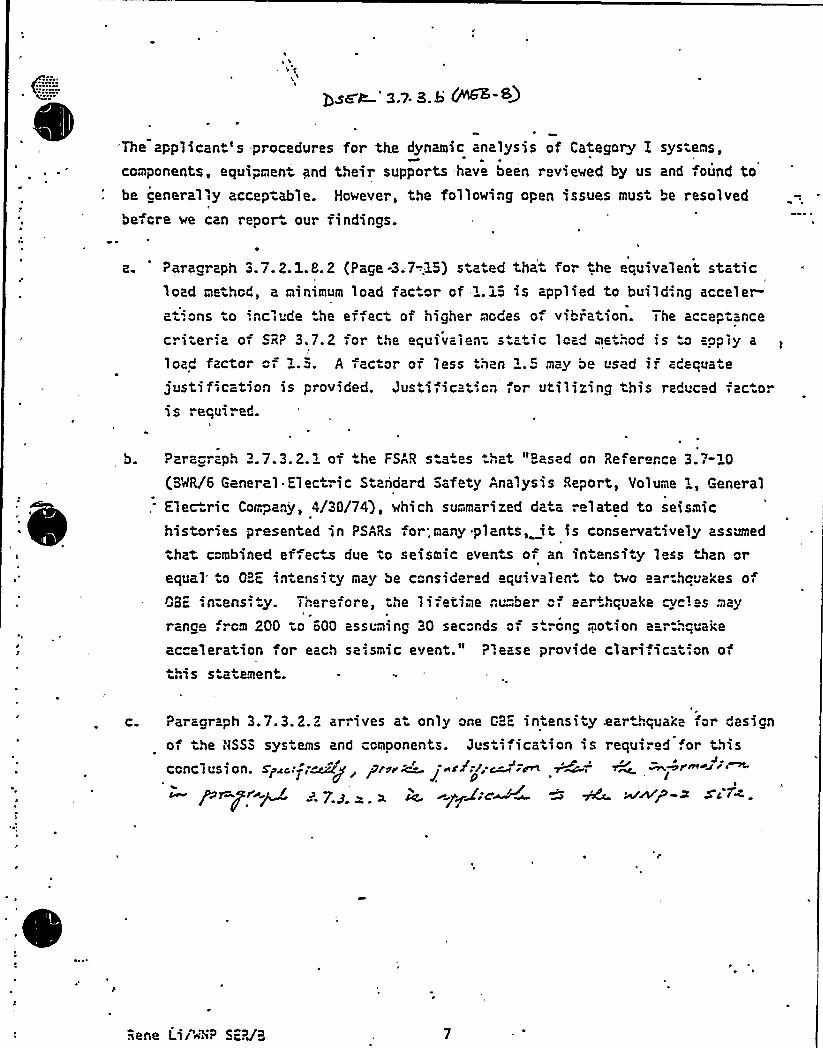
The applican 's procedures for the dynamic analysis of Category E systems,
components, equipment and their supports have been reviewed by us and found tobe cenerall>y accep-able. However, the fallowing cpen issues mus be resolvedbefore we can repor our findings.
Z '0 Paragraph 3.7. 2.1.8.2 (Page -3.7-..15) s z ed that for he equivalent staticload method, a minimum load fac cr of 1.15 is applied to building accelera> Qns to inc >ude he ef > ect af higher mcdes of vibration. The ac"eptancecriter',a of SR? 3,7.2 >or the equivalen- s atic lca" me .'",cd is a acply a
load factor c> 1.5. A >actor of less han 1.:" may be used i. acequate
justification is provided. Jus ifica icn >or utilizing his redvc d ac ar1 s requl . ed.
b. ?ara"raph 3.7.3.2.1 of the FSAR s a es > at ased on Refer rce 3.7-10(B'r/R/6 General Electric Standard Safety Analysis Report, Volume {, General
Elec ric Ca{rpany, 4/30/74), which summarized data related ta seismic
histories presented in PSARs for'.many plants, it is conservatively assumed
tha combined effete due to seismic events of an intensi y less ~San orequal a OBF intensity may be considered equivalen o two ear:hcuakes 0>
~JaE:n-ensi y. Therefore, the 1 ', fetime n{ "ber c ear+> quake r{ 1 as may
range,",cm 200 to 600 assuming 30 sec"nds af s rcng motion ear--.quake
acceleration for each se>smic event." ?',ease provide clari;icatian ofthss s atemen .
c ?aragra~h 3.7.3.2.2 arrives a only one GBE intensity.ear ".qua>;e far designof the NSSS sys ems and ccmoonents. Jus ifica ion is required '.or thisccnclusi on. s~ic..-,-w'~ r,ar~v ~ / i~:r:c-
ra /pr pri~< v y + ~ ~ y~g:cW~ ~ ~ aA'p-2 sa >4.
Rene Lir"~"i? SE?/3

1,l
WNP-2 DSER
'QUESTZON HO. 8'(3 7.3)
Provide clarification of the statement, in Paragraph 3.7.3.2.1of the PSAR,— "Based on Reference 3.7-10, which summarized datarelated to seismic histories presented in PSARs for many plants,it is conservatively assumed that combined effects due, toseismic events of an intensity less than or equal to OBEintensity may be considered equivalent to two earthquakes ofOBE intensity. Therefore, the lifetime number of earthquakecycle may range from 200 to 600 assuming 30 seconds of strongmotion ear&quake acceleration for'ach seismic event".
RESPONSE
See revised 3.7.3.2.1 of PSAR.
. Summation — This item is closed.
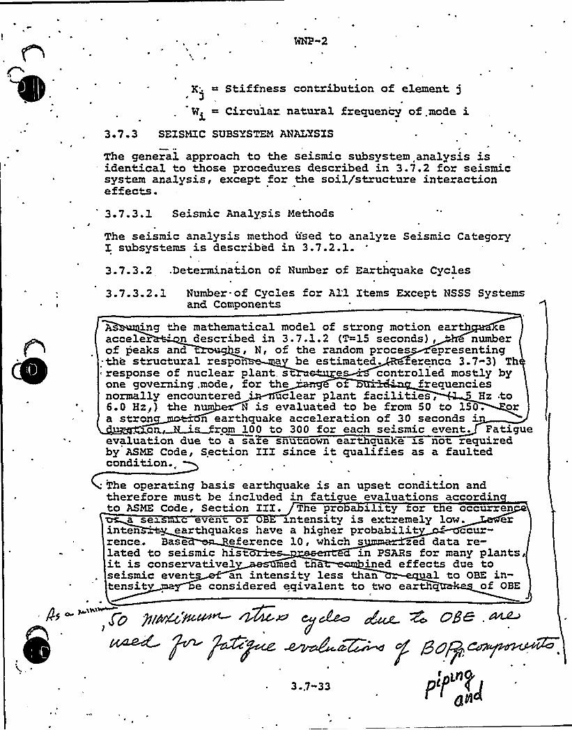
\ ~
I
HNP-2
K' Stiffness contribution of element j3
Wi Circu3.ar. natural frequency of.mode i3 ' 3 SEXSMXC SUBSYSTEM ANALYSIS
The general approach to the seismic subsystem analysis isidentical to those procedures described in 3.7.2 for seismicsystem analysis, except for the soil/structure interactioneffects.
3.7.3.1 Seismic Analysis Methods
The seismic analysis method used to analyze Seismic CategoryX. subsystems is described in 3.7.2.1.
3.7.3.2 .Determination of Number of Earthquake Cycles
3.7.3.2.1 Number of Cycles for All Items Except NSSS Systemsand Components
As ing the mathematical model of strong motion earth eacceler ' described in 3.7.1.2 (T=15 seconds), " numberof peaks and s, N, of the random proces epresenting
~ the structural respon a be estimated. erenca 3.7-3) Thresponse of nuclear plant s es 'ontrolled mostly byone governing, mode, for the ' ' frequenciesnormally encountered uclear plant facilities, Hz to6.0 Hz,) the n N is evaluated to be from 50 to 150. ora stron ' earthquake acceleration of 30 seconds i
an.,~~~rom 100 to 300 for each seismic event. Fatigueevaluation due to a sa e s u aown earthquake xs not requiredby ASME Code, Section IXX since it qualifies as a faultedcondition. „
The operating basis earthquake is an upset condition andtherefore must be included in fati ue evaluations accordinto ASME Code, Section XXI. T e pro abx3.sty or e occurren
a sex c even ox zntensity is extremely low. erinten earthquakes have a higher probabilit ~ ccur-rence.. Base eference 10, which s zed data re-lated to seismic histo in PSARs for many plants,it is conservativel med tha ined effects due toseismic event an intensity less than ual to OBE in-tensit e considered eqivalent to two earthq of OBE
Fo Pi~~~'~~ y~ ~ >ge ~~)
3733ply

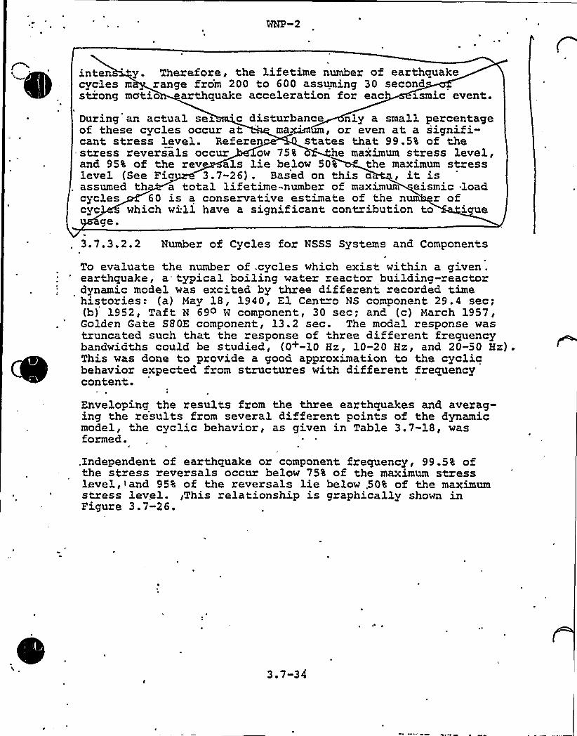
inten '. Therefore, the lifetime number of earthquakecycles m range from 200 to 600 assuming 30 secondstrong mcttio arthquake acceleration for eac cosmic event.
During an actual sex 'c disturbance nly a small percentageof these cycles occur at ma~ , or even at a signifi-cant stress level. Referen states that 99.5% of thestress reversals occur ow 75% o he maximum stress level,and 95% of the rev als lie below 50% the maximum stresslevel (See Fi 3.7-26). Based on this a , it isassumed th a total lifetime-number of maximum eismic loadcycles 60 is a conservative estimate of the num r ofcyc which will have a significant contribution to i ue
ge.
3.7.3.2.2 Number of Cycles for NSSS Systems and Components
To evaluate the number of .cycles which exist within a given .
earthquake, a typical boiling water reactor building-reactordynamic model was excited by three diffe ent recorded timehistories: (a) May 18, 1940, El Cent o NS component 29. 4 sec;(b) 1952, Taft N 69o H component, 30 sec; and (c) March 1957,Golden Gate S80Z component, 13.2 sec. The modal response wastruncated such that the response of three different frequencybandwidths could be studied, (0+-10 Hz, 10-20 Hz, and 20-50 Hz).This was done to provide a good approximation to the cyclicbehavior expected from structures with different frequencycontent.
Enveloping the results from the three earthquakes and averag-ing the results from several different points of the dynamicmodel, the cyclic behavior, as given in Table 3.7-18, wasformed.
.Independent of earthquake or component frequency, 99.5% ofthe stress reversals occur below 75% of the maximum stresslevel,>and 95%, of the reversals lie below .50% of the maximumstress level. IThis relationship is graphically shown inFigure 3.7-26.
3.7-34

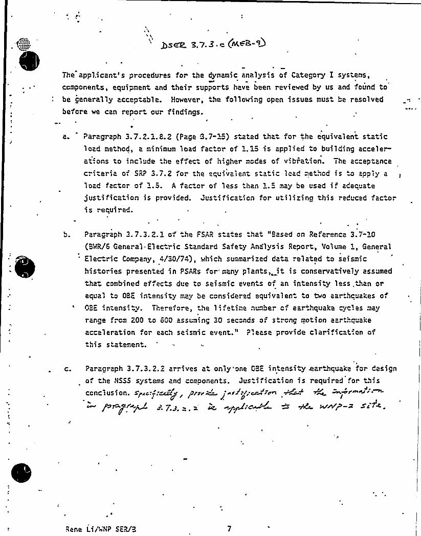
The applicant's procedures for the dynamic analysis of Category E systems,
ccmporents, equipment and their supports have been reviewed by us and found tobe cenerally acceptable. However, the following cpen issues must be resolvedbefcre we can repor our findings.
a. Paragraph 3.7.2.1.8.2 (Page 3.7"L"") s a ed tha for he equivalent staticload methcd, a minimum load factor cf 1.1S is applied to building acceler
4a? ~ Ons to 'ncl "de he erfect of higher'cdes cf vibration I he ac"eptancel
'riteriaof SR? 3.7.2;or the equivalent s atic lead pe .".cd is o app;y a
load factor of 1.S. A factor of less .han 1.S may be used i. zcec atejustification is provided. us ific ticn or utilizing this red cad ac.oris required.
Paracraph 3.7.3.2.1 of .he FSAR sta es hat "Based cn Refererce 3.r-i0("=MR/6 General. Elec ric Standard Safety Analysis Report, Volume i, General
Elec ric Company, 4/30/74), which summarized data ". elated to seismic
histories presented in PSARs or many plants,. it is conserva ively assumed
tha= combined effec.s due to seismic even s of an intensity less .than orequal to OBE '.ntensity may be considered equivalen o No aar hcuakes o
OBE -: ntens', v. There fore, he 1 '. fctime number "= ear,quake cyc. es may
range frcm 200 tc 600 assuming 30 seconds of s ". cng motion ear .". uai;e
acceleration or each seismic event." ?'.ease provide clari;ication ofthis s atement.
C. Par'acraph 3.7.3.2.2 arrives a only one GBE intensity war ".quaice for designo the t)555 sys ems and ccmoonents. Dust'fication is required for this
JS + ~~I prexy ii~ccnclusion. s~~c,:,',Mg J pf~e~~ ~ j yscy+l.'~ ~ ~ mwp -i si
Rene Lii'~'P SE?J'3
QU STION NO. 9(3. 7 3)
~
~ ~
~
~ ~ ~~
~ ~ ~Provide justification of'tilizing one.OBE in ensity earDcpxakefor design of the NSSS systems and cc exponents in Paragraph3.7 3.2..2. Specifically, provide justification .that theinformation in. Paragraph 3.7.3.2.2. is ~pplica1-le to the.HHP-2site..
RESPONSE
For the NSSS piping, 50 peak OBE cycles ax'e used.
For other NSSS ecuipment and components, a genex'.c s"udy se~esas the basis for 10 peak OBE cycles. As shown in the. letter,R. Avgas to R Bosnak; "Number of OBZ,Fatigue Cycles in theBHR NSSS Design", September 17, 1981, 10 peak OBE cy=les canenvelope the cumulative fatigue damage of hundreds of lessseve e ea~Mcpxake cycles.
Accordingly, 'the»SAR is evised as at ached.
SummationThe applicant is'to provide the comparison'f the responsespectra mentioned in the lette by November 20, 198K.~This item is closed.
~ = ~
*The requested response spectra comparison is contained in theletteri R. Artigas to Ra Bosnaki "Number of OBE Fatigue Cyclesin the BWR NSSS Designi" December 3r 1981 (attached).

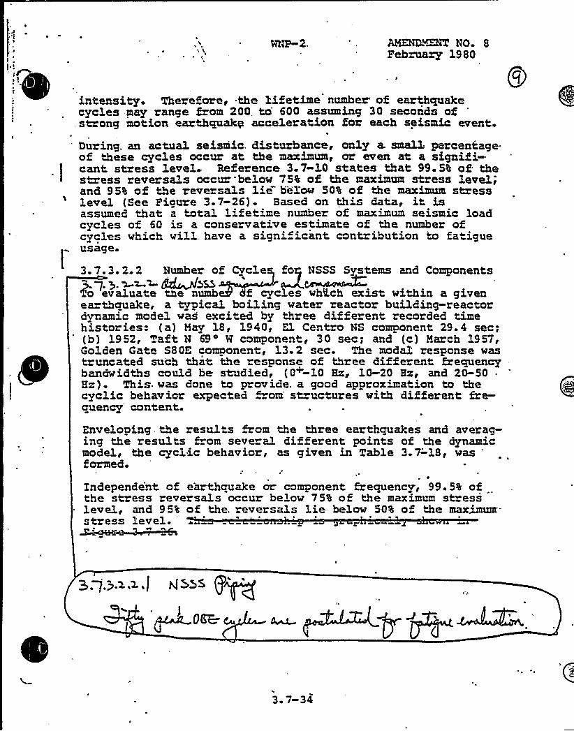
AMEND'QXT NO 8FebrLxazy 1980
: intensity. Therefore, the Xifetime number of earthquakecycles may range from 200, to 600 assuming 30 seconds ofstrong motion earthquake acceleration for each seismic event.
'uring. an actua1 seismic. disturbance, only a. small percentageof these cycles occur at the maximum, or even at a signifi-
1
cant stress level Reference 3-7-10 states that 99 5% of thestress reversals occur below 75% of the maximum stress level,and 95% of the reversals lie" below 50% of the maximum stresslevel (See Piguze 3.7-26)- Based on this data, it isassumed that a total lifetime number of maximum seismic loadcycles of 60 is a conservative estimate of the number ofcycles which will. have a signi"icant contribution to fatigue
L
usage.
3. 7.3. 2.2 Number of Cycle fo NSSS Systems and ComponentsKq.>. ~~~ A~>mTo evaluate the numb f cycles which exist within a givenearthquake, a typical boiling water reactor building-reactoravnamic model was excited by three different recorded timehistories: (a) Hay 18, 1940, El Centavo NS component 29.4 sec;(b) 1952, Taft N 69 W component, 30 sec; and (c) March 1957,Golden Gate S8DE component:, 13.2 sec. The modal response wast uncated such that the response of three different frequencybanawidths could be studied, (0+-10 Hx, 10-20 Hx, and 20-50 .
Hx). This. was done to provide. a good approximation to thecyclic behavior expected from st uctures with different fre-quency content.
Enveloping the results from the three earthquakes and averag-ing the results from several di ferent points of the dynamicmodel, the cycl.ic behavior, as given in Table 3.7-18, was '
ormed.
Independe'nt of earthquake or component frequency, 99.5% ofthe stress reversals occur below 75% of the maximum stresslevel, and 95% of the. reversals lie below 50% of the maximuar-stress level-
hi&>s P~
3 7-34

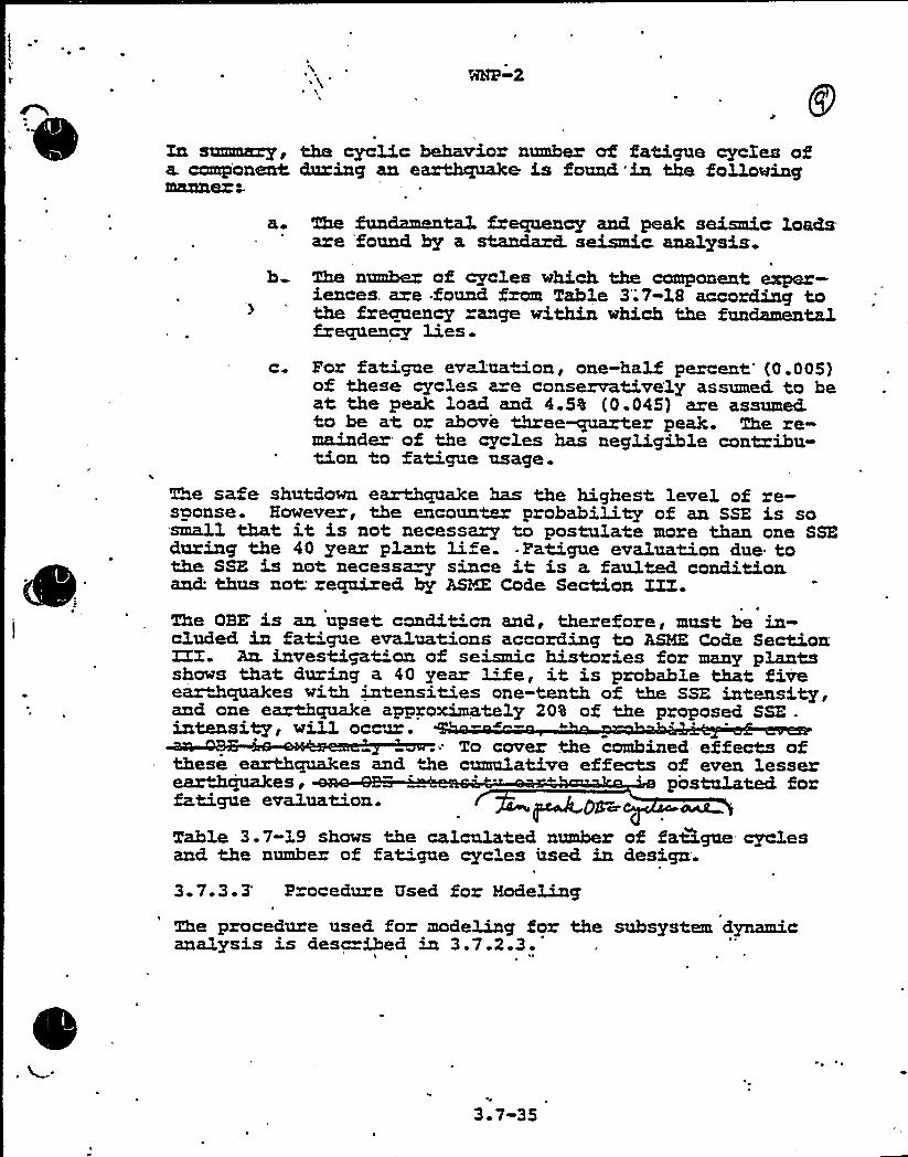
WHP 2
In smmM~, the cycli,c behavior number of fatigue cycXes ofa. component during an eaxth~ce is found in the followingmanner ~
a. The fundamenta1 frequency and peak seismic: loadsare found by a stanckanX. seismic. analysis
I~
b The number of cycles which the component exper-iences. az.e founrd from Table 3;7-18 according tothe frequency range within which the funcbmentalfrequency lies.
c. Por fatigue eva1uation, one-half percent'0.005)of these cycles are conservative'ly assumed. to beat the peak load and 4.5% {0.045) are assumed.to be at or above three~uarter peak. The re-mainder of the cycles has negligible contribu-tion to fatigue usage.
The safe shutdown earthquake has the highest level of re-sponse. However, the encounter probability of an SSE is sosmall that it is not necessary to postulate more than one SSRduring the 40 year plant li. e. -Patigue evaluation due tothe SSE is not necessa~ since it is a faulted conditionancL thus not required by ASIA: Code Section III.The ORE is an 'upset condition and, therefore, must be in-cluded in fatigue evaluations according to ASME Code Section;ZZI. An. investigation of seismic histories for many plantsshows that during a 40 year LUe, it is probable that fiveear&qua3ces with intensities one-tenth of the SSE intensity,and one earthquake approximately 20% of the proposed SSE .
intensity, will, occ~.To cover +De combined effects of
these earthquakes and De cumulative effects of even lesserem<hquakes, postulated forfatigue evaluation. OS~
Table 3.7-19 shows the calculated number of fatigue cyclesand the number of fat'gue cycles used in design.
3.7.3.3' ocedure Used for Modeling
The procedure used for modeling for'he subsystem dynamicanalysis is desc ibed in 3.7.2.3.
\
3.7-35
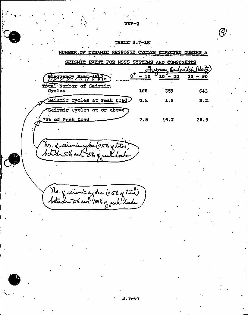
MBIRA 3.7-18
SUMS)M.OP'PSULNXC RESPONSE CXCXZS EXPECTED'MRZHC AI
SZZSMXC ERBIUM'OR NSSS SYSTEMS AHD
I I ~ x 0 LO
TotaL'umbers of Sonic;Cyc1es 168 3S9 643
1D -20 2D 50
Seismic Cyc3es at. Peak Laa 0 8 L.S 3 2.
75% of P 7 5 16.2 2& 9
3 7.67

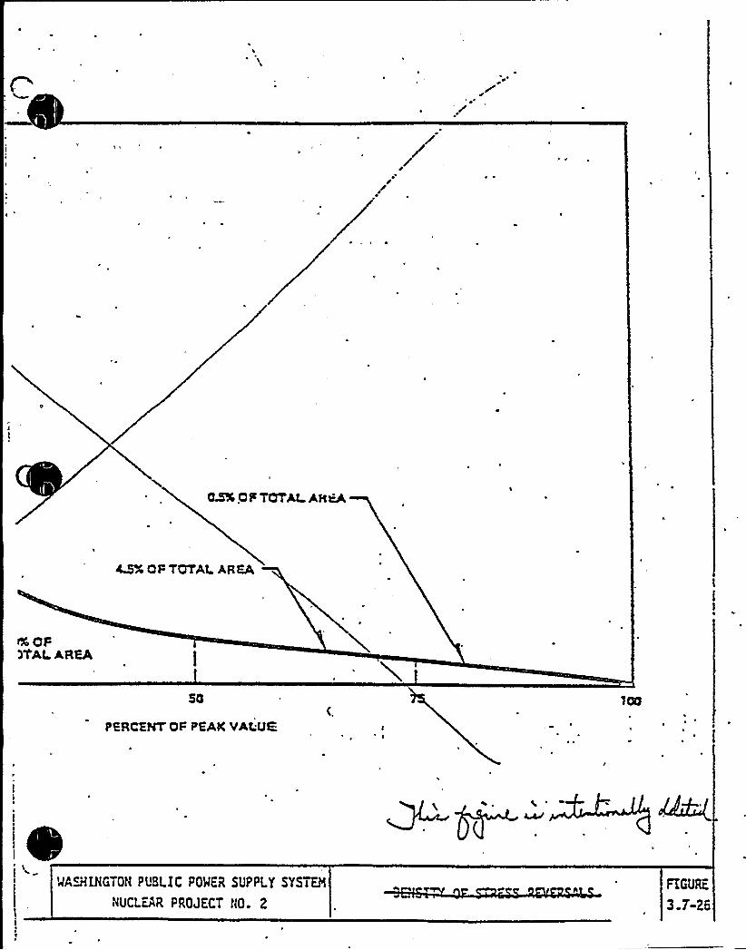
CS% QFTOTAt Afc~
4'F TOTAl. AREA
+aF)TAl.AREA
PfRCEHT OF PEAK VAGUE
@~M~'NGTON PUBLIC POMER SUPPLY SYSTEM
NUCLEAR PROJECT NO. 2
FIGURE
3.T-ZG
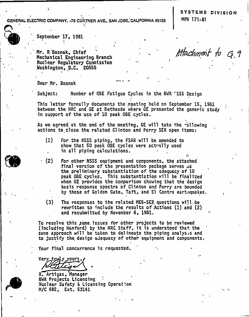
GENERAL ELECTRIC COMPANY, <75 CURTNEFI AVE„SANJOSE,'CAUFOFINIA 95'I25
September D, 1981~ I
. 'r. R Bosnak, ChiefMechanical Engineering- BranchNuclear Regulatory Comnissfon,MasMngton, D.C. 20555
SYSTEMS DlVlSI OH
MFN 171-81
Pkc6mef k q 1
Dear Mr. Bosnak
Subject: Number of OBE Fatigue Cycles in the BMR 'SSS Design
This letter formally documents the meeting held on September 15, 1981between the NRC and GE at Bethesda where GE presented the gener ic studyin support of the use of 10 peak OBE cycles.
As we agreed at the end of the meeting, GE will take the -ollowingactions to close the related Clinton and Perry SER open items:
For the NSSS piping, the FSAR will be amended toshow that 50 peak OBE cycles were act»ally usedin all piping calculations.
For other NSSS equipment and components, the attachedfinal version of the presentation package serves sthe preliminary substantiation of the adequacy of 10peak OBE cycles. This substantiation vill be finalizedwhen GE provides the comparison showing that the designbasis response spectra of Clinton and Perry are boundedby those of Golden Gate, Taft, and El Centro cart;>quakes.
(3) The responses to the related MEB-SER questions will.berewritten to include the results of Actions (1) and (2)and resubmitted by November 6, 1981.
To resolve this .same issues for other projects to be reviewed(including Hanford) by the NRC Staff, it is understood that thesame approach will be taken to delineate the piping ana1ysis andto justify the design adequacy of othei equipment and components.
Your final concurrence is requested.
Very t y ours,
R. Artigas, ManagerBMR Projects LicensingNuclear Safety 5 Licensing OperattonM/C 682, Ext. 53141

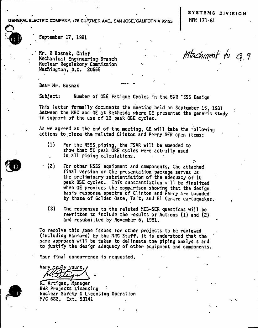
GENERAL ELECTRIC COMPANY, i75 CUQTNER AVE SAN JOSE. CALIFORNIA95125
SYSTEMS DIVISIONMFN 171-81
September 1I, 1981
. 'r. R Bosnak, ChiefMechanical Engineering. Br anchNucl ear Regulatory CoIIInissfon,MasMngton, D.C. 20555
'I
Dear Mr. Bosnak
Subject: Number of OBE Fatigue Cycles in the BMR 'SSS Design
This letter formally documents the meeting held on September 15, 1981between the NRC and GE at Bethesda where GE presented the generic studyin support of the use of 10 peak OBE cycles.
As we agreed at the end of the meeting, GE will take the -ollowingactions to close the related Clinton and Perry SER open items:
For the NSSS piping, the FSAR will be amended toshow that 50 peak OBE cycles were act»ally usedin all piping calculations.
For other NSSS equipment and components, the attachedfinal version of the presentation package serves ~sthe preliminary substantiation of the adequacy of 10peak OBE cycles. This substantiation ~.ill be finalizedwhen GE provides the comparison showing that the designbasis response spectra of Clinton and Perry are boundedby those of Golden Gate, Taft, and El Centro cart;Iquakes.
(3) The responses to the related MEB-SER questions will.berewritten to include the results of Actions (I) and (2)and resubmitted by November 6, 1981.
To resolve this .same issues for other projects to be reviewed(inc1uding Hanford} by the NRC Staff, it is understood that thesame approach will be taken to delineate the piping analysis andto justify the design aJequacy of other equipment and components.
Your final concurrence is requested.
Yery t y our s,
R. Artigas, ManagerBMR Projects LicensingNuclear Safety 5 Licensing Operat!onM/C 682, Ext. 53141

PRESENTATION ON THE NUMBER'F
OBE FATIGUE-CYCLES FOR
BHR NSSS DESIGN
(EXCEPT P! PING)
SEPTEMBER .15, 1981D, K HENH,IE
! SEISMIC E DYNAMIC ANALYSIS
GENERAL ELECTRIC

,
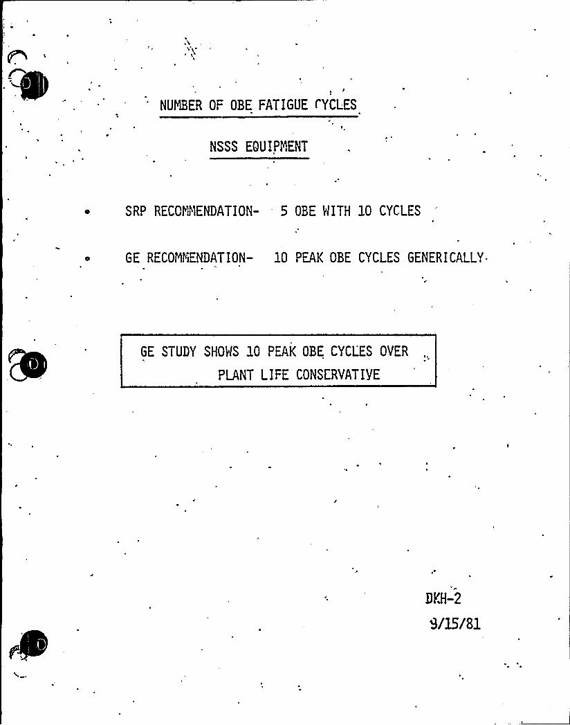
~ I
NUMBER OF OBE FATIGUE t'YCLES
NSSS EQU IPNENT
SRP RECGYii"1ENDATION- 5 OBE MITH 10 CYCLES
GE RECOMI'iENDATION- 10 PEAK OBE CYCLES GENERICALLY
GE STUDY SHOHS 10 PEAK OBE CYCLES OVER
PLANT LIFE CONSERVATIVE
96-2

r >
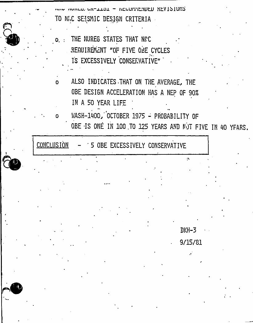
~ 1 ~ ~ lt iiv<iiu. ah-z J.Q J. — hC.L Ul ol iso jJJCJJ ~(tY I5 IUl eb
TO NiiC SE>.SNIC DESIGI'1 CRTTERIA
o.: THE NUREG STATES THAT NPC
BEQUIREYiBT "OF FIVE 08E CYCLES
IS EXCESSIVELY CONSERVATIVE"
o ALSO INDICATES THAT ON THE AVERAGE, THE
OBE DESIGN ACCELERATION HAS A NEP OF 90K
IN A 50 YEAR LIF.E
o 3NSH-1000, OCTOBER 1975 -'ROBABILITY OF
OBE -IS ONE IN 100.TO 125 YEARS AND Y JT FIVE IN QO YFARS.
CONCLUSION — 5 OBE EXCESSIVELY CONSERVATIVE
DKH-3
9/15181

'
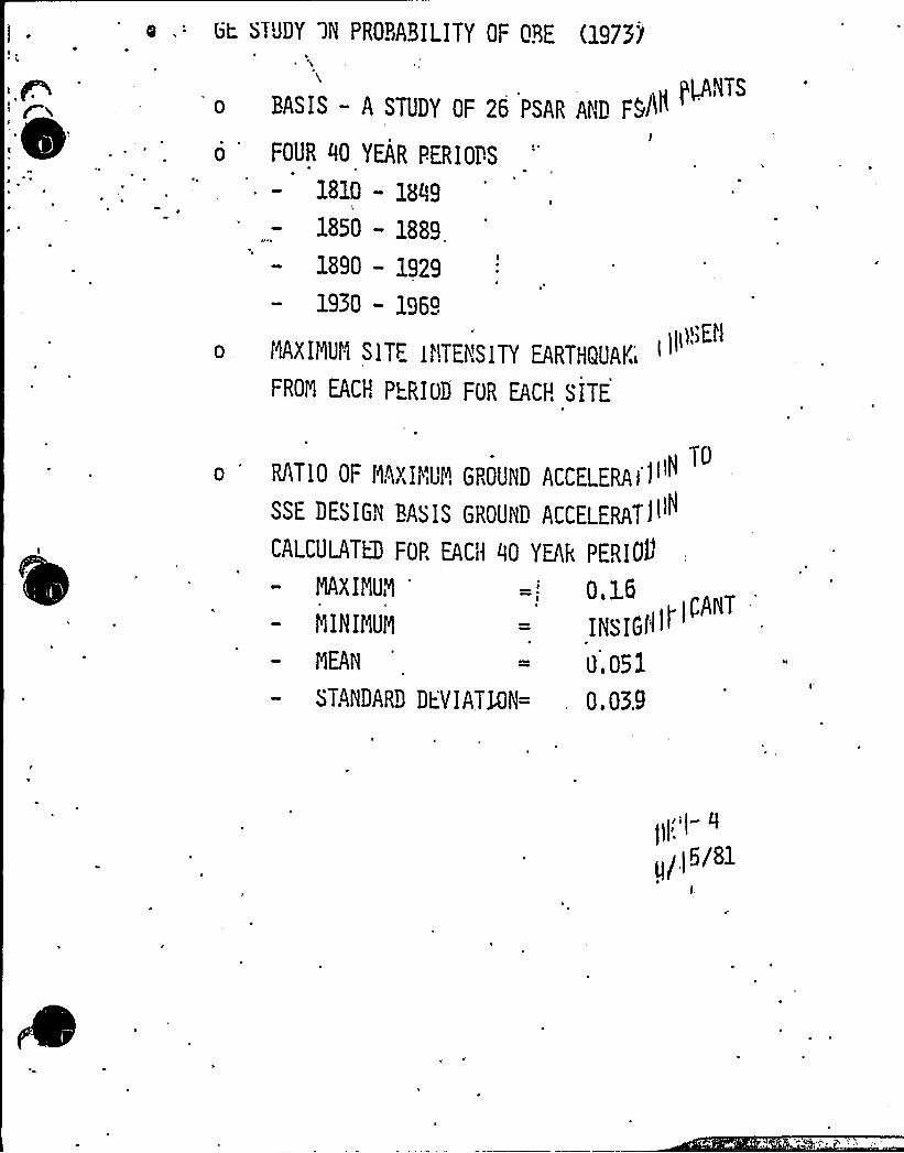
0
l~,,'EilMAXIMUM SITE I,"!TENSITY EARTHQUAK I
FROZ EACH P~RIDD FOR EACH SITE
L-~ ~~uOV ~N PR0BABILITY 0F ORE (197>i
NTS0 BASIS — A STUDY OF 26 PSAR AND FSlN
'OuR
~O YEAR PERIOrS
1810 - 184i9
1850 - 1889
1890 — 1929
1950 - 1969
tDRATIO OF MAXIMUM GROUND ACCELERAII
SSE DESIGN BASIS GROUND ACCELERATIi
CALCULATE) FOP. EACH 40 YEAk PERIOD
~XI'> =,: 0,>6NININLlN INSIGIIit'CAxT
aEAN 0.051
STANIjARD Dt.VIATNN= 0,0%9
(i6/81

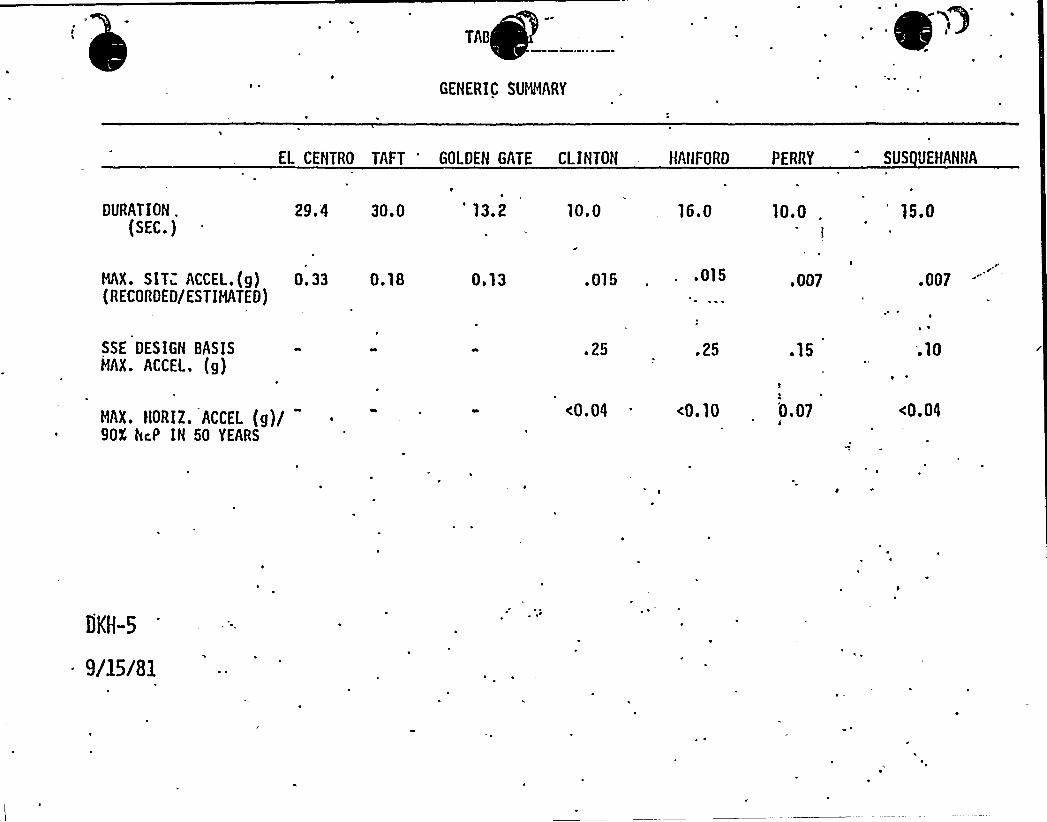
GENERIC SUMMARY
EL CENTRO TAFT 'OLDEN GATE CLINTOH HANFORD PERRY SVS UEHANNA
DURATION .
(SEC.)29.4 30.0 'l3.2 10.0 16.0 10.0 15.0
NX. SIT~ ACCEL.(g) 0.33 0.18{RECORDED/ESTIMATED)
0,13 . 015 .015 .007 .007
SSE DESIGN BASISMAX. ACCEL. (g)
.25 .25 .15 .10
MAX. HORIZ. ACCEL (g)/9OX hcP IH 50 YEARS
<0.04 <0.10 0.07 <0.04
DKH-5
9/15/81
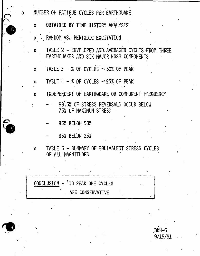
.o NUf'lBER OI- FATIGUE, CYCLES PER EARTHQUAKE
o OBTAINED BY TIME HISTORY AN&,LYSIS
o RANDOM YS. PERIODIC EXCITATION
TABLE 2 — ENVELOPED AND. AVERAGED CYCLES FRON THREE
EARTHQUAKES AND SIX MAJOR NSSS COMPONENTS
o TABLE 5 — % OF CYCLES 50% OF PEAK
TABLE 0 -% OF CYCLES « 25% OF PEAK
INDEPENDENT OF EARTHQUAKE OR COMPONENT Ft'.EQUENCY,
99,5% OF STRESS REVERSALS OCCUR BELON
75% OF MAXIMUM STRESS
95% BELOH 50%
85% BELOM 25%
o TABLE 5 - SUMMARY OF EQUIVALENT STRESS CYCLES
OF ALL MAGNITUDES
CONCLUSION — '10 PEAK OBE CYCLES
ARE CONSERVATIVE
.DKH-6
9/15/81
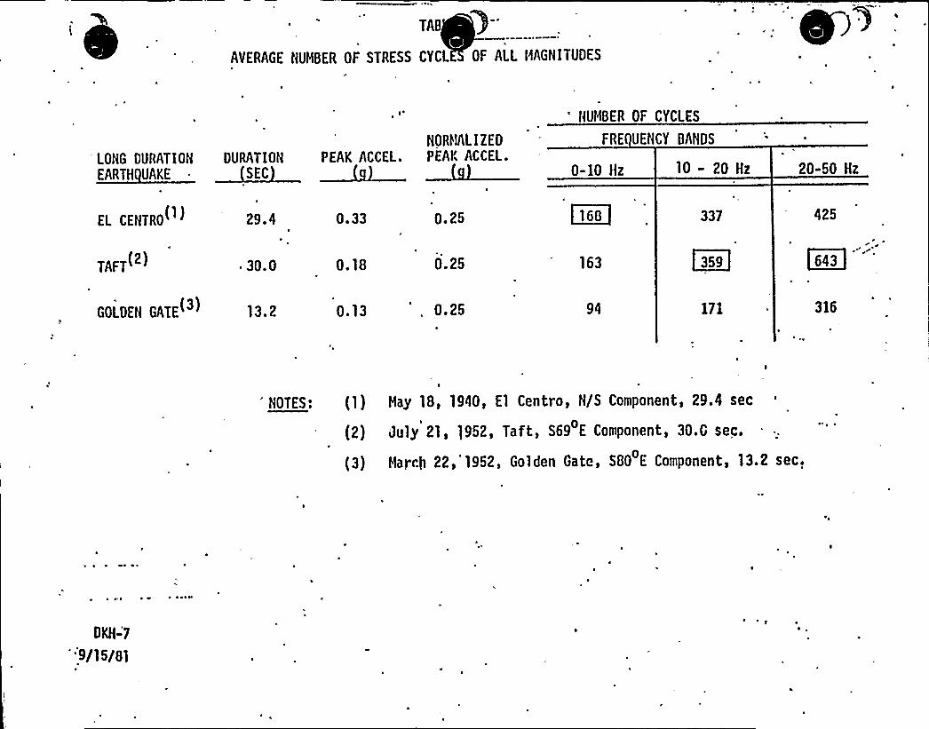
TAB
AVERAGE NUMBER OF STRESS CYCL OF ALL MAGNITUDES
LONG DURATION DURATION
EARTH UAKE ~ SEC
g ~
NORltALI Z ED
PEAK AGGEL. PEAr, AGGEL.0-10 Hz 10- 20 Hz
NUMBER OF CYCLES
FRE UENCY BANDS
20-50 Hz
EL GENTRO( )
TAFT(2)
GOLDEN GATE( )
29.4
~ 30. 0
13. 2
0.33
0.18
0.13
0.25
0.25
0.25
~160
163
337
C35~]
171
425
~643
316
'OTES: (1) May 18, 1940, El Centavo, N/S Component, 29.4 sec
(2) July 21, )952, Taft, S69 E Component, 30.G sec.
(3) March 22,'952, Golden Gate, SOO E Component, 13.2 sec.
DKH-'7
9/15/al
~ ~

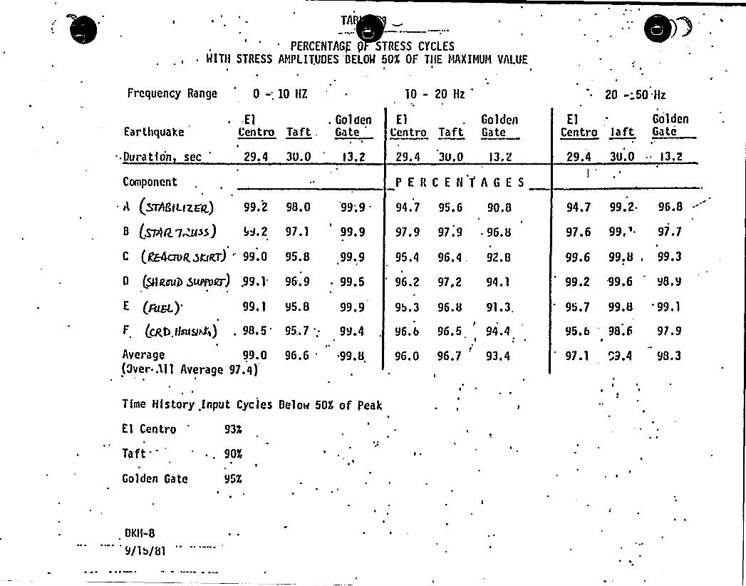
PERCENTAGE {) STRESS CYCLESWITH STRESS AMPLITUDES 'bELOW 50K OF TIlE HAXIHUN VALUE
Frequency Range 0 -'IO HZ 10- 20 Hz 20 - 50 Hz
El GoldenL'entro Taft Gate
. GoldenGate
ElCentro Taft.
29.4 30.0
Earthquake
. Dura tfo'n sec 29,4 3u.0 l3.2
P E R C E H 'f A G E S
l3. 2
Component
A (sTflGltltaa)
0 {~lT7,&aa) b9.2 97.1 99. 9 97.9 97.9 96.8
95.4 96.4 . 92a8c (CGGcro<zrJeT) '9.00 (sHeau0 sunoer) .99.1
(Fan.) 99.1
f (cftb liras<) .
98.9'verage
99.0(Over..ll 1 Average 97.q)
99.995. 8
96.9 . 99.5 94.1'6.2 97,2
gb.3 96.895.8 91.3.99.9
95..7; 99.4 96. 5
96.7
94.496. 6
96.6 96. 099.8 93. 4
992 980 999 94 7 95 6 908 94.7 99.2. 96.8
97 6 99,'7799.6 99.8, 99.3
99.2 99.6 98.9
95.7 99.8 '9.1
95.6 98.6 97.9
97.1 C9.4 98.3
El - Gol denCentro left Gate
29,4 3tj.o 13. 2
Time History input Cycles Below 50Ã of Peak
El Centro 93K
Taft
'olden Gate
901
95X
OKH-8
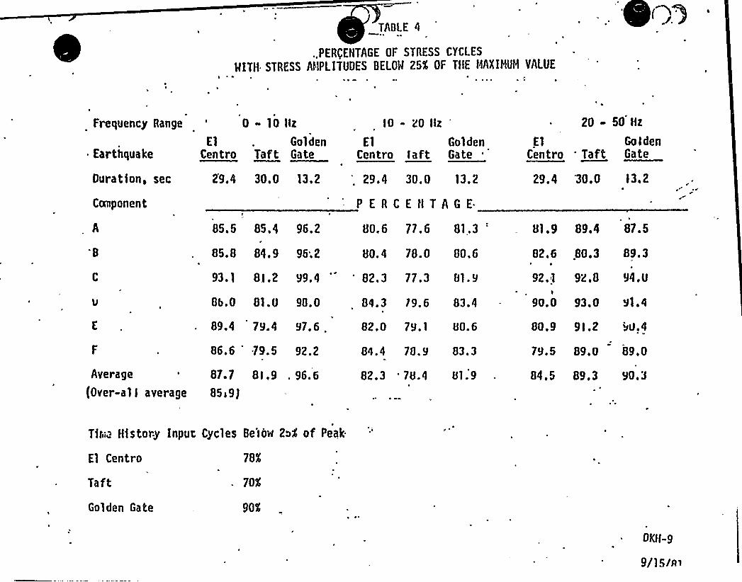
TADI E 4
.,PER(ENTAGE OF STRESS CYCLES
MITH STRESS AMPLITUDES BELOM 25K OF TflE tlQINUM VALUE
(~
Frequency Range
ElEarthquake Centre
0 10
Taft
llz
GoldenGate
lO - 20 llz
ElCentro laft
GoldenGate
20 - 50 Hz
El GoldenCentro 'aft Gate
Duration, sec
Component
29.4 30.0 13.2 '. 29.4 30.0 13.2
PERCENTAGE.
29.4 30.0 l3.2
B
Average
(Over-all average
85.5 85.4
85.8 84.9
96.2
96;2
80. 6 77. 6 81.3
80. 4 28. 0 80.6
8b.o 81.O 98.0
89.4 79.4 97.6 .
86.6 .79.5 92.2
87.7 8l,9 . 96.6
85)9J
84. 3 79. 6 83.4
82.0 ?S.) 80.6
84.4 78.9 83.3
82.3 '8.4 81.9
93. 1 8l,2 99.4'
82.3 77.3 81.9
81. 9 89.4 87. 5
82.6
92.1
90.0
80.3 89.3
92.8 94.0
93.0 V1.4
80.9 9l.2
79.5 89.0
b0.4
89.0
84.5 89.3 90,3
Tiri.a History Input Cycles He'iow 2~4 of Peak.
El Centro
TaftGolden Gate
78Ã
70$
90$

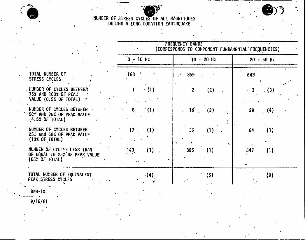
NUMBER OF STRESS CYCLE OF ALL MAGNITUDESDURING A LONG DURATION EARTHQUAKE
)a
FREQUENCY BANDS
(CORRESPONDS TO COMPONENT FUNDAMENTAL FREQUENCIES)
0-10 Hz 10 - 20 Hz 20 - 50 Hz
TOTAL NUMBER OFSTRESS CYCLES
. NUMBER OF CYCLES BETMEEA75K AHD 100K OF Pfi'.,lVALUE (0.5X OF TOTAL)
NUMBER OF CYCLES BETWEEN'' 50" AHD 75K OF PEAK'VALUE<4.5X OF TOTAL)
NUMBER OF CYCLES BETWEEN25,; and 50K OF PEAK VALUE(10$ OF TOTAL)
HUMBER OF CYCL";S lESS THANOR EQUAL TO 25K OF PEAK VALUE(85K OF TOTAL)
168
17 . (1)
143 (1)
359
2 (2)
16 (2)
36 (i)
305
~ 643
3 . (3)
29 (4)
64 (1)
547
TOTAL NUMBER OF EQUIVALENTPEAK STRESS CYCLES
DKH-10
9/15/81
(4} (9)
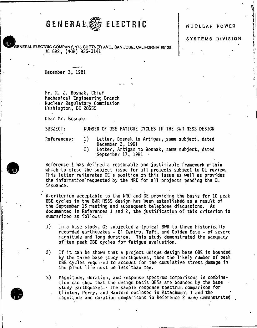
0 E R E R A L;+Ps) E L E C T R I C
GENERAL ELECTRIC COMPANY, 175 CUFITNER AVE., SAN JOSE, CALIFORNIA95125~ ~
IIC 682, (408) 925-3141
!I
4
SYSTEMS DIVISION
December 3, 1981
Hr. R. J. Bosnak, ChiefHechanical Engineering BranchNuclear Regulatory CommissionWashington, DC 20555
Dear Nr. Bosnak:
SUBJECT: IIUHBER OF OBE FATIGUE CYCLES IH THE BWR NSSS DESIGN
References: 1) Letter, Bosnak to Artigas, same subject, datedDecember 2, 1981
2) Letter, Artigas to Bosnak, same subject, datedSeptember 17, 1981
Reference 1 has defined a reasonable and justifiable framework withinwhich to close the subject issue for all projects subject to OL revie~.This letter reiterates GE's position on this issue as well as providesthe information'requested by the NRC for all projects pending the OLissuance;
'-criterion acceptable to the HRC and GE providing the basis for 10 peakOBE cycles in the BWR NSSS design has been established as a result ofthe September 15 meeting and subsequent telephone discussions. Asdocumented in References 1 and 2, the justification of this criterion issummarized as follows:
1) In a base study, GE subjected a typical BWR to three historicallyrecorded earthquakes - El Centro, Taft, and Golden Gate - of severemagnitude and long duration. This study demonstrated the adequacyof ten peak OBE cycles for fatigue evaluation.
2) If it can be shown that a project unique design base OBE is boundedby the three base study earthquakes, then the likely number of peakOBE cycles required to account for the cumulative stress damage inthe plant life must be less than ten.
3) Magnitude, duration, and response spectrum .comparisons in combina«tion can show that the design basis OB~s are bounded by the basestudy earthquakes.- The sample response spectrum comparison forClinton, Perry, and Hanford enclosed in Attachment 1 and themagnitude and duration comparisons in Reference 2 have demonstrated
'
GECERAL ELECTRICMr. R. J. BosnakPage 2Oecember 3, 1981
that the base study earthquakes do indeed bound the site-specificdesign basis OBEs.
Therefore, the use of ten peak OBE cycles is conservative for allproject uniqQe designs. This GE position is supported by NUREG/CR-1161,which recommends revisions to the NRC seismic design criteria. TheNUREG-cites that (a) the requirement of 50 OBE cycles is excessivelyconservative, and (b) the probability'f 10 OBE cycles (as a result ofone OBE) is one in 100 to 125 years. In conclusion, GE firmly believesthis current approach is technically sound.
However, to address the Staff's concern and to expeditiously resolvethis licensing issue, GE intends to demonstrate the achievement of anequivalent level of safety by showing the relevant design margin.Specifically, GE has agreed to substantiate that, for the most limitingRPV component, (a) margin is allowed in the total cumulative fatigueusage, and (b) the contribution of OBE cycles is very negligible in thistotal usage.
Referring to Attachment 2, the usage factor for the most limitingcomponent, feedwater nozzle, is tabulated for BWR/5's and 6's. ForBWR/5's, the highest usage factor occurs on the Hanford 2 project. Thisprecludes the need to list other projects. For BWR/6's, the listedvalues are used for generic design. Both cases- show that the contribu-tion of OBEs is very insignificant and adequate margin is built into thedesign.
This completes our commitment and response to your inquiry. We under-stand that this issue can be written off for all BWR/5 and 6 Projectsbased on this submittal.
Very truly yours,
. Artigas, ManagerBWR Projects LicensingNuclear Safety and Licensing Operation
RA: hmc: sem/107 J
Attachments.

t
Attachment 1
OBE Pesponse Spectrum Comparisons
Clinton, Perry, and Hanford vs. Base Study Earthquakes
PCY:sem/2B12/1/81

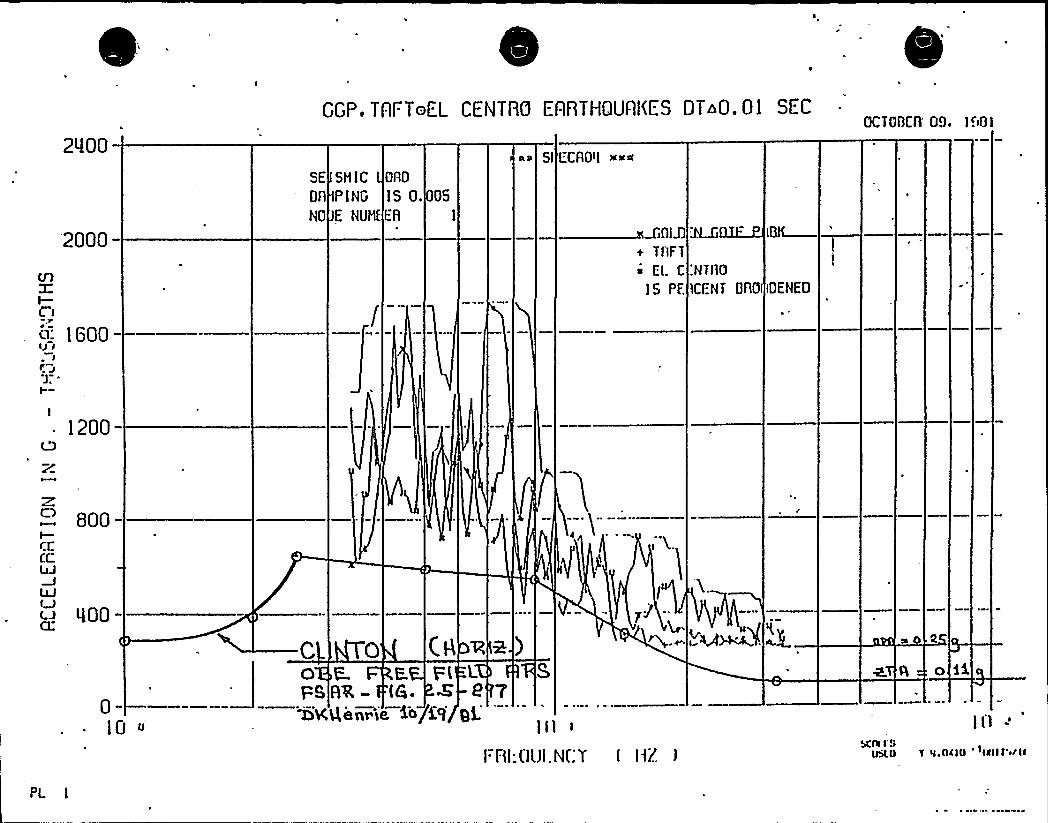
2400
GGP.TAFToEL CENTRQ EARTHQUAKES OT~0.01 SECGC TOOCn'9. I I'IO I
2000
CA
l-ri'i- 1600
SE
Dn
NG
SNIC Onn
PING IS 0. 05
E NUN FA
al Sl LCAQII a~a
wniz+ TnFT0ELC
IS PE
:NTfhD
SCENT DAO IDENED
1200
800IQCCQJ
000
010 U
PL I
CO E. E. Ft L SFURR- (6. K e 7~Kg~~~,e. lola> g.
l HI:UI.ji.N[:7 ( I]Z I
o ii
Iil-'CIII
I SIlail.O l <I.OCIU 'IIIII'/II

=
.
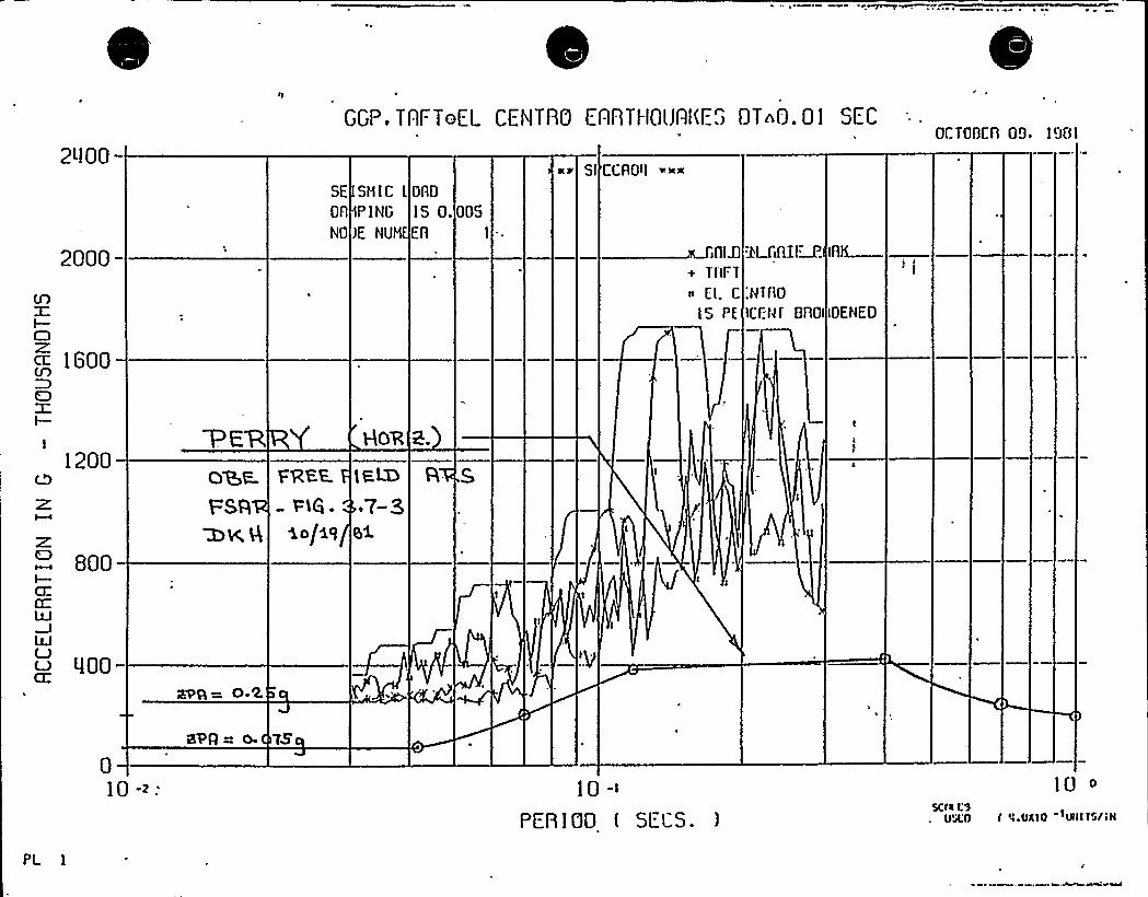
2400
GGP, TAFToEL CENTRG E'ABTHOlJAf<E." DT 0.01 SEC
Sl CCRO~I ~~<
QCTQOCn 09. 1901
2000
(A
~ IGOO
SE SHIC IQAOOn PING IS 0.NQ)E NUM EA
005I
o'LG 1M+ Tnrx~ El. C:NTflQ
IS PE ICf:Nf BBQI IDENEO
1200
800
GOO
OF FAKE.
FSR - Pi6.~K A 1 o/aq
aug= 0-'K
How 2.
010 ->:
avq= o. zs
PFB I GO ( SLLS. )
10 o
SCN L'9UA.Q f i UXlO ~SII Ts/aN
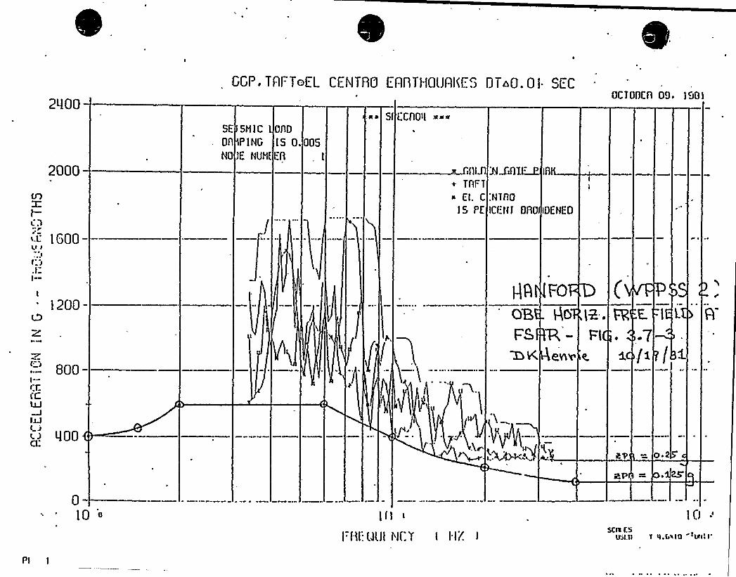
GGP. TAFToLL CENTRCI EnnTI-IQlJAI(E". DT 0.01. SECOCTOOCn O9, IaOI
CA
I—Cl
2~100
2000
SE SHIC I oflDOfl PING IS 0.005NG)E NUN(EA I
.aa SI LCAO~I »~
Ul+ TAFT
El. C
IS PE
AJifll~:NTAQ
lCf'NI BRO )DENED
~L 1600
1200
800I+ffQJ
IM
400
gA FO
H,.Fl
E.
/a
oil
0
Pl

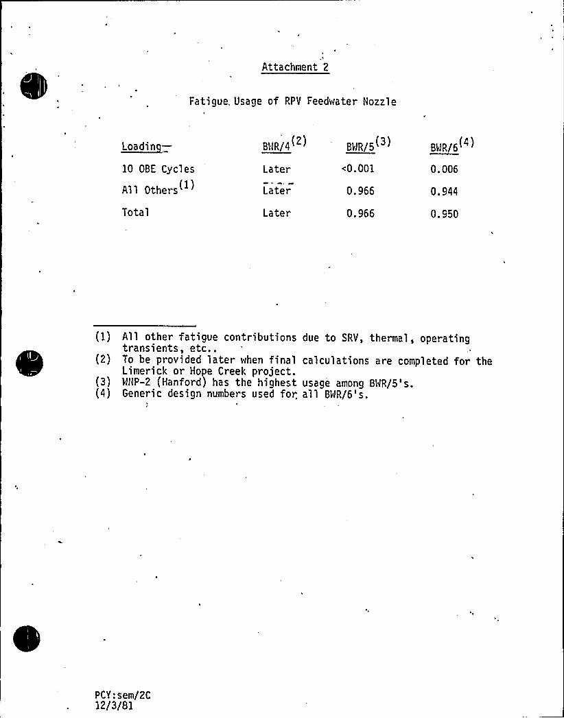
Attachment 2
Fatigue, Usage of RPV Feedwater Nozzle
~Loa din—10 OBE Cycles
All Others(
Total
BWR/4(2)
Later
Later
Later
BBR/5
(0.001
0.966
0.966
BWR/6(4)
0. 006
0. 944
0.950
(1) All other fatigue contributions due to SRV, thermal, operatingtransients, etc..
(2) To be provided later when final calculations are completed for theLimerick or Hope Creel project.
(3) WHP-2 (Hanford) has the highest usage among BWR/5's.(4) Generic design numbers used for. all BWR/6's.
PCY:sem/2C12/3/81
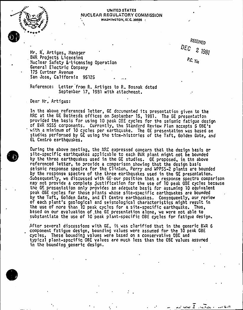
UNlTED STATESNUCLEAR REGULATORY COMMIS'!ON
r<'ASH le TON, Q. C. 20555
Hr. R, Artigas, Manager8'~R Projects Licersinqnuclear Safe.y E+icensing Opera ionGer;eral Electric Cor:.pany175 Curtner AvenueSan Jose, California 95125
Reference: Letter from R. Artigas to R. Bosnak datedSepter:"er 17, 1991 with attachment.
Dear Nr, Artigas:
<fC:IVY@
In the above referer,ced letter, GE dc-..mented its presentation given to thetlRC a+ the GE 8e"..".esda offic s on Sept W -. 15, 1981. Th GE presentationprovided the basis for using lO peak ""-.. cycles or tl seismic fatigue designof 8'~R hSSS co.-.ponents. Currently, the Standard Review Plan accepts 5 OBE'swi<th a minimum of 10 cycles per earth"„u.ke. The GE presentation was based onstudies performed by GE using the ti~-histories of tl e T.ft, Golden Gate, andEL Centro earthquakes.
During the above meeting, the l<RC expressed concern that the design basis orsite-specific earthquakes ap"„licable tc each 84'R plant might not be boundedby the three earthquakes used in the GE studies. GE proposed, in the abovereferenced letter, to provide a comparison showing that the des/gn basiss ismic response spectra for the Clir,.on, Perry and MPPSS-2 plants a. e boundedby the response spectra of tl.. tl..ree earthquakes used in the GE presentation,Subsequently, we discussed with GE. our position that a response spectra comparisont-::ay not provide a co.:piete j«st-f'.cation for the use of 10 peak OSE cycles becausethe GE presentation only provides an adequate basis for assuming 10 equivalentpeak OBE cycles for those plants whose site-s"„ecific earthquakes are boundedby the Taft, Golden Gate, and El Centro earthquakes, Cons quently, our reviewo each plart's geolog'.cal and seisr ological characteristics might result inthe use o more thar 10 peak cycl s or a site-specific earthquake. Thus,based on our evaluation of the 6= presentation alone, we were not able tosubstantiate the use of 10 peak „lant-specific OBE cycles for fatigue design.
After several discussions w ith GE, it was clarified that in the generic 8'nR 6cor<ponent fatigue design, bounding valu s were assu~ed for the 10 pe> G8Ecycles, These bo nding values were based on a conservative 08K andtypic 1 plant-specific OBE values are nuch less than the CSE values assuredin the bounding generic desigr,.
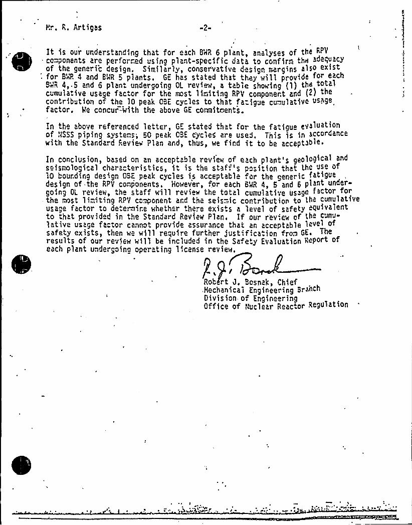
Rr. R. Artigas
cIt is our urderstanding that for ach 8MR 6 plant, analyses of the RP>
cc-" ponents are perfcr;..ed using plant-specific data to confirm th< adequacyof the gen ric design. Similarly, conservative ~ sign ttargins also e~ist
: for 8'4? 4 and BUR 5 plants . GE has stated that they wi 1 1 provide f« e«h8'nR 4~ ~ 5 and 6 plant undergoing OL rev'.ew, a table showing (1) th«otalcumula.ive usage fac Gl fol the rrast liriting RPV componert and (~j ""contribution o. the 10 peak GBE cy les to that fa=igue cu..u ative usage.factor, Ve concur"-with the above GE corniitr.'en".s.
In the above referenced letter, GE stated th t for the fatigue ev>luat'of ,'VASSS piping systems, 50 peak CBE cycleg are used. Tnis is in accordancewith the Stardard Revie Plan ard, thus, we find it to be acceptable
In conclusion, based on an acceptab',e review of each plant'5 geologicalseismological characteristics, it is ".he staf;'s position that the use of10 bourding design GSc. peak cycles is acceptabl ~or the generic fatigue
of the RP~ components, Ho~ev~~, for each B~R 4, ~ and 6 pgoing OL review, the staf will review the total cumulati;e us~ga factor f«the most li;.,iting RPV c"~onent ard the seis-.:ic contribution to Lh< cumulativeusa,e factor to deteraire whether there exists a level of safety <Auivalentto -'hat provided in the Standard Review Plan. If our rev',ew of <he cumu
1 tive usage fac:or cannot provide assurance thai ar, acceptable level o
safety exists, then we will require furtner just fication fro~ GE.results of our review will be included in the Sa. ety Evaluation Reporteach plant undergoing operating license review.
] lRob rt J. Bosnzk, Chief,Mechanica] Engineering BrachDivision of EngineeringOffice of a,'uclear Reactor Regulation

e
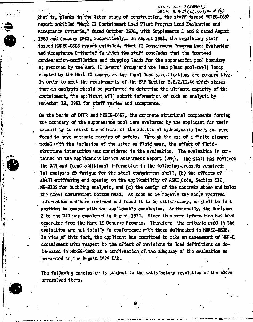
v~«s.s'.2( GS'-lgbow s.s.z(~),(s) M(~3
Chal's, plants in the later stage ef construction, the staff issued NNEMNNreport entitled "HLrk II Containmant Lead Plant Program Load Evaluation and
Acceptance Criteria, dated October X978, «tith Supplamants I and 2 dated August
. X980 and January X98X, respectively. In August 1981, the regulatory staffissued NUM~808.report entitled, Hark II Containiant Program Load Evaluationand Acceptance Criteria. in tMch the staff concludes that the improved
condensation-oscillatien and chugging loads .for the suppression pool boundary
as proposed by-the NaN II Seers'roup.and the lead plant pool-mal loads
adopted by the Hark II eeers as the final load specifications are conservative.In order. to eeet the requimaants of -tha SRP Section 3A.2.IIAdMich statesthat an analysis should be performed to determine the ultimata .capacity ef thacontaintaant, the applicant vri11 submit information of such an analysis byNovena X3, 1981 for staff revie«t and acceptance.
On the basis of DFFR and NtjREG~, the concrete structural components formingthe boundary ef the suppression pool ~ere evaluated by the applicant for theircapabi1ity to resist the effects of the additional hydrodynataic loads and ~found to have adequate margins of safety. Through the use of a finite element
'edel vith the inclusion of the crater as fluid aass, the effect of fluid-structure interaction «tas considered in the eva1uation. The evaluation is con-
tained in the applicant's Design Assessment Report {DAR). The staff %as rerlaedtha MR~ found additional information in the follering .areas.is required:ga) analysis o5 fatigue fee tha steel containmant shHl, (b} the effects efshall stiffening and opening on the appNcability af ASHE Code, $ection III,
. NE-3X33 fer buckling ana)ysis, and {c) the design of the concrete above and helmthe steB containmant bottom head. As soon as ue receive the above requiredinformation and'have revi~ad and found it to be satisfactory, «e shall be in a
position to concur fifth the applicant's conclusion. Additional'ly, tha,Revision2 to the DAR was ccaapleted in August 1979. Since than more information has bean
generated fram the Hark II Generic Program. Therefore, the criteria used in theevaluation are not totally in conformance vfth those delineated in NUREG~08
In view of this fact, the applicant has coamitteS to make an assassmznt of RPNcontainmant Rth respect to the effect ef revisions to load definitions as de-
lineated in NUREG-0808 as.a confirmatioa.ef. the adequacy of the evaluation as
presented in the August, 1979 DAR.
The fo11ering conclusion is subject to the satisfactory reso1ution ef the above
unresolved items.

MHP-2
~ Open SER Issue
3.8.2 Steel Containment Ultimate Ca acit (SEB-1)
A r sponse to this issue was submitted December 14, 1981 by letternu;,.ber G02-81-518.
J
3.8.2(a) Containment Shell Fat'i ue Anal sis
A response to this issue was submitted December 14, 1981, by letternu-...ber G02-81-518.
3.8.2(b) Eff cts of Shell Stiffenin and 0 enin
A response to this issue vas'submitted December 14, 1981, by letterr u-,.ber G02-81-518.
3 .8.2(c) Desi n of Concrete Above/Below Head
A r spense to this issue was submitted December 14, 1981, by letternu7ber G02-81-518. '
The contafnmant concrete and steel internal structures are ghsfg~ to resistvarious anbfnatfons of dead and.live loads, accident-fnduced loads, fncludfngpressure and 5at loads, 'and seismic loads. Tha design of the contaf~internal struehma to vfthstand the effects of suppression pool hydro~mdcloads ms acuap1$ shad in tha st aannar as that for the contafment ructuraas described fn Sectfon 3.8.2. The detaf 16freevaluatfon of the cnpabflfty ofcontainment internal structa~~ to resist these nary identified loads isdescribed in tha applicants'esign Assessnant Report. Me have ravfecad thedesign and analysis procedures and criteria that mra used for the originaldesign and for the reevaluation of the internal structures in the suppression
pool. The contafnmant internal structures mre designed and proportioned to~ renafn within limits established by the Regulatory staff under various load
combinations. These limits as sell as the design and analysis procedures are,in general, based on the American Concrete Institute 318-71 Code and on thaAuerican Institute of Stae1 Construction'Specification for Concrete and Steal
. Structures, respactfvely, modified as appropriate for load axabfnatfons thatare considered as exam.
The applicant vi'il provide impact assessment to.demonstrate unplfanca with'ACI-.349 Coda as atqpentad by Ragulato~ Qdda 3 M2 for tha applfcablc .
internal concrete structures and also to 4senstrata cceplianca Ath ARK Coda,
Section III, Division 2 for the containment concha baseuat structure..
The loads and load combinations used in Tables 3.8-10 and 3.8-I1 fn SacHon
3.8.3 of tha FEAR are different from those of Section 3.8.4 of the SRP.
Hanover, the applicant provided reevaluation design calculations and sh~that the structures interna1 to contafmant have enough capacfty tp cant thaapplicable requfrecants of Section 3.8.4 of the SRP. The staff ravf smf theresults of the reevaluation and accepted tha applicant's Justification.
I
The foll~ng conclusion is subject to the resolution of the unresolved ftoasdiscussed fn this section.
The aatarfals of construction, their fabrfcatfon, constructfon, and installa-tion, are in accordance with tha Amerfcan Concrete Instftuta 328-H. Coda ns
IX
Open SER Issue
3.8.3(a) Inter nal
A response to thisnuvher G02-81-518.
Structure Com 1iance with ACI-349/RG1.142
issue was submitted December 14, 1981 by letter
3.8.3(b) Basement Com liance with ASHE Code
A response to thisnurber C42-81-518.
issue was submitted December'4, 1981, by letter
The design and analysis procedures that sere used for these Category I struc-tures are the same as those approved on previously licensed applications and 5n
general ~ are in accordance wrath procedures. delineated .fn the ACI 3XS-71 Cehand in the AXSC Specification for concrete and steel structures, respectively.
The various Category I structures are designed aqd proportioned to renainerithin liiits established by the. Regulatory staff under the various loadaebinations. These limits are, in general, based on the ACI 3M-71 Code and
on the AISC Specification for concrete and steel structures, respectively,modified as appropriate for load combinations that pre considered extreme.
The aaterials of construction, their fabrication, construction, and installation,are in accordance wrath the ACI 3K-7l Code and the AISC Specification forconcrete and steel structures, respectively.
The applicant. couuaitted to submit assessment report to demonstrate that thedesign of'atego~ I concrete structures is in compliance with the'rectuireeentsof.ACX-349 Code as aeanded by Regulatory-Guide 1.142.
I'he
loads and load aebinations used in Table 3.8-L5 and 3.8-35 in Section 3.8.4of the FSAR are cHfferent from those presented in Section 3.8.4 of the SRP.
The applicant has reevaluated the design of MNP-2 and indicated that the load
combinations and acceptance criteria specified in Section 3.8.4 of-the SRP are
satisfiecL This is acceptable to the staff.
The app1icant co@mitted to submit an evaluation of the design and'analysis ofspent fuel pool structures used in MNP-2 for. staff revi~..A copy of Ninimcce
Requirements Nor Oesign of Spent'Fml Pool Racks" has been given to the applicant.
The applicant confirmed that there are no safety-related Nasonry. sails for MNP-2
facilityr
The following conclusion is subject to the satisfactory resolution of the above
noted unresolved items.
Open SER Issue
3.6.4(a) Cate or I Structures.'om liance with ACI-349/RG1.142 SEB-11
A response to this issue was submitted December 14, 1981, by letternumber G02-81-518.

The design and analysis procedures that mre used for these Category I struc-* tures are th saba as those approved on previously licensed app1ications and in
general, are in accordarum Mith procedures. delineated.fn the ACI AS-TL Codo
and in the AXSC Specifiartion for concrete 'and steel structures,'mspectively.
The various Catego~ I structures are designed and proportioned to reqain%thin liants established by the Regulatory staff under the various londccmbinations. These limits are, in general, based on the ACI 318-71 Code and
on the AISC Specification for concrete and steel structures, respectively,aedified as appropriate for load combinations that ore considered extreme.
The materials of construction, their fabrication, construction, and installation,are in accordance with the ACI 3M-71 Code and the AISC Speci'fica4ion forconcrete and steel structures, respectively.
Thi applicant, committed to submit assessment deport to 4aaenstrate that thechsign of Category I concrete structures is in compliance v$th the'rapdrmantsof ACI-349 Code as amended by Regulatory Guide 1.142.
The loads and load combinations used in Table 3.8-I5 and 3.8-16 in Section 3.L4of the FSAR are differ'ent from those presented in Section 3.8.4 of the SRP.
The applicant has reevaluated the design of MNP-2 and indicated that the load
ccabinations and acceptance criteria specified in Section 3.8.4 of-the SRP are- satisfied. This is acceptable to the staff.
The applicant aemitted to submit an evaluation of the design and analysis ofspent; fuel pool structures used in BHP-2 for. staff revim. A copy of HiniNLMm
ReqvirecM~ Nor Qesign of Spent'Fuel Pool Racks" has been given to the applicant.
The applicant confireed that there are no safety-related masonry ills for MAP-2
facility.
The following conclusion is subject to the satisfactory resolution of the above
noted unresolved items.

Open SER Issue
3.8.4(b) Evaluation of S ent Fuel Pool Structures
The WNP-2 spent fuel pool racks'esign meets the requirements ofthe NRC guidelines promulgated by the NRC letter to all PowerReactor Licensees with enclosure, "Review and Acceptance of SpentFuel Storage and Handling Applications,," dated April 14, 1978,(supplemented January 1979) .
Attached is a comparison of the April 14, 1978 guidelines to thoseof Appendix D to NUREG-0800 Standard Review Plan Section 3.8.3,Revision 0, dated July 1981.
ATTACHMENT AReview of Standard Review Plan 3.8.4 Appendix D Requirements
Appendix D of Standard'Review Plan Section 3.8.4 "TechnicalPosition on Spent .Fuel Pool Racks" was reviewed .and comparedto the existing NRC guidelines made available to all powerreactor licenses in April 1978 and then modified in January1979.
The new appendix addresses only the mechanical, material, andstructural considerations; nuclear and thermal-hydraulicconsiderations are not included. A comparison is given belowfor the subject areas covered by both documents.
Aovendix D Section (1) (b) Fuel Handlin
>Sere specific postulated drop accidents had previously beendefined, Appendix D implies that accident postulation shouldbe made by the licensee and then submitted to the NRC forreview by the Accident Evaluation Branch. The fuel handlingand postulated load drop analysis performed for NNP-2 designare considered sufficient and should meet the requirementsof such a review.
A oendix D Section (2) A olicable Codes, Standards and S ecifications
Appendix D Section 2 states that design, fabrication and in-stallation of spent fuel racks of stainless steel materialmay be performed based upon Subsection NF requirements of theASME Section III Code. This implies that another code mayalso be used, however, in Section (6) (the structural accept-ance criteria section) Subsection NF is imposed. "This leadsto confusion.
P
The original guidelines permitted the AISC Code (supplementedby Standard Review Plan 3.8.4-II-5) to be used as an alternatedesign criteria.. This alternate was the criteria used on theM~P-2 spent fuel rack design.
Appendix D Section (3) Seismic and Im act Loads
Appendix D permits the effects of submergence of the rack,system to be considered on a case by case basis. In theoriginal guidelines the added mass of the water had to beconsidered (amplifies loads) while increased damping due tosubmergence (reduces loads) could not be applied without testdata and/or detailed analytical results. Consequently, the,oriqinal guidelines was more restrictive, leading to larqerresultant loads in the case of dynamic loading conditionssince water damping was not permitted.

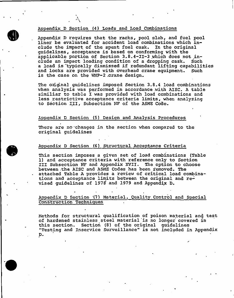
Appendix D Section (4) Loads and Load Combinations
Appendix D requires that the racks, pool slab, and fuel poolliner be evaluated for accident load combinations which in»elude the impact of the spent. fuel cask. In the originalguidelines, acceptance is based on conforming with theapplicable portion of Section 3.8.4-II-3 which does not in-clude an impact loading condition of a dropping cask. Sucha load is "typically dismissed if redundant lifting capabilitiesand locks are provided with overhead crane equipment.. Suchis the case on the WNP-2 .crane design.
The oxigi.nal guidelines imposed Section 3.8.4 load combinationswhen analysis was performed in accordance, with AISC. A tablesimiliar to table I was provided with load combinations and1ess restrictive acceptance criteria limits, when analyzingto Section III, Subsection NF of the ASME CoGe.
A~ endix D Section (5) Design and Anal sis Procedures
There are no .changes in the section when compared to theoriginal guidelines
Ao endix D Section (6) Structural Acce tance CriteriaThis section imposes a given set of load combinations (Table1) and acceptance criteria with reference only to SectionIII Subsection NP and Appendix XVII. The option to choosebetween .the AISC and ASME Codes has been removed. Theattached Table A provides a review of critical load combina-tions and acceptance limits between the original and re-vised guidelines of 1978 and 1979 and Appendix D.
Appendix D Section '(7) Material, Qualit Control and S ecialConstruction Techni ues
Methods for structural qualification of poison material and testo= hardened stainless steel material is no longer covered in *
this section. Section (8) of the original guidelines"Testing and Inservice Surveillance" is not included in AppendixD.

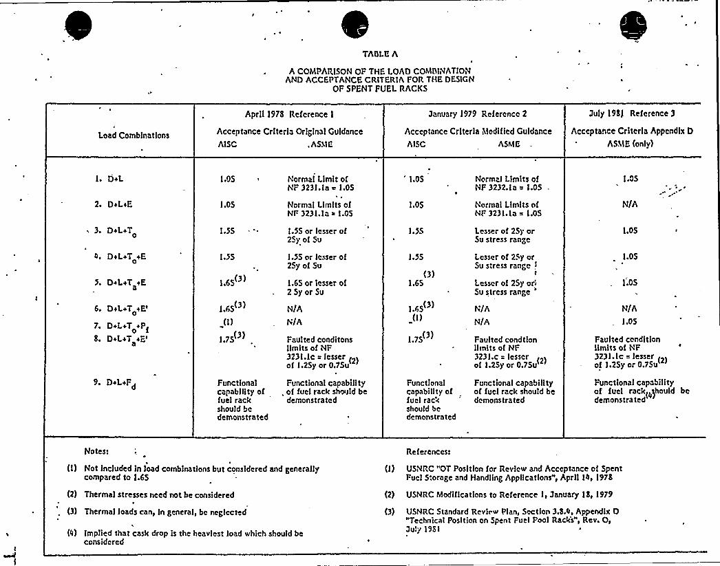
TAOLB A
A COMPARISON OF THE LOAD COMIIINATIONAND ACCEPTANCE CRITERIA FOR THE DESIGN
OF SPENT FUEL RACKS
Load Combinations
April 1978 Reference I
Acceptance Crlterh Orlglnal Guidance
AISC . ASIIE
January 1979 Reference 2
Acceptance Criteria Modified Culdance
AISC ASME
July 198) Reference 3
Acccptancc Criteria Appendix D
ASME (only)
1. D+L
2. D+LiE
~ 3. D+L+T0
4. D+L+T +E0
3» D+L+T tEa
6. DwL+T+E'.
DiL+T +Pf08» DiL+T +E'
9. D+LtFd
I 05
1,05
1.55
1.55
1.65(3»
1»65(3)
0)
1.75(3)
Functionalcapability offuel rackshould bedemonstrated
Normal LimitofNF 3231.la e 1.05
Normal Llrnlts ofNF 3231.la i 1.05
I.SS or lesser of2Sy of Su
I.SS nr lesser of25yof Su
1.65 or lesser of25yor Su
N/A
N/A
Paul ted conditonsllmlts of NF3231.lc = lesser
(2)of 1.25y or 0.75u
Functional capability. of fuel rack should be
demonstrated
'.05
1.05
1.55
I.>5
(3)1.65
1.65'"(I)
1.75(3)
Functionalcapability offuel rackshould bedemonstrated
Normal Limits ofNF 3232.1a ~ 1.05
Normal Limits ofNF 3231.1a =
1.05'esser
of 25y orSu stress range
Lesser ot 25y orSu stress range I
Lesser of 25y or!Su stress range
'/A
N/A
Faulted condtlonlimits of NF3231.c = lesser
2)of 1.25y or 0.75u(
Functional capabilityof fuel rack should bedemonstrated
1.05
N/A
1.05
1.05
1.05
N/A1.05
Faulted conditionlimits of NF3231.lc = lesser
(2)of 1.25y or 0.75u
Functional capabilityof fuel rack(should bcdemonstrated
Notest
(I) Not Included In load combinations but considered and generallycompared to 1.65
(2) Thermal stresses need not be considered
(3) Thermal loads can, ln general, bc neglected
(4) Implied that cask drop is the hcavlcst load which should beconsidered
References:
(I) USNRC "OT Position for Review and Acceptance of SpentFuel Storage and Handling Applications", April 14> 1978
(2) USNRC Modifications to Reference I, January 18, 1979
(3) USNRC Standard Review Plan, Section 3.8.4, Appendix D"Technical Position on Spent Fuel Pool Racks", Rev. O,July I98t
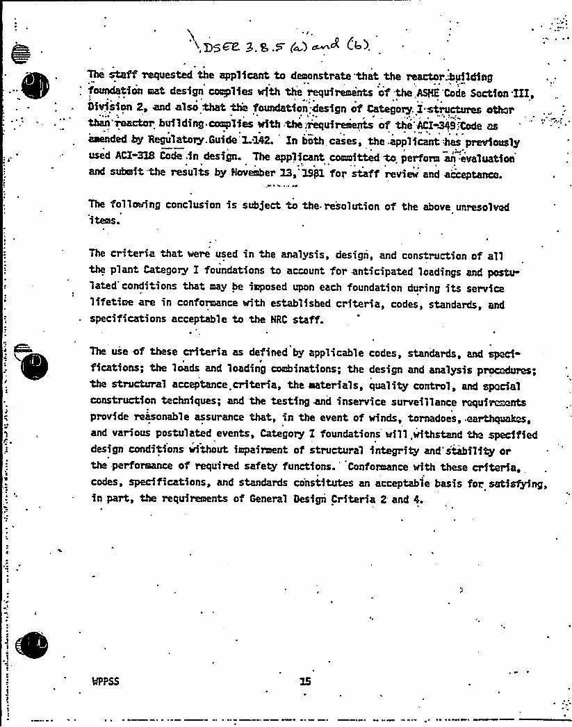
x pg~ g g g (~) ~A C43
The staff mquested the applicant to demonstrate'that the reactor.kuilding'oundation eat design complfes with the requirements of'he,AS% Code Section'III,
OMsion 2, and also that th'e foundation-design of Category,. I Mructures otterthan'mactor building complies with:the ~uireiients of the'ACI-349Xode asamended ky Regulatory. Guide'42. Zn both cases, the .appl icant has previouslyused ACI-3XS Code in design. The applicant committed M perform an:evaluationand submit the results by November Z3,'19/1 for staff review and a'cceptance.
~I 4
The following conclusion is subject to the re'solution of the above unresolveditems.
The criteria that were used in the analysis, design, and construction of allthe plant Category I foundations to account for anticipated loadings and postu-lated'conditions that may be imposed upon each foundation during its servicelifetime are in conformance with established criteria, codes, standards, andspecifications acceptable to the HRC staff.
The use of these criteria as defined by applicable codes, standards, and speci-fications; the loads and loading combinations; the design and analysis procedures;the structural acceptance criteria, the materials, quality control, and spocialconstruction techniques; and the testing ~ inservice surveillance requitemntsprovide reasonable assurance that, in the event of winds, tornadoes, earth}uakes,and various postulated events, Category I foundations will,withstand the specifieddesign conditions without impairment of structural integrity and stability orthe perforlence of required safety functions. Conformance with these criteria, „
codes, specifications, and standards co'nstitutes an acceptable basis for. satisfying,in part, the requirements of General Design Criteria 2 and 4.
MPPSS

i
MHP-2'pen
SER Issue
3.8.5(a) Reactor 8uildin Foun'dation Com 1iance with ASI'iF. Code
A response to this issue was submitted December 14, 1981, by letternumber G02-81-518.
3.8.5(b) Cate or I Foundations Com 1 iance with ACI-349/RG1.142
A response to this issue was submitted D cember 14, 1981, by letternumber'02-81-518.
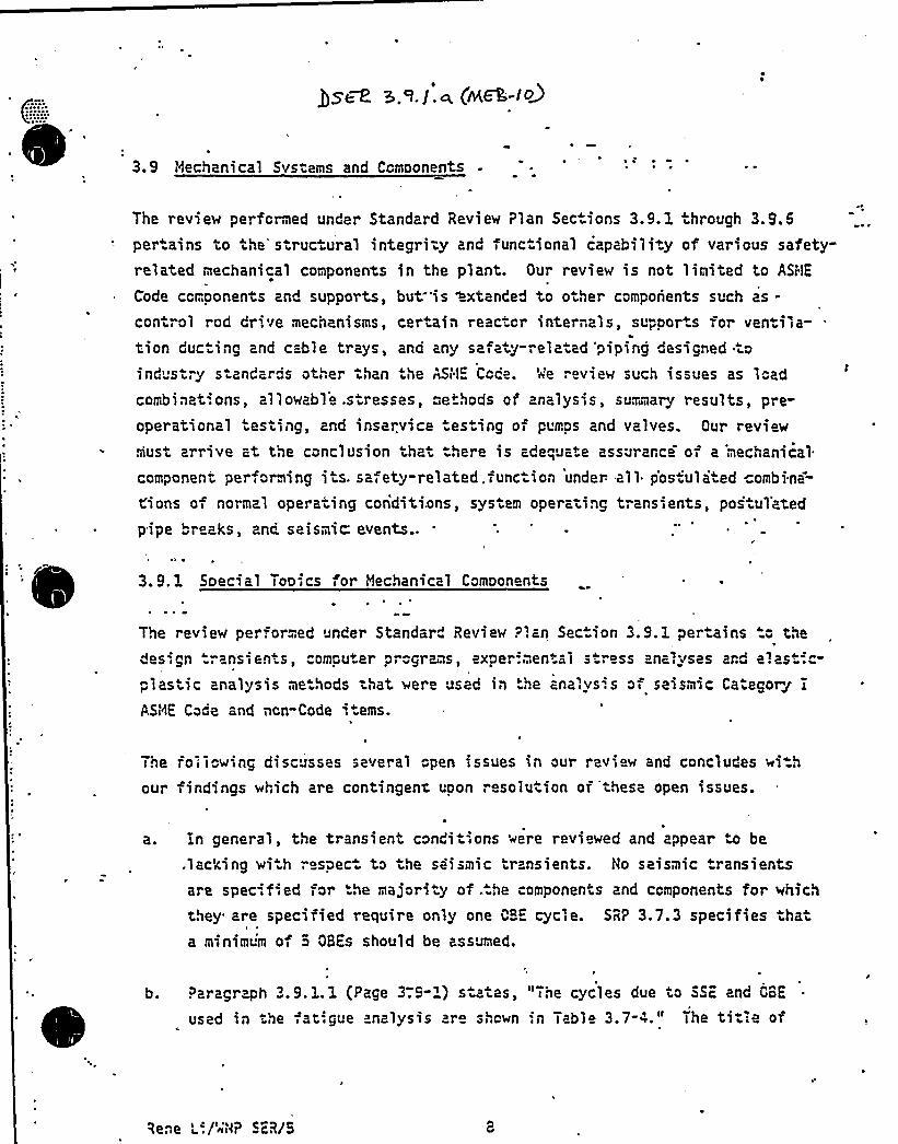
3.9 Mechanical Systems and Components
The revie~ performed under Standard Review Plan Sec.ions 3.9. 1 hrough 3.9.6pertains to the' ructural integri-y and func ional capability of various safety-related mechanical components in the plant. Our revie~ is not limited to ASHE
Code ccmoonents and supports, but is 'extended to other components such as-control rod dr'.ve mecnanisms, certain reac.cr internals, supports for ventila- .
tion ducting and c=ble trays, and any safety-related 'piping designed toind'try s andzrds other than the AS/'1 Coca'A'e review such issues as loadcombinat'.ons, allowable .stresses, methods or analysis, summary results, pre-operational esting 2nd inservice esting of pumps and valves. Our review
must arrive at the conclusion that :here is ade"„Uate assurance of a 'mechanical
component performing its. safety-related.func.ion under all* p'os.'ulated ombina=
t.'ions of normal operating conditions, system operating transients, postul'ated
pipe "reaks, znc. seismic: events..
3. 9. 1 Special Topics for Mechanical Components
The review performed under Standar" Review Plan Sec"ion 3.9. 1 pertains " the
esign ransients, comouter progr?'is, experimental s. ress ana'.uses and elast;"-plastic analysis me hods that were used in '.he analys.'s of seismic Categorj,iASt<E Code and non"Code i .ems.
The following discusses several open issues in our review and concludes withour findings which are contingent uoon resolution oi'these open issues.
a. in general, the transient conditions were reviewed and appear e be
.lacking wi h respec" to the seismic transients. No seismic transientsare specified for the majority of ..he components and components for which
they are specified require only one QBE cycle. SRP 3.7.3 specifies thata minimu'm of o OBEs should be assumed.
b. Paragr ph 3.9. 1. 1 (Page 3".9-') s a es, "The cycles due to SSE and CBE
used in the fat'.gue analysis are shown :n Table 3.7-4." The tit:e of
Rene L'./'~HP SER/5
A
NP-2 OSER
UE5TION NQ. 19~ ~
Ho seismic transients are specified for the majority of the'omponentsand the components for which they are specified require only one GBEcycle. Justification is required.
RESPONSE
5ee the text revision attached.
Summation —This item is close6.
PCY~ rf/45E48/18/81
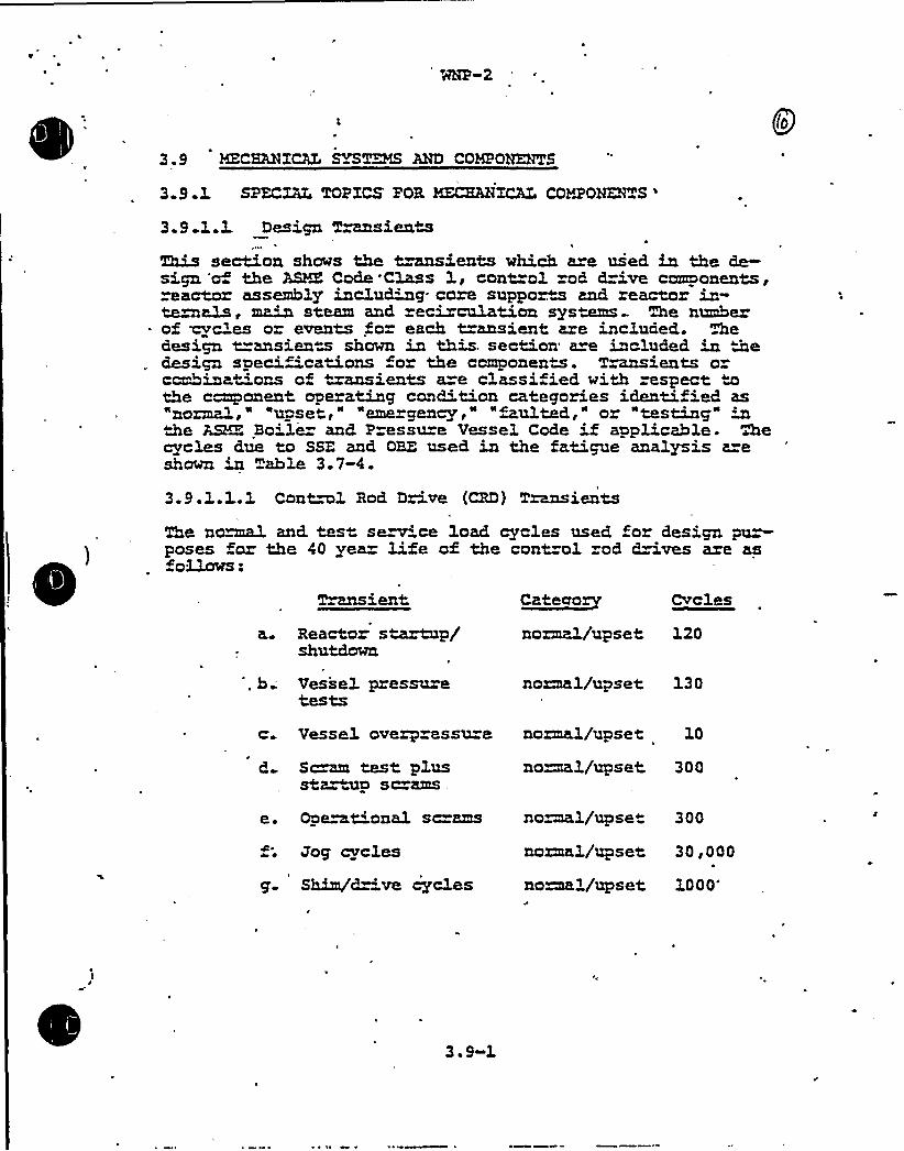
3.9 MZCHANXCAL~~ AND COK?OHENTS
Q(o
3 9 1 SPZCXAL TOPXCS FOR HFZHAHXCAL COY2'ONE%"S
'.9
1.3. Design T~sientsThis section shows the t~ients which are used in the de-sign 'of the ABC Code'Class 1, cont=ol rod d=ive components,reactor assembly inclu~g- core suppor.m and reactor in-te~als, main steam and recirculation sys~ Me number
- of cycles or events for each t=ansient are included. Thedesign transient shown in this. section are included in medesign specifications for the component. Tmasients ocombinat"'ons of "~ients a=e classified with respect tothe component operating condition categories identified as"norma3.," "upset," "erne gency," "faulted," o "testing" inthe ASK'. Boiler and Pressure Vessel Code if applicable. Mecycles due to SSE and OBE used in the fatigue analysis are
Table 3.7-4.
3.9.1.1.1 Contml Rod Drive (CRD) Transients
The no~ and. test se~ ce load cycles used for design pu~poses for the 40 yea@ life of the control od drives are as~ollows.
a.
Transient
Reactor s~xp/shutdown
C~te~ory Cvc:les
normal/upset 120
Vessel pressu~tests
normal/upset 130
c. Vessel overpressu=e normal/upset 10
S~ »~t plusst~~p 8crams,
no~3./upset 300
e. Ope»ational sc=ams
f; Jog cycles
g- Shim/d 've cycles
no~1/upse» 300
normal/upset 30,000
no~1/upset 1000'
~ 9-1

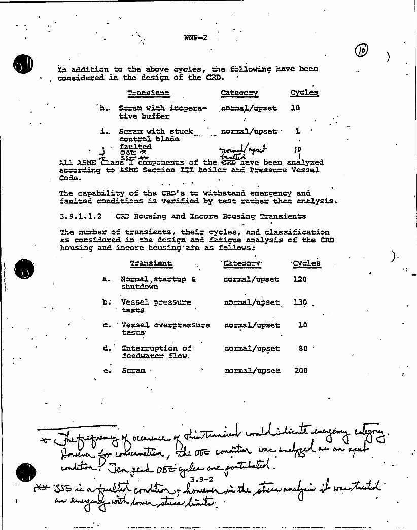
Xn addition to the above cyc3.es, «Me fo11oving have beenconsidered in the design of the CRD.
Transient Cycles' Sc~ with inopera- normal/upset 10
tive bufferScram viW stuck normal/upset '.control, blade
io
All ASME c1ass I components of ~ ~ve been analyzedamong to ASHE Section ZIT Boiler and Pressu=e VesselCode.
The capabi3'ty of the CRD's to wi.stand emergency andfaulted condimns is ver"'~ied by test rather than analysis-
3.9.1.3..2 CRD Housing and Xncore Housing TransienM
The number of t=ansients, thei cycles, and, m~sificationas considered in the design and ~tigue analysis of the CRDhousing and incore housing'a=e as follows:
\MRILS~t.. 'CKtMOZV'vclesa. Normal.soup t
shutdownnormal/upset 120
b; Vessel p=essu=etests
normal/upset 130
c. 'essel. overpressmetests
normal/upset 10
d. Xate~ption offeedMater floe.
e. Scram
normal/upset 80
normal/upset 200

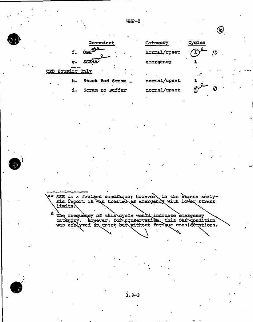
Q(o
sientOBR
S~»
Cate~ox~ 'vclesnonme1/upset +11 /g
CBD Housiner Onl
h. Stuck Rod Scram
ie Sc am no Bouffe~
normal/upset
nominal/upset gy (o
l~~SSEis a fsis, r~ort it
~limits ~,
recpxeacyCat +ewas ed
U
ed condi on; hoeeveci in the Msess anal'ys t=ea as emergen with lowe stress
of ~%cycle wo indicate~en'ver,fo consexvati this 0 ondition
upset bu without faM e consid Mons.~~
3. 9-3
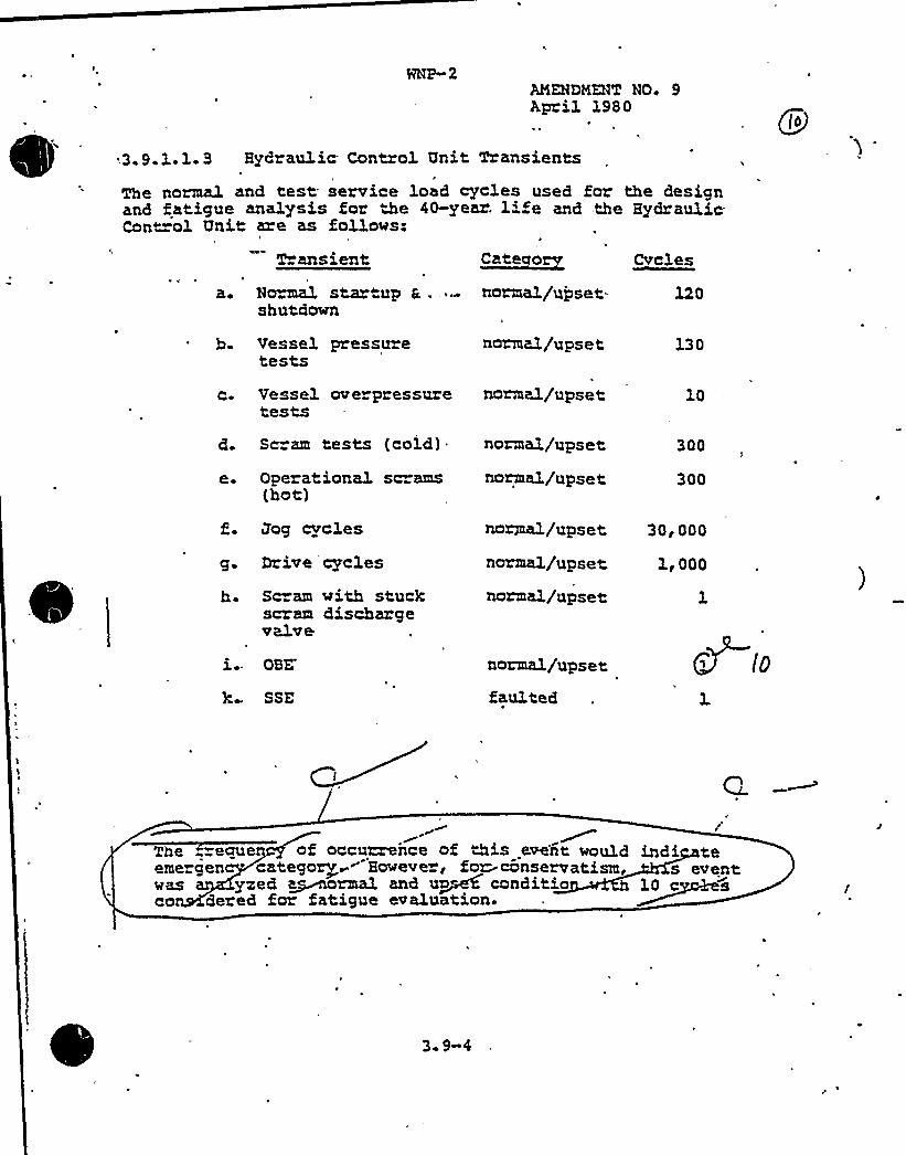
ANEHDMENT NO+ 9April 1980
Cvalss
.3.9.1.1.3 Hydraulic Contxol Unit Transients
The normal and test service load cycles used for the designand fatigue analysis for the 40-year. life and the Kydrau3.icCont=oh. Unit are as follows:
II
T ansient Catecaoev
a. NcmLal startup S..shutdown
normal/upset- 120
b. Vessel pressuretests
norma)./ups e t 130
c. Vessel overpressuretests
normal/upset 3.0
d. Scram tests (cold)- norma3./upset 300
e. Operationa3. sc ams(hot)
normal/upset 300
Bog cyc3.es
g. Drive cycles
h- Sc am with stuckscram dischargevalve
normal/upset 30, 000
normal/upset 1<000
norma3./upset 1
OBE
k SSE
normal/upset
faulted
The eauen of occurren~ce of &is eve'nt wouldemergen catego~~~"Howeve», fcn- conservatism, s eventwas yoked abnormal and u~~ conditio 10 cco dered for fatigue evaluation.
3 9-4

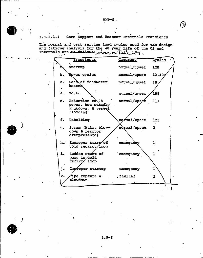
3.9.1.1.4 Core Support and, Reac~mr Xnte~a3.s Transients
The normal and test, service load cycles used for the designand fatigue'nalysis for th 40 year life of &e CS and
ransients ~esse alas
b.
Cs
Startup
owe cycLes
Los~of feedwaterheat
normal/upset L20
no~1/upset 12,40
normal/upse't 80
d. Scram
e. Reduc 'on to 0%
powe , hot s dby.shutdown, 6 ves 1flooding
normal/upse-
noxmal/ups t198
h
Unbolting
Scram (Auto. blow-down 4 reactorove~ressure)
Zmpropex s~ ofcold recixc. oop
/upset
n ~al/upset123
2
Sudden s ofpump in ldrecir . loop
oper star"up'pe rapture 4
blowdown
3. 9-5
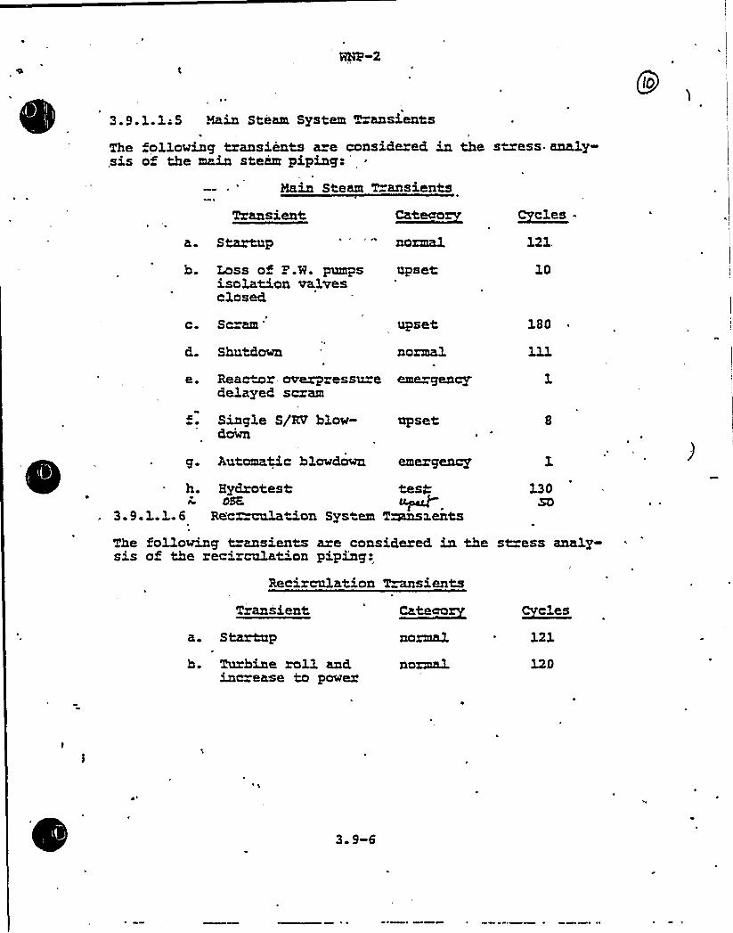
WNP 2
3.9.1.1;5 Hain Steam System Transients
The ollowing transients a e considered in the stress analy-sis of the main steam piping:
'ain
Steam T ansients
Transient
a. Startup normal
h. Lass of P.W. pumps upsetisolation valvesclosed
Cyc3.es ~
121,
10
c. Sc=am upset 180
Shutdown normal
e. Reactor overpressu e erne gencydelayed scram
f. Sing1e S/KT hlow-down
upset
g. Automatic hlowdown emergency
h. Hydrotest test08K
3.9.1.1..6 Recmu'Lation System T~a.ents130
SO
The fo11owing transients are considered in the st=ess analy-sis of the recirculat'on piping:
Recirculation Tmnsients
Transient ~Cateaa
a. Startup
b. Turbine roll andinc ease to power
normal
normal
121
3. 9-6
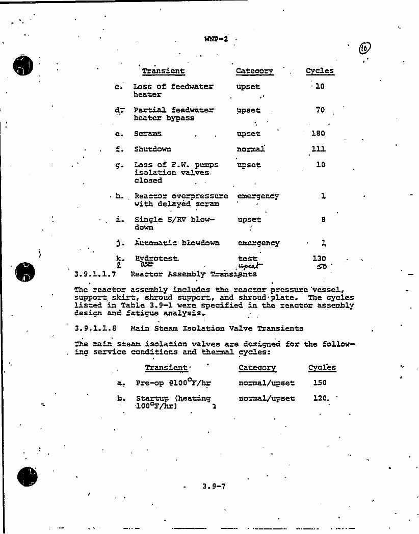
|qNP 2
T ansient Cvcles
c. Loss of feedwa'ter upsetheater
10
d-. Partial feedwaterheater bypass
e. Sc ams
Shutdown
upset,
upset
normal
70
180
g. Loss of P.H. pumps upsetisolation valves.closed
10
h. Reactor ove~ressu e emergencywith deLayed scram
Single S/RV hlow-down
upset
j. Automatic hlowdown erne gency I,
k. Hvd otest. test 130am- Sb
3.9.3..1.7 Reactor Assembly T=ansxpnrs
The reactor assembly includes the reactor pressure vessel,suppor ski~, shroud suppor", and shroud plate. The cycleslis ed in Table 3.9-1 were specified in the reactor assemblydesign and, fatigue analysis..
3.9.1.1.8 Main Steam Xsolation Valve Transients
he main steam isolation valves are des'gned for the follow-g se~ce conditions and the~ cycles-
Transient're~p6100 F/hz
ca~~renormal/upset
Cvcles
150
h. Startup (/eating normal/upset 120.100 Z/h )
3. 9-7

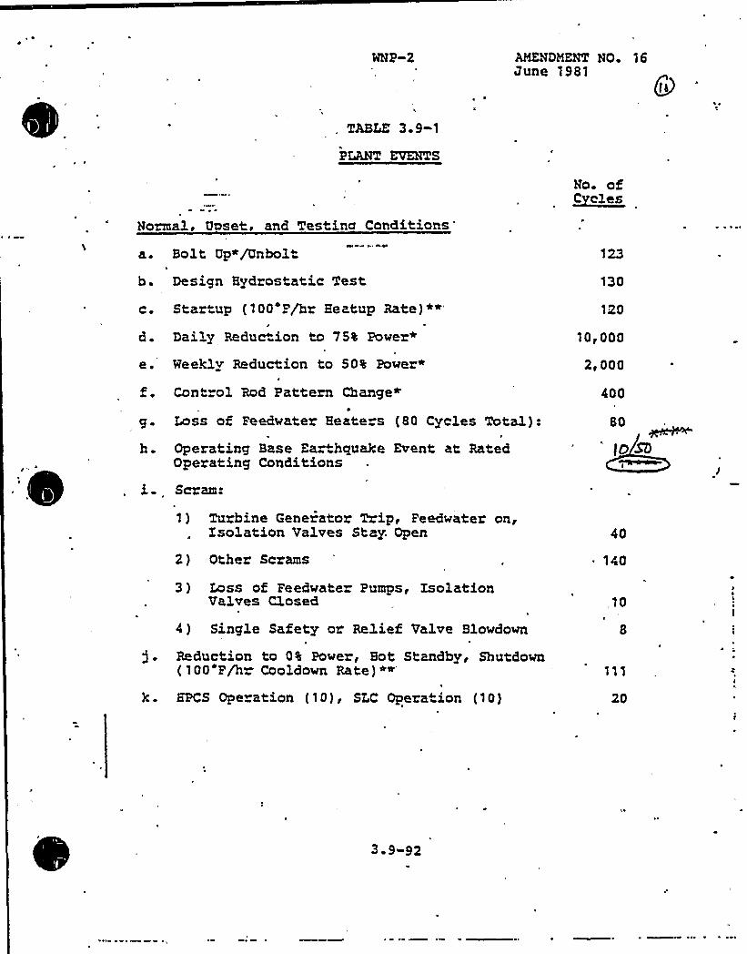
AMENDMENT NO 16June 1981
(i
,. TABLE 3. 9-1
PLANT EVENTS
Normal, Upset, and Testing Conditions
a. Bolt Up*/Unbolt
b. Design Hydrostatic Test
No. of~Celes
130
C ~
e.
~ ~
Startup (100 P/hr Heatup Rate)*»'
Daily Reduction to 75% Power"
Weekly Reduction to 50% Power»
Cont ol Rod Pattern Change»
Loss of Feedwater Heate s (80 Cycles Total):t
Operating Base Earthqua3ce Event at RatedOperating Conditions
Scram:
1) Tuxbine Genexator Trip, Peedwater on,Isolation Valves Stay. Open
2) Other Scrams
3 ) Loss of Peedwater Pumps, IsolationValves Closed
4 ) Single Safety oz Relief Valve Blowdown
Reduction to 0% Powex, Sot Standby< Shutdown(100 P/hr Cooldown Rate)
*»'PCS
Operation (10) < SLC Operation (10)
120
10,000
2~ 000
400
80
tOSD
40
140
„10
8
20
3 9 92
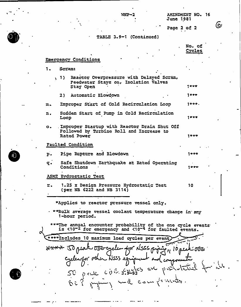
~ ~ HNP-2 MZNDMMT NQ 16June 1981
TABLE 3.9-1 (Continued)
Page 2 of 2
No. ofCvcles
Emeraen Conditions
1. Scram:
1) Reactor Overpressu e with Delayed Sc=am,Feedwater Stays on, Isolation ValvesStay Open
2) Automatic Blowdown r
m Improper Star of Cold Recirculation Loop
n. Sudden Start of Pump in Cold Recircula ionLoop
o. , Improper Startup with Reactor Drain Shut OffFollowed by Turbine Roll and Znc ease toRated Power
1*««,
]*««
Paul ed Condition
p. P pe Rupture and Blowdown
e. Safe Shutdown Ear&qua3ee at Rated OperatingConditions
ASM'ydrostatic Test
1.23 x Design Pressure Hydrostatic Test(per NB 6222 and NB 3114)
10
«Applies to reactor pressure vessel only.««Bu13c average vessel coolant temperature change in'ny
1-hour period.*«~he annual encounter probability of the one cycle events.is <10 2 for emergency and <10 < for faulted events.
««««Includes 10 maximum load cycles per event
MS
QsB
g~,c 4) ~~ ") i~3 9-'93
C

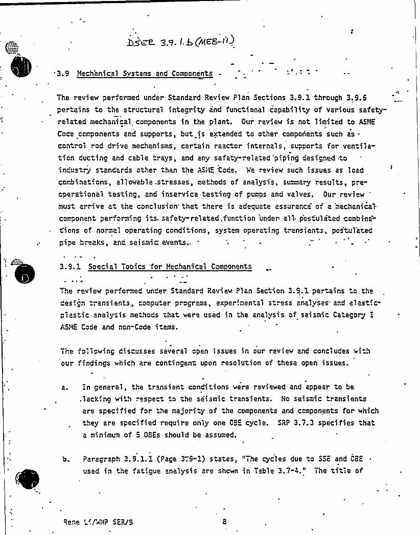
3.9 'iilechanical Systems and Components0 ~r
0
The review perfcrmed under Standard Review Plan Sec ions 3.9.1 hrough 3.9.6per-ains to tha structural integrity and functional capability of various safety-.elated mechanical components in the plant. Our review is not limited to ASHE
Code ccmponents ard supports, but is extended to other components such as-control rcd drive mechanisms, certain reac cr internals, suppor.s for ventila-tlcn due 1ng and cable "rays, and any safety-rela ad piping designed o
;n" st-.g'tandards other .han the ASIDE 'Coca. Ne ". view such issues as leadcombinat.ons, allowable .stresses, methods of analysis, summary results, pra-cserational tasting 2nd inservice testing of pumps and valves. Our review
'iusarrive at the conclusion'hat .hare is ada"„uate assurarce of a 'mechanical
component performing its. safety-related .function under- all pos~ula ed cmbina=
<icns of normal operating conditi.ons, system operating transients, postulatedpipe "reeks, and. seismi- events..
3.9.1 Special Topics 'for Mechanical Components
The review perfon:ad 'der Standard Review Plan Section 3.5.1 pertains " theas'cn ~ ansients, omputar p gl ams, expaf'..an al s. ~ ass ana uses* a,d alast.c
p.astsc analysis methods that vera used in the ana'.ys'.s cf seismic CategoIJ jASIDE Code and ncn-Code i.ams.
The o i I wing discusses several open issues in our review and concludes wi h
our findings which are contingent upon resolution oi these open issues.
in general, the transient conditions were reviewed and appear o be
.lacking wi h raspac ..o the seismic r nsients. Ho seismic transientsare specified for .he majori .y of .he components and ccmponents for which
they are specified require only one OBE cycle. SRP 3.7.3 specifies .hata minimum of c QBEs should be assumed.
b. Parzgr ph 3. 9. 1. 1 (Page 3.9-3.) states, "The cycles due to SSc and CBE
used in he ,atigue analysis are shcwn ',n Table 3.7-4." The title cr
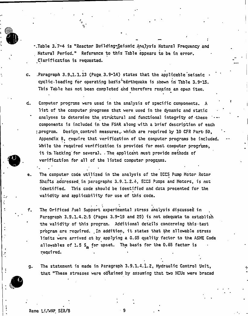
I
-.Table 3. 7-4 is "Reactor Building Seismic An<lysis Natural Frequency and
Natural Period." Reference to this Table appears to be in error.Clarification is requested.
c. .Paragraph 3.9.".1.13 (Page,. 3.9-14) s ates that the applicaNe seismiccyclic loading for operating basis earthquake is shown in Table 3.9-~&.This Table has not been completed and therefore remains an open item.
C"mputer progrwis were used in the analysis of specific components. A
i>st of the ccmouter programs that were used in the dynamic and staticanalyses to determine the structural and func ional integrity of .these
components is-included in the FSAR along with a brief description of each
:xrogran. Design control measures,. which are r equired by 10 CFR Part. "0,ppendlx 8, requ-ire that verificat'.on of the c"mpu er programs be;ncluded.
'awhile he required verification is provided for mos" computer programs.,
it is: 1'acking'or several.. The applicant must provide methods ofverification for all of the listed computer programs.
e. The computer code util'zed in .he analysis of the "-CCS Pump Motor Ro.or
Shaf as adc essed iil pa. agraphs 3. 9. ". 2.-'., ="CS P 'mps and 5!otor s is nor
:dentified. This code should be iden ified and daia presented for the
validity and applicability for use of his code.
The Orificed ;uel Support experimental stress analysis discussed inParagraph 3.9.1.4.2;5 (Pages 3.9-19 and 20) is not adequate to es ablish=he validi y of- this program. Additional de~ails concerning this tes.program are required. in addition, i s ates tha ~he allowable str ss
limits were arrived at by applying a 0.6o quality fac or to the AS'b1E Code
allowables of 1. 9 S for upset. The basis for he 0.6o .actor is".equired.
g. The statemen is made in Paragraph 3.9.1.4.1.2, Hydraulic Control Uni
hat. "7nese s resses were obhined by assuming at two HCUs were braced
Rene L-; "aNP ScR/8 9

'I
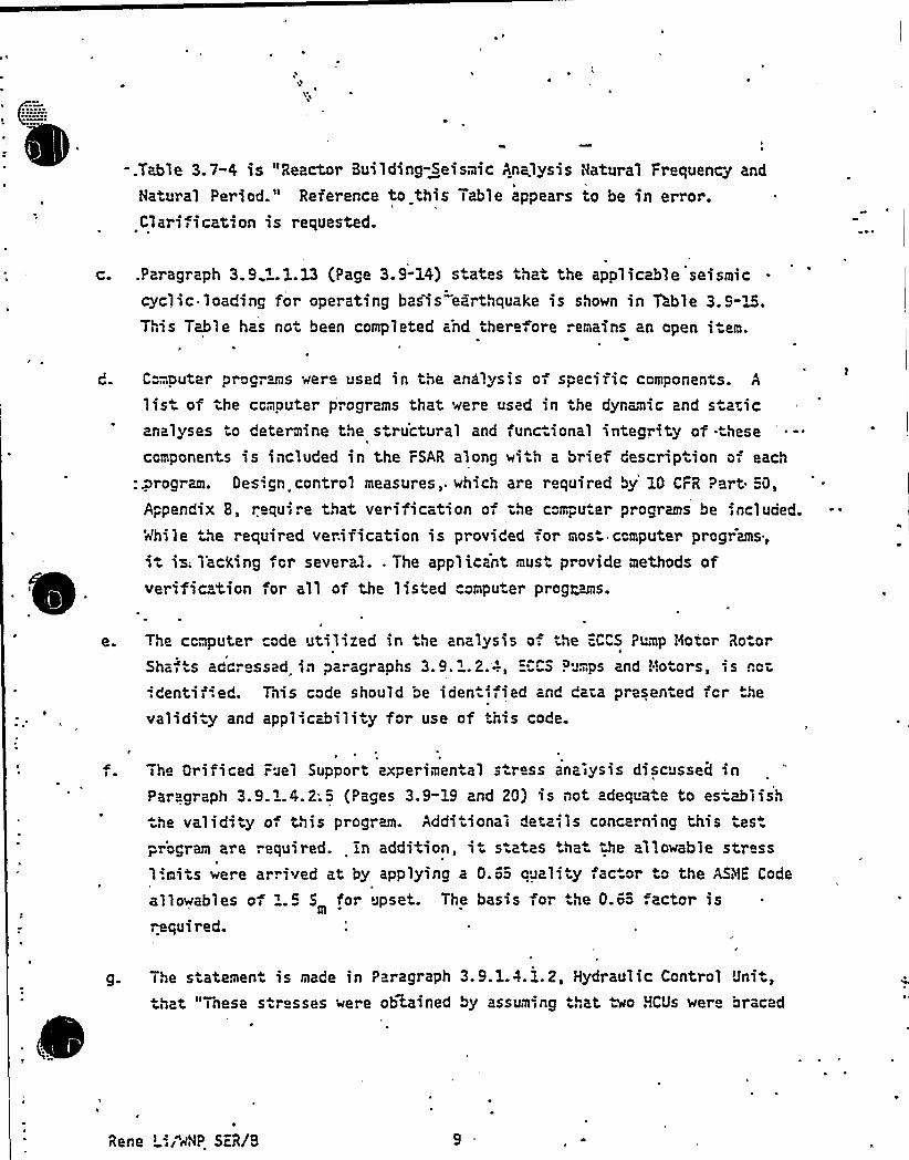
gl
-.Table 3.7-4 is "Reactor Building-Seismic Analysis Natural Frequency and
Natural Period." Reference to this Table appears to be in error.Clarification is requested.
c. .Paragraph 3.9.".1.13 (Page 3.9"14) s ates that the applicable seismiccyclic loading for operating basis"earthquake is shown in Table 3.9-~&.
This Table has not been completed and therefore remains an cpen i em.
'Ie.
C"mputer programs were used in the analysis of speciric components. A
list of the ccmcuter programs that were used in the dynamic and sta~icanalyses to determine the structural and func ional integrity of .these
ccmponents is included in the FSAR along with a br"ef description of each
:xrogran. Des'.gn control measures, which are required by 10 CFR Part. =0,
Appendix 8, require that verificat',on of the ccmpu er programs be ;ncluded.While the required verification is provided =or most ccmputer prcgrams,it isi lacking fcr several.. The applicant must provide methods ofverification for all of the listed computer prog~is.
b
The ccmputer code utilired in he analysis of the =CCS Pump Motor Ro.or
Shz i ts ado essed in pz. agraphs 3. 9. 1. 2.'-'., ="CS Pumps znd !!otors, i s nct:dentiiied. This code should be iden ified znd data presented fcr ~he
validity and appliicability for use of his code.
I'heOrificed Fuel Support experimen al stress anziysis discussed inParagraph 3.9.1.4.2;S (Pages 3.9-19 and 20) is not adequate to establish:he validi y o this program. Addi ional details conce. ning this tes.pr'ogram are required. in addition, it s-ates .ha the allowable stress1'.mits were arrived at by applying a 0.6o quali y fac or to the ASME Code
allowables of '.5 S for upset. The basiis for he 0.65 factor isrequired.
g. The statement is made in Paragraph 3.9.1.4.1.2, Hydraulic Ccntrol Uni.,that "%nese s r sses were obtained by assumina hat wo HCUs were braced
Rene LiI"~'AP ScR/B

VVI ll
QUESTION NO. 11
Paragraph 3.9.1.1=, Design Transients, referring to Table 3.7"4, "ReactorBuilding-Seismic Analysis Natural Frequency and Natural Period " appearsto be in error.. Clarification is required.
RESPONSE
The statement is deleted. See the tex revision a tached.
Summation — This item is c1,osed.
PCY: rf/45E58/18/81

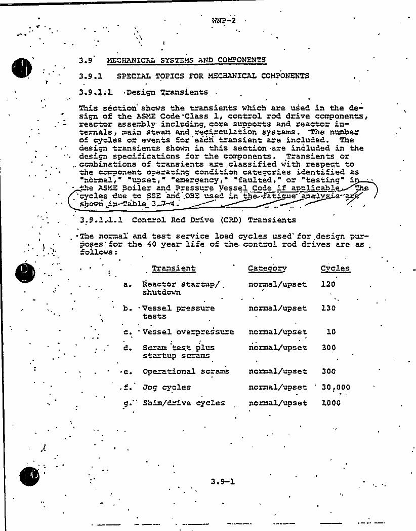
~
~
-3.9
3.9. 1
HE HANZCAL S ST MS AND CO%'ONKNTS
SPECXAL TOPXCS FOR HZCHANXCAL COMPONENTS
~ Design T~ients3.9.1; lThis section shows th'e transients which are used in the de-sign of the ASME Code'Class 1, cont=ol rod drive componentspeactor asseahly including, core supports and reacto- in-
ternals, main steam and rec rculation systems. 'The numhe»o cycles or even s "or each ""ansient are included. Thedesign ransients shown in this sect'on a e included in thedesign spec'cat'ns for the components. Transients o
.. ccmhina 'ons of =ansients a .e classified with respert tothe component opera"'ng condi"'on categories identi 'ed asnodal," "upset," "emergency," "faulted," or "testing" iNe ASY=- Boiler and P essure Vessel Code if aon1icabl
cycles due to SSZ and.OBE used in De-=ati e"analvsQoei in- iahle 3&4.3.9 1.1.1 Con"=ol Rod Drive (CRD) Transients
-Re no=al and test service load cycles used'o design pu"-poses'for the 40 yea life of the. cont"ol rod drives a"e as .
ollows:
Transien Cateao~ Cvclas
a. Reactor startup/ .
shutdownnonaal/upse" 120
h. Uessel pressuretests
I
c. 'essel overpressu"e
nonaa1/upset
norma3./upset
130
d Scram mt pluss a up sc ams
e. Operational scrams
Jog cycles
g. 'him/drive cycles
nonaal/upset 300
norm 1/upset 300
normal/upset '0<000normal/upset 1000
3. 9-1
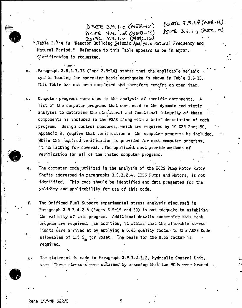
)IaaR. 3.9. (. g (MW-(z.)g«~ z~.i.J p+~-i33 ~m ~.~.i.z C ~-S~ P.S. t.e. +W I~)-
-.Table 3.7-4 is "Reactor Building-Seismic Analysis Natural Frequency and
Natural Period." Reference to this Table appears to be in error.Clarification is requested.
c. .Paragraph 3.9 '.1.13 (Page 3.9-14) stat s that the applicable seismiccyclic loading for operating basis, earthquake is shown in Table 3.9-~&.This Table has not been completed and therefore remains an open item.
d. Computer programs were used in the analysis of specific components. A
list of the computer programs that were used in the dynamic and staticanalyses to determine the structural and iunc ional integrity of .these
components is included in the FSAR along with a brief description oi each
:.program. Oesign control measures,. which are required by 10 CFR Part 50,
Appendix 8, require that verificat',on oi ~he compu er programs be included.While the required verification is .provided ior most computer programs,it isi l'acking for several.. The applicant must provide methods of
'
verification for all of the lis ed computer prog~~s.
The computer code utilized in the analysis of he =CCS ?ump Motor Ro.orShai s addressed in pa. agraphs 3.9.1. 2.-'., =""CS P iips and Hotors, is notidentified. This code should be iden iiiied and data presented for thevalidi y and applicability for use of this code.
The Orificed Fuel Support experimenial s ress analysis discussed inPar graph 3.9.1.4. 2.5 (Pages 3.9-19 and 20) is not adequate to es ablishthe valid', y of this prograa. Additional details concerning this tespr'ogram are required. in addition, it states .hat the allowable stress1'.mits were arrived at by applying a 0.65 quali y ac.or to the ASiilE Code
allowables of '.5 S for upset. The basis for he 0.65 .actor isr equi red.
g. The s atement is made in Paragraph 3.9.1.4.1.2, Hydraulic Control Uni,that "These s resses were ob4ined by assumiing that two HCUs were oracad
Rene L'iI"iiNP ScR/8

together back to back ..." Are the units actually tied together asa o
assumed? Additional details are required.
Subject to resolut'.on of these operr issues, our findings are as follows:
The methods oi analysis that the applicant has employed in he design o allseismic Category I ASHE Code Class ~, 2, and 3 components, component, supports,reactor internals, and other non-Code items are in coniorzance wi"h StandardReview Plan Sac ion 3.9. 1 and satisfy he applic ble portions oi General DesignCriteria 2,4,14, and'5.
The criteria used in defining the applicable transients and the computer codesand analytical methods used in .the analyses provide assurance that the calcu-lations of stresses, strains, and displacaments for he above noted itemsconform with the:current state-of-the-art and are adequate for the design ofthese items..
3..9.2 0 namic Tes ina and Anal sis
:he 'reviiew periormed under Stardard Review Plan Sec"ion 3.9.2 pertains to thecriter..a, testiing procedures, and dynamic analyses employed by .the applicant.to assure the structural integrity and operability of piping systems, mechanicalequipment; reactor i'n erpals and their supports unde. v'.bratory loadings.
3.9.2.1 Preooerat'.onal V-;bration and Dynamic ffec s Pioino Tests
The preopera ional v-ibratiion test program wilil be conduc ed during startup and
ini.ial operation. he purpose of these tes+s is to coniirm that .he piping,components, restraints, and supports have been des'gned +o w >stand the dynamic
loadings and operational transient conditions that will be encoun ered duringservice as required by the ASME Section III Code and .o confirm that no unaccept-able restraint oflnn"mal thermal mot'.on occurs. Me have identified the followingopen issues in our review.
0
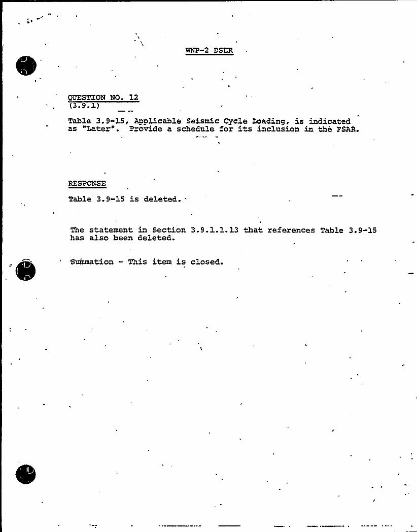
MNP-2 DSER
GUESTXON NO. 12(3 ~ 9. 1)
Table 3.9-15, Applicable Seismic Cycle Loading, is indicatedas "Later". P ovide a schedule or i s inclusion in the TSAR.
RESPONSE
Table 3.9-15 is deleted.
The statement in Section 3.9.1.1.13 that references Table 3.9-15has also been deleted.
P
Suinmation - This item is closed.

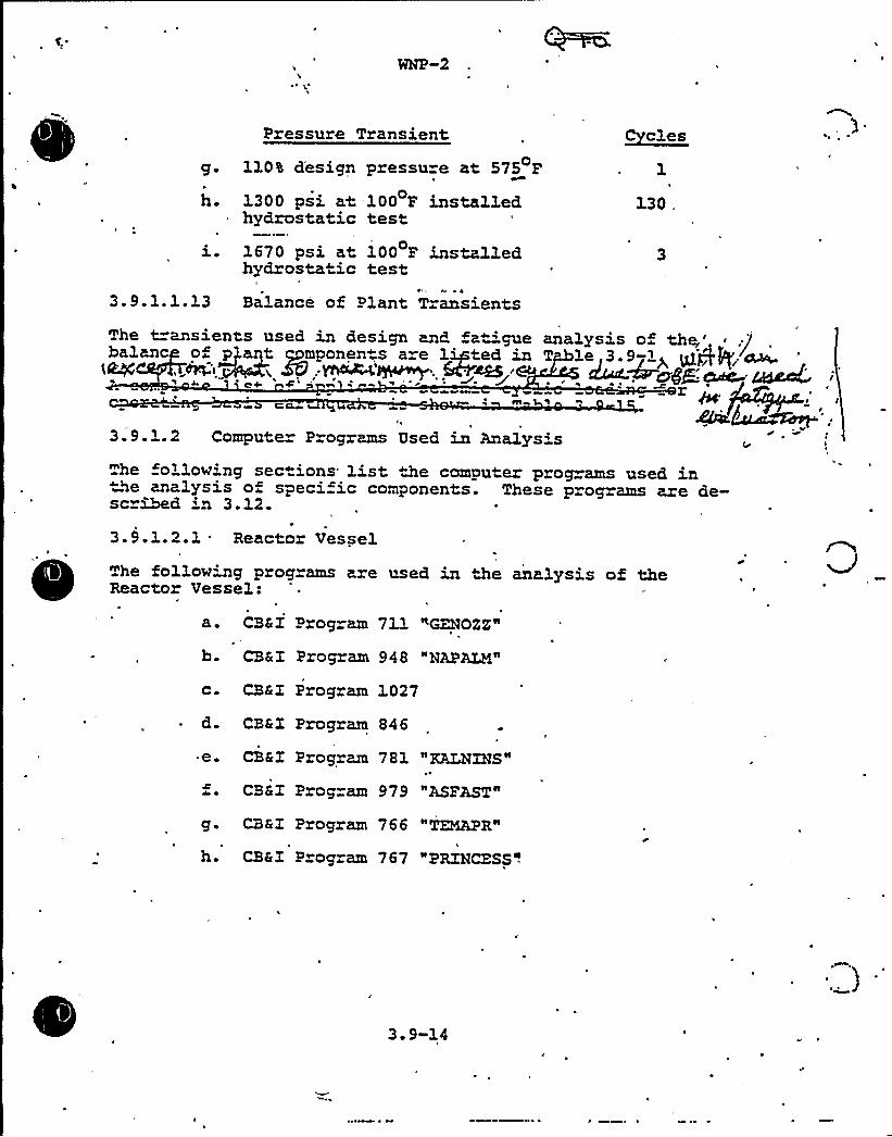
Pressure Transient
g. 110% d'esign pressure at 575 F
h. 1300 psi at -100 F installedhydrostatic test
i. l670 psi at 100 P installedhydrostatic test
3.9.1.1.13 Balance of Plant Transients
Cycles
The t=ansients used in design and fa igue analysis o the„',)balan nd p a t gpmponen"a a e lieted an T le 3.9-1> gjpI P; ~g $5, Yfl4~aN~'~~~'tat M~gP den '.dtLag„''
4 m~ 1C4a
3.9.'.2 Compute Programs Used in Analysishe following sections list the computer prog ams used inNe analysis o speci ic components. These programs are de-
scribed 'n 3.12.
3.9.1.2.1 Reactor Vessel
The following programs are used in the analysis of theReactor Vessel:
a. CB&Z Program 711 "GZNOZZ"
b. CB&I Program 948 "NAPALM"
c. CB&Z Program 1027
d. CB&I Program 846
e. CB&Z Program 781 "KALNZHS"
CB&Z Program 979 "ASPAST"
g. CB&I Program 766 "TEMAPR"
h. CB&I Program 767 "PRINCESS".
3 ~ 9-14
TABLE 3 '-15APPLICABLZ SEISMIC CYCLIC LOADING
3 '-207
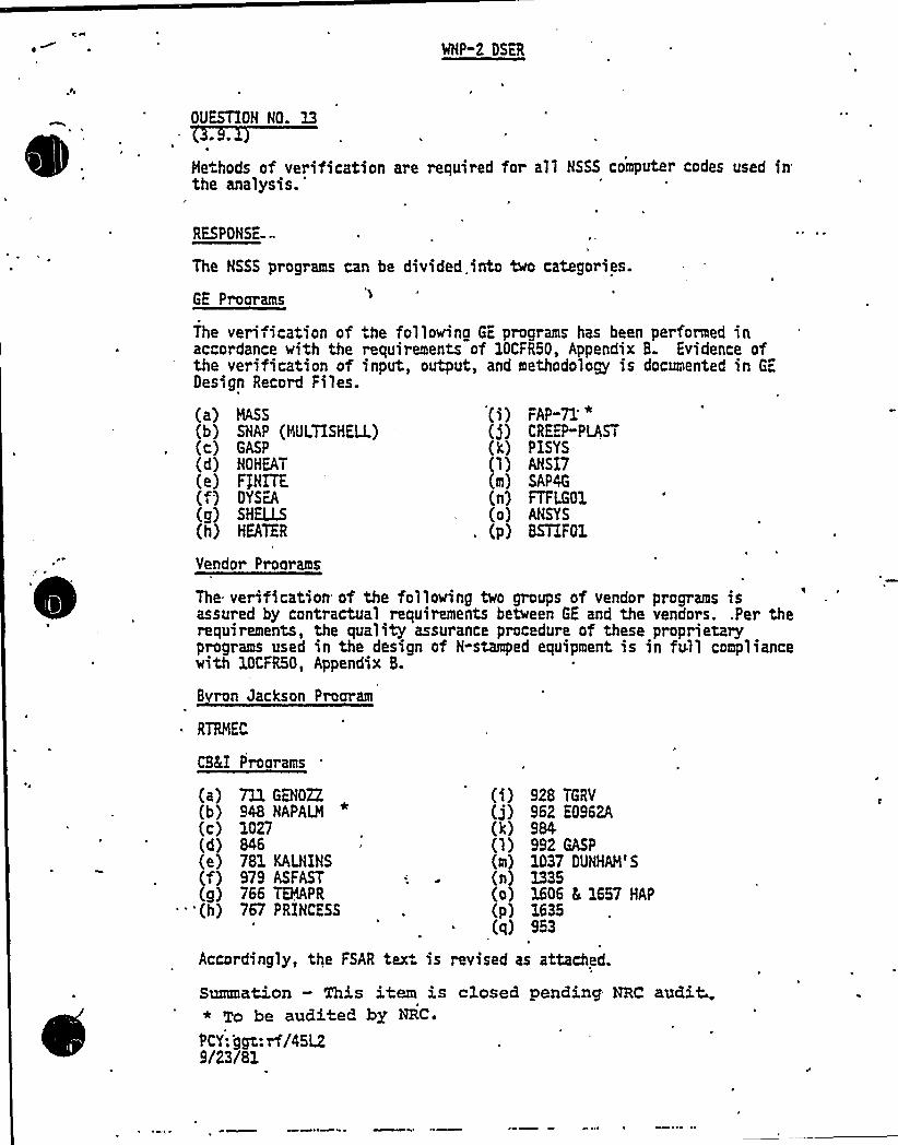
MNP-2 DSER
OUESTION HO. 13
Me hods of verification are required for all HSSS computer codes used inthe
analysis.'ESPON5a-
The NSSS programs can be divided into two categories.
GE Proarams
The veri ication of he followina GE programs has been performed inaccordance with the requirements of 10CFR50, Appendix B. Evidence ofthe verification of input, output, and methodology is documented in Gc,
Design Record Files.
(a) MASS
(b) SNAP (MULTISHELL)(c} GASP
(d) NOHEAT
(e) FjHITE(f) DYSEA
(g) SHELLS(h) HEATER
FAP-71'
(j) CREEP"PLAST(k) PISYS(1) AHSI7{m) SAP4G
(n) FTFLG01(o) AHSYS
(p} 8STIF01
Vendo~ Programs
E ran Jackson Program
RTRMEC
CBKI Proarams
The verification of the following two groups of vendor programs isassured by contractual requirements between GE and the vendors. .Per therequirements, the quality assurance procedure of these proprietaryprograms used in the design of H-stamped equipment is in full compliancewith 10CFR50, Appendix B.
(a) 711 GENOZZ
(b) 948 NAPALM*
(c) 1027(d) 846(e) 781 KALNIHS(f) 979 ASFAST(g} 766 TEMAPR
'(h) 767 PRIHCESS
(i) 928 TGRV
(j) 962 E0962A(k) 984(l) 992 GASP
(m) 1037 DUHHAM'S(n} 1335(0) 1606 5 1657 HAP
(p) 1635( ) 953
Accordingly, the FSAR tex. is revised as attached.
Summation — This item is c1osed pending NRC audit..* To be audited by NRC.
PCY ggt:rf/45L29/23/81
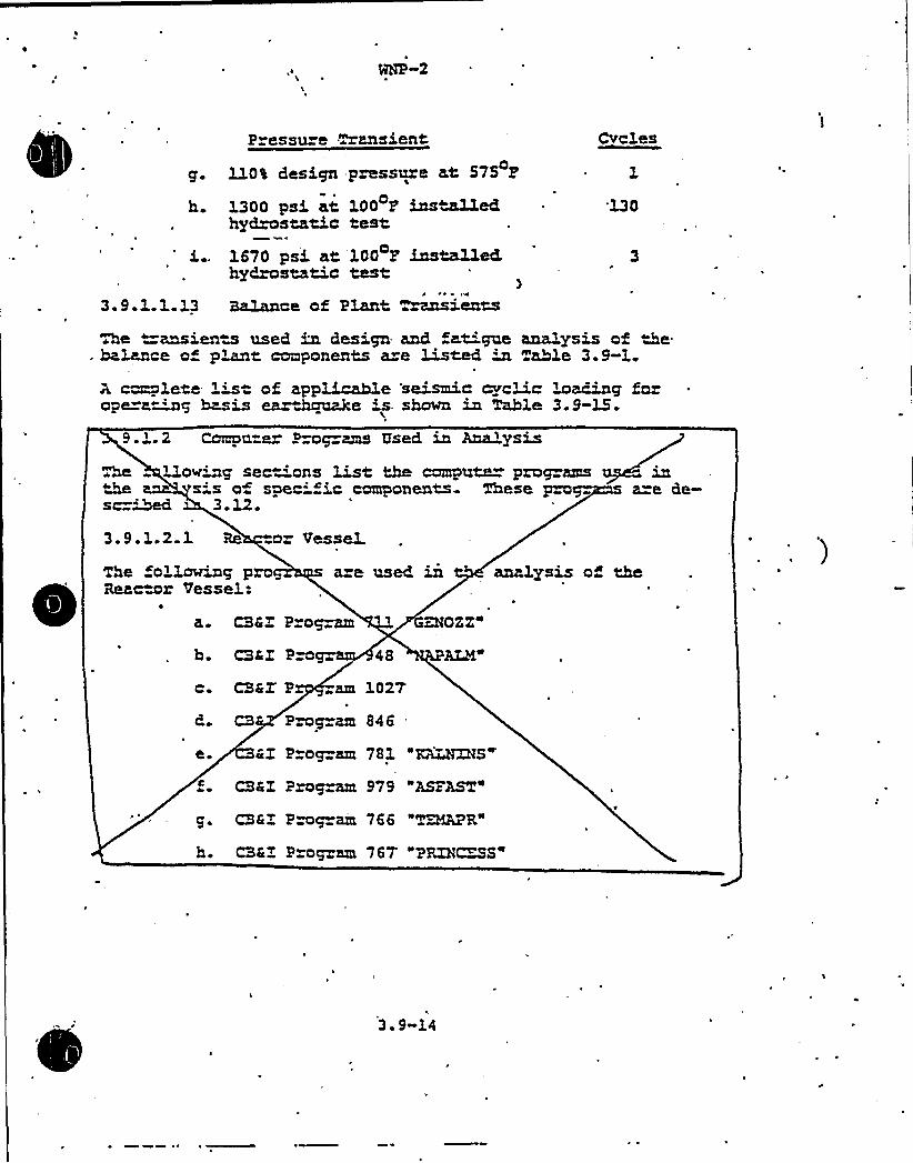
ge
h
P essu e ransient
Ll0% design pressure at 575 P
1300 psi at. 100 P installedhypostatic test.
1670 psi at. 100 F installedhydrostatic test
CYClss
'130
3.9-1.1.13 B~mce of Plant zansienM
he ansiena used in design and at'cpxe analysis of Ae-halance o" p~t components are Listed in Table 3.9-1.
A c~lete 1's of. appXIcmhle 'seismic cvcmc loading fozopera~4g hasis ear Jx~xake 's. shorn in Table 3.9-15.
9.1.2 Compu e Prog ams Used in Analysis
Lloving sec 'ons List the compute prog amssis o spec"'c components These pzosc=~ 3. 12
a=e Ge-
3.9.1.2 1 Re or Vessel.
aze Qsed
P og=am
b CSAI P o
The ollawing proReactor Vessel.:
a. CSSI O'Z2i
ALM"
analysis o" the
c. CSSI' am l027
CS Prog am 846
e. 4I Pzog am 781 "KLLHXÃS
CSEX Program 979 "AVAST"
g. CSRI Pmgzam 766 "T~R"h. CSRI Prog am 767'PRIH~S"
3.9-14

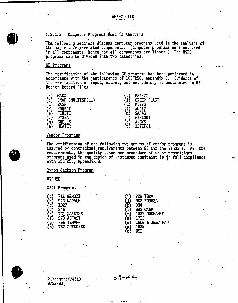
WNP-2 OSER
3.9.1.2 Computer Programs Used in Analysis
The. following sections discuss computer programs used in the analysis ofthe major safety-related components. (Computer programs were not usedin all components, hence not all components are listed.) The NSSS
programs can be divided into two categories.
GE Proarams
The verification of the following Gc, proorams has been performed inaccordance with the requirements of 10CFR50, Appendix P, Evidence of
he verification of input, output, and methodology is documented in GE
Design Record Files.
(a) NSS(b} SNAP (HULTISHELL)(c)(d) NOHEAT
(e) FINITE(f) DYSEA
(g) SHELLS(h) HA~TER
Vendor Programs
FAP-7(j) CRE>:PLAST(k} PISYS(1} ANSI7(m) SAP4G
(n) FTFLG01(o) ANSYS
(p) BSTIF01
The verÃication of the following two groups of vendor programs isassured by contractual requirements between GE and the vendors. Per therequirements, the quality assurance procedure of these proprietary ,
programs used in the design of N-stamped equipment is in full compliancewi.h 10CFRSO, Appendix 8.
B ron Jackson Prooram
CSEE Pro rams
(a) 711 GENOZZ
(b} 948 NAPALM
(c} 1027(d) 846(e) 781 KALNINS(f) 979 ASFAST
(g) 766 TENPR(h) 767 PRINCESS
(i) 928 TGRV
(j) 962 E0962A(k) 984(1) 992 GASP
(m) 1037 OUNHAM'S
(n} 1335(o) 1606 h 1657 HAP
(p) 1635(q) 953
PCY: ggt: rf/45L39/23/81
CL

WNP-2 DSER
L
3.9;L2.1 Reactor Vessel and Internals
3.9.1.2.L1 Reactor Vessel
CB&I Programs (a) through (q) listed above are used to analyze thereactor pressure vessel., Detailed descriptions are provided in Sec-tion 3.12.
. 3.9.LZ.L2 Reactor Internalsr
The foll+rin computer progr.ams are used in the analysis of the coresupport s ructures and other safety-related reactor internals: MASS,SNAP (MULTISH~) GASP NQHEAT FINITE, DYSEA SHELLS HEATER FAP-71and CREEP-PLAST. Detailed descriptions of these programs are providedin Section 4.L
PCY: ggt: rf/45L49/23/81.
8HP~2
i. CS&Z Program 928 TGRV
$ ~ CSEX Pmgram 962 "E0962A"
.. CBRX P~gram 984
1 CBa rogzam 992.
m. CSSZ ~ ~ 7 DUNHAH'S"
n. CSEX Pro am 133
0 ~ Prog ams 1606 and 1657
CBCZ Prog am 1635
q. CBRIT Program 953
~) o ~ ~ ~ o c1PLQg'~
"ollowi.-.g prog ams axe users in the analysis o pipa. ADLPXPE
h DYHAHZC ANALYSTS'P PZP~c P PANEL~ SPAC- STRU
SKELL AIZSZS PROI RAM
e. TZm DZe ~ PZP~ ORC
AMASS ZS (MSS)
TZSHELL)
PZPK DY?QQL.C SZS PROGKLH (PDA)
3.9.1.2.3 Reci cula 'umpNo computer program we e used in Ae sign of the recm~cu-lation pumpa.
3.9-1 2.,4 Pumps and, MotorAn eqa~v ent static computer analysis was performed the
motor rotor shaft. The model const~ted. of 1 e6mas s sinax1ating the List=MuMon of mass in the system,
3. 9-15

J
OP-2 OSER
3.9.L2.2 Piping
3.9.1.2.2.1 Piping Analysis Program/PISYS
PISYS is a computer code specialized for piping load ca1culations. Itutilizes selected stiffness matrices representing standard piping com-ponents, which are assembled to form a finite element model of a pipingsystem. The technique relies on dividing the pipe mode1 into several.discrete substructures, called pipe elements, which ire connected toeach other via nodes called pipe joints. It is through these joints
- that the model interacts with the environment, and loading of thestructure becomes possible. PISYS is based on the linear classicalelasticity in which the resultant deformation and s resses are pro-portional to the loadihg, and the superposition of loading is valid.
PISYS has. a full range of static and..dynamic analysis options whichinclude distributed weight, thermal expansion, differential supportmotion modal extrac.ion, response. spectra, and time history analysis bymodal or direct integration. The PISYS program has been benchmarkedagainst five Nuclear Regulatory Commission piping models for theoption"of"response-'spectrum analysis and the results are documented in areport to the Commission, "PISYS Analysis of NRC Problem," NED0-24210,August, 1979.
3.9. L2.2. 2 Component Analysi s/ANSI7
The ANSI 7 computer program determines stress and accumu1ative usagefactors in accordance with NB-3600 of the ASHE Code, 5~~on III. Theprogram was written to perform stress analysis in accordance with theASHE Code sample problem, and has been verified by reproducing theresults of the sample problem analysis.
3.9.L'2.3'CCS, Pumps and Hotors
3.9.L2.3.1 Rotor Assembly Analysis Program/RTRHEC
RTRHEC is a computer program which calculates and displays resultsof'echanicalanalysis of motor rotor assembly when acted upon by external
farms at any point along shaft (rotating parts only). The shaft deflectiondue to magnetic and centrifugal forces was analyzed. The calculationfor the seismic condition assumes that the motor is operating and thatthe seismic, magnetic, and centrifugal forces all act simultaneously andin phase on the rotor shaft assembly. Note that the distributed rotorassembly ~eight is lumped at the various stations, with the shaft weightat a station being the sum of one-half the weight of the incrementalshaft length just before the station, plus'ne-half the weiglC of theadjacent incremental shaft 1ength just after the station. ending andshear effects are accounted for in the calculations.
PCY:ggt:rf/45LS9/23/81
WNP-2 GSER
3.9.1.2.3.2: Structural Analysis Program/SAP4G
SAP4G is used to analyze the structural and functional integrity of theECCS pump/motor systems. This is a'eneral structural analysis programfor static and dynamic analysis of linear elastic complex structures.The finite element displacement method is used to solve the displace-ments and s resses of each element of the structure. The structure canbe composed of unlimited number of three-.dimensional truss, beam, plate,shell, solid, plate strain-plane stress'nd spring elements that areaxisymmetric. The program can treat thermal and various forms of mech-anical loading. The dynamic analysis includes mode superposition, timehisto~, and response spectrum analysis. Seismic loading and ti~ependentpressure can be treated. The program is versatile and efficient inanalyzing large and complex structural systems. The output containsdisplacements of each nodal point as well as s resses at the surface ofeach element.
3.9.1.2.3.3 Effects of Flange Joint Connections/FTFLQ01
The flange joints connecting De pump bowl castings are analyzed usingFTFLG01. This program uses the local forces and moments determined bySAP4G to perform flat flange calculations in accordance with the rulesset for> in Appendix II and Section III of the ASME Boiler and PressureVessel Code.
3.9.1.2.3.4 Structural Analysis of Oischarge Head/ANSYS
ANSYS is used to analyze the pump discharge head flange and boltingtaking into account of the prying action developed by the flat facecontact surface. The program is described in detail in 3.32.
3.9.1.2.4 RHR HeatExchangers'.9.1.2.4.1
Structural AnalysisProgram/SAP4G'AP4G
is used to analyze the structural and functional integrity of theRHR heat exchangers. The description of this program is provided inSubsection 3.9.1.2.3.2.
3.9.1.2.4.2 Local Stiffness Calculations/BSTIF01
BSTIF01 is used to estimate the local stiffness of the heat exchangershell at the attachment point of the supports. The method used in thisprogram is based on the shell stiffness calculations by P. P. Bijlaardas groundwork for Welding Research Council Bulletin 107. The results ofBSixF01 are used to determine equivalent beam properties of the lowerand upper heat exchanger support bracket to shell attachments'included inthe finite element model of the- heat exchanger.
PCY: ggt: rf/45L69/23/81

J
~
cmd by mass3.ess elastic members, sisaaLa~~g ~We ~~bn of shaft sti mess. The analysis @as pe~oi~~tie 'o obtain compatibility between the roplacaaents " e magnetic and cen~uga1 fo aM~ onthe rotorAll other analyst of sp 'Q.c motor .onents and peagc mponents cons isM o ons ~
3.9.3..2.5 RBR Seat e s
Z'oLh~~g a=e the n~~ pro~m used dyne.c andsta~ c analysis " ete=~e s~~~ and c"-'ona3. integ-
of Me at edge~:uppo~ LoaP. Seism c Analysis'(~6)
S~s Ana3.ysis o" S~o~m (ZD-8)
Other Compute X~~a Used in Ana3.
0~ camu~ p~g ams us ' and staticanalyses o s and fane"'onal in ~ 'cCa~a stems, amponents, ecjuipment and sapao m a
4.1 4 and
3 9A.3 ~e~nenta1 Stress AnaLysis
When expels~~ st ess analysand ~ used ~ lieu of anal'crt, methods for S~mic Camg~ X ~ Code items, the re-ma'mments for expe~mxtal test enmaera ed in the
AS'odewhich aw applimhle o- the spec"'fic components @viert'est sha3.1 be applied. Shen ~~g M ~~zi~d for SeismicCa~~o~ I non-AGtK Code pa~ acccnmt. shaIL be ta3cen ofsi"e effect and ~nsiona3. tole~ces which exist between
e a~x@1 par and, the'est pa or pa~ as ve3.1 as ~er-ences wh'ch may ~ m Ae u'~~u striga o- othergeve~ug mate~al ~perches of the actna1. par and the
md parts, to assure that the loads obtained from the tesa~ a maLis~mc or consent've mpresentation of the. loadca~riag capabili y of the ac~~1 sM~w under the postu-1aM loading.
3 9-16

(
Result of both ZSN:ZIZZ and HAS IN a=e g'ven in Table3.12-2 As can be seen, the~ is close co esca~. between~ deflec"'ons, with NAS&UH giv~g La~er values th~hcutthe lued. head than ZSGFXHX This is due p the Lack ozoational f=eedom at nodes vi2 QSQQ ove= the more
le shear element in ZSOFXHX~~.'his leads- to pre-d'c~ of highe st=esses using ZSCP32~~(as can be seen byc~~ing pages 2 and 3 of Table 3.12-2) . The computeZSCFZNX"~ is -~~~ore a conse~""ve me~~ or,dem~~ig s~sses in ~~ed head. fi~~gs.
pro~ is refe~ to in 3.8.6.4 4
3 L2 LO ADLPME
is a d giaL ~h"e zzagma developed by the A~Me Co. and used for sm~~ and dynam'c analyses of
Rex piping systems. Znput data prepz~"=on uses pip~mgae and output info~~mn is presenM for ea~~u
prcta~ n. he input data may be ~~processed ~plomor put and mode'va'ua~. To aid. a~pid data
p=epa~ - the=e a e ma~ ivan~ ~ ~4qnos s. Theoust au cd'y includes a s ess anal w as re~edby ANSX 831.1 967); 831.1 (1973); AWK Section
Class 1, s 2 and CLass 3 (1971 4 1974) TheASH Code, Sec -on, Class 1 anal m includes cal-cM~~ of at'ue age ac"w an smlifM elastic-plas~ anaLys~i. All crees, ~m, de ~ ec~ns, rota-"'cns and, a su~a~ ~ repo a~ in~shad in the au~~Add'cauQ'y, the pro~ or~~phic, iscmet='c., ands~eoscoow alot~g ca '
y to M che king inca and.e~g comov,ted re
The piping sys~ is odeled as a ~es of sec 'ons. ~Mt liebe&~ network po's. A sec~ ~osed. of ~ightand c ~ed and each membe ma have common cr d'~fe-e t Loads and ysical ~pe mes. The etwor3c points maybe me, y o fuLly res~~ed have specified
that. represent ths.=uR anchor 's orseis~ cho mot on. Lxt~~te sz ings ~~d orjo"'""'the members may be placed <M the section tosen spring hange s< pipe baLXcnm< skew and . d, re-
M i suppor a and ecuipment sC fness o T Knsftec."~pres a=e used to ~duce the size of Ae st='~Ressmat Me
3.12-15

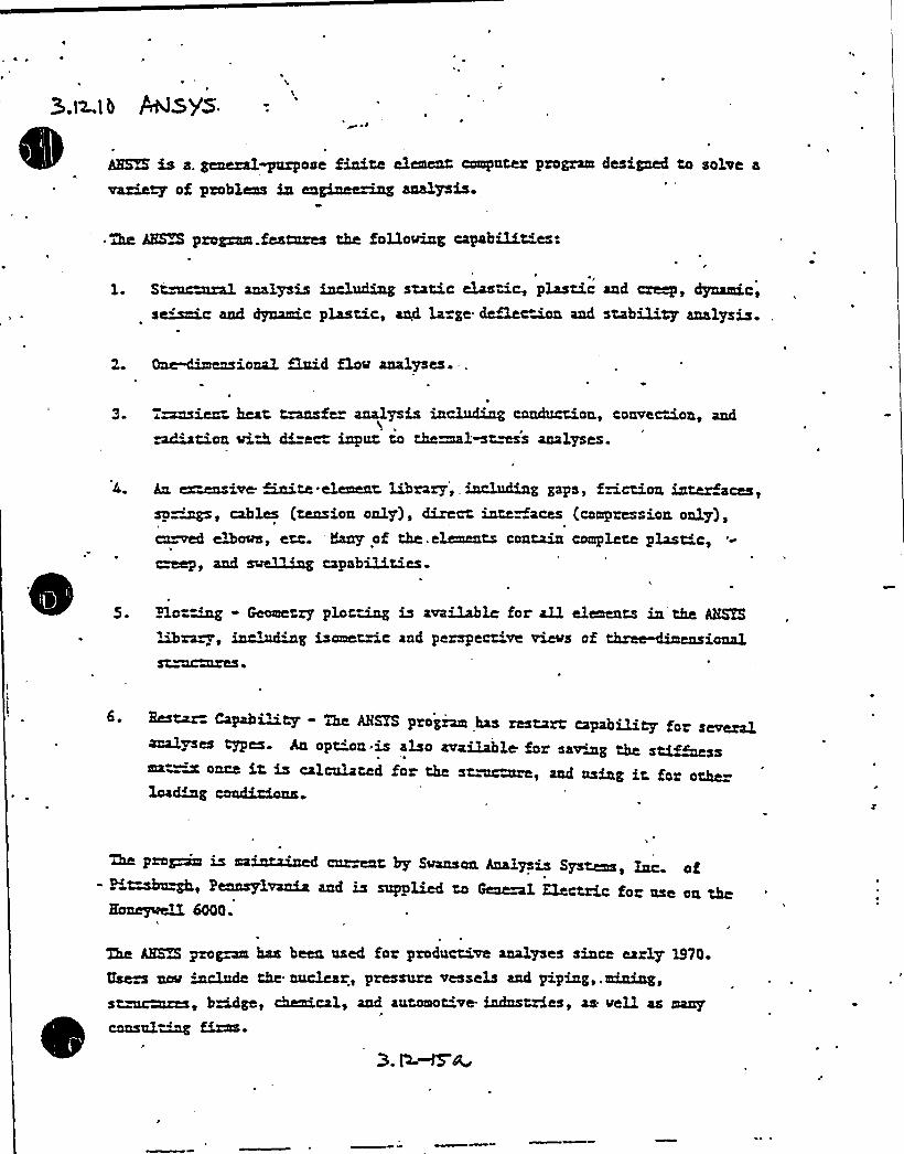
~ ~ ~
AHA %a a. gesmral~ose finite element computer program designed to solve a
of problems in engimm~ analysis.
~ 2m AHA program.features the foDoviag capabilities:
I
1. St~ural analysis tncleLug static elastig plastic and creep, dynamic,
s~c and dyed.c plastic, a~L la ge daBacmon and stability analysis.
2. One-dimensional fluid float analyses. -,.
T~ient heat, t~fe analysis inclnding conduction,, convection, and- tion viA di=ec inpnt to theamlmtmss analyses.
4. ex~ave ~te element ~rory> LILcln67JLg gapa > ~~cthon lJLter aces t(~ion only), di ~ interfa~ (c ~r~sion only),
cn~ ~~ots, etc. 'eany of the. elements contain complete plast'c,~, and exing capabilities.
~
~ ~
~
5. H.o-~ - Geometry plot~ is available for all elements in the Agog
ANSYS program has restart capabiliy m yps. An opt'on.is also available for saving the sti~ss
ea- —m once ir. is calculated for the st~re, and nsing it. fax othe=condialLons.
'Qm pro~ is mainta~f c~t by Swenson Analysis Systens, hzc. of- pi~~h, pennsylvania and is supplied to General Electric for nse an the
Ho~aeD. 6000.
The AHSTS pro~ has been used fox productive analyses since early 1970.
umph &schule the nuclear, pressuxe vessels and piping,.arum<~,st~~, bridge, chaxLcal~ and antomot've- indnstzies, as veil as many
consul~

~ i
„I
'
~:r SP 2
~ s~~ loads on ~ pipinW system may be the=~, deed-s~ ~c q sais:Ac loads'e~~y applimK ge es
zccBaMts ~ ~ ~ loads ~ ~e dynssw4c losds 4 e culpaas no mgL3. mode thee y 8$1d seismic esponse spec R oz;
z7 gc~inpazzc~ns in.one oz.- mo~ ~~~s.~ a reach asmK in ADLPXP to comgnxte- the rasponse~~f
nC shock inputs is hasn't apon a normalmode cc: ~m~si~ me~. ~ o aazXa~ in texasc~ noz=~ modesr ~ch is pe~cnlzL=Ly tBvRQ~Mcfeoas fclz t"RLL8-.e~ e problems, follies gene~y the f~ ~cussedby Koan' ~e=ence 3.D-1$ ).
's
s" ~ ~ application o ~ meehcxK is thedc~~~ the nK M eQzenc cs 'end mode shapes o»ee v-''~~m s o the system. Po=~a c~e~tivees-Lv~s~ reaped ~s system< xe cprre~
Hu+K a 0,
K is the (die ~) ~e~~ ma~X ~- ~~ s '~Mass t=m+ azuK.
u is ~calais, mat='f the ~~~cement.'QC~btes e
M s='Ness ms.Mw KR aMi"N in CTnamics 4omQationd'~~ ~Aha s '~Mess me~~ Rg developed. by Alba~~ the neewaxk po~~ts. Me Rat~~ ma~, de~paui by~s e ma~m te~aaes, includes mass~ ints md. in~~io-netvc=k;points. Mi sti~Ness mat=ad fo= e dvnamics «ozgu-la '~"eqai es s '«Mess valaes at mass po's only. Thus,
ac+ ~~ of K g en+ czLn be sh~ be ~agQ
K ~ A-.B.Z b
vh~ 5
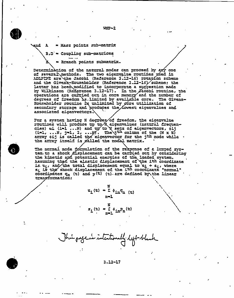
~ Mass paints sob-mat=w
~ S,Q ~ Conp~cy sr~ 'ces~ W'
E anch poinw suhna~De~~on of the nato a2 modes can pro~ bv oneo seve=a 'me~s.'he ~ eige~ae ~u~es~ed inADLPWE a e ithe Jacabi {Refe~ce 3.M~-L6) ~p an schemeand Qe Givens;Eonsehclde (Merce 3.12-16+scheme; «theLa ~ has bee~mad'~ied «~ inca~~~ a s~ces~n madehy %~~an (R~~ence 3.12-17). ~ &e~acohi ~u~, «&eoperamns a=e ca='d cv.= '" caw mam +and «the rMe ofdeg ees o wedcm4.~ted hy a~kle ca e. The GivensBoaseeolee zoe"-'"e ss e='i-'M ey ~ e a~Boa ofse ~~~ sw sge and. 'awRaoes Ae loses eigenvelees adcLssocMted eigenvecM~s ~
Pa a. svsam havana N of freedom, the e'creamQ,ue~='"es ~ "~nce np taA,e'~+a'dies (nam=zl ~~en-s) ei ('~1 ...N) and up N'M sea of e'genvecaw, qij
(i~1, ...N ~ j~l, 2, ...Sf. The+~ calnmn of the (N x 8)a~@ gij is called thd'e'~ve~ o the j~ made ~~o"e a~v iael ed the mat=~
The no~ made ~ 'ian of the m~cnse of e, 1~ed hays«em.ta a. shock lacement can be ca~ed oat by ccnside=hapthe Bmoc paten~ enemies of D'e, loaded sees«~.has —~cZ the ~ ~c ~placement of ~e i~ cao~Lna~M utal Zsplacemen mal ta ui + si, wh zese m 2/shack displacement o «Ae i " caozd~wte 'nona1.caen"'es @ (t) and p( ) ( )- a~ c~»- ei hv'ithe Mea
~XXttean e
8ni(t) ~ Z, P~c~
n~1
Hsi(t) ~ Z 4, pn(t)
nasl
3. X2-17

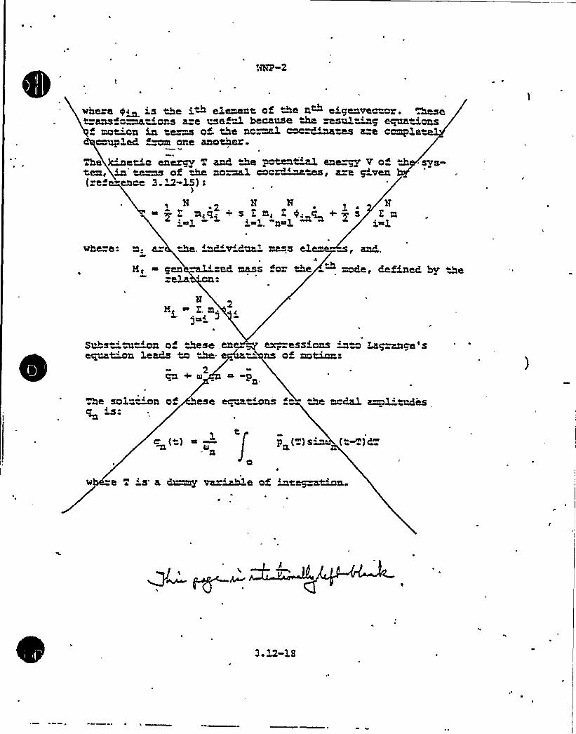
%p~2
vbere y~~ is /e i~ element of Ae n eigenvec"or. ~et ans c~tions a e tse~M because ~ "esul~g eqaa 'cragmot'on in te~ of. the nc"mal coo=dinahes am cample"
ed ~om one another e
he ~+et'c ene~ T and ~~ paten~ ene~ v o<tern, ~~ ~s of M no ~X cocr~~, a=e g'ven(ref ence 3. U-L$):
N ~ N H, l Hm<q +g lm, E4.. q +~s Emi~l i~1. n~l. i~1
@here m< a= the. ~vMaa'ass eleme m, and,
~ pen ~ ed mass for the ~ mde, defined hy Deo
NNi E.
gcsi
Sn"s 'a~n of geese,enequMn leads u W e
~e 2 ~&
+ Ol ~ ~P
cx~~esskons ~~ LK~~cge 5ns 0f motion e
e sol~~n ofis. ese ~u~ns " M modal, am3 M~es
p (N) g4 (ca~) +et'
v -e T 's a d~ va ~e of wtegacM~n.

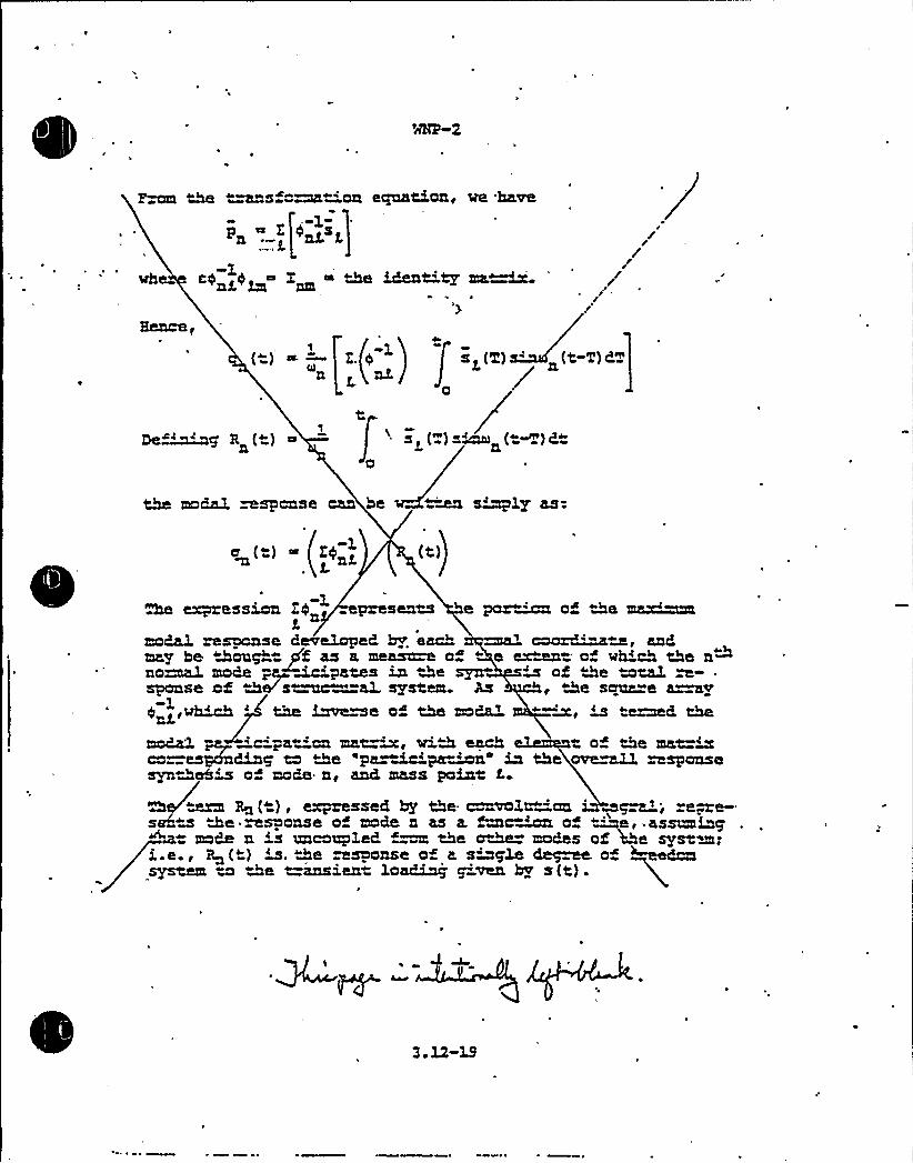
the t~s o~t on equation, we have~e --1-pn .
c0 <0~ X ~ ~t='ty ma~
///
//
(-) "n
1Defang' + Rn
Z. pnJ-
«~e
s ~('2) -'t-T)CT
(see) w~ («~) Q«
the mo6a3. ~spcnse can be ~ s~d3.y as:
he expression Z4 presents e pored of the maximmode. mspcnse 6evetopeC by. each ~ coczd'" x«w, and.may he «2onp g(f as a memn o " e e~=. of wh'ch the nthno~ mode pa~me"'pates M the syn m of «the mta3. m- .
sponse of &e's~c=a3 system. As, the sanz=e ~ywhiah 'he f zve~e of the mo8aX "—~, m teamed the
mc843. ~ e C pat On mat Me Vhth t of the matedco es Mg to «the "pa~Zc~pa~d u, the ove~ wsponsesynQahw o" mode n< ance mass poMt i
Rn ( ) g cxPxssseC by the ~vol@ cols «m Me response of mode n as a fmc~d o ~de, assumiap
moN n w uncozqled. ~~ the oM moaes of the system;i.e., So(e) m. "-cce msoooso od s sdoccla dace~a od Medeasystem to the t=insient loa~j ~ven by s(t).
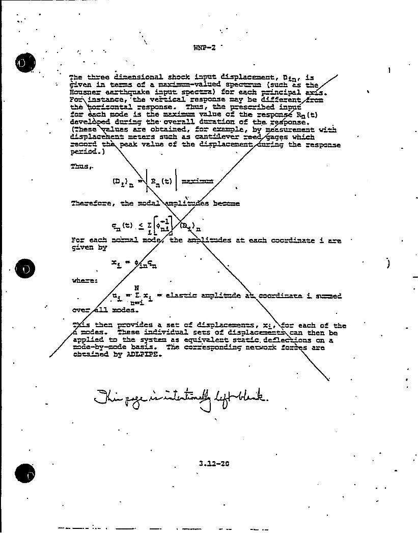
1
e
he ""-ee Cimnsional shack Mpnt ~i@cement, Dg,n, isHansne~ es~z~e ~pal spe~) faY esch ~~c pal 4xL$ ~
p „~<~e, 'the ve Ace3. response mr.y be G~fe ent~f~=ants~ ~sponse. Thas u the ~crMed Mphfar ecch mode V the maxhmm velne of Jxe mspon.d Rn(t)de~iaed d~~ the ave~ d~~ af the. expanse
( bese nes a=e obtained, fo- eence, hy musu=emen v'>t mete=s snch as can~ever es ~hpeak value of the ~~emen —mg the ~sponse
pe=M )
(D ) R (t) mr Mamn
~~a=e, the modal ~~ s b~e
)nPo each na'mal mad, the '~s a» each caa~~w ~ rwp'ven hy
%610 C-8
a< ~ l. x< ~ eke.s~ ma~'~ a coca ~ee, i. ~eK'~mades~
~De ~~~es a se cf Lm&emena, x:, «a each of themades. Kese MvMnal sets o Mplaceme ~can then be
a~~1'eP. ta M st~ as ega'vale t s~~, deQec+ms an a~e~~e has~. The ca=espa~~g ne~M fa s a~oh~ed hp MLPXPE
WNP 2. AHENDMMT NO ~ 9April 1980
~ computes the non~ass'etwork. force-mom sets foreach As seen previously, the network offness matrix
ormed is q rated bv the t=ans ez ma 'f a series of manyindividual m ~ This same ac ted ~mfa mat ~ isused to compute " foz~oment ts at interior points ofthe piping system (in " inq e mass points}.The ceaulative ef ec all < modes is estimated by tzdAgthe sauaea ant of e sum of of the foz~nament ae»wat each icosi io m the pipinq syst Po closely spacedfmquencies opt on ex sos vh=ch en the add tion ofthe abso e value of those modaL moments then forming ~Bes - of tha» sum in the sap-are mot of ~earn tion.This proc~ is refe ed to in 3.9.).Z.X.
3 12 11 EELAP3
h" s prop am describes Ae behavior of vate~oled nuclea-zeac ors du=nq postulated accidents such as loss-of-coolantg pump fai'uze< oz po~e ansients. We behavior ofthe pr~arv coolinq system and the reactor is emphasized. Thepox;~ calculates flaws, mass inventories, ene~ inven»»~es, pressu es, tempezatuzes, and cualities alonq withvariables assoc'ated with zeac~ power, reactor heatMms~er>. or control systems
3~3 is an HRC accepted computer proem and is in thepubl'c domain. For a complete discussion of this pro~ seeReference 3.12-18.
pro~a ~m refer ed to in 3.6.2 2 Th and 3.6 2.3.1.3 12 11 1 RKLAP4/NOD5
R~4 is a computer pzog~ written in PCEKKQf IV for thedie;i»~ ~npumr anaLysis of-nuclear zea~rs and m~>tedsystems. I U primarily appl'ied in the study of system t=an-sient response to postulated perturbations such as coolantloop axpt~, circulation pump failure~ pose exnmions, etc.The proqzam was vri~en to be used for vate~oled. (RvR andMR) reactors and can'e used foz scale models such as LOFTand. SBfZSCVLZ. Additional versatili y extends its usefulnessto related applicat'ons, such as ice condense and contain-ment subcompa~ent analysis Specific cnpians are availablefor reflood (FLOOD} analysis and for the HM'- Evaluation Sodel- "
3 12-21
wNP"2 DSER
I
QUESTION NO. 15(3.9. 1)
The computer code utilized in the analysis of the ECCS Pump Motor RotorShafts addressed in Paragraph 3.9.1.2.4, ECCS Pumps and Motors, is notidentified. This cade should be identified and data 'presented for thevalidity and applicability for use of the code.
RE5POMSE
Referring ta the response to guestAon Ho. ~D, RTRMEC was used by themotor vendor ta estimate the ECCS motor shaf displacement. The resultsof the calculation have been verified by (1) comparison with motor rotorbend test data and (2) comparison with the SAP'esults obtained by GE.The comparison demonstrated the conservatism of RTRMEC.
Summation — This item is closed.
C ~
PCY: ggt/45L79/22/81

MHP-2 DSER.
OUE~iON XO. 16-
Provide addi ional details concerning the test program performed on theorificed fuel support to establish the validity of the program. In.addition, provide justification for using the allowable limits by applyinga 0.65 quali y factor to .he ASME Code allowables of L5 Sm for upsetcondition.
RESPONSE
TestProc'he
following is a detailed description of .he tes program.(Note: NP-2's orificed fuel support is not required to conformwith the ASH= Code; however, the test program is designed to conformto the code irr order to verify the design adequacy.}
Two sepzra e ests were conduc ed, each test was designed to bein conformance with Appendix II of (th j5HE code Sec ion III. Thefirst es series veri ied the stru~ral capability of the fuelsuppor casting to sustain vertical design loads. A produc ionfvel support was stresscoated and subjected to .an extr'emely highvertical load to identify the location and principal stress directions.of the highes. stressed regions. A second fuel support was ins , umentedwith s rain gauges: 12 uniaxial gauges were used where the principals.ress d3re~ions were known from the previous stresscoat test.Six rosetws were used where the principal stress axes could notreadily be determined. (All he gauges used in the experimentals ress analysis were put in the regions- of highes stress asdetermined by the previous s resscoat test.) The fuel support wasmounted in a fixture simulating the geometric characteristics ofboth the load and support in the reactor. Vertical loads only were
'pplied,simulating the weight load of the fuel assemblies.
I. was found that the fve3 support could sus ain a vertical load of104,000 pounds before the onset of yielding in the highest stressedregion. This 104,000 pound load represents a safety factor inexcess of :-5 based on yielding over the normal applied verticalload.
A second series of tests were conducted to investigate the resultingstresses induced in the fuel svpport by a horizontal (or lateral)load applied by the fuel assemblies, during a seismic event. A uelsupport was instrumented with 15 three-element rosette straingauges. The location of these gauges were determined from aninitial computer analysis, and.represented the areas of highests.ress plvs a few key locations of minimal material thickness.
PCY:ggt:rf/45LSo/23/SI..

MHP-2 DSER
'I
The tes fixtures used were designed to apply equal loads on allfour pods. - This was achieved by using two hydraulic cylinders toload two spreader bars.'he load was transmi ted into each. spreaderbar through balls which prevented moment build-up. Each spreaderbar then loaded two arms, which in turn loaded dummy fuel lower tieplates. At the interface of the tie plates in the fuel support,the dimensions of these dummy tie plates'ere identicaT fe thoseused in the production components. During loading, weight wasplaced at the top of the load arms approximately in the center ofthe fuel support. This loading simulated a vertical load whichwould be present due to-the fuel assembly weight.
During Ne initial phases of the testing, it was discovered thatthe s-.resses induced by a horizontal load were a maximum when theapplied vertical load was a minimum. Because the fuel support isnot a ached to the guide tube and sits on a chamfered seat on theguide ~e provided for that purpose, it was found that an in~aseddownward vertical load actually enhanced the fuel support's abilityto sustain a horizontal load.. (Nth increased vertical load,additional rigidity was provided to the fuel support casting by theguide tube.)
A load cell was calibra ed and installed on the lower hydrauliccylinder Load data was recorded on a continuous recorder, ands rain gauge data was recorded on a multi-channel recorder. Thetowl applied load was twice the load cell readings.
The firs horizont-1 loading applied simulated the ASHE code upsetcondition. For this condi .ion the total ver ical load was calculatedto be just under 1,000 pounds with a horizontal load of 2,600pounds being applied. The calculated vertical load. applied to Nefuel cas='ng included its ~eight, the upward component of a U2gseismic load, and the differential pressure across the fuel and thefuel support. The 2,600 pound load was taken from the fuel'supportdesign specification for the upset event. A horizontal test loadof 3,000 pounds was applied to compensate for possible increasedhydraulic pis on friction, changes in friction due to a smallamoun of misalignment and/or. cocking of the load arm in relationto the piston travel direction.
The teq results simulating the upset horizon~1 loading conditions- produced a maximum stress of N,833 psi. The differential pressure
stresses ac-.oss the cas ings were computed. The L,580 psi valueobwined rom the computation was then added to the tes results.(Differen-ial pressures across the fuel suppor were not simula edin the tes program.) The total resultant stress was 12,433 psifor the mset condition. The total stress resultant was less thanthe ASHE code allowable of XS;3BO psi for the upset condition.-
PCY: ggt: rf/45L9e/23/aZ
NP"2 OSER
A second series of test lcadings were applied .o the suoport castingand were designed to simulate the faul.ed condi ions. Ho ver.ical
~ load was applied during this phase of the testing because of thenet result of lg downward force due to gravi y and the lg upward
~ component of force due to the safe shutdown seismic faulted event.The horizontal test load was .applied to simulate 5.,200 pounds offorce for the faulted event.
Testing simulating the faulted horizontal loading produced a maximumstress intensity of 2~,225 psi. A computed stress value of 1,580 psifor the in ernal pressure wad added to the tes result similar tothat o the upset event desc".ibed above. The addi+ion of hese twostresses resul ed in a maximum s ress int nsity of 23,505 psi,which is signi,icantly less than the 35,400 psi allowed'by AS>L~
code for the faulted conditions.
2 Quali y Factor
The 0.65 Quality factor accounts for the fact that not all castingsare fully volumetrically examined. It i s specified in the AS ME
Code, 1974 Edition, Summer 1975 Addenda, Paragraph NG-2571.2(a) .
Summation - this item is closed.
NOTE: Response on "Quality Factor" has been revise'd to citecorrect code edition.
QgcsTLem-. L7
Expand Pa=agraph 3.9.1.4.1.2 (page 3.9-18) to desc~e theac ual moun~g of the hyd=aulic con ol units and to jus™-
y the val'Qiy of the assumption u ~ lized in the CESAR.
Response
Please re e to revised 3.9.1.4.1.2 (page 3.9-18) or thein on@ 'on =ecuested.
Summation — This item is closed.
Ho analysis has bean made or the non-code components of theCBD for the abnormal condition.
The desicn -adecuacy of non™code components of the CRD hasbeen ver' ed by extensive esting programs on compo-
-nents para, specially mt~en ed proto~a c ives andproduction drives. The tasting included postulated abnormalevents as welL as tdxe sauce Li e cycle listed in 3.9.1.3..3..
~ ~1
3.9.1.4.3..2 Eyd~ulic Cor. -ol Uzu.t
The Evd-au»c Ccnt=ol Ur~t (HCU) was analy-ad for the SSZaulted conc='cns, ~ough the implemen ation of the com-
pute code SMIZS (See 3.12) .. Using the method. of "Smn ofAbsolu e Va3.ues of the Nod'a3. Loads," the meum st=ass or.the ECU rme was cal~+ated o be 54,310 psi. The maxiznam~~owab3.a or SS=- 's 60,000 psi fo=.the ECU. These s esses
~,va e cb~ed bv -"——~ag m~<mo ECUs - eoceneback to back . ':" at the ton„'and bo om of theE~xz'a x ~~Wc dI».ks'/+7 n 7~4 ~,~
0e undaman al r~ency o" tha ECU is close to the f e-
.'piency a™ wctu.ch peak saism'c shock will occu=. ~is resultsin overs=assed cond" 'ons in the piping cor~ec ad to theECU dv ing ue sz a shutdown ea~Aquak (SSE) . Bv the.app3'cat'on of bol"~n sti aning st~m to the -ECU fumes
. and d'agonal b ac~a along the rows o~ installed HCU'sg ~De.fmdamenta'racu~cy is mused su ficienZy o avoid peak
. seismic response. Tha s -esses in the .connected piping arethus educed to acceptable values
The analysis of the ECU unde aul ad condition loads estah-" Uhhes the st»uctuM integ ity of the system.
-3.9.1.4.1.3 ~ Eousing
The SSZ is classified. as a faul ed cond"'~won; howeve», inthe CRD housing analysis the SSE event has bean t=aa ed asan emergency ccnditicn. The max~mza membrane s -ass intan-si y occa=s at the tube o tube weld. near'the canter of thehousing. The s=esses a=e widen elastic limiw and a eshown in Table 3.9-2(v)-
e
\
~ I
~ ~ ~ ~ ~ h
3 '-18
%0~ e% ~

4
NNP-2
Response to M~ SERQuestion 417
Insert A-~o "PSAR Page 3.9-18
each pai= of tiers HCUs is suppo~ec 'n each o three mutua.l3.yperpendicular Q.rec"ions by means o s~mts and c'agonz1bracing connec-ed from &e BCUs "o z M"ee ~ensiona~ se'sm'csuppo~ =arne enc1osing rows 'o HCUs znd. anchored to Aeconc ete foundation. See a ached dvigu e Q 17-1.
~ ~
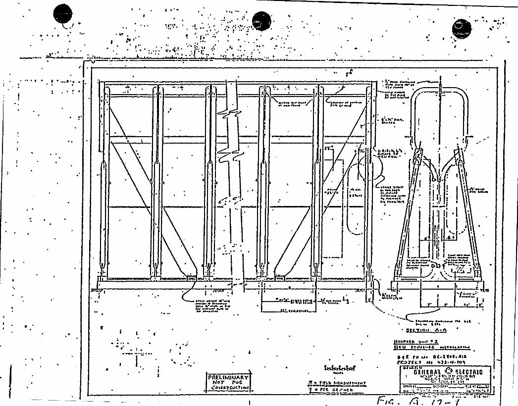

~~,8) jap ~ 3.5.z. I. c. (A&-~c'~
3 ~ g ~ . p (we@-(9) bs +~ ~-5 2 ~ 4 C
The 'applicant should provide a con+it"en'n the FSAR stating tha allrequired piping restraints, components and component supports have beeninstalled in the piping system prior to testing.
b. The applicant's proposed preoperaticnal test program covers the vibrationand dynamic ef ec s.. However, the thermal expansion effects required inSRP 3.9.2.TI-1.d, e, and f are not adequately addr ssed. The thermalmction monitoring program should deal specifically with verificat.on ofs.".ubber movement, adequate clearancas and gaps to allcw froe movement ofthe pipe during heat-up and cooldown and shculd include acceptance criteriaand test procedure;. Additional information on this prcgram is required.
r,: ..:The applicant has not given a clear descrip~ion of the acceptance.criteria~ . for s eacy-s ate piping vibra icns. The s aff's posi ion is hat ac ep ance
limits for vi"ration should be based on half -he endurance lim:t as'.'. defined by the A Code at 10'.cycles.
d.0
Due to a long history of problems dealing wi.h inoper ab.e and inccrrectlyinsta'iled snubbers, and due to the potential safety significance cffailed snub"ers in safety-related'systems and components, i is reques.adthat the cperability program for snubbers shculd be included and docu"mentad by the presarvice inspec.ion and preopera icnal tas program. Me
will require he applicant's response o the let er frcm R. Tecesco toI
R..Ferguson, "Preservice Inspection and Testing of Snubbers," datedMarch 6 '1
Subject to resolu ion of these open issues, our f',ndings wi11 be as follows:
The vibr tion, thermal expansion, and dynamic effects test program which will4e conduc.ed during startup and initial operation on specified high and mod-
erate energy piping, and all associa ed systems, restraints and suppor s is an
acceptable program. The ests provice adequate assurarce that . he piping and
piping restraints of the system have been designed '.o withs .nd vibrationaldynamic effects due to valve closures, pump trips, nd other operating modes
'sociaad with the design basis f",ow condi'icns. n addi ion, the tes s
provide assurance .hat adequa e claarances and freo mcvement of snubbers axis
Rane l.i/WP SiR/8

. Ooestion
18.
Resoonse:
Provide a commitment in the FSAR stating tha. all required pipingrestraints, components and component supports have been inswlled inthe piping systaas prior to testing.
Paragraph '4.2.4.1.2 indicates hat certain test prerequisi es mustbe satisfied prior to the ini iation of any preoperational test.System lineup tests (SLTs) which require, as part b of paragraph14.2.4.1.2 states, that pipe support inspections and adjustnen s. becompleted are examples of these preoperational test prer equisites.In addi ion a separate, distinc SLT governing verification of properinstallation and adjustment of component supports has been generated.Execution of applicable por ions o, this SLT on each piping systenprovides formal documenta.ion'f required support operabili.y.The adminis.ra ive frame work imposed upon the preoperational testprogram as described .in FSAR Chapter 14 provides a commitment whichrequires that all required piping restraints, components and com-ponent supports have been ins~lled prior to tes ing. In summary,suf icient discussion presently exis s in the FSAR to address concernsin this area;
Sonation — This item is closed.

Question
1,9., The applicant's preoperational tes program covers the vibrationand dynamic effec s. However, the thermal expansion effects requiredin SRO 3.9.2.I1-1.d, e and f are not adeq,ately addressed. The ther-mal motion monitoring program should deal specifically with verifica-,tion of snubber movement, adequate clearances and gaps to allow freemovement of the pipe during heatup and coold'own and should includeacceptance criteria and test procedures. Additional information on
this program is required.
Response: The WHP-2 Thermal Expansion Program is conducted during the StartupTes Program which is described in FSAR sec ion 14.2. The speci,icthermal expansion program is described in section 14.2.12.3.'7. Thissection prescribes tes purposes, pr erequisites, a .est descriptionand acceptance cr'iteria. This program will be applied to systemswhich experience an operating temperature greater than 250oF and areclassified in one of the following categories:
—ASME Code Class 1, 2 or 3 piping system
- High energy piping system inside Seismic Category 1
structures
- High energy sys.em whose failure could reduce he
functioning of a Seismic Category 1 feature to anunacceptable safety level
- Seismic Category 1 portions of moderate energy pipingsystem located. outside containment
- Condensate/feedwater piping oer Reg. Guide 1.68.1 c.2.fEg
A combination of'visual inspec ion and remote moni oring of certaininaccessible locations on critical piping will provide data to make
evaluations which address. the defined test purposes. Speci icallyon selected systems,. a pr~heatup visual inspection to establishbaseline test conditions is performed which confirms that no potential
ebs~~c~oa thermal movenent exists, pipe hangers are at, their"cold positions"', snubbers are at the mid-range of travel and adequatepipe whip restraiiit cle rance exists. At an intermediate point and
.again at rate tempe. ature, a visual examination of the selec ed pipingsystems is performed to confirm proper thermal movement relative to thebaseline conditions. At corresponding reactor system temperature es,data is also recorded from the remote monitoring devices ard comparedagainst test acceptance criteria. Following several heatup and cool-down cycles, the thermal movement measurements are recorded a secondtime. to determine that proper "shakedown" of the systems has occurred.Appropriate action based up'on the tes results is taken which includesa r eview of the system pe.formance by the responsible piping designengineering'organization and issuance of their findings.
During the visual inspections, special attention is dire ted tothe following areas of piping/reactor system support components:
- Pipe whip restraint to pipe clearance at rated tanperature
- Snubber expected movement and swing clearances at varioustanperatures including rated
- Con rol rod drive support struc.ure to CRO housing gapa rated temperature
~ '
- Hain s earn piping penetration guide movement at ra.edtmper ature.
- Reactor vessel seismic suppor s operability'esselto sacrificial shield stabilizers
sacrificial shield .o biological shield stabilizers
- Safety related process ins.rument piping movement such as:
Re ctor Vessel L vel instrument pipingHain Steam rlow instrumen pipingRCIC Steam Flow ins.rument piping
- Hot pipe containment penetration temperature profiles
The renote monitoring locations have not been finaTized at present.Piping systens to be monitored have been tentatively identified thatinclude the main steam, recirculation, feedwater, roc or coreisolation cooling and, safety'lief valve discharge line piping.The actual locations and selected piping systems will be establishedafter an iterative selection process which consists of an assessmentof the mos advantageous me suremen loca.".ons coupled with a reviewof possible monitoring locations. Both the responsible piping designorganization and the Swr up Tes oroaniza ion will thus cooperate toachieve an effec ive piping thermal movement monitoring program..
The finalized, detailed tes procedure which delineates selectedpiping systens, applicable es" acc ptance criteria, visual inspec-tion techniques, r mote monitoring locations and required test condi-tions will be available on site for NRC inspection 60 days prior tocommencement of .he Startup Tes-. Program on 'a schedule cons s entwith the preparation of other Startup Test procedures.
Summation — The Supply System will provide a re. erencein 3.9.2 to Chapter l4 of the FSAR. This item- is closed.
See revised FSAR page 3.9.22 (attached).

whose failure would'.hegrade an essential component is definedin 9.1 and is classified as Seismic Class I. These compon-ents were subjected to. an elastic dynamic finite elementanalysis to generate loadings This analysis utilizes. ap-propriate seismic floor respon'se spectra and combines loadsat frequencies up to 33 HZ in'three directions. Imposedstresses were generated and combined for normal, upset, andfaulted conditions. Stresses were compared, depending on thespecific safety class of the equippent, to industrial codes,ASME, ANSI or industrial standards, AISC allowables.3.9.1.4.13 Balance of Plant Equipment
Kith the exception of pipe'hip'estraint design, the faultedcondition was evaluated in accordance with ASME Section IIIby elastic systems and components analysis. Inelastic stressanalysis methods were not utilized for design of any of thesecomponents. Pipe whip restraint design is described in 3.6.2 ~
3 9 ' DYNAMIC TESTING AND ANALYSIS
3.9.2.1 Preoperational Vibration and Dynamic Effects Testingon Piping
The est program is divided into three phases: preoperational .vibration, startup vibration, and operatiqn transients. Pe&. 6
gccQm )4- Q.tx. s.r7 ~ ~ cc ~$ A p j '~ ~ J. E'wpa>ri~ jcs$ p @co3.9.2.1.1 Preoperational Vibration Testing
During the preoperational test phase it is verified thatoperating vibrations in all piping systems included in thep eoperational test program are within acceptable limits.This phase of the test uses visual observation. If, duringthe initial system operation, visual observation indicatesthat piping vibration is significant, measurements are madewith a hand-held vibrograph. The results of those measure-ments will be reviewed by the appropriate engineering group todetermine the acceptability of the measured vibration values,.If the measured vibration values are not acceptable,appropriate design modifications will be made and the systemretested. Visual observations are made during 'initial opera-tion of all piping systems. During the preoperational testprogram described in 14.2, all systems with the exception ofthe recirculation, main steam, RCIC, feedwater and RNCU pipingare operated at rated system flow condition. These remainingpiping systems are monitored and/or visually inspected 'duringthe startup program. Refer to 3.9.2,1.3 and 14.2.12.3.33'.
3.9-22
MWP"2 DSER
UESTION NO. 20(3.9.2.1
The applicant has not given a clear description of the acceptancecriteria for steady-state piping vibrat. ons. The staff s position isthat acceptance limi s for vibration hould be based on half theendurance limit as defined by the ASME Code at 106 cycles.
RESPONSE
For steady-state vibration, the piping peak stress due to vibration only(neglecting pressure) will not exceed 10,000 psi for Level. 1 criterionand 5,000 psi for Level 2 criterion. These limits are below the pipingmaterial fatigue endurance limits as defined in De". ign Fatigue Curves inAppendix l of ASME Code for 106 cycles. The defini '.ions of Level 1 andLevel 2 criteria are clarified in the text revision attached.
Summation - This item is closed.
The FSAR will be changed to quantig level' and Level 2Criteria as indicated above
NOTE: References in Chapters 3 and 14 will be verified.
See revised FSAR pages 3.9-24, 3.9-24a, and 3.9-25 (attached).
II
II
PCY: rf: rm/45E88/19/81 .

amplitude of displacements and numbe of cycles per trans-ient of the main steam and recirculation piping a e measuredand the displacements compa ed with acceptance crite.:ia.The deflections are correlated with st-esses to verify thepipe stresses remain within Code limits. Remote vibration=and deflection measur ments are take during the followingtransients:
'i
a. Recirculation pump starts;b. Recirculation pump at 100% o rated flow;c. Turbine stop valve closuze a 100% power;
Manual discharge of. each S/R valv. at. 1,000 psigand at planned transient tests th t result inS/R valve discharge.
j3.9.2.1.5 Test Evaluation and acceptance CriteriaThe piping response to test conditions are con".id~red accept-able if the organization responsible fo" the stress reportreviews the test results and detentes that the testsverify that the piping esponded in a manner consistent withthe predictions of the stress report and/az that the testsverify that piping stresses a e within Code limits. To en-sure test data integrity and test safety, crite ia. have beenestablished to facilitate assessment of the test while it isin progress. These criteria, designated Le'vel 1 and 2, "redescribed in the following pa agraphs.
.2.1.5.1 Level 1 C iterialf in ouzse of the tests, measurement dicare tt atthe piping sponding in a manner would make testtermination prude the test is t nated. Leve' cri-teria establishes boas on mo ~nt that, if exceeded, makea test hold or terminatio datory. The limits on movement,are based on maximum towable s -ess limits.3.9.2.1.5.2 el 2 CriteriaCon o ce with Leve~ 2 criteria demonstrates that e piping
esponding in a manner consistent .with the stress re
3. 9-24
3.g. 2-.f. ~.w
Level 1 establishes the maximus limi;s for the levei of pig, ~ motionwhich, if exceeded, makes a test Sold or tenaination mandatory.
If the Level 1 limit is exceeded, the plant will be placed in a
satisfactory hold condition, and the responsible pipirg designengineer will be advised. Fo lowing resolution, applicable testsmust be repeated to verify that the requirements of the Level 1
~ . y limits ar satisfied.CZL~
-Level 2 specifies the level of pij'e motion which, if exceeded,requi~es that the responsible piping design engineer be advised,If the Level 2 limit is not satisfied, plant operating and startuptesting plans would not necessarily be alter .d. Investigations ofthe measurements, criteria, and calculations used to generate thepipe motion limits would be initiated. An acceptable resolutioi~mus. be reached by all appropriate and involved parties, includingthe respo",.sible piping design engineer. Depending upon the natureof such resolution, the applicable tests may or iay not have to berepeated.

'
WNP 2
predict . Failure to meet Level ? teria aoe- not n~anthat the pipm s onse'is uns~Cs actory; it means that
'the system is not re 'n accordance with theoreticalpredictions and fur" ana 'sed on test results isnecessary. 2 criteria is in d to screen out testresults are consistent with predictio ad neeC no
ical review from those that must be eva~uat,
3.9.2.1.6 Corrective Actions0
Du ing the cou se of the tests, the remote measurements areregularly checked to determine compliance with Level 1 c=i-teria. Zf t ends indicate that Level 1 crit:ria may beviolated, the measurements a e monitored at ':ore requentintervals. The test is held or te~nated as soon as Level1 criteria is violated. As soon as possible after the testhold or terna ion, the following corrective actions villbe taken:
co
do
Installation Xnspection. A walkdown o thepiping and suspension is maae to iaentify any.obstruction or improperly ope a ing suspensioncomponents. Xf vibration exceeds criteria, thesource of the excitation must be idontified todetermine if it is related to equipment failure.Ac"ion is taken to. correct any discrepanciesbefore repeating the test.Instrumentation Inspection. The instrumen ationinstallation and calibration are checked and anydiscrepancies corrected. Additional instrumen-tation is added, if necessary.
Repeat Test. If actions (a) and (5} identifydiscrepancies that could'account for failure tomeet Level 1 criteria, the test is repeated.
Resolution of Findings. Zf the Level 1 criteriais x'iolated on the repeat test or ns relevantdiscrepancies are identified. in'(a) and (b), theorgani"ation responsible for the stress reportshall review the test results and criteria todetermine if the test'can be safely continued.
3. 9-:?5

Item -'. 21 Snubber I'estin
Th Supply Sys em's response to the letter rom R. Tedesco to R. Ferguson
t
t t"Preservice Inspection and Testing of Snubbers"'ated March 6, 1981 iscontained in the letter from J. Shannon to. R. T'-desco, G02-81-313, "Pre-
'ervice Inspection and Testi"g of Snubbers," .'ated September 24, 1981.This let er states that the Supply System will'cnmply with all of therequirements contained in NRC letter of Nhrch 6, 1981.
Summvtior - This item is closed.

Washington Public Popover Supply SystemP.O. Box 968 3000 George Washington Way Richland, Washington 99352 (509) 372-5000
Sept mber 24, 1981G02-81-313
Docket Ho: 50-397
Director, 0 fice of Nuclear Reactor RegulationU.S. Nuclear Regulatory Cotrttission .
Masnington, D.C. 20555 ~
A.ten-ion:
Sub>ect:
Nr. R. L. TedescoAssistant Director for LicensingDivision of Licensing
PRESERYICE INSPECTION AND TESTINGOF SNUBBERS
Reverence: Letter, R. L. Tedesco to R. L. Ferguson, "Preservice Inspectionand Testing of Snubbers for MHP Units 1 through 5," datedYarch 6, 1981.
Dear Nr. Tedesco:
T¹ Supply Sys em has reviewed the Preservice Inspection and Pre-OperationalTesting requirements transmitted with the reference letter. It is the intentof MHP-2 to ful'ly comply with the requirements as stated. The PreserviceExamination is presently detailed in the MNP-2 Preservice Insp ction ProgramPlan Section 9.3.1; all of the reference letter requirements are compliedwith. The Pre-Operational Testing requirements will be detailed in Chapter 14of the FASR at a later date.
JMS:Jip:cd
cc: R. Auluck, Hf.C0. K. Earle, BERR. M. Hernan, NRCN. S. Reynolds, DELD. D. Tillson
Very truly yours,
QJ
J.~ . ShannonDirector, .Safety and Set;urity

internals in service is essential o assure the proper positioning of reactorfuel assemblies and unimpair C operation of the control rod assenblies topermit -safe reactor operation 'and shutdown. The ccnduc. of .he prooperationalvibration tes s is'n conformance wi .h the provisions o, Regulatory Guide 1.2Q
and Standard Review Plan Section 3.9.2, and satisfies the applicable requirementsof Gene", al Design Criteria 1 and 4.
3.9.2. Dynamic Analysis or Reac or ~ n err als under Faulted Cond'cns
The applicant has presented inadequate data to verify the mathematical models
for the dynamic analysis. Sp cifically an xplana ion of the dyramic model isreques.ed and justification of the statement that "Gnly mction in the verticaldirection will be considered here; he..ca, under s ruc.ural menber'an onTy
V
have an axial load."
3.9.3. ASi~1E Cade Class 1; 2. and 3 Ccmocnen.s. Component Supports. arid 7o're
SuDoort S ructures
Our review under Standard Review Plan Sec '.on 3.9.3 is concerned with thestruc=ural integrity and func.ionability of pressure-retaining components,
their suppor-s, and ccrc support struc ures which ar'e ces'.gned in accordance
with the American Scciety of Hechanical Engineers (ASHE) Boiler 'and Pressure
Vessel Code, Section III, or earlier industry s andards.
3.9.3.i Loadinc Ccmbinat'.'cns. Desicn Transients and Stress Limits
The loading combinations and s.r ss limits used in the design of ( ) allASHE Class 1, 2, and 3 systems, components, equipment and their supports,
(2) all reactor in ernals, and (3) control rod drive components need o
be clarified in the FSAR. Sec"ion 3.9.3. 1 and the majority o, Tables 3.9.2(a) through 3.9. 2 (a c) in the ."SAR do not clearly define he loadingccmbinaticns and s ress limi s. Me will require a "oncisa s"mmary (preferably in :able form) of this informaticn. This summary should include a.
lis-ing'f all the loads which were considered for each service ccnditicnor load case plus the accep ance cr",eria. Appendix 110"1 o NRC
guesticn 0.27 con-ains leading combinations ard acceptance cri aria
Rene Li/MNP SER/B

MNP-2 QS:-R
OUESTION HO. 22~ 0 ~
The applicant has presented inadequate data to verify the mathematicalmodels for the dynamic analysis. Specifically, the explanation of thedynamic model is requested and jus ification of the'statement that,"only motion in the vertical direction will be considered here; hence,each s-m mral member can only have an axial load."
RiSPONSE4
Because o the shroud design in a BMR, the core flow during normaloperation or a LOCA transient is. always upward axially.. Therefore, avertical axial-flow model wiD ~~ nodes is adequate to dynamicallyanalyze the PJ'Y in ernals. The tex description of this model isclarified as Ne a~ached.
Supination — This itezn is closed.
PCY: rf/45E109/21/81 .
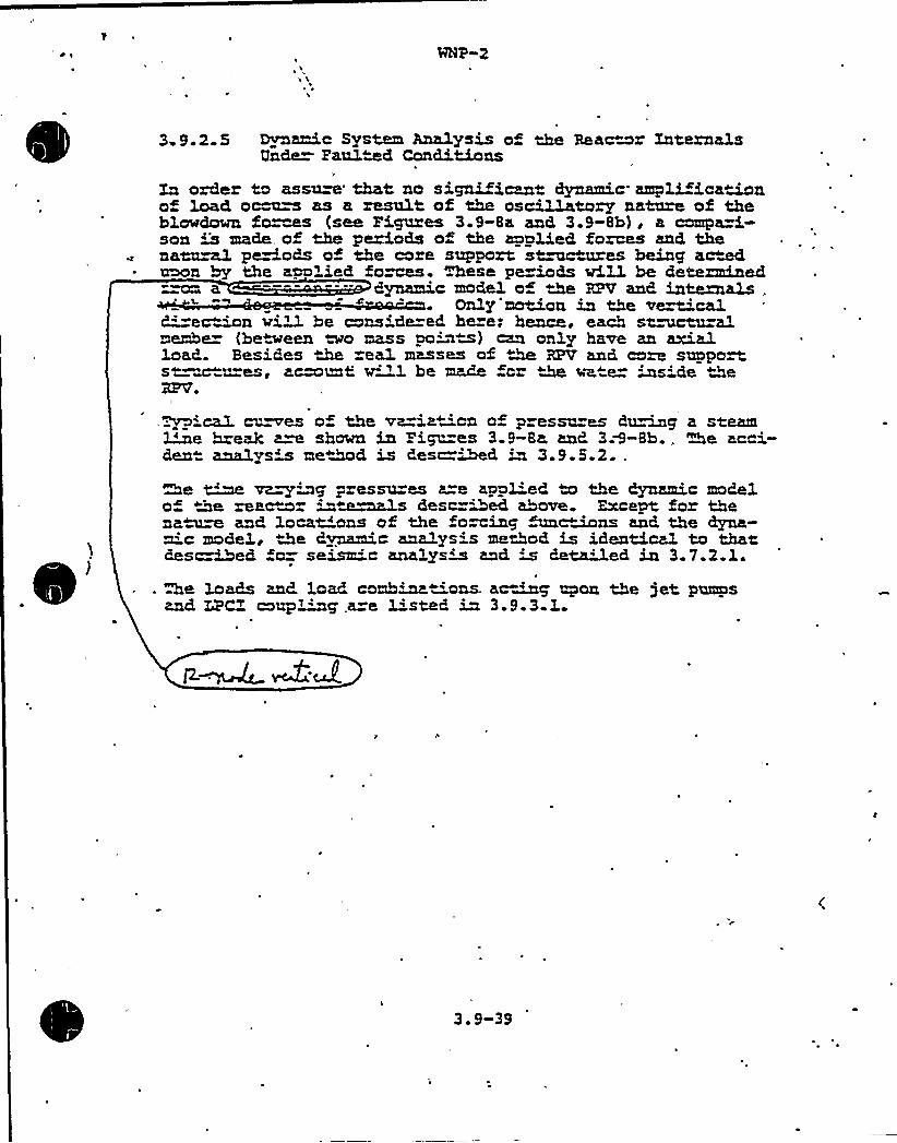
3.9.2.5 Dynamic System Ana1ysis o the Reactor XaternalsUnde Faulted Conditions
Lx order to assam that no significant dynamic amplifica«~no» load o~s as a result of the oscillatory nature of theblowdown fo=ms (see Figures 3.9-8a and 3.9-8h), a compa=i-son m made of the periods o the applied forces and, thenacazmX periods of the core, support st~ures being ac~aeon by the apolied fo ces. These pe~ds wiU. be determined"~ a ---- - — dyrmzmc model o «~ RPV and, internals .
Only'motion in the ve~mcald'-econ wi~ be conside=ed here; hence, each st~uralmembe (be"ween ~ mass po'its) cEn only have an axialload. Besides the ea1 masses of ~ RPV and core supports« ~.™es, acaomt w"1 be made fcr «M water ins'de the3PVo
ica1 ches o» the vawawcn of p essu=es du~@ a steam~e break a~ shown in Pi~es 3.9-8a and 3Ã-Bh., Me acci-den analysis me«~d is Cesc=Med in 3.9.5.2..>e ~ va~~g pressures are apped to the dynamic modelo» «9e reactor a«w~s descried above. Except for thena~~ and locals of the forcing unc~ns and the dyna-mic model, the dynamic analysis method is identical to thatdes~ed fo= seism'c analysis and is de~ed in 3.7.2.1.
he loads and load comb~«'ons. acing upon the jet pumpsand LPC1 coup~~' .are listed in 3.9.3.1
3.9-39

internals in service is'ssential to assure the proper positioning of reactorfuel assemblies and unimpaired operation of the control rod assemblies topermit safe reactor operaticn and shutdown. The conduct of the preoperationalvibra-ion tes s is in conformance with the provisions of Regulatory Guide 1.2eand Standard Review Plan Sec ion 3.9.2, and satisfies the applicable requirementsof General Des'.gn Criteria 1 and 4.
3.9.2.5 Ovnamic Analysis of Reac.ar ~ nternals under Faulted Condi ians
The a"plicant has presented inadequate data to verify the mathematical rodelsfor t.e dynamic analysis. Specifically an explanation of the dynamic mcdel isr quested and justirication of the statement that "Gnly motion in the ver .icaldirec.ion will be consider d here; hence, under s ruc.ural meriber'an onTyhave an axial load."
3.9.3. AS(~1E Cade Class 1 2, and 3 Components. Component Supports, and YoreSUDDor Structures
Cur review under S andard Review Plan Sec.ion 3.9.3 is concerned ~ith the1
szruc=ural integri y and functionability af pressure-retaining ccmoanents,their supports, and core support struc ures which are designed in accordancewi h the American Society of Mechanic 1:ngineers (ASHE) Boiler 'ard PressureVessel Code, Sec icn III, or earlier industry standards.
3.9.3.1 Laadina Ccmbinations. Design Transients and Stress Limits
l/ I
a. The loading combinations and stress limits used in the design af (1) allMME Class 1, 2, and 3 sys ems, ccmpanents, equipment and their supports,(2) al1 r actor internals, and (3) control rod drive ccmponents need o
"e clarified in the FSAR. Section 3.9.3.1 and the majority of Tables 3.9.2(a) through 3.9.2 (a c) in the FSAR do not clearly define the loadingcombinations and stress lim(its. We will require a concise summary (pre<er .
ably in table form) of this information. This summary should include a,
listing of all the loads which were considered for each serv',ce canditicnar load case olus the accep.ance cr',teria. Apoendix 110-1 a NRC
"„uesticn 1 0.27 contains load'.'ng ccmbinations ard acceptance cri er (a
Re..e Li/'ANP SER/3 13

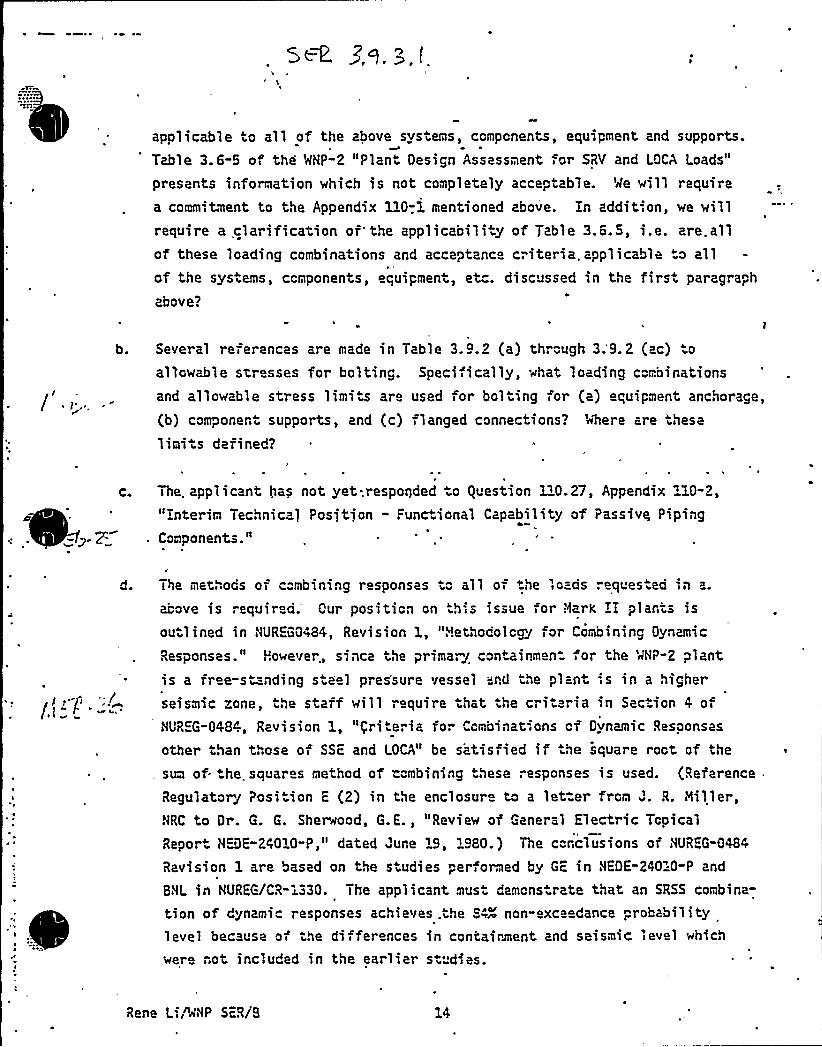
~ ~ ~
apalicable to all of the above systems, ccmpcnents, equipment and supports.Table 3. 6-5 of the 'AHP-2 "Plant Oesign Assessment for SRV and LOCA Loads"
presents information which is not completely acceptable. Me will requirea commitment to the Appendix 110-.1 mentioned above. in addition, we willrequire a clarification or'he applicabili y of arable 3.6. 5, i.e. are.allof these loading combinations and acceptance criteria. applicable ta allof the sysiems, ccmponents, equipmeni, etc. discussed in the firsi paragraph
above?
b. Several references are made in Table 3.9.2 (a) through 3.9. 2 (ac) o
allowable str sses for bolting. Speciiically, what loading combinations
and allowable stress limits are used for bol iing for (a) equipment anchorage,
(b) camponeni supports, and (c) flanged connections? ~here are .hese
1imi is defined?
ci The. applicant has not yet-.responded .o guestion 3 0.27, Appendix 10-2,"rnterim Technical Positjon - Punctional Capability of Passivq PipingComponents."
:
The met .ods of c"mbining responses '." all of the loads ". eques ed in a.
acave is requir ci. Our positicn on h;s issue for Nark I plants isouilined in NUREG0484, Revision 1, "Hethodolcgy far Combining Oynamic
Responses." However., since ihe prima.g cantainmen for the '4NP-2 plantis a rree-sianding sieel pressure vessel 'nd i»e plant is in a higherseismic zone, i»e staff will require that the criteria in Section 4 ofNUR G-0484, Revision 1, "griteria for Ccmbinations cf Oynamic Resaonsas
other than those of SSE and LOCA" be satisfied if'e square roct of the
sum of..he squares method of "cmbining these ".espcnses is used. (Reference
Regulator J Posi ion E (2) in the enclosur ta a let.er frcm J. R. Niller,NRC to Or. G. G. Sherwood, G.E., "Revie~ af General Electric TcpicalReport N DE-24010-P," dated June 19, 1980.) Tne ccnclusions of NUREG-0484
Revision 1 are based on the siudies per ormed by GE in NEOE-240=0"P and
BNL in NUREG/CR-1330. The applicant musi demcns rate ihat an SRSS corbina-
tion of dynamic responses achieves.the 84~ non-exceedance probabilitylevel because of ihe differences in containment and seismic level which
were not included in the earlier st'dies.
Rene L.,"ANP SER/8

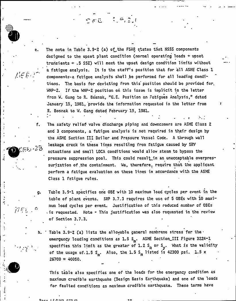
/ g
('.The note in Table 3 ~ 9 2 (a) of the FSAR states that HSSS components
designed to the upset plant condition (normal operating loads + upset
transients. + .5 SSE) will meet the upset design condition limits withouta fatigue analysis. It is the s aff's position that for all ASi~1E Class 1
components a fatigue analysi's shall be per.ormed for all loading condi"
ions. The basis for deviating from this position should be provided for.'rlHP-2. If the MHP"2 position on this issue is implicit in the letterfrom 'rl. Gang "o R. Bosnak, "G. . Position cn Fatigues Analysis," dated
january 15, 198 , provide the information requested in he letter from
R. Bosnak to M. Gang dated February 19, 198".
The safety relief valve discharge piping and downcomers are AS~i1E Class 2
and 3 components, a fatigue analysis is no" required in their design by
the ASNE Sac ion III Boiler and Pressure Vessel Code. A through wall
leakage crack in these lines result'ing from fatigue caused by SR'I
actuations and small LOCA conditions would allow steam to bypass he
pressure suppression pool. This could result in an unacceptable overpres-
surization of .the containment. Me, therefore, require that the applicantperform a fa igue evaluat',on on hese lines in accordance wi h the ASIDE
Class 1 fatigue rules.
~ ~ ~
Table 3.9-1 specifies one OBE ~ith 10 maximum load cycles per event in the
table of plant events. SRP 3.7.3 requires "he use of 5 OBEs with 10 maxi-
mum load cjcles per event. Justification of =his reduced number of OBES
- is reques ed. Note - This jus ification was also requested in he revie~
of Section 3.7.3.
-e
h. 'able 3.9-2 (a) lists the allowable general membrane stress "or the
emergency loading conditions as 1.5 5 . ASME Section III Figure 3224"m
specifies this limit as the greater of 1.2 5 or 5 . What is the validitym
of he usage of.1.5 5 . Also, the 1.5 5 lis.ed is 42300 psi. 1.5 xm m
26700 = 40050.
This table also specifies one of the loads for the emergency condition as
maximum cr dible earthquake (Oesign Basis Ear:hquake) and one of the loads
or faulted conditions as maximum credible earthquake. These terms have
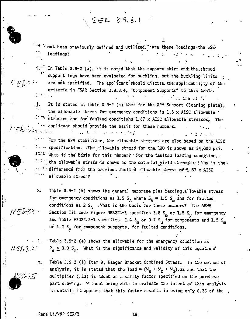
not be n previously defined and utilized. Are these loadings-the SSc.
1 oadi ngs?
- In Table 3.9-2 (a), it is noted that the support skirt and-. the shroudsupport legs have been evaluated for buckling, but the buckling limi s
are not specified. The applicant should discuss. the.applicability o! thecriteria in FSAR Section 3.9.3.4, "Component Suppor w" to th',s table.
it is stated in Table 3. 9-2 (a) that for the RP'I Suppor~ (8earing plate),he allowable stress for emergency conditions is 1 5 x AISLE allowable
E
stresses and for faul ed conditi'ons 1.67 x AISC allowable stresses, The
applicant should provide the basis for these numbers.
t
For the RPV steil'izer, the allowable s.resses are aTso based on the AISC
specification. .The allowable str ss f'r he. R00 is shcwn as 8/,300 psi.Mhat is the basis for this zunb'er? For the faulted loading ccrdition,,-the allowable stres's ',s shown as the material yield strength;; 'dhy is the-difference from the previous .faulted allowable stress of -1.57 x-AISC
all owabl e stress?
Table 3.9-2 (b) shows the general memorane plus bending.allowable s-ressfor e~~~gency condi icns as 1.5 SA wher SA = 1.5 S and ,or
m
conditions as 2 S .. Mhat is the basis for hese numbers? The ASi~E
Section IiI code Figure N83224-1 specifies 1.8 S cr 1.5 S for emer„encym
and Table F1322.2-1 specifies, 2.4 S or 0.7 Su or ccmponenzs and 1.5 Sm
or '.2 S for componen- supports, fcr faulted cond-: ions.
~ Table 3.9-2 (e) shows the allcwable for he emergency ccndit'.on as
P <305.e — m'hat is he significance and validity of >is eq a ion?
Table 3.9-2 (i) Item 9, Hanger Bracket Combined Str ss. In .he methcd ofanalysis, it is stated that the load = (M8 + MC + M0).33 and hat themultiplier (.33) is adde5 as a safety factor specified cn the purchasepar- drawing. Without being able o evaluat the fn en- or this analysisin detail, it appears that his factor resul s in using on1y 0.33 cf the
Rene Lif~NP ScR/3

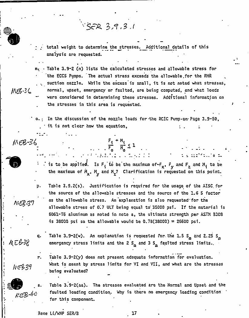
I
total weight to determine the stresses. Additional devils of thisanalysis are reques"ed.
/he-3 <
As Table 3.9"2 {n) lists the calculated stresses and allowable stress forthe ECCS Pumps. The actual stress exceeds the allowable.for the RHR
suction nozzle. Mhile the excess is small, it is rot noted what stresses,normal, upset, emergency or faulted, are being computed, and what loads«ere considered in determining these stresses. Additional information cn
the stresses in this area is requested.
0 Ln tlie discussion of the noz"le loads for -:he RCIC Pump-qn Page 3..9-56,
it is not clear how the equation,
/" F8=4 F. +H-1 1—< 1
F M0 0
r ~ r ~ r
is te be app1iaJ.the maximum of 8X's
F. to be the maximum of -., F and F and H. to be
H and iM? Clarification is requested on this point.
Alg-'g7
T~mle 3.9.2(s). Justification is required for he usage or he ArSC,or.he source of the allowable stresses and the source of he ~.G 5 fac=oras the allowable stress. An explanation is also requested'for theallowable stress of 0.7 ULT being equal to'5000 psi. If the material is6061-76 alumin m as noted in note a, he ultimata strength per AS'308is 38000 psi so the allowable would be 0.78(38000) = 26600 psi.
e
'(C,8-s(q. Table 3.9-2(w). An explanation is reques.ad aor. tile LS S and 2.25 5
m m
emergency s ress limi s and the 2 S and 3 5 aulted s ress limits..I
t)c >59
Tule 3.9-2(y) does not presen adequate information for evaluation.'rlhat is meant by stress limits fcr VI and VII, and «ha are the stressesbeing evaluated?
ps~ ppi»s. Table 3.9-2(aa). The stresses evalua ed are the Normal and Upset and 4e
.aulted loading condition. Why is there no amer-ency loading condition
.or this component.
Rene Lif«'NP SDiB

i
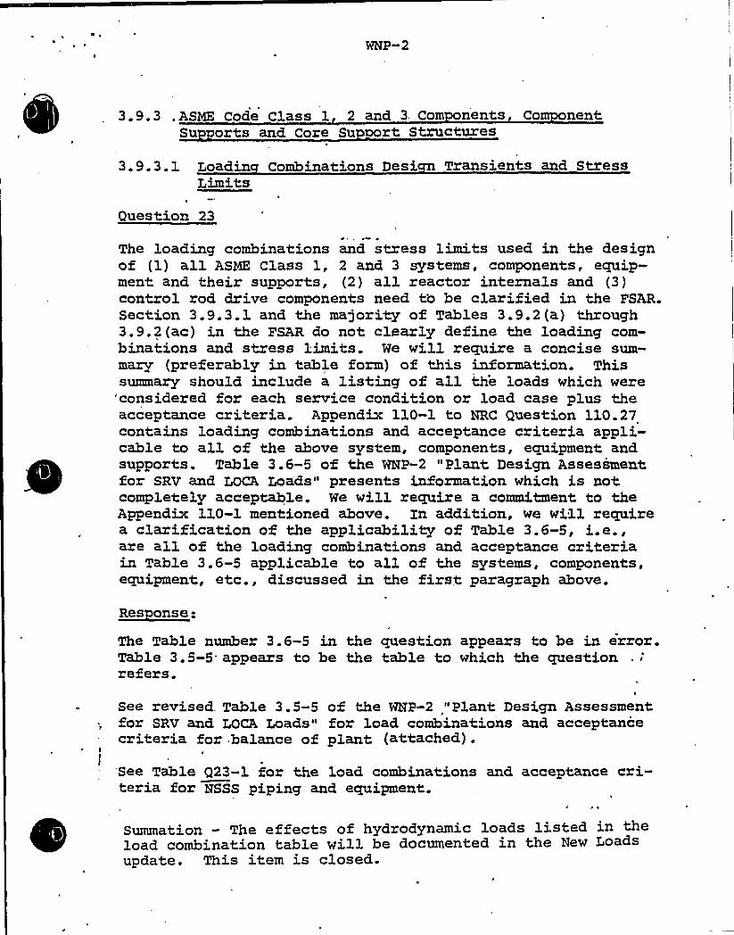
WNP-2
3.9.3 .ASME Code Class 1 2 and 3 Com nents Co nentSu orts and Core Su aort Structures
3.9.3.1 Loadin Combinations Desi, Transients and StressLimits
Question 23' I' ~
The loading combinations and stress limits used in the designof (1) all ASNE Class 1, 2 and 3 systems, components, equip-ment and their supports, (2) all reactor internals and (3}control rod drive components need tb be clarified in the FSAR.Section 3.9.3.1 and the majority of Tables 3.9.2(a) through3.9.2(ac) in the FSAR do not clearly define the loading com-binations and stress limits. We will require a concise sum-mary (preferably in table form) of this information. Thissummary should include a listing of all the loads which were
'considered for each service condition or load case plus theacceptance criteria. Appendix 110-1 to HRC Question 110.27contains loading combinations and acceptance criteria appli-cable to all of the above system, components, equipment andsupports. Table 3.6-5 of the WNP-2 "Plant Design Assessmentfor SRV and LOCA Loads" presents information vhich is notcompletely acceptable. We will require a commitment to theAppendix 110-1 mentioned above. Zn addition, ve vill requirea clarification of the applicability of Table 3.6-5, i.e.,are all of the loading combinations and acceptance criteriain Table 3.6-5 applicable to all of the systems, components,equipment, etc., discussed in the first paragraph above.
~Res anse:
The Table number 3.6-5 in the question appears to be in error.Table 3.5-5. appears to be the table to which the questionrefers.
See re~ised. Table 3.5-5 of the WHP-2 "Plant Design Assessment.for SRV and LOCA Loads" for load combinations and acceptancecriteria for balance of plant (attached).
See Table Q23-1 for the load combinations and acceptance cri»teria for NSSS piping and equipment.
Summation — The effects of hydrodynamic loads listed in theload combination table will be documented in the New Loadsupdate. This item is closed.
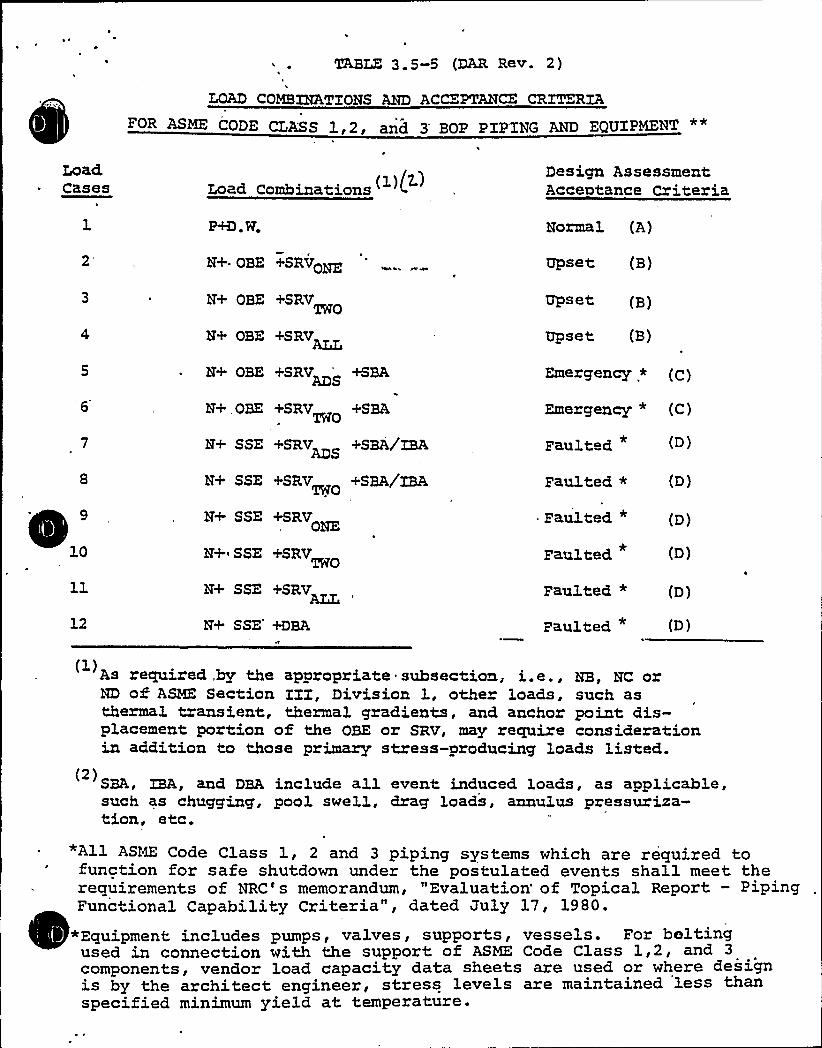
TABLE 3.g-g (DAR Rev. 2)
LOAD COMBINATIONS AND ACCEPTANCE CRANIAE CLASS lg2g and 3'OP PIP'ING AND EQUI ME **
LoadCases Load Combinations (1)(Z3
Design AssessmentAcce tance Criteria
2'2
P+D.N.
H+ OBE +SRVONE
H+ OBE +SRV
H+ OBE +SRV
H+ OBE +SRVS
H+.OBE +SRV +SBA
H+ SSE +SRV +SBA/IBA
H+ SSE +SRV +SBA/IBA
N+ SSE +SRVONE
N+ SSE +SRV
H+ SSE +SRV
N+ SSE +DBA
Hormal (A)
Upset (B)
Upset (B)
Upset (B)
Emergency + (C)
Emergency * (C)
Faulted *
Faulted *
Faulted *
Faulted *
(D)
(D)
(D)
Faulted * (D)
Faulted * (D)
(1) As required „by the appropriate subsection, i.e., HB, NC orHD of ASME Section III, Division 1, other loads, such asthermal transient, thermal gradients, and anchor point dis-placement portion of the OBE or SRV, may require considerationin addition to those primary stress-producing loads listed.
(2) SBA, IBA, and DBA include all event induced loads, as applicable,such as chugging, pool swell, drag loads, annulus pressuriza-tion, etc.
~ *All ASME Code Class 1, 2 and 3 piping systems which are required tofunction for safe shutdown under the postulated events shall meet therequirements of NRC' memorandum, "Evaluation'f Topical Report - Piping
~
~
~ ~
~
~
Functional Capability Criteria", dated July 17, 1980.
*Equipment includes pumps, valves, supports, vessels. For beltingused in connection with the support of ASME Code Class 1,2, and 3
components, vendor load capacity data sheets are used or where designis by the architect engineer, stress levels are maintained less thanspecified minimum yield at temperature.

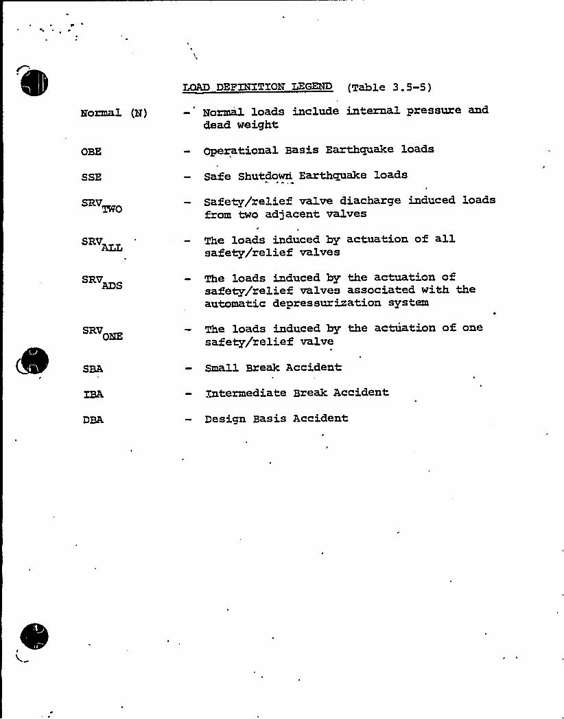
LOAD DEF32TXTION LEGEND (Table 3.5-5)
Eozmal (H) Hormil loads include internal pressure anddead weight,
OBE
SSE
Operational Basis Earthquake loads
Safe Shutdowri Earthcpxake loads
SRV
SRV
Safety/relief valve diacharge induced loadsfrom two adjacent valves
The loads induced by actuation of allsafety/relief valves
SRV The loads induced by the actuation ofsafety/relief valves associated with theautomatic depressurization system
SRV The loads induced by the actuation of onesafety/relief valve
Small Break Accident
DBA
Xntermediate Break Accident
Design Basis Accident

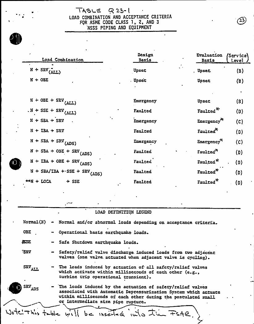
e ~
4
2.5- lLOAD COMBINATION AND ACCEPTANCE CRITERIA
FgR ASHE CODE CLASS 1,. 2, AND 3
NSSS PIPING AND EQUIPMENT
Load, CombinationDesigaBasis
ServiceBasis Lev e]
N + SRV'(~)
N+ OBE
Upset,
, Upset
Upset.
Upset
(B)
(B)
N + OBE + SRV
.H + SSE + SRV(~)N+ SBA+ SRV
N + ZBA + SRV
N + SBA + SRV ~SN + SBA + OBE + SRV
ADS
8 + XBA + OBE + SRV(MS)
8 + SBA/IBA + SSE + SRV MS
+ SSE
Emergency
Faulted
Emergency
Faulted
Emergency
Faulted,
Faulted
Fau1.ted
Faulted
Upset
Faulted
Emergency
Faulted
Emergeacy
(B)
(D)
(C)
(D)
(c)
Faulted
Faulted
Fau1ted
(D)
(D)
(D)
Faulted. (D)
LOAD DEFZNETXON LEGEND
Normal(N) - Normal and/or abaormal loads dependiag oa acceptance criteria.Operational basis earthquake loads
Safe Shutdown earthquake loads
'SEV Safety/relief valve discharge. induced loads from tvo ad)acintvalves (one valve. actuated vhen adjacent valve is cycling).
The loads induced by actuation of all safety/relief valveswhich activate vithin milliseconds of each other (e.g ,turbine trip operational transient)
SRVADS The loads induced by the actuatioa of safety/relief valvesassociated with Automatic Depressuzization System which actuatewithin mi.lliseconds of each other during the postulated smallar ierereediere eire pipe repreee.
4e4C-'~~ s 4 4'I» u i~,( 4» ieseW 6.
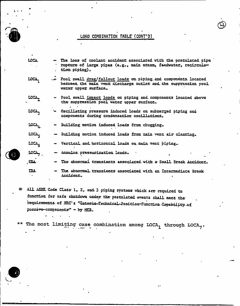
LOAD COMBINATION TABLE (CONT'D)
The loss of caolanc accidenc assayed. Wth the pasculacecL piperupture of lamps pipes (a.g, main szaam, faechratez~ reci"cula-tion. piping) .
Pool swe1L ~dra fallauc loads an. piping. and components. locatedbeccceen the main venc. discharge ouclec ancL the suppression paoksacer upper surface
peal snail france lauds au pdpdne snd. caepansncs lacsrsd abaverbe suppressdan paul surer upper surface-
OsciIXacing pressure induced loads on submerged piping andcomponents during candensaciocc astuciousBui3~ig. mocian induced loads from chug~a
BuilcKng mat"'aa induced loads E=om main venc aiz clear~@
Vertical. and. har"-anca1 loads ocL maia. venc piping,
LOCA
~SEeL
Annulus. pressurization, loads
The abnarmaI, transients associated. wizh a SmaU Break Accidenc
The abnoanaL. transients asso~cced. with. an, Zntezmediate BreakAccidenc
ALL ASK. Cade Class 1,. X,. and.3 piping sYsums MhiM are required ta&urchin for safe shutdown under the postulated evencs shalL meet the'requirements. of 3RC's "Z~~TechnicaL posit-on-".unc~ CkyabQ.icy- oi~ve ~o-~~' by tKB.
** The. most limiting case combination among LOCA through LOCA1 7'

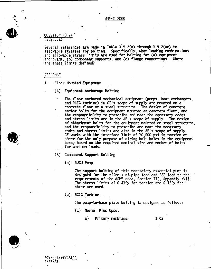
WNP-2 DSER
UESTION NO 24.3.1
Several references are made in Table 3.9.2(a) through 3.9.2(ac) toallowable stresses for bolting. Specifically, what loading combinationsand allowable stress limits are used for bolting for (a) equipmentanchorage, (b) component supports, and (c) flange connections. Wher eare these limits defined?
RESPONSE
1. Floor Mounted Equipment
(A) Equipment Anchorage Bolting
The floor anchored mechanical equipment (pumps, heat exchangers,and RCIC turbine) in GE's scope of supply are mounted on aconcrete floor or a steel structure. The design of concreteanchor bolts for the equipment mounted on concrete floor, andthe responsibility to prescribe and meet the necessary codesand stress limits are in the AE's scope 'of supply. The designof attachment bolts for the equipment mounted on steel structure,and the responsibility to prescribe and meet the necessarycodes and stress limits are also in the AE's scope of supply.GE works with the interface limit of 10,000 psi in tension orshear for the only purpose of sizing bolt holes in the equipmentbase, based on the required nominal size and number of bolts
, for maximum loads.
(B) Component Support Bolting
(a) RWCU Pump
The support bolting of this non-safety essential pump isdesigned for the effects of pipe load and SSE load to therequirements of the ASME code, Section III, Appendix XVII.The stress limits of 0.41Sy for tension and 0.155y forshear are used.
(b) RCIC Turbine
The pump-to-base plate bolting is designed as follows:
(1) Normal Plus Upset
a) Primary membrane: 1. OS
PCY: ggt: rf/45Lll9/23/81

r.
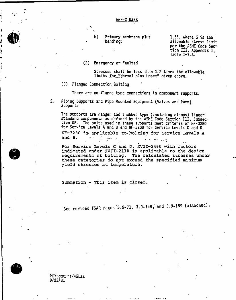
MNP-2 OSER
b} Primary membrane plusbending:
1.5S, where S is theallowable stress limitper the ASHE Code Sec-tion III, Appendix I,Table I-7.3.
(2) Emergency or Faulted
Stresses shall be less than 1.2 times the allowablelimits for, ",gormal plus Upset" given above.
(C) Flanged Connection Bolting
There are no flange type connec.ions in component supports.
2. Piping Supports and Pipe Hounted Equipment (Yalves and Pimp)Supports
The supports are hanger and snubber type (including clamps) linears andard components as defined by the ASHE Code Section III, Subsec-tion NF. The bolts used in these supports meet criteria of NF"3280for Service Leve',s A and B and NF-3230 'for Service Levels C and D.
¹-3280 is applicable to- bolting for Service Levels Aand B.
For Service Levels C and D, XVII-2460 with factorsindicated under XVII-2110 is applicable to the designrequirements of bolting. The calculated stresses underthese categories do not exceed the specified minimumyield stresses at temperature.
Summation — This item is closed.
See revised FSAR pages 3.9-71, 3.9-158, and 3.9-159 (attached).
PCY: ggt: rf/45L129/23/8"
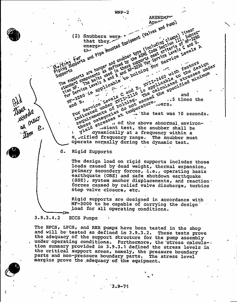
WNP-2AMENDMF"Ap~
(2) Snubbers were. " y.(.
emerg p ~o4 g5< . gQ ~j4 (
< ~++~ pe~<-ge ~pa< ~~yb+ ~e
- os gal% ~o5 o4 gQ adders ~
go<. <s< ~< <jP~ ~ < . 'the test was 10 seconds.
~ g~~e ~~+ .. of the above abnor'mal environ-.sient test, the snubber shall be
aynamically at a frequency within as cified frequency range. The snubber mustoperate normally during the dynamic test.
h
d. Rigid Supports
The design load on rigid supports includes thoseloads caused by dead weight, thermal expansion,primary secondary forces, i.e., operating basisearthquate (OBE) and safe shutdown earthquake(SSE), system anchor displacements, and reaction .
forces caused by relief valve discharge, turbinestop valve closure, etc.Rigid supports are designed in accordance withNF-3000 to be capable of carrying the designload for all operating conditions.
3.9.3.4.2 ECCS Pumps
The HPCS, LPCS, and RHR pumps have been tested in the shopand will be tested as defined in 3.9.3.2. These tests provethe adequacy of the support structure for the pump assemblyun'der'operating conditions. Furthermore, the stress calcula--tion summary provided in 3.9.3.1 defined the stress levels inthe critical support areas, namely, the pressure boundaryparts and non-pressure boundary parts. The stress levelmargins prove the .adequacy of the equipment.
'3 9-71

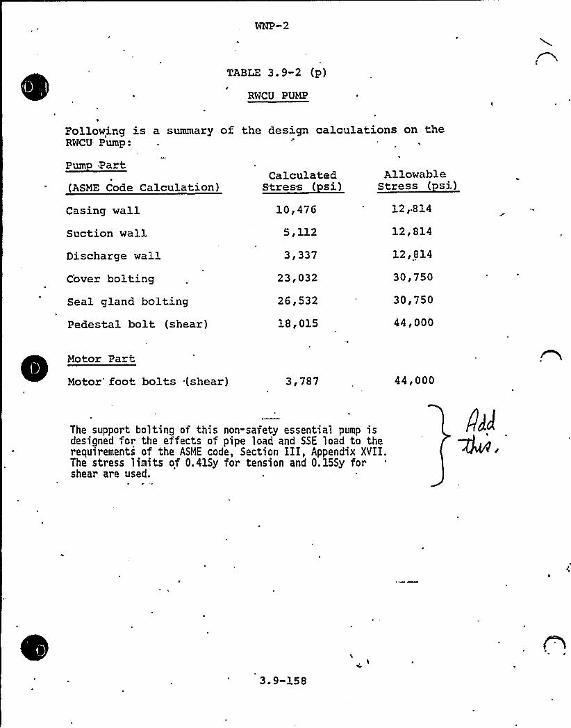
TABLE 3.9-2 (P)
RWCU PUMP
Following is a summary of the design calculations on theRWCU Pump:
(ASME Code Calculation)
Casing wallSuction wall
Discharge wallC'over boltingSeal gland boltingPedestal bolt (shear)
CalculatedStress ( si)
10,476
5,112
3 g 337
23,032
26,532
18,015
AllowableStress ( si)
12'1412,814
12,814
30,750
30,750
44,000
Motor Part
Motor'oot bolts (shear) 3,787 44,000
The support bolting of this non-safety essential. pump isdesigned for the effects of pipe load and SSE load to therequirements of the ASHE code, Section III, Appendix XVII.The stress limits of 0.41Sy for tension and 0.155y forshear are used.
4J
3. 9-158

.
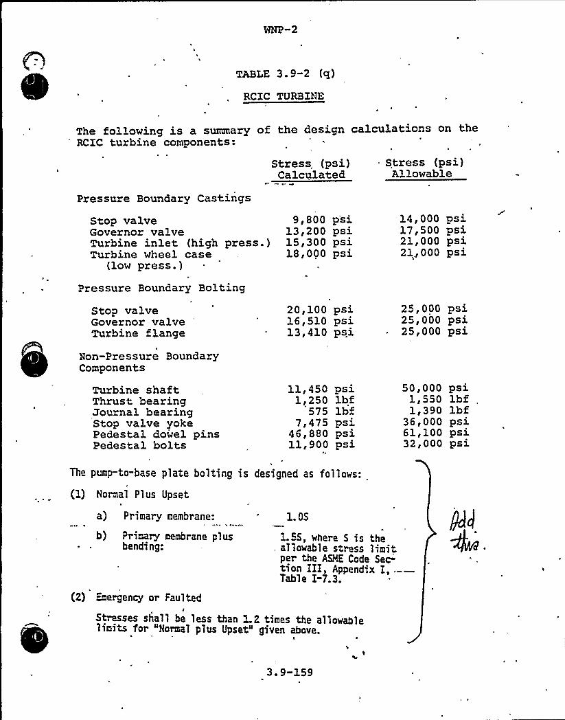
TABLE 3.9-2 (q)
RCZC TURBINE
The following is a summary of the design calculations on theRCZC turbine components:
Pressure Boundary Castings
Stress (psi)Calculated
Stress (psi)Allowable
Stop valveGovernor valveTurbine inlet (high press.)Turbine wheel case
(low press.)
Pressure Boundary Bolting
Stop valveGovernor valveTurbine flange
Don-Pressure BoundaryComponents
9,800 psi13,200 psi15,300 psi18,000 psi
20,100 psi16,510 psi13,410 psi
14,000 psi17,500 psi21,000 psi21,000 psi
25,000 psi25,000 psi25,000 psi
Turbine shaftThrust bearingJournal bearingStop valve yokePedestal dowel pinsPedestal bolts
11,450 psi1,250 lbf
575 lbf7,475 psi
46,880 psi11,900 psi
50,0001,5501,390
36,00061,10032,000
psilbf „lbfps 3.
psst.
psi
The pump-to-base plate bolting is designed as follows:
(1) Normal Plus Upset
a) Primary membrane:
b) Primary membrane plusbending:
1. OS
1.55, where 5 is theallowable stress limitper the ASME Code Sec-tion III, Appendix I, --—Table I-7.3.
(2) urgency or Faultedj
Stresses shall be less than 1.2 times the allowablelimits for "Normal plus Upset" given above.I
3.9-159
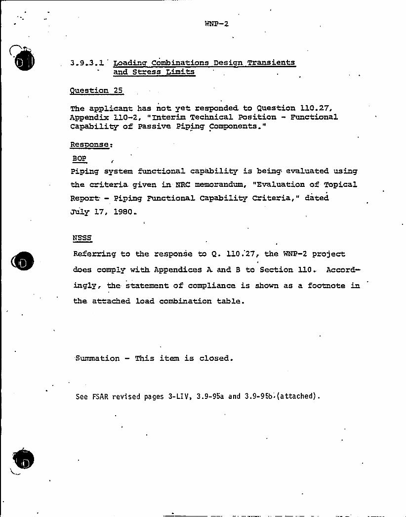
3.9 3.1 Loadin Combinations Desi n Transientsand Stress Limits
uestion 25
The applicant has not yet responded. to Question 3.10.2'T,Appendix 110-2, "Interim Technical Position» FunctionalCapability of Passive Piping Components."
Response:
BOP
Piping system functional capability is being evaluated usingthe c i.teria. given in HRC memorandum, Evaluation of Topi,calReport; - Piping Functional Capability Criteria," dated
July 17, 1980.
NSSS
Referring to the response to Q. 110.27, the WNP-2 projectdoes comply with. Appendices A and B to Section 110.. Accord-
ingly, the statement of compliance is shown as a footnote inthe attached load combination table.
Summation — This item is closed.
See FSAR revised pages 3-LIV, 3.9-95a and 3.9-95b'(attached).

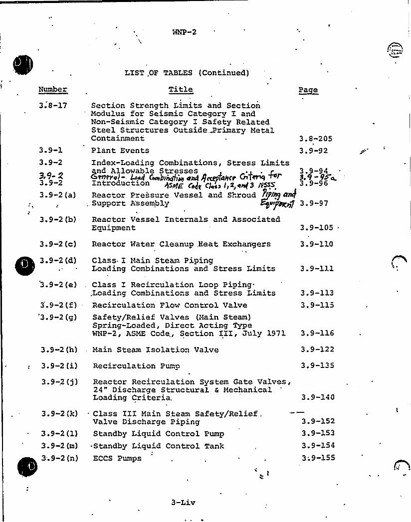
Number
LIST .OF TABLES (Continued)
Title PacCe
3. 8-17
3.9-13. 9-2
9.9- Z3. 9-23.9-2 (a)
3. 9-2 (b)
Section Strength Limits and SectionModulus for Seismi" Categorv I andNon-Seismic Category I Safety RelatedSteel Structures Outside,3'rimary MetalContainmentPlant EventsIndex-Loading Combinations, Stress Limitsgnd Allowable Stresses~~a~- M4 ceeebi~g]jy e~ $caylolcr 4~ +~Introduction q~~< ~p ~ ~ l,g ~g3 y~gReactor Pressure Vessel and Shroud ~llhg 4Q
, Support A'ssembly e7
Reactor Vessel Internals and AssociatedEquipment
3.9-2 (c) Reactor Mater Cleanup, Heat Exchangers
3.8-2053. 9-92
3.9-949.9-9'5<3.9-96
3.9-97
3.9-105
3.9-110
3. 9-2 (d)
3.9-2 (e)
3.9-2 (f)'3. 9-2 (g)
Class I Hain Steam PipingLoading Combinations and Stress Limits
Class I Recirculation Loop Piping.Loading Combinatio..s and Stress LimitsRecirculation Plow Control ValveSafety/Relief Valves (Main Steam)Spring-Loaded, Direct Acting TypeNNP-2, ASME Code,, Section IZI, July 1971
3. 9-111
3.9-1133.9-115
3. 9-116
3.9-2(h) . Main Steam Isolation Valve 3.9-122
3.9-2 (i)3.9-,2 (3)
3. 9-2 (k)
3. 9-2 (1)3. 9-2 (QL)
3..9-2 (n)
Recirculation Pump
Reactor Recirculation System Gate Valves,24" Discharge Structural & MechanicalLoading Criteria,
. Class IZI Main Steam Safety/Relief .
Valve Discharge PipingStandby Liquid Control Pump
~ Standby Liquid Control TankECCS Pumps
3.9-135
3.9-140
3.9-1523.9-1533.9-1543;9-155
3-Liv
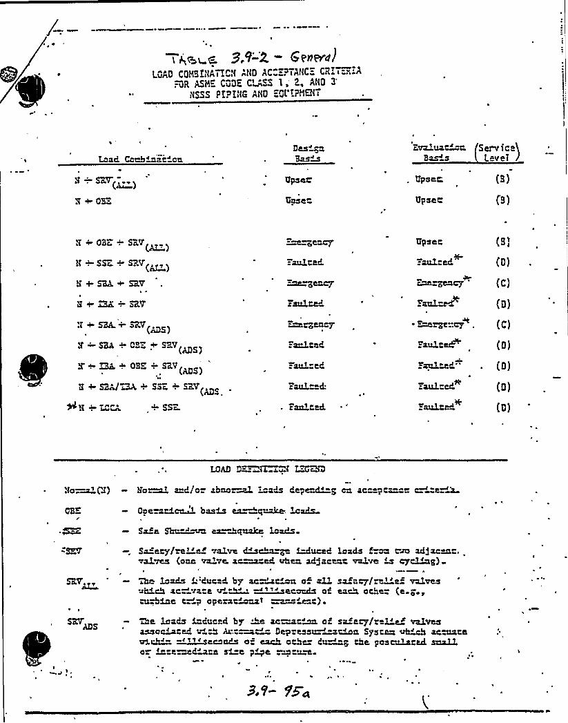
~ 0
'I 6%wC. 9.~-X GPiiEYd)
lQAQ COND<ATICN ANQ AC":-PTANC:- CRIit."..A".-QR ASM'QQK CU~~ I,', ANQ 3
NSSS P!PING AHQ ="QVIPMEHT
Lead Ccabitai" ce
N SET( ~ a~ )
Z+ dB"= Upset
ivaluat'c.Bas s
Upset;Upset,'erv
<ca)LeveI J
N ~ OBc. + SRV
N + SSZ ~ SRV(~~)
N + SKL +'RV1
N+ ~ —:SRV
Z SLL ~ dB + SKV(MS)
5 ~ ~ ~ OBZ -: SRV(ADS)
8 + SKV~ + SSc. + SRV
:aul ted.
g eucy
Faulted
~euy.=audited
:aulted
caul" d:
Upset (pl
(Q)
~~cy 'C)ra~i (g)
- Re~"cy+ (C)
S'aultM (Q)
Faultek" . (Q)
:-aulted. (Q)
SSr- c aulted 2'aultM (g)
LOAD D=-. ILGWU ZZc.BD
'fo ~(d) Eo~ aud/o= abao M "ads dept'"g cu ac"-pt"-" a'=e~~
dpe~td.~ basM ca~@~ ~ads
Sa~e SIn.="~ ea=&auake loads
SR%~~
~ ~
I~~! ~
S4 ety/ref et valve ~~~ ~uced loadsvalves (oat va've. ac=~ed uheu adfacect valve m cy~~~ g)
Wi loads S.iduc d. by'c~~ a~ al'i sa~ecy/a''e~ valvesahhch ac- a= a'e~a'"sacaache aa each ache= (a.e.,aMhMt t ~p opera~&> «~~Mt) ~
Qe loads Seduced by w ac~-w ot sa ety/rtl'e< valvesassort~" AM Art~~~ Depress~~~4a Systna ~4 acuteeach~- ~~~'caaha c= each ache 4 "a cha paacaiacecl acaL~o ~-e ~~te si=e p~e -meum
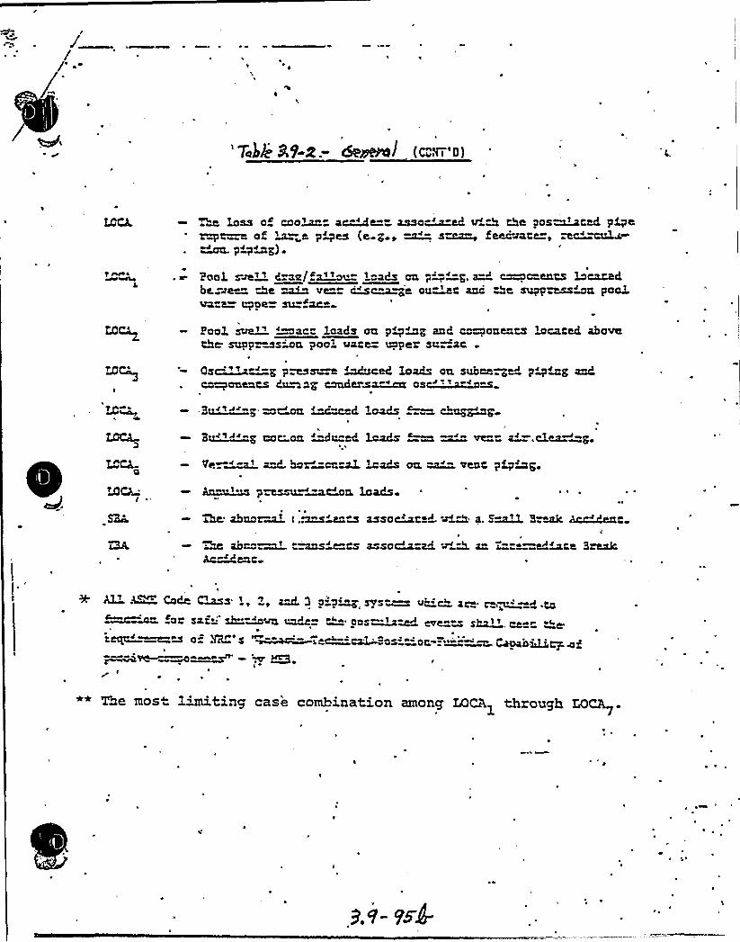
~a loss oS coo~ aWe= assorted v'4 the posited pipeof ~~~~ pres (e g ~~- s~ Seeavate, mc~ "axLc-~ PigisIg) ~
peri rve» l~mlvs"a~- isa|a ea p"-'-'=p. »p. eameavaes ivvsrs6be -ve " Qe ~ vs== m~~s ea~ saa De sEIppnaaa peal@Rent +De~ SIX» ae»
Poalsve.lv '~sea leads aa p~~a aaL e~eeeaes lesaeak abaveebs seppr»saba peei vase= appar sr.=sa
LOCa
I
Os~at"-g p~sI~ ~e6 loads DII suboe~~ p~~~mgaalu'omponents6saag eonder~~ os~ma
Zu—'I '"p as~ Musd le@Is --m abap~p-
LOCA
LOCA
3~vs"'" aae'-aa MI--t4 lasIbs —m ~ v»= s I-.else~=p.
V~~~~ a=d. box=on»~ ~ads ozz ~ vest pampa
I ~ *
Am'"I pzessu~~&a. loads ~ ~
7M ahooE~~ t ..s»»~A assort ~ 4M a S~»~ S~Ak AcddcIt
2x aooo~p t~ie"ts assoMH v A ao, T"a=ate 3reakAccent
Alf- A~ Code ~s l, Zp ~ 3 D.D~ 3 s~ Me-~ ao t,~ ~ t»»x»»oe» SQ t sa I+ Kv~ ~I » ++ '+ Qos~~v»+ ~e»»vI g~7p oe» y ape$ Qeea s
0 HRC s ~~g ~~~os» Dt vev ' b»»aors SI~VL~ W .EI'
««The mos 1'miting case combination among LQCA1 through MCA .I'
~

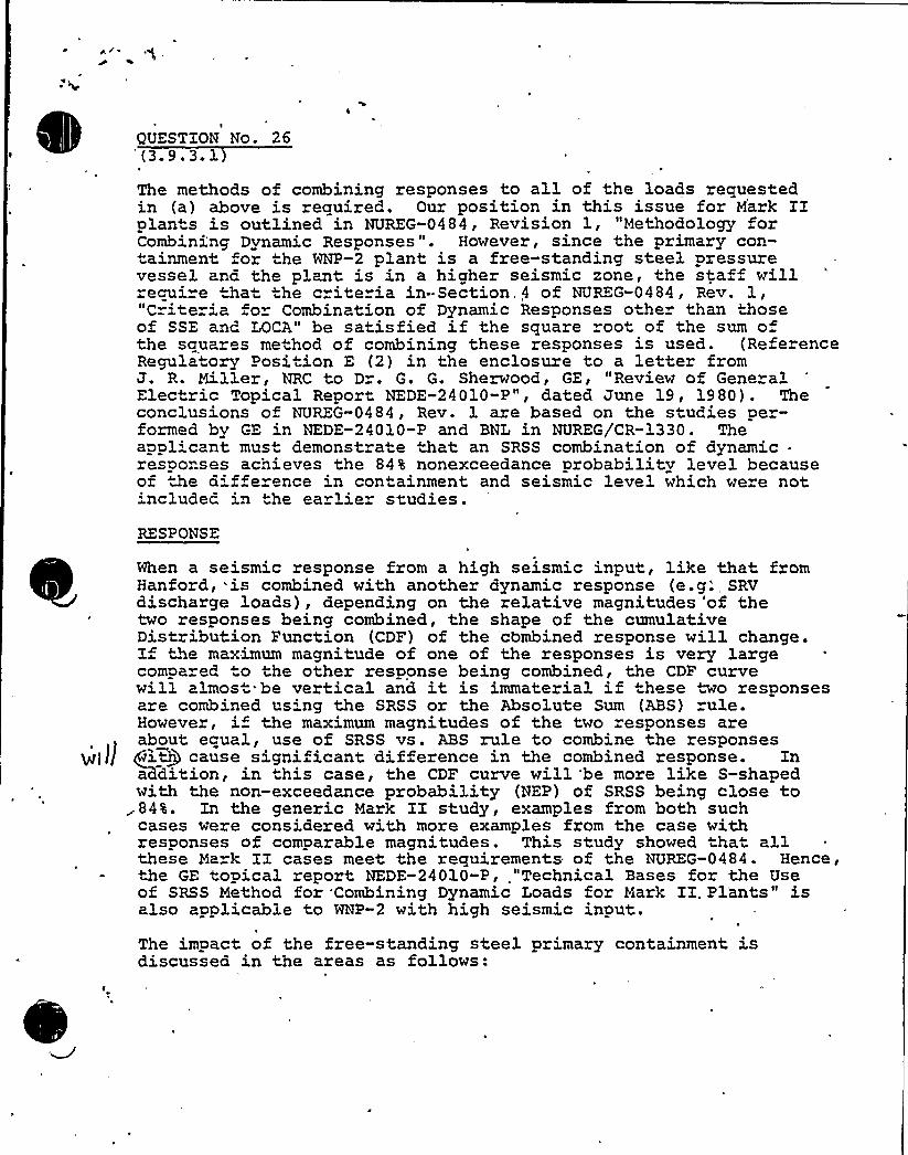
v
I
QUESTION No. 26
The methods of combining responses to all of the loads requestedin (a) above is required. Our position in this issue for Mark IIplants is outlined in NUREG-0484, Revision 1, "Methodology forCombining Dynamic Responses ". However, since the primary con-tainment or the WNP-2 plant is a free-standing steel pressurevessel and the plant is in a higher seismic zone, the staf willrecui e that he criteria in-Section,4 of NUREG-0484, Rev. 1,"Criteria or Combination of Dynamic Responses other than thoseof SSE anc LOCA" be satisfied if the square root of the sum ofthe squares method of combining these responses is used. (ReferenceRegula"ory Position E (2) in the enclosure to a letter fromJ. R. Miller, NRC to Dr. G. G. Sherwood, GE, "Review of GeneralElectric Topical Reoor" NEDE-24010-P", dated June 19, 1980). Theconclusions of NUREG-0484, Rev. 1 are based on the studies per-formed by GE in NEDE-24010-P and BNL in NUREG/CR-1330. Theapplicant must demonstrate that an SRSS combination of dynamic-responses achieves the 84% nonexceedance probability level becauseof the difference in containment and seismic level which were notincluded in the earlier studies.
RESPONSEt
When a seismic response from a high seismic input, like that fromHanford, is combined with another dynamic response (e.g.', SRVdischarge loads), depending on the relative magnitudes 'of thetwo responses being combined, the shape of the cumulativeDistribution Function (CDF) of the 'cbmbined response will change.If the maximum magnitude of one of the responses is very largecompared o the other response being combined, the CDF curvewill almost. be vertical and it is immaterial if these "wo responsesare combined us'ng the SRSS or the Absolute Sum (ABS) rule.However, if the maximum magnitudes of the two responses areabout equal, use of SRSS vs. ABS rule to combine the responses
jt] Jj giQ cause significant difference in the combined response. Inaddition, in this case, the CDF curve will be more like S-shapedwith the non-exceedance probability (NEP) of SRSS being close to84%,. In the generic Mark II study, examples from both suchcases were considered with more examples from the case withresponses of comparable magnitudes. This study showed that allthese Ma k II cases meet the requirements of the NUREG-0484. Hence,the GE topical report NEDE-24010-P, "Technical Bases for the Useof SRSS Method for Combining Dynamic Loads for Mark II. Pl'ants" isalso applicable to WNP-2 with high seismic input.The impact of the free-standing steel primary containment isdiscussed in the areas as follows:
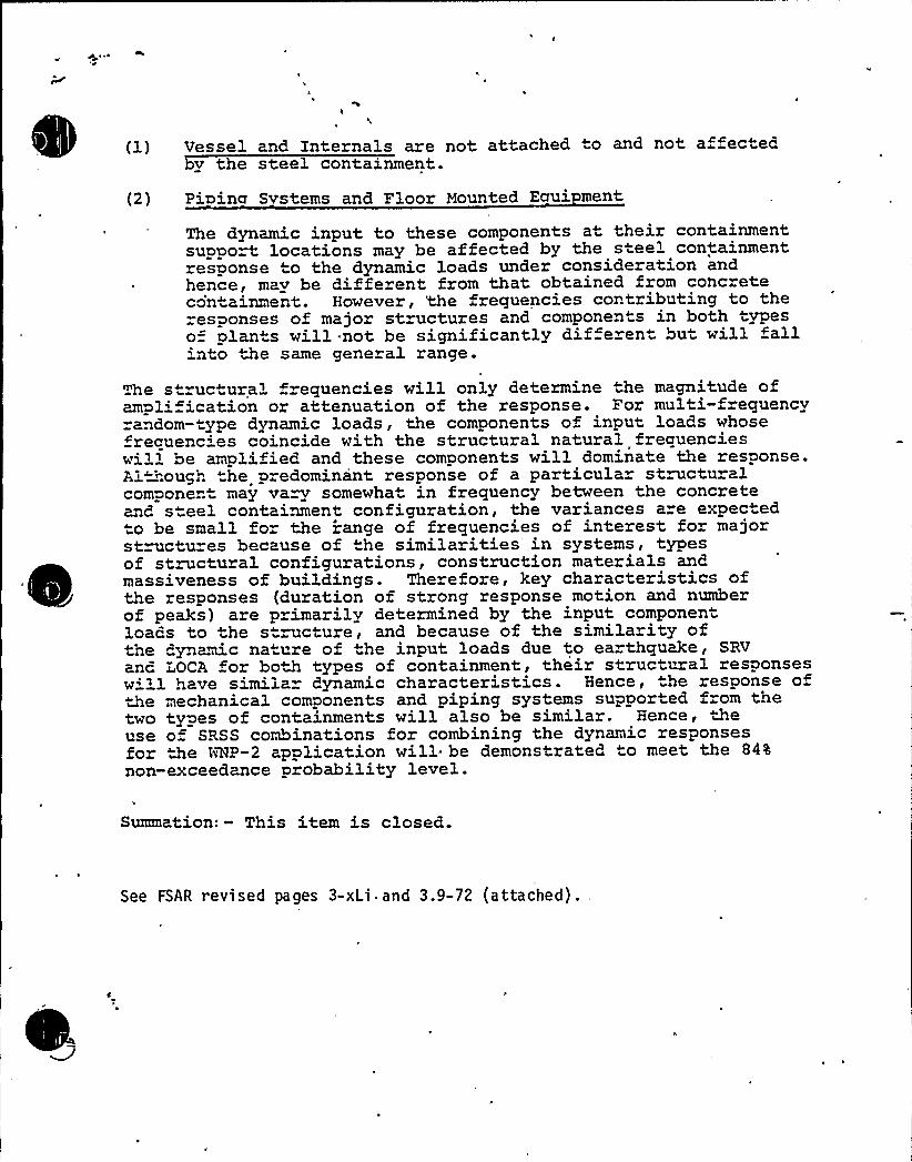
(1) Uessel and Internals are not attached to and not a ectecby the steel containment.
(2) Pioina Svstems and Floor Mounted Ecrui ment
The dynamic input to these components at their containmentsupport locations may be affected by the s eel containmentresponse to the dynamic loads under consideration andhence, mav be different from that obtained from concreteco'n ainment. However, 'the frequencies contributing to theresponses of major structures and components in both typeso= plan s will.not be significantly dif erent bu will fall'nto the same general range.
The structural frequencies will only determine the magnitude ofampli ication or attenuation of the response. For multi-frequencyrandom-type dynamic loads, the components of input loads whosefrecuenc'es coincide with the structural natural frequencieswill be amplified and these components will dominate the response.Although "he predominant response of a particula structuralcomponent may vary somewhat in frequency between the concreteand steel containment configuration, the variances are expec edto be small fo" the range of frequencies of interest for majorstructures because of the similarities in systems, typesof structural configurations, construction materials andmassiveness of buildings. Therefore, key characteristics ofthe responses (duration of strong response motion and numberof peaks) are primarilv determined by the input componentloads to the structure, and because of the similarity oftne dynamic nature of the input loads due to ea thquake, SRVanc LOCA for both types of containment, their structural responsesw'' 1 have similar dynamic characteristics. Hence, the response ofthe mechanical components and piping systems supported from thetwo types of containments will also be similar. Hence, theuse of SPSS combinations for combining the dynamic responsesfor the tAL>-2 application will be demonstrated to meet the 84%
non-exceedance probability level.
Summation: — This item is closed.
See FSAR revised pages 3-xLi and 3.9-72 (attached).

Hh ~-2 AMENDMENT NO. 9April 1980
TABLE OF CONTENTS (Continued)
3.9.3. 3.1 Main 'Steam Safety/Relic f Valves
3.9.3.3.2 Open Relief Systems
3.9.3.3.3 " Closed Rel'ef System
3.9.3.4 'omponent Supports„.
3.9.3.4.1 Piping
3.9.3.4.2 ECCS Pumps
3.9.3.4.3, RCIC Turbine
~Pa e
3.9-66
3.9-67
3.9-68
3.9-69
3.9-69a
3.9-71
3.9-72
3.9.3.4.4 Reactor Mater Cleanup System Pumpg, q, 9'. 5 Co44/A>f N>~hi H Eyulp~t'rtf3.9.4 CONTROL ROD DRIVE SYSTEM (CRDS)
3.9.4.1 Descriptive Information Regarding CRDS
3.9.4.3 Desiqn Loads, Stress L'mits, and Allow-able Deformation
3.9.4.3.1 Control Rod Drive Housing Supports
3.9.4.4 CRD Performance Assurance Program
3.9.5
3.9.5.1
REACTOR PRESSURE VESSEL INTERNALS
Design Arrangements
3.9.4.2 Applicable CRDS Design Specifications
3.9-723i 9 -'72.3.9-72
3.9-72
3.9-72
3.9-73
3.9-73
3.9-74
3.9-75
3.9-76
3.9.5.1.13.9.5.1.1.1
3.9.5.1.1.2
3.9.5.1.2
3.9.5.1.3
3.9.5.1.4
Core Support S"ructures
Shroud
Shroud Head and Steam SeparatorAssembly
Core Plate
Top Guide
Fuel Support
3.9-77
3.9-77
3.9-78
3.'9-78
3.9-78
3.9-79
3-xLi
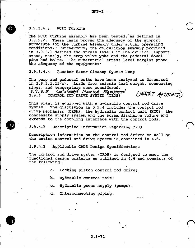
3.9.3.4.3 RCIC Turbine~ ~
The RCIC turbine assembly has been tested,'s defined in3.9.2.2. These tests proved the adequacy of the supportstructure for the turbine assembly under actual operatingconditions. Furthermore, the calculation summary providedin 3.9.3.1 defined the stress levels in the critical supportareas, namely, the stop valve yoke and the pedestal dowelpins 'and bolts. The substantial stress level margins provethe adequacy of the equipment;--
3.9.3.4.4 Reactor Water Cleanup System Pump
The pump and pedestal bolts have been analyzed as discussedin 3.9.3.1.15 (c) ., Loads from seismic dead weight, connectingpipes, and temperature were consider4.B. V. 9. 5 C~galintPQ Plcenl'eg Ei~ipPne~ (~y~~T +~<+ )3 ~ 9.4 CONTROL. ROD DRIVE SYSTEM (CODS)
This plant is equipped with a hydraulic control rod drivesystem. The discussion in 3.9.4 includes the control roddrive mechanism (CRDM), the hydraulic control unit (HCU), thecondensate supply system and the scram. discharge volume andextends to the coupling interface with the control rods.
3.9..'4.1 Descriptive Information Regarding CRDS
Descriptive information on the control rod drives as well asthe entire control and drive system is contained in 4.6.
3.9.4.2 Applicable CRDS Design SpecificationsThe control rod drive system (CRDS) is designed to meet the
'functional design criteria as outli;ned in 4.6 and consists ofthe following:
t
a. Locking piston control rod drive;b. Hydraulic control unit;c. Hydraulic power supply (pumps),
d. Interconnecting piping,
3.9-72

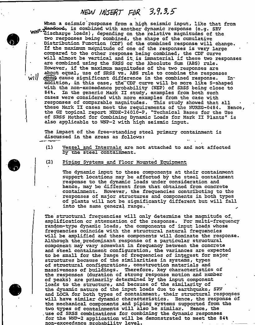
N&v'sBH7 FANhen a se'smic "esponse from a high seismic input, like that fzom's combined with anothe dynamic response (e.g. SRVaischa ge loads), depending on the relative magnitudes of thetwo responses being combined, the shape of the cunulative
~ Dis"-ibution Function (CDF) of the combined esponse w'l change.If the meum magni"ude of one of the responses is very largecompa ed to the other response being combined, the CDF curvewi'1 almost be vertica3. and it is immaterial i these two zesponsesare combi"ed us'ng the SRSS or the Absolute Sum (ABS) rule.However, i the maximum magnitudes of the two responses areabout equal, use of SRSS vs. ABS rule to combine the responses
>flI g@ cause signi icant difference in the combined response. Ls-addition, in this case, t5e CDF curve will be more like S-shapedwide the non-exceedance probability (NEP) of SRSS being close to84%. ~< the gene ic Mark II,study, examples f om both suchcases vere considered with more examples from the case withresponses oz comparable magnitudes. This study showed tha™ allthese Na k II cases meet the requirements of the NUREG-0484. Hence,the GE topical report NZDE-24010-P, "Techn'cal Bases for the Useof SRSS Method =or Combining Dynamic Loads fo Mark II Plants" isalso appl" cable to HNP-2 with high seismic input.The impact of the free-standing steel prima«y containment isdiscussed in the areas as follows:
(1) Vessel and Internals are not attached to and not a fectedy che s"eel containment.
(2) Piuwa Systems and. Floor Mounted Equi~ment
The dynamic input to these components at their containmentsupport locations may be affected by the steel containmentresponse o the dynamic loads under consideration andhence, mav be d'f eren from that. obtained from concretecon~~nnent. However, the frequencies cont«ibuting to theresponses of majo structures and components in both typesof plants villnot be significantly different but will fall'nto the same general range. "
The structural =.requencies will only determine the magnitude of.amplif'cat'on or at¹ruation of the response. For multi-frequencyrandom- ype dynamic 1oads, the components of input loads whosefrequencies coincide with the structu=al natu=al frequencieswill be amplif'ed and. these components will dominate the response.Although the predominant response of a, particular struc u alcomponent may vary somewhat in frequency between the concreteand steel containment configuration, the variances are expectedto be small for the =ange of frequencies of interest for majorstructures because of the similarities in systems, typesof stmctu=al configura ions, construction mate ials andmassiveness of buildings. Therefore, key cha actezistics ofthe responses (auration of stzong response motion and numberof peaks) are p=imarilv detezmined by the input componentloaas to t"e s"ructure, and because o the similarity ofthe dynamic nature of the input loads due to ea«thquake, SRVand LOCA for both types of containment, theiz structural responseswill have simila dynamic characteristics. Hence, the response ofthe mechanical components and piping systems supported from thetwo types of containments will also be simila=. Hence, the
,use of SRSS combinations for combining the dynamic responsesfor >e %--2 application will be demonstrated to meet the 84%nor;exceedance .probability level.

~~ ~ ~ A-
MHP"2 DSER
'OUESTIOH NO. 27
The note in Table 3.9-2(a) of the FSAR states that HSSS components~ designed to the upset plant condition (normal operating loads + upset
transients 5 .5 SSE) will meet the upset design condition limi s withouta fatigue analysis. It is the staff's position that for all ASME Class 1components,a fatigue analysis shall be performed for all loading conditions.The basis for deviating from this position should be provided for MNP-2.If the WNP-2 position on this issue is implicit in the letter fromM. Gang to R. Bosnak, "GE Position on Fatigue Analysis," dated January 15.,
. 198>, provide he information requested in the letter from R. Bosnak tod. Gang, dated February 19, 1981.
RESPOHSE
The information requested was documented in the letter from R. B. Johnsonto R. Bosnak,'"GE Position on Fatigue Analysis," on June 23, 1981. Acopy is at..ached.
Summation — This item is closed.
PCY:rf/45Eu8/18/81
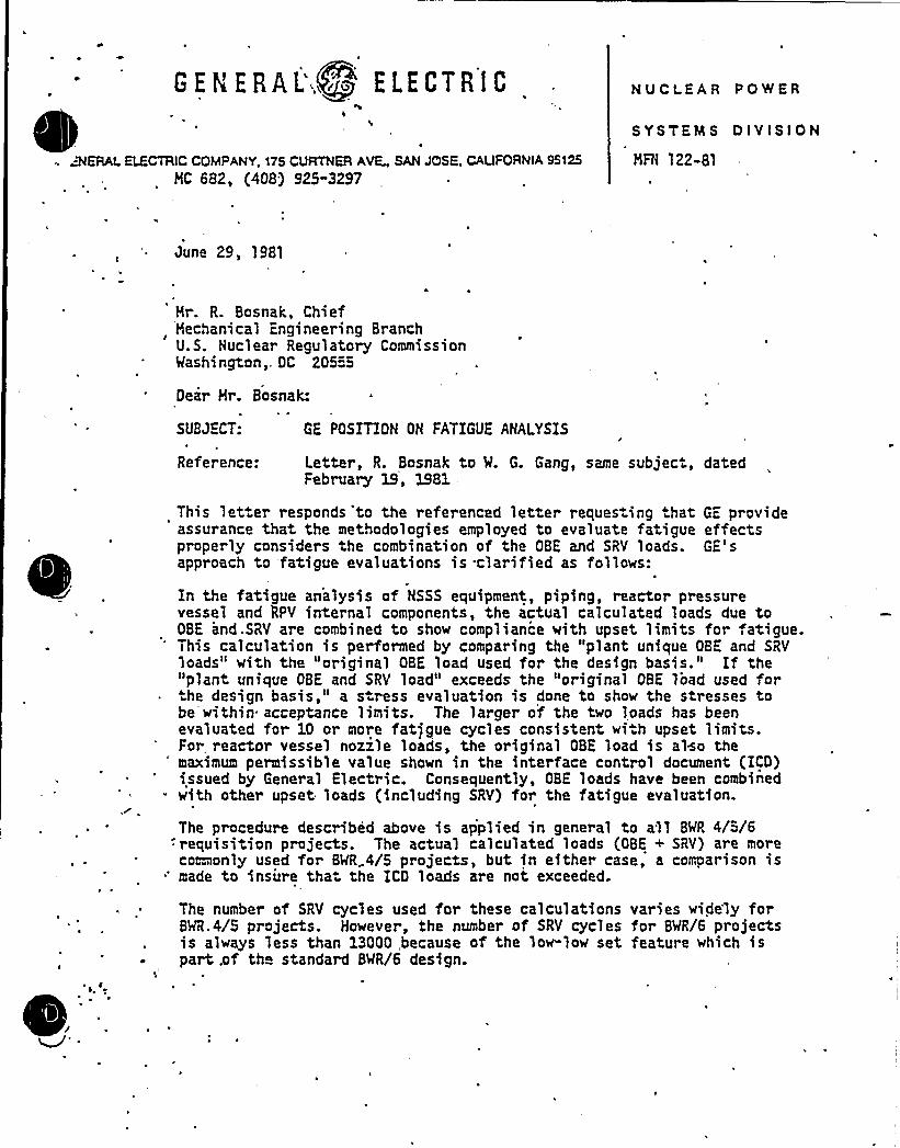
BEN ERAL' ELECTRIC
ERAL ELECTRIC COMPANY, 175 CURTNER AVE„SANJCISE, CAUFORNIA 95125
MC 682, (408) 925"3297
NUCLEAR PO'HER
SYSTEM S D IV!SION
MFN 122-81
June 29, 1981
Mr. R. Bosnak, ChiefMechanical Engineering BranchU.S. Nuclear Regulatory CommissionWashington,, DC 20555
Oeir Mr. Bosnak:
SUBJECT: GE POSITION ON FATIGUE ANALYSIS
Reference: Letter, R. Bosnak to W. G. Gang, same subject, datedFebruary 19, 1981,
This let er responds 'to the referenced letter reques.ing that GE provideassurance that the methodologies employed to evaluate fatigue effectsproperly considers the combination of the OBE and SRV loads. GE'sapproach to 'fatigue evaluations is clarified as follows:
In the fatigue analysis of NSSS equipment, piping, reactor pressurevessel and RPV internal components, the actual calculated loads due toOBE and.SRV are combined to show compliance with upset limits for fatigue.This calculation is performed by comparing the "plant unique OBE and SRVloads" with the "original OBE load used for the design basis." If the"plant unique OBE and SRV load" exceeds the original OBE load used for
he design basis," a s ress evaluation is done to show the stresses tobe within acceptance limits. The larger of the two loads has beenevaluated for 10 or more fat)gue cycles consistent wi h upset limits.For reactor vessel nozile loads, the original OBE load is also themaximum permissible value shown in the interface control document (ICD)issued by General Electric. Consequently, OBE loads have been combinedwith other upset loads (including SRV) for the fatigue evaluation.
The procedure described above is applied in general to all BWR 4/5/6:requisition projects. The actual calculated loads (OBE + SRV) are morecoamonly used for BWR..4/5 projects, but in either case, a comparison is
'ade to insure tha the ICO loads are not exceeded.
The number of SRV cycles used for these calculations varies widely forBWR.4/5 projects. However, the number of SRV cycles for BWR/6 projectsis always less than 13000,because of the low-low set feature which ispart .of the standard BWR/6 design.
.
GEH.:R~L >g ELECTR fC
U.S; Nuclear Regulatory CommissionPage 2
This approach has been discussed with you and members of your staff andwe understand it is acceptable.
Very truly yours,
R. B. ohnson, Acting HanagerBVR Projects LicensingHuclear Safety and Licensing Operation
~ RBJ: sam/1125-26 625
~ cc: L. S. Gifford
bcc: R. VillaG. G. SherwoodP. C. Yin ~BMRPL Staff

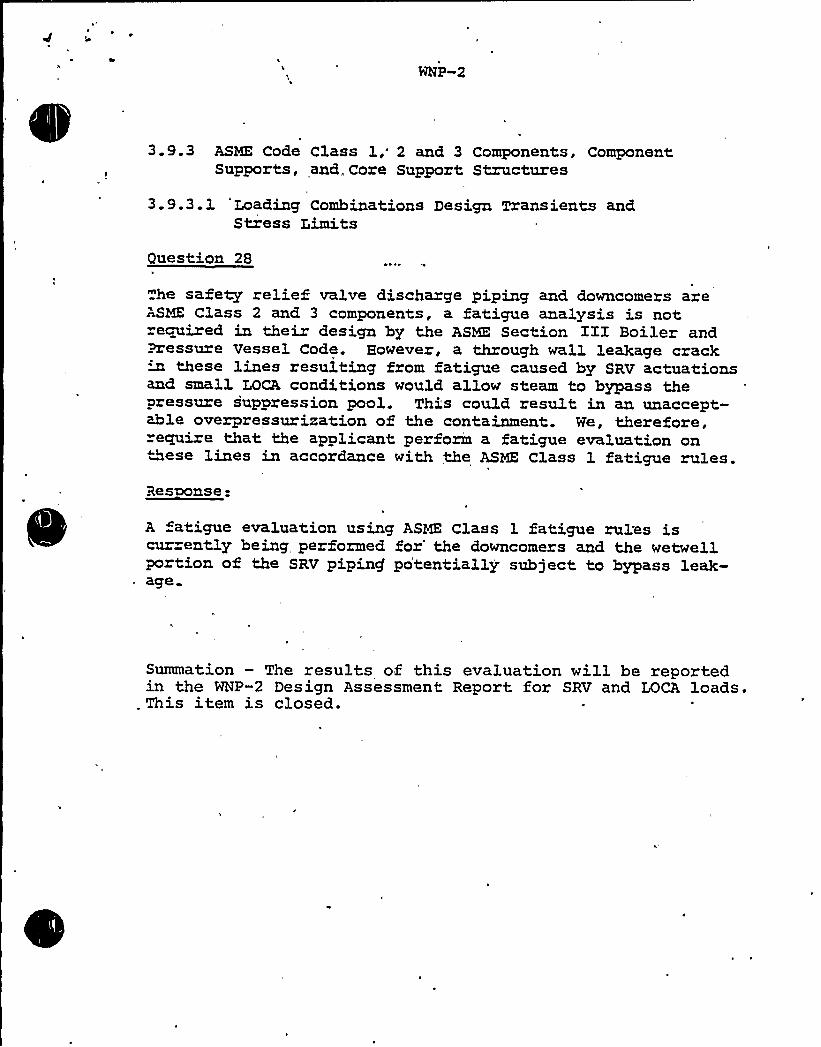
3.9.3 ASME Code Class 1," 2 and 3 Components, ComponentSupports, and„Core Support Structures
3.9.3.1 'Loading Combinations Design Txansients andStress Limits
Question 28
he safety relief valve discharge piping and downcomers areASME Class 2 and 3 components, a fatigue analysis is notxecpxired in their design by the ASME Section III Boiler andPressure Vessel Code. however, a through wall leakage crack
these lines resulting from fatigue caused by SRV actuationsand small LOCA conditions would allow steam to bypass thepressure suppression pool. This could result in an unaccept-able overpressurization of the containment. We, therefore,require that the applicant, perform a fatigue evaluation onNese lines in accoxdance with the ASME Class 1 fatigue rules.Resaonse-
A atigue evaluation using ASME Class 1 fatigue rul'es iscur ently being performed for'he downcomers and the wetwellportion of the SRV pipincf potentially subject to bypass leak-
~ age
Summation — The results of this evaluation will be reportedin the WNP-2 Design Assessment Report for SRV and LOCA loads.
. This item is closed.

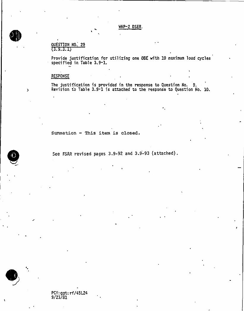
MHP-2 OSER.
OUESTION HO. 29~ ~ 4 )
Provide justification for utilizing one OBE with 10 maximum load cyclesspecified in Table 3.9-1.
RESPONSE
The jus ification is provided in the response to Ques ion No. 9.Revision to Table 3.9-1 is attached to .he response to Question Ho. 10.
Surunation — This item is closed.
See FSAR revised pages 3.9-92 and 3.9-93 (attached).
PCY: ggt: rf/Z5L2Z9/23/81
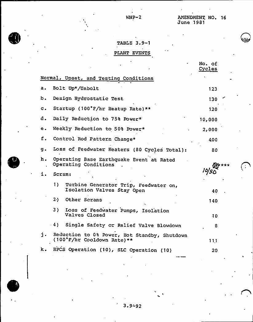
M4P-2 AMENDMENT NO. 16June 1981
TABLE 3. 9-1
PLANT EVENTS
Normal, U set, and Testin Conditions
a. Bolt Up*/Unbolt
b. Design Hydrostatic Test
c. Startup (100'F/hr Heatup Rate)**
d. Daily Reduction to 75% Power*
e. Meekly Reduction to 50% Power*
f. Control Rod Pattern Change*
g. Loss of Feedwater Heaters (80 Cycles Total):h. Operating Base Earthquake Event at Rated
Operating Conditions
i. Scram:
No. of~Ccles
123
130
120
10,000
2,000
400
80
*ee
1%g
1) Turbine Generator Trip, Feedwater on,Isolation Valves Stay Open
2) Other Scrams
3 ) Loss of Feedwater Pumps, IsolationValves Closed
40
140
10
-4) Single Safety o" Relief Valve Blowdown
j . Reduction to 0% Power, Hot Standby, Shutdown(100'F/hr Cooldown Rate)**
k. HPCS Operation (10), SLC Operation (10) 20
3-9-92
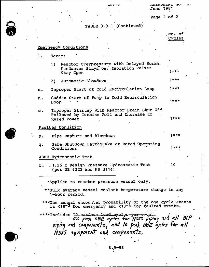
s
navr-,c
TABLE 3.9-1
(Continued)'ol'lGLxlJL'lGLX
J le'v ~ l 'M
June 1981
Page 2 of 2
Emer enc Conditions
. No. of~Cc lee
1. Scram:
1) Reactor Overpressure with Delayed Scram,Feedwater Stays on, Isolation ValvesStay Open
2 ) Automatic Blowdown
m. Improper Start of Cold Recirculation Loop
n. Sudden Start of Pump in Cold RecirculationLoop
1 **4'
***
1 ***
o. Improper Startup with Reactor Drain Shut OffFollowed by Turbine Roll and Increase toRated Power 1***
Faulted Condition
p. Pipe Rupture and Blowdown
q. Safe Shutdown Earthquake at Rated OperatingConditions
ASME 8 drostatic Test
r. 1.25 x Design Pressure Hydrostatic Test(per NB 6222 and NB .3114)
10
*Applies to reactor pressure vessel only.
*",Bulk average vessel coolant temperature change in any1-hour period.
***The annual encounter probability of the one cycle eventsis <10 2 for emergency and <10 + for faulted events.
****Includes5> peak oBE cyeies Eor gsss p>piny a>~ a// RP
pipit) ac/ coxponenQ and /o peP aaE ~les /nor e///IlSS'5 ep>1pnee4 ahd co~/'openYS.
's'Ih
3.9-93h
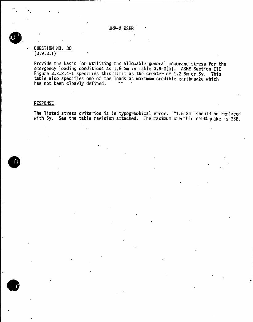
WNP-2 DSER
QUESTION NO. 303.9.3.1
Provide the basis for utilizing the allowable general membrane stress for theemergency loading conditions as 1.5 Sm in Table 3.9-2(a). ASME Section IIIFigure 3.2.2.4-1 specifies this 'limit as the greater of 1.2 Sm or Sy. Thistable also specifies one of the loads as maximum credible earthquake whichhas not been clearly defined.
RESPONSE
The listed stress criterion is in typographical error. "1.5 Sm" should be replacedwith Sy. See the table revision attached. The maximum credible earthquake is SSE.
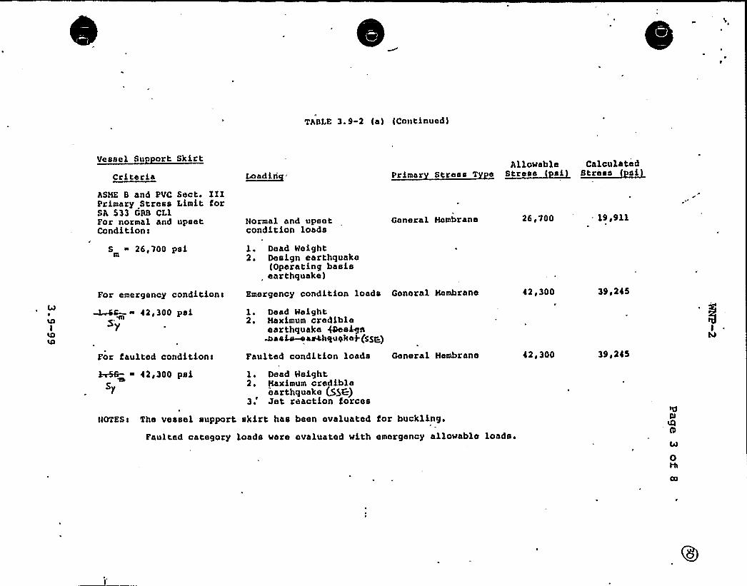
TABLE 3. 9-2 (a) (Continued)
Vessel Su rt SkirtCriteria L~oa din
Allowable Calculated
ASHE B and PVC Sect. IIIPrimary Stress Limit forSA 533 GAB CL1For normal and upsetConditions
S ~ 26,700 psi
Normal and upsetcondition loads
1. Dead Weight2. Design earthquake
{Operating basisearthquake)
General Hembrane 26,700 - 19 g911
For emergency conditions Emergency condition loads General Membrane 42,300 39,245
~S- ~ 42,300 psi5'y
For faulted condition<
1 ~ Dead Weight2. Maximum credible
earthquake 4Qee+nWasLs-oasahqueke> (S5g)
Faulted condition loads General Hembrane 42 '00 39g245
brSB- ~ 42,300 psi l. Dead Weight2. Haximum credible)'arthquake (55K)3.'et reaction forces
NOTES< The vessel support. skirt has been evaluated for buckling.
Faulted category loads were evaluated with emergency allowable loads.
0
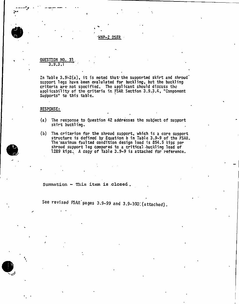
MNP-2 DSER
OUESTION NO. 31,3.9.3.1
En Table 3.9-'2(a), i is noted that the supported skirt and shroudsupport legs have been evalulated for buckling, but-the bucklingcriteria are not specified. The applicant should discuss theapplicability of the criteria in FSAR Section 3.9.3.4, "ComponentSupports" to this table.
RESPONSE:Y
(a) The response to guestion 42 addresses the subject of supportskirt buckling.
(b) The. cri erion for the shroud support, which is a core supportstructure is defined by Equation b in Table 3.9-9 of the FSAR.The maximum faulted condition design load is 854.5 kips pershroud support leg canpar ed to a critical buckling load ofl289 kips;- A copy of Table 3.9»9 is attached for reference.
Summation — This item is, closed .
See revised FSAR pages 3.9-99 and 3.9-100:(attached).

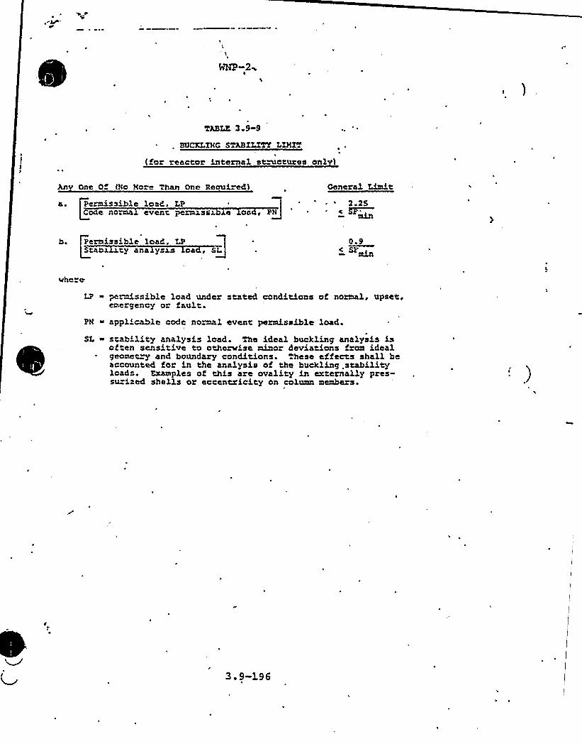
TM3LE -3.9-9
. SUCXr.XNC SmaZLTTT LISZT
(for reactor internal st~ctures onl 3
Anv One Of (No Nore Than One Reoui ed3
a . Perm'ssible load, LPCooe norma event permxssx e oa , PN
Ceneral Limit2 25
* c 5F~
b. I Permissible load. LPQStaox ty ana ysas oa, SQL
4
where
0.9min
LP ~ permissible load under stated conditions of normal, upset.emergency or fault.
PM ~ applicable code normal event period,ssible load.
SL ~ stability analysis load. The ideal buckling analysis isoften sensitive to othcnrise minor deviations from idealgeomet~ and boundary conditions. These effects shall beaccounted for in the analysis of the buckling .stabilityloads. Examples of this are ovality in externally pres-su"ised shells or eccentricity on column members.
3 9-196
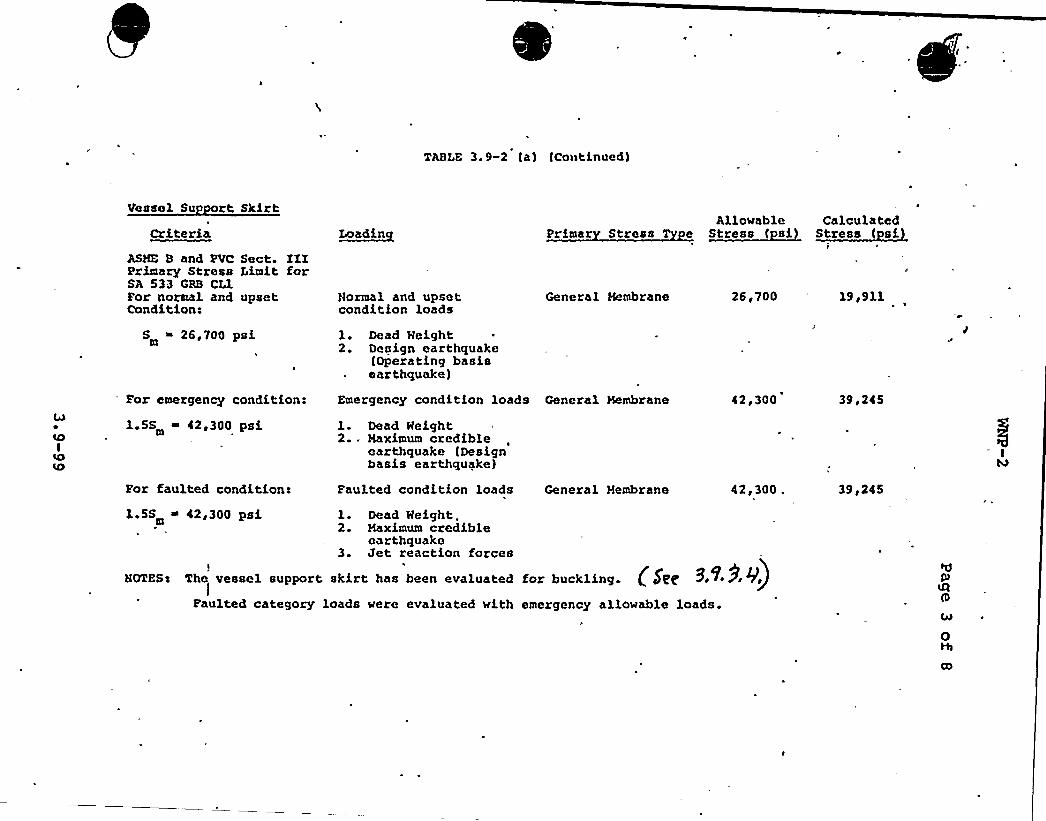
TABLE 3 9-2 (a) tContinued)
Vessel Su rt SkirtCriteria I~I>adin
Allowable Calculated
I
ASME B and PVC Sect. IIIPrimary Stress Limit forSA 533 GRB CL1For normal and upsetCondition:
S ~ 26,700 psi
Normal and upsetcondition loads
l. Dead Weight2. Design earthquake
(Operating basisearthquake)
General Membrane 26i700 19,911
For emergency condition:
1.5S ~ 42,300 psim
Emergency condition loads General Membrane
1. Dead Weight2. - Maximum credible
earthquake (Designbasis earthquake)
42,300 39 '45
For faulted condition- Faulted condition loads General Membrane 42'00 . 39,245
1 5S ~ 42,300 psi 1. Dead Weight.2. Maximum credible
earthquake3. Jet reaction forces
HOMSx The vessel support skirt has been evaluated
Faulted category loads were evaluated with
for hackling. (SPc ~ ~'9 'V)emergency allowable loads.
0Hl

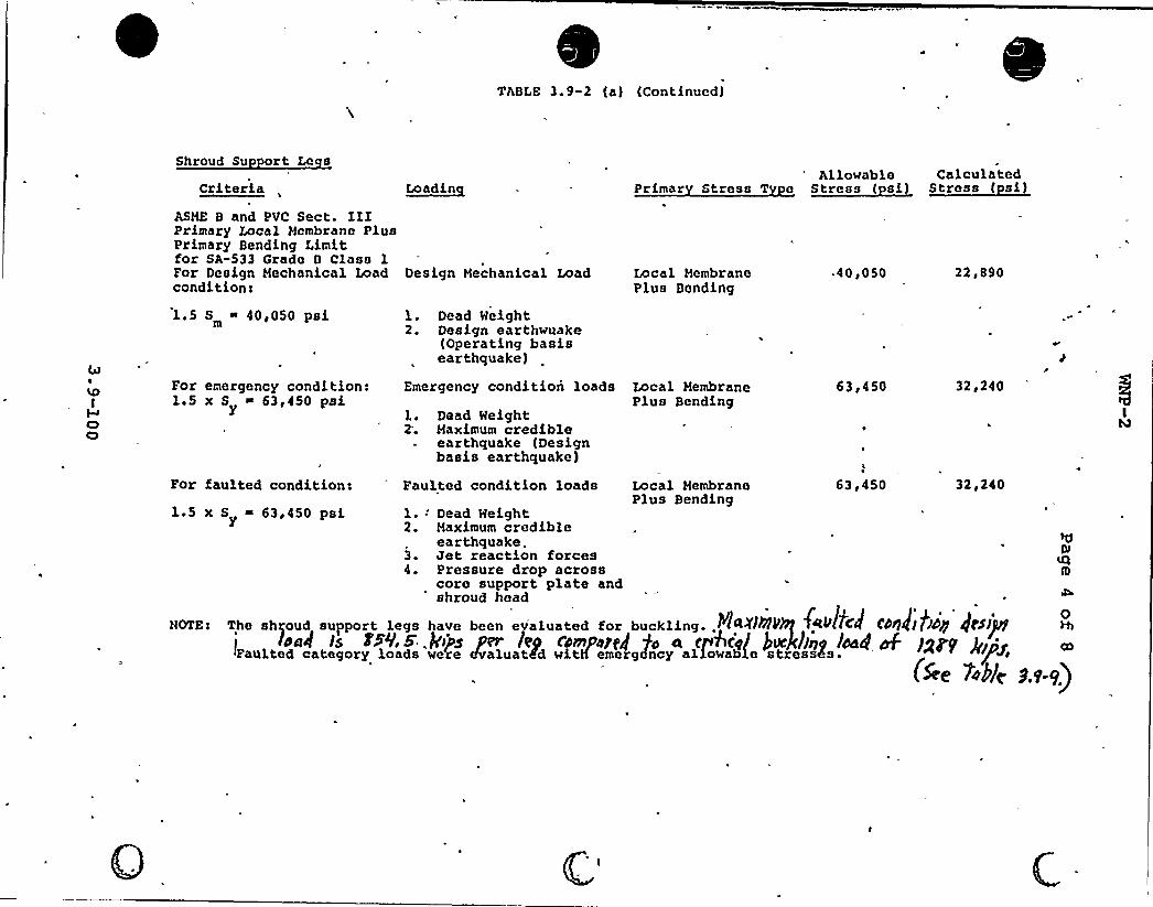
TABLE 3.9-2 (a} (Continued}
Shroud Su ort Le s
Criteria ~loadieAllowable Calculated
Stress ( si}ASHE B and PVC Sect. IIIPrimary Local Membrane PlusPrimary Bending Limitfor SA-533 Grade 0 Class 1For Design Mechanical Load Design Mechanical Loadcondition>
Local MembranePlus Bonding
~ 40S050 22,890
1.5 S ~ 40,050 psim
For emergency condition:1.5 x S ~ 63,450 psi
Y
For faulted condition!1.5 x S ~ 63,450 psi
Y
1. Dead Weight2. Design earthquake
(Operating basisearthquake}
Emergency condition loads
}.. Dead Weight2; Maximum credible
earthquake (Designbasis earthquake)
Faulted condition loads
1.: Dead Weight2. Maximum credible
earthquake.3. Jet reaction forces4. Pressure drop across
core support plate and
Local MembranePlus Bending
Local MembranePlus Bending
63,450
63,450
32,240
32,240
'hroud head
NOTNI The shroud support legs have been evaluated for buckling..YIRZIIIINffRPltCII CDII4IIISII IICSI)PIIdol Is FWls A'j si.fn leg omgdscg go R cjhcgf bo'ckbng lddg ~ Spry PIP+
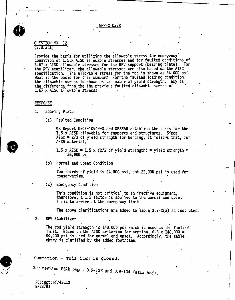
WNP-2 DSER
OUESTION NO. 32
d f f lt d conditions of~ ~ ~ allowable stress for emergency
lo able stresses a1.67 x AISC allowable stresses for the RPY support, earing p
he RpY S.abillzer the allowable stresses are also based on8~4eooohe allowable stress for the rod is shown as , psi.specification. The a
For"the faulted loading condition,Wha is the basis for this number'? or' ah. Wh is1 ab ss is shown as the material yield strengt . y
the di- erence from the the previous faulted a Ilowable stress of1.67 x AISC allowable stress?
RESPONSE
1. Bearing Plate
(a) Faulted Condition
GE Report NEDE"10949"3 and GESSAR establish the basis for the1. 5 x AISC allowable for supports and structures. SinceAISC = 2/3 of yield strength for bending, it follows that, forA-36 material,
1.5 x AISC = 1.5 x (2/3 of yield strength) = yield strength =36,000 psi
(b) Normal and Upset Condition
Two thirds of yield is 24,000 psi, but 22,000 psi is used forconservatism.
(c) Emergency Condition
This condition is not critical to an inactive eouipment,therefore, a 1.5 factor is applied to the normal and upsetlimit to arrive at the emergency limit.
The above clarifications are added to Table 3.9-2(a) as footnotes.
2. RPY Stabilizer
The rod yield strength is 140,000 psi which is used as the faultedlimit. Based on the AISC criterion for tension, 0.6 x 140,000 =84,000 psi is used for normal and upset. Accordingly, the tableentry is clarified by the added footnotes.
Summation — This item is closed.
See revised FSAR pages 3.9-103 and 3.9-104 (attached).
pCV: ggt: rf/45L139/23/81

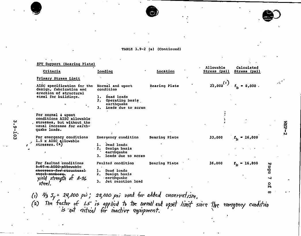
TABLE 3. 9-2 (a) (Continued)
RPV Su ort (Bearin Plate)
CriteriaPrimar Stress Limit
AISC specification for thedesign, fabrication anderection of structuralsteel for buildings.
For normal c upsetconditions AISC allowablestresses, but without theusual increase for earth-quake loads.
L~oadLa
Normal and upsetcondition
1. Dead loads2. Operating basis
earthquake3. Loads due to scram
Location
Bearing Plate
Allowable Calculated
22,000 = fb ~ 8u000(()
For emergency conditionsla5 x AISC allowablestresses. (<)
Emergency condition Bearing Plate
1. Dead loads2. Design basis
earthquake3. Loads due to scram
33 F 000 fb ~ 16,000
For faulted 'cond itions Faulted condition
1. Dead loads2. Design basis
. earthquake3. Jet reaction load
Bearing Plate 36,000 fb ~ l6e800
0
CO
(i) +a s<= N,DDD p>,'a,»ophi uded 4>r added cdhzerygryrn
(2) >be fa kdr o$ ld id agllcd 0 the bar&i drJ upas limp sthce Qc euLey>y cdhgjjyh~~ hot
c>itive'al
fdr lhaCb Vg eyiuiph'rent;
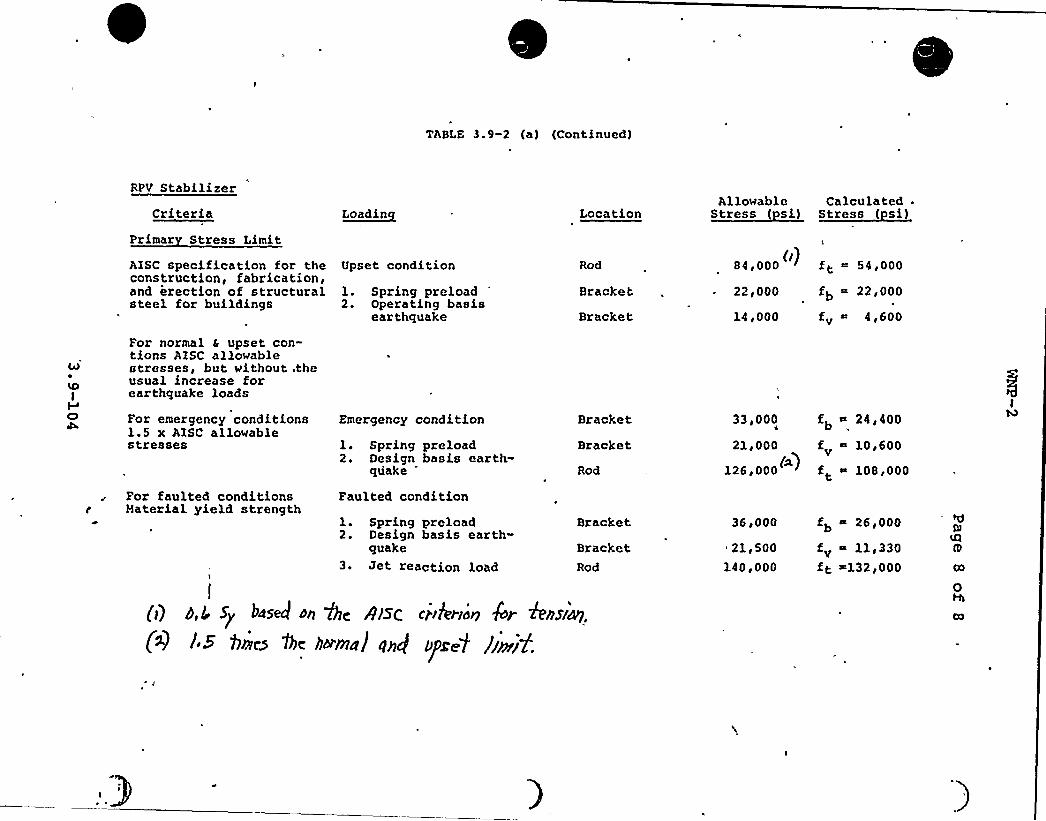
yABLE 3. 9-2 (a) (Continued)
RPV StabilizerCriteria
Primar Stress Limit
Load~ac[ LocationAllowable Calculated .
AISC specification for theconstruction, fabrication,and erection of structuralsteel for buildings
Upset condition
1. Spring preload2. Operating basis
earthquake
Rod
Bracket
Bracket
84,000 (])
22,000
ft 54d000
fb "- 22,000
14,000 fv 4,600
4lLOI
CI
For normal a upset con-tions AISC allowablestresses, but without .theusual increase forearthquake loads
For emergency conditions1.5 x AISC allowablestresses
For faulted conditionsr Haterial yield strength
Emergency condition
1. Spring preload2. Design basis earth-
quake
Faulted condition
1. Spring preload2. Design basis earth-
quake3. Jet reacti.on load
Bracket
Bracket
Rod
Bracket
BracketRod
33,000
21d 000
126,000~ >
36,000
21d 500
140,000
fb ~ 24,400
f ~ 10,600V
f ~ 108,000t
fb ~ 26,000
fv 11,330ft ~132,000
I
(]) P > $y bd5+ dp Q< /)SAN CPikridn kr hh$~49.
(g i.S bee~ the addmn( q~dt y>X~t bnrif.
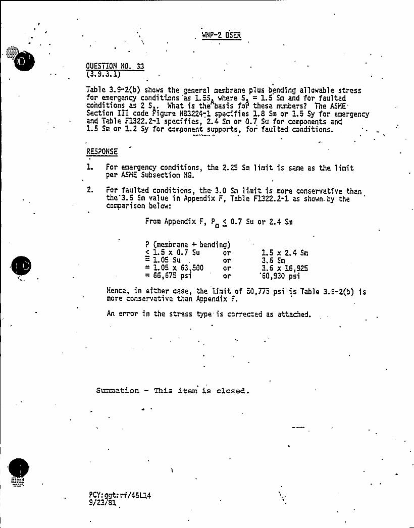
WNP-2 OS=R
OUES"liON HO. 33
Table 3.9"2{b) shows the general membrane plus bending allowable s ressfor emergency conditions 'as L5)A where S = 1.5 Sm and for faul.edconditions as 2 S . What is the basis foIP these numbers? The ASHESection IEE code figure H83224-.1 specifies 1.8 Sm or 1.5 Sy for emergencyand Table F1322.2-1 specifies, 2.4 Sm or 0.7 Su for components and1.5 Sa or 1.2 Sy for component supports, for faulted conditions.
RESPONSE
For emergency conditions, the 2.25 Sm limit is same as the limitper ASME Subsection HG.
2. For faulted condi ions, the 3.0 Sm limit is more conservative thanthe 3.6 Sm value in Appendix F, Table F1322.2-1 as shown. by thecomparison below:
From Appendix F, P < 0.7 Su or 2.4 Sm
P {membrane + bending)< 1.5 x 0.7 Su or= 1.05 Su or= 1.05 x 63,500 or= 66,675 psi 'r 1.5 x 2.4 Sm
3.6 Sm
3.6 x 16,92560,930 psi
Hence, in ei her casa, Ne l.i~it of 50,7T5 psi is Table 3..-2{b) ismore conser rative than Aopendix F.
An error in the s.ress tge is correc:ed as at ached.
Smaehion — This i"em is closed.
PCY: ggt: rf/45L149/23/81

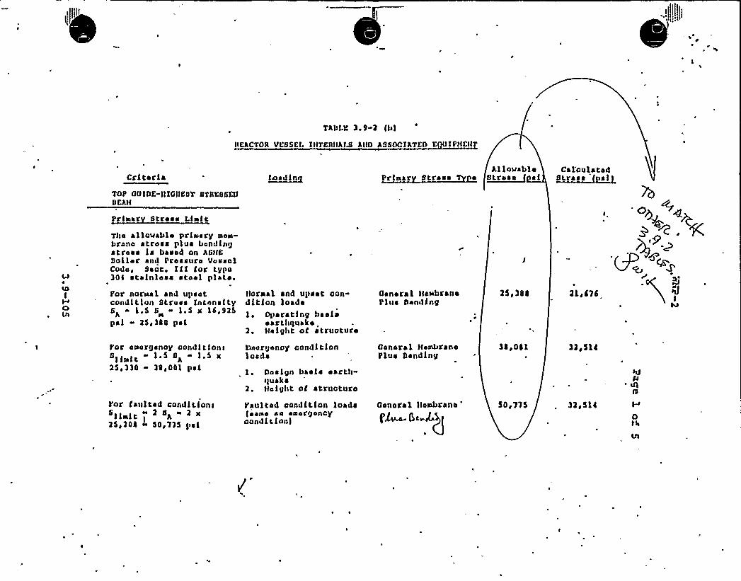
TAIN 3.9-2 (Ll
nehcTOB vessel. rnzeIIHhra Ann hssocrhTen e rpHSH
CBIIBBI~
TOP onrne-IlrGIILQT STIIBSSGrbehH
~ll)~ I IIl Prraar StressAllovable
BLr B ~ f ~ ICal'oulatad
Stress sl
PrlsIar stress LraltTbs allouablu prlaIary sIoaB-brano atroes plus bondingstress ls based on AGHSboll~ r and Prseeurs VussolCods, Sant. Ill tor Lypo304 stainless stosl plaL~ .
for noriaal and upsetcondltlon Btruee intensityS «1.5 S 1.5 x 16,925hpsl «25qiSS psl
I'or ooargenoy condl tlonrSll lt 1.5 Sh « 1.$ x25 ')S 30 F 001 psl
Yor taultad condltlonl1 1II!t A
25 ~ 204 ~ 50 ~ ll5 pel
IIoroal and upset oon-dltlon loads1 Oper ~ 'ting baal ~
~ artbBrukko2 ~ Height oC atruoturo
L'uLargsncy condltlonloads
1 Design basis sartlr-quaka
2. Height oC structure
faulted condltlon loads(saBBa ss aaBorgoncyoondltlon)
rranaral HaxbranoPlus banding
General HssdBranaPlus bending
General llsxbranof'~5t
25 ~ 3SI
3j ~ 0IL
5''lS
llew 676
32B514
32g5140rIB

OP 2 OSER
OVESTION NO. 343.9;3.1)
Tab1e 3.9-2(e) shows the a11owab1e for the emergency condition as Pe c 3.0 Sm.Mhat is the significance and validity of this equationT
RESPONSE
The criterion "Pe < 3.0 Sm" should be deleted. "Eq. 9 < 2.25 Sm" is the criterionfor both emergency load cases. Accordingly, Table 3.9-2(e) is revised as attached.
Xn the new loads update for BOP, Tables 3.9-16 and 3.9-17 willbe upgraded to cover piping, components and supports.

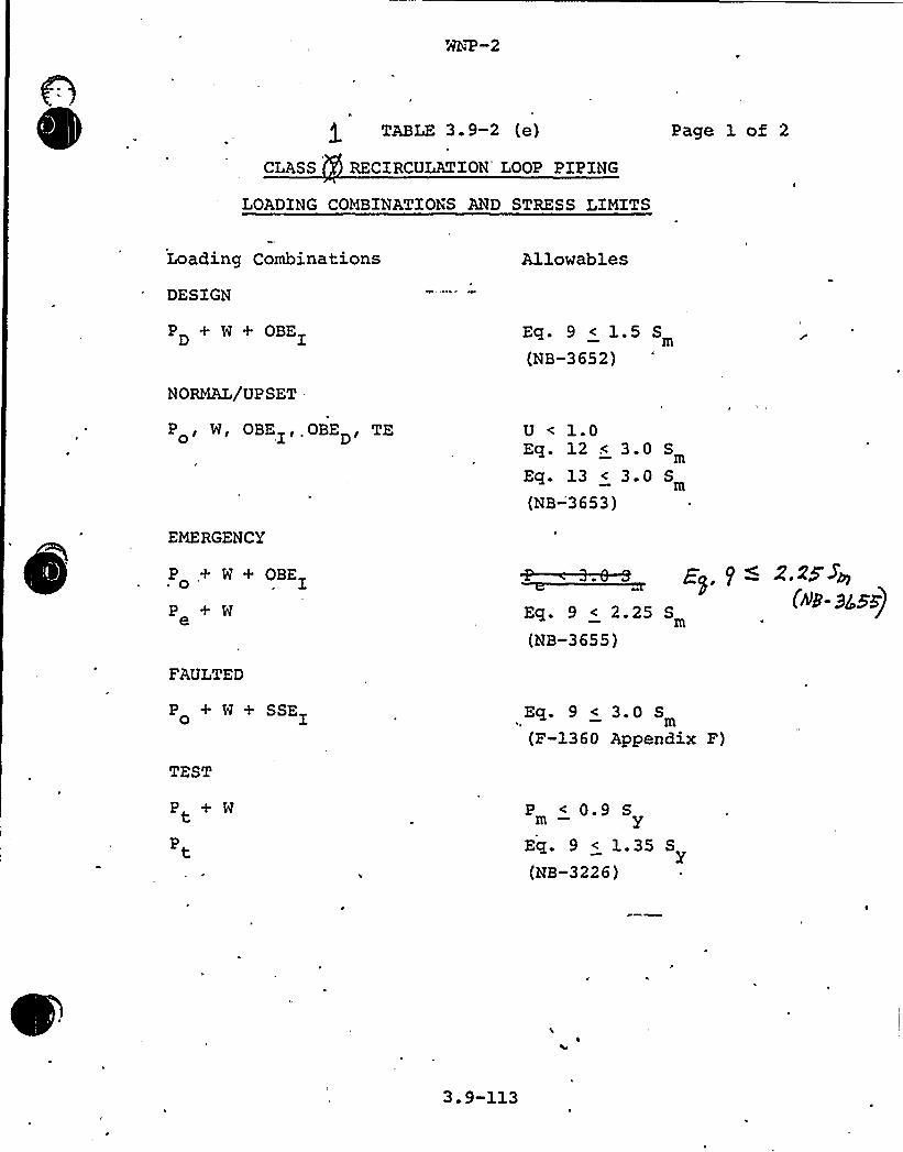
TABLE 3. 9-2 (e)
CLASS RECIRCULATION" LOOP PIPING
Page 1 of 2
LOADING COMBINATIONS AND STRESS LIMITS
Loading Combinations
DESIGN
PD + W + OBE
NORMAL/UPSET.
P , W, OBEI'.OBED'E0
EMERGENCY
P + W + OBEI~ 0 '
+ We
FAULTED
P + W+ SSEI0
Allowables
Eq. 9 < 1.5 S
(NB-3652)
U < 1.0Eq. 12 < 3.0 S
Eq. 13 < 3.0 S
(NB-'3653)
Eq. 9 < 2.25 S
(NB-3655)
Eq. 9 < 3.0 S
(P-1360 Appendix F)
P + W
Pt
P < 0.9 Sm — y
Eq. 9 < 1 35 S
(NB-3226)
3.9-113
MNP-2 OSER
UESTION NO. 353.9.3.1
Table 3.9-2 (i) Item 9, Hanger Bracket Combined Stress. In the method of analysis,it is. stated that the load = (M + M'MO) .33 and that the multiplier (.33) is
added as a safety factor speciRed o3 the purchase part drawing. Without beingable to evaluate the intent oF this-analysis in detail it appears that this factorresults in using only 0.33 of the total weight to determine the stresses. Additionaldetails of this analysis are requested.
RESPONSE
The recirculation pump is suspended from four hanger rods. The load. on each rodshould be (W~ +
MC + M„) x 0.25. In the actual design, (MB + WC + WO) x 0.33is assumed "This prov'fdes a 32 safety margin.
This is clarified by the footnote. in the attached table revision.
Sonation — This item is closed.

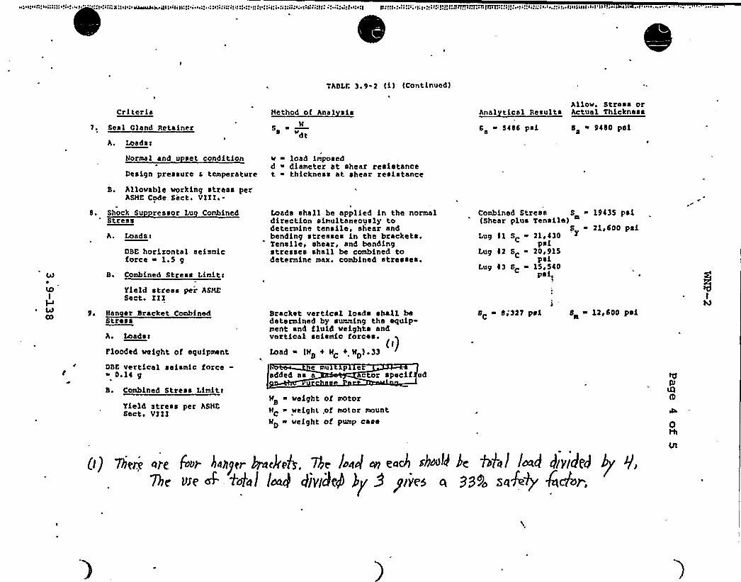
.. lu ~ In.' lg:n. ~ ~ ~ . ~ . ~ --~ .. ~ .;;,",:zu ~ n.i~~ajnujs: ...', ~,...
TABLE 3. 9-2 (i) (Continued)
Criteria Hethod of Anal sishllov. Stress or
Anal tical Results Actual Thickness
7. Seal C)and Retainer
h. Loads<
Normal and u sct condition
Design pressure 6 temperature
B. Allouab]c working stress perASHE Code Sect. VIII.-
SM
~ ltdt
v ~ load imposedd ~ diameter at shear resistancet ~ thickness at shear resistance
6 ~ 5486 psi58 9480 pals
4J
LDI
~ 4JCO
8. Shock Su ressor Lu CombinedStress
h. Loads>
DBE horizontal seismicforce ~ 1.5 g
B. Combined Stress Limits
Yield stress per ASHESect. III
9. Han er Bracket CombinedStress
A. Loadsc
Flooded ueight of equipment
DBE vertical seismic force-i 0.14 g
B. Combined Stress Limits
Yield stress per ASHESect. VIII
Loads shall bc applied in the normaldirection simultaneously todetermine tensile, shear andbending stresses in the brackets.Tensile, shear, and bendingstresses shall be combined todetermine max. combined stresses.
Bracket vertical loads shall bedetermined by summing the equip-ment and fluid weights andvertical seismic forces.
())Load ~ (Mb 4 MC 0 MD)'3
cmu p eadded aa a c or specif ed
MB ~ @eight of motor
MC weight,of motor mount'MD weight of pump case
mbincd Stress Sm 19435 pal(Shear plus Tensile)
S ~ 21,600 paiLg 81 S 21 430
palLug 82 SC 20t915
palLug 43 SC ~ 15,540
pal)
8 8j 327 psi S ~ 12,600 psic
(() 7lieri are 6e rhsgger kjnckef 7Pje l.oocl oy each sbooU ke Aha> load kygded bg7be wet- io'ol Ioa] 41videP )y 9 pie5 a 999o saA+ Aehr.
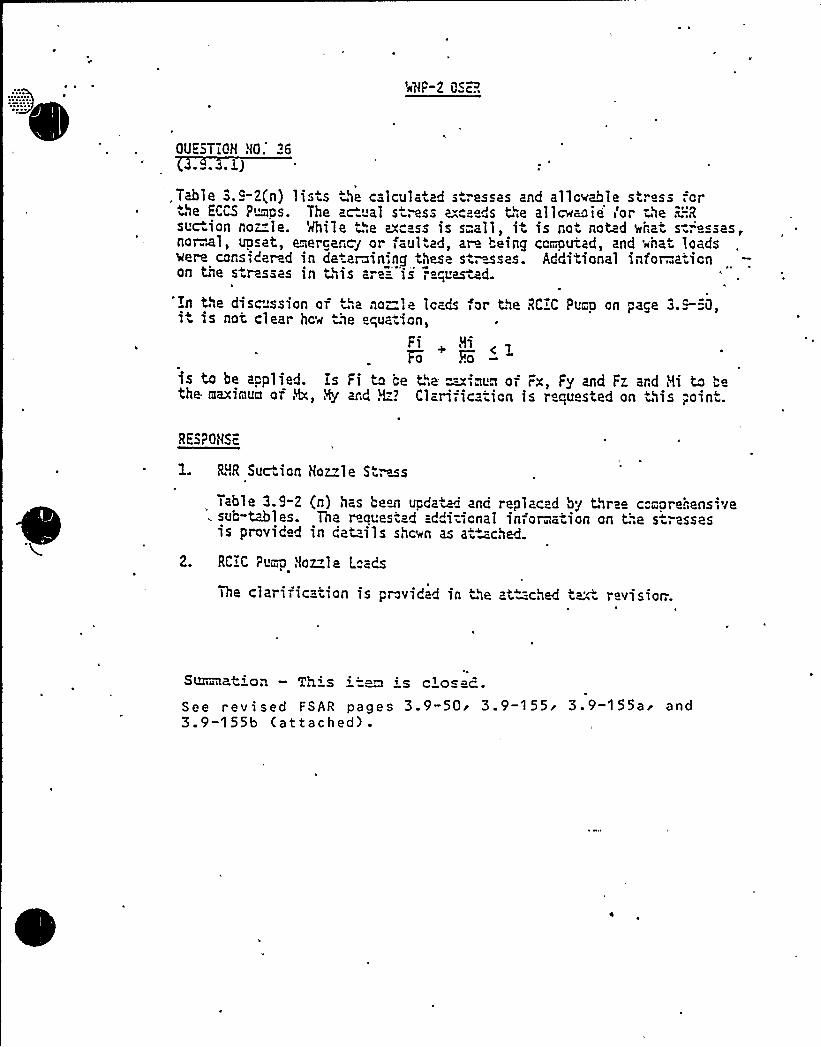
OUE5TIQH HO.'64rwo4o m)
'.Table 3.9-2{n) lists the caIculatad s ".esses and allowable stress forthe ECCS P"~ps. The ac al s ress a"c ds t",e aIIcwmie'or -ae R:-.'R
suc ion no~Ie. %bile ~".e axc ss is s=all, it is ro noted shat s:".'e sas,no~I, upset, emergency or faul ad, ar being corioutad, and '~hat loadsvere considered in de arain',ng these s,wsas. Additional infor..ationon the s ressas in ~",is are=- is ", „uaszd.
In the discussion of,a no-Ie loads for the RCIC Pun on page 3.=""0,it is not clear hc~ '~e equat'.on,
Fi N
is to be applied. Is Fi to ce '".e ==";qua of Fx, Fy and Fz ard Hi to "ethe maximua of Hx, Hy and H"? Clarification is requested on this "oint.
RE5PONSE
1. LfR Sue ion Hoz le St~ms
Table 3.9-2 {n) has been update and replaced by three c"mprehensive. sub-~les. Tha r quest d addi-ionai information on t;",e s ressas
is provided in cat=-ils shan as a- -ched.
2. RCIC Pum Nozzle L"ads
The clarification is provMad in ~he at=-ched text revisior:.
S~ua p-txQil T~ xs ~ ~~ ~ s c~ Qsac
See revised FSAR pages 3.9-50'.9-155'.9-155ai and3.9-155b (attached).

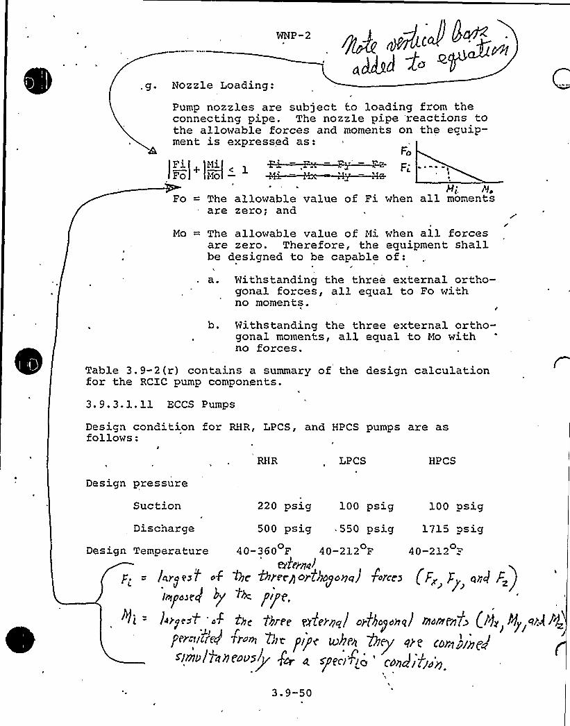
WNP -2
ad&~ ~~,go Nozzle Loading:
Pump nozzles are subject to loading from theconnecting pipe. The nozzle pipe reactions tothe allowable forces and moments on the ecuip-ment is expressed as:
FFi Mi
h
Fo = The allowable value of Fiare zero; and
H;, J9,when all moments
Mo = The allowable value of Mi when all forcesare zero. Therefore, the equipment shallbe designed to be capable of:a. Withstanding the three external ortho-
gonal forces, all equal to Fo withno moments.
b. Withstanding the three external ortho-gonal moments, al3, equal to Mo withno forces.
Table 3.9-2(r) contains a summary of the design calculationfor the RCIC pump components.
3.9.3.1.11 ECCS Pumps
Design cond'tion for RHR, LPCS, and HPCS pumps are asfollows:
RHR LPCS HPCS
Design pressure
Suction 220 psig 100 psig 100 psig
Discnarge 500 psig 550 psig 1715 psigDesign Temperature 40-360 F 40-212 F 40-212 =-
0 0 0
ate)n~Jp„, = /arrest o$ the Areegorlikpono) frees (Fz g orq F~)
'«po~e~ hy ~h pipeli = l~rgeo> '~k the three ml'cene/ o>khaporral roornen7ps (lie l'ly <~A l4
per-"r~'~d <»< >»e prpe k>hpn key're eoz~rnpPslnIolineeo st Joe < epe r
3.9-50
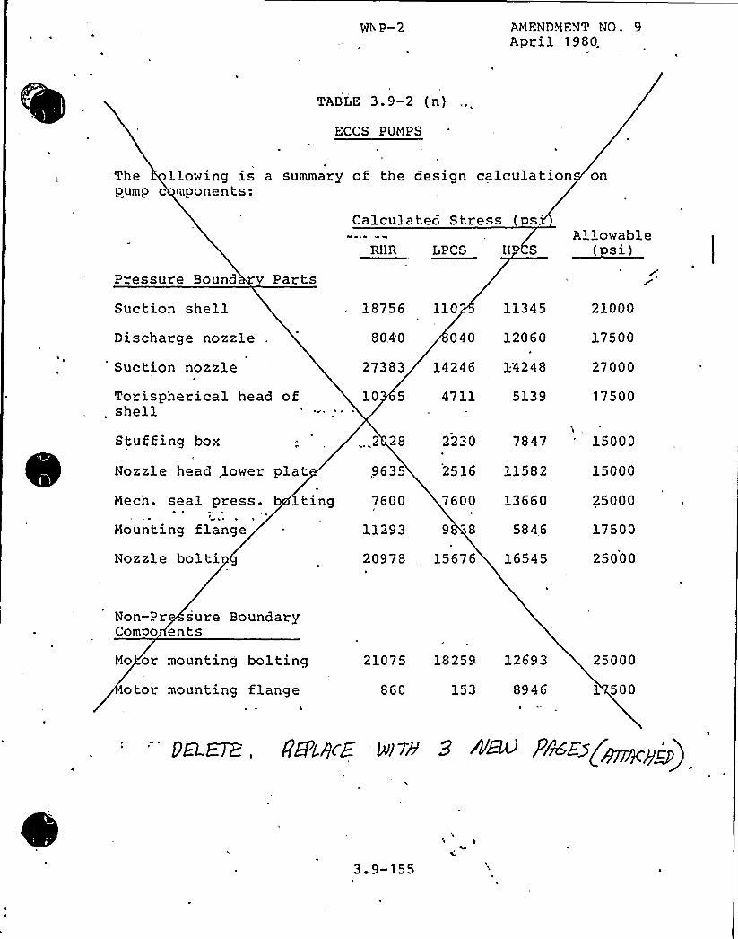
Nt P-2 AMENDMENT NO. 9April 1980.
TABLE 3.9-2 (n)
ECCS PUMPS
The llowing is a summary of the design calculation onpump c mponents:
Calculated Stress (osAllowable
Pressure Bound Parts
Suction shellDischarge nozzle
Suction nozzle
Torispherical head ofshell
Stuffing box
Nozzle head lower platMech. seal press. b lting
t
Mounting flange
Nozzle bolti
18756 110 11345
8040 040 12060
27383 14246 34248
10 5 4711 5139
, 2 28 2230 7847
9635 2516 11582
7600 7600 13660
11293 9 8 5846
20978 15676 16545
21000
17500
27000
17500
15000
15000
25000
17500
25000
Non-Pr sure BoundaryComoo> ents
Mo or mounting boltingotor mounting flange
S
21075 18259 12693
860 153 8946'I-
25000
1 500
gELE7Z, gBLQCE g) 7h 9 +~ PlrdE5gjyyyp(pj)
3.9-155

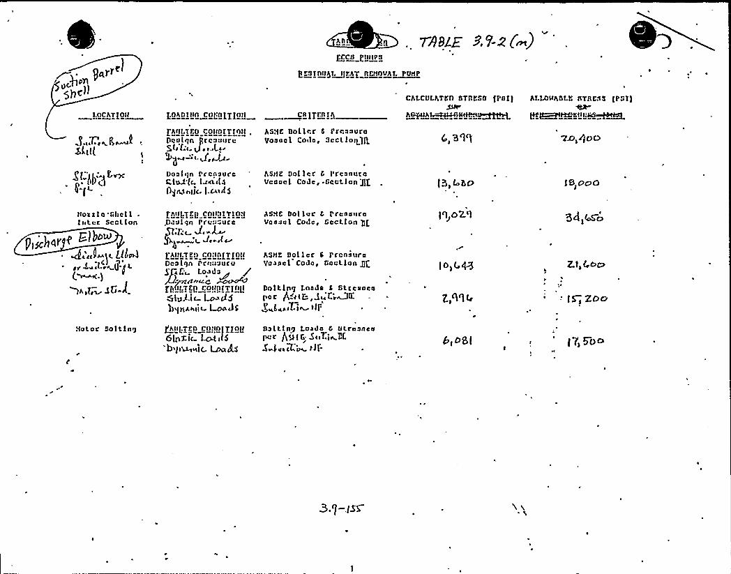
g~trr
"g>> p3)
I.nchT IOH CR ]rl.n IQ
CALCULATED GTDESG, tPGI]
AQPlAI~lki-.)H~~
t) ES IO>)$I~)l'.Ag AEHOVAI~UHP
ALLO)>ADLE GTBKSS lPSI]
3,,T.', K
gt„.II, )r,~pa (
FA>ll.TED colinITInw .Dcolqn grcnnurcQt) fs> Q y >.tLlr~~--" d,m-Donlgn Ircnaurec,ted tc. l~~>tof]gn,a«)lr. ].w)>t$
BSHE Doller 6 PrnnnuroVoancl Co>lar Sect ]0>haft
ASHY Doller 6 PrcnnurnVcanel CoJc, -Gect.ion gf
4, 3'1')
f5,to]5O
'VXi)$pD
]b,ohio
Hoxxle Gt>cll-I«tcr Section
P]sc}]a] P G}ho~
"~",~t ill~rr L,l.r; g(~ )
fA»]:fEQ) Coll:)IT)0/.D alan Pr>:J"ure
Tr~ J,-L-
Dcn li)n I'rin>auruLo~da
ma~«Cft)(ir.TEf> CO>>i) IT]1)tlS]sA'i- Lo P5hqHA~>ii- LOn JS
AGHE Ool Ior 6 I'rennuroVnnaal Code, Section gg
ASHE Dollcr 6 PrcnsuraVennel Cove, Gnetlon gg
Do]ting Ln>)ds 6 Stre>>ncaper P~r(E:, Q~ fsWKg„t,~iLi~ )
fi'Ohioz']
ID)t 48
3d)45O
Z.l, 4OC)
-'5~ Zoo
Notor Salting QA»t.yEn c>):In]y/o]16]nzii t.oti]5b't>~~ic. ~P$
Salting Losda 6 Utrnancapcr P,g< t- Si>T.]~7,f.
S fu)cLi )]f- bl Osl f7) 5DoI

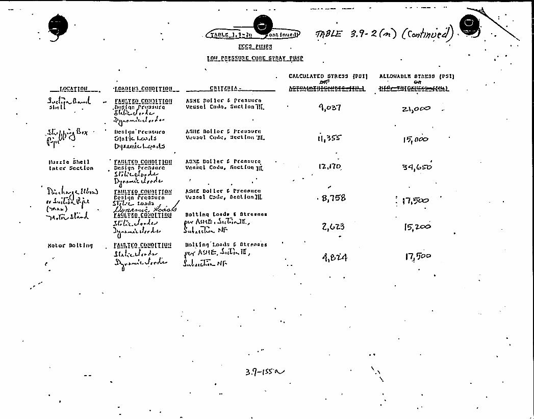
nt(<M( ~-l( ont lnue(
LO)t Pt(KSCI)1E Ct)t)L GP))AT~)ttt[(
[(OChT+0 tI
3 cf., a-Lshell
.8 g>:g((x
Fh)ILTEO CO,')s)Tfntg.f)(:a I qn J'r(.au(trc8 Ma )J). L)~
)).(.J ..l.-l)cullen
I'roun»c o
Glu I lc. f~((l5
'0((N(t(1)t t l~aat5
AS.'lK pof lcc 0 prcauuroVcusol Cndn ~ Suction f[[
AS(t)K Dol loc f l'reuuvrcV((uuul Code, Sect lu» gl
g,o> "I ZI~O~
I[)555'g) 0067
chLcuLATI:D DTADSS [PDI) ALLO)thDL)f DTDDSD [PsllCHt898~~
ttoaxfo ShellInter Gcctlon
l.o<(~).(, )
'ht)f.Ttn connf TLot[Drsf(fn PrcnaurcSf.l;t.du ~Pg((~(. JgrA)rht)).TED rot)of TfottCcuf(fn Prcosurn5;ljL t )A)~du
f59[:TKL) P2-"L2[.T[t)0
J (iLt.Jo ~d(a
AS:tD Dollar f PrcauuraVraucl Codu, ftoct ion pe
hst)E Dol lec 0 Prcoo()ruVauaul Code, Section/[I.
Doltlnq Loada C Dtraauaa~ As)kb ( ~((T.'(&K,J t.l ~ )ATE
IZ,f7O
S,V58
Z)GZ3
-' I)~
ffotoc Doltfng Dolt [n(f I.oa(fu G Dtrcnooa
g~ ll,u(B, ~(i[')~1K,
8 lr(r.Le~ tf[-)7 ~goo
~ ~

1
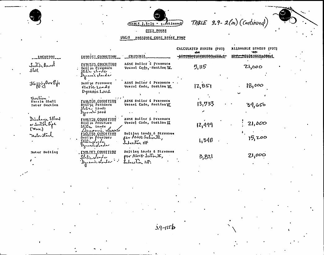
a i.r. g,s-]g - i ~iinu TgglE 9 'P 2(m) (C~e1h)De))rrCS Put)PS
~ill( II Sr .."up~Capt Sian) Pig[
) I)ChT)Att
ChLCVLhTCD OTAL'S8 fPGT) hLLDI)hBLK DT)IKGS {PST)
~~[KKLLGG~~
$ [uI )~ )~ d~ )Ig L
[h'tf;[(:g CA)I )I i 10[tDc:II tn )'cuit JIITCLti[:-~ gf,i,(lihag ~ L Ili s A.~Duel tn PI'coallfcG'libel'lC Ls 4$Di()tnt)t'IC
l<uI'Ci.'lH
ital let C l'rnsauf a
VCG:Ii)1 Coilct. I)nct.lot) 'ltf
hS.')K Dnller C PccaauraVcaun 1 Coda, Gcct ion 'gf )7.,88 [
Zl~ho o
lesotho
MOC. I I CP ii,I'»cela Ghclllnt ec Srct lon
>=,f,, ttl-~~.L- l.$ k Cy-L(m~.))I Z~2~A
.')Ctnf Do 1 t lng
['y)),Ts:I) COt)0[/[0'GSE Cnl lcC C PtcaautcDecl qil Prca" i) Tn Vaaaal CCJC, Sect lan-glt.(; c ).outa))gr «M LCJd
fh)I)7„") rAIII)[g[ot) hs.'ID D»l lac P 1 ca~suceDn:I I In PI'It':Idle Vca"cf Colloq GccL ion gSli.C t i/).u)il8g ~ -c.pu I.T-"I) c()ttl[T[I)tt Dolt fng )dada 0 stTasaaa
~Dna I Tn pcaucucu if~ ArHLSI(ff+fLI$ 4la < [Joel~
[<II),TL) CO))A[/[All Do! t lnq )a~i)a C Stcaaaaefltn 5L 6 At CeWf.~
0
l~~)9 05
lz)0'l'I
l)5<0
0) Qz.l
3Q) H>
2.l) D~
)g ~OC)
g) 0~
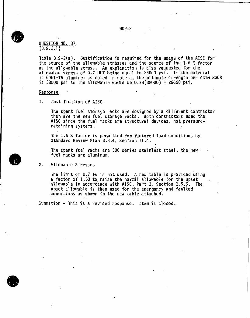
MNP-2
UESTION NO. 373.9. 3.1
Table 3.9-2(s). Justification is required for the usage of the AISC forthe source of the allowable stresses and the source of the 1.6 S factoras the allowable stress. An explanation is also requested for theallowable stress of 0.7 ULT being equal to 35000 psi . If the materialis 6061-T6 aluminum as noted i n note a, the ultimate strength per ASTYi 8308is 38000 psi so the allowable would be. 0.78(38000) = 26600 psi .
~Res ns e
1. Justification of AISC
The spent fuel storage racks are designed by a different contractorthan are the new fuel storage racks. Both contractors used theAISC since the fuel racks are structural devices, not pressure-retaining systems.
The 1.6 S factor is permitted for factored load conditions byStandard Review Plan 3.8.4, Section II.4.The spent fuel racks are 300 series stainless steel, the newfuel racks are aluminum.
2. Allowable Str esses
The 'limit of 0.7 Fu is not used. A new table is provided usinga factor of 1.33 to. raise the normal allowable for the upsetallowable in accordance with AISC, Part I, Section 1.5.6. Theupset allowable is then used for the emergency and faultedconditions as shown in the new table attached.
t
Summation - This is a revised response. Item is closed.
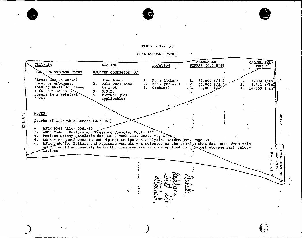
TADI E 3.9-2 (s)
PUEIN STORAGE RACKS
CR1TIIRlh
NI. EUEI. STORAGE RACKS
Stress bq to normalupset or eiiWi- encyloading shall ) causea failure so as toresult in a criticalarray
LOAD1NG
I'AUI,TEl) CON()ZT1ON "A"
1. Dead Imads2. Full Fuel Load
in rack3. S.S.E.4. Thermal (not.
applicable)
AI~ I.ONADI,ESTRESS (0. 7 UI.T)LOCATION
1. Deam (Axial) l.2. Deam (Trans. ) . 2.3. Combined 3.
CSLCOIAT~E
35,000 N/in2 1. 15,090 L/in2.35, 000 5/in 6,673 N/in~35,000 N 3. 16,500 N/in
NOTES:
Source of Allowable Stress (0.7 ULT)
a. ASTII D300 Alloy 6061-TGb. ASHE Code - Doilers a ressure Vessels, Sect. III,c. Product Safety S ards for D'HR-6-Hark III, Sect. VI, h.d. ASHE — Pres e Vessels and Piping: Design and hna)ysis, Volut ~One, Page G9.e. ASTH c d for Doilers and Pressure Vessels was selected on the prhnuse that data used from this
s .e would necessarily be on the conservative side as applied to t:lih&uel storage rack calcu-ations.
(I)IQ 9o a
M Z+ ~ % WM c
o ID+I+
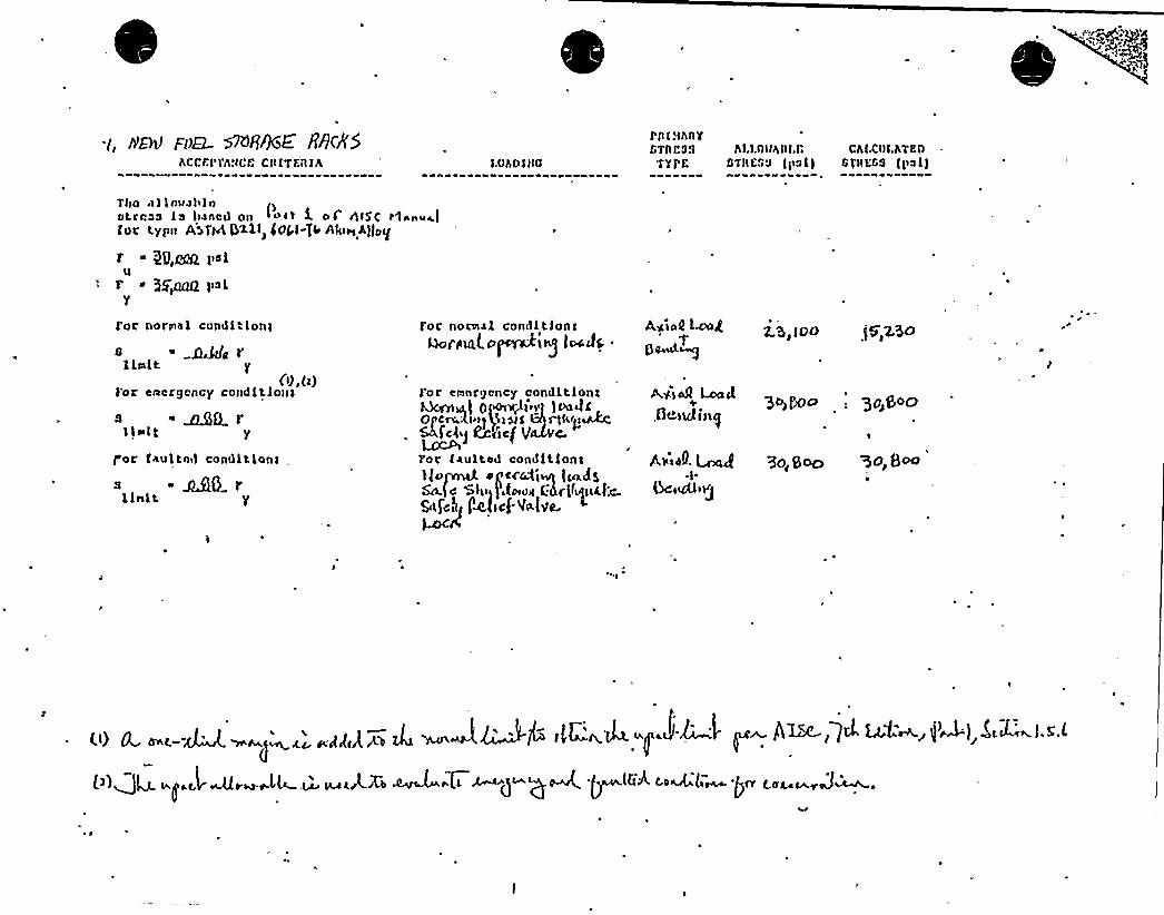
~i, ere Foe MR%E 88cKShCCLI'Fh!ICE C)l ITFnlh ).Ohn) l)0
0,') I.')hnYfTAP33 h).1.0))hnl,l;
'F'g pf. DTII633 (ps I)ChLCI)I.KtE0
)'l)IEss )ps l)
T))o n l louslilnpotrrss Is Iwnc)l On I>)'t l o) fl)5( t1snv~)
for typn A>AAG>>i) IS)W-Tl ~tuh,hllog
29,Mk p«uf ~ g$~ palY
for normal condltlon)
awe r1 lett
(0,(2))'r ceergcncy condlt)o»s
s ~ 8QQl ii)t Y
p'or faultnd condltlon)
-MO rlImlt
for normal cond I t Ion Iuaraml oprwhg )~de .
for ernnrgoncy oondl.t loni~)~) Opo)Q)'ei~ )vedi+Oc~k)>))lp)%$ ~kij>@44:
LccPfc)ij ~')c( Q 4.
For taultod condltlont)(OfANl egtC)4)~ )~d5&.f~ Sl) (t ug l:Ar<fg)al:c.5« f'c)1( fW)cf'4(VI).~CA
Ag)o0 lingp~~Ai)aA Lcect
.Oewding
Avizg.~gGciuSoj
L'5~)oD f5q2~
Qqppo : 36S o
UO,S~ %DE 8
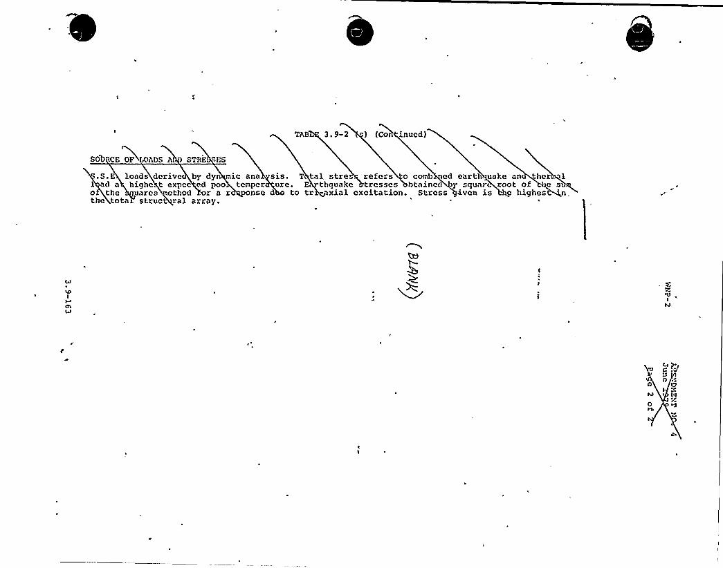
T+B 3, 9-2 ) (Col lnucd)
SOD CE OF IANDS A STRE RES
.S.E loads dcrivc by dyn mic ana1 ad a highc t expcc ed poo tempero the uarcs cthod r a r onsethe tota struct ral array.
sis. T tal stre . refers o comb cd earth uake an hcr 1ure. E thquake resses btainc< y square. root of ge st q
d to tr - xial excitation. Stress+~vcn is hc highest'
p)r
0 'zp)
o
MHP"2 OS"-R
OUESTIOH HO. 38~ ~ el
Table 3.9-2(w). An explanation is reques.ed for the 1.5 Sm and 2.25 Sm
emergency s ress limiw and .the 2 Sm and-3 Sm faulted stress limiw.
RESPOHSE
The current Table 3.9-2(w) is superseded by a new table which providesthe siress limits on the basis of .he ASi~E 3oiler= and Pressure YesselCode, Sec.ion iiI, Subsec.ion HG. The FSAR tax. description of jetpumps is also revised accordingly.
Supination - This item is. closed.
PCY: ggt: rf/45L189/23/81
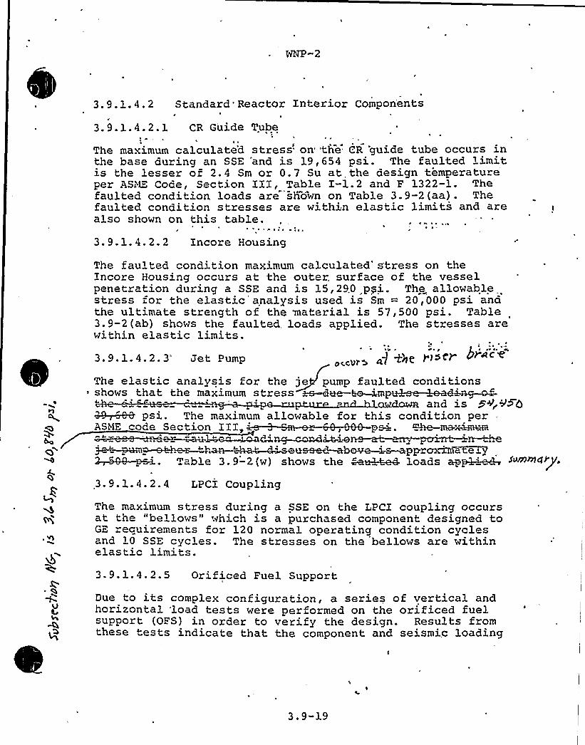
WNP-2
3.9.1.4.2 Standard Reactor Interior ComponentsJ
3. 9. l. 4. 2. 1 CR G'uide Tubel ~
The maximum calculate'd stress on 'the CR 'guide tube occurs inthe base during an SSE "and is 19,654 psi. The faulted limitis the lesser of 2.4 Sm or 0.7 Su at, the design temperatureper ASi~1": Code, Section III, Table X-1.2 and F 1322-1.
The'aultedcondition loads are shown on Table 3.9-2(aa). Thefaulted condition stresses are within elastic limits and arealso shown on this table.
~'
!
3. 9. 1. 4. 2. 2 Incore Housing
The faulted condition maximum calculated'tress on theXncore Housing occurs at the outer. surface of the vesselpenetration during a SSE and is 15,290 pyi. The allowablestress for the elastic analysis used is Sm = 20,000 psi andthe ultimate strength of the material is 57,500 psi. Table3.9-2(ab) shows the faulted, loads applied. The stresses arewithin elastic limits.3. 9. l. 4. 2. 3 Jet Pump occVW> pfizer hiccup'"
The elastic analysis for the je pump faulted conditions
!~&&&psi. The maximum allowable for this condition perASbiE code Section III, ps->, ~ma-x-~
"=peep-e~..—t,ha@ —~~~seu s sed-abave —i-s—apprm~a7:eel"J'.
9. 1. 4. 2. 4 LPCX Coupling
The maximum stress during a SSE on the LPCX coupling occursat the "bellows" which is a purchased component designed toGE recuirements for 120 normal operating condition cyclesand 10 SSE cycles. The stresses on the bellows are withinelastic limits.3.9.1.4.2.5 Orificed Fuel Support
Due to its complex configuration, a series of vertical andhorizontal load tests were performed on the orificed fuelsupport (OFS) in order to verify the design. Results fromthese tests indicate that the component and seismic loading
3.9-19

( t
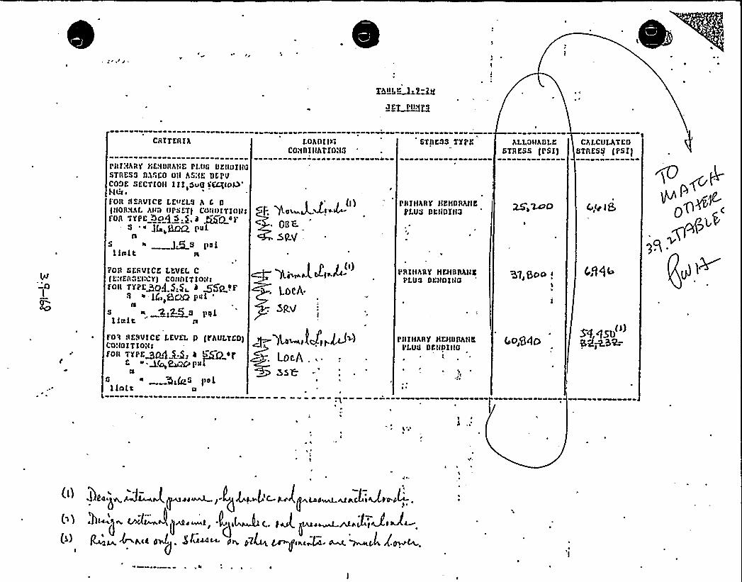
">+"wj5j<'Fk"-P~v
ggb "~i.'+
I I'I
I ~
o e
~ 0 Il
~ ~
l ~ I
I
I I~ 5 ~
il
4I
WP-2 OSiR
OUESTIQN HO. 39(3.9.3.1)
Table 3.9-2{y) does not present adequate information for evalua ion.Rat is meant by stress linis for YI and Y!I, and aha are the s-ressesbeing evaluated?
RES?OHSE
r-
,Table 3.9"2(y) is r vised as attached.
Sumption - .This. item is closed.
PCY: ggt/45L169/22/83.

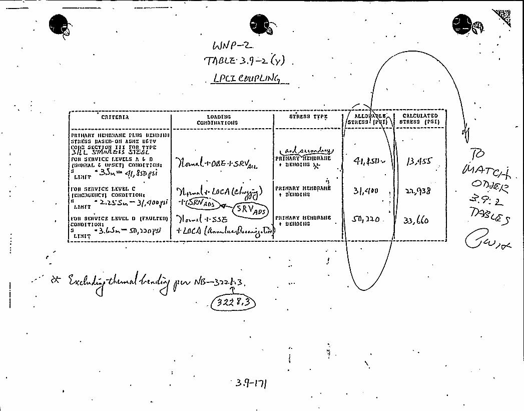
Cl)ITElllh
PI) lttht)Y tlEIID!IhHE Pl.t)S DEt(Dtlt(tGTIIEGG t)ASED Otl AG)IE IICPVCOI)Z Gt:CTIOtt 111 ft)R TYf'E3,(iLL S'Pl(JI.I 1$ 57K:8LfOll GEIIVlCL I.EVELG h 1 D
1 tR)ttHhl. G tltsGET) COt(01T10)l!
LOADIIIGCOItDIIIAT1OIIS
ge h.L< DIE.+SR'„
STRESS TYPE
I Prtg/ \.lossll O'PYOII~fhllY lEtlGIIIJIO
e DEHOlltQ ) (.
t
hLLQ h LttSTRESS (P 1)
g f($5D ~
CALCULATEDSTRESS (PG1)
I'Ott GYERVlCE 1.EVEl. C1LsICROEIICY) COIID1T1OIIC
" 2..2.g g~ —g( i/toogsil.lHlT
10tt SEIIVlCE LFVEL D (FAULTED)COt(01T10it i
$ .U~ $D l3t)p(L1H17
YJ
PR1H'hltY HEHDRhttttl DEIIDllIO
rltrHARY HEI<ttnhttEt 0EttDl IIQ
3 J,c(00, ~q.,g3ps
Mt ll.O .

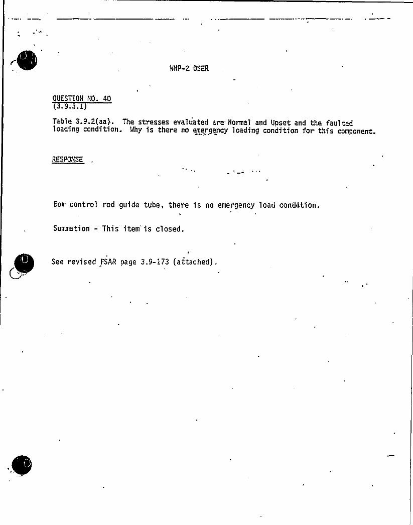
MNP-2 OSER
QUESTION NO. 403.9.3.1
Table 3.9.2(aa). The stresses evaluated are Normal and Upset and the faultedloading condition Mhy is there no emergency loading condition for this component.
RESPONSE
Eov control rod guide tube, there is no emergency load cond~tion.
Summation - This item'is closed.
See revised FSAR page 3.9-173 (attached).

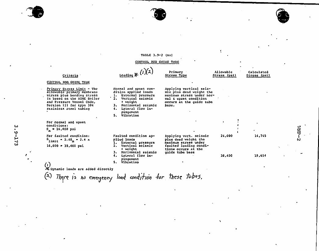
TABLE 3.9-2 (aa)
CONTROL ROD CUIDE TUBE
CriteriaCONTROL ROD CUIDE TUBE
((Y~) PrimaryL~oa din s~tress r Allowable
~Stress ( si(Calculated
~stress ( s
('rimar
Stress Limit - Thea owa e przmary membrane<tress plus bending stressis based one the ASHE Boilerand Pressure Vessel Code,Section III for type 304stainless steel tubing
Normal and upset con-dition applied loadsl. External pressure2. Vertxcal seismic
weight3. Horizontal seismic4. Lateral flow im-
pingement5. Vibration
Applying vertical seis-mic plus dead ~eight themaximum stress under nor-mal 4 upset conditionoccurs at the guide tubebase.
For normal and upsetconditions:S 16,000 psi
For faulted condition:2,45 2.4 xlimit '
16,000 ~ 38,400 psi
Faulted condition ap-plied loadsl. External pressure2. Vertical seismic
+ ~eight3. Horizontal seismic4. Lateral flow im-
pingement5. Vibration
Applying vert. seismicplus dead wolght themaximum stress underfaulted loading condi-tions occurs at theguide tube base
24,000
38,400
14,745
19,654
&Dynamic loads are added directly
(~~ 7krr(.'l s ((s
r(((ergonomy
l(r() r((((kka(( d'or )lese 1((b~5

Equipment gualification BranchInput for Safety Evaluation Report
NNP-2
3.9.3.2 Pump and Valve 0 erabilit Assurance
The staff has reviewed the applicant's pump and valve operabilityassurance program as discussed in Section 3.9.3.2 of the FSAR andcompared this information with Section 3.9.3 of the StandardReview Plan. Based on our review, the applicant has providedinformation to define how active pumps and valves are generally
.qualified with respect to operability.
However, and in particular, for those components where quali-ficaiion and/or operability assurance is by analysis alone, some
question remains as to the confidence level assured by this.methodoloa~. The necessity for additional component testing isbeing considered and can not be established without an inspectionat the plant site. Therefore, for th staff to determine theadequacy of the implementation of the applicant's 'pump and valveoperability assurance program, an on-site audit of the equipmentand supporting documentation is requir d.
The on-site audit will include a plant inspection to observe theas-built configuration and installation of the equipment. Alsoduring the audit the staff will review qualifying documentation,eg., test reports, and analysis, which are described in the applicantsprogram. Thus our overall review includes an FSAR review and anon-sit audit of the equipment. Both phases of the staf reviewmust be determined acceptable to arrive at a favorable conclusionon the applicant's overall pumo and valve operability assuranceprogram.
The applicant had been requested to provide information on thecomple'tion status of the equipment documentation, and on-siteinstallation of the equipment. = Before the audit is conducted, 85to 90 p'ercent completion should be attained for both the equipmentdocumentation and the on-site installation of the equipment.
Once the applicant has indicated that his work is substantially complete,the staff will conduct an'on-site audit shortly thereafter.
Because of the limited number of equipment that can be audited withina reasonable time, the audit results must provide a high degree ofconfidence that the implementation of the applicant's program isacceptable.

3.9.3.3 Desicn and Installation of Pressure Relief Cevices
Me have rev'iewed he design and installation criteria applicable'o the
mounting of pressure relief devices used for the overpressure pro ection of " .
ASME Class 1, 2, and 3 safety and relief valves. Me have specifically reviewed
the applicant's compliance with SQP. 3.,g 3.
The response to question U.0.031 in the FSAR, Amend™en~ 9 does not comply withthe quidelines in Regulatory Guide 1.67, "Installation of Overpressure Oevices"
concerning dynamic load factor. ~ Paragraph 3.9.3.3.2, "Open Relief Systems,"
implies that there may be pressure relief devices of the WP-2 plan~s which
relieve to open discharge systems. More information on what dynamic load
fa'ctor was used and how it was determined is required.
i ~
In addition, the applicant is requested o provide a commit,'ient that all of the~
J'nformationin Sec.ions '3.9;3.'3.2 and 3.9.3.3.3 of =.he . SAR are applicable toboth HSSS and'0P supplied componen s.
Based upon our review of FSAR Section 3. 9. 3. 3 and contingent'pon the
satisfactory reso'.ution of the open,i ams, our findings will be as follows:
The criteria used in the desian and installation of ASl'tE Class 1, 2, and 3
safety and relief valves provide adequate assurance hat, under, dischargingconditions, the resulting stresses will not exceed allowable stress and s ra;nlimits for the materials of construction. Limiting the stresses under the
loacing combinations associated with the actuation of these pressure reliefdevices provides a conservative basis for the design and installation of the
devices to withstand these loads withou- loss. of structural integrity orimpairment of the overpressure protection func ion. The criteria used for the
design and ins.allation of ASHE Class 1, 2,'nd 3 overpressure r lief devices
constitu e an acceptable basis for meeting the applicab;e requirements ofGeneral Oesign Cri eria 1, 2, 4, 14, and 15 and are consistent with those
specif'.ed in Regulatory Guide 1.67 and Standard Revi'ew Plan Section 3.9;3.I
Rene L /'rlHP SZR/8 '9

3.9.3.3- D'esi n and'nsta'll'ation of P'ressure Relief Devices
Question 41
a. The response to Question 110.031 in the FSAR, Amendment 9,does not comply with the guidelines in Regulatory Guide 1.67,"Installation of Overpressure Devices" concerning dynamicload 'factor, Paragraph 3. 9. 3. 3. 2 of the FSAR, "Open ReliefSystems", implies that there may be pressure relief devicesof the WNP-2 plant which relieve to open discharge systems.More information on what dynamic load factor was used and howit. was determined is required. In addition, the applicant isrequested to provide a commitment that all of the informationin Sections 3.9.3.3.2 and 3.9.3.3.3 of the FSAR are appli-cable to both NSSS and BOP supplied components.
b. Indicate how relief valve transients are treated. Clarifywhether it is the intention of the FSAR to indicate that allrelief valve transients are treated using detailed dynamicanalysis techniques.
RESPONSE
a ~ See revised 3.9.3.3.2 of the FSAR. WNP-2 design does notinclude any open relief system, therefore, 3.9.3.3.2 hasbeen deleted from the FSAR. Section 3 . 9 . 3 . 3 . 3 isapplicable to both NSSS and BOP supplied components.
Relief valves which produce transient loadings are evaluatedusing detailed dynamic analysis techniques.
. 1) Detailed dynamic analysis techniques are appliedfor the. evaluation of the 18 mainsteam safety relieflines (See FSAR Section 3.9.3.3.1).
2) Transient analyses for the relief valves listedbelow are performed using detailed dynamic analysis
as described in FSAR Section 3.9.3.3.3.RHR- RV-9 5ARHR-RV-95 BRHR-RV-55ARHR-RV-55 BRHR- RV-3 6
See revised 3.9.3.3 of the FSAR.
To clari y the FSAR, the attached revisions have been prepared.
Summation — This item is closed.
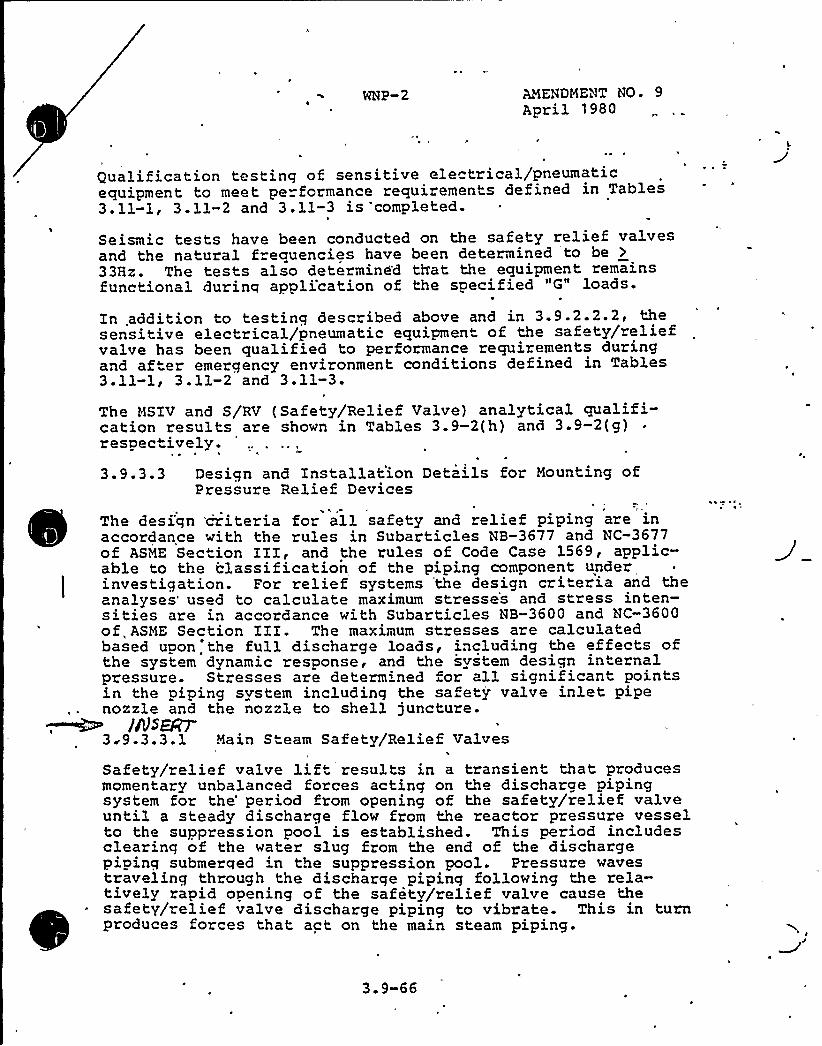
WNP-2 AMENDMENT NO. 9April 1980
Qualification testing of sensitive ele trical/pneumaticequipment to meet performance requirements defined in Tables3.11-1, 3.11-2 and 3.11-3 is completed.
Seismic tests have been conducted on the safety relief valvesand the natural frequencies have been determined to be >
33Hz. The tests also determined th'at the equipment remainsfunctional during appli'cation of the specified "G" loads.
In .addition to testing described above and in 3.9.2.2.2, thesensitive electrical/pneumatic equipment of the safety/reliefvalve has been qualified to performance requirements duringand after emergency environment conditions defined in Tables3-11-1< 3.11-2 and 3.11-3.
The MSIV and S/RV (Safety/Relief Valve) analytical qualifi-cation results are shown in Tables 3.9-2(h) and 3 ~ 9-2(g)respectively.3.9.3.3 Design and Installation Details for Mounting of
Pressure Relief Devices4
The design criteria for all safety and relief piping are inaccordance with the rules in Subarticles NB-3677 and NC-3677of ASME Section III, and the rules of Code Case 1569, applic-able to the classification of the piping component underinvestigation. For relief systems 'the design criteria and theanalyses'sed to calculate maximum stresse's and stress inten-sities are in accordance with Subarticles NB-3600 and NC-3600of, ASME Section III. The maximum stresses are calculatedbased upon'the full discharge loads, including the effects ofthe system dynamic response, and the svstem design internalpressure. Stresses are determined for all significant pointsin the piping system including the sa ety valve inlet pipenozzle and the nozzle to shell juncture.
//gS~3 ~9.3. 3. 1 Main Steam Sa fety/Relief Valves
Safety/relief valve lift results in a transient that producesmomentary unbalanced forces acting on the discharge pipingsystem for the'eriod from opening of the safety/relief valveuntil a steady discharge flow from the reactor pressure vesselto the suppression pool is established. This period includesclearing of the water slug from the end of the dischargepiainq submerqed in the suppression pool. Pressure wavestraveling through the discharge piping following the rela-tively rapid opening of the safety/relief valve cause thesafety/relief valve discharge piping to vibrate. This in turnproduces forces that act on the main steam piping-
3.9-66

Znsert to 3. 9. 3. 3.
De a'led evaluations are per ormed only for valves whichproduce transient eff cts; small relief valves (for example,those lieving tempe azure induced wate expansion), wherepressu"e relic is accomplished w'hou "ransient e fects, arenot evaluated.
ia ~
~ ~ V ~I

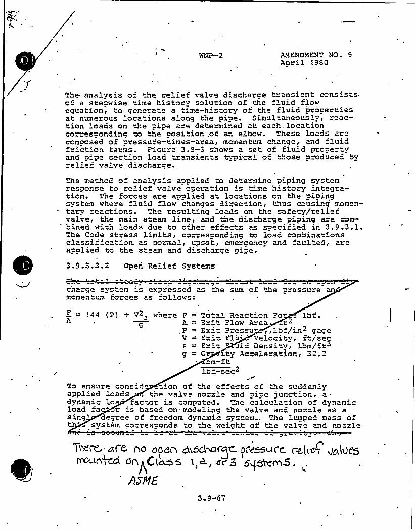
AMENDMENT NO. 9April $ 980
The analvsis of the relief valve discharge transient consists.of a ste wise time history solution of the fluid flowequation, to qenerate a time-history of the fluid prooertiesat numerous locations along the pipe. Simultaneous'y, reac-tion loads on the pipe are determined at each. locationcorrespondinq to the position, of an elbow. These loads arecomposed of pressu='e-times-area, momentum change, and fluidfriction terms. Fiqure 3.9-3 shows a set of fluid propertvand pipe section load transients typ cal of hose produc d byrelief valve discharqe.
The method of analysis applied to determine piping systemresponse to relief valve operation is time h'story integra-tion. The forces are applied at locations on the pipingsystem where fluid flow changes di ection, thus causing momen-tary reactions. The resulting loads on the sa ety/reliefvalve, the main steam line, and the. discharge piping are com-bined with loads due to othe effects as specified in 3.9.3.1.The Code stress limits, cor esponding to load combinationsclassif ica" ion. as normal, upset, erne gency and faulted, areapplied to the steam and discharge pipe.3. 9.3. 3. 2 Open Relief Svstems
I wo e sVQQ s 0 V k V 44
charqe svstem is expressed as the sum of the pressuremomentum forces as follows:
144 (P), + V2 whe e F = otal 3eaction Fo lbf.A, A = Exit Flow Area,t2.P = Exit Pressu- ,,lbf/in2 gageV = Exit. Flu'eloc tv, ft/sec
= Exit aid Densi."v, ibm/ft3g = Gr ty Accelerati.on, 32.2
m-ftlbf-sec2
To ensure consid 'on of the effects of "he suddenlyapplied loads the valve nozzle and pipe junction, adynamic lo factor is computed. The calculation of dynamicload fa is based on- modeling the valve and nozzle as asing degree of freedom dynamic system.. The lumped mass oft 'ystem cor esponds to the weight of the valve and nozzle
0 V 4 ~ 1 1 A Q 0 ~
MM «cc Ao g(g~ Q<~ofg& pqssu<.~ p~(~~/ ~(Ugg~>M QopClas5 'I,<, ar5 gq~m5.ArRE
3 9-67

4
rb in the d'rection tha" causes max'-~ bending s ess in thno" e at the junction of the nozz'e and ~~-pipe. Rotatia3. flexibilityof the system is compu d by a se ies co '. a-t'on o~ozzle 3.exibil'ty and local =.n-pipe lexibil'atthe junc mn o the nozzle and, run-p'pe) .
The rise "ime the discharge '-'ce a the outl of thesa. e y valve e'5w is assumed to be "".e m='.~ a2.ve opening .
e, and the d'sc'harge force 's asm —ed, "o -' linear'yw' ™~e. The ra icx„of maxim'ynamic =" --cns'red'c edby th's single de ree 'b» freedom system ~".e s atic ota-tion caused by the stead state d'scha" fo ce representsthe dynamic load factor.To ensu=e the conside ation o e fec s of th'e suddenlyapplied loads on the pipe sys, dynam'c ~e his oryana3.ysis is pe formed on the pi.g s em. The forcingfunction applied at the po' disc arge is a 'inear orcechange from ze o'o 'the v ue .o .(P) ~M 's .det ~ned.iathe above ecrua 'on ove a time pe iod (t) Kaa corresponds othe va've opening "'hich is provided b~ ~me valve manu-factu=e . A= er "' (t) has been reached 'we~>=orce emains'a the value o ( un 'l the conclusion of ".e 'ae historyinteg=ation. T lumped mass model ~ epresen +bepiping system c'udes ~Me safety-relief valves.
Where mo- than one valve is moun ed on a coczaon heade=, . ocases a compu ed. Zn the irs , u2.l d'scharge of allvalve is assumed to occi. simul~eouslv. 'Zn the second the
or mg unct ons are applied "o a comb~a~'on of valves thay'ds the worst load case. Thi.s wo s 3oa" case is '
3.9.3.3. 3 Closed Relief Svs em
For rel'ef valve d'scha=ging into closed sys ~, an analyti-ca'cdel o one-dimensional t=ansie flow cha acte ist'csfollow.'~g the blow-of of the ups -ea= sa=e v/relief va3veinto the discharging piping sys"em is es™~lished. he time-dependent pressu=e, temperate', dens', ve'ocity and hencethe momentum of the downstream pipe flow are then compu edfrom this conserva ive hydrodynamic/the~cdvnamic flow model,The phenome .a such as flow res -ictior~, f=='c='onal res's-
> ~ 9-68
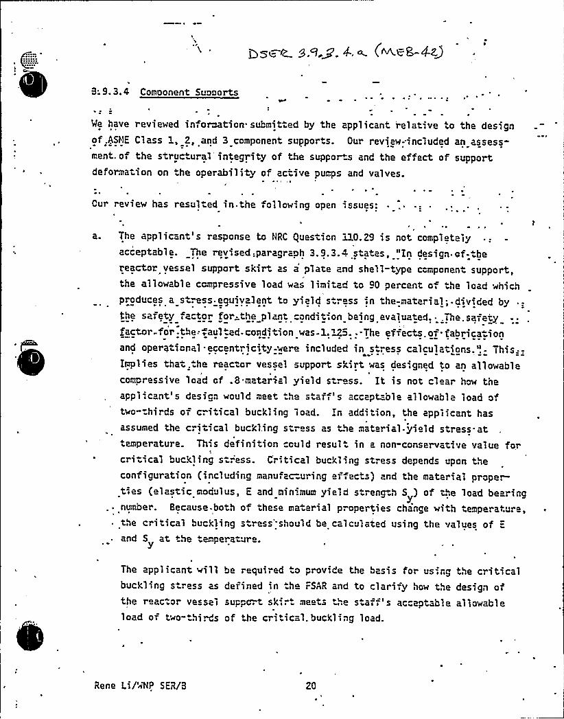
B. 9.3. 4 Component Supports
We have r eviewed information. submitted by the applicant relative to the designof .ASllE Class l, 2, and 3 component supports. Our review-included an assess-ment. oi the struc ural integrity of the support and the effect of supportdeformation on .he operability of active pumps and valves.
Our review has resulted in. the following open .ssues:
a ~ The applicant's response to NRC Question 320.29 is not completelyacceptable. The revised:paragraph 3.9.3.4 s ates, "In design of- be
reactox vessel support skirt as a plate and shell-type component support,the allowable compressive load was limi ed o 90 percent o. he load whichproduces a stress.eouivalent to yield s.ro ss -in the-material.-divided bythe safety iactor for-the ply.'ordii-;on being evaIuated..ihe.safetyfactor for-the:iaul ed-condition was-l.ZS. --The effects. of- fabrica ionand operational. eccentricity-were included in s-".ess calculations.'!- This:-.Implies that. the reac or vessel support skirt was designed io an allowable
I
compressive load cf .8 material yield s ress. It is not clear how theapplicant's design would meet .h staff's accept=-ble allowable load oftwo-=hirds of cri ical buckling load. In add'.tion, the applicant hasassumed the critical buckl.ing str ss as ~He material. yield stress. at
This definition could resul in a non-conservative value forI
temperature.cri-ical buckling st".'ess. Critical buckling stress depends upon theconfiguration (including manu ac=uring effects) and the material prope~
y.ties (elastic modulus, E and minimum yield strength 5 ) of the load bearing
.. number. Because. both of these ma erial properties change with temperature,the critical buckling s ress'hould be calculated using the values of =
and 5 at the empera ure.
The applicant willbuckling s ress as
the r ac or vesselload of two- birds
be required o provide the basis for using the criticaldefined in he FSAR and to clarify how the design ofsuppc t sk meets +he stai i 5 ac eptable allowabl e
of the critical. buckltng load.
Rene Li/'~'NP SER/8 20
WNP-2 DSER
QUESTION NO. 423. 9. 3.4)
The applicant's response to NRC Question 110.29 is notcompletely acceptable. Paragraph 3.9.3.4 implies that thereactor vessel support skirt was designed to an allowablecompressive load of .8 material yield stress. It is notclear how the applicant's design would meet the staff'sacceptable allowable load of two-thirds of critical bucklingload. In addition, the applicant has assumed the criticalbuckling stress as the material yield stress at temperature.Provide basis for this assumption. ~
RESPONSE
Per GE design specification, the permissible compressiveload on the reactor vessel support skirt cylinder (plate andshell type component support) was limited to 90 percent of theload which produces yield stress, divided by the safety factor"for the condition being evaluated. The effects of fabricationand operational eccentricity was included. The safety factorfor faulted conditions was 1.125.
r f
An analysis of reactor pressure vessel support 'Ski:-rt'buckling "for faulted conditions shows that -the support skirt has thecapability to meet ASME Code Section III, Paragraph F-1370(c)faulted condition limits of 0.67 times the critical bucklingstrength of the support at temperature. The faulted conditionanalyzed included the compressive loads due to the. design basismaximum earthquake, the overturning moments and shears due tothe jet reaction load resulting from a severed pipe, and thecompressive effects on the support skirt due to the thermaland pressure expansion of the reactor vessel. The expectedmaximum earthquake loads for the Hanford 2 reactor vesselsupport skirt are less than 50% of the maximum design basisloads used in the buckling analysis described; therefore, theexpected faulted loads are wel'1" below the critical bucklinglimits of Paragraph F-1370(c) for thi's reactor vessel supportskirt. The expected earthquake loads for this reactor weredetermined using the seismic dynamic analysis methods des-cribed in Section 3.7 of the WNP-2 Final Safety Analysis Report.
~ ~ 1
The assumption that the critical buckling stress j.n thematerial yield stress at temperature is not needed in thedesign analysis.
Summation: This item 'is closed.
J s4~ p'g p 4 ~ (AE~ ~3
'. ~ ~ eJ' JO ~
b, in@ aMpirr~~ n~ ~~ 7
vwpn~ 6 o~ Y g—';~ ~o-I.Itin 79-oz. inc rz"~ op ~- a majVi-"rirp 'g - 4«"- i/ --r,>c-i ~ r ~ =-7=ra D-.J'„, gJ!;-
~/z- . A ur j o cr . v~~ ~'/P~~ 'r~ ~ razes a- wr P-4>~~j pp/c ' -~:=5'-4 'Cv~~ R ear"'.cub ~ +ct to resolu.ion of the above open:ss es, "ur -,ind-'res are as
fol 1 ows:
~ ~
The„specified design and service loading c mbi..ations used ror t'ne designo ASHE Code. Class 1 2, and 3.ccmponent sucpor s in syst'ams classifi'ed as
seisnic Category I provide assurance hat, in ae event o< an earthquakeor ether service .'.oadings due .o pos ulatad events or system peratlng
~t ~
transients,. the.resultigg combined stresses imposed on system ccroonentswill not exceed. a31owable stress and. st"ain limits for the ma-erfals df
~ e ~ ~
construction. Kimiting .the stresses under sue% loading ccm>inations
provides a conservative basis for the design of support components towithstand ..he most adverse combination of loading events without loss o
~ .structural integri y or. supported component operability. The des'.gn and'I
service load combinations and associated stress and deformation 3imitsspecified for ASi~IE Code Class 1, 2, and 3 component supports comply withStandard Review Pla'n Sec ion 3.9.3 and sa isfy he applicable portions ofGeneral Oesign Criteria 1, 2, and 4.
3.9.4 Control Rod Orive S stems
Our review under Standard Review Plan Sec ioq 3.9.4 covered the design ofthe hydraulic control rod drive system up to its interface wi.h the controlrods. Me reviewed the analyses and tests perrormed to assure the s ruc uralin. gri y and operabili y of this system during rormal opera ion and underaccident condi ions. Me also reviewed the life-cyc'e'sting performed o
demonstrate the reliability of the con rol rod drive system over its 40 vear1'.
Re..e Li/'ALP SER/B 2'1

WNP-2 DSER
QUESTION NO. 43(3.9.3.4)
The applicant has supplied information concerning the design ofnot only the bolts but also the baseplates into which the boltsare inserted and which the bolts connect to the underlyingconcrete or .steel structures. This information has been. sub-m'tted as a, response to our- Office of„Inspection and EnforcementBullet'n 79-02, "Pipe Support. Base Plate Design Using Conc eteExpansion Anchor Bolts". The review of this information is heineper ormed jointly by our Office of Inspection and Enforcement andour Of ice of Nuclear Reactor Regulation. We will report theresults of our review in a supplement to this Safety EvaluationReport.
Summation — No action. Closed item for MEB.
~ ~ p C'v ~ I '
C

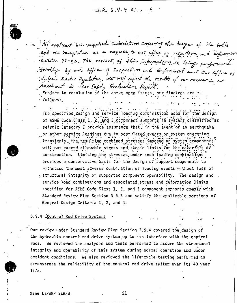
/
~ c- I" ~ $ P-" I1
2u'ILL'in 79-oz . In< rxe'~ a' ~ 'nr ~+;~g>~n7~ gf ~~" M~' I7 -Ax~~ I r~ ~/ ~7-.r~~ ~~ y ~J j'
p Ic A'~ gcA u< f'r 4 P'. V~ ~ ~ ~~) ~+ ~ M I~~> ~ Pkr' ri~
Wppl~n "~ —':= Sad~ Cv~~ As r~~u5'ect to resolu.ion'of ihe above ope'n '.ss es, our findincs are s
fol 1ows:
The..specified design and service loading combinai>ons used ror tne oessgn
of ASHE Code. Class 1, 2, and 3,component suppor.s in systa;.s classi,i'ed zs
seisnic Category I provide assurance ihat, in he event of an earthquakeor ether serv.',ce .loadings d"e o pos ulatad even s or system pe a 1ng
ransjents,. the. resultirg comb}ned stresses imposed on system cpmponenis
wi11 not exceed allowable siress and si",ain limits for the materials of4
construciion. <imi ing .the stresses under sue% loading combinations
provides a conservative basis for ihe design of support conpcnenis io~i-hs and .he mos adverse combination or loading even s without loss oi
~ .siructural in.egriiy or. supported componeni ooerabiliiy. The design and
service load combinations and associaied,stress and deformation limitsspecified for AS<'IE Code Class 1, 2, and 3 component supporis comply wc tnSiandard Review Plan Seciion 3.9.3 and saiis y he applicable poriions orGeneral Oesign Criteria 1, 2, and 4.
3.9.4 Control Rod Orive Svstens
Our revie~ under Siandard Review Plan Seciion 3. 9.4 covered the design ofhe hydraulic control rod dr-;ve system up io its interface ~ith the coptrol
rods. We reviewed the analyses and tesis performed to assure the s ructuralin egri"y and ooerabiiity of this sys em during normal operziion and under
accident cordiiions. Me also reviewed the life-cyc'.e iesiing performed.tode..onstraie the reliability of he con rol rod drive system over its -".0 y ar1'
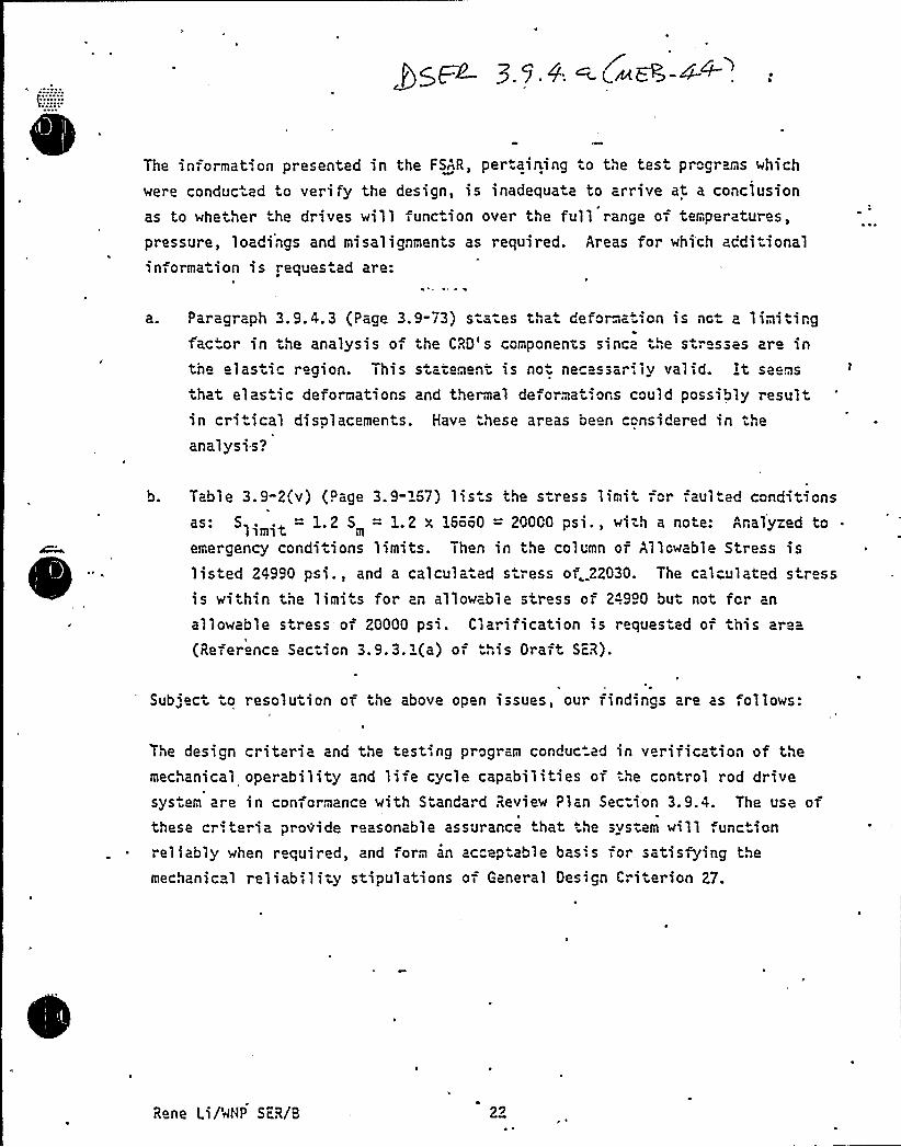
The informat on presented in the FSAR, per.aining io the tesi programs which
were conduc.ad to verify the design, is inadequaie to arrive at a conclusion
as to whether he drives will iunc ion over the full range of temperatures,
pressure, loadings and misalignmenis as required. Areas for which addi iionalinformation is reques ed are:
a. Paragraph 3.9.4.3 (Page 3.9-73) siaies thai deforma. ion is not a limiiingfactor in the analysis oi the CRD's components since the siresses are inthe elasiic region. This statement is no necessarily val id. it seems
ihat elas ic deformations and thermal deformat',ons could possibly resultin critical displacements. Have these areas been considered in the
analysis?
b. Table 3. 9-2(v) (Page 3.9-'57) lis s the siress limii =or faulted conditionsas: S . . = 1.2 S = 1.2 x 15550 = 20000 psi., with a note: Analyzed tol imit m
emergency condi iions limits. Then in the column or Allowable Stress islisted 24990 psi., and a calculaied siress of. 22030. The calculated stressis within the limiis for an allowable stress of 24990 but not for an
allowable stress of 20000 psi. Clarification is reques ed of this area
(Reference Sec ion 3.9.3.i(a) oi ..",is Orait SFR).
/
Sub„'eci o resoluiion of vile above open issues, our findings are as,oilows:
The design criteria and tIie test ng program conduc ad in verific tion of themechanical operability and liie cycle capabili ies of the control rod drivesys em are in conformance with Standard Review Plan Sec"ion 3.9.4. The use ofthese cr',teria provide reasonable assurance that he svs em will func ionreliably when r quired, and iorm an acceptable bas',s for satisfying the
mechanical reliabi liiy stipulations of General Design Cri ierion 27.
Rene Li/'rlNP ScR/8 22
'iHP-2 OSi2
OVFSTIOH NO.
Paragraph 3.9.4.3 (Page'3.9-13) s ~tas thai deformaiion is noi a limiiinafac=or in ihe analysis of the C.";0's comoonents since the s resses are inthe elas.ic region. This state..eni is sot necessarily valid. It seems
that elas ic deformations and hermal deformations could'possibly resultin c-.,itical displacemen-s. Have these areas been considered in iheanalysis?
RrSPQHSi
~ =las.ic and thermal defo-..„ation have both been considered in he desionof .he reac:or inta. nals and cortrol rod drives to ensure thai .he roainse. =abili:v is not affe .ad, '. e. no mechanical interference, duringand after an accident. Siudies show iha- no plastic deformation occurs.
Su~ation — This i"em is closed.
PCY: rf/45e~QS/le/el.
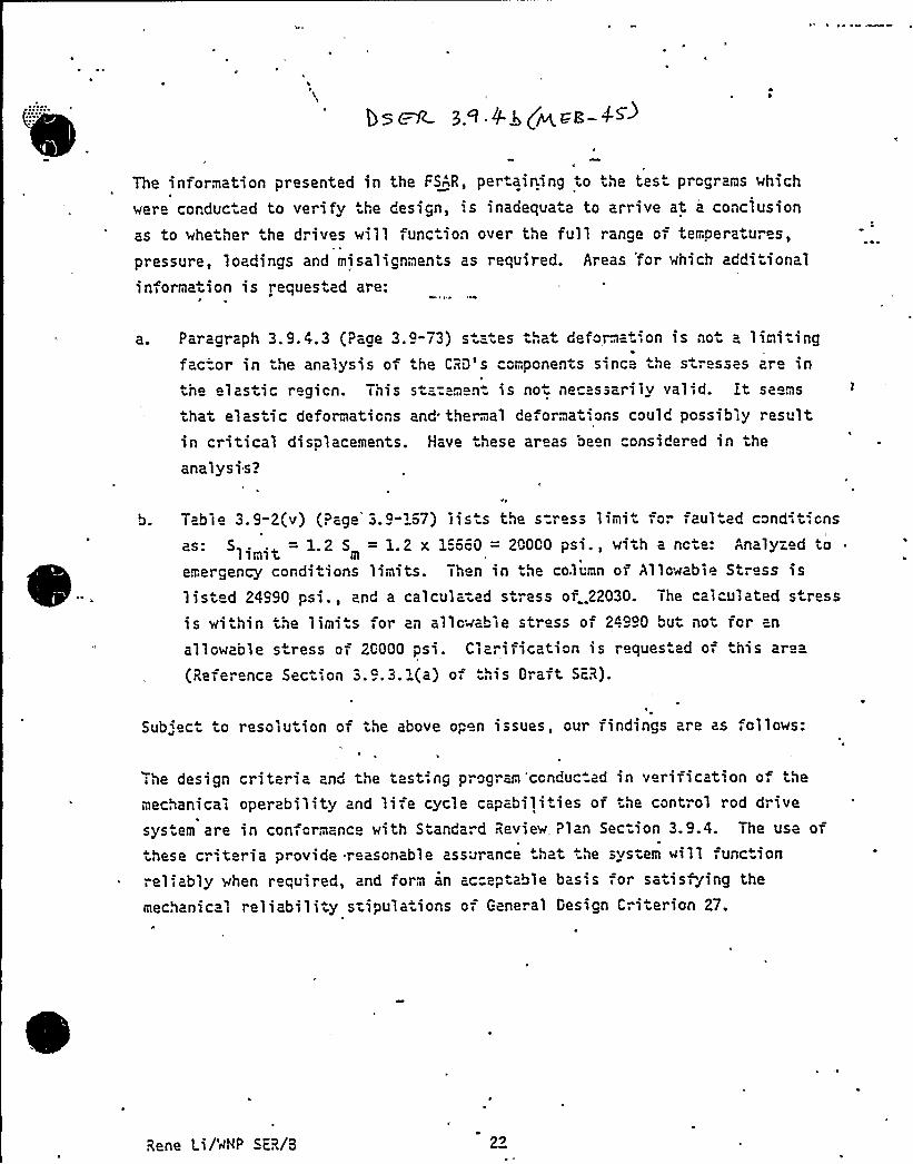
The information presented in the FSAR, per-aining to the tes prcgrans which
were corduc ad to verify the design, is inadequa e to arrive at a conclusion
as to whether the drives will func ion over the full range of temperatures,
pressure, loadings and misalignmenis as required. Areas 'for which additionalinformation is reques ed are:
a. Paragraph 3. 9. 4. 3 (Page 3.
factor in the analysis ofthe 1 asti c regi cn. Thi s
9-73) s =- es that deformation is not a linitingthe CRD's compcnents since the stresses are insta: m n- is no- ne ssarily valid. it seems
that elastic deformaticns and thermal deformat',ons could possibly resultin critical displacements. Have hese areas been considered in the
analysis?
Table 3.9-2(v) (Page 3.4"167) lis s the s=ress linit ro fauI ed conditicnsas: 51 ~ .t = 1.2 5 = 1.2 x l=oc0 = 20000 psi., with a ncte: Analyzed to
1 imlt m
emergency conditions linits. Th n in the column or Allowable Stress islisted 24990 psi., and a calculated s ".ess of..22030. The calculated s ress
is within the limits for an allcwable stress of 249 0 but not fcr an
allowable s ress of 26000 psi. Clarification is reques ed of this area
(Reference Section 3 9.3. 1(a) of his Draft ScR).
Sub„'ect to resolution of the above open issues, our findings are as ,ollows:
he design criteria and the test-;ng program 'ccnduc ad in verification o. the
mechanical operability and liie cycle capabili ies of the control rod drive
sys em are in conformance with Standard Review. Plan Section 3.9.4. The use ofhese cr',teria provide reasonable assurance hat he system will function
reliably when required, and form an accep able basis for satisfying the
mechanical reliability s-ipula ions of General Design Criterion 27.
Rene Li/'aNP ScR/8 22

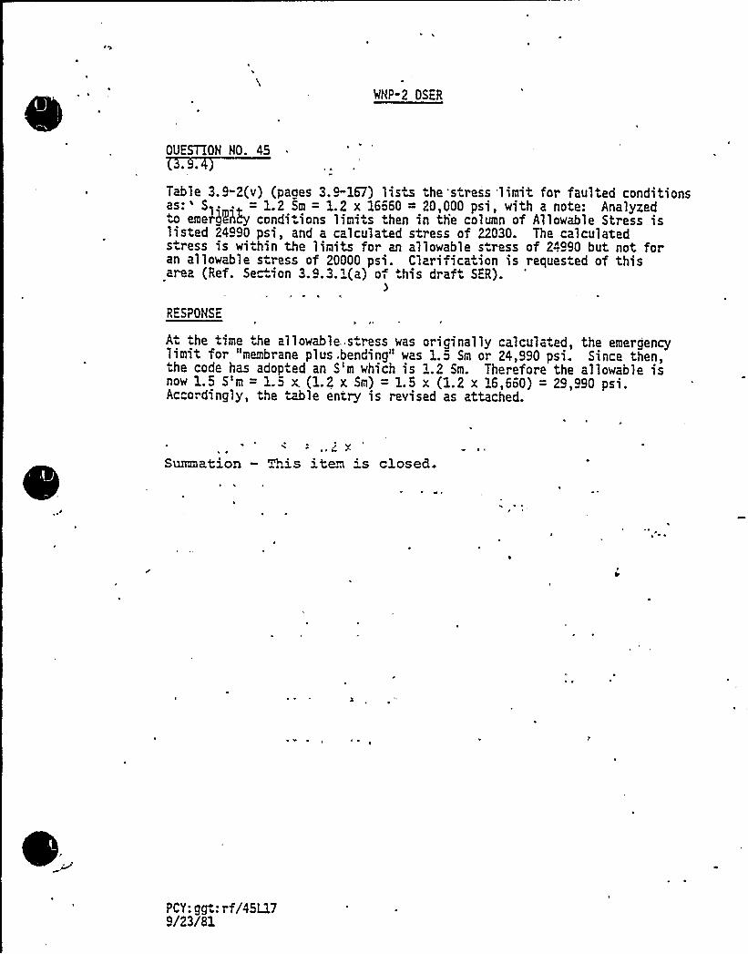
WHP-2 OSER
OUESTION NO. 45
Table 3.9-2(v) (pages 3.9-167) lisw the'stress 'limit for faulted conditionsas:' .. = 1.2 Sm = 1.2 x 16660 = 20,000 psi, with a note: Analyzedw eme45Qy conditions licit< then in tlie coloen of A11oweh1e Stress islisted 24990 psi, and a calculated stress of 22030. The calculateds ress is within the limits for an allowable s ress of 24990 but not foran allowable stress of 20000 psi. Clarifica ion is reques ed of thisar a (Ref. Section 3.9.3.1(a) o< .his draft SER).
RESPONSE
A the time the allowable..s ress was originally calculated, the emergencylimit for "membrane plus .bending" was 1.5 Sm or 24,990 psi. Since then,.he code has adopted an S'm which is 1.2 Sm. Therefore the allowable isnow 1.5 S'm = 1.5 X. (1.2 x Sm) = 1.5 x (1.2 x 16,660) = 29,990 psi.Accordingly, the ~le entry is revised as attached.
Summation — This iten 's closed.
PCY: ggt: rf/45Ll79/23/81

,i
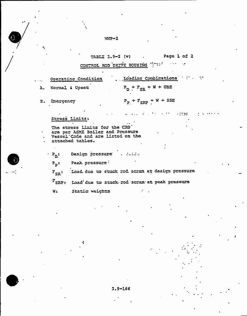
ABZ - 3. 9-2 (v) Page 1 of 2
COh ROL ROD DR~ HOUSING
Ooe=at'za Canc" ion Load~a Carina ions
Na ~ f Upset P +P R+8+QBE
e ce~ cv + r + w + sszP
S"=ess L'-'s:he s -ess i'-'~w o= ~Be VD
aw pe A~X BoiLe and. P~a'=eVesseL, Co6e a=.6 a=e '' t~ an Aea"~M ~~3.es.
PD e
PP.
SR
SRP:
Des'cn o=essu=e
Pea3c. p=essu e.
Load Pne M s~M "o6. sc=an at aesiga pressu=a
Loan'date M s-hack. M sc=m at, peak pressure
Static: weigh~a
3.9 L66

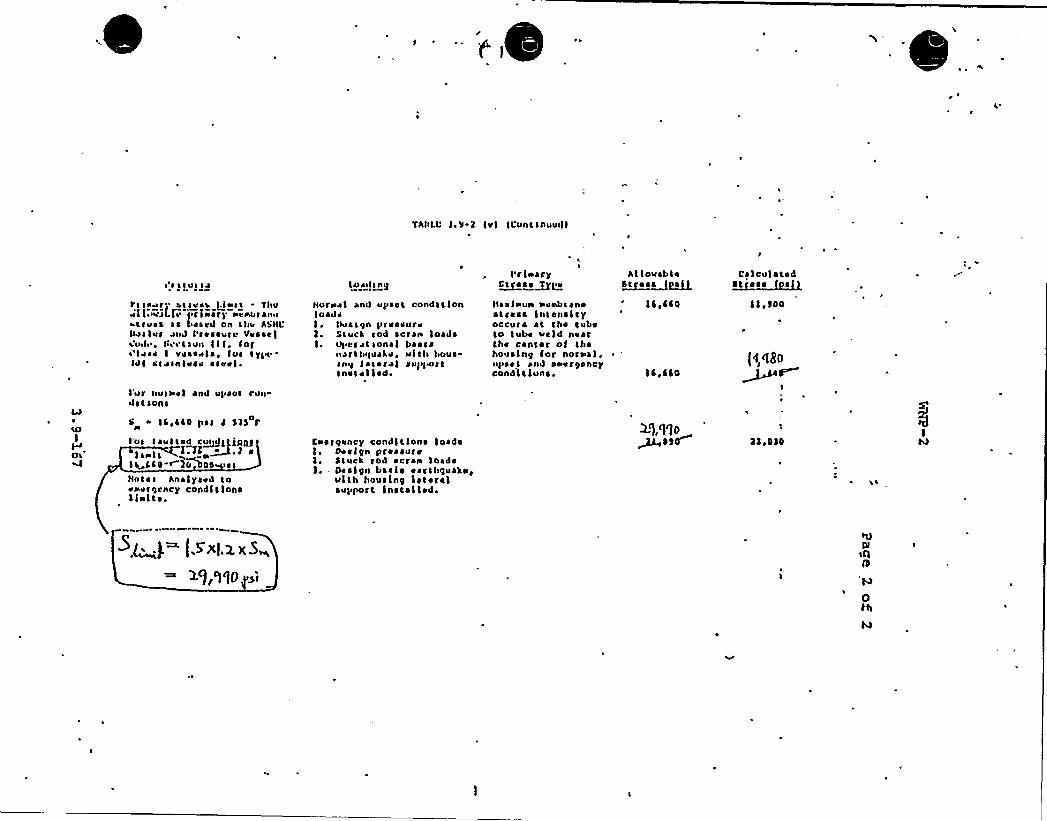
r ~
'fhlsLL'.'J-y Ivl ILunasnuusll
~ ass»I IJPg sr~r- assess J.iasa - Thuv'lian"al.ls 'Iirlnart n«nuranuharv«s ss bes«d on ahv hSHL%slur zuJ I'r«ssuru Vvsse)a.uJ» ~ tsi Ca Sun I I I ~ Inr~'siss I vuasvl ~, Iur tyl»IJI ss Jsnlvaa as»vl ~
Lo1lls hg
Slur»el and ups«a condstlonloaJsI, Is»sago prv ~ svrvl. Sauci rod scran loadsI. aN »reason«I ba ~ ss
narthquate, ulth hoursnit Ias ~ ral rapt~stsnss ~ I led.
I'rlorryS~teas~tli»
Harl»un nvnbaaneharass Intensityoccurs at aha tubsto tube veld n«arthe center ol thahousing for nor»el,ups«a anal svvrgancycondltluns.
hl louabl ~L~a ~ a~a~at
IC,C40
IC,440
CalculatedI~l
llew
l00
Iur null' and upset run-Jstsons
s IL,LLo pss d Sl$ y
I'us la»ised cu~>tllR05I I I lg ~v.P r
li~LLO r 30os00 ~
Hotels hnalysed tovnvrgcncy condlllonsI inl a ~ .
Enatic»ncy condltlona loadsOeslcn pressure
le 5tuck rod reran loadsl - Des l0n ba ~ I ~ ~ arthguA»g
ulth housln0 I ~ Ieralsupport Installed.
lie0)0
ar
saI0s s
sIIll
0th
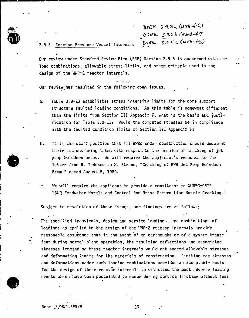
3.9.5 Reactor Pressure Vessel Internals
Our review under S andard Review Plan (SRP) Section 3.9.5 is concerned with the
load c"mbinations, allowable stress limits, and other criteria used in .he
design of he MHP-2 reactor internals.N 4
Our review,has resul ed in the following open issues.
Table 3.9-:3 as. ablishes stress intensity limi s for the core supportstructure faulted loading conditions. As this able is somewhat dif eren
than the limits from Section III Appendix F, what '.s the basis and jus i-fication for Table 3.9-~3? Mould he computed stresses be in complianc
with the ,aul ed condition limits o Sec-ion III Appendix F?
b. :t is the staff posi ion thai all BMRs under construction should doc ment
.heir actions being taken with respec to the problem of cracking of jetpump holddown beams. Me will require the appjicant's response o the
letter fr"m R. Tedesco to H. Strand, "Cracking of BMR Jet Pump Holddown
Beam," dated August 5, 1980.
c. Me will require the applicant to provide a commitment to HUREG-0519,
"BMR Feedwater Nozzle and Control Rod Drive Return Line Nozzle Cracking."
Subject to resolution of these issues, our findings are as follows:
)
The speci ied transients, design and service loadings, and combinations ofloadings as applied to the design of the MHP-2 reactor internals providereasonable assurance that in the event of an earthquake, or of a system trans-ient during normal plant operation, the resulting deflec ions and associated
stresses imposed on these reactor internals would not exce d allowabl ' resses
and deformation limits ror the materials of cons ruction. Limiting the stressesand deformations under such loading ccmbinations provides an acceptable basisfor the design of these reacto internals to wi hstand the most adverse loadingevents which have been pos ulated to oc™' during service lifetime without loss
Rene Li/MHP-S"R/B 23
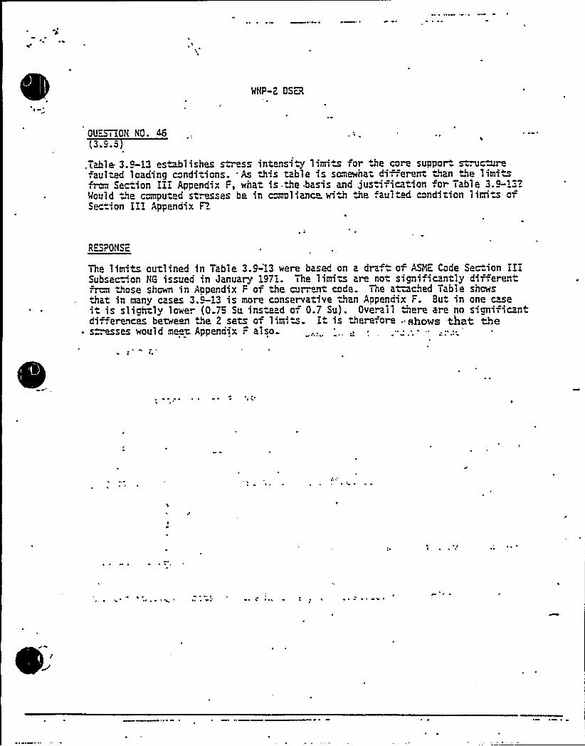
OU~iON NO. 46(3.9.5
,Table 3.9-13 esMlishes swiss intensi.y lima for the core suppor ~ngrefau1~ loading conditions. As this table is senewhat Ci .erenow than the 1imiwfera Section 111 Apoendix F, what is Ne basis and justification .or Table 3.9-1".'EWould the comput d s uses be in comol'anc with the faul"M condition limiw ofSection 111 Appendix F?
R<mPONS™c
~ ~
The limits outlined in Table 3.9-'1,3 were based on a draf of ASNE Code Section II1Subsec .on NG issued in January 1971. The littrits are no signi icantly different
those shown in Appendix F of the mr,.~ code. one aiuched Table showsthat in many cases 3.C-13 is more conservative than Appendix F. But in one case1 is slightly lowe. (0.75 Su. inste d o-, 0.7 Su). Oveail Were are no sianific ntdi.,erences between De 2 sets of limiw. I is therefore "shows that the
~ s . esses would me~t. Appendix .= also
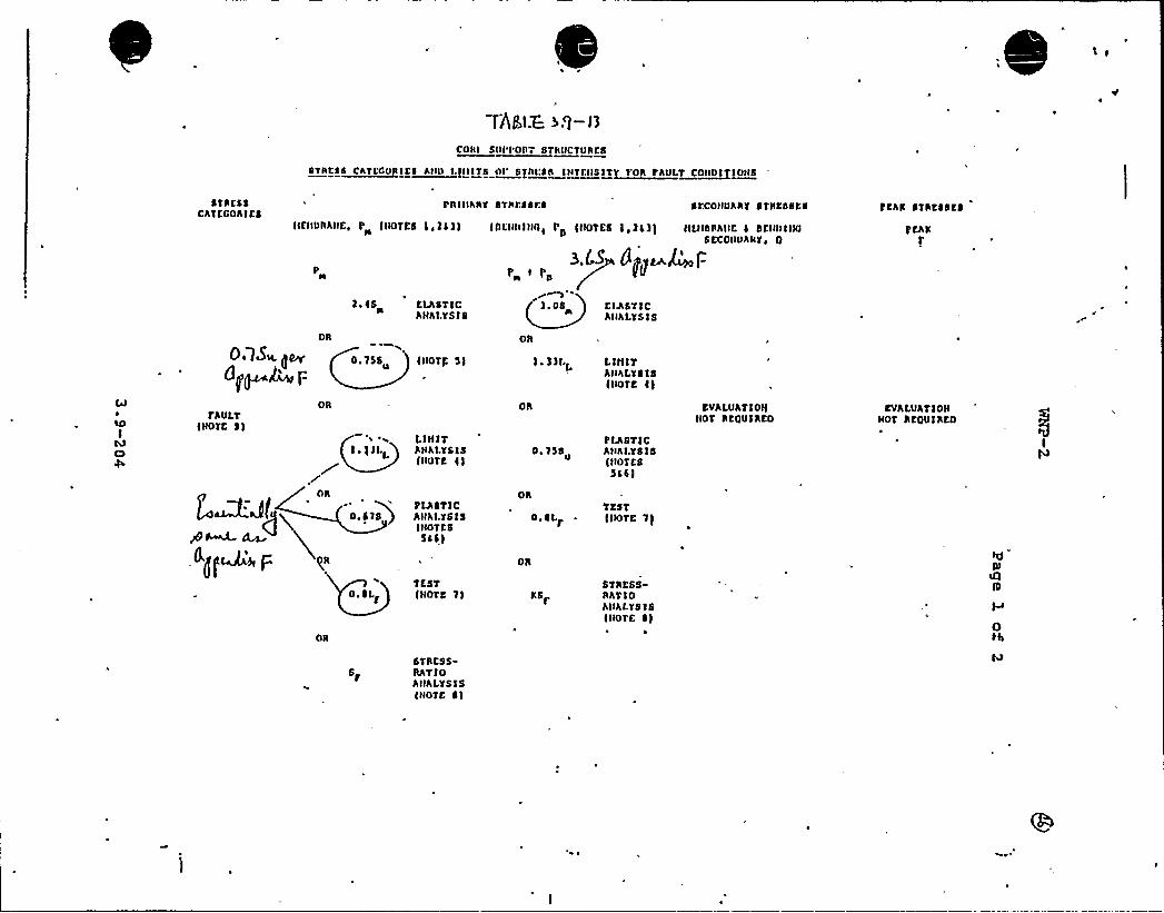
rhea.z ~.>-i~CORI SUI'I'OR ~ STRUCTURES
STSC ~ S~CSTCOO ICI Sl II I /Illtt Ol'jtl' ll ISTCIISIT~TOS ~ SDST~COIIDI IOIIS
STRESSCh')KGOR1KS
I RlllhRY BTRI:88$8 SCCONUARY O'TRL'OSKS FEAR STRESSES
lltllURAHKD I'NOTES 1 c)a))H )RKIIH)NIII PS )IIOTKS ) ~ 3)3) IILllbRAIIE 4 SL'Ht)IIIU8 ECOUUARY ~ Q
P
l. 4$ ELASTICh Nh I.Y8 I8
3~I.S I)j(~l'-rr1
'.0$ KlhSTICAllhLYS)S
0.1$ u. (~d]p )~F
fAULT)HOTE 8)
OR
OTTSS )IIOT): 5)
OR OR
) . 3)I.L L It))TAHALY818)tIOTE 8)
EVALUAT)OI)HOT REOU1RKO
EVALUAT)OHHOT REQU)REO
f.~a<(
<gm p
1.)NIT1 ')LL ANALYSIS
)NOTE ) )
PLASTICO.STS ) AHhLYS)8
)HOTK65a))
TfSTO.SLY )HOTS 1)
0. 15$
OR
O. ~ I ~
OR
PI%ST)CAHRI.Y81$)NOTES5af)
TEST)IIOTE T)
STRESSRATIOAIIAL'FSl8It<OTK 8)
6TRESSRh'T)OAHRI YS 1S)NOEL ~ 1
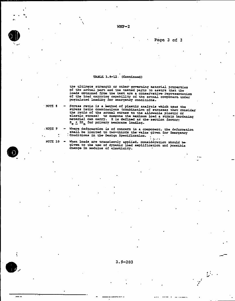
Pace 3 o~ 3
l 9 W {C~a~dl
ae ul~w snraagD oz c~ gcnreraing cata.wl pmper='esof ~e ~L1 par aad ae tasted pa=a to assu e At 2e'oads oh~d «Ex'ne test are 4 cruse vs vo'pzssllntacioao ~ load ca~iag capahi~~ty cd the arcual ~nen- undepc s ~s ted ~s g so anergenry
Smss w~ is a iaethod of plasm analysis vhich usesstuns m~ crcLh~tions (msbiaatioa o~ st=asses that cons'darchI 5~ o ~ ~ s~s to the allcw4414 plastic orelas~ s~ssl to ~qnzca the ~un load 4 ~~in MLrdeniagoatezial can ca~ X is defined as the sec~~a tarwr:S < 2S ~ pz~~ ~Lae loading.Mh~ defozna~ is of concern in a component, the deforna~ashalL he ~M to ae ~W W value gi's bar EmergencyConditions in the Design Sped. ica~~
(,,t ~
Oca loads aw =xnsiently applied, consideasha should he.g'sea to the use of dyaanir load aszpl'Sation aad possiblechange in ~us of clast'c'~.
3.9-203

QUESTION'No. 47
It is the staff position that all BWR's under cons" uction shoulddocument thei" actions being taken with respect to the problem ofcracking of jet pump holddown beams. We will reauire the applicant'sresponse to the letter from R. Tedesco to N. Strand, "Cracking ofBWR Jet Pump Holddown Beam", dated August 5, 1980.
RESPONSE
The supply System's esponse to the letter from R. Tedesco "oN.'t=and "Crack'g of BWR Jet Pump Holddown Beam", dated August 5,1980 is contained in the letter from G. Bouchey to R. Tecescodated December 4, 1980 (GO2-80-279). This letter states theaction which will be taken by the Supply System with respect to theproblem of jet pump holddown beam cracking.
Summation - This item is closed.

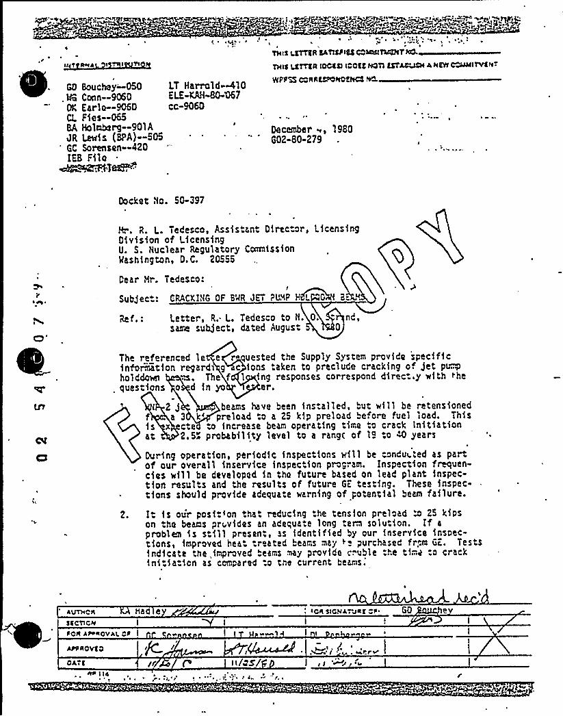
» 'Qtf
."r
II T It+I4 I I
GD Bouchey-.050. 4 Conn —9060
OK Earla—9060CL Ffes-065BA Holmbo rg-901A~R L fs (BPA)-505'C Sorenson--420IEB Ffle~IIS~j~
~ g ~
LT Harrold-<10ELE-08-80467cc-9060
I ~
THIS ~R SATISrIICS cob@a TQC7t T I4CL
THIS LLUTTER IOCCN roost r4OTl EST~ AHCYt~ITVStvTslap% c AAscporroer4c? %»
December ~, 1980GQZ-80-279
Docket No. 50-397
8'. R. L. Tedesco, Assistant 01rector, LicensingDivision of LicensingU. S. Nuclear Regulatory CorrnlfssfonMashfngton, D.C. 20555
Dear Hr. Tedesco:I
Subject: CRACKING OF 6'AR JETI PUMP HFL "GlIN B=
Ref.: Letter, R. L. Tedesco to N. 0. " nd,sarre subject, dated Augus. 0
The referenced le e roquested the Supply System provfdo specfficfnfo&atfon regardl g c tons taken to preclude cracking of Jet ptryholddae m. The f l fng responses correspond direc..y with thequestions o d fn yo er.
2g beams have been fns.alled, but will be retensfonedf a 3 k'reload to a 25 k1p preload before fuel load. Thisfs x cte to increase beam operating time to crack Initiationat 2.5" probability level to a rang( of l9 to 4) years
During operation, period1c fnspectfons wfll be conduI..'ed as partof our overall inservfce fnspect1on program. 1nspectfon frequen-cfos wfll be developod 1n tho future based on lead plant fnspec-tfon results and the results of future GE testing. These fnspec-tfons should provide adequate warning of potential beam failure.
2. It fs our posftron that reducing the tension preload a 25 kfpson tho beans prr,vfdes an adequate long term solution. lf a
problem is still present, as identified by our fnser vice inspec-tions, improved hea. treated beams may Ie purchased fr,m GE. Tests1ndfcate the improved beams may provide c". uble the tf."..z :o crackinitiation as compared :o tne current
beams.'uTHCR
Mad e
5C CTICKS I
SOA AH ROYAI. CR I
APP RO VS O
OAT( r I/os/~ ~
IOR 5ICNA. MRS 1'0
~ \( r ~J 'lr


