Embed Size (px)
Citation preview

2006-01-2173
Modeling of a Loop Heat Pipe with Evaporator of Circumferential Vapor Grooves in Primary Wick
Valeri V. Vlassov and Roger R. Riehl National Institute for Space Research – INPE/DMC
Copyright © 2006 SAE International
ABSTRACT
A new configuration of internal geometry of LHPevaporator is investigated. Cylindrical evaporator has circumferential vapor escape channels instead of axial channels, commonly used in evaporators; only one axial groove is presented to provide vapor collection and direction to the vapor line. These circumferential grooves are combined with circumferential micro-threads on evaporator case internal surface. Mathematical model ofLHP has been developed with emphasis on simulation ofheat-mass transfer in evaporator. The model was verified by the test results obtained for the LHP with axial-groove wick evaporator. The model was then modified and applied to the new evaporator wick geometry. Comparative studies reveal the main reason for considerable improvement of the performance fornew configuration: significant reduction of the two-phaselayer between wall and wick. Two mechanisms are found to be able to contribute in such thicknessreduction. There is effect of liquid trapping in the micro-threads, and like-heat-pipe effect along circumferentialgrooves.
INTRODUCTION
Loop heat pipes technologies for Space applications continue to be an object of extensive studies for the last decade. Many different design of LHPs and CPLs havebeen developed, investigated and tested until now [1-4]. While LHP technologies have reached a certain level of maturity, many issues still remain as the subjects ofactive researches. The reason lies in the complex behavior of the processes of heat and mass transfer inthe components of the two-phase loops. A quest for improvement in performance and reduced cost of LHP fabrication is keeping on and seems that it will never stop.
Most two-phase loops for use in satellite thermal controluses ammonia as working fluid. In spite of attractive thermo-physical properties, it is a high-pressure and
hazardous one and relies on established technology ofproceeding, which calls for significant investments.
INPE adopted a research program, which includes development of heat pipes and loops using acetone as an alternative working fluid. Acetone heat pipes already have been proved in satellite thermal control of Mageon 4 and 5 satellites [5]. For heat pipes radiator assemblies,acetone presented very competitive trade mass performance against ammonia on optimal design study[6].
Some LHPs with polyethylene primary wick have been fabricated at INPE, tested, studied experimentally andtheoretically [7]. The easier-fabrication configuration of the evaporator is one with integral compensation chamber (reservoir). Recently, a new configuration of primary wick groove has been implemented and tested[8]. Experimental results display significant improvementon integral performance of the loop. The objective of thepresent paper is to develop a mathematical model of the LHP with enough details that could be able to help in explaining the mechanisms of the obtained improvement.
EVAPORATOR WICK CONFIGURATIONS
The LHP consists of regular cylindrical capillary evaporator arranged together with reservoir, transportliquid and vapor lines, and a condenser, assembled overa radiator plate. The configuration of evaporator with integrated reservoir is shown in Fig.1.
Fig.1. LHP evaporator-reservoir assembly layout

The previous configuration of the evaporator for TCD-LHP2 is shown in Fig. 2.
Fig.2. Evaporator cross section for TCD-LHP2 prototype (axial grooves)
After analysis in the thermal behavior of the TCD-LHP2, a new configuration for the primary wick, which presents circumferential grooves was conceived and implemented, as presented by Fig. 3.
Fig.3. Evaporator cross section and view on primary wick for TCD-LHP3 prototype (circumferential grooves)
This new wick has been used in the evaporator of the loop called TCD-LHP3, which presents the exact samedimensions and configuration as the TCD-LHP2 [7,8].Active length of both evaporators is 67 mm and outerdiameter of wick is 16.5 mm.
MATHEMATICAL MODEL OF LHP
The basic mathematical model for LHP is presented inRef. [9]. The model was upgraded in such a way that presents a more detailed evaporator-reservoir modeling. The main elements of the upgraded evaporator sub-model are presented below.
For the present investigation, some conceptions for the modeling were admitted. In the model, there has been established main functional mass-transfer couplings, which certainly have main impact on the LHP performance and behavior. From the accumulated knowledge and performed researches up to know, these
couplings could be easily established, whereas their modeling on microscopic level is a challenge. Therefore,the use of pseudo-integrated values of integralcharacteristics of such couplings, factored by uncertain coefficients were applied. The values of mentioned coefficients should be identified through dedicated experimental tests. The nodal representation of admitted coupling in the model of evaporator-reservoir assembling is shown in Fig.4.
Environments
Liquid
Control
qT
eT
weT
rT
wrT
)(tTea)(tTra
leT
)(tQq
)(tQrqwG
weG rG
wrG
m
Heat load
Vapor
veT
ecT
eG
wvG
blT
lrG2m
EvaporatorReservoir
Saddle
Heater
ecTblT
leT
rTwrTweT
veT
eT
)(tTra)(tTea
qT
Fig.4. Nodal coupling representation in the model of the evaporator-reservoir assembling
Upon evaluating these constraints, it becomes necessary to evaluate the values of thermal conductances Gij between nodes. For this, it is necessary to go into analytical relationships for elementsof thermal conductance as deep as possible. With such an analytical support, it is expected a reduction of rangeof uncertainties for these parameters.
First, it is necessary to consider the zone of contactbetween the primary wick and internal surface of evaporator case wall, which composes Gweconductance. The outline of wick-wall zone geometry is shown in Figs. 5 and 6.
The components of thermal conductance Gwe include:

thermal conductance of heat flow from saddle to evaporator wall, differently for areas, covered and does not covered by saddle (Gwe: G'we and G"we);- thermal conductance of liquid micro-film in micro-threads, if they are wetted (Gthr);- thermal conductance of two-phase layer adjacent to the heated wall, if it appears at the top of porousstructure (G2ph);- thermal conductance of vapor layer adjacent to the heated wall, if it appears at the top of porous structure (Gpv);- thermal conductance of liquid micro-film in pores(Gpf).
wSpvw ww
pvRpwR
psR
chR
byR
eR
pc
Fig. 5. Elements of cross sections of evaporators of TCD-LHP3 and TCD-LHP2
pvwv
R
wH
we
th
Fig. 6. The outline of wick-wall zone geometry with micro-threads.
The thermal resistance of the evaporator saddle (Gqw) is defined through the area of contact with evaporator wall:
qw
sdlweeewqw
RLkG )(2, (1)
where the average thickness is defined through the saddle cross-section area and length of contact withevaporator wall and sdl is the fraction of evaporatorcross section perimeter covered by saddle; (from Fig. 2.,
sdl=1/3). To define an analytical expression for Gwe,equations for each component should be elaborated.
Following the experimental and theoretical studies performed by Zhao and Liao [10], the two-phase layer of
lv thickness appears when heat flux reaches its so-named peak heat flux values qpk. Then, under further
increasing, the heat flux reaches its critical magnitude, qcr>qpk, the vapor blanked v is formed along the heated surface of the porous structure. Therefore, it becomesimportant to adopt this experimental finding as a guideline for elaborating the functional model part of evaporation zone.
The general expression for Gwe can be written out as follows:
11112
111, ))(( pvphwpthrwswe GGGGGG (2)
The thermal conductance of the evaporator wall zone, having direct contact with the saddle, is then
wee
we
sdlewws
RLn
LkG1
2(3)
For the zone not covered with the saddle, the expression should be established by an efficiency coefficient such as:
wee
we
sdlewwews
RLn
LkG1
)1(2
(4)
wew
ev
sdle
sdlewe k
hmRmRmTh ;
)1())1((
(5)
The combination these two expressions results in
wswsws GGG (6)
where the Gthr conductance can be expressed as
thth
lthr A
kG (7)
The area of internal evaporator wall surface with wetted micro-threads opened to vapor grooves is defined as
wegecrth wNLswqqA ))(( , (8)
The micro-thread dry-out switch-factor, (qcr-q), was introduced to set the area of heat exchange to 0 whenflooding of micro-threads with liquid gets severe reduction at heat fluxes higher than the critical flux qcr. At this event, a vapor blanket two-phase layer is formed at porous structure top surface adjusted to the heated

surface and the condition for micro-threads dry-out setsup.
The thermal conductance of micro-threads is defined by effective thickness of liquid layer. This thickness can be evaluated as a ratio of volume of liquid contained in themicro-thread and area of free liquid surface. From micro-thread geometry displayed in Fig. 7, it could be derived expressions for minimal and maximal volumes, and so for limit of effective thickness of liquid layer in micro-threads.
th
mrmy
Fig.7. Idealized configuration of meniscus in micro-threads
For the triangular geometry adopted for micro-threadswhich were micromachined in the evaporator housing inner diameter, it was possible to derive the relation:
wr
ArcCscwr
wrr mmmthmth
2442
41)(
222
2)(limmax,
thmthrth r
m
(9)
The minimal value of radius of meniscus of micro-thread given geometry is limited by minimal angle of wetting,
min as
minmin,2
22 wArcTgSecwr th
m (10)
The minimal value of thickness can then be calculatedby substitution as:
wr
ArcCscwr
wr mmmth
th
min,2min,22
min,
min,
2442
41
(11)
It is then assumed that when heat flux q achieves its maximal value qpk, the meniscus radius reaches itsminimum, rm,min. From local momentum balance in themicro-thread, the law for change of meniscus radius can be defined as:
rr pkmm min, (12)
To define the effective thickness of micro-layer in primary wick pores, it is necessary to follow theanalytical approach presented and validatedexperimentally by Zhao and Liao [10]. For the cylindricalgeometry adopted for pores of the wick, the effective thickness of micro-layer here is defined as a thickness of wall for an equivalent cylinder with axial opening from the condition of equivalency of volumes. The volume of liquid in the meniscus of the cylindrical pore, detached in Fig. 8, is defined through double integral.
mrpr
yr
lmaxy
0
lp
Fig.8. Idealized configuration of meniscus in a pore of primary wick
From another hand, it is expressed through the still unknown average thickness of the liquid layer in meniscus. So, it results in a system of two equationssuch as:
))((
2
22max
)(0
max
lpppl
r
yr
y
l
rryV
rdrdyVp
y(13)
The solution of the above system gives the expressionfor the average thickness of the liquid layer in meniscusas:
22
22
3
333
pmm
pmppmlp
rrr
rrrrr(14)
2222234224 44 pmpmpmmppmm rrrrrrrrrrr (15)

The thermal conductance of two-phase layer adjacent tothe heated wall, therefore can be defined as
ipp
eegpvwp G
rLNw
G )(2
2 (16)
where
lpp
p
lip
rr
Ln
ykG max2(17)
The above expression covers the case when all working pores are located in a unique plane, which is the outersurface of porous structure, which corresponds the fluxes q<qpk. Following experimental observation [10], under heat flux increasing above qpk, two-phase layer is established at the top of wick. Its thickness is increased while heat flux continues to rise. It is then assumed thatmaximal magnitude of thickness 2ph,max of such two-phase layer is limited by the geometry of wick as:
pvpwph RRmax,2 (18)
The effective thickness of two-phase layer is kept as anuncertain parameter whose value should be adjusted by experimental results.
In the two-phase micro-layer, an additional thermal resistance of vapor component appears while the thickness of this micro-layer increases. From the typicalsaturation curve of porous structure, it is possible to find the average value of saturation through the thickness of the two-phase layer, )( 2 phS . Therefore, the expression for the effective conductance is derived as:
ph
eegpveffph
LNwSkG
22
2)((19)
where keff –is the effective thermal conductivity of partly saturated (S<1) porous structure.
When the input heat flux overpasses qcr, an additionalvapor micro-layer of variable thickness, v, appears between the wall and adjusted porous structure. Thus,for vapor micro-layer, it appears as:
pv
eegpveffpv
LNwkG
2(20)
The next thermal conductance is one through primary wick, G e, i.e. between the interface and evaporatorcore, also known as “back” conductance. To obtain theanalytical expression for it, the mass and energy local
conservation equations must be solved together. Thus,the mass conservation is defined as:
0rv
rv
(21)
where v is the fluid velocity in radial direction.
For this expression, the boundary condition is:
lepsps LR
mvRr
2: (22)
The energy equation with a convective term is then given by
rT
rk
rTk
rTvC effeffp
12
2
(23)
Under the following boundary conditions:
ecps TTRr : (24)
evphpw TTRRr :2 (25)
The analytical solution can be obtained as:
ps
ecepseec
RRTTrRTRT
rT )( (26)
where
eeff
p
LkCm
2(27)
Heat flux from the bulk wick to the evaporator core is
ps
pseceeffe
Rreffeec
RRR
TTkL
rrTkLQ
ps
2
)(2
(28)
Thus, the thermal conductance is defined as
ps
pseffee RR
RkLG 2 (29)
Note that for the above relation,

ps
effeem
RR
kLGLim
ln
2)(
0(30) G
The analytical expression for heat flux from the vapor-liquid interface to the wick bulk is also available, which is defined as
psec
pseceeffee R
RQRRRTTkLQ 2 (31)
Part of input heat flux is redirected to the heat entering cold liquid, which is defined as
ecep
eceeeffece
TTCmTTLkQQQ 2
(32)
To obtain components of conductance in reservoir, it must be considered the local balance on the passage of entering cold liquid from the liquid line to the evaporator core through the reservoir via bayonet, which can bederived as
brblr gAG (33)
mCgATmCTgA
Tprb
leprrbbl (34)
The conductance depends upon the thermal resistance of bayonet wall and the heat transfer coefficient between bayonet and vapor-liquid mixture in reservoir, hbr. The specific conductance is defined as:
by
by
by
by
brbr R
LnkR
hg 11
(35)
In the reservoir, there is a heat exchange betweenvapor-liquid interface and reservoir wall. It is thensuggested the general equation for effective thermal conductance
rrrr LRhG 2 (36)
The thermal conductance through the wall betweenevaporator and reservoir is defined through the particular solution of auxiliary problem of the conduction along the evaporator axis through its external wall. Whilethe numerical solution is available, the gradient is calculated at the point of the division betweenevaporator and reservoir. The conductance is then defined as
eLzweewr zTR2 (37)
The thermal conductance Gwv is responsible for overheating the vapor in evaporator channels. As more area of the evaporator case internal surface is dried, higher overheating occurs. This can be generalized in the following relationship as
wegecrthrthrwvwv wNLqqhG ))(1( (38)
The heat transfer coefficient hwv is calculated from the common criteria relationships for vapor flow inrectangular channels
After definition of all thermal conductances, the system of equations for overall transient energy balance can bethen defined.
In this case, the energy balance for the dissipatedequipment can be derived as
))(()()( tTTGTTGtQdtdT
Cm eaqqaweqqwqq
q (39)
On the same way, the evaporator case wall can be described by the following relation:
)()(
)()(
wrwewrvewewv
eweweweqqwwe
we
TTGTTG
TTGTTGdtdT
Cm (40)
Thus, the vapor temperature Tve can de obtained from the local energy balance as:
)()(0 vewewvveepv TTGTTmC (41)
Upon evaluating the energy balance at vapor-liquidinterface of primary wick, one can obtain the followingrelation considering the related thermal conductances:
)(
)()(
ecee
ecepewewee
e
TTG
TTmCmTTGdtdT
Cm (42)
At the wick core and secondary wick the energy balance can be expressed via enthalpy as
)()( blecpeceeec
e TTmCTTGdtdH
m (43)
If the effect of back conduction to the evaporator core prevails the cooling effect of entering liquid throughbayonet, the eventual evaporation occurs in the core. The rate of evaporation can be obtained through current enthalpy of evaporator core as:

)()(12 ecsatpececsatpec PTCHPTCHm (44)
Positive magnitude of flow rate corresponds theevaporation. The condensation process is not applicablein this energy balance equation and is impeded by the Heaviside step-function.
Temperature in the evaporator core can be extractedfrom the current enthalpy relation as:
)()(1
1)()(1
11
ecsatecsatpec
pececsatpececec
PTPTCH
CHPTCHHT (45)
It is then suggested that saturation condition occurs in the reservoir. The interface temperature follows the energy balance as:
)()(
)(
2 recrbllr
rwrrr
lrp
TTmTTG
TTGdtdTVC
(46)
The factor (Tec-T r) has been introduced to reflect necessary conditions for condensation of vapor blow out from evaporator core to the reservoir, if occurs.
Finally, the energy equation for the reservoir wall can bewritten as:
))(())((
)()()(
44 tTTGtTTG
tQTTGTTGdtdTCm
rawrhrrawrra
rrwrrwrwewrwr
wr (47)
and the mass thermal capacity is established as
pllpcppcppcpcchpse
lplpppppp
w
wwpvpwpspvee
CCRRL
CCswsRRRRLCm
)1()(
)1(
)()(
22
2222
(48)
where Cpp and pp are the specific heat and density ofprimary capillary structure, Cppc and ppc are the specific heat and density of secondary capillary structure. Models of condenser and pipelines are the same as was used for simulation of the TCD-LHP2 [9].
ADJUSTING OF THE MODEL PARAMETERS BY TEST RESULTS
The present model of the evaporator includes someparameters whose definition could be carried out onlywith certain degree of uncertainty. These are: qpk - peak
heat flux and qcr - critical heat flux (both are defined in Ref. [10]; heat transfer coefficients defined by internal heat exchange in the reservoir: hbr, h r. In the next section the sensitivity analysis will be presented toevaluate the influence of the uncertainties on key temperatures.
These parameters have clear physical interpretation,can be evaluated analytically or through experimentalstudies and do not depend on working fluid properties.
However, the most important parameter that seems to be impossible to evaluate analytically is the thickness of the adjusted two-phase layer combined with wick saturation distribution across this layer. The only way to evaluate it is to identify its magnitude from test results.
First, the model parameters are adjusted by the test results of the TCD-LHP2 prototype with evaporator with axial grooves. Figure 9 shows the result of modeling andtest for the following heat load profile: 60W-5W-80W-2W-40W-10W. Solid lines correspond to modelingresults and dotted lines are experimental tests. Red - evaporator wall, orange - vapor at evaporator outlet, black - reservoir wall, cyan - liquid inlet to evaporator, green - outlet of condenser.
0 5000 10000 15000 20000 25000 30000 35000time, sec
0
20
40
60
80
100
LHP
evap
orat
or te
mpe
ratu
res,
[C]
Fig.9. Result of modeling and test for LHP2 prototype
The effective thickness of the adjusted two-phase layer has been determined from the condition of best fitting of experimental data for each pattern of heat load. Theeffective thickness of the two-phase layer is defined as perimeter-average thickness with adoptedhomogeneously-distributed saturation of 0.5. If the law ofsaturation distribution is known, the real thickness values can be easily restored.
The Fig 10 presents obtained values of the effective thickness of the two-phase layer as a function of heat load. Almost all data fit exponential law except the low-heat load point of 2W.

0 20 40 60Heat load, W
80
0.0
0.4
0.8
1.2
1.6
2.0
Thic
knes
s of
two-
phas
ela
yer,
mm
Fig.10. Restored values of two-phase layer thickness
At maximal heat load (80 W), the restored value exceeds the maximal value (Rpw-Rpv), therefore, it is assumed that vapor blanked has been formed. Its perimeter-average thickness has been identified as 0.56 mm.
FORMAL APPLICATION OF THE MODEL TO TCD-LHP3 CONDITIONS AND SENSITIVITY ANALYSIS
Input parameters for evaporators of TCD-LHP2 and TCD-LHP3 prototypes differ from the area of contact (increasing of 20% for circumferential grooves evaporator) and size of micro-threads. Introducing these changes, the astonishing results can be obtained byformal application of the just adjusted model, as presented by Fig. 11:
0 5000 10000 15000 20000 25000 30000 35000time, sec
0
20
40
60
80
LHP
evap
orat
orte
mpe
ratu
res,
[C]
Fig.11. Result of formal application of the model to TCD-LHP3 conditions
The heat load profile 20W-1W-30W-1W-40W-60W hasbeen used. As one can see, the theoretical curvespresent a good fit to the experimental data.
To evaluate the influence of variation of different parameters to key temperatures, the sensitivity analysisfor the heat load of 60 W has been performed. The results are summarized in Table 1. Twe - is the evaporator wall temperature and Tcc - temperature of the wall of reservoir.
Table 1: Sensitivity analysis for 60 W.
Parameter change(factor)
causeschangein Twe, C
causeschangein Tcc, C
Apv - area of contact of wickwith wall
1.2 -2.2 -1.3
Gqw - thermal conductance between saddle and wall
1.2 0 0
we - effectiveness of evaporator wall (eq, 5)
1.2 -0.3 -0.16
we - effectiveness of evaporator wall (eq, 5)
we=1 -3.2 -1.9
Gws - total thermal conductance of the wall
1.2 -1.0 -0.5
th - average thickness of liquid film in micro-threads opened to grooves (LHP2 only) (eq.10)
1.2 7.4 4.4
Ath - total area of saturated micro-threads (LHP2 only)
1.2 -6.6 -3.9
tlp- average thickness of liquid film in pore
1.2 0 0
lv - thickness of two-phaselayer
1.2 1.9 1.1
The most influencing parameters for the TCD-LHP3 arearea of contact, wall effectiveness and the thickness of the two-phase layer.
TCD-LHP3 ANALYSIS
The main parameter adjusted by the test results is theaverage thickness of two-phase layer. The result of themodeling with only this adjusted parameter is shown in Fig. 12.
One more adjusting was needed to be implemented due to the following observation. As it can be seen from Fig. 12, the vapor line temperature at outlet from evaporator (dotted orange curve) lays very close to evaporator wall temperature (red curve) and does far from reservoir temperature (black curve), which reveals the saturation temperature. This observation leads to the conclusion that compared to the TCD-LHP2 results (Fig. 9), in TCD-LHP3 evaporator the increased heat transfer occurs inthe vapor grooves and internal wall surface. It canhappen only if micro-threads in the groove zone are dried and the appropriate area is liberated for convectiveheat transfer. The setting of this dry-out condition in the model (for all micro-threads opened to vapor grooves)cases the model curve for vapor outlet temperature (orange solid) fits the experimental data. Indeed, the circumferential micro-threads obstruct any axial liquidcommunication; there are no local sources for liquidsupply to those micro-threads opened to vapor grooves.
0 5000 10000 15000 20000 2500time, sec
0
0
10
20
30
40
50LH
P ev
apor
ator
tem
pera
ture
s,[C
]
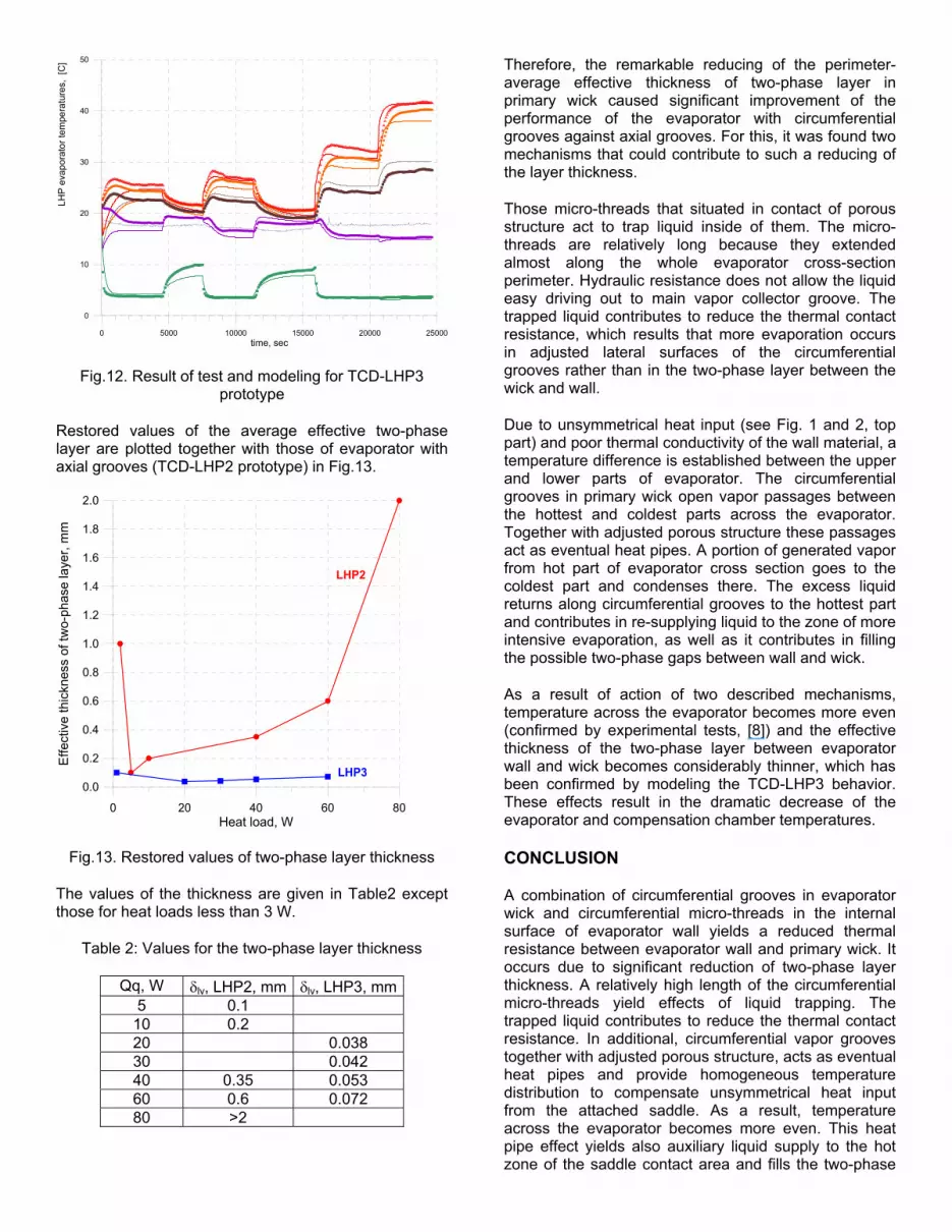
Fig.12. Result of test and modeling for TCD-LHP3 prototype
Restored values of the average effective two-phaselayer are plotted together with those of evaporator with axial grooves (TCD-LHP2 prototype) in Fig.13.
0 20 40 60 8Heat load, W
0
0.0
0.2
0.4
0.6
0.8
1.0
1.2
1.4
1.6
1.8
2.0
Effe
ctiv
eth
ickn
ess
of tw
o-ph
ase
laye
r, m
m
LHP3
LHP2
Fig.13. Restored values of two-phase layer thickness
The values of the thickness are given in Table2 except those for heat loads less than 3 W.
Table 2: Values for the two-phase layer thickness
Qq, W lv, LHP2, mm lv, LHP3, mm5 0.1
10 0.220 0.03830 0.04240 0.35 0.05360 0.6 0.07280 >2
Therefore, the remarkable reducing of the perimeter-average effective thickness of two-phase layer inprimary wick caused significant improvement of the performance of the evaporator with circumferential grooves against axial grooves. For this, it was found twomechanisms that could contribute to such a reducing of the layer thickness.
Those micro-threads that situated in contact of porous structure act to trap liquid inside of them. The micro-threads are relatively long because they extendedalmost along the whole evaporator cross-section perimeter. Hydraulic resistance does not allow the liquideasy driving out to main vapor collector groove. The trapped liquid contributes to reduce the thermal contactresistance, which results that more evaporation occurs in adjusted lateral surfaces of the circumferentialgrooves rather than in the two-phase layer between thewick and wall.
Due to unsymmetrical heat input (see Fig. 1 and 2, top part) and poor thermal conductivity of the wall material, atemperature difference is established between the upper and lower parts of evaporator. The circumferentialgrooves in primary wick open vapor passages betweenthe hottest and coldest parts across the evaporator. Together with adjusted porous structure these passages act as eventual heat pipes. A portion of generated vaporfrom hot part of evaporator cross section goes to the coldest part and condenses there. The excess liquid returns along circumferential grooves to the hottest part and contributes in re-supplying liquid to the zone of more intensive evaporation, as well as it contributes in filling the possible two-phase gaps between wall and wick.
As a result of action of two described mechanisms, temperature across the evaporator becomes more even(confirmed by experimental tests, [8]) and the effective thickness of the two-phase layer between evaporator wall and wick becomes considerably thinner, which has been confirmed by modeling the TCD-LHP3 behavior.These effects result in the dramatic decrease of the evaporator and compensation chamber temperatures.
CONCLUSION
A combination of circumferential grooves in evaporator wick and circumferential micro-threads in the internalsurface of evaporator wall yields a reduced thermal resistance between evaporator wall and primary wick. Itoccurs due to significant reduction of two-phase layer thickness. A relatively high length of the circumferential micro-threads yield effects of liquid trapping. Thetrapped liquid contributes to reduce the thermal contactresistance. In additional, circumferential vapor grooves together with adjusted porous structure, acts as eventual heat pipes and provide homogeneous temperature distribution to compensate unsymmetrical heat input from the attached saddle. As a result, temperatureacross the evaporator becomes more even. This heatpipe effect yields also auxiliary liquid supply to the hotzone of the saddle contact area and fills the two-phase

layer with liquid. This reduction in thermal resistance hasbeen confirmed by LHP modeling and observed inconducted comparative experimental and theoretical studies.
ACKNOWLEDGMENTS
This work has been supported by the National Institute for Space Research (INPE) and by Fundação deAmparo a Pesquisa no Estado de São Paulo (FAPESP/Brazil), grants 03/08365-6 and 03/11477-0.First author also appreciate the CNPq organization forformer support of the research line for mathematical modeling of two-phase thermal devices.
REFERENCES
1. Maydanik, Y.F., 2005, “Loop Heat Pipe”, Applied Thermal Engineering, Vol. 25, pp. 635-657.
2. Nikitkin, M., Cullimore, B., "CPL and LHP technologies: what are the differences, what are the similarities", SAE Paper 981587. Proceeding of the 28th ICES. July 13-16, 1998, Danvers(Massachusetts, USA), pp. 1-10.
3. Maidanik, Y. F., Fershtater YG., "Theoretical basis and classification of loop heat pipes and capillarypumped loops", Proc. of the 10th IHPC. September 21-25, 1997, Stuttgart (Germany), pp. 1-15
4. Goncharov, K., Kolesnikov, V., “Development of Propylene LHP for Spacecraft Thermal Control”, Proceedings of the 12th International Heat Pipe Conference, Moscow-Kostroma-Moscow, Russia,19-24 May, 2002, pp. 171-176
5. Baturkin, V., Zhuk, S., Vojta, J., Lura, F., Biering, B., Loetzke, H-G. “Elaboration of Thermal ControlSystem on the Base of Heat Pipes for MicroSatellites Magion 4, 5 and BIRD.” Proc. of the 12th
International Heat Pipe Conference, Moscow-Kostroma, Russia, 19-24 May, 2002, pp. 264-269
6. Vlassov, V.V. Sousa, F.L, Takahashi, W.K.“Comprehensive Optimization of a Heat Pipe Radiator Assembly filled with Ammonia or Acetone” International Journal of Heat and Mass Transfer,2006, in press.
7. Riehl, R.R., Vlassov, V.V. “Loop Heat Pipes Expertimental Investigations, Mathematical Modeling and Development”, Proc. of VI Minsk International Seminar "Heat Pipes, Heat Pumps, Refrigerators", Minsk, Belarus, 12-15 September, 2005.
8. Riehl, R. R., Santos, N. “Performance Improvement in Loop Heat Pipe Using Primary Wick withCircumferential Grooves”, 36th International Conference on Environmental Systems, Norfolk, VA,July 17-20, paper # 2006-01-2172.
9. Vlassov, V.V., Riehl, R.R. “Modeling of a Loop Heat Pipe for Ground and Space Conditions”. SAE Paper2005-01-2935, International Conference onEnvironmental Systems (ICES), 11-14 July 2005,Hotel Villa Pamphili, Rome, Italy.
10. Zhao, T.S., Liao, Q. “On capillary-driven flow and phase-change heat transfer in a porous structureheated by a finned surface: measurement and modeling”. International Journal of Heat and Mass Transfer, 43, 2000, pp. 1141-1155.
CONTACT
Valeri V. Vlassov, Dr., National Institute for Space Research, INPE-ETE-DMC/Satellites/Thermal Group Av. Dos Astronautas 1758,Sao Jose dos Campos, SP – Brazil CEP 12227-010 E-Mail: [email protected]
http://www.dem.inpe.br/~valeri
DEFINITIONS, ACRONYMS, ABBREVIATIONS
Symbol DescriptionA Area (m) C Specific heat (J/kg) G Thermal conductance (W/K) g Specific thermal conductance (W/K/m2)
Gravity acceleration (m/s2)h Heat transfer coefficient (W/K/m2)H Height of evaporator wick grooves (m) K Permeability (m2)k Thermal conductivity (W/K/m) L Length (m) m Mass flow rate (kg/s)Q Heat load (W) q Heat flux density (W/m2)R Radius (m) r Current radius (m) S Distance step between grooves (m) t Time (s) T Temperature (K) W Width (m) w Width (m) v Velocity (m/s)V Volume (m3)x,y,z Coordinates (m)
GreeksThickness, height (m) PorosityLatent heat of evaporation (J/kg) Dynamic viscosity (Pa s) Density (kg/m3)Surface tension (N/m)
(.) Heaviside step-function
Subscriptsa Ambientb Bayonetby Bayonetc Capillary; condenser

cr Criticale Evaporatoreff Effective eq Equipmentg Groovel Liquidp Porous
Pressure (In Cp)pk Peakr Reservoir
sdl Saddleth Threadthr Threadq Equipmentw Wallv Vapor2ph Two-phase
Vapor-liquid interface