Embed Size (px)
Citation preview
Niederspannungsmotoren in IEC-Baugrößen 63 bis 315
Low Voltage Motors IEC Frame Sizes 63 to 315
Modularer SystemmotorModular System Motor
Technischer Katalog
Technical Catalogue
Motors | Automation | Energy | Transmission & Distribution | Coatings
Watt Drive - Für jede Anwen-dung der passende Antrieb
Watt Drive entwickelt, produziert und vertreibt weltweit Getriebe- und Drehstrommotoren und bietet mit seinem Motor- und Getriebebaukasten ein modular kombinier- bares Spektrum kompletter Antriebssysteme für Produk-tionsmaschinen und industrielle Fertigungsanlagen an. Neben dem umfangreichen Standardprogramm ist eine Stärke von Watt Drive, dass auch maßgeschneiderte Antriebslösungen, speziell nach den jeweiligen spezifi-schen Kundenanforderungen, entwickelt und umgesetzt werden. Vor allem auch durch das einzigartige Bau-kastensystem ist es möglich, vielfältige Lösungen stan-dardmäßig anzubieten und damit einen wichtigen Vorteil sowohl in den Kosten als auch in den Produktionszeiten zu generieren.
Seit 2011 erweitert Watt Drive als Teil des brasilianischen Konzerns WEG dessen Produktportfolio um hochwertige Getriebe- und Getriebemotorenlösungen.
WEG. Globale Lösungen in den Bereichen Motoren, Automation und Energie
WEG ist ein weltweit operierender, führender Anbieter für Lösungen in der Antriebstechnik, Energieerzeugung und -verteilung sowie in der Automatisierungstechnik und im Schaltanlagenbau. 1961 in Brasilien gegründet, hat sich WEG international zu einem der wichtigsten Hersteller für Elektromotoren entwickelt. Mit den Asynchronmotoren der W22-Baureihe bietet WEG zudem eine der branchen-weit breitesten Paletten an energieeffizienten Motoren an und nimmt damit eine Vorreiterrolle ein. Weltweit beschäftigt der Konzern mehr als 28.000 Mitarbeiter in Produktionsstandorten in Brasilien, Argentinien, Mexiko, USA, Österreich, Deutschland, Portugal, China, Indien und Südafrika sowie in Niederlassungen in 25 Ländern der Welt.
Watt Drive - A suitable drive solution for each application
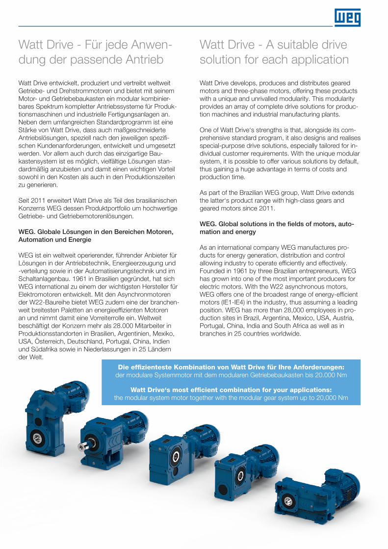
Die effizienteste Kombination von Watt Drive für Ihre Anforderungen:der modulare Systemmotor mit dem modularen Getriebebaukasten bis 20.000 Nm
Watt Drive‘s most efficient combination for your applications:the modular system motor together with the modular gear system up to 20,000 Nm
Watt Drive develops, produces and distributes geared motors and three-phase motors, offering these products with a unique and unrivalled modularity. This modularity provides an array of complete drive solutions for produc-tion machines and industrial manufacturing plants.
One of Watt Drive‘s strengths is that, alongside its com-prehensive standard program, it also designs and realises special-purpose drive solutions, especially tailored for in-dividual customer requirements. With the unique modular system, it is possible to offer various solutions by default, thus gaining a huge advantage in terms of costs and production time.
As part of the Brazilian WEG group, Watt Drive extends the latter‘s product range with high-class gears and geared motors since 2011.
WEG. Global solutions in the fields of motors, auto-mation and energy
As an international company WEG manufactures pro-ducts for energy generation, distribution and control allowing industry to operate efficiently and effectively. Founded in 1961 by three Brazilian entrepreneurs, WEG has grown into one of the most important producers for electric motors. With the W22 asynchronous motors, WEG offers one of the broadest range of energy-efficient motors (IE1-IE4) in the industry, thus assuming a leading position. WEG has more than 28,000 employees in pro-duction sites in Brazil, Argentina, Mexico, USA, Austria, Portugal, China, India and South Africa as well as in branches in 25 countries worldwide.
InhaltsverzeichnisContents
Modular System Motor
Allgemeine InformationenGeneral Information1
Elektrische BasisdatenElectrical Basic Data2
MaßbilderDimension Sheets3
MotormoduleMotor Modules4
3
27
53
63
HAFTUNGSAUSSCHLUSSDieser Produktkatalog enthält Informationen (Beschreibungen und Leistungsmerkmale), die im konkreten Anwendungsfall nicht immer in der beschriebenen Form zutreffen. Die Daten können sich auch durch Weiterentwicklung der Produkte ändern.
Leistungsmerkmale sind nur dann verbindlich, wenn sie beim Vertragsabschluss ausdrücklich vereinbart werden. Liefermög-lichkeiten und technische Änderungen vorbehalten.
DISCLAIMERThis catalogue contains information (descriptions and character-istics), which do not always apply as described in case of actual use. Data can also change due to product development.
Characteristics are only binding if explicitly agreed to in the con-tract. Delivery opportunities and technical modifications are sub-ject to change without notice.
cat4CAD
Modular System Motor2
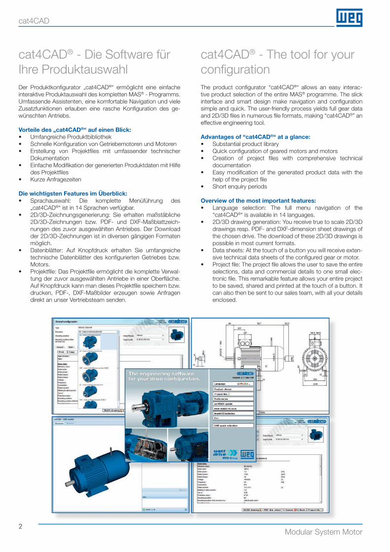
Der Produktkonfigurator „cat4CAD®“ ermöglicht eine einfache interaktive Produktauswahl des kompletten MAS® - Programms.Umfassende Assistenten, eine komfortable Navigation und viele Zusatzfunktionen erlauben eine rasche Konfiguration des ge-wünschten Antriebs.
Vorteile des „cat4CAD®“ auf einen Blick:• Umfangreiche Produktbibliothek• Schnelle Konfiguration von Getriebemotoren und Motoren• Erstellung von Projektfiles mit umfassender technischer
Dokumentation• Einfache Modifikation der generierten Produktdaten mit Hilfe
des Projektfiles• Kurze Anfragezeiten
Die wichtigsten Features im Überblick:• Sprachauswahl: Die komplette Menüführung des
„cat4CAD®“ ist in 14 Sprachen verfügbar.• 2D/3D-Zeichnungsgenerierung: Sie erhalten maßstäbliche
2D/3D-Zeichnungen bzw. PDF- und DXF-Maßblattzeich-nungen des zuvor ausgewählten Antriebes. Der Download der 2D/3D-Zeichnungen ist in diversen gängigen Formaten möglich.
• Datenblätter: Auf Knopfdruck erhalten Sie umfangreiche technische Datenblätter des konfigurierten Getriebes bzw. Motors.
• Projektfile: Das Projektfile ermöglicht die komplette Verwal-tung der zuvor ausgewählten Antriebe in einer Oberfläche. Auf Knopfdruck kann man dieses Projektfile speichern bzw. drucken, PDF-, DXF-Maßbilder erzeugen sowie Anfragen direkt an unser Vertriebsteam senden.
The product configurator “cat4CAD®“ allows an easy interac-tive product selection of the entire MAS® programme. The slick interface and smart design make navigation and configuration simple and quick. The user-friendly process yields full gear data and 2D/3D files in numerous file formats, making “cat4CAD®” an effective engineering tool. Advantages of “cat4CAD®“ at a glance:• Substantial product library• Quick configuration of geared motors and motors• Creation of project files with comprehensive technical
documentation• Easy modification of the generated product data with the
help of the project file• Short enquiry periods
Overview of the most important features:• Language selection: The full menu navigation of the
“cat4CAD®“ is available in 14 languages.• 2D/3D drawing generation: You receive true to scale 2D/3D
drawings resp. PDF- and DXF-dimension sheet drawings of the chosen drive. The download of these 2D/3D drawings is possible in most current formats.
• Data sheets: At the touch of a button you will receive exten-sive technical data sheets of the configured gear or motor.
• Project file: The project file allows the user to save the entire selections, data and commercial details to one small elec-tronic file. This remarkable feature allows your entire project to be saved, shared and printed at the touch of a button. It can also then be sent to our sales team, with all your details enclosed.
cat4CAD® - Die Software für Ihre Produktauswahl
cat4CAD® - The tool for your configuration
3Modular System Motor
Allgemeine InformationenGeneral Information1Modularer Motorbaukasten Modular motor system 4
EUSAS®-Bezeichnung EUSAS®-description 6
Bestelltypenbezeichnung Order type designation 7
Basisausführung / Ausführungsvarianten - elektrisch Basic execution / Electrical options 8
Ausführungsvarianten - mechanisch Mechanical options 9
Ausführungsvarianten - Motormodule Motor modules 10
Ausführungsvarianten - Sonstige Motor modules - Additional options 11
Toleranzen Tolerances 12
Schutzarten Degrees of protection 13
Lackierung Painting 14
Betriebsarten Modes of operation 15
Allgemein General 16
Klemmenanschluss Terminal board connection 26
4Modular System Motor
1
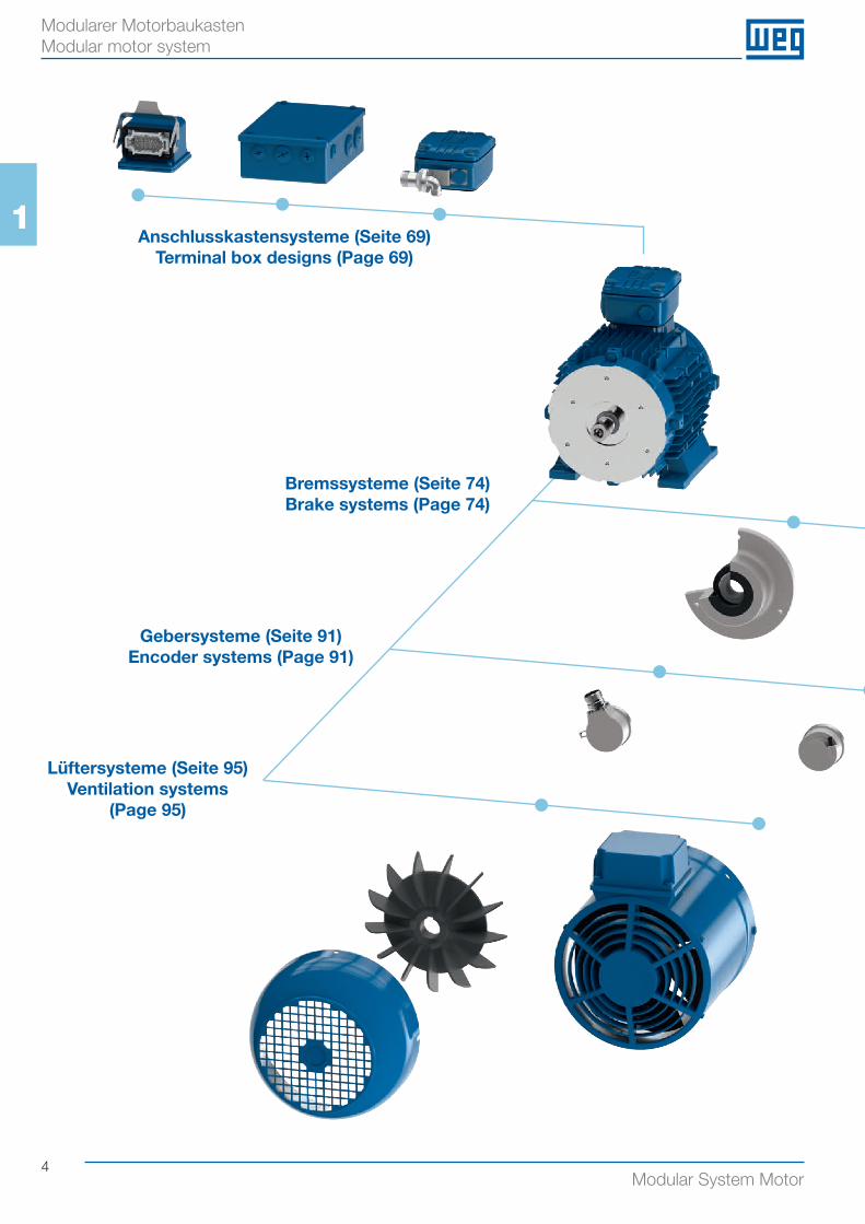
Modularer Motorbaukasten Modular motor system
Anschlusskastensysteme (Seite 69) Terminal box designs (Page 69)
Bremssysteme (Seite 74) Brake systems (Page 74)
Gebersysteme (Seite 91) Encoder systems (Page 91)
Lüftersysteme (Seite 95) Ventilation systems
(Page 95)
5Modular System Motor
1
Modularer Motorbaukasten Modular motor system
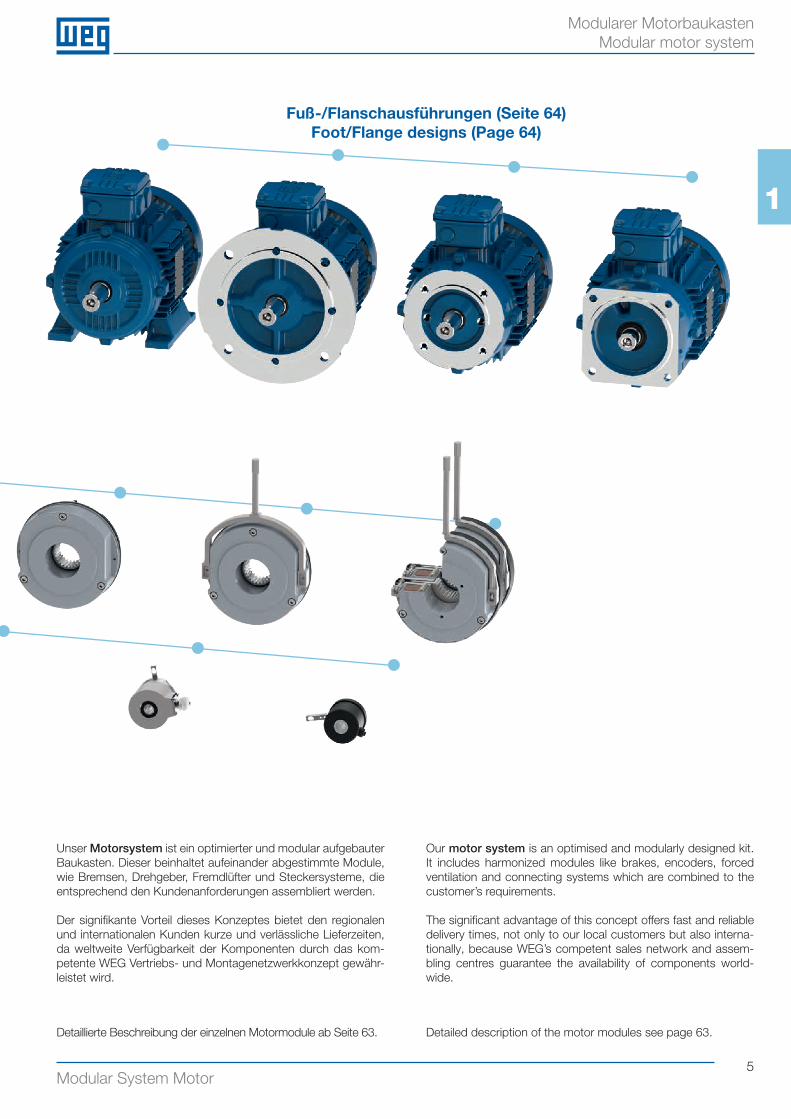
Fuß-/Flanschausführungen (Seite 64)Foot/Flange designs (Page 64)
Unser Motorsystem ist ein optimierter und modular aufgebauter Baukasten. Dieser beinhaltet aufeinander abgestimmte Module, wie Bremsen, Drehgeber, Fremdlüfter und Steckersysteme, die entsprechend den Kundenanforderungen assembliert werden.
Der signifikante Vorteil dieses Konzeptes bietet den regionalen und internationalen Kunden kurze und verlässliche Lieferzeiten, da weltweite Verfügbarkeit der Komponenten durch das kom-petente WEG Vertriebs- und Montagenetzwerkkonzept gewähr-leistet wird.
Detaillierte Beschreibung der einzelnen Motormodule ab Seite 63.
Our motor system is an optimised and modularly designed kit. It includes harmonized modules like brakes, encoders, forced ventilation and connecting systems which are combined to the customer’s requirements.
The significant advantage of this concept offers fast and reliable delivery times, not only to our local customers but also interna-tionally, because WEG’s competent sales network and assem-bling centres guarantee the availability of components world-wide.
Detailed description of the motor modules see page 63.
6Modular System Motor
1
EUSAS®-Bezeichnung EUSAS®-description
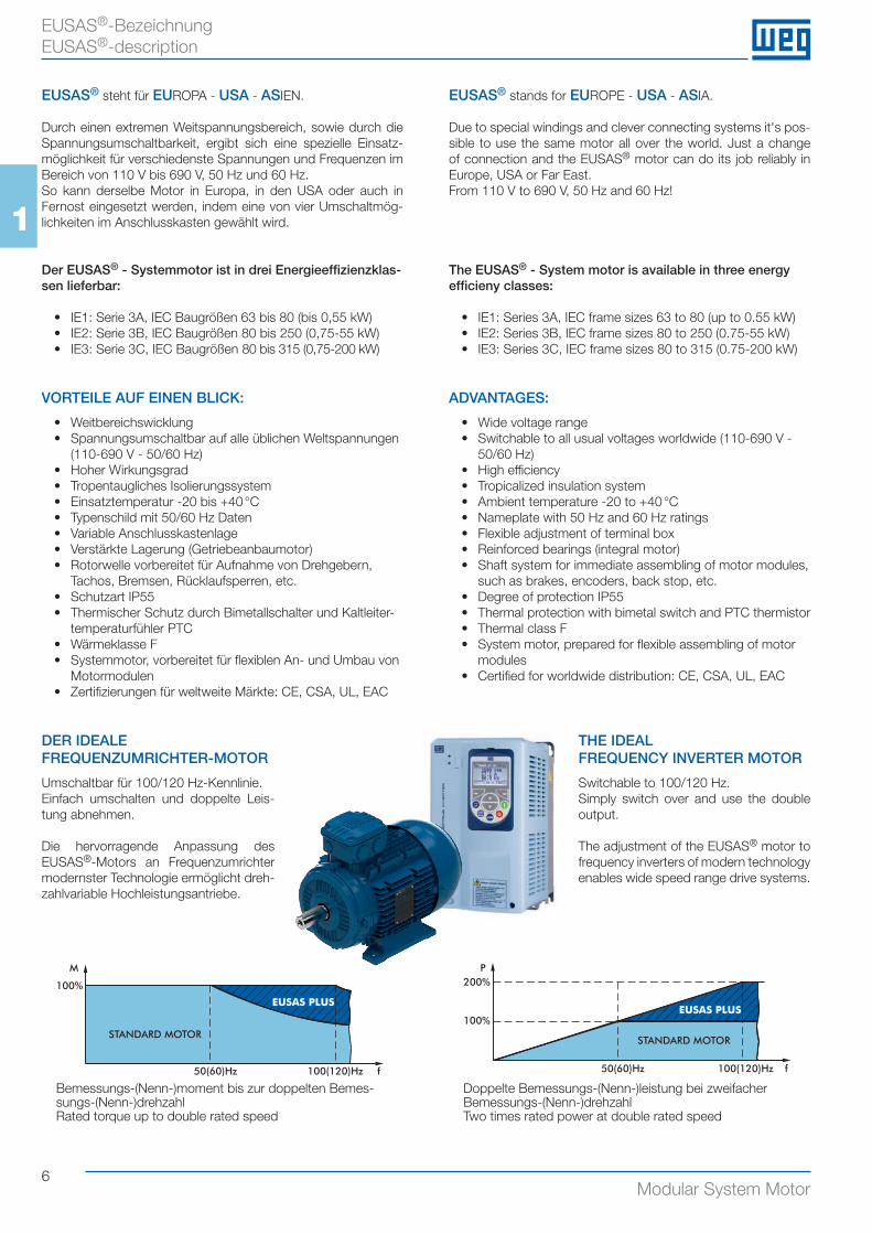
EUSAS® stands for EUROPE - USA - ASIA. Due to special windings and clever connecting systems it's pos-sible to use the same motor all over the world. Just a change of connection and the EUSAS® motor can do its job reliably in Europe, USA or Far East.From 110 V to 690 V, 50 Hz and 60 Hz!
The EUSAS® - System motor is available in three energy efficieny classes:
• IE1: Series 3A, IEC frame sizes 63 to 80 (up to 0.55 kW)• IE2: Series 3B, IEC frame sizes 80 to 250 (0.75-55 kW)• IE3: Series 3C, IEC frame sizes 80 to 315 (0.75-200 kW)
ADVANTAGES:
• Wide voltage range• Switchable to all usual voltages worldwide (110-690 V -
50/60 Hz)• High efficiency• Tropicalized insulation system• Ambient temperature -20 to +40 °C• Nameplate with 50 Hz and 60 Hz ratings• Flexible adjustment of terminal box• Reinforced bearings (integral motor)• Shaft system for immediate assembling of motor modules,
such as brakes, encoders, back stop, etc.• Degree of protection IP55• Thermal protection with bimetal switch and PTC thermistor• Thermal class F• System motor, prepared for flexible assembling of motor
modules• Certified for worldwide distribution: CE, CSA, UL, EAC
THE IDEAL FREQUENCY INVERTER MOTOR
Switchable to 100/120 Hz.Simply switch over and use the double output.
The adjustment of the EUSAS® motor to frequency inverters of modern technology enables wide speed range drive systems.
EUSAS® steht für EUROPA - USA - ASIEN. Durch einen extremen Weitspannungsbereich, sowie durch die Spannungsumschaltbarkeit, ergibt sich eine spezielle Einsatz-möglichkeit für verschiedenste Spannungen und Frequenzen im Bereich von 110 V bis 690 V, 50 Hz und 60 Hz.So kann derselbe Motor in Europa, in den USA oder auch in Fernost eingesetzt werden, indem eine von vier Umschaltmög-lichkeiten im Anschlusskasten gewählt wird.
Der EUSAS® - Systemmotor ist in drei Energieeffizienzklas-sen lieferbar:
• IE1: Serie 3A, IEC Baugrößen 63 bis 80 (bis 0,55 kW)• IE2: Serie 3B, IEC Baugrößen 80 bis 250 (0,75-55 kW)• IE3: Serie 3C, IEC Baugrößen 80 bis 315 (0,75-200 kW)
VORTEILE AUF EINEN BLICK:
• Weitbereichswicklung• Spannungsumschaltbar auf alle üblichen Weltspannungen
(110-690 V - 50/60 Hz)• Hoher Wirkungsgrad• Tropentaugliches Isolierungssystem• Einsatztemperatur -20 bis +40 °C• Typenschild mit 50/60 Hz Daten• Variable Anschlusskastenlage• Verstärkte Lagerung (Getriebeanbaumotor)• Rotorwelle vorbereitet für Aufnahme von Drehgebern,
Tachos, Bremsen, Rücklaufsperren, etc.• Schutzart IP55• Thermischer Schutz durch Bimetallschalter und Kaltleiter-
temperaturfühler PTC• Wärmeklasse F• Systemmotor, vorbereitet für flexiblen An- und Umbau von
Motormodulen• Zertifizierungen für weltweite Märkte: CE, CSA, UL, EAC
DER IDEALE FREQUENZUMRICHTER-MOTOR
Umschaltbar für 100/120 Hz-Kennlinie.Einfach umschalten und doppelte Leis-tung abnehmen.
Die hervorragende Anpassung des EUSAS®-Motors an Frequenzumrichter modernster Technologie ermöglicht dreh-zahlvariable Hochleistungsantriebe.
M
100%
50(60)Hz 100(120)Hz f
STANDARD MOTOR
EUSAS PLUS
P200%
100%
50(60)Hz 100(120)Hz
STANDARD MOTOR
f
EUSAS PLUS
Bemessungs-(Nenn-)moment bis zur doppelten Bemes-sungs-(Nenn-)drehzahlRated torque up to double rated speed
Doppelte Bemessungs-(Nenn-)leistung bei zweifacher Bemessungs-(Nenn-)drehzahlTwo times rated power at double rated speed
7Modular System Motor
11
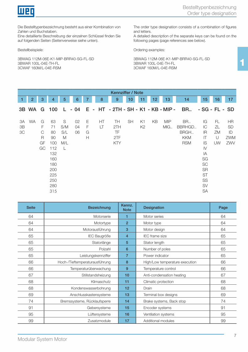
Bestelltypenbezeichnung Order type designation
Seite BezeichnungKennz.Note
Designation Page
64 Motorserie 1 Motor series 64
64 Motortype 2 Motor type 64
64 Motorausführung 3 Motor design 64
65 IEC Baugröße 4 IEC frame size 65
65 Statorlänge 5 Stator length 65
65 Polzahl 6 Number of poles 65
65 Leistungskennziffer 7 Power indicator 65
66 Hoch-/Tieftemperaturausführung 8 High/Low temperature execution 66
66 Temperaturüberwachung 9 Temperature control 66
67 Stillstandsheizung 10 Anti-condensation heating 67
68 Klimaschutz 11 Climatic protection 68
68 Kondenswasserbohrung 12 Drain 68
69 Anschlusskastensysteme 13 Terminal box designs 69
74 Bremssysteme, Rücklaufsperre 14 Brake systems, Back stop 74
91 Gebersysteme 15 Encoder systems 91
95 Lüftersysteme 16 Ventilation systems 95
99 Zusatzmodule 17 Additional modules 99
Bestellbeispiele:
3BWAG 112M-06E-K1-MIP-BRR40-SG-FL-SD3BWAR 100L-04E-TH-FL3CWAF 160M/L-04E-RSM
Ordering examples:
3BWAG 112M-06E-K1-MIP-BRR40-SG-FL-SD3BWAR 100L-04E-TH-FL3CWAF 160M/L-04E-RSM
Die Bestelltypenbezeichnung besteht aus einer Kombination von Zahlen und Buchstaben.Eine detaillierte Beschreibung der einzelnen Schlüssel finden Sie auf folgenden Seiten (Seitenverweise siehe unten).
The order type designation consists of a combination of figures and letters.A detailed description of the separate keys can be found on the following pages (page references see below).
Kennziffer / Note
1 2 3 4 5 6 7 8 9 10 11 12 13 14 15 16 17
3B WA G 100 L - 04 E - HT - 2TH - SH - K1 - KB - MIP - BR.. - SG - FL - SD
3A WA G 63 S 02 E HT TH SH K1 KB MIP BR.. IG FL HR3B F 71 S/M 04 F LT 2TH K2 MIG.. BBRHGD.. IC ZL SD3C C 80 S/L 06 G TF BRGH.. IR ZM ID
R 90 M H 2TF KKM IT U ZWMGF 100 M/L KTY RSM IS UW ZWVGC 112 L IV
132 IA160 SG180 SC200 SR225 ST250 SS280 SV315 SA
8Modular System Motor
1
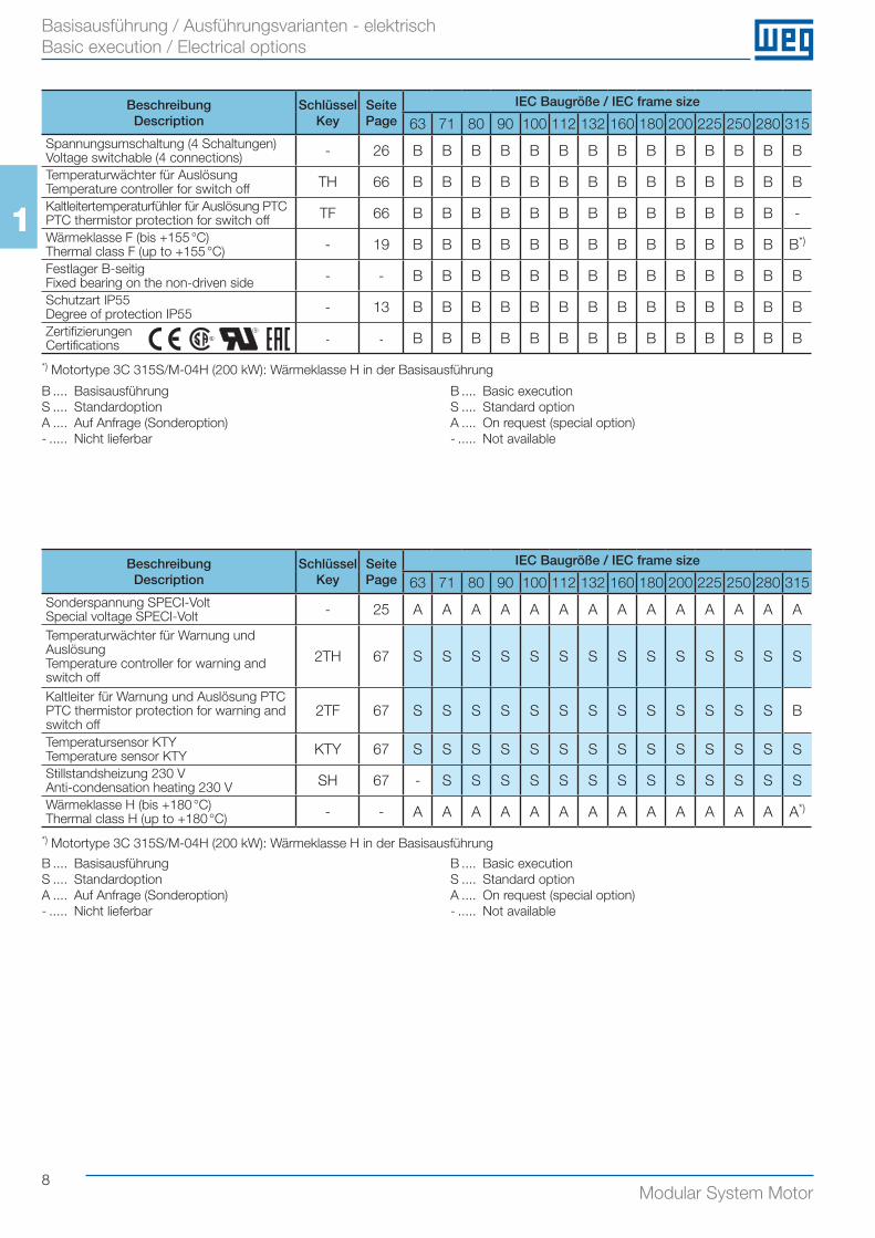
Basisausführung / Ausführungsvarianten - elektrisch Basic execution / Electrical options
BeschreibungDescription
SchlüsselKey
SeitePage
IEC Baugröße / IEC frame size
63 71 80 90 100 112 132 160 180 200 225 250 280 315Sonderspannung SPECI-VoltSpecial voltage SPECI-Volt - 25 A A A A A A A A A A A A A A
Temperaturwächter für Warnung und AuslösungTemperature controller for warning and switch off
2TH 67 S S S S S S S S S S S S S S
Kaltleiter für Warnung und Auslösung PTCPTC thermistor protection for warning and switch off
2TF 67 S S S S S S S S S S S S S B
Temperatursensor KTYTemperature sensor KTY KTY 67 S S S S S S S S S S S S S S
Stillstandsheizung 230 VAnti-condensation heating 230 V SH 67 - S S S S S S S S S S S S S
Wärmeklasse H (bis +180 °C)Thermal class H (up to +180 °C) - - A A A A A A A A A A A A A A*)
B .... BasisausführungS .... Standardoption A .... Auf Anfrage (Sonderoption)- ..... Nicht lieferbar
BeschreibungDescription
SchlüsselKey
SeitePage
IEC Baugröße / IEC frame size
63 71 80 90 100 112 132 160 180 200 225 250 280 315Spannungsumschaltung (4 Schaltungen)Voltage switchable (4 connections) - 26 B B B B B B B B B B B B B B
Temperaturwächter für AuslösungTemperature controller for switch off TH 66 B B B B B B B B B B B B B B
Kaltleitertemperaturfühler für Auslösung PTCPTC thermistor protection for switch off TF 66 B B B B B B B B B B B B B -
Wärmeklasse F (bis +155 °C)Thermal class F (up to +155 °C) - 19 B B B B B B B B B B B B B B*)
Festlager B-seitigFixed bearing on the non-driven side - - B B B B B B B B B B B B B B
Schutzart IP55Degree of protection IP55 - 13 B B B B B B B B B B B B B B
ZertifizierungenCertifications - - B B B B B B B B B B B B B B
B .... Basisausführung S .... Standardoption A .... Auf Anfrage (Sonderoption)- ..... Nicht lieferbar
B .... Basic executionS .... Standard optionA .... On request (special option)- ..... Not available
B .... Basic executionS .... Standard optionA .... On request (special option)- ..... Not available
*) Motortype 3C 315S/M-04H (200 kW): Wärmeklasse H in der Basisausführung
*) Motortype 3C 315S/M-04H (200 kW): Wärmeklasse H in der Basisausführung
9Modular System Motor
1
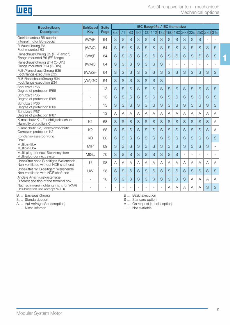
Ausführungsvarianten - mechanisch Mechanical options
BeschreibungDescription
SchlüsselKey
SeitePage
IEC Baugröße / IEC frame size
63 71 80 90 100 112 132 160 180 200 225 250 280 315Getriebeanbau B5-spezialIntegral motor B5-special (WA)R 64 S S S S S S S S S S S S - -
Fußausführung B3Foot mounted B3 (WA)G 64 S S S S S S S S S S S S S S
Flanschausführung B5 (FF-Flansch)Flange mounted B5 (FF-flange) (WA)F 64 S S S S S S S S S S S S S S
Flanschausführung B14 (C-DIN)Flange mounted B14 (C-DIN) (WA)C 64 S S S S S S S - - - - - - -
Fuß-/Flanschausführung B35Foot/flange execution B35 (WA)GF 64 S S S S S S S S S S S S S S
Fuß-Flanschausführung B34Foot/flange execution B34 (WA)GC 64 S S S S S S S - - - - - - -
Schutzart IP56Degree of protection IP56 - 13 S S S S S S S S S S S S S S
Schutzart IP65Degree of protection IP65 - 13 S S S S S S S S S S S S S S
Schutzart IP66Degree of protection IP66 - 13 S S S S S S S S S S S S S S
Schutzart IP67Degree of protection IP67 - 13 A A A A A A A A A A A A A A
Klimaschutz K1, FeuchtigkeitsschutzHumidity protection K1 K1 68 S S S S S S S S S S S S S A
Klimaschutz K2, KorrosionsschutzCorrosion protection K2 K2 68 S S S S S S S S S S S S S A
KondenswasserbohrungDrain KB 68 S S S S S S S S S S S S S S
Multipin-BoxMultipin-Box MIP 69 S S S S S S S S S S S S S -
Multi-plug-connect SteckersystemMulti-plug-connect system MIG.. 70 S S S S S S S S S - - - - -
Unbelüftet ohne B-seitiges WellenendeNon-ventilated without NDE shaft end U 98 A A A A A A A A A A A A A A
Unbelüftet mit B-seitigem WellenendeNon-ventilated with NDE shaft end UW 98 S S S S S S S S S S S S S S
Andere AnschlusskastenlageDifferent position of the terminal box - 18 S S S S S S S S S S A A A A
Nachschmiereinrichtung (nicht für WAR)Relubrication unit (except WAR) - - - - - - - - - A A A A A S S
B .... BasisausführungS .... Standardoption A .... Auf Anfrage (Sonderoption)- ..... Nicht lieferbar
B .... Basic executionS .... Standard optionA .... On request (special option)- ..... Not available
10Modular System Motor
1
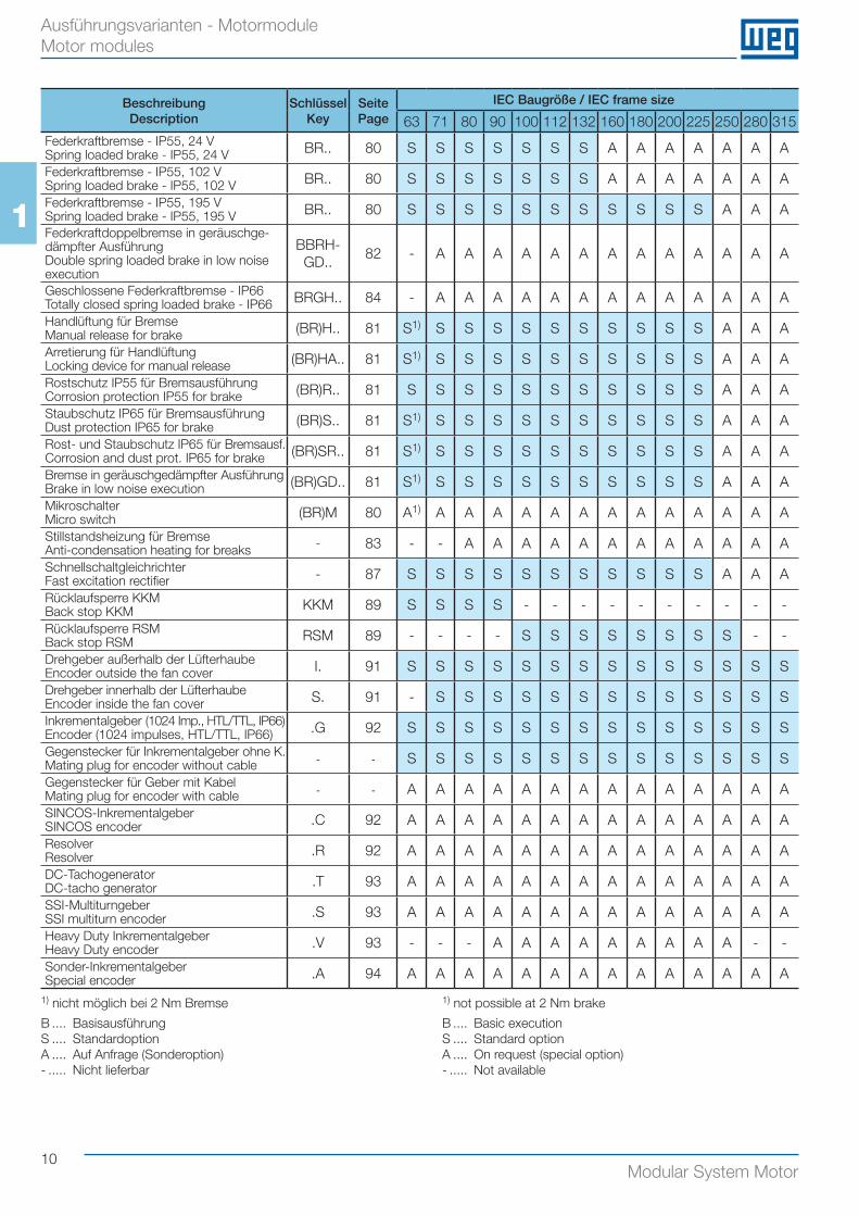
Ausführungsvarianten - Motormodule Motor modules
BeschreibungDescription
SchlüsselKey
SeitePage
IEC Baugröße / IEC frame size
63 71 80 90 100 112 132 160 180 200 225 250 280 315Federkraftbremse - IP55, 24 VSpring loaded brake - IP55, 24 V BR.. 80 S S S S S S S A A A A A A A
Federkraftbremse - IP55, 102 VSpring loaded brake - IP55, 102 V BR.. 80 S S S S S S S A A A A A A A
Federkraftbremse - IP55, 195 VSpring loaded brake - IP55, 195 V BR.. 80 S S S S S S S S S S S A A A
Federkraftdoppelbremse in geräuschge-dämpfter AusführungDouble spring loaded brake in low noise execution
BBRH-GD..
82 - A A A A A A A A A A A A A
Geschlossene Federkraftbremse - IP66Totally closed spring loaded brake - IP66 BRGH.. 84 - A A A A A A A A A A A A A
Handlüftung für BremseManual release for brake (BR)H.. 81 S1) S S S S S S S S S S A A A
Arretierung für HandlüftungLocking device for manual release (BR)HA.. 81 S1) S S S S S S S S S S A A A
Rostschutz IP55 für BremsausführungCorrosion protection IP55 for brake (BR)R.. 81 S S S S S S S S S S S A A A
Staubschutz IP65 für BremsausführungDust protection IP65 for brake (BR)S.. 81 S1) S S S S S S S S S S A A A
Rost- und Staubschutz IP65 für Bremsausf.Corrosion and dust prot. IP65 for brake (BR)SR.. 81 S1) S S S S S S S S S S A A A
Bremse in geräuschgedämpfter AusführungBrake in low noise execution (BR)GD.. 81 S1) S S S S S S S S S S A A A
MikroschalterMicro switch (BR)M 80 A1) A A A A A A A A A A A A A
Stillstandsheizung für BremseAnti-condensation heating for breaks - 83 - - A A A A A A A A A A A A
SchnellschaltgleichrichterFast excitation rectifier - 87 S S S S S S S S S S S A A A
Rücklaufsperre KKMBack stop KKM KKM 89 S S S S - - - - - - - - - -
Rücklaufsperre RSMBack stop RSM RSM 89 - - - - S S S S S S S S - -
Drehgeber außerhalb der LüfterhaubeEncoder outside the fan cover I. 91 S S S S S S S S S S S S S S
Drehgeber innerhalb der LüfterhaubeEncoder inside the fan cover S. 91 - S S S S S S S S S S S S S
Inkrementalgeber (1024 Imp., HTL/TTL, IP66)Encoder (1024 impulses, HTL/TTL, IP66) .G 92 S S S S S S S S S S S S S S
Gegenstecker für Inkrementalgeber ohne K.Mating plug for encoder without cable - - S S S S S S S S S S S S S S
Gegenstecker für Geber mit KabelMating plug for encoder with cable - - A A A A A A A A A A A A A A
SINCOS-InkrementalgeberSINCOS encoder .C 92 A A A A A A A A A A A A A A
ResolverResolver .R 92 A A A A A A A A A A A A A A
DC-TachogeneratorDC-tacho generator .T 93 A A A A A A A A A A A A A A
SSI-Multiturngeber SSI multiturn encoder .S 93 A A A A A A A A A A A A A A
Heavy Duty InkrementalgeberHeavy Duty encoder .V 93 - - - A A A A A A A A A - -
Sonder-InkrementalgeberSpecial encoder .A 94 A A A A A A A A A A A A A A
1) nicht möglich bei 2 Nm Bremse
B .... BasisausführungS .... Standardoption A .... Auf Anfrage (Sonderoption)- ..... Nicht lieferbar
B .... Basic executionS .... Standard optionA .... On request (special option)- ..... Not available
1) not possible at 2 Nm brake
11Modular System Motor
1
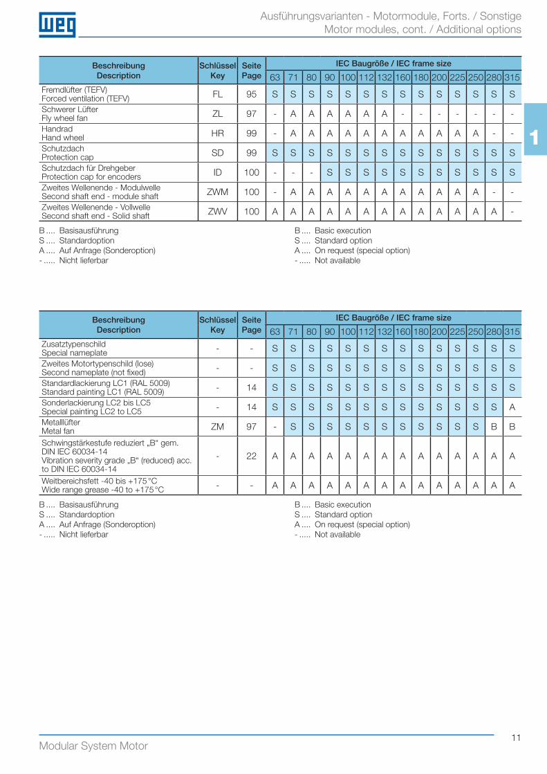
Ausführungsvarianten - Motormodule, Forts. / Sonstige Motor modules, cont. / Additional options
BeschreibungDescription
SchlüsselKey
SeitePage
IEC Baugröße / IEC frame size
63 71 80 90 100 112 132 160 180 200 225 250 280 315ZusatztypenschildSpecial nameplate - - S S S S S S S S S S S S S S
Zweites Motortypenschild (lose)Second nameplate (not fixed) - - S S S S S S S S S S S S S S
Standardlackierung LC1 (RAL 5009)Standard painting LC1 (RAL 5009) - 14 S S S S S S S S S S S S S S
Sonderlackierung LC2 bis LC5Special painting LC2 to LC5 - 14 S S S S S S S S S S S S S A
MetalllüfterMetal fan ZM 97 - S S S S S S S S S S S B B
Schwingstärkestufe reduziert „B“ gem. DIN IEC 60034-14Vibration severity grade „B“ (reduced) acc. to DIN IEC 60034-14
- 22 A A A A A A A A A A A A A A
Weitbereichsfett -40 bis +175 °CWide range grease -40 to +175 °C - - A A A A A A A A A A A A A A
B .... BasisausführungS .... Standardoption A .... Auf Anfrage (Sonderoption)- ..... Nicht lieferbar
BeschreibungDescription
SchlüsselKey
SeitePage
IEC Baugröße / IEC frame size
63 71 80 90 100 112 132 160 180 200 225 250 280 315Fremdlüfter (TEFV)Forced ventilation (TEFV) FL 95 S S S S S S S S S S S S S S
Schwerer LüfterFly wheel fan ZL 97 - A A A A A A - - - - - - -
HandradHand wheel HR 99 - A A A A A A A A A A A - -
SchutzdachProtection cap SD 99 S S S S S S S S S S S S S S
Schutzdach für DrehgeberProtection cap for encoders ID 100 - - - S S S S S S S S S S S
Zweites Wellenende - ModulwelleSecond shaft end - module shaft ZWM 100 - A A A A A A A A A A A - -
Zweites Wellenende - Vollwelle Second shaft end - Solid shaft ZWV 100 A A A A A A A A A A A A A -
B .... BasisausführungS .... Standardoption A .... Auf Anfrage (Sonderoption)- ..... Nicht lieferbar
B .... Basic executionS .... Standard optionA .... On request (special option)- ..... Not available
B .... Basic executionS .... Standard optionA .... On request (special option)- ..... Not available
12Modular System Motor
1
Toleranzen Tolerances
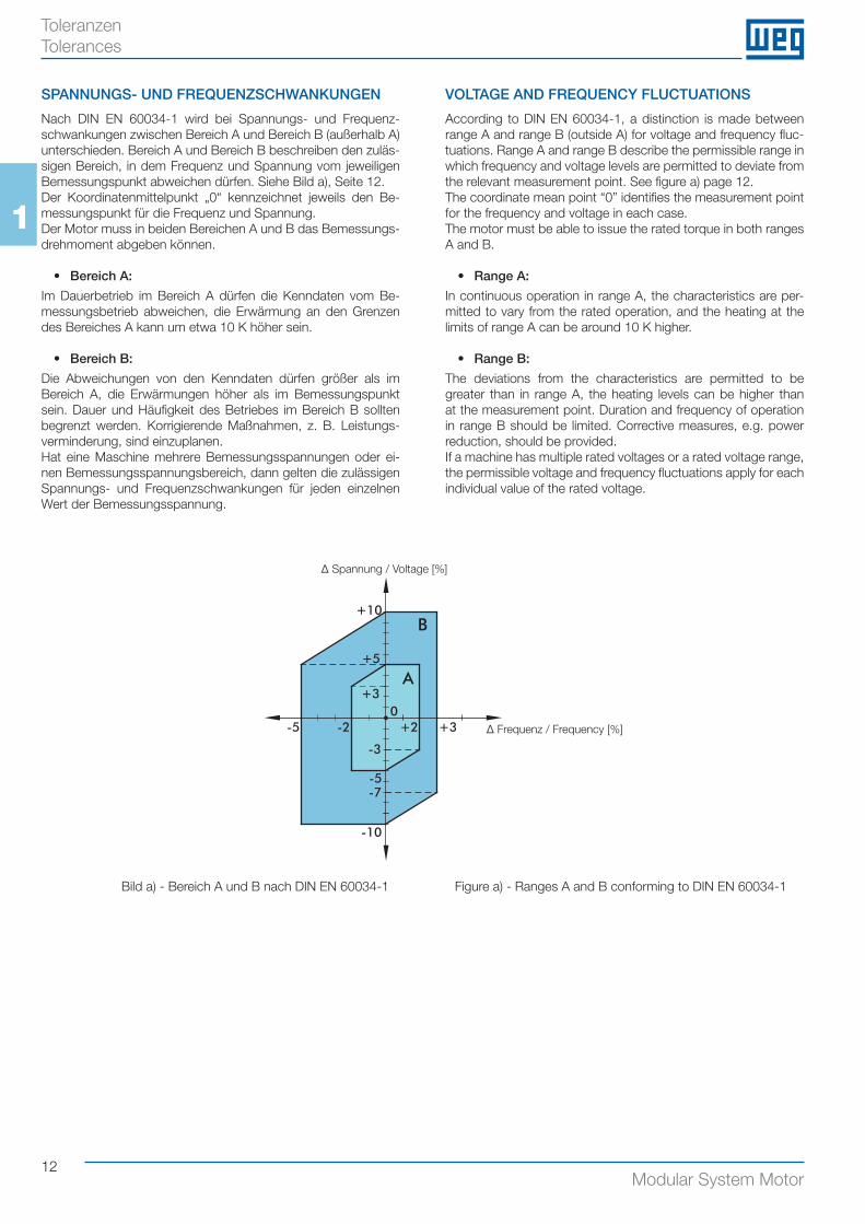
SPANNUNGS- UND FREQUENZSCHWANKUNGEN
Nach DIN EN 60034-1 wird bei Spannungs- und Frequenz-schwankungen zwischen Bereich A und Bereich B (außerhalb A) unterschieden. Bereich A und Bereich B beschreiben den zuläs-sigen Bereich, in dem Frequenz und Spannung vom jeweiligen Bemessungspunkt abweichen dürfen. Siehe Bild a), Seite 12.Der Koordinatenmittelpunkt „0“ kennzeichnet jeweils den Be-messungspunkt für die Frequenz und Spannung.Der Motor muss in beiden Bereichen A und B das Bemessungs-drehmoment abgeben können.
• Bereich A:
Im Dauerbetrieb im Bereich A dürfen die Kenndaten vom Be-messungsbetrieb abweichen, die Erwärmung an den Grenzen des Bereiches A kann um etwa 10 K höher sein.
• Bereich B:
Die Abweichungen von den Kenndaten dürfen größer als im Bereich A, die Erwärmungen höher als im Bemessungspunkt sein. Dauer und Häufigkeit des Betriebes im Bereich B sollten begrenzt werden. Korrigierende Maßnahmen, z. B. Leistungs-verminderung, sind einzuplanen.Hat eine Maschine mehrere Bemessungsspannungen oder ei-nen Bemessungsspannungsbereich, dann gelten die zulässigen Spannungs- und Frequenzschwankungen für jeden einzelnen Wert der Bemessungsspannung.
VOLTAGE AND FREQUENCY FLUCTUATIONS
According to DIN EN 60034-1, a distinction is made between range A and range B (outside A) for voltage and frequency fluc-tuations. Range A and range B describe the permissible range in which frequency and voltage levels are permitted to deviate from the relevant measurement point. See figure a) page 12.The coordinate mean point “0” identifies the measurement point for the frequency and voltage in each case.The motor must be able to issue the rated torque in both ranges A and B.
• Range A:
In continuous operation in range A, the characteristics are per-mitted to vary from the rated operation, and the heating at the limits of range A can be around 10 K higher.
• Range B:
The deviations from the characteristics are permitted to be greater than in range A, the heating levels can be higher than at the measurement point. Duration and frequency of operation in range B should be limited. Corrective measures, e.g. power reduction, should be provided.If a machine has multiple rated voltages or a rated voltage range, the permissible voltage and frequency fluctuations apply for each individual value of the rated voltage.
+10
+5
-3
-5-7
-10
+2 +3-2-5
+3
B
A
0
Δ Spannung / Voltage [%]
Δ Frequenz / Frequency [%]
Bild a) - Bereich A und B nach DIN EN 60034-1 Figure a) - Ranges A and B conforming to DIN EN 60034-1
13Modular System Motor
1
Schutzarten Degrees of protection
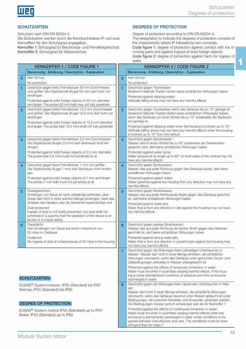
SCHUTZARTEN
Schutzart nach DIN EN 60034-5.Die Schutzarten werden durch die Kennbuchstaben IP und zwei Kennziffern für den Schutzgrad angegeben.Kennziffer 1: Schutzgrad für Berührungs- und FremdkörperschutzKennziffer 2: Schutzgrad für Wasserschutz
DEGREES OF PROTECTION
Degree of protection according to DIN EN 60034-5.The designation to indicate the degrees of protection consists of the characteristic letters IP followed by two numerals.Code figure 1: degree of protection against contact with live or moving parts and against ingress of solid foreign objectsCode figure 2: degree of protection against harm for ingress of water
KENNZIFFER 1 / CODE FIGURE 1 KENNZIFFER 2 / CODE FIGURE 2Benennung - Erklärung / Description - Explanation Benennung - Erklärung / Description - Explanation
0 Kein Schutz
No protection0 Kein Schutz
No protection
1 Geschützt gegen feste Fremdkörper 50 mm Durchmesser und größer: Die Objektsonde (Kugel 50 mm) darf nicht voll eindringen
Protected against solid foreign objects of 50 mm diameter and larger: The probe (50 mm ball) may not fully penetrate
1 Geschützt gegen Tropfwasser:Senkrecht fallende Tropfen dürfen keine schädlichen Wirkungen haben
Protected against dripping water:Vertically falling drops may not have any harmful effects
2 Geschützt gegen feste Fremdkörper 12,5 mm Durchmesser und größer: Die Objektsonde (Kugel 12,5 mm) darf nicht voll eindringen
Protected against solid foreign objects of 12,5 mm diameter and larger: The probe (ball 12,5 mm) shall not fully penetrate
2 Geschützt gegen Tropfwasser wenn das Gehäuse bis zu 15° geneigt ist:Senkrecht fallende Tropfen dürfen keine schädlichen Wirkungen haben, wenn das Gehäuse um einen Winkel bis zu 15° beiderseits der Senkrech-ten geneigt ist
Protected against dripping water when the housing is inclined up to 15°:Vertically falling drops may not have any harmful effects when the housing is inclined up to 15° from the vertical
3 Geschützt gegen feste Fremdkörper 2,5 mm Durchmesser:Die Objektsonde (Kugel 2,5 mm) darf überhaupt nicht ein-dringen
Protected against solid foreign objects of 2,5 mm diameter:The probe (ball 2,5 mm) must not penetrate at all
3 Geschützt gegen Sprühwasser :Wasser, das in einem Winkel bis zu 60° beiderseits der Senkrechten gesprüht wird, darf keine schädlichen Wirkungen haben
Protected against water spray:Water sprayed at an angle up to 60° on both sides of the vertical may not have any harmful effects
4 Geschützt gegen feste Fremdkörper 1 mm und größer:Die Objektsonde (Kugel 1 mm) darf überhaupt nicht eindrin-gen
Protected against solid foreign objects of 1 mm and larger:The probe (1 mm ball) must not penetrate at all
4 Geschützt gegen Spritzwasser:Wasser, das aus jeder Richtung gegen das Gehäuse spritzt, darf keine schädlichen Wirkungen haben
Protected against splash water:Water splashed against the housing from any direction may not have any harmful effects
5 Staubgeschützt:Eindringen von Staub ist nicht vollständig verhindert, aber Staub darf nicht in einer solchen Menge eindringen, dass das Arbeiten des Gerätes oder die Sicherheit beeinträchtigt wird
Dust protected:Ingress of dust is not totally prevented, but dust shall not penetrate in a quantity that the operation of the device is af-fected or to impair safety
5 Geschützt gegen Strahlwasser:Wasser, das aus jeder Richtung als Strahl gegen das Gehäuse gerichtet ist, darf keine schädlichen Wirkungen haben
Protected against water jets:Water that is from any direction in jets against the housing may not have any harmful effects
6 Staubdicht:Kein Eindringen von Staub bei einem Unterdruck von 20 mbar im Gehäuse
Dustproof:No ingress of dust at underpressure of 20 mbar in the housing
6 Geschützt gegen starkes Strahlwasser:Wasser, das aus jeder Richtung als starker Strahl gegen das Gehäuse gerichtet ist, darf keine schädlichen Wirkungen haben
Protected against strong water jets:Water that is from any direction in powerful jets against the housing may not have any harmful effects
SCHUTZARTEN:
EUSAS®-Systemmotoren: IP55 (Standard) bis IP67Bremse: IP55 (Standard) bis IP65
DEGREE OF PROTECTION:
EUSAS®-System motors IP55 (Standard) up to IP67Brake: IP55 (Standard) up to IP65
7 Geschützt gegen die Wirkungen beim zeitweiligen Untertauchen in Wasser: Wasser darf nicht in einer Menge eintreten, die schädliche Wirkungen verursacht, wenn das Gehäuse unter genormten Druck- und Zeitbedingungen zeitweilig im Wasser untergetaucht ist
Protected against the effects of temporary immersion in water:Water must not enter in quantities causing harmful effects, if the hous-ing is under standardized conditions of pressure and time temporarily submerged in water
8 Geschützt gegen die Wirkungen beim dauernden Untertauchen in Was-ser:Wasser darf nicht in einer Menge eintreten, die schädliche Wirkungen verursacht, wenn das Gehäuse dauernd unter Wasser getaucht ist unter Bedingungen, die zwischen Hersteller und Anwender vereinbart werden. Die Bedingungen müssen jedoch schwieriger sein als für Kennziffer 7
Protected against the effects of continuous immersion in water:Water must not enter in quantities causing harmful effects when the enclosure is permanently submerged in water under conditions to be agreed between manufacturer and user. The conditions must be more stringent than for index 7
14Modular System Motor
1
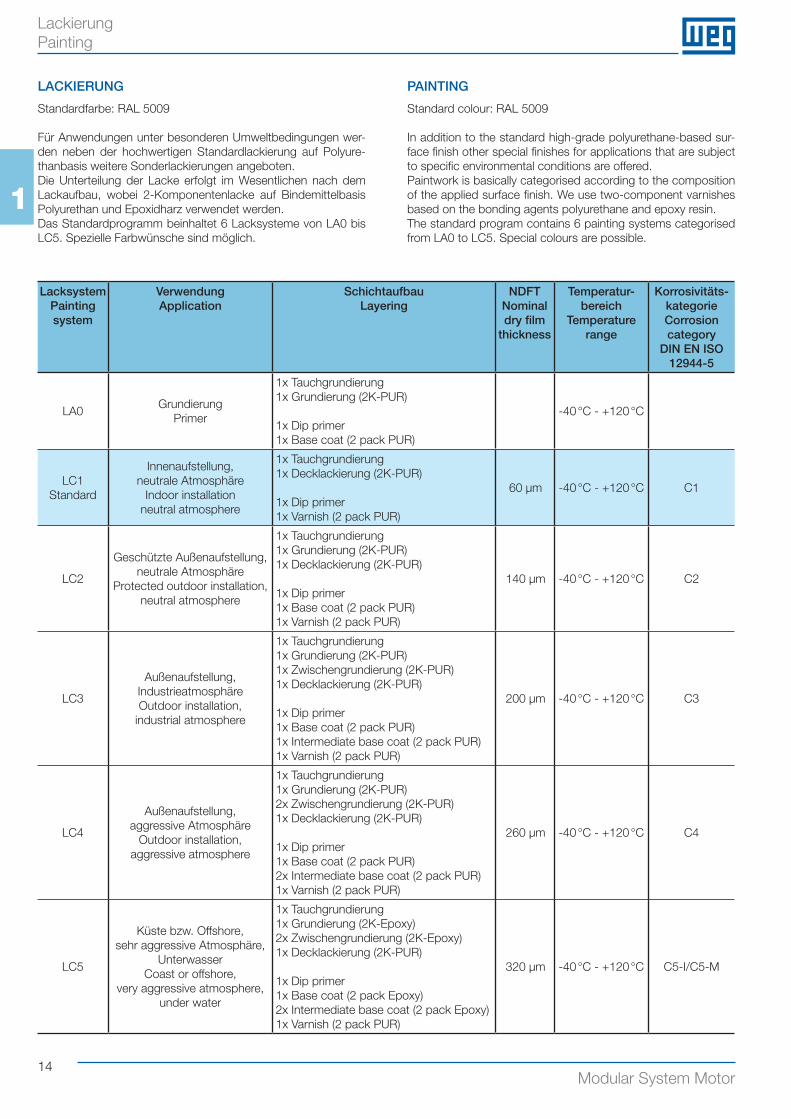
LACKIERUNG
Standardfarbe: RAL 5009
Für Anwendungen unter besonderen Umweltbedingungen wer-den neben der hochwertigen Standardlackierung auf Polyure-thanbasis weitere Sonderlackierungen angeboten.Die Unterteilung der Lacke erfolgt im Wesentlichen nach dem Lackaufbau, wobei 2-Komponentenlacke auf Bindemittelbasis Polyurethan und Epoxidharz verwendet werden.Das Standardprogramm beinhaltet 6 Lacksysteme von LA0 bis LC5. Spezielle Farbwünsche sind möglich.
PAINTING
Standard colour: RAL 5009
In addition to the standard high-grade polyurethane-based sur-face finish other special finishes for applications that are subject to specific environmental conditions are offered.Paintwork is basically categorised according to the composition of the applied surface finish. We use two-component varnishes based on the bonding agents polyurethane and epoxy resin.The standard program contains 6 painting systems categorised from LA0 to LC5. Special colours are possible.
LacksystemPaintingsystem
VerwendungApplication
SchichtaufbauLayering
NDFT Nominal dry film
thickness
Temperatur- bereich
Temperature range
Korrosivitäts-kategorieCorrosion category
DIN EN ISO 12944-5
LA0Grundierung
Primer
1x Tauchgrundierung1x Grundierung (2K-PUR)
1x Dip primer1x Base coat (2 pack PUR)
-40 °C - +120 °C
LC1 Standard
Innenaufstellung,neutrale Atmosphäre
Indoor installationneutral atmosphere
1x Tauchgrundierung1x Decklackierung (2K-PUR)
1x Dip primer1x Varnish (2 pack PUR)
60 μm -40 °C - +120 °C C1
LC2
Geschützte Außenaufstellung,neutrale Atmosphäre
Protected outdoor installation,neutral atmosphere
1x Tauchgrundierung1x Grundierung (2K-PUR)1x Decklackierung (2K-PUR)
1x Dip primer1x Base coat (2 pack PUR)1x Varnish (2 pack PUR)
140 μm -40 °C - +120 °C C2
LC3
Außenaufstellung,IndustrieatmosphäreOutdoor installation,
industrial atmosphere
1x Tauchgrundierung1x Grundierung (2K-PUR)1x Zwischengrundierung (2K-PUR)1x Decklackierung (2K-PUR)
1x Dip primer1x Base coat (2 pack PUR)1x Intermediate base coat (2 pack PUR)1x Varnish (2 pack PUR)
200 μm -40 °C - +120 °C C3
LC4
Außenaufstellung,aggressive Atmosphäre
Outdoor installation,aggressive atmosphere
1x Tauchgrundierung1x Grundierung (2K-PUR)2x Zwischengrundierung (2K-PUR)1x Decklackierung (2K-PUR)
1x Dip primer1x Base coat (2 pack PUR)2x Intermediate base coat (2 pack PUR)1x Varnish (2 pack PUR)
260 μm -40 °C - +120 °C C4
LC5
Küste bzw. Offshore, sehr aggressive Atmosphäre,
UnterwasserCoast or offshore,
very aggressive atmosphere,under water
1x Tauchgrundierung1x Grundierung (2K-Epoxy)2x Zwischengrundierung (2K-Epoxy)1x Decklackierung (2K-PUR)
1x Dip primer1x Base coat (2 pack Epoxy)2x Intermediate base coat (2 pack Epoxy)1x Varnish (2 pack PUR)
320 μm -40 °C - +120 °C C5-I/C5-M
Lackierung Painting
15Modular System Motor
1
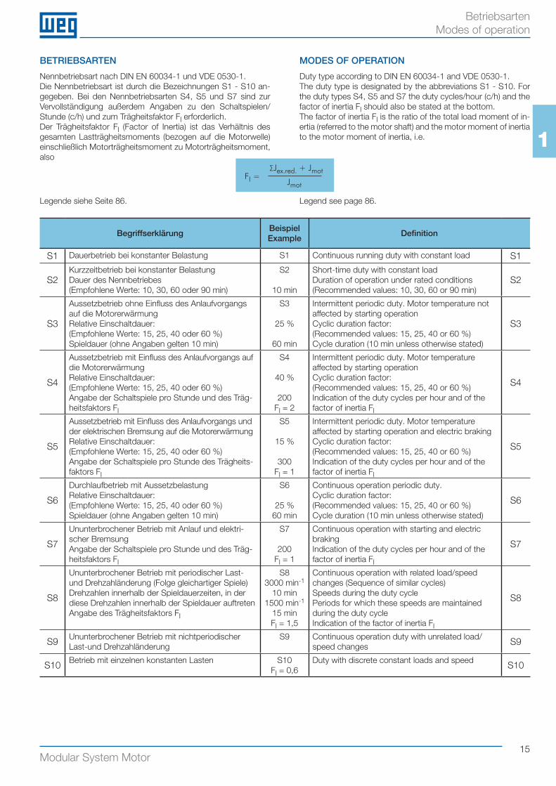
BETRIEBSARTEN
Nennbetriebsart nach DIN EN 60034-1 und VDE 0530-1.Die Nennbetriebsart ist durch die Bezeichnungen S1 - S10 an-gegeben. Bei den Nennbetriebsarten S4, S5 und S7 sind zur Vervollständigung außerdem Angaben zu den Schaltspielen/Stunde (c/h) und zum Trägheitsfaktor Fl erforderlich.Der Trägheitsfaktor Fl (Factor of Inertia) ist das Verhältnis des gesamten Lastträgheitsmoments (bezogen auf die Motorwelle) einschließlich Motorträgheitsmoment zu Motorträgheitsmoment, also
MODES OF OPERATION
Duty type according to DIN EN 60034-1 and VDE 0530-1.The duty type is designated by the abbreviations S1 - S10. For the duty types S4, S5 and S7 the duty cycles/hour (c/h) and the factor of inertia Fl should also be stated at the bottom.The factor of inertia Fl is the ratio of the total load moment of in-ertia (referred to the motor shaft) and the motor moment of inertia to the motor moment of inertia, i.e.
BegriffserklärungBeispielExample
Definition
S1 Dauerbetrieb bei konstanter Belastung S1 Continuous running duty with constant load S1
S2Kurzzeitbetrieb bei konstanter BelastungDauer des Nennbetriebes(Empfohlene Werte: 10, 30, 60 oder 90 min)
S2
10 min
Short-time duty with constant loadDuration of operation under rated conditions(Recommended values: 10, 30, 60 or 90 min)
S2
S3
Aussetzbetrieb ohne Einfluss des Anlaufvorgangs auf die MotorerwärmungRelative Einschaltdauer:(Empfohlene Werte: 15, 25, 40 oder 60 %)Spieldauer (ohne Angaben gelten 10 min)
S3
25 %
60 min
Intermittent periodic duty. Motor temperature not affected by starting operationCyclic duration factor:(Recommended values: 15, 25, 40 or 60 %)Cycle duration (10 min unless otherwise stated)
S3
S4
Aussetzbetrieb mit Einfluss des Anlaufvorgangs auf die MotorerwärmungRelative Einschaltdauer:(Empfohlene Werte: 15, 25, 40 oder 60 %)Angabe der Schaltspiele pro Stunde und des Träg-heitsfaktors Fl
S4
40 %
200Fl = 2
Intermittent periodic duty. Motor temperature affected by starting operationCyclic duration factor:(Recommended values: 15, 25, 40 or 60 %)Indication of the duty cycles per hour and of the factor of inertia Fl
S4
S5
Aussetzbetrieb mit Einfluss des Anlaufvorgangs und der elektrischen Bremsung auf die MotorerwärmungRelative Einschaltdauer:(Empfohlene Werte: 15, 25, 40 oder 60 %)Angabe der Schaltspiele pro Stunde des Trägheits-faktors Fl
S5
15 %
300Fl = 1
Intermittent periodic duty. Motor temperature affected by starting operation and electric braking Cyclic duration factor:(Recommended values: 15, 25, 40 or 60 %)Indication of the duty cycles per hour and of the factor of inertia Fl
S5
S6
Durchlaufbetrieb mit AussetzbelastungRelative Einschaltdauer:(Empfohlene Werte: 15, 25, 40 oder 60 %)Spieldauer (ohne Angaben gelten 10 min)
S6
25 %60 min
Continuous operation periodic duty.Cyclic duration factor: (Recommended values: 15, 25, 40 or 60 %)Cycle duration (10 min unless otherwise stated)
S6
S7
Ununterbrochener Betrieb mit Anlauf und elektri-scher BremsungAngabe der Schaltspiele pro Stunde und des Träg-heitsfaktors Fl
S7
200Fl = 1
Continuous operation with starting and electric brakingIndication of the duty cycles per hour and of the factor of inertia Fl
S7
S8
Ununterbrochener Betrieb mit periodischer Last- und Drehzahländerung (Folge gleichartiger Spiele)Drehzahlen innerhalb der Spieldauerzeiten, in der diese Drehzahlen innerhalb der Spieldauer auftretenAngabe des Trägheitsfaktors FI
S83000 min-1
10 min1500 min-1
15 minFl = 1,5
Continuous operation with related load/speed changes (Sequence of similar cycles)Speeds during the duty cyclePeriods for which these speeds are maintained during the duty cycleIndication of the factor of inertia Fl
S8
S9 Ununterbrochener Betrieb mit nichtperiodischer Last-und Drehzahländerung
S9 Continuous operation duty with unrelated load/speed changes S9
S10 Betrieb mit einzelnen konstanten Lasten S10Fl = 0,6
Duty with discrete constant loads and speed S10
Legende siehe Seite 86. Legend see page 86.
FI = Jmot
Jex.red. + Jmot ∑
Betriebsarten Modes of operation
16Modular System Motor
1
BEMESSUNGSLEISTUNG NACH VDE 0530-1
Die angegebene Bemessungsleistung (Nennleistung) entspricht der Abgabeleistung nach VDE 0530-1 für Dauerbetrieb S1, Fre-quenz 50 / 60 Hz, max. Umgebungstemperatur +40 °C, max. Aufstellungshöhe 1000 m über NN.Die Motoren können nach dieser Norm bei Bemessungswer-ten (Spannung und Frequenz) im betriebswarmen Zustand zwei Minuten mit dem 1,5-fachen Nennstrom belastet werden, ohne Schädigung der Wicklung.Die Motoren sind bei den Bemessungsdaten berechnet nach Wärmeklasse B, aber gefertigt nach Klasse F und deshalb bei Betrieb mit den Bemessungsdaten höher belastbar:
a. Bei Bemessungsleistung und Bemessungsspannung kann die Umgebungstemperatur von +40 °C auf +60 °C erhöht werden.
b. Wenn +40 °C nicht überschritten werden, kann bei gleich-mäßigem Betrieb die Bemessungsleistung um ca. 10 % gesteigert werden.
Die angegebenen technischen Daten gelten für 50 Hz Netzspan-nung und 400 V Bemessungsspannung bei Nennbelastung. Bei Laständerung weichen die angegebenen Werte nach oben oder nach unten ab.
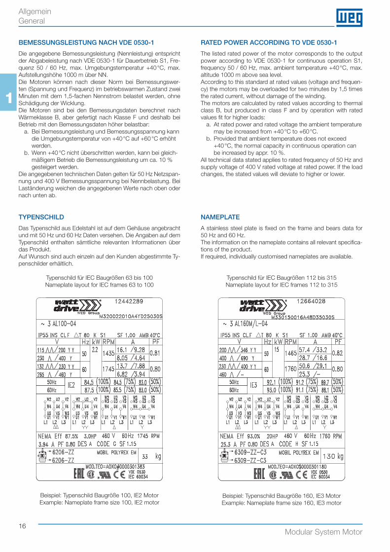
TYPENSCHILD
Das Typenschild aus Edelstahl ist auf dem Gehäuse angebracht und mit 50 Hz und 60 Hz Daten versehen. Die Angaben auf dem Typenschild enthalten sämtliche relevanten Informationen über das Produkt.Auf Wunsch sind auch einzeln auf den Kunden abgestimmte Ty-penschilder erhältlich.
Typenschild für IEC Baugrößen 63 bis 100Nameplate layout for IEC frames 63 to 100
RATED POWER ACCORDING TO VDE 0530-1
The listed rated power of the motor corresponds to the output power according to VDE 0530-1 for continuous operation S1, frequency 50 / 60 Hz, max. ambient temperature +40 °C, max. altitude 1000 m above sea level.According to this standard at rated values (voltage and frequen-cy) the motors may be overloaded for two minutes by 1,5 times the rated current, without damage of the winding.The motors are calculated by rated values according to thermal class B, but produced in class F and by operation with rated values fit for higher loads:
a. At rated power and rated voltage the ambient temperature may be increased from +40 °C to +60 °C.
b. Provided that ambient temperature does not exceed +40 °C, the normal capacity in continuous operation can be increased by appr. 10 %.
All technical data stated applies to rated frequency of 50 Hz and supply voltage of 400 V rated voltage at rated power. If the load changes, the stated values will deviate to higher or lower.
NAMEPLATE
A stainless steel plate is fixed on the frame and bears data for 50 Hz and 60 Hz.The information on the nameplate contains all relevant specifica-tions of the product.If required, individually customised nameplates are available.
Typenschild für IEC Baugrößen 112 bis 315Nameplate layout for IEC frames 112 to 315
Allgemein General
Beispiel: Typenschild Baugröße 100, IE2 Motor Example: Nameplate frame size 100, IE2 motor
Beispiel: Typenschild Baugröße 160, IE3 Motor Example: Nameplate frame size 160, IE3 motor
17Modular System Motor
1
DREHMOMENT
Die Motoren haben einen zum direkten Anlauf geeigneten Kä-figläufer. Die Werte des Anlaufmoments und des Kippmoments sind den Tabellen der Betriebsdaten zu entnehmen (als Viel- faches des Bemessungsmomentes).Eine Abweichung von der Nennversorgungsspannung führt zu einer Variation des Drehmomentes, die proportional zum Quad-rat der Spannungen ist.
WIRKUNGSGRAD
Durch die Norm IEC 60034-30 gelten einheitliche Wirkungsgrad-klassen für 2-, 4-, 6- und 8-polige Asynchronmotoren (50/60 Hz) mit Ausgangsleistungen von 0,12 kW bis 1.000 kW. Diese Norm unterteilt 3-Phasen Asynchronmotoren mit Käfigläufer in die Wir-kungsgradklassen IE1=Standard Efficiency, IE2=High Efficiency und IE3=Premium Efficiency. Unsere Motoren sind am Typen-schild mit Wirkungsgradklasse und Wirkungsgrad gekennzeich-net (Beispiel: IE2-84,5 %).
MOTORSCHUTZ
Die Verwendung der richtigen Schutzeinrichtungen beeinflusst wesentlich die Betriebssicherheit und Lebensdauer der Antrie-be. Strom- und motortemperaturabhängige Schutzeinrichtun-gen stehen zur Wahl.Schmelzsicherungen schützen den Motor nicht vor Überlastung, sondern lediglich die Netzzuleitungen oder Schaltanlagen bei Kurzschluss.
MOTORSCHUTZSCHALTER (MOTORSCHUTZRELAIS)
Bei stromabhängigem Motorschutz muss der Schutzschalter auf den am Typenschild angegebenen Bemessungsstrom eingestellt werden.Motortemperaturabhängige Schutzvorrichtungen (Temperatur-fühler in Wicklung) siehe Seite 66.
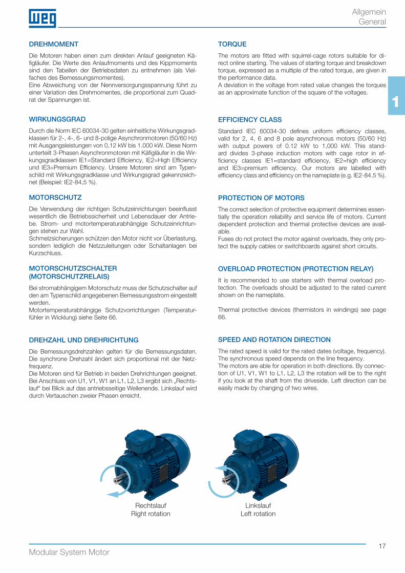
DREHZAHL UND DREHRICHTUNG
Die Bemessungsdrehzahlen gelten für die Bemessungsdaten. Die synchrone Drehzahl ändert sich proportional mit der Netz-frequenz.Die Motoren sind für Betrieb in beiden Drehrichtungen geeignet. Bei Anschluss von U1, V1, W1 an L1, L2, L3 ergibt sich „Rechts-lauf“ bei Blick auf das antriebsseitige Wellenende. Linkslauf wird durch Vertauschen zweier Phasen erreicht.
TORQUE
The motors are fitted with squirrel-cage rotors suitable for di-rect online starting. The values of starting torque and breakdown torque, expressed as a multiple of the rated torque, are given in the performance data.A deviation in the voltage from rated value changes the torques as an approximate function of the square of the voltages.
EFFICIENCY CLASS
Standard IEC 60034-30 defines uniform efficiency classes, valid for 2, 4, 6 and 8 pole asynchronous motors (50/60 Hz) with output powers of 0.12 kW to 1,000 kW. This stand-ard divides 3-phase induction motors with cage rotor in ef-ficiency classes IE1=standard efficiency, IE2=high efficiency and IE3=premium efficiency. Our motors are labelled with efficiency class and efficiency on the nameplate (e.g. IE2-84.5 %).
PROTECTION OF MOTORS
The correct selection of protective equipment determines essen-tially the operation reliability and service life of motors. Current dependent protection and thermal protective devices are avail-able.Fuses do not protect the motor against overloads, they only pro-tect the supply cables or switchboards against short circuits.
OVERLOAD PROTECTION (PROTECTION RELAY)
It is recommended to use starters with thermal overload pro-tection. The overloads should be adjusted to the rated current shown on the nameplate.
Thermal protective devices (thermistors in windings) see page 66.
SPEED AND ROTATION DIRECTION
The rated speed is valid for the rated dates (voltage, frequency). The synchronous speed depends on the line frequency.The motors are able for operation in both directions. By connec-tion of U1, V1, W1 to L1, L2, L3 the rotation will be to the right if you look at the shaft from the driveside. Left direction can be easily made by changing of two wires.
RechtslaufRight rotation
LinkslaufLeft rotation
Allgemein General
18Modular System Motor
1
KÜHLUNG
Die Motoren werden mit Eigenbelüftung (TEFC) gekühlt (IEC 60034-6; Kühlart IC411). Maximale Umgebungstemperatur +40 °C.
Bei Inbetriebnahme des Motors ist zu beachten, dass der Min-destabstand „Y“ (siehe Maßbilder ab Seite 53) von der Lüfter-haube zur Wand eingehalten wird.
• Eigenlüfter (TEFC, IC411)
Bei der Konstruktion des Lüfterflügels wurde besonderer Wert darauf gelegt, den Geräuschpegel so niedrig wie möglich zu hal-ten und die Leistung zu verbessern. Es handelt sich um einen drehrichtungsunabhängigen Radiallüfter.
COOLING
The motors are totally enclosed fan cooled (TEFC) by means of external surface ventilation (IC411), as per IEC 60034-6). Maxi-mum ambient temperature +40 °C.
Please check the minimum distance “Y” (see dimension sheets from page 53) between cover and wall by mounting the motor.
• Integral fans (TEFC, IC411)
Particular attention has been dedicated to the shape in order to reduce noise and improve the efficiency of the motor. Radial con-struction has been selected to allow rotation in both directions.
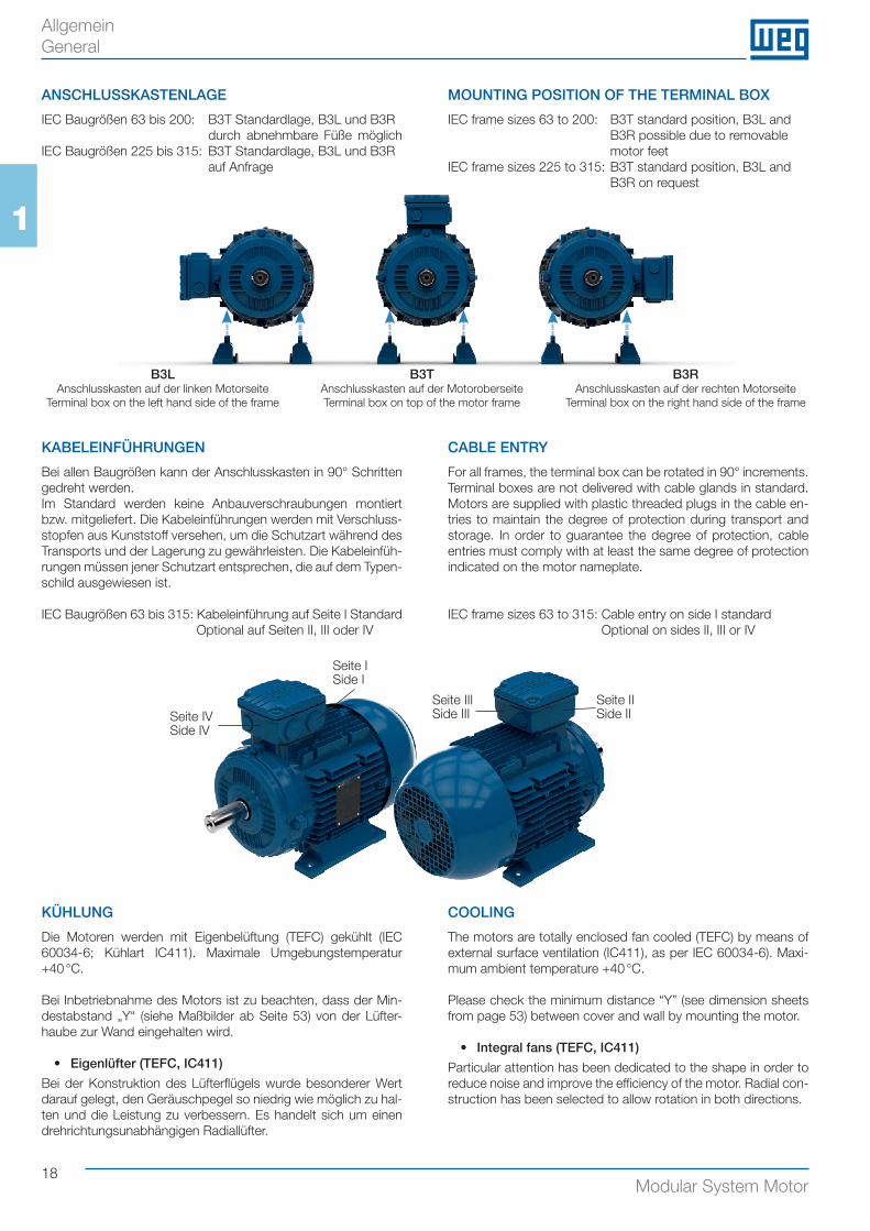
ANSCHLUSSKASTENLAGE
IEC Baugrößen 63 bis 200: B3T Standardlage, B3L und B3R durch abnehmbare Füße möglich IEC Baugrößen 225 bis 315: B3T Standardlage, B3L und B3R auf Anfrage
MOUNTING POSITION OF THE TERMINAL BOX
IEC frame sizes 63 to 200: B3T standard position, B3L and B3R possible due to removable motor feetIEC frame sizes 225 to 315: B3T standard position, B3L and B3R on request
AllgemeinGeneral
KABELEINFÜHRUNGEN
Bei allen Baugrößen kann der Anschlusskasten in 90° Schritten gedreht werden.Im Standard werden keine Anbauverschraubungen montiert bzw. mitgeliefert. Die Kabeleinführungen werden mit Verschluss-stopfen aus Kunststoff versehen, um die Schutzart während des Transports und der Lagerung zu gewährleisten. Die Kabeleinfüh-rungen müssen jener Schutzart entsprechen, die auf dem Typen-schild ausgewiesen ist.
IEC Baugrößen 63 bis 315: Kabeleinführung auf Seite I StandardOptional auf Seiten II, III oder IV
CABLE ENTRY
For all frames, the terminal box can be rotated in 90° increments. Terminal boxes are not delivered with cable glands in standard. Motors are supplied with plastic threaded plugs in the cable en-tries to maintain the degree of protection during transport and storage. In order to guarantee the degree of protection, cable entries must comply with at least the same degree of protection indicated on the motor nameplate.
IEC frame sizes 63 to 315: Cable entry on side I standardOptional on sides II, III or IV
B3T Anschlusskasten auf der MotoroberseiteTerminal box on top of the motor frame
B3L Anschlusskasten auf der linken Motorseite
Terminal box on the left hand side of the frame
B3R Anschlusskasten auf der rechten Motorseite
Terminal box on the right hand side of the frame
Seite ISide I
Seite IISide II
Seite IIISide IIISeite IV
Side IV
19Modular System Motor
1
• Lüfterhaube
Aus behandeltem Stahlblech und so konstruiert, dass die Leis-tung optimiert und die durch den Lüfter verursachte Geräusch-belastung minimiert wird.
• Fremdlüfter (TEFV, IC416)
Für besondere Betriebsbedingungen z. B. erhöhte Schalthäufig-keit oder Regelbetrieb, können die Motoren der IEC Baugrößen 63 bis 315 mit Fremdbelüftung durch zusätzlich angebaute Lüf-termotoren geliefert werden.
ISOLIERUNGEN
Die Motoren dieses Katalogs erfüllen die Forderungen der Wär-meklasse F. Ausnahme: Motorbaugröße 315 (4p, 200 kW) nach Wärmeklasse H.Alle Wicklungen erhalten durch Lackimprägnierung hohe me-chanische Festigkeit.Die höchstzulässige Dauertemperatur der verwendeten Isolier-stoffe und Tränkmittel liegt bei der Grenzübertemperatur, gemäß Wärmeklasse F, von +155 °C.Die Motoren werden jedoch bei den Bemessungswerten nur ge-mäß Wärmeklasse B ausgenutzt. Die Grenzübertemperatur wird also mit reichlichem Sicherheits-zuschlag eingehalten, was ein hohes Überlastungsvermögen bedeutet.
WERKSTOFFE
• Gehäuse und Anschlusskasten:
Gehäuse der IEC Baugrößen:- 63 bis 200: Aluminium- 225 bis 315: Grauguss
Anschlusskasten aller Größen aus Grauguss gefertigt.
• Lagerschilder:
Alle Baugrößen in Grauguss
• Lüfterhaube:
IEC Baugrößen 63 bis 315: Stahlblech
• Lüfterflügel:
IEC Baugrößen 63 bis 250: KunststoffIEC Baugrößen 280 bis 315: MetallLüfter aus Metall sind ab Baugröße 71 optional erhältlich.
• Wicklung:
Es wird Isoliermaterial der Klasse F verwendet. Motoren aus die-sen Werkstoffen können auch in tropischem Klima verwendet werden. Auf Wunsch können zusätzliche Behandlungen für den Einsatz in besonders feuchten und/oder korrodierenden Anwen-dungen vorgenommen werden. Um eine längere Lebensdauer und zeitweilige Überlastungen zu ermöglichen, liegt die Über-temperatur bei den Bemessungswerten innerhalb der Grenzen der Klasse B.
• Läufer:
Es handelt sich um einen Käfigläufer aus Aluminium-Druckguss, der zum direkten Anlauf geeignet ist.
• Wellenmaterial:
IEC Baugrößen 63 bis 280: SAE 1040/45 StahlIEC Baugröße 315: AISI 4140 Stahl
• Fan cover
In treated steel plate, properly profiled to improve efficiency and reduce the noise produced by the fan.
• Forced ventilation (TEFV, IC416)
For special operating conditions, e.g. increased permissible number of operations per hour or variable-speed operation, the motors of IEC sizes 63 to 315 can be supplied with forced venti-lation by means of a separately fitted fan motor.
INSULATION
The motors in this catalogue comply with the requirements of thermal class F. Exception: frame size 315 (4p, 200 kW) accord-ing to thermal class H.All windings are impregnated with varnish with a high mechanical strength.The maximum temperature of the insulation is, according to ther-mal class F, at +155 °C.The motors are utilized at rated values according to thermal class B.Copper wire insulation and the impregnation varnish have a tem-perature index class F and therefore there is a large margin of safety in addition to high overload capacity.
MATERIALS
• Frame and terminal box:
Frame of IEC sizes:- 63 to 200: aluminium- 225 to 315: grey cast iron
Terminal boxes of all sizes are produced of cast iron.
• End-shields:
All frame sizes in grey cast iron
• Fan cover:
IEC frame sizes 63 to 315: steel plate
• Fan:
IEC frame sizes 63 to 250: plasticIEC frame sizes 280 to 315: metalFans of metal are optionally available from frame size 71.
• Stator winding:
Class F insulation material is used. The choice of materials and the type of impregnation allows these motors to be used in tropi-cal climates. Motors can be given additional treatment for par-ticularly corrosive or humid environments, on request.In order to guarantee the possibility of continuous overload and to increase the life of the insulation system, temperature rises are lower than those prescribed by standards and are kept by rated values within class B limits.
• Rotor:
The motor rotors have a squirrel-cage design and are suitable for direct-online starting. The rotor cages are in aluminium die cast.
• Shaft material:
IEC frame sizes 63 to 280: SAE 1040/45 steelIEC frame size 315: AISI 4140 steel
Allgemein General
20Modular System Motor
1
DICHTRING
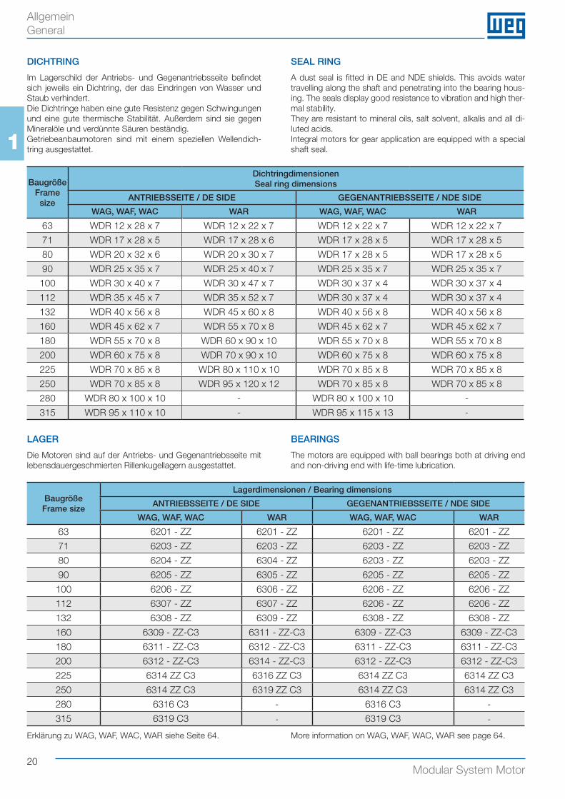
Im Lagerschild der Antriebs- und Gegenantriebsseite befindet sich jeweils ein Dichtring, der das Eindringen von Wasser und Staub verhindert.Die Dichtringe haben eine gute Resistenz gegen Schwingungen und eine gute thermische Stabilität. Außerdem sind sie gegen Mineralöle und verdünnte Säuren beständig. Getriebeanbaumotoren sind mit einem speziellen Wellendich-tring ausgestattet.
SEAL RING
A dust seal is fitted in DE and NDE shields. This avoids water travelling along the shaft and penetrating into the bearing hous-ing. The seals display good resistance to vibration and high ther-mal stability. They are resistant to mineral oils, salt solvent, alkalis and all di-luted acids.Integral motors for gear application are equipped with a special shaft seal.
Baugröße Frame size
DichtringdimensionenSeal ring dimensions
ANTRIEBSSEITE / DE SIDE GEGENANTRIEBSSEITE / NDE SIDE
WAG, WAF, WAC WAR WAG, WAF, WAC WAR
63 WDR 12 x 28 x 7 WDR 12 x 22 x 7 WDR 12 x 22 x 7 WDR 12 x 22 x 7
71 WDR 17 x 28 x 5 WDR 17 x 28 x 6 WDR 17 x 28 x 5 WDR 17 x 28 x 5
80 WDR 20 x 32 x 6 WDR 20 x 30 x 7 WDR 17 x 28 x 5 WDR 17 x 28 x 5
90 WDR 25 x 35 x 7 WDR 25 x 40 x 7 WDR 25 x 35 x 7 WDR 25 x 35 x 7
100 WDR 30 x 40 x 7 WDR 30 x 47 x 7 WDR 30 x 37 x 4 WDR 30 x 37 x 4
112 WDR 35 x 45 x 7 WDR 35 x 52 x 7 WDR 30 x 37 x 4 WDR 30 x 37 x 4
132 WDR 40 x 56 x 8 WDR 45 x 60 x 8 WDR 40 x 56 x 8 WDR 40 x 56 x 8
160 WDR 45 x 62 x 7 WDR 55 x 70 x 8 WDR 45 x 62 x 7 WDR 45 x 62 x 7
180 WDR 55 x 70 x 8 WDR 60 x 90 x 10 WDR 55 x 70 x 8 WDR 55 x 70 x 8
200 WDR 60 x 75 x 8 WDR 70 x 90 x 10 WDR 60 x 75 x 8 WDR 60 x 75 x 8
225 WDR 70 x 85 x 8 WDR 80 x 110 x 10 WDR 70 x 85 x 8 WDR 70 x 85 x 8
250 WDR 70 x 85 x 8 WDR 95 x 120 x 12 WDR 70 x 85 x 8 WDR 70 x 85 x 8
280 WDR 80 x 100 x 10 - WDR 80 x 100 x 10 -
315 WDR 95 x 110 x 10 - WDR 95 x 115 x 13 -
LAGER
Die Motoren sind auf der Antriebs- und Gegenantriebsseite mit lebensdauergeschmierten Rillenkugellagern ausgestattet.
BEARINGS
The motors are equipped with ball bearings both at driving end and non-driving end with life-time lubrication.
BaugrößeFrame size
Lagerdimensionen / Bearing dimensions
ANTRIEBSSEITE / DE SIDE GEGENANTRIEBSSEITE / NDE SIDE
WAG, WAF, WAC WAR WAG, WAF, WAC WAR
63 6201 - ZZ 6201 - ZZ 6201 - ZZ 6201 - ZZ
71 6203 - ZZ 6203 - ZZ 6203 - ZZ 6203 - ZZ
80 6204 - ZZ 6304 - ZZ 6203 - ZZ 6203 - ZZ
90 6205 - ZZ 6305 - ZZ 6205 - ZZ 6205 - ZZ
100 6206 - ZZ 6306 - ZZ 6206 - ZZ 6206 - ZZ
112 6307 - ZZ 6307 - ZZ 6206 - ZZ 6206 - ZZ
132 6308 - ZZ 6309 - ZZ 6308 - ZZ 6308 - ZZ
160 6309 - ZZ-C3 6311 - ZZ-C3 6309 - ZZ-C3 6309 - ZZ-C3
180 6311 - ZZ-C3 6312 - ZZ-C3 6311 - ZZ-C3 6311 - ZZ-C3
200 6312 - ZZ-C3 6314 - ZZ-C3 6312 - ZZ-C3 6312 - ZZ-C3
225 6314 ZZ C3 6316 ZZ C3 6314 ZZ C3 6314 ZZ C3
250 6314 ZZ C3 6319 ZZ C3 6314 ZZ C3 6314 ZZ C3
280 6316 C3 - 6316 C3 -
315 6319 C3 - 6319 C3 -
Allgemein General
Erklärung zu WAG, WAF, WAC, WAR siehe Seite 64. More information on WAG, WAF, WAC, WAR see page 64.
21Modular System Motor
1
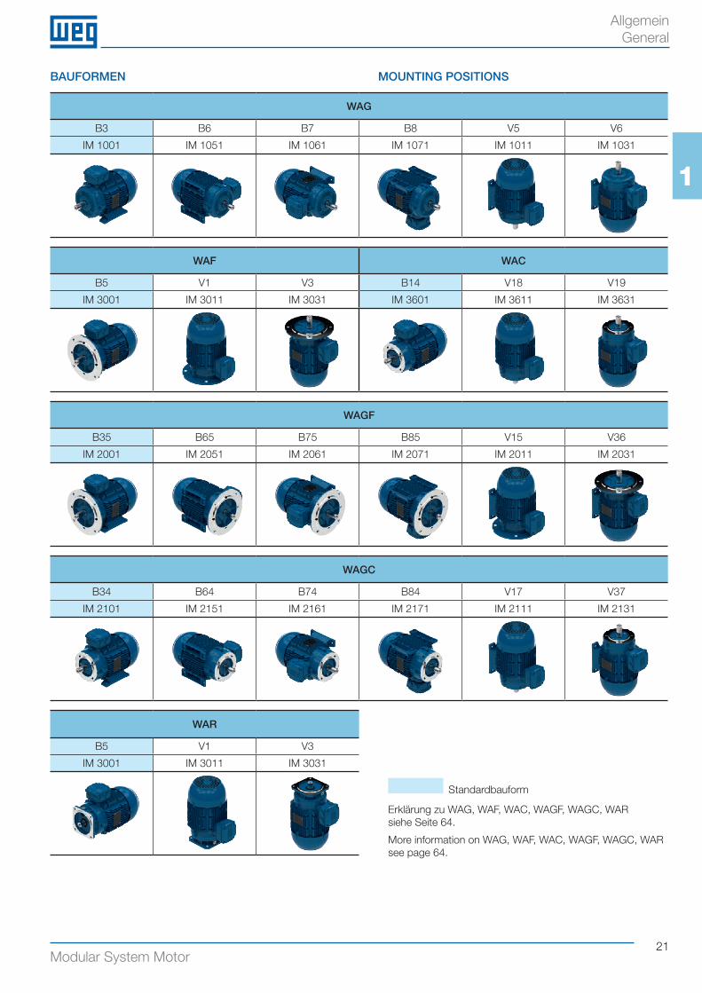
BAUFORMEN MOUNTING POSITIONS
WAG
B3 B6 B7 B8 V5 V6
IM 1001 IM 1051 IM 1061 IM 1071 IM 1011 IM 1031
WAF WAC
B5 V1 V3 B14 V18 V19
IM 3001 IM 3011 IM 3031 IM 3601 IM 3611 IM 3631
WAGF
B35 B65 B75 B85 V15 V36
IM 2001 IM 2051 IM 2061 IM 2071 IM 2011 IM 2031
WAGC
B34 B64 B74 B84 V17 V37
IM 2101 IM 2151 IM 2161 IM 2171 IM 2111 IM 2131
WAR
B5 V1 V3
IM 3001 IM 3011 IM 3031
Allgemein General
Erklärung zu WAG, WAF, WAC, WAGF, WAGC, WARsiehe Seite 64.
More information on WAG, WAF, WAC, WAGF, WAGC, WARsee page 64.
Standardbauform
22Modular System Motor
1
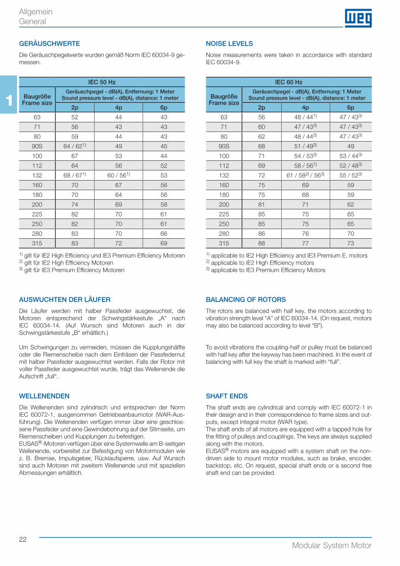
GERÄUSCHWERTE
Die Geräuschpegelwerte wurden gemäß Norm IEC 60034-9 ge-messen.
NOISE LEVELS
Noise measurements were taken in accordance with standard IEC 60034-9.
IEC 50 Hz
BaugrößeFrame size
Geräuschpegel - dB(A), Entfernung: 1 MeterSound pressure level - dB(A), distance: 1 meter
2p 4p 6p
63 52 44 43
71 56 43 43
80 59 44 43
90S 64 / 621) 49 45
100 67 53 44
112 64 56 52
132 68 / 671) 60 / 561) 53
160 70 67 56
180 70 64 56
200 74 69 58
225 82 70 61
250 82 70 61
280 83 70 66
315 83 72 69
IEC 60 Hz
BaugrößeFrame size
Geräuschpegel - dB(A), Entfernung: 1 MeterSound pressure level - dB(A), distance: 1 meter
2p 4p 6p
63 56 48 / 441) 47 / 433)
71 60 47 / 433) 47 / 433)
80 62 48 / 443) 47 / 433)
90S 68 51 / 493) 49
100 71 54 / 533) 53 / 443)
112 69 58 / 561) 52 / 483)
132 72 61 / 582) / 563) 55 / 523)
160 75 69 59
180 75 68 59
200 81 71 62
225 85 75 65
250 85 75 65
280 86 76 70
315 88 77 73
1) giIt für IE2 High Efficiency und IE3 Premium Efficiency Motoren2) gilt für IE2 High Efficiency Motoren3) gilt für IE3 Premium Efficiency Motoren
1) applicable to IE2 High Efficiency and IE3 Premium E. motors2) applicable to IE2 High Efficiency motors3) applicable to IE3 Premium Efficiency Motors
AUSWUCHTEN DER LÄUFER
Die Läufer werden mit halber Passfeder ausgewuchtet, die Motoren entsprechend der Schwingstärkestufe „A“ nach IEC 60034-14. (Auf Wunsch sind Motoren auch in der Schwingstärkestufe „B“ erhältlich.)
Um Schwingungen zu vermeiden, müssen die Kupplungshälfte oder die Riemenscheibe nach dem Einfräsen der Passfedernut mit halber Passfeder ausgewuchtet werden. Falls der Rotor mit voller Passfeder ausgewuchtet wurde, trägt das Wellenende die Aufschrift „full“.
WELLENENDEN
Die Wellenenden sind zylindrisch und entsprechen der Norm IEC 60072-1, ausgenommen Getriebeanbaumotor (WAR-Aus-führung). Die Wellenenden verfügen immer über eine geschlos-sene Passfeder und eine Gewindebohrung auf der Stirnseite, um Riemenscheiben und Kupplungen zu befestigen.EUSAS®-Motoren verfügen über eine Systemwelle am B-seitigen Wellenende, vorbereitet zur Befestigung von Motormodulen wie z. B. Bremse, Impulsgeber, Rücklaufsperre, usw. Auf Wunsch sind auch Motoren mit zweitem Wellenende und mit speziellen Abmessungen erhältlich.
BALANCING OF ROTORS
The rotors are balanced with half key, the motors according to vibration strength level “A” of IEC 60034-14. (On request, motors may also be balanced according to level “B”).
To avoid vibrations the coupling-half or pulley must be balanced with half key after the keyway has been machined. In the event of balancing with full key the shaft is marked with “full”.
SHAFT ENDS
The shaft ends are cylindrical and comply with IEC 60072-1 in their design and in their correspondence to frame sizes and out-puts, except integral motor (WAR type).The shaft ends of all motors are equipped with a tapped hole for the fitting of pulleys and couplings. The keys are always supplied along with the motors.EUSAS® motors are equipped with a system shaft on the non-driven side to mount motor modules, such as brake, encoder, backstop, etc. On request, special shaft ends or a second free shaft end can be provided.
Allgemein General
23Modular System Motor
1Maximal zulässige radiale Belastung / Maximum permissible radial load (Fr in kN)
Bau-größeFrame size
20.000 h, 50 Hz (WAG, WAF, WAC) 40.000 h, 50 Hz (WAG, WAF, WAC)
2 Pole / 2 poles 4 Pole / 4 poles 6 Pole / 6 poles 2 Pole / 2 poles 4 Pole / 4 poles 6 Pole / 6 poles
L L/2 L L/2 L L/2 L L/2 L L/2 L L/2
63 0,3 0,4 0,3 0,4 0,3 0,4 0,2 0,2 0,3 0,3 0,3 0,4
71 0,4 0,5 0,5 0,6 0,5 0,6 0,3 0,3 0,4 0,4 0,4 0,5
80 0,6 0,6 0,7 0,7 0,7 0,8 0,5 0,5 0,5 0,5 0,6 0,6
90 0,6 0,7 0,7 0,7 0,8 0,9 0,5 0,5 0,5 0,5 0,6 0,7
100 0,8 0,9 0,9 1,0 1,1 1,2 0,6 0,7 0,6 0,7 0,8 0,9
112 1,5 1,7 1,8 2,0 1,8 2,3 1,2 1,3 1,3 1,5 1,5 1,7
132 2,0 2,2 2,3 2,4 2,6 2,8 1,6 1,7 1,7 1,8 2,0 2,1
160 2,3 2,5 2,5 2,8 2,7 3,2 1,7 1,9 1,8 2,0 2,1 2,4
180 2,9 3,2 3,3 3,6 3,8 4,2 2,1 2,3 2,3 2,6 2,7 3,0
200 3,6 4,0 4,0 4,4 4,8 5,3 2,7 3,0 2,9 3,2 3,6 3,9
225 4,7 5,1 5,1 5,7 5,7 6,8 3,5 3,8 3,7 4,1 4,5 5,0
250 4,5 5,0 5,0 5,5 6,0 6,6 3,4 3,7 3,6 3,9 4,3 4,8
280 5,2 5,7 5,4 5,9 7,1 7,7 3,9 4,2 3,7 4,0 5,1 5,6
315 - - 6,0 6,5 7,1 7,7 - - 3,9 4,2 4,7 5,1
Fr
Fa
L
Allgemein General
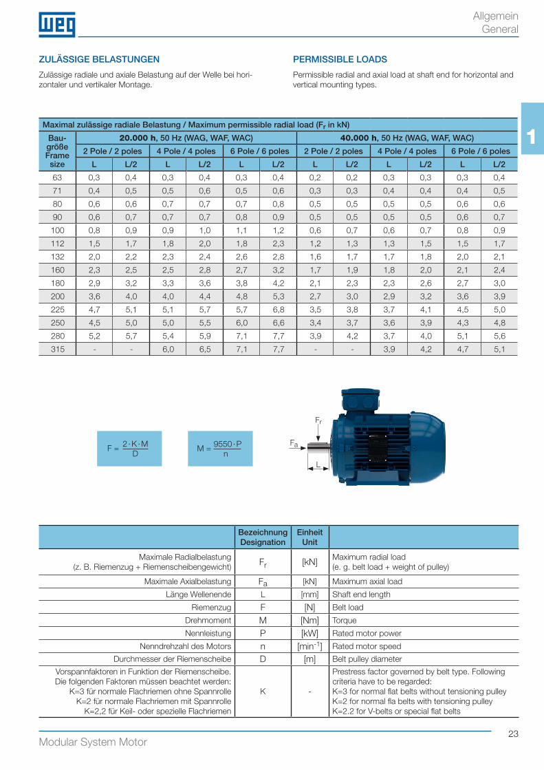
ZULÄSSIGE BELASTUNGEN
Zulässige radiale und axiale Belastung auf der Welle bei hori-zontaler und vertikaler Montage.
PERMISSIBLE LOADS
Permissible radial and axial load at shaft end for horizontal and vertical mounting types.
BezeichnungDesignation
EinheitUnit
Maximale Radialbelastung (z. B. Riemenzug + Riemenscheibengewicht) Fr [kN] Maximum radial load
(e. g. belt load + weight of pulley)
Maximale Axialbelastung Fa [kN] Maximum axial load
Länge Wellenende L [mm] Shaft end length
Riemenzug F [N] Belt load
Drehmoment M [Nm] Torque
Nennleistung P [kW] Rated motor power
Nenndrehzahl des Motors n [min-1] Rated motor speed
Durchmesser der Riemenscheibe D [m] Belt pulley diameter
Vorspannfaktoren in Funktion der Riemenscheibe. Die folgenden Faktoren müssen beachtet werden:
K=3 für normale Flachriemen ohne SpannrolleK=2 für normale Flachriemen mit Spannrolle
K=2,2 für Keil- oder spezielle Flachriemen
K -
Prestress factor governed by belt type. Following criteria have to be regarded:K=3 for normal flat belts without tensioning pulleyK=2 for normal fla belts with tensioning pulleyK=2.2 for V-belts or special flat belts
2 · K · MD
F = 9550 · Pn
M =
24Modular System Motor
1
Maximal zulässige axiale Belastung / Maximum permissible axial load (Fa in kN)
Bau- größeFrame size
PolePoles
20.000 h, 50 Hz (WAG, WAF, WAC) 40.000 h, 50 Hz (WAG, WAF, WAC)
Horizontal
Vertikal mit Welle nach
obenVertical with
shaft upwards
Vertikal mit Welle nach
untenVertical with shaft down-
wards
Horizontal
Vertikal mit Welle nach
obenVertical with
shaft upwards
Vertikal mit Welle nach
untenVertical with shaft down-
wards
Druck Zug Druck Zug Druck Zug Druck Zug Druck Zug Druck Zug
Push Pull Push Pull Push Pull Push Pull Push Pull Push Pull
63
2 0,2 0,5 0,2 0,5 0,2 0,4 0,1 0,4 0,1 0,4 0,2 0,4
4 0,3 0,5 0,3 0,6 0,3 0,5 0,2 0,4 0,2 0,4 0,2 0,4
6 0,4 0,6 0,4 0,6 0,4 0,6 0,3 0,5 0,3 0,5 0,3 0,5
71
2 0,3 0,6 0,3 0,6 0,4 0,6 0,2 0,5 0,2 0,5 0,2 0,5
4 0,5 0,7 0,4 0,7 0,5 0,7 0,3 0,6 0,3 0,6 0,3 0,5
6 0,6 0,8 0,6 0,8 0,6 0,8 0,4 0,6 0,4 0,7 0,4 0,6
80
2 0,3 0,6 0,3 0,6 0,3 0,6 0,2 0,5 0,2 0,5 0,2 0,5
4 0,4 0,7 0,4 0,7 0,5 0,7 0,3 0,5 0,2 0,6 0,3 0,5
6 0,5 0,8 0,5 0,8 0,6 0,8 0,3 0,6 0,3 0,7 0,4 0,6
90
2 0,5 0,8 0,5 0,9 0,3 0,6 0,3 0,6 0,3 0,7 0,4 0,6
4 0,7 1,0 0,6 1,0 0,5 0,7 0,4 0,7 0,4 0,8 0,5 0,7
6 0,8 1,2 0,8 1,2 0,6 0,8 0,6 0,9 0,5 1,0 0,6 0,8
100
2 0,7 1,1 0,6 1,2 0,8 1,0 0,5 0,9 0,4 0,9 0,5 0,8
4 0,9 1,3 0,8 1,4 1,0 1,2 0,6 1,0 0,5 1,1 0,7 0,9
6 1,1 1,5 1,1 1,7 1,3 1,5 0,8 1,2 0,7 1,3 0,9 1,1
112
2 0,6 1,1 0,6 1,2 0,7 1,1 0,4 0,9 0,3 1,0 0,5 0,8
4 0,8 1,3 0,8 1,5 1,0 1,3 0,5 1,0 0,5 1,2 0,7 1,0
6 1,0 1,5 0,9 1,7 1,2 1,4 0,7 1,2 0,6 1,3 0,8 1,1
132
2 1,6 2,1 1,4 2,4 1,8 2,0 1,1 1,6 0,9 1,9 1,3 1,5
4 2,0 2,6 1,8 2,9 2,3 2,3 1,4 1,9 1,2 2,3 1,7 1,7
6 2,4 3,0 2,2 3,4 2,8 2,8 1,7 2,3 1,5 2,6 2,1 2,0
160
2 2,0 2,7 1,7 3,1 2,4 2,5 1,4 2,1 1,1 2,4 1,7 1,8
4 2,6 3,3 2,3 3,7 3,0 3,0 1,8 2,5 1,4 2,9 2,2 2,2
6 3,1 3,8 2,8 4,4 3,7 3,5 2,2 2,9 1,8 3,4 2,7 2,5
180
2 2,5 3,4 1,6 4,8 3,9 2,5 1,7 2,6 0,8 4,0 3,1 1,7
4 3,4 4,3 2,5 5,5 4,6 3,4 2,3 3,2 1,4 4,4 3,5 2,3
6 4,1 5,0 3,2 6,2 5,3 4,1 2,8 3,7 2,0 5,0 4,1 2,9
200
2 3,0 4,0 2,6 4,8 3,8 3,6 2,1 3,1 1,6 3,8 2,8 2,6
4 3,9 4,9 3,3 5,8 4,8 4,3 2,7 3,7 2,1 4,6 3,6 3,1
6 4,9 5,9 4,2 6,8 5,8 5,2 3,4 4,4 2,8 5,3 4,3 3,8
225
2 4,2 5,0 3,4 6,1 5,3 4,2 3,0 3,7 2,2 4,9 4,1 3,0
4 5,4 6,2 4,5 7,6 6,8 5,3 3,8 4,6 2,9 5,9 5,2 3,6
6 6,6 7,4 5,7 8,8 8,0 6,5 4,7 5,5 3,8 6,9 6,2 4,6
250
2 4,1 4,9 3,3 6,2 5,4 4,1 2,9 3,7 2,1 4,9 4,2 2,9
4 5,3 6,1 4,2 7,6 6,9 5,0 3,7 4,5 2,6 6,0 5,2 3,4
6 6,4 7,2 5,3 8,9 8,1 6,1 4,5 5,3 3,4 7,0 6,2 4,2
280
2 4,7 5,5 3,4 7,4 6,7 4,2 3,3 4,1 2,0 6,0 5,2 2,7
4 5,8 6,6 4,0 9,3 8,5 4,8 4,0 4,8 2,2 7,4 6,7 2,9
6 7,4 8,2 5,7 10,7 9,9 6,5 5,2 6,0 3,5 8,5 7,7 4,3
3154 6,7 7,5 4,1 11,4 10,6 4,9 4,6 5,3 1,9 9,2 8,4 2,7
6 8,1 8,9 5,2 13,4 12,7 5,9 5,6 6,4 2,5 10,8 10,0 3,3
Allgemein General
25Modular System Motor
1
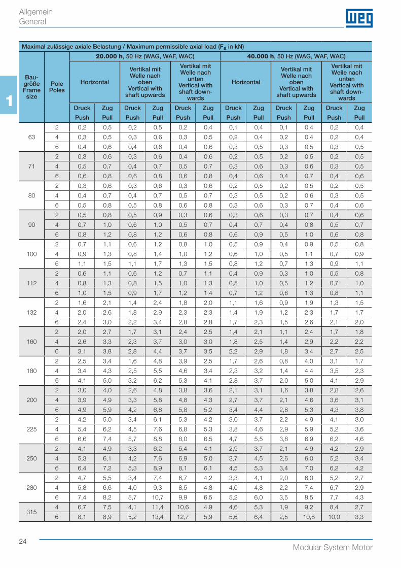
Die Tabellen zeigen Radial- und Axialbelastungswerte an, die auf der Grundlage einer Lagerlebensdauer L10 von 20.000 bzw. 40.000 Stunden und einer Frequenz von 50 Hz berechnet wor-den sind (bei max. +40 °C).Beim Betrieb mit 60 Hz müssen die Werte um 6 % gesenkt wer-den, um die gleiche Lagerlebensdauer zu erhalten.Die Tabellenwerte für die maximal zulässige Radialbelastung gel-ten ohne zusätzliche Axialbelastung. Die Tabellenwerte für die maximal zulässige Axialbelastung gelten ohne zusätzliche Ra-dialbelastung. Für kombinierte Axial- und Radialbelastung bzw. abweichende Werte (L10, Frequenz, Umgebungstemperatur) kontaktieren Sie uns bitte.Der Angriffspunkt der Kraft Fr muss auf dem Wellenende liegen.
SPANNUNG, STROM UND FREQUENZ
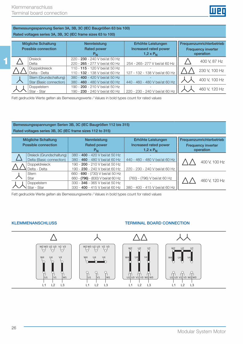
In der Standardausführung werden die Motoren für folgende Bemessungsspannungen geliefert: siehe Klemmenanschluss (Grundschaltung) Seite 26.
SONDERSPANNUNGEN
Motoren für Sonderspannung und/oder Sonderfrequenzen sind auf Anfrage lieferbar.
DREHZAHL UND SCHALTUNG
Motortoleranzbereich lt. Norm IEC 60034.
Klemmenanschluss siehe Seite 26.
• Sternschaltung
Für eine Sternschaltung müssen die Klemmen W2, U2 und V2 zusammengeschlossen und die Klemmen U1, V1 und W1 ange-speist werden.
SCHALTUNG
• Direkte Einschaltung
Das Anzugsmoment beträgt bei direkter Einschaltung je nach Leistung und Polzahl 160 bis 330 % des Nennmoments. Die Einschaltströme betragen das ca. 2,5 bis 8-fache des Nennstro-mes.
• Stern-Dreieck-Anlauf
Der Stern-Dreieck-Anlauf ist die einfachste Art, den Strom und das Anlaufdrehmoment zu reduzieren. Die Motoren, deren Nenn-spannung bei Dreieckschaltung der Netzspannung entspricht, können mit der Stern-Dreieck-Methode angelassen werden. Ab Baugröße 112 werden EUSAS®-Motoren serienmäßig mit Wick-lungen für diese Anlaufmethode geliefert (z. B.: 400 V für Drei-eck-/690 V für Sternschaltung).Für Y-D-Anlauf ist als Betriebsschaltung nur die D-Schaltung möglich (bei Motorauswahl beachten!), da der Motor zunächst in Y-Schaltung an das Netz gelegt und nach dem Hochlaufen auf die D-Stufe umgeschaltet wird. Bei Y-D-Anlauf reduzieren sich die Anlaufstöme und Anlaufmo-mente auf etwa 1/3 der Werte bei direkter Einschaltung. Zu be-achten ist, dass bei der Umschaltung auf die D-Stufe ein Strom-stoß auftritt.
The permissible loads given in the tables relate to a computed service lifetime for the bearings of 20,000 and 40,000 hours with 50 Hz power supply (max. +40 °C).For operation at 60 Hz the values have to be reduced by 6 % in order to achieve the same useful life.
The values for maximum radial loads apply without additional axial load. The values for maximum axial loads apply without ad-ditional radial load. For combined axial and radial loads or differ-ing values (L10, frequency, ambient temperature) please contact us.
The point of action of force Fr has to be on the shaft end.
VOLTAGE, CURRENT AND FREQUENCY
In standard execution the motors are delivered with following rated voltages: see terminal board connection (basic connection) page 26.
SPECIAL VOLTAGES
Motors for special voltages and/or frequencies are availableon request.
SPEED AND CONNECTION
Tolerance of the motor speed according to IEC 60034.
Terminal board connection see page 26.
• Star connection
By linking the W2, U2, V2 terminals (star point) and connect-ing the U1, V1, W1 terminals to the mains a star connection is obtained.
CONNECTION
• Direct connection
The starting torque in direct connection amounts to 160 to 330 % of the rated torque depending on power and number of poles. The starting current is about 2,5 - 8 times of the rated current.
• Star-delta starting
The star-delta starting is an easy way to reduce the starting cur-rent and starting torque. Motors can be started with the star-delta starting method whenever the supply voltage corresponds to the rated voltage of the motors in delta connections.Up from frame size 112 the standard EUSAS® motors are sup-plied with windings designed for this starting method (e.g. 400 V delta / 690 V star).A star-delta-starting is only possible with delta service connec-tion (this shall be considered when selecting a motor!), as the motor is first star-connected and is changed over to delta con-nection after the run-up phase. At star-delta-starting, the starting currents and torques will be reduced to about 1/3 of the values produced in case of direct-online starting. Attention should be paid to the fact that a current impulse is produced when changing over to delta connection.
Allgemein General
26Modular System Motor
11
Bemessungsspannung Serien 3A, 3B, 3C (IEC Baugrößen 63 bis 100)
Rated voltages series 3A, 3B, 3C (IEC frame sizes 63 to 100)
Bemessungsspannungen Serien 3B, 3C (IEC Baugrößen 112 bis 315)
Rated voltages series 3B, 3C (IEC frame sizes 112 to 315)
Fett gedruckte Werte gelten als Bemessungswerte / Values in bold types count for rated values
Mögliche Schaltung Nennleistung Erhöhte Leistungen FrequenzumrichterbetriebPossible connection Rated power Increased rated power Frequency inverter
operationPN 1,2 x PNDreieck 220 - 230 - 240 V bei/at 50 Hz -
400 V, 87 HzDelta 220 - 265 - 277 V bei/at 60 Hz 254 - 265- 277 V bei/at 60 HzDoppeldreieck 110 - 115 - 120 V bei/at 50 Hz -
230 V, 100 HzDelta - Delta 110 - 132 - 138 V bei/at 60 Hz 127 - 132 - 138 V bei/at 60 HzStern (Grundschaltung) 380 - 400 - 420 V bei/at 50 Hz -
400 V, 100 HzStar (Basic connection) 380 - 460 - 480 V bei/at 60 Hz 440 - 460 - 480 V bei/at 60 HzDoppelstern 190 - 200 - 210 V bei/at 50 Hz -
460 V, 120 HzStar - Star 190 - 230 - 240 V bei/at 60 Hz 220 - 230 - 240 V bei/at 60 Hz
Mögliche Schaltung Nennleistung Erhöhte Leistungen FrequenzumrichterbetriebPossible connection Rated power Increased rated power Frequency inverter
operationPN 1,2 x PNDreieck (Grundschaltung) 380 - 400 - 420 V bei/at 50 Hz -
400 V, 100 HzDelta (Basic connection) 380 - 460 - 480 V bei/at 60 Hz 440 - 460 - 480 V bei/at 60 HzDoppeldreieck 190 - 200 - 210 V bei/at 50 Hz -Delta - Delta 190 - 230 - 240 V bei/at 60 Hz 220 - 230 - 240 V bei/at 60 HzStern 660 - 690 - (730) V bei/at 50 Hz -
460 V, 120 HzStar 660 - (796) - (830) V bei/at 60 Hz (760) - (796) V bei/at 60 HzDoppelstern 330 - 346 - 365 V bei/at 50 Hz -Star - Star 330 - 400 - 415 V bei/at 60 Hz 380 - 400 - 415 V bei/at 60 Hz
U1 V1 W1
W4 U4 V4
W2 U2 V2W3 U3 V3
U1 V1 W1
W4 U4 V4
U1
W4 U4 V4
W2 U2 V2 W2 U2 V2
U3 V1 V3 W1 W3 U1
W4 U4 V4
U3 V1 V3 W1 W3
W2 U2 V2W3 U3 V3
KLEMMENANSCHLUSS TERMINAL BOARD CONNECTION
Fett gedruckte Werte gelten als Bemessungswerte / Values in bold types count for rated values
Klemmenanschluss Terminal board connection
27Modular System Motor
Elektrische BasisdatenElectrical Basic Data2Elektrische Basisdaten 3A/3B Electrical basic data 3A/3B 28
Elektrische Basisdaten 3C Electrical basic data 3C 40
Hinweise zu den elektrischen Basisdaten Notes for electrical basic data 52
IE2IE1
IE3
28Modular System Motor
22
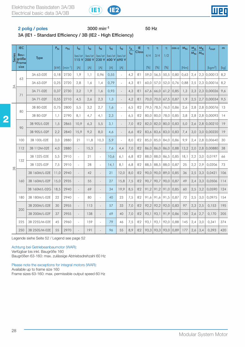
2 polig / poles 3000 min-1 50 Hz3A (IE1 - Standard Efficiency / 3B (IE2 - High Efficiency)
Seri
es
IEC
Bau-größe Frame size
Type
PN
[kW]
nN
[min-1]
IN
bei/at115 V
[A]
IN
bei/at200 V
[A]
IN
bei/at230 V
[A]
IN
bei/at400 V
[A]
IN
bei/at690 V
[A]
IAIN
IEClass
η
4/4
[%]
η
3/4
[%]
η
1/2
[%]
cos ϕ MN
[Nm]
MAMN
MKMN
Jmot
[kgm2]
m
[kg]
3A
633A 63-02E 0,18 2730 1,9 1,1 0,96 0,55 - 4,2 IE1 59,0 56,5 50,5 0,80 0,63 2,4 2,3 0,00013 8,2
3A 63-02F 0,25 2720 2,8 1,6 1,4 0,79 - 4,3 IE1 60,0 57,0 52,0 0,76 0,88 2,5 2,3 0,00016 8,2
713A 71-02E 0,37 2730 3,2 1,9 1,6 0,93 - 4,3 IE1 67,6 66,0 61,2 0,85 1,3 2,3 2,3 0,00026 9,6
3A 71-02F 0,55 2710 4,5 2,6 2,3 1,3 - 4,2 IE1 70,0 70,0 67,5 0,87 1,9 2,5 2,7 0,00034 9,5
3B
803B 80-02E 0,75 2800 5,5 3,2 2,7 1,6 - 6,5 IE2 79,5 78,5 76,0 0,86 2,6 2,8 2,8 0,00076 13
3B 80-02F 1,1 2790 8,1 4,7 4,1 2,3 - 6,5 IE2 80,0 80,0 78,0 0,85 3,8 2,8 2,8 0,00093 14
903B 90S/L-02E 1,5 2865 10,9 6,3 5,5 3,1 - 7,0 IE2 82,0 82,0 80,0 0,83 5,0 2,6 2,8 0,00210 19
3B 90S/L-02F 2,2 2840 15,9 9,2 8,0 4,6 - 6,6 IE2 83,6 83,6 83,0 0,83 7,4 3,0 3,0 0,00220 19
100 3B 100L-02E 3,0 2880 21 11,8 10,3 5,9 - 8,0 IE2 85,0 85,0 84,0 0,86 9,9 2,4 2,8 0,00640 30
112 3B 112M-02E 4,0 2880 - 15,3 - 7,6 4,4 7,0 IE2 86,0 86,0 86,0 0,88 13,2 2,0 2,8 0,00880 38
1323B 132S-02E 5,5 2910 - 21 - 10,6 6,1 6,8 IE2 88,0 88,0 86,5 0,85 18,1 2,2 3,0 0,0197 66
3B 132S-02F 7,5 2910 - 28 - 14,1 8,1 6,8 IE2 88,5 88,5 88,0 0,87 25 2,2 2,9 0,0206 73
160
3B 160M/L-02E 11,0 2940 - 42 - 21 12,0 8,0 IE2 90,0 90,0 89,0 0,85 36 2,5 3,3 0,0421 106
3B 160M/L-02F 15,0 2935 - 55 - 27 15,8 7,5 IE2 90,7 90,7 90,0 0,87 49 2,4 3,3 0,0506 114
3B 160M/L-02G 18,5 2940 - 69 - 34 19,9 8,5 IE2 91,2 91,2 91,0 0,85 60 2,5 3,2 0,0590 124
180 3B 180M/L-02E 22 2940 - 80 - 40 23 7,5 IE2 91,6 91,6 91,5 0,87 72 2,5 3,0 0,0975 154
2003B 200M/L-02E 30 2955 - 113 - 57 33 7,0 IE2 92,2 92,2 92,0 0,83 97 2,3 2,5 0,153 195
3B 200M/L-02F 37 2955 - 138 - 69 40 7,0 IE2 93,1 93,1 91,9 0,86 120 2,6 2,7 0,170 205
225 3B 225S/M-02E 45 2960 - 159 - 79 46 7,5 IE2 93,1 93,1 92,0 0,88 145 2,4 3,0 0,341 374
250 3B 250S/M-02E 55 2970 - 191 - 96 55 8,9 IE2 93,3 93,3 93,0 0,89 177 2,6 3,4 0,393 420
Legende siehe Seite 52 / Legend see page 52
Achtung bei Getriebeanbaumotor (WAR): Verfügbar bis inkl. Baugröße 160Baugrößen 63-160: max. zulässige Abtriebsdrehzahl 60 Hz
Please note the exceptions for integral motors (WAR):Available up to frame size 160Frame sizes 63-160: max. permissible output speed 60 Hz
Elektrische Basisdaten 3A/3B Electrical basic data 3A/3B IE2IE1
29Modular System Motor
22
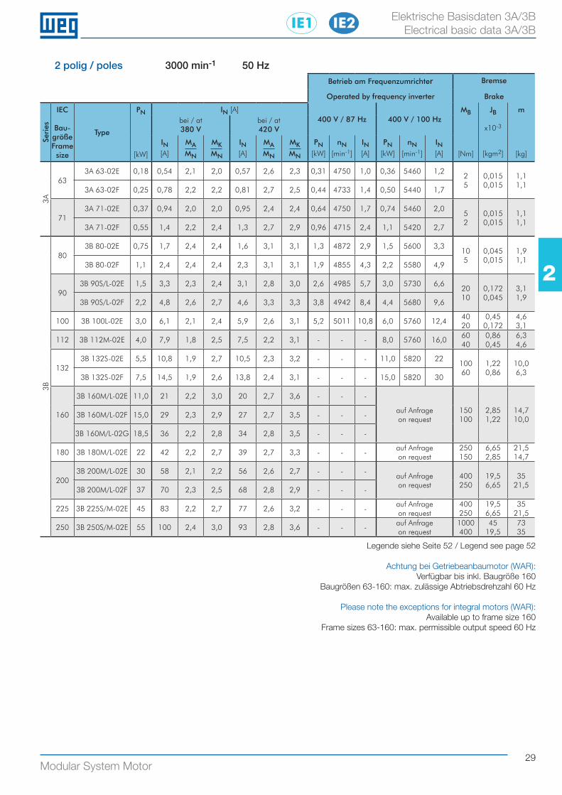
2 polig / poles 3000 min-1 50 HzBetrieb am Frequenzumrichter Bremse
Operated by frequency inverter Brake
Seri
es
IEC
Bau-größe Frame size
Type
PN
[kW]
IN [A]400 V / 87 Hz 400 V / 100 Hz
MB
[Nm]
JB
x10-3
[kgm2]
m
[kg]
bei / at380 V
bei / at420 V
IN[A]
MAMN
MKMN
IN[A]
MAMN
MKMN
PN[kW]
nN[min-1]
IN[A]
PN[kW]
nN[min-1]
IN[A]
3A
633A 63-02E 0,18 0,54 2,1 2,0 0,57 2,6 2,3 0,31 4750 1,0 0,36 5460 1,2
2 5
0,015 0,015
1,1 1,1
3A 63-02F 0,25 0,78 2,2 2,2 0,81 2,7 2,5 0,44 4733 1,4 0,50 5440 1,7
713A 71-02E 0,37 0,94 2,0 2,0 0,95 2,4 2,4 0,64 4750 1,7 0,74 5460 2,0
5 2
0,015 0,015
1,1 1,1
3A 71-02F 0,55 1,4 2,2 2,4 1,3 2,7 2,9 0,96 4715 2,4 1,1 5420 2,7
3B
803B 80-02E 0,75 1,7 2,4 2,4 1,6 3,1 3,1 1,3 4872 2,9 1,5 5600 3,3
10 5
0,045 0,015
1,9 1,1
3B 80-02F 1,1 2,4 2,4 2,4 2,3 3,1 3,1 1,9 4855 4,3 2,2 5580 4,9
903B 90S/L-02E 1,5 3,3 2,3 2,4 3,1 2,8 3,0 2,6 4985 5,7 3,0 5730 6,6
20 10
0,172 0,045
3,1 1,9
3B 90S/L-02F 2,2 4,8 2,6 2,7 4,6 3,3 3,3 3,8 4942 8,4 4,4 5680 9,6
100 3B 100L-02E 3,0 6,1 2,1 2,4 5,9 2,6 3,1 5,2 5011 10,8 6,0 5760 12,440 20
0,45 0,172
4,6 3,1
112 3B 112M-02E 4,0 7,9 1,8 2,5 7,5 2,2 3,1 - - - 8,0 5760 16,060 40
0,86 0,45
6,3 4,6
1323B 132S-02E 5,5 10,8 1,9 2,7 10,5 2,3 3,2 - - - 11,0 5820 22
100 60
1,22 0,86
10,0 6,3
3B 132S-02F 7,5 14,5 1,9 2,6 13,8 2,4 3,1 - - - 15,0 5820 30
160
3B 160M/L-02E 11,0 21 2,2 3,0 20 2,7 3,6 - - -
auf Anfrageon request
150 100
2,85 1,22
14,7 10,0
3B 160M/L-02F 15,0 29 2,3 2,9 27 2,7 3,5 - - -
3B 160M/L-02G 18,5 36 2,2 2,8 34 2,8 3,5 - - -
180 3B 180M/L-02E 22 42 2,2 2,7 39 2,7 3,3 - - -auf Anfrageon request
250 150
6,65 2,85
21,5 14,7
2003B 200M/L-02E 30 58 2,1 2,2 56 2,6 2,7 - - -
auf Anfrageon request
400 250
19,5 6,65
35 21,5
3B 200M/L-02F 37 70 2,3 2,5 68 2,8 2,9 - - -
225 3B 225S/M-02E 45 83 2,2 2,7 77 2,6 3,2 - - -auf Anfrageon request
400 250
19,5 6,65
35 21,5
250 3B 250S/M-02E 55 100 2,4 3,0 93 2,8 3,6 - - -auf Anfrageon request
1000 400
45 19,5
73 35
Legende siehe Seite 52 / Legend see page 52
Achtung bei Getriebeanbaumotor (WAR): Verfügbar bis inkl. Baugröße 160
Baugrößen 63-160: max. zulässige Abtriebsdrehzahl 60 Hz
Please note the exceptions for integral motors (WAR):Available up to frame size 160
Frame sizes 63-160: max. permissible output speed 60 Hz
Elektrische Basisdaten 3A/3B Electrical basic data 3A/3B IE2IE1
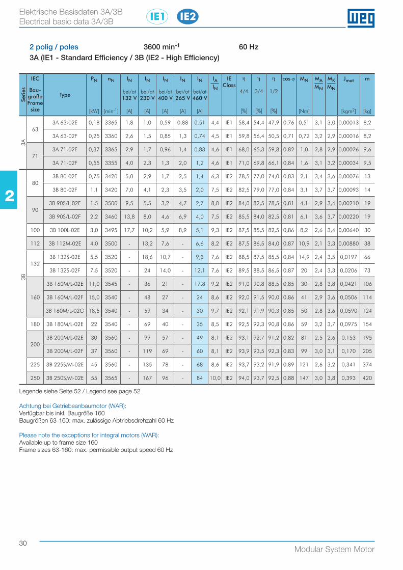
30Modular System Motor
22
Elektrische Basisdaten 3A/3B Electrical basic data 3A/3B
2 polig / poles 3600 min-1 60 Hz3A (IE1 - Standard Efficiency / 3B (IE2 - High Efficiency)
Seri
es
IEC
Bau-größe Frame size
Type
PN
[kW]
nN
[min-1]
IN
bei/at132 V
[A]
IN
bei/at230 V
[A]
IN
bei/at400 V
[A]
IN
bei/at265 V
[A]
IN
bei/at460 V
[A]
IAIN
IEClass
η
4/4
[%]
η
3/4
[%]
η
1/2
[%]
cos ϕ MN
[Nm]
MAMN
MKMN
Jmot
[kgm2]
m
[kg]
3A
633A 63-02E 0,18 3365 1,8 1,0 0,59 0,88 0,51 4,4 IE1 58,4 54,4 47,9 0,76 0,51 3,1 3,0 0,00013 8,2
3A 63-02F 0,25 3360 2,6 1,5 0,85 1,3 0,74 4,5 IE1 59,8 56,4 50,5 0,71 0,72 3,2 2,9 0,00016 8,2
713A 71-02E 0,37 3365 2,9 1,7 0,96 1,4 0,83 4,6 IE1 68,0 65,3 59,8 0,82 1,0 2,8 2,9 0,00026 9,6
3A 71-02F 0,55 3355 4,0 2,3 1,3 2,0 1,2 4,6 IE1 71,0 69,8 66,1 0,84 1,6 3,1 3,2 0,00034 9,5
3B
803B 80-02E 0,75 3420 5,0 2,9 1,7 2,5 1,4 6,3 IE2 78,5 77,0 74,0 0,83 2,1 3,4 3,6 0,00076 13
3B 80-02F 1,1 3420 7,0 4,1 2,3 3,5 2,0 7,5 IE2 82,5 79,0 77,0 0,84 3,1 3,7 3,7 0,00093 14
903B 90S/L-02E 1,5 3500 9,5 5,5 3,2 4,7 2,7 8,0 IE2 84,0 82,5 78,5 0,81 4,1 2,9 3,4 0,00210 19
3B 90S/L-02F 2,2 3460 13,8 8,0 4,6 6,9 4,0 7,5 IE2 85,5 84,0 82,5 0,81 6,1 3,6 3,7 0,00220 19
100 3B 100L-02E 3,0 3495 17,7 10,2 5,9 8,9 5,1 9,3 IE2 87,5 85,5 82,5 0,86 8,2 2,6 3,4 0,00640 30
112 3B 112M-02E 4,0 3500 - 13,2 7,6 - 6,6 8,2 IE2 87,5 86,5 84,0 0,87 10,9 2,1 3,3 0,00880 38
1323B 132S-02E 5,5 3520 - 18,6 10,7 - 9,3 7,6 IE2 88,5 87,5 85,5 0,84 14,9 2,4 3,5 0,0197 66
3B 132S-02F 7,5 3520 - 24 14,0 - 12,1 7,6 IE2 89,5 88,5 86,5 0,87 20 2,4 3,3 0,0206 73
160
3B 160M/L-02E 11,0 3545 - 36 21 - 17,8 9,2 IE2 91,0 90,8 88,5 0,85 30 2,8 3,8 0,0421 106
3B 160M/L-02F 15,0 3540 - 48 27 - 24 8,6 IE2 92,0 91,5 90,0 0,86 41 2,9 3,6 0,0506 114
3B 160M/L-02G 18,5 3540 - 59 34 - 30 9,7 IE2 92,1 91,9 90,3 0,85 50 2,8 3,6 0,0590 124
180 3B 180M/L-02E 22 3540 - 69 40 - 35 8,5 IE2 92,5 92,3 90,8 0,86 59 3,2 3,7 0,0975 154
2003B 200M/L-02E 30 3560 - 99 57 - 49 8,1 IE2 93,1 92,7 91,2 0,82 81 2,5 2,6 0,153 195
3B 200M/L-02F 37 3560 - 119 69 - 60 8,1 IE2 93,9 93,5 92,3 0,83 99 3,0 3,1 0,170 205
225 3B 225S/M-02E 45 3560 - 135 78 - 68 8,6 IE2 93,7 93,2 91,9 0,89 121 2,6 3,2 0,341 374
250 3B 250S/M-02E 55 3565 - 167 96 - 84 10,0 IE2 94,0 93,7 92,5 0,88 147 3,0 3,8 0,393 420
Legende siehe Seite 52 / Legend see page 52
Achtung bei Getriebeanbaumotor (WAR): Verfügbar bis inkl. Baugröße 160Baugrößen 63-160: max. zulässige Abtriebsdrehzahl 60 Hz
Please note the exceptions for integral motors (WAR):Available up to frame size 160Frame sizes 63-160: max. permissible output speed 60 Hz
IE2IE1
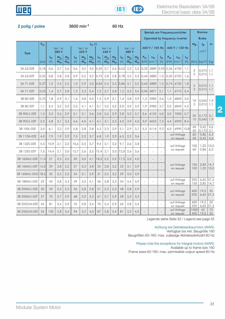
31Modular System Motor
22
Elektrische Basisdaten 3A/3B Electrical basic data 3A/3B
2 polig / poles 3600 min-1 60 HzBetrieb am Frequenzumrichter Bremse
Operated by frequency inverter Brake
Type
PN
[kW]
IN [A]460 V / 105 Hz 460 V / 120 Hz
MB
[Nm]
JB
x10-3
[kgm2]
m
[kg]
bei / at380 V
bei / at420 V
bei / at440 V
bei / at480 V
IN[A]
MAMN
MKMN
IN[A]
MAMN
MKMN
IN[A]
MAMN
MKMN
IN[A]
MAMN
MKMN
PN[kW]
nN[min-1]
IN[A]
PN[kW]
nN[min-1]
IN[A]
3A 63-02E 0,18 0,6 2,7 2,6 0,6 3,4 3,0 0,50 2,7 2,6 0,53 3,3 3,3 0,32 5889 0,93 0,36 6730 1,12 5
0,015 0,015
1,1 1,1
3A 63-02F 0,25 0,8 2,8 2,8 0,9 3,5 3,2 0,73 2,8 2,8 0,78 3,5 3,3 0,44 5880 1,3 0,50 6720 1,6
3A 71-02E 0,37 1,0 2,4 2,5 1,0 2,9 3,0 0,84 2,4 2,5 0,86 3,1 3,2 0,65 5889 1,5 0,74 6730 1,85 2
0,015 0,015
1,1 1,1
3A 71-02F 0,55 1,4 2,7 2,8 1,3 3,3 3,4 1,2 2,7 2,8 1,2 3,3 3,4 0,96 5871 2,1 1,1 6710 2,4
3B 80-02E 0,75 1,8 2,9 3,1 1,6 3,8 4,0 1,5 2,9 3,1 1,4 3,8 3,9 1,3 5985 2,6 1,5 6840 3,010 5
0,045 0,015
1,9 1,1
3B 80-02F 1,1 2,4 3,2 3,2 2,3 4,1 4,1 2,1 3,2 3,2 2,0 3,9 3,9 1,9 5985 3,7 2,2 6840 4,3
3B 90S/L-02E 1,5 3,3 2,6 2,9 3,1 3,1 3,6 2,8 2,6 2,9 2,8 3,3 3,7 2,6 6125 5,0 3,0 7000 5,720 10
0,172 0,045
3,1 1,9
3B 90S/L-02F 2,2 4,8 3,1 3,3 4,6 4,0 4,1 4,1 3,1 3,3 4,0 3,9 4,0 3,9 6055 7,3 4,4 6920 8,4
3B 100L-02E 3,0 6,1 2,3 2,9 5,8 2,8 3,8 5,3 2,3 2,9 5,1 2,9 3,7 5,3 6116 9,3 6,0 6990 10,840 20
0,45 0,172
4,6 3,1
3B 112M-02E 4,0 7,9 1,9 2,9 7,5 2,3 3,7 6,8 1,9 2,9 6,5 2,3 3,6 - - -auf Anfrageon request
60 40
0,86 0,45
6,3 4,6
3B 132S-02E 5,5 10,9 2,1 3,2 10,6 2,5 3,7 9,4 2,1 3,2 9,1 2,6 3,8 - - -auf Anfrageon request
100 60
1,22 0,86
10,0 6,3
3B 132S-02F 7,5 14,4 2,1 3,0 13,7 2,6 3,5 12,4 2,1 3,0 12,0 2,6 3,6 - - -
3B 160M/L-02E 11,0 21 2,5 3,5 20 3,0 4,1 18,2 2,5 3,5 17,5 3,0 4,0 - - -
auf Anfrageon request
150 100
2,85 1,22
14,7 10,0
3B 160M/L-02F 15,0 29 2,8 3,2 27 3,3 3,8 25 2,8 3,2 23 3,1 3,9 - - -
3B 160M/L-02G 18,5 35 2,5 3,2 34 3,1 3,9 31 2,5 3,2 29 3,0 3,9 - - -
3B 180M/L-02E 22 42 2,8 3,3 39 3,5 4,1 36 2,8 3,3 34 3,4 3,9 - - -auf Anfrageon request
250 150
6,65 2,85
21,5 14,7
3B 200M/L-02E 30 59 2,3 2,3 56 2,8 2,8 51 2,3 2,3 48 2,8 2,9 - - -auf Anfrageon request
400 250
19,5 6,65
35 21,5
3B 200M/L-02F 37 70 2,7 2,9 68 3,2 3,3 61 2,7 2,9 58 3,3 3,3 - - -
3B 225S/M-02E 45 81 2,4 2,9 76 2,8 3,4 70 2,4 2,9 65 2,8 3,4 - - -auf Anfrageon request
400 250
19,5 6,65
35 21,5
3B 250S/M-02E 55 100 2,8 3,4 94 3,2 4,0 87 2,8 3,4 81 3,2 4,0 - - -auf Anfrageon request
1000 400
45 19,5
73 35
Legende siehe Seite 52 / Legend see page 52
Achtung bei Getriebeanbaumotor (WAR): Verfügbar bis inkl. Baugröße 160
Baugrößen 63-160: max. zulässige Abtriebsdrehzahl 60 Hz
Please note the exceptions for integral motors (WAR):Available up to frame size 160
Frame sizes 63-160: max. permissible output speed 60 Hz
IE2IE1
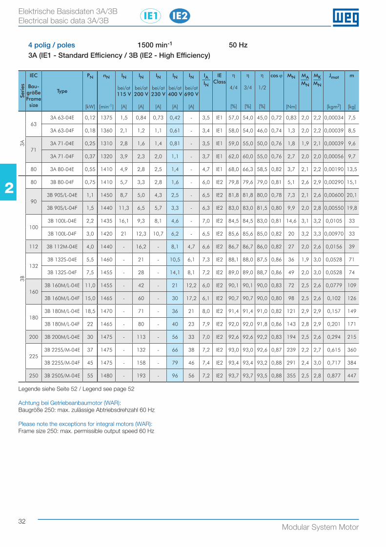
32Modular System Motor
22
Elektrische Basisdaten 3A/3B Electrical basic data 3A/3B
4 polig / poles 1500 min-1 50 Hz3A (IE1 - Standard Efficiency / 3B (IE2 - High Efficiency)
Seri
es
IEC
Bau-größe Frame size
Type
PN
[kW]
nN
[min-1]
IN
bei/at115 V
[A]
IN
bei/at200 V
[A]
IN
bei/at230 V
[A]
IN
bei/at400 V
[A]
IN
bei/at690 V
[A]
IAIN
IEClass
η
4/4
[%]
η
3/4
[%]
η
1/2
[%]
cos ϕ MN
[Nm]
MAMN
MKMN
Jmot
[kgm2]
m
[kg]
3A
633A 63-04E 0,12 1375 1,5 0,84 0,73 0,42 - 3,5 IE1 57,0 54,0 45,0 0,72 0,83 2,0 2,2 0,00034 7,5
3A 63-04F 0,18 1360 2,1 1,2 1,1 0,61 - 3,4 IE1 58,0 54,0 46,0 0,74 1,3 2,0 2,2 0,00039 8,5
713A 71-04E 0,25 1310 2,8 1,6 1,4 0,81 - 3,5 IE1 59,0 55,0 50,0 0,76 1,8 1,9 2,1 0,00039 9,6
3A 71-04F 0,37 1320 3,9 2,3 2,0 1,1 - 3,7 IE1 62,0 60,0 55,0 0,76 2,7 2,0 2,0 0,00056 9,7
80 3A 80-04E 0,55 1410 4,9 2,8 2,5 1,4 - 4,7 IE1 68,0 66,3 58,5 0,82 3,7 2,1 2,2 0,00190 13,5
3B
80 3B 80-04F 0,75 1410 5,7 3,3 2,8 1,6 - 6,0 IE2 79,8 79,6 79,0 0,81 5,1 2,6 2,9 0,00290 15,1
903B 90S/L-04E 1,1 1450 8,7 5,0 4,3 2,5 - 6,5 IE2 81,8 81,8 80,0 0,78 7,3 2,1 2,6 0,00600 20,1
3B 90S/L-04F 1,5 1440 11,3 6,5 5,7 3,3 - 6,3 IE2 83,0 83,0 81,5 0,80 9,9 2,0 2,8 0,00550 19,8
1003B 100L-04E 2,2 1435 16,1 9,3 8,1 4,6 - 7,0 IE2 84,5 84,5 83,0 0,81 14,6 3,1 3,2 0,0105 33
3B 100L-04F 3,0 1420 21 12,3 10,7 6,2 - 6,5 IE2 85,6 85,6 85,0 0,82 20 3,2 3,3 0,00970 33
112 3B 112M-04E 4,0 1440 - 16,2 - 8,1 4,7 6,6 IE2 86,7 86,7 86,0 0,82 27 2,0 2,6 0,0156 39
1323B 132S-04E 5,5 1460 - 21 - 10,5 6,1 7,3 IE2 88,1 88,0 87,5 0,86 36 1,9 3,0 0,0528 71
3B 132S-04F 7,5 1455 - 28 - 14,1 8,1 7,2 IE2 89,0 89,0 88,7 0,86 49 2,0 3,0 0,0528 74
1603B 160M/L-04E 11,0 1455 - 42 - 21 12,2 6,0 IE2 90,1 90,1 90,0 0,83 72 2,5 2,6 0,0779 109
3B 160M/L-04F 15,0 1465 - 60 - 30 17,2 6,1 IE2 90,7 90,7 90,0 0,80 98 2,5 2,6 0,102 126
1803B 180M/L-04E 18,5 1470 - 71 - 36 21 8,0 IE2 91,4 91,4 91,0 0,82 121 2,9 2,9 0,157 149
3B 180M/L-04F 22 1465 - 80 - 40 23 7,9 IE2 92,0 92,0 91,8 0,86 143 2,8 2,9 0,201 171
200 3B 200M/L-04E 30 1475 - 113 - 56 33 7,0 IE2 92,6 92,6 92,2 0,83 194 2,5 2,6 0,294 215
2253B 225S/M-04E 37 1475 - 132 - 66 38 7,2 IE2 93,0 93,0 92,6 0,87 239 2,2 2,7 0,615 360
3B 225S/M-04F 45 1475 - 158 - 79 46 7,4 IE2 93,4 93,4 93,2 0,88 291 2,4 3,0 0,717 384
250 3B 250S/M-04E 55 1480 - 193 - 96 56 7,2 IE2 93,7 93,7 93,5 0,88 355 2,5 2,8 0,877 447
Legende siehe Seite 52 / Legend see page 52
Achtung bei Getriebeanbaumotor (WAR): Baugröße 250: max. zulässige Abtriebsdrehzahl 60 Hz
Please note the exceptions for integral motors (WAR):Frame size 250: max. permissible output speed 60 Hz
IE2IE1
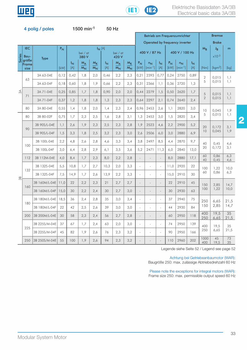
33Modular System Motor
22
Elektrische Basisdaten 3A/3B Electrical basic data 3A/3B
4 polig / poles 1500 min-1 50 HzBetrieb am Frequenzumrichter Bremse
Operated by frequency inverter Brake
Seri
es
IEC
Bau-größe Frame size
Type
PN
[kW]
IN [A]400 V / 87 Hz 400 V / 100 Hz
MB
[Nm]
JB
x10-3
[kgm2]
m
[kg]
bei / at380 V
bei / at420 V
IN[A]
MAMN
MKMN
IN[A]
MAMN
MKMN
PN[kW]
nN[min-1]
IN[A]
PN[kW]
nN[min-1]
IN[A]
3A
633A 63-04E 0,12 0,42 1,8 2,0 0,46 2,2 2,3 0,21 2393 0,77 0,24 2750 0,89
2 5
0,015 0,015
1,1 1,1
3A 63-04F 0,18 0,60 1,8 1,9 0,66 2,2 2,3 0,31 2366 1,1 0,36 2720 1,3
713A 71-04E 0,25 0,85 1,7 1,8 0,90 2,0 2,0 0,44 2279 1,5 0,50 2620 1,7
5 2
0,015 0,015
1,1 1,1
3A 71-04F 0,37 1,2 1,8 1,8 1,3 2,3 2,3 0,64 2297 2,1 0,74 2640 2,4
80 3A 80-04E 0,55 1,4 1,8 2,0 1,4 2,3 2,4 0,96 2453 2,6 1,1 2820 3,010 5
0,045 0,015
1,9 1,1
3B
80 3B 80-02F 0,75 1,7 2,3 2,5 1,6 2,8 3,1 1,3 2453 3,0 1,5 2820 3,4
903B 90S/L-04E 1,1 2,6 1,9 2,3 2,5 2,3 2,8 1,9 2523 4,6 2,2 2900 5,2
20 10
0,172 0,045
3,1 1,9
3B 90S/L-04F 1,5 3,3 1,8 2,5 3,2 2,3 3,0 2,6 2506 6,0 3,0 2880 6,9
1003B 100L-04E 2,2 4,8 2,6 2,8 4,6 3,3 3,4 3,8 2497 8,5 4,4 2870 9,7
40 20
0,45 0,172
4,6 3,1
3B 100L-04F 3,0 6,4 2,8 2,9 6,1 3,5 3,6 5,2 2471 11,3 6,0 2840 13,0
112 3B 112M-04E 4,0 8,4 1,7 2,3 8,0 2,2 2,8 - - - 8,0 2880 17,160 40
0,86 0,45
6,3 4,6
1323B 132S-04E 5,5 10,8 1,7 2,7 10,3 2,0 3,3 - - - 11,0 2920 22
100 60
1,22 0,86
10,0 6,3
3B 132S-04F 7,5 14,9 1,7 2,6 13,9 2,2 3,3 - - - 15,0 2910 30
1603B 160M/L-04E 11,0 22 2,2 2,3 21 2,7 2,7 - - - 22 2910 45
150 100
2,85 1,22
14,7 10,0
3B 160M/L-04F 15,0 30 2,2 2,4 30 2,7 3,0 - - - 30 2930 63
1803B 180M/L-04E 18,5 36 2,4 2,8 35 3,0 3,4 - - - 37 2940 75 250
1506,65 2,85
21,5 14,73B 180M/L-04F 22 42 2,5 2,6 39 3,0 3,0 - - - 44 2930 84
200 3B 200M/L-04E 30 58 2,3 2,4 56 2,7 2,8 - - - 60 2950 118400 250
19,5 6,65
35 21,5
2253B 225S/M-04E 37 67 1,7 2,4 63 2,0 3,0 - - - 74 2950 139
400 250
19,5 6,65
35 21,5
3B 225S/M-04F 45 82 1,9 2,6 76 2,3 3,2 - - - 90 2950 166
250 3B 250S/M-04E 55 100 1,9 2,6 94 2,3 3,2 - - - 110 2960 2021000 400
45 19,5
73 35
Legende siehe Seite 52 / Legend see page 52
Achtung bei Getriebeanbaumotor (WAR): Baugröße 250: max. zulässige Abtriebsdrehzahl 60 Hz
Please note the exceptions for integral motors (WAR):Frame size 250: max. permissible output speed 60 Hz
IE2IE1
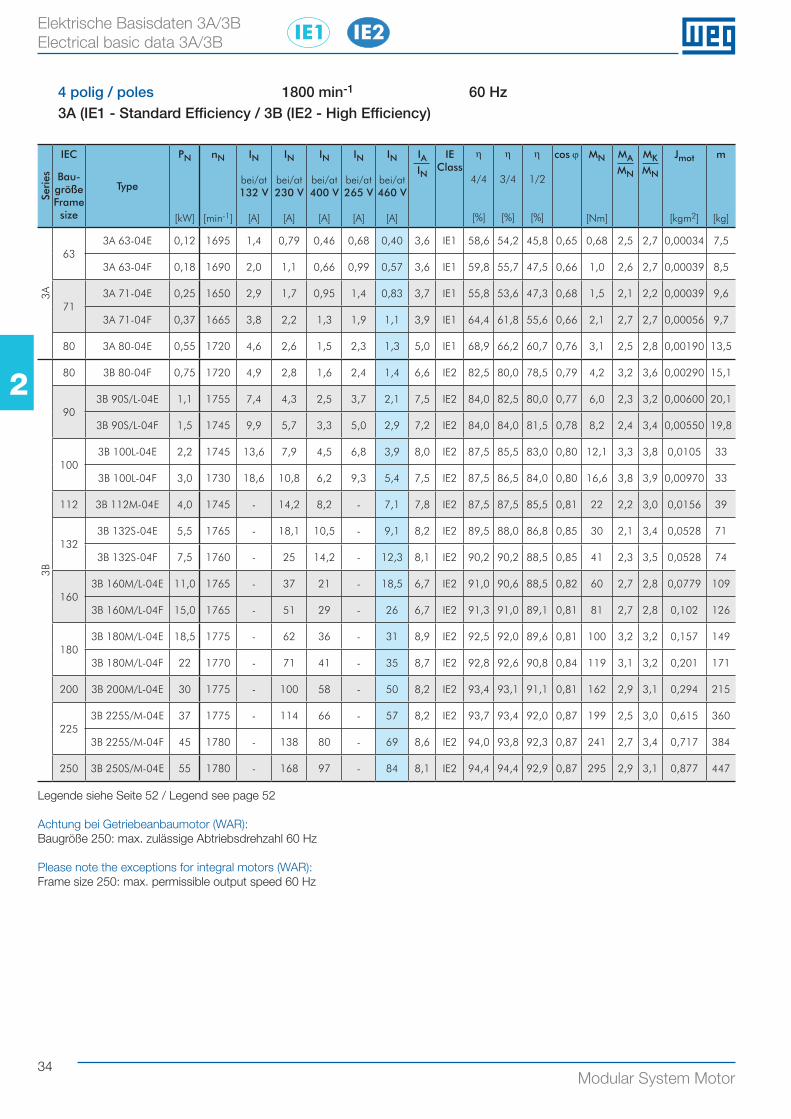
34Modular System Motor
22
Elektrische Basisdaten 3A/3B Electrical basic data 3A/3B
4 polig / poles 1800 min-1 60 Hz3A (IE1 - Standard Efficiency / 3B (IE2 - High Efficiency)
Seri
es
IEC
Bau-größe Frame size
Type
PN
[kW]
nN
[min-1]
IN
bei/at132 V
[A]
IN
bei/at230 V
[A]
IN
bei/at400 V
[A]
IN
bei/at265 V
[A]
IN
bei/at460 V
[A]
IAIN
IEClass
η
4/4
[%]
η
3/4
[%]
η
1/2
[%]
cos ϕ MN
[Nm]
MAMN
MKMN
Jmot
[kgm2]
m
[kg]
3A
633A 63-04E 0,12 1695 1,4 0,79 0,46 0,68 0,40 3,6 IE1 58,6 54,2 45,8 0,65 0,68 2,5 2,7 0,00034 7,5
3A 63-04F 0,18 1690 2,0 1,1 0,66 0,99 0,57 3,6 IE1 59,8 55,7 47,5 0,66 1,0 2,6 2,7 0,00039 8,5
713A 71-04E 0,25 1650 2,9 1,7 0,95 1,4 0,83 3,7 IE1 55,8 53,6 47,3 0,68 1,5 2,1 2,2 0,00039 9,6
3A 71-04F 0,37 1665 3,8 2,2 1,3 1,9 1,1 3,9 IE1 64,4 61,8 55,6 0,66 2,1 2,7 2,7 0,00056 9,7
80 3A 80-04E 0,55 1720 4,6 2,6 1,5 2,3 1,3 5,0 IE1 68,9 66,2 60,7 0,76 3,1 2,5 2,8 0,00190 13,5
3B
80 3B 80-04F 0,75 1720 4,9 2,8 1,6 2,4 1,4 6,6 IE2 82,5 80,0 78,5 0,79 4,2 3,2 3,6 0,00290 15,1
903B 90S/L-04E 1,1 1755 7,4 4,3 2,5 3,7 2,1 7,5 IE2 84,0 82,5 80,0 0,77 6,0 2,3 3,2 0,00600 20,1
3B 90S/L-04F 1,5 1745 9,9 5,7 3,3 5,0 2,9 7,2 IE2 84,0 84,0 81,5 0,78 8,2 2,4 3,4 0,00550 19,8
1003B 100L-04E 2,2 1745 13,6 7,9 4,5 6,8 3,9 8,0 IE2 87,5 85,5 83,0 0,80 12,1 3,3 3,8 0,0105 33
3B 100L-04F 3,0 1730 18,6 10,8 6,2 9,3 5,4 7,5 IE2 87,5 86,5 84,0 0,80 16,6 3,8 3,9 0,00970 33
112 3B 112M-04E 4,0 1745 - 14,2 8,2 - 7,1 7,8 IE2 87,5 87,5 85,5 0,81 22 2,2 3,0 0,0156 39
1323B 132S-04E 5,5 1765 - 18,1 10,5 - 9,1 8,2 IE2 89,5 88,0 86,8 0,85 30 2,1 3,4 0,0528 71
3B 132S-04F 7,5 1760 - 25 14,2 - 12,3 8,1 IE2 90,2 90,2 88,5 0,85 41 2,3 3,5 0,0528 74
1603B 160M/L-04E 11,0 1765 - 37 21 - 18,5 6,7 IE2 91,0 90,6 88,5 0,82 60 2,7 2,8 0,0779 109
3B 160M/L-04F 15,0 1765 - 51 29 - 26 6,7 IE2 91,3 91,0 89,1 0,81 81 2,7 2,8 0,102 126
1803B 180M/L-04E 18,5 1775 - 62 36 - 31 8,9 IE2 92,5 92,0 89,6 0,81 100 3,2 3,2 0,157 149
3B 180M/L-04F 22 1770 - 71 41 - 35 8,7 IE2 92,8 92,6 90,8 0,84 119 3,1 3,2 0,201 171
200 3B 200M/L-04E 30 1775 - 100 58 - 50 8,2 IE2 93,4 93,1 91,1 0,81 162 2,9 3,1 0,294 215
2253B 225S/M-04E 37 1775 - 114 66 - 57 8,2 IE2 93,7 93,4 92,0 0,87 199 2,5 3,0 0,615 360
3B 225S/M-04F 45 1780 - 138 80 - 69 8,6 IE2 94,0 93,8 92,3 0,87 241 2,7 3,4 0,717 384
250 3B 250S/M-04E 55 1780 - 168 97 - 84 8,1 IE2 94,4 94,4 92,9 0,87 295 2,9 3,1 0,877 447
Legende siehe Seite 52 / Legend see page 52
Achtung bei Getriebeanbaumotor (WAR): Baugröße 250: max. zulässige Abtriebsdrehzahl 60 Hz
Please note the exceptions for integral motors (WAR):Frame size 250: max. permissible output speed 60 Hz
IE2IE1
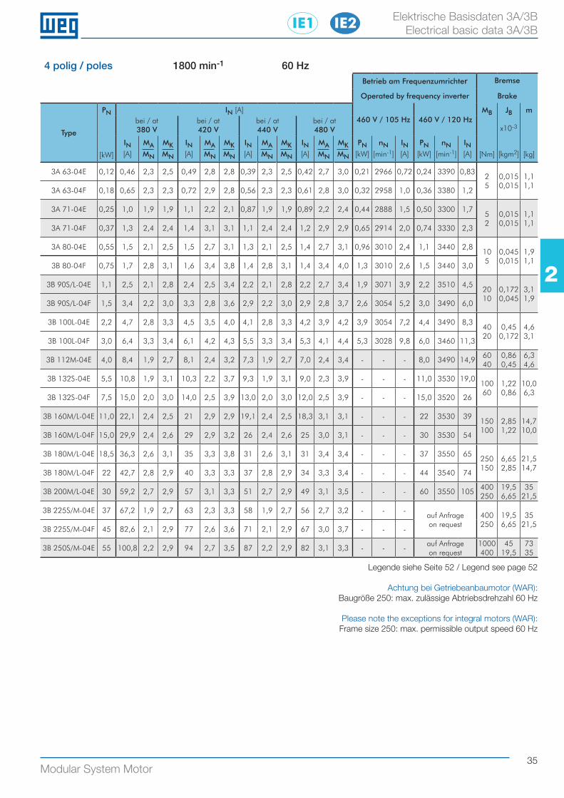
35Modular System Motor
22
Elektrische Basisdaten 3A/3B Electrical basic data 3A/3B
4 polig / poles 1800 min-1 60 HzBetrieb am Frequenzumrichter Bremse
Operated by frequency inverter Brake
Type
PN
[kW]
IN [A]460 V / 105 Hz 460 V / 120 Hz
MB
[Nm]
JB
x10-3
[kgm2]
m
[kg]
bei / at380 V
bei / at420 V
bei / at440 V
bei / at480 V
IN[A]
MAMN
MKMN
IN[A]
MAMN
MKMN
IN[A]
MAMN
MKMN
IN[A]
MAMN
MKMN
PN[kW]
nN[min-1]
IN[A]
PN[kW]
nN[min-1]
IN[A]
3A 63-04E 0,12 0,46 2,3 2,5 0,49 2,8 2,8 0,39 2,3 2,5 0,42 2,7 3,0 0,21 2966 0,72 0,24 3390 0,832 5
0,015 0,015
1,1 1,1
3A 63-04F 0,18 0,65 2,3 2,3 0,72 2,9 2,8 0,56 2,3 2,3 0,61 2,8 3,0 0,32 2958 1,0 0,36 3380 1,2
3A 71-04E 0,25 1,0 1,9 1,9 1,1 2,2 2,1 0,87 1,9 1,9 0,89 2,2 2,4 0,44 2888 1,5 0,50 3300 1,75 2
0,015 0,015
1,1 1,1
3A 71-04F 0,37 1,3 2,4 2,4 1,4 3,1 3,1 1,1 2,4 2,4 1,2 2,9 2,9 0,65 2914 2,0 0,74 3330 2,3
3A 80-04E 0,55 1,5 2,1 2,5 1,5 2,7 3,1 1,3 2,1 2,5 1,4 2,7 3,1 0,96 3010 2,4 1,1 3440 2,810 5
0,045 0,015
1,9 1,1
3B 80-04F 0,75 1,7 2,8 3,1 1,6 3,4 3,8 1,4 2,8 3,1 1,4 3,4 4,0 1,3 3010 2,6 1,5 3440 3,0
3B 90S/L-04E 1,1 2,5 2,1 2,8 2,4 2,5 3,4 2,2 2,1 2,8 2,2 2,7 3,4 1,9 3071 3,9 2,2 3510 4,520 10
0,172 0,045
3,1 1,9
3B 90S/L-04F 1,5 3,4 2,2 3,0 3,3 2,8 3,6 2,9 2,2 3,0 2,9 2,8 3,7 2,6 3054 5,2 3,0 3490 6,0
3B 100L-04E 2,2 4,7 2,8 3,3 4,5 3,5 4,0 4,1 2,8 3,3 4,2 3,9 4,2 3,9 3054 7,2 4,4 3490 8,340 20
0,45 0,172
4,6 3,1
3B 100L-04F 3,0 6,4 3,3 3,4 6,1 4,2 4,3 5,5 3,3 3,4 5,3 4,1 4,4 5,3 3028 9,8 6,0 3460 11,3
3B 112M-04E 4,0 8,4 1,9 2,7 8,1 2,4 3,2 7,3 1,9 2,7 7,0 2,4 3,4 - - - 8,0 3490 14,960 40
0,86 0,45
6,3 4,6
3B 132S-04E 5,5 10,8 1,9 3,1 10,3 2,2 3,7 9,3 1,9 3,1 9,0 2,3 3,9 - - - 11,0 3530 19,0100 60
1,22 0,86
10,0 6,3
3B 132S-04F 7,5 15,0 2,0 3,0 14,0 2,5 3,9 13,0 2,0 3,0 12,0 2,5 3,9 - - - 15,0 3520 26
3B 160M/L-04E 11,0 22,1 2,4 2,5 21 2,9 2,9 19,1 2,4 2,5 18,3 3,1 3,1 - - - 22 3530 39150 100
2,85 1,22
14,7 10,0
3B 160M/L-04F 15,0 29,9 2,4 2,6 29 2,9 3,2 26 2,4 2,6 25 3,0 3,1 - - - 30 3530 54
3B 180M/L-04E 18,5 36,3 2,6 3,1 35 3,3 3,8 31 2,6 3,1 31 3,4 3,4 - - - 37 3550 65250 150
6,65 2,85
21,5 14,7
3B 180M/L-04F 22 42,7 2,8 2,9 40 3,3 3,3 37 2,8 2,9 34 3,3 3,4 - - - 44 3540 74
3B 200M/L-04E 30 59,2 2,7 2,9 57 3,1 3,3 51 2,7 2,9 49 3,1 3,5 - - - 60 3550 105400 250
19,5 6,65
35 21,5
3B 225S/M-04E 37 67,2 1,9 2,7 63 2,3 3,3 58 1,9 2,7 56 2,7 3,2 - - -auf Anfrageon request
400 250
19,5 6,65
35 21,5
3B 225S/M-04F 45 82,6 2,1 2,9 77 2,6 3,6 71 2,1 2,9 67 3,0 3,7 - - -
3B 250S/M-04E 55 100,8 2,2 2,9 94 2,7 3,5 87 2,2 2,9 82 3,1 3,3 - - -auf Anfrageon request
1000 400
45 19,5
73 35
Legende siehe Seite 52 / Legend see page 52
Achtung bei Getriebeanbaumotor (WAR): Baugröße 250: max. zulässige Abtriebsdrehzahl 60 Hz
Please note the exceptions for integral motors (WAR):Frame size 250: max. permissible output speed 60 Hz
IE2IE1
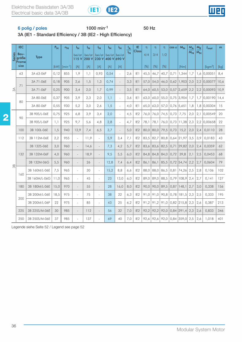
36Modular System Motor
22
Elektrische Basisdaten 3A/3B Electrical basic data 3A/3B
6 polig / poles 1000 min-1 50 Hz3A (IE1 - Standard Efficiency / 3B (IE2 - High Efficiency)
Seri
es
IEC
Bau-größe Frame size
Type
PN
[kW]
nN
[min-1]
IN
bei/at115 V
[A]
IN
bei/at200 V
[A]
IN
bei/at230 V
[A]
IN
bei/at400 V
[A]
IN
bei/at690 V
[A]
IAIN
IEClass
η
4/4
[%]
η
3/4
[%]
η
1/2
[%]
cos ϕ MN
[Nm]
MAMN
MKMN
Jmot
[kgm2]
m
[kg]
3A
63 3A 63-06F 0,12 855 1,9 1,1 0,93 0,54 - 2,6 IE1 45,5 46,7 40,7 0,71 1,344 1,7 1,6 0,00051 8,4
713A 71-06E 0,18 905 2,6 1,5 1,3 0,74 - 3,3 IE1 57,0 54,0 46,0 0,62 1,903 2,0 2,2 0,00077 10,6
3A 71-06F 0,25 900 3,4 2,0 1,7 0,99 - 3,5 IE1 64,0 60,5 53,0 0,57 2,659 2,2 2,2 0,00093 10,9
803A 80-06E 0,37 905 3,9 2,3 2,0 1,1 - 3,6 IE1 63,0 60,0 55,0 0,75 3,904 1,7 1,7 0,00190 14,4
3A 80-06F 0,55 930 5,2 3,0 2,6 1,5 - 4,0 IE1 65,0 63,0 57,0 0,76 5,651 1,8 1,8 0,00304 15
3B
903B 90S/L-06E 0,75 925 6,8 3,9 3,4 2,0 - 4,5 IE2 76,0 76,0 74,5 0,73 7,75 2,0 2,1 0,00549 20
3B 90S/L-06F 1,1 925 9,7 5,6 4,8 2,8 - 4,7 IE2 78,1 78,1 76,0 0,73 11,38 2,3 2,2 0,00658 22
100 3B 100L-06E 1,5 940 12,9 7,4 6,5 3,7 - 5,0 IE2 80,0 80,0 79,5 0,73 15,2 2,0 2,4 0,0110 28
112 3B 112M-06E 2,2 955 - 11,9 - 5,9 3,4 7,1 IE2 83,5 82,7 80,8 0,64 21,97 3,5 3,9 0,0183 43
132
3B 132S-06E 3,0 960 - 14,6 - 7,3 4,2 5,7 IE2 83,6 83,6 82,5 0,71 29,82 2,0 2,4 0,0359 62
3B 132M-06F 4,0 960 - 18,9 - 9,5 5,5 6,0 IE2 84,8 84,8 84,0 0,72 39,8 2,1 2,5 0,0453 68
3B 132M-06G 5,5 960 - 26 - 12,8 7,4 6,4 IE2 86,1 86,1 85,5 0,72 54,74 2,2 2,7 0,0604 79
1603B 160M/L-06E 7,5 965 - 30 - 15,2 8,8 6,6 IE2 88,0 88,0 86,5 0,81 74,26 2,5 2,8 0,106 102
3B 160M/L-06G 11,0 965 - 45 - 23 13,0 6,0 IE2 89,0 89,0 88,5 0,79 108,9 2,4 2,7 0,141 127
180 3B 180M/L-06E 15,0 970 - 55 - 28 16,0 8,0 IE2 90,0 90,0 89,5 0,87 148,1 2,7 3,0 0,338 156
2003B 200M/L-06E 18,5 975 - 75 - 38 22 6,3 IE2 91,0 91,0 90,8 0,78 181,5 2,3 2,5 0,333 195
3B 200M/L-06F 22 975 - 85 - 43 25 6,2 IE2 91,2 91,2 91,0 0,82 215,8 2,3 2,6 0,387 213
225 3B 225S/M-06E 30 985 - 112 - 56 32 7,0 IE2 92,2 92,2 92,0 0,84 291,4 2,3 2,6 0,833 346
250 3B 250S/M-06E 37 985 - 137 - 69 40 7,0 IE2 92,6 92,6 92,0 0,84 359,0 2,5 2,6 1,018 401
Legende siehe Seite 52 / Legend see page 52
IE2IE1
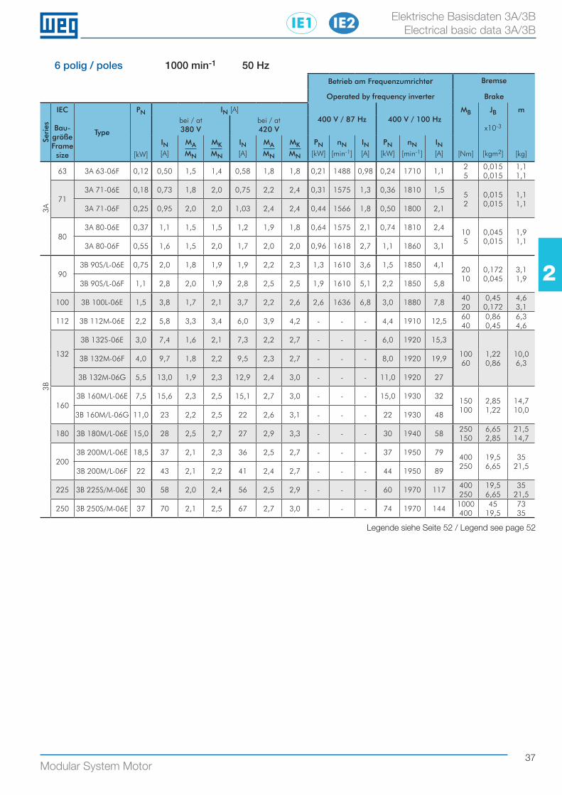
37Modular System Motor
22
Elektrische Basisdaten 3A/3B Electrical basic data 3A/3B
6 polig / poles 1000 min-1 50 HzBetrieb am Frequenzumrichter Bremse
Operated by frequency inverter Brake
Seri
es
IEC
Bau-größe Frame size
Type
PN
[kW]
IN [A]400 V / 87 Hz 400 V / 100 Hz
MB
[Nm]
JB
x10-3
[kgm2]
m
[kg]
bei / at380 V
bei / at420 V
IN[A]
MAMN
MKMN
IN[A]
MAMN
MKMN
PN[kW]
nN[min-1]
IN[A]
PN[kW]
nN[min-1]
IN[A]
3A
63 3A 63-06F 0,12 0,50 1,5 1,4 0,58 1,8 1,8 0,21 1488 0,98 0,24 1710 1,12 5
0,015 0,015
1,1 1,1
713A 71-06E 0,18 0,73 1,8 2,0 0,75 2,2 2,4 0,31 1575 1,3 0,36 1810 1,5
5 2
0,015 0,015
1,1 1,1
3A 71-06F 0,25 0,95 2,0 2,0 1,03 2,4 2,4 0,44 1566 1,8 0,50 1800 2,1
803A 80-06E 0,37 1,1 1,5 1,5 1,2 1,9 1,8 0,64 1575 2,1 0,74 1810 2,4
10 5
0,045 0,015
1,9 1,1
3A 80-06F 0,55 1,6 1,5 2,0 1,7 2,0 2,0 0,96 1618 2,7 1,1 1860 3,1
3B
903B 90S/L-06E 0,75 2,0 1,8 1,9 1,9 2,2 2,3 1,3 1610 3,6 1,5 1850 4,1
20 10
0,172 0,045
3,1 1,9
3B 90S/L-06F 1,1 2,8 2,0 1,9 2,8 2,5 2,5 1,9 1610 5,1 2,2 1850 5,8
100 3B 100L-06E 1,5 3,8 1,7 2,1 3,7 2,2 2,6 2,6 1636 6,8 3,0 1880 7,840 20
0,45 0,172
4,6 3,1
112 3B 112M-06E 2,2 5,8 3,3 3,4 6,0 3,9 4,2 - - - 4,4 1910 12,560 40
0,86 0,45
6,3 4,6
132
3B 132S-06E 3,0 7,4 1,6 2,1 7,3 2,2 2,7 - - - 6,0 1920 15,3
100 60
1,22 0,86
10,0 6,3
3B 132M-06F 4,0 9,7 1,8 2,2 9,5 2,3 2,7 - - - 8,0 1920 19,9
3B 132M-06G 5,5 13,0 1,9 2,3 12,9 2,4 3,0 - - - 11,0 1920 27
1603B 160M/L-06E 7,5 15,6 2,3 2,5 15,1 2,7 3,0 - - - 15,0 1930 32
150 100
2,85 1,22
14,7 10,0
3B 160M/L-06G 11,0 23 2,2 2,5 22 2,6 3,1 - - - 22 1930 48
180 3B 180M/L-06E 15,0 28 2,5 2,7 27 2,9 3,3 - - - 30 1940 58250 150
6,65 2,85
21,5 14,7
2003B 200M/L-06E 18,5 37 2,1 2,3 36 2,5 2,7 - - - 37 1950 79
400 250
19,5 6,65
35 21,5
3B 200M/L-06F 22 43 2,1 2,2 41 2,4 2,7 - - - 44 1950 89
225 3B 225S/M-06E 30 58 2,0 2,4 56 2,5 2,9 - - - 60 1970 117400 250
19,5 6,65
35 21,5
250 3B 250S/M-06E 37 70 2,1 2,5 67 2,7 3,0 - - - 74 1970 1441000 400
45 19,5
73 35
Legende siehe Seite 52 / Legend see page 52
IE2IE1
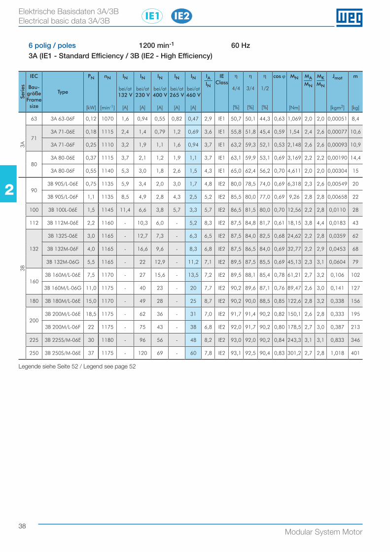
38Modular System Motor
22
Elektrische Basisdaten 3A/3B Electrical basic data 3A/3B
6 polig / poles 1200 min-1 60 Hz3A (IE1 - Standard Efficiency / 3B (IE2 - High Efficiency)
Seri
es
IEC
Bau-größe Frame size
Type
PN
[kW]
nN
[min-1]
IN
bei/at132 V
[A]
IN
bei/at230 V
[A]
IN
bei/at400 V
[A]
IN
bei/at265 V
[A]
IN
bei/at460 V
[A]
IAIN
IEClass
η
4/4
[%]
η
3/4
[%]
η
1/2
[%]
cos ϕ MN
[Nm]
MAMN
MKMN
Jmot
[kgm2]
m
[kg]
3A
63 3A 63-06F 0,12 1070 1,6 0,94 0,55 0,82 0,47 2,9 IE1 50,7 50,1 44,3 0,63 1,069 2,0 2,0 0,00051 8,4
713A 71-06E 0,18 1115 2,4 1,4 0,79 1,2 0,69 3,6 IE1 55,8 51,8 45,4 0,59 1,54 2,4 2,6 0,00077 10,6
3A 71-06F 0,25 1110 3,2 1,9 1,1 1,6 0,94 3,7 IE1 63,2 59,3 52,1 0,53 2,148 2,6 2,6 0,00093 10,9
803A 80-06E 0,37 1115 3,7 2,1 1,2 1,9 1,1 3,7 IE1 63,1 59,9 53,1 0,69 3,169 2,2 2,2 0,00190 14,4
3A 80-06F 0,55 1140 5,3 3,0 1,8 2,6 1,5 4,3 IE1 65,0 62,4 56,2 0,70 4,611 2,0 2,0 0,00304 15
3B
903B 90S/L-06E 0,75 1135 5,9 3,4 2,0 3,0 1,7 4,8 IE2 80,0 78,5 74,0 0,69 6,318 2,3 2,6 0,00549 20
3B 90S/L-06F 1,1 1135 8,5 4,9 2,8 4,3 2,5 5,2 IE2 85,5 80,0 77,0 0,69 9,26 2,8 2,8 0,00658 22
100 3B 100L-06E 1,5 1145 11,4 6,6 3,8 5,7 3,3 5,7 IE2 86,5 81,5 80,0 0,70 12,56 2,2 2,8 0,0110 28
112 3B 112M-06E 2,2 1160 - 10,3 6,0 - 5,2 8,3 IE2 87,5 84,8 81,7 0,61 18,15 3,8 4,4 0,0183 43
132
3B 132S-06E 3,0 1165 - 12,7 7,3 - 6,3 6,5 IE2 87,5 84,0 82,5 0,68 24,62 2,2 2,8 0,0359 62
3B 132M-06F 4,0 1165 - 16,6 9,6 - 8,3 6,8 IE2 87,5 86,5 84,0 0,69 32,77 2,2 2,9 0,0453 68
3B 132M-06G 5,5 1165 - 22 12,9 - 11,2 7,1 IE2 89,5 87,5 85,5 0,69 45,13 2,3 3,1 0,0604 79
1603B 160M/L-06E 7,5 1170 - 27 15,6 - 13,5 7,2 IE2 89,5 88,1 85,4 0,78 61,21 2,7 3,2 0,106 102
3B 160M/L-06G 11,0 1175 - 40 23 - 20 7,7 IE2 90,2 89,6 87,1 0,76 89,47 2,6 3,0 0,141 127
180 3B 180M/L-06E 15,0 1170 - 49 28 - 25 8,7 IE2 90,2 90,0 88,5 0,85 122,6 2,8 3,2 0,338 156
2003B 200M/L-06E 18,5 1175 - 62 36 - 31 7,0 IE2 91,7 91,4 90,2 0,82 150,1 2,6 2,8 0,333 195
3B 200M/L-06F 22 1175 - 75 43 - 38 6,8 IE2 92,0 91,7 90,2 0,80 178,5 2,7 3,0 0,387 213
225 3B 225S/M-06E 30 1180 - 96 56 - 48 8,2 IE2 93,0 92,0 90,2 0,84 243,3 3,1 3,1 0,833 346
250 3B 250S/M-06E 37 1175 - 120 69 - 60 7,8 IE2 93,1 92,5 90,4 0,83 301,2 2,7 2,8 1,018 401
Legende siehe Seite 52 / Legend see page 52
IE2IE1
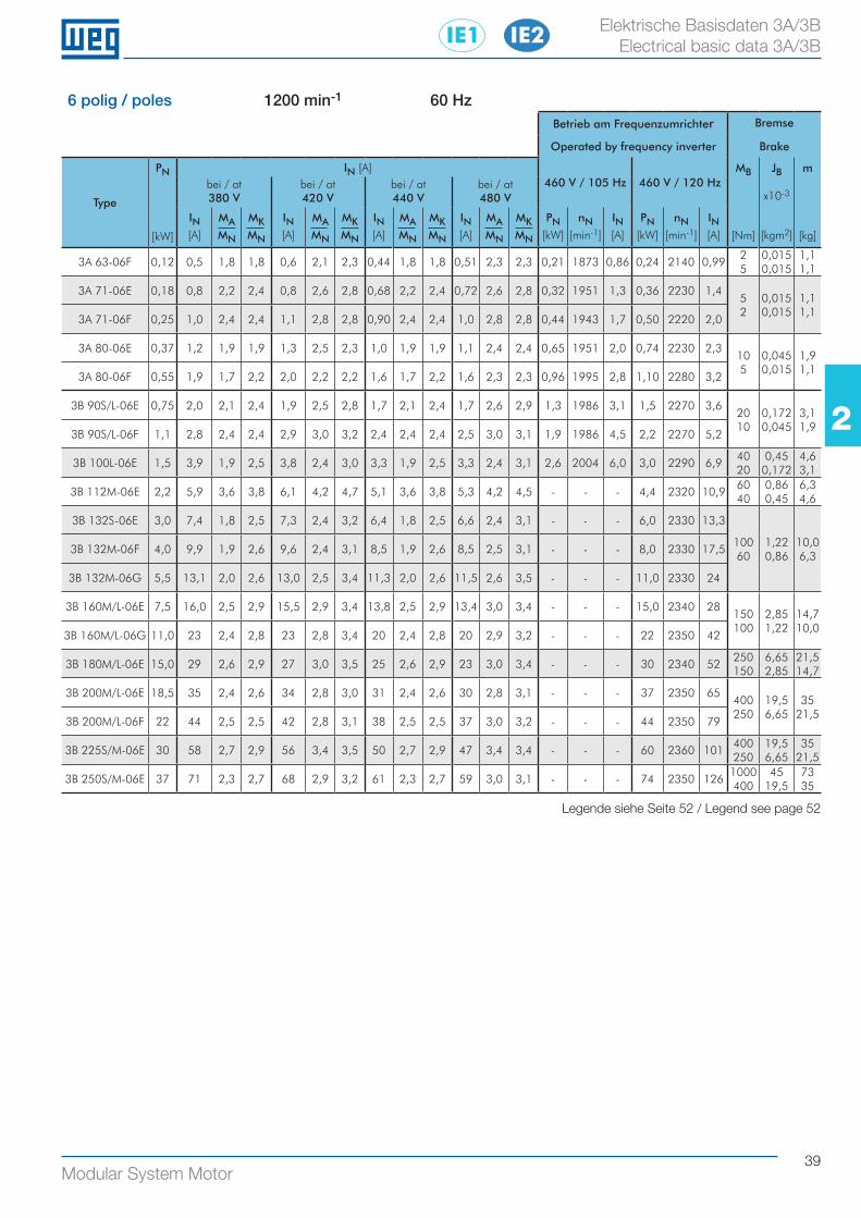
39Modular System Motor
22
Elektrische Basisdaten 3A/3B Electrical basic data 3A/3B
6 polig / poles 1200 min-1 60 HzBetrieb am Frequenzumrichter Bremse
Operated by frequency inverter Brake
Type
PN
[kW]
IN [A]460 V / 105 Hz 460 V / 120 Hz
MB
[Nm]
JB
x10-3
[kgm2]
m
[kg]
bei / at380 V
bei / at420 V
bei / at440 V
bei / at480 V
IN[A]
MAMN
MKMN
IN[A]
MAMN
MKMN
IN[A]
MAMN
MKMN
IN[A]
MAMN
MKMN
PN[kW]
nN[min-1]
IN[A]
PN[kW]
nN[min-1]
IN[A]
3A 63-06F 0,12 0,5 1,8 1,8 0,6 2,1 2,3 0,44 1,8 1,8 0,51 2,3 2,3 0,21 1873 0,86 0,24 2140 0,992 5
0,015 0,015
1,1 1,1
3A 71-06E 0,18 0,8 2,2 2,4 0,8 2,6 2,8 0,68 2,2 2,4 0,72 2,6 2,8 0,32 1951 1,3 0,36 2230 1,45 2
0,015 0,015
1,1 1,1
3A 71-06F 0,25 1,0 2,4 2,4 1,1 2,8 2,8 0,90 2,4 2,4 1,0 2,8 2,8 0,44 1943 1,7 0,50 2220 2,0
3A 80-06E 0,37 1,2 1,9 1,9 1,3 2,5 2,3 1,0 1,9 1,9 1,1 2,4 2,4 0,65 1951 2,0 0,74 2230 2,310 5
0,045 0,015
1,9 1,1
3A 80-06F 0,55 1,9 1,7 2,2 2,0 2,2 2,2 1,6 1,7 2,2 1,6 2,3 2,3 0,96 1995 2,8 1,10 2280 3,2
3B 90S/L-06E 0,75 2,0 2,1 2,4 1,9 2,5 2,8 1,7 2,1 2,4 1,7 2,6 2,9 1,3 1986 3,1 1,5 2270 3,620 10
0,172 0,045
3,1 1,9
3B 90S/L-06F 1,1 2,8 2,4 2,4 2,9 3,0 3,2 2,4 2,4 2,4 2,5 3,0 3,1 1,9 1986 4,5 2,2 2270 5,2
3B 100L-06E 1,5 3,9 1,9 2,5 3,8 2,4 3,0 3,3 1,9 2,5 3,3 2,4 3,1 2,6 2004 6,0 3,0 2290 6,940 20
0,45 0,172
4,6 3,1
3B 112M-06E 2,2 5,9 3,6 3,8 6,1 4,2 4,7 5,1 3,6 3,8 5,3 4,2 4,5 - - - 4,4 2320 10,960 40
0,86 0,45
6,3 4,6
3B 132S-06E 3,0 7,4 1,8 2,5 7,3 2,4 3,2 6,4 1,8 2,5 6,6 2,4 3,1 - - - 6,0 2330 13,3
100 60
1,22 0,86
10,0 6,3
3B 132M-06F 4,0 9,9 1,9 2,6 9,6 2,4 3,1 8,5 1,9 2,6 8,5 2,5 3,1 - - - 8,0 2330 17,5
3B 132M-06G 5,5 13,1 2,0 2,6 13,0 2,5 3,4 11,3 2,0 2,6 11,5 2,6 3,5 - - - 11,0 2330 24
3B 160M/L-06E 7,5 16,0 2,5 2,9 15,5 2,9 3,4 13,8 2,5 2,9 13,4 3,0 3,4 - - - 15,0 2340 28150 100
2,85 1,22
14,7 10,0
3B 160M/L-06G 11,0 23 2,4 2,8 23 2,8 3,4 20 2,4 2,8 20 2,9 3,2 - - - 22 2350 42
3B 180M/L-06E 15,0 29 2,6 2,9 27 3,0 3,5 25 2,6 2,9 23 3,0 3,4 - - - 30 2340 52250 150
6,65 2,85
21,5 14,7
3B 200M/L-06E 18,5 35 2,4 2,6 34 2,8 3,0 31 2,4 2,6 30 2,8 3,1 - - - 37 2350 65400 250
19,5 6,65
35 21,5
3B 200M/L-06F 22 44 2,5 2,5 42 2,8 3,1 38 2,5 2,5 37 3,0 3,2 - - - 44 2350 79
3B 225S/M-06E 30 58 2,7 2,9 56 3,4 3,5 50 2,7 2,9 47 3,4 3,4 - - - 60 2360 101400 250
19,5 6,65
35 21,5
3B 250S/M-06E 37 71 2,3 2,7 68 2,9 3,2 61 2,3 2,7 59 3,0 3,1 - - - 74 2350 1261000 400
45 19,5
73 35
Legende siehe Seite 52 / Legend see page 52
IE2IE1
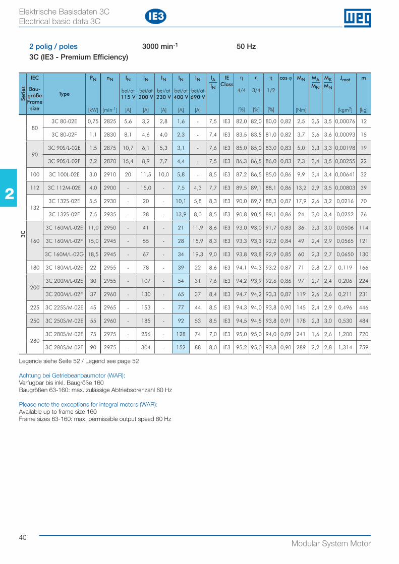
40Modular System Motor
22
Elektrische Basisdaten 3C Electrical basic data 3C
2 polig / poles 3000 min-1 50 Hz3C (IE3 - Premium Efficiency)
Seri
es
IEC
Bau-größe Frame size
Type
PN
[kW]
nN
[min-1]
IN
bei/at115 V
[A]
IN
bei/at200 V
[A]
IN
bei/at230 V
[A]
IN
bei/at400 V
[A]
IN
bei/at690 V
[A]
IAIN
IEClass
η
4/4
[%]
η
3/4
[%]
η
1/2
[%]
cos ϕ MN
[Nm]
MAMN
MKMN
Jmot
[kgm2]
m
[kg]
3C
803C 80-02E 0,75 2825 5,6 3,2 2,8 1,6 - 7,5 IE3 82,0 82,0 80,0 0,82 2,5 3,5 3,5 0,00076 12
3C 80-02F 1,1 2830 8,1 4,6 4,0 2,3 - 7,4 IE3 83,5 83,5 81,0 0,82 3,7 3,6 3,6 0,00093 15
903C 90S/L-02E 1,5 2875 10,7 6,1 5,3 3,1 - 7,6 IE3 85,0 85,0 83,0 0,83 5,0 3,3 3,3 0,00198 19
3C 90S/L-02F 2,2 2870 15,4 8,9 7,7 4,4 - 7,5 IE3 86,3 86,5 86,0 0,83 7,3 3,4 3,5 0,00255 22
100 3C 100L-02E 3,0 2910 20 11,5 10,0 5,8 - 8,5 IE3 87,2 86,5 85,0 0,86 9,9 3,4 3,4 0,00641 32
112 3C 112M-02E 4,0 2900 - 15,0 - 7,5 4,3 7,7 IE3 89,5 89,1 88,1 0,86 13,2 2,9 3,5 0,00803 39
1323C 132S-02E 5,5 2930 - 20 - 10,1 5,8 8,3 IE3 90,0 89,7 88,3 0,87 17,9 2,6 3,2 0,0216 70
3C 132S-02F 7,5 2935 - 28 - 13,9 8,0 8,5 IE3 90,8 90,5 89,1 0,86 24 3,0 3,4 0,0252 76
160
3C 160M/L-02E 11,0 2950 - 41 - 21 11,9 8,6 IE3 93,0 93,0 91,7 0,83 36 2,3 3,0 0,0506 114
3C 160M/L-02F 15,0 2945 - 55 - 28 15,9 8,3 IE3 93,3 93,3 92,2 0,84 49 2,4 2,9 0,0565 121
3C 160M/L-02G 18,5 2945 - 67 - 34 19,3 9,0 IE3 93,8 93,8 92,9 0,85 60 2,3 2,7 0,0650 130
180 3C 180M/L-02E 22 2955 - 78 - 39 22 8,6 IE3 94,1 94,3 93,2 0,87 71 2,8 2,7 0,119 166
2003C 200M/L-02E 30 2955 - 107 - 54 31 7,6 IE3 94,2 93,9 92,6 0,86 97 2,7 2,4 0,206 224
3C 200M/L-02F 37 2960 - 130 - 65 37 8,4 IE3 94,7 94,2 93,3 0,87 119 2,6 2,6 0,211 231
225 3C 225S/M-02E 45 2965 - 153 - 77 44 8,5 IE3 94,3 94,0 93,8 0,90 145 2,4 2,9 0,496 446
250 3C 250S/M-02E 55 2960 - 185 - 92 53 8,5 IE3 94,5 94,5 93,8 0,91 178 2,3 3,0 0,530 484
2803C 280S/M-02E 75 2975 - 256 - 128 74 7,0 IE3 95,0 95,0 94,0 0,89 241 1,6 2,6 1,200 720
3C 280S/M-02F 90 2975 - 304 - 152 88 8,0 IE3 95,2 95,0 93,8 0,90 289 2,2 2,8 1,314 759
Legende siehe Seite 52 / Legend see page 52
Achtung bei Getriebeanbaumotor (WAR): Verfügbar bis inkl. Baugröße 160Baugrößen 63-160: max. zulässige Abtriebsdrehzahl 60 Hz
Please note the exceptions for integral motors (WAR):Available up to frame size 160Frame sizes 63-160: max. permissible output speed 60 Hz
IE3
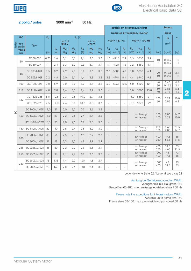
41Modular System Motor
22
Elektrische Basisdaten 3C Electrical basic data 3C
2 polig / poles 3000 min-1 50 HzBetrieb am Frequenzumrichter Bremse
Operated by frequency inverter Brake
Seri
es
IEC
Bau-größe Frame size
Type
PN
[kW]
IN [A]400 V / 87 Hz 400 V / 100 Hz
MB
[Nm]
JB
x10-3
[kgm2]
m
[kg]
bei / at380 V
bei / at420 V
IN[A]
MAMN
MKMN
IN[A]
MAMN
MKMN
PN[kW]
nN[min-1]
IN[A]
PN[kW]
nN[min-1]
IN[A]
3C
803C 80-02E 0,75 1,6 3,1 3,1 1,6 3,8 3,8 1,3 4916 2,9 1,5 5650 3,4
10 5
0,045 0,015
1,9 1,1
3C 80-02F 1,1 2,4 3,3 3,2 2,3 3,9 3,9 1,9 4924 4,2 2,2 5660 4,9
903C 90S/L-02E 1,5 3,2 2,9 2,9 3,1 3,6 3,6 2,6 5003 5,6 3,0 5750 6,4
20 10
0,172 0,045
3,1 1,9
3C 90S/L-02F 2,2 4,5 3,0 3,1 4,4 3,8 3,8 3,8 4994 8,1 4,4 5740 9,3
100 3C 100L-02E 3,0 5,9 3,0 3,0 5,7 3,7 3,6 5,2 5063 10,5 6,0 5820 12,140 20
0,45 0,172
4,6 3,1
112 3C 112M-02E 4,0 7,8 2,6 3,1 7,4 3,2 3,8 - - - 8,0 5800 15,860 40
0,86 0,45
6,3 4,6
1323C 132S-02E 5,5 10,5 2,3 2,8 10,0 2,9 3,5 - - - 11,0 5860 21
100 60
1,22 0,86
10,0 6,3
3C 132S-02F 7,5 14,3 2,6 3,0 13,8 3,3 3,7 - - - 15,0 5870 29
160
3C 160M/L-02E 11,0 21 2,0 2,7 20 2,6 3,3 - - -
auf Anfrageon request
150 100
2,85 1,22
14,7 10,0
3C 160M/L-02F 15,0 29 2,2 2,6 27 2,7 3,2 - - -
3C 160M/L-02G 18,5 35 2,0 2,5 33 2,6 3,0 - - -
180 3C 180M/L-02E 22 40 2,5 2,4 38 3,0 3,0 - - -auf Anfrageon request
250 150
6,65 2,85
21,5 14,7
2003C 200M/L-02E 30 56 2,5 2,1 52 2,9 2,7 - - -
auf Anfrageon request
400 250
19,5 6,65
35 21,5
3C 200M/L-02F 37 68 2,3 2,3 63 2,9 2,9 - - -
225 3C 225S/M-02E 45 80 2,2 2,7 75 2,6 3,1 - - -auf Anfrageon request
400 250
19,5 6,65
35 21,5
250 3C 250S/M-02E 55 96 2,1 2,7 90 2,6 3,3 - - -auf Anfrageon request
1000400
45 19,5
73 35
2803C 280S/M-02E 75 133 1,4 2,3 125 1,8 2,9 - - -
auf Anfrageon request
1000400
45 19,5
73 35
3C 280S/M-02F 90 160 2,0 2,5 148 2,4 3,0 - - -
Legende siehe Seite 52 / Legend see page 52
Achtung bei Getriebeanbaumotor (WAR): Verfügbar bis inkl. Baugröße 160
Baugrößen 63-160: max. zulässige Abtriebsdrehzahl 60 Hz
Please note the exceptions for integral motors (WAR):Available up to frame size 160
Frame sizes 63-160: max. permissible output speed 60 Hz
IE3
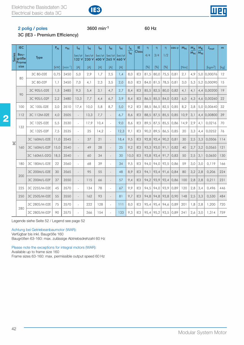
42Modular System Motor
22
Elektrische Basisdaten 3C Electrical basic data 3C
2 polig / poles 3600 min-1 60 Hz3C (IE3 - Premium Efficiency)
Seri
es
IEC
Bau-größe Frame size
Type
PN
[kW]
nN
[min-1]
IN
bei/at132 V
[A]
IN
bei/at230 V
[A]
IN
bei/at400 V
[A]
IN
bei/at265 V
[A]
IN
bei/at460 V
[A]
IAIN
IEClass
η
4/4
[%]
η
3/4
[%]
η
1/2
[%]
cos ϕ MN
[Nm]
MAMN
MKMN
Jmot
[kgm2]
m
[kg]
3C
803C 80-02E 0,75 3450 5,0 2,9 1,7 2,5 1,4 8,0 IE3 81,5 80,0 75,5 0,81 2,1 4,9 5,0 0,00076 12
3C 80-02F 1,1 3450 7,0 4,1 2,3 3,5 2,0 8,0 IE3 84,0 81,5 78,5 0,81 3,0 5,3 5,2 0,00090 15
903C 90S/L-02E 1,5 3485 9,3 5,4 3,1 4,7 2,7 8,4 IE3 85,5 82,5 80,0 0,82 4,1 4,1 4,4 0,00200 19
3C 90S/L-02F 2,2 3480 13,3 7,7 4,4 6,7 3,9 8,4 IE3 86,5 85,5 84,0 0,83 6,0 4,3 4,6 0,00260 22
100 3C 100L-02E 3,0 3510 17,4 10,0 5,8 8,7 5,0 9,2 IE3 88,5 86,5 82,5 0,85 8,2 3,8 5,0 0,00640 32
112 3C 112M-02E 4,0 3505 - 13,3 7,7 - 6,7 8,6 IE3 88,5 87,5 85,5 0,85 10,9 3,1 4,4 0,00800 39
1323C 132S-02E 5,5 3530 - 17,9 10,4 - 9,0 8,6 IE3 89,5 87,5 85,5 0,86 14,9 2,9 4,1 0,0216 70
3C 132S-02F 7,5 3535 - 25 14,2 - 12,3 9,1 IE3 90,2 89,5 86,5 0,85 20 3,3 4,4 0,0252 76
160
3C 160M/L-02E 11,0 3545 - 37 21 - 18,4 9,5 IE3 92,8 92,4 90,2 0,81 30 2,5 3,3 0,0506 114
3C 160M/L-02F 15,0 3540 - 49 28 - 25 9,2 IE3 93,3 93,0 91,1 0,82 40 2,7 3,2 0,0565 121
3C 160M/L-02G 18,5 3540 - 60 34 - 30 10,0 IE3 93,8 93,4 91,7 0,83 50 2,5 3,1 0,0650 130
180 3C 180M/L-02E 22 3560 - 68 39 - 34 9,5 IE3 94,0 94,0 92,5 0,86 59 3,0 3,0 0,119 166
2003C 200M/L-02E 30 3565 - 95 55 - 48 8,9 IE3 94,1 93,4 91,6 0,84 80 3,2 2,8 0,206 224
3C 200M/L-02F 37 3550 - 115 66 - 57 9,4 IE3 94,2 93,9 92,4 0,86 100 2,8 2,8 0,211 231
225 3C 225S/M-02E 45 3570 - 134 78 - 67 9,9 IE3 94,5 94,0 93,9 0,89 120 2,8 3,4 0,496 446
250 3C 250S/M-02E 55 3550 - 162 93 - 81 9,7 IE3 94,8 94,8 93,8 0,90 148 2,5 3,3 0,530 484
2803C 280S/M-02E 75 3570 - 222 128 - 111 8,0 IE3 95,4 95,4 94,6 0,89 201 1,8 2,8 1,200 720
3C 280S/M-02F 90 3575 - 266 154 - 133 9,3 IE3 95,4 95,2 93,5 0,89 241 2,6 3,0 1,314 759
Legende siehe Seite 52 / Legend see page 52
Achtung bei Getriebeanbaumotor (WAR): Verfügbar bis inkl. Baugröße 160Baugrößen 63-160: max. zulässige Abtriebsdrehzahl 60 Hz
Please note the exceptions for integral motors (WAR):Available up to frame size 160Frame sizes 63-160: max. permissible output speed 60 Hz
IE3
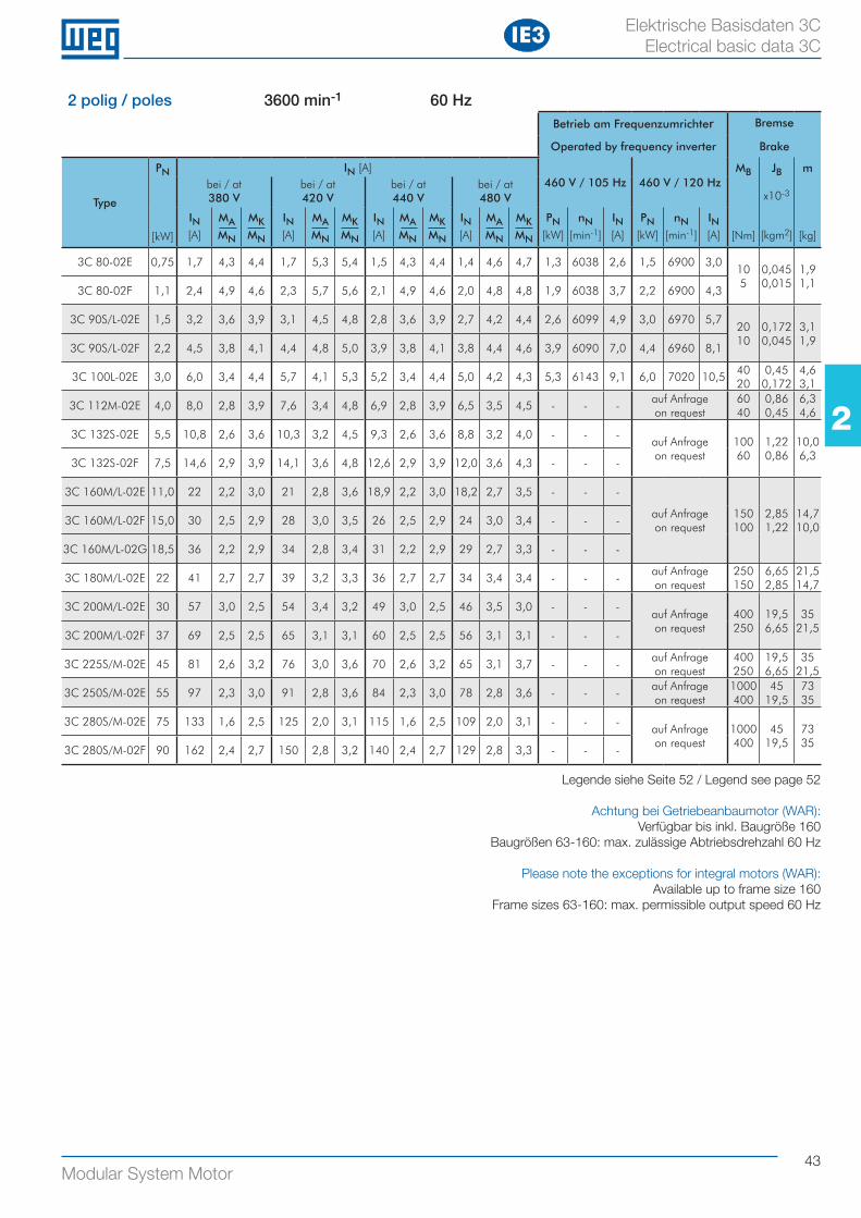
43Modular System Motor
22
Elektrische Basisdaten 3C Electrical basic data 3C
2 polig / poles 3600 min-1 60 HzBetrieb am Frequenzumrichter Bremse
Operated by frequency inverter Brake
Type
PN
[kW]
IN [A]460 V / 105 Hz 460 V / 120 Hz
MB
[Nm]
JB
x10-3
[kgm2]
m
[kg]
bei / at380 V
bei / at420 V
bei / at440 V
bei / at480 V
IN[A]
MAMN
MKMN
IN[A]
MAMN
MKMN
IN[A]
MAMN
MKMN
IN[A]
MAMN
MKMN
PN[kW]
nN[min-1]
IN[A]
PN[kW]
nN[min-1]
IN[A]
3C 80-02E 0,75 1,7 4,3 4,4 1,7 5,3 5,4 1,5 4,3 4,4 1,4 4,6 4,7 1,3 6038 2,6 1,5 6900 3,010 5
0,045 0,015
1,9 1,1
3C 80-02F 1,1 2,4 4,9 4,6 2,3 5,7 5,6 2,1 4,9 4,6 2,0 4,8 4,8 1,9 6038 3,7 2,2 6900 4,3
3C 90S/L-02E 1,5 3,2 3,6 3,9 3,1 4,5 4,8 2,8 3,6 3,9 2,7 4,2 4,4 2,6 6099 4,9 3,0 6970 5,720 10
0,172 0,045
3,1 1,9
3C 90S/L-02F 2,2 4,5 3,8 4,1 4,4 4,8 5,0 3,9 3,8 4,1 3,8 4,4 4,6 3,9 6090 7,0 4,4 6960 8,1
3C 100L-02E 3,0 6,0 3,4 4,4 5,7 4,1 5,3 5,2 3,4 4,4 5,0 4,2 4,3 5,3 6143 9,1 6,0 7020 10,540 20
0,45 0,172
4,6 3,1
3C 112M-02E 4,0 8,0 2,8 3,9 7,6 3,4 4,8 6,9 2,8 3,9 6,5 3,5 4,5 - - -auf Anfrageon request
60 40
0,86 0,45
6,3 4,6
3C 132S-02E 5,5 10,8 2,6 3,6 10,3 3,2 4,5 9,3 2,6 3,6 8,8 3,2 4,0 - - -auf Anfrageon request
100 60
1,22 0,86
10,0 6,3
3C 132S-02F 7,5 14,6 2,9 3,9 14,1 3,6 4,8 12,6 2,9 3,9 12,0 3,6 4,3 - - -
3C 160M/L-02E 11,0 22 2,2 3,0 21 2,8 3,6 18,9 2,2 3,0 18,2 2,7 3,5 - - -
auf Anfrageon request
150 100
2,85 1,22
14,7 10,0
3C 160M/L-02F 15,0 30 2,5 2,9 28 3,0 3,5 26 2,5 2,9 24 3,0 3,4 - - -
3C 160M/L-02G 18,5 36 2,2 2,9 34 2,8 3,4 31 2,2 2,9 29 2,7 3,3 - - -
3C 180M/L-02E 22 41 2,7 2,7 39 3,2 3,3 36 2,7 2,7 34 3,4 3,4 - - -auf Anfrageon request
250 150
6,65 2,85
21,5 14,7
3C 200M/L-02E 30 57 3,0 2,5 54 3,4 3,2 49 3,0 2,5 46 3,5 3,0 - - -auf Anfrageon request
400 250
19,5 6,65
35 21,5
3C 200M/L-02F 37 69 2,5 2,5 65 3,1 3,1 60 2,5 2,5 56 3,1 3,1 - - -
3C 225S/M-02E 45 81 2,6 3,2 76 3,0 3,6 70 2,6 3,2 65 3,1 3,7 - - -auf Anfrageon request
400 250
19,5 6,65
35 21,5
3C 250S/M-02E 55 97 2,3 3,0 91 2,8 3,6 84 2,3 3,0 78 2,8 3,6 - - -auf Anfrageon request
1000400
45 19,5
73 35
3C 280S/M-02E 75 133 1,6 2,5 125 2,0 3,1 115 1,6 2,5 109 2,0 3,1 - - -auf Anfrageon request
1000400
45 19,5
73 35
3C 280S/M-02F 90 162 2,4 2,7 150 2,8 3,2 140 2,4 2,7 129 2,8 3,3 - - -
Legende siehe Seite 52 / Legend see page 52
Achtung bei Getriebeanbaumotor (WAR): Verfügbar bis inkl. Baugröße 160
Baugrößen 63-160: max. zulässige Abtriebsdrehzahl 60 Hz
Please note the exceptions for integral motors (WAR):Available up to frame size 160
Frame sizes 63-160: max. permissible output speed 60 Hz
IE3
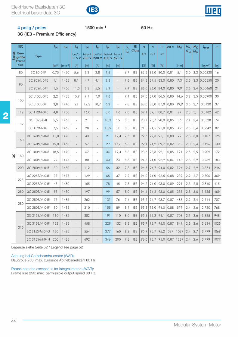
44
22
Modular System Motor
4 polig / poles 1500 min-1 50 Hz3C (IE3 - Premium Efficiency)
Seri
es
IEC
Bau-größe Frame size
Type
PN
[kW]
nN
[min-1]
IN
bei/at115 V
[A]
IN
bei/at200 V
[A]
IN
bei/at230 V
[A]
IN
bei/at400 V
[A]
IN
bei/at690 V
[A]
IAIN
IEClass
η
4/4
[%]
η
3/4
[%]
η
1/2
[%]
cos ϕ MN
[Nm]
MAMN
MKMN
Jmot
[kgm2]
m
[kg]
3C
80 3C 80-04F 0,75 1420 5,6 3,2 2,8 1,6 - 6,7 IE3 82,5 82,0 80,0 0,81 5,1 3,0 3,3 0,00320 16
903C 90S/L-04E 1,1 1455 8,1 4,7 4,1 2,3 - 7,6 IE3 84,8 84,5 83,0 0,80 7,3 2,5 3,3 0,00550 20
3C 90S/L-04F 1,5 1450 11,0 6,3 5,5 3,2 - 7,4 IE3 86,0 86,0 84,0 0,80 9,9 2,6 3,4 0,00660 21
1003C L100L-04E 2,2 1435 15,9 9,1 7,9 4,6 - 7,4 IE3 87,0 87,0 86,5 0,80 14,6 3,2 3,5 0,00900 30
3C L100L-04F 3,0 1440 21 12,3 10,7 6,2 - 7,8 IE3 88,0 88,0 87,0 0,80 19,9 3,5 3,7 0,0120 37
112 3C 112M-04E 4,0 1450 - 16,0 - 8,0 4,6 7,0 IE3 89,1 89,1 88,7 0,81 27 2,3 3,1 0,0182 42
1323C 132S-04E 5,5 1465 - 21 - 10,3 5,9 8,5 IE3 90,7 90,7 90,0 0,85 36 2,4 3,4 0,0528 74
3C 132M-04F 7,5 1465 - 28 - 13,9 8,0 8,5 IE3 91,5 91,5 91,0 0,85 49 2,5 3,4 0,0642 82
1603C 160M/L-04E 11,0 1470 - 43 - 21 12,4 7,5 IE3 92,6 92,3 91,1 0,80 72 2,8 3,0 0,107 125
3C 160M/L-04F 15,0 1465 - 57 - 29 16,6 6,3 IE3 92,1 91,2 89,7 0,82 98 2,0 2,4 0,126 130
1803C 180M/L-04E 18,5 1470 - 67 - 34 19,4 8,3 IE3 93,6 93,3 92,1 0,85 121 2,5 2,5 0,209 172
3C 180M/L-04F 22 1475 - 80 - 40 23 8,6 IE3 94,3 94,0 92,9 0,84 143 2,8 2,9 0,239 183
200 3C 200M/L-04E 30 1480 - 112 - 56 32 7,3 IE3 94,5 94,7 94,0 0,82 194 2,7 2,9 0,374 246
2253C 225S/M-04E 37 1475 - 129 - 65 37 7,2 IE3 94,0 94,0 92,5 0,88 239 2,2 2,7 0,700 369
3C 225S/M-04F 45 1480 - 155 - 78 45 7,5 IE3 94,2 94,0 93,0 0,89 291 2,3 2,8 0,840 415
250 3C 250S/M-04E 55 1480 - 197 - 99 57 8,0 IE3 94,6 94,2 93,0 0,85 355 2,8 3,0 1,155 469
2803C 280S/M-04E 75 1485 - 262 - 131 76 7,4 IE3 95,2 94,7 93,7 0,87 483 2,2 2,4 2,114 707
3C 280S/M-04F 90 1485 - 310 - 155 89 8,1 IE3 95,3 95,0 94,0 0,88 579 2,4 2,6 2,720 768
315
3C 315S/M-04E 110 1485 - 382 - 191 110 8,0 IE3 95,6 95,2 94,1 0,87 708 2,1 2,6 3,325 948
3C 315S/M-04F 132 1485 - 458 - 229 132 8,3 IE3 95,7 95,7 95,0 0,87 849 2,5 2,6 3,634 1025
3C 315S/M-04G 160 1485 - 554 - 277 160 8,2 IE3 95,9 95,7 95,2 087 1029 2,4 2,7 3,799 1069
3C 315S/M-04H 200 1485 - 692 - 346 200 7,8 IE3 96,0 95,7 95,0 0,87 1287 2,4 2,6 3,799 1077
Elektrische Basisdaten 3C Electrical basic data 3C
Legende siehe Seite 52 / Legend see page 52
Achtung bei Getriebeanbaumotor (WAR): Baugröße 250: max. zulässige Abtriebsdrehzahl 60 Hz
Please note the exceptions for integral motors (WAR):Frame size 250: max. permissible output speed 60 Hz
IE3
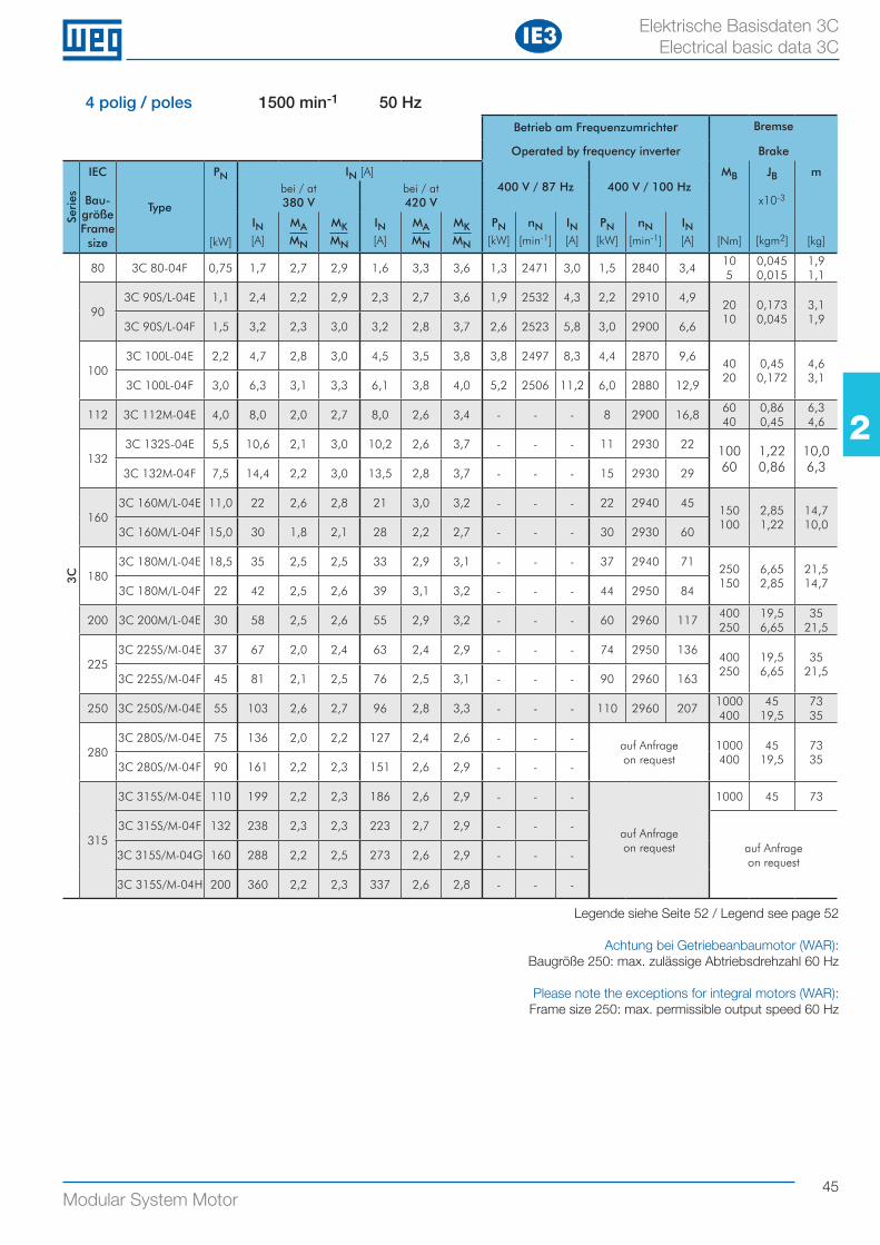
45Modular System Motor
22
4 polig / poles 1500 min-1 50 HzBetrieb am Frequenzumrichter Bremse
Operated by frequency inverter Brake
Seri
es
IEC
Bau-größe Frame size
Type
PN
[kW]
IN [A]400 V / 87 Hz 400 V / 100 Hz
MB
[Nm]
JB
x10-3
[kgm2]
m
[kg]
bei / at380 V
bei / at420 V
IN[A]
MAMN
MKMN
IN[A]
MAMN
MKMN
PN[kW]
nN[min-1]
IN[A]
PN[kW]
nN[min-1]
IN[A]
3C
80 3C 80-04F 0,75 1,7 2,7 2,9 1,6 3,3 3,6 1,3 2471 3,0 1,5 2840 3,410 5
0,045 0,015
1,9 1,1
903C 90S/L-04E 1,1 2,4 2,2 2,9 2,3 2,7 3,6 1,9 2532 4,3 2,2 2910 4,9
20 10
0,173 0,045
3,1 1,9
3C 90S/L-04F 1,5 3,2 2,3 3,0 3,2 2,8 3,7 2,6 2523 5,8 3,0 2900 6,6
1003C 100L-04E 2,2 4,7 2,8 3,0 4,5 3,5 3,8 3,8 2497 8,3 4,4 2870 9,6
40 20
0,45 0,172
4,6 3,1
3C 100L-04F 3,0 6,3 3,1 3,3 6,1 3,8 4,0 5,2 2506 11,2 6,0 2880 12,9
112 3C 112M-04E 4,0 8,0 2,0 2,7 8,0 2,6 3,4 - - - 8 2900 16,860 40
0,86 0,45
6,3 4,6
1323C 132S-04E 5,5 10,6 2,1 3,0 10,2 2,6 3,7 - - - 11 2930 22 100
601,22 0,86
10,0 6,33C 132M-04F 7,5 14,4 2,2 3,0 13,5 2,8 3,7 - - - 15 2930 29
1603C 160M/L-04E 11,0 22 2,6 2,8 21 3,0 3,2 - - - 22 2940 45
150 100
2,85 1,22
14,7 10,0
3C 160M/L-04F 15,0 30 1,8 2,1 28 2,2 2,7 - - - 30 2930 60
1803C 180M/L-04E 18,5 35 2,5 2,5 33 2,9 3,1 - - - 37 2940 71
250 150
6,65 2,85
21,5 14,7
3C 180M/L-04F 22 42 2,5 2,6 39 3,1 3,2 - - - 44 2950 84
200 3C 200M/L-04E 30 58 2,5 2,6 55 2,9 3,2 - - - 60 2960 117400 250
19,5 6,65
35 21,5
2253C 225S/M-04E 37 67 2,0 2,4 63 2,4 2,9 - - - 74 2950 136
400 250
19,5 6,65
35 21,5
3C 225S/M-04F 45 81 2,1 2,5 76 2,5 3,1 - - - 90 2960 163
250 3C 250S/M-04E 55 103 2,6 2,7 96 2,8 3,3 - - - 110 2960 2071000400
45 19,5
73 35
2803C 280S/M-04E 75 136 2,0 2,2 127 2,4 2,6 - - -
auf Anfrageon request
1000400
45 19,5
73 35
3C 280S/M-04F 90 161 2,2 2,3 151 2,6 2,9 - - -
315
3C 315S/M-04E 110 199 2,2 2,3 186 2,6 2,9 - - -
auf Anfrageon request
1000 45 73
3C 315S/M-04F 132 238 2,3 2,3 223 2,7 2,9 - - -
auf Anfrage on request
3C 315S/M-04G 160 288 2,2 2,5 273 2,6 2,9 - - -
3C 315S/M-04H 200 360 2,2 2,3 337 2,6 2,8 - - -
Elektrische Basisdaten 3C Electrical basic data 3C
Legende siehe Seite 52 / Legend see page 52
Achtung bei Getriebeanbaumotor (WAR): Baugröße 250: max. zulässige Abtriebsdrehzahl 60 Hz
Please note the exceptions for integral motors (WAR):Frame size 250: max. permissible output speed 60 Hz
IE3
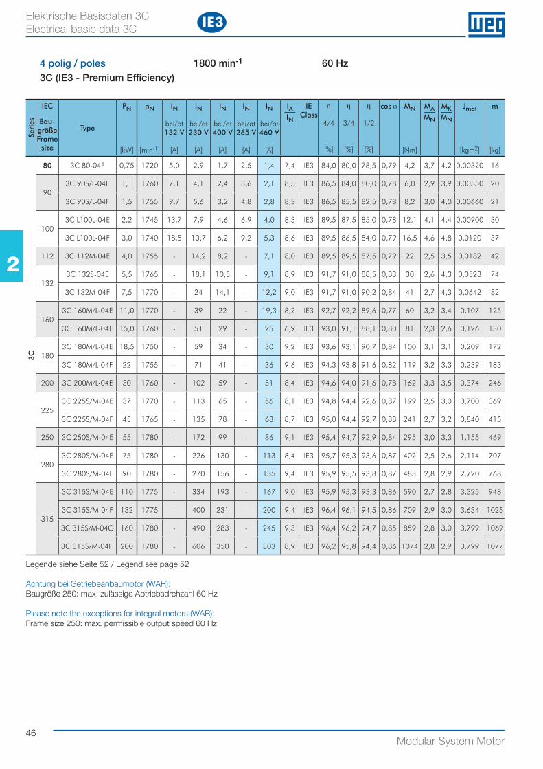
46Modular System Motor
22
Elektrische Basisdaten 3C Electrical basic data 3C
4 polig / poles 1800 min-1 60 Hz3C (IE3 - Premium Efficiency)
Seri
es
IEC
Bau-größe Frame size
Type
PN
[kW]
nN
[min-1]
IN
bei/at132 V
[A]
IN
bei/at230 V
[A]
IN
bei/at400 V
[A]
IN
bei/at265 V
[A]
IN
bei/at460 V
[A]
IAIN
IEClass
η
4/4
[%]
η
3/4
[%]
η
1/2
[%]
cos ϕ MN
[Nm]
MAMN
MKMN
Jmot
[kgm2]
m
[kg]
3C
80 3C 80-04F 0,75 1720 5,0 2,9 1,7 2,5 1,4 7,4 IE3 84,0 80,0 78,5 0,79 4,2 3,7 4,2 0,00320 16
903C 90S/L-04E 1,1 1760 7,1 4,1 2,4 3,6 2,1 8,5 IE3 86,5 84,0 80,0 0,78 6,0 2,9 3,9 0,00550 20
3C 90S/L-04F 1,5 1755 9,7 5,6 3,2 4,8 2,8 8,3 IE3 86,5 85,5 82,5 0,78 8,2 3,0 4,0 0,00660 21
1003C L100L-04E 2,2 1745 13,7 7,9 4,6 6,9 4,0 8,3 IE3 89,5 87,5 85,0 0,78 12,1 4,1 4,4 0,00900 30
3C L100L-04F 3,0 1740 18,5 10,7 6,2 9,2 5,3 8,6 IE3 89,5 86,5 84,0 0,79 16,5 4,6 4,8 0,0120 37
112 3C 112M-04E 4,0 1755 - 14,2 8,2 - 7,1 8,0 IE3 89,5 89,5 87,5 0,79 22 2,5 3,5 0,0182 42
1323C 132S-04E 5,5 1765 - 18,1 10,5 - 9,1 8,9 IE3 91,7 91,0 88,5 0,83 30 2,6 4,3 0,0528 74
3C 132M-04F 7,5 1770 - 24 14,1 - 12,2 9,0 IE3 91,7 91,0 90,2 0,84 41 2,7 4,3 0,0642 82
1603C 160M/L-04E 11,0 1770 - 39 22 - 19,3 8,2 IE3 92,7 92,2 89,6 0,77 60 3,2 3,4 0,107 125
3C 160M/L-04F 15,0 1760 - 51 29 - 25 6,9 IE3 93,0 91,1 88,1 0,80 81 2,3 2,6 0,126 130
1803C 180M/L-04E 18,5 1750 - 59 34 - 30 9,2 IE3 93,6 93,1 90,7 0,84 100 3,1 3,1 0,209 172
3C 180M/L-04F 22 1755 - 71 41 - 36 9,6 IE3 94,3 93,8 91,6 0,82 119 3,2 3,3 0,239 183
200 3C 200M/L-04E 30 1760 - 102 59 - 51 8,4 IE3 94,6 94,0 91,6 0,78 162 3,3 3,5 0,374 246
2253C 225S/M-04E 37 1770 - 113 65 - 56 8,1 IE3 94,8 94,4 92,6 0,87 199 2,5 3,0 0,700 369
3C 225S/M-04F 45 1765 - 135 78 - 68 8,7 IE3 95,0 94,4 92,7 0,88 241 2,7 3,2 0,840 415
250 3C 250S/M-04E 55 1780 - 172 99 - 86 9,1 IE3 95,4 94,7 92,9 0,84 295 3,0 3,3 1,155 469
2803C 280S/M-04E 75 1780 - 226 130 - 113 8,4 IE3 95,7 95,3 93,6 0,87 402 2,5 2,6 2,114 707
3C 280S/M-04F 90 1780 - 270 156 - 135 9,4 IE3 95,9 95,5 93,8 0,87 483 2,8 2,9 2,720 768
315
3C 315S/M-04E 110 1775 - 334 193 - 167 9,0 IE3 95,9 95,3 93,3 0,86 590 2,7 2,8 3,325 948
3C 315S/M-04F 132 1775 - 400 231 - 200 9,4 IE3 96,4 96,1 94,5 0,86 709 2,9 3,0 3,634 1025
3C 315S/M-04G 160 1780 - 490 283 - 245 9,3 IE3 96,4 96,2 94,7 0,85 859 2,8 3,0 3,799 1069
3C 315S/M-04H 200 1780 - 606 350 - 303 8,9 IE3 96,2 95,8 94,4 0,86 1074 2,8 2,9 3,799 1077
Legende siehe Seite 52 / Legend see page 52
Achtung bei Getriebeanbaumotor (WAR): Baugröße 250: max. zulässige Abtriebsdrehzahl 60 Hz
Please note the exceptions for integral motors (WAR):Frame size 250: max. permissible output speed 60 Hz
IE3
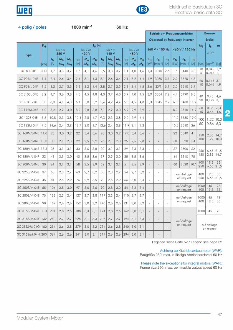
47Modular System Motor
22
Elektrische Basisdaten 3C Electrical basic data 3C
4 polig / poles 1800 min-1 60 HzBetrieb am Frequenzumrichter Bremse
Operated by frequency inverter Brake
Type
PN
[kW]
IN [A]460 V / 105 Hz 460 V / 120 Hz
MB
[Nm]
JB
x10-3
[kgm2]
m
[kg]
bei / at380 V
bei / at420 V
bei / at440 V
bei / at480 V
IN[A]
MAMN
MKMN
IN[A]
MAMN
MKMN
IN[A]
MAMN
MKMN
IN[A]
MAMN
MKMN
PN[kW]
nN[min-1]
IN[A]
PN[kW]
nN[min-1]
IN[A]
3C 80-04F 0,75 1,7 3,3 3,7 1,6 4,1 4,6 1,5 3,3 3,7 1,4 4,0 4,6 1,3 3010 2,6 1,5 3440 3,010 5
0,045 0,015
1,9 1,1
3C 90S/L-04E 1,1 2,4 2,6 3,4 2,4 3,1 4,3 2,1 2,6 3,4 2,1 3,2 4,4 1,9 3080 3,7 2,2 3520 4,320 10
0,173 0,045
3,1 1,9
3C 90S/L-04F 1,5 3,3 2,7 3,5 3,2 3,2 4,4 2,8 2,7 3,5 2,8 3,4 4,5 2,6 3071 5,1 3,0 3510 5,9
3C L100L-04E 2,2 4,7 3,6 3,8 4,5 4,5 4,8 4,0 3,7 4,0 3,9 4,0 4,5 3,9 3054 7,2 4,4 3490 8,340 20
0,45 0,172
4,6 3,1
3C L100L-04F 3,0 6,3 4,1 4,3 6,1 5,0 5,2 5,4 4,2 4,4 5,3 4,5 4,8 5,3 3045 9,7 6,0 3480 11,2
3C 112M-04E 4,0 8,2 2,2 3,0 8,2 2,8 3,8 7,1 2,2 3,0 6,9 2,9 3,9 - - - 8,0 3510 14,960 40
0,86 0,45
6,3 4,6
3C 132S-04E 5,5 10,8 2,3 3,8 10,4 2,8 4,7 9,3 2,3 3,8 9,0 2,9 4,4 - - - 11,0 3530 19,0 100 60
1,22 0,86
10,0 6,33C 132M-04F 7,5 14,6 2,4 3,8 13,7 3,0 4,7 12,6 2,4 3,8 11,9 3,1 4,3 - - - 15,0 3540 26
3C 160M/L-04E 11,0 23 3,0 3,2 22 3,4 3,6 20 3,0 3,2 19,0 3,4 3,6 - - - 22 3540 41150 100
2,85 1,22
14,7 10,0
3C 160M/L-04F 15,0 30 2,1 2,3 29 2,5 2,9 26 2,1 2,3 25 2,5 2,8 - - - 30 3520 53
3C 180M/L-04E 18,5 35 3,1 3,1 33 3,6 3,8 30 3,1 3,1 29 3,3 3,3 - - - 37 3500 62250 150
6,65 2,85
21,5 14,7
3C 180M/L-04F 22 43 2,9 3,0 40 3,5 3,6 37 2,9 3,0 35 3,5 3,6 - - - 44 3510 75
3C 200M/L-04E 30 61 3,1 3,1 58 3,5 3,9 52 3,1 3,1 51 3,5 3,9 - - - 60 3520 107400 250
19,5 6,65
35 21,5
3C 225S/M-04E 37 68 2,3 2,7 63 2,7 3,2 58 2,3 2,7 54 2,7 3,2 - - -auf Anfrageon request
400 250
19,5 6,65
35 21,5
3C 225S/M-04F 45 81 2,5 2,9 76 2,9 3,5 70 2,5 2,9 66 3,0 3,4 - - -
3C 250S/M-04E 55 104 2,8 3,0 97 3,0 3,6 90 2,8 3,0 84 3,2 3,4 - - -auf Anfrageon request
1000400
45 19,5
73 35
3C 280S/M-04E 75 135 2,3 2,4 127 2,7 2,8 117 2,3 2,4 110 2,7 2,7 - - -auf Anfrageon request
1000400
45 19,5
73 35
3C 280S/M-04F 90 162 2,6 2,6 152 3,0 3,2 140 2,6 2,6 131 3,0 3,2 - - -
3C 315S/M-04E 110 201 2,8 2,5 188 3,3 3,1 174 2,8 2,5 162 3,0 3,1 - - -
auf Anfrageon request
1000 45 73
3C 315S/M-04F 132 240 2,7 2,7 225 3,1 3,3 207 2,7 2,7 194 3,1 3,3 - - -
auf Anfrage on request
3C 315S/M-04G 160 294 2,6 2,8 279 3,0 3,2 254 2,6 2,8 240 3,0 3,1 - - -
3C 315S/M-04H 200 364 2,6 2,6 341 3,0 3,1 314 2,6 2,6 294 3,0 3,1 - - -
Legende siehe Seite 52 / Legend see page 52
Achtung bei Getriebeanbaumotor (WAR): Baugröße 250: max. zulässige Abtriebsdrehzahl 60 Hz
Please note the exceptions for integral motors (WAR):Frame size 250: max. permissible output speed 60 Hz
IE3
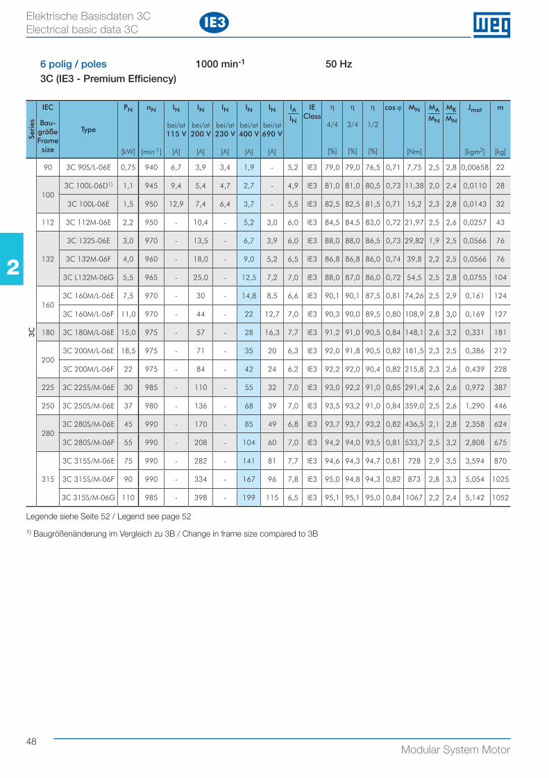
48Modular System Motor
22
Elektrische Basisdaten 3C Electrical basic data 3C
6 polig / poles 1000 min-1 50 Hz3C (IE3 - Premium Efficiency)
Seri
es
IEC
Bau-größe Frame size
Type
PN
[kW]
nN
[min-1]
IN
bei/at115 V
[A]
IN
bei/at200 V
[A]
IN
bei/at230 V
[A]
IN
bei/at400 V
[A]
IN
bei/at690 V
[A]
IAIN
IEClass
η
4/4
[%]
η
3/4
[%]
η
1/2
[%]
cos ϕ MN
[Nm]
MAMN
MKMN
Jmot
[kgm2]
m
[kg]
3C
90 3C 90S/L-06E 0,75 940 6,7 3,9 3,4 1,9 - 5,2 IE3 79,0 79,0 76,5 0,71 7,75 2,5 2,8 0,00658 22
1003C 100L-06D1) 1,1 945 9,4 5,4 4,7 2,7 - 4,9 IE3 81,0 81,0 80,5 0,73 11,38 2,0 2,4 0,0110 28
3C 100L-06E 1,5 950 12,9 7,4 6,4 3,7 - 5,5 IE3 82,5 82,5 81,5 0,71 15,2 2,3 2,8 0,0143 32
112 3C 112M-06E 2,2 950 - 10,4 - 5,2 3,0 6,0 IE3 84,5 84,5 83,0 0,72 21,97 2,5 2,6 0,0257 43
132
3C 132S-06E 3,0 970 - 13,5 - 6,7 3,9 6,0 IE3 88,0 88,0 86,5 0,73 29,82 1,9 2,5 0,0566 76
3C 132M-06F 4,0 960 - 18,0 - 9,0 5,2 6,5 IE3 86,8 86,8 86,0 0,74 39,8 2,2 2,5 0,0566 76
3C L132M-06G 5,5 965 - 25,0 - 12,5 7,2 7,0 IE3 88,0 87,0 86,0 0,72 54,5 2,5 2,8 0,0755 104
1603C 160M/L-06E 7,5 970 - 30 - 14,8 8,5 6,6 IE3 90,1 90,1 87,5 0,81 74,26 2,5 2,9 0,161 124
3C 160M/L-06F 11,0 970 - 44 - 22 12,7 7,0 IE3 90,3 90,0 89,5 0,80 108,9 2,8 3,0 0,169 127
180 3C 180M/L-06E 15,0 975 - 57 - 28 16,3 7,7 IE3 91,2 91,0 90,5 0,84 148,1 2,6 3,2 0,331 181
2003C 200M/L-06E 18,5 975 - 71 - 35 20 6,3 IE3 92,0 91,8 90,5 0,82 181,5 2,3 2,5 0,386 212
3C 200M/L-06F 22 975 - 84 - 42 24 6,2 IE3 92,2 92,0 90,4 0,82 215,8 2,3 2,6 0,439 228
225 3C 225S/M-06E 30 985 - 110 - 55 32 7,0 IE3 93,0 92,2 91,0 0,85 291,4 2,6 2,6 0,972 387
250 3C 250S/M-06E 37 980 - 136 - 68 39 7,0 IE3 93,5 93,2 91,0 0,84 359,0 2,5 2,6 1,290 446
2803C 280S/M-06E 45 990 - 170 - 85 49 6,8 IE3 93,7 93,7 93,2 0,82 436,5 2,1 2,8 2,358 624
3C 280S/M-06F 55 990 - 208 - 104 60 7,0 IE3 94,2 94,0 93,5 0,81 533,7 2,5 3,2 2,808 675
315
3C 315S/M-06E 75 990 - 282 - 141 81 7,7 IE3 94,6 94,3 94,7 0,81 728 2,9 3,5 3,594 870
3C 315S/M-06F 90 990 - 334 - 167 96 7,8 IE3 95,0 94,8 94,3 0,82 873 2,8 3,3 5,054 1025
3C 315S/M-06G 110 985 - 398 - 199 115 6,5 IE3 95,1 95,1 95,0 0,84 1067 2,2 2,4 5,142 1052
Legende siehe Seite 52 / Legend see page 52
1) Baugrößenänderung im Vergleich zu 3B / Change in frame size compared to 3B
IE3
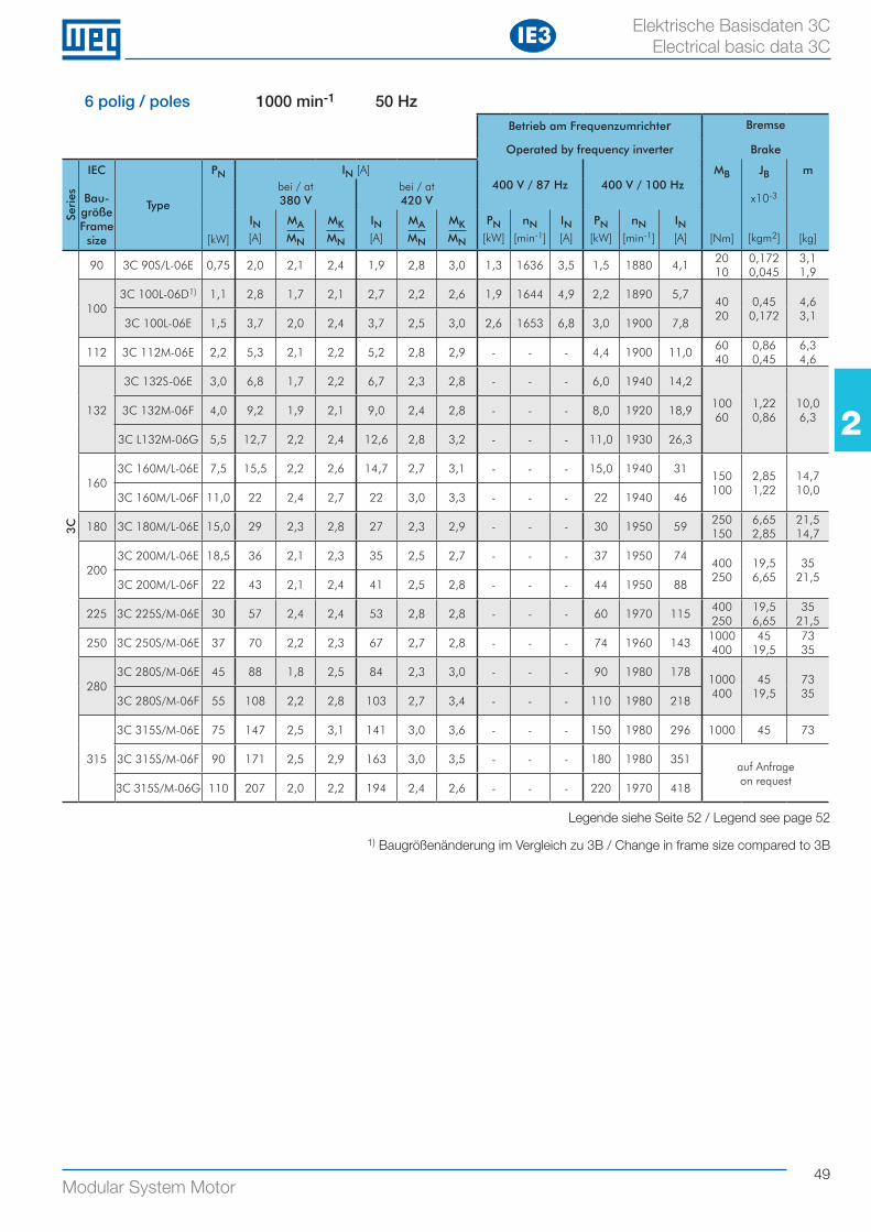
49Modular System Motor
22
Elektrische Basisdaten 3C Electrical basic data 3C
6 polig / poles 1000 min-1 50 HzBetrieb am Frequenzumrichter Bremse
Operated by frequency inverter Brake
Seri
es
IEC
Bau-größe Frame size
Type
PN
[kW]
IN [A]400 V / 87 Hz 400 V / 100 Hz
MB
[Nm]
JB
x10-3
[kgm2]
m
[kg]
bei / at380 V
bei / at420 V
IN[A]
MAMN
MKMN
IN[A]
MAMN
MKMN
PN[kW]
nN[min-1]
IN[A]
PN[kW]
nN[min-1]
IN[A]
3C
90 3C 90S/L-06E 0,75 2,0 2,1 2,4 1,9 2,8 3,0 1,3 1636 3,5 1,5 1880 4,120 10
0,172 0,045
3,1 1,9
1003C 100L-06D1) 1,1 2,8 1,7 2,1 2,7 2,2 2,6 1,9 1644 4,9 2,2 1890 5,7
40 20
0,45 0,172
4,6 3,1
3C 100L-06E 1,5 3,7 2,0 2,4 3,7 2,5 3,0 2,6 1653 6,8 3,0 1900 7,8
112 3C 112M-06E 2,2 5,3 2,1 2,2 5,2 2,8 2,9 - - - 4,4 1900 11,060 40
0,86 0,45
6,3 4,6
132
3C 132S-06E 3,0 6,8 1,7 2,2 6,7 2,3 2,8 - - - 6,0 1940 14,2
100 60
1,22 0,86
10,0 6,3
3C 132M-06F 4,0 9,2 1,9 2,1 9,0 2,4 2,8 - - - 8,0 1920 18,9
3C L132M-06G 5,5 12,7 2,2 2,4 12,6 2,8 3,2 - - - 11,0 1930 26,3
1603C 160M/L-06E 7,5 15,5 2,2 2,6 14,7 2,7 3,1 - - - 15,0 1940 31
150 100
2,85 1,22
14,7 10,0
3C 160M/L-06F 11,0 22 2,4 2,7 22 3,0 3,3 - - - 22 1940 46
180 3C 180M/L-06E 15,0 29 2,3 2,8 27 2,3 2,9 - - - 30 1950 59250 150
6,65 2,85
21,5 14,7
2003C 200M/L-06E 18,5 36 2,1 2,3 35 2,5 2,7 - - - 37 1950 74
400 250
19,5 6,65
35 21,5
3C 200M/L-06F 22 43 2,1 2,4 41 2,5 2,8 - - - 44 1950 88
225 3C 225S/M-06E 30 57 2,4 2,4 53 2,8 2,8 - - - 60 1970 115400 250
19,5 6,65
35 21,5
250 3C 250S/M-06E 37 70 2,2 2,3 67 2,7 2,8 - - - 74 1960 1431000400
45 19,5
73 35
2803C 280S/M-06E 45 88 1,8 2,5 84 2,3 3,0 - - - 90 1980 178
1000400
45 19,5
73 35
3C 280S/M-06F 55 108 2,2 2,8 103 2,7 3,4 - - - 110 1980 218
315
3C 315S/M-06E 75 147 2,5 3,1 141 3,0 3,6 - - - 150 1980 296 1000 45 73
3C 315S/M-06F 90 171 2,5 2,9 163 3,0 3,5 - - - 180 1980 351auf Anfrage on request
3C 315S/M-06G 110 207 2,0 2,2 194 2,4 2,6 - - - 220 1970 418
IE3
Legende siehe Seite 52 / Legend see page 52
1) Baugrößenänderung im Vergleich zu 3B / Change in frame size compared to 3B
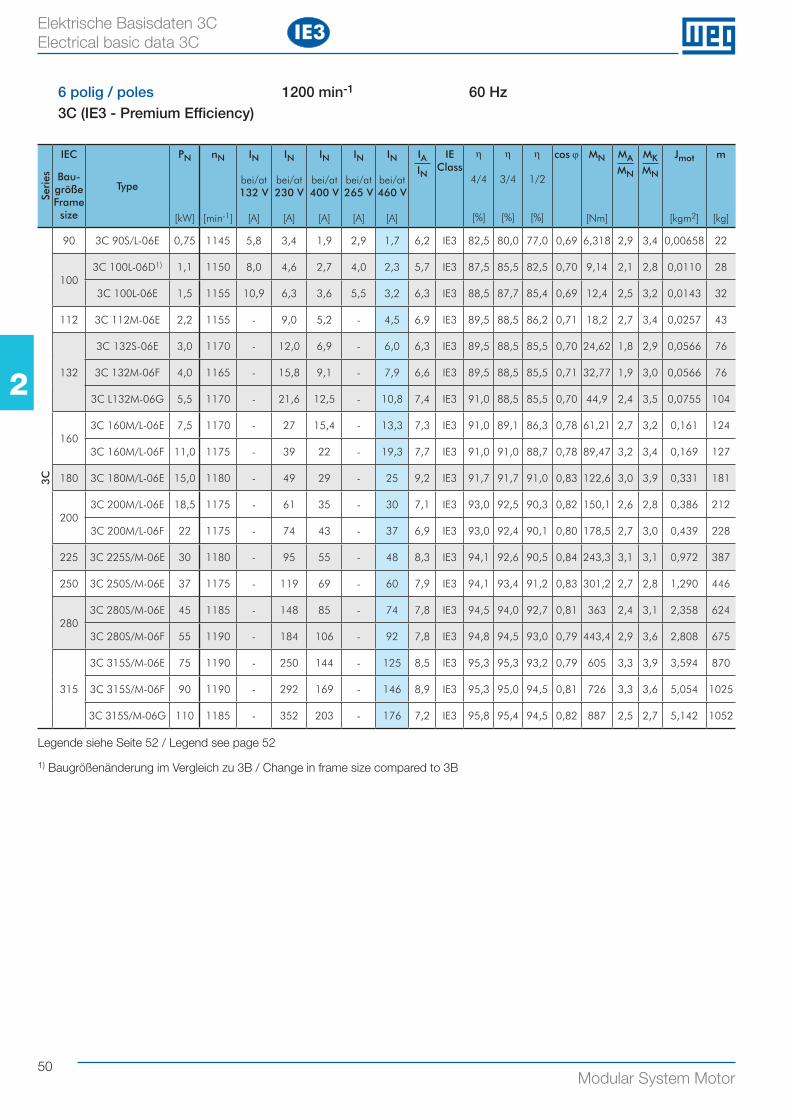
50Modular System Motor
22
Elektrische Basisdaten 3C Electrical basic data 3C
6 polig / poles 1200 min-1 60 Hz3C (IE3 - Premium Efficiency)
Seri
es
IEC
Bau-größe Frame size
Type
PN
[kW]
nN
[min-1]
IN
bei/at132 V
[A]
IN
bei/at230 V
[A]
IN
bei/at400 V
[A]
IN
bei/at265 V
[A]
IN
bei/at460 V
[A]
IAIN
IEClass
η
4/4
[%]
η
3/4
[%]
η
1/2
[%]
cos ϕ MN
[Nm]
MAMN
MKMN
Jmot
[kgm2]
m
[kg]
3C
90 3C 90S/L-06E 0,75 1145 5,8 3,4 1,9 2,9 1,7 6,2 IE3 82,5 80,0 77,0 0,69 6,318 2,9 3,4 0,00658 22
1003C 100L-06D1) 1,1 1150 8,0 4,6 2,7 4,0 2,3 5,7 IE3 87,5 85,5 82,5 0,70 9,14 2,1 2,8 0,0110 28
3C 100L-06E 1,5 1155 10,9 6,3 3,6 5,5 3,2 6,3 IE3 88,5 87,7 85,4 0,69 12,4 2,5 3,2 0,0143 32
112 3C 112M-06E 2,2 1155 - 9,0 5,2 - 4,5 6,9 IE3 89,5 88,5 86,2 0,71 18,2 2,7 3,4 0,0257 43
132
3C 132S-06E 3,0 1170 - 12,0 6,9 - 6,0 6,3 IE3 89,5 88,5 85,5 0,70 24,62 1,8 2,9 0,0566 76
3C 132M-06F 4,0 1165 - 15,8 9,1 - 7,9 6,6 IE3 89,5 88,5 85,5 0,71 32,77 1,9 3,0 0,0566 76
3C L132M-06G 5,5 1170 - 21,6 12,5 - 10,8 7,4 IE3 91,0 88,5 85,5 0,70 44,9 2,4 3,5 0,0755 104
1603C 160M/L-06E 7,5 1170 - 27 15,4 - 13,3 7,3 IE3 91,0 89,1 86,3 0,78 61,21 2,7 3,2 0,161 124
3C 160M/L-06F 11,0 1175 - 39 22 - 19,3 7,7 IE3 91,0 91,0 88,7 0,78 89,47 3,2 3,4 0,169 127
180 3C 180M/L-06E 15,0 1180 - 49 29 - 25 9,2 IE3 91,7 91,7 91,0 0,83 122,6 3,0 3,9 0,331 181
2003C 200M/L-06E 18,5 1175 - 61 35 - 30 7,1 IE3 93,0 92,5 90,3 0,82 150,1 2,6 2,8 0,386 212
3C 200M/L-06F 22 1175 - 74 43 - 37 6,9 IE3 93,0 92,4 90,1 0,80 178,5 2,7 3,0 0,439 228
225 3C 225S/M-06E 30 1180 - 95 55 - 48 8,3 IE3 94,1 92,6 90,5 0,84 243,3 3,1 3,1 0,972 387
250 3C 250S/M-06E 37 1175 - 119 69 - 60 7,9 IE3 94,1 93,4 91,2 0,83 301,2 2,7 2,8 1,290 446
2803C 280S/M-06E 45 1185 - 148 85 - 74 7,8 IE3 94,5 94,0 92,7 0,81 363 2,4 3,1 2,358 624
3C 280S/M-06F 55 1190 - 184 106 - 92 7,8 IE3 94,8 94,5 93,0 0,79 443,4 2,9 3,6 2,808 675
315
3C 315S/M-06E 75 1190 - 250 144 - 125 8,5 IE3 95,3 95,3 93,2 0,79 605 3,3 3,9 3,594 870
3C 315S/M-06F 90 1190 - 292 169 - 146 8,9 IE3 95,3 95,0 94,5 0,81 726 3,3 3,6 5,054 1025
3C 315S/M-06G 110 1185 - 352 203 - 176 7,2 IE3 95,8 95,4 94,5 0,82 887 2,5 2,7 5,142 1052
IE3
Legende siehe Seite 52 / Legend see page 52
1) Baugrößenänderung im Vergleich zu 3B / Change in frame size compared to 3B
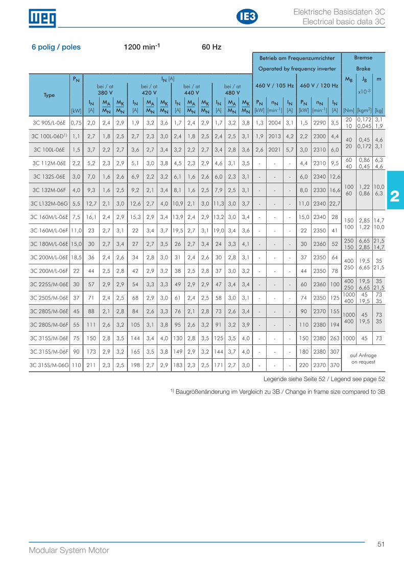
51Modular System Motor
22
Elektrische Basisdaten 3C Electrical basic data 3C
6 polig / poles 1200 min-1 60 HzBetrieb am Frequenzumrichter Bremse
Operated by frequency inverter Brake
Type
PN
[kW]
IN [A]460 V / 105 Hz 460 V / 120 Hz
MB
[Nm]
JB
x10-3
[kgm2]
m
[kg]
bei / at380 V
bei / at420 V
bei / at440 V
bei / at480 V
IN[A]
MAMN
MKMN
IN[A]
MAMN
MKMN
IN[A]
MAMN
MKMN
IN[A]
MAMN
MKMN
PN[kW]
nN[min-1]
IN[A]
PN[kW]
nN[min-1]
IN[A]
3C 90S/L-06E 0,75 2,0 2,4 2,9 1,9 3,2 3,6 1,7 2,4 2,9 1,7 3,2 3,8 1,3 2004 3,1 1,5 2290 3,520 10
0,172 0,045
3,1 1,9
3C 100L-06D1) 1,1 2,7 1,8 2,5 2,7 2,3 3,0 2,4 1,8 2,5 2,4 2,5 3,1 1,9 2013 4,2 2,2 2300 4,440 20
0,45 0,172
4,6 3,1
3C 100L-06E 1,5 3,7 2,2 2,7 3,6 2,7 3,4 3,2 2,2 2,7 3,4 2,8 3,6 2,6 2021 5,7 3,0 2310 6,0
3C 112M-06E 2,2 5,2 2,3 2,9 5,1 3,0 3,8 4,5 2,3 2,9 4,6 3,1 3,5 - - - 4,4 2310 9,560 40
0,86 0,45
6,3 4,6
3C 132S-06E 3,0 7,0 1,6 2,6 6,9 2,2 3,2 6,1 1,6 2,6 6,0 2,3 3,1 - - - 6,0 2340 12,6
100 60
1,22 0,86
10,0 6,3
3C 132M-06F 4,0 9,3 1,6 2,5 9,2 2,1 3,4 8,1 1,6 2,5 7,9 2,5 3,1 - - - 8,0 2330 16,6
3C L132M-06G 5,5 12,7 2,1 3,0 12,6 2,7 4,0 10,9 2,1 3,0 11,3 3,0 3,7 - - - 11,0 2340 22,7
3C 160M/L-06E 7,5 16,1 2,4 2,9 15,3 2,9 3,4 13,9 2,4 2,9 13,2 3,0 3,4 - - - 15,0 2340 28150 100
2,85 1,22
14,7 10,0
3C 160M/L-06F 11,0 23 2,7 3,1 22 3,4 3,7 19,5 2,7 3,1 19,0 3,4 3,6 - - - 22 2350 41
3C 180M/L-06E 15,0 30 2,7 3,4 27 2,7 3,5 26 2,7 3,4 24 3,3 4,1 - - - 30 2360 52250 150
6,65 2,85
21,5 14,7
3C 200M/L-06E 18,5 36 2,4 2,6 34 2,8 3,0 31 2,4 2,6 30 2,8 3,1 - - - 37 2350 64400 250
19,5 6,65
35 21,5
3C 200M/L-06F 22 44 2,5 2,8 42 2,9 3,2 38 2,5 2,8 37 3,0 3,2 - - - 44 2350 78
3C 225S/M-06E 30 57 2,9 2,9 54 3,3 3,3 49 2,9 2,9 47 3,4 3,4 - - - 60 2360 100400 250
19,5 6,65
35 21,5
3C 250S/M-06E 37 71 2,4 2,5 68 2,9 3,0 61 2,4 2,5 58 3,0 3,1 - - - 74 2350 1251000400
45 19,5
73 35
3C 280S/M-06E 45 88 2,1 2,8 84 2,6 3,3 76 2,1 2,8 73 2,6 3,4 - - - 90 2370 1551000400
45 19,5
73 35
3C 280S/M-06F 55 111 2,6 3,2 105 3,1 3,8 95 2,6 3,2 91 3,2 3,9 - - - 110 2380 194
3C 315S/M-06E 75 150 2,8 3,5 144 3,4 4,0 130 2,8 3,5 125 3,5 4,0 - - - 150 2380 263 1000 45 73
3C 315S/M-06F 90 173 2,9 3,2 165 3,5 3,8 149 2,9 3,2 144 3,7 4,0 - - - 180 2380 307auf Anfrageon request
3C 315S/M-06G 110 211 2,3 2,5 198 2,7 2,9 183 2,3 2,5 171 2,7 3,0 - - - 220 2370 370
IE3
Legende siehe Seite 52 / Legend see page 52
1) Baugrößenänderung im Vergleich zu 3B / Change in frame size compared to 3B
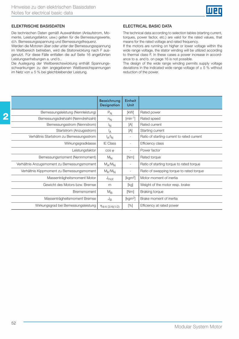
52Modular System Motor
22
Hinweise zu den elektrischen Basisdaten Notes for electrical basic data
BezeichnungDesignation
EinheitUnit
Bemessungsleistung (Nennleistung) PN [kW] Rated power
Bemessungsdrehzahl (Nenndrehzahl) nN [min-1] Rated speed
Bemessungsstrom (Nennstrom) IN [A] Rated current
Startstrom (Anzugsstrom) IA [A] Starting current
Verhältnis Startstrom zu Bemessungsstrom IA/IN - Ratio of starting current to rated current
Wirkungsgradklasse IE Class - Efficiency class
Leistungsfaktor cos ϕ - Power factor
Bemessungsmoment (Nennmoment) MN [Nm] Rated torque
Verhältnis Anzugsmoment zu Bemessungsmoment MA/MN - Ratio of starting torque to rated torque
Verhältnis Kippmoment zu Bemessungsmoment MK/MN - Ratio of swepping torque to rated torque
Massenträgheitsmoment Motor Jmot [kgm2] Motor moment of inertia
Gewicht des Motors bzw. Bremse m [kg] Weight of the motor resp. brake
Bremsmoment MB [Nm] Braking torque
Massenträgheitsmoment Bremse JB [kgm2] Brake moment of inertia
Wirkungsgrad bei Bemessungsleistung η4/4 (3/4)(1/2) [%] Efficiency at rated power
ELEKTRISCHE BASISDATEN
Die technischen Daten gemäß Auswahllisten (Anlaufstrom, Mo-mente, Leistungsfaktor, usw.) gelten für die Bemessungswerte, d.h. Bemessungsspannung und Bemessungsfrequenz.Werden die Motoren über oder unter der Bemessungsspannung im Weitbereich betrieben, wird die Statorwicklung nach F aus-genutzt. Für diese Fälle entfallen die auf Seite 16 angeführten Leistungsanhebungen a. und b..Die Auslegung der Weitbereichswicklung enthält Spannungs-schwankungen zu den angegebenen Weitbereichspannungen im Netz von ± 5 % bei gleichbleibender Leistung.
ELECTRICAL BASIC DATA
The technical data according to selection tables (starting current, torques, power factor, etc.) are valid for the rated values, that means for the rated voltage and rated frequency.If the motors are running on higher or lower voltage within the wide range voltage, the stator winding will be utilized according to thermal class F. In these cases a power increase in accord-ance to a. and b. on page 16 is not possible.The design of the wide range winding permits supply voltage deviations in the indicated wide range voltage of ± 5 % without reduction of the power.
53Modular System Motor
MaßbilderDimension Sheets3Maßbild - WAG B3 Dimension sheet - WAG B3 54
Maßbild - WAF B5 (FF-Flansch) Dimension sheet - WAF B5 (FF-Flange) 56
Maßbild - WAC B14 (C-DIN Flansch) Dimension sheet - WAC B14 (C-DIN Flange) 58
Maßbild - Getriebeanbaumotor WAR (B5 spezial) Dimension sheet - Integral motor WAR (B5 special) 60
Längenbeschreibung Motormodule Length description motor modules 62
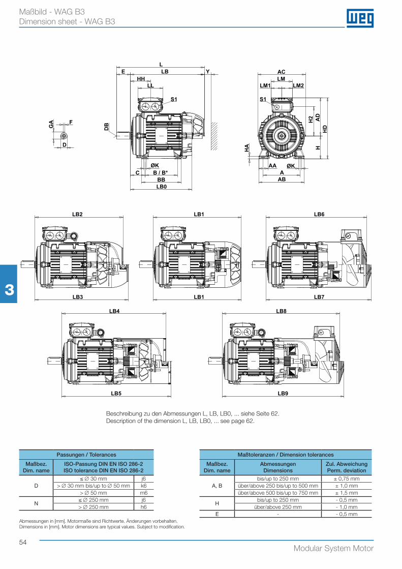
54Modular System Motor
33
Maßbild - WAG B3 Dimension sheet - WAG B3
Passungen / Tolerances Maßtoleranzen / Dimension tolerances
Maßbez.Dim. name
ISO-Passung DIN EN ISO 286-2ISO tolerance DIN EN ISO 286-2
Maßbez.Dim. name
AbmessungenDimensions
Zul. AbweichungPerm. deviation
D≤ ∅ 30 mm j6
A, Bbis/up to 250 mm ± 0,75 mm
> ∅ 30 mm bis/up to ∅ 50 mm k6 über/above 250 bis/up to 500 mm ± 1,0 mm> ∅ 50 mm m6 über/above 500 bis/up to 750 mm ± 1,5 mm
N≤ ∅ 250 mm j6
Hbis/up to 250 mm - 0,5 mm
> ∅ 250 mm h6 über/above 250 mm - 1,0 mmE - - 0,5 mm
Abmessungen in [mm]. Motormaße sind Richtwerte. Änderungen vorbehalten.Dimensions in [mm]. Motor dimensions are typical values. Subject to modification.
GA F
D
LE LB Y
HHLL
S1
ØKC B / B*
BBLB0
ACLM
LM1 LM2
H2 AD
HD
HHA
AAA
ØK
AB
LB2 LB1
LB3
LB4
LB5
LB6
LB7
LB8
LB9
DB
LB1
S1
Beschreibung zu den Abmessungen L, LB, LB0, ... siehe Seite 62.Description of the dimension L, LB, LB0, ... see page 62.
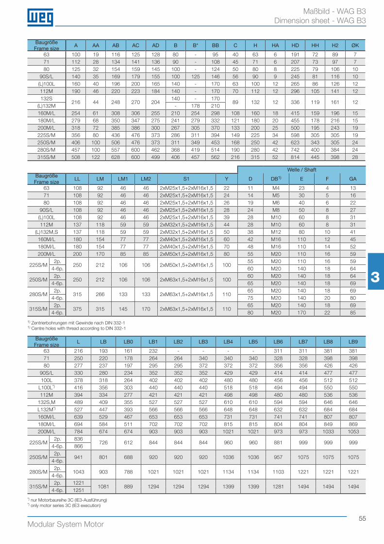
55Modular System Motor
33
Maßbild - WAG B3 Dimension sheet - WAG B3
1) Zentrierbohrungen mit Gewinde nach DIN 332-11) Centre holes with thread according to DIN 332-1
Baugröße Frame size
A AA AB AC AD B B* BB C H HA HD HH H2 ØK
63 100 19 116 125 128 80 - 95 40 63 6 191 72 89 771 112 28 134 141 136 90 - 108 45 71 6 207 73 97 780 125 32 154 159 145 100 - 124 50 80 8 225 79 106 10
90S/L 140 35 169 179 155 100 125 146 56 90 9 245 81 116 10(L)100L 160 40 196 200 165 140 - 170 63 100 12 265 86 126 12112M 190 46 220 223 184 140 - 170 70 112 12 296 105 141 12132S
216 44 248 270 204140 - 170
89 132 12 336 119 161 12(L)132M - 178 210160M/L 254 61 308 306 255 210 254 298 108 160 18 415 159 196 15180M/L 279 68 350 347 275 241 279 332 121 180 20 455 178 216 15200M/L 318 72 385 386 300 267 305 370 133 200 25 500 195 243 19225S/M 356 80 436 476 373 286 311 394 149 225 34 598 305 305 19250S/M 406 100 506 476 373 311 349 453 168 250 42 623 343 305 24280S/M 457 100 557 600 462 368 419 514 190 280 42 742 400 384 24315S/M 508 122 628 600 499 406 457 562 216 315 52 814 445 398 28
Baugröße Frame size
L LB LB0 LB1 LB2 LB3 LB4 LB5 LB6 LB7 LB8 LB9
63 216 193 161 232 - - - - 311 311 381 38171 250 220 178 264 264 340 340 340 328 328 398 39880 277 237 197 295 295 372 372 372 356 356 426 426
90S/L 330 280 234 352 352 352 429 429 414 414 477 477100L 378 318 264 402 402 402 480 480 456 456 512 512
L100L*) 416 356 303 440 440 440 518 518 494 494 550 550112M 394 334 277 421 421 421 498 498 480 480 536 536
132S,M 489 409 355 527 527 527 610 610 594 594 646 646L132M*) 527 447 393 566 566 566 648 648 632 632 684 684160M/L 639 529 467 653 653 653 731 731 741 741 807 807180M/L 694 584 511 702 702 702 815 815 804 804 849 869200M/L 784 674 674 903 903 903 1021 1021 973 973 1033 1053
225S/M2p. 836
726 612 844 844 844 960 960 881 999 999 9994-6p. 866
250S/M2p.
941 801 688 920 920 920 1036 1036 957 1075 1075 10754-6p.
280S/M2p.
1043 903 788 1021 1021 1021 1134 1134 1103 1221 1221 12214-6p.
315S/M2p. 1221
1081 889 1294 1294 1294 1399 1399 1281 1494 1494 14944-6p. 1251
Welle / ShaftBaugröße Frame size
LL LM LM1 LM2 S1 Y D DB1) E F GA
63 108 92 46 46 2xM25x1,5+2xM16x1,5 22 11 M4 23 4 1371 108 92 46 46 2xM25x1,5+2xM16x1,5 24 14 M5 30 5 1680 108 92 46 46 2xM25x1,5+2xM16x1,5 26 19 M6 40 6 22
90S/L 108 92 46 46 2xM25x1,5+2xM16x1,5 28 24 M8 50 8 27(L)100L 108 92 46 46 2xM25x1,5+2xM16x1,5 39 28 M10 60 8 31112M 137 118 59 59 2xM32x1,5+2xM16x1,5 44 28 M10 60 8 31
(L)132M,S 137 118 59 59 2xM32x1,5+2xM16x1,5 50 38 M12 80 10 41160M/L 180 154 77 77 2xM40x1,5+2xM16x1,5 60 42 M16 110 12 45180M/L 180 154 77 77 2xM40x1,5+2xM16x1,5 70 48 M16 110 14 52200M/L 200 170 85 85 2xM50x1,5+2xM16x1,5 80 55 M20 110 16 59
225S/M2p.
250 212 106 106 2xM50x1,5+2xM16x1,5 10055 M20 110 16 59
4-6p. 60 M20 140 18 64
250S/M2p.
250 212 106 106 2xM63x1,5+2xM16x1,5 10060 M20 140 18 64
4-6p. 65 M20 140 18 69
280S/M2p.
315 266 133 133 2xM63x1,5+2xM16x1,5 11065 M20 140 18 69
4-6p. 75 M20 140 20 80
315S/M2p.
375 315 145 170 2xM63x1,5+2xM16x1,5 11065 M20 140 18 69
4-6p. 80 M20 170 22 85
*) nur Motorbaureihe 3C (IE3-Ausführung)*) only motor series 3C (IE3 execution)
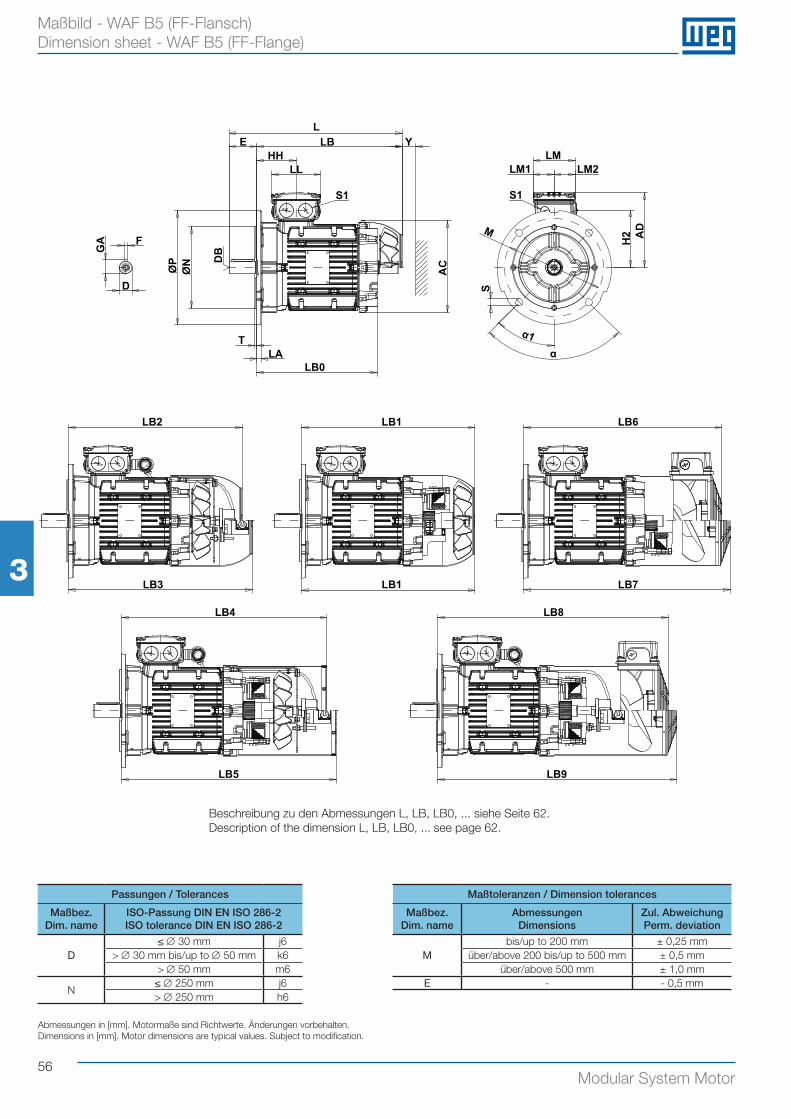
56Modular System Motor
33
Maßbild - WAF B5 (FF-Flansch) Dimension sheet - WAF B5 (FF-Flange)
LE LB
HHLL
S1
YLM
LM1 LM2
AD
H2M
S
α1α
GA F
D
ØP
ØN
TLA
LB0
ACD
B
S1
LB2 LB1
LB3
LB4
LB5
LB6
LB7
LB8
LB9
LB1
Passungen / Tolerances Maßtoleranzen / Dimension tolerances
Maßbez.Dim. name
ISO-Passung DIN EN ISO 286-2ISO tolerance DIN EN ISO 286-2
Maßbez.Dim. name
AbmessungenDimensions
Zul. AbweichungPerm. deviation
D≤ ∅ 30 mm j6
Mbis/up to 200 mm ± 0,25 mm
> ∅ 30 mm bis/up to ∅ 50 mm k6 über/above 200 bis/up to 500 mm ± 0,5 mm> ∅ 50 mm m6 über/above 500 mm ± 1,0 mm
N≤ ∅ 250 mm j6 E - - 0,5 mm> ∅ 250 mm h6
Abmessungen in [mm]. Motormaße sind Richtwerte. Änderungen vorbehalten.Dimensions in [mm]. Motor dimensions are typical values. Subject to modification.
Beschreibung zu den Abmessungen L, LB, LB0, ... siehe Seite 62.Description of the dimension L, LB, LB0, ... see page 62.
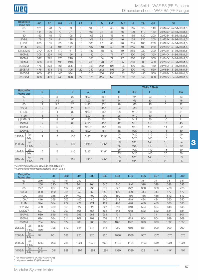
57Modular System Motor
33
Maßbild - WAF B5 (FF-Flansch) Dimension sheet - WAF B5 (FF-Flange)
1) Zentrierbohrungen mit Gewinde nach DIN 332-11) Centre holes with thread according to DIN 332-1
Baugröße Frame size
AC AD HH H2 LA LL LM LM1 LM2 M ØN ØP S1
63 125 128 72 89 6 108 92 46 46 115 95 140 2xM25x1,5+2xM16x1,571 141 136 73 97 9 108 92 46 46 130 110 160 2xM25x1,5+2xM16x1,580 159 145 79 106 9 108 92 46 46 165 130 200 2xM25x1,5+2xM16x1,5
90S/L 179 155 81 116 10 108 92 46 46 165 130 200 2xM25x1,5+2xM16x1,5(L)100L 200 165 86 126 13 108 92 46 46 215 180 250 2xM25x1,5+2xM16x1,5112M 223 184 105 141 13 137 118 59 59 215 180 250 2xM32x1,5+2xM16x1,5
(L)132M,S 270 204 119 161 12 137 118 59 59 265 230 300 2xM32x1,5+2xM16x1,5160M/L 306 255 159 196 18 180 154 77 77 300 250 350 2xM40x1,5+2xM16x1,5180M/L 347 275 178 216 18 180 154 77 77 300 250 350 2xM40x1,5+2xM16x1,5200M/L 386 300 195 243 18 200 170 85 85 350 300 400 2xM50x1,5+2xM16x1,5225S/M 476 373 305 305 18 250 212 106 106 400 350 450 2xM50x1,5+2xM16x1,5250S/M 476 373 343 305 20 250 212 106 106 500 450 550 2xM63x1,5+2xM16x1,5280S/M 600 462 400 384 18 315 266 133 133 500 450 550 2xM63x1,5+2xM16x1,5315S/M 600 499 445 398 22 375 315 145 170 600 550 660 2xM63x1,5+2xM16x1,5
Baugröße Frame size
L LB LB0 LB1 LB2 LB3 LB4 LB5 LB6 LB7 LB8 LB9
63 216 193 161 232 - - - - 311 311 381 38171 250 220 178 264 264 340 340 340 328 328 398 39880 277 237 197 295 295 372 372 372 356 356 426 426
90S/L 330 280 234 352 352 352 429 429 414 414 477 477100L 378 318 264 402 402 402 480 480 456 456 512 512
L100L*) 416 356 303 440 440 440 518 518 494 494 550 550112M 394 334 277 421 421 421 498 498 480 480 536 536
132S,M 489 409 355 527 527 527 610 610 594 594 646 646L132M*) 527 447 393 566 566 566 648 648 632 632 684 684160M/L 639 529 467 653 653 653 731 731 741 741 807 807180M/L 694 584 511 702 702 702 815 815 804 804 849 869200M/L 784 674 674 903 903 903 1021 1021 973 973 1033 1053
225S/M2p. 836
726 612 844 844 844 960 960 881 999 999 9994-6p. 866
250S/M2p.
941 801 688 920 920 920 1036 1036 957 1075 1075 10754-6p.
280S/M2p.
1043 903 788 1021 1021 1021 1134 1134 1103 1221 1221 12214-6p.
315S/M2p. 1221
1081 889 1294 1294 1294 1399 1399 1281 1494 1494 14944-6p. 1251
Welle / ShaftBaugröße Frame size
S T Y α α1 D DB1) E F GA
63 10 3 22 4x90° 45° 11 M4 23 4 1371 10 3,5 24 4x90° 45° 14 M5 30 5 1680 12 3,5 26 4x90° 45° 19 M6 40 6 22
90S/L 12 3,5 28 4x90° 45° 24 M8 50 8 27(L)100L 15 4 39 4x90° 45° 28 M10 60 8 31112M 15 4 44 4x90° 45° 28 M10 60 8 31
(L)132M,S 15 4 50 4x90° 45° 38 M12 80 10 41160M/L 19 5 60 4x90° 45° 42 M16 110 12 45180M/L 19 5 70 4x90° 45° 48 M16 110 14 52200M/L 19 5 80 4x90° 45° 55 M20 110 16 59
225S/M2p.
19 5 100 8x45° 22,5°55 M20 110 16 59
4-6p. 60 M20 140 18 64
250S/M2p.
19 5 100 8x45° 22,5°60 M20 140 18 64
4-6p. 65 M20 140 18 69
280S/M2p.
19 5 110 8x45° 22,5°65 M20 140 18 69
4-6p. 75 M20 140 20 80
315S/M2p.
24 6 110 8x45° 22,5°65 M20 140 18 69
4-6p. 80 M20 170 22 85
*) nur Motorbaureihe 3C (IE3-Ausführung)*) only motor series 3C (IE3 execution)
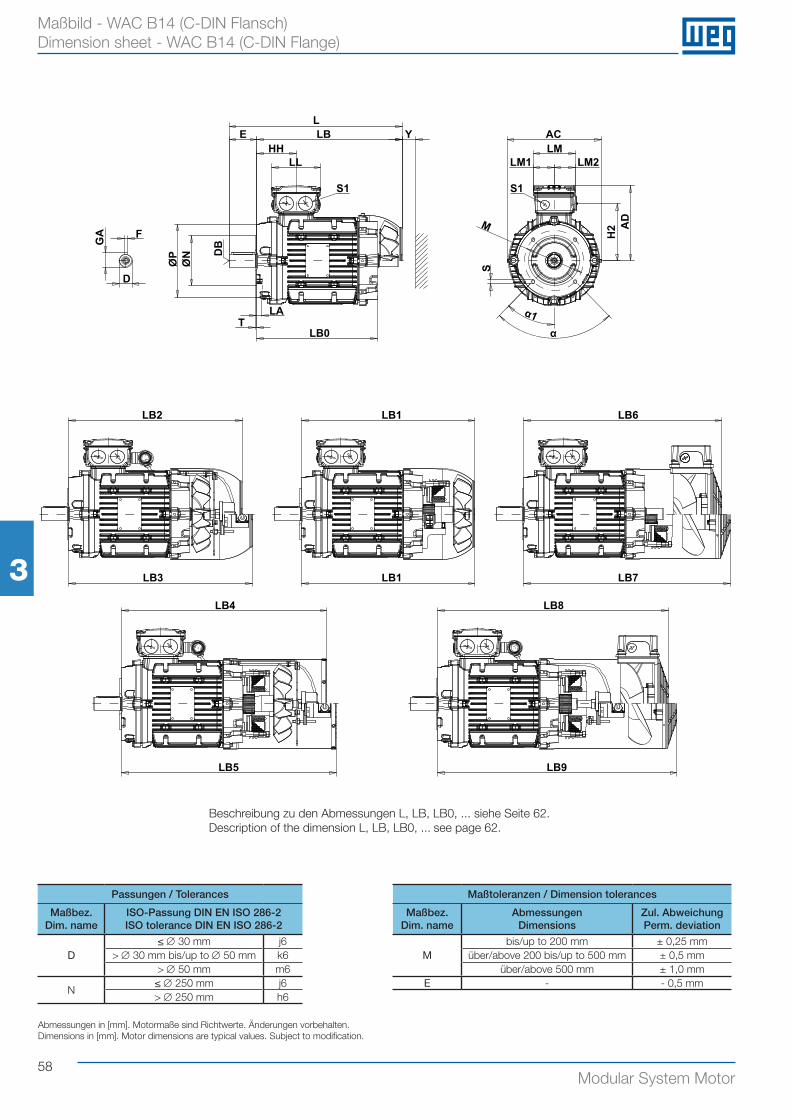
58Modular System Motor
33
Maßbild - WAC B14 (C-DIN Flansch) Dimension sheet - WAC B14 (C-DIN Flange)
LLBE Y
HHLL
S1S1
GA
D
F
LA
LB0T
ØP
ØN D
B
ACLM
LM1 LM2
H2 A
DM
S
α1α
LB2 LB1
LB3
LB6
LB7LB1
LB4
LB5
LB8
LB9
Passungen / Tolerances Maßtoleranzen / Dimension tolerances
Maßbez.Dim. name
ISO-Passung DIN EN ISO 286-2ISO tolerance DIN EN ISO 286-2
Maßbez.Dim. name
AbmessungenDimensions
Zul. AbweichungPerm. deviation
D≤ ∅ 30 mm j6
Mbis/up to 200 mm ± 0,25 mm
> ∅ 30 mm bis/up to ∅ 50 mm k6 über/above 200 bis/up to 500 mm ± 0,5 mm> ∅ 50 mm m6 über/above 500 mm ± 1,0 mm
N≤ ∅ 250 mm j6 E - - 0,5 mm> ∅ 250 mm h6
Abmessungen in [mm]. Motormaße sind Richtwerte. Änderungen vorbehalten.Dimensions in [mm]. Motor dimensions are typical values. Subject to modification.
Beschreibung zu den Abmessungen L, LB, LB0, ... siehe Seite 62.Description of the dimension L, LB, LB0, ... see page 62.
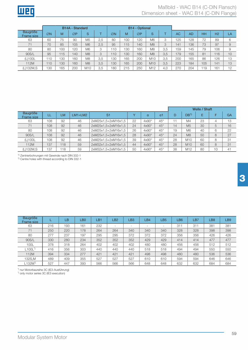
59Modular System Motor
33
Maßbild - WAC B14 (C-DIN Flansch) Dimension sheet - WAC B14 (C-DIN Flange)
1) Zentrierbohrungen mit Gewinde nach DIN 332-11) Centre holes with thread according to DIN 332-1
B14A - Standard B14 - OptionalBaugröße Frame size ØN M ØP S T ØN M ØP S T AC AD HH H2 LA
63 60 75 90 M5 2,5 80 100 120 M6 3 125 128 72 89 671 70 85 105 M6 2,5 95 115 140 M8 3 141 136 73 97 980 80 100 120 M6 3 110 130 160 M8 3,5 159 145 79 106 9
90S/L 95 115 140 M8 3 110 130 160 M8 3,5 179 155 81 116 10(L)100L 110 130 160 M8 3,5 130 165 200 M10 3,5 200 165 86 126 13112M 110 130 160 M8 3,5 130 165 200 M10 3,5 223 184 105 141 13
(L)132M,S 130 165 200 M10 3,5 180 215 250 M12 4,0 270 204 119 161 12
Baugröße Frame size
L LB LB0 LB1 LB2 LB3 LB4 LB5 LB6 LB7 LB8 LB9
63 216 193 161 232 - - - - 311 311 381 38171 250 220 178 264 264 340 340 340 328 328 398 39880 277 237 197 295 295 372 372 372 356 356 426 426
90S/L 330 280 234 352 352 352 429 429 414 414 477 477100L 378 318 264 402 402 402 480 480 456 456 512 512
L100L*) 416 356 303 440 440 440 518 518 494 494 550 550112M 394 334 277 421 421 421 498 498 480 480 536 536
132S,M 489 409 355 527 527 527 610 610 594 594 646 646L132M*) 527 447 393 566 566 566 648 648 632 632 684 684
Welle / ShaftBaugröße Frame size
LL LM LM1=LM2 S1 Y α α1 D DB1) E F GA
63 108 92 46 2xM25x1,5+2xM16x1,5 22 4x90° 45° 11 M4 23 4 1371 108 92 46 2xM25x1,5+2xM16x1,5 24 4x90° 45° 14 M5 30 5 1680 108 92 46 2xM25x1,5+2xM16x1,5 26 4x90° 45° 19 M6 40 6 22
90S/L 108 92 46 2xM25x1,5+2xM16x1,5 28 4x90° 45° 24 M8 50 8 27(L)100L 108 92 46 2xM25x1,5+2xM16x1,5 39 4x90° 45° 28 M10 60 8 31112M 137 118 59 2xM32x1,5+2xM16x1,5 44 4x90° 45° 28 M10 60 8 31
(L)132M,S 137 118 59 2xM32x1,5+2xM16x1,5 50 4x90° 45° 38 M12 80 10 41
*) nur Motorbaureihe 3C (IE3-Ausführung)*) only motor series 3C (IE3 execution)
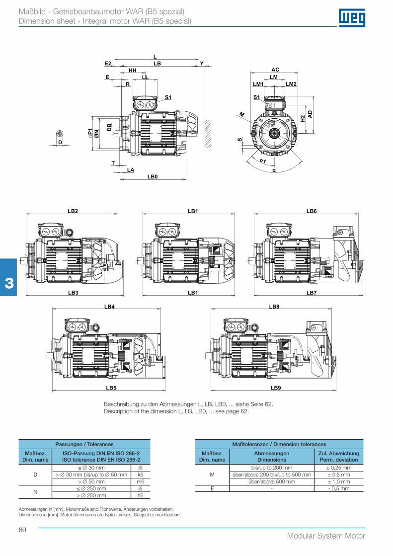
33
60Modular System Motor
33
Maßbild - Getriebeanbaumotor WAR (B5 spezial) Dimension sheet - Integral motor WAR (B5 special)
LE2 LB
HHE
RLL
S1
T
LB0
Y
LA
D
DB
ØN
□P1
ACLM
LM1 LM2
H2 A
D
S
α1α
M
S1
LB2 LB1
LB3
LB6
LB7LB1
LB4
LB5
LB8
LB9
Passungen / Tolerances Maßtoleranzen / Dimension tolerances
Maßbez.Dim. name
ISO-Passung DIN EN ISO 286-2ISO tolerance DIN EN ISO 286-2
Maßbez.Dim. name
AbmessungenDimensions
Zul. AbweichungPerm. deviation
D≤ ∅ 30 mm j6
Mbis/up to 200 mm ± 0,25 mm
> ∅ 30 mm bis/up to ∅ 50 mm k6 über/above 200 bis/up to 500 mm ± 0,5 mm> ∅ 50 mm m6 über/above 500 mm ± 1,0 mm
N≤ ∅ 250 mm j6 E - - 0,5 mm> ∅ 250 mm h6
Abmessungen in [mm]. Motormaße sind Richtwerte. Änderungen vorbehalten.Dimensions in [mm]. Motor dimensions are typical values. Subject to modification.
Beschreibung zu den Abmessungen L, LB, LB0, ... siehe Seite 62.Description of the dimension L, LB, LB0, ... see page 62.
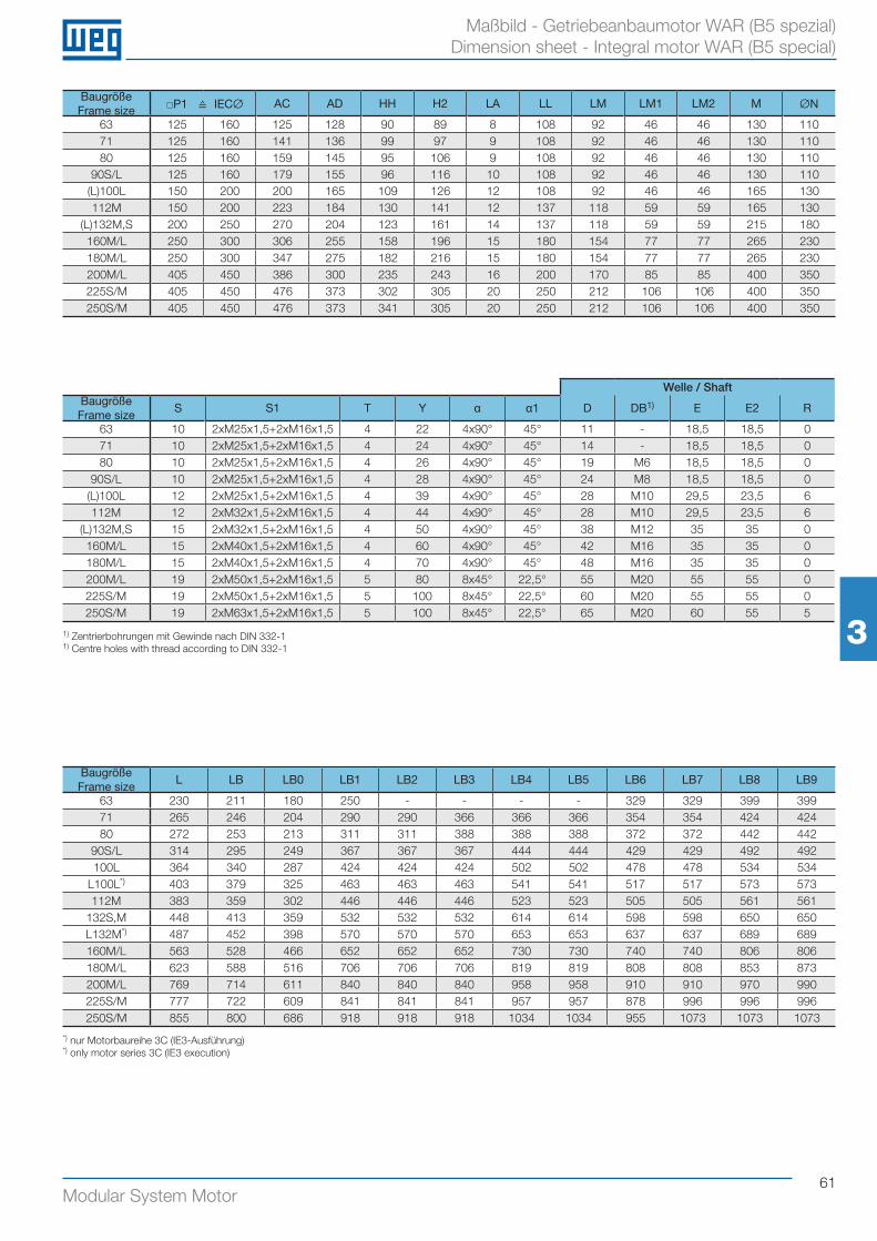
61Modular System Motor
33 33
Maßbild - Getriebeanbaumotor WAR (B5 spezial) Dimension sheet - Integral motor WAR (B5 special)
1) Zentrierbohrungen mit Gewinde nach DIN 332-11) Centre holes with thread according to DIN 332-1
Baugröße Frame size □P1 ≙ IECØ AC AD HH H2 LA LL LM LM1 LM2 M ØN
63 125 160 125 128 90 89 8 108 92 46 46 130 11071 125 160 141 136 99 97 9 108 92 46 46 130 11080 125 160 159 145 95 106 9 108 92 46 46 130 110
90S/L 125 160 179 155 96 116 10 108 92 46 46 130 110(L)100L 150 200 200 165 109 126 12 108 92 46 46 165 130112M 150 200 223 184 130 141 12 137 118 59 59 165 130
(L)132M,S 200 250 270 204 123 161 14 137 118 59 59 215 180160M/L 250 300 306 255 158 196 15 180 154 77 77 265 230180M/L 250 300 347 275 182 216 15 180 154 77 77 265 230200M/L 405 450 386 300 235 243 16 200 170 85 85 400 350225S/M 405 450 476 373 302 305 20 250 212 106 106 400 350250S/M 405 450 476 373 341 305 20 250 212 106 106 400 350
Baugröße Frame size
L LB LB0 LB1 LB2 LB3 LB4 LB5 LB6 LB7 LB8 LB9
63 230 211 180 250 - - - - 329 329 399 39971 265 246 204 290 290 366 366 366 354 354 424 42480 272 253 213 311 311 388 388 388 372 372 442 442
90S/L 314 295 249 367 367 367 444 444 429 429 492 492100L 364 340 287 424 424 424 502 502 478 478 534 534
L100L*) 403 379 325 463 463 463 541 541 517 517 573 573112M 383 359 302 446 446 446 523 523 505 505 561 561
132S,M 448 413 359 532 532 532 614 614 598 598 650 650L132M*) 487 452 398 570 570 570 653 653 637 637 689 689160M/L 563 528 466 652 652 652 730 730 740 740 806 806180M/L 623 588 516 706 706 706 819 819 808 808 853 873200M/L 769 714 611 840 840 840 958 958 910 910 970 990225S/M 777 722 609 841 841 841 957 957 878 996 996 996250S/M 855 800 686 918 918 918 1034 1034 955 1073 1073 1073
Welle / ShaftBaugröße Frame size
S S1 T Y α α1 D DB1) E E2 R
63 10 2xM25x1,5+2xM16x1,5 4 22 4x90° 45° 11 - 18,5 18,5 071 10 2xM25x1,5+2xM16x1,5 4 24 4x90° 45° 14 - 18,5 18,5 080 10 2xM25x1,5+2xM16x1,5 4 26 4x90° 45° 19 M6 18,5 18,5 0
90S/L 10 2xM25x1,5+2xM16x1,5 4 28 4x90° 45° 24 M8 18,5 18,5 0(L)100L 12 2xM25x1,5+2xM16x1,5 4 39 4x90° 45° 28 M10 29,5 23,5 6112M 12 2xM32x1,5+2xM16x1,5 4 44 4x90° 45° 28 M10 29,5 23,5 6
(L)132M,S 15 2xM32x1,5+2xM16x1,5 4 50 4x90° 45° 38 M12 35 35 0160M/L 15 2xM40x1,5+2xM16x1,5 4 60 4x90° 45° 42 M16 35 35 0180M/L 15 2xM40x1,5+2xM16x1,5 4 70 4x90° 45° 48 M16 35 35 0200M/L 19 2xM50x1,5+2xM16x1,5 5 80 8x45° 22,5° 55 M20 55 55 0225S/M 19 2xM50x1,5+2xM16x1,5 5 100 8x45° 22,5° 60 M20 55 55 0250S/M 19 2xM63x1,5+2xM16x1,5 5 100 8x45° 22,5° 65 M20 60 55 5
*) nur Motorbaureihe 3C (IE3-Ausführung)*) only motor series 3C (IE3 execution)
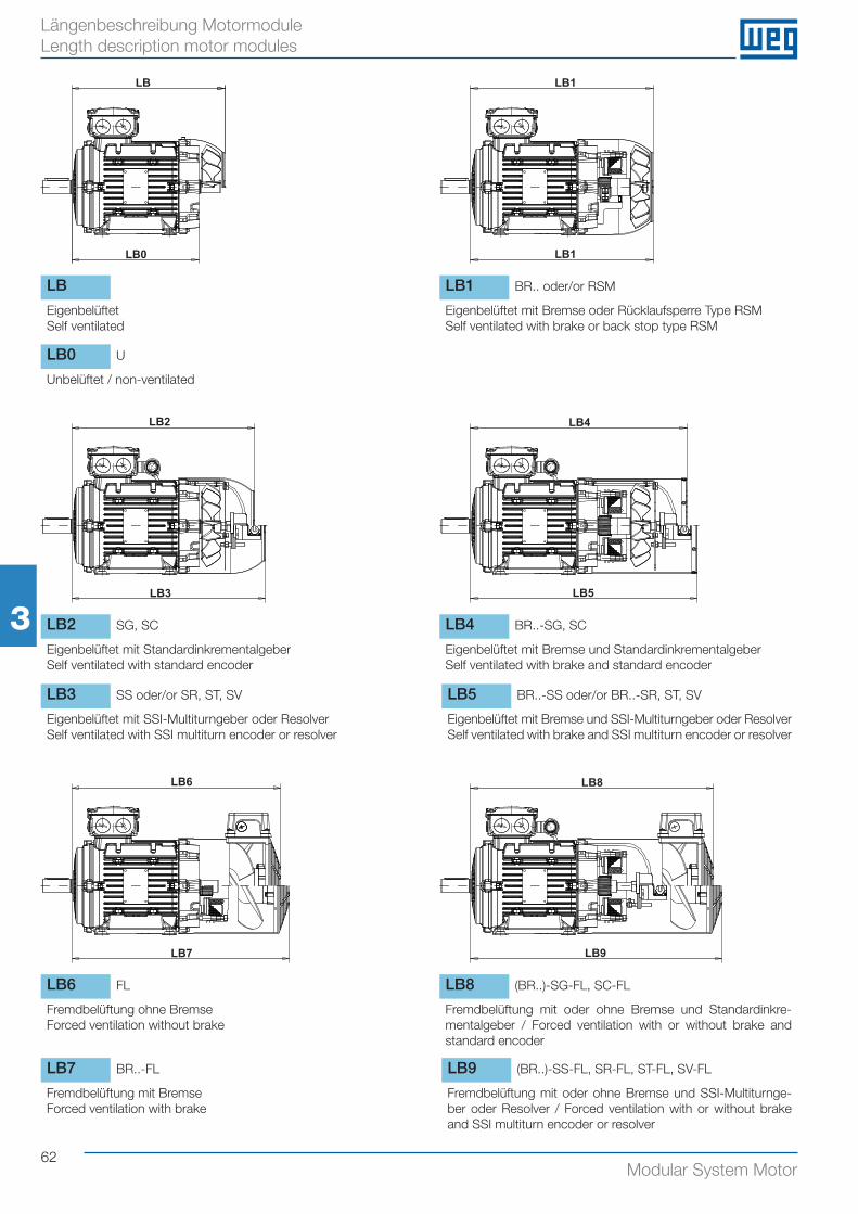
62Modular System Motor
33
Längenbeschreibung Motormodule Length description motor modules
LB2 LB1
LB3
LB4
LB5
LB6
LB7
LB8
LB9
LB1
LB
LB0
LB2 LB1
LB3
LB4
LB5
LB6
LB7
LB8
LB9
LB1
LB
LB0
LB2 LB1
LB3
LB4
LB5
LB6
LB7
LB8
LB9
LB1
LB
LB0
LB2 LB1
LB3
LB4
LB5
LB6
LB7
LB8
LB9
LB1
LB
LB0
LB2 LB1
LB3
LB4
LB5
LB6
LB7
LB8
LB9
LB1
LB
LB0
LB2 LB1
LB3
LB4
LB5
LB6
LB7
LB8
LB9
LB1
LB
LB0
LB2 SG, SC LB4 BR..-SG, SC
Eigenbelüftet mit StandardinkrementalgeberSelf ventilated with standard encoder
Eigenbelüftet mit Bremse und StandardinkrementalgeberSelf ventilated with brake and standard encoder
LB6 FL LB8 (BR..)-SG-FL, SC-FL
Fremdbelüftung ohne BremseForced ventilation without brake
Fremdbelüftung mit oder ohne Bremse und Standardinkre-mentalgeber / Forced ventilation with or without brake and standard encoder
LB LB1 BR.. oder/or RSM
EigenbelüftetSelf ventilated
Eigenbelüftet mit Bremse oder Rücklaufsperre Type RSMSelf ventilated with brake or back stop type RSM
LB3 SS oder/or SR, ST, SV LB5 BR..-SS oder/or BR..-SR, ST, SV
Eigenbelüftet mit SSI-Multiturngeber oder ResolverSelf ventilated with SSI multiturn encoder or resolver
Eigenbelüftet mit Bremse und SSI-Multiturngeber oder ResolverSelf ventilated with brake and SSI multiturn encoder or resolver
LB9 (BR..)-SS-FL, SR-FL, ST-FL, SV-FL
Fremdbelüftung mit oder ohne Bremse und SSI-Multiturnge-ber oder Resolver / Forced ventilation with or without brake and SSI multiturn encoder or resolver
LB0 U
Unbelüftet / non-ventilated
LB7 BR..-FL
Fremdbelüftung mit BremseForced ventilation with brake
63Modular System Motor
MotormoduleMotor Modules4
Motorserie, -type, -ausführung Motor series, type, design 64
Baugröße, Statorlänge, Polzahl, Leistungskennziffer Frame size, Stator length, Number of poles, Power indicator 65
Hoch-/Tieftemperaturausführung, Temperaturüberwachung High/Low temperature execution, Temperature control 66
Stillstandsheizung Anti-condensation heating 67
Klimaschutz, Kondenswasserbohrung Climatic protection, Drain 68
Anschlusskastensysteme Terminal box designs 69
Bremssysteme Brake systems 74
Gleichrichter Rectifier 86
Rücklaufsperre Back stop 89
Gebersysteme Encoder systems 91
Lüftersysteme Ventilation systems 95
Zusatzmodule Additional modules 99
Normen Standards 101
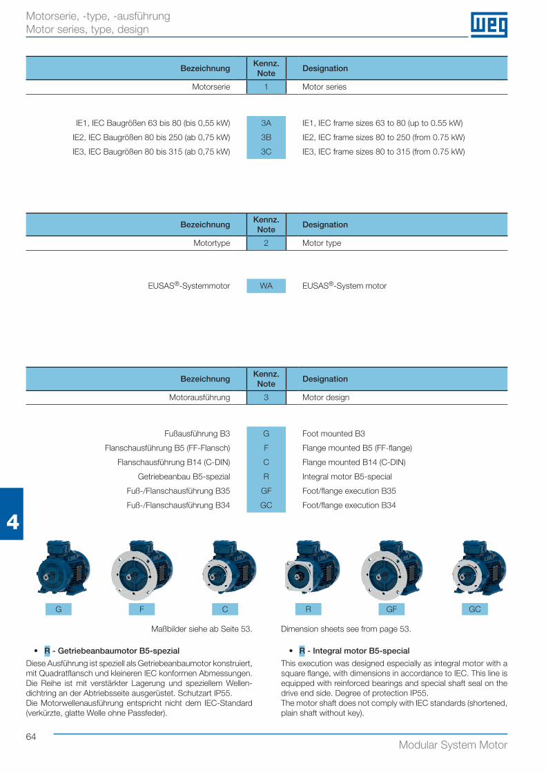
64Modular System Motor
4
Motorserie, -type, -ausführung Motor series, type, design
BezeichnungKennz.Note
Designation
Motorserie 1 Motor series
IE1, IEC Baugrößen 63 bis 80 (bis 0,55 kW) 3A IE1, IEC frame sizes 63 to 80 (up to 0.55 kW)
IE2, IEC Baugrößen 80 bis 250 (ab 0,75 kW) 3B IE2, IEC frame sizes 80 to 250 (from 0.75 kW)
IE3, IEC Baugrößen 80 bis 315 (ab 0,75 kW) 3C IE3, IEC frame sizes 80 to 315 (from 0.75 kW)
BezeichnungKennz.Note
Designation
Motortype 2 Motor type
EUSAS®-Systemmotor WA EUSAS®-System motor
BezeichnungKennz.Note
Designation
Motorausführung 3 Motor design
Fußausführung B3 G Foot mounted B3
Flanschausführung B5 (FF-Flansch) F Flange mounted B5 (FF-flange)
Flanschausführung B14 (C-DIN) C Flange mounted B14 (C-DIN)
Getriebeanbau B5-spezial R Integral motor B5-special
Fuß-/Flanschausführung B35 GF Foot/flange execution B35
Fuß-/Flanschausführung B34 GC Foot/flange execution B34
Maßbilder siehe ab Seite 53. Dimension sheets see from page 53.
• R - Getriebeanbaumotor B5-spezial
Diese Ausführung ist speziell als Getriebeanbaumotor konstruiert, mit Quadratflansch und kleineren IEC konformen Abmessungen. Die Reihe ist mit verstärkter Lagerung und speziellem Wellen-dichtring an der Abtriebsseite ausgerüstet. Schutzart IP55.Die Motorwellenausführung entspricht nicht dem IEC-Standard (verkürzte, glatte Welle ohne Passfeder).
• R - Integral motor B5-special
This execution was designed especially as integral motor with a square flange, with dimensions in accordance to IEC. This line is equipped with reinforced bearings and special shaft seal on the drive end side. Degree of protection IP55.The motor shaft does not comply with IEC standards (shortened, plain shaft without key).
G F C R GF GC
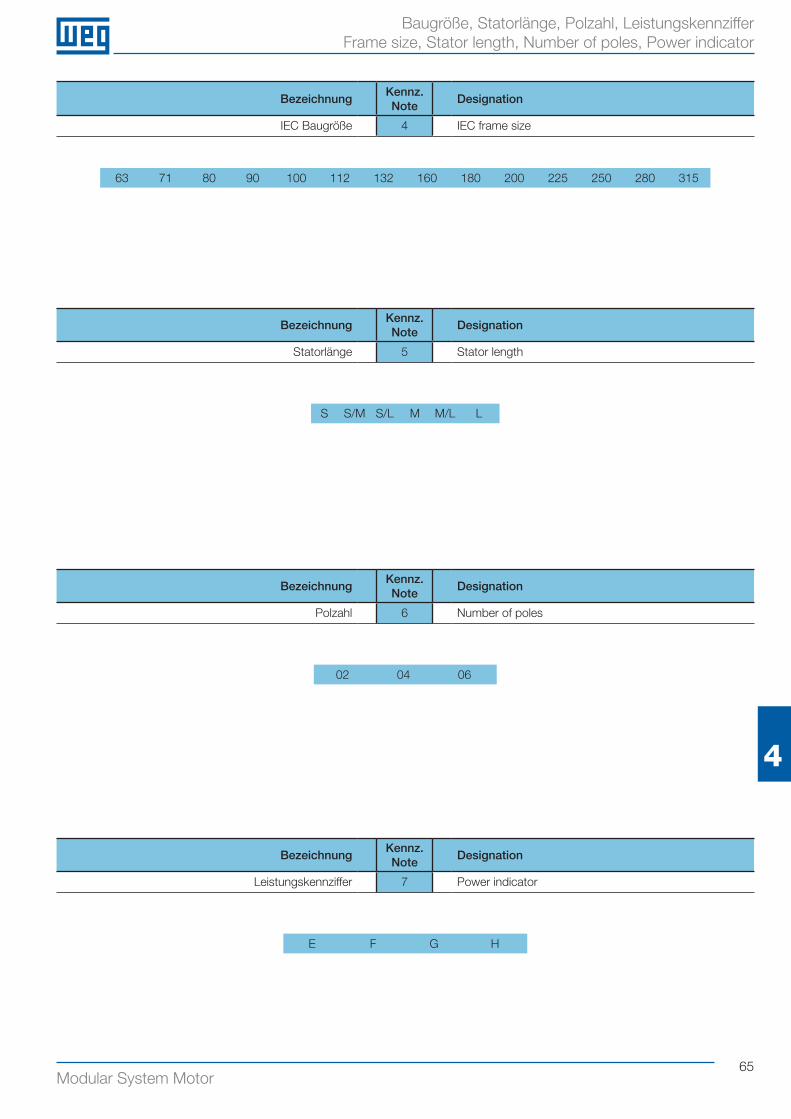
65Modular System Motor
4
Baugröße, Statorlänge, Polzahl, Leistungskennziffer Frame size, Stator length, Number of poles, Power indicator
BezeichnungKennz.Note
Designation
IEC Baugröße 4 IEC frame size
63 71 80 90 100 112 132 160 180 200 225 250 280 315
BezeichnungKennz.Note
Designation
Statorlänge 5 Stator length
S S/M S/L M M/L L
BezeichnungKennz.Note
Designation
Polzahl 6 Number of poles
02 04 06
BezeichnungKennz.Note
Designation
Leistungskennziffer 7 Power indicator
E F G H
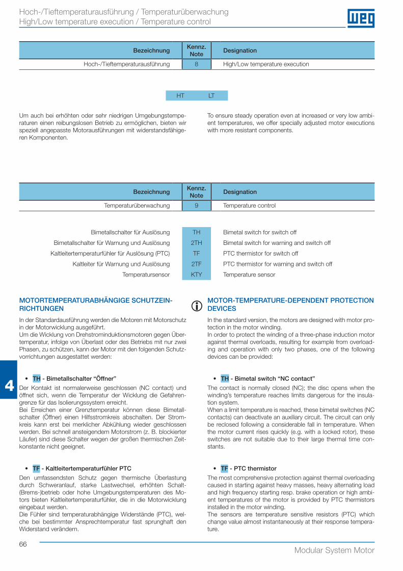
66Modular System Motor
4
Hoch-/Tieftemperaturausführung / Temperaturüberwachung High/Low temperature execution / Temperature control
BezeichnungKennz.Note
Designation
Temperaturüberwachung 9 Temperature control
Bimetallschalter für Auslösung TH Bimetal switch for switch off
Bimetallschalter für Warnung und Auslösung 2TH Bimetal switch for warning and switch off
Kaltleitertemperaturfühler für Auslösung (PTC) TF PTC thermistor for switch off
Kaltleiter für Warnung und Auslösung 2TF PTC thermistor for warning and switch off
Temperatursensor KTY Temperature sensor
MOTORTEMPERATURABHÄNGIGE SCHUTZEIN-RICHTUNGEN
In der Standardausführung werden die Motoren mit Motorschutz in der Motorwicklung ausgeführt.Um die Wicklung von Drehstrominduktionsmotoren gegen Über-temperatur, infolge von Überlast oder des Betriebs mit nur zwei Phasen, zu schützen, kann der Motor mit den folgenden Schutz-vorrichtungen ausgestattet werden:
• TH - Bimetallschalter “Öffner”
Der Kontakt ist normalerweise geschlossen (NC contact) und öffnet sich, wenn die Temperatur der Wicklung die Gefahren-grenze für das Isolierungssystem erreicht.Bei Erreichen einer Grenztemperatur können diese Bimetall-schalter (Öffner) einen Hilfsstromkreis abschalten. Der Strom-kreis kann erst bei merklicher Abkühlung wieder geschlossen werden. Bei schnell ansteigendem Motorstrom (z. B. blockierter Läufer) sind diese Schalter wegen der großen thermischen Zeit-konstante nicht geeignet.
• TF - Kaltleitertemperaturfühler PTC
Den umfassendsten Schutz gegen thermische Überlastung durch Schweranlauf, starke Lastwechsel, erhöhten Schalt-(Brems-)betrieb oder hohe Umgebungstemperaturen des Mo-tors bieten Kaltleitertemperaturfühler, die in die Motorwicklung eingebaut werden.Die Fühler sind temperaturabhängige Widerstände (PTC), wel-che bei bestimmter Ansprechtemperatur fast sprunghaft den Widerstand verändern.
MOTOR-TEMPERATURE-DEPENDENT PROTECTION DEVICES
In the standard version, the motors are designed with motor pro-tection in the motor winding.In order to protect the winding of a three-phase induction motor against thermal overloads, resulting for example from overload-ing and operation with only two phases, one of the following devices can be provided:
• TH - Bimetal switch “NC contact”
The contact is normally closed (NC); the disc opens when the winding’s temperature reaches limits dangerous for the insula-tion system.When a limit temperature is reached, these bimetal switches (NC contacts) can deactivate an auxiliary circuit. The circuit can only be reclosed following a considerable fall in temperature. When the motor current rises quickly (e.g. with a locked rotor), these switches are not suitable due to their large thermal time con-stants.
• TF - PTC thermistor
The most comprehensive protection against thermal overloading caused in starting against heavy masses, heavy alternating load and high frequency starting resp. brake operation or high ambi-ent temperatures of the motor is provided by PTC thermistors installed in the motor winding.The sensors are temperature sensitive resistors (PTC) which change value almost instantaneously at their response tempera-ture.
i
BezeichnungKennz.Note
Designation
Hoch-/Tieftemperaturausführung 8 High/Low temperature execution
HT LT
Um auch bei erhöhten oder sehr niedrigen Umgebungstempe-raturen einen reibungslosen Betrieb zu ermöglichen, bieten wir speziell angepasste Motorausführungen mit widerstandsfähige-ren Komponenten.
To ensure steady operation even at increased or very low ambi-ent temperatures, we offer specially adjusted motor executions with more resistant components.
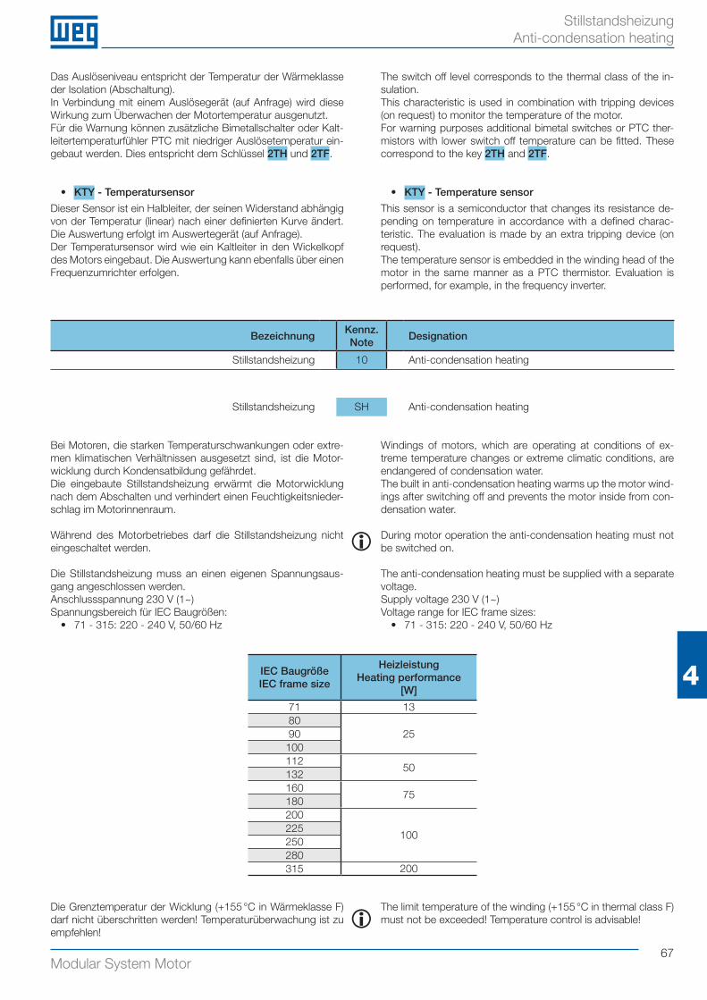
67Modular System Motor
4
Stillstandsheizung Anti-condensation heating
Bei Motoren, die starken Temperaturschwankungen oder extre-men klimatischen Verhältnissen ausgesetzt sind, ist die Motor-wicklung durch Kondensatbildung gefährdet.Die eingebaute Stillstandsheizung erwärmt die Motorwicklung nach dem Abschalten und verhindert einen Feuchtigkeitsnieder-schlag im Motorinnenraum.
Während des Motorbetriebes darf die Stillstandsheizung nicht eingeschaltet werden.
Die Stillstandsheizung muss an einen eigenen Spannungsaus-gang angeschlossen werden.Anschlussspannung 230 V (1~) Spannungsbereich für IEC Baugrößen:
• 71 - 315: 220 - 240 V, 50/60 Hz
Windings of motors, which are operating at conditions of ex-treme temperature changes or extreme climatic conditions, are endangered of condensation water.The built in anti-condensation heating warms up the motor wind-ings after switching off and prevents the motor inside from con-densation water.
During motor operation the anti-condensation heating must not be switched on.
The anti-condensation heating must be supplied with a separate voltage.Supply voltage 230 V (1~)Voltage range for IEC frame sizes:
• 71 - 315: 220 - 240 V, 50/60 Hz
BezeichnungKennz.Note
Designation
Stillstandsheizung 10 Anti-condensation heating
Stillstandsheizung SH Anti-condensation heating
IEC BaugrößeIEC frame size
HeizleistungHeating performance
[W]
71 1380
2590100112
50132160
75180200
100225250280315 200
i
Das Auslöseniveau entspricht der Temperatur der Wärmeklasse der Isolation (Abschaltung). In Verbindung mit einem Auslösegerät (auf Anfrage) wird diese Wirkung zum Überwachen der Motortemperatur ausgenutzt.Für die Warnung können zusätzliche Bimetallschalter oder Kalt-leitertemperaturfühler PTC mit niedriger Auslösetemperatur ein-gebaut werden. Dies entspricht dem Schlüssel 2TH und 2TF.
• KTY - Temperatursensor
Dieser Sensor ist ein Halbleiter, der seinen Widerstand abhängig von der Temperatur (linear) nach einer definierten Kurve ändert. Die Auswertung erfolgt im Auswertegerät (auf Anfrage).Der Temperatursensor wird wie ein Kaltleiter in den Wickelkopf des Motors eingebaut. Die Auswertung kann ebenfalls über einen Frequenzumrichter erfolgen.
The switch off level corresponds to the thermal class of the in-sulation.This characteristic is used in combination with tripping devices (on request) to monitor the temperature of the motor.For warning purposes additional bimetal switches or PTC ther-mistors with lower switch off temperature can be fitted. These correspond to the key 2TH and 2TF.
• KTY - Temperature sensor
This sensor is a semiconductor that changes its resistance de-pending on temperature in accordance with a defined charac-teristic. The evaluation is made by an extra tripping device (on request).The temperature sensor is embedded in the winding head of the motor in the same manner as a PTC thermistor. Evaluation is performed, for example, in the frequency inverter.
iDie Grenztemperatur der Wicklung (+155 °C in Wärmeklasse F) darf nicht überschritten werden! Temperaturüberwachung ist zu empfehlen!
The limit temperature of the winding (+155 °C in thermal class F) must not be exceeded! Temperature control is advisable!
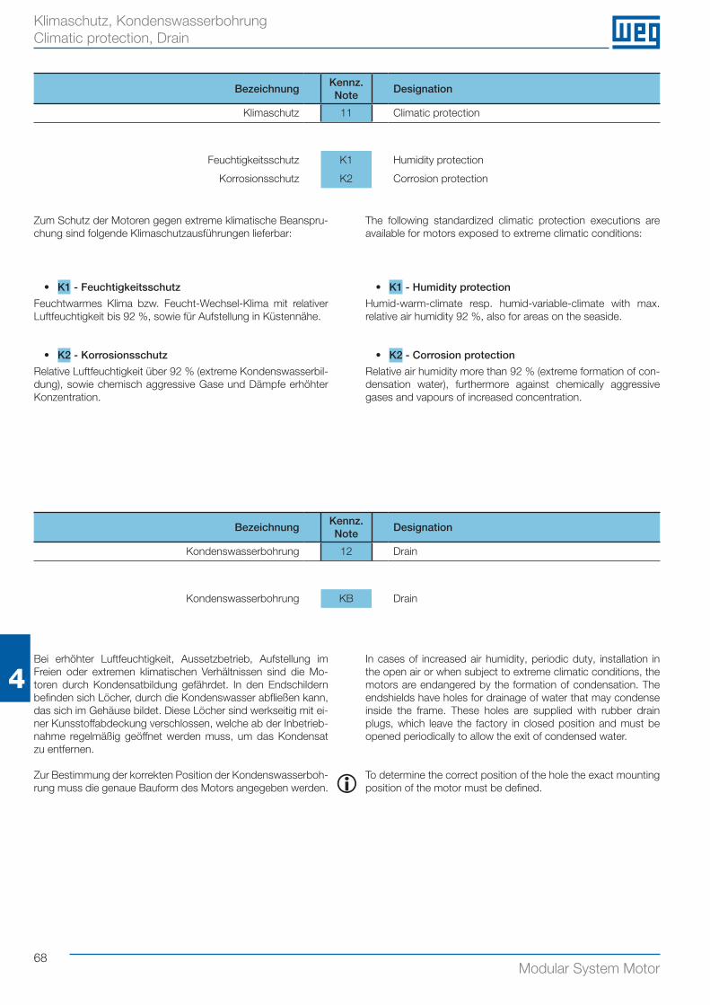
68Modular System Motor
4
Klimaschutz, Kondenswasserbohrung Climatic protection, Drain
• K1 - Feuchtigkeitsschutz
Feuchtwarmes Klima bzw. Feucht-Wechsel-Klima mit relativer Luftfeuchtigkeit bis 92 %, sowie für Aufstellung in Küstennähe.
• K2 - Korrosionsschutz
Relative Luftfeuchtigkeit über 92 % (extreme Kondenswasserbil-dung), sowie chemisch aggressive Gase und Dämpfe erhöhter Konzentration.
• K1 - Humidity protection
Humid-warm-climate resp. humid-variable-climate with max. relative air humidity 92 %, also for areas on the seaside.
• K2 - Corrosion protection
Relative air humidity more than 92 % (extreme formation of con-densation water), furthermore against chemically aggressive gases and vapours of increased concentration.
BezeichnungKennz.Note
Designation
Klimaschutz 11 Climatic protection
Feuchtigkeitsschutz K1 Humidity protection
Korrosionsschutz K2 Corrosion protection
Zum Schutz der Motoren gegen extreme klimatische Beanspru-chung sind folgende Klimaschutzausführungen lieferbar:
The following standardized climatic protection executions are available for motors exposed to extreme climatic conditions:
Bei erhöhter Luftfeuchtigkeit, Aussetzbetrieb, Aufstellung im Freien oder extremen klimatischen Verhältnissen sind die Mo-toren durch Kondensatbildung gefährdet. In den Endschildern befinden sich Löcher, durch die Kondenswasser abfließen kann, das sich im Gehäuse bildet. Diese Löcher sind werkseitig mit ei-ner Kunsstoffabdeckung verschlossen, welche ab der Inbetrieb-nahme regelmäßig geöffnet werden muss, um das Kondensat zu entfernen.
Zur Bestimmung der korrekten Position der Kondenswasserboh-rung muss die genaue Bauform des Motors angegeben werden.
In cases of increased air humidity, periodic duty, installation in the open air or when subject to extreme climatic conditions, the motors are endangered by the formation of condensation. The endshields have holes for drainage of water that may condense inside the frame. These holes are supplied with rubber drain plugs, which leave the factory in closed position and must be opened periodically to allow the exit of condensed water.
To determine the correct position of the hole the exact mounting position of the motor must be defined.
BezeichnungKennz.Note
Designation
Kondenswasserbohrung 12 Drain
Kondenswasserbohrung KB Drain
i
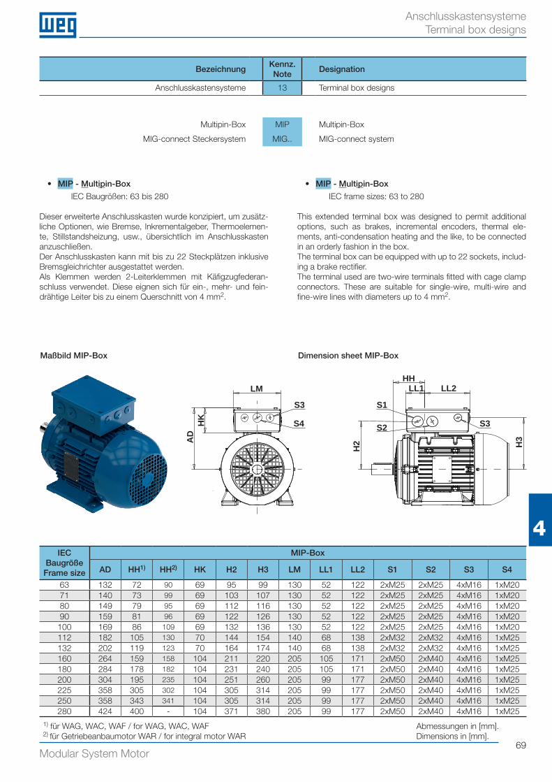
69Modular System Motor
4
Anschlusskastensysteme Terminal box designs
• MIP - Multipin-Box
IEC Baugrößen: 63 bis 280
Dieser erweiterte Anschlusskasten wurde konzipiert, um zusätz-liche Optionen, wie Bremse, Inkrementalgeber, Thermoelemen-te, Stillstandsheizung, usw., übersichtlich im Anschlusskasten anzuschließen. Der Anschlusskasten kann mit bis zu 22 Steckplätzen inklusive Bremsgleichrichter ausgestattet werden. Als Klemmen werden 2-Leiterklemmen mit Käfigzugfederan-schluss verwendet. Diese eignen sich für ein-, mehr- und fein-drähtige Leiter bis zu einem Querschnitt von 4 mm2.
• MIP - Multipin-Box
IEC frame sizes: 63 to 280
This extended terminal box was designed to permit additional options, such as brakes, incremental encoders, thermal ele-ments, anti-condensation heating and the like, to be connected in an orderly fashion in the box. The terminal box can be equipped with up to 22 sockets, includ-ing a brake rectifier. The terminal used are two-wire terminals fitted with cage clamp connectors. These are suitable for single-wire, multi-wire and fine-wire lines with diameters up to 4 mm2.
BezeichnungKennz.Note
Designation
Anschlusskastensysteme 13 Terminal box designs
Multipin-Box MIP Multipin-Box
MIG-connect Steckersystem MIG.. MIG-connect system
IEC BaugrößeFrame size
MIP-Box
AD HH1) HH2) HK H2 H3 LM LL1 LL2 S1 S2 S3 S4
63 132 72 90 69 95 99 130 52 122 2xM25 2xM25 4xM16 1xM2071 140 73 99 69 103 107 130 52 122 2xM25 2xM25 4xM16 1xM2080 149 79 95 69 112 116 130 52 122 2xM25 2xM25 4xM16 1xM2090 159 81 96 69 122 126 130 52 122 2xM25 2xM25 4xM16 1xM20100 169 86 109 69 132 136 130 52 122 2xM25 2xM25 4xM16 1xM20112 182 105 130 70 144 154 140 68 138 2xM32 2xM32 4xM16 1xM25132 202 119 123 70 164 174 140 68 138 2xM32 2xM32 4xM16 1xM25160 264 159 158 104 211 220 205 105 171 2xM50 2xM40 4xM16 1xM25180 284 178 182 104 231 240 205 105 171 2xM50 2xM40 4xM16 1xM25200 304 195 235 104 251 260 205 99 177 2xM50 2xM40 4xM16 1xM25225 358 305 302 104 305 314 205 99 177 2xM50 2xM40 4xM16 1xM25250 358 343 341 104 305 314 205 99 177 2xM50 2xM40 4xM16 1xM25280 424 400 - 104 371 380 205 99 177 2xM50 2xM40 4xM16 1xM25
Maßbild MIP-Box Dimension sheet MIP-Box
Abmessungen in [mm].Dimensions in [mm].
LM
S3
S4HK
AD
HHLL1 LL2
H3
S3
S1
S2
H2
1) für WAG, WAC, WAF / for WAG, WAC, WAF2) für Getriebeanbaumotor WAR / for integral motor WAR
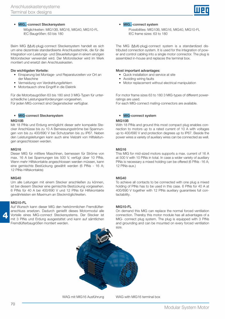
70Modular System Motor
4
Anschlusskastensysteme Terminal box designs
• MIG..-connect Steckersystem
Möglichkeiten: MIG10B, MIG16, MIG40, MIG10-FLIEC Baugrößen: 63 bis 180
Beim MIG (Multi-plug)-connect Steckersystem handelt es sich um eine dezentrale standardisierte Anschlusstechnik, die für die Integration von Leistungs- und Steuerleitungen in einem einzigen Motorstecker verwendet wird. Der Motorstecker wird im Werk montiert und ersetzt den Anschlusskasten.
Die wichtigsten Vorteile:• Einsparung bei Montage- und Reparaturzeiten vor Ort an
der Maschine • Vermeidung von Verdrahtungsfehlern• Motortausch ohne Eingriff in die Elektrik
Für die Motorbaugrößen 63 bis 180 sind 3 MIG-Typen für unter-schiedliche Leistungsanforderungen vorgesehen.Für jeden MIG-connect sind Gegenstecker verfügbar.
• MIG-connect Steckersystem
MIG10BMit 18 PINs und Erdung ermöglicht dieser sehr kompakte Ste-cker Anschlüsse bis zu 10 A Bemessungsströme bei Spannun-gen von bis zu 400/690 V bei Schutzarten bis zu IP67. Neben den Leistungsleitungen kann auch eine Vielzahl von Hilfsleitun-gen angeschlossen werden. MIG16Dieser MIG für mittlere Maschinen, bemessen für Ströme von max. 16 A bei Spannungen bis 500 V, verfügt über 10 PINs. Wenn mehr Hilfskontakte angeschlossen werden müssen, kann eine gemischte Bestückung gewählt werden (6 PINs - 16 A; 12 PINs-Hilfskontakte)
MIG40Um alle Leitungen mit einem Stecker anschließen zu können, ist bei diesem Stecker eine gemischte Bestückung vorgesehen. 6 PINs für 40 A bei 400/690 V und 12 PINs für Hilfskontakte gewährleisten ein Maximum an Steckmöglichkeiten.
MIG10-FLAuf Wunsch kann dieser MIG den herkömmlichen Fremdlüfter-anschluss ersetzen. Dadurch genießt dieses Motormodul alle Vorteile eines MIG-connect Steckersystems. Der Stecker ist mit 3 PINs und Erdung ausgestattet und kann auf sämtlichen Fremdlüfterbaugrößen montiert werden.
WAG mit MIG16 Ausführung
• MIG..-connect system
Possibilities: MIG10B, MIG16, MIG40, MIG10-FLIEC frame sizes: 63 to 180
The MIG (Multi-plug)-connect system is a standardized dis- tributed connection system. It is used for the integration of pow-er and control cabling into a single motor connector. The plug is assembled in-house and replaces the terminal box.
Most important advantages:• Quick installation and service at site• Avoiding wiring faults• Motor replacement without electrical manipulation
For motor frame sizes 63 to 180 3 MIG-types of different power-ratings are used.For each MIG-connect mating-connectors are available.
• MIG-connect system
MIG10BWith 18 PINs and ground this most compact plug enables con-nection to motors up to a rated current of 10 A with voltages up to 400/690 V and protection degrees up to IP67. Beside the power wires a variety of auxiliary wires can be connected as well.
MIG16This MIG for mid-sized motors supports a max. current of 16 A at 500 V with 10 PINs in total. In case a wider variety of auxiliary PINs is necessary a mixed holding can be offered (6 PINs -16 A; 12 PINs-aux.)
MIG40To achieve all contacts to be connected with one plug a mixed holding of PINs has to be used in this case. 6 PINs for 40 A at 400/690 V together with 12 PINs auxiliary guarantees full con-tactability.
MIG10-FLOn demand this MIG can replace the normal forced ventilation connection. Thereby this motor module has all advantages of a MIG- connect plug system. The plug is equipped with 3 PINs and grounding and can be mounted on every forced ventilation size.
WAG with MIG16 terminal box
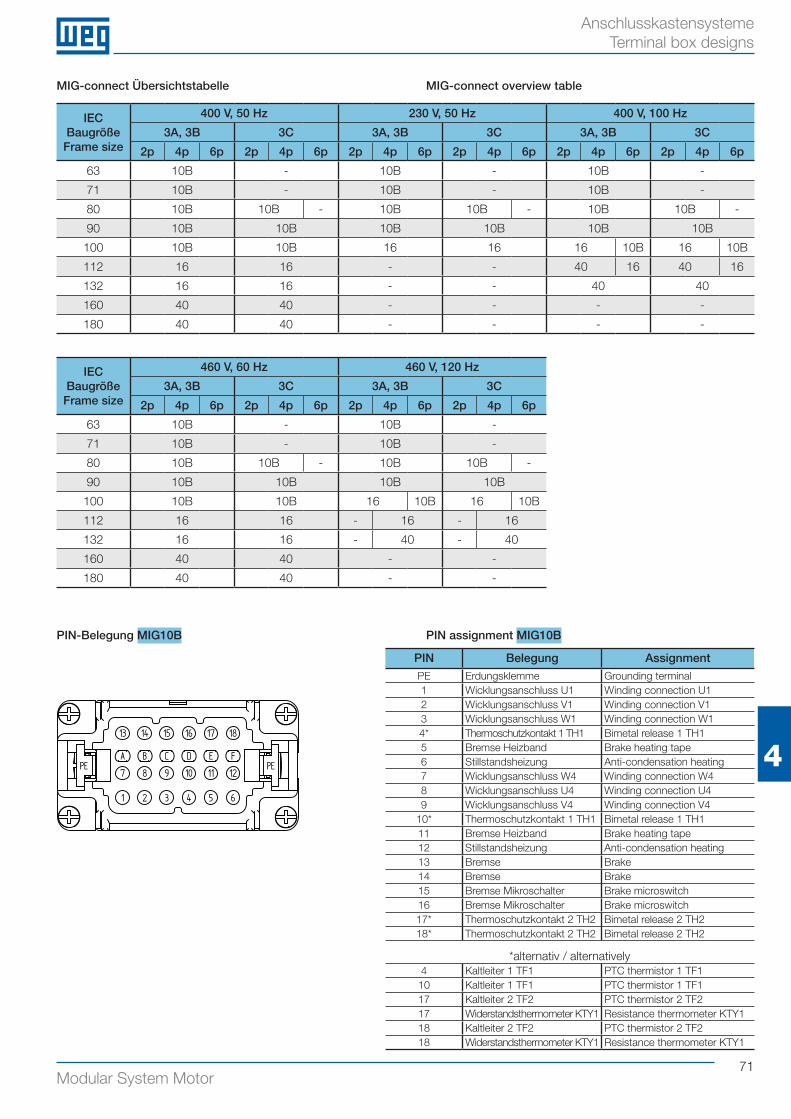
71Modular System Motor
4
Anschlusskastensysteme Terminal box designs
PIN Belegung AssignmentPE Erdungsklemme Grounding terminal1 Wicklungsanschluss U1 Winding connection U12 Wicklungsanschluss V1 Winding connection V13 Wicklungsanschluss W1 Winding connection W14* Thermoschutzkontakt 1 TH1 Bimetal release 1 TH15 Bremse Heizband Brake heating tape6 Stillstandsheizung Anti-condensation heating7 Wicklungsanschluss W4 Winding connection W48 Wicklungsanschluss U4 Winding connection U49 Wicklungsanschluss V4 Winding connection V4
10* Thermoschutzkontakt 1 TH1 Bimetal release 1 TH111 Bremse Heizband Brake heating tape12 Stillstandsheizung Anti-condensation heating13 Bremse Brake14 Bremse Brake15 Bremse Mikroschalter Brake microswitch16 Bremse Mikroschalter Brake microswitch17* Thermoschutzkontakt 2 TH2 Bimetal release 2 TH218* Thermoschutzkontakt 2 TH2 Bimetal release 2 TH2
*alternativ / alternatively4 Kaltleiter 1 TF1 PTC thermistor 1 TF1
10 Kaltleiter 1 TF1 PTC thermistor 1 TF117 Kaltleiter 2 TF2 PTC thermistor 2 TF217 Widerstandsthermometer KTY1 Resistance thermometer KTY118 Kaltleiter 2 TF2 PTC thermistor 2 TF218 Widerstandsthermometer KTY1 Resistance thermometer KTY1
PIN-Belegung MIG10B PIN assignment MIG10B
MIG-connect Übersichtstabelle MIG-connect overview table
6
7 9 108
1 2 3 4 5
PE PE11 12
13 14 15 16 17 18
A B C D E F
IECBaugrößeFrame size
400 V, 50 Hz 230 V, 50 Hz 400 V, 100 Hz
3A, 3B 3C 3A, 3B 3C 3A, 3B 3C
2p 4p 6p 2p 4p 6p 2p 4p 6p 2p 4p 6p 2p 4p 6p 2p 4p 6p
63 10B - 10B - 10B -
71 10B - 10B - 10B -
80 10B 10B - 10B 10B - 10B 10B -
90 10B 10B 10B 10B 10B 10B
100 10B 10B 16 16 16 10B 16 10B
112 16 16 - - 40 16 40 16
132 16 16 - - 40 40
160 40 40 - - - -
180 40 40 - - - -
IECBaugrößeFrame size
460 V, 60 Hz 460 V, 120 Hz
3A, 3B 3C 3A, 3B 3C
2p 4p 6p 2p 4p 6p 2p 4p 6p 2p 4p 6p
63 10B - 10B -
71 10B - 10B -
80 10B 10B - 10B 10B -
90 10B 10B 10B 10B
100 10B 10B 16 10B 16 10B
112 16 16 - 16 - 16
132 16 16 - 40 - 40
160 40 40 - -
180 40 40 - -
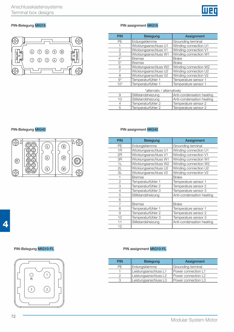
72Modular System Motor
4
Anschlusskastensysteme Terminal box designs
PIN Belegung Assignment
PE Erdungsklemme Grounding terminal1R Wicklungsanschluss U1 Winding connection U12R Wicklungsanschluss V1 Winding connection V13R Wicklungsanschluss W1 Winding connection W11L Wicklungsanschluss W2 Winding connection W22L Wicklungsanschluss U2 Winding connection U23L Wicklungsanschluss V2 Winding connection V21 Bremse Brake2 Temperaturfühler 1 Temperature sensor 13 Temperaturfühler 2 Temperature sensor 24 Temperaturfühler 3 Temperature sensor 35 Stillstandsheizung Anti-condensation heating67 Bremse Brake8 Temperaturfühler 1 Temperature sensor 19 Temperaturfühler 2 Temperature sensor 2
10 Temperaturfühler 3 Temperature sensor 311 Stillstandsheizung Anti-condensation heating12
PIN-Belegung MIG40 PIN assignment MIG40
7 1
8 2
39
10 4
511
12 6
1L
2L
3L 3R
2R
1R
PE PE
PIN-Belegung MIG10-FL PIN assignment MIG10-FL
1
23
PE
PIN Belegung Assignment
PE Erdungsklemme Grounding terminal1 Leistungsanschluss L1 Power connection L12 Leistungsanschluss L2 Power connection L23 Leistungsanschluss L3 Power connection L3
PIN Belegung Assignment
PE Erdungsklemme Grounding terminal1 Wicklungsanschluss U1 Winding connection U12 Wicklungsanschluss V1 Winding connection V13 Wicklungsanschluss W1 Winding connection W14* Bremse Brake5* Bremse Brake6 Wicklungsanschluss W2 Winding connection W27 Wicklungsanschluss U2 Winding connection U28 Wicklungsanschluss V2 Winding connection V29* Temperaturfühler 1 Temperature sensor 1
10* Temperaturfühler 1 Temperature sensor 1
*alternativ / alternatively9 Stillstandsheizung Anti-condensation heating
10 Stillstandsheizung Anti-condensation heating4 Temperaturfühler 2 Temperature sensor 25 Temperaturfühler 2 Temperature sensor 2
PIN-Belegung MIG16 PIN assignment MIG16
6 7 9 108
1 2 3 4 5PE PE
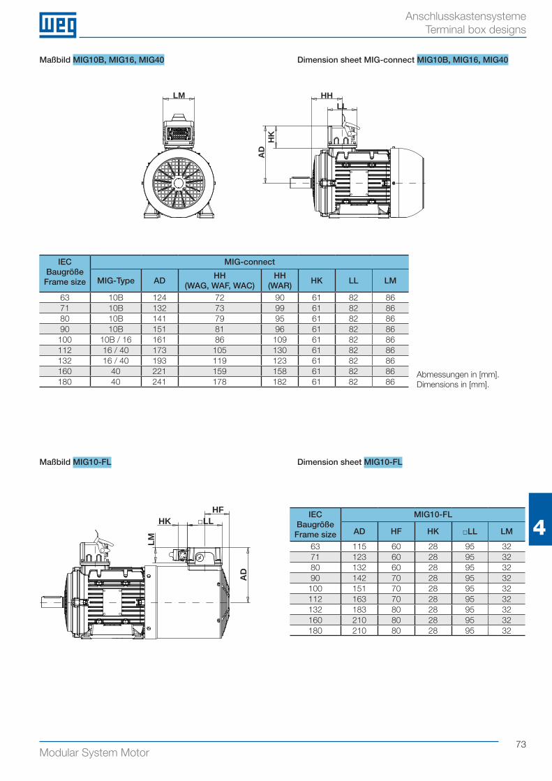
73Modular System Motor
4
Anschlusskastensysteme Terminal box designs
IEC BaugrößeFrame size
MIG-connect
MIG-Type ADHH
(WAG, WAF, WAC)HH
(WAR)HK LL LM
63 10B 124 72 90 61 82 8671 10B 132 73 99 61 82 8680 10B 141 79 95 61 82 8690 10B 151 81 96 61 82 86
100 10B / 16 161 86 109 61 82 86112 16 / 40 173 105 130 61 82 86132 16 / 40 193 119 123 61 82 86160 40 221 159 158 61 82 86180 40 241 178 182 61 82 86
Maßbild MIG10B, MIG16, MIG40 Dimension sheet MIG-connect MIG10B, MIG16, MIG40
Abmessungen in [mm].Dimensions in [mm].
HHLL
HK
AD
LM
HFHK
LM
□LL
AD
Maßbild MIG10-FL Dimension sheet MIG10-FL
IEC BaugrößeFrame size
MIG10-FL
AD HF HK □LL LM
63 115 60 28 95 3271 123 60 28 95 3280 132 60 28 95 3290 142 70 28 95 32
100 151 70 28 95 32112 163 70 28 95 32132 183 80 28 95 32160 210 80 28 95 32180 210 80 28 95 32
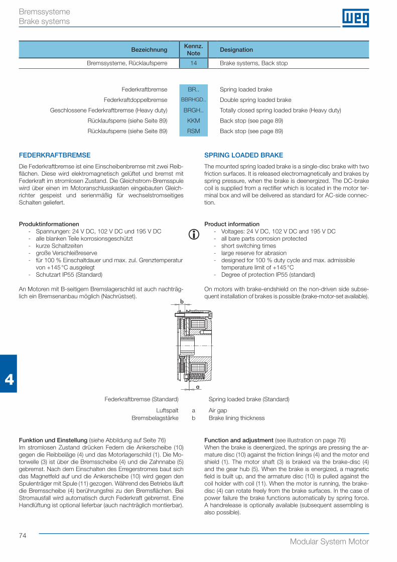
74Modular System Motor
4
Bremssysteme Brake systems
BezeichnungKennz.Note
Designation
Bremssysteme, Rücklaufsperre 14 Brake systems, Back stop
Federkraftbremse BR.. Spring loaded brake
Federkraftdoppelbremse BBRHGD.. Double spring loaded brake
Geschlossene Federkraftbremse (Heavy duty) BRGH.. Totally closed spring loaded brake (Heavy duty)
Rücklaufsperre (siehe Seite 89) KKM Back stop (see page 89)
Rücklaufsperre (siehe Seite 89) RSM Back stop (see page 89)
Funktion und Einstellung (siehe Abbildung auf Seite 76)Im stromlosen Zustand drücken Federn die Ankerscheibe (10) gegen die Reibbeläge (4) und das Motorlagerschild (1). Die Mo-torwelle (3) ist über die Bremsscheibe (4) und die Zahnnabe (5) gebremst. Nach dem Einschalten des Erregerstromes baut sich das Magnetfeld auf und die Ankerscheibe (10) wird gegen den Spulenträger mit Spule (11) gezogen. Während des Betriebs läuft die Bremsscheibe (4) berührungsfrei zu den Bremsflächen. Bei Stromausfall wird automatisch durch Federkraft gebremst. Eine Handlüftung ist optional lieferbar (auch nachträglich montierbar).
Function and adjustment (see illustration on page 76) When the brake is deenergized, the springs are pressing the ar-mature disc (10) against the friction linings (4) and the motor end shield (1). The motor shaft (3) is braked via the brake-disc (4) and the gear hub (5). When the brake is energized, a magnetic field is built up, and the armature disc (10) is pulled against the coil holder with coil (11). When the motor is running, the brake-disc (4) can rotate freely from the brake surfaces. In the case of power failure the brake functions automatically by spring force. A handrelease is optionally available (subsequent assembling is also possible).
i
FEDERKRAFTBREMSE
Die Federkraftbremse ist eine Einscheibenbremse mit zwei Reib-flächen. Diese wird elektromagnetisch gelüftet und bremst mit Federkraft im stromlosen Zustand. Die Gleichstrom-Bremsspule wird über einen im Motoranschlusskasten eingebauten Gleich-richter gespeist und serienmäßig für wechselstromseitiges Schalten geliefert.
Produktinformationen - Spannungen: 24 V DC, 102 V DC und 195 V DC - alle blanken Teile korrosionsgeschützt - kurze Schaltzeiten - große Verschleißreserve - für 100 % Einschaltdauer und max. zul. Grenztemperatur
von +145 °C ausgelegt - Schutzart IP55 (Standard)
An Motoren mit B-seitigem Bremslagerschild ist auch nachträg-lich ein Bremsenanbau möglich (Nachrüstset).
SPRING LOADED BRAKE
The mounted spring loaded brake is a single-disc brake with two friction surfaces. It is released electromagnetically and brakes by spring pressure, when the brake is deenergized. The DC-brake coil is supplied from a rectifier which is located in the motor ter-minal box and will be delivered as standard for AC-side connec-tion.
Product information - Voltages: 24 V DC, 102 V DC and 195 V DC - all bare parts corrosion protected - short switching times - large reserve for abrasion - designed for 100 % duty cycle and max. admissible
temperature limit of +145 °C - Degree of protection IP55 (standard)
On motors with brake-endshield on the non-driven side subse-quent installation of brakes is possible (brake-motor-set available).
Federkraftbremse (Standard) Spring loaded brake (Standard)
Luftspalt a Air gapBremsbelagstärke b Brake lining thickness
a
b
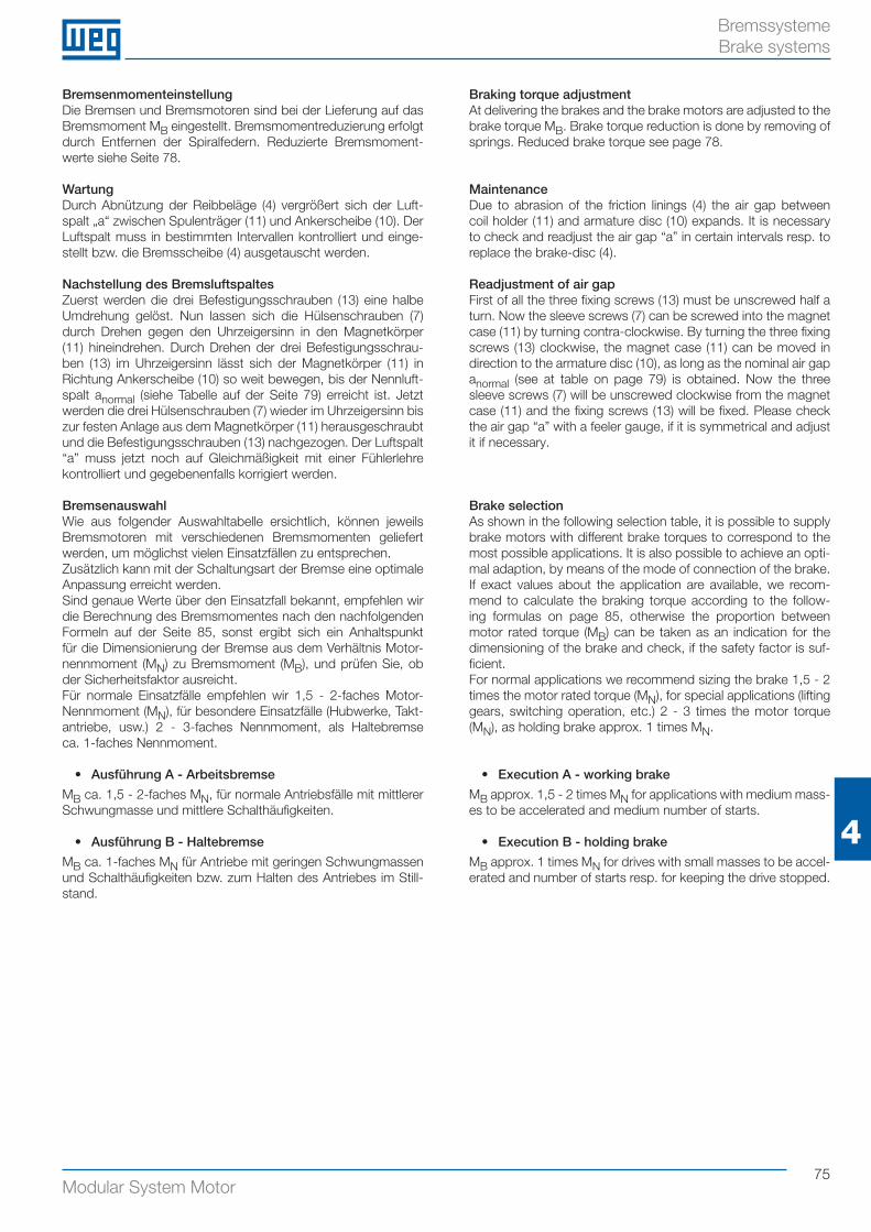
75Modular System Motor
4
Bremssysteme Brake systems
BremsenmomenteinstellungDie Bremsen und Bremsmotoren sind bei der Lieferung auf das Bremsmoment MB eingestellt. Bremsmomentreduzierung erfolgt durch Entfernen der Spiralfedern. Reduzierte Bremsmoment-werte siehe Seite 78.
WartungDurch Abnützung der Reibbeläge (4) vergrößert sich der Luft-spalt „a“ zwischen Spulenträger (11) und Ankerscheibe (10). Der Luftspalt muss in bestimmten Intervallen kontrolliert und einge-stellt bzw. die Bremsscheibe (4) ausgetauscht werden.
Nachstellung des BremsluftspaltesZuerst werden die drei Befestigungsschrauben (13) eine halbe Umdrehung gelöst. Nun lassen sich die Hülsenschrauben (7) durch Drehen gegen den Uhrzeigersinn in den Magnetkörper (11) hineindrehen. Durch Drehen der drei Befestigungsschrau-ben (13) im Uhrzeigersinn lässt sich der Magnetkörper (11) in Richtung Ankerscheibe (10) so weit bewegen, bis der Nennluft-spalt anormal (siehe Tabelle auf der Seite 79) erreicht ist. Jetzt werden die drei Hülsenschrauben (7) wieder im Uhrzeigersinn bis zur festen Anlage aus dem Magnetkörper (11) herausgeschraubt und die Befestigungsschrauben (13) nachgezogen. Der Luftspalt “a” muss jetzt noch auf Gleichmäßigkeit mit einer Fühlerlehre kontrolliert und gegebenenfalls korrigiert werden.
BremsenauswahlWie aus folgender Auswahltabelle ersichtlich, können jeweils Bremsmotoren mit verschiedenen Bremsmomenten geliefert werden, um möglichst vielen Einsatzfällen zu entsprechen.Zusätzlich kann mit der Schaltungsart der Bremse eine optimale Anpassung erreicht werden.Sind genaue Werte über den Einsatzfall bekannt, empfehlen wir die Berechnung des Bremsmomentes nach den nachfolgenden Formeln auf der Seite 85, sonst ergibt sich ein Anhaltspunkt für die Dimensionierung der Bremse aus dem Verhältnis Motor-nennmoment (MN) zu Bremsmoment (MB), und prüfen Sie, ob der Sicherheitsfaktor ausreicht. Für normale Einsatzfälle empfehlen wir 1,5 - 2-faches Motor-Nennmoment (MN), für besondere Einsatzfälle (Hubwerke, Takt-antriebe, usw.) 2 - 3-faches Nennmoment, als Haltebremse ca. 1-faches Nennmoment.
• Ausführung A - Arbeitsbremse
MB ca. 1,5 - 2-faches MN, für normale Antriebsfälle mit mittlerer Schwungmasse und mittlere Schalthäufigkeiten.
• Ausführung B - Haltebremse
MB ca. 1-faches MN für Antriebe mit geringen Schwungmassen und Schalthäufigkeiten bzw. zum Halten des Antriebes im Still-stand.
Braking torque adjustmentAt delivering the brakes and the brake motors are adjusted to the brake torque MB. Brake torque reduction is done by removing of springs. Reduced brake torque see page 78.
MaintenanceDue to abrasion of the friction linings (4) the air gap between coil holder (11) and armature disc (10) expands. It is necessary to check and readjust the air gap “a” in certain intervals resp. to replace the brake-disc (4).
Readjustment of air gapFirst of all the three fixing screws (13) must be unscrewed half a turn. Now the sleeve screws (7) can be screwed into the magnet case (11) by turning contra-clockwise. By turning the three fixing screws (13) clockwise, the magnet case (11) can be moved in direction to the armature disc (10), as long as the nominal air gap anormal (see at table on page 79) is obtained. Now the three sleeve screws (7) will be unscrewed clockwise from the magnet case (11) and the fixing screws (13) will be fixed. Please check the air gap “a” with a feeler gauge, if it is symmetrical and adjust it if necessary.
Brake selectionAs shown in the following selection table, it is possible to supply brake motors with different brake torques to correspond to the most possible applications. It is also possible to achieve an opti-mal adaption, by means of the mode of connection of the brake.If exact values about the application are available, we recom-mend to calculate the braking torque according to the follow-ing formulas on page 85, otherwise the proportion between motor rated torque (MB) can be taken as an indication for the dimensioning of the brake and check, if the safety factor is suf-ficient. For normal applications we recommend sizing the brake 1,5 - 2 times the motor rated torque (MN), for special applications (lifting gears, switching operation, etc.) 2 - 3 times the motor torque (MN), as holding brake approx. 1 times MN.
• Execution A - working brake
MB approx. 1,5 - 2 times MN for applications with medium mass-es to be accelerated and medium number of starts.
• Execution B - holding brake
MB approx. 1 times MN for drives with small masses to be accel-erated and number of starts resp. for keeping the drive stopped.
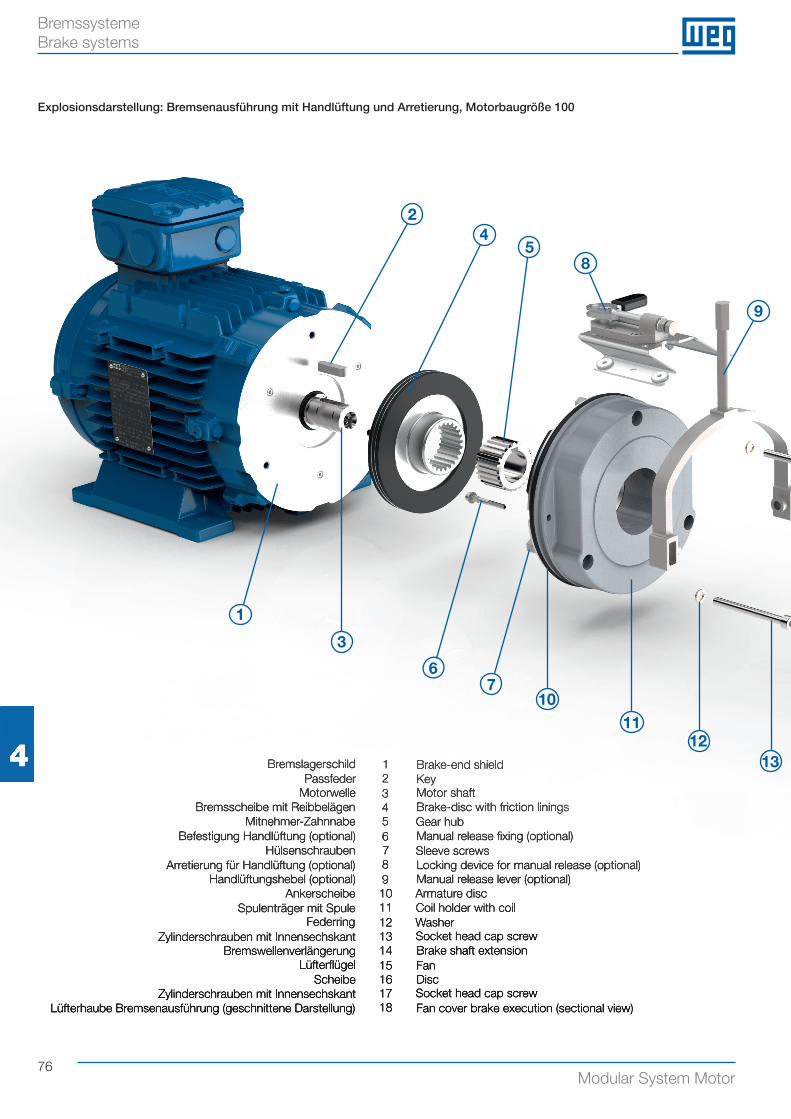
76Modular System Motor
BremssystemeBrake systems
Explosionsdarstellung: Bremsenausführung mit Handlüftung und Arretierung, Motorbaugröße 100
Bremslagerschild 1 Brake-end shieldPassfeder 2 Key
Motorwelle 3 Motor shaftBremsscheibe mit Reibbelägen 4 Brake-disc with friction linings
Mitnehmer-Zahnnabe 5 Gear hubBefestigung Handlüftung (optional) 6 Manual release fi xing (optional)
Hülsenschrauben 7 Sleeve screwsArretierung für Handlüftung (optional) 8 Locking device for manual release (optional)
Handlüftungshebel (optional) 9 Manual release lever (optional)Ankerscheibe 10 Armature disc
Spulenträger mit Spule 11 Coil holder with coilFederring 12 Washer
Zylinderschrauben mit Innensechskant 13 Socket head cap screwBremswellenverlängerung 14 Brake shaft extension
Lüfterfl ügel 15 FanScheibe 16 Disc
Zylinderschrauben mit Innensechskant 17 Socket head cap screwLüfterhaube Bremsenausführung (geschnittene Darstellung) 18 Fan cover brake execution (sectional view)
4 Bremslagerschild 1 Brake-end shieldPassfeder 2 Key
Motorwelle 3 Motor shaftBremsscheibe mit Reibbelägen 4 Brake-disc with friction linings
Mitnehmer-Zahnnabe 5 Gear hubBefestigung Handlüftung (optional) 6 Manual release fi xing (optional)
Hülsenschrauben 7 Sleeve screwsArretierung für Handlüftung (optional) 8 Locking device for manual release (optional)
Handlüftungshebel (optional) 9 Manual release lever (optional)Ankerscheibe 10 Armature disc
Spulenträger mit Spule 11 Coil holder with coilFederring 12 Washer
Zylinderschrauben mit Innensechskant 13 Socket head cap screwBremswellenverlängerung 14 Brake shaft extension
Lüfterfl ügel 15 FanScheibe 16 Disc
Zylinderschrauben mit Innensechskant 17 Socket head cap screwLüfterhaube Bremsenausführung (geschnittene Darstellung) 18 Fan cover brake execution (sectional view)
4
1
3
2
1312
1110
76
9
85
4
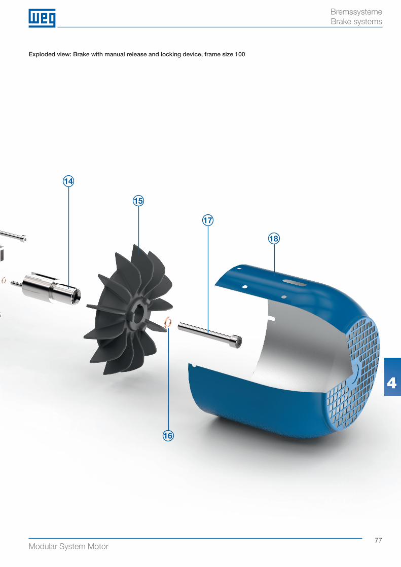
77Modular System Motor
BremssystemeBrake systems
Exploded view: Brake with manual release and locking device, frame size 100
44
16
14
15
17
18
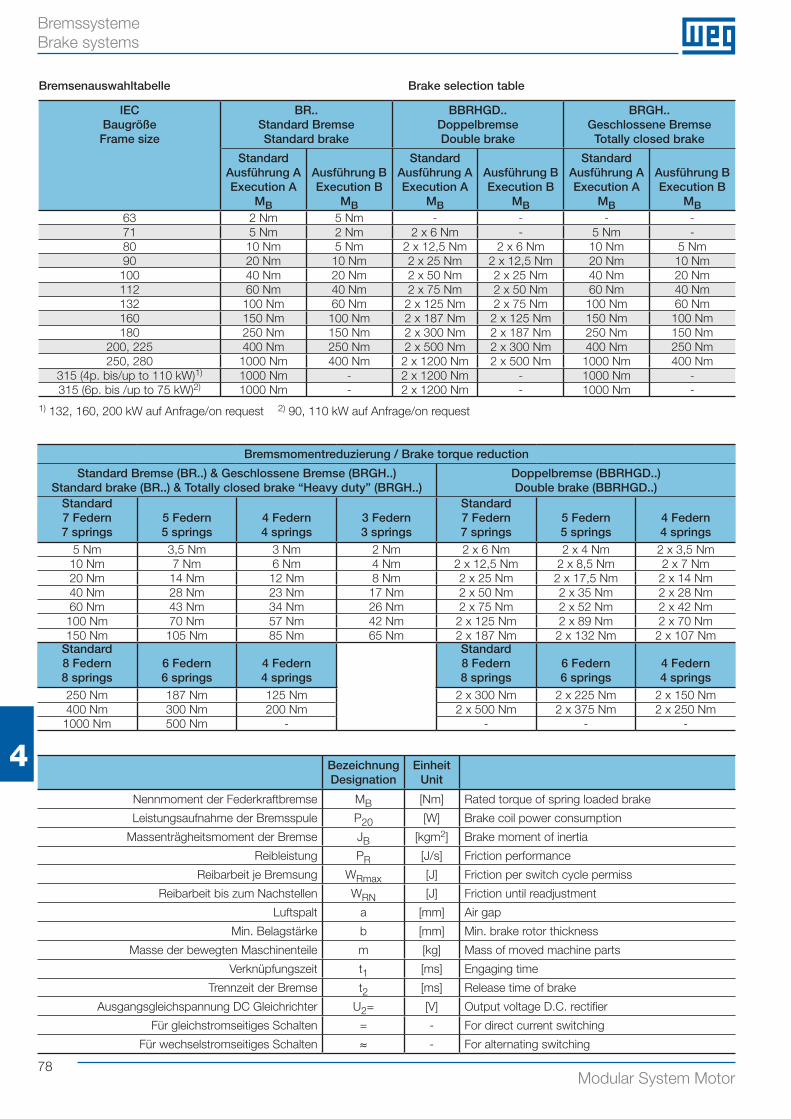
78Modular System Motor
4
Bremssysteme Brake systems
Bremsmomentreduzierung / Brake torque reduction
Standard Bremse (BR..) & Geschlossene Bremse (BRGH..)Standard brake (BR..) & Totally closed brake “Heavy duty” (BRGH..)
Doppelbremse (BBRHGD..)Double brake (BBRHGD..)
Standard7 Federn7 springs
5 Federn5 springs
4 Federn4 springs
3 Federn3 springs
Standard7 Federn7 springs
5 Federn5 springs
4 Federn4 springs
5 Nm 3,5 Nm 3 Nm 2 Nm 2 x 6 Nm 2 x 4 Nm 2 x 3,5 Nm10 Nm 7 Nm 6 Nm 4 Nm 2 x 12,5 Nm 2 x 8,5 Nm 2 x 7 Nm20 Nm 14 Nm 12 Nm 8 Nm 2 x 25 Nm 2 x 17,5 Nm 2 x 14 Nm40 Nm 28 Nm 23 Nm 17 Nm 2 x 50 Nm 2 x 35 Nm 2 x 28 Nm60 Nm 43 Nm 34 Nm 26 Nm 2 x 75 Nm 2 x 52 Nm 2 x 42 Nm
100 Nm 70 Nm 57 Nm 42 Nm 2 x 125 Nm 2 x 89 Nm 2 x 70 Nm150 Nm 105 Nm 85 Nm 65 Nm 2 x 187 Nm 2 x 132 Nm 2 x 10⁷ Nm
Standard8 Federn8 springs
6 Federn6 springs
4 Federn4 springs
Standard8 Federn8 springs
6 Federn6 springs
4 Federn4 springs
250 Nm 187 Nm 125 Nm 2 x 300 Nm 2 x 225 Nm 2 x 150 Nm400 Nm 300 Nm 200 Nm 2 x 500 Nm 2 x 375 Nm 2 x 250 Nm
1000 Nm 500 Nm - - - -
BezeichnungDesignation
EinheitUnit
Nennmoment der Federkraftbremse MB [Nm] Rated torque of spring loaded brake
Leistungsaufnahme der Bremsspule P20 [W] Brake coil power consumption
Massenträgheitsmoment der Bremse JB [kgm2] Brake moment of inertia
Reibleistung PR [J/s] Friction performance
Reibarbeit je Bremsung WRmax [J] Friction per switch cycle permiss
Reibarbeit bis zum Nachstellen WRN [J] Friction until readjustment
Luftspalt a [mm] Air gap
Min. Belagstärke b [mm] Min. brake rotor thickness
Masse der bewegten Maschinenteile m [kg] Mass of moved machine parts
Verknüpfungszeit t1 [ms] Engaging time
Trennzeit der Bremse t2 [ms] Release time of brake
Ausgangsgleichspannung DC Gleichrichter U2= [V] Output voltage D.C. rectifier
Für gleichstromseitiges Schalten = - For direct current switching
Für wechselstromseitiges Schalten ≈ - For alternating switching
IEC BaugrößeFrame size
BR..Standard BremseStandard brake
BBRHGD..DoppelbremseDouble brake
BRGH..Geschlossene Bremse
Totally closed brake
StandardAusführung AExecution A
MB
Ausführung BExecution B
MB
StandardAusführung AExecution A
MB
Ausführung BExecution B
MB
StandardAusführung AExecution A
MB
Ausführung BExecution B
MB63 2 Nm 5 Nm - - - -71 5 Nm 2 Nm 2 x 6 Nm - 5 Nm -80 10 Nm 5 Nm 2 x 12,5 Nm 2 x 6 Nm 10 Nm 5 Nm90 20 Nm 10 Nm 2 x 25 Nm 2 x 12,5 Nm 20 Nm 10 Nm100 40 Nm 20 Nm 2 x 50 Nm 2 x 25 Nm 40 Nm 20 Nm112 60 Nm 40 Nm 2 x 75 Nm 2 x 50 Nm 60 Nm 40 Nm132 100 Nm 60 Nm 2 x 125 Nm 2 x 75 Nm 100 Nm 60 Nm160 150 Nm 100 Nm 2 x 187 Nm 2 x 125 Nm 150 Nm 100 Nm180 250 Nm 150 Nm 2 x 300 Nm 2 x 187 Nm 250 Nm 150 Nm
200, 225 400 Nm 250 Nm 2 x 500 Nm 2 x 300 Nm 400 Nm 250 Nm250, 280 1000 Nm 400 Nm 2 x 1200 Nm 2 x 500 Nm 1000 Nm 400 Nm
315 (4p. bis/up to 110 kW)1) 1000 Nm - 2 x 1200 Nm - 1000 Nm -315 (6p. bis /up to 75 kW)2) 1000 Nm - 2 x 1200 Nm - 1000 Nm -
Bremsenauswahltabelle Brake selection table
1) 132, 160, 200 kW auf Anfrage/on request 2) 90, 110 kW auf Anfrage/on request
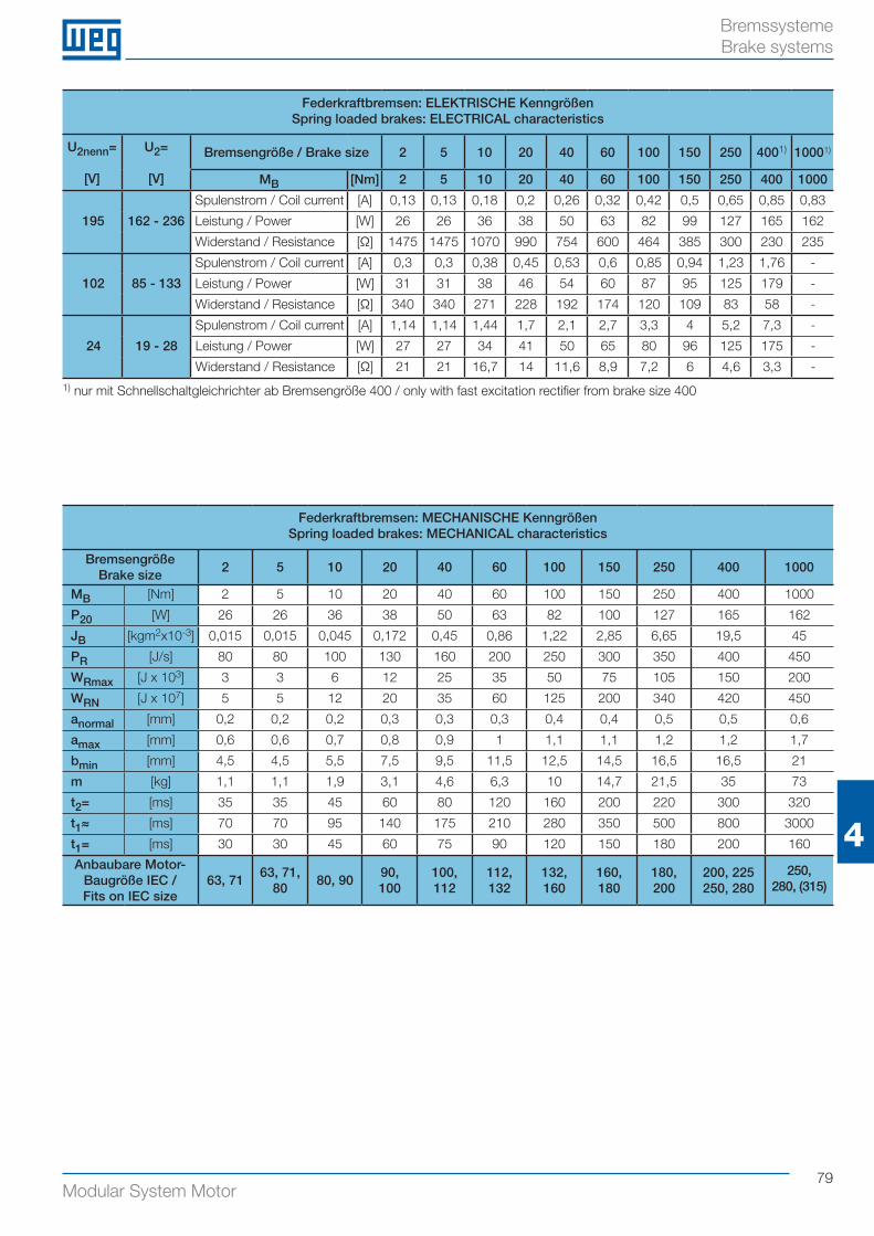
79Modular System Motor
4
Bremssysteme Brake systems
Federkraftbremsen: MECHANISCHE KenngrößenSpring loaded brakes: MECHANICAL characteristics
BremsengrößeBrake size
2 5 10 20 40 60 100 150 250 400 1000
MB [Nm] 2 5 10 20 40 60 100 150 250 400 1000
P20 [W] 26 26 36 38 50 63 82 100 127 165 162
JB [kgm2x10-3] 0,015 0,015 0,045 0,172 0,45 0,86 1,22 2,85 6,65 19,5 45
PR [J/s] 80 80 100 130 160 200 250 300 350 400 450
WRmax [J x 103] 3 3 6 12 25 35 50 75 105 150 200
WRN [J x 107] 5 5 12 20 35 60 125 200 340 420 450
anormal [mm] 0,2 0,2 0,2 0,3 0,3 0,3 0,4 0,4 0,5 0,5 0,6
amax [mm] 0,6 0,6 0,7 0,8 0,9 1 1,1 1,1 1,2 1,2 1,7
bmin [mm] 4,5 4,5 5,5 7,5 9,5 11,5 12,5 14,5 16,5 16,5 21
m [kg] 1,1 1,1 1,9 3,1 4,6 6,3 10 14,7 21,5 35 73
t2= [ms] 35 35 45 60 80 120 160 200 220 300 320
t1≈ [ms] 70 70 95 140 175 210 280 350 500 800 3000
t1= [ms] 30 30 45 60 75 90 120 150 180 200 160
Anbaubare Motor-Baugröße IEC /Fits on IEC size
63, 7163, 71,
8080, 90
90, 100
100,112
112,132
132,160
160,180
180,200
200, 225250, 280
250,280, (315)
Federkraftbremsen: ELEKTRISCHE KenngrößenSpring loaded brakes: ELECTRICAL characteristics
U2nenn=
[V]
U2=
[V]
Bremsengröße / Brake size 2 5 10 20 40 60 100 150 250 4001) 10001)
MB [Nm] 2 5 10 20 40 60 100 150 250 400 1000
195 162 - 236
Spulenstrom / Coil current [A] 0,13 0,13 0,18 0,2 0,26 0,32 0,42 0,5 0,65 0,85 0,83
Leistung / Power [W] 26 26 36 38 50 63 82 99 127 165 162
Widerstand / Resistance [Ω] 1475 1475 1070 990 754 600 464 385 300 230 235
102 85 - 133
Spulenstrom / Coil current [A] 0,3 0,3 0,38 0,45 0,53 0,6 0,85 0,94 1,23 1,76 -
Leistung / Power [W] 31 31 38 46 54 60 87 95 125 179 -
Widerstand / Resistance [Ω] 340 340 271 228 192 174 120 109 83 58 -
24 19 - 28
Spulenstrom / Coil current [A] 1,14 1,14 1,44 1,7 2,1 2,7 3,3 4 5,2 7,3 -
Leistung / Power [W] 27 27 34 41 50 65 80 96 125 175 -
Widerstand / Resistance [Ω] 21 21 16,7 14 11,6 8,9 7,2 6 4,6 3,3 -
1) nur mit Schnellschaltgleichrichter ab Bremsengröße 400 / only with fast excitation rectifier from brake size 400
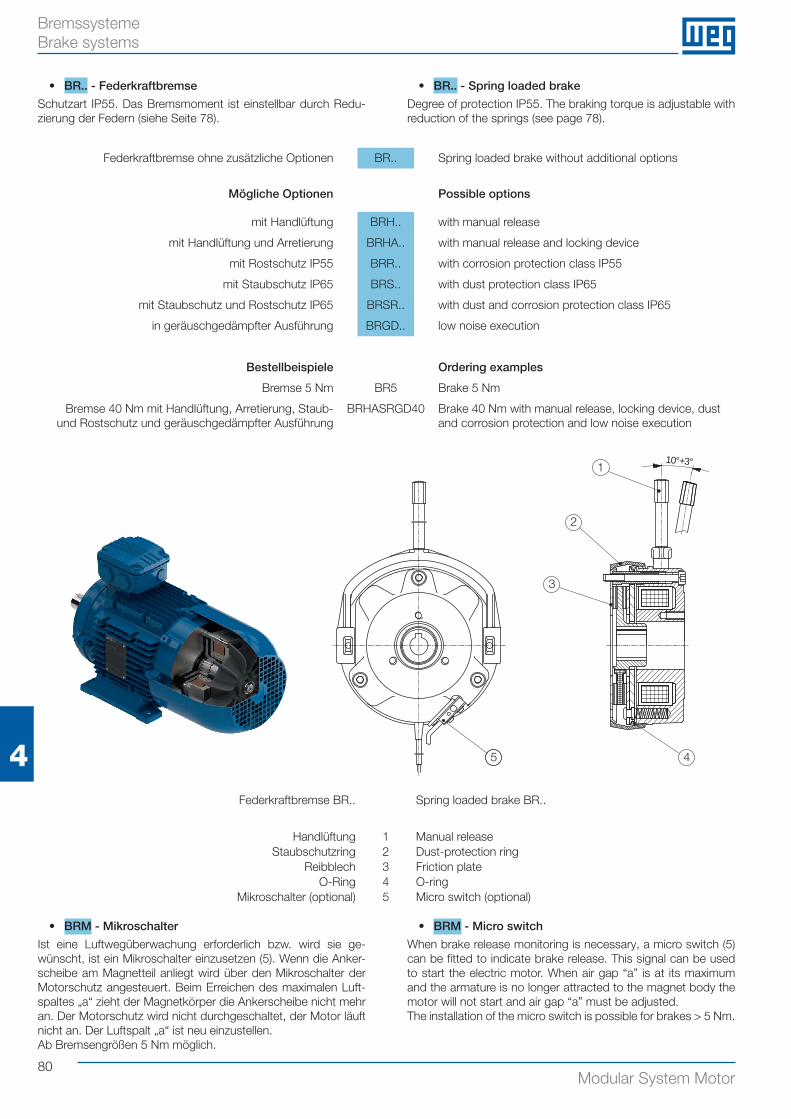
80Modular System Motor
4
Bremssysteme Brake systems
• BR.. - Federkraftbremse
Schutzart IP55. Das Bremsmoment ist einstellbar durch Redu-zierung der Federn (siehe Seite 78).
• BR.. - Spring loaded brake
Degree of protection IP55. The braking torque is adjustable with reduction of the springs (see page 78).
Federkraftbremse ohne zusätzliche Optionen BR.. Spring loaded brake without additional options
Mögliche Optionen Possible options
mit Handlüftung BRH.. with manual release
mit Handlüftung und Arretierung BRHA.. with manual release and locking device
mit Rostschutz IP55 BRR.. with corrosion protection class IP55
mit Staubschutz IP65 BRS.. with dust protection class IP65
mit Staubschutz und Rostschutz IP65 BRSR.. with dust and corrosion protection class IP65
in geräuschgedämpfter Ausführung BRGD.. low noise execution
• BRM - Mikroschalter
Ist eine Luftwegüberwachung erforderlich bzw. wird sie ge-wünscht, ist ein Mikroschalter einzusetzen (5). Wenn die Anker-scheibe am Magnetteil anliegt wird über den Mikroschalter der Motorschutz angesteuert. Beim Erreichen des maximalen Luft-spaltes „a“ zieht der Magnetkörper die Ankerscheibe nicht mehr an. Der Motorschutz wird nicht durchgeschaltet, der Motor läuft nicht an. Der Luftspalt „a“ ist neu einzustellen.Ab Bremsengrößen 5 Nm möglich.
• BRM - Micro switch
When brake release monitoring is necessary, a micro switch (5) can be fitted to indicate brake release. This signal can be used to start the electric motor. When air gap “a” is at its maximum and the armature is no longer attracted to the magnet body the motor will not start and air gap “a” must be adjusted.The installation of the micro switch is possible for brakes > 5 Nm.
10°+3°
5
1
2
3
4
Federkraftbremse BR.. Spring loaded brake BR..
Handlüftung 1 Manual releaseStaubschutzring 2 Dust-protection ring
Reibblech 3 Friction plateO-Ring 4 O-ring
Mikroschalter (optional) 5 Micro switch (optional)
Bestellbeispiele Ordering examples
Bremse 5 Nm BR5 Brake 5 Nm
Bremse 40 Nm mit Handlüftung, Arretierung, Staub- und Rostschutz und geräuschgedämpfter Ausführung
BRHASRGD40 Brake 40 Nm with manual release, locking device, dust and corrosion protection and low noise execution
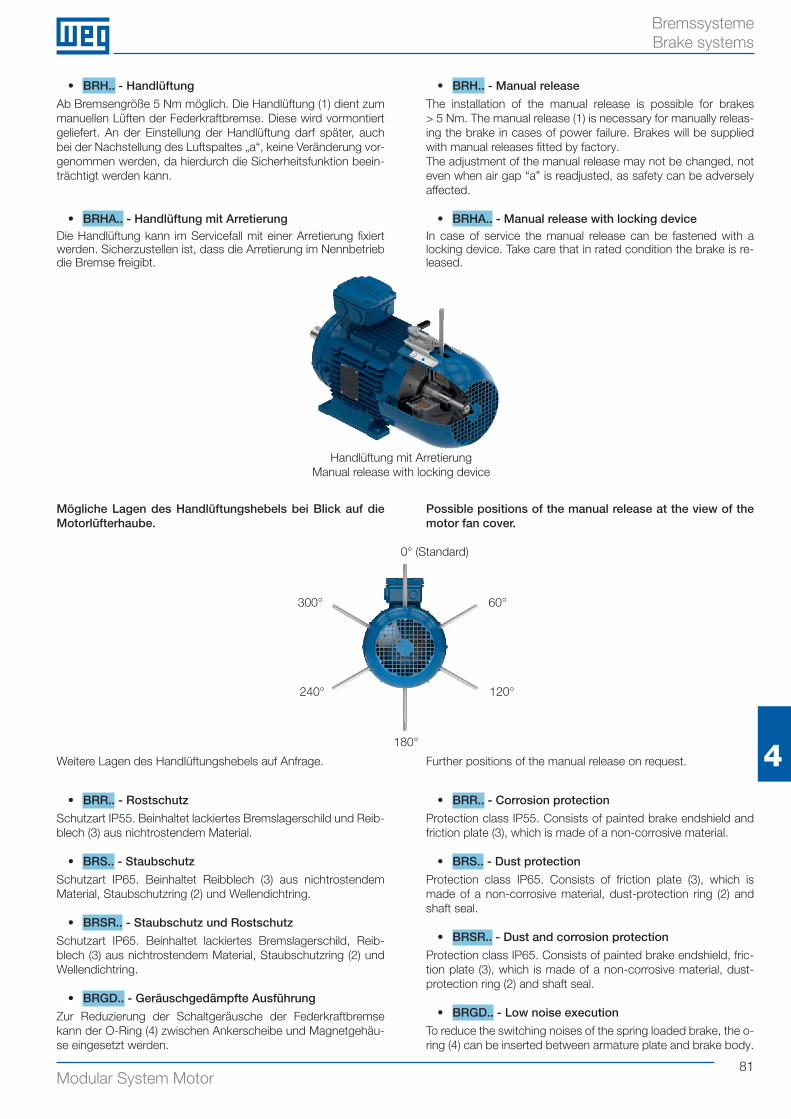
81Modular System Motor
4
Bremssysteme Brake systems
Mögliche Lagen des Handlüftungshebels bei Blick auf die Motorlüfterhaube.
Possible positions of the manual release at the view of the motor fan cover.
0° (Standard)
180°
120°
60°300°
240°
Weitere Lagen des Handlüftungshebels auf Anfrage. Further positions of the manual release on request.
• BRH.. - Handlüftung
Ab Bremsengröße 5 Nm möglich. Die Handlüftung (1) dient zum manuellen Lüften der Federkraftbremse. Diese wird vormontiert geliefert. An der Einstellung der Handlüftung darf später, auch bei der Nachstellung des Luftspaltes „a“, keine Veränderung vor-genommen werden, da hierdurch die Sicherheitsfunktion beein-trächtigt werden kann.
• BRHA.. - Handlüftung mit ArretierungDie Handlüftung kann im Servicefall mit einer Arretierung fixiert werden. Sicherzustellen ist, dass die Arretierung im Nennbetrieb die Bremse freigibt.
• BRH.. - Manual release
The installation of the manual release is possible for brakes > 5 Nm. The manual release (1) is necessary for manually releas-ing the brake in cases of power failure. Brakes will be supplied with manual releases fitted by factory. The adjustment of the manual release may not be changed, not even when air gap “a” is readjusted, as safety can be adversely affected.
• BRHA.. - Manual release with locking device In case of service the manual release can be fastened with a locking device. Take care that in rated condition the brake is re-leased.
• BRR.. - Rostschutz
Schutzart IP55. Beinhaltet lackiertes Bremslagerschild und Reib-blech (3) aus nichtrostendem Material.
• BRS.. - Staubschutz
Schutzart IP65. Beinhaltet Reibblech (3) aus nichtrostendem Material, Staubschutzring (2) und Wellendichtring.
• BRSR.. - Staubschutz und Rostschutz
Schutzart IP65. Beinhaltet lackiertes Bremslagerschild, Reib-blech (3) aus nichtrostendem Material, Staubschutzring (2) und Wellendichtring.
• BRGD.. - Geräuschgedämpfte Ausführung
Zur Reduzierung der Schaltgeräusche der Federkraftbremse kann der O-Ring (4) zwischen Ankerscheibe und Magnetgehäu-se eingesetzt werden.
• BRR.. - Corrosion protection
Protection class IP55. Consists of painted brake endshield and friction plate (3), which is made of a non-corrosive material.
• BRS.. - Dust protection
Protection class IP65. Consists of friction plate (3), which is made of a non-corrosive material, dust-protection ring (2) and shaft seal.
• BRSR.. - Dust and corrosion protection
Protection class IP65. Consists of painted brake endshield, fric-tion plate (3), which is made of a non-corrosive material, dust-protection ring (2) and shaft seal.
• BRGD.. - Low noise execution
To reduce the switching noises of the spring loaded brake, the o-ring (4) can be inserted between armature plate and brake body.
Handlüftung mit ArretierungManual release with locking device
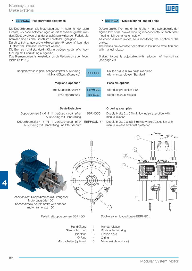
82Modular System Motor
4
Bremssysteme Brake systems
• BBRHGD.. - Federkraftdoppelbremse
Die Doppelbremsen (ab Motorbaugröße 71) kommen dort zum Einsatz, wo hohe Anforderungen an die Sicherheit gestellt wer-den. Diese zwei von einander unabhängig wirkenden Federkraft-bremsen sind für den Einsatz im Theaterbau geeignet. Durch seitlich angeordnete Mikroschalter (5, optional) kann das „Lüften“ der Bremsen überwacht werden.Die Bremsen sind standardmäßig in geräuschgedämpfter Aus-führung mit Handlüftung ausgeführt.Das Bremsmoment ist einstellbar durch Reduzierung der Feder (siehe Seite 78).
• BBRHGD.. - Double spring loaded brake
Double brakes (from motor frame size 71) are two specially de-signed low noise brakes working independently of each other meeting high demands on safety. As option a micro switch (5) is monitoring the function of the brakes.The brakes are executed per default in low noise execution and with manual release.
Braking torque is adjustable with reduction of the springs (see page 78).
Doppelbremse in geräuschgedämpfter Ausführung mit Handlüftung (Standard) BBRHGD..
Double brake in low noise execution with manual release (Standard)
Mögliche Optionen Possible options
mit Staubschutz IP65 BBRHSGD.. with dust protection IP65
ohne Handlüftung BBRGD.. without manual release
Bestellbeispiele Ordering examples
Doppelbremse 2 x 6 Nm in geräuschgedämpfter Ausführung mit Handlüftung
BBRHGD6 Double brake 2 x 6 Nm in low noise execution with manual release
Doppelbremse 2 x 187 Nm in geräuschgedämpfter Ausführung mit Handlüftung und Staubschutz
BBRHSGD187 Double brake 2 x 187 Nm in low noise execution with manual release and dust protection
10°+3°10°+3°
5
1
2
3
4
Federkraftdoppelbremse BBRHGD.. Double spring loaded brake BBRHGD..
Handlüftung 1 Manual releaseStaubschutzring 2 Dust-protection ring
Reibblech 3 Friction plateO-Ring 4 O-ring
Mikroschalter (optional) 5 Micro switch (optional)
Schnittansicht Doppelbremse mit Drehgeber, Motorbaugröße 100
Sectional view double brake with enoder, motor frame size 100
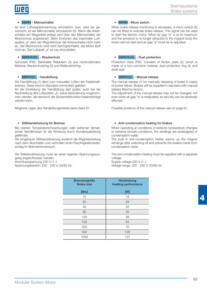
83Modular System Motor
4
Bremssysteme Brake systems
• BBRM - Mikroschalter
Ist eine Luftwegüberwachung erforderlich bzw. wird sie ge-wünscht, ist ein Mikroschalter einzusetzen (5). Wenn die Anker-scheibe am Magnetteil anliegt wird über den Mikroschalter der Motorschutz angesteuert. Beim Erreichen des maximalen Luft-spaltes „a“ zieht der Magnetkörper die Ankerscheibe nicht mehr an. Der Motorschutz wird nicht durchgeschaltet, der Motor läuft nicht an. Der Luftspalt „a“ ist neu einzustellen.
• BBRHSGD.. - Staubschutz
Schutzart IP65. Beinhaltet Reibblech (3) aus nichtrostendem Material, Staubschutzring (2) und Wellendichtring.
• BBRHGD.. - Handlüftung
Die Handlüftung (1) dient zum manuellen Lüften der Federkraft-bremse. Diese wird im Standard vormontiert geliefert.An der Einstellung der Handlüftung darf später, auch bei der Nachstellung des Luftspaltes „a“, keine Veränderung vorgenom-men werden, da hierdurch die Sicherheitsfunktion beeinträchtigt werden kann.
Mögliche Lagen des Handlüftungshebels siehe Seite 81.
• BBRM - Micro switch
When brake release monitoring is necessary, a micro switch (5) can be fitted to indicate brake release. This signal can be used to start the electric motor. When air gap “a” is at its maximum and the armature is no longer attracted to the magnet body the motor will not start and air gap “a” must be re-adjusted.
• BBRHSGD.. - Dust protection
Protection class IP65. Consists of friction plate (3), which is made of a non-corrosive material, dust-protection ring (2) and shaft seal.
• BBRHGD.. - Manual release
The manual release (1) for manually releasing of brake in cases of power failure. Brakes will be supplied in standard with manual release fitted by factory.The adjustment of the manual release may not be changed, not even when air gap “a” is readjusted, as security can be adversely affected.
Possible positions of the manual release see on page 81.
BremsengrößeBrake size
[Nm]
Heizleistung Heating performance
[W]
10 16
20 29
40 33
60 35
100 48
150 53
250 70
400 128
1000 131
• Stillstandsheizung für Bremse
Bei starken Temperaturschwankungen oder extremen klimati-schen Verhältnissen ist die Wicklung durch Kondensatbildung gefährdet.Die eingebaute Stillstandsheizung erwärmt die Magnetwicklung nach dem Abschalten und verhindert einen Feuchtigkeitsnieder-schlag im Bremseninnenraum.
Die Stillstandsheizung muss an einen eigenen Spannungsaus-gang angeschlossen werden.Anschlussspannung 230 V (1~)Spannungsbereich: 220 - 230 V, 50/60 Hz
• Anti-condensation heating for brakes
When operating at conditions of extreme temperature changes or extreme climatic conditions, the windings are endangered of condensation water.The built in anti-condensation heater warms up the magnet windings after switching off and prevents the brakes inside from condensation water.
The anti-condensation heating must be supplied with a separate voltage.Supply voltage 230 V (1~)Voltage range: 220 - 230 V, 50/60 Hz
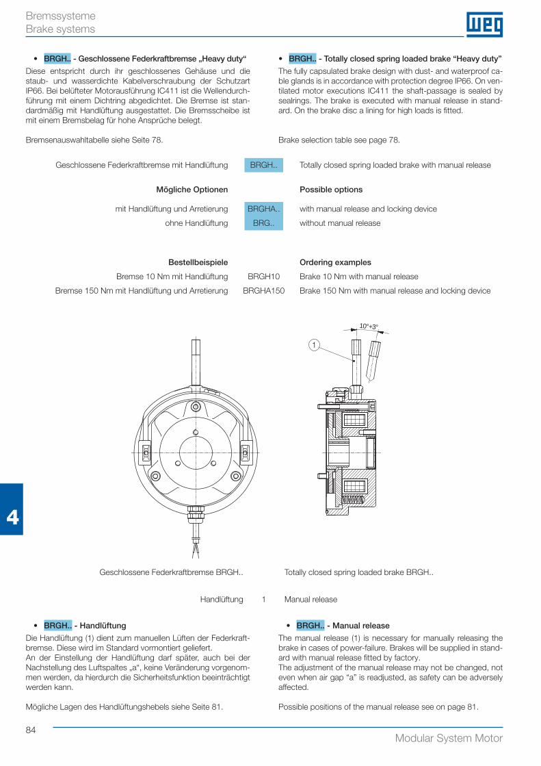
84Modular System Motor
4
Bremssysteme Brake systems
Geschlossene Federkraftbremse mit Handlüftung BRGH.. Totally closed spring loaded brake with manual release
Mögliche Optionen Possible options
mit Handlüftung und Arretierung BRGHA.. with manual release and locking device
ohne Handlüftung BRG.. without manual release
Bestellbeispiele Ordering examples
Bremse 10 Nm mit Handlüftung BRGH10 Brake 10 Nm with manual release
Bremse 150 Nm mit Handlüftung und Arretierung BRGHA150 Brake 150 Nm with manual release and locking device
10°+3°
1
Geschlossene Federkraftbremse BRGH.. Totally closed spring loaded brake BRGH..
Handlüftung 1 Manual release
• BRGH.. - Handlüftung
Die Handlüftung (1) dient zum manuellen Lüften der Federkraft-bremse. Diese wird im Standard vormontiert geliefert.An der Einstellung der Handlüftung darf später, auch bei der Nachstellung des Luftspaltes „a“, keine Veränderung vorgenom-men werden, da hierdurch die Sicherheitsfunktion beeinträchtigt werden kann.
Mögliche Lagen des Handlüftungshebels siehe Seite 81.
• BRGH.. - Manual release
The manual release (1) is necessary for manually releasing the brake in cases of power-failure. Brakes will be supplied in stand-ard with manual release fitted by factory. The adjustment of the manual release may not be changed, not even when air gap “a” is readjusted, as safety can be adversely affected.
Possible positions of the manual release see on page 81.
• BRGH.. - Geschlossene Federkraftbremse „Heavy duty“
Diese entspricht durch ihr geschlossenes Gehäuse und die staub- und wasserdichte Kabelverschraubung der Schutzart IP66. Bei belüfteter Motorausführung IC411 ist die Wellendurch-führung mit einem Dichtring abgedichtet. Die Bremse ist stan-dardmäßig mit Handlüftung ausgestattet. Die Bremsscheibe ist mit einem Bremsbelag für hohe Ansprüche belegt.
Bremsenauswahltabelle siehe Seite 78.
• BRGH.. - Totally closed spring loaded brake “Heavy duty”
The fully capsulated brake design with dust- and waterproof ca-ble glands is in accordance with protection degree IP66. On ven-tilated motor executions IC411 the shaft-passage is sealed by sealrings. The brake is executed with manual release in stand-ard. On the brake disc a lining for high loads is fitted.
Brake selection table see page 78.
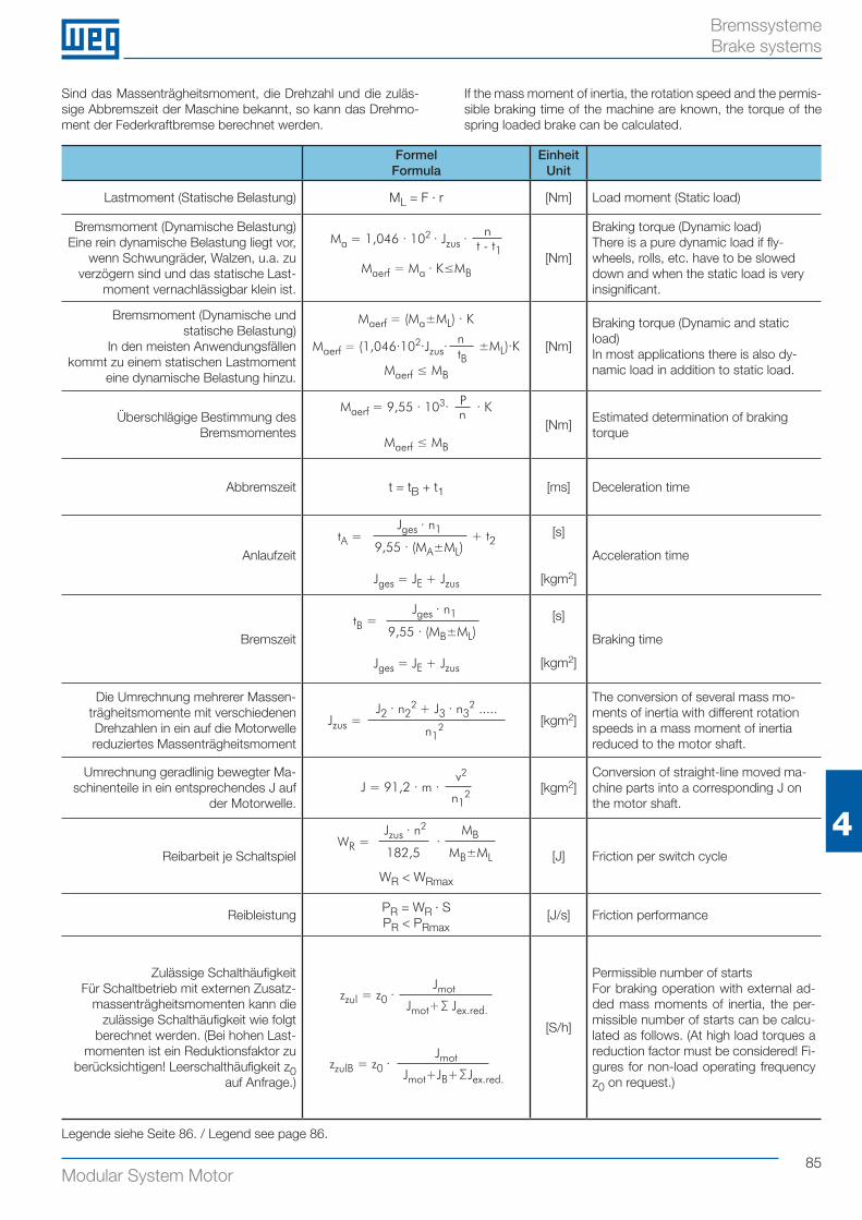
85Modular System Motor
4
Bremssysteme Brake systems
Sind das Massenträgheitsmoment, die Drehzahl und die zuläs-sige Abbremszeit der Maschine bekannt, so kann das Drehmo-ment der Federkraftbremse berechnet werden.
If the mass moment of inertia, the rotation speed and the permis-sible braking time of the machine are known, the torque of the spring loaded brake can be calculated.
FormelFormula
EinheitUnit
Lastmoment (Statische Belastung) ML = F · r [Nm] Load moment (Static load)
Bremsmoment (Dynamische Belastung)Eine rein dynamische Belastung liegt vor,
wenn Schwungräder, Walzen, u.a. zu verzögern sind und das statische Last-
moment vernachlässigbar klein ist.
Ma = 1,046 · 102 · Jzus · n
t - t1[Nm]
Braking torque (Dynamic load)There is a pure dynamic load if fly-wheels, rolls, etc. have to be slowed down and when the static load is very insignificant.
Bremsmoment (Dynamische und statische Belastung)
In den meisten Anwendungsfällen kommt zu einem statischen Lastmoment
eine dynamische Belastung hinzu.
Maerf = (Ma±ML) · K
Maerf = (1,046·102·Jzus· ntB
±ML)·K [Nm]
Braking torque (Dynamic and static load)In most applications there is also dy-namic load in addition to static load.
Überschlägige Bestimmung des Bremsmomentes
Maerf = 9,55 · 103· Pn · K
[Nm]Estimated determination of braking torque
Abbremszeit t = tB + t1 [ms] Deceleration time
AnlaufzeittA =
Jges · n1
9,55 · (MA±ML)+ t2
Jges = JE + Jzus
[s]
[kgm2]
Acceleration time
BremszeittB =
Jges · n1
9,55 · (MB±ML)
Jges = JE + Jzus
[s]
[kgm2]
Braking time
Die Umrechnung mehrerer Massen-trägheitsmomente mit verschiedenen Drehzahlen in ein auf die Motorwelle reduziertes Massenträgheitsmoment
Jzus = J2 · n2
2 + J3 · n32 .....
n12 [kgm2]
The conversion of several mass mo-ments of inertia with different rotation speeds in a mass moment of inertia reduced to the motor shaft.
Umrechnung geradlinig bewegter Ma-schinenteile in ein entsprechendes J auf
der Motorwelle.J = 91,2 · m ·
v2
n12 [kgm2]
Conversion of straight-line moved ma-chine parts into a corresponding J on the motor shaft.
Reibarbeit je SchaltspielWR =
Jzus · n2
182,5·
MB
MB±ML
WR < WRmax
[J] Friction per switch cycle
ReibleistungPR = WR · SPR < PRmax
[J/s] Friction performance
Zulässige SchalthäufigkeitFür Schaltbetrieb mit externen Zusatz-
massenträgheitsmomenten kann die zulässige Schalthäufigkeit wie folgt
berechnet werden. (Bei hohen Last-momenten ist ein Reduktionsfaktor zu
berücksichtigen! Leerschalthäufigkeit z0 auf Anfrage.)
zzul = z0 ·Jmot
zzulB = z0 ·Jmot
Jmot+JB+ Jex.red.
[S/h]
Permissible number of startsFor braking operation with external ad-ded mass moments of inertia, the per-missible number of starts can be calcu-lated as follows. (At high load torques a reduction factor must be considered! Fi-gures for non-load operating frequency z0 on request.)
Legende siehe Seite 86. / Legend see page 86.
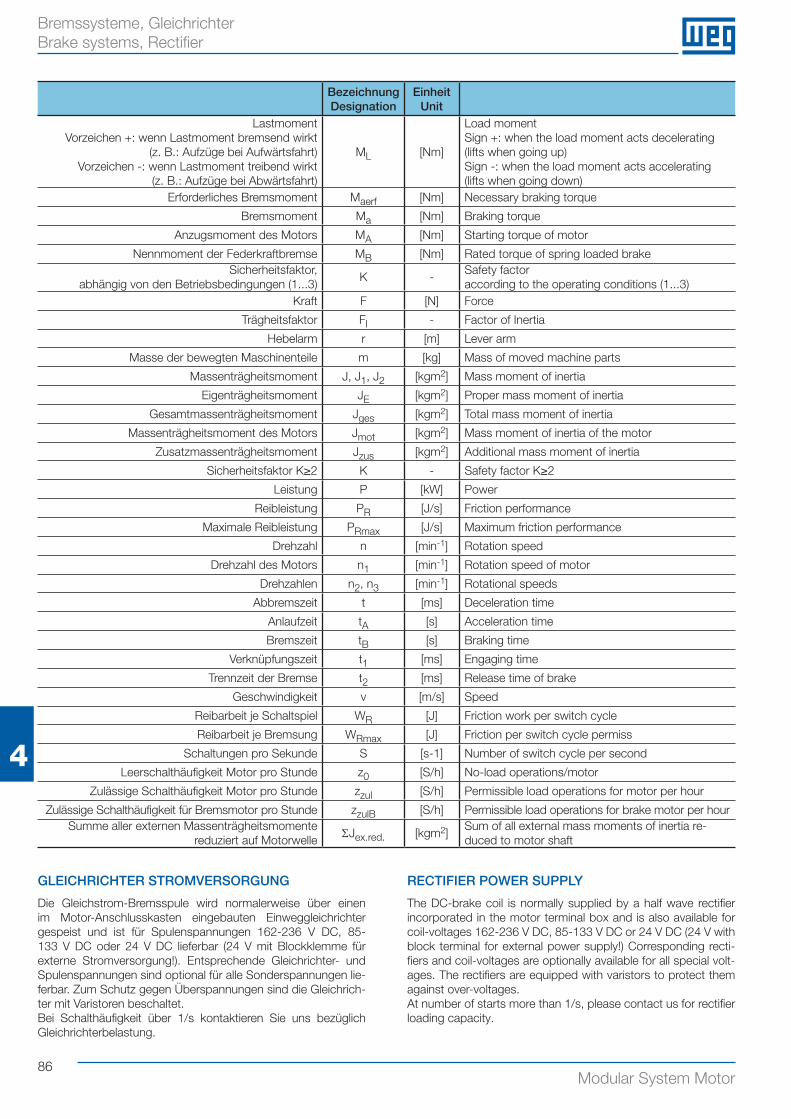
86Modular System Motor
4
Bremssysteme, Gleichrichter Brake systems, Rectifier
GLEICHRICHTER STROMVERSORGUNG
Die Gleichstrom-Bremsspule wird normalerweise über einen im Motor-Anschlusskasten eingebauten Einweggleichrichter gespeist und ist für Spulenspannungen 162-236 V DC, 85-133 V DC oder 24 V DC lieferbar (24 V mit Blockklemme für externe Stromversorgung!). Entsprechende Gleichrichter- und Spulenspannungen sind optional für alle Sonderspannungen lie-ferbar. Zum Schutz gegen Überspannungen sind die Gleichrich-ter mit Varistoren beschaltet. Bei Schalthäufigkeit über 1/s kontaktieren Sie uns bezüglich Gleichrichterbelastung.
RECTIFIER POWER SUPPLY
The DC-brake coil is normally supplied by a half wave rectifier incorporated in the motor terminal box and is also available for coil-voltages 162-236 V DC, 85-133 V DC or 24 V DC (24 V with block terminal for external power supply!) Corresponding recti-fiers and coil-voltages are optionally available for all special volt-ages. The rectifiers are equipped with varistors to protect them against over-voltages.At number of starts more than 1/s, please contact us for rectifier loading capacity.
BezeichnungDesignation
EinheitUnit
Lastmoment Vorzeichen +: wenn Lastmoment bremsend wirkt
(z. B.: Aufzüge bei Aufwärtsfahrt)Vorzeichen -: wenn Lastmoment treibend wirkt
(z. B.: Aufzüge bei Abwärtsfahrt)
ML [Nm]
Load momentSign +: when the load moment acts decelerating (lifts when going up)Sign -: when the load moment acts accelerating (lifts when going down)
Erforderliches Bremsmoment Maerf [Nm] Necessary braking torque
Bremsmoment Ma [Nm] Braking torque
Anzugsmoment des Motors MA [Nm] Starting torque of motor
Nennmoment der Federkraftbremse MB [Nm] Rated torque of spring loaded brakeSicherheitsfaktor,
abhängig von den Betriebsbedingungen (1...3)K -
Safety factoraccording to the operating conditions (1...3)
Kraft F [N] Force
Trägheitsfaktor FI - Factor of Inertia
Hebelarm r [m] Lever arm
Masse der bewegten Maschinenteile m [kg] Mass of moved machine parts
Massenträgheitsmoment J, J1, J2 [kgm2] Mass moment of inertia
Eigenträgheitsmoment JE [kgm2] Proper mass moment of inertia
Gesamtmassenträgheitsmoment Jges [kgm2] Total mass moment of inertia
Massenträgheitsmoment des Motors Jmot [kgm2] Mass moment of inertia of the motor
Zusatzmassenträgheitsmoment Jzus [kgm2] Additional mass moment of inertia
Sicherheitsfaktor K≥2 K - Safety factor K≥2
Leistung P [kW] Power
Reibleistung PR [J/s] Friction performance
Maximale Reibleistung PRmax [J/s] Maximum friction performance
Drehzahl n [min-1] Rotation speed
Drehzahl des Motors n1 [min-1] Rotation speed of motor
Drehzahlen n2, n3 [min-1] Rotational speeds
Abbremszeit t [ms] Deceleration time
Anlaufzeit tA [s] Acceleration time
Bremszeit tB [s] Braking time
Verknüpfungszeit t1 [ms] Engaging time
Trennzeit der Bremse t2 [ms] Release time of brake
Geschwindigkeit v [m/s] Speed
Reibarbeit je Schaltspiel WR [J] Friction work per switch cycle
Reibarbeit je Bremsung WRmax [J] Friction per switch cycle permiss
Schaltungen pro Sekunde S [s-1] Number of switch cycle per second
Leerschalthäufigkeit Motor pro Stunde z0 [S/h] No-load operations/motor
Zulässige Schalthäufigkeit Motor pro Stunde zzul [S/h] Permissible load operations for motor per hour
Zulässige Schalthäufigkeit für Bremsmotor pro Stunde zzulB [S/h] Permissible load operations for brake motor per hourSumme aller externen Massenträgheitsmomente
reduziert auf MotorwelleΣJex.red. [kgm2]
Sum of all external mass moments of inertia re-duced to motor shaft
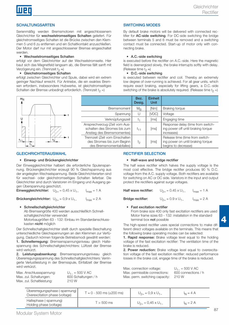
87Modular System Motor
4
Gleichrichter Rectifier
SCHALTUNGSARTEN
Serienmäßig werden Bremsmotoren mit angeschlossenem Gleichrichter für wechselstromseitiges Schalten geliefert. Für gleichstromseitiges Schalten ist die Brücke zwischen den Klem-men 5 und 6 zu entfernen und ein Schaltkontakt anzuschließen. Der Motor darf nur mit angeschlossener Bremse eingeschaltet werden.
• Wechselstromseitiges Schaltenerfolgt vor dem Gleichrichter auf der Wechselstromseite. Hier baut sich das Magnetfeld langsam ab, die Bremse fällt sanft mit Verzögerung ein. (Trennzeit t2 ≈)
• Gleichstromseitiges Schaltenerfolgt zwischen Gleichrichter und Spule, dabei wird ein extrem geringer Nachlauf erreicht. Für Antriebe, die ein exaktes Brem-sen erfordern, insbesondere Hubwerke, ist gleichstromseitiges Schalten der Bremse unbedingt erforderlich. (Trennzeit t2 =)
SWITCHING MODES
By default brake motors will be delivered with connected rec-tifier for AC-side switching. For DC-side switching the bridge between terminals 5 and 6 must be removed and a switching contact must be connected. Start-up of motor only with con-necting brake.
• A.C.-side switchingis executed before the rectifier on A.C.-side. Here the magnetic field is deenergized slowly, the brake interrupts softly with delay. (Release time t2 ≈)
• D.C.-side switchingis executed between rectifier and coil. Thereby an extremely low degree of over-running is achieved. For all gear units, which require exact braking, especially for lifting gears, a D.C.-side switching of the brake is absolutely required. (Release time t2 =)
GLEICHRICHTERAUSWAHL
• Einweg- und Brückengleichrichter
Der Einweggleichrichter halbiert die erforderliche Spulenspan-nung. Brückengleichrichter erzeugt 90 % Gleichspannung aus der angelegten Wechselspannung. Beide Gleichrichterarten sind für wechsel- oder gleichstromseitiges Schalten lieferbar. Die Gleichrichter sind durch Varistoren im Eingang und Ausgang ge-gen Überspannung geschützt.Einweggleichrichter: U2= = 0,45 x U1~ Imax = 1 A
Brückengleichrichter: U2= = 0,9 x U1~ Imax = 2 A
• Schnellschaltgleichrichter Ab Bremsengröße 400 werden ausschließlich Schnell-schaltgleichrichter verwendet Motorbaugrößen 63 - 132: Einbau im Standardanschluss-kasten nicht möglich
Der Schnellschaltgleichrichter stellt durch spezielle Beschaltung unterschiedliche Gleichspannungen an den Klemmen zur Verfü-gung. Dadurch können folgende Betriebsmodi gewählt werden:1. Schnellerregung: Bremsenspannungsniveau gleich Halte-spannung des Schnellschaltgleichrichters: Lüftzeit der Bremse wird verkürzt.2. Leistungsabsenkung: Bremsenspannungsniveau gleich Übererregungsspannung des Schnellschaltgleichrichters: Verrin-gerte Verlustleistung in der Bremsspule, Einfallzeit der Bremse wird verkürzt.
Max. Anschlussspannung: U1~ = 500 V ACMax. zul. Schaltungen: 600 Schaltungen / hMax. zul. Schaltleistung: 210 W
RECTIFIER SELECTION
• Half-wave and bridge rectifier
The half wave rectifier which halves the supply voltage is the most cost effective. The bridge rectifier produces 90 % D.C. voltage from the A.C. supply voltage. Both rectifiers are available for switching on AC or DC side. Varistors in the input and output protect the rectifiers against surge voltages.
Half wave rectifier: U2= = 0.45 x U1~ Imax = 1 A
Bridge rectifier: U2= = 0.9 x U1~ Imax = 2 A
• Fast excitation rectifier From brake size 400 only fast excitation rectifiers are used Motor frame sizes 63 - 132: installation in the standard terminal box not possible
The high-speed rectifier uses special connections to make dif-ferent direct voltages available on the terminals. This means that the following brake operating modes can be selected:1. Rapid response: Brake voltage level equal to the holding voltage of the fast excitation rectifier: The ventilation time of the brake is reduced.2. Power reduction: Brake voltage level equal to overexcita-tion voltage of the fast excitation rectifier: reduced performance losses in the brake coil, engage time of the brake is reduced.
Max. connection voltage: U1~ = 500 V ACMax. permissible connections: 600 connections / hMax. perm. switching capacity: 210 W
Bez.Desig.
EinheitUnit
Bremsmoment MB [Nm] Braking torque
Spannung U [VDC] Voltage
Verknüpfungszeit t1 [ms] Engaging timeAnsprechverzug (Zeit vom Aus-schalten des Stromes bis zum Anstieg des Bremsmomentes)
t11 [ms]Response delay (time from switch-ing power off until braking torqueincreases)
Trennzeit (Zeit vom Einschalten des Stromes bis zum Beginn
des Bremsmomentabfalles)t2 [ms]
Release time (time from switch-ing power on until braking torque begins to decrease)
M
t U
t
B
t11t1
t2
Übererregungsphase (-spannung)Overexcitation phase (voltage)
T = 0 - 500 ms (±200 ms) U2= = 0,9 x U1~ IN = 4 A
Haltephase (-spannung)Holding phase (voltage)
T > 500 ms U2= = 0,45 x U1~ IN = 2 A
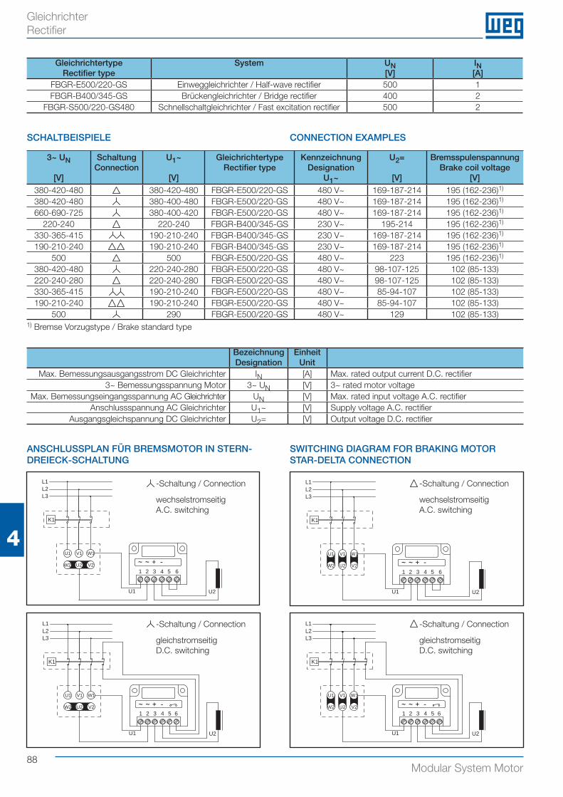
88Modular System Motor
4
Gleichrichter Rectifier
3~ UN
[V]
SchaltungConnection
U1~
[V]
GleichrichtertypeRectifier type
KennzeichnungDesignation
U1~
U2=
[V]
BremsspulenspannungBrake coil voltage
[V]380-420-480 380-420-480 FBGR-E500/220-GS 480 V~ 169-187-214 195 (162-236)1)
380-420-480 380-400-480 FBGR-E500/220-GS 480 V~ 169-187-214 195 (162-236)1)
660-690-725 380-400-420 FBGR-E500/220-GS 480 V~ 169-187-214 195 (162-236)1)
220-240 220-240 FBGR-B400/345-GS 230 V~ 195-214 195 (162-236)1)
330-365-415 190-210-240 FBGR-B400/345-GS 230 V~ 169-187-214 195 (162-236)1)
190-210-240 190-210-240 FBGR-B400/345-GS 230 V~ 169-187-214 195 (162-236)1)
500 500 FBGR-E500/220-GS 480 V~ 223 195 (162-236)1)
380-420-480 220-240-280 FBGR-E500/220-GS 480 V~ 98-107-125 102 (85-133)220-240-280 220-240-280 FBGR-E500/220-GS 480 V~ 98-107-125 102 (85-133)330-365-415 190-210-240 FBGR-E500/220-GS 480 V~ 85-94-107 102 (85-133)190-210-240 190-210-240 FBGR-E500/220-GS 480 V~ 85-94-107 102 (85-133)
500 290 FBGR-E500/220-GS 480 V~ 129 102 (85-133)
BezeichnungDesignation
EinheitUnit
Max. Bemessungsausgangsstrom DC Gleichrichter IN [A] Max. rated output current D.C. rectifier3~ Bemessungsspannung Motor 3~ UN [V] 3~ rated motor voltage
Max. Bemessungseingangsspannung AC Gleichrichter UN [V] Max. rated input voltage A.C. rectifierAnschlussspannung AC Gleichrichter U1~ [V] Supply voltage A.C. rectifier
Ausgangsgleichspannung DC Gleichrichter U2= [V] Output voltage D.C. rectifier
SCHALTBEISPIELE CONNECTION EXAMPLES
ANSCHLUSSPLAN FÜR BREMSMOTOR IN STERN-DREIECK-SCHALTUNG
SWITCHING DIAGRAM FOR BRAKING MOTOR STAR-DELTA CONNECTION
K1
U1 V1 W1
V2U2W2
L1L2L3
1 2 3 4 5 6
U1 U2
K1
U1 V1 W1
V2U2W2
L1L2L3
1 2 3 4 5 6
U1 U2
gleichstromseitigD.C. switching
-Schaltung / Connection
gleichstromseitigD.C. switching
-Schaltung / Connection
L1L2L3
U1 U2
K1
U1 V1 W1
V2U2W21 2 3 4 5 6
U1 V1 W1
V2U2W2
L1L2L3
1 2 3 4
U1 U2
K1
5 6
wechselstromseitigA.C. switching
-Schaltung / Connection
wechselstromseitigA.C. switching
-Schaltung / Connection
GleichrichtertypeRectifier type
System UN[V]
IN[A]
FBGR-E500/220-GS Einweggleichrichter / Half-wave rectifier 500 1FBGR-B400/345-GS Brückengleichrichter / Bridge rectifier 400 2
FBGR-S500/220-GS480 Schnellschaltgleichrichter / Fast excitation rectifier 500 2
1) Bremse Vorzugstype / Brake standard type
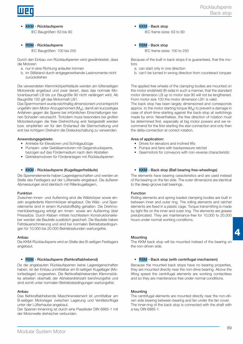
89Modular System Motor
4
Rücklaufsperre Back stop
• KKM - Rücklaufsperre
IEC Baugrößen: 63 bis 90
• RSM - Rücklaufsperre
IEC Baugrößen: 100 bis 250
Durch den Einbau von Rücklaufsperren wird gewährleistet, dass die Motoren
a. nur in eine Richtung anlaufen könnenb. im Stillstand durch entgegenwirkende Lastmomente nicht
zurückdrehen
Die verwendeten Klemmkörperfreiläufe werden am lüfterseitigen Motorende angebaut und zwar derart, dass das normale Mo-toranbaumaß LB bis zur Baugröße 90 nicht verlängert wird. Ab Baugröße 100 gilt das Motormaß LB1.Das Sperrmoment wurde reichhaltig dimensioniert und entspricht ungefähr dem Motor-Anzugsmoment (MA), damit ein kurzzeitiges Anfahren gegen die Sperre bei irrtümlichen Einschaltungen kei-nen Schaden verursacht. Trotzdem muss besonders bei großen Motorleistungen die freie Drehrichtung erst festgestellt werden bzw. empfehlen wir für den Erstanlauf die Sternschaltung und erst bei richtigem Drehsinn die Dreieckschaltung zu verwenden.
Anwendungsgebiete:• Antriebe für Elevatoren und Schrägaufzüge• Pumpen- oder Gebläsemotoren mit Gegendrucksperre,
bezogen auf das Fördermedium nach dem Abstellen• Getriebemotoren für Förderanlagen mit Rücklaufsperren
• KKM - Rücklaufsperre (Kugellagerfreiläufe)
Die Sperrenelemente haben Lagereigenschaften und werden an Stelle des Festlagers auf der Lüfterseite eingebaut. Die äußeren Abmessungen sind identisch mit Rillenkugellagern.
FunktionZwischen Innen- und Außenring sind die Wälzkörper sowie ein-zeln angefederte Klemmkörper eingebaut. Die Wälz- und Sper-relemente sind in einem Kunststoffkäfig gehalten. Die Drehmo-mentübertragung erfolgt am Innen- sowie am Außenring über Presssitze. Durch Kleben mittels hochfestem Konstruktionskle-ber werden die Bauteile zusätzlich gesichert. Die Bauteile haben Fettdauerschmierung und sind bei normalen Betriebsbedingun-gen für 10.000 bis 20.000 Betriebsstunden wartungsfrei.
AnbauDie KKM-Rücklaufsperre wird an Stelle des B-seitigen Festlagers angebaut.
• RSM - Rücklaufsperre (fliehkraftabhebend)
Da die angebauten Rücklaufsperren keine Lagereigenschaften haben, ist der Einbau unmittelbar am B-seitigen Kugellager (Mo-torfestlager) vorgesehen. Die fliehkraftabhebenden Klemmstük-ke arbeiten oberhalb der Abheberdrehzahl berührungsfrei und sind somit unter normalen Betriebsbedingungen wartungsfrei.
AnbauDas fliehkraftabhebende Maschinenelement ist unmittelbar am B-seitigen Motorlager zwischen Lagerung und Ventilatorflügel unter der Lüfterhaube angebaut.Der Sperren-Innenring ist durch eine Passfeder DIN 6885-1 mit der Motorwelle drehsicher verbunden.
• KKM - Back stop
IEC frame sizes: 63 to 90
• RSM - Back stop
IEC frame sizes: 100 to 250
Because of the built in back stops it is guaranteed, that the mo-tors
a. can start only in one directionb. can´t be turned in wrong direction from counteract torques
The applied free wheels of the clamping bodies are mounted on the motor endshield (B-side) in such a manner, that the standard motor dimension LB up to motor size 90 will not be lengthened. From motor size 100 the motor dimension LB1 is valid. The back stop has been largely dimensioned and corresponds approx. to the motor starting torque (MA) to prevent a damage in case of short-time-starting against the back-stop at switchings made by error. Nevertheless, the free direction of rotation must be determined first, especially at big motor powers and we re-commend for the first-starting the star-connection and only then the delta-connection at correct rotation.
Area of application:• Drives for elevators and inclined lifts• Pumps and fans with backpressure ratchet• Gearmotors for conveyors with non-reverse characteristic
• KKM - Back stop (Ball bearing free-wheelings)
The elements have bearing caracteristics and are used instead of the bearing on the fan side. The outer dimensions are identical to the deep-groove ball bearings.
FunctionRolling elements and spring loaded clamping bodies are built in between inner and outer ring. The rolling elements and ratchet elements are fixed in a plastic cage. Torque transmitting is made by tight fits on the inner and outer ring. The elements are grease prelubricated. They are maintenance-free for 10,000 to 20,000 hours under normal working conditions.
MountingThe KKM back stop will be mounted instead of the bearing on the non-driven side.
• RSM - Back stop (with centrifugal mechanism)
Because the mounted back stops have no bearing properties, they are mounted directly near the non-drive bearing. Above the lifting speed the centrifugal elements are working contactless and so they are maintenance free under normal conditions.
MountingThe centrifugal elements are mounted directly near the non-dri-ven side bearing between bearing and fan under the fan cover.The inner-ring of the back stop is connected with the shaft with a key DIN 6885-1.
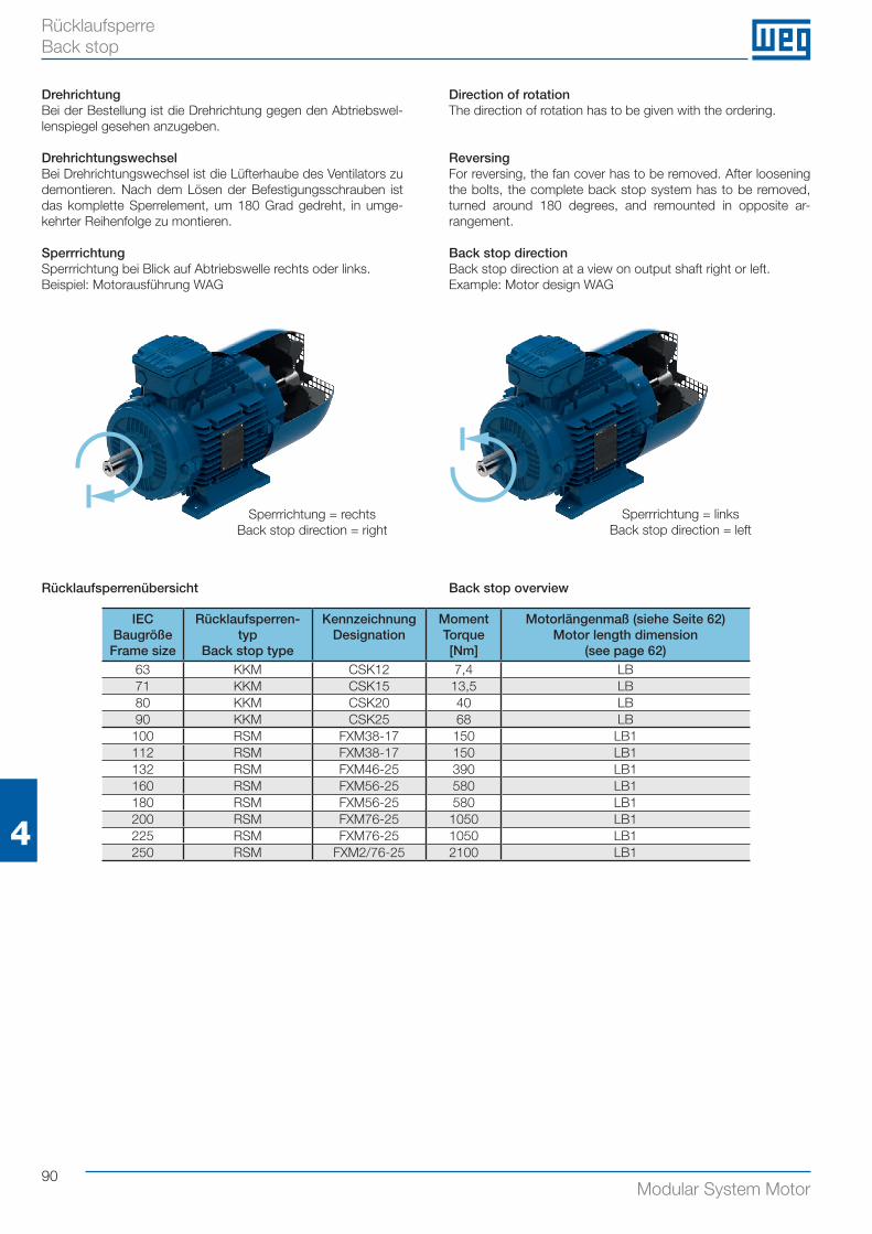
90Modular System Motor
4
Rücklaufsperre Back stop
DrehrichtungBei der Bestellung ist die Drehrichtung gegen den Abtriebswel-lenspiegel gesehen anzugeben.
DrehrichtungswechselBei Drehrichtungswechsel ist die Lüfterhaube des Ventilators zu demontieren. Nach dem Lösen der Befestigungsschrauben ist das komplette Sperrelement, um 180 Grad gedreht, in umge-kehrter Reihenfolge zu montieren.
SperrrichtungSperrrichtung bei Blick auf Abtriebswelle rechts oder links.Beispiel: Motorausführung WAG
Direction of rotationThe direction of rotation has to be given with the ordering.
ReversingFor reversing, the fan cover has to be removed. After loosening the bolts, the complete back stop system has to be removed, turned around 180 degrees, and remounted in opposite ar-rangement.
Back stop directionBack stop direction at a view on output shaft right or left.Example: Motor design WAG
IEC BaugrößeFrame size
Rücklaufsperren-typ
Back stop type
KennzeichnungDesignation
MomentTorque[Nm]
Motorlängenmaß (siehe Seite 62)Motor length dimension
(see page 62)63 KKM CSK12 7,4 LB71 KKM CSK15 13,5 LB80 KKM CSK20 40 LB90 KKM CSK25 68 LB
100 RSM FXM38-17 150 LB1112 RSM FXM38-17 150 LB1132 RSM FXM46-25 390 LB1160 RSM FXM56-25 580 LB1180 RSM FXM56-25 580 LB1200 RSM FXM76-25 1050 LB1225 RSM FXM76-25 1050 LB1250 RSM FXM2/76-25 2100 LB1
Sperrrichtung = rechtsBack stop direction = right
Sperrrichtung = linksBack stop direction = left
Rücklaufsperrenübersicht Back stop overview
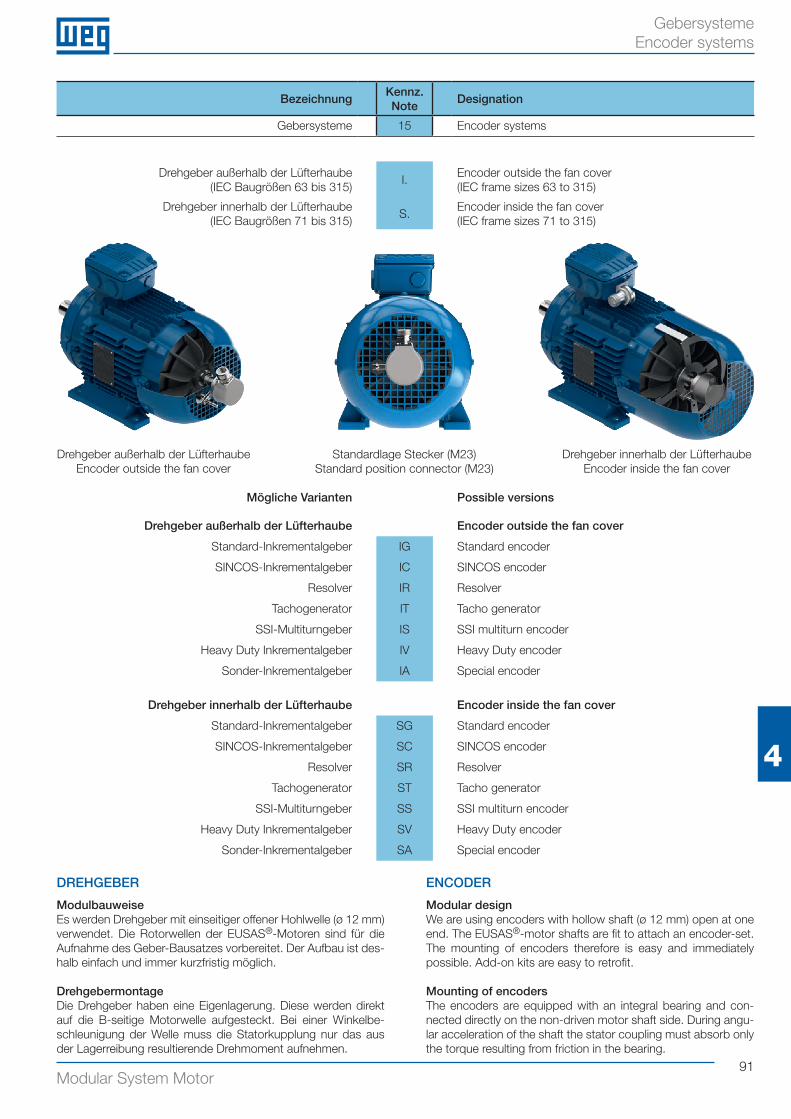
91Modular System Motor
4
Gebersysteme Encoder systems
BezeichnungKennz.Note
Designation
Gebersysteme 15 Encoder systems
DREHGEBER
ModulbauweiseEs werden Drehgeber mit einseitiger offener Hohlwelle (ø 12 mm) verwendet. Die Rotorwellen der EUSAS®-Motoren sind für die Aufnahme des Geber-Bausatzes vorbereitet. Der Aufbau ist des-halb einfach und immer kurzfristig möglich.
DrehgebermontageDie Drehgeber haben eine Eigenlagerung. Diese werden direkt auf die B-seitige Motorwelle aufgesteckt. Bei einer Winkelbe-schleunigung der Welle muss die Statorkupplung nur das aus der Lagerreibung resultierende Drehmoment aufnehmen.
ENCODER
Modular designWe are using encoders with hollow shaft (ø 12 mm) open at one end. The EUSAS®-motor shafts are fit to attach an encoder-set. The mounting of encoders therefore is easy and immediately possible. Add-on kits are easy to retrofit.
Mounting of encodersThe encoders are equipped with an integral bearing and con-nected directly on the non-driven motor shaft side. During angu-lar acceleration of the shaft the stator coupling must absorb only the torque resulting from friction in the bearing.
Drehgeber außerhalb der Lüfterhaube(IEC Baugrößen 63 bis 315)
I.Encoder outside the fan cover(IEC frame sizes 63 to 315)
Drehgeber innerhalb der Lüfterhaube(IEC Baugrößen 71 bis 315)
S.Encoder inside the fan cover(IEC frame sizes 71 to 315)
Mögliche Varianten Possible versions
Drehgeber außerhalb der Lüfterhaube Encoder outside the fan cover
Standard-Inkrementalgeber IG Standard encoder
SINCOS-Inkrementalgeber IC SINCOS encoder
Resolver IR Resolver
Tachogenerator IT Tacho generator
SSI-Multiturngeber IS SSI multiturn encoder
Heavy Duty Inkrementalgeber IV Heavy Duty encoder
Sonder-Inkrementalgeber IA Special encoder
Drehgeber innerhalb der Lüfterhaube Encoder inside the fan cover
Standard-Inkrementalgeber SG Standard encoder
SINCOS-Inkrementalgeber SC SINCOS encoder
Resolver SR Resolver
Tachogenerator ST Tacho generator
SSI-Multiturngeber SS SSI multiturn encoder
Heavy Duty Inkrementalgeber SV Heavy Duty encoder
Sonder-Inkrementalgeber SA Special encoder
Drehgeber außerhalb der LüfterhaubeEncoder outside the fan cover
Drehgeber innerhalb der LüfterhaubeEncoder inside the fan cover
Standardlage Stecker (M23) Standard position connector (M23)
92Modular System Motor
4
Gebersysteme Encoder systems
• IG, SG - Standard-Inkrementalgeber
Type: Kübler Sendix 5020Impulse pro Umdrehung: 1024Ausgangssignal: HTL oder TTLSpannungsversorgung: 10 - 30 V bei HTL, 5 V bei TTLSchutzart: IP66IG Standard-Ausführung: mit Stecker (M23) am GeberSG Standard-Ausführung: Stecker (M23) am Anschlusskasten(Gegenstecker nicht im Lieferumfang enthalten)
Auf Wunsch sind andere Impulszahlen pro Umdrehung lieferbar.
• IC, SC - SINCOS-Inkrementalgeber
Impulse pro Umdrehung: 1024Ausgangssignal: Sinus 1VSSSpannungsversorgung: 10 - 30 V oder 5 VIC Standard-Ausführung: mit Stecker (M23) am GeberSC Standard-Ausführung: Stecker (M23) am Anschlusskasten(Gegenstecker nicht im Lieferumfang enthalten)
Auf Wunsch sind weitere Impulse pro Umdrehung lieferbar.
Inkrementalgeber in mechanischer Standardbauform können auch als elektrische Variante SINCOS ausgeführt werden. Hier-bei stehen die Signale A und B als sinusförmige Spannungssi-gnale mit einem Signalpegel von 1 VSS bzw. ein 0-Impuls einmal pro Umdrehung am Ausgang zur Verfügung. Sie können in der Folgeelektronik vielfältig weiterverarbeitet werden. Durch Inter-polation der beiden um 90 ° verschobenen Signale lassen sich sehr hohe Auflösungen erreichen und können so auch bei sehr langsamen Bewegungen zur Drehzahlkontrolle eingesetzt wer-den.
• IR, SR - Resolver
Schutzart: IP54 (IP66 auf Anfrage)IR Standard-Ausführung: mit 0,6 m Kabel (einseitig offen, 6 Litzen)SR Standard-Ausführung: mit 0,6 m Kabel (einseitig offen, 6 Litzen)
Resolver sind überwiegend 2-polige, elektromagnetische Mess-umformer zur Wandlung der Winkellage eines Rotors in eine elektrische Größe. Resolver sind verschleißfrei und robust, da die für die Informationsgewinnung wesentlichen Elemente nur aus Eisenkern und Kupferwicklungen bestehen. Deshalb spielt Verschmutzung auch eine untergeordnete Rolle.Die Konfiguration besteht aus 2 um 90 ° versetzt angeordneten Statorwicklungen (S1/S3 und S2/S4) und einer rotierenden Ro-torwicklung (R1/R2). Dabei wird die Rotorwicklung induktiv, also bürstenlos gespeist.Die Rotorwicklung R1/R2 wird mit einer sinusförmigen Wechsel-spannung erregt. Die Amplituden, der in den Statorwicklungen S1/S3 und S2/S4 induzierten Spannungen, sind abhängig vom Winkel des Rotors.
Standardeingangsspannung: E(R1/R2) = E x sin(ωt)
Ausgang: E(S1/S3) = Tr x E(R1/R2) x cos(φ) E(S2/S4) = Tr x E(R1/R2) x sin(φ)
Standardeingangsspannung: E(R1/R2) = 7 VStandardübersetzung: Tr = 0,5
• IG, SG - Standard encoder
Type: Kübler Sendix 5020Pulses per revolution: 1024Output signal: HTL or TTLVoltage supply: 10 - 30 V at HTL, 5 V at TTLDegree of protection: IP66IG standard: with pin connector (M23) on the encoder SG standard: with pin connector (M23) on the terminal box(Mating connector not included in delivery)
Other numbers of pulses per revolution on request.
• IC, SC - SINCOS encoder
Pulses per revolution: 1024Output signal: Sinus 1VPPVoltage supply: 10 - 30 V or 5 VIC standard: with pin connector (M23) on the encoder SC standard: with pin connector (M23) on the terminal box(Mating connector not included in delivery)
Additional pulses per revolution can be supplied if required.
Encoders in standard mechanical designs can also be imple-mented as electric SINCOS versions. In this case, signals A and B are available on the output as sinusoidal voltage signals with a signal level of 1 VSS or one 0 pulse once per rotation. These can be used in many different ways in the downstream electro-nics. Via interpolation of the two signals shifted by 90 °, very high resolutions are achieved and can therefore also be used with very slow movements for speed control.
• IR, SR - Resolver
Degree of protection: IP54 (IP66 on request)IR standard execution: with 0.6 m cable (one-way open, 6 strands)SR standard execution: with 0.6 m cable (one-way open, 6 strands)
Resolvers are primarily 2-pole, electro-magnetic measuring transducers for converting the angle position of a rotor into an electrical value. Resolvers are wear-free and robust, as the most important elements for acquiring the information consist only of iron core and copper coils. Contamination therefore plays a les-ser role.The configuration consists of 2 stator coils positioned at an offset of 90 ° (S1/S3 and S2/S4) and a rotating rotor coil (R1/R2). In this process, the rotor coil supply is inductive, in other words, brushless.The R1/R2 rotor coil is excited using a sinusoidal alternating voltage. The amplitudes of the voltages induced in stator coils S1/S3 and S2/S4 depend on the rotor angle.
Input voltage: E(R1/R2) = E x sin(ωt)
Output: E(S1/S3) = Tr x E(R1/R2) x cos(φ) E(S2/S4) = Tr x E(R1/R2) x sin(φ)
Standard input voltage: E(R1/R2) = 7 VStandard transformation ratio: Tr= 0.5
93Modular System Motor
4
Gebersysteme Encoder systems
• IT, ST - DC-Tachogenerator
Ausgangssignal: 7 V / 1.000 min-1
Schutzart: IP54 (IP66 auf Anfrage)IT Standard-Ausführung: mit 1 m Kabel (einseitig offen, 2 Litzen)ST Standard-Ausführung: mit 1 m Kabel (eins. offen, 2 Litzen)
Auf Wunsch sind andere Ausgangsspannungen lieferbar.
Tachogeneratoren oder Analogtachos sind Geräte zur Erfassung der Drehzahl, indem sie eine der Antriebsdrehzahl proportionale Spannung liefern. Diese Spannung kann in geregelten Antrieben direkt weiterverarbeitet werden. Ein Spulenanker rotiert in einem Feld aus feststehenden Dau-ermagneten. Dadurch werden in den Spulen Spannungen in-duziert. Diese werden über hochwertige Kollektorkontakte abgegriffen, sodass eine gleichgerichtete drehzahlkonstante Gleichspannung entsteht. Bei Drehrichtungsänderung ändert sich auch die Polarität.
Standardausgangsspannung: U0 = n x k
Standardmaschinenkonstante: k = 7 V / 1.000 min-1
Max. zulässige Drehzahl: nmax = 10.000 min-1
Besondere Vorteile der Analogtachos: - Drehzahl und Drehrichtung werden in Echtzeit erfasst - Drehzahlbereich größer 1:20.000 - Robustheit gegenüber mechanischen und elektrischen
Einwirkungen - Großer Temperaturbereich -30 °C - +130 °C als Standard - Störsicherheit der Signalübertragung - Zweiadriges Kabel für kostengünstige Signalübertragung - Hilfsenergie (Spannungsversorgung) nicht erforderlich
• IS, SS - SSI-Multiturngeber
Digits pro Umdrehung: 8192 bei 4096 mögl. UmdrehungenAusgangssignal: TTLSpannungsversorgung: 5 VSchutzart: IP66SS Standard-Ausführung: mit Stecker am Anschlusskasten
Der SSI-Multiturn-Absolutwertgeber kann über 4096 Motorum-drehungen immer eine einzige, genau definierte Position an den Antriebsumrichter melden.Die Auflösung beträgt dabei 8192 Schritte pro Umdrehung. Die serielle Kommunikation entspricht den Spezifikationen des SSI-Protokolls. SSI bedeutet Synchron Serielles Interface.
Die zulässige Leitungslänge beträgt bei EMV-gerechter Verdrah-tung mindestens 100 m.
• IV, SV - Heavy Duty Inkrementalgeber
Für IEC Baugrößen 90 bis 250 möglichImpulse pro Umdrehung: 1024Ausgangssignal: HTL oder TTLSpannungsversorgung: 10 - 30 V bei HTL, 5 V bei TTLSchutzart: IP65Optional sind Isoliereinsätze zum Schutz vor Wellenströmen verfügbar.
Der Heavy Duty Inkrementalgeber besticht durch seine extreme Robustheit bei gleichzeitig kompakter Bauform. Durch seine spezielle Konstruktion ist er prädesteniert für alle Anwendungen mit sehr harten Umgebungsbedinungen.
• IT, ST - DC-tacho generator
Output signal: 7 V / 1,000 min-1
Degree of protection: IP54 (IP66 on request)IT standard execution: with 1 m cable (one-way open, 2 strands)ST standard execution: with 1 m cable (one-way open, 2 strands)
Other output voltages on request.
Tacho generators and analogue speedometers are devices for recording the speed by supplying a voltage proportional to the drive speed, and they combine high control dynamics with a ro-bust design. This voltage can be processed further directly in regulated drive units. A coil anchor rotates in a field of fixed permanent magnets. This induces voltages in the coils. These are tapped via high quality collector contacts, to produce a rectified, constant-speed direct voltage. If the direction of rotation is changed, the polarity also changes.
Standard output voltage: U0 = n x k
Standard machine constant: k = 7 V / 1,000 min-1
Max. permissible speed: nmax = 10,000 min-1
Special advantages of the analogue speedometers: - Speed and rotational direction are recorded in real-time - Speed range greater than 1:20,000 - Robust design in the face of mechanical and electrical
effects - Wider temperature range -30 °C - +130 °C than standard - Interference immunity of signal transmission - Two-wire cable for cost-effective signal transmission - Auxiliary power (voltage supply) not required
• IS, SS - SSI multiturn encoder
Digits per revolution: 8192 digits at 4096 possible rotationsOutput signal: TTLVoltage supply: 5 VDegree of protection: IP66SS standard execution: with pin connector on the terminal box
The SSI multiturn absolute encoder signalizes a single exactly defined position to the drive frequency controller. Maximum per-missable number of motor revolutions can be 4096.The resolution is 8192 steps per revolution. The serial communi-cation is corresponding to the specification of the SSI-protocol.SSI means Synchronous Serial Interface.
The permissible cable length is 100 m at least if EMC-compatible wiring is guaranteed.
• IV, SV - Heavy Duty encoder
Possible for IEC frame sizes 90 to 250Pulses per revolution: 1024Output signal: HTL or TTLVoltage supply: 10 - 30 V HTL, 5 V TTLDegree of protection: IP65Optional isolation inserts available to protect against shaft cur-rents.
The Heavy Duty encoder boasts a high degree of ruggedness in a very compact design. Its special construction makes it perfect for all applications in very harsh environments.
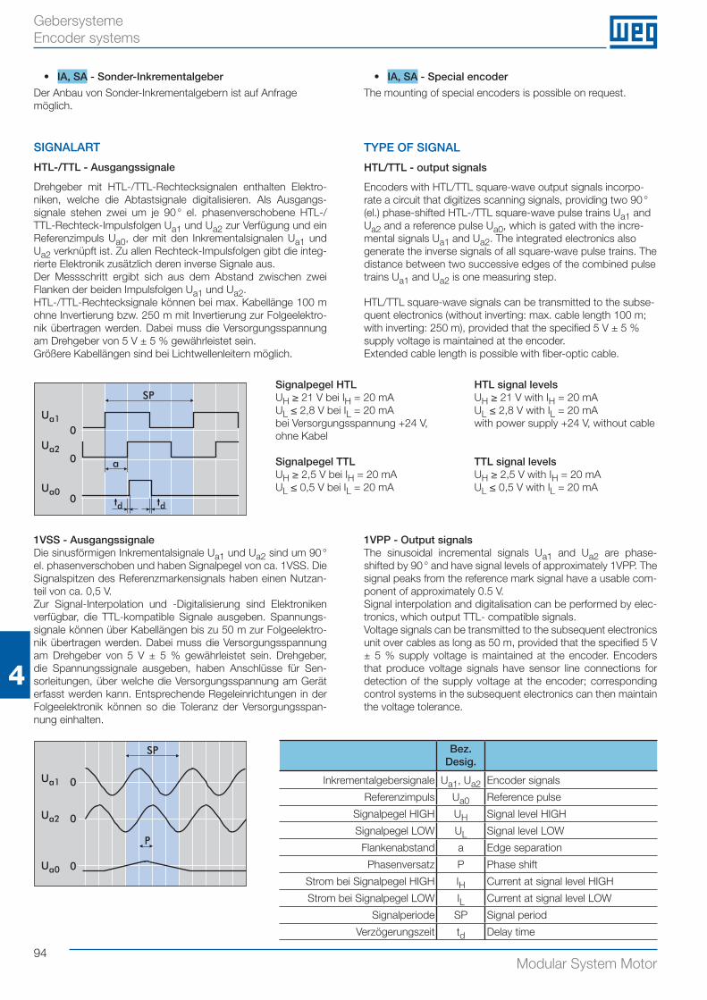
94Modular System Motor
4
Gebersysteme Encoder systems
1VSS - AusgangssignaleDie sinusförmigen Inkrementalsignale Ua1 und Ua2 sind um 90 ° el. phasenverschoben und haben Signalpegel von ca. 1VSS. Die Signalspitzen des Referenzmarkensignals haben einen Nutzan-teil von ca. 0,5 V.Zur Signal-Interpolation und -Digitalisierung sind Elektroniken verfügbar, die TTL-kompatible Signale ausgeben. Spannungs-signale können über Kabellängen bis zu 50 m zur Folgeelektro-nik übertragen werden. Dabei muss die Versorgungsspannung am Drehgeber von 5 V ± 5 % gewährleistet sein. Drehgeber, die Spannungssignale ausgeben, haben Anschlüsse für Sen-sorleitungen, über welche die Versorgungsspannung am Gerät erfasst werden kann. Entsprechende Regeleinrichtungen in der Folgeelektronik können so die Toleranz der Versorgungsspan-nung einhalten.
1VPP - Output signalsThe sinusoidal incremental signals Ua1 and Ua2 are phase- shifted by 90 ° and have signal levels of approximately 1VPP. The signal peaks from the reference mark signal have a usable com-ponent of approximately 0.5 V.Signal interpolation and digitalisation can be performed by elec-tronics, which output TTL- compatible signals.Voltage signals can be transmitted to the subsequent electronics unit over cables as long as 50 m, provided that the specified 5 V ± 5 % supply voltage is maintained at the encoder. Encoders that produce voltage signals have sensor line connections for detection of the supply voltage at the encoder; corresponding control systems in the subsequent electronics can then maintain the voltage tolerance.
• IA, SA - Sonder-Inkrementalgeber
Der Anbau von Sonder-Inkrementalgebern ist auf Anfrage möglich.
SIGNALART
HTL-/TTL - Ausgangssignale
Drehgeber mit HTL-/TTL-Rechtecksignalen enthalten Elektro-niken, welche die Abtastsignale digitalisieren. Als Ausgangs-signale stehen zwei um je 90 ° el. phasenverschobene HTL-/TTL-Rechteck-Impulsfolgen Ua1 und Ua2 zur Verfügung und ein Referenzimpuls Ua0, der mit den Inkrementalsignalen Ua1 und Ua2 verknüpft ist. Zu allen Rechteck-Impulsfolgen gibt die integ-rierte Elektronik zusätzlich deren inverse Signale aus.Der Messschritt ergibt sich aus dem Abstand zwischen zwei Flanken der beiden Impulsfolgen Ua1 und Ua2.HTL-/TTL-Rechtecksignale können bei max. Kabellänge 100 m ohne Invertierung bzw. 250 m mit Invertierung zur Folgeelektro-nik übertragen werden. Dabei muss die Versorgungsspannung am Drehgeber von 5 V ± 5 % gewährleistet sein.Größere Kabellängen sind bei Lichtwellenleitern möglich.
• IA, SA - Special encoder
The mounting of special encoders is possible on request.
TYPE OF SIGNAL
HTL/TTL - output signals
Encoders with HTL/TTL square-wave output signals incorpo-rate a circuit that digitizes scanning signals, providing two 90 ° (el.) phase-shifted HTL-/TTL square-wave pulse trains Ua1 and Ua2 and a reference pulse Ua0, which is gated with the incre-mental signals Ua1 and Ua2. The integrated electronics also generate the inverse signals of all square-wave pulse trains. The distance between two successive edges of the combined pulse trains Ua1 and Ua2 is one measuring step. HTL/TTL square-wave signals can be transmitted to the subse-quent electronics (without inverting: max. cable length 100 m; with inverting: 250 m), provided that the specified 5 V ± 5 % supply voltage is maintained at the encoder. Extended cable length is possible with fiber-optic cable.
Ua1
Ua2
SP
0
0
0Ua0
a
td td
0
0
0
Ua1
Ua2
Ua0
SP
P
Signalpegel HTLUH ≥ 21 V bei IH = 20 mAUL ≤ 2,8 V bei IL = 20 mAbei Versorgungsspannung +24 V, ohne Kabel
Signalpegel TTLUH ≥ 2,5 V bei IH = 20 mAUL ≤ 0,5 V bei IL = 20 mA
HTL signal levelsUH ≥ 21 V with IH = 20 mAUL ≤ 2,8 V with IL = 20 mAwith power supply +24 V, without cable
TTL signal levelsUH ≥ 2,5 V with IH = 20 mAUL ≤ 0,5 V with IL = 20 mA
Bez.Desig.
Inkrementalgebersignale Ua1, Ua2 Encoder signals
Referenzimpuls Ua0 Reference pulse
Signalpegel HIGH UH Signal level HIGH
Signalpegel LOW UL Signal level LOW
Flankenabstand a Edge separation
Phasenversatz P Phase shift
Strom bei Signalpegel HIGH IH Current at signal level HIGH
Strom bei Signalpegel LOW IL Current at signal level LOW
Signalperiode SP Signal period
Verzögerungszeit td Delay time
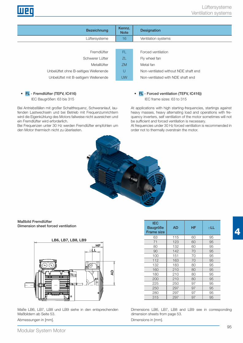
95Modular System Motor
4
Lüftersysteme Ventilation systems
BezeichnungKennz.Note
Designation
Lüftersysteme 16 Ventilation systems
Fremdlüfter FL Forced ventilation
Schwerer Lüfter ZL Fly wheel fan
Metalllüfter ZM Metal fan
Unbelüftet ohne B-seitiges Wellenende U Non-ventilated without NDE shaft end
Unbelüftet mit B-seitigem Wellenende UW Non-ventilated with NDE shaft end
• FL - Fremdlüfter (TEFV, IC416)
IEC Baugrößen: 63 bis 315
Bei Antriebsfällen mit großer Schaltfrequenz, Schweranlauf, lau-fenden Lastwechseln und bei Betrieb mit Frequenzumrichtern wird die Eigenkühlung des Motors fallweise nicht ausreichen und ein Fremdlüfter wird erforderlich.Bei Frequenzen unter 30 Hz werden Fremdlüfter empfohlen um den Motor thermisch nicht zu überlasten.
• FL - Forced ventilation (TEFV, IC416))
IEC frame sizes: 63 to 315
At applications with high starting-frequencies, startings against heavy masses, heavy alternating load and operations with fre-quency inverters, self ventilation of the motor sometimes will not be sufficient and forced ventilation is necessary.At frequencies under 30 Hz forced ventilation is recommended in order not to thermally overstrain the motor.
Maßbild FremdlüfterDimension sheet forced ventilation
Abmessungen in [mm].
Maße LB6, LB7, LB8 und LB9 siehe in den entsprechenden Maßbildern ab Seite 53.
Dimensions LB6, LB7, LB8 and LB9 see in corresponding dimension sheets from page 53.
LB6, LB7, LB8, LB9HF
□LL
AD
IEC BaugrößeFrame size
AD HF □LL
63 115 60 9571 123 60 9580 132 60 9590 142 70 95
100 151 70 95112 163 70 95132 183 80 95160 210 80 95180 210 80 95200 210 80 95225 250 97 95250 297 97 95280 297 97 95315 297 97 95
Dimensions in [mm].
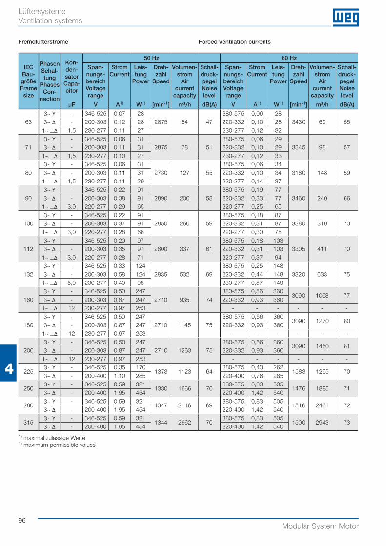
96Modular System Motor
4
Lüftersysteme Ventilation systems
IEC Bau-größeFrame size
Phasen Schal-tung
Phases Con-
nection
Kon-den-sator Capa-citor
50 Hz 60 Hz
Span-nungs-bereichVoltage range
StromCurrent
Leis-tung
Power
Dreh-zahl
Speed
Volumen-strom
Air current
capacity
Schall-druck-pegel Noise level
Span-nungs-bereichVoltage range
StromCurrent
Leis-tung
Power
Dreh-zahl
Speed
Volumen-strom
Air current
capacity
Schall-druck-pegel Noise level
μF V A1) W1) [min-1] m³/h dB(A) V A1) W1) [min-1] m³/h dB(A)
633~ Y - 346-525 0,07 28
2875 54 47380-575 0,06 28
3430 69 553~ ∆ - 200-303 0,12 28 220-332 0,10 281~ ⊥∆ 1,5 230-277 0,11 27 230-277 0,12 32
713~ Y - 346-525 0,06 31
2875 78 51380-575 0,06 29
3345 98 573~ ∆ - 200-303 0,11 31 220-332 0,10 291~ ⊥∆ 1,5 230-277 0,10 27 230-277 0,12 33
803~ Y - 346-525 0,06 31
2730 127 55380-575 0,06 34
3180 148 593~ ∆ - 200-303 0,11 31 220-332 0,10 341~ ⊥∆ 1,5 230-277 0,11 29 230-277 0,14 37
903~ Y - 346-525 0,22 91
2890 200 58380-575 0,19 77
3460 240 663~ ∆ - 200-303 0,38 91 220-332 0,33 771~ ⊥∆ 3,0 220-277 0,29 65 220-277 0,25 65
1003~ Y - 346-525 0,22 91
2850 260 59380-575 0,18 87
3380 310 703~ ∆ - 200-303 0,37 91 220-332 0,31 871~ ⊥∆ 3,0 220-277 0,28 66 220-277 0,30 75
1123~ Y - 346-525 0,20 97
2800 337 61380-575 0,18 103
3305 411 703~ ∆ - 200-303 0,35 97 220-332 0,31 1031~ ⊥∆ 3,0 220-277 0,28 71 220-277 0,37 94
1323~ Y - 346-525 0,33 124
2835 532 69380-575 0,25 148
3320 633 753~ ∆ - 200-303 0,58 124 220-332 0,44 1481~ ⊥∆ 5,0 230-277 0,40 98 230-277 0,57 149
1603~ Y - 346-525 0,50 247
2710 935 74380-575 0,56 360
3090 1068 773~ ∆ - 200-303 0,87 247 220-332 0,93 360
1~ ⊥∆ 12 230-277 0,97 253 - - - - - -
1803~ Y - 346-525 0,50 247
2710 1145 75380-575 0,56 360
3090 1270 803~ ∆ - 200-303 0,87 247 220-332 0,93 360
1~ ⊥∆ 12 230-277 0,97 253 - - - - - -
2003~ Y - 346-525 0,50 247
2710 1263 75380-575 0,56 360
3090 1450 813~ ∆ - 200-303 0,87 247 220-332 0,93 360
1~ ⊥∆ 12 230-277 0,97 253 - - - - - -
2253~ Y - 346-525 0,35 170
1373 1123 64380-575 0,43 262
1583 1295 703~ ∆ - 200-400 1,10 285 220-400 0,76 285
2503~ Y - 346-525 0,59 321
1330 1666 70380-575 0,83 505
1476 1885 713~ ∆ - 200-400 1,95 454 220-400 1,42 540
2803~ Y - 346-525 0,59 321
1347 2116 69380-575 0,83 505
1516 2461 723~ ∆ - 200-400 1,95 454 220-400 1,42 540
3153~ Y - 346-525 0,59 321
1344 2662 70380-575 0,83 505
1500 2943 733~ ∆ - 200-400 1,95 454 220-400 1,42 540
Fremdlüfterströme Forced ventilation currents
1) maximal zulässige Werte 1) maximum permissible values
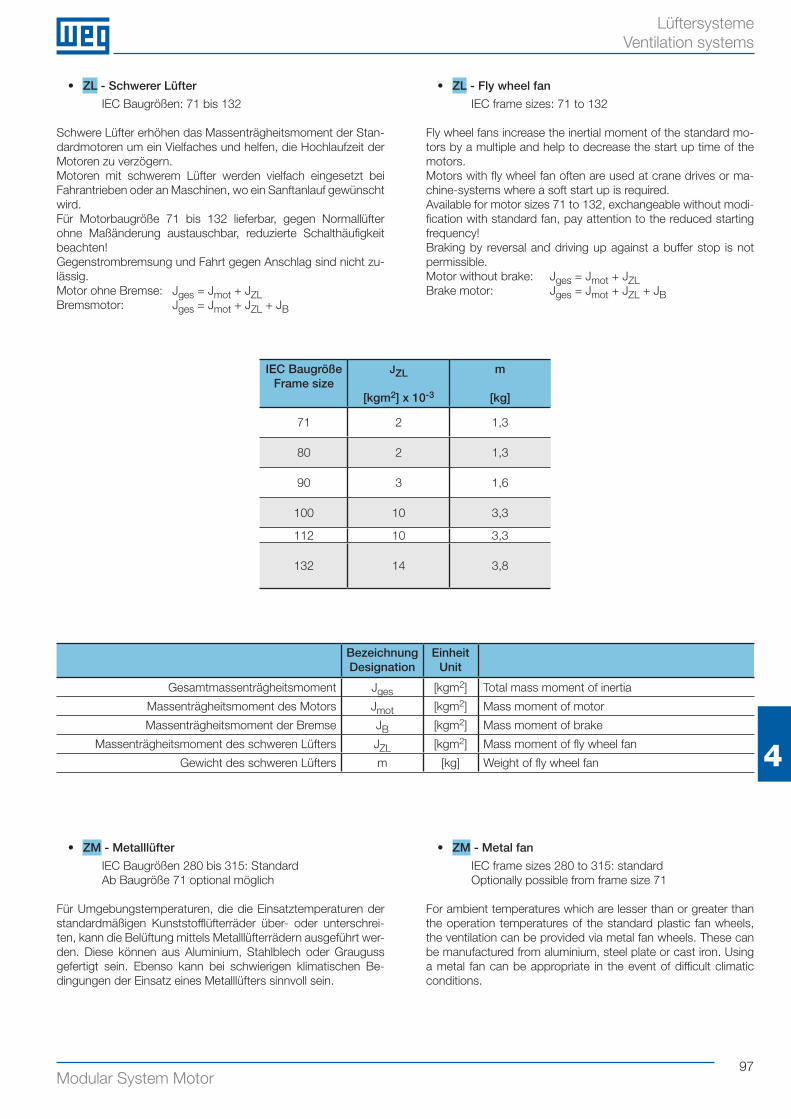
97Modular System Motor
4
Lüftersysteme Ventilation systems
• ZL - Schwerer Lüfter
IEC Baugrößen: 71 bis 132
Schwere Lüfter erhöhen das Massenträgheitsmoment der Stan-dardmotoren um ein Vielfaches und helfen, die Hochlaufzeit der Motoren zu verzögern.Motoren mit schwerem Lüfter werden vielfach eingesetzt bei Fahrantrieben oder an Maschinen, wo ein Sanftanlauf gewünscht wird.Für Motorbaugröße 71 bis 132 lieferbar, gegen Normallüfter ohne Maßänderung austauschbar, reduzierte Schalthäufigkeit beachten!Gegenstrombremsung und Fahrt gegen Anschlag sind nicht zu-lässig.Motor ohne Bremse: Jges = Jmot + JZLBremsmotor: Jges = Jmot + JZL + JB
• ZL - Fly wheel fan
IEC frame sizes: 71 to 132
Fly wheel fans increase the inertial moment of the standard mo-tors by a multiple and help to decrease the start up time of the motors.Motors with fly wheel fan often are used at crane drives or ma-chine-systems where a soft start up is required.Available for motor sizes 71 to 132, exchangeable without modi-fication with standard fan, pay attention to the reduced starting frequency!Braking by reversal and driving up against a buffer stop is not permissible.Motor without brake: Jges = Jmot + JZLBrake motor: Jges = Jmot + JZL + JB
IEC BaugrößeFrame size
JZL
[kgm2] x 10-3
m
[kg]
71 2 1,3
80 2 1,3
90 3 1,6
100 10 3,3
112 10 3,3
132 14 3,8
BezeichnungDesignation
EinheitUnit
Gesamtmassenträgheitsmoment Jges [kgm2] Total mass moment of inertia
Massenträgheitsmoment des Motors Jmot [kgm2] Mass moment of motor
Massenträgheitsmoment der Bremse JB [kgm2] Mass moment of brake
Massenträgheitsmoment des schweren Lüfters JZL [kgm2] Mass moment of fly wheel fan
Gewicht des schweren Lüfters m [kg] Weight of fly wheel fan
• ZM - Metalllüfter
IEC Baugrößen 280 bis 315: StandardAb Baugröße 71 optional möglich
Für Umgebungstemperaturen, die die Einsatztemperaturen der standardmäßigen Kunststofflüfterräder über- oder unterschrei-ten, kann die Belüftung mittels Metalllüfterrädern ausgeführt wer-den. Diese können aus Aluminium, Stahlblech oder Grauguss gefertigt sein. Ebenso kann bei schwierigen klimatischen Be- dingungen der Einsatz eines Metalllüfters sinnvoll sein.
• ZM - Metal fan
IEC frame sizes 280 to 315: standardOptionally possible from frame size 71
For ambient temperatures which are lesser than or greater than the operation temperatures of the standard plastic fan wheels, the ventilation can be provided via metal fan wheels. These can be manufactured from aluminium, steel plate or cast iron. Using a metal fan can be appropriate in the event of difficult climatic conditions.
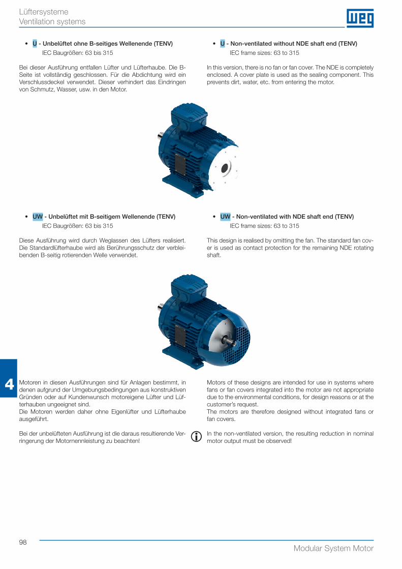
98Modular System Motor
4
Lüftersysteme Ventilation systems
• U - Unbelüftet ohne B-seitiges Wellenende (TENV)
IEC Baugrößen: 63 bis 315
Bei dieser Ausführung entfallen Lüfter und Lüfterhaube. Die B-Seite ist vollständig geschlossen. Für die Abdichtung wird ein Verschlussdeckel verwendet. Dieser verhindert das Eindringen von Schmutz, Wasser, usw. in den Motor.
• U - Non-ventilated without NDE shaft end (TENV)
IEC frame sizes: 63 to 315
In this version, there is no fan or fan cover. The NDE is completely enclosed. A cover plate is used as the sealing component. This prevents dirt, water, etc. from entering the motor.
Motoren in diesen Ausführungen sind für Anlagen bestimmt, in denen aufgrund der Umgebungsbedingungen aus konstruktiven Gründen oder auf Kundenwunsch motoreigene Lüfter und Lüf-terhauben ungeeignet sind.Die Motoren werden daher ohne Eigenlüfter und Lüfterhaube ausgeführt.
Bei der unbelüfteten Ausführung ist die daraus resultierende Ver-ringerung der Motornennleistung zu beachten!
Motors of these designs are intended for use in systems where fans or fan covers integrated into the motor are not appropriate due to the environmental conditions, for design reasons or at the customer’s request.The motors are therefore designed without integrated fans or fan covers.
In the non-ventilated version, the resulting reduction in nominal motor output must be observed!i
• UW - Unbelüftet mit B-seitigem Wellenende (TENV)
IEC Baugrößen: 63 bis 315
Diese Ausführung wird durch Weglassen des Lüfters realisiert. Die Standardlüfterhaube wird als Berührungsschutz der verblei-benden B-seitig rotierenden Welle verwendet.
• UW - Non-ventilated with NDE shaft end (TENV)
IEC frame sizes: 63 to 315
This design is realised by omitting the fan. The standard fan cov-er is used as contact protection for the remaining NDE rotating shaft.
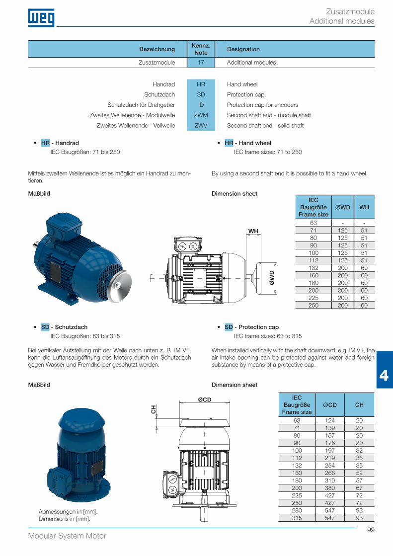
99Modular System Motor
4
Zusatzmodule Additional modules
BezeichnungKennz.Note
Designation
Zusatzmodule 17 Additional modules
Handrad HR Hand wheel
Schutzdach SD Protection cap
Schutzdach für Drehgeber ID Protection cap for encoders
Zweites Wellenende - Modulwelle ZWM Second shaft end - module shaft
Zweites Wellenende - Vollwelle ZWV Second shaft end - solid shaft
• HR - Handrad
IEC Baugrößen: 71 bis 250
Mittels zweitem Wellenende ist es möglich ein Handrad zu mon-tieren.
• HR - Hand wheel
IEC frame sizes: 71 to 250
By using a second shaft end it is possible to fit a hand wheel.
Maßbild Dimension sheet
• SD - Schutzdach
IEC Baugrößen: 63 bis 315
Bei vertikaler Aufstellung mit der Welle nach unten z. B. IM V1, kann die Luftansaugöffnung des Motors durch ein Schutzdach gegen Wasser und Fremdkörper geschützt werden.
• SD - Protection cap
IEC frame sizes: 63 to 315
When installed vertically with the shaft downward, e.g. IM V1, the air intake opening can be protected against water and foreign substance by means of a protective cap.
Maßbild Dimension sheet
Abmessungen in [mm].Dimensions in [mm].
WH
ØW
D
IEC BaugrößeFrame size
ØWD WH
63 - -71 125 5180 125 5190 125 51
100 125 51112 125 51132 200 60160 200 60180 200 60200 200 60225 200 60250 200 60
IEC BaugrößeFrame size
ØCD CH
63 124 2071 139 2080 157 2090 176 20
100 197 32112 219 35132 254 35160 266 52180 310 57200 380 67225 427 72250 427 72280 547 93315 547 93
CH
ØCD
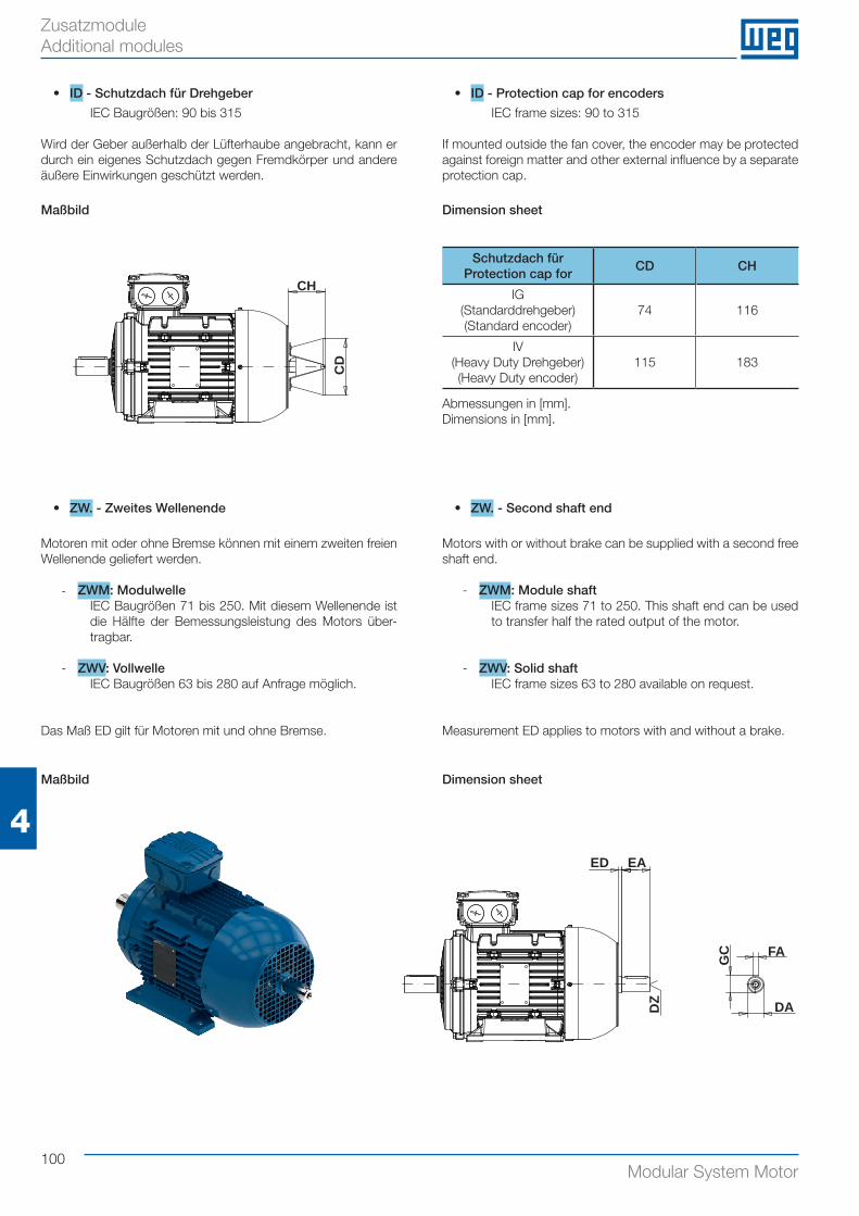
100Modular System Motor
4
Zusatzmodule Additional modules
Maßbild Dimension sheet
Abmessungen in [mm].Dimensions in [mm].
ED EA
DZ
GC FA
DA
• ZW. - Zweites Wellenende
Motoren mit oder ohne Bremse können mit einem zweiten freien Wellenende geliefert werden.
- ZWM: ModulwelleIEC Baugrößen 71 bis 250. Mit diesem Wellenende ist die Hälfte der Bemessungsleistung des Motors über-tragbar.
- ZWV: VollwelleIEC Baugrößen 63 bis 280 auf Anfrage möglich.
Das Maß ED gilt für Motoren mit und ohne Bremse.
• ZW. - Second shaft end
Motors with or without brake can be supplied with a second free shaft end.
- ZWM: Module shaftIEC frame sizes 71 to 250. This shaft end can be used to transfer half the rated output of the motor.
- ZWV: Solid shaftIEC frame sizes 63 to 280 available on request.
Measurement ED applies to motors with and without a brake.
• ID - Schutzdach für Drehgeber
IEC Baugrößen: 90 bis 315
Wird der Geber außerhalb der Lüfterhaube angebracht, kann er durch ein eigenes Schutzdach gegen Fremdkörper und andere äußere Einwirkungen geschützt werden.
• ID - Protection cap for encoders
IEC frame sizes: 90 to 315
If mounted outside the fan cover, the encoder may be protected against foreign matter and other external influence by a separate protection cap.
CH
CD
Schutzdach fürProtection cap for
CD CH
IG (Standarddrehgeber)(Standard encoder)
74 116
IV (Heavy Duty Drehgeber)(Heavy Duty encoder)
115 183
Maßbild Dimension sheet
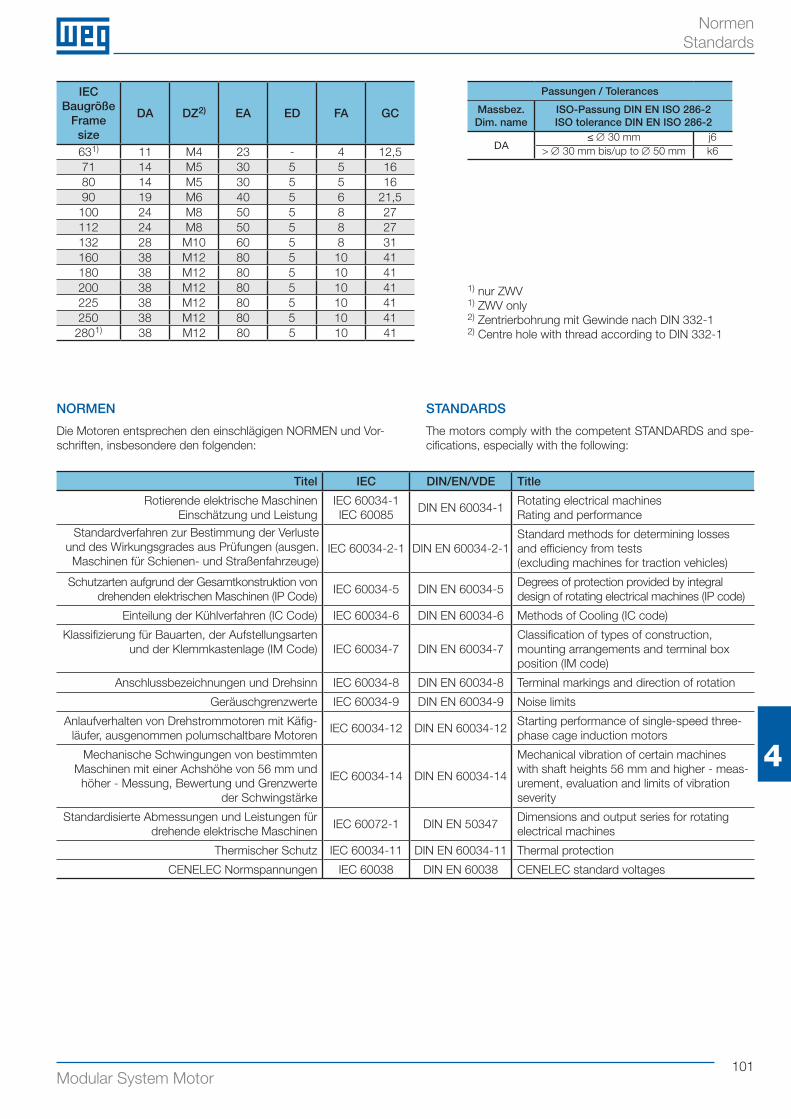
101Modular System Motor
4
Normen Standards
Titel IEC DIN/EN/VDE Title
Rotierende elektrische MaschinenEinschätzung und Leistung
IEC 60034-1IEC 60085
DIN EN 60034-1Rotating electrical machinesRating and performance
Standardverfahren zur Bestimmung der Verluste und des Wirkungsgrades aus Prüfungen (ausgen. Maschinen für Schienen- und Straßenfahrzeuge)
IEC 60034-2-1 DIN EN 60034-2-1Standard methods for determining losses and efficiency from tests (excluding machines for traction vehicles)
Schutzarten aufgrund der Gesamtkonstruktion von drehenden elektrischen Maschinen (IP Code)
IEC 60034-5 DIN EN 60034-5Degrees of protection provided by integral design of rotating electrical machines (IP code)
Einteilung der Kühlverfahren (IC Code) IEC 60034-6 DIN EN 60034-6 Methods of Cooling (IC code)
Klassifizierung für Bauarten, der Aufstellungsarten und der Klemmkastenlage (IM Code) IEC 60034-7 DIN EN 60034-7
Classification of types of construction, mounting arrangements and terminal box position (IM code)
Anschlussbezeichnungen und Drehsinn IEC 60034-8 DIN EN 60034-8 Terminal markings and direction of rotation
Geräuschgrenzwerte IEC 60034-9 DIN EN 60034-9 Noise limits
Anlaufverhalten von Drehstrommotoren mit Käfig-läufer, ausgenommen polumschaltbare Motoren
IEC 60034-12 DIN EN 60034-12Starting performance of single-speed three-phase cage induction motors
Mechanische Schwingungen von bestimmten Maschinen mit einer Achshöhe von 56 mm und
höher - Messung, Bewertung und Grenzwerte der Schwingstärke
IEC 60034-14 DIN EN 60034-14
Mechanical vibration of certain machines with shaft heights 56 mm and higher - meas-urement, evaluation and limits of vibration severity
Standardisierte Abmessungen und Leistungen für drehende elektrische Maschinen
IEC 60072-1 DIN EN 50347Dimensions and output series for rotating electrical machines
Thermischer Schutz IEC 60034-11 DIN EN 60034-11 Thermal protection
CENELEC Normspannungen IEC 60038 DIN EN 60038 CENELEC standard voltages
NORMEN
Die Motoren entsprechen den einschlägigen NORMEN und Vor-schriften, insbesondere den folgenden:
STANDARDS
The motors comply with the competent STANDARDS and spe-cifications, especially with the following:
IEC Baugröße
Frame size
DA DZ2) EA ED FA GC
631) 11 M4 23 - 4 12,571 14 M5 30 5 5 1680 14 M5 30 5 5 1690 19 M6 40 5 6 21,5
100 24 M8 50 5 8 27112 24 M8 50 5 8 27132 28 M10 60 5 8 31160 38 M12 80 5 10 41180 38 M12 80 5 10 41200 38 M12 80 5 10 41225 38 M12 80 5 10 41250 38 M12 80 5 10 41
2801) 38 M12 80 5 10 41
Passungen / Tolerances
Massbez.Dim. name
ISO-Passung DIN EN ISO 286-2ISO tolerance DIN EN ISO 286-2
DA≤ ∅ 30 mm j6
> ∅ 30 mm bis/up to ∅ 50 mm k6
1) nur ZWV1) ZWV only2) Zentrierbohrung mit Gewinde nach DIN 332-12) Centre hole with thread according to DIN 332-1
102Modular System Motor
AnschlusskastenAusführungen 69Kabeleinführung 18Lage 18MIP/MIG 69ff
Arretierung für Handlüftung 81Bauformen 21Bemessungsleistung 16Bestellschlüssel 7Betriebsarten 15Bremse siehe FederkraftbremseBremssysteme 74ffcat4CAD 2Dichtring 20Doppelbremse siehe FederkraftdoppelbremseDrehmoment 17Drehzahl, -richtung 17, 25Elektrische Daten 27ffEUSAS
Vorteile und Allgemeines 6Federkraftbremse
Allgemein 74Ausführungsmöglichkeiten 80fElektrische und Mechanische Kenngrößen 79
Schutzarten 80Federkraftdoppelbremse
Ausführungsmöglichkeiten 82fSchutzarten 83
Fremdlüfter siehe LüftersystemeGebersysteme
Heavy Duty Inkrementalgeber 93Resolver 92SINCOS-Inkrementalgeber 92Sonder-Inkrementalgeber 94SSI-Multiturngeber 93Standard-Inkrementalgeber 92Tachogenerator 93Schutzdach 100
Gleichrichter 86ffHandlüftung
Arretierung 81für Bremse 81für Doppelbremse 83für geschlossene Bremse 84
Handrad siehe ZusatzmoduleHoch-/Tieftemperaturausführung 66IE1
Einteilung 6, 64Elektrische Daten 28ff
IE2Einteilung 6, 64Elektrische Daten 28ff
IE3Einteilung 6, 64Elektrische Daten 40ff
Isolierungen 18Klemmenanschluss 26Klimaschutz
Feuchtigkeitsschutz (K1) 68Korrosionsschutz (K2) 68
Kondenswasserbohrung 68Lackierung 14Lager 20Leistungskennziffer 65Lüftersysteme
Fremdlüfter 95fMetalllüfter 97Schwerer Lüfter 97Unbelüftete Ausführungen 98
Metalllüfter siehe LüftersystemeMIG-connect Steckersystem 70ffMikroschalter 80, 83MIP - Multipin-Box 69Module 63ffMotorschutz, -schalter 17Normen 101Polzahl 65Rücklaufsperre 89fSchaltung 25Schutzarten 13Schutzdach siehe ZusatzmoduleSchwerer Lüfter siehe LüftersystemeSpannungen 25fSpannungs- und Frequenzschwankungen 12Statorlänge 65Stillstandsheizung
Bremse 83Motor 67
TemperaturüberwachungBimetallschalter (TH) 66Kaltleiterfühler (TF) 66Temperatursensor (KTY) 67
Typenschild 16Unbelüftete Ausführungen
siehe LüftersystemeWAC 9, 58f, 64WAF 9, 56f, 64WAG 9, 54f, 64WAR 9, 60f, 64Werkstoffe 19Wirkungsgrad 17Zusatzmodule
Handrad 99Schutzdach für Drehgeber 100Schutzdach für Motor 99Zweites Wellenende 100
Zweites Wellenendesiehe Zusatzmodule
Glossar
103Modular System Motor
Glossary
Additional modulesHand wheel 99Protection cap for encoders 100Protection cap for motors 99Second shaft end 100
Anti-condensation heatingBrake 83Motor 67
Back stop 89fBearings 20Brake see Spring loaded brakeBrake systems 74ffcat4CAD 2Climatic protection
Corrosion protection (K2) 68Humidity protection (K1) 68
Connection 25Degrees of protection 13Double brake see Spring loaded double brakeDrain 68Efficiency class 17Electrical Data 27ffEncoder systems
Heavy Duty encoder 93Protection cap 100Resolver 92SINCOS encoder 92Special encoder 94SSI multiturn encoder 93Standard encoder 92Tacho generator 93
EUSASAdvantages and Misc. 6
Fly wheel fan see Ventilation systemsForced ventilation see Ventilation systemsHand wheel see Additional modulesHigh/Low temperature execution 66IE1
Classification 6, 64Electrical data 28ff
IE2Classification 6, 64Electrical data 28ff
IE3Classification 6, 64Electrical data 40ff
Insulation 18Locking device for manual release 81Manual release
For brake 81For double brake 83For totally closed brake 84Locking device 81
Materials 19Metal fan see Ventilation systemsMicro switch 80, 83
MIG-connect system 70ffMIP-Multipin-Box 69Modes of operation 15Modules 63ffMotor and overload protection 17Mounting positions 21Nameplate 16Non-ventilated see Ventilation systemsNumber of poles 65Order type designation 7Painting 14Power indicator 65Protection cap see Additional modulesRated power 16Rectifier 86ffSeal ring 20Second shaft end see Additional modulesSpeed, Direction 17, 25Spring loaded brake 74
Degree of protection 80Electrical and mechanical characteristics
79
Executions 80fMiscellaneous 74
Spring loaded double brakeDegrees of protection 83Executions 82f
Standards 101Stator length 65Temperature control
Bimetal switch (TH) 66PTC thermistor (TF) 66Temperature sensor (KTY) 67
Terminal board connection 26Terminal box
Cable entry 18Designs 69MIP/MIG 69ffPosition 18
Torque 17Ventilation systems
Fly wheel fan 97Forced ventilation 95fMetal fan 97Non-ventilated 98
Voltages 25fVoltage and frequency fluctuations 12WAC 9, 58f, 64WAF 9, 56f, 64WAG 9, 54f, 64WAR 9, 60f, 64
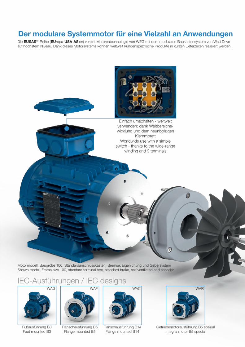
Motormodell: Baugröße 100, Standardanschlusskasten, Bremse, Eigenlüftung und GebersystemShown model: Frame size 100, standard terminal box, standard brake, self ventilated and encoder
Einfach umschalten - weltweit verwenden: dank Weitbereichs-wicklung und dem neunbolzigen
Klemmbrett
Der modulare Systemmotor für eine Vielzahl an Anwendungen
Fußausführung B3 Foot mounted B3
Flanschausführung B5 Flange mounted B5
Flanschausführung B14 Flange mounted B14
Getriebemotorausführung B5 spezialIntegral motor B5 special
IEC-Ausführungen / IEC designs
Die EUSAS®-Reihe (EUropa-USA-ASien) vereint Motorentechnologie von WEG mit dem modularen Baukastensystem von Watt Drive auf höchstem Niveau. Dank dieses Motorsystems können weltweit kundenspezifische Produkte in kurzen Lieferzeiten realisiert werden.
WAG WAF WAC WAR
Worldwide use with a simple switch - thanks to the wide-range
winding and 9 terminals
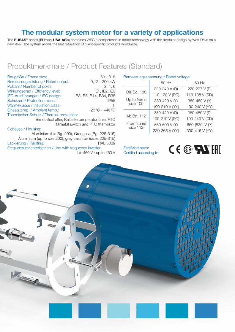
Produktmerkmale / Product Features (Standard)Bemessungsspannung / Rated voltage:
50 Hz 60 Hz
Bis Bg. 100
Up to frame size 100
220-240 V (D) 220-277 V (D)
110-120 V (DD) 110-138 V (DD)
380-420 V (Y) 380-480 V (Y)
190-210 V (YY) 190-240 V (YY)
Ab Bg. 112
From frame size 112
380-420 V (D) 380-480 V (D)
190-210 V (DD) 190-240 V (DD)
660-690 V (Y) 660-(830) V (Y)
330-365 V (YY) 330-415 V (YY)
Zertifiziert nach: Certified according to:
The EUSAS®-series (EUrope-USA-ASia) combines WEG‘s competence in motor technology with the modular design by Watt Drive on a new level. The system allows the fast realisation of client-specific products worldwide.
The modular system motor for a variety of applications
Baugröße / Frame size: 63 - 315Bemessungsleistung / Rated output: 0,12 - 200 kWPolzahl / Number of poles: 2, 4, 6Wirkungsgrad / Efficiency level: IE1, IE2, IE3 IEC-Ausführungen / IEC design: B3, B5, B14, B34, B35Schutzart / Protection class: IP55 Wärmeklasse / Insulation class: FEinsatztemp. / Ambient temp.: -20 °C - +40 °C Thermischer Schutz / Thermal protection:
Bimetallschalter, Kaltleitertemperaturfühler PTC Bimetal switch and PTC thermistor
Gehäuse / Housing: Aluminium (bis Bg. 200), Grauguss (Bg. 225-315)
Aluminium (up to size 200), grey cast iron (sizes 225-315)Lackierung / Painting: RAL 5009Frequenzumrichterbetrieb / Use with frequency inverter:
bis 460 V / up to 460 V
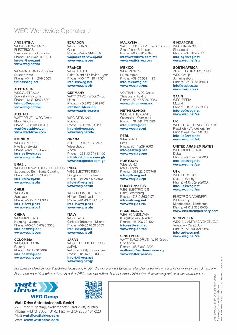
WEG Worldwide Operations
Watt Drive Antriebstechnik GmbH 2753 Markt Piesting, Wöllersdorfer Straße 68, Austria Phone: +43 (0) 2633 404-0, Fax: +43 (0) 2633 404-220 Mail: [email protected] Web: www.wattdrive.com
ARGENTINAWEG EQUIPAMIENTOS ELECTRICOS San Francisco - CordobaPhone: +54 3564 421 [email protected]/ar
WEG PINTURAS - PulverluxBuenos AiresPhone: +54 11 4299 [email protected]
AUSTRALIAWEG AUSTRALIAScoresby - Victoria Phone: +61 3 9765 [email protected]/au
AUSTRIAWATT DRIVE - WEG GroupMarkt PiestingPhone: +43 2633 404 [email protected]
BELGIUMWEG BENELUXNivelles - BelgiumPhone: +32 67 88 84 [email protected]/be
BRAZILWEG EQUIPAMENTOS ELÉTRICOSJaraguá do Sul - Santa CatarinaPhone: +55 47 [email protected]/br
CHILEWEG CHILESantiagoPhone: +56 2 784 [email protected]/cl
CHINAWEG NANTONGNantong - Jiangsu Phone: +86 0513 8598 [email protected]/cn
COLOMBIAWEG COLOMBIABogotáPhone: +57 1 416 [email protected]/co
ECUADORWEG ECUADORQuitoPhone: +5932 5144 [email protected]/ec
FRANCEWEG FRANCESaint Quentin Fallavier - LyonPhone: +33 4 74 99 11 [email protected]/fr
GERMANYWATT DRIVE - WEG Group Unna Phone: +49 2303 986 [email protected]
WEG GERMANY Kerpen Phone: +49 2237 9291 [email protected]/de
GHANAZEST ELECTRIC GHANA WEG GroupAccraPhone: +233 30 27 664 [email protected]
INDIAWEG ELECTRIC INDIABangalore - KarnatakaPhone: +91 80 4128 2007 [email protected]/in
WEG INDUSTRIES INDIAHosur - Tamil NaduPhone: +91 4344 301 [email protected]/in
ITALYWEG ITALIACinisello Balsamo - MilanoPhone: +39 02 6129 [email protected]/it
JAPANWEG ELECTRIC MOTORSJAPANYokohama City - KanagawaPhone: +81 45 550 [email protected]/jp
MALAYSIAWATT EURO-DRIVE - WEG GroupShah Alam, SelangorPhone: +603 [email protected]
MEXICOWEG MEXICOHuehuetoca Phone: +52 55 5321 [email protected]/mx
VOLTRAN - WEG GroupTizayuca - HidalgoPhone: +52 77 5350 9354www.voltran.com.mx
NETHERLANDSWEG NETHERLANDS Oldenzaal - OverijsselPhone: +31 541 571 [email protected]/nl
PERUWEG PERULimaPhone: +51 1 209 [email protected]/pe
PORTUGALWEG EUROMaia - PortoPhone: +351 22 [email protected]/pt
RUSSIA and CISWEG ELECTRIC CIS Saint Petersburg Phone: +7 812 363 2172 [email protected] www.weg.net/ru
SCANDINAVIAWEG SCANDINAVIAKungsbacka - SwedenPhone: +46 300 73 [email protected]/se
SINGAPOREWATT EURO-DRIVE - WEG Group SingaporePhone: +65 6 862 [email protected]
SINGAPOREWEG SINGAPORE SingaporePhone: +65 [email protected]/sg
SOUTH AFRICAZEST ELECTRIC MOTORSWEG Group JohannesburgPhone: +27 11 723 [email protected]
SPAINWEG IBERIAMadridPhone: +34 91 655 30 [email protected]/es
UKWEG ELECTRIC MOTORS U.K.Redditch - WorcestershirePhone: +44 1527 513 [email protected]/uk
UNITED ARAB EMIRATESWEG MIDDLE EAST DubaiPhone: +971 4 813 [email protected]/ae
USAWEG ELECTRIC Duluth - GeorgiaPhone: +1 678 249 [email protected] www.weg.net/us
ELECTRIC MACHINERYWEG GroupMinneapolis - MinnesotaPhone: +1 612 378 8000www.electricmachinery.com
VENEZUELAWEG INDUSTRIAS VENEZUELAValencia - CaraboboPhone: +58 241 821 [email protected]/ve
For those countries where there is not a WEG own operation, find our local distributor at www.weg.net or www.wattdrive.com.
Cod
: 50
0492
97 |
Rev
: 00
| Dat
e (m
/y) 0
8/20
14Ä
nder
unge
n je
der
zeit
vorb
ehal
ten.
Th
e va
lues
sho
wn
are
sub
ject
to c
hang
e w
ithou
t prio
r no
tice.
Für Länder ohne eigene WEG-Niederlassung finden Sie unseren zuständigen Händler unter www.weg.net oder www.wattdrive.com.


