Embed Size (px)
Citation preview

Applications of Watt II function generator cognates
P.A. Simionescua,*, M.R. Smithb
aDepartment of Mechanism and Robot Theory, Politehnica, University of Bucharest, Spl. Independentei 313, 77206Bucharest, Romania
bDepartment of Mechanical, Materials and Manufacturing Engineering, University of Newcastle, Newcastle upon Tyne,NE1 7RU, UK
Received 25 September 1997; received in revised form 10 March 2000
Abstract
7R and 3RT3R Watt II function-generating mechanisms are examined and the existence of a doublein®nity of cognates are highlighted. For both the cases reference dimensional con®guration mechanismsare de®ned which have a minimum number of parameters, these being considered best suited forperforming a function generation synthesis. Overconstrained mechanisms are also shown to result fromthe merging of the input and output elements of two or more such function cognates. The practicalcases of the rack-and-pinion and central-lever steering linkages are examined as planar mechanisms, anda maximum number of only three and four independent design parameters, respectively, are proven toexist. 7 2000 Elsevier Science Ltd. All rights reserved.
Keywords: Planar geometrical transformations; Reference con®gurations; Function cognates; Overconstrainedmechanisms
1. Introduction
The occurrence of cognates in planar mechanism kinematics and their association inoverconstrained mechanisms have been studied by many authors, more recently by Dijksman[1±3]. However, function generation cognates have been signi®cantly less thoroughlyinvestigated, most of the published literature focusing on coupler-curve and coupler cognate
Mechanism and Machine Theory 35 (2000) 1535±1549
0094-114X/00/$ - see front matter 7 2000 Elsevier Science Ltd. All rights reserved.PII: S0094-114X(00)00011-2
www.elsevier.com/locate/mechmt
* Corresponding author. Department of Mechanical Engineering, Auburn University, 201 Ross Hall, Auburn, AL
36849, USA. Tel.: +1-334-844-5894; fax: +1-334-844-5900.E-mail address: [email protected] (P.A. Simionescu).
mechanisms. In many cases, Robert's theorem of three-fold generation of four-bar couplercurves has been the starting point for studying more complex mechanism cognates and theresulting overconstrained mechanisms. The six-bar Watt and Stephenson mechanisms withturning joints only (7R) were analysed by Dijksman for curve, coupler and function generationcognates. Extending the conclusions reached for the Watt I mechanism, by applying a properinversion, the Watt II linkage was found to have a double in®nity of function cognates [2]. Inspite of the obvious consequences, no overconstrained mechanism obtained by associating twoor more function cognates of the Watt II type appears to have been reported.The Watt II mechanism, which is the concern of the present paper, has numerous practical
applications due to its topological symmetry, the most common of them being the central-leverand rack-and-pinion type steering mechanisms, which will be further considered as examples.
2. 7R Watt II mechanism
The Watt II con®guration consists of two four-bar linkages connected in series, the commonmember being a ternary link. It is known that for any mechanism having rotational input andoutput member(s) the transmission function is independent of the scale of the mechanism. Thiskinematic property is valid no matter whether the mechanism is planar or spatial, or has innerjoints other than revolute joints. If a complex linkage can be interpreted as a number ofmechanisms arranged in series and connected via turning elements, it is possible to scale onlysome of the loops in the mechanism, without altering its input-output transmission function.Thus the mechanism in Fig. 1(b) will have the same transmission function as the initialmechanism in Fig. 1(a), from which it has been obtained by scaling the second four-bar by afactor k.The same transmission function will be ful®lled (apart from a phase angle Da� by the
mechanism in Fig. 1(c), which has been obtained from the initial one by rotating the secondfour-bar component mechanism and reshaping the middle ternary link, so that the ®xed anglea is modi®ed by an amount Da:These two geometrical transformations applied successively to either of the two four-bar
component mechanisms are the reason for the already proven double-in®nity of functioncognates [2]. A particular case among these in®nities will be that in which the ternary link hasthe ¯oating joints merged into a double joint. If the length of this middle link is furtherconsidered equal to unity, a reference mechanism with normalised dimensions will result(Fig. 2). The parameters describing the geometry of this reference-normalised mechanism arereduced to a minimum i.e., the lengths l1±l6 together with the ®xed angle of the ground link b:A normalisation of the 7R Watt II mechanisms has been used by McLarnan [4] and by
Dhingra and Mani [5] in the synthesis of function generators, with unit ground lengths l1 � 1and l6 � 1 and the ®xed angle b � 1808: A more productive choice is to have a unit lengthternary link �l0 � 1� instead of the ground links, since the degenerate case of a four-bar loopwith a zero ground link length is still a movable structure (with unit transmission ratio) ascompared to a zero crank length mechanism which becomes an immobile triangular frame. Tothe seven design variables describing the input±output transmission function jo�ji � of themechanism, there can be added the values of the initial angles ji and jo of the input and
P.A. Simionescu, M.R. Smith /Mechanism and Machine Theory 35 (2000) 1535±15491536

Fig. 1. Input±output invariant transformations of a Watt II 7R mechanism.
P.A. Simionescu, M.R. Smith /Mechanism and Machine Theory 35 (2000) 1535±1549 1537

output links de®ning the ®rst precision point and a corresponding nine-precision-pointsynthesis problem can be formulated [4,5]. This contradicts a recent paper of Dhingra et al. [6]in which the normalisation of the mechanism considered in their earlier paper [5] is abandonedand the parameters describing the mechanism geometry are chosen in terms of Cartesian co-ordinates of the component joints. An 11-precision-point synthesis problem was formulated inthese Cartesian co-ordinates as design variables, which the authors admitted they were unableto solve.Regarding the reference mechanism as that in Fig. 2, after the synthesis has been performed
for a desired function, the whole resulting normalised mechanism can be scaled according tothe gauge requirements. Finally the required position of the ground joints may be chosen byrotating and if necessary independent scaling of the component four-bar loops relative to thecentral ground joint, following the pattern in Fig. 1(b) and (c).Based on the above procedures, a function cognate of the mechanism in Fig. 2 was designed,
which was required to have the same distance between the ground joints A and E.Subsequently, the input and output members of the initial and resultant cognates were mergedand the overconstrained mechanism in Fig. 3 obtained.The method was as follows. The initial mechanism with the numerical data shown in Fig. 2
was scaled by the global factor 50 (to give practical dimensions in millimetres) then the leftfour-bar loop was scaled by the factor 1.5 and the right four-bar loop by the factor 1.25. Thetwo loops were then rotated one against the other at 65.698 by which the distance between theouter ground joints was reduced to the initial one and the input and output members of theinitial and scaled mechanisms could be merged into single elements (Fig. 3(a)).AutoCAD2 package was used to determine the intersection point O ' of two circles centred
on A and E (with radii equal to 1.5 � EO and 1.25 � AO, respectively) and then to align
Fig. 2. Reference dimensional con®guration of a Watt II 7R mechanism.
P.A. Simionescu, M.R. Smith /Mechanism and Machine Theory 35 (2000) 1535±15491538

Fig. 3. Working model of Watt II 7R function cognates associated in an overconstrained mechanism.
P.A. Simionescu, M.R. Smith /Mechanism and Machine Theory 35 (2000) 1535±1549 1539

independently the corresponding scaled four-bar contours relative to the lines O 'E and O 'A.From the in®nite number of possibilities, a mechanism having as many non-fractionaldimensions as possible was chosen. The set of dimensions obtained by this procedure is givenin Table 1.The mobility of the mechanism is due only to the correlated dimensions of the elements
since, according to Grubler's formula, this should have zero degree of freedom:
f � 3�nÿ 1� ÿ 2 � j � 3�9ÿ 1� ÿ 2 � 12 � 0 �1�where n is the total number of elements and j is the number of simple joints.Using the kinematic and kinetostatic planar linkage simulation software OSMEC [7], the
mechanism in Fig. 3 with the data in Table 1 was modelled, but with the element OCconsidered disconnected to give the mechanism a topological single degree of freedom. Theanalysis showed that the distance between the released joints O and C varies insigni®cantly byonly 0.7248 � 10ÿ4 mm (0.32 � 10ÿ4%) throughout the whole working range of the inputelement ED ' (from about 1028 to 3898). This small variation is the result of the truncated inputdata and of the round-o� errors in the software. In a working mechanism (such as thephotographs shown in Fig. 3), the accuracy of manufacturing would be lower, the mechanismbeing able to move only as result of the joint clearances and link elasticities.
3. The Watt II central-lever steering mechanism
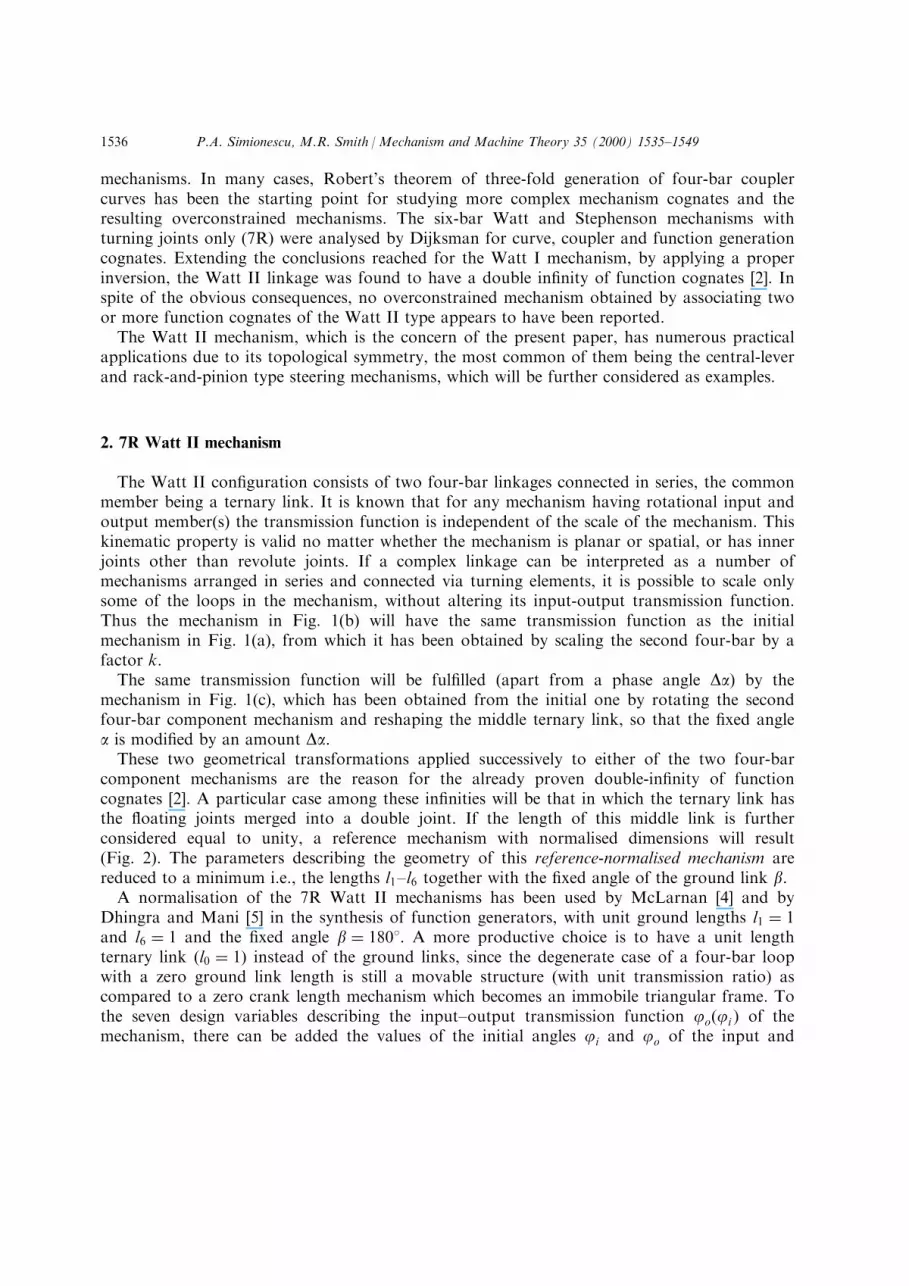
A practical application of the 7R Watt II mechanism is the central-lever steering linkageused in motor vehicles and towed trailers. In this case, the transmission function of themechanism is de®ned, due to the dimensional symmetry, by only four of the seven parametersof the reference cognate shown in Fig. 4. A preferred set of parameters can be j0, l, g0, and lc(in which as many angles as possible have been included, because the loop closure isguaranteed for any initial position of the mechanism), while the length lt of the tie-rod andangle b can be easily calculated in terms of the same. The kingpin track length l0 is usuallyprescribed and can be taken as the normalised member �l0 � 1�, and the steering performanceof the mechanism determined for a generic vehicle with a given wheel base/wheel track ratio.Both Duditza and Alexandru [8] and Arday®o and Qiao [9] considered the ®xed angle a of thecentral-lever (which is non-zero in most practical designs) as an extra design parameter. Thepresent considerations show that no steering improvements can be achieved by varying this
Table 1
Numerical data of the mechanism in Fig. 3
xO = 0.0 xA = 70 xE = ÿ50 xO ' = ÿ4.12838yO = 0.0 yA = 0.0 yE = ÿ20 yO ' = 46.48906AB = 65 BC = 110 CO = 50 angle hBAB 'i = 32.0968CD = 75 DE = 40 D 'E = 60 angle hC1O 'C2i = 65.6908C2D ' = 112.5 C2O ' = 75 C1O ' = 62.5 angle hDED 'i = 33.5968B 'C1 = 137.5 AB ' = 81.25
P.A. Simionescu, M.R. Smith /Mechanism and Machine Theory 35 (2000) 1535±15491540
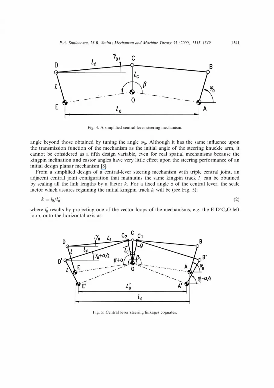
angle beyond those obtained by tuning the angle j0: Although it has the same in¯uence uponthe transmission function of the mechanism as the initial angle of the steering knuckle arm, itcannot be considered as a ®fth design variable, even for real spatial mechanisms because thekingpin inclination and castor angles have very little e�ect upon the steering performance of aninitial design planar mechanism [8].From a simpli®ed design of a central-lever steering mechanism with triple central joint, an
adjacent central joint con®guration that maintains the same kingpin track l0 can be obtainedby scaling all the link lengths by a factor k. For a ®xed angle a of the central lever, the scalefactor which assures regaining the initial kingpin track l0 will be (see Fig. 5):
k � l0=l00 �2�
where l 00 results by projecting one of the vector loops of the mechanisms, e.g. the E 'D 'C2O leftloop, onto the horizontal axis as:
Fig. 4. A simpli®ed central-lever steering mechanism.
Fig. 5. Central lever steering linkages cognates.
P.A. Simionescu, M.R. Smith /Mechanism and Machine Theory 35 (2000) 1535±1549 1541

l 00 � 2
�l cos
�pÿ j0 �
a2
�� lt cos
�g0 �
a2
�ÿ lc cos
�p2� a
2
���3�
4. 3RT3R Watt II mechanism
A second type of the Watt II six-bar mechanism, with many practical applications, is that inwhich the middle ground joint slides (Fig. 6(a)).This sliding joint provides the same displacement, velocity and higher derivatives to all the
points rigidly attached to the translational ternary link. This implies that, by choosing di�erentpositions of the two pivot joints on this translational link together with a proper repositioningof the other rotational ground joint, di�erent con®gurations can be obtained which will assurethe same transmission function between the two pivoting grounded members. Again a doublein®nity of function cognates will result from an initial con®guration as in Fig. 6(a). One willcorrespond to di�erent points along the horizontal axis (di�erent Dx displacements) as shownin Fig. 6(b), and the other to di�erent vertical displacements Dy as shown in Fig. 6(c).As for the 7R Watt II mechanism, a reference normalised con®guration can be de®ned,
having a ternary link of zero length and an input member of unit length l0 � 1 (Fig. 7).Alternatively, the output member l3 can be chosen to have a unit length, both cases beingpreferable to a normalised ground link l4 � 1, which excludes the particular con®gurations(which sometimes may be of interest) having the joints O and A merged into a triple groundjoint. The total number of parameters describing the input±output transmission function of themechanism is 6, i.e., the member lengths l1±l4 together with the distance l5 and the angle apositioning the slider track.From the reference con®guration mechanism in Fig. 7, with the given numerical data, the
following succession of geometrical transformations was applied so as to obtain a cognatehaving the same distance between the ground joint axes.A global scaling of the mechanism by the factor 150 was initially applied in order to obtain
appropriate dimensions in millimetres. The inner loop OD 'C2C1B 'A shown in Fig. 8 was thenobtained by scaling the resulting pentagonal loop by a factor 0.6. The right crank and itscoupler were then moved so as to obtain a superimposed ground joint A. The central slidingelement is now triangular, having the track parallel with that of the joint C. AutoCAD2; wasagain used to facilitate the graphical constructions (the software calculating all the linear andangular transformations in double precision).As in the previous case, the input and output members may be merged into single elements,
and the overconstrained mechanism shown in Fig. 8 obtained, the dimensions of which aregiven in Table 2. Working models of this and the mechanism shown in Fig. 3 have beenmanufactured in the Department of Mechanical, Materials and Manufacturing Engineering atthe University of Newcastle upon Tyne to demonstrate the e�ectiveness of this method [10].Once again Grubler's formula has the same form as Eq. (3) giving a formal zero mobility tothe mechanism.A computer simulation of the mechanism was also performed, in this case the joints C1 and
C2 being permitted to slide independently on parallel tracks. The distance between the centre of
P.A. Simionescu, M.R. Smith /Mechanism and Machine Theory 35 (2000) 1535±15491542

Fig. 6. Input±output invariant transformations of a Watt II 3RT3R mechanism.
P.A. Simionescu, M.R. Smith /Mechanism and Machine Theory 35 (2000) 1535±1549 1543

these joints varied by 0.4411 mm (1.1%) for the almost whole rotation range of the inputelement OD (ÿ478, 2278), again due to truncated input data and round-o� errors.
5. The Watt II rack-and-pinion steering mechanism
A common practical embodiment of the Watt II mechanism with a central translationalground joint is the rack-and-pinion steering linkage. There are two relatively di�erentcon®gurations, one having the pivot joints of the ternary link very close to each othercorresponding to the central outrigger rack-and-pinion steering linkages, and the other, morecommonly used, having these same pivot joints distantly disposed on the actuatingtranslational element.The central outrigger type can be well approximated by the simpli®ed con®guration shown
in Fig. 9, in which the central pivot joints are merged into a single triple joint. Due to thedimensional symmetry, the number of parameters describing the geometry reduces from 6 to 3,viz. the steering knuckle arm length l, and the initial angles j0 and g0: The kingpin track l0 willbecome the reference length as in the case of the central-lever steering mechanism.
Fig. 7. Reference dimensional con®guration of a Watt II 3RT3R mechanism.
Table 2
Numerical data of the mechanism in Fig. 8
xO = 0.0 xA = 79.86732 yC = 34.41459
yO = 0.0 yA = ÿ55.20297 C2D ' = 54AB = 150 DO = 75 D 'O = 45BC = 105 AB ' = 90 xC1ÿxC2 = 31.94693
CD = 90 B 'C1 = 63 yC2ÿyC1 = 22.36948
P.A. Simionescu, M.R. Smith /Mechanism and Machine Theory 35 (2000) 1535±15491544

Fig. 8. Working model of Watt II 3RT3R function cognates associated in an overconstrained mechanism.
P.A. Simionescu, M.R. Smith /Mechanism and Machine Theory 35 (2000) 1535±1549 1545

A real rack-and-pinion steering linkage with distant central pivot joints will have a referencecognate with merged central joints (see Fig. 10), and consequently the parameters describing itsgeometry will be three in number. These can be conveniently considered as the initial angles j0
and g0 of the steering knuckle arm and of the tie-rod respectively, together with the ratio l 0=l 0t(note that l 0 � k� l and l 0t � k� lt, where k is the scaling factor by which the inner loop hasbeen obtained). Either of the lengths l 0 or l 0t or alternatively that of the tie-rod can be chosen apriori (for the case of an independent wheel front axle, the tie-rod length must be correlatedwith the suspension geometry such that the cross-coupling e�ect between steering and wheelbump and rebound is reduced to a minimum). This contradicts the ®ndings of Zarak andTownsend [11], who considered four design parameters in the synthesis of a rack-and-pinionplanar steering mechanism. The fourth geometrical parameter chosen is redundant and any®ne-tuning of its value would not improve in any way the steering characteristics of themechanism.If the design is performed initially for a simpli®ed con®guration with merged central joints
such as that in Fig. 9 (with prescribed kingpin track l0 and rack length lr), the real mechanismlink lengths can be obtained by multiplying them by a scale factor k of less than unity:
k � l 0t=lt � l 0=l � �l0 � lr �=l0 �4�
Fig. 9. A simpli®ed central outrigger rack-and-pinion steering mechanism.
Fig. 10. Rack-and-pinion steering linkage cognates.
P.A. Simionescu, M.R. Smith /Mechanism and Machine Theory 35 (2000) 1535±15491546

This equation results from consideration of the similar triangles EC2D '0ECD and CC1C20CAE where lr denotes the rack length.
6. Conclusions and further studies
An intuitive method for determining Watt II function cognates and the correspondingoverconstrained mechanisms has been presented.A proof of the invariance of the transmission function following the geometrical
transformations illustrated in Figs. 1 and 6, is that the transmission function of any mechanismhaving rotational input and output members can be expressed as a dimensionless equation interms of link lengths ratios.It is interesting to note that the pantograph linkage shown in Fig. 11, known as Burmester's
pantograph [2], can be considered as resulting from a particular overconstrained mechanism ofthe Watt II type, with the ground joints of the input and output members merged into a singletriple joint. When the pantograph traces arcs of circles centred in O, it suggests a 7R Watt IIorigin while, when its traces straight lines, a 3RT3R Watt II origin might be invoked. Fig. 12shows a proposed generalisation of this pantograph derived from a 3RT3R Watt II mechanismwith the same proportions as mechanism in Fig. 8 (Table 2). A number of supplementaryelements have been introduced such that the ¯oating L-shaped link derived from the formercentral translating link has rotation inhibited. The proof that this is a pantograph linkage relieson the fact that the line C1C2 remains parallel with the ground joint line AO, ensuring
Fig. 11. Burmester's pantograph.
P.A. Simionescu, M.R. Smith /Mechanism and Machine Theory 35 (2000) 1535±1549 1547

similarity of the triangles CC1C20CAO, OD 'C20ODC and AB 'C10ABC. Consequently, anypoint solidly ®xed with the L-shaped member of the pantograph will trace the same curve asthat traced by the joint C, but with a reduction in scale k = C2D '/CD = B 'C1/CB.
Acknowledgements
The ®rst author acknowledges the support of Romanian Ministry of Education through thegrant no. 5843/1996 for his research visit at the University of Newcastle upon Tyne.
References
[1] E.A. Dijksman, Six-bar cognates of Watt's form, J. of Engineering for Industry 93 (1971) 183±190.[2] E.A. Dijksman, Motion Geometry of Mechanisms, Cambridge University Press, Cambridge, 1976.
[3] E.A. Dijksman, Assembling complete pole con®gurations for (over) constrained planar mechanisms, J. ofMechanical Design 116 (1994) 215±225.
[4] C.W. McLarnan, Synthesis of six-link plane mechanisms by numerical analysis, J. of Engineering for Industry
85 (1963) 5±11.[5] A.K. Dhingra, N.K. Mani, Finitely and multiply separated synthesis of link and gear mechanisms using
symbolic computing, J. of Mechanical Design 115 (1993) 560±567.[6] A.K. Dhingra, J.C. Cheng, D. Kohli, Synthesis of six-link, slider-crank and four-bar mechanisms for function,
path and motion generation using homotopy with m-homogenisation, J. of Mechanical Design 116 (1994)1122±1131.
[7] OSMEC Users Manual. ESDU International, 27 Corsham St., London, N1 6UA, 1997.
[8] Fl. Duditza, P. Alexandru, Synthesis of the seven-joint space mechanism used in the steering system of roadvehicles, in: Proc. of the 5th World Congress on the Theory of Machines and Mechanisms, Newcastle uponTyne, vol. 4, 1975, pp. 697±702.
Fig. 12. A 3RT3R Watt II pantograph derived from the overconstrained mechanism in Fig. 8.
P.A. Simionescu, M.R. Smith /Mechanism and Machine Theory 35 (2000) 1535±15491548

[9] D.D. Arday®o, D. Qiao, Analytical design of seven-joint spatial steering mechanism, Mechanism and MachineTheory 22 (1987) 315±319.
[10] P.A. Simionescu, M.R. Smith, Four- and six-bar function cognates and overconstrained mechanisms, in: Proc.of the 10th World Congress on the Theory of Machines and Mechanisms, Oulu, vol. 2, 1999, pp. 523±529.
[11] C.E. Zarak, M.A. Townsend, Optimal design of rack-and-pinion steering linkages, J. of Mechanisms,
Transmissions and Automation in Design 105 (1983) 220±226.
P.A. Simionescu, M.R. Smith /Mechanism and Machine Theory 35 (2000) 1535±1549 1549


