Embed Size (px)
Citation preview

arX
iv:c
ond-
mat
/040
9009
v1 [
cond
-mat
.sof
t] 1
Sep
200
4
Modulational Instabilities and Domain Walls in Coupled Discrete Nonlinear
Schrodinger Equations
Z. Rapti1,2, A. Trombettoni3, P.G. Kevrekidis1,2, D.J. Frantzeskakis4, Boris A. Malomed5 and A.R. Bishop2
1Department of Mathematics and Statistics, University of Massachusetts, Amherst MA 01003-4515, USA2 Center for Nonlinear Studies and Theoretical Division,
Los Alamos National Laboratory, Los Alamos, NM 87545, USA3 Istituto Nazionale per la Fisica della Materia, and Dipartimento di Fisica,Universita’ di Parma, parco Area delle Scienze 7A, I-43100 Parma, Italy
4 Department of Physics, University of Athens, Panepistimiopolis, Zografos, Athens 15784, Greece5Department of Interdisciplinary Studies, Faculty of Engineering, Tel Aviv University, Tel Aviv 69978, Israel
We consider a system of two discrete nonlinear Schrodinger equations, coupled by nonlinear andlinear terms. For various physically relevant cases, we derive a modulational instability criterion forplane-wave solutions. We also find and examine domain-wall solutions in the model with the linearcoupling.
I. INTRODUCTION
Modulational instabilities (MIs) have a time-honored history in nonlinear wave equations. Their occurrences spanareas ranging from fluid dynamics [1] (where they are usually referred to as the Benjamin-Feir instability) and nonlinearoptics [2, 3] to plasma physics [4].
While earlier manifestations of such instabilities were studied in continuum systems [3, 5], in the last decade therole of the MI in the dynamics of discrete systems has emerged. In particular, the MI was analyzed in the context ofthe discrete nonlinear Schrodinger equation [6], a ubiquitous nonlinear-lattice dynamical model [7, 8]. More recently,it was studied in the context of weakly interacting trapped Bose-Einstein condensates (BECs), where the analyticalpredictions based on the discrete model [9] were found to be in agreement with the experiment [10] (see also the recentworks [11, 12, 13], and recent reviews in [14, 15]). Additionally, the development of “discrete nonlinear optics” (basedon nonlinear waveguide arrays) has recently provided the first experimental observation of the MI in the latter classof systems [16].
An extension of these recent works, which is relevant to both BECs in the presence of an optical-lattice potential[17, 18, 19, 21] and nonlinear optics in photorefractive crystals [22], is the case of multi-component discrete fields.These can correspond to a mixture of two different atomic species, or different spin states of the same atom, in BECs[23], or to light waves carried by different polarizations or different wavelengths in optical systems [24].
The corresponding two-component model is based on two coupled discrete nonlinear Schrodinger (DNLS) equations,
i∂u1n
∂t= −d1(u1,n+1 + u1,n−1 − 2u1,n) + (s11|u1,n|
2 + s12|u2,n|2)u1,n + cu2,n,
i∂u2,n
∂t= −d2(u2,n+1 + u2,n−1 − 2u2,n) + (s12|u1,n|
2 + s22|u2,n|2)u2,n + cu1,n. (1)
This is a discrete analog of the well-known model describing nonlinear interactions of the above-mentioned lightwaves through self-phase-modulation and cross-phase-modulation (XPM) [3, 5]. In optics, Eqs. (1) describe an arrayof optical waveguides, the evolution variable being the propagation distance z (rather than time t). The choice ofthe nonlinear coefficients in the optical models is limited to the combinations s11 = s22 = 3s12/2 for orthogonallinear polarizations, and s11 = s22 = s12/2 for circular polarizations or different carrier wavelengths. In BECs,the coefficients sjk in Eqs. (1), are related to the three scattering lengths αjk which account for collisions betweenatoms belonging to the same (αjj) or different (αjk, j 6= k) species; in that case, αij > 0 (αij < 0) correspondsto the repulsive (attractive) interaction between the atoms. The linear coupling between the components, which isaccounted for by the coefficient c in Eqs. (1), is relevant in optics for a case of circular polarizations in an array ofoptical fibers with deformed (non-circular) cores, or for linear polarizations in an array of twisted fibers [24]. On theother hand, in the BECs context, c represents the Rabi frequency of transitions between two different spin states ina resonant microwave field [20, 21].
Stimulated by the experimental relevance of the MI in discrete coupled systems, the aim of the present work isto develop a systematic study of the instability in the two-component dynamical lattices. We give an analyticalderivation of the MI criteria for the case of both the nonlinear and linear coupling between the components. As aresult of the analysis, we also find a novel domain-wall (DW) stationary pattern in the case of the linear coupling.The presentation is structured as follows: In the following sections we derive plane-wave solutions and analyze theirstability, corroborating it with a numerical analysis of the stability intervals. We do this for the model with the linear

2
coupling in section II and for the one with the purely nonlinear coupling in section III. In section IV, we examine DWstates in the linearly coupled lattices. Finally, the results and findings are summarized in section V.
II. THE MODEL WITH THE LINEAR COUPLING
We look for plane-wave solutions in the form
ujn = Aj exp [i(qjn − ωjt)] , j = 1, 2. (2)
The linear coupling imposes the restrictions q1 = q2 ≡ q and ω1 = ω2 ≡ ω. Inserting Eq. (2) into Eqs. (1) yields
ωA1 = −2d1(cos q − 1)A1 + (s11A21 + s12A
22)A1 + cA2,
ωA2 = −2d2(cos q − 1)A2 + (s12A21 + s22A
22)A2 + cA1. (3)
In the particular, but physically relevant, symmetric case, with d1 = d2 and s11 = s22, it follows from here that theamplitudes A1,2 obey an equation [(s11 − s12)A1A2 − c]
(
A21 − A2
2
)
= 0, hence either of the following two relationsmust then be satisfied:
A1 = ±A2; (4)
A1A2 =c
s11 − s12. (5)
In the case of Eq. (4), a nonzero solution has A1 = ±√
(2d1(cos q − 1) + ω ∓ c) / (s11 + s22). It exists withs11 + s12 > 0, provided 2d1(cos q − 1) + ω ∓ c > 0, and with s11 + s12 < 0, if 2d1(cos q − 1) + ω ∓ c < 0. Whens11 = −s12, one obtains solutions of the form (A1, A2) = (±A, A) with arbitrary A and −2d1(cos q − 1) = ω ∓ c.
On the other hand, from Eq. (5), one finds that
A21 =
ω + 2d1(cos q − 1)
2s11
±1
2
√
(
ω + 2d1(cos q − 1)
s11
)2
−4c2
(s11 − s12)2(6)
under the restriction that this expression must be positive. When c 6= 0, solutions of this type exist as long as[ω + 2d1(cos q − 1)] s11 > 0 (as the term under the square root is smaller in magnitude than the one outside) and theargument of the square root in (6) is non-negative. The first condition implies ω > −2d1(cos q − 1), for s11 > 0, andω < −2d1(cos q − 1), for s11 < 0. In the case s12 = 0, Eq. (6) takes the simpler form
A21 = (2s11)
−1[
ω + 2d1(cos q − 1) ±√
(ω + 2d1(cos q − 1))2 − 4c2]
. (7)
For both s12 = 0 and s12 = 2s11, it is necessary to impose the condition |ω + 2d1(cos q − 1)| ≥ 2c for the solutions tobe real. We note that these relations are similar to those derived in Ref. [21], where linearly and nonlinearly coupledsystems of continuum NLS equation were considered.
It is also worth noting that the existence of two distinct uniform states with a fixed product from Eq. (5) suggests apossibility of a domain-wall (DW) solution in the model with the linear coupling. DW solutions in nonlinearly coupleddiscrete nonlinear Schrodinger equations were examined in Ref. [25] (following an analogy with the continuum onesof Ref. [26]). However, the present case is different, as both uniform states have non-vanishing amplitudes in bothcomponents, and, as seen from Eq. (5), the DWs may exist only if c 6= 0. This possibility is examined in more detailin section IV.
To examine the stability of the plane waves, we substitute
ujn(x, t) = [Aj + Bjn(x, t)] exp[i(qn − ωt)] (8)
into Eqs. (1), to obtain a system of two coupled linearized equations for the perturbations Bj(x, t). Furthermore,assuming a general solution of the above-mentioned system of the form
Bjn = αj cos(Qn − Ωt) + iβj sin(Qn − Ωt), (9)

3
where Q and Ω are the wavenumber and frequency of perturbation, we arrive at a set of four homogeneous equationsfor α1, β1, α2 and β2. The latter have a nontrivial solution if Q and Ω satisfy the dispersion relation
[
(Ω − 2d1 sin Q sin q)2 −
(
2d1 cos q(cos Q − 1) + cA2
A1
) (
2d1 cos q(cos Q − 1) + cA2
A1− 2s11A
21
)]
×
[
(Ω − 2d2 sin Q sin q)2 −
(
2d2 cos q(cosQ − 1) + cA1
A2
) (
2d2 cos q(cosQ − 1) + cA1
A2− 2s22A
22
)]
−2c(2s12A1A2 + c)(Ω − 2d1 sin Q sin q)(Ω − 2d2 sin Q sin q) − c2
(
2d1 cos q(cosQ − 1) + cA2
A1− 2s11A
21
)
×
(
2d2 cos q(cos Q − 1) + cA1
A2− 2s22A
22
)
− (2s12A1A2 + c)2
×
[(
2d1 cos q(cosQ − 1) + cA2
A1
) (
2d2 cos q(cosQ − 1) + cA1
A2
)
− c2
]
= 0. (10)
Note that in the absence of coupling, i.e., c = s12 = 0, we obtain a known relation [6]
(Ω − 2dj sin Q sin qj)2 = 2dj cos qj(cosQ − 1)
(
2dj cos qj(cosQ − 1) − 2sjjA2j
)
, (11)
which gives the MI condition if the right-hand side becomes negative, i.e.,
dj cos qj(2dj cos qj sin2 (Q/2) + sjjA2j) < 0. (12)
We will now consider the particular case d1 = d2 ≡ d, the general case being technically tractable but too involved.Then, the dispersion relation (10) takes the from
(Ω − 2d sinQ sin q)4 − (K1 + K2 + K3)(Ω − 2d sin Q sin q)2 + K1K2 − K4 = 0, (13)
where
K1 =
(
2d cos q(cosQ − 1) + cA2
A1
) (
2d cos q(cos Q − 1) + cA2
A1− 2s11A
21
)
,
K2 =
(
2d cos q(cosQ − 1) + cA1
A2
) (
2d cos q(cos Q − 1) + cA1
A2− 2s22A
22
)
,
K3 = 2c(2s12A1A2 + c),
K4 = c2
(
2d cos q(cosQ − 1) + cA2
A1− 2s11A
21
) (
2d cos q(cosQ − 1) + cA1
A2− 2s22A
22
)
+(2s12A1A2 + c)2[(
2d cos q(cosQ − 1) + cA2
A1
) (
2d cos q(cosQ − 1) + cA1
A2
)
− c2
]
.
It immediately follows from Eq. (13) that, to avoid the MI, both solutions for (Ω−2d sinQ sin q)21,2 should be positive.Taking into account the binomial nature of the equation, it is concluded that the spatially homogeneous solution isunstable if either the sum Σ = K1 + K2 + K3 or the product Π = K1K2 − K4 of the solutions is negative:
K1 + K2 + K3 < 0; (14)
K1K2 − K4 < 0. (15)
To proceed further, we may fix the value of the perturbation wavenumber, to investigate in what parameterregion it would give rise to the MI. We illustrate this approach in Figs. 1 and 2, in which we fix Q = π ands11 = s22 = A1 = A2 = d1 = d2 = 1 and vary c and s12 (the coefficients of the linear and XPM coupling), to examinetheir effect on the stability interval. From Eq. (12) we see that for these values of the parameters the modulationalunstable region is π/2 < q < 2π/3 = 2.0945. It can be inferred from the figures that c may widen the MI interval bydecreasing its lower edge. On the other hand, s12 has a more complex effect: while making the instability intervallarger by increasing its upper edge (until it reaches π), it may also open MI bands within the initially modulationallystable region (see, e.g., the lower panel of Fig. 2).
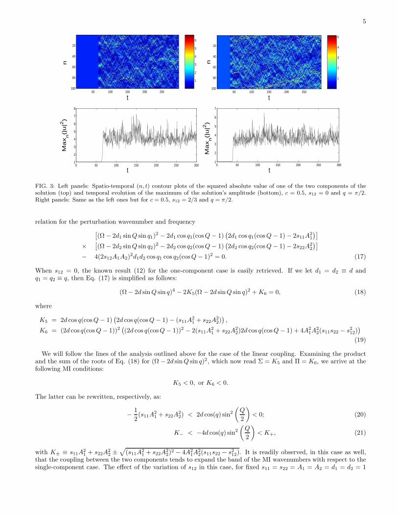
For reasons of completeness, we also illustrate nonlinear development of the MI in the coupled nonlinear lattices insome typical examples. In particular, the role of the MI in generating large-amplitude excitations in the presence ofthe linear coupling only (s12 = 0) is illustrated in the left panel of Fig. 3, for c = 0.5. In the right panel of the figure,the MI in the presence of both linear and nonlinear coupling (c = 0.5, s12 = 2/3) is shown. It is readily observed thatthe nonlinear coupling enhances the instability growth rate and, hence, the MI sets in earlier.

4
1.4 1.6 1.8 2 2.2−5
0
5
Σ , Π
q
1.4 1.6 1.8 2 2.2
−2
0
2
4
6
Σ , Π
q
1.2 1.3 1.4 1.5 1.6 1.7 1.8 1.9 2 2.1 2.2
−2
0
2
4
6
q
Σ , Π
FIG. 1: The figure shows, for s12 = 0, the cases of c = 0 (top panel; unstable for π/2 < q < 2.0945), c = 0.25 (middle panel;unstable for 1.4455 < q < 2.0945) and c = 0.5 (bottom panel; unstable for 1.318 < q < 2.0945). The solid line shows the sumΣ and the dashed line the product Π of the solutions of Eq. (13). The instability takes place in intervals of the wavenumber qof the unperturbed plane-wave solution where either Σ or Π (or both) are negative.
1.2 1.4 1.6 1.8 2 2.2 2.4 2.6−5
0
5
q
Σ , Π
1.2 1.4 1.6 1.8 2 2.2 2.4 2.6 2.8 3
−10
0
10
q
Σ , Π
1 1.5 2 2.5 3
−10
0
10
Σ , Π
q
FIG. 2: Same as Fig. 1 but fixing c = 0.25 and varying s12. The figure shows the cases of s12 = 2/3 (top panel; unstablefor 1.4455 < q < 2.556), s12 = 1 (middle panel; unstable for π/2 < q < π), and s12 = 2 (bottom panel; unstable for0.8955 < q < 1.4455 and π/2 < q < π).
III. THE CASE OF THE PURELY NONLINEAR COUPLING
A physically relevant case that we also wish to consider here is the one with only the nonlinear coupling present,i.e., c = 0. The corresponding dispersion relations read
ωj = −2dj(cos qj − 1) + sj1A21 + sj2A
22, j = 1, 2. (16)
To study the stability of the plane waves in this case, we use Eq. (8) as before, and obtain the following dispersion
5
1
2
3
4
5
6
t
n
50 100 150 200 250
20
40
60
80
100
0 50 100 150 200 250 3001
2
3
4
5
6
7
8
t
Ma
xn(|
u|2
)
1
2
3
4
5
t
n
50 100 150 200 250
20
40
60
80
100
0 50 100 150 200 250 3001
2
3
4
5
6
7
t
Ma
xn(|
u|2
)
FIG. 3: Left panels: Spatio-temporal (n, t) contour plots of the squared absolute value of one of the two components of thesolution (top) and temporal evolution of the maximum of the solution’s amplitude (bottom), c = 0.5, s12 = 0 and q = π/2.Right panels: Same as the left ones but for c = 0.5, s12 = 2/3 and q = π/2.
relation for the perturbation wavenumber and frequency
[
(Ω − 2d1 sinQ sin q1)2 − 2d1 cos q1(cosQ − 1)
(
2d1 cos q1(cos Q − 1) − 2s11A21
)]
×[
(Ω − 2d2 sinQ sin q2)2 − 2d2 cos q2(cosQ − 1)
(
2d2 cos q2(cos Q − 1) − 2s22A22
)]
− 4(2s12A1A2)2d1d2 cos q1 cos q2(cosQ − 1)2 = 0. (17)
When s12 = 0, the known result (12) for the one-component case is easily retrieved. If we let d1 = d2 ≡ d andq1 = q2 ≡ q, then Eq. (17) is simplified as follows:
(Ω − 2d sin Q sin q)4 − 2K5(Ω − 2d sinQ sin q)2 + K6 = 0, (18)
where
K5 = 2d cos q(cosQ − 1)(
2d cos q(cosQ − 1) − (s11A21 + s22A
22)
)
,
K6 = (2d cos q(cos Q − 1))2(
(2d cos q(cosQ − 1))2 − 2(s11A21 + s22A
22)2d cos q(cosQ − 1) + 4A2
1A22(s11s22 − s2
12))
(19)
We will follow the lines of the analysis outlined above for the case of the linear coupling. Examining the productand the sum of the roots of Eq. (18) for (Ω − 2d sin Q sin q)2, which now read Σ = K5 and Π = K6, we arrive at thefollowing MI conditions:
K5 < 0, or K6 < 0.
The latter can be rewritten, respectively, as:
−1
2(s11A
21 + s22A
22) < 2d cos(q) sin2
(
Q
2
)
< 0; (20)
K− < −4d cos(q) sin2
(
Q
2
)
< K+, (21)
with K± ≡ s11A21 + s22A
22 ±
√
(s11A21 + s22A2
2)2 − 4A2
1A22(s11s22 − s2
12). It is readily observed, in this case as well,that the coupling between the two components tends to expand the band of the MI wavenumbers with respect to thesingle-component case. The effect of the variation of s12 in this case, for fixed s11 = s22 = A1 = A2 = d1 = d2 = 1

6
1 1.2 1.4 1.6 1.8 2 2.2 2.4 2.6 2.8 3−2
0
2
4
Σ , Π
q
1 1.2 1.4 1.6 1.8 2 2.2 2.4 2.6 2.8 3−5
0
5
Σ , Π
q
1 1.2 1.4 1.6 1.8 2 2.2 2.4 2.6 2.8 3
−20
−10
0
Σ , Π
q
FIG. 4: Same as Fig. 2 but setting c = 0 and varying s12. The figure shows the cases of s12 = 2/3 (top panel; unstable forπ/2 < q < 2.5550), s12 = 1 (middle panel; unstable for π/2 < q < π), and s12 = 2 (bottom panel; unstable for 1.0472 < q < π).
and Q = π, is shown in Fig. 4. Notice also that Eqs. (20) and (21) suggest multi-component generalizations of theMI criteria.
When s11 = s22 ≡ s, A1 = A2 ≡ A and s, s12 > 0, the MI conditions given by Eqs. (20)-(21) can be written in acompact form,
− sA2 < 2d cos(q) sin2 (Q/2) < 0; (22)
(s − s12)A2 < −2d cos(q) sin2 (Q/2) < (s + s12)A
2. (23)
From Eq. (22), we obtain that (for Q = π)
π
2< q < π − arccos
(
sA2
2d
)
, (24)
while similarly from Eq. (23), it follows that
π − arccos
(
(s − s12)A2
2d
)
< q < π − arccos
(
(s + s12)A2
2d
)
. (25)
Examining the latter relations in more detail, we conclude that, for s > s12, the region of unstable wavenumbers is
π/2 < q < π − arccos(
(s+s12)A2
2d
)
, while, for s < s12, Eq. (25) contains the interval of unstable q. This is illustrated
for the case with A = d = s = 1 as a function of s12 in Fig. 5.A typical example of the simulated development of the MI in the case of purely nonlinear coupling is shown in Fig.
6 for s12 = 2/3 and q = π/2.
IV. DOMAIN WALLS IN THE SYSTEM WITH THE LINEAR COUPLING
The expressions (6) for the amplitudes of the plane-wave solutions suggest a novel possibility: Focusing morespecifically on the so-called anti-continuum limit of d = 0 (we use d1 = d2 ≡ d) and following the path of [25], wecan construct domain-wall (DW) solutions that connect the homogeneous state given by Eq. (6) with its “conjugate”state of A2 = c/(A1(s11 − s12)). Such a solution can then be continued for finite coupling, to examine its spatialprofile and dynamical stability.
An example of such a solution, for the case where the nonlinear coupling is absent, is given in Fig. 7. It is observedthat the solution is stable for d < 0.033, and it becomes unstable due to a cascade of oscillatory instabilities (throughthe corresponding eigenvalue quartets) for larger values of d.

7
0 0.5 1 1.5 2 2.5 30
0.5
1
1.5
2
2.5
3
q
s12
MI
NO MI
NO MI
FIG. 5: The threshold wavenumbers q for the modulational instability vs. s12, as found from Eqs. (24) and (25) (for the caseof A = d = s = 1).
1
2
3
4
t
n
50 100 150 200 250
20
40
60
80
100
0 50 100 150 200 250 3001
2
3
4
5
6
t
Max
n(|u|
2 )
FIG. 6: Same as Fig. 3, but for s12 = 2/3 and c = 0 (purely nonlinear coupling); q = π/2.
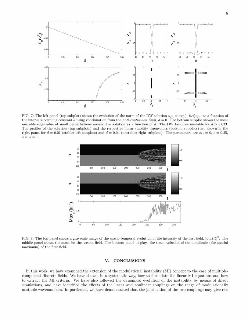
We have also examined the evolution of the DWs when they are unstable. A typical result is displayed in Fig. 8. Itis seen from the bottom panel, which shows the time evolution of the solution’s maximum amplitude, that growth ofthe oscillatory instability eventually destroys the configuration, through “lattice turbulence”. This apparently chaoticevolution can be attributed to the mixing of a large number of unstable eigenmodes. The dynamics remain extremelycomplex despite the eventual saturation of the instability.
The increase of the nonlinear coupling constant s12 reduces the stability window of these solutions. In particular,the case of s12 = 0.3 is shown in Fig. 9 in which, the stability window has shrunk to d < 0.012.
One can also consider a modified DW, where an extra site between the two domains has equal or opposite amplitudesof the two fields. We have checked that such solutions are always unstable (due to the presence of real eigenvaluepairs), for all values of d. Still more unstable (with a larger number of unstable eigenvalues) are more sophisticatedDW patterns, with additional intermediate sites inserted between the two domains.
8
0 0.01 0.02 0.03 0.04 0.05
49.96
49.98
50
Σn(v
n2)
d
0 0.01 0.02 0.03 0.04 0.050
0.05
0.1
0.15
d
λr
46 48 50 52 54
0.5
1
v1 ,
v2
n
−1 −0.5 0 0.5 1−1
−0.5
0
0.5
1
λi
λr
46 48 50 52 54
0.5
1
v1 ,
v2
n
−0.1 0 0.1−1
−0.5
0
0.5
1
λi
λr
FIG. 7: The left panel (top subplot) shows the evolution of the norm of the DW solution ujn = exp(−iωt)vjn, as a function ofthe inter-site coupling constant d using continuation from the anti-continuum limit, d = 0. The bottom subplot shows the mostunstable eigenvalue of small perturbations around the solution as a function of d. The DW becomes unstable for d > 0.033.The profiles of the solution (top subplots) and the respective linear-stability eigenvalues (bottom subplots) are shown in theright panel for d = 0.01 (stable; left subplots) and d = 0.04 (unstable; right subplots). The parameters are s12 = 0, c = 0.25,s = ω = 1.
0.5
1
1.5
n
t50 100 150 200 250 300 350
20
40
60
80
100
0.5
1
1.5
n
t50 100 150 200 250 300 350
20
40
60
80
100
0 50 100 150 200 250 300 350
1
1.5
2
Max
n(|u|
2 )
t
FIG. 8: The top panel shows a grayscale image of the spatio-temporal evolution of the intensity of the first field, |u1n(t)|2. Themiddle panel shows the same for the second field. The bottom panel displays the time evolution of the amplitude (the spatialmaximum) of the first field.
V. CONCLUSIONS
In this work, we have examined the extension of the modulational instability (MI) concept to the case of multiple-component discrete fields. We have shown, in a systematic way, how to formulate the linear MI equations and howto extract the MI criteria. We have also followed the dynamical evolution of the instability by means of directsimulations, and have identified the effects of the linear and nonlinear couplings on the range of modulationallyunstable wavenumbers. In particular, we have demonstrated that the joint action of the two couplings may give rise

9
0 0.01 0.02 0.03 0.04 0.05
49.96
49.98
50
Σn(v
n2)
d
0 0.01 0.02 0.03 0.04 0.050
0.05
0.1
0.15
λr
d
46 48 50 52 54
0.5
1
v1 ,
v2
n
−1 −0.5 0 0.5 1−0.5
0
0.5
λi
λr
46 48 50 52 54
0.5
1
v1 ,
v2
n
−0.2 0 0.2
−0.5
0
0.5
λi
λr
FIG. 9: Same as Fig. 7, but for s12 = 0.3. The instability sets in for d > 0.012.
to noteworthy features, such as opening of new MI bands on the wavenumber scale.Additionally, the identification of a pair of conjugate uniform solutions in the two-component model has prompted
us to examine domain-wall (DW) solutions between such states. We were able to demonstrate that the DWs can belinearly stable, provided that the inter-site coupling in the lattice is sufficiently weak.
From our results, it is clear that multi-component lattice models have a rich phenomenology, which is a naturaladdition to that of single-component ones. It would be interesting to observe the predicted features in experimentalsettings, including weakly coupled BECs and photonic-crystal nonlinear media.
Acknowledgements. ZR and PGK gratefully acknowledge the hospitality of the Center of Nonlinear Studies ofthe Los Alamos National Laboratory where part of this work was performed. PGK also acknowledges the supportof NSF-DMS-0204585, NSF-CAREER and the Eppley Foundation for Research. DJF acknowledges support of theSpecial Research Account of University of Athens. The work of BAM was supported, in a part, by the Israel ScienceFoundation through the grant No. 8006/03. Research at Los Alamos is performed under the auspices of the US-DoE.
[1] T. B. Benjamin and J. E. Feir, J. Fluid. Mech. 27, 417 (1967).[2] L. A. Ostrovskii, Sov. Phys. JETP 24, 797 (1969).[3] G. P. Agrawal. Nonlinear Fiber Optics. Academic Press, San Diego, CA, 1995.[4] T. Taniuti and H. Washimi, Phys. Rev. Lett. 21, 209 (1968); A. Hasegawa, Phys. Rev. Lett. 24, 1165 (1970).[5] A. Hasegawa and Y. Kodama, Solitons in Optical Communications, Clarendon Press (Oxford 1995)[6] Yu. S. Kivshar and M. Peyrard, Phys. Rev. A 46, 3198 (1992).[7] D. N. Christodoulides and R. I. Joseph, Opt. Lett. 13, 794 (1988)[8] For recent reviews see, e.g., P. G. Kevrekidis, K. Ø. Rasmussen, and A. R. Bishop, Int. J. Mod. Phys. B, 15, 2833
(2001); J. C. Eilbeck and M. Johansson,– Proc. of the 3rd Conf. Localization & Energy Transfer in Nonlinear Systems(June 17-21 2002, San Lorenzo de El Escorial Madrid), ed. L. Vazquez et al. (World Scientific, New Jersey, 2003), p. 44(arXiv:nlin.PS/0211049).
[9] A. Smerzi, A. Trombettoni, P. G. Kevrekidis, and A. R. Bishop, Phys. Rev. Lett. 89, 170402, (2002)[10] F. S. Cataliotti, L. Fallani, F. Ferlaino, C. Fort, P. Maddaloni and M. Inguscio, New J. Phys. 5, 71 (2003).[11] V. V. Konotop and M. Salerno Phys. Rev. A 65, 021602 (2002).[12] M. Machholm, A. Nicolin, C. J. Pethick and H. Smith, Phys. Rev. A 69 (2004) 043604.[13] L. Fallani et al., cond-mat/0404045.[14] F.Kh. Abdullaev, S.A. Darmanyan and J. Garnier, Progr. Opt. 44, 303 (2002).[15] P. G. Kevrekidis and D. J. Frantzeskakis, Mod. Phys. Lett. B 18, 173 (2004).[16] J. Meier et al., Phys. Rev. Lett. 92, 163902 (2004).[17] O. Mandel, M. Greiner, A. Widera, T. Rom, T. W. Hansch, and I. Bloch, Phys. Rev. Lett. 91, 010407 (2003).[18] B. Deconinck, J. N. Kutz, M. S. Patterson, and B. W. Warner, J. Phys. A: Math. Gen. 36, 5431 (2003).

10
[19] P. G. Kevrekidis, G. Theocharis, D. J. Frantzeskakis, B. A. Malomed and R. Carretero-Gonzalez, Eur. Phys. J. D: At.Mol. Opt. Phys. 28, 181 (2004).
[20] R. J. Ballagh, K. Burnett, and T. F. Scott, Phys. Rev. Lett. 78, 1607 (1997); J. Williams, R. Walser, J. Cooper, E. Cornell,
and M. Holland, Phys. Rev. A 59, R31 (1999); P. Ohberg and S. Stenholm, Phys. Rev. A 59, 3890 (1999).[21] M.A. Porter, P. G. Kevrekidis, and B.A. Malomed, nlin CD/0401023, Physica D 196 (2004) 106.[22] For recent work see, e.g., J. W. Fleischer et al., Phys. Rev. Lett. 92, 123904 (2004); D. N. Neshev et al., Phys. Rev. Lett.
92, 123903 (2004)[23] See, e.g., C. J. Myatt et al., Phys. Rev. Lett. 78, 586 (1997); D. S. Hall et al., Phys. Rev. Lett. 81, 1539 (1998); D. M.
Stamper-Kurn et al., Phys. Rev. Lett. 80, 2027 (1998); G. Modugno et al., Science 294, 1320 (2001); M. Mudrich et al.,Phys. Rev. Lett. 88, 253001 (2002); M. Trippenbach et al., J. Phys. B 33, 4017 (2000); S. Coen and M. Haelterman, Phys.
Rev. Lett. 87, 140401 (2001); P. Ohberg and L. Santos, Phys. Rev. Lett. 86, 2918 (2001); Th. Busch and J. R. Anglin,Phys. Rev. Lett. 87, 010401 (2001).
[24] For a recent discussion of the various optical applications see, e.g., J. Hudock et al., Phys. Rev. E 67, 056618 (2003).[25] P. G. Kevrekidis et al., Phys. Rev. E 67, 036614 (2003).[26] B.A. Malomed, Phys. Rev. E 50, 1565 (1994).


